valves, controls and system protectors | climate technologies
TRANSCRIPT

Valves, Controls and System ProtectorsGeneral Purpose Catalog


3
Table of Contents Page Thermal Expansion Valves (TXV) Quick Select Guide 5 A Series 6-9 BA/BN Series 10-13 NXT Series 14-16 TXV Connect Kits 17 HF/HFK Series 18-28 TRAE+ Series 29-31 T Series 32-36 TI Valves Series 37-43 TFE 44-45 ZZ Series 46-47 LCL Take-Apart 48-49 ACP(E) 50-51 935 Series 52-55
TXV Extended Capacity Tables Electronic Expansion Valve and Control (EXV) EXM/EXL 89 EX2 90-92 EX3 93-96 EX4-EX8 97-98 EXD-U00 99 EC2 100-104 EC3-X32 105 EC3-X33 106 EC3-D72 107 CX 108 PT5 109-110 PT6 111-112 FSE 113 Pressure Transmitters 114
EX Extended Capacity Tables
Solenoid Valves & Coils Quick Select Guide 189 50RB 190 100RB 191-192 200RB 193-196 200RD 197-198 240RA 199-200 500RB 201-203 540RA 204-205 M36 206 Coils for Solenoid Valves 207-211
Mechanical Pressure Regulators CPHE 213-214 M36 215-216

4
Table of Contents Page Shut Off Valves ACK 217 BV 218 System Protectors Quick Select Guide 219 Recommended System Tonnage 220-221 EK 222-225 EKZ 226-227 BFK 228-229 BFKZ 230-231 STAS 232-233 ADKS 234-235 Filter Drier Cores 236 ASF 237 HMI 238-239 AMI 240-241 A-IHL 242 A-AS 243 ACC 244
System Protectors Capacity Tables 245-252
Oil Controls DCFM 253-254 HighEfficiencyCentrifugalOilSeparator 255 A-F 256-257 A-WZ 258-259 AOR 260 OMB 261-262 W-OLC 263
Temperature Pressure Controls Quick Select Guide 265 TS1 266-267 PS1 268-269 PS2 270-271 PS3 272-273 FD113 274 FSC 275-277 FSX 278 FF444 279
Contact Lists

Thermal Expansion Valves
5
Quick Select Guide
ApplicationNominal Capacity
Valve Family
Adjustable Superheat
Internal Check Valve
Style Connections Configuration Port
HermeticReplaceable
Power Element
Field ServiceableR-22 R-410A SAE ODF Angle Straight Conventional Balanced
Air Conditioning and
Refrigeration
1/4 to 5 1 ¼ to 5 AA X X X X X1/4 to 5 1 ¼ to 5 AN X X X X X1/4 to 5 1 ¼ to 5 AAC X X X X X X1/4 to 5 1 ¼ to 5 ANC X X X X X X1/4 to 5 AFA X X X X X1/2 to 6 ½ to 7 ½ BA X X X X X1/2 to 6 ½ to 7 ½ BN X X X X X
½ to 15 NXT X X X X X X X X1/4 to 5 1/2 HFK X X X X X X X X1/4 to 5 1/2 HF X X X X X X X
8 to 20 HF EXT X X X X X X1/3 to 5 TI X X X X X8 to 20 12 to 20 TF X X X X X
1/2 to 12 TL X X X X X X1/2 to 12 TCL X X X X X X X11 and 14 TJL X X X X X X14 and 18 TJR X X X X X X22 to 45 TER X X X X X X
55 TIR X X X X X X70 and 85 THR X X X X X X
100 TMR X X X X X X10 to 40 TRAE+ X X X X X50 to 70 TRAE X X X X X
Constant Pressure 1/2 to 5 ACP X X X XUltra-Low Temp 3/4 to 8 ZZ X X X X X X X
De-Superheating LA X X X X XLCL X X X X X X X
Applications Operating RangesR-134a
Domestic Refrigerators and Freezers, Ice Makers,Dehumidifiers, Transport Refrigeration, Medium Temperature Supermarket
Equipment,MediumTemperature Commercial Equipment
MCMZ
MW35 (MOP)MW55
R-22Residential Air Conditioners &Heat Pumps, Commercial and
Industrial Chillers, Medium Temperature Supermarket Equipment, Commercial Air Handlers
HCA/HAA AIR COND. & HEAT PUMPHW/HW100
HCHW65 (MOP)
HZ
R-404A/R-507Low Temperature Cases, Ice Makers, Commercial Air Handlers,
Conditioners, Soft Ice Cream Machines, Environmental Chambers
SCSZ
SW45 (MOP)R-410A ZW195
-50 -40 -30 -20 -10 0 +10 +20 +30 +40 +50
Charge Code Selector

Emerson Climate Technologies6
Thermal Expansion Valves
Nomenclature example: AACEB 2 HC 30 IN 3/8 x 1/2 ODF ANG
A A C E B 2 H C 30 IN 3/8 x 1/2 ODF ANGValve Series
Hermetic Design
Superheat Adjustment
A = Adjustable
N = Non-Adjustable
Internal Check Valve
(optional) Reverse
FlowBypass
Application
Equalizer
E=External
(Omit for Internal)
Bleed Hole
(optional)
(Omit for no bleed
hole)
Capacity Nominal Rating in
Tons
(See nominal capacity table
below)
Refrigerant Code
+F = R-12• H = R-22
+M = R-134a• N = R-407C*P = R-507*R = R-502
*S = R-404AZ = R-410A
Charge Code
C = medium temp
CA = heat pumpW(MOP) =
press. limitingZ = low temp
AA = wide range
Capillary Tube
Length
30 IN &
5 FT (std)
Inlet x Outlet Connection
Sizes
1/4 x 3/83/8 x 1/21/2 x 5/85/8 x 7/8
Connection Type
SAE=flareODF = solder
Chatleff (optional)Aeroquip (optional)
Configuration
S/T = straight-thru
ANG = 90° angle
+ = R-134a are interchangeable refrigerant charges* = R-507 and R-404A are interchangeable refrigerant charges• = R-22 and R-407C are interchangeable refrigerant charges
AA/AN Series – Nominal* Capacity Table in Tons (kW)R-134a R-22 R-410A R-507/R-404A R-407C1/8 (0.4) 1/5 (0.7) – 1/8 (0.4) 1/51/4 (0.9) 1/4 (0.9) 1/4 (0.9) 1/4 (0.9) 1/4 (0.9)1/2 (1.8) 1/2 (1.8) 1/2 (1.8) 1/2 (1.8) 1/2 (1.8)3/4 (2.7) 1 (3.5) 1 (3.5) 3/4 1 (3.5)1 (3.5) 1½ (5.3) 1½ (5.3) 1 (3.5) 1¼ (4.4)
1½ (5.3) 2 (7.0) 2 (7.0) 1¼ (4.4) 2 (7.0)2 (7.0) 2½ (8.8) 3 (11.0) 2 (7.0) 2½ (8.8)
2½ (9.0) 3 (11.0) 4 (14.0) 2¼ (8.0) 3¼ (11.5)3 (11.0) 4 (14.0) 5 (17.0) 2½ (8.8) 4 (14.0)4 (14.0) 5 (17.0) – 3½ (12.0) 5¼ (19.0)
All capacities shown are at 100°F condensing, 40°F evaporator temperature.*See Extended Capacity Tables for ratings at a wide range of conditions per ARI standard 750.
Features• Stainless steel power element eliminates corrosion and prevents valve failure• Hermetic, leak-free construction• Compact size allows installation in limited spaces• Mass spectrometer tested to ensure less than 0.10 oz/year external leakage rate
Specifications Maximum working pressure: 700 psigUR/CUR file number: SA 5312
The A series is used for heat pump, air conditioning, food services and commercial applications.
Options• ZW195 charge available for R-410A systems• Adjustable or non-adjustable superheat • SAE or ODF connections standard – Chatleff or Aeroquip are available• External or internal equalizer • Internal check valve allows reverse flow for heat pump applications, eliminating the need for external piping and external check valve• Bleed type pressure equalization to accommodate PSC type compressors• Pressure limiting charges (MOP) available
A Series

Emerson Climate Technologies7
Thermal Expansion Valves
ANCE SAE Dimensional DataConnection Size
A BInlet Outlet
3/8 SAE 3/8 SAE 1.67 1.671/2 SAE 1/2 SAE 1.75 1.75
ANCE ODF Dimensional DataConnection Size
A± .002 B± .002 C MIN D MIN E F
Inlet Outlet1/4 ODF 3/8 ODF 0.25 0.38 0.32 0.32 1.70 1.733/8 ODF 3/8 ODF 0.38 0.38 0.32 0.32 1.70 1.733/8 ODF 1/2 ODF 0.38 0.50 0.32 0.38 1.73 1.731/2 ODF 1/2 ODF 0.50 0.50 0.38 0.38 1.73 1.731/2 ODF 5/8 ODF 0.63 0.61 0.38 0.50 1.75 1.75
AACE ODF Dimensional DataConnection Size
A± .002 B± .002 C MIN D MIN E F
Inlet Outlet1/4 ODF 3/8 ODF 0.25 0.38 0.32 0.32 1.70 1.733/8 ODF 3/8 ODF 0.38 0.38 0.32 0.32 1.70 1.733/8 ODF 1/2 ODF 0.38 0.50 0.32 0.38 1.73 1.731/2 ODF 1/2 ODF 0.50 0.50 0.38 0.38 1.73 1.731/2 ODF 5/8 ODF 0.63 0.61 0.38 0.50 1.75 1.75
AACE SAE Dimensional DataConnection Size
A BInlet Outlet
3/8 SAE 3/8 SAE 1.67 1.671/2 SAE 1/2 SAE 1.75 1.75
1.75
2.63
1.361.77
B A
ANCESAE
A Series

Emerson Climate Technologies8
Thermal Expansion Valves
Ordering Information
Without Internal Check ValveRefrigerant Series Tons* Charge Connections Cap Tube PCN
R-410A AAE
1-1/2 ZW195 3/8 X 1/2 ODF S/T 30 IN 066515
3ZW195 3/8 X 3/8 ODF S/T 30 IN 064595ZW195 3/8 X 1/2 ODF S/T 30 IN 065579ZW195 CHATLEFF 30 IN 015776
5 ZW195 1/2 X 5/8 ODF S/T 30 IN 065580ZW195 CHATLEFF 30 IN 015794
R-134a AA
1/8 MC 1/4 X 3/8 ODF S/T 30 IN 066030MC 1/4 X 1/2 ODF S/T 30 IN 065821
1/4 MC 1/4 X 3/8 ODF S/T 30 IN 062051MC 1/4 X 1/2 ODF S/T 5 FT 065623
1 MC 3/8 X 1/2 ODF S/T 30 IN 065776
1/2 MC 1/4 X 3/8 SAE S/T 30 IN 058985MC 1/4 X 1/2 ODF S/T 5 FT 065624
1/2 MZ 1/4 X 3/8 SAE S/T 30 IN 058986
AAE 1/2 MC 1/4 X 1/2 ODF S/T 5 FT 0656301 MC 3/8 X 1/2 ODF S/T 5 FT 065631
R-22 R-407C
AA
1/4 HC 1/4 X 3/8 ODF S/T 5 FT 056315HC 1/4 X 1/2 ODF S/T 5 FT 055932
1/2HC 1/4 X 1/2 ODF S/T 5 FT 065626HC 3/8 X 3/8 ODF S/T 30 IN 056547HC 3/8 X 1/2 SAE S/T 5 FT 057828
AAE
1/2HC 1/4 X 1/2 ODF S/T 5 FT 065632HC 3/8 X 1/2 ODF S/T 5 FT 065633HC 3/8 X 1/2 SAE ST 5 FT 057987
1HC 1/4 X 3/8 ODF ST 30 IN 059582HC 1/4 X 1/2 ODF S/T 5 FT 065634HC 3/8 X 1/2 ODF S/T 5 FT 065635
1-1/2 HC 3/8 X 1/2 ODF S/T 5 FT 064424
2 HC 3/8 X 1/2 ODF S/T 5 FT 064425HCA 3/8 X 1/2 ODF S/T 30 IN 049632
2-1/2HAA 3/8 X 1/2 ODF S/T 30 IN 063648HAA CHATLEFF 30 IN 013938HCA 3/8 X 1/2 ODF S/T 30 IN 049633
3
HC 3/8 X 1/2 ODF S/T 5 FT 062376HC 3/8 X 1/2 SAE S/T 5 FT 056686
HCA 3/8 X 1/2 ODF S/T 30 IN 049634HCA 1/2 X 5/8 ODF S/T 30 IN 060643
4HC 1/2 X 5/8 ODF S/T 5 FT 061960
HCA 3/8 X 1/2 ODF S/T 30 IN 049638HCA 1/2 X 1/2 ODF S/T 30 IN 061247
5
HAA 3/8 X 1/2 ODF S/T 30 IN 063649HAA CHATLEFF 30 IN 013939HC 1/2 X 5/8 ODF S/T 5 FT 059565HC 5/8 X 7/8 ODF S/T 30 IN 061805
HCA 3/8 X 1/2 ODF S/T 30 IN 054024HCA 1/2 X 5/8 ODF S/T 30 IN 059683
HW100 3/8 X 5/8 ODF S/T 5 FT 062088
AAEB
2 HCA 3/8 X 1/2 ODF S/T 30 IN 0596163 HCA 3/8 X 1/2 ODF S/T 30 IN 0596034 HCA 1/2 X 1/2 ODF S/T 30 IN 0596055 HCA 1/2 X 1/2 ODF S/T 30 IN 059607
Without Internal Check Valve (cont.)Refrigerant Series Tons* Charge Connections Cap Tube PCN
R-404A R-507
AA
1/8 SC 1/4 X 3/8 ODF S/T 6A 30 IN 065921
1/4SC 1/4 X 1/2 ODF S/T 30 IN 063503
SW45 1/4 X 3/8 ODF S/T 5 FT 065676SZ 1/4 X 3/8 ODF S/T 5 FT 065675
1/2SC 1/4 X 1/2 ODF S/T 30 IN 063504
SW45 1/4 X 1/2 ODF S/T 5 FT 065685SZ 1/4 X 1/2 ODF S/T 5 FT 065682SZ 3/8 X 1/2 ODF S/T 30 IN 063925
3/4SC 3/8 X 1/2 ODF S/T 30 IN 066200
SW45 3/8 X 1/2 ODF S/T 30 IN 065686SZ 3/8 X 1/2 ODF S/T 30 IN 065149
1 SC 3/8 X 1/2 ODF S/T 30 IN 066201
AAE
1/4 SC 1/4 X 1/2 ODF S/T 30 IN 066422SZ 1/4 X 1/2 ODF S/T 30 IN 066435
1/2
SC 1/4 X 1/2 ODF S/T 30 IN 066423SC 3/8 X 1/2 ODF S/T 5 FT 066085
SW45 1/4 X 1/2 ODF S/T 5 FT 065636SW45 3/8 X 1/2 ODF S/T 5 FT 065688
SZ 1/4 X 1/2 ODF S/T 30 IN 066436SZ 3/8 X 1/2 ODF S/T 5 FT 065687
3/4 SC 3/8 X 1/2 ODF S/T 5 FT 066086SZ 1/4 X 1/2 ODF S/T 30 IN 066437
1SC 3/8 X 1/2 ODF S/T 5 FT 066087
SW45 3/8 X 1/2 ODF S/T 5 FT 065637SZ 3/8 X 1/2 ODF S/T 5 FT 065183
1-1/4SC 3/8 X 1/2 ODF S/T 5 FT 066081
SW45 3/8 X 1/2 ODF S/T 5 FT 066079SZ 3/8 X 1/2 ODF S/T 5 FT 066080
1-1/2SC 3/8 X 1/2 ODF S/T 5 FT 066448
SW45 3/8 X 1/2 ODF S/T 5 FT 065698SZ 3/8 X 1/2 ODF S/T 5 FT 065697
2SC 3/8 X 1/2 ODF S/T 30 IN 065330
SW45 3/8 X 1/2 ODF S/T 5 FT 065690SZ 3/8 X 1/2 ODF S/T 5 FT 065689
2-1/4SW45 3/8 X 1/2 ODF S/T 5 FT 066082
SZ 3/8 X 1/2 ODF S/T 5 FT 066083SC 3/8 X 1/2 ODF S/T 5 FT 066084
2-1/2 SW45 1/2 X 5/8 ODF S/T 5 FT 065148SZ 1/2 X 5/8 ODF S/T 5 FT 065691
3 SW45 3/8 X 1/2 ODF S/T 5 FT 065693SZ 3/8 X 1/2 ODF S/T 5 FT 065692
A Series

Emerson Climate Technologies9
Thermal Expansion Valves
With Internal Check ValveRefrigerant Series Tons* Charge Connections Cap Tube PCN
R-410A
AACE
1-1/2 ZW195 3/8 X 1/2 ODF S/T 5 FT 065871ZW195 CHATLEFF 30 IN 016432
2 ZW195 3/8 X 1/2 ODF S/T 5 FT 065872ZW195 CHATLEFF 30 IN 016615
3 ZW195 3/8 X 1/2 ODF S/T 5 FT 065873ZW195 CHATLEFF 30 IN 015795
4 ZW195 3/8 X 1/2 ODF S/T 5 FT 065874ZW195 CHATLEFF 30 IN 016433
5 ZW195 1/2 X 5/8 ODF S/T 5 FT 065875ZW195 CHATLEFF 30 IN 015796
AACEB
1-1/2 ZW195 3/8 X 1/2 ODF S/T 30 IN 0659462 ZW195 3/8 X 1/2 ODF S/T 30 IN 0659423 ZW195 3/8 X 1/2 ODF S/T 30 IN 0659434 ZW195 3/8 X 1/2 ODF S/T 30 IN 0659445 ZW195 3/8 X 1/2 ODF S/T 30 IN 065945
R-22 R-407C
AACE
1 HCA 3/8 X 1/2 ODF S/T 30 IN 0637951-1/2 HCA 3/8 X 1/2 ODF S/T 5 FT 058923
2 HCA 3/8 X 1/2 ODF S/T 30 IN 063676
2-1/2 HAA 3/8 X 1/2 ODF S/T 30 IN 064102HAA CHATLEFF 30 IN 014091
3 HCA 3/8 X 1/2 ODF S/T 5 FT 065868HCA 1/2 X 5/8 ODF S/T 5 FT 065797
4 HCA 3/8 X 1/2 ODF S/T 5 FT 065869
5HAA 3/8 X 1/2 ODF S/T 30 IN 064103HAA CHATLEFF 30 IN 014092HAA 1/2 X 5/8 ODF S/T 5 FT 065863
AACEB
1-1/2 HCA 3/8 X 1/2 ODF S/T 30 IN 065842 2 HCA 3/8 X 1/2 ODF S/T 30 IN 0659593 HCA 3/8 X 1/2 ODF S/T 30 IN 0659414 HCA 3/8 X 5/8 ODF S/T 30 IN 065844
* For interchangeable refrigerant charges R-134a/R-12, R-404A/R- 507/R-502, and R-22/R-407C, the tons of capacity shown in the table are for the first (primary) refrigerant listed. Consult the Nominal Capacity Table for determining the tons of capacity for the secondary refrigerants listed. Example: A 1/4 ton R-12 valve is required. What R-134a ton valve should be selected? Solution: From the Nominal Capacity Table, a 1/2 ton R-134a valve is equivalent to a 1/4 ton R-12 valve.
Chatleff Gasket Kit – KG 10045 (PCN: 066031)
A Series

Emerson Climate Technologies10
Thermal Expansion Valves
B A E B 1/2 H CA 5 FT 3/8 x 1/2 ODF S/TValve Series
Hermetic Balanced
Port Design
Superheat Adjustment
A = Adjustable
N = Non-Adjustable
Equalizer
E=External
(Omit for Internal)
Bleed Hole (optional)
(Omit for no bleed hole)
Capacity Nominal Rating
in Tons
(See nominal capacity table
below)
Refrigerant Code
+F = R-12• H = R-22
+M = R-134a• N = R-407C*P = R-507*R = R-502
*S = R-404AZ = R-410A
Charge Code
C = medium tempCA = heat pumpW(MOP) = press.
limitingZ = low temp
Capillary Tube Length
30 IN &
5 FT (std)
Inlet x Outlet Connection
Sizes
1/4 x 3/83/8 x 1/21/2 x 5/85/8 x 7/8
Connection Type
SAE=flare
ODF = solder
Configuration
S/T = straight-thru
ANG = 90° angle
Features • Stainless steel power element eliminates corrosion and prevents valve failure• Hermetic, leak-free construction• Compact size allows installation in limited spaces• Bi-Flow capability allows one valve to control the superheat in both cooling and heating modes for heat pump applications• Balanced port construction compensates for changes in operating pressures due to varying ambients, gas defrost, heat reclaim, or widely varying evaporator loads
The BA/BN series is a balanced ported valve. Typical applications include: refrigerated cases, coolers, freezers, ice machines and air conditioning systems. BA/BN valves operate over widely varying operating conditions.
Options• ZW195 charge available for R-410A systems• External or internal equalizer • Bleed type pressure equalization available to accommodate PSC type compressors• SAE or ODF connections standard – Chatleff or Aeroquip are available• Adjustable or non-adjustable superheat
Specifications • Maximum working pressure: 700 psig
Nomenclature example: BAEB 1/2 HCA 5 FT 3/8 x 1/2 ODF S/T
R-134a R-22/R-407C R-410A R-404A/R-5071/2 (1.8) 1/2 (1.8) 1/2 (1.8) 1/4 (0.9)
3/4 1 (3.5) 1 (3.5) 1/2 (1.8)1 (3.5) 1½ (5.3) 1½ (5.3) 1 (3.5)
1½ (5.3) 2 (7.0) 2 (7.0) 1¼ (4.4)2 (7.0) 2½ (9.0) 3 (11.0) 1½ (5.3)
2¼ (8.0) 3 (11.0) 3½ (12.0) 2 (7.0)3 (11.0) 4 (14.0) 4½ (16.0) 2½ (9.0)
3½ (12.0) 5 (17.0) 6 (21.0) 3 (11.0)3½ (12.0) 6 (21.0) 7½ (26.0) 4 (14.0)
BA/BN Series – Nominal* Capacity Table in Tons (kW)
All capacities shown are at 100°F condensing, 40°F evaporator temperature. *See Extended Capacity Tables for ratings at a wide range of conditions per ARI standard 750
+ = R-134a are interchangeable refrigerant charges* = R-507 and R-404A are interchangeable refrigerant charges• = R-22 and R-407C are interchangeable refrigerant charges
BA/BN Series

Emerson Climate Technologies11
Thermal Expansion Valves
TOP VIEW SHOWING EXTERNAL EQUALIZER LOCATION
Remote Bulb Tubing Length 30” or 5’ StandardBA(E) & BN(E) Remote Bulb Dimensions
Refrigerant Charge Length DiameterHCA, HAA 2.31 0.75
MC, MZ, MW (MOP), RW (MOP)
2.09 0.50RC, SC, SZ, SW (MOP),
PC, PZ, PW (MOP)
ODF CONNECTIONSSTRAIGHT–THRU CONFIGURATION ONLY
ODF CONNECTIONSSTRAIGHT–THRU CONFIGURATION ONLY
BA/BN Dimensional Data (in)BAE
Connection SizeA B C MIN D MIN E F
Inlet Outlet1/4 ODF 3/8 ODF 0.25 0.38 0.31 0.32 1.70 1.73
3/8 ODF 3/8 ODF 0.38 0.38 0.32 0.32 1.73 1.73
3/8 ODF 1/2 ODF 0.38 0.50 0.32 0.41 1.73 1.73
1/2 ODF 1/2 ODF 0.50 0.50 0.41 0.41 1.73 1.73
1/2 ODF 5/8 ODF 0.50 0.63 0.41 0.50 1.73 1.75
5/8 ODF 5/8 ODF 0.63 0.61 0.50 0.50 1.75 1.75
5/8 ODF 7/8 ODF 0.63 0.88 0.50 0.62 1.75 1.73
BN(E) Dimensional Data (in)Connection Size
A B C MIN D MIN E FInlet Outlet
1/4 ODF 3/8 ODF 0.25 0.38 0.31 0.32 1.70 1.73
3/8 ODF 3/8 ODF 0.38 0.38 0.32 0.32 1.73 1.73
3/8 ODF 1/2 ODF 0.38 0.50 0.32 0.41 1.73 1.73
1/2 ODF 1/2 ODF 0.50 0.50 0.41 0.41 1.73 1.73
1/2 ODF 5/8 ODF 0.50 0.63 0.41 0.50 1.73 1.75
5/8 ODF 5/8 ODF 0.63 0.61 0.50 0.50 1.75 1.75
5/8 ODF 7/8 ODF 0.63 0.88 0.50 0.62 1.75 1.73
BA(E) Dimensional Diagram
BN(E) Dimensional Diagram
BA/BN Series

Emerson Climate Technologies12
Thermal Expansion Valves
Ordering InformationRefrigerant Series Tons* Charge Connections Cap Tube PCN
R-410A
BAE
1-1/2 ZW195 3/8 X 1/2 ODF S/T 5 FT 0658762 ZW195 3/8 X 1/2 ODF S/T 5 FT 0658773 ZW195 3/8 X 1/2 ODF S/T 5 FT 065878
4-1/2 ZW195 3/8 X 1/2 ODF S/T 5 FT 0658806 ZW195 1/2 X 3/8 ODF S/T 5 FT 065586
7-1/2 ZW195 5/8 X 7/8 ODF S/T 5 FT 066088
BAEB
1-1/2 ZW195 3/8 X 1/2 ODF S/T 5 FT 0653362 ZW195 3/8 X 1/2 ODF S/T 5 FT 0653373 ZW195 3/8 X 1/2 ODF S/T 5 FT 065338
4-1/2 ZW195 3/8 X 1/2 ODF S/T 5 FT 065339
6ZW195 3/8 X 1/2 ODF S/T 5 FT 065340ZW195 1/2 X 3/8 ODF S/T 5 FT 065978
R-134a BAE
3/4 MC 3/8 X 1/2 ODF S/T 30 IN 0627541 MC 3/8 X 1/2 ODF S/T 30 IN 061967
1-1/2 MC 3/8 X 1/2 ODF S/T 30 IN 0631292 MC 3/8 X 1/2 ODF S/T 30 IN 0628303 MC 3/8 X 1/2 ODF S/T 30 IN 063201
BA/BN Series

Emerson Climate Technologies13
Thermal Expansion Valves
R-22R-407C
BAE
1 HCA 3/8 X 1/2 ODF S/T 30 IN 063200
1-1/2HCA 3/8 X 1/2 ODF S/T 30 IN 061954
HW100 3/8 X 1/2 ODF S/T 30 IN 062831
2HCA 3/8 X 1/2 ODF S/T 30 IN 061955HCA 1/2 X 1/2 ODF S/T 5 FT 063018
2-1/2HCA 3/8 X 1/2 ODF S/T 30 IN 061956HCA 1/2 X 5/8 ODF S/T 30 IN 061962
HW100 3/8 X 1/2 ODF S/T 30 IN 062616
3HCA 3/8 X 1/2 ODF S/T 30 IN 061957HCA 1/2 X 5/8 ODF S/T 5 FT 063019
HW100 3/8 X 1/2 ODF S/T 30 IN 062372
4
HCA 3/8 X 1/2 ODF S/T 30 IN 061958HCA 1/2 X 5/8 ODF S/T 30 IN 061963HCA 5/8 X 5/8 ODF S/T 5 FT 063020
HW100 3/8 X 1/2 ODF S/T 30 IN 062373
5
HCA 3/8 X 1/2 ODF S/T 5 FT 062839HCA 1/2 X 1/2 ODF S/T 5 FT 062852HCA 1/2 X 5/8 ODF S/T 5 FT 061964HCA 5/8 X 5/8 ODF S/T 5 FT 062838
HW100 3/8 X 1/2 ODF S/T 30 IN 062374
6HCA 1/2 X 1/2 ODF S/T 5 FT 062853HCA 1/2 X 5/8 ODF S/T 5 FT 062736
BNE
3HCA 3/8 X 1/2 ODF S/T 5 FT 064166HCA 1/2 X 1/2 ODF S/T 5 FT 062289
4HCA 3/8 X 3/8 ODF S/T 30 IN 063132HCA 3/8 X 1/2 ODF S/T 30 IN 061971
5HCA 1/2 X 1/2 ODF S/T 5 FT 062290HCA 1/2 X 5/8 ODF S/T 5 FT 065226
BAEB
1-1/2HCA 3/8 X 1/2 ODF S/T 30 IN 062789HCA 1/2 X 1/2 ODF S/T 30 IN 063006
2 HCA 3/8 X 1/2 ODF S/T 30 IN 062790
3HCA 3/8 X 1/2 ODF S/T 30 IN 061968HCA 1/2 X 1/2 ODF S/T 30 IN 063015HCA 1/2 X 5/8 ODF S/T 5 FT 063348
4HCA 3/8 X 1/2 ODF S/T 30 IN 063939HCA 1/2 X 1/2 ODF S/T 5 FT 063010
5HCA 3/8 X 1/2 ODF S/T 5 FT 061980HCA 1/2 X 1/2 ODF S/T 30 IN 063128
6HCA 1/2 X 1/2 ODF S/T 30 IN 063940HCA 1/2 X 5/8 ODF S/T 5 FT 064805HCA 5/8 X 5/8 ODF S/T 5 FT 065977
* For interchangeable refrigerant charges R-134a/R-12, R-404A/R-507/R-502, and R-22/R-407C, the tons of capacity shown in the table are for the first (primary) refrigerant listed. Consult the Nominal Capacity Table for determining the tons of capacity for the secondary refrigerants listed.
Example: A 1/4 ton R-12 valve is required. What R-134a ton valve should be selected? Solution: From the Nominal Capacity Table, a 1/2 ton R-134a valve is equivalent to a 1/4 ton R-12 valve.
BA/BN Series

Emerson Climate Technologies14
Thermal Expansion Valves
Nomenclature example: NAE 3 ZAA ODF B15%N A E 3 ZAA ODF B15%
NXT Series Body Type A = Adjustable, With Check, Straight-Through
B = Adjustable, No Check, Straight-Through C = Non-Adjustable, With Check,
Straight-Through D = Non-Adjustable, No Check,
Straight-Through
EqualizerE = External
Equalizer
Capacity(In Tons)
Refrigerant Code
ZAA = R-410A
Connection Type
ODF = SolderCHA = Chatleff
Bleed %(Omit for None)
Features• Precision superheat control optimized for R-410 A systems• Enhanced power element design offers extended valve life• Stainless steel power element eliminates corrosion and prevents valve failure• Laser etched identification markings for permanent legibility• Hermetic, leak-free construction of all joints• Compact size allows installation in limited spaces• Bi-Flow capability allows one valve to control the superheat in both cooling and heating modes for close-coupled or packaged heat pump applications• Balanced port construction compensates for changes in operating pressures due to varying ambients, gas defrost, heat reclaim, or widely varying evaporator loads• External equalizer is standard• Screens on ODF inlet connections
The Emerson NXT Series is a balanced ported valve designed for high efficiency R-410A air conditioning and heat pump applications. NXT Series valves operate over a wide range of conditions andapplications, while offering excellent performance, superiorreliability, and unparalleled valve life.
Specifications• Maximum working pressure (MWP): 700 psig• R-410A operating range: -20°F to +50°F• UR/CUR file number: SA 5312
Options• High flow internal check valve (1-7 tons) allows reverse flow for heat pump applications, eliminating the need for external check valve and improving overall system efficiency• Adjustable or non-adjustable superheat• Bleed type pressure equalization available to accommodate PSC type compressors• ODF connections are standard - Chatleff connections are available• External equalizer (1/4” ODF) is a standard offering. Other configurations are available• External equalizer 1/8” tube with 45° end cut is a standard offering - other terminations are available
Non-Adjustable Adjustable
NXT Series

Emerson Climate Technologies15
Thermal Expansion Valves
Ordering InformationAdjustable, Straight-Through Body Style, Individually Packaged
Refrigerant Capacity (Tons) Check Valve Bleed Inlet X Outlet Bulb Cap Tube Length External Equalizer PCN
R-410A
1/2- 3/8 ODF X 3/8 ODF 30” 30” With Angle Cut 095064
15% 3/8 ODF X 3/8 ODF 30” 30” With Angle Cut 095065- 3/8 ODF X 1/2 ODF 30” 1/4" ODF 095066
1
√ - 3/8 ODF X 1/2 ODF 5 ft 1/4" ODF 095000√ 15% 3/8 ODF X 1/2 ODF 5 ft 1/4" ODF 095001√ - Chatleff X Chatleff 5 ft 5 ft With 1/4" SAE Flare Nut 095002√ - 3/8 ODF X 1/2 ODF 5 ft 5 ft With Angle Cut 095003
- 3/8 ODF X 1/2 ODF 5 ft 1/4" ODF 09500415% 3/8 ODF X 1/2 ODF 5 ft 1/4" ODF 095005
1-1/2
√ - 3/8 ODF X 1/2 ODF 5 ft 1/4" ODF 095006√ 15% 3/8 ODF X 1/2 ODF 5 ft 1/4" ODF 095007√ - Chatleff X Chatleff 5 ft 5 ft With 1/4" SAE Flare Nut 095008√ - 3/8 ODF X 1/2 ODF 5 ft 5 ft With Angle Cut 095009
- 3/8 ODF X 1/2 ODF 5 ft 1/4" ODF 09501015% 3/8 ODF X 1/2 ODF 5 ft 1/4" ODF 095011
2
√ - 3/8 ODF X 1/2 ODF 5 ft 1/4" ODF 095012√ 15% 3/8 ODF X 1/2 ODF 5 ft 1/4" ODF 095013√ - Chatleff X Chatleff 5 ft 5 ft With 1/4" SAE Flare Nut 095014√ - 3/8 ODF X 1/2 ODF 5 ft 5 ft With Angle Cut 095015
- 3/8 ODF X 1/2 ODF 5 ft 1/4" ODF 09501615% 3/8 ODF X 1/2 ODF 5 ft 1/4" ODF 095017
3
√ - 3/8 ODF X 1/2 ODF 5 ft 1/4" ODF 095018√ 15% 3/8 ODF X 1/2 ODF 5 ft 1/4" ODF 095019√ - Chatleff X Chatleff 5 ft 5 ft With 1/4" SAE Flare Nut 095020√ - 3/8 ODF X 1/2 ODF 5 ft 5 ft With Angle Cut 095021
- 3/8 ODF X 1/2 ODF 5 ft 1/4" ODF 09502215% 3/8 ODF X 1/2 ODF 5 ft 1/4" ODF 095023
4
√ - 3/8 ODF X 1/2 ODF 5 ft 1/4" ODF 095024√ 15% 3/8 ODF X 1/2 ODF 5 ft 1/4" ODF 095025√ - Chatleff X Chatleff 5 ft 5 ft With 1/4" SAE Flare Nut 095026√ - 3/8 ODF X 1/2 ODF 5 ft 5 ft With Angle Cut 095027
- 3/8 ODF X 1/2 ODF 5 ft 1/4" ODF 09502815% 3/8 ODF X 1/2 ODF 5 ft 1/4" ODF 095029
5
√ - 3/8 ODF X 1/2 ODF 5 ft 1/4" ODF 095063√ - 1/2 ODF X 5/8 ODF 5 ft 1/4" ODF 095030√ 15% 1/2 ODF X 5/8 ODF 5 ft 1/4" ODF 095031√ - Chatleff X Chatleff 5 ft 5 ft With 1/4" SAE Flare Nut 095032√ - 1/2 ODF X 5/8 ODF 5 ft 5 ft With Angle Cut 095033
- 1/2 ODF X 5/8 ODF 5 ft 1/4" ODF 09503415% 1/2 ODF X 5/8 ODF 5 ft 1/4" ODF 095035
6
√ - 1/2 ODF X 5/8 ODF 5 ft 1/4" ODF 095036√ 15% 1/2 ODF X 5/8 ODF 5 ft 1/4" ODF 095037√ - Chatleff X Chatleff 5 ft 5 ft With 1/4" SAE Flare Nut 095038√ - 1/2 ODF X 5/8 ODF 5 ft 5 ft With Angle Cut 095039
- 1/2 ODF X 5/8 ODF 5 ft 1/4" ODF 09504015% 1/2 ODF X 5/8 ODF 5 ft 1/4" ODF 095041
7
√ - 5/8 ODF X 7/8 ODF 5 ft 1/4" ODF 095042√ 15% 5/8 ODF X 7/8 ODF 5 ft 1/4" ODF 095043√ - Chatleff X Chatleff 5 ft 5 ft With 1/4" SAE Flare Nut 095044√ - 5/8 ODF X 7/8 ODF 5 ft 5 ft With Angle Cut 095045
- 5/8 ODF X 7/8 ODF 5 ft 1/4" ODF 09504615% 5/8 ODF X 7/8 ODF 5 ft 1/4" ODF 095047
NXT Series R-410A

Emerson Climate Technologies16
Thermal Expansion Valves
Ordering InformationAdjustable, Straight-Through Body Style, Individually Packaged (continued)
Refrigerant Capacity (Tons) Check Valve Bleed Inlet X Outlet Bulb Cap Tube Length External Equalizer PCN
R-410A
8 - 5/8 ODF X 7/8 ODF 5 ft 1/4" ODF 09504815% 5/8 ODF X 7/8 ODF 5 ft 1/4" ODF 095049
10 - 5/8 ODF X 7/8 ODF 5 ft 1/4" ODF 09505015% 5/8 ODF X 7/8 ODF 5 ft 1/4" ODF 095051
12
- 1/2 ODF X 5/8 ODF 5 ft 1/4" ODF 095060- 5/8 ODF X 7/8 ODF 5 ft 1/4" ODF 095052
15% 5/8 ODF X 7/8 ODF 5 ft 1/4" ODF 095053- 5/8 ODF X 1-1/8 ODF 5 ft 1/4" ODF 095054- 7/8 ODF X 1-1/8 ODF 5 ft 1/4" ODF 095055
15
- 5/8 ODF X 7/8 ODF 5 ft 1/4" ODF 09505615% 5/8 ODF X 7/8 ODF 5 ft 1/4" ODF 095057
- 5/8 ODF X 1-1/8 ODF 5 ft 1/4" ODF 095058- 7/8 ODF X 1-1/8 ODF 5 ft 1/4" ODF 095059
Non-Adjustable - ODF Connections with 1/4 ODF Equalizer Shown
Adjustable - ODF Connections with 1/4 ODF Equalizer Shown
NXT Series Dimensional Data (in)
ConnectionsDimension
A B C D3/8 ODF 1.65 1.65 0.379 0.341/2 ODF 1.65 1.65 0.504 0.485/8 ODF 2.15 2.15 0.629 0.757/8 ODF 2.15 2.15 0.879 0.75
1-1/8 ODF 2.40 2.40 1.129 0.91Chatleff 1.80 1.36 - -
NXT Series R-410A

Emerson Climate Technologies17
Thermal Expansion Valves
Features• ODF TXVs with chatleff and aeroquip adapters• One valve to fit all systems• TXV with internal check, bulb strap, and connection options all in one box• R-410A and R-22 kits in multiple capacities• Easy field replacement of fixed orifice for increased efficiency
Dimension Data
Specifications• Maximum Working Pressure (MWP):700 psig• UL File number (valves): SA 5312
TXV Connect Kits
Emerson™ TXV Connect kits include our latest generation thermal expansion valves plus chattleff and aeroquip adapters that are easy to install into all residential air conditioning systems.
Individual adapter kits
PCN Description Capacity(tons)* Refrigerant066657 TXV + CONNECT 2½T R-22 1-1/2 to 3
R-22066658 TXV + CONNECT 5T R-22 3-1/2 to 5
066660 TXV + CONNECT 1½T R-410A 1-1/2
R-410A
066661 TXV + CONNECT 2T R-410A 2
066662 TXV + CONNECT 3T R-410A 3
066663 TXV + CONNECT 4T R-410A 4
066664 TXV + CONNECT 5T R-410A 5
066653 CHATLEFF ADAPTER ASSEMBLY N/A N/A
066679 CHATLEFF ADAPTER ASSEMBLY (SHORT) N/A
066654 AEROQUIP ADAPTER ASSEMBLY N/A N/A
* For extended capacity tables, use NXT series for R-410A applications and A-Series for R-22
AeroquipAdapter Assembly
ChatleffAdapter Assembly
(PCN 066679)does not have extension

Emerson Climate Technologies18
Thermal Expansion ValvesHF/HFK Series
Options• ODF or SAE connections• Straight-through or angle flow configurations• Removable inlet strainer (ODF only)• Internal or external equalizer
Specifications• Maximum working pressure: 450 psig• UR/CUR file number: SA5312
Features• Stainless steel replaceable power element eliminates corrosion and prevents valve failure• Two body sizes provide capacities from 1/4 to 20 tons
NOTE: If the HF body is stamped HFK, then the cage is replaceable.Standard Body – HF & HFK• The HF is offered several ways: – Pre-packaged HFK service kits – Include a mix of bodies and power elements with a complete set of cages to serve the most applications with a minimum of parts – Individual components – Bodies, cages, & power elements may be ordered separately – Finished valves – Assembled valves ready for immediate installation• Bi-Flow capability up to 5-1/2 tons R-22 allows one valve to control the superheat in both cooling and heating modes
Nomenclature example: HFESC 2 HC 5 FT 3/8 x 1/2 ODF S/THF N E S C B 2 H C 5 FT 3/8 x 1/2 ODF S/T
Valve Series
Balanced Port Design
Superheat Adjustment
N = Non-Adjustable
Omit for Adjustable
Equalizer
E=External
(Omit for Internal)
Connection Type
S = Solder
(Omit for SAE Flare)
Removable Inlet
Strainer(optional)
C = Inlet Strainer
(ODF only)
Bleed Hole
(optional)
(Omit for no bleed
hole)
Capacity Nominal Rating in
Tons
(Seenominalcapacity
table below)
Refrigerant Code
+F = R-12• H = R-22
+M = R-134a• N = R-407C* P = R-507* R = R-502
* S = R-404A
Charge Code
C = medium temp
CA = heat pumpW(MOP) =
press. limitingZ = low temp
AA = wide range
Capillary Tube
Length5 FT (std)
Inlet x Outlet
Connection Sizes
1/4 x 3/83/8 x 1/2
ConnectionType
SAE = flareODF = solder
Configuration
ANG = 90° angleS/T = straight-
thru
Extended Body – HF• Capacity range from 8 to 20 tons (R-22)• Finished valve only
Standard Body HFR-134a R-22/R-407C R404A/R-507
1/4 (0.9) 1/4 (0.9) 1/8 (0.4)1/2 (1.8) 1/2 (1.8) 1/4 (0.9)3/4 (2.7) 1 (3.5) 1/2 (1.8)1 (3.5) 1 1/2 (5.3) 1 (3.5)
1 1/2 (5.3) 2 (7.0) 1 1/4 (4.4)1 3/4 (6.2) 2 1/2 (8.8) 1 1/2 (5.3)2 1/2 (8.8) 3 (11.0) 2 (7.0)4 (14.0) 5 1/2 (20.0) 3 1/2 (12.0)
HF Series-Nominal* Capacity Tables in Tons (kW)Extended Body HF
R-134a R-22/R-407C R-404A/R-5076(21.0) 8 (28.0) 5 (17.0)
7 1/2 (27.0) 10 (35.0) 7 (27.0)11 (39.0) 15 (53.0) 10 (35.0)14 (50.0) 20 (70.0) 13 (46.0)
All capacities shown are at 100°F condensing, 40°F evaporator temperature.*See Extended Capacity Tables for ratings at a wide range of conditions per ARI standard 750.
+ = R-134a are interchangeable refrigerant charges* = R-507 and R-404A are interchangeable refrigerant charges• = R-22 and R-407C are interchangeable refrigerant charges
The HF series is a balanced ported valve designed for refrigeration, air conditioning and heat pump applications.

Emerson Climate Technologies19
Thermal Expansion Valves
Dimensional Data
Extended Body HF
ODF
Standard Body HF
SAE
ODF ODFw/optional strainer
at inlet
¼ thru 5½ tons R-22
8, 10, 15 & 20 ton R-22
HF ODFConnection Size
A± .002 B± .002 C MIN D MIN E FInlet Outlet
1/4 ODF 3/8 ODF 0.25 0.38 0.31 0.312.50 2.503/8 ODF 1/2 ODF 0.25 0.50 0.31 0.37
3/8 ODF 1/2 ODF 0.38 0.50 0.37 0.37
HF SAEConnection Size
A B CInlet Outlet
1/4 SAE 1/2 SAE 3.11 1.27 1.833/8 SAE 1/2 SAE 2.72
HF/HFK Series

Emerson Climate Technologies20
Thermal Expansion Valves
HFK Cage Nominal* Capacity Table
PCN Description1 Cage Code R-22 R-134a R-404 R-507 R-407C
064868 KT-20299-0 0 ¼ ¼ ⅛ ⅛ ¼064869 KT-20299-1 1 ½ ½ ¼ ¼ ½064870 KT-20299-2 2 1 ¾ ½ ½ 1064871 KT-20299-3 3 1½ 1 1 1 1½064872 KT-20299-4 4 2 1½ 1¼ 1¼ 2064873 KT-20299-5 5 2½ 1¾ 1½ 1½ 2½064874 KT-20299-6 6 3 2½ 2 2 3064875 KT-20299-7 7 5½ 4 3½ 3½ 5½
1 Cage Kit includes Cage, Insertion Tool and ID Clips.*All capacities shown are at 100°F condensing, 40°F evaporator temperature.See Extended Capacity Tables for ratings at a wide range of conditions per ARI standard 750.
HFK AccessoriesPCN Description
064897 Cage Box (Empty)064898 Insertion Tool064899 Oil Bottle
065203 Cage Gasket Kit(12 sets)
HFK Body Selection Table
PCN Description Type Connections (Inlet x Outlet)064881 KT-20298-1 HFK 1/4 x 1/2 SAE Ang Inlet064882 KT-20298-2 HFK 3/8 x 1/2 SAE Ang Inlet064883 KT-20298-3 HFKE 1/4 x 1/2 SAE Ang Inlet064884 KT-20298-4 HFKE 3/8 x 1/2 SAE Ang Inlet064885 KT-20298-5 HFKSC 3/8 x 1/2 ODF Ang Inlet w/ Strainer064886 KT-20298-6 HFKESC 3/8 x 1/2 ODF Ang Inlet w/ Strainer064887 KT-20298-7 HFKS 3/8 x 1/2 ODF S/T064888 KT-20298-8 HFKS 3/8 x 5/8 ODF S/T064889 KT-20298-9 HFKS 1/2 x 5/8 ODF S/T064890 KT-20298-10 HFKS 1/2 x 7/8 ODF S/T064891 KT-20298-11 HFKES 3/8 x 1/2 ODF S/T064892 KT-20298-12 HFKES 3/8 x 5/8 ODF S/T064895 KT-20298-13 HFKES 1/2 x 5/8 ODF S/T064896 KT-20298-14 HFKES 1/2 x 7/8 ODF S/T
HF & HFK Power Element Table
PCN Description System Refrigerant(s) Application
053769 X26300-FW15-1 R-134a/R-12 Low Temp MOP054798 X26300-FW35-1 R-134a/R-12 Low Temp MOP063869 X26300-FW55-1 R-134a/R-12 Low Temp MOP053766 X26300-FZ-1 R-134a/R-12 Low Temp053763 X26300-FC-1 R-134a/R-12 Medium Temp058074 X26300-MC-1 R-134a Medium Temp053767 X26300-HZ-1 R-22/R-407C Low Temp057834 X26300-HCA-1 R-22/R-407C Heat Pump057764 X26300-HW100-1 R-22/R-407C AC MOP053764 X26300-HC-1 R-22/R-407C A/C Med. Temp058085 X26300-SW45-1 R-404/ R-507/ R-502 Low Temp MOP058082 X26300-SZ-1 R-404/ R-507/ R-502 Low Temp058083 X26300-SC-1 R-404/ R-507/ R-502 Medium Temp
Ordering InformationUse the following tables to order individual components.
Cage Kit (PCN 064879)Item Qty
Size 0 Cage (1/4 ton R-22) 2Size 1 Cage (1/2 ton R-22) 2Size 2 Cage (1 ton R-22) 2Size 3 Cage (1 1/2 ton R-22) 2Size 4 Cage (2 ton R-22) 2Size 5 Cage (2 1/2 ton R-22) 2Size 6 Cage (3 ton R-22) 2Size 7 Cage (5 1/2 ton R-22) 2Insertion Tool 1Oil Bottle 1Cage ID Tags 16
Replacement Parts – SAE InletPCN Part Number Description
027385 X-11176-1 3/8” Inlet Filter Screen058707 27676-1 Seal Cap048638 X-11176-7 1/4” Inlet Filter Screen
Replacement Parts- HFSC & HFESC OnlyPCN Kit Number Description
057686 KT-20264 Includes seal cap, gasket o-ring, screen, spring
HF/HFK Series

Emerson Climate Technologies21
Thermal Expansion Valves
SAE/ODF Kit (PCN 065135)Item QtyHFK 3/8 x 1/2 SAE ANG 1HFKE 3/8 x 1/2 SAE ANG 1HFKS 3/8 x 1/2 ODF S/T 1HFKES 3/8 x 1/2 ODF S/T 1Cage Kit (PCN 064879) 1Insertion Tool (PCN 064898) 1Service Box 1FC Power Element 1FZ Power Element 1HC Power Element 1HZ Power Element 1SC Power Element 1SW45 Power Element 1
Cage Kit (PCN 064879)Item QtySize 0 Cage (1/4 ton R-22) 2Size 1 Cage (1/2 ton R-22) 2Size 2 Cage (1 ton R-22) 2Size 3 Cage (1 1/2 ton R-22) 2Size 4 Cage (2 ton R-22) 2Size 5 Cage (2 1/2 ton R-22) 2Size 6 Cage (3 ton R-22) 2Size 7 Cage (5 1/2 ton R-22) 2Insertion Tool 1Oil Bottle 1Cage ID Tags 16
HFK Pre-Packaged Kits The HFK is a pre-packaged kit consisting of a mix of popular bodies and power elements with a complete selection of cages. These kits provide great flexibility allowing valves to be assembled as needed for each application. Three kits are provided as shown below, along with the cage kit which is included in each pre-packaged kit. In addition, custom kits can be assembled by stocking an empty kit case with desired components.
SAE Kit (PCN 064876)Item QtyHFK 1/4 X ½ Body 1HFK 3/8 X ½ Body 1HFKE 3/8 X ½ Body 2FC Power Element 2HC Power Element 1HZ Power Element 1SZ Power Element 2Cage Kit (PCN 064879) 1
ODF Kit (PCN 064877)Item QtyHFKSC 3/8 X ½ Body 1HFKES 3/8 X ½ Body 1HFKESC 3/8 X ½ Body 2FC Power Element 2HC Power Element 1HZ Power Element 1SZ Power Element 2Cage Kit (PCN 064879) 1
HFK Assembly Procedure (see 6 assembly steps & diagrams below)
1. Remove adjusting stem assembly from body with 15/16” wrench.
2. Lubricate both o-rings on cage. 3. Insert cage into body with driver and insertion tool and hand tighten. (Do not over-tighten)
4. Replace adjustment stem assembly to body and hand tighten. Use the 15/16” wrench to tighten adjustment stem assembly 60° or one wrench flat. (300-360 inch lbs. - Do not over-tighten)
5. Attach cage identification clip on power element cap tube.
6. Screw power element to top of valve body and hand tighten. Use the 1” wrench to tighten power element 60° or one wrench flat. (300-360 inch lbs. - Do not over-tighten)
Ordering Information
HF/HFK Series

Emerson Climate Technologies22
Thermal Expansion Valves
HF Series – Internally EqualizedRefrigerant Series Tons* Charge Connections Cap Tube PCN
R-134a HFHFS
1/4MC 3/8 X 1/2 ODF ANG 5 FT 058545MC 3/8 X 1/2 SAE ANG 5 FT 057618
1/2MC 3/8 X 1/2 ODF S/T 5 FT 058100MC 3/8 X 1/2 SAE ANG 5 FT 057620
1 MC 3/8 X 1/2 ODF S/T 5 FT 065641
R-22R-407C
HFHFS
1/4
HC 1/4 X 1/2 SAE ANG 5 FT 058430HC 3/8 X 1/2 ODF ANG 5 FT 055493HC 3/8 X 1/2 ODF S/T 5 FT 055633HC 3/8 X 1/2 SAE 5 FT 054921HZ 1/4 X 1/2 SAE ANG 5 FT 059653HZ 3/8 X 1/2 ODF S/T 5 FT 056169
1/2
HC 1/4 X 1/2 SAE ANG 5 FT 009812HC 3/8 X 1/2 ODF ANG 5 FT 054723HC 3/8 X 1/2 ODF S/T 5 FT 054136HC 3/8 X 1/2 SAE 5 FT 054135HZ 3/8 X 1/2 SAE 5 FT 054364
1
HC 3/8 X 1/2 ODF ANG 5 FT 055702HC 3/8 X 1/2 ODF S/T 5 FT 055928HC 3/8 X 1/2 SAE 5 FT 054927HZ 3/8 X 1/2 SAE 5 FT 054928
1-1/2HC 3/8 X 1/2 ODF ANG 5 FT 055969HC 3/8 X 1/2 ODF S/T 5 FT 056018HC 3/8 X 1/2 SAE 5 FT 054933
2HC 3/8 X 1/2 SAE 5 FT 054939HZ 3/8 X 1/2 SAE ANG 5 FT 054940
2-1/2 HC 3/8 X 1/2 SAE 5 FT 054947
3HC 3/8 X 1/2 SAE 5 FT 053316HC 3/8 X 1/2 ODF S/T 5 FT 053915
R-404A R-507
HFHFS
1/4SC 1/4 X 1/2 30 IN 066516
SW45 1/4 X 1/2 30 IN 066517SZ 1/4 X 1/2 30 IN 066518
1/2SC 1/4 X 1/2 30 IN 066519
SW45 1/4 X 1/2 30 IN 066520SZ 1/4 X 1/2 30 IN 066521
1SC 3/8 X 1/2 ODF S/T 5 FT 065643
SW45 3/8 X 1/2 5 FT 066522SZ 3/8 X 1/2 5 FT 066523
1-1/2SC 3/8 X 1/2 5 FT 066524
SW45 3/8 X 1/2 5 FT 066525SZ 3/8 X 1/2 5 FT 066526
2SC 3/8 X 1/2 5 FT 066527
SW45 3/8 X 1/2 5 FT 066528SZ 3/8 X 1/2 5 FT 066529
3-1/2SC 3/8 X 1/2 5 FT 066530
SW45 3/8 X 1/2 5 FT 066531SZ 3/8 X 1/2 5 FT 066532
Ordering InformationUse the following tables to order factory assembled valves.
HF/HFK Series

Emerson Climate Technologies23
Thermal Expansion Valves
Ordering Information (continued)
HF Series – Externally Equalized (continued)Refrigerant Series Tons* Charge Connections Cap Tube PCN
R-134a HFEHFES
1/4 MC 3/8 X 1/2 SAE ANG 30 IN 057860
1/2MC 3/8 X 1/2 ODF S/T 5 FT 065645MC 3/8 X 1/2 SAE ANG 5 FT 057616
3/4MC 3/8 X 1/2 ODF ANG 5 FT 057784MC 3/8 X 1/2 SAE ANG 30 IN 057861MC 3/8 X 1/2 ODF S/T 5 FT 059422
1MC 3/8 X 1/2 ODF ANG 5 FT 058546MC 3/8 X 1/2 ODF S/T 5 FT 065646MC 3/8 X 1/2 SAE ANG 5 FT 057617
1-1/2 MC 3/8 X 1/2 SAE ANG 5 FT 057895
1-3/4MC 3/8 X 1/2 ODF S/T 5 FT 065647MC 3/8 X 1/2 SAE 5 FT 058152MC 3/8 X 1/2 SAE ANG 5 FT 057896
4 MC 3/8 X 1/2 SAE ANG 5 FT 0578976 MC 5/8 X 7/8 ODF S/T 5 FT 057903
11MC 5/8 X 7/8 ODF S/T 5 FT 057906MC 7/8 X 1 1/8 ODF S/T 5 FT 058681
14 MC 7/8 X 1 3/8 ODF S/T 5 FT 064000
R-22 R-407C
HFEHFES
1/4HC 3/8 X 1/2 ODF S/T 5 FT 055927HC 3/8 X 1/2 SAE 5 FT 054924HZ 3/8 X 1/2 SAE 5 FT 054925
1/2
HC 1/4 X 1/2 SAE ANG 5 FT 059079HC 3/8 X 1/2 ODF ANG 5 FT 054838HC 3/8 X 1/2 ODF S/T 5 FT 055827HC 3/8 X 1/2 SAE 5 FT 054361HZ 3/8 X 1/2 ODF S/T 5 FT 055889HZ 3/8 X 1/2 SAE 5 FT 054365
1
HC 3/8 X 1/2 ODF ANG 5 FT 055494HC 3/8 X 1/2 ODF S/T 5 FT 055708HC 3/8 X 1/2 SAE 5 FT 054930
HW 35 3/8 X 1/2 SAE 5 FT 054932HZ 3/8 X 1/2 SAE 5 FT 054931
1-1/2
HC 3/8 X 1/2 ODF ANG 5 FT 055495HC 3/8 X 1/2 ODF S/T 5 FT 055863HC 3/8 X 1/2 SAE 5 FT 054936HZ 3/8 X 1/2 ODF S/T 5 FT 055870HZ 3/8 X 1/2 SAE 5 FT 054937
2
HC 3/8 X 1/2 ODF S/T 5 FT 055706HC 3/8 X 1/2 SAE 5 FT 054942HC 3/8 X 1/2 ODF ANG 5 FT 054946HZ 3/8 X 1/2 SAE 5 FT 054943
2-1/2HC 3/8 X 1/2 ODF ANG 5 FT 056042HC 3/8 X 1/2 ODF S/T 5 FT 055931HC 3/8 X 1/2 SAE 5 FT 054950
3
HC 3/8 X 1/2 ODF ANG 5 FT 054756HC 3/8 X 1/2 ODF S/T 5 FT 053916HC 3/8 X 1/2 SAE 5 FT 053317HC 1/2 X 5/8 ODF ANG 5 FT 064761
HCA 3/8 X 1/2 ODF S/T 5 FT 058648HCA 1/2 X 5/8 ODF S/T 5 FT 061730HZ 3/8 X 1/2 ODF S/T 5 FT 055924HZ 3/8 X 1/2 SAE 5 FT 053191
HF/HFK Series

Emerson Climate Technologies24
Thermal Expansion Valves
Ordering Information (continued)
HF Series – Externally Equalized (continued)Refrigerant Series Tons* Charge Connections Cap Tube PCN
R-22 R-407C
HFEHFES
5-1/2
HC 3/8 X 1/2 ODF S/T 5 FT 054141HC 3/8 X 1/2 SAE 5 FT 054140HC 1/2 X 5/8 ODF ANG 5 FT 054778HC 1/2 X 7/8 ODF S/T 5 FT 055187HC 5/8 X 7/8 ODF S/T 5 FT 054779
HCA 3/8 X 1/2 ODF S/T 5 FT 065649HCA 1/2 X 5/8 ODF ANG 5 FT 057378HZ 3/8 X 1/2 ODF S/T 5 FT 054780HZ 3/8 X 1/2 SAE 5 FT 054777
8
HC 1/2 X 5/8 ODF S/T 5 FT 057312HC 5/8 X 1 1/8 ODF ST 5 FT 057313
HCA 1/2 X 7/8 ODF S/T 5 FT 056818HCA 5/8 X 1 1/8 ODF ST 5 FT 056819
10
HC 1/2 X 5/8 ODF S/T 5 FT 057315HC 5/8 X 7/8 ODF S/T 5 FT 057256HC 7/8 X 1 1/8 ODF S/T 5 FT 057316
HCA 5/8 X 7/8 ODF S/T 5 FT 056820HCA 58 X 1 1/8 ODF S/T 5 FT 056821
12 HC 5/8 X 1 1/8 ODF S/T 5 FT 062737
15
HC 5/8 X 7/8 ODF S/T 5 FT 057317HC 7/8 X 1 1/8 ODF S/T 5 FT 057318
HCA 5/8 X 1 1/8 ODF S/T 5 FT 056824HCA 5/8 X 7/8 ODF S/T 5 FT 056823HCA 7/8 X 1 1/8 ODF S/T 5 FT 056825
20 HC 7/8 X 1 1/8 ODF S/T 5 FT 062055HCA 7/8 X 1 1/8 ODF S/T 5 FT 058490
HF/HFK Series

Emerson Climate Technologies25
Thermal Expansion Valves
R-404A R-507 HFE
HFES
1/4
SC 1/4 X 1/2 ODF S/T 30IN 066533SW 45 3/8 X 1/2 ODF S/T 5 FT 065734SW 45 3/8 X 1/2 SAE ANG 5 FT 066623
SZ 3/8 X 1/2 ODF S/T 5 FT 065733
1/2
SC 3/8 X 1/2 ODF ANG 5 FT 058975SW 45 3/8 X 1/2 ODF S/T 5 FT 065736SW 45 3/8 X 1/2 SAE ANG 5 FT 066040
SZ 3/8 X 1/2 ODF ANG 5 FT 058995SZ 3/8 X 1/2 ODF S/T 5 FT 065735
1
SC 3/8 X 1/2 ODF S/T 5 FT 065650SC 3/8 X 1/2 ODF ANG 5 FT 058976
SW 45 3/8 X 1/2 ODF ANG 5 FT 059086SW 45 3/8 X 1/2 SAE ANG 5 FT 066624SW 45 3/8 X 1/2 ODF S/T 5 FT 065651
SZ 3/8 X 1/2 ODF S/T 5 FT 064289
1-1/4SC 3/8 X 1/2 ODF ANG 5 FT 058977
SW 45 3/8 X 1/2 ODF S/T 5 FT 057976SZ 3/8 X 1/2 ODF S/T 5 FT 065737
1-1/2
SC 3/8 X 1/2 ODF S/T 5 FT 057974SW 45 3/8 X 1/2 ODF S/T 5 FT 065738SW 45 3/8 X 1/2 SAE ANG 5 FT 066625
SZ 3/8 X 1/2 ODF S/T 5 FT 064290
2
SC 3/8 X 1/2 ODF S/T 5 FT 057958SW 45 3/8 X 1/2 ODF S/T 5 FT 065740SW 45 3/8 X 1/2 SAE ANG 5 FT 066627
SZ 3/8 X 1/2 ODF S/T 5 FT 065739
3-1/2
SC 3/8 X 1/2 ODF S/T 5 FT 065652SC 5/8 X 7/8 ODF S/T 5 FT 062151
SW 45 1/2 X 5/8 ODF S/T 5 FT 066534SZ 1/2 X 5/8 ODF S/T 5 FT 061694
5SW 45 5/8 X 7/8 ODF S/T 5 FT 064170
SC 5/8 X 7/8 ODF S/T 5 FT 066536SZ 5/8 X 7/8 ODF S/T 5 FT 058451
7SC 5/8 X 7/8 ODF S/T 5 FT 066536
SW45 5/8 X 7/8 ODF S/T 5 FT 066537SZ 5/8 X 7/8 ODF S/T 5 FT 064291
10SC 5/8 X 7/8 ODF S/T 5 FT 066538
SW 45 5/8 X 7/8 ODF S/T 5 FT 064195SZ 5/8 X 7/8 ODF S/T 5 FT 062828
* For interchangeable refrigerant charges R-134a/R-12, R-404A/R-507/R-502, and R-22/R-407C, the tons of capacity shown in the table are for the first (primary) refrigerant listed. Consult the Nominal Capacity Table for determining the tons of capacity for the secondary refrigerants listed. Example: A 1/4 ton R-12 valve is required. What R-134a ton valve should be selected? Solution: From the Nominal Capacity Table, a 1/2 ton R-134a valve is equivalent to a 1/4 ton R-12 valve.
Ordering Information (continued)
HF Series – Externally Equalized (continued)
HF/HFK Series

Emerson Climate Technologies26
Thermal Expansion Valves
HFESC Series – Externally Equalized (continued)Refrigerant Series Tons* Charge Connections Cap Tube PCN
R-12 HFESC1/2 FC 3/8 X 1/2 ODF ANG 5 FT 0573971 FC 3/8 X 1/2 ODF ANG 5 FT 057398
1-1/2 FC 3/8 X 1/2 ODF ANG 5 FT 057399
R-134a R-12 HFESC
1/4 MC 3/8 X 1/2 ODF ANG 5 FT 0575721/2 MC 3/8 X 1/2 ODF ANG 5 FT 0580691 MC 3/8 X 1/2 ODF ANG 5 FT 057570
1-1/2 MC 3/8 X 1/2 ODF ANG 5 FT 0575682-1/2 MC 3/8 X 1/2 ODF ANG 5 FT 058421
R-22 R-407C HFESC
1/4HC 3/8 X 1/2 ODF ANG 5 FT 057409HZ 3/8 X 1/2 ODF ANG 5 FT 057428
1/2HC 3/8 X 1/2 ODF ANG 5 FT 057291HZ 3/8 X 1/2 ODF ANG 5 FT 057429
1HC 3/8 X 1/2 ODF ANG 5 FT 057410HZ 3/8 X 1/2 ODF ANG 5 FT 057430
1-1/2HC 3/8 X 1/2 ODF ANG 5 FT 057292HZ 3/8 X 1/2 ODF ANG 5 FT 057321
2HZ 3/8 X 1/2 ODF ANG 5 FT 057433HC 3/8 X 1/2 ODF ANG 5 FT 057294
2-1/2HC 3/8 X 1/2 ODF ANG 5 FT 057411HZ 3/8 X 1/2 ODF ANG 5 FT 057434
3HC 3/8 X 1/2 ODF ANG 5 FT 057412HZ 3/8 X 1/2 ODF ANG 5 FT 057748
5-1/2 HC 3/8 X 1/2 ODF ANG 5 FT 0577818 HC 3/8 X 1/2 ODF ANG 5 FT 058609
Ordering Information (continued)
HF/HFK Series

Emerson Climate Technologies27
Thermal Expansion Valves
R-404AR-507 HFESC
1/4SC 1/4 X 1/2 ODF ANG 30 IN 066539
SW45 1/4 X 1/2 ODF ANG 30 IN 066540SZ 1/4 X 1/2 ODF ANG 30 IN 066542
1/2SC 1/4 X 1/2 ODF ANG 30 IN 066543
SW45 1/4 X 1/2 ODF ANG 30 IN 066544SZ 1/4 X 1/2 ODF ANG 30 IN 066545
1SC 3/8 X 1/2 ODF ANG 5 FT 058135
SW45 3/8 X 1/2 ODF ANG 5 FT 058157SZ 3/8 X 1/2 ODF ANG 5 FT 058118
1-1/2SC 3/8 X 1/2 ODF ANG 5 FT 058119
SW45 3/8 X 1/2 ODF ANG 5 FT 058136SZ 3/8 X 1/2 ODF ANG 5 FT 058121
2SC 3/8 X 1/2 ODF ANG 5 FT 058122
SW45 3/8 X 1/2 ODF ANG 5 FT 058212SZ 3/8 X 1/2 ODF ANG 5 FT 058214
3-1/2SC 3/8 X 1/2 ODF ANG 5 FT 058071
SW45 3/8 X 1/2 ODF ANG 5 FT 066547SZ 3/8 X 1/2 ODF ANG 5 FT 066548
5SC 3/8 X 1/2 ODF ANG 5 FT 058220
SW45 3/8 X 1/2 ODF ANG 5 FT 058221SZ 3/8 X 1/2 ODF ANG 5 FT 066549
7SC 5/8 X 7/8 ODF ANG 5 FT 065458
SW45 5/8 X 7/8 ODF ANG 5 FT 066550SZ 5/8 X 7/8 ODF ANG 5 FT 064058
10SC 5/8 X 7/8 ODF ANG 5 FT 064219
SW45 5/8 X 7/8 ODF ANG 5 FT 066551SZ 5/8 X 7/8 ODF ANG 5 FT 064059
1/4 RC 3/8 X 1/2 ODF ANG 5 FT 057436RZ 3/8 X 1/2 ODF ANG 5 FT 057454
1/2 RC 3/8 X 1/2 ODF ANG 5 FT 057437RZ 3/8 X 1/2 ODF ANG 5 FT 057455
1RC 3/8 X 1/2 ODF ANG 5 FT 057438
RW 45 3/8 X 1/2 ODF ANG 5 FT 057446RZ 3/8 X 1/2 ODF ANG 5 FT 057456
1-1/2RC 3/8 X 1/2 ODF ANG 5 FT 057439
RW 45 3/8 X 1/2 ODF ANG 5 FT 057448RZ 3/8 X 1/2 ODF ANG 5 FT 057322
2 RC 3/8 X 1/2 ODF ANG 5 FT 057440RZ 3/8 X 1/2 ODF ANG 5 FT 057457
2-1/2 RC 3/8 X 1/2 ODF ANG 5 FT 057441RZ 3/8 X 1/2 ODF ANG 5 FT 057458
5 RC 3/8 X 1/2 ODF ANG 5 FT 058595RZ 3/8 X 1/2 ODF ANG 5 FT 059654
Ordering Information (continued)
HFESC Series – Externally Equalized (continued)
HF/HFK Series

Emerson Climate Technologies28
Thermal Expansion Valves
HFSC Series – Internally EqualizedRefrigerant Series Tons* Charge Connections Cap Tube PCN
R-134a HFSC1/4 MC 3/8 X 1/2 ODF ANG 5 FT 0575731/2 MC 3/8 X 1/2 ODF ANG 5 FT 058067
R-22 R-407C HFSC
1/4 HC 3/8 X 1/2 ODF ANG 5 FT 057467
1/2HC 3/8 X 1/2 ODF ANG 5 FT 057293HZ 3/8 X 1/2 ODF ANG 5 FT 057482
1 HC 3/8 X 1/2 ODF ANG 5 FT 0574682 HC 3/8 X 1/2 ODF ANG 5 FT 057470
R-404A R-507 HFSC
1/8SC 3/8 X 1/2 ODF ANG 5 FT 058248
SW45 1/4 X 1/2 ODF ANG 30 IN 066552SZ 1/4 X 1/2 ODF ANG 30 IN 066553
1/4SC 3/8 X 1/2 ODF ANG 5 FT 058249
SW45 1/4 X 1/2 ODF ANG 30 IN 066554SZ 1/4 X 1/2 ODF ANG 30 IN 066555
1/2SC 3/8 X 1/2 ODF ANG 5 FT 058250
SW45 1/4 X 1/2 ODF ANG 30 IN 066556SZ 1/4 X 1/2 ODF ANG 30 IN 066557
1SC 3/8 X 1/2 ODF ANG 5 FT 058251
SW45 3/8 X 1/2 ODF ANG 5 FT 066558SZ 3/2 X 1/2 ODF ANG 5 FT 066559
1-1/4SC 3/8 X 1/2 ODF ANG 5 FT 058252
SW45 3/8 X 1/2 ODF ANG 5 FT 066560SZ 3/8 X 1/2 ODF ANG 5 FT 066561
* For interchangeable refrigerant charges R-134a/R-12, R-404A/R-507/R-502, and R-22/R-407C, the tons of capacity shown in the table are for the first (primary) refrigerant listed. Consult the Nominal Capacity Table for determining the tons of capacity for the secondary refrigerants listed.
Example: A 1/4 ton R-12 valve is required. What R-134a ton valve should be selected? Solution: From the Nominal Capacity Table, a 1/2 ton R-134a valve is equivalent to a 1/4 ton R-12 valve.
HF/HFK Series

Emerson Climate Technologies29
Thermal Expansion Valves
Nomenclature example: TRAE+ 30 HC 10 FT 7/8 x 11/8 ODF S/TTRA E + 30 H C 10 FT 7/8 x 1⅛ ODF S/TValve Series
Double Balanced
Port Design
Equalizer
E=External 1/4”SAE
Replaceable Components
Cage and Power
Assembly
Capacity Nominal Rating
in Tons
(See nominal capacity table
below)
Refrigerant Code
+F = R-12• H = R-22
+M = R-134a• N = R-407C*P = R-507*R = R-502
*S = R-404A
Charge Code
C = medium temp
CA = heat pumpW(MOP) =
press. limitingZ = low temp
Capillary Tube Length
10 FT (std)
Inlet x Outlet Connection
Sizes
5/8 x 7/87/8 x 1 ⅛1 ⅛ x 1 ⅜
Connection Type
ODF = solder (Only)
Configuration
S/T = straight-thru(Only)
The TRAE Plus series is a large capacity valve designed for refrigeration, air conditioning, heat pump, and chiller applications.
Features• Stainless steel power element eliminates corrosion and prevents valve failure• Suitable for Bi-Flow applications• Replaceable power element and cage assembly for full serviceability• Double balanced port design improves operation and stability over wide loads and evaporator temperature ranges• Square body with straight-thru connections• Solid copper connections• External superheat adjustment• Large diaphragm provides superior stability• Permanent inlet strainer
TRAE+ Series
Specifications• Maximum working pressure: 450 psig• Torque Power Assembly: 375 - 425 in. lb.• UR/CUR file number: SA5312
Options• Cages (For available cage kits, see page 26.)
TRAE+ Series – Nominal* Capacity Table in Tons (kW)R-134a R-22/R-407C R-507/R-404A9 (32) 10 (35) 8 (28)13 (46) 15 (53) 12 (42)14 (50) 20 (71) 14 (50)22 (78) 30 (106) 20 (71)30 (106) 40 (142) 30 (106)
All capacities shown are at 100°F condensing, 40°F evaporator temperature.*See Extended Capacity Tables for ratings at a wide range of conditions per ARI standard 750.
TRAE+ Dimensional Data (in)
TRAE Valve Type
Nominal Inlet (B)
Sizes (ODF) Outlet (E)
Inlet Inlet
A C D F
TRAE+ 10-40 Tons
5/8 7/8 1.57 0.50 2.09 0.75
5/8 1-1/8 1.57 0.50 2.21 0.91
7/8 7/8 2.09 0.75 2.09 0.75
7/8 1-3/8 2.09 0.75 2.21 0.91
7/8 1-3/8 2.09 0.75 2.39 0.97
1-1/8 1-1/8 2.21 0.91 2.21 0.97
1-1/8 1-3/8 2.21 0.91 2.39 0.97
+ = R-134a are interchangeable refrigerant charges* = R-507 and R-404A are interchangeable refrigerant charges• = R-22 and R-407C are interchangeable refrigerant charges

Emerson Climate Technologies30
Thermal Expansion Valves
Features• Suitable for Bi-Flow applications• External superheat adjustment• Integral body with straight-thru connections• Balanced port design improves valve operation and stability over wide loads and evaporator temperature range• Solid copper connections• Large diaphragm provides superior stability
TRAE Series
Specifications• Maximum Working Pressure: 450 psig• UR/CUR file number: SA5312
The TRAE series is a large capacity valve for chiller, heat pump, refrigeration, and air conditioning applications.
Remote Bulb TableRemote Bulb
Tubing Length Bulb Length5, 10, 15 ft. 4-7/820, 30 ft.40, 50 ft. 6-3/16
TRAE Series – Nominal* Capacity Table in Tons (kW)R-134a R-22/R-407C R-507/R-404A40 (142) 50 (177) 35 (124)45 (159) 60 (212) 40 (142)50 (177) 70 (248) 50 (177)
All capacities shown are at 100°F condensing, 40°F evaporator temperature.*See Extended Capacity Tables for ratings at a wide range of conditions per ARI standard 750.
Nomenclature example: TRAE 50 HC 10 FT 7/8 x 11/8 ODF S/TTRA E 50 H C 10 FT 7/8 x 1⅛ ODF S/T
Valve Series Hermetic Balanced
Port Design
Equalizer
E=External 1/4”SAE
Capacity Nominal Rating
in Tons
(See nominal capacity table
below)
Refrigerant Code
+F = R-12• H = R-22
+M = R-134a• N = R-407C*P = R-507*R = R-502
*S = R-404A
Charge Code
C = medium tempCA = heat pumpW(MOP) = press.
limitingZ = low temp
Capillary Tube Length
10 FT (std)
Inlet x Outlet Connection
Sizes
1/4 x 3/83/8 x 1/2
Connection Type
ODF = solder (Only)
Configuration
S/T = straight-thru(Only)
+ = R-134a are interchangeable refrigerant charges* = R-507 and R-404A are interchangeable refrigerant charges• = R-22 and R-407C are interchangeable refrigerant charges
Dimensional Data (in) Remote Bulb Tubing Length 10’ Standard
Connection Size A B C MIN D MIN E FInlet Outlet7/8 ODF 7/8 ODF 0.88 0.88 0.75 0.75 2.09 2.097/8 ODF 1-1/8 ODF 0.88 1.13 0.75 0.91 2.90 2.217/8 ODF 1-3/8 ODF 0.88 1.38 0.75 0.97 2.90 2.39
1-1/8 ODF 1-1/8 ODF 1.13 1.13 0.91 0.91 2.21 2.211-1/8 ODF 1-3/8 ODF 1.13 1.38 0.91 0.97 2.21 2.391-3/8 ODF 1-3/8 ODF 1.38 1.38 0.91 0.97 2.39 2.39

Emerson Climate Technologies31
Thermal Expansion Valves
Ordering Information
Cage Replacement Kits for TRAE+ Series Valves Cage kits are cross referenced by capacity and tonnage in the table below. Each cage kit consists of a replacement cage and cage removal wrench. In addition, the cage removal wrench (KT-20294) can be ordered as a separate item.
Refrigerant Series Tons* Charge Connections Cap Tube PCN
R-22 R-407CR-404AR-134A
TRAE+
10
HC 5/8 X 7/8 ODF S/T 5 FT 062718HCA 5/8 X 7/8 ODF S/T 10 FT 063138HCA 7/8 X 1-1/8 ODF S/T 10 FT 063554HC 7/8 X 1-1/8 ODF S/T 15 FT 063100
15
HC 7/8 X 1-1/8 ODF S/T 10 FT 062721HCA 5/8 X 7/8 ODF S/T 10 FT 063510HCA 7/8 X 1-1/8 ODF S/T 10 FT 062722HCA 7/8 X 1-3/8 ODF S/T 10 FT 063141
HW100 5/8 X 7/8 ODF S/T 10 FT 063103
20
HC 7/8 X 1-3/8 ODF S/T 10 FT 063650HCA 7/8 X 1-1/8 ODF S/T 10 FT 062725HCA 1 1/8 X 1-1/8 ODF S/T 10 FT 064581
HW90 7/8 X 1-1/8 ODF S/T 15 FT 064018HC 7/8 X 1-1/8 ODF S/T 10 FT 062724SC 7/8 X 1-1/8 ODF S/T 10 FT 063461SZ 5/8 X 7/8 ODF S/T 10 FT 064923
30
HC 7/8 X 1-1/8 ODF S/T 10 FT 062727HC 1-1/8 X 1-3/8 ODF S/T 10 FT 062728
HCA 1-1/8 X 1-3/8 ODF S/T 10 FT 062730HW100 7/8 X 1-3/8 ODF S/T 5 FT 063425
MC 1-1/8 X 1-3/8 ODF S/T 10 FT 064001
40HC 1-1/8 X 1-3/8 ODF S/T 10 FT 062733HC 1-1/8 X 1-3/8 ODF S/T 15 FT 063153
HCA 1-1/8 X 1-3/8 ODF S/T 10 FT 062734
TRAE
35 SC 1-1/8 X 1-3/8 ODF S/T 10 FT 06421740 MC 1-1/8 X 1-3/8 ODF S/T 15 FT 06394150 HC 1-1/8 X 1-3/8 ODF S/T 10 FT 06170060 HC 1-1/8 X 1-3/8 ODF S/T 10 FT 06186570 HC 1-1/8 X 1-3/8 ODF S/T 10 FT 061866
(+) Replaceable Power Assembly
PCN TRAE+ KITNominal Capacity - Tons
R-22 R-12/R-134a R-507/R-404A/ R-502063387 KT-20289 CAGE KIT 10 9 8
063388 KT-20290 CAGE KIT 15 13 12
063389 KT-20291 CAGE KIT 20 14 14
063390 KT-20292 CAGE KIT 30 22 20
063391 KT-20293 CAGE KIT 40 30 30
063392 KT-20294 CAGE WRENCH KIT All tonnages
Replacement PartsDescription Part Number PCNPower Assembly X-28458 HCA-2 063414
X-28458 MC 063593X-28458 SC 065439X-28458 HW100-2 063416X-28458 SW45-2 065298
Seal Nut 27676-1 058707
TRAE/TRAE+ Series

Emerson Climate Technologies32
Thermal Expansion Valves
The T series Take-Apart valves, with adjustable superheat and replaceable, interchangeable components are ideal for original equipment and field replacements in air conditioning, heat pump, and refrigeration applications.
T Series – Take-Apart
Features• Take-Apart construction for easy field service• External superheat adjustment• Bi-Flow capability• Stainless steel power assembly up to 18 tons
Options• Interchangeable, replaceable cages• Interchangeable body flanges• Interchangeable power assemblies• 1/4 to 100 tons capacity
Specifications• Maximum working pressure: 450 psig• Torque Bolts: 300 in. lb.
Nomenclature example: TCLEB 5 HC 5 FT 3/8 x 1/2 SAE ANGTCL E B 5 H C 5 FT 3/8 x 1/2 SAE ANG
Valve Series Take-Apart Adjustable
Equalizer
E=External
(Omit for Internal)
Bleed Hole(optional)
B=Bleed Hole
(Omit for no bleed hole)
Capacity Nominal Rating
in Tons
(See Cage Assembly
Interchangeability Tables)
Refrigerant Code +F = R-12• H = R-22
+M = R-134a• N = R-407C*P = R-507*R = R-502*S = R404A
Charge Code
C = medium tempCA = heat pump
W(MOP) = press. limitingZ = low temp
Capillary Tube Length Inlet x OutletConnection Sizes
Various sizes are available (valve is also available less flange)
Connection Type
SAE=flareODF=solder
Configuration
ANG = 90° angleS/T=straight-thru
Single Outlet “T” Series Body Flanges with Bleed Hole for Use with PSC CompressorsValve Type Bleed Hole Diameter1 for % Capacity Bypass
R-134a R-22/R-407C R-507/R-404A10% 15% 20% 25% 30% 40%
Dia. (In)
Drill Size
Dia. (In)
Drill Size
Dia. (In)
Drill Size
Dia. (In)
Drill Size
Dia. (In)
Drill Size
Dia. (In)
Drill Size
TCL1/4F TCL1/2H TCL1/2R – – 0.02 1/64 0.02 77 0.02 76 0.02 74 0.03 72
TCL1/2F TCL1H TCL1/2R 0.02 77 0.02 75 0.02 73 0.03 71 0.03 69 0.04 65
TCL1F TCL2H TCL1R 0.03 71 0.03 1/32 0.04 64 0.04 60 0.05 56 0.05 55
TCL2F TCL3H TCL2R 0.03 70 0.04 65 0.04 60 0.04 57 0.05 3/4 0.06 54
TCL3F TCL5H TCL3R 0.04 65 0.04 57 0.05 55 0.06 54 0.06 1/16 0.07 50
TCL4F TCL7-1/2H TCL4-1/2R 0.04 57 0.05 55 0.06 53 0.07 51 0.08 48 0.09 44
TCL6-1/2F TCL10H TCL7R 0.05 55 0.06 53 0.07 50 0.08 47 0.09 44 0.10 39
TCL7-1/2F TCL12H TCL8R 0.05 55 0.06 53 0.07 50 0.08 47 0.09 44 0.10 391Bleed hole sizes shown above are based on a percent of full effective port area of the valve. This does not necessarily indicate the percent of valve capacity that will be bypassed. The hole sizes shown above should be used for reference only. Normal industry practice is to equalize systems 3 to 5 minutes.
+ =R-134a are interchangeable refrigerant charges* = R-507 and R-404A are interchangeable refrigerant charges• = R-22 and R-407C are interchangeable refrigerant charges

Emerson Climate Technologies33
Thermal Expansion Valves
Externally AdjustableCage AssemblyStep 1: Select Cage
from Capacity Table
Small Capacity ½ to 18 tons(R-22 Nominal – Bi Flow)
SAE ANGLE
ODF ANGLEODF STRAIGHT THRU
SAE STRAIGHT THRU
FLANGES
Straight-Thru, SAE
SAE ANGLE
ODF ANGLEODF STRAIGHT THRU
SAE STRAIGHT THRU
FLANGES
Angle, ODF
Step 2: Select Flange
ValveType
Cage Assembly1
R-134a R-22 R-404AR-507 R-407C Description PCN
TCL TCLE
1/4 1/2 1/4 1/2 X22440B1A 0370341/4 1/2 1/4 1/2 X22440B1B 0370353/4 1 1/2 1 X22440B2A 0370363/4 1 1/2 1 X22440B2B 037037
1-1/2 2 1 2 X22440B3A 0370381-1/2 2 1 2 X22440B3B 0370392-1/2 3 2 3 X22440B4A 0370402-1/2 3 2 3 X22440B4B 0370413-1/2 5 3 5 X22440B5B 0370435-1/2 7-1/2 4-1/2 7-1/2 X22440B6B 0370457-1/2 10 7 10 X22440B7B 037047
9 12 8 12 X22440B8B 037049
TJLE9 11 7 11 XC724B4B 09334311 14 9 14 XC724B5B 038699
TJR11 14 9 14 X11873B4B 08883713 18 12 18 X11873B5B 089058
1 Gaskets included on cage.Gasket strip X13455-1 (PCN: 027579) replaces all older T-Series Gasket kits.
Valve Type Flow Size & Style Connections Body Flange Part
Inlet Outlet Number PCN
TCL TCLE
Angle
3/8 SAE 1/2 SAE C500-4 0569323/8 SAE 5/8 SAE C500-5 0571531/2 SAE 5/8 SAE C500-6 0562943/8 ODF 1/2 ODF C501-4 0655273/8 OFD 5/8 ODF C501-5 0657481/2 ODF 5/8 ODF C501-7 065861
5/8 ODF or7/8 ODM
7/8 ODF or1-1/8 ODM A576 027764
Straight- Thru
3/8 SAE 1/2 SAE X6669-4 0511763/8 SAE 5/8 SAE X6669-1 0505631/2 SAE 1/2 SAE X6669-5 0833781/2 SAE 5/8 SAE X6669-2 0508423/8 ODF 1/2 ODF 9761-5 0277693/8 ODF 5/8 ODF 9761-3 0277711/2 ODF 1/2 ODF 9761-6 0277661/2 ODF 5/8 ODF 9761-4 0272681/2 ODF 7/8 ODF 9761-2 0277705/8 ODF 5/8 ODF X6346-16 0447335/8 ODF 7/8 ODF X6346-17 0448465/8 ODF 1-1/8 ODF X6346-18 0940387/8 ODF 1-1/8 ODF X6346-34 071757
TJLE
Angle 5/8 ODF or7/8 ODM
7/8 ODF or1-1/8 ODM B504 044984
Straight- Thru
5/8 ODF 1-1/8 ODF X6347-2 0942897/8 ODF 1-1/8 ODF X6347-6 0572107/8 ODF 1-3/8 ODF X6347-7 057323
TJR2Angle 5/8 ODF or
1-1/8 ODM7/8 ODF or1-1/8 ODM 10331 029411
Straight- Thru
7/8 ODF or1-1/8 ODM
7/8 ODF or1-1/8 ODM 10332 032988
T Series – Take-Apart
2 TJR is balanced ported. TJR flange includes extended length capscrews.

Emerson Climate Technologies34
Thermal Expansion Valves
NOTE: Nominal capacities shown here are based on 40°F evaporator temperature and 100°F vapor-free liquid refrigerant entering the valve. R-12 and R-134a rated at 60 PSID. All other refrigerants rated at 100 PSID.
Step 3: SelectPower Assembly
Capscrews
Superheat Plug x28124-1 (ODM)(PCN: 058336)
TCL-TCLE-TJLE-TJR Power Assemblies3
Refrigerant Equalizer Type
Cap Tube
Length
Application Power 5
Assembly PCNTemp. Range
MOP4 (psi)
R-22
Internal 5 FT -20 to +50 NONE XB-1019HC1A 0620781/4 SAE 5 FT -20 to +50 NONE XB-1019HC1B 0534161/4 SAE 10 FT -20 to +50 NONE XB-1019HC2B 0543901/4 SAE 5 FT -20 to +50 NONE XB-1019HCA1B 0560391/4 SAE 5 FT -50 to +5 35 XB-1019HW351B 0899751/4 SAE 5 FT -50 to +20 55 XB-1019HW551B 0391521/4 SAE 5 FT -50 to +30 65 XB-1019HW651B 0894451/4 SAE 5 FT -50 to +50 100 XB-1019HW1001B 0624371/4 SAE 20 FT -10 to +50 NONE XB-1019HW4B 0557031/4 SAE 10 FT -50 to +50 100 XB-1019HW1002B 0626581/4 SAE 5 FT -50 to +10 NONE XB-1019HZ1B 0405681/4 SAE 10 FT -50 to +10 NONE XB-1019HZ2B 054105
R-407C1/4 SAE 5 FT -20 to +50 NONE XB-1019NC1B 0648371/4 SAE 5 FT -20 to +50 100 XB-1019NW1001B 063069
R-5071/4 SAE 5 FT -20 to +50 NONE XB-1019PC1B 0619491/4 SAE 5 FT -50 to 0 40 XB-1019PW401B 0642001/4 SAE 5 FT -50 to +10 NONE XB-1019PZ1B 061951
R-134a
1/4 SAE 5 FT -20 to +50 NONE XB-1019MC1B 0578781/4 SAE 10 FT -20 to +50 NONE XB-1019MC2B 0595481/4 SAE 5 FT -50 to +50 55 XB-1019MW551B 0573701/4 SAE 5 FT -50 to +10 NONE XB-1019MZ1B 061946
R-404A
1/4 SAE 5 FT -20 to +50 NONE XB-1019SC-1B 0591891/4 SAE 5 FT -50 to 0 40 XB-1019SW401B 0591301/4 SAE 5 FT -50 to +25 65 XB-1019SW651B 0635411/4 SAE 10 FT -50 to +10 NONE XB-1019SZ2B 061948
Misc.
Internal 5 FT
Liquid Injection
NONE XB-1019A-1A 0373891/4 SAE 5 FT NONE XB-1019A-1B 0348031/4 SAE 5 FT NONE XB-1019B-1B 0322071/4 SAE 5 FT NONE XB-1019C-1B 0351621/4 SAE 5 FT NONE XB-1019CW-1B 084768
3 Capscrews included with Power Assembly4 Maximum Operating Pressure Limit to prevent motor overload5 Power Assembly final character: A=Internally Equalized, B=Externally Equalized
T Series – Take-Apart

Emerson Climate Technologies35
Thermal Expansion Valves
Angle, ODF Straight-Thru, ODF
Step 2: Select Flange
Externally AdjustableDouble PortedCage AssemblyStep 1: Select Cage
from Capacity Table Capscrews
Superheat Plug x28124-1 (ODM)(PCN: 058336)
Step 3: SelectPower Assembly
Large Capacity 22 to 100 tons(R22 Nominal – Balanced Ported and Bi Flow)
ValveType
Cage Assembly1
R-134a R-22 R-404AR-507 R-407C Description PCN
TER
16 22 14 22 X9117B6B 07789619 26 16 26 X9117B7B 07811725 35 21 35 X9117B8B 07115531 45 27 45 X9117B9B 029429
TIR 45 55 37 55 X9166B10B 070738
THR45 55 37 55 X9144B10B 07123855 75 48 70 X9144B11B 02084668 85 60 85 X9144B13B 021067
TMR 68 100 60 100 X9144B14B 0651231 Gaskets included on cage. Gasket strip X13455-1 (PCN: 027579) replaces all older T-Series Gasket kits.
Valve Type Style Size & Style Connections Body Flange PartInlet Outlet Number PCN
TER2ANGLE 7/8 ODF or
1-1/8 ODM7/8 ODF or1-1/8 ODM 9153 027919
STRAIGHT- THRU
7/8 ODF or1-1/8 ODM
7/8 ODF or1-1/8 ODM 9152 027918
TIRANGLE 7/8 ODF or
1-1/8 ODM7/8 ODF or1-1/8 ODM 9151 027926
STRAIGHT- THRU
7/8 ODF or1-1/8 ODM
7/8 ODF or1-1/8 ODM 9150 028849
THRANGLE 1-1/8 ODM 1-1/8 ODM 9149 028030
STRAIGHT-THRU 1-1/8 ODM 1-1/8 ODM 9148 028032
TMR2ANGLE 1-1/8 ODM 1-1/8 ODM 9149-1 065124
STRAIGHT-THRU 1-1/8 ODM 1-1/8 ODM 9148-1 065125
2 TER-TMR Flange includes extended length capscrews.
TER-TIR-THR-TMR Power Assemblies3
Refrigerant Equalizer Type
Cap Tube
Length
Application PowerAssembly PCNTemp.
RangeMOP4
(psi)
R-22
1/4 SAE 10 FT -20 to +50 NONE XC-726HC2B 0564211/4 SAE 10 FT -50 to +50 35 XC-726HW352B 0245111/4 SAE 10 FT -50 to +30 65 XC-726HW652B 0250111/4 SAE 10FT -20 to +50 NONE XC-726HCA2B 0593331/4 SAE 10 FT -50 to +50 100 XC-726HW1002B 0367501/4 SAE 10 FT -50 to +10 NONE XC-726HZ2B 040569
R-134A1/4 SAE 10 FT -20 to +50 NONE XC-726MC2B 0572351/4 SAE 10 FT -50 to +50 55 XC-726MW552B 0573721/4 SAE 10 FT -50 to +10 NONE XC-726MZ2B 063075
R-404A
1/4 SAE 10 FT -20 to +50 NONE XC-726SC2B 0623031/4 SAE 10 FT -50 to +10 40 XC-726SW402B 0631271/4 SAE 10 FT -50 to +25 65 XC-726SW652B 0616921/4 SAE 10 FT -50 to +10 NONE XC-726SZ2B 063974
3 Capscrews included with Power Assembly4 Maximum Operating Pressure Limit to prevent motor overload
NOTE: Nominal capacities shown here are based on 40°F evaporator temperature and 100°F vapor-free liquid refrigerant entering the valve. R-12 and R-134a rated at 60 PSID. All other refrigerants rated at 100 PSID.
CAGE
SAE ANGLE
ODF ANGLEODF STRAIGHT THRU
SAE STRAIGHT THRU
FLANGES
SAE ANGLE
ODF ANGLEODF STRAIGHT THRU
SAE STRAIGHT THRU
FLANGES
Additional PartsDescription PCN
Packing Nut Wrench 039862Gasket Strip 027579
Superheat Adjustment Plug 058336
T Series – Take-Apart

Emerson Climate Technologies36
Thermal Expansion Valves
Ordering InformationValves less flange – (VLF)
TCLE, TJLE & TJRESAE External 5 FT. Cap Tube Length
Valve DescriptionR-22 PCN
TCLE 1 HC 062884TCLE 2 HC 061724TCLE 3 HC 054395TCLE 5 HC 054399
TCLE 7-1/2 HC 054401TCLE 7-1/2 HW100 054079
TCLE 10 HC 054404TCLE 10 HW100 059076
TCLE 12 HC 060854TJLE 11 HC 060855TJLE 14 HC 060856TJRE 14 HC 060857TJRE 18 HC 060858
TER, TIR & THR10 FT. Cap Tube Length
Valve DescriptionR-22 PCN
TER 22 HC 061673TER 22 HW100 058582
TER 26 HC 061674TER 35 HC 061675
TER 35 HW100 058038TER 45 HC 061676TIR 55 HC 061677THR 75 HC 064961THR 100 HC 062036
THR 100 HW100 052912
TCLE/TJLE/TJRE Rapid Response Power Assemblies
Description PCNX-8019 FWS 1B 031654X-8019 HWS 1B 055652X-8019 HWS 2B 055873X-8019 RWS 1A 032131X-8019 RWS 2B 042426
Nomenclature Cross-ReferenceRefrigerant New Old
R-22TJLE11 TJLE1400TJLE14 TJLE1800
TER/TIR/THRRapid Response Power Assemblies
Description PCNX-7726 FWS 2B 035083X-7726 HWS 2B 093565X-7726 RWS 2B 036616
Replacement Cap Screw KitsPCN Description Contains Screw # Pcs. Per Pkg.
054569 KT-30021 PS-286-5 10054570 KT-30022 PS-168-5 10054571 KT-30023 PS-259 10054572 KT-30024 PS-370 10054573 KT-30025 PS-514-5 10054574 KT-30026 PS-517-5 10
T Series – Take-Apart

Emerson Climate Technologies37
Thermal Expansion Valves
206
TILE
Thermo™-Expansion Valves Series TINew valve design, exchangeable orifices
Type Code TI S E – M W
Valve series
Connection type L: Brazing, stainless steel ODF fittings (outlet / equaliser) S : Brazing, copper ODF fittings : Flare
Equaliser E : External : InternalRefrigerantCharge W: Liquid (without MOP feature) Wxxx: Vapor (with MOP feature) ADxxx: Adsorption (similar MOP feature)
Features
• Laser-welded diaphragm with large diameter for high reliability and maximum lifetime
• Constant superheat across wide application rangesEasy and precise superheat setting by modified threads
• TILE with stainless steel fittings allow brazing without wet rags
• With capacities between 0.4 kW and 14.2 kW (R404A) ideally suited for service work
• Internal or external equaliser
• Brazing and flare connections available
• Capillary tube length 1.5 m
• PS: 45 bar. TS: -45 ... +75°C
• No CE marking according art. 3.3 PED 97/23 EC
TIE
Orifice Assembly with strainer for inlet connection
Valve selection for other operating conditions see “Correction Tables for Thermo-Expansion Valves Series TI, TX3, TX6, T and L”, quick selection tables on next pages or Copeland Select which can be downloaded from www.emersonclimate.eu.
*Nominal capacity is based on the following conditions:
RefrigerantEvaporating temperature
Condensingtemperature
Sub- cooling
R407C, R407F+4°C dew
point+38°C bubble p.+43°C dew point
1K
R22, R134a, R404A, R410A, R507
+4°C +38°C 1K
Brazing Adapter for TILE and TIS(E)
Type PartNo.
Connection, ODF
mm inch
TIA-M06 802 500 6.0 -
TIA-M10 802 501 10.0 -
TIA-014 802 502 - 1⁄4”
TIA-038 802 503 - 3⁄8”
Gasket Set 803 780 100 pieces
Nominal Capacity* (kW)
Type TIO-00X TIO-000 TIO-001 TIO-002 TIO-003 TIO-004 TIO-005 TIO-006
Part No. 800 532 800 533 800 534 800 535 800 536 800 537 800 538 800 539
R134a 0.3 0.8 1.9 3.1 5.0 8.3 10.1 11.7
R22 0.5 1.3 3.2 5.3 8.5 13.9 16.9 19.5
R404A 0.4 1.0 2.3 3.9 6.2 10.1 12.3 14.2
R407C 0.5 1.4 3.5 5.7 9.2 15.0 18.3 21.1
R410A 0.6 1.5 3.7 6.2 9.9 16.2 19.7 22.8
R507 0.4 1.0 2.3 3.9 6.2 10.1 12.3 14.2
R407F 0.6 1.5 3.6 5.9 9.5 15.5 18.9 21.8
Features
• Laser-welded diaphragm with large diameter for high
TI Valves Series
Thermo™-Expansion Valves Series TINew valve design, exchangeable orifices

Emerson Climate Technologies38
Thermal Expansion Valves
207
TI Valve Bodies without cage and nut
Inlet: Flare 5⁄8“-18UNF for 6mm, 8mm., 10mm, 1⁄4”, 5⁄16“ and 3⁄8“ tubesOutlet: Flare 3⁄4“-16UNF for 12mm and 1⁄2“ tubes. Solder metric: ODF for 12mm tubes. Solder inch: ODF for 1⁄2“ tubesExt. Equalizer: Flare 7⁄16”-20UNF for 6mm and 1⁄4“ tubes. Solder metric: ODF for 6mm tubes. Solder inch: ODF for 1⁄4“ tubes
RefrigerantOutlet/ Equal-
izerConnection
Type Part No. Type Part No.MOP
°C
Evaporating temperature
range °C
external Equalizer internal Equalizer
R404A /R507
Brazingstainless steel
TILE-SW (12mm) 802465 - -45 ... +20
TILE-SW (1⁄2“) 802466 - -45 ... +20
Brazingcopper
TISE-SW (12mm) 802462 TIS-SW (12mm) 802461 - -45 ... +20
TISE-SW (1⁄2“) 802464 TIS-SW (1⁄2“) 802463 - -45 ... +20
TISE-SAD10 (1⁄2“) 802479 TIS-SAD10 (1⁄2“) 802478 +10 -45 ... 0
TISE-SW75 (12mm) 802471 0 -45 ... -3
TISE-SW75 (1⁄2“) 802472 0 -45 ... -3
TISE-SAD-20 (12mm) 802474 -20 -45 ... -27
TISE-SAD-20 (1⁄2“) 802475 -20 -45 ... -27
Flare
TIE-SW 802460 TI-SW 802459 - -45 ... +20
TIE-SAD10 802477 TI-SAD10 802476 +10 -45 ... 0
TIE-SW75 802470 TI-SW75 802469 0 -45 ... -3
TIE-SAD-20 802473 -20 -45 ... -27
R134a
Brazingstainless steel
TILE-MW (12mm) 802451 - -45 ... +20
TILE-MW (1⁄2“) 802452 - -45 ... +20
Brazingcopper
TISE-MW (12 mm) 802448 TIS-MW (12 mm) 802447 - -45 ... +20
TISE-MW (1⁄2“) 802450 TIS-MW (1⁄2“) 802449 - -45 ... +20
TISE-MW55 (12mm) 802457 +14 -45 ... +11
TISE-MW55 (1⁄2“) 802458 +14 -45 ... +11
FlareTIE-MW 802446 TI-MW 802445 - -45 ... +20
TIE-MW55 802456 TI-MW55 802455 +14 -45 ... +11
R407C
Brazingstainless steel
TILE-NW (12mm) 802486 - -45 ... +20
TILE-NW (1⁄2“) 802485 - -45 ... +20
Brazingcopper
TISE-NW (12mm) 802438 TIS-NW (12mm) 802437 - -45 ... +20
TISE-NW (1⁄2“) 802440 TIS-NW (1⁄2“) 802439 - -45 ... +20
Flare TIE-NW 802436 TI-NW 802435 - -45 ... +20
R22
Brazingstainless steel
TILE-HW (12mm) 802426 - -45 ... +20
TILE-HW (1⁄2“) 802427 - -45 ... +20
Brazingcopper
TISE-HW (12mm) 802423 TIS-HW (12mm) 802422 - -45 ... +20
TISE-HW (1⁄2“) 802425 TIS-HW (1⁄2“) 802424 - -45 ... +20
TISE-HW100 (12mm) 802431 +15 -45 ... +13
TISE-HW100 (1⁄2“) 802432 +15 -45 ... +13
FlareTIE-HW 802421 TI-HW 802420 - -45 ... +20
TIE-HAD10 802430 +10 -45 ... 0
R410ABrazing
stainless steel
TILE-ZW (12mm) 802488 - -35 ... +20
TILE-ZW (1⁄2“) 802489 - -35 ... +20
TILE-ZW175 (12mm) 802490 +16.4 -35 ... +15
TILE-ZW175(1⁄2“) 802491 +16.4 -35 ... +15
TI Valves Series

Emerson Climate Technologies39
Thermal Expansion Valves
208
Quick Selection Tables
Published capacity data at 1 K subcooling at the inlet of the expan-sion valve and 1.5 bar pressure drop in the refrigeration system. For proper valve selection especially in case of high pressure drops, we recommend the use of correction factors.
To facilitate valve dimensioning for other than the standard condi-tions, Emerson Climate Technologies offers Copeland Select (www.emersonclimate.eu).
Condensing Temperature
°C
R134a Capacity (kW) Valve Type TI … - M….Evaporating Temperature (°C) Cage
Size+30 +20 +10 +5 0 -5 -10 -15 -20 -25 -30
+50
0.23 0.27 0.29 0.29 0.30 0.30 0.30 0.26 0.22 0.19 0.16 TIO-00X
0.60 0.71 0.76 0.78 0.79 0.79 0.79 0.68 0.59 0.50 0.43 TIO-000
1.42 1.68 1.81 1.85 1.87 1.88 1.87 1.63 1.39 1.20 1.01 TIO-001
2.32 2.74 2.96 3.02 3.05 3.07 3.06 2.65 2.27 1.95 1.66 TIO-002
3.74 4.42 4.77 7.87 4.92 4.94 4.93 4.28 3.66 3.15 2.67 TIO-003
6.21 7.34 7.93 8.08 8.17 8.21 8.19 7.10 6.08 5.23 4.43 TIO-004
7.56 8.93 9.64 9.84 9.95 9.99 9.97 8.64 7.40 6.36 5.39 TIO-005
8.76 10.34 11.17 11.40 11.52 11.57 11.55 10.01 8.57 7.37 6.25 TIO-006
+40
0.12 0.21 0.25 0.26 0.27 0.28 0.28 0.25 0.21 0.18 0.16 TIO-00X
0.33 0.56 0.67 0.67 0.73 0.74 0.75 0.66 0.57 0.49 0.42 TIO-000
0.79 1.34 1.60 1.60 1.73 1.76 1.78 1.56 1.35 1.17 1.00 TIO-001
1.29 2.18 2.60 2.73 2.82 2.88 2.91 2.55 2.20 1.91 1.63 TIO-002
2.08 3.52 4.20 4.40 4.55 4.64 4.69 4.11 3.56 3.08 2.63 TIO-003
3.45 5.84 6.97 7.31 7.55 7.70 7.79 6.83 5.90 5.12 4.37 TIO-004
4.19 7.10 8.48 8.90 9.19 9.38 9.48 8.31 7.18 6.23 5.32 TIO-005
4.86 8.23 9.83 10.31 10.64 10.86 10.98 9.63 8.32 7.22 6.16 TIO-006
+35
0.17 0.23 0.24 0.26 0.26 0.27 0.24 0.21 0.18 0.15 TIO-00X
0.44 0.60 0.65 0.68 0.70 0.72 0.63 0.55 0.48 0.41 TIO-000
1.06 1.43 1.54 1.61 1.67 1.70 1.50 1.31 1.14 0.98 TIO-001
1.72 2.33 2.50 2.63 2.72 2.78 2.45 2.13 1.86 1.59 TIO-002
2.78 3.75 4.04 4.24 4.39 4.48 3.95 3.44 3.00 2.57 TIO-003
4.62 6.23 6.71 7.05 7.28 7.43 6.56 5.71 4.97 4.27 TIO-004
5.62 7.58 8.16 8.57 8.86 9.05 7.99 6.95 6.05 5.19 TIO-005
6.51 8.79 9.45 9.93 10.26 10.48 9.25 8.05 7.01 6.01 TIO-006
+30
0.09 0.19 0.21 0.23 0.24 0.25 0.23 0.20 0.17 0.15 TIO-00X
0.25 0.51 0.57 0.62 0.65 0.67 0.60 0.52 0.46 0.40 TIO-000
0.60 1.20 1.35 1.46 1.54 1.59 1.42 1.25 1.09 0.94 TIO-001
0.98 1.96 2.21 2.39 2.51 2.60 2.32 2.03 1.78 1.54 TIO-002
1.58 3.16 3.57 3.85 4.05 4.19 3.74 3.28 2.87 2.48 TIO-003
2.63 5.25 5.92 6.39 6.73 6.96 6.21 5.44 4.77 4.11 TIO-004
3.20 6.39 7.20 7.78 8.19 8.47 7.56 6.62 5.81 5.00 TIO-005
3.71 7.40 8.34 9.01 9.49 9.82 8.75 7.67 6.73 5.80 TIO-006
+25
0.14 0.18 0.20 0.22 0.23 0.21 0.18 0.16 0.14 TIO-00X
0.37 0.47 0.54 0.58 0.61 0.56 0.49 0.43 0.38 TIO-000
0.89 1.12 1.27 1.38 1.46 1.32 1.17 1.03 0.90 TIO-001
1.45 1.82 2.08 2.25 2.38 2.15 1.91 1.68 1.46 TIO-002
2.33 2.94 3.35 3.64 3.84 3.47 3.07 2.72 2.36 TIO-003
3.87 4.88 5.56 6.03 6.37 5.76 5.10 4.51 3.91 TIO-004
4.71 5.94 6.76 7.34 7.75 7.01 6.21 5.49 4.76 TIO-005
5..45 6.88 7.84 8.51 8.98 8.12 7.19 6.36 5.52 TIO-006
+20
0.02 0.12 0.16 0.19 0.20 0.19 0.17 0.15 0.13 TIO-00X
0.04 0.33 0.43 0.50 0.54 0.50 0.45 0.40 0.35 TIO-000
0.10 0.77 1.02 1.18 1.29 1.19 1.07 0.96 0.84 TIO-001
0.17 1.26 1.66 1.92 2.10 1.94 1.75 1.56 1.37 TIO-002
0.27 2.04 2.68 3.10 3.39 3.13 2.82 2.52 2.20 TIO-003
0.44 3.38 4.45 5.14 5.62 5.20 4.68 4.18 3.66 TIO-004
0.54 4.11 5.41 6.25 6.84 6.33 5.69 5.09 4.45 TIO-005
0.62 4.76 6.27 7.24 7.92 7.33 6.59 5.89 5.15 TIO-006
TI Valves Series

Emerson Climate Technologies40
Thermal Expansion Valves
209
Condensing Temperature
°C
R404A Capacity (kW) Valve Type TI … - S….Evaporating Temperature (°C) Cage
Size+30 +20 +10 +5 0 -5 -10 -15 -20 -25 -30 -35 -40 -45
+50
0.27 0.32 0.34 0.35 0.35 0.35 0.34 0.30 0.25 0.22 0.18 0.15 0.13 0.10 TIO-00X
0.71 0.82 0.88 0.89 0.89 0.89 0.88 0.77 0.65 0.56 0.47 0.39 0.33 0.27 TIO-000
1.65 1.91 2.04 2.07 2.08 2.07 2.05 1.80 1.53 1.30 1.10 0.92 0.76 0.62 TIO-001
50.00 2.82 3.28 3.50 3.55 3.57 3.55 3.52 3.08 2.62 2.24 1.88 1.58 1.30 TIO-002
4.47 5.19 5.54 5.62 5.65 5.63 5.57 4.88 4.14 3.54 2.98 2.50 2.06 1.69 TIO-003
7.29 8.47 9.05 9.17 9.21 9.18 9.09 7.96 6.76 5.78 4.86 4.07 3.37 2.76 TIO-004
8.85 10.29 10.99 11.15 11.20 11.16 11.04 9.67 8.22 7.02 5.90 4.95 4.09 3.36 TIO-005
10.26 11.93 12.74 12.92 12.98 12.93 12.80 11.21 9.53 8.13 6.84 5.74 4.75 3.89 TIO-006
+40
0.20 0.29 0.34 0.35 0.36 0.37 0.37 0.33 0.28 0.24 0.21 0.18 0.15 0.12 TIO-00X
0.51 0.75 0.87 0.91 0.93 0.95 0.95 0.84 0.73 0.63 0.54 0.46 0.38 0.32 TIO-000
1.19 1.75 2.04 2.12 2.18 2.21 2.22 1.97 1.70 1.47 1.25 1.06 0.89 0.74 TIO-001
2.03 3.00 3.49 3.64 3.73 3.78 3.80 3.38 2.91 2.52 2.14 1.82 1.53 1.27 TIO-002
3.22 4.76 5.53 5.76 5.91 5.99 6.02 5.35 4.61 3.99 3.39 2.88 2.42 2.01 TIO-003
5.25 7.76 9.02 9.40 9.64 9.78 9.83 8.73 7.52 6.50 5.54 4.70 3.94 3.28 TIO-004
6.38 9.43 10.96 11.42 11.71 11.88 11.94 10.61 9.14 7.90 6.73 5.71 4.79 3.98 TIO-005
7.40 10.93 12.71 13.23 13.58 13.77 13.84 12.30 10.59 9.16 7.80 6.62 5.55 4.62 TIO-006
+35
0.25 0.32 0.34 0.36 0.37 0.37 0.33 0.29 0.25 0.21 0.18 0.15 0.13 TIO-00X
0.65 0.83 0.88 0.92 0.94 0.95 0.85 0.74 0.64 0.55 0.47 0.40 0.33 TIO-000
1.53 1.93 2.06 2.14 2.20 2.23 1.99 1.73 1.50 1.29 1.10 0.93 0.77 TIO-001
2.62 3.32 3.52 3.67 3.76 3.82 3.42 2.96 2.58 2.21 1.88 1.59 1.33 TIO-002
4.15 5.25 5.58 5.81 5.96 6.05 5.41 4.69 4.08 3.50 2.98 2.51 2.10 TIO-003
6.77 8.56 9.10 9.48 9.72 9.86 8.83 7.65 6.66 5.70 4.87 4.10 3.43 TIO-004
8.22 10.41 11.06 11.51 11.81 11.98 10.73 9.30 8.09 6.93 5.92 4.99 4.17 TIO-005
9.53 12.06 12.82 13.35 13.69 13.89 12.44 10.78 9.38 8.03 6.86 5.78 4.83 TIO-006
+30
0.19 0.29 0.32 0.34 0.36 0.36 0.33 0.29 0.25 0.22 0.19 0.16 0.13 TIO-00X
0.49 0.75 0.83 0.88 0.91 0.94 0.85 0.74 0.65 0.56 0.48 0.41 0.34 TIO-000
1.15 1.75 1.93 2.05 2.13 2.19 1.98 1.73 1.51 1.30 1.12 0.95 0.79 TIO-001
1.97 3.01 3.30 3.51 3.66 3.75 3.39 2.96 2.59 2.23 1.92 1.62 1.36 TIO-002
3.13 4.76 5.23 5.56 5.79 5.94 5.36 4.69 4.10 3.53 3.03 2.57 2.16 TIO-003
5.10 7.77 8.53 9.07 9.44 9.69 8.75 7.65 6.70 5.77 4.95 4.19 3.52 TIO-004
6.20 9.44 10.36 11.02 11.48 11.77 10.63 9.29 8.14 7.01 6.01 5.09 4.27 TIO-005
7.18 10.94 12.01 12.77 13.30 13.65 12.33 10.77 9.43 8.12 6.97 5.90 4.95 TIO-006
+25
0.25 0.29 0.32 0.34 0.35 0.32 0.28 0.25 0.22 0.19 0.16 0.13 TIO-00X
0.63 0.74 0.81 0.86 0.90 0.82 0.73 0.64 0.55 0.48 0.41 0.34 TIO-000
1.48 1.72 1.90 2.02 2.10 1.92 1.69 1.49 1.29 1.12 0.95 0.80 TIO-001
2.53 2.95 3.25 3.46 3.60 3.29 2.90 2.56 2.22 1.91 1.63 1.37 TIO-002
4.01 4.68 5.14 5.48 5.71 5.21 4.60 4.06 3.51 3.03 2.58 2.17 TIO-003
6.54 7.63 8.39 8.94 9.31 8.51 7.50 6.62 5.73 4.95 4.21 3.55 TIO-004
7.95 9.27 10.20 10.86 11.31 10.34 9.11 8.04 6.96 6.01 5.11 4.31 TIO-005
9.22 10.75 11.82 12.59 13.11 11.98 10.56 9.32 8.07 6.97 5.93 5.00 TIO-006
+20
0.17 0.24 0.28 0.31 0.33 0.30 0.27 0.24 0.21 0.18 0.16 0.13 TIO-00X
0.44 0.61 0.72 0.79 0.84 0.78 0.70 0.62 0.54 0.47 0.40 0.34 TIO-000
1.04 1.42 1.67 1.85 1.97 1.83 1.63 1.45 1.27 1.10 0.94 0.80 TIO-001
1.78 2.44 2.87 3.16 3.37 3.13 2.79 2.49 2.17 1.88 1.61 1.36 TIO-002
2.82 3.86 4.54 5.01 5.34 4.96 4.42 3.94 3.44 2.98 2.55 2.16 TIO-003
4.59 6.30 7.41 8.17 8.71 8.09 7.21 6.42 5.61 4.87 4.16 3.53 TIO-004
5.58 7.66 9.00 9.93 10.58 9.83 8.76 7.80 6.81 5.91 5.06 4.28 TIO-005
6.47 8.88 10.43 11.51 12.27 11.39 10.16 9.05 7.90 6.86 5.86 4.97 TIO-006
TI Valves Series

Emerson Climate Technologies41
Thermal Expansion Valves
210
Condensing Temperature°C R407C Capacity (kW) Valve Type TI … - N….Evaporating Temperature (°C) Cage Size
Dew Point Bubble Point +20 +10 +5 0 -5 -10 -15 -20 -25
+54 +50
0.49 0.52 0.52 0.53 0.53 0.53 0.46 0.38 0.32 TIO-00X
1.27 1.34 1.36 1.37 1.37 1.36 1.19 1.00 0.83 TIO-000
3.17 3.35 3.39 3.42 3.42 3.41 2.99 2.49 2.07 TIO-001
5.16 5.45 5.53 5.57 5.57 5.55 4.86 4.06 3.37 TIO-002
8.33 8.80 8.92 8.98 9.00 8.96 7.85 6.55 5.44 TIO-003
13.58 14.35 14.55 14.65 14.67 14.61 12.80 10.69 8.87 TIO-004
16.57 17.50 17.75 17.87 17.89 17.82 15.61 13.04 10.82 TIO-005
19.11 20.18 20.46 20.60 20.63 20.55 18.00 15.03 12.47 TIO-006
+45 +40
0.44 0.49 0.51 0.52 0.53 0.53 0.47 0.39 0.33 TIO-00X
1.14 1.28 1.32 1.34 1.36 1.37 1.21 1.02 0.85 TIO-000
2.86 3.19 3.29 3.36 3.40 3.42 3.02 2.54 2.13 TIO-001
4.66 5.19 5.36 5.47 5.54 5.58 4.93 4.14 3.46 TIO-002
7.52 8.38 8.65 8.83 8.95 9.00 7.95 6.69 5.59 TIO-003
12.25 13.66 14.10 14.40 14.58 14.67 12.96 10.91 9.11 TIO-004
14.95 16.67 17.20 17.57 17.79 17.90 15.82 13.31 11.12 TIO-005
17.24 19.22 19.83 20.25 20.52 20.64 18.24 15.34 12.82 TIO-006
+40 +35
0.40 0.47 0.49 0.50 0.51 0.52 0.46 0.39 0.33 TIO-00X
1.03 1.21 1.26 1.30 1.33 1.34 1.19 1.01 0.85 TIO-000
2.58 3.02 3.15 3.25 3.32 3.36 2.99 2.52 2.12 TIO-001
4.20 4.91 5.14 5.30 5.41 5.47 4.86 4.11 3.45 TIO-002
6.78 7.93 8.29 8.55 8.73 8.84 7.85 6.63 5.56 TIO-003
11.06 12.93 13.52 13.94 14.23 14.41 12.79 10.81 9.07 TIO-004
13.49 15.77 16.49 17.01 17.36 17.58 15.61 13.19 11.06 TIO-005
15.56 18.19 19.02 19.61 20.02 20.27 18.00 15.21 12.75 TIO-006
+35 +30
0.34 0.43 0.46 0.48 0.49 0.50 0.45 0.38 0.32 TIO-00X
0.88 1.11 1.18 1.24 1.28 1.30 1.16 0.99 0.83 TIO-000
2.19 2.78 2.96 3.09 3.19 3.25 2.91 2.47 2.08 TIO-001
3.57 4.53 4.82 5.04 5.20 5.30 4.74 4.02 3.39 TIO-002
5.76 7.30 7.78 8.13 8.39 8.56 7.64 6.49 5.47 TIO-003
9.39 11.91 12.69 13.26 13.67 13.95 12.46 10.58 8.92 TIO-004
11.46 14.53 15.48 16.18 16.68 17.02 15.21 12.91 10.88 TIO-005
13.22 16.75 17.85 18.66 19.23 19.62 17.53 14.89 12.54 TIO-006
+30 +25
0.38 0.42 0.44 0.46 0.48 0.43 0.37 0.31 TIO-00X
0.98 1.08 1.15 1.21 1.24 1.12 0.96 0.81 TIO-000
2.46 2.70 2.88 3.01 3.11 2.80 2.39 2.02 TIO-001
4.01 4.40 4.70 4.91 5.06 4.55 3.89 3.29 TIO-002
6.47 7.11 7.58 7.92 8.16 7.35 6.28 5.32 TIO-003
10.55 11.59 12.36 12.91 13.31 11.98 10.24 8.67 TIO-004
12.87 14.14 15.07 15.75 16.24 14.62 12.49 10.58 TIO-005
14.84 16.31 17.38 18.17 18.72 16.86 14.40 12.19 TIO-006
+26 +20
0.37 0.40 0.43 0.45 0.41 0.35 0.30 TIO-00X
0.95 1.04 1.11 1.16 1.06 0.91 0.78 TIO-000
2.37 2.61 2.78 2.91 2.65 2.28 1.94 TIO-001
3.86 4.25 4.54 4.74 4.31 3.71 3.16 TIO-002
6.23 6.86 7.32 7.65 6.96 6.00 5.11 TIO-003
10.16 11.19 11.93 12.47 11.35 9.77 8.33 TIO-004
12.40 13.65 14.56 15.22 13.85 11.92 10.16 TIO-005
14.30 15.74 16.79 17.55 15.97 13.75 11.71 TIO-006
TI Valves Series

Emerson Climate Technologies42
Thermal Expansion Valves
212
Condensing Temperature
°C
R507 Capacity (kW) Valve Type TI … - S….Evaporating Temperature (°C) Cage
Size+30 + 20 + 10 + 5 + 0 -5 -10 -15 -20 -25 -30 -35 -40 -45
+50
0.29 0.34 0.36 0.37 0.37 0.37 0.37 0.32 0.27 0.23 0.19 0.16 0.13 0.11 TIO-00X
0.73 0.85 0.91 0.92 0.93 0.93 0.92 0.80 0.68 0.58 0.49 0.40 0.33 0.26 TIO-000
1.68 1.95 2.09 2.12 2.13 2.13 2.11 1.83 1.57 1.33 1.12 0.92 0.76 0.61 TIO-001
2.85 3.31 3.54 3.59 3.62 3.61 3.58 3.10 2.66 2.26 1.89 1.57 1.28 1.03 TIO-002
4.54 5.26 5.63 5.71 5.75 5.74 5.69 4.93 4.23 3.59 3.01 2.49 2.04 1.64 TIO-003
7.39 8.57 9.17 9.31 9.36 9.35 9.28 8.04 6.88 5.85 4.90 4.06 3.32 2.67 TIO-004
9.00 10.44 11.16 11.33 11.40 11.39 11.30 9.79 8.38 7.12 5.97 4.94 4.04 3.26 TIO-005
10.39 12.05 12.89 13.08 13.16 13.15 13.04 11.31 9.68 8.22 6.89 5.70 4.66 3.76 TIO-006
+40
0.21 0.31 0.36 0.37 0.38 0.39 0.39 0.34 0.30 0.26 0.22 0.18 0.15 0.12 TIO-00X
0.52 0.77 0.89 0.93 0.96 0.97 0.98 0.86 0.75 0.64 0.54 0.46 0.38 0.31 TIO-000
1.20 1.77 2.05 2.14 2.20 2.23 2.25 1.98 1.71 1.47 1.25 1.05 0.87 0.71 TIO-001
2.04 3.00 3.48 3.63 3.73 3.79 3.82 3.35 2.91 2.50 2.12 1.78 1.47 1.20 TIO-002
3.24 4.76 5.54 5.77 5.93 6.02 6.07 5.33 4.62 3.97 3.37 2.82 2.34 1.91 TIO-003
5.28 7.76 9.02 9.40 9.66 9.81 9.88 8.68 7.53 6.47 5.49 4.60 3.80 3.10 TIO-004
6.43 9.45 10.99 11.45 11.76 11.95 12.04 10.57 9.17 7.88 6.68 5.60 4.63 3.78 TIO-005
7.42 10.91 12.68 13.22 13.58 13.79 13.90 12.20 10.59 9.10 7.72 6.46 5.35 4.36 TIO-006
+35
0.27 0.34 0.36 0.37 0.38 0.39 0.35 0.30 0.26 0.22 0.19 0.16 0.13 TIO-00X
0.67 0.84 0.90 0.94 0.96 0.98 0.86 0.75 0.65 0.56 0.47 0.39 0.32 TIO-000
1.53 1.94 2.06 2.15 2.21 2.25 1.99 1.74 1.50 1.28 1.08 0.90 0.73 TIO-001
2.60 3.29 3.50 3.65 6.75 3.81 3.37 2.94 2.55 2.17 1.83 1.52 1.25 TIO-002
4.14 5.23 5.56 5.80 5.96 6.06 5.36 4.68 4.05 3.45 2.90 2.41 1.98 TIO-003
6.74 8.52 9.06 9.45 9.71 9.87 8.73 7.62 6.59 5.62 4.73 3.93 3.23 TIO-004
8.21 10.38 11.04 11.50 11.82 12.02 10.63 9.28 8.03 6.84 5.76 4.79 3.93 TIO-005
9.47 11.98 12.74 13.28 13.65 13.87 12.27 10.72 9.27 7.90 6.65 5.53 4.54 TIO-006
+30
0.20 0.31 0.34 0.36 0.37 0.38 0.34 0.30 0.26 0.22 0.19 0.16 0.13 TIO-00X
0.50 0.76 0.84 0.89 0.93 0.96 0.85 0.75 0.65 0.56 0.47 0.40 0.33 TIO-000
1.16 1.75 1.93 2.05 2.14 2.20 1.96 1.73 1.50 1.29 1.09 0.91 0.75 TIO-001
1.96 2.98 3.27 3.48 3.63 3.73 3.33 2.93 2.55 2.19 1.85 1.54 1.27 TIO-002
3.12 4.73 5.19 5.53 5.77 5.93 5.29 4.66 4.05 3.47 2.94 2.45 2.02 TIO-003
5.08 7.71 8.46 9.01 9.40 9.66 8.62 7.59 6.60 5.66 4.79 4.00 3.29 TIO-004
6.18 9.38 10.30 10.97 11.44 11.76 10.50 9.24 8.04 6.89 5.83 4.87 4.01 TIO-005
7.14 10.83 11.90 12.66 13.21 13.58 12.12 10.67 9.28 7.96 6.73 5.62 4.63 TIO-006
+25
0.26 0.30 0.33 0.35 0.37 0.33 0.29 0.26 0.22 0.19 0.16 0.13 TIO-00X
0.64 0.75 0.82 0.88 0.92 0.83 0.73 0.64 0.56 0.47 0.40 0.33 TIO-000
1.48 1.72 1.90 2.02 2.11 1.90 1.69 1.48 1.28 1.09 0.91 0.75 TIO-001
2.50 2.92 3.21 3.43 3.58 3.23 2.87 2.51 2.17 1.84 1.55 1.28 TIO-002
3.98 4.64 5.11 5.45 5.68 5.13 4.56 3.99 3.45 2.93 2.46 2.03 TIO-003
6.48 7.56 8.32 8.87 9.26 8.36 7.42 6.51 5.61 4.77 4.01 3.32 TIO-004
7.89 9.20 10.13 10.80 11.28 10.18 9.04 7.92 6.84 5.82 4.88 4.04 TIO-005
9.11 10.63 11.70 12.47 13.02 11.76 10.44 9.15 7.89 6.71 5.63 4.66 TIO-006
+20
0.18 0.25 0.29 0.32 0.34 0.31 0.28 0.25 0.22 0.19 0.16 0.13 TIO-00X
0.45 0.62 0.73 0.80 0.86 0.79 0.71 0.63 0.54 0.46 0.39 0.33 TIO-000
1.04 1.42 1.67 1.85 1.97 1.81 1.63 1.44 1.25 1.07 0.90 0.75 TIO-001
1.76 2.41 2.84 3.13 3.34 3.07 2.76 2.44 2.12 1.81 1.53 1.27 TIO-002
2.80 3.84 4.51 4.98 5.32 4.88 4.38 3.88 3.37 2.88 2.43 2.02 TIO-003
4.57 6.25 7.34 8.11 8.66 7.95 7.14 6.31 5.49 4.70 3.96 3.29 TIO-004
5.56 7.61 8.94 9.88 10.55 9.68 8.69 7.69 6.68 5.72 4.82 4.01 TIO-005
6.42 8.78 10.32 11.40 12.18 11.17 10.04 8.88 7.71 6.60 5.57 4.63 TIO-006
TI Valves Series
213
Condensing Temperature
°C
R22 Capacity (kW) Valve Type TI … - H….Evaporating Temperature (°C) Cage
Size+ 30 + 20 + 10 + 5 0 -5 -10 -15 -20 -25 -30 -35 -40 -45
+50
0.38 0.45 0.50 0.51 0.52 0.53 0.53 0.46 0.41 0.35 0.30 0.26 0.22 0.19 TIO-00X
0.98 1.17 1.29 1.33 1.35 1.38 1.36 1.20 1.05 0.91 0.78 0.66 0.57 0.48 TIO-000
2.40 2.86 3.16 3.26 3.32 3.39 3.33 2.95 2.58 2.24 1.91 1.62 1.40 1.19 TIO-001
4.03 4.78 5.29 4.47 5.56 5.67 5.57 4.95 4.32 3.75 3.20 2.72 2.35 2.00 TIO-002
6.41 7.64 8.42 8.70 8.85 9.03 8.87 7.88 6.87 5.97 5.10 4.34 3.45 3.18 TIO-003
10.50 12.51 13.79 14.26 14.50 14.80 14.53 12.90 11.26 9.79 8.35 7.10 6.14 5.21 TIO-004
12.80 15.24 16.81 17.37 17.67 18.03 17.70 15.72 13.72 11.93 10.18 8.66 7.49 6.35 TIO-005
14.76 17.58 19.38 20.04 20.38 20.79 20.42 18.14 15.82 13.76 11.74 9.98 8.64 7.32 TIO-006
+40
0.24 0.37 0.44 0.46 0.48 0.50 0.49 0.44 0.39 0.34 0.29 0.25 0.22 0.18 TIO-00X
0.61 0.95 1.14 1.20 1.25 1.29 1.27 1.15 1.01 0.88 0.75 0.64 0.56 0.47 TIO-000
1.51 2.33 2.78 2.94 3.07 3.17 3.12 2.82 2.47 2.16 1.85 1.58 1.38 1.17 TIO-001
2.52 3.90 4.66 4.92 5.13 5.30 5.23 4.73 4.14 3.62 3.10 2.65 2.31 1.96 TIO-002
4.02 6.21 7.42 7.84 8.18 8.44 8.33 7.53 6.59 5.76 4.94 4.23 3.68 3.12 TIO-003
6.59 10.17 12.16 12.85 13.39 13.83 13.65 12.33 10.79 9.44 8.10 6.92 6.03 5.12 TIO-004
8.03 12.40 14.82 15.65 16.32 16.85 16.63 15.03 13.15 11.50 9.87 8.44 7.35 6.23 TIO-005
9.26 14.30 17.09 18.05 18.82 19.43 19.18 17.33 15.17 13.26 11.38 9.73 8.48 7.19 TIO-006
+35
0.30 0.40 0.43 0.45 0.47 0.48 0.43 0.38 0.33 0.29 0.24 0.21 0.18 TIO-00X
0.79 1.03 1.11 1.17 1.22 1.23 1.11 0.98 0.85 0.74 0.63 0.55 0.47 TIO-000
1.93 2.53 2.72 2.88 3.00 3.01 2.71 2.40 2.09 1.81 1.55 1.35 1.15 TIO-001
3.24 4.23 4.56 4.82 5.02 5.03 4.54 4.02 3.50 3.03 2.60 2.27 1.93 TIO-002
5.16 6.74 7.27 7.68 8.00 8.01 7.23 6.40 5.57 4.83 4.14 3.61 3.07 TIO-003
8.45 11.04 11.90 12.58 13.11 13.13 11.85 10.49 9.13 7.92 6.78 5.92 5.03 TIO-004
10.30 13.46 14.50 15.32 15.97 16.00 14.44 12.78 11.12 9.65 8.27 7.21 6.13 TIO-005
11.87 15.52 16.73 17.67 18.42 18.45 16.65 14.74 12.83 11.13 9.53 8.32 7.07 TIO-006
+30
0.21 0.34 0.38 0.41 0.44 0.44 0.41 0.36 0.31 0.27 0.24 0.21 0.18 TIO-00X
0.55 0.89 0.99 1.07 1.13 1.15 1.05 0.93 0.81 0.70 0.61 0.53 0.46 TIO-000
1.35 2.19 2.44 2.63 2.78 2.81 2.57 2.29 1.99 1.72 1.50 1.31 1.12 TIO-001
2.26 3.67 4.09 4.41 4.66 4.71 4.30 3.83 3.33 2.88 2.52 2.20 1.88 TIO-002
3.59 5.84 6.51 7.02 7.42 7.50 6.84 6.10 5.30 4.59 4.01 3.51 2.99 TIO-003
5.89 9.56 10.66 11.50 12.16 12.28 11.21 10.00 8.68 7.51 6.57 5.75 4.90 TIO-004
7.18 11.65 12.99 14.02 14.81 14.97 13.66 12.18 10.58 9.16 8.01 7.01 5.98 TIO-005
8.28 13.44 14.98 16.16 17.08 17.26 15.76 14.05 12.20 10.56 9.24 8.08 6.89 TIO-006
+25
0.28 0.33 0.38 0.40 0.41 0.38 0.34 0.30 0.26 0.23 0.20 0.17 TIO-00X
0.71 0.85 0.97 1.04 1.07 0.98 0.88 0.78 0.68 0.59 0.51 0.44 TIO-000
1.76 2.10 2.37 2.56 2.62 2.40 2.16 1.91 1.67 1.44 1.26 1.08 TIO-001
2.94 3.51 3.97 4.29 4.39 4.03 3.62 3.21 2.79 2.42 2.12 1.81 TIO-002
4.68 5.59 6.33 6.84 7.00 6.41 5.77 5.11 4.45 3.85 3.37 2.88 TIO-003
7.67 9.16 10.36 11.20 11.46 10.50 9.46 8.37 7.29 6.31 5.52 4.72 TIO-004
9.35 11.16 12.63 13.64 13.96 12.80 11.52 10.19 8.89 7.69 6.73 5.75 TIO-005
10.79 12.88 14.57 15.74 16.11 14.76 13.29 11.76 10.25 8.87 7.76 6.64 TIO-006
+20
0.18 0.26 0.31 0.35 0.38 0.35 0.32 0.28 0.25 0.22 0.19 0.16 TIO-00X
0.45 0.67 0.81 0.91 0.97 0.91 0.83 0.73 0.64 0.56 0.49 0.42 TIO-000
1.12 1.65 2.00 2.24 2.38 2.22 2.03 1.79 1.58 1.37 1.21 1.04 TIO-001
1.87 2.77 3.34 3.76 3.98 3.72 3.39 3.00 2.65 2.30 2.02 1.74 TIO-002
2.98 4.41 5.33 5.99 6.34 5.92 5.40 4.78 4.22 3.66 3.22 2.77 TIO-003
4.88 7.22 8.72 9.80 10.38 9.70 8.85 7.84 6.91 6.00 5.28 4.54 TIO-004
5.95 8.80 10.63 11.95 12.65 11.83 10.79 9.55 8.42 7.31 6.44 5.53 TIO-005
6.86 10.15 12.26 13.78 14.59 13.64 12.44 11.02 9.72 8.43 7.42 6.38 TIO-006

Emerson Climate Technologies43
Thermal Expansion Valves
213
Condensing Temperature
°C
R22 Capacity (kW) Valve Type TI … - H….Evaporating Temperature (°C) Cage
Size+ 30 + 20 + 10 + 5 0 -5 -10 -15 -20 -25 -30 -35 -40 -45
+50
0.38 0.45 0.50 0.51 0.52 0.53 0.53 0.46 0.41 0.35 0.30 0.26 0.22 0.19 TIO-00X
0.98 1.17 1.29 1.33 1.35 1.38 1.36 1.20 1.05 0.91 0.78 0.66 0.57 0.48 TIO-000
2.40 2.86 3.16 3.26 3.32 3.39 3.33 2.95 2.58 2.24 1.91 1.62 1.40 1.19 TIO-001
4.03 4.78 5.29 4.47 5.56 5.67 5.57 4.95 4.32 3.75 3.20 2.72 2.35 2.00 TIO-002
6.41 7.64 8.42 8.70 8.85 9.03 8.87 7.88 6.87 5.97 5.10 4.34 3.45 3.18 TIO-003
10.50 12.51 13.79 14.26 14.50 14.80 14.53 12.90 11.26 9.79 8.35 7.10 6.14 5.21 TIO-004
12.80 15.24 16.81 17.37 17.67 18.03 17.70 15.72 13.72 11.93 10.18 8.66 7.49 6.35 TIO-005
14.76 17.58 19.38 20.04 20.38 20.79 20.42 18.14 15.82 13.76 11.74 9.98 8.64 7.32 TIO-006
+40
0.24 0.37 0.44 0.46 0.48 0.50 0.49 0.44 0.39 0.34 0.29 0.25 0.22 0.18 TIO-00X
0.61 0.95 1.14 1.20 1.25 1.29 1.27 1.15 1.01 0.88 0.75 0.64 0.56 0.47 TIO-000
1.51 2.33 2.78 2.94 3.07 3.17 3.12 2.82 2.47 2.16 1.85 1.58 1.38 1.17 TIO-001
2.52 3.90 4.66 4.92 5.13 5.30 5.23 4.73 4.14 3.62 3.10 2.65 2.31 1.96 TIO-002
4.02 6.21 7.42 7.84 8.18 8.44 8.33 7.53 6.59 5.76 4.94 4.23 3.68 3.12 TIO-003
6.59 10.17 12.16 12.85 13.39 13.83 13.65 12.33 10.79 9.44 8.10 6.92 6.03 5.12 TIO-004
8.03 12.40 14.82 15.65 16.32 16.85 16.63 15.03 13.15 11.50 9.87 8.44 7.35 6.23 TIO-005
9.26 14.30 17.09 18.05 18.82 19.43 19.18 17.33 15.17 13.26 11.38 9.73 8.48 7.19 TIO-006
+35
0.30 0.40 0.43 0.45 0.47 0.48 0.43 0.38 0.33 0.29 0.24 0.21 0.18 TIO-00X
0.79 1.03 1.11 1.17 1.22 1.23 1.11 0.98 0.85 0.74 0.63 0.55 0.47 TIO-000
1.93 2.53 2.72 2.88 3.00 3.01 2.71 2.40 2.09 1.81 1.55 1.35 1.15 TIO-001
3.24 4.23 4.56 4.82 5.02 5.03 4.54 4.02 3.50 3.03 2.60 2.27 1.93 TIO-002
5.16 6.74 7.27 7.68 8.00 8.01 7.23 6.40 5.57 4.83 4.14 3.61 3.07 TIO-003
8.45 11.04 11.90 12.58 13.11 13.13 11.85 10.49 9.13 7.92 6.78 5.92 5.03 TIO-004
10.30 13.46 14.50 15.32 15.97 16.00 14.44 12.78 11.12 9.65 8.27 7.21 6.13 TIO-005
11.87 15.52 16.73 17.67 18.42 18.45 16.65 14.74 12.83 11.13 9.53 8.32 7.07 TIO-006
+30
0.21 0.34 0.38 0.41 0.44 0.44 0.41 0.36 0.31 0.27 0.24 0.21 0.18 TIO-00X
0.55 0.89 0.99 1.07 1.13 1.15 1.05 0.93 0.81 0.70 0.61 0.53 0.46 TIO-000
1.35 2.19 2.44 2.63 2.78 2.81 2.57 2.29 1.99 1.72 1.50 1.31 1.12 TIO-001
2.26 3.67 4.09 4.41 4.66 4.71 4.30 3.83 3.33 2.88 2.52 2.20 1.88 TIO-002
3.59 5.84 6.51 7.02 7.42 7.50 6.84 6.10 5.30 4.59 4.01 3.51 2.99 TIO-003
5.89 9.56 10.66 11.50 12.16 12.28 11.21 10.00 8.68 7.51 6.57 5.75 4.90 TIO-004
7.18 11.65 12.99 14.02 14.81 14.97 13.66 12.18 10.58 9.16 8.01 7.01 5.98 TIO-005
8.28 13.44 14.98 16.16 17.08 17.26 15.76 14.05 12.20 10.56 9.24 8.08 6.89 TIO-006
+25
0.28 0.33 0.38 0.40 0.41 0.38 0.34 0.30 0.26 0.23 0.20 0.17 TIO-00X
0.71 0.85 0.97 1.04 1.07 0.98 0.88 0.78 0.68 0.59 0.51 0.44 TIO-000
1.76 2.10 2.37 2.56 2.62 2.40 2.16 1.91 1.67 1.44 1.26 1.08 TIO-001
2.94 3.51 3.97 4.29 4.39 4.03 3.62 3.21 2.79 2.42 2.12 1.81 TIO-002
4.68 5.59 6.33 6.84 7.00 6.41 5.77 5.11 4.45 3.85 3.37 2.88 TIO-003
7.67 9.16 10.36 11.20 11.46 10.50 9.46 8.37 7.29 6.31 5.52 4.72 TIO-004
9.35 11.16 12.63 13.64 13.96 12.80 11.52 10.19 8.89 7.69 6.73 5.75 TIO-005
10.79 12.88 14.57 15.74 16.11 14.76 13.29 11.76 10.25 8.87 7.76 6.64 TIO-006
+20
0.18 0.26 0.31 0.35 0.38 0.35 0.32 0.28 0.25 0.22 0.19 0.16 TIO-00X
0.45 0.67 0.81 0.91 0.97 0.91 0.83 0.73 0.64 0.56 0.49 0.42 TIO-000
1.12 1.65 2.00 2.24 2.38 2.22 2.03 1.79 1.58 1.37 1.21 1.04 TIO-001
1.87 2.77 3.34 3.76 3.98 3.72 3.39 3.00 2.65 2.30 2.02 1.74 TIO-002
2.98 4.41 5.33 5.99 6.34 5.92 5.40 4.78 4.22 3.66 3.22 2.77 TIO-003
4.88 7.22 8.72 9.80 10.38 9.70 8.85 7.84 6.91 6.00 5.28 4.54 TIO-004
5.95 8.80 10.63 11.95 12.65 11.83 10.79 9.55 8.42 7.31 6.44 5.53 TIO-005
6.86 10.15 12.26 13.78 14.59 13.64 12.44 11.02 9.72 8.43 7.42 6.38 TIO-006
TI Valves Series

Emerson Climate Technologies44
Thermal Expansion Valves
Features• Stainless steel power element eliminates corrosion and prevents valve failure• Replaceable power element• External superheat adjustment• ODF connections• Balanced port construction compensates for changes in operating pressures due to varying ambients, or widely varying evaporator loads• Bi-Directional control capacity• External equalizer
Specifications• Maximum working pressure: 450 psig
The TFE R-22 series is designed for large tonnage heat pump, air conditioning, and commercial refrigeration applications.
Nomenclature example: TFES 10 HCA 5/8 x 7/8 ODF S/TTF E S 10 H CA 5/8 x 7/8 ODF S/T
Valve Series Balanced Port, Replaceable
Power Assembly
Equalizer
E=External
¼” ODF
Connection Type
S = solder (Only)
Capacity Nominal Rating
in Tons
(See nominal capacity table
below)
Refrigerant Code
• H = R-22M = R-134a
• N = R-407C*P = R-507*R = R-502
*S = R-404A
Charge Code
C = medium tempCA = heat pump
Inlet x Outlet Connection Sizes
(See ordering information table
below)
Connection Type
ODF=solder
Configuration
S/T = Straight-thru
TFE Nominal* Capacity Table in TonsR-134a R-22/R-407C R-502 , R-404a/R-507
6 8 58 10 7
10 12 915 20 14
Ordering InformationValve Series
Capacity Tons*(R-22 Nominal) Connections
PCNHCA Charge
(R-22 Heat Pump)
TFES
8 5/8 X 7/8 ODF S/T 6A ODF EE 06160810 5/8 X 7/8 ODF S/T 6A ODF EE 06161012 5/8 X 7/8 ODF S/T 6A 06160920 5/8 X 7/8 ODF S/T 6A 064493
Inlet/Outlet Fittings Dimensional Data (in)Connections Inlet Outlet Equalizer
Inlet Outlet A B C MIN D MIN. 1/4 ODF SAE
1/4 ODF3/8 ODF 0.25 0.38
0.31
0.31
1.70 1.65
1/2 ODF 0.25 0.50 0.375/8 ODF 0.25 0.63 0.50
3/8 ODF
3/8 ODF 0.38 0.38 0.311/2 ODF 0.38 0.50 0.375/8 ODF 0.38 0.63 0.507/8ODF 0.38 0.88 0.76
1/2 ODF1/2ODF 0.50 0.50 0.37 0.375/8 ODF 0.50 0.63 0.37 0.507/8ODF 0.50 0.88 0.37 0.76
5/8 ODF5/8 ODF 0.63 0.63 0.50 0.507/8ODF 0.63 0.88 0.50 0.76
1-1/8 ODF 0.63 1.13 0.50 0.91
7/8 ODF7/8ODF 0.88 0.88 0.76 0.76
1-1/8 ODF 0.88 1.13 0.76 0.91
Dimensional Data (in)
*See Extended Capacity Tables for ratings at a wide range of conditionsper ARI standard 750
* = R-507, R-502 and R-404A are interchangeable refrigerant charges, • = R-22 and R-407C are interchangeable refrigerant charges
Remote BulbCharge Tubing Length (Ft) F G
C,A,Z
2, 2-1/2, 5 3.060.6310 3.56
15, 20, 30 4.8140, 50 6.19
0.76CA, AA 2-1/2, 5, 10 2.31
Replacement PartsDescription PCN
Power AssemblyX-28458 HCA-2 063414
X-28458 HW100-2 063416X-28458 SW45-2 065298
Seal Nut 27676-1 058707
TFE R-22 Series

Emerson Climate Technologies45
Thermal Expansion Valves
Features• Stainless steel power element eliminates corrosion and prevents valve failure• Replaceable power element• External superheat adjustment• ODF connections• Balanced port construction compensates for changes in operating pressures due to varying ambients, or widely varying evaporator loads• Bi-Directional control capacity• External equalizer• ZAA charge for R-410A systems
Specifications• Maximum working pressure: 630 psig
The TFE R-410A series is designed for large tonnage heat pump, air conditioning, and commercial refrigeration applications.
Nomenclature example: TFES 16 ZAA 5/8 x 7/8 ODF S/TTF E S 16 Z AA 5/8 x 7/8 ODF S/T
Valve Series Balanced Port, Replaceable
Power Assembly
Equalizer
E=External
¼” ODF
Connection Type
S = solder
Capacity Nominal Rating
in Tons
Refrigerant Code
Z = R-410A
Charge Code
AA = wide range
Inlet x Outlet Connection Sizes
(See ordering information table
below)
Connection Type
ODF=solder
Configuration
S/T = Straight-thru
Ordering Information
Refrigerant Tons Bleed Inlet x OutletSensing Bulb
Capillary Tube Length
PCN
R-410A
12- 5/8 ODF x 7/8 ODF 5 ft. 066146
15% 5/8 ODF x 7/8 ODF 5 ft. 066147- 7/8 ODF x 1-1/8 ODF 10 ft. 066148
16- 5/8 ODF x 7/8 ODF 5 ft. 066149
15% 5/8 ODF x 7/8 ODF 5 ft. 066150- 7/8 ODF x 1-1/8 ODF 10 ft. 066151
20- 5/8 ODF x 7/8 ODF 5 ft. 066152
15% 5/8 ODF x 7/8 ODF 5 ft. 066153- 7/8 ODF x 1-1/8 ODF 10 ft. 066154
Inlet/Outlet Fittings Dimensional Data (in)Connections Inlet Outlet
Inlet Outlet A B MIN C D MIN.
1/2 ODF1/2ODF 0.50 0.37 0.50 0.375/8 ODF 0.50 0.37 0.63 0.507/8ODF 0.50 0.37 0.88 0.76
5/8 ODF5/8 ODF 0.63 0.50 0.63 0.507/8ODF 0.63 0.50 0.88 0.76
1-1/8 ODF 0.63 0.50 1.13 0.91
7/8 ODF7/8ODF 0.88 0.76 0.88 0.76
1-1/8 ODF 0.88 0.76 1.13 0.91
Dimensional Data (in)
Replacement PartsDescription PCN
R-410A Power Assembly (10 ft.)* 066155*Seal Nut 058707
*Approved for use only on TFE-Series R-410A valves (with ZAA charge)
TFE Nominal* Capacity Table in TonsModel Typical System ApplicationTFE 12 10-13 TonsTFE 16 14-17 TonsTFE 20 18-20 Tons
*See Extended Capacity Tables for ratings at a wide range of conditions perARI standard 750
TFE R-410A Series

Emerson Climate Technologies46
Thermal Expansion Valves
NOTE: Nominal capacities shown here are based upon the following conditions:
Features• Take-Apart construction for easy field service• Improved internal construction extends valve life• External equalizer standard• Exclusive cage bellows eliminates friction at low temperatures• External superheat adjustment
ZZ Series – for Ultra Low Temps
The ZZ series is designed for ultra low temperature applications such as environmental test chambers and other applications where the desired evaporator temperature is below -40°F.
Refrigerant EvaporatorTemperature
Liquid Temperature at Valve Inlet
Pressure DropAcross Valve
R-23 -40°F 0°F 150 psig
R-22 -40°F 20°F 150 psig
Specifications• Maximum working pressure: 450 psig
Options• Interchangeable cages, power assemblies, and flanges for maximum flexibility
Nomenclature example: ZZC 6 B G125 10 FT 3/8 x 5/8 ODF ANGZZC 6 B G125 10 FT 3/8 x 5/8 ODF ANG
Valve Series Ultra Low
Temperature
Take-Apart
Capacity (nominal @ -40°F)
Tons
Refrigerant Code
B = R-13/R-23H = R-22
R = R-502
Charge Code
Z = low tempG(MOP) = press.limiting
CapillaryTube Length
10 FT (std)
Inlet x Outlet Connection Sizes
Connection Type
SAE = flareODF=solder
Configuration
ANG = 90° angleS/T = straight-thru
R-13/R-23Valve Type
R-22 Valve Type
Standard Connections
ZZC 1BG ZZC 3/4HZ3/8 ODF x 5/8 ODFZZC 2-1/2BG ZZC 1-1/2HZ
ZZC 4BG ZZC 2-1/2HZZZC 6BG ZZC 4HZ
1/2 ODF x 5/8 ODFZZC 9BG ZZC 6HZZZC 13BG ZZC 8HZ
ZZ ER 20BG -- 7/8 ODF x 1-1/8 ODM

Emerson Climate Technologies47
Thermal Expansion Valves
Ordering Information
Cage Assemblies & Gaskets FlangesValve Description PCN PCN Description Connections
ZZC1BG, ZZC3/4RHW, ZZC3/4RW X10110-B1B 021288 027770 9761-2 1/2 X 7/8 ODF S/T
ZZC2-1/2BG, ZZC1-1/2HW, ZZC1-1/2RW X10110-B2B 020871 027771 9761-3 3/8 X 5/8 ODF S/T
ZZC4BG, ZZC2-1/2HW, ZZC2-1/2RW X10110-B3B 096091 027268 9761-4 1/2 X 5/8 ODF S/T
ZZC6BG, ZZC4HW, ZZC3-1/2RW X10110-B4B 096312 027769 9761-5 3/8 X 1/2 ODF S/T
ZZC9BG, ZZC6HW, ZZC5RW X10110-B5B 096425 027766 9761-6 1/2 X 1/2 ODF S/T
ZZC13BG, ZZC8HW, ZZC8RW X10110-B6B 096646 027764 A-576 5/8 X 7/8 ODF ANG
ZZER6BG, ZZER4HW, ZZC3-1/2RW X10059-B4B 045362 056932 C-500-4 3/8 X 1/2 SAE ANG
ZZER9BG, ZZER6HW, ZZER5RW X10059-B5B 033697 057153 C-500-5 3/8 X 5/8 SAE ANG
ZZER20BG, ZZER12HW, ZZER11RW X10059-B6B 030071 056294 C-500-6 1/2 X 5/8 SAE ANG
ZZER21BG, ZZER13HW, ZZER13RW X10059-B7B 025100 065527 C-501-4 3/8 X 1/2 ODF ANG
ZZER29BG, ZZER18HW, ZZER18RW X10059-B8B 025101 065748 C-501-5 3/8 X 5/8 ODF ANG
ZZIR48BG, ZZIR30HW, ZZIR29RW X10060-B10B 025090 065861 C-501-7 1/2 X 5/8 ODF ANG
ZZJR16BG, ZZJR10HW, ZZJR9RW X10111-B5B 089306 044733 X-6346-16 5/8 X 5/8 ODF S/T
044846 X-6346-17 5/8 X 7/8 ODF S/T
094038 X-6346-18 5/8 X 1-1/8 ODF S/T
071757 X-6346-34 7/8 X 1-1/8 ODF S/T
050563 X-6669-1 3/8 X 5/8 SAE S/T
050842 X-6669-2 1/2 X 5/8 SAE S/T
051176 X-6669-4 3/8 X 1/2 SAE S/T
083378 X-6669-5 1/2 X 1/2 SAE S/T
Replacement Gasket SetPCN Description
027579 X-13455-1Gasket Set includes necessary body flange gasket & seat gasket
ZZ Series – for Ultra Low Temps
Power AssembliesPCN Description
094594 XC-726 BG 30-2B 10FT. SAE EE
039130 XC-726 BG 125-2B 10 FT. SAE EE
024511 XC-726 HW 35-2B 10 FT. SAE EE
025011 XC-726 HW 65-2B 10 FT. SAE EE
023357 XC-726 HW 85-3B 15 FT. SAE EE
036750 XC-726 HW 100-2B 10FT. SAE EE
040569 XC-726 HZ-2B 10FT. SAE EE
Replacement Power Assembly consists of: power assembly, and bulb clamps

Emerson Climate Technologies48
Thermal Expansion ValvesLCL Take-Apart
Features• Stainless steel power element eliminates corrosion and prevents valve failure• Take-Apart construction for easy field service
The LCL Take-Apart series is a desuperheating (Liquid Injection) valve used in conjunction with hot gas bypass to prevent excessive suction line superheat. LCL valves can be used for interstage cooling in compound systems.
Specifications• Maximum working pressure: 450 psig
Options• Interchangeable, replaceable cages for versatility• External superheat adjustment• Interchangeable body flanges • Interchangeable power assemblies
Nomenclature example: LCLE 2 B 5 FT 3/8 x 1/2 ODF S/TLCL E 2 B 5 FT 3/8 x 1/2 ODF S/T
Valve Series De-Superheating Liquid Injection
Take-Apart
Equalizer
E=External
(Omit for Internal)
Capacity Nominal NOTE: This
is not system capacity
(Contact ApplicationEngineeringfor sizing)
Refrigerant Code Capillary Tube Length
5 FT (std)
Inlet x Outlet ConnectionSizes
(see table below)
Connection Type
SAE = flare
ODF=solder
Configuration
ANG = 90° angle
S/T = straight-thru
Ordering Information
Description Equalizer TypePCN By Charge
ConnectionsSelect From Table BelowA B C
LCL 1
Internal
022018 022017 --
Same as TCL & TCLE
LCL 2 022005 021996 045527LCL 3 055093 021987 --LCL 6 047759 -- --
LCLE 11/4””SAE External
055096 -- --LCLE 2 022003 021997 --LCLE 3 021991 021985 --LCLE 4 -- 061054 055097
NOTE: Add charge suffix symbol “A”, “B”, or “C” based on the following table. Example: LCLE4-A
LCL (LA) Charge Codes
Saturated SuctionRefrigerant
R-134A R-22 R-404A/R-507Required Suction Gas Required Suction Gas Required Suction Gas
TEMP. 45°F 65°F 45°F 65°F 45°F 65°F40°F -- B (GL) -- A (CL) -- --30°F B (GL) B (GL) -- A (CL) -- A (CL)20°F B (GL) C (UL) A (CL) B (GL) -- A (CL)10°F B (GL) C (UL) B (GL) B (GL) A (CL) B (GL)0°F C (UL) C (UL) B (GL) B (GL) A (CL) B (GL)
-10°F C (UL) C (UL) B (GL) C (UL) B (GL) B (GL)-20°F C (UL) C (UL) B (GL) C (UL) B (GL) C (UL)-30°F C (UL) C (UL) C (UL) C (UL) B (GL) C (UL)-40°F C (UL) C (UL) C (UL) C (UL) B (GL) C (UL)
( ) Denotes LA Series valve charge code.
Note: Valve sizes LCL5, LCL8, LCLE5 and LCLE8 are OBSOLETE.
Replacement Valve Guide
If have: Replace with:LA(E)S 1/2 LCL 1LA(E)S 1 LCL 2LA(E)S 2 LCL 3LA(E)S 3 LCL 4LA(E)S 5 LCL 6
LCL 5 LCL 6LCLE 5 LCLE 6LCL 8 LCL 9
LCLE 8 LCLE 9

Emerson Climate Technologies49
Thermal Expansion Valves
LCL AngleConnection Size A B C
MIN.D
MIN. E F G H JInlet Outlet3/8 SAE 1/2 SAE 3.06 1.50 1.13 1.20 4.143/8 SAE 5/8 SAE 3.19 1.63 1.13 1.20 4.141/2 SAE 5/8 SAE 3.19 1.63 1.38 1.20 4.39
1/4 ODF 3/8 ODF 0.25 0.38 0.31 0.31 2.91 1.34 0.94 1.20 3.953/8 ODF 1/2 ODF 0.38 0.50 0.31 0.38 3.03 1.47 1.06 1.20 4.113/8 ODF 5/8 ODF 0.38 0.63 0.31 0.50 3.16 1.59 1.06 1.20 4.111/2 ODF 5/8 ODF 0.50 0.63 0.38 0.50 3.16 1.59 1.90 1.20 4.205/8 ODF 7/8 ODF 0.63 0.88 0.50 0.75 3.56 2.00 1.69 1.20 4.83LCL Straight Thru3/8 SAE 1/2 SAE 1.78 1.98 3.70 0.38 0.693/8 SAE 5/8 SAE 1.78 2.16 3.70 0.38 0.691/2 SAE 1/2 SAE 1.97 1.56 3.70 0.38 0.69
3/8 ODF 1/2 ODF 0.38 0.50 0.31 0.38 1.41 1.58 3.69 0.38 0.693/8 ODF 5/8 ODF 0.38 0.63 0.31 0.50 1.41 1.63 3.69 0.36 0.671/2 ODF 1/2 ODF 0.50 0.50 0.38 0.38 1.41 1.56 3.70 0.38 0.691/2 ODF 5/8 ODF 0.50 0.63 0.38 0.50 1.59 1.63 3.69 0.36 0.675/8 ODF 5/8 ODF 0.63 0.63 0.50 0.50 1.59 1.63 3.70 0.38 0.695/8 ODF 7/8 ODF 0.63 0.88 0.50 0.75 1.59 1.94 3.70 0.38 0.695/8 ODF 1-1/8 ODF 0.88 1.13 0.50 0.91 1.59 2.38 3.70 0.38 0.697/8 ODF 1-1/8 ODF 0.88 1.13 0.75 0.91 1.94 2.38 3.81 0.38 0.69
Remote Bulb Dimensions
Straight-Thru
Angle
Dimensional Data
Allow 2-1/8” above valve for removal of power assembly.
LCL(E) Dimensional Data (in)
Capillary Tubing Length
(Ft)
Standard Remote Bulb
Diameter Length
55/8
3-1/1610 3-9/16
15 or 20 4-13/16
LCL Take-Apart

Emerson Climate Technologies50
Thermal Expansion Valves
PCN Description PCN Description046838 ACP 1 IE 1/4 x 3/8-1/2 SAE ANG 049204 ACP 5 IE 3/8 X 3/8-1/2 SAE ANG047652 ACP 6 IE 1/4 x 3/8 ODF ANG 047653 ACP 6 IE 1/4 x 3/8 SAE ANG047680 ACP 1 IE 1/4 x 3/8 ODF ANG 057233 ACP 1 IE 1/4 x 3/8 ODF S/T056240 ACP 1 IE 1/4 X 3/8 SAE ANG 065922 ACP 6 IE 3/8 x 3/8 ODF ANG046839 ACP 2 IE 1/4 X 3/8 SAE ANG 047654 ACP 7 IE 3/8 x 1/2 ODF ANG047651 ACP 2 IE 1/4 x 3/8 ODF ANG 047285 ACP 7 IE 3/8 x 3/8-1/2 SAE ANG047283 ACP 3 IE 1/4 X 3/8 ODF ANG 047655 ACP 8 IE 3/8 x 1/2 ODF ANG046840 ACP 3 IE 1/4 x 3/8 SAE ANG 047657 ACP 9 IE 3/8 X 1/2 ODF ANG047105 ACP 4 IE 1/4 x 3/8 ODF ANG 057209 ACP 9 IE 3/8 X 3/8 ODF ANG047101 ACP 4 IE 1/4 X 3/8 SAE ANG 057771 ACP 9 IE 1/2 x 5/8 ODF ANG047284 ACP 5 IE 1/4 x 3/8 ODF ANG 052773 ACP 9 IE 1/4 X 3/8 ODF ANG047332 ACP 5 IE 1/4 X 3/8 SAE ANG 047658 ACP 9 IE 3/8 x 3/8-1/2 SAE ANG053374 ACP 5 IE 3/8 x 3/8 ODF ANG 057327 ACP 9 IE 3/8 X 3/8 SAE S/T
047280 ACPE 1 SAE EE 1/4 x 3/8 SAE S/T053231 ACPE 1 SAE EE 1/4 x 3/8 ODF ANG047790 ACPE 7 SAE EE 3/8 x 1/2 ODF ANG048657 ACPE 9 SAE EE 3/8 x 1/2 ODF S/T
058674 ACPE 9 SAE EE 1/2 x 5/8 ODF S/T057017 ACPE 9 ODF EE 3/8 x 1/2 ODF ANG
Features• Friction-free floating design• Can be used as a small capacity hot gas bypass valve • Fully adjustable from 0-80 psig (factory setting 40 psig)• Wrench flats on inlets and outlets
ACP (E) – Automatic
The ACP is designed for small cooling units where the heat load is reasonably constant. The ACP is ideal for room air conditioners, domestic refrigerators, drink dispensers, food dispensers, ice cream cabinets, bottle coolers, home freezers, ice cube makers, ice cream freezers, and milk coolers.
Specifications• Maximum working pressure: 500 psig• Maximum working temperature: 300°F• UL/CUL file number: SA5312
Options• Internal or external equalizer• SAE or ODF connections
Ordering Information
Nomenclature example: ACPE 6 SAE EE 1/4 x 3/8 ODF ANGACP E 6 SAE EE 1/4 x 3/8 ODF ANG
Valve Series Equalizer
E=External (optional)
Port Size (diameter)
see table below
External Equalizer Type
Inlet x Outlet Connection Sizes Connection Type
ODF or SAE
Body Style
ANG = AngleS/T = Straight-thru
ACP(E)- Nominal* Capacity Table in Tons
*All capacities shown are at 100°F Condensing, 40°F Evaporator Temperature, with a solid column of liquid at the valve inlet.
Valve Port Diameter (in)
R-12/R-134a R-407C/R-22 R-502/R-404A/R-507
Pressure Drop Across Valve – PSI60 100 100
ACP(E)1 0.05 0.31 0.44 0.29ACP(E)2 0.06 0.41 0.57 0.38ACP(E)3 0.10 0.65 0.91 0.61ACP(E)4 0.11 0.90 1.30 0.87ACP(E)5 0.13 1.40 1.96 1.31ACP(E)6 0.14 1.90 2.67 1.78ACP(E)7 0.17 2.30 3.28 2.19ACP(E)8 0.20 2.70 3.75 2.50ACP(E)9 0.23 3.80 5.32 3.55

Emerson Climate Technologies51
Thermal Expansion Valves
ACP(E) E F G H Valve Type Inlet Outlet A B DIA. MIN. DIA. MIN. K L M 1/4 1.50 3/8 1.64 Straight-Thru 1/2 1/2 1.72 1.72 – – – 1/4 1.50 SAE 3/8 1.64 1/2 1.72 1/4 1.25 0.25 0.32 3/8 0.37 0.32 3/8 1.19 0.37 0.32 4.25 1.88 1.48 1/2 0.50 0.38 Straight-Thru 1.19 1/2 0.50 0.38 ODF 5/8 5/8 1.38 1.38 0.62 0.50 0.62 0.50 1/4 1.25 0.25 0.32 3/8 1.19 0.37 0.32 1/4 1/2 1.25 1.19 0.25 0.32 0.50 0.38 1/2 0.50 0.38 0.87 0.75 3/8 0.37 0.32 0.87 0.75
ACP Straight-ThruACP Angle
ACP Dimensional Data
3/8 1.64
ACP(E) E F G H Valve Type Inlet Outlet A B DIA. MIN. DIA. MIN. K L 1/4 1.50 3/8 1.64 Angle 1/2 3/8 - 1/2 1.72 1/4 1.50 SAE 3/8 1.64 1/2 1.72 1/4 1.25 0.25 0.32 3/8 0.37 0.32 3/8 0.37 0.32 4.55 2.17 1/2 0.50 0.38 Angle 1.19 1/2 – 0.50 0.38 ODF 5/8 5/8 1.38 0.62 0.50 0.62 0.50 4.73 2.36 1/4 1.25 0.25 0.32 3/8 1.19 0.37 0.32 1/4 1/2 1.25 0.25 0.32 0.50 0.38 4.55 2.17 1/2 7/8 1.19 0.50 0.38 0.87 0.75 5.11 2.73
4.50 2.13 3/8
Dimensional Data (in)
5/8 1.98
7/8 1.19 1.75
— — — — — 5/8 4.61 2.23
ACP (E)– Automatic

Emerson Climate Technologies52
Thermal Expansion Valves
Applications• Series 935 valves are applied as temperature controls. • Applications include:
- Desuperheating of discharge gas on compres sors. In this case bulbs are mounted on the high pressure outlet of the compressor - Control of compressor oil temperatures
• Series 935 valves shall not be used to control superheat
Features• Modular design for economical logistics and easy assembly
and servicing • Very good stability because of the large forces generated by
the large diaphragm diameter• High-quality materials and processes for high reliability and
long lifetime• Combinations of different charges with various orifice
springs cover a very large application range• PS: 46 / 31 bar with XB / XC power assembly• TS: -45 ... +65°C• No CE marking according art. 3.3 PED 97/23 EC• Non-standard connection sizes see last page of this chapter
935
Liquid Injection Valves Series 935Exchangeable Power Assemblies and Orifices
Type Code
Valve SeriesTemperature CodeCapacity CodeFlange Style WL=Angle Style DL=Straight throughConnection Size
935 - 7 - B WL 10x16 Type Code XB1019 YL - 2A
Power AssemblyCharge CodeCapillary Tube Length (3m)
Series
Nominal Capacity Qn
kWOrifice
Standard Flange. AngleSolder/ODF
Power As-sembly
R134a R22R404A/
R507R407C R407F
mm inch
935- * -
A 4.0 5.2 3.8 5.6 5.8 X10-*01C 501 - 5 mm
10 x 16C 501 - 5
3⁄8 x 5⁄8
XB1019 - * - 2A
B 7.8 10.1 7.4 10.9 11.3 X10-*02
C 11.1 14.2 10.3 15.4 15.9 X10-*03
D 16.3 21.1 15.6 22.8 23.6 X10-*04 C 501 - 7 mm12 x 16
C 501 - 71⁄2 x 5⁄8E 22.5 28.9 21.0 31.2 32.3 X10-*05
G 32.0 41.2 29.9 44.5 46.1 X10-*06 A 576 mm16 x 22
(22 x 28 ODM)
A 5765⁄8 x 7⁄8
(7⁄8 x 1-1⁄8 ODM)X 46.6 60.0 43.5 64.9 67.1 X10-*07
* = Temperature Code Temperature Range °C * = Spring Code * = Charge Code
3 -1 / +17 B UL
6 +14 / +38 C KL
7 + 36/ +50 A YL
105 +44 / +70 C YL
106 +66 / +94 C JL
100 +94 / +121 C LL
Nominal capacity (Qn) is based on the following conditions:
Refrigerant Evaporating temperature Condensing temperature Subcooling
R407C+4°C dewpoint
+38°C bubble point+43°C dew point
1K
R134a, R404A, R507 +4°C +38°C 1K
229
Applications Series 935 valves are applied as temperature controls.
Applications• Series 935 valves are applied as temperature controls. • Applications include:
- Desuperheating of discharge gas on compres sors. In this case bulbs are mounted on the high pressure outlet of the compressor - Control of compressor oil temperatures
• Series 935 valves shall not be used to control superheat
Features• Modular design for economical logistics and easy assembly
and servicing • Very good stability because of the large forces generated by
the large diaphragm diameter• High-quality materials and processes for high reliability and
long lifetime• Combinations of different charges with various orifice
springs cover a very large application range• PS: 46 / 31 bar with XB / XC power assembly• TS: -45 ... +65°C• No CE marking according art. 3.3 PED 97/23 EC• Non-standard connection sizes see last page of this chapter
935
Liquid Injection Valves Series 935Exchangeable Power Assemblies and Orifices
Type Code
Valve SeriesTemperature CodeCapacity CodeFlange Style WL=Angle Style DL=Straight throughConnection Size
935 - 7 - B WL 10x16 Type Code XB1019 YL - 2A
Power AssemblyCharge CodeCapillary Tube Length (3m)
Series
Nominal Capacity Qn
kWOrifice
Standard Flange. AngleSolder/ODF
Power As-sembly
R134a R22R404A/
R507R407C R407F
mm inch
935- * -
A 4.0 5.2 3.8 5.6 5.8 X10-*01C 501 - 5 mm
10 x 16C 501 - 5
3⁄8 x 5⁄8
XB1019 - * - 2A
B 7.8 10.1 7.4 10.9 11.3 X10-*02
C 11.1 14.2 10.3 15.4 15.9 X10-*03
D 16.3 21.1 15.6 22.8 23.6 X10-*04 C 501 - 7 mm12 x 16
C 501 - 71⁄2 x 5⁄8E 22.5 28.9 21.0 31.2 32.3 X10-*05
G 32.0 41.2 29.9 44.5 46.1 X10-*06 A 576 mm16 x 22
(22 x 28 ODM)
A 5765⁄8 x 7⁄8
(7⁄8 x 1-1⁄8 ODM)X 46.6 60.0 43.5 64.9 67.1 X10-*07
* = Temperature Code Temperature Range °C * = Spring Code * = Charge Code
3 -1 / +17 B UL
6 +14 / +38 C KL
7 + 36/ +50 A YL
105 +44 / +70 C YL
106 +66 / +94 C JL
100 +94 / +121 C LL
Nominal capacity (Qn) is based on the following conditions:
Refrigerant Evaporating temperature Condensing temperature Subcooling
R407C+4°C dewpoint
+38°C bubble point+43°C dew point
1K
R134a, R404A, R507 +4°C +38°C 1K
229
935 Series
Liquid Injection Valves Series 935Exchangeable Power Assemblies and Orifices

Emerson Climate Technologies53
Thermal Expansion Valves
Valve selection for operating conditions other than nominal conditions:
Qn = Qo x Kt x Kp
Qn: Nominal valve capacityQo: Required cooling or desuperheating capacityKt: Correction factor for evaporating and liquid temperatureKp: Correction factor for pressure drop at valve
Correction Tables for Series 935
Liquid Temperature
entering Valve
°C
R134a Correction Factor ktEvaporating Temperature (°C)
+30 +25 +20 +15 +10 +5 0 -5 -10 -15 -20 -25 -30
+60 1.22 1.25 1.27 1.30 1.33 1.36 1.40 1.44 1.48 1.51 1.56 1.61 1.67
+55 1.14 1.16 1.18 1.21 1.23 1.26 1.29 1.33 1.36 1.39 1.43 1.47 1.52
+50 1.07 1.08 1.10 1.13 1.15 1.17 1.20 1.23 1.26 1.28 1.32 1.36 1.39
+45 1.00 1.02 1.04 1.06 1.08 1.10 1.12 1.15 1.17 1.19 1.22 1.26 1.29
+40 0.93 0.96 0.98 0.99 1.01 1.03 1.05 1.08 1.10 1.12 1.14 1.17 1.20
+35 0.90 0.91 0.92 0.94 0.96 0.97 0.99 1.01 1.03 1.05 1.07 1.10 1.12
+30 0.85 0.86 0.88 0.89 0.91 0.92 0.94 0.96 0.98 0.99 1.01 1.03 1.06
+25 0.82 0.83 0.85 0.86 0.87 0.89 0.91 0.92 0.94 0.95 0.97 1.00
+20 0.80 0.81 0.82 0.83 0.85 0.89 0.88 0.89 0.91 0.92 0.94
+15 0.77 0.78 0.79 0.81 0.82 0.84 0.84 0.86 0.88 0.89
+10 0.75 0.76 0.77 0.78 0.80 0.81 0.82 0.84 0.85
+5 0.73 0.74 0.75 0.76 0.77 0.78 0.80 0.81
0 0.71 0.72 0.73 0.74 0.75 0.76 0.78
-5 0.69 0.70 0.71 0.72 0.73 0.74
-10 0.68 0.68 0.69 0.70 0.71
Correction Factor kΔp
Δp (bar) 0.5 1.0 1.5 2.0 2.5 3.0 3.5 4.0 4.5 5.0 5.5 6.0 6.5 7.0 7.5 8.0
KΔp 3.50 2.48 2.02 1.75 1.57 1.43 1.32 1.24 1.17 1.11 1.06 1.01 0.97 0.94 0.90 0.88
Δp (bar) 8.5 9.0 9.5 10.0 10.5 11.0 11.5 12.0 13.0 14.0 15.0 16.0 17.0 18.0 19.0 20.0
KΔp 0.85 0.83 0.80 0.78 0.76 0.75 0.73 0.72 0.69 0.66 0.64 0.62 0.60 0.58 0.57 0.55
230
Spare Parts
Description Type Part No.
Gasket Set for 935 Series Valves X 13455 -1 027 579
Service Tool for 935 Series X 99999 800 005
Steel screws for following flange types:C501, 9761, 6346, A5769148, 9149, 9152, 9153, 10331, 10332
Screw ST 32Screw ST 48
803 573803 574
Bronze screws for following flange types:C501, 9761, 6346, A576 9148, 9149, 9152, 9153, 10331, 10332
Screw BZ 32Screw BZ 48
803 575803 576
935 Series

Emerson Climate Technologies54
Thermal Expansion Valves
Liquid Temperature
entering Valve °C
R404A Correction Factor ktEvaporating Temperature (°C)
+30 +25 +20 +15 +10 +5 0 -5 -10 -15 -20 -25 -30 -35 -40 -45
+60 1.56 1.59 1.64 1.69 1.74 1.81 1.88 1.96 2.06 2.16 2.28 2.42 2.57 2.75 2.95 3.19
+55 1.32 1.35 1.38 1.42 1.46 1.50 1.55 1.61 1.68 1.75 1.83 1.92 2.01 2.13 2.25 2.39
+50 1.16 1.18 1.20 1.23 1.26 1.30 1.34 1.38 1.43 1.48 1.54 1.61 1.68 1.75 1.84 1.94
+45 1.04 1.05 1.07 1.10 1.12 1.15 1.18 1.22 1.26 1.30 1.34 1.39 1.45 1.51 1.57 1.64
+40 0.94 0.96 0.97 0.99 1.02 1.04 1.07 1.09 1.13 1.16 1.20 1.24 1.28 1.33 1.38 1.43
+35 0.87 0.88 0.90 0.91 0.93 0.95 0.97 1.00 1.02 1.05 1.08 1.11 1.15 1.19 1.23 1.27
+30 0.81 0.82 0.83 0.84 0.86 0.88 0.90 0.92 0.94 0.96 0.99 1.02 1.05 1.08 1.11 1.15
+25 0.76 0.77 0.79 0.80 0.82 0.83 0.85 0.87 0.89 0.92 0.94 0.97 0.99 1.02 1.05
+20 0.73 0.74 0.75 0.77 0.78 0.80 0.81 0.83 0.85 0.87 0.90 0.92 0.95 0.97
+15 0.70 0.71 0.72 0.73 0.75 0.76 0.78 0.80 0.82 0.84 0.86 0.88 0.90
+10 0.67 0.68 0.69 0.71 0.72 0.74 0.75 0.77 0.79 0.81 0.83 0.85
+5 0.65 0.66 0.67 0.68 0.70 0.71 0.73 0.74 0.76 0.78 0.80
0 0.63 0.64 0.65 0.66 0.68 0.69 0.71 0.72 0.74 0.75
-5 0.61 0.62 0.63 0.65 0.66 0.67 0.69 0.70 0.72
-10 0.60 0.61 0.62 0.63 0.64 0.65 0.67 0.68
Correction Factor kΔp
Δp (bar) 0.5 1.0 1.5 2.0 2.5 3.0 3.5 4.0 4.5 5.0 5.5 6.0 6.5 7.0 8.0 9.0
KΔp 4.55 3.21 2.62 2.27 2.03 1.86 1.72 1.61 1.52 1.44 1.37 1.31 1.26 1.21 1.14 1.07
Δp (bar) 10.0 11.0 12.0 13.0 14.0 15.0 16.0 17.0 18.0 19.0 20.0 21.0 22.0 23.0 24.0 25.0
KΔp 1.02 0.97 0.93 0.89 0.86 0.83 0.80 0.78 0.76 0.74 0.72 0.70 0.69 0.67 0.66 0.64
231
Liquid Temperature
entering Valve °C
R407C Correction Factor ktEvaporating Temperature (°C)
+30 +25 +20 +15 +10 +5 0 -5 -10 -15 -20 -25
+55 1.20 1.21 1.23 1.26 1.28 1.31 1.34 1.37 1.40 1.44 1.48 1.52
+50 1.10 1.11 1.13 1.15 1.17 1.19 1.22 1.24 1.27 1.30 1.33 1.37
+45 1.02 1.03 1.05 1.06 1.08 1.10 1.12 1.14 1.17 1.19 1.22 1.25
+40 0.95 0.96 0.98 0.99 1.01 1.02 1.04 1.06 1.08 1.11 1.13 1.16
+35 0.89 0.90 0.92 0.93 0.94 0.96 0.98 0.99 1.01 1.03 1.05 1.07
+30 0.85 0.85 0.87 0.88 0.89 0.90 0.92 0.93 0.95 0.97 0.99 1.01
+25 0.81 0.82 0.83 0.84 0.85 0.87 0.88 0.90 0.91 0.93 0.95
+20 0.78 0.79 0.80 0.81 0.82 0.84 0.85 0.86 0.88 0.90
+15 0.75 0.76 0.77 0.78 0.80 0.81 0.82 0.84 0.85
+10 0.73 0.74 0.75 0.76 0.77 0.78 0.80 0.81
+5 0.71 0.72 0.73 0.74 0.75 0.76 0.77
0 0.69 0.70 0.71 0.72 0.73 0.74
-5 0.67 0.68 0.69 0.70 0.71
-10 0.65 0.66 0.67 0.68
Correction Factor kΔp
Δp (bar) 0.5 1.0 1.5 2.0 2.5 3.0 3.5 4.0 4.5 5.0 5.5 6.0 6.5 7.0 8.0 9.0
KΔp 4.78 3.33 2.72 2.36 2.11 1.92 1.78 1.67 1.57 1.49 1.42 1.36 1.31 1.26 1.18 1.11
Δp (bar) 10.0 11.0 12.0 13.0 14.0 15.0 16.0 17.0 18.0 19.0 20.0 21.0 22.0 23.0 24.0 25.0
KΔp 1.05 1.01 0.96 0.92 0.89 0.86 0.83 0.81 0.79 0.76 0.75 0.73 0.71 0.70 0.68 0.67
Note: See beginning of this chapter for determining of conditions for systems with R407C.
935 Series

Emerson Climate Technologies55
Thermal Expansion Valves
232
Liquid Temperature
entering Valve °C
R507 Correction Factor ktEvaporating Temperature (°C)
+30 +25 +20 +15 +10 +5 0 -5 -10 -15 -20 -25 -30 -35 -40 -45
+60 1.54 1.57 1.61 1.65 1.71 1.76 1.83 1.90 1.98 2.08 2.18 2.30 2.43 2.58 2.75 2.95
+55 1.30 1.33 1.36 1.39 1.43 1.47 1.52 1.57 1.62 1.69 1.76 1.83 1.92 2.02 2.12 2.25
+50 1.15 1.17 1.19 1.22 1.24 1.28 1.31 1.35 1.40 1.44 1.49 1.55 1.61 1.68 1.76 1.84
+45 1.03 1.05 1.07 1.09 1.11 1.14 1.17 1.20 1.23 1.27 1.31 1.36 1.40 1.46 1.52 1.58
+40 0.94 0.96 0.97 0.99 1.01 1.03 1.06 1.08 1.11 1.14 1.17 1.21 1.25 1.29 1.34 1.39
+35 0.87 0.88 0.90 0.91 0.93 0.95 0.97 0.99 1.01 1.04 1.07 1.10 1.13 1.16 1.20 1.24
+30 0.81 0.82 0.83 0.85 0.86 0.88 0.89 0.91 0.93 0.96 0.98 1.01 1.03 1.06 1.09 1.13
+25 0.77 0.78 0.79 0.80 0.82 0.83 0.85 0.87 0.89 0.91 0.93 0.95 0.98 1.01 1.03
+20 0.73 0.74 0.75 0.77 0.78 0.79 0.81 0.83 0.85 0.87 0.89 0.91 0.93 0.96
+15 0.70 0.71 0.72 0.73 0.75 0.76 0.78 0.79 0.81 0.83 0.85 0.87 0.89
+10 0.67 0.68 0.69 0.70 0.72 0.73 0.74 0.76 0.78 0.79 0.81 0.83
+5 0.64 0.65 0.67 0.68 0.69 0.70 0.72 0.73 0.75 0.76 0.78
0 0.62 0.63 0.64 0.65 0.66 0.68 0.69 0.70 0.72 0.73
-5 0.60 0.61 0.62 0.63 0.64 0.65 0.66 0.68 0.69
-10 0.58 0.59 0.60 0.61 0.62 0.63 0.64 0.65
Correction Factor kΔp
Δp (bar) 0.5 1.0 1.5 2.0 2.5 3.0 3.5 4.0 4.5 5.0 5.5 6.0 6.5 7.0 8.0 9.0
KΔp 4.63 3.27 2.67 2.31 2.07 1.89 1.75 1.64 1.54 1.46 1.40 1.34 1.28 1.24 1.16 1.09
Δp (bar) 10.0 11.0 12.0 13.0 14.0 15.0 16.0 17.0 18.0 19.0 20.0 21.0 22.0 23.0 24.0 25.0
KΔp 1.03 0.99 0.94 0.91 0.87 0.85 0.82 0.79 0.77 0.75 0.73 0.71 0.70 0.68 0.67 0.65
935 Series


57
TXV Extended Capacity Tables
Evaporator Temperature 0°F -20°F -40°F Nominal Pressure Drop Across Valve (PSI) Pressure Drop Across Valve (PSI) Pressure Drop Across Valve (PSI)Valve Type Rating 60 80 100 125 150 175 80 100 125 150 175 200 80 100 125 150 175 200
AA/AN/AFA 1/5 0.13 0.15 0.17 0.19 0.21 0.22 0.10 0.11 0.13 0.14 0.15 0.16 0.07 0.08 0.09 0.10 0.10 0.11AA/AN/AAC/ANC 1/4 0.23 0.27 0.30 0.33 0.36 0.39 0.18 0.20 0.23 0.25 0.27 0.28 0.12 0.13 0.15 0.16 0.18 0.19AA/AN/AAC/ANC/AFA 1/2 0.40 0.46 0.52 0.58 0.63 0.68 0.32 0.36 0.40 0.44 0.47 0.51 0.21 0.23 0.26 0.29 0.31 0.33 AA/AN/AAC/ANC/AFA 1 0.64 0.74 0.83 0.92 1.01 1.09 0.51 0.57 0.64 0.70 0.75 0.81 0.34 0.38 0.43 0.47 0.50 0.54 AA/AN/AAC/ANC/AFA 1-1/2 0.91 1.05 1.17 1.31 1.44 1.55 0.73 0.82 0.91 1.00 1.08 1.15 0.48 0.54 0.60 0.66 0.71 0.76 AA/AN/AAC/ANC/AFA 2 1.35 1.56 1.74 1.95 2.13 2.31 1.07 1.20 1.34 1.47 1.58 1.69 0.71 0.79 0.89 0.97 1.05 1.12 AA/AN/AAC/ANC/AFA 2-1/2 1.89 2.18 2.44 2.73 2.99 3.23 1.51 1.69 1.89 2.07 2.23 2.39 0.99 1.11 1.24 1.36 1.46 1.57AA/AN/AAC/ANC/AFA 3 2.31 2.67 2.98 3.33 3.65 3.95 1.85 2.07 2.31 2.53 2.74 2.93 1.22 1.36 1.53 1.67 1.80 1.93 AA/AN/AAC/ANC/AFA 4 2.75 3.18 3.55 3.97 4.35 4.70 2.19 2.45 2.74 3.00 3.24 3.46 1.44 1.61 1.80 1.97 2.13 2.28 AA/AN/AAC/ANC/AFA 5 3.75 4.33 4.84 5.41 5.93 6.40 3.00 3.35 3.75 4.11 4.44 4.74 1.97 2.20 2.46 2.70 2.91 3.11TCLE 1/2 0.34 0.39 0.44 0.49 0.54 0.58 0.27 0.30 0.34 0.37 0.40 0.43 0.18 0.20 0.23 0.25 0.27 0.28 TCLE 1 0.65 0.75 0.84 0.94 1.03 1.11 0.52 0.58 0.65 0.71 0.77 0.82 0.34 0.38 0.43 0.47 0.50 0.54 TCLE 2 1.30 1.50 1.68 1.88 2.06 2.22 1.04 1.16 1.30 1.42 1.54 1.64 0.69 0.77 0.86 0.94 1.02 1.09 TCLE 3 2.40 2.77 3.10 3.46 3.79 4.10 1.92 2.15 2.40 2.63 2.84 3.04 1.26 1.41 1.58 1.73 1.86 1.99 TCLE 5 3.50 4.04 4.52 5.05 5.53 5.98 2.79 3.12 3.49 3.82 4.13 4.41 1.84 2.06 2.30 2.52 2.72 2.91 TCLE 7-1/2 5.08 5.87 6.56 7.33 8.03 8.68 4.05 4.53 5.06 5.55 5.99 6.40 2.67 2.99 3.34 3.66 3.95 4.22 TCLE 10 7.00 8.08 9.04 10.10 11.07 11.95 5.59 6.25 6.99 7.65 8.27 8.84 3.68 4.11 4.60 5.04 5.44 5.82 TCLE 12 8.44 9.75 10.90 12.18 13.34 14.41 6.74 7.54 8.43 9.23 9.97 10.66 4.44 4.96 5.55 6.08 6.57 7.02 TJL 11 7.48 8.64 9.66 10.80 11.83 12.77 5.97 6.67 7.46 8.17 8.83 9.44 3.93 4.39 4.91 5.38 5.81 6.21 TJL 14 9.54 11.02 12.32 13.77 15.08 16.29 7.62 8.52 9.53 10.43 11.27 12.05 5.02 5.61 6.28 6.87 7.42 7.94
Evaporator Temperature 50°F 40°F 20°F Nominal Pressure Drop Across Valve (PSI) Pressure Drop Across Valve (PSI) Pressure Drop Across Valve (PSI)Valve Type Rating 60 80 100 125 150 175 60 80 100 125 150 175 60 80 100 125 150 175
AA/AN/AFA 1/5 0.15 0.17 0.19 0.22 0.24 0.26 0.15 0.17 0.19 0.21 0.23 0.25 0.14 0.16 0.18 0.20 0.22 0.24AA/AN/AAC/ANC 1/4 0.26 0.30 0.34 0.38 0.41 0.44 0.26 0.30 0.33 0.37 0.40 0.44 0.25 0.29 0.32 0.36 0.40 0.43AA/AN/AAC/ANC/AFA 1/2 0.46 0.53 0.59 0.66 0.73 0.79 0.45 0.52 0.58 0.65 0.71 0.77 0.44 0.51 0.57 0.64 0.70 0.75AA/AN/AAC/ANC/AFA 1 0.73 0.84 0.94 1.05 1.15 1.25 0.72 0.83 0.93 1.04 1.14 1.23 0.70 0.81 0.90 1.01 1.11 1.20AA/AN/AAC/ANC/AFA 1-1/2 1.05 1.21 1.36 1.52 1.66 1.79 1.03 1.19 1.33 1.49 1.63 1.76 1.01 1.17 1.30 1.46 1.60 1.72AA/AN/AAC/ANC/AFA 2 1.54 1.78 1.99 2.22 2.43 2.63 1.52 1.75 1.96 2.19 2.40 2.59 1.48 1.71 1.91 2.14 2.34 2.53AA/AN/AAC/ANC/AFA 2-1/2 2.16 2.49 2.79 3.12 3.42 3.69 2.13 2.46 2.75 3.07 3.37 3.64 2.08 2.40 2.69 3.00 3.29 3.55AA/AN/AAC/ANC/AFA 3 2.65 3.06 3.42 3.82 4.19 4.53 2.61 3.01 3.37 3.77 4.13 4.46 2.55 2.94 3.29 3.68 4.03 4.35AA/AN/AAC/ANC/AFA 4 3.14 3.63 4.05 4.53 4.96 5.36 3.10 3.58 4.00 4.47 4.90 5.29 3.03 3.50 3.91 4.37 4.79 5.17AA/AN/AAC/ANC/AFA 5 4.30 4.97 5.55 6.21 6.80 7.34 4.24 4.89 5.47 6.12 6.70 7.24 4.14 4.78 5.34 5.98 6.55 7.07TCLE 1/2 0.39 0.45 0.50 0.56 0.62 0.67 0.39 0.45 0.50 0.56 0.61 0.66 0.38 0.44 0.49 0.55 0.60 0.65TCLE 1 0.74 0.85 0.96 1.07 1.17 1.26 0.73 0.84 0.94 1.05 1.15 1.24 0.71 0.82 0.92 1.02 1.12 1.21TCLE 2 1.49 1.72 1.92 2.15 2.36 2.54 1.47 1.70 1.90 2.12 2.33 2.51 1.44 1.66 1.86 2.08 2.28 2.46TCLE 3 2.75 3.18 3.55 3.97 4.35 4.70 2.71 3.13 3.50 3.91 4.29 4.63 2.65 3.06 3.42 3.82 4.19 4.53TCLE 5 4.01 4.63 5.18 5.79 6.34 6.85 3.95 4.56 5.10 5.70 6.25 6.75 3.86 4.46 4.98 5.57 6.10 6.59TCLE 7-1/2 5.82 6.72 7.51 8.40 9.20 9.94 5.75 6.64 7.42 8.30 9.09 9.82 5.60 6.47 7.23 8.08 8.85 9.56TCLE 10 8.02 9.26 10.35 11.58 12.68 13.70 7.92 9.15 10.23 11.44 12.53 13.53 7.72 8.91 9.97 11.14 12.21 13.18TCLE 12 9.67 11.17 12.48 13.96 15.29 16.51 9.55 11.03 12.33 13.79 15.10 16.31 9.31 10.75 12.02 13.44 14.72 15.90TJL 11 8.57 9.90 11.06 12.37 13.55 14.64 8.47 9.78 10.93 12.22 13.39 14.46 8.25 9.53 10.65 11.91 13.04 14.09TJL 14 10.92 12.61 14.10 15.76 17.27 18.65 10.80 12.47 13.94 15.59 17.07 18.44 10.52 12.15 13.58 15.18 16.63 17.97
R-22 Conventional Valves (Tons)– A Series and T Series
Refrigerant Liquid Temperature °F 0 10 20 30 40 50 60 70 80 90 100 110 120 130 140 R-12 Correction Factor 1.60 1.54 1.48 1.42 1.36 1.30 1.24 1.18 1.12 1.06 1.00 .94 .88 .82 .75 R-134a Correction Factor 1.70 1.63 1.56 1.49 1.42 1.36 1.29 1.21 1.14 1.07 1.00 .93 .85 .78 .71 R-22 Correction Factor 1.56 1.51 1.45 1.40 1.34 1.29 1.23 1.17 1.12 1.06 1.00 .94 .88 .82 .76 R-404A/R-507 Correction Factor 2.00 1.90 1.80 1.70 1.60 1.50 1.40 1.30 1.20 1.10 1.00 .90 .80 .70 .50
These factors include corrections for liquid refrigerant density and net refrigerating effect and are based on an average evaporator temperature of 0°F.However, they may be used for any evaporator temperature from -40°F to +40°F since the variation in the actual factors across this range is insignificant.
Refrigerant Liquid Temperature Valve Capacity Multiplier Correction Factors
Note: Standard capacity is rated at 100F liquid inlet and 40F evaporator temperature; with 100 Psi pressure drop across the TXV per ARI 750-2001.

58
TXV Extended Capacity Tables
Evaporator Temperature 0°F -20°F -40°F Nominal Pressure Drop Across Valve (PSI) Pressure Drop Across Valve (PSI) Pressure Drop Across Valve (PSI)Valve Type Rating 60 80 100 125 150 175 80 100 125 150 175 200 80 100 125 150 175 200
AA/AN/AFA 1/8 0.11 0.13 0.14 0.16 0.17 0.19 0.08 0.09 0.10 0.11 0.12 0.13 0.05 0.06 0.06 0.07 0.07 0.08 AA/AN/AAC/ANC/AFA 1/4 0.19 0.22 0.25 0.27 0.30 0.32 0.14 0.16 0.18 0.19 0.21 0.22 0.09 0.10 0.11 0.12 0.13 0.14 AA/AN/AAC/ANC/AFA 1/2 0.34 0.39 0.44 0.49 0.54 0.58 0.25 0.28 0.31 0.34 0.37 0.40 0.15 0.17 0.19 0.21 0.22 0.24 AA/AN/AAC/ANC/AFA 3/4 0.54 0.62 0.70 0.78 0.85 0.92 0.40 0.45 0.50 0.55 0.59 0.63 0.25 0.28 0.31 0.34 0.37 0.40 AA/AN/AAC/ANC/AFA 1 0.77 0.89 0.99 1.11 1.22 1.32 0.57 0.64 0.71 0.78 0.84 0.90 0.35 0.39 0.44 0.48 0.52 0.55 AA/AN/AAC/ANC/AFA 1-1/2 1.13 1.30 1.46 1.63 1.79 1.93 0.85 0.95 1.06 1.16 1.26 1.34 0.52 0.58 0.65 0.71 0.77 0.82 AA/AN/AAC/ANC/AFA 2 1.59 1.84 2.05 2.29 2.51 2.72 1.19 1.33 1.49 1.63 1.76 1.88 0.73 0.82 0.91 1.00 1.08 1.15 AA/AN/AAC/ANC/AFA 2-1/2 1.95 2.25 2.52 2.81 3.08 3.33 1.45 1.62 1.81 1.99 2.14 2.29 0.89 1.00 1.11 1.22 1.32 1.41 AA/AN/AAC/ANC/AFA 3 2.31 2.67 2.98 3.33 3.65 3.95 1.72 1.92 2.15 2.36 2.54 2.72 1.06 1.19 1.33 1.45 1.57 1.68 AA/AN/AAC/ANC/AFA 4 3.16 3.65 4.08 4.56 5.00 5.40 2.36 2.64 2.95 3.23 3.49 3.73 1.45 1.62 1.81 1.99 2.14 2.29TCLE 1/4 0.29 0.33 0.37 0.42 0.46 0.50 0.22 0.25 0.28 0.30 0.33 0.35 0.13 0.15 0.16 0.18 0.19 0.21 TCLE 3/4 0.54 0.62 0.70 0.78 0.85 0.92 0.41 0.46 0.51 0.56 0.61 0.65 0.25 0.28 0.31 0.34 0.37 0.40 TCLE 1-1/2 1.10 1.27 1.42 1.59 1.74 1.88 0.82 0.92 1.03 1.12 1.21 1.30 0.50 0.56 0.63 0.68 0.74 0.79 TCLE 2-1/2 2.02 2.33 2.61 2.92 3.19 3.45 1.51 1.69 1.89 2.07 2.23 2.39 0.93 1.04 1.16 1.27 1.38 1.47 TCLE 3-1/2 2.95 3.41 3.81 4.26 4.66 5.04 2.20 2.46 2.75 3.01 3.25 3.48 1.35 1.51 1.69 1.85 2.00 2.13 TCLE 5-1/2 4.28 4.94 5.53 6.18 6.77 7.31 3.19 3.57 3.99 4.37 4.72 5.04 1.96 2.19 2.45 2.68 2.90 3.10 TCLE 7-1/2 5.90 6.81 7.62 8.52 9.33 10.08 4.40 4.92 5.50 6.02 6.51 6.96 2.70 3.02 3.38 3.70 3.99 4.27 TCLE 9 7.11 8.21 9.18 10.26 11.24 12.14 5.30 5.93 6.63 7.26 7.84 8.38 3.26 3.64 4.08 4.46 4.82 5.15 TJL 9 6.30 7.27 8.13 9.09 9.96 10.76 4.70 5.25 5.88 6.44 6.95 7.43 2.89 3.23 3.61 3.96 4.27 4.57 TJL 11 8.03 9.27 10.37 11.59 12.70 13.71 5.99 6.70 7.49 8.20 8.86 9.47 3.68 4.11 4.60 5.04 5.44 5.82
R-134a Conventional Valves (Tons)– A Series and T Series
Evaporator Temperature 50°F 40°F 20°F Nominal Pressure Drop Across Valve (PSI) Pressure Drop Across Valve (PSI) Pressure Drop Across Valve (PSI)Valve Type Rating 60 80 100 125 150 175 60 80 100 125 150 175 60 80 100 125 150 175
AA/AN/AFA 1/8 0.14 0.16 0.18 0.20 0.22 0.24 0.14 0.16 0.18 0.20 0.22 0.24 0.13 0.15 0.17 0.19 0.21 0.22 AA/AN/AAC/ANC/AFA 1/4 0.25 0.29 0.32 0.36 0.40 0.43 0.24 0.28 0.31 0.35 0.38 0.41 0.23 0.27 0.30 0.33 0.36 0.39 AA/AN/AAC/ANC/AFA 1/2 0.43 0.50 0.56 0.62 0.68 0.73 0.43 0.50 0.56 0.62 0.68 0.73 0.41 0.47 0.53 0.59 0.65 0.70 AA/AN/AAC/ANC/AFA 3/4 0.70 0.81 0.90 1.01 1.11 1.20 0.68 0.79 0.88 0.98 1.08 1.16 0.65 0.75 0.84 0.94 1.03 1.11 AA/AN/AAC/ANC/AFA 1 1.00 1.15 1.29 1.44 1.58 1.71 0.98 1.13 1.27 1.41 1.55 1.67 0.93 1.07 1.20 1.34 1.47 1.59 AA/AN/AAC/ANC/AFA 1-1/2 1.47 1.70 1.90 2.12 2.32 2.51 1.44 1.66 1.86 2.08 2.28 2.46 1.38 1.59 1.78 1.99 2.18 2.36 AA/AN/AAC/ANC/AFA 2 2.06 2.38 2.66 2.97 3.26 3.52 2.02 2.33 2.61 2.92 3.19 3.45 1.93 2.23 2.49 2.79 3.05 3.30 AA/AN/AAC/ANC/AFA 2-1/2 2.53 2.92 3.27 3.65 4.00 4.32 2.47 2.85 3.19 3.57 3.91 4.22 2.37 2.74 3.06 3.42 3.75 4.05 AA/AN/AAC/ANC/AFA 3 3.00 3.46 3.87 4.33 4.74 5.12 2.94 3.39 3.80 4.24 4.65 5.02 2.81 3.24 3.63 4.06 4.44 4.80 AA/AN/AAC/ANC/AFA 4 4.10 4.73 5.29 5.92 6.48 7.00 4.02 4.64 5.19 5.80 6.36 6.87 3.84 4.43 4.96 5.54 6.07 6.56TCLE 1/4 0.37 0.43 0.48 0.53 0.59 0.63 0.37 0.43 0.48 0.53 0.59 0.63 0.35 0.40 0.45 0.51 0.55 0.60 TCLE 3/4 0.70 0.81 0.90 1.01 1.11 1.20 0.69 0.80 0.89 1.00 1.09 1.18 0.66 0.76 0.85 0.95 1.04 1.13 TCLE 1-1/2 1.42 1.64 1.83 2.05 2.25 2.43 1.39 1.61 1.79 2.01 2.20 2.37 1.33 1.54 1.72 1.92 2.10 2.27 TCLE 2-1/2 2.62 3.03 3.38 3.78 4.14 4.47 2.57 2.97 3.32 3.71 4.06 4.39 2.46 2.84 3.18 3.55 3.89 4.20 TCLE 3-1/2 3.82 4.41 4.93 5.51 6.04 6.52 3.74 4.32 4.83 5.40 5.91 6.39 3.58 4.13 4.62 5.17 5.66 6.11 TCLE 5-1/2 5.55 6.41 7.17 8.01 8.78 9.48 5.43 6.27 7.01 7.84 8.59 9.27 5.20 6.00 6.71 7.51 8.22 8.88 TCLE 7-1/2 7.65 8.83 9.88 11.04 12.10 13.06 7.49 8.65 9.67 10.81 11.84 12.79 7.16 8.27 9.24 10.33 11.32 12.23 TCLE 9 9.22 10.65 11.90 13.31 14.58 15.75 9.03 10.43 11.66 13.03 14.28 15.42 8.64 9.98 11.15 12.47 13.66 14.76 TJL 9 8.17 9.43 10.55 11.79 12.92 13.95 8.00 9.24 10.33 11.55 12.65 13.66 7.65 8.83 9.88 11.04 12.10 13.06 TJL 11 10.42 12.03 13.45 15.04 16.48 17.80 10.20 11.78 13.17 14.72 16.13 17.42 9.76 11.27 12.60 14.09 15.43 16.67
Refrigerant Liquid Temperature °F 0 10 20 30 40 50 60 70 80 90 100 110 120 130 140 R-12 Correction Factor 1.60 1.54 1.48 1.42 1.36 1.30 1.24 1.18 1.12 1.06 1.00 .94 .88 .82 .75 R-134a Correction Factor 1.70 1.63 1.56 1.49 1.42 1.36 1.29 1.21 1.14 1.07 1.00 .93 .85 .78 .71 R-22 Correction Factor 1.56 1.51 1.45 1.40 1.34 1.29 1.23 1.17 1.12 1.06 1.00 .94 .88 .82 .76 R-404A/R-507 Correction Factor 2.00 1.90 1.80 1.70 1.60 1.50 1.40 1.30 1.20 1.10 1.00 .90 .80 .70 .50
These factors include corrections for liquid refrigerant density and net refrigerating effect and are based on an average evaporator temperature of 0°F.However, they may be used for any evaporator temperature from -40°F to +40°F since the variation in the actual factors across this range is insignificant.
Refrigerant Liquid Temperature Valve Capacity Multiplier Correction Factors
Note: Standard capacity is rated at 100F liquid inlet and 40F evaporator temperature; with 60 Psi pressure drop across the TXV per ARI 750-2001.

59
TXV Extended Capacity Tables
Evaporator Temperature 50°F 40°F 20°F Nominal Pressure Drop Across Valve (PSI) Pressure Drop Across Valve (PSI) Pressure Drop Across Valve (PSI)Valve Type Rating 60 80 100 125 150 175 60 80 100 125 150 175 60 80 100 125 150 175
AA/AN/AFA 1/8 0.11 0.13 0.14 0.16 0.17 0.19 0.11 0.13 0.14 0.16 0.17 0.19 0.10 0.12 0.13 0.14 0.16 0.17 AA/AN/AAC/ANC/AFA 1/4 0.19 0.22 0.25 0.27 0.30 0.32 0.19 0.22 0.25 0.27 0.30 0.32 0.18 0.21 0.23 0.26 0.28 0.31 AA/AN/AAC/ANC/AFA 1/2 0.33 0.38 0.43 0.48 0.52 0.56 0.33 0.38 0.43 0.48 0.52 0.56 0.31 0.36 0.40 0.45 0.49 0.53 AA/AN/AAC/ANC/AFA 3/4 0.54 0.62 0.70 0.78 0.85 0.92 0.52 0.60 0.67 0.75 0.82 0.89 0.50 0.58 0.65 0.72 0.79 0.85 AA/AN/AAC/ANC/AFA 1 0.77 0.89 0.99 1.11 1.22 1.32 0.75 0.87 0.97 1.08 1.19 1.28 0.71 0.82 0.92 1.02 1.12 1.21 AA/AN/AAC/ANC/AFA 1-1/4 1.13 1.30 1.46 1.63 1.79 1.93 1.10 1.27 1.42 1.59 1.74 1.88 1.05 1.21 1.36 1.52 1.66 1.79 AA/AN/AAC/ANC/AFA 2 1.58 1.82 2.04 2.28 2.50 2.70 1.55 1.79 2.00 2.24 2.45 2.65 1.47 1.70 1.90 2.12 2.32 2.51 AA/AN/AAC/ANC/AFA 2-1/4 1.94 2.24 2.50 2.80 3.07 3.31 1.89 2.18 2.44 2.73 2.99 3.23 1.80 2.08 2.32 2.60 2.85 3.07 AA/AN/AAC/ANC/AFA 2-1/2 2.30 2.66 2.97 3.32 3.64 3.93 2.25 2.60 2.90 3.25 3.56 3.84 2.14 2.47 2.76 3.09 3.38 3.65 AA/AN/AAC/ANC/AFA 3-1/2 3.15 3.64 4.07 4.55 4.98 5.38 3.08 3.56 3.98 4.45 4.87 5.26 2.92 3.37 3.77 4.21 4.62 4.99TCLE 1/4 0.29 0.33 0.37 0.42 0.46 0.50 0.28 0.32 0.36 0.40 0.44 0.48 0.27 0.31 0.35 0.39 0.43 0.46 TCLE 1/2 0.54 0.62 0.70 0.78 0.85 0.92 0.53 0.61 0.68 0.76 0.84 0.91 0.50 0.58 0.65 0.72 0.79 0.85 TCLE 1 1.09 1.26 1.41 1.57 1.72 1.86 1.07 1.24 1.38 1.54 1.69 1.83 1.01 1.17 1.30 1.46 1.60 1.72 TCLE 2 2.01 2.32 2.59 2.90 3.18 3.43 1.97 2.27 2.54 2.84 3.11 3.36 1.87 2.16 2.41 2.70 2.96 3.19 TCLE 3 2.94 3.39 3.80 4.24 4.65 5.02 2.87 3.31 3.71 4.14 4.54 4.90 2.72 3.14 3.51 3.93 4.30 4.65 TCLE 4-1/2 4.26 4.92 5.50 6.15 6.74 7.28 4.16 4.80 5.37 6.00 6.58 7.10 3.95 4.56 5.10 5.70 6.25 6.75 TCLE 7 5.87 6.78 7.58 8.47 9.28 10.02 5.73 6.62 7.40 8.27 9.06 9.79 5.45 6.29 7.04 7.87 8.62 9.31 TCLE 8 7.08 8.18 9.14 10.22 11.19 12.09 6.91 7.98 8.92 9.97 10.93 11.80 6.57 7.59 8.48 9.48 10.39 11.22 TJL 7 6.27 7.24 8.09 9.05 9.91 10.71 6.13 7.08 7.91 8.85 9.69 10.47 5.82 6.72 7.51 8.40 9.20 9.94 TJL 9 8.00 9.24 10.33 11.55 12.65 13.66 7.81 9.02 10.08 11.27 12.35 13.34 7.42 8.57 9.58 10.71 11.73 12.67
R-404A/R-507 Conventional Valves (Tons)– A Series and T Series
Evaporator Temperature 0°F -20°F -40°F Nominal Pressure Drop Across Valve (PSI) Pressure Drop Across Valve (PSI) Pressure Drop Across Valve (PSI)Valve Type Rating 60 80 100 125 150 175 80 100 125 150 175 200 80 100 125 150 175 200
AA/AN/AFA 1/8 0.09 0.10 0.12 0.13 0.14 0.15 0.07 0.08 0.09 0.10 0.10 0.11 0.05 0.06 0.06 0.07 0.07 0.08 AA/AN/AAC/ANC/AFA 1/4 0.16 0.18 0.21 0.23 0.25 0.27 0.12 0.13 0.15 0.16 0.18 0.19 0.08 0.09 0.10 0.11 0.12 0.13 AA/AN/AAC/ANC/AFA 1/2 0.28 0.32 0.36 0.40 0.44 0.48 0.22 0.25 0.28 0.30 0.33 0.35 0.14 0.16 0.18 0.19 0.21 0.22 AA/AN/AAC/ANC/AFA 3/4 0.44 0.51 0.57 0.64 0.70 0.75 0.35 0.39 0.44 0.48 0.52 0.55 0.23 0.26 0.29 0.31 0.34 0.36 AA/AN/AAC/ANC/AFA 1 0.63 0.73 0.81 0.91 1.00 1.08 0.50 0.56 0.63 0.68 0.74 0.79 0.32 0.36 0.40 0.44 0.47 0.51 AA/AN/AAC/ANC/AFA 1-1/4 0.93 1.07 1.20 1.34 1.47 1.59 0.73 0.82 0.91 1.00 1.08 1.15 0.48 0.54 0.60 0.66 0.71 0.76 AA/AN/AAC/ANC/AFA 2 1.31 1.51 1.69 1.89 2.07 2.24 1.03 1.15 1.29 1.41 1.52 1.63 0.67 0.75 0.84 0.92 0.99 1.06 AA/AN/AAC/ANC/AFA 2-1/4 1.61 1.86 2.08 2.32 2.55 2.75 1.26 1.41 1.58 1.73 1.86 1.99 0.82 0.92 1.03 1.12 1.21 1.30 AA/AN/AAC/ANC/AFA 2-1/2 1.91 2.21 2.47 2.76 3.02 3.26 1.50 1.68 1.88 2.05 2.22 2.37 0.98 1.10 1.23 1.34 1.45 1.55 AA/AN/AAC/ANC/AFA 3-1/2 2.61 3.01 3.37 3.77 4.13 4.46 2.04 2.28 2.55 2.79 3.02 3.23 1.34 1.50 1.68 1.83 1.98 2.12TCLE 1/4 0.24 0.28 0.31 0.35 0.38 0.41 0.19 0.21 0.24 0.26 0.28 0.30 0.12 0.13 0.15 0.16 0.18 0.19 TCLE 1/2 0.45 0.52 0.58 0.65 0.71 0.77 0.35 0.39 0.44 0.48 0.52 0.55 0.23 0.26 0.29 0.31 0.34 0.36 TCLE 1 0.91 1.05 1.17 1.31 1.44 1.55 0.71 0.79 0.89 0.97 1.05 1.12 0.46 0.51 0.58 0.63 0.68 0.73 TCLE 2 1.67 1.93 2.16 2.41 2.64 2.85 1.31 1.46 1.64 1.79 1.94 2.07 0.86 0.96 1.08 1.18 1.27 1.36 TCLE 3 2.43 2.81 3.14 3.51 3.84 4.15 1.91 2.14 2.39 2.62 2.82 3.02 1.25 1.40 1.56 1.71 1.85 1.98 TCLE 4-1/2 3.53 4.08 4.56 5.10 5.58 6.03 2.77 3.10 3.46 3.79 4.10 4.38 1.81 2.02 2.26 2.48 2.68 2.86 TCLE 7 4.86 5.61 6.27 7.01 7.68 8.30 3.81 4.26 4.76 5.22 5.64 6.02 2.49 2.78 3.11 3.41 3.68 3.94 TCLE 8 5.86 6.77 7.57 8.46 9.27 10.01 4.60 5.14 5.75 6.30 6.80 7.27 3.01 3.37 3.76 4.12 4.45 4.76 TJL 7 5.19 5.99 6.70 7.49 8.21 8.86 4.07 4.55 5.09 5.57 6.02 6.44 2.66 2.97 3.33 3.64 3.93 4.21 TJL 9 6.62 7.64 8.55 9.56 10.47 11.31 5.20 5.81 6.50 7.12 7.69 8.22 3.40 3.80 4.25 4.66 5.03 5.38
Refrigerant Liquid Temperature °F 0 10 20 30 40 50 60 70 80 90 100 110 120 130 140 R-12 Correction Factor 1.60 1.54 1.48 1.42 1.36 1.30 1.24 1.18 1.12 1.06 1.00 .94 .88 .82 .75 R-134a Correction Factor 1.70 1.63 1.56 1.49 1.42 1.36 1.29 1.21 1.14 1.07 1.00 .93 .85 .78 .71 R-22 Correction Factor 1.56 1.51 1.45 1.40 1.34 1.29 1.23 1.17 1.12 1.06 1.00 .94 .88 .82 .76 R-404A/R-507 Correction Factor 2.00 1.90 1.80 1.70 1.60 1.50 1.40 1.30 1.20 1.10 1.00 .90 .80 .70 .50
These factors include corrections for liquid refrigerant density and net refrigerating effect and are based on an average evaporator temperature of 0°F.However, they may be used for any evaporator temperature from ‑40°F to +40°F since the variation in the actual factors across this range is insignificant.
Refrigerant Liquid Temperature Valve Capacity Multiplier Correction Factors
Note: Standard capacity is rated at 100F liquid inlet and 40F evaporator temperature; with 100 Psi pressure drop across the TXV per ARI 750-2001.

60
TXV Extended Capacity Tables
R-407C Conventional Valves (Tons)– A Series and T Series
Evaporator Temperature 50°F 40°F 20°F Nominal Pressure Drop Across Valve (PSI) Pressure Drop Across Valve (PSI) Pressure Drop Across Valve (PSI)Valve Type Rating 60 80 100 125 150 175 60 80 100 125 150 175 60 80 100 125 150 175
AA/AN/AFA 1/5 0.14 0.16 0.18 0.20 0.22 0.24 0.14 0.16 0.18 0.20 0.22 0.24 0.14 0.16 0.18 0.20 0.22 0.24 AA/AN/AAC/ANC/AFA 1/4 0.25 0.29 0.32 0.36 0.40 0.43 0.24 0.28 0.31 0.35 0.38 0.41 0.23 0.27 0.30 0.33 0.36 0.39 AA/AN/AAC/ANC/AFA 1/2 0.44 0.51 0.57 0.64 0.70 0.75 0.43 0.50 0.56 0.62 0.68 0.73 0.41 0.47 0.53 0.59 0.65 0.70 AA/AN/AAC/ANC/AFA 1 0.70 0.81 0.90 1.01 1.11 1.20 0.69 0.80 0.89 1.00 1.09 1.18 0.66 0.76 0.85 0.95 1.04 1.13 AA/AN/AAC/ANC/AFA 1-1/4 1.00 1.15 1.29 1.44 1.58 1.71 0.98 1.13 1.27 1.41 1.55 1.67 0.95 1.10 1.23 1.37 1.50 1.62 AA/AN/AAC/ANC/AFA 2 1.48 1.71 1.91 2.14 2.34 2.53 1.45 1.67 1.87 2.09 2.29 2.48 1.39 1.61 1.79 2.01 2.20 2.37 AA/AN/AAC/ANC/AFA 2-1/2 2.07 2.39 2.67 2.99 3.27 3.54 2.04 2.36 2.63 2.94 3.23 3.48 1.95 2.25 2.52 2.81 3.08 3.33 AA/AN/AAC/ANC/AFA 3-1/4 2.54 2.93 3.28 3.67 4.02 4.34 2.49 2.88 3.21 3.59 3.94 4.25 2.39 2.76 3.09 3.45 3.78 4.08 AA/AN/AAC/ANC/AFA 4 3.02 3.49 3.90 4.36 4.78 5.16 2.96 3.42 3.82 4.27 4.68 5.06 2.84 3.28 3.67 4.10 4.49 4.85 AA/AN/AAC/ANC/AFA 5-1/4 4.12 4.76 5.32 5.95 6.51 7.04 4.05 4.68 5.23 5.85 6.40 6.92 3.89 4.49 5.02 5.61 6.15 6.64TCLE 1/2 0.38 0.44 0.49 0.55 0.60 0.65 0.37 0.43 0.48 0.53 0.59 0.63 0.36 0.42 0.46 0.52 0.57 0.61 TCLE 1 0.71 0.82 0.92 1.02 1.12 1.21 0.70 0.81 0.90 1.01 1.11 1.20 0.67 0.77 0.86 0.97 1.06 1.14 TCLE 2 1.43 1.65 1.85 2.06 2.26 2.44 1.41 1.63 1.82 2.04 2.23 2.41 1.35 1.56 1.74 1.95 2.13 2.31 TCLE 3 2.64 3.05 3.41 3.81 4.17 4.51 2.59 2.99 3.34 3.74 4.10 4.42 2.49 2.88 3.21 3.59 3.94 4.25 TCLE 5 3.85 4.45 4.97 5.56 6.09 6.58 3.77 4.35 4.87 5.44 5.96 6.44 3.62 4.18 4.67 5.23 5.72 6.18 TCLE 7-1/2 5.58 6.44 7.20 8.05 8.82 9.53 5.48 6.33 7.07 7.91 8.66 9.36 5.26 6.07 6.79 7.59 8.32 8.98 TCLE 10 7.69 8.88 9.93 11.10 12.16 13.13 7.55 8.72 9.75 10.90 11.94 12.89 7.25 8.37 9.36 10.46 11.46 12.38 TCLE 12 9.27 10.70 11.97 13.38 14.66 15.83 9.10 10.51 11.75 13.13 14.39 15.54 8.74 10.09 11.28 12.62 13.82 14.93 TJL 11 8.22 9.49 10.61 11.86 13.00 14.04 8.07 9.32 10.42 11.65 12.76 13.78 7.75 8.95 10.01 11.19 12.25 13.24 TJL 14 10.48 12.10 13.53 15.13 16.57 17.90 10.29 11.88 13.28 14.85 16.27 17.57 9.88 11.41 12.76 14.26 15.62 16.87
Evaporator Temperature 0°F -20°F -40°F Nominal Pressure Drop Across Valve (PSI) Pressure Drop Across Valve (PSI) Pressure Drop Across Valve (PSI)Valve Type Rating 60 80 100 125 150 175 80 100 125 150 175 200 80 100 125 150 175 200
AA/AN/AFA 1/5 0.11 0.13 0.14 0.16 0.17 0.19 0.09 0.10 0.11 0.12 0.13 0.14 0.05 0.06 0.06 0.07 0.07 0.08 AA/AN/AAC/ANC/AFA 1/4 0.20 0.23 0.26 0.29 0.32 0.34 0.15 0.17 0.19 0.21 0.22 0.24 0.09 0.10 0.11 0.12 0.13 0.14 AA/AN/AAC/ANC/AFA 1/2 0.35 0.40 0.45 0.51 0.55 0.60 0.26 0.29 0.33 0.36 0.38 0.41 0.17 0.19 0.21 0.23 0.25 0.27 AA/AN/AAC/ANC/AFA 1 0.56 0.65 0.72 0.81 0.89 0.96 0.42 0.47 0.53 0.58 0.62 0.66 0.27 0.30 0.34 0.37 0.40 0.43 AA/AN/AAC/ANC/AFA 1-1/4 0.80 0.92 1.03 1.15 1.26 1.37 0.61 0.68 0.76 0.84 0.90 0.96 0.38 0.42 0.48 0.52 0.56 0.60 AA/AN/AAC/ANC/AFA 2 1.18 1.36 1.52 1.70 1.87 2.02 0.90 1.01 1.13 1.23 1.33 1.42 0.56 0.63 0.70 0.77 0.83 0.89 AA/AN/AAC/ANC/AFA 2-1/2 1.65 1.91 2.13 2.38 2.61 2.82 1.26 1.41 1.58 1.73 1.86 1.99 0.79 0.88 0.99 1.08 1.17 1.25 AA/AN/AAC/ANC/AFA 3-1/4 2.02 2.33 2.61 2.92 3.19 3.45 1.54 1.72 1.93 2.11 2.28 2.43 0.97 1.08 1.21 1.33 1.43 1.53 AA/AN/AAC/ANC/AFA 4 2.40 2.77 3.10 3.46 3.79 4.10 1.83 2.05 2.29 2.51 2.71 2.89 1.15 1.29 1.44 1.57 1.70 1.82 AA/AN/AAC/ANC/AFA 5-1/4 3.28 3.79 4.23 4.73 5.19 5.60 2.50 2.80 3.13 3.42 3.70 3.95 1.57 1.76 1.96 2.15 2.32 2.48TCLE 1/2 0.30 0.35 0.39 0.43 0.47 0.51 0.23 0.26 0.29 0.31 0.34 0.36 0.14 0.16 0.18 0.19 0.21 0.22 TCLE 1 0.56 0.65 0.72 0.81 0.89 0.96 0.43 0.48 0.54 0.59 0.64 0.68 0.27 0.30 0.34 0.37 0.40 0.43 TCLE 2 1.14 1.32 1.47 1.65 1.80 1.95 0.87 0.97 1.09 1.19 1.29 1.38 0.55 0.61 0.69 0.75 0.81 0.87 TCLE 3 2.10 2.42 2.71 3.03 3.32 3.59 1.60 1.79 2.00 2.19 2.37 2.53 1.01 1.13 1.26 1.38 1.49 1.60 TCLE 5 3.06 3.53 3.95 4.42 4.84 5.23 2.33 2.61 2.91 3.19 3.45 3.68 1.47 1.64 1.84 2.01 2.17 2.32 TCLE 7-1/2 4.44 5.13 5.73 6.41 7.02 7.58 3.38 3.78 4.23 4.63 5.00 5.34 2.13 2.38 2.66 2.92 3.15 3.37 TCLE 10 6.12 7.07 7.90 8.83 9.68 10.45 4.66 5.21 5.83 6.38 6.89 7.37 2.93 3.28 3.66 4.01 4.33 4.63 TCLE 12 7.38 8.52 9.53 10.65 11.67 12.60 5.62 6.28 7.03 7.70 8.31 8.89 3.54 3.96 4.43 4.85 5.24 5.60 TJL 11 6.54 7.55 8.44 9.44 10.34 11.17 4.98 5.57 6.23 6.82 7.37 7.87 3.13 3.50 3.91 4.29 4.63 4.95 TJL 14 8.34 9.63 10.77 12.04 13.19 14.24 6.35 7.10 7.94 8.70 9.39 10.04 4.00 4.47 5.00 5.48 5.92 6.32
Refrigerant Liquid Temperature °F 0 10 20 30 40 50 60 70 80 90 100 110 120 130 140 R-12 Correction Factor 1.60 1.54 1.48 1.42 1.36 1.30 1.24 1.18 1.12 1.06 1.00 .94 .88 .82 .75 R-134a Correction Factor 1.70 1.63 1.56 1.49 1.42 1.36 1.29 1.21 1.14 1.07 1.00 .93 .85 .78 .71 R-22 Correction Factor 1.56 1.51 1.45 1.40 1.34 1.29 1.23 1.17 1.12 1.06 1.00 .94 .88 .82 .76 R-404A/R-507 Correction Factor 2.00 1.90 1.80 1.70 1.60 1.50 1.40 1.30 1.20 1.10 1.00 .90 .80 .70 .50
These factors include corrections for liquid refrigerant density and net refrigerating effect and are based on an average evaporator temperature of 0°F.However, they may be used for any evaporator temperature from ‑40°F to +40°F since the variation in the actual factors across this range is insignificant.
Refrigerant Liquid Temperature Valve Capacity Multiplier Correction Factors
Note: Standard capacity is rated at 100F liquid inlet and 40F evaporator temperature; with 100 Psi pressure drop across the TXV per ARI 750-2001.

61
TXV Extended Capacity Tables
Evaporator Temperature 50°F 40°F 20°F Nominal Pressure Drop Across Valve (PSI) Pressure Drop Across Valve (PSI) Pressure Drop Across Valve (PSI)Valve Type Rating 110 140 160 210 245 285 110 140 160 210 245 285 110 140 160 210 245 285
AA/AN/AAC/ANC/AFA 1/4 0.34 0.38 0.41 0.47 0.51 0.55 0.34 0.38 0.41 0.47 0.51 0.55 0.33 0.37 0.40 0.46 0.49 0.53 AA/AN/AAC/ANC/AFA 1/2 0.60 0.68 0.72 0.83 0.90 0.97 0.59 0.67 0.71 0.82 0.88 0.95 0.58 0.65 0.70 0.80 0.87 0.93 AA/AN/AAC/ANC/AFA 1 0.96 1.08 1.16 1.33 1.43 1.55 0.95 1.07 1.15 1.31 1.42 1.53 0.93 1.05 1.12 1.28 1.39 1.50 AA/AN/AAC/ANC/AFA 1-1/2 1.38 1.56 1.66 1.91 2.06 2.22 1.36 1.53 1.64 1.88 2.03 2.19 1.33 1.50 1.60 1.84 1.98 2.14 AA/AN/AAC/ANC/AFA 2 2.03 2.29 2.45 2.80 3.03 3.27 2.01 2.27 2.42 2.78 3.00 3.24 1.96 2.21 2.36 2.71 2.93 3.15 AA/AN/AAC/ANC/AFA 3 2.85 3.22 3.44 3.94 4.25 4.59 2.82 3.18 3.40 3.90 4.21 4.54 2.74 3.09 3.30 3.79 4.09 4.41 AA/AN/AAC/ANC/AFA 4 3.49 3.94 4.21 4.82 5.21 5.62 3.45 3.89 4.16 4.77 5.15 5.55 3.36 3.79 4.05 4.64 5.01 5.41 AA/AN/AAC/ANC/AFA 5 4.14 4.67 4.99 5.72 6.18 6.66 4.10 4.63 4.94 5.66 6.12 6.60 3.99 4.50 4.81 5.51 5.95 6.42
R-410A Conventional Valves (Tons)– A Series
Refrigerant Liquid Temperature °F 0 10 20 30 40 50 60 70 80 90 100 110 120 130 140 R-12 Correction Factor 1.60 1.54 1.48 1.42 1.36 1.30 1.24 1.18 1.12 1.06 1.00 .94 .88 .82 .75 R-134a Correction Factor 1.70 1.63 1.56 1.49 1.42 1.36 1.29 1.21 1.14 1.07 1.00 .93 .85 .78 .71 R-22 Correction Factor 1.56 1.51 1.45 1.40 1.34 1.29 1.23 1.17 1.12 1.06 1.00 .94 .88 .82 .76 R-404A/R-507 Correction Factor 2.00 1.90 1.80 1.70 1.60 1.50 1.40 1.30 1.20 1.10 1.00 .90 .80 .70 .50
These factors include corrections for liquid refrigerant density and net refrigerating effect and are based on an average evaporator temperature of 0°F.However, they may be used for any evaporator temperature from ‑40°F to +40°F since the variation in the actual factors across this range is insignificant.
Refrigerant Liquid Temperature Valve Capacity Multiplier Correction Factors
Note: Standard capacity is rated at 100F liquid inlet and 40F evaporator temperature; with 160 Psi pressure drop across the TXV per ARI 750-2001.
Evaporator Temperature 0°F -20°F -40°F Nominal Pressure Drop Across Valve (PSI) Pressure Drop Across Valve (PSI) Pressure Drop Across Valve (PSI)Valve Type Rating 140 160 210 245 285 330 140 160 210 245 285 330 140 160 210 245 285 330
AA/AN/AAC/ANC/AFA 1/4 0.34 0.36 0.42 0.45 0.49 0.52 0.24 0.26 0.29 0.32 0.34 0.37 0.16 0.17 0.20 0.21 0.23 0.25 AA/AN/AAC/ANC/AFA 1/2 0.60 0.64 0.73 0.79 0.86 0.92 0.41 0.44 0.50 0.54 0.58 0.63 0.27 0.29 0.33 0.36 0.39 0.41 AA/AN/AAC/ANC/AFA 1 0.95 1.02 1.16 1.26 1.36 1.46 0.66 0.71 0.81 0.87 0.94 1.01 0.44 0.47 0.54 0.58 0.63 0.68 AA/AN/AAC/ANC/AFA 1-1/2 1.36 1.45 1.67 1.80 1.94 2.09 0.95 1.02 1.16 1.26 1.36 1.46 0.63 0.67 0.77 0.83 0.90 0.97 AA/AN/AAC/ANC/AFA 2 2.01 2.15 2.46 2.66 2.87 3.09 1.40 1.50 1.71 1.85 2.00 2.15 0.93 0.99 1.14 1.23 1.33 1.43 AA/AN/AAC/ANC/AFA 3 2.82 3.01 3.45 3.73 4.02 4.33 1.96 2.10 2.40 2.59 2.80 3.01 1.30 1.39 1.59 1.72 1.85 2.00 AA/AN/AAC/ANC/AFA 4 3.46 3.70 4.24 4.58 4.94 5.31 2.40 2.57 2.94 3.17 3.42 3.68 1.60 1.71 1.96 2.12 2.28 2.46 AA/AN/AAC/ANC/AFA 5 4.10 4.38 5.02 5.42 5.85 6.29 2.85 3.05 3.49 3.77 4.07 4.38 1.89 2.02 2.31 2.50 2.70 2.90

62
TXV Extended Capacity Tables
Evaporator Temperature 50°F 40°F 20°F Nominal Pressure Drop Across Valve (PSI) Pressure Drop Across Valve (PSI) Pressure Drop Across Valve (PSI)Valve Type Rating 60 80 100 125 150 175 60 80 100 125 150 175 60 80 100 125 150 175
BA/BN 1/2 0.39 0.45 0.50 0.56 0.62 0.67 0.39 0.45 0.50 0.56 0.61 0.66 0.38 0.44 0.49 0.55 0.60 0.65 BA/BN 1 0.75 0.87 0.97 1.08 1.19 1.28 0.74 0.85 0.95 1.06 1.16 1.26 0.72 0.83 0.93 1.04 1.14 1.23 BA/BN 1-1/2 1.16 1.34 1.50 1.67 1.83 1.98 1.15 1.32 1.48 1.65 1.81 1.96 1.12 1.29 1.45 1.62 1.77 1.91 BA/BN 2 1.56 1.80 2.01 2.25 2.47 2.66 1.53 1.77 1.98 2.21 2.42 2.62 1.50 1.73 1.94 2.17 2.37 2.56 BA/BN 2-1/2 1.96 2.26 2.53 2.83 3.10 3.35 1.94 2.24 2.50 2.80 3.06 3.31 1.89 2.18 2.44 2.73 2.99 3.23 BA/BN 3 2.38 2.75 3.07 3.44 3.76 4.06 2.35 2.71 3.03 3.39 3.71 4.01 2.29 2.64 2.96 3.31 3.62 3.91 BA/BN 4 3.08 3.56 3.98 4.45 4.87 5.26 3.04 3.51 3.92 4.38 4.80 5.19 2.97 3.43 3.83 4.29 4.70 5.07 BA/BN 5 3.90 4.50 5.03 5.63 6.17 6.66 3.85 4.45 4.97 5.56 6.09 6.57 3.75 4.33 4.84 5.41 5.93 6.40 BA/BN 6 4.85 5.60 6.26 7.00 7.67 8.28 4.78 5.52 6.17 6.90 7.56 8.16 4.67 5.39 6.03 6.74 7.38 7.98HF 1/4 0.22 0.25 0.28 0.32 0.35 0.38 0.22 0.25 0.28 0.31 0.34 0.37 0.21 0.24 0.27 0.30 0.33 0.36 HF 1/2 0.42 0.48 0.54 0.61 0.66 0.72 0.41 0.47 0.53 0.59 0.65 0.70 0.40 0.46 0.52 0.58 0.63 0.68 HF 1 0.75 0.87 0.97 1.08 1.19 1.28 0.74 0.85 0.95 1.06 1.16 1.26 0.72 0.83 0.93 1.04 1.14 1.23 HF 1-1/2 1.14 1.32 1.47 1.65 1.80 1.95 1.12 1.30 1.45 1.62 1.78 1.92 1.10 1.27 1.42 1.59 1.74 1.88 HF 2 1.53 1.77 1.98 2.21 2.42 2.61 1.52 1.75 1.96 2.19 2.40 2.59 1.48 1.71 1.91 2.14 2.34 2.53 HF 2-1/2 1.96 2.26 2.53 2.83 3.10 3.35 1.94 2.25 2.51 2.81 3.07 3.32 1.89 2.18 2.44 2.73 2.99 3.23 HF 3 2.59 2.99 3.34 3.74 4.10 4.42 2.56 2.96 3.31 3.70 4.05 4.38 2.50 2.89 3.23 3.61 3.95 4.27 HF 5-1/2 4.61 5.32 5.95 6.65 7.29 7.87 4.56 5.27 5.89 6.59 7.21 7.79 4.44 5.13 5.73 6.41 7.02 7.58 HF 8 6.42 7.41 8.29 9.27 10.15 10.96 6.34 7.33 8.19 9.16 10.03 10.83 6.18 7.14 7.98 8.92 9.77 10.55 HF 10 8.13 9.39 10.50 11.73 12.85 13.88 8.06 9.30 10.40 11.63 12.74 13.76 7.83 9.04 10.11 11.30 12.38 13.37 HF 15 12.05 13.91 15.56 17.39 19.05 20.58 11.91 13.77 15.40 17.22 18.86 20.37 11.61 13.41 14.99 16.76 18.36 19.83 HF 20 15.87 18.33 20.49 22.91 25.09 27.10 15.68 18.07 20.20 22.58 24.74 26.72 15.28 17.64 19.73 22.05 24.16 26.10TFE 8 6.30 7.27 8.13 9.09 9.96 10.76 6.23 7.19 8.04 8.99 9.85 10.64 6.07 7.01 7.84 8.76 9.60 10.37 TFE 10 8.63 9.97 11.14 12.46 13.65 14.74 8.53 9.85 11.01 12.31 13.48 14.56 8.31 9.60 10.73 11.99 13.14 14.19 TFE 12 10.71 12.37 13.83 15.46 16.93 18.29 10.59 12.23 13.67 15.28 16.74 18.08 10.32 11.92 13.32 14.90 16.32 17.62 TFE 20 16.35 18.88 21.11 23.60 25.85 27.92 16.17 18.67 20.87 23.33 25.56 27.61 15.75 18.19 20.33 22.73 24.90 26.90TRAE+ 10 9.27 10.70 11.97 13.38 14.66 15.83 9.16 10.58 11.83 13.23 14.49 15.65 8.93 10.31 11.53 12.89 14.12 15.25 TRAE+ 15 13.52 15.61 17.45 19.51 21.38 23.09 13.36 15.43 17.25 19.29 21.13 22.82 13.02 15.03 16.81 18.79 20.59 22.24 TRAE+ 20 15.09 17.42 19.48 21.78 23.86 25.77 14.91 17.22 19.25 21.52 23.58 25.47 14.53 16.78 18.76 20.97 22.97 24.81 TRAE+ 30 22.87 26.41 29.53 33.01 36.16 39.06 22.60 26.10 29.18 32.62 35.74 38.60 22.02 25.43 28.43 31.78 34.82 37.61 TRAE+ 40 31.43 36.29 40.58 45.37 49.70 53.68 31.07 35.88 40.11 44.84 49.12 53.06 30.27 34.95 39.08 43.69 47.86 51.70 TRAE 50 42.43 48.99 54.78 61.24 67.09 72.46 41.94 48.42 54.14 60.53 66.31 71.62 40.87 47.19 52.76 58.99 64.62 69.80 TRAE 60 46.28 53.44 59.75 66.80 73.18 79.04 45.75 52.82 59.06 66.03 72.33 78.13 44.58 51.48 57.55 64.35 70.49 76.13 TRAE 70 55.09 63.61 71.12 79.52 87.10 94.08 54.45 62.87 70.29 78.59 86.09 92.98 53.06 61.27 68.50 76.59 83.90 90.62TJR 14 11.55 13.34 14.91 16.67 18.26 19.73 11.42 13.18 14.74 16.48 18.05 19.50 11.13 12.85 14.37 16.06 17.60 19.01 TJR 18 13.83 15.97 17.85 19.96 21.87 23.62 13.67 15.79 17.65 19.73 21.62 23.35 13.32 15.38 17.20 19.23 21.06 22.75 TER 22 17.29 19.96 22.32 24.96 27.34 29.53 17.09 19.73 22.06 24.66 27.02 29.18 16.65 19.23 21.50 24.03 26.33 28.44 TER 26 20.43 23.59 26.38 29.49 32.30 34.89 20.19 23.32 26.07 29.15 31.93 34.49 19.68 22.72 25.41 28.41 31.12 33.61 TER 35 27.50 31.75 35.50 39.69 43.48 46.97 27.18 31.39 35.09 39.23 42.98 46.42 26.49 30.59 34.20 38.24 41.88 45.24 TER 45 35.36 40.83 45.65 51.04 55.91 60.39 34.95 40.36 45.12 50.45 55.26 59.69 34.06 39.33 43.97 49.16 53.85 58.17 TIR 55 43.22 49.91 55.80 62.38 68.34 73.81 42.72 49.33 55.15 61.66 67.54 72.96 41.63 48.07 53.74 60.09 65.82 71.10 THR 75 55.01 63.52 71.02 79.40 86.98 93.95 54.37 62.78 70.19 78.47 85.96 92.85 52.98 61.18 68.40 76.47 83.77 90.48 THR 85 66.79 77.12 86.23 96.40 105.60 114.07 66.02 76.23 85.23 95.29 104.39 112.75 64.33 74.28 83.05 92.85 101.71 109.86 TMR 100 78.58 90.74 101.45 113.42 124.25 134.20 77.67 89.68 100.27 112.11 122.81 132.64 75.69 87.40 97.72 109.25 119.68 129.27
R-22 Balanced Ported Valves (Tons)– B, HF, TFE, TRAE and T Series
Refrigerant Liquid Temperature °F 0 10 20 30 40 50 60 70 80 90 100 110 120 130 140 R-12 Correction Factor 1.60 1.54 1.48 1.42 1.36 1.30 1.24 1.18 1.12 1.06 1.00 .94 .88 .82 .75 R-134a Correction Factor 1.70 1.63 1.56 1.49 1.42 1.36 1.29 1.21 1.14 1.07 1.00 .93 .85 .78 .71 R-22 Correction Factor 1.56 1.51 1.45 1.40 1.34 1.29 1.23 1.17 1.12 1.06 1.00 .94 .88 .82 .76 R-404A/R-507 Correction Factor 2.00 1.90 1.80 1.70 1.60 1.50 1.40 1.30 1.20 1.10 1.00 .90 .80 .70 .50
These factors include corrections for liquid refrigerant density and net refrigerating effect and are based on an average evaporator temperature of 0°F.However, they may be used for any evaporator temperature from ‑40°F to +40°F since the variation in the actual factors across this range is insignificant.
Refrigerant Liquid Temperature Valve Capacity Multiplier Correction Factors
Note: Standard capacity is rated at 100F liquid inlet and 40F evaporator temperature; with 100 Psi pressure drop across the TXV per ARI 750-2001.

63
TXV Extended Capacity Tables
These factors include corrections for liquid refrigerant density and net refrigerating effect and are based on an average evaporator temperature of 0°F.However, they may be used for any evaporator temperature from ‑40°F to +40°F since the variation in the actual factors across this range is insignificant.
R-22 Balanced Ported Valves (Tons)– B, HF, TFE, TRAE and T Series (cont.)
Evaporator Temperature 0°F -20°F -40°F Nominal Pressure Drop Across Valve (PSI) Pressure Drop Across Valve (PSI) Pressure Drop Across Valve (PSI)Valve Type Rating 60 80 100 125 150 175 80 100 125 150 175 200 80 100 125 150 175 200
BA/BN 1/2 0.34 0.39 0.44 0.49 0.54 0.58 0.27 0.30 0.34 0.37 0.40 0.43 0.18 0.20 0.23 0.25 0.27 0.28 BA/BN 1 0.65 0.75 0.84 0.94 1.03 1.11 0.52 0.58 0.65 0.71 0.77 0.82 0.34 0.38 0.43 0.47 0.50 0.54 BA/BN 1-1/2 1.02 1.18 1.32 1.47 1.61 1.74 0.81 0.91 1.01 1.11 1.20 1.28 0.53 0.59 0.66 0.73 0.78 0.84BA/BN 2 1.36 1.57 1.76 1.96 2.15 2.32 1.08 1.21 1.35 1.48 1.60 1.71 0.71 0.79 0.89 0.97 1.05 1.12 BA/BN 2-1/2 1.72 1.99 2.22 2.48 2.72 2.94 1.37 1.53 1.71 1.88 2.03 2.17 0.90 1.01 1.13 1.23 1.33 1.42 BA/BN 3 2.08 2.40 2.69 3.00 3.29 3.55 1.66 1.86 2.08 2.27 2.46 2.62 1.09 1.22 1.36 1.49 1.61 1.72 BA/BN 4 2.69 3.11 3.47 3.88 4.25 4.59 2.15 2.40 2.69 2.94 3.18 3.40 1.41 1.58 1.76 1.93 2.09 2.23 BA/BN 5 3.40 3.93 4.39 4.91 5.38 5.81 2.72 3.04 3.40 3.72 4.02 4.30 1.79 2.00 2.24 2.45 2.65 2.83 BA/BN 6 4.23 4.88 5.46 6.11 6.69 7.22 3.38 3.78 4.23 4.63 5.00 5.34 2.23 2.49 2.79 3.05 3.30 3.53HF 1/4 0.19 0.22 0.25 0.27 0.30 0.32 0.15 0.17 0.19 0.21 0.22 0.24 0.10 0.11 0.13 0.14 0.15 0.16 HF 1/2 0.36 0.42 0.46 0.52 0.57 0.61 0.29 0.32 0.36 0.40 0.43 0.46 0.19 0.21 0.24 0.26 0.28 0.30 HF 1 0.65 0.75 0.84 0.94 1.03 1.11 0.52 0.58 0.65 0.71 0.77 0.82 0.34 0.38 0.43 0.47 0.50 0.54 HF 1-1/2 1.00 1.15 1.29 1.44 1.58 1.71 0.79 0.88 0.99 1.08 1.17 1.25 0.52 0.58 0.65 0.71 0.77 0.82 HF 2 1.34 1.55 1.73 1.93 2.12 2.29 1.07 1.20 1.34 1.47 1.58 1.69 0.70 0.78 0.88 0.96 1.04 1.11 HF 2-1/2 1.72 1.99 2.22 2.48 2.72 2.94 1.37 1.53 1.71 1.88 2.03 2.17 0.90 1.01 1.13 1.23 1.33 1.42 HF 3 2.26 2.61 2.92 3.26 3.57 3.86 1.81 2.02 2.26 2.48 2.68 2.86 1.19 1.33 1.49 1.63 1.76 1.88 HF 5-1/2 4.03 4.65 5.20 5.82 6.37 6.88 3.22 3.60 4.03 4.41 4.76 5.09 2.12 2.37 2.65 2.90 3.14 3.35 HF 8 5.61 6.48 7.24 8.10 8.87 9.58 4.48 5.01 5.60 6.13 6.63 7.08 2.95 3.30 3.69 4.04 4.36 4.66 HF 10 7.10 8.20 9.17 10.25 11.23 12.13 5.67 6.34 7.09 7.76 8.39 8.97 3.73 4.17 4.66 5.11 5.52 5.90HF 15 10.53 12.16 13.59 15.20 16.65 17.98 8.40 9.39 10.50 11.50 12.42 13.28 5.53 6.18 6.91 7.57 8.18 8.74 HF 20 13.86 16.00 17.89 20.01 21.91 23.67 11.06 12.37 13.83 15.14 16.36 17.49 7.28 8.14 9.10 9.97 10.77 11.51TFE 8 5.50 6.35 7.10 7.94 8.70 9.39 4.39 4.91 5.49 6.01 6.49 6.94 2.89 3.23 3.61 3.96 4.27 4.57 TFE 10 7.54 8.71 9.73 10.88 11.92 12.88 6.02 6.73 7.53 8.24 8.90 9.52 3.96 4.43 4.95 5.42 5.86 6.26 TFE 12 9.35 10.80 12.07 13.50 14.78 15.97 7.47 8.35 9.34 10.23 11.05 11.81 4.92 5.50 6.15 6.74 7.28 7.78 TFE 20 14.28 16.49 18.44 20.61 22.58 24.39 11.40 12.75 14.25 15.61 16.86 18.02 7.51 8.40 9.39 10.28 11.11 11.87TRAE+ 10 8.10 9.35 10.46 11.69 12.81 13.83 6.47 7.23 8.09 8.86 9.57 10.23 4.26 4.76 5.33 5.83 6.30 6.74 TRAE+ 15 11.80 13.63 15.23 17.03 18.66 20.15 9.42 10.53 11.78 12.90 13.93 14.89 6.21 6.94 7.76 8.50 9.18 9.82 TRAE+ 20 13.18 15.22 17.02 19.02 20.84 22.51 10.52 11.76 13.15 14.41 15.56 16.63 6.93 7.75 8.66 9.49 10.25 10.96 TRAE+ 30 19.97 23.06 25.78 28.82 31.58 34.11 15.94 17.82 19.93 21.83 23.58 25.20 10.50 11.74 13.13 14.38 15.53 16.60 TRAE+ 40 27.45 31.70 35.44 39.62 43.40 46.88 21.92 24.51 27.40 30.02 32.42 34.66 14.43 16.13 18.04 19.76 21.34 22.82 TRAE 50 37.06 42.79 47.84 53.49 58.60 63.29 29.59 33.08 36.99 40.52 43.76 46.79 19.48 21.78 24.35 26.67 28.81 30.80 TRAE 60 40.42 46.67 52.18 58.34 63.91 69.03 32.27 36.08 40.34 44.19 47.73 51.02 21.25 23.76 26.56 29.10 31.43 33.60 TRAE 70 48.11 55.55 62.11 69.44 76.07 82.16 38.41 42.94 48.01 52.60 56.81 60.73 25.29 28.28 31.61 34.63 37.40 39.99TJR 14 10.09 11.65 13.03 14.56 15.95 17.23 8.05 9.00 10.06 11.02 11.91 12.73 5.30 5.93 6.63 7.26 7.84 8.38 TJR 18 12.08 13.95 15.60 17.44 19.10 20.63 9.64 10.78 12.05 13.20 14.26 15.24 6.35 7.10 7.94 8.70 9.39 10.04 TER 22 15.10 17.44 19.49 21.79 23.88 25.79 12.05 13.47 15.06 16.50 17.82 19.05 7.94 8.88 9.93 10.87 11.74 12.55 TER 26 17.84 20.60 23.03 25.75 28.21 30.47 14.25 15.93 17.81 19.51 21.08 22.53 9.38 10.49 11.73 12.84 13.87 14.83 TER 35 24.02 27.74 31.01 34.67 37.98 41.02 19.18 21.44 23.98 26.26 28.37 30.33 12.63 14.12 15.79 17.29 18.68 19.97 TER 45 30.88 35.66 39.87 44.57 48.83 52.74 24.66 27.57 30.83 33.77 36.47 38.99 16.24 18.16 20.30 22.24 24.02 25.68 TIR 55 37.75 43.59 48.74 54.49 59.69 64.47 30.13 33.69 37.66 41.26 44.56 47.64 19.84 22.18 24.80 27.17 29.34 31.37 THR 75 48.04 55.47 62.02 69.34 75.96 82.04 38.35 42.88 47.94 52.51 56.72 60.64 25.26 28.24 31.58 34.59 37.36 39.94 THR 85 58.33 67.35 75.30 84.19 92.23 99.62 46.57 52.07 58.21 63.77 68.88 73.63 30.67 34.29 38.34 42.00 45.36 48.49 TMR 100 68.63 79.25 88.60 99.06 108.51 117.21 54.79 61.26 68.49 75.02 81.04 86.63 36.08 40.34 45.10 49.40 53.36 57.05
Refrigerant Liquid Temperature °F 0 10 20 30 40 50 60 70 80 90 100 110 120 130 140 R-12 Correction Factor 1.60 1.54 1.48 1.42 1.36 1.30 1.24 1.18 1.12 1.06 1.00 .94 .88 .82 .75 R-134a Correction Factor 1.70 1.63 1.56 1.49 1.42 1.36 1.29 1.21 1.14 1.07 1.00 .93 .85 .78 .71 R-22 Correction Factor 1.56 1.51 1.45 1.40 1.34 1.29 1.23 1.17 1.12 1.06 1.00 .94 .88 .82 .76 R-404A/R-507 Correction Factor 2.00 1.90 1.80 1.70 1.60 1.50 1.40 1.30 1.20 1.10 1.00 .90 .80 .70 .50
These factors include corrections for liquid refrigerant density and net refrigerating effect and are based on an average evaporator temperature of 0°F.However, they may be used for any evaporator temperature from ‑40°F to +40°F since the variation in the actual factors across this range is insignificant.
Refrigerant Liquid Temperature Valve Capacity Multiplier Correction Factors

64
TXV Extended Capacity Tables
R-134a Balanced Ported Valves (Tons)– B, HF, TFE, TRAE and T Series
Evaporator Temperature 50°F 40°F 20°F Nominal Pressure Drop Across Valve (PSI) Pressure Drop Across Valve (PSI) Pressure Drop Across Valve (PSI)Valve Type Rating 60 80 100 125 150 175 60 80 100 125 150 175 60 80 100 125 150 175
BA/BN 1/2 0.37 0.43 0.48 0.53 0.59 0.63 0.37 0.43 0.48 0.53 0.59 0.63 0.35 0.40 0.45 0.51 0.55 0.60 BA/BN 3/4 0.71 0.82 0.92 1.02 1.12 1.21 0.70 0.81 0.90 1.01 1.11 1.20 0.67 0.77 0.86 0.97 1.06 1.14 BA/BN 1 1.11 1.28 1.43 1.60 1.76 1.90 1.09 1.26 1.41 1.57 1.72 1.86 1.04 1.20 1.34 1.50 1.64 1.78 BA/BN 1-1/2 1.48 1.71 1.91 2.14 2.34 2.53 1.45 1.67 1.87 2.09 2.29 2.48 1.39 1.61 1.79 2.01 2.20 2.37 BA/BN 2 1.87 2.16 2.41 2.70 2.96 3.19 1.84 2.12 2.38 2.66 2.91 3.14 1.76 2.03 2.27 2.54 2.78 3.01 BA/BN 2-1/4 2.27 2.62 2.93 3.28 3.59 3.88 2.22 2.56 2.87 3.20 3.51 3.79 2.13 2.46 2.75 3.07 3.37 3.64 BA/BN 3 2.94 3.39 3.80 4.24 4.65 5.02 2.88 3.33 3.72 4.16 4.55 4.92 2.75 3.18 3.55 3.97 4.35 4.70 BA/BN 3-1/2 3.72 4.30 4.80 5.37 5.88 6.35 3.64 4.20 4.70 5.25 5.76 6.22 3.48 4.02 4.49 5.02 5.50 5.94 BA/BN 4-1/4 4.62 5.33 5.96 6.67 7.30 7.89 4.53 5.23 5.85 6.54 7.16 7.74 4.33 5.00 5.59 6.25 6.85 7.39HF 1/4 0.21 0.24 0.27 0.30 0.33 0.36 0.21 0.24 0.27 0.30 0.33 0.36 0.20 0.23 0.26 0.29 0.32 0.34 HF 1/2 0.40 0.46 0.52 0.58 0.63 0.68 0.39 0.45 0.50 0.56 0.62 0.67 0.37 0.43 0.48 0.53 0.59 0.63 HF 3/4 0.71 0.82 0.92 1.02 1.12 1.21 0.70 0.81 0.90 1.01 1.11 1.20 0.67 0.77 0.86 0.97 1.06 1.14 HF 1 1.09 1.26 1.41 1.57 1.72 1.86 1.06 1.22 1.37 1.53 1.68 1.81 1.02 1.18 1.32 1.47 1.61 1.74 HF 1-1/2 1.46 1.69 1.88 2.11 2.31 2.49 1.43 1.65 1.85 2.06 2.26 2.44 1.37 1.58 1.77 1.98 2.17 2.34 HF 1-3/4 1.87 2.16 2.41 2.70 2.96 3.19 1.84 2.12 2.38 2.66 2.91 3.14 1.76 2.03 2.27 2.54 2.78 3.01 HF 2-1/2 2.47 2.85 3.19 3.57 3.91 4.22 2.42 2.79 3.12 3.49 3.83 4.13 2.32 2.68 3.00 3.35 3.67 3.96 HF 4 4.40 5.08 5.68 6.35 6.96 7.51 4.31 4.98 5.56 6.22 6.81 7.36 4.12 4.76 5.32 5.95 6.51 7.04 HF 6 6.12 7.07 7.90 8.83 9.68 10.45 6.00 6.93 7.75 8.66 9.49 10.25 5.74 6.63 7.41 8.28 9.08 9.80 HF 7-1/2 7.75 8.95 10.01 11.19 12.25 13.24 7.59 8.76 9.80 10.96 12.00 12.96 7.26 8.38 9.37 10.48 11.48 12.40 HF 11 11.50 13.28 14.85 16.60 18.18 19.64 11.26 13.00 14.54 16.25 17.80 19.23 10.77 12.44 13.90 15.55 17.03 18.39 HF 14 15.13 17.47 19.53 21.84 23.92 25.84 14.82 17.11 19.13 21.39 23.43 25.31 14.18 16.37 18.31 20.47 22.42 24.22TFE 6 6.01 6.94 7.76 8.67 9.50 10.26 5.89 6.80 7.60 8.50 9.31 10.06 5.63 6.50 7.27 8.13 8.90 9.62 TFE 8 8.23 9.50 10.62 11.88 13.01 14.06 8.06 9.31 10.41 11.63 12.74 13.77 7.71 8.90 9.95 11.13 12.19 13.17 TFE 10 10.22 11.80 13.19 14.75 16.16 17.45 10.01 11.56 12.92 14.45 15.83 17.10 9.57 11.05 12.35 13.81 15.13 16.34 TFE 15 15.60 18.01 20.14 22.52 24.67 26.64 15.28 17.64 19.73 22.05 24.16 26.10 14.61 16.87 18.86 21.09 23.10 24.95TRAE+ 9 8.84 10.21 11.41 12.76 13.98 15.10 8.66 10.00 11.18 12.50 13.69 14.79 8.29 9.57 10.70 11.97 13.11 14.16 TRAE+ 13 12.89 14.88 16.64 18.61 20.38 22.01 12.63 14.58 16.31 18.23 19.97 21.57 12.08 13.95 15.60 17.44 19.10 20.63 TRAE+ 14 14.39 16.62 18.58 20.77 22.75 24.58 14.09 16.27 18.19 20.34 22.28 24.06 13.48 15.57 17.40 19.46 21.31 23.02 TRAE+ 22 21.81 25.18 28.16 31.48 34.48 37.25 21.36 24.66 27.58 30.83 33.77 36.48 20.43 23.59 26.38 29.49 32.30 34.89 TRAE+ 30 29.98 34.62 38.70 43.27 47.40 51.20 29.36 33.90 37.90 42.38 46.42 50.14 28.09 32.44 36.26 40.54 44.41 47.97 TRAE 40 40.48 46.74 52.26 58.43 64.00 69.13 39.64 45.77 51.18 57.22 62.68 67.70 37.92 43.79 48.95 54.73 59.96 64.76 TRAE 45 44.15 50.98 57.00 63.73 69.81 75.40 43.24 49.93 55.82 62.41 68.37 73.85 41.36 47.76 53.40 59.70 65.40 70.64 TRAE 50 52.54 60.67 67.83 75.83 83.07 89.73 51.46 59.42 66.43 74.28 81.37 87.88 49.22 56.83 63.54 71.04 77.82 84.06TJR 11 11.02 12.72 14.23 15.91 17.42 18.82 10.79 12.46 13.93 15.57 17.06 18.43 10.32 11.92 13.32 14.90 16.32 17.62 TJR 13 13.19 15.23 17.03 19.04 20.86 22.53 12.92 14.92 16.68 18.65 20.43 22.07 12.36 14.27 15.96 17.84 19.54 21.11 TER 16 16.49 19.04 21.29 23.80 26.07 28.16 16.15 18.65 20.85 23.31 25.54 27.58 15.45 17.84 19.95 22.30 24.43 26.39 TER 19 19.49 22.51 25.16 28.13 30.82 33.29 19.09 22.04 24.65 27.55 30.18 32.60 18.26 21.08 23.57 26.36 28.87 31.18 TER 25 26.23 30.29 33.86 37.86 41.47 44.80 25.69 29.66 33.17 37.08 40.62 43.87 24.58 28.38 31.73 35.48 38.86 41.98 TER 31 33.73 38.95 43.55 48.69 53.33 57.60 33.03 38.14 42.64 47.67 52.23 56.41 31.60 36.49 40.80 45.61 49.96 53.97 TIR 45 41.23 47.61 53.23 59.51 65.19 70.41 40.37 46.62 52.12 58.27 63.83 68.94 38.62 44.59 49.86 55.74 61.06 65.96 THR 55 52.47 60.59 67.74 75.73 82.96 89.61 51.38 59.33 66.33 74.16 81.24 87.75 49.15 56.75 63.45 70.94 77.71 83.94 THR 68 63.71 73.57 82.25 91.96 100.73 108.81 62.40 72.05 80.56 90.07 98.66 106.57 59.69 68.92 77.06 86.16 94.38 101.94 TMR 68 74.95 86.54 96.76 108.18 118.51 128.00 73.41 84.77 94.77 105.96 116.07 125.37 70.22 81.08 90.65 101.35 111.03 119.92
Refrigerant Liquid Temperature °F 0 10 20 30 40 50 60 70 80 90 100 110 120 130 140 R-12 Correction Factor 1.60 1.54 1.48 1.42 1.36 1.30 1.24 1.18 1.12 1.06 1.00 .94 .88 .82 .75 R-134a Correction Factor 1.70 1.63 1.56 1.49 1.42 1.36 1.29 1.21 1.14 1.07 1.00 .93 .85 .78 .71 R-22 Correction Factor 1.56 1.51 1.45 1.40 1.34 1.29 1.23 1.17 1.12 1.06 1.00 .94 .88 .82 .76 R-404A/R-507 Correction Factor 2.00 1.90 1.80 1.70 1.60 1.50 1.40 1.30 1.20 1.10 1.00 .90 .80 .70 .50
These factors include corrections for liquid refrigerant density and net refrigerating effect and are based on an average evaporator temperature of 0°F.However, they may be used for any evaporator temperature from ‑40°F to +40°F since the variation in the actual factors across this range is insignificant.
Refrigerant Liquid Temperature Valve Capacity Multiplier Correction Factors
Note: Standard capacity is rated at 100F liquid inlet and 40F evaporator temperature; with 60 Psi pressure drop across the TXV per ARI 750-2001.

65
TXV Extended Capacity Tables
R-134a Balanced Ported Valves (Tons)– B, HF, TFE, TRAE and T Series (cont.)
Evaporator Temperature 0°F -20°F -40°F Nominal Pressure Drop Across Valve (PSI)) Pressure Drop Across Valve (PSI) Pressure Drop Across Valve (PSI)Valve Type Rating 60 80 100 125 150 175 80 100 125 150 175 200 80 100 125 150 175 200
BA/BN 1/2 0.29 0.33 0.37 0.42 0.46 0.50 0.22 0.25 0.28 0.30 0.33 0.35 0.13 0.15 0.16 0.18 0.19 0.21 BA/BN 3/4 0.55 0.64 0.71 0.79 0.87 0.94 0.41 0.46 0.51 0.56 0.61 0.65 0.25 0.28 0.31 0.34 0.37 0.40 BA/BN 1 0.86 0.99 1.11 1.24 1.36 1.47 0.64 0.72 0.80 0.88 0.95 1.01 0.39 0.44 0.49 0.53 0.58 0.62 BA/BN 1-1/2 1.14 1.32 1.47 1.65 1.80 1.95 0.85 0.95 1.06 1.16 1.26 1.34 0.52 0.58 0.65 0.71 0.77 0.82 BA/BN 2 1.44 1.66 1.86 2.08 2.28 2.46 1.08 1.21 1.35 1.48 1.60 1.71 0.66 0.74 0.83 0.90 0.98 1.04 BA/BN 2-1/4 1.75 2.02 2.26 2.53 2.77 2.99 1.31 1.46 1.64 1.79 1.94 2.07 0.80 0.89 1.00 1.10 1.18 1.26 BA/BN 3 2.27 2.62 2.93 3.28 3.59 3.88 1.69 1.89 2.11 2.31 2.50 2.67 1.04 1.16 1.30 1.42 1.54 1.64 BA/BN 3-1/2 2.87 3.31 3.71 4.14 4.54 4.90 2.14 2.39 2.68 2.93 3.17 3.38 1.31 1.46 1.64 1.79 1.94 2.07 BA/BN 4-1/4 3.57 4.12 4.61 5.15 5.64 6.10 2.66 2.97 3.33 3.64 3.93 4.21 1.63 1.82 2.04 2.23 2.41 2.58HF 1/4 0.16 0.18 0.21 0.23 0.25 0.27 0.12 0.13 0.15 0.16 0.18 0.19 0.07 0.08 0.09 0.10 0.10 0.11 HF 1/2 0.31 0.36 0.40 0.45 0.49 0.53 0.23 0.26 0.29 0.31 0.34 0.36 0.14 0.16 0.18 0.19 0.21 0.22 HF 3/4 0.55 0.64 0.71 0.79 0.87 0.94 0.41 0.46 0.51 0.56 0.61 0.65 0.25 0.28 0.31 0.34 0.37 0.40 HF 1 0.84 0.97 1.08 1.21 1.33 1.43 0.63 0.70 0.79 0.86 0.93 1.00 0.38 0.42 0.48 0.52 0.56 0.60 HF 1-1/2 1.13 1.30 1.46 1.63 1.79 1.93 0.84 0.94 1.05 1.15 1.24 1.33 0.52 0.58 0.65 0.71 0.77 0.82 HF 1-3/4 1.44 1.66 1.86 2.08 2.28 2.46 1.08 1.21 1.35 1.48 1.60 1.71 0.66 0.74 0.83 0.90 0.98 1.04 HF 2-1/2 1.91 2.21 2.47 2.76 3.02 3.26 1.42 1.59 1.78 1.94 2.10 2.25 0.87 0.97 1.09 1.19 1.29 1.38 HF 4 3.39 3.91 4.38 4.89 5.36 5.79 2.53 2.83 3.16 3.46 3.74 4.00 1.55 1.73 1.94 2.12 2.29 2.45 HF 6 4.72 5.45 6.09 6.81 7.46 8.06 3.52 3.94 4.40 4.82 5.21 5.57 2.16 2.41 2.70 2.96 3.19 3.42 HF 7-1/2 5.98 6.91 7.72 8.63 9.46 10.21 4.46 4.99 5.58 6.11 6.60 7.05 2.74 3.06 3.43 3.75 4.05 4.33 HF 11 8.87 10.24 11.45 12.80 14.02 15.15 6.62 7.40 8.28 9.06 9.79 10.47 4.06 4.54 5.08 5.56 6.00 6.42HF 14 11.67 13.48 15.07 16.84 18.45 19.93 8.71 9.74 10.89 11.93 12.88 13.77 5.34 5.97 6.68 7.31 7.90 8.44TFE 6 4.64 5.36 5.99 6.70 7.34 7.92 3.46 3.87 4.33 4.74 5.12 5.47 2.12 2.37 2.65 2.90 3.14 3.35 TFE 8 6.35 7.33 8.20 9.17 10.04 10.84 4.74 5.30 5.93 6.49 7.01 7.49 2.91 3.25 3.64 3.98 4.30 4.60 TFE 10 7.88 9.10 10.17 11.37 12.46 13.46 5.88 6.57 7.35 8.05 8.70 9.30 3.61 4.04 4.51 4.94 5.34 5.71 TFE 15 12.03 13.89 15.53 17.36 19.02 20.55 8.97 10.03 11.21 12.28 13.27 14.18 5.51 6.16 6.89 7.54 8.15 8.71TRAE+ 9 6.82 7.88 8.80 9.84 10.78 11.65 5.09 5.69 6.36 6.97 7.53 8.05 3.12 3.49 3.90 4.27 4.61 4.93 TRAE+ 13 9.94 11.48 12.83 14.35 15.72 16.98 7.42 8.30 9.28 10.16 10.97 11.73 4.55 5.09 5.69 6.23 6.73 7.19 TRAE+ 14 11.1 12.82 14.33 16.02 17.55 18.96 8.28 9.26 10.35 11.34 12.25 13.09 5.08 5.68 6.35 6.96 7.51 8.03 TRAE+ 22 16.82 19.42 21.71 24.28 26.59 28.73 12.55 14.03 15.69 17.18 18.56 19.84 7.70 8.61 9.63 10.54 11.39 12.17 TRAE+ 30 23.12 26.70 29.85 33.37 36.56 39.48 17.25 19.29 21.56 23.62 25.51 27.27 10.59 11.84 13.24 14.50 15.66 16.74 TRAE 40 31.21 36.04 40.29 45.05 49.35 53.30 23.29 26.04 29.11 31.89 34.45 36.82 14.29 15.98 17.86 19.57 21.14 22.59 TRAE 45 34.04 39.31 43.95 49.13 53.82 58.13 25.40 28.40 31.75 34.78 37.57 40.16 15.59 17.43 19.49 21.35 23.06 24.65 TRAE 50 40.52 46.79 52.31 58.49 64.07 69.20 30.23 33.80 37.79 41.39 44.71 47.80 18.55 20.74 23.19 25.40 27.44 29.33TJR 11 8.50 9.81 10.97 12.27 13.44 14.52 6.34 7.09 7.93 8.68 9.38 10.02 3.89 4.35 4.86 5.33 5.75 6.15 TJR 13 10.17 11.74 13.13 14.68 16.08 17.37 7.59 8.49 9.49 10.39 11.23 12.00 4.66 5.21 5.83 6.38 6.89 7.37 TER 16 12.72 14.69 16.42 18.36 20.11 21.72 9.49 10.61 11.86 12.99 14.04 15.01 5.82 6.51 7.28 7.97 8.61 9.20 TER 19 15.03 17.36 19.40 21.69 23.76 25.67 11.21 12.53 14.01 15.35 16.58 17.72 6.88 7.69 8.60 9.42 10.18 10.88 TER 25 20.23 23.36 26.12 29.20 31.99 34.55 15.09 16.87 18.86 20.66 22.32 23.86 9.26 10.35 11.58 12.68 13.70 14.64 TER 31 26.01 30.03 33.58 37.54 41.13 44.42 19.41 21.70 24.26 26.58 28.71 30.69 11.91 13.32 14.89 16.31 17.62 18.83 TIR 45 31.79 36.71 41.04 45.88 50.26 54.29 23.72 26.52 29.65 32.48 35.08 37.50 14.56 16.28 18.20 19.94 21.53 23.02 THR 55 40.46 46.72 52.23 58.40 63.97 69.10 30.19 33.75 37.74 41.34 44.65 47.73 18.53 20.72 23.16 25.37 27.41 29.30 THR 68 49.13 56.73 63.43 70.91 77.68 83.91 36.66 40.99 45.83 50.20 54.22 57.96 22.50 25.16 28.13 30.81 33.28 35.58 TMR 68 57.80 66.74 74.62 83.43 91.39 98.71 43.12 48.21 53.90 59.04 63.78 68.18 26.47 29.59 33.09 36.25 39.15 41.85
Refrigerant Liquid Temperature °F 0 10 20 30 40 50 60 70 80 90 100 110 120 130 140 R-12 Correction Factor 1.60 1.54 1.48 1.42 1.36 1.30 1.24 1.18 1.12 1.06 1.00 .94 .88 .82 .75 R-134a Correction Factor 1.70 1.63 1.56 1.49 1.42 1.36 1.29 1.21 1.14 1.07 1.00 .93 .85 .78 .71 R-22 Correction Factor 1.56 1.51 1.45 1.40 1.34 1.29 1.23 1.17 1.12 1.06 1.00 .94 .88 .82 .76 R-404A/R-507 Correction Factor 2.00 1.90 1.80 1.70 1.60 1.50 1.40 1.30 1.20 1.10 1.00 .90 .80 .70 .50
These factors include corrections for liquid refrigerant density and net refrigerating effect and are based on an average evaporator temperature of 0°F.However, they may be used for any evaporator temperature from ‑40°F to +40°F since the variation in the actual factors across this range is insignificant.
Refrigerant Liquid Temperature Valve Capacity Multiplier Correction Factors

66
TXV Extended Capacity Tables
R-404A/R-507 Balanced Ported Valves (Tons)– B, HF, TFE, TRAE and T Series
Evaporator Temperature 50°F 40°F 20°F Nominal Pressure Drop Across Valve (PSI) Pressure Drop Across Valve (PSI) Pressure Drop Across Valve (PSI)Valve Type Rating 60 80 100 125 150 175 60 80 100 125 150 175 60 80 100 125 150 175
BA/BN 1/4 0.29 0.33 0.37 0.42 0.46 0.50 0.28 0.32 0.36 0.40 0.44 0.48 0.27 0.31 0.35 0.39 0.43 0.46 BA/BN 1/2 0.55 0.64 0.71 0.79 0.87 0.94 0.53 0.61 0.68 0.76 0.84 0.91 0.51 0.59 0.66 0.74 0.81 0.87 BA/BN 1 0.85 0.98 1.10 1.23 1.34 1.45 0.83 0.96 1.07 1.20 1.31 1.42 0.79 0.91 1.02 1.14 1.25 1.35 BA/BN 1-1/4 1.14 1.32 1.47 1.65 1.80 1.95 1.11 1.28 1.43 1.60 1.76 1.90 1.06 1.22 1.37 1.53 1.68 1.81 BA/BN 1-1/2 1.44 1.66 1.86 2.08 2.28 2.46 1.41 1.63 1.82 2.04 2.23 2.41 1.34 1.55 1.73 1.93 2.12 2.29 BA/BN 2 1.74 2.01 2.25 2.51 2.75 2.97 1.70 1.96 2.19 2.45 2.69 2.90 1.62 1.87 2.09 2.34 2.56 2.77 BA/BN 2-1/2 2.26 2.61 2.92 3.26 3.57 3.86 2.20 2.54 2.84 3.18 3.48 3.76 2.09 2.41 2.70 3.02 3.30 3.57 BA/BN 3 2.85 3.29 3.68 4.11 4.51 4.87 2.79 3.22 3.60 4.03 4.41 4.76 2.65 3.06 3.42 3.82 4.19 4.53 BA/BN 4 3.55 4.10 4.58 5.12 5.61 6.06 3.47 4.01 4.48 5.01 5.49 5.93 3.29 3.80 4.25 4.75 5.20 5.62HF 1/8 0.16 0.18 0.21 0.23 0.25 0.27 0.16 0.18 0.21 0.23 0.25 0.27 0.15 0.17 0.19 0.22 0.24 0.26 HF 1/4 0.31 0.36 0.40 0.45 0.49 0.53 0.30 0.35 0.39 0.43 0.47 0.51 0.28 0.32 0.36 0.40 0.44 0.48 HF 1/2 0.55 0.64 0.71 0.79 0.87 0.94 0.53 0.61 0.68 0.76 0.84 0.91 0.51 0.59 0.66 0.74 0.81 0.87 HF 1 0.83 0.96 1.07 1.20 1.31 1.42 0.82 0.95 1.06 1.18 1.30 1.40 0.77 0.89 0.99 1.11 1.22 1.32 HF 1-1/4 1.12 1.29 1.45 1.62 1.77 1.91 1.10 1.27 1.42 1.59 1.74 1.88 1.04 1.20 1.34 1.50 1.64 1.78 HF 1-1/2 1.44 1.66 1.86 2.08 2.28 2.46 1.41 1.63 1.82 2.04 2.23 2.41 1.34 1.55 1.73 1.93 2.12 2.29 HF 2 1.90 2.19 2.45 2.74 3.00 3.24 1.86 2.15 2.40 2.68 2.94 3.18 1.76 2.03 2.27 2.54 2.78 3.01 HF 3-1/2 3.38 3.90 4.36 4.88 5.34 5.77 3.30 3.81 4.26 4.76 5.22 5.64 3.13 3.61 4.04 4.52 4.95 5.35 HF 5 4.70 5.43 6.07 6.78 7.43 8.03 4.59 5.30 5.93 6.63 7.26 7.84 4.36 5.03 5.63 6.29 6.89 7.45 HF 7 5.95 6.87 7.68 8.59 9.41 10.16 5.81 6.71 7.50 8.39 9.19 9.92 5.52 6.37 7.13 7.97 8.73 9.43 HF 10 8.83 10.20 11.40 12.75 13.96 15.08 8.62 9.95 11.13 12.44 13.63 14.72 8.19 9.46 10.57 11.82 12.95 13.99 HF 13 11.62 13.42 15.00 16.77 18.37 19.84 11.35 13.11 14.65 16.38 17.95 19.38 10.78 12.45 13.92 15.56 17.04 18.41TFE 5 4.62 5.33 5.96 6.67 7.30 7.89 4.51 5.21 5.82 6.51 7.13 7.70 4.28 4.94 5.53 6.18 6.77 7.31 TFE 7 6.32 7.30 8.16 9.12 9.99 10.79 6.17 7.12 7.97 8.91 9.76 10.54 5.86 6.77 7.57 8.46 9.27 10.01 TFE 9 7.84 9.05 10.12 11.32 12.40 13.39 7.66 8.85 9.89 11.06 12.11 13.08 7.28 8.41 9.40 10.51 11.51 12.43 TFE 14 11.98 13.83 15.47 17.29 18.94 20.46 11.70 13.51 15.10 16.89 18.50 19.98 11.11 12.83 14.34 16.04 17.57 18.97TRAE+ 8 6.79 7.84 8.77 9.80 10.74 11.60 6.63 7.66 8.56 9.57 10.48 11.32 6.30 7.27 8.13 9.09 9.96 10.76 TRAE+ 12 9.90 11.43 12.78 14.29 15.65 16.91 9.67 11.17 12.48 13.96 15.29 16.51 9.19 10.61 11.86 13.26 14.53 15.69 TRAE+ 14 11.05 12.76 14.27 15.95 17.47 18.87 10.79 12.46 13.93 15.57 17.06 18.43 10.25 11.84 13.23 14.79 16.21 17.51 TRAE+ 20 16.75 19.34 21.62 24.18 26.48 28.61 16.36 18.89 21.12 23.61 25.87 27.94 15.54 17.94 20.06 22.43 24.57 26.54TRAE+ 30 23.02 26.58 29.72 33.23 36.40 39.31 22.49 25.97 29.03 32.46 35.56 38.41 21.36 24.66 27.58 30.83 33.77 36.48 TRAE 35 31.08 35.89 40.12 44.86 49.14 53.08 30.36 35.06 39.19 43.82 48.00 51.85 28.84 33.30 37.23 41.63 45.60 49.25 TRAE 40 33.90 39.14 43.76 48.93 53.60 57.90 33.11 38.23 42.74 47.79 52.35 56.55 31.45 36.32 40.60 45.39 49.73 53.71 TRAE 50 40.34 46.58 52.08 58.23 63.78 68.89 39.41 45.51 50.88 56.88 62.31 67.31 37.44 43.23 48.33 54.04 59.20 63.94TJR 9 8.46 9.77 10.92 12.21 13.38 14.45 8.26 9.54 10.66 11.92 13.06 14.11 7.85 9.06 10.13 11.33 12.41 13.41 TJR 12 10.13 11.70 13.08 14.62 16.02 17.30 9.89 11.42 12.77 14.27 15.64 16.89 9.40 10.85 12.14 13.57 14.86 16.05 TER 14 12.66 14.62 16.34 18.27 20.02 21.62 12.37 14.28 15.97 17.85 19.56 21.13 11.75 13.57 15.17 16.96 18.58 20.07 TER 16 14.96 17.27 19.31 21.59 23.65 25.55 14.62 16.88 18.87 21.10 23.12 24.97 13.88 16.03 17.92 20.03 21.95 23.70 TER 21 20.14 23.26 26.00 29.07 31.84 34.40 19.68 22.72 25.41 28.41 31.12 33.61 18.69 21.58 24.13 26.98 29.55 31.92 TER 27 25.90 29.91 33.44 37.38 40.95 44.23 25.30 29.21 32.66 36.52 40.00 43.21 24.03 27.75 31.02 34.68 37.99 41.04 TIR 37 31.65 36.55 40.86 45.68 50.04 54.05 30.92 35.70 39.92 44.63 48.89 52.81 29.37 33.91 37.92 42.39 46.44 50.16 THR 48 40.29 46.52 52.01 58.15 63.70 68.81 39.35 45.44 50.80 56.80 62.22 67.20 37.38 43.16 48.26 53.95 59.10 63.84 THR 60 48.92 56.49 63.16 70.61 77.35 83.55 47.78 55.17 61.68 68.96 75.55 81.60 45.39 52.41 58.60 65.51 71.77 77.52 TMR 60 57.55 66.45 74.30 83.07 90.99 98.29 56.22 64.92 72.58 81.15 88.89 96.01 53.40 61.66 68.94 77.08 84.43 91.20
Refrigerant Liquid Temperature °F 0 10 20 30 40 50 60 70 80 90 100 110 120 130 140 R-12 Correction Factor 1.60 1.54 1.48 1.42 1.36 1.30 1.24 1.18 1.12 1.06 1.00 .94 .88 .82 .75 R-134a Correction Factor 1.70 1.63 1.56 1.49 1.42 1.36 1.29 1.21 1.14 1.07 1.00 .93 .85 .78 .71 R-22 Correction Factor 1.56 1.51 1.45 1.40 1.34 1.29 1.23 1.17 1.12 1.06 1.00 .94 .88 .82 .76 R-404A/R-507 Correction Factor 2.00 1.90 1.80 1.70 1.60 1.50 1.40 1.30 1.20 1.10 1.00 .90 .80 .70 .50
These factors include corrections for liquid refrigerant density and net refrigerating effect and are based on an average evaporator temperature of 0°F.However, they may be used for any evaporator temperature from ‑40°F to +40°F since the variation in the actual factors across this range is insignificant.
Refrigerant Liquid Temperature Valve Capacity Multiplier Correction Factors
Note: Standard capacity is rated at 100F liquid inlet and 40F evaporator temperature; with 100 Psi pressure drop across the TXV per ARI 750-2001.

67
TXV Extended Capacity Tables
R-404A/R-507 Balanced Ported Valves (Tons)– B, HF, TFE, TRAE and T Series (cont.)
Evaporator Temperature 0°F -20°F -40°F Nominal Pressure Drop Across Valve (PSI) Pressure Drop Across Valve (PSI) Pressure Drop Across Valve (PSI)Valve Type Rating 60 80 100 125 150 175 80 100 125 150 175 200 80 100 125 150 175 200
BA/BN 1/4 0.24 0.28 0.31 0.35 0.38 0.41 0.19 0.21 0.24 0.26 0.28 0.30 0.12 0.13 0.15 0.16 0.18 0.19 BA/BN 1/2 0.45 0.52 0.58 0.65 0.71 0.77 0.36 0.40 0.45 0.49 0.53 0.57 0.23 0.26 0.29 0.31 0.34 0.36 BA/BN 1 0.71 0.82 0.92 1.02 1.12 1.21 0.55 0.61 0.69 0.75 0.81 0.87 0.36 0.40 0.45 0.49 0.53 0.57 BA/BN 1-1/4 0.94 1.09 1.21 1.36 1.49 1.61 0.74 0.83 0.93 1.01 1.09 1.17 0.48 0.54 0.60 0.66 0.71 0.76 BA/BN 1-1/2 1.19 1.37 1.54 1.72 1.88 2.03 0.93 1.04 1.16 1.27 1.38 1.47 0.61 0.68 0.76 0.84 0.90 0.96 BA/BN 2 1.44 1.66 1.86 2.08 2.28 2.46 1.13 1.26 1.41 1.55 1.67 1.79 0.74 0.83 0.93 1.01 1.09 1.17 BA/BN 2-1/2 1.87 2.16 2.41 2.70 2.96 3.19 1.47 1.64 1.84 2.01 2.17 2.32 0.96 1.07 1.20 1.31 1.42 1.52 BA/BN 3 2.36 2.73 3.05 3.41 3.73 4.03 1.85 2.07 2.31 2.53 2.74 2.93 1.21 1.35 1.51 1.66 1.79 1.91 BA/BN 4 2.94 3.39 3.80 4.24 4.65 5.02 2.31 2.58 2.89 3.16 3.42 3.65 1.51 1.69 1.89 2.07 2.23 2.39HF 1/8 0.13 0.15 0.17 0.19 0.21 0.22 0.10 0.11 0.13 0.14 0.15 0.16 0.07 0.08 0.09 0.10 0.10 0.11 HF 1/4 0.25 0.29 0.32 0.36 0.40 0.43 0.20 0.22 0.25 0.27 0.30 0.32 0.13 0.15 0.16 0.18 0.19 0.21 HF 1/2 0.45 0.52 0.58 0.65 0.71 0.77 0.36 0.40 0.45 0.49 0.53 0.57 0.23 0.26 0.29 0.31 0.34 0.36 HF 1 0.69 0.80 0.89 1.00 1.09 1.18 0.54 0.60 0.68 0.74 0.80 0.85 0.35 0.39 0.44 0.48 0.52 0.55 HF 1-1/4 0.93 1.07 1.20 1.34 1.47 1.59 0.73 0.82 0.91 1.00 1.08 1.15 0.48 0.54 0.60 0.66 0.71 0.76 HF 1-1/2 1.19 1.37 1.54 1.72 1.88 2.03 0.93 1.04 1.16 1.27 1.38 1.47 0.61 0.68 0.76 0.84 0.90 0.96 HF 2 1.57 1.81 2.03 2.27 2.48 2.68 1.23 1.38 1.54 1.68 1.82 1.94 0.81 0.91 1.01 1.11 1.20 1.28 HF 3-1/2 2.80 3.23 3.61 4.04 4.43 4.78 2.19 2.45 2.74 3.00 3.24 3.46 1.43 1.60 1.79 1.96 2.11 2.26 HF 5 3.89 4.49 5.02 5.61 6.15 6.64 3.05 3.41 3.81 4.18 4.51 4.82 2.00 2.24 2.50 2.74 2.96 3.16 HF 7 4.93 5.69 6.36 7.12 7.80 8.42 3.87 4.33 4.84 5.30 5.72 6.12 2.53 2.83 3.16 3.46 3.74 4.00 HF 10 7.31 8.44 9.44 10.55 11.56 12.48 5.73 6.41 7.16 7.85 8.47 9.06 3.75 4.19 4.69 5.13 5.55 5.93 HF 13 9.62 11.11 12.42 13.89 15.21 16.43 7.55 8.44 9.44 10.34 11.17 11.94 4.93 5.51 6.16 6.75 7.29 7.80TFE 5 3.82 4.41 4.93 5.51 6.04 6.52 3.00 3.35 3.75 4.11 4.44 4.74 1.96 2.19 2.45 2.68 2.90 3.10 TFE 7 5.23 6.04 6.75 7.55 8.27 8.93 4.10 4.58 5.13 5.61 6.06 6.48 2.68 3.00 3.35 3.67 3.96 4.24 TFE 9 6.50 7.51 8.39 9.38 10.28 11.10 5.10 5.70 6.38 6.98 7.54 8.06 3.33 3.72 4.16 4.56 4.93 5.27 TFE 14 9.92 11.45 12.81 14.32 15.68 16.94 7.78 8.70 9.73 10.65 11.51 12.30 5.08 5.68 6.35 6.96 7.51 8.03TRAE+ 8 5.62 6.49 7.26 8.11 8.89 9.60 4.41 4.93 5.51 6.04 6.52 6.97 2.88 3.22 3.60 3.94 4.26 4.55 TRAE+ 12 8.20 9.47 10.59 11.84 12.97 14.00 6.43 7.19 8.04 8.80 9.51 10.17 4.20 4.70 5.25 5.75 6.21 6.64 TRAE+ 14 9.15 10.57 11.81 13.21 14.47 15.63 7.18 8.03 8.98 9.83 10.62 11.35 4.69 5.24 5.86 6.42 6.94 7.42 TRAE+ 20 13.87 16.02 17.91 20.02 21.93 23.69 10.88 12.16 13.60 14.90 16.09 17.20 7.11 7.95 8.89 9.74 10.52 11.24 TRAE+ 30 19.06 22.01 24.61 27.51 30.14 32.55 14.95 16.71 18.69 20.47 22.11 23.64 9.77 10.92 12.21 13.38 14.45 15.45 TRAE 35 25.73 29.71 33.22 37.14 40.68 43.94 20.19 22.57 25.24 27.65 29.86 31.92 13.19 14.75 16.49 18.06 19.51 20.86 TRAE 40 28.07 32.41 36.24 40.52 44.38 47.94 22.02 24.62 27.53 30.15 32.57 34.82 14.39 16.09 17.99 19.70 21.28 22.75 TRAE 50 33.41 38.58 43.13 48.22 52.83 57.06 26.20 29.29 32.75 35.88 38.75 41.43 17.13 19.15 21.41 23.46 25.34 27.08TJR 9 7.01 8.09 9.05 10.12 11.08 11.97 5.50 6.15 6.88 7.53 8.13 8.70 3.59 4.01 4.49 4.92 5.31 5.68 TJR 12 8.39 9.69 10.83 12.11 13.27 14.33 6.58 7.36 8.23 9.01 9.73 10.40 4.30 4.81 5.38 5.89 6.36 6.80 TER 14 10.48 12.10 13.53 15.13 16.57 17.90 8.22 9.19 10.28 11.26 12.16 13.00 5.30 5.93 6.63 7.26 7.84 8.38TER 16 12.39 14.31 16.00 17.88 19.59 21.16 9.72 10.87 12.15 13.31 14.38 15.37 6.35 7.10 7.94 8.70 9.39 10.04 TER 21 16.68 19.26 21.53 24.08 26.37 28.49 13.08 14.62 16.35 17.91 19.35 20.68 8.55 9.56 10.69 11.71 12.65 13.52 TER 27 21.45 24.77 27.69 30.96 33.92 36.63 16.82 18.81 21.03 23.03 24.88 26.59 11.00 12.30 13.75 15.06 16.27 17.39 TIR 37 26.21 30.26 33.84 37.83 41.44 44.76 20.56 22.99 25.70 28.15 30.41 32.51 13.44 15.03 16.80 18.40 19.88 21.25 THR 48 33.36 38.52 43.07 48.15 52.75 56.97 26.17 29.26 32.71 35.83 38.71 41.38 17.10 19.12 21.38 23.42 25.29 27.04 THR 60 40.51 46.78 52.30 58.47 64.05 69.18 31.77 35.52 39.71 43.50 46.99 50.23 20.77 23.22 25.96 28.44 30.72 32.84 TMR 60 47.66 55.03 61.53 68.79 75.36 81.39 37.38 41.79 46.73 51.18 55.29 59.10 24.43 27.31 30.54 33.45 36.13 38.63
Refrigerant Liquid Temperature °F 0 10 20 30 40 50 60 70 80 90 100 110 120 130 140 R-12 Correction Factor 1.60 1.54 1.48 1.42 1.36 1.30 1.24 1.18 1.12 1.06 1.00 .94 .88 .82 .75 R-134a Correction Factor 1.70 1.63 1.56 1.49 1.42 1.36 1.29 1.21 1.14 1.07 1.00 .93 .85 .78 .71 R-22 Correction Factor 1.56 1.51 1.45 1.40 1.34 1.29 1.23 1.17 1.12 1.06 1.00 .94 .88 .82 .76 R-404A/R-507 Correction Factor 2.00 1.90 1.80 1.70 1.60 1.50 1.40 1.30 1.20 1.10 1.00 .90 .80 .70 .50
These factors include corrections for liquid refrigerant density and net refrigerating effect and are based on an average evaporator temperature of 0°F.However, they may be used for any evaporator temperature from ‑40°F to +40°F since the variation in the actual factors across this range is insignificant.
Refrigerant Liquid Temperature Valve Capacity Multiplier Correction Factors

68
TXV Extended Capacity Tables
R-407C Balanced Ported Valves (Tons)– B, HF, TFE, TRAE and T Series
Evaporator Temperature 50°F 40°F 20°F Nominal Pressure Drop Across Valve (PSI) Pressure Drop Across Valve (PSI) Pressure Drop Across Valve (PSI)Valve Type Rating 60 80 100 125 150 175 60 80 100 125 150 175 60 80 100 125 150 175 BA/BN 1/2 0.38 0.44 0.49 0.55 0.60 0.65 0.37 0.43 0.48 0.53 0.59 0.63 0.36 0.42 0.46 0.52 0.57 0.61 BA/BN 1 0.72 0.83 0.93 1.04 1.14 1.23 0.70 0.81 0.90 1.01 1.11 1.20 0.68 0.79 0.88 0.98 1.08 1.16 BA/BN 1-1/2 1.12 1.29 1.45 1.62 1.77 1.91 1.10 1.27 1.42 1.59 1.74 1.88 1.05 1.21 1.36 1.52 1.66 1.79 BA/BN 2 1.49 1.72 1.92 2.15 2.36 2.54 1.47 1.70 1.90 2.12 2.32 2.51 1.41 1.63 1.82 2.04 2.23 2.41 BA/BN 2-1/2 1.88 2.17 2.43 2.71 2.97 3.21 1.85 2.14 2.39 2.67 2.93 3.16 1.78 2.06 2.30 2.57 2.81 3.04 BA/BN 3 2.28 2.63 2.94 3.29 3.60 3.89 2.24 2.59 2.89 3.23 3.54 3.83 2.15 2.48 2.78 3.10 3.40 3.67 BA/BN 4 2.96 3.42 3.82 4.27 4.68 5.06 2.90 3.35 3.74 4.19 4.59 4.95 2.79 3.22 3.60 4.03 4.41 4.76 BA/BN 5 3.74 4.32 4.83 5.40 5.91 6.39 3.67 4.24 4.74 5.30 5.80 6.27 3.52 4.06 4.54 5.08 5.57 6.01 BA/BN 6 4.65 5.37 6.00 6.71 7.35 7.94 4.57 5.28 5.90 6.60 7.23 7.80 4.38 5.06 5.65 6.32 6.93 7.48HF 1/4 0.21 0.24 0.27 0.30 0.33 0.36 0.21 0.24 0.27 0.30 0.33 0.36 0.20 0.23 0.26 0.29 0.32 0.34 HF 1/2 0.40 0.46 0.52 0.58 0.63 0.68 0.39 0.45 0.50 0.56 0.62 0.67 0.38 0.44 0.49 0.55 0.60 0.65 HF 1 0.72 0.83 0.93 1.04 1.14 1.23 0.70 0.81 0.90 1.01 1.11 1.20 0.68 0.79 0.88 0.98 1.08 1.16 HF 1-1/2 1.09 1.26 1.41 1.57 1.72 1.86 1.07 1.24 1.38 1.54 1.69 1.83 1.03 1.19 1.33 1.49 1.63 1.76 HF 2 1.47 1.70 1.90 2.12 2.32 2.51 1.44 1.66 1.86 2.08 2.28 2.46 1.39 1.61 1.79 2.01 2.20 2.37 HF 2-1/2 1.88 2.17 2.43 2.71 2.97 3.21 1.85 2.14 2.39 2.67 2.93 3.16 1.78 2.06 2.30 2.57 2.81 3.04 HF 3 2.49 2.88 3.21 3.59 3.94 4.25 2.44 2.82 3.15 3.52 3.86 4.17 2.35 2.71 3.03 3.39 3.72 4.01 HF 5-1/2 4.43 5.12 5.72 6.39 7.00 7.57 4.34 5.01 5.60 6.26 6.86 7.41 4.17 4.82 5.38 6.02 6.59 7.12 HF 8 6.16 7.11 7.95 8.89 9.74 10.52 6.05 6.99 7.81 8.73 9.57 10.33 5.81 6.71 7.50 8.39 9.19 9.92 HF 10 7.80 9.01 10.07 11.26 12.33 13.32 7.65 8.83 9.88 11.04 12.10 13.06 7.35 8.49 9.49 10.61 11.62 12.55 HF 15 11.57 13.36 14.94 16.70 18.29 19.76 11.35 13.11 14.65 16.38 17.95 19.38 10.90 12.59 14.07 15.73 17.23 18.62 HF 20 15.22 17.57 19.65 21.97 24.06 25.99 14.94 17.25 19.29 21.56 23.62 25.51 14.35 16.57 18.53 20.71 22.69 24.51TFE 8 6.05 6.99 7.81 8.73 9.57 10.33 5.94 6.86 7.67 8.57 9.39 10.14 5.70 6.58 7.36 8.23 9.01 9.73 TFE 10 8.28 9.56 10.69 11.95 13.09 14.14 8.13 9.39 10.50 11.73 12.85 13.88 7.80 9.01 10.07 11.26 12.33 13.32 TFE 12 10.28 11.87 13.27 14.84 16.25 17.56 10.09 11.65 13.03 14.56 15.95 17.23 9.69 11.19 12.51 13.99 15.32 16.55 TFE 20 15.69 18.12 20.26 22.65 24.81 26.80 15.40 17.78 19.88 22.23 24.35 26.30 14.79 17.08 19.09 21.35 23.39 25.26TRAE+ 10 8.90 10.28 11.49 12.85 14.07 15.20 8.73 10.08 11.27 12.60 13.80 14.91 8.39 9.69 10.83 12.11 13.27 14.33 TRAE+ 15 12.97 14.98 16.74 18.72 20.51 22.15 12.73 14.70 16.43 18.37 20.13 21.74 12.22 14.11 15.78 17.64 19.32 20.87 TRAE+ 20 14.48 16.72 18.69 20.90 22.89 24.73 14.21 16.41 18.35 20.51 22.47 24.27 13.64 15.75 17.61 19.69 21.57 23.29 TRAE+ 30 21.94 25.33 28.32 31.67 34.69 37.47 21.45 24.77 27.69 30.96 33.92 36.63 20.68 23.88 26.70 29.85 32.70 35.32 TRAE+ 40 30.16 34.83 38.94 43.53 47.69 51.51 29.60 34.18 38.21 42.72 46.80 50.55 28.43 32.83 36.70 41.04 44.95 48.55 TRAE 50 40.71 47.01 52.56 58.76 64.37 69.53 39.97 46.15 51.60 57.69 63.20 68.26 38.37 44.31 49.54 55.38 60.67 65.53 TRAE 60 44.41 51.28 57.33 64.10 70.22 75.84 43.59 50.33 56.27 62.92 68.92 74.44 41.86 48.34 54.04 60.42 66.19 71.49 TRAE 70 52.85 61.03 68.23 76.28 83.56 90.26 51.88 59.91 66.98 74.88 82.03 88.60 49.82 57.53 64.32 71.91 78.77 85.08TJR 14 11.08 12.79 14.30 15.99 17.52 18.92 10.88 12.56 14.05 15.70 17.20 18.58 10.45 12.07 13.49 15.08 16.52 17.85 TJR 18 13.27 15.32 17.13 19.15 20.98 22.66 13.03 15.05 16.82 18.81 20.60 22.25 12.51 14.45 16.15 18.06 19.78 21.36 TER 22 16.59 19.16 21.42 23.95 26.23 28.33 16.28 18.80 21.02 23.50 25.74 27.80 15.63 18.05 20.18 22.56 24.71 26.69 TER 26 19.60 22.63 25.30 28.29 30.99 33.47 19.24 22.22 24.84 27.77 30.42 32.86 18.48 21.34 23.86 26.67 29.22 31.56 TER 35 26.39 30.47 34.07 38.09 41.73 45.07 25.90 29.91 33.44 37.38 40.95 44.23 24.87 28.72 32.11 35.90 39.32 42.47 TER 45 33.93 39.18 43.80 48.97 53.65 57.95 33.30 38.45 42.99 48.06 52.65 56.87 31.98 36.93 41.29 46.16 50.56 54.62 TIR 55 41.47 47.89 53.54 59.86 65.57 70.82 40.71 47.01 52.56 58.76 64.37 69.53 39.08 45.13 50.45 56.41 61.79 66.74 THR 75 52.78 60.95 68.14 76.18 83.45 90.14 51.81 59.83 66.89 74.78 81.92 88.48 49.74 57.43 64.21 71.79 78.65 84.95 THR 100 64.08 73.99 82.73 92.49 101.32 109.44 62.91 72.64 81.22 90.80 99.47 107.44 60.40 69.74 77.98 87.18 95.50 103.15 TMR 100 75.39 87.05 97.33 108.82 119.20 128.75 74.01 85.46 95.55 106.82 117.02 126.40 71.06 82.05 91.74 102.57 112.36 121.36
Refrigerant Liquid Temperature °F 0 10 20 30 40 50 60 70 80 90 100 110 120 130 140 R-12 Correction Factor 1.60 1.54 1.48 1.42 1.36 1.30 1.24 1.18 1.12 1.06 1.00 .94 .88 .82 .75 R-134a Correction Factor 1.70 1.63 1.56 1.49 1.42 1.36 1.29 1.21 1.14 1.07 1.00 .93 .85 .78 .71 R-22 Correction Factor 1.56 1.51 1.45 1.40 1.34 1.29 1.23 1.17 1.12 1.06 1.00 .94 .88 .82 .76 R-404A/R-507 Correction Factor 2.00 1.90 1.80 1.70 1.60 1.50 1.40 1.30 1.20 1.10 1.00 .90 .80 .70 .50
These factors include corrections for liquid refrigerant density and net refrigerating effect and are based on an average evaporator temperature of 0°F.However, they may be used for any evaporator temperature from ‑40°F to +40°F since the variation in the actual factors across this range is insignificant.
Refrigerant Liquid Temperature Valve Capacity Multiplier Correction Factors
Note: Standard capacity is rated at 100°F liquid inlet and 40°F evaporator temperature; with 100 Psi pressure drop across the TXV per ARI 750-2001.

69
TXV Extended Capacity Tables
R-407C Balanced Ported Valves (Tons)– B, HF, TFE, TRAE and T Series (cont.)
Evaporator Temperature 0°F -20°F -40°F Nominal Pressure Drop Across Valve (PSI) Pressure Drop Across Valve (PSI) Pressure Drop Across Valve (PSI)Valve Type Rating 60 80 100 125 150 175 80 100 125 150 175 200 80 100 125 150 175 200
BA/BN 1/2 0.30 0.35 0.39 0.43 0.47 0.51 0.23 0.26 0.29 0.31 0.34 0.36 0.14 0.16 0.18 0.19 0.21 0.22 BA/BN 1 0.57 0.66 0.74 0.82 0.90 0.97 0.43 0.48 0.54 0.59 0.64 0.68 0.27 0.30 0.34 0.37 0.40 0.43 BA/BN 1-1/2 0.89 1.03 1.15 1.28 1.41 1.52 0.68 0.76 0.85 0.93 1.01 1.08 0.43 0.48 0.54 0.59 0.64 0.68 BA/BN 2 1.19 1.37 1.54 1.72 1.88 2.03 0.90 1.01 1.13 1.23 1.33 1.42 0.57 0.64 0.71 0.78 0.84 0.90 BA/BN 2-1/2 1.50 1.73 1.94 2.17 2.37 2.56 1.14 1.27 1.43 1.56 1.69 1.80 0.72 0.80 0.90 0.99 1.06 1.14 BA/BN 3 1.82 2.10 2.35 2.63 2.88 3.11 1.38 1.54 1.73 1.89 2.04 2.18 0.87 0.97 1.09 1.19 1.29 1.38 BA/BN 4 2.35 2.71 3.03 3.39 3.72 4.01 1.79 2.00 2.24 2.45 2.65 2.83 1.13 1.26 1.41 1.55 1.67 1.79 BA/BN 5 2.98 3.44 3.85 4.30 4.71 5.09 2.27 2.54 2.84 3.11 3.36 3.59 1.43 1.60 1.79 1.96 2.11 2.26 BA/BN 6 3.70 4.27 4.78 5.34 5.85 6.32 2.82 3.15 3.53 3.86 4.17 4.46 1.77 1.98 2.21 2.42 2.62 2.80HF 1/4 0.17 0.20 0.22 0.25 0.27 0.29 0.13 0.15 0.16 0.18 0.19 0.21 0.08 0.09 0.10 0.11 0.12 0.13 HF 1/2 0.32 0.37 0.41 0.46 0.51 0.55 0.24 0.27 0.30 0.33 0.35 0.38 0.15 0.17 0.19 0.21 0.22 0.24 HF 1 0.57 0.66 0.74 0.82 0.90 0.97 0.43 0.48 0.54 0.59 0.64 0.68 0.27 0.30 0.34 0.37 0.40 0.43 HF 1-1/2 0.87 1.00 1.12 1.26 1.38 1.49 0.66 0.74 0.83 0.90 0.98 1.04 0.42 0.47 0.53 0.58 0.62 0.66 HF 2 1.17 1.35 1.51 1.69 1.85 2.00 0.89 1.00 1.11 1.22 1.32 1.41 0.56 0.63 0.70 0.77 0.83 0.89 HF 2-1/2 1.50 1.73 1.94 2.17 2.37 2.56 1.14 1.27 1.43 1.56 1.69 1.80 0.72 0.80 0.90 0.99 1.06 1.14 HF 3 1.98 2.29 2.56 2.86 3.13 3.38 1.51 1.69 1.89 2.07 2.23 2.39 0.95 1.06 1.19 1.30 1.41 1.50 HF 5-1/2 3.52 4.06 4.54 5.08 5.57 6.01 2.68 3.00 3.35 3.67 3.96 4.24 1.69 1.89 2.11 2.31 2.50 2.67 HF 8 4.90 5.66 6.33 7.07 7.75 8.37 3.73 4.17 4.66 5.11 5.52 5.90 2.35 2.63 2.94 3.22 3.48 3.72 HF 10 6.20 7.16 8.00 8.95 9.80 10.59 4.72 5.28 5.90 6.46 6.98 7.46 2.97 3.32 3.71 4.07 4.39 4.70 HF 15 9.20 10.62 11.88 13.28 14.55 15.71 7.01 7.84 8.76 9.60 10.37 11.08 4.41 4.93 5.51 6.04 6.52 6.97 HF 20 12.11 13.98 15.63 17.48 19.15 20.68 9.22 10.31 11.53 12.63 13.64 14.58 5.81 6.50 7.26 7.96 8.59 9.19TFE 8 4.81 5.55 6.21 6.94 7.61 8.21 3.66 4.09 4.58 5.01 5.41 5.79 2.31 2.58 2.89 3.16 3.42 3.65 TFE 10 6.59 7.61 8.51 9.51 10.42 11.25 5.02 5.61 6.28 6.87 7.42 7.94 3.16 3.53 3.95 4.33 4.67 5.00 TFE 12 8.18 9.45 10.56 11.81 12.93 13.97 6.23 6.97 7.79 8.53 9.21 9.85 3.92 4.38 4.90 5.37 5.80 6.20 TFE 20 12.49 14.42 16.12 18.03 19.75 21.33 9.51 10.63 11.89 13.02 14.07 15.04 5.98 6.69 7.48 8.19 8.84 9.46TRAE+ 10 7.08 8.18 9.14 10.22 11.19 12.09 5.39 6.03 6.74 7.38 7.97 8.52 3.39 3.79 4.24 4.64 5.01 5.36 TRAE+ 15 10.32 11.92 13.32 14.90 16.32 17.62 7.86 8.79 9.83 10.76 11.63 12.43 4.95 5.53 6.19 6.78 7.32 7.83 TRAE+ 20 11.52 13.30 14.87 16.63 18.21 19.67 8.77 9.81 10.96 12.01 12.97 13.87 5.52 6.17 6.90 7.56 8.16 8.73 TRAE+ 30 17.46 20.16 22.54 25.20 27.61 29.82 13.30 14.87 16.63 18.21 19.67 21.03 8.37 9.36 10.46 11.46 12.38 13.23 TRAE+ 40 24.00 27.71 30.98 34.64 37.95 40.99 18.28 20.44 22.85 25.03 27.04 28.90 11.50 12.86 14.38 15.75 17.01 18.18 TRAE 50 32.40 37.41 41.83 46.77 51.23 55.33 24.67 27.58 30.84 33.78 36.49 39.01 15.53 17.36 19.41 21.27 22.97 24.56 TRAE 60 35.34 40.81 45.62 51.01 55.88 60.35 26.91 30.09 33.64 36.85 39.80 42.55 16.94 18.94 21.18 23.20 25.05 26.78 TRAE 70 42.06 48.57 54.30 60.71 66.50 71.83 32.03 35.81 40.04 43.86 47.37 50.64 20.16 22.54 25.20 27.61 29.82 31.88TJR 14 8.82 10.18 11.39 12.73 13.95 15.06 6.72 7.51 8.40 9.20 9.94 10.63 4.23 4.73 5.29 5.79 6.26 6.69 TJR 18 10.56 12.19 13.63 15.24 16.70 18.03 8.04 8.99 10.05 11.01 11.89 12.71 5.06 5.66 6.33 6.93 7.48 8.00 TER 22 13.20 15.24 17.04 19.05 20.87 22.54 10.05 11.24 12.56 13.76 14.86 15.89 6.33 7.08 7.91 8.67 9.36 10.01 TER 26 15.60 18.01 20.14 22.52 24.67 26.64 11.88 13.28 14.85 16.27 17.57 18.78 7.48 8.36 9.35 10.24 11.06 11.83 TER 35 21.00 24.25 27.11 30.31 33.20 35.86 15.99 17.88 19.99 21.90 23.65 25.28 10.06 11.25 12.58 13.78 14.88 15.91 TER 45 27.00 31.18 34.86 38.97 42.69 46.11 20.56 22.99 25.70 28.15 30.41 32.51 12.94 14.47 16.18 17.72 19.14 20.46 TIR 55 33.00 38.11 42.60 47.63 52.18 56.36 25.13 28.10 31.41 34.41 37.17 39.73 15.82 17.69 19.78 21.66 23.40 25.01 THR 75 42.00 48.50 54.22 60.62 66.41 71.73 31.98 35.75 39.98 43.79 47.30 50.56 20.13 22.51 25.16 27.56 29.77 31.83 THR 100 51.00 58.89 65.84 73.61 80.64 87.10 38.84 43.42 48.55 53.18 57.45 61.41 24.44 27.32 30.55 33.47 36.15 38.64 TMR 100 60.00 69.28 77.46 86.60 94.87 102.47 45.69 51.08 57.11 62.56 67.58 72.24 28.76 32.15 35.95 39.38 42.54 45.47
Refrigerant Liquid Temperature °F 0 10 20 30 40 50 60 70 80 90 100 110 120 130 140 R-12 Correction Factor 1.60 1.54 1.48 1.42 1.36 1.30 1.24 1.18 1.12 1.06 1.00 .94 .88 .82 .75 R-134a Correction Factor 1.70 1.63 1.56 1.49 1.42 1.36 1.29 1.21 1.14 1.07 1.00 .93 .85 .78 .71 R-22 Correction Factor 1.56 1.51 1.45 1.40 1.34 1.29 1.23 1.17 1.12 1.06 1.00 .94 .88 .82 .76 R-404A/R-507 Correction Factor 2.00 1.90 1.80 1.70 1.60 1.50 1.40 1.30 1.20 1.10 1.00 .90 .80 .70 .50
These factors include corrections for liquid refrigerant density and net refrigerating effect and are based on an average evaporator temperature of 0°F.However, they may be used for any evaporator temperature from ‑40°F to +40°F since the variation in the actual factors across this range is insignificant.
Refrigerant Liquid Temperature Valve Capacity Multiplier Correction Factors

70
TXV Extended Capacity Tables
R-410A Balanced Ported Valves (Tons) – B Series
Valve Type Nominal Rating
Evaporator Temperature50 ºF 40 ºF 20 ºF
Pressure Drop Across Valve (PSI) Pressure Drop Across Valve (PSI) Pressure Drop Across Valve (PSI)75 110 140 160 210 240 285 75 110 140 160 210 240 285 75 110 140 160 210 240 285
BA/BN
1 0.8 1.0 1.1 1.2 1.3 1.4 1.6 0.8 1.0 1.1 1.2 1.3 1.4 1.5 0.8 0.9 1.1 1.1 1.3 1.4 1.51-1/2 1.3 1.6 1.8 1.9 2.2 1.4 1.6 1.3 1.6 1.7 1.9 2.1 2.3 2.5 1.3 1.5 1.7 1.8 2.1 2.2 2.4
2 1.8 2.2 2.5 2.6 3.0 3.2 3.5 1.8 2.2 2.4 2.6 3.0 3.2 3.5 1.7 2.1 2.4 2.6 2.9 3.1 3.43 2.3 2.8 3.1 3.3 3.8 4.1 4.5 2.3 2.8 3.1 3.3 3.8 4.1 4.4 2.2 2.7 3.0 3.2 3.7 4.0 4.3
3-1/2 3.0 3.6 4.0 4.3 5.0 5.3 5.8 2.9 3.6 4.0 4.3 4.9 5.3 5.7 2.9 3.5 3.9 4.2 4.8 5.1 5.64-1/2 4.1 5.0 5.6 6.0 6.9 7.4 8.0 4.1 5.0 5.6 6.0 6.9 7.3 8.0 4.0 4.9 5.5 5.9 6.7 7.2 7.8
6 5.1 6.1 6.9 7.4 8.5 9.0 9.9 5.0 6.1 6.8 7.3 8.4 9.0 9.8 4.9 5.9 6.7 7.2 8.2 8.8 9.67-1/2 6.2 7.5 8.5 9.1 10.4 11.1 12.1 6.2 7.5 8.4 9.0 10.3 11.0 12.0 6.0 7.3 8.2 8.8 10.1 10.8 11.8
Valve Type Nominal Rating
Evaporator Temperature0 ºF -20 ºF -40 ºF
Pressure Drop Across Valve (PSI) Pressure Drop Across Valve (PSI) Pressure Drop Across Valve (PSI)
75 110 140 160 210 240 285 75 110 140 160 210 240 285 75 110 140 160 210 240 285
BA/BN
1 0.8 0.9 1.0 1.1 1.3 1.4 1.5 0.7 0.9 1.0 1.1 1.2 1.3 1.4 0.7 0.9 1.0 1.0 1.2 1.3 1.41-1/2 1.2 1.5 1.7 1.8 2.0 2.2 2.4 1.2 1.4 1.6 1.7 2.0 2.1 2.3 1.1 1.4 1.6 1.7 1.9 2.0 2.2
2 1.7 2.1 2.3 2.5 2.8 3.0 3.3 1.6 2.0 2.3 2.4 2.8 3.0 3.2 1.6 1.9 2.2 2.3 2.7 2.8 3.13 2.2 2.6 3.0 3.2 3.6 3.9 4.2 2.1 2.5 2.9 3.1 3.5 3.8 4.1 2.0 2.5 2.8 3.0 3.4 3.6 3.9
3-1/2 2.8 3.4 3.8 4.1 4.7 5.0 5.5 2.7 3.3 3.7 4.0 4.5 4.8 5.3 2.6 3.2 3.6 3.8 4.4 4.7 5.14-1/2 3.9 4.7 5.3 5.7 6.5 7.0 7.6 3.8 4.6 5.2 5.5 6.3 6.8 7.4 3.6 4.4 5.0 5.3 6.1 6.5 7.1
6 4.8 5.8 6.5 7.0 8.0 8.5 9.3 4.6 5.6 6.3 6.8 7.7 8.3 9.0 4.5 5.4 6.1 6.5 7.5 8.0 8.77-1/2 5.9 7.1 8.0 8.6 9.8 10.5 11.4 5.7 6.9 7.8 8.3 9.5 10.2 11.1 5.5 6.6 7.5 8.0 9.2 9.8 10.7
Note: Standard capacity is rated at 100 ºF liquid inlet and 40 ºF evap temperature; with 160 Psi pressure drop across TXV per ARI-750-2001. These ratings assume vapor free liquid entering the thermal expansion valve.

71
TXV Extended Capacity Tables
Refrigerant Liquid Temperature Valve Capacity Multiplier Correction FactorsRefrigerant Liquid Temperature °F
50 60 70 80 90 100 110 120 130 140R-410A Correction Factor 1.37 1.30 1.23 1.15 1.08 1.00 0.92 0.84 0.75 0.65These factors include corrections for liquid refrigerant density and net refrigeration effect, and are based on an average evaporator temperature of 0°F with a maximum 7°F Change in Superheat. However, they may be used for any evaporator temperature from ‑40°F to +40°F since the variation in the actual factors across this range is insignificant.
R-410A Balanced Ported Valves (Tons) – NXT Series
Valve TypeNominal RatingTons
Evaporator Temperature50 ºF 40 ºF 20 ºF
Pressure Drop Across Valve (PSI) Pressure Drop Across Valve (PSI) Pressure Drop Across Valve (PSI)75 110 140 160 210 240 285 75 110 140 160 210 240 285 75 110 140 160 210 240 285
NXT-Series
1/2 0.4 0.5 0.5 0.6 0.6 0.7 0.8 0.4 0.5 0.5 0.6 0.6 0.7 0.7 0.4 0.5 0.5 0.5 0.6 0.7 0.71 0.7 0.8 0.9 1.0 1.2 1.2 1.3 0.7 0.8 0.9 1.0 1.1 1.2 1.3 0.7 0.8 0.9 1.0 1.1 1.2 1.3
1-1/2 1.0 1.3 1.4 1.5 1.7 1.9 2.0 1.0 1.2 1.4 1.5 1.7 1.8 2.0 1.0 1.2 1.4 1.5 1.7 1.8 2.02 1.4 1.7 1.9 2.0 2.3 2.5 2.7 1.4 1.7 1.9 2.0 2.3 2.4 2.7 1.3 1.6 1.8 2.0 2.2 2.4 2.63 2.1 2.5 2.8 3.0 3.5 3.7 4.0 2.1 2.5 2.8 3.0 3.4 3.7 4.0 2.0 2.4 2.7 2.9 3.4 3.6 3.94 2.8 3.3 3.8 4.0 4.6 4.9 5.4 2.7 3.3 3.7 4.0 4.6 4.9 5.3 2.7 3.2 3.7 3.9 4.5 4.8 5.25 3.5 4.2 4.7 5.0 5.8 6.2 6.7 3.4 4.1 4.7 5.0 5.7 6.1 6.7 3.3 4.1 4.6 4.9 5.6 6.0 6.56 4.1 5.0 5.7 6.1 6.9 7.4 8.1 4.1 5.0 5.6 6.0 6.9 7.3 8.0 4.0 4.9 5.5 5.9 6.7 7.2 7.87 4.8 5.9 6.6 7.1 8.1 8.6 9.4 4.8 5.8 6.5 7.0 8.0 8.6 9.3 4.7 5.7 6.4 6.8 7.8 8.4 9.18 5.8 7.0 7.9 8.5 9.7 10.4 11.3 5.7 7.0 7.8 8.4 9.6 10.3 11.2 5.6 6.8 7.7 8.2 3.4 10.1 11.010 7.1 8.6 9.7 10.4 11.9 12.7 13.9 7.1 8.5 9.6 10.3 11.8 12.6 13.8 6.9 8.4 9.4 10.1 11.6 12.4 13.512 8.7 10.6 11.9 12.7 14.6 15.6 17.0 8.6 10.5 11.8 12.6 14.5 15.5 16.9 8.5 10.2 11.6 12.4 14.2 15.1 16.515 10.2 12.4 14.0 14.9 17.1 18.3 19.9 10.1 12.3 13.8 14.8 16.9 18.1 19.7 9.9 12.0 13.5 14.5 16.6 17.7 19.3
Valve TypeNominalRating Tons
Evaporator Temperature0 ºF -20 ºF -40 ºF
Pressure Drop Across Valve (PSI) Pressure Drop Across Valve (PSI) Pressure Drop Across Valve (PSI)75 110 140 160 210 240 285 75 110 140 160 210 240 285 75 110 140 160 210 240 285
NXT-Series
1/2 0.4 0.4 0.5 0.5 0.6 0.7 0.7 0.4 0.4 0.5 0.5 0.6 0.6 0.7 0.3 0.4 0.5 0.6 0.6 0.6 0.71 0.7 0.8 0.9 1.0 1.1 1.2 1.3 0.6 0.6 0.9 0.9 1.1 1.1 1.2 0.6 0.7 0.8 0.9 1.0 1.1 1.2
1-1/2 1.0 1.2 1.3 1.4 1.6 1.8 1.9 0.9 1.1 1.3 1.4 1.6 1.7 1.8 0.9 1.1 1.2 1.3 1.5 1.6 1.82 1.3 1.6 1.8 1.9 2.2 2.3 2.5 1.3 1.5 1.7 1.8 2.1 2.3 2.5 1.2 1.5 1.7 1.8 2.0 2.2 2.43 2.0 2.4 2.7 2.9 3.3 3.5 3.8 1.9 2.3 2.6 2.8 3.2 3.4 3.7 1.8 2.2 2.5 2.7 3.1 3.3 3.64 2.6 3.2 3.6 3.8 4.4 4.7 5.1 2.5 3.1 3.5 3.7 4.2 4.5 4.9 2.4 3.0 3.3 3.6 4.1 4.4 4.85 3.3 3.9 4.5 4.8 5.5 5.8 6.4 3.2 3.8 4.3 4.6 5.3 5.7 6.2 3.0 3.7 4.2 4.5 5.1 5.5 5.96 3.9 4.7 5.3 5.7 6.5 7.0 7.6 3.8 4.6 5.2 5.5 6.3 6.8 7.4 3.7 4.4 5.0 5.3 6.1 6.5 7.17 4.8 5.9 6.6 6.7 8.1 8.6 9.4 4.4 5.4 6.0 6.5 7.4 7.9 8.6 4.3 5.2 5.8 6.2 7.1 7.6 8.38 5.5 6.6 7.5 8.0 9.2 9.8 10.7 5.3 6.4 7.2 7.7 8.9 9.5 10.3 5.1 6.2 7.0 7.5 8.6 9.2 10.010 6.7 8.1 9.2 9.8 11.3 12.0 13.1 6.5 7.9 8.9 9.5 10.9 11.7 12.7 6.3 7.6 8.6 9.2 10.5 11.2 12.312 8.2 10.0 11.3 12.0 13.8 14.7 16.1 8.0 9.7 10.9 11.7 13.4 14.3 15.6 7.7 9.3 10.5 11.2 12.9 13.8 15.015 9.6 11.7 13.2 14.1 16.1 17.3 18.8 9.3 11.3 12.8 13.7 15.6 16.7 18.2 9.0 10.3 12.3 13.2 15.1 15.1 17.6
Note: Standard capacity is rated at 100 ºF liquid inlet and 40 ºF evap temperature; with 160 Psi pressure drop across TXV per ARI-750-2001. These ratings assume vapor free liquid entering the thermal expansion valve.

72
TXV Extended Capacity Tables
Valve Type
Nominal Rating
Evaporator Temperature50 ºF 40 ºF 20 ºF
Pressure Drop Across Valve (PSI) Pressure Drop Across Valve (PSI) Pressure Drop Across Valve (PSI)75 110 140 160 210 240 285 75 110 140 160 210 240 285 75 110 140 160 210 240 285
TFES12 8.1 9.9 11.1 11.9 13.6 14.6 15.9 8.1 9.8 11.0 11.8 13.5 14.5 15.7 7.9 9.6 10.8 11.5 13.2 14.1 15.416 12.4 15.0 16.9 18.1 20.7 22.1 24.1 12.3 14.8 16.7 17.9 20.5 21.9 23.9 12.0 14.5 16.4 17.5 20.1 21.5 23.420 13.3 16.1 18.2 19.5 22.3 23.8 26.0 13.2 16.0 18.1 19.3 22.1 23.6 25.8 12.9 15.7 17.7 18.9 21.6 23.1 25.2
Valve Type
Nominal Rating
Evaporator Temperature0 ºF -20 ºF -40 ºF
Pressure Drop Across Valve (PSI) Pressure Drop Across Valve (PSI) Pressure Drop Across Valve (PSI)75 110 140 160 210 240 285 75 110 140 160 210 240 285 75 110 140 160 210 240 285
TFES12 7.7 9.3 10.5 11.2 12.9 13.8 15.0 7.5 9.0 10.2 10.9 12.5 13.3 14.5 7.2 8.7 9.8 10.5 12.0 12.9 14.016 11.7 14.1 16.0 17.1 19.5 20.9 22.8 11.3 13.7 15.5 16.5 18.9 20.2 22.1 10.9 13.2 14.9 15.9 18.3 19.5 21.320 12.6 15.2 17.2 18.4 21.1 22.5 24.5 12.2 14.8 16.7 17.8 20.4 21.8 23.8 11.8 14.3 16.1 17.2 19.7 21.1 22.9
Note: Standard capacity is rated at 100 ºF liquid inlet and 40 ºF evap temperature; with 160 Psi pressure drop across TXV per ARI 750-2001. These ratings assume vapor free liquid entering the thermal expansion valve.
R-410A Balance Ported Valves (Tons) - TFE Series
Refrigerant Liquid Temperature Correction FactorsRefrigerant Liquid Temperature °F
50 60 70 80 90 100 110 120 130 140R-410A Correction Factor 1.37 1.30 1.23 1.15 1.08 1.00 0.92 0.84 0.75 0.65
These factors include corrections for liquid refrigerant density and net refrigeration effect and are based on an average evaporator temperature of 40 ºF with maximum 7 ºF change in superheat. However, they may be used for any evaporator temperature from -40 ºF to +40 ºF; since the variation in the actual factors across this range is insignificant.

73
TXV Extended Capacity Tables
Evaporator Temperature -20°C -30°C -40°C Nominal Pressure Drop Across Valve (kPa) Pressure Drop Across Valve (kPa) Pressure Drop Across Valve (kPa)Valve Type Rating 400 600 700 800 1000 1100 600 700 800 1000 1100 1200 600 700 800 1000 1100 1200
AA/AN/AFA 1/5 0.46 0.56 0.61 0.65 0.73 0.76 0.35 0.38 0.41 0.46 0.48 0.50 0.25 0.27 0.29 0.32 0.34 0.35AA/AN/AAC/ANC 1/4 0.81 1.00 1.08 1.15 1.29 1.35 0.64 0.69 0.74 0.82 0.86 0.90 0.42 0.46 0.49 0.55 0.58 0.60AA/AN/AAC/ANC/AFA 1/2 1.42 1.73 1.87 2.00 2.24 2.35 1.13 1.22 1.31 1.46 1.53 1.60 0.74 0.80 0.86 0.96 1.01 1.05AA/AN/AAC/ANC/AFA 1 2.27 2.77 3.00 3.20 3.58 3.76 1.81 1.95 2.08 2.33 2.44 2.55 1.20 1.30 1.39 1.55 1.63 1.70AA/AN/AAC/ANC/AFA 1-1/2 3.22 3.95 4.26 4.56 5.09 5.34 2.58 2.79 2.98 3.34 3.50 3.65 1.70 1.84 1.96 2.19 2.30 2.40AA/AN/AAC/ANC/AFA 2 4.78 5.85 6.32 6.76 7.56 7.93 3.79 4.09 4.37 4.89 5.13 5.36 2.51 2.71 2.90 3.24 3.40 3.55AA/AN/AAC/ANC/AFA 2-1/2 6.69 8.19 8.85 9.46 10.58 11.10 5.35 5.77 6.17 6.90 7.24 7.56 3.50 3.79 4.05 4.52 4.75 4.96AA/AN/AAC/ANC/AFA 3 8.18 10.02 10.82 11.56 12.93 13.56 6.55 7.07 7.56 8.45 8.87 9.26 4.32 4.66 4.99 5.58 5.85 6.11AA/AN/AAC/ANC 4 9.74 11.92 12.88 13.77 15.39 16.14 7.75 8.37 8.95 10.01 10.50 10.96 5.10 5.51 5.89 6.58 6.90 7.21AA/AN/AAC/ANC/AFA 5 13.28 16.26 17.56 18.77 20.99 22.01 10.62 11.47 12.26 13.71 14.38 15.02 6.97 7.53 8.05 9.00 9.44 9.86
TCLE 1/2 1.20 1.47 1.59 1.70 1.90 2.00 0.96 1.03 1.10 1.23 1.29 1.35 0.64 0.69 0.74 0.82 0.86 0.90TCLE 1 2.30 2.82 3.04 3.25 3.64 3.82 1.84 1.99 2.13 2.38 2.49 2.60 1.20 1.30 1.39 1.55 1.63 1.70TCLE 2 4.60 5.64 6.09 6.51 7.28 7.63 3.68 3.98 4.25 4.75 4.98 5.21 2.44 2.64 2.82 3.15 3.31 3.45TCLE 3 8.50 10.41 11.24 12.02 13.43 14.09 6.80 7.34 7.85 8.77 9.20 9.61 4.46 4.82 5.15 5.76 6.04 6.31TCLE 5 12.39 15.17 16.39 17.52 19.59 20.55 9.88 10.67 11.40 12.75 13.37 13.97 6.51 7.04 7.52 8.41 8.82 9.21TCLE 7-1/2 17.98 22.02 23.79 25.43 28.43 29.82 14.34 15.49 16.55 18.51 19.41 20.28 9.45 10.21 10.91 12.20 12.80 13.37TCLE 10 24.78 30.35 32.78 35.04 39.18 41.09 19.79 21.37 22.85 25.55 26.79 27.99 13.03 14.07 15.04 16.82 17.64 18.42TCLE 12 29.88 36.59 39.52 42.25 47.24 49.55 23.86 25.77 27.55 30.80 32.31 33.74 15.72 16.98 18.15 20.29 21.28 22.23 TJL 11 26.48 32.43 35.03 37.45 41.87 43.91 21.13 22.83 24.40 27.28 28.62 29.89 13.91 15.03 16.06 17.96 18.84 19.67TJL 14 33.77 41.36 44.68 47.76 53.40 56.00 26.97 29.14 31.15 34.82 36.52 38.15 17.77 19.19 20.52 22.94 24.06 25.13
R-22 Conventional Valves (kWatts) – A Series, T Series
Evaporator Temperature 10°C 0°C -10°C Nominal Pressure Drop Across Valve (kPa) Pressure Drop Across Valve (kPa) Pressure Drop Across Valve (kPa)Valve Type Rating 400 600 700 800 1000 1100 400 600 700 800 1000 1100 400 600 700 800 1000 1100
AA/AN/AFA 1/5 0.53 0.65 0.70 0.75 0.84 0.88 0.52 0.64 0.69 0.74 0.82 0.86 0.50 0.61 0.66 0.70 0.78 0.82AA/AN/AAC/ANC 1/4 0.92 1.13 1.22 1.30 1.46 1.53 0.90 1.11 1.20 1.28 1.43 1.50 0.89 1.08 1.17 1.25 1.40 1.47AA/AN/AAC/ANC/AFA 1/2 1.63 1.99 2.15 2.30 2.57 2.70 1.59 1.95 2.10 2.25 2.51 2.64 1.56 1.91 2.06 2.20 2.46 2.58AA/AN/AAC/ANC/AFA 1 2.58 3.16 3.42 3.65 4.09 4.29 2.55 3.12 3.37 3.61 4.03 4.23 2.48 3.03 3.28 3.50 3.92 4.11AA/AN/AAC/ANC/AFA 1-1/2 3.72 4.55 4.92 5.26 5.88 6.16 3.65 4.47 4.82 5.16 5.77 6.05 3.58 4.38 4.73 5.06 5.65 5.93AA/AN/AAC/ANC/AFA 2 5.45 6.68 7.21 7.71 8.62 9.04 5.37 6.58 7.11 7.60 8.50 8.91 5.24 6.42 6.93 7.41 8.28 8.69AA/AN/AAC/ANC/AFA 2-1/2 7.65 9.36 10.12 10.81 12.09 12.68 7.54 9.24 9.98 10.66 11.92 12.50 7.36 9.02 9.74 10.41 11.64 12.21AA/AN/AAC/ANC/AFA 3 9.38 11.49 12.41 13.27 14.83 15.56 9.24 11.32 12.22 13.07 14.61 15.32 9.03 11.06 11.94 12.77 14.27 14.97AA/AN/AAC/ANC 4 11.12 13.61 14.70 15.72 17.58 18.43 10.97 13.43 14.51 15.51 17.34 18.19 10.73 13.14 14.19 15.17 16.96 17.79AA/AN/AAC/ANC/AFA 5 15.22 18.64 20.14 21.53 24.07 25.24 15.00 18.37 19.84 21.21 23.72 24.87 14.66 17.95 19.39 20.73 23.17 24.30
TCLE 1/2 1.38 1.69 1.83 1.95 2.18 2.29 1.37 1.68 1.81 1.94 2.17 2.27 1.35 1.65 1.78 1.90 2.13 2.23TCLE 1 2.62 3.21 3.47 3.70 4.14 4.34 2.58 3.16 3.41 3.65 4.08 4.27 2.51 3.08 3.32 3.55 3.97 4.17TCLE 2 5.27 6.46 6.98 7.46 8.34 8.75 5.21 6.38 6.89 7.37 8.24 8.64 5.10 6.24 6.74 7.21 8.06 8.45TCLE 3 9.74 11.92 12.88 13.77 15.39 16.14 9.60 11.75 12.70 13.57 15.17 15.92 9.38 11.49 12.41 13.27 14.83 15.56TCLE 5 14.20 17.39 18.78 20.08 22.44 23.54 13.98 17.13 18.50 19.78 22.11 23.19 13.66 16.74 18.08 19.32 21.61 22.66TCLE 7-1/2 20.60 25.23 27.25 29.14 32.58 34.17 20.35 24.92 26.92 28.77 32.17 33.74 19.82 24.28 26.22 28.04 31.34 32.87TCLE 10 28.39 34.77 37.56 40.15 44.89 47.08 28.05 34.36 37.11 39.67 44.35 46.52 27.33 33.47 36.15 38.65 43.21 45.32TCLE 12 34.23 41.93 45.28 48.41 54.13 56.77 33.81 41.41 44.73 47.81 53.46 56.07 32.96 40.36 43.60 46.61 52.11 54.65TJL 11 30.34 37.16 40.13 42.90 47.97 50.31 29.97 36.71 39.65 42.39 47.39 49.70 29.21 35.77 38.63 41.30 46.18 48.43TJL 14 38.66 47.34 51.14 54.67 61.12 64.11 38.22 46.82 50.57 54.06 60.44 63.39 37.24 45.61 49.26 52.67 58.88 61.76
Refrigerant Liquid Temperature °F 0 10 20 30 40 50 60 70 80 90 100 110 120 130 140 R-12 Correction Factor 1.60 1.54 1.48 1.42 1.36 1.30 1.24 1.18 1.12 1.06 1.00 .94 .88 .82 .75 R-134a Correction Factor 1.70 1.63 1.56 1.49 1.42 1.36 1.29 1.21 1.14 1.07 1.00 .93 .85 .78 .71 R-22 Correction Factor 1.56 1.51 1.45 1.40 1.34 1.29 1.23 1.17 1.12 1.06 1.00 .94 .88 .82 .76 R-404A/R-507 Correction 2.00 1.90 1.80 1.70 1.60 1.50 1.40 1.30 1.20 1.10 1.00 .90 .80 .70 .50
These factors include corrections for liquid refrigerant density and net refrigerating effect and are based on an average evaporator temperature of 0°F.However, they may be used for any evaporator temperature from ‑40°F to +40°F since the variation in the actual factors across this range is insignificant.
Refrigerant Liquid Temperature Correction Factors

74
TXV Extended Capacity Tables
Evaporator Temperature -20°C -30°C -40°C Nominal Pressure Drop Across Valve (kPa) Pressure Drop Across Valve (kPa) Pressure Drop Across Valve (kPa)Valve Type Rating 400 600 700 800 1000 1100 600 700 800 1000 1100 1200 600 700 800 1000 1100 1200 AA/AN/AFA 1/8 0.39 0.48 0.52 0.55 0.62 0.65 0.28 0.31 0.33 0.37 0.38 0.40 0.18 0.19 0.20 0.23 0.24 0.25AA/AN/AAC/ANC 1/4 0.67 0.82 0.89 0.95 1.06 1.12 0.50 0.54 0.57 0.64 0.67 0.70 0.32 0.34 0.37 0.41 0.43 0.45AA/AN/AAC/ANC/AFA 1/2 1.20 1.47 1.59 1.70 1.90 2.00 0.89 0.96 1.02 1.14 1.20 1.25 0.53 0.57 0.61 0.69 0.72 0.75AA/AN/AAC/ANC/AFA 3/4 1.91 2.34 2.53 2.70 3.02 3.17 1.42 1.53 1.64 1.83 1.92 2.00 0.89 0.96 1.02 1.14 1.20 1.25AA/AN/AAC/ANC/AFA 1 2.73 3.34 3.61 3.85 4.31 4.52 2.02 2.18 2.33 2.60 2.73 2.85 1.24 1.34 1.43 1.60 1.68 1.75AA/AN/AAC/ANC/AFA 1-1/2 4.00 4.90 5.29 5.66 6.32 6.63 3.01 3.25 3.47 3.88 4.07 4.26 1.84 1.99 2.13 2.38 2.49 2.60AA/AN/AAC/ANC/AFA 2 5.63 6.89 7.45 7.96 8.90 9.33 4.21 4.55 4.86 5.44 5.70 5.96 2.58 2.79 2.98 3.34 3.50 3.65AA/AN/AAC/ANC/AFA 2-1/2 6.90 8.45 9.13 9.76 10.91 11.45 5.13 5.54 5.93 6.63 6.95 7.26 3.15 3.40 3.64 4.07 4.27 4.46AA/AN/AAC/ANC 3 8.18 10.02 10.82 11.56 12.93 13.56 6.09 6.58 7.03 7.86 8.24 8.61 3.75 4.05 4.33 4.84 5.08 5.31AA/AN/AAC/ANC/AFA 4 11.19 13.70 14.80 15.82 17.69 18.55 8.35 9.02 9.65 10.79 11.31 11.81 5.13 5.54 5.93 6.63 6.95 7.26 TCLE 1/4 1.03 1.26 1.36 1.45 1.62 1.70 0.78 0.84 0.90 1.01 1.05 1.10 0.46 0.50 0.53 0.59 0.62 0.65TCLE 3/4 1.91 2.34 2.53 2.70 3.02 3.17 1.45 1.57 1.68 1.87 1.97 2.05 0.89 0.96 1.02 1.14 1.20 1.25TCLE 1-1/2 3.89 4.77 5.15 5.51 6.16 6.46 2.90 3.14 3.35 3.75 3.93 4.11 1.77 1.91 2.04 2.29 2.40 2.50TCLE 2-1/2 7.15 8.76 9.46 10.11 11.31 11.86 5.35 5.77 6.17 6.90 7.24 7.56 3.29 3.56 3.80 4.25 4.46 4.66TCLE 3-1/2 10.44 12.79 13.81 14.77 16.51 17.32 7.79 8.41 8.99 10.05 10.55 11.01 4.78 5.16 5.52 6.17 6.47 6.76TCLE 5-1/2 15.15 18.56 20.04 21.43 23.96 25.13 11.29 12.20 13.04 14.58 15.29 15.97 6.94 7.49 8.01 8.96 9.39 9.81TCLE 7-1/2 20.89 25.58 27.63 29.54 33.02 34.64 15.58 16.82 17.99 20.11 21.09 22.03 9.56 10.32 11.04 12.34 12.94 13.52TCLE 9 25.17 30.83 33.30 35.59 39.80 41.74 18.76 20.27 21.66 24.22 25.40 26.53 11.54 12.47 13.33 14.90 15.63 16.32TJL 9 22.30 27.31 29.50 31.54 35.26 36.98 16.64 17.97 19.21 21.48 22.53 23.53 10.23 11.05 11.81 13.21 13.85 14.47TJL 11 28.43 34.81 37.60 40.20 44.95 47.14 21.20 22.90 24.48 27.38 28.71 29.99 13.03 14.07 15.04 16.82 17.64 18.42
R-134a Conventional Valves (kWatts) – A Series, T Series
Evaporator Temperature 10°C 0°C -10°C Nominal Pressure Drop Across Valve (kPa) Pressure Drop Across Valve (kPa) Pressure Drop Across Valve (kPa)Valve Type Rating 400 600 700 800 1000 1100 400 600 700 800 1000 1100 400 600 700 800 1000 1100
AA/AN/AFA 1/8 0.50 0.61 0.66 0.70 0.78 0.82 0.50 0.61 0.66 0.70 0.78 0.82 0.46 0.56 0.61 0.65 0.73 0.76AA/AN/AAC/ANC 1/4 0.89 1.08 1.17 1.25 1.40 1.47 0.85 1.04 1.12 1.20 1.34 1.41 0.81 1.00 1.08 1.15 1.29 1.35AA/AN/AAC/ANC/AFA 1/2 1.52 1.86 2.01 2.15 2.41 2.52 1.52 1.86 2.01 2.15 2.41 2.52 1.45 1.78 1.92 2.05 2.29 2.41AA/AN/AAC/ANC/AFA 3/4 2.48 3.03 3.28 3.50 3.92 4.11 2.41 2.95 3.18 3.40 3.81 3.99 2.30 2.82 3.04 3.25 3.64 3.82AA/AN/AAC/ANC/AFA 1 3.54 4.34 4.68 5.01 5.60 5.87 3.47 4.25 4.59 4.91 5.49 5.75 3.29 4.03 4.36 4.66 5.21 5.46AA/AN/AAC/ANC/AFA 1-1/2 5.20 6.37 6.88 7.36 8.23 8.63 5.10 6.24 6.74 7.21 8.06 8.45 4.89 5.98 6.46 6.91 7.72 8.10AA/AN/AAC/ANC/AFA 2 7.29 8.93 9.65 10.31 11.53 12.09 7.15 8.76 9.46 10.11 11.31 11.86 6.83 8.37 9.04 9.66 10.80 11.33AA/AN/AAC/ANC/AFA 2-1/2 8.96 10.97 11.85 12.67 14.16 14.85 8.74 10.71 11.57 12.37 13.83 14.50 8.39 10.28 11.10 11.86 13.27 13.91AA/AN/AAC/ANC 3 10.62 13.01 14.05 15.02 16.79 17.61 10.41 12.75 13.77 14.72 16.46 17.26 9.95 12.18 13.16 14.07 15.73 16.50AA/AN/AAC/ANC/AFA 4 14.51 17.78 19.20 20.53 22.95 24.07 14.23 17.43 18.83 20.13 22.50 23.60 13.59 16.65 17.98 19.22 21.49 22.54
TCLE 1/4 1.31 1.60 1.73 1.85 2.07 2.17 1.31 1.60 1.73 1.85 2.07 2.17 1.24 1.52 1.64 1.75 1.96 2.05TCLE 3/4 2.48 3.03 3.28 3.50 3.92 4.11 2.44 2.99 3.23 3.45 3.86 4.05 2.34 2.86 3.09 3.30 3.69 3.87TCLE 1-1/2 5.03 6.16 6.65 7.11 7.95 8.34 4.92 6.03 6.51 6.96 7.78 8.16 4.71 5.77 6.23 6.66 7.44 7.81TCLE 2-1/2 9.27 11.36 12.27 13.12 14.66 15.38 9.10 11.14 12.04 12.87 14.38 15.09 8.71 10.67 11.52 12.32 13.77 14.44TCLE 3-1/2 13.52 16.56 17.89 19.12 21.38 22.43 13.24 16.22 17.51 18.72 20.93 21.96 12.67 15.52 16.77 17.92 20.04 21.02TCLE 5-1/2 19.65 24.06 25.99 27.79 31.06 32.58 19.22 23.54 25.43 27.18 30.39 31.88 18.41 22.55 24.35 26.03 29.11 30.53TCLE 7-1/2 27.08 33.17 35.82 38.30 42.82 44.91 26.51 32.47 35.08 37.50 41.92 43.97 25.35 31.04 33.53 35.85 40.08 42.03TCLE 9 32.64 39.97 43.18 46.16 51.61 54.13 31.97 39.15 42.29 45.21 50.54 53.01 30.59 37.46 40.46 43.25 48.36 50.72TJL 9 28.92 35.42 38.26 40.90 45.73 47.96 28.32 34.68 37.46 40.05 44.78 46.96 27.08 33.17 35.82 38.30 42.82 44.91TJL 11 36.89 45.18 48.80 52.17 58.32 61.17 36.11 44.22 47.77 51.06 57.09 59.88 34.55 42.32 45.71 48.86 54.63 57.30
Refrigerant Liquid Temperature °F 0 10 20 30 40 50 60 70 80 90 100 110 120 130 140 R-12 Correction Factor 1.60 1.54 1.48 1.42 1.36 1.30 1.24 1.18 1.12 1.06 1.00 .94 .88 .82 .75 R-134a Correction Factor 1.70 1.63 1.56 1.49 1.42 1.36 1.29 1.21 1.14 1.07 1.00 .93 .85 .78 .71 R-22 Correction Factor 1.56 1.51 1.45 1.40 1.34 1.29 1.23 1.17 1.12 1.06 1.00 .94 .88 .82 .76 R-404A/R-507 Correction 2.00 1.90 1.80 1.70 1.60 1.50 1.40 1.30 1.20 1.10 1.00 .90 .80 .70 .50
These factors include corrections for liquid refrigerant density and net refrigerating effect and are based on an average evaporator temperature of 0°F.However, they may be used for any evaporator temperature from ‑40°F to +40°F since the variation in the actual factors across this range is insignificant.
Refrigerant Liquid Temperature Correction Factors

75
TXV Extended Capacity Tables
Evaporator Temperature -20°C -30°C -40°C Nominal Pressure Drop Across Valve (kPa) Pressure Drop Across Valve (kPa) Pressure Drop Across Valve (kPa)Valve Type Rating 400 600 700 800 1000 1100 600 700 800 1000 1100 1200 600 700 800 1000 1100 1200
AA/AN/AFA 1/8 0.32 0.39 0.42 0.45 0.50 0.53 0.25 0.30 0.33 0.35 0.39 0.41 0.18 0.22 0.23 0.25 0.28 0.29AA/AN/AAC/ANC 1/4 0.57 0.69 0.75 0.80 0.90 0.94 0.42 0.52 0.56 0.60 0.67 0.70 0.28 0.35 0.37 0.40 0.45 0.47AA/AN/AAC/ANC/AFA 1/2 0.99 1.21 1.31 1.40 1.57 1.64 0.78 0.95 1.03 1.10 1.23 1.29 0.50 0.61 0.66 0.70 0.78 0.82AA/AN/AAC/ANC/AFA 3/4 1.56 1.91 2.06 2.20 2.46 2.58 1.24 1.52 1.64 1.75 1.96 2.05 0.81 1.00 1.08 1.15 1.29 1.35AA/AN/AAC/ANC/AFA 1 2.23 2.73 2.95 3.15 3.53 3.70 1.77 2.17 2.34 2.50 2.80 2.94 1.13 1.39 1.50 1.60 1.79 1.88AA/AN/AAC/ANC/AFA 1-1/2 3.29 4.03 4.36 4.66 5.21 5.46 2.58 3.16 3.42 3.65 4.09 4.29 1.70 2.08 2.25 2.40 2.69 2.82AA/AN/AAC/ANC/AFA 2 4.64 5.68 6.13 6.56 7.33 7.69 3.65 4.47 4.82 5.16 5.77 6.05 2.37 2.90 3.14 3.35 3.75 3.93AA/AN/AAC/ANC/AFA 2-1/2 5.70 6.98 7.54 8.06 9.01 9.45 4.46 5.46 5.90 6.31 7.05 7.40 2.90 3.56 3.84 4.11 4.59 4.81AA/AN/AAC/ANC 3 6.76 8.28 8.94 9.56 10.69 11.21 5.31 6.50 7.02 7.51 8.40 8.81 3.47 4.25 4.59 4.91 5.49 5.75AA/AN/AAC/ANC/AFA 4 9.24 11.32 12.22 13.07 14.61 15.32 7.22 8.84 9.55 10.21 11.42 11.98 4.74 5.81 6.28 6.71 7.50 7.87
TCLE 1/4 0.85 1.04 1.12 1.20 1.34 1.41 0.67 0.82 0.89 0.95 1.06 1.12 0.42 0.52 0.56 0.60 0.67 0.70TCLE 3/4 1.59 1.95 2.11 2.25 2.52 2.64 1.24 1.52 1.64 1.75 1.96 2.05 0.81 1.00 1.08 1.15 1.29 1.35TCLE 1-1/2 3.22 3.95 4.26 4.56 5.09 5.34 2.51 3.08 3.32 3.55 3.97 4.17 1.63 1.99 2.15 2.30 2.57 2.70TCLE 2-1/2 5.91 7.24 7.82 8.36 9.35 9.80 4.64 5.68 6.13 6.56 7.33 7.69 3.04 3.73 4.03 4.31 4.81 5.05TCLE 3-1/2 8.60 10.54 11.38 12.17 13.60 14.27 6.76 8.28 8.94 9.56 10.69 11.21 4.43 5.42 5.85 6.26 7.00 7.34TCLE 5-1/2 12.50 15.30 16.53 17.67 19.76 20.72 9.81 12.01 12.97 13.87 15.50 16.26 6.41 7.85 8.48 9.06 10.13 10.63TCLE 7-1/2 17.20 21.07 22.76 24.33 27.20 28.53 13.49 16.52 17.84 19.07 21.33 22.37 8.81 10.80 11.66 12.47 13.94 14.62TCLE 9 20.74 25.41 27.44 29.34 32.80 34.40 16.28 19.94 21.54 23.03 25.75 27.00 10.66 13.05 14.10 15.07 16.85 17.67TJL 9 18.37 22.50 24.30 25.98 29.05 30.47 14.41 17.65 19.06 20.38 22.78 23.89 9.42 11.53 12.46 13.32 14.89 15.62TJL 11 23.43 28.70 31.00 33.14 37.05 38.86 18.41 22.55 24.35 26.03 29.11 30.53 12.04 14.74 15.92 17.02 19.03 19.96
R-404A/R-507 Conventional Valves (kWatts) – A Series, T Series
Evaporator Temperature 10°C 0°C -10°C Nominal Pressure Drop Across Valve (kPa) Pressure Drop Across Valve(kPa) Pressure Drop Across Valve (kPa)Valve Type Rating 400 600 700 800 1000 1100 400 600 700 800 1000 1100 400 600 700 800 1000 1100
AA/AN/AFA 1/8 0.39 0.48 0.52 0.55 0.62 0.65 0.39 0.48 0.52 0.55 0.62 0.65 0.35 0.43 0.47 0.50 0.56 0.59AA/AN/AAC/ANC 1/4 0.67 0.82 0.89 0.95 1.06 1.12 0.67 0.82 0.89 0.95 1.06 1.12 0.64 0.78 0.84 0.90 1.01 1.06AA/AN/AAC/ANC/AFA 1/2 1.17 1.43 1.55 1.65 1.85 1.94 1.17 1.43 1.55 1.65 1.85 1.94 1.10 1.34 1.45 1.55 1.74 1.82AA/AN/AAC/ANC/AFA 3/4 1.91 2.34 2.53 2.70 3.02 3.17 1.84 2.25 2.44 2.60 2.91 3.05 1.77 2.17 2.34 2.50 2.80 2.94AA/AN/AAC/ANC/AFA 1 2.73 3.34 3.61 3.85 4.31 4.52 2.66 3.25 3.51 3.75 4.20 4.40 2.51 3.08 3.32 3.55 3.97 4.17AA/AN/AAC/ANC/AFA 1-1/2 4.00 4.90 5.29 5.66 6.32 6.63 3.89 4.77 5.15 5.51 6.16 6.46 3.72 4.55 4.92 5.26 5.88 6.16AA/AN/AAC/ANC/AFA 2 5.59 6.85 7.40 7.91 8.84 9.28 5.49 6.72 7.26 7.76 8.68 9.10 5.20 6.37 6.88 7.36 8.23 8.63AA/AN/AAC/ANC/AFA 2-1/2 6.87 8.41 9.08 9.71 10.86 11.39 6.69 8.19 8.85 9.46 10.58 11.10 6.37 7.80 8.43 9.01 10.08 10.57AA/AN/AAC/ANC 3 8.14 9.97 10.77 11.51 12.87 13.50 7.97 9.76 10.54 11.26 12.59 13.21 7.58 9.28 10.02 10.71 11.98 12.56AA/AN/AAC/ANC/AFA 4 11.15 13.66 14.75 15.77 17.63 18.49 10.90 13.35 14.42 15.42 17.24 18.08 10.34 12.66 13.67 14.62 16.34 17.14
TCLE 1/4 1.03 1.26 1.36 1.45 1.62 1.70 0.99 1.21 1.31 1.40 1.57 1.64 0.96 1.17 1.26 1.35 1.51 1.59TCLE 3/4 1.91 2.34 2.53 2.70 3.02 3.17 1.88 2.30 2.48 2.65 2.97 3.11 1.77 2.17 2.34 2.50 2.80 2.94TCLE 1-1/2 3.86 4.73 5.10 5.46 6.10 6.40 3.79 4.64 5.01 5.36 5.99 6.28 3.58 4.38 4.73 5.06 5.65 5.93TCLE 2-1/2 7.12 8.71 9.41 10.06 11.25 11.80 6.97 8.54 9.23 9.86 11.03 11.56 6.62 8.11 8.76 9.36 10.47 10.98TCLE 3-1/2 10.41 12.75 13.77 14.72 16.46 17.26 10.16 12.44 13.44 14.37 16.06 16.85 9.63 11.79 12.74 13.62 15.22 15.97TCLE 5-1/2 15.08 18.47 19.95 21.33 23.84 25.01 14.73 18.04 19.48 20.83 23.28 24.42 13.98 17.13 18.50 19.77 22.11 23.19TCLE 7-1/2 20.78 25.45 27.49 29.39 32.86 34.46 20.28 24.84 26.83 28.69 32.07 33.64 19.29 23.63 25.52 27.28 30.50 31.99TCLE 9 25.06 30.70 33.16 35.44 39.63 41.56 24.46 29.96 32.36 34.59 38.68 40.56 23.26 28.48 30.77 32.89 36.77 38.57TJL 9 22.20 27.18 29.36 31.39 35.09 36.81 21.70 26.58 28.71 30.69 34.31 35.99 20.60 25.23 27.25 29.14 32.58 34.17TJL 11 28.32 34.68 37.46 40.05 44.78 46.96 27.65 33.86 36.57 39.10 43.71 45.85 26.27 32.17 34.75 37.15 41.53 43.56
Refrigerant Liquid Temperature °F 0 10 20 30 40 50 60 70 80 90 100 110 120 130 140 R-12 Correction Factor 1.60 1.54 1.48 1.42 1.36 1.30 1.24 1.18 1.12 1.06 1.00 .94 .88 .82 .75 R-134a Correction Factor 1.70 1.63 1.56 1.49 1.42 1.36 1.29 1.21 1.14 1.07 1.00 .93 .85 .78 .71 R-22 Correction Factor 1.56 1.51 1.45 1.40 1.34 1.29 1.23 1.17 1.12 1.06 1.00 .94 .88 .82 .76 R-404A/R-507 Correction 2.00 1.90 1.80 1.70 1.60 1.50 1.40 1.30 1.20 1.10 1.00 .90 .80 .70 .50
These factors include corrections for liquid refrigerant density and net refrigerating effect and are based on an average evaporator temperature of 0°F.However, they may be used for any evaporator temperature from ‑40°F to +40°F since the variation in the actual factors across this range is insignificant.
Refrigerant Liquid Temperature Correction Factors

76
TXV Extended Capacity Tables
Evaporator Temperature -20°C -30°C -40°C Nominal Pressure Drop Across Valve (kPa) Pressure Drop Across Valve (kPa) Pressure Drop Across Valve (kPa)Valve Type Rating 400 600 700 800 1000 1100 600 700 800 1000 1100 1200 600 700 800 1000 1100 1200
AA/AN/AFA 1/8 0.39 0.48 0.52 0.55 0.62 0.65 0.32 0.39 0.42 0.45 0.50 0.53 0.18 0.22 0.23 0.25 0.28 0.29AA/AN/AAC/ANC 1/4 0.71 0.87 0.94 1.00 1.12 1.17 0.53 0.65 0.70 0.75 0.84 0.88 0.32 0.39 0.42 0.45 0.50 0.53AA/AN/AAC/ANC/AFA 1/2 1.24 1.52 1.64 1.75 1.96 2.05 0.92 1.13 1.22 1.30 1.46 1.53 0.60 0.74 0.80 0.85 0.95 1.00AA/AN/AAC/ANC/AFA 3/4 1.98 2.43 2.62 2.80 3.13 3.29 1.49 1.82 1.97 2.10 2.35 2.47 0.96 1.17 1.26 1.35 1.51 1.59AA/AN/AAC/ANC/AFA 1 2.83 3.47 3.75 4.01 4.48 4.70 2.16 2.64 2.86 3.05 3.41 3.58 1.35 1.65 1.78 1.90 2.13 2.23AA/AN/AAC/ANC/AFA 1-1/2 4.18 5.12 5.53 5.91 6.60 6.93 3.19 3.90 4.21 4.51 5.04 5.28 1.98 2.43 2.62 2.80 3.13 3.29AA/AN/AAC/ANC/AFA 2 5.84 7.15 7.73 8.26 9.24 9.69 4.46 5.46 5.90 6.31 7.05 7.40 2.80 3.43 3.70 3.95 4.42 4.64AA/AN/AAC/ANC/AFA 2-1/2 7.15 8.76 9.46 10.11 11.31 11.86 5.45 6.68 7.21 7.71 8.62 9.04 3.43 4.21 4.54 4.86 5.43 5.69AA/AN/AAC/ANC 3 8.50 10.41 11.24 12.02 13.43 14.09 6.48 7.93 8.57 9.16 10.24 10.74 4.07 4.99 5.39 5.76 6.44 6.75AA/AN/AAC/ANC/AFA 4 11.61 14.22 15.36 16.42 18.36 19.25 8.85 10.84 11.71 12.52 13.99 14.68 5.56 6.81 7.35 7.86 8.79 9.22
TCLE 1/4 1.06 1.30 1.40 1.50 1.68 1.76 0.81 1.00 1.08 1.15 1.29 1.35 0.50 0.61 0.66 0.70 0.78 0.82TCLE 3/4 1.98 2.43 2.62 2.80 3.13 3.29 1.52 1.86 2.01 2.15 2.41 2.52 0.96 1.17 1.26 1.35 1.51 1.59TCLE 1-1/2 4.04 4.94 5.34 5.71 6.38 6.69 3.08 3.77 4.07 4.36 4.87 5.11 1.95 2.38 2.58 2.75 3.08 3.23TCLE 2-1/2 7.43 9.10 9.83 10.51 11.75 12.33 5.66 6.94 7.49 8.01 8.96 9.39 3.58 4.38 4.73 5.06 5.65 5.93TCLE 3-1/2 10.83 13.27 14.33 15.32 17.13 17.96 8.25 10.10 10.91 11.66 13.04 13.68 5.20 6.37 6.88 7.36 8.23 8.63TCLE 5-1/2 15.72 19.25 20.79 22.23 24.85 26.06 11.97 14.65 15.83 16.92 18.92 19.84 7.54 9.23 9.97 10.66 11.92 12.50TCLE 7-1/2 21.66 26.53 28.66 30.64 34.26 35.93 16.50 20.20 21.82 23.33 26.08 27.36 10.37 12.70 13.72 14.67 16.40 17.20TCLE 9 26.13 32.00 34.56 36.95 41.31 43.32 19.89 24.37 26.32 28.14 31.46 32.99 12.53 15.35 16.58 17.72 19.81 20.78TJL 9 23.15 28.35 30.63 32.74 36.61 38.39 17.63 21.59 23.32 24.93 27.87 29.23 11.08 13.57 14.66 15.67 17.52 18.37TJL 11 29.52 36.16 39.06 41.75 46.68 48.96 22.48 27.53 29.74 31.79 35.54 37.28 14.16 17.34 18.73 20.03 22.39 23.48
R-407C Conventional Valves (kWatts) – A Series, T Series
Evaporator Temperature 10°C 0°C -10°C Nominal Pressure Drop Across Valve (kPa) Pressure Drop Across Valve (kPa) Pressure Drop Across Valve (kPa)Valve Type Rating 400 600 700 800 1000 1100 400 600 700 800 1000 1100 400 600 700 800 1000 1100
AA/AN/AFA 1/8 0.50 0.61 0.66 0.70 0.78 0.82 0.50 0.61 0.66 0.70 0.78 0.82 0.50 0.61 0.66 0.70 0.78 0.82AA/AN/AAC/ANC 1/4 0.89 1.08 1.17 1.25 1.40 1.47 0.85 1.04 1.12 1.20 1.34 1.41 0.81 1.00 1.08 1.15 1.29 1.35AA/AN/AAC/ANC/AFA 1/2 1.56 1.91 2.06 2.20 2.46 2.58 1.52 1.86 2.01 2.15 2.41 2.52 1.45 1.78 1.92 2.05 2.29 2.41AA/AN/AAC/ANC/AFA 3/4 2.48 3.03 3.28 3.50 3.92 4.11 2.44 2.99 3.23 3.45 3.86 4.05 2.34 2.86 3.09 3.30 3.69 3.87AA/AN/AAC/ANC/AFA 1 3.54 4.34 4.68 5.01 5.60 5.87 3.47 4.25 4.59 4.91 5.49 5.75 3.36 4.12 4.45 4.76 5.32 5.58AA/AN/AAC/ANC/AFA 1-1/2 5.24 6.42 6.93 7.41 8.28 8.69 5.13 6.29 6.79 7.26 8.12 8.51 4.92 6.03 6.51 6.96 7.78 8.16AA/AN/AAC/ANC/AFA 2 7.33 8.97 9.69 10.36 11.59 12.15 7.22 8.84 9.55 10.21 11.42 11.98 6.90 8.45 9.13 9.76 10.91 11.45AA/AN/AAC/ANC/AFA 2-1/2 8.99 11.01 11.89 12.72 14.22 14.91 8.81 10.80 11.66 12.47 13.94 14.62 8.46 10.36 11.19 11.97 13.38 14.03AA/AN/AAC/ANC 3 10.69 13.09 14.14 15.12 16.90 17.73 10.48 12.83 13.86 14.82 16.57 17.38 10.05 12.31 13.30 14.22 15.90 16.67AA/AN/AAC/ANC/AFA 4 14.58 17.86 19.29 20.63 23.06 24.19 14.34 17.56 18.97 20.28 22.67 23.78 13.77 16.87 18.22 19.47 21.77 22.84
TCLE 1/4 1.35 1.65 1.78 1.90 2.13 2.23 1.31 1.60 1.73 1.85 2.07 2.17 1.27 1.56 1.69 1.80 2.02 2.11TCLE 3/4 2.51 3.08 3.32 3.55 3.97 4.17 2.48 3.03 3.28 3.50 3.92 4.11 2.37 2.90 3.14 3.35 3.75 3.93TCLE 1-1/2 5.06 6.20 6.70 7.16 8.00 8.39 4.99 6.11 6.60 7.06 7.89 8.28 4.78 5.85 6.32 6.76 7.56 7.93TCLE 2-1/2 9.35 11.45 12.36 13.22 14.78 15.50 9.17 11.23 12.13 12.97 14.50 15.20 8.81 10.80 11.66 12.47 13.94 14.62TCLE 3-1/2 13.63 16.69 18.03 19.27 21.55 22.60 13.35 16.35 17.65 18.87 21.10 22.13 12.81 15.69 16.95 18.12 20.26 21.25TCLE 5-1/2 19.75 24.19 26.13 27.94 31.23 32.76 19.40 23.76 25.66 27.43 30.67 32.17 18.62 22.81 24.63 26.33 29.44 30.88TCLE 7-1/2 27.22 33.34 36.01 38.50 43.04 45.14 26.73 32.73 35.36 37.80 42.26 44.32 25.67 31.43 33.95 36.30 40.58 42.56TCLE 9 32.82 40.19 43.41 46.41 51.89 54.42 32.21 39.45 42.62 45.56 50.93 53.42 30.94 37.89 40.93 43.76 48.92 51.31TJL 9 29.10 35.64 38.49 41.15 46.01 48.25 28.57 34.99 37.79 40.40 45.17 47.37 27.44 33.60 36.29 38.80 43.38 45.50TJL 11 37.10 45.44 49.08 52.47 58.66 61.52 36.43 44.61 48.19 51.51 57.60 60.41 34.98 42.84 46.27 49.46 55.30 58.00
Refrigerant Liquid Temperature °F 0 10 20 30 40 50 60 70 80 90 100 110 120 130 140 R-12 Correction Factor 1.60 1.54 1.48 1.42 1.36 1.30 1.24 1.18 1.12 1.06 1.00 .94 .88 .82 .75 R-134a Correction Factor 1.70 1.63 1.56 1.49 1.42 1.36 1.29 1.21 1.14 1.07 1.00 .93 .85 .78 .71 R-22 Correction Factor 1.56 1.51 1.45 1.40 1.34 1.29 1.23 1.17 1.12 1.06 1.00 .94 .88 .82 .76 R-404A/R-507 Correction 2.00 1.90 1.80 1.70 1.60 1.50 1.40 1.30 1.20 1.10 1.00 .90 .80 .70 .50
These factors include corrections for liquid refrigerant density and net refrigerating effect and are based on an average evaporator temperature of 0°F.However, they may be used for any evaporator temperature from ‑40°F to +40°F since the variation in the actual factors across this range is insignificant.
Refrigerant Liquid Temperature Correction Factors

77
TXV Extended Capacity Tables
R-410A Conventional Valves (kWatts)– A Series
Evaporator Temperature 10°C 0°C -10°C Nominal Pressure Drop Across Valve (kPa) Pressure Drop Across Valve (kPa) Pressure Drop Across Valve (kPa)Valve Type Rating 750 1000 1100 1450 1700 2000 750 1000 1100 1450 1700 2000 750 1000 1100 1450 1700 2000 AA/AN/AAC/ANC 1/4 1.20 1.39 1.46 1.67 1.81 1.97 1.20 1.39 1.46 1.67 1.81 1.97 1.17 1.35 1.41 1.62 1.76 1.91AA/AN/AAC/ANC/AFA 1/2 2.12 2.45 2.57 2.95 3.20 3.47 2.09 2.41 2.53 2.90 3.14 3.41 2.05 2.37 2.49 2.85 3.09 3.35AA/AN/AAC/ANC/AFA 1 3.40 3.92 4.12 4.73 5.12 5.55 3.36 3.88 4.07 4.68 5.06 5.49 3.29 3.80 3.99 4.58 4.96 5.38AA/AN/AAC/ANC/AFA 1-1/2 4.89 5.64 5.92 6.79 7.35 7.98 4.81 5.56 5.83 6.69 7.25 7.86 4.71 5.44 5.70 6.55 7.09 7.69AA/AN/AAC/ANC/AFA 2 7.19 8.30 8.70 9.99 10.82 11.74 7.12 8.22 8.62 9.89 10.71 11.62 6.94 8.01 8.40 9.65 10.45 11.33AA/AN/AAC/ANC/AFA 3 10.09 11.65 12.22 14.03 15.19 16.48 9.98 11.53 12.09 13.88 15.03 16.30 9.70 11.20 11.75 13.49 14.60 15.84AA/AN/AAC/ANC/AFA 4 12.35 14.27 14.96 17.18 18.60 20.17 12.21 14.10 14.79 16.98 18.39 19.94 11.89 13.73 14.40 16.54 17.91 19.42AA/AN/AAC/ANC 5 14.66 16.92 17.75 20.38 22.06 23.93 14.51 16.76 17.58 20.18 21.85 23.70 14.12 16.31 17.11 19.64 21.27 23.07
Evaporator Temperature -20°C -30°C -40°C Nominal Pressure Drop Across Valve (kPa) Pressure Drop Across Valve (kPa) Pressure Drop Across Valve (kPa)Valve Type Rating 1000 1100 1450 1700 2000 2300 1000 1100 1450 1700 2000 2300 1000 1100 1450 1700 2000 2300 AA/AN/AAC/ANC 1/4 1.20 1.26 1.45 1.57 1.70 1.83 0.85 0.89 1.02 1.11 1.20 1.29 0.57 0.59 0.68 0.74 0.80 0.86AA/AN/AAC/ANC/AFA 1/2 2.12 2.23 2.56 2.77 3.00 3.22 1.45 1.52 1.75 1.89 2.05 2.20 0.96 1.00 1.15 1.25 1.35 1.45AA/AN/AAC/ANC/AFA 1 3.36 3.53 4.05 4.38 4.76 5.10 2.34 2.45 2.81 3.05 3.30 3.54 1.56 1.63 1.88 2.03 2.20 2.36AA/AN/AAC/ANC/AFA 1-1/2 4.81 5.05 5.80 6.28 6.81 7.30 3.36 3.53 4.05 4.38 4.76 5.10 2.23 2.34 2.69 2.91 3.15 3.38AA/AN/AAC/ANC/AFA 2 7.12 7.46 8.57 9.28 10.06 10.79 4.96 5.20 5.97 6.46 7.01 7.52 3.29 3.45 3.96 4.29 4.66 4.99AA/AN/AAC/ANC/AFA 3 9.98 10.47 12.02 13.02 14.12 15.14 6.94 7.28 8.35 9.05 9.81 10.52 4.60 4.83 5.54 6.00 6.51 6.98AA/AN/AAC/ANC/AFA 4 12.25 12.85 14.75 15.97 17.32 18.58 8.50 8.91 10.23 11.08 12.02 12.88 5.66 5.94 6.82 7.38 8.01 8.59AA/AN/AAC/ANC 5 14.51 15.22 17.48 18.92 20.53 22.01 10.09 10.58 12.15 13.15 14.27 15.30 6.69 7.02 8.06 8.72 9.46 10.15
These factors include corrections for liquid refrigerant density and net refrigerating effect and are based on an average evaporator temperature of 0°F.However, they may be used for any evaporator temperature from ‑40°F to +40°F since the variation in the actual factors across this range is insignificant.
Refrigerant Liquid Temperature Correction Factors Refrigerant Liquid Temperature °F 0 10 20 30 40 50 60 70 80 90 100 110 120 130 140 R-12 Correction Factor 1.60 1.54 1.48 1.42 1.36 1.30 1.24 1.18 1.12 1.06 1.00 .94 .88 .82 .75 R-134a Correction Factor 1.70 1.63 1.56 1.49 1.42 1.36 1.29 1.21 1.14 1.07 1.00 .93 .85 .78 .71 R-22 Correction Factor 1.56 1.51 1.45 1.40 1.34 1.29 1.23 1.17 1.12 1.06 1.00 .94 .88 .82 .76 R-404A/R-507 Correction 2.00 1.90 1.80 1.70 1.60 1.50 1.40 1.30 1.20 1.10 1.00 .90 .80 .70 .50

78
TXV Extended Capacity Tables
R-22 Balanced Ported Valves (kWatts)– B, HF, TFE, TRAE and T Series
Evaporator Temperature 10°C 0°C -10°C Nominal Pressure Drop Across Valve (kPa) Pressure Drop Across Valve (kPa) Pressure Drop Across Valve (kPa)Valve Type Rating 400 600 700 800 1000 1100 400 600 700 800 1000 1100 400 600 700 800 1000 1100 BA/BN 1/2 1.38 1.69 1.83 1.95 2.18 2.29 1.37 1.68 1.81 1.94 2.17 2.27 1.35 1.65 1.78 1.90 2.13 2.23BA/BN 1 2.66 3.25 3.51 3.75 4.20 4.40 2.60 3.19 3.45 3.68 4.12 4.32 2.55 3.12 3.37 3.60 4.03 4.23BA/BN 1-1/2 4.11 5.03 5.43 5.81 6.49 6.81 4.06 4.97 5.37 5.74 6.42 6.73 3.96 4.86 5.24 5.61 6.27 6.57BA/BN 2 5.52 6.76 7.31 7.81 8.73 9.16 5.43 6.65 7.18 7.68 8.58 9.00 5.31 6.50 7.02 7.51 8.40 8.81BA/BN 2-1/2 6.94 8.50 9.18 9.81 10.97 11.51 6.86 8.40 9.07 9.69 10.84 11.37 6.69 8.19 8.85 9.46 10.58 11.10BA/BN 3 8.43 10.32 11.15 11.92 13.32 13.97 8.31 10.18 10.99 11.75 13.14 13.78 8.11 9.93 10.72 11.46 12.82 13.44BA/BN 4 10.90 13.35 14.42 15.42 17.24 18.08 10.75 13.16 14.22 15.20 17.00 17.83 10.51 12.88 13.91 14.87 16.62 17.44BA/BN 5 13.81 16.91 18.26 19.52 21.83 22.89 13.63 16.69 18.03 19.27 21.55 22.60 13.28 16.26 17.56 18.77 20.99 22.01BA/BN 6 17.17 21.03 22.71 24.28 27.15 28.47 16.92 20.72 22.38 23.93 26.75 28.06 16.53 20.25 21.87 23.38 26.14 27.41 HF/HN 1/4 0.78 0.95 1.03 1.10 1.23 1.29 0.77 0.94 1.02 1.09 1.21 1.27 0.74 0.91 0.98 1.05 1.18 1.23HF/HN 1/2 1.49 1.82 1.97 2.10 2.35 2.47 1.45 1.78 1.92 2.06 2.30 2.41 1.42 1.73 1.87 2.00 2.24 2.35HF/HN 1 2.66 3.25 3.51 3.75 4.20 4.40 2.60 3.19 3.45 3.68 4.12 4.32 2.55 3.12 3.37 3.60 4.03 4.23HF/HN 1-1/2 4.04 4.94 5.34 5.71 6.38 6.69 3.98 4.87 5.26 5.62 6.29 6.59 3.89 4.77 5.15 5.51 6.16 6.46HF/HN 2 5.42 6.63 7.16 7.66 8.56 8.98 5.37 6.58 7.11 7.60 8.50 8.91 5.24 6.42 6.93 7.41 8.28 8.69HF/HN 2-1/2 6.94 8.50 9.18 9.81 10.97 11.51 6.88 8.43 9.10 9.73 10.88 11.41 6.69 8.19 8.85 9.46 10.58 11.10HF/HN 3 9.17 11.23 12.13 12.97 14.50 15.20 9.08 11.12 12.01 12.84 14.35 15.05 8.85 10.84 11.71 12.52 13.99 14.68HF/HN 5-1/2 16.32 19.99 21.59 23.08 25.80 27.06 16.15 19.78 21.37 22.84 25.54 26.78 15.72 19.25 20.79 22.23 24.85 26.06HF/HN 8 22.73 27.83 30.06 32.14 35.93 37.69 22.46 27.50 29.71 31.76 35.51 37.24 21.88 26.79 28.94 30.94 34.59 36.28HF/HN 10 28.78 35.25 38.07 40.70 45.51 47.73 28.52 34.93 37.73 40.33 45.09 47.29 27.72 33.95 36.67 39.20 43.83 45.97HF/HN 15 42.83 52.46 56.66 60.58 67.73 71.03 42.23 51.72 55.86 59.72 66.77 70.03 41.10 50.34 54.37 58.12 64.98 68.16HF/HN 20 56.29 68.94 74.46 79.60 89.00 93.34 55.39 67.84 73.27 78.33 87.58 91.85 54.09 66.25 71.56 76.50 85.53 89.70 TFE 8 22.30 27.31 29.50 31.54 35.26 36.98 22.05 27.00 29.16 31.18 34.86 36.56 21.49 26.32 28.43 30.39 33.98 35.63TFE 10 30.55 37.42 40.41 43.20 48.30 50.66 30.19 36.98 39.94 42.70 47.73 50.06 29.42 36.03 38.92 41.60 46.51 48.78TFE 12 37.91 46.43 50.15 53.62 59.95 62.87 37.48 45.91 49.59 53.01 59.27 62.16 36.53 44.74 48.33 51.67 57.76 60.58TFE 20 57.88 70.89 76.57 81.85 91.51 95.98 57.23 70.09 75.70 80.93 90.48 94.90 54.98 67.33 72.73 77.75 86.93 91.17 TRAE+ 10 32.82 40.19 43.41 46.41 51.89 54.42 32.44 39.73 42.91 45.88 51.29 53.79 31.61 38.72 41.82 44.71 49.98 52.42TRAE+ 15 47.86 58.62 63.31 67.69 75.67 79.37 47.30 57.93 62.57 66.89 74.79 78.44 46.09 56.45 60.97 65.18 72.88 76.43TRAE+ 20 53.42 65.42 70.67 75.55 84.46 88.58 52.78 64.65 69.83 74.65 83.46 87.53 51.44 63.00 68.04 72.74 81.33 85.30TRAE+ 30 80.96 99.16 107.10 114.49 128.01 134.26 80.01 98.00 105.85 113.16 126.51 132.69 77.95 95.47 103.12 110.24 123.25 129.27TRAE+ 40 111.26 136.27 147.19 157.35 175.92 184.51 109.98 134.70 145.50 155.54 173.90 182.39 107.16 131.24 141.75 151.54 169.43 177.70TRAE 50 150.20 183.96 198.70 212.42 237.49 249.08 148.46 181.82 196.39 209.95 234.73 246.19 144.68 177.20 191.39 204.61 228.76 239.92TRAE 60 163.83 200.65 216.73 231.69 259.04 271.68 161.95 198.34 214.24 229.03 256.06 268.56 157.81 193.28 208.77 223.18 249.52 261.70TRAE 70 195.02 238.85 257.99 275.80 308.35 323.40 192.74 236.06 254.97 272.58 304.75 319.62 187.83 230.05 248.48 265.64 296.99 311.48 TJR 14 40.89 50.08 54.09 57.82 64.65 67.80 36.14 44.26 47.81 51.11 57.14 59.93 39.40 48.26 52.12 55.72 62.30 65.34TJR 18 48.96 59.96 64.77 69.24 77.41 81.19 48.40 59.27 64.02 68.44 76.52 80.26 47.15 57.75 62.38 66.68 74.56 78.19TER 22 61.21 74.96 80.97 86.56 96.78 101.50 60.49 74.08 80.02 85.55 95.64 100.31 58.94 72.19 77.97 83.36 93.19 97.74TER 26 72.32 88.58 95.67 102.28 114.35 119.93 63.95 78.32 84.59 90.43 101.11 106.04 69.67 85.32 92.16 98.52 110.15 115.53TER 35 97.35 119.23 128.78 137.67 153.92 161.44 96.22 117.84 127.29 136.07 152.14 159.56 93.77 114.85 124.05 132.62 148.27 155.51TER 45 125.17 153.31 165.59 177.02 197.92 207.58 123.72 151.53 163.67 174.97 195.62 205.17 120.57 147.67 159.50 170.52 190.64 199.95TIR 55 153.00 187.38 202.40 216.37 241.91 253.72 151.23 185.21 200.05 213.86 239.11 250.78 147.37 180.49 194.95 208.41 233.01 244.39THR 70 194.74 238.50 257.61 275.40 307.90 322.93 192.47 235.72 254.61 272.19 304.32 319.17 187.55 229.70 248.10 265.23 296.54 311.02THR 85 236.44 289.57 312.78 334.37 373.84 392.09 233.71 286.23 309.17 330.51 369.52 387.56 227.73 278.91 301.26 322.06 360.07 377.64TMR 100 278.17 340.69 367.99 393.40 439.83 461.30 274.95 336.74 363.72 388.83 434.73 455.95 267.94 328.16 354.45 378.93 423.65 444.33
Refrigerant Liquid Temperature °F 0 10 20 30 40 50 60 70 80 90 100 110 120 130 140 R-12 Correction Factor 1.60 1.54 1.48 1.42 1.36 1.30 1.24 1.18 1.12 1.06 1.00 .94 .88 .82 .75 R-134a Correction Factor 1.70 1.63 1.56 1.49 1.42 1.36 1.29 1.21 1.14 1.07 1.00 .93 .85 .78 .71 R-22 Correction Factor 1.56 1.51 1.45 1.40 1.34 1.29 1.23 1.17 1.12 1.06 1.00 .94 .88 .82 .76 R-404A/R-507 Correction 2.00 1.90 1.80 1.70 1.60 1.50 1.40 1.30 1.20 1.10 1.00 .90 .80 .70 .50
These factors include corrections for liquid refrigerant density and net refrigerating effect and are based on an average evaporator temperature of 0°F.However, they may be used for any evaporator temperature from ‑40°F to +40°F since the variation in the actual factors across this range is insignificant.
Refrigerant Liquid Temperature Correction Factors

79
TXV Extended Capacity Tables
R-22 Balanced Ported Valves (kWatts)– B, HF, TFE, TRAE and T Series
Evaporator Temperature -20°C -30°C -40°C Nominal Pressure Drop Across Valve (kPa) Pressure Drop Across Valve (kPa) Pressure Drop Across Valve (kPa)Valve Type Rating 400 600 700 800 1000 1100 600 700 800 1000 1100 1200 600 700 800 1000 1100 1200 BA/BN 1/2 1.20 1.47 1.59 1.70 1.90 2.00 0.96 1.03 1.10 1.23 1.29 1.35 0.64 0.69 0.74 0.82 0.86 0.90BA/BN 1 2.30 2.82 3.04 3.25 3.64 3.82 1.84 1.99 2.13 2.38 2.49 2.60 1.20 1.30 1.39 1.55 1.63 1.70BA/BN 1-1/2 3.61 4.42 4.78 5.11 5.71 5.99 2.87 3.10 3.31 3.70 3.88 4.06 1.88 2.03 2.17 2.42 2.54 2.65BA/BN 2 4.81 5.90 6.37 6.81 7.61 7.98 3.82 4.13 4.41 4.94 5.18 5.41 2.51 2.71 2.90 3.24 3.40 3.55BA/BN 2-1/2 6.09 7.46 8.05 8.61 9.63 10.10 4.85 5.24 5.60 6.26 6.57 6.86 3.19 3.44 3.68 4.11 4.31 4.51BA/BN 3 7.36 9.02 9.74 10.41 11.64 12.21 5.88 6.35 6.79 7.59 7.96 8.31 3.86 4.17 4.46 4.98 5.22 5.46BA/BN 4 9.52 11.66 12.60 13.47 15.06 15.79 7.61 8.22 8.79 9.83 10.31 10.76 4.99 5.39 5.76 6.44 6.76 7.06BA/BN 5 12.04 14.74 15.92 17.02 19.03 19.96 9.63 10.40 11.12 12.43 13.04 13.62 6.34 6.84 7.32 8.18 8.58 8.96BA/BN 6 14.97 18.34 19.81 21.18 23.68 24.83 11.97 12.92 13.82 15.45 16.20 16.92 7.89 8.53 9.12 10.19 10.69 11.16 HF/HN 1/4 0.67 0.82 0.89 0.95 1.06 1.12 0.53 0.57 0.61 0.69 0.72 0.75 0.35 0.38 0.41 0.46 0.48 0.50HF/HN 1/2 1.27 1.56 1.69 1.80 2.02 2.11 1.03 1.11 1.19 1.33 1.39 1.45 0.67 0.73 0.78 0.87 0.91 0.95HF/HN 1 2.30 2.82 3.04 3.25 3.64 3.82 1.84 1.99 2.13 2.38 2.49 2.60 1.20 1.30 1.39 1.55 1.63 1.70HF/HN 1-1/2 3.54 4.34 4.68 5.01 5.60 5.87 2.80 3.02 3.23 3.61 3.79 3.95 1.84 1.99 2.13 2.38 2.49 2.60HF/HN 2 4.74 5.81 6.28 6.71 7.50 7.87 3.79 4.09 4.37 4.89 5.13 5.36 2.48 2.68 2.86 3.20 3.36 3.50HF/HN 2-1/2 6.09 7.46 8.05 8.61 9.63 10.10 4.21 4.55 4.86 5.44 5.70 5.96 3.19 3.44 3.68 4.11 4.31 4.51HF/HN 3 8.00 9.80 10.58 11.31 12.65 13.27 6.41 6.92 7.40 8.27 8.68 9.06 4.21 4.55 4.86 5.44 5.70 5.96HF/HN 5-1/2 14.27 17.47 18.87 20.18 22.56 23.66 11.40 12.31 13.16 14.72 15.43 16.12 7.50 8.11 8.67 9.69 10.16 10.61HF/HN 8 19.86 24.32 26.27 28.09 31.40 32.93 15.86 17.13 18.31 20.47 21.47 22.43 10.44 11.28 12.06 13.48 14.14 14.77HF/HN 10 25.13 30.78 33.25 35.54 39.74 41.68 20.07 21.68 23.18 25.91 27.18 28.39 13.20 14.26 15.25 17.05 17.88 18.67HF/HN 15 37.17 45.52 49.17 52.57 58.77 61.64 29.74 32.12 34.34 38.39 40.26 42.05 19.58 21.14 22.60 25.27 26.51 27.68HF/HN 20 49.21 60.26 65.09 69.59 77.80 81.60 39.15 42.29 45.21 50.55 53.01 55.37 25.77 27.84 29.76 33.27 34.89 36.45 TFE 8 19.47 23.85 25.76 27.53 30.78 32.29 15.54 16.79 17.94 20.06 21.04 21.98 10.23 11.05 11.81 13.21 13.85 14.47TFE 10 26.69 32.69 35.31 37.75 42.20 44.26 21.31 23.02 24.61 27.51 28.85 30.14 14.02 15.14 16.19 18.10 18.98 19.83TFE 12 33.10 40.54 43.79 46.81 52.33 54.89 26.44 28.56 30.53 34.14 35.81 37.40 17.42 18.81 20.11 22.48 23.58 24.63TFE 20 50.55 61.91 66.87 71.49 79.93 83.83 40.36 43.59 46.60 52.10 54.64 57.07 26.59 28.72 30.70 34.32 36.00 37.60 TRAE+ 10 28.67 35.12 37.93 40.55 45.34 47.55 22.90 24.74 26.45 29.57 31.01 32.39 15.08 16.29 17.41 19.47 20.42 21.33TRAE+ 15 41.77 51.16 55.26 59.07 66.05 69.27 33.35 36.02 38.51 43.05 45.15 47.16 21.98 23.74 25.38 28.38 29.77 31.09TRAE+ 20 46.66 57.14 61.72 65.98 73.77 77.37 37.24 40.22 43.00 48.08 50.42 52.67 24.53 26.50 28.33 31.67 33.22 34.69TRAE+ 30 70.69 86.58 93.52 99.98 111.78 117.23 56.43 60.95 65.16 72.85 76.40 79.80 37.17 40.15 42.92 47.99 50.33 52.57TRAE+ 40 97.17 119.01 128.55 137.42 153.64 161.14 77.60 83.81 89.60 100.18 105.07 109.74 51.08 55.18 58.98 65.95 69.17 72.24TRAE 50 131.19 160.68 173.55 185.53 207.43 217.56 104.75 113.14 120.95 135.23 141.83 148.14 68.96 74.48 79.63 89.03 93.37 97.52TRAE 60 143.09 175.24 189.29 202.36 226.24 237.28 114.24 123.39 131.91 147.48 154.68 161.55 75.23 81.25 86.86 97.12 101.86 106.38TRAE 70 170.31 208.59 225.30 240.85 269.28 282.43 135.97 146.87 157.01 175.54 184.11 192.29 89.53 96.70 103.38 115.58 121.22 126.61 TJR 14 35.72 43.75 47.25 50.51 56.48 59.23 28.50 30.78 32.91 36.79 38.59 40.30 18.76 20.27 21.66 24.22 25.40 26.53TJR 18 42.76 52.37 56.57 60.48 67.61 70.91 34.13 36.86 39.40 44.06 46.21 48.26 22.48 24.28 25.96 29.02 30.44 31.79TER 22 53.45 65.47 70.71 75.60 84.52 88.64 42.66 46.07 49.26 55.07 57.76 60.33 28.11 30.36 32.46 36.29 38.06 39.75TER 26 63.15 77.35 83.54 89.31 99.85 104.73 50.45 54.49 58.25 65.12 68.30 71.34 33.21 35.87 38.34 42.87 44.96 46.96TER 35 85.03 104.14 112.49 120.25 134.45 141.01 67.90 73.34 78.40 87.65 91.93 96.02 44.71 48.29 51.63 57.72 60.54 63.23TER 45 109.32 133.88 144.61 154.60 172.84 181.28 87.30 94.29 100.80 112.70 118.20 123.46 57.49 62.10 66.38 74.22 77.84 81.30TIR 55 133.64 163.67 176.78 188.99 211.30 221.61 106.66 115.21 123.16 137.70 144.42 150.84 70.23 75.86 81.10 90.67 95.10 99.33THR 70 170.06 208.28 224.97 240.50 268.89 282.02 135.76 146.64 156.76 175.26 183.82 191.99 89.42 96.59 103.25 115.44 121.08 126.46THR 100 206.49 252.90 273.16 292.02 326.49 342.42 164.86 178.07 190.36 212.83 223.22 233.14 108.57 117.27 125.37 140.17 147.01 153.54TMR 100 242.95 297.55 321.39 343.58 384.14 402.89 193.96 209.50 223.96 250.40 262.62 274.30 127.72 137.96 147.48 164.89 172.94 180.63
Refrigerant Liquid Temperature °F 0 10 20 30 40 50 60 70 80 90 100 110 120 130 140 R-12 Correction Factor 1.60 1.54 1.48 1.42 1.36 1.30 1.24 1.18 1.12 1.06 1.00 .94 .88 .82 .75 R-134a Correction Factor 1.70 1.63 1.56 1.49 1.42 1.36 1.29 1.21 1.14 1.07 1.00 .93 .85 .78 .71 R-22 Correction Factor 1.56 1.51 1.45 1.40 1.34 1.29 1.23 1.17 1.12 1.06 1.00 .94 .88 .82 .76 R-404A/R-507 Correction 2.00 1.90 1.80 1.70 1.60 1.50 1.40 1.30 1.20 1.10 1.00 .90 .80 .70 .50
These factors include corrections for liquid refrigerant density and net refrigerating effect and are based on an average evaporator temperature of 0°F.However, they may be used for any evaporator temperature from ‑40°F to +40°F since the variation in the actual factors across this range is insignificant.
Refrigerant Liquid Temperature Correction Factors

80
TXV Extended Capacity Tables
R-134a Balanced Ported Valves (kWatts)– B, HF, TFE, TRAE and T Series
Evaporator Temperature 10°C 0°C -10°C Nominal Pressure Drop Across Valve (kPa) Pressure Drop Across Valve (kPa) Pressure Drop Across Valve (kPa)Valve Type Rating 400 600 700 800 1000 1100 400 600 700 800 1000 1100 400 600 700 800 1000 1100 BA/BN 1/2 1.31 1.60 1.73 1.85 2.07 2.17 1.31 1.60 1.73 1.85 2.07 2.17 1.24 1.52 1.64 1.75 1.96 2.05BA/BN 3/4 2.51 3.08 3.32 3.55 3.97 4.17 2.48 3.03 3.28 3.50 3.92 4.11 2.37 2.90 3.14 3.35 3.75 3.93BA/BN 1 3.93 4.81 5.20 5.56 6.21 6.52 3.86 4.73 5.10 5.46 6.10 6.40 3.68 4.51 4.87 5.21 5.82 6.11BA/BN 1-1/2 5.24 6.42 6.93 7.41 8.28 8.69 5.13 6.29 6.79 7.26 8.12 8.51 4.92 6.03 6.51 6.96 7.78 8.16BA/BN 2 6.62 8.11 8.76 9.36 10.47 10.98 6.51 7.98 8.62 9.21 10.30 10.80 6.23 7.63 8.24 8.81 9.85 10.33BA/BN 2-1/4 8.04 9.84 10.63 11.36 12.71 13.33 7.86 9.63 10.40 11.11 12.43 13.03 7.54 9.23 9.97 10.66 11.92 12.50BA/BN 3 10.41 12.75 13.77 14.72 16.46 17.26 10.20 12.49 13.49 14.42 16.12 16.91 9.74 11.92 12.88 13.77 15.39 16.14BA/BN 3-1/2 13.17 16.13 17.42 18.62 20.82 21.84 12.89 15.78 17.05 18.22 20.37 21.37 12.32 15.09 16.30 17.42 19.48 20.43BA/BN 4-1/4 16.35 20.03 21.64 23.13 25.86 27.12 16.04 19.64 21.21 22.68 25.36 26.59 15.33 18.77 20.28 21.68 24.24 25.42 HF/HN 1/4 0.74 0.91 0.98 1.05 1.18 1.23 0.74 0.91 0.98 1.05 1.18 1.23 0.71 0.87 0.94 1.00 1.12 1.17HF/HN 1/2 1.42 1.73 1.87 2.00 2.24 2.35 1.38 1.69 1.83 1.95 2.18 2.29 1.31 1.60 1.73 1.85 2.07 2.17HF/HN 3/4 2.51 3.08 3.32 3.55 3.97 4.17 2.48 3.03 3.28 3.50 3.92 4.11 2.37 2.90 3.14 3.35 3.75 3.93HF/HN 1 3.86 4.73 5.10 5.46 6.10 6.40 3.75 4.60 4.96 5.31 5.93 6.22 3.61 4.42 4.78 5.11 5.71 5.99HF/HN 1-1/2 5.17 6.33 6.84 7.31 8.17 8.57 5.06 6.20 6.70 7.16 8.00 8.39 4.85 5.94 6.42 6.86 7.67 8.04HF/HN 1-3/4 6.62 8.11 8.76 9.36 10.47 10.98 6.51 7.98 8.62 9.21 10.30 10.80 6.23 7.63 8.24 8.81 9.85 10.33HF/HN 2-1/2 8.74 10.71 11.57 12.37 13.83 14.50 8.57 10.49 11.33 12.12 13.55 14.21 8.21 10.06 10.86 11.61 12.99 13.62HF/HN 4 15.58 19.08 20.61 22.03 24.63 25.83 15.26 18.69 20.18 21.58 24.12 25.30 14.58 17.86 19.29 20.63 23.06 24.19HF/HN 6 21.66 26.53 28.66 30.64 34.26 35.93 21.24 26.01 28.10 30.04 33.58 35.22 20.32 24.89 26.88 28.74 32.13 33.70HF/HN 7-1/2 27.44 33.60 36.29 38.80 43.38 45.50 26.87 32.91 35.54 38.00 42.48 44.56 25.70 31.48 34.00 36.35 40.64 42.62HF/HN 11 40.71 49.86 53.85 57.57 64.37 67.51 39.86 48.82 52.73 56.37 63.02 66.10 38.13 46.69 50.44 53.92 60.28 63.22HF/HN 14 53.56 65.60 70.85 75.75 84.69 88.82 52.46 64.25 69.40 74.19 82.95 87.00 50.20 61.48 66.40 70.99 79.37 83.24 TFE 6 21.28 26.06 28.14 30.09 33.64 35.28 20.85 25.54 27.58 29.49 32.97 34.58 19.93 24.41 26.37 28.19 31.51 33.05TFE 8 29.13 35.68 38.54 41.20 46.07 48.31 28.53 34.94 37.74 40.35 45.11 47.32 27.29 33.43 36.11 38.60 43.15 45.26TFE 10 36.18 44.31 47.86 51.16 57.20 60.00 35.44 43.40 46.88 50.11 56.03 58.76 33.88 41.49 44.82 47.91 53.57 56.18TFE 15 55.22 67.64 73.05 78.10 87.32 91.58 54.09 66.25 71.56 76.50 85.53 89.70 51.72 63.34 68.42 73.14 81.78 85.77 TRAE+ 9 31.29 38.33 41.40 44.26 49.48 51.89 30.66 37.55 40.55 43.35 48.47 50.84 29.35 35.94 38.82 41.50 46.40 48.67TRAE+ 13 45.63 55.89 60.36 64.53 72.15 75.67 44.71 54.76 59.15 63.23 70.69 74.14 42.76 52.37 56.57 60.48 67.61 70.91TRAE+ 14 50.94 62.39 67.39 72.04 80.54 84.48 49.88 61.09 65.98 70.54 78.86 82.71 47.72 58.44 63.13 67.49 75.45 79.13TRAE+ 22 77.21 94.56 102.14 109.19 122.08 128.03 75.61 92.61 100.03 106.93 119.56 125.39 72.32 88.58 95.67 102.28 114.35 119.93TRAE+ 30 106.13 129.98 140.40 150.09 167.80 176.00 103.93 127.29 137.49 146.99 164.33 172.36 99.44 121.79 131.54 140.63 157.23 164.90TRAE 40 143.30 175.50 189.57 202.66 226.58 237.63 140.33 171.86 185.63 198.45 221.87 232.70 134.24 164.41 177.58 189.84 212.25 222.61TRAE 45 156.29 191.42 206.75 221.03 247.12 259.18 153.07 187.47 202.49 216.47 242.02 253.84 146.41 179.32 193.69 207.06 231.50 242.80TRAE 50 185.99 227.79 246.04 263.03 294.08 308.43 182.17 223.11 240.99 257.63 288.03 302.09 174.24 213.40 230.50 246.41 275.50 288.94 TJR 11 39.01 47.78 51.61 55.17 61.68 64.69 38.20 46.78 50.53 54.02 60.39 63.34 36.53 44.74 48.33 51.67 57.76 60.58TJR 13 46.69 57.19 61.77 66.03 73.83 77.43 45.74 56.02 60.50 64.68 72.32 75.85 43.75 53.59 57.88 61.88 69.18 72.56TER 16 58.37 71.49 77.22 82.55 92.30 96.80 57.17 70.02 75.63 80.85 90.40 94.81 54.69 66.98 72.35 77.35 86.48 90.70TER 19 68.99 84.50 91.27 97.57 109.09 114.41 67.58 82.77 89.40 95.57 106.85 112.07 64.64 79.17 85.51 91.42 102.21 107.19TER 25 92.85 113.72 122.83 131.32 146.82 153.98 90.94 111.38 120.31 128.61 143.79 150.81 87.01 106.57 115.11 123.06 137.58 144.30TER 31 119.40 146.24 157.96 168.86 188.79 198.01 116.93 143.20 154.68 165.36 184.88 193.90 111.86 137.00 147.98 158.20 176.87 185.51TIR 45 145.95 178.76 193.08 206.41 230.77 242.04 142.91 175.03 189.05 202.10 225.96 236.99 136.71 167.44 180.86 193.34 216.17 226.72THR 55 185.74 227.49 245.72 262.68 293.69 308.02 181.89 222.76 240.61 257.22 287.59 301.62 173.99 213.09 230.17 246.06 275.10 288.53THR 68 225.53 276.22 298.35 318.95 356.60 374.00 220.90 270.54 292.22 312.39 349.27 366.31 211.30 258.79 279.53 298.83 334.10 350.41TMR 68 265.32 324.95 350.99 375.22 419.51 439.99 259.87 318.28 343.78 367.51 410.89 430.95 248.58 304.45 328.84 351.54 393.04 412.22
Refrigerant Liquid Temperature °F 0 10 20 30 40 50 60 70 80 90 100 110 120 130 140 R-12 Correction Factor 1.60 1.54 1.48 1.42 1.36 1.30 1.24 1.18 1.12 1.06 1.00 .94 .88 .82 .75 R-134a Correction Factor 1.70 1.63 1.56 1.49 1.42 1.36 1.29 1.21 1.14 1.07 1.00 .93 .85 .78 .71 R-22 Correction Factor 1.56 1.51 1.45 1.40 1.34 1.29 1.23 1.17 1.12 1.06 1.00 .94 .88 .82 .76 R-404A/R-507 Correction 2.00 1.90 1.80 1.70 1.60 1.50 1.40 1.30 1.20 1.10 1.00 .90 .80 .70 .50
These factors include corrections for liquid refrigerant density and net refrigerating effect and are based on an average evaporator temperature of 0°F.However, they may be used for any evaporator temperature from ‑40°F to +40°F since the variation in the actual factors across this range is insignificant.
Refrigerant Liquid Temperature Correction Factors

81
TXV Extended Capacity Tables
R-134a Balanced Ported Valves (kWatts)– B, HF, TFE, TRAE and T Series
Evaporator Temperature -20°C -30°C -40°C Nominal Pressure Drop Across Valve (kPa) Pressure Drop Across Valve (kPa) Pressure Drop Across Valve (kPa)Valve Type Rating 400 600 700 800 1000 1100 600 700 800 1000 1100 1200 600 700 800 1000 1100 1200 BA/BN 1/2 1.03 1.26 1.36 1.45 1.62 1.70 0.78 0.84 0.90 1.01 1.05 1.10 0.46 0.50 0.53 0.59 0.62 0.65BA/BN 3/4 1.95 2.38 2.58 2.75 3.08 3.23 1.45 1.57 1.68 1.87 1.97 2.05 0.89 0.96 1.02 1.14 1.20 1.25BA/BN 1 3.04 3.73 4.03 4.31 4.81 5.05 2.27 2.45 2.62 2.92 3.07 3.20 1.38 1.49 1.59 1.78 1.87 1.95BA/BN 1-1/2 4.04 4.94 5.34 5.71 6.38 6.69 3.01 3.25 3.47 3.88 4.07 4.26 1.84 1.99 2.13 2.38 2.49 2.60BA/BN 2 5.10 6.24 6.74 7.21 8.06 8.45 3.82 4.13 4.41 4.94 5.18 5.41 2.34 2.52 2.70 3.02 3.16 3.30BA/BN 2-1/4 6.20 7.59 8.20 8.76 9.80 10.27 4.64 5.01 5.35 5.99 6.28 6.56 2.83 3.06 3.27 3.66 3.83 4.01BA/BN 3 8.04 9.84 10.63 11.36 12.71 13.33 5.98 6.46 6.91 7.72 8.10 8.46 3.68 3.98 4.25 4.75 4.98 5.21BA/BN 3-1/2 10.16 12.44 13.44 14.37 16.06 16.85 7.58 8.18 8.75 9.78 10.26 10.71 4.64 5.01 5.35 5.99 6.28 6.56BA/BN 4-1/4 12.64 15.48 16.72 17.87 19.98 20.96 9.42 10.17 10.87 12.16 12.75 13.32 5.77 6.23 6.66 7.45 7.81 8.16 HF/HN 1/4 0.57 0.69 0.75 0.80 0.90 0.94 0.42 0.46 0.49 0.55 0.58 0.60 0.25 0.27 0.29 0.32 0.34 0.35HF/HN 1/2 1.10 1.34 1.45 1.55 1.74 1.82 0.81 0.88 0.94 1.05 1.10 1.15 0.50 0.54 0.57 0.64 0.67 0.70HF/HN 3/4 1.95 2.38 2.58 2.75 3.08 3.23 1.45 1.57 1.68 1.87 1.97 2.05 0.89 0.96 1.02 1.14 1.20 1.25HF/HN 1 2.97 3.64 3.93 4.21 4.70 4.93 2.23 2.41 2.58 2.88 3.02 3.15 1.35 1.45 1.55 1.74 1.82 1.90HF/HN 1-1/2 4.00 4.90 5.29 5.66 6.32 6.63 2.97 3.21 3.43 3.84 4.03 4.21 1.84 1.99 2.13 2.38 2.49 2.60HF/HN 1-3/4 5.10 6.24 6.74 7.21 8.06 8.45 3.82 4.13 4.41 4.94 5.18 5.41 2.34 2.52 2.70 3.02 3.16 3.30HF/HN 2-1/2 6.76 8.28 8.94 9.56 10.69 11.21 5.03 5.43 5.80 6.49 6.81 7.11 3.08 3.33 3.56 3.98 4.17 4.36HF/HN 4 12.00 14.70 15.88 16.97 18.97 19.90 8.96 9.67 10.34 11.56 12.13 12.67 5.49 5.93 6.34 7.08 7.43 7.76HF/HN 6 16.71 20.46 22.10 23.63 26.42 27.71 12.46 13.46 14.39 16.09 16.87 17.62 7.65 8.26 8.83 9.87 10.35 10.81HF/HN 7-1/2 21.17 25.93 28.00 29.94 33.47 35.11 15.79 17.05 18.23 20.38 21.38 22.33 9.70 10.48 11.20 12.52 13.13 13.72HF/HN 11 31.40 38.46 41.54 44.41 49.65 52.07 23.43 25.31 27.06 30.25 31.73 33.14 14.37 15.52 16.60 18.55 19.46 20.33HF/HN 14 41.31 50.60 54.65 58.42 65.32 68.51 30.83 33.30 35.60 39.81 41.75 43.61 18.90 20.42 21.83 24.40 25.60 26.73 TFE 6 16.43 20.12 21.73 23.23 25.97 27.24 12.25 13.23 14.14 15.81 16.58 17.32 7.50 8.11 8.67 9.69 10.16 10.61TFE 8 22.48 27.53 29.74 31.79 35.54 37.28 16.78 18.12 19.38 21.66 22.72 23.73 10.30 11.13 11.90 13.30 13.95 14.57TFE 10 27.90 34.16 36.90 39.45 44.11 46.26 20.82 22.48 24.04 26.87 28.18 29.44 12.78 13.80 14.76 16.50 17.30 18.07TFE 15 42.59 52.16 56.34 60.23 67.33 70.62 31.75 34.30 36.67 40.99 42.99 44.91 19.51 21.07 22.52 25.18 26.41 27.58 TRAE+ 9 24.14 29.57 31.94 34.14 38.17 40.04 18.02 19.46 20.81 23.26 24.40 25.48 11.04 11.93 12.75 14.26 14.95 15.62TRAE+ 13 35.19 43.10 46.55 49.76 55.64 58.35 26.27 28.37 30.33 33.91 35.57 37.15 16.11 17.40 18.60 20.79 21.81 22.78TRAE+ 14 39.29 48.13 51.98 55.57 62.13 65.16 29.31 31.66 33.85 37.84 39.69 41.45 17.98 19.42 20.77 23.22 24.35 25.43TRAE+ 22 59.54 72.92 78.77 84.21 94.15 98.74 44.43 47.99 51.30 57.36 60.15 62.83 27.26 29.44 31.47 35.19 36.91 38.55TRAE+ 30 81.84 100.24 108.27 115.75 129.41 135.72 61.07 65.96 70.51 78.83 82.68 86.36 37.49 40.49 43.29 48.40 50.76 53.02TRAE 40 110.48 135.31 146.16 156.25 174.69 183.22 82.45 89.05 95.20 106.44 111.63 116.60 50.59 54.64 58.41 65.31 68.49 71.54TRAE 45 120.50 147.58 159.41 170.41 190.53 199.83 89.92 97.12 103.83 116.08 121.75 127.16 55.19 59.61 63.73 71.25 74.73 78.05TRAE 50 143.44 175.68 189.75 202.86 226.80 237.87 107.01 115.59 123.57 138.15 144.90 151.34 65.67 70.93 75.83 84.78 88.91 92.87 TJR 11 30.09 36.85 39.81 42.55 47.58 49.90 22.44 24.24 25.92 28.97 30.39 31.74 13.77 14.87 15.90 17.78 18.65 19.47TJR 13 36.00 44.09 47.63 50.91 56.92 59.70 26.87 29.02 31.03 34.69 36.38 38.00 16.50 17.82 19.05 21.30 22.34 23.33TER 16 45.03 55.15 59.57 63.68 71.20 74.67 33.59 36.29 38.79 43.37 45.49 47.51 20.60 22.25 23.79 26.60 27.90 29.14TER 19 53.21 65.16 70.39 75.24 84.13 88.23 39.68 42.86 45.82 51.23 53.73 56.12 24.36 26.31 28.12 31.44 32.98 34.44TER 25 71.61 87.71 94.74 101.28 113.23 118.76 53.42 57.70 61.68 68.96 72.33 75.55 32.78 35.41 37.85 42.32 44.38 46.36TER 31 92.08 112.77 121.80 130.21 145.58 152.69 68.71 74.22 79.34 88.71 93.04 97.17 42.16 45.54 48.68 54.43 57.09 59.63TIR 45 112.54 137.83 148.87 159.15 177.94 186.62 83.97 90.70 96.96 108.40 113.69 118.75 51.54 55.67 59.52 66.54 69.79 72.89THR 55 143.23 175.42 189.47 202.56 226.46 237.52 106.87 115.44 123.41 137.97 144.71 151.14 65.60 70.85 75.74 84.68 88.82 92.77THR 68 173.92 213.01 230.07 245.96 274.99 288.41 129.78 140.17 149.85 167.54 175.72 183.53 79.65 86.03 91.97 102.83 107.85 112.64
Refrigerant Liquid Temperature °F 0 10 20 30 40 50 60 70 80 90 100 110 120 130 140 R-12 Correction Factor 1.60 1.54 1.48 1.42 1.36 1.30 1.24 1.18 1.12 1.06 1.00 .94 .88 .82 .75 R-134a Correction Factor 1.70 1.63 1.56 1.49 1.42 1.36 1.29 1.21 1.14 1.07 1.00 .93 .85 .78 .71 R-22 Correction Factor 1.56 1.51 1.45 1.40 1.34 1.29 1.23 1.17 1.12 1.06 1.00 .94 .88 .82 .76 R-404A/R-507 Correction 2.00 1.90 1.80 1.70 1.60 1.50 1.40 1.30 1.20 1.10 1.00 .90 .80 .70 .50
These factors include corrections for liquid refrigerant density and net refrigerating effect and are based on an average evaporator temperature of 0°F.However, they may be used for any evaporator temperature from ‑40°F to +40°F since the variation in the actual factors across this range is insignificant.
Refrigerant Liquid Temperature Correction Factors

82
TXV Extended Capacity Tables
R-404A/R-507 Balanced Ported Valves (kWatts)– B, HF, TFE, TRAE and T Series
Evaporator Temperature 10°C 0°C -10°C Nominal Pressure Drop Across Valve (kPa) Pressure Drop Across Valve (kPa) Pressure Drop Across Valve (kPa)Valve Type Rating 400 600 700 800 1000 1100 400 600 700 800 1000 1100 400 600 700 800 1000 1100 BA/BN 1/2 1.03 1.26 1.36 1.45 1.62 1.70 0.99 1.21 1.31 1.40 1.57 1.64 0.96 1.17 1.26 1.35 1.51 1.59BA/BN 3/4 1.95 2.38 2.58 2.75 3.08 3.23 1.88 2.30 2.48 2.65 2.97 3.11 1.81 2.21 2.39 2.55 2.85 2.99BA/BN 1 3.01 3.69 3.98 4.26 4.76 4.99 2.94 3.60 3.89 4.16 4.65 4.87 2.80 3.43 3.70 3.95 4.42 4.64BA/BN 1-1/2 4.04 4.94 5.34 5.71 6.38 6.69 3.93 4.81 5.20 5.56 6.21 6.52 3.75 4.60 4.96 5.31 5.93 6.22BA/BN 2 5.10 6.24 6.74 7.21 8.06 8.45 4.99 6.11 6.60 7.06 7.89 8.28 4.74 5.81 6.28 6.71 7.50 7.87BA/BN 2-1/4 6.16 7.54 8.15 8.71 9.74 10.21 6.02 7.37 7.96 8.51 9.52 9.98 5.73 7.02 7.59 8.11 9.07 9.51BA/BN 3 8.00 9.80 10.58 11.31 12.65 13.27 7.79 9.54 10.30 11.01 12.31 12.91 7.40 9.06 9.79 10.46 11.70 12.27BA/BN 3-1/2 10.09 12.36 13.35 14.27 15.95 16.73 9.88 12.10 13.07 13.97 15.62 16.38 9.38 11.49 12.41 13.27 14.83 15.56BA/BN 4-1/4 12.57 15.39 16.62 17.77 19.87 20.84 12.28 15.04 16.25 17.37 19.42 20.37 11.65 14.26 15.41 16.47 18.41 19.31 HF/HN 1/4 0.57 0.69 0.75 0.80 0.90 0.94 0.57 0.69 0.75 0.80 0.90 0.94 0.53 0.65 0.70 0.75 0.84 0.88HF/HN 1/2 1.10 1.34 1.45 1.55 1.74 1.82 1.06 1.30 1.40 1.50 1.68 1.76 0.99 1.21 1.31 1.40 1.57 1.64HF/HN 3/4 1.95 2.38 2.58 2.75 3.08 3.23 1.88 2.30 2.48 2.65 2.97 3.11 1.81 2.21 2.39 2.55 2.85 2.99HF/HN 1 2.94 3.60 3.89 4.16 4.65 4.87 2.90 3.56 3.84 4.11 4.59 4.81 2.73 3.34 3.61 3.85 4.31 4.52HF/HN 1-1/2 3.96 4.86 5.24 5.61 6.27 6.57 3.89 4.77 5.15 5.51 6.16 6.46 3.68 4.51 4.87 5.21 5.82 6.11HF/HN 1-3/4 5.10 6.24 6.74 7.21 8.06 8.45 4.99 6.11 6.60 7.06 7.89 8.28 4.74 5.81 6.28 6.71 7.50 7.87HF/HN 2-1/2 6.73 8.24 8.90 9.51 10.63 11.15 6.58 8.06 8.71 9.31 10.41 10.92 6.23 7.63 8.24 8.81 9.85 10.33HF/HN 4 11.97 14.65 15.83 16.92 18.92 19.84 11.68 14.31 15.45 16.52 18.47 19.37 11.08 13.57 14.66 15.67 17.52 18.37HF/HN 6 16.64 20.38 22.01 23.53 26.31 27.59 16.25 19.90 21.49 22.98 25.69 26.95 15.43 18.90 20.42 21.83 24.40 25.60HF/HN 7-1/2 21.06 25.80 27.86 29.79 33.30 34.93 20.57 25.19 27.21 29.09 32.52 34.11 19.54 23.93 25.85 27.63 30.90 32.40HF/HN 11 31.26 38.28 41.35 44.21 49.42 51.84 30.51 37.37 40.37 43.15 48.25 50.60 28.99 35.51 38.35 41.00 45.84 48.08HF/HN 14 41.13 50.38 54.42 58.17 65.04 68.21 40.18 49.21 53.15 56.82 63.53 66.63 38.16 46.74 50.48 53.97 60.34 63.28 TFE 6 16.35 20.03 21.64 23.13 25.86 27.12 15.97 19.55 21.12 22.58 25.24 26.48 15.15 18.56 20.04 21.43 23.96 25.13TFE 8 22.37 27.40 29.60 31.64 35.37 37.10 21.84 26.75 28.89 30.89 34.53 36.22 20.74 25.41 27.44 29.34 32.80 34.40TFE 10 27.75 33.99 36.71 39.25 43.88 46.02 27.12 33.21 35.87 38.35 42.87 44.97 25.77 31.56 34.09 36.45 40.75 42.74TFE 15 42.41 51.94 56.10 59.98 67.05 70.33 41.42 50.73 54.79 58.57 65.49 68.68 39.33 48.17 52.03 55.62 62.19 65.22 TRAE+ 9 24.04 29.44 31.80 33.99 38.01 39.86 23.47 28.75 31.05 33.19 37.11 38.92 22.30 27.31 29.50 31.54 35.26 36.98TRAE+ 13 35.05 42.92 46.36 49.56 55.41 58.12 34.23 41.93 45.28 48.41 54.13 56.77 32.53 39.84 43.04 46.01 51.44 53.95TRAE+ 14 39.12 47.91 51.75 55.32 61.85 64.87 38.20 46.78 50.53 54.02 60.39 63.34 36.29 44.44 48.00 51.31 57.37 60.17TRAE+ 22 59.30 72.62 78.44 83.86 93.75 98.33 57.91 70.93 76.61 81.90 91.57 96.04 55.01 67.38 72.77 77.80 86.98 91.23TRAE+ 30 81.49 99.81 107.80 115.25 128.85 135.14 79.61 97.51 105.32 112.59 125.88 132.03 75.61 92.61 100.03 106.93 119.56 125.39TRAE 40 110.02 134.75 145.55 155.60 173.96 182.45 107.47 131.63 142.18 151.99 169.93 178.23 102.09 125.04 135.06 144.38 161.42 169.30TRAE 45 120.01 146.98 158.75 169.71 189.75 199.01 117.21 143.55 155.05 165.76 185.32 194.37 111.33 136.35 147.28 157.45 176.03 184.62TRAE 50 142.80 174.90 188.91 201.95 225.79 236.81 139.51 170.87 184.56 197.30 220.59 231.35 132.54 162.32 175.33 187.44 209.56 219.79 TJR 11 29.95 36.68 39.62 42.35 47.35 49.66 29.24 35.81 38.68 41.35 46.23 48.49 27.79 34.03 36.76 39.30 43.94 46.08TJR 13 35.86 43.92 47.44 50.71 56.70 59.47 35.01 42.88 46.31 49.51 55.36 58.06 33.28 40.75 44.02 47.06 52.61 55.18TER 16 44.82 54.89 59.29 63.38 70.86 74.32 43.79 53.63 57.93 61.93 69.24 72.62 41.60 50.94 55.03 58.82 65.77 68.98TER 19 52.96 64.86 70.06 74.89 83.73 87.82 51.75 63.39 68.47 73.19 81.83 85.83 49.14 60.18 65.00 69.49 77.69 81.48TER 25 71.30 87.32 94.32 100.83 112.73 118.23 69.67 85.32 92.16 98.52 110.15 115.53 66.16 81.03 87.52 93.57 104.61 109.72TER 31 91.69 112.29 121.29 129.66 144.97 152.04 89.56 109.69 118.48 126.66 141.61 148.52 85.07 104.18 112.53 120.30 134.50 141.07TIR 45 112.04 137.22 148.22 158.45 177.15 185.80 109.46 134.06 144.80 154.80 173.07 181.51 103.97 127.34 137.54 147.04 164.39 172.41THR 55 142.63 174.68 188.68 201.70 225.51 236.52 139.30 170.61 184.28 197.00 220.25 231.00 132.33 162.06 175.05 187.14 209.22 219.44THR 68 173.18 212.10 229.09 244.91 273.82 287.18 169.14 207.15 223.75 239.20 267.44 280.49 160.68 196.79 212.56 227.24 254.06 266.46TMR 68 203.73 249.51 269.51 288.11 322.12 337.84 199.02 243.75 263.28 281.46 314.68 330.04 189.04 231.52 250.07 267.34 298.89 313.48
Refrigerant Liquid Temperature °F 0 10 20 30 40 50 60 70 80 90 100 110 120 130 140 R-12 Correction Factor 1.60 1.54 1.48 1.42 1.36 1.30 1.24 1.18 1.12 1.06 1.00 .94 .88 .82 .75 R-134a Correction Factor 1.70 1.63 1.56 1.49 1.42 1.36 1.29 1.21 1.14 1.07 1.00 .93 .85 .78 .71 R-22 Correction Factor 1.56 1.51 1.45 1.40 1.34 1.29 1.23 1.17 1.12 1.06 1.00 .94 .88 .82 .76 R-404A/R-507 Correction 2.00 1.90 1.80 1.70 1.60 1.50 1.40 1.30 1.20 1.10 1.00 .90 .80 .70 .50
These factors include corrections for liquid refrigerant density and net refrigerating effect and are based on an average evaporator temperature of 0°F.However, they may be used for any evaporator temperature from ‑40°F to +40°F since the variation in the actual factors across this range is insignificant.
Refrigerant Liquid Temperature Correction Factors

83
TXV Extended Capacity Tables
Refrigerant Liquid Temperature °F 0 10 20 30 40 50 60 70 80 90 100 110 120 130 140 R-12 Correction Factor 1.60 1.54 1.48 1.42 1.36 1.30 1.24 1.18 1.12 1.06 1.00 .94 .88 .82 .75 R-134a Correction Factor 1.70 1.63 1.56 1.49 1.42 1.36 1.29 1.21 1.14 1.07 1.00 .93 .85 .78 .71 R-22 Correction Factor 1.56 1.51 1.45 1.40 1.34 1.29 1.23 1.17 1.12 1.06 1.00 .94 .88 .82 .76 R-404A/R-507 Correction 2.00 1.90 1.80 1.70 1.60 1.50 1.40 1.30 1.20 1.10 1.00 .90 .80 .70 .50
These factors include corrections for liquid refrigerant density and net refrigerating effect and are based on an average evaporator temperature of 0°F.However, they may be used for any evaporator temperature from ‑40°F to +40°F since the variation in the actual factors across this range is insignificant.
Refrigerant Liquid Temperature Correction Factors
R-404A/R-507 Balanced Ported Valves (kWatts)– B, HF, TFE, TRAE and T Series (cont.)
Evaporator Temperature -20°C -30°C -40°C Nominal Pressure Drop Across Valve (kPa) Pressure Drop Across Valve (kPa) Pressure Drop Across Valve (kPa)Valve Type Rating 400 600 700 800 1000 1100 600 700 800 1000 1100 1200 600 700 800 1000 1100 1200 BA/BN 1/2 0.85 0.98 1.10 1.23 1.34 1.45 0.67 0.73 0.78 0.87 0.91 0.95 0.42 0.46 0.49 0.55 0.58 0.60BA/BN 3/4 1.59 1.84 2.06 2.30 2.52 2.72 1.27 1.38 1.47 1.65 1.73 1.80 0.81 0.88 0.94 1.05 1.10 1.15BA/BN 1 2.51 2.90 3.24 3.63 3.97 4.29 1.95 2.10 2.25 2.51 2.64 2.75 1.27 1.38 1.47 1.65 1.73 1.80BA/BN 1-1/2 3.33 3.84 4.30 4.80 5.26 5.68 2.62 2.83 3.02 3.38 3.55 3.70 1.70 1.84 1.96 2.19 2.30 2.40BA/BN 2 4.21 4.86 5.44 6.08 6.66 7.19 3.29 3.56 3.80 4.25 4.46 4.66 2.16 2.33 2.49 2.79 2.92 3.05BA/BN 2-1/4 5.10 5.89 6.58 7.36 8.06 8.71 4.00 4.32 4.62 5.16 5.42 5.66 2.62 2.83 3.02 3.38 3.55 3.70BA/BN 3 6.62 7.64 8.55 9.55 10.47 11.31 5.20 5.62 6.01 6.72 7.05 7.36 3.40 3.67 3.92 4.39 4.60 4.81BA/BN 3-1/2 8.35 9.65 10.79 12.06 13.21 14.27 6.55 7.07 7.56 8.45 8.87 9.26 4.28 4.63 4.95 5.53 5.80 6.06BA/BN 4-1/4 10.41 12.02 13.44 15.02 16.46 17.77 8.18 8.83 9.44 10.56 11.07 11.56 5.35 5.77 6.17 6.90 7.24 7.56 HF/HN 1/4 0.46 0.53 0.59 0.66 0.73 0.79 0.35 0.38 0.41 0.46 0.48 0.50 0.25 0.27 0.29 0.32 0.34 0.35HF/HN 1/2 0.89 1.02 1.14 1.28 1.40 1.51 0.71 0.76 0.82 0.91 0.96 1.00 0.46 0.50 0.53 0.59 0.62 0.65HF/HN 3/4 1.59 1.84 2.06 2.30 2.52 2.72 1.27 1.38 1.47 1.65 1.73 1.80 0.81 0.88 0.94 1.05 1.10 1.15HF/HN 1 2.44 2.82 3.15 3.53 3.86 4.17 1.91 2.06 2.21 2.47 2.59 2.70 1.24 1.34 1.43 1.60 1.68 1.75HF/HN 1-1/2 3.29 3.80 4.25 4.75 5.21 5.62 2.58 2.79 2.98 3.34 3.50 3.65 1.70 1.84 1.96 2.19 2.30 2.40HF/HN 1-3/4 4.21 4.86 5.44 6.08 6.66 7.19 3.29 3.56 3.80 4.25 4.46 4.66 2.16 2.33 2.49 2.79 2.92 3.05HF/HN 2-1/2 5.56 6.42 7.18 8.02 8.79 9.49 4.35 4.70 5.03 5.62 5.90 6.16 2.87 3.10 3.31 3.70 3.88 4.06HF/HN 4 9.91 11.45 12.80 14.31 15.67 16.93 7.75 8.37 8.95 10.01 10.50 10.96 5.06 5.47 5.85 6.54 6.85 7.16HF/HN 6 13.77 15.90 17.78 19.88 21.77 23.52 10.80 11.66 12.47 13.94 14.62 15.27 7.08 7.65 8.18 9.14 9.59 10.01HF/HN 7-1/2 17.45 20.15 22.53 25.19 27.59 29.81 13.70 14.80 15.82 17.69 18.55 19.37 8.96 9.67 10.34 11.56 12.13 12.67HF/HN 11 25.88 29.88 33.41 37.35 40.92 44.19 20.28 21.91 23.42 26.19 27.46 28.69 13.28 14.34 15.33 17.14 17.97 18.77HF/HN 14 34.05 39.32 43.96 49.15 53.85 58.16 26.73 28.87 30.86 34.50 36.19 37.80 17.45 18.85 20.15 22.53 23.63 24.68 TFE 6 13.52 15.61 17.46 19.52 21.38 23.09 10.62 11.47 12.26 13.71 14.38 15.02 6.94 7.49 8.01 8.96 9.39 9.81TFE 8 18.51 21.38 23.90 26.72 29.27 31.62 14.51 15.68 16.76 18.74 19.65 20.53 9.49 10.25 10.95 12.25 12.85 13.42TFE 10 23.01 26.57 29.71 33.21 36.38 39.30 18.05 19.50 20.85 23.31 24.45 25.53 11.79 12.73 13.61 15.22 15.96 16.67TFE 15 35.12 40.55 45.34 50.69 55.52 59.97 27.54 29.75 31.80 35.56 37.29 38.95 17.98 19.42 20.77 23.22 24.35 25.43 TRAE+ 9 19.89 22.97 25.68 28.72 31.46 33.98 15.61 16.86 18.03 20.15 21.14 22.08 10.20 11.01 11.77 13.16 13.80 14.42TRAE+ 13 29.03 33.52 37.47 41.90 45.90 49.57 22.76 24.59 26.28 29.39 30.82 32.19 14.87 16.06 17.17 19.19 20.13 21.03TRAE+ 14 32.39 37.40 41.82 46.75 51.21 55.32 25.42 27.45 29.35 32.81 34.42 35.95 16.60 17.93 19.17 21.43 22.48 23.48TRAE+ 22 49.10 56.70 63.39 70.87 77.63 83.85 38.52 41.60 44.47 49.72 52.15 54.47 25.17 27.19 29.06 32.49 34.08 35.59TRAE+ 30 67.47 77.91 87.11 97.39 106.68 115.23 52.92 57.16 61.11 68.32 71.66 74.84 34.59 37.36 39.94 44.65 46.83 48.91TRAE 40 91.08 105.17 117.59 131.47 144.02 155.56 71.47 77.20 82.53 92.27 96.77 101.08 46.69 50.43 53.92 60.28 63.22 66.03TRAE 45 99.37 114.74 128.28 143.43 157.11 169.70 77.95 84.20 90.01 100.63 105.55 110.24 50.94 55.02 58.82 65.76 68.97 72.04TRAE 50 118.27 136.57 152.69 170.71 187.00 201.99 92.75 100.18 107.10 119.74 125.58 131.17 60.64 65.50 70.02 78.29 82.11 85.76 TJR 11 24.82 28.65 32.04 35.82 39.24 42.38 19.47 21.03 22.48 25.14 26.36 27.53 12.71 13.73 14.67 16.41 17.21 17.97TJR 13 29.70 34.30 38.34 42.87 46.96 50.72 23.29 25.16 26.90 30.07 31.54 32.94 15.22 16.44 17.58 19.65 20.61 21.53TER 16 37.10 42.84 47.89 53.55 58.66 63.36 29.10 31.43 33.60 37.57 39.40 41.15 18.76 20.27 21.66 24.22 25.40 26.53TER 19 43.86 50.65 56.62 63.31 69.35 74.91 34.41 37.17 39.73 44.42 46.59 48.66 22.48 24.28 25.96 29.02 30.44 31.79TER 25 59.05 68.18 76.23 85.23 93.36 100.84 46.30 50.01 53.47 59.78 62.69 65.48 30.27 32.69 34.95 39.07 40.98 42.80TER 31 75.93 87.68 98.03 109.60 120.06 129.68 59.54 64.31 68.75 76.87 80.62 84.21 38.94 42.06 44.96 50.27 52.73 55.07TIR 45 94.20 108.77 121.61 135.97 148.94 160.88 72.78 78.61 84.04 93.96 98.55 102.93 47.58 51.39 54.94 61.42 64.42 67.28THR 55 118.09 136.36 152.46 170.45 186.72 201.68 92.64 100.06 106.97 119.60 125.44 131.02 60.53 65.38 69.90 78.15 81.96 85.61THR 68 143.41 165.59 185.14 206.99 226.74 244.91 112.47 121.48 129.86 145.19 152.28 159.05 73.53 79.42 84.90 94.92 99.55 103.98TMR 68 168.72 194.82 217.81 243.52 266.76 288.14 132.33 142.93 152.80 170.83 179.17 187.14 86.48 93.41 99.86 111.65 117.10 122.30

84
TXV Extended Capacity Tables
R-407C Balanced Ported Valves (kWatts)– B, HF, TFE, TRAE and T Series
Evaporator Temperature 10°C 0°C -10°C Nominal Pressure Drop Across Valve (kPa) Pressure Drop Across Valve (kPa) Pressure Drop Across Valve (kPa)Valve Type Rating 400 600 700 800 1000 1100 400 600 700 800 1000 1100 400 600 700 800 1000 1100
BA/BN 1/2 1.35 1.65 1.78 1.90 2.13 2.23 1.31 1.60 1.73 1.85 2.07 2.17 1.27 1.56 1.69 1.80 2.02 2.11BA/BN 3/4 2.55 3.12 3.37 3.60 4.03 4.23 2.48 3.03 3.28 3.50 3.92 4.11 2.41 2.95 3.18 3.40 3.81 3.99BA/BN 1 3.96 4.86 5.24 5.61 6.27 6.57 3.89 4.77 5.15 5.51 6.16 6.46 3.72 4.55 4.92 5.26 5.88 6.16BA/BN 1-1/2 5.27 6.46 6.98 7.46 8.34 8.75 5.20 6.37 6.88 7.36 8.23 8.63 4.99 6.11 6.60 7.06 7.89 8.28BA/BN 2 6.66 8.15 8.80 9.41 10.52 11.04 6.55 8.02 8.66 9.26 10.35 10.86 6.30 7.72 8.34 8.91 9.96 10.45BA/BN 2-1/4 8.07 9.89 10.68 11.41 12.76 13.38 7.93 9.71 10.49 11.21 12.54 13.15 7.61 9.32 10.07 10.76 12.03 12.62BA/BN 3 10.48 12.83 13.86 14.82 16.57 17.38 10.27 12.57 13.58 14.52 16.23 17.02 9.88 12.10 13.07 13.97 15.62 16.38BA/BN 3-1/2 13.24 16.22 17.51 18.72 20.93 21.96 12.99 15.91 17.19 18.37 20.54 21.54 12.46 15.26 16.48 17.62 19.70 20.66BA/BN 4-1/4 16.46 20.16 21.78 23.28 26.03 27.30 16.18 19.81 21.40 22.88 25.58 26.83 15.51 18.99 20.51 21.93 24.52 25.71
HF/HN 1/4 0.74 0.91 0.98 1.05 1.18 1.23 0.74 0.91 0.98 1.05 1.18 1.23 0.71 0.87 0.94 1.00 1.12 1.17HF/HN 1/2 1.42 1.73 1.87 2.00 2.24 2.35 1.38 1.69 1.83 1.95 2.18 2.29 1.35 1.65 1.78 1.90 2.13 2.23HF/HN 3/4 2.55 3.12 3.37 3.60 4.03 4.23 2.48 3.03 3.28 3.50 3.92 4.11 2.41 2.95 3.18 3.40 3.81 3.99HF/HN 1 3.86 4.73 5.10 5.46 6.10 6.40 3.79 4.64 5.01 5.36 5.99 6.28 3.65 4.47 4.82 5.16 5.77 6.05HF/HN 1-1/2 5.20 6.37 6.88 7.36 8.23 8.63 5.10 6.24 6.74 7.21 8.06 8.45 4.92 6.03 6.51 6.96 7.78 8.16HF/HN 1-3/4 6.66 8.15 8.80 9.41 10.52 11.04 6.55 8.02 8.66 9.26 10.35 10.86 6.30 7.72 8.34 8.91 9.96 10.45HF/HN 2-1/2 8.81 10.80 11.66 12.47 13.94 14.62 8.64 10.58 11.43 12.22 13.66 14.32 8.32 10.19 11.01 11.76 13.15 13.80HF/HN 4 15.68 19.21 20.75 22.18 24.80 26.01 15.36 18.82 20.32 21.73 24.29 25.48 14.76 18.08 19.53 20.88 23.34 24.48HF/HN 6 21.81 26.71 28.85 30.84 34.48 36.16 21.42 26.23 28.33 30.29 33.86 35.52 20.57 25.19 27.21 29.09 32.52 34.11HF/HN 7-1/2 27.61 33.82 36.53 39.05 43.66 45.79 27.08 33.17 35.82 38.30 42.82 44.91 26.02 31.87 34.42 36.80 41.14 43.15HF/HN 11 40.96 50.16 54.18 57.92 64.76 67.92 40.18 49.21 53.15 56.82 63.53 66.63 38.59 47.26 51.04 54.57 61.01 63.99HF/HN 14 53.88 65.99 71.27 76.20 85.19 89.35 52.89 64.77 69.96 74.79 83.62 87.70 50.80 62.22 67.20 71.84 80.32 84.24
TFE 6 21.42 26.23 28.33 30.29 33.86 35.52 21.03 25.75 27.82 29.74 33.25 34.87 20.18 24.71 26.69 28.54 31.90 33.46TFE 8 29.31 35.90 38.78 41.45 46.35 48.61 28.78 35.25 38.07 40.70 45.51 47.73 27.61 33.82 36.53 39.05 43.66 45.79TFE 10 36.39 44.57 48.14 51.46 57.54 60.35 35.72 43.75 47.25 50.51 56.48 59.23 34.30 42.01 45.38 48.51 54.24 56.88TFE 15 55.54 68.03 73.48 78.55 87.82 92.11 54.52 66.77 72.12 77.10 86.20 90.40 52.36 64.12 69.26 74.04 82.78 86.82
TRAE+ 9 31.51 38.59 41.68 44.56 49.82 52.25 30.90 37.85 40.88 43.71 48.86 51.25 29.70 36.38 39.29 42.00 46.96 49.25TRAE+ 13 45.91 56.23 60.74 64.93 72.60 76.14 45.06 55.19 59.61 63.73 71.25 74.73 43.26 52.98 57.23 61.18 68.40 71.74TRAE+ 14 51.26 62.78 67.81 72.49 81.05 85.00 50.30 61.61 66.55 71.14 79.54 83.42 48.29 59.14 63.88 68.29 76.35 80.07TRAE+ 22 77.67 95.12 102.74 109.84 122.80 128.80 75.93 93.00 100.45 107.39 120.06 125.92 73.21 89.66 96.84 103.53 115.75 121.40TRAE+ 30 106.77 130.76 141.24 150.99 168.81 177.05 104.78 128.33 138.62 148.19 165.68 173.76 100.64 123.26 133.14 142.33 159.13 166.90TRAE 40 144.11 176.50 190.64 203.81 227.86 238.99 141.49 173.29 187.18 200.10 223.72 234.64 135.83 166.36 179.69 192.09 214.77 225.25TRAE 45 157.21 192.54 207.97 222.33 248.57 260.71 154.31 188.99 204.13 218.23 243.98 255.89 148.18 181.49 196.03 209.56 234.30 245.74TRAE 50 187.09 229.14 247.50 264.58 295.81 310.25 183.66 224.93 242.95 259.73 290.38 304.56 176.36 216.00 233.31 249.41 278.85 292.46
TJR 11 39.22 48.04 51.89 55.47 62.02 65.04 38.52 47.17 50.95 54.47 60.90 63.87 36.99 45.31 48.94 52.32 58.49 61.35TJR 13 46.13 56.49 61.02 65.23 72.93 76.49 46.13 56.49 61.02 65.23 72.93 76.49 44.29 54.24 58.58 62.63 70.02 73.44TER 16 58.73 71.93 77.69 83.05 92.86 97.39 57.63 70.58 76.24 81.50 91.12 95.57 55.33 67.77 73.19 78.25 87.48 91.75TER 19 69.38 84.98 91.79 98.12 109.71 115.06 68.11 83.42 90.10 96.32 107.69 112.95 65.42 80.12 86.54 92.52 103.44 108.49TER 25 93.42 114.42 123.58 132.12 147.71 154.92 91.69 112.29 121.29 129.66 144.97 152.04 88.04 107.83 116.47 124.51 139.20 146.00TER 31 120.11 147.11 158.89 169.86 189.91 199.18 117.88 144.38 155.94 166.71 186.39 195.49 113.21 138.65 149.76 160.10 179.00 187.74TIR 45 146.80 179.80 194.20 207.61 232.12 243.45 144.11 176.50 190.64 203.81 227.86 238.99 138.34 169.44 183.01 195.65 218.74 229.42THR 55 186.84 228.83 247.17 264.23 295.42 309.84 183.41 224.63 242.63 259.38 289.99 304.15 176.08 215.65 232.93 249.01 278.41 291.99THR 68 226.84 277.83 300.09 320.80 358.67 376.18 222.70 272.75 294.61 314.95 352.12 369.31 213.82 261.87 282.85 302.38 338.07 354.57TMR 68 266.88 326.86 353.05 377.43 421.98 442.57 262.00 320.88 346.59 370.52 414.25 434.47 251.55 308.09 332.77 355.75 397.74 417.15
Refrigerant Liquid Temperature °F 0 10 20 30 40 50 60 70 80 90 100 110 120 130 140 R-12 Correction Factor 1.60 1.54 1.48 1.42 1.36 1.30 1.24 1.18 1.12 1.06 1.00 .94 .88 .82 .75 R-134a Correction Factor 1.70 1.63 1.56 1.49 1.42 1.36 1.29 1.21 1.14 1.07 1.00 .93 .85 .78 .71 R-22 Correction Factor 1.56 1.51 1.45 1.40 1.34 1.29 1.23 1.17 1.12 1.06 1.00 .94 .88 .82 .76 R-404A/R-507 Correction 2.00 1.90 1.80 1.70 1.60 1.50 1.40 1.30 1.20 1.10 1.00 .90 .80 .70 .50
These factors include corrections for liquid refrigerant density and net refrigerating effect and are based on an average evaporator temperature of 0°F.However, they may be used for any evaporator temperature from ‑40°F to +40°F since the variation in the actual factors across this range is insignificant.
Refrigerant Liquid Temperature Correction Factors

85
TXV Extended Capacity Tables
R-407C Balanced Ported Valves (kWatts)– B, HF, TFE, TRAE and T Series (cont.)
Evaporator Temperature -20°C -30°C -40°C Nominal Pressure Drop Across Valve (kPa) Pressure Drop Across Valve (kPa) Pressure Drop Across Valve (kPa)Valve Type Rating 400 600 700 800 1000 1100 600 700 800 1000 1100 1200 600 700 800 1000 1100 1200 BA/BN 1/2 1.06 1.30 1.40 1.50 1.68 1.76 0.81 0.88 0.94 1.05 1.10 1.15 0.50 0.54 0.57 0.64 0.67 0.70BA/BN 3/4 2.02 2.47 2.67 2.85 3.19 3.35 1.52 1.64 1.76 1.97 2.06 2.15 0.96 1.03 1.10 1.23 1.29 1.35BA/BN 1 3.15 3.86 4.17 4.46 4.98 5.22 2.41 2.60 2.78 3.11 3.26 3.40 1.52 1.64 1.76 1.97 2.06 2.15BA/BN 1-1/2 4.21 5.16 5.57 5.96 6.66 6.99 3.19 3.44 3.68 4.11 4.31 4.51 2.02 2.18 2.33 2.60 2.73 2.8BA/BN 2 5.31 6.50 7.02 7.51 8.40 8.81 4.04 4.36 4.66 5.21 5.46 5.71 2.55 2.75 2.94 3.29 3.45 3.60BA/BN 2-1/4 6.44 7.89 8.52 9.11 10.19 10.68 4.89 5.28 5.64 6.31 6.61 6.91 3.08 3.33 3.56 3.98 4.17 4.36BA/BN 3 8.32 10.19 11.01 11.76 13.15 13.80 6.34 6.84 7.32 8.18 8.58 8.96 4.00 4.32 4.62 5.16 5.42 5.66BA/BN 3-1/2 10.55 12.92 13.96 14.92 16.68 17.49 8.04 8.68 9.28 10.37 10.88 11.36 5.06 5.47 5.85 6.54 6.85 7.16BA/BN 4-1/4 13.10 16.04 17.33 18.52 20.71 21.72 9.98 10.78 11.53 12.89 13.52 14.12 6.27 6.77 7.24 8.09 8.48 8.86 HF/HN 1/4 0.60 0.74 0.80 0.85 0.95 1.00 0.46 0.50 0.53 0.59 0.62 0.65 0.28 0.31 0.33 0.37 0.38 0.40HF/HN 1/2 1.13 1.39 1.50 1.60 1.79 1.88 0.85 0.92 0.98 1.10 1.15 1.20 0.53 0.57 0.61 0.69 0.72 0.75HF/HN 3/4 2.02 2.47 2.67 2.85 3.19 3.35 1.52 1.64 1.76 1.97 2.06 2.15 0.96 1.03 1.10 1.23 1.29 1.35HF/HN 1 3.08 3.77 4.07 4.36 4.87 5.11 2.34 2.52 2.70 3.02 3.16 3.30 1.49 1.61 1.72 1.92 2.01 2.10HF/HN 1-1/2 4.14 5.07 5.48 5.86 6.55 6.87 3.15 3.40 3.64 4.07 4.27 4.46 1.98 2.14 2.29 2.56 2.68 2.80HF/HN 1-3/4 5.31 6.50 7.02 7.51 8.40 8.81 4.04 4.36 4.66 5.21 5.46 5.71 2.55 2.75 2.94 3.29 3.45 3.60HF/HN 2-1/2 7.01 8.58 9.27 9.91 11.08 11.62 5.35 5.77 6.17 6.90 7.24 7.56 3.36 3.63 3.88 4.34 4.55 4.76HF/HN 4 12.46 15.26 16.48 17.62 19.70 20.66 9.49 10.25 10.95 12.25 12.85 13.42 5.98 6.46 6.91 7.72 8.10 8.46HF/HN 6 17.35 21.24 22.95 24.53 27.43 28.77 13.20 14.26 15.25 17.05 17.88 18.67 8.32 8.99 9.61 10.74 11.26 11.76HF/HN 7-1/2 21.95 26.88 29.03 31.04 34.70 36.40 16.71 18.05 19.29 21.57 22.62 23.63 10.51 11.36 12.14 13.57 14.24 14.87HF/HN 11 32.57 39.89 43.08 46.06 51.49 54.01 24.82 26.80 28.65 32.04 33.60 35.09 15.61 16.86 18.03 20.15 21.14 22.08HF/HN 14 42.87 52.50 56.71 60.63 67.78 71.09 32.64 35.25 37.69 42.14 44.19 46.16 20.57 22.22 23.75 26.55 27.85 29.09 TFE 6 17.03 20.85 22.53 24.08 26.92 28.24 12.96 13.99 14.96 16.73 17.54 18.32 8.18 8.83 9.44 10.56 11.07 11.56TFE 8 23.33 28.57 30.86 32.99 36.89 38.69 17.77 19.19 20.52 22.94 24.06 25.13 11.19 12.08 12.92 14.44 15.15 15.82TFE 10 28.96 35.47 38.31 40.95 45.79 48.02 22.05 23.82 25.47 28.47 29.86 31.19 13.88 14.99 16.02 17.91 18.79 19.62TFE 15 44.21 54.15 58.49 62.53 69.91 73.32 33.67 36.36 38.87 43.46 45.58 47.61 21.17 22.87 24.44 27.33 28.66 29.94 TRAE+ 9 25.06 30.70 33.16 35.44 39.63 41.56 19.08 20.61 22.03 24.63 25.84 26.98 12.00 12.96 13.86 15.49 16.25 16.97TRAE+ 13 36.53 44.74 48.33 51.67 57.76 60.58 27.82 30.05 32.13 35.92 37.67 39.35 17.52 18.93 20.23 22.62 23.73 24.78TRAE+ 14 40.78 49.95 53.95 57.67 64.48 67.63 31.05 33.53 35.85 40.08 42.04 43.91 19.54 21.11 22.56 25.23 26.46 27.63TRAE+ 22 61.81 75.70 81.76 87.41 97.73 102.50 47.08 50.85 54.37 60.78 63.75 66.58 29.63 32.00 34.21 38.25 40.12 41.90TRAE+ 30 84.96 104.05 112.39 120.15 134.33 140.89 64.71 69.90 74.72 83.54 87.62 91.52 40.71 43.97 47.01 52.56 55.12 57.57TRAE 40 114.70 140.47 151.73 162.20 181.35 190.20 87.33 94.33 100.84 112.74 118.25 123.51 54.98 59.38 63.48 70.97 74.44 77.75TRAE 45 125.10 153.22 165.50 176.92 197.81 207.46 95.26 102.89 110.00 122.98 128.98 134.72 59.97 64.77 69.24 77.42 81.20 84.81TRAE 50 148.89 182.36 196.97 210.57 235.42 246.91 113.39 122.47 130.93 146.38 153.53 160.35 71.37 77.08 82.41 92.13 96.63 100.93 TJR 11 31.22 38.24 41.30 44.16 49.37 51.78 23.79 25.69 27.47 30.71 32.21 33.64 14.97 16.17 17.29 19.33 20.28 21.18TJR 13 37.38 45.78 49.45 52.87 59.11 61.99 28.46 30.74 32.86 36.74 38.54 40.25 17.91 19.35 20.68 23.12 24.25 25.33TER 16 46.73 57.23 61.82 66.08 73.88 77.49 35.58 38.43 41.08 45.93 48.17 50.31 22.41 24.20 25.87 28.93 30.34 31.69TER 19 55.22 67.64 73.05 78.10 87.32 91.58 42.06 45.42 48.56 54.29 56.94 59.48 26.48 28.60 30.58 34.18 35.85 37.45TER 25 74.34 91.05 98.34 105.13 117.54 123.28 56.60 61.14 65.36 73.08 76.64 80.05 35.61 38.47 41.12 45.98 48.22 50.36TER 31 95.58 117.06 126.44 135.17 151.13 158.50 72.78 78.61 84.04 93.96 98.55 102.93 45.81 49.48 52.89 59.14 62.02 64.78TIR 45 116.82 143.07 154.54 165.21 184.71 193.72 88.96 96.09 102.72 114.85 120.45 125.81 56.00 60.49 64.67 72.30 75.83 79.20THR 55 148.68 182.10 196.69 210.27 235.08 246.56 113.21 122.28 130.72 146.15 153.29 160.10 71.26 76.97 82.28 92.00 96.49 100.78THR 68 180.54 221.12 238.83 255.32 285.46 299.39 137.49 148.51 158.76 177.50 186.17 194.45 86.52 93.45 99.90 111.69 117.15 122.35TMR 68 212.40 260.14 280.98 300.38 335.83 352.23 161.74 174.70 186.76 208.81 219.00 228.74 101.81 109.97 117.56 131.44 137.85 143.98
Refrigerant Liquid Temperature °F 0 10 20 30 40 50 60 70 80 90 100 110 120 130 140 R-12 Correction Factor 1.60 1.54 1.48 1.42 1.36 1.30 1.24 1.18 1.12 1.06 1.00 .94 .88 .82 .75 R-134a Correction Factor 1.70 1.63 1.56 1.49 1.42 1.36 1.29 1.21 1.14 1.07 1.00 .93 .85 .78 .71 R-22 Correction Factor 1.56 1.51 1.45 1.40 1.34 1.29 1.23 1.17 1.12 1.06 1.00 .94 .88 .82 .76 R-404A/R507 Correction 2.00 1.90 1.80 1.70 1.60 1.50 1.40 1.30 1.20 1.10 1.00 .90 .80 .70 .50
These factors include corrections for liquid refrigerant density and net refrigerating effect and are based on an average evaporator temperature of 0°F.However, they may be used for any evaporator temperature from ‑40°F to +40°F since the variation in the actual factors across this range is insignificant.
Refrigerant Liquid Temperature Correction Factors

86
TXV Extended Capacity Tables
R-410A Balanced Ported Valves (kWatts)– B Series
Valve Type Nominal Rating
Evaporator Temperature10 ºC 4 ºC -7 ºC
Pressure Drop Across Valve (kPa) Pressure Drop Across Valve (kPa) Pressure Drop Across Valve (kPa)500 800 1000 1100 1400 1700 2000 500 800 1000 1100 1400 1700 2000 500 800 1000 1100 1400 1700 2000
BA/BN
1 2.8 3.4 3.8 4.1 4.7 5.0 5.5 2.8 3.4 3.8 4.1 4.7 5.0 5.4 2.7 3.3 3.7 4.0 4.6 4.9 5.31-1/2 4.5 5.5 6.2 6.6 7.6 5.0 5.5 4.5 5.4 6.1 6.6 7.5 8.0 8.8 4.4 5.3 6.0 6.4 7.4 7.9 8.6
2 6.3 7.7 8.6 9.2 10.6 11.3 12.3 6.3 7.6 8.6 9.2 10.5 11.2 12.2 6.1 7.4 8.4 9.0 10.3 11.0 12.03 8.0 9.7 11.0 11.8 13.5 14.4 15.7 8.0 9.7 10.9 11.7 13.4 14.3 15.6 7.8 9.5 10.7 11.4 13.1 14.0 15.2
3-1/2 10.4 12.6 14.2 15.2 17.4 18.6 20.3 10.3 12.5 14.1 15.1 17.3 18.4 20.1 10.1 12.2 13.8 14.7 16.9 18.0 19.74-1/2 14.5 17.6 19.8 21.2 24.3 25.9 28.3 14.4 17.4 19.6 21.0 24.0 25.7 28.0 14.1 17.0 19.2 20.5 23.5 25.2 27.4
6 17.7 21.5 24.2 25.9 29.7 31.7 34.6 17.6 21.3 24.0 25.7 29.4 31.5 34.3 17.2 20.8 23.5 25.1 28.8 30.8 33.67 21.8 26.4 29.8 31.9 36.5 39.0 42.5 21.6 26.2 29.5 31.6 36.2 38.7 42.2 21.2 25.6 28.9 30.9 35.4 37.9 41.3
Valve Type Nominal Rating
Evaporator Temperature-18 ºC -29 ºC -40 ºC
Pressure Drop Across Valve (kPa) Pressure Drop Across Valve (kPa) Pressure Drop Across Valve (kPa)500 800 1000 1100 1400 1700 2000 500 800 1000 1100 1400 1700 2000 500 800 1000 1100 1400 1700 2000
BA/BN
1 2.7 3.2 3.6 3.9 4.4 4.8 5.2 2.6 3.1 3.5 3.8 4.3 4.6 5.0 2.5 3.0 3.4 3.6 4.2 4.4 4.81-1/2 4.3 5.2 5.8 6.3 7.2 7.7 8.3 4.1 5.0 5.7 6.1 6.9 7.4 8.1 4.0 4.8 5.5 5.8 6.7 7.2 7.8
2 6.0 7.2 8.2 8.7 10.0 10.7 11.6 5.8 7.0 7.9 8.5 9.7 10.4 11.3 5.6 6.8 7.6 8.2 9.3 10.0 10.93 7.6 9.2 10.4 11.1 12.7 13.6 14.8 7.4 8.9 10.1 10.8 12.3 13.2 14.4 7.1 8.6 9.7 10.4 11.9 12.7 13.9
3-1/2 9.8 11.9 13.4 14.3 16.4 17.6 19.1 9.5 11.5 13.0 13.9 15.9 17.0 18.5 9.2 11.1 12.5 13.4 15.4 16.4 17.94-1/2 13.7 16.6 18.7 20.0 22.9 24.5 26.7 13.3 16.1 18.1 19.4 22.2 23.7 25.9 12.8 15.5 17.5 18.7 21.4 22.9 24.9
6 16.8 20.3 22.9 24.5 28.0 30.0 32.7 16.2 19.7 22.2 23.7 27.2 29.0 31.7 15.7 19.0 21.4 22.9 26.2 28.0 30.57 20.6 25.0 28.1 30.1 34.5 36.9 40.2 20.0 24.2 27.3 29.2 33.4 35.7 38.9 19.3 23.3 26.3 28.1 32.2 34.5 37.5
Note: 1. These ratings assume vapor free liquid enetering the termal expansion valve. 2. Standard capacity is rated at 38°C liquid inlet and 4.4°C evap temperture, with 11 bar pressure drop across TXV.

87
TXV Extended Capacity Tables
Refrigerant Liquid Temperature Correction FactorsRefrigerant Liquid Temperature °C
10 16 21 27 32 38 43 49 54 60R-410A Correction Factor 1.37 1.30 1.23 1.15 1.08 1.00 0.92 0.84 0.75 0.65These factors include corrections for liquid refrigerant density and net refrigeration effect, and are based on an average evaporator temperature of 4.4°C with a maximum 14°C Change in Superheat. However, they may be used for other evaporator temperatures.
R-410A Balanced Ported Valves (kWatts) – NXT Series
Valve TypeNominal RatingTons
Evaporator Temperature10 ºC 4 ºC -7 ºC
Pressure Drop Across valve (kPa) Pressure Drop Across valve (kPa) Pressure Drop Across valve (kPa)500 750 1000 1100 1450 1700 2000 500 750 1000 1100 1450 1700 2000 500 750 1000 1100 1450 1700 2000
NXT-Series
1/2 1.4 1.6 1.9 2.0 2.3 2.4 2.6 1.3 1.6 1.8 2.0 2.3 2.4 2.6 1.3 1.6 1.8 1.9 2.2 2.4 2.61 2.4 2.9 3.3 3.5 4.1 4.3 4.7 2.4 2.9 3.3 3.5 4.0 4.3 4.7 2.4 2.8 3.2 3.4 3.9 4.2 4.6
1-1/2 3.6 4.4 5.0 5.3 6.1 6.5 7.1 3.6 4.4 4.9 5.3 6.0 6.4 7.0 3.5 4.3 4.8 5.2 5.9 6.3 6.92 4.8 5.9 6.6 7.1 8.1 8.7 9.4 4.8 5.8 6.6 7.0 8.0 8.6 9.4 4.7 5.7 6.4 6.9 7.9 8.4 9.23 7.3 8.8 9.9 10.6 12.2 13.0 14.2 7.2 8.7 9.8 10.5 12.1 12.9 14.1 7.1 8.5 9.6 10.3 11.8 12.6 13.8 4 9.7 11.7 13.2 14.2 16.2 17.3 18.9 9.6 11.6 13.1 14.0 16.1 17.2 18.7 9.4 11.4 12.9 13.7 15.7 16.8 18.35 12.1 14.7 16.6 17.7 20.3 21.7 23.6 12.0 14.6 16.4 17.6 20.1 21.5 23.4 11.8 14.2 16.1 17.2 19.7 21.0 22.96 14.5 17.6 19.9 21.2 24.3 26.0 28.3 14.4 17.5 19.7 21.1 24.1 25.8 28.1 14.1 17.1 19.3 20.6 23.6 25.2 27.57 17.0 20.5 23.2 24.8 28.4 30.3 33.1 16.8 20.4 23.0 24.6 28.1 30.1 32.8 16.5 19.9 22.5 24.0 27.5 29.4 32.18 20.3 24.5 27.8 29.7 34.0 36.4 39.6 20.2 24.4 27.5 29.4 33.7 36.1 39.9 19.7 23.9 27.0 28.8 33.0 35.3 38.510 25.0 30.3 34.1 36.5 41.8 44.7 48.7 24.8 30.0 33.9 36.2 41.5 44.3 48.3 24.2 29.4 33.1 35.4 40.6 43.4 47.312 30.6 37.1 41.8 44.7 51.2 54.8 59.7 30.4 36.8 41.5 44.3 50.8 54.3 59.2 29.7 36.0 40.6 43.4 49.7 53.1 57.915 35.8 43.4 49.0 52.4 60.0 64.1 69.9 35.5 43.0 48.6 51.9 59.5 63.6 69.3 34.8 42.1 47.5 50.8 58.2 62.2 67.8
Valve TypeNominal RatingTons
Evaporator Temperature-18 ºC -29 ºC -40 ºC
Pressure Drop Across valve (kPa) Pressure Drop Across valve (kPa) Pressure Drop Across valve (kPa)500 750 1000 1100 1450 1700 2000 500 750 1000 1100 1450 1700 2000 500 750 1000 1100 1450 1700 2000
NXT-Series
1/2 1.3 1.6 1.8 1.9 2.1 2.3 2.5 1.2 1.5 1.7 1.8 2.1 2.2 2.4 1.2 1.5 1.6 1.8 2.0 2.1 2.31 2.3 2.9 3.1 3.3 3.8 4.1 4.5 2.2 2.7 3.0 3.2 3.7 4.0 4.3 2.1 2.6 2.9 3.1 3.6 3.8 4.2
1-1/2 3.4 4.2 4.7 5.0 5.7 6.1 6.7 3.3 4.0 4.5 4.9 5.6 6.0 6.5 3.2 3.9 4.4 4.7 5.4 5.7 6.32 4.6 5.5 6.3 6.7 7.7 8.2 8.9 4.4 5.4 6.1 6.5 7.4 7.9 8.6 4.3 5.2 5.8 6.3 7.2 7.7 8.33 6.9 8.3 9.4 10.0 11.5 12.3 13.4 6.7 8.1 9.1 9.7 11.1 11.9 13.0 6.4 7.8 8.8 9.4 10.7 11.5 12.54 9.2 11.1 12.5 13.4 15.3 16.4 17.9 8.9 10.7 12.1 13.0 14.8 15.9 17.3 8.6 10.4 11.7 12.5 14.3 15.3 16.75 11.4 13.9 15.6 16.7 19.2 20.5 22.3 11.1 13.4 15.2 16.2 18.6 19.8 21.6 10.7 13.0 14.6 15.6 17.9 19.1 20.96 13.7 16.6 18.8 20.1 23.0 24.6 26.8 13.3 16.1 18.2 19.4 22.3 23.8 25.9 12.8 15.6 17.5 18.8 21.5 23.0 25.07 17.0 20.5 23.2 23.4 28.4 30.3 33.1 15.5 18.8 21.2 22.7 26.0 27.8 30.3 15.0 18.1 20.5 21.9 25.1 26.8 29.28 19.3 23.3 26.2 28.1 32.1 34.4 37.4 18.6 22.5 25.4 27.2 31.1 33.3 36.3 18.0 21.7 24.5 26.2 30.0 32.1 35.010 23.6 28.6 32.2 34.5 39.5 42.2 46.0 22.9 27.7 31.2 33.4 38.3 40.9 44.6 22.1 26.7 30.1 32.2 36.9 39.5 43.012 28.9 35.0 39.5 42.2 48.4 51.7 56.4 28.0 33.9 38.3 40.9 46.9 50.1 54.6 27.0 32.7 36.9 39.5 45.2 48.4 52.715 33.9 41.0 46.3 49.5 56.7 60.6 66.0 32.8 39.7 44.8 47.9 54.9 58.7 64.0 31.7 38.3 43.2 46.2 53.0 56.6 67.8
Note: 1. These ratings assume vapor free liquid enetering the termal expansion valve. 2. Standard capacity is rated at 38°C liquid inlet and 4.4°C evap temperture, with 11 bar pressure drop across TXV.

88
TXV Extended Capacity Tables
Valve Type
Nominal Rating
Evaporator Temperature10 ºC 4 ºC -7 ºC
Pressure Drop Across Valve (kPa) Pressure Drop Across Valve (kPa) Pressure Drop Across Valve (kPa)500 800 1000 1100 1400 1700 2000 500 800 1000 1100 1400 1700 2000 500 800 1000 1100 1400 1700 2000
TFES42 28.6 34.6 39.1 41.8 47.9 51.2 55.8 28.4 34.3 38.7 41.4 47.5 50.7 55.3 27.7 33.6 37.9 40.5 46.4 49.6 54.1
56 43.4 52.5 59.3 63.4 72.6 77.6 84.6 43.0 52.1 58.8 62.8 72.0 76.9 83.9 42.1 51.0 57.5 61.5 70.4 75.3 82.1
70 46.8 56.6 63.9 68.3 78.3 83.7 91.2 46.4 56.2 63.4 67.7 77.6 83.0 90.4 45.4 55.0 62.0 66.3 75.9 81.2 88.5
Valve Type
Nominal Rating
Evaporator Temperature-18 ºC -29 ºC -40 ºC
Pressure Drop Across Valve (kPa) Pressure Drop Across Valve (kPa) Pressure Drop Across Valve (kPa)500 800 1000 1100 1400 1700 2000 500 800 1000 1100 1400 1700 2000 500 800 1000 1100 1400 1700 2000
TFES42 27.0 32.7 36.9 39.5 45.2 48.3 52.7 26.2 31.7 35.8 38.2 43.8 46.8 51.0 25.3 30.6 34.5 36.9 42.3 45.2 49.2
56 41.0 49.6 56.0 59.9 68.6 73.3 79.9 39.7 48.1 54.2 58.0 66.4 71.0 77.4 38.3 46.4 52.3 56.0 64.1 68.5 74.7
70 44.2 53.5 60.4 64.5 73.9 79.0 86.1 42.8 51.8 58.5 62.5 71.6 76.6 83.5 41.3 50.0 56.4 60.3 69.1 73.9 80.5
Note: 1. These ratings assume vapor free liquid entering the thermal expansion valve. 2. Standard capacity is rated at 38 ºC liquid inlet and 4.4 ºC evap temperature; with 11 bar pressure drop across TXV per ARI 750-2001.
R-410A Balanced Ported Valves (kWatts) - TFE Series
Refrigerant Liquid Temperature Correction FactorsRefrigerant Liquid Temperature °C
10 16 21 27 32 38 43 49 54 60R-410A Correction Factor 1.37 1.30 1.23 1.15 1.08 1.00 0.92 0.84 0.75 0.65
These factors include corrections for liquid refrigerant density and net refrigeration effect and are based on an average evaporator temperature of 4.4 ºC with maximum -14 ºC change in superheat. However, they may be used for any evaporator temperature.

EX Valves & Controls
89
143
Electrical Control Valves Series EXM/EXLfor OEM use, stepper motor driven
Features • Unipolar stepper motor• Bi-flow (same performance in both flow directions in term
of capacity)• High MOPD: 40 bar in normal flow direction• Removable coils in two versions: 12VDC/24VDC• Continuous modulation of mass flow, no stress (liquid ham-
mering) in the refrigeration circuit• Linear flow• Resolution: 500 pulses (half steps) or 250 full steps• Hermetic design• Only Bulk packing in boxes of 10 identical pieces• Reliability: 225 millions pulses at continuous 40 bar
differential pressure• The valve is not released for refrigeration applications such
as cold rooms and refrigeration display cabinets.
Selection Chart
The nominal capacity is based on the following conditions:
Refrigerant Evaporating temperature Condensing temperature Subcooling
R407C +4°C (dew point) +38°C bubble point /+43°C dew point 1K
R134a, R410A +4°C +38°C 1K
Max. allowable pressure PS 45 bar
MOPD 40 bar in normal flow direction
Temperature range TS -30 to +70°C (liquid refrigerant) -30 to +60°C (ambient)
CE marking Not required
Weight Valve EXM: 65 g, EXL: 76 gCoil EXM: 124 g, EXL: 156 g
Package and delivery Bulk pack with 10 pieces
Stepper motor type Uni-polar, constant voltage
Full travel time 16.6 seconds at 30 pulse/sec.5.5 seconds at 90 pulse/sec
Reference position Mechanical stop at fully close position
Total number of pulses 500 half step (250 full step)
Insulation class EXM: AEXL: E
Cable length 1m
Technical Data
EXM/EXL with Coil
Type Part No. DescriptionNominal Capacity kW Connection
size/styleR410A R407C R134a
EXM-B0A 800 399M Valve less coil 1.8 1.6 1.2
1/4“ ODMEXM-B0B 800 400M Valve less coil 5.5 5.0 3.7
EXM-B0D 800 401M Valve less coil 11.6 10.5 7.7
EXM-B0E 800 402M Valve less coil 13.7 12.4 9.1
EXM-125 800 403M Coil 12VDC, 5 wires - - -
EXM-24U 800 415M Coil 24VDC, 6 wires - - -
EXL-B1F 800 405M Valve less coil 17.0 15.4 11.3 1/4“ ODF
8 mm ODMEXL-B1G 800 406M Valve less coil 23.0 20.7 15.2
EXL-125 800 407M Coil 12VDC, 5 wires - - -
EXL-24U 800 416M Coil 24VDC, 6 wires - - -
Features for OEM use, stepper motor driven Unipolar stepper motor
143
Electrical Control Valves Series EXM/EXLfor OEM use, stepper motor driven
Features • Unipolar stepper motor• Bi-flow (same performance in both flow directions in term
of capacity)• High MOPD: 40 bar in normal flow direction• Removable coils in two versions: 12VDC/24VDC• Continuous modulation of mass flow, no stress (liquid ham-
mering) in the refrigeration circuit• Linear flow• Resolution: 500 pulses (half steps) or 250 full steps• Hermetic design• Only Bulk packing in boxes of 10 identical pieces• Reliability: 225 millions pulses at continuous 40 bar
differential pressure• The valve is not released for refrigeration applications such
as cold rooms and refrigeration display cabinets.
Selection Chart
The nominal capacity is based on the following conditions:
Refrigerant Evaporating temperature Condensing temperature Subcooling
R407C +4°C (dew point) +38°C bubble point /+43°C dew point 1K
R134a, R410A +4°C +38°C 1K
Max. allowable pressure PS 45 bar
MOPD 40 bar in normal flow direction
Temperature range TS -30 to +70°C (liquid refrigerant) -30 to +60°C (ambient)
CE marking Not required
Weight Valve EXM: 65 g, EXL: 76 gCoil EXM: 124 g, EXL: 156 g
Package and delivery Bulk pack with 10 pieces
Stepper motor type Uni-polar, constant voltage
Full travel time 16.6 seconds at 30 pulse/sec.5.5 seconds at 90 pulse/sec
Reference position Mechanical stop at fully close position
Total number of pulses 500 half step (250 full step)
Insulation class EXM: AEXL: E
Cable length 1m
Technical Data
EXM/EXL with Coil
Type Part No. DescriptionNominal Capacity kW Connection
size/styleR410A R407C R134a
EXM-B0A 800 399M Valve less coil 1.8 1.6 1.2
1/4“ ODMEXM-B0B 800 400M Valve less coil 5.5 5.0 3.7
EXM-B0D 800 401M Valve less coil 11.6 10.5 7.7
EXM-B0E 800 402M Valve less coil 13.7 12.4 9.1
EXM-125 800 403M Coil 12VDC, 5 wires - - -
EXM-24U 800 415M Coil 24VDC, 6 wires - - -
EXL-B1F 800 405M Valve less coil 17.0 15.4 11.3 1/4“ ODF
8 mm ODMEXL-B1G 800 406M Valve less coil 23.0 20.7 15.2
EXL-125 800 407M Coil 12VDC, 5 wires - - -
EXL-24U 800 416M Coil 24VDC, 6 wires - - -
Electrical Control Valves Series EXM/EXLfor OEM use, stepper motor driven
EXM/EXL Series

Emerson Climate Technologies 90
EX Valves & ControlsEX2 – Pulse Modulated Electric
144
Electrical Control Valves Series EX2Pulse width modulated with exchangeable orificesCan be used with EC2 display case controllers
Features • Pulse width modulated• Shut-off function eliminates the necessity of a separate
solenoid valve• Dampened plunger reduces noise effects of water hammer• One valve body can be combined with 6 orifices to make
7 capacity ranges up to 18.7 kW (R407C)• Applicable to all common refrigerants (HCFC, HFC) and for
subcritical CO2 applications• Long lifetime, high reliability• PS: 40bar, TS: -40 to +65°C
Selection Chart
* Orifice should be selected at max. 80% of Qn to allow covering the load fluctuation
EX2 with Orifice
Type Part No. Function Capacity Qn at 100% open Valve (kW) *
R134a R22 R404A R507 R407C R744 R407F
EX2-M00 801 091 10 mm inlet / 12 mm outlet ODF13.3 17.2 12.1 12.1 18.7 35.0 19.2
EX2-I00 801 090 3⁄8” inlet / 1⁄2” outlet ODF
EXO-004 801 089 Orifice 4 8.5 10.9 7.7 7.7 11.8 22.2 12.2
EXO-003 801 088 Orifice 3 5.6 7.2 5.1 5.1 7.8 14.6 8.0
EXO-002 801 087 Orifice 2 3.3 4.3 3.0 3.0 4.7 8.7 4.8
EXO-001 801 086 Orifice 1 2.5 3.2 2.3 2.3 3.5 6.5 3.6
EXO-000 801 085 Orifice 0 1.2 1.6 1.1 1.1 1.7 3.3 1.8
EXO-00X 801 084 Orifice X 0.7 0.9 0.6 0.6 1.0 1.8 1.0
ASC 24V 801 062 Coil 24 VAC 50-60Hz (8W)
For other operating conditions the selection tool “Copeland Select” can be downloaded from www.emersonclimate.eu, or use correc-tion factors with following formula:
Qn = Qo x Kt x K∆p
Qn: Nominal valve capacityQo: Required cooling capacityKt: Correction factor for evaporating and liquid temperatureK∆p: Correction factor for pressure drop at valve
The nominal capacity (Qn) is based on the following conditions:
Refrigerant Evaporating temperature Condensing temperature Subcooling
R407C, R407F +4°C (dew point) +38°C bubble point /+43°C dew point 1K
R22, R134a, R404A, R507 +4°C +38°C 1K
R744 -40°C -10°C 1K
Description Type PCN (single packing) PCN (bulk packing)
Plug and cable assembly (1.5 m) ASC-N15 804570 804570M
Plug and cable assembly (3.0 m) ASC-N30 804571 804571M
Plug and cable assembly (6.0 m) ASC-N60 804572 -
Plug PG9 Plug 801012 -
Plug PG11 Plug 801013 -
Electrical Control Valves Series EX2Pulse width modulated with exchangeable orificesCan be used with EC2 display case controllers
Features
144
Electrical Control Valves Series EX2Pulse width modulated with exchangeable orificesCan be used with EC2 display case controllers
Features • Pulse width modulated• Shut-off function eliminates the necessity of a separate
solenoid valve• Dampened plunger reduces noise effects of water hammer• One valve body can be combined with 6 orifices to make
7 capacity ranges up to 18.7 kW (R407C)• Applicable to all common refrigerants (HCFC, HFC) and for
subcritical CO2 applications• Long lifetime, high reliability• PS: 40bar, TS: -40 to +65°C
Selection Chart
* Orifice should be selected at max. 80% of Qn to allow covering the load fluctuation
EX2 with Orifice
Type Part No. Function Capacity Qn at 100% open Valve (kW) *
R134a R22 R404A R507 R407C R744 R407F
EX2-M00 801 091 10 mm inlet / 12 mm outlet ODF13.3 17.2 12.1 12.1 18.7 35.0 19.2
EX2-I00 801 090 3⁄8” inlet / 1⁄2” outlet ODF
EXO-004 801 089 Orifice 4 8.5 10.9 7.7 7.7 11.8 22.2 12.2
EXO-003 801 088 Orifice 3 5.6 7.2 5.1 5.1 7.8 14.6 8.0
EXO-002 801 087 Orifice 2 3.3 4.3 3.0 3.0 4.7 8.7 4.8
EXO-001 801 086 Orifice 1 2.5 3.2 2.3 2.3 3.5 6.5 3.6
EXO-000 801 085 Orifice 0 1.2 1.6 1.1 1.1 1.7 3.3 1.8
EXO-00X 801 084 Orifice X 0.7 0.9 0.6 0.6 1.0 1.8 1.0
ASC 24V 801 062 Coil 24 VAC 50-60Hz (8W)
For other operating conditions the selection tool “Copeland Select” can be downloaded from www.emersonclimate.eu, or use correc-tion factors with following formula:
Qn = Qo x Kt x K∆p
Qn: Nominal valve capacityQo: Required cooling capacityKt: Correction factor for evaporating and liquid temperatureK∆p: Correction factor for pressure drop at valve
The nominal capacity (Qn) is based on the following conditions:
Refrigerant Evaporating temperature Condensing temperature Subcooling
R407C, R407F +4°C (dew point) +38°C bubble point /+43°C dew point 1K
R22, R134a, R404A, R507 +4°C +38°C 1K
R744 -40°C -10°C 1K
Description Type PCN (single packing) PCN (bulk packing)
Plug and cable assembly (1.5 m) ASC-N15 804570 804570M
Plug and cable assembly (3.0 m) ASC-N30 804571 804571M
Plug and cable assembly (6.0 m) ASC-N60 804572 -
Plug PG9 Plug 801012 -
Plug PG11 Plug 801013 -

Emerson Climate Technologies 91
EX Valves & ControlsEX2 – Pulse Modulated Electric
145
Liquid Tem-perature entering Valve °C
R134aCorrection Factor Kt
Evaporating Temperature °C
+15 +10 +5 0 -5 -10 -15 -20 -25 -30 -40
+55 1.21 1.23 1.26 1.29 1.33 1.33 1.39 1.43 1.47 1.52 1.62
+50 1.13 1.15 1.17 1.20 1.23 1.26 1.28 1.32 1.36 1.39 1.48
+45 1.06 1.08 1.10 1.12 1.15 1.17 1.19 1.22 1.26 1.29 1.37
+40 0.99 1.01 1.03 1.05 1.08 1.10 1.12 1.14 1.17 1.20 1.27
+35 0.94 0.96 0.97 0.99 1.01 1.03 1.05 1.07 1.10 1.12 1.18
+30 0.89 0.91 0.92 0.94 0.96 0.98 0.99 1.01 1.03 1.06 1.11
+25 0.85 0.86 0.87 0.89 0.91 0.92 0.94 0.95 0.97 1.00 1.04
+20 0.81 0.82 0.83 0.85 0.89 0.88 0.89 0.91 0.92 0.94 0.98
+15 0.77 0.78 0.79 0.81 0.82 0.84 0.84 0.86 0.88 0.89 0.93
+10 0.75 0.76 0.77 0.78 0.80 0.81 0.82 0.84 0.85 0.89
+5 0.73 0.74 0.75 0.76 0.77 0.78 0.80 0.81 0.84
0 0.71 0.72 0.73 0.74 0.75 0.76 0.78 0.81
-5 0.69 0.70 0.71 0.72 0.73 0.74 0.77
-10 0.68 0.68 0.69 0.70 0.71 0.74
Correction Factor KΔp
Δp 3.5 4.0 4.5 5.0 5.5 6.0 6.5 7.0 7.5 8.0 8.5 9.0 10.0 11.0 12.0 13.0 14.0 15.0 16.0 17.0 18.0 19.0 20.0 21.0
KΔp 1.34 1.25 1.18 1.12 1.07 1.02 0.98 0.95 0.91 0.88 0.86 0.83 0.79 0.75 0.72 0.69 0.67 0.65 0.63 0.61 0.59 0.57 0.56 0.55
Liquid Tem-perature entering Valve °C
R404ACorrection Factor Kt
Evaporating Temperature °C
+15 +10 +5 0 -5 -10 -15 -20 -25 -30 -35 -40
+55 1.42 1.46 1.50 1.55 1.61 1.68 1.75 1.83 1.92 2.01 2.13 2.25
+50 1.23 1.26 1.30 1.34 1.38 1.43 1.48 1.54 1.61 1.68 1.75 1.84
+45 1.10 1.12 1.15 1.18 1.22 1.26 1.30 1.34 1.39 1.45 1.51 1.57
+40 0.99 1.02 1.04 1.07 1.09 1.13 1.16 1.20 1.24 1.28 1.33 1.38
+35 0.91 0.93 0.95 0.97 1.00 1.02 1.05 1.08 1.11 1.15 1.19 1.23
+30 0.84 0.86 0.88 0.90 0.92 0.94 0.96 0.99 1.02 1.05 1.08 1.11
+25 0.79 0.80 0.82 0.83 0.85 0.87 0.89 0.92 0.94 0.97 0.99 1.02
+20 0.74 0.75 0.77 0.78 0.80 0.81 0.83 0.85 0.87 0.90 0.92 0.95
+15 0.70 0.71 0.72 0.73 0.75 0.76 0.78 0.80 0.82 0.84 0.86 0.88
+10 0.67 0.68 0.69 0.71 0.72 0.74 0.75 0.77 0.79 0.81 0.83
+5 0.65 0.66 0.67 0.68 0.70 0.71 0.73 0.74 0.76 0.78
0 0.63 0.64 0.65 0.66 0.68 0.69 0.71 0.72 0.74
-5 0.61 0.62 0.63 0.65 0.66 0.67 0.69 0.70
-10 0.60 0.61 0.62 0.63 0.64 0.65 0.67
Correction Factor KΔp
Δp 3.5 4.0 4.5 5.0 5.5 6.0 6.5 7.0 7.5 8.0 8.5 9.0 10.0 11.0 12.0 13.0 14.0 15.0 16.0 17.0 18.0 19.0 20.0 21.0
KΔp 1.74 1.63 1.54 1.46 1.39 1.33 1.28 1.23 1.19 1.15 1.12 1.09 1.03 0.98 0.94 0.9 0.87 0.84 0.81 0.79 0.77 0.75 0.73 0.71
Liquid Tem-perature entering Valve °C
R744Correction Factor Kt
Evaporating Temperature °C
+5 0 -5 -10 -15 -20 -25 -30 -35 -40
+5 1.12 1.10 1.09 1.08 1.08 1.08 1.07 1.07 1.08 1.08
0 1.02 1.01 1.01 1.00 1.00 1.00 1.00 1.00 1.01
-5 0.95 0.94 0.94 0.94 0.94 0.94 0.94 0.94
-10 0.89 0.89 0.88 0.88 0.88 0.89 0.89
-15 0.84 0.84 0.84 0.84 0.84 0.84
-20 0.80 0.80 0.80 0.80 0.80
-25 0.76 0.76 0.76 0.76
-30 0.73 0.73 0.73
-35 0.70 0.70
-40 0.67
Correction Factor KΔp
Δp 5.0 6.0 7.0 8.0 9.0 10.0 11.0 12.0 13.0 14.0 15.0 16.0 17.0 18.0 19.0 20.0 21.0 22.0 23.0 24.0 25.0 26.0 27.0 28.0
KΔp 1.81 1.65 1.53 1.43 1.35 1.28 1.22 1.17 1.12 1.08 1.05 1.01 0.98 0.95 0.93 0.91 0.88 0.86 0.84 0.83 0.81 0.79 0.78 0.77

Emerson Climate Technologies 92
EX Valves & Controls
146
Liquid Tem-perature entering Valve °C
R22Correction Factor Kt
Evaporating Temperature °C
+15 +10 +5 0 -5 -10 -15 -20 -25 -30 -35 -40
+55 1.17 1.19 1.20 1.22 1.24 1.25 1.27 1..29 1.32 1.34 1.37 1.39
+50 1.11 1.11 1.13 1.15 1.16 1.18 1.20 1.22 1.24 1.26 1.28 1.30
+45 1.05 1.05 1.07 1.08 1.10 1.12 1.13 1.15 1.17 1.18 1.20 1.23
+40 1.00 1.01 1.02 1.03 1.04 1.06 1.07 1.09 1.10 1.12 1.14 1.16
+35 0.95 0.96 0.97 0.98 0.99 1.01 1.02 1.03 1.05 1.06 1.08 1.10
+30 0.91 0.92 0.93 0.94 0.95 0.96 0.97 0.98 1.00 1.01 1.03 1.04
+25 0.87 0.88 0.89 0.89 0.91 0.92 0.93 0.94 0.95 0.96 0.98 0.99
+20 0.83 0.84 0.85 0.86 0..87 0.88 0.89 0.90 0.91 0.92 0.93 0.95
+15 0.80 0.81 0.81 0.82 0.83 0.84 0.85 0.86 0.87 0.88 0.89 0.91
+10 0.78 0.78 0.79 0.80 0.81 0.82 0.83 0.84 0.85 0.86 0.87
+5 0.75 0.76 0.77 0.78 0.79 0.79 0.80 0.81 0.82 0.83
0 0.73 0.74 0.75 0.76 0.77 0.77 0.78 0.79 0.80
-5 0.72 0.72 0.73 0.74 0.75 0.75 0.76 0.77
-10 0.70 0.71 0.71 0.72 0.73 0.74 0.74
Correction Factor KΔp
Δp 3.5 4.0 4.5 5.0 5.5 6.0 6.5 7.0 7.5 8.0 8.5 9.0 10.0 11.0 12.0 13.0 14.0 15.0 16.0 17.0 18.0 19.0 20.0 21.0
KΔp 1.59 1.49 1.40 1.33 1.27 1.22 1.17 1.13 1.09 1.05 1.02 0.99 0.94 0.90 0.86 0.83 0.80 0.77 0.75 0.72 0.70 0.68 0.67 0.65
Liquid Tem-perature entering Valve °C
R507Correction Factor Kt
Evaporating Temperature °C
+15 +10 +5 0 -5 -10 -15 -20 -25 -30 -35 -40
+55 1.39 1.43 1.47 1.52 1.57 1.62 1.69 1.76 1.83 1.92 2.02 2.12
+50 1.22 1.24 1.28 1.31 1.35 1.40 1.44 1.49 1.55 1.61 1.68 1.76
+45 1.09 1.11 1.14 1.17 1.20 1.23 1.27 1.31 1.36 1.40 1.46 1.52
+40 0.99 1.01 1.03 1.06 1.08 1.11 1.14 1.17 1.21 1.25 1.29 1.34
+35 0.91 0.93 0.95 0.97 0.99 1.01 1.04 1.07 1.10 1.13 1.16 1.20
+30 0.85 0.86 0.88 0.89 0.91 0.93 0.96 0.98 1.01 1.03 1.06 1.09
+25 0.79 0.80 0.82 0.83 0.85 0.87 0.89 0.91 0.93 0.95 0.98 1.01
+20 0.74 0.75 0.77 0.78 0.79 0.81 0.83 0.85 0.87 0.89 0.91 0.93
+15 0.71 0.71 0.72 0.73 0.75 0.76 0.78 0.79 0.81 0.83 0.85 0.87
+10 0.67 0.68 0.69 0.70 0.72 0.73 0.74 0.76 0.78 0.79 0.81
+5 0.64 0.65 0.67 0.68 0.69 0.70 0.72 0.73 0.75 0.76
0 0.62 0.63 0.64 0.65 0.66 0.68 0.69 0.70 0.72
-5 0.60 0.61 0.62 0.63 0.64 0.65 0.66 0.68
-10 0.58 0.59 0.60 0.61 0.62 0.63 0.64
Correction Factor KΔp
Δp 3.5 4.0 4.5 5.0 5.5 6.0 6.5 7.0 7.5 8.0 8.5 9.0 10.0 11.0 12.0 13.0 14.0 15.0 16.0 17.0 18.0 19.0 20.0 21.0
KΔp 1.75 1.64 1.54 1.46 1.4 1.34 1.28 1.24 1.19 1.16 1.12 1.09 1.03 0.99 0.94 0.91 0.87 0.84 0.82 0.79 0.77 0.75 0.73 0.71
Liquid Tem-perature entering Valve °C
R407CCorrection Factor Kt
Evaporating Temperature °C
+15 +10 +5 0 -5 -10 -15 -20 -25
+55 1.26 1.28 1.31 1.34 1.37 1.40 1.44 1.48 1.52
+50 1.15 1.17 1.19 1.22 1.24 1.27 1.30 1.33 1.37
+45 1.06 1.08 1.10 1.12 1.14 1.17 1.19 1.22 1.25
+40 0.99 1.01 1.02 1.04 1.06 1.08 1.11 1.13 1.16
+35 0.93 0.94 0.96 0.98 0.99 1.01 1.03 1.05 1.07
+30 0.88 0.89 0.90 0.92 0.93 0.95 0.97 0.99 1.01
+25 0.83 0.84 0.85 0.87 0.88 0.90 0.91 0.93 0.95
+20 0.79 0.80 0.81 0.82 0.84 0.85 0.86 0.88 0.90
+15 0.75 0.76 0.77 0.78 0.80 0.81 0.82 0.84 0.85
+10 0.73 0.74 0.75 0.76 0.77 0.78 0.80 0.81
+5 0.71 0.72 0.73 0.74 0.75 0.76 0.77
0 0.69 0.70 0.71 0.72 0.73 0.74
-5 0.67 0.68 0.69 0.70 0.71
-10 0.65 0.66 0.67 0.68
Correction Factor KΔp
Δp 3.5 4.0 4.5 5.0 5.5 6.0 6.5 7.0 7.5 8.0 8.5 9.0 10.0 11.0 12.0 13.0 14.0 15.0 16.0 17.0 18.0 19.0 20.0 21.0
KΔp 1.81 1.69 1.59 1.51 1.44 1.38 1.33 1.28 1.23 1.19 1.16 1.13 1.07 1.02 0.98 0.94 0.9 0.87 0.84 0.82 0.8 0.78 0.76 0.74
EX2 – Pulse Modulated Electric

Emerson Climate Technologies 93
EX Valves & Controls
Features• Positiveshut-off,noneedforabattery• IP67MoistureProtection-Operatesinhumid,icy,andwetenvironments
• Superiorcontrolresolutionforhighefficiency(steppermotordriven)
• Verylonglife,Highreliability• Take-apartconstructionforeasyfieldserviceability –Cleanable/removablestrainer –Fieldexchangeablepinandorifice• 1valveassemblywith8fieldserviceablepin/orificecombinationsforflexiblecapacity
Key Specifications• MWP:500psig• MOPD:360psig(Uni-flow)• IP67(withproperplugs)• WorkingTemperature:-58~167°F(liquid)• Seatleakage:16SCCM• Integralsolenoidcoilwiththreevoltageoptions:230VAC/120VAC/24VAC
• Certification:UL/CE
TheEmersonEX3isanelectronicallycontrolledexpansiondevicethatprovidesprecisecontrolofrefrigerantflowandsystemsuperheat.TheEX3employsahighresolution,linearsteppermotorinconjunctionwithabuiltinsolenoidtoprovidepositiveclosureintheeventofpowerinterruption.Thisautomatic“shut-off”capability,combinedwithatake-a-partconstructionandwaterresistantdesign,maketheEX3arobustsolutionformanyapplicationsincludingsupermarketcasesandwalk-ins.
EX3 Electronic Expansion Valve
Ordering InformationTheEX3offersseveraldifferentexchangeablecomponentstomaximizeflexibility
Step 1 Step 2 Step 3 Step 4 Step 5
Sizing ValveAssembly
Order Stator
Select StatorPlug
withLeadWire
Select SolenoidCoil
Order CoilConnector
Valveassemblywithdifferentpinandorificesizes
(capacity)
Steppermotor,withO-ring
M12statorplugwithleadwires
SolenoidcoilwithO-ringsandscrewcap
ConnectorforreliableIP67seal
Options:EX3-2000~EX3-5000EX3-6000~EX3-9000
Options:EX3-S012
Options:EX3-M300:3metersEX3-M600:6meters
Options:EX3-C230:220-230VACEX3-C120:110-120VACEX3-C024:24VAC
Options:EX3-PL67
TIE
TIE
TIE
TIE
TIE

Emerson Climate Technologies 94
EX Valves & ControlsEX3 Electronic Expansion Valve
Ordering ExampleStep 1: Sizing the ValveNominalcoolingcapacity:Tons
EX3-2000 EX3-3000 EX3-4000 EX3-5000 EX3-6000 EX3-7000 EX3-8000 EX3-9000R-404A 0.25 0.53 0.86 1.39 2.25 2.85 3.17 4.06R-134a 0.29 0.60 0.97 1.57 2.54 3.22 3.59 4.59R-22 0.40 0.84 1.34 2.18 3.53 4.47 4.98 6.36R-407F 0.38 0.79 1.27 2.06 3.34 4.23 4.71 6.02R-507 0.25 0.52 0.83 1.35 2.18 2.77 3.08 3.94
ThenominalcapacityisbaseduponthefollowingstandardconditionsperARI:Evaporating Temperature Condensing Temperature
40°F(4.4°C) 100°F(38°C)
Selecttheappropriatevalve
PCN Model Description098252 EX3-2000 ValveassemblywithPin#2,Orifice#1098253 EX3-3000 ValveassemblywithPin#3,Orifice#1098254 EX3-4000 ValveassemblywithPin#4,Orifice#1098255 EX3-5000 ValveassemblywithPin#5,Orifice#1098256 EX3-6000 ValveassemblywithPin#6,Orifice#2098257 EX3-7000 ValveassemblywithPin#7,Orifice#2098258 EX3-8000 ValveassemblywithPin#8,Orifice#2098259 EX3-9000 ValveassemblywithPin#9,Orifice#2
Step 2: Order Stepper MotorPCN Model Description098263 EX3-S012
1pcSteppermotorstator1pcO-ring(Ø23.4mm)
Step 3: Choose A CablePCN Model Description098250 EX3-M300 M12plugtostator(3MLength)
098251 EX3-M600 M12plugtostator(6MLength)
Step 4: Choose Solenoid CoilPCN Model Description098260 EX3-C230 SolenoidCoil,220-230VAC50/60Hz,
1pcScrew-cap,1pcO-ring(Ø10.5mm)1pcO-ring(Ø23.4mm)
098261 EX3-C120 SolenoidCoil,110-120VAC50/60Hz,1pcScrew-cap,1pcO-ring(Ø10.5mm)1pcO-ring(Ø23.4mm)
098262 EX3-C024 SolenoidCoil,24VAC50/60Hz,1pcScrew-cap,1pcO-ring(Ø10.5mm)1pcO-ring(Ø23.4mm)
Step 5: Choose plug to solenoid coilPCN Model Description098276 EX3-PL67 Connector(Solenoid),IP67
TIE
TIE
TIE
TIE
TIE

Emerson Climate Technologies 95
EX Valves & Controls
Note:1.ItisstronglyrecommendedtouseEX3-PL67toforreliableIP67classprotection.2.PleaseuseUL246430AWG(minimum)3COD7.0mmwiringforsolenoidcoil.
EX3 Electronic Expansion Valve

Emerson Climate Technologies 96
EX Valves & Controls
Replacement ComponentsItem Strainer Kit Pin Assembly Kit Orifice Kit Seal Assembly Kit O-ring (Body)
PCN(Description) 098264
098265(Pin#2)098266(Pin#3)098267(Pin#4)098268(Pin#5)098269(Pin#6)098270(Pin#7)098271(Pin#8)098272(Pin#9)
098273(Orifice#1)098274(Orifice#2) 098277 098275
Visual
Components
O-ring:Ø26.7mm 1pc O-ring:
Ø26.7mm 1pc O-ring:Ø26.7mm 1pc O-ring:
Ø10.5mm 1pc O-ring:Ø26.7mm 5pcs
Strainer 1pc Pin 1pc Orifice 1pc Screwcap 1pc – –
StrainerCover 1pc Snap-ring 2pcs – – O-ring:Ø23.4mm 2pcs – –
Dimensional Data
EX3 Electronic Expansion Valve

Emerson Climate Technologies 97
EX Valves & Controls
Features• Fullyhermeticdesign• Fastfullstroketime• Applicabletoallcommonrefrigerants(HCFC,HFC),for subcriticalCO2applications• Highresolutionandexcellentrepeatability• Bi-flowversionsforheatpumpapplications• Positiveshut-offfunctiontoeliminatetheuseofan additionalsolenoidvalve• Linearflowcapacity• Widecapacityrange(10-100%)• Continuousmodulationofmassflow,nostress (liquidhammering)intherefrigerationcircuit• Directcouplingofmotorandvalveforhighreliability (nogearmechanism)• Ceramicslideandportforaccurateflowandminimalwear• Balancedforcedesign• Corrosionresistantstainlesssteelbody,andconnections
Specifications• CEmarking: EX4/EX5:notrequired EX6-EX8:required,CatI,ModuleA• MOPD: EX4-EX6:580psid EX7:507psid EX8:435psid• MWP: EX4-EX7:870psig EX8:650psig• Ambienttemperature: -40°Fto+130°F• Humidity: 5to95%R.H.• Externalleakage: ≤0.1oz/yr(R-22)• Steppermotortype: Bi-polar,phasecurrentby choppercontrol (constantcurrent)• Electricalconnection: 4pinterminalviaplug• Driversupplyvoltage: Recommended:24VDC Range:18-36VDC• Phasecurrent(operating): EX4-EX6:500mAmax EX7:750mA EX8:800mA• Holdingcurrent: EX4-EX6:100mA EX7:250mA EX8:500mA• Nominalinputpower perphase: EX4-EX6:3.5W EX7-EX8:5W• Phaseinductance: EX4-EX6:30mH±25% EX7:20mH±25% EX8:22mH±25%• Stepmode: 2phasefullstep• Stepangle: 1.8°perstep±8%• Totalnumberofsteps: EX4-EX6:750fullsteps EX7:1600fullsteps EX8:2600fullsteps• Steppingrate: 500Hz• Windingresistance perphase: EX4-EX6:13ohm±10% EX7:8ohm±10% EX8:6ohm±10%• Fulltraveltime: EX4-EX6:1.5seconds EX7:3.2seconds EX8:5.2seconds
TheEX4-EX8aresteppermotordrivenvalvesthatareoptimizedforthecontrolofliquidorgaseousmassflowinrefrigerationsystems.Multifunctioncapabilityasexpansionvalve,hotgasbypass,suctiongasthrottling,headpressure,liquidlineactuatorandotherapplicationssystems.
Valve Type
Inlet x Outlet (ODF) B C D E H1 H2
EX4-I21 3/8”x5/8” 0.3 1.8 2.2 0.4 4.4 1.0EX5-U21 5/8”x7/8” 0.4 2.2 2.6 0.6 4.4 1.0EX6-I21 7/8”x1-1/8” 0.6 2.6 3.0 0.7 4.4 1.0EX7-I21 1-1/8”x1-3/8” 0.8 3.1 3.2 0.9 6.2 1.7EX8-I21 1-5/8”x1-5/8” 0.8 3.1 3.1 0.8 7.9 2.2
Dimensional Data (in)
EX4-EX8 Electrical Control Valve

Emerson Climate Technologies 98
EX Valves & Controls
Ordering Information
Description Type Inlet Connection (in)
Outlet Connection
(in)PCN
EX4ElectricalControlValve EX4-I21 3/8 5/8 800615
EX5ElectricalControlValve EX5-U21 5/8 7/8 800618
EX6ElectricalControlValve EX6-I21 7/8 11/8 800620
EX7ElectricalControlValve EX7-I21 11/8 13/8 800624
EX8ElectricalControlValve EX8-I21 15/8 15/8 804631
EX4Bi-FlowElectricalControlValve EX4-U31 5/8 5/8 800617
EX5Bi-FlowElectricalControlValve EX5-U31 7/8 7/8 800619
EX6Bi-FlowElectricalControlValve EX6-I31 11/8 11/8 800622
EX7Bi-FlowElectricalControlValve EX7-U31 13/8 13/8 800626
ValveConnectorCable EXV-M60 N/A N/A 804665
EX4/EX5/EX6/EX7/EX8 Nominal capacities as expansion valves and liquid injection valves
Nominal Capacities in Tons (10% - 100%)Valve Type R-407C R-22 R-134a R-404A R-410A R-23 R-124 R-744
EX4 .6–5 .6–4.7 .3–3.6 .3–3.3 .6–5.5 .6–5.1 .3–2.6 .9–9.5EX5 1.4–15.1 1.4–14.2 1.1–11.1 1.1–10 1.7–16.5 1.4–15.4 .9–8 2.8–29EX6 4.3–35.8 4.3–34.1 2.8–26.4 2.8–23.9 4.3–39.8 3.7–37 2–19.1 6.8–69.4EX7 10–98.7 10–93.8 7.1–72.5 7.1–65.4 11.4–109.5 – – 19.9–190.5EX8 28.4–263 25.6–250.2 19.9–193.4 17.1–174.3 28.4–292 – – 51.2–508.7
Note1:EXBi-flowversionsarenotreleasedforusewithR-124andR-23refrigerants.Note2:EXBi-flowversionshaveidenticalcapacityinbothflowdirection.
Refrigerant Evaporating Temperature Condensing Temperature SubcoolingR-22,R-134a,R-404A,R-410A +40°F +100°F 2°F
R-407C +40°Fdewpoint +100°Fbubble 2°FR-124 +68°F +176°F 2°FR-23 -76°F -13°F 2°FR-744 -40°F 14°F 2°F
Thenominalcapacityisbasedonthefollowingconditions:
EX4-EX8 Electrical Control Valve

Emerson Climate Technologies 99
EX Valves & Controls
Specifications•Supplyvoltage: 24VAC±10%,50-60HZ,24VDC±10%•Supplycurrent: Tobeprotectedbya0.8Aexternalfuse•Powerconsumption: 10VAinconjunctionwithEXvalve•Temperature: Storage:-5°Fto+150°F Operating:32°Fto+140°F•Humidity: <90%R.H.noncondensing•Approvals: EMCEN61326-1,EN50081,EN50082•Marking: CE•Inputanaloguesignal: 4-20mA Burden364Ω 0-10V Impedence27KΩ•Digitalinput: 24VAC±10%,50-60Hz,24VDC±10%•ConnectiontoEX4-8: Via4wirescable,maximum6mlength AWG20/22•Connector: Screwterminalsforwiresize12/20AWG•Mounting: DINrailmounted•Housing: Aluminum
Features• Valveopeningisproportionalto4-20mAor0-10Vanalog inputsignal• Plugandplay,noparametersettingsrequired• Digitalinputcanbeusedtoforcevalveclosing• Dip-switchesforselectionofEXcontrolvalvetype, analoginputandstartmode
Dimensional Data (in)
TheEXD-U00isauniversaldriverthatenablestheoperationofEmersonsteppermotordrivenvalvesusedinapplicationssuchassolenoidvalves,electronicexpansionvalves,hotgasbypassorevaporatorpressureregulatorascapacitycontrol,crankcasepressureregulator,heatreclaimregulator,andliquidlevelcontrol.
Ordering Information
Description Type Reference # PCNUniversalDriverModule EXD-U00 804557 097710
ElectricalTerminalKit K09-U00 804559 097711
EXD-U00 Universal Driver Module

Emerson Climate Technologies 100
EX Valves & Controls
Example for Web page monitoring
Features of EC2-3 models:
• Superheat control for Pulse Width Modulated Valves (e.g. EX2-Series) see Selection Table
• Self-adapting controller, no user setup necessary
• Limitation of evaporating temperature (MOP)
Features of all models:
• Air temperature control
• Defrost timer for natural, electric or hot-gas defrost with fan control
• Integrated timer and alarm functions
• All parameters and functions are programmable: - via standard Web browser (EC2-xx2 models) - via LON communication (EC2-xx1 models) - with integral keypad
• Password protection to eliminate unauthorized use
• Multiple language support (www.emersonclimate.eu)
• Standard 29 x 71 mm cutout dimensions
• 2 1⁄2 digit display in °C or °F
• CE approved
Communication LON (see chapter “Electronic Controllers and Sensors”)
• Echelon® LON FTT-10 interface based on the Lonworks® standard for monitoring and configuration through a supervisory system
Display Case and Universal Controllers Series EC2With Web Server functionality and TCP/IP Protocol or with LON Protocol (FTT-10)
Communication TCP/IP Ethernet
• Web Server function provides monitoring and configuration through a standard web browser. Ethernet interface, as used in most office PCs
• Graphical visualisation via built-in Web pages
• Fixed or dynamic TCP/IP address with username and password
• Alarms via e-mail
• Up to 30 days datalog
Options
• Standard screw terminal kit K02-000 available for all models.
• OEM crimp versions available upon request
• Ethernet cable ECX-N60 for EC2-xx2
• NTC temperature sensors
• Transformers for 230VAC mains
EC2 Controller
Selection Table
Functional Overview
TCP/IP LON
TypePart No.
single unit
Part No. Kit*
TypePart No.
single unit
Part No. Kit*
Display Case and Cold Room Controllers
Temperature and Superheat Control of EX2 (Press. / Temp. input)Version for use with a compressor pack system
EC2-352EC2-372
807 772807 688
808 009808 011
EC2-351EC2-371
807 771807 689
808 008808 010
* Kit contains terminal kit, pressure transmitter PT5-07M with cable assembly, transformer 25VA, 4 NTC sensors 6m fin, pipe and air version (EC2-35x only)
Temperature and Superheat Control of EX2 (Temp. / Temp. input)Version for use with a compressor pack system
EC2-312EC2-392
807 682807 692
808 005808 007
EC2-311EC2-391
807 681807 691
808 004808 006
* Kit contains terminal kit, transformer 25VA, 5 NTC sensors 6m fin, pipe and air version (EC2-31x only), see chapter “Accessories & Spare Parts”.
Thermostat control, for Thermo-Expansion valve Version for use with a compressor pack system
EC2-212EC2-292
807 482807 672
808 001808 003
EC2-211EC2-291
807 481807 671
808 000808 002
* Kit contains terminal kit, transformer 25VA, 3 NTC sensors 6m fin, pipe (EC2-29x only) and air version (EC2-21x only), see chapter “Accessories & Spare Parts”.
Universal Controllerswith 2 digital inputs, 3 temperature inputs, 4 relay outputs
EC2-112 807 472 EC2-111 807 471
179
Display Case and Universal Controllers Series EC2With Web Server functionality and TCP/IP Protocol or with LON Protocol (FTT-10)
Features of EC2-3 models: Superheat control for Pulse Width Modulated Valves (e.g. EX2- Series) see Selection Table
Example for Web page monitoring
Features of EC2-3 models:
• Superheat control for Pulse Width Modulated Valves (e.g. EX2-Series) see Selection Table
• Self-adapting controller, no user setup necessary
• Limitation of evaporating temperature (MOP)
Features of all models:
• Air temperature control
• Defrost timer for natural, electric or hot-gas defrost with fan control
• Integrated timer and alarm functions
• All parameters and functions are programmable: - via standard Web browser (EC2-xx2 models) - via LON communication (EC2-xx1 models) - with integral keypad
• Password protection to eliminate unauthorized use
• Multiple language support (www.emersonclimate.eu)
• Standard 29 x 71 mm cutout dimensions
• 2 1⁄2 digit display in °C or °F
• CE approved
Communication LON (see chapter “Electronic Controllers and Sensors”)
• Echelon® LON FTT-10 interface based on the Lonworks® standard for monitoring and configuration through a supervisory system
Display Case and Universal Controllers Series EC2With Web Server functionality and TCP/IP Protocol or with LON Protocol (FTT-10)
Communication TCP/IP Ethernet
• Web Server function provides monitoring and configuration through a standard web browser. Ethernet interface, as used in most office PCs
• Graphical visualisation via built-in Web pages
• Fixed or dynamic TCP/IP address with username and password
• Alarms via e-mail
• Up to 30 days datalog
Options
• Standard screw terminal kit K02-000 available for all models.
• OEM crimp versions available upon request
• Ethernet cable ECX-N60 for EC2-xx2
• NTC temperature sensors
• Transformers for 230VAC mains
EC2 Controller
Selection Table
Functional Overview
TCP/IP LON
TypePart No.
single unit
Part No. Kit*
TypePart No.
single unit
Part No. Kit*
Display Case and Cold Room Controllers
Temperature and Superheat Control of EX2 (Press. / Temp. input)Version for use with a compressor pack system
EC2-352EC2-372
807 772807 688
808 009808 011
EC2-351EC2-371
807 771807 689
808 008808 010
* Kit contains terminal kit, pressure transmitter PT5-07M with cable assembly, transformer 25VA, 4 NTC sensors 6m fin, pipe and air version (EC2-35x only)
Temperature and Superheat Control of EX2 (Temp. / Temp. input)Version for use with a compressor pack system
EC2-312EC2-392
807 682807 692
808 005808 007
EC2-311EC2-391
807 681807 691
808 004808 006
* Kit contains terminal kit, transformer 25VA, 5 NTC sensors 6m fin, pipe and air version (EC2-31x only), see chapter “Accessories & Spare Parts”.
Thermostat control, for Thermo-Expansion valve Version for use with a compressor pack system
EC2-212EC2-292
807 482807 672
808 001808 003
EC2-211EC2-291
807 481807 671
808 000808 002
* Kit contains terminal kit, transformer 25VA, 3 NTC sensors 6m fin, pipe (EC2-29x only) and air version (EC2-21x only), see chapter “Accessories & Spare Parts”.
Universal Controllerswith 2 digital inputs, 3 temperature inputs, 4 relay outputs
EC2-112 807 472 EC2-111 807 471
179
EC2 Series

Emerson Climate Technologies 101
EX Valves & Controls
Case Controller EC2-312 807 682Terminal Kit K02-000 800 050Electrical Control Valve EX2-M00 801 091Orifice size 3 EXO-003 801 088 Coil 24VAC / 10W ASC 24V 801 062Cable Assembly for ASC ASC-N15 804 5702 pipe sensors ECN-N60 804 4972 air sensors ECN-S30 804 305Defrost sensor ECN-F60 804 283Transformer 25VA ECT-323 804 424Ethernet Cable 6m ECX-N60 804 422
K02-000
ECT-323
PT5 PT4-Mxx
Accessories
Type Part No.
Terminal kits, cables
Terminal kit for EC2-31x, -35x, -37x, -39x K02-000 800 050
Terminal kit for EC2-11x, -21x, -29x K02-211 807 647
Ethernet Cable RJ45/4-pin-conn. 6m cable length ECX-N60 804 422
Sensors
Air-Sensors, single insulated (10 kΩ at 25°C)
for EC2-21x, -31x, -35x
1.5m cable length ECN-S15 804 304
3m cable length ECN-S30 804 305
6m cable length ECN-S60 804 284
Pipe and pocket sensors NTC (10 kΩ at 25°C)
Air sensors for EC2-29x, EC2-3xx
3m cable length ECN-N30 804 496
6m cable length ECN-N60 804 497
12m cable length ECN-N99 804 499
Defrost sensor (10 kΩ at 25°C)
(including fin clip)6m cable length ECN-F60 804 283
Pressure transmitter-0.8…7 bar PT5-07M 802 350
0 ... 18 bar PT5-18M 802 351
Cable plug assembly for PT5
1.5m cable length PT4-M15 804 803
3m cable length PT4-M30 804 804
6m cable length PT4-M60 804 805
Transformer 230VAC Input, 24V output
25VA ECT-323 804 424
20VA ECT-523 804 332
Technical Data
Supply voltage 24V AC ±10% 50/60 Hz
class II only
Power consumption 20VA incl. EX2 valve (EC2-3xx)
4VA (EC2-11x, -21x, -29x)
Inputs up to 5 Temperature sensors:
Refrigerant inlet (saturated temp.)
Refrigerant outlet (suction temp.)
Air into / Air out of evaporator
Defrost termination
Output contact rating
cos ϕ = 0.5:
(Voltage free contacts)
SPDT & SPST relays,
250V max / 8A resistive load EC2-3xx
6A resistive load EC2-2xx
2A inductive load all EC2
(defrost, compressor, fan)
Triac output to EX2 24VAC, 1 A max.
Communication LON: FTT10 , TCP/IP: Ethernet
Temperature
storage
operation
operation
-10 … +70°C
0 … +50°C (housing)
- 50 … +50°C (NTC sensor)
Display 2 1/2 digits red LED
Automatic decimal point between
-19.9 & +19.9
Switchable between °C & °F
Indicator LEDs
Varies upon model
Compressor, defrost, fan, alarm,
service LED
Protection (EN 60529) IP 65 (front protection with gasket)
Sensor type NTC 10KΩ @ 25°C
Order codes see above
Weight ~ 150g
Typical Order Package for a display case
ECN-XX
180
EC2 Series

Emerson Climate Technologies 102
EX Valves & Controls
Block Diagrams
EC2-31x / -39x Case Controller (EX2, Temp/Temp)
Inputs1 = Coil in temperature2 = Coil out temperature3 = Air in temperature4 = Air out temperature5 = Defrost temperature
EC2-35x / -37x Case Controller (EX2, Press/Temp)
EC2-21x / -29x Case Controller (TXV) EC2-11x Universal I/O Controller
Inputs1 = Digital Input2 = Digital Input3 = Air in temperature4 = Air out temperature5 = Defrost temperature
Inputs1 = Digital Input2 = Digital Input3 = Temperature input4 = Temperature input5 = Temperature input
181
1 2 3 4 5
Inputs1 = Suction pressure2 = Coil out temperature3 = Air in temperature4 = Air out temperature5 = Defrost temperature
Outputs6 = EX2 Expansion valve7 = Compressor (EC2-35x only) Spare relay (EC2-37x only)8 = Fan 9 = Defrost heater
Outputs6 = EX2 Expansion valve7 = Compressor (EC2-31x only) Spare relay (EC2-39x only)8 = Fan9 = Defrost heater
Outputs6 = Solenoid valve7 = Compressor (EC2-21x only) Spare relay (EC2-29x only)8 = Fan 9 = Defrost heater
Outputs6 = Digital output7 = Digital output8 = Digital output9 = Digital output
EC2 Series

Emerson Climate Technologies 103
EX Valves & Controls
Selection Table
Accessories
K02-211 ECT-323PT5 PT4-Mxx
TCP/IP LON
Description TypePart No.
single unitPart No.
Kit*Type
Part No. single unit
Part No. Kit*
Condensing Unit Controller for 2 compressors, 2 fans,
with on/off controlEC2-512 807 732 808 015
Condensing Unit Controller for 2 compressors or 1 Digital Scroll and 1 single stage compressor, variable fan speed control
EC2-552 807 738 808 019
* EC2-7xx Kits contain terminal kit, pressure transmitter PT5-30M with cable assembly, transformer 25VA (see chapter “Accessories & Spare Parts”).
Description Type Part No.
Terminal kits for EC2-51x, -71x series K02-211 807 647
Terminal kits for EC2-55x, -74x series K02-540 800 080
Transformer 230VAC Input, 24V output 25VA ECT-323 804 424
20VA ECT-523 804 332
Pressure transmitter PT5 for suction and condensing pressure sensing (details “Pressure Transmitters Series PT5”)
-0.8 … 7 bar, 4 … 20mA
0 … 18 bar, 4 … 20mA
0 … 30 bar, 4 … 20mA
PT5-07M 802 350
PT5-18M 802 351
PT5-30M 802 352
Cable assembly
1.5m PT4-M15 804 803
3.0m PT4-M30 804 804
6.0m PT4-M60 804 805
NTC Sensor ECN
single insulated for ambient temperature sensing
-50 … +50°C (10kΩ at 25°C)
1.5m ECN-S15 804 304
3m ECN-S30 804 305
6m ECN-S60 804 284
186
Condensing Unit Controllers
* EC2-5xx Kits contains terminal kit, pressure transmitters PT5-07M and PT5-30M with cable assemblies, transformer 25VA (see “Pressure Transmitters Series PT5”).
Condenser Controller for up to 4 fans EC2-712 807 752 808 021 EC2-711 807 751
Condenser Controller with analogue output for fan
speed controlEC2-742 807 762 808 023 EC2-741 807 761 808 022
Condenser Controllers
EC2 Series

Emerson Climate Technologies 104
EX Valves & Controls
EC2-512 Condensing Unit Controller for up to 2 compressors and 2 fans
Inputs1 = Suction pressure2 = Condenser pressure3 = Safety switch comp 14 = Safety switch comp 25 = Safety switches fans
Block DiagramsEC2-71x Condenser Controller for up to 4 fans
Inputs1 = Safety switch fan 12 = Safety switch fan 23 = Safety switch fan 34 = Safety switch fan 45 = Condenser pressure
Inputs1 = Condenser pressure2 = Ambient temperature
EC2-552 Condensing Unit Controller for 2 single stage compressors or 1 Digital ScrollTM and 1 single stage compressor
Inputs1 = Suction pressure2 = Condenser pressure3 = Safety switch comp 14 = Safety switch comp 25 = Temperature input
EC2-74x Condenser Controller with fan speed control
187
Outputs3 = Speed controlled fan with EC- motor 4 = Sprinkler5 = Solenoid valve at 2 stage condenser coil10= Fan speed Power Module
Outputs6 = Fan 17 = Fan 28 = Fan 39 = Fan 4
Outputs6 = Compressor 17 = Compressor 28 = Fan 19 = Fan 2
Outputs6 = Digital ScrollTM Compressor7 = Single Stage Compressor8 = Speed controlled fan with EC-motor10 = PWM Digital Scroll Solenoid valve
EC2 Series

Emerson Climate Technologies 105
EX Valves & Controls
Ordering InformationDescription Type PCN
SuperheatController EC3-X32 807782TerminalKit K03-X32 807644
TemperatureSensor ECN-N60 804497ElectricalControlValve EX4-EX8** **
PressureSensors(R-22/R-124/R-134a/R-404A/R-407C/R507C) PT5-07M 802350
PressureSensor(R-410A) PT5-18M 802851PressureSensor(R-744) PT5-30M 802352
PlugandCableAssemblyforPressureSensor PT4-M60 804805
OptionalDisplay/Keypad ECD-002 807657
CableConnectionbetweenEC3-X32andECD-002
ECC-N30oranystandardCat5patchcordwithRJ45connectors
807861
ReplacementBattery EC3 807790**ForfurtherdetailsrefertotheEX4-EX8productpage.
Dimensional Data
Specifications• Supplyvoltage: 24VAC±10%,50/60Hz• Digitalinput: 24VAC±10%,50-60Hz,24VDC±10%• Powerconsumption: 25VAmax.includingconnectedEX valveanddisplay/keyboard• Internalbattery chargingtime: Approx.2hoursifbatteryisfulllyempty• Plug-inconnectorsize:Removablescrewversion,wiresize 12-20AWG• Groundconnection: 1/4in.spadeearthconnector• Applieddirective: EMC,LVD,RoHS(EN61326, EN50081,EN61000-6-2, EN61000-4-2,EN61000-4-3, EN610004-4,EN61000-4-5, EN61000-4-6,EN61000-4-11)• Marking: CE• Temperatures: Storage,-5°F,to+150°F Operating,32°F,to+140°F• Humidity: 0–80%R.H.noncondensing
TheEC3isastand-aloneuniversalsuperheatcontrollerforstablesuperheatcontrolwithsteppermotordrivenelectroniccontrolvalvesandisusedforairconditioning,refrigerationandindustrialapplicationssuchaschillers,industrialprocesscoolingrooftops,heatpumps,packageunits,closecontrols,coldroom,foodprocessandairdriers.WiththeEC3-X32,parameterscanbedownloadedthroughECD-002orthroughTCP/IPcompatibleinterface.
Features• SuperheatcontrolinconjuctionwithEmersonstepper motordrivenelectricalcontrolvalvesEX4-EX8• Limitationofevaporatingpressure(MOP)• Lowandhighsuperheatalarm• Lowpressureswitchfunction/alarm• Freezeprotectionfunction/alarm• Pumpdownfunction• Monitoringofsensorsandsensorwiringanddetection ofsensorandwiringfailures• Intelligentalarmmanagementtoprotectthecompressor, i.efailsafeoperation• IntegralrechargeablebatterytocloseEXcontrolvalves incaseofpowerloss.• SupportofTCP/IPEthernettechnologywithWebServer functionalityallowsmonitoringandconfigurationof controllersthroughastandardWebBrowser• Electricalconnectionviaplug-intypescrewterminal• AluminumhousingforDINrailmounting
EC3-X32 Superheat Controller

Emerson Climate Technologies 106
EX Valves & Controls
Ordering Information Description Type PCN
SuperheatController EC3-X33 807783TerminalKit K03-X33 807645
TemperatureSensor ECN-N60 804497ElectricalControlValve EX4-EX8** **
PressureSensors(R-22/R-124/R-134a/R-404A/R-407C/R507C) PT5-07M 802350
PressureSensor(R-410A) PT5-18M 802851PressureSensor(R-744) PT5-30M 802352
PlugandCableAssemblyforPressureSensor PT4-M60 804805
OptionalDisplay/Keypad ECD-002 807657
CableConnectionbetweenEC3-X33andECD-002
ECC-N30oranystandardCat5patch
cordwithRJ45connectors
807861
ReplacementBattery EC3 807790**ForfurtherdetailsrefertotheEX4-EX8productpage.
Dimensional Data
Specifications• SupplyVoltage: 24VAC±10%,50/60Hz• DigitalInput: 24VAC±10%,50-60Hz,24VDC±10%• PowerConsumption: 25VAmax.includingconnected EXvalveanddisplay/keyboard• Internalbattery chargingtime: Approx.2hoursifbatteryisfulllyempty• Plug-inconnectorsize:Removablescrewversionwiresize 12-20AWG• Groundconnection: 1.4in.spadeearthconnector• AppliedDirective: EMC,LVD,RoHS EN61326,EN50081,EN61000-6-2, EN61000-4-2,EN61000-4-3, EN610004-4,EN61000-4-5, EN61000-4-6,EN61000-4-11)• Marking: CE• Temperatures: Storage:-5°Fto+150°F Operating:32°Fto+140°F• Humidity: 0–80%R.H.noncondensing
TheEC3isastand-aloneuniversalsuperheatcontrollerforstablesuperheatcontrolwithsteppermotordrivenelectroniccontrolvalvesandisusedforairconditioning,refrigerationandindustrialapplicationssuchaschillers,industrialprocesscoolingrooftops,heatpumps,packageunits,closecontrols,coldroom,foodprocessandairdriers.TheEC3-X33requirestheuseoftheECD-002displaykeypadunitforsettingupthecontroller.
Features• SuperheatcontrolinconjuctionwithEmersonstepper motordrivenelectricalcontrolvalvesEX4-EX8• Limitationofevaporatingpressure(MOP)• Lowandhighsuperheatalarm• Monitoringofsensorsandsensorwiringanddetection ofsensorandwiringfailures• Intelligentalarmmanagementtoprotectthecompressor, i.efailsafeoperation• IntegralrechargeablebatterytocloseEXcontrolvalves incaseofpowerloss.• Electricalconnectionviaplug-intypescrewterminal• AluminumhousingforDINrailmounting
EC3-X33 Superheat Controller

Emerson Climate Technologies 107
EX Valves & Controls
Ordering Information
Description TCP/IPType PCN
DigitalSuperheatController(TCP/IP) EC3-D72 807805
TerminalKitforEC3-D72/-D73 K03-331 804497ReplacementBatteryforEC3 807790
ForstablesuperheatcontrolwithEX4…EX6electricalcontrolvalvesandautomaticsynchronizationofthePWMcapacitycontrolvalveincorporatedintotheCopelandScrollDigital™compressortechnology
Features•Limitationofevaporatingpressure(MOP)•Feed-throughof4…20mAsignalofevaporatingpressuretransmittertooperatethirdpartycontrollerswithacommonpressuretransmitter
•Intelligentalarmmanagement,superheatalarm•Monitoringofsensorsandsensorwiring,detectionofsensorandwiringfailures
•IntegralrechargeablebatterytocloseElectricalControlValveincaseofpowerloss
•Electricalconnectionviaplug-intypescrewterminals•AluminumhousingforDINrailmounting•SynchronizationofthePWMsolenoidvalveusedforvariablecapacitycontroloftheCopelandScrollDigital
Additional featuresEC3-X32 and EC3-D72 with TCP/IP•WebServerfunctionalityallowsmonitoringandconfigurationofcontrollersthroughastandardWebBrowser(e.g.InternetExplorer®)
•Internaldataloggingandalarmmessagingbyemail•Multiplelanguagesupport(EmersonClimate.com)•Freezeprotection•Lowandhighsuperheatalarm•Lowpressureswitchfunction/Alarm
EC3-D72 Digital Superheat ControllerEC3-D72 Digital Superheat Controller

Emerson Climate Technologies 108
EX Valves & Controls
High Pressure Expansion Valves Series CX4, CX5, CX6, CX7
Features and Benefits • Multifunction• Fully hermetic design in two versions: ODF connections and• Mainly for CO2 systems• Stepper motor driven• Short opening and closing time• Very fast full-stroke time• High resolution and excellent repeatability• Positive shut-off function to eliminate the use of an
additional solenoid valve• Linear flow capacity• Extremely wide capacity range (10 … 100%)• Direct coupling of motor and valve for high reliability (no
gearmechanism)• Ceramic slide and port for accurate flow and minimal wear• Balanced force design• Corrosion resistant stainless steel body and connections• Europe patent No. 0743476, USA patent No. 5735501,
Japan patent No. 28225789
CX4/5/6/7 with ODF connections
Cable and Connector Assemblies
Selection Table
Type Part No. Kv(m3/hr) Capacity Range Inlet Connection Outlet Connection Electric
Connector
CX4-CO2 801 990 0.2
10 ... 100%
3⁄8” ODF 5⁄8” (16 mm) ODF
M12 plug
CX5-CO2 801 991 0.6 5⁄8” (16 mm) ODF 7⁄8” (22 mm)
CX6-CO2 801 992 1.5 7⁄8” (22 mm) ODF 1-1⁄8” ODF
CX7-CO2 801 996 5.5 1-1⁄8” ODF 1-1⁄8” ODF
CX4-CO2F 802 000 0.2 5⁄8” Thread 5⁄8” Thread
CX5-CO2F 802 001 0.6 7⁄8” Thread 7⁄8” Thread
CX6-CO2F 802 002 1.5 7⁄8” Thread 7⁄8” Thread
CX7-CO2F 802 003 5.5 7⁄8” Thread 7⁄8” Thread
Type Part No. Temperature Range LengthConnector type
to valveConnector type to driver
board or controllerIllustration
EXV-M15 804 663
-50 … +80°C
1.5 m
M12 Loose wiresEXV-M30 804 664 3.0 m
EXV-M60 804 665 6.0 m
ALCO Controls CX4 / CX5 / CX6 / CX7 are stepper motor driven valves for precise control of refrigerant mass flow in air condi-tioning and refrigeration systems with CO2. The Control Valves can be used as high pressure gas valve for gas cooler control, expansion device, hot gas and cold gas bypass, liquid injection duty, evaporator pressure regulator, crankcase pressure regula-tor, head pressure regulator, or liquid level control.
167
CX4/5/6/7 with thread connections
Note 1: The valves are delivered without cable/connector assembly (order separately).Note 2: The valves with thread connections are delivered without counterpart steel tube fitting
Accessory Kit
Kit set Part No. Kit contentUseable forvalve type
External tube(outside diameter)
Required quantity of kits for each valve(inlet and outlet)
Illustration
CXK-058 802 010Two ferrule
gripsand one
nut
CX4-CO2F 5⁄8” 2
CXK-078 802 011
CX5-CO2F 7⁄8” 2
CX6-CO2F 7⁄8” 2
CX7-CO2F 7⁄8” 2
ALCO Controls CX4 / CX5 / CX6 / CX7 are stepper motor driven
High Pressure Expansion Valves Series CX4, CX5, CX6, CX7
CX Series

Emerson Climate Technologies 109
EX Valves & Controls
193
PT5 Pressure Transmitters convert a pressure into a linear electrical 4 .. 20mA output signal suitable for controlling simple compressor and fan switching to the more sophisticated application of superheat modulation of Electronic Control Valves.
With competitive performance to price characteristics and an easy to install pre-fabricated M12 cable assembly, PT5 transmitters are the designers choice for all heat pump, refrigeration and air conditioning applications.
Features• Piezo-resistive sensor with output signal 4 to 20 mA and
2-wire connection for the precise operation of superheat, compressor or fan control systems
• Specially calibrated pressure ranges with ±1% accuracy performance to fulfill demands of today’s refrigeration and HVAC applications
• Fully hermetic• PT5-xxM with 7⁄16”-20UNF pressure connection and Schrader
valve opener• PT5-xxT with 6mm x 40mm stainless steel tube and integrated
brazing neck for easy mounting in applications requiring a fully hermetic system solution
• PT5-150D with pressure connection 1⁄4“ NPT (M) suitable for subcritical and transcritical CO2 systems
• Vibration, shock and pulsation resistant• Protection class IP65 / IP67 (type-specific)
Pressure Transmitter PT5
PT5-xxT
PT5-xxM with PT4-Mxx Cable Assembly
PT5-150D
Type
Part No.Pressure range
for signal output(bar)*
Outputsignal
Medium Temp. Range at
pressureconnection
(°C)
PS:Max. working
pressure(bar)*
PT:Test
pressure (bar)*
Burst pressure
(bar)*
Pressure ConnectionSingle
packMulti-
pack**
PT5-07M 802 350 802 350M -0.8 .. 7
4 .. 20 mA
-40 .. +100
27 30 150 7⁄16” – 20 UNF
(withSchrader
valve opener)
PT5-18M 802 351 802 351M 0 .. 18 55 63 250
PT5-30M 802 352 802 352M 0 .. 30 60 100 400
PT5-50M 802 353 802 353M 0 .. 50 100 150 400
PT5-07T 802 380 802 380M -0.8 .. 7
-40 .. +135
27 30 150
PT5-18T 802 381 802 381M 0 .. 18 55 63 250 6mm tubex 40mm
long1⁄4” NPT
(M)
PT5-30T 802 382 802 382M 0 .. 30 60 100 400
PT5-50T 802 383 802 383M 0 .. 50 100 150 400
PT5-150D 802 379 - 0 .. 150 -40 .. +100 220 320 1000
Selection Table
Selection Plug/Cable Assemblies: assembly fits all models
*) Sealed gauge pressure **) PT5xxM: 20 pcs, PT5-xxT: 10 pcs
Type
Part No.Cable
LengthWeight
(g/piece)Temperature Range
Single packMultipack**
20 pcs
PT4-M15 804 803 804 803M 1.5 m 50 -50 ... +80°C static application-25 ... +80°C mobile applica-
tionPT4-M30 804 804 804 804M 3.0 m 80
PT4-M60 804 805 804 805M 6.0 m 140
PT5 Pressure Transmitters convert a pressure into a linear electrical
193
PT5 Pressure Transmitters convert a pressure into a linear electrical 4 .. 20mA output signal suitable for controlling simple compressor and fan switching to the more sophisticated application of superheat modulation of Electronic Control Valves.
With competitive performance to price characteristics and an easy to install pre-fabricated M12 cable assembly, PT5 transmitters are the designers choice for all heat pump, refrigeration and air conditioning applications.
Features• Piezo-resistive sensor with output signal 4 to 20 mA and
2-wire connection for the precise operation of superheat, compressor or fan control systems
• Specially calibrated pressure ranges with ±1% accuracy performance to fulfill demands of today’s refrigeration and HVAC applications
• Fully hermetic• PT5-xxM with 7⁄16”-20UNF pressure connection and Schrader
valve opener• PT5-xxT with 6mm x 40mm stainless steel tube and integrated
brazing neck for easy mounting in applications requiring a fully hermetic system solution
• PT5-150D with pressure connection 1⁄4“ NPT (M) suitable for subcritical and transcritical CO2 systems
• Vibration, shock and pulsation resistant• Protection class IP65 / IP67 (type-specific)
Pressure Transmitter PT5
PT5-xxT
PT5-xxM with PT4-Mxx Cable Assembly
PT5-150D
Type
Part No.Pressure range
for signal output(bar)*
Outputsignal
Medium Temp. Range at
pressureconnection
(°C)
PS:Max. working
pressure(bar)*
PT:Test
pressure (bar)*
Burst pressure
(bar)*
Pressure ConnectionSingle
packMulti-
pack**
PT5-07M 802 350 802 350M -0.8 .. 7
4 .. 20 mA
-40 .. +100
27 30 150 7⁄16” – 20 UNF
(withSchrader
valve opener)
PT5-18M 802 351 802 351M 0 .. 18 55 63 250
PT5-30M 802 352 802 352M 0 .. 30 60 100 400
PT5-50M 802 353 802 353M 0 .. 50 100 150 400
PT5-07T 802 380 802 380M -0.8 .. 7
-40 .. +135
27 30 150
PT5-18T 802 381 802 381M 0 .. 18 55 63 250 6mm tubex 40mm
long1⁄4” NPT
(M)
PT5-30T 802 382 802 382M 0 .. 30 60 100 400
PT5-50T 802 383 802 383M 0 .. 50 100 150 400
PT5-150D 802 379 - 0 .. 150 -40 .. +100 220 320 1000
Selection Table
Selection Plug/Cable Assemblies: assembly fits all models
*) Sealed gauge pressure **) PT5xxM: 20 pcs, PT5-xxT: 10 pcs
Type
Part No.Cable
LengthWeight
(g/piece)Temperature Range
Single packMultipack**
20 pcs
PT4-M15 804 803 804 803M 1.5 m 50 -50 ... +80°C static application-25 ... +80°C mobile applica-
tionPT4-M30 804 804 804 804M 3.0 m 80
PT4-M60 804 805 804 805M 6.0 m 140
PT5 Pressure Transmitter

Emerson Climate Technologies 110
EX Valves & Controls
194
Supply voltage(polarity protected)
Nominal: 24VdcRange: 7.. 30VdcPT5-150D: 7 .. 26.4Vdc
Sensor lifetime 30 million load cycles with 1.3 times of nominal pressure
Permissible noise & rippleInfluence of supply voltage
< 1 Vp-p< 0,02 %FS/V
Electrical connection
PT4-Mxx Cable Assembly
M12 connection according to EN61076-2-101 Part 2Prefabricated, various cable lengths
Operating current Maximum ≤ 24 mA4 to 20 mA output
Medium compatibility CFC, CHFC, HFC, CO2
Not released for use with caustic, flammable substances or am-monia!
Load resistance RL ≤ Ub - 7.0V 0.02A
Approvals/Marking CE: 2004/108/EEC, EN 61326 Emission (Group 1; Class B) and immunity (industrial locations)UL, cRUus (UL File Nr. E258370)GOST for Russian markets
Response time ≤ 5 ms
Weight (without plug and cable ass.)
PT5-xxM, -150D: ~ 80 gPT5-xxT: ~ 60 g
Protection class (EN 60529) PT5-07, -18: IP65 with plug PT5-30, -50, -150: IP67 with plug
Mounting position Non position sensitive; details see operating instructions
Vibration at 10…2000Hz 20 g according to IEC 60068-2-6
Temperatures Transport and storage Operating ambient housing Medium: PT5-xxM, -150D PT5-xxT
-25 .. +80 °C-40 .. +80 °C-40 .. +100 °C-40 .. +135 °C
MaterialsHousing, pressure connector and diaphragm with medium contactElectrical connector
Stainless steel 316L, 1.4534 1.4301 (PT5-xxT)
Highly resistive, fiberglas-en-forced plastic PBTGF30
Type Total error * Temperature range
PT5-07 / 18 ±1% FS -40 … +20 °C
PT5-30 / -50/ ±1% FS ±2% FS
+10 … +50 °C -10 … +80 °C
PT5-150D±1% FS ±2% FS
+10 … +50 °C -10 … +100 °C
Technical Data Pressure Transmitter
Accuracy Performance
*) Total error includes non-linearity, hysteresis, repeatability as well as offset and span drift due to the temperature changes.
Note: % FS is related to Percentage of Full sensor Scale.
Electrical connections
PT5-xxM
The PT4-Mxx cable assembly can only be fitted onto the Pressure Transmitters one way.Locate the corresponding lug shown as (1) opposite. BN = brown, WH = white(5) = Electronic Controller e.g. EC2 & EC3 Series
PT5 Pressure Transmitter

Emerson Climate Technologies 111
EX Valves & Controls
195
The PT6 series of Pressure Transmitters convert a pressure into a linear electrical 4 .. 20mA output signal suitable for controlling simple compressor and fan switching to the more sophisticated application of superheat modulation of EX series Electrical Control Valves.
Features• Sensitive pressure cells with strong primary output signals
for the precise operation of superheat, compressor or fan controls systems
• Ceramic cell with gasket• Pressure connector 7⁄16-20 UNF with Schrader valve opener• Output signal 4 to 20 mA• Standard pressure ranges compatible with former Emerson
pressure transmitters - Sealed gauge pressure • Calibrated at pressure and temperature ranges to fulfill
demands of today’s refrigeration and HVAC applications• Reduced Full Scale Error characteristics over the complete
temperature range• Easy install M12 electrical connection with pre-assembled
cable assemblies available in various lengths• Protection class IP 65• Vibration, shock and pulsation resistant• CE-mark under EC EMC-Directive• UL listed. File Nr. E258370• OEM product: available in multipacks with 20 pieces
only
Pressure Transmitter PT6
PT4-Mxx Cable Assembly
PT6-xxM
Selection Chart, Pressure Transmitters
TypePart No.
Multipack20 pcs
Pressure range for signal output
(bar)*
Outputsignal
Medium tempera-ture range
(°C)
PS:Max. working
pressure(bar)*
PT:Test
pressure(bar)*
Burstpressure
(bar)*Pressure Connection
PT6-18M 802 361M 0 … 184 … 20
mA-40 … + 100
36 40 54 7⁄16” – 20 UNF (with Schrader valve
opener)PT6-30M 802 362M 0 … 30 60 100 120
PT6-50M 802 363M 0 ... 50 100 150 200
Selection Chart, Plug/Cable Assemblies: assembly fits all models
*) Sealed gauge pressure
Type
Part No.
LengthWeight
(grams/pcs)Temperature RangeIndividually
packagedMultipack 20pcs
PT4-M15 804 803 804 803M 1.5 m 50-50 to +80°C static application
-25 to +80°C mobile applicationPT4-M30 804 804 804 804M 3.0 m 80
PT4-M60 804 805 804 805M 6.0 m 140
The PT6 series of Pressure Transmitters convert a pressure into alinear electrical 4 .. 20mA output signal suitable for controllingsimple compressor and fan switching to the more sophisticatedapplication of superheat modulation of EX series Electrical ControlValves.
PT6 Pressure Transmitter

Emerson Climate Technologies 112
EX Valves & Controls
196
Supply voltageNominalRange (polarity protected)
24Vdc 7.. 30Vdc
Sensor lifetime ≥ 10.000.000 cycles with 1.0 nominal pressure
Permissible noise & rippleInfluence of supply voltage
< 1 Vp-p< 0,02 %FS/V
Burst pressure See selection chart
Operating current Maximum ≤ 24 mA4 to 20 mA output
Medium compatibilitynot suitable for ammonia and inflammable refrig-erants!
HFC, HCFC, CFC
Load resistance RL ≤ Ub - 7.0V 0.02A
ApprovalsCE conformityCE marking according to EMC
97/32/ECCE marked according to 2004/108/EEC,EN 61326(Certificate upon request)
Response time ≤ 5 ms
Weight (without plug and cable ass.)
80 g Marking(UL File Nr. E258370)
CE and UL
Mounting position Refer to operating instructions for more details
Vibration at 10…2000Hz 20g according to IEC 68-2-6
Temperatures Operating ambient housingMedium Transport and storage
-40 .. +80 °C-40 .. +100 °C-20 .. +80 °C
MaterialsHousing, pressure con-nector and diaphragm with medium contactElectrical connector
Brass sealing CR70,Ceramic sensor cell AL2O3 96%
Highly resistive, fiberglas-enforced plastic (PBTGF30)
Packaging and Delivery Multipacks only (20 pieces) Protection class (EN 60529)
IP65 with plug
Type Total error * Temperature range
PT6-18M ≤ ±1.5% FS -20…. +20 °C
PT6-30M ≤ ±1.5% FS≤ ±2% FS
Typically ≤ ±2% FS
0 …. +40 °C-20 …. +60 °C-20 …. +80 °C
PT6-50M ≤ ±1% FS≤ ±2% FS
Typically ≤ ±2% FS
0 …. +40 °C-20 …. +60 °C-20 …. +80 °C
Technical Data
Accuracy Performance
*) Total error includes non-linearity, hysteresis, repeatability as well as offset and span drift due to the temperature changes.
Note: %FS is related to Percentage of Full sensor Scale.
Electrical connections
PT6-xxM(top view)
The PT4-Mxx cable assembly can only be fitted onto the Pressure Transmitters one way.Locate the corresponding lug shown as (1) opposite. BN = brown, WH = white(5) = Electronic Controller e.g. EC2 & EC3 Series
PT6 Pressure Transmitter

Emerson Climate Technologies 113
EX Valves & ControlsFSE Fan Speed Control Module
Electronic Fan Speed Control Modules FSE generate a 0…10 V signal, which is used to control the speed of condenser fan motors in commercial refrigeration and air-conditioning systems. Ideal for use with high efficient EC-motors but can be also used with phase cut controllers for induction motors.
Features
• Energy saving due to improved cooling efficiency
• Pressure for minimum speed adjustable
• Small proportional band and large hysteresis to minimize cycling at small pressure changes
• Reduced fan noise level during low ambient temp. conditions
• Improved overall performance of cooling system
• Easy installation with cables for power supply and motor connection factory wired
• IP 65 protection for outdoor mounting
• UL file nr.: E355325FSE Control Modules
Selection Chart Control Modules FSE
Technical Data FSE
Cable Assemblies for connection of FSE Control Module to controller
Type Part No. RefrigerantsAdjustment Range
PCut (bar)*Cut-off Pressure factory set (bar)
TestPressure
Pressure Connection
Weight(g)
FSE-01S 804 701 R134a 4 … 12.5 7.8 30 bar 7⁄16’’ -20 UNF female 125
FSE-02S 804 706R22, R407C, R404A, R507
10 … 21 15.5 36 bar 7⁄16’’ -20 UNF female 125
FSE-03S 804 711 R410A 12 … 28 20.4 50 bar 7⁄16’’ -20 UNF female 150
Type Part No. No of leadsDiameter of leads
Temperature Range °CCable length
mtr.
PS3-N15 804 580
3 0.75 mm2 -25/+80
1.5
PS3-N30 804 581 3.0
PS3-N60 804 582 6.0
Supply Voltage 10V; supplied by controller
Operating current 0…10 VDC output
max. 1 mA
Medium compatibility HFC, HCFC, POE-, synthetic and mineral oils
Protection class (IEC529/EN 60529)
IP 65 with cable connector assemblies PS3-Nxx
Pressure connection FSE-01S and FSE-02S FSE-03S
BrassStainless Steel
Max. operating pressure PS FSE-01S: 27barFSE-02S: 32barFSE-03S: 45bar
Temperature RangeStorage and transportationOperation
-30° … +70°C-20° … +65°C
MaterialsHousing cover
PA
202
Electronic Fan Speed Control Modules FSE generate a 0…10 V signal,
FSE Fan Speed Control Module

Emerson Climate Technologies 114
EX Valves & Controls
Specifications• Supply voltage: Nominal 24 VDC Range (polarity protected) 7 – 30 VDC• Permissible noise & ripple: < 1 Vp-p
• Influenceof supply voltage: < 0.02 % FS/V• Operatingcurrent: 4to20mAouput,Max.≤24mA• Loadresistance: RL≤Ub-8.0V0.02A• Mounting position: Non-position sensitive• Response time: <5 ms• Temperatures: Ambient: -40°F to +176°F Medium:-58°Fto+275°F Storage:-40°Fto+185°F• SensorLife: ≥10,000,000cyclesfullstrokeat77°F• Burst Pressure: -07M = 2,176 psi -18Mand-30M=3,626psi• Electrical connection: PT4-M60• Approvals: CEmarkingaccordingtoPED, not allowed (SEP) CEmarkingaccordingtoEMC, CEmarked• Medium compatibility: HFC, HCFC, CFC (not suitable for ammoniaandflammablerefrigerants!)• Vibration at 10 – 2000 Hz: Max. 4 g• Materials: Stainless steel housing, pressure connector and diaphragm in contact with sensed medium• Pressure Range PT5-07M: 12-102 psi PT5-18M:0-261psi PT5-30M: 0-435 psi
Features• Pressuresenstivepiezo-basedcellwithstrong primaryoutputsignalforpreciseoperation• Compactdimensions• Vibration,shockandpulsationresistant• Reducedfullscaleerrorovercomplete temperaturerange• Sealedgaugeabsolutepressurereferenceforincreased accuracyindependentofatmosphericpressurevariation• Outputsignalis4to20mA• Calibratedforspecifictemperatureandpressure rangestofulfillapplicationdemandsinair conditioningandrefrigerationsystems• Easy-to-installM12electricalconnectionwith pre-assembledcableassembly• Pressureconnector7/16-20UNFwith Schradervalve
Dimensional Data (in)
ThePressureTranmittersconvertapressureintoalinearelectricoutputsignal.Attheheartofthetransmitterthereisapiezoresistivechipenclosedinanoilcapsule.
Ordering InformationDescription Type Refrigerant Pressure Range PCN
PressureTransmitter PT5-07M R22,R134A,R507,R404A,R407C,R124 22”Hg-100psi 802350PressureTransmitter PT5-18M R410 0-261psi 802351PressureTransmitter PT5-30M R744 0-435psi 802334Plug/CableAssemblies PT4-M60 804805
Pressure Transmitters

Emerson Climate Technologies 115
EX Extended Capacity Tables
R-22 Extended Capacities (Tons) - EX2 Series Capacities are for EX2 @ 100% duty cycle
Valve Type
NominalRating
Evaporator Temperature50°F 40°F 20°F
Pressure Drop Across Valve (PSI) Pressure Drop Across Valve (PSI) Pressure Drop Across Valve (PSI)60 80 100 125 150 175 60 80 100 125 150 175 60 80 100 125 150 175
EX2-00X 0.23 0.18 0.21 0.23 0.26 0.28 0.31 0.18 0.21 0.23 0.26 0.28 0.31 0.17 0.20 0.22 0.25 0.27 0.29
EX2-000 0.4 0.31 0.36 0.40 0.45 0.49 0.53 0.31 0.36 0.40 0.45 0.49 0.53 0.30 0.35 0.39 0.43 0.47 0.51
EX2-001 0.81 0.64 0.74 0.83 0.92 1.01 1.09 0.63 0.73 0.81 0.91 1.00 1.08 0.61 0.70 0.79 0.88 0.96 1.04
EX2-002 1.1 0.86 0.99 1.11 1.24 1.36 1.47 0.85 0.98 1.10 1.23 1.34 1.45 0.83 0.96 1.07 1.20 1.31 1.42
EX2-003 2.0 1.57 1.81 2.08 2.27 2.48 2.68 1.55 1.79 2.00 2.21 2.45 2.65 1.51 1.74 1.95 2.18 2.39 2.58
EX2-004 2.7 2.12 2.45 2.74 3.06 3.35 3.62 2.10 2.42 2.71 3.03 3.32 3.59 2.04 2.36 2.63 2.94 3.23 3.48
EX2-M00 4.3 3.38 3.90 4.36 4.88 5.34 5.77 3.34 3.86 4.31 4.82 5.28 5.70 3.25 3.75 4.20 4.69 5.14 5.55
Valve Type
NominalRating
Evaporator Temperature0°F -20°F -40°F
Pressure Drop Across Valve (PSI) Pressure Drop Across Valve (PSI) Pressure Drop Across Valve (PSI)60 80 100 125 150 175 80 100 125 150 175 200 80 100 125 150 175 200
EX2-00X 0.23 0.17 0.20 0.22 0.25 0.27 0.29 0.19 0.21 0.24 0.26 0.28 0.30 0.18 0.20 0.23 0.25 0.27 0.28
EX2-000 0.4 0.29 0.33 0.37 0.42 0.46 0.50 0.33 0.37 0.41 0.45 0.49 0.52 0.32 0.36 0.40 0.44 0.47 0.51
EX2-001 0.81 0.60 0.69 0.77 0.87 0.95 1.02 0.67 0.75 0.84 0.92 0.99 1.06 0.64 0.72 0.80 0.88 0.95 1.01
EX2-002 1.1 0.81 0.94 1.05 1.17 1.28 1.38 0.90 1.01 1.13 1.23 1.33 1.42 0.87 0.97 1.09 1.19 1.29 1.38
EX2-003 2.0 1.47 1.70 1.90 2.12 2.32 2.51 1.64 1.83 2.05 2.25 2.43 2.59 1.59 1.78 1.99 2.18 2.35 2.51
EX2-004 2.7 1.99 2.30 2.57 2.87 3.15 3.40 2.22 2.48 2.78 3.04 3.28 3.51 2.14 2.39 2.68 2.93 3.17 3.38
EX2-M00 4.3 3.16 3.65 4.08 4.56 5.00 5.40 3.54 3.96 4.43 4.85 5.24 5.60 3.42 3.82 4.28 4.68 5.06 5.41

Emerson Climate Technologies 116
EX Extended Capacity Tables
R-134a Extended Capacities (Tons) - EX2 Series Capacities are for EX2 @ 100% duty cycle
Valve Type NominalRating
Evaporator Temperature50°F 40°F 20°F
Pressure Drop Across Valve (PSI) Pressure Drop Across Valve (PSI) Pressure Drop Across Valve (PSI)60 80 100 125 150 175 60 80 100 125 150 175 60 80 100 125 150 175
EX2-00X 0.23 0.17 0.20 0.22 0.25 0.27 0.29 0.17 0.20 0.22 0.25 0.27 0.29 0.16 0.18 0.21 0.23 0.25 0.27
EX2-000 0.4 0.30 0.35 0.39 0.43 0.47 0.51 0.23 0.33 0.37 0.42 0.46 0.50 0.28 0.32 0.36 0.40 0.44 0.48
EX2-001 0.81 0.61 0.70 0.79 0.88 0.96 1.04 0.59 0.68 0.79 0.85 0.93 1.01 0.57 0.66 0.74 0.82 0.90 0.97
EX2-002 1.1 0.82 0.95 1.06 1.18 1.30 1.40 0.81 0.94 1.05 1.17 1.28 1.38 0.77 0.89 0.99 1.11 1.22 1.32
EX2-003 2.0 1.56 1.79 2.00 2.24 2.45 2.65 1.52 1.75 1.96 2.19 2.40 2.60 1.47 1.70 1.90 2.12 2.32 2.51
EX2-004 2.7 2.02 2.33 2.61 2.92 3.19 3.45 1.98 2.29 2.56 2.86 3.13 3.38 1.90 2.19 2.45 2.74 3.00 3.24
EX2-M00 4.3 3.22 3.72 4.16 4.65 5.09 5.50 3.16 3.65 4.08 4.56 5.00 5.40 3.02 3.49 3.90 4.36 4.78 5.16
Valve Type NominalRating
Evaporator Temperature0°F -20°F -40°F
Pressure Drop Across Valve (PSI) Pressure Drop Across Valve (PSI) Pressure Drop Across Valve (PSI)60 80 100 125 150 175 80 100 125 150 175 200 80 100 125 150 175 200
EX2-00X 0.23 0.15 0.17 0.19 0.22 0.24 0.26 0.17 0.19 0.21 0.23 0.25 0.27 0.16 0.18 0.20 0.22 0.24 0.25EX2-000 0.4 0.27 0.31 0.35 0.39 0.43 0.46 0.29 0.32 0.38 0.40 0.43 0.46 0.28 0.31 0.35 0.38 0.41 0.44EX2-001 0.81 0.54 0.62 0.70 0.78 0.85 0.92 0.59 0.66 0.74 0.81 0.87 0.93 0.56 0.63 0.70 0.77 0.83 0.89EX2-002 1.1 0.74 0.85 0.36 1.07 1.17 1.26 0.81 0.91 1.01 1.11 1.20 1.28 0.76 0.85 0.95 1.04 1.12 1.20EX2-003 2.0 1.41 1.63 1.82 2.04 2.23 2.41 1.56 1.74 1.95 2.14 2.31 2.47 1.49 1.67 1.86 2.04 2.20 2.36EX2-004 2.7 1.81 2.09 2.34 2.61 2.86 3.09 1.98 2.21 2.48 2.71 2.93 3.13 1.88 2.10 2.35 2.57 2.78 2.97EX2-M00 4.3 2.88 3.33 3.72 4.16 4.55 4.32 3.16 3.53 3.95 4.33 4.67 5.00 2.99 3.34 3.74 4.09 4.42 4.73

Emerson Climate Technologies 117
EX Extended Capacity Tables
R-404A/R-507 Extended Capacities (Tons) - EX2 Series Capacities are for EX2 @ 100% duty cycle
Valve Type NominalRating
Evaporator Temperature50°F 40°F 20°F
Pressure Drop Across Valve (PSI) Pressure Drop Across Valve (PSI) Pressure Drop Across Valve (PSI)60 80 100 125 150 175 60 80 100 125 150 175 60 80 100 125 150 175
EX2-00X 0.23 0.13 0.15 0.17 0.19 0.21 0.22 0.13 0.15 0.17 0.19 0.21 0.22 0.12 0.14 0.15 0.17 0.19 0.20
EX2-000 0.4 0.23 0.27 0.30 0.33 0.36 0.39 0.22 0.25 0.28 0.32 0.35 0.38 0.21 0.24 0.27 0.30 0.33 0.36
EX2-001 0.81 0.47 0.54 0.61 0.68 0.74 0.80 0.46 0.53 0.59 0.66 0.73 0.79 0.43 0.50 0.56 0.62 0.68 0.73
EX2-002 1.1 0.63 0.73 0.81 0.91 1.00 1.08 0.52 0.72 0.80 0.89 0.98 1.06 0.59 0.68 0.76 0.85 0.93 1.01
EX2-003 2.0 1.15 1.33 1.48 1.66 1.82 1.96 1.12 1.29 1.45 1.62 1.77 1.91 1.07 1.24 1.38 1.54 1.69 1.83
EX2-004 2.7 1.55 1.79 2.00 2.24 2.45 2.65 1.52 1.76 1.96 2.19 2.40 2.60 1.44 1.66 1.86 2.08 2.28 2.46
EX2-M00 4.3 2.47 2.85 3.19 3.57 3.91 4.22 2.42 2.79 3.12 3.49 3.83 4.13 2.30 2.66 2.97 3.32 3.64 3.93
Valve Type NominalRating
Evaporator Temperature0°F -20°F -40°F
Pressure Drop Across Valve (PSI) Pressure Drop Across Valve (PSI) Pressure Drop Across Valve (PSI)60 80 100 125 150 175 80 100 125 150 175 200 80 100 125 150 175 200
EX2-00X 0.23 0.12 0.14 015 0.17 0.19 0.20 0.13 0.35 0.16 0.18 0.19 0.21 0.12 0.13 0.15 0.16 0.18 0.19
EX2-000 0.4 0.20 0.23 0.26 0.29 0.32 0.34 0.22 0.25 0.28 0.30 0.33 0.35 0.20 0.22 0.25 0.27 0.30 0.32
EX2-001 0.81 0.41 0.47 0.53 0.59 0.65 0.70 0.44 0.49 0.55 0.60 0.65 0.70 0.41 0.46 0.51 0.56 0.61 0.65
EX2-002 1.1 0.55 0.64 0.71 0.79 0.67 0.94 0.60 0.67 0.75 0.82 0.89 0.95 0.56 0.63 0.70 0.77 0.83 0.89
EX2-003 2.0 1.01 1.17 1.30 1.46 1.60 1.72 1.09 1.22 1.36 1.49 1.61 1.72 1.02 1.14 1.28 1.40 1.51 1.61
EX2-004 2.7 1.38 1.57 1.76 1.96 2.15 2.32 1.48 1.65 1.85 2.03 2.19 2.34 1.38 1.54 1.73 1.89 2.04 2.18
EX2-M00 4.3 2.17 2.51 2.80 3.13 3.43 371 2.35 2.63 2.94 3.22 3.48 3.72 2.19 2.45 2.74 3.00 3.24 3.46

Emerson Climate Technologies 118
EX Extended Capacity Tables
R-407C Extended Capacities (Tons) - EX2 Series Capacities are for EX2 @ 100% duty cycle
Valve Type NominalRating
Evaporator Temperature50°F 40°F 20°F
Pressure Drop Across Valve (PSI) Pressure Drop Across Valve (PSI) Pressure Drop Across Valve (PSI)60 80 100 125 150 175 60 80 100 125 150 175 60 80 100 125 150 175
EX2-00X 0.23 0.17 0.20 0.22 0.25 0.27 0.29 0.17 0.20 0.22 0.25 0.27 0.29 0.16 0.18 0.21 0.23 0.25 0.27
EX2-000 0.4 0.30 0.35 0.39 0.43 0.47 0.51 0.30 0.35 0.39 0.43 0.47 0.51 0.28 0.32 0.36 0.40 0.44 0.48
EX2-001 0.81 0.61 0.70 0.79 0.88 0.96 1.04 0.50 0.69 0.77 0.87 0.95 1.02 0.58 0.67 0.75 0.84 0.92 0.99
EX2-002 1.1 0.83 0.96 1.07 1.20 1.31 1.42 0.81 0.94 1.05 1.17 1.28 1.38 0.78 0.90 1.01 1.13 1.23 1.33
EX2-003 2.0 1.51 1.74 1.95 2.18 2.39 2.58 1.48 1.71 1.91 2.14 2.34 2.53 1.42 1.64 1.83 2.05 2.25 2.43
EX2-004 2.7 2.04 2.36 2.63 2.94 3.23 3.48 2.00 2.31 2.58 2.89 3.16 3.42 1.92 2.22 2.48 2.77 3.14 3.28
EX2-M00 4.3 3.24 3.74 4.18 4.68 5.12 5.53 3.18 3.67 4.11 4.59 5.03 5.43 3.06 3.53 3.95 4.42 4.84 5.23
Valve Type NominalRating
Evaporator Temperature0°F -20°F -40°F
Pressure Drop Across Valve (PSI) Pressure Drop Across Valve (PSI) Pressure Drop Across Valve (PSI)60 80 100 125 150 175 80 100 125 150 175 200 80 100 125 150 175 200
EX2-00X 0.23 0.16 0.18 0.21 0.23 0.25 0.27 0.17 0.19 0.21 0.23 0.25 0.27 0.16 0.18 0.20 0.22 0.24 0.25
EX2-000 0.4 0.27 0.31 0.35 0.39 0.43 0.46 0.30 0.34 0.38 0.41 0.44 0.47 0.28 0.31 0.35 0.38 0.41 0.44
EX2-001 0.81 0.55 0.64 0.71 0.79 0.87 0.94 0.60 0.67 0.75 0.82 0.89 0.95 0.57 0.64 0.71 0.78 0.84 0.90
EX2-002 1.1 0.75 0.87 0.97 1.08 1.19 1.28 0.82 0.92 1.03 1.12 1.21 1.30 0.78 0.87 0.98 1.07 1.15 1.23EX2-003 2.0 1.36 1.57 1.76 1.96 2.15 2.32 1.49 1.67 1.86 2.04 2.20 2.36 1.42 1.59 1.78 1.94 2.10 2.25EX2-004 2.7 1.83 2.11 2.36 2.64 2.89 3.13 2.02 2.26 2.53 2.77 2.99 3.19 1.91 2.14 2.39 2.62 2.82 3.02EX2-M00 4.3 2.92 3.37 3.77 4.21 4.82 4.99 3.21 3.59 4.01 4.40 4.75 5.08 3.05 3.41 3.81 4.18 4.51 4.82

Emerson Climate Technologies 119
EX Extended Capacity Tables
R-22 Extended Capacities (kWatts) - EX2 Series Capacities are for EX2 @ 100% duty cycle
Valve Type NominalRating
Evaporator Temperature10°C 0°C -10°C
Pressure Drop Across Valve (kPa) Pressure Drop Across Valve (kPa) Pressure Drop Across Valve (kPa)400 600 700 800 1000 1100 400 600 700 800 1000 1100 400 600 700 800 1000 1100
EX2-00X 0.23 0.64 0.78 0.84 0.90 1.01 1.06 0.64 0.78 0.84 0.90 1.01 1.06 0.60 0.74 0.80 0.85 0.95 1.00
EX2-000 0.4 1.10 1.34 1.45 1.55 1.74 1.82 1.10 1.34 1.45 1.55 1.74 1.82 1.06 1.30 1.40 1.50 1.68 1.76
EX2-001 0.81 2.27 2.77 3.00 3.20 3.58 3.76 2.23 2.73 2.95 3.15 3.53 3.70 2.16 2.64 2.86 3.05 3.41 3.58
EX2-002 1.1 3.04 3.73 4.03 4.31 4.81 5.05 3.01 3.69 3.98 4.26 4.76 4.99 2.94 3.60 3.89 4.16 4.65 4.87
EX2-003 2.0 5.56 6.81 7.35 7.86 8.79 9.22 5.49 6.72 7.26 7.76 8.68 9.10 5.35 6.55 7.07 7.56 8.45 8.86
EX2-004 2.7 7.50 9.19 9.93 10.81 11.87 12.45 7.43 9.10 9.83 10.51 11.75 12.33 7.22 8.84 9.55 10.21 11.42 11.38
EX2-M00 4.3 11.97 14.65 15.83 16.92 18.92 19.84 11.82 14.48 15.64 16.72 18.69 19.61 11.51 14.09 15.22 16.27 18.19 19.08
Valve Type NominalRating
Evaporator Temperature-20°C -30°C -40°C
Pressure Drop Across Valve (kPa) Pressure Drop Across Valve (kPa) Pressure Drop Across Valve (kPa)400 600 700 800 1000 1100 600 700 800 1000 1100 1200 600 700 800 1000 1100 1200
EX2-00X 0.23 0.60 0.74 0.80 0.85 0.95 1.00 0.67 0.73 0.78 0.91 0.91 0.95 0.64 0.69 0.74 0.82 0.86 0.90
EX2-000 0.4 1.03 1.26 1.36 1.45 1.62 1.70 1.17 1.26 1.35 1.58 1.58 1.65 1.13 1.22 1.31 1.46 1.53 1.60
EX2-001 0.81 2.12 2.60 2.81 3.00 3.36 3.52 2.37 2.56 2.74 3.21 3.21 3.35 2.27 2.45 2.62 2.92 3.07 3.20
EX2-002 1.1 2.87 3.51 3.79 4.06 4.53 4.76 3.19 3.44 3.68 4.31 4.31 4.51 3.08 3.33 3.56 3.98 4.17 4.36
EX2-003 2.0 5.20 6.37 6.88 7.36 8.23 8.63 5.81 6.27 6.70 7.86 7.86 8.21 5.63 6.08 6.50 7.27 7.62 7.96
EX2-004 2.7 7.04 8.63 9.32 9.96 11.14 11.68 7.86 8.49 9.07 10.64 10.64 11.11 7.58 8.18 8.75 9.78 10.26 10.71
EX2-M00 4.3 11.19 13.70 14.80 15.82 17.69 18.55 12.58 13.54 14.47 16.97 16.97 17.72 12.11 13.08 13.98 15.63 16.39 17.12

Emerson Climate Technologies 120
EX Extended Capacity Tables
R-134a Extended Capacities (kWatts) - EX2 Series Capacities are for EX2 @ 100% duty cycle
Valve Type NominalRating
Evaporator Temperature10°C 0°C -10°C
Pressure Drop Across Valve (kPa) Pressure Drop Across Valve (kPa) Pressure Drop Across Valve (kPa)400 600 700 800 1000 1100 400 600 700 800 1000 1100 400 600 700 800 1000 1100
EX2-00X 0.23 0.60 0.74 0.80 0.85 0.95 1.00 0.60 0.74 0.80 0.85 0.95 1.00 0.57 0.69 0.75 0.80 0.90 0.94
EX2-000 0.4 1.06 1.30 1.40 1.50 1.68 1.76 1.03 1.26 1.36 1.45 1.62 1.70 0.99 1.21 1.31 1.40 1.57 1.64
EX2-001 0.81 2.06 2.64 2.86 3.05 3.41 3.58 2.09 2.56 2.76 2.95 3.30 3.46 2.02 2.47 2.67 2.85 3.19 3.35
EX2-002 1.1 2.90 3.56 3.84 4.11 4.59 4.81 2.87 3.51 3.79 4.06 4.53 4.76 2.73 3.34 3.61 3.85 4.31 4.52
EX2-003 2.0 5.49 6.72 7.26 7.76 8.68 9.10 5.38 6.59 7.12 7.61 8.51 8.92 5.20 6.37 6.88 7.36 8.23 8.63
EX2-004 2.7 7.15 8.76 9.46 10.11 11.31 11.86 7.01 8.58 9.27 9.91 11.08 11.62 5.73 8.24 8.90 9.51 10.63 11.15
EX2-M00 4.3 11.40 13.96 15.08 16.12 18.02 18.90 11.19 13.70 14.80 15.82 17.69 18.55 10.69 13.09 14.14 15.12 16.90 17.73
Valve Type NominalRating
Evaporator Temperature-20°C -30°C -40°C
Pressure Drop Across Valve (kPa) Pressure Drop Across Valve (kPa) Pressure Drop Across Valve (kPa)400 600 700 800 1000 1100 600 700 800 1000 1100 1200 600 700 800 1000 1100 1200
EX2-00X 0.23 0.53 0.65 0.70 0.75 0.84 0.88 0.60 0.65 0.69 0.78 0.81 0.85 0.57 0.61 0.65 0.73 0.77 0.80EX2-000 0.4 0.96 1.17 1.26 1.35 1.51 1.59 1.03 1.11 1.19 1.33 1.39 1.45 0.99 1.07 1.14 1.28 1.34 1.40EX2-001 0.81 1.91 2.34 2.53 2.70 3.02 3.17 2.09 2.26 2.41 2.70 2.83 2.95 1.98 2.14 2.29 2.56 2.68 2.80EX2-002 1.1 2.62 3.21 3.47 3.70 4.14 4.34 2.87 3.10 3.31 3.70 3.88 4.06 2.69 2.91 3.11 3.47 3.64 3.80EX2-003 2.0 4.39 6.11 6.60 7.06 7.89 8.28 5.52 5.96 6.38 7.13 7.48 7.81 5.27 5.70 6.09 6.81 7.14 7.46EX2-004 2.7 6.41 7.85 8.48 9.06 10.13 10.63 7.01 7.57 8.09 9.05 9.49 9.91 6.66 7.19 7.68 8.59 9.01 9.41EX2-M00 4.3 10.20 12.49 13.49 14.42 16.12 16.91 11.19 12.08 12.92 14.44 15.15 15.82 10.58 11.43 12.22 13.66 14.33 14.97
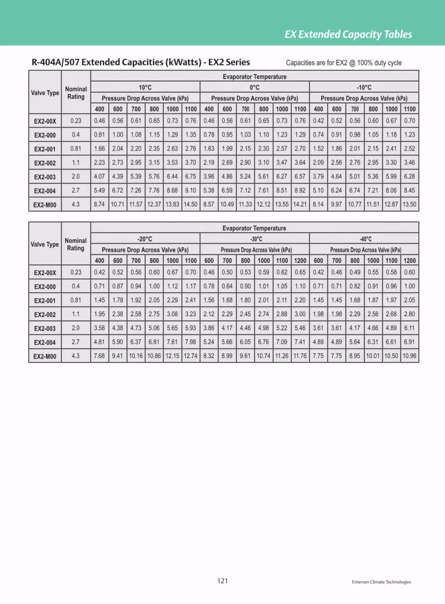
Emerson Climate Technologies 121
EX Extended Capacity Tables
R-404A/507 Extended Capacities (kWatts) - EX2 Series Capacities are for EX2 @ 100% duty cycle
Valve Type NominalRating
Evaporator Temperature10°C 0°C -10°C
Pressure Drop Across Valve (kPa) Pressure Drop Across Valve (kPa) Pressure Drop Across Valve (kPa)400 600 700 800 1000 1100 400 600 700 800 1000 1100 400 600 700 800 1000 1100
EX2-00X 0.23 0.46 0.56 0.61 0.65 0.73 0.76 0.46 0.56 0.61 0.65 0.73 0.76 0.42 0.52 0.56 0.60 0.67 0.70
EX2-000 0.4 0.81 1.00 1.08 1.15 1.29 1.35 0.78 0.95 1.03 1.10 1.23 1.29 0.74 0.91 0.98 1.05 1.18 1.23
EX2-001 0.81 1.66 2.04 2.20 2.35 2.63 2.76 1.63 1.99 2.15 2.30 2.57 2.70 1.52 1.86 2.01 2.15 2.41 2.52
EX2-002 1.1 2.23 2.73 2.95 3.15 3.53 3.70 2.19 2.69 2.90 3.10 3.47 3.64 2.09 2.56 2.76 2.95 3.30 3.46
EX2-003 2.0 4.07 4.39 5.39 5.76 6.44 6.75 3.96 4.86 5.24 5.61 6.27 6.57 3.79 4.64 5.01 5.36 5.99 6.28
EX2-004 2.7 5.49 6.72 7.26 7.76 8.68 9.10 5.38 6.59 7.12 7.61 8.51 8.92 5.10 6.24 6.74 7.21 8.06 8.45
EX2-M00 4.3 8.74 10.71 11.57 12.37 13.83 14.50 8.57 10.49 11.33 12.12 13.55 14.21 8.14 9.97 10.77 11.51 12.87 13.50
Valve Type NominalRating
Evaporator Temperature-20°C -30°C -40°C
Pressure Drop Across Valve (kPa) Pressure Drop Across Valve (kPa) Pressure Drop Across Valve (kPa)400 600 700 800 1000 1100 600 700 800 1000 1100 1200 600 700 800 1000 1100 1200
EX2-00X 0.23 0.42 0.52 0.56 0.60 0.67 0.70 0.46 0.50 0.53 0.59 0.62 0.65 0.42 0.46 0.49 0.55 0.58 0.60
EX2-000 0.4 0.71 0.87 0.94 1.00 1.12 1.17 0.78 0.64 0.90 1.01 1.05 1.10 0.71 0.71 0.82 0.91 0.96 1.00
EX2-001 0.81 1.45 1.78 1.92 2.05 2.29 2.41 1.56 1.68 1.80 2.01 2.11 2.20 1.45 1.45 1.68 1.87 1.97 2.05
EX2-002 1.1 1.95 2.38 2.58 2.75 3.08 3.23 2.12 2.29 2.45 2.74 2.88 3.00 1.98 1.98 2.29 2.56 2.68 2.80
EX2-003 2.0 3.58 4.38 4.73 5.06 5.65 5.93 3.86 4.17 4.46 4.98 5.22 5.46 3.61 3.61 4.17 4.66 4.89 6.11
EX2-004 2.7 4.81 5.90 6.37 6.81 7.61 7.98 5.24 5.66 6.05 6.76 7.09 7.41 4.89 4.89 5.64 6.31 6.61 6.91
EX2-M00 4.3 7.68 9.41 10.16 10.86 12.15 12.74 8.32 8.99 9.61 10.74 11.26 11.76 7.75 7.75 8.95 10.01 10.50 10.96

Emerson Climate Technologies 122
EX Extended Capacity Tables
R-407C Extended Capacities (kWatts) - EX2 Series Capacities are for EX2 @ 100% duty cycle
Valve Type NominalRating
Evaporator Temperature10°C 0°C -10°C
Pressure Drop Across Valve (kPa) Pressure Drop Across Valve (kPa) Pressure Drop Across Valve (kPa)400 600 700 800 1000 1100 400 600 700 800 1000 1100 400 600 700 800 1000 1100
EX2-00X 0.23 0.60 0.74 0.80 0.85 0.95 1.0 0.60 0.74 0.80 0.85 0.95 1.00 0.57 0.69 0.75 0.80 0.90 0.94
EX2-000 0.4 1.06 1.30 1.40 1.50 1.65 1.75 1.06 1.30 1.40 1.68 1.68 1.76 0.99 1.21 1.31 1.40 1.57 1.64
EX2-001 0.81 2.16 2.64 2.86 3.05 3.41 3.58 2.12 2.60 2.81 3.36 3.36 3.52 2.05 2.51 2.72 2.90 3.25 3.40
EX2-002 1.1 2.94 3.60 3.89 4.16 4.65 4.87 2.87 3.51 3.79 4.53 4.53 4.76 2.76 3.38 3.65 3.90 4.37 4.58
EX2-003 2.0 5.35 6.55 7.07 7.56 8.45 8.86 5.24 6.42 6.93 8.28 8.28 8.69 5.03 6.16 6.65 7.11 7.95 8.34
EX2-004 2.7 7.22 8.84 9.55 10.21 11.42 11.98 7.08 8.67 9.37 11.19 11.19 11.74 6.80 8.32 8.99 9.61 10.75 11.27
EX2-M00 4.3 11.47 14.05 15.17 16.22 18.14 19.02 11.26 13.79 14.89 17.80 17.80 18.67 10.83 13.27 14.33 15.32 17.13 17.96
Valve Type NominalRating
Evaporator Temperature-20°C -30°C -40°C
Pressure Drop Across Valve (kPa) Pressure Drop Across Valve (kPa) Pressure Drop Across Valve (kPa)400 600 700 800 1000 1100 600 700 800 1000 1100 1200 600 700 800 1000 1100 1200
EX2-00X 0.23 0.57 0.69 0.75 0.80 0.90 0.94 0.60 0.65 0.69 0.78 0.81 0.85 0.57 0.61 0.65 0.73 0.77 0.80
EX2-000 0.4 0.96 1.17 1.26 1.35 1.51 1.59 1.06 1.15 1.23 1.37 1.44 1.50 0.99 1.07 1.14 1.28 1.34 1.40
EX2-001 0.81 1.95 2.38 2.58 2.75 3.08 3.23 2.12 2.29 2.45 2.74 2.88 3.00 2.02 2.18 2.33 2.60 2.73 2.85
EX2-002 1.1 2.66 3.25 3.51 3.75 4.20 4.40 2.90 3.14 3.35 3.75 3.93 4.11 2.76 2.98 3.19 3.56 3.74 3.90
EX2-003 2.0 4.81 5.90 6.37 6.81 7.61 7.98 5.27 5.70 6.09 6.81 7.14 7.46 5.03 5.43 5.80 6.49 6.81 7.11
EX2-004 2.7 6.48 7.93 8.57 9.16 10.24 10.74 7.15 7.72 8.26 9.23 9.68 10.11 6.76 7.30 7.81 8.73 9.15 9.56
EX2-M00 4.3 10.34 12.66 13.67 14.62 16.34 17.14 11.36 12.27 13.12 14.67 15.39 16.07 10.80 11.66 12.47 13.94 14.62 15.27

Emerson Climate Technologies 123
EX Extended Capacity Tables
R-22 Extended Capacities (Tons) - EX3 Series
Valve Type
Evaporator Temperature50°F 40°F 20°F
Pressure Drop Across Valve (PSI) Pressure Drop Across Valve (PSI) Pressure Drop Across Valve (PSI)60 80 100 125 150 175 60 80 100 125 150 175 60 80 100 125 150 175
EX3-2000 0.32 0.36 0.41 0.46 0.50 0.54 0.31 0.36 0.40 0.45 0.49 0.53 0.30 0.35 0.39 0.44 0.48 0.52
EX3-3000 0.66 0.76 0.85 0.95 1.04 1.13 0.65 0.75 0.84 0.94 1.03 1.12 0.64 0.73 0.82 0.92 1.01 1.09
EX3-4000 1.06 1.23 1.37 1.54 1.68 1.82 1.05 1.21 1.36 1.52 1.66 1.80 1.02 1.18 1.32 1.48 1.62 1.75
EX3-5000 1.72 1.99 2.23 2.49 2.73 2.95 1.70 1.97 2.20 2.46 2.69 2.91 1.66 1.92 2.14 2.40 2.62 2.84
EX3-6000 2.79 3.22 3.60 4.02 4.41 4.76 2.76 3.18 3.56 3.98 4.36 4.71 2.68 3.10 3.47 3.87 4.24 4.58
EX3-7000 3.53 4.08 4.56 5.10 5.59 6.04 3.49 4.03 4.51 5.04 5.52 5.96 3.40 3.93 4.39 4.91 5.38 5.81
EX3-8000 3.94 4.55 5.08 5.68 6.23 6.72 3.89 4.49 5.02 5.62 6.15 6.64 3.79 4.38 4.89 5.47 5.99 6.47
EX3-9000 5.03 5.81 6.49 7.26 7.95 8.59 4.97 5.74 6.42 7.17 7.86 8.49 4.84 5.59 6.25 6.99 7.65 8.27
Valve Type
Evaporator Temperature
0°F -20°F -40°F
Pressure Drop Across Valve (PSI) Pressure Drop Across Valve (PSI) Pressure Drop Across Valve (PSI)
60 80 100 125 150 175 80 100 125 150 175 200 80 100 125 150 175 200
EX3-2000 0.29 0.34 0.38 0.43 0.47 0.50 0.33 0.37 0.41 0.45 0.49 0.52 0.32 0.36 0.40 0.44 0.47 0.50
EX3-3000 0.62 0.71 0.80 0.89 0.98 1.05 0.69 0.77 0.86 0.95 1.02 1.09 0.67 0.75 0.83 0.91 0.99 1.05
EX3-4000 0.99 1.15 1.28 1.44 1.57 1.70 1.11 1.24 1.39 1.52 1.64 1.76 1.07 1.20 1.34 1.47 1.59 1.70
EX3-5000 1.61 1.86 2.08 2.33 2.55 2.75 1.80 2.01 2.25 2.47 2.67 2.85 1.74 1.95 2.17 2.38 2.57 2.75
EX3-6000 2.61 3.01 3.36 3.76 4.12 4.45 2.91 3.26 3.64 3.99 4.31 4.61 2.81 3.15 3.52 3.85 4.16 4.45
EX3-7000 3.30 3.81 4.27 4.77 5.22 5.64 3.69 4.13 4.62 5.06 5.46 5.84 3.57 3.99 4.46 4.88 5.27 5.64
EX3-8000 3.68 4.25 4.75 5.31 5.82 6.29 4.11 4.60 5.14 5.63 6.09 6.51 3.97 4.44 4.97 5.44 5.88 6.28
EX3-9000 4.70 5.43 6.07 6.78 7.43 8.03 5.26 5.88 6.57 7.20 7.77 8.31 5.07 5.67 6.34 6.95 7.50 8.02
Refrigerant Liquid Correction Factor
Liquid Line Temp, °F 0 10 20 30 40 50 60 70 80 90 100 110 120 130 140
Capacity Multiplier (R-22) 1.54 1.49 1.43 1.38 1.33 1.27 1.22 1.17 1.11 1.06 1.00 0.94 0.89 0.83 0.77
Capacity Multiplier (R-134a) 1.64 1.58 1.51 1.45 1.39 1.32 1.26 1.19 1.13 1.07 1.00 0.93 0.87 0.80 0.73
Capacity Multiplier (R-404A) 1.92 1.83 1.74 1.65 1.56 1.47 1.38 1.29 1.19 1.10 1.00 0.90 0.80 0.69 0.58
Capacity Multiplier (R-407F) 1.68 1.62 1.55 1.48 1.42 1.35 1.28 1.21 1.14 1.07 1.00 0.93 0.85 0.78 0.70
Capacity Multiplier (R-507) 1.87 1.78 1.70 1.61 1.53 1.44 1.36 1.27 1.18 1.09 1.00 0.91 0.81 0.71 0.60

Emerson Climate Technologies 124
EX Extended Capacity Tables
R-134a Extended Capacities (Tons) - EX3 Series
Valve Type
Evaporator Temperature
50°F 40°F 20°F
Pressure Drop Across Valve (PSI) Pressure Drop Across Valve (PSI) Pressure Drop Across Valve (PSI)
60 80 100 125 150 175 60 80 100 125 150 175 60 80 100 125 150 175
EX3-2000 0.30 0.34 0.38 0.43 0.47 0.51 0.29 0.34 0.38 0.42 0.46 0.50 0.28 0.32 0.36 0.40 0.44 0.47
EX3-3000 0.62 0.72 0.80 0.90 0.98 1.06 0.61 0.70 0.78 0.88 0.96 1.04 0.58 0.67 0.75 0.84 0.92 0.99
EX3-4000 1.00 1.15 1.29 1.44 1.58 1.71 0.98 1.13 1.26 1.41 1.55 1.67 0.93 1.08 1.21 1.35 1.48 1.60
EX3-5000 1.62 1.87 2.09 2.34 2.56 2.77 1.59 1.83 2.05 2.29 2.51 2.71 1.52 1.75 1.96 2.19 2.40 2.59
EX3-6000 2.62 3.02 3.38 3.78 4.14 4.47 2.56 2.96 3.31 3.70 4.06 4.38 2.45 2.83 3.17 3.54 3.88 4.19
EX3-7000 3.32 3.83 4.29 4.79 5.25 5.67 3.25 3.75 4.20 4.69 5.14 5.55 3.11 3.59 4.01 4.49 4.92 5.31
EX3-8000 3.70 4.27 4.78 5.34 5.85 6.32 3.62 4.18 4.68 5.23 5.73 6.19 3.46 4.00 4.47 5.00 5.48 5.91
EX3-9000 4.73 5.46 6.10 6.82 7.47 8.07 4.63 5.34 5.97 6.68 7.32 7.90 4.42 5.11 5.71 6.39 7.00 7.56
Valve Type
Evaporator Temperature
0°F -20°F -40°F
Pressure Drop Across Valve (PSI) Pressure Drop Across Valve (PSI) Pressure Drop Across Valve (PSI)
60 80 100 125 150 175 80 100 125 150 175 200 80 100 125 150 175 200
EX3-2000 0.26 0.31 0.34 0.38 0.42 0.45 0.29 0.32 0.36 0.40 0.43 0.46 0.27 0.31 0.34 0.38 0.41 0.43
EX3-3000 0.55 0.64 0.71 0.80 0.87 0.94 0.61 0.68 0.76 0.83 0.90 0.96 0.57 0.64 0.72 0.78 0.85 0.91
EX3-4000 0.89 1.03 1.15 1.28 1.41 1.52 0.98 1.09 1.22 1.34 1.44 1.54 0.92 1.03 1.15 1.26 1.36 1.46
EX3-5000 1.45 1.67 1.87 2.09 2.29 2.47 1.58 1.77 1.98 2.17 2.34 2.50 1.50 1.67 1.87 2.05 2.21 2.37
EX3-6000 2.34 2.70 3.01 3.37 3.69 3.99 2.56 2.86 3.20 3.50 3.78 4.05 2.42 2.70 3.02 3.31 3.58 3.82
EX3-7000 2.96 3.42 3.82 4.27 4.68 5.06 3.24 3.63 4.05 4.44 4.80 5.13 3.07 3.43 3.83 4.20 4.53 4.85
EX3-8000 3.30 3.81 4.26 4.76 5.21 5.63 3.61 4.04 4.52 4.95 5.34 5.71 3.42 3.82 4.27 4.68 5.05 5.40
EX3-9000 4.21 4.87 5.44 6.08 6.66 7.20 4.62 5.16 5.77 6.32 6.83 7.30 4.36 4.88 5.45 5.97 6.45 6.90
Refrigerant Liquid Correction Factor
Liquid Line Temp, °F 0 10 20 30 40 50 60 70 80 90 100 110 120 130 140
Capacity Multiplier (R-22) 1.54 1.49 1.43 1.38 1.33 1.27 1.22 1.17 1.11 1.06 1.00 0.94 0.89 0.83 0.77
Capacity Multiplier (R-134a) 1.64 1.58 1.51 1.45 1.39 1.32 1.26 1.19 1.13 1.07 1.00 0.93 0.87 0.80 0.73
Capacity Multiplier (R-404A) 1.92 1.83 1.74 1.65 1.56 1.47 1.38 1.29 1.19 1.10 1.00 0.90 0.80 0.69 0.58
Capacity Multiplier (R-407F) 1.68 1.62 1.55 1.48 1.42 1.35 1.28 1.21 1.14 1.07 1.00 0.93 0.85 0.78 0.70
Capacity Multiplier (R-507) 1.87 1.78 1.70 1.61 1.53 1.44 1.36 1.27 1.18 1.09 1.00 0.91 0.81 0.71 0.60

Emerson Climate Technologies 125
EX Extended Capacity Tables
R-404A Extended Capacities (Tons) - EX3 Series
Valve Type
Evaporator Temperature
50°F 40°F 20°F
Pressure Drop Across Valve (PSI) Pressure Drop Across Valve (PSI) Pressure Drop Across Valve (PSI)
60 80 100 125 150 175 60 80 100 125 150 175 60 80 100 125 150 175
EX3-2000 0.20 0.23 0.26 0.29 0.32 0.35 0.20 0.23 0.26 0.29 0.31 0.34 0.19 0.22 0.24 0.27 0.30 0.32
EX3-3000 0.42 0.49 0.55 0.61 0.67 0.72 0.41 0.48 0.53 0.60 0.65 0.71 0.39 0.45 0.51 0.57 0.62 0.67
EX3-4000 0.68 0.79 0.88 0.98 1.08 1.16 0.67 0.77 0.86 0.96 1.05 1.14 0.63 0.73 0.82 0.91 1.00 1.08
EX3-5000 1.10 1.28 1.43 1.59 1.75 1.89 1.08 1.25 1.39 1.56 1.71 1.84 1.03 1.18 1.32 1.48 1.62 1.75
EX3-6000 1.79 2.06 2.30 2.58 2.82 3.05 1.74 2.01 2.25 2.52 2.76 2.98 1.66 1.91 2.14 2.39 2.62 2.83
EX3-7000 2.26 2.61 2.92 3.27 3.58 3.87 2.21 2.55 2.86 3.19 3.50 3.78 2.10 2.43 2.71 3.03 3.32 3.59
EX3-8000 2.52 2.91 3.25 3.64 3.99 4.31 2.46 2.85 3.18 3.56 3.90 4.21 2.34 2.70 3.02 3.38 3.70 4.00
EX3-9000 3.22 3.72 4.16 4.65 5.09 5.50 3.15 3.63 4.06 4.54 4.98 5.38 2.99 3.45 3.86 4.32 4.73 5.11
Valve Type
Evaporator Temperature
0°F -20°F -40°F
Pressure Drop Across Valve (PSI) Pressure Drop Across Valve (PSI) Pressure Drop Across Valve (PSI)
60 80 100 125 150 175 80 100 125 150 175 200 80 100 125 150 175 200
EX3-2000 0.18 0.20 0.23 0.26 0.28 0.30 0.19 0.21 0.24 0.26 0.28 0.30 0.18 0.20 0.22 0.24 0.26 0.28
EX3-3000 0.37 0.43 0.48 0.54 0.59 0.63 0.40 0.45 0.50 0.55 0.59 0.63 0.37 0.42 0.47 0.51 0.55 0.59
EX3-4000 0.60 0.69 0.77 0.86 0.94 1.02 0.65 0.72 0.81 0.88 0.95 1.02 0.60 0.67 0.75 0.82 0.89 0.95
EX3-5000 0.97 1.12 1.25 1.40 1.53 1.65 1.05 1.17 1.31 1.43 1.55 1.65 0.97 1.09 1.22 1.33 1.44 1.54
EX3-6000 1.56 1.81 2.02 2.26 2.47 2.67 1.69 1.89 2.11 2.32 2.50 2.67 1.57 1.76 1.97 2.15 2.33 2.49
EX3-7000 1.98 2.29 2.56 2.86 3.13 3.39 2.14 2.40 2.68 2.94 3.17 3.39 1.99 2.23 2.49 2.73 2.95 3.15
EX3-8000 2.21 2.55 2.85 3.19 3.49 3.77 2.39 2.67 2.99 3.27 3.53 3.78 2.22 2.48 2.78 3.04 3.29 3.51
EX3-9000 2.82 3.26 3.64 4.07 4.46 4.82 3.05 3.41 3.81 4.18 4.51 4.82 2.84 3.17 3.55 3.89 4.20 4.49
Refrigerant Liquid Correction Factor
Liquid Line Temp, °F 0 10 20 30 40 50 60 70 80 90 100 110 120 130 140
Capacity Multiplier (R-22) 1.54 1.49 1.43 1.38 1.33 1.27 1.22 1.17 1.11 1.06 1.00 0.94 0.89 0.83 0.77
Capacity Multiplier (R-134a) 1.64 1.58 1.51 1.45 1.39 1.32 1.26 1.19 1.13 1.07 1.00 0.93 0.87 0.80 0.73
Capacity Multiplier (R-404A) 1.92 1.83 1.74 1.65 1.56 1.47 1.38 1.29 1.19 1.10 1.00 0.90 0.80 0.69 0.58
Capacity Multiplier (R-407F) 1.68 1.62 1.55 1.48 1.42 1.35 1.28 1.21 1.14 1.07 1.00 0.93 0.85 0.78 0.70
Capacity Multiplier (R-507) 1.87 1.78 1.70 1.61 1.53 1.44 1.36 1.27 1.18 1.09 1.00 0.91 0.81 0.71 0.60

Emerson Climate Technologies 126
EX Extended Capacity Tables
R-407F Extended Capacities (Tons) - EX3 Series
Valve Type
Evaporator Temperature
50°F 40°F 20°F
Pressure Drop Across Valve (PSI) Pressure Drop Across Valve (PSI) Pressure Drop Across Valve (PSI)
60 80 100 125 150 175 60 80 100 125 150 175 60 80 100 125 150 175
EX3-2000 0.30 0.35 0.39 0.43 0.47 0.51 0.30 0.34 0.38 0.43 0.47 0.50 0.29 0.33 0.37 0.41 0.45 0.49
EX3-3000 0.63 0.72 0.81 0.90 0.99 1.07 0.62 0.71 0.80 0.89 0.98 1.05 0.60 0.69 0.77 0.86 0.95 1.02
EX3-4000 1.01 1.16 1.30 1.45 1.59 1.72 0.99 1.15 1.28 1.43 1.57 1.70 0.96 1.11 1.24 1.39 1.52 1.64
EX3-5000 1.63 1.89 2.11 2.36 2.58 2.79 1.61 1.86 2.08 2.32 2.55 2.75 1.56 1.80 2.01 2.25 2.47 2.66
EX3-6000 2.64 3.05 3.41 3.81 4.18 4.51 2.60 3.01 3.36 3.76 4.12 4.45 2.52 2.91 3.26 3.64 3.99 4.31
EX3-7000 3.35 3.87 4.32 4.84 5.30 5.72 3.30 3.81 4.26 4.77 5.22 5.64 3.20 3.69 4.13 4.62 5.06 5.46
EX3-8000 3.73 4.31 4.82 5.39 5.90 6.37 3.68 4.25 4.75 5.31 5.82 6.28 3.56 4.11 4.60 5.14 5.63 6.08
EX3-9000 4.77 5.50 6.15 6.88 7.54 8.14 4.70 5.43 6.07 6.78 7.43 8.03 4.55 5.25 5.87 6.57 7.19 7.77
Valve Type
Evaporator Temperature
0°F -20°F -40°F
Pressure Drop Across Valve (PSI) Pressure Drop Across Valve (PSI) Pressure Drop Across Valve (PSI)
60 80 100 125 150 175 80 100 125 150 175 200 80 100 125 150 175 200
EX3-2000 0.28 0.32 0.36 0.40 0.44 0.47 0.31 0.34 0.38 0.42 0.45 0.48 0.29 0.33 0.37 0.40 0.43 0.46
EX3-3000 0.58 0.67 0.74 0.83 0.91 0.98 0.64 0.71 0.80 0.87 0.94 1.01 0.61 0.68 0.76 0.84 0.90 0.97
EX3-4000 0.93 1.07 1.20 1.34 1.47 1.58 1.03 1.15 1.28 1.41 1.52 1.62 0.98 1.10 1.23 1.35 1.45 1.55
EX3-5000 1.50 1.74 1.94 2.17 2.38 2.57 1.67 1.86 2.08 2.28 2.46 2.63 1.59 1.78 1.99 2.18 2.36 2.52
EX3-6000 2.43 2.81 3.14 3.51 3.84 4.15 2.70 3.01 3.37 3.69 3.99 4.26 2.58 2.88 3.22 3.53 3.81 4.08
EX3-7000 3.08 3.56 3.98 4.45 4.87 5.26 3.42 3.82 4.27 4.68 5.05 5.40 3.27 3.65 4.08 4.47 4.83 5.17
EX3-8000 3.43 3.96 4.43 4.95 5.43 5.86 3.81 4.25 4.76 5.21 5.63 6.02 3.64 4.07 4.55 4.98 5.38 5.75
EX3-9000 4.39 5.06 5.66 6.33 6.93 7.49 4.86 5.44 6.08 6.66 7.19 7.69 4.65 5.20 5.81 6.37 6.88 7.35
Refrigerant Liquid Correction Factor
Liquid Line Temp, °F 0 10 20 30 40 50 60 70 80 90 100 110 120 130 140
Capacity Multiplier (R-22) 1.54 1.49 1.43 1.38 1.33 1.27 1.22 1.17 1.11 1.06 1.00 0.94 0.89 0.83 0.77
Capacity Multiplier (R-134a) 1.64 1.58 1.51 1.45 1.39 1.32 1.26 1.19 1.13 1.07 1.00 0.93 0.87 0.80 0.73
Capacity Multiplier (R-404A) 1.92 1.83 1.74 1.65 1.56 1.47 1.38 1.29 1.19 1.10 1.00 0.90 0.80 0.69 0.58
Capacity Multiplier (R-407F) 1.68 1.62 1.55 1.48 1.42 1.35 1.28 1.21 1.14 1.07 1.00 0.93 0.85 0.78 0.70
Capacity Multiplier (R-507) 1.87 1.78 1.70 1.61 1.53 1.44 1.36 1.27 1.18 1.09 1.00 0.91 0.81 0.71 0.60

Emerson Climate Technologies 127
EX Extended Capacity Tables
R-507 Extended Capacities (Tons) - EX3 Series
Valve Type
Evaporator Temperature50°F 40°F 20°F
Pressure Drop Across Valve (PSI) Pressure Drop Across Valve (PSI) Pressure Drop Across Valve (PSI)60 80 100 125 150 175 60 80 100 125 150 175 60 80 100 125 150 175
EX3-2000 0.20 0.23 0.26 0.29 0.31 0.34 0.19 0.22 0.25 0.28 0.31 0.33 0.18 0.21 0.24 0.26 0.29 0.31
EX3-3000 0.41 0.48 0.53 0.60 0.65 0.71 0.40 0.47 0.52 0.58 0.64 0.69 0.38 0.44 0.50 0.55 0.61 0.66
EX3-4000 0.67 0.77 0.86 0.96 1.05 1.14 0.65 0.75 0.84 0.94 1.03 1.11 0.62 0.71 0.80 0.89 0.98 1.06
EX3-5000 1.08 1.25 1.39 1.56 1.71 1.84 1.06 1.22 1.36 1.52 1.67 1.80 1.00 1.16 1.29 1.45 1.58 1.71
EX3-6000 1.75 2.02 2.25 2.52 2.76 2.98 1.71 1.97 2.20 2.46 2.70 2.91 1.62 1.87 2.09 2.34 2.56 2.77
EX3-7000 2.22 2.56 2.86 3.20 3.50 3.78 2.16 2.50 2.79 3.12 3.42 3.70 2.05 2.37 2.65 2.96 3.25 3.51
EX3-8000 2.47 2.85 3.19 3.56 3.90 4.21 2.41 2.78 3.11 3.48 3.81 4.12 2.29 2.64 2.95 3.30 3.62 3.91
EX3-9000 3.15 3.64 4.07 4.55 4.98 5.38 3.08 3.56 3.98 4.45 4.87 5.26 2.92 3.38 3.77 4.22 4.62 4.99
Valve Type
Evaporator Temperature0°F -20°F -40°F
Pressure Drop Across Valve (PSI) Pressure Drop Across Valve (PSI) Pressure Drop Across Valve (PSI)60 80 100 125 150 175 80 100 125 150 175 200 80 100 125 150 175 200
EX3-2000 0.17 0.20 0.22 0.25 0.27 0.29 0.19 0.21 0.23 0.26 0.28 0.29 0.17 0.19 0.22 0.24 0.26 0.27
EX3-3000 0.36 0.42 0.47 0.52 0.57 0.62 0.39 0.44 0.49 0.53 0.58 0.62 0.36 0.40 0.45 0.50 0.54 0.57
EX3-4000 0.58 0.67 0.75 0.84 0.92 0.99 0.63 0.70 0.79 0.86 0.93 0.99 0.58 0.65 0.73 0.80 0.86 0.92
EX3-5000 0.94 1.09 1.22 1.36 1.49 1.61 1.02 1.14 1.27 1.39 1.51 1.61 0.95 1.06 1.18 1.29 1.40 1.49
EX3-6000 1.53 1.76 1.97 2.20 2.41 2.61 1.65 1.84 2.06 2.26 2.44 2.60 1.53 1.71 1.91 2.09 2.26 2.42
EX3-7000 1.93 2.23 2.50 2.79 3.06 3.30 2.09 2.34 2.61 2.86 3.09 3.30 1.94 2.17 2.42 2.66 2.87 3.07
EX3-8000 2.16 2.49 2.78 3.11 3.41 3.68 2.33 2.60 2.91 3.19 3.44 3.68 2.16 2.42 2.70 2.96 3.19 3.42
EX3-9000 2.75 3.18 3.55 3.97 4.35 4.70 2.97 3.32 3.72 4.07 4.40 4.70 2.76 3.09 3.45 3.78 4.08 4.36
Refrigerant Liquid Correction FactorLiquid Line Temp, °F 0 10 20 30 40 50 60 70 80 90 100 110 120 130 140
Capacity Multiplier (R-22) 1.54 1.49 1.43 1.38 1.33 1.27 1.22 1.17 1.11 1.06 1.00 0.94 0.89 0.83 0.77
Capacity Multiplier (R-134a) 1.64 1.58 1.51 1.45 1.39 1.32 1.26 1.19 1.13 1.07 1.00 0.93 0.87 0.80 0.73
Capacity Multiplier (R-404A) 1.92 1.83 1.74 1.65 1.56 1.47 1.38 1.29 1.19 1.10 1.00 0.90 0.80 0.69 0.58
Capacity Multiplier (R-407F) 1.68 1.62 1.55 1.48 1.42 1.35 1.28 1.21 1.14 1.07 1.00 0.93 0.85 0.78 0.70
Capacity Multiplier (R-507) 1.87 1.78 1.70 1.61 1.53 1.44 1.36 1.27 1.18 1.09 1.00 0.91 0.81 0.71 0.60

Emerson Climate Technologies 128
EX Extended Capacity Tables
R-404A Extended Capacities (kWatts) - EX3 Series
Valve TypeCondensing Temperature
(°C)
Evaporating Temperature (°C)
15 10 5 0 -5 -10 -15 -20 -25 -30 -35 -40 -45
EX3-2000
60
0.87 0.87 0.87 0.86 0.85 0.83 0.80 0.78 0.75 0.71 0.68 0.64 0.60EX3-3000 1.82 1.82 1.82 1.80 1.77 1.73 1.68 1.62 1.56 1.49 1.42 1.34 1.26EX3-4000 2.92 2.94 2.93 2.89 2.84 2.78 2.70 2.61 2.51 2.40 2.28 2.16 2.03EX3-5000 4.74 4.76 4.74 4.69 4.61 4.51 4.38 4.23 4.07 3.89 3.70 3.50 3.29EX3-6000 7.66 7.70 7.67 7.59 7.46 7.28 7.08 6.84 6.57 6.28 5.98 5.65 5.32EX3-7000 9.71 9.76 9.72 9.62 9.46 9.24 8.97 8.67 8.33 7.97 7.58 7.17 6.74EX3-8000 10.81 10.87 10.83 10.72 10.53 10.29 10.00 9.66 9.28 8.88 8.44 7.99 7.51EX3-9000 13.81 13.88 13.84 13.69 13.45 13.14 12.77 12.34 11.86 11.34 10.78 10.20 9.60EX3-2000
55
0.93 0.94 0.95 0.94 0.94 0.92 0.90 0.88 0.85 0.83 0.79 0.76 0.72EX3-3000 1.94 1.97 1.98 1.97 1.96 1.93 1.89 1.84 1.79 1.73 1.66 1.59 1.51EX3-4000 3.11 3.16 3.18 3.18 3.15 3.10 3.04 2.96 2.87 2.78 2.67 2.55 2.44EX3-5000 5.05 5.13 5.16 5.15 5.10 5.03 4.93 4.80 4.66 4.50 4.33 4.14 3.95EX3-6000 8.17 8.29 8.34 8.32 8.25 8.13 7.97 7.77 7.53 7.28 7.00 6.70 6.38EX3-7000 10.35 10.51 10.58 10.56 10.46 10.31 10.10 9.85 9.55 9.23 8.87 8.49 8.09EX3-8000 11.53 11.71 11.78 11.76 11.65 11.48 11.25 10.97 10.64 10.28 9.88 9.46 9.02EX3-9000 14.73 14.96 15.05 15.02 14.89 14.67 14.37 14.01 13.59 13.13 12.62 12.08 11.52EX3-2000
50
1.00 1.03 1.04 1.04 1.04 1.03 1.01 0.99 0.97 0.94 0.91 0.88 0.85EX3-3000 2.10 2.14 2.17 2.18 2.17 2.15 2.12 2.08 2.03 1.97 1.91 1.84 1.77EX3-4000 3.37 3.45 3.49 3.50 3.49 3.46 3.41 3.34 3.26 3.17 3.07 2.96 2.85EX3-5000 5.47 5.59 5.66 5.68 5.66 5.61 5.53 5.42 5.29 5.14 4.98 4.81 4.62EX3-6000 8.84 9.04 9.15 9.18 9.15 9.07 8.94 8.76 8.55 8.32 8.05 7.77 7.47EX3-7000 11.21 11.46 11.60 11.64 11.61 11.50 11.33 11.11 10.85 10.54 10.21 9.85 9.47EX3-8000 12.49 12.77 12.92 12.97 12.93 12.81 12.62 12.38 12.08 11.74 11.37 10.97 10.55EX3-9000 15.95 16.31 16.51 16.57 16.51 16.36 16.12 15.81 15.43 15.00 14.53 14.02 13.47EX3-2000
45
0.94 0.98 1.01 1.03 1.03 1.03 1.03 1.01 1.00 0.98 0.95 0.92 0.89EX3-3000 1.97 2.05 2.11 2.15 2.16 2.16 2.15 2.12 2.08 2.04 1.99 1.93 1.87EX3-4000 3.17 3.31 3.40 3.45 3.48 3.47 3.45 3.41 3.35 3.28 3.20 3.11 3.01EX3-5000 5.14 5.36 5.51 5.60 5.64 5.63 5.60 5.53 5.44 5.32 5.19 5.04 4.88EX3-6000 8.31 8.67 8.90 9.05 9.11 9.11 9.05 8.94 8.79 8.60 8.39 8.15 7.89EX3-7000 10.54 10.99 11.29 11.47 11.55 11.55 11.47 11.34 11.15 10.91 10.64 10.33 10.00EX3-8000 11.74 12.24 12.58 12.78 12.87 12.86 12.78 12.63 12.41 12.15 11.85 11.51 11.14EX3-9000 15.00 15.63 16.06 16.32 16.44 16.43 16.33 16.13 15.86 15.52 15.14 14.70 14.23EX3-2000
40
0.90 0.96 1.00 1.03 1.05 1.05 1.06 1.05 1.04 1.02 1.00 0.98 0.95EX3-3000 1.89 2.01 2.10 2.15 2.19 2.21 2.21 2.19 2.17 2.13 2.09 2.04 1.99EX3-4000 3.04 3.23 3.37 3.47 3.52 3.55 3.55 3.53 3.49 3.43 3.37 3.29 3.20EX3-5000 4.93 5.24 5.47 5.62 5.71 5.75 5.76 5.72 5.66 5.57 5.46 5.33 5.19EX3-6000 7.97 8.48 8.84 9.08 9.23 9.30 9.30 9.25 9.15 9.00 8.83 8.62 8.39EX3-7000 10.11 10.75 11.21 11.52 11.71 11.80 11.80 11.73 11.60 11.42 11.19 10.93 10.64EX3-8000 11.26 11.98 12.49 12.83 13.04 13.14 13.14 13.06 12.92 12.72 12.46 12.17 11.85EX3-9000 14.38 15.30 15.95 16.39 16.66 16.78 16.79 16.69 16.50 16.24 15.92 15.55 15.13EX3-2000
35
0.83 0.91 0.97 1.01 1.04 1.06 1.06 1.07 1.06 1.05 1.03 1.01 0.99EX3-3000 1.74 1.90 2.03 2.11 2.17 2.21 2.23 2.23 2.22 2.19 2.16 2.12 2.07EX3-4000 2.79 3.06 3.26 3.40 3.49 3.55 3.58 3.58 3.56 3.53 3.47 3.41 3.33EX3-5000 4.53 4.97 5.29 5.51 5.67 5.76 5.81 5.81 5.78 5.72 5.63 5.53 5.41EX3-6000 7.32 8.03 8.55 8.91 9.16 9.31 9.39 9.39 9.34 9.25 9.11 8.94 8.74EX3-7000 9.28 10.18 10.84 11.30 11.62 11.81 11.90 11.91 11.85 11.72 11.55 11.33 11.08EX3-8000 10.34 11.34 12.07 12.59 12.94 13.15 13.26 13.27 13.20 13.06 12.86 12.62 12.34EX3-9000 13.21 14.49 15.42 16.08 16.53 16.80 16.93 16.95 16.86 16.68 16.43 16.12 15.77

Emerson Climate Technologies 129
EX Extended Capacity Tables
R-404A Extended Capacities (kWatts) - EX3 Series
Valve TypeCondensing Temperature
(°C)
Evaporating Temperature (°C)
15 10 5 0 -5 -10 -15 -20 -25 -30 -35 -40 -45
EX3-2000
30
0.71 0.83 0.91 0.97 1.01 1.04 1.05 1.06 1.06 1.06 1.05 1.03 1.02
EX3-3000 1.49 1.73 1.90 2.02 2.11 2.17 2.21 2.22 2.23 2.21 2.19 2.16 2.12
EX3-4000 2.39 2.78 3.05 3.25 3.39 3.49 3.55 3.58 3.58 3.56 3.53 3.48 3.42
EX3-5000 3.88 4.50 4.95 5.27 5.50 5.66 5.75 5.80 5.81 5.78 5.72 5.64 5.54
EX3-6000 6.27 7.28 8.00 8.52 8.89 9.15 9.30 9.38 9.39 9.34 9.25 9.12 8.95
EX3-7000 7.95 9.23 10.15 10.81 11.28 11.60 11.79 11.89 11.90 11.84 11.73 11.56 11.35
EX3-8000 8.86 10.28 11.30 12.04 12.56 12.92 13.14 13.24 13.26 13.19 13.06 12.88 12.65
EX3-9000 11.31 13.14 14.44 15.38 16.05 16.50 16.78 16.92 16.93 16.85 16.68 16.45 16.15
EX3-2000
25
0.52 0.70 0.81 0.90 0.96 1.00 1.03 1.04 1.05 1.05 1.05 1.04 1.02
EX3-3000 1.09 1.45 1.70 1.87 2.00 2.09 2.15 2.18 2.20 2.20 2.19 2.17 2.14
EX3-4000 1.75 2.34 2.73 3.01 3.21 3.35 3.45 3.51 3.54 3.54 3.53 3.49 3.45
EX3-5000 2.83 3.79 4.43 4.88 5.21 5.44 5.60 5.69 5.74 5.75 5.72 5.67 5.59
EX3-6000 4.58 6.13 7.17 7.90 8.42 8.79 9.05 9.20 9.28 9.29 9.25 9.16 9.04
EX3-7000 5.81 7.78 9.09 10.01 10.68 11.15 11.47 11.67 11.77 11.78 11.73 11.62 11.46
EX3-8000 6.47 8.66 10.12 11.15 11.89 12.42 12.78 13.00 13.11 13.12 13.06 12.94 12.76
EX3-9000 8.26 11.07 12.93 14.25 15.19 15.87 16.32 16.60 16.74 16.76 16.69 16.53 16.31
EX3-2000
20
0.49 0.67 0.79 0.88 0.94 0.98 1.01 1.02 1.03 1.03 1.03 1.02
EX3-3000 1.02 1.41 1.65 1.83 1.96 2.04 2.10 2.14 2.16 2.16 2.15 2.13
EX3-4000 1.64 2.26 2.66 2.94 3.15 3.29 3.38 3.44 3.47 3.48 3.46 3.43
EX3-5000 2.67 3.67 4.32 4.77 5.10 5.33 5.49 5.58 5.63 5.64 5.62 5.57
EX3-6000 4.31 5.93 6.98 7.72 8.25 8.62 8.87 9.03 9.11 9.12 9.08 9.00
EX3-7000 5.47 7.52 8.85 9.79 10.46 10.93 11.25 11.45 11.55 11.56 11.51 11.41
EX3-8000 6.09 8.37 9.86 10.90 11.65 12.17 12.53 12.75 12.86 12.88 12.83 12.71
EX3-9000 7.78 10.70 12.59 13.92 14.88 15.55 16.00 16.29 16.43 16.45 16.38 16.23
EX3-2000
15
0.45 0.64 0.76 0.85 0.91 0.95 0.98 1.00 1.00 1.01 1.00
EX3-3000 0.94 1.34 1.59 1.77 1.90 1.98 2.04 2.08 2.10 2.10 2.10
EX3-4000 1.51 2.16 2.57 2.85 3.05 3.19 3.29 3.35 3.38 3.38 3.37
EX3-5000 2.45 3.50 4.16 4.62 4.95 5.18 5.33 5.43 5.48 5.49 5.47
EX3-6000 3.96 5.65 6.72 7.47 8.00 8.37 8.62 8.78 8.86 8.87 8.84
EX3-7000 5.02 7.17 8.53 9.47 10.14 10.62 10.93 11.13 11.23 11.25 11.21
EX3-8000 5.60 7.98 9.50 10.55 11.30 11.82 12.18 12.40 12.51 12.53 12.48
EX3-9000 7.15 10.20 12.13 13.48 14.43 15.10 15.56 15.84 15.98 16.01 15.94
EX3-2000
10
0.40 0.60 0.73 0.81 0.87 0.91 0.94 0.96 0.97 0.97
EX3-3000 0.83 1.26 1.52 1.70 1.82 1.91 1.97 2.01 2.02 2.03
EX3-4000 1.34 2.02 2.44 2.73 2.93 3.07 3.17 3.23 3.26 3.26
EX3-5000 2.17 3.28 3.96 4.42 4.75 4.98 5.14 5.23 5.28 5.29
EX3-6000 3.51 5.31 6.40 7.15 7.68 8.05 8.30 8.46 8.54 8.56
EX3-7000 4.46 6.73 8.12 9.07 9.74 10.21 10.53 10.73 10.83 10.85
EX3-8000 4.96 7.49 9.04 10.10 10.85 11.38 11.73 11.95 12.06 12.09
EX3-9000 6.34 9.57 11.55 12.90 13.86 14.53 14.98 15.26 15.41 15.44

Emerson Climate Technologies 130
EX Extended Capacity Tables
R-134a Extended Capacities (kWatts) - EX3 Series
Valve TypeCondensing Temperature
(°C)
Evaporating Temperature (°C)
15 10 5 0 -5 -10 -15 -20 -25 -30 -35 -40 -45EX3-2000
60
1.23 1.24 1.24 1.24 1.23 1.22 1.20 1.18 1.15 1.12 1.09 1.06 1.02EX3-3000 2.56 2.59 2.60 2.60 2.58 2.55 2.51 2.46 2.40 2.34 2.28 2.21 2.14EX3-4000 4.12 4.17 4.18 4.17 4.14 4.10 4.03 3.95 3.87 3.77 3.66 3.55 3.44EX3-5000 6.69 6.76 6.78 6.77 6.72 6.64 6.54 6.41 6.27 6.11 5.94 5.76 5.57EX3-6000 10.81 10.93 10.97 10.94 10.87 10.74 10.57 10.37 10.14 9.88 9.61 9.31 9.01EX3-7000 13.71 13.86 13.91 13.88 13.78 13.62 13.40 13.15 12.86 12.53 12.18 11.81 11.43EX3-8000 15.27 15.43 15.49 15.46 15.35 15.17 14.93 14.64 14.32 13.96 13.57 13.16 12.73EX3-9000 19.50 19.71 19.79 19.74 19.60 19.37 19.07 18.71 18.29 17.83 17.33 16.81 16.26EX3-2000
55
1.20 1.22 1.23 1.24 1.24 1.23 1.21 1.20 1.17 1.15 1.12 1.09 1.06EX3-3000 2.50 2.55 2.58 2.59 2.59 2.57 2.54 2.50 2.45 2.40 2.34 2.28 2.21EX3-4000 4.03 4.11 4.15 4.17 4.16 4.13 4.08 4.02 3.95 3.86 3.77 3.67 3.56EX3-5000 6.53 6.66 6.73 6.76 6.75 6.70 6.62 6.52 6.40 6.26 6.11 5.95 5.78EX3-6000 10.56 10.77 10.88 10.93 10.91 10.83 10.71 10.54 10.35 10.13 9.88 9.62 9.34EX3-7000 13.39 13.65 13.80 13.86 13.83 13.73 13.58 13.37 13.12 12.84 12.53 12.19 11.84EX3-8000 14.91 15.20 15.37 15.43 15.40 15.29 15.12 14.89 14.62 14.30 13.96 13.58 13.19EX3-9000 19.04 19.42 19.64 19.71 19.67 19.54 19.32 19.02 18.67 18.27 17.83 17.35 16.85EX3-2000
50
1.15 1.18 1.21 1.22 1.22 1.22 1.21 1.20 1.18 1.16 1.14 1.11 1.08EX3-3000 2.40 2.47 2.52 2.55 2.56 2.56 2.54 2.51 2.47 2.43 2.38 2.32 2.26EX3-4000 3.86 3.98 4.06 4.10 4.12 4.11 4.08 4.04 3.98 3.91 3.83 3.74 3.64EX3-5000 6.25 6.45 6.58 6.65 6.68 6.67 6.62 6.55 6.45 6.34 6.21 6.06 5.90EX3-6000 10.11 10.43 10.64 10.76 10.80 10.78 10.71 10.59 10.43 10.25 10.03 9.80 9.54EX3-7000 12.82 13.23 13.49 13.64 13.70 13.67 13.58 13.43 13.23 12.99 12.72 12.42 12.10EX3-8000 14.28 14.73 15.02 15.19 15.25 15.23 15.12 14.96 14.74 14.47 14.17 13.84 13.48EX3-9000 18.24 18.82 19.19 19.41 19.49 19.45 19.32 19.10 18.82 18.49 18.10 17.67 17.22EX3-2000
45
1.07 1.12 1.16 1.18 1.20 1.20 1.20 1.19 1.18 1.16 1.14 1.12 1.09EX3-3000 2.24 2.35 2.42 2.47 2.50 2.51 2.51 2.49 2.46 2.43 2.39 2.34 2.28EX3-4000 3.61 3.78 3.90 3.98 4.02 4.04 4.03 4.01 3.96 3.91 3.84 3.76 3.68EX3-5000 5.85 6.13 6.32 6.45 6.53 6.55 6.54 6.50 6.43 6.34 6.22 6.10 5.96EX3-6000 9.46 9.91 10.23 10.43 10.55 10.59 10.58 10.51 10.39 10.24 10.06 9.86 9.63EX3-7000 11.99 12.56 12.97 13.23 13.38 13.43 13.41 13.32 13.18 12.99 12.76 12.50 12.22EX3-8000 13.36 14.00 14.44 14.73 14.90 14.96 14.94 14.84 14.68 14.47 14.21 13.92 13.61EX3-9000 17.06 17.88 18.45 18.82 19.03 19.11 19.08 18.95 18.75 18.48 18.16 17.79 17.38EX3-2000
40
0.97 1.04 1.09 1.13 1.15 1.16 1.17 1.17 1.16 1.15 1.13 1.11 1.09EX3-3000 2.03 2.18 2.28 2.36 2.41 2.44 2.45 2.44 2.43 2.40 2.37 2.33 2.28EX3-4000 3.26 3.50 3.67 3.79 3.87 3.92 3.93 3.93 3.90 3.86 3.81 3.74 3.67EX3-5000 5.29 5.68 5.96 6.15 6.28 6.35 6.38 6.37 6.33 6.26 6.17 6.07 5.95EX3-6000 8.56 9.18 9.63 9.95 10.15 10.27 10.31 10.30 10.23 10.12 9.98 9.81 9.61EX3-7000 10.85 11.65 12.22 12.61 12.87 13.02 13.08 13.06 12.97 12.83 12.65 12.44 12.19EX3-8000 12.09 12.97 13.61 14.05 14.34 14.50 14.57 14.54 14.45 14.30 14.09 13.85 13.58EX3-9000 15.44 16.57 17.38 17.95 18.32 18.53 18.61 18.58 18.46 18.26 18.00 17.69 17.34EX3-2000
35
0.83 0.93 1.00 1.05 1.09 1.11 1.13 1.13 1.13 1.12 1.11 1.09 1.08EX3-3000 1.74 1.95 2.10 2.20 2.28 2.32 2.35 2.36 2.36 2.34 2.32 2.29 2.25EX3-4000 2.80 3.13 3.37 3.54 3.66 3.74 3.78 3.80 3.80 3.77 3.73 3.68 3.62EX3-5000 4.54 5.08 5.47 5.75 5.94 6.06 6.14 6.16 6.15 6.12 6.05 5.97 5.87EX3-6000 7.35 8.22 8.84 9.29 9.60 9.80 9.92 9.96 9.95 9.89 9.78 9.65 9.48EX3-7000 9.31 10.42 11.21 11.78 12.18 12.43 12.58 12.63 12.62 12.54 12.40 12.23 12.03EX3-8000 10.37 11.61 12.49 13.12 13.56 13.85 14.01 14.07 14.05 13.96 13.82 13.62 13.40EX3-9000 13.25 14.83 15.96 16.76 17.32 17.69 17.90 17.98 17.95 17.84 17.65 17.40 17.11

Emerson Climate Technologies 131
EX Extended Capacity Tables
R-134a Extended Capacities (kWatts) - EX3 Series
Valve TypeCondensing Temperature
(°C)
Evaporating Temperature (°C)
15 10 5 0 -5 -10 -15 -20 -25 -30 -35 -40 -45
EX3-2000
30
0.64 0.79 0.89 0.96 1.01 1.04 1.06 1.08 1.08 1.08 1.07 1.06 1.05EX3-3000 1.34 1.64 1.85 2.00 2.11 2.18 2.23 2.25 2.26 2.26 2.25 2.22 2.19EX3-4000 2.15 2.64 2.98 3.22 3.39 3.51 3.58 3.63 3.64 3.64 3.61 3.58 3.53EX3-5000 3.49 4.29 4.83 5.22 5.49 5.68 5.81 5.88 5.91 5.90 5.86 5.80 5.72EX3-6000 5.64 6.93 7.81 8.44 8.88 9.19 9.39 9.50 9.55 9.54 9.48 9.38 9.25EX3-7000 7.16 8.79 9.90 10.70 11.26 11.65 11.91 12.05 12.11 12.09 12.02 11.89 11.73EX3-8000 7.97 9.79 11.03 11.92 12.55 12.98 13.26 13.42 13.49 13.47 13.38 13.25 13.06EX3-9000 10.18 12.50 14.09 15.22 16.02 16.58 16.94 17.15 17.23 17.20 17.10 16.92 16.69EX3-2000
25
0.30 0.58 0.73 0.83 0.90 0.95 0.99 1.01 1.02 1.03 1.03 1.02 1.01EX3-3000 0.64 1.21 1.53 1.74 1.89 1.99 2.07 2.11 2.14 2.15 2.15 2.13 2.11EX3-4000 1.03 1.95 2.46 2.80 3.04 3.21 3.32 3.40 3.44 3.46 3.45 3.43 3.40EX3-5000 1.66 3.16 3.98 4.54 4.92 5.20 5.39 5.51 5.58 5.61 5.60 5.57 5.51EX3-6000 2.69 5.11 6.44 7.33 7.96 8.40 8.71 8.91 9.02 9.07 9.06 9.00 8.91EX3-7000 3.41 6.48 8.17 9.30 10.10 10.66 11.05 11.30 11.44 11.50 11.48 11.41 11.30EX3-8000 3.80 7.21 9.09 10.36 11.25 11.87 12.30 12.58 12.74 12.81 12.79 12.71 12.59EX3-9000 4.85 9.21 11.62 13.23 14.36 15.16 15.72 16.07 16.28 16.36 16.34 16.24 16.08EX3-2000
20
0.16 0.51 0.67 0.77 0.84 0.89 0.93 0.95 0.96 0.97 0.97 0.96EX3-3000 0.34 1.06 1.39 1.61 1.76 1.86 1.94 1.98 2.01 2.02 2.02 2.01EX3-4000 0.54 1.70 2.24 2.59 2.83 3.00 3.11 3.19 3.23 3.25 3.25 3.23EX3-5000 0.88 2.76 3.63 4.20 4.59 4.86 5.05 5.17 5.24 5.27 5.27 5.24EX3-6000 1.43 4.46 5.87 6.78 7.42 7.86 8.16 8.36 8.48 8.52 8.52 8.47EX3-7000 1.81 5.66 7.44 8.60 9.40 9.97 10.35 10.60 10.75 10.81 10.80 10.74EX3-8000 2.01 6.30 8.29 9.58 10.47 11.10 11.53 11.81 11.97 12.04 12.03 11.96EX3-9000 2.57 8.05 10.58 12.24 13.38 14.18 14.73 15.09 15.29 15.38 15.36 15.27EX3-2000
15
0.41 0.59 0.70 0.77 0.82 0.86 0.88 0.89 0.90 0.90EX3-3000 0.87 1.23 1.46 1.61 1.72 1.79 1.84 1.86 1.88 1.88EX3-4000 1.40 1.98 2.34 2.59 2.76 2.88 2.96 3.00 3.02 3.02EX3-5000 2.26 3.21 3.80 4.20 4.48 4.67 4.79 4.86 4.89 4.89EX3-6000 3.66 5.19 6.15 6.80 7.24 7.55 7.75 7.86 7.91 7.91EX3-7000 4.64 6.59 7.79 8.62 9.18 9.57 9.82 9.97 10.03 10.03EX3-8000 5.17 7.34 8.68 9.60 10.23 10.66 10.94 11.11 11.18 11.17EX3-9000 6.60 9.37 11.09 12.26 13.07 13.62 13.98 14.19 14.28 14.27EX3-2000
10
0.29 0.50 0.61 0.69 0.74 0.78 0.80 0.81 0.82EX3-3000 0.61 1.04 1.28 1.44 1.55 1.63 1.67 1.70 1.71EX3-4000 0.98 1.67 2.06 2.32 2.50 2.62 2.69 2.74 2.76EX3-5000 1.59 2.72 3.35 3.76 4.05 4.24 4.37 4.44 4.47EX3-6000 2.57 4.39 5.41 6.08 6.54 6.86 7.06 7.18 7.23EX3-7000 3.26 5.57 6.86 7.72 8.30 8.69 8.95 9.10 9.17EX3-8000 3.64 6.20 7.64 8.59 9.24 9.68 9.97 10.14 10.22EX3-9000 4.64 7.92 9.76 10.98 11.81 12.37 12.74 12.95 13.05

Emerson Climate Technologies 132
EX Extended Capacity Tables
R-22 Extended Capacities (kWatts) - EX3 Series
Valve TypeCondensing Temperature
(°C)
Evaporating Temperature (°C)
15 10 5 0 -5 -10 -15 -20 -25 -30 -35 -40 -45EX3-2000
60
1.61 1.65 1.67 1.69 1.70 1.71 1.70 1.69 1.68 1.66 1.64 1.62 1.59EX3-3000 3.36 3.44 3.50 3.54 3.56 3.57 3.56 3.54 3.52 3.48 3.44 3.39 3.33EX3-4000 5.41 5.54 5.63 5.69 5.72 5.74 5.73 5.70 5.66 5.60 5.53 5.45 5.36EX3-5000 8.78 8.98 9.13 9.23 9.28 9.30 9.29 9.24 9.17 9.08 8.97 8.84 8.70EX3-6000 14.19 14.52 14.76 14.92 15.01 15.04 15.01 14.94 14.83 14.68 14.50 14.29 14.06EX3-7000 17.99 18.41 18.71 18.92 19.03 19.07 19.04 18.95 18.80 18.62 18.39 18.12 17.83EX3-8000 20.04 20.51 20.84 21.07 21.20 21.24 21.20 21.10 20.94 20.73 20.48 20.19 19.86EX3-9000 25.60 26.19 26.62 26.91 27.08 27.13 27.08 26.96 26.75 26.49 26.16 25.79 25.37EX3-2000
55
1.57 1.62 1.65 1.68 1.70 1.70 1.71 1.70 1.70 1.68 1.67 1.65 1.62EX3-3000 3.28 3.38 3.45 3.51 3.54 3.56 3.57 3.56 3.55 3.52 3.48 3.44 3.39EX3-4000 5.27 5.43 5.56 5.64 5.70 5.73 5.74 5.73 5.70 5.66 5.60 5.53 5.46EX3-5000 8.55 8.81 9.01 9.15 9.25 9.30 9.31 9.30 9.25 9.18 9.09 8.97 8.85EX3-6000 13.82 14.25 14.57 14.80 14.95 15.03 15.06 15.03 14.95 14.84 14.69 14.51 14.30EX3-7000 17.52 18.06 18.47 18.76 18.96 19.06 19.09 19.06 18.96 18.82 18.63 18.40 18.14EX3-8000 19.51 20.12 20.57 20.90 21.12 21.23 21.27 21.23 21.12 20.96 20.75 20.49 20.20EX3-9000 24.93 25.70 26.28 26.70 26.97 27.12 27.16 27.11 26.98 26.77 26.50 26.18 25.80EX3-2000
50
1.50 1.56 1.61 1.65 1.67 1.69 1.70 1.70 1.69 1.68 1.67 1.65 1.63EX3-3000 3.14 3.27 3.37 3.44 3.49 3.53 3.55 3.55 3.54 3.52 3.49 3.46 3.42EX3-4000 5.05 5.26 5.42 5.53 5.62 5.67 5.70 5.71 5.70 5.67 5.62 5.56 5.50EX3-5000 8.19 8.52 8.78 8.98 9.11 9.20 9.25 9.26 9.24 9.19 9.12 9.02 8.91EX3-6000 13.23 13.78 14.20 14.51 14.73 14.88 14.95 14.97 14.93 14.86 14.74 14.59 14.41EX3-7000 16.78 17.47 18.00 18.40 18.68 18.86 18.96 18.98 18.94 18.84 18.69 18.50 18.27EX3-8000 18.69 19.46 20.05 20.49 20.81 21.01 21.12 21.14 21.09 20.98 20.82 20.60 20.35EX3-9000 23.88 24.86 25.61 26.18 26.58 26.84 26.97 27.01 26.94 26.80 26.59 26.32 26.00EX3-2000
45
1.41 1.49 1.55 1.59 1.63 1.65 1.67 1.68 1.68 1.67 1.66 1.65 1.63EX3-3000 2.95 3.11 3.24 3.33 3.40 3.45 3.49 3.50 3.51 3.50 3.48 3.45 3.41EX3-4000 4.74 5.00 5.21 5.36 5.48 5.56 5.61 5.63 5.64 5.62 5.59 5.55 5.49EX3-5000 7.69 8.11 8.44 8.69 8.88 9.01 9.10 9.14 9.14 9.12 9.07 9.00 8.90EX3-6000 12.43 13.11 13.65 14.06 14.36 14.57 14.70 14.77 14.78 14.74 14.66 14.54 14.39EX3-7000 15.76 16.63 17.31 17.82 18.21 18.48 18.65 18.73 18.75 18.70 18.59 18.44 18.25EX3-8000 17.55 18.52 19.28 19.85 20.28 20.58 20.77 20.86 20.88 20.82 20.71 20.54 20.33EX3-9000 22.42 23.66 24.62 25.36 25.90 26.29 26.53 26.65 26.67 26.60 26.45 26.24 25.97EX3-2000
40
1.29 1.39 1.46 1.52 1.57 1.60 1.62 1.64 1.64 1.65 1.64 1.63 1.62EX3-3000 2.69 2.90 3.06 3.18 3.28 3.35 3.39 3.42 3.44 3.44 3.43 3.41 3.38EX3-4000 4.33 4.67 4.92 5.12 5.27 5.38 5.46 5.51 5.53 5.53 5.52 5.48 5.44EX3-5000 7.03 7.57 7.98 8.31 8.55 8.73 8.86 8.93 8.97 8.97 8.95 8.89 8.82EX3-6000 11.36 12.23 12.91 13.43 13.82 14.12 14.32 14.44 14.50 14.51 14.46 14.38 14.26EX3-7000 14.41 15.51 16.37 17.03 17.53 17.90 18.15 18.31 18.39 18.40 18.34 18.23 18.08EX3-8000 16.05 17.28 18.23 18.97 19.53 19.94 20.22 20.40 20.48 20.49 20.43 20.31 20.14EX3-9000 20.50 22.07 23.29 24.23 24.94 25.47 25.83 26.06 26.16 26.17 26.09 25.94 25.72EX3-2000
35
1.13 1.26 1.36 1.43 1.49 1.53 1.56 1.59 1.60 1.60 1.60 1.60 1.59EX3-3000 2.37 2.63 2.84 2.99 3.11 3.20 3.27 3.32 3.34 3.36 3.36 3.34 3.32EX3-4000 3.81 4.24 4.56 4.82 5.01 5.16 5.26 5.33 5.38 5.40 5.40 5.38 5.35EX3-5000 6.18 6.87 7.40 7.81 8.12 8.36 8.53 8.65 8.72 8.75 8.75 8.72 8.67EX3-6000 9.99 11.10 11.96 12.62 13.13 13.52 13.79 13.98 14.10 14.15 14.15 14.10 14.01EX3-7000 12.66 14.08 15.17 16.01 16.65 17.14 17.49 17.73 17.88 17.94 17.94 17.88 17.77EX3-8000 14.10 15.68 16.90 17.83 18.55 19.09 19.48 19.75 19.91 19.99 19.98 19.92 19.79EX3-9000 18.01 20.03 21.58 22.78 23.69 24.38 24.88 25.23 25.44 25.53 25.53 25.44 25.28

Emerson Climate Technologies 133
EX Extended Capacity Tables
R-22 Extended Capacities (kWatts) - EX3 Series
Valve TypeCondensingTemperature
(°C)
Evaporating Temperature (°C)
15 10 5 0 -5 -10 -15 -20 -25 -30 -35 -40 -45
EX3-2000
30
0.93 1.10 1.22 1.32 1.39 1.45 1.49 1.52 1.54 1.55 1.56 1.56 1.55
EX3-3000 1.93 2.29 2.55 2.75 2.91 3.03 3.11 3.18 3.22 3.24 3.25 3.25 3.24
EX3-4000 3.11 3.69 4.11 4.43 4.68 4.87 5.01 5.11 5.18 5.22 5.23 5.23 5.21
EX3-5000 5.05 5.98 6.66 7.19 7.59 7.89 8.12 8.28 8.40 8.46 8.49 8.48 8.45
EX3-6000 8.16 9.66 10.77 11.62 12.27 12.76 13.13 13.39 13.57 13.68 13.72 13.71 13.66
EX3-7000 10.34 12.25 13.66 14.73 15.55 16.18 16.65 16.98 17.21 17.34 17.40 17.39 17.33
EX3-8000 11.52 13.65 15.22 16.41 17.32 18.02 18.54 18.92 19.17 19.32 19.38 19.37 19.30
EX3-9000 14.72 17.43 19.44 20.96 22.13 23.02 23.68 24.16 24.49 24.68 24.76 24.74 24.65
EX3-2000
25
0.62 0.88 1.05 1.18 1.27 1.34 1.40 1.44 1.47 1.48 1.50 1.50 1.50
EX3-3000 1.30 1.84 2.20 2.46 2.66 2.81 2.92 3.00 3.06 3.10 3.13 3.14 3.13
EX3-4000 2.09 2.96 3.54 3.96 4.27 4.52 4.70 4.83 4.93 4.99 5.03 5.04 5.04
EX3-5000 3.40 4.80 5.73 6.42 6.93 7.32 7.62 7.84 7.99 8.10 8.16 8.18 8.17
EX3-6000 5.49 7.76 9.27 10.37 11.20 11.84 12.32 12.67 12.92 13.09 13.19 13.22 13.21
EX3-7000 6.96 9.84 11.76 13.15 14.21 15.01 15.62 16.07 16.38 16.60 16.72 16.77 16.75
EX3-8000 7.75 10.96 13.09 14.65 15.83 16.72 17.39 17.89 18.25 18.49 18.62 18.67 18.66
EX3-9000 9.90 14.00 16.73 18.71 20.21 21.36 22.22 22.86 23.31 23.61 23.79 23.85 23.83
EX3-2000
20
0.56 0.83 1.00 1.12 1.22 1.29 1.34 1.38 1.40 1.42 1.43 1.44
EX3-3000 1.17 1.73 2.09 2.35 2.54 2.69 2.80 2.88 2.94 2.97 2.99 3.00
EX3-4000 1.88 2.78 3.36 3.78 4.09 4.33 4.50 4.63 4.72 4.78 4.82 4.83
EX3-5000 3.05 4.51 5.45 6.13 6.63 7.01 7.30 7.51 7.66 7.75 7.81 7.83
EX3-6000 4.93 7.29 8.81 9.90 10.72 11.34 11.80 12.14 12.38 12.54 12.62 12.65
EX3-7000 6.26 9.24 11.17 12.56 13.60 14.38 14.97 15.40 15.70 15.90 16.01 16.05
EX3-8000 6.97 10.30 12.44 13.99 15.14 16.02 16.67 17.15 17.49 17.71 17.83 17.87
EX3-9000 8.90 13.15 15.89 17.87 19.34 20.46 21.29 21.90 22.34 22.62 22.78 22.83
EX3-2000
15
0.48 0.76 0.94 1.06 1.15 1.22 1.27 1.31 1.34 1.35 1.36
EX3-3000 1.01 1.60 1.96 2.22 2.41 2.55 2.66 2.74 2.79 2.83 2.84
EX3-4000 1.62 2.57 3.16 3.57 3.88 4.11 4.28 4.40 4.49 4.55 4.58
EX3-5000 2.63 4.17 5.12 5.79 6.29 6.66 6.94 7.14 7.28 7.37 7.42
EX3-6000 4.25 6.74 8.28 9.37 10.17 10.77 11.22 11.55 11.77 11.92 12.00
EX3-7000 5.40 8.55 10.50 11.88 12.90 13.66 14.23 14.64 14.93 15.11 15.21
EX3-8000 6.01 9.52 11.69 13.23 14.37 15.22 15.85 16.31 16.63 16.83 16.95
EX3-9000 7.68 12.16 14.94 16.90 18.35 19.44 20.24 20.83 21.24 21.50 21.65
EX3-2000
10
0.38 0.69 0.87 0.99 1.08 1.15 1.20 1.23 1.26 1.27
EX3-3000 0.80 1.45 1.82 2.08 2.27 2.40 2.51 2.58 2.63 2.66
EX3-4000 1.29 2.33 2.93 3.34 3.64 3.87 4.03 4.15 4.23 4.29
EX3-5000 2.10 3.77 4.74 5.42 5.91 6.27 6.54 6.73 6.87 6.95
EX3-6000 3.39 6.10 7.67 8.76 9.55 10.14 10.57 10.89 11.10 11.24
EX3-7000 4.29 7.74 9.73 11.11 12.11 12.86 13.41 13.80 14.08 14.25
EX3-8000 4.78 8.62 10.83 12.37 13.49 14.32 14.93 15.37 15.68 15.87
EX3-9000 6.11 11.01 13.84 15.80 17.24 18.30 19.08 19.64 20.03 20.27

Emerson Climate Technologies 134
EX Extended Capacity Tables
R-407F Extended Capacities (kWatts) - EX3 Series
Valve Type
Condensing Temperature Evaporating Temperature (°C)
DewPoint (°C)
BubblePoint (°C) 15 10 5 0 -5 -10 -15 -20 -25 -30 -35 -40 -45
EX3-2000
63.5 60
1.65 1.67 1.69 1.69 1.69 1.68 1.66 1.64 1.61 1.58 1.55 1.51 1.47EX3-3000 3.45 3.50 3.53 3.53 3.52 3.50 3.47 3.42 3.37 3.30 3.23 3.15 3.07EX3-4000 5.55 5.63 5.67 5.68 5.67 5.63 5.58 5.50 5.41 5.31 5.20 5.07 4.94EX3-5000 9.00 9.13 9.19 9.21 9.19 9.13 9.04 8.92 8.78 8.61 8.43 8.23 8.01EX3-6000 14.56 14.76 14.87 14.91 14.87 14.78 14.63 14.43 14.20 13.93 13.63 13.31 12.96EX3-7000 18.46 18.71 18.86 18.90 18.85 18.73 18.54 18.30 18.00 17.66 17.28 16.87 16.43EX3-8000 20.56 20.84 21.00 21.05 21.00 20.86 20.65 20.38 20.05 19.67 19.25 18.79 18.30EX3-9000 26.27 26.63 26.83 26.89 26.83 26.65 26.39 26.04 25.61 25.13 24.59 24.00 23.38EX3-2000
58.5 55
1.67 1.70 1.72 1.74 1.74 1.74 1.72 1.71 1.68 1.66 1.63 1.59 1.56EX3-3000 3.49 3.56 3.60 3.63 3.64 3.63 3.60 3.57 3.52 3.47 3.40 3.33 3.26EX3-4000 5.61 5.72 5.80 5.84 5.85 5.83 5.79 5.74 5.66 5.57 5.47 5.36 5.24EX3-5000 9.10 9.28 9.40 9.47 9.48 9.46 9.40 9.30 9.18 9.04 8.87 8.69 8.49EX3-6000 14.72 15.01 15.21 15.31 15.34 15.30 15.20 15.05 14.86 14.62 14.35 14.06 13.74EX3-7000 18.66 19.04 19.28 19.41 19.45 19.40 19.27 19.08 18.83 18.54 18.20 17.82 17.42EX3-8000 20.78 21.20 21.47 21.62 21.66 21.60 21.47 21.25 20.98 20.65 20.27 19.85 19.40EX3-9000 26.55 27.09 27.44 27.63 27.68 27.60 27.43 27.15 26.80 26.38 25.89 25.36 24.78EX3-2000
54 50
1.65 1.70 1.73 1.75 1.77 1.77 1.76 1.75 1.73 1.71 1.69 1.66 1.62EX3-3000 3.46 3.56 3.62 3.67 3.69 3.70 3.69 3.66 3.63 3.58 3.52 3.46 3.39EX3-4000 5.56 5.72 5.83 5.90 5.94 5.94 5.93 5.89 5.83 5.76 5.67 5.56 5.45EX3-5000 9.02 9.27 9.45 9.57 9.63 9.64 9.61 9.55 9.45 9.33 9.19 9.02 8.84EX3-6000 14.59 15.00 15.29 15.48 15.58 15.60 15.55 15.45 15.29 15.10 14.86 14.60 14.31EX3-7000 18.50 19.02 19.39 19.62 19.75 19.77 19.72 19.58 19.39 19.14 18.84 18.51 18.14EX3-8000 20.61 21.18 21.59 21.85 21.99 22.02 21.96 21.81 21.59 21.32 20.99 20.61 20.20EX3-9000 26.33 27.06 27.59 27.92 28.10 28.14 28.05 27.87 27.59 27.24 26.81 26.34 25.81EX3-2000
49 45
1.61 1.67 1.72 1.75 1.77 1.78 1.78 1.77 1.76 1.74 1.72 1.70 1.67EX3-3000 3.37 3.49 3.59 3.65 3.70 3.72 3.72 3.71 3.68 3.65 3.60 3.54 3.48EX3-4000 5.41 5.62 5.77 5.88 5.94 5.98 5.98 5.96 5.92 5.86 5.79 5.70 5.60EX3-5000 8.78 9.11 9.36 9.53 9.64 9.69 9.70 9.67 9.60 9.51 9.39 9.24 9.08EX3-6000 14.20 14.74 15.14 15.41 15.59 15.68 15.70 15.64 15.54 15.38 15.18 14.95 14.69EX3-7000 18.00 18.68 19.19 19.54 19.77 19.88 19.90 19.83 19.70 19.50 19.25 18.96 18.62EX3-8000 20.04 20.81 21.37 21.76 22.01 22.14 22.16 22.09 21.94 21.72 21.44 21.11 20.74EX3-9000 25.61 26.59 27.31 27.81 28.13 28.29 28.31 28.22 28.03 27.75 27.39 26.97 26.50EX3-2000
44 40
1.53 1.61 1.67 1.72 1.75 1.77 1.77 1.78 1.77 1.76 1.74 1.72 1.69EX3-3000 3.20 3.37 3.50 3.59 3.65 3.69 3.71 3.71 3.70 3.67 3.63 3.59 3.53EX3-4000 5.15 5.42 5.62 5.77 5.87 5.93 5.97 5.97 5.95 5.90 5.84 5.77 5.68EX3-5000 8.36 8.79 9.12 9.36 9.52 9.62 9.67 9.68 9.64 9.58 9.48 9.36 9.21EX3-6000 13.52 14.22 14.75 15.14 15.40 15.57 15.65 15.66 15.60 15.49 15.33 15.13 14.91EX3-7000 17.14 18.03 18.70 19.19 19.53 19.74 19.84 19.85 19.78 19.64 19.44 19.19 18.90EX3-8000 19.09 20.08 20.82 21.37 21.75 21.98 22.10 22.11 22.03 21.87 21.65 21.37 21.04EX3-9000 24.39 25.65 26.61 27.30 27.79 28.09 28.23 28.24 28.14 27.94 27.66 27.30 26.89

Emerson Climate Technologies 135
EX Extended Capacity Tables
EX3-2000
39.5 35
1.42 1.52 1.60 1.66 1.70 1.73 1.75 1.76 1.76 1.75 1.74 1.72 1.70EX3-3000 2.97 3.19 3.35 3.47 3.56 3.62 3.66 3.67 3.67 3.66 3.63 3.59 3.55EX3-4000 4.78 5.12 5.39 5.58 5.72 5.82 5.88 5.91 5.91 5.88 5.84 5.78 5.70EX3-5000 7.75 8.31 8.73 9.05 9.28 9.44 9.54 9.58 9.58 9.54 9.47 9.37 9.25EX3-6000 12.54 13.44 14.13 14.64 15.01 15.27 15.42 15.50 15.49 15.43 15.32 15.16 14.97EX3-7000 15.89 17.04 17.91 18.56 19.04 19.36 19.56 19.64 19.64 19.57 19.42 19.22 18.97EX3-8000 17.70 18.98 19.95 20.67 21.20 21.56 21.78 21.88 21.88 21.79 21.63 21.40 21.13EX3-9000 22.62 24.25 25.49 26.41 27.09 27.55 27.83 27.95 27.95 27.84 27.63 27.35 27.00

Emerson Climate Technologies 136
EX Extended Capacity Tables
R-407F Extended Capacities (kWatts) - EX3 Series
Valve Type
Condensing Temperature Evaporating Temperature (°C)
Dew Point (°C)
BubblePoint (°C)
15 10 5 0 -5 -10 -15 -20 -25 -30 -35 -40 -45
EX3-2000
34.5 30
1.27 1.40 1.50 1.58 1.64 1.68 1.70 1.72 1.73 1.73 1.72 1.70 1.69
EX3-3000 2.65 2.93 3.14 3.30 3.42 3.50 3.56 3.59 3.61 3.61 3.59 3.56 3.53
EX3-4000 4.27 4.72 5.05 5.31 5.50 5.63 5.73 5.78 5.80 5.80 5.78 5.73 5.67
EX3-5000 6.92 7.65 8.20 8.61 8.92 9.14 9.29 9.38 9.41 9.41 9.37 9.29 9.20
EX3-6000 11.19 12.37 13.26 13.93 14.43 14.78 15.02 15.17 15.23 15.22 15.15 15.04 14.88
EX3-7000 14.19 15.68 16.81 17.66 18.29 18.74 19.05 19.23 19.31 19.30 19.21 19.06 18.86
EX3-8000 15.80 17.47 18.72 19.67 20.37 20.87 21.21 21.41 21.50 21.49 21.39 21.23 21.01
EX3-9000 20.19 22.32 23.92 25.13 26.02 26.67 27.10 27.36 27.47 27.46 27.33 27.12 26.84
EX3-2000
30 25
1.06 1.24 1.37 1.47 1.55 1.60 1.64 1.66 1.68 1.68 1.68 1.68 1.66
EX3-3000 2.22 2.59 2.87 3.08 3.23 3.34 3.42 3.48 3.51 3.52 3.52 3.50 3.47
EX3-4000 3.57 4.17 4.62 4.95 5.19 5.38 5.51 5.59 5.64 5.66 5.66 5.63 5.59
EX3-5000 5.79 6.77 7.49 8.02 8.43 8.72 8.93 9.07 9.15 9.19 9.18 9.13 9.06
EX3-6000 9.36 10.95 12.11 12.98 13.63 14.11 14.45 14.68 14.81 14.86 14.84 14.77 14.65
EX3-7000 11.87 13.88 15.35 16.45 17.28 17.89 18.32 18.61 18.77 18.84 18.82 18.73 18.58
EX3-8000 13.22 15.46 17.10 18.32 19.24 19.92 20.40 20.72 20.91 20.98 20.96 20.86 20.69
EX3-9000 16.89 19.75 21.84 23.41 24.59 25.45 26.07 26.47 26.71 26.81 26.78 26.65 26.44
EX3-2000
25 20
0.76 1.02 1.20 1.33 1.43 1.50 1.55 1.59 1.61 1.63 1.63 1.63 1.62
EX3-3000 1.59 2.14 2.52 2.79 2.99 3.14 3.25 3.32 3.37 3.40 3.41 3.41 3.39
EX3-4000 2.55 3.45 4.05 4.48 4.80 5.05 5.22 5.34 5.42 5.47 5.49 5.48 5.45
EX3-5000 4.14 5.59 6.56 7.27 7.79 8.18 8.47 8.67 8.80 8.87 8.90 8.89 8.84
EX3-6000 6.70 9.04 10.61 11.76 12.61 13.24 13.70 14.02 14.23 14.35 14.39 14.37 14.30
EX3-7000 8.49 11.46 13.46 14.90 15.98 16.78 17.36 17.77 18.04 18.20 18.25 18.22 18.13
EX3-8000 9.46 12.76 14.99 16.60 17.80 18.69 19.34 19.80 20.10 20.26 20.32 20.29 20.19
EX3-9000 12.08 16.31 19.15 21.21 22.74 23.88 24.71 25.29 25.68 25.89 25.97 25.93 25.79
EX3-2000
20 15
0.98 1.16 1.28 1.38 1.45 1.50 1.53 1.55 1.57 1.57 1.57
EX3-3000 2.04 2.42 2.68 2.88 3.02 3.13 3.20 3.25 3.27 3.28 3.27
EX3-4000 3.29 3.88 4.31 4.63 4.86 5.03 5.15 5.22 5.26 5.28 5.27
EX3-5000 5.33 6.30 6.99 7.51 7.88 8.16 8.35 8.47 8.54 8.56 8.54
EX3-6000 8.63 10.19 11.31 12.14 12.75 13.19 13.50 13.70 13.81 13.84 13.81
EX3-7000 10.94 12.92 14.34 15.39 16.17 16.73 17.12 17.37 17.50 17.55 17.51
EX3-8000 12.18 14.39 15.97 17.14 18.01 18.63 19.06 19.34 19.49 19.54 19.50
EX3-9000 15.56 18.38 20.41 21.90 23.00 23.80 24.35 24.71 24.91 24.97 24.92
EX3-2000
15.5 10
0.92 1.10 1.22 1.31 1.38 1.43 1.46 1.48 1.49 1.50
EX3-3000 1.93 2.29 2.56 2.75 2.89 2.99 3.06 3.10 3.12 3.13
EX3-4000 3.10 3.69 4.11 4.42 4.64 4.80 4.92 4.99 5.02 5.03
EX3-5000 5.02 5.99 6.67 7.17 7.53 7.79 7.97 8.09 8.15 8.16
EX3-6000 8.12 9.68 10.79 11.59 12.18 12.61 12.90 13.08 13.18 13.20
EX3-7000 10.30 12.27 13.68 14.70 15.45 15.98 16.35 16.58 16.71 16.74
EX3-8000 11.47 13.67 15.23 16.37 17.20 17.80 18.21 18.47 18.61 18.64
EX3-9000 14.65 17.47 19.46 20.92 21.98 22.74 23.27 23.60 23.77 23.82

Emerson Climate Technologies 137
EX Extended Capacity Tables
R-507 Extended Capacities (kWatts) - EX3 Series
Valve TypeCondensing Temperature
(°C)
Evaporating Temperature (°C)
15 10 5 0 -5 -10 -15 -20 -25 -30 -35 -40 -45EX3-2000
60
0.83 0.84 0.83 0.82 0.81 0.79 0.77 0.74 0.71 0.68 0.64 0.60 0.57EX3-3000 1.74 1.75 1.74 1.72 1.69 1.65 1.60 1.54 1.48 1.41 1.34 1.26 1.18EX3-4000 2.81 2.82 2.81 2.77 2.72 2.66 2.58 2.48 2.38 2.27 2.16 2.03 1.90EX3-5000 4.55 4.57 4.55 4.50 4.41 4.31 4.18 4.03 3.86 3.69 3.49 3.30 3.09EX3-6000 7.36 7.39 7.36 7.27 7.14 6.96 6.75 6.51 6.24 5.96 5.65 5.33 4.99EX3-7000 9.33 9.37 9.33 9.22 9.05 8.83 8.56 8.26 7.92 7.55 7.16 6.76 6.33EX3-8000 10.39 10.43 10.39 10.27 10.08 9.83 9.54 9.20 8.82 8.41 7.98 7.52 7.05EX3-9000 13.27 13.33 13.27 13.12 12.88 12.56 12.18 11.75 11.27 10.75 10.19 9.61 9.01EX3-2000
55
0.90 0.91 0.92 0.91 0.91 0.89 0.87 0.85 0.82 0.79 0.76 0.73 0.69EX3-3000 1.88 1.91 1.92 1.91 1.89 1.86 1.83 1.78 1.72 1.66 1.59 1.52 1.45EX3-4000 3.02 3.07 3.09 3.08 3.05 3.00 2.94 2.86 2.77 2.67 2.56 2.45 2.33EX3-5000 4.90 4.98 5.00 4.99 4.94 4.86 4.76 4.64 4.49 4.33 4.16 3.97 3.78EX3-6000 7.93 8.04 8.09 8.07 7.99 7.86 7.70 7.50 7.26 7.00 6.72 6.43 6.11EX3-7000 10.05 10.20 10.26 10.23 10.13 9.97 9.76 9.50 9.21 8.88 8.53 8.15 7.75EX3-8000 11.19 11.36 11.42 11.39 11.28 11.11 10.87 10.59 10.26 9.89 9.50 9.07 8.63EX3-9000 14.30 14.51 14.59 14.55 14.41 14.19 13.89 13.52 13.10 12.64 12.13 11.59 11.02EX3-2000
50
0.93 0.95 0.97 0.97 0.97 0.96 0.95 0.93 0.91 0.89 0.86 0.83 0.79EX3-3000 1.94 1.99 2.02 2.04 2.03 2.02 1.99 1.95 1.90 1.85 1.79 1.73 1.66EX3-4000 3.12 3.21 3.25 3.27 3.27 3.24 3.20 3.14 3.06 2.98 2.88 2.78 2.67EX3-5000 5.06 5.20 5.28 5.31 5.30 5.26 5.19 5.09 4.97 4.83 4.67 4.51 4.33EX3-6000 8.18 8.40 8.53 8.59 8.57 8.50 8.38 8.23 8.03 7.81 7.56 7.28 6.99EX3-7000 10.38 10.66 10.82 10.89 10.87 10.78 10.63 10.43 10.18 9.90 9.58 9.24 8.87EX3-8000 11.56 11.87 12.05 12.13 12.11 12.01 11.84 11.62 11.34 11.02 10.67 10.29 9.88EX3-9000 14.76 15.16 15.39 15.49 15.46 15.34 15.13 14.84 14.49 14.08 13.63 13.14 12.62EX3-2000
45
0.93 0.96 0.99 1.01 1.01 1.01 1.00 0.99 0.97 0.95 0.93 0.90 0.87EX3-3000 1.93 2.02 2.07 2.10 2.12 2.12 2.10 2.07 2.04 1.99 1.94 1.88 1.82EX3-4000 3.11 3.24 3.33 3.38 3.41 3.40 3.38 3.34 3.28 3.21 3.12 3.03 2.93EX3-5000 5.05 5.26 5.40 5.49 5.52 5.52 5.48 5.41 5.32 5.20 5.07 4.92 4.75EX3-6000 8.16 8.50 8.73 8.87 8.93 8.92 8.86 8.75 8.59 8.41 8.19 7.95 7.69EX3-7000 10.34 10.78 11.07 11.25 11.32 11.31 11.23 11.09 10.90 10.66 10.39 10.08 9.75EX3-8000 11.52 12.01 12.33 12.53 12.61 12.60 12.51 12.35 12.14 11.87 11.57 11.23 10.86EX3-9000 14.72 15.34 15.75 16.00 16.11 16.09 15.98 15.78 15.50 15.17 14.78 14.34 13.87EX3-2000
40
0.89 0.95 0.99 1.01 1.03 1.04 1.04 1.03 1.02 1.00 0.98 0.96 0.93EX3-3000 1.86 1.98 2.06 2.12 2.15 2.17 2.17 2.15 2.13 2.09 2.05 2.00 1.95EX3-4000 2.99 3.18 3.32 3.41 3.46 3.49 3.49 3.47 3.42 3.37 3.30 3.22 3.13EX3-5000 4.86 5.16 5.38 5.53 5.62 5.66 5.65 5.62 5.55 5.46 5.35 5.22 5.08EX3-6000 7.85 8.35 8.70 8.94 9.08 9.14 9.14 9.08 8.98 8.83 8.65 8.45 8.21EX3-7000 9.95 10.58 11.03 11.33 11.51 11.59 11.59 11.52 11.39 11.20 10.97 10.71 10.41EX3-8000 11.09 11.79 12.28 12.62 12.82 12.91 12.91 12.83 12.68 12.48 12.22 11.93 11.60EX3-9000 14.16 15.06 15.69 16.12 16.38 16.50 16.49 16.39 16.20 15.94 15.61 15.24 14.82EX3-2000
35
0.82 0.90 0.96 1.00 1.02 1.04 1.05 1.05 1.04 1.03 1.02 1.00 0.97EX3-3000 1.71 1.88 2.00 2.08 2.14 2.18 2.19 2.19 2.18 2.16 2.12 2.08 2.04EX3-4000 2.76 3.02 3.22 3.35 3.45 3.50 3.53 3.53 3.51 3.47 3.42 3.35 3.28EX3-5000 4.47 4.90 5.22 5.44 5.59 5.68 5.72 5.72 5.69 5.63 5.54 5.44 5.31EX3-6000 7.23 7.93 8.43 8.79 9.03 9.18 9.25 9.25 9.20 9.10 8.96 8.79 8.59EX3-7000 9.17 10.05 10.69 11.15 11.46 11.64 11.73 11.73 11.67 11.54 11.36 11.14 10.89EX3-8000 10.21 11.20 11.91 12.42 12.76 12.97 13.06 13.07 12.99 12.85 12.66 12.41 12.13EX3-9000 13.05 14.30 15.21 15.86 16.30 16.56 16.69 16.69 16.60 16.42 16.17 15.86 15.50

Emerson Climate Technologies 138
EX Extended Capacity Tables
R-507 Extended Capacities (kWatts) - EX3 Series
Valve TypeCondensing Temperature
(°C)
Evaporating Temperature (°C)
15 10 5 0 -5 -10 -15 -20 -25 -30 -35 -40 -45EX3-2000
30
0.70 0.82 0.90 0.96 1.00 1.02 1.04 1.05 1.05 1.05 1.03 1.02 1.00
EX3-3000 1.47 1.71 1.88 2.00 2.09 2.14 2.18 2.20 2.20 2.19 2.16 2.13 2.09
EX3-4000 2.37 2.75 3.02 3.22 3.35 3.45 3.50 3.53 3.53 3.52 3.48 3.43 3.37
EX3-5000 3.85 4.46 4.90 5.21 5.44 5.59 5.68 5.73 5.73 5.70 5.64 5.56 5.46
EX3-6000 6.22 7.21 7.92 8.43 8.79 9.04 9.19 9.26 9.27 9.22 9.12 8.99 8.83
EX3-7000 7.88 9.14 10.04 10.69 11.15 11.46 11.65 11.74 11.75 11.69 11.57 11.40 11.19
EX3-8000 8.78 10.18 11.18 11.91 12.42 12.77 12.98 13.08 13.09 13.02 12.89 12.70 12.46
EX3-9000 11.22 13.01 14.29 15.21 15.86 16.31 16.58 16.71 16.72 16.63 16.46 16.22 15.92
EX3-2000
25
0.52 0.69 0.81 0.89 0.95 0.99 1.02 1.03 1.04 1.04 1.04 1.03 1.01
EX3-3000 1.08 1.45 1.69 1.86 1.98 2.07 2.12 2.16 2.18 2.18 2.17 2.15 2.12
EX3-4000 1.74 2.33 2.71 2.99 3.18 3.32 3.42 3.47 3.50 3.51 3.49 3.45 3.41
EX3-5000 2.83 3.77 4.40 4.84 5.16 5.39 5.54 5.63 5.68 5.69 5.66 5.60 5.52
EX3-6000 4.57 6.10 7.11 7.83 8.35 8.71 8.96 9.11 9.18 9.19 9.15 9.06 8.93
EX3-7000 5.80 7.73 9.02 9.93 10.58 11.05 11.36 11.55 11.64 11.66 11.60 11.48 11.32
EX3-8000 6.46 8.61 10.04 11.06 11.79 12.30 12.65 12.87 12.97 12.98 12.92 12.79 12.61
EX3-9000 8.25 11.00 12.83 14.12 15.06 15.71 16.16 16.43 16.57 16.58 16.50 16.34 16.11
EX3-2000
20
0.49 0.67 0.79 0.87 0.93 0.97 1.00 1.01 1.02 1.02 1.02 1.01
EX3-3000 1.03 1.40 1.65 1.82 1.94 2.03 2.09 2.12 2.14 2.14 2.13 2.11
EX3-4000 1.65 2.25 2.65 2.92 3.12 3.26 3.36 3.41 3.44 3.45 3.43 3.40
EX3-5000 2.67 3.65 4.29 4.74 5.06 5.29 5.44 5.54 5.58 5.59 5.56 5.51
EX3-6000 4.32 5.91 6.94 7.67 8.18 8.55 8.80 8.95 9.03 9.04 8.99 8.91
EX3-7000 5.48 7.49 8.80 9.72 10.38 10.84 11.16 11.35 11.44 11.46 11.41 11.30
EX3-8000 6.11 8.34 9.80 10.83 11.56 12.08 12.43 12.64 12.75 12.76 12.70 12.58
EX3-9000 7.80 10.66 12.52 13.83 14.77 15.43 15.87 16.15 16.28 16.30 16.23 16.07
EX3-2000
15
0.45 0.64 0.76 0.84 0.90 0.94 0.97 0.99 1.00 1.00 0.99
EX3-3000 0.95 1.34 1.59 1.76 1.89 1.97 2.03 2.07 2.08 2.09 2.08
EX3-4000 1.52 2.15 2.56 2.84 3.03 3.17 3.27 3.33 3.35 3.36 3.34
EX3-5000 2.47 3.49 4.14 4.60 4.92 5.15 5.30 5.39 5.44 5.45 5.42
EX3-6000 3.99 5.65 6.70 7.43 7.95 8.32 8.57 8.72 8.79 8.81 8.77
EX3-7000 5.06 7.16 8.50 9.42 10.09 10.55 10.86 11.05 11.15 11.17 11.12
EX3-8000 5.64 7.98 9.46 10.50 11.23 11.75 12.10 12.31 12.42 12.44 12.38
EX3-9000 7.20 10.19 12.09 13.41 14.35 15.01 15.45 15.73 15.86 15.89 15.82
EX3-2000
10
0.40 0.60 0.72 0.81 0.87 0.91 0.94 0.95 0.96 0.96
EX3-3000 0.85 1.26 1.52 1.69 1.81 1.90 1.96 2.00 2.01 2.02
EX3-4000 1.36 2.03 2.44 2.72 2.92 3.06 3.15 3.21 3.24 3.24
EX3-5000 2.21 3.29 3.95 4.41 4.73 4.96 5.11 5.20 5.25 5.26
EX3-6000 3.57 5.32 6.39 7.13 7.65 8.02 8.26 8.41 8.49 8.51
EX3-7000 4.52 6.74 8.10 9.04 9.70 10.17 10.48 10.67 10.77 10.79
EX3-8000 5.04 7.51 9.03 10.07 10.81 11.32 11.67 11.88 11.99 12.01
EX3-9000 6.44 9.59 11.53 12.87 13.81 14.47 14.91 15.18 15.32 15.34

Emerson Climate Technologies 139
EX Extended Capacity Tables
Valve Type Condensing Temperature (°F)Evaporating Temperature (°F)
60 50 40 30 20 10 0 -10 -20 -30 -40 -50EX4
140
5 5 5 5 5 5 5 5 5 5 5 5EX5 15 15 16 16 16 16 16 16 15 15 15 15EX6 36 37 38 38 38 38 38 38 37 37 36 35EX7 99 102 104 105 105 105 105 104 103 101 99 97EX8 265 271 277 279 281 281 280 277 274 269 264 258EX4
130
5 5 5 5 6 6 6 6 5 5 5 5EX5 15 16 16 16 17 17 17 17 16 16 16 16EX6 37 38 39 40 40 40 40 40 40 39 39 38EX7 101 105 107 109 110 110 111 110 109 108 106 104EX8 269 279 285 292 293 295 296 294 291 288 283 277EX4
120
5 5 6 6 6 6 6 6 6 6 6 6EX5 15 16 17 17 17 17 17 17 17 17 17 17EX6 37 39 40 41 42 42 42 42 42 42 41 40EX7 101 106 110 112 114 115 116 116 116 114 113 111EX8 270 283 293 299 305 308 309 310 309 305 301 297EX4
110
5 5 5 6 6 6 6 6 6 6 6 6EX5 15 15 16 17 17 17 18 18 18 17 17 17EX6 35 37 39 40 42 42 43 43 43 42 42 41EX7 96 102 107 111 114 115 117 118 117 116 115 113EX8 257 273 286 297 305 308 313 314 313 309 308 303EX4
100
5 5 5 6 6 6 6 6 6 6 6 6EX5 14 15 16 17 17 17 18 18 18 18 18 18EX6 33 36 38 40 41 42 43 43 43 43 43 42EX7 90 98 105 110 113 116 118 119 119 118 118 116EX8 240 261 281 294 301 308 315 316 316 315 316 311EX4
90
4 4 5 5 5 6 6 6 6 6 6 6EX5 12 13 15 16 16 17 17 18 18 18 18 18EX6 28 33 36 38 40 41 42 42 43 43 43 43EX7 78 89 98 104 109 112 116 116 118 118 118 117EX8 207 239 260 277 290 300 308 311 314 314 315 313EX4
80
3 4 4 5 5 5 6 6 6 6 6 6EX5 9 12 13 15 15 16 17 17 17 17 17 17EX6 22 28 32 35 37 39 40 41 42 42 42 42EX7 61 77 87 97 103 107 111 113 114 116 115 114EX8 163 204 233 257 274 286 297 300 305 309 308 305EX4
70
2 3 4 4 5 5 5 5 6 6 6 6EX5 5 9 11 13 14 15 16 16 17 17 17 17EX6 11 21 27 31 34 37 39 39 40 41 41 41EX7 31 59 75 86 94 101 106 108 111 112 114 113EX8 84 157 201 230 251 270 284 289 295 300 303 301EX4
60
- 1 3 4 4 5 5 5 5 5 5 5EX5 - 4 8 11 13 14 15 15 16 16 16 16EX6 - 10 20 26 30 33 36 37 38 39 40 39EX7 - 27 56 72 84 92 98 102 105 108 109 109EX8 - 72 150 192 224 245 262 273 281 287 291 290
R-410A Extended Capacities (Tons) - EX4-8 Series, as expansion and liquid injection valvesThe following tables provide the capacity of valves at different conditions considering 20 psi pressure drop through liquid line:

Emerson Climate Technologies 140
EX Extended Capacity Tables
EX4
50
- - 1 3 3 4 4 5 5 5 5 5EX5 - - 3 8 10 12 14 14 15 15 16 16EX6 - - 8 19 25 29 33 35 36 37 38 38EX7 - - 21 53 69 80 90 95 99 102 104 104EX8 - - 57 143 185 214 239 254 265 272 278 277

Emerson Climate Technologies 141
EX Extended Capacity Tables
Valve Type Condensing TemperatureBubble Point (°F)
Evaporating Temperature (°F)60 50 40 30 20 10 0 -10
EX4
140
5 5 5 5 5 5 5 5EX5 14 15 15 15 15 15 14 14EX6 34 35 35 35 35 35 34 33EX7 95 97 97 97 96 95 94 92EX8 253 257 258 259 256 255 250 244EX4
130
5 5 5 5 5 5 5 5EX5 15 15 15 15 15 15 15 14EX6 35 35 36 36 36 35 35 34EX7 95 96 98 98 98 97 96 94EX8 253 257 261 261 261 260 256 252EX4
120
5 5 5 5 5 5 5 5EX5 14 15 15 15 15 15 15 15EX6 34 35 36 36 36 36 36 36EX7 93 96 99 99 99 100 99 98EX8 249 256 264 265 265 266 264 261EX4
110
4 5 5 5 5 5 5 5EX5 14 14 15 15 15 15 15 15EX6 33 34 35 35 36 36 36 35EX7 90 93 96 97 99 99 99 98EX8 239 248 255 260 263 264 263 260EX4
100
4 4 5 5 5 5 5 5EX5 13 14 14 15 15 15 15 15EX6 30 32 34 35 35 36 36 36EX7 84 89 94 96 98 9 99 98EX8 224 239 250 256 260 263 254 262EX4
90
4 4 4 5 5 5 5 5EX5 11 13 13 14 14 15 15 15EX6 27 30 32 33 34 35 35 35EX7 75 83 87 92 94 96 97 96EX8 201 220 233 244 250 256 259 257EX4
80
3 4 4 4 4 5 5 5EX5 10 11 12 13 13 14 14 14EX6 23 26 29 31 32 33 34 34EX7 63 73 80 85 88 91 93 93EX8 169 193 212 227 235 243 247 248EX4
70
2 3 4 4 4 4 4 4EX5 7 9 11 12 13 13 14 14EX6 17 22 26 28 30 31 32 33EX7 47 61 71 77 83 87 89 90EX8 125 164 190 206 220 231 236 239EX4
60
0 2 3 3 4 4 4 4EX5 2 7 9 10 11 12 13 13EX6 4 16 21 24 27 29 30 31EX7 10 43 58 67 74 79 82 85EX8 26 115 154 179 197 211 219 225
R-407C Extended Capacities (Tons) - EX4-8 Series, as expansion and liquid injection valvesThe following tables provide the capacity of valves at different conditions considering 20 psi pressure drop through liquid line:

Emerson Climate Technologies 142
EX Extended Capacity Tables
EX4
50
- - 2 3 3 4 4 4EX5 - - 6 8 10 11 12 12EX6 - - 15 20 23 26 27 29EX7 - - 40 55 64 70 75 79EX8 -- - 107 146 170 187 201 210

Emerson Climate Technologies 143
EX Extended Capacity Tables
Valve Type Condensing Temperature (°F)
Evaporating Temperature (°F)60 50 40 30 20 10 0 -10 -20 -30 -40 -50
EX4
140
5 5 5 5 5 5 5 5 5 5 5 5EX5 15 15 15 16 16 16 16 15 15 15 15 15EX6 35 36 37 37 38 38 37 37 37 36 36 35EX7 97 100 101 102 103 104 103 102 102 100 98 96EX8 260 266 270 273 275 276 272 271 266 262 262 257EX4
130
5 5 5 5 5 5 5 5 5 5 5 5EX5 14 15 15 15 16 16 16 15 15 15 15 15EX6 34 35 36 37 37 37 37 37 37 37 36 36EX7 94 97 100 101 102 103 102 102 101 101 99 98EX8 251 258 266 270 273 274 273 273 270 268 264 260EX4
120
4 5 5 5 5 5 5 5 5 5 5 5EX5 14 14 15 15 15 15 16 15 15 15 15 15EX6 33 34 35 36 37 37 37 37 37 37 37 36EX7 90 94 97 99 100 102 103 102 102 101 100 99EX8 240 250 259 264 268 272 274 272 271 270 268 263EX4
110
4 4 5 5 5 5 5 5 5 5 5 5EX5 12 13 14 14 15 15 15 15 15 15 15 15EX6 30 32 34 34 35 36 36 36 37 36 36 36EX7 82 88 92 95 98 99 100 100 101 99 99 98EX8 219 234 246 253 260 263 266 266 268 265 263 261EX4
100
4 4 4 5 5 5 5 5 5 5 5 5EX5 11 12 13 14 14 15 15 15 15 15 15 15EX6 27 29 31 33 34 35 35 36 36 36 35 35EX7 74 81 87 91 93 96 97 98 98 98 98 97EX8 197 216 231 242 249 256 259 263 263 262 260 258EX4
90
3 4 4 4 4 5 5 5 5 5 5 5EX5 9 11 12 13 13 14 14 14 14 14 14 14EX6 22 26 29 31 32 33 34 34 35 35 35 34EX7 61 71 78 84 87 91 93 94 95 95 95 94EX8 163 190 209 224 233 242 249 251 255 254 253 251EX4
80
2 3 3 4 4 4 4 4 5 5 5 5EX5 7 9 10 11 12 13 13 14 14 14 14 14EX6 16 21 25 27 29 30 32 33 33 33 33 33EX7 44 58 68 75 81 84 87 89 90 91 91 91EX8 117 156 182 201 215 224 233 239 240 243 243 241EX4
70
- 2 3 3 4 4 4 4 4 4 4 4EX5 - 6 8 10 11 12 12 13 13 13 13 13EX6 - 15 20 24 26 28 30 31 31 32 32 32EX7 - 40 55 65 72 77 81 84 85 87 88 87EX8 - 108 147 173 191 205 217 224 227 231 234 233EX4
60
- - 2 3 3 3 4 4 4 4 4 4EX5 - - 6 8 9 10 11 12 12 12 12 12EX6 - - 13 19 22 25 27 28 29 29 30 30EX7 - - 36 51 61 68 74 76 79 81 82 82EX8 - - 97 137 163 182 196 204 211 216 219 219
R-22 Extended Capacities (Tons) - EX4-8 Series, as expansion and liquid injection valvesThe following tables provide the capacity of valves at different conditions considering 20 psi pressure drop through liquid line:

Emerson Climate Technologies 144
EX Extended Capacity Tables
EX4
50
- - - 2 2 3 3 3 4 4 4 4EX5 - - - 5 7 9 10 11 11 11 12 12EX6 - - - 11 17 21 23 25 26 27 28 28EX7 - - - 31 47 57 65 69 73 74 76 77EX8 - - - 83 126 152 172 185 194 199 203 206

Emerson Climate Technologies 145
EX Extended Capacity Tables
Valve Type Condensing Temperature (°F)
Evaporating Temperature (°F)60 50 40 30 20 10 0 -10 -20
EX4
140
4 4 4 4 4 4 4 3 3EX5 11 11 11 11 11 11 11 11 10EX6 27 27 27 27 27 26 26 25 25EX7 74 75 75 75 73 73 71 69 68EX8 197 200 200 199 196 194 190 185 181EX4
130
4 4 4 4 4 4 4 4 3EX5 11 11 11 11 11 11 11 11 10EX6 26 26 27 27 27 27 26 26 25EX7 72 73 74 74 73 73 72 70 69EX8 191 194 198 197 196 194 192 187 183EX4
120
3 4 4 4 4 4 4 4 4EX5 10 11 11 11 11 11 11 11 11EX6 25 26 26 27 27 27 26 26 25EX7 68 71 73 73 73 73 72 71 70EX8 182 188 194 196 195 195 193 189 186EX4
110
3 3 3 4 4 4 4 4 3EX5 10 10 11 11 11 11 11 11 11EX6 23 24 25 26 26 26 26 26 25EX7 63 65 69 70 71 71 71 70 69EX8 168 176 183 187 189 191 189 188 184EX4
100
3 3 3 3 3 3 3 3 3EX5 9 9 10 10 10 11 11 11 10EX6 20 22 24 24 25 25 25 25 25EX7 56 60 65 67 69 69 69 69 68EX8 149 161 173 178 183 184 185 184 182EX4
90
2 3 3 3 3 3 3 3 3EX5 7 8 9 9 10 10 10 10 10EX6 16 19 21 22 23 24 24 24 24EX7 44 52 58 61 64 66 66 66 66EX8 118 139 153 163 170 175 177 176 177EX4
80
1 2 2 3 3 3 3 3 3EX5 4 6 7 8 9 9 9 10 10EX6 10 15 18 20 21 22 23 23 23EX7 27 40 49 54 58 60 62 62 63EX8 72 107 130 144 154 160 165 166 167EX4
70
- 1 2 2 3 3 3 3 3EX5 - 3 6 7 8 8 9 9 9EX6 - 8 13 16 18 20 21 21 22EX7 - 22 37 45 50 54 57 59 59EX8 - 58 98 120 134 145 152 156 158EX4
60
- - 1 2 2 2 3 3 3EX5 - - 2 5 6 7 8 8 8EX6 - - 5 12 15 17 18 19 20EX7 - - 14 32 40 46 50 52 53EX8 - - 38 84 107 122 133 139 143
R-134a Extended Capacities (Tons) - EX4-8 Series, as expansion and liquid injection valvesThe following tables provide the capacity of valves at different conditions considering 20 psi pressure drop through liquid line:

Emerson Climate Technologies 146
EX Extended Capacity Tables
EX4
50
- - - - 1 2 2 2 2EX5 - - - - 4 5 6 7 7EX6 - - - - 9 13 15 16 17EX7 - - - - 26 36 42 45 48EX8 - - - - 69 95 111 120 128

Emerson Climate Technologies 147
EX Extended Capacity Tables
Valve Type Condensing Temperature (°F)
Evaporating Temperature (°F)60 50 40 30 20 10 0 -10 -20 -30 -40 -50
EX4
130
3 3 3 3 3 3 3 3 3 2 2 2EX5 9 9 9 9 9 9 8 8 8 8 7 7EX6 21 21 22 21 21 21 20 20 19 18 17 16EX7 58 59 59 58 58 57 56 54 52 50 48 45EX8 153 156 157 156 154 152 148 143 139 133 127 120EX4
120
3 3 3 3 3 3 3 3 3 3 3 3EX5 9 9 9 10 9 9 9 9 9 9 8 8EX6 22 22 23 23 23 23 22 22 21 20 20 19EX7 59 61 62 63 62 62 61 60 58 56 54 52EX8 158 162 165 168 166 165 163 169 165 149 144 138EX4
110
3 3 3 3 3 3 3 3 3 3 3 3EX5 9 9 10 10 10 10 10 9 9 9 9 8EX6 21 22 23 23 23 23 23 23 22 22 21 20EX7 58 60 63 63 64 64 63 62 61 59 58 56EX8 153 161 167 168 170 171 168 165 163 158 154 148EX4
100
3 3 3 3 3 3 3 3 3 3 3 3EX5 8 9 9 10 10 10 10 10 10 10 9 9EX6 20 21 23 23 24 24 24 24 23 23 22 22EX7 54 59 62 64 65 66 66 66 64 63 62 59EX8 145 156 165 171 174 175 176 173 171 168 164 158EX4
90
2 3 3 3 3 3 3 3 3 3 3 3EX5 7 8 9 9 10 10 10 10 10 10 10 9EX6 17 20 21 23 23 24 24 24 24 23 23 23EX7 48 54 58 62 64 65 66 66 66 64 63 62EX8 127 144 156 164 170 173 176 176 175 171 169 165EX4
80
2 2 3 3 3 3 3 3 3 3 3 3EX5 6 7 8 9 9 10 10 10 10 10 10 9EX6 13 17 19 21 22 23 23 24 24 23 23 23EX7 37 46 53 58 61 63 64 65 65 64 63 62EX8 98 124 142 154 162 168 171 173 172 171 169 166EX4
70
1 2 2 3 3 3 3 3 3 3 3 3EX5 2 5 7 8 9 9 9 10 10 10 10 10EX6 6 13 17 19 21 22 23 23 24 23 23 23EX7 16 35 46 52 57 60 62 64 64 64 64 63EX8 42 94 122 138 152 160 166 170 172 170 170 168EX4
60
- 1 2 2 2 3 3 3 3 3 3 3EX5 - 2 5 7 8 8 9 9 9 9 9 9EX6 - 4 12 16 18 20 21 22 22 22 23 22EX7 - 11 33 43 50 55 58 60 61 62 62 61EX8 - 30 89 116 133 146 155 159 163 164 165 162EX4
50
- - - 2 2 2 3 3 3 3 3 3EX5 - - - 5 6 7 8 9 9 9 9 9EX6 - - - 11 15 18 19 20 21 21 22 22EX7 - - - 31 42 48 53 56 58 59 60 59EX8 - - - 82 111 128 142 149 154 157 160 158
R-404A/R-507 Extended Capacities (Tons) - EX4-8 Series, as expansion and liquid injection valvesThe following tables provide the capacity of valves at different conditions considering 20 psi pressure drop through liquid line:

Emerson Climate Technologies 148
EX Extended Capacity Tables
EX4
40
- - - - 1 2 2 2 3 3 3 3EX5 - - - - 4 6 7 8 8 8 8 9EX6 - - - - 10 14 17 18 19 20 20 21EX7 - - - - 27 38 46 50 53 55 56 56EX8 - - - - 72 102 122 133 142 146 149 150

Emerson Climate Technologies 149
EX Extended Capacity Tables
Valve Type Condensing Temperature (°F)Evaporating Temperature (°F)
-50 -60 -70 -80 -90 -100 -110 -120 -130 -140EX4
05 5 5 5 5 5 5 5 5 5
EX5 14 15 15 16 16 16 16 16 16 16EX6 33 35 36 38 38 39 39 39 39 38EX4
-104 4 5 5 5 5 5 5 5 5
EX5 12 13 14 15 15 15 16 15 16 15EX6 29 32 34 35 36 37 37 37 37 37EX4
-203 4 4 4 5 5 5 5 5 5
EX5 10 12 13 14 14 15 15 15 15 15EX6 24 28 31 33 34 35 36 36 36 36EX4
-302 3 4 4 4 4 5 5 5 5
EX5 7 9 11 12 13 13 14 14 14 14EX6 17 23 26 29 31 32 33 33 33 34EX4
-40- 2 3 3 4 4 4 4 4 4
EX5 - 6 9 10 11 12 12 13 13 13EX6 - 16 21 25 27 29 30 31 31 31EX4
-50- - 2 3 3 3 4 4 4 4
EX5 - - 5 8 9 10 11 11 12 12EX6 - - 13 19 23 25 26 27 28 28
Valve Type Condensing Temperature (°F)Evaporating Temperature (°F)
80 70 60 50 40EX4
2102 2 2 2 2
EX5 6 6 6 5 5EX6 15 14 13 13 12EX4
2002 2 2 2 2
EX5 7 6 6 6 6EX6 16 15 15 14 14EX4
1902 2 2 2 2
EX5 7 7 7 7 6EX6 17 17 17 16 15EX4
1803 2 2 2 2
EX5 8 8 7 7 7EX6 18 18 18 17 17EX4
1703 3 2 2 2
EX5 8 8 8 7 7EX6 18 18 18 18 17EX4
1603 3 3 3 3
EX5 8 8 8 8 8EX6 18 19 19 18 18EX4
1502 2 3 3 3
EX5 7 8 8 8 8EX6 18 18 18 18 18
R-23 Extended Capacities (Tons) - EX4-8 Series, as expansion and liquid injection valvesThe following tables provide the capacity of valves at different conditions considering 20 psi pressure drop through liquid line:
R-124 Extended Capacities (Tons) - EX4-8 Series, as expansion and liquid injection valvesThe following tables provide the capacity of valves at different conditions considering 20 psi pressure drop through liquid line:

Emerson Climate Technologies 150
EX Extended Capacity Tables
Valve Type Condensing Temperature (°F)Evaporating Temperature (°F)
10 0 -10 -20 -30 -40 -50EX4
30
6 7 8 9 10 10 10EX5 18 22 25 27 29 30 31EX6 43 53 60 65 70 73 75EX7 117 145 165 179 191 200 206EX8 312 388 439 479 510 534 549EX4
20
- 6 7 8 9 9 10EX5 - 18 22 25 27 29 30EX6 - 43 53 60 65 69 72EX7 - 119 145 164 178 189 197EX8 - 319 387 437 476 506 526EX4
10
- - 6 7 8 9 9EX5 - - 18 22 25 27 29EX6 - - 43 53 60 65 68EX7 - - 119 145 163 178 187EX8 - - 318 386 436 474 500EX4
0
- - - 6 7 8 9EX5 - - - 17 21 24 26EX6 - - - 41 51 58 63EX7 - - - 114 140 159 172EX8 - - - 303 373 423 458EX4
-10
- - - - 5 7 8EX5 - - - - 17 20 23EX6 - - - - 40 49 55EX7 - - - - 109 134 152EX8 - - - - 290 359 405EX4
-20
- - - - 3 5 6EX5 - - - - 19 16 20EX6 - - - - 22 38 47EX7 - - - - 61 104 129EX8 - - - - 163 278 344EX4
-30
- - - - - 3 5EX5 - - - - - 8 15EX6 - - - - - 19 35EX7 - - - - - 53 96EX8 - - - - - 142 257
R-744 Extended Capacities (Tons) - EX4-8 Series, as expansion and liquid injection valvesThe following tables provide the capacity of valves at different conditions considering 20 psi pressure drop through liquid line:

Emerson Climate Technologies 151
EX Extended Capacity Tables
EX4-8 Nominal capacities (Tons) - as hot gas bypass regulatorValve Type R-22/R-407C R-134a R-404A/R-507
EX4 1.4 1.0 1.3EX5 4.5 3.1 4.3EX6 10.5 7.3 10.1EX7 37.3 26.0 35.7EX8 113.0 79.0 108.5
The nominal capacity is based on the following conditions:Refrigerant Evaporating Temperature Condensing Temperature Subcooling
R-22, R-134a, R-404A, R-507 +40°F +100°F 2°FR-407C +40°F bubble point +100°F dew point 2°F
Remarks: Note 1: Bi-flow versions are not released for hot gas bypass applications. Note 2: EX4, EX5, EX6, EX7 and EX8 must be installed with motor downward in hot gas line applications. This insures the valve life expectancy.
Extended Capacities (Tons) - EX4-8 SeriesValve Type Liquid / Condensing Temperature°F R-22 / R-407C R-134a R-404A / R-507
EX4
140 bubble point for all refrigerants(147 dew point for R-407C)
2 1 2EX5 7 5 6EX6 15 11 13EX7 54 38 46EX8 165 117 139EX4
130 bubble point for all refrigerants(138 dew point for R-407C)
2 1 2EX5 6 4 5EX6 14 10 12EX7 49 35 44EX8 150 106 132EX4
120 bubble point for all refrigerants(128 dew point for R-407C)
2 1 2EX5 6 4 5EX6 13 9 12EX7 45 32 41EX8 138 97 126EX4
110 bubble point for all refrigerants(119 dew point for R-407C)
2 1 1EX5 5 3 5EX6 12 8 11EX7 41 29 38EX8 124 87 117

Emerson Climate Technologies 152
EX Extended Capacity Tables
EX6-8 Nominal capacities (Tons) - as suction pressure regulator (evaporator or crankcase)Valve Type R-407C R-22 R-134a R-404A
EX6 1.1 1.1 0.9 1.0EX7 3.8 4.0 3.0 3.5EX8 11.5 12.2 9.2 10.5
The nominal capacity is based on the following conditions:Refrigerant Evaporating Temperature Condensing Temperature Subcooling Pressure DropR-22, R-134a, R-404A +40°F +100°F 2°F 2 psidR-407C +40°F bubble point +100°F dew point 2°F 2 psid
Remarks: Bi-flow versions are not released for use below -40°F. EX6, EX7 and EX8 must be installed with motor downward in suction line applications. This insures the valve life expectancy.Multiply above nominal capacities by following factors to obtain capacities at different pressure drops:∆P, psid 1.5 2.0 3.0 4.5Correction factor 0.82 1.00 1.15 1.41
Example: EX6 provides 1 ton at 2.0 psid pressure drop with R-404A: 4 psi pressure drop.
R-22 Extended Capacities (Tons) - EX6-8 Series, suction pressure regulator duty
Valve Type
Condensing Temperature °FEvaporating Temperature °F
50 40 30 20 10 0 -10 -20 -30 -40EX6
1401 1 1 1 1 1 1 0 0 0
EX7 4 3 3 3 2 2 2 2 1 1EX8 11 10 9 8 7 6 5 5 4 3EX6
1301 1 1 1 1 1 1 0 0 0
EX7 4 3 3 3 3 2 2 2 1 1EX8 12 11 10 8 8 7 6 5 4 4EX6
1201 1 1 1 1 1 1 0 0 0
EX7 4 4 3 3 3 2 2 2 1 1EX8 12 11 10 9 8 7 6 5 4 4EX6
1101 1 1 1 1 1 1 1 0 0
EX7 4 4 3 3 3 2 2 2 2 1EX8 13 12 11 9 8 7 6 6 5 4EX6
1001 1 1 1 1 1 1 1 0 0
EX7 4 4 4 3 3 3 2 2 2 1EX8 14 12 11 10 9 8 7 6 5 4

Emerson Climate Technologies 153
EX Extended Capacity Tables
R-407C Extended Capacities (Tons) - EX6-8 Series, suction pressure regulator duty
Valve Type Condensing Temperature Bubble Point °F Evaporating Temperature °F50 40 30 20 10
EX6140
1 1 1 1 1EX7 3 3 3 2 2EX8 10 9 8 7 6EX6
1301 1 1 1 1
EX7 4 3 3 2 2EX8 11 9 8 7 7EX6
1201 1 1 1 1
EX7 4 3 3 3 2EX8 12 10 9 8 7EX6
1101 1 1 1 1
EX7 4 4 3 3 2EX8 12 11 10 8 8EX6
1001 1 1 1 1
EX7 4 4 3 3 3EX8 13 11 10 9 8

Emerson Climate Technologies 154
EX Extended Capacity Tables
R-134a Extended Capacities (Tons) - EX6-8 Series, suction pressure regulator duty
Valve Type
Condensing Temperature °F Evaporating Temperature °F
50 40 30 20 10
EX6140
1 1 1 1 0EX7 3 2 2 2 2EX8 8 7 6 5 5EX6
1301 1 1 1 0
EX7 3 3 2 2 2EX8 9 8 7 6 5EX6
1201 1 1 1 1
EX7 3 3 2 2 2EX8 9 8 7 6 5EX6
1101 1 1 1 1
EX7 3 3 3 2 2EX8 10 9 8 7 6EX6
1001 1 1 1 1
EX7 3 3 3 2 2EX8 11 9 8 7 6
R-404A/R-507 Extended Capacities (Tons) - EX6-8 Series, suction pressure regulator duty
Valve Type Condensing Temperature °F Evaporating Temperature °F
50 40 30 20 10 0 -10 -20 -30 -40EX6
140
1 1 1 0 0 0 0 0 0 0EX7 3 2 2 2 2 1 1 1 1 1EX8 8 7 6 5 5 4 3 3 2 2EX6
130
1 1 1 1 1 0 0 0 0 0EX7 3 3 2 2 2 2 1 1 1 1EX8 9 8 7 6 5 5 4 3 3 2EX6
120
1 1 1 1 1 0 0 0 0 0EX7 3 3 3 2 2 2 1 1 1 1EX8 10 9 8 7 6 5 4 4 3 3EX6
110
1 1 1 1 1 1 0 0 0 0EX7 4 3 3 2 2 2 2 1 1 1EX8 11 10 9 8 7 6 5 4 4 3EX6
100
1 1 1 1 1 1 1 0 0 0EX7 4 3 3 3 2 2 2 2 1 1EX8 12 11 9 8 7 6 5 5 4 3

Emerson Climate Technologies 155
EX Extended Capacity Tables
EX5-8 Nominal capacities (Tons) - as condensing pressure regulator and liquid dutyValve Type R-407C R-22 R-134a R-404A
EX5 5 6 5 4EX6 12 13 12 9EX7 44 46 43 31EX8 133 140 131 93
Refrigerant Evaporating Temperature Condensing Temperature Subcooling Pressure DropR-22, R-134a, R-404A +40°F +100°F 2°F 5 psidR-407C +40°F dew point +100°F bubble 2°F 5 psid
Multiply above nominal capacities by following factors to obtain capacities at different pressure drops.∆P, psid 2.0 3.0 5.0Correction factor 0.65 0.76 1.00
R-22 Extended Capacities (Tons) - EX5-8 Series, condensing pressure regulator and liquid duty
Valve Type Condensing Temperature °F
Evaporating Temperature °F50 40 30 20 10 0 -10 -20 -30 -40
EX5
140
4 4 4 4 4 4 4 4 4 4EX6 10 10 10 10 10 9 9 9 9 9EX7 36 36 35 35 34 33 33 32 31 31EX8 111 109 107 105 104 102 100 98 96 94EX5
130
5 5 5 4 4 4 4 4 4 4EX6 11 11 11 10 10 10 10 10 10 9EX7 39 38 38 37 37 36 35 35 34 33EX8 118 116 115 113 111 109 107 105 103 101EX5
120
5 5 5 5 5 5 5 5 4 4EX6 12 12 11 11 11 11 11 10 10 10EX7 42 41 41 40 39 39 38 37 37 36EX8 126 125 123 121 119 117 115 113 111 109EX5
110
5 5 5 5 5 5 5 5 5 5EX6 12 12 12 12 12 12 11 11 11 11EX7 44 43 43 42 42 41 40 40 39 38EX8 133 132 130 128 126 124 122 120 118 116EX5
100
6 6 6 5 5 5 5 5 5 5EX6 13 13 13 13 12 12 12 12 12 11EX7 47 46 46 45 44 44 43 42 41 41EX8 142 140 138 136 134 132 130 128 126 124
R-134a Extended Capacities (Tons) - EX5-8 Series,condensing pressure regulator and liquid duty
Valve Type Condensing Temperature °F Evaporating Temperature °F50 40 30 20
EX5
140
4 4 4 4EX6 9 9 9 8EX7 33 32 31 30EX8 100 98 95 92
EX5
130
4 4 4 4EX6 10 10 9 9EX7 36 35 34 33EX8 108 105 102 99

Emerson Climate Technologies 156
EX Extended Capacity Tables
EX5
120
5 5 4 4EX6 11 11 10 10EX7 39 38 37 36EX8 117 115 112 108EX5
110
5 5 5 5EX6 12 11 11 11EX7 41 40 39 38EX8 125 122 119 116EX5
100
5 5 5 5EX6 12 12 12 12EX7 44 43 42 41EX8 134 131 128 125

Emerson Climate Technologies 157
EX Extended Capacity Tables
R-1404A/R-507 Extended Capacities (Tons) - EX5-8 Series,condensing pressure regulator and liquid duty
Valve Type Condensing Temperature °FEvaporating Temperature °F
50 40 30 20 10 0 -10 -20 -30 -40EX5
140
2 2 2 2 2 2 2 2 2 2EX6 5 5 5 5 5 4 4 4 4 4EX7 19 19 18 17 17 16 15 14 13 13EX8 59 57 55 52 50 48 45 43 41 38EX5
130
3 3 3 2 2 2 2 2 2 2EX6 6 6 6 6 5 5 5 5 5 4EX7 22 22 21 20 19 19 18 17 16 15EX8 68 66 63 61 59 56 54 52 49 47EX5
120
3 3 3 3 3 3 3 2 2 2EX6 7 7 7 7 6 6 6 6 5 5EX7 26 25 24 23 23 22 21 20 19 19EX8 78 76 73 71 69 66 64 61 59 56
EX5
110
3 3 3 3 3 3 3 3 3 3
EX6 8 8 8 7 7 7 7 6 6 6EX7 28 28 27 26 25 24 23 23 22 21EX8 86 84 81 79 77 74 71 69 66 64EX5
100
4 4 4 4 3 3 3 3 3 3EX6 9 9 8 8 8 8 7 7 7 7EX7 31 31 30 29 28 27 26 26 25 24EX8 95 93 91 88 86 83 80 78 75 73

Emerson Climate Technologies 158
EX Extended Capacity Tables
R-407C Extended Capacities (Tons) - EX5-8 Series,condensing pressure regulator and liquid duty
Valve Type Condensing TemperatureDew Point °F
Evaporating Temperature °F50 40 30 20
EX5
140
4 4 4 4
EX6 9 9 9 8
EX7 32 32 31 30
EX8 98 96 94 91
EX5
130
4 4 4 4
EX6 10 10 9 9
EX7 35 34 34 33
EX8 106 105 102 100
EX5
120
5 5 4 4
EX6 11 11 10 10EX7 38 38 37 36EX8 117 115 112 110EX5
110
5 5 5 5EX6 12 11 11 11EX7 41 40 40 39
EX8 125 123 120 118
EX5
100
5 5 5 5
EX6 12 12 12 12
EX7 44 44 43 42
EX8 135 133 130 128
EX6-8 Nominal capacities (Tons) - for hot gas flow such as heat reclaim applicationValve Type R-22 / R-407C R-404A / R-507
EX6 3.1 2.8EX7 11.1 10.2EX8 33.8 30.7
The nominal capacity is based on the following conditions:Refrigerant Evaporating temperature Condensing temperature Subcooling Pressure Drop Isentropic Efficiency
R-22, R-404A, R-507 +40°F +100°F 2°F 2 psid 80%R-407C +40°F bubble point +100°F dew point 2°F 2 psid 80%
Remarks: Bi-flow versions are not released for hot gas flow applications. EX6, EX7 and EX8 must be installed with motor downward in suction line applications. This insures the valve life expectancy.

Emerson Climate Technologies 159
EX Extended Capacity Tables
R-22/R-407C Extended Capacities (Tons) - EX6-8 Series,hot gas flow such as heat reclaim application
Valve TypeCondensingTemperature
°F
PressureDroppsi
Evaporating Temperature °F
60 50 40 30 20 10 0 -10 -20 -30 -40 -50
EX6
140
1.5
1.6 1.5 1.5 1.5 1.4 1.4 1.3 1.3 1.2 1.2 1.2 1.1
EX7 5.6 5.5 5.3 5.2 5.0 4.9 4.7 4.6 4.4 4.3 4.1 4.0
EX8 17.0 16.6 16.2 15.7 15.3 14.8 14.4 13.9 13.4 13.0 12.5 12.0
EX6
7
3.4 3.3 3.3 3.2 3.1 3.0 2.9 2.8 2.7 2.6 2.5 2.4
EX7 12.2 11.9 11.6 11.3 10.9 10.6 10.3 10.0 9.6 9.3 9.0 8.6
EX8 37.0 36.1 35.2 34.2 33.3 32.3 31.3 30.3 29.3 28.2 27.2 26.2
EX6
14
4.8 4.7 4.5 4.4 4.3 4.2 4.0 3.9 3.8 3.7 3.5 3.4
EX7 17.3 16.9 16.4 16.0 15.6 15.1 14.6 14.2 13.7 13.2 12.7 12.3
EX8 52.5 51.3 49.9 48.6 47.3 45.9 44.5 43.0 41.6 40.2 38.7 37.3
EX6
120
1.5
1.5 1.5 1.5 1.4 1.4 1.4 1.3 1.3 1.2 1.2 1.2 1.1
EX7 5.5 5.3 5.2 5.1 4.9 4.8 4.7 4.5 4.4 4.3 4.1 4.0
EX8 16.6 16.2 15.8 15.4 15.0 14.6 14.2 13.8 13.4 12.9 12.5 12.1
EX6
7
3.3 3.3 3.2 3.1 3.0 2.9 2.9 2.8 2.7 2.6 2.5 2.4
EX7 11.8 11.6 11.3 11.0 10.7 10.4 10.1 9.9 9.6 9.3 8.9 8.6
EX8 35.9 35.1 34.3 33.5 32.6 31.7 30.8 29.9 29.0 28.1 27.2 26.2
EX6
14
4.6 4.5 4.4 4.3 4.2 4.1 4.0 3.9 3.7 3.6 3.5 3.4
EX7 16.8 16.4 16.0 15.6 15.2 14.8 14.4 14.0 13.5 13.1 12.7 12.3
EX8 50.9 49.7 48.6 47.4 46.2 44.9 43.7 42.4 41.1 39.8 38.5 37.2
EX6
100
1.5
1.5 1.4 1.4 1.4 1.3 1.3 1.3 1.2 1.2 1.2 1.1 1.1
EX7 5.2 5.1 5.0 4.9 4.7 4.6 4.5 4.4 4.3 4.1 4.0 3.9
EX8 15.8 15.4 15.1 14.7 14.4 14.0 13.7 13.3 12.9 12.5 12.2 11.8
EX6
7
3.2 3.1 3.0 3.0 2.9 2.8 2.7 2.7 2.6 2.5 2.4 2.4
EX7 11.2 11.0 10.7 10.5 10.2 10.0 9.7 9.5 9.2 8.9 8.7 8.4
EX8 34.1 33.4 32.6 31.9 31.1 30.4 29.6 28.8 28.0 27.1 26.3 25.5
EX6
14
4.4 4.3 4.2 4.1 4.0 3.9 3.8 3.7 3.6 3.5 3.4 3.3
EX7 15.8 15.5 15.2 14.8 14.5 14.1 13.7 13.4 13.0 12.6 12.2 11.8
EX8 48.0 47.0 46.0 45.0 43.9 42.8 41.7 40.6 39.5 38.3 37.2 36.0
EX6
80
1.5
1.4 1.3 1.3 1.3 1.2 1.2 1.2 1.2 1.1 1.1 1.1 1.0
EX7 4.8 4.7 4.6 4.5 4.4 4.3 4.2 4.1 4.0 3.9 3.8 3.7
EX8 14.7 14.4 14.1 13.8 13.5 13.2 12.8 12.5 12.2 11.9 11.5 11.2
EX6
7
2.9 2.9 2.8 2.8 2.7 2.6 2.6 2.5 2.4 2.4 2.3 2.2
EX7 10.4 10.2 10.0 9.8 9.6 9.3 9.1 8.9 8.6 8.4 8.2 7.9
EX8 31.6 31.0 30.4 29.7 29.0 28.4 27.7 27.0 26.3 25.6 24.8 24.1
EX6
14
4.0 4.0 3.9 3.8 3.7 3.6 3.5 3.4 3.4 3.3 3.2 3.1
EX7 14.6 14.3 14.0 13.7 13.4 13.1 12.8 12.5 12.1 11.8 11.5 11.1
EX8 44.3 43.4 42.6 41.7 40.7 39.8 38.8 37.9 36.9 35.9 34.8 33.8

Emerson Climate Technologies 160
EX Extended Capacity Tables
R-404A/R-507 Extended Capacities (Tons) - EX6-8 Series,hot gas flow such a heat reclaim applications
Valve Type CondensingTemperature °F
PressureDrop psi
Evaporating Temperature °F60 50 40 30 20 10 0 -10 -20 -30 -40 -50
EX6
140
1.5
1.2 1.1 1.1 1.0 1.0 0.9 0.9 0.8 0.8 0.7 0.7 0.6
EX7 4.2 4.1 3.9 3.7 3.5 3.3 3.2 3.0 2.8 2.6 2.4 2.2
EX8 12.8 12.3 11.8 11.3 10.7 10.1 9.6 9.0 8.4 7.8 7.2 6.6
EX6
7
2.6 2.5 2.4 2.3 2.2 2.0 1.9 1.8 1.7 1.6 1.4 1.3
EX7 9.2 8.8 8.4 8.1 7.7 7.3 6.8 6.4 6.0 5.6 5.2 4.7
EX8 27.8 26.7 25.6 24.5 23.3 22.0 20.8 19.5 18.2 16.9 15.6 14.4
EX6
14
3.6 3.4 3.3 3.2 3.0 2.8 2.7 2.5 2.4 2.2 2.0 1.9
EX7 13.0 12.5 12.0 11.4 10.9 10.3 9.7 9.1 8.5 7.9 7.3 6.7
EX8 39.4 37.9 36.3 34.7 33.0 31.3 29.5 27.7 25.9 24.1 22.2 20.4
EX6
120
1.5
1.3 1.3 1.2 1.2 1.1 1.1 1.0 1.0 0.9 0.9 0.8 0.8
EX7 4.6 4.5 4.3 4.2 4.0 3.8 3.7 3.5 3.3 3.2 3.0 2.8
EX8 14.0 13.6 13.1 12.7 12.2 11.7 11.2 10.7 10.1 9.6 9.1 8.5
EX6
7
2.8 2.7 2.6 2.5 2.4 2.3 2.2 2.1 2.0 1.9 1.8 1.7
EX7 10.0 9.7 9.4 9.0 8.7 8.3 8.0 7.6 7.2 6.9 6.5 6.1
EX8 30.4 29.5 28.5 27.5 26.4 25.4 24.3 23.1 22.0 20.9 19.7 18.6
EX6
14
3.9 3.8 3.7 3.5 3.4 3.3 3.1 3.0 2.8 2.7 2.5 2.4
EX7 14.1 13.7 13.3 12.8 12.3 11.8 11.3 10.8 10.3 9.7 9.2 8.7
EX8 43.0 41.7 40.3 38.9 37.4 35.9 34.4 32.8 31.2 29.6 28.0 26.3
EX6
100
1.5
1.3 1.3 1.2 1.2 1.2 1.1 1.1 1.1 1.0 1.0 0.9 0.9
EX7 4.7 4.6 4.4 4.3 4.2 4.0 3.9 3.7 3.6 3.4 3.3 3.1
EX8 14.2 13.9 13.5 13.1 12.7 12.2 11.8 11.4 10.9 10.4 10.0 9.5
EX6
7
2.9 2.8 2.7 2.6 2.5 2.5 2.4 2.3 2.2 2.1 2.0 1.9
EX7 10.1 9.9 9.6 9.3 9.0 8.7 8.4 8.1 7.8 7.4 7.1 6.8
EX8 30.8 30.0 29.2 28.3 27.4 26.5 25.5 24.6 23.6 22.6 21.6 20.6
EX6
14
4.0 3.9 3.7 3.6 3.5 3.4 3.3 3.2 3.0 2.9 2.8 2.6
EX7 14.3 13.9 13.5 13.1 12.7 12.3 11.9 11.4 11.0 10.5 10.0 9.6
EX8 43.5 42.3 41.2 39.9 38.7 37.4 36.1 34.7 33.3 31.9 30.5 29.1
EX6
80
1.5
1.3 1.3 1.2 1.2 1.2 1.1 1.1 1.1 1.0 1.0 0.9 0.9
EX7 4.6 4.5 4.4 4.2 4.1 4.0 3.9 3.8 3.6 3.5 3.4 3.2
EX8 13.9 13.6 13.3 12.9 12.6 12.2 11.8 11.4 11.0 10.6 10.2 9.8
EX6
7
2.8 2.7 2.6 2.6 2.5 2.4 2.4 2.3 2.2 2.1 2.0 2.0
EX7 9.9 9.6 9.4 9.2 8.9 8.7 8.4 8.1 7.8 7.6 7.3 7.0
EX8 30.0 29.3 28.6 27.8 27.1 26.3 25.5 24.7 23.8 22.9 22.1 21.2
EX6
14
3.8 3.7 3.7 3.6 3.5 3.4 3.3 3.2 3.0 2.9 2.8 2.7
EX7 13.9 13.5 13.2 12.9 12.5 12.2 11.8 11.4 11.0 10.6 10.2 9.8
EX8 42.1 41.1 40.1 39.1 38.0 36.9 35.8 34.7 33.5 32.3 31.1 29.8

Emerson Climate Technologies 161
EX Extended Capacity Tables
R-134a Extended Capacities (kWatts) EX4-8 Series, as expansion and liquid injection valves
Valve Type Condensing Temperature °C
Extended capacity (kW) Evaporating Temperature (°C)
+15 +10 +5 0 -5 -10 -15 -20 -25 -30 -35 -40 -45EX4
+60
13 13 13 13 13 13 12 12 12 12 11 11 11EX5 39 39 39 39 39 39 38 37 36 35 34 33 32EX6 93 94 94 94 93 92 90 89 87 84 82 79 77EX7 255 257 258 257 255 252 248 243 237 231 224 217 210EX8 679 686 688 686 680 672 661 648 633 616 598 580 560EX4
+55
12 13 13 13 13 13 13 12 12 12 12 11 11EX5 38 39 39 39 39 39 38 38 37 36 35 34 33EX6 91 92 93 94 93 93 92 90 88 86 84 82 80EX7 249 253 256 257 256 254 251 247 242 237 231 225 218EX8 663 676 683 685 683 678 670 659 647 632 616 599 582EX4
+50
12 12 13 13 13 13 13 12 12 12 12 12 11EX5 36 38 38 39 39 39 38 38 37 37 36 35 34EX6 87 90 91 92 93 92 92 91 89 88 86 84 81EX7 238 246 250 253 254 253 251 249 245 240 235 229 223EX8 636 655 668 675 677 676 671 663 653 640 627 611 595EX4
+45
11 12 12 12 12 13 12 12 12 12 12 12 11EX5 34 36 37 38 38 38 38 38 37 37 36 35 35EX6 81 85 88 90 91 91 91 90 89 88 86 84 82EX7 223 234 241 246 248 249 249 247 244 240 236 231 226EX8 595 623 642 655 662 664 663 658 651 641 629 616 602EX4
+40
10 11 11 12 12 12 12 12 12 12 12 12 11EX5 31 33 35 36 37 37 37 37 37 36 36 35 34EX6 74 79 83 85 87 88 89 88 88 87 85 84 82EX7 202 217 227 234 239 242 243 242 240 238 234 230 225EX8 539 578 606 625 638 645 647 646 641 634 625 614 601EX4
+35
9 10 10 11 11 12 12 12 12 12 12 11 11EX5 27 30 32 34 35 35 36 36 36 36 35 35 34EX6 63 71 76 80 83 84 85 86 85 85 84 83 81EX7 173 194 209 219 226 231 234 235 234 232 230 227 223EX8 463 517 556 584 604 616 623 625 624 620 613 604 594EX4
+30
7 8 9 10 11 11 11 11 11 11 11 11 11EX5 20 25 28 30 32 33 34 34 34 34 34 34 33EX6 49 60 67 73 76 79 81 82 82 82 81 80 79EX7 133 164 184 199 210 217 221 224 225 224 223 221 217EX8 356 436 492 534 559 578 590 597 600 599 595 588 580EX4
+25
3 6 8 9 9 10 10 11 11 11 11 11 11EX5 10 18 23 26 29 30 31 32 33 33 33 32 32EX6 23 121 152 137 188 198 206 210 213 214 213 212 210EX7 63 121 152 173 188 198 206 210 213 214 213 212 210EX8 169 322 406 462 501 529 548 560 567 570 569 565 559EX4
+20
2 5 7 8 9 9 10 10 10 10 10 10EX5 5 16 21 25 27 28 29 30 31 31 31 31EX6 12 38 51 58 64 68 70 72 73 73 73 73EX7 34 105 139 160 175 186 193 197 200 201 201 199EX8 90 281 370 427 467 495 514 526 533 536 535 532EX4
+15
4 6 7 8 9 9 9 9 9 9EX5 13 19 22 25 26 27 28 28 29 29EX6 32 45 53 59 62 65 67 68 68 68EX7 87 123 145 161 171 178 183 186 187 187EX8 231 328 388 428 456 475 488 495 498 498

Emerson Climate Technologies 162
EX Extended Capacity Tables
EX4
+10
3 5 6 7 8 8 8 9 9EX5 9 16 20 22 24 25 26 26 26EX6 22 38 47 52 56 59 61 62 62EX7 61 104 128 144 155 162 167 170 171EX8 162 277 341 384 413 432 445 452 455

Emerson Climate Technologies 163
EX Extended Capacity Tables
R-22 Extended Capacities (kWatts) EX4-8 Series, as expansion and liquid injection valves
Valve TypeCondensing Temperature
(°C)
Evaporating Temperature (°C)
+15 +10 +5 0 -5 -10 -15 -20 -25 -30 -35 -40 -45
EX4
+60
17 17 18 18 18 18 18 18 18 17 17 17 17EX5 51 52 53 54 54 54 54 54 53 53 52 52 51EX6 123 126 128 129 130 130 130 129 128 127 126 124 122EX7 337 345 351 355 357 358 357 356 353 350 345 340 335EX8 900 921 936 946 952 954 953 948 941 932 921 908 893EX4
+55
16 17 17 18 18 18 18 18 18 18 17 17 17EX5 50 51 52 53 54 54 54 54 54 53 53 52 52EX6 119 123 126 128 129 130 130 130 129 128 127 126 124EX7 328 339 346 352 355 357 358 357 356 353 350 345 340EX8 876 903 923 938 948 953 955 953 949 941 932 921 908EX4
+50
16 16 17 17 18 18 18 18 18 18 18 17 17EX5 48 50 51 52 53 54 54 54 54 54 53 53 52EX6 114 119 123 125 127 129 129 129 129 128 127 126 125EX7 314 327 337 345 350 354 355 356 355 353 351 347 343EX8 838 873 899 919 933 943 948 949 947 942 935 925 914EX4
+45
15 16 16 17 17 17 17 18 18 18 17 17 17EX5 45 47 49 51 52 52 53 53 53 53 53 52 52EX6 107 113 118 121 124 126 127 128 128 127 127 126 124EX7 295 311 324 334 341 346 349 351 351 350 348 346 342EX8 787 830 864 890 909 923 932 936 937 934 929 922 912EX4
+40
13 15 15 16 16 17 17 17 17 17 17 17 17EX5 41 44 46 48 50 51 52 52 52 52 52 52 51EX6 98 106 111 116 119 122 124 125 125 125 125 124 123EX7 270 290 306 319 328 335 340 343 345 345 344 342 339EX8 719 774 817 850 875 894 907 915 919 919 916 911 903EX4
+35
12 13 14 15 16 16 16 17 17 17 17 17 17EX5 36 40 43 45 47 49 50 50 51 51 51 51 50EX6 86 96 103 109 113 117 119 121 122 122 122 122 121EX7 237 264 284 300 312 321 327 332 335 336 336 335 333EX8 632 703 757 799 831 856 873 885 893 896 896 893 888EX4
+30
10 11 13 14 15 15 16 16 16 16 16 16 16EX5 29 35 39 42 44 46 47 48 49 49 49 49 49EX6 70 83 93 100 106 110 113 116 117 118 118 118 118EX7 194 229 256 276 291 303 312 318 322 325 326 326 324EX8 516 611 682 735 776 808 831 848 859 866 869 868 865EX4
+25
7 9 11 12 13 14 15 15 15 16 16 16 16EX5 20 28 33 37 40 43 44 46 46 47 47 48 48EX6 47 67 80 90 97 102 106 109 112 113 114 114 114EX7 130 184 220 246 266 281 292 301 307 311 313 314 314EX8 347 491 587 656 709 749 779 802 818 829 835 837 836

Emerson Climate Technologies 164
EX Extended Capacity Tables
R-22 Extended Capacities (kWatts) EX4-8 Series, as expansion and liquid injection valves
Valve TypeCondensing Temperature
(°C)
Evaporating Temperature (°C)
+15 +10 +5 0 -5 -10 -15 -20 -25 -30 -35 -40 -45
EX4
+20
6 9 10 12 13 13 14 14 15 15 15 15EX5 18 26 32 36 39 41 42 44 45 45 45 46EX6 43 63 76 85 93 98 102 105 107 108 109 109EX7 117 173 209 235 254 269 280 288 294 298 300 300EX8 312 461 557 627 678 718 747 768 784 793 799 801EX4
+15
5 8 10 11 12 13 13 14 14 14 14EX5 15 24 30 34 37 39 40 42 42 43 43EX6 37 58 71 81 88 93 97 100 102 103 104EX7 101 160 196 222 241 256 266 274 279 283 285EX8 269 426 524 593 644 682 710 731 745 754 759EX4
+10
4 7 9 10 11 12 13 13 13 13EX5 12 22 28 31 34 36 38 39 40 40EX6 29 53 66 76 82 87 91 94 96 97EX7 80 145 182 208 227 241 251 258 263 267EX8 214 386 485 554 604 642 669 689 702 711

Emerson Climate Technologies 165
EX Extended Capacity Tables
R-404A/R-507 Extended Capacities (kWatts) EX4-8 Series,as expansion and liquid injection valves
Valve TypeCondensing Temperature
(°C)
Evaporating Temperature (°C)
+15 10+ +5 0 -5 -10 -15 -20 -25 -30 -35 -40 -45
EX4
+60
9 9 9 9 9 9 9 8 8 8 7 7 6EX5 28 28 28 28 28 27 26 25 24 23 22 21 20EX6 68 68 68 67 66 65 63 61 58 56 33 50 47EX7 186 187 186 184 181 177 172 166 160 153 145 137 129EX8 495 498 496 491 482 471 458 443 425 407 387 366 344EX4
+55
10 10 10 10 10 10 10 9 9 9 8 8 8EX5 30 31 31 31 30 30 29 29 28 27 26 25 23EX6 72 73 74 74 73 72 70 69 67 64 62 59 56EX7 198 201 202 202 200 197 193 188 182 176 169 162 154EX8 527 535 538 537 533 525 514 501 486 470 451 432 411EX4
+50
10 10 11 11 11 11 10 10 10 10 9 9 9EX5 31 32 32 32 32 32 32 31 30 30 29 28 27EX6 74 76 77 78 78 77 76 75 73 71 69 66 64EX7 203 208 211 213 219 211 208 204 200 194 188 181 174EX8 541 555 564 567 567 562 555 545 532 518 501 484 465EX4
+45
10 10 11 11 11 11 11 11 11 10 10 10 9EX5 31 32 33 33 33 33 33 33 32 32 31 30 29EX6 74 77 79 80 80 80 80 79 78 76 74 72 69EX7 201 210 215 219 220 220 219 216 212 208 202 196 190EX8 537 559 574 583 587 586 582 575 566 553 539 524 506EX4
+40
10 10 11 11 11 11 11 11 11 11 11 10 10EX5 29 31 33 33 34 34 34 34 34 33 32 32 31EX6 71 75 78 80 81 82 82 81 81 79 78 76 74
EX7 193 205 214 219 223 225 225 223 221 217 213 208 202
EX8 515 547 570 585 594 598 598 595 588 578 567 553 538EX4
+35
9 10 10 11 11 11 11 11 11 11 11 11 11EX5 27 30 31 33 34 34 34 34 34 34 33 33 32EX6 65 71 75 79 81 82 83 83 82 81 80 79 77EX7 178 195 207 215 221 225 226 226 225 223 219 215 210EX8 474 519 551 574 590 599 603 604 600 594 585 573 560EX4
+30
8 9 10 10 11 11 11 11 11 11 11 11 11EX5 23 27 30 31 33 34 34 34 34 34 34 33 33EX6 56 65 71 75 78 81 82 83 83 82 81 80 79EX7 153 177 194 206 215 221 224 226 226 225 223 219 215EX8 409 472 517 550 573 588 598 603 603 600 593 584 573

Emerson Climate Technologies 166
EX Extended Capacity Tables
R-404A/R-507 Extended Capacities (kWatts) EX4-8 Series,as expansion and liquid injection valves
Valve TypeCondensing Temperature
(°C)
Evaporating Temperature (°C)
+15 10+ +5 0 -5 -10 -15 -20 -25 -30 -35 -40 -45
EX4
+25
6 8 9 10 10 11 11 11 11 11 11 11 11EX5 17 23 27 29 31 32 33 34 34 34 34 34 33EX6 42 55 64 70 74 78 80 81 82 82 81 80 79EX7 114 150 174 191 204 213 218 222 224 224 223 220 217EX8 305 400 465 510 543 566 582 592 596 597 593 587 579EX4
+20
1 5 7 8 9 10 10 11 11 11 11 11 11EX5 3 16 22 26 28 30 32 33 33 33 33 33 33EX6 8 40 53 62 68 73 76 78 80 80 80 80 79EX7 21 108 146 170 187 200 208 214 218 219 220 218 216EX8 56 289 388 453 499 532 555 571 580 585 585 582 576EX4
+15
5 7 8 9 10 10 10 11 11 11 11EX5 15 21 25 28 29 31 32 32 32 33 32EX6 37 51 60 66 71 74 76 77 78 78 78EX7 101 139 164 181 194 202 208 212 213 214 213EX8 268 371 437 484 516 540 555 564 569 569 566EX4
+10
5 7 8 9 9 10 10 10 10 10EX5 14 20 24 26 28 30 31 31 31 31EX6 33 48 57 64 68 71 73 75 75 75EX7 91 131 156 174 186 195 201 204 206 206EX8 242 350 417 464 496 519 535 544 548 549

Emerson Climate Technologies 167
EX Extended Capacity Tables
R-407C Extended Capacities (kWatts) EX4-8 Series, as expansion and liquid injection valves
Valve TypeCondensing Temperature°C Evaporating Temperature (°C)Dew Point Bubble Point +15 +10 +5 0 -5 -10 -15 -20 -25 -30 -35 -40 -45
EX4
+64 +60
16 17 17 17 17 17 16 16 16 15 15 15 14EX5 50 51 51 51 51 50 50 49 48 47 46 45 43EX6 119 120 121 121 121 119 118 116 114 112 109 106 103EX7 328 332 333 333 332 329 325 320 314 308 301 293 285EX8 874 884 889 889 885 877 867 854 838 821 802 781 759EX4
+59 +55
17 17 17 17 17 17 17 17 16 16 16 15 15EX5 50 51 52 52 52 52 51 51 50 49 48 47 46EX6 120 122 123 124 124 123 122 121 119 117 114 112 109EX7 330 336 339 341 341 339 336 332 328 322 315 308 301EX8 879 895 904 909 908 904 897 886 873 858 840 821 801EX4
+54 +50
16 17 17 17 17 17 17 17 17 17 16 16 16EX5 50 51 52 52 53 53 52 52 51 51 50 49 48EX6 118 121 123 125 125 125 125 123 122 120 118 116 113EX7 326 334 340 343 345 345 343 340 336 331 325 319 312EX8 869 891 906 915 919 919 914 907 896 883 868 851 832EX4
+50 +45
16 16 17 17 17 17 17 17 17 17 17 16 16EX5 48 50 51 52 53 53 53 52 52 51 51 50 49EX6 115 119 122 124 125 125 125 125 124 122 120 118 116EX7 316 327 336 341 344 346 345 344 341 337 332 326 320EX8 843 873 894 909 918 921 920 916 908 897 884 869 853EX4
+45 +40
15 16 16 17 17 17 17 17 17 17 17 17 16EX5 46 48 50 51 52 52 52 52 52 52 51 50 49EX6 109 114 118 121 123 124 125 125 124 123 121 120 118EX7 300 315 326 334 339 342 344 343 341 338 334 330 324EX8 801 840 870 891 905 913 916 915 910 902 891 878 864EX4
+40 +35
14 15 16 16 17 17 17 17 17 17 17 17 16EX5 42 45 48 49 50 51 52 52 52 51 51 50 50EX6 101 108 113 117 120 122 123 123 123 122 121 120 118EX7 278 297 312 323 330 335 338 339 338 337 334 330 325EX8 742 793 832 860 880 894 901 904 902 897 889 879 866

Emerson Climate Technologies 168
EX Extended Capacity Tables
R-407C Extended Capacities (kWatts) EX4-8 Series, as expansion and liquid injection valves
Valve TypeCondensing Temperature°C Evaporating Temperature (°C)Dew Point Bubble Point +15 +10 +5 0 -5 -10 -15 -20 -25 -30 -35 -40 -45
EX4
+35 +30
12 14 15 15 16 16 16 17 17 17 17 16 16EX5 38 42 45 47 48 49 50 51 51 51 50 50 49EX6 90 99 106 111 115 118 119 120 121 120 120 119 117EX7 248 273 292 306 317 324 329 331 332 331 329 326 323EX8 661 729 779 817 844 864 876 883 885 884 878 870 860EX4
+30 +25
10 12 13 14 15 15 16 16 16 16 16 16 16EX5 32 37 41 44 46 47 48 49 49 49 49 49 48EX6 75 88 97 103 108 112 115 116 117 117 117 116 115EX7 207 241 266 285 299 309 316 320 322 323 322 320 317EX8 552 644 710 760 796 823 841 853 860 861 859 854 846EX4
+26 +20
7 10 12 13 14 14 15 15 16 16 16 16 15EX5 23 30 36 39 42 44 46 47 47 48 48 48 47EX6 54 72 85 94 100 105 108 111 112 113 113 113 112EX7 148 199 233 258 276 289 299 305 309 312 312 311 309EX8 395 530 621 687 735 770 796 814 825 831 832 829 824EX4
+21 +15
7 9 11 12 13 14 14 15 15 15 15 15EX5 21 29 34 38 40 42 44 45 45 46 46 46EX6 50 69 81 90 96 101 104 106 108 108 108 108EX7 137 189 223 247 265 277 287 293 297 299 299 298EX8 365 503 594 658 705 740 764 781 791 796 796 795EX4
+16 +10
6 9 11 12 13 13 14 14 14 14 14EX5 19 27 32 36 38 40 42 43 43 43 43EX6 45 64 76 85 91 96 99 101 103 103 103EX7 123 176 210 234 251 264 273 279 282 282 284EX8 329 470 561 624 670 704 727 743 753 753 758

Emerson Climate Technologies 169
EX Extended Capacity Tables
R-410A Extended Capacities (kWatts) EX4-8 Series, as expansion and liquid injection valves
Valve Type Condensing Temperature °C
Evaporating Temperature (°C)+15 +10 +5 0 -5 -10 -15 -20 18 -30 -35 -40 -45
EX4
+60
17 17 18 18 18 18 18 18 18 18 17 17 17EX5 51 52 53 54 54 54 54 54 53 53 52 51 50EX6 123 126 129 130 131 131 131 130 129 127 125 123 120EX7 339 348 354 358 360 361 360 358 354 350 344 338 331EX8 - - - - - - - - - - - - -EX4
+55
18 18 19 19 19 19 19 19 19 19 19 18 18EX5 53 55 56 57 57 58 58 58 57 57 56 55 54EX6 127 132 135 137 138 139 139 139 138 137 135 133 131EX7 350 362 370 377 381 383 383 382 380 377 372 366 360EX8 935 965 988 1005 1016 1021 1023 1020 1014 1005 992 978 961EX4
+50
18 18 19 19 20 20 20 20 20 20 20 19 19EX5 53 55 57 58 59 60 60 60 60 59 59 58 57EX6 128 133 137 140 142 144 145 145 144 143 142 140 138EX7 351 366 377 386 392 396 398 398 397 394 391 386 380EX8 936 975 1006 1029 1045 1056 1061 1062 1059 1052 1043 1030 1015EX4
+45
17 18 19 19 20 20 20 20 20 20 20 20 20EX5 52 54 57 58 60 60 61 61 61 61 61 60 59EX6 124 131 136 141 144 146 147 148 148 147 146 145 143EX7 342 361 375 387 395 401 405 407 407 405 403 399 394EX8 913 962 1001 1031 1054 1070 1080 1085 1085 1082 1075 1064 1052EX4
+40
16 17 18 19 20 20 20 21 21 21 21 20 20EX5 49 52 55 57 59 60 61 62 62 62 62 61 61EX6 118 126 133 138 142 145 147 149 149 149 149 148 146EX7 324 348 366 381 392 400 406 409 411 411 409 406 402EX8 864 927 977 1015 1045 1067 1082 1091 1095 1095 1091 1084 1073EX4
+35
15 16 18 18 19 20 20 20 21 21 21 20 20EX5 45 49 53 55 58 59 60 61 62 62 62 62 61EX6 108 118 127 134 139 143 146 148 149 149 149 149 148EX7 296 326 349 368 382 393 401 406 409 411 410 409 406EX8 789 869 932 981 1019 1048 1069 1083 1092 1095 1095 1090 1082

Emerson Climate Technologies 170
EX Extended Capacity Tables
R-410A Extended Capacities (kWatts) EX4-8 Series, as expansion and liquid injection valves
Valve Type Condensing Temperature °C
Evaporating Temperature (°C)+15 +10 +5 0 -5 -10 -15 -20 18 -30 -35 -40 -45
EX4
+30
13 15 16 17 18 19 20 20 20 20 20 20 20EX5 38 44 49 52 55 57 59 60 61 61 61 61 61EX6 93 107 118 126 133 138 142 145 147 148 148 148 147EX7 255 294 325 348 366 380 390 398 403 406 407 406 405EX8 680 786 866 928 976 1013 1041 1061 1075 1083 1086 1084 1079EX4
+25
10 13 15 16 17 18 19 19 20 20 20 20 20EX5 29 38 44 48 52 54 56 58 59 60 60 60 60EX6 71 91 106 117 125 131 136 140 143 144 145 146 145EX7 195 251 291 321 344 361 375 385 392 397 399 400 399EX8 520 669 775 855 916 964 1000 1027 1046 1058 1065 1067 1065EX4
+20
4 9 12 14 16 17 18 18 19 19 19 20 20EX5 13 28 37 43 47 51 53 55 57 58 58 59 59EX6 31 68 89 103 114 122 129 133 137 139 141 142 142EX7 84 188 244 284 314 337 354 367 377 383 388 390 390EX8 225 501 652 758 837 898 944 979 1005 1023 1034 1040 1042EX4
+15
3 9 12 14 15 16 17 18 18 19 19 19EX5 10 27 36 42 46 49 52 54 55 56 57 57EX6 23 65 86 100 111 119 125 130 133 135 137 137EX7 64 178 236 276 305 327 344 357 366 372 376 378EX8 172 475 629 735 813 873 917 951 976 992 1003 1008EX4
+10
1 8 11 13 15 16 17 17 18 18 18EX5 4 25 34 40 44 47 50 52 53 54 55EX6 10 60 82 96 107 115 121 125 128 130 132EX7 28 166 225 265 294 315 332 344 352 358 362EX8 76 443 600 706 783 841 885 917 940 956 965

Emerson Climate Technologies 171
EX Extended Capacity Tables
R-124 Extended Capacities (kWatts) EX4-8 Series, as expansion and liquid injection valves
Valve Type CondensingTemperature °C
Evaporating Temperature (°C)
+30 +25 +20 +15 +10 +5 0EX4
+1007 7 7 6 6 6 5
EX5 22 21 20 19 18 17 16EX6 53 51 49 47 44 42 39EX4
+958 8 7 7 7 7 6
EX5 24 23 23 22 21 20 19EX6 57 56 54 52 50 47 45EX4
+908 8 8 8 7 7 7
EX5 25 25 24 24 23 22 21EX6 61 59 58 56 54 52 50EX4
+859 9 8 8 8 8 7
EX5 26 26 25 25 24 23 23EX6 63 62 61 60 58 56 54EX4
+809 9 9 8 8 8 8
EX5 27 27 26 26 25 25 24EX6 64 63 63 62 61 59 57EX4
+759 9 9 9 9 8 8
EX5 27 27 27 26 26 25 25EX6 64 64 64 63 62 61 60EX4
+709 9 9 9 9 9 8
EX5 26 26 27 27 26 26 25EX6 62 63 64 63 63 62 61EX4
+658 8 9 9 9 9 8
EX5 25 26 26 26 26 26 26EX6 60 61 62 63 63 62 62EX4
+608 8 8 8 8 8 8
EX5 23 24 25 26 26 26 26EX6 56 58 60 61 62 62 61

Emerson Climate Technologies 172
EX Extended Capacity Tables
R-23 Extended Capacities (kWatts) EX4-8 Series, as expansion and liquid injection valves
Valve Type CondensingTemperature °C
Evaporating Temperature (°C)
-45 -50 -55 -60 -65 -70 -75 -80 -85 -90 -95 -100EX4
-1017 18 19 19 19 19 19 19 19 19 19 18
EX5 53 55 56 57 58 58 58 58 58 57 57 56EX6 127 132 135 138 139 140 140 140 139 138 137 135EX4
-1516 17 18 18 19 19 19 19 19 19 18 18
EX5 50 52 54 55 56 57 57 57 57 57 56 55EX6 119 125 130 133 135 137 137 137 137 136 135 134EX4
-2015 16 17 17 18 18 18 18 18 18 18 18
EX5 45 48 51 53 54 55 55 55 55 55 55 54EX6 109 117 122 127 130 132 133 134 133 133 132 131EX4
-2513 14 15 16 17 17 17 18 18 18 18 17
EX5 40 44 47 49 51 52 53 53 53 53 53 53EX6 96 106 113 118 122 125 127 128 129 128 128 127EX4
-3011 13 14 15 16 16 16 17 17 17 17 17
EX5 33 38 42 45 47 49 50 51 51 51 51 51EX6 78 92 101 108 114 117 120 122 122 123 123 122EX4
-357 10 12 13 14 15 15 16 16 16 16 16
EX5 22 30 36 40 43 45 46 47 48 48 48 48EX6 53 73 86 96 103 108 111 114 115 116 116 116EX4
-406 9 11 12 13 14 14 15 15 15 15
EX5 19 28 33 37 40 42 43 44 45 45 45EX6 46 67 80 90 96 101 104 106 108 108 108EX4
-455 8 10 11 12 13 13 13 14 14
EX5 15 25 30 34 37 39 40 41 41 41EX6 37 60 73 82 88 93 96 98 99 100

Emerson Climate Technologies 173
EX Extended Capacity Tables
R-744 Extended Capacities (kWatts) EX4-8 Series, as expansion and liquid injection valves
Valve TypeCondensingTemperature
°C
Evaporating Temperature (°C)
+8 +5 0 -5 -10 -15 -20 -25 -30 -35 -40 -45 -50EX4
+10
5 12 18 22 26 29 31 33 34 35 36 37 38EX5 15 36 55 68 79 87 94 99 104 108 110 113 114EX6 36 86 132 164 189 208 225 238 249 257 264 269 273EX7 99 237 362 450 518 572 617 653 683 707 726 740 750EX8 - - - - - - - - - - - - -EX4
+5
12 19 23 27 29 32 33 35 36 37 38EX5 37 57 71 81 90 96 102 106 110 113 115EX6 89 137 170 195 215 231 244 254 263 269 274EX7 244 376 466 535 589 634 670 699 722 739 753EX8 - - - - - - - - - - -EX4
0
12 19 24 27 30 32 34 35 36 37EX5 38 58 72 83 91 98 103 107 111 113EX6 90 139 173 198 218 234 247 257 265 271EX7 247 383 475 544 598 642 677 705 727 744EX8 659 1023 1267 1452 1598 1715 1809 1883 1942 1987EX4
-5
12 19 24 27 30 32 34 35 36EX5 97 59 73 83 91 98 103 107 110EX6 89 140 174 199 219 234 247 257 264EX7 245 385 477 547 601 644 678 705 725EX8 654 1028 1275 1460 1604 1718 1809 1881 1937EX4
-10
12 19 24 27 30 32 34 35EX5 36 58 72 83 91 97 102 106EX6 87 139 173 198 217 233 245 254EX7 239 382 475 544 597 639 671 697EX8 639 1021 1269 1452 1594 1705 1793 1861EX4
-15
11 19 23 27 29 31 33EX5 35 57 71 82 89 96 100EX6 84 137 171 195 214 229 240EX7 229 376 468 536 588 628 660EX8 613 1003 1250 1431 1570 1677 1761

Emerson Climate Technologies 174
EX Extended Capacity Tables
R-744 Extended Capacities (kWatts) EX4-8 Series, as expansion and liquid injection valves
Valve TypeCondensingTemperature
°C
Evaporating Temperature (°C)
+8 +5 0 -5 -10 -15 -20 -25 -30 -35 -40 -45 -50EX4
-20
11 18 23 26 29 31EX5 33 56 70 80 87 93EX6 79 133 166 191 209 223EX7 216 365 457 523 574 613EX8 576 974 1220 1398 1532 1636EX4
-25
10 18 22 25 28EX5 30 53 67 77 85EX6 72 128 161 185 202EX7 198 350 442 507 556EX8 528 935 1179 1353 1483EX4
-30
9 17 21 24EX5 27 51 64 74EX6 64 121 154 177EX7 175 332 423 486EX8 466 887 1129 1298EX4
-35
7 16 20EX5 22 47 61EX6 53 113 146EX7 145 310 400EX8 386 828 1068EX4
-40
5 14EX5 16 43EX6 37 103EX7 103 284EX8 275 759

Emerson Climate Technologies 175
EX Extended Capacity Tables
R-407 Extended Capacities (EXV)As Expansion Valve The Following Correction Factors (kt) Related To Evaporating And Condensing Temperatures Apply
Liquid temperature °CCorrection factors for EXV Evaporating temperature °C
+20 +15 +10 +5 0 -5 -10 -15 -20 -25 -30 -35 -40 -45+65 1.51 1.53 1.55 1.58 1.61 1.64 1.68 1.71 1.75 1.80 1.85 1.90 1.96 2.02+60 1.35 1.37 1.39 1.41 1.43 1.46 1.49 1.52 1.55 1.59 1.63 1.67 1.71 1.76+55 1.23 1.25 1.26 1.28 1.30 1.32 1.35 1.37 1.40 1.43 1.46 1.50 1.53 1.57+50 1.14 1.15 1.16 1.18 1.20 1.22 1.24 1.26 1.28 1.31 1.33 1.36 1.39 1.43+45 1.06 1.07 1.08 1.10 1.11 1.13 1.14 1.16 1.18 1.20 1.23 1.25 1.28 1.31+40 0.99 1.00 1.01 1.02 1.04 1.05 1.07 1.08 1.10 1.12 1.14 1.16 1.18 1.21+35 0.93 0.94 0.95 0.96 0.97 0.99 1.00 1.01 1.03 1.05 1.06 1.08 1.10 1.13+30 0.88 0.89 0.90 0.91 0.92 0.93 0.94 0.95 0.97 0.98 1.00 1.02 1.03 1.05+25 0.83 0.84 0.85 0.86 0.87 0.88 0.89 0.90 0.91 0.93 0.94 0.96 0.97 0.99+20 0.79 0.80 0.81 0.82 0.82 0.83 0.84 0.85 0.87 0.88 0.89 0.91 0.92 0.94+15 0.76 0.76 0.77 0.78 0.78 0.79 0.80 0.81 0.82 0.83 0.85 0.86 0.87 0.89+10 0.72 0.73 0.74 0.74 0.75 0.76 0.77 0.77 0.78 0.79 0.81 0.82 0.83 0.84+5 0.69 0.70 0.70 0.71 0.72 0.72 0.73 0.74 0.75 0.76 0.77 0.78 0.79 0.800 0.66 0.67 0.68 0.68 0.69 0.69 0.70 0.71 0.72 0.73 0.73 0.74 0.75 0.77-5 0.64 0.64 0.65 0.65 0.66 0.67 0.67 0.68 0.69 0.70 0.70 0.71 0.72 0.73-10 0.62 0.62 0.62 0.63 0.63 0.64 0.65 0.65 0.66 0.67 0.68 0.68 0.69 0.70
For Applications As Expansion Valve The Following Correction Factors (kΔp)Related To The Pressure Drop At Valve Apply
Correction factors for EXVsΔP (bar) 1 1.5 2 2.5 3 3.5 4 4.5 5 5.5 6 6.5 7 7.5
kΔP 3.51 2.87 2.48 2.22 2.03 1.88 1.76 1.66 1.57 1.5 1.43 1.38 1.33 1.28ΔP (bar) 8 9 10 11 12 13 14 15 16 17 18 19 20 21
kΔP 1.24 1.17 1.11 1.06 1.01 0.97 0.94 0.91 0.88 0.85 0.83 0.81 0.79 0.77
Application Hot Gas Bypass - Nominal Capacities (kW)Valve Type Kv, m3/h R22 / R407C R134a R404A / R507
EX4 0.21 4.9 3.4 4.6EX5 0.68 16 11 15EX6 1.57 37 26 35EX7 5.58 131 92 126EX8 16.95 399 278 382
The nominal capacity (Qn) is based on the following conditions:
Refrigerant Evaporating temperature Condensing temperature Subcooling
R407C +4°C (dew point) +38°C bubble point /+43°C dew point 1K
R22, R134a, R404A, R507 +4°C +38°C 1K
For other operating conditions use Excel-based SelectionTool (download rom www.emersonclimate.eu) or use thefollowing quick selection tables.
Biflow versions are not released for hot gas bypass applications.EX4 .. EX8 must be installed with motor downward in hot gas line applications. This ensures the valve life expectancy. Install a check valveon main hot gas line just after branch to Control Valve.

Emerson Climate Technologies 176
EX Extended Capacity Tables
Valve typeExtended Capacity kW Condensing
Temperature °CR22 / R407C R134a R404A / R507EX4 7 4.9 5.8
60 bubble point for all refrig(64 dew point for R407C)
EX5 23 16 19EX6 54 38 45EX7 191 135 161EX8 581 411 488EX4 6.1 4.3 5.5
50 bubble point for allrefrig.
(54 dew point for R407C)
EX5 20 14 18EX6 46 32 41EX7 163 115 147EX8 495 348 447EX4 4.9 3.7 4.9
40 bubble point for allrefrig.
(45 dew point for R407C)
EX5 16 12 16EX6 38 27 36EX7 136 95 130EX8 414 289 394EX4 4.3 2.8 4
30 bubble point for allrefrig.
(35 dew point for R407C)
EX5 14 9 13EX6 32 22 31EX7 112 78 111EX8 340 236 336

Emerson Climate Technologies 177
EX Extended Capacity Tables
Application Suction Pressure Regulation(Evaporating or Crankcase Pressure) - Nominal Capacities (kW)
Valve Type Kv, m3/h R407C R22 R134a R404AEX6 1.57 3.9 4.1 3.1 3.5EX7 5.58 14 15 11 13EX8 16.95 42 45 34 38
The nominal capacity (Qn) is based on the following conditions:
R-134a Extended Capacities (kWatts) EX6-8 Series
Valve Type CondensingTemperature °C
Evaporating Temperature (°C)+10 +5 0 -10 -20
EX6+60
3 2 2 2 1EX7 10 9 8 6 4EX8 30 27 24 18 13EX6
+503 3 2 2 1
EX7 11 10 9 7 5EX8 34 30 27 21 15EX6
+403 3 3 2 2
EX7 12 11 10 8 6EX8 38 34 30 23 17EX6
+304 3 3 2 2
EX7 14 12 11 8 6EX8 41 37 33 26 19EX6
+204 4 3 3 2
EX7 15 13 12 9 7EX8 45 40 36 28 21
Example:The EX6 provides 3.5 kW at 0.15 bar pressure drop with R404A or3.5*1.41=4.9 kW at 0.3 bar pressure drop.
Multiply above nominal capacities by following factors to obtain capacitiesat different pressure drops:
Typical Order Package 1) Valve EX6, EX7 or EX8 Plug and cable assembly EXV-M60 2) Controller Kit EXD-U00 Part No. 808 038
∆P, bar 0.10 0.15 0.20 0.30Correction factor 0.82 1.00 1.15 1.41
Refrigerant Evaporating temperature Condensing temperature Subcooling Pressure Drop
R407C +4°C (dew point) +38°C bubble point /+43°C dew point 1K 0.15 bar
R22, R134a, R404A +4°C +38°C 1K 0.15 bar
For other operating conditions use Excel-based Selection Tool (download from www.emersonclimate.eu) or use the following quick selection tables.
For biflow versions attention should be paid to the temperature range TS -40°C to +80°C ! The EX6 .. EX8 must be installed with motor downward in suction line applications. This ensures the valve life expectancy.

Emerson Climate Technologies 178
EX Extended Capacity Tables
R-22 Extended Capacities (kWatts) EX6-8 Series
Valve TypeCondensingTemperature
°C
Evaporating Temperature (°C)
+10 +5 0 -10 -20 -30 -40
EX6+60
4 3 3 3 2 2 1EX7 13 12 11 9 7 5 4EX8 41 37 34 27 22 17 12EX6
+504 4 3 3 2 2 1
EX7 15 13 12 10 8 6 5EX8 45 41 37 30 24 19 14EX6
+405 4 4 3 2 2 1
EX7 16 15 13 11 9 7 5EX8 49 45 41 33 27 21 15EX6
+305 4 4 3 3 2 2
EX7 17 16 14 12 9 7 5EX8 53 48 44 36 29 22 16EX6
+205 5 4 4 3 2 2
EX7 19 17 15 13 10 8 6EX8 56 52 47 39 31 24 18

Emerson Climate Technologies 179
EX Extended Capacity Tables
R-404A/R-507 Extended Capacities (kWatts) EX6-8 Series,Application Suction Pressure Regulation (Evaporating or Crankcase Pressure)
Valve TypeCondensingTemperature
°C
Evaporating Temperature (°C)
+10 +5 0 -20 -30 -40EX6
+603 2 2 1 1 1
EX7 9 8 8 4 3 2EX8 29 26 23 13 10 7EX6
+503 3 3 2 1 1
EX7 12 11 9 6 4 3EX8 36 32 29 18 13 9EX6
+404 3 3 2 1 1
EX7 14 12 11 7 5 4EX8 42 38 34 21 16 12EX6
+304 4 4 2 2 1
EX7 16 14 13 8 6 5EX8 48 43 39 25 19 14EX6
+205 4 4 3 2 1
EX7 17 16 14 9 7 5EX8 53 48 44 28 21 16
R-407C Extended Capacities (kWatts) EX6-8 Series, Application Suction Pressure Regulation (Evaporating or Crankcase Pressure)
Valve TypeCondensing Temperature Evaporating Temperature (°C)
Dew point°C
Bubble point°C +10 +5 0 -10 -20
EX6+64 +60
3 3 3 2 2EX7 12 11 10 8 6EX8 36 33 29 23 18EX6
+54 +504 3 3 2 2
EX7 14 12 11 9 7EX8 41 37 34 27 21EX6
+45 +404 4 3 3 2
EX7 15 14 12 10 8EX8 46 42 38 30 23EX6
+35 +305 4 4 3 2
EX7 17 15 14 11 9EX8 51 46 41 33 26EX6
+26 +205 5 4 3 3
EX7 18 16 15 12 9EX8 55 50 45 36 28

Emerson Climate Technologies 180
EX Extended Capacity Tables
Application Condensing Pressure Regulation and Liquid Duty - Nominal Capacities (kW)Valve Type Kv, m3/h R407C R22 R134a R404A
EX5 0.68 18 20 18 13
EX6 1.57 43 46 42 30
EX7 5.58 153 162 151 106
EX8 16.95 463 491 458 323
The nominal capacity (Qn) is based on the following conditions:Refrigerant Evaporating temperature Condensing temperature Subcooling Pressure Drop
R407C +4°C (dew point) +38°C bubble point /+43°C dew point 1K 0.35 bar
R22, R134a, R404A +4°C +38°C 1K 0.35 bar
Multiply above nominal capacities by following factors to obtain capacities at different pressure drops:
∆P, bar 0.15 0.20 0.35 Example:The EX6 provides 30kW at 0.35bar pressure drop with R404A or 30*0.76=22.8 kW at 0.2 bar pressure drop.Correction factor 0.65 0.76 1.00
R-134a Extended Capacities (kWatts) EX5-8 Series
Valve TypeCondensingTemperature
°C
Evaporating Temperature (°C)
+10 0 -10 -20EX5
+60
14 13 13 12EX6 32 31 29 27EX7 115 109 104 98EX8 350 332 315 296EX5
+50
16 15 15 14EX6 37 36 34 32EX7 133 127 121 115EX8 405 387 369 350EX5
+30
18 18 17 16EX6 42 41 39 37EX7 151 145 139 133EX8 458 440 422 403EX5
+40
20 20 19 18EX6 47 46 44 42EX7 168 162 156 150EX8 512 493 474 455EX5
+20
22 22 21 20EX6 52 51 49 47EX7 186 180 173 167EX8 564 546 526 507

Emerson Climate Technologies 181
EX Extended Capacity Tables
R-22 Extended Capacities (kWatts) EX5-8 Series, as expansion and liquid injection valves
Valve Type CondensingTemperature °C
Evaporating Temperature (°C)
+10 0 -10 -20 -30 -40
EX5
+60
15 15 15 14 14 13EX6 36 35 34 33 32 30EX7 128 124 120 116 112 108EX8 387 377 365 353 341 328EX5
+50
17 17 16 17 16 15EX6 41 40 36 39 36 35EX7 144 141 129 137 129 124EX8 439 428 391 416 391 377EX5
+30
19 19 19 18 17 17EX6 45 44 43 42 41 39EX7 161 157 153 149 145 140EX8 488 477 465 453 439 426EX5
+40
21 21 20 20 19 19EX6 50 49 48 46 45 44EX7 177 173 169 165 160 156EX8 536 525 513 500 486 472EX5
+20
23 23 22 22 21 21EX6 54 53 52 51 49 48EX7 192 188 184 180 175 171EX8 584 572 560 547 533 519

Emerson Climate Technologies 182
EX Extended Capacity Tables
R-404A/R-507 Extended Capacities (kWatts) EX5-8 Series,Application Condensing Pressure Regulation and Liquid Duty
Valve TypeCondensingTemperature
°C
Evaporating Temperature (°C)
+10 0 -10 -20 -30 -40
EX5
+60
8 8 7 6 6 5EX6 19 17 16 15 13 12EX7 66 62 58 53 48 43EX8 202 189 175 160 146 130EX5
+50
11 10 9 9 8 8EX6 24 23 22 20 19 17EX7 87 82 78 73 67 62EX8 264 250 236 220 205 189EX5
+30
13 12 12 11 10 10EX6 30 28 27 26 24 23EX7 106 101 96 91 85 80EX8 321 306 291 276 260 243EX5
+40
15 14 14 13 12 12EX6 35 33 32 30 29 27EX7 123 119 114 108 103 97EX8 375 360 345 329 312 295EX5
+20
17 16 16 15 14 14EX6 40 38 37 35 34 32EX7 141 136 131 125 120 114EX8 427 412 397 380 363 346

Emerson Climate Technologies 183
EX Extended Capacity Tables
R-407C Extended Capacities (kWatts) EX5-8 Series,Application Condensing Pressure Regulation and Liquid Duty
Valve TypeCondensing Temperature Evaporating Temperature (°C)
Dew Point °C Dew Point °C +10 0 -10 -20EX5
+64 +60
14 13 12 12EX6 32 30 29 28EX7 112 108 103 98EX8 340 327 313 298EX5
+54 +50
16 15 15 14EX6 37 36 35 33EX7 132 128 123 118EX8 402 388 373 358EX5
+45 +30
18 18 17 17EX6 43 41 40 38EX7 152 147 142 137EX8 460 446 431 415EX5
+35 +40
21 20 19 19EX6 48 47 45 44EX7 170 166 160 155EX8 517 503 487 471EX5
+26 +20
23 22 22 21EX6 53 52 50 49EX7 189 184 179 173EX8 573 558 543 526
Application Hot Gas Flow such as Heat Reclaim Application - Nominal Capacities (kW)Valve Type Kv, m3/h R22 / R407C R134a R404A / R507 R410A
EX6 1.57 11 9 10 13EX7 5.58 39 33 36 47EX8 16.95 119 101 108 144
The nominal capacity (Qn) is based on the following conditions:
Refrigerant Evaporating temperature
Condensing temperature Subcooling Pressure Drop Isentropic Efficiency
R407C +4°C (dew point) +38°C bubble point /+43°C dew point 1K 0.35 bar 80%
R22, R134a,R404A, R507 +4°C +38°C 1K 0.35 bar 80%
For other conditions see following tables.Valves must be installed with motor downward in hot gas line applications.This ensures the valve life expectancy. Bi-flow versions are not released for hot gas flow applications.

Emerson Climate Technologies 184
EX Extended Capacity Tables
R-134a Extended Capacities (kWatts) EX6-8 Series
Valve Type CondensingTemperature °C
PressureDrop bar
Evaporating Temperature (°C)+15 +10 +5 0 -5 -10 -15 -20 -25 -30 -35 -40 -45
EX6
+60
0.15 5 4 4 4 4 4 4 4 3 3 3 3
EX7 16 16 16 15 15 14 14 13 13 12 12 11 10EX8 50 49 47 46 44 43 41 40 38 37 35 33 32EX6
0.510 10 10 9 9 9 8 8 8 7 7 7 6
EX7 36 35 34 33 32 31 30 29 28 26 25 24 23EX8 110 107 104 101 97 94 91 87 84 80 77 74 70EX6
1.014 14 13 13 12 12 12 11 11 10 10 9 9
EX7 50 49 47 46 44 43 41 40 38 37 35 34 32EX8 152 148 144 139 135 130 126 121 116 112 107 102 97EX6
+50
0.15 4 4 4 4 4 4 4 4 3 3 3 3
EX7 16 16 15 15 14 14 14 13 13 12 12 11 11EX8 49 48 47 45 44 43 41 40 39 37 36 35 33EX6
0.510 10 9 9 9 9 8 8 8 8 7 7 7
EX7 35 35 34 33 32 31 30 29 28 27 26 25 24EX8 108 105 102 99 97 94 91 88 85 82 79 76 73EX6
1.014 13 13 13 12 12 12 11 11 10 10 10 9
EX7 49 48 46 45 44 43 41 40 39 37 36 34 33EX8 148 145 141 137 133 129 125 121 117 113 109 105 100EX6
+40
0.14 4 4 4 4 4 4 4 4 3 3 3 3
EX7 16 15 15 14 14 14 13 13 13 12 12 11 11EX8 47 46 45 44 43 42 40 39 38 37 36 34 33EX6
0.510 9 9 9 9 8 8 8 8 7 7 7 7
EX7 34 33 32 32 31 30 29 28 27 26 26 25 24EX8 103 100 98 96 93 91 88 86 83 80 78 75 73EX6
1.013 13 12 12 12 12 11 11 11 10 10 10 9
EX7 46 45 44 43 42 41 40 39 38 36 35 34 33EX8 141 138 134 131 128 124 121 117 114 110 107 103 100EX6
+30
0.14 4 4 4 4 4 4 3 3 3 3 3 3
EX7 15 14 14 14 13 13 13 12 12 12 11 11 11EX8 44 43 42 42 41 40 39 38 37 35 34 33 32EX6
0.59 9 9 8 8 8 8 8 7 7 7 7 6
EX7 32 31 30 30 29 28 28 27 26 25 25 24 23EX8 96 94 92 90 88 86 84 81 79 77 75 72 70EX6
1.012 12 12 11 11 11 11 10 10 10 9 9 9
EX7 43 42 41 40 39 38 37 36 35 34 33 32 31EX8 130 128 125 122 119 117 114 111 108 105 102 98 95

Emerson Climate Technologies 185
EX Extended Capacity Tables
R-22/R-407C Extended Capacities (kWatts) EX5-8 Series,Application Hot Gas Flow such as Heat Reclaim Application
Valve Type CondensingTemperature °C
PressureDrop bar
Evaporating Temperature (°C)
+15 +10 +5 0 -5 -10 -15 -20 -25 -30 -35 -40 -45EX6
+60
0.16 5 5 5 5 5 5 5 4 4 4 4 4
EX7 20 19 19 18 18 17 17 16 16 15 15 14 14EX8 59 58 57 55 54 53 51 50 48 47 45 44 42EX6
0.512 12 12 11 11 11 10 10 10 10 9 9 9
EX7 43 42 41 40 39 38 37 36 35 34 33 32 31EX8 131 129 126 123 119 116 113 110 107 103 100 97 94EX6
1.017 17 16 16 15 15 15 14 14 13 13 13 12
EX7 60 59 58 56 55 53 52 51 49 48 46 45 43EX8 183 179 175 171 167 162 158 154 149 145 140 135 131EX6
+50
0.15 5 5 5 5 5 5 5 4 4 4 4 4
EX7 19 19 18 18 17 17 17 16 16 15 15 14 14EX8 58 57 56 54 53 52 51 49 48 47 45 44 42EX6
0.512 12 11 11 11 11 10 10 10 10 9 9 9
EX7 42 41 40 40 39 38 37 36 35 34 33 32 31EX8 128 126 123 120 117 115 112 109 106 103 100 97 94EX6
1.017 16 16 15 15 15 14 14 14 13 13 13 12
EX7 59 57 56 55 54 52 51 50 49 47 46 44 43EX8 178 175 171 167 163 159 155 151 147 143 139 135 131EX6
+40
0.15 5 5 5 5 5 5 4 4 4 4 4 4
EX7 18 18 18 17 17 16 16 16 15 15 15 14 14EX8 56 55 54 52 51 50 49 48 47 45 44 43 42EX6
0.511 11 11 11 10 10 10 10 9 9 9 9 8
EX7 40 40 39 38 37 36 35 35 34 33 32 31 30EX8 123 120 118 115 113 110 108 105 103 100 97 94 92EX6
1.016 15 15 15 14 14 14 14 13 13 12 12 12
EX7 56 55 54 53 52 50 49 48 47 46 44 43 42EX8 170 167 163 160 157 153 149 146 142 139 135 131 127EX6
+30
0.15 5 5 5 4 4 4 4 4 4 4 4 4
EX7 17 17 17 16 16 16 15 15 15 14 14 14 13EX8 53 52 51 50 49 48 46 45 44 43 42 41 40EX6
0.511 10 10 10 10 10 9 9 9 9 9 8 8
EX7 38 37 37 36 35 34 34 33 32 31 30 30 29EX8 115 113 111 109 107 104 102 100 97 95 93 90 88EX6
1.015 14 14 14 14 13 13 13 12 12 12 12 11
EX7 52 51 50 49 48 47 46 45 44 43 42 41 40EX8 159 156 153 150 147 144 141 138 134 131 128 124 121
* Condensing temperatures R407C:The relation between bubble points and dew points is as follows:
Bubble point °C Dew point °C+60 +64+50 +54+40 +45+30 +35

Emerson Climate Technologies 186
EX Extended Capacity Tables
R-404A Extended Capacities (kWatts) EX5-8 Series,Application Hot Gas Flow such as Heat Reclaim Application
Valve Type CondensingTemperature °C
PressureDrop bar
Evaporating Temperature (°C)
+15 +10 +5 0 -5 -10 -15 -20 -25 -30 -35 -40 -45
EX6
+60
0.14 4 4 4 4 3 3 3 3 3 3 2 2
EX7 15 14 14 13 13 12 11 11 10 10 9 8 8EX8 45 43 42 40 38 36 35 33 31 29 27 25 23EX6
0.59 9 8 8 8 7 7 7 6 6 6 5 5
EX7 32 31 30 29 28 26 25 24 22 21 20 18 17EX8 99 95 92 88 84 80 76 72 68 64 60 56 52EX6
1.013 12 12 11 11 10 10 9 9 8 8 7 7
EX7 45 44 42 40 39 37 35 33 31 29 27 26 24EX8 137 132 127 122 117 112 106 101 95 89 84 78 72EX6
+50
0.15 4 4 4 4 4 4 4 3 3 3 3 3
EX7 16 16 15 15 14 14 13 13 12 11 11 10 10EX8 49 47 46 44 43 41 40 38 36 35 33 31 30EX6
0.510 10 9 9 9 8 8 8 7 7 7 6 6
EX7 35 34 33 32 31 30 29 28 26 25 24 23 22EX8 107 104 101 98 95 91 88 84 80 77 73 69 65EX6
1.014 13 13 13 12 12 11 11 10 10 9 9 8
EX7 49 48 46 45 43 42 40 38 37 35 33 32 30EX8 149 145 141 136 131 127 122 117 112 107 102 96 91EX6
+40
0.15 4 4 4 4 4 4 4 4 3 3 3 3
EX7 16 16 16 15 15 14 14 13 13 12 12 11 11EX8 50 49 47 46 45 43 42 40 39 37 36 34 33EX6
0.510 10 10 9 9 9 9 8 8 8 7 7 7
EX7 36 35 34 33 32 31 30 29 28 27 26 25 24EX8 109 107 104 101 98 95 92 89 86 83 79 76 73EX6
1.014 14 13 13 13 12 12 11 11 11 10 10 9
EX7 50 49 48 46 45 44 42 41 39 38 36 35 33EX8 152 148 144 140 136 132 128 124 119 115 110 105 101EX6
+30
0.15 4 4 4 4 4 4 4 4 4 3 3 3
EX7 16 16 15 15 15 14 14 13 13 13 12 12 11EX8 49 48 47 46 45 43 42 41 40 38 37 36 34EX6
0.510 10 10 9 9 9 9 8 8 8 8 7 7
EX7 35 35 34 33 32 31 31 30 29 28 27 26 25EX8 108 105 103 101 98 95 93 90 87 84 81 78 76EX6
1.014 13 13 13 13 12 12 12 11 11 10 10 10
EX7 49 48 47 46 45 43 42 41 40 38 37 36 34EX8 149 146 142 139 135 132 128 124 120 117 113 109 104

Emerson Climate Technologies 187
EX Extended Capacity Tables
R-410A Extended Capacities (kWatts) EX 5-8 Series,Application Hot Gas Flow such as Heat Reclaim Application
Valve TypeCondensingTemperature
°C
PressureDropbar
Evaporating Temperature (°C)
+15 +10 +5 0 -5 -10 -15 -20 -25 -30 -35 -40 -45EX6
+60
0.16 6 6 6 5 5 5 5 5 5 4 4 4
EX7 21 21 20 20 19 19 18 18 17 16 16 15 15EX8 64 63 62 60 58 57 55 53 52 50 48 46 44EX6
0.513 13 13 12 12 12 11 11 11 10 10 10 9
EX7 47 46 45 44 43 41 40 39 38 36 35 34 32EX8 143 140 137 133 130 126 122 118 115 111 107 103 99EX6
1.019 18 18 17 17 16 16 15 15 14 14 13 13
EX7 66 64 63 61 60 58 56 55 53 51 49 47 46EX8 200 196 191 186 182 177 171 166 161 155 150 144 138EX6
+50
0.16 6 6 6 6 6 5 5 5 5 5 5 4
EX7 22 22 21 21 20 20 19 19 18 18 17 17 16EX8 67 66 65 63 62 60 59 57 55 54 52 50 48EX6
0.514 14 13 13 13 12 12 12 11 11 11 10 10
EX7 49 48 47 46 45 44 43 42 40 39 38 37 35EX8 149 146 143 140 137 133 130 126 123 119 115 111 108EX6
1.019 19 19 18 18 17 17 16 16 15 15 14 14
EX7 69 67 66 64 63 61 60 58 57 55 53 51 50EX8 209 204 200 196 191 186 182 177 172 167 161 156 151EX6
+40
0.16 6 6 6 6 6 5 5 5 5 5 5 5
EX7 22 22 21 21 20 20 19 19 18 18 17 17 16EX8 67 66 65 63 62 60 59 58 56 54 53 51 50EX6
0.514 13 13 13 13 12 12 12 11 11 11 11 10
EX7 49 48 47 46 45 44 43 42 41 40 39 37 36EX8 148 146 143 140 137 134 131 127 124 121 117 114 110EX6
1.019 19 18 18 18 17 17 16 16 16 15 15 14
EX7 68 67 66 64 63 61 60 59 57 55 54 52 51EX8 207 203 199 195 191 187 182 178 173 168 164 159 154EX6
+30
0.16 6 6 6 6 5 5 5 5 5 5 5 5
EX7 21 21 21 20 20 19 19 19 18 18 17 17 16EX8 65 64 63 61 60 59 58 56 55 53 52 51 49EX6
0.513 13 13 13 12 12 12 12 11 11 11 10 10
EX7 47 46 45 45 44 43 42 41 40 39 38 37 36EX8 143 141 138 135 133 130 127 124 121 118 115 112 109EX6
1.018 18 18 17 17 17 16 16 16 15 15 14 14
EX7 65 64 63 62 61 60 58 57 56 54 53 51 50EX8 199 195 192 188 185 181 177 173 169 165 160 156 152


Solenoid Valves & Coils
189
Application Feature Valve Nominal Liquid Capacity R-22 (in tons)*
Nominal Liquid Capacity R-410A (in tons)*
Liquid Line Discharge Gas Suction Line
Two Way, Normally ClosedSolenoid Valve
50RB .54100RB2 1.3200RB2 3.6200RB3 4.8200RB4 8.0200RB5 8.2200RB6 9.5200RB7 17.0200RB9 30.5
200RB12 34.9200RD 2 3.4200RD 3 4.5200RD 4 7.5200RD 5 7.7200RD 6 8.9240RA8 15.6
240RA9 (5/8) 23.3240RA9 (1-1/8) 30.5
240RA12 34.9240RA16 58.0240RA20 95.4
Two Way, Normally OpenSolenoid Valve
500RB2 3.1500RB3 4.8500RB4 5.6500RB5 8.2500RB6 10.0500RB7 15.6540RA8 15.6
540RA9 (5/8) 23.3540RA9 (1-1/8) 30.5
540RA12 34.9540RA16 58.0540RA20 95.4
Quick Select Guide – Refrigeration Applications
* 3 psi pressure drop per ARI Standard 760.All ratings are based on largest connection size.

Emerson Climate Technologies 190
Solenoid Valves & Coils
PCN DESCRIPTION CONNECTION SIZE COIL VOLTAGE/HZ R-134a R-22 R-407C R-404A/R-507063588 50RB 4 T 2 2 SML
1/4” ODF24/50-60
0.5 (1.8) .54 (1.9) .51 (1.8) .34 (1.2)063455 50RB 4 T 2 2 SML 120/50-60063514 50RB 4 T 2 2 SML 220/50-60
Capacities based on 100°F liquid and 40°F saturated evaporator per ARI standard 760-87. *See Extended Capacity Tables for ratings at a wide range of conditions.
The 50RB is a direct-acting, 2-way, normally closed valve. 50RB valves are used for liquid or discharge gas refrigerant service.
Features• Long-lifemoldedcoils• Extendedendsforeasyinstallation(standard)• Screw-oncoil• 100meshinletscreenstandard
Specifications• PTFEseatmaterial• 30”leads• Maximumfluidtemperature: 250°F • Maximumworkingpressure: 500psig• MOPD: 300psig• UL/CULfilenumber: MH25894
NOTE: Mounting enclosing tube more than 90o off vertical up position is not recommended.
Nomenclature example:50RB4T22SML120/50-60
Dimensional Data (in)
Options• Connectionsizestofityoursystem• Straight-thrudesign• ReplacewithRMFcoil
Ordering Information and Nominal* Liquid Capacity Table – Tons (kW)
50R B 4 T 2 2 SML 120/50-60Basic Valve
TypeDesign Series
Port Size (in 1/64”)
Connection TypeT = ODF straight thru
Inlet Connection Size
(in 1/8”)
Outlet Connection Size
(in 1/8”)
Coil (RMF as
replacement)
Coil Voltages
.50STRIPPED
5.50
1.54
2.00
FLOW
50RB4T22SHOWN WITH "SML" COIL
30" LEADWIRE
1.50REQUIRED FORCOIL REMOVAL
50RB

Emerson Climate Technologies 191
Solenoid Valves & Coils
Ordering Information and Nominal* Liquid Capacity Table – Tons (kW)PCN Product Description Connection Size R-134a R-22 R-407C R-404A/R-507
047503 100RB 2S2 VLC 1/4” ODF
1.2 (4.2) 1.27 (4.5) 1.21 (4.3) .85 (3.0)
047504 100RB 2S3 VLC 3/8” ODF047505 100RB 2S4 VLC 1/2” ODF047500 100RB 2F2 VLC 1/4” SAE047501 100RB 2F3 VLC 3/8” SAE047502 100RB2P2VLC 1/4”NPTF
The 100RB is a direct-acting, 2-way, normally closed valve. 100 RB valves are used for liquid or discharge gas refrigerant service.
Features• Onecoilfitsallvalvesizes• Extendedendsforeasyinstallation(standard)• Long-lifemoldedcoils• PTFEO-ringforsuperiorexternalsealing
Specifications• Maximumfluidtemperature: 250°F • Maximumworkingpressure: 500psig• MOPD: 300psig• UL/CULfilenumber: MP604
NOTE: Mounting enclosing tube more than 90° off vertical up position is not recommended.
Options• SAEorODFconnectionsizesin1/4”and3/8”,1/4”NPTF
Capacities based on 100°F liquid and 40°F saturated evaporator per ARI standard 760-87. *See Extended Capacity Tables for ratings at a wide range of conditions.
Nomenclature example:100RB2F2VLC100R B 2 F 2 VLC
Valve Series Design Series
Port Size (in 1/16”)
Connection TypeF = SAE S = ODFP = NPTF
Connection Size(in 1/8”)
Coil*
*NOTE:Valvesareshippedwithoutthesolenoidcoils(VLC=ValveLessCoil).Seecoilassembliesforavailability.
100RB

Emerson Climate Technologies 192
Solenoid Valves & Coils100RB
Valve Repair Kit“K”indicatespartissuppliedinvalverepairkitKS30112 (PCN049191)Note:Universal(2/3hole)spannerwrenchX11981-1(PCN027451)
includedincompleterepairkit.
Coil AssemblySee coil assemblies for availibility.
Parts KitKG-10041PCN:054812
(Contains12pieceseachofPTFEandneopreneO-rings.)
BODY
(PTFE AND NEOPRENE)GASKET (K)
PLUNGER SPRING (K)
PLUNGER ASSEMBLY (K)
THREE HOLEENCLOSING TUBEASSEMBLY (K)
COIL RETAINER
COILASSEMBLY
SERVICETOOL (K)
Dimensional Data (in)
Exploded View & Parts Kit Data
Valve Connection Size A B100RB 2S2 VLC 1/4 ODF 4.63 0.31100RB 2S3 VLC 3/8 ODF 4.63 0.31100RB 2S4 VLC 1/2 ODF 4.63 0.38100RB 2F2 VLC 1/4 SAE 3.10 -100RB 2F3 VLC 3/8 SAE 3.47 -100RB2P2VLC 1/4NPTF 1.56 -
2.80
1.77 0.67
0.85
2.83
A
B B
0.33
45°45°
DIA. 1.50
7/8 DIA. KNOCKOUT(BOTH SIDES)
2 IN. REQUIREDFOR COIL REMOVAL
BOTTOM VIEW OF SQUARE BODYODF CONNECTIONS ONLY
8-32 UNC-2B THD1/4 IN. DEEP2 HOLES ONDIA. .906 B.C.
BOTTOM VIEW OF ROUND BODYSAE & NPTF CONNECTIONS ONLY
8-32 UNC-2B THD1/4 IN. DEEP2 HOLES ONDIA. 1.234 B.C.

Emerson Climate Technologies 193
Solenoid Valves & Coils
Nomenclature example:200RB4T3MVLC200R B 4 T 3 M VLC
Valve Series Design Series
Port Size (in 1/16”)
Connection TypeF = SAE S = ODF
T = Copper Extended Ends
Connection Size(In 1/8”) M = manual stem
T = mounting stud(optional)
Coil*
*NOTE:Valvesareshippedwithoutthesolenoidcoils(VLC=ValveLessCoil).Seecoilassembliesforavailibility.
Options• Availablein7orificesizes• Manualstemormountingstud• Bi-Flowoperation-conversioneitherfactoryassembledor withkit(except200RB7&9)
• Onecoilfitsallvalvesizes• Extendedendsforeasyinstallation(standard)• Long-lifemoldedcoils• PTFEO-ringforsuperiorexternalsealing
Specifications• Maximumfluidtemperature: 250°F• Maximumworkingpressure: 500psig• Minimumoperatingpressuredrop: 2psi• MOPD: 300psig• UL/CULfilenumber: MP604NOTE: Mounting enclosing tube more than 90o off vertical up position is not recommended.NOTE: MOPD based on AC application. Consult application engineer for DC application.
The 200RB is a pilot-operated, 2-way, normally closed valve. 200RB valves are used for liquid, discharge, or suction gas refrigerant service.
200RB

Emerson Climate Technologies 194
Solenoid Valves & Coils
Ordering Information and Nominal* Liquid Capacity Table – Tons (kW)PCN
Description Connection Size R-134a R-22 R-407C R-404A/R-507StandardValve
Mounting Stud1
Manual Stem2
053104 - - N/A 200RB 2 F 2 1/4 SAE
2.7 (9.5) 3.6 (12.7) 3.4 (12.0) 1.9 (6.7)062611 - - N/A 200RB 2 F 3 3/8 SAE053105 053236 N/A 200RB 2 T 2 1/4 ODF053106 054170 N/A 200RB 2 T 3 3/8 ODF052725 - - - - 200RB 3 F 2 1/4 SAE
3.6 (12.7) 4.8 (16.9) 4.5 (15.8) 2.5 (8.8)
052726 056438 - - 200RB 3 F 3 3/8 SAE052727 055855 - - 200RB 3 F 4 1/2 SAE049608 - - - - 200RB 3 T 2 1/4 ODF049609 049585 065620 200RB 3 T 3 3/8 ODF049692 - - 065621 200RB 3 T 4 1/2 ODF047506 047508 047507 200RB 4 F 3 3/8 SAE
6.0 (21.1) 8.0 (28.1) 7.5 (26.4) 4.2 (14.8)
047511 047513 047512 200RB 4 S 3 3/8ODFX1/2ODM047516 047515 047514 200RB 4 S 4 1/2ODFX5/8ODM047517 049162 049186 200RB 4 T 3 3/8 ODF047518 049163 049187 200RB 4 T 4 1/2 ODF058950 058045 056518 200RB 4 T 5 5/8 ODF047519 047521 047520 200RB 5 F 4 1/2 SAE
6.2 (21.8) 8.2 (28.8) 7.7 (27.1) 4.3 (15.1)
059729 047523 047522 200RB 5 F 5 5/8 SAE047524 047526 047525 200RB 5 S 4 1/2ODFX5/8ODM049201 047528 047527 200RB 5 S 5 5/8 ODF061227 054323 - - 200RB 5 T 3 3/8 ODF057206 049164 049188 200RB 5 T 4 1/2 ODF059730 049165 049189 200RB 5 T 5 5/8 ODF059731 047531 047530 200RB 6 F 4 1/2 SAE
7.2 (25.3) 9.5 (33.4) 8.9 (31.3) 5.0 (17.6)
059732 047534 047533 200RB 6 F 5 5/8 SAE047537 047539 047538 200RB 6 S 4 1/2ODFX5/8ODM047540 047542 047541 200RB 6 S 5 5/8 ODF047544 047546 047545 200RB 6 T 4 1/2 ODF056766 047548 047547 200RB 6 T 5 5/8 ODF064037 - - - - 200RB 7 S 5 5/8ODFX7/8ODM
12.7 (44.7) 17.0 (59.8) 16.2 (57.0) 9.1 (32.0)064062 - - - - 200RB 7 T 4 1/2 ODF064063 064562 064267 200RB 7 T 5 5/8 ODF064282 064284 064283 200RB 7 T 7 7/8 ODF064762 064764 064763 200RB 9 T 5 5/8 ODF
23.6 (83.0) 30.5 (107.3) 29.0 (102.0) 16.4 (57.7)064645 064766 064765 200RB 9 T 7 7/8 ODF064767 064769 064768 200RB 9 T 9 1 1/8 ODF
Capacities based on 100°F liquid and 40°F saturated evaporator per ARI standard 760-87. All ratings are based on largest connection size.*See Extended Capacity Tables for ratings at a wide range of conditions.
1 Add “T” to the end of description for Mounting Stud2 Add “M” to the end of the description for Manual Stem
200RB

Emerson Climate Technologies 195
Solenoid Valves & Coils200RB
With Extended EndsValve Port Size Conn. Size & Style A B C
200RB 2T21/8
1/4 ODF
2.42 4.62
0.25200RB 2T3 3/8 ODF 0.31200RB 3T2
3/161/4 ODF 0.25
200RB 3T3 3/8 ODF 0.31200RB 3T4
1/2 ODF 0.38200RB 4T4
1/42.50 5.00
200RB 4T5 5/8 ODF 3.25 6.50 0.50200RB 5T3
5/163/8 ODF 2.31 4.62 0.31
200RB 5T4 1/2 ODF 2.50 5.00 0.38200RB 5T5 5/8 ODF 3.25 6.50 0.50200RB 6T3
3/83/8 ODF 2.31 4.62 0.31
200RB 6T4 1/2 ODF 2.50 5.00 0.38200RB 6T5 5/8 ODF 3.25 6.50 0.50
Ordering Information and Nominal Liquid Capacity Table for Bi-Flow Solenoids
- Tons (kW) PCN
Description Connection Size R-134a R-22 R-407C R-404A/R-507Standard
ValveMounting
StudManualStem
009689 -- -- 200RB GS-1925 3 T 3 3/8 ODF 4.4 (15.6) 4.8 (17.0) 4.5 (16.0) 3.2 (11.3)009690 -- -- 200RB GS-1926 4 T 3 3/8 ODF 5.3 (18.6) 5.6 (19.8) 5.3 (18.8) 3.7 (13.1)009692 -- -- 200RB GS-1928 5 T 4 1/2 ODF 7.8 (27.7) 8.2 (29.0) 7.8 (27.6) 54. (19.1)009693 -- -- 200RB GS-1929 5 T 5 5/8 ODF009694 -- -- 200RB GS-1930 6 T 5 5/8 ODF 9.4 (33.4) 10.0 (35.4) 9.5 (33.6) 6.5 (23.0)
200RB2-6 Dimensional Data (in)
200RB7 and 200RB9 Dimensional Data (in)
Without Extended EndsValve Port Size Conn. Size & Style A B
200RB 4S31/4
3/8 ODF x 1/2 ODM 0.50200RB 4S4 1/2 ODF x 5/8 ODM 0.56200RB 4F3 3/8SAE(maleflare) – 3.12200RB 5S4
5/16
1/2 ODF x 5/8 ODM0.56 2.37
200RB 5S5 5/8 ODF200RB 5F4 1/2SAE(maleflare)
–3.50
200RB 5F5 5/8SAE(maleflare) 3.75200RB 6S4
3/8
1/2 ODF x 5/8 ODM0.56 2.37
200RB 6S5 5/8 ODF200RB 6F4 1/2SAE(maleflare)
–3.50
200RB 6F5 5/8SAE(maleflare) 3.75
Valve Port Size Conn. Size & Style A B C200RB7S5
7/165/8 ODF x 7/8 ODM 2.98
3.69 0.53200RB7T5 5/8 ODF x 5/8 ODF 6.88200RB7T7 7/8 ODF x 7/8 ODF 7.13200RB9T5
9/16
5/8 ODF x 5/8 ODF 6.88
4.05 0.68200RB9T6 3/4 ODF x 3/4 ODF 7.38200RB9T7 7/8 ODF x 7/8 ODF 7.13200RB9T9 1 1/8 ODF x 1 1/8 ODF 8.50
B
3.41
0.59
A A
1.77
0.85
200RB2-6 Dimensional Data
7/8 DIA. KNOCKOUT(BOTH SIDES)
2 IN. REQUIREDFOR COIL REMOVAL
1.77
0.85
3.41
A
B
C
0.59
2 IN. REQUIREDFOR COIL REMOVAL
200RB With Extended Ends
Without Extended Ends
With Extended Ends

Emerson Climate Technologies 196
Solenoid Valves & Coils
Valve Complete Kit PCN Manual Opening Kit PCN Bi-Flow Kit PCN Gasket Kit PCN200RB2 KS30386 066223 N/A N/A KS30387 066224 KG10025 049190200RB3 KS30386 066223 KS30377 065695 KS30387 066224 KG10025 049190200RB4 KS30386 066223 KS30117 053959 KS30387 066224 KG10025 049190200RB5 KS30386 066223 KS30117 053959 KS30387 066224 KG10025 049190200RB6 KS30386 066223 KS30117 053959 KS30387 066224 KG10025 049190200RB7 KS30354 064263 KS30361 064831 N/A N/A KG00002 064262200RB9 KS30362 064825 KS30364 064832 N/A N/A KG00003 064830
Valve Repair Kit“K” indicates part is supplied in
valverepairkitKS30386. (PCN066223)
Gasket KitGasketKitKG10025 (PCN049190)
(contains 12 pieces - each of PTFEandneopreneO-rings)
Coil AssemblySee coil assemblies for availability.
Valve Kits
200RB Bi-Flow ConversionStandard 200RB uni-directional valves can be converted to Bi-Flow operation by replacing the internal parts with thecomponentsinkitKS30387(PCN066224).Unlikethestandardvalvewhichpermitsflowinonedirectiononlywhenenergized,theBi-Flowversionallowsthevalvetoflowineither direction, depending on differential pressures, when energized.Ifthevalveisnotenergizedwhenflowinginthereversedirection,valve“flutter”willoccur.Also,withthevalve de-energized, a higher downstream pressure than upstream(back-flow)willforcethevalveopen.NOTE: A 200RB7 and 200RB9 cannot be converted to a Bi-Flow valve.
(PTFE and Neoprene)Replace with same
gasket color and material; discard other
200RB Valve Kits
Exploded View& Parts Kit Data

Emerson Climate Technologies 197
Solenoid Valves & Coils
Nomenclature example:200RD4T3MVLC200R D 4 T 3 M VLC
Valve Series Design Series
Port Size (in 1/16”)
Connection TypeT = Copper Extended Ends
Connection Size(In 1/8”)
M = manual stemT = mounting stud
(optional)
Coil*
*NOTE:Valvesareshippedwithoutthesolenoidcoils(VLC=ValveLessCoil).Seeavailablecoilassemblies.
Features• Onecoilfitsallvalvesizes• Extendedendsforeasyinstallation(standard)• Long-lifemoldedcoils• PTFEO-ringforsuperiorexternalsealing
Options• Availablein7orificesizes• Manualstemormountingstud• Bi-Flowoperation-conversioneitherfactoryassembledor withkitexcept200RD7and200RD9
Specifications• Maximumfluidtemperature: 250°F• Maximumworkingpressure: 680psig• Minimumoperatingpressuredrop: 2psi• MOPD: 550psig• UL/CULfilenumber: MP604
NOTE: Mounting enclosing tube more than 90o off vertical up position is not recommended.
NOTE: MOPD based on AC application. Consult application engineer for DC application.
The200RDisapilot-operated,2-way,normallyclosed,solenoidvalvethatissuitableforallrefrigerants,includingR-410AandR-744.200RDvalvesareusedforliquid,discharge,orsuctiongasrefrigerantservice.
Ordering Information and Nominal * Liquid Capacity - Tons (kW)PCN
Description Connection Size R-410A R-744Standard Valve
Mounting Stud1
Manual Stem2
066158 066179 – 200RD 2 T 2 1/4 ODF3.4 (11.9) 8.16 (28.7)
066159 066180 – 200RD 2 T 3 3/8 ODF066160 – – 200RD 3 T 2 1/4 ODF
4.5 (15.8) 10.86 (38.2)066161 066182 066203 200RD 3 T 3 3/8 ODF066162 066183 066204 200RD 3 T 4 1/2 ODF066163 066184 066205 200RD 4 T 3 3/8 ODF
7.5 (26.4) 18.01 (63.3)066164 066185 066206 200RD 4 T 4 1/2 ODF066165 066186 066181 200RD 4 T 5 5/8 ODF066166 066187 066208 200RD 5 T 3 3/8 ODF
7.7 (27.1) 18.62 (65.5)066167 066188 066209 200RD 5 T 4 1/2 ODF066168 066189 066210 200RD 5 T 5 5/8 ODF066169 066190 066211 200RD 6 T 4 1/2 ODF
8.9 (31.3) 21.49 (75.6)066170 066191 066212 200RD 6 T 5 5/8 ODF066172 066195 066214 200RD 7 T 5 5/8 ODF
15.7 (55.2) 37.62 (132.3)066173 066194 066215 200RD 7 T 7 7/8 ODF066174 066202 066216 200RD 9 T 5 5/8 ODF
27.7 (97.6) 67.66 (238.0)066175 066196 066217 200RD 9 T 7 7/8 ODF066176 066197 066218 200RD 9 T 9 1 1/8 ODF
1 Add “T” to the end of description for Mounting Stud2 Add “M” to the end of the description for Manual Stem
Capacities based on ARI standard. All ratings are based on largest connection size *See Extended Capacity Tables for ratings at a wide range of conditions.
200RD

Emerson Climate Technologies 198
Solenoid Valves & Coils200RD
With Extended EndsValve Port Size Connection Size & Style A B C
200RD 2T21/8
1/4 ODF
2.42 4.62
0.25200RD 2T3 3/8 ODF 0.31200RD 3T2
3/161/4 ODF 0.25
200RD 3T3 3/8 ODF 0.31200RD 3T4
1/2 ODF 0.38200RD 4T4
1/42.50 5.00
200RD 4T5 5/8 ODF 3.25 6.50 0.50200RD 5T3
5/163/8 ODF 2.31 4.62 0.31
200RD 5T4 1/2 ODF 2.50 5.00 0.38200RD 5T5 5/8 ODF 3.25 6.50 0.50200RD 6T4
3/81/2 ODF 2.50 5.00 0.38
200RD 6T5 5/8 ODF 3.25 6.50 0.50
1.77
0.85
3.41
A
B
C
0.59
2 IN. REQUIREDFOR COIL REMOVAL
200RB With Extended Ends
With Extended Ends
Exploded View& Parts Kit Data
Ordering Information and Nominal Liquid Capacity Table for Bi-FlowSolenoids - Tons
(kW) PCN
Description Connection Size R-134a R-22 R-407C R-404A/R-507 R-410AStandard
ValveMounting
StudManualStem
016996 -- -- 200RD3T3 VLC BF 3/8 ODF 3.62 (12.73) 4.80 (16.88) 4.51 (15.86) 2.52 (8.86) 4.50 (15.83)016997 -- -- 200RD4T3 VLC BF 3/8 ODF 6.00 (21.10) 7.95 (27.96) 7.48 (26.31) 4.18 (14.70) 7.45 (26.20)016998 -- -- 200RD5T4 VLC BF 1/2 ODF 6.21 (21.84) 8.22 (28.91) 7.73 (27.19) 4.33 (15.23) 7.71 (27.11)016999 -- -- 200RD5T5 VLC BF 5/8 ODF017000 -- -- 200RD6T5 VLC BF 5/8 ODF 7.16 (25.18) 9.48 (33.34) 8.92 (31.37) 4.99 (17.55) 8.89 (31.26)
200RD7 and 200RD9 Dimensional Data (in)
Valve Port Size Connection Size & Style A B C200RD7S5
7/165/8 ODF x 7/8 ODM 2.98
3.69 0.53200RD7T5 5/8 ODF x 5/8 ODF 6.88200RD7T7 7/8 ODF x 7/8 ODF 7.13200RD9T5
9/16
5/8 ODF x 5/8 ODF 6.88
4.05 0.68200RD9T6 3/4 ODF x 3/4 ODF 7.38200RD9T7 7/8 ODF x 7/8 ODF 7.13200RD9T9 1 1/8 ODF x 1 1/8 ODF 8.50
Valve KitsValve Complete Kit PCN Gasket Kit PCN Bi-Flow Kit PCN
200RD2-6 KS30386 066223 KG10025 049190 KS30387 066224
200RD7 KS30390 066449 KG00002 064262 N/A N/A
200RD9 KS30391 066450 KG00003 064830 N/A N/A (K)Indicatepartssuppliedinacompletevalverepairkit.

Emerson Climate Technologies 199
Solenoid Valves & Coils
Ordering Information and Nominal* Liquid Capacity Table – Tons (kW)PCN
Description Connection Size R-134a R-22 R-407C R-404A/R-507Standard
ValveMounting
Stud1Manual Stem2
060374 040846 040845 240RA 8 T 5 5/8 ODF14.8 (52.5) 15.6 (55.2) 14.8 (52.4) 8.4 (29.5)
060375 044860 045753 240RA 8 T 7 7/8 ODF060376 040848 040847 240RA 9 T 5 5/8 ODF 22.0 (78.0) 23.3 (82.5) 22.1 (78.2) 15.3 (54.2)060377 043205 043204 240RA 9 T 7 7/8 ODF
28.9 (102.3) 30.5 (108.0) 29.0 (103.0) 21.0 (71.1)060378 044861 045752 240RA 9 T 9 1 1/8 ODF060379 040850 040849 240RA 12 T 7 7/8 ODF
33.2 (117.5) 34.9 (124.0) 33.2 (118.0) 23.0 (81.4)060380 043959 045549 240RA 12 T 9 1 1/8 ODF060381 042549 042548 240RA 16 T 9 1 1/8 ODF
55.1 (195.1) 58.0 (205.0) 55.2 (195.0) 38.3 (135.0)060382 044428 044788 240RA 16 T 11 1 3/8 ODF060383 047761 046636 240RA 20 T 11 1 3/8 ODF
86.8 (307.4) 95.4 (338.0) 90.8 (321.0) 65.7 (230.0)060384 047747 046637 240RA 20 T 13 1 5/8 ODF060385 054297 046638 240RA 20 T 17 2 1/8 ODF
Features• Onecoilfitsallvalvesizes• Canbebrazedintothelinewithoutdisassembly• PTFEdiaphragmforhightemperature applications• Extendedendsforeasyinstallation(standard)• Long-lifemoldedcoils• Mountingstudmodelscanbefieldconvertedto manual stem
Specifications• Maximumfluidtemperature: 250°F • Maximumworkingpressure: 500psig• MOPD: 300psig• UL/CULfilenumber: MP604
NOTE: Mounting enclosing tube more than 90o off vertical up position is not recommended.
The 240RA is a 2-way, normally closed diaphragm valve. 240RA valves are used for liquid, suction, and hot gas service.
Options• Manual stem or mounting stud
1 Add “T” to the end of description for Mounting Stud2 Add “M” to the end of the description for Manual Stem
Nomenclature example:240RA8T5MVLC240R A** 8 T 5 M VLCValve Series
Design Series
Port Size (in 1/16”)
Connection TypeT = copper entended ends
Connection Size(in 1/8”)
M = manual stem T = mounting stud
(optional)
Coil*
*NOTE:Valvesareshippedwithoutthesolenoidcoils(VLC=ValveLessCoil).Seecoilassembliesforavailability.**NOTE:Letter“H”isnolongerusedsinceall240RAvalvesnowcontainthehightemperaturediaphragmforhotgas.
Capacities based on 100°F liquid and 40°F saturated evaporator per ARI standard 760-87. *See Extended Capacity Tables for ratings at a wide range of conditions.
240RA

Emerson Climate Technologies 200
Solenoid Valves & Coils240RA
Valve Kits Valve Complete Kit PCN Manual Opener Kit PCN
240RA8 KS30321 060626 KS30066 044657240RA9 KS30322 060627 KS30067 044658240RA12 KS30323 060628 KS30067 044658240RA16 KS30324 060629 KS30068 044491240RA20 KS30325 060630 KS30098 047723
GasketKitforall240RAvalvesisKG10028(PCN054356)
Valve Repair Kit“K”indicatespartissuppliedincompletevalverepairkit.
Manual Stem Kit“M”indicatespartissuppliedinmanualstemkit.
Gasket Kit“G”indicatesgasketissuppliedingasketkit.Note:Spannerwrench(X11981-1servicetool)
includedincompletevalvekit.
Coil AssemblySee coil assemblies for availability.
Exploded View& Parts Kit Data
Valve Port Size
Conn. Size A B C D E
240RA8T5T
1/2 5/8 ODF
4.80 1.343.28 6.88 0.50
240RA8T5M 5.28 1.83240RA8T7T
7/8 ODF 4.80 1.34
3.41 7.13 0.75240RA8T7M 5.28 1.83240RA9T5T
9/16
5/8 ODF 5.08 1.50
3.20 6.88 0.50240RA9T5M 5.56 2.08240RA9T7T
7/8 ODF 5.08 1.50
3.33 7.13 0.75240RA9T7M 5.56 2.08240RA9T9T
1-1/8 ODF5.08 1.50
4.02 8.50 0.91240RA9T9M 5.56 2.08240RA12T7T
3/4 7/8 ODF
5.08 1.503.52 7.50 0.75
240RA12T7M 5.56 2.08240RA12T9T
1-1/8 ODF5.08 1.50
4.02 8.500.91
240RA12T9M 5.56 2.08240RA16T9T
1 1-1/8 ODF
5.34 1.664.13 9.06
240RA16T9M 5.80 2.23240RA16T11T
1-3/8 ODF5.34 1.66
5.13 11.060.97
240RA16T11M 5.80 2.23240RA20T11T
1-1/4
1-3/8 ODF5.45 1.31
5.11 10.81240RA20T11M 6.47 2.33240RA20T13T
1-5/8 ODF5.45 1.31
5.89 12.38 1.09240RA20T13M 6.47 2.33240RA20T17T
2-1/8 ODF5.45 1.31
6.58 13.75 1.34240RA20T17M 6.47 2.33
5.78
2.28
WITH MANUAL STEM - "M" VERSION
Dimensional Data (in)

Emerson Climate Technologies 201
Solenoid Valves & Coils
Nomenclatureexample:500RB4T3VLC500R B 4 T 3 VLCValve Series
Design Series
Port Size (in 1/16”)
Connection TypeF = SAE
T=ODF(copperentendedfittings)P=NPTF
S = ODF inlet/ODM outlet
Connection Size(in 1/8”)
Coil*
*NOTE:Valvesareshippedwithoutthesolenoidcoils(VLC=ValveLessCoil).Seecoilassembliesforavailability.
Features• Onecoilfitsallvalvesizes• Extended ends for easy installation• Can be positioned in remote locations• Long-life molded coils• Low pressure differential required for full opening• PTFEO-ringforsuperiorexternalsealing
Specifications• Maximumfluidtemperature: 250°F• Maximumworkingpressure: 500psig• MOPD: 275psig• UL/CULfilenumber: MP604
The 500RB is a pilot-operated, 2-way, normally open valve. 500RB valves are used for liquid, suction or discharge gas refrigerant service.
Options• Connectiontypes:SAE,ODF,NPTFandODF inlet with ODM outlet NOTE: Mounting enclosing tube more than 90o off vertical up
position is not recommended.NOTE: This valve requires a DM, MM or ASC2-Type coil assembly. ASC2-Type Coil requires cable assembly (PCN:059261).
500RB

Emerson Climate Technologies 202
Solenoid Valves & Coils
Ordering Information and Nominal* Liquid Capacity Table – Tons (kW)PCN Description Connection Size R-134a R-22 R-407C R-404A/R-507
063274 500RB 2 F 2 1/4 SAE2.9 (10.4) 3.1 (11.0) 2.9 (10.3) 2.1 (7.4)063278 500RB 2 T 2 1/4 ODF
063280 500RB 2 T 3 3/8 ODF063286 500RB 3 F 4 1/2 SAE
4.4 (15.6) 4.8 (17.0) 4.5 (16.0) 3.2 (11.3)063288 500RB 3 T 2 1/4 ODF063290 500RB 3 T 3 3/8 ODF063292 500RB 3 T 4 1/2 ODF063294 500RB 4 F 3 3/8 SAE
5.3 (18.6) 5.6 (19.8) 5.3 (18.8) 3.7 (13.1)
063298 500RB4P3 3/8NPTF063302 500RB 4 S 4 1/2 ODF x 5/8 ODM063304 500RB 4 T 2 1/4 ODF063306 500RB 4 T 3 3/8 ODF063308 500RB 4 T 4 1/2 ODF063310 500RB 4 T 5 5/8 ODF063312 500RB 5 F 4 1/2 SAE
7.8 (27.7) 8.2 (29.0) 7.8 (27.6) 5.4 (19.1)
063314 500RB 5 F 5 5/8 SAE063316 500RB5P3 3/8NPTF063318 500RB 5 S 4 1/2 ODF x 5/8 ODM063320 500RB 5 S 5 5/8 ODF063322 500RB 5 T 3 3/8 ODF063323 500RB 5 T 4 1/2 ODF063325 500RB 5 T 5 5/8 ODF063329 500RB 6 F 5 5/8 SAE
9.4 (33.4) 10.0 (35.4) 9.5 (33.6) 6.5 (23.0)
063331 500RB6P3 3/8NPTF063333 500RB 6 S 4 1/2 ODF x 5/8 ODM063335 500RB 6 S 5 5/8 ODF063337 500RB 6 T 3 3/8 ODF063339 500RB 6 T 4 1/2 ODF064038 500RB 7 S 5 5/8 ODF x 7/8 ODM
14.8 (52.5) 15.6 (55.2) 14.8 (52.4) 10.3 (36.5)064064 500RB 7 T 4 1/2 ODF
Capacities based on 100°F liquid and 40°F saturated evaporator per ARI standard 760-87. *See Extended Capacity Tables for ratings at a wide range of conditions.
500RB

Emerson Climate Technologies 203
Solenoid Valves & Coils500RB
Gasket KitGasketKitKG10025 - PCN 049190
(contains12pieces-eachofPTFEandNeopreneO-rings).
Coil AssemblyDM, MM or ASC-Type style only
UseMagMaxstylecoilforoperationonDCvoltage. No other DC coil may be used.
Exploded View & Parts Kit Data
Dimensional Data (in)
*NOTE: Drawing indicates extended copper tube version.
Replace with same gasket color and material; discard other
Without Extended EndsValve Port Size Conn. Size & Style A B
500RB4P31/4
3/8NPTF - 2.37500RB 4S4 1/2ODFX5/8ODM 0.56 2.37500RB 4F3 3/8SAE(maleflare)
-3.12
500RB5P3
5/16
3/8NPTF 2.37500RB 5S4 1/2ODFX5/8ODM
0.562.37
500RB 5S5 5/8 ODF 2.37500RB 5F4 1/2SAE(maleflare)
-3.50
500RB 5F5 5/8SAE(maleflare) 3.75500RB6P3
3/8
3/8NPTF 2.37500RB 6S4 1/2ODFX5/8ODM
0.562.37
500RB 6S5 5/8 ODF 2.37500RB 6F5 5/8SAE(maleflare) - 3.75500RB 7S5 7/16 5/8ODFX7/8ODM 0.63 2.98
With Extended EndsValve Port Size Conn. Size & Style A B
500RB 2T21/8
1/4 ODF
2.42 4.67500RB 2T3 3/8 ODF500RB 3T2
3/161/4 ODF
500RB 3T3 3/8 ODF500RB 3T4 1/2 ODF500RB 4T4
1/41/2 ODF 2.50 5.00
500RB 4T5 5/8 ODF 3.25 6.50500RB 5T3
5/163/8 ODF 2.31 4.63
500RB 5T4 1/2 ODF 2.50 5.00500RB 5T5 5/8 ODF 3.25 6.50500RB 6T3
3/83/8 ODF 2.31 4.63
500RB 6T4 1/2 ODF 2.50 5.00
3.47
1.81
0.68
1.77
0.85
3.68
B0.63 A
500RB7 Dimensional Data
2 IN. REQUIREDFOR COIL REMOVAL
7/8 DIA. KNOCKOUT(BOTH SIDES)
Valve Kits Valve Complete Kit PCN
500RB 2-6 KS-30353 064268500RB 7 KS-30355 064264

Emerson Climate Technologies 204
Solenoid Valves & Coils
Ordering Information and Nominal* Liquid Capacity Table – Tons (kW)PCN
Description Connection Size R-134a R-22 R-407C R-404A/R-507Standard Valve Mounting Stud1
058573 540RA 8 T 4 1/2 ODF14.8 (52.5) 15.6 (55.2) 14.8 (52.4) 10.3 (36.5)
060392 046265 540RA 8 T 5 5/8 ODF046266 540RA 9 T 5 5/8 ODF 22.0 (78.0) 23.3 (82.5) 22.1 (78.2) 15.3 (54.2)
060395 046268 540RA 9 T 7 7/8 ODF28.9 (102.3) 30.5 (108.0) 29.0 (103.0) 20.1 (71.1)
060396 047497 540RA 9 T 9 1 1/8 ODF060397 046269 540RA 12 T 7 7/8 ODF
33.2 (117.5) 34.9 (123.0) 33.2 (118.0) 23.0 (81.0)060398 047498 540RA 12 T 9 1 1/8 ODF060399 046270 540RA 16 T 9 1 1/8 ODF 55.1 (195.1) 58.0 (205.0) 55.2 (195.0) 38.3 (136.0)
047953 540RA 20 T 11 1 3/8 ODF86.8 (307.4) 95.4 (338.0) 90.8 (321.0) 65.7 (233.0)
060402 047954 540RA 20 T 13 1 5/8 ODF
Features• Canbebrazedintothelinewithoutdisassembly• PTFEdiaphragm• Extendedendsforeasyinstallation• Long-lifemoldedcoils• Lowpressuredifferentialrequiredforfullopening
Specifications• Maximumfluidtemperature: 250°F• Maximumworkingpressure: 500psig• MOPD: 250psig• UL/CULfilenumber: MP604
NOTE: Mounting enclosing tube more than 90o off vertical up position is not recommended.
NOTE: This valve requires a DM, MM or ASC2-Type coil assembly. ASC2-Type Coil requires snap cap and cable assembly (PCN:059261).
The 540RA is a 2-way, normally open diaphragm valve. 540RA valves are used for liquid, suction and hot gas service.
1 Add “T” to the end of description for Mounting StudCapacities based on 100°F liquid and 40°F saturated evaporator per ARI standard 760-87. *See Extended Capacity Tables for ratings at a wide range of conditions.
Nomenclature example:540RA8T5VLC540R A 8 T 5 VLCValve Series
Design Series
Port Size (in 1/16”)
Connection TypeT = copper entended ends
Connection Size(in 1/8”)
Coil*
*NOTE:Valvesareshippedwithoutthesolenoidcoils(VLC=ValveLessCoil).Seecoilassembliesforavailability.
540RA

Emerson Climate Technologies 205
Solenoid Valves & Coils540RA
540RA Valve Kits
Valve Repair Kit“K”indicatespartissuppliedincompletevalverepairkit.
Gasket Kit“G”indicatesgasketissuppliedingasketkit.
Note: Spanner wrench X11981-1(PCN027451)isincludedincompletevalvekit.(service tool used to remove and replace enclosing tube collar)
Coil AssemblySee coil assemblies for availability.
Exploded View & Parts Kit Data
Valve Port Size Conn. Size A B C D
540RA8T5-T 1/2 5/8 ODF 4.80 1.34 3.28 6.88
540RA9T5-T
9/16
5/8 ODF
5.08 1.50
3.20 6.88
540RA9T7-T 7/8 ODF 3.33 7.13
540RA9T9-T 1 1/8 ODF 4.02 8.50
540RA12T7-T 3/4
7/8 ODF 3.52 7.50
540RA12T9-T 1 1/8 ODF 4.02 8.50
540RA16T9-T 1 1 1/8 ODF 5.34 1.66 4.25 9.06
540RA20T11-T1-1/4
1 3/8 ODF5.45 1.31
5.11 10.81
540RA20T13-T 1 5/8 ODF 5.89 12.38
Valve Kit # PCN
540RA8 KS30328 060633540RA9 KS30329 060634540RA12 KS30330 060635540RA16 KS30331 060636540RA20 KS30332 060637
GasketKitforall540RAvalvesisKG10028(PCN054356)
A
B
C
D
1.77
0.75
2 IN. REQUIREDFOR COIL REMOVAL
540RA Dimensional Data
ODF INLETCONNECTOR
7/16-14UNC-2ATHREAD
7/8 DIA. KNOCKOUT(BOTH SIDES)

Emerson Climate Technologies 206
Solenoid Valves & Coils
243
M36-118 M36-078 with ASC Coil
and DS2 Chopper Plug
Features
• For heat reclaim application
• Pilot connection to suction line required. no minimum pressure drop
• Compact size
• Snapon clip for attaching solenoid coils
• No disassembly necessary for brazing
• Max. allowable pressure PS: 35 bar
Options:
• Actuation coil and cable assemblies available for various voltages, see “2Way Solenoid Valves coils ASC”
Nominal capacities at +38°C condensing temperature. +4°C evaporating temperature (saturated pressures / dew point). 0.15 bar pressure drop between valve inlet and outlet.
For other operating conditions multiply required capacity Qo with correction factors Kt and K∆p.
Qo x Kt x K∆p = Qn
3-Way Solenoid Valves Series M36
Capacity Data
Correction Tables
Qo: Required cooling capacityKt: Correction factor for evaporating and liquid temperatureK∆p: Correction factor for pressure drop at valveQn: Nominal valve capacity
Accessories and spare parts for series M36
Type Part No.Connection Solder/ODF Nominal Capacity Qn (kW) kv-Value
m3/hCoil Type
mm inch R134a R22 R404A / R507 R407C
M36078 801 420 22 7⁄828.9 35.1 31.3 38.5 6.7 ASC
M36118 801 421 11⁄8
Correction Factor Kt
Evaporating Temperature (°C)
+10 +5 0 5 10 15 20 25 30 35 40
Kt 0.96 1.00 1.03 1.06 1.10 1.13 1.17 1.20 1.24 1.29 1.33
Correction Factor K∆pPressure drop across Valve (bar)
0.10 0.14 0.20 0.30 0.40 0.50 0.60 0.70 0.80 0.90 1.00
K∆p 1.22 1.00 0.87 0.71 0.61 0.55 0.50 0.46 0.43 0.41 0.39
Description Part No.
Repair Kit for M36UNF (ORing Gasket & pilot assembly) 801 440
Conversion Table 3031 Series to M363031 Series has been replaced by M36 Series
former type Part No. Replacement Part No.
3031 RC 12S7 055 939 M36078 801 420
3031 RC 12S9 055 940 M36118 801 421
Features
•Forheatreclaimapplication
3-way Soienold Vaives Series M36
3-way Soienold Vaives Series M36
243
M36-118 M36-078 with ASC Coil
and DS2 Chopper Plug
Features
• For heat reclaim application
• Pilot connection to suction line required. no minimum pressure drop
• Compact size
• Snapon clip for attaching solenoid coils
• No disassembly necessary for brazing
• Max. allowable pressure PS: 35 bar
Options:
• Actuation coil and cable assemblies available for various voltages, see “2Way Solenoid Valves coils ASC”
Nominal capacities at +38°C condensing temperature. +4°C evaporating temperature (saturated pressures / dew point). 0.15 bar pressure drop between valve inlet and outlet.
For other operating conditions multiply required capacity Qo with correction factors Kt and K∆p.
Qo x Kt x K∆p = Qn
3-Way Solenoid Valves Series M36
Capacity Data
Correction Tables
Qo: Required cooling capacityKt: Correction factor for evaporating and liquid temperatureK∆p: Correction factor for pressure drop at valveQn: Nominal valve capacity
Accessories and spare parts for series M36
Type Part No.Connection Solder/ODF Nominal Capacity Qn (kW) kv-Value
m3/hCoil Type
mm inch R134a R22 R404A / R507 R407C
M36078 801 420 22 7⁄828.9 35.1 31.3 38.5 6.7 ASC
M36118 801 421 11⁄8
Correction Factor Kt
Evaporating Temperature (°C)
+10 +5 0 5 10 15 20 25 30 35 40
Kt 0.96 1.00 1.03 1.06 1.10 1.13 1.17 1.20 1.24 1.29 1.33
Correction Factor K∆pPressure drop across Valve (bar)
0.10 0.14 0.20 0.30 0.40 0.50 0.60 0.70 0.80 0.90 1.00
K∆p 1.22 1.00 0.87 0.71 0.61 0.55 0.50 0.46 0.43 0.41 0.39
Description Part No.
Repair Kit for M36UNF (ORing Gasket & pilot assembly) 801 440
Conversion Table 3031 Series to M363031 Series has been replaced by M36 Series
former type Part No. Replacement Part No.
3031 RC 12S7 055 939 M36078 801 420
3031 RC 12S9 055 940 M36118 801 421

Emerson Climate Technologies 207
Solenoid Valves & Coils
Features• Compactdesigns• Coilwindingsareinsulatedtoprovideshockandvibration protection• ASC2isdesignedtoprovideweatherprotection• Interchangeablehousings
Voltage Options• 24V50/60Hz• 120V50/60Hz(standard)• 208-220/208-240V50/60Hz• 480V50/60Hz• 120-240V50/60Hz• 12VD.C.(MMSeriesrecommended)• 24VD.C.(MMSeriesrecommended)
ASC2 – DIN MMG – Special DC
AMC - 1/2” Conduit AMG - Junction Box AMS - Open Frame
Nominal Voltageand Frequency
Applied Voltageand Frequency
204CD 214C 211CA 222CB 210CA
Inrush Holding Inrush Holding Inrush Holding Inrush Holding Inrush Holding24/60 24/60 1.23 0.61 1.17 0.61 0.92 0.61 1.00 0.74 0.92 0.61
120/60 120/60 0.23 0.14 0.22 0.14 0.17 0.14 0.19 0.16 0.17 0.14
240/60 240/60 0.13 0.08 0.12 0.08 0.10 0.08 0.11 0.08 0.10 0.08
480/60 480/60 0.06 0.04 0.05 0.04 0.05 0.04 0.05 0.04 0.05 0.04
SeetheMM(MAGMAX)SeriesCoilforDCApplications
MAGMAX Coil (Type MM): For Use On DC Applications OnlyVoltage Amperes Holding Watts Holding12VDC 0.4 4
24VDC 0.4 4
Solenoid Coil Prefix Selection Table 1)SelectPrefix2)SelectVoltage3)SelectPCNValve Type J-Box Conduit Leads Spades Molded-DIN With Connector
50RB - - SML* - -
100RB AMG AMC AMF AMS ASC2
200RB / 200RD AMG AMC AMF AMS ASC2
222CB (Steam) AHG AHC - - -
500RB DMG - DMF DMS -
540RA - - - DMS ASC2
222CB (Water) AMG AMC AMF AMS ASC2
Special DC Application MMG - MMF - -
* SML is OEM - RMF is Wholesale replacement
Note - All coils NEMAI except ASC2 NEMA2
NomenclatureCoil Code
A M GSeries Insulation Enclosure
A = 12 WattB = 15 WattC = 18 WattD = 7 WattM = 4 Watt
B or G = Class BM = Class FH=ClassH
C = Conduit ConnectionF = Open Frame LeadsG = Junction BoxL = Grommet 18” LeadsS = Spade Connection
Requires ASC2 female connector (PCN059261).
Coils for Solenoid Valves
AM/EM Coil: 204CD214CB211CA222CB210CA

Emerson Climate Technologies 208
Solenoid Valves & CoilsCoils for Solenoid Valves
Nominal Voltageand Frequency
Applied Voltageand Frequency
Amperes VA WattsMax.
CoilInsulationInrush Holding Holding
24-50/60 24/50 1.20 .96 23
17/12Class
FMolded
24-50/60 24/60 1.0 .74 18
120-50/60 120/50 .25 .21 25
120-50/60 120/60 .19 .16 19
208-220/50 208-240/60 208/50 .14 .08 17
208-220/50 208-240/60 208/60 .12 .06 12
208-220/50 208-240/60 220/50 .16 .10 24
208-220/50 208-240/60 240/60 .13 .08 19
480-50/60 480/50 .06 .05 24
480-50/60 480/60 .05 .04 19
SeetheMM(MAGMAX)SeriesCoilforDCApplications
Nominal Voltageand Frequency
Applied Voltageand Frequency
Amperes VAHolding
WattsMax.
CoilInsulationInrush Holding
24-50/60 24/50 2.00 .96 23
17/12Class
FMolded
24-50/60 24/60 1.6 .74 18
120-50/60 120/50 .45 .21 25
120-50/60 120/60 .36 .16 19
208-220/50 208-240/60 208/50 .19 .08 17
208-220/50 208-240/60 208/60 .15 .06 12
208-220/50 208-240/60 220/50 .24 .10 24
208-220/50 208-240/60 240/60 .19 .08 19
480-50/60 480/50 .11 .05 24
480-50/60 480/60 .09 .04 19
SeetheMM(MAGMAX)SeriesCoilforDCApplications
AM Coil: 100RB240RA
710/713RA
AM Coil: 200RB/200RD
Nominal Voltageand Frequency
Applied Voltageand Frequency
Amperes VAHolding
WattsMax.
CoilInsulationInrush Holding
24-50/60 24/50 1.70 1.00 24
17/12Class
FMolded
24-50/60 24/60 1.41 0.64 15
120-50/60 120/50 0.38 0.24 29
120-50/60 120/60 0.32 0.16 19
208-220/50 208-240/60 208/50 0.17 0.10 21
208-220/50 208-240/60 208/60 0.15 0.06 13
208-220/50 208-240/60 220/50 0.20 0.14 33
208-220/50 208-240/60 240/60 0.22 0.09 22
480-50/60 480/50 0.10 0.07 33
480-50/60 480/60 0.09 0.04 22
SeetheMM(MAGMAX)SeriesCoilforDCApplications
AM Coil: 702RA

Emerson Climate Technologies 209
Solenoid Valves & Coils
Nominal Voltageand Frequency
Applied Voltageand Frequency
Amperes VAHolding
WattsMax.
CoilInsulationInrush Holding
24-50/60 24/50 1.80 .71 17
17/12Class
FMolded
24-50/60 24/60 1.56 .52 12
120-50/60 120/50 .36 .14 17
120-50/60 120/60 .31 .10 12
240-50/60 240/50 .19 .08 19
240-50/60 240/60 .17 .06 14
Nominal Voltageand Frequency
Applied Voltageand Frequency
Amperes VAHolding
WattsMax.
CoilInsulationInrush Holding
24-50/60 24/50 1.67 1.10 26
15/12ClassH
Molded
24-50/60 24/60 1.41 .83 20
120-50/60 120/50 .31 .22 26
120-50/60 120/60 .26 .16 20
240-50/60 240/50 .17 .13 31
240-50/60 240/60 .15 .10 23
Nominal Voltageand Frequency
Applied Voltageand Frequency
Amperes VAHolding
WattsMax.
CoilInsulationInrush Holding
24-50/60 24/50 1.21 .72 17
17/12Class
FMolded
24-50/60 24/60 1.02 .52 13
120-50/60 120/50 .24 .14 17
120-50/60 120/60 .20 .10 12
240-50/60 240/50 .13 .08 20
240-50/60 240/60 .11 .06 14
Nominal Voltageand Frequency
Applied Voltageand Frequency
Amperes VAHolding
WattsMax.
CoilInsulationInrush Holding
24-50/60 24/50 .87 .50 12
RMF/7RMS/10
ClassF
Molded
24-50/60 24/60 .90 .40 10
120-50/60 120/50 .19 .19 22
120-50/60 120/60 .17 .09 10
208-50/60 208/60 .08 .03 7
220-50/60 220/50 .10 .05 11
240-50/60 240/50 .11 .06 14
240-50/60 240/60 .10 .04 11
DM Coil: 500RB
ASC2 Coil: 100RB240RA
710/713RA
DM Coil: 100RB240RA
710/713RA
RMS/RMF Coil: 50RB
Nominal Voltageand Frequency
Applied Voltageand Frequency
Amperes VAHolding
WattsMax.
CoilInsulationInrush Holding
24-50/60 24/50 2.18 1.07 26
15/12ClassH
Molded
24-50/60 24/60 1.90 .81 19
120-50/60 120/50 .43 .21 25
120-50/60 120/60 .38 .16 19
240-50/60 240/50 .24 .12 30
240-50/60 240/60 .21 .09 22
ASC2 Coil: 200RB/200RD
540RA
Coils for Solenoid Valves

Emerson Climate Technologies 210
Solenoid Valves & Coils
Voltage / Frequency Description PCN Description PCN Description PCN
24V50/60Hz
AHG24V50/60Hz 057669 AMC24V50/60Hz 057631 AMF24V50/60Hz 057539AMG24V50/60Hz 057341 AHC24V50/60Hz 057736 AMF24V50/60Hz 057538
DMS24V50/60Hz 062013DMG24V50/60Hz 055129 -- -- RMF24V50/60Hz 065677
-- -- -- -- AMS24V50/60Hz 057603-- -- -- -- RMS24V50/60Hz 065680
120V50/60HzAHG120V50/60Hz 057673 AMC120V50/60Hz 057598 RMF120V50/60Hz 065678AMG120V50/60Hz 057331 AHC120V50/60Hz 057743 AMS120V50/60Hz 057349DMG120V50-60Hz 054762 -- -- RMS120V50/60Hz 065204
208-220/208-24050/60Hz
AHG208-220/208-24050/60Hz 057671 AMF208-220/208-24050/60Hz 057540AMG208-220/208-24050/60Hz 057342 AMC208-220/208-24050/60Hz 057594 RMF208-220/208-24050/60Hz 065679DMG208-220/208-24050/60Hz 054764 -- -- AMS208-220/208-24050/60Hz 057531
-- -- -- -- RMS208-220/208-24050/60Hz 065681-- -- -- -- DMS208-220/208-24050/60Hz 063399
480V50/60Hz AMG480V50/60Hz 057527 -- -- AMF480V50/60Hz 057534120-240V50/60Hz AMG120-240V50/60Hz 057343 AMC120-240V50/60Hz 057730 AMF120-240V50/60Hz 062410
277V60HzAMG277V60Hz 057528 -- -- AMF277V50/60Hz 057533
-- -- -- -- AMS277V50/60Hz 05771412V DC AMG 12V DC 057521 AMC 12V DC 057596 -- --24V DC AMG 24V DC 057523 AMC 24V DC 057633 -- --
Ordering Information
AMC - 1/2” ConduitAMG Junction Box AMS - Open Frame
6” Leads 18” Leads 18” Leads or1.4” Spades
Coils for Solenoid Valves

Emerson Climate Technologies 211
Solenoid Valves & Coils
ASC2 – DIN MMG
Voltage/Frequency Description PCN Description PCN24V50/60Hz ASC2 24/50-60 062792 -- --
24V50/60Hz ASC2L 24/50-60 063542 -- --
120V50/60Hz ASC2 120/50-60 062462 -- --
120V50/60Hz ASC2 GS-2562-1 015384 -- --
208-220/208-24050-60Hz ASC2 208-240/50-60 062463 -- --
208-220/208-24050-60Hz ASC2 GS-2562-2 015383 -- --
12V -- -- MMG 12V DC 063524
12V -- -- MMF 12V DC 062972
24V ASC2 24V DC 064375 MMG 24V DC 063526
AM and ASC 2 style DC coils should not be used for direct replacements on OEM equipment. The use of this coil on new applications may result in the valve not opening. New applications should use the MMcoilbecauseofthesignificantincreasein opening power of the MM Coil over the standard AM and ASC 2 style DC coil.
Coil Enclosure OptionsOptions Code
Junction Box G
Conduit - 18” Leads C
Open Frame - 18” Leads F
Open Frame - Spades S
Dual Voltage Wiring Diagram
A B120 240240 480
RMF
Coils for Solenoid Valves


Emerson Climate Technologies 213
Mechanical Pressure RegulatorsCPHE
248
Nominal capacities at +38°C condensing temperature, +4°C evaporating temperature (saturated temperatures / dew point) and 1 K liquid sub cooling at the inlet of the expansion valve.
Capacity Data CPHE
Specific connection sizes and flanges available on request. For selection, see last page of “ThermoExpansion Valves” chapter.
CPHE
Features
• Highquality materials and processes for high reliability and long lifetime
• Superior partial load performance due to double seat orifice design (CPHE3 to CPHE6)
• Modular design for economical logistics and easy assembly and servicing
• External equalization
Specific connection sizes and flanges available on request.For selection see last page of “ThermoExpansion Valves” chapter.
Hot Gas Bypass Regulators Series CPHE
Technical Data
Adjustment Range 0.4 ... 5 bar
Factory Setting 1.4 bar
Max. allowable Pressure PS 35 bar
Medium Temperature Range TS –40°C ... 120°C
Ambient Temperature Range 40 ... 50°C
Transport Temperature Range 40 ... 70°C
Type Nominal Bypass Capacity Qn Orifice Standard Flange Power
kW Solder/ODF Assembly
R134a R22 R407C R404A / R507 mm inch
CPHE 1X 3.5 5 5.8 4.5 X 22440B5BC 501 7 mm
12 x 16C 501 7
1⁄2 x 5⁄8
X7818 1
CPHE 2X 6.4 9 10.4 8.1 X 22440B8B
A 576 mm 16 x 22
(22 x 28O ODM)
A 576 5⁄8 x 7⁄8
(7⁄8 x 11⁄8
ODM)
CPHE 3X 12 17 20 15 X 11873B5B1033122 x 22
10331 7⁄8 x 7⁄8
(11⁄8 x 11⁄8 ODM)
CPHE 3.5X 13 19 22 17 X 9117B7B9153 mm
22 x 229153 7⁄8 x 7⁄8
CPHE 4X 16 23 27 21 X 9117B9B
CPHE 5X 21 29 34 26 X 9166B10B
CPHE 6X 35 50 58 45 X 9144B13B9149
22 x 229149 7⁄8 x 7⁄8
Hot Gas Bypass Regulators Series CPHE
Features High-quality materials and processes for high reliability and long lifetime

Emerson Climate Technologies 214
Mechanical Pressure Regulators
249
For other evaporating temperatures the bypass capacity QByp shall be multiplied with the correction factor KByp.
QByp x KByp = Qn
QByp: Required bypass capacityKByp: Correction factor for evaporating temperatureQn: Nominal valve capacity
Correction Tables for Series ACP and CPHE
RefrigerantCondensing
Temperature°C
Correction Factor KByp
Evaporating Temperature °C
+10 0 -10 -20 -30 -40
R134a
50 0.78 0.77 0.78 0.80
40 0.99 0.94 0.93 0.94
30 1.35 1.21 1.15 1.14
R22
50 0.80 0.77 0.77 0.77 0.79 0.82
40 1.00 0.93 0.91 0.91 0.92 0.95
30 1.34 1.19 1.12 1.10 1.09 1.12
R407C
50 0.83 0.82 0.83 0.86
40 0.99 0.95 0.95 0.97
30 1.26 1.17 1.13 1.13
R404A / R507
50 0.86 0.85 0.87 0.91 0.97 1.06
40 0.99 0.95 0.94 0.96 1.00 1.05
30 1.26 1.13 1.09 1.08 1.10 1.14
CPHE

Emerson Climate Technologies 215
Mechanical Pressure RegulatorsM36
3-Way Solenoid Valves Series M36
Features
For heat reclaim application
250
Correction Table
Evaporator Pressure Regulator Series PRE
Evaporator and Crankcase Pressure Regulator Series PRE and PRC
Features
• Compact design permits minimal space requirements
• Schrader valve on inlet for ease of setting
• Direct operated regulator
• Balanced port design provides accurate pressure control
• Copper tubes for easy soldering
*Nominal capacities are based on evaporating Temperature +4°C, condensing temperature +38°C and a pressure drop of 1K.
Selection for operating conditions other than +38°C/+4°C and 1 K liquid subcooling
at the inlet of the valve: Qn = Qo x Kt
Qn: Nominal valve capacity
Qo: Required cooling capacity
Technical Data
Refrigerants HFC. HCFC
Oil compatibility Mineral, Alkyl Benzene and PolyolEster (POE) lubricants
Max. allowable pressure PSMax. test pressure PT
25 bar30 bar
Material. housing CW509L (EN12420)
Temperature range Storage 30°C to 80°CMedium TS 30°C to 80°CAmbient 30°C to 80°C
Pressure change per turn:Valve size 1Valve size 2
0.6 bar0.4 bar
Pressure rangeFactory setting
0.5 to 6.9 bar2 bar
Weight:PRC/PRE1..PRC/PRE2..
0.6 kg1.3 kg
Selection
Type Part No.Tube Connection
ODF
Nominal Capacity* Qn (kW)
R134a R404A / R507 R407C R22
PRE 11A 800 380 16 mm 5/8”3.0 4.5 4.5 4.8
PRE 11B 800 381 22 mm 7/8”
PRE 21C 800 382 28 mm7.4 11.1 11.1 11.9
PRE 21D 800 383 1 1/8”
RefrigerantCondensing
Temperature°C
Correction Factor Kt
Evaporating Temperature °C
+10 0 -10 -20 -30
R404A / R507
60 1.35 1.91 2.77 4.18 6.53
50 1.05 1.46 2.07 3.05 4.62
40 0.88 1.22 1.71 2.48 3.69
30 0.77 1.06 1.48 2.12 3.13
R407C
55 1.02 1.42 2.04
50 0.94 1.31 1.87
40 0.84 1.17 1.66
30 0.77 1.06 1.50
R134a
60 1.04 1.51 2.17
50 0.92 1.34 1.91
40 0.83 1.20 1.71
30 0.76 1.10 1.55
R22
60 1.02 1.37 1.87 2.67 3.91
50 0.93 1.25 1.70 2.42 3.53
40 0.86 1.15 1.57 2.22 3.23
30 0.80 1.07 1.45 2.05 2.98

Emerson Climate Technologies 216
Mechanical Pressure Regulators
251
Crankcase Pressure Regulator Series PRC
Capacity Table
*Nominal capacities are based on evaporating tempera ture +4°C and condensing temperature +38°C and a pressure drop of 1 K.
Selection for operating conditions other than +38°C / +4°C and 1 K liquid subcooling at the inlet of the valve: (capacities are based on a pressure drop of 0.07 bar).
Selection
Type Part No.Tube Connection
ODF
Nominal Capacity* Qn (kW)
R134a R404A / R507 R407C R22
PRC 11A 800 384 16 mm 5/8”3.0 4.5 4.5 4.8
PRC 11B 800 385 22 mm 7/8”
PRC 21C 800 386 28 mm
7.4 11.1 11.1 11.9PRC 21D 800 387 1 1/8”
PRC 21C 800 388 35 mm 13/8”
RefrigerantEvaporating Temperature
°C
Capacity (kW) Valve setting °C
Valve Size 1: PRC-11x Valve Size 2: PRC-21x
-20 -15 -10 -5 0 +5 +10 -20 -15 -10 -5 0 +5 +10
R22
29 2.3 3.4 4.4 4.8 4.9 5.8 8.8 10.0 10.0 10.0
21 2.4 4.1 5.4 5.8 6.5 12.1 12.1 12.1
14 2.7 4.9 6.2 8.1 13.8 13.8
8 3.5 5.3 9.0 15.4
3 3.1 9.9
R407 C6 3.1 4.8 7.9 13.9
1 2.9 9.2
R134 a
6 2.1 3.9 5.3 5.2 10.3 12.9
1 2.4 4.7 6.1 12.2
7 3.3 8.1
R404A /R507
27 1.6 2.9 3.7 3.9 4.8 8.2 8.2 8.2
20 1.9 3.5 4.5 5.7 9.8 9.8
14 2.2 4.5 6.8 11.6
10 3.1 8.1
Crankcase Pressure Regulator Series PRC
M36

Shut Off Valves
217
Ordering Information and Dimensional Data (in)
PCN Description Connection Size A B C D
Opening Pressure (oz/sq in)
Opening Pressure
(psig)
MWP (psig)
Nominal Tons R-22 Suction 40°F @ 1 psi
Nominal Tons R-22 Liquid
40°F @ 1 psiCv
064985 ACK-4 1/4 ODF 4.00 0.88 0.254 ± 0.002 0.19 1.20 0.08 800 0.40 2.60 0.9064986 ACK-6 3/8 ODF 0.379 ± 0.002 0.40 1.30 0.08 0.60 3.10 1.0064987 ACK-8 1/2 ODF 5.00 1.13 0.504 ± 0.002 0.31 3.50 0.22 680 1.20 9.40 3.1064988 ACK-10 5/8 ODF 0.629 ± 0.002 0.50 1.40 13 3.6064989 ACK-12 3/4 ODF 7.00 1.63 0.754 ± 0.002 0.63 3.80 0.24 680 3.30 27 8.0064990 ACK-14 7/8 ODF 0.879 ± 0.003 0.42 3.70 29 9.2064991 ACK-18 1-1/8 ODF 8.38 2.13 1.130 ± 0.003 0.94 6.80 0.43 680 6 51 15.4064992 ACK-22 1-3/8 ODF 9.38 2.63 1.380 ± 0.003 1.04 10.20 0.64 680 9.50 79 23.8064993 ACK-26 1-5/8 ODF 10.50 3.13 1.630 ± 0.003 1.07 11.40 0.71 680 17 102 24.2064994 ACK-34 2-1/8 ODF 12.00 3.63 2.130 ± 0.003 1.34 18.10 1.13 680 30 213 38.7064995 ACK-42 2-5/8 ODF 13.00 4.13 2.630 ± 0.003 1.50 23.00 1.44 680 50 375 71.7
Nomenclature example: ACK-4ACK 4
Check Valve Series Copper ODFConnection Size
(in 1/16”)
Dimensional Data
The ACK check valve is a normally closed magnetic check valve that prevents reverse refrigerant flow in liquid lines and compressor discharge lines.
Features• Copper Connection Sizes 1/4” through 2-5/8”• Hermetic Spun Copper Design• Magnetic Checking Action• Built-In 30 Mesh Stainless Steel Strainer• Can Be Installed In Any Position
Specifications• UL/CUL File number: SA 5312
Cross Reference (Identical Lay-In)Emerson A-1 Components Superior
ACK-4 MS-4 900M-4SACK-6 MS-6 900M-6SACK-8 MS-8 900M-8SACK-10 MS-10 900M-10SACK-12 MS-12 900M-12SACK-14 MS-14 900M-14SACK-18 MS-18 N/AACK-22 MS-22 N/AACK-26 MS-26 N/AACK-34 MS-34 N/AACK-42 MS-42 N/A
ACK Check Valves

Emerson Climate Technologies 218
Shut Off Valves
The BVE/BVS series welded refrigeration ball valves isolate suction, discharge, and liquid line pipework during maintenance shutdown periods.
Features• Forged brass body• Compact, lightweight, hermetic welded design• Compatible with HCFC and HFC refrigerants/lubricants including R-410A and CO2 • Full flow design*• Bi-directional flow characteristics• Valve stem cap retained by strap attached to main body• Integrated access port available on all sizes• Low operating friction design
Specifications• Body: Forged Brass• Extended tubes: 100% Copper Connections • Maximum working pressure: 650 psig • Fluid temperature range: -40°F to 250°F (302°F short term)• UL/CUL file number: SA 5312
Dimensional Data
Nomenclature example: BVE 1 1/8
BV E 1/8Ball
ValveAccess Valve
E = without S = with
Connection Size(in 1/8”)
BV Series Refrigeration Ball Valves
Replacement Parts: Locking Seal Caps
BVE/BVS Valve Size (in.) PCN Quantity
(per pack)1/4 - 7/8 806770 10 pcs.
1 1/8 - 1 3/8 806771 10 pcs.1 5/8 - 2 5/8 806772 10 pcs.
D Metric Threads
Selection & Ordering InformationModels Without Access Valve
Models With Access Valve Connection
Size (in.)Dimensions Port
SizeWeight(lbs.)Model PCN Model PCN A B C D E
BVE 014 806730 BVS 014 806750 1/4 ODF 4.72 4.02 2.36 M3 0.59 Full Port 0.79BVE 038 806732 BVS 038 806752 3/8 ODF 4.72 4.02 2.36 0.59 Full Port 0.79BVE 012 806734 BVS 012 806754 1/2 ODF 5.00 4.21 2.50
M4
0.87 Full Port 0.79BVE 058 806736 BVS 058 806756 5/8 ODF 5.00 3.98 2.50 0.87 Full Port 0.84BVE 034 806737 BVS 034 806757 3/4 ODF 6.18 4.92 3.09 1.22 Full Port 1.45BVE 078 806738 BVS 078 806758 7/8 ODF 6.18 4.65 3.09 1.22 Full Port 1.45BVE 118 806739 BVS 118 806759 1 1/8 ODF 6.65 4.84 3.33 1.50 Full Port 2.29BVE 138 806741 BVS 138 806761 1 3/8 ODF 9.09 7.17 4.55
M6
1.89 Full Port 3.61BVE 158 806742 BVS 158 806762 1 5/8 ODF 10.91 8.66 5.45 2.17 Full Port 5.35BVE 218* 806744 BVS 218* 806764 2 1/8 ODF 11.69 8.98 5.85 2.91 2” Port 10.48BVE 258* 806745 BVS 258* 806765 2 5/8 ODF 11.69 8.74 5.85 2.91 2" Port 12.20BVE 318* 806746 BVS 318” 806766 3 1/8 ODF 11.69 8.39 5.85 2.91 2” Port 12.60
* 2” port

System Protectors
219
Quick Select Guide
Hermetic Filter Driers
Type Filter Drier Recommended Use Function
Liquid EK CFC, HCFC, HFC Premium Universal Replacement
Liquid ADK CFC, HCFC, HFC High Acid and Water Removal
Liquid BOK-HH CFC, HCFC, HFC Burnout Cleanup with Charcoal
Liquid BFK CFC, HCFC, HFC Bi-Flow Heat Pump
Suction SFD CFC, HCFC, HFC Suction Line Filter Drier
Suction CSFD CFC, HCFC, HFC Compact Suction Line Filter Drier
Suction ASD CFC, HCFC, HFC Premium Suction Line Filter Drier
Suction ASK-HH CFC, HCFC, HFC Burnout Cleanup with Charcoal
Suction ASF CFC, HCFC, HFC Filter Only
Take-Apart Filter Driers
Type Filter Drier Liquid Suction
Take-Apart STAS X X
Take-Apart ADKS X X
Take-Apart BTAS X
Replaceable Cores/Filters for Take-Apart Shells
Type Core/Filter Recommended use Function
Core UK-48/100 CFC, HCFC, HFC Premium Universal Replacement
Core D-42/48 CFC, HCFC High Acid Removal
Core H-42/48/100 CFC, HCFC High Acid and Water Removal
Core W-42/48/100HH CFC, HCFC, HFC Burnout Cleanup with Charcoal
Filter F-48/100 CFC, HCFC, HFC Filter Only
Core RH-48 Reclaim Use Only High Acid and Water Removal
Core RW-48 Reclaim Use Only Burnout Cleanup

Emerson Climate Technologies 220
System Protectors
Take-Apart Liquid Line Filter Driers in Tons*
DescriptionRefrigeration, Low Temp. &
Commercial InstallationsAir Conditioning
Field Replacement & Field Installations
R-12/R-134a R-22 R-404A/R-502/R-507A R-12/R-134a R-22/R-407C/R-410A+
STAS 485T 8 10 8 8 10STAS 487T 10 13 10 10 12 1/2STAS 489T 10 15 10 10 15STAS 4811T 13 20 13 13 20STAS 967T 20 25 15 20 25STAS 969T 25 30 20 25 30STAS 9611T 30 35 25 30 35STAS 9613T 35 40 30 35 40
STAS-9625S-V 40 45 35 40 45STAS 1449T 30 40 30 30 40STAS 14411T 40 50 35 40 50STAS 14413T 45 55 40 45 55STAS 14417T 60 50 45 50 60STAS 19211T 50 70 45 50 70STAS 19213T 60 80 55 60 80STAS 19217T 65 85 60 65 85ADKS 30013T 50 65 45 50 65ADKS 30017T 60 80 50 60 80ADKS 40017T 65 85 55 65 85ADKS 40021T 75 100 65 75 100
* For kW, multiply tons by 3.5+ Consult product catalog pages for R-410A suitability.
Recommended System Tonnage

Emerson Climate Technologies 221
System ProtectorsRecommended System Tonnage
Hermetic Liquid Line Filter Driers (EK, ADK, BFK, BOK)(Recommended Capacities at 2 psi drop (See catalog page showing ARI data for capacity at 1 psi drop.)
DescriptionRefrigeration
Low Temp. & Commercial InstallationsAir Conditioning
Field Replacement & Field InstallationsR-134a R-22 R-404A/R-507 R-134a R-22/R-407C/R-410A
032
1/2 1/21/2 1 1-1/2
032S033
033S052
3/4 3/4052S053
1-1/2 2 1-1/2 3 4053S082
11 3/4 1-1/2 2
082S0825S 2 1 3 4
083
23
24 5
083S084
4 5 7-1/2084S162
1-1/2 2 1 1-1/2 2162S
1625S 2 3 2 3 4163
35
3
4 5163S164
5 10164S165
7-1/2 7-1/2 12165S303
45 4 6
303S304
7-1/2 4 7-1/2 10304S305
7-1/210
510 15
305S307S 18 24309S 15 20 26413
4 54 5 5
4145 7-1/2 12
414S415
7-1/2 7-1/27-1/2
12 18415S417S
1010 18 25
419S 12 10 20 27757S 20 25 15 22 30759S 22 30 20 25 34

Emerson Climate Technologies 222
System Protectors
The EK Liquid Line filter drier is a premium compacted bead filter drier with a 20 micron outlet pad for maximum filtration. The EK is a premium universal replacement liquid line filter drier for CFC, HCFC and HFC refrigerants including R-134a, R-22, R-404A, R-407C, R-410A, R-500and R-507.
Features• Filtration first for more effective use of surface area of desiccant• High moisture and acid removal capacity• Solid copper connections• Corrosion resistant epoxy powder paint finish• Approved for POE oils with Copeland™ compressors• Shock resistant steel shell construction
Specifications• Desiccant blend - optimized for high water capacity and acid capacity• Filtration: 20 microns• Maximum working pressure: 680 psig• UL/CUL file number: SA 3124
Nomenclature example: EK-083SEK 08 3 SDrier
SeriesUnit Size(in cu. in.)
Connection Size(in 1/8”)
S = ODFconnections
(omit for SAE)
Dimensional Data
EK Liquid Line Filter Drier
Ordering Information
PCN Description Dimensions (in) Weight (lbs)A B D E F060009 EK 032 4.38
2.57 1.75 0.48
060012 EK 032S 3.83 2.71 0.56060011 EK 032FM 3.92060010 EK 032MF 3.92060013 EK 033 4.69060014 EK 033S 4.03 2.79 0.62047601 EK 052 4.83 3.02
2.64
1.04
057013 EK 052MF 4.37063978 EK 0525S 4.20 3.56 0.32 3.02047602 EK 052S 4.15 3.46 0.35
3.02047603 EK 053 5.14047604 EK 053S 4.48 3.24 0.62047605 EK 082 5.64
3.833.833.83
1.23
047606 EK 082S 4.96 4.27 0.35049551 EK 0825S 5.01 4.37 0.32056906 EK 083MF 5.70047607 EK 083 5.95047608 EK 083S 5.29 4.05 0.62047609 EK 084 6.17047610 EK 084S 5.33 4.07 0.63047611 EK162 6.58
4.77 1.49
047612 EK 162S 5.90 5.21 0.35056045 EK 1625S 5.95 5.31 0.32047613 EK 163 6.89047614 EK 163S 6.24 5.43 0.40047615 EK 164 7.11047616 EK 164S 6.33 5.33 0.50047617 EK 165 7.57047618 EK 165S 6.55 5.30 0.63047619 EK 167S 7.13 5.63 0.75048210 EK 303 9.66
7.54 3.14 3.01
048211 EK 303S 9.01 8.21 0.40048212 EK 304 9.88048213 EK 304S 9.10 8.10 0.50048214 EK 305 10.34048215 EK 305S 9.32 8.07 0.63048216 EK 306S 9.73 8.48 0.63048217 EK 307S 9.90 8.40 0.75048218 EK 309S 10.26 8.45 0.90048219 EK 413 9.79
7.673.64
3.35
048220 EK 414 10.01048221 EK 414S 9.23 8.23 0.50048222 EK 415 10.47 -048223 EK 415S 9.45 8.20 0.63048224 EK 417S 10.03 8.53 0.75048225 EK 419S 10.39 8.58 0.91048228 EK 757S 15.25 14.02 0.61 13.16 6.14048229 EK 759S 15.88 14.07 0.91

Emerson Climate Technologies 223
System Protectors
The EK Contractor’s Choice filter drier is designed for foodservice and residental air conditioning applications.
Features• Extended solid copper connections• Dual access valves for faster and easier system diagnosis• Incorporates all the internal features of the premium EK
Specifications• Desiccant blend - optimized for high water capacity and acid capacity• Filtration: 20 microns• Maximum working pressure: 680 psig• UL/CUL file number: SA 3124
Ordering InformationPCN Description
063908 EK 032S VV065966 EK 052S VV065963 EK 053S VV065964 EK 083S VV065965 EK 163S VV
The EK Cap Tube filter drier is designed for foodservicerefrigeration systems.
Features• Schrader valve on the inlet side acts as a maintenance and charging port• Outlet is designed to accept capillary tubing without the need for crimping• Extended solid copper 1/4 ODF connection inlet by cap tube• Incorporates all the internal features of the premium EK
Specifications• Desiccant blend - optimized for high water capacity and acid capacity• Filtration: 20 microns• Maximum working pressure: 680 psig• UL/CUL file number: SA 3124
Ordering InformationPCN Description
063208 EK 032 SV CAP (3 cubic inch)065846 EK 052 SV CAP (5 cubic inch)
EK Contractor’s Choice Filter Drier
EK Cap Tube Filter Drier

Emerson Climate Technologies 224
System ProtectorsEK Filter Driers
Capacity Tables
Description ConnectionsInlet/Outlet
R-134a R-22 R-407C R-410A R-404A/507 R-744
R-134a R-22/R-410A R-407C R-404A/
R-507 R-744 75oF 125oF 75oF 125oF 75oF 125oF 75oF 125oF 75oF 125oF -10oF 25oFEK 03 2 FM 1/4 Fem/1/4 Male SAE 2.0 2.2 2.1 1.4 2.8
40 37 40 33 33 25 21 19 38 37 30 34
EK 03 2 MF 1/4 Male/1/4 Fem SAE 2.0 2.2 2.1 1.4 2.8EK 03 2 1/4 SAE 2.0 2.2 2.1 1.4 2.8
EK 03 2 S 1/4 ODF 2.7 2.9 2.9 2.0 3.7EK 032 SV 1/4 ODF 2.7 2.9 2.9 2.0 3.7
EK 03 3 3/8 SAE 3.0 3.3 3.2 2.2 4.3EK 03 3 S 3/8 ODF 3.0 3.3 3.2 2.2 4.3
EK 05 2 FM 1/4 Fem/1/4 Male SAE 2.1 2.3 2.2 1.5 3.0
116 106 114 97 95 75 64 58 109 106 81 89
EK 05 2 MF 1/4 Male/1/4 Fem SAE 2.1 2.3 2.2 1.5 3.0EK 05 2 1/4 SAE 2.1 2.3 2.2 1.5 3.0
EK 05 2 S 1/4 ODF 3.3 3.6 3.5 2.4 4.6EK 05 3 MF 3/8 Male/3/8 Fem SAE 3.5 3.8 3.7 2.5 4.9
EK 05 3 3/8 SAE 3.5 3.8 3.7 2.5 4.9EK 05 3 S 3/8 ODF 4.4 4.8 4.7 3.2 6.2
EK 08 2 FM 1/4 Fem/1/4 Male SAE 2.3 2.5 2.4 1.7 3.2
237 218 235 200 195 155 159 118 224 217 163 180
EK 08 2 MF 1/4 Male/1/4 Fem SAE 2.3 2.5 2.4 1.7 3.2EK 08 2 1/4 SAE 2.3 2.5 2.4 1.7 3.2
EK 08 2 S 1/4 ODF 3.1 3.4 3.3 2.2 4.4EK 08 25 S 5/16 ODF 3.5 3.8 3.7 2.5 4.9EK 08 3 MF 3/8 Male/3/8 Fem SAE 4.0 4.3 4.3 2.9 5.5
EK 08 3 3/8 SAE 4.0 4.3 4.3 2.9 5.5EK 08 3 S 3/8 ODF 4.5 4.9 4.8 3.3 6.3EK 08 4 1/2 SAE 6.7 7.3 7.1 4.9 9.4
EK 08 4 S 1/2 ODF 7.1 7.7 7.5 5.1 9.9EK 16 2 MF 1/4 Male/1/4 Fem SAE 2.3 2.5 2.4 1.7 3.2
371 341 368 313 305 240 206 186 350 340 260 286
EK 16 2 1/4 SAE 2.3 2.5 2.4 1.7 3.2EK 16 2 S 1/4 ODF 3.1 3.4 3.3 2.2 4.4
EK 16 25 S 5/16 ODF 3.1 3.4 3.3 2.2 4.4EK 16 3 3/8 SAE 3.9 4.2 4.1 2.8 5.4
EK 16 3 S 3/8 ODF 4.4 4.8 4.7 3.2 6.2EK 164 3/8 SAE 6.1 4.4 6.5 4.2 10.1
EK 16 4 S 1/2 ODF 8.5 9.2 9.0 6.2 11.9EK 16 5 5/8 SAE 9.7 10.5 10.3 7.0 13.5
EK 16 5 S 5/8 ODF 10.1 10.9 10.7 7.3 14.1EK 16 7 S 7/8 ODF 15.5 16.8 16.5 11.2 21.7EK 30 3 3/8 SAE 4.3 4.7 4.6 3.1 6.1
664 611 657 561 548 434 515 355 627 608 458 504
EK 30 3 S 3/8 ODF 6.3 6.8 6.7 4.6 8.8EK 30 4 1/2 SAE 8.1 8.8 8.6 5.9 11.4
EK 30 4 S 1/2 ODF 10.0 10.8 10.6 7.2 13.9EK 30 5 5/8 SAE 10.6 11.5 11.3 7.7 14.8
EK 30 6 S 3/4 ODF 14.8 16.0 15.7 10.7 20.6EK 30 7 S 7/8 ODF 16.8 18.2 17.9 12.2 23.5EK 30 9 S 1 1/8 ODF 19.6 21.2 20.8 14.2 27.3EK 41 3 3/8 SAE 4.3 4.7 4.6 3.1 6.1
938 854 919 785 765 607 715 465 876 850 638 702
EK 41 4 1/2 SAE 10.4 11.3 11.1 7.5 14.6EK 41 4 S 1/2 ODF 10.8 11.7 11.5 7.8 15.1EK 41 5 5/8 SAE 12.0 13.0 12.8 8.7 16.8
EK 41 7 S 7/8 ODF 20.3 22.0 21.6 14.7 28.4EK 41 9 S 1 1/8 ODF 27.7 30.0 29.4 20.1 38.7EK 75 7 S 7/8 ODF 22.2 24.1 23.6 16.1 31.1
2159 2019 2159 1880 1810 1460 1460 1111 2019 2019 1578 1737EK 75 9 S 1 1/8 ODF 32.7 35.4 34.8 23.7 45.7

Emerson Climate Technologies 225
System Protectors
Capacity Tables
Description ConnectionsInlet/Outlet
R-134a R-22 R-407C R-410A R-404A/507 R-744
R-134a R-22/R-410A R-407C R-404A/
R-507 R-744 75oF 125oF 75oF 125oF 75oF 125oF 75oF 125oF 75oF 125oF -10oF 25oFEK 03 2 FM 1/4 Fem/1/4 Male SAE 2.0 2.2 2.1 1.4 2.8
40 37 40 33 33 25 21 19 38 37 30 34
EK 03 2 MF 1/4 Male/1/4 Fem SAE 2.0 2.2 2.1 1.4 2.8EK 03 2 1/4 SAE 2.0 2.2 2.1 1.4 2.8
EK 03 2 S 1/4 ODF 2.7 2.9 2.9 2.0 3.7EK 032 SV 1/4 ODF 2.7 2.9 2.9 2.0 3.7
EK 03 3 3/8 SAE 3.0 3.3 3.2 2.2 4.3EK 03 3 S 3/8 ODF 3.0 3.3 3.2 2.2 4.3
EK 05 2 FM 1/4 Fem/1/4 Male SAE 2.1 2.3 2.2 1.5 3.0
116 106 114 97 95 75 64 58 109 106 81 89
EK 05 2 MF 1/4 Male/1/4 Fem SAE 2.1 2.3 2.2 1.5 3.0EK 05 2 1/4 SAE 2.1 2.3 2.2 1.5 3.0
EK 05 2 S 1/4 ODF 3.3 3.6 3.5 2.4 4.6EK 05 3 MF 3/8 Male/3/8 Fem SAE 3.5 3.8 3.7 2.5 4.9
EK 05 3 3/8 SAE 3.5 3.8 3.7 2.5 4.9EK 05 3 S 3/8 ODF 4.4 4.8 4.7 3.2 6.2
EK 08 2 FM 1/4 Fem/1/4 Male SAE 2.3 2.5 2.4 1.7 3.2
237 218 235 200 195 155 159 118 224 217 163 180
EK 08 2 MF 1/4 Male/1/4 Fem SAE 2.3 2.5 2.4 1.7 3.2EK 08 2 1/4 SAE 2.3 2.5 2.4 1.7 3.2
EK 08 2 S 1/4 ODF 3.1 3.4 3.3 2.2 4.4EK 08 25 S 5/16 ODF 3.5 3.8 3.7 2.5 4.9EK 08 3 MF 3/8 Male/3/8 Fem SAE 4.0 4.3 4.3 2.9 5.5
EK 08 3 3/8 SAE 4.0 4.3 4.3 2.9 5.5EK 08 3 S 3/8 ODF 4.5 4.9 4.8 3.3 6.3EK 08 4 1/2 SAE 6.7 7.3 7.1 4.9 9.4
EK 08 4 S 1/2 ODF 7.1 7.7 7.5 5.1 9.9EK 16 2 MF 1/4 Male/1/4 Fem SAE 2.3 2.5 2.4 1.7 3.2
371 341 368 313 305 240 206 186 350 340 260 286
EK 16 2 1/4 SAE 2.3 2.5 2.4 1.7 3.2EK 16 2 S 1/4 ODF 3.1 3.4 3.3 2.2 4.4
EK 16 25 S 5/16 ODF 3.1 3.4 3.3 2.2 4.4EK 16 3 3/8 SAE 3.9 4.2 4.1 2.8 5.4
EK 16 3 S 3/8 ODF 4.4 4.8 4.7 3.2 6.2EK 164 3/8 SAE 6.1 4.4 6.5 4.2 10.1
EK 16 4 S 1/2 ODF 8.5 9.2 9.0 6.2 11.9EK 16 5 5/8 SAE 9.7 10.5 10.3 7.0 13.5
EK 16 5 S 5/8 ODF 10.1 10.9 10.7 7.3 14.1EK 16 7 S 7/8 ODF 15.5 16.8 16.5 11.2 21.7EK 30 3 3/8 SAE 4.3 4.7 4.6 3.1 6.1
664 611 657 561 548 434 515 355 627 608 458 504
EK 30 3 S 3/8 ODF 6.3 6.8 6.7 4.6 8.8EK 30 4 1/2 SAE 8.1 8.8 8.6 5.9 11.4
EK 30 4 S 1/2 ODF 10.0 10.8 10.6 7.2 13.9EK 30 5 5/8 SAE 10.6 11.5 11.3 7.7 14.8
EK 30 6 S 3/4 ODF 14.8 16.0 15.7 10.7 20.6EK 30 7 S 7/8 ODF 16.8 18.2 17.9 12.2 23.5EK 30 9 S 1 1/8 ODF 19.6 21.2 20.8 14.2 27.3EK 41 3 3/8 SAE 4.3 4.7 4.6 3.1 6.1
938 854 919 785 765 607 715 465 876 850 638 702
EK 41 4 1/2 SAE 10.4 11.3 11.1 7.5 14.6EK 41 4 S 1/2 ODF 10.8 11.7 11.5 7.8 15.1EK 41 5 5/8 SAE 12.0 13.0 12.8 8.7 16.8
EK 41 7 S 7/8 ODF 20.3 22.0 21.6 14.7 28.4EK 41 9 S 1 1/8 ODF 27.7 30.0 29.4 20.1 38.7EK 75 7 S 7/8 ODF 22.2 24.1 23.6 16.1 31.1
2159 2019 2159 1880 1810 1460 1460 1111 2019 2019 1578 1737EK 75 9 S 1 1/8 ODF 32.7 35.4 34.8 23.7 45.7
1 All ratings in accordance with ARI Standard 710-04. 86oF liquid refrigerant temperature 2 Water Capacities are based on: 3 20 drops of water = 1 gram = 1 cc 5oF saturated vapor temperature Equilibrium Point Dryness (EPD) of: 3.1 lbs./min./ton for R-134a 50 parts per million for R-134a, R404-A/507, 2.9 lbs./min./ton for R-22 and R-407C R-410A, R-407C, and R-744 4 For 2 PSI ∆P, Multiply values by 1.4 4.0 lbs./min./ton for R-404A/507 and R-12 60 parts per million for R-22 2.7 lbs./min./ton for R-410A 15 parts per million for R-12 5 Since there is currently no ARI standard for R-744, values are based on 1 ton of refrigeration at 20°F liquid refrigerant temperature and -20°F saturated vapor temperature.
EK Filter Driers
Liquid Refrigerant Holding Capacity-Ounces
Unit Size R-134a R-22 R-407C R-410A R-404A/R-507 R-74475°F 125°F 75°F 125°F 75°F 125°F 75°F 125°F 75°F 125°F 20°F -20°F
03 2.6 2.3 2.6 2.3 2.5 2.1 2.3 1.9 2.3 1.9 2.1 2.305 6.0 5.4 5.9 5.3 5.6 4.9 5.3 4.4 5.2 4.4 4.8 5.308 7.6 6.9 7.5 6.8 7.2 6.3 6.7 5.7 6.6 5.6 6.1 6.716 9.4 8.6 9.3 8.4 8.9 7.8 8.3 7.0 8.2 6.9 7.5 8.330 26.4 23.9 26.1 23.5 24.9 21.9 23.3 19.6 22.9 19.4 21.1 23.441 36.9 33.1 36.4 32.5 34.7 30.3 32.5 27.2 31.9 26.8 29.2 32.475 66.7 60.3 65.8 59.2 62.8 55.2 58.7 49.5 57.7 48.9 53.1 58.9

Emerson Climate Technologies 226
System Protectors
The EK Liquid Line filter drier is a premium OEM R-410A filter drier with 20 micron filtration for maximum protection.
Features• Filtration first for more effective use of desiccant• High moisture removal capacity to prevent POE oil damage• Solid copper connections• Corrosion resistant epoxy powder paint finish• Copeland™ brand products approved for POE Oils• Shock resistant steel shell construction
Specifications• Desiccant blend - 100% molecular sieve• Filtration: 20 microns• Maximum working pressure: 680 psig• UL/CUL file number: SA 3124
Nomenclature example: EKZ-083SEKZ 08 3 SDrier
SeriesUnit Size(in cu. in.)
Connection Size(in 1/8”)
S = ODFconnections
EKZ Liquid Line Filter DrierR-410A OPTIMIZED
Ordering Information
DescriptionDimension (in)
Weight (lbs)A B D E F
EKZ-032S 3.94 3.25 0.352.57 1.75 0.62
EKZ-033S 4.03 2.79 0.62EKZ-052S 4.15 3.46 0.35
3.00 2.64 0.99EKZ-0525S 4.20 3.56 0.32EKZ-053S 4.48 3.24 0.62EKZ-054S 4.58 3.58 0.50EKZ-083S 5.29 4.05 0.62
3.80 2.64 1.15EKZ-084S 5.33 4.07 0.63EKZ-085S 5.60 4.08 0.76EKZ-163S 6.24 5.43 0.40
4.76 2.64 1.48EKZ-164S 6.33 5.33 0.50EKZ-165S 6.55 5.30 0.63EKZ-167S 7.13 5.63 0.75EKZ-305S 9.32 8.07 0.63
7.46 3.14 2.80EKZ-306S 9.73 8.48 0.63EKZ-307S 9.90 8.40 0.75EKZ-417S 10.03 8.53 0.75
7.68 3.64 3.21EKZ-419S 10.39 8.58 0.91
Dimensional Data

Emerson Climate Technologies 227
System Protectors
Capacity Tables
Description Connections Inlet/Outlet
Flow Capacity Tons @ 1 psi ΔP 1, 4 (For kW, multiply tons by 3.5 )
Water Capacity 2 Drops of Water 3
R-134a R-22 R-407C R-410A R-404A/507 R-744
R-134a R-22/R-410A R-407C R404A/
R-507 R-744 75°F 125°F 75°F 125°F 75°F 125°F 75°F 125°F 75°F 125°F -10°F 25°F
EKZ 03 2 S 1/4 ODF 2.7 2.9 2.9 2.0 3.749 45 49 43 45 40 45 40 49 45 35 39
EKZ 03 3 S 3/8 ODF 3.0 3.3 3.2 2.2 4.3EKZ 05 2 S 1/4 ODF 3.3 3.6 3.5 2.4 4.6
130 120 130 115 115 110 115 110 130 120 93 103EKZ 05 25 S 5/16 ODF 3.4 3.8 3.7 2.5 4.9EKZ 05 3 S 3/8 ODF 4.4 4.8 4.7 3.2 6.2EKZ 05 4 S 1/2 ODF 6.9 7.5 7.4 5.0 9.7EKZ 08 3 S 3/8 ODF 4.5 4.9 4.8 3.3 6.3
240 225 240 210 215 210 215 210 240 225 173 191EKZ 08 4 S 1/2 ODF 7.1 7.7 7.5 5.1 9.9EKZ 08 5 S 5/8 ODF 9.1 9.8 9.7 6.6 12.6EKZ 16 3 S 3/8 ODF 4.4 4.8 4.7 3.2 6.2
440 415 445 390 400 390 400 390 440 415 317 350EKZ 16 4 S 1/2 ODF 8.5 9.2 9.0 6.2 11.9EKZ 16 5 S 5/8 ODF 10.1 10.9 10.7 7.3 14.1EKZ 16 7 S 7/8 ODF 15.5 16.8 16.5 11.2 21.7EKZ 30 5 S 5/8 ODF 10.6 11.5 11.3 7.7 14.8
730 690 730 645 660 640 660 640 730 690 522 576EKZ 30 6 S 3/4 ODF 14.8 16.0 15.7 10.7 20.6EKZ 30 7 S 7/8 ODF 16.8 18.2 17.9 12.2 23.5EKZ 41 7 S 7/8 ODF 20.3 22.0 21.6 14.7 28.4
1030 960 1030 900 930 900 930 900 1030 960 731 806EKZ 41 9 S 1 1/8 ODF 27.7 30.0 29.4 20.1 38.7
1 All ratings in accordance with ARI Standard 710-04. 86°F liquid refrigerant temperature 2 Water Capacities are based on: 3 20 drops of water = 1 gram = 1 cc 5°F saturated vapor temperature Equilibrium Point Dryness (EPD) of: 3.1 lbs./min./ton for R-134a 50 parts per million for R-134a, R404-A/507, 2.9 lbs./min./ton for R-22 and R-407C R-410A, R-407C, and R-744 4 For 2 PSI ΔP, Multiply values by 1.4 4.0 lbs./min./ton for R-404A/507 and R-12 60 parts per million for R-22 4.4 lbs./min./ton for R-502 15 parts per million for R-12 2.7 lbs./min./ton for R-410A 30 parts per million for R-5025 Since there is currently no ARI standard for R-744,values are based on 1 ton of refrigeration at 20°F liquid refrigerant temperature and -20°F saturated vapor temperature.
Liquid Refrigerant Holding Capacity-Ounces
Unit Size R-134a R-22 R-407C R-410A R-404A/R-507 R-74475°F 125°F 75°F 125°F 75°F 125°F 75°F 125°F 75°F 125°F 20°F -20°F
03 2.6 2.3 2.6 2.3 2.5 2.1 2.3 1.9 2.3 1.9 2.1 2.305 6.0 5.4 5.9 5.3 5.6 4.9 5.3 4.4 5.2 4.4 4.8 5.308 7.6 6.9 7.5 6.8 7.2 6.3 6.7 5.7 6.6 5.6 6.1 6.716 9.4 8.6 9.3 8.4 8.9 7.8 8.3 7.0 8.2 6.9 7.5 8.330 26.4 23.9 26.1 23.5 24.9 21.9 23.3 19.6 22.9 19.4 21.1 23.441 36.9 33.1 36.4 32.5 34.7 30.3 32.5 27.2 31.9 26.8 29.2 32.475 53.1 58.9
EKZ Liquid Line Filter Drier

Emerson Climate Technologies 228
System Protectors
The BFK is a solid core, bi-directional, liquid line filter drier for heat pump applications for use with CFC, HCFC, and HFC refrigerants.
Features • Available 5 to 30 cu. in. size• Internal check valves allow flow and filtration in either direction, eliminates need for external check valves• High moisture and acid removal capacity• Corrosion resistant epoxy powder paint finish• Approved for POE oils with Copeland™ compressors
Nomenclature example: BFK 165SBFK 16 5 SSeries Unit Size
(in cu. in.)Connection Size
(in 1/8”)S = ODF
connections(omit for SAE)
Specifications • Desiccant Blend: optimized for high water capacity and acid capacity• Filtration: 40 microns• Maximum working pressure: 680 psig• UL/CUL file number: SA 3124
Dimensional Data
BFK Liquid Line Bi-Directional Filter Drier
Ordering Information
PCN Description ConnectionDimensions (in)
Weight (lbs) A B C D E
062300 BFK-052 1/4 SAE 4.84
3.03
2.64 0.99
062425 BFK-052S 1/4 ODF 4.16 3.47 0.35062254 BFK-053 3/8 SAE 5.15062255 BFK-053S 3/8 ODF 4.49 3.25 0.62058597 BFK-0825S 5/16 ODF 5.02
3.84
4.38 0.32043321 BFK-083 3/8 SAE 5.96043323 BFK-083S 3/8 ODF 5.31 4.50 0.40043325 BFK-084 1/2 SAE 6.184043327 BFK-084S 1/2 ODF 5.40 4.40 0.50043728 BFK085 5/8 SAE 6.64043730 BFK-085S 5/8 ODF 5.62 4.37 0.63043330 BFK-163 3/8 SAE 6.824
4.70
3.14
2.08
043333 BFK-163S 3/8 ODF 6.17 5.37 0.40043335 BFK-164 1/2 SAE 7.04043337 BFK-164S 1/2 ODF 6.26 5.26 0.50043732 BFK-165 5/8 SAE 7.50043734 BFK-165S 5/8 ODF 6.48 5.23 0.63058589 BFK-167S 7/8 ODF 7.06 5.56 0.75063076 BFK303 3/8 SAE 9.674
7.55 0.35
063077 BFK-303S 3/8 ODF 9.01 7.77 0.62063078 BFK-304 1/2 SAE 9.89063079 BFK-304S 1/2 ODF 9.05 7.79 0.63063080 BFK-305 5/8 SAE 10.35063081 BFK-305S 5/8 ODF 9.32 7.81 0.76063082 BFK-306 3/4 SAE 10.67063083 BFK-306S 3/4 ODF 9.74 7.83 0.96063084 BFK-307S 7/8 ODF 9.91 7.79 1.06063451 BFK-309S 1 1/8 ODF 10.27 7.98 1.14

Emerson Climate Technologies 229
System Protectors
1 All ratings in accordance with ARI Standard 710-04. 86oF liquid refrigerant temperature 2 Water Capacities are based on: 3 20 drops of water = 1 gram = 1 cc 5oF saturated vapor temperature Equilibrium Point Dryness (EPD) of: 3.1 lbs./min./ton for R-134a 50 parts per million for R-134a, R404-A/507, 2.9 lbs./min./ton for R-22 and R-407C R-410A, R-407C, and R-744 4 For 2 PSI ∆P, Multiply values by 1.4 4.0 lbs./min./ton for R-404A/507 and R-12 60 parts per million for R-22 2.7 lbs./min./ton for R-410A 15 parts per million for R-12 5 Since there is currently no ARI standard for R-744, values are based on 1 ton of refrigeration at 20°F liquid refrigerant temperature and -20°F saturated vapor temperature.
Liquid Refrigerant Holding Capacity-Ounces
Unit Size R-22 R-407C R-410A R-74475°F 125°F 75°F 125°F 75°F 125°F 20°F -20°F
05 4.6 4.2 4.4 3.9 4.1 3.5 3.7 4.108 7.7 6.9 7.3 6.4 6.9 5.8 6.2 6.916 14.2 12.7 13.5 11.8 12.6 10.6 11.4 12.730 21.0 18.7 20.0 17.4 19.6 16.5 16.8 18.7
BFK Liquid Line Bi-Directional Filter Drier
Description ConnectionFlow Capacity
Tons @ 1 psi ∆P 1, 4
(For kW, multiply tons by 3.5)
Water Capacity 2
Drops Of Water 3
R-22 R-407C R-410A R-744R-22 R-410A R-407C R-744 75°F 125°F 75°F 125°F 75°F 125°F -10°F 25°F
BFK-05 2 1/4 SAE 1.6 1.6 1.6 2.1
73 66 58 42 39 35 81 89BFK-05 2S 1/4 ODF 2.2 2.2 2.2 2.8BFK-05 3 3/8 SAE 3.5 3.5 3.4 4.5
BFK-05 3S 3/8 ODF 4.0 4.0 3.9 5.2BFK-08 3 3/8 SAE 4.5 4.5 4.4 5.8
159 144 106 79 85 75 136 150
BFK-08 3S 3/8 ODF 5.1 5.1 5.0 6.6BFK-08 4 1/2 SAE 6.4 6.4 6.3 8.3
BFK-08 4S 1/2 ODF 6.7 6.7 6.6 8.6BFK-08 5 5/8 SAE 7.2 7.2 7.0 9.3
BFK-08 5S 5/8 ODF 8.1 8.1 7.9 10.4BFK-16 3 3/8 SAE 4.6 4.6 4.5 5.9
323 294 237 179 178 160 221 260
BFK-16 3S 3/8 ODF 5.2 5.2 5.1 6.7BFK-16 4 1/2 SAE 7.7 7.7 7.6 9.9
BFK-16 4S 1/2 ODF 8.1 8.1 7.9 10.4BFK-16 5 5/8 SAE 8.3 8.3 8.1 10.7
BFK-16 5S 5/8 ODF 8.7 8.7 8.5 11.2BFK-30 3S 3/8 ODF 5.8 5.8 5.7 7.5
585 532 452 345 415 293 453 533
BFK-30 4 1/2 SAE 7.6 7.6 7.5 9.8BFK-30 4S 1/2 ODF 9.7 9.7 9.5 12.5BFK-30 5 5/8 SAE 10.3 10.3 10.1 13.3
BFK-30 5S 5/8 ODF 14.2 14.2 13.9 18.3BFK-30 6S 3/4 ODF 16.0 16.0 15.7 20.6BFK-30 7S 7/8 ODF 16.7 16.7 16.4 21.5BFK-30 9S 1 1/8 ODF 18.0 18.0 17.5 23.2
BFK Liquid Line Bi-Directional Filter Drier

Emerson Climate Technologies 230
System Protectors
The BFKZ is a solid core, bi-directional, liquid line filter drier for OEM heat pump applications optimized for use with R-410A.
Features• Available 5 to 30 cu. in. size• Internal check valves allow flow and filtration in either direction, eliminates need for external check valves• High moisture and acid removal capacity• Corrosion resistant epoxy powder paint finish• Copeland™ brand products approved for POE oils
Nomenclature example: BFKZ 165SBFKZ 16 5 SSeries Unit Size
(in cu. in.)Connection Size
(in 1/8”)S = ODF
connections(omit for SAE)
Dimensional Data
Specifications• Desiccant Blend: 100% Molecular Sieve Desiccant optimized for high water capacity • Filtration: 40 microns• Maximum working pressure: 680 psig• UL/CUL file number: SA 3124
BFKZ Liquid Line Bi-Directional Filter Drier R-410A OPTIMIZED
Ordering Information
Description Connection Dimension (in) Weight (lbs)A B C D E
BFKZ-052 1/4 SAE 4.84
3.00
0.00
2.64 1.03
BFKZ-052S 1/4 ODF 4.16 3.47 0.35BFKZ-053 3/8 SAE 5.15 0.00
BFKZ-053S 3/8 ODF 4.49 3.25 0.62BFKZ-054 1/2 SAE 5.34
BFKZ-054S 1/2 ODF 4.50 3.29 0.61BFKZ-0825S 5/16 ODF 5.02
3.82
4.38 0.32BFKZ-083 3/8 SAE 5.96 0.00
BFKZ-083S 3/8 ODF 5.31 4.50 0.40BFKZ-084 1/2 SAE 6.18 0.00
BFKZ-084S 1/2 ODF 5.40 4.40 0.50
BFKZ-085 5/8 SAE Is not set up in GDL Is not set up in GDL
BFKZ-085S 5/8 ODF 5.62 4.37 0.63BFKZ-163 3/8 SAE 6.82
4.64
0.00
3.14 2.07
BFKZ-163S 3/8 ODF 6.17 5.37 0.40BFKZ-164 1/2 SAE 7.04 0.00
BFKZ-164S 1/2 ODF 6.26 5.26 0.50BFKZ-165 5/8 SAE 7.50 0.00
BFKZ-165S 5/8 ODF 6.48 5.23 0.63
BFKZ-166S 3/4 ODF Is not set up in GDL Is not set up in GDL Is not set up in GDL
BFKZ-167S 7/8 ODF 7.06 5.56 0.75BFKZ-305 5/8 SAE 10.35
7.50
0.00
3.14 3.18BFKZ-305S 5/8 ODF 9.32 7.81 0.76BFKZ-306S 3/4 ODF 9.74 7.83 0.96BFKZ-307S 7/8 ODF 9.91 7.79 1.06BFKZ-309S 1 1/8 ODF 10.27 7.98 1.14

Emerson Climate Technologies 231
System Protectors
Liquid Refrigerant Holding Capacity-Ounces
Unit Size R-22 R-407C R-410A R-74475°F 125°F 75°F 125°F 75°F 125°F 20°F -20°F
05 4.6 4.2 4.4 3.9 4.1 3.5 3.7 4.108 7.7 6.9 7.3 6.4 6.9 5.8 6.2 6.916 14.2 12.7 13.5 11.8 12.6 10.6 11.4 12.730 21.0 18.7 20.0 17.4 19.6 16.5 16.3 18.7
BFKZ Capacity Tables
Description Connection
Flow CapacityTons @ 1 psi ∆P 1, 4
(For kW, multiply tons by 3.5)
Water Capacity 2
Drops Of Water 3
R-22 R-407C R-410A R-744R-22 R-410A R-407C R-744 75°F 125°F 75°F 125°F 75°F 125°F -10°F 25°F
BFKZ-05 2 1/4 SAE 1.6 1.6 1.6 2.1
95 90 95 90 95 90 90 105
BFKZ-05 2S 1/4 ODF 2.2 2.2 2.2 2.8
BFKZ-05 3 3/8 SAE 3.5 3.5 3.4 4.5
BFKZ-05 3S 3/8 ODF 4.0 4.0 3.9 5.2
BFKZ-05 4 1/2 SAE 6.0 6.0 5.9 7.7
BFKZ-05 4S 1/2 ODF 6.3 6.3 6.2 8.1
BFKZ-082 5S 5/16 ODF 3.0 3.0 3.0 3.9
150 140 150 140 150 140 149 175
BFKZ-08 3 3/8 SAE 4.5 4.5 4.4 5.8
BFKZ-08 3S 3/8 ODF 5.1 5.1 5.0 6.6
BFKZ-08 4 1/2 SAE 6.4 6.4 6.3 8.3
BFKZ-08 4S 1/2 ODF 6.7 6.7 6.6 8.6
BFKZ-08 5 5/8 SAE 7.2 7.2 7.0 9.3
BFKZ-08 5S 5/8 ODF 8.1 8.1 7.9 10.4
BFKZ-16 3 3/8 SAE 4.6 4.6 4.5 5.9
295 280 295 280 295 280 289 338
BFKZ-16 3S 3/8 ODF 5.2 5.2 5.1 6.7
BFKZ-16 4 1/2 SAE 7.7 7.7 7.6 9.9
BFKZ-16 4S 1/2 ODF 8.1 8.1 7.9 10.4
BFKZ-16 5 5/8 SAE 8.3 8.3 8.1 10.7
BFKZ-16 5S 5/8 ODF 8.7 8.7 8.5 11.2
BFKZ-16 6S 3/4 ODF 15.0 15.0 14.7 19.4
BFKZ-16 7S 7/8 ODF 16.0 16.0 15.7 20.6
BFKZ-30 5 5/8 SAE 10.3 10.3 10.1 13.3
550 540 610 570 610 570 418 490
BFKZ-30 5S 5/8 ODF 14.2 14.2 13.9 18.3
BFKZ-30 6S 3/4 ODF 16.0 16.0 15.7 20.6
BFKZ-30 7S 7/8 ODF 16.7 16.7 16.4 21.5
BKFZ-30 9S 1-1/8 ODF 18.0 18.0 17.5 23.2
1 All ratings in accordance with ARI Standard 710-04. 86oF liquid refrigerant temperature5oF saturated vapor temperature3.1 lbs./min./ton for R-134a2.9 lbs./min./ton for R-22 and R-407C4.0 lbs./min./ton for R-404A/507 and R-124.4 lbs./min./ton for R-5022.7 lbs./min./ton for R-410A
2 Water Capacities are based on: Equilibrium Point Dryness (EPD) of:50 parts per million for R-134a, R404-A/507, R-410A , R-407C, and R-74460 parts per million for R-2215 parts per million for R-1230 parts per million for R-502
5 Since there is currently no ARI standard for R-744, values are based on 1 ton of refrigeration at 20°F liquid refrigerant temperature and -20°F saturated vapor temperature.
3 20 drops of water = 1 gram = 1 cc
4 For 2 PSI ∆P, Multiply values by 1.4
BFKZ Liquid Line Bi-Directional Filter Drier

Emerson Climate Technologies 232
System Protectors
Ordering Information
PCN Description Connection Size
NumberOf 48 in3
Cores
Desiccant Volume (Cu. In.)
Dimensions (in)A B C D
053001 STAS-485T 5/8 ODF
1 48
9.94 6.00 3.78 0.63053003 STAS-487T 7/8 ODF 9.69 6.25 3.75 0.78053005 STAS-489T 1 1/8 ODF 9.75 6.31 3.84 0.94053007 STAS-4811T 1 3/8 ODF 9.84 6.44 3.97 0.94053043 STAS-4813S-V1 1 5/8 ODF 9.88 6.02 4.03 1.13053044 STAS-4817S-V1 2 1/8 ODF 10.06 6.56 4.56 1.34053045 STAS-4821S-V1 2 5/8 ODF 10.44 7.03 4.75 1.04053375 STAS-4813T 1 5/8 ODF 9.88 6.50 4.03 1.13053938 STAS-4811SV 1 3/8 ODF 9.84 6.44 3.97 0.94053010 STAS-967T 7/8 ODF
2 96
15.19 11.72 3.75 0.78053012 STAS-969T 1 1/8 ODF 15.22 11.78 3.84 0.94053014 STAS-9611T 1 3/8 ODF 15.31 11.91 3.97 1.03053017 STAS-9613T 1 5/8 ODF 15.38 11.97 4.03 1.13053018 STAS-9617T 2 1/8 ODF 15.56 12.03 4.56 1.34053047 STAS-9617S-V1 2 1/8 ODF 15.56 12.03 4.56 1.34053048 STAS-9621S-V1 2 5/8 ODF 15.94 12.50 4.75 1.50059739 STAS-9625 SV1 3 1/8 ODF 16.54 12.63 5.44 1.66053020 STAS-1449T 1 1/8 ODF
3 144
21.25 17.38 3.84 0.94053022 STAS-14411T 1 3/8 ODF 21.34 17.53 3.97 1.03053024 STAS-14413T 1 5/8 ODF 21.38 17.59 4.03 1.13053025 STAS-14417T 2 1/8 ODF 21.56 17.63 4.56 1.34053028 STAS-19211T 1 3/8 ODF
4 192
26.91 23.00 3.97 1.03053030 STAS-19213T 1 5/8 ODF 26.94 23.17 4.03 1.13053031 STAS-19217T 2 1/8 ODF 27.13 23.13 4.56 1.34056213 STAS-1927/5T 7/8 X 5/8 26.50 6.00 3.69 0.78/0.63
1 “SV” style include stainless steel bolts and access valve. NOTE: “T” style can be used for suction by removing pipe plug and installing X-11562-2.
The STAS is a replaceable core filter drier for CFC, HCFC, and HFC refrigerants for use in large commercial air conditioning and refrigeration systems.
Features• Slotted cover/unique internal hardware for hassle-free installation• Full flow fittings for low pressure drop• Corrosion resistant epoxy powder paint finish• Sturdy steel shells for long life• Solid copper connections• 100 mesh outlet screen
Nomenclature example: STAS 489TSTAS 48 9 TSteel
Take-ApartSeries
Unit Size(in cu. in.)
Connection Size(in 1/8”)
System ServiceT = Liquid Line Service
SV = Suction Line Service
Dimensional Data
Specifications• Filtration (with core): 40 microns• Maximum working pressure: SV version = 500 psig T version = 680 psig• UL/CUL file number: SA7175
STAS Models are shipped without filter or filter drier cores. See filter or filter drier cores for availability.
STAS Steel Liquid and Suction Line Filter Drier
6.19
D

Emerson Climate Technologies 233
System Protectors
Mounting Backet for STAS 48*
1 All ratings in accordance with ARI Standard 710-04. 86oF liquid refrigerant temperature • 5°F saturated vapor temperature • 3.1 lbs./min./ton for R-134a • 2.9 lbs./min./ton for R-22 and R-407C • 4.0 lbs./min./ton for R-404A/507 and R-122 For 2 PSI ∆P, Multiply values by 1.43 For kW, multiply by 3.5
Replacement Parts For STAS
6.12
.12
O4.74
Exploded View
Description ConnectionsLiquid Flow CapacityTons @ 1 psi ΔP 1, 2, 3
R-134a R-22 R-407C R-404A/507 R-410ASTAS-485T 5/8 ODF 21 22 21 15 22STAS-487T 7/8 ODF 38 41 39 27 41STAS-489T 1 1/8 ODF 53 58 56 38 58STAS-4811T 1 3/8 ODF 75 81 78 53 81STAS-4813T 1 5/8 ODF 81 89 85 58 89STAS-967T 7/8 ODF 42 45 43 30 45STAS-969T 1 1/8 ODF 65 71 68 47 71STAS-9611T 1 3/8 ODF 80 87 83 57 87STAS-9613T 1 5/8 ODF 92 100 95 65 100STAS-1449T 1 1/8 ODF 66 72 69 47 72STAS-14411T 1 3/8 ODF 92 100 96 65 100STAS-14413T 1 5/8 ODF 93 101 97 66 101STAS-14417T 2 1/8 ODF 110 120 115 78 120STAS-19211T 1 3/8 ODF 94 102 98 67 102STAS-19213T 1 5/8 ODF 103 113 108 74 113STAS-19217T 2 1/8 ODF 113 123 117 80 123
Flange Cover Assembly Description PCN All STAS Driers - Include Flange Cover, Compression Spring, Pipe
Plug, and Grade 5 BoltsX12176-3 054046
Shell Strainer AssemblySTAS-48 X27458-1 060274STAS-96 X27458-2 060275STAS-144 X27458-3 060276STAS-192 X27458-4 060277
Miscellaneous Parts Cover Bolts (Stainless Steel -
suction line service) X25787-7 053121
Access Valve (V Option) X11562-2 037409 Gasket Set (Includes cover
gasket) X11983-1 027453
Handle 26446-1 053812 Inlet Retainer 26477-1 053813
Spring 26439-1 060258 Mounting Bracket X28747-1 061715
*More than one mounting bracket may be required for shell sizes 96 and above.
STAS Steel Liquid and Suction Line Filter Drier
FELT OR GASKET
FELT OR GASKET
FELT OR GASKET
FELT OR GASKET

Emerson Climate Technologies 234
System Protectors
PCN Description ConnectionSize
Number Of
100 in3 Cores
Dimensions (in) Weight
(lbs)A B C D F* G
026570 ADKS-30013T 1 5/8 ODF3
25.27 20.32 5.24 1.13
6.00 7.5639.00
037978 ADKS-30017T 2 1/8 ODF 25.41 20.45 5.43 1.66032105 ADKS-40017T 2 1/8 ODF
431.91 26.95 5.43 1.66
46.00037570 ADKS-40021T 2 5/8 ODF 32.81 27.86 6.19 1.47* Does not include weld bead 1 “H” Dimension is the clearance required to change the internal hardware assemblyT = 1/4” FPT access connection
Specifications• Filtration (with core): 40 microns• Maximum working pressure: 500 psig* • UL/CUL file number: SA 3124• Bolt Torque: 35 ft-lbs
*Note: Not suitable for R-410A applications above 500 psig.
The ADKS is a replaceable core filter drier for use with CFC, HCFC, and HFC refrigerants in very large commercial air conditioning and refrigerant systems.
Features• Full flow fittings for low pressure drop• Corrosion resistant epoxy powder paint finish• Sturdy steel shells for long life durability
Nomenclature example: ADKS 30013TADKS 300 13 TSystem
ProtectorSeries
Unit Size(in cu. in.)
Connection Size(in 1/8”)
T = Tap AccessConnection
Ordering Information
Dimensional Data
ADKS Models are shipped without filter cores or filter drier cores. See filter or filter drier cores for availability.
ADKS Liquid and Suction Line Filter Drier

Emerson Climate Technologies 235
System Protectors
Capacity Tables (in Tons)
Liquid Line for Replaceable Block Type ADKS Filter Driers
Replacement Parts
Description ConnectionFlow Capacity In
Tons @ 1 psi ∆P 1, 2
R-134a R-22/R-410A R-407C R-404/507ADKS 30013T 1 5/8 ODF 102 110 108 73ADKS 30017T 2 1/8 ODF 148 160 157 107ADKS 40017T 2 1/8 ODF 157 170 167 114ADKS 40021T 2 5/8 ODF 166 180 177 120
1 All ratings in accordance with ARI Standard 710-04. 86oF liquid refrigerant temperature 5oF saturated vapor temperature 3.1 lbs./min./ton for R-134a 2.9 lbs./min./ton for R-22 and R-407C 4.0 lbs./min./ton for R-404A/507 and R-12 2 For 2 PSI ∆P. Multipy values by 1.4
Flange Cover Description PCNADKS-300, ADKS-400 X12176-2 027467
Shell Strainer AssemblyADKS-300 X10574-5 039967ADKS-400 X10574-6 038315
Miscellaneous PartsGasket Set
(Includes cover gasket) X-11983-2 027454
SHELL STRAINER ASSEMBLY
FILTER-DRIER BLOCK
FILTER-DRIER BLOCK GASKET
INLET BLOCK RETAINER
ADKS INTERNALS
FILTER-DRIER BLOCK
Exploded View
ADKS Liquid and Suction Line Filter Drier

Emerson Climate Technologies 236
System Protectors
Universal replacement cores and filter cores for use in our ADKS and STAS shells and similar competitive Take-Apart type filter drier shells. May not be used for BTAS.
Features • Water capacities to suit specific system conditions• Exceptional acid capacities for normal system protection, or to effectively clean-up following a compressor burnout• Activated carbon blend for soluble contaminant and wax removal (W-HH Series)Nomenclature example: H 48
H 48Series Cubic Inch
Dimensional Data
Specifications • Interchangeable with competitive products
NOTE: Filter Drier cores are suitable for use with R-11 AND R-123 but filters are NOT.
1 Water Capacities are based on: 2 20 drops of water = 1 gram = 1 cc Equilibrium Point Dryness (EPD) of: 50 parts per million for R-134a, R404-A/R-410A and R-407C 60 parts per million for R-22 15 parts per million for R-12
3 D-42, H-42 and W-42 include one neoprene composite lid gasket and one core gasket. All other cores include a universal neoprene composite gasket kit which includes 2 sizes of replacement lid gaskets, and gaskets for the top and bottom of the core or filter.
Ordering Information and Capacity Tables
PCN Description3 Recommended Refrigerant Type Function R-134a R-22 R-407C R-404A/R-507 R-410A
75°F 125°F 75°F 125°F 75°F 125°F 75°F 125°F 75°F 125°F061617 UK-48 CFC, HCFC, HFC Premium Universal Replacement 1272 1168 1181 1072 1033 786 1319 1241 976 707059541 D-48 CFC, HCFC High Acid Removal 415 340 363 254 225 95 457 343 210 86059542 H-48 CFC, HCFC High Acid and Water Removal 676 538 597 436 445 285 721 535 380 226061235 W-48-HH CFC, HCFC, HFC Burnout Cleanup 387 294 335 226 290 165 417 289 249 130089338 H-100 CFC, HCFC High Acid and Water Removal 1112 834 962 673 726 418 1199 839 672 364062549 HX-48 CFC, HCFC, HFC Highest Water Removal 1710 1600 1600 1491 1459 1161 1765 1710 1280 930062424 UK-100 CFC, HCFC, HFC Premium Universal Replacement 2769 2550 2574 2345 2182 1682 2868 2710 - -043582 W-100-HH CFC, HCFC, HFC Burnout Cleanup 1077 812 938 621 629 363 1162 792 573 307089559 F-48 CFC, HCFC, HFC Filter (Suction Only)
N/A047664 F-48R CFC, HCFC, HFC Filter (Suction Only) Reverse Flow
095762 F-100 CFC, HCFC, HFC Filter (Suction Only)061237 RH-48 CFC, HCFC Removal 1096 920 1037 790 750 530 1090 940 650 420061238 RW-48 CFC, HCFC Cleanup 583 493 532 380 380 230 600 482 350 197
Filter Drier Block Size
Dimensions Weight (lbs)A B C
42 6.00 1.58 3.12 1.0048 5.50 1.77 3.72 1.50100 6.50 2.06 4.81 4.00
Catalog Number
Dimensions Weight (lbs)A B C
F-48/F-48R 5.50 2.81 3.88 0.75F-100 6.50 3.75 4.81 1.50
Filter Drier Cores and Filters

Emerson Climate Technologies 237
System Protectors
The ASF is a specifically designed filter to protect the compressor from dirt and all solid contaminants.
Features• Dual access valves for easy pressure readings• Solid copper connections• Corrosion resistant epoxy powder paint finish
Nomenclature example: ASF 35S5-VVASF 35 S 5 VVSeries Unit Size
(in cu. in.)Connections
S = ODFF = SAE
Connection Size(in 1/8”)
Dual AccessValves
Dimensional Data
Specifications• Filtration: 40 microns• Maximum working pressure: 500 psig• UL/CUL file number: SA 3124
Ordering Information
PCN Description ConnectionSize
Dimensions Weight(lbs)A B C D E*
062961 ASF 11S4 1/2 ODF 4.38 3.38 0.50 2.88 2.63 1.50062962 ASF 11S5 5/8 ODF 4.63 3.38 0.63 2.88 2.63 1.50062963 ASF 28S7 7/8 ODF 6.50 5.00 0.75 4.13 3.06 2.00062964 ASF 28S7-VV 1 1/8 ODF 7.41 5.61 0.91 4.13 3.06 2.00049177 ASF 28S3-VV 3/8 ODF 5.59 4.72 0.44 4.13 3.69 2.00049178 ASF 28S4-VV 1/2 ODF 5.69 4.69 0.50 4.13 3.69 2.00049179 ASF 35F5-VV 5/8 SAE 7.56 – – 4.75 3.69 2.50049180 ASF 35S5-VV 5/8 ODF 6.53 5.28 0.63 4.75 3.69 2.50059999 ASF 45F3-VV 3/8 SAE 7.69 – – 5.56 3.69 3.00049181 ASF 45S6-VV 3/4 ODF 7.75 6.50 0.63 5.56 3.69 3.00049182 ASF 45S7-VV 7/8 ODF 7.94 6.44 0.75 5.56 3.69 3.00049183 ASF 50S9-VV 1 1/8 ODF 8.84 7.03 0.91 6.13 5.00 3.50063113 ASF 64S17-V 2 1/8 ODF 11.75 9.06 1.31 7.63 5.00 3.50063115 ASF 64S21-V 2 5/8 ODF 13.00 10.00 1.50 7.88 5.00 3.50049184 ASF 75S11-VV 1 3/8 ODF 12.25 10.31 0.97 8.25 5.00 5.00049185 ASF 75S13-VV 1 5/8 ODF 12.16 9.91 1.13 8.25 5.00 5.00
* Dimension does not include weld bead
ASF Suction Line Filter
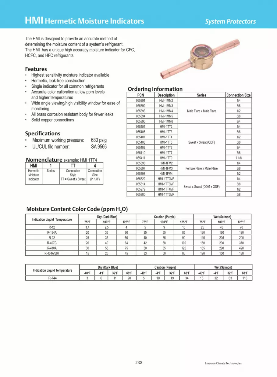
Emerson Climate Technologies 238
System Protectors
The HMI is designed to provide an accurate method of determining the moisture content of a system’s refrigerant. The HMI has a unique high accuracy moisture indicator for CFC, HCFC, and HFC refrigerants.
Features• Highest sensitivity moisture indicator available• Hermetic, leak-free construction• Single indicator for all common refrigerants• Accurate color calibration at low ppm levels and higher temperatures• Wide angle viewing/high visibility window for ease of monitoring• All brass corrosion resistant body for fewer leaks• Solid copper connections
Specifications• Maximum working pressure: 680 psig• UL/CUL file number: SA 9566
Nomenclature example: HMI 1TT4HMI 1 TT 4
HermeticMoistureIndicator
Series ConnectionStyle
TT = Sweat x Sweat
ConnectionSize
(in 1/8”)
Ordering InformationPCN Description Series Connection Size
065391 HMI-1MM2
Male Flare x Male Flare
1/4065392 HMI-1MM3 3/8065393 HMI-1MM4 1/2065394 HMI-1MM5 5/8065395 HMI-1MM6 3/4065405 HMI-1TT2
Sweat x Sweat (ODF)
1/4065406 HMI-1TT3 3/8065407 HMI-1TT4 1/2065408 HMI-1TT5 5/8065409 HMI-1TT6 3/4065410 HMI-1TT7 7/8065411 HMI-1TT9 1 1/8065396 HMI-1FM2
Female Flare x Male Flare1/4
065397 HMI-1FM3 3/8065398 HMI-1FM4 1/2065622 HMI-1TT2MF
Sweat x Sweat (ODM x ODF)
1/4065814 HMI-1TT3MF 3/8065979 HMI-1TT4MF 1/2065980 HMI-1TT5MF 5/8
Moisture Content Color Code (ppm H2O)
Indication Liquid Temperature Dry (Dark Blue) Caution (Purple) Wet (Salmon)75°F 100°F 125°F 75°F 100°F 125°F 75°F 100°F 125°F
R-12 1.4 2.5 4 5 9 15 25 43 70R-134A 20 35 60 35 55 85 130 160 190
R-22 25 35 50 40 65 90 145 205 290R-407C 26 40 64 42 68 109 150 230 370R-410A 30 55 75 50 85 120 165 290 420
R-404A/507 15 25 45 33 50 80 120 150 180
HMI Hermetic Moisture Indicators
Indication Liquid TemperatureDry (Dark Blue) Caution (Purple) Wet (Salmon)
-40oF -4oF 32oF 68oF -40oF -4oF 32oF 68oF -40oF -4oF 32oF 68oFR-744 3 6 11 20 5 10 19 34 16 32 63 116

Emerson Climate Technologies 239
System Protectors
Dimensional Data
FEMALE FLARE X MALE FLARETYPE "FM"
A
MALE FLARE X MALE FLARETYPE "MM"
A
B
DC
F
C
TUBE STUB MALE X TUBE STUB FEMALETYPE "TTMF"
TUBE STUB X TUBE STUBTYPE "TT"
A
G
F EF
DC
A
DC
B
E
B
D
HMI
Dimensional Data (in)Type Number Connection Size A B C D E F Min G
HMI - 1MM2 1/4 SAE 3.13 1.56 0.34 0.94HMI - 1MM3 3/8 SAE 3.38 1.69 0.34 0.94HMI - 1MM4 1/2 SAE 3.62 1.81 0.47 1.19HMI - 1MM5 5/8 SAE 3.88 1.94 0.47 1.19HMI - 1MM6 3/4 SAE 5.00 2.50 0.59 1.53HMI - 1FM2 1/4 SAE FM 2.75 1.19 0.34 0.94HMI - 1FM3 3/8 SAE FM 3.00 1.31 0.47 1.19HMI - 1FM4 1/2 SAE FM 3.22 1.41 0.47 1.19HMI - 1TT2 1/4 ODF 5.56 0.34 0.94 0.25 0.38HMI - 1TT3 3/8 ODF 5.61 0.34 0.94 0.38 0.40HMI - 1TT4 1/2 ODF 5.87 0.47 1.19 0.50 0.50HMI - 1TT5 5/8 ODF 5.87 0.61 1.19 0.63 0.63HMI - 1TT6 3/4 ODF 6.56 0.61 1.50 0.75 0.63HMI - 1TT7 7/8 ODF 6.31 0.61 1.50 0.88 0.75HMI - 1TT9 1 1/8 ODF 6.59 0.67 1.37 1.13 0.90
HMI - 1TT2MF 1/4 ODM x 1/4 ODF 5.56 0.34 0.94 0.25 0.38 0.25HMI - 1TT3MF 3/8 ODM x 3/8 ODF 5.61 0.34 0.94 0.38 0.38 0.38HMI - 1TT4MF 1/2 ODM x 1/2 ODF 5.87 0.47 1.19 0.50 0.50 0.50HMI - 1 TT5MF 5/8 ODM x 5/8 ODF 5.87 0.61 1.19 0.63 0.50 0.62
HMI Hermetic Moisture Indicators

Emerson Climate Technologies 240
System Protectors
Nomenclature example: AMI 1SS4AMI 1 SS 4
MoistureIndicatorSeries
Design Series1 = standardconnection
2 = bushing style
ConnectionStyle
TT = Sweat x Sweat
ConnectionSize
(in 1/8”)
Specifications• Maximum working pressure: 650 psig• UL/CUL file number: SA 9566
The AMI is designed to provide an accurate method ofdetermining the moisture content of a system’s refrigerant.The AMI has a unique high accuracy moisture indicator for CFC, HCFC and HFC refrigerants. For the AMI-2 Series, see the bottom of the following page.
Features• Highest sensitivity moisture indicator available• Take-Apart design for easy repair• Single indicator for all common refrigerants• Accurate color calibration at low ppm levels and higher temperatures• Wide angle viewing/high visibility window for ease of monitoring• Solid copper connections
Replacement Parts For AMIPCN Part Number021371 Lenscap 12740-1020877 “O” Ring PS1525-2027511 Lens Assembly Kit
(Consists of lens assembly, lens cap and “O” ring)
X12978-1
Ordering InformationPCN Description Series Connection
Size048804 AMI-1MM3
Male Flare x Male Flare3/8
048805 AMI-1MM4 1/2048806 AMI-1MM5 5/8048811 AMI-1SS2
Sweat x Sweat (OD Female)
1/4048812 AMI-1SS3 3/8048813 AMI-1SS4 1/2048814 AMI-1SS5 5/8048815 AMI-1SS7 7/8048816 AMI-1SS9 1 1/8047298 AMI-1TT2 EXTENDED ENDS 1/4042771 AMI-1TT3 EXTENDED ENDS 3/8022302 AMI-1TT4 EXTENDED ENDS 1/2031136 AMI-1TT5 EXTENDED ENDS 5/8031357 AMI-1TT7 EXTENDED ENDS 7/8031578 AMI-1TT9 EXTENDED ENDS 1 1/8048800 AMI-1FM2
Female Flare x Male Flare1/4
048801 AMI-1FM3 3/8048802 AMI-1FM4 1/2
Moisture Content Color Code (ppm H2O)Indication
Liquid TemperatureDry (Dark Blue) Caution (Purple) Wet (Salmon)
75°F 100°F 125°F 75°F 100°F 125°F 75°F 100°F 125°FR-12 1.4 2.5 4 5 9 15 25 43 70
R-134A 20 35 60 35 55 85 130 160 190R-22 25 35 50 40 65 90 145 205 290
R-407C 26 40 64 42 68 109 150 230 370R-410A 30 55 75 50 85 120 165 290 420
R-404A/507 15 25 45 33 50 80 120 150 180
BODY
O-RING
LENS ASSEMBLY
LENS CAP
AMI Moisture Indicators
IndicationLiquid Temperature
Dry (Dark Blue) Caution (Purple) Wet (Salmon)-40oF -4oF 32oF 68oF -40oF -4oF 32oF 68oF -40oF -4oF 32oF 68oF
R-744 3 6 11 20 5 10 19 34 16 32 63 116

Emerson Climate Technologies 241
System Protectors
Dimensional Data
Dimensional Data (in)Description Connection Size A B C D E F Min.
AMI-1MM2 1/4 SAE 3.13 1.560.34 1.19
AMI-1MM3 3/8 SAE 3.38 1.69AMI-1MM4 1/2 SAE 3.63 1.81
0.47 1.44AMI-1MM5 5/8 SAE 3.88 1.94AMI-1FM2 1/4 SAE 2.75 1.19 0.34 1.19AMI-1FM3 3/8 SAE 3.00 1.31
0.47 1.44AMI-1FM4 1/2 SAE 3.22 1.41AMI-1SS2 1/4 ODF
2.25 1.13 0.34 1.190.25 .32
AMI-1SS3 3/8 ODF 0.38 .32AMI-1SS4 1/2 ODF
2.63 1.31 0.47 1.440.50 .38
AMI-1SS5 5/8 ODF 0.63 .50AMI-1SS7 7/8 ODF 3.13 1.56 0.61 1.75 0.88 .76AMI-1SS9 1 1/8 ODF 3.38 1.69 0.67 1.92 1.13 .90AMI-1TT2 1/4 ODF
4.89 0.34 1.19.25 .32
AMI-1TT3 3/8 ODF 0.38 .32AMI-1TT4 1/2 ODF 4.92
0.47 1.440.50 .38
AMI-1TT5 5/8 ODF 4.91 0.63 .50AMI-1TT7 7/8 ODF 6.36 0.61 1.75 0.88 .76AMI-1TT9 1 1/8 ODF 6.59 0.67 1.92 1.125 .90AMI 1TT11 1 3/8 ODF 6.94 1.00 2.39 1.38 1.3
AMI-2 Series Dimensions (in)PCN Description Connection
Size A Dia. B C064167 AMI-2S7 7/8 ODM 0.88 1.34 1.00064168 AMI-2S9 1 1/8 ODM 1.13 1.25 1.00022303 AMI-2S11 1 3/8 ODM 1.38 1.56 1.94028388 AMI-2S13 1 5/8 ODM 1.63 1.69 1.44031219 AMI-2S17 2 1/8 ODM 2.13 1.94 1.69
AMI Moisture Indicators
AMI-2
AMI-1

Emerson Climate Technologies 242
System Protectors
Nomenclature example: A-IHL 9SA-IHL 9 SSeries Connection
Size (in 1/8”)S = ODF
The A-IHL saddle design moisture indicator is used for largediameter tubing in CFC, HCFC, and HFC refrigerants.
Features• Saddle design• Solid copper connections• Replaceable moisture indicator• Eliminates the need for bypass installation - positive reaction to system moisture levels
Specifications• Maximum working pressure: 680 psig• UL/CUL file number: SA 9566 Ordering Information
PCN Model ConnectionSize
OverallLength (in)
060853 A-IHL-9S 1 1/8 ODF 6.31061030 A-IHL-11S 1 3/8 ODF 7.12061031 A-IHL-13S 1 5/8 ODF 7.87061032 A-IHL-17S 2 1/8 ODF 8.68*060973 *A-IHL-21S 2 5/8 ODF 9.45
*A-IHL - 21S has a maximum working pressure of 500 psig
A-IHL Moisture Indicators

Emerson Climate Technologies 243
System Protectors
Specifications• Maximum working pressure: 300 psig• Fusible plug temperature: 430°F• UL/CUL file number: SA 10225
The A-AS protects the compressor from liquid slugging and is used with CFC, HCFC, and HFC refrigerants. It is available for systems through 28 tons nominal capacity.
Features• Designed to operate in a range of +40°F to -40°F evaporator temperature• Fusible plug on larger diameter units• Solid copper connections• Corrosion resistant epoxy powder paint finish• Inlet deflector directs refrigerant flow to prevent internal splashing and aid in the collection of refrigerant oil
Nomenclature example: A-AS 3 125A AS 3 12 5
Series AccumulatorSuction
Diameter(in)
Height(in)
Fitting Sizein 1/8”
Ordering Information and Dimensional Data (in)
PCN DescriptionA
Fitting Size
(nominal)
BDiameter
CHeight
DFitting
SeparationWeight
(lbs)Tons R-22
(+40°F)
Holding Capacity (lbs)50% of System Charge
40°F LiquidR-22/R-134a
40°F LiquidR-404A/R-507
060819 A-AS 3 84* 1/2 3.00 8.00 1.63 2.00 2.00 1.50 1.50
060963 A-AS 3 105* 5/8 3.00 10.00 1.63 2.40 3.00 2.00 2.00
060812 A-AS 3 125* 5/8 3.00 12.00 1.63 2.90 3.00 3.00 2.50
060813 A-AS 3 126* 3/4 3.00 12.00 1.63 2.90 4.00 3.00 2.50
060964 A-AS 3 145* 5/8 3.00 15.00 1.63 3.30 3.00 3.50 3.00
060965 A-AS 3 146* 3/4 3.00 14.00 1.63 3.30 4.00 3.50 2.75
060967 A-AS 4 64 1/2 4.00 6.00 2.50 2.80 2.00 2.50 2.00
060821 A-AS 4 65 5/8 4.00 6.00 2.50 2.80 3.00 2.50 2.00
060966 A-AS 4105 5/8 4.00 10.00 2.50 4.60 3.00 4.00 3.50
060820 A-AS 4 106 3/4 4.00 10.00 2.50 4.60 4.00 4.00 3.50
060824 A-AS 5 96 3/4 5.00 9.00 2.75 5.10 4.00 6.00 5.50
060818 A-AS 5 97 7/8 5.00 9.00 2.75 5.10 7.30 6.00 5.50
060822 A-AS 5 126 3/4 5.00 12.00 2.75 6.60 4.00 8.00 7.50
060823 A-AS 5 127 7/8 5.00 12.00 2.75 6.60 7.30 8.00 7.50
060814 A-AS 5 137 7/8 5.00 13.00 2.75 7.10 7.30 8.50 8.00
060815 A-AS 5 139 1-1/8 5.00 13.00 2.75 7.10 11.80 8.50 8.00
060817 A-AS 5 179 1-1/8 5.00 17.00 2.75 8.40 11.80 12.00 10.00
060816 A-AS 5 1711 1-3/8 5.00 17.00 2.75 8.40 18.80 12.00 10.00
060825 A-AS 6 117 7/8 6.00 11.00 2.94 10.00 7.30 10.00 9.00
060826 A-AS 6 137 7/8 6.00 13.00 2.94 11.70 7.30 12.84 11.49
060968 A-AS 6 139 1-1/8 6.00 13.00 2.94 11.70 11.80 12.84 11.49
060827 A-AS 6 1411 1-3/8 6.00 14.00 2.94 12.10 18.80 14.05 12.57
060969 A-AS 6 1713 1-5/8 6.00 17.00 2.94 15.40 28.50 17.32 15.49
060828 A-AS 6 2013 1-5/8 6.00 20.00 2.94 18.10 28.50 20.62 18.44
060970 A-AS 6 2513 1-5/8 6.00 25.00 2.94 22.60 28.50 25.81 23.08*Not supplied with a fusible plug
Dimensional Data
A-AS Suction Accumulators

Emerson Climate Technologies 244
System Protectors
Nomenclature example: ACC-3637S
ACC 36 3 7 SSeries Internal Volume
(cu. in.)Diameter
(in.)Connection Size
(in. 1/8”)ODF
The ACC is a charge compensator that is designed to work in heat pump applications. It increases system efficiency by storing extra refrigerant in the heating mode. It then returns refrigerant back into circulation in the cooling mode.
Features• Solid copper connection• Corrosion resistant epoxy powder paint finish
Specifications• Maximum working pressure: 680 psig• UL/CUL file number: SA5760
Dimensional Data
ACC Charge Compensator
R-410A
Ordering Information
PCN DescriptionInternal Volume
(cu. in.)Liquid LineConnection
Connection
Dimensions (in.) Holding Capacity (oz.)
A B CR-410A
75oF 125oF066631 ACC-2336S 23 3/8 ODF 3/4 ODF 7.19 3.33 3.50 15 13
066632 ACC-3636S36
3/8 ODF 3/4 ODF 8.94 5.08 3.50 24 20
066633 ACC-3637S 3/8 ODF 7/8 ODF 8.94 5.08 3.50 24 20
066634 ACC-4736S47
3/8 ODF 3/4 ODF 10.18 6.32 3.50 31 26
066635 ACC-4737S 3/8 ODF 7/8 ODF 10.18 6.32 3.50 30 25
066493 ACC-6236S62
3/8 ODF 3/4 ODF 12.06 8.20 3.50 40 34
066636 ACC-6237S 3/8 ODF 7/8 ODF 12.06 8.20 3.50 40 33
066637 ACC-7837S78
3/8 ODF 7/8 ODF 14.11 10.25 3.50 51 43
066638 ACC-7836S 3/8 ODF 3/4 ODF 14.11 10.25 3.50 50 42
066639 ACC-9536S95
3/8 ODF 3/4 ODF 15.86 12.00 3.50 60 51
066640 ACC-9537S 3/8 ODF 7/8 ODF 15.86 12.00 3.50 59 50

245
System Protector Capacity Tables
Emerson Climate Technologies
Hermetic Suction Line Filter Drier Flow Capacities
Description Connections
Flow Capacity In Tons Refrigerant1 (For kW, Multiply Tons By 3.5)2
R-12 R-134a R-744Evaporator Temperature (°F)
40 20 0 -20 40 20 0 -20 20 0 -20 -40Pressure Drop (PSI)
2 1.5 1 0.5 2 1.5 1 0.5 6 5 4 3ASD 28S3-VV 3/8 ODF 1.1 0.6 0.5 0.5 1.1 0.6 0.5 0.4 7.2 6.3 6.8 8.5ASD 28S4-VV 1/2 ODF 1.8 1.2 0.8 0.7 1.9 1.2 0.8 0.6 11.8 10.2 10.6 14.2ASD 35F5-VV 5/8 SAE 2.1 1.4 1.1 0.9 2.2 1.4 1.0 0.8 13.7 12.2 12.9 17.0ASD 35S5-VV 5/8 ODF 2.8 1.9 1.4 1.1 2.9 1.9 1.3 1.0 18.1 15.6 16.7 22.7ASD 45S6-VV 3/4 ODF 3.8 2.5 1.8 1.2 3.9 2.5 1.7 1.1 21.8 22.4 24.2 28.4ASD 45S7-VV 7/8 ODF 5.0 3.6 2.3 1.5 5.1 3.5 2.2 1.3 28.7 29.2 31.1 36.9ASD 50S9-VV 1-1/8 ODF 7.1 5.0 3.2 1.8 7.3 4.9 3.0 1.6 41.1 41.3 43.2 49.6ASD 75S11-VV 1-3/8 ODF 8.6 5.9 3.7 2.0 8.8 5.8 3.5 1.8 50.5 49.6 50.8 56.7ASD 75S13-VV 1-5/8 ODF 9.0 6.2 3.9 2.1 9.3 6.1 3.7 1.9 53.9 52.0 53.0 59.6ASF 28S3-VV 3/8 ODF 1.2 0.8 0.5 0.5 1.2 0.8 0.5 0.4 7.5 6.3 6.8 9.9ASF 28S4-VV 1/2 ODF 1.9 1.3 0.9 0.8 2.0 1.3 0.9 0.7 12.8 11.2 12.1 17.0ASF 35F5-VV 5/8 SAE 2.2 1.5 1.1 0.9 2.3 1.5 1.0 0.8 14.6 12.6 13.6 18.4ASF 35S5-VV 5/8 ODF 3.2 2.2 1.6 1.4 3.3 2.2 1.5 1.2 20.6 18.0 19.7 26.9ASF 45S6-VV 3/4 ODF 4.7 3.2 2.3 1.8 4.8 3.1 2.2 1.6 30.5 26.7 28.0 38.3ASF 45S7-VV 7/8 ODF 6.5 4.8 3.3 1.9 6.7 4.7 3.1 1.7 37.4 38.9 42.4 51.0ASF 50S9-VV 1-1/8 ODF 9.2 6.8 4.5 2.6 9.5 6.7 4.3 2.3 59.2 58.3 62.1 69.5
ASF 64S17-VV 2-1/8 ODF 25.3 18.3 12.6 7.2 26.0 18 12 6.4 127.8 131.2 144.0 170.2ASF 75S11-VV 1-3/8 ODF 11.7 8.8 5.9 3.4 12.0 8.7 5.6 3.0 49.9 72.9 83.4 95.0ASF 75S13-VV 1-5/8 ODF 13.6 9.7 6.6 3.8 14.0 9.5 6.3 3.4 74.8 72.9 75.8 92.2
ASK 165S-VV-HH 5/8 ODF 1.9 1.4 0.8 0.6 2.0 1.4 0.8 0.5 10.6 10.2 10.6 12.8ASK 166S-VV-HH 3/4 ODF 2.4 1.7 1.1 0.7 2.5 1.7 1.0 0.6 13.1 12.6 12.9 14.2ASK 167S-VV-HH 7/8 ODF 2.6 1.8 1.2 0.7 2.7 1.8 1.1 0.6 14.3 13.6 14.4 15.6ASK 306S-VV-HH 3/4 ODF 3.3 2.3 1.5 0.9 3.4 2.3 1.4 0.8 17.1 17.0 17.4 19.9ASK 307S-VV-HH 7/8 ODF 3.5 2.5 1.6 0.9 3.6 2.5 1.5 0.8 19.0 18.5 18.9 21.3ASK 309S-VV-HH 1-1/8 ODF 3.8 2.6 1.7 0.9 3.9 2.6 1.6 0.8 20.3 19.4 19.7 22.7CSFD 14S4-VV 1/2 ODF 1.3 0.9 0.5 0.3 1.3 0.9 0.5 0.3 6.2 6.3 6.8 8.5CSFD 14S5-VV 5/8 ODF 2.2 1.5 0.9 0.6 2.3 1.5 0.9 0.5 11.2 11.7 12.1 14.2CSFD 14S6-VV 3/4 ODF 3.0 2.1 13.7 0.8 3.1 2.1 13 0.7 15.3 15.6 16.7 19.9CSFD 14S7-VV 7/8 ODF 3.2 2.2 1.5 0.8 3.3 2.2 1.4 0.7 16.2 16.5 17.4 21.3CSFD 14S9-VV 1-1/8 ODF 4.4 3.1 1.9 1.1 4.5 3.0 1.8 1.0 21.8 22.4 23.5 28.4SFD 13F3-VV 3/8 SAE 0.7 0.4 0.2 0.1 0.7 0.4 0.2 0.1 4.4 3.9 3.0 2.8SFD 13S3-VV 3/8 ODF 1.3 0.8 0.5 0.2 1.3 0.8 0.5 0.2 6.9 6.3 6.1 7.1SFD 13F4-VV 1/2 SAE 1.5 1.0 0.6 0.3 1.5 1.0 0.6 0.3 7.5 7.8 8.3 9.9SFD 13S4-VV 1/2 ODF 2.2 1.5 1.1 0.6 2.3 1.5 1.0 0.5 10.9 11.2 12.1 14.2SFD 13F5-VV 5/8 SAE 2.4 1.7 1.2 0.7 2.5 1.7 1.1 0.6 11.5 11.7 12.1 14.2SFD 13S5-VV 5/8 ODF 3.0 2.1 1.4 0.8 3.1 2.1 1.3 0.7 15.3 15.6 16.7 19.9SFD 13S6-VV 3/4 ODF 4.0 2.7 1.8 1.0 4.1 2.7 1.7 0.9 19.9 20.4 21.2 25.5SFD 13S7-VV 7/8 ODF 4.3 3.1 2.0 1.1 4.4 3.0 1.9 1.0 22.4 22.4 22.7 26.9SFD 27S6-VV 3/4 ODF 4.0 2.7 1.8 1.0 4.1 2.7 1.7 0.9 19.9 20.4 21.2 25.5SFD 27S7-VV 7/8 ODF 4.6 3.2 2.0 1.1 4.7 3.1 1.9 1.0 23.4 23.3 24.2 28.4SFD 27S9-VV 1-1/8 ODF 5.1 3.5 2.1 1.1 5.2 3.4 2.0 1.0 26.5 26.2 26.5 29.8SFD 54S11-VV 1-3/8 ODF 4.4 2.9 1.8 1.0 4.5 2.9 1.7 0.9 22.8 22.4 22.7 25.5SFD 54S13-VV 1-5/8 ODF 4.5 3.1 1.9 1.0 4.6 3.0 1.8 0.9 23.1 22.8 24.2 28.4
1 All ratings in accordance with ARI Standard 730-04.2 Example: 1.0 tons x 3.5 = 3.5 kW

246
System Protector Capacity Tables
Emerson Climate Technologies
Hermetic Suction Line Filter Drier Flow Capacities
Description Connections
Flow Capacity In Tons Refrigerant1 (For kW, Multiply Tons By 3.5)2
R-22 R-407C R-410AEvaporator Temperature (°F)
40 20 0 -20 -40 40 20 0 -20 -40 40 20 0 -20 -40Pressure Drop (PSI)
3 2 1.5 1 0.5 3 2 1.5 1 0.5 3 2 1.5 1 0.5ASD 28S3-VV 3/8 ODF 2.3 1.3 0.9 0.6 0.5 2.1 1.2 0.8 0.5 0.4 2.8 1.6 1.1 0.7 0.6ASD 28S4-VV 1/2 ODF 3.8 2.1 1.4 1.0 0.8 3.5 1.9 1.2 0.9 0.7 4.6 2.6 1.7 1.2 1.0ASD 35F5-VV 5/8 SAE 4.4 2.5 1.7 1.2 0.9 4.1 2.3 1.5 1.0 0.7 5.3 3.0 2.1 1.5 1.1ASD 35S5-VV 5/8 ODF 5.8 3.2 2.2 1.6 1.0 5.4 2.9 1.9 1.4 0.8 7.0 3.9 2.7 2.0 1.3ASD 45S6-VV 3/4 ODF 7.0 4.6 3.2 2.0 1.1 6.5 4.2 2.8 1.7 0.9 8.5 5.6 3.9 2.5 1.4ASD 45S7-VV 7/8 ODF 9.2 6.0 4.1 2.6 1.4 8.5 5.5 3.6 2.3 1.2 11.2 7.3 5.0 3.2 1.8ASD 50S9-VV 1-1/8 ODF 13.2 8.5 5.7 3.5 1.8 12.2 7.7 5.0 3.1 1.5 16.0 10.3 7.0 4.3 2.3ASD 75S11-VV 1-3/8 ODF 16.2 10.2 6.7 4.0 2.0 15.0 9.3 5.9 3.5 1.7 19.6 12.4 8.2 5.0 2.5ASD 75S13-VV 1-5/8 ODF 17.3 10.7 7.0 4.2 2.1 16.0 9.7 6.2 3.7 1.7 21.0 13.0 8.6 5.2 2.6ASF 28S3-VV 3/8 ODF 2.4 1.3 0.9 0.7 0.5 2.2 1.2 0.8 0.6 0.4 2.9 1.6 1.1 0.9 0.6ASF 28S4-VV 1/2 ODF 4.1 2.3 1.6 1.2 0.9 3.8 2.1 1.4 1.0 0.7 5.0 2.8 2.0 1.5 1.1ASF 35F5-VV 5/8 SAE 4.7 2.6 1.8 1.3 1.0 4.4 2.4 1.6 1.1 0.8 5.7 3.2 2.2 1.6 1.3ASF 35S5-VV 5/8 ODF 6.6 3.7 2.6 1.9 1.6 6.1 3.4 2.3 1.7 1.3 8.0 4.5 3.2 2.4 2.0ASF 45S6-VV 3/4 ODF 9.8 5.5 3.7 2.7 2.2 9.1 5.0 3.3 2.4 1.8 11.9 6.7 4.5 3.4 2.8ASF 45S7-VV 7/8 ODF 12.0 8.0 5.6 3.6 3.0 11.1 7.3 5.0 3.1 2.5 14.6 9.7 6.9 4.5 3.8ASF 50S9-VV 1-1/8 ODF 19.0 12.0 8.2 4.9 2.6 17.6 10.9 7.3 4.3 2.2 23.0 14.6 10.1 6.1 3.3ASF 64S17-VV 2-1/8 ODF 41.0 27.0 19.0 12.0 6.9 38.0 24.5 16.8 10.5 5.7 49.7 32.8 23.3 14.9 8.6ASF 75S11-VV 1-3/8 ODF 16.0 15.0 11.0 6.7 3.3 14.8 13.6 9.7 5.8 2.7 19.4 18.2 13.5 8.3 4.1ASF 75S13-VV 1-5/8 ODF 24.0 15.0 10.0 6.5 3.2 22.2 13.6 8.9 5.7 2.7 29.1 18.2 12.3 8.1 4.0
ASK 165S-VV-HH 5/8 ODF 3.4 2.1 1.4 0.9 0.4 3.2 1.9 1.2 0.8 0.3 4.1 2.6 1.7 1.1 0.5ASK 166S-VV-HH 3/4 ODF 4.2 2.6 1.7 1.0 0.5 3.9 2.4 1.5 0.9 0.4 5.1 3.2 2.1 1.2 0.6ASK 167S-VV-HH 7/8 ODF 4.6 2.8 1.9 1.1 0.6 4.3 2.5 1.7 1.0 0.5 5.6 3.4 2.3 1.4 0.8ASK 306S-VV-HH 3/4 ODF 5.5 3.5 2.3 1.4 0.8 5.1 3.2 2.0 1.2 0.7 6.7 4.3 2.8 1.7 1.0ASK 307S-VV-HH 7/8 ODF 6.1 3.8 2.5 1.5 0.8 5.7 3.5 2.2 1.3 0.7 7.4 4.6 3.1 1.9 1.0ASK 309S-VV-HH 1-1/8 ODF 6.5 4.0 2.6 1.6 0.8 6.0 3.6 2.3 1.4 0.7 7.9 4.9 3.2 2.0 1.0CSFD 14S4-VV 1/2 ODF 2.0 1.3 0.9 0.6 0.3 1.9 1.2 0.8 0.5 0.2 2.4 1.6 1.1 0.7 0.4CSFD 14S5-VV 5/8 ODF 3.6 2.4 1.6 1.0 0.5 3.3 2.2 1.4 0.9 0.4 4.4 2.9 2.0 1.2 0.6CSFD 14S6-VV 3/4 ODF 4.9 3.2 2.2 1.4 0.7 4.5 2.9 1.9 1.2 0.6 5.9 3.9 2.7 1.7 0.9CSFD 14S7-VV 7/8 ODF 5.2 3.4 2.3 1.5 0.8 4.8 3.1 2.0 1.3 0.7 6.3 4.1 2.8 1.9 1.0CSFD 14S9-VV 1-1/8 ODF 7.0 4.6 3.1 2.0 1.0 6.5 4.2 2.7 1.7 0.8 8.5 5.6 3.8 2.5 1.3SFD 13F3-VV 3/8 SAE 1.4 0.8 0.4 0.2 0.1 1.3 0.7 0.4 0.2 0.1 1.7 1.0 0.5 0.2 0.1SFD 13S3-VV 3/8 ODF 2.2 1.3 0.8 0.5 0.2 2.0 1.2 0.7 0.4 0.2 2.7 1.6 1.0 0.6 0.3SFD 13F4-VV 1/2 SAE 2.4 1.6 1.1 0.7 0.4 2.2 1.5 1.0 0.6 0.3 2.9 1.9 1.3 0.9 0.5SFD 13S4-VV 1/2 ODF 3.5 2.3 1.6 1.0 0.6 3.2 2.1 1.4 0.9 0.5 4.2 2.8 2.0 1.2 0.8SFD 13F5-VV 5/8 SAE 3.7 2.4 1.6 1.0 0.6 3.4 2.2 1.4 0.9 0.5 4.5 2.9 2.0 1.2 0.8SFD 13S5-VV 5/8 ODF 4.9 3.2 2.2 1.4 0.8 4.5 2.9 1.9 1.2 0.7 5.9 3.9 2.7 1.7 1.0SFD 13S6-VV 3/4 ODF 6.4 4.2 2.8 1.8 1.0 5.9 3.8 2.5 1.6 0.8 7.8 5.1 3.4 2.2 1.3SFD 13S7-VV 7/8 ODF 7.2 4.6 3.0 1.9 1.0 6.7 4.2 2.7 1.7 0.8 8.7 5.6 3.7 2.4 1.3SFD 27S6-VV 3/4 ODF 6.4 4.2 2.8 1.8 1.0 5.9 3.8 2.5 1.6 0.8 7.8 5.1 3.4 2.2 1.3SFD 27S7-VV 7/8 ODF 7.5 4.8 3.2 2.0 1.1 7.0 4.4 2.8 1.7 0.9 9.1 5.8 3.9 2.5 1.4SFD 27S9-VV 1-1/8 ODF 8.5 5.4 3.5 2.1 1.1 7.9 4.9 3.1 1.8 0.9 10.3 6.6 4.3 2.6 1.4SFD 54S11-VV 1-3/8 ODF 7.3 4.6 3.0 1.8 1.0 6.8 4.2 2.7 1.6 0.8 8.9 5.6 3.7 2.2 1.3SFD 54S13-VV 1-5/8 ODF 7.4 4.7 3.2 2.0 1.0 6.9 4.3 2.8 1.7 0.8 9.0 5.7 3.9 2.5 1.3
1 All ratings in accordance with ARI Standard 730-04.2 Example: 1.0 tons x 3.5 = 3.5 kW

247
System Protector Capacity Tables
Emerson Climate Technologies
Hermetic Suction Line Filter Drier Flow Capacities
Description Connections
Flow Capacity In Tons Refrigerant1 (For kW, Multiply Tons By 3.5)2
R-502 R-404A/R-507Evaporator Temperature (°F)
40 20 0 -20 40 20 0 -20 -40Pressure Drop (PSI)
3 2 1.5 1 3 2 1.5 1 0.5ASD 28S3-VV 3/8 ODF 2.2 1.1 0.7 0.5 2.1 1.1 0.7 0.5 0.3ASD 28S4-VV 1/2 ODF 3.7 1.8 1.1 0.7 3.6 1.8 1.1 0.7 0.5ASD 35F5-VV 5/8 SAE 4.2 2.1 1.3 0.9 4.1 2.1 1.3 0.9 0.6ASD 35S5-VV 5/8 ODF 5.6 2.8 1.7 1.1 5.4 2.8 1.7 1.1 0.8ASD 45S6-VV 3/4 ODF 6.6 3.7 2.5 1.5 6.4 3.7 2.5 1.6 1.0ASD 45S7-VV 7/8 ODF 7.7 4.8 3.3 1.9 7.5 4.8 3.3 2.0 1.1ASD 50S9-VV 1-1/8 ODF 11.0 6.9 4.6 2.7 11.0 6.9 4.6 2.8 1.4ASD 75S11-VV 1-3/8 ODF 14.0 8.4 5.4 3.1 14.0 8.4 5.4 3.2 1.6ASD 75S13-VV 1-5/8 ODF 15.0 8.9 5.7 3.3 15.0 8.9 5.7 3.4 1.7ASF 28S3-VV 3/8 ODF 2.3 1.1 0.7 0.5 2.2 1.1 0.7 0.5 0.3ASF 28S4-VV 1/2 ODF 3.9 2.0 1.2 0.8 3.8 2.0 1.2 0.8 0.6ASF 35F5-VV 5/8 SAE 4.5 2.3 1.4 0.9 4.4 2.3 1.4 0.9 0.7ASF 35S5-VV 5/8 ODF 6.3 3.2 2.0 1.4 6.1 3.2 2.0 1.4 1.0ASF 45S6-VV 3/4 ODF 9.4 4.7 2.9 1.8 9.1 4.7 2.9 1.9 1.4ASF 45S7-VV 7/8 ODF 10.0 6.3 4.5 2.7 9.8 6.3 4.5 2.8 1.5ASF 50S9-VV 1-1/8 ODF 16.0 10.0 6.6 3.9 16.0 10.0 6.7 4.0 2.0ASF 64S17-VV 2-1/8 ODF 36.0 23.0 15.0 9.5 35.0 23.0 15.0 9.8 5.2ASF 75S11-VV 1-3/8 ODF 21.0 13.0 8.2 4.9 20.0 13.0 8.3 5.1 2.6ASF 75S13-VV 1-5/8 ODF 22.0 13.0 8.3 5.0 21.0 13.0 8.4 5.2 2.7
ASK 165S-VV-HH 5/8 ODF 3.3 1.9 1.2 0.8 3.2 1.9 1.2 0.8 0.3ASK 166S-VV-HH 3/4 ODF 4.0 2.4 1.6 0.9 3.9 2.4 1.6 0.9 0.5ASK 167S-VV-HH 7/8 ODF 4.4 2.6 1.7 1.0 4.3 2.6 1.7 1.0 0.6ASK 306S-VV-HH 3/4 ODF 5.2 3.2 2.2 1.2 5.0 3.2 2.2 1.2 0.7ASK 307S-VV-HH 7/8 ODF 5.8 3.5 2.3 1.4 5.6 3.5 2.3 1.4 0.7ASK 309S-VV-HH 1-1/8 ODF 6.2 3.7 2.4 1.4 6.0 3.7 2.4 1.5 0.7CSFD 14S4-VV 1/2 ODF 1.3 0.8 0.5 0.3 1.3 0.8 0.5 0.3 0.2CSFD 14S5-VV 5/8 ODF 2.7 1.7 1.1 0.7 2.6 1.7 1.1 0.7 0.3CSFD 14S6-VV 3/4 ODF 3.7 2.3 1.5 0.9 3.6 2.3 1.5 0.9 0.5CSFD 14S7-VV 7/8 ODF 4.0 2.4 1.6 1.0 3.9 2.4 1.6 1.0 0.5CSFD 14S9-VV 1-1/8 ODF 5.1 3.1 2.0 1.3 4.9 3.1 2.0 1.3 0.7SFD 13F3-VV 3/8 SAE 1.3 0.7 0.4 0.2 1.3 0.7 0.4 0.2 0.1SFD 13S3-VV 3/8 ODF 2.0 1.1 0.7 0.4 1.9 1.1 0.7 0.4 0.2SFD 13F4-VV 1/2 SAE 2.2 1.3 0.9 0.5 2.1 1.3 0.9 0.5 0.3SFD 13S4-VV 1/2 ODF 3.1 1.9 1.3 0.8 3.0 1.9 1.3 0.8 0.4SFD 13F5-VV 5/8 SAE 3.3 2.0 1.4 0.9 3.2 2.0 1.4 0.9 0.5SFD 13S5-VV 5/8 ODF 4.3 2.7 1.8 1.1 4.2 2.7 1.8 1.1 0.6SFD 13S6-VV 3/4 ODF 5.8 3.5 2.3 1.4 5.6 3.5 2.3 1.4 0.7SFD 13S7-VV 7/8 ODF 6.5 3.9 2.6 1.4 6.3 3.9 2.6 1.5 0.8SFD 27S6-VV 3/4 ODF 5.8 3.5 2.3 1.4 5.6 3.5 2.3 1.4 0.7SFD 27S7-VV 7/8 ODF 6.7 4.1 2.7 1.5 6.5 4.1 2.7 1.6 0.8SFD 27S9-VV 1-1/8 ODF 7.7 4.6 3.0 1.6 7.5 4.6 3.0 1.7 0.9SFD 54S11-VV 1-3/8 ODF 6.6 3.9 2.5 1.4 6.4 3.9 2.5 1.5 0.7SFD 54S13-VV 1-5/8 ODF 6.7 4.0 2.6 1.5 6.5 4.0 2.6 1.6 0.8
1 All ratings in accordance with ARI Standard 730-04.2 Example: 1.0 tons x 3.5 = 3.5 kW

248
System Protector Capacity Tables
Emerson Climate Technologies
Take-Apart Suction Line Filter Drier Flow Capacities
Description Connections Filter Drier Cartridge
Flow Capacity In Tons Refrigerant1 (For kW, Multiply Tons By 3.5)2
R-12 R-134aEvaporator Temperature (°F)
40 20 0 -20 40 20 0 -20Pressure Drop (PSI)
2 1.5 1 0.5 2 1.5 1 0.5ADKS 30013T 1-5/8 ODF (3) F-100 Filter 24.0 17.0 12.0 7.0 25.0 17.0 11.0 6.2ADKS 30017T 2-1/8 ODF (3) F-100 Filter 42.0 31.0 20.0 12.0 43.0 30.0 19.0 11.0ADKS 40017T 2-1/8 ODF (4) F-100 Filter 44.0 32.0 21.0 12.0 45.0 31.0 20.0 11.0ADKS 40021T 2-5/8 ODF (4) F-100 Filter 66.0 48.0 32.0 19.0 68.0 47.0 30.0 17.0ADKS 30013T 1-5/8 ODF (3) 100 cu in Core 19.0 14.0 9.1 5.5 20.0 14.0 8.7 4.9ADKS 30017T 2-1/8 ODF (3) 100 cu in Core 30.0 22.0 15.0 8.7 31.0 22.0 14.0 7.7ADKS 40017T 2-1/8 ODF (4) 100 cu in Core 33.0 23.0 16.0 9.5 34.0 23.0 15.0 8.4ADKS 40021T 2-5/8 ODF (4) 100 cu in Core 48.0 35.0 23.0 14.0 49.0 34.0 22.0 12.0BTAS-27 S-V 7/8 ODF A2F Filter 4.7 3.4 2.2 1.2 4.8 3.3 2.1 1.1BTAS-39 S-V 1-1/8 ODF A3F Filter 7.1 5.1 3.4 1.9 7.3 5.0 3.2 1.7BTAS-311 S-V 1-3/8 ODF A3F Filter 7.9 5.6 3.7 2.1 8.1 5.5 3.5 1.9BTAS-313 S-V 1-5/8 ODF A3F Filter 13.0 8.9 5.9 3.4 13.0 8.8 5.6 3.0BTAS-317 S-V 2-1/8 ODF A3F Filter 15.0 11.0 7.2 4.2 16.0 11.0 6.9 3.7BTAS-411 S-V 1-3/8 ODF A4F Filter 17.0 12.0 8.0 4.5 17.0 12.0 7.4 4.0BTAS-413 S-V 1-5/8 ODF A4F Filter 20.0 15.0 10.0 5.5 21.0 14.0 9.1 4.9BTAS-417 S-V 2-1/8 ODF A4F Filter 28.0 20.0 13.0 7.5 29.0 20.0 12.0 6.7BTAS-421 S-V 2-5/8 ODF A4F Filter 34.0 24.0 16.0 9.1 35.0 24.0 15.0 8.1BTAS-517 S-V 2-1/8 ODF A5F Filter 33.0 24.0 16.0 9.1 34.0 24.0 15.0 8.1BTAS-521 S-V 2-5/8 ODF A5F Filter 44.0 32.0 21.0 12.0 45.0 31.0 20.0 11.0BTAS-525 S-V 3-1/8 ODF A5F Filter 54.0 39.0 25.0 15.0 56.0 38.0 24.0 13.0BTAS-25 S-V 5/8 ODF A2F-D Filter Drier 2.4 1.7 1.2 0.7 2.5 1.7 1.1 0.6BTAS-27 S-V 7/8 ODF A2F-D Filter Drier 4.0 2.8 1.9 1.1 4.1 2.8 1.8 1.0BTAS-39 S-V 1-1/8 ODF A3F-D Filter Drier 5.2 3.7 2.4 1.4 5.3 3.6 2.3 1.2BTAS-311 S-V 1-3/8 ODF A3F-D Filter Drier 7.2 5.2 3.4 1.9 7.4 5.1 3.2 1.7BTAS-313 S-V 1-5/8 ODF A3F-D Filter Drier 10.0 7.4 4.8 2.8 11.0 7.3 4.6 2.5BTAS-317 S-V 2-1/8 ODF A3F-D Filter Drier 12.0 8.5 5.7 3.3 12.0 8.4 5.4 2.9BTAS-411 S-V 1-3/8 ODF A4F-D Filter Drier 15.0 11.0 7.0 4.1 15.0 11.0 6.7 3.6BTAS-413 S-V 1-5/8 ODF A4F-D Filter Drier 15.0 11.0 7.2 4.2 16.0 11.0 6.9 3.7BTAS-417 S-V 2-1/8 ODF A4F-D Filter Drier 22.0 16.0 11.0 6.1 23.0 16.0 10.0 5.4BTAS-421 S-V 2-5/8 ODF A4F-D Filter Drier 23.0 17.0 11.0 6.3 24.0 16.0 10.0 5.6BTAS-517 S-V 2-1/8 ODF A5F-D Filter Drier 27.0 19.0 13.0 7.2 28.0 19.0 12.0 6.4BTAS-521 S-V 2-5/8 ODF A5F-D Filter Drier 32.0 23.0 15.0 8.8 33.0 23.0 14.0 7.8BTAS-525 S-V 3-1/8 ODF A5F-D Filter Drier 38.0 27.0 18.0 10.0 39.0 27.0 17.0 9.2STAS-489 S-V 1-1/8 ODF (1) F-48 Filter 13.0 8.0 5.0 2.0 13.0 8.0 5.0 2.0STAS-4811 S-V 1-3/8 ODF (1) F-48 Filter 15.0 10.0 6.0 3.0 15.0 10.0 6.0 3.0STAS-4813 S-V 1-5/8 ODF (1) F-48 Filter 19.0 12.0 7.0 5.0 20.0 12.0 7.0 4.0STAS-4817 S-V 2-1/8 ODF (1) F-48 Filter 24.0 15.0 11.0 6.0 25.0 15.0 10.0 5.0STAS-4821 S-V 2-5/8 ODF (1) F-48 Filter 29.0 20.0 14.0 7.0 30.0 20.0 13.0 6.0STAS-9617 S-V 2-1/8 ODF (2) F-48 Filter 27.0 18.0 11.0 6.0 28.0 18.0 10.0 5.0STAS-9621 S-V 2-5/8 ODF (2) F-48 Filter 37.0 25.0 16.0 8.0 38.0 25.0 15.0 7.0STAS-9625 S-V 3-1/8 ODF (2) F-48 Filter 65.0 52.0 38.0 21.0 79.0 61.0 43.0 20.0STAS-489 S-V 1-1/8 ODF (1) 48 cu in Core 8.0 6.0 4.0 1.0 8.0 6.0 4.0 1.0STAS-4811 S-V 1-3/8 ODF (1) 48 cu in Core 10.0 7.0 4.0 2.0 10.0 7.0 4.0 2.0STAS-4813 S-V 1-5/8 ODF (1) 48 cu in Core 13.0 8.0 5.0 3.0 13.0 8.0 5.0 3.0STAS-4817 S-V 2-1/8 ODF (1) 48 cu in Core 17.0 10.0 7.0 5.0 17.0 10.0 7.0 4.0STAS-4821 S-V 2-5/8 ODF (1) 48 cu in Core 19.0 13.0 8.0 5.0 20.0 13.0 8.0 4.0STAS-9617 S-V 2-1/8 ODF (2) 48 cu in Core 18.0 12.0 6.0 5.0 18.0 12.0 6.0 4.0STAS-9621 S-V 2-5/8 ODF (2) 48 cu in Core 24.0 17.0 11.0 6.0 25.0 17.0 10.0 5.0STAS-9625 S-V 3-1/8 ODF (2) 48 cu in Core 24.0 19.0 14.0 7.4 29.0 23.0 16.0 7.0
1 All ratings in accordance with ARI Standard 730-04.2 Example: 1.0 tons x 3.5 = 3.5 kW

249
System Protector Capacity Tables
Emerson Climate Technologies
Take-Apart Suction Line Filter Drier Flow Capacities
Description Connections Filter Drier Cartridge
Flow Capacity In Tons Refrigerant1 (For kW, Multiply Tons By 3.5)2
R-22 R-407C R-410AEvaporator Temperature (°F)
40 20 0 -20 -40 40 20 0 -20 -40 40 20 0 -20 -40Pressure Drop (PSI)
3 2 1.5 1 0.5 3 2 1.5 1 0.5 3 2 1.5 1 0.5ADKS 30013T 1-5/8 ODF (3) F-100 Filter 45.0 30.0 20.0 13.0 7.0 41.7 27.3 17.7 11.3 5.8 – – – – –ADKS 30017T 2-1/8 ODF (3) F-100 Filter 77.0 50.0 35.0 22.0 12.0 71.4 45.5 31.0 19.2 10.0 – – – – –ADKS 40017T 2-1/8 ODF (4) F-100 Filter 80.0 53.0 37.0 23.0 13.0 74.2 48.2 32.8 20.0 10.8 – – – – –ADKS 40021T 2-5/8 ODF (4) F-100 Filter 122.0 80.0 55.0 34.0 19.0 113.1 72.7 48.7 29.6 15.8 – – – – –ADKS 30013T 1-5/8 ODF (3) 100 cu in Core 35.0 23.0 16.0 10.0 5.5 32.4 20.9 14.2 8.7 4.6 – – – – –ADKS 30017T 2-1/8 ODF (3) 100 cu in Core 56.0 37.0 25.0 16.0 8.8 51.9 33.6 22.1 13.9 7.3 – – – – –ADKS 40017T 2-1/8 ODF (4) 100 cu in Core 61.0 40.0 27.0 17.0 9.5 56.5 36.4 23.9 14.8 7.9 – – – – –ADKS 40021T 2-5/8 ODF (4) 100 cu in Core 88.0 58.0 40.0 25.0 14.0 81.6 52.7 35.4 21.8 11.6 – – – – –BTAS-27 S-V 7/8 ODF A2F Filter 8.8 5.7 3.9 2.5 1.3 8.2 5.2 3.5 2.2 1.1 – – – – –BTAS-39 S-V 1-1/8 ODF A3F Filter 14.0 8.8 5.9 3.7 2.0 13.0 8.0 5.2 3.2 1.7 – – – – –BTAS-311 S-V 1-3/8 ODF A3F Filter 15.0 10.0 6.6 4.1 2.2 13.9 9.1 5.8 3.6 1.8 – – – – –BTAS-313 S-V 1-5/8 ODF A3F Filter 24.0 16.0 11.0 6.6 3.5 22.2 14.5 9.7 5.8 2.9 – – – – –BTAS-317 S-V 2-1/8 ODF A3F Filter 29.0 19.0 13.0 8.1 4.3 26.9 17.3 11.5 7.1 3.6 – – – – –BTAS-411 S-V 1-3/8 ODF A4F Filter 31.0 20.0 14.0 8.7 4.6 28.7 18.2 12.4 7.6 3.8 – – – – –BTAS-413 S-V 1-5/8 ODF A4F Filter 38.0 25.0 17.0 11.0 5.7 35.2 22.7 15.1 9.6 4.7 – – – – –BTAS-417 S-V 2-1/8 ODF A4F Filter 53.0 34.0 23.0 15.0 7.8 49.1 30.9 20.4 13.1 6.5 – – – – –BTAS-421 S-V 2-5/8 ODF A4F Filter 64.0 42.0 29.0 18.0 10.0 59.3 38.2 25.7 15.7 8.3 – – – – –BTAS-517 S-V 2-1/8 ODF A5F Filter 63.0 41.0 28.0 18.0 9.4 58.4 37.3 24.8 15.7 7.8 – – – – –BTAS-521 S-V 2-5/8 ODF A5F Filter 84.0 54.0 37.0 23.0 12.0 77.9 49.1 32.8 20.0 10.0 – – – – –BTAS-525 S-V 3-1/8 ODF A5F Filter 103.0 67.0 46.0 29.0 15.0 95.5 60.9 40.7 25.3 12.5 – – – – –BTAS-25 S-V 5/8 ODF A2F-D Filter Drier 4.6 3.0 2.0 1.3 0.7 4.3 2.7 1.8 1.1 0.6 – – – – –BTAS-27 S-V 7/8 ODF A2F-D Filter Drier 7.5 4.9 3.3 2.1 1.1 7.0 4.5 2.9 1.8 0.9 – – – – –BTAS-39 S-V 1-1/8 ODF A3F-D Filter Drier 10.0 6.3 4.3 2.7 1.4 9.3 5.7 3.8 2.4 1.2 – – – – –BTAS-311 S-V 1-3/8 ODF A3F-D Filter Drier 14.0 8.9 6.0 3.8 2.0 13.0 8.1 5.3 3.3 1.7 – – – – –BTAS-313 S-V 1-5/8 ODF A3F-D Filter Drier 20.0 13.0 8.6 5.4 2.9 18.5 11.8 7.6 4.7 2.4 – – – – –BTAS-317 S-V 2-1/8 ODF A3F-D Filter Drier 23.0 15.0 10.0 6.3 3.4 21.3 13.6 8.9 5.5 2.8 – – – – –BTAS-411 S-V 1-3/8 ODF A4F-D Filter Drier 28.0 18.0 13.0 7.8 4.2 26.0 16.4 11.5 6.8 3.5 – – – – –BTAS-413 S-V 1-5/8 ODF A4F-D Filter Drier 29.0 19.0 13.0 8.1 4.3 26.9 17.3 11.5 7.1 3.6 – – – – –BTAS-417 S-V 2-1/8 ODF A4F-D Filter Drier 43.0 28.0 19.0 12.0 6.3 39.9 25.5 16.8 10.5 5.2 – – – – –BTAS-421 S-V 2-5/8 ODF A4F-D Filter Drier 44.0 29.0 19.0 12.0 6.5 40.8 26.4 16.8 10.5 5.4 – – – – –BTAS-517 S-V 2-1/8 ODF A5F-D Filter Drier 51.0 33.0 22.0 14.0 7.5 47.3 30.0 19.5 12.2 6.2 – – – – –BTAS-521 S-V 2-5/8 ODF A5F-D Filter Drier 61.0 40.0 27.0 17.0 9.0 56.5 36.4 23.9 14.8 7.5 – – – – –BTAS-525 S-V 3-1/8 ODF A5F-D Filter Drier 72.0 47.0 32.0 20.0 11.0 66.7 42.7 28.3 17.4 9.2 – – – – –STAS-489 S-V 1-1/8 ODF (1) F-48 Filter 22.0 14.0 10.0 6.0 2.0 20.0 13.0 9.0 5.0 2.0 27.0 17.0 12.0 7.4 2.5STAS-4811 S-V 1-3/8 ODF (1) F-48 Filter 28.0 17.0 12.0 7.0 3.0 26.0 15.0 11.0 6.0 2.0 34.0 21.0 15.0 8.6 3.7STAS-4813 S-V 1-5/8 ODF (1) F-48 Filter 35.0 20.0 15.0 8.0 4.0 32.0 18.0 13.0 7.0 3.0 43.0 24.0 18.0 9.8 4.9STAS-4817 S-V 2-1/8 ODF (1) F-48 Filter 47.0 30.0 20.0 10.0 5.0 44.0 27.0 18.0 9.0 4.0 57.0 36.0 24.0 12.0 6.2STAS-4821 S-V 2-5/8 ODF (1) F-48 Filter 60.0 40.0 25.0 15.0 7.0 56.0 36.0 22.0 13.0 6.0 73.0 48.0 30.0 18.0 8.6STAS-9617 S-V 2-1/8 ODF (2) F-48 Filter 50.0 30.0 20.0 12.0 6.0 46.0 27.0 18.0 10.0 5.0 61.0 36.0 24.0 15.0 7.4STAS-9621 S-V 2-5/8 ODF (2) F-48 Filter 70.0 43.0 28.0 17.0 8.0 65.0 39.0 25.0 15.0 7.0 85.0 52.0 34.0 21.0 9.9STAS-9625 S-V 3-1/8 ODF (2) F-48 Filter 101.0 82.0 65.0 46.0 22.0 94.0 75.0 58.0 40.0 18.0 113.0 93.0 75.0 55.0 30.0STAS-489 S-V 1-1/8 ODF (1) 48 cu in Core 15.0 9.0 7.0 4.0 1.0 14.0 8.0 6.0 3.0 1.0 18.0 11.0 8.5 4.9 1.2STAS-4811 S-V 1-3/8 ODF (1) 48 cu in Core 18.0 11.0 8.0 5.0 2.0 17.0 10.0 7.0 4.0 2.0 22.0 13.0 9.7 6.1 2.5STAS-4813 S-V 1-5/8 ODF (1) 48 cu in Core 23.0 13.0 10.0 6.0 3.0 21.0 12.0 9.0 5.0 2.0 28.0 16.0 12.0 7.4 3.7STAS-4817 S-V 2-1/8 ODF (1) 48 cu in Core 31.0 20.0 13.0 7.0 3.0 29.0 18.0 12.0 6.0 2.0 38.0 24.0 16.0 8.6 3.7STAS-4821 S-V 2-5/8 ODF (1) 48 cu in Core 40.0 27.0 17.0 10.0 5.0 37.0 25.0 15.0 9.0 4.0 49.0 33.0 21.0 12.0 6.2STAS-9617 S-V 2-1/8 ODF (2) 48 cu in Core 33.0 20.0 13.0 8.0 4.0 31.0 18.0 12.0 7.0 3.0 40.0 24.0 16.0 9.8 4.9STAS-9621 S-V 2-5/8 ODF (2) 48 cu in Core 47.0 28.0 18.0 11.0 6.0 44.0 25.0 16.0 10.0 5.0 57.0 34.0 22.0 14.0 7.4STAS-9625 S-V 3-1/8 ODF (2) 48 cu in Core 38.0 30.0 24.0 17.0 7.6 35.0 27.0 24.0 15.0 6.0 43.0 35.0 28.0 20.0 11.01 All ratings in accordance with ARI Standard 730-04.2 Example: 1.0 tons x 3.5 = 3.5 kW

250
System Protector Capacity Tables
Emerson Climate Technologies
Take-Apart Suction Line Filter Drier Flow Capacities
Description Connections Filter Drier Cartridge
Flow Capacity In Tons Refrigerant1 (For kW, Multiply Tons By 3.5)2
R-502 R-404A/R-507Evaporator Temperature (°F)
40 20 0 -20 -40 40 20 0 -20 -40Pressure Drop (PSI)
3 2 1.5 1 0.5 3 2 1.5 1 0.5ADKS 30013T 1-5/8 ODF (3) F-100 Filter 38.0 24.0 16.0 9.9 5.2 37.0 24.0 16.0 10.0 5.5ADKS 30017T 2-1/8 ODF (3) F-100 Filter 64.0 40.0 27.0 17.0 8.9 62.0 40.0 27.0 18.0 9.4ADKS 40017T 2-1/8 ODF (4) F-100 Filter 68.0 43.0 28.0 17.0 9.2 66.0 43.0 29.0 18.0 9.8ADKS 40021T 2-5/8 ODF (4) F-100 Filter 102.0 64.0 43.0 27.0 14.0 99.0 64.0 43.0 28.0 15.0ADKS 30013T 1-5/8 ODF (3) 100 cu in Core 30.0 19.0 12.0 7.7 4.1 29.0 19.0 13.0 8.0 4.3ADKS 30017T 2-1/8 ODF (3) 100 cu in Core 47.0 30.0 20.0 12.0 6.4 46.0 30.0 20.0 13.0 6.8ADKS 40017T 2-1/8 ODF (4) 100 cu in Core 51.0 32.0 22.0 13.0 7.0 49.0 32.0 22.0 14.0 7.4ADKS 40021T 2-5/8 ODF (4) 100 cu in Core 74.0 47.0 31.0 19.0 10.0 72.0 47.0 32.0 20.0 11.0BTAS-27 S-V 7/8 ODF A2F Filter 7.4 4.6 3.1 1.8 0.9 7.2 4.6 3.1 1.9 1.0BTAS-39 S-V 1-1/8 ODF A3F Filter 11.0 7.0 4.7 2.8 1.4 11.0 7.0 4.7 2.9 1.5BTAS-311 S-V 1-3/8 ODF A3F Filter 12.0 7.8 5.2 3.1 1.6 12.0 7.8 5.2 3.2 1.7BTAS-313 S-V 1-5/8 ODF A3F Filter 20.0 12.0 8.2 5.0 2.5 19.0 12.0 8.3 5.2 2.7BTAS-317 S-V 2-1/8 ODF A3F Filter 25.0 15.0 10.0 6.1 3.1 24.0 15.0 10.0 6.3 3.3BTAS-411 S-V 1-3/8 ODF A4F Filter 27.0 16.0 11.0 6.6 3.4 26.0 16.0 11.0 6.8 3.6BTAS-413 S-V 1-5/8 ODF A4F Filter 32.0 20.0 13.0 8.1 4.1 31.0 20.0 14.0 8.4 4.4BTAS-417 S-V 2-1/8 ODF A4F Filter 44.0 28.0 18.0 11.0 5.7 43.0 28.0 19.0 12.0 6.0BTAS-421 S-V 2-5/8 ODF A4F Filter 54.0 34.0 23.0 14.0 6.9 52.0 34.0 23.0 14.0 7.3BTAS-517 S-V 2-1/8 ODF A5F Filter 54.0 33.0 22.0 13.0 6.8 52.0 33.0 22.0 14.0 7.2BTAS-521 S-V 2-5/8 ODF A5F Filter 70.0 44.0 29.0 18.0 9.0 68.0 44.0 29.0 18.0 9.6BTAS-525 S-V 3-1/8 ODF A5F Filter 87.0 54.0 36.0 22.0 11.0 84.0 54.0 36.0 23.0 12.0BTAS-25 S-V 5/8 ODF A2F-D Filter Drier 3.9 2.4 1.6 1.0 0.5 3.8 2.4 1.6 1.0 0.5BTAS-27 S-V 7/8 ODF A2F-D Filter Drier 6.3 3.9 2.6 1.5 0.8 6.1 3.9 2.6 1.6 0.9BTAS-39 S-V 1-1/8 ODF A3F-D Filter Drier 8.1 5.1 3.4 2.0 1.0 7.9 5.1 3.4 2.1 1.1BTAS-311 S-V 1-3/8 ODF A3F-D Filter Drier 11.0 7.1 4.8 2.9 1.5 11.0 7.1 4.8 3.0 1.6BTAS-313 S-V 1-5/8 ODF A3F-D Filter Drier 16.0 10.0 6.7 4.1 2.1 16.0 10.0 6.8 4.2 2.2BTAS-317 S-V 2-1/8 ODF A3F-D Filter Drier 19.0 12.0 7.9 4.8 2.4 19.0 12.0 8.0 5.0 2.6BTAS-411 S-V 1-3/8 ODF A4F-D Filter Drier 24.0 15.0 10.0 5.9 3.0 23.0 15.0 10.0 6.1 3.2BTAS-413 S-V 1-5/8 ODF A4F-D Filter Drier 25.0 15.0 10.0 6.1 3.1 24.0 15.0 10.0 6.3 3.3BTAS-417 S-V 2-1/8 ODF A4F-D Filter Drier 36.0 22.0 15.0 9.0 4.6 35.0 22.0 15.0 9.3 4.9BTAS-421 S-V 2-5/8 ODF A4F-D Filter Drier 37.0 23.0 15.0 9.2 4.7 36.0 23.0 15.0 10.0 5.0BTAS-517 S-V 2-1/8 ODF A5F-D Filter Drier 42.0 27.0 18.0 11.0 4.7 41.0 27.0 18.0 11.0 5.0BTAS-521 S-V 2-5/8 ODF A5F-D Filter Drier 52.0 32.0 22.0 13.0 6.6 50.0 32.0 22.0 13.0 7.0BTAS-525 S-V 3-1/8 ODF A5F-D Filter Drier 61.0 38.0 25.0 15.0 7.8 59.0 38.0 25.0 16.0 8.3STAS-489 S-V 1-1/8 ODF (1) F-48 Filter 21.0 12.0 8.0 5.0 3.0 20.0 12.0 8.0 5.0 3.0STAS-4811 S-V 1-3/8 ODF (1) F-48 Filter 15.0 15.0 10.0 6.0 4.0 15.0 15.0 10.0 6.0 4.0STAS-4813 S-V 1-5/8 ODF (1) F-48 Filter 31.0 18.0 11.0 7.0 5.0 30.0 18.0 11.0 7.0 5.0STAS-4817 S-V 2-1/8 ODF (1) F-48 Filter 41.0 25.0 15.0 9.0 7.0 40.0 25.0 15.0 9.0 7.0STAS-4821 S-V 2-5/8 ODF (1) F-48 Filter 57.0 30.0 20.0 12.0 8.0 55.0 30.0 20.0 12.0 8.0STAS-9617 S-V 2-1/8 ODF (2) F-48 Filter 41.0 25.0 15.0 10.0 7.0 40.0 25.0 15.0 10.0 7.0STAS-9621 S-V 2-5/8 ODF (2) F-48 Filter 62.0 35.0 25.0 14.0 9.0 60.0 35.0 25.0 15.0 10.0STAS-9625 S-V 3-1/8 ODF (2) F-48 Filter 73.0 59.0 47.0 34.0 19.0 80.0 63.0 50.0 35.0 18.0STAS-489 S-V 1-1/8 ODF (1) 48 cu in Core 13.0 8.0 6.0 4.0 2.0 13.0 8.0 6.0 4.0 2.0STAS-4811 S-V 1-3/8 ODF (1) 48 cu in Core 18.0 10.0 6.0 4.0 3.0 17.0 10.0 6.0 4.0 3.0STAS-4813 S-V 1-5/8 ODF (1) 48 cu in Core 21.0 12.0 7.0 5.0 4.0 20.0 12.0 7.0 5.0 4.0STAS-4817 S-V 2-1/8 ODF (1) 48 cu in Core 28.0 17.0 10.0 6.0 5.0 27.0 17.0 10.0 6.0 5.0STAS-4821 S-V 2-5/8 ODF (1) 48 cu in Core 38.0 20.0 13.0 8.0 6.0 37.0 20.0 13.0 8.0 6.0STAS-9617 S-V 2-1/8 ODF (2) 48 cu in Core 28.0 17.0 11.0 7.0 5.0 27.0 17.0 11.0 7.0 5.0STAS-9621 S-V 2-5/8 ODF (2) 48 cu in Core 41.0 23.0 17.0 10.0 7.0 40.0 23.0 17.0 10.0 7.0STAS-9625 S-V 3-1/8 ODF (2) 48 cu in Core 27.0 22.0 18.0 13.0 6.7 30.0 24.0 18.0 13.0 6.5
1 All ratings in accordance with ARI Standard 730-04.
2 Example: 1.0 tons x 3.5 = 3.5 kW

251
System Protector Capacity Tables
Emerson Climate Technologies
A-AS Suction Accumulator Capacity Tables in Tons of Refrigeration
Description R-134a R-404A/R-507-40oF -20oF 0oF +20oF +40oF -40oF -20oF 0oF +20oF +40oF
A-AS 3 84 0.20 0.30 0.60 0.80 1.20 0.20 0.40 0.80 1.00 1.30A-AS 3 105 0.30 0.50 0.80 1.20 1.70 0.40 0.60 1.20 1.60 2.00A-AS 3 125 0.30 0.50 0.80 1.20 1.70 0.40 0.60 1.20 1.60 2.00A-AS 3 126 0.40 0.60 1.00 1.60 2.30 0.40 0.70 1.50 2.00 2.60A-AS 3 145 0.30 0.50 0.80 1.20 1.70 0.40 0.60 1.20 1.60 2.00A-AS 3 146 0.40 0.60 1.00 1.60 2.30 0.40 0.70 1.50 2.00 2.60A-AS 4 64 0.20 0.30 0.60 0.80 1.20 0.20 0.40 0.80 1.00 1.30A-AS 4 65 0.30 0.50 0.80 1.20 1.70 0.40 0.60 1.20 1.60 2.00A-AS 4 105 0.30 0.50 0.80 1.20 1.70 0.40 0.60 1.20 1.60 2.00A-AS 4 106 0.40 0.60 1.00 1.60 2.30 0.40 0.70 1.50 2.00 2.60A-AS 5 96 0.40 0.60 1.00 1.60 2.30 0.40 0.70 1.50 2.00 2.60A-AS 5 97 0.70 1.10 1.80 2.80 4.00 0.80 1.30 2.70 3.60 4.60A-AS 5 126 0.40 0.60 1.00 1.60 2.30 0.40 0.70 1.50 2.00 2.60A-AS 5 127 0.70 1.10 1.80 2.80 4.00 0.80 1.30 2.70 3.60 4.60A-AS 5 137 0.70 1.10 1.80 2.80 4.00 0.80 1.30 2.70 3.60 4.60A-AS 5 139 1.30 2.00 3.10 5.00 7.20 1.40 2.10 4.40 5.90 7.60A-AS 5 179 1.90 3.00 3.10 5.00 7.20 1.40 2.10 4.40 5.90 7.60A-AS 5 1711 1.90 3.00 4.60 7.30 10.70 2.20 3.40 7.20 9.60 12.20A-AS 6 117 0.70 1.10 1.80 2.80 4.00 0.80 1.30 2.70 3.60 4.60A-AS 6 137 0.70 1.10 1.80 2.80 4.00 0.80 1.30 2.70 3.60 4.60A-AS 6 139 1.30 2.00 3.10 5.00 7.20 1.40 2.10 4.40 5.90 7.60A-AS 6 1411 1.90 3.00 4.60 7.30 10.70 2.20 3.40 7.20 9.60 12.20A-AS 6 1713 3.00 4.80 7.30 11.70 17.00 3.30 5.10 10.70 14.20 18.20A-AS 6 2013 3.00 4.80 7.30 11.70 17.00 3.30 5.10 10.70 14.20 18.20A-AS 6 2513 3.00 4.80 7.30 11.70 17.00 3.30 5.10 10.70 14.20 18.20

252
System Protector Capacity Tables
Emerson Climate Technologies
Description R-22 R-502-40oF -20oF 0oF +20oF +40oF -40oF -20oF 0oF +20oF +40oF
A-AS 3 84 0.40 0.60 0.90 1.40 2.00 0.30 0.50 0.80 1.30 1.80A-AS 3 105 0.50 0.80 1.40 2.10 3.00 0.50 0.80 1.20 1.90 2.70A-AS 3 125 0.50 0.80 1.40 2.10 3.00 0.50 0.80 1.20 1.90 2.70A-AS 3 126 0.72 1.10 1.80 2.80 4.00 0.60 1.00 1.60 2.50 3.50A-AS 3 145 0.50 0.80 1.40 2.10 3.00 0.60 0.80 1.20 1.90 2.70A-AS 3 146 0.72 1.10 1.80 2.80 4.00 0.60 1.00 1.60 2.50 3.50A-AS 4 64 0.40 0.60 0.90 1.40 2.00 0.30 0.50 0.80 1.30 1.80A-AS 4 65 0.50 0.80 1.40 2.10 3.00 0.50 0.80 1.20 1.90 2.70
A-AS 4 105 0.50 0.80 1.40 2.10 3.00 0.50 0.80 1.20 1.90 2.70A-AS 4 106 0.72 1.10 1.80 2.80 4.00 0.60 1.00 1.60 2.50 3.50A-AS 5 96 0.72 1.10 1.80 2.80 4.00 0.60 1.00 1.60 2.50 3.50A-AS 5 97 1.30 2.00 3.30 5.10 7.30 1.10 1.70 2.80 4.30 6.20
A-AS 5 126 0.72 1.10 1.80 2.80 4.00 0.60 1.00 1.60 2.50 3.50A-AS 5 127 1.30 2.00 3.30 5.10 7.30 1.10 1.70 2.80 4.30 6.20A-AS 5 137 1.30 2.00 3.30 5.10 7.30 1.10 1.70 2.80 4.30 6.20A-AS 5 139 2.10 3.30 5.30 8.30 11.80 1.90 2.90 4.60 7.10 10.20A-AS 5 179 2.10 3.30 5.30 8.30 11.80 1.90 2.90 4.60 7.10 10.20A-AS 5 1711 3.40 5.30 8.50 13.20 18.80 3.00 4.60 7.40 11.60 16.50A-AS 6 117 1.30 2.00 3.30 5.10 7.30 1.10 1.70 2.80 4.30 6.20A-AS 6 137 1.30 2.00 3.30 5.10 7.30 1.10 1.70 2.80 4.30 6.20A-AS 6 139 2.10 3.30 5.30 8.30 11.80 1.90 2.90 4.60 7.10 10.20A-AS 6 1411 3.40 5.30 8.50 13.20 18.80 3.00 4.60 7.40 11.60 16.50A-AS 6 1713 5.10 8.00 12.80 20.00 28.50 4.40 6.90 11.00 17.20 24.50A-AS 6 2013 5.10 8.00 12.80 20.00 28.50 4.40 6.90 11.00 17.20 24.50A-AS 6 2513 12.80 20.80 28.50 4.40 6.90 11.00 17.20 24.50
The maximum capacity in tons recommended is based on a pressure drop through the accumulator equivalent to 1.0oF.Note: 1) The minimum system capacity in tons must be no less than 15% of the stated capacity in order to ensure a positive return of oil. 2) All of the data is based on tons of refrigeration and is not related to horsepower. 3) Minimum evaporator temperature of -40oF. Minimum temperature of the suction gas through the accumulator is 12oF.

Oil Controls
253
DCFM Charge Calculations
Example: System: 10 tons, R-22 Evaporator Temperature: -32C/-27FCondensing Temperature: 46C/115F
In the DCFM graphs below for R-22, follow the -32C/-27F evaporator temperature line to the intersection with the 46C/115F condensing temperature line. Extend a horizontal line from this point into the DCFM / ton line. Then, multiply the DCFM / ton factor by the capacity in tons provided to calculate the total compressor charge (DCFM).
How to Calculate DCFM Charge
DCFM = Cubic feet per minute
Example:
0.72 DCFM x 10 ton = 7.2 CFM tonOil Separator selected: AF-58889
Evaporator temperature
Co
nd
ense
r te
mp
erat
ureEvaporator temperature
Co
nd
ense
r te
mp
erat
ure
2004FC-118 R14 (10/14) Emerson™ valves, controls and system protectors – General Purpose Catalog
Oil Controls
OC 1
DCFM Charge Calculations
Example: System: 10 tons, R-22 Evaporator Temperature: -32C/-27FCondensing Temperature: 46C/115F
In the DCFM graphs below for R-22, follow the -32C/-27F evaporator temperature line to the intersection with the 46C/115F condensing temperature line. Extend a horizontal line from this point into the DCFM / ton line. Then, multiply the DCFM / ton factor by the capacity in tons provided to calculate the total compressor charge (DCFM).
How to Calculate DCFM Charge
DCFM = Cubic feet per minute
Example:
0.72 DCFM x 10 ton = 7.2 CFM tonOil Separator selected: AF-58889
Evaporator temperature
Co
nd
ense
r te
mp
erat
ureEvaporator temperature
Co
nd
ense
r te
mp
erat
ure

Emerson Climate Technologies254
Oil Controls
Evaporator temperature
Co
nd
ense
r te
mp
erat
ure
Co
nd
ense
r te
mp
erat
ure
Evaporator temperature
DCFM Charge Calculations

Emerson Climate Technologies255
Oil Controls
Capacity Table
DescriptionSolder
ConnectionSize (ODF)
Syle Number
Shell O.D.
Maximum Capacity of Refrigeration at Evaporator TemperatureDischarge Maximum
CFM
Oil Pre-Charge
Amount (oz.)
ReplaceableFloatPCN
R-134a R-22/407C R-404A/507 R-410A-40F +40F -40F +40F -40F +40F -40F +40F
Tons kW Tons kW Tons kW Tons kW Tons kW Tons kW Tons kW Tons kWA-WC 41777 7/8" 1 4” 4.5 16 5.6 19 7.1 25 8 28 6.3 22 8.3 29 11 38 12 43 6.74 14
N/AA-WC 41999 1 1/8" 5.3 19 6.5 23 8.3 29 9.4 33 7.4 26 9.7 34 13 45 14 50 11.55A-WC 6181111 1 3/8"
26” 8.5 30 10 37 13 46 15 53 12 41 16 54 20 71 23 80 15.94
25
A-WC 6181313 1 5/8" 6” 12 42 15 51 19 65 21 74 16 58 22 76 28 100 32 112 24.42A-WC 6181717 2 1/8" 6” 14 48 17 58 21 74 24 84 19 66 25 87 32 114 37 129 31.26A-FC 6221111 1 3/8"
3 6”
12 42 15 51 19 65 21 74 16 58 22 76
Not Available
15.94
065847
A-FC 6221111H 15.94A-FC 6221313 1 5/8" 14 48 17 58 21 74 24 84 19 66 25 87 24.42
A-FC 6221313H 24.42A-FC 6221717
2 1/8"14 50 17 61 22 77 25 88 20 69 26 91 31.26
A-FC 6221717H 31.26A-FC 8241717
4
8” 23 80 28 97 35 124 40 140 31 110 41 145 38.06A-FC 8241717H 38.06A-FC 10272121 2 5/8" 10” 45 159 56 195 71 248 80 280 63 220 83 290 66.05
A-FC 10272121H 66.05A-FC 12302525H 3 1/8" 12” 72 253 88 309 112 393 127 445 100 349 131 460 88.87 N/A
Nomenclature example: A-FC 8241717HA F C 8 24 17 17 H
Series F = FlangedW = Welded
Centrifugal Diameter(in)
Length (in)
InletConnection
in 1/8”
Outlet Connection
in 1/8”
5” Legs Standard
H = 10” Legs
The High Efficiency Centrifugal Oil Separator is used in ultra-low temperature systems with long refrigerant lines or inherent oilreturn problems. It is also used on multiple compressor racks for supermarkets and air conditioning systems for use with CFCs,HCFCs, HFCs, and their lubricants. Suitable for use with R-410A.
Features• Internal oil collection screen• Hermetic welded or accessible bolted flange construction • Corrosion resistant epoxy powder paint• High efficiency (99%) centrifugal separation• R-410A pressure rated
Specifications• Maximum working pressure: 450 psi - flanged models* 600 psi - welded models*• UL/CUL file number: SA8547
Ordering Information
PCN DescriptionSolder
Connection Size
Dimensions
A B C D065895* A-WC 41777 7/8 17.01 2.95 4.00 2.95 065896* A-WC 41999 1 1/8 19.02 3.07066094* A-WC 6181111 1 3/8 18.26 4.05
6.0066095* A-WC 6181313 1 5/8 4.63066096* A-WC 6181717 2 1/8 18.38 4.76065930 A-FC 6221111 1 3/8
17.003.94
6.0
5.00065931 A-FC 6221111H 10.00065362 A-FC 6221313 1 5/8 4.53 5.00065932 A-FC 6221313H 10.00065933 A-FC 6221717
2 1/817.13 4.65 5.00
065934 A-FC 6221717H 10.00065276 A-FC 8241717 19.06 6.83 8.0 5.00065935 A-FC 8241717H 10.00065936 A-FC 10272121 2 5/8 22.10 6.11 10.00 5.00065937 A-FC 10272121H 10.00065938 A-FC 12302525H 3 1/8 25.10 7.05 12.00
Replacement PartsPCN Part Contains
065847 Float Assembly Kit* Flange w/intergral float ass’y and flange gasket065849 Gasket Kit Flange gasket
*Repairs AC & R series S1900 Standard and 5200 Helical Oil Separators
High Efficiency Centrifugal Oil Separator

Emerson Climate Technologies256
Oil Controls
The A-F is used for multiple compressor racks in supermarkets and air conditioning systems for use with HCFCs, HFCs and their lubricants.
Features• Hermetic welded or accessible bolted flange construction• Solid copper connections• Corrosion resistant epoxy powder paint
A-F Oil Separators
Nomenclature example: AF 5582 4
A F 5582 4
Series F = Flanged Model NumberConnection Size
( in 1/8")
Description R-22/R-407 R-134a R-404A
FLANGED PCN-40F/C 40F (4C) -40F/C 40F (4C) -40F/C 40F (4C)
Tons kW Tons kW Tons kW Tons kW Tons kW Tons kW
A-F 58824 060877 1.5 5.3 2.0 7.1 1.0 3.5 1.8 6.2 1.5 5.3 2.0 7.0
A-F 58855 060878 4.5 15.9 5.5 19.5 3.3 11.5 4.5 15.9 4.0 14.2 5.5 19.0
A-F 58877 060879 7.0 24.8 8.0 28.3 4.8 16.8 6.5 23.0 6.5 23.0 8.5 30.0
A-F 58889 060759 9.0 31.9 11.0 37.2 6.5 23.0 8.5 30.1 8.5 30.1 11.0 38.0
A-F 589011 060760 11.5 40.7 14.0 47.8 8.0 28.3 11.5 40.7 10.5 37.2 14.0 49.0
A-F 589213 060761 14.0 49.6 18.0 62.0 9.5 33.6 13.3 46.9 14.0 49.6 17.0 60.0
A-F 579213 060875 16.0 56.6 18.0 63.7 11.8 41.6 16.0 56.6 17.5 62.0 23.0 81.0
A-F 579417 060876 25.0 88.5 30.0 106.0 18.0 63.7 25.6 89.4 26.0 92.0 34.0 121.0
*See replacement parts page. Repair kits for style 2 only.
A-F Series

Emerson Climate Technologies257
Oil Controls
Dimensional Drawing
Description StyleNo.
ConnectionSize (inch)
Dimensions (mm) Oil Pre-chargeAmount
(0%) A B C
A-F 58824
2.0
1/2 ODF
101.6
266.7
139.7 500.0
A-F 58855 5/8 ODF 381.0
A-F 58877 7/8 ODF 457.2
A-F 58889 1 1/8 ODF 541.0
A-F 589011 1 3/8 ODF 543.6
A-F 589213 1 5/8 ODF 553.7
A-F 5792131.0
1 5/8 ODF152.4
510.5 111.8600.0
A-F 579417 2 1/8 ODF 515.6 116.8
A-F Oil Separators

Emerson Climate Technologies258
Oil Controls
Nomenclature example: A-WZ 55824A WZ 5582 4
Series W = Welded Model Number Connection Size(in 1/8”)
The A-WZ is used for multiple compressor racks in supermarkets and air conditioning systems for use with HCFCs, HFCs and their lubricants. Suitable for use with R-410A.
Features• Hermetic welded construction• Copper plated steel connections• Corrosion resistant epoxy powder paint
Specifications• Maximum working pressure:600 psi• UL/CUL file number: SA8547• CE marked per PED 97/23EC
A-WZ Oil Separators
*Remark: This model inlet/outlet connector is pure copper tube.
Ordering Information and Capacity Table
PCN Description
SolderConnection
Size (ODF) (in)
Shell OD mm (in)
Length (mm)
Maximum Capacity of Refrigeration at Evaporator TemperatureOil Pre-charge
Amount (ml)
R-134a R-22/R-407C R-404A R-410A-40F/C 40F (4C) -40F/C 40F (4C) -40F/C 40F (4C) -40F/C 40F (4C)
Tons kW Tons kW Tons kW Tons kW Tons kW Tons kW Tons kW Tons kW
066666 A-WZ 55824* 1/2
101.6 (4)
276.9 1.0 3.5 1.8 6.2 1.5 5.3 2.0 7.1 1.5 5.3 2.0 7.0 2.7 9.5 3.1 10.9
500
066667 A-WZ 55855 5/8 338.0 3.3 11.5 4.5 15.9 4.5 15.9 5.5 19.5 4.0 14.2 5.5 19.0 7.4 26.0 8.4 29.5
066668 A-WZ 55877 7/8 384.2 4.8 16.8 6.5 23.0 7.0 24.8 8.0 28.3 6.5 23.0 8.5 30.0 11.0 38.7 12.0 42.2
066669 A-WZ 55889 1 1/8 415.8 6.5 23.0 8.5 30.1 9.0 31.9 11.0 37.2 8.5 30.1 11.0 38.0 15.0 52.8 17.0 59.8
066670 A-WZ 559011 1 3/8 498.3 8.0 28.3 11.5 40.7 11.5 40.7 14.0 47.8 10.5 37.2 14.0 49.0 19.0 66.8 21.0 73.9
066671 A-WZ 569011 1 3/8 152.4 (6)
399.0 9.5 33.4 13.7 48.2 13.0 45.8 14.0 49.8 11.0 38.7 19.0 66.9 19.0 66.8 21.0 73.9750
066672 A-WZ 569213 1 5/8 469.2 18.0 63.7 25.6 89.4 25.0 88.5 30.0 106.0 26.0 92.0 34.0 121.0 24.0 84.4 28.0 98.5

Emerson Climate Technologies259
Oil Controls
No Shell OD Model PCN A B C D
1
4inch
A-WZ 55824 066666 251.5 276.9 24.8 1/2''
2 A-WZ 55855 066667 300.0 338.0 38.3 5/8''
3 A-WZ 55877 066668 347.5 384.2 36.7 7/8''
4 A-WZ 55889 066669 371.5 415.8 44.9 1 1/8''
5 A-WZ 559011 066670 451.7 498.3 47.8 1 3/8''
66inch
A-WZ 569011 066671 355.6 399.0 44.5 1 3/8''
7 A-WZ 569213 066672 431.8 469.2 38.1 1 5/8''
Unit: mm
Dimensional Data
Shell OD: 101.6mm (4inch)
Shell OD: 152.4mm (6inch)
A-WZ Oil Separators

Emerson Climate Technologies260
Oil Controls
AOR-4
AOR-2
A
A
B
B
The AOR oil reservoir is a holding vessel for stand-by oil necessary for the operation of commercial refrigeration systems. It is a direct replacement of popular competitive models.
Features• Two sight glasses with floating ball indicators - 2 gallon model• Three sight glasses with floating ball indicators - 4 gallon model • 3/8” flare rotolock valves on top and bottom• Corrosion resistant epoxy powder paint finish• Standard mounting stud 3/8 x 16 TPI
Specifications• Maximum working pressure: 450 psi• UL/CUL file number: SA8547
Dimensional Data
Ordering Information
PCN DescriptionTotal
VolumeGallons
A Level
Volume (gals)
B Level
Volume (gals)
Length(in)
Number of sight glasses
064950 AOR-2 2 3/4 1-2/3 20” 2065981 AOR-3 3 2/3 2-2/3 31”
3064951 AOR-4 4 1-1/2 3-3/4 38”
Nomenclature example: AOR-3AOR 3Series Gallons
Replacement Parts for AOR Oil ReservoirsPCN Part Contains
066002 Mounting Kit Mounting brackets, self-tapping bolts and mounting stud nuts
AOR Oil Reservoirs

Emerson Climate Technologies261
Oil ControlsOMB
Nomenclature example: OMB-JB1 ASC2 24 50/60OMB JB1 ASC2 24 50/60
Oil ManagementControl
JB1 - Junction BoxMO1 - Series
Relief Connector
Solenoid Coil ModelNumber, Voltage, Frequency
(included)
The OMB is a compressor crankcase oil level protective control ideal for use with Copeland Scroll™ models ZF, ZB, ZR and ZS.It is also recommended for Copeland™ brand products, Carlyle, Bitzer and other semi-hermetic compressors.
Features• Precision oil level measurement for maximum protection• Easy monitoring with alarm and status lights • Foam resistant design prevents nuisance trips unlike optical sensor designs• Contaminant proof operation ensures accurate control• Only approved oil level control for Copeland Scroll Compressors• 5-time lockout feature protects compressor from repeated low oil level condition• Self-contained unit with oil level sensor and integral solenoid to manage oil level supply• Reverse Hall-effect sensor for precise measurement of oil level and protection from sensor magnetic debris contamination• SPDT output contact for compressor shut-down and alarming• Easy installation by sightglass replacement• Adapters suitable for various types of scroll compressors (not required for reciprocating compressors)• UL Recognized (File Number# MP604)• Flourescent floating ball• Integral sight glass• Debris retention magnet for reliable operation
Specifications• Maximum working pressure: 870 psi• Solenoid MOPD: 350 psi• Supply voltage: 24 V AC, 50/60 Hz• Solenoid coil: ASC 2L 24 V AC, 50/60 Hz• Current consumption: 0.6A• Time delay for low level signalling: 5-10 seconds• Time delay for after setpoint recovery: 5-10 seconds• Alarm delay time: 120 seconds• Alarm switch: SPDT• Alarm contact rating: 10A @ 125; 5A @ 220 V AC 50/60 Hz• Refrigerant compatibility: HFC, HCFC, CFC• Oil temperature: 180°F Max.• Storage and transport temperature: 140°F Max.• Operating ambient temperature: 120°F Max.• Oil supply fitting: 1/4” Male SAE• UL/CUL file number: SA8547 • Transformer VA requirements*: 25”*NOTE: Field supplied transformer should always be of thesame primary voltage as the electrical supply system.
Dimensional Data
Unit must be mounted horizontallyfor correct operation.
Ordering InformationPCN DESCRIPTION
Oil Management Control065365 OMB-JB1 ASC 2 24/50-60 - STD065366 OMB-MO1 ASC 2 24/50-60 - STD
Service Parts048638 Inlet Flare Screen020877 Sight Glass O-Ring064812 Mounting O-Rings (3 pieces)049191 KS-30112 Solenoid Repair Kit

Emerson Climate Technologies262
Oil ControlsOMB adaptors
Description PCNRecommended Torque Adapter to Compressor
Drawing
Screw Adapter3/4" x 14 NPTF
065668OMB-ACA
30 - 40 ft - lbs
Screw Adapter1 1/8" x 12 UNF-2A THD
065667OMB - ACB
30 - 40 ft - lbs
Screw Adapter, Female Nut
1 3/4" x 12 UNF - 2B THD
066078OMB - ACE
30 - 40 ft - lbs
Rotalock Adapter1 1/4" x 12 UNF-2B THD
066650 OMB-ACF
80 ft - lbs
Rotalock Adapter1 1/4" x 12 UNF-2B THD
066652OMB - ACG replacement for 066077OMB-ACD
80 ft - lbs
Adapter forCopeland Semi-Hermetic
063521OMB - AUA
120 in - lbs
Screw Adapter1 1/2" x 18 UNEF - 2A
THD
065982OMB - ASA
30 - 40 ft - lbs
*Install OMB to adapter flange (1/4" x 20 UNC x 1" Hex bolt) at 120 in- lbs
ADDITIONAL FLANGE RING INCLUDED
ADDITIONAL FLANGE RING INCLUDED
ADDITIONAL FLANGE RING INCLUDED
ADDITIONAL FLANGE RING INCLUDED
ADDITIONAL FLANGE RING INCLUDED
1.825
1.825
2.000 HEX
3/4 NPT
1.500 HEX
1.500 HEX
1.143
1.595
1.595
2.057
1.65
2.36
3/4" NPT
1 1/2-18 UNEF-2A THD
1 1/4-12 UNF-2B THD
1 3/4-12 UNF-2B
THD
1.595
1 1/8-12 UNF-2A THD
.984
3/4" NPT
1 1/4-12 UNF-2B THD

Emerson Climate Technologies263
Oil Controls
The W-OLC controls the oil level in the compressor crankcase with a float operated valve and keeps the oil level at the compressor manufacturer’s recommended level. It is a direct replacement of popular competitive models.
Features• Corrosion resistant epoxy powder paint finish• Universal mounting pattern for standard semi- hermetic compressors
Specifications• Maximum working pressure: 450 psi• UL/CUL file number: SA8547• Max. OPD: 90 psi
Dimensional Data
4.45"5.45"
4.00"
45.0°"
3.25"
90.0°"
3.25"
3/8" FLARE
.75"
Ordering InformationPCN Description Sight Glass Level
064953 W-OLC-2 1/2 sight glass064954 W-OLC-4 1/4 sight glass065170 W-OLC-2-4 1/4 to 1/2 level (adjustable)
See adapters page.
Nomenclature example: W-OLC-2W-OLC 2
Series Sight Glass** 2 = 1/2, 4 = 1/4, 2 -4 = adjustable
The Oil Level factory setting is in the middle of the Sight Glass at 30 PSI for the Oil Level Control. Located on the top of the control is the seal cap. Remove this to adjust the oil level. To adjust the stem, turn it clockwise and counterclockwise, respectively, to lower and raise the stem. One can determine the adjustment needed from the OLC-2-4 Oil Level Chart. One eighth of an inch increments are used to illustrate the oil level at a selection of differential pressure conditions.
Unlike our Competitors Controls no damage will occur when attempting to adjust beyond 7 turns. Our Design has a hard Stop to prevent damage.
In the case of an unexpected system defrost or load increase, large amounts of oil will return through the suction line. Consequently, the oil control will not be able to keep the oil level from rising beyond the control point.
W-OLC Mechanical Oil Level Regulator


Temperature Pressure Controls
265
Quick Select Guide
Application Feature TypeCommercialRefrigeration
Air ConditioningControls
Temperature Control, Adjustable Set Point and Differential TS1Single Pressure Control, Adjustable Set Point and Differential PS1Dual Pressure Control, Adjustable Set Point and Differential PS2
Differential PressureControl FD113Mini-Pressure
ControlsMini-Pressure Control PSC
Electronic Fan Speed Control FSXIndustrial Pressure Controls Industrial Pressure Control, U.L. Approved FF444

Emerson Climate Technologies266
Temperature Pressure Controls
The TS1 series adjustable thermostats are designed for application in refrigeration and heat pump systems. In these systems, thermostats serve control and monitoring functions, such as space temperature control, high/low temperature alarming or defrost termination. By operating a set of electrical contacts, a temperature value is kept inside a certain limit.
Features• Adjustabletemperatureanddifferentials• Rangeanddifferentialindividuallylockablebywireseal• Captiveterminalandcoverscrews• Manualtoggleforsystemcheckoutandoverride• Bellowsheaterforthermostatswithvapourcharge• Standardaccessoriesincludemountingbracketsandknob with lockplate on all individually packed controls• Non-ambientsensitive• Heavy-dutySPDTswitchallowshandlingofmostloads directly without the use of relays
Specifications• Ambienttemperatureranges-50°Cto+70°C (-58°Fto+158°F)• SPDTswitchratedfor120VAC/240VACat 24FLAand144LRA• Agencyapprovalsinclude:UL/CULfilenumberE85974, VDE0631/0660,TÜV,CE73/23/EWG,CE93/68/EWG
Options• Vaporcharges• Factorysettocustomerspecification• Differenttypesofmountingbrackets• Sensorbulbwellsandcapillarytubeholders• Specialapprovals• Rangeanddifferentialpointerinunits°Cand°F
Nomenclature example:TS1B1ETS1 B 1 E
Product Name Housing Variant/function Temperature Range Sensor TypeTS1 = Adjustable thermostatTSA = Customer specials
C = Frost monitor, auto resetD = Frost monitor, manual reset
0=+40to+68°F(+4.5to+20°C)
NOTESTempranges0-4: manual reset for falling temperature
P=VaporCharge,6m.capilary
TS1 Series Single Control

Emerson Climate Technologies267
Temperature Pressure Controls
Dimensional Diagrams (in)
Ordering Information
Type PCNAdjustment Range
Factory Setting°F (°C)
Temperature SensorUpper Setpoint Different Setpoint Charge Type °F (°C) °F (°K)
Freeze-Stat, Top Operated Without Off-Switch (Capillary Type Sensor)TS1-C0P 097882 40to 68(+4.5...+20) 5(3)fix 40/36(4.5/+2) VAPOR 20FT.(6m.)capillaryTS1-D0P 097885 40to 68(+4.5...+20) man.resetca.5(3)fix 36(+2) VAPOR 20FT.(6m.)capillary
Sensor type PVapor charge
2m (6.56 ft)
TS1 Series Single Control

Emerson Climate Technologies268
Temperature Pressure Controls
PS1 Single Pressure Controls are designed for use on high and low pressure applications in refrigeration, airconditioning and heatpump systems, providing single-device control of the compressor orother electrical device.
Features• Adjustablepressuresanddifferentials• Narrowadjustabledifferentialdependingonmodel• Rangeanddifferentialpointerinunitsbarandpsig• Rangeanddifferentialindividuallylockablebytab• HighratedSPDTcontactsforallversions• Captiveterminalandcoverscrews• Manualtoggleforsystemcheckoutandoverride
Options• Differentpressureconnections• Automaticandmanualresetversions• Factorysettocustomerspecification
Nomenclature
Type code PS1 -
Product Name
PS1 = Adjustable Single Pressostat
Pressure range
3 = -0.3 to 7 bar4 = 2 to 20 bar5 = 6 to 31 bar
Function
A = Pressure control, automaticB = Pressure cut out, external manual reset EN 12263R = Pressure control, external manual resetW = Pressure limiter, automatic, DIN/EN 12263
Pressure connector
A = 7/16” -20 UNF male (1/4” SAE male flare)K = 1m cap tube and schrader valve opener, 7/16” -20UNF flare nutU = 6mm ODF solder, 80mm lenghtR = 1/4” male, brass (1/4” BSPP Fitting)
Specifications• SPDTswitchratedfor12FLAand72LRAat240VAC and16FLAand96LRAat120VAC• Agencyapprovalsinclude:UL/CULfilenumberE85974 CEper(LVD)lowvoltagedirective
PS1 Series Single Controls

Emerson Climate Technologies269
Temperature Pressure Controls
Ordering Information
Single Pressure Control PCN Pressure Range
(bar)Differential
(bar)Factory
Setting (bar) Function Pressure Connection
PS1-A3A 099035 -0.3 to 7 1 to 5 3.4 Automatic 1/4” SAE male flare
PS1-A3K 099041 -0.3 to 7 1 to 5 3.4 Automatic 1m cap tube with nut
PS1-A3R 099014 -0.3 to 7 1 to 5 3.4 Automatic 1/4” BSPP fitting
PS1-A3U 099015 -0.3 to 7 1 to 5 3.4 Automatic 6mm tube, 80mm length
PS1-A4A 099016 2 to 20 3 to 15 10 Automatic 1/4” SAE male flare
PS1-X4A 099043 2 to 20 3 to 15 10 Automatic 1/4” SAE male flare
PS1-A5A 099036 6 to31 3 to 15 20 Automatic 1/4” SAE male flare
PS1-A5K 099039 6 to31 3 to 15 20 Automatic 1m cap tube with nut
PS1-B5U 099020 6 to31 3 to 15 20 Extrenal Manual Reset 6mm tube, 80mm length
PS1-R5A 099037 6 to31 Fixed 20 Extrenal Manual Reset 1/4” SAE male flare
PS1-W5U 099033 6 to31 3 to 15 20 Automatic 6mm tube, 80mm length
Bracket 099019
Note:Bracketnotincludedwithcontrols.Soldseparately.100bracketsperbox.
Dimensional Drawing
PS1 Series Single Controls

Emerson Climate Technologies270
Temperature Pressure Controls
PS2DualPressureControlsaredesignedforuseonhighandlowpressure applications in refrigeration, airconditioning, and heat pump systems. This control react to changes in eitherlow or high side pressures, providing single-device control of thecompressor or other electrical device.
Features• Adjustablepressuresanddifferentials• Narrowadjustabledifferentialdependingonmodel• Rangeanddifferentialpointerinunitsbarandpsig• Rangeanddifferentialindividuallylockablebytab• HighratedSPDTcontactsforallversions• Captiveterminalandcoverscrews• Manualtoggleforsystemcheckoutandoverride• Factoryinstalledwirebridgeforreducedinstallationeffort• Highsideconvertiblefrommanualtoautoreset.
Options• Differentpressureconnections• Automaticandmanualresetversions• Factorysettocustomerspecification
Nomenclature
Specifications• SPDTswitchratedfor12FLAand72LRAat240VACand16FLA and96LRAat120VAC• Agencyapprovalsinclude: UL/CULfilenumberE85974, CEper(LVD)lowvoltagedirective
Type code PS2 -
Product Name
PS2 = Adjustable Dual Pressostat
Pressure range
7 = -0.3 to 7 bar 6 to 31 bar8 = 6 to 31 bar 6 to 31 bar
Function
A = Both sides, automatic pressure controlsG = Left side: cut out, external manual reset EN 12263 Right side: cut out, external manual reset EN 12263L = Left side: automatic pressure control Right side: external manual resetM = Left side: automatic pressure control Right side: convertible R to AR = Both sides: external manual reset
Pressure connector
A = 7/16” -20 UNF male (1/4” SAE male flare)K = 1m cap tube and schrader valve opener,7/16” -20UNF flare nutR = 1/4” ODF solder, 80mm length
PS2 Series Dual Control

Emerson Climate Technologies271
Temperature Pressure Controls
Ordering Information
Dual Pressure Control
PCN
Pressure Range(bar)
Differential(bar) Function
Pressure Connection
Left side Right Side
Factory setting
Left side
Right side
Factory setting Left / Right
PS2-A7A 099038 -0.3 to 7 6 to 31 3.4 1 to 5 Fixed 20 Automatic / Automatic 1/4” SAE male flare
PS2-A7K 099001 -0.3 to 7 6 to 31 3.4 1 to 5 Fixed 20 Automatic / Automatic 1m cap tube with nut
PS2-G8A 099002 -0.3 to 7 6 to 31 20 1 to 5 Fixed 21External Manual Reset /
Internal Manual reset1/4” SAE male flare
PS2-L7A 099040 -0.3 to 7 6 to 31 3.4 1 to 5 Fixed 20Automatic /
External Manual Reset1/4” SAE male flare
PS2-L7X 099004 -0.3 to 7 6 to 31 3.4 1 to 5 Fixed 20Automatic /
External Manual Reset80mm cap tube with 1/4”
ODF fitting
PS2-M7A 099042 -0.3 to 7 6 to 31 3.4 1 to 5 Fixed 20Automatic / Convertible from
Automatic to Manual1/4” SAE male flare
PS2-R7A 099007 -0.3 to 7 6 to 31 3.4 1 to 5 Fixed 20External Manual Reset / External Manual reset
1/4” SAE male flare
Bracket 099019
Note:Bracketnotincludedwithcontrols.Soldseparately.100bracketsperbox.
Dimensional Drawing
PS2 Series Dual Control

Emerson Climate Technologies272
Temperature Pressure Controls
260
Features
• Maximum allowable pressure up to 43 bar / test pressure up to 48 bar
• Standard factory settings from stock in small volumes
• High and low pressure switches
• High temperature version with snubber for direct compressor mounting (range 6)
• Direct mounting reduces the number of joints and thus avoiding potential leakage
• Precise setting and repeatability
• IP 65 protection if used with PS3Nxx cables with plug (acc. EN 175301803), no additional gasket required (molded into plug)
• Cables with plug to be ordered separately
Pressure Controls Series PS3 / Standard typesCompact Pressure Switch with fixed switch-point settings
Standards
• per Low Voltage Directive
• per PED Directive 97/23 EG, TÜV appr. versions only
• Manufactured and tested to standards on our own responsibility
• • UnderwriterLaboratories(FileNo.E85974)
*Note: For high temperature applications, i. e., medium temperatures between 70 °C and 150 °C, the maximum ambient temperature must be derated as per drawing. E.g.: on medium temperature 120 °C the ambient temperature of 55 °C around the switch housing should not be exceeded.
70 80 90 100 110 120 130 140 150
70
60
50
40
30
Maximum Ambient Temperature (°C)
Medimum Temperature (°C)
Technical Data
Protection according toEN 60529 / IEC 529
IP 00IP 30 with terminal coverIP 65 with PS3Nxx cables with plug or Plug DIN 43650
Inductive Amp. (AC) 3A / 230V AC
Inductive Amp. (DC) 0.1A / 230V DC
Motor rating. full load Amp. 6A / 120/240V AC
Motor rating. locked rotor Amp. 36A / 120/240V AC
Temperature range TS *ambient. storage andtransportation medium
40 °C .. 70 °C40 °C .. 70 °C (150°C range 6)
Pressure Range PS 0.6 .. 43 bar
Vibration resistance (10..1000 Hz) 4 g
Type of contacts 1 SPDT
Medium compatibility HFC, HCFC
PS3
Medium Temperature (oC)Medium Temperature (oC)
Maximum Ambient Temperature (oC)
Pressure Controls Series PS3 / Standard typesCompact Pressure Switch with fixed switch-point settings
Features • Maximum allowable pressure up to 43 bar / test pressure up
to 48 bar
260
Features
• Maximum allowable pressure up to 43 bar / test pressure up to 48 bar
• Standard factory settings from stock in small volumes
• High and low pressure switches
• High temperature version with snubber for direct compressor mounting (range 6)
• Direct mounting reduces the number of joints and thus avoiding potential leakage
• Precise setting and repeatability
• IP 65 protection if used with PS3Nxx cables with plug (acc. EN 175301803), no additional gasket required (molded into plug)
• Cables with plug to be ordered separately
Pressure Controls Series PS3 / Standard typesCompact Pressure Switch with fixed switch-point settings
Standards
• per Low Voltage Directive
• per PED Directive 97/23 EG, TÜV appr. versions only
• Manufactured and tested to standards on our own responsibility
• • UnderwriterLaboratories(FileNo.E85974)
*Note: For high temperature applications, i. e., medium temperatures between 70 °C and 150 °C, the maximum ambient temperature must be derated as per drawing. E.g.: on medium temperature 120 °C the ambient temperature of 55 °C around the switch housing should not be exceeded.
70 80 90 100 110 120 130 140 150
70
60
50
40
30
Maximum Ambient Temperature (°C)
Medimum Temperature (°C)
Technical Data
Protection according toEN 60529 / IEC 529
IP 00IP 30 with terminal coverIP 65 with PS3Nxx cables with plug or Plug DIN 43650
Inductive Amp. (AC) 3A / 230V AC
Inductive Amp. (DC) 0.1A / 230V DC
Motor rating. full load Amp. 6A / 120/240V AC
Motor rating. locked rotor Amp. 36A / 120/240V AC
Temperature range TS *ambient. storage andtransportation medium
40 °C .. 70 °C40 °C .. 70 °C (150°C range 6)
Pressure Range PS 0.6 .. 43 bar
Vibration resistance (10..1000 Hz) 4 g
Type of contacts 1 SPDT
Medium compatibility HFC, HCFC
PS3
Medium Temperature (oC)Medium Temperature (oC)
Maximum Ambient Temperature (oC)
PS3 Pressure Controls Series

Emerson Climate Technologies273
Temperature Pressure Controls
261
Pressure Controls Series PS3 / Standard types
Selection Chart Cable Assemblies
Pressure Control Type
Part No.
Fixed setting
Reset
Max. TemperatureLeakage Test
Pressurebar
Pressure ConnectionCut-out
barCut-in
barAmbient
°C
PressureConnection
°C
High Pressure Controls
PS3-A6S 0 715 603 16.0 11.0
auto +70 +150 48
7/16”20UNF female thread
withSchrader opener
PS3-A6S 0 715 604 19.0 15.0
PS3-A6S 0 715 600 26.5 22.5
Low Pressure Controls / Pressure Limiter for low pressure protection PSL TÜV / EN 12263
PS3-W1S 0 714 760 0.3 1.2
auto +70 +70 30
7/16”20UNF female thread
withSchrader opener
PS3-W1S 0 714 761 0.3 1.8
PS3-W1S 0 714 762 2.0 3.5
Pressure Limiter for high pressure protection PSH TÜV / EN 12263
PS3-W6S 0 715 831 14.0 10.0
auto +70 +150 48
7/16”20UNF female thread
withSchrader
opener and snubber
PS3-W6S 0 715 556 21.0 16.0
PS3-W6S 0 715 555 25.0 20.0
PS3-W6S 0 715 567 29.0 23.0
PS3-W6S 0 715 550 33.5 27.5
PS3-W6S 0 715 553 40.0 33.0
Pressure Cut-Out for high pressure protection PZH with snubber for direct compressor mounting TÜV / EN 12263
PS3-B6S 0 715 568 19.2
approx. 5 bar below cutout
externalmanual reset
+70 +150 48
7/16”20UNF female thread
withSchrader
opener and snubber
PS3-B6S 0 715 564 22.7
PS3-B6S 0 715 563 27.3
PS3-B6S 0 715 569 29.5
PS3-B6S 0 715 560 36.0
Temperature Range-50 to 80°C / no UL Length (mtr.) Leads
Type Part No.
PS3-N15 804 580 1.5
3 x 0.75 mm2PS3-N30 804 581 3.0
PS3-N60 804 582 6.0
Plug according to EN 175301 Part No.
PG9 801 012
PG11 801 013
Pressure Controls Series PS3 / Standard types
PS3 Pressure Controls Series

Emerson Climate Technologies274
Temperature Pressure Controls
TheFD113OilPressureSafetyControlsensestheeffectiveoilpressure on pressure lubricate compressors. If inadequate oil pressure exists, a time delay is energized. If the oil pressure does not recover to safe levels within the time delay setting, the compressor is shut down. The time delay allows the compressor adequate time to establish oil pressure on start up and avoids nuisance shutdowns on pressure drop of short duration during the run cycle.
Maximumapplicationflexibilityisassuredbyprovidinganadjustable differential pressure switch which can be adjusted to the compressor’s minimum required oil pressure needs and an adjustable electronic time delay which allows the selection of the length of time the compressor runs below the minimum pressure before shutdown. The minimum pressure setting and time delay valuesspecifiedbythecompressormanufacturershouldbeusedwheninstallingtheFD113control.
Features• Pressurerangeadjustablefrom4to65psid;Timerstart pressure-timerstoppressureis3psidabovetimerstart pressure• ASPDTswitchisusedinthepressureportionofthecontrol which allows the addition of a “safe-light” when desired• ElectronicTimerisTime-Adjustablefrom20to150seconds Supplyvoltage-24to240VoltAC/DC;Timingunaffected by voltage or ambient temperature variations• ASPDTManualResetSwitchisusedintheTimerModule; Upon time-out, the compressor is stopped and an alarm circuitisenergized;Torestartthecompressoranddeener- gize the alarm circuit, the reset button is pushed• AfactoryinstalledJumperallowstheFD113tobepowered fromasinglesourcepower;Shouldseparatecircuitsbe desiredforthetimerand“Lockout”switch,theJumpercan be removed
Specifications• Agencyapprovalsinclude:UL/CULfilenumberE85974, VDE0631/0660,TÜV,CE73/23/EWG,CE93/68/EWG
Dimensional Data (in)
Ordering Information
PCN Part Number AdjustablePressure Range
AdjustableTime Delay
SupplyVoltage
PressureConnection
097456 FD113–ZUK 4-65psid
20to150seconds
Factory-set at120seconds
24to240V AC/DC
(2)36’’capillary with1/4’’flarenut
FD113-ZUK Oil Pressure Safety

Emerson Climate Technologies275
Temperature Pressure Controls
The PSC Mini Pressure Control provides the ultimate in reliability andflexibilityinacommercialgrademinipressurecontrol.A standardplugconnectabledesignsimplifiesinstallationand service. The SPDT switch allows the addition of alarm circuits on high or low pressure applications. Models with high temperature bellows and built-in pressure pulsation snubbers make the PSC ideally suited for compressor head mounting high pressure limit control applications—automatic or manual reset versions are available.
PressureRanges/DifferentialalsomakethePSCcontrolsideallysuited for condenser fan cycling applications. Low Pressure versions with standard or narrow differential switches make these controls ideally suited low pressure limit or back-up safety controlsonelectronicallycontrolledsystems.Numerousoptions,such as panel mount or capillary connections are available on high volume applications. Standard on all models are worldwide agency approvals.
Typical Applications• HighPressureLimit/Alarm• CondenserFanCycling• LowPressureLimit/Alarm• LowPressureCycling(Back-Up)• DefrostTermination/FanDelay• RuptureGuardAlarm
Features• CommercialGradeHigh/Low/CondenserFanCycling PressureControlsforuseonRefrigeration/ACApplications• Mini-Size2’’x1-1/2’’x2-3/4’’• StandardSPDTSwitchAction• AutomaticorManualReset• Modelsavailablewithhightemperaturebellowsandbuilt-in pressure pulsation snubber for direct head mount high pressure sensing/limit applications• PlugConnectablewithhubfor1/2’’flexibleconduit• Factorypresettocustomer’sdesiredpressurespecifications• Precise,repeatablesettings• Narrowdifferential‘‘Micro’’switchavailableonlowpressure models
Specifications• WorldwideApprovals:UL/CUL/VDE/TÜV• UL/CULfilenumber:E85974Electrical Ratings–SPDT Switch• StandardSwitch–High/LowPressure – LoadContact:6FLA–36LRA–120/240VAC PilotDuty:240VA@120,480VA@240VAC – BackContact0.5Amp120/240VACPilotDuty• MicroSwitch–LowPressure – 2.5FLA–15LRA–120/240VAC PilotDuty:120VA@120,240VA@240VAC – BackContact0.5Amp120/240VACPilotDutyAmbient Temperature – Storage:–30°to+160°FOperating:–20°to+140°F• LowPressure – Singlediaphragm Maximummediatemperature150°F• HighPressure – Bellowsdesign Maximummediatemperature300°F – InternalPressurePulsationSnubber available for direct head mountProtection – Protectfromrain,directsunlightandexteriordamageWeight – Approximately0.25pound,dependinguponconfigurationCompatibility – HFC,HCFC,CFCAgency Approvals – UL/CUL/DIN/TÜV,dependinguponconfiguration
Switch Action• SPDTStandard • 1–2 OpenonRise Close on Fall • 1–4 CloseonRise OpenonFall
- +Pressure
SPDT
Switch Contacts
42
1
PSC Mini Pressure Control

Emerson Climate Technologies276
Temperature Pressure Controls
Specification Selection Table
PCNType and
DescriptionHigh Event
Range (PSIG)
Differential Range (PSID) Setting Reset
FunctionPressure
ConnectionElectrical Connetion
Electrical Ratings
Maximum Over
PressureMounting
Low Pressure Controls
097815 PSC-AJS1
15”to904Low/7High 1.5/6
Auto1/4”SAEFemale
withValveDepressor
DINPlugwith1/2”NPTFHubforFlexConduit Connection
36”Cable
2.5FLA/15LRA360PSIG Free Standing
Direct Mount097849 PSC-A1S 9Low/15High 5/15 6FLA/36LRA
PCN High Pressure Contols097793 PSC-W6S
145to623 72Low/87High320/395 Auto Same as above,
plus stainless steel bellows with snubber
DINPlugwith1/2”NPTFHubforFlexConduit Connection
36”Cable6FLA/36LRA 695PSIG Free Standing
Direct Mount097998 PSC-B6S 395 Manual
1 Micro-Switch Construction.2 AllswitchesSPDTratingsstatedare1sideonly120/240VAC.Oppositeswitchside–1/2amppilotduty120/240.
Nomenclature example:PSC-W6S
PSC W 6 SProduct Name Function Pressure Range/Contacts Pressure Connections
A = Pressure control, automatic, high or low pressure applications (Single diaphragm option, 158°Frating,Range1-5only,withoutsnubber)(Bellowsoption,300°Frating,withsnubber,Range6only)
B = Pressure cut-out, external manual reset, DIN/TUVapproved(Doublediaphragmoption,158°F,withoutsnubber,Range1-5)(Bellows option,300°Frating,withsnubber,Range6only)
R=Pressure control, external manual reset, high or low pressure applications (Single diaphragmoption,158°Frating,Range1-5only,withoutsnubber)(Bellowsoption,300°Frating,withsnubber,Range6only)
W=Pressure limiter, automatic, DIN/TUVapproved(Doublediaphragmoption,158°F,withoutsnubber,Range1-5)(Bellows option, 300°Frating,withsnubber,Range6only)
Standard Contacts1=Lowpressure15”Hgto90psig5=Highpressure100to465psig6=Highpressure145to623psig
Microswitch ContactsJ=Lowpressure15”Hgto90psig
K=1mcaptubew/flarenut7/16”-20UNF(range1-5)
L = 1/4”ODMsolderw/1mcaptube(range1-5)
S =7/16”-20UNFfemale,Schraderdepressor(range1-6)
PSC Mini Pressure Control

Emerson Climate Technologies277
Temperature Pressure Controls
The PSC is factory preset.
For special applications, these controls can be factory preset to other values as illustrated on the appropriate graphs.
Micro-Switch Setting CapabilityPressure Range = J
Standard-Switch Setting CapabilityPressure Range = 1
Standard-Switch Setting CapabilityPressure Range = 5
90
80
70
60
50
40
30
20
10
0
-101 2 3 4 5 6 7 8 9 10 11
# Turns of Adjustment Screw
P/PS
IG
90
80
70
60
50
40
30
20
10
0
-101 2 3 4 5 6 7 8 9 10 11
# Turns of Adjustment Screw
P/PS
IG
500
450
400
350
300
250
200
150
100
50
01 2 3 4 5 6 7 8 9 10 11
# Turns of Adjustment Screw
P/PS
IG
652
580
507
435
362
290
217
145
72
01 2 3 4 5 6 7 8 9 10 11
# Turns of Adjustment Screw
Pres
sure
Standard Switch Setting CapabilityPressure Range = 6
PSC Setting Capabilities

Emerson Climate Technologies278
Temperature Pressure Controls
TheFSXFanSpeedControlcontrolstheheadpressureinair–cooled condensers by reducing the fan speed to maintain head pressure as the outside temperatures/condenser pressure drops. As the motor speed drops under lower ambient/load condition fan noise is also reduced.
The FSX is designed for use with permanent split capacitor and shaded pole fan motors, approved for use by motor/equipment manufacturersforvariablevoltage,phaseangle(triac)speedcontrol.
Features• Connectorincludes2m.cableinstalled(FSFandFSO)• Connectorturnable(in90°steps)• CompactDesign• State–of–the–ArtElectronics• Directmount—Easilyretrofittosuitablemotor• LowPressure“TurnOff”Operation• AdjustablePressureSetting• MultipleFSXcontrolscanbeusedinparallelonmulti– circuit condensers• 2Cabletypes: FSF-N15withinternalcircuitdesigntocomplywith EC-Directive89/336/EC(Electromagneticcompatibility requirementsforEurope) FSO-N15,standardwithinternalvoltagespikeandover current protection
Options• CustomCalibration• OtherOperatingVoltages/PressureRanges
Specifications• Nominalcurrent: 0.2to4Ampmaxupto104°F(40°C) 0.2to2.5Ampmaxupto140°F(60°C) Startingcurrent:max.8Amp• TemperatureRange Storage and transportation: -30°Cto70°C Ambienttemperature: -20°Cto55°C Mediumtemperature: -20°Cto70°C• PressureOperatedFanSpeedControl• SupplyVoltage: 230VAC+15-20%.• Protection: Provideanultimateenclosureto protect from direct rain, sunlight and external damage.• Weight: 3-1/2ounces• Approvals: UL/CULfilenumberE183816 CELowVoltageDirective72/23/EC ConnectorperDIN43650
Ordering Information
Description PCN Adjustable Range Modulating Band Factory Setting Pressure Connection
(PSI)FSX-42S 097993 190to360 55 235
7/16”-20UNFFemaleFSX-43S 097774 180to411 66 316
Nomenclature example:FSX-41SFS X 4 1 S
Fan Speed Control Series Max. Current Rating Pressure Range Pressure Connection4=4Ampsmaximum
at104°Fambienttemperature
PressureRange Modulating Band Factory Setting S=1/4”SAEfemale(7/16”-20UNF)withSchrader Depressor1=6.5to15bar(95to220psig)
2=13to25bar(190to360psig)3=12.4to28.4(180to411psig)
35psig55psig66psig
11bar(160psig)16.2bar(235psig)21.8bar(316psig)
Parts/AccessoriesPCN TyPE
097995 FSF-N15Cable(EMC)097775 FSO-N15Cable(standard)
FSX Electric Fan Speed Control

Emerson Climate Technologies279
Temperature Pressure Controls
Nomenclature example:FF444-V2-DRFFF444 V2 D R FIndustrial PressureControl
Lower Switch PointRange
Upper Switch PointRange
SmallestDifferential@Lower-HigherendofRange
StandardSettings
ValveDesign ResetType Pressure ConnectionD = Diaphragm A = Auto
R=Manual,Locking on
PressureRise
A=7/16”-20UNFmale
F=1/4”-18NPTFV4 6-217psig0.4-15bar
15-232psig1-16bar
9-14psig0.6-1bar
58/174psig4/12bar
V5 12-435psig0.8-30bar
29-464psig2-32bar
17-29psig1.2-2bar
145/290psig10/20bar
TheFF444IndustrialPressureControlsaregeneralpurposeswitchessuitableforoil,waterandairatpressuresupto465psig.
Typical Applications• IndustrialPressureControl• PneumaticandHydraulicSystems• OilLubricationSystems• Pump/CompressorControl
Features• SPDTsnap-actioncontacts• Independentadjustableupperandlowerswitchingpresures• Diaphragm-typecontrolforlowpressureapplications (BunaNdiaphragm): • resistanttomineraloils • mediumtemperaturesupto160°F• Transparentpolyamidehood–U.V.resistant• SurfacemountedType4enclosure• Optionalmanualresetlockingonpressurerise
Options• Optionalmanualresetlockingonpressurerise
Specifications• Controlcircuitrating: 5A(B300)• Ratedvoltage: 300VACmaximum• Ambientoperatingtemperature: –10°Fto+120°F• Mediumtemp.atpressureelement: +160°FMax.• Resistancetovibration: (4Hzto1000Hz)4g• Weight: 1.1lbs.• UL/CULfilenumber: E85974
Dimensional Data (in)
Description 120VAC 240VACMaximum motor
rating single phase 1/2hp 1-1/2hp
Motor rated, FLA 10A 10A
Motorrated,LRA 60A 60A
Ordering Information
PCN Description097311 FF444-V4-DAF
097379 FF444-V4-DRF
- +Pressure
SPDT
Switch Contacts
42
1
FF444 Industrial Pressure Control


EmersonClimateAsia.comAsia 02 C05 03 – R00 Issued 01/2015Emerson is trademark of Emerson Electric Co. or one of its affiliated companies ©2015 Emerson Climate Technologies, Inc. All rights reserved.
Scan With Your Smartphone For More Information
Asia Pacific HeadquartersEmerson Climate TechnologiesSuite No. 2503-8, 25/F, Exchange Tower, 33 Wang Chiu Road, Kowloon Bay, Kowloon, Hong KongTel: (852) 2866 3108Fax: (852) 2520 6227
AustraliaEmerson Climate Technologies Australia Pty Ltd356 Chisholm RoadAuburn NSW 2144, AustraliaTel: (612) 9795 2800 Fax: (612) 9738 1699
China - BeijingEmerson Climate Technologies (Suzhou) Co. LtdBeijing Sales OfficeRoom 1017 JianWei Building, 66 Nan Lishi Road, XiCheng District, Beijing, PRC Tel: (8610) 5763 0488Fax: (8610) 5763 0499
China - GuangzhouEmerson Climate Technologies (Suzhou) Co. LtdGuangzhou Sales Office508-509 R&F Yinglong Plaza, No. 76 Huangpu Road West, Guangzhou, PRC Tel: (8620) 2886 7668Fax: (8620) 2886 7622
China - ShanghaiEmerson Climate Technologies (Suzhou) Co. LtdShanghai Sales Office1801 Building B, New CaoHeJing International Business Center, 391 Guiping Rd, Shanghai, PRCTel: (86-21) 3418 3968Fax: (86-21) 3418 3988
India - MumbaiEmerson Climate Technologies (India) LtdDelphi B-Wing, 601-602, 6th FloorCentral Avenue, Hiranandani Business Park,Powai, Mumbai 400076Tel: (9122) 2500 6630 / 2500 6632Fax: (9122) 2500 6570
India - PuneEmerson Climate Technologies (India) LtdPlot No. 23, Rajiv Gandhi Infotech Park,Phase - II, Hinjewadi,Pune 411 057, Maharashtra, IndiaTel: (9120) 2553 4988Fax: (9120) 2553 6350
IndonesiaPT Emerson IndonesiaBSD Taman Tekno 8JI. Tekno Widya Blok H10 No 2 & 3Tangerang Selatan 15314IndonesiaTel: (6221) 266 6244Fax: (6221) 266 6245
JapanEmerson Japan LtdShin-yokohama Tosho Building No. 3-9-5 Shin-Yokohama, Kohoku-kuYokohama 222-0033 JapanTel: (8145) 475 6371Fax: (8145) 475 3565
MalaysiaEmerson Electric (Malaysia) Sdn. Bhd.Level M2, Blk A, Menara PKNS-PJJalan Yong Shook Lin46050 Petaling Jaya, Selangor, MalaysiaTel: (603) 7949 9222Fax: (603) 7949 9333
Middle East & AfricaEmerson Climate TechnologiesPO Box 26382Jebel Ali Free Zone – SouthDubai, UAETel: (9714) 811 8100Fax: (9714) 886 5465
PhilippinesEmerson Climate Technologies10/F SM Cyber West Avenue, EDSA cor. West Avenue, Barangay Bungad, Diliman,Quezon City 1105 PhilippinesTel: (632) 689 7200
South KoreaEmerson Electric Korea Ltd.3F POBA Gangna Tower 343, Hakdong-ro, Gangnam-gu,Seoul 135-820, Republic of KoreaTel: (822) 3483 1500Fax: (822) 592 7883
TaiwanEmerson Electric (Taiwan) Co. Ltd3F No. 2 DunHua South Road Sec.1, Taipei (105), TaiwanTel: (8862) 8161 7688Fax: (8862) 8161 7614
Thailand Emerson Electric (Thailand) Ltd34th Floor, TCIF Tower,1858/133, Bangna Trad,Bangkok 10260, ThailandTel: (662) 716 4700Fax: (662) 751 4241
VietnamEmerson Climate Technologies - VietnamSuite 307-308,123 Truong Dinh St., Dist.3 Ho Chi Minh, VietnamTel: (84) 908 009 189
Contact Lists