v+ keyword reference manual - omron
TRANSCRIPT

V+ Keyword
Reference Manual
I672-E-01

Copyright Notice
The information contained herein is the property of Omron Robotics and Safety Technologies, Inc., andshall not be reproduced in whole or in part without prior written approval of Omron Robotics andSafety Technologies, Inc.. The information herein is subject to change without notice and should not beconstrued as a commitment by Omron Robotics and Safety Technologies, Inc. The documentation is peri-odically reviewed and revised.
Omron Robotics and Safety Technologies, Inc., assumes no responsibility for any errors or omissions inthe documentation.
Copyright 2022 Omron Robotics and Safety Technologies, Inc. by OMRON Corporation. All rightsreserved.
Sysmac and SYSMAC are trademarks or registered trademarks of OMRON Corporation in Japan andother countries for OMRON factory automation products.
EtherCAT® is a registered trademark and patented technology, licensed by Beckhoff AutomationGmbH, Germany.
DeviceNet is a trademark of ODVA.
Other company names and product names in this document are the trademarks or registered trade-marks of their respective companies.
Created in the United States of America.

28319-000 Rev. A V+ Keyword Reference Manual 3
Table of Contents
Chapter 1: Introduction 111.1 Intended Audience 121.2 Related Manuals 121.3 Alert Levels 121.4 Special Information 131.5 Keyword Syntax 131.6 Keyword Parameters 14Parameter Data Type Designations 14Numeric Parameters 15
Chapter 2: Keyword Quick Reference 172.1 Function Keyword Summary 172.2 Monitor Command Keyword Summary 242.3 Other Keyword Summary 272.4 Program Command Keyword Summary 282.5 System Parameter Keyword Summary 352.6 System Switch Keyword Summary 35
Chapter 3: Keyword Details 373.1 Function Keywords 37ABS 37ACCEL 38ACOS 40ALIGN 42ASC 43ASIN 44ATAN2 46BASE 48BCD 49BELT 50BITS 52BMASK 54BSTATUS 55CAS 57$CHR 58COM 59CONFIG 60COS 65CUBRT 67$DBLB 68DBLB 69DCB 71

$DECODE 72$DEFAULT 75DEFINED 77DEST 78DEVICE 80DISTANCE 82DURATION 83DX 85DY 86DZ 87ENCLATCH 88$ENCODE 89$ERROR 92ERROR 93FALSE 97$FLTB 98FLTB 99FRACT 101FRAME 102FREE 104GETC 105GET.EVENT 107HERE 108HOUR.METER 109$ID 110ID 111IDENTICAL 122INRANGE 123$INTB 126INT 127INTB 129INVERSE 131IOSTAT 132LAST 135LATCH 137LATCHED 138LEN 140$LNGB 141LNGB 142MAX 144$MID 145MIN 146NETWORK 147NORMAL 149NOT 150NULL 151OFF 152ON 153OUTSIDE 154PARAMETER 155#PDEST 156#PHERE 157
4 V+ Keyword Reference Manual 28319-000 Rev. A

28319-000 Rev. A V+ Keyword Reference Manual 5
PI 158#PLATCH 159POS 160#PPOINT 161PRIORITY 163RANDOM 164RX 165RY 166RZ 167SCALE 168SELECT 169#SET.POINT 171SHIFT 172SIG.INS 173SIGN 175SIG 176SIN 178SOLVE.FLAGS 180SPEED 182SQRT 184SQR 185STATE 186STATUS 194STRDIF 196SWITCH 198TAN 199TAS 200TASK 203$TIME 206$TIME4 208TIME 210TIMER 212TOOL 215TPS 216TRANS 217$TRANSB 219TRANSB 221TRUE 223$TRUNCATE 224$UNPACK 225VAL 227VLOCATION 228VPARAMETER 231VRESULT 233VSTATE 235WINDOW 236
3.2 Monitor Command Keywords 239ABORT 239BASE 241BITS 243CALIBRATE 245CD 248

COMMANDS 249COPY 251CYCLE.END 252DEFAULT 254DELETE 258DELETEL 260DELETEM 262DELETEP 264DELETER 266DELETES 268DIRECTORY 270DISABLE 272DO 274ENABLE 276ESTOP 278EXECUTE 279FCOPY 283FDELETE 285FDIRECTORY 287FLIST 292FREE 293FRENAME 294FSET 295HERE 296ID 298IO 301JOG 303KILL 307LIST 308LISTL 310LISTP 312LISTR 313LISTS 315LOAD 317MDIRECTORY 320MODULE 322NET 324PANIC 327PARAMETER 328PING 330PRIME 331PROCEED 333RENAME 335RESET 336RESET.LOCK 337RETRY 338SELECT 340SIGNAL 342SPEED 344SRV.RESET 346SSTEP 347STACK 349
6 V+ Keyword Reference Manual 28319-000 Rev. A

28319-000 Rev. A V+ Keyword Reference Manual 7
STATUS 351STORE 355STOREL 357STOREM 359STOREP 361STORER 363STORES 365SWITCH 367TESTP 369TOOL 370WAIT.START 372WHERE 374XSTEP 375ZERO 378
3.3 Other Keywords 380.END 380IPS 381MMPS 382
3.4 Program Command Keywords 383ABORT 383ABOVE 385ACCEL 387ALIGN 390ALTER 391ALTOFF 393ALTON 394ANY 396APPRO 397APPROS 398ATTACH 400AUTO 404BASE 407BELOW 409BITS 411BRAKE 413BREAK 414BY 416CALIBRATE 417CALL 421CALLS 424CASE 426CLEAR.EVENT 429CLEAR.LATCHES 430COARSE 431CPOFF 433CPON 435CYCLE.END 437DECOMPOSE 439DEF.DIO 441DEFBELT 443DEPART 445

DEPARTS 447DETACH 449DISABLE 451DO 453DOS 455DRIVE 457DURATION 459ELSE 461ENABLE 462END 464ESTOP 466EXECUTE 467EXIT 471EXTERNAL 472FCLOSE 474FCMND 475FCOPY 479FDELETE 481FEMPTY 483FINE 485FLIP 487FOPEN 490FOPENA 493FOPEND 496FOPENR 499FOPENW 502FOR 505FSEEK 507FSET 509GLOBAL 511GOTO 513HALT 514HERE 515IF ... GOTO 517IF ... THEN 519IGNORE 521JMOVE 522JOG 523KEYMODE 527KILL 529LEFTY 530LOCAL 532LOCK 534MC 536MCS 537MULTIPLE 540MOVE 541MOVEC 542MOVES 549NEXT 550NOFLIP 551NONULL 552
8 V+ Keyword Reference Manual 28319-000 Rev. A

28319-000 Rev. A V+ Keyword Reference Manual 9
NOOVERLAP 554NULL 556OVERLAP 558PACK 560PANIC 562PARAMETER 563PAUSE 565PDNT.CLEAR 566PDNT.NOTIFY 567PDNT.WRITE 568PENDANT 570PROCEED 573.PROGRAM 575PROMPT 578REACT 581REACTE 584REACTI 586READ 588READY 592RELEASE 594RESET 595RETRY 596RETURN 598RETURNE 599RIGHTY 600RUNSIG 602SELECT 604SET.EVENT 606SET 607SETBELT 609SETDEVICE 611SIGNAL 613SINGLE 615SOLVE.ANGLES 616SOLVE.TRANS 623SPEED 625STOP 628SWITCH 629TIMER 631TOOL 632TYPE 633UNTIL 636VALUE 637VPARAMETER 638VRUN 640VWAITI 641WAIT 642WAIT.EVENT 643WHILE 646WINDOW 648WRITE 650
3.5 System Parameter Keywords 653

BELT.MODE 653DEVIATION 656JOG.TIME 657NOT.CALIBRATED 658VTIMEOUT 660
3.6 System Switch Keywords 661AUTO.POWER.OFF 661CP 663DECEL.100 664DELAY.IN.TOL 665DRY.RUN 667MESSAGES 669OBSTACLE 670POWER 672ROBOT 674SCALE.ACCEL 676SCALE.ACCEL.ROT 678UPPER 679
10 V+ Keyword Reference Manual 28319-000 Rev. A

Chapter 1: Introduction
V+ uses a special programming language and command set to send and request informationto and from the robot control system..
When V+ is used with the Standard Control system, use ACE software to create I/O, logic,safety, and motion control functions.
When V+ is used with Robot Integrated Control, use IEC 61131-3 programming language spe-cifications to create I/O, logic, safety, and motion control functions. With the addition ofshared variables, shared signals, and function blocks for interacting with V+ program exe-cution, you can develop an entire control solution from the software. Refer to the V+ User'sManual (Cat. No. I671) and the NJ-series Robot Integrated CPU Unit User's Manual (Cat. No.O037) for more information.
The keywords detailed in this manual are used with Sysmac Studio or ACE Software for cre-ating V+ programs and issuing commands from the Monitor Window.
Make the following considerations when using keywords that specify a robot number.
l When these keywords are used with Standard Control systems, you must specify [1] asthe robot number parameter. If no value or a value > 1 is used, the error *No robot con-nected to system* (-622) will be returned.
l When these keywords are used with a Robot Integrated Control system, all configuredrobots will be affected when specifying [] or [0] for the robot number parameter. Usethe specific robot number to affect a particular robot in a multi-robot system.
Additional Information: More information about keyword syntax, parameters,and data types can be found in the V+ User's Manual (Cat. No. I671).
Additional Information: The information in this document applies to systemsrunning versions 4 and higher. Systems prior to version 4 are considered as leg-acy systems.
Keyword types described below have a longer execution time when used with Robot Integ-rated Control systems compared to Standard systems. Refer to the V+ User's Manual (Cat. No.I671) for more information.
Table 1-1. V+ Keyword Types
Keyword Type Usage
Function keywords Used to return values from the V+ control system.
Monitor commandkeywords
Used to issue individual operations in the Monitor Window or to cre-ate Monitor Command programs.
Program commandkeywords
Used to command operations in V+ Programs.
System parameterkeyword
Used to manipulate system parameters in V+ Programs or with theMonitor Window.
28319-000 Rev. A V+ Keyword Reference Manual 11

12 V+ Keyword Reference Manual 28319-000 Rev. A
1.1 Intended Audience
Keyword Type Usage
System switchkeywords
Used to manipulate system switches in V+ Programs or withthe Monitor Window.
Other keywords Used to specify units when using the SPEED program commandkeyword.
Refer to the V+ User's Manual (Cat. No. I671) for more inform-ation.
1.1 Intended AudienceThis manual is intended for the following personnel, who must also have knowledge of com-mon programming practices and robotic control methods.
l Personnel in charge of introducing FA systems.l Personnel in charge of designing FA systems.l Personnel in charge of installing and maintaining FA systems.l Personnel in charge of managing FA systems and facilities.
1.2 Related ManualsUse the following related manuals for reference.
Table 1-2. Related Manuals
Manual Description
V+ User's Manual (Cat. No. I671) Provides information that is necessary to useV+.
Automation Control Environment (ACE) Ver-sion 4 User's Manual (Cat. No. I633)
Instruction for the use of the ACE Version 4software.
Sysmac Studio Robot Integrated SystemBuilding Function with Robot Integrated CPUUnit Operation Manual (Cat. No. W595)
Learning about the operating procedures andfunctions of the Sysmac Studio to configureRobot Integrated System using Robot Integ-rated CPU Unit.
Robot User Guides User Guide for the robot in use.
T20 Pendant User's Manual (Cat. No. I601) Describes the use of the optional T20 manualcontrol pendant.
NJ-series Robot Integrated CPU UnitUser's Manual (Cat. No. O037)
Describes the settings and operation of theCPU Unit and programming concepts forOMRON robot control.
Robot Safety Guide (Cat. No. I590) Contains safety information for OMRON indus-trial robots.
1.3 Alert LevelsThe following alert levels are used throughout this document.

Chapter 1: Introduction
!DANGER: Identifies an imminently hazardous situation which, if notavoided, is likely to result in serious injury, and might result in death or severeproperty damage.
!WARNING: Identifies a potentially hazardous situation which, if notavoided, will result in minor or moderate injury, and might result in seriousinjury, death, or significant property damage.
!CAUTION: Identifies a potentially hazardous situation which, if not avoided,might result in minor injury, moderate injury, or property damage.
1.4 Special InformationThe following notation is used throughout this document to indicate special information.
IMPORTANT: Information to ensure safe use of the product.
NOTE: Information for more effective use of the product.
Additional Information: Helpful tips, recommendations, and best practices.
1.5 Keyword SyntaxUse the following guidelines with the keyword syntax provided in this manual.
l Keywords are presented with uppercase text and parameters are presented with lower-case text.
l Any parentheses, brackets, and commas must be used exactly as shown.l Bold text represents required syntax and non-bold text represents optional syntax.l Commas must be present between consecutive parameters.l Blank spaces are not evaluated by the system and extra spaces or missing spaces do notcause syntax problems.
Use the following example to understand how keyword syntax is presented in this manual.
KEYWORD req_param1 = req_param2 SECONDARY.KEYWORD opt_param1, opt_param2
Table 1-3. Keyword Syntax Details
Item Details
KEYWORD Required and must be entered exactly as shown.
req_param1 Required and must be replaced with a value, variable, orexpression.
= Assignment operator. If required, follows the keyword and / or
28319-000 Rev. A V+ Keyword Reference Manual 13

14 V+ Keyword Reference Manual 28319-000 Rev. A
1.6 Keyword Parameters
Item Details
parameters.
req_param2 Required when an equal sign is present and must be replacedwith a value, variable, or expression.
SECONDARY.KEYWORD If present, required and must be entered exactly as shown.
opt_param1, opt_param2 Optional and if used, must be replaced with a value, variable,or expression.
1.6 Keyword ParametersThis section describes parameters and how they are used with keyword syntax.
NOTE: Do not confuse keyword parameters with system parameter keywords.Refer to System Parameter Keywords on page 653 for more information.
Parameters are considered arguments to keywords. Keywords may have multiple requiredand optional parameters. Some keywords do not use any parameters such as BREAK orFALSE .
When an optional parameter is omitted, the system will assume a default. Omitting anoptional parameter that is in the middle of the keyword's syntax must respect the use of anynecessary commas, as shown below.
CALL program_name(1, , n+3)
If an the optional parameter is trailing, it can be removed if unused. Consider the CALLkeyword shown with the syntax structure CALL program(arg_list). If this keyword is used tosimply execute a new subroutine program without passing arguments, the syntax would be asfollows.
CALL program_name
Parameter Data Type Designations
The data type of the constant or variable must be the same type that is required by thekeyword. String and numeric parameters can be constant values or any valid variable names.Use the following rules to designate parameter data types used in keyword syntax.
l String variables must be preceded with the $ symbol and string constants must beenclosed in quotes.
l Precision Point variables must be preceded with a # symbol.l Belt variables must be preceded with a % symbol.l Real and integer constants can be used without modification.
Additional Information: Keywords cannot be used as variable names or pro-gram names.

Chapter 1: Introduction
Numeric Parameters
Several types of numeric parameters can appear in keyword syntax. For each type of para-meter, the value can generally be specified by a numeric constant, a variable name, or a math-ematical expression. There are some restrictions on the numeric values that are accepted byV+. The following rules determine how a value will be interpreted in the various situations.
l Distances are used to define locations to where a robot is to move. The unit of measurefor distances is in millimeters, although units are never explicitly entered for any value.Values entered for distances can be positive or negative. Refer to the IPS keyword for aspecial case of specifying robot speed in inches/s.
l Joint numbers are integers from 1 up to the number of joints in the robot. Refer to therobot User's Guide for information about robot joint numbering arrangements.
l Signal numbers are used to identify digital signals. They are always considered asinteger values. A negative signal number indicates an OFF state. Refer to the appro-priate robot user's guide and the V+ User's Manual (Cat. No. I671) for more informationabout signal numbers for your particular robot.
l Integer parameters can be satisfied with real values (values with integer and fractionalparts). When an integer is required, the value is rounded and the resulting integer isused.
l Parameters indicated as being scalar variables can be satisfied with a real value (withinteger and fractional parts) except where noted. Scalar variables can range from -9.22*1018 to 9.22*1018 in value (displayed as -9.22E18 and 9.22E18). Numbers declaredto be double-precision values can range from -1.8*10-307 to 1.8*10-307.
All numbers in this manual are decimal unless otherwise noted. Binary numbers are shown as^B, octal numbers as ^, and hexadecimal numbers as ^H.
28319-000 Rev. A V+ Keyword Reference Manual 15


Chapter 2: Keyword Quick Reference
Use the sections below as a quick reference to all keywords described in this document.
2.1 Function Keyword SummaryThe table below provides a summary of all function keywords.
Keyword Description Reference
ABS Real-valued function that returns the absolute value (mag-nitude) of the argument provided.
Page 37
ACCEL Real-valued function that returns the current setting forrobot acceleration, deceleration, or the maximum allowablepercentage limits defined in the robot configuration profile.
Page 38
ACOS Real-valued function that returns the arc cosine of its argu-ment.
Page 40
ALIGN Transformation function that aligns the input location withthe nearest axis of the world coordinate system.
Page 42
ASC Real-valued function that returns an ASCII character valuefrom within a string.
Page 43
ASIN Real-valued function that returns the arc sine of its argu-ment.
Page 44
ATAN2 Real-valued function that returns the size of the angle indegrees that has its trigonometric tangent equal to value_1/value_2.
Page 46
BASE Transformation function that returns the transformationvalue that represents the translation and rotation set by thelast BASE program command or monitor command.
Page 48
BCD Real-valued function that converts a real value to BinaryCoded Decimal (BCD) format.
Page 49
BELT Real-valued function that returns information about a con-veyor belt being tracked with the conveyor tracking fea-ture.
Page 50
BITS Real-valued function that reads multiple digital signals andreturns the value corresponding to the binary bit pattern.
Page 52
BMASK Real-valued function that creates a bit mask by setting indi-vidual bits.
Page 54
BSTATUS Real-valued function that returns information about thestatus of the conveyor tracking system.
Page 55
CAS Real-valued function that compares a real variable to a test Page 57
28319-000 Rev. A V+ Keyword Reference Manual 17

18 V+ Keyword Reference Manual 28319-000 Rev. A
2.1 Function Keyword Summary
Keyword Description Reference
value and conditionally sets a new value as one indivisibleoperation.
$CHR String function that returns a one-character string cor-responding to a given ASCII value.
Page 58
COM Perform the binary complement operation on a value. Page 59
CONFIG Real-valued function that returns a value providing inform-ation about the robot's geometric configuration or thestatus of the motion servo control features.
Page 60
COS Real-valued function that returns the trigonometric cosineof a given angle.
Page 65
CUBRT Real-valued function that returns the cube root of a value. Page 67
$DBLB String function that returns an 8-byte string containing thebinary representation of a real value in double-precisionIEEE 754 floating-point format.
Page 68
DBLB Real-valued function that returns the value of eight bytes ofa string interpreted as an IEEE double-precision floating-point number.
Page 69
DCB Real-valued function that converts BCD digits into an equi-valent integer value.
Page 71
$DECODE String function that extracts part of a string as delimited bygiven break characters.
Page 72
$DEFAULT String function that returns a string containing the currentor initial system default device, unit, and directory path fordisk file access.
Page 75
DEFINED Real-valued function that determines if a variable has beendefined.
Page 77
DEST Transformation function that returns a transformationvalue representing the planned destination location for thecurrent robot motion.
Page 78
DEVICE Real-valued function that returns a real value from a spe-cified device. The value may be data or status information,depending upon the device and the parameters.
Page 80
DISTANCE Real-valued function that determines the distance betweenthe points defined by two location values.
Page 82
DURATION Real-valued function that returns the current setting forone of the motion DURATION specifications.
Page 83
DX Real-valued function that returns the X-axis component ofa given transformation value.
Page 85
DY Real-valued function that returns the Y-axis component of agiven transformation value.
Page 86

Chapter 2: Keyword Quick Reference
Keyword Description Reference
DZ Real-valued function that returns the Z-axis component ofa given transformation value.
Page 87
ENCLATCH Real-valued function that returns the encoder position(mm) for any encoder in the system at the occurrence ofthe last latch.
Page 88
$ENCODE String function that returns a string created from outputspecifications.
Page 89
$ERROR String function that returns the error message associatedwith the given error code.
Page 92
ERROR Real-valued function that returns the message number of arecent system message that caused program execution tostop or caused a REACTE operation.
Page 93
FALSE Real-valued function that returns the value used by V+ torepresent a logical false result.
Page 97
$FLTB String function that returns a 4-byte string containing thebinary representation of a real value in single-precisionIEEE floating-point format.
Page 98
FLTB Real-valued function that returns the value of four bytes ofa string interpreted as an IEEE single-precision floating-point number.
Page 99
FRACT Real-valued function that returns the fractional part of theargument.
Page 101
FRAME Transformation function that returns a transformationvalue defined by four positions.
Page 102
FREE Real-valued function that returns the amount of unusedfree memory of storage space.
Page 104
GETC Real-valued function that returns the next character (byte)from a device or input record on the specified logical unit.
Page 105
GET.EVENT Real-valued function that return events that are set for thespecified task.
Page 107
HERE Transformation function that returns a transformationvalue that represents the current location of the robot toolpoint.
Page 108
HOUR.METER Real-valued function that returns the current value of therobot hour meter.
Page 109
$ID String function that returns the system ID string. Page 110
ID Real-valued function that returns values that identify theconfiguration of the current system.
Page 111
IDENTICAL Real-valued function that determines whether two locationvalues are exactly the same.
Page 122
28319-000 Rev. A V+ Keyword Reference Manual 19

20 V+ Keyword Reference Manual 28319-000 Rev. A
2.1 Function Keyword Summary
Keyword Description Reference
INRANGE Real-valued function that returns a value that indicates if aspecific location can be reached by the robot and providesadditional information when a location cannot be reached.
Page 123
$INTB String function that returns a 2-byte string containing thebinary representation of a 16-bit integer.
Page 126
INT Real-valued function that returns the integer part of thevalue.
Page 127
INTB Real-valued function that returns the value of two bytes ofa string interpreted as a signed 16-bit binary integer.
Page 129
INVERSE Transformation function that returns the transformationvalue that is the mathematical inverse of the given trans-formation value.
Page 131
IOSTAT Real-valued function that returns status information for thelast input / output operation for a device associated with alogical unit.
Page 132
LAST Real-valued function that returns the highest index used foran array (dimension).
Page 135
LATCH Transformation function that returns a transformationvalue representing the location of the robot at the occur-rence of the last external trigger.
Page 137
LATCHED Real-valued function that returns the status of the positionlatch and which input triggered it.
Page 138
LEN Real-valued function that returns the number of charactersin the given string.
Page 140
$LNGB String function that returns a 4-byte string containing thebinary representation of a 32-bit integer.
Page 141
LNGB Real-valued function that returns the value of four bytes ofa string interpreted as a signed 32-bit binary integer.
Page 142
MAX Real-valued function that returns the maximum value con-tained in the list of values.
Page 144
$MID String function that returns a substring of the specifiedstring.
Page 145
MIN Real-valued function that returns the minimum value con-tained in the list of values.
Page 146
NETWORK Real-valued function that returns network status andIP address information of the robot controller.
Page 147
NORMAL Transformation function that corrects a transformation forany mathematical round-off errors.
Page 149
NOT Operator that performs logical negation of a value. Page 150
NULL Transformation function that returns a null transformation Page 151

Chapter 2: Keyword Quick Reference
Keyword Description Reference
value (one with all zero components).
OFF Real-valued function that returns the value used by V+ torepresent a logical false result.
Page 152
ON Real-valued function that returns the value used by V+ torepresent a logical true result.
Page 153
OUTSIDE Real-valued function that tests a value to determine if it isoutside a specified range.
Page 154
PARAMETER Real-valued function that returns the current setting of thenamed system parameter.
Page 155
#PDEST Precision-point function that returns a precision-point valuerepresenting the planned destination location for the cur-rent robot motion.
Page 156
#PHERE Precision-point function that returns a precision-point valuerepresenting the current location of the currently selectedrobot.
Page 157
PI Real-valued function that returns the value of the math-ematical constant pi (3.141593).
Page 158
#PLATCH Precision-point function that returns a precision-point valuerepresenting the location of the robot at the occurrence ofthe last external trigger.
Page 159
POS Real-valued function that returns the starting character pos-ition of a substring in a string.
Page 160
#PPOINT Precision- point function that returns a precision-pointvalue composed from the given components.
Page 161
PRIORITY Real-valued function that returns the current reaction lock-out priority for the program.
Page 163
RANDOM Real-valued function that returns a pseudo-random num-ber.
Page 164
RX Transformation function that returns a transformationdescribing a rotation about the X-axis.
Page 165
RY Transformation function that returns a transformationdescribing a rotation about the Y-axis.
Page 166
RZ Transformation function that returns a transformationdescribing a rotation about the Z-axis.
Page 167
SCALE Transformation function that returns a transformationvalue equal to the transformation parameter with the pos-ition scaled by the scale factor.
Page 168
SELECT Real-valued function that returns information about thedevice specified for the currently selected task. .
Page 169
#SET.POINT Precision point function that returns the commanded joint- Page 171
28319-000 Rev. A V+ Keyword Reference Manual 21

22 V+ Keyword Reference Manual 28319-000 Rev. A
2.1 Function Keyword Summary
Keyword Description Reference
angle positions computed by the trajectory generator dur-ing the last trajectory-evaluation cycle.
SHIFT Transformation function that returns a transformationvalue resulting from shifting the position of the trans-formation parameter by the given shift amounts.
Page 172
SIG.INS Real-valued function that returns an indication of whether adigital I/O signal is installed in the system or whether a soft-ware signal is available in the system.
Page 173
SIGN Real-valued function that returns the value 1, with the signof the value parameter.
Page 175
SIG Real-valued function that returns the logical AND of thestates of the indicated digital signals.
Page 176
SIN Real-valued function that returns the trigonometric sine ofa given angle.
Page 178
SOLVE.FLAGS Real-valued function that returns bit flags representing therobot configuration specified by an array of joint positions.
Page 180
SPEED Real-valued function that returns one of the system motionspeed factors.
Page 182
SQRT Real-valued function that returns the square root of theparameter.
Page 184
SQR Real-valued function that returns the square of the para-meter.
Page 185
STATE Real-valued function that returns a value to provide inform-ation about the robot system state.
Page 186
STATUS Real-valued function that returns status information for anapplication program.
Page 194
STRDIF Real-valued function that compares two strings byte-by-byte for the purpose of sorting.
Page 196
SWITCH Real-valued function that returns information about the set-ting of a system switch.
Page 198
TAN Real-valued function that returns the trigonometric tangentof a given angle.
Page 199
TAS Real-valued function that returns the current value of areal-valued variable and assigns it a new value. The twoactions are done indivisibly so that no other program taskcan modify the variable at the same time.
Page 200
TASK Real-valued function that returns information about a pro-gram execution task.
Page 203
$TIME String function that returns a string value containing eitherthe current system date and time or the specified date andtime.
Page 206

Chapter 2: Keyword Quick Reference
Keyword Description Reference
$TIME4 String function that returns a string value containing eitherthe current system four-digit date and time or the specifiedfour-digit date and time.
Page 208
TIME Real-valued function that returns an integer value rep-resenting either the date or the time specified in the givenstring parameter.
Page 210
TIMER Real-valued function that returns the current time value ofthe specified system timer.
Page 212
TOOL Transformation function that returns the value of the trans-formation specified in the last TOOL operation.
Page 215
TPS Real-valued function that returns the number of ticks of thesystem clock that occur per second (Ticks Per Second).
Page 216
TRANS Transformation function that returns a transformationvalue computed from the given X, Y, Z position dis-placements and y, p, r orientation rotations.
Page 217
$TRANSB String function that returns a 48-byte string containing thebinary representation of a transformation value.
Page 219
TRANSB Transformation function that returns a transformationvalue represented by a 48-byte or 96-byte string.
Page 221
TRUE Real-valued function that returns the value used by V+ torepresent a logical true result.
Page 223
$TRUNCATE String function that returns all characters in the input stringuntil an ASCII NUL (or the end of the string) is encountered.
Page 224
$UNPACK String function that returns a substring from an array of128-character string variables.
Page 225
VAL Real-valued function that returns the real value rep-resented by the characters in the input string.
Page 227
VLOCATION Transformation function that returns a cartesian trans-formation result of the execution of the specified visionsequence. The returned value is a transform result as x, y,z, yaw, pitch, and roll.
Page 228
VPARAMETER Transformation function that returns the current value of avision tool parameter.
Page 231
VRESULT Real-valued function that returns a specified result of a vis-ion tool, or returns the status of a specified tool.
Page 233
VSTATE Real-valued function that returns the state of the executionof a sequence.
Page 235
WINDOW Real-valued function that returns a value to indicate wherethe location described by the belt-relative transformationvalue is relative to the predefined boundaries of the work-ing range on a moving conveyor belt.
Page 236
28319-000 Rev. A V+ Keyword Reference Manual 23

24 V+ Keyword Reference Manual 28319-000 Rev. A
2.2 Monitor Command Keyword Summary
2.2 Monitor Command Keyword SummaryThe table below provides a summary of all monitor command keywords.
Keyword Description Reference
ABORT Monitor command that terminates execution of anexecutable program.
Page 239
BASE Monitor command that translates and rotates the worldreference frame relative to the robot.
Page 241
CALIBRATE Monitor command that initializes the robot positioningsystem.
Page 245
CD Monitor command that displays or changes the defaultpath for disk access.
Page 248
COMMANDS Monitor command that initiates processing of a MonitorCommand program.
Page 249
COPY Monitor command that creates a new program as a copyof an existing program.
Page 251
CYCLE.END Monitor command that terminates the specified execut-able program the next time it executes a STOP operationor its equivalent. It will suspend processing of a com-mand program until a program completes execution.
Page 252
DEFAULT Monitor command that defines the default relationshipbetween the V+ disk logical device and the physicaldevice to be accessed. This also displays the currentdefault.
Page 254
DELETE Monitor command that deletes the specified programsfrom the system memory.
Page 258
DELETEL Monitor command that deletes the named location vari-ables from the system memory.
Page 260
DELETEM Monitor command that deletes the named program mod-ule from the system memory.
Page 262
DELETEP Monitor command that deletes the named programsfrom the system memory.
Page 264
DELETER Monitor command that deletes the named real-valuedvariables from the system memory.
Page 266
DELETES Monitor command that deletes the named string vari-ables from the system memory.
Page 268
DIRECTORY Monitor command that displays the names of some or allof the programs in the system memory.
Page 270
DISABLE Monitor command that turns OFF one or more systemswitches.
Page 272
DO Monitor command that executes a keyword(s) as thoughit were the next step in an executable program or the
Page 274

Chapter 2: Keyword Quick Reference
Keyword Description Reference
next step in the specified task / program context.
ENABLE Monitor command that turns ON one or more systemswitches.
Page 276
ESTOP Monitor command that stops the robot in the same man-ner as if an emergency stop signal was received.
Page 278
EXECUTE Monitor command that begins execution of a control pro-gram.
Page 279
FCOPY Monitor command that copies the information in an exist-ing disk file to a new disk file.
Page 283
FDELETE Monitor command that deletes one or more disk filesmatching the given file specification.
Page 285
FDIRECTORY Monitor command that displays information about thefiles on a disk and the amount of space remaining forstorage as well as creates and delete subdirectories ondisks.
Page 287
FLIST Monitor command that lists the contents of the specifieddisk file on the Monitor Window.
Page 292
FREE Monitor command that displays the percentage of avail-able system memory not currently in use.
Page 293
FRENAME Monitor command that changes the name of a disk file. Page 294
FSET Monitor command that sets or modifies attributes of anetwork device.
Page 295
HERE Monitor command that defines the value of a trans-formation or precision-point variable to be equal to thecurrent robot location.
Page 296
ID Monitor command that displays identity informationabout components of the system.
Page 298
IO Monitor command that displays the current states ofexternal digital input / output signals or internal softwaresignals.
Page 301
JOG Monitor command that moves the specified joint of therobot, or moves the robot tool along the specifiedCartesian axis. Each time JOG is executed, the robotmoves for up to 300 ms.
Page 303
KILL Monitor command that clears a program execution stackand detaches any I/O devices that are attached.
Page 307
LIST Monitor command that displays the value of the expres-sion.
Page 308
LISTL Monitor command that displays the values of the listedlocations.
Page 310
28319-000 Rev. A V+ Keyword Reference Manual 25

26 V+ Keyword Reference Manual 28319-000 Rev. A
2.2 Monitor Command Keyword Summary
Keyword Description Reference
LISTP Monitor command that displays all the steps of the listeduser programs.
Page 312
LISTR Monitor command that displays the values of the realexpressions specified.
Page 313
LISTS Monitor command that displays the values of the spe-cified strings.
Page 315
LOAD Monitor command that loads the contents of the spe-cified disk file into the system memory.
Page 317
MDIRECTORY Monitor command that displays the names of all the pro-gram modules in the system memory or the names ofthe programs in a specified program module.
Page 320
MODULE Monitor command that creates a new program module,or modifies the contents of an existing module.
Page 322
NET Monitor command that displays status information aboutthe network. Also displays details about the remotemounts that are currently defined in the V+ system.
Page 324
PANIC Monitor command that simulates an external E-stop but-ton press, stops all robots immediately but does not turnOFF robot high power.
Page 327
PARAMETER Monitor command that sets or displays the values ofsystem parameters.
Page 328
PING Monitor command that tests the network connection to anode.
Page 330
PRIME Monitor command that prepares a program for executionbut does not start execution.
Page 331
PROCEED Monitor command that resumes execution of an applic-ation program.
Page 333
RENAME Monitor command that changes the name of a user pro-gram in memory to the new name provided.
Page 335
RESET Monitor command that will turn OFF all the digital outputsignals.
Page 336
RESET.LOCK Monitor command that detaches a robot from the applic-ation program.
Page 337
RETRY Monitor command that repeats execution of the last inter-rupted statement and continues execution of the pro-gram.
Page 338
SELECT Monitor command that selects a robot for subsequentMonitor Window operations
Page 340
SIGNAL Monitor command that turns ON or OFF digital output sig-nals, internal software signals, or host signals.
Page 342

Chapter 2: Keyword Quick Reference
Keyword Description Reference
SPEED Monitor command that specifies monitor speed. Page 344
SRV.RESET Monitor command that restarts and resets V+. Page 346
SSTEP Monitor command that executes a single step or anentire subroutine of a control program.
Page 347
STACK Monitor command that specifies the amount of systemmemory reserved for a program task to use for sub-routine calls and automatic variables.
Page 349
STATUS Monitor command that returns status information for thesystem and the programs being executed.
Page 351
STORE Monitor command that stores programs and variables ina disk file.
Page 355
STOREL Monitor command that stores location variables in a diskfile.
Page 357
STOREM Monitor command that stores a specified program mod-ule to a disk file.
Page 359
STOREP Monitor command that stores program files to a disk file. Page 361
STORER Monitor command that stores real variables in a disk file. Page 363
STORES Monitor command that stores a string variable in a diskfile.
Page 365
SWITCH Monitor command that displays the settings of systemswitches in the Monitor Window.
Page 367
TESTP Monitor command that tests for the presence of thenamed program in the system memory.
Page 369
TOOL Monitor command that sets the internal transformationused to represent the location and orientation of the tooltip relative to the tool-mounting flange of the robot.
Page 370
WAIT.START Monitor command that puts a MonitorCommand program into a wait state until a condition issatisfied.
Page 372
WHERE Monitor command that displays the current location ofthe robot and the hand opening.
Page 374
XSTEP Monitor command that executes a single step of a pro-gram.
Page 375
ZERO Monitor command that initializes the V+ system anddeletes all the programs and data in system memory.
Page 378
2.3 Other Keyword SummaryThe table below provides a summary of all keywords not categorized as function, monitorcommand, program command, system parameter, or system switch keywords.
28319-000 Rev. A V+ Keyword Reference Manual 27

28 V+ Keyword Reference Manual 28319-000 Rev. A
2.4 Program Command Keyword Summary
Keyword Description Reference
.END Keyword that marks the end of an V+ program. Page 380
IPS Specify the units for a SPEED program command as inchesper second.
Page 381
MMPS Specify the units for a SPEED program command as mil-limeters per second.
Page 382
2.4 Program Command Keyword SummaryThe table below provides a summary of all program command keywords.
Keyword Description Reference
ABORT Terminate execution of an executing program task. Page 383
ABOVE Request a change in the robot configuration during thenext motion so that the elbow is above the line from theshoulder to the wrist.
Page 385
ACCEL Set acceleration and deceleration for robot motions andoptionally specify a defined acceleration profile.
Page 387
ALIGN Align the robot tool Z-axis with the nearest world axis. Page 390
ALTER Specify the magnitude of the real-time path modi-fication that is to be applied to the robot path during thenext trajectory computation.
Page 391
ALTOFF Terminate real-time path-modification mode (altermode).
Page 393
ALTON Enable real-time path-modification mode (alter mode)and specify the way in which alter coordinate inform-ation will be interpreted.
Page 394
ANY Signal the beginning of an alternative group of com-mands for the CASE structure.
Page 396
APPRO Start a robot motion toward a location defined relativeto specified location with joint-interpolated motion.
Page 397
APPROS Start a robot motion toward a location defined relativeto specified location with straight-line motion.
Page 398
ATTACH Make a device available for use by the application pro-gram.
Page 400
AUTO Declare temporary variables that are automatically cre-ated on the program stack when the program isentered.
Page 404
BASE Translate and rotate the world reference frame relativeto the robot.
Page 407
BELOW Request a change in the robot configuration during the Page 409

Chapter 2: Keyword Quick Reference
Keyword Description Reference
next motion so that the elbow is below the line from theshoulder to the wrist.
BITS Set or clear a group of digital signals based on a value. Page 411
BRAKE Abort the current robot motion. Page 413
BREAK Suspend program execution until the current motioncompletes.
Page 414
BY Completes the syntax of the SCALE and SHIFT func-tions.
Page 416
CALIBRATE Initialize the robot positioning system with the robot'scurrent position.
Page 417
CALL Suspend execution of the current program and continueexecution with a new subroutine program.
Page 421
CALLS Suspend execution of the current program and continueexecution with a new subroutine program specified witha string value.
Page 424
CASE Initiate processing of a CASE structure by defining thevalue of interest.
Page 426
CLEAR.EVENT Clear an event associated with the specified task. Page 429
CLEAR.LATCHES Empties the latch buffer for the selected device. Page 430
COARSE Enable a low-precision nulling tolerance for the robot. Page 431
CPOFF Instruct the V+ system to stop the robot at the com-pletion of the next motion operation (or all subsequentmotion operations) and null position errors.
Page 433
CPON Instruct the V+ system to execute the next motion oper-ations (or all subsequent motion operations) as part of acontinuous path.
Page 435
CYCLE.END Terminate the executing program in the specified taskthe next time it executes a STOP program command (orits equivalent).
Page 437
DECOMPOSE Extract the real values of individual components of a loc-ation value.
Page 439
DEF.DIO Assign virtual digital I/O to standard V+ signal numbersfor use by keywords.
Page 441
DEFBELT Define a belt variable for use with a conveyor trackingrobot.
Page 443
DEPART Start a robot motion away from the current locationwith joint-interpolated motion.
Page 445
DEPARTS Start a robot motion away from the current locationwith straight-line motion.
Page 447
28319-000 Rev. A V+ Keyword Reference Manual 29

30 V+ Keyword Reference Manual 28319-000 Rev. A
2.4 Program Command Keyword Summary
Keyword Description Reference
DETACH Release a specified device from the control of the applic-ation program.
Page 449
DISABLE Turn OFF one or more system switches. Page 451
DO Introduce a DO program structure. Page 453
DOS Execute a keyword defined by a string expression. Page 455
DRIVE Execute a keyword defined by a string expression. Page 455
DURATION Set the minimum execution time for subsequent robotmotions.
Page 459
ELSE Separate the alternate group of statements in an IF ...THEN control structure.
Page 461
ENABLE Turn ON one or more system switches. Page 462
END Mark the end of a control structure. Page 464
ESTOP Stop the robot in the same manner as if an emergency-stop signal was received.
Page 466
EXECUTE Begin execution of a control program. Page 467
EXIT Branch to the statement following the nth nested loop ofa control structure.
Page 471
EXTERNAL Declare a variable that is shared between V+ and theNJ-series Robot Integrated CPU Unit.
Page 472
FCLOSE Close the disk file currently open on the specified logicalunit.
Page 474
FCMND Generate a device-specific command to the input / out-put device specified by the logical unit.
Page 475
FCOPY Copy the information in an existing disk file to a newdisk file.
Page 479
FDELETE Delete the specified disk file. Page 481
FEMPTY Empty any internal buffers in use for a disk file by writ-ing the buffers to the file if necessary.
Page 483
FINE Enable a high-precision nulling tolerance for the robot. Page 485
FLIP Request a change in the robot configuration during thenext motion so that the pitch angle of the robot wristhas a negative value.
Page 487
FOPEN Create and open a new TCP connection. Page 490
FOPENA Opens a file for read-write-append access. If the spe-cified file does not already exist, the file is created.
Page 493
FOPEND Opens a disk directory for reading. Page 496

Chapter 2: Keyword Quick Reference
Keyword Description Reference
FOPENR Opens a file for read-only access. Page 499
FOPENW Opens a file for read-write access. If the file alreadyexists, an error occurs.
Page 502
FOR Execute a program loop a specified number of times. Page 505
FSEEK Position a file open for random access and initiate a readoperation on the specified record.
Page 507
FSET Set or modify attributes of a network device. Page 509
GLOBAL Declare a variable to be global and specify the type ofthe variable.
Page 511
GOTO Perform an unconditional branch to the program stepidentified by the given label.
Page 513
HALT Stop program execution and do not allow the programto be resumed.
Page 514
HERE Set the value of a transformation or precision-point vari-able equal to the current robot location.
Page 515
IF ... GOTO Branch to the specified step label if the value of thelogical expression is TRUE (non-zero).
Page 517
IF ... THEN Conditionally execute a group of keywords (or one oftwo groups) depending on the result of a logical expres-sion.
Page 519
IGNORE Cancel the effect of a REACT or REACTI program com-mand.
Page 521
JMOVE Moves all robot joints to positions described by a list ofjoint values. The robot performs a coordinated motion injoint-interpolated mode.
Page 522
JOG Jogs the specified joint of the robot or moves the robottool along the specified cartesian direction.
Page 523
KEYMODE Set the behavior of a group of keys on the pendant. Page 527
KILL Clear a program execution stack and detach any I/Odevices that are attached.
Page 529
LEFTY Request a change in the robot configuration during thenext motion to make the first two links of a SCARA robotuse the left arm orientation.
Page 530
LOCAL Declare permanent variables that are defined onlywithin the current program.
Page 532
LOCK Set the program reaction lock-out priority to the valuegiven.
Page 534
MC Introduce a monitor command within a MonitorCommand program.
Page 536
28319-000 Rev. A V+ Keyword Reference Manual 31

32 V+ Keyword Reference Manual 28319-000 Rev. A
2.4 Program Command Keyword Summary
Keyword Description Reference
MCS Invoke a monitor command from an application pro-gram.
Page 537
MOVE Initiate a robot motion to the position and orientationdescribed by the given location with joint-interpolatedmotion.
Page 541
MOVEC Initiate a circular / arc-path robot motion using the pos-itions and orientations described by the given locations.
Page 542
MOVES Initiate a robot motion to the position and orientationdescribed by the given location with straight-linemotion.
Page 549
MULTIPLE Allow full rotations of the robot wrist joints. Page 540
NEXT Branch to the END statement of the nth nested loop, per-form the loop test, and loop if appropriate.
Page 550
NOFLIP Request a change in the robot configuration during thenext motion so the pitch angle of the robot wrist has apositive value.
Page 551
NONULL Instruct the V+ system to not wait for position errors tobe nulled at the end of continuous-path motions.
Page 552
NOOVERLAP Instruct the V+ system to not wait for position errors tobe nulled at the end of continuous-path motions.
Page 552
NULL Instruct the V+ system to wait for position errors to benulled at the end of continuous path motions.
Page 556
OVERLAP Disable the NOOVERLAP limit-error checking either forthe next motion or for all subsequent motions.
Page 558
PACK Replace a substring within an array of (128-character)string variables, or within a (non-array) string variable.
Page 560
PANIC Simulate an external E-Stop button press to stop allrobots immediately, but do not turn off high power.
Page 562
PARAMETER Set the value of a system parameter. Page 563
PAUSE Stop program execution but allow the program to beresumed.
Page 565
PDNT.CLEAR Clears the current notification window or custom mes-sage window on the T20 pendant, if any, and returnsthe T20 pendant back to the Home screen.
Page 566
PDNT.NOTIFY Creates a pendant notification. Page 567
PDNT.WRITE Sets the pendant's Custom Message screen. Page 568
PENDANT Return input from the manual control pendant. Page 570
PROCEED Resume execution of an application program. Page 573
.PROGRAM Define the arguments that are passed to a program Page 575

Chapter 2: Keyword Quick Reference
Keyword Description Reference
when it is invoked.
PROMPT Display a string on the Monitor Window and wait foroperator input.
Page 578
REACT Initiate continuous monitoring of a specified digital sig-nal and automatically trigger a subroutine call if the sig-nal transitions.
Page 581
REACTE Initiate the monitoring of system messages that occurduring execution of the current program task.
Page 584
REACTI Initiate continuous monitoring of a specified digital sig-nal. Automatically stop the current robot motion if thesignal transitions properly and optionally trigger a sub-routine call.
Page 586
READ Read a record from an open file or from an attacheddevice that is not file oriented. For an network device,read a string from an attached and open TCP con-nection.
Page 588
READY Move the robot to the ready location. Page 592
RELEASE Allow the next available program task to run. Page 594
RESET Turn OFF all external output signals. Page 595
RETRY Repeat execution of the last interrupted program com-mand and continue execution of the program.
Page 596
RETURN Terminate execution of the current subroutine andresume execution of the suspended program at its nextstep.
Page 598
RETURNE Terminate execution of an error reaction subroutineand resume execution of the last-suspended program atthe step following the statement that caused the sub-routine to be invoked.
Page 599
RIGHTY Request a change in the robot configuration during thenext motion to make the first two links of a SCARA robotuse the right arm orientation.
Page 600
RUNSIG Turn ON or OFF the specified digital signal as long asexecution of the invoking program task continues.
Page 602
SELECT Select a unit of the named device for access by the cur-rent task.
Page 604
SET.EVENT Set an event associated with the specified task. Page 606
SET SET Page 607
SETBELT Set the encoder offset of the specified belt variableequal to the value of the expression.
Page 609
SETDEVICE Initialize a device or set device parameters. The oper- Page 611
28319-000 Rev. A V+ Keyword Reference Manual 33

34 V+ Keyword Reference Manual 28319-000 Rev. A
2.4 Program Command Keyword Summary
Keyword Description Reference
ation performed depends on the device referenced.
SIGNAL Turn ON or OFF external digital output signals orinternal software signals.
Page 613
SINGLE Limit rotations of the robot wrist joint to the range -180degrees to +180 degrees.
Page 615
SOLVE.ANGLES Compute the robot joint positions for the current robotthat are equivalent to a specified transformation.
Page 616
SOLVE.TRANS Compute the transformation equivalent to a given set ofjoint positions for the current robot.
Page 623
SPEED Set the nominal speed for subsequent robot motions. Page 625
STOP Terminate execution of the current program cycle. Page 628
SWITCH Enable or disable a system switch based on a value. Page 629
TIMER Set the specified system timer to the given time value. Page 631
TOOL Set the internal transformation used to represent thelocation and orientation of the tool tip relative to thetool mounting flange of the robot.
Page 632
TYPE Display the information described by the output spe-cifications on the Monitor Window.
Page 633
UNTIL Indicate the end of a DO ... UNTIL control structure andspecify the expression that is evaluated to determinewhen to exit the loop. The loop continues to be executeduntil the expression value is nonzero.
Page 636
VALUE Indicate the values that a CASE statement expressionmust match in order for the program statements imme-diately following to be executed.
Page 637
VPARAMETER Sets the current value of a vision tool parameter. Page 638
VRUN Initiates the execution of a vision sequence. Page 640
VWAITI Waits until the specified vision sequence reaches thestate specified by the type parameter.
Page 641
WAIT Put the program into a wait loop for one trajectorycycle. If a condition is specified, wait until the conditionis TRUE.
Page 642
WAIT.EVENT Suspend program execution until a specified event hasoccurred or until a specified amount of time haselapsed.
Page 643
WHILE Initiate processing of a WHILE structure if the conditionis TRUE or skipping of the WHILE structure if the con-dition is initially FALSE.
Page 646
WINDOW Set the boundaries of the operating region of the spe- Page 648

Chapter 2: Keyword Quick Reference
Keyword Description Reference
cified belt variable for conveyor tracking.
WRITE Write a record to an open file or to any I/O device. Fornetwork device, write a string to an attached device andopen a TCP connection.
Page 650
2.5 System Parameter Keyword SummaryThe table below provides a summary of all system parameter keywords.
Keyword Description Reference
BELT.MODE System parameter that sets the characteristics of theconveyor tracking feature of the V+ system.
Page 653
DEVIATION Adds a path deviation from 1 to 100% to the motion inthe singularity region when a robot is in singularity.
Page 656
JOG.TIME System parameter that sets the keep-alive time of a jogoperation.
Page 657
NOT.CALIBRATED System parameter that indicates or asserts the cal-ibration status of the robots connected to the system.
Page 658
VTIMEOUT System parameter that sets a timeout value so that anerror message is returned if no response is received fol-lowing a vision command.
Page 660
2.6 System Switch Keyword SummaryThe table below provides a summary of all system switch keywords.
Keyword Description Reference
AUTO.POWER.OFF This system switch disables high power when certainmotion errors occur.
Page 661
CP System switch that controls the continuous-path func-tion of a robot.
Page 663
DECEL.100 System Switch that enables or disables the maximumdeceleration of 100% for the ACCEL program com-mand keyword.
Page 664
DELAY.IN.TOL System switch that controls the timing of coarse or finenulling after the V+ system completes a motion seg-ment.
Page 665
DRY.RUN System switch that controls whether or not V+ com-municates with the robot.
Page 667
MESSAGES System Switch to enable or disable output to the Mon-itor Window from TYPE Program Commands.
Page 669
OBSTACLE System Switch that enables or disables up to four Page 670
28319-000 Rev. A V+ Keyword Reference Manual 35

36 V+ Keyword Reference Manual 28319-000 Rev. A
2.6 System Switch Keyword Summary
Keyword Description Reference
obstacles for a selected robot.
POWER System Switch that controls or monitors the status ofthe robot high power.
Page 672
ROBOT System switch that enables or disables one robot or allrobots.
Page 674
SCALE.ACCEL System switch that enables or disables the scaling ofacceleration and deceleration as a function of programspeed.
Page 676
SCALE.ACCEL.ROT System switch that specifies whether or not theSCALE.ACCEL switch takes into account the Cartesianrotational speed during straight-line motions.
Page 678
UPPER System switch that controls whether or not the case ofeach character is ignored when string comparisons areperformed.
Page 679

Chapter 3: Keyword Details
This section provides details for all V+ keywords.
3.1 Function KeywordsUse the information in this section to understand function keywords and their use with the V+system.
ABS
Real-valued function that returns the absolute value (magnitude) of the argu-ment provided.
Syntax
ABS (value)
Parameter
value Real-valued expression.
Examples
The following example returns 0.123.
ABS(0.123)
The following example returns 5.462
ABS(-5.462)
The following example returns 0.013125.
ABS(1.3125E-2)
The following example divides the variable "part.size" by the absolute value ofthe variable "belt.scale" and returns the result to the variable "belt.length".
belt.length = part.size/ABS(belt.scale)
28319-000 Rev. A V+ Keyword Reference Manual 37

38 V+ Keyword Reference Manual 28319-000 Rev. A
3.1 Function Keywords
ACCEL
Real-valued function that returns the current setting for robot acceleration, decel-eration, or the maximum allowable percentage limits defined in the robot con-figuration profile.
Syntax
ACCEL (value)
Usage Considerations
The ACCEL function returns information for the robot selected by the taskexecuting the function.
NOTE: If the task executing this function does not have a robotselected, the output of this function is invalid.
Parameter
value Real-valued expression, the result of which is rounded to aninteger to select the value that is returned. Setting the selectparameter to the following values will return the specifiedinformation.
l 0: Number of selected acceleration profile.l 1: Accelerationl 2: Decelerationl 3: Maximum allowable acceleration percentagel 4: Maximum allowable deceleration percentagel 5: Program speed below which acceleration and decel-eration are scaled proportional to a program's speedsetting when the SCALE.ACCEL system switch isenabled
Examples
The following example will return the current acceleration setting.
ACCEL(1)
The following example will return the current deceleration setting.
ACCEL(2)
Related Keywords
ACCEL (program command)
SCALE.ACCEL
SELECT (real-valued function)

Chapter 3: Keyword Details
SELECT (program command)
28319-000 Rev. A V+ Keyword Reference Manual 39

40 V+ Keyword Reference Manual 28319-000 Rev. A
3.1 Function Keywords
ACOS
Real-valued function that returns the arc cosine of its argument.
Syntax
ACOS (value)
Usage Considerations
The value parameter must be in the range of -1.0 to +1.0. Any value outside thisrange will cause an illegal value error.
Parameter
value Real-valued expression that defines the cosine value to beconsidered.
Details
Returns the inverse cosine (arccosine) of the argument, which is assumed to bein the range of -1.0 to +1.0. The resulting value is always in the range of 0.0 to+180.0, inclusive.
Examples
The following example returns a value of 90.
ACOS(0)
The following example returns a value of 180.
ACOS(-1)
The following example returns a value of 84.2608295.
ACOS(0.1)
The following example returns a value of 60.
ACOS(0.5)
NOTE: TYPE, PROMPT, and other similar commands output theresults of the above examples as single-precision values. However,they are actually stored and manipulated as double-precision val-ues. The LISTR monitor command will display real values to fullprecision.
Related Keywords
COS

Chapter 3: Keyword Details
SIN
ASIN
TAN
ATAN2
28319-000 Rev. A V+ Keyword Reference Manual 41

42 V+ Keyword Reference Manual 28319-000 Rev. A
3.1 Function Keywords
ALIGN
Transformation function that aligns the input location with the nearest axis ofthe world coordinate system.
Syntax
ALIGN (location)
Parameter
location Transformation value to be used as a reference.
Details
Returns a modified version of the input location that is aligned parallel to thenearest axis of the World coordinate system.
Example
The following example aligns the position of a robot to a location defined as"point1" and sets it to the value of the location variable "align.loc".
SET align.loc= ALIGN(point1)
Related Keywords
ALIGN (program command)
SELECT (program command)
SELECT (real-valued function)

Chapter 3: Keyword Details
ASC
Real-valued function that returns an ASCII character value from within a string.
Syntax
ASC(string, index)
Parameters
string String expression from which the character is to be picked. Ifthe string is empty, the function returns the value -1.
index Optional real-valued expression defining the character pos-ition of interest. The first character of the string is selected ifthe index is omitted or has a value of 0 or 1.
If the value of the index is negative, or greater than thelength of the string, the function returns the value -1.
Details
The ASCII value of the specified character is returned as a real value.
Examples
The following example returns the ASCII value of the letter "a".
ASC("sample", 2)
The following example returns the ASCII value of the first character of the stringcontained in the variable "$name".
ASC($name)
The following example uses the value of the real variable "i" as an index to thecharacter of interest in the string contained in the variable "$system".
ASC($system, i)
Related Keywords
$CHR
VAL
28319-000 Rev. A V+ Keyword Reference Manual 43

44 V+ Keyword Reference Manual 28319-000 Rev. A
3.1 Function Keywords
ASIN
Real-valued function that returns the arc sine of its argument.
Syntax
ASIN (value)
Usage Considerations
The value parameter must be in the range of -1.0 to +1.0. Any value outside thisrange will cause an illegal value error.
Parameter
value Real-valued expression that defines the sine value to be con-sidered.
Details
Returns the inverse sine (arcsine) of the argument, which is assumed to be in therange of -1.0 to +1.0. The resulting value is always in the range of -90.0 to +90.0,inclusive.
Examples
The following example returns a value of 0.
ASIN(0)
The following example returns a value of -90.
ASIN(-1)
The following example returns a value of 5.73917047.
ASIN(0.1)
The following example returns a value of 30.
ASIN(0.5)
NOTE: TYPE, PROMPT, and similar commands output the resultsof the above examples as single-precision values. However, theyare actually stored and manipulated as double-precision values.The LISTR monitor command will display real values to full pre-cision.
Related Keywords
COS

Chapter 3: Keyword Details
ACOS
SIN
TAN
ATAN2
28319-000 Rev. A V+ Keyword Reference Manual 45
46 V+ Keyword Reference Manual 28319-000 Rev. A
3.1 Function Keywords
ATAN2
Real-valued function that returns the size of the angle in degrees that has its tri-gonometric tangent equal to value_1/value_2.
Syntax
ATAN2 (value_1, value_2)
Usage Considerations
The returned value is zero if both parameter values are zero.
Parameters
value_1 Real-valued expression.
value_2 Real-valued expression.
Examples
The following example returns 26.1067.
ATAN2(0.123,0.251)
The following example returns -6.600926.
ATAN2(-5.462,47.2)
The following example returns -90.56748.
ATAN2(1.3125E+2,-1.3)
The following example returns and angle value to the "slope" variable from tri-gonometric tangent equal to "rise"/"run".
slope = ATAN2(rise, run)
NOTE: TYPE, PROMPT, and similar commands output the resultsof the above examples as single-precision values. However, theyare actually stored and manipulated as double-precision values.The LISTR monitor command will display real values to full pre-cision.
Related Keywords
COS
ACOS
SIN

Chapter 3: Keyword Details
ASIN
TAN
28319-000 Rev. A V+ Keyword Reference Manual 47

48 V+ Keyword Reference Manual 28319-000 Rev. A
3.1 Function Keywords
BASE
Transformation function that returns the transformation value that representsthe translation and rotation set by the last BASE program command or monitorcommand.
Syntax
BASE
Usage Considerations
The BASE function returns information for the robot selected by the task execut-ing the function.
The statement LISTL BASE can be used to display the current base setting.
NOTE: If the task executing this function does not have a robotselected, the output of this function is invalid.
Examples
The following example sets the new base location using the BASE program com-mand and then moves to the new base location.
BASE 100,100
MOVE BASE
Related Keywords
BASE (monitor command)
BASE (program command)
LISTL
SELECT (real-valued function)
SELECT (program command)

Chapter 3: Keyword Details
BCD
Real-valued function that converts a real value to Binary Coded Decimal (BCD)format.
Syntax
BCD (value)
Usage Considerations
The BCD function is most useful when used in conjunction with the BITSkeyword.
Parameter
value Real-valued expression defining the value to be converted.
Details
The BCD function converts an integer value in the range 0 to 9999 into its BCDrepresentation. This can be used to set a BCD value on a set of external outputsignals for example.
Example
The following example converts the real variable "digit" to a BCD value andapplies it to external digital output signals 4 through 8.
BITS 4,4 = BCD(digit)
Related Keywords
DCB
BITS (program command)
BITS (real-valued function)
BITS (monitor command)
28319-000 Rev. A V+ Keyword Reference Manual 49

50 V+ Keyword Reference Manual 28319-000 Rev. A
3.1 Function Keywords
BELT
Real-valued function that returns information about a conveyor belt beingtracked with the conveyor tracking feature.
Syntax
BELT (%belt_var, mode)
Usage Considerations
The BELT system switch must be enabled before this function can be used.
The SETBELT program command is generally used in conjunction with the BELTfunction to set the effective belt position to zero. This must be done each timethe robot will perform a sequence of motions relative to the belt and must bedone shortly before the first motion of such a sequence.
WARNING: It is important to execute the SETBELT pro-gram command each time the robot is going to track thebelt to make sure the difference between the current beltposition as returned by the BELT function and the belt pos-ition of the specified belt variable does not exceed8,388,607 (^H7FFFFF) during active belt tracking. Unpre-dictable robot motion may result if the difference doesexceed this value while tracking the belt.
Parameters
%belt_var The name of the belt variable used to reference the con-veyor belt. As with all belt variables, the name mustbegin with a percent symbol (%).
mode Control value that determines the information that willbe returned.
If the mode is omitted, its value is equal to zero, or < -1, the BELT function returns the encoder reading inencoder counts of the belt specified by the belt variable.The value returned by this function is limited to an abso-lute value of 8,388,607 and will roll over to -8,388,608after.
If the value is equal to -1, the BELT function returns thelast latched encoder position in encoder counts of thebelt specified by the belt variable. This value equivalentto the value returned by DEVICE(0, enc, stt, 4) except itis not bounded to 8,388,607.
If the value of the expression is greater than zero, theencoder velocity is returned in units of encoder countsper V+ cycle. For Standard Control systems, the V+

Chapter 3: Keyword Details
cycle time is approximately 4 ms. For Robot IntegratedControl systems, the cycle time is approximately 2 or 4ms.
Examples
The following example will set the point of interest on the referenced conveyorto be that corresponding to the current reading of the belt encoder.
SETBELT %main.belt = BELT(%main.belt)
The folowing example will save the current speed of the belt associated with thebelt variable "%b".
belt.speed = BELT(%b, 1)
Related Keywords
DEFBELT
DEVICE
SETBELT
28319-000 Rev. A V+ Keyword Reference Manual 51

52 V+ Keyword Reference Manual 28319-000 Rev. A
3.1 Function Keywords
BITS
Real-valued function that reads multiple digital signals and returns the value cor-responding to the binary bit pattern.
Syntax
BITS (first_sig, num_sigs)
Usage Considerations
External digital input or output signals or internal software signals can be ref-erenced.
A maximum of 32 signals can be read at one time.
Any group of up to 32 signals can be read provided that all the signals in thegroup are configured for use by the system.
Parameters
first_sig Real-valued expression defining the lowest-numbered sig-nal to be read.
num_sigs Optional real-valued expression specifying the number ofsignals to be affected. A value of 1 is assumed if none isspecified. The maximum valid value is 32.
Details
This function returns a value that corresponds to the binary bit pattern presenton 1 to 32 digital signals.
The binary representation of the value returned by the function has its least-sig-nificant bit determined by signal numbered first_sig and its higher-order bitsdetermined by the next num_sigs -1 signals.
Example
The example below assumes that the following input signal states are present.
Signal: 1008 1007 1006 1005 1004 1003 1002 1001State: 1 1 0 1 0 1 1 0
The following statement will return a value of 5 for variable "x" because the foursignals 1003, 1004, 1005, and 1006 can be interpreted as a binary representationof that value.
x = BITS(1003, 4)
Related Keywords
BITS (program command)
IO

Chapter 3: Keyword Details
RESET
SIG
SIG.INS
SIGNAL (monitor command)
SIGNAL (program command)
28319-000 Rev. A V+ Keyword Reference Manual 53

54 V+ Keyword Reference Manual 28319-000 Rev. A
3.1 Function Keywords
BMASK
Real-valued function that creates a bit mask by setting individual bits.
Syntax
BMASK (bit, bit, ..., bit)
Parameter
bit Integer value from 1 to 32 specifying a bit to turn ON. Theleast-significant bit is number 1.
Details
This function creates a bit mask by turning ON the specified bits and leaving allother bits OFF (ON = 1, OFF = 0).
Bit 32 is the sign bit and yields a negative number when set.
Examples
The following example creates a bit mask ^B10001 and attaches to a disk LUNwith mode bit 2 turned ON.
bm = BMASK(1, 5)
mode = BMASK(2)ATTACH (lun, mode) "DISK"

Chapter 3: Keyword Details
BSTATUS
Real-valued function that returns information about the status of the conveyortracking system.
Syntax
BSTATUS
Usage Considerations
The BSTATUS function returns information for the robot selected by the taskexecuting the function.
Details
This function is normally used when the BELT.MODE system parameter bit 4 isset.
This function returns a value that is equivalent to the binary value representedby a set of bit flags that indicate the following conditions of the conveyor track-ing software.
Bit 1 (LSB) Tracking belt (mask value = 1)
When this bit is set, the robot is currently tracking a belt.
Bit 2 Destination upstream (mask value = 2)
When this bit is set, the destination location was found tobe upstream of the belt window during the planning of thelast motion.
Bit 3 Destination downstream (mask value = 4)
When this bit is set, the destination location was found tobe downstream of the belt window during the planning ofthe last motion.
Bit 4 Window violation (mask value = 8)
When this bit is set, a window violation occurred while therobot was tracking a belt during the last belt-relativemotion. This flag is cleared at the start of each belt-rel-ative motion.
Related Keywords
BELT (real-valued function)
28319-000 Rev. A V+ Keyword Reference Manual 55

56 V+ Keyword Reference Manual 28319-000 Rev. A
3.1 Function Keywords
PARAMETER (monitor command)
PARAMETER (Program command)
PARAMETER (real-valued function)
WINDOW (program command)
WINDOW (real-valued function)

Chapter 3: Keyword Details
CAS
Real-valued function that compares a real variable to a test value and con-ditionally sets a new value as one indivisible operation.
Syntax
CAS (variable, test_value, new_value)
Usage Considerations
The V+ system does not enforce any protection scheme for global variables thatare shared by multiple program tasks. It is the programmer's responsibility tokeep track of the usage of such global variables. The CAS real-valued function(or the similar TAS function) can be used to implement logical interlocks onaccess to shared variables.
This function can also be used to bypass a restriction on the simultaneous accessof global arrays by multiple program tasks. Program execution can fail if two ormore tasks attempt to increase the size of an array at the same time. Refer to theV+ User's Manual (Cat. No. I671) for more information about global array accessrestriction.
Parameters
variable Name of the real-valued variable to be tested andassigned the new value given.
test_value Real value, variable, or expression that defines the com-parison value.
new_value Real value, variable, or expression that defines the newvalue to be assigned to the specified variable.
Details
If the variable is equal to the test value, the new value is stored in the variable.Otherwise the variable is not modified. The original value of the variable isreturned as the function value.
The compare and set-new-value operations occur with interrupts locked so thatthe operation is indivisible. This function provides a way for setting semaphoresbetween tasks, similar to the TAS real-valued function. Refer to TAS for moreinformation.
If the variable is undefined when the function is executed, it is treated as havingthe value zero.
Related Keywords
TAS
28319-000 Rev. A V+ Keyword Reference Manual 57

58 V+ Keyword Reference Manual 28319-000 Rev. A
3.1 Function Keywords
$CHR
String function that returns a one-character string corresponding to a givenASCII value.
Syntax
$CHR(value)
Parameter
value Real-valued expression defining the value to be translatedinto a character. The value must be in the range of 0 to 255(decimal).
If the value is in the range 0 to 127 (decimal), the cor-responding ASCII character will be returned.
Example
The following example returns the character "A" (ASCII value 65).
$CHR(65)
Related Keywords
ASC
$DBLB
$FLTB
$INTB
$LNGB

Chapter 3: Keyword Details
COM
Perform the binary complement operation on a value.
Syntax
... COM value ...
Usage Considerations
The COM function is meaningful only when performed on an integer value.Only the integer parts of real values are used. Any fractional parts are ignored.
Parameter
value Real-valued expression defining the value to be com-plemented.
Details
The COM function performs the binary complement operation on a bit-by-bitbasis, resulting in a real value.
The COM operation consists of the following steps.
1. Convert the operand to a sign-extended 32-bit integer, truncating any frac-tional part.
2. Perform a binary complement operation.
3. Convert the result back to a real value.
To review the order of evaluation for operators within expressions, refer to theV+ User's Manual (Cat. No. I671).
Examples
The following example returns the value of -41.
COM 40
Related Keywords
NOT
28319-000 Rev. A V+ Keyword Reference Manual 59

60 V+ Keyword Reference Manual 28319-000 Rev. A
3.1 Function Keywords
CONFIG
Real-valued function that returns a value providing information about therobot's geometric configuration or the status of the motion servo control features.
Syntax
CONFIG (select)
Usage Considerations
The CONFIG function returns information for the robot selected by the taskexecuting the function.
If the V+ system is not configured to control a robot, use of the CONFIG functioncauses an error.
Parameter
select Optional real value, variable, or expression interpreted as aninteger that has a value from 0 to 13 and selects the categoryof the configuration information to be returned.
Details
This function returns a value that is interpreted as a series of bit flags. The inter-pretation of the value returned by this function depends on the select parameter.
When the select parameter is omitted or has the value 0, 1, or 2, the CONFIGfunction returns a value that can be interpreted as bit flags indicating a geo-metric configuration of the robot. Each bit in the value represents one char-acteristic of a robot configuration.
When the select parameter is 3, 4, or 5, the CONFIG function returns a value thatcan be interpreted as bit flags indicating the settings of several robot motionservo control features. Each bit in the value represents the state of one motionservo control feature.
When the select parameter is 6, 7, or 8, the CONFIG function returns a value thatrepresents the setting of the FINE tolerance. Limitations to this functionalityapply when using FINE with the ALWAYS parameter. Refer to FINE on page485 for more information.
When the select parameter is 9, 10, or 11, the CONFIG function returns a valuethat represents the setting of the COARSE tolerance. Limitations to this func-tionality apply when using COARSE with the ALWAYS parameter. Refer toCOARSE on page 431 for more information.
The parameter values in this group determine which robot configuration isreturned by the function.
select = 0
This returns the robot's current configuration. The default value is 0.

Chapter 3: Keyword Details
select = 1
This returns the configuration the robot will achieve at the completion of the cur-rent motion or the current configuration if no motion is in progress (while therobot is attached).
select = 2
This returns the configuration the robot achieves at the completion of the nextmotion assuming that it is a joint-interpolated and not straight-line motion.
The interpretations of the bit flags returned when Select = 1, 2, or 3 are shown inthe table below.
Bit # BitMask Indication if Bit ON
1 1 Robot has righty configuration.
2 2 Robot has below configuration.
3 4 Robot has flipped configuration.
select = 3
This returns the permanent settings of the robot motion servo control featuresthat are defined by keywords that specify the ALWAYS qualifier.
select = 4
This returns the temporary settings for the motion currently executing or the lastmotion completed if no motion is in progress.
select = 5
This returns the temporary settings that will apply to the next motion per-formed.
The interpretations of the bit flags returned by selections 3, 4, and 5 are shown inthe table below.
Bit# BitMask
Indication if bitCLEAR Bit SET
1 1 None None
2 2 FINE asserted COARSE asserted
3 4 NULL asserted NONULL asserted
4 8 MULTIPLE asserted SINGLE asserted
28319-000 Rev. A V+ Keyword Reference Manual 61

62 V+ Keyword Reference Manual 28319-000 Rev. A
3.1 Function Keywords
Bit# BitMask
Indication if bitCLEAR Bit SET
5 ^H10 CPON asserted CPOFF asserted
6 ^H20 OVERLAP asserted NOOVERLAP asserted
select = 6
This returns the FINE tolerance as the permanent setting as a percentage of thestandard tolerance.
select = 7
This returns FINE tolerance as the setting used for the previous or currentmotion as a percentage of the standard tolerance.
Select = 8
This returns FINE tolerance as the setting to be used for the next motion as a per-centage of the standard tolerance.
select = 9
This returns COARSE tolerance as the permanent setting as a percentage of thestandard tolerance.
select = 10
This returns COARSE tolerance as the setting used for the previous or currentmotion as a percentage of the standard tolerance.
select = 11
This returns the COARSE tolerance as the setting to be used for the next motionas a percentage of the standard tolerance.
select = 12
When select = 12, the available joint configuration options for the selected robotare returned as shown in the table below.
Bit # Bit Mask Indication if bit set
1 1 Robot can have lefty or righty configuration.
2 2 Robot can have above or below configuration.
3 4 Robot can have flipped or noflip configuration.
18 ^H20000 Robot supports the OVERLAP and NOOVERLAP

Chapter 3: Keyword Details
Bit # Bit Mask Indication if bit set
keywords.
22 ^H200000 Robot's last rotary joint can be limited to ±180degrees with SINGLE program commands.
select = 13
When the select parameter is 13, the type of robot motion is returned. The bit val-ues returned are shown in the table below.
Bit # BitMask Description
1 1 This bit is set if the motion is joint interpolated. It iscleared for straight-line motion.
Example
The following example will check the if the robot is moving to a righty or leftyconfiguration. Text will be displayed in the Monitor Window to indicate the con-figuration.
IF (CONFIG(1)==0) OR (CONFIG(1)==4 THENTYPE "Robot is moving to a lefty position."
ENDIF (CONFIG(1)==1) OR (CONFIG(1)==5) THEN
TYPE "Robot is moving to a righty position."END
Related Keywords
ABOVE
BELOW
COARSE
CPOFF
CPON
FINE
FLIP
LEFTY
NOFLIP
NONULL
NOOVERLAP
NULL
28319-000 Rev. A V+ Keyword Reference Manual 63

64 V+ Keyword Reference Manual 28319-000 Rev. A
3.1 Function Keywords
OVERLAP
RIGHTY
SELECT
SELECT (real-valued function)
SINGLE
STATE

Chapter 3: Keyword Details
COS
Real-valued function that returns the trigonometric cosine of a given angle.
Syntax
COS(angle)
Usage Considerations
The angle parameter must be measured in degrees. The parameter is interpretedas modulo 360 degrees, but excessively large values may cause a loss of accuracyin the returned value.
Parameter
angle Real-valued expression that defines the angular value (indegrees) to be considered.
Details
Returns the trigonometric cosine of the argument, which is assumed to be indegrees. The resulting value is always in the range of -1.0 to +1.0, inclusive.
Examples
The following example returns a value of 0.999962.
COS(0.5)
The following example returns a value of 0.9954596.
COS(-5.462)
The following example returns a value of 0.4999999.
COS(60)
The following example returns a value of -0.659345.
COS(1.3125E+2)
NOTE: TYPE, PROMPT, and similar commands output the resultsof the above examples as single-precision values. However, theyare actually stored and manipulated as double-precision values.The LISTR monitor command will display real values to full pre-cision.
Related Keywords
ACOS
28319-000 Rev. A V+ Keyword Reference Manual 65

66 V+ Keyword Reference Manual 28319-000 Rev. A
3.1 Function Keywords
SIN
ASIN
TAN
ATAN2

Chapter 3: Keyword Details
CUBRT
Real-valued function that returns the cube root of a value.
Syntax
CUBRT(value)
Parameters
value Real-valued expression defining the value whose cuberoot is to be computed.
Examples
The following example returns a value of 0.497319.
CUBRT(0.123)
The following example returns a value of 2.0.
CUBRT(8)
The following example returns a value of -1.7611.
CUBRT(-5.462)
The following example returns a value of 5.081982.
CUBRT(1.3125E+2)
NOTE: TYPE, PROMPT, and similar commands output the resultsof the above examples as single-precision values. However, theyare actually stored and manipulated as double-precision values.The LIST and LISTR monitor commands display real values to fullprecision.
Related Keywords
SQR
SQRT
28319-000 Rev. A V+ Keyword Reference Manual 67

68 V+ Keyword Reference Manual 28319-000 Rev. A
3.1 Function Keywords
$DBLB
String function that returns an 8-byte string containing the binary representationof a real value in double-precision IEEE 754 floating-point format.
Syntax
$DBLB(value, littleEndian)
Parameter
value Real-valued expression which is converted to itsIEEE 754 floating-point binary representation.
littleEndian Optional value to specify the type of little endian. If1, then it is a little end, otherwise it is big end.
Details
The primary use of this function is to convert a double-precision real value to itsbinary representation in an output record of a data file.
A real value is converted to its binary representation using the IEEE double-pre-cision standard floating-point format. This 64-bit value is packed as eight suc-cessive 8-bit characters in a string. Refer to the DBLB real-valued function for amore detailed description of IEEE 754 floating-point format.
Example
The following example will return a character string as shown below.
$DBLB(1.215)
Character string returned as:
$CHR(^H3F)+$CHR(^H3F)+$CHR(^H70)+$CHR(^HA3)+$CHR(^HD7)+$CHR(^H0A)+$CHR(^H3D)+$CHR(^H71)
Related Keywords
$CHR
FLTB
$FLTB
$INTB
$TRANSB

Chapter 3: Keyword Details
DBLB
Real-valued function that returns the value of eight bytes of a string interpretedas an IEEE double-precision floating-point number.
Syntax
DBLB ($string, first_char, litteEndian)
Parameters
$string String expression that contains the eight bytes to beconverted.
first_char Optional real-valued expression that specifies theposition of the first of the eight bytes in the string.
If first_char is omitted or has a value of 0 or 1, thefirst eight bytes of the string are extracted.
If first_char is greater than 1, it is interpreted as thecharacter position for the first byte. For example, avalue of 2 means that the second through ninthbytes are extracted.
If first_char specifies eight bytes that are beyond theend of the input string, an error is generated.
littleEndian Optional value to specify the type of little endian. If1, then it is a little end. Specifying a value other than1 for the DBLB keyword argument does not result inbig endian.
Details
The primary use of this function is to convert a binary floating-point numberfrom an input data record to a value that can be used internally by V+.
Floating-point Numbers
Eight sequential bytes of the given string are interpreted as being a double-pre-cision (64-bit) floating-point number in the IEEE standard format. This 64-bitfield is interpreted as follows.
FractionExponentS
63 62 52 51 0
Bytes 1 and 2 Bytes 3 and 4 Bytes 5 and 6 Bytes 7 and 8
28319-000 Rev. A V+ Keyword Reference Manual 69

70 V+ Keyword Reference Manual 28319-000 Rev. A
3.1 Function Keywords
Figure 3-1. 64-bit Floating Point Format
Table 3-1. 64-Bit Floating Point Format Description
Item Description
S Sign bit (0 = positive, 1 = negative)
Exponent Binary exponent, biased by -1023
Fraction Binary fraction with an implied 1 to the left of the binary point
The value of a floating point number is shown below for 0 < exponent < 2047.
-1s * (1.fraction) * 2exp -1023
Double-precision real values have the following special values.
Exponent Fraction Description
0 Zero Zero value
0 Nonzero Denormalized number
2047 Zero Signed infinity
2047 Nonzero Not a number
The range for normalized numbers is approximately 2.2 x 10-308 to 1.8 x 10307
Example
The following example returns a value of 1.0.
DBLB($CHR(^H3F)+$CHR(^HF0)+$CHR(0)+$CHR(0)+$CHR(0)+$CHR(0)+$CHR(0)+$CHR(0))
Related Keywords
ASC
$DBLB
FLTB
$FLTB
INTB
TRANSB
VAL

Chapter 3: Keyword Details
DCB
Real-valued function that converts BCD digits into an equivalent integer value.
Syntax
DCB(value)
Usage Considerations
No more than four BCD digits can be converted. The DCB function is most oftenused with the BITS real-valued function to decode input from the digital inputsignal lines.
Parameter
value Real value interpreted as a binary bit pattern representingup to four BCD digits.
NOTE: An error is reported if any digit is not a valid BCD digit (ifa digit is greater than 9).
Example
The following example sets the real variable "input" equal to the integer equi-valent of the BCD input on the specified signals if external input signals 1001-1008 (8 bits of input) receive two BCD digits from an external device.
input = DCB(BITS(1001, 8))
Related Keywords
BITS
BCD
28319-000 Rev. A V+ Keyword Reference Manual 71

72 V+ Keyword Reference Manual 28319-000 Rev. A
3.1 Function Keywords
$DECODE
String function that extracts part of a string as delimited by given break char-acters.
Syntax
$DECODE ($string_var, string_exp, mode)
Usage Considerations
$DECODE modifies the input $string_var variable as well as returning a stringvalue.
The evaluation for break characters is always performed without regard for thecase of the characters in the input string.
The break characters are treated as individual characters independent of theother characters in the string that defines them.
Parameters
$string_var String variable that contains the string to be scanned.After the function is processed, this variable will con-tain the portion of the original string that was notreturned as the function value.
NOTE: This parameter is modified by the function and cannot be spe-cified as a string constant or expression.
If the program causes the same variable to receive the function value, thevariable contain the value returned by the function.
string_exp String constant, variable, or expression that definesthe individual break characters, which are to be con-sidered as separating the substrings of interest in theinput string value. The order of the characters in thisstring has no effect on the function operation.
mode Optional real value, variable, or expression that con-trols the operation performed by the function. Modevalues are -3, -2, 0, and 1.
If the mode is negative, 0, or is omitted, charactersup to the first break character are removed from theinput string and returned as the output of the func-tion.
If the mode is greater than 0, characters up to thefirst non-break character are removed from the inputstring and returned as the output of the function.This case returns all the leading break characters in

Chapter 3: Keyword Details
the input string.
Details
This function is used to scan an input string and return the initial substring asdelimited by any of a group of break characters. After the substring is returnedby the function, it is deleted from the input string.
The string returned and deleted can either contain no break characters (mode 0),or all break characters (mode 1). $DECODE can return and delete all the char-acters up to the first break character for a desired substring or the function canreturn and delete all the leading break characters which are usually discarded.
By alternating the modes, groups of desired characters can be extracted from theinput string (see the first example below).
The modes -2 and -3 copy all nonbreak characters up to the first break charactersplus the first break character.
Mode -2 is equivalent to the following statements.
$s = $DECODE($i,$break,0) ;Extract up to the first break character$s = $s+$MID($i,1,1) ;Add on 1st break character$i = $MID($i,2,127) ;Remove the break character
The following statement has the same functionality.$s = $DECODE($i,$break,-2) ;Extract through 1st break character
Mode -3 is equivalent to mode -2 if a break character is present. However, if nobreak character is contained in the input string, mode -3 returns an empty stringand leaves the input string unchanged.
Examples
The examples below extract consecutive numbers from the string "$input",assuming that the numbers are separated by some combination of spaces andcommas.
The first example within the DO structure sets the variable "$temp" to the sub-string from "$input" that contains the first number, and removes that substringfrom "$input". The VAL function is used to convert the numeric string into itscorresponding real value, which is assigned to the next element of the real arrayvalue. The $DECODE function is used a second time to extract the charactersthat separate the numbers. The characters found are ignored.
i = 0 ;Set array indexDO
$temp = $DECODE($string_var," ,",0) ;Extract a number stringvalue[i] = VAL($temp) ;Convert to real value$temp = $DECODE($string_var," ,",1) ;Discard spaces and commasi = i+1 ;Advance the array index
UNTIL $string_var == "" ;Stop when input is empty
In a case where "$string_var" contains a sequence of numeric values as stringsseparated by spaces, commas, or any combination of spaces and commas,
28319-000 Rev. A V+ Keyword Reference Manual 73

74 V+ Keyword Reference Manual 28319-000 Rev. A
3.1 Function Keywords
executing the following statement results in the first four elements of the "value"array getting the values shown below.
$string_var = "1234. 93465.2, .4358,3458103"
value[0] = 1234.0value[1] = 93465.2value[2] = 0.4358value[3] = 3458103.0
The string variable input ($string_var) also contains an empty string ("").
As shown above, use of the $DECODE function normally involves two stringvariables as the input variable and the output variable. If you are interested onlyin the characters up to the first break character, and want to discard all the char-acters that follow, the same variable can be used for both input and output. Inthe following example, the same variable is used on both sides of the equal signbecause the programmer wants to discard all the white space (spaces and tabs)characters at the end of the input string.
NOTE: The break characters are specified by a string expressionconsisting of a space character and a tab character.
$line = $DECODE($line," "+$CHR(9),0) ;Discard trailing blanks
Related Keywords
$TRUNCATE
$MID

Chapter 3: Keyword Details
$DEFAULT
String function that returns a string containing the current or initial systemdefault device, unit, and directory path for disk file access.
Syntax
$DEFAULT (mode, empty_arg)
Usage Considerations
Parentheses must be included even when mode is omitted.
Parameter
mode Optional real value, variable, or expression (inter-preted as an integer) that specifies the default path tobe returned.
If the parameter is omitted, or has the value 0, thecurrent system default path is returned.
If the parameter has the value 1, the default pathreturned is the one that was in effect immediatelyafter the V+ system was booted from disk.
empty_arg This should be NULL.
Details
The system default device, unit, and directory path can be set by the CD orDEFAULT command. The $DEFAULT function returns the current or initialdefault values as a string as shown below.
device>disk_unit:directory_path
This string contains the portions of the following information that have been set.
device Can be one of the following.
DISK A local disk.
SYSTEM A disk device, drive, and sub-directory path currently set with theDEFAULT monitor command.
Additional Information: Refer to theATTACH command for more inform-ation on valid devices.
28319-000 Rev. A V+ Keyword Reference Manual 75

76 V+ Keyword Reference Manual 28319-000 Rev. A
3.1 Function Keywords
disk_unit The disk unit specified to the DEFAULT command.The colon (:) is omitted if no unit was specified.
directory_path Any input to the DEFAULT command that followedthe device and unit. The directory path is omitted if noadditional input was specified.
Example
The following example sets the default drive specification to DISK>D:\TEST\and then displays it on the terminal for confirmation.
DEFAULT = DISK>D:\TEST\ LISTS $DEFAULT()
Related Keywords
CD
DEFAULT

Chapter 3: Keyword Details
DEFINED
Real-valued function that determines if a variable has been defined.
Syntax
DEFINED (var_name)
Parameter
var_name The name of a location, string, or real variable. Bothscalar variables and array variables are permitted. A loc-ation variable can be a transformation, a precisionpoint, or a belt variable.
Details
The value of the specified variable is tested. If the value is defined, the functionreturns the value TRUE. Otherwise, the value FALSE is returned.
If a specific array element is specified for array variables, the single array ele-ment is tested. If no array element is specified, this function returns a TRUEvalue if any element of the array is defined.
NOTE: For non-real arguments (i.e., strings, locations, trans-formations) that are passed in the argument list of a CALL state-ment, you can test to see if the variable is defined or not. Youcannot assign a value to undefined non-real arguments within thecalled program. If you attempt to assign a value to an undefinednon-real argument, an undefined value error message is returned.
When using DEFINED to test for user input, assign a default value to the vari-able before testing it as shown in the examples below.
Examples
The following statement returns a value of TRUE if the variable "base_part" isdefined.
DEFINED(base_part)
The following statement returns a value of TRUE if any element of the array"corner" has been defined.
DEFINED(corner[])
Related Keywords
STATUS
TESTP
28319-000 Rev. A V+ Keyword Reference Manual 77
78 V+ Keyword Reference Manual 28319-000 Rev. A
3.1 Function Keywords
DEST
Transformation function that returns a transformation value representing theplanned destination location for the current robot motion.
Syntax
DEST
Usage Considerations
The DEST function returns information for the robot selected by the task execut-ing the function.
NOTE: If the task executing this function does not have a robotselected, the output of this function is invalid.
Details
DEST returns the location to which a robot was moving when its motion wasinterrupted. This applies to motion keywords with the following considerations.
l Motions to named locations.
MOVE startMOVES #part[10]
NOTE: Even though the second statement references a pre-cision-point location variable, the DEST function returns atransformation value during that motion.
l Motions to locations defined relative to named locations or defined rel-ative to the current robot location.
APPROS drop, 50.00DEPART 30.00MOVE SHIFT(HERE BY 50,0,10)
l Motions to special locations.
READY
The location value returned by the DEST function may not be the same as the loc-ation at which the robot stops if the motion of the robot is interrupted for somereason. For example, if an emergency stop operation occurs, the robot stopsimmediately, but the DEST function still returns the location to which the robotwas moving.
If a motion is not started because V+ detects the destination location cannot bereached, then the DEST function is not set to the goal location.
Example
The following example continues a motion that has been interrupted by a reac-tion initiated by a REACTI keyword. The subroutine automatically invoked can

Chapter 3: Keyword Details
contain steps such as the following to process the interruption and resume theoriginal motion.
SET save = HERESET old.dest = DESTold.speed = SPEED(3)DEPART 50.0
.
.
.APPRO save, 50.0MOVES saveSPEED old.speedMOVES old.dest
Related Keywords
HERE
#PDEST
SELECT (real-valued function)
SELECT (program command)
28319-000 Rev. A V+ Keyword Reference Manual 79

80 V+ Keyword Reference Manual 28319-000 Rev. A
3.1 Function Keywords
DEVICE
Real-valued function that returns a real value from a specified device. The valuemay be data or status information, depending upon the device and the para-meters.
Syntax
DEVICE (type, unit, error, p1, p2,...)
Usage Considerations
The syntax contains optional parameters that may be useful only for specificdevice types and information requests.
Parameters
type Real value, variable, or expression interpreted as an integerthat indicates the type of device being referenced. The fol-lowing types are available.
0 = Belt encoder1 = (Reserved for future use))2 = Force Processor Board3 = Robot device4 = Vision5 = (Reserved for future use)
unit Real value that indicates the device unit number. The valuemust be in the range 0 to -1, where -1 is the maximum num-ber of devices of the specified type. The value should be 0 ifthere is only one device of the given type.
error Optional real variable that receives a standard system errornumber which indicates if this function succeeded or failed. Ifthis parameter is omitted, any device error stops programexecution. If error is specified, the program must check it todetect errors.
p1, p2,...
Optional real values that are sent to the device as part of therequest. The number of values specified and the meanings ofthe values depend upon the particular device type.
Details
DEVICE is a function for returning data and status information from externaldevices.

Chapter 3: Keyword Details
Examples
The following example captures the current belt encoder position when the lastparameter =1 and captures the next latched encoder position from the bufferwhen the last parameter = 4.
IF (sv.emulate.mode) THENlatch.num = 1latch.value = DEVICE(0,pick.encoder[0]-1,sts,1)
ELSElatch.value = DEVICE(0,pick.encoder[0]-1,sts,4)
ENDSETBELT %pick.belt[0] = latch.value
Related Keywords
SETDEVICE
28319-000 Rev. A V+ Keyword Reference Manual 81

82 V+ Keyword Reference Manual 28319-000 Rev. A
3.1 Function Keywords
DISTANCE
Real-valued function that determines the distance between the points defined bytwo location values.
Syntax
DISTANCE (location_1, location_2)
Usage Considerations
Only X, Y, and Z axes are considered.
Either location can be expressed as a compound transformation.
Parameter
location_1 Transformation value that defines the first point ofinterest. This can be a function, a variable, or a com-pound transformation.
location_2 Transformation value that defines the second point ofinterest. This can be a function, a variable, or a com-pound transformation.
Details
Returns the distance in millimeters between the points defined by the two spe-cified locations. The order in which the locations are specified does not matter.Also, the orientations defined by the locations have no effect on the valuereturned.
Example
The following example sets the value of the real variable x to be the distancebetween where the robot tool point is currently located and the point defined bythe transformation part.
x = DISTANCE(HERE, part)
Related Keywords
IDENTICAL

Chapter 3: Keyword Details
DURATION
Real-valued function that returns the current setting for one of the motionDURATION specifications.
Syntax
DURATION (select)
Usage Considerations
The DURATION function returns information for the robot selected by the taskexecuting the function.
NOTE: If the task executing this function does not have a robotselected, the output of this function is invalid.
Parameter
select Real-valued expression whose value determines which dur-ation value should be returned.
Details
This function returns the user-specified minimum robot motion duration inseconds corresponding to the select parameter value. Refer to the DURATIONprogram command for an explanation of the specification of motion durationtimes.
Different select values determine when the duration time returned applies asdescribed below. The acceptable range for the select parameter is 2 to 4. Othervalues for this parameter are invalid.
Select DURATION value returned
2 Permanent minimum robot motion duration (set by a DURATION... ALWAYS statement)
3 Temporary motion duration for the current or last motion.
4 Temporary motion duration to be used for the next motion.
Examples
The following example will check if the DURATION setting is 2 using the real-valued function and if not, will set it to 2 using the program command.
SELECT ROBOT = 1
IF DURATION(2)<>2 THENDURATION 2 ALWAYS
END
28319-000 Rev. A V+ Keyword Reference Manual 83

84 V+ Keyword Reference Manual 28319-000 Rev. A
3.1 Function Keywords
Related Keywords
CONFIG
DURATION (program command)
SELECT (program command)
SELECT (real-valued function)

Chapter 3: Keyword Details
DX
Real-valued function that returns the X-axis component of a given trans-formation value.
Syntax
DX (location)
Parameter
location Transformation value from which a component is desired.This can be a function, a variable, or a compound trans-formation.
Details
This function returns the respective X-axis component of the specified trans-formation value.
NOTE: The DECOMPOSE command can also be used to obtainthe displacement components of a transformation value. If the rota-tion components are desired, the DECOMPOSE command must beused. DECOMPOSE is more efficient if more than one element isneeded and the location is a compound transformation.
Example
Consider the transformation "start" with the following components.
125, 250, -50, 135, 50, 75
The following example will return a value of 125.00.
DX(start)
Related Keywords
DECOMPOSE
DY
DZ
RX
RY
RZ
28319-000 Rev. A V+ Keyword Reference Manual 85

86 V+ Keyword Reference Manual 28319-000 Rev. A
3.1 Function Keywords
DY
Real-valued function that returns the Y-axis component of a given trans-formation value.
Syntax
DY (location)
Parameter
location Transformation value from which a component is desired.This can be a function, a variable, or a compound trans-formation.
Details
This function returns the respective Y-axis component of the specified trans-formation value.
NOTE: The DECOMPOSE command can also be used to obtainthe displacement components of a transformation value. If the rota-tion components are desired, the DECOMPOSE command must beused. DECOMPOSE is more efficient if more than one element isneeded and the location is a compound transformation.
Example
Consider the transformation "start" with the following components.
125, 250, -50, 135, 50, 75
The following example will return a value of 250.00.
DY(start)
Related Keywords
DECOMPOSE
DX
DZ
RX
RY
RZ

Chapter 3: Keyword Details
DZ
Real-valued function that returns the Z-axis component of a given trans-formation value.
Syntax
DZ (location)
Parameter
location Transformation value from which a component is desired.This can be a function, a variable, or a compound trans-formation.
Details
This function returns the respective Z-axis component of the specified trans-formation value.
NOTE: The DECOMPOSE command can also be used to obtainthe displacement components of a transformation value. If the rota-tion components are desired, the DECOMPOSE command must beused. DECOMPOSE is more efficient if more than one element isneeded and the location is a compound transformation.
Example
Consider the transformation "start" with the following components.
125, 250, -50, 135, 50, 75
The following example will return a value of -50.00.
DZ(start)
Related Keywords
DECOMPOSE
DX
DY
RX
RY
RZ
28319-000 Rev. A V+ Keyword Reference Manual 87

88 V+ Keyword Reference Manual 28319-000 Rev. A
3.1 Function Keywords
ENCLATCH
Real-valued function that returns the encoder position (mm) for any encoder in the system atthe occurrence of the last latch.
Syntax
ENCLATCH(select)
Usage Considerations
If an encoder that is not configured is specified for the select parameter, executing theENCLATCH keyword will return an error.
Parameter
select Optional integer, expression, or real variable specifying the encoder id.This can be a value from 1 to 116.
Details
The ENCLATCH keyword returns a real-value that represents the location in millimeters ofthe encoder when the last trigger occurred. The LATCHED keyword should be used todetermine when trigger has occurred and a valid location has been recorded. The DEVICEkeyword may be also used to read the latched value of an encoder as well as other inform-ation of the encoder.
Operation of the external trigger can be configured with the Sysmac Studio or ACE software.Refer to the Sysmac Studio Robot Integrated System Building Function with Robot Integrated CPUUnit Operation Manual (Cat. No. W595) / Automation Control Environment (ACE) Version 4 User'sManual (Cat. No. I633) for more information.
Examples
The following example returns the encoder position of encoder 1 and assigns the value to"Latch_pos".
encoder_id = 1Latch_sig = LATCHED(-1*encid)Latch_pos = ENCLATCH(encid)
Related Keywords
DEVICE
LATCHED
LATCHED

Chapter 3: Keyword Details
$ENCODE
String function that returns a string created from output specifications.
Syntax
$ENCODE (output_specification, output_specification, ...)
Parameter
An output specification can consist of any of the following components in anyorder, separated by commas.
l A string expression.
l A real-valued expression that is evaluated to determine a value to be dis-played.
l Format control specifier that determines the format of the output message.
Details
This function makes strings normally produced by the TYPE command availablewithin a program. The $ENCODE function creates a string value but does notgenerate any output.
The following format specifiers can be used to control the display of numeric val-ues. These settings remain in effect for the remainder of the function parameterlist unless another specifier is used.
For all these specifiers, if a value is too large to be displayed in the given fieldwidth, the field is filled with asterisk characters (*).
/D Use the default format, which is equivalent to /G15.8 (seebelow), except trailing zeros and all but one leading spaceare omitted.
The following format specifications accept a 0 as the width field. Thiscauses the actual field size to vary to fit the value and all leading spacesto be suppressed. This is useful when a value is displayed within a lineof text or at the end of a line.
/En.m Format values in scientific notation (for example, -1.234E+02) in fields n spaces wide with m digits in the frac-tional parts. If n is not zero, it must be large enough toinclude space for a minus sign (if the displayed value is neg-ative), one digit to the left of the decimal point, a decimalpoint (if m is not zero), m digits, and four or five charactersfor the exponent.
28319-000 Rev. A V+ Keyword Reference Manual 89

90 V+ Keyword Reference Manual 28319-000 Rev. A
3.1 Function Keywords
/Fn.m Format values in fixed-point notation (for example, -123.4)in fields n spaces wide, with m digits in the fractional parts.
/Gn.m Format values in F format with m digits in the fractionalparts if that can be done in fields n spaces wide. Otherwise/En.m format is used.
/Hn Format values as hexadecimal integers in fields n spaceswide.
/In Format values as decimal integers in fields n spaces wide.
/On Format values as octal integers in fields n spaces wide.
The following specifiers can be used to insert special characters in thestring.
/Cn Include the characters carriage return (CR) and line feed(LF) n times.
If the string resulting from the $ENCODE function is output to the Mon-itor Window, this results in n blank lines if the format control specifier isat the beginning or end of the function parameter list. Otherwise, n -1blank lines result.
/Un Include the characters necessary to move the cursor up nlines if the resulting string is output to the Monitor Win-dow.
/Xn Include n spaces.
Example
The following example adds a formatted representation of the value of count tothe string contained in $output.
$output = $output+$ENCODE(/F6.2, count)
The following example provides a method of adding a format control specifier tothe output from a PROMPT command. This example displays the value of themotor as part of the prompt message.

Chapter 3: Keyword Details
PROMPT $ENCODE("Start motor #",/I0,motor," (Y/N)? "), $answer
This PROMPT command displays the following user prompt when the value ofmotor is 3.
Start motor #3 (Y/N)?
Related Keywords
PROMPT
TYPE
28319-000 Rev. A V+ Keyword Reference Manual 91

92 V+ Keyword Reference Manual 28319-000 Rev. A
3.1 Function Keywords
$ERROR
String function that returns the error message associated with the given errorcode.
Syntax
$ERROR (error_code)
Parameter
error_code Real-valued expression, with a negative value, thatidentifies an error condition.
Details
Any error code returned by the IOSTAT function or by message string and alsoby the ERROR real-valued function can be converted into their corresponding V+error message strings with this function. The ERROR real-valued function mustbe used to determine the variable portion of the error message for an error codeless than or equal to -1000.
Refer to the V+ User's Manual (Cat. No. I671) for a list of all the V+ error messagesand their error codes.
Example
The following example displays an error message if an I/O error occurs:
READ (5) $inputIF IOSTAT(5) < 0 THEN
TYPE "I/O error during read: ", $ERROR(IOSTAT(5))HALT
END
Related Keywords
ERROR
IOSTAT
REACTE

Chapter 3: Keyword Details
ERROR
Real-valued function that returns the message number of a recent system mes-sage that caused program execution to stop or caused a REACTE operation.
Syntax
ERROR (source, select)
Usage Considerations
Executing a REACTE statement clears any system messages for the current taskand prevents the ERROR function from returning messages as expected.
A first-in-first-out buffer is available that receives all asynchronous messagesthat occur from the time an enable high power request is issued until power isdisabled for any reason. The buffer is accessed using the this function.
The asynchronous message buffer is not valid while the robot is in the power-down initialization state. User programs should wait until STATE(1) <> 0 beforecalling this function with a source parameter > 1000.
Additional Information: Refer to the V+ User's Manual (Cat. No.I671) for error details.
28319-000 Rev. A V+ Keyword Reference Manual 93

94 V+ Keyword Reference Manual 28319-000 Rev. A
3.1 Function Keywords
Parameters
source Real value, variable, or expression interpreted as an integerwhose value selects the source of the message code as follows.
-2 Return additional message code for current robot.
ERROR(-2, 0) Returns the standard V+ messageERROR(-2, 1) Returns the motor mask for the
current robot. This bit mask indic-ates the motor(s) referenced forthe message number returned bythe statement ERROR(-2,0). TheLSB indicates motor 1, etc. If thestatement ERROR(-2, 1)=0, themessage is not associated with aspecific motor.
-1 Return the number of the most recent messagefrom the program in which the ERROR function isexecuted.
0 Return the number of the most recent messagefrom the program executing as task 0.
0 < source ≤ 63
Return the number of the most recent messagefrom the program executing as the correspondingtask number.
2000 Returns the last V+ system message.
2001 to 2008
Returns the last message associated with a specificrobot where 2001 to 2008 corresponds with robots1 to 8.
select Optional real value, variable, or expression interpreted as aninteger that selects the message information to be returned.The value 0 is assumed if this parameter is omitted.
0 Return the message number of the most recent pro-gram execution error excluding I/O errors. Refer toIOSTAT for the specified program task.
1 If the most recent message for the specified pro-gram task had a code in the range -1100 to -1199,return the variable part of the corresponding mes-sage as a numeric value. If the most recent mes-sage had an error code in the range -1000 to -1099, return the variable portion of the cor-responding message as a bit mask indicating the

Chapter 3: Keyword Details
joints or motors to which the message applies.Zero is returned if the message did not have a vari-able portion in its message. Refer to see select = 3below.
2 Return the message number of the most recentmessage from an MCS Program commandexecuted by the specified program task.
3 Return the number of the robot associated with themost recent message for the specified programtask. Zero is returned if the message was not asso-ciated with a specific robot. Refer to select = 1.
Details
An V+ task can access any messages that result in robot power being disabled.These include the asynchronous messages that previously were output only tothe Monitor Window.
This function is useful in a REACTE subroutine program to determine why theREACTE was triggered.
NOTE: The ERROR function does not report errors reported bythe IOSTAT function.
Refer to the V+ User's Manual (Cat. No. I671) for a list of all the V+ system mes-sages and their error numbers.
When the select parameter is 1, the value returned by this function should beinterpreted as a 6-bit numeric value. The following example illustrates how thevalue should be interpreted.
Example
The example below will return the message corresponding to an error codewhere the following conditions are present.
l "code" is the basic error code from ERROR(n) or IOSTAT(lun) forexample.
l "vcode" is the variable part of the error code from ERROR (n,1) forexample.
l "robot" is the number of the robot associated wiht the error from ERROR(n,3) for example.
l "$msg" is the corresponding error message. This may be null.
.PROGRAM error.string(code, vcode, robot, $msg)AUTO i, n$msg = ""IF code < 0 THEN
28319-000 Rev. A V+ Keyword Reference Manual 95

96 V+ Keyword Reference Manual 28319-000 Rev. A
3.1 Function Keywords
$msg = $ERROR(code)
IF (-1100 < code) AND (code <= -1000) THENn = 1FOR i = 1 TO 7
IF vcode BAND n THEN$msg = $msg+$ENCODE(i)
ENDn = 2*n
ENDEND
IF (-1200 < code) AND (code <= -1100) THEN$msg = $msg+$ENCODE(vcode)
END
IF robot AND (SELECT(ROBOT,-1) > 1) THEN$msg = $msg+" (Robot"+$ENCODE(robot)+")"
ENDEND
RETURN.END
Related Keywords
$ERROR
IOSTAT
MCS
REACTE

Chapter 3: Keyword Details
FALSE
Real-valued function that returns the value used by V+ to represent a logicalfalse result.
Syntax
FALSE
Details
This named constant is useful for situations where true and false conditions needto be specified. The value returned is 0.
Example
The following example program loop will execute continuously until the sub-routine cycle returns a FALSE value for the real variable "continue".
DOCALL cycle(continue)
UNTIL continue == FALSE
Related Keywords
OFF
ON
TRUE
28319-000 Rev. A V+ Keyword Reference Manual 97

98 V+ Keyword Reference Manual 28319-000 Rev. A
3.1 Function Keywords
$FLTB
String function that returns a 4-byte string containing the binary representationof a real value in single-precision IEEE floating-point format.
Syntax
$FLTB (value)
Parameter
value Real-valued expression, the value of which is converted toits IEEE floating-point binary representation.
littleEndian Optional value to specify the type of little endian.A 0 setsas Big Endian. A 1 sets as Little Endian.
Details
A real value is converted to its binary representation using the IEEE single-pre-cision standard floating-point format. This 32-bit value is packed as four suc-cessive 8-bit characters in a string. Refer to the FLTB real-valued function for amore detailed description of IEEE floating-point format.
The main use of this function is to convert a real value to its binary rep-resentation in an output record of a data file.
Example
The following example will return a character string as shown below.
$FLTB(1.215)
Character string returned as:
$CHR(^H3F)+$CHR(^H9B)+$CHR(^H85)+$CHR(^H1F)
Related Keywords
$CHR
DBLB
$DBLB
FLTB
$INTB
LNGB
$LNGB
TRANSB

Chapter 3: Keyword Details
FLTB
Real-valued function that returns the value of four bytes of a string interpretedas an IEEE single-precision floating-point number.
Syntax
FLTB ($string, first_char, littleEndian)
Parameters
$string String expression that contains the four bytes to beconverted.
first_char Optional real-valued expression that specifies theposition of the first of the four bytes in the string.
If first_char is omitted or has a value of 0 or 1, thefirst four bytes of the string are extracted. If thefirst_char is greater than 1, it is interpreted as thecharacter position for the first byte.
For example, a value of 2 indicates that the second,third, fourth, and fifth bytes are extracted.
An error is generated if first_char specifies fourbytes that are beyond the end of the input string.
littleEndian Optional value to specify the type of little endian.If 1, then it is a little end, otherwise it is big end.
Details
The main use of this function is to convert a binary floating-point number froman input data record to a value that can be used internally by V+.
Four sequential bytes of the given string are interpreted as being a single-pre-cision (32-bit) floating-point number in the IEEE standard format. This 32-bitfield is interpreted as follows.
FractionExponentS
31 30 23 22 0
Byte 1 Byte 2 Byte 3 Byte 4
Figure 3-2. 32-bit Floating Point Format
28319-000 Rev. A V+ Keyword Reference Manual 99

100 V+ Keyword Reference Manual 28319-000 Rev. A
3.1 Function Keywords
Table 3-2. 32-Bit Floating Point Format Description
Item Description
S Sign bit (0 = positive, 1 = negative)
Exponent Binary exponent, biased by -127
Fraction Binary fraction with an implied 1 to the left of the binary point
For 0 < exp < 255, the value of a floating-point number is:
-1s * (1.fraction) * 2exp -127
For exp = 0, the value is zero; for exp = 255, an overflow error exists.
Examples
The following example returns 1.0.
FLTB($CHR(^H3F)+$CHR(^H80)+$CHR(0)+$CHR(0))
The following example returns -3.0.
FLTB($CHR(^HC0)+$CHR(^H40)+$CHR(0)+$CHR(0))
Related Keywords
ASC
DBLB
$DBLB
$FLTB
INTB
LNGB
$LNGB
TRANSB
VAL

Chapter 3: Keyword Details
FRACT
Real-valued function that returns the fractional part of the argument.
Syntax
FRACT (value)
Parameter
value Real-valued expression whose fractional part is returned bythis function.
Details
The fractional part of a real value is the portion to the right of the decimal pointwhen the value is written without the use of scientific notation.
The value returned has the same sign as the function argument.
Examples
The following example returns 0.123.
FRACT(0.123)
The following example returns -0.462.
FRACT(-5.462)
The following example returns 0.25.
FRACT(1.3125E+2)
Related Keywords
INT
28319-000 Rev. A V+ Keyword Reference Manual 101

102 V+ Keyword Reference Manual 28319-000 Rev. A
3.1 Function Keywords
FRAME
Transformation function that returns a transformation value defined by four pos-itions.
Syntax
FRAME (location_1, location_2, location_3, location_4)
Parameters
location_1 Transformation, compound transformation, or a trans-formation-valued function whose position is used todefine the X axis of the computed frame.
The positive X axis is parallel to a line passing throughthe points defined by location_1 and location_2 in thedirection from location_1 to location_2.
location_2 Transformation, compound transformation, or a trans-formation-valued function whose position is used todefine the X axis of the computed frame.
The positive X axis is parallel to a line passing throughthe points defined by location_1 and location_2 in thedirection from location_1 to location_2.
location_3 Transformation, compound transformation, or a trans-formation-valued function whose position is used todefine the Y axis of the computed frame.
The X-Y plane is parallel to the plane that contains thepoints defined by location_1, location_2, and location_3.
location_4 Transformation, compound transformation, or a trans-formation-valued function whose position is returned asthe position of the computed frame transformation.
The origin is at the point defined by location_4.
Details
While the robot can be used to define an X, Y, Z position very accurately, it isoften difficult to define an orientation precisely. For applications such as pal-letizing, the FRAME function is very useful for accurately defining a base trans-formation whose position and orientation are determined by four positions.
Example
The following example defines the transformation base.frame to have the sameX, Y, Z position as origin, its X axis parallel to the line from center to x, and its Yaxis approximately in the same direction as the line from center to y.

Chapter 3: Keyword Details
SET base.frame = FRAME(center, x, y, origin)
Related Keywords
TRANS
28319-000 Rev. A V+ Keyword Reference Manual 103

104 V+ Keyword Reference Manual 28319-000 Rev. A
3.1 Function Keywords
FREE
Real-valued function that returns the amount of unused free memory of storagespace.
Syntax
FREE (memory, select)
Function
Return the amount of unused free memory storage space.
Parameters
memory Optional real value, variable, or expression interpreted as aninteger that specifies which portion of system memory is tobe examined. The value zero is assumed if the parameter isomitted.
l 0: Program memoryl 1: Reserved for future usel 2: Reserved for future use
select Optional real value, variable, or expression interpreted as aninteger that specifies what information about the memory isto be returned. The value zero is assumed if the parameter isomitted.
l 0: Percentage of memory availablel 1: Available memory in kilobytes (1024 bytes)
Details
This function returns the information displayed by the FREE monitor command.Unlike the FREE monitor command, this function returns only one value determ-ined by the values specified for the memory and select parameters.
Examples
The following example will display the available memory in kilobytes in theMonitor Window.
memory = FREE(0,1)TYPE memory
Related Keywords
FREE (monitor command)

Chapter 3: Keyword Details
GETC
Real-valued function that returns the next character (byte) from a device or inputrecord on the specified logical unit.
Syntax
GETC (lun, mode)
Usage Considerations
The logical unit must be attached by the program for normal, variable-lengthrecord input / output.
Parameters
lun Real value, variable, or expression interpreted as an integerthat identifies the device to be accessed.
Refer to the ATTACH command for a description of the unitnumbers.
mode Real value, variable, or expression interpreted as an integerthat specifies the mode of the read operation. The mode isused only for the terminal.
The value is interpreted as a sequence of bit flags as detailedbelow. All bits are assumed to be clear if no mode value isspecified.
Bit 1 (least significant bit): disable waiting for input(mask value = 1)
If this bit is OFF, program execution is suspended until thenext byte is received. If the bit is ON and no bytes are avail-able, the function immediately returns the error code for "Nodata received" (-526).
NOTE: A -526 error may be returned by thefirst no-wait GETC even if there are bytesqueued.
Bit 2 Disable echo (mask value = 2)
If this bit is OFF, input from the terminal is echoed back tothe source. If the bit is ON, characters are not echoed back tothe source.
Details
The next byte from the device is returned. When reading from a record-orienteddevice such as the disk file or Monitor Window, the carriage-return and line-feed
28319-000 Rev. A V+ Keyword Reference Manual 105

106 V+ Keyword Reference Manual 28319-000 Rev. A
3.1 Function Keywords
characters at the end of records are also returned. When the end of a disk file isreached, a Ctrl+Z character (26 decimal) is returned.
When reading from the terminal, GETC will return the next character entered atthe keyboard. All control characters will be read except Ctrl+S, Ctrl+Q, Ctrl+O,and Ctrl+W, which will have their normal terminal control functions.
Normally, the byte value returned is in the range 0 to 255 (decimal). If an inputerror occurs, a negative error code number is returned. Refer to the V+ User'sManual (Cat. No. I671) for more information about error numbers.
Example
The following example reads characters from a disk file until a comma, char-acter, a control character, or an I/O error is encountered. The characters areappended to the string variable $field. The disk file must have already beenopened for accessing variable-length records.
$field = ""c = GETC(5)WHILE (c > ^H1F) AND (c <> ',) DO
$field = $field+$CHR(c)c = GETC(5)
ENDIF c < 0 THEN
TYPE $ERROR(c)HALT
END
Related Keywords
ATTACH
READ

Chapter 3: Keyword Details
GET.EVENT
Real-valued function that return events that are set for the specified task.
Syntax
GET.EVENT (task)
Usage Considerations
Do not confuse this function with the GETEVENT program command.
Parameter
task Optional real value, variable, or expression interpreted as aninteger that specifies the task for which events are to bereturned. The valid range is -1 to 6, or -1 to 64, inclusive. Ifthe parameter is omitted or has the value -1, the currenttask is referenced.
Details
This function returns events of the specified task. If the task parameter is set to avalue of -1, it will return events of the current task.
The events are returned in a value that should be interpreted as a sequence of bitflags as detailed below.
Bit 1 (least significant bit) I/O Completion (mask value = 1)
When this bit is ON, it indicates that a system input/ output operation has com-pleted. Refer to SET.EVENT and WAIT.EVENT keywords for more information.
Related Keywords
CLEAR.EVENT
SET.EVENT
WAIT.EVENT
28319-000 Rev. A V+ Keyword Reference Manual 107

108 V+ Keyword Reference Manual 28319-000 Rev. A
3.1 Function Keywords
HERE
Transformation function that returns a transformation value that represents thecurrent location of the robot tool point.
Syntax
HERE
Usage Considerations
The current location is obtained by reading the instantaneous value of the jointencoders so that it represents the actual location of the robot.
The HERE function returns information for the robot selected by the task execut-ing the function.
NOTE: If the task executing this function does not have a robotselected, the output of this function is invalid.
Example
The following example calculates the distance between the current robot locationand the location the robot is currently moving to.
dist = DISTANCE(HERE, DEST)
Related Keywords
DISTANCE
HERE (monitor command)
HERE (program command)
SELECT (program command)
SELECT (real-valued function)

Chapter 3: Keyword Details
HOUR.METER
Real-valued function that returns the current value of the robot hour meter.
Syntax
HOUR.METER(robot number)
Details
The robot hour meter records the number of hours that robot power has beenturned ON. The meter is updated after one half hour of power-on time andhourly thereafter.
The hour meter is maintained by the Robot Signature Card in robot controller. Ifthe Robot Signature Card does not respond, the HOUR.METER function returnsthe value -1.
Examples
The following example assigns the current reading of the robot hour meter to thereal-valued variable "start".
start = HOUR.METER
28319-000 Rev. A V+ Keyword Reference Manual 109

110 V+ Keyword Reference Manual 28319-000 Rev. A
3.1 Function Keywords
$ID
String function that returns the system ID string.
Syntax
$ID (select)
Parameter
select Integer specifying the ID information to return. Valid integervalues are described below.
Integer Description
-1 Returns the system revision message.
-2 Returns the revision letter and issue numberfor the V+ system.
-3 Returns the vision revision message string.
-4 Returns the servo revision message string.
Details
This function returns a string that identifies the revision and date of the reques-ted system software component.
Example
The following example will display the revision letter and issue number for theV+ system in the Monitor Window.
$string1=$ID(-2)
TYPE $string1
Related Keywords
ID (monitor command)
ID (function)

Chapter 3: Keyword Details
ID
Real-valued function that returns values that identify the configuration of thecurrent system.
Syntax
ID (component, device, board)
Usage Considerations
The function returns the value 0 for devices that do not exist. Device numbersthat do not exist return the value 0. For valid devices, an *Invalid argument*error message is reported if the requested component is not valid.
Parameters
component Real value, variable, or expression interpreted as aninteger whose value determines which component ofidentification information is returned.
device Optional real value, variable, or expression inter-preted as an integer whose value selects the device tobe identified. Device 1 (the basic system) is assumedif this parameter is omitted.
board Optional integer specifying the CPU of interest whenthe device parameter value equals 4. Board 1 (themain CPU) is assumed if this parameter is omitted.
Details
The ID function enables a program to access the information displayed by the IDmonitor command keyword. The values of the components are the same as thefields displayed by that command.
Use the table below to understand parameter settings and the associated inform-ation that is returned with the ID real-valued function.
Table 3-3. ID Parameter Details
Device Component Board InformationReturned
1: BasicSystem
1: Model Number Not Used The model des-ignation of the NJ-series Robot Integ-rated CPU Unit isreturned when therobot in servicemode.
28319-000 Rev. A V+ Keyword Reference Manual 111

112 V+ Keyword Reference Manual 28319-000 Rev. A
3.1 Function Keywords
Device Component Board InformationReturned
The model des-ignation of the robotis returned when therobot is in operationmode.
2: Serial Number The NJ-series RobotIntegratedCPU Unit returns3000.
When the robot is inservice mode, theserial number of therobot is returned.
3: V+ Internal Major Ver-sion
The V+ internal majorversion is returned.
4: V+ Internal Minor Ver-sion
The V+ internal minorversion is returned.
11: ControllerHardware Configuration
A value of 4 isreturned if EmulationMode is active.
A value of 0 isreturned if EmulationMode is not active.
14: V+ External Version A value of 3 isreturned (V+3).
2: T20 Pend-ant
1: Pendant Version Not used The complete versionnumber of the Pend-ant software isreturned.
If Emulation Mode isoperating or the Pend-ant is not connected,the error *PendantNot Connected* (-657) is returned.
2: Pendant Major Version The major versionnumber of the Pend-ant software isreturned.

Chapter 3: Keyword Details
Device Component Board InformationReturned
If Emulation Mode isoperating or the Pend-ant is not connected,the error *PendantNot Connected* (-657) is returned.
3: Pendant Minor Version The minor versionnumber of the Pend-ant software isreturned.
If Emulation Mode isoperating or the Pend-ant is not connected,the error *PendantNot Connected* (-657) is returned.
4: Pendant Build Version The build version ofthe Pendant softwareis returned.
If Emulation Mode isoperating or the Pend-ant is not connected,the error *PendantNot Connected* (-657) is returned.
5: PendantRevision Version
The revision versionof the Pendant soft-ware is returned.
If Emulation Mode isoperating or the Pend-ant is not connected,the error *PendantNot Connected* (-657) is returned.
6: Pendant Connected The status of thependant connection isreturned.
l -1: Pendant isconnected andcom-municating
l 0: A timeoutoccurred and
28319-000 Rev. A V+ Keyword Reference Manual 113

114 V+ Keyword Reference Manual 28319-000 Rev. A
3.1 Function Keywords
Device Component Board InformationReturned
the pendantcould not bedetected.
If Emulation Mode isoperating or the Pend-ant is not connected,the error *PendantNot Connected* (-657) is returned.
4: SystemCPUs
1: Number of the CPU CPU Board(-32768 to32767)
The number ofthe CPU is returned.
A non-existant CPUwill return a value of -1.
The main CPU willreturn a value of 1.
5: CPU Type Not used The NJ-series RobotIntegratedCPU Unit returns avalue of 9.
8: RobotConfigurationfor currentlyselectedrobot
1: Robot Model Not used Returns the modeldesignation of therobot.
2: Robot Serial Number Returns the serialnumber of the robot.
3: Number of Motors Returns the numberof motors configuredfor the robot.
4: Value Interpreted asBit Flags for the RobotJoints That Are Enabled
Returns a value inter-preted as bit flags forthe robot joints thatare enabled.
A value of 0 isreturned if the robotdoes not have jointsthat can be select-ively disabled.
5:Kinematic Module ID Returns the robot con-trol module iden-tification number.
7: Number of Robot Joints Returns the number

Chapter 3: Keyword Details
Device Component Board InformationReturned
Configured for Use of robot joints con-figured for use.
8: First RobotOption Word
Returns the firstRobot Option Word.
Refer to Robot OptionWords on page119 for more inform-ation.
9: Product Type Returns the robotproduct type.
10: Number of CartesianAxes Used During MotionPlanning
Returns the numberof axes used duringmotion planning.
This number specifieshow many valuesmust be defined inthe robot load modulearrays to determinethe maximumcartesian velocitiesand accelerations.
11: SecondRobot Option Word
Returns the SecondRobot Option Word.
Refer to Robot OptionWords on page 119for more information.
12: Information Aboutthe Robot Module
Returns informationabout the robot mod-ule. Only bit 1 (mask1) is defined.
If this bit is ON, thespecified robot is anOMRON robot.
13: Robot Safety Level Returns the safetylevel configured forthe robot.
l 0: No safetylevel con-figured
l 1: Configuredas a Category1 Robot Sys-
28319-000 Rev. A V+ Keyword Reference Manual 115

116 V+ Keyword Reference Manual 28319-000 Rev. A
3.1 Function Keywords
Device Component Board InformationReturned
tem per ISO10218 andEN954
l 3: Configuredas a Category3 Robot Sys-tem per ISO10218 andEN954
15: eSeries Robot Type Returns the eSeriesrobot type.
l 0: eSeries Litel 1: eSeriesStandard
l 2: eSeries Prol 3: sSeries
16: First and Second Partsof the Robot Security ID
Returns the first andsecond part of theRobot Security ID,shown as "aaaa-bbbb" below.
Security ID: aaaa-bbbb-cccc
17: Third Part of theRobot Security ID
Returns the third partof the Robot SecurityID, shown as"cccc" below.
Security ID: aaaa-bbbb-cccc
18: Number of Tasks Cur-rently Attached tothe Robot
Returns the numberof the task currentlyattached to the robot.
19: Robot Joint Control Returns a value of -1if the robot can bemoved under jointcontrol mode.
Returns a value of 0 ifthe robot can bemoved under jointcontrol mode.
10: Belt 7: Number of Belts Not used Returns the numberof belts configured inthe system.

Chapter 3: Keyword Details
Device Component Board InformationReturned
11 to 18:Robot con-figuration forrobots 1 to 8
(10 + robotnumber)
1: Robot Model Not used Returns the modeldesignation of therobot.
2: Robot Serial Number Not used Returns the serialnumber of the robot.
3: Number of Motors Returns the numberof motors configuredfor the robot.
4: Value Interpreted asBit Flags for the RobotJoints That Are Enabled
Returns a value inter-preted as bit flags forthe robot joints thatare enabled.
A value of 0 isreturned if the robotdoes not have jointsthat can be select-ively disabled.
5:Kinematic Module ID Returns the robot con-trol module iden-tification number.
7: Number of Robot JointsConfigured for Use
Returns the numberof robot joints con-figured for use.
8: First RobotOption Word
Returns the firstRobot Option word.
Refer to Robot OptionWords on page119 for more inform-ation.
9: Product Type Returns the robotproduct type.
10: Number of CartesianAxes Used During MotionPlanning
Returns the numberof axes used duringmotion planning.
This number specifieshow many valuesmust be defined inthe robot load modulearrays to determinethe maximumcartesian velocitiesand accelerations.
28319-000 Rev. A V+ Keyword Reference Manual 117

118 V+ Keyword Reference Manual 28319-000 Rev. A
3.1 Function Keywords
Device Component Board InformationReturned
11:Second Robot Option Wor-d
Returns the secondRobot Option word.
Refer to Robot OptionWords on page 119for more information.
12: Information Aboutthe Robot Module
Returns informationabout the robot mod-ule. Only bit 1 (mask1) is defined.
If this bit is ON, thespecified robot is anOMRON robot.
13: Robot Safety Level Returns the safetylevel configured forthe robot.
l 0: No safetylevel con-figured
l 1: Configuredas a Category1 Robot Sys-tem per ISO10218 andEN954
l 3: Configuredas a Category3 Robot Sys-tem per ISO10218 andEN954
15: eSeries Robot Type Returns the eSeriesrobot type.
l 0: eSeries Litel 1: eSeriesStandard
l 2: eSeries Prol 3: sSeries
16: First and Second Partsof the Robot Security ID
Returns the first andsecond part of theRobot Security ID,shown as "aaaa-bbbb" below.
Security ID: aaaa-bbbb-cccc

Chapter 3: Keyword Details
Device Component Board InformationReturned
17: Third Part of theRobot Security ID
Returns the third partof the Robot SecurityID, shown as"cccc" below.
Security ID: aaaa-bbbb-cccc
18: Number of Tasks Cur-rently Attached tothe Robot
Returns the numberof the task currentlyattached to the robot.
19: Robot Joint Control Returns a value toindicate if the robotcan be moved underjoint control.
l -1: robot canbe movedunder joint con-trol
l 0: robot can-not be movedunder joint con-trol
Robot Option Words
The interpretation of the high-order bits in the first option word are described inthe following table.
Table 3-4. First Robot Option Word Details
BitNumber
Mask ValueDesciption
Decimal Hexadecimal
9 256 100 When this bit is ON, motor limit-stop testing is enabled.
This should be enabled only forrobots that have excessive motorcoupling and that have motorlimit-stop data allocated.
10 512 200 When this bit is ON, free modepower OFF is enabled.
Any limit violations during freemode cause the robot power to bedisabled.
28319-000 Rev. A V+ Keyword Reference Manual 119

120 V+ Keyword Reference Manual 28319-000 Rev. A
3.1 Function Keywords
BitNumber
Mask ValueDesciption
Decimal Hexadecimal
11 1024 400 When this bit is ON, the systemwill automatically execute aCALIBRATE monitor commandupon boot.
12 Reserved for future use
13 4096 1000 When this bit is ON, the systemchecks for collisions with staticobstacles in cartesian space dur-ing joint-interpolated motions.
When this bit is ON, joint-inter-polated motions have the samecomputational load as straight-line motions.
14 8192 2000 Reserved for future use.
15 Reserved for future use
16
The interpretation of the bits in the second option word are described in the fol-lowing table.
Table 3-5. Second Robot Option Word Details
Bit Num-ber
Mask ValueDescription
Decimal Hexadecimal
1 1 1 When this bit is ON, the robot hasan RSC.
2 2 2 When this bit is ON, the robot isequipped with an extended-length quill.
3 4 4 When this bit is ON, the robot isequipped with the cleanroomoption.
4 8 8 Reserved for future use.
5 16 10 When this bit is ON, the robot isequipped with the the high-torque option.
6 32 20 Reserved for future use.
7 64 40 When this bit is ON, the robot isequipped with the EC certification

Chapter 3: Keyword Details
Bit Num-ber
Mask ValueDescription
Decimal Hexadecimal
option.
8 128 80 When this bit is ON, the robot hasa high resolution joint 4.
9 256 100 Reserved for future use.
10 512 200 When this bit is ON, the robot hasan amber LED.
This option is only available witheCobra robot models.
11
Reserved for future use.
12
13
14
15
16
Related Keywords
ID (monitor command)
$ID (real-valued function)
SELECT (monitor command)
SELECT (program command)
SELECT (real-valued function)
28319-000 Rev. A V+ Keyword Reference Manual 121

122 V+ Keyword Reference Manual 28319-000 Rev. A
3.1 Function Keywords
IDENTICAL
Real-valued function that determines whether two location values are exactly thesame.
Syntax
IDENTICAL (location1, location2)
Parameter
location1 Transformation value that defines one of the locations ofinterest. This can be a function, a variable, or a com-pound transformation.
location2 Transformation value that defines one of the locations ofinterest. This can be a function, a variable, or a com-pound transformation.
Details
This function returns the value TRUE if the positional and rotational componentsof the two specified locations are exactly the same. Even a single-bit difference inany of the components results in the value FALSE being returned.
Example
The following example sets the value of the real variable x to TRUE if the valueof "loc" relative to the "base.1" frame is exactly the same as the value stored inthe variable "part".
x = IDENTICAL(base.1:loc,part)
Related Keywords
DISTANCE

Chapter 3: Keyword Details
INRANGE
Real-valued function that returns a value that indicates if a specific location canbe reached by the robot and provides additional information when a locationcannot be reached.
Syntax
INRANGE (location)
Usage Considerations
The INRANGE function returns information for the robot selected by the taskexecuting the function.
Use INRANGE( ) to check if the selected robot current joint positions are withinrange of the joint motion limits for programmed motion. For instance, if youmanually rotate the tool flange of a SCARA robot out of its default range [-360,360] while you are teaching the robot a new position, INRANGE( ) willreport Joint 4 out of range. In such a case, the robot can still be jogged back intorange by jogging Joint 4.
Use INRANGE(HERE) to check if the selected robot Cartesian position HERE iswithin range; however, it cannot be used to properly detect a SCARA robot Joint4 or articulated robot Joint 6 that is not within its motion limits.
INRANGE(location) checks if the reduced transformation is within the workenvelope of the robot, and it is possible that a joint is not in range while thereduced transformation is in range. This can result in a false positive indicatingthe current robot position is in range when it is not.
Parameter
location Optional transformation function, variable, or compoundthat specifies a desired position and orientation for therobot tool tip. If this parameter is omitted, INRANGE willindicate if the current location of the selected robot can bereached.
Details
This function returns a value that indicates whether or not the given location canbe reached by the robot. A returned value of 0 indicates that the specified loc-ation can be reached.
If the location cannot be reached, the returned value is a coded binary numberthat provides additional information. A bit equal to 1 in the value indicates thatthe corresponding robot constraint would be violated, as shown in the tablebelow.
28319-000 Rev. A V+ Keyword Reference Manual 123

124 V+ Keyword Reference Manual 28319-000 Rev. A
3.1 Function Keywords
BitNumber
Mask ValueIndication if bit set
Hex Decimal
1 1 1 Joint or motor 1 is limiting
2 2 2 Joint or motor 2 is limiting
3 4 4 Joint or motor 3 is limiting
4 8 8 Joint or motor 4 is limiting
5 10 16 Joint or motor 5 is limiting
6 20 32 Joint or motor 6 is limiting
7 40 64 Joint or motor 7 is limiting
8 80 128 Joint or motor 8 is limiting
9 100 256 Joint or motor 9 is limiting
10 200 512 Joint or motor 10 is limiting
11 400 1024 Joint or motor 11 is limiting
12 800 2048 Joint or motor 12 is limiting
13 1000 4096 Collision detected
14 2000 8192 Location is too close in
15 4000 16384 Location is too far out
16 8000 32768 Motor is limiting, rather than joint(see below)
17 10000 65536 Orientation is out of range for theQuattro platform
18 20000 131072 Kinematic solution not found
If the motion system is configured to return motor-limit as well as joint-limiterrors, bit 16 indicates whether a joint or motor would limit motion to location. Ifbit 16 is set, all the joints passed their limit checks and the indicated motor is lim-iting. Otherwise, the indicated joint is limiting.
The mask values indicated above can be used with the BAND keyword todetermine if a corresponding bit is set.

Chapter 3: Keyword Details
Example
The following example returns a value of 0 if the robot can reach the locationdefined by the compound transformation "pallet:hole". If both joints 2 and 3would prevent the motion from being made, the value returned would be 6.
INRANGE(pallet:hole)
Related Keywords
SELECT (program command)
SELECT (real-valued function)
28319-000 Rev. A V+ Keyword Reference Manual 125

126 V+ Keyword Reference Manual 28319-000 Rev. A
3.1 Function Keywords
$INTB
String function that returns a 2-byte string containing the binary representationof a 16-bit integer.
Syntax
$INTB (value)
Parameter
value Real-valued expression, the value of which is con-verted to its binary representation.
littleEndian Optional value to specify the type of little endian. If 1,then it is a little end, otherwise it is big end.
Details
The integer part of a real value is converted into its binary representation andthe low 16 bits of that binary representation are packed into a string as two 8-bitcharacters. Bits 9-16 are packed first, followed by bits 1-8.
This function is equivalent to the following.
$CHR(INT(value/256) BAND ^HFF) + $CHR(INT(value) BAND ^HFF)
The main use of this function is to convert integers to binary representationwithin an output record of a data file.
Example
The following example returns the character string "AC".
$INTB(65*256+67)
Related Keywords
$CHR
$DBLB
$FLTB
INTB
$LNGB

Chapter 3: Keyword Details
INT
Real-valued function that returns the integer part of the value.
Syntax
INT (value)
Parameter
value Real-valued expression whose integer part is returned bythis function.
Details
Returns the portion of the value parameter to the left of the decimal point whenthe value is written without the use of scientific notation.
The value is not rounded before dropping the fraction.
The sign of the value parameter is preserved unless the result is zero.
Examples
The following example returns 0.0.
INT(0.123)
The following example returns 10.0.
INT(10.8)
The following example returns -5.0.
INT(-5.462)
The following example returns 131.0.
INT(1.3125E+2)
The following example returns the value of "cost" truncated to an integer.
INT(cost)
The following example returns the value of "cost" rounded to the nearest integer.The sign of the function needs to be included to correctly round negative valuesof "cost".
INT(cost+0.5*SIGN(cost))
28319-000 Rev. A V+ Keyword Reference Manual 127

128 V+ Keyword Reference Manual 28319-000 Rev. A
3.1 Function Keywords
Related Keywords
FRACT

Chapter 3: Keyword Details
INTB
Real-valued function that returns the value of two bytes of a string interpretedas a signed 16-bit binary integer.
Syntax
INTB ($string, first_char, littleEndian)
Parameters
$string String expression that contains the two bytes to be con-verted.
first_char Optional real-valued expression that specifies the pos-ition of the first of the two bytes in the string.
If first_char is omitted or has a value of 0 or 1, the firsttwo bytes of the string are extracted. If first_char isgreater than 1, it is interpreted as the character positionfor the first byte. For example, a value of 2 establishesthat the second byte contains bits 9 to 16 and the thirdbyte contains bits 1 to 8. An error is generated if first_char specifies a byte pair that is beyond the end of theinput string.
littleEndian Optional value to specify the type of little endian. If 1,then it is a little end, otherwise it is big end.
Details
Two sequential bytes of a string are interpreted as being a 2's-complement 16-bitsigned binary integer. The first byte contains bits 9 to 16, and the second bytecontains bits 1 to 8.
The main use of this function is to convert binary numbers from an input datarecord to values that can be used internally by V+.
The twp expression below (INTB vs. ASC ) have the same functionality.
value = INTB($string, first_char)
value = ASC($string,first_char)*256 + ASC($string,first_char+1)IF value > 32767 THEN
value = value-65536END
To compute an unsigned integer, use the following statement..
INTB($string) BAND ^HFFFF
28319-000 Rev. A V+ Keyword Reference Manual 129

130 V+ Keyword Reference Manual 28319-000 Rev. A
3.1 Function Keywords
Examples
The following example returns the value of 2565.
INTB($CHR(10)+$CHR(5))
The following example returns the value of -1.
INTB($CHR(255)+$CHR(255))
Related Keywords
ASC
DBLB
FLTB
$INTB
LNGB
VAL

Chapter 3: Keyword Details
INVERSE
Transformation function that returns the transformation value that is the math-ematical inverse of the given transformation value.
Syntax
INVERSE (transformation)
Parameter
transformation Transformation-valued expression.
Details
Mathematically, the value from this function is a transformation such that thevalue of the compound transformation shown below is the identity trans-formation (or NULL).
INVERSE(trans):trans
Consider a transformation x that defines the location of object A relative to objectB. Then INVERSE(x) is the transformation that defines the location of object B rel-ative to A.
Example
The following example will move the robot to the same location when two dif-ferent end-effectors are present, represented by "offset_tool1" and "offset_tool2".
TOOL NULLMOVE place_loc:INVERSE(offset_tool1)MOVE place_loc:INVERSE(offset_tool2)
Related Keywords
HERE
SET
28319-000 Rev. A V+ Keyword Reference Manual 131

132 V+ Keyword Reference Manual 28319-000 Rev. A
3.1 Function Keywords
IOSTAT
Real-valued function that returns status information for the last input / outputoperation for a device associated with a logical unit.
Syntax
IOSTAT (lun, mode)
Usage Considerations
IOSTAT returns information only for the most recent operation. If more than oneoperation is performed, the status should be checked after each one.
IMPORTANT: IOSTAT should be used after each I/O operation. Ifone I/O operation fails, a subsequent operation may have unex-pected behavior. For example, if opening a file fails, a write oper-ation may not be issued. I/O operation errors do not stop programexecution and therefore cannot be handled asynchronously withREACTE.
When reading a file of unknown length, IOSTAT is the only method to determ-ine when the end of the file is reached.
Parameters
lun Real-valued expression whose integer value is the logicalunit number for the I/O device of interest. Refer to ATTACHfor information on the logical unit numbers recognized by theV+ system and how logical units are associated with I/Odevices.
mode Optional expression that selects the type of I/O status to bereturned for the specified logical unit. The following tableshows the effects of the various mode values. If the modevalue is omitted, the value zero is assumed.
Mode Value returned by IOSTAT
0 Status of the last complete I/O oper-ation.
1 Status of a pending pre-read request.
2 Size in bytes of the last file opened or ofthe last record read.
When sequential-access mode is beingused, the byte count returned by IOSTAT(...,2) includes the carriage-return and

Chapter 3: Keyword Details
Mode Value returned by IOSTAT
line-feed characters at the end of eachrecord.
3 Status of any outstanding write request.
Details
Unlike most V+ keywords, I/O associated keywords do not force the program tostop when an error is detected. Instead, the error status is stored internally foraccess with the IOSTAT function. This feature allows the program to interpretand possibly recover from many I/O errors.
The value returned for modes 0, 1, and 3 is shown in the table below.
IOSTAT ValueReturned on EOF Description
1 Normal success - for mode 3, this value indicates thatno write request is outstanding.
0 Operation not yet complete
< 0 Standard V+ error number.
Refer to the V+ User's Manual (Cat. No. I671) forerror number information.
Examples
The following example attempts to open a file for reading and ensures the fileexists. If the file does exist, it will return its size in bytes to the variable "file.s-ize". If the file does not exist, a message "Error opening file" is returned.
ATTACH (dlun, 4) "DISK"FOPENR (dlun) "RECORD.DAT"IF IOSTAT(dlun) < 0 THEN
TYPE "Error opening file"HALT
ENDfile.size = IOSTAT(dlun,2)
The following example will read and display records until the end of the file isreached.
ieeof = -504READ (dlun) $recordWHILE IOSTAT(dlun) > 0 DO
TYPE $recordREAD (dlun) $record
ENDIF IOSTAT(dlun) == ieeof THEN
28319-000 Rev. A V+ Keyword Reference Manual 133

134 V+ Keyword Reference Manual 28319-000 Rev. A
3.1 Function Keywords
TYPE "Normal end of file"ELSE
TYPE /B, "I/O error ", $ERROR(IOSTAT(dlun))ENDFCLOSE (dlun)DETACH (dlun)
In the following example, a TCP server program segment performs a no-waitread and then checks the status to determine whether a client connection or dis-connection was made.
ATTACH (lun,4) "TCP"IF IOSTAT (lun) < 0 THEN
TYPE "Attach error: ", $ERROR(IOSTAT(lun))ENDno_wait = 1READ (lun, handle, no_wait) $in.strstatus = IOSTAT(lun)CASE status OFVALUE 1:TYPE "Data received. Handle =", handle
VALUE 100:TYPE "New connection established. Handle =", handle
VALUE 101:TYPE "Connection closed. Handle =", handle
VALUE -526:WAIT
ANYTYPE "Error during READ: ", $ERROR(status)GOTO 100
END
Related Keywords
ATTACH
FCLOSE
FCMND
FEMPTY
FOPEN
FSEEK
READ
WRITE

Chapter 3: Keyword Details
LAST
Real-valued function that returns the highest index used for an array (dimen-sion).
Syntax
LAST (array_name[])
Usage Considerations
If an automatic variable is referenced, this function returns the index specified inthe AUTO statement that declared this array, regardless of which elements havebeen assigned values.
Parameter
array_name[] Name of the array to be tested. Any type of V+array variable can be specified (real-value, location,string, or belt). At least one array index must beomitted.
Details
This function can be used to determine which elements of an array have alreadybeen defined. For one-dimension arrays (for example, part[ ]), this functionreturns the largest array index for which an element is defined.
For multiple-dimension arrays (for example, $names[,]), this function returns thelargest array index for which an element is defined for the left-most dimensionthat is omitted from the array specification.
NOTE: There cannot be an index specified to the right of an omit-ted index.
The value returned by this function is an index, not an array element. The valueis not a count of the array elements that are defined. It is the largest index forwhich an array element is defined.
The value -1 is returned if the array does not have any elements defined for therequested dimension. The value of -1 is returned if any of the following situ-ations occur.
l The array does not exist.
l The array has more or fewer dimensions than the number indicated in thefunction call. For example, LAST(a[ ]) will return -1 if the array "a" hastwo dimensions.
l The specified dimension in a multiple-dimension array has not beendefined. For example, LAST(a[20,]) returns -1 if LAST(a[,]) returns 19because no elements a[20,i] exist.
28319-000 Rev. A V+ Keyword Reference Manual 135

136 V+ Keyword Reference Manual 28319-000 Rev. A
3.1 Function Keywords
The error *Illegal array index* results if there is not at least one blank index inthe array specification supplied to this function or if there is an index specifiedto the right of a blank index.
Examples
If the array part[ ] has all its elements defined from part[0] through part[10], thefollowing example returns the value 10 (not 11, the number of elements defined).
LAST(part[])
If the given two-dimension array has elements [2,0], [2,3], and [2,5] defined, thefollowing example returns the value 5 regardless of the status of elements [i,j] fori other than 2.
LAST($names[2,])
Related Keywords
AUTO

Chapter 3: Keyword Details
LATCH
Transformation function that returns a transformation value representing the loc-ation of the robot at the occurrence of the last external trigger.
Syntax
LATCH (select)
Usage Considerations
LATCH(0) returns information for the robot selected by the task executing thefunction.
NOTE: If the task executing this function does not have a robotselected, the output of this function is invalid.
Parameter
select Optional integer, expression, or real variable specifying thefollowing values.
l 0: Robot position latch of currently selected robot(default).
l n: Robot position latch of robot n.
Details
LATCH returns a transformation value that represents the location of the robotwhen the last external trigger occurred.
Additional Information: The LATCHEDreal-valued functionshould be used to determined when an external trigger hasoccurred and a valid location has been recorded.
Operation of the external trigger can be configured from the Sysmac Studio orACE software. Refer to the Sysmac Studio Robot Integrated System Building Func-tion with Robot Integrated CPU Unit Operation Manual (Cat. No. W595) / AutomationControl Environment (ACE) Version 4 User's Manual (Cat. No. I633) for moreinformation.
Additional Information: The DEVICE function may be used toread the latched value of an external encoder
Related Keywords
DEVICE
LATCHED
CLEAR.LATCHES
#PLATCH
28319-000 Rev. A V+ Keyword Reference Manual 137

138 V+ Keyword Reference Manual 28319-000 Rev. A
3.1 Function Keywords
LATCHED
Real-valued function that returns the status of the position latch and which input triggered it.
Syntax
LATCHED (select)
Usage Considerations
A maximum of 8 signals can be associated with a single belt encoder.
Configuration of the position latch signal ranges can be set from the V+ System ConfigurationEditor in the Sysmac Studio or ACE software. Refer to Sysmac Studio Robot Integrated SystemBuilding Function with Robot Integrated CPU Unit Operation Manual (Cat. No. W595) / AutomationControl Environment (ACE) Version 4 User's Manual (Cat. No. I633) for more information.
Parameter
select Integer, expression, or real variable that determines whether any latcheshave occurred since the last time the function was executed.
l 0: Returns latch information for currently selected robotl -n (<0): Returns latch information for belt encoder nl +n (>0): Returns latch information for robot n
Details
This function returns a non-zero value if a position latch occurred while the robot location orbelt encoder position has been latched since the LATCHED function was last used. The fol-lowing values are returned where n represents any digital input signal on the controller.
l 0: No latch event has been detected.l n: A rising edge was detected where n represents the digital input signal on the con-troller.
l -n: A falling edge was detected where n represents the digital input signal on the con-troller.
When this function returns a non-zero value, the data for the latch event is made available forretrieval with the following keywords.
l DEVICE - Returns position information for the external encoder.l BELT - Returns position information for the external encoder.l LATCH - Returns robot location information as a transformation value.l #PLATCH - Returns robot location information as a precision point value.
NOTE: After one or multiple non-zero values are returned by this function andthe latch buffer is empty, subsequent use of the function returns the valueFALSE until the next occurrence of a latch trigger.
Related Keywords
DEVICE
BELT

Chapter 3: Keyword Details
ENCLATCH
LATCH
CLEAR.LATCHES
#PLATCH
28319-000 Rev. A V+ Keyword Reference Manual 139

140 V+ Keyword Reference Manual 28319-000 Rev. A
3.1 Function Keywords
LEN
Real-valued function that returns the number of characters in the given string.
Syntax
LEN (string)
Parameter
string String constant, variable, or expression whose length is to becomputed.
Example
The following example returns the number of characters in the string "$str" tovariable "str.len" with a value of 5.
$str = "Hello"str.len = LEN($str)

Chapter 3: Keyword Details
$LNGB
String function that returns a 4-byte string containing the binary representationof a 32-bit integer.
Syntax
$LNGB (value)
Usage Considerations
Real values are rounded and any fractional part is lost. Values must be in therange ^H7FFFFFFF to -^H80000000
Parameter
value Real value, variable, or expression whose value is to beconverted to its binary representation.
littleEndian Optional value to specify the type of little endian. If 1,then it is a little end, otherwise it is big end.
Details
The primary use of this function is to convert integer values to binary rep-resentation within an output record of a data file.
The integer part of a real value is converted into its binary representation. Thelow 32-bits of that binary representation are assembled into a string as four 8-bitcharacters. Bits 25 to 32 are assembled into the first byte, followed by bits 17 to24 in the second byte, and so forth.
The operation performed by this function is equivalent to the following state-ment.
$CHR(INT(value/^H1000000) BAND ^HFF)+ $CHR(INT(value/^H10000) BAND ^HFF)+$CHR(INT(value/^H100) BAND ^HFF)+ $CHR(INT(value) BAND ^HFF)
Example
The following example returns the value $INTB(67)+$INTB(12345).
$LNGB(67*65536+12345)
Related Keywords
$CHR
$FLTB
$INTB
LNGB
TRANSB
28319-000 Rev. A V+ Keyword Reference Manual 141

142 V+ Keyword Reference Manual 28319-000 Rev. A
3.1 Function Keywords
LNGB
Real-valued function that returns the value of four bytes of a string interpretedas a signed 32-bit binary integer.
Syntax
LNGB ($string, first_char, littleEndian)
Usage Considerations
Single-precision numbers are stored internally with only 24 bits of significanceand input values that contain more than 24 significant bits are converted withsome loss in precision.
Double-precision numbers are stored with 32 bits of significance with the most-significant bit as the sign bit and are converted with no loss of precision.
The main use of this function is to convert binary numbers from an input datarecord to values that can be used internally by V+.
Parameters
$string String constant, variable, or expression that containsthe four bytes to be converted.
first_char Optional real value, variable, or expression interpretedas an integer that specifies the position of the first ofthe four bytes in the string. An error results if first_charspecifies a series of four bytes that goes beyond the endof the input string.
If first_char is omitted or has the value 0 or 1, the firstfour bytes of the string are extracted. If first_char isgreater than 1, it is interpreted as the character positionfor the first byte (see below).
littleEndian Optional value to specify the type of little endian. If 1,then it is a little end, otherwise it is big end.
Details
Four sequential characters (bytes) of a string are interpreted as being a 2's-com-plement 32-bit signed binary integer. The first of the four bytes contains bits 25to 32 of the integer, the second of the four bytes contains bits 17 to 24, and so on.
For example, if first_char has the value 9, then the ninth character (byte) in theinput string contains bits 25 to 32 of the integer, the tenth byte of the string con-tains bits 17 to 24, and so on.

Chapter 3: Keyword Details
Example
The following example returns the value 65541.
LNGB($INTB(1)+$INTB(5))
Related Keywords
ASC
DBLB
FLTB
INTB
$LNGB
TRANSB
VAL
28319-000 Rev. A V+ Keyword Reference Manual 143

144 V+ Keyword Reference Manual 28319-000 Rev. A
3.1 Function Keywords
MAX
Real-valued function that returns the maximum value contained in the list of val-ues.
Syntax
MAX (value, ..., value)
Parameter
value Each value in the list can be specified as a real-valued con-stant, variable, or expression.
Details
The list of values provided is scanned for the largest value and that value isreturned by the function.
The sign of each value is considered. For example, the value -10 is considered lar-ger than -100.
Example
The following example sets "max.value" to the largest value of the variables x, y,and z, or to 0 if all three variables have values less than 0.
max.value = MAX(x, y, z, 0)
Related Keywords
MIN
OUTSIDE

Chapter 3: Keyword Details
$MID
String function that returns a substring of the specified string.
Syntax
$MID (string, first_char, num_chars)
Parameters
string String variable, constant, or expression from which the sub-string is extracted.
first_char Optional real-valued expression that specifies the first char-acter of the substring.
num_chars Real-valued expression that specifies the number of char-acters to be copied to the substring.
Details
If first_char is omitted or has a value less than or equal to 1, the substring startswith the first character of string. If first_char is larger than the length of theinput string, the function returns an empty string.
If there are fewer than num_chars characters from the specified starting char-acter position to the end of the input string, the output string consists of only thecharacters up to the end of the input string. No error results and the outputstring is not extended to the requested length.
Example
The following example result in the string variable "$substring" containing thestring cd. cd is the 2-character string that starts at character position 3 of thestring abcde contained in the string variable "$string".
$string = "abcdef"$substring = $MID($string, 3, 2)
Related Keywords
$DECODE
$UNPACK
28319-000 Rev. A V+ Keyword Reference Manual 145

146 V+ Keyword Reference Manual 28319-000 Rev. A
3.1 Function Keywords
MIN
Real-valued function that returns the minimum value contained in the list of val-ues.
Syntax
MIN (value, ..., value)
Parameter
value Each value in the list can be specified as a real-valued con-stant, variable, or expression.
Details
The list of values provided is scanned for the smallest value, and that value isreturned by the function.
The sign of each value is considered. Thus, for example, the value -100 is con-sidered smaller than -10.
Example
The following example sets "min.value" to the smallest value of the variables x,y, and z, or to the value 1000 if all three variables have values greater than 1000.
min.value = MIN(1000, x, y, z)
Related Keywords
MAX
OUTSIDE

Chapter 3: Keyword Details
NETWORK
Real-valued function that returns network status and IP address information ofthe robot controller.
Syntax
NETWORK (component, code)
Parameters
component Real-valued expression that identifies the componentof the network that is of interest.
l 1 = TCPl 3 = reserved for future use
code Optional real-valued expression that identifies theinformation desired where ADn is the nth byte of theIP address and NMn is the nth byte of the NetworkMask.
This value is only used when component = 1.
0 = Return status value as described below (default).1 = Return AD1*256 + AD22 = Return AD3*256 + AD43 = Return NM1*256 + NM24 = Return NM3*256 + NM4
11 = Return AD112 = Return AD213 = Return AD314 = Return AD415 = Return NM116 = Return NM217 = Return NM318 = Return NM4
Details
This function returns one of the following values if status is requested (code = 0).
Value Meaning
0 Hardware not present
-1 Hardware present
1 Driver is running
28319-000 Rev. A V+ Keyword Reference Manual 147

148 V+ Keyword Reference Manual 28319-000 Rev. A
3.1 Function Keywords
Example
The following example will display the last octet of the robot controller's IPaddress in the Monitor Window.
ip[1]=NETWORK(1,14)
$last.octet=$ENCODE(ip[1])
TYPE $last.octet

Chapter 3: Keyword Details
NORMAL
Transformation function that corrects a transformation for any mathematicalround-off errors.
Syntax
NORMAL (transformation_value)
Parameter
transformation_value Transformation, transformation valued func-tion, or compound transformation whosevalue is to be normalized.
Details
The NORMAL function returns a transformation value that is similar to theinput argument but has the orientation portion of the value corrected for anysmall accumulation of computational errors that may have occurred.
Use this function after a lengthy series of computations that modifies a trans-formation value. For instance, a procedural motion that incrementally changesthe orientation of a transformation should occasionally normalize the resultantvalue. Within a transformation, the orientation of the robot is represented bythree perpendicular unit vectors. Because of the small inaccuracies that occur incomputer computations after being incrementally modified many times, thesevectors can become non-perpendicular or not of unit length.
Example
The following example calculates a local transformation relative to the currentrobot location and returns the value to the variable "normal.loc".
SET normal.loc=NORMAL(HERE)
28319-000 Rev. A V+ Keyword Reference Manual 149

150 V+ Keyword Reference Manual 28319-000 Rev. A
3.1 Function Keywords
NOT
Operator that performs logical negation of a value.
Syntax
... NOT value ...
Details
The NOT operator operates on a single value, converting it from logically true tofalse, and vice versa. If the single value is 0, a -1.0 (TRUE) is returned. Other-wise, a 0.0 (FALSE) value is returned.
Examples
The following example, if the variable "initialized" has a false value, thekeywords in the IF structure will be executed.
IF NOT initialized THENCALL appl.setup()initialized = TRUE
END
In the following example, the value of 40 is interpreted as logically TRUE since itis nonzero. The statement below returns a value of 0.0 (FALSE).
NOT 40
Related Keywords
COM

Chapter 3: Keyword Details
NULL
Transformation function that returns a null transformation value (one with allzero components).
Syntax
NULL
Usage Considerations
The trajectory of the robot in the emulation mode is considered to be the same asthe current target position. Therefore, unlike with an actual robot, no positioningerror occurs when the operation is completed.
Details
A null transformation corresponds to a null vector (X = Y = Z = 0) and no rota-tion (yaw = pitch = roll = 0). A null transformation is useful with a SHIFT func-tion to create a transformation representing a translation with no rotation forexample.
Examples
The following example will define the new transformation "new.loc" to be theresult of shifting an existing transformation "old.loc" in the world coordinate dir-ections.
new.loc = SHIFT(NULL BY x.shift,y.shift,z.shift):old.loc
The following example will determine the length of the vector described by thetransformation "test.loc".
dist = DISTANCE(NULL, test.loc)
Related Keywords
CONFIG
NULL
SHIFT
28319-000 Rev. A V+ Keyword Reference Manual 151

152 V+ Keyword Reference Manual 28319-000 Rev. A
3.1 Function Keywords
OFF
Real-valued function that returns the value used by V+ to represent a logicalfalse result.
Syntax
OFF
Details
This named constant is useful for situations where ON and OFF conditions needto be specified. The value returned is 0.
This function is equivalent to the FALSE function.
Example
The following example executes any statements between the DO and UNTILkeywords until the system switch POWER turns OFF.
DO;statement;statement;statement
UNTIL SWITCH(POWER) = = OFF
Related Keywords
FALSE
ON

Chapter 3: Keyword Details
ON
Real-valued function that returns the value used by V+ to represent a logical trueresult.
Syntax
ON
Details
This named constant is useful for situations where ON and OFF conditions needto be specified. The value returned is -1.
This function is equivalent to the TRUE function.
Example
The following example displays "System switch POWER is ON" in the MonitorWindow when the system switch POWER is enabled.
IF(SWITCH(POWER)==ON) THENTYPE "System switch POWER is ON"
END
Related Keywords
OFF
TRUE
28319-000 Rev. A V+ Keyword Reference Manual 153

154 V+ Keyword Reference Manual 28319-000 Rev. A
3.1 Function Keywords
OUTSIDE
Real-valued function that tests a value to determine if it is outside a specifiedrange.
Syntax
OUTSIDE (low, test, high)
Parameters
low Real value, expression, or variable specifying the lower limitof the range to be tested.
test Real value, expression, or variable to test against the range.
high Real value, expression, or variable specifying the upper limitof the range to be tested.
Details
Returns TRUE (-1) if test is less than low or greater than high. Returns FALSE (0)otherwise.
Example
The following example evaluates the value of "angle" and displays "Angle is outof reach." if it is outside of the values of 0 to 180.
IF OUTSIDE(0,angle,180) THENTYPE "Angle is out of reach."
END
Related Keywords
MAX
MIN

Chapter 3: Keyword Details
PARAMETER
Real-valued function that returns the current setting of the named system para-meter.
Syntax
PARAMETER (parameter_name)
PARAMETER (parameter_name[index])
Parameters
parameter_name Name of the system parameter whose value is tobe returned.
index For parameters that can be qualified by an index,this is a required real value, variable, or expres-sion that specifies the specific parameter elementof interest.
Details
This function returns the current setting of the given system parameter.
Additional Information: The parameter name can be abbreviatedto the minimum length that identifies it uniquely.
Examples
The following example illustrates how the current setting of the BELT.MODEsystem parameter can be displayed on the Monitor Window during program exe-cution:
TYPE "The BELT.MODE parameter is set to", PARAMETER(BELT.MODE)
Related Keywords
BELT.MODE
NOT.CALIBRATED
PARAMETER
PARAMETER (program command)
28319-000 Rev. A V+ Keyword Reference Manual 155

156 V+ Keyword Reference Manual 28319-000 Rev. A
3.1 Function Keywords
#PDEST
Precision-point function that returns a precision-point value representing theplanned destination location for the current robot motion.
Syntax
#PDEST
Usage Considerations
The #PDEST function returns information for the robot selected by the taskexecuting the function.
NOTE: If the task executing this function does not have a robotselected, the output of this function is invalid.
Details
The #PDEST function can be used to determine the robot's destination before itsmotion was interrupted.
The #PDEST function is equivalent to the DEST transformation function and canbe used interchangeably with DEST depending upon the type of location inform-ation that is desired. Refer to the description of the DEST function for moreinformation on the use of both the #PDEST and DEST functions.
Example
The following example displays the joint values at the destination location"point1".
MOVE point1DECOMPOSE j[]=#PDESTTYPE j[0],j[1],j[2],j[3],j[4],j[5]
Related Keywords
DEST
HERE
SELECT
SELECT (real-valued function)

Chapter 3: Keyword Details
#PHERE
Precision-point function that returns a precision-point value representing the cur-rent location of the currently selected robot.
Syntax
#PHERE
Usage Considerations
The #PHERE function is considered to be a precision-point keyword and the "#"character must precede the function name whenever it is used.
PHERE is a reserved word in V+ and cannot be used for a variable.
Details
The PHERE real-valued function is equivalent to the HERE.
Example
The following example uses #PHERE to set a precision point value "pp".
SET #pp = #PHERE
Related Keywords
HERE
28319-000 Rev. A V+ Keyword Reference Manual 157

158 V+ Keyword Reference Manual 28319-000 Rev. A
3.1 Function Keywords
PI
Real-valued function that returns the value of the mathematical constant pi(3.141593).
Syntax
PI
Usage Considerations
TYPE, PROMPT, and similar commands display the result of the example belowas a single-precision value. However, pi is stored and manipulated as a double-precision value. The LISTR monitor command displays real values to full pre-cision.
Example
The following example returns the circumference of a semi-circle using values of"arc_length" and "radius".
arc_length=PI*radius

Chapter 3: Keyword Details
#PLATCH
Precision-point function that returns a precision-point value representing the loc-ation of the robot at the occurrence of the last external trigger.
Syntax
#PLATCH(select)
Usage Considerations
The function name #PLATCH is considered to be a precision-point keyword andthe "#" character must precede all uses of the function.
#PLATCH(0) returns information for the robot selected by the task executing thefunction.
NOTE: If the task executing this function does not have a robotselected, the output of this function is invalid.
Parameter
select Optional integer, expression, or real variable specifying thefollowing values.
l 0: Robot position latch of currently selected robot(default)
l n: Robot position latch of robot n
Details
#PLATCH returns a precision-point value that represents the location of therobot when the last trigger occurred. The LATCHED function should be used todetermine when an external trigger has occurred and a valid location has beenrecorded.
Operation of the external trigger can be configured from the V+ System Con-figuration Editor in the Sysmac Studio or ACE software. Refer to the Sysmac Stu-dio Robot Integrated System Building Function with Robot Integrated CPU UnitOperation Manual (Cat. No. W595) / Automation Control Environment (ACE) Version4 User's Manual (Cat. No. I633) for more information.
Related Keywords
LATCH
LATCHED
28319-000 Rev. A V+ Keyword Reference Manual 159

160 V+ Keyword Reference Manual 28319-000 Rev. A
3.1 Function Keywords
POS
Real-valued function that returns the starting character position of a substring ina string.
Syntax
POS (search_string, sub_string, start)
Parameters
search_string String expression to be searched for the occurrence ofa substring.
sub_string String expression containing the substring to besearched for within the search string.
start Optional expression indicating the character positionwithin the search string where searching is to begin.
Details
Returns the character position in search_string where sub_string begins. If thesubstring does not occur within the search string, a value of 0 is returned.
If start is provided, it indicates the character position within search_string wheresearching will begin (a value of 1 indicates the first character). If start is omittedor less than 1, searching begins with the first character. If start is greater than thelength of search_string, a value of 0 is returned.
When checking for a matching substring, uppercase and lowercase letters areconsidered to be the same.
Examples
The following example returns 5.
POS("file.ext", ".")
The following example returns 0.
POS("file", ".")
The following example returns 4.
POS("abcdefgh", "DE")
The following example returns 6.
POS("1-2-3-4", "-", 5)
Chapter 3: Keyword Details
#PPOINT
Precision- point function that returns a precision-point value composed from thegiven components.
Syntax
#PPOINT (j1_value, j2_value, j3_value, j4_value, j5_value, j6_value, j7_value, j8_value, j9_value, j10_value, j11_value, j12_value)
Usage Considerations
The #PPOINT function name is considered to be a precision-point name. The "#"character must precede all uses of the function.
If more values are specified than the number of robot joints, the extra values areignored.
A 0 value is assumed for any parameter that is omitted.
Parameters
j1_value Optional real-valued expressions for the respective robotjoint positions.
j2_value
j3_value
...
j12_value
Details
Returns a precision-point value composed from the given components, whichare the positions of the first through last robot joints, respectively.
Examples
The following example assumes that you want to perform a coordinated motionof joints 2 and 3 of a robot with 4 joints, starting from its current location.
The following statements define the current location and fill an array with com-ponents.
HERE #ref DECOMPOSE x[] = #ref
The following statement moves the robot to the new precision points definedwith modified components.
MOVE #PPOINT(x[0], x[1]+a, x[2]-a/2, x[3])
28319-000 Rev. A V+ Keyword Reference Manual 161

162 V+ Keyword Reference Manual 28319-000 Rev. A
3.1 Function Keywords
The following statements lead to the same final location, but robot joints 2 and 3are not moved simultaneously with this method.
DRIVE 2, a, 100 DRIVE 3, -a/2, 100
Related Keywords
DECOMPOSE
TRANS

Chapter 3: Keyword Details
PRIORITY
Real-valued function that returns the current reaction lock-out priority for theprogram.
Syntax
PRIORITY
Usage Considerations
This function returns the reaction lock-out priority, not the program priority ofthe executing program.
Details
The PRIORITY function can be used to determine the current setting of the reac-tion lock-out priority for the task executing the function.
The reaction lock-out priority for each program task is set to 0 when execution ofthe task is initiated. The priority can be changed by the program at any timewith the LOCK command, or the priority is set automatically when a reactionoccurs as prescribed by a REACT or REACTI commands.
Example
The following example raises the priority, performs some operation that requiresa reaction routine to be locked out, and then restores it to its previous value.
save = PRIORITY
IF save < 10 THENLOCK 10
END
LOCK save
Related Keywords
LOCK
REACT
REACTI
28319-000 Rev. A V+ Keyword Reference Manual 163

164 V+ Keyword Reference Manual 28319-000 Rev. A
3.1 Function Keywords
RANDOM
Real-valued function that returns a pseudo-random number.
Syntax
RANDOM
Details
Returns a pseudo-random number in the range 0.0 to 1.0, inclusive. Each timethe RANDOM function is evaluated, it returns a different value.
The numbers generated by this function are pseudo-random because thesequence repeats after this function has been called 224 (16,777,216) times.
Example
The following example will return a random number between 0.0 and 1.0 to thevariable "random1".
random1 = RANDOM

Chapter 3: Keyword Details
RX
Transformation function that returns a transformation describing a rotationabout the X-axis.
Syntax
RX (angle)
Parameter
angle Real-valued expression that represents the rotation angle indegrees.
Details
These functions generate a transformation whose value consists of a rotationabout the X-axis and a 0 displacement (X, Y, Z = 0).
Example
The following example creates a transformation "frame2" equivalent to "frame1"rotated around the X-axis by 45 degrees.
SET frame1 = TRANS(100,100,-960,0,180,0)SET frame2 = frame1:RX(45)
Related Keywords
DX
DY
DZ
RY
RZ
28319-000 Rev. A V+ Keyword Reference Manual 165

166 V+ Keyword Reference Manual 28319-000 Rev. A
3.1 Function Keywords
RY
Transformation function that returns a transformation describing a rotationabout the Y-axis.
Syntax
RY (angle)
Parameter
angle Real-valued expression that represents the rotation angle indegrees.
Details
These functions generate a transformation whose value consists of a rotationabout the Y-axis and a 0 displacement (X, Y, Z = 0).
Example
The following example creates a transformation "frame2" equivalent to "frame1"rotated around the Y-axis by 45 degrees.
SET frame1 = TRANS(100,100,-960,0,180,0)SET frame2 = frame1:RY(45)
Related Keywords
DX
DY
DZ
RX
RZ

Chapter 3: Keyword Details
RZ
Transformation function that returns a transformation describing a rotationabout the Z-axis.
Syntax
RZ (angle)
Parameter
angle Real-valued expression that represents the rotation angle indegrees.
Details
These functions generate a transformation whose value consists of a rotationabout the Z-axis and a 0 displacement (X, Y, Z = 0).
Example
The following example creates a transformation "frame2" equivalent to "frame1"rotated around the Z-axis by 30 degrees.
SET frame1 = TRANS(0,0,0,0,0,30)SET frame2 = frame1:RZ(30)
Related Keywords
DX
DY
DZ
RX
RY
28319-000 Rev. A V+ Keyword Reference Manual 167

168 V+ Keyword Reference Manual 28319-000 Rev. A
3.1 Function Keywords
SCALE
Transformation function that returns a transformation value equal to the trans-formation parameter with the position scaled by the scale factor.
Syntax
SCALE (transformation BY scale_factor)
Parameters
transformation Transformation expression that is to be scaled.
scale_factor Real-valued expression that is used to scale thetransformation parameter value.
Details
The value returned is equal to the value of the input transformation parametervalue except that the X, Y, and Z position components are multiplied by thescale factor parameter. The rotation components have their values unchanged.
Example
The following example will result in the transformation y receiving the value of(250, 187.5, 125, 10, 20, 30) if the original transformation x has the value (200, 150,100, 10, 20, 30).
SET y = SCALE(x BY 1.25)
Related Keywords
SHIFT

Chapter 3: Keyword Details
SELECT
Real-valued function that returns information about the device specified for thecurrently selected task. .
Syntax
SELECT (device_type, mode)
Parameters
device_type Parameterd that identifies the type of device that is tobe selected. The only valid device_type is ROBOT.
mode Optional real value, variable, or expression interpretedas an integer that specifies the device_type number forthe function.
If this parameter is omitted or has the value 0, the func-tion returns the number of the device_type currentlyselected or 0 if no device_type is selected.
NOTE: If a previously selected robotbecomes disconnected from theEtherCAT network, the statement SELECT(ROBOT) will return a 2 even if the Ether-CAT connection has been restored. Thepreviously selected robot is not updatedautomatically.
If mode has the value -1, the function returns the totalnumber of units available and communicating onthe EtherCAT network.
Details
This function returns either the number of the specified device that is currentlyselected or the total number of devices connected to the system controller. It alsocan be used to retrieve the state of a specified robot.
If the V+ system is not configured to control a robot, the selected robot is always1 and the total number of robots is 0.
SELECT(ROBOT) returns the number of the currently selected robot.
SELECT(ROBOT,-1) returns the number of robots that are communicating withEtherCAT.
SELECT(ROBOT, rob_num), where "rob_num" represents a specific robot,returns one of the following values to represent the state of the robot.
l 0: Not Configured - the robot is not in the NJ-series Robot IntegratedCPU Unit configuration.
28319-000 Rev. A V+ Keyword Reference Manual 169

170 V+ Keyword Reference Manual 28319-000 Rev. A
3.1 Function Keywords
l 1: Not Synchronized - the EtherCAT configuration of the robot and theNJ-series Robot Integrated CPU Unit does not match. The robot did notconnect during normal startup.
l 2: Not Connected - The robot is not connected to the EtherCAT network.l 3: Ready - The robot is configured, synchronized, and connected.
Additional Information: Refer to the V+ User's Manual (Cat. No.I671) for information about associated errors -622, -508, and -315.
Examples
The following example returns the unit number of the robot selected for the cur-rent task to the variable "our.robot".
our.robot = SELECT(ROBOT)
The following example returns the total number of robots connected to the con-troller to the variable "num.robots".
num.robots = SELECT(ROBOT,-1)
Related Keywords
SELECT (monitor command)
SELECT (program command)

Chapter 3: Keyword Details
#SET.POINT
Precision point function that returns the commanded joint-angle positions com-puted by the trajectory generator during the last trajectory-evaluation cycle.
Syntax
#SET.POINT
Usage Considerations
The name "set.point" cannot be used as a program.
Details
For each trajectory-evaluation cycle, joint-angle positions are computed, con-verted to encoder counts, and sent to the servos as the commanded motor pos-itions. You can use this function to capture these positions.
Example
The following example will save the robot joint values every 100 milliseconds tothe array "set.points".
MOVE point2i = 0WHILE STATE(2) == 1 DO
DECOMPOSE angles[i,] = #SET.POINTi = i+1WAIT.EVENT , 0.1
END
28319-000 Rev. A V+ Keyword Reference Manual 171

172 V+ Keyword Reference Manual 28319-000 Rev. A
3.1 Function Keywords
SHIFT
Transformation function that returns a transformation value resulting from shift-ing the position of the transformation parameter by the given shift amounts.
Syntax
SHIFT (transformation BY x_shift, y_shift, z_shift)
Parameters
transformation Transformation expression that is to be shifted.
x_shift Optional real-valued expressions that are added tothe respective position components of the trans-formation parameter.y_shift
z_shift
Details
The value returned is equal to the value of the input transformation parametervalue except that the three shift parameter values are added to the X, Y, and Zposition components. If any shift parameter is omitted, its value is assumed to be0.
Example
The following example will result in the transformation y receiving the value(205, 145, 110, 10, 20, 30) if the original transformation x has the value of (200,150, 100, 10, 20, 30).
SET y = SHIFT(x BY 5,-5,10)
Related Keywords
SCALE
TRANS

Chapter 3: Keyword Details
SIG.INS
Real-valued function that returns an indication of whether a digital I/O signal isinstalled in the system or whether a software signal is available in the system.
Syntax
SIG.INS (signal_num)
Usage Considerations
The SIG.INS function keyword will return TRUE if the host signal is availableand FALSE if it is not available (not mapped).
If the SIG.INS function is used to determine the status of digital I/O associatedwith an IOBlox unit that is either not configured or does not physically exist,errors will occur as described in the details section below.
Parameter
signal_num Real-valued expression that defines the number of thedigital I/O or software signal to check. The absolute valueis used and negative signal numbers are allowed.
Details
This function returns TRUE (-1) if the specified digital I/O or software signal isavailable for use by the system. Otherwise, FALSE (0.0) is returned. The functionalways returns TRUE if signal_number is 0.
This function can be used to ensure the digital I/O signals are installed as expec-ted by the application program.
Executing this function for an IOBlox signal that does not physically exist willcause a -508 *Device not ready* error.
Executing this function for an IOBlox signal that is not configured will cause a -405 *Illegal digital signal* error.
NOTE: When using the Emulator, executing this function for anIOBlox signal that is not configured will cause a -405 *Illegal digitalsignal* error.
Example
The following example checks whether digital I/O signal 12 is installed as aninput signal (referenced as signal 1012). A message is displayed on the MonitorWindow if the signal is not configured correctly
in.sig = 1012IF NOT SIG.INS(in.sig) THEN
TYPE "Digital I/O signal ", in.sig, "is not installed"END
28319-000 Rev. A V+ Keyword Reference Manual 173

174 V+ Keyword Reference Manual 28319-000 Rev. A
3.1 Function Keywords
Related Keywords
BITS (monitor command)
BITS (program command)
BITS (real-valued function)
IO
RESET
RUNSIG
SIGNAL
SIGNAL (program command)

Chapter 3: Keyword Details
SIGN
Real-valued function that returns the value 1, with the sign of the value para-meter.
Syntax
SIGN (value)
Parameter
value Real-valued expression.
Details
This function returns -1.0 if the value of the parameter is less than zero. If theparameter value is greater than or equal to zero, +1.0 is returned.
Example
The following example returns 1.0.
SIGN(0)
The following example returns 1.0.
SIGN(0.123)
The following example returns -1.0.
SIGN(-5.462)
The following example returns 1.0.
SIGN(1.3125E+2)
28319-000 Rev. A V+ Keyword Reference Manual 175

176 V+ Keyword Reference Manual 28319-000 Rev. A
3.1 Function Keywords
SIG
Real-valued function that returns the logical AND of the states of the indicateddigital signals.
Syntax
SIG (signal_num, ..., signal_num)
Parameter
signal_num Real-valued expression that evaluates to a digital I/O orinternal signal number. A negative value indicates neg-ative logic for that signal.
Details
Returns a TRUE (-1) or FALSE (0) value obtained by performing a logical ANDof the states of all the indicated digital signals. SIG will return TRUE if all thespecified signal states are TRUE. Otherwise, SIG will return FALSE.
Refer to the appropriate robot user's guide and the V+ User's Manual (Cat. No.I671) for more information about signal numbers for your particular robot.
Only digital signals that are present on the system can be used. You can use theIO monitor command or the SIG.INS function to check the current digital I/Oconfiguration. Signals 3001 and 3002 refer to the robot selected by the currenttask. Signal 3001 is the state of the hand-close solenoid. Signal 3002 is the state ofthe hand-open solenoid.
If the sign of a signal_num parameter is positive, the signal is interpreted asbeing TRUE if it has a high value. If the sign of a signal_num parameter is neg-ative, the signal is interpreted as being TRUE if it has a low value.
NOTE: SIG(0) returns a value of TRUE.
Examples
The examples below it is assumed that the following digital I/O signals areinstalled and have the indicated values.
l Input signal 1001 is On
l Input signal 1004 is Off
l Input signal 33 is Off
The following example returns -1.0 (TRUE).
SIG(1001)
The following example returns 0.0 (FALSE).

Chapter 3: Keyword Details
SIG(1004)
The following example returns -1.0 (TRUE).
SIG(-1004)
The following example returns 0.0 (FALSE).
SIG(1001,1004)
The following example returns -1.0 (TRUE).
SIG(1001,-1004)
Related Keywords
BITS
BITS
BITS (real-valued function)
IO
RESET
RUNSIG
SIGNAL (program command)
SIGNAL (monitor command)
28319-000 Rev. A V+ Keyword Reference Manual 177

178 V+ Keyword Reference Manual 28319-000 Rev. A
3.1 Function Keywords
SIN
Real-valued function that returns the trigonometric sine of a given angle.
Syntax
SIN (value)
Usage Considerations
The angle parameter must be measured in degrees.
The parameter is interpreted as modulo 360 degrees, but excessively large valuesmay cause a loss of accuracy in the returned value.
Parameter
value Real-valued expression that defines the angular value to beconsidered.
Details
Returns the trigonometric sine of the argument, which is assumed to have unitsof degrees. The resulting value is always in the range of -1.0 to +1.0, inclusive.
Examples
The following example returns 2.146753E-03.
SIN(0.123)
The following example returns -0.09518556.
SIN(-5.462)
The following example returns .5.
SIN(30)
NOTE: TYPE, PROMPT, and similar commands output the resultsof the above examples as single-precision values. However, theyare actually stored and manipulated as double-precision values.The LISTR monitor command will display real values to full pre-cision.
Related Keywords
ASIN
COS
ACOS

Chapter 3: Keyword Details
TAN
ATAN2
28319-000 Rev. A V+ Keyword Reference Manual 179

180 V+ Keyword Reference Manual 28319-000 Rev. A
3.1 Function Keywords
SOLVE.FLAGS
Real-valued function that returns bit flags representing the robot configurationspecified by an array of joint positions.
Syntax
SOLVE.FLAGS (joints[index])
Usage Considerations
The SOLVE.FLAGS function returns information for the robot selected by thetask executing the function.
If the V+ system is not configured to control a robot, use of the SOLVE.FLAGSfunction causes an error.
Parameters
joints Real array that contains the robot joint positions. The firstspecified element of the array must contain the position forjoint 1, the second element must contain the value for joint2, etc. For rotating joints, the joint positions are assumed tohave units of degrees. For translational joints, the joint pos-itions are assumed to have units of millimeters.
index Optional real value, variable, or expression interpreted as aninteger that identifies the array element that contains theposition for joint 1. If no index is specified, element 0 mustcontain the position for joint 1.
Details
This function returns bit flags that indicate the configuration of the robot (forexample, righty or lefty) for a given set of joint positions. This function is usefulfor providing the configuration data required by the SOLVE.ANGLES programcommand.
The bits of the value returned by this function are interpreted as describedbelow.
Bit 1 (LSB) RIGHTY (mask value = 1)
If this bit is set, the position has the robot in a right-arm configuration. Other-wise, the position is for a left-arm configuration.
Bit 2 BELOW (mask value = 2)
If this bit is set, the position has the robot configured with the elbow below theline from the shoulder to the wrist. Otherwise, the robot elbow is above theshoulder-wrist line.
NOTE: This bit is always 0 when a SCARA robot is in use.

Chapter 3: Keyword Details
Bit 3 FLIP (mask value = 4)
If this bit is set, the position has the robot configured with the pitch axis of thewrist set to a negative angle. Otherwise, the wrist pitch angle has a positivevalue.
NOTE: This bit is always 0 when the robot does not have a three-axis wrist, as is the case for a four-axis SCARA robot.
Related Keywords
ABOVE
BELOW
DECOMPOSE
LEFTY
RIGHTY
FLIP
NOFLIP
SELECT
SELECT
SOLVE.ANGLES
SOLVE.TRANS
28319-000 Rev. A V+ Keyword Reference Manual 181

182 V+ Keyword Reference Manual 28319-000 Rev. A
3.1 Function Keywords
SPEED
Real-valued function that returns one of the system motion speed factors.
Syntax
SPEED (select)
Usage Considerations
The SPEED function returns information for the robot selected by the task execut-ing the function.
NOTE: If the task executing this function does not have a robotselected, the output of this function is invalid.
Parameter
select Real-valued expression whose value determines whichspeed factor should be returned.
Details
This function returns the system motion speed factor corresponding to the selectparameter value. The acceptable parameter values and the corresponding speedvalues returned are described below.
Select Speed value returned
1 Monitor speed.
2 Permanent program speed (set by a SPEED program command).
3 Temporary program speed for the last or current motion.
4 Temporary program speed to be used for the next motion.
5 Permanent program rotation speed.
6 Temporary program rotation speed for the last or currentstraight-line motion.
7 Temporary program rotation speed to be used for the nextstraight-line motion.
8 The maximum allowable setting for program speed.
NOTE: The value returned should be interpreted as a percentageof normal speed even if the program speed was set by a SPEEDprogram command that specified a speed setting.

Chapter 3: Keyword Details
Examples
The following example makes one motion at 1/2 of the permanent programspeed
new.speed = SPEED(2)/2SPEED new.speedMOVE pick.up
The following example has same operation as the example above.
SPEED SPEED(2)/2MOVE pick.up
Related Keywords
ACCEL
DURATION
SELECT (real-valued function)
SELECT (program command)
SPEED (monitor command)
SPEED (program command)
28319-000 Rev. A V+ Keyword Reference Manual 183

184 V+ Keyword Reference Manual 28319-000 Rev. A
3.1 Function Keywords
SQRT
Real-valued function that returns the square root of the parameter.
Syntax
SQRT (value)
Parameter
value Real-valued expression defining the value whose square rootis to be computed.
Details
Returns the square root of the argument if the argument is greater than 0. Anerror results if the argument is less than 0.
Examples
The following example returns 0.3507136.
SQRT(0.123)
The following example returns 2.0.
SQRT(4)
The following example returns *Negative square root*.
SQRT(-5.462)
The following example returns 11.45644.
SQRT(1.3125E+2)
NOTE: TYPE, PROMPT, and similar commands output the resultsof the above examples as single-precision values. However, theyare actually stored and manipulated as double-precision values.The LISTR monitor command will display real values to full pre-cision.
Related Keywords
SQR

Chapter 3: Keyword Details
SQR
Real-valued function that returns the square of the parameter.
Syntax
SQR (value)
Parameter
value Real-valued expression whose value is to be squared.
Details
This function computes the square of a value. The result is equal to (value *value).
Examples
The following example returns 0.015129.
SQR(0.123)
The following example returns 16.
SQR(4)
The following example returns 29.8334.
SQR(-5.462)
The following example returns 17226.56 .
SQR(1.3125E+2)
NOTE: TYPE, PROMPT, and similar commands output the resultsof the above examples as single-precision values. However, theyare actually stored and manipulated as double-precision values.The LISTR monitor command will display real values to full pre-cision.
Related Keywords
SQRT
28319-000 Rev. A V+ Keyword Reference Manual 185

186 V+ Keyword Reference Manual 28319-000 Rev. A
3.1 Function Keywords
STATE
Real-valued function that returns a value to provide information about the robotsystem state.
Syntax
STATE (select)
Usage Considerations
The STATE function returns information for the robot selected by the task execut-ing the function.
Additional Information: Refer to the V+ User's Manual (Cat. No.I671) for more information about robot states.
Parameter
select Real value, variable, or expression interpreted as an integerthat selects the category of state information returned. Theinformation categories are listed below.Refer to Detailsbelow for more information.
l 1: Overall robot statel 2: Current or previous motionl 3: Current manual control model 4: Controller interface panel settingsand hardware status
l 5: Front Panel operating mode selectionl 6: Alter mode status for current motionl 7: Alter mode status for next motionl 8: Robot connected to pendantl 9: Time until completion of robot motionl 10: Percentage of current motion completedl 11: Which portion of the acceleration profile is cur-rently being generated
l 12: ALTER command statusl 13: Trajectory generator execution rate in Hzl 14: Reserved for future usel 15: Number of the motion being executedl 16 to 18: Reserved for future usel 19: Reserved for future use (returns*Invalid argument* -407)
l 20: Acceleration ramp up timel 21: Constant acceleration timel 22: Acceleration ramp down timel 23: Constant velocity timel 24: Deceleration ramp up timel 25: Constant deceleration timel 26: Deceleration ramp down timel 27: Total motion timel 28 to 29: Reserved for future use

Chapter 3: Keyword Details
l 30: State of Front Panel indicatorl 31 to 29: Reserved for future usel 40: Belt tracking status
Details
When select = 1, the function returns information about the overall robot state asfollows.
Value Description
0 Resetting system after robot power has been turned OFF.
1 A fatal error has occurred and robot power cannot be turnedON.
2 Waitingr to turn ON robot power.
3 Robot power was turned ON and initialization is occurring.
4 Indicates that Manual control mode is active. Refer to select= 3.
5 A CALIBRATE command is executing.
6 Reserved for future use.
7 Robot is under program control.
8 Robot power is ON and robot is not calibrated and cannot bemoved.
9 Reserved for future use.
10 Front panel power light is blinking slowly (1 Hz) and waitingto be pressed. Robot power will be turned ON when the blink-ing button is pressed.
11 Front panel power light is blinking rapidly (4 Hz). Robotpower will be turned ON when the COMP/PWR button on thependant is pressed.
NOTE: Pressing the front panel power lightwhen it is blinking rapidly will cause robotpower to be turned OFF. The normal processwill be required to turn power back ON.
28319-000 Rev. A V+ Keyword Reference Manual 187

188 V+ Keyword Reference Manual 28319-000 Rev. A
3.1 Function Keywords
When select = 2, the function returns information about the current or previousrobot motion as follows. These modes can change only when the robot is underprogram control (when STATE(1) = 7).
Value Description
0 No motion operations executed yet.
1 Normal trajectory evaluation is in progress (including normalacceleration, deceleration and segment transitions).
2 Motion stopped at a planned location. A RETRY command hasno effect.
3 Position error is being nulled at unplanned final location.
4 Motion stopped at an unplanned location due to a belt win-dow violation. A RETRY command completes the previousmotion.
5 Decelerating due to a triggered REACTI or BRAKE operation.
6 Stopped due to a triggered REACTI or BRAKE command. ARETRY command completes the previous motion.
7 Decelerating due to a hardware error or ESTOP operation.
8 Stopped due to a hardware error or ESTOP operation. ARETRY command completes the previous motion.
9 Decelerating due to a stop-on-force condition.
10 Stopped due to a stop-on-force condition.
When select = 3, the function returns information about the current manual con-trol mode as follows (refer to the JOG program command for more information).
Value Description
0 Manual mode without selection.
1 Free-joint mode.
2 Individual joint control.
3 World coordinates control.

Chapter 3: Keyword Details
Value Description
4 Tool coordinates control.
5 Computer control enabled.
6 Reserved for future use.
7 JogTo mode.
8 Align mode.
9 Frame mode.
When select = 4, the returned value returns information about the hardwarestatus to be read by programs. Interpret the value as a set of bit flags, each ofwhich indicates a corresponding condition.
Value Description
^H1 Reserved for future use.
^H2 Reserved for future use.
^H4 ESTOP circuit is open (see note below).
^H8 HIGH POWER button is pushed (see note below).
^H10 ESTOP channel 1 relay is open.
^H20 ESTOP channel 2 is open.
^H40 Front Panel keyswitch is in manual state.
^H80 Reserved for future use.
^H100 to^HF00
ESTOP source:
0x0 = No ESTOP or pending (waiting for 120 ms settlingperiod)
0x1 = ESTOP from loss of ESTOP source
0x2 = ESTOP from Front Panel
0x3 = ESTOP from Pendant
0x4 = ESTOP from User ESTOP
28319-000 Rev. A V+ Keyword Reference Manual 189

190 V+ Keyword Reference Manual 28319-000 Rev. A
3.1 Function Keywords
Value Description
0x5 = ESTOP from Line ESTOP Input
0x6 = ESTOP from Muted Safety Gate (auto mode only)
0x7 = ESTOP from AUTO to Manual change
0x8 = ESTOP from Manual to AUTO change
0x9 - 0xE = Reserved for future use
0xF = Unresolved ESTOP source
^H1000 3-position Enable switch is closed (reported only in manualmode).
When select = 5, the returned value indicates the settings of the switch on theFront Panel.
Value Description
1 Automatic mode.
2 Manual mode.
When select = 6, the function returns an indication of whether or not the real-time path-modification facility (alter mode) is enabled. If zero is returned, altermode is disabled for the current motion. If a nonzero value is returned, alter isenabled, and the low byte of this value contains bits that correspond to the modespecified in the ALTON command that initiated the path modification.
When select = 7, the function returns an indication of whether or not the real-time path-modification facility (alter mode) is enabled for the next plannedmotion. If zero is returned, alter mode is disabled for the next motion. If anonzero value is returned, alter is enabled, and the low byte of this value con-tains bits that correspond to the mode specified in the ALTON command that ini-tiated the path modification.
When select = 8, the number of the robot connected to the manual controlpendant is returned.
When select = 9, the function returns the time in seconds left until completion ofthe current motion. A returned value of 0 indicates that no motion is in progress.For continuous-path motions, the value of STATE(9) decreases during eachmotion until the transition to the next motion, and then the value changes to thetime left in the next motion. STATE(9) does not reach 0 before it is reset to reflectthe next motion.
When select = 10, the function returns the percentage of the current motion thathas completed. The value 100 indicates that no motion is in progress. For

Chapter 3: Keyword Details
continuous-path motions, the value of STATE(10) increases during each motionuntil the transition to the next motion, and then the value changes to reflect thestart of the next motion. STATE(10) does not reach 100 before it is reset to reflectthe next motion.
Additional Information: The percentage will be returned with anaccuracy of 0.8%.
When select = 11, the function returns detailed information on which portion ofthe acceleration profile is currently being generated for the selected robot.
Value Description
0 Idle (not evaluating trajectory).
1 Ramping up acceleration for new segment.
2 Constant acceleration section.
3 Ramping down acceleration.
4 Constant velocity section.
5 Ramping up acceleration during the transition sectionbetween motions.
6 Constant acceleration during the transition section betweenmotions.
7 Ramping down acceleration during the transition sectionbetween motions.
8 Ramping up deceleration.
9 Constant deceleration.
10 Ramping down deceleration.
11 Nulling final errors.
When select = 12, the function returns a flag that is set to nonzero when anALTER program command is executed for the currently selected robot, andcleared after the trajectory generator processes the posted ALTER data. This flagcan be used to coordinate the execution of ALTER commands with the pro-cessing of the data by the trajectory generator.
When select = 13, the function returns the trajectory generator execution rate inHertz. If the trajectory generator is executed,, this function returns the value 62.5.
28319-000 Rev. A V+ Keyword Reference Manual 191

192 V+ Keyword Reference Manual 28319-000 Rev. A
3.1 Function Keywords
When select = 15, the function returns the number of the motion that is beingexecuted by the selected robot. This number is 0 when a program that isattached to the robot first begins executing. The counter is reset to 1 at the startof each EXECUTE cycle. The value is incremented each time the trajectory gen-erator begins evaluating a new motion (or transitions to a new continuous-pathmotion). The value of STATE(15) ranges from 0 to ^HFFFF. After reaching^HFFFF, the value resets to 0.
The following program commands affect the value of STATE(15):
ALIGN, APPRO, APPROS, DEPART, DEPARTS, DRIVE, JMOVE,MOVE, MOVES, MOVEF, READY
Commands that affect one or more subsequent motions (e.g., ACCEL, AMOVE,ABOVE, BELOW, DURATION, FLIP, LEFTY, NOFLIP, MULTIPLE, RIGHTY,SINGLE, SPEED, , TOOL, UNIDIRECT, ...) do not affect the value of STATE(15),because they do not actually initiate a motion.
NOTE: Function keywords do not affect the value of STATE(15),because these do not cause a motion. Location-valued functions(e.g., DEST, FRAME, INVERSE, SCALE, SHIFT, TRANS, etc.)simply compute location values.
When select is 20 through 27, the function returns detailed information on theplanned execution time of the current motion (or the previously executed motionif the robot is stopped).
Unlike STATE(9) that returns the remaining motion execution time corrected forthe monitor speed setting, the values returned by STATE(20) through STATE(27)are the planned values and are not affected by the setting of the monitor speedvalue. The values returned by these functions (in units of seconds) are:
select Information returned
20 Acceleration ramp up time.
21 Constant acceleration time.
22 Acceleration ramp down time.
23 Constant velocity time.
24 Deceleration ramp up time.
25 Constant deceleration time.
26 Deceleration ramp down time.
27 Total motion time (sum of STATE(20) through STATE(26)).

Chapter 3: Keyword Details
When select = 30, the function returns the state of the Front Panel power light.The possible values returned by this function are described below.
Value Description
0 Light is OFF.
1 Light is ON.
2 Light is blinking at 4 Hz.
3 Light is blinking at 1 Hz.
When select = 40, the function returns a flag that is set to nonzero when the cur-rently selected robot is tracking a belt.
Example
The following example shows how the STATE function can be used to determinewhether or not a REACTI was triggered during a robot motion:
REACTI 1001MOVES finalBREAKCASE STATE(2) OFVALUE 2:TYPE "Motion completed normally"
VALUE 6:TYPE "Motion stopped by REACTI"
VALUE 8:TYPE "Motion stopped by panic button"
END
Related Keywords
SELECT (program command)
SELECT (real-valued function)
STATUS (monitor command)
STATUS (real-valued function)
28319-000 Rev. A V+ Keyword Reference Manual 193

194 V+ Keyword Reference Manual 28319-000 Rev. A
3.1 Function Keywords
STATUS
Real-valued function that returns status information for an application program.
Syntax
STATUS (program_name)
Parameter
program_name String constant, variable, or expression that spe-cifies the name of the application program ofinterest. Letters in the name can be uppercase orlowercase. The string can be empty ( ) in order notto specify a program name, but the parameter can-not be omitted.
Details
This function returns information about the execution status of the specified pro-gram.
If no program name is specified (the parameter string is empty [ ]), the task num-ber of the program containing the function call is returned. This allows a pro-gram to determine which system task it is executing as. Refer to the V+ User'sManual (Cat. No. I671) for more information about tasks and task numbers.
If a program name is specified as the function parameter, the status of that pro-gram is returned as described below
ValueReturned Program Status
-1 Not executing.
-2 Not defined.
-3 Write-interlocked when the program is beingcopied, deleted, renamed, or edited in read-write mode.
-4 Not executable when the program contains astructure error or bad syntax.
-5 Read-interlocked when the program is execut-ing by one or more tasks or is being edited inread-only mode.
NOTE: If a program is being executed by multiple tasks, theSTATUS function returns -5. There is no way to use the STATUS

Chapter 3: Keyword Details
function to determine when the program ceases to be executed byone of those tasks. The STATUS function does not return -1 untilall the tasks stop executing the program.
The function returns a not defined status if an invalid program name is specified(for example, if the name does not start with a letter).
Example
The following example demonstrates how the STATUS function can be used todecide whether or not to initiate execution of an application program.
IF STATUS("pc.main") == -1 THENEXECUTE 1 pc.main
END
NOTE: The STATUS function does not return -1 if the program isbeing executed by any program task. This example may not beappropriate for some situations. Refer to the example shown forthe EXECUTE program command for another technique for ini-tiating execution of another program task.
Related Keywords
DEFINED
STATE
STATUS
TESTP
28319-000 Rev. A V+ Keyword Reference Manual 195

196 V+ Keyword Reference Manual 28319-000 Rev. A
3.1 Function Keywords
STRDIF
Real-valued function that compares two strings byte-by-byte for the purpose ofsorting.
Syntax
STRDIF ($a, $b)
Usage Considerations
This function always compares bytes exactly. It ignores the setting of theUPPERsystem switch.
Parameters
$a A string constant, variable, or expression that contains thebytes to be compared with those in $b.
$b A string constant, variable, or expression that contains thebytes to be compared with those in $a.
Details
This function compares strings byte-by-byte using the unsigned byte valueswithout any case conversion regardless of the UPPER system switch setting. Thetwo strings can have different lengths. The returned values and their meaningsare described below.
Returned Value Description
-1 $a is less than $b.
0 $a is exactly the same as $b.
1 $a is greater than $b.
Example
The following example will sort two string variables in alphabetical order andthen display the results with the TYPE command.
$name[0] = "Michael"$name[1] = "MARK"CASE STRDIF($name[0],$name[1]) OFVALUE -1, 0:$list[0] = $name[0]$list[1] = $name[1]
VALUE 1:$list[0] = $name[1]$list[1] = $name[0]
ENDTYPE "Names in alphabetic order: ", $list[0], " ", $list[1]

Chapter 3: Keyword Details
Related Keywords
UPPER
28319-000 Rev. A V+ Keyword Reference Manual 197

198 V+ Keyword Reference Manual 28319-000 Rev. A
3.1 Function Keywords
SWITCH
Real-valued function that returns information about the setting of a systemswitch.
Syntax
SWITCH (switch_name)
SWITCH (switch_name[index])
Parameters
switch_name Name of the system switch of interest.
index For switches that can be qualified by an index, this isa required real value, variable, or expression that spe-cifies the specific switch element of interest.
Details
This function returns FALSE (0.0) if the specified switch is disabled. Otherwise,TRUE (-1) is returned.
The switch name can be abbreviated to the minimum length that identifies ituniquely.
Refer to the V+ User's Manual (Cat. No. I671) for more information about systemswitches.
Example
The following example checks whether the DRY.RUN switch is enabled. If it is, amessage is displayed in the Monitor Window.
IF SWITCH(DRY.RUN) THENTYPE "DRY RUN mode is enabled"
END
Related Keywords
DISABLE (monitor command)
DISABLE (program command)
ENABLE (monitor command)
ENABLE (program command)
SWITCH (monitor command)
SWITCH (program command)

Chapter 3: Keyword Details
TAN
Real-valued function that returns the trigonometric tangent of a given angle.
Syntax
TAN (value)
Usage Considerations
The angle parameter must be measured in degrees.
The parameter is interpreted as modulo 360 degrees, but excessively large values may cause aloss of accuracy in the returned value.
Parameter
value Real-valued expression that defines the angular value to be considered.
Details
Returns the trigonometric tangent of the argument, which is assumed to have units of degrees.
Examples
The following example returns 0.5773503.
TAN(30)
The following example returns 1.
TAN(45)
NOTE: TYPE, PROMPT, and similar commands output the results of the aboveexamples as single-precision values. However, they are actually stored andmanipulated as double-precision values. The LISTR monitor command will dis-play real values to full precision.
Related Keywords
ASIN
COS
ACOS
SIN
TAN
ATAN2
28319-000 Rev. A V+ Keyword Reference Manual 199

200 V+ Keyword Reference Manual 28319-000 Rev. A
3.1 Function Keywords
TAS
Real-valued function that returns the current value of a real-valued variable andassigns it a new value. The two actions are done indivisibly so that no other pro-gram task can modify the variable at the same time.
Syntax
TAS (variable, new_value)
Usage Considerations
The V+ system does not enforce any protection scheme for global variables thatare shared by multiple program tasks. It is the programmer's responsibility tomanage the usage of such global variables. The TAS function can be used toimplement logical interlocks on access to shared variables.
This function can also be used to manage a restriction on the simultaneousaccess of global arrays by multiple program tasks. Program execution can fail iftwo or more tasks attempt to increase the size of an array at the same time. Referto the V+ User's Manual (Cat. No. I671) for more information.
Parameters
variable Name of the real-valued variable to be evaluated andassigned the new value given. If the variable is notdefined when the function is executed, the functionreturns the value 0.
new_value Real value, variable, or expression that defines the newvalue to be assigned to the specified variable.
Details
Different program tasks execute simultaneously which causes time sharing of thesystem processor, so it is possible for any task to be interrupted by another inthe middle of performing some computation or storing data into variables. Whendata is shared by two or more tasks, the programs must implement an interlockscheme to prevent the data from being accessed when it is only partiallyupdated.
The TAS function can be used to allow multiple V+ tasks to modify shared datastructures. This function provides a way for a task to lock out others while thelocking task modifies the data structures. Without the TAS function, a muchmore complicated polling scheme would be needed to administer the controlvariable, to prevent more than one program from setting the control variable sim-ultaneously for example.
As an example of the use of shared variables, consider this V+ program thatincrements and decrements a global variable:
.PROGRAM tas_test()AUTO i

Chapter 3: Keyword Details
FOR i = 1 TO 1E+06counter = counter+1counter = counter-1
END.END
If the variable "counter" starts at 0, and the program "tas_test" is run sim-ultaneously in tasks 1 and 2, you might expect that counter will have the value 0after execution completes but this is normally not correct. Since the two tasks aremodifying the same variable at the same time, the value becomes corrupted.
This can be addressed by modifying the program to employ an interlock asshown below.
.PROGRAM tas_test()AUTO iFOR i = 1 TO 1E+06
WHILE TAS(locked,TRUE) DOWAIT
END
counter = counter+1counter = counter-1
locked = FALSEEND
.END
When the program is executed simultaneously in two or more tasks, the value ofthe variable "counter" will always be the same as before the program startsbecause each task blocks the other task(s) while accessing the shared variable.
The global variable locked does not need to be initialized before the program isexecuted because the TAS function returns FALSE if the variable is not defined.The lock implicitly beins in the OFF state.
NOTE: The lock should be released as soon as possible becausethe other task could be waiting for it to be released.
Take care to make sure the lock is always released after it getsapplied. Otherwise the other task could be blocked forever, and thecurrent task would also be blocked the next time it tries to acquirethe lock.
Example
The following example demonstrates the key aspects of using the TAS functionto ensure exclusive access by an application program to data that is also used byanother program task. The same command sequence must be used in any otherapplication program that needs to access the data.
The real-variable "data.locked" has the value FALSE when the data is not inter-locked and the value TRUE when the data is interlocked. This variable is set toTRUE with the TAS function, to detect if the other program task has already set
28319-000 Rev. A V+ Keyword Reference Manual 201

202 V+ Keyword Reference Manual 28319-000 Rev. A
3.1 Function Keywords
it to TRUE. Since TAS evaluates and sets the value indivisibly, both programswill not set "data.locked" to TRUE simultaneously without detecting a conflict.
Use of the semaphore variable "data.locked" involves the three steps shownbelow.
1. Look for the lock variable to have the "unlocked" setting (FALSE) and sim-ultaneously apply the "lock" setting (TRUE). This loop will cycle con-tinuously until another task sets the lock variable to the "unlocked" setting(FALSE), at which time this task asserts the lock for itself as shown below.
WHILE TAS(data.locked,TRUE) DOWAIT
END
2. Perform desired operations accessing the shared data3. Release the lock on the shared data structure.
data.locked = FALSE
The WHILE loop causes program execution to be blocked until the variable"data.locked" is found to have the value FALSE. The program is blocked if theother program has locked the semaphore variable in order to access the shareddata. The TAS function will set the variable "data.locked" to TRUE each time thefunction is executed, but that will have no effect if the variable already has thatvalue.
Once the program gains exclusive access to the shared data, it can safely accessthe data.
The last statement in step 3 above releases the data for access by the applicationexecuting as the other program task.
Related Keywords
CAS

Chapter 3: Keyword Details
TASK
Real-valued function that returns information about a program execution task.
Syntax
TASK (select, task_num)
Usage Considerations
If select = 1 and a value of 3 is returned (TASK stopped due to ABORT),the PROCEED program command can be used to resume execution of this pro-gram. It is recommended to check that the program has stopped executingbefore checking this state. Refer to the example below for more information.
Parameters
select Optional real-valued expression that has a value of 0, 1, or2 and selects the category of task information returned.The value 0 is assumed if the parameter is omitted.
task_num Optional integer value that specifies which system pro-gram task is to be accessed.
Details
This function returns various information about the system program executiontasks. Refer to the V+ User's Manual (Cat. No. I671) for more information abouttask execution.
The select parameter determines the type of information that is returned asdescribed below.
select = 0 Task number: The function returns the number of thetask executing the current program.
select = 1 Task run state: Returns the run state for the task spe-cified by the task_num parameter. The value returnedshould be interpreted as described below.
Value Interpretation
-1 Invalid task number.
0 Idle
1 Stopped due to program completion.
2 Stopped due to program execution
28319-000 Rev. A V+ Keyword Reference Manual 203

204 V+ Keyword Reference Manual 28319-000 Rev. A
3.1 Function Keywords
Value Interpretation
error (for example, undefined value).
3 Task stopped due to ABORT.
4 Executing
5 Stopped due to PAUSE or breakpoint.
7 Stopped due to single-step execution.
select = 2 Task status bits: Returns an integer value that shouldbe interpreted as a set of bit flags that indicate the fol-lowing information about the task specified by the task_num parameter.
Bit Num-ber
Bitmask
Indication if bit isON
1 1 Reserved for futureuse.
2 2 Task has robotattached.
Examples
The following example will check that the program has stopped executing after avalue of 3 is returned for select = 1. The PROCEED program command is thenused to resume execution of the program.
IF (TASK(1,2) <> 4) THENIF (TASK(1,2) == 3) THEN
IF try.proceed THENPROCEED 2
ELSEEXECUTE 2 same.prog()
ENDEND
END
The following example will display the task number the program is running inthe Monitor Window.
TYPE "This program is running as task number :", TASK()
The following example demonstrates how the TASK function can be used todecide whether to initiate execution of a program "named pc.job.2" with task 2

Chapter 3: Keyword Details
IF TASK(1,2) <> 4 THENIF STATUS("pc.job.2") == -1 THEN
EXECUTE 2 pc.job.2()ELSE
TYPE /B, "Can't start task 2"END
END
The following example checks if the current task has a robot attached and typesa message in the Monitor Window based on the outcome.
IF (TASK(2,TASK(0))<>2)THENTYPE "robot not attached" ENDIF (TASK(2,TASK(0))==2)THENTYPE "robot is attached"
END
Related Keywords
ERROR
PROCEED (program command)
STATE
STATUS
STATUS (real-valued function)
28319-000 Rev. A V+ Keyword Reference Manual 205

206 V+ Keyword Reference Manual 28319-000 Rev. A
3.1 Function Keywords
$TIME
String function that returns a string value containing either the current systemdate and time or the specified date and time.
Syntax
$TIME (date, time)
Parameters
date Optional integer value representing the year, month, andday. The value is interpreted as shown below where themonth ranges from 1 to 12.
date = (year-1980)*512 + month*32 + day
time Optional integer value representing the hour, minutes, andseconds past midnight. The value is interpreted as shownbelow where the hour ranges from 0 to 23.
time = hour*2048 + minute*32 + second/2
NOTE: This function always returns a string containing both thedate and the time. This can result in an erroneous date string if thedate parameter is omitted when the time parameter is specified.
Details
If both the date and time parameters are omitted, this function returns the cur-rent system date and time in the format described below. An empty string isreturned if the system clock has not been initialized.
If the date and time parameters are specified, their values are converted to anASCII string in the format described below and the string is returned. This oper-ation is used to decode the output values generated by the TIME function.
The date and time are output in the format dd-mmm-yy hh:mm:ss in which theindividual elements are defined as described below.
Element Description
dd The day of the month (1 to 31).
mmm The month, specified as a 3-letter abbreviation (JAN, FEB,MAR, APR, MAY, JUN, JUL, AUG, SEP, OCT, NOV, or DEC).
yy The year where 80 to 99 represent 1980 through 1999 and 00to 79 represent 2000 through 2079.
hh The hour of the day (0 to 23)
mm Minutes past the hour (0 to 59)
ss Seconds past the minute (0 to 59)

Chapter 3: Keyword Details
NOTE: The $TIME function converts passed arguments instead ofthe system time when either the date or the time parameter is sup-plied. However, the function attempts to generate a string rep-resentation of both parameters. It returns the date 01-Jan-80 if youdo not provide a date value. It returns the time substring 00:00:00if you do not specify a time value. The following statements can beused to return only the date and the time.
$date = $MID($TIME(date,),1,9)
$time = $MID($TIME(,time),11,8)
Example
The following example displays time in the Monitor Window based on a bit-mask.
TYPE $TIME(10333,41472)
The following example displays the current system time in the Monitor Window.
$current_time=$TIME()TYPE $current_time
Related Keywords
TIME
$TIME4 (string function)
28319-000 Rev. A V+ Keyword Reference Manual 207

208 V+ Keyword Reference Manual 28319-000 Rev. A
3.1 Function Keywords
$TIME4
String function that returns a string value containing either the current systemfour-digit date and time or the specified four-digit date and time.
Syntax
$TIME4 (date, time)
Parameters
date Optional integer value representing the year, month, andday. The value is interpreted as shown below where monthranges from 1 to 12.
date = (year-1980)*512 + month*32 + day
time Optional integer value representing the hour, minutes, andseconds past midnight. The value is interpreted as shownbelow where hour ranges from 0 to 23.
time = hour*2048 + minute*32 + second/2
NOTE: This function always returns a string containing both thedate and the time. That can result in an erroneous date string if thedate parameter is omitted when the time parameter is specified.
Details
If both the date and time parameters are omitted, this function returns the cur-rent system date and time in the format described below. An empty string isreturned if the system clock has not been initialized.
If the date and time parameters are specified, their values are converted to anASCII string in the format described below and the string is returned. This oper-ation is used to decode the output values generated by the TIME function.
The date and time are output in the format dd-mmm-yyyy hh:mm:ss in whichthe individual elements are defined as described below.
Additional Information: Using values that are not within theranges below may cause unexpected values to be returned.
Element Description
dd The day of the month (1 to 31).
mmm The month, specified as a 3-letter abbreviation (JAN, FEB,MAR, APR, MAY, JUN, JUL, AUG, SEP, OCT, NOV, or DEC).
yyyy The year (1980 to 2079).
hh The hour of the day (0 to 23).
mm Minutes past the hour (0 to 59).

Chapter 3: Keyword Details
Element Description
ss Seconds past the minute (0 to 59).
NOTE: The $TIME4 function converts passed arguments insteadof the system time when either the date or the time parameter issupplied. However, the function attempts to generate a string rep-resentation of both parameters. It returns the date 01-Jan-80 if youdo not provide a date value. It returns the time substring 00:00:00if you do not specify a time value. The following statements can beused to return only the date and the time.
$date = $MID($TIME4(date,),1,11)
$time = $MID($TIME4(,time),13,8)
Example
The following example will display "31-Jan-2020 20:16:00" in the Monitor Win-dow.
AUTO REAL date, year, monthAUTO REAL day, time, hour, minute, second
date = (year-1980)*512 + month*32 + daytime = hour*2048 + minute*32 + second/2TYPE $TIME4(20543,41472)
Related Keywords
TIME (real-valued function)
$TIME (string function)
28319-000 Rev. A V+ Keyword Reference Manual 209

210 V+ Keyword Reference Manual 28319-000 Rev. A
3.1 Function Keywords
TIME
Real-valued function that returns an integer value representing either the date orthe time specified in the given string parameter.
Syntax
TIME (string, select)
Parameters
string Optional string variable, constant, or expression that spe-cifies the date and time in the format described below. (Seebelow for details.)
select Real value, variable, or expression (interpreted as an integer)that selects the value to be returned. An error results if selectis not one of the following:
select Returned Defined ss
1 date (year-1980)*512 +month*32 + day
2 time hour*2048 + minute*32 +second/2
3 seconds time past the minute
Details
This function can be used to encode the date and time into compact (unsigned16-bit) integer formats. After the integer date and time values are obtained, theycan be arithmetically compared to other date and time values to determinebefore and after conditions.
In a Standard Control system, system time can be set and displayed. However,In a Robot Integrated Control system, system time can only be displayed. If youattempt to set time, Error -423 Illegal operation occurs.
NOTE: You should not try to manipulate the encoded integer val-ues to perform date or time arithmetic. For example, you shouldnot attempt to add days to an encoded date value.
If the string parameter is supplied, both the date and the time must be specifiedin the string. The value of the string must have one of the following formats:
dd-mmm-yy hh:mm:ss dd-mmm-yyyy hh:mm:ssdd-mmm-yy hh:mm dd-mmm-yyyy hh:mm

Chapter 3: Keyword Details
The function returns the value -1 if the input string does not have an acceptableformat (see the example below).
The individual date and time elements are defined as follows:
Additional Information: Using values that are not within theranges below may cause unexpected values to be returned.
Element Description
dd The day of the month (1 to 31)
mmm The month, specified as a 3-letter abbreviation (JAN, FEB,MAR, APR, MAY, JUN, JUL, AUG, SEP, OCT, NOV, or DEC)
yy The year, where 80 to 99 represent 1980 through 1999,respectively, and 00 to 79 represent 2000 through 2079,respectively.
yyyy The year (1980 to 2079)
hh The hour of the day (0 to 23)
mm Minutes past the hour (0 to 59)
ss Seconds past the minute (0 to 59; 0 assumed if :ss omit-ted)
If the string parameter is not supplied and the select parameter is 1, the currentdate of the system clock is returned. In addition, the current time of the systemclock is stored in the (internal) administrative data for the program task. If thestring parameter is not supplied and the select parameter is 2 or 3, the selectedtime value is returned for the system-clock time previously saved.
Example
The following example demonstrates how the TIME real-valued function can beused to make sure you enter a valid date and time after a prompt:
PROMPT "Enter the date and time (dd-mmm-yy hh:mm:ss): ", $time
WHILE (TIME($time,1) == -1) DOTYPE /B, " Cannot interpret date/time."PROMPT "Try again (dd-mmm-yy hh:mm:ss): ", $time
ENDTIME $time
Related Keywords
$TIME
$TIME4
28319-000 Rev. A V+ Keyword Reference Manual 211

212 V+ Keyword Reference Manual 28319-000 Rev. A
3.1 Function Keywords
TIMER
Real-valued function that returns the current time value of the specified systemtimer.
Syntax
TIMER (timer_number)
Usage Considerations
The accuracy and resolution of the timers vary according to which timer is selec-ted. Double variables should be used to achieve maximum resolution.
Parameter
timer_num-ber
Real value, variable, or expression interpreted as aninteger that specifies the number of the timer to be read.The value must be in the range -4 to 15.
Value Description
1-15 Timers with a resolution of one mil-lisecond and a maximum count of >2.E+009. They can be used to measurean interval of up to 596 hours from whenthey were set by the TIMER keyword.
0 Returns the number of seconds since theV+ system was started with a resolutionof 1 millisecond and a maximum count ofabout 2.E+009. It is valid only during thefirst 596 hours of system operation andshould generally not be used.
-1 Returns the low 24 bits of the time sincethe V+ system was started, in counts of16 milliseconds. It can be used to com-pute time intervals of up to 74 hours.
-2 Returns the low 24 bits of the time sincethe V+ system was started, in counts of 1millisecond. It can be used to computetime intervals of up to 4.6 hours.
-3 Returns the time in seconds since V+ wasstarted as a 52-bit double-precisionvalue. This timer has a resolution of 1 mil-lisecond and a maximum count of >

Chapter 3: Keyword Details
Value Description
4.E+015. It can be used to compute inter-vals of > 100,000 years. It is used liketimers -1 and -2 except that double vari-ables are required and no BAND oper-ation or scale factors are used.
AUTO DOUBLE start_time, intervalstart_time = TIMER(-3)...interval = TIMER(-3)-start_time
-4 Returns the double-precision time of thecurrent robot-position or belt-encoderlatch for this task. The timer resolution is1 microsecond. This time will only bevalid for 128 seconds.
Details
Timers -1 and -2
If you do not want to use timers 1 through 15 or need more than 15 timers,Timers -1 and -2 may be used as follows.
AUTO DOUBLE start_time, interval, scalescale = 62.5 )start_time = TIMER(-1)...interval = ((TIMER(-1)-start_time) BAND ^HFFFFFF)/scale
The timer_number = -3 setting provides a preferred method for computing suchintervals provided that a double value can be used.
The type of V+ variable used in time computations affects the maximum intervalthat can be computed with full resolution with the following considerations.
l Standard real variables have only 24 bits of resolution which limits thetime interval to 16,777,216 (224) counts. This limit corresponds to about 4.6hours for millisecond timers and 74 hours for 16-millisecond timers.
l Double real variables have 52 bits of precision, which stores the full res-olution of the various timers. This is the default type used when none isexplicitly specified.
Example
The following example shows how the TIMER program command and theTIMER function can be used to time the execution of a subroutine.
TIMER 1 = 0CALL test.routine()TYPE "Elapsed time =", TIMER(1)," seconds"
28319-000 Rev. A V+ Keyword Reference Manual 213

214 V+ Keyword Reference Manual 28319-000 Rev. A
3.1 Function Keywords
Related Keywords
TIMER

Chapter 3: Keyword Details
TOOL
Transformation function that returns the value of the transformation specified inthe last TOOL operation.
Syntax
TOOL
Usage Considerations
The TOOL function returns information for the robot selected by the task execut-ing the function.
NOTE: If the task executing this function does not have a robotselected, the output of this function is invalid.
Additional Information: The monitor command statement LISTLTOOL can be used to display the current tool setting.
Examples
The following example displays the value of the current TOOL transformation inthe Monitor Window.
LISTL TOOL
The following example saves the value of the current TOOL.
SET save.tool = TOOL
Related Keywords
TOOL (program command)
28319-000 Rev. A V+ Keyword Reference Manual 215

216 V+ Keyword Reference Manual 28319-000 Rev. A
3.1 Function Keywords
TPS
Real-valued function that returns the number of ticks of the system clock thatoccur per second (Ticks Per Second).
Syntax
TPS
Example
The following example shows how an event can be tested each system clock tick,with a time-out of 5 seconds using the TPS function and the WAIT keyword.
FOR ticks = 1 TO 5*TPSIF SIG(1001) THEN
TYPE "Signal ON"HALT
ENDWAIT
ENDTYPE "Time-out while waiting for signal 1001"

Chapter 3: Keyword Details
TRANS
Transformation function that returns a transformation value computed from thegiven X, Y, Z position displacements and y, p, r orientation rotations.
Syntax
TRANS (X_value, Y_value, Z_value, y_value, p_value, r_value)
Usage Considerations
If any parameter is omitted, its value is taken to be zero.
Parameters
X_value
Y_value
Z_value
Optional expressions for the X, Y, and Z displacement com-ponents, respectively.
y_value
p_value
r_value
Optional expressions for the yaw, pitch, and roll orientationcomponents, respectively.
Details
The input parameter values are used to compute a transformation value that canbe assigned to a location variable or used in a compound transformation ormotion request.
Examples
The following example returns points on a circle where "r" is the radius and"angle" is the angle of rotation about the circle.
TRANS(r*COS(angle), r*SIN(angle), 0, 0, 0, 0)
The following example moves the robot tool point around the circle in steps of 1degree. "frame" is a transformation defining the position of the center of thecircle and the plane in which it lies, "r" is the radius of the circle and "angle" isthe angle of rotation about the circle.
FOR angle = 0 TO 360-1MOVE frame:TRANS(r*COS(angle), r*SIN(angle), 0, 0, 0, 0)
END
Related Keywords
DECOMPOSE
DX
28319-000 Rev. A V+ Keyword Reference Manual 217

218 V+ Keyword Reference Manual 28319-000 Rev. A
3.1 Function Keywords
DY
DZ
FRAME
#PPOINT
SET
SHIFT
TRANSB

Chapter 3: Keyword Details
$TRANSB
String function that returns a 48-byte string containing the binary representationof a transformation value.
Syntax
$TRANSB (transformation type)
Parameter
transformation Transformation variable or function (or compoundtransformation) that defines the value to be con-verted to a string value.
type Optional real expression which specifies the type ofthe position coordinates (0 = float, 1 = double).
littleEndian Optional value to specify the type of little endian. If1, then it is a little end, otherwise it is big endian.
Details
The primary use of this function is to convert a transformation value to its bin-ary representation in an output record of a data file.
This function converts the given transformation value to the binary rep-resentation of its twelve internal components. The twelve values defining thetransformation are the components of a 3 x 4 transformation matrix, stored bycolumn. Each of the twelve 32-bit values is assembled as four successive 8-bitcharacters in a string, resulting in a total of 48 or 96 characters.
The IEEE single-precision or double-precision standard floating-point format isused for the conversion. Refer to the FLTB and DBLB real-valued functions fordetails of the IEEE floating-point format.
Examples
The following example demonstrates how to convert a given transformationvalue to binary representation of its twelve (internal) components. The twelvevalues defining the transformation are the components of a 3 x 4 transformationmatrix, stored by column. Each of the twelve values are packed as eight suc-cessive 8-bit characters in a string, resulting in a total of 96 characters. The IEEEdouble-precision standard floating-point format is used for the con-version.Translation values (Euler angles) are provided below.
335.182 286.815 563.376 -35.264 60.000 144.736
Raw data (3 x 4 transformation matrix) are provided below.
-9.61839277086041E-06 0.707103380497577 0.707110181793747
28319-000 Rev. A V+ Keyword Reference Manual 219

220 V+ Keyword Reference Manual 28319-000 Rev. A
3.1 Function Keywords
-0.707103380497577 -0.500009618392771 0.4999951907804860.707110181793747 -0.49999519078048 0.5335.182 286.815 563.376
SET tval = TRANS (335.182, 286.815, 563.376, -35.264, 60.000, 144.736 )
Sout_trans = $TRANSB(tval,1)TYPE /C1, "RatFOR j = 0 70 11$13] = DBLB(SMID(Sout_trans,8*5+1,8))TYPE t[3]
END
Related Keywords
$FLTB
FLTB
TRANSB

Chapter 3: Keyword Details
TRANSB
Transformation function that returns a transformation value represented by a 48-byte or 96-byte string.
Syntax
TRANSB (string, first_char, type, littleEndian)
Parameters
string String expression that contains the 48 or 96 bytes tobe converted.
first_char Optional real-valued expression that specifies the pos-ition of the first of the 48 bytes in the string.
If first_char is omitted or has a value of 0 or 1, thefirst 48 or 96 bytes of the string are extracted. If first_char is greater than 1, it is interpreted as the char-acter position for the first byte. For example, a valueof 2 means that the second through 49th or 97thbytes are extracted. An error is generated if first_charspecifies 48 or 96 bytes that are beyond the end of theinput string.
type Optional real expression which specifies the type ofthe position coordinates (0 = float, 1 = double).
littleEndian Optional value to specify the type of little endian. If1, then it is a little end, otherwise it is big end.
Details
The main use of this function is to convert the binary representation of a trans-formation value from an input data record to values that can be used internallyby V+.
48 or 96 sequential bytes of the given string are interpreted as being a set oftwelve single-precision (32-bit) or double-precision (64-bit) floating-point num-bers in the IEEE standard format. Refer to the description of the DBLB and FLTBfunctions for details of the floating-point format. The twelve values are inter-preted as the components of a 3-by-4 transformation matrix stored by column.
Example
The following example demonstrates how to convert the Convert the binary rep-resentation of a transformation value from an input data record to values thatcan be used internally by V+. 96 sequential bytes of the given string are inter-preted as being a set of twelve double-precision (64-bit) floating-point numbersin the IEEE standard format.
28319-000 Rev. A V+ Keyword Reference Manual 221

222 V+ Keyword Reference Manual 28319-000 Rev. A
3.1 Function Keywords
SET in_trans = TRANSB(Sout_trans, 0,1)DECOMPOSE d[]= in trans
TYPE $ENCODE(/C1,"Trans:",/C1,d[0],d[1],d[2],d[3],d[4],d{5])
Related Keywords
DBLB
FLTB
TRANS
$TRANSB

Chapter 3: Keyword Details
TRUE
Real-valued function that returns the value used by V+ to represent a logical trueresult.
Syntax
... TRUE
Details
This named constant is useful for situations where true and false conditions needto be specified. The value returned is –1.
Example
The following example executes continuously until the subroutine processreturns a TRUE value for the real variable error.
DOCALL process(error)
UNTIL error == TRUE
The following example will execute indefinitely.
WHILE TRUE DOCALL move.part()
END
Related Keywords
OFF
ON
FALSE
28319-000 Rev. A V+ Keyword Reference Manual 223

224 V+ Keyword Reference Manual 28319-000 Rev. A
3.1 Function Keywords
$TRUNCATE
String function that returns all characters in the input string until an ASCII NUL(or the end of the string) is encountered.
Syntax
$TRUNCATE (string)
Parameter
string String variable, constant, or expression that specifies thestring to be truncated.
Details
This function is similar to performing a $DECODE function with an ASCII NUL(^H00) specified as the break character. $TRUNCATE differs from the $DECODEfunction in the following ways.
l The input can be a string expression.
l The input string is not modified.
Usage Consideration
Because of its simplicity, the $TRUNCATE function executes much faster thanthe $DECODE function.
Example
The example below sets the value of the string variable "$substring" equal to"abcdef". This is an artificial situation, since you would not want to perform a$TRUNCATE operation when the result is apparent from the input. However, itis presented to illustrate that this function can scan an arbitrary string expressionand return the first substring delimited by a NUL.
$substring = $TRUNCATE("abcdef"+$CHR(0)+"ghijk")
Related Keywords
$DECODE

Chapter 3: Keyword Details
$UNPACK
String function that returns a substring from an array of 128-character string vari-ables.
Syntax
$UNPACK (string_array[index], first_char, num_chars)
Parameters
string_array String array variable from which the substring is to beextracted. It is assumed that each string within thearray is defined and is 128 characters long.
index Optional integer value(s) that identifies the first arrayelement to be considered. The first_char value is inter-preted relative to the element specified by this index.
If no index is specified, element 0 is assumed.
first_char Real-valued expression that specifies the position of thefirst character of the substring within the string array. Avalue of 1 corresponds to the first character of the spe-cified string array element. This value must be greaterthan 0.
The value of first_char can be greater than 128. In this-case, the array element accessed follows the elementspecified in the function call. For example, a value of130 corresponds to the second character in the array ele-ment following that specified by index.
num_chars Real-valued expression that specifies the number ofcharacters to be returned by the function. This valuecan range from 0 to 128.
Details
This function extracts a substring from an array of strings. Substrings are per-mitted to overlap two string array elements. For example, a 10-character sub-string whose first character is the 127th character in element [3] is composed ofthe last two characters in element [3] followed by the first eight characters of ele-ment [4].
In order to efficiently access the string array, this function assumes that all of thearray elements are defined and are 128 characters long. For multidimensionalarrays, only the right-most array index is incremented to locate the substring.For example, element [2,3] is followed by element [2,4].
28319-000 Rev. A V+ Keyword Reference Manual 225
226 V+ Keyword Reference Manual 28319-000 Rev. A
3.1 Function Keywords
Example
The following examle sets the value of the string variable "$substring" equal to asubstring extracted from the string array "$list[]". The substring is specified asstarting in element "$list[3]". However, because the first character is to be num-ber 130, the 11-character substring actually consists of the second through 12thcharacters of "$list[4]".
$substring = $UNPACK($list[3], 130, 11)
Related Keywords
$MID
PACK

Chapter 3: Keyword Details
VAL
Real-valued function that returns the real value represented by the characters inthe input string.
Syntax
VAL (string)
Usage Considerations
The input string can be a number in scientific notation.
The input string can contain leading number base indicators (^H).
The input string can contain a + or - sign before the numeric part of the string,but after any optional base indicator.
Any character that cannot be interpreted as part of a number or as a base indic-ator marks the end of the characters that are converted.
Parameter
string String constant, variable, or expression.
Examples
The following example returns the real value 123.
VAL("123 Elm Street")
The following example returns the real value 0.012.
VAL("1.2E-2")
The following example returns the real value 255 .
VAL("^HFF")
Related Keywords
ASC
$ENCODE
FLTB
INTB
LNGB
28319-000 Rev. A V+ Keyword Reference Manual 227

228 V+ Keyword Reference Manual 28319-000 Rev. A
3.1 Function Keywords
VLOCATION
Transformation function that returns a cartesian transformation result of the execution of thespecified vision sequence. The returned value is a transform result as x, y, z, yaw, pitch, androll.
Syntax
VLOCATION($ip, sequence_id, tool_id, instance_id, result_id, index_id, frame_id)
Usage Considerations
Refer to the Robot Vision Manager User's Manual (Cat. No. I667) and V+ Module Reference manual(Cat. No. I668) for additional information.
Parameters
$ip IP address of the vision server. The vision server is the PC on whichthe Robot Vision Manager is running and uses a standard IP addressformat (192.168.1.120 for example).
sequence_id Index of the vision sequence. The first sequence is 1.
tool_id Optional index of the tool in the vision sequence. The first tool is 1.
instance_id Optional index of the instance in the specified result frame. If no res-ult frame is specified, it is the index for all instances returned by thetool.
result_id Optional identifier (ID) of the result.
Typically this value is 1311. For gripper offset location, this valuecan be set to 1400 and incremented by 1 for each additional gripperoffset. The maximum value is 1499.
index_id Reserved for internal use (value is always 1).
frame_id Optional index of the frame for which you want to retrieve the resultcontained in the specified instance.
Details
If no value is provided for optional parameters, they default to 1.
To retrieve global values, use the following parameter settings.
l sequence_id: -1l tool_id: -1
To retrieve camera values, use the following parameter settings.
l sequence_id: -1l tool_id: cameraIndex

Chapter 3: Keyword Details
To retrieve camera-relative-to robot values, use the following parameter settings.
l sequence_id: -1l tool_id: cameraIndexl index_id: robotIndex
To retrieve sequence values, use the following parameter settings.
l sequence_id: sequenceIndexl tool_id: -1
To retrieve belt calibration-related values, use the information in the table below.
Property sequence_id tool_id instance_
idresult_id index_id frame_
id
Frame
-1 cameraindex n/a
10000
robotindex n/a
UpstreamLimit 10001
Down-streamLimit
10002
NearsideLimit 10003
VisionOrigin 10050
To retrieve belt latch calibration offsets, use the values provided below.
l Property: LatchCalibrationOffsetl sequence_id: -1l tool_id: Reference number as defined in keyword mapping parameter of Robot VisionManager Latch Calibration in Sysmac Studio or ACE software.
l instance_id: n/al result_id: 10010l index_id: robotIndexl frame_id: n/a
Examples
The following example retrieves the location of a found instance where the 1311 result_idindicates using the first gripper offset. This is equivalent to using the 1400 result_id.
SET location = VLOCATION($ip, 1, 2, 1, 1311)
The following example sets 1 to 6 gripper offset locations where the first gripper offset loc-ation is 1400.
SET location = VLOCATION ($ip, 1, 2, 1, 1400)SET location = VLOCATION ($ip, 1, 2, 1, 1401)SET location = VLOCATION ($ip, 1, 2, 1, 1402)SET location = VLOCATION ($ip, 1, 2, 1, 1403)SET location = VLOCATION ($ip, 1, 2, 1, 1404)SET location = VLOCATION ($ip, 1, 2, 1, 1405)
28319-000 Rev. A V+ Keyword Reference Manual 229

230 V+ Keyword Reference Manual 28319-000 Rev. A
3.1 Function Keywords
The following example retrieves the location of the belt frame where the BeltCalibrationFrameindex is 1000.
VLOCATION ($ip, -1, cameraIndex, , 10000, robotIndex)
The following example retrieves the location of the vision origin where the VisionOrigin indexis 10050.
VLOCATION ($ip, -1, cameraIndex, , 10050, robotIndex)
Related Keywords
VPARAMETER
VRESULT
VSTATE

Chapter 3: Keyword Details
VPARAMETER
Transformation function that returns the current value of a vision tool parameter.
Syntax
VPARAMETER ($ip, sequence_id, tool_id, parameter_id, index_id, object_id)
Usage Considerations
Refer to the Robot Vision Manager User's Manual (Cat. No. I667) and V+ Module Reference manual(Cat. No. I668) for additional information.
Parameters
$ip IP address of the vision server. The vision server is the PC on whichthe Robot Vision Manager software is running and uses a standardIP address format (192.168.1.120 for example).
sequence_id Index of the vision sequence. The first sequence is 1.
tool_id Optional index of the tool in the vision sequence. The first tool is 1.
parameter_id Optional identifier (ID) of the parameter.
index_id Reserved for internal use. Value is always 1.
object_id Some parameters require an object index to access specific valuesin an array.
Details
If no value is provided for optional parameters, they default to 1.
To retrieve global values, use the following parameter settings.
l sequence_id: -1l tool_id: -1
To retrieve camera values, use the following parameter settings.
l sequence_id: -1l tool_id: cameraIndex
To retrieve sequence values, use the following parameter settings.
l sequence_id: sequenceIndexl tool_id: -1
To retrieve belt calibration-related values for Scale (10004), use the following parameter set-tings.
l sequence_id = -1l tool_id = cameraIndex
28319-000 Rev. A V+ Keyword Reference Manual 231

232 V+ Keyword Reference Manual 28319-000 Rev. A
3.1 Function Keywords
l index_id = robotIndexl object_id = n/a
To retrieve sequence-related values for Mode (10200), use the following parameter settings.
l sequence_id = sequenceIndexl tool_id = -1l index_id = n/al object_id = n/a
Example
The following example will retrieve the scale value for the belt calibration.
scalevalue = VPARAMETER ($ip, -1, cameraIndex, 10004, robotIndex)
Related Keywords
VLOCATION
VRESULT
VSTATE
Chapter 3: Keyword Details
VRESULT
Real-valued function that returns a specified result of a vision tool, or returns the status of aspecified tool.
Syntax
VRESULT ($ip, sequence_id, tool_id, instance_id, result_id, index_id, frame_id)
Usage Considerations
Refer to the Robot Vision Manager User's Manual (Cat. No. I667) and V+ Module Reference manual(Cat. No. I668) for additional information.
Parameters
$ip IP address of the vision server. The vision server is the PC on whichthe Robot Vision Manager software is running and uses a standardIP address format (192.168.1.120 for example).
sequence_id Index of the vision sequence. The first sequence is 1.
tool_id Optional index of the tool in the vision sequence. The first tool is 1.
instance_id Optional index of the instance in the specified result frame. If no res-ult frame is specified, it is the index for all instances returned by thetool.
result_id Optional identifier (ID) of the result.
index_id Reserved for internal use. Value is always 1.
frame_id Optional index of the frame for which you want to retrieve the resultcontained in the specified instance.
Details
If no value is provided for optional parameters, they default to 1.
When a VRESULT function is issued for a specific tool, it checks to see if that tool supportsthe VRESULT code. If the specified tool does not support the code, the VRESULT functionmoves to the parent tool to see if it supports the code. This process continues until it finds atool that supports the code. If no valid tool is found, an invalid vision result error is gen-erated.
For example, suppose an Arc Finder tool is placed relative to a Blob Analyzer tool. In theapplication, the Blob Analyzer tool locates many blobs objects and adds an Arc Finder tool ateach instance. If you make a request for the blob area associated with an arc finder instance,the VRESULT function will recognize that the Arc Finder tool does not support that code, so itmoves to the parent tool (the Blob Analyzer tool) and finds the blob instance associated withthe specified arc result. It validates that the blob result supports the VRESULT code andreturns the data.
28319-000 Rev. A V+ Keyword Reference Manual 233
234 V+ Keyword Reference Manual 28319-000 Rev. A
3.1 Function Keywords
Some vision tools are considered Frame Sources. The Blob Analyzer and Locator tool are themost commonly used Frame Sources. When these tools execute, it will mark each result as aseparate frame or grouping. Any vision tools relative to a Frame Source will associacte each ofits results with the frame it is relative to. In this case, you may want to use the frame_id para-meter to extract the results.
Using the Arc Finder tool relative to the Blob Analyzer tool described above for example, ifthe Blob Analyzer locates 5 different results, then the Arc Finder tool will execute 5 differentArc Finder operations, one relative to each result returned by the Blob Analyzer. The ArcFinder will associate each result with a frame number that correlates with the index of the res-ult returned by the Blob Analyzer. If you want to request an Arc Finder result associated withthe 4th result of the Blob Analyzer, you would reference index_id =1 in frame_id = 4 (request-ing the first instance in result frame 4). In this situation, you can still access all the Arc Finderresults using frame_id = -1.
NOTE: Some child vision tools may have multiple results within each frameand might have no results within a frame.
Example
The following example retrieves the number of instances found by a Locator tool whereinstance count = 1310.
instance_count = VRESULT($ip, 1, 2, 1, 1310)
Related Keywords
VLOCATION
VPARAMETER
VSTATE

Chapter 3: Keyword Details
VSTATE
Real-valued function that returns the state of the execution of a sequence.
Syntax
VSTATE ($ip, sequence_id)
Usage Considerations
Refer to the Robot Vision Manager User's Manual (Cat. No. I667) and V+ Module Reference manual(Cat. No. I668) for additional information.
Parameters
$ip IP address of the vision server. The vision server is the PC on whichthe Robot Vision Manager software is running and uses a standardIP address format (192.168.1.120 for example).
sequence_id Index of the vision sequence. The first sequence is 1.
Details
Details for the values returned are provided below.
Value Description
0 Idle
1 Running
2 Paused
3 Done
4 Error
5 Starting
Examples
The following example will wait until the vision sequence has completed.
DOWAIT
UNTIL VSTATE($ip, 1) == 3
Related Keywords
VLOCATION
VPARAMETER
VRESULT
28319-000 Rev. A V+ Keyword Reference Manual 235

236 V+ Keyword Reference Manual 28319-000 Rev. A
3.1 Function Keywords
WINDOW
Real-valued function that returns a value to indicate where the locationdescribed by the belt-relative transformation value is relative to the predefinedboundaries of the working range on a moving conveyor belt.
Syntax
WINDOW (transformation, time, mode)
Usage Considerations
The belt variable referenced in the compound transformation must have alreadybeen defined using a DEFBELT keyword.
Parameters
transformation Compound transformation value that is definedrelative to a belt. The compound transformationmust begin with a belt variable.
time Optional real-valued expression that specifies thetime to anticipate when the transformation is eval-uated. The result of the function is the value pre-dicted to apply time seconds in the future, basedon the current belt position and speed. This para-meter is used to evaluate if a motion can be cor-rectly completed within an anticipated timeperiod.
A time of zero (default) evaluates the instant-aneous value of the location. Negative times areconverted to 0 and times greater than 32,768/60seconds are set equal to 32,768/60.
mode Optional real-valued expression that specifieswhether the result of the function represents a dis-tance inside or outside the belt window.
Details
The value returned is a distance in millimeters and should be interpreted asdescribed below.
NOTE: The definitions of upstream and downstream depend onthe value of the BELT.MODE system parameter.
l If the value of the mode expression is less than or equal to zero (default),the value returned is interpreted as described below.
0 The location is outside the window.

Chapter 3: Keyword Details
<0 The location is inside the window, closest to the down-stream window boundary. The distance is ABS (value_returned).
>0 The location is inside the window, closest to theupstream window boundary. The distance to the bound-ary is the returned value.
“distance” = 0
“distance” > 0 “distance” < 0
UpstreamWindowBoundary
DownstreamWindowBoundary
Figure 3-3. WINDOW Function for Mode < or = 0
l If the value of the mode expression is greater than zero, the valuereturned is interpreted as described below.
0 Indicates the location is within the window.
<0 Indicates the location is upstream of the upstream win-dow boundary. The distance is ABS(value_returned).
>0 Indicates the location is downstream of the downstreamwindow boundary. The distance is the value returned.
28319-000 Rev. A V+ Keyword Reference Manual 237

238 V+ Keyword Reference Manual 28319-000 Rev. A
3.1 Function Keywords
“distance” = 0
“distance” < 0 “distance” > 0
UpstreamWindowBoundary
DownstreamWindowBoundary
Figure 3-4. WINDOW Function for Mode > 0
NOTE: The value returned by the WINDOW function alwaysbecomes more positive as the test location moves downstream,except for the discontinuity at the middle of the window when themode value is less than or equal to zero.
Example
The following example sets the variable "distance" to a nonzero value if the loc-ation will be outside the operating window for "%belt1" in 2 seconds. The vari-able "distance" will be 0 if th elocation is within the window.
distance = WINDOW(%belt1:pick.up, 2, 1)
The distance is nonzero if, in two seconds, the location will be outside the oper-ating window for %belt1. Otherwise, distance is zero if the location is within thewindow.
Related Keywords
BELT (real-valued function)
BELT.MODE
BSTATUS
DEFBELT
SETBELT

Chapter 3: Keyword Details
3.2 Monitor Command KeywordsUse the information in this section to understand monitor command keywords and their usewith the V+ system.
ABORT
Monitor command that terminates execution of an executable program.
Syntax
ABORT task
Usage Considerations
ABORT does not force DETACH or FCLOSE operations on the disk or networkcommunication logical units. If the program has one or more files open and youdecide not to resume execution of the program, you should use a KILL com-mand to close all the files and detach the logical units.
Parameters
task Optional real value, variable, or expression interpreted asan integer that specifies which program task is to be ter-minated.
Details
Terminates execution of the specified active program after completion of the stepcurrently being executed. If the task is controlling a robot, robot motion ter-minates at the completion of the current motion. Program execution can beresumed with the PROCEED command.
If the task number is not specified, the ABORT command accesses task number0.
If the task being aborted was initiated with a monitor command keyword, a com-pletion message in the following form is displayed:Program task # stopped at program_name, step step_number date time
However, if the task was initiated from another task with an EXECUTE programcommand keyword, the completion message is not displayed.
Related Keywords
ABORT (program command)
CYCLE.END (monitor command)
CYCLE.END (program command)
ESTOP (monitor command)
ESTOP (program command)
28319-000 Rev. A V+ Keyword Reference Manual 239

240 V+ Keyword Reference Manual 28319-000 Rev. A
3.2 Monitor Command Keywords
EXECUTE (monitor command)
EXECUTE (program command)
KILL (monitor command)
KILL (program command)
PANIC (monitor command)
PANIC (program command)
PROCEED
RETRY
STATUS

Chapter 3: Keyword Details
BASE
Monitor command that translates and rotates the world reference frame relativeto the robot.
Syntax
BASE X_shift, Y_shift, Z_shift, Z_rotation
Usage Considerations
The BASE command applies to the robot selected with the SELECT keyword.This command can be used while programs are executing. An error will result ifthe robot is attached by any executing program.
If the V+ system is not configured to control a robot, use of the BASE commandcauses an error.
Parameters
X_shift Optional real-valued expression describing the X com-ponent in the normal world coordinate system of theorigin point for the new coordinate system. A zerovalue is assumed if no value is provided.
Y_shift Optional real-valued expression describing the Y com-ponent in the normal world coordinate system of theorigin point for the new coordinate system. A zerovalue is assumed if no value is provided.
Z_shift Optional real-valued expression describing the Z com-ponent in the normal world coordinate system of theorigin point for the new coordinate system. A zerovalue is assumed if no value is provided.
Z_rotation Optional real-valued expression describing the rota-tion about the Z-axis component in the normal worldcoordinate system of the origin point for the newcoordinate system. A zero value is assumed if novalue is provided.
Details
When the V+ system is initialized, the origin of the reference frame of the robotis defined in the kinematic model. For SCARA robots, the X-Y plane is at therobot mounting surface, the X axis is in the direction defined by joint 1 equal tozero, and the Z axis coincides with the joint-1 axis. Refer to the RobotUser's Guide for the default location of the reference frame for your robot.
The BASE command offsets and rotates the reference frame as specified above.This is useful if the robot is moved after the locations have been defined for anapplication. This command can be used to compensate for the location
28319-000 Rev. A V+ Keyword Reference Manual 241

242 V+ Keyword Reference Manual 28319-000 Rev. A
3.2 Monitor Command Keywords
differences that occur when a robot is moved to locations that have been definedby transformations relative to a robot reference frame (to a point translated bydX, dY, dZ, and rotated by Z_degrees). This ensures motions to the previouslydefined locations will still work properly.
Additionally, the BASE command can be used to realign the X and Y coordinateaxes so that SHIFT functions cause displacements in desired, nonstandard dir-ections.
NOTE: The BASE command has no effect on locations defined asprecision points. The parameters for the BASE command describethe displacement of the robot relative to its normal location. TheBASE function can be used with the LISTL command to displaythe current BASE setting (with the statement "LISTL BASE").
Examples
The following example will redefine the world reference frame because the robothas been shifted "xbase" millimeters in the positive X direction, 50.5 millimetersin the negative Z direction, and rotated 30 degrees about the Z axis.
BASE xbase,, -50.5, 30
The following example will redefine the world reference frame to effectivelyshift all locations 100 millimeters in the negative X direction and 50 millimetersin the positive Z direction from their nominal location. The arguments for thisstatement describe movement of the robot reference frame relative to the robotand have an opposite effect on locations relative to the robot.
BASE 100,, -50
Related Keywords
BASE (transformation function)
BASE (program command)
SELECT (monitor command)
SELECT (program command)
SELECT (real-valued function)

Chapter 3: Keyword Details
BITS
Monitor command that sets or clears a group of digital signals based on a value.
Syntax
BITS first_sig, num_sigs = value
Usage Considerations
External, digital output, or internal software signals can be referenced. The spe-cified signals must not include any that are configured for input.
No more than 32 signals can be set at one time.
Any group of up to 32 signals can be set, providing that all the signals in thegroup are configured for use by the system.
Parameters
first_sig Real-valued expression defining the lowest-numbered sig-nal to be affected.
num_sigs Optional real-valued expression specifying the number ofsignals to be affected. A value of 1 is assumed if none isspecified. The maximum valid value is 32.
value Real-valued expression defining the value to be set onthe specified signals. If the binary representation of thevalue has more bits than "num_sigs," only the lowest"num_sigs" signals will be affected.
Details
Sets or clears one or more external, output signal, or internal software signalbased on the value on the right of the equal sign. The effect of this operation isto round value to an integer, and then set or clear a number of signals based onthe individual bits of the binary representation of the integer.
Examples
The following example sets external output signals 1-4 (4 bits) to the binary rep-resentation of the BCD digit "7".
BITS 1,4 = BCD(7)
The following example sets external output signals 9-16 (8 bits) to the binary rep-resentation of the current monitor speed setting. If the monitor speed were cur-rently set to 50% (110010 binary), then signals 9-16 would be set as shown afterthe command:
BITS 9,8 = SPEED(1)
28319-000 Rev. A V+ Keyword Reference Manual 243

244 V+ Keyword Reference Manual 28319-000 Rev. A
3.2 Monitor Command Keywords
9 → 0 (off) 13 → 1 (ON)
10 → 1 (on) 14 → 1 (ON)
11 → 0 (off) 15 → 0 (OFF)
12 → 0 (off) 16 → 0 (OFF)
The following example sets external output signals 1-8 (8 bits) to the binary rep-resentation of the constant 255, which is 11111111. Signals 1-8 will all be turnedON.
BITS 1,8 = 255
Related Keywords
BITS (program command)
BITS (real-valued function)
RESET
SIG (real-valued function)
SIG.INS (real-valued function)
SIGNAL (monitor command)
SIGNAL (program command)

Chapter 3: Keyword Details
CALIBRATE
Monitor command that initializes the robot positioning system.
Syntax
CALIBRATE mode, robot
Usage Considerations
This keyword is typically issued with no mode specified.
The CALIBRATE operation has no effect if the DRY.RUN system switch isenabled.
If the robot is to be moved, the CALIBRATE program command or monitor com-mand keywords must be processed every time system power is turned ON andthe V+ system is booted from disk. If a robot has the option to executeCALIBRATE at boot enabled, then it will perform the CALIBRATION operationupon bootup. If this option is not enabled (or not supported for that robot), thenthis keyword must be executed after high power is enabled.
Refer to Sysmac Studio Robot Integrated System Building Function with Robot Integ-rated CPU Unit Operation Manual (Cat. No. W595) / Automation Control Envir-onment (ACE) Version 4 User's Manual (Cat. No. I633) for more information aboutenabling the option to execute CALIBRATE at boot.
Robots cannot be moved with the manual control pendant or under program con-trol if the robot is not calibrated until the CALIBRATE program command ormonitor command keyword has been processed.
If multiple robots are connected to the system controller and the "robot" para-meter is omitted (or 0), this keyword attempts to calibrate all the robots insequence unless they are disabled with the ROBOT system switch. All of theenabled robots must be calibrated before any of them can be moved under pro-gram control.
NOTE: If the optional front panel or a remote front panel isinstalled, the controller keyswitch must be set to AUTOMATICmode for this command to be processed.
The CALIBRATE keyword may operate differently for each type of robot. TheCALIBRATE keyword generally causes all the robot joints to move. The pos-itions from which the CALIBRATE keyword can be issued depend on the type ofrobot being controlled. The only restriction is that the robot must be far enoughfrom the limits of the working range that it will not move out of range duringthe calibration process.
28319-000 Rev. A V+ Keyword Reference Manual 245

246 V+ Keyword Reference Manual 28319-000 Rev. A
3.2 Monitor Command Keywords
Parameters
mode A real-valued expression that indicates what part of cal-ibration is to be performed:Value ofmode Interpretation
0 (or omit-ted)
Perform a normal calibration of all the robotscontrolled by the system. Tthe following oper-ations are performed.
l Load the main calibration program if it isnot already in memory.
l Execute the main calibration programwith the load, execute, delete, and mon-itor flags set, which causes the robot-specific routines to be loaded, therobots to be calibrated, and the robotroutines to be deleted.
l Delete the main calibration program if itwas loaded. Regardless of whether ornot the main calibration program isdeleted at the end of the process, therobot-specific routines will have beendeleted by the main program.
1 Load the main calibration program if it is notalready in memory, and execute the main cal-ibration program with the load and monitorflags set. This causes the main program toload the applicable robot-specific routines.Note that the actual calibration process is notperformed.
2 Execute the main calibration program whichmust already be in memory with the executeand monitor flags set. This causes the systemrobot(s) to be calibrated, and all the cal-ibration programs to be left in memory.
3 Execute the main calibration program (whichmust already be in memory) with the deleteand monitor flags set. This causes all therobot-specific calibration routines to bedeleted from memory. Then the main cal-ibration program is deleted from memory.Note that the actual calibration process is notperformed.

Chapter 3: Keyword Details
Details
When the calibration operation is started, the V+ system proceeds as if the robotis not calibrated and does not let you execute a robot-control program. Thependant COMP mode light does not come on when the robot is not calibrated.
The robot becomes uncalibrated whenever system power is switched OFF. As asafety measure, robots also become uncalibrated whenever certain servo errorsoccur.
In the cases that involve loading the main calibration program, the CALIBRATEoperation loads the disk file "cal_util.v2". For convenience, the loading operationsearches for the file in the following directories and in the following order:
1. The current default directory
2. \CALIB\ on the local disk from which the V+ system was booted(skipped when the system was booted from the TFTP device)
3. DISK>D:\CALIB\
The calibration program is executed in task 0. If task 0 is already active, theCALIBRATE operation fails.
Related Keywords
CALIBRATE (program command)
NOT.CALIBRATED
28319-000 Rev. A V+ Keyword Reference Manual 247

248 V+ Keyword Reference Manual 28319-000 Rev. A
3.2 Monitor Command Keywords
CD
Monitor command that displays or changes the default path for disk access.
Syntax
CD path
Parameter
path Optional string specifying the disk-directory path ofinterest. Normally, this parameter contains directorynames and backslash (\) characters. The V+ systemadds a backslash if one is not included at the end of apath specification.
If the path parameter is omitted, the current dir-ectory path is displayed.
Details
This command is a synonym for typing the following.
default disk = path
Refer to the DEFAULT command for information about specifying the path for adisk directory.
Examples
Type the following to display the default path.
cd
Type the following to change the default path to C:\TEST\JOBS\. The pathmust already exist to change the default path as specified in this example. Thetrailing backslash can be omitted.
cd c:\test\jobs\
Type the following to move up the directory path one level.
cd ..
Type the following to move back down one level for this example (return toc:\TEST\JOBS from c:\TEST).
cd jobs
Related Keywords
DEFAULT

Chapter 3: Keyword Details
COMMANDS
Monitor command that initiates processing of a Monitor Command program.
Syntax
COMMANDS program
Usage Considerations
The COMMANDS command can be issued when program task 0 is executing,but the system keyboard will not respond to input until either the program com-pletes or CTRL+C is pressed to abort the COMMANDS command.
Every command line in a Monitor Command program must begin with "MC".
The Front Panel keyswitch must be set to AUTOMATIC mode for this commandto be processed.
Parameter
program Name of the Monitor Command program to be pro-cessed.
Details
COMMANDS initiates processing of the specified Monitor Command program,which must already be in memory. Processing of the program will continue untilone of the following occurs.
l The end of the Monitor Command program is reached.
l A CTRL+C sequence is pressed on the system keyboard.
l A COMMANDS command is encountered in the program.
l An error occurs.
If a COMMANDS command is included in a Monitor Command program, thenew Monitor Command program will be invoked and any remaining lines in thefirst Monitor Command program will be ignored. Monitor Command programscan be linked from one to another, but no return path can be made to occur aswith executable programs. Any executable program invoked by a MonitorCommand program (with an EXECUTE command) can utilize all of the controlkeywords available in the V+ language.
The autostart feature provides a method to automatically issue a COMMANDScommand when the controller is powered ON and the V+ system is loaded fromdisk. Refer to the V+ User's Manual (Cat. No. I671) for more information.
Example
The following example begins processing of the Monitor Command programnamed "setup".
28319-000 Rev. A V+ Keyword Reference Manual 249

250 V+ Keyword Reference Manual 28319-000 Rev. A
3.2 Monitor Command Keywords
commands setup
Related Keywords
CYCLE.END
DO

Chapter 3: Keyword Details
COPY
Monitor command that creates a new program as a copy of an existing program.
SyntaxCOPY new_program = old_program
Usage Considerations
The COPY command can be used to copy a program that is executing. COPYdoes not copy disk files, only programs resident in system memory (refer to theFCOPY command to copy disk files).
Parameters
new_program Name to be given to the program created.
old_program Name of the program to be copied.
Details
Creates a new program as an exact copy of an existing program. The new copyof the program is placed in the GLOBAL program module. After the COPY oper-ation, either the new or the old program can be edited as desired.
NOTE: If there is already a program in the system memory withthe specified new name, the COPY operation is not performed andan error message is displayed. In this case, you must first delete orrename the conflicting program before copying, or use a differentname for the copy.
Example
The following example makes a copy of program "test" and assigns the name"test.cpy" to the new copy.
COPY test.cpy = test
Related Keywords
FCOPY (monitor command)
FCOPY (program command)
RENAME
28319-000 Rev. A V+ Keyword Reference Manual 251

252 V+ Keyword Reference Manual 28319-000 Rev. A
3.2 Monitor Command Keywords
CYCLE.END
Monitor command that terminates the specified executable program the nexttime it executes a STOP operation or its equivalent. It will suspend processing ofa command program until a program completes execution.
Syntax
CYCLE.END task, stop_flag
Usage Considerations
The CYCLE.END command has no effect if the specified program task is not act-ive.
The CYCLE.END command blocks all keyboard input until the specified taskcompletes execution. Pressing CTRL+C releases the keyboard. In that case theCYCLE.END command will still terminate the program if the "stop_flag" isTRUE.
Parameters
task Optional real value, variable, or expression inter-preted as an integer that specifies which programtask is to be monitored or terminated.
If the task number is not specified, the CYCLE.ENDcommand accesses task number 0.
stop_flag Optional real value, variable, or expression inter-preted as a logical (TRUE or FALSE) value. If the para-meter is omitted or has the value 0, the specified taskis not stopped, but the CYCLE.END has all its othereffects. If the parameter has a nonzero value, theselected task will stop at the end of its current cycle.
Details
If the "stop_flag" parameter has a TRUE value, the specified program task willterminate the next time it executes a STOP operation or its equivalent, regardlessof how many program cycles are left to be executed.
NOTE: CYCLE.END does not terminate a program with con-tinuous internal loops. Such a program must be terminated withthe ABORT operation.
Regardless of the "stop_flag" parameter, this command waits until the programactually is terminated. If the program being terminated loops internally, so thatthe current execution cycle never ends, the CYCLE.END command waits forever.
To release the system keyboard from a CYCLE.END command that is waitingfor a program to terminate, press CTRL+C.

Chapter 3: Keyword Details
Example
The following portion of a command program shows how to make a commandprogram wait for execution of one program to complete before issuing the nextcommand.
MC EXECUTE 1 setup )MC CYCLE.END 1MC EXECUTE 1 main.1MC EXECUTE mainMC CYCLE.END
Related Keywords
ABORT (monitor command)
ABORT (program command)
EXECUTE (monitor command)
EXECUTE (program command)
HALT
KILL (monitor command)
KILL (program command)
PROCEED
RETRY
STATUS (monitor command)
STATUS (real-valued function)
STOP
28319-000 Rev. A V+ Keyword Reference Manual 253

254 V+ Keyword Reference Manual 28319-000 Rev. A
3.2 Monitor Command Keywords
DEFAULT
Monitor command that defines the default relationship between the V+ disklogical device and the physical device to be accessed. This also displays the cur-rent default.
Syntax
DEFAULT DISK = physical_device>unit:directory_path
Usage Considerations
The simpler CD command can be used instead of the DEFAULT command.
Parameters
physical_device Optional name of the physical device to be asso-ciated with the disk logical device. An accept-able device name is "DISK", which must bespecified (without quotes) and can be abbre-viated to "DI".
The ">" character must be omitted if the physicaldevice is omitted, in which case the previousdefault physical device is not changed.
When the physical device is specified, thedefault unit is canceled if no unit is specified.
unit Optional string specifying the desired defaultunit.
l For the DISK physical device (i.e., a con-troller-based disk), this parameter is theletter name of the disk drive of interest.
l For the TFTP device, this is the name orIP address (in dotted decimal format) ofthe TFTP server that will be accessed.
The ":" character must not be entered if the unitis not specified. In that case, the previous defaultunit is not changed (except as noted above).
directory_path Optional string specifying the directory path ofinterest. Normally, this parameter will containfile names and backslash (\) characters. For diskdevices, V+ adds a "\" if one is not included atthe end of a path specification.
When the current or specified physical device isnot a disk device, a leading "\" specifies that thedirectory path starts at the top-level directory.

Chapter 3: Keyword Details
The path replaces any default path currentlydefined (absolute path). The absence of a leading"\" indicates that the path is to be appended tothe current default path (relative path).
NOTE: If the"unit" and "dir-ectory_path" parameters are omit-ted, the unit and the directory pathwill be canceled in the default. Ifall parameters are omitted, the cur-rent directory path is displayed.
If the "unit" parameter specifies aunit different from the currentdefault, the directory path spe-cified is always started at the top-level directory.
As a special case, nonstandard directories (forexample, "[...]" or "/.../") are accepted to assistwith referencing other systems.
Details
In the following description, the term "directory specification" is used to refer tothe combination of physical device and/or disk unit and/or directory path.
When a disk-related V+ operation (for example, FDIRECTORY , LOAD , STORE ,and FOPEN_) is processed, the V+ system automatically combines the current"default" directory specification with the directory specification supplied to thecommand or function. The DEFAULT command can be used to set the directoryspecification that is to be used in such situations (see the examples below).
NOTE: The DEFAULT command does not verify that the specifieddefault device, unit, and directory can actually be accessed.
The DEFAULT command can be entered without any parameters to have the cur-rent default directory specification displayed on the Monitor screen.
When the V+ system is booted from disk, the initial default disk relationship isset according to the configuration stored on the system disk.
NOTE: OMRON delivers V+ system boot disks with the defaultdisk unit set to "DISK>D". The default unit and directory path canbe changed using Sysmac Studio or ACE software. Refer to the Sys-mac Studio Robot Integrated System Building Function with Robot Integ-rated CPU Unit Operation Manual (Cat. No. W595) / AutomationControl Environment (ACE) Version 4 User's Manual (Cat. No. I633)for more information.
After a DEFAULT command is processed, subsequent disk operations (andDEFAULT commands) will use the new default directory specification as
28319-000 Rev. A V+ Keyword Reference Manual 255

256 V+ Keyword Reference Manual 28319-000 Rev. A
3.2 Monitor Command Keywords
required. The following rules determine the directory specification that will res-ult from a combination of the default specification and the directory specificationthat is included in any command or function.
1. If no unit is specified, the current default unit will be used. Any directorypath specified is appended to the default directory path if the specifiedpath does not start with a backslash (\). Otherwise, the default directorypath is ignored. However, the DEFAULT command cancels both thedefault unit and directory path if both the unit and directory path areomitted.
2. If the unit specified is the same as the current default unit, the specifieddirectory path (if any) is appended to the default directory path if the spe-cified path does not start with a backslash (\). Otherwise, the default dir-ectory path is ignored.
3. If the unit specified is different from the current default unit, any dir-ectory path specified is always started at the top-level directory of the spe-cified unit. The default directory path is ignored.
Refer to the V+ User's Manual (Cat. No. I671) for more information disk dir-ectories.
Examples
The following examples illustrate how the DEFAULT command can be used todisplay or set the default directory specification.
DEFAULT Displays the current default for DISK.
DEFAULT = A: Changes the default disk drive to unit"A".
DEFAULT = DI>D:\ROB1 Changes the default subdirectory to bethe subdirectory "ROB1" on disk unit"D", on the (local) physical device"DISK".
DEFAULT = TEST\DEMO When used after the previous command,this changes the default directory path to"\ROB1\TEST\DEMO\" (on disk unit"D").
The following examples show how the default directory specification is appliedin certain situations. In each case, the current default directory specification isassumed to be "DISK>D:\ROB1\".
In the following example, the whole default directory specification is used.l Command as entered by user: FDIRECTORY *.V2l Command as processed: FDIRECTORY DISK>D:\ROB1\*.V2
The following example, the device, disk, and root directory are taken from thedefault directory specification.
l Command as entered by user: FDIRECTORY JOB1\FEED*.*l Command as processed: FDIRECTORY DISK>D:\ROB1\JOB1\FEED*.*

Chapter 3: Keyword Details
In the following example, the device and disk are taken from the default dir-ectory specification and the default root directory is ignored because the spe-cified path starts with a backslash.
l Command as entered by user: FDIRECTORY \JOB1\FEED*.*l Command as processed: FDIRECTORY DISK>D:\JOB1\FEED*.*
Related Keywords
CD
$DEFAULT
FDIRECTORY
FSET
LOAD
STORE
FOPEN
FOPENA
FOPEND
FOPENR
FOPENW
28319-000 Rev. A V+ Keyword Reference Manual 257

258 V+ Keyword Reference Manual 28319-000 Rev. A
3.2 Monitor Command Keywords
DELETE
Monitor command that deletes the specified programs from the system memory.
Syntax
DELETE program, ..., program
Usage Considerations
A program cannot be deleted while it is executing or is present on an executionstack, as shown by the STATUS function.
DELETE does not delete disk files, but removes programs from system memory.Deleted programs can be reloaded with a LOAD command if the programshave previously been stored to disk. The FDELETE command deletes disk filesfrom a storage disk.
Additional Information: It is good programming practice togroup programs into modules, so the DELETEM command wouldnormally be used instead of DELETE.
Parameter
program Name of a program to be deleted.
Details
The DELETE command completely deletes the named programs. This commanddeletes the programs themselves (like the DELETEP command) and it alsodeletes all the following items that are used exclusively by the named programs.
l
NOTE: Programs and their referenced items are not deleted ifthey are in an active program execution stack as shown by theSTATUS function. A KILL command should be used to clear theappropriate program execution stack before deleting programs ref-erenced in the stack.
Example
The following example deletes the program named assembly.
DELETE assembly
Related Keywords
DELETEL
DELETEM

Chapter 3: Keyword Details
DELETEP
DELETER
DELETES
FDELETE (monitor command)
FDELETE (program command)
28319-000 Rev. A V+ Keyword Reference Manual 259

260 V+ Keyword Reference Manual 28319-000 Rev. A
3.2 Monitor Command Keywords
DELETEL
Monitor command that deletes the named location variables from the systemmemory.
Syntax
DELETEL @task:program loc_variable, ..., loc_variable
Usage Considerations
If an array element is specified, that element is deleted.
If an array name is specified without explicit index(es) (for example, "DELETELa[ ]"), the entire array is deleted.
If one or more of the right-most indexes of a multiple-dimension array are omit-ted, all the elements defined for those indexes are deleted. The followingexamples demonstrate this.
This example deletes the elements a[3,2,0] to a[3,2,last].
DELETEL a[3,2,]
This example deletes all the elements a[3,i,j] for all i and j.
DELETEL a[3,,]
This example deletes the entire array.
DELETEL a[,,]
Parameters
@task:program These optional parameters specify the contextfor the location variables. The location vari-ables will be treated as though they are ref-erenced from the specified context. If nocontext is specified, the location variables willbe considered global. Refer to the V+ User'sManual (Cat. No. I671) for information aboutvariable context.
loc_variable Name of a location variable to be deleted.
Details
Deletes an arbitrary number of location variables (transformations and/or pre-cision points). This operation can be used to recover the memory storage spaceoccupied by location variables that are no longer needed.

Chapter 3: Keyword Details
Once a location variable is deleted, it cannot be referenced by any V+ operationor function. An attempt to reference a deleted variable will result in an error mes-sage just as if the variable had never been defined.
Examples
The following example deletes the transformation "pick" and the precision point"#park" from memory.
DELETEL pick, #park
The following example deletes the transformation variable "temp" which is alocal variable in the program "main".
DELETEL @main temp
Related Keywords
DELETE
DELETER
DELETES
FDELETE
28319-000 Rev. A V+ Keyword Reference Manual 261

262 V+ Keyword Reference Manual 28319-000 Rev. A
3.2 Monitor Command Keywords
DELETEM
Monitor command that deletes the named program module from the systemmemory.
Syntax
DELETEM module
Usage Considerations
A module will not be deleted if any of its programs are interlocked (see below).
The programs in the module are deleted even if they are referenced by other pro-grams in memory.
DELETEM removes program modules from system memory. It does not erasethe associated disk file.
Parameter
module Name of a program module to be deleted.
Details
Deletes a program module and all of its programs from the system memory.This operation can be used to recover the memory storage space occupied by pro-grams that are no longer needed.
Unlike the DELETE command, DELETEM does not delete subroutines that arereferenced by the programs deleted, except when the subroutines are also con-tained in the specified module. Variables referenced by the deleted programs arenot deleted.
If any of the programs in the module are interlocked (see the STATUS real-val-ued function), those programs are not deleted and the module is not deleted. AKILL command should be used to clear the appropriate program execution stackbefore deleting a module containing programs referenced in an execution stack.
Refer to the V+ User's Manual (Cat. No. I671) for information about program mod-ules.
Example
The following example deletes the program module named "main.package" andall the programs it contains (assuming that none of the programs are inter-locked).
DELETEM main.package
Related Keywords
DELETE
DELETEP

Chapter 3: Keyword Details
FDELETE
MDIRECTORY
MODULE
STOREM
28319-000 Rev. A V+ Keyword Reference Manual 263

264 V+ Keyword Reference Manual 28319-000 Rev. A
3.2 Monitor Command Keywords
DELETEP
Monitor command that deletes the named programs from the system memory.
Syntax
DELETEP program, ..., program
Usage Considerations
A program cannot be deleted while it is executing or is present on an active exe-cution stack, as shown by the STATUS function.
Subroutines and variables referenced by the deleted programs are not deleted.Refer to the DELETE command for more information.
DELETEP removes a program from memory. It does not erase the associateddisk file.
Additional Information: It is good programming practice togroup programs into modules, so the DELETEM command wouldnormally be used instead of DELETEP.
Parameter
program Name of a program to be deleted.
Details
Deletes an arbitrary number of programs from the system memory. This oper-ation can be used to recover the memory storage space occupied by programsthat are no longer needed.
Unlike the DELETE command, DELETEP does not delete subroutines or vari-ables referenced by the named programs.
NOTE: Programs are not deleted if they are in an active programexecution stack as shown by the STATUS function. A KILL com-mand should be used to clear the appropriate program executionstack before deleting programs referenced in the stack.
Example
The follwoing example deletes the program named "test.one".
DELETEP test.one
Related Keywords
DELETE
DELETEM
FDELETE

Chapter 3: Keyword Details
KILL
STATUS
28319-000 Rev. A V+ Keyword Reference Manual 265

266 V+ Keyword Reference Manual 28319-000 Rev. A
3.2 Monitor Command Keywords
DELETER
Monitor command that deletes the named real-valued variables from the systemmemory.
Syntax
DELETER @task:program real_variable, ..., real_variable
Usage Considerations
DELETER does not delete External variables.
Parameters
@task:program These optional parameters specify the context forthe real variables. The real variables will be treatedas though they are referenced from the specifiedcontext. If no context is specified, the real variableswill be considered global. Refer to the V+ User'sManual (Cat. No. I671) for information about vari-able context.
real_variable Name of a real-valued variable to be deleted.
Details
Deletes an arbitrary number of real-valued variables. This operation can be usedto recover the memory storage space occupied by real-valued variables that areno longer needed.
Once a real-valued variable is deleted, it cannot be referenced by any V+ oper-ation or function. An attempt to reference a deleted variable will result in anerror message just as if the variable had never been defined.
If an array element is specified, that element is deleted. The entire array isdeleted, however, if an array name is specified without explicit index(es) (forexample, "DELETER a[ ]").
If one or more of the right-most indexes of a multiple-dimension array are omit-ted, all the elements defined for those indexes are deleted. The followingexamples demonstrate this.
This example deletes the elements a[3,2,0] to a[3,2,last].
DELETER a[3,2,]
This example deletes all the elements a[3, i, j] for all i and j.
DELETER a[3, , ]
This example deletes the entire array.

Chapter 3: Keyword Details
DELETER a[, , ]
Examples
The following example deletes the real variable "count" and the real array ele-ment "x[2]".
DELETER count, x[2]
The following exampe deletes the real array "part", which is a local variable inthe program "insert".
DELETER @insert part[]
Related Keywords
DELETE
DELETEL
DELETES
FDELETE
28319-000 Rev. A V+ Keyword Reference Manual 267

268 V+ Keyword Reference Manual 28319-000 Rev. A
3.2 Monitor Command Keywords
DELETES
Monitor command that deletes the named string variables from the systemmemory.
Syntax
DELETES @task:program string_var, ..., string_var
Parameters
@task:program These optional parameters specify the context forthe location variables. The location variables will betreated as though they are referenced from the spe-cified context. If no context is specified, the locationvariables will be considered global. Refer to the V+User's Manual (Cat. No. I671) for information aboutvariable context.
string_var Name of a string variable to be deleted.
Details
Deletes an arbitrary number of string variables. This operation can be used torecover the memory storage space occupied by string variables that are nolonger needed.
Once a string variable is deleted, it cannot be referenced by any V+ operation orfunction. An attempt to reference a deleted variable will result in an error mes-sage just as if the variable had never been defined.
If an array element is specified, that element is deleted. The entire array isdeleted, however, if an array name is specified without explicit index(es) (forexample, "DELETES $a[ ]").
If one or more of the right-most indexes of a multiple-dimension array are omit-ted, all the elements defined for those indexes are deleted. The followingexamples demonstrate this.
(For example, the command "DELETES $a[3,2,]" deletes the elements "$a[3,2,0]"to "$a[3,2,last]". The command "DELETES $a[3, , ]" deletes all the elements "$a[3,i, j]" for all "i" and "j". The command "DELETES $a[, , ]" deletes the entire array).
This example deletes the elements $a[3,2,0] to $a[3,2,last].
DELETES $a[3,2,]
This example deletes all the elements $a[3, i, j] for all i and j.
DELETES $a[3, , ]
This example deletes the entire array.

Chapter 3: Keyword Details
DELETES $a[, , ]
Examples
The following example deletes the string variable "$input".
DELETES $input
The following example deletes the string variable "$response", which is a localvariable in the program "menu".
DELETES @menu $response
Related Keywords
DELETE
DELETEL
DELETER
FDELETE
28319-000 Rev. A V+ Keyword Reference Manual 269

270 V+ Keyword Reference Manual 28319-000 Rev. A
3.2 Monitor Command Keywords
DIRECTORY
Monitor command that displays the names of some or all of the programs in thesystem memory.
Syntax
DIRECTORY /switch wildcard_spec
Usage Considerations
This command lists the programs resident in system memory. It does not list thefiles on a disk drive (refer to the FDIRECTORY command).
Parameters
switch Optional qualifier with the following switch values.
Switch Value Purpose
/S Suppress protected programs
/? Display only non-executable pro-grams
/M Display only modified programs
wildcard_spec
Optional character string that can include wildcardsusing either the "?" or "*" character. Both wildcards oper-ate identically and can match 0, 1, or multiple characters.
Details
The following information can be displayed for each program listed:
l A question mark ("?") is shown at the left if the program cannot beexecuted. This usually indicates that the program contains a programmingerror.
l For any program name that is displayed, if the copy in memory has beenmodified since last being loaded or stored, an "M" is displayed before theprogram name.
l If the program has restricted access, a code letter for the type of restrictionis shown at the left.
l A "P" is shown if the program is protected. That means the pro-gram cannot be displayed, edited, or stored.
l An "R" is shown if the program is read-only. That means the pro-gram cannot be edited or stored.
l The name of the program is displayed.

Chapter 3: Keyword Details
l If the program is not protected, the entire .PROGRAM command for theprogram is displayed. Any parameters required by the program are dis-played, as is any comment on the .PROGRAM line.
l If the program is protected, the .PROGRAM command is truncated afterthe program name.
Example
The following example will display all unexecutable programs in the controllermemory including protected programs.
DIRECTORY /?
Related Keywords
FDIRECTORY
MDIRECTORY
28319-000 Rev. A V+ Keyword Reference Manual 271

272 V+ Keyword Reference Manual 28319-000 Rev. A
3.2 Monitor Command Keywords
DISABLE
Monitor command that turns OFF one or more system switches.
Syntax
DISABLE switch, ..., switch
Usage Considerations
The DISABLE command can be used while a program is executing.
If a specified switch accepts an index qualifier and the index is 0 or omitted withor without the brackets, all the elements of the switch array are disabled.
Parameter
switch Name of a system switch to be turned OFF.
The name can be abbreviated to the minimum length thatuniquely identifies the switch. For example, the MESSAGESswitch can be referred to as "ME" since there is no otherswitch with a name beginning with the letters "ME".
Details
System switches control various aspects of the operation of the V+ system. Referto the V+ User's Manual (Cat. No. I671) for available system switches and theirfunctions.
When a switch is turned OFF, the feature it controls is no longer functional oravailable for use. Turning a switch ON with the ENABLE command or programcommand makes the associated feature functional or available for use.
NOTE: The system switches are shared by all the program tasks.Consideration should be exercised when multiple tasks are dis-abling and enabling switches, otherwise the switches may not beset correctly for one or more of the tasks.
Disabling the DRY.RUN switch does not have effect until the nextEXECUTE monitor command or program command is processedfor task 0, an ATTACH program command is executed for therobot, or a CALIBRATE monitor command or program commandis processed.
The SWITCH monitor command or the SWITCH function can be used to determ-ine the status of a switch at any time. The SWITCH program command can beused like the DISABLE program command to disable a switch.
Example
The following example will turn OFF the CP (Continuous Path) switch.

Chapter 3: Keyword Details
DISABLE CP
Related Keywords
ENABLE (monitor command)
ENABLE (program command)
SWITCH (monitor command)
SWITCH
SWITCH (real-valued function)
28319-000 Rev. A V+ Keyword Reference Manual 273

274 V+ Keyword Reference Manual 28319-000 Rev. A
3.2 Monitor Command Keywords
DO
Monitor command that executes a keyword(s) as though it were the next step inan executable program or the next step in the specified task / program context.
Syntax
DO @task:program instruction
Usage Considerations
The specified program task cannot be currently executing.
Refer to the V+ User's Manual (Cat. No. I671) for information about keywords thatcan be used with the DO command.
Parameters
programinstruction
Optional V+ keyword(s) to be executed. If no keywordis specified, the last keyword executed with a DO com-mand is repeated (regardless of the context specified orassumed).
!WARNING: Typing a DO commandwith no program instruction specifiedcan result in unexpected motion of therobot, because the previous DO oper-ation is executed again.
task Optional integer that specifies the program task that isto execute the operation.
This parameter is also used to determine the context forany variables referenced in the operation.
If "task" is omitted, the colon (":") must also be omitted.Then, the main program task (0) or the current debugtask is used.
program Optional program name that specifies the context forany variables or statement labels referenced in the oper-atoin. If "program<" is omitted, the colon (":") must alsobe omitted. Then, the program on top of the stack spe-cified by "task" (or the current debug program) is used.Refer to the V+ User's Manual (Cat. No. I671) for inform-ation about variable context.
The last context specified will be used if all the com-mand parameters are omitted. Global context or the cur-rent debug program is the initial default.

Chapter 3: Keyword Details
Details
V+ language keywords can be processed only if they are included in a programand that program is executed. The DO command provides the ability to executea single keyword without creating a program.
The DO monitor command executes a single operation as though it were con-tained within a program. This command can be used to move the robot (forexample, "DO READY") or to alter the sequence of program step execution (forexample, "DO @ 2 GOTO 100").
A new global variable can be created with a DO command only if the program isnull. That occurs when no "@" is present or when there is no program on the topof the stack for the specified task.
When a DO command is processed, the following behavior can occur.
l Any temporary robot-configuration or trajectory-control parameter set-tings for the referenced program task are canceled by a motion performedwith a DO command.
l If any REACT, REACTE, REACTI, or RUNSIG commands were active in aprogram that has been interrupted with a PAUSE command, the com-mands(s) are re-enabled during execution of the operation in the DO com-mand.
Examples
The following example performs a straight-line motion to the location defined bythe transformation "safe.location".
DO MOVES safe.location
The following example executes an operation in program task 1 to assign thevalue 5 to the variable i which is a local variable in the program "io.check".
DO @1:io.check i = 5
Related Keywords
DOS
DO (program command)
EXECUTE
EXECUTE
SSTEP
XSTEP
28319-000 Rev. A V+ Keyword Reference Manual 275

276 V+ Keyword Reference Manual 28319-000 Rev. A
3.2 Monitor Command Keywords
ENABLE
Monitor command that turns ON one or more system switches.
Syntax
ENABLE switch, ..., switch
Usage Considerations
The ENABLE monitor command can be used when a program is executing.
If a specified switch accepts an index qualifier and the index is 0 or omitted withor without the brackets, all the elements of the switch array are enabled.
Parameter
switch Name of a system switch to be turned ON.
The name can be abbreviated to the minimum length thatuniquely identifies the switch. For example, the MESSAGESswitch can be referred to with "ME", because there is noother switch name that begins with the letters "ME".
Details
System switches control various aspects of the operation of the V+ system. Whenthe high-power enable operation is issued, all robots are checked for out-of-range errors. A message is displayed on the Monitor Window for each robot inerror. Refer to the V+ User's Manual (Cat. No. I671) for available system switchesand their functions.
When a switch is turned ON, the feature it controls is functional and availablefor use. Turning a switch OFF with the DISABLE monitor command or programcommand makes the associated feature not functional or available for use.
NOTE: The system switches are shared by all the program tasks.Consideration should be exercised when multiple tasks are dis-abling and enabling switches, otherwise the switches may not beset correctly for one or more of the tasks.
Disabling the DRY.RUN switch does not have effect until the nextEXECUTE monitor command or program command is processedfor task 0, an ATTACH program command is executed for therobot, or a CALIBRATE monitor command or program commandis processed.
The SWITCH monitor command or the SWITCH function can be used to determ-ine the status of a switch at any time.

Chapter 3: Keyword Details
Example
The following example will turn ON the MESSAGES system switch.
ENABLE MESSAGES
Related Keywords
DISABLE (monitor command)
DISABLE (program command)
SWITCH (monitor command)
SWITCH (program command)
SWITCH (real-valued function)
28319-000 Rev. A V+ Keyword Reference Manual 277

278 V+ Keyword Reference Manual 28319-000 Rev. A
3.2 Monitor Command Keywords
ESTOP
Monitor command that stops the robot in the same manner as if an emergencystop signal was received.
Syntax
ESTOP robot_num
Parameters
robot_num Optional real value, variable, or expression interpreted as aninteger that indicates the number of the robot affected. If theparameter is omitted or 0, the operation for all robots arealtered. Otherwise, only the operation for the specified robotis affected.
Details
This command immediately initiates an emergency-stop, power-down sequence.Depending on the system configuration, this may or may not include a con-trolled stop before engaging the brakes and de-asserting high power.
No error will be generated if the specified robot_num is not connected.
Example
The following example initiates an emergency-stop, power down sequence forrobot 2.
ESTOP 2
Related Keywords
ABORT (monitor command)
ABORT (program command)
BRAKE
ESTOP (program command)
PANIC (monitor command)
PANIC (program command)
STATE

Chapter 3: Keyword Details
EXECUTE
Monitor command that begins execution of a control program.
Syntax
EXECUTE /C task program(param_list), cycles, step
Usage Considerations
No program can already be active as the specified program task.
Parameters
/C Optional qualifier that conditionally attachesthe selected robot. The qualifier has an effectonly when starting the execution of task 0.
task Optional integer specifying which programtask is to be activated.
program Optional name of the program to be executed.If the name is omitted, the last program namespecified in an EXECUTE monitor command,program command, or PRIME monitor com-mand for the selected task is used.
!WARNING: Entering an EXECUTEcommand with no program specifiedcould result in unexpected motion ofthe robot, since the previous programis executed again.
param_list Optional list of constants, variables, or expres-sions separated by commas that must cor-respond in type and number to the argumentsin the .PROGRAM statement for the programspecified. If no arguments are required by theprogram, the list is blank and the parenthesesmay be omitted.
Program parameters may be omitted asdesired using commas to skip omitted para-meters. No commas are required if parametersare omitted at the end of the list. Omitted para-meters are passed to the called program as"undefined" and can be detected with theDEFINED function.
28319-000 Rev. A V+ Keyword Reference Manual 279

280 V+ Keyword Reference Manual 28319-000 Rev. A
3.2 Monitor Command Keywords
The parameters are evaluated in the contextof the new task that is started as describedbelow.
cycles Optional real value, variable, or expressioninterpreted as an integer that specifies thenumber of program execution cycles to be per-formed. If omitted, the cycle count is assumedto be 1. For unlimited cycles, specify any neg-ative value. The maximum loop count valueallowed is 32767.
step Optional real value, variable, or expressioninterpreted as an integer that specifies thestep at which program execution is to begin. Ifomitted, program execution begins at the firstexecutable statement in the program (afterthe initial blank and comment lines and all theAUTO, GLOBAL, and LOCAL statements).
Details
This command initiates execution of the specified control program. The programwill be executed the number of times specified with the cycles parameter, start-ing at the specified program step. If no program is specified, the system reex-ecutes the last program executed by the selected program task.
NOTE: A program can initiate execution of other related pro-grams with the EXECUTE program command. After a program ini-tiates execution of another program, the initiating program can usethe STATUS and ERROR functions to monitor the status of theother program.
If the task number is not specified, the EXECUTE command accesses task num-ber 0.
The optional /C qualifier has an effect only when starting execution of task 0.When /C is not specified, an EXECUTE command for task 0 fails if the robot can-not be attached. Attachment requires that the robot is calibrated and that armpower is enabled or that the DRY.RUN system switch is enabled. When /C is spe-cified, an EXECUTE command for task 0 attempts to attach the robot but allowsexecution to continue without any indication of error if the robot cannot beattached.
Certain default conditions are assumed whenever program execution is initiated.This is equivalent to the following program commands.
CPON ALWAYSDURATION 0 ALWAYSFINE 100 ALWAYSLOCK 0MULTIPLE ALWAYSNULL ALWAYS

Chapter 3: Keyword Details
OVERLAP ALWAYSSPEED 100,100 ALWAYSSELECT ROBOT = 1
The robot configuration is saved for subsequent motions.
An execution cycle is terminated when a STOP program command is executed, aRETURN program command is executed in the top-level program, or the lastdefined step of the program is encountered. The value of can range from -32768to 32767. The program is executed one time if cycles is omitted or has the value 0or 1. Any negative value for cycles causes the program to be executed con-tinuously until a HALT program command is executed, an error occurs, or theuser (or another program) aborts execution of the program.
NOTE: Each time an execution cycle is initiated, the executionparameters are reset to their default values. This includes motionspeed, robot configuration, and servo modes. The robot currentlyselected is not changed.
If step is specified, the program begins execution at that step. Subsequent cyclesalways begin at the first executable step of the program.
Examples
The follwoing example initiates execution (as task 0) of the program named"assembly" with execution to continue indefinitely until execution is aborted, aHALT program command is executed, or a run-time error occurs.
EXECUTE assembly,-1
The following example initiates execution with program task 2, of the programnamed "test". The parameter values 1 and 2 are passed to the program.
EXECUTE 2 test(1,2)
The following example initiates execution of the last program executed by pro-gram task 0 or by the current debug task. No parameters are passed to the pro-gram.
EXECUTE
Related Keywords
ABORT
ABORT (program command)
CALL
CYCLE.END (monitor command)
CYCLE.END (program command)
EXECUTE (program command)
KILL (monitor command)
28319-000 Rev. A V+ Keyword Reference Manual 281

282 V+ Keyword Reference Manual 28319-000 Rev. A
3.2 Monitor Command Keywords
KILL (program command)
PRIME
PROCEED
RETRY (monitor command)
SSTEP
STATUS
STATE
XSTEP

Chapter 3: Keyword Details
FCOPY
Monitor command that copies the information in an existing disk file to a newdisk file.
Syntax
FCOPY new_file = old_file
Parameters
new_file File specification for the new disk file to be created. If theperiod (".") and filename extension are omitted, thedefault is a blank extension. The current default device,unit, and directory path are considered as appropriate.Refer to the DEFAULT command for more information.
old_file Specification of an existing disk file. If the period (".")and filename extension are omitted, the default is a blankextension. The current default device, unit, and directorypath are considered as appropriate.
Details
If the new file already exists or the old file does not exist, an error is reportedand no copying takes place. You cannot overwrite an existing file. The existingfile must first be deleted with an FDELETE command.
If the file to be copied has the read-only attribute, the new file will also have thatattribute. Files with the protected attribute cannot be copied. Refer toFDIRECTORY for a description of file protection attributes.
When a file is copied, the file creation date and time are preserved along withthe standard file attributes. The only attribute that is affected is the archived bit,which is cleared to indicate that the file is not archived.
In general, a file specification consists of the following six elements.
1. An optional physical device (for example, DISK>)
2. An optional disk unit (for example, D:)
3. An optional directory path (for example, DEMO\)
4. A file name (for example, NEWFILE)
5. A period character (".")
6. A file extension (for example, V2)
28319-000 Rev. A V+ Keyword Reference Manual 283

284 V+ Keyword Reference Manual 28319-000 Rev. A
3.2 Monitor Command Keywords
Example
The following example creates a file named "newfile.v2" on disk device "D" thatis an exact copy of the existing file named "oldfile.v2" on disk device "D".
FCOPY D:\newfile.v2 = D:\oldfile.v2
Related Keywords
COPY
DEFAULT
FCOPY (program command)
FRENAME

Chapter 3: Keyword Details
FDELETE
Monitor command that deletes one or more disk files matching the given file spe-cification.
Syntax
FDELETE file_spec
Usage Considerations
If a file is deleted, the information in it cannot be recovered.
This command can also delete subdirectory files. Subdirectory files can also bedeleted with the FDIRECTORY command.
Parameter
file_spec File specification for the file(s) to be deleted. Thismay contain an optional physical device, an optionaldisk unit, and an optional directory path. A file nameand a file extension must be specified. The file nameor extension may contain wildcard matching char-acters (see below).
The current default disk unit and directory path areconsidered as appropriate. Refer to the DEFAULTcommand.
If the file specification does not include a period anda file extension, a blank name extension is assumed.
Details
Wildcard characters (asterisks, "*") can be used in file names and extensions. Awildcard character within a name or extension indicates that any charactershould be accepted in that position. A wildcard character at the end of a name orextension indicates that any trailing characters are acceptable.
All files that match a wildcard specification will be deleted. When using the wild-card feature, it is a good idea to issue an FDIRECTORY command with the samefile specification first. After verifying that the files listed are the ones you intendto delete, you can issue an FDELETE command with the same file specification.
Examples
The following examples will require the user to respond "Y" to the verificationprompt.
The following example deletes the disk file named "f3.lc" from the defaultdevice.
28319-000 Rev. A V+ Keyword Reference Manual 285

286 V+ Keyword Reference Manual 28319-000 Rev. A
3.2 Monitor Command Keywords
FDELETE f3.lc
The following example deletes all disk files with the extension "V2" from disk"D".
FDELETE D:*.v2
The following example deletes all disk files with a file name starting with the let-ters "abc" and file extension starting with the letter "b" from disk "A".
FDELETE A:abc*.b*
Related Keywords
DEFAULT
DELETE
FDELETE
FDIRECTORY

Chapter 3: Keyword Details
FDIRECTORY
Monitor command that displays information about the files on a disk and theamount of space remaining for storage as well as creates and delete sub-directories on disks.
Syntax
FDIRECTORY /qualifier file_spec
Usage Considerations
When the parameter /qualifier is specified, no space is allowed between thekeyword and the slash (/).
Subdirectories can be nested to a maximum depth of 16. The total length of a dir-ectory path specification cannot exceed 80 characters including any defaults.
Subdirectories cannot be deleted if they contain files or if they are being accessed(for example, after an FOPEND operation).
Parameters
/qualifier Optional qualifier "/C" or "/D", which specifies that a sub-directory is to be created or deleted, respectively. If omit-ted, a directory listing is generated.
file_spec Optional file specification string that selects the file(s) tobe displayed, or the subdirectory to be created or deleted.
If a directory is being displayed, the file specification maycontain a physical device, a disk unit, a directory path, afile name, and a file extension. The file name or extensioncan be omitted or can contain wildcard matching char-acters (see item 6 under details below).
If a subdirectory is being created or deleted, the file nameand extension must be omitted. A directory must be spe-cified, and it must be terminated with a "\" character.
For either function of the command, the default directoryspecification (set with the DEFAULT monitor command) isused to supply any missing portion of the file spe-cification.
Details
The directory information for the entire default directory is displayed if no filespecification or qualifier is entered. The optional file specification can be used tospecify the physical device, disk drive, and directory path, and to select the filesto be displayed.
28319-000 Rev. A V+ Keyword Reference Manual 287

288 V+ Keyword Reference Manual 28319-000 Rev. A
3.2 Monitor Command Keywords
When displaying directory information, the command initially displays the dir-ectory path used, including any portion obtained from the default directory spe-cification. Then the following information is displayed for each file that satisfiesthe given file specification.
l The file name
l The file extension
l The number of kilobytes occupied by the file
l Codes for any special attributes for the file
l The date and time the file was written (this may not be present)
The display can be aborted by typing CTRL+C at the Monitor Window.
The qualifier "/C" (create) or "/D" (delete) can be appended to the keyword to cre-ate or delete a subdirectory . The specific subdirectory to be considered is thelast subdirectory that appears in the directory specification resulting from a com-bination of the current default and the input on the command line. The user isasked for confirmation when deleting a subdirectory.
NOTE: When creating and deleting subdirectories, all the inter-mediate subdirectories in the directory specification must alreadyexist. They are not created or deleted. Subdirectories cannot bedeleted if they contain any disk files.
IMPORTANT: The statement "FDELETE *.*" can be used to deleteall files in a subdirectory. Use the DEFAULT command to makesure you are in the correct subdirectory before issuing this com-mand.
A complete file specification consists of the following elements.
1. An optional physical device name followed by a ">" character. An accept-able device name is "DISK" which can be abbreviated to "D".
The ">" character must not be entered if the physical device is notspecified.
2. An optional disk unit designation followed by a colon (":"). If no disk unitis specified, the current default disk is assumed. For normal V+ disk files,the unit is the letter name of the disk drive of interest such as "A" or "C".
A colon (":") must terminate the unit if it is specified.
3. An optional directory path which specifies the subdirectory of interest.This parameter should contain file names and backslash (\) characters.
A leading slash (\) specifies that the directory path starts at thetop-level directory. Any default path currently defined is not used.A directory path specified as a single slash (\) character indicatesthat the top-level directory is to be accessed.

Chapter 3: Keyword Details
The absence of a leading slash (\) usually indicates that the path isto be appended to the current default path. I the unit specified isdifferent from the current default unit, the directory path isassumed to start at the top-level directory-even if no leading slash(\) is specified.
4. An optional file name with one to eight characters.
5. A period character (.).
NOTE: This can be omitted if no extension isentered. Omitting the period is equivalent to spe-cifying "*" for the file extension.
6. An optional file extension with up to three characters.
File names and extensions can include wildcard characters (*). A wildcard char-acter within a file name or extension indicates that any character should be accep-ted in that position. A wildcard character at the end of a file name or extensionindicates that any trailing characters are acceptable. Wildcard characters cannotbe used in specifications of directory paths.
Disk files can have special attributes to restrict their use. The attributes listedbelow are used with V+ program packages. When an attribute has been appliedto a file, the corresponding letter is displayed by the FDIRECTORY command.
P Protected file.
The file can be loaded into the system memory and the pro-grams contained in the file can be executed. The programscannot be edited, displayed, or traced during execution. Theprograms cannot be stored from memory onto a disk.
Protected files cannot be copied from one disk to another withthe FCOPY monitor command nor can they be displayed withthe FLIST monitor command or accessed by application pro-grams.
R Read-only file.
The file can be loaded into the system memory and the pro-grams contained in the file can be executed and displayed.The programs cannot be edited or stored from memory onto adisk.
Read-only files can be copied from one disk to another withthe FCOPY monitor command and they can be displayed withthe FLIST monitor command. Application programs cannotoverwrite them.
Examples
The following example will display directory information for all the files on thedefault disk in the current default directory.
28319-000 Rev. A V+ Keyword Reference Manual 289

290 V+ Keyword Reference Manual 28319-000 Rev. A
3.2 Monitor Command Keywords
FDIRECTORY
The following example will display information for all the files with the name"demo" in subdirectory "v1" on disk "A".
FDIRECTORY A:\v1\demo
The following example will display all the files in the default directory that havethree-character names beginning with "f" and ending with "n".
FDIRECTORY f*n
The following example will display all the files in the default directory withnames beginning with "f".
FDIRECTORY f*
The following example will display all the files in the default directory with theextension "lc".
FDIRECTORY .lc
The following example will display all the files with the extension "v2" in thetop-level directory on the default disk.
FDIRECTORY \.v2
The following example will create subdirectory "v1" in the top-level directory ondisk "C".
FDIRECTORY/C C:\v1\
The following example will create subdirectory "t" within subdirectory "v1" ondisk "C".
FDIRECTORY/C C:\v1\t\
The following example will delete subdirectory "t" from the current default dir-ectory path on disk "A" (or from the top-level directory if the current default unitis not "A").
FDIRECTORY/D A:t\
Related Keywords
FCOPY
FLIST
FDELETE
FOPEND

Chapter 3: Keyword Details
DEFAULT
28319-000 Rev. A V+ Keyword Reference Manual 291

292 V+ Keyword Reference Manual 28319-000 Rev. A
3.2 Monitor Command Keywords
FLIST
Monitor command that lists the contents of the specified disk file on the MonitorWindow.
Syntax
FLIST file_spec
Usage Considerations
To abort the listing operation, press CTRL+C.
The listing operation does not affect programs and data in the system memory.
Parameter
file_spec File specification for the file(s) to be listed. This may containan optional physical device, an optional disk unit, anoptional directory path, a file name, and an optional fileextension.
The current default device, unit, and directory path are con-sidered as appropriate. Refer to the DEFAULT command formore information.
Details
This command lists the contents of any disk file on the Monitor Window thatcontains standard ASCII text. This command is useful for examining an V+application program stored on the disk without loading it into memory. All diskfiles generated by the V+ "STORE_" commands can be read using this command.
Disk files with the protected attribute cannot be listed. Protected files are indic-ated by a "P" in the output from the FDIRECTORY command.
Example
The following example lists the contents of the disk file "test.v2" on the MonitorWindow.
FLIST test.v2
Related Keywords
DEFAULT
FDIRECTORY
LISTP

Chapter 3: Keyword Details
FREE
Monitor command that displays the percentage of available system memory notcurrently in use.
Syntax
FREE
Details
This command displays information about the status of system memory usage.This information provides the percentage of the memory available for applic-ation programs and variables that is not currently utilized.
The information returned from the FREE command appears as follows where"nn.nn" represents the percentage value.
% unused program memory = nn.nn
All system program memory that does not contain V+ system software is avail-able to store application programs and data. If vision or servo tasks are runningon the CPU, their programs are considered program memory.
Some operations may result in the error message, "Not enough storage area"even though the FREE operation indicates that a small percentage of programmemory is available. This can happen because the unused memory is frag-mented into pieces that are too small to store application information. If this hap-pens, store the entire contents of memory onto disk, ZERO memory, and reloadyour programs and variables from disk.
If you receive any other error messages, memory may be corrupted. Save yourprograms and issue another FREE command. If the error persists, restart yourcontroller. If the error persists after a restart, contact your local Omron Roboticsand Safety Technologies, Inc. representative.
Additional Information: Refer to the V+ User's Manual (Cat. No.I671) for error information.
Example
The following example will return the percentage of available system memorynot currently in use.
FREE
The following information will be returned (as an example).
% unused program memory = 67.03
Related Keywords
FREE
ZERO
28319-000 Rev. A V+ Keyword Reference Manual 293

294 V+ Keyword Reference Manual 28319-000 Rev. A
3.2 Monitor Command Keywords
FRENAME
Monitor command that changes the name of a disk file.
Syntax
FRENAME new_file = old_file
Parameters
new_file New name of the disk file.
If it is necessary to locate the file, this parameter caninclude an optional physical device, an optional diskunit, and an optional directory path in addition to the filename and extension.
The current default device, unit, and directory path areconsidered as appropriate (refer to the DEFAULT com-mand for more information). An error will occur if thisname is already in use.
old_file Name of the file that is to be renamed.
If the file does not exist, an error will occur. No device,disk unit, or directory path may be specified.
Details
Only the name of the file is changed. The file contents and size are not affected.
The disk unit (if specified) must be on the left as shown in the example below.
Example
The following example changes the name of the existing file "data.v2" on disk"D" to the name "parts.v2".
FRENAME D:\parts.v2 = data.v2
Related Keywords
DEFAULT
FCOPY
RENAME

Chapter 3: Keyword Details
FSET
Monitor command that sets or modifies attributes of a network device.
Syntax
FSET device attribute_list
Parameters
device Name of the physical device whose attributesare to be changed.
The name can be abbreviated. Refer to theATTACH program command for a description ofunit numbers and names.
attribute_list List of keywords and arguments which specifyattributes for this device.
Refer to the description of the FSET programcommand for detailed information on validkeywords.
Details
Using FSET with TCP
You may define new nodes on the network using the FSET command to accessthe TCP device.
You can use the attributes listed below when accessing this device with theFSET command.
l /ADDRESS
IP Address
l /NODE
Node name
Examples
User the following example to define a new network node called "SERVER2"with the IP address 192.9.200.22.
fset tcp /node 'SERVER2' /address 192 9 200 22
Related Keywords
ATTACH
FSET (program command)
28319-000 Rev. A V+ Keyword Reference Manual 295

296 V+ Keyword Reference Manual 28319-000 Rev. A
3.2 Monitor Command Keywords
HERE
Monitor command that defines the value of a transformation or precision-pointvariable to be equal to the current robot location.
Syntax
HERE @task:program loc_variable
Usage Considerations
If no task is specified, the HERE command returns information for the robotselected by the V+ monitor (with the SELECT monitor command). If a task is spe-cified, the command returns the location of the robot selected by that task (withthe SELECT program command).
If the V+ system is not configured to control a robot, use of the HERE commandwill cause an error.
Parameters
@task:program These optional parameters specify the context for thelocation variable. The location variable will be treatedas though it is referenced from the specified context.If no context is specified, the location variable will beconsidered global.
loc_variable Transformation, precision point, or a compound trans-formation that ends with a transformation variable.
Details
This command defines the value of a transformation or precision-point variableto be equal to the current robot location.
Normally, the robot location is determined by reading the instantaneous valuesof the joint encoders. If the robot has either backlash or linearity compensationenabled, the commanded robot location is used instead..
If a compound transformation is specified, only the rightmost element of thecompound transformation will be given a value by this command. An error mes-sage results if any other transformation in the compound transformation is notalready defined.
Examples
The following example defines the transformation "place" to be equal to the cur-rent robot location.
HERE place
The following example assigns the current location of the robot to the precisionpoint "#pick", which is treated as a local variable in the program "test".

Chapter 3: Keyword Details
HERE @test #pick
Related Keywords
HERE (program command)
HERE (transformation function)
SELECT
SELECT (real-valued function)
WHERE
28319-000 Rev. A V+ Keyword Reference Manual 297

298 V+ Keyword Reference Manual 28319-000 Rev. A
3.2 Monitor Command Keywords
ID
Monitor command that displays identity information about components of thesystem.
Syntax
ID
Usage Considerations
If this command is issued when there is no robot connected, the robot section isnot displayed.
Details
The option words contain coded information about the system (formatted ashexadecimal values). This information is useful to support personnel whentroubleshooting the system.
If a user-defined startup message has been defined, that message is displayed inthe Monitor Window when an ID monitor command is issued.
Use the example below to understand the information that is returned when theID monitor command is issued.
Software: 3.0 87-1000 (Edit C8, 14-Jun-2019, Production Release)Controller: 000-0000000
eV+ EmulatorSecurity ID: 0000-0000-0000Robot 1: 571-0 1000-0-0 6
Adept eCobra 800 Robot (Professional).
The software information returned is described below.
Software: <version>.<revision> <opt1>-<opt2> (<ID message>)
version the V+ version number, which is the same value thatis returned by the real-valued function statement ID(3).
revision the V+ revision number, which is the same value thatis returned by the real-valued function statement ID(4).
opt1 the system option word 1, which is the same valuethat is returned by the real-valued function state-ment ID(5).
opt2 the system option word 2, which is the same valuethat is returned by the real-valued function state-ment ID(6).
ID message the identifying string, which is the same value that isreturned by the real-valued function statement $ID(-1).

Chapter 3: Keyword Details
The controller information returned is described below.
Controller: <model>-<serial><revision> <opt>
model the controller model number, which is the same valuethat is returned by the function ID(1).
serial the controller serial number, which is the same valuethat is returned by the function ID(2).
revision the controller hardware revision/ID, displayed as ahexadecimal value. (This value is returned by thefunction ID(10).)
options the controller option word, which is the same valuethat is returned by the function ID(8).
The Security ID information returned is described below.
SecurityID: <aaaa-bbbb-cccc>
aaaa-bbbb-cccc the 12-character hexadecimal card security codeused to associate option licenses with specific con-trollers.
The Processor information returned is described below.
Processor n: <version>.<revision> <type>-<opt> <Memory>Mb
n the CPU number, which is the same value that isreturned by the function ID(1,4, n).
version the CPU hardware version code, which is the samevalue that is returned by the function ID(3,4, n).
revision the CPU hardware revision code, which is the samevalue that is returned by the function ID(4,4, n).
type the CPU type, which is the same value that isreturned by the function ID(5,4, n).
opt indicates active system software components on thisprocessor, which is the value that is returned by ID(6,4, n).Bit 1 = V+Bit 2 = VisionBit 3 = Servo
Memory the RAM size, in megabytes, which is the same valuethat is returned by the expression ID(7,4, n) / 1024.
Robot n: <model>-<serial> <opt1-opt2> <cat> <module> <module name>
model the robot model number, which is the value that isreturned by the function ID(1,10+n).
28319-000 Rev. A V+ Keyword Reference Manual 299

300 V+ Keyword Reference Manual 28319-000 Rev. A
3.2 Monitor Command Keywords
serial the robot serial number, which is the value that isreturned by the function ID(2,10+n).
opt1 robot option word 1, which is the value that isreturned by the function ID(8,10+n).
opt2 robot option word 2, which is the value that isreturned by the function ID(11,10+n).
cat a single digit indicating the robot safety level that isreturned by the function ID(13,10+n):
modulemodule name
These values are the kinematic device module number[returned by the function ID(5,10+n)] and name (which isnot available from a function).
Example
The following information is displayed in the Monitor Window when the IDmonitor command is issued under the following conditions.
l The system is operating in Emulation Mode.l There is one eCobra 800 configured in the system.l The V+ software version is 3 and the revision is 0.l System Option 1 = 87^H (10000111)
Software: 3.0 87-1000 (Edit C8, 14-Jun-2019, Production Release)Controller: 000-0000000
eV+ EmulatorSecurity ID: 0000-0000-0000Robot 1: 571-0 1000-0-0 6
Adept eCobra 800 Robot (Professional).
Related Keywords
ID (real-valued function)

Chapter 3: Keyword Details
IO
Monitor command that displays the current states of external digital input / out-put signals or internal software signals.
Syntax
IO signal_group
Usage Considerations
This monitor command will return the value of signals that are mapped in thehost and returns "-" for signals that are not mapped.
Parameter
signal_group Optional integer value that selects which digital signals areto be displayed.
Details
The IO command can be used to monitor the system digital signals. If no signalgroup is specified, all the input and output signals are displayed.
If a signal group is specified, the value must be a value from 0 to 3. Displaying asingle group is useful when the system has many signals installed.
Signal group Signals displayed
0 Digital output signals
1 Digital input signals
2 System software signals
3 The 3000 series of digital outputsignals
4 Signals mapped in the Host
A "1" is displayed for each signal that is ON, a "0" is displayed for each signalthat is OFF, and a "-" is displayed for each signal that does not have a hardwareconfiguration.
Example
The following example is a sample display from an IO 0 command.
0032-0001 ---- ---- ---- ---- ---- ---- 0000 01100064-0033 0000 0000 0000 0000 0100 0000 0000 0000
This display indicates that signals 2, 3, and 47 are ON. All others are OFF or notinstalled.
28319-000 Rev. A V+ Keyword Reference Manual 301

302 V+ Keyword Reference Manual 28319-000 Rev. A
3.2 Monitor Command Keywords
Related Keywords
RESET
SIG
SIG.INS
SIGNAL (monitor command)
SINGLE (program command)

Chapter 3: Keyword Details
JOG
Monitor command that moves the specified joint of the robot, or moves the robottool along the specified Cartesian axis. Each time JOG is executed, the robotmoves for up to 300 ms.
Syntax
JOG (status) robot, mode, axis, speed, location, appro_dist
Usage Considerations
Each time JOG is executed, the robot moves for the time specified withthe JOG.TIME system parameter
The specified robot cannot be attached by any task when using a mode otherthan COMP. Otherwise, the error message *Robot interlocked* is generated.
After the robot is moved with the JOG command, the system is left in MANUALmode (i.e., as though a manual mode had been selected on the pendant). JOGmode 5 (or the pendant) can be used to restore COMP mode. Otherwise, an error*COMP mode disabled* will be returned when a task attempts to attach therobot.
If a joint is out of range, the JOG command can be used to return the joint backinto range. Refer to the details section below for more information.
Parameters
status An optional status variable (returns 1 for success, oth-erwise contains an V+ error code)
robot Specifies the robot number.
mode Specifies the jog mode, as follows:
-1Keep-alive mode. Continues the previous com-mand for the time specified with the JOG.TIME sys-tem parameter.1 Free joint mode. A positive speed will put the spe-cified joint(s) in Free mode. A negative speed willput the specified joint(s) out of Free mode.2 Individual joint control.
28319-000 Rev. A V+ Keyword Reference Manual 303

304 V+ Keyword Reference Manual 28319-000 Rev. A
3.2 Monitor Command Keywords
3World coordinates control.4Tool coordinates control.5Restore COMP mode.6Reserved for future use.7 Jogs towards the specified location using the spe-cified speed.8 Jog toward alignment of the robot tool-Z axis withthe nearest World axis.9Cartesian control relative to a frame defined by thespecified location.
axis Specifies the joint number or Cartesian coordinate (X=1,Y=2, ...), depending on the specified jog mode for thedesired motion (see above).
This parameter is ignored for modes 7 and 8, but a valuemust always be specified.
speed Specifies the speed and direction of the motion. This isinterpreted as a percentage of the speed in manual mode.Values above 100 are interpreted as 100%, values below -100 are interpreted as -100%.
If Free mode is specified, a positive speed will put thegiven joint in free mode and a negative speed will put thejoint out of free mode.
location Optional transformation, precision point, location function,or compound transformation that specifies the destinationto which the robot is to move. This parameter is ignoredand can be omitted for all modes except 7 and 9.
appro_dist Optional real-valued expression that specifies the distancealong the robot tool Z axis between the specified locationand the actual desired destination.
A positive distance sets the tool back (negative tool-Z)from the specified location. A negative distance offsets thetool forward (positive tool-Z). This parameter is used onlyfor mode 7.
Details
When the status variable is supplied and there is an error, the JOG commanddoes not directly return an error. The error is simply returned in the status vari-able.
Each time the JOG command is executed, the robot moves for the time specifiedwith the JOG.TIME system parameter. Another JOG can be executed before theprevious motion is completed. For extended smooth motion, subsequent JOGcommands should be executed within the JOG.TIME value of the previous JOG

Chapter 3: Keyword Details
command. The keep-alive mode can be used for that purpose. The keep-alivemode will have no effect after the timeout of the JOG.TIME value. It has aneffect only before the robot stops.
The following error conditions can be reported when the command is processed:
l Mode 1: The error *Illegal joint number* (-609) is returned if FREE modeis not permitted for the specified joint.
l Mode 2: The error *Joint control of robot not possible* (-938) is returned ifthe robot does not support joint control.
l Modes 3, 4, 8, 9: The error *Cartesian control of robot not possible* (-635)is returned if the robot does not support Cartesian control.
l Mode 7: If the location cannot be reached, the motion stops at the limit ofpossible motion and the error *Location out of range* (-610) is returnedwhen the motion stops. If any other motion error occurs during themotion (e.g., an obstacle is encountered), the associated error is reported.
l Modes 7 and 9: The error *Missing argument* (-454) is returned if a loc-ation is not specified. For mode 7, a straight-line motion is performedtoward the specified location if the location is specified with a trans-formation. A joint-interpolated motion is performed if the location is spe-cified with a precision point. However, if the robot does not permit thetype of motion associated with how the location is specified (e.g., therobot does not permit joint-interpolated motion), the motion is performedin the manner that is permitted by the robot.
When a robot joint is out of range, it can be driven into range in either of thesemethods:
l Enter MAN mode on the pendant and manually control the joint.
l Put the pendant in COMP mode and use the JOG command to move thejoint back into range (JOG is allowed only in pendant COMP mode).
NOTE: Use of COMP mode when a joint is out of range isvery restricted. All motion commands (except JOG) return a*Position out of range* error in that situation. In addition,JOG can move the joint only in the direction that moves thejoint back into range.
Additional Information: Refer to the V+ User's Manual (Cat.No. I671) for error information.
Examples
The following example will jog joint 3 in a negative direction in joint mode.
JOG 1, 2, 3, -10
The following example will jog the X-axis in World mode.
JOG 1, 3, 1, 10
28319-000 Rev. A V+ Keyword Reference Manual 305

306 V+ Keyword Reference Manual 28319-000 Rev. A
3.2 Monitor Command Keywords
The following example will jog the Y-axis in Tool mode.
JOG 1, 4, 2, 10
The following example will jog towards the location defined as "loc1".
JOG 1, 7, 1, 10,loc1
The following example will jog to a position 50 mm above the location definedas "loc1".
JOG 1, 7, 1, 10, loc1, 50
Related Keywords
DRIVE
JMOVE
JOG (program command)
JOG.TIME
MOVE (program command)

Chapter 3: Keyword Details
KILL
Monitor command that clears a program execution stack and detaches any I/Odevices that are attached.
Syntax
KILL task
Usage Considerations
The KILL monitor command cannot be used while the specified program task isexecuting.
The KILL monitor command has no effect if the specified task execution stack isempty.
Parameter
task Optional real value, variable, or expression interpretedas an integer that specifies which program task is to becleared.
Details
This operation clears the selected program execution stack, closes any open files,and detaches any I/O devices that may have been left attached by abnormal pro-gram termination.
This situation can occur if a program executes a PAUSE program command or isterminated by an ABORT monitor command or program command, or an errorcondition while an I/O device is attached or a file is open. If a limited access I/Odevice is left attached, no other program task can use that device until it isdetached.
When the task number is not specified, the KILL command accesses task number0.
Example
The following example will remove any program from task 10 if the program isnot executing.
KILL 10
Related Keywords
ABORT
EXECUTE
STATUS
28319-000 Rev. A V+ Keyword Reference Manual 307

308 V+ Keyword Reference Manual 28319-000 Rev. A
3.2 Monitor Command Keywords
LIST
Monitor command that displays the value of the expression.
SyntaxLIST @task:program expression, ..., expression
Parameters
@task:program These optional parameters specify the context forany location variables specified. The location vari-ables are treated as though they are referencedfrom the specified context. If no context is spe-cified, the location variables are considered global.Refer to the V+ User's Manual (Cat. No. I671) formore information about variable context.
If global context is used and the BASE , DEST ,HERE , or TOOL keywords are referenced, the func-tions return information for the robot selected bythe V+ monitor (refer to the SELECT monitor com-mand for more information).
expression Optional real-valued constant, function, variable,or expression whose value is to be displayed.
Details
This command allows expressions of any type to be displayed. Unlike the LISTxcommands, it does not display multiple array elements if the right-hand index isleft blank.
If an error occurs, a line containing the error message is displayed for the cor-responding expression.
If no error occurs, the value of the expression is displayed in the followingformat where type is one of the data types shown below, and the value formatdepends on the type.
type = value
Data Type Value
REAL A single numeric value
TRANS Six numeric values for X, Y, Z, y, p, r
PPOINT N numeric values for J1 to Jn of the precision point
STRING A quoted string
UNKNOWN An error string that begins with *

Chapter 3: Keyword Details
Related Keywords
FLIST (monitor command)
LISTL (monitor command)
LISTP
LISTR (monitor command)
LISTS (monitor command)
SELECT (monitor command)
SELECT (real-valued function)
SELECT
28319-000 Rev. A V+ Keyword Reference Manual 309

310 V+ Keyword Reference Manual 28319-000 Rev. A
3.2 Monitor Command Keywords
LISTL
Monitor command that displays the values of the listed locations.
Syntax
LISTL /N @task:program location, ..., location
Parameters
/N If /N is specified, only the names of the variablesare displayed and not the values. Only a single lineis displayed for each array with empty brackets toshow the array dimensions.
If the argument list contains a location parameter,the /N is ignored.
@task:program These optional parameters specify the context forany location variables specified. The location vari-ables are treated as though they are referencedfrom the specified context. If no context is spe-cified, the location variables are considered global.Refer to the V+ User's Manual (Cat. No. I671) formore information about variable context.
If global context is used and the BASE , DEST ,HERE , or TOOL functions are referenced, the func-tions return information for the robot selected bythe V+ monitor (refer to the SELECT monitor com-mand for more information).
location Optional transformation, precision point, locationfunction, or compound transformation whose valueis to be displayed.
Details
If no parameters are specified, the values of all global location variables are dis-played in alphabetical order. If a program context is specified but no variablesare listed, all the location variables local to that program are displayed.
Each location parameter can include any number of wildcard characters andeach wildcard can match 0, 1, or multiple characters.
If an array element is specified, that element is displayed. The entire array is dis-played if an array name is specified without explicit index(es). If one or more ofthe right-most indexes of a multiple-dimension array are omitted, all the ele-ments defined for those indexes are displayed. For example, the statement"LISTL a[3,2,]" displays the elements a[3,2,0] to a[3,2,last].

Chapter 3: Keyword Details
Examples
The following example will display the values of transformation "pick", com-pound transformation "hold:part", and the current tool transformation on theMonitor Window.
LISTL pick,hold:part,TOOL
The following example will display the values of all location variables defined aslocal to program "test".
LISTL @test
Related Keywords
LISTL (monitor command)
LISTP
LISTR (monitor command)
LISTS (monitor command)
SELECT (monitor command)
SELECT (real-valued function)
28319-000 Rev. A V+ Keyword Reference Manual 311

312 V+ Keyword Reference Manual 28319-000 Rev. A
3.2 Monitor Command Keywords
LISTP
Monitor command that displays all the steps of the listed user programs.
Syntax
LISTP program, ..., program
Usage Considerations
Protected programs cannot be displayed.
The programs must be resident in system memory.
Parameters
program Optional name of an application program to be displayed.
Details
If one or more programs are specified on the command line, those programs aredisplayed on the Monitor Window. If no program names are specified, this com-mand displays all programs in the system memory that are not protected fromaccess.
Additional Information: When a program reports that it is notexecutable and no errors are displayed in the V+ Editor, executingthis monitor command will expose program lines with problemsby displaying a question mark (?) in the left margin.
Related Keywords
FLIST
LIST
LISTL
LISTR
LISTS

Chapter 3: Keyword Details
LISTR
Monitor command that displays the values of the real expressions specified.
Syntax
LISTR /N @task:program expression, ..., expression
Parameters
/N If /N is specified, only the names of the variablesare displayed and not the values. Only a single lineis displayed for each array with empty brackets toshow the array dimensions.
If the argument list contains an expression para-meter, the /N is ignored.
@task:program These optional parameters specify the context forany real-valued variables or task-specific functionsspecified. The real-valued variables and functionsare treated as though they are referenced from thespecified context. If no context is specified, globalcontext is used. Refer to the V+ User's Manual(Cat. No. I671) for more information about vari-able context.
If global context is used and the BASE , DEST ,HERE , or TOOL functions are referenced, the func-tions return information for the robot selected bythe V+ monitor (refer to the SELECT monitor com-mand for more information).
expression Optional real-valued constant, function, variable,or expression whose value is to be displayed.
Details
If no parameters are specified, the values of all global real-valued variables aredisplayed. If a program context is specified, but no expressions are listed, all ofthe real-valued variables local to that program are displayed.
Each expression parameter can include any number of wildcard characters andeach wildcard can match 0, 1, or multiple characters.
If an array element is specified, that element is displayed. The entire array is dis-played if an array name is specified without explicit index(es). If one or more ofthe right-most indexes of a multiple-dimension array are omitted, all the ele-ments defined for those indexes are displayed. For example, the statement"LISTR b[3,2,]" displays the elements b[3,2,0] to b[3,2,last]. The statment "LISTR b[ , ,]" displays the entire array.
28319-000 Rev. A V+ Keyword Reference Manual 313

314 V+ Keyword Reference Manual 28319-000 Rev. A
3.2 Monitor Command Keywords
NOTE: Some functions return information associated with a spe-cific V+ program task (for example, IOSTAT and PRIORITY ).When referenced by a LISTR command, such functions return val-ues for the program task specified by the context parameter(@task). If no task context is specified, such functions return valuesfor task 0.
Example
The following example displays the value of the real variable "loop.count" andthe current value of system TIMER number 2 on the Monitor Window.
LISTR loop.count, TIMER(2)
Related Keywords
LIST (monitor command)
LISTL (monitor command)
LISTP
LISTS (monitor command)
SELECT (monitor command)
SELECT (real-valued function)

Chapter 3: Keyword Details
LISTS
Monitor command that displays the values of the specified strings.
Syntax
LISTS /N @task:program string, ..., string
Parameters
/N If /N is specified, only the names of the variablesare displayed and not the values. Only a single lineis displayed for each array without index(es), withbrackets and 0 to 2 commas displayed to show thearray dimensions.
The /N option has no effect on a string argumentthat is specified as a string constant, function, orexpression.
@task:program These optional parameters specify the context forany string variables specified. The string variablesare treated as though they are referenced from thespecified context. If no context is specified, thestring variables are considered global. Refer to theV+ User's Manual (Cat. No. I671) for more inform-ation about variable context.
string Optional string constant, function, variable, orexpression whose value is to be displayed.
Details
If no parameters are specified, the values of all global string variables are dis-played in alphabetical order. If a program context is specified, but no variablesare listed, all the string variables local to that program are displayed.
Each string parameter can include any number of wildcard characters and eachwildcard can match 0, 1, or multiple characters.
If an array element is specified, that element is displayed. The entire array is dis-played if an array name is specified without explicit index(es) (for example,"$line[ ]"). If one or more of the right-most indexes of a multiple-dimension arrayare omitted, all the elements defined for those indexes are displayed. Forexample, the command "LISTS $c[3,2,]" displays the elements $c[3,2,0] to $c[3,2,last].
The LISTS command uses the following special methods to display certain char-acters in string values.
l ASCII control characters (values 0 to 31 decimal) are displayed as two-character sequences, each consisting of a circumflex character ("^", 94
28319-000 Rev. A V+ Keyword Reference Manual 315

316 V+ Keyword Reference Manual 28319-000 Rev. A
3.2 Monitor Command Keywords
decimal) followed by the character with ASCII value equal to the actualcontrol character plus 96 (decimal). For example, a carriage-return char-acter (13 decimal) is converted to "^m" (13 + 96 = 109, which is the ASCIIvalue for "m").
l A double quote character ("", 34 decimal) is displayed as "^".
l A circumflex character ("^", 94 decimal) is displayed as "^^".
l A byte with the parity bit set (high-order bit of the 8-bit byte) is not dis-tinguished by the LISTS command. LISTS will display both $CHR(^B11000001) and $CHR(^B01000001) as "A".
Example
The following example displays the value of the string variable "$message" andthe text of the last error message in the Monitor Window.
LISTS $message, $ERROR(ERROR(0))
Related Keywords
LIST (monitor command)
LISTL (monitor command)
LISTP
LISTR (monitor command)
SELECT (monitor command)
SELECT (real-valued function)

Chapter 3: Keyword Details
LOAD
Monitor command that loads the contents of the specified disk file into the sys-tem memory.
Syntax
LOAD /qualifier file_spec
Usage Considerations
When a file is loaded in read-only mode, only the first program in the file is lis-ted on the monitor screen (if /Q was not specified to suppress all programnames).
Parameters
/qualifier Optional qualifier whose possible values are shown below.Switch Value Purpose
/Q Suppress the listing of program namesto the monitor screen when the file isloaded.
/S Squeeze programs as they are loadedinto memory in much the same waythat the SQUEEZE utility program oper-ates on program files.
All in-line comments and full-line com-ments are deleted with the exception offull-line comments that begin with thecharacter sequence ";*".
/R Force all of the loaded programs to bein read-only mode except when otherconsiderations dictate that a moresecure mode be utilized.
!CAUTION: When a file is loaded with the/S switch, you should also use /R to preventothers from mistakenly editing the squeezedversion of a file and possibly overwritingthe unsqueezed version when the changesare saved.
file_spec File specification for the disk file from which programs andvariables are to be loaded. This consists of an optional phys-ical device, an optional disk unit, an optional directorypath, a file name, and an optional file extension.
The current default device, unit, and directory path are con-
28319-000 Rev. A V+ Keyword Reference Manual 317

318 V+ Keyword Reference Manual 28319-000 Rev. A
3.2 Monitor Command Keywords
sidered as appropriate. Refer to the DEFAULT commandfor more information.
If no filename extension is specified, the extension ".V2" isappended to the name given if a local disk is to beaccessed.
Details
This command loads the contents of the specified disk file into the systemmemory. The disk file can contain programs and/or variables, but it must havethe format produced by the V+ STORE_ commands.
If an attempt is made to load a program that has the same name as a programalready in memory, an error message is displayed and the new program is notloaded. The currently loaded program must be deleted with the DELETE com-mand or memory must be zeroed with the ZERO command before a new pro-gram of the same name can be loaded with the LOAD command.
If a location variable, real variable, or string variable already exists in memorythat has the same name as one contained in the disk file, the previous variable isdeleted and replaced by the information on the diskette without warning.
If a program is being loaded into the system and there is a program line that V+cannot process, an error message appears on the monitor screen and the line ismarked with a question mark. You can then use the V+ editor to modify the pro-gram after it is completely read into memory. This is useful, for example, whenyou load a program that was composed off-line.
When a LOAD command loads programs into memory, all the programs areentered in a program module with the same name as the first program read fromthe disk file. The program module is created if it does not already exist. The pro-grams loaded are entered into the module in the order that they are read fromdisk. Refer to the description of the MODULE command for an explanation ofprogram modules.
The autostart feature available with V+ systems allows you to automaticallyissue a LOAD command when the robot system is powered on and V+ is loadedfrom disk. Refer to the V+ User's Manual (Cat. No. I671) for more information.
If the file is in special, binary program format, the LOAD command auto-matically applies the special manipulation the file requires.
Examples
The following example loads the contents of the file PALLET.V2 from disk D (the SD Card).
LOAD D:pallet
The following example loads all the programs contained in file F3.PG into thesystem memory.

Chapter 3: Keyword Details
LOAD f3.pg
Related Keywords
DEFAULT
MODULE
STORE
STOREL
STOREM
STOREP
STORER
STORES
28319-000 Rev. A V+ Keyword Reference Manual 319

320 V+ Keyword Reference Manual 28319-000 Rev. A
3.2 Monitor Command Keywords
MDIRECTORY
Monitor command that displays the names of all the program modules in the sys-tem memory or the names of the programs in a specified program module.
Syntax
MDIRECTORY /M module
Parameters
/M Optional qualifier that specifies that only modifiedmodules or modified programs within a module arelisted.
module Optional name of a program module in memory.All the modules in memory are listed if this para-meter is omitted. If this parameter is specified, allthe programs in the named module are listed.
Details
This command can be used to obtain information about the program modulescurrently defined in the system memory. Program modules are automatically cre-ated by the LOAD command. The MODULE command can be used to create,expand, or rearrange a program module.
When the command parameters are omitted, the MDIRECTORY command liststhe names of all program modules currently in memory.
For any module or program name that is displayed, if the copy in memory hasbeen modified since last being loaded or stored, an "M" appears before the pro-gram or module name.
When the module parameter is specified, the MDIRECTORY command functionslike a DIRECTORY command, except only programs in the specified module arelisted in the sequence they follow in the module. Refer to the DIRECTORY com-mand for details about the information displayed.
The order of programs in a module can be changed with the MODULE monitorcommand.
Examples
The following example displays the names of all of the program modules inmemory.
MDIRECTORY
The following example displays the names of all of the programs in the programmodule named main.package.
MDIRECTORY main.package

Chapter 3: Keyword Details
Related Keywords
DELETEM
DIRECTORY
LOAD
MODULE
STOREM
28319-000 Rev. A V+ Keyword Reference Manual 321

322 V+ Keyword Reference Manual 28319-000 Rev. A
3.2 Monitor Command Keywords
MODULE
Monitor command that creates a new program module, or modifies the contentsof an existing module.
Syntax
MODULE module = program, ..., program
Parameters
module Name of a program module.
program Name of a program in memory.
Details
A program module is a group of programs that can be referred to by a singlename. The following monitor commands can be used to access program mod-ules:
l LOAD creates a new module if necessary and enters programs in the mod-ule as they are read from a disk file.
l DELETEM deletes all the programs contained in a module and deletes themodule.
l MDIRECTORY lists either all the modules currently in memory or all theprograms in a named module.
l MODULE either creates a new module or modifies the contents of an exist-ing module.
l STOREM stores in a disk file all the programs in a module.
Program modules are created automatically by the LOAD monitor commandwhen a program file is read from disk. The MODULE command can be used tocreate new program modules, or to expand or rearrange the contents of modulesalready defined in the system memory.
If the specified program module does not already exist, the MODULE commandwill create the module. In that case, all the listed programs will be placed in thenew module.
If the specified module does exist, the MODULE command will add the listedprograms at the end of the module. If any of the programs are already in the spe-cified module, they will be moved to the end of the module.
Each program in memory may belong to one module at most. Whenever a pro-gram is added to a module and the program is already in another module, theprogram will be removed from its previous module.

Chapter 3: Keyword Details
Example
If there is no program module named "system.1" in memory, the example belowwill create that module and put three programs into it. If there is a programmodule named "system.1" in memory, this command will add the three pro-grams to the module.
MODULE system.1 = main.program, subroutine.1, subroutine.2
Related Keywords
DELETEM
LOAD
MDIRECTORY
MODULE
STOREM
28319-000 Rev. A V+ Keyword Reference Manual 323

324 V+ Keyword Reference Manual 28319-000 Rev. A
3.2 Monitor Command Keywords
NET
Monitor command that displays status information about the network. Also dis-plays details about the remote mounts that are currently defined in the V+ sys-tem.
Syntax
NET mode
Parameter
The mode parameter is an optional value that indicates what part of the statusinformation is to be displayed. The values for the mode parameter are describedin the table below.
NOTE: Omitting the optional mode parameter will have the samefunction as specifying a 0 value.
Value Description
0 Display network status information as shown below.
.NET 0
TCP/IP: Up
FTP: Option not installed
Local IP address: 192.9.222.252Packets transmitted: 105007Packets received: 577717
Transmission errors: 0
Reception errors: 6
Missed packets: 0
Available TCP connections: 32
Mount Node PathXC ASERVER C:/ADEPT/DISKS/DISK_C
1 Display additional information about errors to the output as shownbelow.
.NET 1
TCP/IP: Up
FTP: Option not installed
Local IP address: 192.9.222.252
Packets transmitted: 105007
Packets received: 577875
Transmission errors: 0
Reception errors: 6
Missed packets: 0

Chapter 3: Keyword Details
Value Description
Reception framing error: 0
Reception CRC error: 3
Reception overflow: 3
Reception buffer error: 0
Transmission late collision: 0
Transmission loss of carrier: 0
Transmission retry error: 0
Transmission buffer error/underflow: 0
Available TCP connections: 32
Mount Node Path
XC ASERVER C:/ADEPT/DISKS/DISK_C
2 Display network status and IP addresses of the defined nodes asshown below.
.NET 2
TCP/IP: Up
FTP: Option not installed
Name IP address
ASERVER 192.9.222.252
Details
This command displays informationabout the TCP/IP protocol.
There can be any one of three network states as described in the table below.
Network State Description
Up This indicates that the networkhas initialized successfully andis running.
Option installed The software option isinstalled, but the protocol isnot currently active.
Hardware not installed The Ethernet cable is not con-nected.
If TCP/IP is in the Up state, additional information is also displayed as shown inthe following example.
28319-000 Rev. A V+ Keyword Reference Manual 325

326 V+ Keyword Reference Manual 28319-000 Rev. A
3.2 Monitor Command Keywords
Examples
If the TCP/IP network is in the Up state, issuing a NET command will returninformation as shown in the example below (your values may be different)..
Local IP address 192.9.222.252Packets transmitted 105007Packets received 577717 Trans-mission errors 0Reception errors 0Missed packets 0 Avail-able TCP Connections 32
The following additional output is displayed only if mode is specified with anonzero value.
Reception framing error 0Reception CRC error 0Reception overflow 0Reception buffer error 0Transmission late collision 0Transmission loss of carrier 0Transmission retry error 0Transmission buffer error/underflow 0
Related Keywords
NETWORK
Chapter 3: Keyword Details
PANIC
Monitor command that simulates an external E-stop button press, stops allrobots immediately but does not turn OFF robot high power.
Syntax
PANIC robot_num
Parameter setting
robot_num Optional real value, variable, or expression interpreted as aninteger that indicates the number of the robot affected. If theparameter is omitted or 0, the operation for all robots arealtered. Otherwise, only the operation for the specified robotis affected.
Details
This command performs the following actions:
l Immediately stops robot motion.
l Stops execution of the robot control program if the robot is attached andno REACTE operation has been executed to enable program processing oferror.
Unlike pressing the emergency stop button on the manual control pendant, highpower remains enabled after a PANIC operation is processed.
Example
The following monitor command example will simulate an external E-stop but-ton press, stop robot 2 immediately, but does not turn OFF robot high power.
PANIC 2
Related Keywords
ABORT (monitor command)
ABORT (program command)
ESTOP (monitor command)
ESTOP (program command)
PANIC (program command)
28319-000 Rev. A V+ Keyword Reference Manual 327

328 V+ Keyword Reference Manual 28319-000 Rev. A
3.2 Monitor Command Keywords
PARAMETER
Monitor command that sets or displays the values of system parameters.
Syntax
PARAMETER parameter[index] = value
Usage Considerations
If the equal sign and value are omitted, the system parameter is not changed andits current value is displayed in the Monitor Window.
If no system parameter is specified, the current values of all system parametersare displayed in the Monitor Window.
Refer to the V+ User's Manual (Cat. No. I671) for more information aboutsystem parameters.
Parameters
parameter Name of the system parameter whose value is tobe displayed or modified. The name must be spe-cified when the equal sign and a value areincluded in the command to modify thesystem parameter value. The name can be omit-ted when the command is being used to displaysystem parameter values. When specified, thesystem parameter name can be abbreviated.
index For system parameters that can be qualified by anindex, this is an optional real value, variable, orexpression that specifies the specific parameterelement of interest.
value Optional real value, variable, or expression defin-ing the value to be assigned to thesystem parameter. The equal sign must be omit-ted if no value is specified.
Details
If a value is specified, the specified system parameter is set to the value on theright-hand side of the equal sign. The parameter name can be abbreviated to theminimum length that identifies it uniquely.
The PARAMETER command can be used without any arguments to see a list ofall the system parameters available with your V+ system. A subset of the com-plete list can be requested by providing an abbreviation for thesystem parameter name and no input value. Then, all the system parameterswith names beginning with the specified root will be displayed with their cur-rent values (see examples below).

Chapter 3: Keyword Details
If the specified parameter accepts an index qualifier and the index is zero oromitted with or without the brackets, all the elements of the parameter array aremodified or displayed.
If the system parameter name is omitted but an index is specified, the values ofall parameters without indexes are displayed along with the specified element ofall parameter arrays.
Examples
The following example sets the BELT.MODE system parameter to 4.
PARAMETER BELT.MODE = 4
The following example displays the current settings of the system parameterswith names that begin with "B".
PARAMETER B
Related Keywords
BELT.MODE
NOT.CALIBRATED
PARAMETER (program command)
PARAMETER (real-valued function)
28319-000 Rev. A V+ Keyword Reference Manual 329

330 V+ Keyword Reference Manual 28319-000 Rev. A
3.2 Monitor Command Keywords
PING
Monitor command that tests the network connection to a node.
Syntax
PING node
Parameters
node Name or IP address of the network node with which com-munication will be attempted. If a node name is used, it musthave been defined in the V+ configuration file or by anFSET monitor command keyword or programcommand keyword.
Details
This command tests the network connection to an addressed node. If the noderesponds, the command displays "Success". If the node does not respond within5 seconds, the command displays "Node not reachable".
Examples
The following example will return a message of "Success" if a connection to thenode name "server2" was successful. If the connection was unsuccessful, the mes-sage "Node not reachable" will be returned.
ping server2
The following example will return a message of "Success" if a connection to thenode with an IP address of 172.16.200.1 was successful. If the connection wasunsuccessful, the message "Node not reachable" will be returned.
ping 172.16.200.1
Related Keywords
FSET (monitor command)
FSET (program command)
NET

Chapter 3: Keyword Details
PRIME
Monitor command that prepares a program for execution but does not start exe-cution.
Syntax
PRIME task program(param_list), cycles, step
Usage Considerations
PRIME resets the execution stack for the selected program execution task andcancels the context of any program that is paused for that task.
A PRIME command cannot be processed while the selected program task isalready active.
This command can be used only when the external Front Panel keyswitch is setto AUTOMATIC mode.
Parameters
task Optional integer number that specifies which system pro-gram task is to be activated.
program Optional name of the program to be executed. If thename is omitted, the last program name specified in anEXECUTE monitor command, program command, orPRIME monitor command for the selected task is used.
param_list Optional list of constants, variables, or expressions sep-arated by commas that must correspond in type andnumber to the arguments in the .PROGRAM statementfor the program specified. If no arguments are requiredby the program, the list is blank and the parenthesesmay be omitted.
Program parameters may be omitted as desired usingcommas to skip omitted parameters. No commas arerequired if parameters are omitted at the end of the list.Omitted parameters are passed to the called program asundefined and can be detected with the DEFINED func-tion.
cycles Optional real value, variable, or expression interpretedas an integer that specifies the number of program exe-cution cycles to be performed. If omitted, the cycle countis assumed to be 1. For unlimited cycles, specify any neg-ative value. The maximum loop count value allowed is32767.
28319-000 Rev. A V+ Keyword Reference Manual 331

332 V+ Keyword Reference Manual 28319-000 Rev. A
3.2 Monitor Command Keywords
step Optional real value, variable, or expression interpretedas an integer that specifies the step at which programexecution is to begin. If omitted, program executionbegins at the first executable statement in the programafter the initial blank and comment lines and all theAUTO, GLOBAL, and LOCAL statements.
DetailsThis command prepares a program for execution. It can be considered as being the sameas the EXECUTE monitor command, except that PRIME does not actually start programexecution.
After a program is primed, execution can be started with the PROCEED monitor com-mand.
Example
The following example will prepare the "rob.move" program on task 1.
PRIME 1 rob.move()
Related Keywords
EXECUTE (monitor command)
EXECUTE (program command)
STOREP
XSTEP

Chapter 3: Keyword Details
PROCEED
Monitor command that resumes execution of an application program.
Syntax
PROCEED task
Usage Considerations
A program cannot resume if it has completed execution normally or has stoppeddue to a HALTprogram command.
Parameter
task Real value, variable, or expression interpreted as aninteger that specifies which program task is to beexecuted. If no task number is specified, task number 0is assumed.
Details
This command resumes execution of the specified program task at the step fol-lowing the one where execution was halted due to a PAUSE program command,, an ABORT monitor command, a breakpoint, single-step execution, or a runtimeerror.
In addition to continuing execution of a suspended program, this command canbe used to initiate execution of a program that has been prepared for executionwith the PRIME monitor command.
If the specified task is executing and the program is at a WAIT or WAIT.EVENTprogram command (for example, waiting for an external signal condition to besatisfied), entering PROCEED in the Monitor Window has the effect of skippingover the WAIT or WAIT.EVENT program commands.
This command has no effect if the specified task is executing and the program isnot at a WAIT or WAIT.EVENT program command.
NOTE: PROCEED differs from RETRY. If a program statementgenerated an error, RETRY attempts to re-execute that statement,but PROCEED resumes execution at the statement that follows. If arobot motion was in progress when the program stopped, RETRYattempts to complete that motion where PROCEED advances tothe next motion.
Example
The following example will continue execution of a paused program on task 2.
PROCEED 2
28319-000 Rev. A V+ Keyword Reference Manual 333

334 V+ Keyword Reference Manual 28319-000 Rev. A
3.2 Monitor Command Keywords
Related Keywords
ABORT (monitor command)
ABORT (program command)
EXECUTE (monitor command)
EXECUTE (program command)
PRIME
RETRY
SSTEP
STATUS
XSTEP

Chapter 3: Keyword Details
RENAME
Monitor command that changes the name of a user program in memory to thenew name provided.
Syntax
RENAME new_program = old_program
Usage Considerations
RENAME can be used on any program in memory. If the program is currentlyexecuting, an error "Program Interlocked" will be returned. If a program isstopped, but still on the stack, the program will be removed from the stack (sim-ilar to KILL) and renamed in memory. RENAME does not change the name of adisk file. It changes the name of a program resident in system memory.
Parameters
new_program New name for the program.
old_program Current name of the program.
Details
If there is already a program in the system memory with the specified newname, the RENAME operation is not performed and an error message is dis-played. In this case, you must first delete the existing program with the newname to perform the RENAME operation.
If the user program being renamed is currently assigned to a program module,the program is removed from the module and assigned with the new name tothe global module.
Refer to the MODULE command for information about program modules.
Example
The following example changes the name of program "oldprog" to "newprog".
RENAME newprog=oldprog
Related Keywords
COPY
FRENAME
28319-000 Rev. A V+ Keyword Reference Manual 335

336 V+ Keyword Reference Manual 28319-000 Rev. A
3.2 Monitor Command Keywords
RESET
Monitor command that will turn OFF all the digital output signals.
Syntax
RESET
Usage Considerations
This monitor command has no effect on Host I/O (external) signal numbers 4001to 4999.
The RESET program command is useful in the initialization portion of a pro-gram to ensure that all the external output signals are in a known state.
!WARNING: Do not issue this commandunless you are sure all output signals can besafely turned OFF. Be particularly careful ofdevices that are activated when a signal isturned OFF.
Related Keywords
BITS (monitor command)
BITS (program command)
BITS (real-valued function)
IO
SIG
SIG.INS
SIGNAL (monitor command)
SIGNAL (program command)

Chapter 3: Keyword Details
RESET.LOCK
Monitor command that detaches a robot from the application program.
Syntax
RESET.LOCK
Usage Considerations
This command will detach all robots that are currently attached.
Related Keywords
ATTACH
DETACH
28319-000 Rev. A V+ Keyword Reference Manual 337

338 V+ Keyword Reference Manual 28319-000 Rev. A
3.2 Monitor Command Keywords
RETRY
Monitor command that repeats execution of the last interrupted statement andcontinues execution of the program.
Syntax
RETRY task
Usage Considerations
RETRY cannot be processed when the specified task is executing.
A program cannot be resumed if it has completed execution normally or hasstopped due to a HALT program command.
Parameter
task Real value, variable, or expression interpreted as aninteger that specifies which program task is to beexecuted. If no task number is specified, task number 0is assumed.
Details
This command restarts execution of the specified task similar to the PROCEEDmonitor command. After a RETRY command, the point at which executionresumes depends on the status at the time execution was interrupted. If a pro-gram step or robot motion was interrupted before its completion, use of aRETRY command causes the interrupted operation to be completed before exe-cution continues normally. This allows you to retry a step that has been abortedor that caused an error.
If no program step or robot motion was interrupted, the RETRY command hasthe same effect as the PROCEED command.
NOTE: When a RETRY command is used to resume an inter-rupted motion, all motion parameters are restored to the settings ineffect before the motion was interrupted.
Example
The following example will resume from where the task number defined by"task.num" was interrupted (if the task is not executing or has not been stoppedfrom the HALT operation).
RETRY task.num
Related Keywords
PROCEED

Chapter 3: Keyword Details
SSTEP
STATUS
XSTEP
28319-000 Rev. A V+ Keyword Reference Manual 339

340 V+ Keyword Reference Manual 28319-000 Rev. A
3.2 Monitor Command Keywords
SELECT
Monitor command that selects a robot for subsequent Monitor Window oper-ations
Syntax
SELECT device_type = unit
Usage Considerations
The SELECT command needs to be used only if there are multiple devices of thesame type connected to your system.
If the SELECT command is not issued, automatic selection will occur for the firstrobot of the system, starting from the lowest robot identifier (1).
The SELECT command affects only the robot selection for the Monitor Window(i.e., for subsequent monitor commands, such as HERE and WHERE). If youwant to change the selection for a program task, you must execute the SELECTprogram command in that program task, either within a program, or by usingthe DO monitor command. For example, DO @1 SELECT ROBOT = 2 changes therobot selection for program task 1.
Parameters
device_type Keyword that identifies the type of device that is to beselected. The only valid device type is ROBOT.
unit Real value, variable, or expression interpreted as aninteger that specifies the particular robot to be selec-ted. The values that are accepted depend on the con-figuration of the system.
Details
In a multiple-robot system, the SELECT monitor command specifies which robotthe Monitor Window will access.
If the robot number specified for the unit parameter is not valid, a (-407) *Invalidargument* error occurs.
If the robot number specified for the unit parameter is valid, but the robot is notconfigured in the system, a (-622) *No robot connected to system* error occurs.
If the robot number specified for the unit parameter is valid and the robot is con-figured in the system, a (1) *Success* information message occurs.
Example
The following example will select robot 2 for subsequent Monitor Window oper-ations.:
SELECT ROBOT = 2

Chapter 3: Keyword Details
Related Keywords
ATTACH
SELECT (program command)
SELECT
28319-000 Rev. A V+ Keyword Reference Manual 341

342 V+ Keyword Reference Manual 28319-000 Rev. A
3.2 Monitor Command Keywords
SIGNAL
Monitor command that turns ON or OFF digital output signals, internal softwaresignals, or host signals.
Syntax
SIGNAL signal, ..., signal
Usage Considerations
To control host signals with the SIGNAL command, they must be assigned in therange of 4001 to 4999 in the NJ-series Robot Integrated CPU Unit using SysmacStudio or ACE software. Refer to the Sysmac Studio Robot Integrated System Build-ing Function with Robot Integrated CPU Unit Operation Manual (Cat. No. W595) /Automation Control Environment (ACE) Version 4 User's Manual (Cat. No. I633) formore information.
Parameter
signal Real-valued expression that evaluates to a digitaloutput or internal signal number. A positive valueindicates ON, a negative value indicates OFF.
SIGNAL ignores parameters with a zero value.
Details
The value of the signal parameter determines which signal is to be controlled.The following values for the signal parameter are available.
l Digital outputs connected to XIO and IO Blox of each robot: 1 to 999l Robot outputs for end effectors such as a gripper: 3001 to 3004l Internal software signals: 2001 to 2999l Host signals: 4001 to 4999
Refer to the V+ User's Manual (Cat. No. I671) for more information about defaultsignal allocation when multiple robots are present.
In emulation mode, digital inputs (numbered from 1001 to 1999) can also be con-trolled with the SIGNAL command.
Executing this monitor command keyword for an IOBlox signal that does notphysically exist will cause a -508 *Device not ready* error.
Example
The following example will turn OFF the digital output signal specified by thevalue of the variable "reset" (assuming the value of "reset" is positive), and turnON the digital output signal 4.
SIGNAL -reset, 4

Chapter 3: Keyword Details
The following example will turn digital output signal 1 OFF, digital output sig-nal 4 ON, and internal software signal 2010 ON.
SIGNAL -1, 4, 2010
Related Keywords
BITS (monitor command)
BITS (program command)
BITS (real-valued function)
IO
RESET
RUNSIG
SIG
SIG.INS
28319-000 Rev. A V+ Keyword Reference Manual 343

344 V+ Keyword Reference Manual 28319-000 Rev. A
3.2 Monitor Command Keywords
SPEED
Monitor command that specifies monitor speed.
Syntax
SPEED speed_factor
Usage Considerations
Monitor speed is limited to 100 or less. If you specify a faster speed, 100 will beassumed. A value of 100 is considered normal, full speed and 50 is 1/2 of fullspeed.
l Motion speed has different affects for joint-interpolated motions andstraight-line motions. Refer to the V+ User's Manual (Cat. No. I671) formore information.
l SPEED settings takes effect immediately including the speed of any cur-rently executing motions.
The speed of robot motions is determined by a combination of the monitor speedsetting set with the SPEED monitor command and the program speed setting setby an executing program with a SPEED program command.
If the V+ system is not configured to control a robot, use of the SPEED commandwill cause an error.
Parameter
speed_factor Real-valued expression whose value is used as a newspeed factor.
Details
The speed at which robot motion occurs is a function of both the speed set bythis command and the speed set by a SPEED program command. During a con-tinuous path motion, when the program speed is changed, the path followed isaltered to maintain the specified speed and acceleration. However, when themonitor speed is changed, the path is unaffected but the accelerations will bemodified.
Monitor speed is applied as a percentage of set program speeds. This allows con-venient adjustments to the speed of the robot motions without modification toprograms or variables. The relationship of the monitor SPEED, the programSPEED, and the accelerations can be explained as follows.
When the monitor speed is 100%, V+ generates motions that attempt to achievethe specified program speed and acceleration. During continuous path motions,this will result in the path being rounded near intermediate destination locationsto prevent excessive accelerations. If the program speed is increased and theaccelerations remain constant, the rounding at intermediate points is increased tomaintain the acceleration specifications.

Chapter 3: Keyword Details
If the monitor speed is set below 100%, V+ generates the same path that wouldhave been planned for a monitor speed of 100% and the rounding is unchanged.The duration of each part of the motion (acceleration segments, constant velocitysegments, and deceleration segments) are proportionally scaled to slow downthe entire motion.
NOTE: The monitor speed is set to 50 when V+ is initialized. Thespeed cannot be set lower than 0.000001 [1.0E-6].
Example
The following example sets the monitor speed to 30%.
SPEED 30
Related Keywords
SCALE.ACCEL
SPEED (program command)
SPEED (real-valued function)
28319-000 Rev. A V+ Keyword Reference Manual 345

346 V+ Keyword Reference Manual 28319-000 Rev. A
3.2 Monitor Command Keywords
SRV.RESET
Monitor command that restarts and resets V+.
Syntax
SRV.RESET
Usage Considerations
This command will cause all switch and parameter settings to be reset to theirdefault values.
NOTE: The robot EtherCAT configuration will not be reset.
Details
Issuing the SRV.RESET command will reset the V+ system. All robot high powerwill be disabled.
The following conditions will prevent the command from executing.
l The number of robots in the system differs from the current configuration.l Any robot is attached to a task or any task is running.l Any robot is in an error state.
The name of each configured robot is displayed on the Monitor Window alongwith any errors that may have occurred while resetting the system.

Chapter 3: Keyword Details
SSTEP
Monitor command that executes a single step or an entire subroutine of a controlprogram.
Syntax
SSTEP task
Usage Considerations
SSTEP (subroutine-step) can be used to single-step any of the available systemprogram tasks independent of the execution status of other system tasks.
Parameter
task Optional integer number that specifies which systemprogram task is to be executed. If no task number isspecified, task number 0 is assumed.
Details
If the next program step to be executed is not a CALL or CALLS program com-mand, the SSTEP command operates the same as an XSTEP command withoutprogram arguments.
If the program step to be executed is a CALL or CALLS program command, theSSTEP command causes the entire called subroutine to be executed before pro-gram execution stops at the step following the CALL or CALLS program com-mand.
As with the PROCEED and RETRY commands, an SSTEP command can beexecuted only after single-step execution of the preceding program statment, aPAUSE program command, a breakpoint, or a nonfatal error during programexecution.
During single-step execution, the next statement to be executed is displayed inthe Monitor Window and the manual control pendant.
The SSTEP status is retained by the V+ system even if program execution stopswithin the called subroutine and is restarted at that point with additional XSTEPSSTEP command, or with a PROCEED command. Program execution will stopwhen the original subroutine finally executes a RETURN program command.
Example
The following example will execute the next step of the program that was execut-ing as task 0.
SSTEP
The following example will execute the next step of program task 1.
28319-000 Rev. A V+ Keyword Reference Manual 347

348 V+ Keyword Reference Manual 28319-000 Rev. A
3.2 Monitor Command Keywords
SSTEP 1
Related Keywords
CALL
EXECUTE (monitor command)
EXECUTE (program command)
PRIME
PROCEED
RETRY
STATUS
XSTEP

Chapter 3: Keyword Details
STACK
Monitor command that specifies the amount of system memory reserved for aprogram task to use for subroutine calls and automatic variables.
Syntax
STACK task = size
Usage Considerations
This command cannot be executed while any program task is active.
This command cannot be issued using the Monitor Window while the SysmacStudio or ACE software is connected. This command is typically used with theMC keyword in a Monitor Command program.
This command is not executable while operating in Emulation Mode.
The RETRY monitor command can be used to continue task execution after issu-ing the STACK command.
If an attempt is made to set the stack size smaller than the amount of stackmemory currently in use by the task, the stack size will be set to the size cur-rently in use.
If you do not want to use the default stack size (128 kB), it must be set everytime the V+ system is booted from disk. An initialization command program canbe used to set the stack sizes in this case.
Parameters
task Real-valued constant, variable, or expression inter-preted as an integer that specifies the program taskwhose stack size is to be changed.
size Real-valued constant, variable, or expression thatspecifies the amount of stack space to be reserved inkilobytes. The number of bytes to be reserved is com-puted by multiplying the size parameter value by1024.
Details
When subroutine calls are made, V+ uses an internal storage area called a stackto save information required by the subroutine that begins executing. Thisinformation includes the following items.
l The name and step number of the calling program.
l Data necessary to access subroutine arguments.
l The values of any automatic variables specified in the called program.
28319-000 Rev. A V+ Keyword Reference Manual 349

350 V+ Keyword Reference Manual 28319-000 Rev. A
3.2 Monitor Command Keywords
The STACK command allows users to explicitly allocate storage space to thestack for each program task. To optimize the use of system memory, the amountof stack space can be adjusted for a particular application. Stacks can be madearbitrarily large, limited only by the amount of memory available in your sys-tem.
If a STACK command cannot allocate the amount of storage requested, it willfail with the error message *Not enough storage area*. If this occurs, take the fol-lowing steps. These steps will compact the program storage area and may per-mit a larger stack to be allocated.
1. Reduce the sizes of other program task stacks if possible.
2. Issue a ZERO monitor command to delete all programs in memory
1. Issue the desired STACK command.
2. Reload the programs.
If a program task runs out of stack space, it will stop with the error message"*Not enough program stack space*". If this happens, use the STACK monitorcommand to increase the stack size and then issue the RETRY monitor commandto continue program execution. All the other program tasks must be stopped.
The STATUS command can be used to display the stack statistics for a single pro-gram task. The maximum stack value indicates how much stack space wasrequested by the task that generated the error.
Examples
The following statement will reserve 64 kilobytes of memory on the stack fortask 0.
STACK 0 = 64
Related Keywords
AUTO
STATUS

Chapter 3: Keyword Details
STATUS
Monitor command that returns status information for the system and the pro-grams being executed.
Syntax
STATUS select
Usage Considerations
The STATUS command can be used at any time to determine the status of thesystem.
Parameter
select Optional real value, variable, or expression interpreted as aninteger that selects the information to be returned.
Details
If the select parameter is omitted, the status of all the program tasks is returned.
The information returned is not updated continuously.
If the value of the select parameter is 0 or positive, it must correspond to one ofthe program tasks.
The following example provides descriptions of the information returned fromthe STATUS command when the select parameter is omitted.
ROBOT
This appears only in systems with a robot present. The following messages arepossible for the "ROBOT:" field shown above.
l Fatal Error
A fatal hardware error has occurred. Robot power is OFF and cannot beturned ON until the error is resolved.
l Robot power off
Robot power is OFF and can be turned ON if necessary.
28319-000 Rev. A V+ Keyword Reference Manual 351

352 V+ Keyword Reference Manual 28319-000 Rev. A
3.2 Monitor Command Keywords
l Not calibrated
Robot power is ON, but the robot is not calibrated and cannot be moveduntil a CALIBRATE monitor command or program command is issued.
l COMP mode
Robot power is ON and the robot is enabled for control by an applicationprogram.
l Manual mode
Robot power is ON and the robot is being controlled by the manual con-trol pendant.
Monitor Speed
The "Monitor speed:" field of the information returned shows the current mon-itor speed factor.
TASK
The "TASK" column lists all running tasks
STATE
The "STATE" field contains messages indicating the current state of each pro-gram task as described below.
l Not active
The task is currently inactive.
l Program running
The task is executing the program indicated at the right.
l Program input
The executing program is waiting for input from some I/O device.
l Program WAIT
The executing program is waiting at a WAIT program command state-ment.
MAIN
The "MAIN" column indicates the main program that is being executed that isthe program that was invoked with an EXECUTE monitor command or programcommand, or a PRIME or XSTEP monitor command.
CURRENT PROGRAM
The "CURRENT PROGRAM" column is the program that is currently on the topof the stack and is the program that is currently executing. It may be either the

Chapter 3: Keyword Details
main program or a program that was subsequently invoked with a CALL orCALLS program command (or a reaction).
STEP
The "STEP" column indicates the number of the next step to be executed withinthe current program.
CYCLES
The "CYCLES" column indicates the number of execution cycles of the main pro-gram that have been completed when the STATUS command was issued.
STACK
The "STACK" column indicates the present size of the execution stack in kilo-bytes.
The following example provides descriptions of the information returned fromthe STATUS command when the select parameter has a program task specified.
The "STATE", "PROGRAM", and "STEP" fields in this format are similar to the"STATE", "CURRENT PROGRAM", and "STEP" fields in the description above.
If the selected program task is active, only the program on the top of the stack isshown. If the task state is "Not active", then the entire execution stack is shown,beginning with the main program and ending with the top of the stack.
CYCLES
The "CYCLES" column returns the total number of cycles that have been com-pleted, followed by the total number of cycles to be completed. The value -1indicates that cycles are to be executed indefinitely.
STACK
The "STACK" column indicates the size of the stack in kilobytes currently in use.
MAX
The "MAX" column shows the maximum amount of the stack that has been usedsince the last time the program was executed. If a program has failed with the"*Not enough program stack space*" error, the MAX field indicates how muchstack space was requested by the system. This will return a value to use to real-locate stack space to the task.
LIMIT
The "LIMIT" field shows the limit on the stack size. This limit may be changedwith the STACK monitor command.
28319-000 Rev. A V+ Keyword Reference Manual 353

354 V+ Keyword Reference Manual 28319-000 Rev. A
3.2 Monitor Command Keywords
Example
In the example shown below, tasks 0 and 1 are running, task 2 has completedone cycle and is no longer running, and task 3 is inactive and has an emptystack.
Task 1 was started by the request "EXECUTE 1 ai.monitor.jobs" (see the "MAIN"column). The next step to execute is step 25 of program "ai.check.job" which wascalled either directly or indirectly by the main program "ai.monitor.jobs". Thetask has not completed any cycles and is using a stack that is currently 2.5 kilo-bytes in size.
Related Keywords
ABORT (monitor command)
ABORT (program command)
EXECUTE (monitor command)
EXECUTE (program command)
KILL (monitor command)
KILL (program command)
PROCEED (monitor command)
RETRY
STACK
STATUS (real-valued function)

Chapter 3: Keyword Details
STORE
Monitor command that stores programs and variables in a disk file.
Syntax
STORE /levels file_spec = program, ..., program
Usage Considerations
STORE can be used while a program is executing. An executing program can bestored.
There must be sufficient room on the disk to store the new disk file. Otherwise,the store operation will fail.
Loading and storing precision points on a system with less axes than the onewhich defined them will result in components being lost.
Protected and read-only programs in memory cannot be stored.
This monitor command does not store External variables.
Parameters
/levels Optional qualifier that determines the level of pro-gram references to consider if a program parameter isspecified. If /levels is omitted, all program referencesare processed as described below. If the qualifier isspecified as "/2", for example, only the first two levelsof program references are processed.
file_spec Specification of the disk file into which the programsand variables should be stored. This consists of anoptional physical device, an optional disk unit, anoptional directory path, a file name, and an optionalfile extension.
The current default device, unit, and directory pathare considered as appropriate. Refer to the DEFAULTcommand for more information.
If no filename extension is specified, the extension".V2" will be appended to the name given (for diskfiles only).
program Optional name of a program in memory.
Details
This command creates the specified disk file and stores the following inform-ation in the file:
28319-000 Rev. A V+ Keyword Reference Manual 355

356 V+ Keyword Reference Manual 28319-000 Rev. A
3.2 Monitor Command Keywords
l The specified programs.
l All the subroutines referenced directly and indirectly by the specified pro-grams (unless limited by a "/levels" qualifier).
l All the global (location, real-valued, and string) variables referenced bythe programs and subroutines that are stored.
If no program names are specified, all the programs, subroutines, and global vari-ables in memory are saved in the disk file.
This command stores the same information as the separate commands STOREP ,STOREL , STORER , and STORES , but the STORE command creates only onefile rather than four.
As the programs are stored on the disk, their names are displayed on the Mon-itor Window. You may see names other than those given on the command linesince referenced subroutines are automatically stored. Programs are stored inalphabetical order regardless of the order used in the command.
Examples
The following example creates a file named "F3.V2" on the default disk unit andstores the two programs named "cycle" and "motor" along with all the sub-routines and global variables they reference.
STORE f3=cycle,motor
The following examplel creates a file named "F3.V2" on the default disk unit andstores only the program "cycle" and the subroutines it calls directly (but no sub-routines called by those subroutines), along with all the global variables ref-erenced by those programs.
STORE /2 f3=cycle
The following example creates a file named "DEMO.V2" on disk unit "D" andstores all the programs and global variables that are in memory.
STORE D:demo
Related Keywords
DEFAULT
FCOPY
LOAD
STOREL
STOREM
STOREP
STORER
STORES

Chapter 3: Keyword Details
STOREL
Monitor command that stores location variables in a disk file.
Syntax
STOREL /levels file_spec = program, ..., program
Usage Considerations
STOREL can be used while a program is executing.
There must be sufficient room on the disk to store the new disk file. Otherwise,the store operation will fail.
Loading and storing precision points on a system with fewer axes than the onewhich defined them will result in components being lost.
Parameters
/levels Optional qualifier that determines the level of pro-gram references to consider if a program parameteris specified. If /levels is omitted, all program ref-erences are processed as described below. If the qual-ifier is specified as "/2", for example, only the firsttwo levels of program references are processed.
file_spec Specification of the disk file into which the programsand variables should be stored. This consists of anoptional physical device, an optional disk unit, anoptional directory path, a file name, and an optionalfile extension.
The current default device, unit, and directory pathare considered as appropriate. Refer to theDEFAULT command for more information.
If no filename extension is specified, the extension".LC" will be appended to the name given (for diskfiles only).
program Optional name of a program in memory.
Details
This command stores the names and values of all the global location variablesreferenced in the specified programs, and in any subroutines referenced by thoseprograms unless limited by the /levels parameter. If no programs are specified,all global location variables with defined values are stored in the disk file.
28319-000 Rev. A V+ Keyword Reference Manual 357

358 V+ Keyword Reference Manual 28319-000 Rev. A
3.2 Monitor Command Keywords
Example
The following example will store all the global location variables referenced bythe program named "motor" and by all the subroutines referenced by "motor"into a disk file named "F2.LC".
STOREL f2=motor
Related Keywords
DEFAULT
FCOPY
LOAD
STORE
STOREM
STOREP
STORER
STORES

Chapter 3: Keyword Details
STOREM
Monitor command that stores a specified program module to a disk file.
Syntax
STOREM /qualifiers file_spec = module
Usage Considerations
STOREM can be used while a program is executing.
There must be sufficient room on the disk to store the new disk file. Otherwise,the store operation will fail.
Protected and read-only programs in memory cannot be stored.
Parameters
/qualifiers Any combination of up to three qualifiers may bespecified to store multiple data types in additionto the module programs. If all the qualifiers areomitted, only the module programs are stored inthe specified file.
If /L is specified, the global location and precisionpoint variables referenced directly by the moduleprograms are stored in a .LOCATIONS section atthe end of the file.
If /R is specified, the global real and double vari-ables referenced directly by the module programsare stored in .REAL and .DOUBLE sections at theend of the file.
If /S is specified, the global string variables ref-erenced directly by the module programs arestored in a .STRINGS section at the end of the file.
file_spec Specification of the disk file into which the pro-grams should be stored. This consists of anoptional physical device, an optional disk unit, anoptional directory path, a file name, and anoptional file extension.
The current default device, unit, and directorypath are considered as appropriate. Refer to theDEFAULT command for more information.
If no filename extension is specified, the extension".PG" will be appended to the name given (for diskfiles only).
28319-000 Rev. A V+ Keyword Reference Manual 359

360 V+ Keyword Reference Manual 28319-000 Rev. A
3.2 Monitor Command Keywords
module Name of a program module in memory.
Details
This command stores in the indicated disk file all the unrestricted programs inthe specified program module. As the programs are stored on the disk, theirnames are displayed on the Monitor Window. Programs are stored in thesequence they follow in the module.
Example
The following example stores all the programs in the program module named"main" into a disk file named "LINE23.PG".
STOREM line23=main
Related Keywords
DEFAULT
FCOPY
LOAD
MDIRECTORY
MODULE
STORE
STOREP

Chapter 3: Keyword Details
STOREP
Monitor command that stores program files to a disk file.
Syntax
STOREP /levels file_spec = program, ..., program
Usage Considerations
STOREP can be used while a program is executing.
There must be sufficient room on the disk to store the new disk file. Otherwise,the store operation will fail.
Protected and read-only programs in memory cannot be stored.
NOTE: In general, it is good programming practice to group pro-grams into modules, so STOREM should normally be used insteadof STOREP.
Parameters
/levels Optional qualifier that determines the level of pro-gram references to consider if a program parameteris specified. If /levels is omitted, all program ref-erences are processed as described below. If the qual-ifier is specified as "/2", for example, only the firsttwo levels of program references are processed.
file_spec Specification of the disk file into which the programsshould be stored. This consists of an optional phys-ical device, an optional disk unit, an optional dir-ectory path, a file name, and an optional fileextension.
The current default device, unit, and directory pathare considered as appropriate. Refer to theDEFAULT command for more information.
If no filename extension is specified, the extension".PG" will be appended to the name given (for diskfiles only).
program Optional name of a program in memory.
Details
This command stores the specified programs in the indicated disk file. In addi-tion to the programs specified, any subroutines referenced by those programsand any subroutines referenced by the subroutines are also automatically stored,
28319-000 Rev. A V+ Keyword Reference Manual 361

362 V+ Keyword Reference Manual 28319-000 Rev. A
3.2 Monitor Command Keywords
unless limited by the /levels parameter. If no program names are given, all theprograms in memory are saved in the disk file.
As the programs are stored on the disk, their names are displayed on the Mon-itor Window. You may see names other than those given on the command linesince referenced subroutines are automatically stored. Programs are stored inalphabetical order regardless of the order used in the command.
Example
The following example stores the program named "test" and all the subroutinesreferenced by it into a disk file named "F1.NEW".
STOREP f1.new=test
Related Keywords
DEFAULT
FCOPY
LOAD
STORE
STOREL
STOREM
STORES

Chapter 3: Keyword Details
STORER
Monitor command that stores real variables in a disk file.
Syntax
STORER /levels file_spec = program, ..., program
Usage Considerations
STORER can be used while a program is executing.
There must be sufficient room on the disk to store the new disk file. Otherwise,the store operation will fail.
Parameters
/levels Optional qualifier that determines the level of pro-gram references to consider if a program parameteris specified. If /levels is omitted, all program ref-erences are processed as described below. If the qual-ifier is specified as "/2", for example, only the firsttwo levels of program references are processed.
file_spec Specification of the disk file in which the variablesshould be stored. This consists of an optional phys-ical device, an optional disk unit, an optional dir-ectory path, a file name, and an optional fileextension.
The current default device, unit, and directory pathare considered as appropriate. Refer to theDEFAULT command for more information.
If no filename extension is specified, the extension".RV" will be appended to the name given (for diskfiles only).
program Optional name of a program in memory.
Details
This command stores the names and values of all the global real variables ref-erenced in the specified programs, and in any subroutines referenced by thoseprograms unless limited by a the /levels parameter. If no programs are specified,all defined global real variables are stored in the disk file.
NOTE: Although they can have real values, system parameters arenot stored with the STORER command.
28319-000 Rev. A V+ Keyword Reference Manual 363

364 V+ Keyword Reference Manual 28319-000 Rev. A
3.2 Monitor Command Keywords
Example
The following example stores all the global real variables referenced by the pro-gram named "cycle" and by all the subroutines referenced by "cycle" into a diskfile named "F2.RV".
STORER f2=cycle
Related Keywords
DEFAULT
FCOPY
LOAD
STORE
STOREL
STOREM
STOREP
STORES

Chapter 3: Keyword Details
STORES
Monitor command that stores a string variable in a disk file.
Syntax
STORES /levels file_spec = program, ..., program
Usage Considerations
STORES can be used while a program is executing.
There must be sufficient room on the disk to store the new disk file. Otherwise,the store operation will fail.
Parameters
/levels Optional qualifier that determines the level of pro-gram references to consider if a program parameter isspecified. If /levels is omitted, all program referencesare processed as described below. If the qualifier isspecified as "/2", for example, only the first two levelsof program references are processed.
file_spec Specification of the disk file into which the variablesshould be stored. This consists of an optional physicaldevice, an optional disk unit, an optional directorypath, a file name, and an optional file extension.
The current default device, unit, and directory pathare considered as appropriate. Refer to the DEFAULTcommand for more information.
If no filename extension is specified, the extension".ST" will be appended to the name given (for diskfiles only.
program Optional name of a program in memory.
Details
This command stores the names and values of all global string variables ref-erenced in the specified programs, and in any subroutines referenced by thoseprograms unless limited by the /levels parameter. If no programs are specified,all global defined string variables are stored in the disk file.
Refer to the LISTS command for the format used to store certain special char-acters.
28319-000 Rev. A V+ Keyword Reference Manual 365

366 V+ Keyword Reference Manual 28319-000 Rev. A
3.2 Monitor Command Keywords
Example
The following example stores all the global string variables in system memoryinto a disk file named "F3.ST".
STORES f3
Related Keywords
DEFAULT
FCOPY
LOAD
STORE
STOREL
STOREM
STOREP
STORER

Chapter 3: Keyword Details
SWITCH
Monitor command that displays the settings of system switches in the MonitorWindow.
Syntax
SWITCH switch[index]
Usage Considerations
If no switch parameter is provided, the current settings of all switches are dis-played.
Refer to the V+ User's Manual (Cat. No. I671) for more information about systemswitches.
Parameters
switch Optional name of a switch to be displayed. The switchname can be abbreviated as described below.
index For switches that can be qualified by an index, this isan optional real value, variable, or expression that des-ignates the specific switch element of interest.
Details
This command displays the settings of the specified switch as "On" (enabled) or"Off" (disabled). If no switch name is specified, the status of all switches is dis-played.
A subset of the complete list can be displayed by providing an abbreviation forthe switch name. All the switches with names beginning with the specified rootwill be displayed with their current settings.
If the specified switch accepts an index qualifier and the index is 0 or omitted(with or without the brackets), all the elements of the switch array are displayed.
If the switch name is omitted but an index is specified, the values of all switcheswithout indexes are displayed along with the specified element of all switcharrays.
Examples
The following example displays the current settings of the CP switch.
SWITCH CP
Related Keywords
DISABLE (monitor command)
DISABLE (program command)
28319-000 Rev. A V+ Keyword Reference Manual 367

368 V+ Keyword Reference Manual 28319-000 Rev. A
3.2 Monitor Command Keywords
ENABLE
ENABLE (program command)
SWITCH (program command)
SWITCH (real-valued function)

Chapter 3: Keyword Details
TESTP
Monitor command that tests for the presence of the named program in the sys-tem memory.
Syntax
TESTP program
Parameter
program Name of the program to search for.
Details
This command is primarily useful in Monitor Command programs. A successmessage is output if the program is found. Otherwise, an error response isreturned.
Example
The following example will generate an error message if the program "move" isnot in memory.
TESTP move
Related Keywords
DIRECTORY
STATUS
28319-000 Rev. A V+ Keyword Reference Manual 369

370 V+ Keyword Reference Manual 28319-000 Rev. A
3.2 Monitor Command Keywords
TOOL
Monitor command that sets the internal transformation used to represent the loc-ation and orientation of the tool tip relative to the tool-mounting flange of therobot.
Syntax
TOOL @task:program transform_value
Usage Considerations
The TOOL command applies to the robot selected by the V+ monitor with theSELECT monitor command.
The command can be used while programs are executing. However, an errorwill result if the robot is attached by any executing program.
If the V+ system is not configured to control a robot, use of the TOOL commandwill cause an error.
Parameters
@task:program These optional parameters specify the context forany variables referenced by the command. Thevariables will be treated as though they are ref-erenced from the specified context. If no context isspecified, the variables will be considered global.Refer to the V+ User's Manual (Cat. No. I671) formore information about variable context.
transform_value Optional transformation variable, function, or com-pound transformation expression that will be thenew tool transformation. If the transformationvalue is omitted, the tool is set to NULL.
Details
If no transformation value is specified, the tool transformation is set equal to thenull tool. The null tool has its center at the surface of the tool mounting flangeand its coordinate axes parallel to those of the last joint of the robot representedby the transformation [0,0,0,0,0,0]. The tool transformation is automatically setequal to the null tool when the system is turned ON and after a ZERO monitorcommand.
The relative tool transformation is automatically taken into consideration eachtime the location of the robot is requested, when a command is issued to movethe robot to a location defined by a transformation, and when manually con-trolled motions are performed in world or tool mode. Refer to the V+ User'sManual (Cat. No. I671) for information about how to define a tool transformation.
If the transformation value specified as the argument to this command is mod-ified after the TOOL command is issued, the change does not affect motions of

Chapter 3: Keyword Details
the robot until another TOOL command is issued. For example, if the trans-formation value is specified by a transformation variable, changes to the value ofthat variable will not affect the tool transformation until another TOOL com-mand is issued with the variable.
NOTE: The monitor command statement "LISTL TOOL" can beused to display the current tool setting.
Examples
The following example replaces the current tool transformation with the value ofcompound transformation "grip:extension".
TOOL grip:extension
The following example cancels any tool transformation that may be in effect.
TOOL
Related Keywords
SELECT (monitor command)
SELECT (real-valued function)
TOOL (program command)
TOOL (transformation function)
28319-000 Rev. A V+ Keyword Reference Manual 371

372 V+ Keyword Reference Manual 28319-000 Rev. A
3.2 Monitor Command Keywords
WAIT.START
Monitor command that puts a Monitor Command program into a wait state untila condition is satisfied.
Syntax
WAIT.START condition
Usage Considerations
This command is not intended to be used in the Monitor Window. It is normallyused as a step in a Monitor Command program.
You can cancel an activated WAIT.START command by pressing the EmergencyStop button on the external Front Panel or by pressing the Emergency Stop but-ton on the pendant.
Aborting an activated WAIT.START command causes termination of the Mon-itor Command program containing the command.
Refer to the V+ User's Manual (Cat. No. I671) for more information about MonitorCommand programs.
Parameter
condition Optional real value, variable, or expression that is eval-uated for a TRUE (nonzero) or FALSE (0) value.
Details
This command can be used to suspend processing of a MonitorCommand program until a desired condition exists. For example, the state of oneor more external signals can be used as the condition for continuation.
If the condition parameter is included in a WAIT.START command, the MonitorCommand program is suspended until the condition value makes a transitionfrom FALSE (0) to TRUE (nonzero).
NOTE: The Monitor Command program is suspended if the con-dition being tested is already TRUE when the WAIT.START com-mand is executed. A transition from FALSE to TRUE must occur toresume.
The WAIT.START command checks for the specified condition only once everysystem cycle. There can be a delay of 1 system cycle between satisfaction of thecondition and resumption of program execution.
Example
The following example stops processing of the Monitor Command program untilthe state of digital input signal 1001 changes from OFF to ON.
WAIT.START SIG(1001)

Chapter 3: Keyword Details
Related Keywords
WAIT
28319-000 Rev. A V+ Keyword Reference Manual 373

374 V+ Keyword Reference Manual 28319-000 Rev. A
3.2 Monitor Command Keywords
WHERE
Monitor command that displays the current location of the robot and the handopening.
Syntax
WHERE
Usage Considerations
The WHERE command applies to the robot selected by the V+ monitor with theSELECT command.
If the V+ system is not configured to control a robot, use of the WHERE com-mand will cause an error.
Details
The location of the robot tool point is displayed in cartesian world coordinatesand as joint positions together with the current hand opening.
Example
The following example shows the output displayed when the WHERE commandis issued for a 4-axis robot.
Related Keywords
HERE
SELECT (monitor command)
SELECT (real-valued function)

Chapter 3: Keyword Details
XSTEP
Monitor command that executes a single step of a program.
Syntax
XSTEP task program (param_list), cycles, step
Usage Considerations
XSTEP can be used to single-step any of the system program tasks, independentof the execution status of other system tasks.
Parameters
task Optional integer that specifies which system programtask is to be executed. If no task number is specified,task 0 is assumed.
program Optional name of the application program to beexecuted.
NOTE: XSTEP commands that do notinclude a program name do not affect thetemporary time slice and priority para-meters.
param_list Optional parameter list for the program. Refer to thedescription of the EXECUTE monitor command and pro-gram command for details.
cycles Optional real value, variable, or expression interpretedas an integer that specifies the number of program exe-cution cycles to be performed. Refer to the descriptionof the EXECUTE monitor command and program com-mand for details.
step Optional real value, variable, or expression interpretedas an integer that specifies the step at which programexecution is to begin.
Details
The XSTEP command can be used to execute an application program one step ata time. This is frequently useful while a program is being developed and pro-gram errors are detected and corrected.
The following aspects of program execution must be considered when using thiscommand.
28319-000 Rev. A V+ Keyword Reference Manual 375

376 V+ Keyword Reference Manual 28319-000 Rev. A
3.2 Monitor Command Keywords
l The system program task that is to be utilized
l The program that is to be executed
l Program execution is stopped after one command.
The optional task parameter specifies which of the system program tasks is to beactivated.
If any of the program arguments (program, param_list, cycles, or step) are spe-cified, program execution is initiated in the same manner as for the EXECUTEmonitor command. Unlike the EXECUTE monitor command, the first executableprogram statement is displayed in the Monitor Window but is not executed.XSTEP must then be entered again without any program arguments to executethat statement.
If all the command arguments are omitted, the following operations are per-formed.
1. The displayed program statement is executed.
2. The next statement to be executed is displayed in the Monitor Window.
3. The program is stopped again.
As with the PROCEED and RETRY monitor commands, an XSTEP commandwith no arguments can be executed only after execution has stopped due to oneof the following events.
l An ABORT keyword operation is processed.
l Single-step execution of the preceding program statement.
l A PAUSE program command is executed.
l A breakpoint is encountered.
l Occurrence of a nonfatal error during program execution.
Examples
The following example initiate execution of program "pack" for three cycles astask 0. The parameters "p2" and "17" are passed to the program. The first execut-able step of "pack" is displayed in anticipation of its execution with a subsequentXSTEP command (without parameters).
XSTEP pack(p2,17),3
The following example prepares the program "assembly" for execution as pro-gram task 0 or the current debug task starting at step number 23. If "XSTEP" isthen typed, step 23 will be executed.
XSTEP assembly,,23
The following example executes the next step of the program executing as pro-gram task 2.

Chapter 3: Keyword Details
XSTEP 2
The following example executes the next step of the program that was executingas task 0 (or the current debug task).
XSTEP
The following example moves the execution pointer to step number 45 in the pro-gram that was executing as task 0 (or the current debug task).
XSTEP ,,45
Related Keywords
EXECUTE (monitor command)
EXECUTE (program command)
PRIME
PROCEED
SSTEP
STATUS
28319-000 Rev. A V+ Keyword Reference Manual 377

378 V+ Keyword Reference Manual 28319-000 Rev. A
3.2 Monitor Command Keywords
ZERO
Monitor command that initializes the V+ system and deletes all the programsand data in system memory.
Syntax
ZERO
Usage Considerations
This command cannot be used when any program task is executing or when arobot is attached to a task.
Any currently selected robot will not be affected by this command.
This command cannot be used while online with a controller. Refer to the SysmacStudio Robot Integrated System Building Function with Robot Integrated CPU UnitOperation Manual (Cat. No. W595) / Automation Control Environment (ACE) Version4 User's Manual (Cat. No. I633) for more information.
Details
This command initializes the V+ system and deletes all the programs and vari-ables in memory.
The following changes occur when the command is processed.l All the programs and variables in memory are deleted.l The program execution stacks are cleared.l The status line is cleared.l Any latch data buffers are cleared.l Any tool transformations are automatically set equal to the null tool whenthe system is turned ON after a ZERO operation.
l The BASE transformation is automatically set equal to the null transformwhen the system is turned ON after a ZERO operation.
l All logical units are detached (except the robot).l Movement parameters such as SPEED, FINE, etc. are reset to default.Other parameters and switches are not affected.
ExampleThe following example deletes all programs and data in system memory.
ZERO
Related Keywords
DELETE
DELETEL
DELETEM

Chapter 3: Keyword Details
DELETEP
DELETER
DELETES
28319-000 Rev. A V+ Keyword Reference Manual 379

380 V+ Keyword Reference Manual 28319-000 Rev. A
3.3 Other Keywords
3.3 Other KeywordsUse the information in this section to understand other keywords and their use with the V+system.
.END
Keyword that marks the end of an V+ program.
Syntax
.END
Usage Considerations
The V+ editors automatically add this line to the end of every program.
This keyword must exist at the end of every V+ program. Programs missing the.END keyword do not load correctly into the V+ system.
Example
The following example will display the string "Valid Program" in the MonitorWindow.
.PROGRAM program1()TYPE "Valid Program"
.END
Related Keywords
.PROGRAM

Chapter 3: Keyword Details
IPS
Specify the units for a SPEED program command as inches per second.
Syntax
SPEED value IPS ALWAYS
Usage Considerations
IPS can be used only as a parameter for a SPEED program command.
The speed setting specified is scaled by the monitor speed in effect when therobot motion occurs.
Speeds specified with the IPS keyword apply to straight-line motions. Joint-inter-polated motions do not maintain the specified tool speed.
To specify speed in millimeters per second, use the MMPS keyword.
Details
IPS is an optional parameter for the SPEED program command which specifiesthe units to be used for the speed value. When IPS is specified in a SPEEDprogram command, the speed value is interpreted as inches per second forstraight-line motions.
Refer to the SPEED program command for further details on setting motionspeeds with the IPS keyword.
Example
The following example sets the robot tool tip speed to 20 inches per second forthe next straight-line robot motion (assuming the monitor speed is set to 100).
SPEED 20 IPS
Related Keywords
MMPS
SPEED (monitor command)
SPEED
SPEED (real-valued function)
28319-000 Rev. A V+ Keyword Reference Manual 381

382 V+ Keyword Reference Manual 28319-000 Rev. A
3.3 Other Keywords
MMPS
Specify the units for a SPEED program command as millimeters per second.
Syntax
SPEED value MMPS ALWAYS
Usage Considerations
MMPS can be used only as a parameter for a SPEED program command.
The speed setting specified is scaled by the monitor speed in effect when therobot motion occurs.
Speeds specified with the MMPS keyword apply to straight-line motions. Joint-interpolated motions do not maintain the specified tool speed.
To specify units in inches per second, use the IPS keyword.
Details
MMPS is an optional parameter for the SPEED program command which spe-cifies the units to be used for the speed value. When MMPS is specified in aSPEED program command, the speed value is interpreted as millimeters persecond for straight-line motions.
Refer to the SPEED program command for further details on setting motionspeeds with the MMPS keyword.
Example
The following example sets the default program speed for straight-line motionsto 10 millimeters per second (assuming the monitor speed is set to 100).
SPEED 10 MMPS ALWAYS
Related Keywords
IPS
SPEED (monitor command)
SPEED
SPEED (real-valued function)

Chapter 3: Keyword Details
3.4 Program Command KeywordsUse the information in this section to understand program command keywords and their usewith the V+ system.
ABORT
Terminate execution of an executing program task.
Syntax
ABORT task_num
Usage Considerations
ABORT is ignored if no program is executing as the specified task.
ABORT does not force DETACH or FCLOSE operations on the disk logical units. If the pro-gram has one or more files open and you decide not to resume execution of the program, usethe KILL keyword to close all the files and detach the logical units.
Parameter
task_num Optional real value, variable, or expression interpreted as an integerthat specifies which program task is to be terminated. The default taskis 0.
Details
The ABORT program command terminates execution of the specified active executable pro-gram after completion of the step currently being executed. If the task is controlling a robot,robot motion terminates at the completion of the current motion. Program execution can beresumed with the PROCEED keyword.
Example
The following example will terminate the execution of the program on task 1 after moving tothe "safe.loc" position.
MOVE safe.locBREAKABORT 1
Related Keywords
ABORT (monitor command)
CYCLE.END (monitor command)
CYCLE.END (program command)
ESTOP (monitor command)
ESTOP (program command)
EXECUTE
28319-000 Rev. A V+ Keyword Reference Manual 383

384 V+ Keyword Reference Manual 28319-000 Rev. A
3.4 Program Command Keywords
KILL (monitor command)
KILL (program command)
PANIC (monitor command)
PANIC (program command)
PROCEED
STATUS (monitor command)
STATUS (real-valued function)
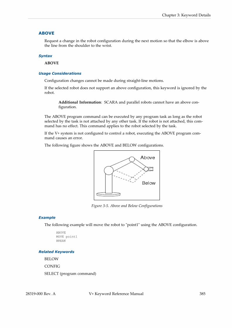
Chapter 3: Keyword Details
ABOVE
Request a change in the robot configuration during the next motion so that the elbow is abovethe line from the shoulder to the wrist.
Syntax
ABOVE
Usage Considerations
Configuration changes cannot be made during straight-line motions.
If the selected robot does not support an above configuration, this keyword is ignored by therobot.
Additional Information: SCARA and parallel robots cannot have an above con-figuration.
The ABOVE program command can be executed by any program task as long as the robotselected by the task is not attached by any other task. If the robot is not attached, this com-mand has no effect. This command applies to the robot selected by the task.
If the V+ system is not configured to control a robot, executing the ABOVE program com-mand causes an error.
The following figure shows the ABOVE and BELOW configurations.
Figure 3-5. Above and Below Configurations
Example
The following example will move the robot to "point1" using the ABOVE configuration.
ABOVEMOVE point1BREAK
Related Keywords
BELOW
CONFIG
SELECT (program command)
28319-000 Rev. A V+ Keyword Reference Manual 385

386 V+ Keyword Reference Manual 28319-000 Rev. A
3.4 Program Command Keywords
SELECT (monitor command)
SELECT (real-valued function)

Chapter 3: Keyword Details
ACCEL
Set acceleration and deceleration for robot motions and optionally specify a defined accel-eration profile.
Syntax
ACCEL (profile) acceleration, deceleration
Usage Considerations
The ACCEL program command can be executed by any program task as long as the robotselected by the task is not attached by any other task. This command applies to the robot selec-ted by the task.
If the V+ system is not configured to control a robot, executing this command causes the error*Robot not attached to this program*.
Before an acceleration / deceleration profile can be used, it must be defined for the selectedrobot (profile 0 is always defined).
If an acceleration profile that is not defined is initially specified in the program, the systemwill default to acceleration profile 1 for eCobra and Viper robots.
If an acceleration profile that is not defined is initially specified in the program, the systemwill default to acceleration profile 2 for iX3 and iX4 robots.
If an acceleration profile that is defined (2, for example) is specified in the program and thenlater in the same program, an acceleration profile is specified that does not exist (7, forexample), the program will continue to use the previously specified profile (2, for example).
If a parameter is omitted, the current setting remains in effect.
Parameters
profile Optional integer specifying the acceleration profile to use. Acceptablevalues are 0 to 8, depending on the number of defined profiles. Thedefault is the last specified profile.
acceleration Optional real value, variable, or expression considered as a per-centage of the maximum possible acceleration.
deceleration Optional real value, variable, or expression considered as a per-centage of the maximum possible deceleration.
The value should normally be in the range of 1 to 100. If an out-of-range value is specified, the nearest limit will be used.
Details
If profile 0 is used, a square wave acceleration profile is generated at the beginning and end ofthe motion.
If a profile is specified, that profile is invoked for subsequent robot motions. Defined profilesset the maximum rate of change of the acceleration and deceleration. The values set with thiscommand define the maximum acceleration and deceleration magnitudes that are achieved.
28319-000 Rev. A V+ Keyword Reference Manual 387

388 V+ Keyword Reference Manual 28319-000 Rev. A
3.4 Program Command Keywords
When the V+ system is initialized, the profile, acceleration, and deceleration values are set toinitial values. The initially selected profile may be 0, 1, or 2 depending on the type of robot.The settings are not affected when program execution starts or stops or when a ZERO monitorcommand is processed.
Default acceleration and deceleration values of 100% are set for use with typical robot pay-loads and link inertias. However, because the actual attainable values vary greatly as a func-tion of the end-effector, payload, and the initial and final locations of a motion, accelerationsgreater than 100% may be permitted for your robot. If you specify a higher acceleration ordeceleration than is permitted, the default values are used.
You can use the ACCEL(3) and ACCEL(4) function statements to determine the maximumallowable acceleration and deceleration settings.
For a given motion, the maximum attainable acceleration may be less than what is requested.This occurs when a profile with a nonzero acceleration ramp time is used and there is insuf-ficient time to reach the maximum acceleration. A specific time must elapse before the accel-eration can be changed from 0 to the specified maximum value. If the maximum accelerationcannot be achieved, the trapezoidal profile is reduced to a triangular shape. This occurs dur-ing the following circumstances.
l The motion is too short. In this case, the change in position is achieved before the max-imum acceleration can be achieved.
l The maximum motion speed is too low. In this case, the maximum speed is achievedbefore the maximum acceleration.
In both of these situations, raising the maximum acceleration and deceleration values does notaffect the time for the motion.
Additional Information: If you increase the maximum acceleration and decel-eration values but the motion time does not change, try increasing the programspeed, switch to an acceleration profile that allows faster acceleration ramptimes, or switch to acceleration profile 0 which specifies a square-wave accel-eration profile.
NOTE: This type of acceleration limiting cannot occur with acceleration profile0 because a square-wave acceleration instantaneously changes acceleration val-ues without ramping.
Examples
The following example sets the default acceleration time to 50% of normal and the decel-eration time to 30% of normal.
ACCEL 50, 30
The following example changes the deceleration time to 60% of normal and does not changethe acceleration time.
ACCEL ,60
The following example reduces the acceleration and deceleration to one half of their currentsettings.

Chapter 3: Keyword Details
ACCEL ACCEL(1)/2, ACCEL(2)/2
The following example invokes defined profile 2 and sets the acceleration magnitude to 80%of the defined rate.
ACCEL (2) 80
Related Keywords
ACCEL (real-valued function)
DURATION
SCALE.ACCEL
SELECT
SELECT (real-valued function)
SELECT (monitor command)
SPEED
28319-000 Rev. A V+ Keyword Reference Manual 389

390 V+ Keyword Reference Manual 28319-000 Rev. A
3.4 Program Command Keywords
ALIGN
Align the robot tool Z-axis with the nearest world axis.
Syntax
ALIGN
Usage Considerations
The ALIGN program command can be executed by any program task as long as the task hasattached a robot. The command applies to the robot selected by the task.
If the system is not configured to control a robot, executing this command causes an error.
Details
The ALIGN program Command causes the tool to be rotated so that its Z-axis is aligned par-allel to the nearest axis of the world coordinate system. This command is primarily useful foraligning the tool before a series of locations is taught. This typically accomplished with theuse of the DO monitor command.
Example
The following example will move the robot to "point1" and align the tool's z-axis to thenearest world axis.
MOVE point1ALIGN
Related Keywords
SELECT (program command)
SELECT (monitor command)
SELECT (real-valued function)

Chapter 3: Keyword Details
ALTER
Specify the magnitude of the real-time path modification that is to be applied to the robotpath during the next trajectory computation.
Syntax
ALTER Dx, Dy, Dz, Rx, Ry, Rz
Usage Considerations
This program command can be executed by the task that is controlling a robot in alter modeor by any other task that has selected the robot (using the SELECT keyword).
Additional Information: Refer to the ALTON program command for moreinformation about enabling alter mode.
This command is ignored if the selected robot is not in alter mode.
When alter mode is enabled, this command should be executed once during each trajectorycycle. If this command is executed more often, only the last set of values defined during eachcycle will be used.
Parameters
DxDyDz
RxRyRz
Optional real values, variables, or expressions that define the translationsalong, and the rotations about, the X, Y, and Z axes.
In cumulative mode, omitted coordinates are interpreted as 0. In non-cumu-lative mode, omitted coordinates default to the values specified in the previousALTER command.
Distances are interpreted as millimeters; angles are interpreted as degrees.
Details
After alter mode has been enabled with the ALTON program command, this commandshould be executed once each trajectory-generation cycle to specify the amount by which thepath is to be modified. The coordinates defined by this command are interpreted according tothe modes specified by the ALTON program command that initiated alter mode.
Example
The following statements can be embedded in a program loop that uses sensor data to controlthe motion of the robot.
ALTER 0.1*sx, , 0.2*sz
WAIT
Related Keywords
ALTOFF
ALTON
28319-000 Rev. A V+ Keyword Reference Manual 391

392 V+ Keyword Reference Manual 28319-000 Rev. A
3.4 Program Command Keywords
STATE
Chapter 3: Keyword Details
ALTOFF
Terminate real-time path-modification mode (alter mode).
Syntax
ALTOFF
Usage Considerations
A robot must be attached by the program task prior to executing this program command.
Turning OFF alter mode causes a break in continuous-path motion.
Details
This program command suspends program execution until any previous robot motion hasbeen completed and then turns OFF real-time path modification mode (alter mode). After altermode is OFF, the robot position is at a final location that reflects both the destination of thelast robot motion and the total alter correction that has been applied.
Related Keywords
ALTER
ALTON
STATE
28319-000 Rev. A V+ Keyword Reference Manual 393

394 V+ Keyword Reference Manual 28319-000 Rev. A
3.4 Program Command Keywords
ALTON
Enable real-time path-modification mode (alter mode) and specify the way in which altercoordinate information will be interpreted.
Syntax
ALTON mode
Usage Considerations
A robot must be attached by the program task prior to executing this program command.
Alter mode cannot be active at the time this program command is executed.
Any motions that are performed while alter mode is enabled must be of the straight-linemotion type and cannot be specified relative to a conveyor belt.
For V+ , you can modify the robot path by periodically adding the compensation values,which are requested from NJ-series Robot Integrated CPU Unit. Refer to the NJ-series RobotIntegrated CPU Unit User's Manual (Cat. No. O037).
Parameters
mode Optional real value, variable, or expression that defines how path-modi-fication data specified by subsequent ALTER commands are to be inter-preted. The mode value is interpreted as a sequence of bit flags that aredetailed below. The bits are assumed to be clear if the mode parameter isomitted.
Bit 1 (LSB): Accumulate Corrections (mask value = 1)
If this bit is ON, coordinate values specified by subsequent ALTER com-mands are interpreted as incremental and are accumulated. If this bitOFF, each set of coordinate values is interpreted as the total (non-cumulative) correction to be applied.
Bit 2: World Coordinates (mask value = 2)
If this bit is ON, coordinate values specified by subsequent ALTER com-mands are interpreted to be in the world coordinate system. If this bit isOFF, coordinates are interpreted to be in the tool coordinate system.
Bit 3: Period Modification from NJ-series Robot IntegratedCPU Unit
If this bit is ON, coordinate values are periodically requested from theNJ-series Robot Integrated CPU Unit.
This keyword cannot be used at the same time with the ALTERkeyword. This condition will return a -621 *(Robot Interlocked)* mes-sage.
This bit should not be ON while bit 1 is ON. This condition will return a-407 *(Invalid Argument)* message.

Chapter 3: Keyword Details
Details
This program command initiates the real-time path-modification (alter) functionality. Afterthis command is executed, the coordinate values specified by ALTER commands will auto-matically be superimposed on the nominal path computed by the V+ trajectory generator dur-ing all subsequent robot motions. The corrections can be applied in all six degrees of freedomand they can be specified as cumulative or noncumulative values in world or tool coordinates.
Additional Information: RX, RY, and RZ angles represent an extrinsic rotationand are different than the intrinsic rotation yaw, pitch, and roll angles of trans-formation variables.
Once alter mode is initiated, the robot location is corrected during all subsequent motions andbetween motions if breaks occur between continuous-path segments. Alter mode is terminatedby any of the following actions.
l Executing an ALTOFF program command
l Detaching the robot
l Prematurely terminating a robot motion
l Stopping program execution
Example
The following example will initiate alter mode and interpret subsequent ALTER commands astotal corrections (bit 1 is OFF) and world-coordinate (bit 2 is ON) corrections to the nominalpath of the robot.
ALTON 2
Related Keywords
ALTER
ALTOFF
STATE
28319-000 Rev. A V+ Keyword Reference Manual 395

396 V+ Keyword Reference Manual 28319-000 Rev. A
3.4 Program Command Keywords
ANY
Signal the beginning of an alternative group of commands for the CASE structure.
Syntax
ANY
Usage Considerations
The ANY statement must be within a CASE structure.
Details
Refer to CASE on page 426 for more information.
Examples
Refer to CASE on page 426 for more information.
Related Keywords
CASE
VALUE

Chapter 3: Keyword Details
APPRO
Start a robot motion toward a location defined relative to specified location with joint-inter-polated motion.
Syntax
APPRO location, distance
Usage Considerations
The APPRO program command can be executed by any program task as long as the task hasattached a robot. The command applies to the robot selected by the task.
If the V+ system is not configured to control a robot, executing these commands will cause anerror.
Parameters
location Transformation value that defines the basis for the final location.
distance Real-valued expression that specifies the distance along the robot toolZ-axis between the specified location and the actual desired des-tination.
A positive distance sets the tool back (negative tool Z-axis) from thespecified location. A negative distance offsets the tool forward (pos-itive tool Z-axis).
Details
This command initiates a robot motion to the orientation described by the given locationvalue. The position of the destination location is offset from the given location by the distancegiven, measured along the Z-axis of the specified location in the negative direction.
Example
The following example moves the tool by joint-interpolated motion to a location "offset" mil-limeters from that defined by the transformation "place".
APPRO place,offset
Related Keywords
DEPART
DEPARTS
MOVE
MOVES
28319-000 Rev. A V+ Keyword Reference Manual 397

398 V+ Keyword Reference Manual 28319-000 Rev. A
3.4 Program Command Keywords
APPROS
Start a robot motion toward a location defined relative to specified location with straight-linemotion.
Syntax
APPROS location, distance
Function
Usage Considerations
APPROS causes a straight-line motion, during which no changes in configuration are per-mitted.
The APPROS program command can be executed by any program task as long as the task hasattached a robot. The command applies to the robot selected by the task.
If the V+ system is not configured to control a robot, executing these commands will cause anerror.
Parameters
location Transformation value that defines the basis for the final location.
distance Real-valued expression that specifies the distance along the robot toolZ-axis between the specified location and the actual desired des-tination.
A positive distance sets the tool back (negative Z-axis) from the spe-cified location. A negative distance offsets the tool forward (positiveZ-axis).
Details
This command initiates a robot motion to the orientation described by the given locationvalue. The position of the destination location is offset from the given location by the distancegiven, measured along the Z-axis of the specified location in the negative direction.
Example
The following example moves the tool along a straight-line to a location 50 millimeters fromthat defined by the transformation "place" with the offset along the resultant Z-axis to a loc-ation beyond the location "place".
APPROS place,-50
Related Keywords
DEPART
DEPARTS
MOVE

Chapter 3: Keyword Details
MOVES
28319-000 Rev. A V+ Keyword Reference Manual 399

400 V+ Keyword Reference Manual 28319-000 Rev. A
3.4 Program Command Keywords
ATTACH
Make a device available for use by the application program.
Syntax
ATTACH (lun, mode) $device
Usage Considerations
The robot is automatically attached when the EXECUTE monitor command or program com-mand is processed for task 0 except when the DRY.RUN system switch is enabled. All theother logical units are automatically detached when program execution begins.
It is recommended to use the IOSTAT real-valued function with the ATTACH program com-mand to monitor the successful completion of the operation. Refer to the example below formore information.
If the Monitor Window or the pendant was attached when a program stopped executing, it isautomatically reattached if execution of the program is resumed with the PROCEED, RETRY,SSTEP, or XSTEP keywords.
Parameters
lun The logical unit number to associate with the attached device. The inter-pretation of this parameter depends on the value of the mode para-meter as described below.
If bit 3 of the mode parameter is 0, this parameter is optional anddefaults to 0 to attach the robot.
It can be a real value, variable, or expression interpreted as an integerin the range 0 to 24 that specifies the logical unit to be attached. If thelogical unit specified is not 0, you can use the $device parameter to over-ride the default device for the logical unit.
If bit 3 of the mode parameter is 1, this parameter is required and mustbe a real variable. In this case, the V+ system attaches the device spe-cified by the $device parameter and automatically assigns a logical unitnumber to this parameter. If all the logical units are in use, the para-meter is set to -1 . V+ assigns a value to the lun parameter even if theATTACH request fails.
mode Optional real value, variable, or expression (interpreted as a bit field)that defines how the ATTACH request is to be processed. The value spe-cified is interpreted as a sequence of bit flags as detailed below. The bitsare assumed to be clear if no value is specified.
Bit 1 (mask value = 1, LSB): Queue (0) versus Fail (1)
This bit controls how the device driver responds to the attach requestfrom the control program task. The device driver is an internal systemtask that is separate from the control program task. For most applic-ations, this bit should be ON.

Chapter 3: Keyword Details
If this bit is OFF and the device is already attached by another controlprogram task, the driver queues this attach request and signals the con-trol program that there is an error in the attachment request. In thiscase, the operation IOSTAT(lun) returns a negative number. The attach-ment will complete when the device becomes available.
If this bit is ON and the device is already attached by another controlprogram task, the device driver immediately signals that the attachrequest has failed.
Bit 2 (mask value = 2): Wait (0) versus No-wait (1)
This bit controls whether or not the control program task waits for aresponse from the device driver. For most applications, this bit shouldbe OFF.
If this bit is OFF, program execution waits for the device driver to signalthe result of the attach request.
If this bit is ON, program execution does not wait for the result of theattach request. The program must then use the function statementIOSTAT(lun) to determine if the attachment has succeeded (see above).If the program attempts to read from or write to the logical unit whilethe attachment is pending, program execution then waits for the attach-ment to complete.
Bit 3 (mask value = 4): Specify LUN (0) versus Have LUNAssigned (1)
This bit determines how the lun parameter is processed.
If this bit is OFF, the device corresponding to the value of lun isattached. The value of the lun parameter specifies the device that is tobe attached except when a different device is specified with the $deviceparameter (refer to the Details section below).
If this bit is ON, the device to be attached is specified by the $deviceparameter which should not be omitted. In this case, a logical unit isautomatically selected and the value of the lun parameter is turned ONby the ATTACH keyword. V+ assigns a value to lun even if the ATTACHrequest fails. This mode cannot be used to attach the robot or pendant.
$device Optional string constant, variable, or expression that identifies thedevice to be attached. If bit 3 of the mode parameter is 0, this para-meter is used to override the default device associated with the value ofthe lun parameter (the logical unit 0 is always the robot).
The acceptable device names are provided below.
l DISK - Physical drive in the controller (disk or Secure Digitalcard)
l MONITOR - The Monitor Windowl SERIAL:n - Reserved for future use.l SYSTEM - Disk device set with the CD or DEFAULT keywordsl TCP - TCP protocol device driverl TFTP - Reserved for future use.l UDP - UDP protocol device driver
28319-000 Rev. A V+ Keyword Reference Manual 401

402 V+ Keyword Reference Manual 28319-000 Rev. A
3.4 Program Command Keywords
Details
The robot must remain attached by a robot control program to execute motion of the robot.When the robot is detached, you can use the manual control pendant to move the robot underdirections from the application program. This is useful, for application setup sequences forexample.
Program task 0 automatically attaches robot 1 when that task begins execution. A robot con-trol program executed by any of the other program tasks must explicitly attach the robot.
Any task can attach to any robot, provided that the robot is not already attached by a differenttask. The robot that is attached by an ATTACH command is the one that was last specified bya SELECT program command executed by the current task. If no SELECT program commandhas been executed, then robot 1 is attached. The SELECT program command can be used toselect a different robot only if no robot is currently attached to the task.
To successfully attach the robot, the system must be in COMP mode. Otherwise (for mode bit1 = 0), program execution is suspended without notice until the system is placed in COMPmode. This situation can be avoided with the following methods.
l Use the STATE function to determine if the system is in COMP mode before executingan ATTACH command.
l Set bit 1 in the mode value and use the IOSTAT function to determine the success ofthe ATTACH command.
When the Monitor Window (logical unit 4) is attached, all keyboard input will be buffered forinput requests by the program.
NOTE: When the Monitor Window is attached, a user is not able to typeABORT to terminate program execution. The program must provide a means forfielding a termination request or you must use the pendant or emergency stopswitch to stop program execution.
When a DISK device is attached, it allows a program to read and write data from and to files(DISK refers to the Secure Digital card). One of the FOPEN program commands must be usedto specify which file to access. WRITE and READ program commands can then be used totransfer information to and from the file. FCMND program commands can be used to sendcommands to the file system.
When mode bit 3 = 0 and the $device parameter is omitted, the logical unit number implicitlyspecifies the corresponding default device from the following table.
Number Device
0 Robot (default when lun is omitted)
1 Reserved for future use
2, 3, 4 Monitor Window
5, 6, 7, 8 Disk
9 No default device
3.1Default Device Numbers Supplied by the LUN

Chapter 3: Keyword Details
Number Device
10, 11, 12, 13 Reserved for future use
14, 15, 16 No default device
17, 18, 19 Disk
20, 21, 22, 23, 24 Reserved for future use
25, 26, 27, 28, 29, 30, 31 No default devices
Examples
The following example will attempt to attach the robot for an amount of time specified bytimer 3 (5 seconds). The IOSTAT real-valued function will return information to monitor thesuccess or failure of the ATTACH operation during this time interval. If the attach operation isnot successful within the 5 second interval, a message will be displayed in the Monitor Win-dow.
start = TIMER(-3)DO
ATTACH (0,1)UNTIL (IOSTAT(0, 0) == 1) OR ((TIMER(-3) - start) > 5)
IF IOSTAT(0 , 0) < 1 THENTYPE "The following error occurred: ", $ERROR(IOSTAT(0,0))TYPE "The program will be interrupted!"
HALTEND
Related Keywords
DETACH
FSET
IOSTAT
SELECT (program command)
28319-000 Rev. A V+ Keyword Reference Manual 403

404 V+ Keyword Reference Manual 28319-000 Rev. A
3.4 Program Command Keywords
AUTO
Declare temporary variables that are automatically created on the program stack when the pro-gram is entered.
Syntax
AUTO type variable, ..., variable
Usage Considerations
AUTO (automatic) variables have an undetermined value when a program is first entered, butthey are not considered undefined. They have no value after the program exits.
AUTO commands must appear before any executable keyword in the program. Only the.PROGRAM command, comments, blank lines, GLOBAL and LOCAL commands, and otherAUTO commands may precede this command.
If a variable is listed in an AUTO command, any global variables with the same name cannotbe accessed directly by the program.
The values of AUTO variables are not saved by the STORE or restored by the LOAD com-mands.
Parameters
type If the type parameter is specified, all the variables must match thattype (REAL, DOUBLE, or LOC). Array variables must have theirindexes specified explicitly, indicating the highest valid index for thearray.
If this keyword is omitted, the type of each variable is determined byits use within the program. An error is generated if the type cannot bedetermined from usage.
LOC Location variable (transformation or precisionpoint).
REAL Single-precision real variable.
DOUBLE Double-precision real variable.
Refer to the GLOBAL command for details on thedefault type.
variable Name of a variable of any data type available with V+ (belt, precisionpoint, real-value, string, and transformation). Each variable can be asimple variable or an array. If the type parameter is specified, all thevariables must match that type. Array variables must have theirindexes specified explicitly, indicating the highest valid index for thearray.

Chapter 3: Keyword Details
Details
This command is used to declare variables to be defined only within the current program. AnAUTO variable can be referenced only by the specific calling instance of a program. Thenames of AUTO variables can be selected without regard for the names of variables defined inany other programs.
AUTO variables are allocated each time the program is called and their values are not pre-served between successive subroutine calls. These values can be displayed with monitor com-mands only when the program task is inactive, but is on an execution stack. When a programis first entered, AUTO variables have arbitrary, undetermined values but they are not con-sidered undefined. AUTO variables are lost when the program exits.
Unlike a LOCAL variable, a separate copy of an AUTO variable is created each time a pro-gram is called, even if it is called simultaneously by several different program tasks or calledrecursively by a single task. If a program that uses LOCAL or global variables is called by sev-eral different program tasks or recursively by a single task, the values of those variables canbe modified by the different program instances and can cause unpredictable program errors.Therefore, AUTO variables should be used for all temporary local variables to minimize thechance of such errors.
Variables can be defined as GLOBAL, AUTO, or LOCAL. An attempt to define AUTO,GLOBAL, or LOCAL variables with the same name will result in the error message "Attemptto redefine variable class".
Variables can be defined only once within the same context (AUTO, LOCAL, or GLOBAL).Attempting to define a variable more than once with a different type will result in the errormessage "Attempt to redefine variable type".
AUTO array variables must have the size of each dimension specified in the AUTO statement.Each index specified must represent the last element to be referenced in that dimension. Thefirst element allocated always has index value zero. For example, the following statementallocates a transformation array with 24 elements. The left-hand index ranges from 0 to 3, andthe right-hand index ranges from 0 to 5.
AUTO LOC points[3,5]
The storage space for AUTO variables is allocated on the program execution stack. If the stackis too small for the number of AUTO variables declared, the task execution will stop with theerror message "Too many subroutine calls". If this happens, use the STATUS monitor com-mand to determine how much additional stack space is required. Then, use the STACK mon-itor command to increase the stack size and then issue the RETRY monitor command tocontinue program execution.
AUTO variables cannot be deleted with the DELETE_ commands.
AUTO variables can be referenced with monitor commands such as DELETE_, DO , HERE ,LIST_, TOOL by using the optional context specifier @ as shown in the example below.
command @task:program command_arguments
Examples
The following example statement will declare the variables loc.a, $ans, and i to be AUTO inthe current program. The variable types for loc.a and i must be clear from their use in the
28319-000 Rev. A V+ Keyword Reference Manual 405

406 V+ Keyword Reference Manual 28319-000 Rev. A
3.4 Program Command Keywords
program.
AUTO loc.a, $ans, i
The following example will declare the variables i, j, and tmp[ ] to be AUTO, real variables inthe current program. Array elements tmp[0] through tmp[10] are defined.
AUTO REAL i, j, tmp[10]
The following example will declare the variable "loc" to be an AUTO variable in the currentprogram. The variable type of "loc" must be determined by its use in the program. Since "loc"appears by itself, it is not interpreted as the type-specifying keyword.
AUTO loc
Related Keywords
GLOBAL
LOCAL
STACK
DO
HERE
TOOL

Chapter 3: Keyword Details
BASE
Translate and rotate the world reference frame relative to the robot.
Syntax
BASE X_shift, Y_shift, Z_shift, Z_rotation
Usage Considerations
The BASE program command causes a break in continuous-path motion.
This command can be executed by any program task as long as the robot selected by the taskis not attached by any other task. This command applies to the robot selected by the task.
If the V+ system is not configured to control a robot, use of the BASE command will cause anerror.
Parameters
X_shift Optional real-valued expression describing the X component in the nor-mal world coordinate system of the origin point for the new coordinatesystem. Zero is assumed if no value is provided.
Y_shift Optional real-valued expression describing the Y component in the nor-mal world coordinate system of the origin point for the new coordinatesystem. Zero is assumed if no value is provided.
Z_shift Optional real-valued expression describing the Z component in the nor-mal world coordinate system of the origin point for the new coordinatesystem. Zero is assumed if no value is provided.
Z_rotation Optional real-valued expression describing the rotation about the Z-axis in the normal world coordinate system of the origin point for thenew coordinate system. Zero is assumed if no value is provided.
Details
When the V+ system is initialized, the origin of the reference frame of the robot is assumed tobe fixed in space such that the X-Y plane is at the robot mounting surface, the X-axis is in thedirection defined by joint 1 equal to zero, and the Z-axis coincides with the joint-1 axis.
The BASE command offsets and rotates the reference frame as specified above. This is usefulif the robot is moved after locations have been defined for an application.
If the robot is moved relative to those locations to a point translated by X_shift, Y_shift, Z_shift and rotated by Z_rotation degrees about the Z axis, a BASE command can be used tocompensate so that motions to the previously defined locations will still be as desired afterrobot locations have been defined by transformations relative to the robot reference frame.
Another convenient use for the BASE command is to realign the X and Y coordinate axes sothat SHIFT functions cause displacements in desired, nonstandard directions.
28319-000 Rev. A V+ Keyword Reference Manual 407

408 V+ Keyword Reference Manual 28319-000 Rev. A
3.4 Program Command Keywords
NOTE: The BASE program command has no effect on locations defined as pre-cision points. The arguments for the BASE program command describe the dis-placement of the robot relative to its normal location.
Additional Information: The BASE function can be used with the LISTL mon-itor command to display the current BASE setting in the Monitor Window.
Examples
The following example redefines the world reference frame because the robot has been shiftedby "xbase" millimeters in the positive X direction and 50.5 millimeters in the negative Z dir-ection and has been rotated 30 degrees about the -axis.
BASE xbase,, -50.5, 30
The following example redefines the world reference frame to shift all locations 100 mil-limeters in the negative X direction and 50 millimeters in the positive Z direction from theirnominal location. The arguments for this statement describe movement of the robot referenceframe relative to the robot and have an opposite effect on locations relative to the robot.
BASE 100,, -50
Related Keywords
BASE (transformation function)
SELECT (monitor command)
SELECT (program command)
SELECT (real-valued function)

Chapter 3: Keyword Details
BELOW
Request a change in the robot configuration during the next motion so that the elbow is belowthe line from the shoulder to the wrist.
Syntax
BELOW
Usage Considerations
Configuration changes cannot be made during straight-line motions.
If the selected robot does not support a below configuration, this command is ignored by therobot.
Additional Information: SCARA and parallel robots cannot have a below con-figuration.
The BELOW program command can be executed by any program task as long as the robotselected by the task is not attached by any other task. If the robot is not attached, this com-mand has no effect. This command applies to the robot selected by the task.
If the V+ system is not configured to control a robot, executing the BELOW command willcause an error.
The following figure shows the ABOVE and BELOW configurations.
Figure 3-6. Above and Below Configurations
Example
The following example will move the robot to "point1" using the BELOW configuration.
BELOWMOVE point1BREAK
Related Keywords
ABOVE
CONFIG
SELECT (program command)
28319-000 Rev. A V+ Keyword Reference Manual 409

410 V+ Keyword Reference Manual 28319-000 Rev. A
3.4 Program Command Keywords
SELECT (monitor command)
SELECT (real-valued function)

Chapter 3: Keyword Details
BITS
Set or clear a group of digital signals based on a value.
Syntax
BITS first_sig, num_sigs = value
Usage Considerations
Both external digital output signals and internal software signals can be referenced. Input sig-nals must not be referenced. Input signals are displayed by the monitor command IO 1.
No more than 32 signals can be set at one time.
Any group of up to 32 signals can be set, provided that all the signals in the group are con-figured for use by the system.
All V+ digital output commands do not wait for a V+ cycle and will turn ON outputs imme-diately, excluding latch inputs. Digital inputs are checked approximately every 4 ms for Stand-ard Control systems and approximately 8 ms or 16 ms for Robot Integrated systems..
Parameters
first_sig Real-valued expression defining the lowest-numbered signal to beaffected.
num_sigs Optional real-valued expression specifying the number of signals to beaffected. A value of 1 is assumed if none is specified. The maximumvalid value is 32.
value Real-valued expression defining the value to be set on the specified sig-nals. If the binary representation of the value has more bits than num_sigs, only the lowest num_sigs signals will be affected.
Details
This program command turns ON or OFF one or more external output signals or internal soft-ware signals based on the value to the right of the equal sign. The effect of this command is toround the value parameter to an integer and then turn ON or OFF a number of signals basedon the individual bits of the binary representation of the integer.
Examples
The following example sets external output signals 1-8 (8 bits) to the binary representation ofthe current monitor speed setting.
BITS 1,8 = SPEED(1)
If the monitor speed were set to 50% (0011 0010 binary), then signals 1-8 are set as followsafter the statement above is issued.
signal 1: 0 (OFF) signal 5: 1 (ON)
28319-000 Rev. A V+ Keyword Reference Manual 411

412 V+ Keyword Reference Manual 28319-000 Rev. A
3.4 Program Command Keywords
signal 2: 1 (ON) signal 6: 1 (ON)
signal 3: 0 (OFF) signal 7: 0 (OFF)
signal 4: 0 (OFF) signal 8: 0 (OFF)
The following example sets external output signals 5-9 (4 bits) to the binary representation ofthe BCD digit 7
BITS 5,4 = BCD(7)
The following example sets external output signals 1-8 (8 bits) to the binary representation ofthe constant 255, which is 11111111 (binary). Signals 1-8 will all be turned ON.
BITS 1,8 = 255
Related Keywords
BITS (real-valued function)
IO
RESET
SIG
SIG.INS
SIGNAL (monitor command)
SIGNAL (program command)

Chapter 3: Keyword Details
BRAKE
Abort the current robot motion.
Syntax
BRAKE
Usage Considerations
The BRAKE program command can be executed by any program task includinga task that is not actively controlling the robot.
This command does not cause a BREAK to occur.
If more than one robot is connected to the controller, this command applies tothe robot currently selected (refer to the SELECT keyword).
If the V+ system is not configured to control a robot, the BRAKE command willnot generate an error due to the absence of a robot.
Details
The BRAKE program command causes the current robot motion to be abortedimmediately. In response to this command, the robot will decelerate to a stopand then begin the next motion without waiting for position errors to null.
NOTE: Program execution is not suspended until the robotmotion stops.
Example
The following example initiates a robot motion and simultaneously tests for acondition to be met. If the condition is met, the motion is stopped with a BRAKEcommand. Otherwise, the motion is completed normally.
MOVES step[1]DO
IF SIG(1023) THENBRAKEEXIT
ENDUNTIL STATE(2) == 2MOVES step[2]
Related Keyword
BREAK
28319-000 Rev. A V+ Keyword Reference Manual 413

414 V+ Keyword Reference Manual 28319-000 Rev. A
3.4 Program Command Keywords
BREAK
Suspend program execution until the current motion completes.
Syntax
BREAK
Usage Considerations
The BREAK program command is only used to wait for motion by the robotattached to the current task.
If the V+ system is not configured to control a robot, executing the BREAK com-mand will cause an error.
Details
This command has two effects.
1. Program execution is suspended until the robot reaches its current des-tination.
NOTE: BREAK cannot be used to make one task wait untila motion is completed by another task.
2. The continuous-path transition between the current motion and that com-manded by the next motion statement is broken. The two motions are pre-vented from being merged into a single continuous path.
The BREAK command causes continuous-path processing to terminate by block-ing V+ program execution until the motion ends. CPOFF program commandcauses the trajectory generator to terminate continuous path without affectingthe forward processing of the V+ program.
Example
The following example will move the robot to "point2" after the move to "point1"is completed without blending or forward processing.
MOVE point1BREAKMOVE point2
Related Keywords
BRAKE
CPOFF
CPON
CP
SELECT (program command)
SELECT (monitor command)

Chapter 3: Keyword Details
SELECT (real-valued function)
28319-000 Rev. A V+ Keyword Reference Manual 415

416 V+ Keyword Reference Manual 28319-000 Rev. A
3.4 Program Command Keywords
BY
Completes the syntax of the SCALE and SHIFT functions.
Syntax
SCALE(transformation BY value)
SHIFT(transformation BY value, value, value)
Examples
SET new.trans = SCALE(old.trans BY scale.factor)
SET new.trans = SHIFT(old.trans BY x,y,z)
Related Keywords
SCALE
SHIFT

Chapter 3: Keyword Details
CALIBRATE
Initialize the robot positioning system with the robot's current position.
Syntax
CALIBRATE mode, status, robot
Usage Considerations
Normally, the keyword is issued with mode equal to zero.
The command has no effect on a robot when the DRY.RUN switch is enabled.
If the robot is to be moved, the CALIBRATE program command or monitor com-mand keywords must be processed every time system power is turned ON andthe system is booted from disk. If a robot has the option to execute CALIBRATEat boot enabled, then it will perform the CALIBRATION operation upon bootup.If this option is not enabled (or not supported for that robot), then this keywordmust be executed after high power is enabled.
Refer to Sysmac Studio Robot Integrated System Building Function with Robot Integ-rated CPU Unit Operation Manual (Cat. No. W595) / Automation Control Envir-onment (ACE) Version 4 User's Manual (Cat. No. I633) for more information aboutenabling the option to execute CALIBRATE at boot.
Robots cannot be moved with the manual control pendant or under program con-trol if the robot is not calibrated until the CALIBRATE program command ormonitor command keyword has been processed.
The CALIBRATE keyword may operate differently for each type of robot. Forrobots with non-absolute (e.g., incremental) encoders, this keyword causes therobot to move. In this case, the robot must be far enough from the limits of theworking range that it will not move out of range during the calibration process.Refer to the CALIBRATE monitor command keyword for details of the robotmotion.
If the V+ system is not configured to control a robot, executing the CALIBRATEkeyword causes an error.
28319-000 Rev. A V+ Keyword Reference Manual 417

418 V+ Keyword Reference Manual 28319-000 Rev. A
3.4 Program Command Keywords
Parameters
mode Optional real expression that indicates what part of cal-ibration is to be performed:
Value ofmode Interpretation
0(or omitted)
Perform a normal calibration.
In detail, the following operations are per-formed:
(a) Load the main calibration program if it isnot already in memory.
(b) Execute the main calibration programwith the load, execute, and delete flags set.This causes the robot-specific calibrationroutines to be loaded, the robots to be cal-ibrated, and the robot routines to bedeleted. The main calibration program is leftin memory.
1 Load the main calibration program if it is notalready in memory, and execute the maincalibration program with the load flag set.This causes the calibration program to loadthe applicable robot-specific calibrationroutines. Note that the calibration process isnot performed.
2 Execute the main calibration program(which must already be in memory) withthe execute flag set. That causes the sys-tem robot(s) to be calibrated, and all the cal-ibration programs to be left in memory.
3 Execute the main calibration program whichmust already be in memory with the deleteflag set. This causes the calibration programto delete the robot-specific calibrationroutines from memory. Note that the actualcalibration process is not performed and themain calibration program is left in memory.
status Optional real-valued variable that receives the exit statusreturned by the calibration program, or (in mode -1) fromV+ when trying to enter into the calibrate mode.
robot Optional real value, variable, or expression interpreted as aninteger that indicates the number of the robot affected. If theparameter is omitted or 0, all robots are affected. Otherwise,

Chapter 3: Keyword Details
only the setting for the specified robot is affected.
Details
When the calibration operation is started, V+ assumes that the robot is not cal-ibrated and restricts your ability to move the robot with the pendant or an applic-ation program.
NOTE: The COMP mode light on the pendant does not come onwhen the robot is not calibrated.
Robots with incremental encoders lose start-up calibration whenever systempower is switched OFF. As a safety measure, these robots also lose start-up cal-ibration whenever an *Encoder quadrature error* occurs for one of the robotjoints. Other servo errors that can cause the robot to lose calibration are *Un-expected zero index*, *No zero index*, and *RSC Communications Failure*.
NOTE: For the eCobra 600 and 800 robots, this operation causes asmall motion of joint 4 (theta).
If this program command attempts to load the main calibration program, thesame program, module, and file name, and search algorithm, are employed asfor the CALIBRATE monitor command.
If you wish to execute a CALIBRATE operation in task 0, it can be accomplishedby using the /C qualifier on the EXECUTE program command keyword in a pro-gram. With that qualifier specified, a program to calibrate the robot can run intask 0 even when the DRY.RUN system switch is disabled. A program runningin any task other than 0 can execute the CALIBRATE operation without specialconditions.
The CALIBRATE operation shall only be executed from one task at a time. If itmight be called from multiple tasks (from a REACTE program for example) thecall needs to be protected by a mutex using the TAS keyword (see examplebelow).
Examples
The following example can be used by any program task to perform start-up cal-ibration on the robot (if task 0 is used, the DRY.RUN system switch must beenabled before the program is executed).
DETACH()DISABLE DRY.RUNENABLE POWER
CALIBRATEATTACH()
The following example must be used if CALIBRATE is called from more thanone task.
GLOBAL en_po_lock
28319-000 Rev. A V+ Keyword Reference Manual 419

420 V+ Keyword Reference Manual 28319-000 Rev. A
3.4 Program Command Keywords
WHILE TAS(en_po_lock,TRUE) DOWAIT
END
ENABLE POWER
CALIBRATEATTACH()
en_po_lock = FALSE
Related Keywords
CALIBRATE (monitor command)
NOT.CALIBRATED
SELECT (program command)
SELECT (real-valued function)
TAS

Chapter 3: Keyword Details
CALL
Suspend execution of the current program and continue execution with a newsubroutine program.
Syntax
CALL program(arg_list)
Usage Considerations
External variable types cannot be used for the arg_list parameter.
Parameters
program Name of the new program to be executed.
arg_list Optional list of subroutine arguments separated by com-mas to be passed between the current program and thenew program. If no argument list is specified, the par-entheses after the program parameter can be omitted.
Arguments can be used to pass data to the called pro-gram, to receive results back, or a combination of both asdescribed below.
Each argument can be any one of the data types sup-ported by V+ (belt, precision point, real-value, string, andtransformation) and can be specified as a constant, a vari-able, or an expression (see note below). The type of eachargument must match the type of its counterpart in theargument list of the called program. An argument spe-cified as a variable can be a simple variable, an array ele-ment, or an array with one or more of its indexes leftblank (see below for more information).
NOTE: If a value is being passed back tothe calling program, the parameter must bespecified as a variable.
External variable types cannot be used.
Any argument can be omitted but the corresponding argu-ment in the called program will be undefined. If an argu-ment is omitted within the argument list, the separatingcomma must still be included. If an argument is omittedat the end of the list, the comma preceding the argumentcan also be omitted.
NOTE: Refer to the .PROGRAM programcommand for information on the effect ofomitting an argument.
28319-000 Rev. A V+ Keyword Reference Manual 421

422 V+ Keyword Reference Manual 28319-000 Rev. A
3.4 Program Command Keywords
Details
The CALL command causes execution of the current program to be suspendedtemporarily. Execution continues at the first step of the indicated new program,which is then considered a subroutine.
Execution automatically returns to the current program when a RETURN com-mand is executed in the subroutine. Execution continues with the keywordimmediately following the CALL command.
Subroutine arguments can be passed by value or by reference. When an argu-ment is passed by value, a copy of the argument value is passed to the sub-routine. Any changes to the corresponding subroutine argument in thesubroutine will not be passed back to the calling program. Any argument that isspecified as an expression or compound transformation will be passed by value.
When an argument is a scalar or array variable, it is passed by reference. Thatmeans a pointer to the variable is passed to the subroutine, which then workswith exactly the same variable as the calling program. If the called subroutinechanges the value of the variable, the value is also changed for the calling pro-gram. This can be especially significant, for example, if the same variable ispassed as two arguments of a subroutine call. Then, any change to either of thecorresponding subroutine arguments in the subroutine automatically changesthe other corresponding subroutine argument.
Note that an argument that is passed by reference (because it is a variable) cangenerally be forced to passage by value. The way that is done depends on thetype of the variable as shown in the following examples.
l For a real variable, passage by value can be forced by enclosing the vari-able in parentheses as shown below.
CALL prog_a((count))
l For a string variable, an empty string ("") can be added to the variable asshown below.
CALL prog_b($str.var+"")
l For a transformation variable (for example, start), an equivalent trans-formation value can be specified by a compound transformation con-sisting of the variable and the NULL transformation as shown below.
CALL prog_c(start:NULL)
As stated above, the items in the arg_list must match their corresponding itemsin the called subroutine. In addition to straightforward matches of scalar toscalar, and arrays of equal numbers of dimensions, there are several situations inwhich higher dimension arrays can be passed in place of lower dimensionarrays. For example, all the following cases are valid.
l Array element passed to a scalar:

Chapter 3: Keyword Details
CALL example(a[1]) ---> .PROGRAM example(b)CALL example(a[1,2]) ---> .PROGRAM example(b)CALL example(a[1,2,3]) ---> .PROGRAM example(b)
l One dimension of an array passed to a one-dimensional array:
CALL example(a[]) ---> .PROGRAM example(b[])CALL example(a[1,]) ---> .PROGRAM example(b[])CALL example(a[1,2,]) ---> .PROGRAM example(b[])
l Two dimensions of an array passed to a two-dimensional array:
CALL example(a[,]) ---> .PROGRAM example(b[,])CALL example(a[1,,]) ---> .PROGRAM example(b[,])
l Three dimensions of an array passed to a three-dimensional array:
CALL example(a[,,]) ---> .PROGRAM example(b[,,])
Examples
The following example executes the program named "pallet", passing to it apointer to the variable "count". When a RETURN command is executed in the"pallet" subroutine, control returns to the program containing the CALL com-mand and the "count" variable will contain the current value of the cor-responding subroutine argument.
CALL pallet(count)
The following example executes the program named "cycle". The value 1 ispassed to the first parameter of the program "cycle", its second parameter isundefined, and its third parameter receives the value of the expression n+3. Ifthe "cycle" program has more than three parameters, the remaining parametersare all undefined.
Because none of the arguments in the CALL command are variables, no data willbe returned by the program "cycle".
CALL cycle(1, , n+3)
Related Keywords
CALLS
RETURN
28319-000 Rev. A V+ Keyword Reference Manual 423

424 V+ Keyword Reference Manual 28319-000 Rev. A
3.4 Program Command Keywords
CALLS
Suspend execution of the current program and continue execution with a newsubroutine program specified with a string value.
Syntax
CALLS string(arg_list)
Usage Considerations
CALLS takes much longer to execute than the normal CALL command. CALLSshould be used only when necessary.
Parameters
string String value, variable, or expression defining the name of thenew program to be executed. The letters in the name can belowercase or uppercase and must be within 1 to 15 char-acters in length.
arg_list Optional list of subroutine arguments separated by commasto be passed between the current program and the new pro-gram. If no argument list is specified, the parentheses afterthe program parameter can be omitted. Refer to the CALLcommand for further information on subroutine arguments.
NOTE: Since the argument list is not specified as part of the stringparameter, all the subroutines called by a specific CALLS com-mand must have equivalent argument lists.
Details
The CALLS command functions almost exactly the same as the CALL command.The only difference between the two is the way the subroutine name is specified.CALL requires that the name be explicitly entered in the command step. CALLSpermits the name to be specified by a string variable or expression, which canhave its value defined when the program is executed. That allows the programto call different subroutines depending on the circumstances.
As with the CALL command, execution automatically returns to the current pro-gram when a RETURN command is executed in the subroutine. Execution con-tinues with the keyword immediately following the CALLS command.
Examples
The example below demonstrates how the CALLS command can be used toexecute a subroutine whose name is determined when the program is executed.
The program reads a set of four digital inputs (1001 to 1004) to determine whichof sixteen different part types applies and is returned to the "type" variable. The

Chapter 3: Keyword Details
part type is considered to be a hexadecimal number which is converted to thecorresponding ASCII character as the "$type" variable. Once the character isdefined, the appropriate subroutine ("part.0", "part.1", ..., "part.f") is called. Thepart-type value is also used to select the portion of the two-dimensional arrayargument that is passed to the subroutine.
type = BITS(1001,4)$type = $ENCODE(/H0, type)CALLS "part."+$type(arguments[type,], status)
This example can be made more robust by using the STATUS real-valued func-tion to make sure the proposed subroutine exists before it is called. Using thisfunction avoids possible errors from undefined program names.
Related Keywords
CALL
CALLS
.PROGRAM
RETURN
STATUS
28319-000 Rev. A V+ Keyword Reference Manual 425

426 V+ Keyword Reference Manual 28319-000 Rev. A
3.4 Program Command Keywords
CASE
Initiate processing of a CASE structure by defining the value of interest.
Syntax
CASE value OF
Usage Considerations
This command must be part of a complete CASE structure.
Parameter
value Real value, variable, or expression that defines the value tobe matched in the CASE structure to determine whichkeywords are executed.
Details
The CASE command is a flexible structure available in V+. It provides a meansfor executing one group of keywords from among any number of groups. Thecomplete syntax is as follows (the blank lines are not required).
CASE evaluation OFVALUE evaluation_condition_1,...:group_of_steps
VALUE evaluation_condition_2,...:group_of_steps
.
.
.ANYgroup_of_steps
END
The three vertical dots indicate that any number of VALUE steps can be used toexecute additional groups of keywords.
The ANY step listed above is optional. There can be only one ANY step in aCASE structure and it must mark the last group in the structure as shown above.
The ANY and END steps must be on lines by themselves as shown. However, aswith all instructions, those lines can have comments.
The CASE structure is processed as follows.
1. The expression following the CASE keyword is evaluated.2. All the VALUE steps are scanned until one is found to meet the eval-uation conditions.
3. Keywords following that VALUE step are executed.4. Execution continues at the first keyword after the END step.

Chapter 3: Keyword Details
If no VALUE step is found that meets the evaluation conditions and there is anANY step in the structure, then the keywords following the ANY step will beexecuted.
If no VALUE evaluation condition is met in the structure, and there is no ANYstep, none of the commands in the entire CASE structure are executed.
Examples
The following example shows the basic function of a CASE command:
CASE number OFVALUE 1:TYPE "one"
VALUE 2:TYPE "two"
ANYTYPE "Not one or two"
END
The following sample program prompts to enter a test value. If the value is neg-ative, the program displays a message and then exits. Otherwise, a CASEcommmand is used to classify the input value as a member of one of the fol-lowing three groups.
1. Even integers from 0 to 10.2. Odd integers from 0 to 10.3. All other numbers.
PROMPT "Enter a value from 0 to 10: ", xCASE x OFVALUE 0, 2, 4, 6, 8, 10:TYPE "The number", x, " is EVEN"
VALUE 1, 3, 5, 7, 9:TYPE "The number", x, " is ODD"
ANYTYPE x, " is not an integer from 0 to 10"
END
The following example shows a use of the CASE command to test Boolean con-ditions.
PROMPT "Enter a number", xCASE TRUE OFVALUE (x > 0):TYPE "The number was greater than 0."
VALUE (x == 0):TYPE "The number was equal to 0."
VALUE (x < 0):TYPE "The number was less than 0."
END
The following example demonstrates how to use the CASE command to evaluatestring data.
CASE TRUE OFVALUE ($string1=="hello"):
28319-000 Rev. A V+ Keyword Reference Manual 427

428 V+ Keyword Reference Manual 28319-000 Rev. A
3.4 Program Command Keywords
TYPE "string=hello"VALUE($string1=="world"):TYPE "string=world"
ANYTYPE "unknown string"
END
Related Keywords
ANY
END
TRUE
VALUE

Chapter 3: Keyword Details
CLEAR.EVENT
Clear an event associated with the specified task.
Syntax
CLEAR.EVENT task, flag
Parameters
task Optional real value, variable, or expression interpreted as aninteger that specifies the task for which the event is to becleared. The valid range is 0 to 6 or 0 to 27, inclusive. If thisparameter is omitted, the number of the current task is used.
flag Not used. Defaults to 1.
Details
This command clears the event associated with the specified task.
The default event cleared is the input / output completion event for which thestatement WAIT.EVENT 1 waits. This event is cleared by the execution (not thecompletion) of any input / output keyword operation.
Related Keywords
GET.EVENT
SET.EVENT
WAIT.EVENT
28319-000 Rev. A V+ Keyword Reference Manual 429

430 V+ Keyword Reference Manual 28319-000 Rev. A
3.4 Program Command Keywords
CLEAR.LATCHES
Empties the latch buffer for the selected device.
Syntax
CLEAR.LATCHES (select)
Parameter
select Integer, expression, or real variable that determineswhether any latches have occurred since the last time thefunction was executed. The setting values are describedbelow.
0 Clears latch buffer for currently selected robot
-n (< 0) Clears latch buffer for belt n
Details
This program command clears the event and all information associated with thespecified latch buffer.
As opposed to the LATCHEDReal-valued function, no latch event data will bemade available for retrieval.
Example
The following example is typically used in an initialization program to ensurelatches that may have been detected when V+ programs were not executing arecleared from the buffer (first in, first out), so that any new latches are accurate.For the example below, if you stop your V+ programs and belt 1 continues togenerate latches, these latches may not be associated with objects still upstreamof the robot. It is good practice to clear latch buffers when programs are startingup, except in applications where these latches may still be valid.
CLEAR.LATCHES(-1)
Related Keywords
DEVICE
LATCHED
LATCH
#PLATCH

Chapter 3: Keyword Details
COARSE
Enable a low-precision nulling tolerance for the robot.
Syntax
COARSE tolerance ALWAYS
Usage Considerations
Only the next robot motion will be affected unless the ALWAYS parameter isspecified.
If the tolerance parameter is specified, its value becomes the default for any sub-sequent COARSE program command executed during the current executioncycle, regardless of whether ALWAYS is specified.
The statement FINE 100 ALWAYS is assumed whenever program execution isinitiated and when a new execution cycle begins. This is the default state of theV+ system.
The COARSE command can be executed by any program task as long as therobot selected by the task is not attached by any other task. The commandapplies to the robot selected by the task.
If the V+ system is not configured to control a robot, executing the COARSE com-mand causes an error.
Parameters
tolerance Optional real value, variable, or expression that specifiesthe percentage of the standard coarse tolerances that areto be used for each joint of the robot attached by the cur-rent execution task. Refer to the Details section below fordefault values.
ALWAYS Optional qualifier that establishes COARSE as the defaultcondition. COARSE will remain in effect until disabled by aFINE program command. If ALWAYS is not specified, theCOARSE command will apply only to the next robotmotion.
Details
The COARSE program command enables a low-precision feature in the robotmotion servos system so that larger errors in the final positions of the robotjoints are permitted at the ends of motions. This allows faster motion executionwhen high accuracy is not required.
Lower precision is sometimes required in belt tracking applications when theconstant motion of the robot prevents the servos from settling to high precision.
If the tolerance parameter is specified, the new setting takes effect at the start ofthe next motion. The value becomes the default for any subsequent COARSE
28319-000 Rev. A V+ Keyword Reference Manual 431

432 V+ Keyword Reference Manual 28319-000 Rev. A
3.4 Program Command Keywords
command executed during the current execution cycle, regardless of whetherALWAYS is specified. Changing the COARSE tolerance does not affect the FINEtolerance.
If the tolerance parameter is omitted, the most recent setting for the attachedrobot is used. The default setting is restored to 100 percent when program exe-cution begins or a new execution cycle starts, assuming that the robot is attachedto the program.
Examples
The following example enables the low-precision feature for the next motionoperation only.
COARSE
The following example enables the low-precision feature for the next motionoperation with the tolerance settings changed to 150% of the standard tolerancefor each joint
COARSE 150
The followinge example enables the low-precision feature until it is explicitly dis-abled.
COARSE ALWAYS
Related Keywords
CALL
CALLS
EXECUTE (monitor command)
EXECUTE (program command)
PRIME
SSTEP
XSTEP

Chapter 3: Keyword Details
CPOFF
Instruct the V+ system to stop the robot at the completion of the next motionoperation (or all subsequent motion operations) and null position errors.
Syntax
CPOFF ALWAYS
Usage Considerations
Only the next robot motion will be affected if the ALWAYS parameter is not spe-cified. This is the default state of the V+ system.
If the CP system switch is disabled, continuous-path processing never occursregardless of any CPOFF commands that are executed.
CPON ALWAYS is assumed whenever program execution is initiated and whena new execution cycle begins.
The CPOFF program command can be executed by any program task as long asthe robot selected by the task is not attached by any other task. The commandapplies only to the robot selected by the task.
If the V+ system is not configured to control a robot, executing the CPOFF com-madn causes an error.
Parameter
ALWAYS Optional qualifier that establishes CPOFF as the defaultcondition. When ALWAYS is included in a CPOFF com-mand, CPOFF will remain in effect continuously until dis-abled by a CPON command. If ALWAYS is not specified,the CPOFF command applies only to the next robotmotion.
Details
When CPOFF is active, the robot will come to a stop at the completion of thenext robot motion and any final position errors will be nulled (if required).
Unlike the BREAK program command which is executed after a motion to causecontinuous-path processing to terminate, CPON and CPOFF are executed beforea motion operation to affect the continuous-path processing of the next motioncommand. While BREAK applies to only one motion operation, CPOFF canapply to all the motion operations that follow.
NOTE: The BREAK program command causes continuous-pathprocessing to terminate by blocking V+ program execution untilthe motion ends. CPOFF causes the trajectory generator to ter-minate continuous path without affecting the forward processingof the V+ program.
28319-000 Rev. A V+ Keyword Reference Manual 433

434 V+ Keyword Reference Manual 28319-000 Rev. A
3.4 Program Command Keywords
Examples
The following example will cause the robot to move to the position defined as"pos1", decelerate its motion, and stop briefly before moving to the positiondefined as "pos2" (the flow of the program execution will not be stopped). Therobot motions between pos1 and pos2 are not blended.
CPOFF ALWAYSMOVES pos1MOVES pos2
Related Keywords
BREAK
CP
CPON
SELECT (program command)
SELECT (real-valued function)

Chapter 3: Keyword Details
CPON
Instruct the V+ system to execute the next motion operations (or all subsequentmotion operations) as part of a continuous path.
Syntax
CPON ALWAYS
Usage Considerations
Only the next robot motion will be affected if the ALWAYS parameter is not spe-cified.
If the CP system switch is disabled, continuous-path processing never occursregardless of any CPON commands that are executed.
CPON ALWAYS is assumed whenever program execution is initiated and whena new execution cycle begins. This is the default state of the V+ system.
The CPON program command can be executed by any program task as long asthe robot selected by the task is not attached by any other task. The commandapplies only to the robot selected by the task.
If the V+ system is not configured to control a robot, executing the CPON com-mand causes an error.
Parameter
ALWAYS Optional qualifier that establishes CPON as the default con-dition. If ALWAYS is specified, CPON will remain in effectcontinuously until disabled by a CPOFF program com-mand. If ALWAYS is not specified, the CPON commandapplies only to the next robot motion.
Details
When CPON is active, it is possible to execute a series of motion operations thatare blended into a single continuous path. Each motion will be performed in suc-cession without stopping the robot at specified locations.
Unlike the BREAK program command which is executed after a motion oper-ation to cause continuous-path processing to terminate, CPON and CPOFF areexecuted before a motion operation to affect the continuous-path processing ofthe next motion operation.
NOTE: The BREAK program command causes continuous-pathprocessing to terminate by blocking V+ program execution untilthe motion ends. CPOFF causes the trajectory generator to ter-minate continuous path without affecting the forward processingof the V+ program.
28319-000 Rev. A V+ Keyword Reference Manual 435

436 V+ Keyword Reference Manual 28319-000 Rev. A
3.4 Program Command Keywords
Executing the CPON command will permit continuous-path processing to occur,but any of the following conditions will break a continuous path and overrideCPON functionality.
l No subsequent motion operation is executed before completion of thenext motion operation.
l The CP system switch is disabled.
l The next motion operation is followed by an operation that explicitly orimplicitly causes motion termination (for example, BREAK).
Example
The following example will cause the robot to begin blending moves betweenpositions defined as "pos1" and "pos2" when it was previously commanded tonot blend using other methods.
CPON ALWAYSMOVES pos1MOVES pos2
Related Keywords
BREAK
CP
CPOFF
SELECT (program command)
SELECT (real-valued function)

Chapter 3: Keyword Details
CYCLE.END
Terminate the executing program in the specified task the next time it executes aSTOP program command (or its equivalent).
Suspend processing of an executable program until a program running in thespecified task completes execution.
Syntax
CYCLE.END task_num, stop_flag
Usage Considerations
The CYCLE.END program command has no effect if the specified program taskis not active.
The CYCLE.END program command suspends execution of the program con-taining the keyword until the specified program task completes execution. If aprogram is aborted while its execution is suspended by a CYCLE.END com-mand, the program task specified by the CYCLE.END command will still be ter-minated if the stop_flag is TRUE.
Parameters
task_num Optional real value, variable, or expression interpretedas an integer that specifies which program task is to bemonitored or terminated.
If the task number is not specified, the CYCLE.END pro-gram command always accesses task 0.
stop_flag Optional real value, variable, or expression interpretedas a logical TRUE or FALSE value. If the parameter isomitted or has the value 0, the specified task is notstopped, but CYCLE.END has all its other functionality asdescribed below. If the parameter has a nonzero value,the selected task stops at the end of its current cycle.
Details
If the stop_flag parameter has a TRUE value, the specified program task will ter-minate the next time it executes a STOP program command (or its equivalent),regardless of how many program cycles are left to be executed.
NOTE: CYCLE.END will not terminate a program with con-tinuous internal loops. Such a program must be terminated withthe ABORT keyword.
Regardless of the stop_flag parameter, this command will wait until the programis terminated. If the program being terminated loops internally so that the cur-
28319-000 Rev. A V+ Keyword Reference Manual 437

438 V+ Keyword Reference Manual 28319-000 Rev. A
3.4 Program Command Keywords
rent execution cycle never ends, the CYCLE.END command will wait indef-initely.
To proceed from a CYCLE.END that is waiting for a program to terminate, abortthe program that is waiting for a CYCLE.END by issuing an ABORT monitorcommand for the program task that executed the CYCLE.END command.
Example
The following example demonstrates how a program task can be initiated fromanother program task. The ABORT and CYCLE.END program commands areused to ensure the specified program task is not already active.
ABORT 3CYCLE.END 3EXECUTE 3 new.program
Related Keywords
ABORT (monitor command)
ABORT (program command)
CYCLE.END (monitor command)
EXECUTE (monitor command)
EXECUTE (program command)
KILL (monitor command)
KILL (program command)
STATUS (monitor command)
STATUS (real-valued function)
STOP

Chapter 3: Keyword Details
DECOMPOSE
Extract the real values of individual components of a location value.
Syntax
DECOMPOSE array_name[index] = location
Parameters
array_name Name of the real-valued array that has its elementsdefined.
index Optional integer value(s) that identifies the first arrayelement to be defined. Zero will be assumed for anyomitted index. If a multiple-dimension array is spe-cified, only the right-most index is incremented as thevalues are assigned.
location Location value that is decomposed into its componentvalues. This can be a transformation value or a pre-cision-point value and can be defined by a variable or alocation-valued function.
Details
This program command assigns values to consecutive elements of the namedarray corresponding to the components of the specified location.
If the location is represented as a transformation value, 6 elements are definedcorresponding to X, Y, Z, yaw, pitch, and roll.
If the location is represented as a precision-point value, then 1 to 12 elements aredefined depending on the number of robot joints present that correspond to theindividual joint positions.
Examples
The following example assigns the components of transformation part to ele-ments 0 to 5 of array "x".
DECOMPOSE x[] = part
The following example assigns the components of precision point "#pick" toarray element "angles[4]" and those that follow.
DECOMPOSE angles[4] = #pick
The following example will decompose a multi-dimension variable array named"point".
SET point[0] = TRANS(1,10,2,10,3,10)SET point[1] = TRANS(1,20,2,20,3,20)
28319-000 Rev. A V+ Keyword Reference Manual 439

440 V+ Keyword Reference Manual 28319-000 Rev. A
3.4 Program Command Keywords
SET point[2] = TRANS(1,30,2,30,3,30)
FOR i = 0 TO 2DECOMPOSE a[i,] = point[i]
END
FOR i = 0 TO 2FOR j = 0 TO 5
TYPE "a[", i, ",", j, "]", a[i,j]END
END
Related Keywords
#PPOINT
TRANS

Chapter 3: Keyword Details
DEF.DIO
Assign virtual digital I/O to standard V+ signal numbers for use by keywords.
Syntax
DEF.DIO signal = count, operation
Usage Considerations
This program does not support Host I/O signal numbers 4001 to 4999. Refer tothe Sysmac Studio Robot Integrated System Building Function with Robot IntegratedCPU Unit Operation Manual (Cat. No. W595) / Automation Control Environment(ACE) Version 4 User's Manual (Cat. No. I633) for more information.
Parameters
signal Value representing a V+ signal number from 17 to 505for output or from 1017 to 1505 for input.
count The number of signals desired. Default is 8 and the rangeis 1 to 32.
operation An optional integer or real-valued expression rep-resenting the action to be taken. If omitted or positive,the signals will be configured. If negative, the signals willbe removed.
Details
Each DEF.DIO operation can only map 32 inputs or 32 outputs. However mul-tiple operations can be made to map more signals. The signals mapped this wayare equivalent to soft signals and can be read or set with the SIG function or theSIGNAL and BITS program commands.
If the signal is already mapped to a real or virtual digital I/O, an error -405 *Illegal digital signal * is returned.
Example
The following example defines input signals 1033 through 1048 as virtual sig-nals.
DEF.DIO 1033 = 16
Related Keywords
BITS
IO
RESET
28319-000 Rev. A V+ Keyword Reference Manual 441

442 V+ Keyword Reference Manual 28319-000 Rev. A
3.4 Program Command Keywords
RUNSIG
SIG
SIG.INS
SIGNAL

Chapter 3: Keyword Details
DEFBELT
Define a belt variable for use with a conveyor tracking robot.
Syntax
DEFBELT %belt_var = nom_trans, belt_num, vel_avg, scale_fact
Usage Considerations
The DEFBELT program command cannot be executed while the robot is movingrelative to the specified belt variable.
When a belt variable is initialized using this command, its window parametersare set to allow any location in the working volume of the robot and no belt win-dow is set. Refer to the WINDOW program command for more information.
Parameters
%belt_var Name of the belt variable to be defined.
nom_trans Transformation value that defines the position and ori-entation of the conveyor belt. This can be provided by atransformation variable, a transformation-valued func-tion, or a compound transformation.
The X-axis of the nominal transformation defines the dir-ection of travel of the belt. Normally, the belt movesalong the direction of +X. The X-Y plane defined by thistransformation is parallel to the surface of the belt. The(X, Y, Z) position defined by the nominal transformationdefines the approximate center of the belt with respectto the robot.
belt_num The number of the encoder used for reading the instant-aneous location of the belt. Encoders numbered from 1to 99 can be specified. This can be specified with a con-stant, a variable, or an expression.
vel_avg This parameter is currently ignored, but some valuemust be provided.
scale_fact The calibration constant that relates motion of the con-veyor belt with counts of the encoder mounted on theconveyor. This value which can be supplied as a con-stant, a real variable, or an expression is interpreted ashaving the units in millimeters of belt travel per encodercount.
28319-000 Rev. A V+ Keyword Reference Manual 443

444 V+ Keyword Reference Manual 28319-000 Rev. A
3.4 Program Command Keywords
Details
A conveyor belt is modeled by a belt variable. In addition to the parameters forthe DEFBELT program command, a belt variable contains the following inform-ation
l Window parameters, which define the working range of the robot alongthe belt (set with the WINDOW program command).
l An encoder offset which is used to adjust the origin of the belt frame ofreference (set with the SETBELT program command).
Belt variables have the following characteristics.
l Belt variable names must always be preceded by the percent character(%). Otherwise, the normal rules for variable names apply.
l Belt variable arrays are allowed, for example, %b[x].
l Belt variables can be passed as subroutine parameters just like other vari-ables.
l Belt variables can be defined only with the DEFBELT command. There isno assignment command for them. The following statements are invalid.
%new_belt = %old_beltSET %new_belt = %old_belt
l Belt variables cannot be stored on a mass-storage device.
l Variables used to define the parameters in a DEFBELT command can bestored on a mass-storage device.
Example
The following example defines the belt variable "%belt.var". The value of"b.num" must be the number of the encoder to be associated with this belt vari-able. The variable "b.num" is also used as an index for arrays of data describingthe position and orientation of the belt, its velocity smoothing, and the encoderscale factor.
DEFBELT %belt.var = belt.nom[b.num], b.num, v.avg[b.num],belt.sf[b.num]
Related Keywords
BELT (real-valued function)
BELT.MODE
BSTATUS
SETBELT
WINDOW (program command)
WINDOW (real-valued function)

Chapter 3: Keyword Details
DEPART
Start a robot motion away from the current location with joint-interpolatedmotion.
Syntax
DEPART distance
Usage Considerations
This program command can be executed by any program task as long as the taskhas attached a robot. This command applies to the robot selected by the task.
If the V+ system is not configured to control a robot, executing this commandcauses an error.
Parameter
distance Real-valued expression that specifies the distance in mil-limeters along the robot tool Z-axis between the currentrobot location and the desired destination.
A positive distance moves the tool back (toward negativetool Z) from the current location. A negative distancemoves the tool forward (toward positive tool Z).
Details
This program command initiates a joint-interpolated robot motion to a new loc-ation which is offset from the current location by the distance given, measuredalong the current tool Z-axis.
Example
The following example moves the robot tool 80 millimeters back from its currentlocation using a joint-interpolated motion.
DEPART 80
Related Keywords
APPRO
APPROS
DEPARTS
MOVE
MOVEF
MOVES
SELECT (program command)
28319-000 Rev. A V+ Keyword Reference Manual 445

446 V+ Keyword Reference Manual 28319-000 Rev. A
3.4 Program Command Keywords
SELECT (real-valued function)

Chapter 3: Keyword Details
DEPARTS
Start a robot motion away from the current location with straight-line motion.
Syntax
DEPARTS distance
Usage Considerations
The DEPARTS program command causes a straight-line motion during which nochanges in configuration are permitted.
This command can be executed by any program task as long as the task hasattached a robot. This command applies to the robot selected by the task.
If the V+ system is not configured to control a robot, executing this commandcauses an error.
Parameter
distance Real-valued expression that specifies the distance in mil-limeters along the robot tool Z-axis between the currentrobot location and the desired destination.
A positive distance moves the tool back (toward negativetool Z) from the current location. A negative distancemoves the tool forward (toward positive tool Z).
Details
This command initiates a straight-line robot motion to a new location which isoffset from the current location by the distance given, measured along the cur-rent tool Z-axis.
Examples
The following example withdraws the robot tool (2 * offset) millimeters along astraight-line path from its current location.
DEPARTS 2*offset
Related Keywords
APPRO
APPROS
DEPART
MOVE
MOVEF
MOVES
28319-000 Rev. A V+ Keyword Reference Manual 447

448 V+ Keyword Reference Manual 28319-000 Rev. A
3.4 Program Command Keywords
SELECT (program command)
SELECT (real-valued function)

Chapter 3: Keyword Details
DETACH
Release a specified device from the control of the application program.
Syntax
DETACH (logical_unit)
Usage Considerations
Detaching the robot causes a break in continuous-path motion.
DETACH automatically forces an FCLOSE operation if a disk file is open on thespecified device.
The robot is automatically attached to task 0 when the EXECUTE keyword is pro-cessed to initiate that task and the DRY.RUN system switch is disabled. All otherlogical units are automatically detached when program execution begins. Otherevents that cause automatic detachment are listed below.
Parameter
logical_unit Optional real value, variable, or expression interpretedas an integer that identifies the device to be detached.Refer to the ATTACH program command for a descriptionof logical unit numbers.
The parentheses can be omitted if the logical unit num-ber is omitted. This will cause the robot to be detached.
Details
This program command releases the specified device from control by the applic-ation program. No error is generated if the device was not previously attached.
Control of the specified device can be returned to the program with theATTACH program command.
When logical_unit is 0 or omitted, the program releases control of the robot.While the robot is detached, robot power can be turned OFF and ON, thependant can be used to move the robot, and a different robot can be selected ifmore than one robot is connected to the system controller. A delay of one systemcycle occurs when a robot is detached.
This is useful for applications that require defining where the robot should belocated for certain operations. A teaching program can DETACH the robot andthen output directions in the Monitor Window or the pendant. You can then usethe pendant to move the robot to the desired locations. The Monitor Window orthe pendant can be used for accepting input.
When a disk logical unit is detached, any device that was specified by the cor-responding ATTACH program command is forgotten and subsequent ATTACHcommand must specify the device again if the default device is not desired.
28319-000 Rev. A V+ Keyword Reference Manual 449

450 V+ Keyword Reference Manual 28319-000 Rev. A
3.4 Program Command Keywords
The following events automatically detach all the logical units (except the robot)from the affected program task.
l Processing of the EXECUTE keyword
l Processing of the KILL keyword
l Processing of the ZERO monitor command
l Normal completion of program executionIf a program terminates execution abnormally, all of its devices remain attached,but the teach pendant is detached. Abnormal termination of program executionrefers to any cause other than HALT or STOP program commands. If the task issubsequently resumed, the program automatically reattaches the Monitor Win-dow and pendant if they were attached before the termination.
NOTE: It is possible that another program task attached thependant in the meantime. This results in an error message whenthe stopped task is restarted.
Examples
The following example will release program control of the robot.
DETACH
The following example will discontinue program control of the pendant.
DETACH (1)
Related Keywords
ATTACH

Chapter 3: Keyword Details
DISABLE
Turn OFF one or more system switches.
Syntax
DISABLE switch, ... , switch
Usage Considerations
If a specified system switch accepts an index qualifier and the index is zero oromitted with or without the brackets, all the elements of the switch array areenabled.
Parameter
switch Name of a system switch to be turned OFF.
The name can be abbreviated to the minimum length thatuniquely identifies the switch. For example, the MESSAGESsystem switch can be referred to as "ME" since there is noother switch with a name beginning with the letters ME.
Details
When a system switch is turned OFF, the feature it controls is no longer func-tional or available for use. Turning a switch ON with the ENABLE keywordmakes the associated feature functional or available for use.
IMPORTANT: The system switches are shared by all the programtasks. Care should be exercised when multiple tasks are disablingand enabling switches. Otherwise, the switches may not be set cor-rectly for one or more of the tasks.
NOTE: Disabling the DRY.RUN system switch does not have aneffect until the next EXECUTE keyword is processed for task 0, anATTACH program command is executed for the robot, or aCALIBRATE keyword is processed.
The SWITCH monitor command or the SWITCH real-valued function can beused to determine the status of a system switch at any time. The SWITCH pro-gram command can be used like the DISABLE program command is used to dis-able a switch.
Example
The following example turns OFF the MESSAGES system switch.
DISABLE MESSAGES
28319-000 Rev. A V+ Keyword Reference Manual 451

452 V+ Keyword Reference Manual 28319-000 Rev. A
3.4 Program Command Keywords
Related Keywords
ENABLE (monitor command)
ENABLE (program command)
SWITCH (monitor command)
SWITCH (program command)
SWITCH (real-valued function)

Chapter 3: Keyword Details
DO
Introduce a DO program structure.
Syntax
DO
Usage Considerations
The DO program structure must be concluded with an UNTIL command.
Details
The DO structure provides a way to control the execution of a group ofkeywords based on a control expression. The syntax for the DO structure is asfollows:
DOgroup_of_steps
UNTIL logical_expression
Processing of the DO structure can be described as follows.
1. The group of command steps is executed.
2. The logical expression is evaluated. If the result is FALSE, return to item1. Otherwise, proceed to item 3.
3. Program execution continues at the first command after the UNTIL com-mand.
When this structure is used, it is assumed that some action occurs within thegroup of enclosed keywords that changes the result of the logical expressionfrom FALSE to TRUE when the structure should be exited. Alternately, alogical_expression can be replaced with an expression that evaluates the state ofa digital I/O signal (see example below).
The group of keywords within the DO structure is always executed at least onetime. Refer to the WHILE command for a variation of this functionality.
There do not need to be any keywords between the DO and UNTIL commands.When there are no such keywords, the UNTIL criterion is continuously eval-uated until it is satisfied, at which time program execution continues with thekeywords following the UNTIL command.
Example
The following example uses a DO structure to control a task that involves mov-ing parts from one place to another. The sequence assumes that the digital signalline buffer.full changes to the on state when the parts buffer becomes full. Then,the robot typically performs a different sequence of motions.
.
.DO
28319-000 Rev. A V+ Keyword Reference Manual 453

454 V+ Keyword Reference Manual 28319-000 Rev. A
3.4 Program Command Keywords
CALL get.part()CALL put.part()
UNTIL SIG(buffer.full)..
Related Keywords
DO
EXIT
NEXT
UNTIL
WHILE

Chapter 3: Keyword Details
DOS
Execute a keyword defined by a string expression.
Syntax
DOS string, error
Usage Considerations
Before the command is executed, the string must be translated from ASCII intothe internal representation used by V+. This causes the DOS command to executeslower than issuing the keyword directly.
The string cannot define a declaration statement or most of the control structurestatements.
The DOS command is ignored if the string defines a comment line or a blankline.
If a variable referenced in the command is not found in the current program con-text, the variable is assumed to be global. Any new variables that are created bythe command (for example, in an assignment statement) are created as globaltypes. Normal variable type checking is performed and errors are generated ifthere are type conflicts.
The single-line control statements GOTO, IF ... GOTO, CALL, and CALLS areallowed and execute normally. The multi-line control structures (for example,CASE ... END, IF ... ELSE ... END) cannot be executed by the DOS command.
Parameters
string String constant, variable, or expression that defines thekeyword to be executed. The command may contain a labelfield (which is ignored) and may be followed by a standardcomment field. Leading and trailing spaces and tabs areignored.
error Optional real variable that receives any parsing or executionerror generated by the command. The value is set to 1 if thecommand succeeds. If the command fails, a standard V+error number is returned.
If this parameter is omitted and an error occurs, execution ofthe program stops and the appropriate error message is dis-played.
Details
The DOS (DO String) command provides a method for altering a program dur-ing run-time. The embedded keyword that is defined by a string expression isexecuted as though it had been entered in the program as a normal keyword.
28319-000 Rev. A V+ Keyword Reference Manual 455

456 V+ Keyword Reference Manual 28319-000 Rev. A
3.4 Program Command Keywords
The keyword executes in the context of the current program. Any subroutineargument, automatic variable, or local variable can be accessed.
Examples
The following example causes the variable "var" to be assigned the value 123. If"var" is undefined, a new global variable named "var" is created. Any errorscause the program to stop executing.
DOS "var = 123"
The following example causes the keyword contained in the string variable $insto be executed. If an error occurs, an V+ error code is placed in the real variablestatus and execution continues.
DOS $ins, status
Related Keywords
DO
MCS
Chapter 3: Keyword Details
DRIVE
Move an individual joint of the robot.
Syntax
DRIVE joint, change, speed
Usage Considerations
The DRIVE program command can be executed by any program task as long asthe task has attached a robot. This command applies to the robot selected by thetask.
If the V+ system is not configured to control a robot, executing the DRIVE com-mand causes an error.
Parameters
joint Number of the robot joint to be moved. This can be spe-cified by a constant, a variable, or an expression.
change The change desired in the joint position. This can be spe-cified by a constant, a variable, or an expression. Thevalue can be positive or negative.
The value is interpreted in the units used to measure thejoint position. A change for a rotary joint must be the num-ber of degrees the joint is to move. A change for a linearjoint must specify the number of millimeters to move.
speed The temporary program speed to be used for the motion,considered as a percentage of the current program speedsetting. This can be specified by a constant, a variable, oran expression.
Details
The DRIVE program command operates the single specified robot joint, chan-ging its position by the amount specified with the change parameter in degreesor millimeters. The joint parameter can be 1, 2, ..., n, where n is the number ofjoints the robot has.
The speed of the motion is governed by a combination of the speed given in thiscommand and the monitor speed setting. The regular program speed setting isnot used. Refer to the SPEED monitor command and the SPEED program com-mand for information about motion speeds.
The duration setting established by the DURATION program command alsoaffects the execution time of the motion.
28319-000 Rev. A V+ Keyword Reference Manual 457

458 V+ Keyword Reference Manual 28319-000 Rev. A
3.4 Program Command Keywords
Example
The following example changes the angle of joint 2 by driving the joint 62.4degrees in the negative direction at a speed of 75% of the monitor speed.
DRIVE 2,-62.4,75
Related Keywords
SELECT
SELECT (program command)

Chapter 3: Keyword Details
DURATION
Set the minimum execution time for subsequent robot motions.
Syntax
DURATION time ALWAYS
Usage Considerations
Unless the ALWAYS parameter is specified, only the next robot motion isaffected.
The statement DURATION 0 ALWAYS is assumed whenever program executionis initiated and when a new execution cycle begins.
The DURATION program command affects the DRIVE program command.
The setting of the SPEED monitor command affects the results of theDURATION setting.
The DURATION command can be executed by any program task as long as therobot selected by the task is not attached by any other task. This commandapplies to the robot selected by the task.
If the V+ system is not configured to control a robot, executing the DURATIONcommand causes an error.
Parameters
time Real-valued expression that specifies the minimum lengthof time in seconds that subsequent robot motions take toperform.
If the value is zero, robot motions are performed withoutconsideration of their time duration and use only theapplicable values for SPEED and ACCEL keywords.
ALWAYS Optional keyword that determines how long the new dur-ation will have an effect.
If ALWAYS is included, the specified duration time appliesto all subsequent robot motions until the duration settingis changed by another DURATION command. The specifiedduration applies only to the next robot motion if ALWAYSis not included.
Details
This command sets the minimum execution time for subsequent robot motions.For any motion, the time specified by the DURATION command has no effect ifthe duration setting is less than the time computed by the V+ robot-motion tra-jectory generator using the current motion speed and acceleration settings. If theduration is longer than the time computed by the trajectory generator, the
28319-000 Rev. A V+ Keyword Reference Manual 459

460 V+ Keyword Reference Manual 28319-000 Rev. A
3.4 Program Command Keywords
motion is slowed so that its elapsed time corresponds approximately to the spe-cified duration.
NOTE: Actual motion times may differ slightly from the durationsetting due to quantization effects and due to acceleration anddeceleration profiling.
The DURATION command does not specify the duration of an entire motion,but instead specifies the minimum time of the constant-velocity segment plusone-half the acceleration and deceleration segments. Continuous-path motions inwhich individual motions are blended together get the correct duration, but asingle motion takes longer than the specified duration. The time of motion isprimarily defined either by the value of DURATION or SPEED, using the valuethat provides the longer time.
Consider a situation where the value of a periodic, external signal is used to con-tinuously correct the path of the robot while the robot is moving. TheDURATION command can be used to match the motion execution time to thesensor sampling rate and processing time. This ensures that the robot is kept inmotion while new information is being processed.
Example
The following example evaluates an external sensor and moves to the computedrobot location. This sequence is repeated 20 times at intervals of 24 milliseconds(6/TPS seconds). This assumes the default period of 4 milliseconds for the V+ tra-jectory generator. The motion speed is set to a very large value to ensure motionis paced by the duration setting.
DURATION 6/TPS ALWAYSSPEED 200 ALWAYS
FOR i = 1 TO 20CALL read.signal(loc)MOVE loc
END
Related Keywords
ACCEL
DURATION
SELECT
SELECT (real-valued function)
SPEED (monitor command)
SPEED (program command)

Chapter 3: Keyword Details
ELSE
Separate the alternate group of statements in an IF ... THEN control structure.
Syntax
ELSE
Usage Considerations
ELSE can be used only within an IF ... THEN ... ELSE ... END control structure.
Details
Denotes the end of a group of statements to be executed if the value of thelogical expression in an IF logical_expr THEN control structure is nonzero, andthe start of the group of statements to be executed if the value is zero.
Example
The following example determines whether the variable "input.signal" has beendefined. If it has, the program checks the signal indicated by the value of"input.signal" and types different messages depending on its setting. The outerIF does not include an ELSE clause.
IF DEFINED(input.signal) THENIF SIG(input.signal) THEN
TYPE "The input signal is ON"ELSE
TYPE "The input signal is OFF"END
END
Related Keyword
IF ... THEN
28319-000 Rev. A V+ Keyword Reference Manual 461

462 V+ Keyword Reference Manual 28319-000 Rev. A
3.4 Program Command Keywords
ENABLE
Turn ON one or more system switches.
Syntax
ENABLE switch, ..., switch
Usage Considerations
The ENABLE can be used when a program is executing.
If a specified system switch accepts an index qualifier and the index is zero oromitted with or without the brackets, all the elements of the switch array areenabled.
Parameter
switch Name of a system switch to be turned ON.
The name can be abbreviated to the minimum length thatuniquely identifies the switch. For example, theMESSAGES switch can be referred to with "ME" since thereis no other switch with a name beginning with the lettersME.
Details
When a system switch is turned ON, the feature it controls is functional andavailable for use. Turning a switch OFF with the DISABLE keyword makes theassociated feature not functional or available for use.
IMPORTANT: The system switches are shared by all the programtasks. Care should be exercised when multiple tasks are disablingand enabling switches. Otherwise, the switches may not be set cor-rectly for one or more of the tasks.
The SWITCH monitor command or the SWITCH real-valued function can beused to determine the status of a system switch at any time. The SWITCH pro-gram command can be used like the ENABLE program command is used to seta switch.
Example
The following example turns ON the MESSAGES system switch.
ENABLE MESSAGES
Related Keywords
DISABLE
DISABLE

Chapter 3: Keyword Details
SWITCH
SWITCH (program command)
SWITCH (real-valued function)
28319-000 Rev. A V+ Keyword Reference Manual 463

464 V+ Keyword Reference Manual 28319-000 Rev. A
3.4 Program Command Keywords
END
Mark the end of a control structure.
Syntax
END
Usage Considerations
Every END program command must be part of a CASE, FOR, IF ... GOTO, IF ...THEN, or WHILE control structure.
Details
Every CASE, FOR, IF ... GOTO, IF ... THEN, or WHILE control structure musthave its end marked by this END program command. The V+ editor displays anerror message when program editing is exited if the correct number of END com-mands do not exist in a program.
Examples
The following example demonstrates the use of END in a WHILE control struc-ture.
WHILE TRUE DO;statements
END
The following example demonstrates the use of END in a FOR control structure.
FOR i = 0 TO 10;statements
END
The following example demonstrates the use of END in an IF ... THEN controlstructure.
IF (condition) THEN;statements
ELSE;statements
END
The following example demonstrates the use of END in a CASE control struc-ture.
CASE condition OFVALUE (condition):
;statementsVALUE (condition):
;statementsVALUE (condition):
;statementsANY
;statements

Chapter 3: Keyword Details
END
The following example demonstrates the use of END in an IF ... GOTO controlstructure.
ATTACH(dlun, 4) "DISK"IF IOSTAT(dlun) < 0 GOTO 100FOPENW(dlun) "my_file"IF IOSTAT(dlun) < 0 GOTO 100
...FCLOSE(dlun) "my_file"IF IOSTAT(dlun) < 0 GOTO 100DETACH(dlun)
100 IF IOSTAT(dlun) < 0 THENTYPE $ERROR(IOSTAT(dlun))
END
Related Keywords
CASE
FOR
IF ... GOTO
IF ... THEN
WHILE
28319-000 Rev. A V+ Keyword Reference Manual 465

466 V+ Keyword Reference Manual 28319-000 Rev. A
3.4 Program Command Keywords
ESTOP
Stop the robot in the same manner as if an emergency-stop signal was received.
Syntax
ESTOP robot_num
Parameters
robot_num Optional real value, variable, or expression interpreted as aninteger that indicates the number of the robot affected. If theparameter is omitted or 0, the settings for all robots arealtered. Otherwise, only the setting for the specified robot isaffected.
Details
This keyword immediately issues the emergency-stop signal and then proceedswith a normal power-down sequence. It is functionally identical to pressing theE-STOP button on the pendant.
No error will be generated if the specified robot_num is not connected.
Example
The following example initiates an emergency-stop, power down sequence forrobot 2.
ESTOP 2
Related Keywords
ABORT (monitor command)
ABORT (program command)
BRAKE
ESTOP (program command)
PANIC (monitor command)
PANIC (program command)
STATE

Chapter 3: Keyword Details
EXECUTE
Begin execution of a control program.
Syntax
EXECUTE /C task program (param_list), cycles, step, priority[i]
Usage Considerations
A program cannot already be active as the specified program task.
Parameters
/C Optional qualifier that conditionally attaches the selec-ted robot. The qualifier has an effect only when startingthe execution of task 0.
task Real value or expression specifying which program taskis to be activated. Refer to the V+ User's Manual (Cat.No. I671) for more information about program tasks.
program Name of the program to be executed.
param_list Optional list of constants, variables, or expressions sep-arated by commas that must correspond in type andnumber to the arguments in the .PROGRAM statementfor the program specified. If no arguments are requiredby the program, the list is blank but the parenthesesmust be entered.
Program parameters may be omitted as desired, usingcommas to skip omitted parameters. No commas arerequired if parameters are omitted at the end of the list.Omitted parameters are passed to the called program asundefined and can be detected with the DEFINED real-valued function.
Automatic variables and subroutine arguments cannotbe passed by reference in an EXECUTE command. Theymust be passed by value (refer to the CALL programcommand).
The parameters are evaluated in the context of the newtask that is started.
cycles Optional real value, variable, or expression interpretedas an integer that specifies the number of program exe-cution cycles to be performed. If omitted, the cyclecount is assumed to be 1. For unlimited cycles, specifyany negative value. The maximum loop count valueallowed is 32,767.
28319-000 Rev. A V+ Keyword Reference Manual 467
468 V+ Keyword Reference Manual 28319-000 Rev. A
3.4 Program Command Keywords
step Optional real value, variable, or expression interpretedas an integer that specifies the step at which programexecution is to begin. If omitted, program executionbegins at the first executable statement in the program(after the initial blank and comment lines and all theAUTO and LOCAL statements).
priority[] Optional array of real values interpreted as integers thatare used by V+ to override the default execution prioritywithin the task. The array contains 16 elements, whichspecify the program priority in each of 16 one-mil-lisecond time slices. If specified, the elements must bein the range -1 to 64, inclusive. Refer to the V+ User'sManual (Cat. No. I671) for more information.
i Optional real value, variable, or expression interpretedas an integer that specifies the index value of the firstelement.
Details
This command initiates execution of the specified control program. The programis executed cycles times, starting at the specified program step.
After a program initiates execution of another program, the initiating programcan use the STATUS and ERROR functions to monitor the status of the other pro-gram.
The optional /C qualifier has an effect only when starting execution of task 0.When /C is not specified, an EXECUTE command for task 0 fails if the robot can-not be attached. Attachment requires that the robot be calibrated and that armpower be enabled or that the DRY.RUN Sysetem Switch is enabled. When /C isspecified, an EXECUTE command for task 0 attempts to attach the robot, butallows execution of task 0 to continue without any indication of error if the robotcannot be attached.
Certain default conditions are assumed whenever program execution is initiated.They are equivalent to the following statements.
CPON ALWAYSDURATION 0 ALWAYSFINE 100 ALWAYSLOCK 0MULTIPLE ALWAYSNULL ALWAYSOVERLAP ALWAYSSPEED 100,100 ALWAYSSELECT ROBOT = 1
The robot configuration is saved for subsequent motions.
An execution cycle is terminated when a STOP program command is executed, aRETURN program command is executed in the top-level program, or the lastdefined step of the program is encountered. The value of cycles can range from -

Chapter 3: Keyword Details
32,768 to 32,767. The program is executed one time if cycles is omitted or has thevalue 0 or 1. Any negative value for cycles causes the program to be executedcontinuously until a HALT program command is executed, an error occurs, orexecution of the program is aborted.
NOTE: Each time an execution cycle is initiated, the executionparameters are reset to their default values. This includes motionspeed, robot configuration, and servo modes. The robot currentlyselected is not changed.
If step is specified, the program begins execution at that step for the first pass.Successive cycles always begin at the first executable step of the program.
All the EXECUTE parameters are evaluated in the context of the new task that isstarted. This can lead to unexpected results when the EXECUTE command isused and an attempt is made to pass a task-dependent value (for example, theTASK function). In such a case, if you want the task-dependent value to reflectthe invoking task, you must assign the task-dependent value to a variable andpass that variable.
Examples
The following example initiates execution (as task 0) of the program named"assembly" with execution to continue until HALT program command isexecuted, an error occurs, or execution of the program is aborted.
EXECUTE 0 assembly, -1
The following example initiates execution, with program task 2, of the programnamed "test". The parameter values 1 and 2 are passed to the program.
EXECUTE 2 test(1,2)
The following example demonstrates how an application program can be ini-tiated from another application program. The ABORT and CYCLE.END programcommands are used to ensure the specified program task is not already active.
ABORT 3CYCLE.END 3EXECUTE 3 new.program
Related Keywords
ABORT (monitor command
ABORT (program command)
CALL (program command)
CYCLE.END (monitor command)
CYCLE.END (program command)
EXECUTE (monitor command)
KILL (monitor command)
28319-000 Rev. A V+ Keyword Reference Manual 469

470 V+ Keyword Reference Manual 28319-000 Rev. A
3.4 Program Command Keywords
KILL (program command)
PRIME
PROCEED
RETRY
SSTEP
STATUS
STATUS (real-valued function)
XSTEP

Chapter 3: Keyword Details
EXIT
Branch to the statement following the nth nested loop of a control structure.
Syntax
EXIT count
Usage Considerations
This command works with the FOR, WHILE, and DO control structures.
Parameter
count Optional integer value (expressions and variables are notacceptable) specifying how many nested structures to exit.The default value is 1.
Details
When an EXIT command is reached, the control structure is terminated and exe-cution continues at the first command following the outermost control structureexited.
Example
In the following example, if input signal 1001 is set, exit one control structure. If1002 is set, exit three control structures.
FOR i = 1 TO 40WHILE ctrl.var DO
DOIF SIG(1002) THEN
EXIT 3ENDIF SIG(1001) THEN
EXITEND
UNTIL FALSEcount = count+1
ENDEND
Related Keywords
DO
FOR
NEXT
WHILE
28319-000 Rev. A V+ Keyword Reference Manual 471

472 V+ Keyword Reference Manual 28319-000 Rev. A
3.4 Program Command Keywords
EXTERNAL
Declare a variable that is shared between V+ and the NJ-series Robot Integrated CPU Unit.
Syntax
EXTERNAL variable, ..., variable
Usage Considerations
EXTERNAL statements must appear before any executable statement in the program.
The External variable must also be declared with the same name in the NJ-series Robot Integ-rated CPU Unit. Refer to the NJ-series Robot Integrated CPU Unit User's Manual (Cat. No. O037)for more information.
External variables can be accessed from V+ programs and the Monitor Window in the sameway as global variables.
The variable will automatically be a double-precision data type.
If the value of the External variable is out of range for the data type defined in the NJ-seriesRobot Integrated CPU Unit, it will have an undefined value in that unit.
External variables cannot be declared with the same name as other variable types (GLOBAL,LOCAL, AUTO) in the same program.
The EXTERNAL keyword can only be used with Robot Integrated Control systems. Using thiskeyword with Standard Control systems will return the error -406 *Undefined program orvariable name*.
Parameters
variable Variable name as a double-precision data type. Each variable can be asimple variable or an array.
If an array is used, the array size is defined in the NJ-series Robot Integ-rated CPU Unit declaration and must match the array size of the vari-able parameter. Array variables must not have their indexes specified,but they must include brackets [] after the variable name. The arraysize range is 0 to 99 and only one-dimension, fixed length arrays areallowed.
Refer to the details section below for information about variable names.
Details
After declaring the External variable, it will be available for use with any V+ programexecuted in any V+ task.
Once an External variable has been declared, it is available to any executing program until thevariable is deleted or all V+ programs that reference it are removed from system memory.
The following conditions will create an error when retrieving the value of an External variablefrom the NJ-series Robot Integrated CPU Unit.

Chapter 3: Keyword Details
l The variable does not exist in the NJ-series Robot Integrated CPU Unit (-406, undefinedprogram or variable name).
l The array limits are exceeded (-404, illegal array index)l The variable type is not supported or the types do not match (-404, illegal array index)
Variable Names
The name of the External variable must be the same in the V+ system and the NJ-series RobotIntegrated CPU Unit.
Variable names must begin with an alphabetic character (a-z) and can include 0-9, a-z, peri-ods, and underscores.
The maximum length of a variable name is 15 bytes.
Examples
The following example declares an external variable "myvar", accesses the variable value, andthen changes the value.
EXTERNAL myvarIF myvar==1 THEN
myvar=myvar+1END
Related Keywords
AUTO
GLOBAL
LOCAL
28319-000 Rev. A V+ Keyword Reference Manual 473

474 V+ Keyword Reference Manual 28319-000 Rev. A
3.4 Program Command Keywords
FCLOSE
Close the disk file currently open on the specified logical unit.
Syntax
FCLOSE (logical_unit)
Usage Considerations
No error is generated if a file is not open on the logical unit, although theIOSTAT real-valued function returns an error code.
Parameter
logical_unit Real value, variable, or expression (interpreted as aninteger) that identifies the device to be accessed. Referto the ATTACH command for a description of logicalunit numbers.
Details
After a program has finished accessing a file that has been opened with anFOPEN command, the program must close the file by executing an FCLOSE com-mand. FCLOSE frees the file for access by the V+ monitor and other programs.In addition, for files that have been opened for writing, FCLOSE writes out anydata still buffered by V+ and updates the file directory information. If this oper-ation is not performed, the disk file may not actually contain all of the inform-ation written to it.
An FCLOSE operation is automatically performed on a logical unit when theunit is detached, when the program that issued the FOPEN completes execution,or when a KILL of the program task is performed.
The IOSTAT real-valued function should be used to check for successful com-pletion of a close operation. The error code for File not opened will be returnedif there was no file currently open on the specified logical unit.
Related Keywords
ATTACH
DETACH
FOPEN
FOPENR
IOSTAT
KILL (monitor command)
KILL (program command)

Chapter 3: Keyword Details
FCMND
Generate a device-specific command to the input / output device specified by thelogical unit.
Syntax
FCMND (logical_unit, command_code) $out_string, $in_string
Usage Considerations
The logical unit referenced must have been previously attached.
As appropriate, the current default device, unit, and directory path are con-sidered for any disk file specification. Refer to the DEFAULT monitor commandfor more information.
Parameters
logical_unit Real-valued expression that identifies the deviceto be accessed. Refer to the ATTACH program com-mand for a description of logical unit numbers.
command_code Real-valued expression that specifies the com-mand to be executed.
$out_string String constant, variable, or expression that istransmitted to the device along with the commandcode to specify the operation to be performed.
$in_string Optional string variable. This variable receives anyinformation returned from the device as a result ofthe command.
Details
The FCMD program command allows a program to generate device-specific com-mand sequences. For example, this command can be used to send a command tothe disk to delete a file or to rename a file. Since these are maintenance oper-ations which are not generally performed by V+ programs, no special-purposeV+ program commands exist for performing these operations.
Any error in the specification of this command such as attempting to access aninvalid unit, will cause a program error and will halt program execution. Errorsassociated with performing the actual operations such as device not ready, donot halt program execution since these errors can occur in the normal operationof a program. These normal errors can be detected by using the IOSTAT functionafter performing the FCMND.
NOTE: In general, it is good practice to always test whether eachFCMND operation completed successfully using the IOSTAT func-tion.
28319-000 Rev. A V+ Keyword Reference Manual 475

476 V+ Keyword Reference Manual 28319-000 Rev. A
3.4 Program Command Keywords
File Command Codes
A file cannot be open on the logical unit when the FCMND command isexecuted.
6 Rename a file. The $out_string parameter must contain theold file name, including any required disk unit and directorypath specification. The $in_string parameter must containthe new file name.
14 Create a subdirectory. The $out_string parameter must con-tain the specification of the subdirectory, including anoptional unit name if the current default disk unit is not to beaccessed. Refer to the V+ User's Manual (Cat. No. I671) for adescription of subdirectory specifications.
NOTE: Only the final subdirectory in the spe-cified directory path is created by this oper-ation. All the intermediate subdirectories arenot created and they must already exist.
15 Delete a subdirectory. The $out_string parameter must con-tain the specification of the subdirectory, including anoptional unit name if the current default disk unit is not to beaccessed. Refer to the V+ User's Manual (Cat. No. I671) for adescription of subdirectory specifications.
NOTE: Only the final subdirectory in the spe-cified directory path is created by this oper-ation. All the intermediate subdirectories arenot created and they must already exist.
19 Assert the creation date / time for the file currently open onthe specified logical unit. This file command can be issued atany time a disk file is opened. Once issued, when the file isclosed, the file's creation date and time are set equal to thespecified values rather than the current date and time. If thiscommand is issued when the file is closed, V+ does not auto-matically assert the not archived bit. The input string mustcontain date and time while observing the following con-siderations.
l date is a 16-bit integer word representing the date inthe standard compressed format used by the TIMEand $TIME functions.
l time is a 16-bit integer word representing the time inthe standard compressed format.
l This file command code applies only to local diskdrives.
20 Return the number of unused and total number of kilobytes

Chapter 3: Keyword Details
on a local disk. The returned string is in the form uuuuu/tttttwhere uuuuu is the number of unused kilobytes and ttttt isthe total number of kilobytes. A file must be open on thedrive with prereads disabled. The open file identifies the diskunit.
21 Read the creation date / time for the file currently open onthe specified logical unit. This file command can be issuedany time after a file has been opened. Normally, this com-mand returns the values that are read from the disk directoryat the time the file was opened. However, if an FCMND 19statement has been issued to assert file creation date andtime, the FCMND 21 statement returns the value set byFCMND19 statement. The string returned by this commandcontains date and time (use the INTB to extract the values).The following considerations should be made.
l date is a 16-bit integer word representing the date inthe standard compressed format used by the TIMEand $TIME functions.
l time is a 16-bit integer word representing the time inthe standard compressed format.
l This file command code applies only to local diskdrives.
TCP Command Codes
600 Initiate a close connection from the TCP server side for the cli-ent identified by the handle number "handle" in the statmentFCMND (lun, 600) $INTB(handle).
NOTE: Close-connection requests are morecommonly initiated by the client side.
601 Initiate a PING monitor command. The resulting IOSTAT func-tion value returned is either 1, indicating the client was foundon the network, or -562, indicating a network timeout.
28319-000 Rev. A V+ Keyword Reference Manual 477

478 V+ Keyword Reference Manual 28319-000 Rev. A
3.4 Program Command Keywords
Examples
The following example checks to see if a client is on the network.
FCMND (lun, 601) "node_address", $str
Related Keywords
ATTACH
DETACH
FDELETE (monitor command)
FDELETE (program command)
FDIRECTORY
FOPEN
FRENAME
IOSTAT
MCS

Chapter 3: Keyword Details
FCOPY
Copy the information in an existing disk file to a new disk file.
Syntax
FCOPY err, $new_file = $old_file
Parameters
err Optional parameter used to return an error.
$new_file String constant, variable, or expression that specifies thefile for the new disk file to be created. If the period (".")and filename extension are omitted, the default is a blankextension. The current default device, unit, and directorypath are considered as appropriate. Refer to theDEFAULT command for more information.
$old_file String constant, variable, or expression that specifies anexisting disk file. If the period (".") and filename exten-sion are omitted, the default is a blank extension. The cur-rent default device, unit, and directory path areconsidered as appropriate.
Details
If the new file already exists or the old file does not exist, an error is reportedand no copying takes place. You cannot overwrite an existing file. The existingfile must first be deleted with an FDELETE command.
If the file to be copied has the read-only attribute, the new file will also have thatattribute. Files with the protected attribute cannot be copied. Refer toFDIRECTORY for a description of file protection attributes.
When a file is copied, the file creation date and time are preserved along withthe standard file attributes. The only attribute that is affected is the archived bit,which is cleared to indicate that the file is not archived.
In general, a file specification consists of the following six elements.
1. An optional physical device (for example, DISK>)
2. An optional disk unit (for example, D:)
3. An optional directory path (for example, DEMO\)
4. A file name (for example, NEWFILE)
5. A period character (".")
6. A file extension (for example, V2)
28319-000 Rev. A V+ Keyword Reference Manual 479

480 V+ Keyword Reference Manual 28319-000 Rev. A
3.4 Program Command Keywords
Example
The following example creates a file named "newfile.v2" on disk device "D" thatis an exact copy of the existing file named "oldfile.v2" on disk device "D".
FCOPY "D:\newfile.v2" = "D:\oldfile.v2"
Related Keywords
DEFAULT
FCOPY (monitor command)
FRENAME

Chapter 3: Keyword Details
FDELETE
Delete the specified disk file.
Syntax
FDELETE (lun) object
Usage Considerations
The logical unit number must be attached, but no file can be currently open onthat logical unit.
The FCLOSE keyword must be issued before deleting an open disk file with thiskeyword.
Parameters
lun Real value, variable, or expression interpreted as aninteger that corresponds to a disk. Refer to theATTACH command for a description of logical unitnumbers.
object String constant, variable, or expression specifying thedisk file to delete. The error "Nonexistent file" will bereported with IOSTAT if the specified object does notexist.
The string may contain an optional disk unit and anoptional directory path and must contain a file name, aperiod (.), and a file extension. The current default diskunit and directory path are considered as appropriate.Refer to the DEFAULT command for more inform-ation.
Details
If a disk logical unit number is specified, the object parameter is interpreted asthe specification of a disk file to be deleted. If the deletion fails for any reason(for example, the file does not exist or the disk is protected), an error will bereturned via the IOSTAT real-valued function.
Examples
The following example closes and then deletes the disk file defined by the filespecification in the string variable $file.
FCLOSE (5) $file
FDELETE (5) $file
28319-000 Rev. A V+ Keyword Reference Manual 481

482 V+ Keyword Reference Manual 28319-000 Rev. A
3.4 Program Command Keywords
Related Keywords
ATTACH
FCLOSE
FDELETE (monitor command)
FOPEN
IOSTAT

Chapter 3: Keyword Details
FEMPTY
Empty any internal buffers in use for a disk file by writing the buffers to the fileif necessary.
Syntax
FEMPTY (logical_unit)
Usage Considerations
When accessing a file, the file must be open for random access on the specifiedlogical unit (refer to the FOPEN_ commands for more information).
Parameter
lun Real value, variable, or expression (interpreted as aninteger) that identifies the device to be accessed. Referto the ATTACH command for a description of logicalunit numbers.
Details
During random-access I/O of a disk file, V+ writes data to the disk in blocks of512 bytes (characters). For efficiency, when a record with a length of less than512 bytes is written using a WRITE command, that data is stored in an internalbuffer and might not actually be written to the disk until a later time.
When a disk logical unit is referenced, the FEMPTY command directs V+ towrite its internal buffer contents immediately to the disk file. That is useful, forexample, in applications where data integrity is especially critical.
The IOSTAT real-valued function can be used to determine if any error resultsfrom an FEMPTY operation.
Examples
The following example empties the internal output buffer for logical unit 5 andwrite to the disk immediately.
FEMPTY (5)
Related Keywords
ATTACH
FOPEN
FOPENA
FOPEND
FOPENR
28319-000 Rev. A V+ Keyword Reference Manual 483

484 V+ Keyword Reference Manual 28319-000 Rev. A
3.4 Program Command Keywords
FOPENW
IOSTAT
WRITE

Chapter 3: Keyword Details
FINE
Enable a high-precision nulling tolerance for the robot.
Syntax
FINE tolerance ALWAYS
Usage Considerations
Only the next robot motion will be affected if the ALWAYS parameter is not spe-cified.
If the tolerance parameter is specified, its value becomes the default for any sub-sequent FINE program commands executed during the current execution cycle,regardless of whether ALWAYS is specified.
The statement FINE 100 ALWAYS is assumed whenever program execution isinitiated and when a new execution cycle begins. This is the default state of theV+ system.
The FINE program command can be executed by any program task as long asthe robot selected by the task is not attached by any other task. This commandapplies to the robot selected by the task.
If the V+ system is not configured to control a robot, executing the FINE com-mand causes an error.
Parameters
tolerance Optional real value, variable, or expression that specifiesthe percentage of the standard fine tolerances that areused for each joint of the robot attached by the currentexecution task.
ALWAYS Optional qualifier that establishes FINE as the default con-dition. FINE will remain in effect continuously until dis-abled by a COARSE program command. If ALWAYS is notspecified, the FINE command will apply only to the nextrobot motion.
Details
The FINE program command enables the high-precision feature in the robotmotion servo system so that small errors in the final positions of the robot jointsare permitted at the ends of motions. This produces high-accuracy motions butincreases cycle times since the settling time at the end of each motion isincreased.
If the tolerance parameter is specified, the new setting takes effect at the start ofthe next motion. The value becomes the default for any subsequent FINE com-mands executed during the current execution cycle regardless of whether or not
28319-000 Rev. A V+ Keyword Reference Manual 485

486 V+ Keyword Reference Manual 28319-000 Rev. A
3.4 Program Command Keywords
ALWAYS is specified. Changing the FINE tolerance does not affect the COARSEtolerance.
If the tolerance parameter is omitted, the most recent setting for the attachedrobot is used. The default setting is restored to 100 percent when program exe-cution begins or a new execution cycle starts assuming that the robot is attachedto the program.
Examples
The following example enables the high-precision feature for the next motionoperation only.
FINE
The following example enables the high-tolerance feature for the next motionoperation with the tolerance settings changed to 50% of the standard tolerancefor each joint.
FINE 50
The following example enables the high-tolerance feature until it is explicitly dis-abled.
FINE ALWAYS
Related Keywords
COARSE
CONFIG
DELAY.IN.TOL
NONULL
NULL
SELECT (program command)
SELECT (real-valued function)

Chapter 3: Keyword Details
FLIP
Request a change in the robot configuration during the next motion so that thepitch angle of the robot wrist has a negative value.
Syntax
FLIP
Usage Considerations
Configuration changes cannot be made during straight-line motions.
If the selected robot does not support a flip configuration, this command isignored by the robot.
The FLIP program command can be executed by any program task as long as therobot selected by the task is not attached by any other task. If the robot is notattached, this command has no effect. This command applies to the robot selec-ted by the task.
If the V+ system is not configured to control a robot, executing the FLIP com-mand causes an error.
Details
Enabling a FLIP configuration forces the wrist joint to have a negative rotation.Enabling a NOFLIP configuration forces a wrist joint to have a positive rotation.
Wrist joint angles are expressed as ±180°.
NOTE: Robots can change configuration during joint-interpolatedmoves only.
28319-000 Rev. A V+ Keyword Reference Manual 487

488 V+ Keyword Reference Manual 28319-000 Rev. A
3.4 Program Command Keywords
Figure 3-7. FLIP / NOFLIP Configurations
The following figures illustrate FLIP versus NOFLIP configurations for a 6-axisrobot.
Figure 3-8. FLIP / NOFLIP Example on Viper 650 Robot

Chapter 3: Keyword Details
Example
The following example demonstrates the use of the FLIP and NOFLIP com-mands.
FLIPMOVE loc_a
NOFLIPMOVE loc_a
Related Keywords
CONFIG
NOFLIP
SELECT (program command)
SELECT (real valued function)
28319-000 Rev. A V+ Keyword Reference Manual 489

490 V+ Keyword Reference Manual 28319-000 Rev. A
3.4 Program Command Keywords
FOPEN
Create and open a new TCP connection.
Syntax
FOPEN (lun, mode) attribute
Usage Considerations
The logical unit must be attached before an open operation will succeed.
Parameters
lun Real value, variable, or expression (interpreted as aninteger) that defines the logical unit number assignedto the TCP device. Refer to the ATTACH command fora description of unit numbers.
mode Type of TCP connection. 0 = client mode, 16 = servermode.
attribute When opening a TCP connection in server mode, thisstring defines the characteristics of the server. Whenopening a connection in client mode, the string definesthe name of the server in addition to characteristics ofthe connection.
The attribute list which is processed like an output spe-cification for the TYPE command is used to compose asingle string that is passed to the TCP driver. Thestring must not exceed 512 characters.
NOTE: An V+ string literal or string vari-able cannot exceed 128 characters. Inorder to create an attribute list longerthan 128 characters, you must con-catenate multiple strings.
The attribute list can consist of one or more com-ponents separated by commas. Each component can beexpressed in any of the following ways.
l A string constant, variable, or expression.
l A real-valued constant, variable, or expressionthat is evaluated to determine a value to be usedin the control string.
l A format control specifier that determines theformat of information in the control string.

Chapter 3: Keyword Details
Details
A TCP/IP connection can be opened in either server mode or client mode. Inserver mode, one or more clients (depending on the value assigned to/CLIENTS) are allowed to connect to the server for subsequent communication.
To establish a client-server connection, the client must know the port number forthe server. For this reason, when using the FOPEN instruction for opening aserver connection, the port is explicitly defined using the /LOCAL_PORT attrib-ute. The server does not need to know the port number used by the client.
Port numbers 0 through 255 are used by standard TCP application packages. Ifyou are writing your own custom protocol, use a port number greater than 255.
The following table shows valid TCP attributes for the FOPEN instruction.
Table 3-6. FOPEN TCP Attributes
Attribute: /CLIENTS
Explanation: Defines the number of client con-nections allowable on a server. If omit-ted, a single client connection isassumed. The maximum number of cli-ent connections is 31.
Attribute: /LOCAL_PORT
Explanation: Defines the local port number for theconnection. If omitted, a local portnumber is automatically assigned.
Attribute: /REMOTE_PORT
Explanation: Defines the port number of a server towhich a client connection is to bemade. This must be provided whenestablishing a client connection.
Examples
The following example configures a TCP server with local port 260 to accept 5 cli-ent connections.
FOPEN (lun, 16) "/LOCAL_PORT 260 /CLIENTS 5"
The following example configures a TCP client connection that connects to portnumber 260 on the server called "server1".
FOPEN (lun, 0) "server1 /REMOTE_PORT 260"
28319-000 Rev. A V+ Keyword Reference Manual 491

492 V+ Keyword Reference Manual 28319-000 Rev. A
3.4 Program Command Keywords
Related Keywords
ATTACH
DETACH
FCLOSE
FDELETE
FEMPTY
FSET
IOSTAT

Chapter 3: Keyword Details
FOPENA
Opens a file for read-write-append access. If the specified file does not alreadyexist, the file is created.
Syntax
FOPENA (lun, record_len, mode) file_spec
Usage Considerations
If the file already exists, no error occurs and the file position is set to the end ofthe file. Write operations then append to the existing file.
A logical unit must be attached before an open operation will succeed.
No more than 60 disk files and 160 network files can be open by the entire sys-tem at any time. That includes files opened by all of the program tasks and bythe system monitor (for example, for an FCOPY command).
Parameters
lun Real-valued expression defining the logical unit number ofthe disk device to be accessed.
Refer to the ATTACH command for a description of unitnumbers.
record_len Optional real-valued expression defining the length ofrecords to be read and written.
If the record length is omitted or is 0, variable-lengthrecords are processed. In this case, random access ofrecords cannot be done.
If the record length is non-zero, it specifies the length (incharacters) of fixed-length records to be processed. Ran-dom access is allowed with fixed-length records.
mode Optional real-valued expression defining how read accessis to be executed. The value specified is interpreted as asequence of bit flags as detailed below. All bits areassumed to be clear if no mode value is specified.
Bit 1 (least significant bit): disable pre-reads (maskvalue = 1)
If this bit is OFF, V+ will read a record as soon as the fileis opened (pre-read) and after each READ command inanticipation of subsequent READ requests. If this bit isON, no such pre-reads are performed.
Bit 2: enable random access (mask value = 2)
If this bit is OFF, the file will be accessed sequentially.
28319-000 Rev. A V+ Keyword Reference Manual 493

494 V+ Keyword Reference Manual 28319-000 Rev. A
3.4 Program Command Keywords
Records are read or written in the order they occur in thefile.
If this bit is ON, the file is accessed using random accesswhich is allowed only for disk files with fixed-lengthrecords. In random-access mode, the record-number para-meter in the READ or WRITE command specifies whichrecord is accessed.
Bit 4: force disk write (mask value = 8)
If ON, the physical disk is written every time a record iswritten for a disk file being opened for write access. Thedirectory or file allocation information is updated witheach write. This mode is equivalent to (and faster than)closing the file after every write. It is significantly slowerthan normal buffered mode but it guarantees that inform-ation that is written will not be lost due to a system crashor power failure.
This mode is intended primarily for use with log files thatare left opened over an extended period of time and inter-mittently updated. For these types of files, the additionalsignificant overhead of this mode is not as important asthe benefit.
file_spec String constant, variable, or expression specifying the fileto be opened. The string may contain an optional disk unitand an optional directory path, and must contain a filename, a period (.), and a file extension.
The current default disk unit and directory path are con-sidered as appropriate.
Refer to the V+ User's Manual (Cat. No. I671) for moreinformation on disk units and directory paths.
Details
This command opens a disk file so that input / output operations can be per-formed. When the operations are complete, the file should be closed using anFCLOSE or DETACH command.
Related Keywords
ATTACH
DETACH
FCLOSE
FOPEN
FOPEND
FOPENR

Chapter 3: Keyword Details
FOPENW
FSEEK
IOSTAT
READ
WRITE
28319-000 Rev. A V+ Keyword Reference Manual 495

496 V+ Keyword Reference Manual 28319-000 Rev. A
3.4 Program Command Keywords
FOPEND
Opens a disk directory for reading.
Syntax
FOPEND (lun, record_len, mode) file_spec
Usage Considerations
The file name and extension in the file_spec parameter are used to prepare a filename template for use when read operations are later performed. Those readoperations return only records from the disk directory file that match the filename template. Any attempt to write to the directory file causes an error. Referto the V+ User's Manual (Cat. No. I671) for information about the format of dir-ectory records.
The file name and extension can include wildcard characters (asterisks "*"). Awildcard character within a file name or extension indicates that any charactershould be accepted in that position. A wildcard character at the end of a filename or extension indicates that any trailing characters are acceptable. A wild-card character in place of a file name (or extension) indicates that any name (orextension) is acceptable. Omission of the file name, the period, and the file exten-sion is equivalent to specifying *.*. Omission of the period and file extension isequivalent to specifying a wildcard extension.
A logical unit must be attached before an open operation will succeed.
No more than 60 disk files and 160 network files can be open by the entire sys-tem at any time. That includes files opened by all of the program tasks and bythe system monitor (for example, for an FCOPY command).
Parameters
lun Real-valued expression defining the logical unit number ofthe disk device to be accessed.
Refer to the ATTACH command for a description of unitnumbers.
record_len Optional real-valued expression defining the length ofrecords to be read.
If the record length is omitted or is 0, variable-lengthrecords are processed. In this case, random access ofrecords cannot be done.
If the record length is non-zero, it specifies the length (incharacters) of fixed-length records to be processed. Ran-dom access is allowed with fixed-length records.
mode Optional real-valued expression defining how read accessis to be executed. The value specified is interpreted as asequence of bit flags as detailed below. All bits are
Chapter 3: Keyword Details
assumed to be clear if no mode value is specified.
Bit 1 (least significant bit): disable pre-reads (maskvalue = 1)
If this bit is OFF, V+ will read a record as soon as the fileis opened (pre-read) and after each READ command inanticipation of subsequent READ requests. If this bit isON, no such pre-reads are performed.
Bit 2: enable random access (mask value = 2)
If this bit is OFF, the file will be accessed sequentially.Records are read in the order they occur in the file.
If this bit is ON, the file is accessed using random accessthat is allowed only for disk files with fixed-lengthrecords. In random-access mode, the record-number para-meter in the READ command specifies which record isaccessed.
Bit 4: force disk write (mask value = 8)
If ON, the physical disk is written every time a record iswritten for a disk file being opened for write access. Thedirectory or file allocation information is updated witheach write. This mode is equivalent to (and faster than)closing the file after every write. It is significantly slowerthan normal buffered mode but it guarantees that inform-ation that is written will not be lost due to a system crashor power failure.
This mode is intended primarily for use with log files thatare left opened over an extended period of time and inter-mittently updated. For these types of files, the additionalsignificant overhead of this mode is not as important asthe benefit.
file_spec String constant, variable, or expression specifying the fileto be opened. The string may contain an optional disk unitand an optional directory path, and must contain a filename, a period (.), and a file extension. The file name andextension are optional and both can contain wildcard char-acters (refer to Usage Considerations above).
The current default disk unit and directory path are con-sidered as appropriate.
Refer to the V+ User's Manual (Cat. No. I671) for moreinformation on disk units and directory paths.
Details
This command opens a disk file so that input / output operations can be per-formed. When the operations are complete, the file should be closed using an
28319-000 Rev. A V+ Keyword Reference Manual 497

498 V+ Keyword Reference Manual 28319-000 Rev. A
3.4 Program Command Keywords
FCLOSE or DETACH command.
Example
The following example opens the current default directory to find all the fileswith the extension DAT.
FOPEND (5) "*.dat"
Related Keywords
ATTACH
DETACH
FCLOSE
FOPEN
FOPENA
FOPENR
FOPENW
FSEEK
IOSTAT
READ

Chapter 3: Keyword Details
FOPENR
Opens a file for read-only access.
Syntax
FOPENR (lun, record_len, mode) file_spec
Usage Considerations
A logical unit must be attached before an open operation will succeed.
No more than 60 disk files and 160 network files can be open by the entire sys-tem at any time. That includes files opened by all of the program tasks and bythe system monitor (for example, for an FCOPY command).
Parameters
lun Real-valued expression defining the logical unit number ofthe disk device to be accessed.
Refer to the ATTACH command for a description of unitnumbers.
record_len Optional real-valued expression defining the length ofrecords to be read.
If the record length is omitted or is 0, variable-lengthrecords are processed. In this case, random access ofrecords cannot be done.
If the record length is non-zero, it specifies the length (incharacters) of fixed-length records to be processed. Ran-dom access is allowed with fixed-length records.
mode Optional real-valued expression defining how read accessis to be executed. The value specified is interpreted as asequence of bit flags as detailed below. All bits areassumed to be clear if no mode value is specified.
Bit 1 (least significant bit): disable pre-reads (maskvalue = 1)
If this bit is OFF, V+ will read a record as soon as the fileis opened (pre-read) and after each READ command inanticipation of subsequent READ requests. If this bit isON, no such pre-reads are performed.
Bit 2: enable random access (mask value = 2)
If this bit is OFF, the file will be accessed sequentially.Records are read in the order they occur in the file.
If this bit is ON, the file is accessed using random accessthat is allowed only for disk files with fixed-length
28319-000 Rev. A V+ Keyword Reference Manual 499

500 V+ Keyword Reference Manual 28319-000 Rev. A
3.4 Program Command Keywords
records. In random-access mode, the record-number para-meter in the READ command specifies which record isaccessed.
Bit 4: force disk write (mask value = 8)
If ON, the physical disk is written every time a record iswritten for a disk file being opened for write access. Thedirectory or file allocation information is updated witheach write. This mode is equivalent to (and faster than)closing the file after every write. It is significantly slowerthan normal buffered mode but it guarantees that inform-ation that is written will not be lost due to a system crashor power failure.
This mode is intended primarily for use with log files thatare left opened over an extended period of time and inter-mittently updated. For these types of files, the additionalsignificant overhead of this mode is not as important asthe benefit.
file_spec String constant, variable, or expression specifying the fileto be opened. The string may contain an optional disk unitand an optional directory path, and must contain a filename, a period (.), and a file extension.
The current default disk unit and directory path are con-sidered as appropriate.
Refer to the V+ User's Manual (Cat. No. I671) for moreinformation on disk units and directory paths.
Details
This command opens a disk file so that input / output operations can be per-formed. When the operations are complete, the file should be closed using anFCLOSE or DETACH command.
Example
The following example opens the file named data.dat on the default device forread-only access with variable-length records (record length omitted). Since themode parameter is omitted, pre-reads will occur and the records will be accessedsequentially (this is required for variable-length records).
FOPENR (5) "data.dat"
Related Keywords
ATTACH
DETACH
FCLOSE

Chapter 3: Keyword Details
FOPEN
FOPENA
FOPEND
FOPENW
FSEEK
IOSTAT
READ
28319-000 Rev. A V+ Keyword Reference Manual 501

502 V+ Keyword Reference Manual 28319-000 Rev. A
3.4 Program Command Keywords
FOPENW
Opens a file for read-write access. If the file already exists, an error occurs.
Syntax
FOPENW (lun, record_len, mode) file_spec
Usage Considerations
Any error in the specification of this instruction (such as attempting to access aninvalid unit) will cause a program error and will halt program execution. Errorsassociated with performing the actual operations (such as device not ready) donot halt program execution since these errors can occur in the normal operationof a program. These normal errors can be detected by using the IOSTAT func-tion.
A logical unit must be attached before an open operation will succeed.
No more than 60 disk files and 160 network files can be open by the entire sys-tem at any time. That includes files opened by all of the program tasks and bythe system monitor (for example, for an FCOPY command).
Parameters
lun Real-valued expression defining the logical unit number ofthe disk device to be accessed.
Refer to the ATTACH command for a description of unitnumbers.
record_len Optional real-valued expression defining the length ofrecords to be read and written.
If the record length is omitted or is 0, variable-lengthrecords are processed. In this case, random access ofrecords cannot be done.
If the record length is non-zero, it specifies the length (incharacters) of fixed-length records to be processed. Ran-dom access is allowed with fixed-length records.
mode Optional real-valued expression defining how read accessis to be executed. The value specified is interpreted as asequence of bit flags as detailed below. All bits areassumed to be clear if no mode value is specified.
Bit 1 (least significant bit): disable pre-reads (maskvalue = 1)
If this bit is OFF, V+ will read a record as soon as the fileis opened (pre-read) and after each READ command inanticipation of subsequent READ requests. If this bit isON, no such pre-reads are performed.

Chapter 3: Keyword Details
Bit 2: enable random access (mask value = 2)
If this bit is OFF, the file will be accessed sequentially.Records are read or written in the order they occur in thefile.
If this bit is ON, the file is accessed using random accesswhich is allowed only for disk files with fixed-lengthrecords. In random-access mode, the record-number para-meter in the READ or WRITE command specifies whichrecord is accessed.
Bit 4: force disk write (mask value = 8)
If ON, the physical disk is written every time a record iswritten for a disk file being opened for write access. Thedirectory or file allocation information is updated witheach write. This mode is equivalent to (and faster than)closing the file after every write. It is significantly slowerthan normal buffered mode but it guarantees that inform-ation that is written will not be lost due to a system crashor power failure.
This mode is intended primarily for use with log files thatare left opened over an extended period of time and inter-mittently updated. For these types of files, the additionalsignificant overhead of this mode is not as important asthe benefit.
file_spec String constant, variable, or expression specifying the fileto be opened. The string may contain an optional disk unitand an optional directory path, and must contain a filename, a period (.), and a file extension.
The current default disk unit and directory path are con-sidered as appropriate.
Refer to the V+ User's Manual (Cat. No. I671) for moreinformation on disk units and directory paths.
Details
This command opens a disk file so that input / output operations can be per-formed. When the operations are complete, the file should be closed using anFCLOSE or DETACH command.
Example
The following example opens the file named x.d on the device D for read-writeaccess using fixed-length records of 32 characters each. The mode value 3 hasboth bits 1 and 2 set therefore pre-reads are disabled and the random accessmethod is used.
28319-000 Rev. A V+ Keyword Reference Manual 503

504 V+ Keyword Reference Manual 28319-000 Rev. A
3.4 Program Command Keywords
FOPENW (5, 32, 3) "D:x.d"
Related Keywords
ATTACH
DETACH
FCLOSE
FOPEN
FOPENA
FOPEND
FOPENR
FSEEK
IOSTAT
READ
WRITE

Chapter 3: Keyword Details
FOR
Execute a program loop a specified number of times.
Syntax
FOR loop_var = initial TO final STEP increment
Usage Considerations
Every FOR command must have an associated END command.
An External variable cannot be used for the loop_var parameter.
Parameters
loop_var Real valued variable that is initialized when the FORcommand is executed. This is incremented each time theloop is executed. This cannot be a specified value orexpression.
Additional Information: This is typicallydeclared as an AUTO variable.
NOTE: An External variable cannot beused for the loop_var parameter.
initial Real value that determines the value of the loop_var thefirst time the loop is executed.
final Real value that establishes the value to be compared tothe loop_var to determine when the loop should be ter-minated.
increment Optional real-value that establishes the value to beadded to the loop_var every time the loop is executed. Ifomitted, the increment defaults to 1 and STEP may alsobe omitted.
Details
The commands between the FOR statement and the matching END statementare executed repeatedly and loop_var is changed each time by the value des-ignated as increment.
The processing of this structure is as is described below.
1. When the FOR statement is first entered, set loop_var to the initial value.
2. Determine the values of the increment and final parameters.
28319-000 Rev. A V+ Keyword Reference Manual 505

506 V+ Keyword Reference Manual 28319-000 Rev. A
3.4 Program Command Keywords
3. Compare the value of final to the value of loop_var with the followingconditions.
l If increment is positive and loop_var is greater than final, skip toitem 7 below.
l If increment is negative and loop_var is less than final, skip to item7 below.
4. Execute the keywords following the FOR statement.
5. When the END step is reached, add the value of increment to the loop_var..
6. Go back to item 3 above.
7. Continue program execution at the first keyword after END. loop_varretains the value it had at the time of the evaluation in item 3 aboveunless it has been intentionally incremented or decremented within thelogic contained in the loop (or elsewhere if not declared as an AUTO vari-able).
The group of keywords in the FOR structure may not be executed if the eval-uation in item 3 fails the first time.
The values of initial, increment, and final when the FOR statement is firstexecuted determine how many times the group of keywords in the FOR loop areexecuted. Any changes to the values of these parameters within the FOR loophave no effect on the processing of the FOR structure.
Changes to the loop_var within the loop affect the operation of the loop andshould normally not occur in a typical program.
NOTE: If initial, final, or increment are not integer values, round-ing in the floating point computations may cause the loop to beexecuted more or fewer times than expected.
Example
The following example sets all elements of a 10x10 array to 0.
FOR i = 1 TO 10FOR j = 1 TO 10
array[i,j] = 0END
END
Related Keywords
DO
END
EXIT
NEXT
WHILE

Chapter 3: Keyword Details
FSEEK
Position a file open for random access and initiate a read operation on the spe-cified record.
Syntax
FSEEK (logical_unit, record_number)
Usage Considerations
A file must be open for random access on the specified logical unit. Refer to theFOPEN_ commands for more information).
For efficiency in most applications, the file should be opened in no pre-readmode.
Parameters
logical_unit Real-valued expression that identifies the device to beaccessed.
Refer to the ATTACH command for a description ofunit numbers.
record_number Optional real-valued expression that specifies therecord to read for file-oriented devices opened in ran-dom-access mode. If omitted, the record followingthe one last read is assumed.
Details
When a file is open for random access, system performance can be improved byoverlapping the time required for disk file access with processing of the currentdata. By using the FSEEK command, an application program can initiate a diskseek and possible read operation immediately after a READ command is pro-cessed but before processing the data.
Any error in the specification of this command (such as referencing an invalidunit) causes a program error and halts program execution. Errors associatedwith performing the actual seek operation (such as end of file or device notready) do not halt program execution since these errors may occur in the normaloperation of a program. These normal errors can be detected by using theIOSTAT function after performing the subsequent READ operation. In general, itis good practice to always test whether each file operation completed suc-cessfully by testing the value from IOSTAT .
Example
The following example will seek record number 130 in the file open on logicalunit 5.
28319-000 Rev. A V+ Keyword Reference Manual 507

508 V+ Keyword Reference Manual 28319-000 Rev. A
3.4 Program Command Keywords
FSEEK (5, 130)
Related Keywords
ATTACH
FOPENA
FOPEND
FOPENR
FOPENW
IOSTAT
READ

Chapter 3: Keyword Details
FSET
Set or modify attributes of a network device.
Syntax
FSET (logical_unit) attribute_list
Usage Considerations
The IOSTAT function should be used after each FSET command to determine thesuccess of the FSET operation.
Parameters
logical_unit Real value, variable, or expression interpreted as aninteger that defines the logical unit number of the net-work device. Refer to the ATTACH program commandfor a description of unit numbers.
attribute_list List of string constants, expressions, real values, vari-ables, and format specifiers used to define the char-acteristics of the network device. Refer to thedescription of the FOPEN program command fordetailed information on this parameter.
Details
The TCP Transmission Control Protocol network device may be referenced withthe FSET command.
You can use the attributes listed in the following table when accessing thesedevices with the FSET command.
Attribute Description
/ADDRESS IP address (applies only to the TCP device).
/NODE Node name.
Table 3-8. FSET Attributes for Networks
You may define new nodes on the network using the FSET command to access alogical unit that has been attached to the TCP device. The string used with theFSET command has the same format as that used with the NODE statement inthe V+ configuration file.
Examples
The followinge example defines a new node called "SERVER2" with the IPaddress 172.16.200.102.
28319-000 Rev. A V+ Keyword Reference Manual 509

510 V+ Keyword Reference Manual 28319-000 Rev. A
3.4 Program Command Keywords
ATTACH (lun, 4) "TCP"FSET (lun) "/NODE 'SERVER2' /ADDRESS '172.16.200.102'"
Related Keywords
FOPEN
IOSTAT

Chapter 3: Keyword Details
GLOBAL
Declare a variable to be global and specify the type of the variable.
Syntax
GLOBAL type variable, ..., variable
Usage Considerations
GLOBAL statements must appear before any executable statement in the pro-gram.
Parameters
type If the type parameter is specified, all the variables mustmatch that type (REAL, DOUBLE, OR LOC). Array vari-ables must have their indexes specified explicitly, indic-ating the highest valid index for the array.
If this keyword is omitted, the type of each variable isdetermined by its use within the program. An error is gen-erated if the type cannot be determined from usage.
LOC Location variable (transformation or pre-cision point).
REAL Single-precision real variable.
DOUBLE Double-precision real variable.
Refer to the GLOBAL command fordetails on the default type.
variable Variable name (belt, precision point, real-value, string, andtransformation). Each variable can be a simple variable oran array. If the type parameter is specified, all the vari-ables must match the specified type. Array variables mustnot have their indexes specified.
Details
Variables that are not declared to be AUTO or LOCAL are GLOBAL by default.Double precision and location global variables do not need to be declared.
Global variables can be accessed by any program that does not declare a LOCALor AUTO variable of the same name. For example, if program_a declares var1 tobe a GLOBAL variable and program_b declares var1 to be AUTO variable, pro-gram_b cannot use or alter GLOBAL var1. A new copy of variable var1 that isspecific to program_b is created each time program_b executes.
28319-000 Rev. A V+ Keyword Reference Manual 511

512 V+ Keyword Reference Manual 28319-000 Rev. A
3.4 Program Command Keywords
Examples
The following example creates 2 string variables and 1 untyped global variable.
GLOBAL $str_1, $str_2, x
The following example creates 1 global precision point global variable.
GLOBAL LOC #ppoint_1
The following example creates 2 double precision real global variables.
GLOBAL var_1, var_2
Related Keywords
AUTO
LOCAL
EXTERNAL

Chapter 3: Keyword Details
GOTO
Perform an unconditional branch to the program step identified by the givenlabel.
Syntax
GOTO label
Parameter
label Label of the program step to which execution is to branch.Step labels are integer values that range in value from 0 to65535.
Details
This command causes program execution to jump to the line that contains thespecified step label. A step label is different from a line number. Line numbersare the numbers automatically assigned by the V+ program editors to assist theediting process. Step labels must be explicitly entered on program lines whereappropriate.
IMPORTANT: Modern, structured programming considers GOTOstatements to be poor programming practice. Omron Robotics andSafety Technologies, Inc. suggests you use one of the other controlstructures in place of GOTO statements.
Example
The following example asks you to enter a number from 1 to 100. If the numberinput is not in that range, the GOTO 10 command causes execution to jump tostep label 10.
10 PROMPT "Enter a number from 1 to 100: ", numberIF (number < 1) OR (number > 100) THEN
TYPE /B, /C1, "*Invalid response*", /C1GOTO 10END
Related Keywords
DO
EXIT
FOR
IF ... THEN
IF ... GOTO
NEXT
WHILE
28319-000 Rev. A V+ Keyword Reference Manual 513

514 V+ Keyword Reference Manual 28319-000 Rev. A
3.4 Program Command Keywords
HALT
Stop program execution and do not allow the program to be resumed.
Syntax
HALT
Usage Considerations
The PROCEED monitor command cannot be used to resume program executionafter a HALT program command has been used to stop a program.
HALT forces an FCLOSE and / or DETACH operation on the disk logical unitsas required.
Details
The HALT program command causes a break and then terminates execution ofthe application program regardless of any program loops remaining to be com-pleted. The message (HALTED) is displayed.
After termination by a HALT command, program execution cannot be resumedwith a PROCEED or RETRY command.
Example
The following example halts the execution of the program task after the robotreaches the location defined as "safe_loc".
MOVE safe_locBREAKHALT
Related Keywords
PAUSE
RETURN
STOP

Chapter 3: Keyword Details
HERE
Set the value of a transformation or precision-point variable equal to the currentrobot location.
Syntax
HERE location_var
Usage Considerations
The HERE program command returns information for the robot selected by thetask executing the command.
If the V+ system is not configured to control a robot, use of the HERE commandwill cause an error.
Parameter
location_var Transformation, precision point, or compound trans-formation that ends with a transformation variable.
Details
The HERE program command sets the value of a transformation or precision-point variable equal to the current robot location.
Normally, the robot location is determined by reading the instantaneous valuesof the joint encoders. If the robot has either backlash or linearity compensationenabled, the commanded robot location is used.
If the location_var is a compound transformation, only the right-most trans-formation is defined. Its value is set equal to the current robot location relative tothe reference frame determined by the other transformations. An error messageresults if any of the other transformations are not already defined.
Examples
The following example sets the transformation "part" equal to the current robotlocation.
HERE part
The following example assigns the current location of the robot to the precisionpoint "#part"
HERE #part
Related Keywords
HERE (monitor command)
HERE (transformation function)
28319-000 Rev. A V+ Keyword Reference Manual 515

516 V+ Keyword Reference Manual 28319-000 Rev. A
3.4 Program Command Keywords
SELECT (program command)
SELECT (real-valued function)
SET

Chapter 3: Keyword Details
IF ... GOTO
Branch to the specified step label if the value of the logical expression is TRUE(non-zero).
Syntax
IF logical_expr GOTO label
Usage Considerations
In general, the preferred programming practice is to use the IF ... THEN com-mand rather than this command.
Parameters
logical_expr Real-valued expression whose value is tested forTRUE (nonzero) or FALSE (0).
label Label of the program step to which execution is tobranch.
Details
If the value of the expression is non-zero, program execution branches andbegins executing the keyword with a label matching the one specified. If thevalue of the expression is zero, the next keyword is executed as usual.
If the specified statement label is not defined, the program is not executable. Anyattempt to branch to an undefined label is identified when the editor is exitedand when the program is loaded into memory from a disk file.
The most common use for IF ... GOTO is as an exit-on-error condition (seeexample below).
Example
The following example checks each I/O operation and branches to a labelwhenever an I/O error occurs.
ATTACH(dlun, 4) "DISK"IF IOSTAT(dlun) < 0 GOTO 100FOPENW(dlun) "my_file"IF IOSTAT(dlun) < 0 GOTO 100
...FCLOSE(dlun) "my_file"IF IOSTAT(dlun) < 0 GOTO 100DETACH(dlun)
100 IF IOSTAT(dlun) < 0 THENTYPE $ERROR(IOSTAT(dlun))
END
28319-000 Rev. A V+ Keyword Reference Manual 517

518 V+ Keyword Reference Manual 28319-000 Rev. A
3.4 Program Command Keywords
Related Keywords
GOTO
IF ... THEN

Chapter 3: Keyword Details
IF ... THEN
Conditionally execute a group of keywords (or one of two groups) depending onthe result of a logical expression.
Syntax
IF logical_expr THEN
first keyword area
ELSE
second keyword area
END
Usage Considerations
Every IF ... THEN command must have an associated END command.
The ELSE command may be omitted if there are no items in the secondkeywords area shown in the syntax section above.
Parameters
logical_expr Real-valued expression whose value is tested for TRUE(non-zero) or FALSE (0).
Details
This control structure provides a means for conditionally executing one of twogroups of keywords. The control structure functions as described below (refer tothe Syntax section above).
1. The logical_expr is evaluated. If the result is TRUE, proceed to item 2below. If the result is FALSE (0), skip to item 4 below.
2. The first keyword area is executed.
3. Skip to item 5 below.
4. If there is an ELSE command, the second keyword area is executed.
5. Program execution continues at the next keyword after the END com-mand.
The ELSE and END steps must be on lines by themselves as shown in the syntaxsection above.
There are no restrictions on the keywords that can be in either group in the struc-ture and nested IF structures can be used if necessary.
28319-000 Rev. A V+ Keyword Reference Manual 519

520 V+ Keyword Reference Manual 28319-000 Rev. A
3.4 Program Command Keywords
Examples
In the following example, if the value of variable "row" is greater than 5, theexpression row > 5 will be TRUE (-1.0) and variable "spacing" is assigned a valueof 10. If the value of variable "row" is less than 5, the expression row > 5 will beFALSE (0) and variable "spacing" is assigned a value of 20.
21 IF row > 5 THEN22 spacing = 1023 ELSE24 spacing = 2025 END
The following program example determines whether the variable "input.signal"has been defined. If it has, the program checks the signal indicated by the valueof "input.signal" and types different messages depending on its setting. Theouter IF does not include an ELSE clause.
IF DEFINED(input.signal) THENIF SIG(input.signal) THEN
TYPE "The input signal is ON"ELSE
TYPE "The input signal is OFF"END
END
Related Keywords
CASE
DEFINED
ELSE
IF ... GOTO

Chapter 3: Keyword Details
IGNORE
Cancel the effect of a REACT or REACTI program command.
Syntax
IGNORE signal
Usage Considerations
Only digital I/O signals that physically exist in the system as inputs are availablefor reaction monitoring.
The IGNORE program command must be executed by the same program taskthat initiated by the REACT or REACTI program commands.
Parameter
signal Digital input signal number (see details below).
Details
The IGNORE program command disables continuous monitoring of the spe-cified signal, canceling the effect of the lastREACT or REACTI for this signal.
The following signals can be used with the REACT program command.
Signal Type Range Details
Digital Input 1001 to 1999 Signals are only available ifthey physically exist in the sys-tem.
Software 2001 to 2999 All signal are available
Host 4001 to 4999
Example
The following example stops monitoring of the digital input or soft signal iden-tified by the value of "test".
IGNORE test
Related Keywords
LOCK
REACT
REACTI
28319-000 Rev. A V+ Keyword Reference Manual 521

522 V+ Keyword Reference Manual 28319-000 Rev. A
3.4 Program Command Keywords
JMOVE
Moves all robot joints to positions described by a list of joint values. The robotperforms a coordinated motion in joint-interpolated mode.
Syntax
JMOVE expression1,...,expressionn
Usage Considerations
You must specify at least one expression (joint), in order to move the robot.
Parameters
expression1 Optional expression for the joint-1 value.
expressionn Optional expression for the nth joint value.
Details
You can specify a maximum of 12 expressions.
If an expression is omitted, that joint is not moved.
If more expressions are specified than there are joints for a robot, the extraexpressions are ignored.
Example
The following example moves joint 1 and joint 3 to the positions represented byvariables "j1" and "j3".
JMOVE j1,,j3

Chapter 3: Keyword Details
JOG
Jogs the specified joint of the robot or moves the robot tool along the specifiedcartesian direction.
Syntax
JOG (status) robot, mode, axis, speed, location, appro_dist
Usage Considerations
Each time the JOG program command is executed, the robot moves for the timespecified with the JOG.TIME system parameter.
The specified robot cannot be attached by any other task when using a modeother than COMP. Otherwise, the error message *Robot interlocked* is gen-erated. The robot can be attached by the current program, but it does not need tobe attached. If the robot is not attached when the JOG program command isexecuted, attach the robot after the JOG program command before executing anyother motion commands.
After the robot is moved with the JOG command, the system is left in MANUALmode (i.e., as though a manual mode had been selected on the pendant). Thestatement JOG mode 5 (or the pendant) can be used to restore COMP mode.Otherwise, an error *COMP mode disabled* will be returned when a taskattempts to attach the robot.
If a joint is out of range, the JOG command can be used to return joint intorange.
Parameters
status An optional status variable. Returns 1 for success; oth-erwise, contains a V+ error code.
robot Specifies the robot number.
mode Specifies the jog mode as described below.
-1 Keep-alive mode. Continues the previousoperation for the time specified using theJOG.TIME system parameter..
1 Free joint mode. A positive speed will putthe specified joint(s) in Free mode. A neg-ative speed will take the specified joint(s)out of Free mode.
2 Individual joint control.
28319-000 Rev. A V+ Keyword Reference Manual 523

524 V+ Keyword Reference Manual 28319-000 Rev. A
3.4 Program Command Keywords
3 World coordinates control.
4 Tool coordinates control.
5 Restore COMP mode.
6 unused.
7 Jog toward the specified location using thespecified speed.
8 Jog toward alignment of the robot tool-Zaxis with the nearest World axis.
9 Cartesian control relative to a frame definedby the specified location.
axis Specifies the joint number or Cartesian coordinate (X=1,Y=2, ...), depending on the specified jog mode (see above),for the desired motion.
This parameter is ignored for modes 7 and 8, but a valuemust always be specified.
speed Specifies the speed and direction of the motion. This isinterpreted as a percentage of the speed in manual mode.Values above 100 are interpreted as 100%, values below -100 are interpreted as -100%.
If Free mode is specified, a positive speed will put thegiven joint in free mode and a negative speed will put thejoint out of free mode.
location Optional transformation, precision point, location function,or compound transformation that specifies the destinationto which the robot is to move. This parameter is ignoredand can be omitted for all modes except 7 and 9.
appro_dist Optional real-valued expression that specifies the distance.The position of the destination location is offset from thegiven location by the distance given, measured along theZ-axis of the specified location in the negative direction. Apositive distance sets the tool back (negative tool-Z) fromthe specified location. A negative distance offsets the toolforward (positive tool-Z). This parameter is used only formode 7.
Details
When the status variable is supplied and there is an error, the JOG commanddoes not cause program execution to stop. The error is returned in the status vari-able.

Chapter 3: Keyword Details
A new JOG command can be executed before the previous motion is completed.For extended smooth motion, subsequent JOG commands should be executedwithin the JOG.TIME value of the previous JOG command. The keep-alive modecan be used for this purpose. The keep-alive mode will have no effect after thetimeout of the JOG.TIME value. It has an effect only before the robot stops.
The following error conditions can be reported when the command is processed.
l Mode 1: The error *Illegal joint number* (-609) is returned if FREE modeis not permitted for the specified joint.
l Mode 2: The error *Joint control of robot not possible* (-938) is returned ifthe robot does not support joint control.
l Modes 3, 4, 8, 9: The error *Cartesian control of robot not possible* (-635)is returned if the robot does not support Cartesian control.
l Mode 7: If the location cannot be reached, the motion stops at the limit ofpossible motion and the error *Location out of range* (-610) is returnedwhen the motion stops. If any other motion error occurs during themotion (e.g., an obstacle is encountered), the associated error is reported.
l Modes 7 and 9: The error *Missing argument* (-454) is returned if a loc-ation is not specified. For mode 7, a straight-line motion is performedtoward the specified location if the location is specified with a trans-formation. A joint-interpolated motion is performed if the location is spe-cified with a precision point.
When a robot joint is out-of-range, it can be driven into range with a methoddescribed below.
l Enter MAN mode on the Front Panel and manually control the joint.
l Put the pendant in COMP mode and use the JOG command to move thejoint back into range. JOG is allowed only in pendant COMP mode.
NOTE: Use of COMP mode when a joint is out of range isrestricted. All motion commands (except JOG) return a *Pos-ition out of range* error in that situation. In addition, JOGcan move the joint only in the direction that moves the jointback into range.
Examples
The following exmaple jogs joint 3 in a negative direction.
JOG 1, 2, 3, -10
The following example jogs the X-axis in world mode.
JOG 1, 3, 1, 10
The following example jogs the Y-axis in tool mode.
28319-000 Rev. A V+ Keyword Reference Manual 525

526 V+ Keyword Reference Manual 28319-000 Rev. A
3.4 Program Command Keywords
JOG 1, 4, 2, 10
The following example jog the robot tool toward "loc1".
JOG 1, 7, 1, 10,loc1
The following example jogs the robot tool toward a location 50mm above "loc1".
JOG 1, 7, 1, 10,loc1, 50
Related Keywords
JOG
JOG.TIME
MOVE

Chapter 3: Keyword Details
KEYMODE
Set the behavior of a group of keys on the pendant.
Syntax
KEYMODE first_key,last_key = mode
Usage Considerations
The pendant must be attached before KEYMODE can be processed.
Additional Information: Refer to the T20 Pendant User's Manual(Cat. No. I601) for information about the key number assignments.
Parameters
first_key Real-valued expression that defines the first key numberin a set of keys to be affected.
last_key Real-valued expression that defines the last key numberin a set of keys to be affected.
mode Real-valued expression that defines the key mode to beset for the specified set of keys. The mode must have oneof the following values (the modes are described below):
0: Keyboard mode1: Toggle mode2: Level mode
Details
The various key modes are described below. Refer to the description of thePENDANT real-valued function for more information on interaction with thependant.
0 - Keyboard Mode
Keys programmed in this mode function similar to a terminal keyboard. A pro-gram can use the function PENDANT(0) to request the number of the next keypressed. The program then waits until one of the keys programmed inKEYBOARD MODE is pressed and then number of the key is returned.
Type-ahead is not possible. The program does not detect any keys that arepressed while there is no PENDANT(0) function pending.
1 - Toggle Mode
When you press a key that is in this mode, the internal state maintained by V+ istoggled. The current state of the key can be evaluated as necessary.
28319-000 Rev. A V+ Keyword Reference Manual 527

528 V+ Keyword Reference Manual 28319-000 Rev. A
3.4 Program Command Keywords
2 - Level Mode
The key's current level is maintained by the pendant and may be requested. Thekey's state is ON only when it is being pressed. This is useful for cursor control,for example. The value returned is not valid if the pendant is not attached.
Attach/Detach Requirements
The pendant must be attached (with the ATTACH program command) beforethe program can read keys using the PENDANT function, set the modes of anyof the keys, or send text to the display.
Defaults
The key modes default to keyboard mode when the pendant is attached.
Example
The following example will set the manual control soft keys to level mode.
KEYMODE 1,5 = 2
Related Keywords
ATTACH
PENDANT (real-valued function)

Chapter 3: Keyword Details
KILL
Clear a program execution stack and detach any I/O devices that are attached.
Syntax
KILL task_number
Usage Considerations
The KILL program command cannot be used while the specified program task isexecuting.
The KILL program command has no effect if the specified task execution stack isempty.
Parameter
task_number Optional real value, variable, or expression interpretedas an integer that specifies which program task is to becleared.
Details
The KILL program command operation clears the selected program executionstack, closes any open files, and detaches any I/O devices that may have been leftattached by abnormal program termination.
This situation can occur if a program executes a PAUSE program command, isterminated by an ABORT keyword, or an error condition occurs while an I/Odevice is attached or a file is open. If a limited-access I/O device is left attached,no other program task can use that device until it is detached.
The KILL command always accesses task 0 if the task number is omitted.
Example
The following example will execute the KILL operation on task 1 if signal 2001 istrue.
IF (SIG(2001)==TRUE ) THENKILL(1)
END
Related Keywords
ABORT (monitor command)
ABORT (program command)
EXECUTE (monitor command)
EXECUTE (program command)
STATUS
28319-000 Rev. A V+ Keyword Reference Manual 529

530 V+ Keyword Reference Manual 28319-000 Rev. A
3.4 Program Command Keywords
LEFTY
Request a change in the robot configuration during the next motion to make thefirst two links of a SCARA robot use the left arm orientation.
Syntax
LEFTY
Usage Considerations
Configuration changes cannot be made during straight-line motions.
If the selected robot does not support a left-handed configuration, this commandis ignored by the robot.
The LEFTY program command can be executed by any program task as long asthe robot selected by the task is not attached by any other task. If the robot is notattached, this command has no effect. This command applies to the robot selec-ted by the task.
If the V+ system is not configured to control a robot, executing the LEFTY com-mand causes an error.
The following figure shows the LEFTY / RIGHTY configurations for the top viewof a SCARA robot.
Figure 3-9. Lefty / Righty Configuration
Example
The following example will move the robot to location "point1" in the lefty con-figuration.
LEFTYMOVE point1

Chapter 3: Keyword Details
Related Keywords
CONFIG
RIGHTY
SELECT (program command)
SELECT (real-valued function)
SELECT (monitor command)
28319-000 Rev. A V+ Keyword Reference Manual 531

532 V+ Keyword Reference Manual 28319-000 Rev. A
3.4 Program Command Keywords
LOCAL
Declare permanent variables that are defined only within the current program.
Syntax
LOCAL type variable, ..., variable
Usage Considerations
Subroutines can be called simultaneously by multiple program tasks and recurs-ively by a single task. Local and global variables can be corrupted if such callsoccur inadvertently. The use of automatic variables in place of local variables isrecommended for this reason.
LOCAL statements must appear before any executable statement in the program.
If a variable is listed in a LOCAL statement, any global variable with the samename cannot be accessed directly by that program.
The values of local variables are not saved or restored by the STORE or LOADmonitor commands.
Parameters
type If the type parameter is specified, all the variables mustmatch that type (REAL, DOUBLE, or LOC). Array vari-ables must have their indexes specified explicitly, indic-ating the highest valid index for the array.
If this keyword is omitted, the type of each variable isdetermined by its use within the program. An error is gen-erated if the type cannot be determined from usage.
LOC Location variable (transformation or pre-cision point).
REAL Single-precision real variable.
DOUBLE Double-precision real variable.
Refer to the GLOBAL command fordetails on the default type.
variable Variable name (belt, precision point, real-value, string, andtransformation). Each variable can be a simple variable oran array. If the type parameter is specified, all the vari-ables must match the specified type. Array variables mustnot have their indexes specified.

Chapter 3: Keyword Details
Details
This command is used to declare variables to be defined only within the currentprogram. A local variable can be referenced only within its own program. Thenames of local variables can be selected without regard for the names of localvariables defined in other programs.
Local variables are allocated only once during program execution and their val-ues are preserved between successive subroutine calls. These values are alsoshared if the same program is executed by multiple program tasks.
If a program that uses LOCAL (or global) variables is called by several differentprogram tasks or called recursively by a single task, the values of those variablescan be modified by the different program instances and cause unpredictable pro-gram errors. Therefore, automatic variables should be used for all temporarylocal variables to minimize the chance of errors. Refer to the AUTO commandfor more information.
Variables can be defined as automatic, global, or local. Once a variable has beenassigned to a class, an attempt to assign the variable to a different class will res-ult in the error message "Attempt to redefine variable class".
Variables can be defined only once within the same context (automatic, local, orglobal). Attempting to define a variable more than once with a different typewill result in the error message "Attempt to redefine variable type".
Local variables can be referenced with monitor commands such as DELETE_,DO , HERE , LIST, TOOL by using the optional context specifier @ as shown inthe example below.
command @task:program command_arguments
Example
The following example declares the variables "loc.a", "$ans", and "i" to be local tothe current program.
LOCAL loc.a, $ans, i
Related Keywords
AUTO
LOCAL
STACK
DO
HERE
TOOL
28319-000 Rev. A V+ Keyword Reference Manual 533

534 V+ Keyword Reference Manual 28319-000 Rev. A
3.4 Program Command Keywords
LOCK
Set the program reaction lock-out priority to the value given.
Syntax
LOCK priority
Usage Considerations
LOCK 0 is assumed whenever program execution is initiated and when a newexecution cycle begins.
Changing the priority may affect how reactions are processed. Before using thiscommand, be sure you know what reactions (and their priorities) are active.
Parameter
priority Real-valued expression with a value from 0 to 127, whichbecomes the new reaction lock-out priority.
Details
When a program is executed, it is placed on the execution stack. When the pro-gram's task becomes the highest priority task in a time slice, the program's pri-ority is set to 0 and it begins execution. During actual execution, a program'stask can be suspended at the end of a time slice, in which case the task waitsuntil the next time it is the highest priority task in a time slice. The LOCK com-mand does not affect the task priority value within a time slice. It only changesthe program priority of an executing program.
Program priority becomes important when a reaction routine (REACT, REACTE,REACTI) is invoked. A program can defer execution of a REACT or REACTIroutine by setting the temporary program priority to a value higher than theREACT or REACTI program priority. This is the function of a LOCK command.For example, if a LOCK command changes the temporary program priority to20, any REACT or REACTI interrupts with lower priority values are deferred.
Additional Information: If the execution of the REACTI operationis postponed and the LOCK command is used to change theREACTI operation to a higher priority, the system will execute theoperation. This differs from the behavior of the normal REACTIoperation. After the system executes the operation, execute theREACTI operation.
If the execution of the REACTI operation is postponed and the LOCK commandis used to set the priority of the REACTI operation to a higher priority, the cur-rent command will be executed without stopping immediately. After the currentcommand is executed, issue the REACTI command. REACTE routines cannot bedeferred by priority considerations.

Chapter 3: Keyword Details
Deferred reactions are not ignored. Every time a new LOCK command is pro-cessed, any deferred reaction programs are checked to see if their priority is highenough for them to execute. As soon as the program priority is lowered, allpending reaction routines with a higher priority are run according to their rel-ative priority.
The PRIORITY real-valued function can be used to determine the program pri-ority at any time.
NOTE: Although a LOCK command can be used to change theprogram priority within a reaction program, the priority stillreturns to its pre-reaction value when a RETURN is executed in theprogram. This occurs only when executing a RETURN from a reac-tion program.
Example
The following example increases the program priority by 10.
LOCK PRIORITY+10
Related Keywords
PRIORITY
REACT
REACTI
28319-000 Rev. A V+ Keyword Reference Manual 535

536 V+ Keyword Reference Manual 28319-000 Rev. A
3.4 Program Command Keywords
MC
Introduce a monitor command within a Monitor Command program.
Syntax
MC monitor_command
Usage Considerations
The MC command can be contained only within a Monitor Command program.Monitor Command programs can contain only MC commands, blank lines, andcomment lines.
Additional Information: Refer to the V+ User's Manual (Cat. No.I671) for more information about Monitor Command programs.
Parameter
monitor_command Any valid V+ monitor command keyword.
Details
Command programs are created using one of the V+ editors. To indicate to theeditor that a Monitor Command program is being created, every operation lineof a Monitor Command program must begin with the letters MC followed byone or more spaces. As with regular application programs, MonitorCommand programs can contain blank lines and comment lines to add clarity.
Every non-blank line of a Monitor Command program must contain a monitorcommand or a comment. Monitor commands and program commands cannot bemixed. Program commands can be included by using the DO command. You cantype a line with the form "MC DO".
Example
The following Monitor Command program example loads disk files, prepares forexecution of a program, and begins the execution. A DO command is used toinclude a MOVE command.
1 .PROGRAM setup()2 MC LOAD C:project3 MC LOAD B:project.lc4 MC SPEED 505 MC DO MOVE safe.loc6 MC EXECUTE motion, -17 .END
Related Keywords
COMMANDS
DO
MCS

Chapter 3: Keyword Details
MCS
Invoke a monitor command from an application program.
Syntax
MCS string
Parameter
string String value, variable, or expression that defines one of the fol-lowing V+ monitor commands: DELETE , DELETEL ,DELETEM , DELETEP, DELETER , DELETES , FCOPY ,LOAD , STORE , STOREL , STOREM , STOREP , STORER ,STORES
Details
Monitor commands are typically invoked from the Monitor Window or fromMonitor Command programs which contain only monitor commands. The MCScommand can be used to invoke the following monitor commands from anapplication program.
DELETE DELETEL DELETEM DELETEP DELETER
DELETES FCOPY LOAD STORE STOREL
STOREM STOREP STORER STORES
Using these commands, an application program can store, load, and copy pro-grams to and from disk, and also delete programs from memory. Similarly, vari-ables can be deleted from memory when they are no longer needed. Also, visionprototypes can be renamed.
Loading, storing, and deleting programs and global variables is not interlockedfor multi-task access in V+. Therefore, if you are incorporating multiple MCScommands in a program, you will need to use TAS interlocks to prevent mul-tiple tasks from issuing the commands. Refer to the TAS command for moreinformation.
NOTE: If the monitor command specified in the string parametercontains a blank program context (it contains @), any variables lis-ted in the command are treated as though they are referencedwithin the program containing the MCS command. Refer to the V+User's Manual (Cat. No. I671) for more information about programcontext.
Program execution is not stopped if an error occurs while processing the mon-itor command. The ERROR real-valued function can be used after the MCS com-mand to check for the occurrence of an error.
28319-000 Rev. A V+ Keyword Reference Manual 537

538 V+ Keyword Reference Manual 28319-000 Rev. A
3.4 Program Command Keywords
NOTE: If a DELETE_ command is used within a subroutine todelete one of the subroutine parameters (one of the variables in the.PROGRAM statement), the variable is not deleted and no errorcondition is recorded.
If the FCOPY option is used, logical units 5 (disk 1) and 6 (disk 2) must be avail-able. If LOAD or STORE_ is used, logical unit 5 must be available.
Example
The following example loads a disk file, executes the program in the file, anddeletes the program from the system memory. Another program file is thenloaded into memory and executed.
Although this simple example can also be implemented with a MonitorCommand program, the following demonstrates use of the MCS command in anormal program.
.PROGRAM admin()MCS "LOAD C:setup"CALL setupMCS "DELETEP setup"MCS "LOAD C:demo_1"CALL demo_main
.END
Related Keywords
DELETE
DELETEL
DELETEM
DELETEP
DELETER
DELETES
ERROR
FCOPY
LOAD
MC
STORE
STOREL
STOREM
STOREP
STORER
STORES

Chapter 3: Keyword Details
TAS
28319-000 Rev. A V+ Keyword Reference Manual 539

540 V+ Keyword Reference Manual 28319-000 Rev. A
3.4 Program Command Keywords
MULTIPLE
Allow full rotations of the robot wrist joints.
Syntax
MULTIPLE ALWAYS
Usage Considerations
Only the next robot motion is affected if the ALWAYS parameter is not spe-cified.
MULTIPLE ALWAYS is assumed whenever program execution is initiated andwhen a new execution cycle begins. This is the default state of the V+ system.
The MULTIPLE program command can be executed by any program task aslong as the robot selected by the task is not attached by any other task. This com-mand applies to the robot selected by the task.
If the V+ system is not configured to control a robot, executing the MULTIPLEcommand causes an error.
Parameter
ALWAYS Optional qualifier that establishes MULTIPLE as the defaultcondition. If ALWAYS is specified, MULTIPLE will remain ineffect continuously until disabled by a SINGLE programcommand. If ALWAYS is not specified, the MULTIPLE com-mand applies only to the next robot motion.
Details
While MULTIPLE is active, full rotations of the wrist joints are used as requiredduring motion planning and execution.
The MULTIPLE setting is ignored if NOOVERLAP is active.
Related Keywords
NOOVERLAP
SINGLE

Chapter 3: Keyword Details
MOVE
Initiate a robot motion to the position and orientation described by the given loc-ation with joint-interpolated motion.
Syntax
MOVE location
Usage Considerations
MOVE causes a joint-interpolated motion.
This command can be executed by any program task as long as the task hasattached a robot. This command applies to the robot selected by the task.
If the V+ system is not configured to control a robot, executing this commandcauses an error.
Parameter
location Transformation, precision point, location function, or com-pound transformation that specifies the destination towhich the robot is to move.
Details
The MOVE program command causes a joint-interpolated motion. Intermediateset points between the initial and final robot locations are computed by inter-polating between the initial and final joint positions. Any changes in con-figuration requested by the program since the last MOVE operation (forexample, issuing a LEFTY command) are executed during the motion.
Examples
The following example moves to the location described by the precision point"#pick" with joint-interpolated motion.
MOVE #pick
Related Keywords
APPRO
APPROS
DEPART
DEPARTS
MOVEC
SELECT (program command)
SELECT (real-valued function)
28319-000 Rev. A V+ Keyword Reference Manual 541

542 V+ Keyword Reference Manual 28319-000 Rev. A
3.4 Program Command Keywords
MOVEC
Initiate a circular / arc-path robot motion using the positions and orientationsdescribed by the given locations.
Syntax
MOVEC(angle, turn) location1, location2
MOVEC(angle, turn) center
Usage Considerations
The MOVEC program command can be executed by any program task as long asthe task has attached a robot. This command applies to the robot selected by thetask.
If the V+ system is not configured to control a robot, executing this commandcauses an error.
Parameters
angle Real-valued expression that specifies the angle of thearc in degrees. This parameter is optional if location2 isspecified. The angle parameter can be a positive or neg-ative number but must be specified within the range of -360 to +360. A positive value will result in a clockwisetool motion. A negative value will result in a coun-terclockwise tool motion.
turn Optional boolean expression that specifies whether thetool should rotate with the arc. If turn is omitted or 0,then the tool orientation will stay constant with a MOVEC(angle) center statement and end at the orientation oflocation2 for a MOVEC location1, location2 statement . Ifturn is non-zero, the tool orientation will be rotated bythe angle of the arc around the axis of the circle andmaintain a constant orientation relative to the tra-jectory.
center Transformation, precision point, location function, orcompound transformation that specifies the center ofthe circle.
location1 Transformation, precision point, location function, orcompound transformation that specifies an intermediatelocation on the circle / arc through which the robot is tomove.
location2 Optional transformation, precision point, location func-tion, or compound transformation that specifies the end-

Chapter 3: Keyword Details
point of the circle / arc to which the robot is to move. Ifthis parameter is not supplied, then angle must be spe-cified.
Details
MOVEC(angle,turn) location1, location2
The MOVEC program command syntax is designed to create a circle / arc pathending at a location defined by the location2 parameter. The circle / arc path canbegin from the current robot position or the current robot destination whenusing a continuous path motion. The intermediate location designated with thelocation1 parameter is used to define the plane of the circle and the angle of thearc as shown in the figure below.
Start
Location1
Location2
Figure 3-10. 3-point Plane and Angle Definition
If the three points are aligned or two of them coincide, issuing the MOVEC com-mand will cause a straight-line motion instead of creating a circle or arc.
With this syntax, the orientation of location1 is not used.
If angle is specified, then the robot will move by angle degrees and not neces-sarily finish at location2. The angle has higher priority than location2 in definingthe final position.
When angle is specified, the orientation of location2 is ignored. The final ori-entation is determined entirely by the turn parameter. If the turn parameter isomitted or 0, then the final orientation will be the orientation of the start pos-ition. If the turn parameter is non-zero, then the final orientation is the the startposition rotated by angle around the axis of the arc.
When turn is non-zero, the MOVEC command will generate an *invalid ori-entation* error for 4-axis robots when the plane of the circle is not parallel to theX-Y plane of the Tool center point.
28319-000 Rev. A V+ Keyword Reference Manual 543

544 V+ Keyword Reference Manual 28319-000 Rev. A
3.4 Program Command Keywords
As with straight-line motion, circular motion is compatible with multi-turn rota-tion. If location2 is a precision point, the multi-turn joint can rotate more than360 degrees.
MOVEC(angle,turn) center
This MOVEC program command syntax is designed to create a circle / arc paththat starts from the current robot position or in case of continuous path motion,the current robot destination. The path is centered around the center location.The end location is specified with angle degrees.
The plane of the circle is defined as the plane passing through the start positionand parallel to the X-Y plane of the center location. If the Z-orientation of the cen-ter location is not perpendicular to the straight line passing through center andthe start position, then the center of the circle is not the location center. It is theintersection of the Z-axis of center and a plane that is perpendicular to this axisand passes through the start position.
After the center of the circle is defined, the radius of the circle is the distancefrom the start position to the center.
center
end_pos
start_pos
angle
Figure 3-11. Angle and Center Definition
Examples
The following example shows MOVEC used with transformations.
MOVEC loc1, loc2

Chapter 3: Keyword Details
The following example shows MOVEC used with continuous path motion asshown in the figure below.
MOVES p1
MOVEC p2, p3
MOVES p4
BREAK
Start
p1
p2
p3 p4
Figure 3-12. Continuous Path with MOVEC
The following example shows MOVEC used to create a full circle with aSCARA robot as shown in the figure below.
SET center = TRANS(300,0,210,90,30,0)
SET start_pos = TRANS(420, 0, 210, 0, 180, 0)
MOVES start_pos
BREAK
MOVEC(360) center
BREAK
28319-000 Rev. A V+ Keyword Reference Manual 545

546 V+ Keyword Reference Manual 28319-000 Rev. A
3.4 Program Command Keywords
Figure 3-13. MOVEC Creating a Full Circle
NOTE: In the previous figure, "MOVEC(360,1) center" will returnan *invalid orientation* error because the robot cannot maintain aconstant orientation relative to a non-horizontal circle.
The following example shows MOVEC used to create a half circle with rotatingorientation for dispensing with a 6-axis robot.
SET center = TRANS(300,0,250,0,-150,0)
SET start_pos = center:TRANS(0,0,0,-90):TRANS(100,,,,-30)
MOVES start_pos
BREAK
MOVEC(180,TRUE) center
BREAK

Chapter 3: Keyword Details
Figure 3-14. 6-axis MOVEC Half-circle with Rotating Tool Orientation
Changing the last 3 lines can modify the previous example to create the samemotion without rotating the orientation as shown below.
MOVEC(180) center
BREAK
IMPROVE IMAGE BELOW
Figure 3-15. 6-axis MOVEC Half-circle with Non-rotating Tool Ori-entation
Related Keywords
APPRO
DEPART
MOVE
MOVES
SELECT (program command)
28319-000 Rev. A V+ Keyword Reference Manual 547

548 V+ Keyword Reference Manual 28319-000 Rev. A
3.4 Program Command Keywords
SELECT (real-valued function)

Chapter 3: Keyword Details
MOVES
Initiate a robot motion to the position and orientation described by the given loc-ation with straight-line motion.
Syntax
MOVES location
Usage Considerations
MOVES causes a straight-line motion, during which no changes in configurationare permitted.
This command can be executed by any program task as long as the task hasattached a robot. This command applies to the robot selected by the task.
If the V+ system is not configured to control a robot, executing this commandcauses an error.
Parameter
location Transformation, precision point, location function, or com-pound transformation that specifies the destination towhich the robot is to move.
Details
The MOVES program command causes a straight-line motion. During such amotion the tool is moved along a straight-line path and is smoothly rotated to itsfinal orientation.
Examples
The following example moves along a straight-line path to the location describedby the compound transformation "ref:place".
MOVES ref:place
Related Keywords
APPRO
APPROS
DEPART
DEPARTS
MOVEC
SELECT (program command)
SELECT (real-valued function)
28319-000 Rev. A V+ Keyword Reference Manual 549

550 V+ Keyword Reference Manual 28319-000 Rev. A
3.4 Program Command Keywords
NEXT
Branch to the END statement of the nth nested loop, perform the loop test, andloop if appropriate.
Syntax
NEXT count
Usage Considerations
This command can be used with the FOR, WHILE, and DOcontrol structures.
Parameter
count Optional integer specifying the number of nested structuresto branch to the end of (expressions and variables are notacceptable).
Details
When a NEXT command is processed with count = 1, execution continues at theend of the control structure. If count > 1, execution continues at the end of countnumber of nested control structures.
Example
If error = 1, branch to the end of the innermost control structure. If error = 2,branch to the end of the outermost control structure:
FOR i = 1 to 20FOR j = 1 to 10
FOR k = 10 to 50IF error == 1 THEN
NEXTENDIF error == 2 THEN
NEXT 3END
ENDEND
END
Related Keywords
DO
END
EXIT
FOR
WHILE

Chapter 3: Keyword Details
NOFLIP
Request a change in the robot configuration during the next motion so the pitchangle of the robot wrist has a positive value.
Syntax
NOFLIP
Usage Considerations
Configuration changes cannot be made during straight-line motions.
If the selected robot does not support a no-flip configuration, this command isignored by the robot.
The NOFLIP program command can be executed by any program task as long asthe robot selected by the task is not attached by any other task. If the robot is notattached, this command has no effect. This command applies to the robot selec-ted by the task.
If the V+ system is not configured to control a robot, executing the NOFLIP com-mand causes an error.
Refer to the FLIP program command for more information.
Example
The following example moves the robot to "point1" with the NOFLIP con-figuration.
NOFLIPMOVE point1
Related Keywords
CONFIG
FLIP
SELECT (program command)
SELECT (real-valued function)
SELECT (monitor command)
28319-000 Rev. A V+ Keyword Reference Manual 551

552 V+ Keyword Reference Manual 28319-000 Rev. A
3.4 Program Command Keywords
NONULL
Instruct the V+ system to not wait for position errors to be nulled at the end ofcontinuous-path motions.
Syntax
NONULL ALWAYS
Usage Considerations
Only the next robot motion is affected if the ALWAYS parameter is not spe-cified.
NULL ALWAYS is assumed whenever program execution is initiated and whena new execution cycle begins. This is the default state of the V+ system.
The NONULL program command can be executed by any program task as longas the robot selected by the task is not attached by any other task. This commandapplies to the robot selected by the task.
If the V+ system is not configured to control a robot, executing the NONULLcommand causes an error.
Executing this keyword will have no difference in operation when used in emu-lation mode. The trajectory of the robot in the emulation mode is considered tobe the same as the current target position. Therefore, unlike with an actual robot,no positioning error occurs when the operation is completed.
Parameter
ALWAYS Optional qualifier that establishes NONULL as the defaultcondition. When ALWAYS is included in a NONULL com-mand, NONULL remains in effect continuously until dis-abled by a NULL program command. If ALWAYS is notspecified, the NONULL command applies only to the nextrobot motion.
Details
When NONULL is active and a break in the robot motion occurs, V+ does notwait for the servos to signal that all moving joints have reached their specifiedpositions before it begins the next motion. At the end of the allotted time, V+assumes that all joints have reached their final positions and starts commandingthe next motion.
Like COARSE mode, this mode allows faster motion if high final-position accur-acy is not required.
NOTE: Position-error checking is not active while NONULL is act-ive and large position errors can occur.

Chapter 3: Keyword Details
Examples
The following example issues the NONULL operation for a single motion to loc-ation "point1".
NONULLMOVE point1
The following example issues the NONULL operation for a series of motions tolocation "point2" and "point3".
NONULL ALWAYSMOVE point2MOVE point3
Related Keywords
COARSE
CONFIG
DELAY.IN.TOL
FINE
NULL
SELECT (program command)
SELECT (real-valued function)
SELECT (monitor command)
28319-000 Rev. A V+ Keyword Reference Manual 553

554 V+ Keyword Reference Manual 28319-000 Rev. A
3.4 Program Command Keywords
NOOVERLAP
Generate a program error if a subsequent motion is planned that causes a selec-ted multi-turn axis to move more than ±180 degrees to avoid a limit stop.
Syntax
NOOVERLAP ALWAYS
Usage Considerations
NOOVERLAP applies to the operation of the following robots and their respect-ive joints.
l Joints 1, 4, and the final joint for 6-axis robots
l Joint 4 for SCARA robots
l Tool rotation for parallel robots
OVERLAP ALWAYS is assumed whenever program execution is initiated andwhen a new execution cycle begins. This is the default state of the V+ system.
The NOOVERLAP program command can be executed by any program task aslong as the robot selected by the task is not attached by any other task. This com-mand applies to the robot selected by the task.
If the V+ system is not configured to control a robot, executing theNOOVERLAP command causes an error.
Parameter
ALWAYS Optional qualifier that establishes NOOVERLAP as thedefault condition. If ALWAYS is specified, NOOVERLAPremains active continuously until disabled by an OVERLAPprogram command. If ALWAYS is not specified, theNOOVERLAP command applies only to the next robotmotion.
Details
When NOOVERLAP is active and the transformation destination of a joint-inter-polated or straight-line motion requires that a multiple-turn axis rotate morethan ±180 degrees to avoid a limit stop, a program error will occur and themotion will not be performed. If the destination is specified as a precision point,this check is not performed.
Given a transformation destination, a multiple-turn axis normally attempts tomove to a new position by moving in the direction that requires less than 180degrees of motion. The only conditions that force an axis to make a largerchange are if SINGLE program command is issued or if a software limit stopwould be violated.
When NOOVERLAP is active, the setting of SINGLE mode is ignored.

Chapter 3: Keyword Details
Additional Information: As with other user program errors, theerror condition generated as a result of the NOOVERLAP checkcan be detected by a standard REACTE subroutine if desired.
Related Keywords
OVERLAP
SELECT (program command)
SELECT (real-valued function)
28319-000 Rev. A V+ Keyword Reference Manual 555

556 V+ Keyword Reference Manual 28319-000 Rev. A
3.4 Program Command Keywords
NULL
Instruct the V+ system to wait for position errors to be nulled at the end of con-tinuous path motions.
Syntax
NULL ALWAYS
Usage Considerations
Only the next robot motion is affected if the ALWAYS parameter is not spe-cified.
NULL ALWAYS is assumed whenever program execution is initiated and whena new execution cycle begins. This is the default state of the V+ system.
The NULL program command can be executed by any program task as long asthe robot selected by the task is not attached by any other task. This commandapplies to the robot selected by the task.
If the V+ system is not configured to control a robot, executing the NULL com-mand causes an error.
Executing this keyword will have no difference in operation when used in emu-lation mode. The trajectory of the robot in the emulation mode is considered tobe the same as the current target position. Therefore, unlike with an actual robot,no positioning error occurs when the operation is completed.
Parameter
ALWAYS Optional qualifier that establishes NULL as the default con-dition. If ALWAYS is specified, NULL remains in effect con-tinuously until disabled by a NONULL program command.If ALWAYS is not specified, the NULL command appliesonly to the next robot motion.
Details
When NULL is active and a break in the robot motion occurs, V+ waits for theservos to signal that all moving joints have reached their specified positionsbefore it begins the next motion. Position accuracy is determined by theCOARSE and FINE program commands.
Example
The following example issues the NULL operation for a single motion to location"point1".
NULLMOVE point1
Related Keywords
COARSE

Chapter 3: Keyword Details
CONFIG
DELAY.IN.TOL
FINE
NONULL
SELECT (program command)
SELECT (real-valued function)
SELECT (monitor command)
28319-000 Rev. A V+ Keyword Reference Manual 557

558 V+ Keyword Reference Manual 28319-000 Rev. A
3.4 Program Command Keywords
OVERLAP
Disable the NOOVERLAP limit-error checking either for the next motion or forall subsequent motions.
Syntax
OVERLAP ALWAYS
Usage Considerations
OVERLAP applies to the operation of the following robots and their respectivejoints.
l Joints 1, 4, and the final joint for 6-axis robots
l Joint 4 for SCARA robots
l Tool rotation for parallel robots
OVERLAP ALWAYS is assumed whenever program execution is initiated andwhen a new execution cycle begins. This is the default state of the V+ system.
The OVERLAP program command can be executed by any program task as longas the robot selected by the task is not attached by any other task. This commandapplies to the robot selected by the task.
If the V+ system is not configured to control a robot, executing the OVERLAPcommand causes an error.
Parameter
ALWAYS Optional qualifier that establishes OVERLAP as the defaultcondition. If ALWAYS is specified, OVERLAP remains ineffect continuously until disabled by a NOOVERLAP pro-gram command. If ALWAYS is not specified, the OVERLAPcommand applies only to the next robot motion.
Details
When OVERLAP is active, the settings of SINGLE program command affects therobot motion.
When OVERLAP is active and the transformation destination of a joint-inter-polated or straight-line motion requires that a multiple-turn axis rotate morethan ±180 degrees, the motion is executed without generating a program error.
OVERLAP disables the limit-error checking of NOOVERLAP. The OVERLAP set-ting is applied whenever program execution is initiated and when a new exe-cution cycle begins.
Related Keywords
NOOVERLAP
SELECT (program command)

Chapter 3: Keyword Details
SELECT (real-valued function)
SINGLE
28319-000 Rev. A V+ Keyword Reference Manual 559

560 V+ Keyword Reference Manual 28319-000 Rev. A
3.4 Program Command Keywords
PACK
Replace a substring within an array of (128-character) string variables, or withina (non-array) string variable.
Syntax
PACK string_array[index], first_char, num_chars = string
PACK string_var, first_char, num_chars = string
Parameters
string_array String array variable that is modified by the substringon the right-hand side of the equal sign. Each elementwithin the string array is assumed to be 128 characterslong (see below).
index Optional integer value that identifies the first array ele-ment to be considered. The first_char value is inter-preted relative to the element specified by this index.If no index is specified, element zero is assumed.
string_var String variable that is modified by the substring onthe right-hand side of the equal sign.
first_char Real-valued expression that specifies the position ofthe first character of the substring within the stringarray. A value of 1 corresponds to the first characterof the specified string array element. This value mustbe greater than zero.
The value of first_char can be greater than 128. In thatcase, the array element accessed follows the elementspecified in the function call. For example, a value of130 corresponds to the second character in the arrayelement following that specified by index.
num_chars Real-valued expression that specifies the number ofcharacters to be copied from the string to the array.This value can range from 0 to 128.
string String variable, constant, or expression from which thesubstring is to be extracted. The string must be at leastnum_chars long.
Details
This comand replaces a substring within an array of strings or within a stringvariable. When an array of strings is being modified, the substring is permitted

Chapter 3: Keyword Details
to overlap two elements of the string array. For example, a 10-character sub-string whose first character is to replace the 127th character in element [3] super-sedes the last two characters in element [3] and the first eight characters ofelement [4].
If the array element to be modified is not defined, the element is created andfilled with ASCII NUL characters (^H00) up to the specified start of the sub-string. Similarly, if the array element to be modified is too short, the string ispadded with ASCII NUL characters to the start of the substring.
In order to efficiently access the string array, this command assumes that all ofthe array elements from the start of the array until the element before the ele-ment accessed are defined and are 128 characters long. For multidimensionalarrays, only the right-most array index is incremented to locate the substring.For example, element [2,3] is followed by element [2,4].
When a string variable is modified, the replacement is done in a manner similarto that for an individual array element. An error results if the operation causesthe string to be longer than 128 characters.
Example
The following example replaces 11 characters within the string array "$list[ ]".The replacement is specified as starting in array element "$list[3]". However,since the first character replaced is to be number 130, the 11-character substringreplaces the second through 12th characters of "$list[4]".
PACK $list[3], 130, 11 = $string
Related Keywords
$MID
$UNPACK
28319-000 Rev. A V+ Keyword Reference Manual 561

562 V+ Keyword Reference Manual 28319-000 Rev. A
3.4 Program Command Keywords
PANIC
Simulate an external E-Stop button press to stop all robots immediately, but donot turn off high power.
Syntax
PANIC robot_num
Parameters
robot_num Optional real value, variable, or expression interpreted as aninteger that indicates the number of the robot affected. If theparameter is omitted or 0, the settings for all robots arealtered. Otherwise, only the setting for the specified robot isaffected.
Usage Considerations
If no robot is specified with the robot_num parameter, all robots are stopped.
This command has no effect on non-robot systems.
Details
This commandperforms the following actions:
l Immediately stops robot motion.
l Stops execution of the robot control program if the robot is attached andno REACTE has been executed to enable program processing of error.
Unlike pressing the emergency stop button on the pendant, high power is leftturned ON after a PANIC operation is processed.
Related Keywords
ABORT (monitor command)
ABORT (program command)
ESTOP (program command)
ESTOP (monitor command)
PANIC (monitor command)

Chapter 3: Keyword Details
PARAMETER
Set the value of a system parameter.
Syntax
PARAMETER parameter_name = value
PARAMETER parameter_name[index] = value
Usage Considerations
If the specified system parameter accepts an index qualifier and the index is 0 oromitted with or without the brackets, all the elements of the parameter array areassigned the value given.
Parameters
parameter_name Name of the parameter whose value is to be mod-ified.
index For parameters that can be qualified by an index,this is an optional real value, variable, or expres-sion that specifies the specific parameter elementof interest (see above).
value Real value, variable, or expression defining thevalue to be assigned to the system parameter.
Details
The PARAMETER program command sets the given system parameter to thevalue on the right. The parameter name can be abbreviated to the minimumlength that identifies it uniquely.
NOTE: A regular assignment statement cannot be used to set thevalue of a system parameter.
Refer to the V+ User's Manual (Cat. No. I671) for more information aboutsystem parameters.
Example
The following example will set the BELT.MODE parameter to have bits 1 and 3turned ON (mask values 1 + 4).
PARAMETER BELT.MODE = 5
28319-000 Rev. A V+ Keyword Reference Manual 563

564 V+ Keyword Reference Manual 28319-000 Rev. A
3.4 Program Command Keywords
Related Keywords
BELT.MODE
NOT.CALIBRATED
PARAMETER (monitor command)

Chapter 3: Keyword Details
PAUSE
Stop program execution but allow the program to be resumed.
Syntax
PAUSE
Usage Considerations
Unlike HALT and STOP, the PAUSE program command does not force FCLOSEor DETACH operations on the disk logical units. If the program has a file openand you decide not to continue execution of the current program, you shouldissue a KILL program command with the appropriate task number to close allfiles and detach all logical units.
Details
The PAUSE program command causes a break and terminates execution of theapplication program, displaying the message (PAUSED). Execution can sub-sequently be continued issuing a PROCEED monitor command with the appro-priate task number.
When debugging a program, a PAUSE command can be inserted to stop pro-gram execution temporarily while the values of variables are checked.
NOTE: Any robot motion in progress when a PAUSE command isprocessed completes normally.
Related Keywords
HALT
KILL (monitor command)
KILL (program command)
PROCEED
STOP
28319-000 Rev. A V+ Keyword Reference Manual 565

566 V+ Keyword Reference Manual 28319-000 Rev. A
3.4 Program Command Keywords
PDNT.CLEAR
Clears the current notification window or custom message window on the T20pendant, if any, and returns the T20 pendant back to the Home screen.
Syntax
PDNT.CLEAR
Usage Considerations
The target pendant will be the one connected to the currently selected robot.
Refer to the V+ User's Manual (Cat. No. I671) for information about T20 pendantprogramming.
Example
The following example will clear the screen of the T20 pendant that is connectedto the currently selected robot.
PDNT.CLEAR
Related Keywords
PDNT.NOTIFY
PDNT.WRITE

Chapter 3: Keyword Details
PDNT.NOTIFY
Creates a pendant notification.
Syntax
PDNT.NOTIFY $title, $msg
Usage Considerations
The pendant does not need to be attached using an ATTACH command prior tousing this operation.
The target pendant will be the one connected to the currently selected robot.
Refer to the V+ User's Manual (Cat. No. I671) for information about T20 pendantprogramming.
Parameters
$title Optional string constant, variable, or expression that con-tains the title of the pendant notification.
$msg Optional string constant, variable, or expression that con-tains the message of pendant notification.
Details
PDNT.NOTIFY is used to create a simple notification box on the T20 Pendantscreen that can be cleared by pressing the OK or Cancel buttons on the pendantor with a PDNT.CLEAR operation.
Example
The following example will create a notification box with a title and message onthe T20 pendant that is connected to the currently selected robot.
PDNT.NOTIFY “Manual Mode”, “To enable power, press and hold
the enable switch.”
Related Keywords
PDNT.CLEAR
PDNT.WRITE
28319-000 Rev. A V+ Keyword Reference Manual 567

568 V+ Keyword Reference Manual 28319-000 Rev. A
3.4 Program Command Keywords
PDNT.WRITE
Sets the pendant's Custom Message screen.
Syntax
PDNT.WRITE (msgsize) $title, $msg, $f1, $f2, $f3, $f4
Usage Considerations
The pendant does not need to be attached using an ATTACH command prior tousing this operation.
The target pendant will be the one connected to the currently selected robot.
Refer to the V+ User's Manual (Cat. No. I671) for information about T20 pendantprogramming.
Parameters
msgsize Optional Real value, variable, or expression whose valuerepresents the array size of $msg.
$title Optional string constant, variable, or expression that con-tains the title of the pendant’s Custom Message screen.
$msg Optional string constant, variable, or expression that con-tains the body of the pendant’s Custom Message screen.This can accept html tags to create an html-formatted textbox. If $msg is an array and msgsize > 1, it will con-catenate all the elements of the array.
$f1 Optional string constant, variable, or expression that con-tains the label of the F1 Key of the Custom MessageScreen.
$f2 Optional string constant, variable, or expression that con-tains the label of the F2 Key of the Custom MessageScreen.
$f3 Optional string constant, variable, or expression that con-tains the label of the F3 Key of the Custom MessageScreen.
$f4 Optional string constant, variable, or expression that con-tains the label of the F4 Key of the Custom MessageScreen.

Chapter 3: Keyword Details
Details
PDNT.WRITE is used to set the screen of the T20 Pendant. This is used to createa user interface to program the pendant through V+. The screen can be eitherupdated with a subsequent PDNT.WRITE or cleared with a PDNT.CLEAR.While the screen is displayed, all green keys, as well as Select Robot, are active,so that the robot can always be jogged. All other keys have no effect.
Example
The following example will create a screen with specified text for the title, mes-sage, and function keys for the T20 pendant that is connected to the currentlyselected robot..
$p.title = "Operator Control"
$p.msg[0] = "Select Options from buttons below"
$p.f[1] = "Apps"
$p.f[2] = "Status"
$p.f[3] = ""
$p.f[4] = ""
PDNT.WRITE $p.title, $p.msg[], $p.f[1], $p.f[2], $p.f[3], $p.f[4]
Related Keywords
KEYMODE
PENDANT
PDNT.CLEAR
PDNT.NOTIFY
28319-000 Rev. A V+ Keyword Reference Manual 569

570 V+ Keyword Reference Manual 28319-000 Rev. A
3.4 Program Command Keywords
PENDANT
Return input from the manual control pendant.
Syntax
PENDANT (select) key
Usage Considerations
The pendant must be attached using an ATTACH operation prior to using thisfunction.
Refer to the V+ User's Manual (Cat. No. I671) for information about T20 pendantprogramming.
Parameter
select Real-valued expression whose value selects what type ofpendant information is returned.
key Return value from the pendant depending on select.
Details
The value returned depends upon the select parameter as follows:
select> 0
Immediately returns a value that reflects the actual state of the key with thegiven key number at the moment the operation is called. The state of the keydepends upon the key mode setting for that key. Refer to the KEYMODE pro-gram command for information about setting key modes. The value returned ismeaningful only if the pendant is connected. The pendant logical unit does notneed to be attached for this mode of operation.
If a key is in keyboard mode, the value ON (-1) indicates that the key is pressed.The value OFF (0) indicates that the key is not pressed.
If a key is in level mode, the value ON (-1) indicates that the pendant is attachedand that the key is pressed. The value OFF (0) indicates the key is not pressed.
If a key is in toggle mode, the value ON (-1) indicates that the key is on and thevalue OFF (0) indicates that the key is off.
NOTE: When select is equal to 36 (indicating the SLOW key), thevalue returned indicates the current state of slow mode, as indic-ated by the LED on the key. The SLOW key is always in togglemode and is not affected by the KEYMODE command.

Chapter 3: Keyword Details
select = 0
Returns the key number of the next keyboard mode key pressed. Program exe-cution is suspended until a keyboard mode key is pressed. If no key is pro-grammed in this mode, an error occurs. The pendant logical unit must beattached for this mode of operation.
select = -2
Returns the current value from the speed label, in the range of 0 to 100 (decimal).When the Pendant Jog mode is COMP, the monitor speed is returned. In otherjog modes, the jog speed is returned. The pendant logical unit does not need tobe attached for this mode of operation.
select = -3
Returns the current display screen active on the pendant. This can be used, forexample, to determine the state of the manual control before attempting to writeto it. The pendant logical unit does not need to be attached for this mode of oper-ation.
The display modes should be interpreted as follows:
Display mode Interpretation
1 Home screen
2 Other screens
3 Error screen
4 USER (custom) screen
select = -4
Returns the version number of the manual control software. This is the same asthe value returned by the real-valued function ID(1,2). The value -1 is returned ifthe pendant is not connected to the system. The pendant logical unit does notneed to be attached for this mode of operation.
Examples
The following example sets the manual control soft keys to keyboard mode, andthen waits for one of them to be pressed.
ATTACH (1)KEYMODE 1,5 = 0key = PENDANT(0)TYPE "Soft key #", key, " pressed"DETACH (1)
The following examle sets the DONE key to level mode and loops until the key ispressed.
28319-000 Rev. A V+ Keyword Reference Manual 571

572 V+ Keyword Reference Manual 28319-000 Rev. A
3.4 Program Command Keywords
ATTACH (1)KEYMODE 8 = 2WAIT PENDANT(8)DETACH (1)
Related Keywords
ATTACH
KEYMODE

Chapter 3: Keyword Details
PROCEED
Resume execution of an application program.
Syntax
PROCEED task
Usage Considerations
A program cannot resume if it has completed execution normally or has stoppeddue to a HALT program command.
Parameter
task Real value, variable, or expression interpreted as aninteger that specifies which program task is to beexecuted. If no task number is specified, task number 0is assumed.
Details
The PROCEED program command resumes execution of the specified programtask at the step following the one where execution was halted due to a PAUSEprogram command, an ABORT program command, a breakpoint, single-step exe-cution, or a runtime error.
In addition to continuing execution of a suspended program, this command canbe used to initiate execution of a program that has been prepared for executionwith the PRIME monitor command.
If the specified task is executing and the program is at a WAIT or WAIT.EVENTstatement (for example, waiting for an external signal condition to be satisfied),issuing a PROCEED command has the effect of skipping the WAIT orWAIT.EVENT statement.
This command has no effect if the specified task is executing and the program isnot at a WAIT or WAIT.EVENT statement.
PROCEED differs from RETRY command. If a program statement generated anerror, RETRY command attempts to re-execute that statement. The PROCEEDcommand resumes execution at the next program statement. If a robot motionwas in progress when the program stopped,RETRY attempts to complete thatmotion but PROCEED will advance to the next motion.
Example
The following example will resume execution of task 2 if it is stopped due to aPAUSE or breakpoint operation.
IF (TASK(1,2)==5)THENPROCEED 2
END
28319-000 Rev. A V+ Keyword Reference Manual 573

574 V+ Keyword Reference Manual 28319-000 Rev. A
3.4 Program Command Keywords
Related Keywords
ABORT
ABORT (program command)
EXECUTE (monitor command)
EXECUTE (program command)
PRIME
PROCEED
RETRY (monitor command)
RETRY (program command)
STATUS
SSTEP
XSTEP

Chapter 3: Keyword Details
.PROGRAM
Define the arguments that are passed to a program when it is invoked.
Syntax
.PROGRAM program_name(argument_list) ;comment
Usage Considerations
This command is inserted automatically by the V+ editors when a new programis edited.
This special command must be the first line of every program and cannot beomitted from a program.
Additional Information: Refer to the V+ User's Manual (Cat. No.I671) for more information about passing arguments and variablesto and from V+ programs.
Parameters
program_name Name of the program in which this keyword isfound.
argument_list Optional list of variable names, separated by com-mas. Each variable can be any one of the data typesavailable with V+ (belt, precision point, real-value,string, and transformation). Each variable can be asimple variable or an array with all of its indexesleft blank.
;comment Optional comment that is displayed when the pro-gram is loaded from a disk file and when theDIRECTORY monitor command is processed. Thesemicolon [;] should be omitted if no comment isincluded.
Details
The V+ editor automatically enters a .PROGRAM line when you edit a new pro-gram. They also prevent you from deleting the line or changing the programname. You can edit the line to add, delete, or modify the argument list. TheRENAME monitor command must be used to change the program name.
The variables in the argument list are considered automatic variables for thenamed program. Refer to the AUTO keyword for more information.
When a program begins execution (for example, with an EXECUTE keyword ora CALL program command), the arguments in the .PROGRAM command are
28319-000 Rev. A V+ Keyword Reference Manual 575

576 V+ Keyword Reference Manual 28319-000 Rev. A
3.4 Program Command Keywords
associated with those in the EXECUTE or CALL keywords. This associationallows values to be passed between a program and its caller.
Refer to the description of the CALL program command for an explanation ofhow the program arguments receive their values from a calling program andreturn their values to the calling program. The following rules apply to any pro-gram argument that is omitted when the program executes.
l Real-valued scalar parameters can be assigned a value within a program ifthey are omitted.
l Location, string, and belt (scalar or array) parameters, and real-valuedarray parameters, cannot be assigned a value within a program if they areomitted. AUTO variables can be used to bypass this restriction, as shownin the example below. Undefined parameters can be passed as programarguments and then be assigned a value.
NOTE: If a program attempts to assign a value to one of theseomitted variables, the error *Undefined value* results. In that case,the error refers to the variable on the left side of the assignmentstatement.
l If an undefined or omitted parameter is passed to another programthrough a subsequent CALL program command and the type of the vari-able is ambiguous (i.e., the type could be real-valued or location), the para-meter is assumed to be real-valued.
l Elements of an omitted array parameter cannot be passed by reference ina subsequent CALL program command.
The DEFINED real-valued function can be used within a program to checkwhether a program parameter is defined (meaning both passed as a argumentand as an argument that has been assigned a value previously). The examplebelow shows how a program can be written to accommodate undefined or omit-ted parameters.
A comment can be included on the .PROGRAM line, which is displayed whenthe program is loaded from the disk and by the DIRECTORY monitor command.
Examples
The following example defines a program that expects no arguments to bepassed to it.
.PROGRAM get()
The following example defines a program that expects a string-valued argumentand either a location or real-valued argument. The type of the second argumentis determined by its use in the program.
.PROGRAM test($n, dx)

Chapter 3: Keyword Details
The following example shows how a program can be written to manageundefined or omitted parameters. The example shows part of the programexample, which has a real-valued parameter and a string parameter.
.PROGRAM example(real, $string)AUTO $internal.varIF NOT DEFINED(real) THEN
real = 1ENDIF DEFINED($string) THEN
$internal.var = $stringELSE
$internal.var = "default"END
.END
Related Keywords
CALL
CALLS
EXECUTE (monitor command)
EXECUTE (program command)
PRIME
SSTEP
XSTEP
28319-000 Rev. A V+ Keyword Reference Manual 577

578 V+ Keyword Reference Manual 28319-000 Rev. A
3.4 Program Command Keywords
PROMPT
Display a string on the Monitor Window and wait for operator input.
Syntax
PROMPT output_string, variable_list
Usage Considerations
Do not use the PROMPT keyword with a Monitor Command program or whenaccess to the Monitor Window is not available.
Do not use an External array variable for the variable_list parameter.
Parameters
output_string Optional string expression that is output to the Mon-itor Window. The cursor is left at the end of the string.
variable_list A list of real-valued variables or a single string vari-able that receives the data.
NOTE: External array variables are notsupported.
Details
Displays the text of the output string on the Monitor Window and waits for youto type in a line terminated by pressing the return key.
The input line can be processed in either of two ways as described below.
1. If a list of real-valued variables is specified as the variable list, the line isassumed to contain a list of numbers separated by space characters and/orcommas. Each number is converted from text to its internal rep-resentation, and its value is stored in the next variable contained in thevariable list. If more values are read than the number of variables spe-cified, the extra values are ignored. If fewer values are read, the remain-ing variables are set to zero. If data is read that is not a number, an erroroccurs and program execution stops. Each PROMPT command shouldrequest only one value to avoid confusion and to reduce the possibility oferror.
2. If a single string variable is specified as the variable list, the entire inputline is stored in the string variable. The program must then process thestring appropriately.
If you press the return key or press CTRL+C, an empty line is read. This resultsin all the real variables being set to zero or the string variable being assigned anempty string.

Chapter 3: Keyword Details
If you press CTRL+Z, an end-of-file error condition results. If there is noREACTE command active, program execution is terminated and an error mes-sage is displayed. For this reason, CTRL+Z can be a useful way to abort programexecution at a PROMPT.
Examples
The following example will examine the statement below.
PROMPT "Enter the number of parts: ", part.count
The following message will be displayed in the Monitor Window.
Enter the number of parts:
After you type a number and press the return key, the variable "part.count" is setequal to the value typed and program execution resumes.
The following example will examine the statement below.
PROMPT "Enter the number of parts: ", $input
If you enter characters that are not valid for numeric input, V+ does not outputan error message. The application program can use the various string functionsto extract numeric values from the input string.
If you want to include format specifications in the string output to the terminal(such as /Cn to skip lines), you can use either the $ENCODE function or theTYPE command as shown below.
PROMPT $ENCODE(/B,/C1,/X10)+"Enter the number of parts: ",$input
The statement above will beep the terminal, space down a line, space over tenspaces, output the string, and wait for your input. A + sign must be usedbetween the $ENCODE function and the quoted string because the entire out-put_string parameter must be a single string expression.
The following statements are equivalent to the previous example.
TYPE /B, /C1, /X10, /SPROMPT "Enter the number of parts: ", $input
TYPE /B, /C1, /X10, "Enter the number of parts: ", /SPROMPT , $input
/S must be included in the TYPE command as shown to have the prompt stringoutput on one line and to have the cursor remain on that line.
Related Keywords
GETC
READ
28319-000 Rev. A V+ Keyword Reference Manual 579

580 V+ Keyword Reference Manual 28319-000 Rev. A
3.4 Program Command Keywords
TYPE

Chapter 3: Keyword Details
REACT
Initiate continuous monitoring of a specified digital signal and automatically trig-ger a subroutine call if the signal transitions.
Syntax
REACT signal_num, program, priority
Usage Considerations
The REACT program command can be executed by any of the program tasks.Each task can have its own independent REACT definition.
The following signals can be used with the REACT program command.
Signal Type Range Details
Digital Input 1001 to 1999 Signals are only available ifthey physically exist in the sys-tem.
Software 2001 to 2999 All signal are available
Host 4001 to 4999
Reactions are triggered by signal transitions and not levels. If a signal is going tobe monitored for a transition from OFF to ON and the signal is already ONwhen a REACT command is executed, the reaction does not occur until the sig-nal goes OFF and then ON again.
A signal must remain in its state for at least 1 cycle plus an additional 2 ms toassure detection of a transition.
NOTE: If software signals are being used to trigger reactions, theWAIT program command with no argument should be used asrequired to ensure that the signal state remains constant for therequired time period.
The requested signal monitoring is enabled as soon as a REACT command isexecuted. This can affect the motion initiated by a motion statement precedingthe REACT command in the program.
Parameters
signal_num Real-valued expression representing the signal to bemonitored. The signal number must be within the rangesspecified above. The software signals can be used by oneprogram task to interrupt another task. If signal_num ispositive, V+ reacts to the transition from OFF to ON. Ifsignal_num is negative, V+ reacts to a transition fromON to OFF.
28319-000 Rev. A V+ Keyword Reference Manual 581

582 V+ Keyword Reference Manual 28319-000 Rev. A
3.4 Program Command Keywords
program Name of the subroutine that is to be called when the sig-nal transitions properly.
priority Optional real-valued expression that indicates the rel-ative importance of this reaction as explained below. Thevalue of this expression is interpreted as an integervalue and can range from 1 to 127. Refer to the LOCKprogram command for additional details on priority val-ues. The default value is 1.
Details
When the specified signal transition is detected, V+ reacts by checking the pri-ority specified with the REACT command against the program priority setting atthat time. The program priority is always set to 0 when execution begins and canbe changed with the LOCK program command. If the REACT priority is greaterthan the program priority, the normal program execution sequence is inter-rupted and the equivalent of a CALL operation is executed.
The program priority is temporarily raised to the REACT priority, locking outany reactions of equal or lower importance. When a RETURN program com-mand is executed in a reaction subroutine, the program priority is restored to thevalue it had before the reaction program was invoked.
If the REACT priority is less than or equal to the program priority when the sig-nal transition is detected, the reaction is queued and does not occur until the pro-gram priority is lowered. Depending upon the relative priorities, there can be aconsiderable delay between the time a signal transition is detected by V+ and thetime the reaction program is invoked.
If multiple reactions are pending because of a priority lockout, the reaction withthe highest priority is serviced first when the locking priority is lowered. If mul-tiple pending reactions have the same priority, the one associated with thehighest signal number is processed first.
The subroutine call to a program is performed such that when a RETURN pro-gram command is encountered, the next statement to be executed is the one thatfollows the last statement processed before the reaction program was initiated. Ifthere is a sequence of statements that you do not want interrupted by a reactionprogram, you should use the LOCK program command to raise the program pri-ority during that sequence.
The signal monitoring continues until one of the following occurs.
l An IGNORE program command is executed for the signal.
l A reaction occurs in which case the IGNORE signal_num is automaticallyperformed.
l A REACT program command is executed that refers to the same signal. Ifthe signal specified in a REACT command is already being monitored bya previous REACT or REACTI command, the old command is canceledwhen the new REACT command is executed.

Chapter 3: Keyword Details
Example
The following example monitors the digital input signal 1001 for an OFF to ONtransition. When this occurs, the program designated as "trap1" will be invokedwith a priority level of 10.
REACT 1001, trap1, 10
Related Keywords
IGNORE
LOCK
PRIORITY
REACTE
REACTI
SIG.INS
28319-000 Rev. A V+ Keyword Reference Manual 583

584 V+ Keyword Reference Manual 28319-000 Rev. A
3.4 Program Command Keywords
REACTE
Initiate the monitoring of system messages that occur during execution of thecurrent program task.
Syntax
REACTE program_name
Usage Considerations
The REACTE program command can be executed by any of the program tasks.
Each task can have its own independent REACTE statement. A task cannot dir-ectly detect system messages caused by another task, but tasks can signal othertasks with global variables or software signals.
IMPORTANT: Using the REACTE command for purposes otherthan pre-programmed error routines when an unexpected erroroccurs requires extreme caution and can cause unpredictable beha-vior.
See below for other considerations.
Parameter
program_name Optional name of the program that is to be called when asystem message occurs. If no program is specified, theprevious REACTE operation is canceled and any pendingsystem messages are discarded.
Details
The main purpose for the REACTE program command is to allow for pre-pro-grammed error routines to execute when an unexpected system message occurs.If a robot hardware error occurs, a program can be executed to set external out-put signal lines to shut down external equipment, for example.
If a system message occurs after a REACTE command has been executed, the spe-cified program is invoked rather than stopping normal program execution. Theprogram is invoked with similar functionality to the CALL program command.The ERROR function can be used within the error-handling program to determ-ine what system message caused the program to be invoked.
The following considerations should be made when using theREACTE command.
l The program priority is raised to 254 when the error-handling program isinvoked, locking out all reaction programs.
l Execution of the program task stops if an error occurs while the system isprocessing a previous system message.

Chapter 3: Keyword Details
l The user program stack must have enough available memory for onemore subroutine to execute. The error *Too many subroutine calls* cannotbe processed. Refer to the STACK monitor command for more inform-ation.
l The error-handling program can contain a RETURN statement. When it isexecuted, the program tries to re-execute the command that caused thesystem message. This may cause a looping condition if the system mes-sage continues to occur.
l Before the error-handling program is entered, a DETACH command forthe robot (logical unit number 0) is executed. An ATTACH commandmust be executed for the robot before program control of the robot canresume.
l If a STOP, HALT, or PAUSE command is executed within the error-hand-ling program, the original system message is output unless the error-hand-ling program contains a REACTE command with no argument.
l Unlike REACT and REACTI commands, execution of the REACTE error-handling program is never deferred because of priority considerations.
Example
The following example initiates monitoring of system messages and the program"error.trap" is executed if any error should occur during execution of the currentprogram task.
REACTE error.trap
Related Keywords
ERROR
REACT
REACTI
RETURN
28319-000 Rev. A V+ Keyword Reference Manual 585

586 V+ Keyword Reference Manual 28319-000 Rev. A
3.4 Program Command Keywords
REACTI
Initiate continuous monitoring of a specified digital signal. Automatically stopthe current robot motion if the signal transitions properly and optionally triggera subroutine call.
Syntax
REACTI signal_num, program, priority
Usage Considerations
For most applications, the REACTI command should be used only in a robot con-trol program.
When a REACTI triggers, the robot that is stopped is the robot selected by thetask at the time of the trigger, regardless of which robot was selected at the timethe REACTI command was executed.
Refer to the considerations listed for the REACT program command.
The following signals can be used with the REACTI program command.
Signal Type Range Details
Digital Input 1001 to 1999 Signals are only available ifthey physically exist in the sys-tem.
Software 2001 to 2999 All signal are available
Host 4001 to 4999
Parameters
signal_num Real-valued expression representing the signal to be mon-itored. The signal number must be within the ranges spe-cified above. The software signals can be used by asecondary program to interrupt the robot control pro-gram.
If signal_num is positive, V+ reacts to a transition fromOFF to ON. If signal is negative, V+ reacts to a transitionfrom ON to OFF.
program Optional name of the subroutine that is called when thesignal transitions.
priority Optional real-valued expression that indicates the relativeimportance of this reaction as explained below. The valueof this expression is interpreted as an integer value andcan range from 1 to 127. If this argument is omitted, itdefaults to 1. Refer to the LOCK program command foradditional details on priority values.

Chapter 3: Keyword Details
Details
When the specified signal transition is detected, V+ reacts by immediately stop-ping the current robot motion. If a program is specified, V+ continues processingthe reaction just as it would for a REACT program command. Refer to thedescription of the REACT program command for a complete explanation of thisprocessing.
When REACTI is used by a program task that is not controlling the robot, caremust be exercised to make sure the robot control program does not nullify theintended effect of the reaction subroutine. If your application has one programtask monitoring the signal and a different program task controlling the robot,make the following considerations when planning for processing of the reaction.
l The robot motion in process at the time of the reaction is stopped as if aBRAKE program command were executed, but execution of the robot con-trol program is not directly affected.
l If a reaction subroutine is specified, that routine is executed by the taskthat is monitoring the reaction and not by the task controlling the robot.
The signal monitoring continues until one of the following occurs.
l An IGNORE program command is executed for the signal.
l A reaction occurs in which caseIGNORE signal_num is automatically per-formed.
l A REACTI command is executed that refers to the same signal. If the sig-nal specified in a REACTI command is already being monitored by a pre-vious REACTI or REACT command, the old command is canceled whenthe new REACTI command is executed.
If you do not want the robot motion to stop until the reaction program is called,use a REACT program command and place a BRAKE statement in the reactionprogram.
Example
The following example initiates monitoring of external input signal 1001. Therobot motion is stopped immediately if the signal ever changes from ON to OFFbecause the signal is specified as a negative value. A branch to program "alarm"occurs when the program priority falls below 10 if it is not already at or belowthat level.
REACTI -1001, alarm, 10
Related Keywords
ERROR
REACT
REACTE
RETURN
28319-000 Rev. A V+ Keyword Reference Manual 587

588 V+ Keyword Reference Manual 28319-000 Rev. A
3.4 Program Command Keywords
READ
Read a record from an open file or from an attached device that is not file ori-ented. For an network device, read a string from an attached and open TCP con-nection.
Syntax
READ (lun, record_num, mode) var_list
Usage Considerations
The logical unit referenced by this command must have been attached pre-viously.
For file-oriented devices, a file must already have been opened with an FOPEN_keyword.
Do not use an External array variable for the var_list parameter.
Parameters
lun Real-valued expression that identifies the device to beaccessed. Refer to the ATTACH program command for adescription of unit numbers.
record_num Optional real-valued expression that specifies the recordto read for file-oriented devices opened in random-access mode. For nonfile-oriented devices or for sequen-tial access of a file, this parameter should be 0 or omit-ted. Records are numbered from 1 to 16,777,216.
When accessing the TCP device with a server program,this parameter is an optional real variable that returnsthe client handle number. The handle can be used toidentify the client accessing a multiple-client server.
mode Optional real-valued expression that specifies the modeof the read operation. The mode is used only for the Mon-itor Window logical unit. The value is interpreted as asequence of bit flags as detailed below. All bits areassumed to be clear if no mode value is specified.
l Bit 1 (LSB, mask value = 1):Wait (0) vs. No-wait (1)
If this bit is OFF, program execution is suspendeduntil the read operation is completed. If the bit isON and the requested data is not available, pro-gram execution continues immediately and theIOSTAT function returns the error code for *Nodata received* (-526).

Chapter 3: Keyword Details
l Bit 2 (mask value = 2): Echo (0) vs. No-echo(1)
If this bit is OFF, input from the terminal is echoedback to the source. If the bit is ON, characters arenot echoed back to the source. .
var_list Either a list of real-valued input variables or a list ofstring variables that receives the data.
NOTE: External array variables are notsupported.
Details
The READ program command is a general purpose data input operation thatreads a record from a specified logical unit. A record can contain an arbitrary listof characters but must not exceed 512 characters in length. For files that areopened in fixed-length record mode, this comman continues to read charactersuntil it has read exactly the number of characters specified during the cor-responding FOPEN_ keyword operation.
For variable-length record mode as with most devices, this command reads char-acters until the first carriage-return (CR) and line-feed (LF) character sequence orCtrl+Z key input is encountered. For example, if you perform a variable-lengthrecord mode read from the disk, you receive all the characters until a CR and LFis encountered.
The special character Ctrl+Z (26 decimal) indicates the logical end of the file,which is reported as an error by the IOSTAT function. No input characters canbe read beyond that point.
READ operations from the Monitor Window and the pendant are alwaysassumed to be in variable-length record mode. Except as noted below, therecords are terminated by CR and LF which are not returned as part of therecord. A READ operation from these devices is not complete until a CR and LFare received as input. For example, if you perform a READ operation from theMonitor Window, you receive all the characters until the RETURN key ispressed.
NOTE: When a CR is received from the Monitor Window, V+ auto-matically adds a LF.
The GETC function can be used instead of the READ program com-mand if you want to receive the CR and LF characters at the end ofa record.
If bit 1 is ON in the mode parameter value, a read operation that is not completedoes not cause the program to wait and returns immediately with the error *Nodata received* (error code -526). Then, additional READ commands must beexecuted until one is complete in order to obtain the data in the variable list. The
28319-000 Rev. A V+ Keyword Reference Manual 589

590 V+ Keyword Reference Manual 28319-000 Rev. A
3.4 Program Command Keywords
IOSTAT function can be used to determine when such a READ operatoin is com-plete.
Once a record has been read, it is processed in one of the following ways.
l If the var_list parameter is a list of real-valued variables, the record isassumed to contain a list of numbers separated by space characters and /or commas. Each number is converted from text to its internal rep-resentation and its value is stored in the next variable contained in thevariable list. If more values are read than the number of variables spe-cified, the extra values are ignored. If fewer values are read, the remain-ing variables are set to 0. If data is read that is not a number, an erroroccurs and program execution stops (or an error reaction occurs).
l If the var_list parameter is a list of string variables, the entire record isstored in the string variables as follows. The first 128 bytes in the recordare copied to the first string variable. If there are more than 128 bytes inthe record, the second string variable is filled with the next 128 bytes. Thiscontinues until the entire record has been processed or all the string vari-ables have been filled.
If there is not enough data to fill all the string variables, the unusedstring variables are set to the empty string (""). If there is too muchdata for the number of string variables specified, an error is repor-ted by the IOSTAT function.
When a READ operation is performed in variable-length recordmode, the strings contain all the characters up to, but not includ-ing, the terminating CR and LF which are discarded.
Any error in the specification of this command such as attempting to read froman invalid unit causes a program error and halts program execution. Errors asso-ciated with performing the actual read operation such as end of file or device notready do not halt program execution since these errors may occur in the normaloperation of a program. These normal errors can be detected by using theIOSTAT function after performing the read.
NOTE: In general, it is good practice to always check whethereach read operation completed successfully by testing the valuefrom the IOSTAT function.
When accessing a network device, the record_num parameter allows a server tocommunicate with multiple clients on a single logical unit. The parameterprovides a handle number that you can be used to identify the client from whichthe READ data was received. Handles are allocated when a client connects to theserver and are deallocated when the client disconnects. In order to determinewhen the client connection or disconnection is done, you must use the IOSTATfunction after the READ operation.
The READ command with TCP/IP communication reads data until either theinput string is full or the buffer is empty, at which point the command returns.The READ operation with TCP/IP does not allow fixed-length records and doesnot terminate when encountering a delimiter.

Chapter 3: Keyword Details
Example
The following example reads a line of text from the disk and stores the record inthe string variable " $disk.input".
READ (5) $disk.input
Related Keywords
ATTACH
FOPEN
FOPENA
FOPEND
FOPENR
FOPENW
FSEEK
GETC
IOSTAT
PROMPT
28319-000 Rev. A V+ Keyword Reference Manual 591

592 V+ Keyword Reference Manual 28319-000 Rev. A
3.4 Program Command Keywords
READY
Move the robot to the ready location.
Syntax
READY
Usage Considerations
Before executing this command, ensure that the robot will not collide with anyobjects while moving to the ready location.
Moving the robot to the ready location forces the robot into a standard con-figuration.
The READY program command can be executed by any program task as long asthe task has attached a robot. This command applies to the robot selected by thetask.
If the V+ system is not configured to control a robot, executing the READY com-mand causes an error.
Details
The READY program command always succeeds, regardless of where the robotis located at the time the command is executed.
The following table lists the joint positions for the READY locations for variousrobots.
Joint eCobra600
eCobra800
Viper650/850
iX3565
iX4600/850
1 -43.5° -42.9° 0° 0° 0°
2 96.8° 93.4° -90° 0° 0°
3 10.0 mm 10.0 mm 180° 0° 0°
4 53.8° 50.5° 0° 0° 0°
5 N/A N/A 0° N/A N/A
6 N/A N/A 0° N/A N/A
Example
The following example selects robot 1, attaches it to the current task, and thenmoves it to the ready position.
SELECT ROBOT=1ATTACH

Chapter 3: Keyword Details
READY
Related Keywords
SELECT
SELECT (real-valued function)
SELECT (monitor command)
28319-000 Rev. A V+ Keyword Reference Manual 593

594 V+ Keyword Reference Manual 28319-000 Rev. A
3.4 Program Command Keywords
RELEASE
Allow the next available program task to run.
Syntax
RELEASE
Details
This command releases control to another task that is ready to run.
This command can be used in place of the WAIT command with no argumentsin cases where other tasks must be given an opportunity to run, but a delay untilthe next trajectory cycle is not desired.
Related Keywords
WAIT
WAIT.EVENT

Chapter 3: Keyword Details
RESET
Turn OFF all external output signals.
Syntax
RESET
Usage Considerations
This program command has no effect on Host I/O (external) signal numbers 4001to 4999.
Details
The RESET program command is useful in the initialization portion of a pro-gram to ensure that all the external output signals are in a known state.
!DANGER: Before issuing this command, ensure all devices con-nected to the output signals can safely be turned OFF.
Example
The following example will turn OFF all external output signals if "reset.sig" istrue.
IF reset.sig==TRUERESET
END
Related Keywords
BITS
BITS (program command)
BITS
IO
RESET (monitor command)
SIG
SIGNAL (monitor command)
SIGNAL (program command)
28319-000 Rev. A V+ Keyword Reference Manual 595

596 V+ Keyword Reference Manual 28319-000 Rev. A
3.4 Program Command Keywords
RETRY
Repeat execution of the last interrupted program command and continue exe-cution of the program.
Syntax
RETRY task
Usage Considerations
The RETRY program command cannot be processed when the specified task isexecuting.
A program cannot be resumed if it has completed execution normally or hasstopped due to a HALT program command.
Parameter
task Real value, variable, or expression interpreted as aninteger that specifies which program task is to beexecuted. If no task number is specified, task number 0is assumed.
Details
The RETRY program command restarts execution of the specified task similar tothe PROCEED program command. After a RETRY command, the point at whichexecution resumes depends on the status at the time execution was interrupted.If a program step or robot motion was interrupted before its completion, use of aRETRY command causes the interrupted operation to be completed before exe-cution continues normally. This allows you to retry a step that has been abortedor that caused an error.
If no program step or robot motion was interrupted, the RETRY command hasthe same effect as the PROCEED program command.
NOTE: When a RETRY command is used to resume an inter-rupted motion, all motion parameters are restored to the settingsthat were active before the motion was interrupted.
Example
The following example will resume from where the task number defined by"task.num" was interrupted (if the task is not executing or has not been stoppedfrom the HALT operation).
IF TASK (task.num)<>4 THENRETRY task.num
END
Related Keywords
PROCEED (program command)

Chapter 3: Keyword Details
PROCEED (monitor command)
SSTEP
STATUS
XSTEP
28319-000 Rev. A V+ Keyword Reference Manual 597

598 V+ Keyword Reference Manual 28319-000 Rev. A
3.4 Program Command Keywords
RETURN
Terminate execution of the current subroutine and resume execution of the sus-pended program at its next step.
Syntax
RETURN
Details
A RETURN program command in a main program has the same effect as aSTOP program command.
A RETURN operation is assumed when program execution reaches the last stepof a subroutine. It is poor programming practice to omit the RETURN statement.At RETURN statement should be included as the last line of each subroutine.
In an error reaction subroutine, if the reaction subroutine was invoked becauseof a program error as opposed to an asynchronous servo error or PANIC buttonpress, the statement that caused the error is executed again. The error may occuragain immediately. The RETURNE program command should be used in errorreaction subroutines to avoid that situation.
If a RETURN command is used to exit from a reaction routine, the program reac-tion priority is restored to the value it was before the reaction routine started exe-cution.
Related Keywords
CALL
CALLS
LOCK
REACT
REACTE
REACTI
RETURNE

Chapter 3: Keyword Details
RETURNE
Terminate execution of an error reaction subroutine and resume execution of thelast-suspended program at the step following the statement that caused the sub-routine to be invoked.
Syntax
RETURNE
Details
The RETURNE program command is intended for use in error reaction sub-routines invoked by the REACTE keyword.
If a RETURNE command is used to exit from an error reaction routine, the pro-gram reaction priority is restored to the value it was before the error reactionroutine started execution.
When a RETURNE command is executed in an error reaction subroutine, exe-cution continues with the statement following the one executing when the erroroccurred. In this situation, a RETURN command results in the statement thatgenerated the error being executed again, possibly causing a repeat of the error.
NOTE: Because of the forward processing ability of V+, the state-ment that is the source of an error may not be the one executingwhen the error is registered. For example, when a MOVE programcommand is processed, the robot begins moving but during themotion several additional statements may be processed. If an envel-ope or similar error occurs after this forward processing, theRETURNE operation is based on the statement processing whenthe error occurs and not the MOVE program command.
A RETURNE command in a program that is not executed in response to an errorhas the same effect as a RETURN operation. A RETURNE operation takesslightly longer to execute than a RETURN operation.
Related Keywords
REACTE
RETURN
28319-000 Rev. A V+ Keyword Reference Manual 599

600 V+ Keyword Reference Manual 28319-000 Rev. A
3.4 Program Command Keywords
RIGHTY
Request a change in the robot configuration during the next motion to make thefirst two links of a SCARA robot use the right arm orientation.
Syntax
RIGHTY
Usage Considerations
Configuration changes cannot be made during straight-line motions.
If the selected robot does not support a right-handed configuration, this com-mand is ignored by the robot.
The RIGHTY command can be executed by any program task as long as therobot selected by the task is not attached by any other task. If the robot is notattached, this command has no effect. This command applies to the robot selec-ted by the task.
If the V+ system is not configured to control a robot, executing the RIGHTY com-mand causes an error.
The following figure shows the LEFTY / RIGHTY configurations for the top viewof a SCARA robot.
Figure 3-16. Lefty / Righty Configuration
Example
The following example will move the robot to location "point1" in the righty con-figuration.

Chapter 3: Keyword Details
RIGHTYMOVE point1
Related Keywords
CONFIG
LEFTY
SELECT (program command)
SELECT (real-valued function)
SELECT (monitor command)
28319-000 Rev. A V+ Keyword Reference Manual 601

602 V+ Keyword Reference Manual 28319-000 Rev. A
3.4 Program Command Keywords
RUNSIG
Turn ON or OFF the specified digital signal as long as execution of the invokingprogram task continues.
Syntax
RUNSIG signal_num
Usage Considerations
Only one signal can be associated with the RUNSIG program command for eachprogram task.
Parameter
signal_num Optional real-valued expression that specifies one of thedigital output signals or an internal software signal that isto be controlled.
The signal is set to ON during program execution if thevalue is positive. A negative value results in the signalbeing set to OFF during program execution and is turnedON when execution stops.
If no signal is specified, any RUNSIG in effect for the taskis canceled.
Details
The RUNSIG program command causes the specified digital signal to be turnedON or OFF as soon as the command is executed. The signal state is restored assoon as execution of the invoking program task stops or the STOP program com-mand is executed.
This command is typically used in an application where auxiliary equipmentmust be stopped when an error occurs during program execution.
Only one signal can be activated by a RUNSIG command at any one time foreach program task. An error condition results unless a program cancels the firstRUNSIG operation before attempting to initiate a second RUNSIG operation.
If program execution is interrupted after a RUNSIG command has beenexecuted, the specified signal returns to the selected state again if a PROCEED orRETRY command is issued. If an SSTEP or XSTEP monitor command is issued,the signal returns to the specified state during execution of the command that isinvoked. Similarly, processing of a DO monitor command temporarily activatesthe RUNSIG signal for the corresponding program task. The EXECUTE keywordcancels any previous RUNSIG operation for the specified program task.

Chapter 3: Keyword Details
Example
The following example turns ON the digital signal identified by the value of thevariable "run.signal" assuming the value is positive. The signal remains ONthroughout execution of the current program. The signal goes OFF when exe-cution ends.
RUNSIG run.signal
Related Keywords
IO
RESET
SIG
SIG.INS
SIGNAL
SIGNAL (monitor command)
28319-000 Rev. A V+ Keyword Reference Manual 603

604 V+ Keyword Reference Manual 28319-000 Rev. A
3.4 Program Command Keywords
SELECT
Select a unit of the named device for access by the current task.
Syntax
SELECT device_type = unit
Usage Considerations
The SELECT program command should be used only if there are multipledevices of the same type connected to the V+ system.
The SELECT program command affects only the task in which the command isexecuted.
The statement SELECT ROBOT can be executed only if there is no robot attachedto the current task. If there is uncertainty about whether or not a robot isattached, a program should execute a DETACH program command beforeexecuting the SELECT command.
If the EtherCAT connection to the robot is not active and a COMM_STOP erroris present, you can still select it. It is recommended to use the SELECT real-val-ued function to get the state of the robot before issuing the SELECT programcommand.
Parameters
device_type Specifier that identifies the type of device that is to beselected. The only valid device_type specifier is ROBOT.
unit Real value, variable, or expression interpreted as aninteger that specifies the particular unit to be selected.The values that are accepted depend on the con-figuration of the system.
Details
In a multiple-robot system, the SELECT program command selects the robotwith which the current task is to communicate. The SELECT monitor commandspecifies which robot the V+ monitor is to access. The SELECT program com-mand specifies which robot receives motion commands and returns robot-related information (for example, the HERE function).
Each time a program task begins execution, robot 1 is automatically selected. If arobot is selected, information about the robot can be accessed. In order for a pro-gram to move a robot, the robot must be selected and attached with theATTACH program command.
As an example, if robot 2 is selected by a SELECT command, all motion oper-ations executed by the current task are directed to that robot until anotherSELECT command is issued. All robot-related functions will return informationabout robot 2.

Chapter 3: Keyword Details
NOTE: When task 0 is executed, robot 1 is automatically selectedand attached when program execution begins.
In order for any task to change its selected robot, no robot can be attached by thetask. More than one task can have a particular robot selected, but only one taskcan have a robot attached. If a robot is already attached to a different task, anATTACH operation waits or generates an error depending on the mode para-meter for the ATTACH command.
If the robot number specified for the unit parameter is not valid, a (-407) *Invalidargument* error occurs.
If the robot number specified for the unit parameter is valid, but the robot is notconfigured in the system, a (-622) *No robot connected to system* error occurs.
If the robot number specified for the unit parameter is valid and the robot is con-figured in the system, a (1) *Success* information message occurs.
Example
The following example selects robot 3 and moves it. This program is normallynot executed by task 0, since that task is attached to robot 1 by default.
.PROGRAM test()SELECT ROBOT = 3ATTACH (0,1)IF IOSTAT(0) < 0 THEN
TYPE /B, "Error attaching robot: ", $ERROR(IOSTAT(0))PAUSE
ENDMOVE xMOVE yDETACH
.END
Related Keywords
ATTACH
OBSTACLE
SELECT
28319-000 Rev. A V+ Keyword Reference Manual 605

606 V+ Keyword Reference Manual 28319-000 Rev. A
3.4 Program Command Keywords
SET.EVENT
Set an event associated with the specified task.
Syntax
SET.EVENT task, flag
Parameters
task Optional real value, variable, or expression interpreted as aninteger that specifies the task for which the event is to beset. The valid range is 0 to 27. If this parameter is omitted,the number of the current task is used.
flag Not used, defaults to 1.
Details
The SET.EVENT program command sets the event associated with the specifiedtask. For example, if a task had been suspended by a WAIT.EVENT 1 statement,executing the SET.EVENT command for that task causes it to resume executionduring the next available time slice for which it is eligible.
Related Keywords
CLEAR.EVENT
GET.EVENT
WAIT.EVENT

Chapter 3: Keyword Details
SET
Set the value of the location variable on the left equal to the location value on theright of the equal sign.
Syntax
SET location_var = location_value
Parameters
location_var Single location variable or compound transformationthat ends with a transformation variable.
location_value Location value of the same type as the location variableon the left of the equal sign, defined by a variable, func-tion, compound transformation.
Details
A program error is generated if the right-hand side is not defined or is not thesame type of location representation (transformation or precision point).
If a compound transformation is specified to the left of the equal sign, only itsright-most relative transformation is defined. An error condition results if anyother transformation in the compound transformation is not already defined.
If a transformation variable is specified on the left-hand side, the right-hand sidecan contain a transformation, a compound transformation, or a transformationfunction.
Examples
The following example sets the value of the transformation "pick" equal to thelocation of "corner" plus the location of shift relative to "corner".
SET pick = corner:shift
The following example sets the value of the precision point "#place" equal to thatof the precision point "#post".
SET #place = #post
The following example sets the value of the transformation part to the currentrobot location, relative to the transformation pallet.
SET pallet:part = HERE
The following example sets the value of "loc1" to X = 550,Y = 450, Z = 750, y = 0,p = 180, r = 45.
SET loc1 = TRANS(550, 450, 750, 0, 180, 45)
28319-000 Rev. A V+ Keyword Reference Manual 607

608 V+ Keyword Reference Manual 28319-000 Rev. A
3.4 Program Command Keywords
Related Keywords
HERE (program command)
HERE (monitor command)

Chapter 3: Keyword Details
SETBELT
Set the encoder offset of the specified belt variable equal to the value of theexpression.
Syntax
SETBELT %belt_var = expression
Usage Considerations
The BELT system switch must be enabled for this command to be executed.
The SETBELT program command cannot be executed while the robot is movingrelative to the specified belt variable.
The belt variable referenced must have been defined previously using aDEFBELT program command.
Parameters
%belt_var Name of belt variable associated with the encoder off-set to be set.
expression Real-valued expression that specifies a signed 24-bitencoder offset value.
Details
When computing the position of a belt associated with a belt variable, V+ sub-tracts the offset value from the current belt position value and uses the dif-ference, modulo 16,777,216.
The expression value is normally a signed number in the range -8,388,608 to8,388,607. If the number is outside this range, its value modulo 16,777,216 isused.
The SETBELT program command is generally used in conjunction with the BELTunction to set the effective belt position to 0. This must be done each time therobot will perform a sequence of motions relative to the belt and must be donebefore the first motion of such a sequence.
WARNING: It is important to execute SETBELT each timethe robot needs to track the belt to make sure the dif-ference between the current belt position as returned bythe BELT function and the belt position of the specifiedbelt variable does not exceed 8,388,607 (^H7FFFFF) dur-ing active belt tracking. Unpredictable robot motion mayresult if the difference exceeds this value while trackingthe belt.
28319-000 Rev. A V+ Keyword Reference Manual 609

610 V+ Keyword Reference Manual 28319-000 Rev. A
3.4 Program Command Keywords
The SETBELT program command can be used to synchronize robot motion withthe encoder value latched by an external signal or by a vision system. Refer tothe LATCHEDfunction and the DEVICE function for more information.
Example
The following example waits for a digital signal and then sets the belt position to0. That is done by setting the belt offset equal to the current belt position. Then,the robot is moved onto the belt.
WAIT sig(1001)SETBELT %belt1 = BELT(%belt1)MOVES %belt1:pickup
Related Keywords
BELT
DEFBELT
LATCHED
WINDOW
WINDOW (real-valued function)

Chapter 3: Keyword Details
SETDEVICE
Initialize a device or set device parameters. The operation performed depends onthe device referenced.
Syntax
SETDEVICE (type, unit, error, command) p1, p2, ...
Usage Considerations
The syntax contains optional parameters that apply only to specific device typesand commands.
Parameters
type Real value, variable, or expression interpreted as aninteger that indicates the type of device being referenced.The following types are available
l 0: Belt encoderl 1: Reserved for future usel 2: Force Processor boardl 3: Robot device (Omron Robotics and Safety Tech-nologies, Inc. servo only)
l 4: Visionl 5: Reserved for future use
unit Real value, variable, or expression interpreted as aninteger that indicates the device unit number. The valuemust be in the range 0 to (max -1), where max is the max-imum number of devices of the specified type. The valueshould be 0 if there is only one device of the given type.
error Optional real variable that receives a standard systemerror number that indicates if this command succeeded orfailed. If this parameter is omitted, any device error stopsprogram execution. If an error variable is specified, theprogram must explicitly check it to detect errors.
command Real value, variable, or expression that specifies whichdevice command or parameters are being set by this com-mand. Some commands are standard and recognized byall devices. Other commands apply only to particulardevice types.
p1, p2, ... Optional real values, variables, or expressions, the valuesof which are sent to the device as data for a command.The number of parameters specified and their meaningsdepend upon the particular device type being accessed.
28319-000 Rev. A V+ Keyword Reference Manual 611

612 V+ Keyword Reference Manual 28319-000 Rev. A
3.4 Program Command Keywords
Details
SETDEVICE is a general-purpose command for initializing external devices. Itinitializes the software and allows various parameters associated with the deviceto be set.
Two standard SETDEVICE commands are recognized by all devices as describedbelow.
command = 0 Initialize deviceThis command should be issued once before accessingthe device with any other command. Normally, no addi-tional parameters are required but some device typesmay permit them.
command = 1 Reset deviceThis command resets the device. Normally no additionalparameters are required but some device types may per-mit them.
Related Keywords
DEVICE

Chapter 3: Keyword Details
SIGNAL
Turn ON or OFF external digital output signals or internal software signals.
Syntax
SIGNAL signal_num, ..., signal_num
Parameter
signal_num Real-valued expression that evaluates to a digital outputor internal signal number. A positive value indicates turnON. A negative value indicates turn OFF. The SIGNALcommand ignores parameters with a 0 value.
Details
The magnitude of a signal_num parameter determines which digital or internalsignal is to be considered.
Only digital signals that are installed and configured as outputs can be used. Tocheck your current digital I/O configuration, use the IO monitor command. Sig-nals 3001 and 3002 refer to the robot selected by the current task. Signal 3001 isthe state of the hand-close solenoid. Signal 3002 is the state of the hand-opensolenoid.
If the sign of the signal_num parameter is positive, the signal is turned ON. Ifthe sign of the signal_num parameter is negative, the signal is turned OFF.
Executing this program command keyword for an IOBlox signal that does notphysically exist will cause a -508 *Device not ready* error.
NOTE: All V+ digital output keywords do not wait for a completeV+ cycle and they are turned ON immediately. Digital inputs arechecked approximately every 4 ms for Standard Control systemsand approximately 8 ms or 16 ms for Robot Integrated systems.This makes it possible to turn ON and OFF a signal before the sys-tem can read the output.
Examples
The following example turns OFF the external output signal specified by thevalue of the variable "reset" assuming the value of reset is positive, and turnsON external output signal 4.
SIGNAL -reset, 4
The following example turns external output signal 1 OFF, external output signal4 ON, and internal software signal 2010 ON.
SIGNAL -1, 4, 2010
28319-000 Rev. A V+ Keyword Reference Manual 613

614 V+ Keyword Reference Manual 28319-000 Rev. A
3.4 Program Command Keywords
Related Keywords
BITS
BITS (program command)
BITS (real-valued function)
IO
NOOVERLAP
OVERLAP
RESET
RUNSIG
SIG
SIG.INS
SIGNAL

Chapter 3: Keyword Details
SINGLE
Limit rotations of the robot wrist joint to the range -180 degrees to +180 degrees.
Syntax
SINGLE ALWAYS
Usage Considerations
Only the next robot motion is affected if the ALWAYS parameter is not spe-cified.
The SINGLE program command can be executed by any program task as long asthe robot selected by the task is not attached by any other task. This programcommand applies to the robot selected by the task.
If the V+ system is not configured to control a robot, executing the SINGLE com-mand causes an error.
Parameter
ALWAYS Optional qualifier that establishes SINGLE as the default con-dition. If ALWAYS is specified, SINGLE remains in effect con-tinuously. If ALWAYS is not specified, the SINGLE commandapplies only to the next robot motion.
Details
When moving to a transformation-specified location, the robot normally movesthe wrist joint the minimum distance necessary to achieve the required ori-entation. In some cases, this action can move the wrist close to a limit stop sothat a subsequent straight-line motion hits the stop.
Executing the SINGLE program command causes subsequent motion(s) to forcethe wrist back to near the center of its range, so that straight-line motions willnot fail in this way.
The SINGLE command is commonly specified during an APPRO operation topick up an object whose position and orientation were unknown at robot pro-gramming time. Once the object is acquired, the wrist motion can be kept to aminimum.
The SINGLE setting is ignored if NOOVERLAP is active.
Related Keywords
CONFIG
NOOVERLAP
OVERLAP
SELECT (program command)
SELECT (real-valued function)
28319-000 Rev. A V+ Keyword Reference Manual 615

616 V+ Keyword Reference Manual 28319-000 Rev. A
3.4 Program Command Keywords
SOLVE.ANGLES
Compute the robot joint positions for the current robot that are equivalent to aspecified transformation.
Syntax
SOLVE.ANGLES o.jts[o.idx], o.flags, error = trans, i.jts[i.idx],i.flags
Usage Considerations
Since the computation performed by this command is a function of the geometryof the robot based on link dimensions, number of axes, tool offsets, and base off-sets, robots with different geometric parameters yields different results. Robotsof the same general type may differ slightly in their dimensions and this pro-gram command may return slightly different results when executed on two dif-ferent robot systems of the same type.
The SOLVE.ANGLES program command returns information for the robot selec-ted by the task executing the command.
If the V+ system is not configured to control a robot, executing this commanddoes not generate an error because of the absence of a robot. However, theinformation returned may not be meaningful.
Parameters
o.jts Real-valued array in which the computed joint angles arereturned. The first specified element of the array containsthe position for joint 1, the second element contains thevalue for joint 2, etc. For rotating joints, the joint positionsare in degrees. For translational joints, the joint positions arein millimeters.
If a computed joint position is outside the working range forthe joint, the limit stop closest to the initial joint position asindicated by i.jts[ ] is returned.
o.idx Optional real value, variable, or expression interpreted as aninteger that identifies the array element to receive the pos-ition for joint 1. If no index is specified, array element 0 con-tains the position for joint 1.
o.flags Real variable that receives a bit-flag value that indicates theconfiguration of the robot corresponding to the computedjoint positions. The bit flags are interpreted as describedbelow.

Chapter 3: Keyword Details
Bit Flag Description
Bit 1 (LSB) RIGHTY(mask value = 1)
If this bit is ON, the pos-ition has the robot in aright-arm configuration.Otherwise, the positionhas the robot in a left-armconfiguration.
Bit 2 BELOW(mask value = 2)
If this bit is ON, the pos-ition has the robot con-figured with the elbowbelow the line from theshoulder to the wrist.Otherwise, the robotelbow is above theshoulder-wrist line. Thisbit is always 0 when aSCARA robot is in use.
Bit 3 FLIP(mask value = 4)
If this bit is ON, the pos-ition has the robot con-figured with the pitch axisof the wrist set to a neg-ative angle. Otherwise,the pitch angle of therobot wrist has a positivevalue. This bit is always 0when the robot does nothave a three-axis wrist,which is the case for aSCARA robot.
error Real variable that receives a bit-flag value that indicateswhether any joint positions were computed to be outside oftheir working range, or whether the XYZ position of the des-tination was outside the working envelope of the robot. Thebit flags are interpreted as described below.
Bit Flag Description
Bits 1 - 12Joint/Motor outof range
If ON, the computed value for thejoint or motor was found to be out-side of its limit stops as shownbelow.
Bit Joint/ Mask Value
28319-000 Rev. A V+ Keyword Reference Manual 617

618 V+ Keyword Reference Manual 28319-000 Rev. A
3.4 Program Command Keywords
Bit Flag Description
Motor #Motor #Motor #
1 1 ^H1
2 2 ^H2
3 3 ^H4
4 4 ^H8
5 5 ^H10
6 6 ^H20
7 7 ^H40
8 8 ^H80
9 9 ^H100
10 10 ^H200
11 11 ^H400
12 12 ^H800
Bit 13 Collision(mask value =^H1000)
When this bit is turned ON, a col-lision has been detected.
Bit 14 Too close(mask value =^H2000)
The XYZ position of the des-tination cannot be reachedbecause it was too close to thecolumn of the robot.
Bit 15 Too far(mask value =^H4000)
The XYZ position of the des-tination cannot be reachedbecause it was too far away fromthe robot.
Bit 16 Joint vs.motor(mask value =^H8000)
If ON, a motor is limiting. Other-wise, a joint is limiting.

Chapter 3: Keyword Details
trans Transformation variable, function, or compound trans-formation that defines the robot location of interest.
i.jts Real array that contains the joint positions representing thestarting location for the robot. These values are referencedfor multiple-turn joints to minimize joint rotations and whena computed joint position is out of range to determine whichlimit stop to return.
The first specified element of the array must contain the pos-ition for joint 1. The second element must contain the valuefor joint 2, etc. For rotating joints, the joint positions areassumed to be in degrees. For translational joints, the jointpositions are assumed to be in millimeters.
i.idx Optional real value, variable, or expression interpreted as aninteger that identifies the array element that contains theposition value for joint 1. If no index is specified, element 0must contain the position for joint 1.
i.flags Real value, variable, or expression whose value is inter-preted as bit flags that indicate the initial configuration of therobot, any changes in configuration that are to be made, andspecial operating modes. The bit flags are interpreted asdescribed below.
Bit Flag Description
Bit 1: (LSB) RIGHTY(mask value = 1)
If this bit is ON, the robotis assumed initially to be ina right-arm configuration.Otherwise, the robot isassumed to be in a left-arm configuration.
Bit 2: BELOW(mask value = ^H2)
If this bit is ON, the robotis assumed initially to haveits elbow below the linefrom the shoulder to thewrist. Otherwise, the robotis assumed to have itselbow above that line. Thisbit is ignored for robotslike SCARA configurationsthat do not have an elbowthat moves in a verticalplane.
28319-000 Rev. A V+ Keyword Reference Manual 619

620 V+ Keyword Reference Manual 28319-000 Rev. A
3.4 Program Command Keywords
Bit Flag Description
Bit 3: FLIP(mask value = ^H4)
If this bit is ON, the robotis assumed initially to havethe pitch axis of the wristset to a negative value.Otherwise, the pitch angleis assumed to be set to apositive value. This bit isignored if the robot doesnot have a three-axiswrist.
Bit 9: ChangeRIGHTY/LEFTY(mask value = ^H100)
If this bit is ON, the com-mand attempts to com-pute a set of jointpositions corresponding tothe RIGHTY/LEFTY con-figuration specified by bit10.
Bit 10: Change toRIGHTY (mask value =^H200)
When bit 9 is ON and thisbit is ON, the commandattempts to compute jointpositions for a right-armconfiguration. If bit 9 is ONand this bit is 0, the com-mand attempts to com-pute a set of jointpositions for a left-armconfiguration.
Bit 11: ChangeBELOW/ABOVE(mask value = ^H400)
If this bit is ON, the com-mand attempts to com-pute a set of jointpositions corresponding tothe BELOW/ABOVE con-figuration specified by bit12. This bit is ignored forrobots like SCARA con-figurations that do nothave an elbow that movesin a vertical plane.
Bit 12: Change toBELOW (mask value =^H800)
When bit 11 is ON and thisbit is ON, the comandattempts to compute jointpositions for an elbow-

Chapter 3: Keyword Details
Bit Flag Description
down configuration. If bit11 is ON and this bit is 0,the command attempts tocompute joint positions foran elbow-up configuration.This bit is ignored forrobots like SCARA con-figurations that do nothave an elbow that movesin a vertical plane.
Bit 13: ChangeFLIP/NOFLIP(mask value = ^H1000)
If this bit is ON, the com-mand attempts to com-pute a set of jointpositions corresponding tothe FLIP/NOFLIP con-figuration specified by bit14. This bit is ignored ifthe robot does not have athree-axis wrist.
Bit 14: Change to FLIP(mask value = ^H2000)
When bit 13 is ON and thisbit is ON, the commandattempts to compute jointpositions for a FLIP wristconfiguration. If bit 13 isON and this bit is 0, thecommand attempts tocompute joint positions fora NOFLIP wrist con-figuration. This bit isignored if the robot doesnot have a three-axiswrist.
Bit 21: Avoid degen-eracy(mask value =^H100000)
When this bit is ON, if thecomputed value of joint#2 is within 10 degrees ofhaving the outer link fullyextended (joint 2 between-10 and +10 degrees invalue), an out-of-rangeerror for joint 2 issignaled.
Bit 22: Single-turn joint4 (mask value =
When this bit is ON, thecomputed value of joint 4
28319-000 Rev. A V+ Keyword Reference Manual 621

622 V+ Keyword Reference Manual 28319-000 Rev. A
3.4 Program Command Keywords
Bit Flag Description
^H200000) is restricted to the rangeof -180 to +180 degrees.
Bit 23: Straight-linemotion (mask value =^H400000)
When this bit is ON, thejoint positions returnedmust correspond to thesame configuration asthose initially specified. Nochange in robot con-figuration is allowed.
Details
The SOLVE.ANGLES program command computes the joint positions that areequivalent to a specified transformation value using the geometric data of therobot connected to the system. The specified transformation is interpreted to bethe position and location of the end of the robot tool in the world coordinate sys-tem, taking into consideration the current TOOL transformation and BASE off-sets.
Example
The examples below do not perform any useful function but are intended to illus-trate how the SOLVE.ANGLES command operates. After execution of these com-mands, both the jts2 and jts arrays contain approximately the same values. Anydifferences in the values are due to computational rounding errors.
HERE #cposDECOMPOSE jts[] = #cposSOLVE.TRANS new.t, error = jts[]SOLVE.ANGLES jts2[], flags, error = new.t, jts[], SOLVE.FLAGS(jts[])
Related Keywords
DECOMPOSE
SELECT (program command)
SELECT (real-valued function)
SOLVE.FLAGS
SOLVE.TRANS

Chapter 3: Keyword Details
SOLVE.TRANS
Compute the transformation equivalent to a given set of joint positions for thecurrent robot.
Syntax
SOLVE.TRANS transform, error = joints[index]
Usage Considerations
Since the computation performed by this command is a function of the geometryof the robot based on link dimensions, number of axes, tool offsets, and base off-sets, robots with different geometric parameters yield different results. Robots ofthe same general type may differ slightly in their dimensions and this commandmay return slightly different results when executed on two different robot sys-tems of the same type.
The SOLVE.TRANS program command refers to the robot selected by the taskexecuting the command.
If the V+ system is not configured to control a robot, executing theSOLVE.TRANS command does not generate an error because of the absence of arobot. However, the information returned may not be meaningful.
Parameters
transform Transformation variable or transformation array element inwhich the result is stored.
error Real variable that is set to a V+ error code if a computationalerror occurred during processing of the command. This vari-able is set to 0 if no error occurs. The only error that is repor-ted is arithmetic overflow [-409], so this parameter can beconsidered as returning a TRUE or FALSE value.
joints Real-valued array that contains the joint positions that are tobe converted to an equivalent transformation. The first spe-cified element of the array must contain the position for joint1, the second element must contain the value for joint 2, etc.For rotating joints, the joint positions are assumed to haveunits of degrees. For translational joints, the joint positionsare assumed to have units of millimeters.
index Optional integer value that identifies the array element thatcontains the position for joint 1. If no index is specified, ele-ment 0 must contain the position for joint 1.
Details
The SOLVE.TRANS program command converts a set of joint positions to anequivalent transformation value using the geometric data of the robot connectedto the system. The computed transformation represents the position and ori-entation of the end of the tool in the world coordinate system taking into con-sideration the current TOOL transformation and BASE offsets.
28319-000 Rev. A V+ Keyword Reference Manual 623
624 V+ Keyword Reference Manual 28319-000 Rev. A
3.4 Program Command Keywords
Example
The example below computes the position and orientation to which the robot ismoved if its current location is altered by rotating joint 1 by 10 degrees.
HERE #cposDECOMPOSE joints[1] = #cposjoints[1] = joints[1]+10SOLVE.TRANS new.trans, error = joints[1]
Related Keywords
DECOMPOSE
SELECT (program command)
SELECT (real-valued function)
SOLVE.ANGLES
SOLVE.TRANS

Chapter 3: Keyword Details
SPEED
Set the nominal speed for subsequent robot motions.
Syntax
SPEED speed_factor, r_speed_factor units ALWAYS
Usage Considerations
SPEED 100,100 ALWAYS is assumed whenever program execution is started andwhen a new execution cycle begins. This is the default state of the V+ system.
Motion speed has different meanings for joint-interpolated motions and straight-line motions.
The speed of robot motions is determined by a combination of the programspeed setting and the monitor speed setting.
The SPEED program command can be executed by any program task as long asthe robot selected by the task is not attached by any other task. This commandapplies to the robot selected by the task.
If the V+ system is not configured to control a robot, executing the SPEED com-mand causes an error.
Parameters
speed_factor Real value, variable, or expression whose value is used asa new speed factor. The value 100 is considered normalfull speed and 50 is one-half of full speed. If IPS or MMPSis specified for units, the value is considered the linear tooltip speed.
Refer to the Sysmac Studio Robot Integrated SystemBuilding Function with Robot Integrated CPU Unit Oper-ation Manual (Cat. No. W595) / Automation Control Envir-onment (ACE) Version 4 User's Manual (Cat. No. I633)for more information about full speed settings.
r_speed_factor Optional real value, variable, or expression whose value isused as a new straight-line motion rotational speed factor.The value 100 is considered normal full speed and 50 isone-half of full speed.
units Optional keyword that determines how to interpret thespeed_factor parameter. The IPS (inches per second) orMMPS (millimeters per second) keywords can be used.
ALWAYS Optional qualifier that specifies the program speed_factorwill be active until the next SPEED command changes pro-gram speed. Otherwise, it is active only for the nextmotion operation (including APPROS and DEPART).
28319-000 Rev. A V+ Keyword Reference Manual 625

626 V+ Keyword Reference Manual 28319-000 Rev. A
3.4 Program Command Keywords
Details
If the units parameter is omitted, this command determines the program speed(the nominal robot motion speed) assuming that the monitor speed factor is100%.
If MONITOR is specified for units, the monitor speed is set. In this case, the para-meter r_speed_factor is ignored and ALWAYS is assumed. The speed at whichmotions are performed is determined by combining the values specified in thiscommand with the current program speed setting. Monitor speed changes takeplace immediately, including the remaining portion of a currently executingmove.
If IPS or MMPS is specified in the units parameter, speed_factor is interpreted asthe absolute tool-tip speed for straight-line motions. In this case, the speed_factorparameter has no direct meaning for joint-interpolated motions.
The effects of changing program speed and monitor speed differ slightly for con-tinuous-path motions. As the robot moves through a series of points, the robotcomes as close to the points as possible while maintaining the program speedand specified accelerations. As program speed increases, the robot makes coarserapproximations to the actual point in order to maintain the program speed andaccelerations.
When the monitor speed is increased, the path of the robot relative to the com-manded destination points is not altered but the accelerations are increased. Forapplications where path following is important, the path can be defined with themonitor speed set to a low value and then accurately replayed at a higher mon-itor speed.
When the monitor speed is set, its value is limited to a maximum of 100%. Noerror is reported if a higher speed setting is specified. Speed cannot be less than0.000001 (1.0E-6).
When the program speed is set, its value is limited to a maximum that dependson the robot being controlled. No error is reported if a higher speed setting isspecified. The maximum speed value for the current robot is returned by thereal-valued function SPEED(8).
If a tool with a large offset is attached to the robot and straight-line motions areexecuted, the robot joint and flange speeds can be very large when rotationsabout the tool tip are made. The r_speed_factor parameter provides control ofthe maximum tool rotation speeds during straight-line motions.
If a rotational speed factor (r_speed_factor) is specified, it is interpreted as a per-centage of maximum cartesian rotation speed to be used during straight-linemotions. If the r_speed_factor parameter is not specified, one of the followingresults occurs.
l If the units parameter is omitted, the rotational speed is set to the value ofspeed_factor.
l If the units parameter is specified, the rotational speed is not changed.
When IPS or MMPS are specified, the speed_factor is converted internally to thecorresponding nominal speed. If the SPEED function is used to read the program

Chapter 3: Keyword Details
speed, the value returned is a percentage speed factor and not an absolute speedsetting.
Additional Information: The final robot speed is a combination ofthe monitor speed (SPEED monitor command), the program speed(SPEED program command), and the acceleration or deceleration(ACCEL program command).
Examples
The following example sets the program speed to 50% for the next motion assum-ing the monitor speed is 10):
SPEED 50
The following example sets the nominal tool tip speed to 20 inches per secondassuming the monitor speed is 100 for straight-line motions. Rotations about thetool tip are limited to 40% of maximum. The settings remains in effect untilchanged by another SPEED command.
SPEED 20, 40 IPS ALWAYS
The following sets the monitor speed to 50% of normal.
SPEED 50 MONITOR
Related Keywords
ACCEL
DURATION
IPS
MMPS
SCALE.ACCEL
SELECT
SELECT (real-valued function)
SPEED (monitor command)
SPEED (real-valued function)
28319-000 Rev. A V+ Keyword Reference Manual 627

628 V+ Keyword Reference Manual 28319-000 Rev. A
3.4 Program Command Keywords
STOP
Terminate execution of the current program cycle.
Syntax
STOP
Usage Considerations
STOP does not halt program execution if there are more program cycles toexecute.
The PROCEED program command cannot be used to resume program executionafter a STOP command causes the program to halt.
If program execution is halted by a STOP command, FCLOSE and / or DETACHoperations are forced on all attached I/O devices.
Details
The STOP program command terminates execution of the current programunless more program loops are to be completed, in which case execution of theprogram continues at its first step (refer to the EXECUTE keywords). The STOPcommand is used to mark the end of a program execution pass.
NOTE: The HALT program command has a different effectbecause it cancels all remaining cycles.
NOTE: A RETURN program command in a main program has thesame effect as a STOP command. A main program is one that isinvoked by an EXECUTE keyword or a PRIME or XSTEP monitorcommand. A subroutine is a program that is invoked by a CALLor CALLS program command (or a reaction) within another pro-gram.
The STOP program command counts one more program cycles as complete andone less remaining. If the result is that no more cycles are remaining, programexecution halts.
If more cycles are remaining, the internal robot motion parameters are rein-itialized and program execution continues with the first step of the main pro-gram even if the STOP operation occurred within a subroutine or reactionprogram.
Related Keywords
ABORT
ABORT (program command)
EXECUTE
HALT
PAUSE

Chapter 3: Keyword Details
SWITCH
Enable or disable a system switch based on a value.
Syntax
SWITCH switch_name = value
SWITCH switch_name[index] = value
Usage Considerations
If the specified switch accepts an index qualifier and the index is 0 or omittedwith or without the brackets, all the elements of the switch array are set accord-ing to the value given.
Parameters
switch_name Name of the system switch whose setting is to be mod-ified. The switch name can be abbreviated to the min-imum length that identifies it uniquely.
index For system switches that can be qualified by an index,this is an optional real value, variable, or expressionthat specifies the specific switch element of interest.
value Real value, variable, or expression that determineswhether the system switch is to be enabled or dis-abled. The switch is enabled if the value is TRUE(nonzero). The switch is disabled if the value is FALSE(zero).
Details
The SWITCH program command sets the given system switch to the settingimplied by the value on the right of the equal sign.
The switch name can be abbreviated to the minimum length that identifies ituniquely.
Refer to the V+ User's Manual (Cat. No. I671) for more information about systemswitches.
Example
The following example shows how the SWITCH function and command can beused to save the setting of a system switch and to restore it.
old.upper = SWITCH(UPPER)...
SWITCH UPPER = old.upper
28319-000 Rev. A V+ Keyword Reference Manual 629

630 V+ Keyword Reference Manual 28319-000 Rev. A
3.4 Program Command Keywords
Related Keywords
DISABLE (monitor command)
DISABLE (program command)
ENABLE (monitor command)
ENABLE (program command)
SWITCH (monitor command)
SWITCH (real-valued function)

Chapter 3: Keyword Details
TIMER
Set the specified system timer to the given time value.
Syntax
TIMER timer_number = time_value
Usage Considerations
Times measured by V+ are precise only to within 1 millisecond (0.001 seconds)and shorter times cannot be measured.
Timers with numbers <= 0 are read-only and cannot be set with this command.
Parameters
timer_number Real-valued expression interpreted as the integer num-ber of the timer to be set. The value must range from 1 to15.
time_value Real-valued expression interpreted as the time inseconds to which the timer is set. This parameter mayspecify fractions of a second and may be negative.
Details
When used as described in the examples below, the timers can be used to meas-ure an interval of 596 hours from when they were set by the TIMER command.Timers have a resolution of one millisecond and a maximum count of > 2.E+009.
Additional Information: Use the TIMER function to read theinstantaneous value of a system timer.
Example
The following examples provides two ways to wait for a certain amount of timeusing the TIMER command and function. Each example sets the timer and thenwaits until the timer value has changed by the delay period.
TIMER 1 = 0WAIT TIMER(1) > delayTIMER 1 = -delayWAIT TIMER(1) > 0
Related Keywords
TIMER (real-valued function)
28319-000 Rev. A V+ Keyword Reference Manual 631

632 V+ Keyword Reference Manual 28319-000 Rev. A
3.4 Program Command Keywords
TOOL
Set the internal transformation used to represent the location and orientation ofthe tool tip relative to the tool mounting flange of the robot.
Syntax
TOOLtransformation_value
Usage Considerations
The TOOL program command causes a break in continuous-path motion.
The TOOL program command can be executed by any program task as long asthe robot selected by the task is not attached by any other task. This commandapplies to the robot selected by the task.
If the V+ system is not configured to control a robot, executing the TOOL com-mand causes an error.
Parameter
transformation_value Optional transformation variable or function, orcompound transformation expression that is thenew tool transformation. If the transformationvalue is omitted, the tool is set to NULL.
Details
The TOOL program command causes a break in the robot continuous-pathmotion and sets the value of the tool transformation equal to the transformationvalue given.
Refer to the TOOL monitor command for a complete description of this com-mand's operation. To define a tool transformation, refer to the V+ User's Manual(Cat. No. I671) for more information.
Related Keywords
SELECT (program command)
SELECT (real-valued function)
TOOL (monitor command)
TOOL (transformation function)

Chapter 3: Keyword Details
TYPE
Display the information described by the output specifications on the MonitorWindow.
Syntax
TYPE output_specification, ..., output_specification
Usage Considerations
No output is generated if the MESSAGES system switch is disabled.
A blank line is output if no parameters are provided.
Program execution normally waits for the output to be completed before con-tinuing. There is an output specification described below that can be used to pre-vent waiting if it is undesirable for execution to be delayed.
The output from a single TYPE command cannot exceed 512 characters. The /Sformat control specifier described below can be used to output longer messages.
Parameter
An output_specification can consist of any of the following components in anyorder, separated by commas.
l A string expression.
l A real-valued expression, which is evaluated to determine a value to bedisplayed.
l Format control specifier, which determines the format of the output mes-sage (see details below).
Details
The following format control specifiers can be used to control the way in whichnumeric values are displayed. These settings remain in effect for the remainderof the command unless another specifier is used to change their effect.
For these display modes, if a value is too large to be displayed in the specifiedfield width, the field is filled with asterisk characters (*).
/D uses the default format, which displays values to full precision with a singleleading space. Scientific notation is used for values greater than or equal to1,000,000.
NOTE: The following format specifications accept a zero as thefield width (n). That causes the actual field size to vary to fit thevalue and causes all leading spaces to be suppressed. That is usefulwhen a value is displayed within a line of text or at the end of aline.
/En.m Output values in scientific notation in fields n spaces wide,
28319-000 Rev. A V+ Keyword Reference Manual 633

634 V+ Keyword Reference Manual 28319-000 Rev. A
3.4 Program Command Keywords
with m digits the fractional parts. If n is not zero, it must belarge enough to include space for a minus sign if the dis-played value is negative, one digit to the left of the decimalpoint, a decimal point if m is not zero, m digits, and four orfive characters for the exponent.
/Fn.m Output values in fixed-point notation (for example, -123.4) infields n spaces wide with m digits in the fractional parts.
/Gn.m Output values in F format with m digits in the fractional partsif the values are larger than 0.01 and will fit in fields n spaceswide. Otherwise /En.m format is used.
/Hn Output values as hexadecimal integers in fields n spaces wide.
/In Output values as decimal integers in fields n spaces wide.
/On Output values as octal integers in fields n spaces wide.
The following specifiers can be used to control the appearance of the output.
/Cn Output the characters carriage return (CR) and line feed (LF)n times. This will result in n blank lines if the format controlspecifier is at the beginning or end of an output specification.Otherwise, n-1 blank lines will result.
/S Do not output a carriage return (CR) or line feed (LF) after dis-playing the current line.
/Un Move the cursor up n lines.
/Xn Output n spaces.
The following specifier can be used to perform control functions.
/N Initiate output without having program execution wait for itscompletion. A second output request will force program exe-cution to wait for the first output if it has not yet completed.
Example
The following example will display the message "Point 5 = 12.67". This exampleassumes that the real variable "i" has the value 5 and that array element "point[5]" has the value 12.666666.
TYPE, "Point", i, " = " /F5.2, point[i]

Chapter 3: Keyword Details
If point[5] has the value 1000, the statement above would display "Point 5 =*****" because the value is too large to be displayed in the specified format(/F5.2). The command can display any value for point[5] if the format spe-cification were /F0.5.
Related Keywords
$ENCODE
MESSAGES
PROMPT
WRITE
28319-000 Rev. A V+ Keyword Reference Manual 635

636 V+ Keyword Reference Manual 28319-000 Rev. A
3.4 Program Command Keywords
UNTIL
Indicate the end of a DO ... UNTIL control structure and specify the expressionthat is evaluated to determine when to exit the loop. The loop continues to beexecuted until the expression value is nonzero.
Syntax
UNTIL expression
Usage Considerations
UNTIL must be used in conjunction with a DO control structure. Refer to the DOcommand for more information.
Parameter
expression Real-valued expression, constant, or relation that isinterpreted as either TRUE (nonzero) or FALSE (zero).
Details
If the expression in the UNTIL statement is 0, program execution continues withthe statement following the matching DO command. If the expression isnonzero, program execution continues with the statement following the UNTILcommand.
Example
The following example is a loop that continues to prompt you to enter a numberuntil you enter one that is greater than or equal to 0.
DOPROMPT "Enter a positive number: ", number
UNTIL number >= 0
Related Keywords
DO
EXIT
NEXT
WHILE

Chapter 3: Keyword Details
VALUE
Indicate the values that a CASE statement expression must match in order forthe program statements immediately following to be executed.
Syntax
VALUE expression_list:
Usage Considerations
VALUE must be part of a CASE control structure. Refer to the CASE commandfor more information.
Parameter
expression_list Real value, variable, or expressions, separated bycommas, that defines the value to be matched inthe CASE structure to determine which state-ments are executed.
Related Keywords
ANY
CASE
28319-000 Rev. A V+ Keyword Reference Manual 637

638 V+ Keyword Reference Manual 28319-000 Rev. A
3.4 Program Command Keywords
VPARAMETER
Sets the current value of a vision tool parameter.
Syntax
VPARAMETER(sequence_id, tool_id, parameter_id, index_id, object_id) $ip = value
Usage Considerations
Refer to the Robot Vision Manager User's Manual (Cat. No. I667) for additional information.
Parameters
sequence_id Optional index of the vision sequence. The first sequence is 1.
tool_id Optional index of the tool in the vision sequence. The first tool is 1.
parameter_id Optional identifier (ID) of the parameter.
index_id Reserved for internal use. Value is always 1.
object_id Some parameters require an object index to access specific valuesin an array.
$ip IP address of the vision server. The vision server is the PC on whichthe Robot Vision Manager software is running and uses a standardIP address format (192.168.1.120 for example).
value Real-value expression.
Details
If no value is provided for optional parameters, they default to 1.
Example
The following example will set a Locator to find a maximum of 4 object instances where theMaximumInstanceCount - 519.
VPARAMETER(1, 2, 519) $ip = 4
Related Keywords
VLOCATION
VPARAMETER (real-valued function)
VRESULT
VRUN
VSTATE

Chapter 3: Keyword Details
VTIMEOUT
VWAITI
28319-000 Rev. A V+ Keyword Reference Manual 639

640 V+ Keyword Reference Manual 28319-000 Rev. A
3.4 Program Command Keywords
VRUN
Initiates the execution of a vision sequence.
Syntax
VRUN $ip, sequence_id
Parameters
$ip IP address of the vision server. The vision server is the PC on whichthe Robot Vision Manager is running and uses a standard IP addressformat (192.168.1.120 for example).
sequence_id Index of the vision sequence. The first sequence is 1.
Example
The following example executes the first sequence
VRUN $ip, 1
Related Keywords
VLOCATION
VPARAMETER (real-valued function)
VPARAMETER (program command)
VRESULT
VSTATE
VTIMEOUT
VWAITI

Chapter 3: Keyword Details
VWAITI
Waits until the specified vision sequence reaches the state specified by the type parameter.
Syntax
VWAITI (sequence_id) $ip, type
Parameters
sequence_id Optional index of the vision sequence. The first sequence is 1.
$ip IP address of the vision server. The vision server is the PC on whichthe Robot Vision Manager is running and uses a standard IP addressformat (192.168.1.120 for example).
type Optional vision sequence state to reach before completing asdescribed below.
l 0: Wait for full completion (default).l 1: Wait until image acquisition has completed.
Details
Use a VWAITI program command after a VRUN program command. In a conveyor-trackingapplication, the absence of a specific VWAITI command can interfere with the Virtual Cameratool and the Communication tool to cause a delay in the execution of the application.
NOTE: Issuing a VWAITI command can block other tasks executing other V+Robot Vision Manager keywords. Consider using VSTATE if your applicationhas multiple V+ tasks interacting with Robot Vision Manager sequences.
Examples
The following example will execute the first sequence and wait for full completion.
VRUN $ip, 1VWAITI (1) $ip, 0
Related Keywords
VLOCATION
VPARAMETER (real-valued function)
VPARAMETER (program command)
VRESULT
VRUN
VSTATE
VTIMEOUT
28319-000 Rev. A V+ Keyword Reference Manual 641

642 V+ Keyword Reference Manual 28319-000 Rev. A
3.4 Program Command Keywords
WAIT
Put the program into a wait loop for one trajectory cycle. If a condition is spe-cified, wait until the condition is TRUE.
Syntax
WAIT condition
Usage Considerations
To wait for a specific time period, use the WAIT.EVENT program command.
During execution, use the PROCEED monitor command to cancel a WAIT com-mand in an application program.
Parameter
condition Optional real value, variable, or expression that is testedfor a TRUE (nonzero) or FALSE (zero) value.
Details
A WAIT program command with no condition specified is useful in programsthat need to perform an operation only once each trajectory cycle.
If no condition is supplied with the WAIT program command, program exe-cution is suspended until the next trajectory cycle. Trajectory cycles occur at 16,8, and 4 millisecond intervals, depending on the system configuration.
If a trajectory cycle delay is necessary (for example, while manipulating signalsmonitored by REACT or REACTI program commands), execute two consecutiveWAIT commands with no arguments.
If a condition is specified, the WAIT command will suspend program executionuntil the condition exists. For example, the state of one or more digital signalscan be used as the condition for continuation.
Examples
The following example will stop program execution while external input signal1001 is ON and 1003 is OFF and will poll once each V+ trajectory cycle.
WHILE SIG(1000, -1003) DOWAIT
END
Related Keywords
RELEASE
WAIT.EVENT
WAIT.START

Chapter 3: Keyword Details
WAIT.EVENT
Suspend program execution until a specified event has occurred or until a spe-cified amount of time has elapsed.
Syntax
WAIT.EVENT mask, timeout
Usage Considerations
If a WAIT.EVENT program command in an application program has executionsuspended, the WAIT.EVENT can be canceled with the PROCEED monitor com-mand.
Parameters
mask Optional real value, variable, or expression that specifiesthe events for which to wait. The value is interpreted as asequence of bit flags, as detailed below. All the bits areassumed to be clear if no mask value is specified.
Bit 1 (LSB, mask value = 1):Wait for I/O
If this bit is ON, the desired event is the completion of anyinput / output operation by the current task.
timeout Optional real value, variable, or expression that specifiesthe number of seconds to wait. No time-out processing isperformed if the parameter is omitted or the value is neg-ative or zero.
Details
The WAIT.EVENT program command is used to suspend program executionuntil a specified event has occurred or until a specified amount of time haselapsed in the timeout clock.
When the program resumes execution after a WAIT.EVENT command, theGET.EVENT function can be used to verify that the desired event has actuallyoccurred. This is the only way to distinguish between the occurrence of an eventand a time-out if one was specified.
If the mask parameter has the value 0 or is omitted, this command is a very effi-cient method to suspend program execution for the time period specified by thetimeout parameter.
If the timeout parameter is omitted or has a negative or 0 value, this commandsuspends program execution indefinitely until the specified event occurs.
If both mask and timeout are 0 or omitted, this command has no impact on sys-tem behavior.
28319-000 Rev. A V+ Keyword Reference Manual 643

644 V+ Keyword Reference Manual 28319-000 Rev. A
3.4 Program Command Keywords
The WAIT.EVENT 1 statement waits for an event to be signaled for a task.Events are signaled by either a SET.EVENT program command or by a pendingno-wait I/O program command when the I/O operation is completed.
There is no way to confirm why the event was set. It may have been set by anI/O operation, a SET.EVENT program command, or some internal system pro-cess. For this reason, it is necessary to evaluate for the desired condition afterexecuting the WAIT.EVENT operation. For I/O, repeat the no-wait I/O operationor use the IOSTAT function. For SET.EVENT operation issued by other tasks,define and check a global variable.
To avoid program logic issues where the event is set or cleared between eval-uation and waiting, use the following loop in the waiting task.
NOTE: The statement order is critical in this loop.
1. CLEAR.EVENT
2. Issue no-wait I/O if appropriate.
3. Check I/O status or check global variable.
4. Exit loop if operation complete.
5. WAIT.EVENT 1
6. GOTO step 1
If using SET.EVENT to signal another task, use the following sequence (the state-ment order is critical).
1. Set the global variable.
2. SET.EVENT for the appropriate task.
Examples
The following example suspends program execution for 5.5 seconds.
WAIT.EVENT , 5.5
The following example suspends program execution until the completion of anysystem input / output, or until another program task sets events using theSET.EVENT command.
WAIT.EVENT 1
The following example suspends program execution for five seconds until thecompletion of any system input/ output or until another program task uses theSET.EVENT command to set events. The current program should use theGET.EVENT function to determine whether an event has occurred or fiveseconds has elapsed.

Chapter 3: Keyword Details
WAIT.EVENT 1, 5
Related Keywords
CLEAR.EVENT
GET.EVENT
SET.EVENT
28319-000 Rev. A V+ Keyword Reference Manual 645
646 V+ Keyword Reference Manual 28319-000 Rev. A
3.4 Program Command Keywords
WHILE
Initiate processing of a WHILE structure if the condition is TRUE or skipping ofthe WHILE structure if the condition is initially FALSE.
Syntax
WHILE condition DO
Usage Considerations
Every WHILE statement must be part of a complete WHILE ... DO ... END struc-ture.
Parameter
condition Real-valued expression that is evaluated and tested for aTRUE (nonzero) or FALSE (zero) value.
Details
This structure provides another method for executing a group of statements untila control condition is satisfied (similar to the DO command). The complete syn-tax for the WHILE structure is shown below.
WHILE condition DOgroup_of_steps
END
Processing of the WHILE structure can be described as follows.
1. Evaluate the condition. If the result is FALSE, proceed to item 4.
2. Execute the group_of_steps.
3. Return to item 1.
4. Continue program execution at the first statement after the END com-mand.
Unlike the DO structure described elsewhere, the group of statements within theWHILE structure may not be executed at all. If the condition has a FALSE valuewhen the WHILE is first executed, then the group of statements are notexecuted.
When this structure is used, it is assumed that some action occurs within thegroup of enclosed statements that will change the result of the logical expressionfrom TRUE to FALSE when the structure should be exited.
Example
The following example uses a WHILE structure to monitor a combination ofinput signals to determine when a sequence of motions should be stopped. Inthis example, if the signal from either part feeder becomes zero (assumed to

Chapter 3: Keyword Details
indicate the feeder is empty), then the repetitive motions of the robot stops andthe program continues.
If either feeder is empty when the WHILE structure is first encountered, then exe-cution immediately skips to any statements after END.
feeder.1 = 1037feeder.2 = 1038
WHILE SIG(feeder.1, feeder.2) DOCALL move.part.1()
CALL move.part.2()END
Related Keywords
DO
EXIT
NEXT
UNTIL
28319-000 Rev. A V+ Keyword Reference Manual 647

648 V+ Keyword Reference Manual 28319-000 Rev. A
3.4 Program Command Keywords
WINDOW
Set the boundaries of the operating region of the specified belt variable for con-veyor tracking.
Syntax
WINDOW %belt_var = location, location, program, priority
Usage Considerations
The belt variable referenced must have already been defined using a DEFBELTprogram command.
Parameters
%belt_var Name of the belt variable whose window is being estab-lished.
location Compound transformation that, together with the dir-ection of the belt, defines one boundary of the operatingwindow along the belt.
The window boundaries are planes that are perpendicularto the direction of belt travel and include the positionsspecified by the two transformations. The order of thetransformations is not important. This command auto-matically determines which transformation representsthe upstream boundary and which is for the downstreamboundary.
program Optional program that is called if a window violationoccurs while tracking the belt. It is subject to the spe-cified priority level and the current priority level of thesystem.
priority Optional priority level of the window violation program. Ifno priority is specified, a priority of 1 is set.
Details
The operating window defined by this program command is used both atmotion planning time and motion execution time to determine if the destinationof the motion is within acceptable limits.
When a motion is being planned, the destination of the motion is comparedagainst the operating window. If a window violation occurs, the window viol-ation program is ignored and a program error may be generated dependingupon the setting of the BELT.MODE system parameter and the nature of theerror.

Chapter 3: Keyword Details
When a motion relative to the belt is being executed or after the motion is com-pleted and the robot continues to track the destination, the destination is com-pared against the window every V+ trajectory cycle. If a window violationoccurs and a program has been specified, the program is automatically invokedsubject to its priority level and the robot continues to track the belt and follow itscontinuous path motion.
NOTE: The presumption is made that the specified program dir-ects the robot as required to recover from the window violation.
If no program has been specified, the robot is immediately stopped and a win-dow violation program error is signaled. If a REACTE operation has beenexecuted, the REACTE operation is activated. Otherwise, program execution isterminated.
Example
The following example executes the subroutine "belt.error" if a window vioationoccurs while the robot is tracking the belt. The working window for the belt vari-able "%belt1" is defined by locations "win1" and "win2".
WINDOW %belt1 = win1, win2, belt.error
Related Keywords
BELT (real-valued function)
BELT.MODE
BSTATUS
DEFBELT
SETBELT
WINDOW (real-valued function)
28319-000 Rev. A V+ Keyword Reference Manual 649

650 V+ Keyword Reference Manual 28319-000 Rev. A
3.4 Program Command Keywords
WRITE
Write a record to an open file or to any I/O device. For network device, write astring to an attached device and open a TCP connection.
Syntax
WRITE (lun,record_num) format_list
Usage Considerations
The device to receive the output must have been attached. If the output is to adisk file, the file must have been opened with an FOPENA or FOPENW programcommand.
Program execution waits for the write operation to complete unless there is a /Nformat specifier in the format list.
Parameters
lun Real-valued expression that identifies the device to beaccessed. Refer to the ATTACH program command for adescription of unit numbers.
record_num Optional real-valued expression that represents the num-ber of the record to be written. This should be 0 (default)to write the next sequential record. If the value is not 0,the record is written in random-access mode whichrequires that the records all have the same length. Inrandom-access mode, records are numbered from 1 to16,777,216.
When accessing the TCP device with a server program,this parameter is an optional real value, variable, orexpression interpreted as an integer that defines the cli-ent handle. Refer to the READ program command formore information.
format_list Consists of a list of output variables, string expressions,and format specifiers used to create the output record.The format list is processed exactly like an output spe-cification for the TYPE program command.
When accessing the TCP device, you can include the /Nspecifier to prevent the V+ system from waiting for awrite acknowledgment.
Details
This is a general-purpose data output command that writes a record to a spe-cified logical unit. A record can contain an arbitrary list of characters, but mustnot exceed 512 characters in length.

Chapter 3: Keyword Details
For files that are opened in fixed-length record mode, this command appendsNULL characters to the output record if it is shorter than the file records.
When accessing the TCP/IP device, the record_num parameter enables a serverto communicate with multiple clients on a single logical unit. Handles are alloc-ated when a client connects to the server and deallocated when a client dis-connects. During a connection the READ program command that receives datafrom the TCP logical unit returns the client handle. A WRITE program commandcan then use the handle value to send data to the corresponding client.
Examples
The following example writes a message stored in the variable "$message" to themanual control pendant.
ATTACH (1)WRITE (1) $messageIF IOSTAT(0) < 0 THEN
TYPE /B, "Error Writing to Disk: ", $ERROR(IOSTAT(0))
PAUSEENDDETACH(1)
The following example writes a file with variable-length records to the systemdisk drive.
ATTACH (dlun, 4) "DISK"FOPENW (dlun) "A:testfile.dat"FOR i = 0 TO LAST($lines[])
WRITE (dlun) $lines[i]ENDFCLOSE (dlun)DETACH (dlun)
The following writes the string " $str" to the client defined by the handle whichmust have been defined previously when the a message was received. It doesnot wait for acknowledgment
WRITE (lun, handle) $str, /N
Related Keywords
ATTACH
DETACH
FCLOSE
FEMPTY
FOPEN
FOPENA
FOPEND
FOPENR
28319-000 Rev. A V+ Keyword Reference Manual 651

652 V+ Keyword Reference Manual 28319-000 Rev. A
3.4 Program Command Keywords
FOPENW
IOSTAT
PROMPT
READ
TYPE

Chapter 3: Keyword Details
3.5 System Parameter KeywordsUse the information in this section to understand system parameter keywords and their usewith the V+ system.
BELT.MODE
System parameter that sets the characteristics of the conveyor tracking feature ofthe V+ system.
Syntax
...BELT.MODE[robot_num]
Usage Considerations
The current value of the BELT.MODE parameter can be determined with thePARAMETER monitor command or function keywords.
The value of the BELT.MODE parameter can be modified only with thePARAMETER monitor command or program command keywords.
Parameter
robot_num Optional real value, variable, or expression interpreted as aninteger that indicates the number of the robot affected. If theparameter is omitted or 0, the settings for all robots arealtered. Otherwise, only the setting for the specified robot isaffected.
Details
This parameter is interpreted as a bit-flag word. The initial setting of this para-meter is 0 (all the bits are zero). Bits can be set by assigning the value resultingfrom adding together the desired bit mask values.
The bit flags have the following interpretations:
Bit 1 (LSB) Upstream/downstream definition (mask value = 1)
When this bit is set to one, the instantaneous direction oftravel of the belt is used to define upstream and down-stream for the window testing routines, both in theinternal motion planner and the WINDOW real-valuedfunction.
When this bit is set to zero, going from upstream to down-stream always corresponds to traveling in the direction ofthe positive X axis of the nominal transformation.
Bit 2 Stopped-belt processing (mask value = 2)
When this bit is set to one, a program error will be gen-erated during motion planning if the destination is outside
28319-000 Rev. A V+ Keyword Reference Manual 653

654 V+ Keyword Reference Manual 28319-000 Rev. A
3.5 System Parameter Keywords
of the belt window and the belt is stopped.
When this bit is set to zero, if the belt is stopped duringmotion planning, the direction of the positive X axis of thenominal transformation is used to define the downstreamdirection. The normal window-error criteria are thenapplied (see below).
Bit 3 Window error definition (mask value = 4)
When this bit is set to one, destination locations that aredownstream or upstream of the belt window cause motioninstructions to fail during planning.
When this bit is set to zero, upstream window violationscause planning to wait until the location comes into thewindow. Destination locations that are downstream of thebelt window cause window errors.
Bit 4 Effect of window errors (mask value = 8)
When this bit is set to one, motion operations that fail dur-ing planning due to a window error are ignored (skipped)and program execution continues normally. When thisoption is selected, each belt-relative motion operationshould be followed by an explicit test for planning errorsusing the BSTATUS function.
When this bit is zero, window errors during motion plan-ning generate a program step execution error, which eitherhalts program execution or triggers the REACTE routine.
Regardless of the setting of this bit, window errors thatoccur while the robot is actually tracking the belt cause theprogram specified in the latest WINDOW operation to beexecuted. If no such program has been specified, programexecution is halted.
Example
The following example sets the parameter to have bits 1 and 3 set to one (maskvalues 1 + 4):
PARAMETER BELT.MODE = 5
Related Keywords
BELT (real-valued function)
BSTATUS (real-valued function)
PARAMETER (monitor command)
PARAMETER (program command)

Chapter 3: Keyword Details
PARAMETER (real-valued function)
WINDOW (program command)
WINDOW (real-valued Function)
28319-000 Rev. A V+ Keyword Reference Manual 655

656 V+ Keyword Reference Manual 28319-000 Rev. A
3.5 System Parameter Keywords
DEVIATION
Adds a path deviation from 1 to 100% to the motion in the singularity region when a robot isin singularity.
Syntax
DEVIATION[robot_num] = value
Usage Considerations
When the value is set to 0, singularity handling is disabled. When it set to a value between 1to 100, it deviates from the path.
Additional Information: SCARA robots are not affected by singularity regions.
Parameter
robot_num Optional real value, variable, or expression interpreted as an integer thatindicates the number of the robot affected. If the parameter is omitted or0, the settings for all robots are altered. Otherwise, only the setting forthe specified robot is affected.
Details
The parameter manages problems related to singularities. It detects when the robot is in sin-gularity using and then adds a small deviation to the motion in the singularity region. Oncethe robot is out of singularity, it does not go back to the original path.
Example
The following example will set deviation to 2% for robot 1.
PARAMETER DEVIATION[1] = 2
Related Keywords
PARAMETER (real-valued function)
PARAMETER (monitor command)
PARAMETER (program command)

Chapter 3: Keyword Details
JOG.TIME
System parameter that sets the keep-alive time of a jog operation.
Syntax
...JOG.TIME
Usage Considerations
The value of the JOG.TIME parameter can be modified only with the PARAMETER monitorcommand or program command keywords.
If the V+ system is controlling more than one robot, the JOG.TIME parameter controls thekeep-alive time of jog operation for all the robots.
The current value of the JOG.TIME parameter can be determined with the PARAMETER mon-itor command or function keywords.
Details
The JOG program command and monitor command keywords are used to execute a jog move.
The JOG.TIME parameter setting determines the keep-alive time of jog operation. Each time ajog operation is executed, this parameter setting specifies the time the axis or joint moves.
The value for this parameter can range from 0.1 to 5.0 seconds. This parameter is set to 0.3seconds when the V+ system is initialized.
Example
The following example sets the keep-alive time to 0.5 seconds.
PARAMETER JOG.TIME = 0.5
Related Keywords
JOG (program command)
JOG (monitor command)
PARAMETER (program command)
PARAMETER (real-valued function)
PARAMETER (monitor command)
28319-000 Rev. A V+ Keyword Reference Manual 657

658 V+ Keyword Reference Manual 28319-000 Rev. A
3.5 System Parameter Keywords
NOT.CALIBRATED
System parameter that indicates or asserts the calibration status of the robots con-nected to the system.
Syntax
... NOT.CALIBRATED
Usage Considerations
The current value of the NOT.CALIBRATED system parameter can be determ-ined with the PARAMETER monitor command or function.
The results indicate that a runtime calibration has been performed with the a cal-ibration operation. It does not indicate if calibration offsets have been stored pre-viously.
The parameter name can be abbreviated.
Details
The value of this parameter can range from 0 to 255 and should be interpreted asa bit mask. Bits 1 through 8 correspond to robots 1 through 8. Values have thefollowing interpretations, for example.
Value ofparameter Interpretation
0 All robots are calibrated.
1 Robot 1 is not calibrated.
3 Robots 1 and 2 are not calibrated.
7 Robots 1 through 3 are not calibrated.
On power-up, this parameter is set to indicate that all installed robots are not cal-ibrated. If a robot is not connected or not defined, its NOT.CALIBRATED bit isalways OFF.
The CALIBRATE monitor command and program command attempt to calibrateany enabled robot that has its NOT.CALIBRATED bit ON. When the calibrationoperation completes, the NOT.CALIBRATED bits are updated.
Consider a system that has only one robot installed. If the CALIBRATE monitorcommand is issued and it succeeds, the NOT.CALIBRATED is set to 0. If threerobots are connected and the CALIBRATE monitor command succeeds in cal-ibrating robots 1 and 2, but not robot 3, NOT.CALIBRATED is set to 4 (binary100-robots 1 and 2 calibrated, 3 not calibrated).
The purpose of this parameter is to allow one of the bits to be ON to force thecorresponding robot to be calibrated the next time a CALIBRATE monitor

Chapter 3: Keyword Details
command or program command is executed. This parameter can also be used todetermine the calibration status of the robot(s).
The parameter value can be changed at any time. The following rules describehow a new asserted value is affected.
l If the new value asserts that a robot is not calibrated, the V+ systembehaves as if the robot is not calibrated whether or not the servo softwareacknowledges that the robot is not calibrated.
l If the new value asserts that a robot is calibrated, V+ tracks the calibrated/not calibrated state for that robot.
NOTE: It is normally not meaningful to use a PARAMETERNOT.CALIBRATED statement to turn OFF a bit.
Examples
The following example will perform the runtime calibration for all robots if anyrobot is not calibrated.
IF PARAMETER(NOT.CALIBRATED) <> 0 THENCALIBRATE
END
Related Keywords
CALIBRATE
CALIBRATE (program command)
PARAMETER (monitor command)
PARAMETER (program command)
PARAMETER (real-valued function)
ROBOT
28319-000 Rev. A V+ Keyword Reference Manual 659

660 V+ Keyword Reference Manual 28319-000 Rev. A
3.5 System Parameter Keywords
VTIMEOUT
System parameter that sets a timeout value so that an error message is returned if no responseis received following a vision command.
Syntax
PARAMETER VTIMEOUT = value
Details
The statement VTIMEOUT = 0 sets the timeout value to 16 ms. This is the minimum timeoutthat will be used.
The timeout value is expressed in seconds (0.15 represents 150 ms).
Examples
The following example will set a timeout value so an error message will occur if there is noresponse after 200 ms.
PARAMETER VTIMEOUT = 0.20
Related Keywords
PARAMETER (program command)
PARAMETER (real-valued function)
VLOCATION
VPARAMETER (real-valued function)
VPARAMETER (program command)
VRESULT
VRUN
VSTATE
VWAITI

Chapter 3: Keyword Details
3.6 System Switch KeywordsUse the information in this section to understand system switch keywords and their use withthe V+ system.
AUTO.POWER.OFF
This system switch disables high power when certain motion errors occur.
Syntax
...AUTO.POWER.OFF[robot_num]
Usage Considerations
This system switch functions during automatic mode but not during manual mode. It is espe-cially useful in reducing operator intervention during common nulling-timeout and envelopeerrors.
If a parameter is not specified while using this switch with a monitor command, all robots inthe system will be affected.
This system switch is disabled by default.
Parameter
robot_num Required real value, variable, or expression interpreted as an integer thatindicates the number of the robot affected.
Details
When this switch is enabled, V+ disables high power for all associated motion errors thatoccur on the specified robot_num. The associated motion errors are listed below.
l Soft Envelope Errorl Soft Overspeed Errorl Force Protect Limit Exceeded
Example
The following example instructs V+ to disable high power to robot 1 when associated motionerrors occur.
ENABLE AUTO.POWER.OFF[1]
Related Keywords
DISABLE (monitor command)
DISABLE (program command)
ENABLE (monitor command)
ENABLE (program command)
SWITCH (monitor command)
28319-000 Rev. A V+ Keyword Reference Manual 661

662 V+ Keyword Reference Manual 28319-000 Rev. A
3.6 System Switch Keywords
SWITCH (program command)
SWITCH (real-valued function)

Chapter 3: Keyword Details
CP
System switch that controls the continuous-path function of a robot.
Syntax
... CP[robot_num]
Parameters
robot_num Optional real value, variable, or expression interpreted as an integer thatindicates the number of the robot affected. If the parameter is omitted or0, the settings for all robots are altered. Otherwise, only the setting forthe specified robot is affected.
Details
The CP switch can be used to turn OFF continuous-path motion processing.
This switch is ON when the V+ system is initialized.
Refer to the V+ User's Manual (Cat. No. I671) for more information about continuous-path tra-jectories.
Example
The following example turns OFF continuous-path motion processing for all robots in the sys-tem.
DISABLE CP
Related Keywords
BREAK (program command)
CPOFF (program command)
CPON (program command)
DISABLE (monitor command)
DISABLE (program command)
ENABLE (monitor command)
ENABLE (program command)
SWITCH (monitor command)
SWITCH (program command)
SWITCH (real-valued function)
28319-000 Rev. A V+ Keyword Reference Manual 663

664 V+ Keyword Reference Manual 28319-000 Rev. A
3.6 System Switch Keywords
DECEL.100
System switch that enables or disables the maximum deceleration of 100% for the ACCEL pro-gram command keyword.
Syntax
...DECEL.100[robot_num]
Usage Considerations
When DECEL.100 is enabled for a selected robot, the maximum deceleration percentage isused to limit the value specified by the ACCEL program command keyword.
DECEL.100 is disabled for all robots by default.
Parameter
robot_num Optional real value, variable, or expression interpreted as an integer thatindicates the number of the robot affected. If the parameter is omitted or0, the settings for all robots are altered. Otherwise, only the setting forthe specified robot is affected.
Example
The following example will cause the ACCEL program command keyword to use 100% forthe maximum deceleration on robot 2.
DECEL.100[2]
Related Keywords
ACCEL (program command)
ACCEL (real-valued function)
SPEED (monitor command)
SPEED (program command)

Chapter 3: Keyword Details
DELAY.IN.TOL
System switch that controls the timing of coarse or fine nulling after the V+ system completesa motion segment.
Syntax
... DELAY.IN.TOL [robot_num]
Usage Considerations
For many applications, enabling this switch produces the best nulling behavior. However, theswitch should be disabled for backward compatibility with previous V+ systems.
Enabling this switch will have no difference in operation when used in emulation mode. Thetrajectory of the robot in the emulation mode is considered to be the same as the current targetposition and no positioning error occurs when the operation is completed.
Parameter
robot_num
Optional real value, variable, or expression (interpreted as an integer)that indicates the number of the robot affected. If the index is omitted orzero in an ENABLE or DISABLE keyword, the settings for all robots arealtered. Otherwise, only the setting for the specified robot is affected.
Details
The DELAY.IN.TOL system switch is disabled by default for all SCARA robots.
If the switch is enabled, the final commanded location reached by the robot is more precise,but the overall time to complete the motion is increased. When the robot has reached the end-point of the motion segment within the specified FINE / COARSE tolerance specified, the sys-tem will add extra delay (typically 2-3 milliseconds). During this time, the system is waitingfor the commanded velocity to reach 0 while the robot remains within the specified tolerancebefore the next motion can begin. This function ensures that the robot has reached the desiredlocation within the specified FINE / COARSE tolerance and has come to a complete stopbefore proceeding to the next motion segment.
If the switch is disabled and the robot has reached the final commanded location within thespecified FINE / COARSE tolerance, the next motion is immediately commanded withoutdelay.
Changing the state of this switch during a move will not affect the current robot motion.
Example
The following example will enable the DELAY.IN.TOL system switch for robot 2.
ENABLE DELAY.IN.TOL[2]
Related Keywords
COARSE
FINE
28319-000 Rev. A V+ Keyword Reference Manual 665

666 V+ Keyword Reference Manual 28319-000 Rev. A
3.6 System Switch Keywords
NULL
NONULL

Chapter 3: Keyword Details
DRY.RUN
System switch that controls whether or not V+ communicates with the robot.
Syntax
... DRY.RUN[robot_num]
Usage Considerations
The DRY.RUN System Switch can be enabled or disabled by an application program, but thenew setting of the switch does not take effect until the next time any of the following eventsoccur:
l An EXECUTE keyword is processed for task 0
l The robot is attached with an ATTACH keyword
l A CALIBRATE keyword is executed
Before an application program changes the setting of the DRY.RUN switch, the program musthave the robot detached. Otherwise, a -602 *Robot already attached to program* error resultswhen the attempt is made to change the switch setting.
Parameters
robot_num Optional real value, variable, or expression interpreted as an integer thatindicates the number of the robot affected. If the parameter is omitted or0, the settings for all robots are altered. Otherwise, only the setting forthe specified robot is affected.
Details
This system switch can be used to stop V+ from sending motion commands to the robot andexpecting position information back from the robot. When the system is in DRY.RUN mode,application programs can be executed to test for such things as proper logical flow and correctexternal communication without concerns about the robot collisions.
The pendant can still be used to control the robot while the system is in DRY.RUN mode.
The DRY.RUN switch is examined whenever a robot is attached. Task 0 attempts to attach therobot when program execution begins or is resumed. The DRY.RUN setting for a task can bechanged during execution by detaching the robot, changing DRY.RUN, and then attaching therobot.
NOTE: Do not allow multiple tasks to change DRY.RUN simultaneously, sincethe DRY.RUN state can then be different from that expected. Your programsshould use a software interlock in this case.
The DRY.RUN switch is initially disabled.
!WARNING: Digital and analog I/O are not affected by DRY.RUN, so externaldevices driven by analog or digital output commands still operate.
28319-000 Rev. A V+ Keyword Reference Manual 667

668 V+ Keyword Reference Manual 28319-000 Rev. A
3.6 System Switch Keywords
Example
The following example enables the DRY.RUN system switch for robot 2.
ENABLE DRY.RUN[2]
Related Keywords
DISABLE
ENABLE
SWITCH (monitor command)
SWITCH (program command)
SWITCH (real-valued function)

Chapter 3: Keyword Details
MESSAGES
System switch to enable or disable output to the Monitor Window from TYPE program com-mands.
Syntax
... MESSAGES
Details
If this system switch is enabled, output from TYPE program commands are displayed on theMonitor Window. Otherwise, output is suppressed.
This switch is enabled by default.
Example
The following example will enable the MESSAGES system switch if it is disabled and then dis-play "Messages are now enabled" in the Monitor Window.
IF (SWITCH(MESSAGES)==FALSE)THENENABLE MESSAGESTYPE "Messages now enabled"
END
Related Keywords
DISABLE (monitor command)
DISABLE (program command)
ENABLE (monitor command)
ENABLE (program command)
SWITCH (monitor command)
SWITCH (program command)
SWITCH (real-valued function)
TYPE
28319-000 Rev. A V+ Keyword Reference Manual 669

670 V+ Keyword Reference Manual 28319-000 Rev. A
3.6 System Switch Keywords
OBSTACLE
System switch that enables or disables up to four obstacles for a selected robot.
Syntax
...OBSTACLE[switch_ID]
Usage Considerations
You must specify a robot with the SELECT program command keyword before manipulatingthe OBSTACLE system switch.
If the switch_ID parameter value is not included in the OBSTACLE statement or the value spe-cified is not a defined obstacle, an *Invalid argument* (-407) error will occur.
Obstacles must be configured using the Sysmac Studio or ACE software. Refer to Sysmac Stu-dio Robot Integrated System Building Function with Robot Integrated CPU Unit Operation Manual(Cat. No. W595) / Automation Control Environment (ACE) Version 4 User's Manual (Cat. No. I633)for more information.
Parameter
switch_ID Required real value, variable, or expression interpreted as an integerthat indicates the obstacle to enable or disable.
Only values of 1 to 4 are permitted.
Details
Up to four obstacles are available for each robot configured in the system. Each obstacle canbe enabled or disabled with the OBSTACLE system switch parameter switch_ID. Use theexamples below to understand how to enable and disable obstacles associated with each robotin the system.
The SWITCH keyword can be used to read the state of obstacles for a selected robot. Use theexamples below to understand how to read the state of obstacles associated with each robot inthe system.
Additional Information: Refer to the Sysmac Studio Robot Integrated System Build-ing Function with Robot Integrated CPU Unit Operation Manual (Cat. No. W595) /Automation Control Environment (ACE) Version 4 User's Manual (Cat. No. I633) forinformation about configuring obstacles.
Example
The following program command example will enable obstacle 1 for robot 2.
SELECT ROBOT = 2SWITCH OBSTACLE [1] = TRUE
The following program command example will enable obstacle 1 and obstacle 2 for robot 2.
SELECT ROBOT = 2

Chapter 3: Keyword Details
ENABLE OBSTACLE [1], OBSTACLE [2]
The following program command example will enable obstacle 1 for robot 1 and disableobstacle 1 for robot 2.
SELECT ROBOT = 1ENABLE OBSTACLE [1]SELECT ROBOT = 2DISABLE OBSTACLE [1]
The following real-valued function example will return the state to variable "VAR" of obstacle2 for robot 2.
SELECT ROBOT = 2VAR = SWITCH(OBSTACLE [2])
The following monitor command example will list all obstacle states for all robots in the Mon-itor Window.
SWITCH OBSTACLE
The following monitor command example will list the state of obstacle 1 for robot #2 in theMonitor Window.
SELECT ROBOT = 2SWITCH OBSTACLE [1]
Related Keywords
ENABLE (program command)
ENABLE (monitor command)
DISABLE (program command)
DISABLE (monitor command)
SELECT (program command)
SELECT (monitor command)
SWITCH (program command)
SWITCH (monitor command)
28319-000 Rev. A V+ Keyword Reference Manual 671

672 V+ Keyword Reference Manual 28319-000 Rev. A
3.6 System Switch Keywords
POWER
System Switch that controls or monitors the status of the robot high power.
Syntax
... POWER[robot_num]
Usage Considerations
Before an application program changes the setting of the POWER switch, the pro-gram must have the robot detached. Otherwise, a -314 error *Switch can't beenabled* error results when the attempt is made to change the switch setting.
!DANGER: Do not use the POWER switch to enable power fromwithin a program unless your system is subject to European cer-tification. With European certification, special safety features arebuilt-in to the system to prevent the robot from being activatedwithout warning. Refer to the Details section below for additionalinformation.
!DANGER: Using this switch to turn ON high power is poten-tially dangerous when performed from a program because therobot can be activated without direct operator action. TurningON high power from the terminal can be hazardous if you do nothave a clear view of the robot workspace or do not have imme-diate access to an emergency stop button.
Parameter
robot_num Optional real value, variable, or expression interpreted as aninteger that indicates the number of the robot affected. If theparameter is omitted or 0, the settings for all robots arealtered. Otherwise, only the setting for the specified robot isaffected.
Details
Enabling this switch is equivalent to pushing the COMP/PWR button on thependant to turn ON high power. If there is no error condition that preventspower from turning ON, the enabling process proceeds to the second stepbelow, in which you must press the HIGH POWER button on the Front Panel.Systems not subject to European certification do not require the second step.
Disabling this switch requests the robot to perform a controlled deceleration andpower-down sequence. This sequence consists of the following steps.
1. Decelerating all robots according to the user-specified parameters. See thefollowing Note.
2. Turning ON the brakes.

Chapter 3: Keyword Details
3. Waiting for the user-specified brake-delay interval. See the followingNote.
4. Turning OFF the amplifiers and power.
5. Asserting the backplane Emergency Stop signal and deasserting the HighPower Enable (HPE) signal.
NOTE: DISABLE POWER may take an arbitrarily long time dueto long deceleration times and long brake turn-on delays. Use theESTOP keyword when an immediate shutdown is necessary.. Thevalue of this switch can be checked at any time with the SWITCHreal-valued function to determine if high power is ON or OFF.
To disable power from a robot program without generating an error condition,the program must either be in DRY.RUN mode or detach the robot from pro-gram control. See the DRY.RUN System Switch or DETACH program commandkeyword for details.
Example
The following program example detaches the robot and turns high power OFF,..
DETACDISABLE POWER[2]
Related Keywords
DETACH
DISABLE (monitor command)
DISABLE (program command)
DRY.RUN
ENABLE (monitor command)
ENABLE (program command)
ESTOP (program command)
SWITCH (monitor command)
SWITCH (program command)
SWITCH (real-value function)
28319-000 Rev. A V+ Keyword Reference Manual 673

674 V+ Keyword Reference Manual 28319-000 Rev. A
3.6 System Switch Keywords
ROBOT
System switch that enables or disables one robot or all robots.
Syntax
... ROBOT [robot_num]
Usage Considerations
The ROBOT system switches may be modified only when both of the following conditions aresatisfied:
1. The POWER system switch is OFF.
2. When the V+ system was booted from disk, at least one robot started up without report-ing a fatal error.
The ROBOT switches may be modified only for robots that are present and that started upwithout a fatal error.
The settings of these switches can be checked at any time with the SWITCH keyword monitorcommand or real-valued function to determine which robots are enabled.
Parameter
robot_num Optional real value, variable, or expression interpreted as an integer thatindicates the number of the robot affected. If the parameter is omitted or 0,the settings for all robots are altered. Otherwise, only the setting for the spe-cified robot is affected.
Details
When the V+ system starts up after booting from disk, all the robots that started up withoutreporting a fatal error are enabled by default, and all the corresponding ROBOT SystemSwitches are enabled. After start up, the ROBOT switches can be used to selectively disablerobots. This can aid in troubleshooting of individual robots.
When a robot is disabled by use of the ROBOT switch, that robot is bypassed when:
l Power is enabled for all robots with the COMP/PWR button on the pendant or with thePOWER System Switch.
l All the robots are calibrated with the CALIBRATE keyword.
NOTE: Motion operations should not be executed for a robot that has been dis-abled.
Example
The following example disables robot 2.
DISABLE ROBOT[2]

Chapter 3: Keyword Details
Related Keywords
DISABLE (monitor command)
DISABLE (program command)
ENABLE (monitor command)
ENABLE (program command)
SWITCH (monitor command)
SWITCH (program command)
SWITCH (real-valued function)
28319-000 Rev. A V+ Keyword Reference Manual 675

676 V+ Keyword Reference Manual 28319-000 Rev. A
3.6 System Switch Keywords
SCALE.ACCEL
System switch that enables or disables the scaling of acceleration and deceleration as a func-tion of program speed.
Syntax
... SCALE.ACCEL [robot_num]
Usage Considerations
If robot_num is omitted or zero when the switch is accessed with the SWITCH real-valuedfunction, the setting of the switch for robot 1 is returned.
This system switch will affect the scaling of acceleration and deceleration as long as the pro-gram speed is below the SCALE.ACCEL Upper Limit. Refer to Sysmac Studio Robot IntegratedSystem Building Function with Robot Integrated CPU Unit Operation Manual (Cat. No. W595) /Automation Control Environment (ACE) Version 4 User's Manual (Cat. No. I633) for more inform-ation about this setting.
Parameter
robot_num Optional real value, variable, or expression interpreted as an integerthat indicates the number of the robot affected. If the parameter isomitted or 0, the settings for all robots are altered. Otherwise, only thesetting for the specified robot is affected.
Details
This switch is enabled when the V+ system is initialized.
When this switch is enabled and the program speed is below the preset threshold value, theeffective acceleration and deceleration for that robot are calculated as follows where accel-eration_setting and deceleration_setting are values set by the ACCEL keyword.
effective acceleration = program_speed * acceleration_settingeffective deceleration = program_speed * deceleration_setting
For example, if program speed 50% is specified and the threshold value is 150, the effectiveacceleration and deceleration are 50% of the current settings. If the program speed is higherthan 150% with the threshold set to 150, the current acceleration and deceleration are usedwithout modification.
NOTE: All robots have the SCALE.ACCEL speed threshold set by default to avery large value (1e16), effectively forcing the scaling of accelerations and decel-eration for all speeds when this switch is enabled.
CAUTION: For program speeds over 100%, if the default settingfor the SCALE.ACCEL limit is used and SCALE.ACCEL is enabled,the robot is driven at much higher rates of acceleration and decel-eration, as compared to V+ 11.0.

Chapter 3: Keyword Details
If the SCALE.ACCEL switch is disabled for a robot, accelerations and decelerations are notscaled based on the program speed. In this case, accelerations and decelerations are higherthan normal at reduced speeds. This is particularly noticeable at very slow speeds and as a res-ult, robot motions may appear to be more rough or jerky.
Example
Turn OFF acceleration scaling for robot 2:
DISABLE SCALE.ACCEL[2]
Related Keywords
ACCEL (program command)
ACCEL (real-valued function)
SPEED (monitor command)
SPEED (real-valued function)
SCALE.ACCEL.ROT
28319-000 Rev. A V+ Keyword Reference Manual 677

678 V+ Keyword Reference Manual 28319-000 Rev. A
3.6 System Switch Keywords
SCALE.ACCEL.ROT
System switch that specifies whether or not the SCALE.ACCEL switch takes into account theCartesian rotational speed during straight-line motions.
Syntax
... SCALE.ACCEL.ROT [robot_num]
Parameter
robot_num Optional real value, variable, or expression interpreted as an integerthat indicates the number of the robot affected. If the index is omittedor zero in an ENABLE or DISABLE keyword, the settings for all robotsare altered. Otherwise, only the setting for the specified robot isaffected.
Details
If SCALE.ACCEL.ROT is enabled for a selected robot, the lesser of the Cartesian linear androtational speeds is used to scale acceleration and deceleration during straight-line motions. IfSCALE.ACCEL.ROT is disabled for a selected robot, only the Cartesian linear speed is con-sidered when SCALE.ACCEL is in effect. The SCALE.ACCEL.ROT switch is enabled for allrobots by default when the V+ system is initialized.
Example
The following example will cause SCALE.ACCEL not to use Cartesian rotational speed forrobot 2:
DISABLE SCALE.ACCEL.ROT[2]
Related Keywords
ACCEL
ACCEL (real-valued function)
SPEED (monitor command)
SPEED (real-valued function)

Chapter 3: Keyword Details
UPPER
System switch that controls whether or not the case of each character is ignored when stringcomparisons are performed.
Syntax
... UPPER
Usage Considerations
This system switch value is shared globally by all program tasks. If you change the value inone task, it affects comparisons in all other tasks. Do not change this switch during normalprogram execution.
Details
When this switch is enabled and two strings are compared using the operators <, <=, ==, <>,>=, or >, all lowercase characters are treated as though they were uppercase characters. WhenUPPER is enabled, both of the following comparisons return a TRUE value.
"a" == "A" and "A" == "A"
When UPPER is disabled, the case of characters is considered during string comparisons. Forexample, the comparison on the left in the statements above returns a FALSE value while thecomparison on the right returns a TRUE value.
UPPER is enabled by default so that string comparisons are performed without consideringthe case of the characters.
The STRDIF function always compares strings considering their case. You can leave UPPERenabled always and then use STRDIF in situations where case is important.
Examples
The following example will display a "0" (true) in the Monitor Window.
$s1="Case"$s2="case"
DISABLE UPPERa= $s1==$s2TYPE a
The following example will display a "-1" (false) in the Monitor Window.
$s1="Case"$s2="case"
ENABLE UPPERa= $s1==$s2TYPE a
Related Keywords
DISABLE
28319-000 Rev. A V+ Keyword Reference Manual 679

680 V+ Keyword Reference Manual 28319-000 Rev. A
3.6 System Switch Keywords
DISABLE (program command)
ENABLE (monitor command)
ENABLE (program command)
SWITCH (monitor command)
SWITCH (program command)
SWITCH (real-valued function)
STRDIF

Authorized Distributor:
Cat. No. I672-E-01 0122
© OMRON Corporation 2022 All Rights Reserved. In the interest of product improvement, specifications are subject to change without notice.
OMRON Corporation Industrial Automation Company
OMRON ELECTRONICS LLC2895 Greenspoint Parkway, Suite 200 Hoffman Estates, IL 60169 U.S.A.Tel: (1) 847-843-7900/Fax: (1) 847-843-7787
OMRON ROBOTICS AND SAFETY TECHNOLOGIES, INC. 4225 Hacienda Drive, Pleasanton, CA 94588 U.S.A Tel: (1) 925-245-3400/Fax: (1) 925-960-0590
Regional HeadquartersOMRON EUROPE B.V.Wegalaan 67-69, 2132 JD HoofddorpThe NetherlandsTel: (31)2356-81-300/Fax: (31)2356-81-388
Contact: www.ia.omron.comKyoto, JAPAN
OMRON ASIA PACIFIC PTE. LTD.No. 438A Alexandra Road # 05-05/08 (Lobby 2), Alexandra Technopark, Singapore 119967Tel: (65) 6835-3011/Fax: (65) 6835-2711 OMRON (CHINA) CO., LTD.
Room 2211, Bank of China Tower, 200 Yin Cheng Zhong Road, PuDong New Area, Shanghai, 200120, ChinaTel: (86) 21-5037-2222/Fax: (86) 21-5037-2200
28319-000 A