using modbus library with step7 siemens plcs
TRANSCRIPT
Using MODBUS Library with STEP7
SIEMENS PLCs
A Report submitted in partial fulfillment of the
Requirements for the degree of B.Sc. (HON)
In
Electrical and Electronic Engineering
Under Supervision of
Dr. Abdelrahman Ali Karar
By
Mohammed Mutwakil Ahmed Abushama
To
Department of Electrical and Electronic Engineering
Faculty of Engineering and Architecture
University of Khartoum
July 2009
V
TABLE OF CONTENTS
Dedication ............................................................................................................. I
Acknowledgement ............................................................................................... II
Abstract (English version) ................................................................................. III
Abstract (Arabic Version) ................................................................................. IV
Table of Contents…………………………………………………………....V
List of Figures ................................................................................................. VIII
List of Tables ...................................................................................................... X
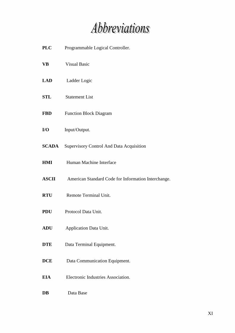
Abbreviations ..................................................................................................... XI
Chapter 1: Introduction
1.1 Programmable logic controller (PLC) .............................................. 1
1.2 Fieldbus protocols ........................................................................... 1
1.3 Project Objectives ............................................................................ 2
1.4 Thesis Layout .................................................................................... 2
Chapter 2: Theory
2.1 Siemens SIMATIC S7-200 PLC ...................................................... 3
2.1.1 S7-200 CPU ............................................................................ 3
2.1.2 STEP 7-Micro/WIN Programming Package ......................... 3
2.1.3 S7-200 Operation & Execution .............................................. 5
2.1.4 Operation Mode ...................................................................... 7
2.2 Modbus Protocol .............................................................................. 7
2.2.1 Protocol description ............................................................... 8
2.2.2 Modbus transaction .............................................................. 10
2.2.3 Data Encoding ...................................................................... 11
2.2.4 Data Model ........................................................................... 11
2.2.4.1 Four Main Function Codes ....................................... 12
2.2.5 Byte Format in RTU mode ................................................... 12
2.2.6 Modbus Message RTU Framing .......................................... 13
2.3 S7-200 Communications ............................................................ …14
2.3.1 Using the Modbus protocol library in Micro/WIN ............. 14
2.3.1.1 Modbus Addressing .................................................. 15
VI
2.3.1.2 MBUS-INIT Instruction ............................................ 15
2.3.1.3 MBUS-SLAVE Instruction....................................... 17
2.4 Serial data communication ............................................................ 17
2.4.1 Interface standards ............................................................... 18
2.4.1.1 RS-232 standard ........................ …………………..18
2.4.1.2 RS-485 standard ....................................................... 20
2.4.1.3 Serial interface converter ......................................... 21
2.4.2 Data Acquisition ................................................................... 21
Chapter 3: Design and Implementation
3.1 Using STEP7 Micro/Win ............................................................... 24
3.1.1 MBUS_INIT ......................................................................... 24
3.1.2 MBUS_SLAVE .................................................................... 24
3.2 Simulation of master/slave connection Introduction .................... 25
3.2.1 Description of the software ................................................... 25
3.2.2 Basic Simulation Configuration ........................................... 25
3.2.3 Simulation Parameters Adjustment ...................................... 25
3.2.3.1 Communication parameters ...................................... 25
3.2.3.2 Master definitions ..................................................... 26
3.3 Modbus Master VB software ......................................................... 27
3.3.1 VB program flowchart .......................................................... 28
3.3.2 Application design ................................................................ 29
Chapter 4: Tests and Results
4.1 Results of Monitoring bytes traffic ................................................ 30
4.1.1 Automatic Control ................................................................. 30
4.1.2 Manual Control ...................................................................... 31
4.2 Results of VB master software ....................................................... 33
Chapter 5: Conclusions and Recommendations
5.1 Conclusions .................................................................................. 35
5.1.1 Benefits ……………………….................…………….… 35
5.1.2 Limitations ………………………………..........…………36
5.2 Recommendations and future work .............................................. 36

VII
References ......................................................................................................... 37
Appendix A: Devices figures .............................................................................
Appendix B : Micro/Win ladder diagram ........................................................
Appendix B: VB program code………………...............…………………
37
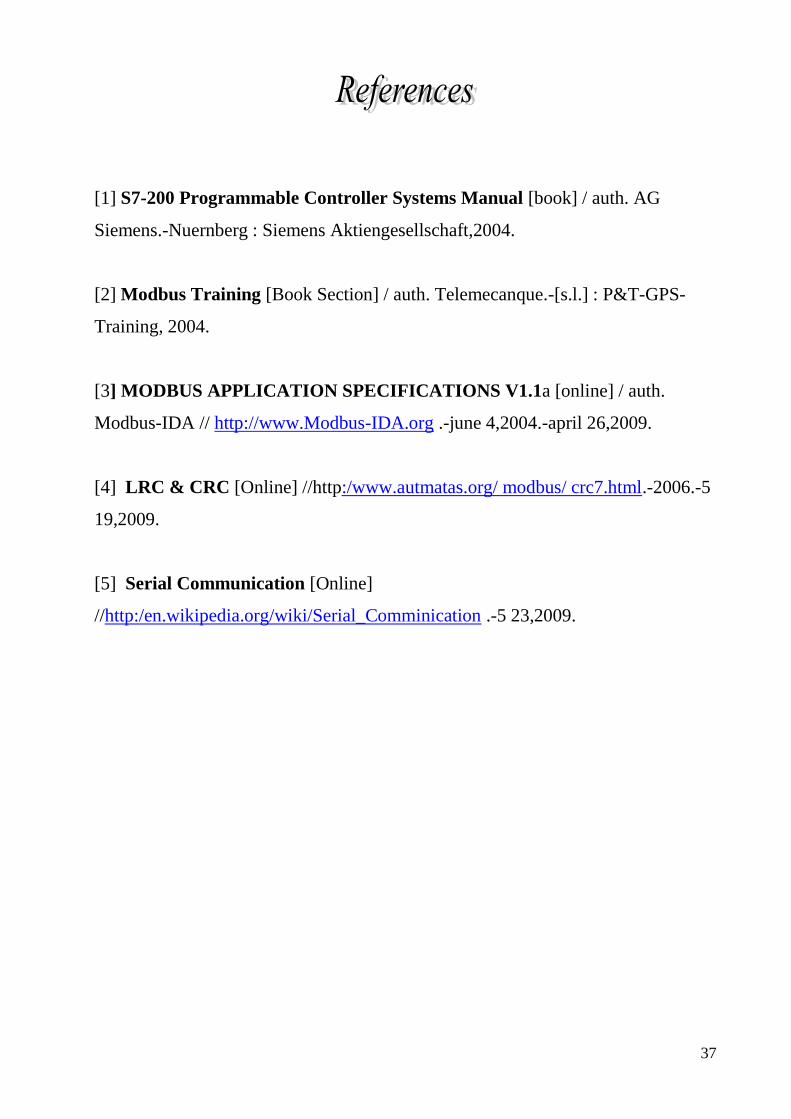
[1] S7-200 Programmable Controller Systems Manual [book] / auth. AG
Siemens.-Nuernberg : Siemens Aktiengesellschaft,2004.
[2] Modbus Training [Book Section] / auth. Telemecanque.-[s.l.] : P&T-GPS-
Training, 2004.
[3] MODBUS APPLICATION SPECIFICATIONS V1.1a [online] / auth.
Modbus-IDA // http://www.Modbus-IDA.org .-june 4,2004.-april 26,2009.
[4] LRC & CRC [Online] //http:/www.autmatas.org/ modbus/ crc7.html.-2006.-5
19,2009.
[5] Serial Communication [Online]
//http:/en.wikipedia.org/wiki/Serial_Comminication .-5 23,2009.
VIII
LIST OF FIGURES
Fig. 2-1 S7-200 Micro PLC ................................................................................................ 3
Fig. 2-2 STEP7-Micro/Win .............................................................................................. 4
Fig. 2-3 Controlling Inputs and Outputs ........................................................................ 5
Fig. 2-4 S7-200 Scan Cycle................................................................................................. 7
Fig. 2-5 Modbus Protocol Describtion ........................................................................... 8
Fig. 2-6 Modbus Transaction (error free) ..................................................................... 10
Fig. 2-7 Modbus Transaction (exeption response) ..................................................... 11
Fig. 2-8 Modbus Addressing Model .............................................................................. 11
Fig. 2-9 RTU Message Frame ......................................................................................... 13
Fig. 2-10 Connection Structure....................................................................................... 14
Fig. 2-11 MBUS_INIT ..................................................................................................... 15
Fig. 2-12 MBUS_SLAVE ................................................................................................ 17
Fig. 2-13 RS-232 Interfaces between DTE and DCE ................................................ 18
Fig. 2-14 Pinout of RS-232 .............................................................................................. 19
Fig. 2-15 Pinout of RS-485 .............................................................................................. 20
Fig. 2-16 RS-232/RS-485 Converter ............................................................................. 21
Fig. 2-17 S7-200 RS-232/PPI Multi Master Cable ...................................................... 23
Fig. 3-1 MBUS_INIT Settings ........................................................................................ 24
Fig. 3-2 MBUS_SLAVE Settings ................................................................................... 24
Fig. 3-3 Master communication parameter setting......................................................26
Fig. 3-2 Master Definitions ..................................................................................... .......26
Fig. 3-5 VB Program Flow Chart .................................................................................. 28
Fig. 3-6 Application Circuit ............................................................................................ 29
Fig. 4-1 Read Coil Status .................................................................................................. 30
Fig. 4-2 Read Discrete Inputs ......................................................................................... 31
Fig. 4-3 (a) Write Single Coil; (b) Check the response ............................................... 32
Fig. 4-4 Modbus Master Design .................................................................................... 33

IX
Fig 4-5 Reading Operation .............................................................................................. 33
Fig 4-6 Writing Operation .............................................................................................. 34
X
LIST OF TABLES
Table 2-1 Modbus Data Model ...................................................................................... 12
Table 2-2 Modbus Function Code ................................................................................. 12
Table 2-3 Modbus Mapping ............................................................................................ 15
Table 2-4 Modbus Slave Protocol Execution Error Codes ...................................... 16

I
To my dear parents, who gave me the support during the
preparation of this project.
With love, faith and respect
XI
PLC Programmable Logical Controller.
VB Visual Basic
LAD Ladder Logic
STL Statement List
FBD Function Block Diagram
I/O Input/Output.
SCADA Supervisory Control And Data Acquisition
HMI Human Machine Interface
ASCII American Standard Code for Information Interchange.
RTU Remote Terminal Unit.
PDU Protocol Data Unit.
ADU Application Data Unit.
DTE Data Terminal Equipment.
DCE Data Communication Equipment.
EIA Electronic Industries Association.
DB Data Base

II
I would like to thank Dr. Abdelrahman Ali Karar who was the
supervisor of my project.
Special thanks to my colleague Mohammed A.Omer for his great
cooperation.
Thanks to everyone helped me or gave me part of his/her time for
supervision or advising me to come out with this work.
III
The main objective of this project is to give a basic idea about exchanging data between
programmable logical controllers (PLC) and the computer, based on Modbus protocol and serial
data interface.
This project focused gets the features of PLC (flexibility, and reliability), features of
computer (reliability, and processing speed), and the features of Modbus protocol (flexibility,
and low development cost).
In order to achieve our objective, we first simulate the communication between master and
slave devices.
Then a real-time process has been developing by using visual basic program represent the
master, and a programmable logic controller (PLC) represents a slave device.
The serial interfaces used are RS-232 and RS-485.
In conclusion, we achieved our aims and objectives.
Chapter 1 Introduction
1
Chapter 1
Introduction
1.1 Programmable logic controller (PLC):
A programmable logic controller (PLC) or programmable controller is a digital computer
used for automation of electromechanical processes, such as control of machinery on factory
assembly lines, amusement rides, or lighting fixtures.
Control engineering has evolved over time. In the past humans were the main methods for
controlling systems. More recently electricity has been used for control and early electrical control
was based on relays. These relays allow power to be switched on and off without a mechanical
switch. It is common to use relays to make simple logical control decisions. The development of low
cost computer has brought the most recent revolution, the Programmable Logic Controller (PLC).
The advent of the PLC began in the 1970s, and has become the most common choice for
manufacturing controls.
PLCs are used in many industries and machines, such as packaging and semiconductor
machines. Unlike general-purpose computers, the PLC is designed for multiple inputs and output
arrangements, extended temperature ranges, immunity to electrical noise, and resistance to vibration
and impact. Programs to control machine operation are typically stored in battery-backed or non-
volatile memory. A PLC is an example of a real time system since output results must be produced
in response to input conditions within a bounded time, otherwise unintended operation will result.
1.2 Fieldbus protocols:
A protocol is essentially a common set of rules governing the exchange of data between the
transmitter and receiver of a communications network, and is normally associated with the
packaging of data transmitted on the communications interface.
The fieldbuses and their protocols are used today primarily as the communication system for
exchange of information between automation systems and distributed field devices. All leading
manufacturers of automation technology offer fieldbus interfaces for their devices. That is why the
fieldbus systems present a very dynamically growing branch of the industry. Each fieldbus protocol
has its own frame structure that is different from one another.
Chapter 1 Introduction
2
The most popular fieldbus are used in industrial today are:
Modbus protocol.
Canbus protocol.
Profibus protocol
1.3 Project Objectives:
The main objective of this project is to give a basic idea about exchanging data between
SIMATIC S7-200 PLC and PC by using Modbus protocol, and to implement a data acquisition
system to communicate with PLC via serial communication.
To achieve this objective, work was divided into two sub-objectives:
The first objective is to monitor the byte traffic between a master device (PC) and slave
device (PLC) as simulation.
The second objective is to build a modbus master that can communicate with the PLC,
by implement reading and writing operations to its coils and discrete inputs as a real-time
process.
1.4 Thesis Layout:
This thesis is organized as follows:
Chapter 2: Introduces the concepts of the S7-200 PLC and it is configurations.
Chapter 3: Describes the design and VB program implementation.
Chapter 4: Describes the results that obtain from our design.
Chapter 5: Presents conclusions and recommended future work.
Appendix A: Contains devices figures.
Appendix B : Contains Micro/Win ladder diagram
Appendix C: Contains VB code.
Theory Chapter 2
3
Chapter 2
Theory
2.1 Siemens SIMATIC S7-200 PLC:
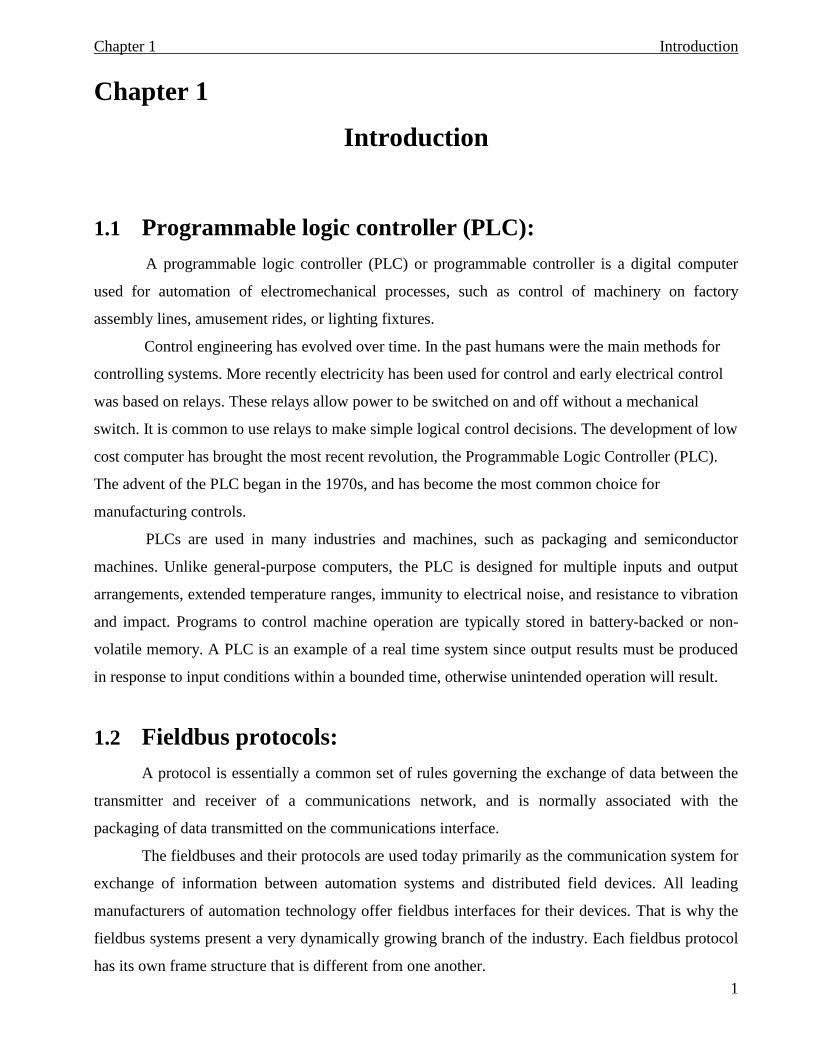
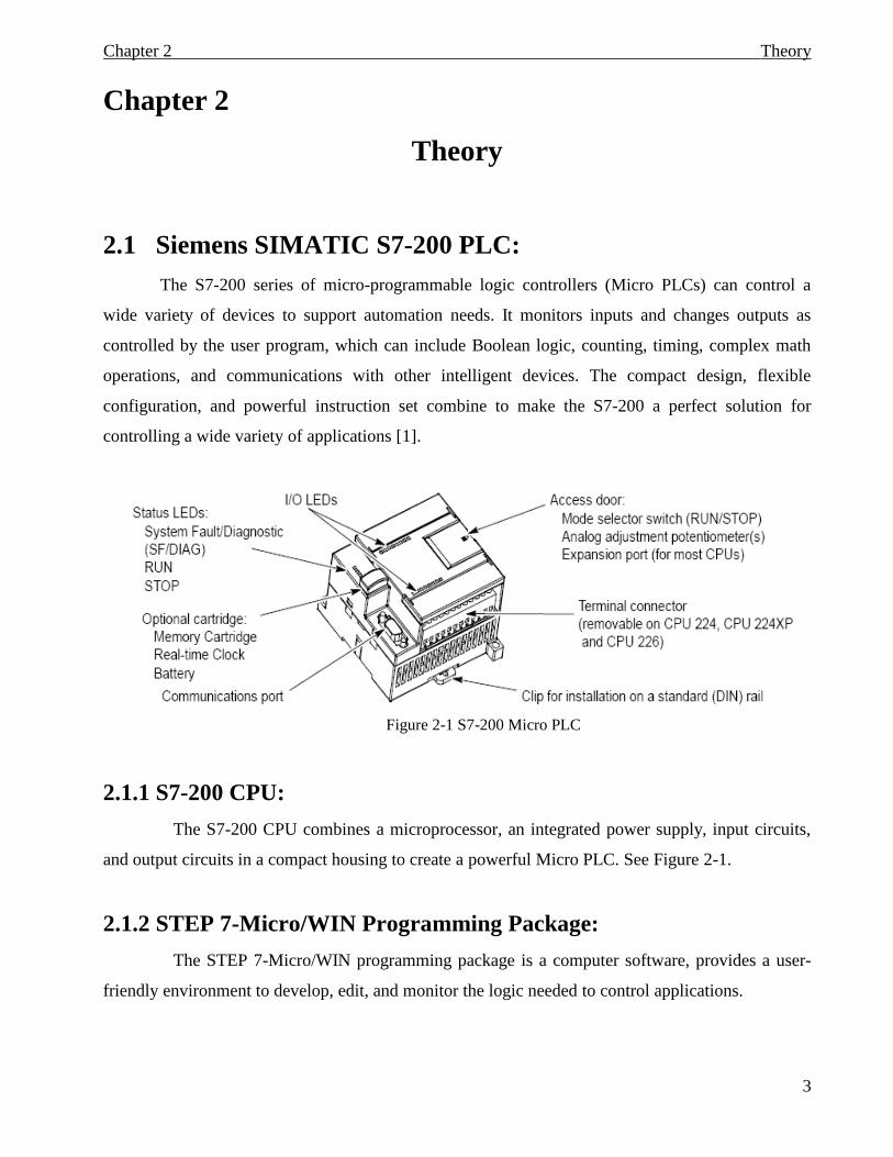
The S7-200 series of micro-programmable logic controllers (Micro PLCs) can control a
wide variety of devices to support automation needs. It monitors inputs and changes outputs as
controlled by the user program, which can include Boolean logic, counting, timing, complex math
operations, and communications with other intelligent devices. The compact design, flexible
configuration, and powerful instruction set combine to make the S7-200 a perfect solution for
controlling a wide variety of applications [1].
Figure 2-1 S7-200 Micro PLC
2.1.1 S7-200 CPU:
The S7-200 CPU combines a microprocessor, an integrated power supply, input circuits,
and output circuits in a compact housing to create a powerful Micro PLC. See Figure 2-1.
2.1.2 STEP 7-Micro/WIN Programming Package:
The STEP 7-Micro/WIN programming package is a computer software, provides a user-
friendly environment to develop, edit, and monitor the logic needed to control applications.
Theory Chapter 2
4
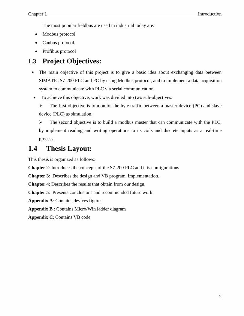
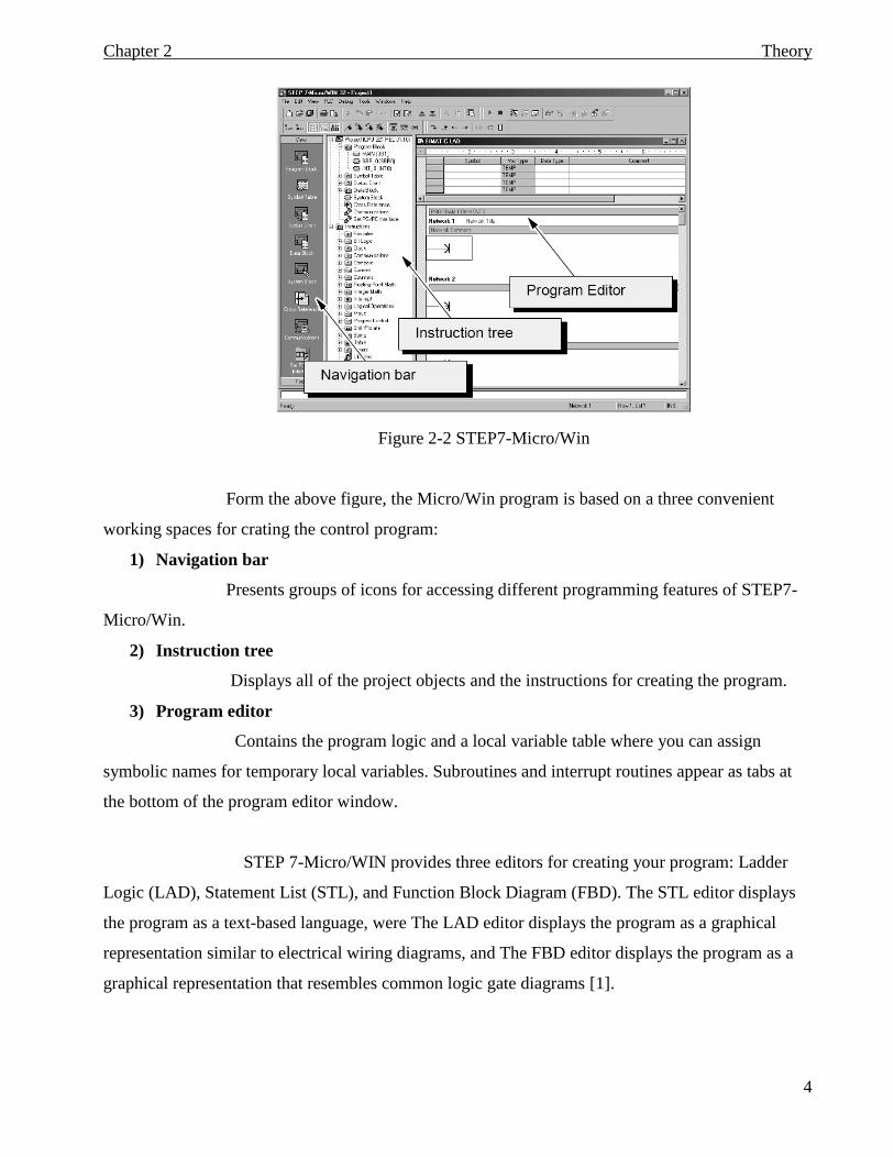
Figure 2-2 STEP7-Micro/Win
Form the above figure, the Micro/Win program is based on a three convenient
working spaces for crating the control program:
1) Navigation bar
Presents groups of icons for accessing different programming features of STEP7-
Micro/Win.
2) Instruction tree
Displays all of the project objects and the instructions for creating the program.
3) Program editor
Contains the program logic and a local variable table where you can assign
symbolic names for temporary local variables. Subroutines and interrupt routines appear as tabs at
the bottom of the program editor window.
STEP 7-Micro/WIN provides three editors for creating your program: Ladder
Logic (LAD), Statement List (STL), and Function Block Diagram (FBD). The STL editor displays
the program as a text-based language, were The LAD editor displays the program as a graphical
representation similar to electrical wiring diagrams, and The FBD editor displays the program as a
graphical representation that resembles common logic gate diagrams [1].
Theory Chapter 2
5
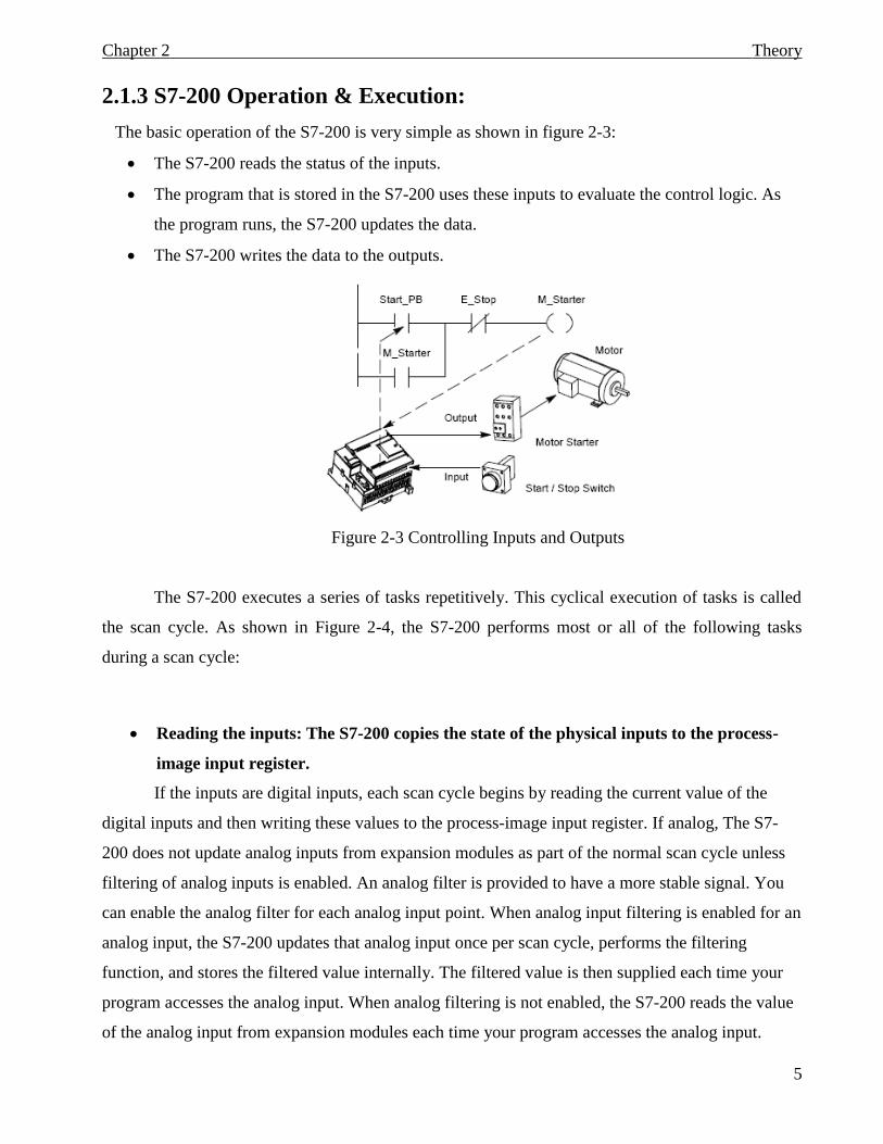
2.1.3 S7-200 Operation & Execution:
The basic operation of the S7-200 is very simple as shown in figure 2-3:
The S7-200 reads the status of the inputs.
The program that is stored in the S7-200 uses these inputs to evaluate the control logic. As
the program runs, the S7-200 updates the data.
The S7-200 writes the data to the outputs.
Figure 2-3 Controlling Inputs and Outputs
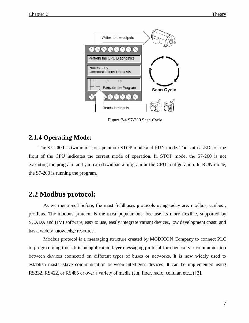
The S7-200 executes a series of tasks repetitively. This cyclical execution of tasks is called
the scan cycle. As shown in Figure 2-4, the S7-200 performs most or all of the following tasks
during a scan cycle:
Reading the inputs: The S7-200 copies the state of the physical inputs to the process-
image input register.
If the inputs are digital inputs, each scan cycle begins by reading the current value of the
digital inputs and then writing these values to the process-image input register. If analog, The S7-
200 does not update analog inputs from expansion modules as part of the normal scan cycle unless
filtering of analog inputs is enabled. An analog filter is provided to have a more stable signal. You
can enable the analog filter for each analog input point. When analog input filtering is enabled for an
analog input, the S7-200 updates that analog input once per scan cycle, performs the filtering
function, and stores the filtered value internally. The filtered value is then supplied each time your
program accesses the analog input. When analog filtering is not enabled, the S7-200 reads the value
of the analog input from expansion modules each time your program accesses the analog input.
Theory Chapter 2
6
Executing the control logic in the program: The S7-200 executes the instructions of the
program and stores the values in the various memory areas.
During the execution phase of the scan cycle, the S7-200 executes program, starting with
the first instruction and proceeding to the end instruction. The immediate I/O instructions give you
immediate access to inputs and outputs during the execution of either the program or an interrupt
routine.
Processing any communications requests: The S7-200 performs any tasks required for
communications.
During the message-processing phase of the scan cycle, the S7-200 processes any messages
that were received from the communications port or intelligent I/O modules.
Executing the CPU self-test diagnostics: The S7-200 ensures that the firmware, the
program memory, and any expansion modules are working properly.
During this phase of the scan cycle, the S7-200 checks for proper operation of the CPU and
for the status of any expansion modules.
Writing to the outputs: The values stored in the process-image output register are
written to the physical outputs.
At the end of every scan cycle, the S7-200 writes the values stored in the process-image
output register to the digital outputs. (Analog outputs are updated immediately, independently from
the scan cycle.)
The execution of the user program is dependent upon whether the S7-200 is in STOP mode
or in RUN mode. In RUN mode, your program is executed; in STOP mode, your program is
not executed [1].
Theory Chapter 2
7
Figure 2-4 S7-200 Scan Cycle
2.1.4 Operating Mode:
The S7-200 has two modes of operation: STOP mode and RUN mode. The status LEDs on the
front of the CPU indicates the current mode of operation. In STOP mode, the S7-200 is not
executing the program, and you can download a program or the CPU configuration. In RUN mode,
the S7-200 is running the program.
2.2 Modbus protocol:
As we mentioned before, the most fieldbuses protocols using today are: modbus, canbus ,
profibus. The modbus protocol is the most popular one, because its more flexible, supported by
SCADA and HMI software, easy to use, easily integrate variant devices, low development coast, and
has a widely knowledge resource.
Modbus protocol is a messaging structure created by MODICON Company to connect PLC
to programming tools. It is an application layer messaging protocol for client/server communication
between devices connected on different types of buses or networks. It is now widely used to
establish master-slave communication between intelligent devices. It can be implemented using
RS232, RS422, or RS485 or over a variety of media (e.g. fiber, radio, cellular, etc...) [2].
Theory Chapter 2
8
Standard Modbus ports on Modicon controllers use an RS-232compatible serial interface that
defines connector pinouts, cabling, signal levels, transmission baud rates, and parity checking.
Controllers can be networked directly or via modems.
Controllers communicate using a master-slave technique, in which only one device (the
master) can initiate transactions (queries). The other devices (the slaves) respond by supplying the
requested data to the master, or by taking the action requested in the query. Typical master devices
include host processors and programming panels. Typical slaves include programmable controllers.
The master can address individual slaves, or can initiate a broadcast message to all slaves.
Slaves return a message (response) to queries that are addressed to them individually. Responses are
not returned to broadcast queries from the master.
The Modbus protocol has two serial transmission modes:
ASCII transmission mode:
When controllers are setup to communicate on a modbus network using ASCII(American
Standard Code for Information Interchange) mode, each eight-bit byte in a message is sent as two
ASCII characters. The main advantage of this mode is that it allows time intervals of up to one
second to occur between characters without causing an error.
RTU transmission mode
When controllers are setup to communicate on a Modbus network using RTU (Remote
Terminal Unit) mode, each eight-bit byte in a message contains two fourbit hexadecimal
characters. The main advantage of this mode is that its greater character density allows better
data throughput than ASCII for the same baud rate.
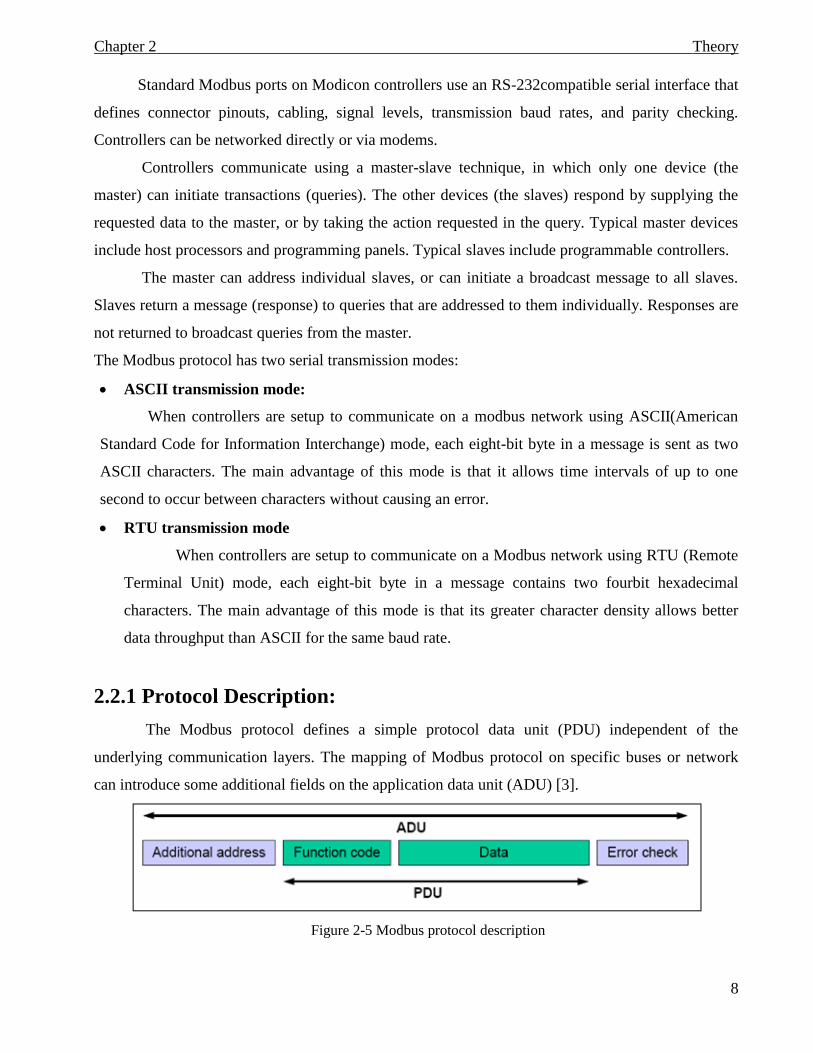
2.2.1 Protocol Description:
The Modbus protocol defines a simple protocol data unit (PDU) independent of the
underlying communication layers. The mapping of Modbus protocol on specific buses or network
can introduce some additional fields on the application data unit (ADU) [3].
Figure 2-5 Modbus protocol description
Theory Chapter 2
9
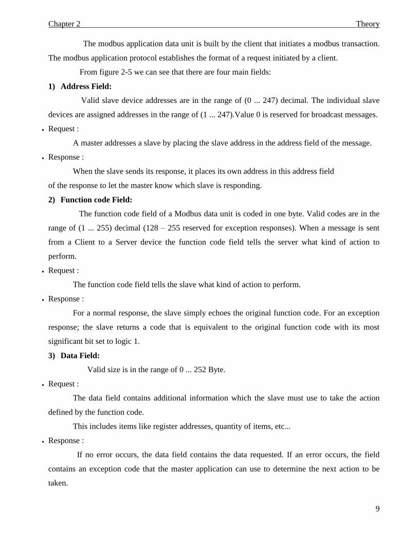
The modbus application data unit is built by the client that initiates a modbus transaction.
The modbus application protocol establishes the format of a request initiated by a client.
From figure 2-5 we can see that there are four main fields:
1) Address Field:
Valid slave device addresses are in the range of (0 ... 247) decimal. The individual slave
devices are assigned addresses in the range of (1 ... 247).Value 0 is reserved for broadcast messages.
Request :
A master addresses a slave by placing the slave address in the address field of the message.
Response :
When the slave sends its response, it places its own address in this address field
of the response to let the master know which slave is responding.
2) Function code Field:
The function code field of a Modbus data unit is coded in one byte. Valid codes are in the
range of (1 ... 255) decimal (128 – 255 reserved for exception responses). When a message is sent
from a Client to a Server device the function code field tells the server what kind of action to
perform.
Request :
The function code field tells the slave what kind of action to perform.
Response :
For a normal response, the slave simply echoes the original function code. For an exception
response; the slave returns a code that is equivalent to the original function code with its most
significant bit set to logic 1.
3) Data Field:
Valid size is in the range of 0 ... 252 Byte.
Request :
The data field contains additional information which the slave must use to take the action
defined by the function code.
This includes items like register addresses, quantity of items, etc...
Response :
If no error occurs, the data field contains the data requested. If an error occurs, the field
contains an exception code that the master application can use to determine the next action to be
taken.
Theory Chapter 2
10
4) Error check Field:
It contains the checksum value.
Request :
The checksum is calculated by the master and sends to the slave.
Response :
The checksum is re-calculated by the slave and compared to the value sent by the master. If a
difference is detected, the slave will not construct a response to the master.
In ASCII mode, the error checking field contains two ASCII characters. The error check
characters are the result of a Longitudinal Redundancy Check (LRC) calculation that is
performed on the message contents, exclusive of the beginning colon and terminating CRLF
characters [4].
In RTU mode, the error checking field contains a 16-bit value implemented as two eight-bit
bytes. The error check value is the result of a Cyclical Redundancy Check (CRC) calculation
performed on the message contents [4].
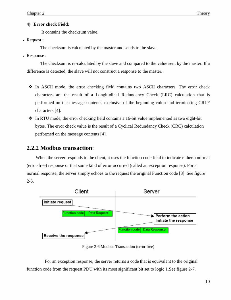
2.2.2 Modbus transaction:
When the server responds to the client, it uses the function code field to indicate either a normal
(error-free) response or that some kind of error occurred (called an exception response). For a
normal response, the server simply echoes to the request the original Function code [3]. See figure
2-6.
Figure 2-6 Modbus Transaction (error free)
For an exception response, the server returns a code that is equivalent to the original
function code from the request PDU with its most significant bit set to logic 1.See figure 2-7.
Theory Chapter 2
11
Figure 2-7 Modbus Transaction (exception response)
2.2.3 Data Encoding:
Modbus uses a ‘big-Endian’ representation for addresses and data items. This means that
when a numerical quantity larger than a single byte is transmitted, the most significant byte is sent
first. So for example:
Register size value
16 - Bits 0x1234 the first byte sent is 0x12 then 0x34
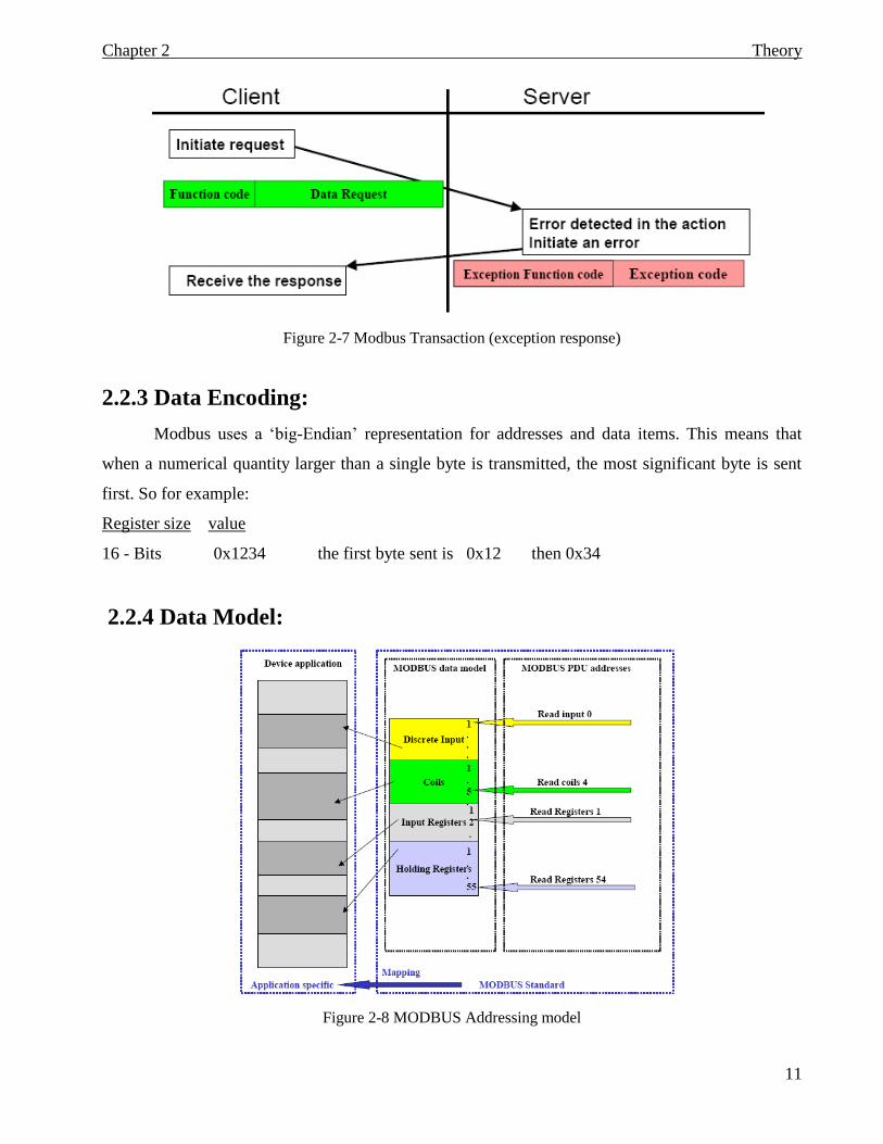
2.2.4 Data Model:
Figure 2-8 MODBUS Addressing model
Theory Chapter 2
12
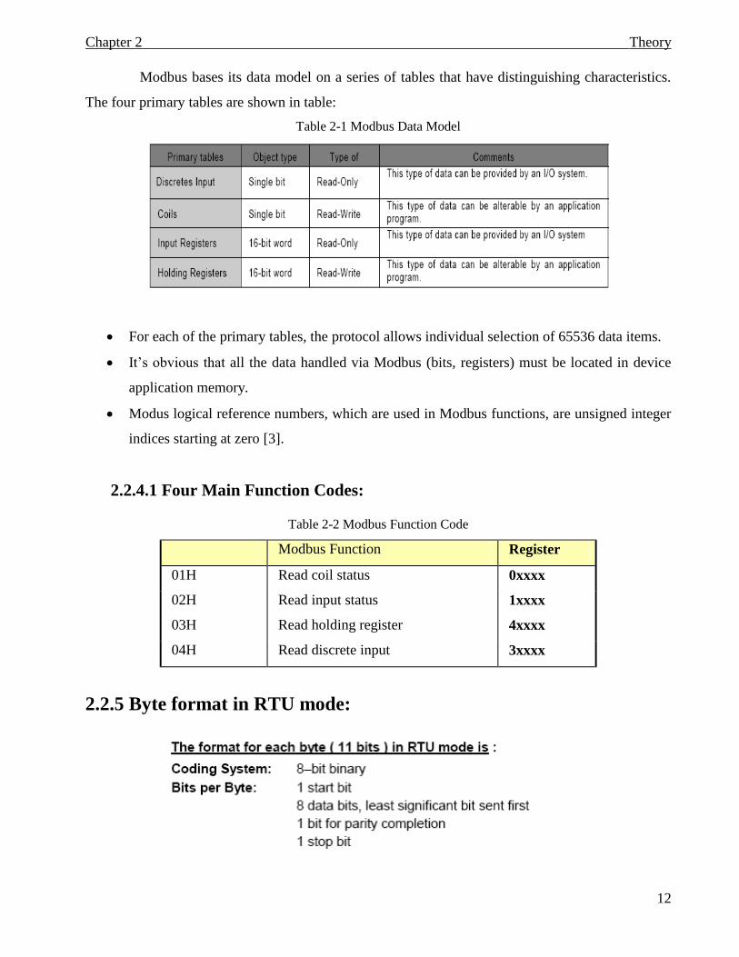
Modbus bases its data model on a series of tables that have distinguishing characteristics.
The four primary tables are shown in table:
Table 2-1 Modbus Data Model
For each of the primary tables, the protocol allows individual selection of 65536 data items.
It’s obvious that all the data handled via Modbus (bits, registers) must be located in device
application memory.
Modus logical reference numbers, which are used in Modbus functions, are unsigned integer
indices starting at zero [3].
2.2.4.1 Four Main Function Codes:
Table 2-2 Modbus Function Code
Modbus Function Register
01H Read coil status 0xxxx
02H Read input status 1xxxx
03H Read holding register 4xxxx
04H Read discrete input 3xxxx
2.2.5 Byte format in RTU mode:
Theory Chapter 2
13
Even parity is required; other modes (odd parity, no parity) may also be used .In order to
ensure a maximum compatibility with other products.
Remark : the use of no parity requires 2 stop bits.
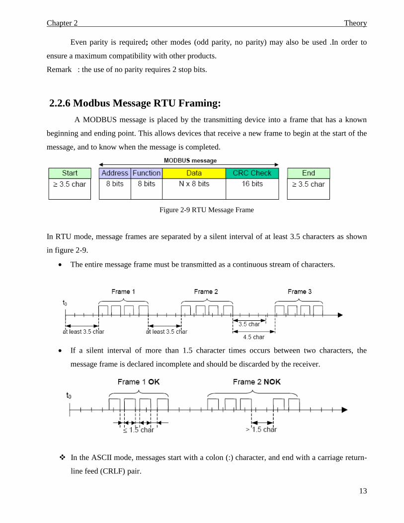
2.2.6 Modbus Message RTU Framing:
A MODBUS message is placed by the transmitting device into a frame that has a known
beginning and ending point. This allows devices that receive a new frame to begin at the start of the
message, and to know when the message is completed.
Figure 2-9 RTU Message Frame
In RTU mode, message frames are separated by a silent interval of at least 3.5 characters as shown
in figure 2-9.
The entire message frame must be transmitted as a continuous stream of characters.
If a silent interval of more than 1.5 character times occurs between two characters, the
message frame is declared incomplete and should be discarded by the receiver.
In the ASCII mode, messages start with a colon (:) character, and end with a carriage return-
line feed (CRLF) pair.
Theory Chapter 2
14
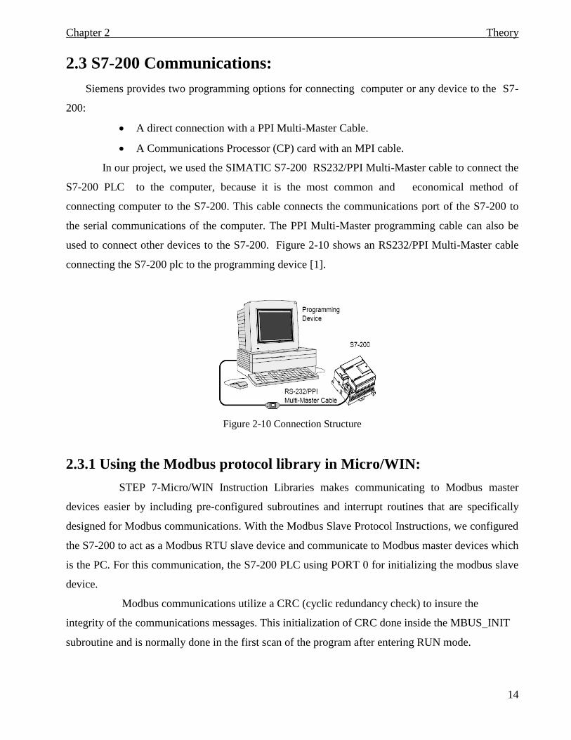
2.3 S7-200 Communications:
Siemens provides two programming options for connecting computer or any device to the S7-
200:
A direct connection with a PPI Multi-Master Cable.
A Communications Processor (CP) card with an MPI cable.
In our project, we used the SIMATIC S7-200 RS232/PPI Multi-Master cable to connect the
S7-200 PLC to the computer, because it is the most common and economical method of
connecting computer to the S7-200. This cable connects the communications port of the S7-200 to
the serial communications of the computer. The PPI Multi-Master programming cable can also be
used to connect other devices to the S7-200. Figure 2-10 shows an RS232/PPI Multi-Master cable
connecting the S7-200 plc to the programming device [1].
Figure 2-10 Connection Structure
2.3.1 Using the Modbus protocol library in Micro/WIN:
STEP 7-Micro/WIN Instruction Libraries makes communicating to Modbus master
devices easier by including pre-configured subroutines and interrupt routines that are specifically
designed for Modbus communications. With the Modbus Slave Protocol Instructions, we configured
the S7-200 to act as a Modbus RTU slave device and communicate to Modbus master devices which
is the PC. For this communication, the S7-200 PLC using PORT 0 for initializing the modbus slave
device.
Modbus communications utilize a CRC (cyclic redundancy check) to insure the
integrity of the communications messages. This initialization of CRC done inside the MBUS_INIT
subroutine and is normally done in the first scan of the program after entering RUN mode.
Theory Chapter 2
15
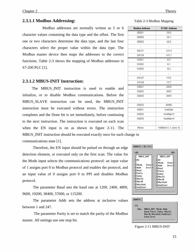
2.3.1.1 Modbus Addressing: Table 2-3 Modbus Mapping
Modbus addresses are normally written as 5 or 6
character values containing the data type and the offset. The first
one or two characters determine the data type, and the last four
characters select the proper value within the data type. The
Modbus master device then maps the addresses to the correct
functions. Table 2-3 shows the mapping of Modbus addresses in
S7-200 PLC [1].
2.3.1.2 MBUS-INIT Instruction:
The MBUS_INIT instruction is used to enable and
initialize, or to disable Modbus communications. Before the
MBUS_SLAVE instruction can be used, the MBUS_INIT
instruction must be executed without errors. The instruction
completes and the Done bit is set immediately, before continuing
to the next instruction. The instruction is executed on each scan
when the EN input is on as shown in figure 2-11. The
MBUS_INIT instruction should be executed exactly once for each change in
communications state [1].
Therefore, the EN input should be pulsed on through an edge
detection element, or executed only on the first scan. The value for
the Mode input selects the communications protocol: an input value
of 1 assigns port 0 to Modbus protocol and enables the protocol, and
an input value of 0 assigns port 0 to PPI and disables Modbus
protocol.
The parameter Baud sets the baud rate at 1200, 2400, 4800,
9600, 19200, 38400, 57600, or 115200.
The parameter Addr sets the address at inclusive values
between 1 and 247.
The parameter Parity is set to match the parity of the Modbus
master. All settings use one stop bit.
Figure 2-11 MBUS-INIT
Theory Chapter 2
16
The accepted values are:
0-no parity
1-odd parity
2-even parity
The parameter Delay extends the standard Modbus end-of-message timeout condition by
adding the specified number of milliseconds to the standard Modbus message timeout. The typical
value for this parameter should be 0 when operating on a wired network.
The parameter MaxIQ sets the number of I and Q points available to Modbus addresses
00xxxx and 01xxxx at values of 0 to 128. A value of 0 disables all reads and writes to the inputs and
outputs. The suggested value for MaxIQ is 128, which allows access to all I and Q points in the S7-
200.
The parameter MaxAI sets the number of word input (AI) registers available to Modbus
address 03xxx at values of 0 to 32. A value of 0 disables reads of the analog inputs. The suggested
value for MaxAI to allow access to all of the S7-200 analog inputs, is as follows:
0 for CPU 221
16 for CPU 222, which we used in our project.
32 for CPU 224, CPU 224XP, and CPU 226
The parameter MaxHold sets the number of word holding registers in V memory
available to Modbus address 04xxx. The parameter HoldStart is the address of the start of the
holding registers in V memory. This value is generally set to VB0, so the parameter HoldStart is set
to &VB0 (address of VB0).
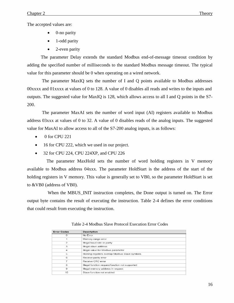
When the MBUS_INIT instruction completes, the Done output is turned on. The Error
output byte contains the result of executing the instruction. Table 2-4 defines the error conditions
that could result from executing the instruction.
Table 2-4 Modbus Slave Protocol Execution Error Codes
Theory Chapter 2
17
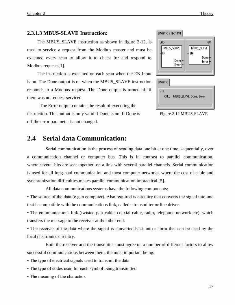
2.3.1.3 MBUS-SLAVE Instruction:
The MBUS_SLAVE instruction as shown in figure 2-12, is
used to service a request from the Modbus master and must be
executed every scan to allow it to check for and respond to
Modbus requests[1].
The instruction is executed on each scan when the EN Input
is on. The Done output is on when the MBUS_SLAVE instruction
responds to a Modbus request. The Done output is turned off if
there was no request serviced.
The Error output contains the result of executing the
instruction. This output is only valid if Done is on. If Done is Figure 2-12 MBUS-SLAVE
off,the error parameter is not changed.
2.4 Serial data Communication:
Serial communication is the process of sending data one bit at one time, sequentially, over
a communication channel or computer bus. This is in contrast to parallel communication,
where several bits are sent together, on a link with several parallel channels. Serial communication
is used for all long-haul communication and most computer networks, where the cost of cable and
synchronization difficulties makes parallel communication impractical [5].
All data communications systems have the following components:
• The source of the data (e.g. a computer). Also required is circuitry that converts the signal into one
that is compatible with the communications link, called a transmitter or line driver.
• The communications link (twisted-pair cable, coaxial cable, radio, telephone network etc), which
transfers the message to the receiver at the other end.
• The receiver of the data where the signal is converted back into a form that can be used by the
local electronics circuitry.
Both the receiver and the transmitter must agree on a number of different factors to allow
successful communications between them, the most important being:
• The type of electrical signals used to transmit the data
• The type of codes used for each symbol being transmitted
• The meaning of the characters
Theory Chapter 2
18
• How the flow of data is controlled
• How errors are detected and corrected
2.4.1 Interface standards:
Communications interface standards define the electrical and mechanical details that allow
communication equipment from different manufacturers to be connected together and to function
efficiently. Two standards are commonly employed for communications between PCs and controller
devices:
• RS-232 standard
• RS-485 standard
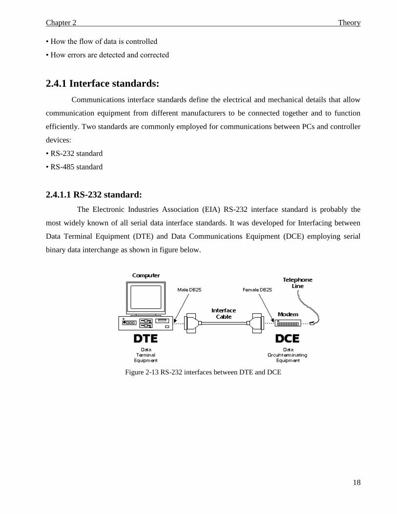
2.4.1.1 RS-232 standard:
The Electronic Industries Association (EIA) RS-232 interface standard is probably the
most widely known of all serial data interface standards. It was developed for Interfacing between
Data Terminal Equipment (DTE) and Data Communications Equipment (DCE) employing serial
binary data interchange as shown in figure below.
Figure 2-13 RS-232 interfaces between DTE and DCE
Theory Chapter 2
19
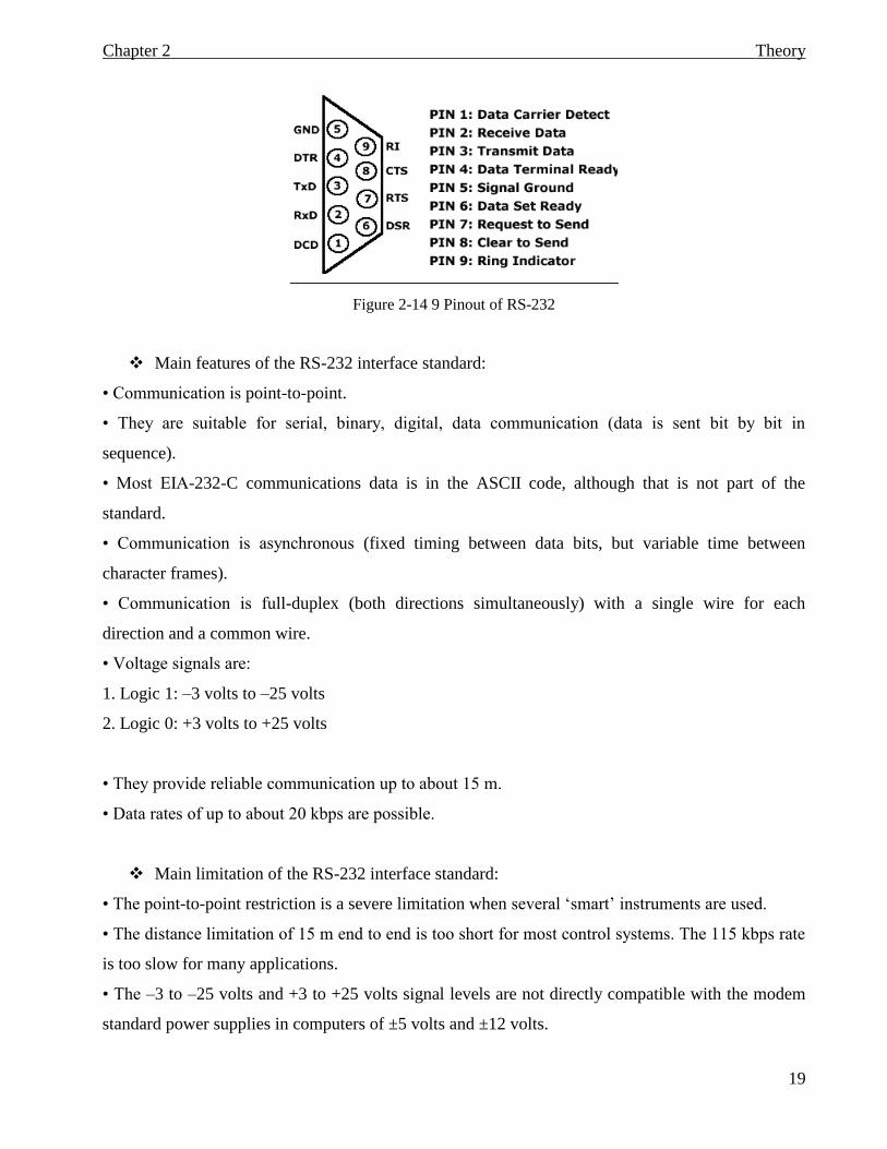
Figure 2-14 9 Pinout of RS-232
Main features of the RS-232 interface standard:
• Communication is point-to-point.
• They are suitable for serial, binary, digital, data communication (data is sent bit by bit in
sequence).
• Most EIA-232-C communications data is in the ASCII code, although that is not part of the
standard.
• Communication is asynchronous (fixed timing between data bits, but variable time between
character frames).
• Communication is full-duplex (both directions simultaneously) with a single wire for each
direction and a common wire.
• Voltage signals are:
1. Logic 1: –3 volts to –25 volts
2. Logic 0: +3 volts to +25 volts
• They provide reliable communication up to about 15 m.
• Data rates of up to about 20 kbps are possible.
Main limitation of the RS-232 interface standard:
• The point-to-point restriction is a severe limitation when several ‘smart’ instruments are used.
• The distance limitation of 15 m end to end is too short for most control systems. The 115 kbps rate
is too slow for many applications.
• The –3 to –25 volts and +3 to +25 volts signal levels are not directly compatible with the modem
standard power supplies in computers of ±5 volts and ±12 volts.
Theory Chapter 2
20
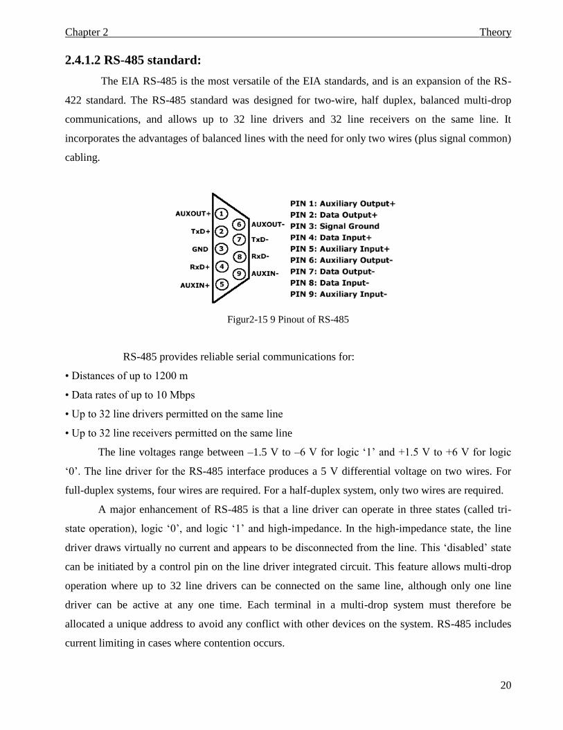
2.4.1.2 RS-485 standard:
The EIA RS-485 is the most versatile of the EIA standards, and is an expansion of the RS-
422 standard. The RS-485 standard was designed for two-wire, half duplex, balanced multi-drop
communications, and allows up to 32 line drivers and 32 line receivers on the same line. It
incorporates the advantages of balanced lines with the need for only two wires (plus signal common)
cabling.
Figur2-15 9 Pinout of RS-485
RS-485 provides reliable serial communications for:
• Distances of up to 1200 m
• Data rates of up to 10 Mbps
• Up to 32 line drivers permitted on the same line
• Up to 32 line receivers permitted on the same line
The line voltages range between –1.5 V to –6 V for logic ‘1’ and +1.5 V to +6 V for logic
‘0’. The line driver for the RS-485 interface produces a 5 V differential voltage on two wires. For
full-duplex systems, four wires are required. For a half-duplex system, only two wires are required.
A major enhancement of RS-485 is that a line driver can operate in three states (called tri-
state operation), logic ‘0’, and logic ‘1’ and high-impedance. In the high-impedance state, the line
driver draws virtually no current and appears to be disconnected from the line. This ‘disabled’ state
can be initiated by a control pin on the line driver integrated circuit. This feature allows multi-drop
operation where up to 32 line drivers can be connected on the same line, although only one line
driver can be active at any one time. Each terminal in a multi-drop system must therefore be
allocated a unique address to avoid any conflict with other devices on the system. RS-485 includes
current limiting in cases where contention occurs.
Theory Chapter 2
21
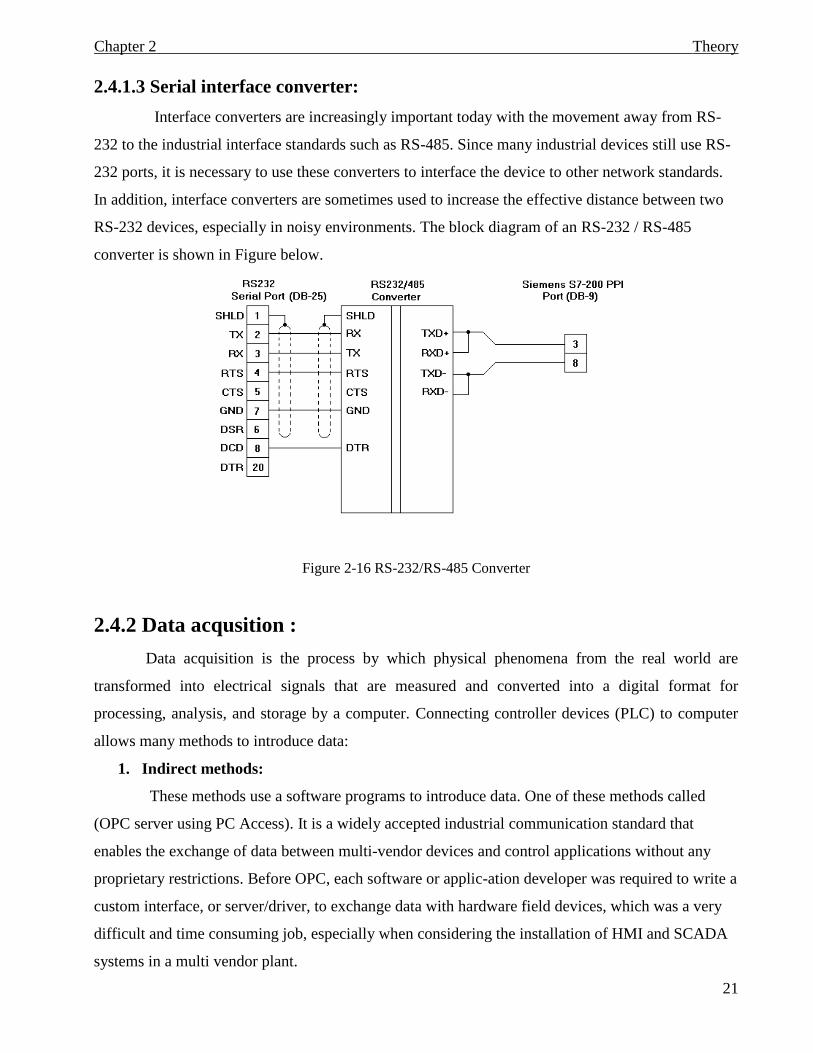
2.4.1.3 Serial interface converter:
Interface converters are increasingly important today with the movement away from RS-
232 to the industrial interface standards such as RS-485. Since many industrial devices still use RS-
232 ports, it is necessary to use these converters to interface the device to other network standards.
In addition, interface converters are sometimes used to increase the effective distance between two
RS-232 devices, especially in noisy environments. The block diagram of an RS-232 / RS-485
converter is shown in Figure below.
Figure 2-16 RS-232/RS-485 Converter
2.4.2 Data acqusition :
Data acquisition is the process by which physical phenomena from the real world are
transformed into electrical signals that are measured and converted into a digital format for
processing, analysis, and storage by a computer. Connecting controller devices (PLC) to computer
allows many methods to introduce data:
1. Indirect methods:
These methods use a software programs to introduce data. One of these methods called
(OPC server using PC Access). It is a widely accepted industrial communication standard that
enables the exchange of data between multi-vendor devices and control applications without any
proprietary restrictions. Before OPC, each software or applic-ation developer was required to write a
custom interface, or server/driver, to exchange data with hardware field devices, which was a very
difficult and time consuming job, especially when considering the installation of HMI and SCADA
systems in a multi vendor plant.
Theory Chapter 2
22
A typical OPC architecture is based on two components:
OPC Server is a software application that drives bi-directional communication with
the equipment such as PLC, a database (DB) or any data source and exposes
collected data to the OPC Client.
OPC Client is a software application used to access (for reading and/or writing)
information provided by the OPC Server through the OPC standard.
Another method called OPC server using KEPServerEx program can be used.
KEPServerEx is a 32-bit windows application that provides a means of bringing data and
information from a wide range of industrial devices and systems into client applications on your
windows PC. The main objective of this method is to bring data from different processes
simultaneously using different industrial protocols, unlike the (OPC server using PC Access), which
configured only for Siemens PLCs drivers.
2. Direct methods:
In the direct method, the data transfers directly through cables to the client (no need for
the server to bring data). This method is more flexible, and easy to use, because all we need is to
configure the communication protocol, and settings to bring data.
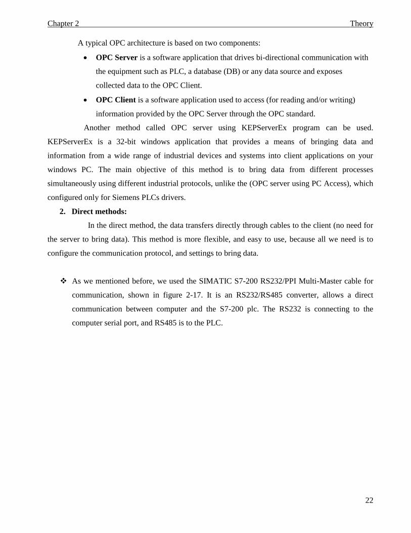
As we mentioned before, we used the SIMATIC S7-200 RS232/PPI Multi-Master cable for
communication, shown in figure 2-17. It is an RS232/RS485 converter, allows a direct
communication between computer and the S7-200 plc. The RS232 is connecting to the
computer serial port, and RS485 is to the PLC.
Theory Chapter 2
23
Figure 2-17 S7-200 RS-232/PPI Multi-Master Cable
For connection directly to the computer:
We set the PPI/Freeport mode (Switch 5=0)
The baud rate (Switches 1, 2, and 3)
The local (Switch 6=0). The Local setting is the same as setting the PC/PPI cable to
DCE.
The 11 Bit (Switch 7=0)
Chapter 3 Design and Implementation
24
Chapter 3
Design and Implementation
3.1 Using STEP 7-Micro/WIN:
As we mentioned before, we used Micro/WIN software program to create the
ladder of our application which is controlling several motors.
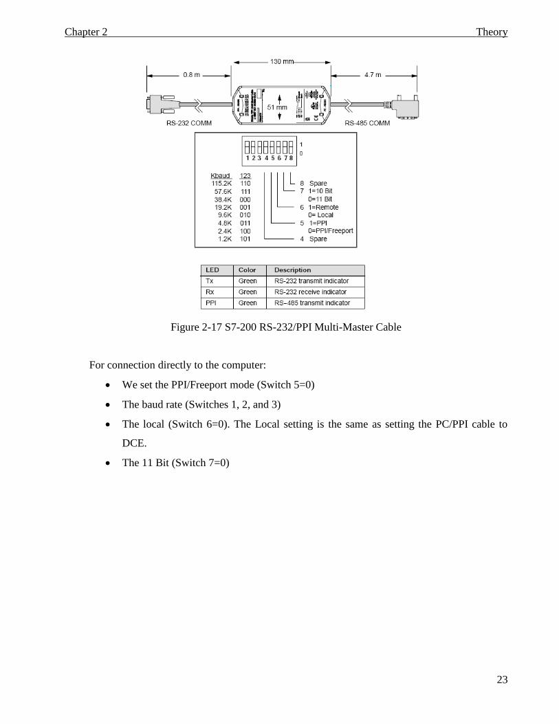
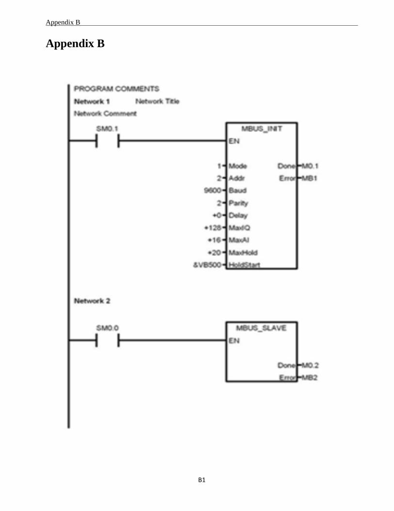
3.1.1 MBUS_INIT:
We configured the MBUS_INIT as shown in figure 3-1
Mode: set to 1,enables modbus protocol through port0.
Add: define the address starting at 2.
Baud: set the baud rate (which is the number of
symbols per second transferred) at 9600.
Parity: set the value 2 which refers to even
parity.
Delay: 0 because it’s a wired communication.
MaxIQ: set the maximum number of inputs and
outputs.
MaxAI: set the number of word input to 16
which typically for CPU-222XP.
MaxHold: set the number of holding registers Figure 3-1 MBUS-INIT Settings
HoldSt~: starting of holding register.
Done: staring execution.
Error: contains the result of executing the instruction
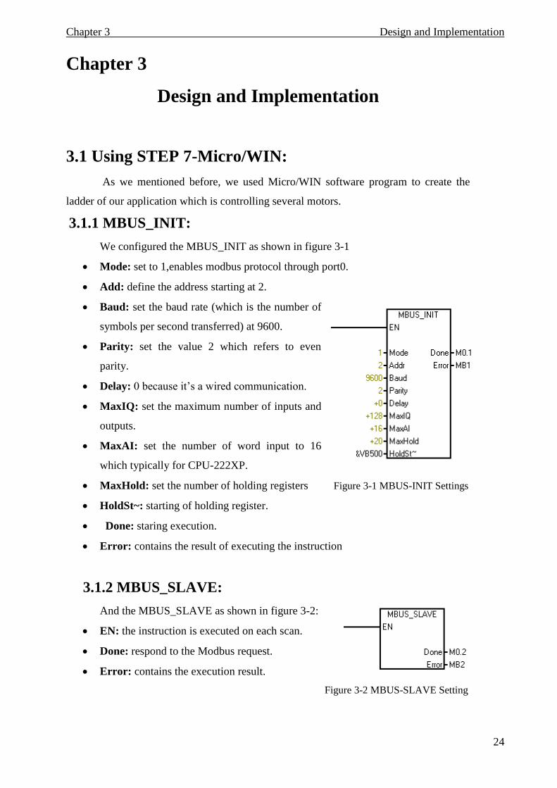
3.1.2 MBUS_SLAVE:
And the MBUS_SLAVE as shown in figure 3-2:
EN: the instruction is executed on each scan.
Done: respond to the Modbus request.
Error: contains the execution result.
Figure 3-2 MBUS-SLAVE Setting
Chapter 3 Design and Implementation
25
3.2 Simulation of master/slave connection:
One of the objectives of this project is to monitor the byte traffic (frames) between
master and slave devices that communicate via modbus protocol.
To achieve this objective, a software program (Modbus Poll) is used. Then serial traffic
was tested for the four main modbus function codes:
1. Read coil status.
2. Read discrete inputs.
3. Read holding register.
4. Read input register.
3.2.1 Description of the software:
It has some features like:
- Supporting Modbus/TCP, RTU and ASCII modes.
- Monitoring of serial traffic.
We constraint our work in RTU mode because of it is higher throughput as
mentioned in chapter two.
3.2.2 Basic Simulation Configuration:
The S7-200 PLC and the computer were connected together by means of a serial
interface (RS232/RS485 PPI cable). The computer holds the modbus poll software and the plc
acts as a modbus slave. Then the various parameters of the software were adjusted to perform
the required communication.
3.2.3 Simulation Parameters Adjustment:
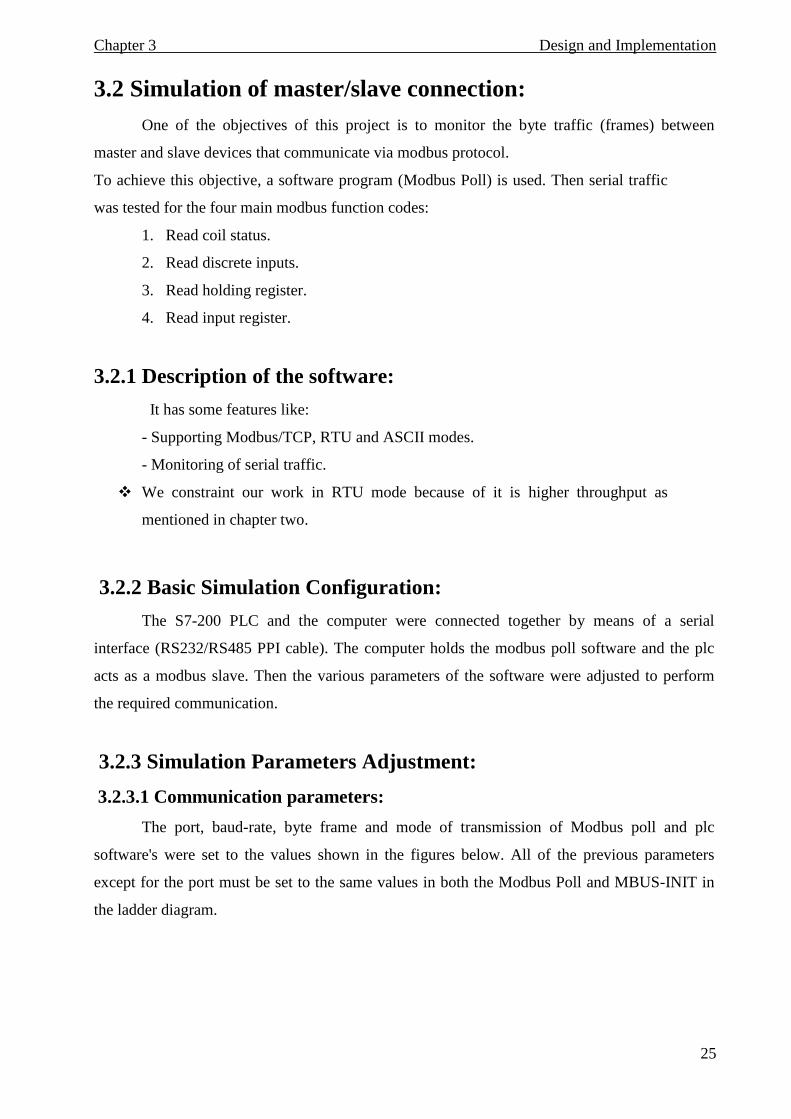
3.2.3.1 Communication parameters:
The port, baud-rate, byte frame and mode of transmission of Modbus poll and plc
software's were set to the values shown in the figures below. All of the previous parameters
except for the port must be set to the same values in both the Modbus Poll and MBUS-INIT in
the ladder diagram.
Chapter 3 Design and Implementation
26
Figure 3-3 Master communication parameter settings
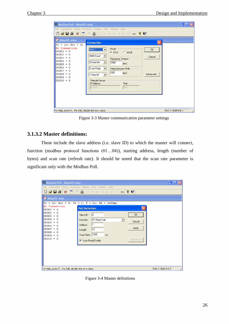
3.1.3.2 Master definitions:
These include the slave address (i.e. slave ID) to which the master will connect,
function (modbus protocol functions (01…04)), starting address, length (number of
bytes) and scan rate (refresh rate). It should be noted that the scan rate parameter is
significant only with the Modbus Poll.
Figure 3-4 Master definitions
Chapter 3 Design and Implementation
27
3.2.1 Modbus Master VB software:
In order to acquire the measured values from S7-200 PLC, we developed a program
written in Visual Basic (VB) language with help of modbus ActiveX control (Mbaxp.ocx).
Main features of the program include:
Acts as Modbus master.
Communication interface (RS232).
Supports RTU mode.
Supports modbus function code 01 (Read Coil Status).
o Description of the functions used in the software listed by their prototypes:
1. Open Connection :
Its used to open connection with required com port (1,2,3…etc), some
parameters must be set before this function called (port num, baud rate, data
bits, parity, stop bits, protocol mode, time out ).
2. Read Coil Status ( Handle As Integer, Slave ID As Integer, Start Adder As Long,
Quantity, Update Rate As long):
It’s used to send request to slave for reading coils (outputs) of the plc.
3. Close Connection :
It’s used to terminate the connection.
4. Force Single Coil (Handle As Integer, Slave ID As Integer, Address As long, Update
rate As long) :
It’s used to write to a single coil, and the desired value will be sent to the plc
outputs..
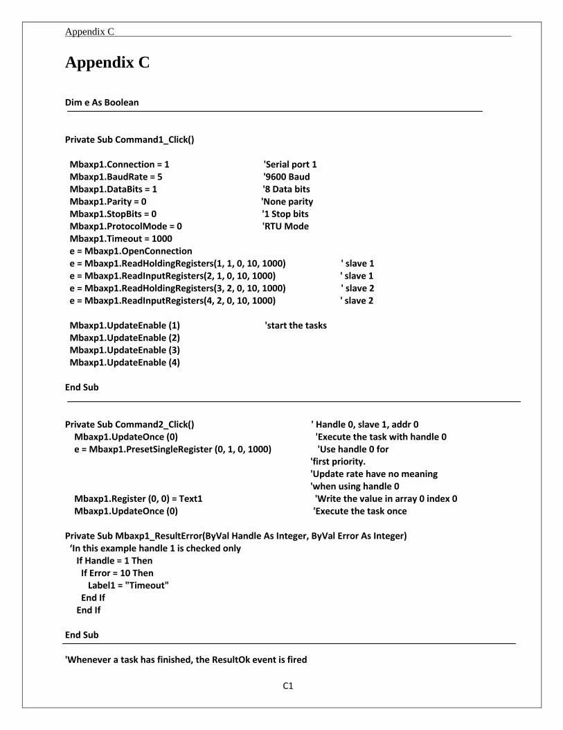
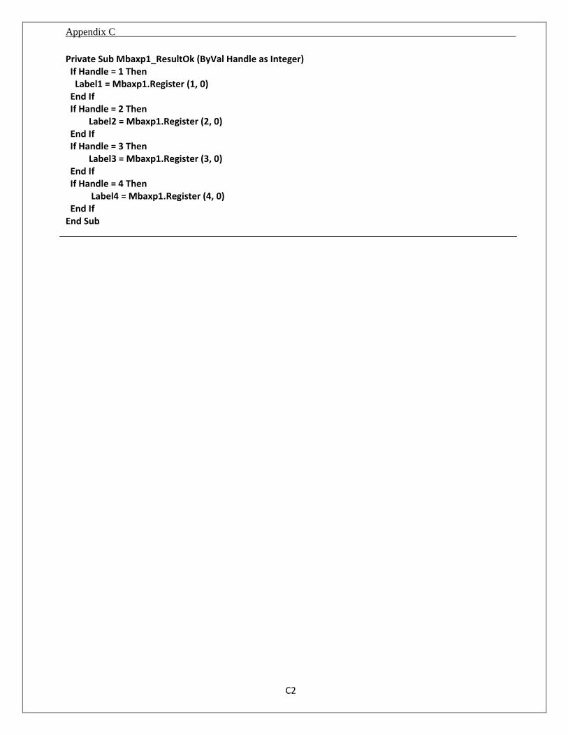
The VB software full code is contained in the Appendix.
Chapter 3 Design and Implementation
28
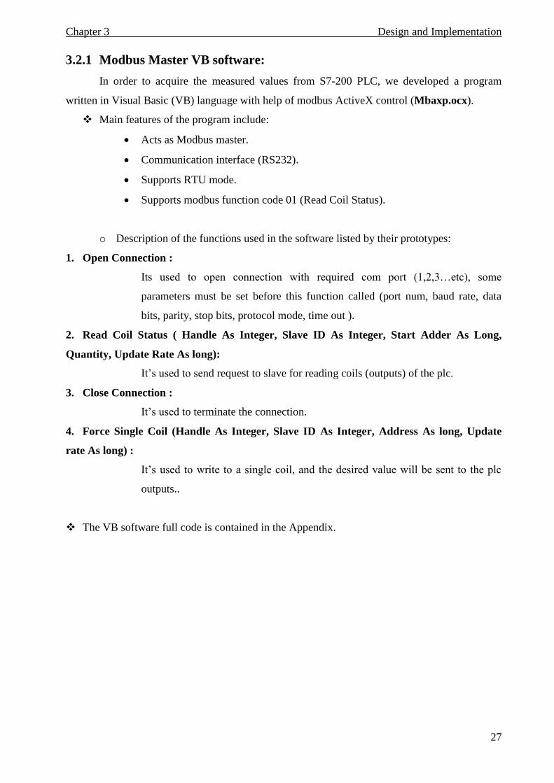
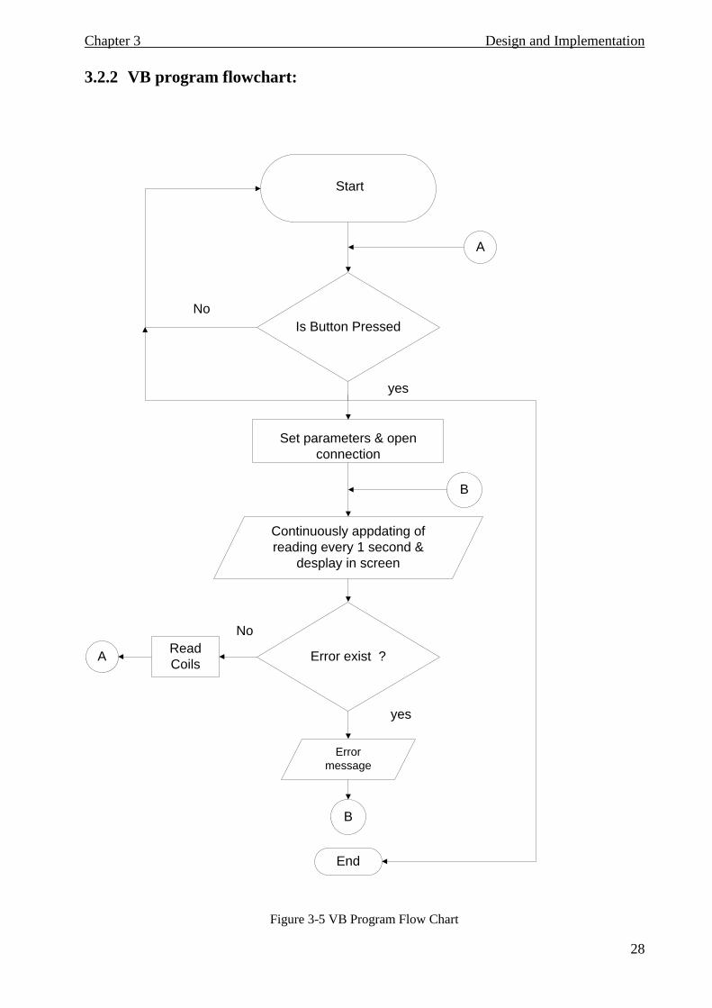
3.2.2 VB program flowchart:
Continuously appdating of
reading every 1 second &
desplay in screen
Start
Is Button Pressed
Set parameters & open
connection
Error exist ?
Error
message
B
End
Read
CoilsA
B
A
No
yes
No
yes
Figure 3-5 VB Program Flow Chart
Chapter 3 Design and Implementation
29
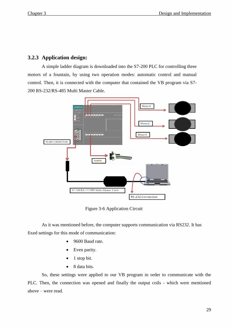
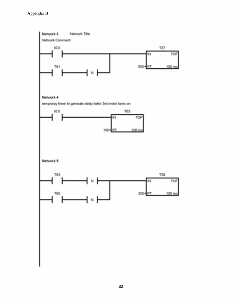
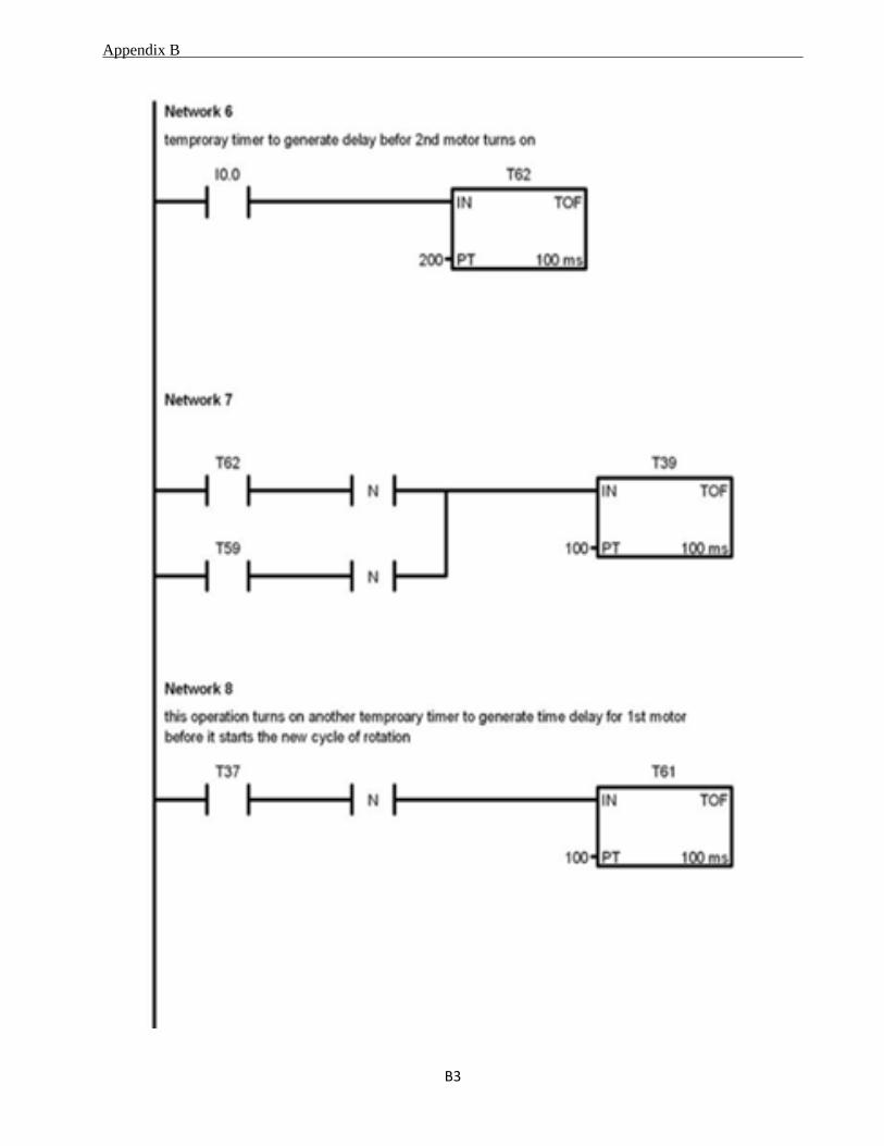
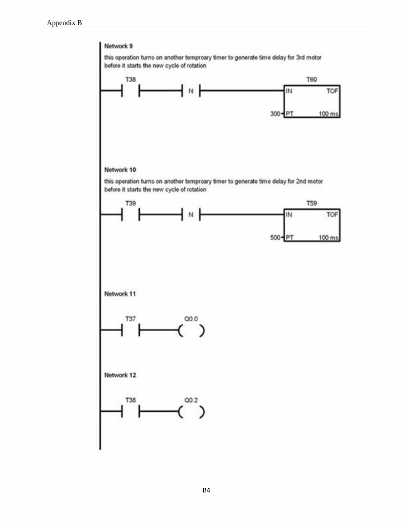
3.2.3 Application design:
A simple ladder diagram is downloaded into the S7-200 PLC for controlling three
motors of a fountain, by using two operation modes: automatic control and manual
control. Then, it is connected with the computer that contained the VB program via S7-
200 RS-232/RS-485 Multi Master Cable.
Figure 3-6 Application Circuit
As it was mentioned before, the computer supports communication via RS232. It has
fixed settings for this mode of communication:
9600 Baud rate.
Even parity.
1 stop bit.
8 data bits.
So, these settings were applied to our VB program in order to communicate with the
PLC. Then, the connection was opened and finally the output coils - which were mentioned
above – were read.
Chapater 4 Tests and Results
30
Chapter 4
Tests and Results
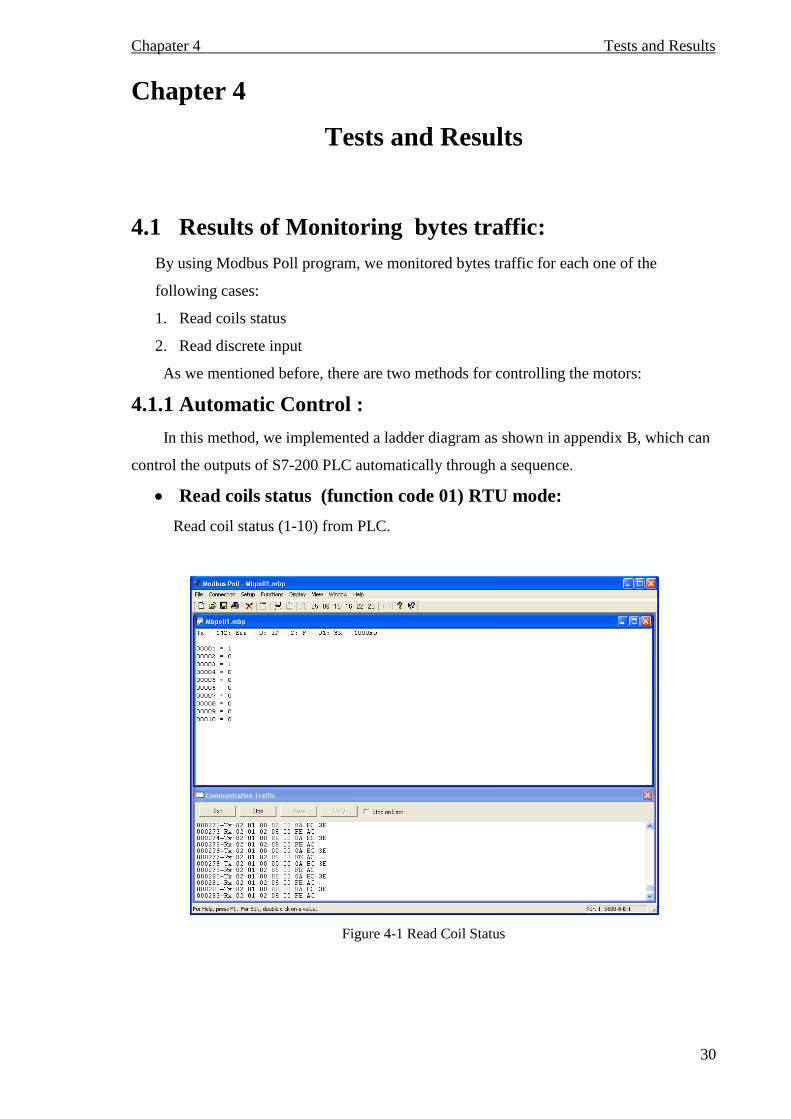
4.1 Results of Monitoring bytes traffic:
By using Modbus Poll program, we monitored bytes traffic for each one of the
following cases:
1. Read coils status
2. Read discrete input
As we mentioned before, there are two methods for controlling the motors:
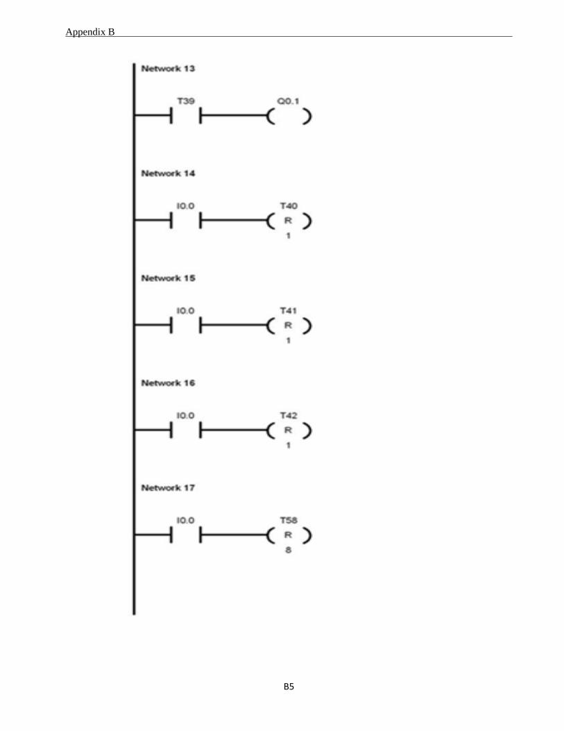
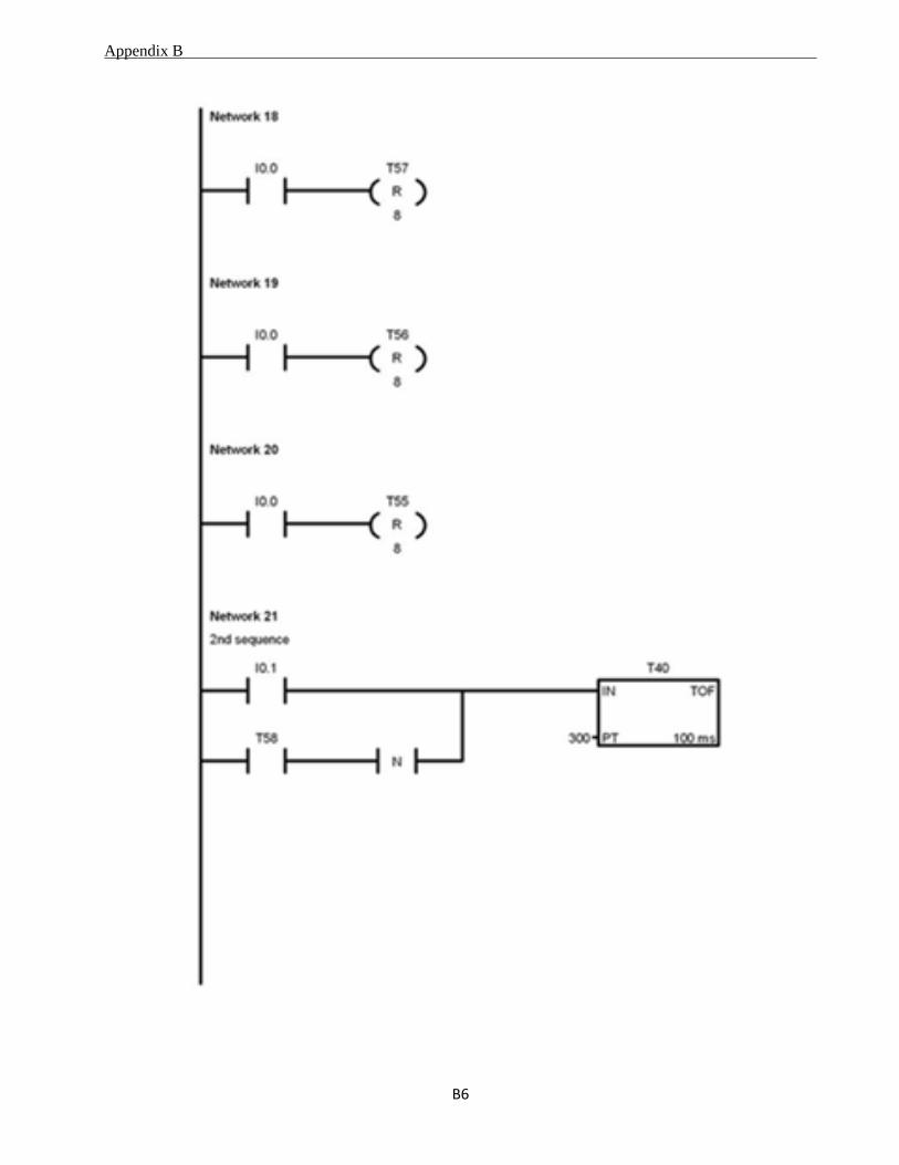
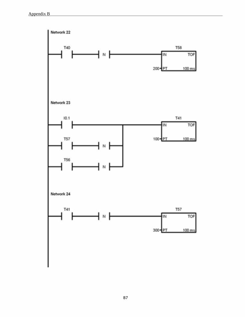
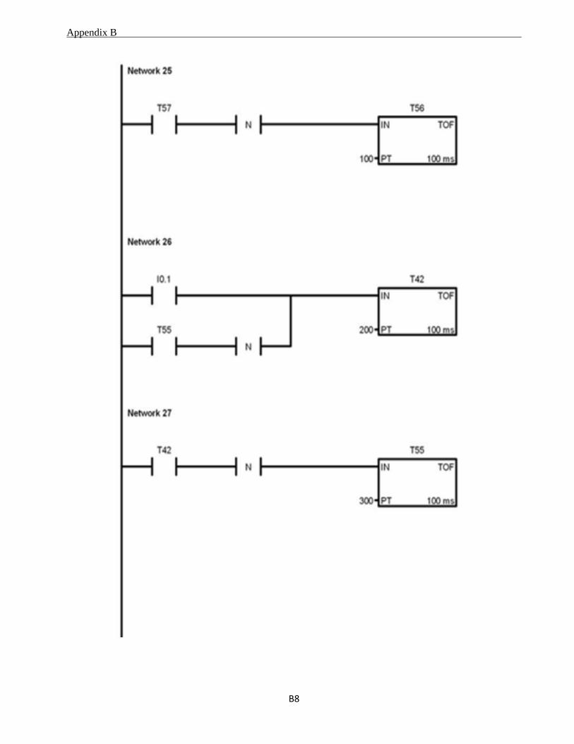
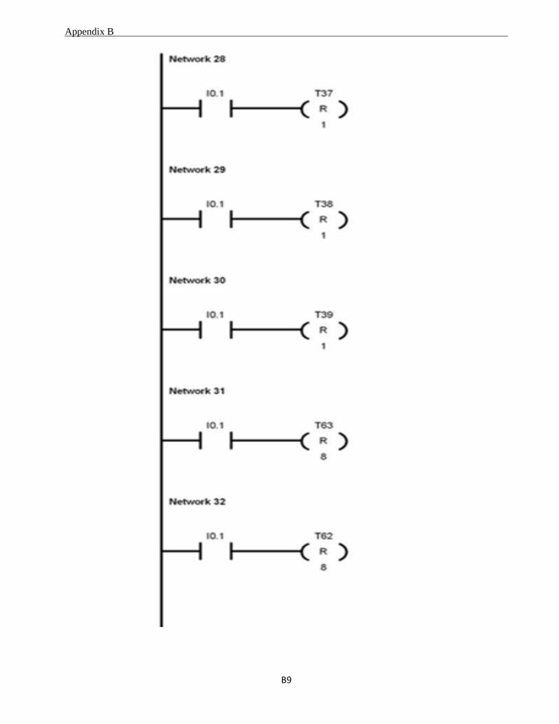
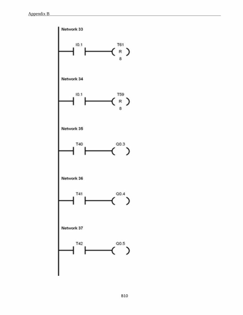
4.1.1 Automatic Control :
In this method, we implemented a ladder diagram as shown in appendix B, which can
control the outputs of S7-200 PLC automatically through a sequence.
Read coils status (function code 01) RTU mode:
Read coil status (1-10) from PLC.
Figure 4-1 Read Coil Status
Chapater 4 Tests and Results
31
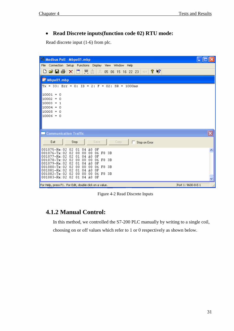
Read Discrete inputs(function code 02) RTU mode:
Read discrete input (1-6) from plc.
Figure 4-2 Read Discrete Inputs
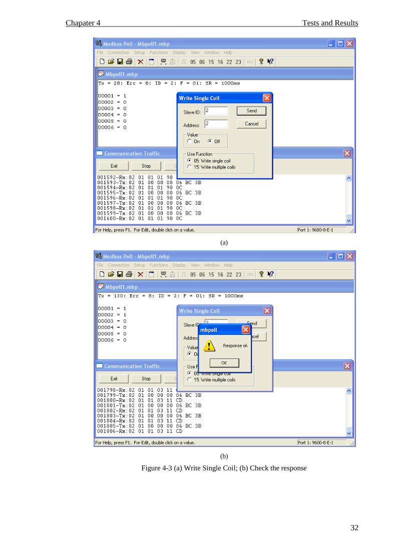
4.1.2 Manual Control:
In this method, we controlled the S7-200 PLC manually by writing to a single coil,
choosing on or off values which refer to 1 or 0 respectively as shown below.
Chapater 4 Tests and Results
32
(a)
(b)
Figure 4-3 (a) Write Single Coil; (b) Check the response
Chapater 4 Tests and Results
33
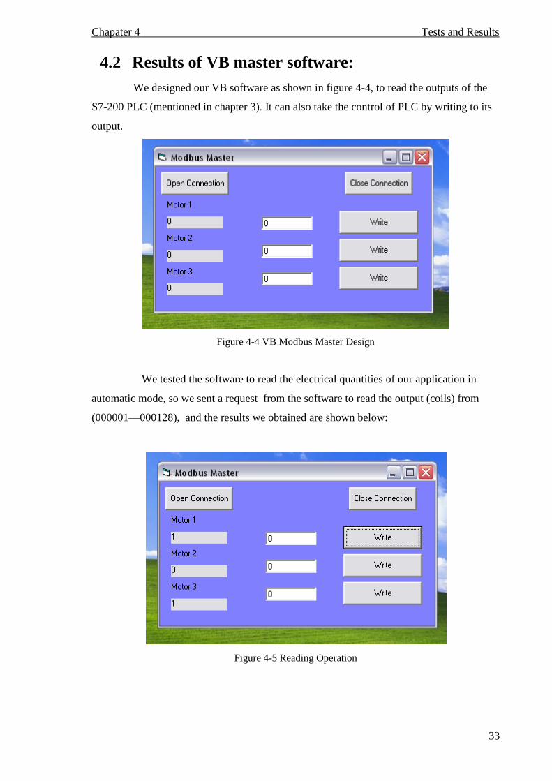
4.2 Results of VB master software:
We designed our VB software as shown in figure 4-4, to read the outputs of the
S7-200 PLC (mentioned in chapter 3). It can also take the control of PLC by writing to its
output.
Figure 4-4 VB Modbus Master Design
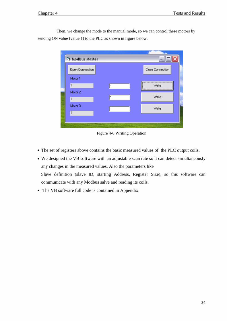
We tested the software to read the electrical quantities of our application in
automatic mode, so we sent a request from the software to read the output (coils) from
(000001—000128), and the results we obtained are shown below:
Figure 4-5 Reading Operation
Chapater 4 Tests and Results
34
Then, we change the mode to the manual mode, so we can control these motors by
sending ON value (value 1) to the PLC as shown in figure below:
Figure 4-6 Writing Operation
The set of registers above contains the basic measured values of the PLC output coils.
We designed the VB software with an adjustable scan rate so it can detect simultaneously
any changes in the measured values. Also the parameters like
Slave definition (slave ID, starting Address, Register Size), so this software can
communicate with any Modbus salve and reading its coils.
The VB software full code is contained in Appendix.
Appendix A
1A
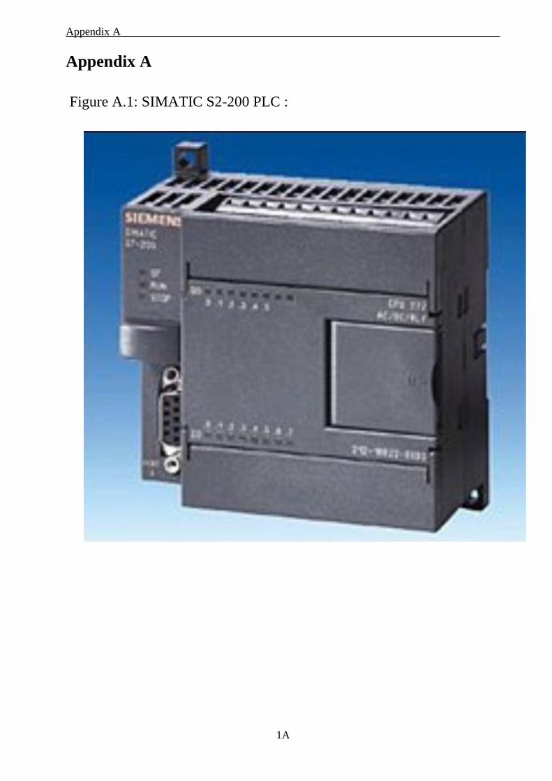
Appendix A
Figure A.1: SIMATIC S2-200 PLC :
Appendix A
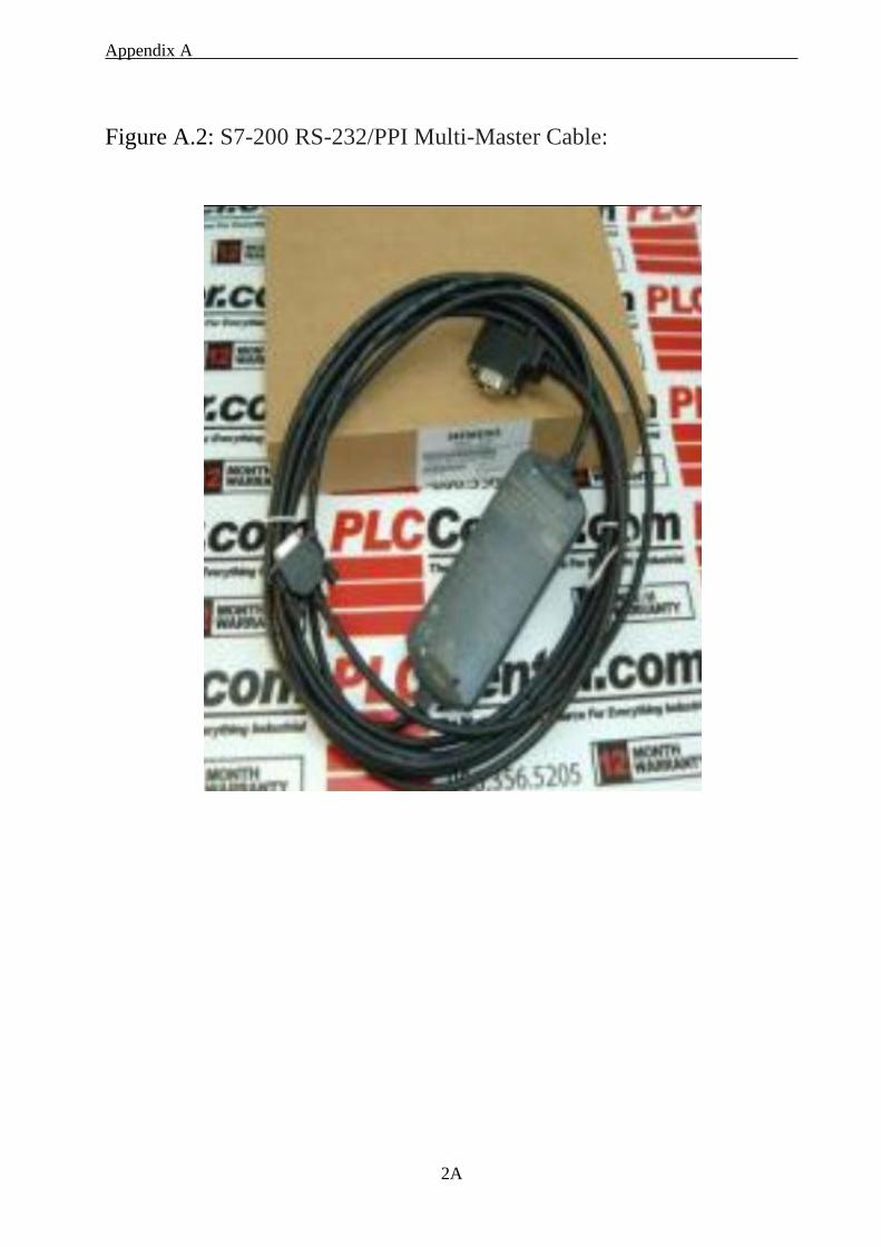
2A
Figure A.2: S7-200 RS-232/PPI Multi-Master Cable:
Appendix B
B1
Appendix B
Appendix B
B2
Appendix B
B3
Appendix B
B4
Appendix B
B5
Appendix B
B6
Appendix B
B7
Appendix B
B8
Appendix B
B9
Appendix B
B10
Appendix C
C1
Appendix C Dim e As Boolean Private Sub Command1_Click() Mbaxp1.Connection = 1 'Serial port 1 Mbaxp1.BaudRate = 5 '9600 Baud Mbaxp1.DataBits = 1 '8 Data bits Mbaxp1.Parity = 0 'None parity Mbaxp1.StopBits = 0 '1 Stop bits Mbaxp1.ProtocolMode = 0 'RTU Mode Mbaxp1.Timeout = 1000 e = Mbaxp1.OpenConnection e = Mbaxp1.ReadHoldingRegisters(1, 1, 0, 10, 1000) ' slave 1 e = Mbaxp1.ReadInputRegisters(2, 1, 0, 10, 1000) ' slave 1 e = Mbaxp1.ReadHoldingRegisters(3, 2, 0, 10, 1000) ' slave 2 e = Mbaxp1.ReadInputRegisters(4, 2, 0, 10, 1000) ' slave 2 Mbaxp1.UpdateEnable (1) 'start the tasks Mbaxp1.UpdateEnable (2) Mbaxp1.UpdateEnable (3) Mbaxp1.UpdateEnable (4) End Sub Private Sub Command2_Click() ' Handle 0, slave 1, addr 0 Mbaxp1.UpdateOnce (0) 'Execute the task with handle 0 e = Mbaxp1.PresetSingleRegister (0, 1, 0, 1000) 'Use handle 0 for 'first priority. 'Update rate have no meaning 'when using handle 0 Mbaxp1.Register (0, 0) = Text1 'Write the value in array 0 index 0 Mbaxp1.UpdateOnce (0) 'Execute the task once Private Sub Mbaxp1_ResultError(ByVal Handle As Integer, ByVal Error As Integer) ‘In this example handle 1 is checked only If Handle = 1 Then If Error = 10 Then Label1 = "Timeout" End If End If End Sub 'Whenever a task has finished, the ResultOk event is fired
Appendix C
C2
Private Sub Mbaxp1_ResultOk (ByVal Handle as Integer) If Handle = 1 Then Label1 = Mbaxp1.Register (1, 0) End If If Handle = 2 Then Label2 = Mbaxp1.Register (2, 0) End If If Handle = 3 Then Label3 = Mbaxp1.Register (3, 0) End If If Handle = 4 Then Label4 = Mbaxp1.Register (4, 0) End If End Sub