update 2016-1 - premier machine tools
TRANSCRIPT
UPDATE 2016-1
GB

SOLUTIONS & SUPPORT
By choosing Seco, you get more than just a comprehen-sive portfolio of advanced metal-cutting solutions and expert services. You get a partnership based on trust, respect and communication and a team that is always ready to help you gain the competitive advantage.
Globally headquartered in Fagersta, Sweden and present in
more than 50 countries, Seco develops cutting tools, processes
and services for high productivity and profitability. Our team
of over 5,000 dedicated employees maintains partnerships
around the world to identify and overcome the challenges
faced by today’s manufacturers.
Our broad selection of milling, turning, holemaking and
toolholding solutions include over 30,000 standard products,
custom items for special applications and a team of metal-
cutting experts who help customers identify and implement
cost-effective solutions.
1
Contents
Milling Square shoulder and slot milling cutters ................................................... 2-7
Helical milling cutters ............................................................................... 8-11
Copy milling cutters .................................................................................. 12-18
High feed milling cutters ........................................................................... 19-22
Inserts ...................................................................................................... 23-28
Solid end mills JABRO® – Solid2-JS554 ........................................................................... 29-35
JABRO® – HFM-JHF980 .......................................................................... 36-40
Turning Secomax™ PCBN – Technical information .............................................. 41-49
Steadyline®, GL heads – ISO Turning ....................................................... 50-64
Steadyline®, GL heads – MDT, Jetstream Tooling® ................................... 65-67
Steadyline®, GL heads – Threading .......................................................... 68
Inserts ...................................................................................................... 69
Secomax™, PCBN Inserts ....................................................................... 70-82
Parting-off – Toolholders and blades, Jetstream Tooling® ......................... 83-85
Holemaking Crownloc®Plus Chamfer module SD400 ................................................. 86-87
Threadmaster™ R396.18/R396.19 ......................................................... 88
Threadmaster™ Taps .............................................................................. 89-121
Tooling Taper-Face – Guide and norms ................................................................ 122-124
Taper-Face – Holders ............................................................................... 125-141
Steadyline® GL holders – Additional – Guide and norms ........................... 142-143
Steadyline® GL holders – HSK-T/A ........................................................... 144
Steadyline® GL holders – Seco-Capto® .................................................... 145-146
Steadyline® GL holders – Cylindrical ........................................................ 147-148
Steadyline® Combimaster® – Guide and norm .......................................... 149
Steadyline® Combimaster® holders .......................................................... 150-153
SMG* Workpiece Materials – SMG* ................................................................... 154-165
Declaration of conformity ................................................................................................................. 166-168
* SMG = Seco Material Group
Mill
ing
So
lid e
nd
mill
sTu
rnin
gH
ole
mak
ing
Too
ling
2
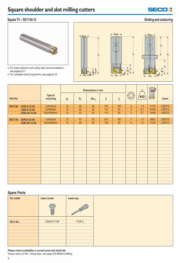
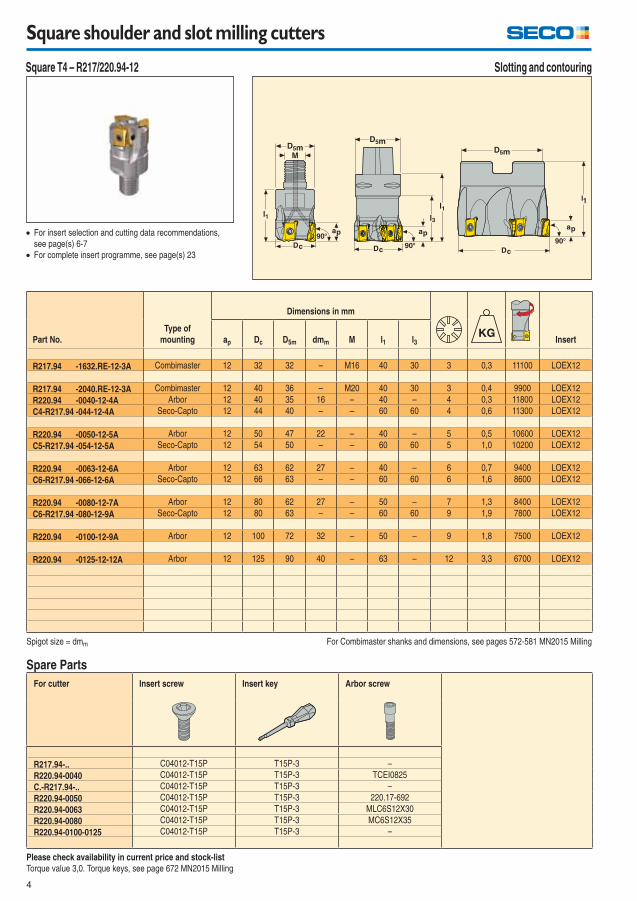
Square shoulder and slot milling cutters
For cutter Insert screw Insert key
R217.94-.. C04012-T15P T15P-3
Spare Parts
For insert selection and cutting data recommendations,
see page(s) 6-7
For complete insert programme, see page(s) 23
Please check availability in current price and stock-list
Torque value 3,0 Nm, Torque keys, see page 672 MN2015 Milling
Part No.
Type of
mounting
Dimensions in mm
Insertap Dc dmm l2 l3
R217.94 -3232.0-12-3A Cylindrical 12 32 32 195 135 3 1,2 11100 LOEX12
-3232.3-12-3A Cyl/Weldon 12 32 32 110 30 3 0,7 12400 LOEX12
-2532.3S-12-3A Seco/Weldon 12 32 25 110 30 3 0,7 12400 LOEX12
R217.94 -3240.0-12-4A Cylindrical 12 40 32 210 150 4 1,4 9900 LOEX12
-3240.3S-12-4A Seco/Weldon 12 40 32 120 30 4 1,3 11100 LOEX12
Slotting and contouring Square T4 – R217.94-12
3
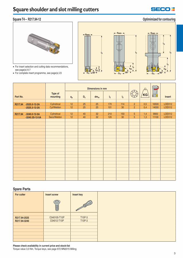
Square shoulder and slot milling cutters
For cutter Insert screw Insert key
R217.94-2525 C040105-T15P T15P-3
R217.94-3240 C04012-T15P T15P-3
Spare Parts
For insert selection and cutting data recommendations,
see page(s) 6-7
For complete insert programme, see page(s) 23
Please check availability in current price and stock-list
Torque value 3,0 Nm, Torque keys, see page 672 MN2015 Milling
Part No.
Type of
mounting
Dimensions in mm
Insertap Dc dmm l2 l3
R217.94 -2525.0-12-2A Cylindrical 12 25 25 170 114 2 0,5 16500 LOEX12
-2525.3-12-2A Cyl/Weldon 12 25 25 101 30 2 0,4 14000 LOEX12
R217.94 -3240.0-12-5A Cylindrical 12 40 32 210 150 5 1,4 9900 LOEX12
-3240.3S-12-5A Seco/Weldon 12 40 32 120 30 5 1,3 11100 LOEX12
Optimimized for contouring Square T4 – R217.94-12
4
Square shoulder and slot milling cutters
For cutter Insert screw Insert key Arbor screw
R217.94-.. C04012-T15P T15P-3 –
R220.94-0040 C04012-T15P T15P-3 TCEI0825
C.-R217.94-.. C04012-T15P T15P-3 –
R220.94-0050 C04012-T15P T15P-3 220.17-692
R220.94-0063 C04012-T15P T15P-3 MLC6S12X30
R220.94-0080 C04012-T15P T15P-3 MC6S12X35
R220.94-0100-0125 C04012-T15P T15P-3 –
Spare Parts
For insert selection and cutting data recommendations,
see page(s) 6-7
For complete insert programme, see page(s) 23
Please check availability in current price and stock-list
Torque value 3,0. Torque keys, see page 672 MN2015 Milling
Spigot size = dmm For Combimaster shanks and dimensions, see pages 572-581 MN2015 Milling
Part No.
Type of
mounting
Dimensions in mm
Insertap Dc D5m dmm M l1 l3
R217.94 -1632.RE-12-3A Combimaster 12 32 32 – M16 40 30 3 0,3 11100 LOEX12
R217.94 -2040.RE-12-3A Combimaster 12 40 36 – M20 40 30 3 0,4 9900 LOEX12
R220.94 -0040-12-4A Arbor 12 40 35 16 – 40 – 4 0,3 11800 LOEX12
C4-R217.94 -044-12-4A Seco-Capto 12 44 40 – – 60 60 4 0,6 11300 LOEX12
R220.94 -0050-12-5A Arbor 12 50 47 22 – 40 – 5 0,5 10600 LOEX12
C5-R217.94 -054-12-5A Seco-Capto 12 54 50 – – 60 60 5 1,0 10200 LOEX12
R220.94 -0063-12-6A Arbor 12 63 62 27 – 40 – 6 0,7 9400 LOEX12
C6-R217.94 -066-12-6A Seco-Capto 12 66 63 – – 60 60 6 1,6 8600 LOEX12
R220.94 -0080-12-7A Arbor 12 80 62 27 – 50 – 7 1,3 8400 LOEX12
C6-R217.94 -080-12-9A Seco-Capto 12 80 63 – – 60 60 9 1,9 7800 LOEX12
R220.94 -0100-12-9A Arbor 12 100 72 32 – 50 – 9 1,8 7500 LOEX12
R220.94 -0125-12-12A Arbor 12 125 90 40 – 63 – 12 3,3 6700 LOEX12
Slotting and contouring Square T4 – R217/220.94-12
5
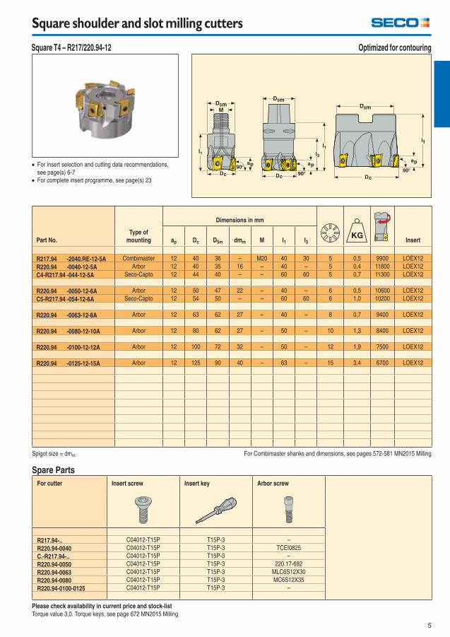
Square shoulder and slot milling cutters
For cutter Insert screw Insert key Arbor screw
R217.94-.. C04012-T15P T15P-3 –
R220.94-0040 C04012-T15P T15P-3 TCEI0825
C.-R217.94-.. C04012-T15P T15P-3 –
R220.94-0050 C04012-T15P T15P-3 220.17-692
R220.94-0063 C04012-T15P T15P-3 MLC6S12X30
R220.94-0080 C04012-T15P T15P-3 MC6S12X35
R220.94-0100-0125 C04012-T15P T15P-3 –
Spare Parts
For insert selection and cutting data recommendations,
see page(s) 6-7
For complete insert programme, see page(s) 23
Please check availability in current price and stock-list
Torque value 3,0. Torque keys, see page 672 MN2015 Milling
Spigot size = dmm For Combimaster shanks and dimensions, see pages 572-581 MN2015 Milling
Part No.
Type of
mounting
Dimensions in mm
Insertap Dc D5m dmm M l1 l3
R217.94 -2040.RE-12-5A Combimaster 12 40 36 – M20 40 30 5 0,5 9900 LOEX12
R220.94 -0040-12-5A Arbor 12 40 35 16 – 40 – 5 0,4 11800 LOEX12
C4-R217.94 -044-12-5A Seco-Capto 12 44 40 – – 60 60 5 0,7 11300 LOEX12
R220.94 -0050-12-6A Arbor 12 50 47 22 – 40 – 6 0,5 10600 LOEX12
C5-R217.94 -054-12-6A Seco-Capto 12 54 50 – – 60 60 6 1,0 10200 LOEX12
R220.94 -0063-12-8A Arbor 12 63 62 27 – 40 – 8 0,7 9400 LOEX12
R220.94 -0080-12-10A Arbor 12 80 62 27 – 50 – 10 1,3 8400 LOEX12
R220.94 -0100-12-12A Arbor 12 100 72 32 – 50 – 12 1,9 7500 LOEX12
R220.94 -0125-12-15A Arbor 12 125 90 40 – 63 – 15 3,4 6700 LOEX12
Optimized for contouring Square T4 – R217/220.94-12
6
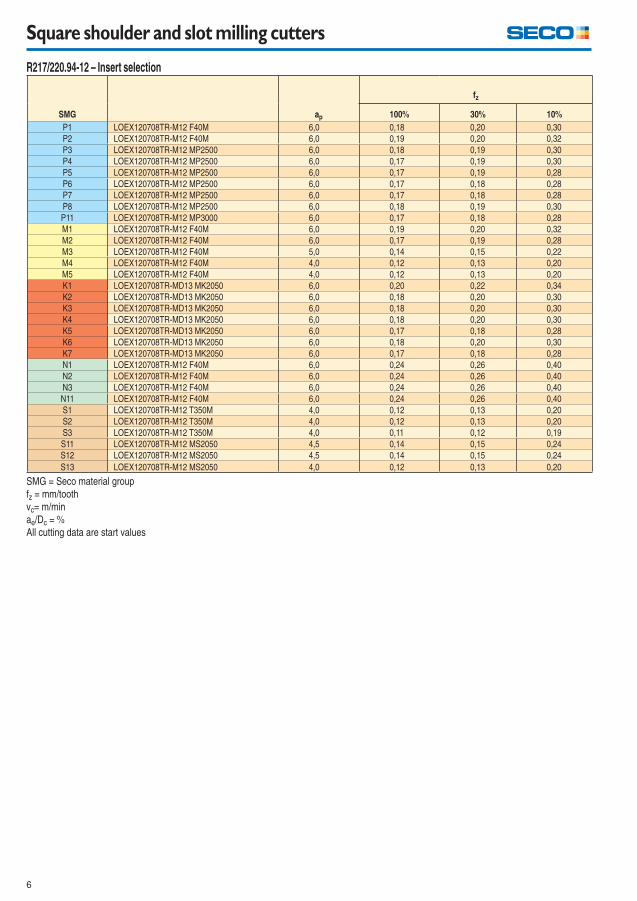
Square shoulder and slot milling cutters
R217/220.94-12 – Insert selection
SMG ap
fz
100% 30% 10%
P1 LOEX120708TR-M12 F40M 6,0 0,18 0,20 0,30
P2 LOEX120708TR-M12 F40M 6,0 0,19 0,20 0,32
P3 LOEX120708TR-M12 MP2500 6,0 0,18 0,19 0,30
P4 LOEX120708TR-M12 MP2500 6,0 0,17 0,19 0,30
P5 LOEX120708TR-M12 MP2500 6,0 0,17 0,19 0,28
P6 LOEX120708TR-M12 MP2500 6,0 0,17 0,18 0,28
P7 LOEX120708TR-M12 MP2500 6,0 0,17 0,18 0,28
P8 LOEX120708TR-M12 MP2500 6,0 0,18 0,19 0,30
P11 LOEX120708TR-M12 MP3000 6,0 0,17 0,18 0,28
M1 LOEX120708TR-M12 F40M 6,0 0,19 0,20 0,32
M2 LOEX120708TR-M12 F40M 6,0 0,17 0,19 0,28
M3 LOEX120708TR-M12 F40M 5,0 0,14 0,15 0,22
M4 LOEX120708TR-M12 F40M 4,0 0,12 0,13 0,20
M5 LOEX120708TR-M12 F40M 4,0 0,12 0,13 0,20
K1 LOEX120708TR-MD13 MK2050 6,0 0,20 0,22 0,34
K2 LOEX120708TR-MD13 MK2050 6,0 0,18 0,20 0,30
K3 LOEX120708TR-MD13 MK2050 6,0 0,18 0,20 0,30
K4 LOEX120708TR-MD13 MK2050 6,0 0,18 0,20 0,30
K5 LOEX120708TR-MD13 MK2050 6,0 0,17 0,18 0,28
K6 LOEX120708TR-MD13 MK2050 6,0 0,18 0,20 0,30
K7 LOEX120708TR-MD13 MK2050 6,0 0,17 0,18 0,28
N1 LOEX120708TR-M12 F40M 6,0 0,24 0,26 0,40
N2 LOEX120708TR-M12 F40M 6,0 0,24 0,26 0,40
N3 LOEX120708TR-M12 F40M 6,0 0,24 0,26 0,40
N11 LOEX120708TR-M12 F40M 6,0 0,24 0,26 0,40
S1 LOEX120708TR-M12 T350M 4,0 0,12 0,13 0,20
S2 LOEX120708TR-M12 T350M 4,0 0,12 0,13 0,20
S3 LOEX120708TR-M12 T350M 4,0 0,11 0,12 0,19
S11 LOEX120708TR-M12 MS2050 4,5 0,14 0,15 0,24
S12 LOEX120708TR-M12 MS2050 4,5 0,14 0,15 0,24
S13 LOEX120708TR-M12 MS2050 4,0 0,12 0,13 0,20
SMG = Seco material group
fz = mm/tooth
vc= m/min
ae/Dc = %
All cutting data are start values
7
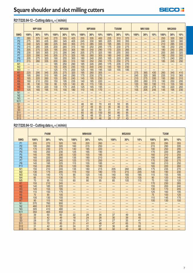
Square shoulder and slot milling cutters
R217/220.94-12 – Cutting data vc = ( m/min)
SMG
MP1500 MP2500 MP3000 T350M MK1500 MK2050
100% 30% 10% 100% 30% 10% 100% 30% 10% 100% 30% 10% 100% 30% 10% 100% 30% 10%
P1 285 375 445 270 355 425 255 335 400 235 310 370 — — — 250 330 390P2 275 365 435 260 345 405 245 330 385 225 300 355 — — — 240 320 380P3 240 325 380 225 300 355 215 285 335 195 265 310 — — — 210 285 330P4 215 285 335 200 265 315 190 250 295 175 230 275 — — — 185 250 290P5 205 275 325 195 255 305 185 240 290 170 220 265 — — — 180 240 285P6 230 305 365 215 290 340 205 275 325 190 255 300 — — — 200 265 320P7 220 290 345 205 275 325 195 260 305 180 240 280 — — — 190 250 300P8 205 275 320 190 255 300 180 240 285 165 220 260 — — — 175 240 280P11 215 280 335 200 265 315 190 250 295 175 230 275 — — — 185 245 290M1 — — — 185 250 290 185 245 285 175 235 270 — — — — — —M2 — — — 155 205 245 155 200 240 145 190 230 — — — — — —M3 — — — 125 170 200 125 165 195 120 155 185 — — — — — —K1 220 290 345 205 275 320 195 260 305 — — — 275 365 430 260 345 410K2 195 260 310 185 240 290 175 230 275 — — — 245 325 385 235 310 365K3 165 220 260 155 205 245 145 195 230 — — — 210 275 330 195 260 310K4 160 210 250 150 195 235 140 185 220 — — — 200 260 315 190 250 295K5 95 130 150 90 120 140 85 115 135 — — — 120 160 190 115 155 180K6 140 185 220 130 170 205 125 165 195 — — — 175 230 275 165 220 260K7 125 165 195 115 155 180 110 145 170 — — — 155 205 245 145 195 230N1 — — — — — — — — — — — — — — — — — —N2 — — — — — — — — — — — — — — — — — —N3 — — — — — — — — — — — — — — — — — —N11 — — — — — — — — — — — — — — — — — —S1 — — — — — — 46 60 70 43 55 65 — — — — — —S2 — — — — — — 37 49 55 35 46 55 — — — — — —S3 — — — — — — 32 43 50 31 41 48 — — — — — —S11 — — — — — — 65 85 100 60 80 95 — — — — — —S12 — — — — — — 36 48 55 34 46 55 — — — — — —S13 — — — — — — 30 39 46 28 37 43 — — — — — —
R217/220.94-12 – Cutting data vc = ( m/min)
SMG
F40M MM4500 MS2050 T25M
100% 30% 10% 100% 30% 10% 100% 30% 10% 100% 30% 10%
P1 205 270 320 165 220 260 — — — 225 295 355P2 195 260 305 160 215 250 — — — 215 290 335P3 170 230 270 140 185 220 — — — 190 250 295P4 155 200 235 125 165 190 — — — 170 220 260P5 145 195 230 120 155 185 — — — 160 210 255P6 165 220 260 135 180 210 — — — 180 240 285P7 155 205 245 125 170 200 — — — 170 230 270P8 145 195 225 115 155 185 — — — 160 210 250P11 150 200 235 120 165 190 — — — 165 220 260M1 155 210 245 135 180 215 205 260 295 175 235 270M2 130 175 205 115 150 180 170 215 245 145 190 230M3 105 140 170 90 120 145 140 165 185 115 155 185M4 85 110 130 75 95 110 105 125 135 90 120 145M5 70 95 110 60 80 95 85 105 115 75 100 120K1 155 210 245 — — — — — — 170 230 265K2 140 185 220 — — — — — — 155 200 240K3 120 155 185 — — — — — — 130 170 205K4 110 150 175 — — — — — — 125 160 195K5 70 90 105 — — — — — — 75 100 120K6 100 130 155 — — — — — — 110 145 170K7 90 115 140 — — — — — — 100 130 150N1 570 760 900 — — — — — — — — —N2 460 610 720 — — — — — — — — —N3 305 410 480 — — — — — — — — —N11 350 465 550 — — — — — — — — —S1 39 50 60 22 29 34 37 49 55 — — —S2 32 42 49 18 24 28 30 39 45 — — —S3 28 37 43 16 21 24 27 35 41 — — —S11 55 70 85 31 41 48 47 65 75 — — —S12 31 42 49 24 31 37 36 49 60 — — —S13 25 34 39 19 25 30 32 42 48 — — —
8
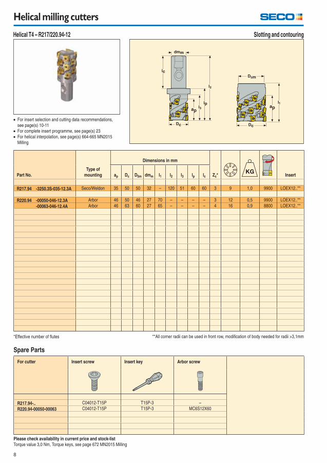
Helical milling cutters
For cutter Insert screw Insert key Arbor screw
R217.94-.. C04012-T15P T15P-3 –
R220.94-00050-00063 C04012-T15P T15P-3 MC6S12X60
Spare Parts
For insert selection and cutting data recommendations,
see page(s) 10-11
For complete insert programme, see page(s) 23
For helical interpolation, see page(s) 664-665 MN2015
Milling
Please check availability in current price and stock-list
Torque value 3,0 Nm, Torque keys, see page 672 MN2015 Milling
*Effective number of fl utes **All corner radii can be used in front row, modifi cation of body needed for radii >3,1mm
Part No.
Type of
mounting
Dimensions in mm
Zc* Insertap Dc D5m dmm l1 l2 l3 lp lc
R217.94 -3250.3S-035-12.3A Seco/Weldon 35 50 50 32 – 120 51 60 60 3 9 1,0 9900 LOEX12..**
R220.94 -00050-046-12.3A Arbor 46 50 46 27 70 – – – – 3 12 0,5 9900 LOEX12..**
-00063-046-12.4A Arbor 46 63 60 27 65 – – – – 4 16 0,9 8800 LOEX12..**
Slotting and contouring Helical T4 – R217/220.94-12
9
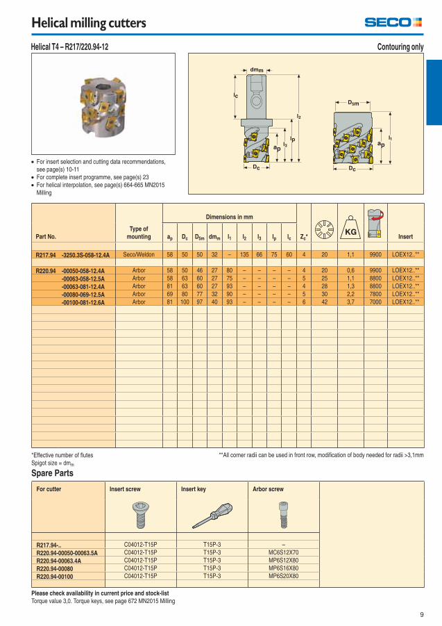
Helical milling cutters
For cutter Insert screw Insert key Arbor screw
R217.94-.. C04012-T15P T15P-3 –
R220.94-00050-00063.5A C04012-T15P T15P-3 MC6S12X70
R220.94-00063.4A C04012-T15P T15P-3 MP6S12X80
R220.94-00080 C04012-T15P T15P-3 MP6S16X80
R220.94-00100 C04012-T15P T15P-3 MP6S20X80
Spare Parts
For insert selection and cutting data recommendations,
see page(s) 10-11
For complete insert programme, see page(s) 23
For helical interpolation, see page(s) 664-665 MN2015
Milling
Please check availability in current price and stock-list
Torque value 3,0. Torque keys, see page 672 MN2015 Milling
*Effective number of fl utes
Spigot size = dmm
**All corner radii can be used in front row, modifi cation of body needed for radii >3,1mm
Part No.
Type of
mounting
Dimensions in mm
Zc* Insertap Dc D5m dmm l1 l2 l3 lp lc
R217.94 -3250.3S-058-12.4A Seco/Weldon 58 50 50 32 – 135 66 75 60 4 20 1,1 9900 LOEX12..**
R220.94 -00050-058-12.4A Arbor 58 50 46 27 80 – – – – 4 20 0,6 9900 LOEX12..**
-00063-058-12.5A Arbor 58 63 60 27 75 – – – – 5 25 1,1 8800 LOEX12..**
-00063-081-12.4A Arbor 81 63 60 27 93 – – – – 4 28 1,3 8800 LOEX12..**
-00080-069-12.5A Arbor 69 80 77 32 90 – – – – 5 30 2,2 7800 LOEX12..**
-00100-081-12.6A Arbor 81 100 97 40 93 – – – – 6 42 3,7 7000 LOEX12..**
Contouring only Helical T4 – R217/220.94-12
10
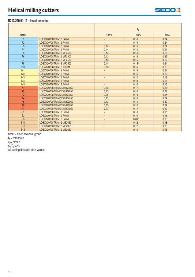
Helical milling cutters
R217/220.94-12 – Insert selection
SMG
fz
100% 30% 10%
P1 LOEX120708TR-M12 F40M – 0,16 0,24
P2 LOEX120708TR-M12 F40M – 0,16 0,24
P3 LOEX120708TR-M12 F40M 0,14 0,15 0,24
P4 LOEX120708TR-M12 F40M 0,14 0,15 0,24
P5 LOEX120708TR-M12 MP2500 0,14 0,15 0,22
P6 LOEX120708TR-M12 MP2500 0,13 0,15 0,22
P7 LOEX120708TR-M12 MP2500 0,13 0,15 0,22
P8 LOEX120708TR-M12 MP2500 0,14 0,15 0,24
P11 LOEX120708TR-M12 T350M 0,13 0,15 0,22
M1 LOEX120708TR-M12 F40M – 0,16 0,24
M2 LOEX120708TR-M12 F40M – 0,15 0,22
M3 LOEX120708TR-M12 F40M – 0,12 0,18
M4 LOEX120708TR-M12 F40M – 0,10 0,16
M5 LOEX120708TR-M12 F40M – 0,10 0,16
K1 LOEX120708TR-MD13 MK2050 0,16 0,17 0,26
K2 LOEX120708TR-MD13 MK2050 0,15 0,16 0,24
K3 LOEX120708TR-MD13 MK2050 0,15 0,16 0,24
K4 LOEX120708TR-MD13 MK2050 0,15 0,16 0,24
K5 LOEX120708TR-MD13 MK2050 0,13 0,14 0,22
K6 LOEX120708TR-MD13 MK2050 0,15 0,16 0,24
K7 LOEX120708TR-MD13 MK2050 0,13 0,14 0,22
S1 LOEX120708TR-M12 F40M – 0,10 0,16
S2 LOEX120708TR-M12 F40M – 0,10 0,16
S3 LOEX120708TR-M12 F40M – 0,095 0,15
S11 LOEX120708TR-M12 MS2050 – 0,12 0,18
S12 LOEX120708TR-M12 MS2050 – 0,12 0,18
S13 LOEX120708TR-M12 MS2050 – 0,10 0,16
SMG = Seco material group
fz = mm/tooth
vc= m/min
ae/Dc = %
All cutting data are start values
11
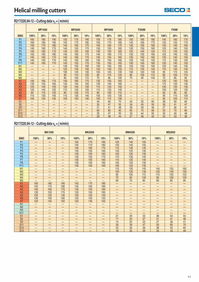
Helical milling cutters
R217/220.94-12 – Cutting data vc = ( m/min)
SMG
MP1500 MP2500 MP3000 T350M F40M
100% 30% 10% 100% 30% 10% 100% 30% 10% 100% 30% 10% 100% 30% 10%
P1 160 180 190 155 175 190 155 175 185 150 165 180 140 160 170P2 160 180 190 155 175 185 150 170 185 145 165 175 135 155 170P3 150 170 180 145 165 175 145 160 175 135 155 165 130 145 160P4 140 160 175 140 155 170 135 155 165 130 150 160 120 140 150P5 140 160 170 135 155 165 130 150 165 125 145 155 115 135 150P6 150 165 180 145 160 175 140 160 170 135 155 165 125 145 155P7 145 160 175 140 160 170 135 155 165 130 150 160 120 140 150P8 140 155 170 135 155 165 130 150 160 125 145 155 115 135 145P11 145 160 170 140 155 170 135 150 165 130 145 160 120 140 150M1 — — — 135 155 165 130 150 165 130 150 160 120 140 155M2 — — — 120 140 150 120 140 150 115 135 145 110 130 140M3 — — — 105 125 135 105 125 135 100 120 135 95 115 125M4 — — — 90 110 120 90 110 120 85 105 115 80 100 110M5 — — — 80 100 110 75 95 105 75 95 105 70 85 95K1 145 165 175 140 160 170 135 155 165 — — — 120 140 150K2 135 155 165 130 150 165 130 145 160 — — — 115 130 145K3 125 145 155 120 140 150 115 135 150 — — — 100 120 135K4 120 140 155 115 135 150 115 135 145 — — — 100 120 130K5 90 110 120 85 105 115 80 100 110 — — — 65 85 95K6 115 130 145 110 130 140 105 125 135 — — — 90 110 120K7 105 125 135 100 120 130 100 115 130 — — — 85 105 115S1 — — — — — — 44 60 70 42 55 65 38 50 60S2 — — — — — — 35 47 55 34 45 50 30 41 47S3 — — — — — — 31 41 48 29 39 46 27 36 41S11 — — — — — — 60 80 90 60 75 85 50 70 80S12 — — — — — — 35 47 55 33 44 50 30 40 48S13 — — — — — — 28 38 44 27 36 42 24 33 38
R217/220.94-12 – Cutting data vc = ( m/min)
SMG
MK1500 MK2050 MM4500 MS2050
100% 30% 10% 100% 30% 10% 100% 30% 10% 100% 30% 10%
P1 — — — 150 170 185 125 145 155 — — —P2 — — — 150 170 180 125 140 155 — — —P3 — — — 140 160 170 115 135 145 — — —P4 — — — 135 155 165 105 125 135 — — —P5 — — — 130 150 160 105 120 135 — — —P6 — — — 140 155 170 110 130 140 — — —P7 — — — 135 155 165 110 125 140 — — —P8 — — — 130 150 160 105 120 130 — — —P11 — — — 135 150 165 105 125 135 — — —M1 — — — — — — 115 130 145 140 155 160M2 — — — — — — 100 120 130 125 140 150M3 — — — — — — 85 105 115 110 120 125M4 — — — — — — 70 90 100 90 100 105M5 — — — — — — 60 75 85 80 85 95K1 160 180 190 155 175 185 — — — — — —K2 150 170 180 145 165 180 — — — — — —K3 140 160 170 135 155 165 — — — — — —K4 135 155 170 135 150 165 — — — — — —K5 105 125 135 100 120 130 — — — — — —K6 130 150 160 125 145 155 — — — — — —K7 120 140 150 120 135 150 — — — — — —N1 — — — — — — — — — — — —N2 — — — — — — — — — — — —N3 — — — — — — — — — — — —N11 — — — — — — — — — — — —S1 — — — — — — 21 29 33 38 50 55S2 — — — — — — 17 23 27 31 41 46S3 — — — — — — 15 20 23 27 36 41S11 — — — — — — 30 39 47 50 65 75S12 — — — — — — 23 30 36 38 50 60S13 — — — — — — 18 25 29 33 43 49
12
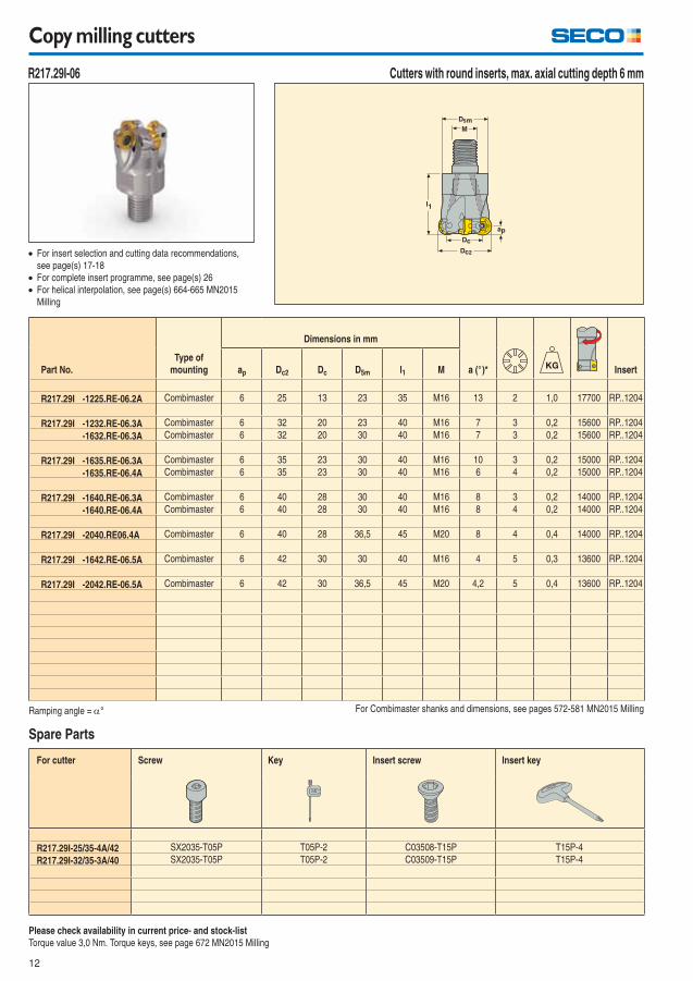
Copy milling cutters
Cutters with round inserts, max. axial cutting depth 6 mm
For cutter Screw Key Insert screw Insert key
R217.29I-25/35-4A/42 SX2035-T05P T05P-2 C03508-T15P T15P-4
R217.29I-32/35-3A/40 SX2035-T05P T05P-2 C03509-T15P T15P-4
R217.29I-06
For insert selection and cutting data recommendations,
see page(s) 17-18
For complete insert programme, see page(s) 26
For helical interpolation, see page(s) 664-665 MN2015
Milling
Please check availability in current price- and stock-list
Torque value 3,0 Nm. Torque keys, see page 672 MN2015 Milling
Ramping angle = ° For Combimaster shanks and dimensions, see pages 572-581 MN2015 Milling
Spare Parts
Part No.
Type of
mounting
Dimensions in mm
a (°)* Insertap Dc2 Dc D5m l1 M
R217.29I -1225.RE-06.2A Combimaster 6 25 13 23 35 M16 13 2 1,0 17700 RP..1204
R217.29I -1232.RE-06.3A Combimaster 6 32 20 23 40 M16 7 3 0,2 15600 RP..1204
-1632.RE-06.3A Combimaster 6 32 20 30 40 M16 7 3 0,2 15600 RP..1204
R217.29I -1635.RE-06.3A Combimaster 6 35 23 30 40 M16 10 3 0,2 15000 RP..1204
-1635.RE-06.4A Combimaster 6 35 23 30 40 M16 6 4 0,2 15000 RP..1204
R217.29I -1640.RE-06.3A Combimaster 6 40 28 30 40 M16 8 3 0,2 14000 RP..1204
-1640.RE-06.4A Combimaster 6 40 28 30 40 M16 8 4 0,2 14000 RP..1204
R217.29I -2040.RE06.4A Combimaster 6 40 28 36,5 45 M20 8 4 0,4 14000 RP..1204
R217.29I -1642.RE-06.5A Combimaster 6 42 30 30 40 M16 4 5 0,3 13600 RP..1204
R217.29I -2042.RE-06.5A Combimaster 6 42 30 36,5 45 M20 4,2 5 0,4 13600 RP..1204
13
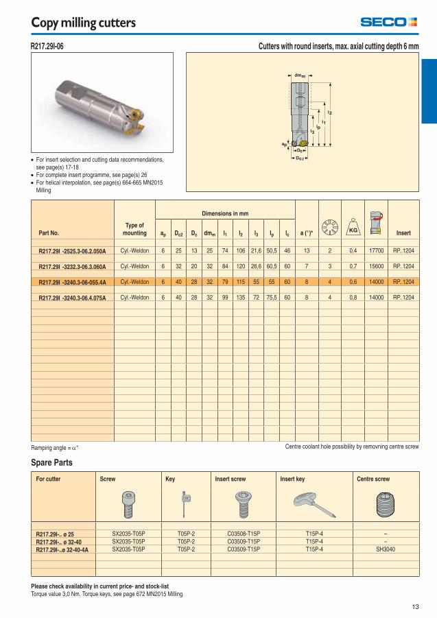
Copy milling cutters
Cutters with round inserts, max. axial cutting depth 6 mm
For cutter Screw Key Insert screw Insert key Centre screw
R217.29I-.. ø 25 SX2035-T05P T05P-2 C03508-T15P T15P-4 –
R217.29I-.. ø 32-40 SX2035-T05P T05P-2 C03509-T15P T15P-4 –
R217.29I-..ø 32-40-4A SX2035-T05P T05P-2 C03509-T15P T15P-4 SH3040
R217.29I-06
For insert selection and cutting data recommendations,
see page(s) 17-18
For complete insert programme, see page(s) 26
For helical interpolation, see page(s) 664-665 MN2015
Milling
Please check availability in current price- and stock-list
Torque value 3,0 Nm. Torque keys, see page 672 MN2015 Milling
Ramping angle = ° Centre coolant hole possibility by removning centre screw
Spare Parts
Part No.
Type of
mounting
Dimensions in mm
a (°)* Insertap Dc2 Dc dmm l1 l2 l3 lp lc
R217.29I -2525.3-06.2.050A Cyl.-Weldon 6 25 13 25 74 106 21,6 50,5 46 13 2 0,4 17700 RP..1204
R217.29I -3232.3-06.3.060A Cyl.-Weldon 6 32 20 32 84 120 26,6 60,5 60 7 3 0,7 15600 RP..1204
R217.29I -3240.3-06-055.4A Cyl.-Weldon 6 40 28 32 79 115 55 55 60 8 4 0,6 14000 RP..1204
R217.29I -3240.3-06.4.075A Cyl.-Weldon 6 40 28 32 99 135 72 75,5 60 8 4 0,8 14000 RP..1204
14
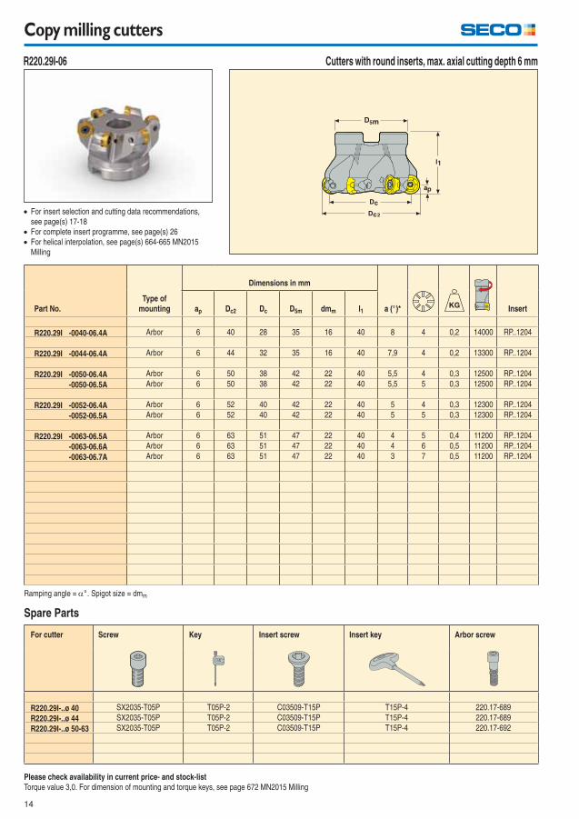
Copy milling cutters
Cutters with round inserts, max. axial cutting depth 6 mm
For cutter Screw Key Insert screw Insert key Arbor screw
R220.29I-..ø 40 SX2035-T05P T05P-2 C03509-T15P T15P-4 220.17-689
R220.29I-..ø 44 SX2035-T05P T05P-2 C03509-T15P T15P-4 220.17-689
R220.29I-..ø 50-63 SX2035-T05P T05P-2 C03509-T15P T15P-4 220.17-692
R220.29I-06
For insert selection and cutting data recommendations,
see page(s) 17-18
For complete insert programme, see page(s) 26
For helical interpolation, see page(s) 664-665 MN2015
Milling
Please check availability in current price- and stock-list
Torque value 3,0. For dimension of mounting and torque keys, see page 672 MN2015 Milling
Ramping angle = ° . Spigot size = dmm
Spare Parts
Part No.
Type of
mounting
Dimensions in mm
a (°)* Insertap Dc2 Dc D5m dmm l1
R220.29I -0040-06.4A Arbor 6 40 28 35 16 40 8 4 0,2 14000 RP..1204
R220.29I -0044-06.4A Arbor 6 44 32 35 16 40 7,9 4 0,2 13300 RP..1204
R220.29I -0050-06.4A Arbor 6 50 38 42 22 40 5,5 4 0,3 12500 RP..1204
-0050-06.5A Arbor 6 50 38 42 22 40 5,5 5 0,3 12500 RP..1204
R220.29I -0052-06.4A Arbor 6 52 40 42 22 40 5 4 0,3 12300 RP..1204
-0052-06.5A Arbor 6 52 40 42 22 40 5 5 0,3 12300 RP..1204
R220.29I -0063-06.5A Arbor 6 63 51 47 22 40 4 5 0,4 11200 RP..1204
-0063-06.6A Arbor 6 63 51 47 22 40 4 6 0,5 11200 RP..1204
-0063-06.7A Arbor 6 63 51 47 22 40 3 7 0,5 11200 RP..1204
15
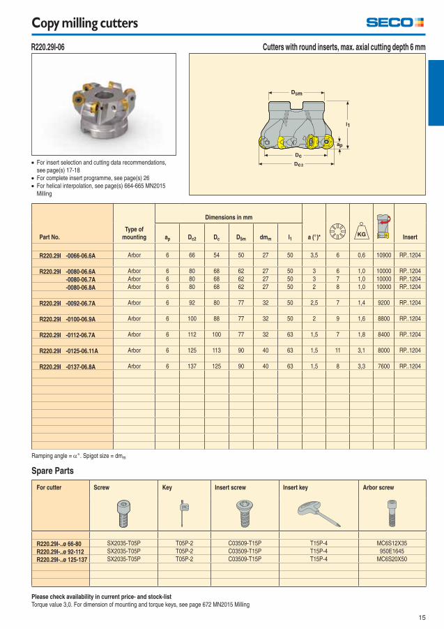
Copy milling cutters
Cutters with round inserts, max. axial cutting depth 6 mm
For cutter Screw Key Insert screw Insert key Arbor screw
R220.29I-..ø 66-80 SX2035-T05P T05P-2 C03509-T15P T15P-4 MC6S12X35
R220.29I-..ø 92-112 SX2035-T05P T05P-2 C03509-T15P T15P-4 950E1645
R220.29I-..ø 125-137 SX2035-T05P T05P-2 C03509-T15P T15P-4 MC6S20X50
R220.29I-06
For insert selection and cutting data recommendations,
see page(s) 17-18
For complete insert programme, see page(s) 26
For helical interpolation, see page(s) 664-665 MN2015
Milling
Please check availability in current price- and stock-list
Torque value 3,0. For dimension of mounting and torque keys, see page 672 MN2015 Milling
Ramping angle = ° . Spigot size = dmm
Spare Parts
Part No.
Type of
mounting
Dimensions in mm
a (°)* Insertap Dc2 Dc D5m dmm l1
R220.29I -0066-06.6A Arbor 6 66 54 50 27 50 3,5 6 0,6 10900 RP..1204
R220.29I -0080-06.6A Arbor 6 80 68 62 27 50 3 6 1,0 10000 RP..1204
-0080-06.7A Arbor 6 80 68 62 27 50 3 7 1,0 10000 RP..1204
-0080-06.8A Arbor 6 80 68 62 27 50 2 8 1,0 10000 RP..1204
R220.29I -0092-06.7A Arbor 6 92 80 77 32 50 2,5 7 1,4 9200 RP..1204
R220.29I -0100-06.9A Arbor 6 100 88 77 32 50 2 9 1,6 8800 RP..1204
R220.29I -0112-06.7A Arbor 6 112 100 77 32 63 1,5 7 1,8 8400 RP..1204
R220.29I -0125-06.11A Arbor 6 125 113 90 40 63 1,5 11 3,1 8000 RP..1204
R220.29I -0137-06.8A Arbor 6 137 125 90 40 63 1,5 8 3,3 7600 RP..1204
16
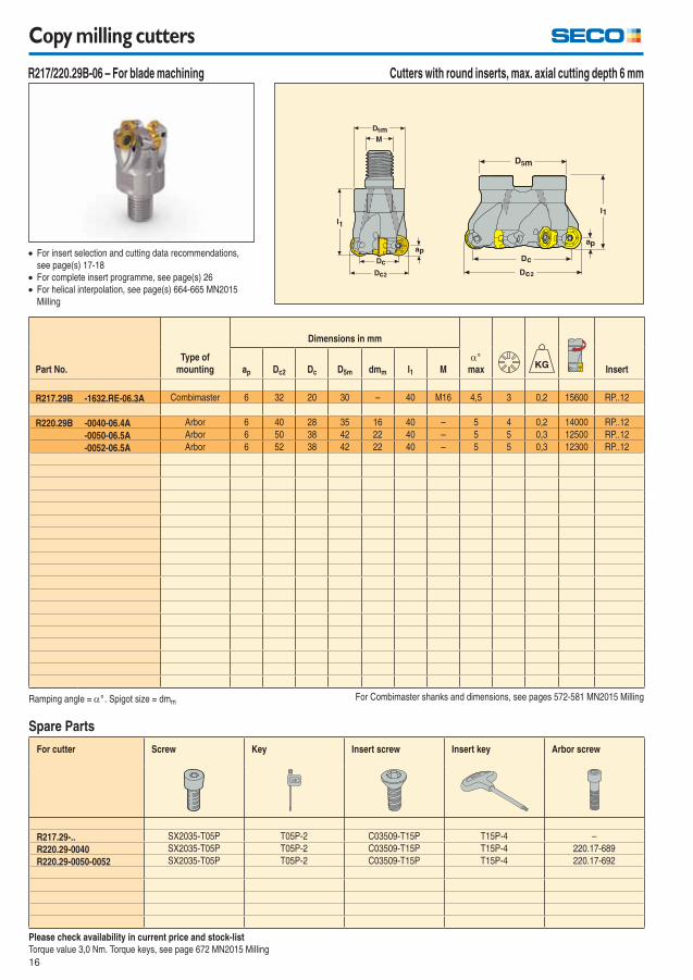
Copy milling cutters
For cutter Screw Key Insert screw Insert key Arbor screw
R217.29-.. SX2035-T05P T05P-2 C03509-T15P T15P-4 –
R220.29-0040 SX2035-T05P T05P-2 C03509-T15P T15P-4 220.17-689
R220.29-0050-0052 SX2035-T05P T05P-2 C03509-T15P T15P-4 220.17-692
Spare Parts
Please check availability in current price and stock-list
Torque value 3,0 Nm. Torque keys, see page 672 MN2015 Milling
Ramping angle = ° . Spigot size = dmm For Combimaster shanks and dimensions, see pages 572-581 MN2015 Milling
Part No.
Type of
mounting
Dimensions in mm
°
max Insertap Dc2 Dc D5m dmm l1 M
R217.29B -1632.RE-06.3A Combimaster 6 32 20 30 – 40 M16 4,5 3 0,2 15600 RP..12
R220.29B -0040-06.4A Arbor 6 40 28 35 16 40 – 5 4 0,2 14000 RP..12
-0050-06.5A Arbor 6 50 38 42 22 40 – 5 5 0,3 12500 RP..12
-0052-06.5A Arbor 6 52 38 42 22 40 – 5 5 0,3 12300 RP..12
Cutters with round inserts, max. axial cutting depth 6 mm
For insert selection and cutting data recommendations,
see page(s) 17-18
For complete insert programme, see page(s) 26
For helical interpolation, see page(s) 664-665 MN2015
Milling
R217/220.29B-06 – For blade machining
17
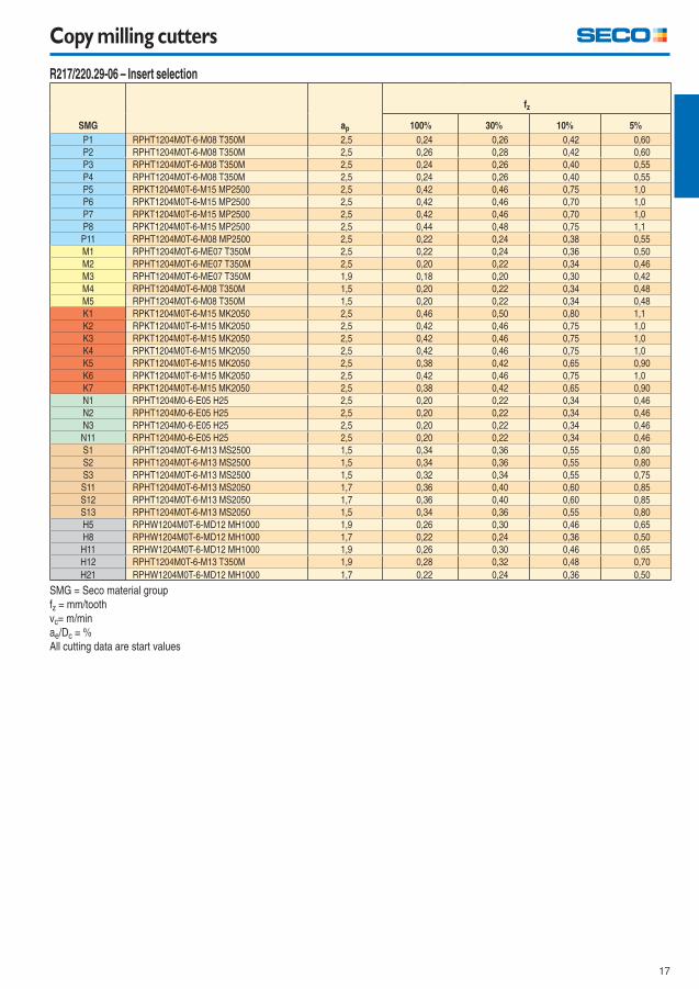
Copy milling cutters
R217/220.29-06 – Insert selection
SMG ap
fz
100% 30% 10% 5%
P1 RPHT1204M0T-6-M08 T350M 2,5 0,24 0,26 0,42 0,60
P2 RPHT1204M0T-6-M08 T350M 2,5 0,26 0,28 0,42 0,60
P3 RPHT1204M0T-6-M08 T350M 2,5 0,24 0,26 0,40 0,55
P4 RPHT1204M0T-6-M08 T350M 2,5 0,24 0,26 0,40 0,55
P5 RPKT1204M0T-6-M15 MP2500 2,5 0,42 0,46 0,75 1,0
P6 RPKT1204M0T-6-M15 MP2500 2,5 0,42 0,46 0,70 1,0
P7 RPKT1204M0T-6-M15 MP2500 2,5 0,42 0,46 0,70 1,0
P8 RPKT1204M0T-6-M15 MP2500 2,5 0,44 0,48 0,75 1,1
P11 RPHT1204M0T-6-M08 MP2500 2,5 0,22 0,24 0,38 0,55
M1 RPHT1204M0T-6-ME07 T350M 2,5 0,22 0,24 0,36 0,50
M2 RPHT1204M0T-6-ME07 T350M 2,5 0,20 0,22 0,34 0,46
M3 RPHT1204M0T-6-ME07 T350M 1,9 0,18 0,20 0,30 0,42
M4 RPHT1204M0T-6-M08 T350M 1,5 0,20 0,22 0,34 0,48
M5 RPHT1204M0T-6-M08 T350M 1,5 0,20 0,22 0,34 0,48
K1 RPKT1204M0T-6-M15 MK2050 2,5 0,46 0,50 0,80 1,1
K2 RPKT1204M0T-6-M15 MK2050 2,5 0,42 0,46 0,75 1,0
K3 RPKT1204M0T-6-M15 MK2050 2,5 0,42 0,46 0,75 1,0
K4 RPKT1204M0T-6-M15 MK2050 2,5 0,42 0,46 0,75 1,0
K5 RPKT1204M0T-6-M15 MK2050 2,5 0,38 0,42 0,65 0,90
K6 RPKT1204M0T-6-M15 MK2050 2,5 0,42 0,46 0,75 1,0
K7 RPKT1204M0T-6-M15 MK2050 2,5 0,38 0,42 0,65 0,90
N1 RPHT1204M0-6-E05 H25 2,5 0,20 0,22 0,34 0,46
N2 RPHT1204M0-6-E05 H25 2,5 0,20 0,22 0,34 0,46
N3 RPHT1204M0-6-E05 H25 2,5 0,20 0,22 0,34 0,46
N11 RPHT1204M0-6-E05 H25 2,5 0,20 0,22 0,34 0,46
S1 RPHT1204M0T-6-M13 MS2500 1,5 0,34 0,36 0,55 0,80
S2 RPHT1204M0T-6-M13 MS2500 1,5 0,34 0,36 0,55 0,80
S3 RPHT1204M0T-6-M13 MS2500 1,5 0,32 0,34 0,55 0,75
S11 RPHT1204M0T-6-M13 MS2050 1,7 0,36 0,40 0,60 0,85
S12 RPHT1204M0T-6-M13 MS2050 1,7 0,36 0,40 0,60 0,85
S13 RPHT1204M0T-6-M13 MS2050 1,5 0,34 0,36 0,55 0,80
H5 RPHW1204M0T-6-MD12 MH1000 1,9 0,26 0,30 0,46 0,65
H8 RPHW1204M0T-6-MD12 MH1000 1,7 0,22 0,24 0,36 0,50
H11 RPHW1204M0T-6-MD12 MH1000 1,9 0,26 0,30 0,46 0,65
H12 RPHT1204M0T-6-M13 T350M 1,9 0,28 0,32 0,48 0,70
H21 RPHW1204M0T-6-MD12 MH1000 1,7 0,22 0,24 0,36 0,50
SMG = Seco material group
fz = mm/tooth
vc= m/min
ae/Dc = %
All cutting data are start values
18
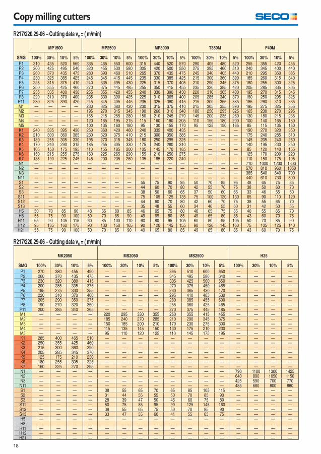
Copy milling cutters
R217/220.29-06 – Cutting data vc = ( m/min)
SMG
MP1500 MP2500 MP3000 T350M F40M
100% 30% 10% 5% 100% 30% 10% 5% 100% 30% 10% 5% 100% 30% 10% 5% 100% 30% 10% 5%
P1 310 435 520 560 335 465 550 600 315 440 520 570 290 405 480 520 255 355 420 455P2 300 425 495 540 320 455 530 580 305 420 500 550 275 395 460 510 240 345 400 440P3 260 370 435 475 280 390 460 510 265 370 435 475 245 340 405 440 210 295 350 385P4 230 325 385 425 245 345 415 445 235 330 385 425 215 300 360 390 185 260 315 340P5 225 315 375 410 240 335 395 430 225 315 370 405 210 290 345 375 180 255 300 325P6 250 355 425 460 270 375 445 485 255 350 415 455 235 330 385 420 205 285 335 365P7 235 335 400 430 255 355 420 455 240 330 390 430 220 310 365 400 195 270 315 345P8 220 310 370 400 235 330 390 425 225 310 365 400 205 285 340 370 180 250 295 325P11 230 325 390 420 245 345 405 445 235 325 380 415 215 300 355 385 185 260 310 335M1 — — — — 230 325 380 420 230 315 375 410 215 305 355 390 195 275 325 355M2 — — — — 195 270 315 345 190 260 310 340 180 250 295 325 165 230 270 295M3 — — — — 155 215 255 280 150 210 245 270 145 200 235 260 130 180 215 235M4 — — — — 120 165 195 215 115 160 190 205 110 150 180 200 100 140 165 180M5 — — — — 100 135 160 180 95 130 155 170 95 125 150 165 85 115 135 150K1 240 335 395 430 250 360 420 460 240 335 400 435 — — — — 190 270 320 350K2 210 300 360 385 230 320 375 410 215 300 350 385 — — — — 175 240 285 310K3 180 255 305 330 195 270 315 345 180 250 295 325 — — — — 145 205 240 260K4 170 240 290 315 185 255 305 330 175 240 280 310 — — — — 140 195 230 250K5 105 150 175 195 110 155 185 200 105 145 170 185 — — — — 85 120 140 155K6 150 215 255 275 160 225 265 290 155 210 250 275 — — — — 125 170 200 220K7 135 190 225 245 145 200 235 260 135 185 220 240 — — — — 110 150 175 195N1 — — — — — — — — — — — — — — — — 710 1000 1200 1300N2 — — — — — — — — — — — — — — — — 570 810 960 1050N3 — — — — — — — — — — — — — — — — 385 540 640 700N11 — — — — — — — — — — — — — — — — 440 610 730 800S1 — — — — — — — — 55 75 90 95 50 70 85 95 48 65 75 85S2 — — — — — — — — 44 60 70 80 42 55 70 75 38 50 60 70S3 — — — — — — — — 38 50 60 65 37 50 60 65 33 46 55 60S11 — — — — — — — — 75 105 125 135 75 100 120 130 65 90 110 120S12 — — — — — — — — 44 60 70 80 42 60 70 75 38 55 65 70S13 — — — — — — — — 35 48 55 60 34 46 55 60 31 42 50 55H5 50 70 85 90 48 65 80 85 46 65 75 80 46 65 75 85 40 55 65 70H8 55 75 90 100 50 70 85 90 49 65 80 85 49 65 80 85 43 60 70 75H11 65 90 105 115 60 85 100 110 60 80 95 105 60 80 95 105 50 70 85 90H12 95 135 160 175 90 130 150 165 90 120 145 155 90 120 145 160 75 105 125 140H21 55 75 90 100 50 70 85 90 49 65 80 85 49 65 80 85 43 60 70 75
R217/220.29-06 – Cutting data vc = ( m/min)
SMG
MK2050 MS2050 MS2500 H25
100% 30% 10% 5% 100% 30% 10% 5% 100% 30% 10% 5% 100% 30% 10% 5%
P1 270 380 455 490 — — — — 365 510 600 650 — — — —P2 260 370 435 475 — — — — 345 495 580 640 — — — —P3 230 320 380 415 — — — — 305 425 500 550 — — — —P4 200 285 335 375 — — — — 270 375 450 485 — — — —P5 195 275 330 355 — — — — 260 365 430 470 — — — —P6 220 310 370 400 — — — — 295 410 485 530 — — — —P7 205 290 350 375 — — — — 280 385 455 500 — — — —P8 190 270 320 350 — — — — 255 360 425 465 — — — —P11 200 285 340 365 — — — — 270 375 445 485 — — — —M1 — — — — 220 295 330 355 250 355 415 455 — — — —M2 — — — — 185 240 270 285 210 290 345 375 — — — —M3 — — — — 150 185 200 210 170 230 275 300 — — — —M4 — — — — 115 135 145 150 130 175 210 230 — — — —M5 — — — — 95 110 120 125 110 145 175 195 — — — —K1 285 400 465 510 — — — — — — — — — — — —K2 250 355 425 460 — — — — — — — — — — — —K3 215 300 360 390 — — — — — — — — — — — —K4 205 285 345 370 — — — — — — — — — — — —K5 125 175 210 230 — — — — — — — — — — — —K6 180 255 305 325 — — — — — — — — — — — —K7 160 225 270 295 — — — — — — — — — — — —N1 — — — — — — — — — — — — 790 1100 1300 1425N2 — — — — — — — — — — — — 640 890 1050 1150N3 — — — — — — — — — — — — 425 590 700 770N11 — — — — — — — — — — — — 485 680 800 880S1 — — — — 38 55 65 70 65 85 105 115 — — — —S2 — — — — 31 44 55 55 50 70 85 90 — — — —S3 — — — — 28 39 47 50 45 60 75 80 — — — —S11 — — — — 50 75 85 95 90 125 145 160 — — — —S12 — — — — 38 55 65 75 50 70 85 90 — — — —S13 — — — — 33 47 55 60 41 55 65 75 — — — —H5 — — — — — — — — — — — — — — — —H8 — — — — — — — — — — — — — — — —H11 — — — — — — — — — — — — — — — —H12 — — — — — — — — — — — — — — — —H21 — — — — — — — — — — — — — — — —
19
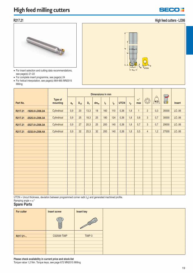
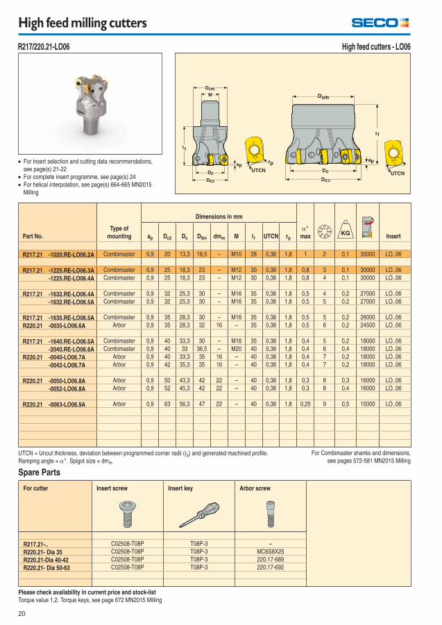
High feed milling cutters
High feed cutters - LO06
For cutter Insert screw Insert key
R217.21-.. C02508-T08P T08P-3
R217.21
For insert selection and cutting data recommendations,
see page(s) 21-22
For complete insert programme, see page(s) 24
For helical interpolation, see page(s) 664-665 MN2015
Milling
Please check availability in current price and stock-list
Torque value 1,2 Nm. Torque keys, see page 672 MN2015 Milling
UTCN = Uncut thickness, deviation between programmed corner radii (rp) and generated machined profi le.
Ramping angle = °
Spare Parts
Part No.
Type of
mounting
Dimensions in mm
°
max Insertap Dc2 Dc dmm l2 lp UTCN rp
R217.21 -1820.0-LO06.2A Cylindrical 0,9 20 13,3 18 160 110 0,38 1,8 1 2 0,3 35000 LO..06
R217.21 -2525.0-LO06.3A Cylindrical 0,9 25 18,3 25 180 124 0,38 1,8 0,8 3 0,7 30000 LO..06
R217.21 -2527.0-LO06.3A Cylindrical 0,9 27 20,3 25 200 140 0,38 1,8 0,7 3 0,7 29000 LO..06
R217.21 -3232.0-LO06.4A Cylindrical 0,9 32 25,3 32 200 140 0,38 1,8 0,5 4 1,2 27000 LO..06
20
High feed milling cutters
For cutter Insert screw Insert key Arbor screw
R217.21-.. C02508-T08P T08P-3 –
R220.21- Dia 35 C02508-T08P T08P-3 MC6S8X25
R220.21-Dia 40-42 C02508-T08P T08P-3 220.17-689
R220.21- Dia 50-63 C02508-T08P T08P-3 220.17-692
Spare Parts
For insert selection and cutting data recommendations,
see page(s) 21-22
For complete insert programme, see page(s) 24
For helical interpolation, see page(s) 664-665 MN2015
Milling
Please check availability in current price and stock-list
Torque value 1,2. Torque keys, see page 672 MN2015 Milling
UTCN = Uncut thickness, deviation between programmed corner radii (rp) and generated machined profi le.
Ramping angle = ° . Spigot size = dmm
For Combimaster shanks and dimensions,
see pages 572-581 MN2015 Milling
Part No.
Type of
mounting
Dimensions in mm
°
max Insertap Dc2 Dc D5m dmm M l1 UTCN rp
R217.21 -1020.RE-LO06.2A Combimaster 0,9 20 13,3 18,5 – M10 28 0,38 1,8 1 2 0,1 35000 LO..06
R217.21 -1225.RE-LO06.3A Combimaster 0,9 25 18,3 23 – M12 30 0,38 1,8 0,8 3 0,1 30000 LO..06
-1225.RE-LO06.4A Combimaster 0,9 25 18,3 23 – M12 30 0,38 1,8 0,8 4 0,1 30000 LO..06
R217.21 -1632.RE-LO06.4A Combimaster 0,9 32 25,3 30 – M16 35 0,38 1,8 0,5 4 0,2 27000 LO..06
-1632.RE-LO06.5A Combimaster 0,9 32 25,3 30 – M16 35 0,38 1,8 0,5 5 0,2 27000 LO..06
R217.21 -1635.RE-LO06.5A Combimaster 0,9 35 28,3 30 – M16 35 0,38 1,8 0,5 5 0,2 26000 LO..06
R220.21 -0035-LO06.6A Arbor 0,9 35 28,3 32 16 – 35 0,38 1,8 0,5 6 0,2 24500 LO..06
R217.21 -1640.RE-LO06.5A Combimaster 0,9 40 33,3 30 – M16 35 0,38 1,8 0,4 5 0,2 18000 LO..06
-2040.RE-LO06.6A Combimaster 0,9 40 33 36,5 – M20 40 0,38 1,8 0,4 6 0,4 18000 LO..06
R220.21 -0040-LO06.7A Arbor 0,9 40 33,3 35 16 – 40 0,38 1,8 0,4 7 0,2 18000 LO..06
-0042-LO06.7A Arbor 0,9 42 35,3 35 16 – 40 0,38 1,8 0,4 7 0,2 18000 LO..06
R220.21 -0050-LO06.8A Arbor 0,9 50 43,3 42 22 – 40 0,38 1,8 0,3 8 0,3 16000 LO..06
-0052-LO06.8A Arbor 0,9 52 45,3 42 22 – 40 0,38 1,8 0,3 8 0,4 16000 LO..06
R220.21 -0063-LO06.9A Arbor 0,9 63 56,3 47 22 – 40 0,38 1,8 0,25 9 0,5 15000 LO..06
High feed cutters - LO06 R217/220.21-LO06
21
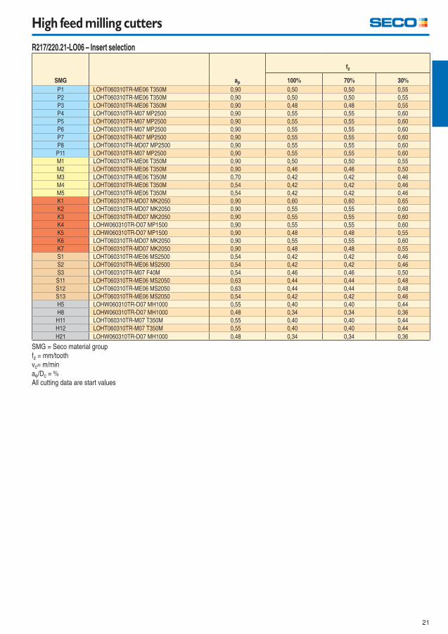
High feed milling cutters
R217/220.21-LO06 – Insert selection
SMG ap
fz
100% 70% 30%
P1 LOHT060310TR-ME06 T350M 0,90 0,50 0,50 0,55
P2 LOHT060310TR-ME06 T350M 0,90 0,50 0,50 0,55
P3 LOHT060310TR-ME06 T350M 0,90 0,48 0,48 0,55
P4 LOHT060310TR-M07 MP2500 0,90 0,55 0,55 0,60
P5 LOHT060310TR-M07 MP2500 0,90 0,55 0,55 0,60
P6 LOHT060310TR-M07 MP2500 0,90 0,55 0,55 0,60
P7 LOHT060310TR-M07 MP2500 0,90 0,55 0,55 0,60
P8 LOHT060310TR-MD07 MP2500 0,90 0,55 0,55 0,60
P11 LOHT060310TR-M07 MP2500 0,90 0,55 0,55 0,60
M1 LOHT060310TR-ME06 T350M 0,90 0,50 0,50 0,55
M2 LOHT060310TR-ME06 T350M 0,90 0,46 0,46 0,50
M3 LOHT060310TR-ME06 T350M 0,70 0,42 0,42 0,46
M4 LOHT060310TR-ME06 T350M 0,54 0,42 0,42 0,46
M5 LOHT060310TR-ME06 T350M 0,54 0,42 0,42 0,46
K1 LOHT060310TR-MD07 MK2050 0,90 0,60 0,60 0,65
K2 LOHT060310TR-MD07 MK2050 0,90 0,55 0,55 0,60
K3 LOHT060310TR-MD07 MK2050 0,90 0,55 0,55 0,60
K4 LOHW060310TR-D07 MP1500 0,90 0,55 0,55 0,60
K5 LOHW060310TR-D07 MP1500 0,90 0,48 0,48 0,55
K6 LOHT060310TR-MD07 MK2050 0,90 0,55 0,55 0,60
K7 LOHT060310TR-MD07 MK2050 0,90 0,48 0,48 0,55
S1 LOHT060310TR-ME06 MS2500 0,54 0,42 0,42 0,46
S2 LOHT060310TR-ME06 MS2500 0,54 0,42 0,42 0,46
S3 LOHT060310TR-M07 F40M 0,54 0,46 0,46 0,50
S11 LOHT060310TR-ME06 MS2050 0,63 0,44 0,44 0,48
S12 LOHT060310TR-ME06 MS2050 0,63 0,44 0,44 0,48
S13 LOHT060310TR-ME06 MS2050 0,54 0,42 0,42 0,46
H5 LOHW060310TR-D07 MH1000 0,55 0,40 0,40 0,44
H8 LOHW060310TR-D07 MH1000 0,48 0,34 0,34 0,36
H11 LOHT060310TR-M07 T350M 0,55 0,40 0,40 0,44
H12 LOHT060310TR-M07 T350M 0,55 0,40 0,40 0,44
H21 LOHW060310TR-D07 MH1000 0,48 0,34 0,34 0,36
SMG = Seco material group
fz = mm/tooth
vc= m/min
ae/Dc = %
All cutting data are start values
22
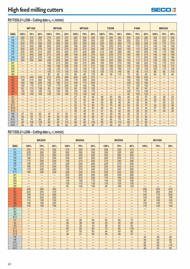
High feed milling cutters
R217/220.21-LO06 – Cutting data vc = ( m/min)
SMG
MP1500 MP2500 MP3000 T350M F40M MM4500
100% 70% 30% 100% 70% 30% 100% 70% 30% 100% 70% 30% 100% 70% 30% 100% 70% 30%
P1 280 315 385 270 305 375 260 290 355 260 295 360 205 235 285 185 210 255P2 270 305 375 265 300 365 250 285 345 255 290 350 200 225 275 180 205 245P3 240 270 330 235 265 320 220 250 305 220 250 300 175 200 245 155 175 210P4 210 240 290 205 230 285 195 220 270 195 220 270 155 175 215 140 155 190P5 200 225 275 195 220 270 185 210 255 190 215 260 150 170 205 135 150 185P6 225 255 310 220 250 305 210 235 285 210 240 290 165 190 230 150 170 205P7 215 240 295 210 235 285 195 220 270 200 225 275 160 180 215 140 160 195P8 200 225 275 195 220 270 185 210 255 185 210 255 150 170 205 130 150 180P11 205 235 285 200 230 280 190 215 265 195 220 265 155 175 210 135 155 190M1 — — — 190 215 265 190 210 260 195 220 270 160 180 225 155 175 210M2 — — — 160 180 220 155 175 215 165 185 225 135 150 185 130 145 175M3 — — — 130 145 175 125 140 170 130 150 180 110 125 150 105 115 140M4 — — — 100 115 135 100 110 135 105 115 140 85 95 115 80 90 110M5 — — — 85 95 115 85 95 110 85 95 115 70 80 95 65 75 90K1 215 245 295 210 235 290 200 225 275 — — — 160 180 220 — — —K2 190 215 265 185 210 255 175 200 245 — — — 140 160 195 — — —K3 160 185 225 160 180 215 150 170 205 — — — 120 135 165 — — —K4 155 175 210 150 170 205 145 160 195 — — — 115 130 155 — — —K5 95 110 130 95 105 125 90 100 120 — — — 70 80 95 — — —K6 135 155 185 135 150 185 125 140 175 — — — 100 115 140 — — —K7 120 140 165 120 135 160 115 130 155 — — — 90 100 125 — — —S1 — — — — — — 47 50 65 48 55 65 40 45 55 25 28 33S2 — — — — — — 37 42 50 39 43 50 32 36 44 20 22 27S3 — — — — — — 33 37 44 34 38 46 28 32 38 17 20 23S11 — — — — — — 65 75 90 70 75 90 55 65 75 35 39 46S12 — — — — — — 38 42 50 39 44 50 33 36 44 27 30 36S13 — — — — — — 30 34 41 31 35 42 26 29 35 21 24 29H5 47 55 65 42 47 55 41 46 55 44 49 60 35 39 47 — — —H8 50 55 70 44 50 60 43 49 60 47 50 60 37 42 50 — — —H11 60 70 80 55 60 70 50 60 70 55 65 75 45 50 60 — — —H12 90 100 125 80 90 110 80 90 105 85 95 115 65 75 90 — — —H21 50 55 70 44 50 60 43 49 60 47 50 60 37 42 50 — — —
R217/220.21-LO06 – Cutting data vc = ( m/min)
SMG
MK2050 MS2050 MS2500 MH1000
100% 70% 30% 100% 70% 30% 100% 70% 30% 100% 70% 30%
P1 245 275 335 275 300 340 295 335 410 — — —P2 235 265 325 265 290 330 290 325 400 — — —P3 210 235 290 230 255 285 255 290 350 — — —P4 185 210 255 205 225 250 225 255 310 — — —P5 175 200 240 195 215 235 215 240 295 — — —P6 195 225 270 220 240 265 240 270 330 — — —P7 185 210 255 205 225 250 225 255 315 — — —P8 175 200 240 195 215 240 215 240 295 — — —P11 180 205 250 200 220 245 220 250 305 — — —M1 — — — 230 255 290 205 235 285 — — —M2 — — — 190 210 230 170 195 235 — — —M3 — — — 145 160 170 140 155 190 — — —M4 — — — 105 115 120 110 125 150 — — —M5 — — — 90 100 100 90 100 125 — — —K1 255 290 355 — — — — — — 200 225 275K2 225 255 315 — — — — — — 175 200 240K3 190 215 265 — — — — — — 150 170 205K4 185 205 250 — — — — — — 140 160 195K5 115 130 155 — — — — — — 90 100 120K6 160 180 220 — — — — — — 125 140 170K7 145 165 195 — — — — — — 110 125 150N1 — — — — — — — — — — — —N2 — — — — — — — — — — — —N3 — — — — — — — — — — — —N11 — — — — — — — — — — — —S1 — — — 45 48 60 55 60 75 — — —S2 — — — 36 38 48 43 48 60 — — —S3 — — — 33 35 43 38 42 50 — — —S11 — — — 60 65 80 75 85 100 — — —S12 — — — 47 50 60 44 49 60 — — —S13 — — — 39 41 50 35 39 47 — — —H5 — — — — — — — — — 44 49 60H8 — — — — — — — — — 46 50 65H11 — — — — — — — — — 55 60 75H12 — — — — — — — — — 85 95 115H21 — — — — — — — — — 46 50 65
23
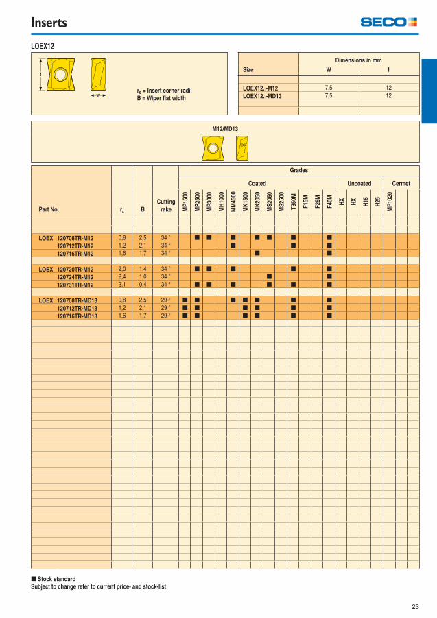
Inserts
LOEX12
Part No. r B
Cutting
rake
Grades
Coated Uncoated CermetM
P15
00
MP
2500
MP
3000
MH
1000
MM
4500
MK
1500
MK
2050
MS
2050
MS
2500
T35
0M
F15
M
F25
M
F40
M
HX
HX
H15
H25
MP
1020
LOEX 120708TR-M12 0,8 2,5 34 ° [ [ [ [ [ [ [
120712TR-M12 1,2 2,1 34 ° [ [ [
120716TR-M12 1,6 1,7 34 ° [ [
LOEX 120720TR-M12 2,0 1,4 34 ° [ [ [ [ [
120724TR-M12 2,4 1,0 34 ° [ [
120731TR-M12 3,1 0,4 34 ° [ [ [ [ [ [
LOEX 120708TR-MD13 0,8 2,5 29 ° [ [ [ [ [ [ [
120712TR-MD13 1,2 2,1 29 ° [ [ [ [ [ [
120716TR-MD13 1,6 1,7 29 ° [ [ [ [ [ [
[ Stock standard
Subject to change refer to current price- and stock-list
Dimensions in mm
Size W l
LOEX12..-M12 7,5 12
LOEX12..-MD13 7,5 12
M12/MD13
re = Insert corner radii
B = Wiper fl at width
24
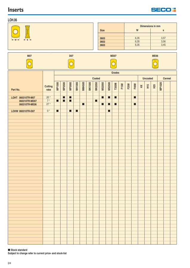
Inserts
LOH.06
Part No.
Cutting
rake
Grades
Coated Uncoated Cermet
MP
1500
MP
2500
MP
3000
MH
1000
MM
4500
MK
1500
MK
2050
MS
2050
MS
2500
T35
0M
F15
M
F25
M
F40
M
HX
H15
H25
MP
1020
LOHT 060310TR-M07 20 ° [ [ [ [ [ [
060310TR-MD07 7 ° [ [ [ [
060310TR-ME06 27 ° [ [ [ [ [
LOHW 060310TR-D07 0 ° [ [ [ [
[ Stock standard
Subject to change refer to current price- and stock-list
Size
Dimensions in mm
W s
0603 6,35 3,57
0603 6,35 3,56
0603 6,35 3,45
M07 D07 MD07 ME06
25
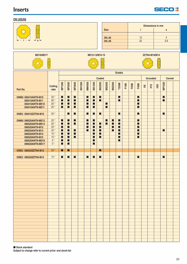
Inserts
ON.U05/09
Part No.
Cutting
rake
Grades
Coated Uncoated Cermet
MP
1500
MP
2500
MP
3000
MH
1000
MM
4500
MK
1500
MK
2050
MS
2050
MS
2500
T35
0M
F15
M
F25
M
F40
M
HX
H15
H25
MP
1020
ONMU 050410ANTN-M10 20 ° [ [ [ [ [ [ [ [ [
050410ANTN-M11 20 ° [ [ [ [ [ [ [ [ [
050410ANTN-ME10 20 ° [ [ [ [ [ [ [
050410ANTN-ME11 20 ° [ [ [ [ [ [ [
ONEU 050410ZZTN4-M10 20 ° [ [ [ [ [ [ [ [
ONMU 090520ANTN-ME12 20 ° [ [ [ [ [ [ [ [ [
090520ANTN-ME13 20 ° [ [ [ [ [ [ [ [ [ [
090520ANTN-M12 20 ° [ [ [ [ [ [ [ [
090520ANTN-M13 20 ° [ [ [ [ [ [ [ [ [ [
090520ANTN-M14 15 ° [ [ [ [ [ [ [
090520ANTN-M15 15 ° [ [ [ [ [ [ [
090520ANTN-MD16 0 ° [ [ [ [
090520ANTN-MD17 0 ° [ [ [
ONEU 090520ZZTN4-M12 20 ° [ [ [
ONEU 090520ZZTN4-M14 15 ° [ [ [ [ [ [ [ [ [
[ Stock standard
Subject to change refer to current price- and stock-list
Dimensions in mm
Size l s
ON..05 12 4
ON..09 22 5,8
MD16/MD17 ME10-13/M10-15 ZZTN4-M10/M14
26
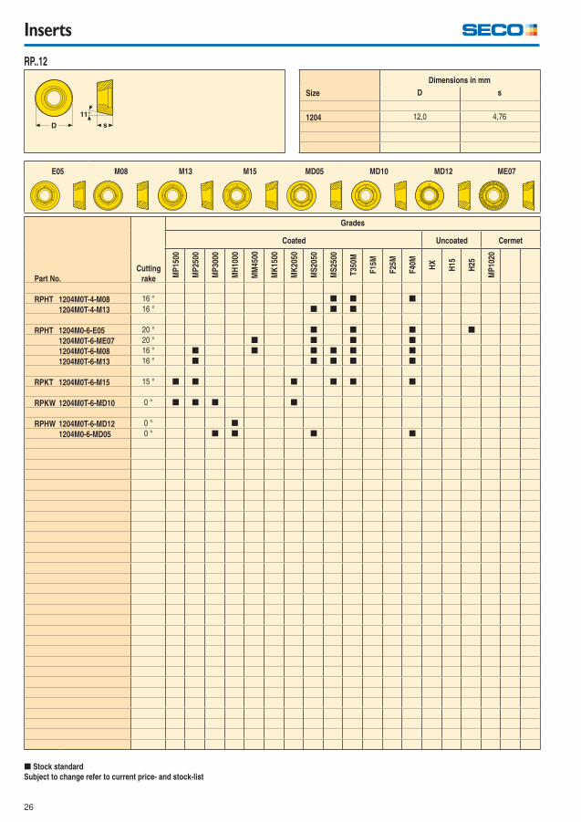
Inserts
RP..12
Part No.
Cutting
rake
Grades
Coated Uncoated Cermet
MP
1500
MP
2500
MP
3000
MH
1000
MM
4500
MK
1500
MK
2050
MS
2050
MS
2500
T35
0M
F15
M
F25
M
F40
M
HX
H15
H25
MP
1020
RPHT 1204M0T-4-M08 16 ° [ [ [
1204M0T-4-M13 16 ° [ [ [
RPHT 1204M0-6-E05 20 ° [ [ [ [
1204M0T-6-ME07 20 ° [ [ [ [
1204M0T-6-M08 16 ° [ [ [ [ [ [
1204M0T-6-M13 16 ° [ [ [ [ [
RPKT 1204M0T-6-M15 15 ° [ [ [ [ [ [
RPKW 1204M0T-6-MD10 0 ° [ [ [ [
RPHW 1204M0T-6-MD12 0 ° [
1204M0-6-MD05 0 ° [ [ [ [
[ Stock standard
Subject to change refer to current price- and stock-list
Size
Dimensions in mm
D s
1204 12,0 4,76
E05 M08 M13 M15 MD05 MD10 MD12 ME07
27
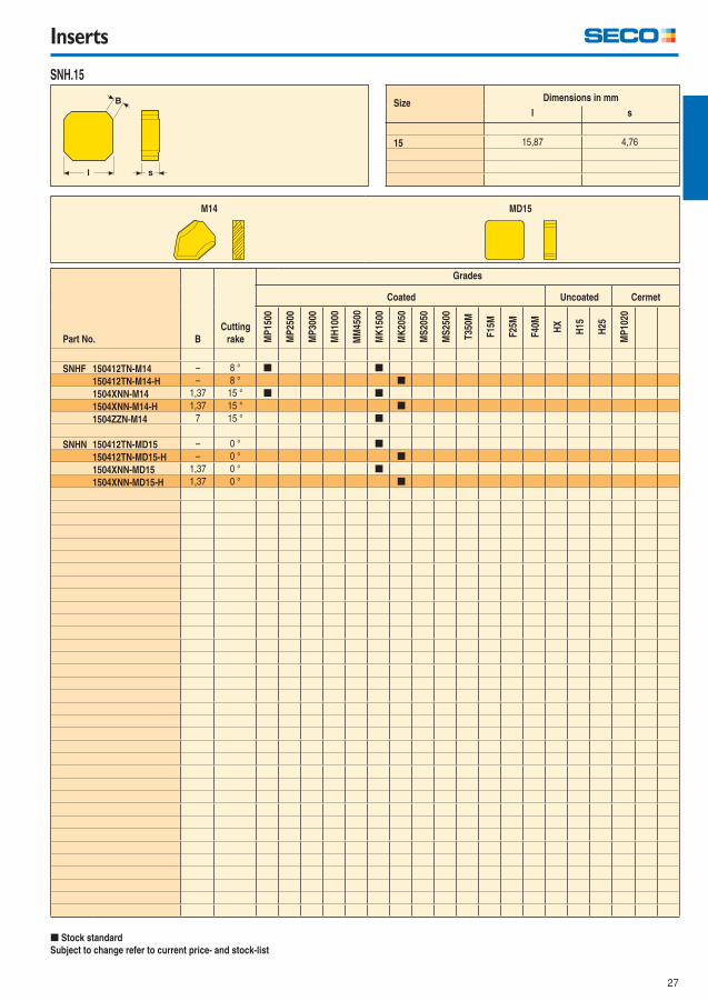
Inserts
SNH.15
Part No. B
Cutting
rake
Grades
Coated Uncoated Cermet
MP
1500
MP
2500
MP
3000
MH
1000
MM
4500
MK
1500
MK
2050
MS
2050
MS
2500
T35
0M
F15
M
F25
M
F40
M
HX
H15
H25
MP
1020
SNHF 150412TN-M14 – 8 ° [ [
150412TN-M14-H – 8 ° [
1504XNN-M14 1,37 15 ° [ [
1504XNN-M14-H 1,37 15 ° [
1504ZZN-M14 7 15 ° [
SNHN 150412TN-MD15 – 0 ° [
150412TN-MD15-H – 0 ° [
1504XNN-MD15 1,37 0 ° [
1504XNN-MD15-H 1,37 0 ° [
[ Stock standard
Subject to change refer to current price- and stock-list
SizeDimensions in mm
l s
15 15,87 4,76
M14 MD15
28
Inserts
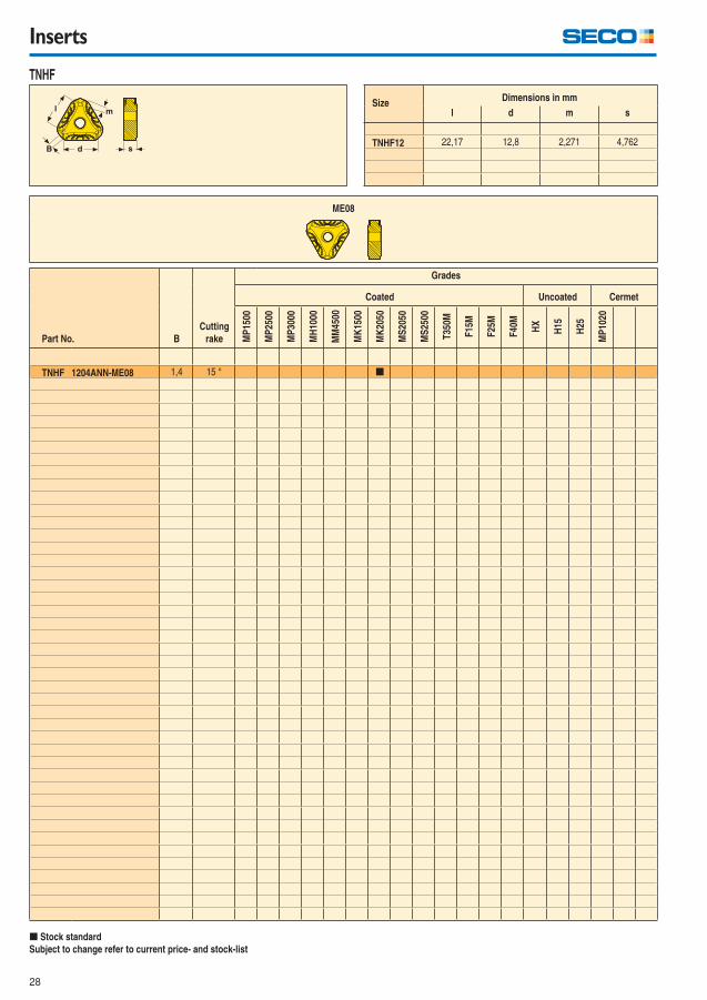
TNHF
Part No. B
Cutting
rake
Grades
Coated Uncoated Cermet
MP
1500
MP
2500
MP
3000
MH
1000
MM
4500
MK
1500
MK
2050
MS
2050
MS
2500
T35
0M
F15
M
F25
M
F40
M
HX
H15
H25
MP
1020
TNHF 1204ANN-ME08 1,4 15 ° [
[ Stock standard
Subject to change refer to current price- and stock-list
SizeDimensions in mm
l d m s
TNHF12 22,17 12,8 2,271 4,762
ME08
29
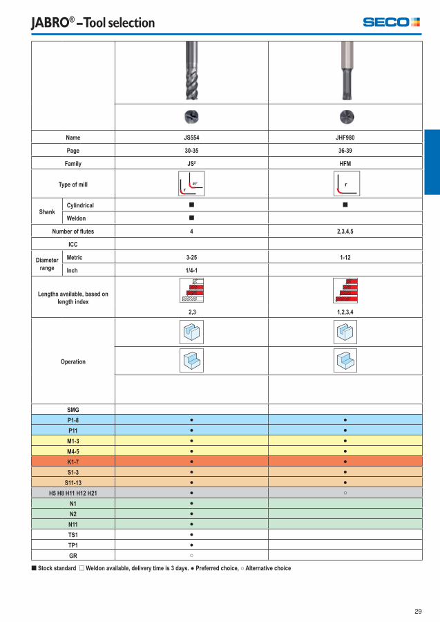
JABRO® – Tool selection
Name JS554 JHF980
Page 30-35 36-39
Family JS² HFM
Type of mill
ShankCylindrical [ [
Weldon [
Number of fl utes 4 2,3,4,5
ICC
Diameter range
Metric 3-25 1-12
Inch 1/4-1
Lengths available, based on length index
2,3 1,2,3,4
Operation
SMG
P1-8 ● ●P11 ● ●M1-3 ● ●M4-5 ● ●K1-7 ● ●S1-3 ● ●
S11-13 ● ●H5 H8 H11 H12 H21 ● ○
N1 ●N2 ●N11 ●TS1 ●TP1 ●GR ○
[ Stock standard ] Weldon available, delivery time is 3 days. ● Preferred choice, ○ Alternative choice
30
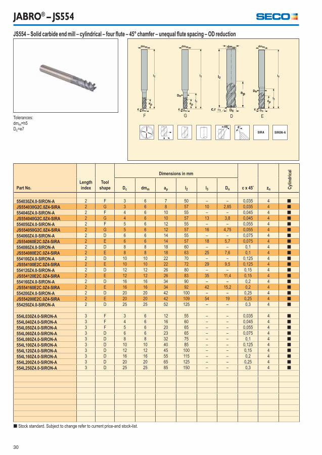
JABRO® – JS554
[ Stock standard. Subject to change refer to current price-and stock-list.
Part No.Lengthindex
Toolshape
Dimensions in mm
c x 45˚ zn Cyl
ind
rica
l
Dc dmm ap l2 l3 Dn
554030Z4.0-SIRON-A 2 F 3 6 7 50 – – 0,035 4 [
JS554030G2C.0Z4-SIRA 2 G 3 6 8 57 10 2,85 0,035 4 [
554040Z4.0-SIRON-A 2 F 4 6 10 55 – – 0,045 4 [
JS554040G2C.0Z4-SIRA 2 G 4 6 10 57 13 3,8 0,045 4 [
554050Z4.0-SIRON-A 2 F 5 6 12 55 – – 0,055 4 [
JS554050G2C.0Z4-SIRA 2 G 5 6 12 57 16 4,75 0,055 4 [
554060Z4.0-SIRON-A 2 D 6 6 14 55 – – 0,075 4 [
JS554060E2C.0Z4-SIRA 2 E 6 6 14 57 18 5,7 0,075 4 [
554080Z4.0-SIRON-A 2 D 8 8 18 60 – – 0,1 4 [
JS554080E2C.0Z4-SIRA 2 E 8 8 18 63 25 7,6 0,1 4 [
554100Z4.0-SIRON-A 2 D 10 10 22 70 – – 0,125 4 [
JS554100E2C.0Z4-SIRA 2 E 10 10 22 72 29 9,5 0,125 4 [
554120Z4.0-SIRON-A 2 D 12 12 26 80 – – 0,15 4 [
JS554120E2C.0Z4-SIRA 2 E 12 12 26 83 35 11,4 0,15 4 [
554160Z4.0-SIRON-A 2 D 16 16 34 90 – – 0,2 4 [
JS554160E2C.0Z4-SIRA 2 E 16 16 34 92 42 15,2 0,2 4 [
554200Z4.0-SIRON-A 2 D 20 20 42 100 – – 0,25 4 [
JS554200E2C.0Z4-SIRA 2 E 20 20 42 109 54 19 0,25 4 [
554250Z4.0-SIRON-A 2 D 25 25 52 125 – – 0,3 4 [
554L030Z4.0-SIRON-A 3 F 3 6 12 55 – – 0,035 4 [
554L040Z4.0-SIRON-A 3 F 4 6 16 60 – – 0,045 4 [
554L050Z4.0-SIRON-A 3 F 5 6 20 65 – – 0,055 4 [
554L060Z4.0-SIRON-A 3 D 6 6 23 65 – – 0,075 4 [
554L080Z4.0-SIRON-A 3 D 8 8 32 75 – – 0,1 4 [
554L100Z4.0-SIRON-A 3 D 10 10 40 85 – – 0,125 4 [
554L120Z4.0-SIRON-A 3 D 12 12 45 100 – – 0,15 4 [
554L160Z4.0-SIRON-A 3 D 16 16 55 115 – – 0,2 4 [
554L200Z4.0-SIRON-A 3 D 20 20 65 125 – – 0,25 4 [
554L250Z4.0-SIRON-A 3 D 25 25 85 150 – – 0,3 4 [
Tolerances:
dmm=h5
Dc=e7
JS554 – Solid carbide end mill – cylindrical – four fl ute – 45° chamfer – unequal fl ute spacing – OD reduction
F G D E

31
JABRO® – JS554
Tolerances:
dmm=h5
Dc=e7
r1=+/-0,02 mm
Part No.Lengthindex
Toolshape
Dimensions in mm
r1 zn Cyl
ind
rica
l
Dc dmm ap l2 l3 Dn
JS554030G2R015.0Z4-SIRA 2 G 3 6 7 57 10 2,85 0,15 4 [
JS554040G2R020.0Z4-SIRA 2 G 4 6 10 57 13 3,8 0,2 4 [
JS554050G2R020.0Z4-SIRA 2 G 5 6 12 57 16 4,75 0,2 4 [
554060R020Z4.0-SIRON-A 2 D 6 6 14 55 – – 0,2 4 [
JS554060E2R020.0Z4-SIRA 2 E 6 6 14 57 18 5,7 0,2 4 [
JS554060E2R050.0Z4-SIRA 2 E 6 6 14 57 18 5,7 0,5 4 [
JS554060E2R100.0Z4-SIRA 2 E 6 6 14 57 18 5,7 1 4 [
554080R050Z4.0-SIRON-A 2 D 8 8 18 60 – – 0,5 4 [
JS554080E2R050.0Z4-SIRA 2 E 8 8 18 63 25 7,6 0,5 4 [
JS554080E2R100.0Z4-SIRA 2 E 8 8 18 63 25 7,6 1 4 [
554100R050Z4.0-SIRON-A 2 D 10 10 22 70 – – 0,5 4 [
JS554100E2R050.0Z4-SIRA 2 E 10 10 22 72 29 9,5 0,5 4 [
554100R100Z4.0-SIRON-A 2 D 10 10 22 70 – – 1 4 [
JS554100E2R100.0Z4-SIRA 2 E 10 10 22 72 29 9,5 1 4 [
JS554100E2R200.0Z4-SIRA 2 E 10 10 22 72 29 9,5 2 4 [
JS554100E2R250.0Z4-SIRA 2 E 10 10 22 72 29 9,5 2,5 4 [
554120R050Z4.0-SIRON-A 2 D 12 12 26 80 – – 0,5 4 [
JS554120E2R050.0Z4-SIRA 2 E 12 12 26 83 35 11,4 0,5 4 [
554120R100Z4.0-SIRON-A 2 D 12 12 26 80 – – 1 4 [
JS554120E2R100.0Z4-SIRA 2 E 12 12 26 83 35 11,4 1 4 [
JS554120E2R200.0Z4-SIRA 2 E 12 12 26 83 35 11,4 2 4 [
JS554120E2R250.0Z4-SIRA 2 E 12 12 26 83 35 11,4 2,5 4 [
JS554120E2R300.0Z4-SIRA 2 E 12 12 26 83 35 11,4 3 4 [
554160R050Z4.0-SIRON-A 2 D 16 16 34 90 – – 0,5 4 [
JS554160E2R050.0Z4-SIRA 2 E 16 16 34 92 42 15,2 0,5 4 [
554160R100Z4.0-SIRON-A 2 D 16 16 34 90 – – 1 4 [
554160R200Z4.0-SIRON-A 2 D 16 16 34 90 – – 2 4 [
554160R310Z4.0-SIRON-A 2 D 16 16 34 90 – – 3,1 4 [
554160R400Z4.0-SIRON-A 2 D 16 16 34 90 – – 4 4 [
554200R050Z4.0-SIRON-A 2 D 20 20 42 100 – – 0,5 4 [
554200R100Z4.0-SIRON-A 2 D 20 20 42 100 – – 1 4 [
JS554200E2R200.0Z4-SIRA 2 E 20 20 42 110 54 19 2 4 [
554200R250Z4.0-SIRON-A 2 D 20 20 42 100 – – 2,5 4 [
554200R310Z4.0-SIRON-A 2 D 20 20 42 100 – – 3,1 4 [
554200R400Z4.0-SIRON-A 2 D 20 20 42 100 – – 4 4 [
JS554200E2R600.0Z4-SIRA 2 E 20 20 42 109 54 19 6 4 [
554250R050Z4.0-SIRON-A 2 D 25 25 52 125 – – 0,5 4 [
554250R100Z4.0-SIRON-A 2 D 25 25 52 125 – – 1 4 [
554250R310Z4.0-SIRON-A 2 D 25 25 52 125 – – 3,1 4 [
554250R400Z4.0-SIRON-A 2 D 25 25 52 125 – – 4 4 [
[ Stock standard. Subject to change refer to current price-and stock-list.
JS554 – Solid carbide end mill – cylindrical – four fl ute – corner radius – unequal fl ute spacing – OD-reduction
G D E
32
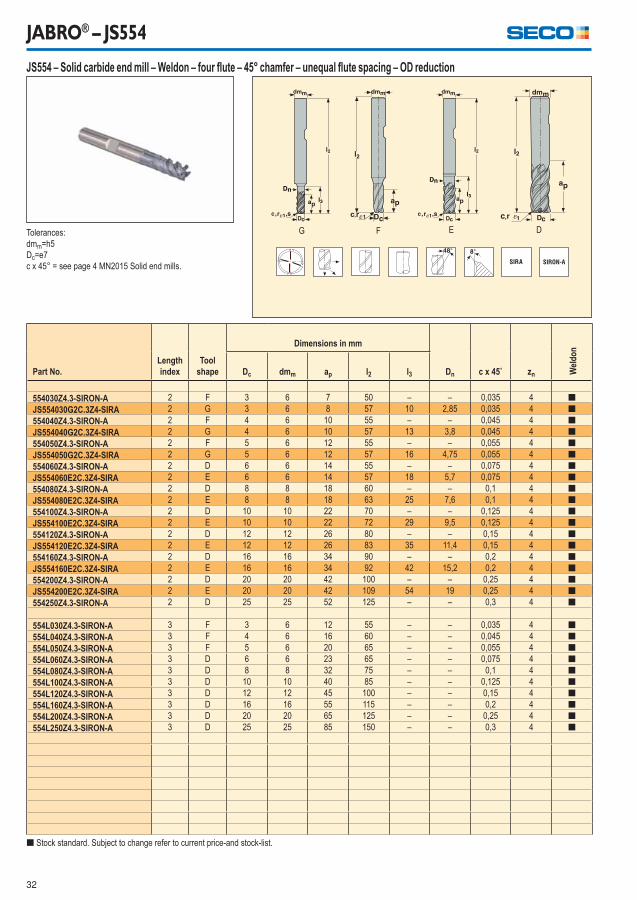
JABRO® – JS554
[ Stock standard. Subject to change refer to current price-and stock-list.
Part No.Lengthindex
Toolshape
Dimensions in mm
Dn c x 45˚ zn Wel
do
n
Dc dmm ap l2 l3
554030Z4.3-SIRON-A 2 F 3 6 7 50 – – 0,035 4 [
JS554030G2C.3Z4-SIRA 2 G 3 6 8 57 10 2,85 0,035 4 [
554040Z4.3-SIRON-A 2 F 4 6 10 55 – – 0,045 4 [
JS554040G2C.3Z4-SIRA 2 G 4 6 10 57 13 3,8 0,045 4 [
554050Z4.3-SIRON-A 2 F 5 6 12 55 – – 0,055 4 [
JS554050G2C.3Z4-SIRA 2 G 5 6 12 57 16 4,75 0,055 4 [
554060Z4.3-SIRON-A 2 D 6 6 14 55 – – 0,075 4 [
JS554060E2C.3Z4-SIRA 2 E 6 6 14 57 18 5,7 0,075 4 [
554080Z4.3-SIRON-A 2 D 8 8 18 60 – – 0,1 4 [
JS554080E2C.3Z4-SIRA 2 E 8 8 18 63 25 7,6 0,1 4 [
554100Z4.3-SIRON-A 2 D 10 10 22 70 – – 0,125 4 [
JS554100E2C.3Z4-SIRA 2 E 10 10 22 72 29 9,5 0,125 4 [
554120Z4.3-SIRON-A 2 D 12 12 26 80 – – 0,15 4 [
JS554120E2C.3Z4-SIRA 2 E 12 12 26 83 35 11,4 0,15 4 [
554160Z4.3-SIRON-A 2 D 16 16 34 90 – – 0,2 4 [
JS554160E2C.3Z4-SIRA 2 E 16 16 34 92 42 15,2 0,2 4 [
554200Z4.3-SIRON-A 2 D 20 20 42 100 – – 0,25 4 [
JS554200E2C.3Z4-SIRA 2 E 20 20 42 109 54 19 0,25 4 [
554250Z4.3-SIRON-A 2 D 25 25 52 125 – – 0,3 4 [
554L030Z4.3-SIRON-A 3 F 3 6 12 55 – – 0,035 4 [
554L040Z4.3-SIRON-A 3 F 4 6 16 60 – – 0,045 4 [
554L050Z4.3-SIRON-A 3 F 5 6 20 65 – – 0,055 4 [
554L060Z4.3-SIRON-A 3 D 6 6 23 65 – – 0,075 4 [
554L080Z4.3-SIRON-A 3 D 8 8 32 75 – – 0,1 4 [
554L100Z4.3-SIRON-A 3 D 10 10 40 85 – – 0,125 4 [
554L120Z4.3-SIRON-A 3 D 12 12 45 100 – – 0,15 4 [
554L160Z4.3-SIRON-A 3 D 16 16 55 115 – – 0,2 4 [
554L200Z4.3-SIRON-A 3 D 20 20 65 125 – – 0,25 4 [
554L250Z4.3-SIRON-A 3 D 25 25 85 150 – – 0,3 4 [
Tolerances:
dmm=h5
Dc=e7
c x 45° = see page 4 MN2015 Solid end mills.
JS554 – Solid carbide end mill – Weldon – four fl ute – 45° chamfer – unequal fl ute spacing – OD reduction
G F E D
33
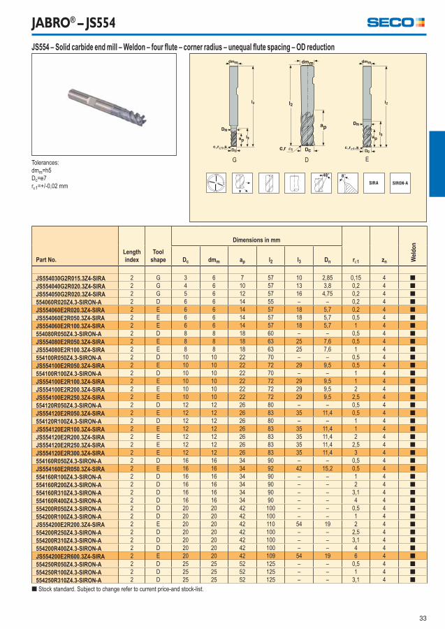
JABRO® – JS554
Tolerances:
dmm=h5
Dc=e7
r1=+/-0,02 mm
Part No.Lengthindex
Toolshape
Dimensions in mm
r1 zn Wel
do
n
Dc dmm ap l2 l3 Dn
JS554030G2R015.3Z4-SIRA 2 G 3 6 7 57 10 2,85 0,15 4 [
JS554040G2R020.3Z4-SIRA 2 G 4 6 10 57 13 3,8 0,2 4 [
JS554050G2R020.3Z4-SIRA 2 G 5 6 12 57 16 4,75 0,2 4 [
554060R020Z4.3-SIRON-A 2 D 6 6 14 55 – – 0,2 4 [
JS554060E2R020.3Z4-SIRA 2 E 6 6 14 57 18 5,7 0,2 4 [
JS554060E2R050.3Z4-SIRA 2 E 6 6 14 57 18 5,7 0,5 4 [
JS554060E2R100.3Z4-SIRA 2 E 6 6 14 57 18 5,7 1 4 [
554080R050Z4.3-SIRON-A 2 D 8 8 18 60 – – 0,5 4 [
JS554080E2R050.3Z4-SIRA 2 E 8 8 18 63 25 7,6 0,5 4 [
JS554080E2R100.3Z4-SIRA 2 E 8 8 18 63 25 7,6 1 4 [
554100R050Z4.3-SIRON-A 2 D 10 10 22 70 – – 0,5 4 [
JS554100E2R050.3Z4-SIRA 2 E 10 10 22 72 29 9,5 0,5 4 [
554100R100Z4.3-SIRON-A 2 D 10 10 22 70 – – 1 4 [
JS554100E2R100.3Z4-SIRA 2 E 10 10 22 72 29 9,5 1 4 [
JS554100E2R200.3Z4-SIRA 2 E 10 10 22 72 29 9,5 2 4 [
JS554100E2R250.3Z4-SIRA 2 E 10 10 22 72 29 9,5 2,5 4 [
554120R050Z4.3-SIRON-A 2 D 12 12 26 80 – – 0,5 4 [
JS554120E2R050.3Z4-SIRA 2 E 12 12 26 83 35 11,4 0,5 4 [
554120R100Z4.3-SIRON-A 2 D 12 12 26 80 – – 1 4 [
JS554120E2R100.3Z4-SIRA 2 E 12 12 26 83 35 11,4 1 4 [
JS554120E2R200.3Z4-SIRA 2 E 12 12 26 83 35 11,4 2 4 [
JS554120E2R250.3Z4-SIRA 2 E 12 12 26 83 35 11,4 2,5 4 [
JS554120E2R300.3Z4-SIRA 2 E 12 12 26 83 35 11,4 3 4 [
554160R050Z4.3-SIRON-A 2 D 16 16 34 90 – – 0,5 4 [
JS554160E2R050.3Z4-SIRA 2 E 16 16 34 92 42 15,2 0,5 4 [
554160R100Z4.3-SIRON-A 2 D 16 16 34 90 – – 1 4 [
554160R200Z4.3-SIRON-A 2 D 16 16 34 90 – – 2 4 [
554160R310Z4.3-SIRON-A 2 D 16 16 34 90 – – 3,1 4 [
554160R400Z4.3-SIRON-A 2 D 16 16 34 90 – – 4 4 [
554200R050Z4.3-SIRON-A 2 D 20 20 42 100 – – 0,5 4 [
554200R100Z4.3-SIRON-A 2 D 20 20 42 100 – – 1 4 [
JS554200E2R200.3Z4-SIRA 2 E 20 20 42 110 54 19 2 4 [
554200R250Z4.3-SIRON-A 2 D 20 20 42 100 – – 2,5 4 [
554200R310Z4.3-SIRON-A 2 D 20 20 42 100 – – 3,1 4 [
554200R400Z4.3-SIRON-A 2 D 20 20 42 100 – – 4 4 [
JS554200E2R600.3Z4-SIRA 2 E 20 20 42 109 54 19 6 4 [
554250R050Z4.3-SIRON-A 2 D 25 25 52 125 – – 0,5 4 [
554250R100Z4.3-SIRON-A 2 D 25 25 52 125 – – 1 4 [
554250R310Z4.3-SIRON-A 2 D 25 25 52 125 – – 3,1 4 [
[ Stock standard. Subject to change refer to current price-and stock-list.
JS554 – Solid carbide end mill – Weldon – four fl ute – corner radius – unequal fl ute spacing – OD reduction
G D E
34
JABRO® – JS554
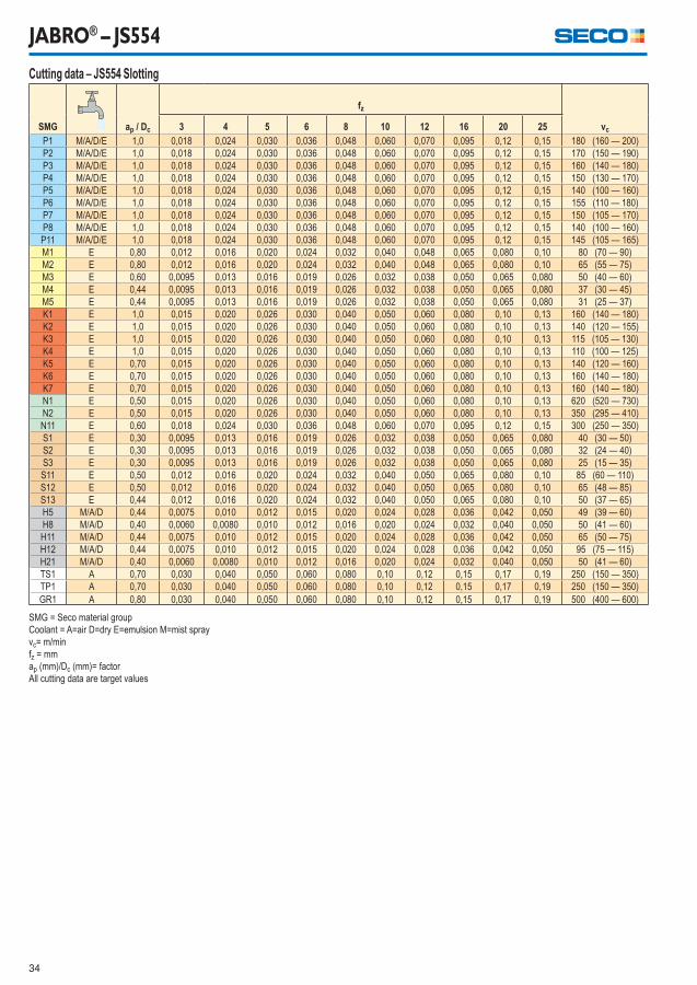
Cutting data – JS554 Slotting
SMG ap / Dc
fz
vc3 4 5 6 8 10 12 16 20 25
P1 M/A/D/E 1,0 0,018 0,024 0,030 0,036 0,048 0,060 0,070 0,095 0,12 0,15 180 (160 — 200)
P2 M/A/D/E 1,0 0,018 0,024 0,030 0,036 0,048 0,060 0,070 0,095 0,12 0,15 170 (150 — 190)
P3 M/A/D/E 1,0 0,018 0,024 0,030 0,036 0,048 0,060 0,070 0,095 0,12 0,15 160 (140 — 180)
P4 M/A/D/E 1,0 0,018 0,024 0,030 0,036 0,048 0,060 0,070 0,095 0,12 0,15 150 (130 — 170)
P5 M/A/D/E 1,0 0,018 0,024 0,030 0,036 0,048 0,060 0,070 0,095 0,12 0,15 140 (100 — 160)
P6 M/A/D/E 1,0 0,018 0,024 0,030 0,036 0,048 0,060 0,070 0,095 0,12 0,15 155 (110 — 180)
P7 M/A/D/E 1,0 0,018 0,024 0,030 0,036 0,048 0,060 0,070 0,095 0,12 0,15 150 (105 — 170)
P8 M/A/D/E 1,0 0,018 0,024 0,030 0,036 0,048 0,060 0,070 0,095 0,12 0,15 140 (100 — 160)
P11 M/A/D/E 1,0 0,018 0,024 0,030 0,036 0,048 0,060 0,070 0,095 0,12 0,15 145 (105 — 165)
M1 E 0,80 0,012 0,016 0,020 0,024 0,032 0,040 0,048 0,065 0,080 0,10 80 (70 — 90)
M2 E 0,80 0,012 0,016 0,020 0,024 0,032 0,040 0,048 0,065 0,080 0,10 65 (55 — 75)
M3 E 0,60 0,0095 0,013 0,016 0,019 0,026 0,032 0,038 0,050 0,065 0,080 50 (40 — 60)
M4 E 0,44 0,0095 0,013 0,016 0,019 0,026 0,032 0,038 0,050 0,065 0,080 37 (30 — 45)
M5 E 0,44 0,0095 0,013 0,016 0,019 0,026 0,032 0,038 0,050 0,065 0,080 31 (25 — 37)
K1 E 1,0 0,015 0,020 0,026 0,030 0,040 0,050 0,060 0,080 0,10 0,13 160 (140 — 180)
K2 E 1,0 0,015 0,020 0,026 0,030 0,040 0,050 0,060 0,080 0,10 0,13 140 (120 — 155)
K3 E 1,0 0,015 0,020 0,026 0,030 0,040 0,050 0,060 0,080 0,10 0,13 115 (105 — 130)
K4 E 1,0 0,015 0,020 0,026 0,030 0,040 0,050 0,060 0,080 0,10 0,13 110 (100 — 125)
K5 E 0,70 0,015 0,020 0,026 0,030 0,040 0,050 0,060 0,080 0,10 0,13 140 (120 — 160)
K6 E 0,70 0,015 0,020 0,026 0,030 0,040 0,050 0,060 0,080 0,10 0,13 160 (140 — 180)
K7 E 0,70 0,015 0,020 0,026 0,030 0,040 0,050 0,060 0,080 0,10 0,13 160 (140 — 180)
N1 E 0,50 0,015 0,020 0,026 0,030 0,040 0,050 0,060 0,080 0,10 0,13 620 (520 — 730)
N2 E 0,50 0,015 0,020 0,026 0,030 0,040 0,050 0,060 0,080 0,10 0,13 350 (295 — 410)
N11 E 0,60 0,018 0,024 0,030 0,036 0,048 0,060 0,070 0,095 0,12 0,15 300 (250 — 350)
S1 E 0,30 0,0095 0,013 0,016 0,019 0,026 0,032 0,038 0,050 0,065 0,080 40 (30 — 50)
S2 E 0,30 0,0095 0,013 0,016 0,019 0,026 0,032 0,038 0,050 0,065 0,080 32 (24 — 40)
S3 E 0,30 0,0095 0,013 0,016 0,019 0,026 0,032 0,038 0,050 0,065 0,080 25 (15 — 35)
S11 E 0,50 0,012 0,016 0,020 0,024 0,032 0,040 0,050 0,065 0,080 0,10 85 (60 — 110)
S12 E 0,50 0,012 0,016 0,020 0,024 0,032 0,040 0,050 0,065 0,080 0,10 65 (48 — 85)
S13 E 0,44 0,012 0,016 0,020 0,024 0,032 0,040 0,050 0,065 0,080 0,10 50 (37 — 65)
H5 M/A/D 0,44 0,0075 0,010 0,012 0,015 0,020 0,024 0,028 0,036 0,042 0,050 49 (39 — 60)
H8 M/A/D 0,40 0,0060 0,0080 0,010 0,012 0,016 0,020 0,024 0,032 0,040 0,050 50 (41 — 60)
H11 M/A/D 0,44 0,0075 0,010 0,012 0,015 0,020 0,024 0,028 0,036 0,042 0,050 65 (50 — 75)
H12 M/A/D 0,44 0,0075 0,010 0,012 0,015 0,020 0,024 0,028 0,036 0,042 0,050 95 (75 — 115)
H21 M/A/D 0,40 0,0060 0,0080 0,010 0,012 0,016 0,020 0,024 0,032 0,040 0,050 50 (41 — 60)
TS1 A 0,70 0,030 0,040 0,050 0,060 0,080 0,10 0,12 0,15 0,17 0,19 250 (150 — 350)
TP1 A 0,70 0,030 0,040 0,050 0,060 0,080 0,10 0,12 0,15 0,17 0,19 250 (150 — 350)
GR1 A 0,80 0,030 0,040 0,050 0,060 0,080 0,10 0,12 0,15 0,17 0,19 500 (400 — 600)
SMG = Seco material group
Coolant = A=air D=dry E=emulsion M=mist spray
vc= m/min
fz = mm
ap (mm)/Dc (mm)= factor
All cutting data are target values
35
JABRO® – JS554
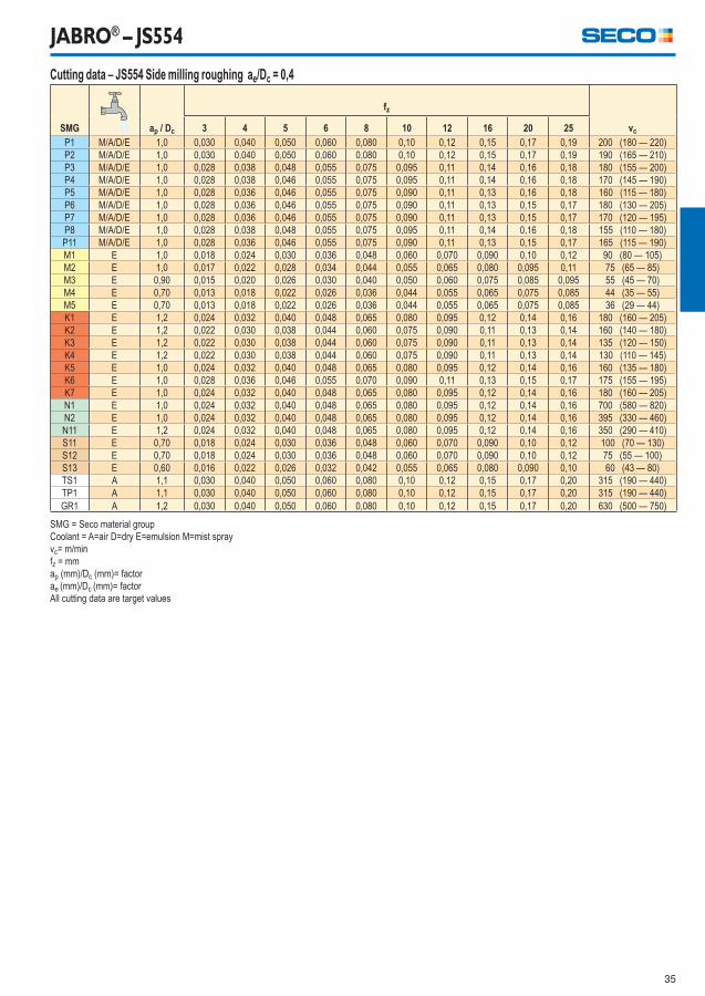
Cutting data – JS554 Side milling roughing ae/Dc = 0,4
SMG ap / Dc
fz
vc3 4 5 6 8 10 12 16 20 25
P1 M/A/D/E 1,0 0,030 0,040 0,050 0,060 0,080 0,10 0,12 0,15 0,17 0,19 200 (180 — 220)
P2 M/A/D/E 1,0 0,030 0,040 0,050 0,060 0,080 0,10 0,12 0,15 0,17 0,19 190 (165 — 210)
P3 M/A/D/E 1,0 0,028 0,038 0,048 0,055 0,075 0,095 0,11 0,14 0,16 0,18 180 (155 — 200)
P4 M/A/D/E 1,0 0,028 0,038 0,046 0,055 0,075 0,095 0,11 0,14 0,16 0,18 170 (145 — 190)
P5 M/A/D/E 1,0 0,028 0,036 0,046 0,055 0,075 0,090 0,11 0,13 0,16 0,18 160 (115 — 180)
P6 M/A/D/E 1,0 0,028 0,036 0,046 0,055 0,075 0,090 0,11 0,13 0,15 0,17 180 (130 — 205)
P7 M/A/D/E 1,0 0,028 0,036 0,046 0,055 0,075 0,090 0,11 0,13 0,15 0,17 170 (120 — 195)
P8 M/A/D/E 1,0 0,028 0,038 0,048 0,055 0,075 0,095 0,11 0,14 0,16 0,18 155 (110 — 180)
P11 M/A/D/E 1,0 0,028 0,036 0,046 0,055 0,075 0,090 0,11 0,13 0,15 0,17 165 (115 — 190)
M1 E 1,0 0,018 0,024 0,030 0,036 0,048 0,060 0,070 0,090 0,10 0,12 90 (80 — 105)
M2 E 1,0 0,017 0,022 0,028 0,034 0,044 0,055 0,065 0,080 0,095 0,11 75 (65 — 85)
M3 E 0,90 0,015 0,020 0,026 0,030 0,040 0,050 0,060 0,075 0,085 0,095 55 (45 — 70)
M4 E 0,70 0,013 0,018 0,022 0,026 0,036 0,044 0,055 0,065 0,075 0,085 44 (35 — 55)
M5 E 0,70 0,013 0,018 0,022 0,026 0,036 0,044 0,055 0,065 0,075 0,085 36 (29 — 44)
K1 E 1,2 0,024 0,032 0,040 0,048 0,065 0,080 0,095 0,12 0,14 0,16 180 (160 — 205)
K2 E 1,2 0,022 0,030 0,038 0,044 0,060 0,075 0,090 0,11 0,13 0,14 160 (140 — 180)
K3 E 1,2 0,022 0,030 0,038 0,044 0,060 0,075 0,090 0,11 0,13 0,14 135 (120 — 150)
K4 E 1,2 0,022 0,030 0,038 0,044 0,060 0,075 0,090 0,11 0,13 0,14 130 (110 — 145)
K5 E 1,0 0,024 0,032 0,040 0,048 0,065 0,080 0,095 0,12 0,14 0,16 160 (135 — 180)
K6 E 1,0 0,028 0,036 0,046 0,055 0,070 0,090 0,11 0,13 0,15 0,17 175 (155 — 195)
K7 E 1,0 0,024 0,032 0,040 0,048 0,065 0,080 0,095 0,12 0,14 0,16 180 (160 — 205)
N1 E 1,0 0,024 0,032 0,040 0,048 0,065 0,080 0,095 0,12 0,14 0,16 700 (580 — 820)
N2 E 1,0 0,024 0,032 0,040 0,048 0,065 0,080 0,095 0,12 0,14 0,16 395 (330 — 460)
N11 E 1,2 0,024 0,032 0,040 0,048 0,065 0,080 0,095 0,12 0,14 0,16 350 (290 — 410)
S11 E 0,70 0,018 0,024 0,030 0,036 0,048 0,060 0,070 0,090 0,10 0,12 100 (70 — 130)
S12 E 0,70 0,018 0,024 0,030 0,036 0,048 0,060 0,070 0,090 0,10 0,12 75 (55 — 100)
S13 E 0,60 0,016 0,022 0,026 0,032 0,042 0,055 0,065 0,080 0,090 0,10 60 (43 — 80)
TS1 A 1,1 0,030 0,040 0,050 0,060 0,080 0,10 0,12 0,15 0,17 0,20 315 (190 — 440)
TP1 A 1,1 0,030 0,040 0,050 0,060 0,080 0,10 0,12 0,15 0,17 0,20 315 (190 — 440)
GR1 A 1,2 0,030 0,040 0,050 0,060 0,080 0,10 0,12 0,15 0,17 0,20 630 (500 — 750)
SMG = Seco material group
Coolant = A=air D=dry E=emulsion M=mist spray
vc= m/min
fz = mm
ap (mm)/Dc (mm)= factor
ae (mm)/Dc (mm)= factor
All cutting data are target values
36
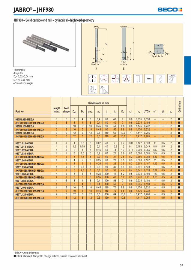
JABRO® – JHF980
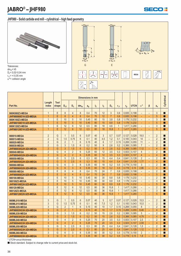
Tolerances:
dmm= h5
Dc= 0,02/-0,04 mm
r1= +/-0,05 mm
°= collision angle
Part No.Lengthindex
Toolshape
Dimensions in mm
r1 rp UTCN ° β zn Cyl
ind
rica
l
Dc1 Dc dmm ap l2 l3 Dn
980K080Z3-MEGA 1 E 8 4 8 0,4 70 12 3 0,6 0,935 0,198 – – 3 [
JHF980080E1H.0Z5-MEGA 1 E 8 4 8 0,4 70 12 7 0,6 0,935 0,198 – – 5 [
980K100Z3-MEGA 1 E 10 5 10 0,45 80 15 3,8 0,8 1,176 0,232 – – 3 [
JHF980100E1H.0Z5-MEGA 1 E 10 5 10 0,45 80 15 8,8 0,8 1,176 0,232 – – 5 [
980K120Z3-MEGA 1 E 12 6 12 0,5 80 18 4,6 1 1,417 0,266 – – 3 [
JHF980120E1H.0Z5-MEGA 1 E 12 6 12 0,5 80 18 10,6 1 1,417 0,265 – – 5 [
980010-MEGA 2 G 1 0,5 6 0,07 40 3 0,7 0,07 0,127 0,028 19,5 – 2 [
980015-MEGA 2 G 1,5 0,75 6 0,1 40 4,5 1,2 0,1 0,183 0,043 14 – 2 [
980020-MEGA 2 G 2 1 6 0,15 40 6 1,7 0,15 0,269 0,055 11 – 2 [
980030-MEGA 2 G 3 1,5 6 0,2 50 9 2,6 0,2 0,366 0,085 7 – 2 [
JHF980030G2H.0Z4-MEGA 2 G 3 1,5 6 0,2 50 9 2,6 0,2 0,366 0,085 7,12 – 4 [
980040-MEGA 2 G 4 2 6 0,25 60 12 3,5 0,3 0,503 0,107 4 – 2 [
JHF980040G2H.0Z4-MEGA 2 G 4 2 6 0,25 60 12 3,5 0,3 0,503 0,107 4 – 4 [
980050-MEGA 2 G 5 2,5 6 0,3 60 15 4,4 0,4 0,641 0,128 2 – 2 [
JHF980050G2H.0Z4-MEGA 2 G 5 2,5 6 0,3 60 15 4,4 0,4 0,641 0,128 1,77 – 4 [
980060-MEGA 2 G 6 3 8 0,35 60 18 5,2 0,5 0,778 0,150 3 – 2 [
JHF980060G2H.0Z4-MEGA 2 G 6 3 8 0,35 60 18 5,2 0,5 0,778 0,15 2,86 – 4 [
980080-MEGA 2 E 8 4 8 0,4 70 24 7 0,6 0,935 0,198 – – 2 [
JHF980080E2H.0Z5-MEGA 2 E 8 4 8 0,4 70 24 7 0,6 0,935 0,198 – – 5 [
980100-MEGA 2 E 10 5 10 0,45 80 30 8,8 0,8 1,176 0,232 – – 2 [
980100Z3-MEGA 2 E 10 5 10 0,45 80 30 8,8 0,8 1,176 0,232 – – 3 [
JHF980100E2H.0Z5-MEGA 2 E 10 5 10 0,45 80 30 8,8 0,8 1,176 0,232 – – 5 [
980120-MEGA 2 E 12 6 12 0,5 80 36 10,6 1 1,417 0,266 – – 2 [
980120Z3-MEGA 2 E 12 6 12 0,5 80 36 10,6 1 1,417 0,266 – – 3 [
JHF980120E2H.0Z5-MEGA 2 E 12 6 12 0,5 80 36 10,6 1 1,417 0,265 – – 5 [
980ML010-MEGA 3 G 1 0,5 6 0,07 40 5 0,7 0,07 0,127 0,028 15,5 – 2 [
980ML015-MEGA 3 G 1,5 0,75 6 0,1 40 7,5 1,2 0,1 0,183 0,043 10,5 – 2 [
980ML020-MEGA 3 G 2 1 6 0,15 40 10 1,7 0,15 0,269 0,055 8 – 2 [
JHF980020G3H.0Z4-MEGA 3 G 2 1 6 0,15 40 10 1,7 0,15 0,269 0,055 8,46 – 4 [
980ML030-MEGA 3 G 3 1,5 6 0,2 50 15 2,6 0,2 0,366 0,085 5 – 2 [
JHF980030G3H.0Z4-MEGA 3 G 3 1,5 6 0,2 50 15 2,6 0,2 0,366 0,085 4,79 – 4 [
980ML040-MEGA 3 G 4 2 6 0,25 70 20 3,5 0,3 0,503 0,107 2,5 – 2 [
JHF980040G3H.0Z4-MEGA 3 G 4 2 6 0,25 70 20 3,5 0,3 0,503 0,107 2,59 – 4 [
980ML050-MEGA 3 G 5 2,5 6 0,3 80 25 4,4 0,4 0,641 0,128 1,5 – 2 [
JHF980050G3H.0Z4-MEGA 3 G 5 2,5 6 0,3 80 25 4,4 0,4 0,641 0,128 1,12 – 4 [
980ML060-MEGA 3 G 6 3 8 0,35 80 30 5,2 0,5 0,778 0,150 2 – 2 [
JHF980060G3H.0Z4-MEGA 3 G 6 3 8 0,35 80 30 5,2 0,5 0,778 0,15 1,8 – 4 [
* UTCN=uncut-thickness
[ Stock standard. Subject to change refer to current price-and stock-list.
JHF980 – Solid carbide end mill – cylindrical – high feed geometry
G E
37
JABRO® – JHF980
Tolerances:
dmm= h5
Dc= 0,02/-0,04 mm
r1= +/-0,05 mm
°= collision angle
Part No.Lengthindex
Toolshape
Dimensions in mm
r1 rp UTCN ° β zn Cyl
ind
rica
l
Dc1 Dc dmm ap l2 l3 Dn
980ML080-MEGA 3 E 8 4 8 0,4 80 40 7 0,6 0,935 0,198 – – 2 [
JHF980080E3H.0Z5-MEGA 3 E 8 4 8 0,4 80 40 7 0,6 0,935 0,198 – – 5 [
980ML100-MEGA 3 E 10 5 10 0,45 90 50 8,8 0,8 1,176 0,232 – – 2 [
JHF980100E3H.0Z5-MEGA 3 E 10 5 10 0,45 90 50 8,8 0,8 1,176 0,232 – – 5 [
980ML120-MEGA 3 E 12 6 12 0,5 110 60 10,6 1 1,417 0,266 – – 2 [
JHF980120E3H.0Z5-MEGA 3 E 12 6 12 0,5 110 60 10,6 1 1,417 0,265 – – 5 [
980TL010-MEGA 4 J 1 0,5 6 0,07 40 7 0,7 0,07 0,127 0,028 13 0,5 2 [
980TL015-MEGA 4 J 1,5 0,75 6 0,1 40 10,5 1,2 0,1 0,183 0,043 8,5 0,5 2 [
980TL020-MEGA 4 J 2 1 6 0,15 50 14 1,7 0,15 0,269 0,055 6,5 0,5 2 [
980TL030-MEGA 4 J 3 1,5 6 0,2 60 21 2,6 0,2 0,366 0,085 3,5 0,5 2 [
JHF980030J4H.0Z4-MEGA 4 J 3 1,5 6 0,2 60 21 2,6 0,2 0,366 0,085 3,63 0,5 4 [
980TL040-MEGA 4 J 4 2 6 0,25 80 28 3,5 0,3 0,503 0,107 2 0,5 2 [
JHF980040J4H.0Z4-MEGA 4 J 4 2 6 0,25 80 28 3,5 0,3 0,503 0,107 1,93 0,5 4 [
980TL050-MEGA 4 J 5 2,5 6 0,3 90 35 4,4 0,4 0,641 0,128 1 0,5 2 [
JHF980050J4H.0Z4-MEGA 4 J 5 2,5 6 0,3 90 35 4,4 0,4 0,641 0,128 0,82 0,5 4 [
980TL060-MEGA 4 J 6 3 8 0,35 100 42 5,2 0,5 0,778 0,150 1,5 0,5 2 [
JHF980060J4H.0Z4-MEGA 4 J 6 3 8 0,35 100 42 5,2 0,5 0,778 0,15 1,33 0,5 4 [
980TL080-MEGA 4 E 8 4 8 0,4 100 56 7 0,6 0,935 0,198 – 0,5 2 [
JHF980080E4H.0Z5-MEGA 4 E 8 4 8 0,4 100 56 7 0,6 0,935 0,198 – 0,5 5 [
980TL100-MEGA 4 E 10 5 10 0,45 110 70 8,8 0,8 1,176 0,232 – 0,5 2 [
JHF980100E4H.0Z5-MEGA 4 E 10 5 10 0,45 110 70 8,8 0,8 1,176 0,232 – 0,5 5 [
980TL120-MEGA 4 E 12 6 12 0,5 130 84 10,6 1 1,417 0,266 – 0,5 2 [
JHF980120E4H.0Z5-MEGA 4 E 12 6 12 0,5 130 84 10,6 1 1,417 0,265 – 0,5 5 [
* UTCN=uncut-thickness
[ Stock standard. Subject to change refer to current price-and stock-list.
JHF980 – Solid carbide end mill – cylindrical – high feed geometry
J E
38
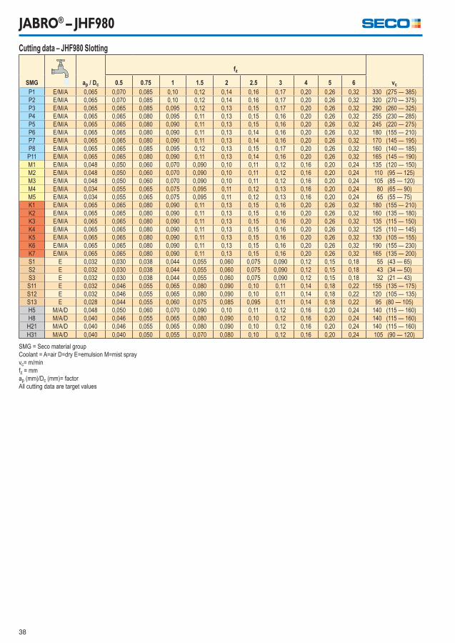
JABRO® – JHF980
Cutting data – JHF980 Slotting
SMG ap / Dc
fz
vc0.5 0.75 1 1.5 2 2.5 3 4 5 6
P1 E/M/A 0,065 0,070 0,085 0,10 0,12 0,14 0,16 0,17 0,20 0,26 0,32 330 (275 — 385)
P2 E/M/A 0,065 0,070 0,085 0,10 0,12 0,14 0,16 0,17 0,20 0,26 0,32 320 (270 — 375)
P3 E/M/A 0,065 0,065 0,085 0,095 0,12 0,13 0,15 0,17 0,20 0,26 0,32 290 (260 — 325)
P4 E/M/A 0,065 0,065 0,080 0,095 0,11 0,13 0,15 0,16 0,20 0,26 0,32 255 (230 — 285)
P5 E/M/A 0,065 0,065 0,080 0,090 0,11 0,13 0,15 0,16 0,20 0,26 0,32 245 (220 — 275)
P6 E/M/A 0,065 0,065 0,080 0,090 0,11 0,13 0,14 0,16 0,20 0,26 0,32 180 (155 — 210)
P7 E/M/A 0,065 0,065 0,080 0,090 0,11 0,13 0,14 0,16 0,20 0,26 0,32 170 (145 — 195)
P8 E/M/A 0,065 0,065 0,085 0,095 0,12 0,13 0,15 0,17 0,20 0,26 0,32 160 (140 — 185)
P11 E/M/A 0,065 0,065 0,080 0,090 0,11 0,13 0,14 0,16 0,20 0,26 0,32 165 (145 — 190)
M1 E/M/A 0,048 0,050 0,060 0,070 0,090 0,10 0,11 0,12 0,16 0,20 0,24 135 (120 — 150)
M2 E/M/A 0,048 0,050 0,060 0,070 0,090 0,10 0,11 0,12 0,16 0,20 0,24 110 (95 — 125)
M3 E/M/A 0,048 0,050 0,060 0,070 0,090 0,10 0,11 0,12 0,16 0,20 0,24 105 (85 — 120)
M4 E/M/A 0,034 0,055 0,065 0,075 0,095 0,11 0,12 0,13 0,16 0,20 0,24 80 (65 — 90)
M5 E/M/A 0,034 0,055 0,065 0,075 0,095 0,11 0,12 0,13 0,16 0,20 0,24 65 (55 — 75)
K1 E/M/A 0,065 0,065 0,080 0,090 0,11 0,13 0,15 0,16 0,20 0,26 0,32 180 (155 — 210)
K2 E/M/A 0,065 0,065 0,080 0,090 0,11 0,13 0,15 0,16 0,20 0,26 0,32 160 (135 — 180)
K3 E/M/A 0,065 0,065 0,080 0,090 0,11 0,13 0,15 0,16 0,20 0,26 0,32 135 (115 — 150)
K4 E/M/A 0,065 0,065 0,080 0,090 0,11 0,13 0,15 0,16 0,20 0,26 0,32 125 (110 — 145)
K5 E/M/A 0,065 0,065 0,080 0,090 0,11 0,13 0,15 0,16 0,20 0,26 0,32 130 (105 — 155)
K6 E/M/A 0,065 0,065 0,080 0,090 0,11 0,13 0,15 0,16 0,20 0,26 0,32 190 (155 — 230)
K7 E/M/A 0,065 0,065 0,080 0,090 0,11 0,13 0,15 0,16 0,20 0,26 0,32 165 (135 — 200)
S1 E 0,032 0,030 0,038 0,044 0,055 0,060 0,075 0,090 0,12 0,15 0,18 55 (43 — 65)
S2 E 0,032 0,030 0,038 0,044 0,055 0,060 0,075 0,090 0,12 0,15 0,18 43 (34 — 50)
S3 E 0,032 0,030 0,038 0,044 0,055 0,060 0,075 0,090 0,12 0,15 0,18 32 (21 — 43)
S11 E 0,032 0,046 0,055 0,065 0,080 0,090 0,10 0,11 0,14 0,18 0,22 155 (135 — 175)
S12 E 0,032 0,046 0,055 0,065 0,080 0,090 0,10 0,11 0,14 0,18 0,22 120 (105 — 135)
S13 E 0,028 0,044 0,055 0,060 0,075 0,085 0,095 0,11 0,14 0,18 0,22 95 (80 — 105)
H5 M/A/D 0,048 0,050 0,060 0,070 0,090 0,10 0,11 0,12 0,16 0,20 0,24 140 (115 — 160)
H8 M/A/D 0,040 0,046 0,055 0,065 0,080 0,090 0,10 0,12 0,16 0,20 0,24 140 (115 — 160)
H21 M/A/D 0,040 0,046 0,055 0,065 0,080 0,090 0,10 0,12 0,16 0,20 0,24 140 (115 — 160)
H31 M/A/D 0,040 0,040 0,050 0,055 0,070 0,080 0,10 0,12 0,16 0,20 0,24 105 (90 — 120)
SMG = Seco material group
Coolant = A=air D=dry E=emulsion M=mist spray
vc= m/min
fz = mm
ap (mm)/Dc (mm)= factor
All cutting data are target values
39
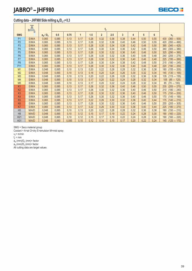
JABRO® – JHF980
Cutting data – JHF980 Side milling ae/Dc 1= 0,3
SMG ap / Dc
fz
vc0.5 0.75 1 1.5 2 2.5 3 4 5 6
P1 E/M/A 0,065 0,085 0,13 0,17 0,26 0,32 0,36 0,38 0,44 0,50 0,55 430 (360 — 500)
P2 E/M/A 0,065 0,085 0,13 0,17 0,26 0,32 0,36 0,40 0,46 0,50 0,55 420 (350 — 490)
P3 E/M/A 0,065 0,085 0,13 0,17 0,26 0,30 0,34 0,38 0,42 0,48 0,50 385 (340 — 425)
P4 E/M/A 0,065 0,085 0,13 0,17 0,26 0,30 0,34 0,36 0,42 0,46 0,50 340 (305 — 380)
P5 E/M/A 0,065 0,085 0,13 0,17 0,26 0,30 0,32 0,36 0,40 0,46 0,50 325 (290 — 360)
P6 E/M/A 0,065 0,085 0,13 0,17 0,26 0,30 0,32 0,36 0,40 0,46 0,48 240 (205 — 275)
P7 E/M/A 0,065 0,085 0,13 0,17 0,26 0,30 0,32 0,36 0,40 0,46 0,48 225 (195 — 260)
P8 E/M/A 0,065 0,085 0,13 0,17 0,26 0,30 0,34 0,38 0,42 0,48 0,50 215 (180 — 245)
P11 E/M/A 0,065 0,085 0,13 0,17 0,26 0,30 0,32 0,36 0,40 0,46 0,48 220 (190 — 250)
M1 E/M/A 0,048 0,065 0,10 0,13 0,20 0,22 0,26 0,28 0,32 0,36 0,38 180 (155 — 200)
M2 E/M/A 0,048 0,065 0,10 0,13 0,18 0,20 0,24 0,26 0,30 0,32 0,34 145 (130 — 165)
M3 E/M/A 0,048 0,065 0,10 0,13 0,20 0,22 0,26 0,28 0,32 0,36 0,38 135 (115 — 155)
M4 E/M/A 0,048 0,065 0,10 0,13 0,17 0,20 0,22 0,24 0,28 0,32 0,34 105 (85 — 120)
M5 E/M/A 0,048 0,065 0,10 0,13 0,17 0,20 0,22 0,24 0,28 0,32 0,34 85 (70 — 100)
K1 E/M/A 0,065 0,085 0,13 0,17 0,26 0,32 0,36 0,40 0,46 0,50 0,55 235 (205 — 270)
K2 E/M/A 0,065 0,085 0,13 0,17 0,26 0,30 0,32 0,36 0,40 0,46 0,50 210 (180 — 240)
K3 E/M/A 0,065 0,085 0,13 0,17 0,26 0,30 0,32 0,36 0,40 0,46 0,50 175 (150 — 200)
K4 E/M/A 0,065 0,085 0,13 0,17 0,26 0,30 0,32 0,36 0,40 0,46 0,50 170 (145 — 190)
K5 E/M/A 0,065 0,085 0,13 0,17 0,22 0,26 0,30 0,32 0,36 0,40 0,44 175 (140 — 210)
K6 E/M/A 0,065 0,085 0,13 0,17 0,26 0,30 0,32 0,36 0,40 0,46 0,50 255 (205 — 305)
K7 E/M/A 0,065 0,085 0,13 0,17 0,22 0,26 0,30 0,32 0,36 0,40 0,44 225 (180 — 270)
H5 M/A/D 0,048 0,065 0,10 0,13 0,20 0,22 0,26 0,28 0,32 0,36 0,38 180 (150 — 210)
H8 M/A/D 0,048 0,065 0,10 0,12 0,15 0,17 0,19 0,22 0,24 0,28 0,30 190 (160 — 220)
H21 M/A/D 0,048 0,065 0,10 0,12 0,15 0,17 0,19 0,22 0,24 0,28 0,30 190 (160 — 220)
H31 M/A/D 0,048 0,060 0,085 0,10 0,12 0,14 0,15 0,17 0,20 0,22 0,24 145 (125 — 170)
SMG = Seco material group
Coolant = A=air D=dry E=emulsion M=mist spray
vc= m/min
fz = mm
ap (mm)/Dc (mm)= factor
ae (mm)/Dc (mm)= factor
All cutting data are target values
40
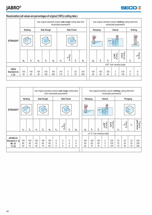
JABRO®
Recalculation (all values are percentages of original (100%) cutting data.)
STRAIGHT
Use original standard version side rough cutting data then
recalculate parameters!
Use original standard version slotting cutting data then
recalculate parameters!
Slotting Side Rough Side Finish Ramping Helical Drilling
ap fz ae fz ap vc
a e(%
of
Dc)
fz ap ap fz fz
a p/3
60º
(% o
f D
c)
ho
le Ø
(≥%
of
Dc)
fz
a p(%
of
Dc)
≤30° max ramping angle
JS554Standard (2)
L (3)
100
40
100
60
100
38
100
105
100
200
110
110
3
3
53
53
150
250
100
50
100
50
100
60
3
3
130
130
X
X
X
X
STRAIGHT
Use original standard version side rough cutting data
then recalculate parameters!
Use original standard version slotting cutting data then
recalculate parameters!
Slotting Side Rough Side Finish Ramping Helical Plunging
vc fz vc fz ap vc
a e(%
of
Dc)
fz ap ap fz fz
a p/3
60º
(% o
f D
c)
ho
le Ø
(≥%
of
Dc)
vc
a e(%
of
Dc)
fz
plu
ng
e d
epth
(% o
f D
c1)
≤1,5° max ramping angle
JHF980 K+Standard (1, 2)
ML (3)TL (4)
100
80
50
100
85
70
100
80
50
100
85
70
100
80
60
X
X
X
X
X
X
X
X
X
X
X
X
100
80
60
100
85
70
100
85
70
3
3
3
130
130
130
70
70
70
30
30
30
33
33
33
200
200
200
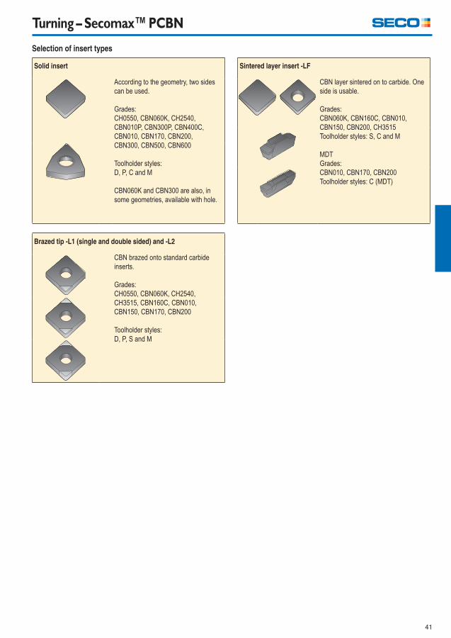
41
Turning – Secomax™ PCBN
Sintered layer insert -LF
CBN layer sintered on to carbide. One
side is usable.
Grades:
CBN060K, CBN160C, CBN010,
CBN150, CBN200, CH3515
Toolholder styles: S, C and M
MDT
Grades:
CBN010, CBN170, CBN200
Toolholder styles: C (MDT)
Selection of insert types
Solid insert
According to the geometry, two sides
can be used.
Grades:
CH0550, CBN060K, CH2540,
CBN010P, CBN300P, CBN400C,
CBN010, CBN170, CBN200,
CBN300, CBN500, CBN600
Toolholder styles:
D, P, C and M
CBN060K and CBN300 are also, in
some geometries, available with hole.
Brazed tip -L1 (single and double sided) and -L2
CBN brazed onto standard carbide
inserts.
Grades:
CH0550, CBN060K, CH2540,
CH3515, CBN160C, CBN010,
CBN150, CBN170, CBN200
Toolholder styles:
D, P, S and M
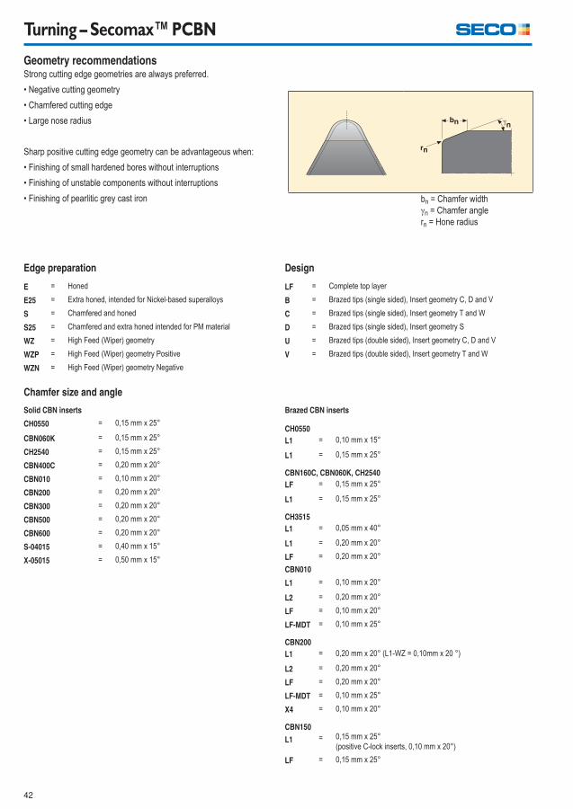
42
Turning – Secomax™ PCBN
Geometry recommendations Strong cutting edge geometries are always preferred.
� Negative cutting geometry
� Chamfered cutting edge
� Large nose radius
Sharp positive cutting edge geometry can be advantageous when:
� Finishing of small hardened bores without interruptions
� Finishing of unstable components without interruptions
� Finishing of pearlitic grey cast iron bn = Chamfer width
n = Chamfer angle
rn = Hone radius
Design
LF = Complete top layer
B = Brazed tips (single sided), Insert geometry C, D and V
C = Brazed tips (single sided), Insert geometry T and W
D = Brazed tips (single sided), Insert geometry S
U = Brazed tips (double sided), Insert geometry C, D and V
V = Brazed tips (double sided), Insert geometry T and W
Edge preparation
E = Honed
E25 = Extra honed, intended for Nickel-based superalloys
S = Chamfered and honed
S25 = Chamfered and extra honed intended for PM material
WZ = High Feed (Wiper) geometry
WZP = High Feed (Wiper) geometry Positive
WZN = High Feed (Wiper) geometry Negative
Brazed CBN inserts
CH0550
L1 = 0,10 mm x 15°
L1 = 0,15 mm x 25°
CBN160C, CBN060K, CH2540
LF = 0,15 mm x 25°
L1 = 0,15 mm x 25°
CH3515
L1 = 0,05 mm x 40°
L1 = 0,20 mm x 20°
LF = 0,20 mm x 20°
CBN010
L1 = 0,10 mm x 20°
L2 = 0,20 mm x 20°
LF = 0,10 mm x 20°
LF-MDT = 0,10 mm x 25°
CBN200
L1 = 0,20 mm x 20° (L1-WZ = 0,10mm x 20 °)
L2 = 0,20 mm x 20°
LF = 0,20 mm x 20°
LF-MDT = 0,10 mm x 25°
X4 = 0,10 mm x 20°
CBN150
L1 = 0,15 mm x 25°
(positive C-lock inserts, 0,10 mm x 20°)
LF = 0,15 mm x 25°
Chamfer size and angle
Solid CBN inserts
CH0550 = 0,15 mm x 25°
CBN060K = 0,15 mm x 25°
CH2540 = 0,15 mm x 25°
CBN400C = 0,20 mm x 20°
CBN010 = 0,10 mm x 20°
CBN200 = 0,20 mm x 20°
CBN300 = 0,20 mm x 20°
CBN500 = 0,20 mm x 20°
CBN600 = 0,20 mm x 20°
S-04015 = 0,40 mm x 15°
X-05015 = 0,50 mm x 15°
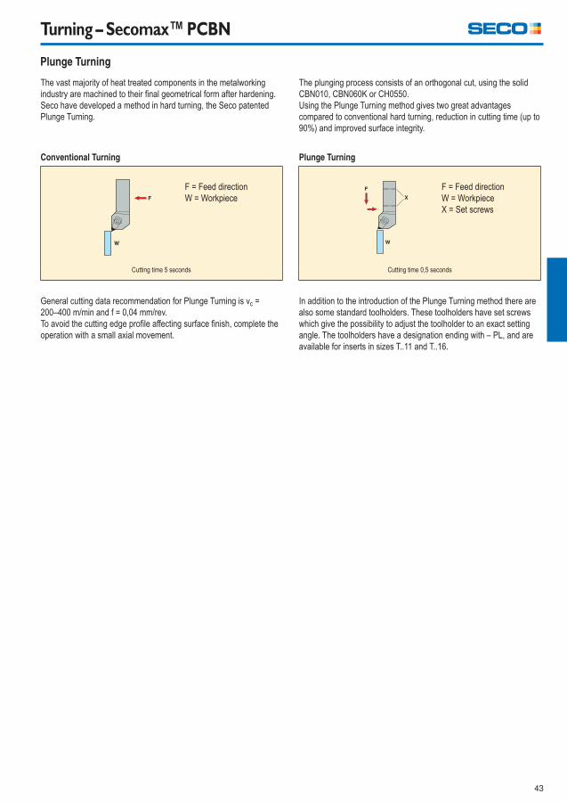
43
Turning – Secomax™ PCBN
Plunge Turning
The plunging process consists of an orthogonal cut, using the solid
CBN010, CBN060K or CH0550.
Using the Plunge Turning method gives two great advantages
compared to conventional hard turning, reduction in cutting time (up to
90%) and improved surface integrity.
Plunge Turning
F = Feed direction
W = Workpiece
X = Set screws
Cutting time 0,5 seconds
In addition to the introduction of the Plunge Turning method there are
also some standard toolholders. These toolholders have set screws
which give the possibility to adjust the toolholder to an exact setting
angle. The toolholders have a designation ending with – PL, and are
available for inserts in sizes T..11 and T..16.
The vast majority of heat treated components in the metalworking
industry are machined to their fi nal geometrical form after hardening.
Seco have developed a method in hard turning, the Seco patented
Plunge Turning.
Conventional Turning
F = Feed direction
W = Workpiece
Cutting time 5 seconds
General cutting data recommendation for Plunge Turning is vc =
200–400 m/min and f = 0,04 mm/rev.
To avoid the cutting edge profi le affecting surface fi nish, complete the
operation with a small axial movement.
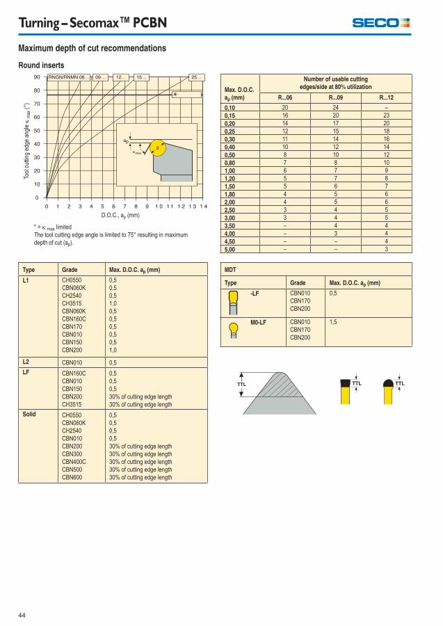
44
Turning – Secomax™ PCBN
Maximum depth of cut recommendations
Max. D.O.C.
ap (mm)
Number of usable cutting
edges/side at 80% utilization
R...06 R...09 R...12
0,10 20 24 –
0,15 16 20 23
0,20 14 17 20
0,25 12 15 18
0,30 11 14 16
0,40 10 12 14
0,50 8 10 12
0,80 7 8 10
1,00 6 7 9
1,20 5 7 8
1,50 5 6 7
1,80 4 5 6
2,00 4 5 6
2,50 3 4 5
3,00 3 4 5
3,50 – 4 4
4,00 – 3 4
4,50 – – 4
5,00 – – 3
Round inserts
Tool
cut
ting
edge
ang
le
max
(°)
D.O.C., ap (mm)
* = max limited
The tool cutting edge angle is limited to 75° resulting in maximum
depth of cut (ap).
MDT
Type Grade Max. D.O.C. ap (mm)
-LF CBN010
CBN170
CBN200
0,5
M0-LF CBN010
CBN170
CBN200
1,5
Type Grade Max. D.O.C. ap (mm)
L1 CH0550
CBN060K
CH2540
CH3515
CBN060K
CBN160C
CBN170
CBN010
CBN150
CBN200
0,5
0,5
0,5
1,0
0,5
0,5
0,5
0,5
0,5
1,0
L2 CBN010 0,5
LF CBN160C
CBN010
CBN150
CBN200
CH3515
0,5
0,5
0,5
30% of cutting edge length
30% of cutting edge length
Solid CH0550
CBN060K
CH2540
CBN010
CBN200
CBN300
CBN400C
CBN500
CBN600
0,5
0,5
0,5
0,5
30% of cutting edge length
30% of cutting edge length
30% of cutting edge length
30% of cutting edge length
30% of cutting edge length
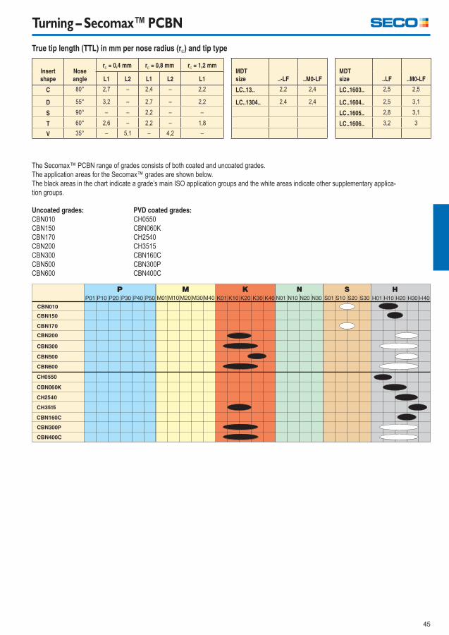
45
Turning – Secomax™ PCBN
Insert
shape
Nose
angle
r = 0,4 mm r = 0,8 mm r = 1,2 mmMDT
size ..-LF ..M0-LF
MDT
size ..LF ..M0-LFL1 L2 L1 L2 L1
C 80° 2,7 – 2,4 – 2,2 LC..13.. 2,2 2,4 LC..1603.. 2,5 2,5
D 55° 3,2 – 2,7 – 2,2 LC..1304.. 2,4 2,4 LC..1604.. 2,5 3,1
S 90° – – 2,2 – – LC..1605.. 2,8 3,1
T 60° 2,6 – 2,2 – 1,8 LC..1606.. 3,2 3
V 35° – 5,1 – 4,2 –
True tip length (TTL) in mm per nose radius (r) and tip type
The Secomax™ PCBN range of grades consists of both coated and uncoated grades.
The application areas for the Secomax™ grades are shown below.
The black areas in the chart indicate a grade’s main ISO application groups and the white areas indicate other supplementary applica-
tion groups.
Uncoated grades:
CBN010
CBN150
CBN170
CBN200
CBN300
CBN500
CBN600
PVD coated grades:
CH0550
CBN060K
CH2540
CH3515
CBN160C
CBN300P
CBN400C

46
Turning – Secomax™ PCBN
CH0550 Format:
Solid & brazed tips (single & double sided).
Composition:
40% cBN bi-modal grain size distribution with average grain size of 3 μm and a
TiCN ceramic binder.
Coating:
(Ti, Al, Cr)N coating.
CBN060K Format:
Solid, full-face layer and brazed tips (single and double sided).
Composition:
60% cBN content grade with an average grain size of 1-2 μm and a TiCN ceramic
binder.
Coating:
(Ti, Si, Al)N coating.
CH2540 Format:
Solid & brazed tips (single & double sided).
Composition:
65% cBN bi-modal grain size distribution with average grain size of 6 μm and a
TiCN ceramic binder.
Coating:
(Ti, Si)N coating.
CH3515 Format:
Full-faced brazed layer and brazed tips (single sided).
Composition:
90% cBN average grain size of 4 μm and a AlN ceramic binder.
Coating:
(Ti, Al)N coating.
Grades
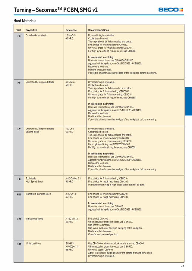
47
Turning – Secomax™ PCBN, SMG v2
Hard Materials
SMG Properties Reference Recommendations
H3 Case hardened steels 16 MnCr 5
60 HRC
Dry machining is preferable.
Coolant can be used.
The chips should be fully annealed and brittle.
First choice for fi nish machining: CH0550.
Universal grade for fi nish machining: CBN010.
For high surface fi nish requirements, use CH0550.
In interrupted machining:
Moderate interruptions, use CBN060K/CBN010.
Aggressive interruptions, use CH2540/CH3515/CBN150.
Reduce the feed rate.
Machine without coolant.
If possible, chamfer any sharp edges of the workpiece before machining.
H5 Quenched & Tempered steels 42 CrMo 4
50 HRC
Dry machining is preferable.
Coolant can be used.
The chips should be fully annealed and brittle.
First choice for fi nish machining: CBN060K.
Universal grade for fi nish machining: CBN010.
For high surface fi nish requirements, use CH0550.
In interrupted machining:
Moderate interruptions, use CBN060K/CBN010.
Aggressive interruptions, use CH2540/CH3515/CBN150.
Reduce the feed rate.
Machine without coolant.
If possible, chamfer any sharp edges of the workpiece before machining.
H7 Quenched & Tempered steels
Bearing steels
100 Cr 6
60 HRC
Dry machining is preferable.
Coolant can be used.
The chips should be fully annealed and brittle.
First choice for fi nish machining: CBN060K.
Universal grade for fi nish machining: CBN010.
For rough machining, use CBN200/CBN300.
For high surface fi nish requirements, use CH0550.
In interrupted machining:
Moderate interruptions, use CBN060K/CBN010.
Aggressive interruptions, use CH2540/CH3515/CBN150.
Reduce the feed rate.
Machine without coolant.
If possible, chamfer any sharp edges of the workpiece before machining.
H8 Tool steels
High Speed Steels
X 40 CrMoV 5 1
50 HRC
First choice for fi nish machining: CBN010.
First choice for rough machining: CBN200.
Interrupted machining of high speed steels can not be done.
H11 Martensitic stainless steels X 20 Cr 13
45 HRC
First choice for fi nish machining: CBN010.
First choice for rough machining: CBN300.
In interrupted machining:
Moderate interruptions, use CBN010.
Aggressive interruptions, use CH2540/CH3515/CBN150.
H21 Manganese steels X 120 Mn 12
50 HRC
First choice CBN300.
When a tougher grade is needed use CBN500.
Use chamfered inserts.
Use stable toolholder and rigid clamping of the workpiece.
Machine without coolant.
Chamfer workpiece edges fi rst.
H31 White cast irons EN-GJN-
HV600(XCr11)
55 HRC
Use CBN300 or when centerlock inserts are used CBN200.
When a tougher grade is needed use CBN500.
Universal option: CBN600.
Adjust the depth of cut to get under the casting skin and blow holes.
Dry machining is preferable.
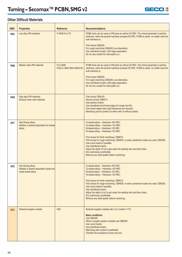
48
Turning – Secomax™ PCBN, SMG v2
Other Diffi cult Materials
SMG Properties Reference Recommendations
PM1 Low alloy PM materials F-0008 Fe-0.7C PCBN tools can be used on PM parts as soft as 25 HRC. The critical parameter is particle
hardness, when the particle hardness exceeds 50 HRC, PCBN is useful, no matter what the
bulk hardness is.
First choice CBN200.
For rough machining CBN300 is an alternative.
Use chamfered inserts, S25 edge preparation.
Do not use coolant for interrupted cut.
PM2 Medium alloy PM materials FLC-4608
Fe2Cu1.8Ni0.5Mo0.2Mn0.8C
PCBN tools can be used on PM parts as soft as 25 HRC. The critical parameter is particle
hardness, when the particle hardness exceeds 50 HRC, PCBN is useful, no matter what the
bulk hardness is.
First choice CBN200.
For rough machining CBN300 is an alternative.
Use chamfered inserts, S25 edge preparation.
Do not use coolant for interrupted cut.
PM3 High alloy PM materials
Exhaust valve seat materials
First choice CBN150.
Second choice CBN010.
Use positive inserts.
Use chamfered and honed edges for longer tool life.
Use honed edges when tight tolerances are required.
Machining can be carried out either with or without coolant.
HF1 Hard facing alloys
Welded or plasma deposited iron based
alloys
Cr-based alloys – Hardness <60 HRC.
Co-based alloys – Hardness >35 HRC.
Ni-based alloys – Hardness >35 HRC.
Fe-based alloys – Hardness >35 HRC.
First choice for fi nish machining: CBN010.
First choice for rough machining: CBN500, or when centerlock inserts are used: CBN200.
Use round inserts if possible.
Use chamfered inserts.
Adjust the depth of cut to get under the welding skin and blow holes.
Dry machining is preferable.
Remove any weld spatter before machining.
HF2 Hard facing alloys
Welded or plasma deposited cubalt and
nickel based alloys
Cr-based alloys – Hardness <60 HRC.
Co-based alloys – Hardness >35 HRC.
Ni-based alloys – Hardness >35 HRC.
Fe-based alloys – Hardness >35 HRC.
First choice for fi nish machining: CBN010.
First choice for rough machining: CBN500, or when centerlock inserts are used: CBN200.
Use round inserts if possible.
Use chamfered inserts.
Adjust the depth of cut to get under the welding skin and blow holes.
Dry machining is preferable.
Remove any weld spatter before machining.
CC1 Sintered tungsten carbide G50 Sintered tungsten carbide with a Co content >17%.
Basic conditions:
Use CBN300.
When a tougher grade is needed use CBN500.
Use round inserts.
Use chamfered inserts.
Machining with coolant is preferable.
Chamfer the workpiece at entry and exit.
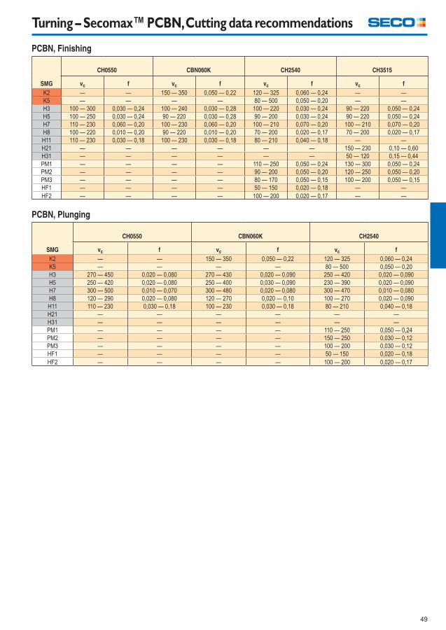
49
Turning – Secomax™ PCBN, Cutting data recommendations
PCBN, Finishing
SMG
CH0550 CBN060K CH2540 CH3515
vc f vc f vc f vc f
K2 — — 150 — 350 0,050 — 0,22 120 — 325 0,060 — 0,24 — —
K5 — — — — 80 — 500 0,050 — 0,20 — —
H3 100 — 300 0,030 — 0,24 100 — 240 0,030 — 0,28 100 — 220 0,030 — 0,24 90 — 220 0,050 — 0,24
H5 100 — 250 0,030 — 0,24 90 — 220 0,030 — 0,28 90 — 200 0,030 — 0,24 90 — 220 0,050 — 0,24
H7 110 — 230 0,060 — 0,20 100 — 230 0,060 — 0,20 100 — 210 0,070 — 0,20 100 — 210 0,070 — 0,20
H8 100 — 220 0,010 — 0,20 90 — 220 0,010 — 0,20 70 — 200 0,020 — 0,17 70 — 200 0,020 — 0,17
H11 110 — 230 0,030 — 0,18 100 — 230 0,030 — 0,18 80 — 210 0,040 — 0,18 — —
H21 — — — — — — 150 — 230 0,10 — 0,60
H31 — — — — — — 50 — 120 0,15 — 0,44
PM1 — — — — 110 — 250 0,050 — 0,24 130 — 300 0,050 — 0,24
PM2 — — — — 90 — 200 0,050 — 0,20 120 — 250 0,050 — 0,20
PM3 — — — — 80 — 170 0,050 — 0,15 100 — 200 0,050 — 0,15
HF1 — — — — 50 — 150 0,020 — 0,18 — —
HF2 — — — — 100 — 200 0,020 — 0,17 — —
PCBN, Plunging
SMG
CH0550 CBN060K CH2540
vc f vc f vc f
K2 — — 150 — 350 0,050 — 0,22 120 — 325 0,060 — 0,24
K5 — — — — 80 — 500 0,050 — 0,20
H3 270 — 450 0,020 — 0,080 270 — 430 0,020 — 0,090 250 — 420 0,020 — 0,090
H5 250 — 420 0,020 — 0,080 250 — 400 0,030 — 0,090 230 — 390 0,020 — 0,090
H7 300 — 500 0,010 — 0,070 300 — 480 0,020 — 0,080 300 — 470 0,010 — 0,080
H8 120 — 290 0,020 — 0,080 120 — 270 0,020 — 0,10 100 — 270 0,020 — 0,090
H11 110 — 230 0,030 — 0,18 100 — 230 0,030 — 0,18 80 — 210 0,040 — 0,18
H21 — — — — — —
H31 — — — — — —
PM1 — — — — 110 — 250 0,050 — 0,24
PM2 — — — — 150 — 250 0,030 — 0,12
PM3 — — — — 100 — 200 0,030 — 0,12
HF1 — — — — 50 — 150 0,020 — 0,18
HF2 — — — — 100 — 200 0,020 — 0,17
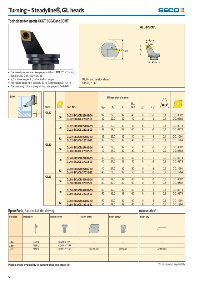
50
Turning – Steadyline®, GL heads
Toolholders for inserts CCGT, CCGX and CCMT
Size Part No.
Dimensions in mm
o° s°D5m f1 l1
Dm
min
GL32
06GL32-SCLCR-22032-06 32 22,0 32 40 0 -2 0,1 CC..0602
GL32-SCLCL-22032-06 32 22,0 32 40 0 -2 0,1 CC..0602
09GL32-SCLCR-22032-09 32 22,0 32 40 0 -2 0,1 CC..09T3
GL32-SCLCL-22032-09 32 22,0 32 40 0 -2 0,1 CC..09T3
12GL32-SCLCR-22032-12 32 22,0 32 40 0 -8 0,1 CC..1204..
GL32-SCLCL-22032-12 32 22,0 32 40 0 -8 0,1 CC..1204..
GL40
06GL40-SCLCR-27032-06 40 27,0 32 50 0 -2 0,2 CC..0602
GL40-SCLCL-27032-06 40 27,0 32 50 0 -2 0,2 CC..0602
09GL40-SCLCR-27032-09 40 27,0 32 50 0 -2 0,2 CC..09T3
GL40-SCLCL-27032-09 40 27,0 32 50 0 -2 0,2 CC..09T3
12GL40-SCLCR-27032-12 40 27,0 32 50 0 -8 0,2 CC..1204..
GL40-SCLCL-27032-12 40 27,0 32 50 0 -8 0,2 CC..1204..
GL50
06GL50-SCLCR-32032-06 50 32,0 32 60 0 -2 0,3 CC..0602
GL50-SCLCL-32032-06 50 32,0 32 60 0 -2 0,3 CC..0602
09GL50-SCLCR-32032-09 50 32,0 32 60 0 -2 0,3 CC..09T3
GL50-SCLCL-32032-09 50 32,0 32 60 0 -2 0,3 CC..09T3
12GL50-SCLCR-32032-12 50 32,0 32 60 0 -5 0,3 CC..1204..
GL50-SCLCL-32032-12 50 32,0 32 60 0 -5 0,3 CC..1204..
For insert programme, see page(s) 70 and MN 2015 Turning,
page(s) 343-347, 400-401, 431
o° = Rake angle, s° = Inclination angle
For holder code key, see MN 2015 Turning page(s) 12-13
For damping holders programme, see page(s) 144-148
Please check availability in current price and stock-list
min
GL..-SCLCR/L
*To be ordered separately
95,0 °
Right-hand version shown
kar (r) = 95°
For size Insert key Insert screw Insert shim Shim screw
..-06 T07P-2 C02506-T07P – –
..-09 T15P-2 C04008-T15P – –
..-12 T15P-2 C05012-T15P 123.19-621 CA5008
Spare Parts, Parts included in delivery
Shim key
–
–
5SMS795
Accessories*
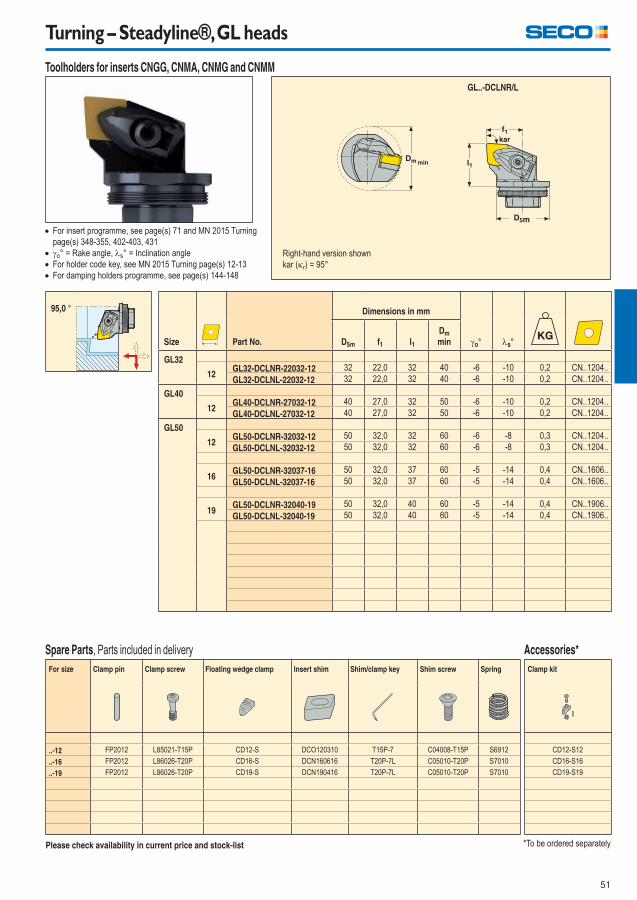
51
Turning – Steadyline®, GL heads
Size Part No.
Dimensions in mm
o° s°D5m f1 l1
Dm
min
GL32
12GL32-DCLNR-22032-12 32 22,0 32 40 -6 -10 0,2 CN..1204..
GL32-DCLNL-22032-12 32 22,0 32 40 -6 -10 0,2 CN..1204..
GL40
12GL40-DCLNR-27032-12 40 27,0 32 50 -6 -10 0,2 CN..1204..
GL40-DCLNL-27032-12 40 27,0 32 50 -6 -10 0,2 CN..1204..
GL50
12GL50-DCLNR-32032-12 50 32,0 32 60 -6 -8 0,3 CN..1204..
GL50-DCLNL-32032-12 50 32,0 32 60 -6 -8 0,3 CN..1204..
16GL50-DCLNR-32037-16 50 32,0 37 60 -5 -14 0,4 CN..1606..
GL50-DCLNL-32037-16 50 32,0 37 60 -5 -14 0,4 CN..1606..
19GL50-DCLNR-32040-19 50 32,0 40 60 -5 -14 0,4 CN..1906..
GL50-DCLNL-32040-19 50 32,0 40 60 -5 -14 0,4 CN..1906..
For insert programme, see page(s) 71 and MN 2015 Turning
page(s) 348-355, 402-403, 431
o° = Rake angle, s° = Inclination angle
For holder code key, see MN 2015 Turning page(s) 12-13
For damping holders programme, see page(s) 144-148
Please check availability in current price and stock-list
min
GL..-DCLNR/L
*To be ordered separately
95,0 °
Right-hand version shown
kar (r) = 95°
Toolholders for inserts CNGG, CNMA, CNMG and CNMM
For size Clamp pin Clamp screw Floating wedge clamp Insert shim Shim/clamp key Shim screw Spring
..-12 FP2012 L85021-T15P CD12-S DCO120310 T15P-7 C04008-T15P S6912
..-16 FP2012 L86026-T20P CD16-S DCN160616 T20P-7L C05010-T20P S7010
..-19 FP2012 L86026-T20P CD19-S DCN190416 T20P-7L C05010-T20P S7010
Spare Parts, Parts included in delivery
Clamp kit
CD12-S12
CD16-S16
CD19-S19
Accessories*
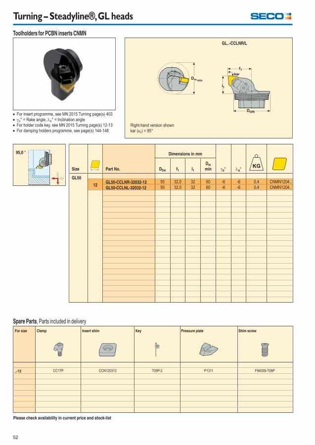
52
Turning – Steadyline®, GL heads
Size Part No.
Dimensions in mm
o° s°D5m f1 l1
Dm
min
GL50
12GL50-CCLNR-32032-12 50 32,0 32 60 -6 -6 0,4 CNMN1204..
GL50-CCLNL-32032-12 50 32,0 32 60 -6 -6 0,4 CNMN1204..
For insert programme, see MN 2015 Turning page(s) 403
o° = Rake angle, s° = Inclination angle
For holder code key, see MN 2015 Turning page(s) 12-13
For damping holders programme, see page(s) 144-148
Please check availability in current price and stock-list
min
GL..-CCLNR/L
95,0 °
Right-hand version shown
kar (r) = 95°
Toolholders for PCBN inserts CNMN
For size Clamp Insert shim Key Pressure plate Shim screw
..-12 CC17P CCN120312 T09P-2 P1311 F94009-T09P
Spare Parts, Parts included in delivery
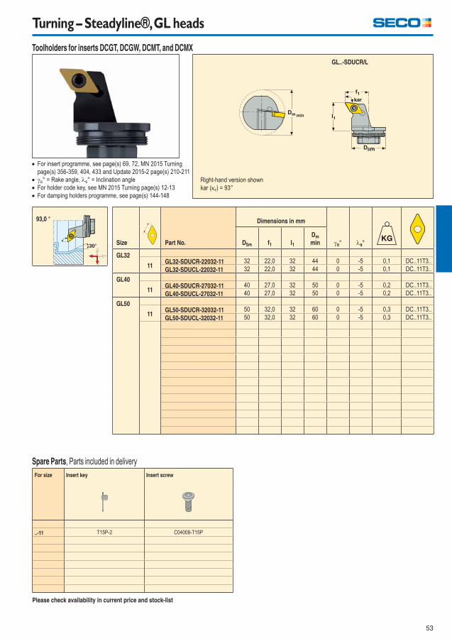
53
Turning – Steadyline®, GL heads
Size Part No.
Dimensions in mm
o° s°D5m f1 l1
Dm
min
GL32
11GL32-SDUCR-22032-11 32 22,0 32 44 0 -5 0,1 DC..11T3..
GL32-SDUCL-22032-11 32 22,0 32 44 0 -5 0,1 DC..11T3..
GL40
11GL40-SDUCR-27032-11 40 27,0 32 50 0 -5 0,2 DC..11T3..
GL40-SDUCL-27032-11 40 27,0 32 50 0 -5 0,2 DC..11T3..
GL50
11GL50-SDUCR-32032-11 50 32,0 32 60 0 -5 0,3 DC..11T3..
GL50-SDUCL-32032-11 50 32,0 32 60 0 -5 0,3 DC..11T3..
For size Insert key Insert screw
..-11 T15P-2 C04008-T15P
For insert programme, see page(s) 69, 72, MN 2015 Turning
page(s) 356-359, 404, 433 and Update 2015-2 page(s) 210-211
o° = Rake angle, s° = Inclination angle
For holder code key, see MN 2015 Turning page(s) 12-13
For damping holders programme, see page(s) 144-148
Please check availability in current price and stock-list
min
GL..-SDUCR/L
93,0 °
Spare Parts, Parts included in delivery
Right-hand version shown
kar (r) = 93°
Toolholders for inserts DCGT, DCGW, DCMT, and DCMX
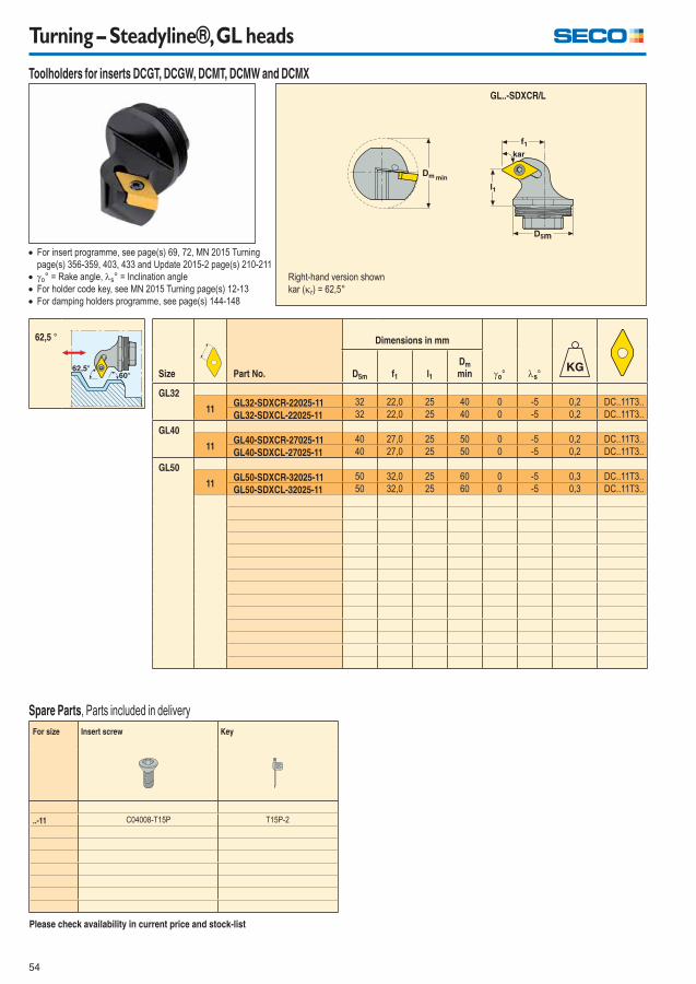
54
Turning – Steadyline®, GL heads
Size Part No.
Dimensions in mm
o° s°D5m f1 l1
Dm
min
GL32
11GL32-SDXCR-22025-11 32 22,0 25 40 0 -5 0,2 DC..11T3..
GL32-SDXCL-22025-11 32 22,0 25 40 0 -5 0,2 DC..11T3..
GL40
11GL40-SDXCR-27025-11 40 27,0 25 50 0 -5 0,2 DC..11T3..
GL40-SDXCL-27025-11 40 27,0 25 50 0 -5 0,2 DC..11T3..
GL50
11GL50-SDXCR-32025-11 50 32,0 25 60 0 -5 0,3 DC..11T3..
GL50-SDXCL-32025-11 50 32,0 25 60 0 -5 0,3 DC..11T3..
For size Insert screw Key
..-11 C04008-T15P T15P-2
For insert programme, see page(s) 69, 72, MN 2015 Turning
page(s) 356-359, 403, 433 and Update 2015-2 page(s) 210-211
o° = Rake angle, s° = Inclination angle
For holder code key, see MN 2015 Turning page(s) 12-13
For damping holders programme, see page(s) 144-148
Please check availability in current price and stock-list
min
GL..-SDXCR/L
62,5 °
62,5
Spare Parts, Parts included in delivery
Right-hand version shown
kar (r) = 62,5°
Toolholders for inserts DCGT, DCGW, DCMT, DCMW and DCMX
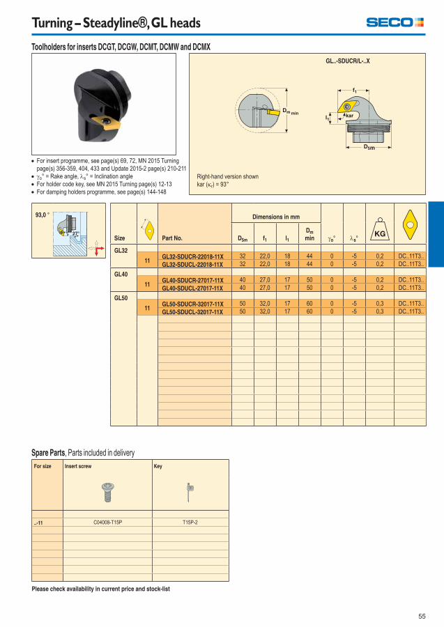
55
Turning – Steadyline®, GL heads
Size Part No.
Dimensions in mm
o° s°D5m f1 l1
Dm
min
GL32
11GL32-SDUCR-22018-11X 32 22,0 18 44 0 -5 0,2 DC..11T3..
GL32-SDUCL-22018-11X 32 22,0 18 44 0 -5 0,2 DC..11T3..
GL40
11GL40-SDUCR-27017-11X 40 27,0 17 50 0 -5 0,2 DC..11T3..
GL40-SDUCL-27017-11X 40 27,0 17 50 0 -5 0,2 DC..11T3..
GL50
11GL50-SDUCR-32017-11X 50 32,0 17 60 0 -5 0,3 DC..11T3..
GL50-SDUCL-32017-11X 50 32,0 17 60 0 -5 0,3 DC..11T3..
For size Insert screw Key
..-11 C04008-T15P T15P-2
For insert programme, see page(s) 69, 72, MN 2015 Turning
page(s) 356-359, 404, 433 and Update 2015-2 page(s) 210-211
o° = Rake angle, s° = Inclination angle
For holder code key, see MN 2015 Turning page(s) 12-13
For damping holders programme, see page(s) 144-148
Please check availability in current price and stock-list
min
GL..-SDUCR/L-..X
93,0 °
Spare Parts, Parts included in delivery
Right-hand version shown
kar (r) = 93°
Toolholders for inserts DCGT, DCGW, DCMT, DCMW and DCMX
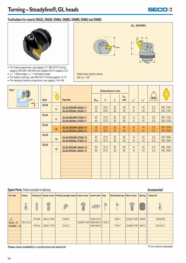
56
Turning – Steadyline®, GL heads
Size Part No.
Dimensions in mm
o° s°D5m f1 l1
Dm
min
GL32
11GL32-DDUNR-22032-11 32 22,0 32 40 -6 -10 0,2 DN..1104..
GL32-DDUNL-22032-11 32 22,0 32 40 -6 -10 0,2 DN..1104..
GL40
11GL40-DDUNR-27032-11 40 27,0 32 50 -5 -10 0,2 DN..1104..
GL40-DDUNL-27032-11 40 27,0 32 50 -5 -10 0,2 DN..1104..
GL32
15GL32-DDUNR-22032-15 32 22,0 32 40 -6 -14 0,2 DN..1504..
GL32-DDUNL-22032-15 32 22,0 32 40 -6 -14 0,2 DN..1504..
GL40
15GL40-DDUNR-27032-15 40 27,0 32 50 -6 -12 0,2 DN..1504..
GL40-DDUNL-27032-15 40 27,0 32 50 -6 -12 0,2 DN..1504..
GL50
15GL50-DDUNR-32032-15 50 27,0 32 60 -6 -12 0,3 DN..1504..
GL50-DDUNL-32032-15 50 27,0 32 60 -6 -12 0,3 DN..1504..
For insert programme, see page(s) 73, MN 2015 Turning
page(s) 359-365, 406-408 and Update 2015-2 page(s) 212
o° = Rake angle, s° = Inclination angle
For holder code key, see MN 2015 Turning page(s) 12-13
For damping holders programme, see page(s) 144-148
Please check availability in current price and stock-list
min
GL..-DDUNR/L
*To be ordered separately
93,0 °
Right-hand version shown
kar (r) = 93°
Toolholders for inserts DNGG, DNGM, DNMA, DNMG, DNMM, DNMU and DNMX
For size Clamp Clamp pin Clamp screw Floating wedge clamp Insert screw Insert shim Key Shim/clamp key Shim screw Spring
..-11 – FP1508 L84017-T09P CD09-S – DDN110310 – T09P-2 C03007-T09P S5608
GL32-..-15 CD12-S12 – – – C04008-T15P DDN150416 T15P-2 – – –
GL40/50-..-15 – FP2012 L85021-T15P CD12-S – DDN150416 – T15P-7 C04008-T15P S6912
Spare Parts, Parts included in delivery
Clamp kit
CD09-S09
–
CD12-S12
Accessories*
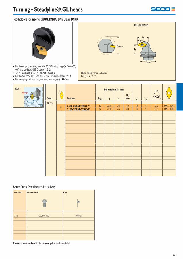
57
Turning – Steadyline®, GL heads
Size Part No.
Dimensions in mm
o° s°D5m f1 l1
Dm
min
GL32
11GL32-SDXNR-22025-11 32 22,0 25 40 -5 -11 0,2 DN..1104..
GL32-SDXNL-22025-11 32 22,0 25 40 -5 -11 0,2 DN..1104..
For size Insert screw Key
..-11 C03511-T09P T09P-2
For insert programme, see MN 2015 Turning page(s) 364-365,
407 and Update 2015-2 page(s) 212
o° = Rake angle, s° = Inclination angle
For holder code key, see MN 2015 Turning page(s) 12-13
For damping holders programme, see page(s) 144-148
Please check availability in current price and stock-list
min
GL..-SDXNR/L
62,5 °
62,5
Spare Parts, Parts included in delivery
Right-hand version shown
kar (r) = 62,5°
Toolholders for inserts DNGG, DNMA, DNMU and DNMX
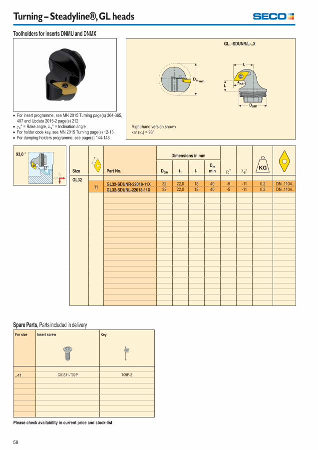
58
Turning – Steadyline®, GL heads
Size Part No.
Dimensions in mm
o° s°D5m f1 l1
Dm
min
GL32
11GL32-SDUNR-22018-11X 32 22,0 18 40 -5 -11 0,2 DN..1104..
GL32-SDUNL-22018-11X 32 22,0 18 40 -5 -11 0,2 DN..1104..
For size Insert screw Key
..-11 C03511-T09P T09P-2
For insert programme, see MN 2015 Turning page(s) 364-365,
407 and Update 2015-2 page(s) 212
o° = Rake angle, s° = Inclination angle
For holder code key, see MN 2015 Turning page(s) 12-13
For damping holders programme, see page(s) 144-148
Please check availability in current price and stock-list
min
GL..-SDUNR/L-..X
93,0 °
Spare Parts, Parts included in delivery
Right-hand version shown
kar (r) = 93°
Toolholders for inserts DNMU and DNMX
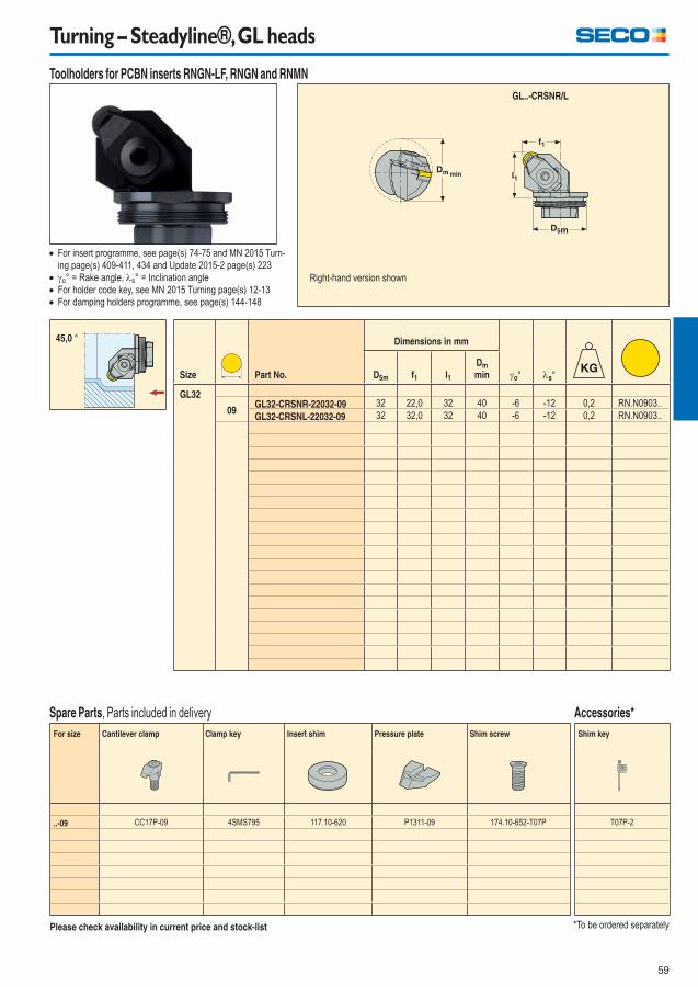
59
Turning – Steadyline®, GL heads
Size Part No.
Dimensions in mm
o° s°D5m f1 l1
Dm
min
GL32
09GL32-CRSNR-22032-09 32 22,0 32 40 -6 -12 0,2 RN.N0903..
GL32-CRSNL-22032-09 32 32,0 32 40 -6 -12 0,2 RN.N0903..
For insert programme, see page(s) 74-75 and MN 2015 Turn-
ing page(s) 409-411, 434 and Update 2015-2 page(s) 223
o° = Rake angle, s° = Inclination angle
For holder code key, see MN 2015 Turning page(s) 12-13
For damping holders programme, see page(s) 144-148
Please check availability in current price and stock-list
min
GL..-CRSNR/L
*To be ordered separately
45,0 °
Right-hand version shown
Toolholders for PCBN inserts RNGN-LF, RNGN and RNMN
For size Cantilever clamp Clamp key Insert shim Pressure plate Shim screw
..-09 CC17P-09 4SMS795 117.10-620 P1311-09 174.10-652-T07P
Spare Parts, Parts included in delivery
Shim key
T07P-2
Accessories*
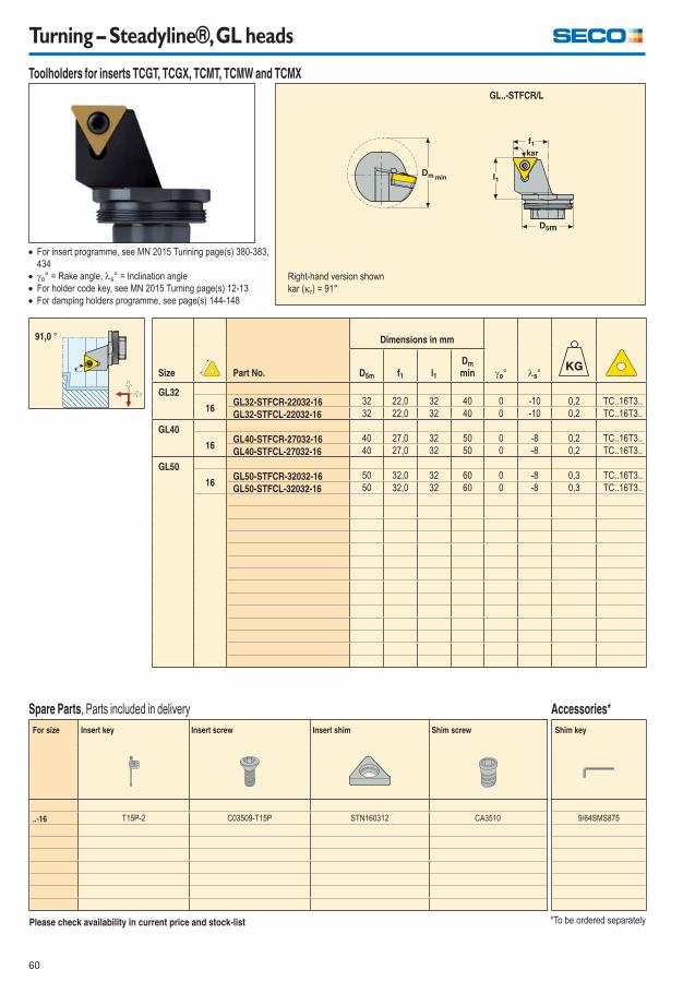
60
Turning – Steadyline®, GL heads
Size Part No.
Dimensions in mm
o° s°D5m f1 l1
Dm
min
GL32
16GL32-STFCR-22032-16 32 22,0 32 40 0 -10 0,2 TC..16T3..
GL32-STFCL-22032-16 32 22,0 32 40 0 -10 0,2 TC..16T3..
GL40
16GL40-STFCR-27032-16 40 27,0 32 50 0 -8 0,2 TC..16T3..
GL40-STFCL-27032-16 40 27,0 32 50 0 -8 0,2 TC..16T3..
GL50
16GL50-STFCR-32032-16 50 32,0 32 60 0 -8 0,3 TC..16T3..
GL50-STFCL-32032-16 50 32,0 32 60 0 -8 0,3 TC..16T3..
For insert programme, see MN 2015 Turining page(s) 380-383,
434
o° = Rake angle, s° = Inclination angle
For holder code key, see MN 2015 Turning page(s) 12-13
For damping holders programme, see page(s) 144-148
Please check availability in current price and stock-list
min
GL..-STFCR/L
*To be ordered separately
91,0 °
Right-hand version shown
kar (r) = 91°
Toolholders for inserts TCGT, TCGX, TCMT, TCMW and TCMX
For size Insert key Insert screw Insert shim Shim screw
..-16 T15P-2 C03509-T15P STN160312 CA3510
Spare Parts, Parts included in delivery
Shim key
9/64SMS875
Accessories*
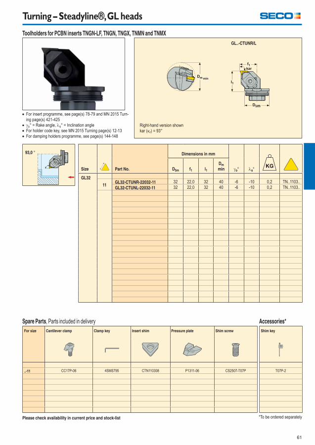
61
Turning – Steadyline®, GL heads
Size Part No.
Dimensions in mm
o° s°D5m f1 l1
Dm
min
GL32
11GL32-CTUNR-22032-11 32 22,0 32 40 -6 -10 0,2 TN..1103..
GL32-CTUNL-22032-11 32 22,0 32 40 -6 -10 0,2 TN..1103..
For insert programme, see page(s) 78-79 and MN 2015 Turn-
ing page(s) 421-425
o° = Rake angle, s° = Inclination angle
For holder code key, see MN 2015 Turning page(s) 12-13
For damping holders programme, see page(s) 144-148
min
GL..-CTUNR/L
93,0 °
Right-hand version shown
kar (r) = 93°
Toolholders for PCBN inserts TNGN-LF, TNGN, TNGX, TNMN and TNMX
Please check availability in current price and stock-list
For size Cantilever clamp Clamp key Insert shim Pressure plate Shim screw
..-11 CC17P-06 4SMS795 CTN110308 P1311-06 CS2507-T07P
Spare Parts, Parts included in delivery
Shim key
T07P-2
Accessories*
*To be ordered separately
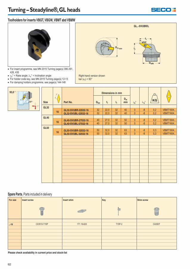
62
Turning – Steadyline®, GL heads
Size Part No.
Dimensions in mm
o° s°D5m f1 l1
Dm
min
GL32
16GL32-SVUBR-22032-16 32 22,0 32 40 0 -8 0,2 VBMT1604..
GL32-SVUBL-22032-16 32 22,0 32 40 0 -8 0,2 VBMT1604..
GL40
16GL40-SVUBR-27032-16 40 27,0 32 50 0 -8 0,2 VBMT1604..
GL40-SVUBL-27032-16 40 27,0 32 50 0 -8 0,2 VBMT1604..
GL50
16GL50-SVUBR-32032-16 50 32,0 32 63 0 -8 0,3 VBMT1604..
GL50-SVUBL-32032-16 50 32,0 32 63 0 -8 0,3 VBMT1604..
For insert programme, see MN 2015 Turning page(s) 390-391,
426, 435
o° = Rake angle, s° = Inclination angle
For holder code key, see MN 2015 Turning page(s) 12-13
For damping holders programme, see page(s) 144-148
Please check availability in current price and stock-list
min
GL..-SVUBR/L
93,0 °
Right-hand version shown
kar (r) = 93°
Toolholders for inserts VBGT, VBGW, VBMT abd VBMW
For size Insert screw Insert shim Key Shim screw
..-16 C03510-T15P 171.19-620 T15P-2 CA3507
Spare Parts, Parts included in delivery
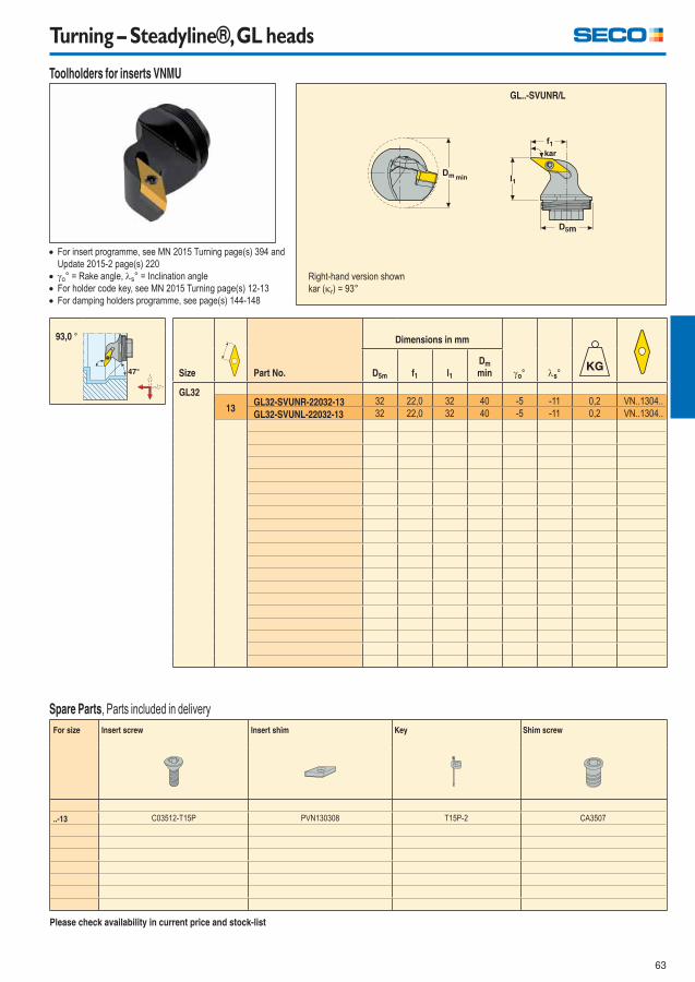
63
Turning – Steadyline®, GL heads
Size Part No.
Dimensions in mm
o° s°D5m f1 l1
Dm
min
GL32
13GL32-SVUNR-22032-13 32 22,0 32 40 -5 -11 0,2 VN..1304..
GL32-SVUNL-22032-13 32 22,0 32 40 -5 -11 0,2 VN..1304..
For insert programme, see MN 2015 Turning page(s) 394 and
Update 2015-2 page(s) 220
o° = Rake angle, s° = Inclination angle
For holder code key, see MN 2015 Turning page(s) 12-13
For damping holders programme, see page(s) 144-148
Please check availability in current price and stock-list
min
GL..-SVUNR/L
93,0 °
Right-hand version shown
kar (r) = 93°
Toolholders for inserts VNMU
For size Insert screw Insert shim Key Shim screw
..-13 C03512-T15P PVN130308 T15P-2 CA3507
Spare Parts, Parts included in delivery
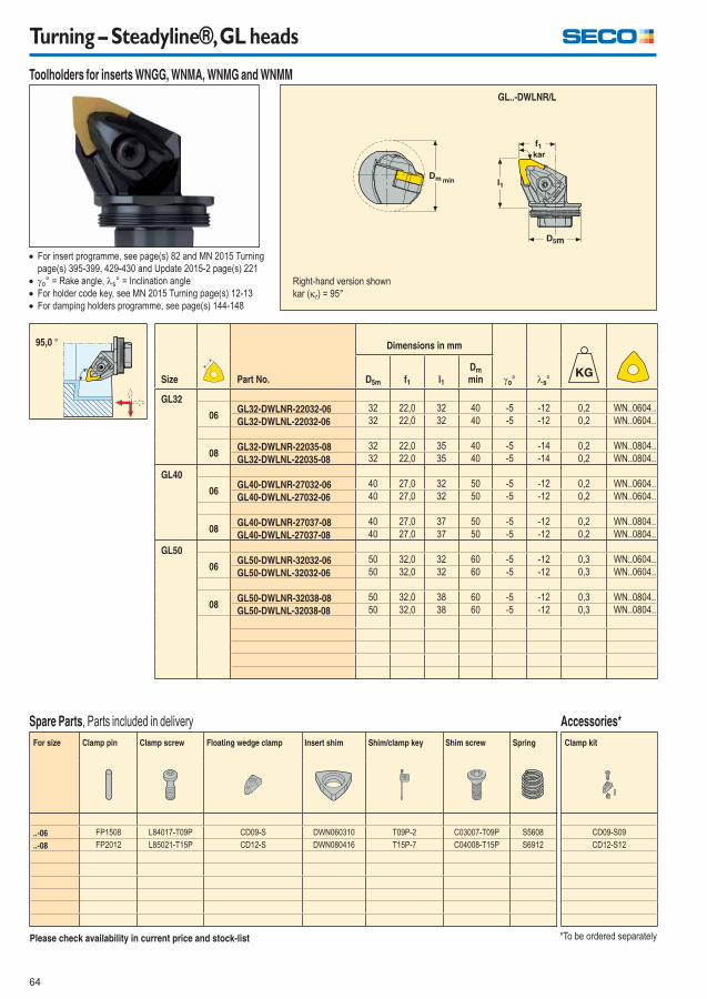
64
Turning – Steadyline®, GL heads
Size Part No.
Dimensions in mm
o° s°D5m f1 l1
Dm
min
GL32
06GL32-DWLNR-22032-06 32 22,0 32 40 -5 -12 0,2 WN..0604..
GL32-DWLNL-22032-06 32 22,0 32 40 -5 -12 0,2 WN..0604..
08GL32-DWLNR-22035-08 32 22,0 35 40 -5 -14 0,2 WN..0804..
GL32-DWLNL-22035-08 32 22,0 35 40 -5 -14 0,2 WN..0804..
GL40
06GL40-DWLNR-27032-06 40 27,0 32 50 -5 -12 0,2 WN..0604..
GL40-DWLNL-27032-06 40 27,0 32 50 -5 -12 0,2 WN..0604..
08GL40-DWLNR-27037-08 40 27,0 37 50 -5 -12 0,2 WN..0804..
GL40-DWLNL-27037-08 40 27,0 37 50 -5 -12 0,2 WN..0804..
GL50
06GL50-DWLNR-32032-06 50 32,0 32 60 -5 -12 0,3 WN..0604..
GL50-DWLNL-32032-06 50 32,0 32 60 -5 -12 0,3 WN..0604..
08GL50-DWLNR-32038-08 50 32,0 38 60 -5 -12 0,3 WN..0804..
GL50-DWLNL-32038-08 50 32,0 38 60 -5 -12 0,3 WN..0804..
For insert programme, see page(s) 82 and MN 2015 Turning
page(s) 395-399, 429-430 and Update 2015-2 page(s) 221
o° = Rake angle, s° = Inclination angle
For holder code key, see MN 2015 Turning page(s) 12-13
For damping holders programme, see page(s) 144-148
Please check availability in current price and stock-list
min
GL..-DWLNR/L
*To be ordered separately
95,0 °
Right-hand version shown
kar (r) = 95°
Toolholders for inserts WNGG, WNMA, WNMG and WNMM
For size Clamp pin Clamp screw Floating wedge clamp Insert shim Shim/clamp key Shim screw Spring
..-06 FP1508 L84017-T09P CD09-S DWN060310 T09P-2 C03007-T09P S5608
..-08 FP2012 L85021-T15P CD12-S DWN080416 T15P-7 C04008-T15P S6912
Spare Parts, Parts included in delivery
Clamp kit
CD09-S09
CD12-S12
Accessories*

65
MDT – Steadyline®, GL heads, Jetstream Tooling®
*DCINN – minimum bore diameter, see MN Turning 2015 page(s) 477
For insert programme, see MN 2015 Turning page(s)
578-591, 593-594
For damping holders programme, see page(s) 144-148
Please check availability in current price and stock-list
GL.-CGJR/L-..JET
Right-hand version shown
Size Part No.
Dimensions in mm
D5m f1 l1 ar DCINN*
GL32
2,0GL32-CGJR-25032-1902JET 32 25,0 32,0 7,5 43 0,2 LC..1902..
GL32-CGJL-25032-1902JET 32 25,0 32,0 7,5 43 0,2 LC..1902..
GL40
2,0GL40-CGJR-29032-1902JET 40 29,0 32,0 7,5 51 0,2 LC..1902..
GL40-CGJL-29032-1902JET 40 29,0 32,0 7,5 51 0,2 LC..1902..
GL50
2,0GL50-CGJR-34032-1902JET 50 34,0 32,0 7,5 61 0,3 LC..1902..
GL50-CGJL-34032-1902JET 50 34,0 32,0 7,5 61 0,3 LC..1902..
GL.-CGJR/L-..JET
90 °
Toolholders for LCGF, LCGN, LCMF and LCMR
For size Clamp key Clamp screw
1902 T15P-7 L85011-T15P
Spare Parts, Parts included in delivery
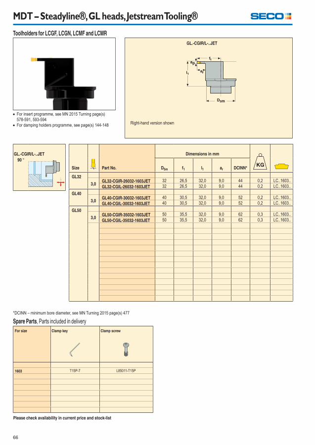
66
MDT – Steadyline®, GL heads, Jetstream Tooling®
*DCINN – minimum bore diameter, see MN Turning 2015 page(s) 477
For insert programme, see MN 2015 Turning page(s)
578-591, 593-594
For damping holders programme, see page(s) 144-148
Please check availability in current price and stock-list
GL.-CGIR/L-..JET
Right-hand version shown
Size Part No.
Dimensions in mm
D5m f1 l1 ar DCINN*
GL32
3,0GL32-CGIR-26032-1603JET 32 26,5 32,0 9,0 44 0,2 LC..1603..
GL32-CGIL-26032-1603JET 32 26,5 32,0 9,0 44 0,2 LC..1603..
GL40
3,0GL40-CGIR-30032-1603JET 40 30,5 32,0 9,0 52 0,2 LC..1603..
GL40-CGIL-30032-1603JET 40 30,5 32,0 9,0 52 0,2 LC..1603..
GL50
3,0GL50-CGIR-35032-1603JET 50 35,5 32,0 9,0 62 0,3 LC..1603..
GL50-CGIL-35032-1603JET 50 35,5 32,0 9,0 62 0,3 LC..1603..
GL.-CGIR/L-..JET
90 °
Toolholders for LCGF, LCGN, LCMF and LCMR
For size Clamp key Clamp screw
1603 T15P-7 L85011-T15P
Spare Parts, Parts included in delivery
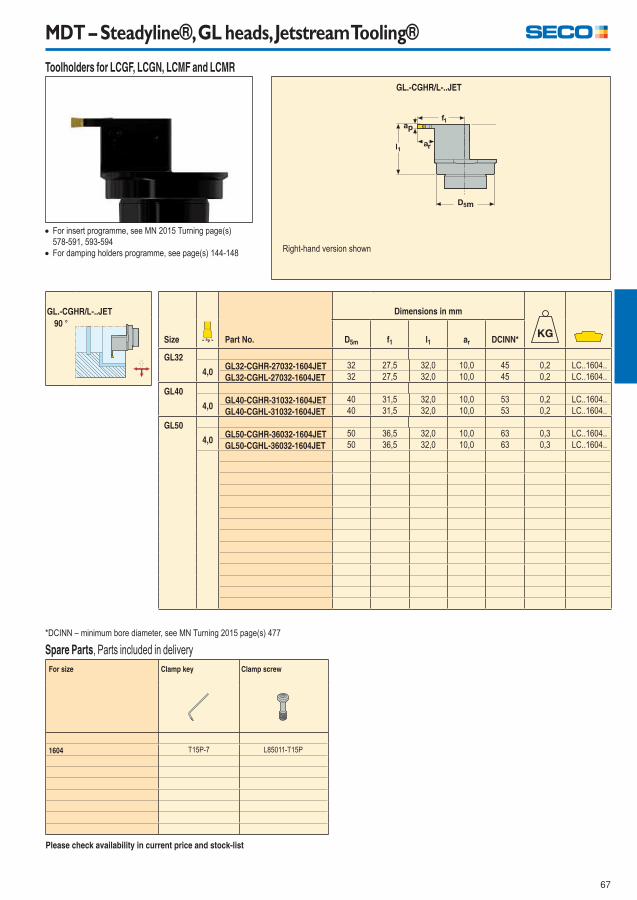
67
MDT – Steadyline®, GL heads, Jetstream Tooling®
*DCINN – minimum bore diameter, see MN Turning 2015 page(s) 477
For insert programme, see MN 2015 Turning page(s)
578-591, 593-594
For damping holders programme, see page(s) 144-148
Please check availability in current price and stock-list
GL.-CGHR/L-..JET
Right-hand version shown
Size Part No.
Dimensions in mm
D5m f1 l1 ar DCINN*
GL32
4,0GL32-CGHR-27032-1604JET 32 27,5 32,0 10,0 45 0,2 LC..1604..
GL32-CGHL-27032-1604JET 32 27,5 32,0 10,0 45 0,2 LC..1604..
GL40
4,0GL40-CGHR-31032-1604JET 40 31,5 32,0 10,0 53 0,2 LC..1604..
GL40-CGHL-31032-1604JET 40 31,5 32,0 10,0 53 0,2 LC..1604..
GL50
4,0GL50-CGHR-36032-1604JET 50 36,5 32,0 10,0 63 0,3 LC..1604..
GL50-CGHL-36032-1604JET 50 36,5 32,0 10,0 63 0,3 LC..1604..
GL.-CGHR/L-..JET
90 °
Toolholders for LCGF, LCGN, LCMF and LCMR
For size Clamp key Clamp screw
1604 T15P-7 L85011-T15P
Spare Parts, Parts included in delivery
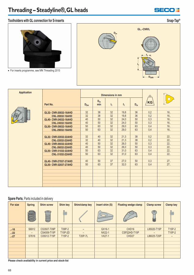
68
Threading – Steadyline®, GL heads
Toolholders with GL connection for S-inserts
Application
Part No.
Dimensions in mm
D5m
Dm
min l1 f1 Dm
GL32- CNR-20032-16AHD 32 38 32 19,8 36 0,2 16..
CNL-20032-16AHD 32 38 32 19,8 36 0,2 16..
GL40- CNR-24032-16AHD 40 50 32 24,0 50 0,3 16..
CNL-24032-16AHD 40 50 32 24,0 50 0,3 16..
GL50- CNR-29032-16AHD 50 63 32 29,0 63 0,4 16..
CNL-29032-16AHD 50 63 32 29,0 63 0,4 16..
GL32- CNR-22032-22AHD 32 40 32 21,3 38 0,2 22..
CNL-22032-22AHD 32 40 32 21,3 38 0,2 22..
GL40- CNR-26032-22AHD 40 50 32 26,0 50 0,3 22..
CNL-26032-22AHD 40 50 32 26,0 50 0,3 22..
GL50- CNR-31032-22AHD 50 63 32 31,0 63 0,4 22..
CNL-31032-22AHD 50 63 32 31,0 63 0,4 22..
GL40- CNR-27037-27AHD 40 50 37 27,0 50 0,3 27..
GL50- CNR-32037-27AHD 50 63 37 32,0 63 0,4 27..
For inserts programme, see MN Threading 2015
Please check availability in current price and stock-list
Snap-Tap®
GL..-CNR/L
For size Spring Shim screw Shim key Shim/clamp key Insert shim (S) Floating wedge clamp Clamp screw Clamp key
..-16 S6912 CS3507-T09P T09P-2 – GX16-1 CHD16 L85020-T15P T15P-2
..-22 – CS4009-T15P T15P-2D – NX22-1 CSP22HD-T15P – T15P-2
..-27 S7616 C05012-T15P T15P-2 T20P-7L VX27-1 CHD27 L86025-T20P –
Spare Parts, Parts included in delivery
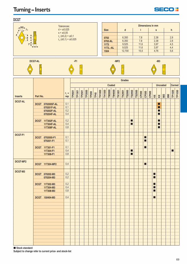
69
Turning – Inserts
Inserts Part No.
r =
rep
Grades
Coated Uncoated Cermet
TP
0501
TP
1501
TP
2501
TP
3500
TP
200
TP
40
TH
1000
TH
1500
TM
2000
TM
4000
TK
1001
TK
2001
TS
2000
TS
2050
TS
2500
CP
200
CP
500
CP
600
HX
KX
883
890
TP
1020
TP
1030
DCGT-ALDCGT 0702005F-AL 0,1 [
070201F-AL 0,1 [
070202F-AL 0,2 [
070204F-AL 0,4 [
DCGT 11T302F-AL 0,2 [ [
11T304F-AL 0,4 [ [
11T308F-AL 0,8 [
DCGT-F1DCGT 0702005-F1 0,1 [
070201-F1 0,1 [
DCGT 11T301-F1 0,1 [
11T304-F1 0,4 [ [
11T308-F1 0,8 [
DCGT-MF2DCGT 11T304-MF2 0,4 [
DCGT-M3DCGT 070202-M3 0,2 [
070204-M3 0,2 [
DCGT 11T302-M3 0,2 [
11T304-M3 0,4 [
11T308-M3 0,8 [
DCGT 150404-M3 0,4 [
[ Stock standard
Subject to change refer to current price- and stock-list
Tolerances:
d = ±0,025
s = ±0,05
r (≥0,2) = ±0,1
r (≤0,1) = ±0,025
Size
Dimensions in mm
d l s h
0702 6,350 7,8 2,38 2,9
0702-AL 6,350 7,8 2,38 2,8
11T3 9,525 11,6 3,97 4,5
11T3..-AL 9,525 11,6 3,97 4,4
1504 12,700 15,5 4,76 5,6
DCGT-AL -F1 -MF2 -M3
DCGT
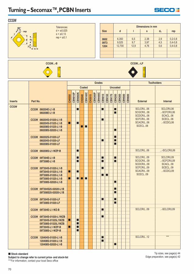
70
Turning – Secomax™, PCBN Inserts
Inserts Part No.
Grades Toolholders
Coated Uncoated
CH
0550
CB
N01
0P
CB
N06
0K
CH
2540
CB
N16
0C
CH
3515
CB
N30
0P
CB
N40
0C
CB
N01
0
CB
N15
0
CB
N17
0
CB
N20
0
CB
N30
0
CB
N50
0
CB
N60
0
External Internal
CCGWCCGW 060204E-L1-B [ [ [ SCLCR/L..06
SCGCR/L..06
SCDCR/L..06
SCFCR/L..06
SCACR/L..06
SCECL..06
SCLCR/L06
..-SCFCR/L06
SCACL..06
SCECL..06
..-SCDCL06
060208E-L1-B [
CCGW 060204S-01020-L1-B [
060204S-01525-L1-B [ [
060208S-01525-L1-B [ [
060208S-02020-L1-B [
CCGW 060202S-01020-LF [
060204S-01020-LF [ [
060208S-01020-LF [
CCGW 060208S-L1-WZP-B [ SCLCR/L..06 ...-SCLCR/L06
CCGW 09T304E-L1-B [ [ [ SCLCR/L..09
SCGCR/L..09
SCDCR/L..09
SCFCR/L..09
SCACR/L..09
SCECL..09
SCLCR/L09
..-SCFCR/L09
SCACL..09
SCECL..09
..-SCDCL09
09T308E-L1-B [ [ [
CCGW 09T304S-01020-L1-B [
09T304S-01525-L1-B [ [
09T308S-01020-L1-B [ [
09T308S-01525-L1-B [ [ [ [
09T308S-02020-L1-B [
CCGW 09T304S25-02020-L1B [
09T308S25-02020-L1B [
CCGW 09T304S-01020-LF [ [
09T308S-01020-LF [
CCGW 09T304E-L1-WZ-B [ SCLCR/L..09 ..-SCLCR/L09
CCGW 09T304S-01020-L1WZB [
09T304S-01525L1WZB [ [
09T308S-01525L1WZB [
09T304S-L1-WZP-B [ [
09T308S-L1-WZP-B [
CCGW 120404S-01020-L1-B [ SCLCR/L..12 ***
120408S-01020-L1-B [
120408S-02020-L1-B [
[ Stock standard
Subject to change refer to current price- and stock-list
***For information, contact your local Seco offi ce
Tolerances:
d = ±0,025
s = ±0,13
rep = ±0,1
Size
Dimensions in mm
d l s d1 rep
0602 6,350 6,5 2,38 2,9 0,2-0,8
09T3 9,525 9,7 3,97 4,5 0,4-0,8
1204 12,700 12,9 4,76 5,6 0,4-0,8
CCGW...-B CCGW...-LF
CCGW
Tip sizes, see page(s) 44
Edge preparation, see page(s) 42
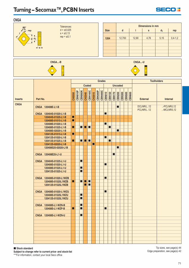
71
Turning – Secomax™, PCBN Inserts
Inserts Part No.
Grades Toolholders
Coated Uncoated
CH
0550
CB
N01
0P
CB
N06
0K
CH
2540
CB
N16
0C
CH
3515
CB
N30
0P
CB
N40
0C
CB
N01
0
CB
N15
0
CB
N17
0
CB
N20
0
CB
N30
0
CB
N50
0
CB
N60
0
External Internal
CNGACNGA 120408E-L1-B [ DCLNR/L..12
PCLNR/L..12
..-PCLNR/L12
..-MCLNR/L12
CNGA 120404S-01020-L1-B [
120404S-01525-L1-B [
120408S-01015-L1-B [
120408S-01020-L1-B [
120408S-01525-L1-B [ [ [ [ [
120408S-02020-L1-B [
120412S-01015-L1-B [
120412S-01020-L1-B [
120412S-01525-L1-B [ [ [ [ [
120412S-02020-L1-B [
120408S25-02020-L1B [
CNGA 120408E25-L1-U [
CNGA 120404S-01525-L1-U [
120408S-01020-L1-U [
120408S-01525-L1-U [
120412S-01525-L1-U [
CNGA 120408S-01020-L1WZB [
120408S-01525L1WZB [ [ [ [
120412S-01525L1WZB [ [
CNGA 120408S-01020-L1WZU [
120408S-01525L1WZU [
120412S-01525L1WZU [
CNGA 120408S-L1-WZN-B [
120408S-L1-WZP-B [ [ [
CNGA 120408S-L1-WZN-U [
[ Stock standard
Subject to change refer to current price- and stock-list
***For information, contact your local Seco offi ce
Tolerances:
d = ±0,025
s = ±0,13
rep = ±0,1
Size
Dimensions in mm
d l s d1 rep
1204 12,700 12,90 4,76 5,15 0,4-1,2
CNGA...-B CNGA...-U
CNGA
Tip sizes, see page(s) 44
Edge preparation, see page(s) 42
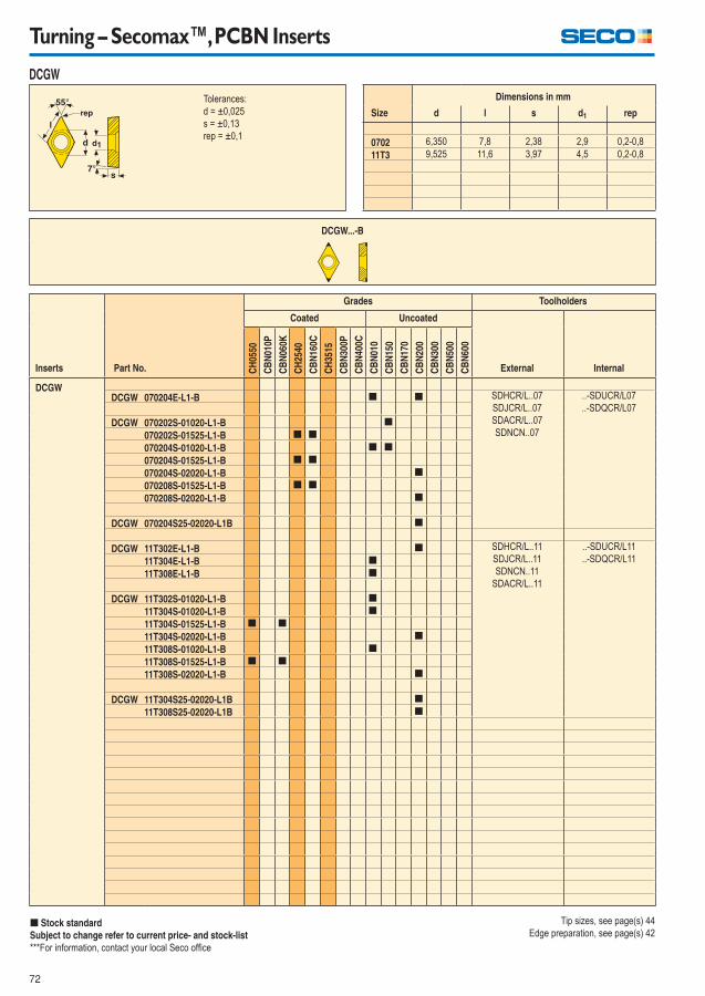
72
Turning – Secomax™, PCBN Inserts
Inserts Part No.
Grades Toolholders
Coated Uncoated
CH
0550
CB
N01
0P
CB
N06
0K
CH
2540
CB
N16
0C
CH
3515
CB
N30
0P
CB
N40
0C
CB
N01
0
CB
N15
0
CB
N17
0
CB
N20
0
CB
N30
0
CB
N50
0
CB
N60
0
External Internal
DCGWDCGW 070204E-L1-B [ [ SDHCR/L..07
SDJCR/L..07
SDACR/L..07
SDNCN..07
..-SDUCR/L07
..-SDQCR/L07
DCGW 070202S-01020-L1-B [
070202S-01525-L1-B [ [
070204S-01020-L1-B [ [
070204S-01525-L1-B [ [
070204S-02020-L1-B [
070208S-01525-L1-B [ [
070208S-02020-L1-B [
DCGW 070204S25-02020-L1B [
DCGW 11T302E-L1-B [ SDHCR/L..11
SDJCR/L..11
SDNCN..11
SDACR/L..11
..-SDUCR/L11
..-SDQCR/L1111T304E-L1-B [
11T308E-L1-B [
DCGW 11T302S-01020-L1-B [
11T304S-01020-L1-B [
11T304S-01525-L1-B [ [
11T304S-02020-L1-B [
11T308S-01020-L1-B [
11T308S-01525-L1-B [ [
11T308S-02020-L1-B [
DCGW 11T304S25-02020-L1B [
11T308S25-02020-L1B [
[ Stock standard
Subject to change refer to current price- and stock-list
***For information, contact your local Seco offi ce
Tolerances:
d = ±0,025
s = ±0,13
rep = ±0,1
Size
Dimensions in mm
d l s d1 rep
0702 6,350 7,8 2,38 2,9 0,2-0,8
11T3 9,525 11,6 3,97 4,5 0,2-0,8
DCGW...-B
DCGW
Tip sizes, see page(s) 44
Edge preparation, see page(s) 42
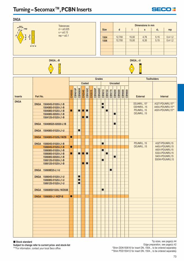
73
Turning – Secomax™, PCBN Inserts
Inserts Part No.
Grades Toolholders
Coated Uncoated
CH
0550
CB
N01
0P
CB
N06
0K
CH
2540
CB
N16
0C
CH
3515
CB
N30
0P
CB
N40
0C
CB
N01
0
CB
N15
0
CB
N17
0
CB
N20
0
CB
N30
0
CB
N50
0
CB
N60
0
External Internal
DNGADNGA 150404S-01020-L1-B [ DDJNR/L..15*
DDHNR/L..15
PDJNR/L..15
DDJNR/L..15
A32T-PDUNR/L15**
A40U-PDUNR/L15**
A50V-PDUNR/L15**150408S-01020-L1-B [
150408S-01525-L1-B [ [ [ [ [
150408S-02020-L1-B [
150412S-01525-L1-B [ [
DNGA 150408S25-02020-L1B [
DNGA 150408S-01525-L1-U [
DNGA 150408S-01525L1WZB [
DNGA 150604S-01020-L1-B [ PDJNR/L..15
DDJNR/L..15
A32T-PDUNR/L15
A40U-PDUNR/L15
A50V-PDUNR/L15
S32U-PDUNR/L15
S40V-PDUNR/L15
S50W-PDUNR/L15
150604S-01525-L1-B [
150608S-01020-L1-B [
150608S-01525-L1-B [ [ [ [ [
150608S-02020-L1-B [
150612S-01020-L1-B [
150612S-01525-L1-B [ [
DNGA 150608E25-L1-U [
DNGA 150604S-01525-L1-U [
150608S-01525-L1-U [
150612S-01525-L1-U [
DNGA 150608S01020L1WZ93B [
DNGA 150608S-L1-WZP-B [
[ Stock standard
Subject to change refer to current price- and stock-list
***For information, contact your local Seco offi ce
Tolerances:
d = ±0,025
s = ±0,13
rep = ±0,1
Size
Dimensions in mm
d l s d1 rep
1504 12,700 15,00 4,76 5,15 0,4-1,2
1506 12,700 15,00 6,35 5,15 0,4-1,2
DNGA...-B DNGA...-U
DNGA
Tip sizes, see page(s) 44
Edge preparation, see page(s) 42
*Shim DDN150616 for insert DN..1504.., to be ordered separately
**Shim PDD150412 for insert DN..1504.., to be ordered separately
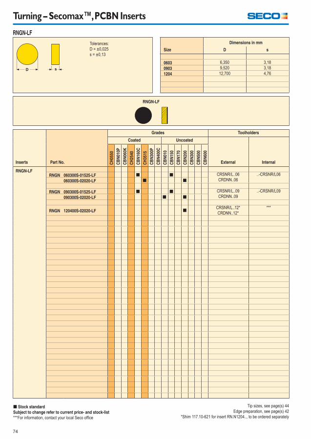
74
Turning – Secomax™, PCBN Inserts
Inserts Part No.
Grades Toolholders
Coated Uncoated
CH
0550
CB
N01
0P
CB
N06
0K
CH
2540
CB
N16
0C
CH
3515
CB
N30
0P
CB
N40
0C
CB
N01
0
CB
N15
0
CB
N17
0
CB
N20
0
CB
N30
0
CB
N50
0
CB
N60
0
External Internal
RNGN-LFRNGN 060300S-01525-LF [ [ CRSNR/L..06
CRDNN..06
..-CRSNR/L06
060300S-02020-LF [ [
RNGN 090300S-01525-LF [ [ CRSNR/L..09
CRDNN..09
..-CRSNR/L09
090300S-02020-LF [ [
RNGN 120400S-02020-LF [CRSNR/L..12*
CRDNN..12*
***
[ Stock standard
Subject to change refer to current price- and stock-list
***For information, contact your local Seco offi ce
Tolerances:
D = ±0,025
s = ±0,13 Size
Dimensions in mm
D s
0603 6,350 3,18
0903 9,520 3,18
1204 12,700 4,76
RNGN-LF
RNGN-LF
Tip sizes, see page(s) 44
Edge preparation, see page(s) 42
*Shim 117.10-621 for insert RN.N1204.., to be ordered separately
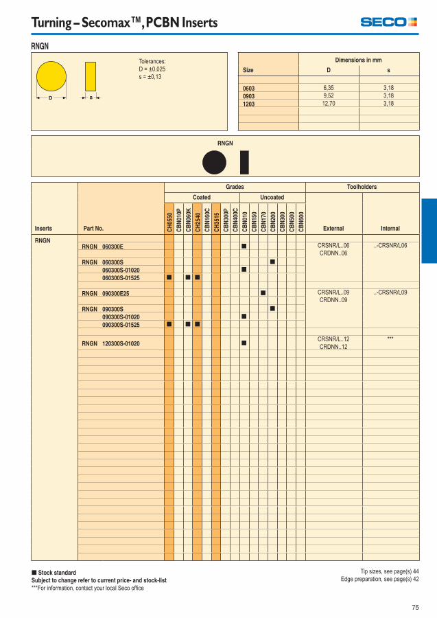
75
Turning – Secomax™, PCBN Inserts
Inserts Part No.
Grades Toolholders
Coated Uncoated
CH
0550
CB
N01
0P
CB
N06
0K
CH
2540
CB
N16
0C
CH
3515
CB
N30
0P
CB
N40
0C
CB
N01
0
CB
N15
0
CB
N17
0
CB
N20
0
CB
N30
0
CB
N50
0
CB
N60
0
External Internal
RNGNRNGN 060300E [ CRSNR/L..06
CRDNN..06
..-CRSNR/L06
RNGN 060300S [
060300S-01020 [
060300S-01525 [ [ [
RNGN 090300E25 [ CRSNR/L..09
CRDNN..09
..-CRSNR/L09
RNGN 090300S [
090300S-01020 [
090300S-01525 [ [ [
RNGN 120300S-01020 [CRSNR/L..12
CRDNN..12
***
[ Stock standard
Subject to change refer to current price- and stock-list
***For information, contact your local Seco offi ce
Tolerances:
D = ±0,025
s = ±0,13 Size
Dimensions in mm
D s
0603 6,35 3,18
0903 9,52 3,18
1203 12,70 3,18
RNGN
RNGN
Tip sizes, see page(s) 44
Edge preparation, see page(s) 42
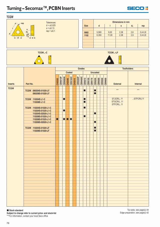
76
Turning – Secomax™, PCBN Inserts
Inserts Part No.
Grades Toolholders
Coated Uncoated
CH
0550
CB
N01
0P
CB
N06
0K
CH
2540
CB
N16
0C
CH
3515
CB
N30
0P
CB
N40
0C
CB
N01
0
CB
N15
0
CB
N17
0
CB
N20
0
CB
N30
0
CB
N50
0
CB
N60
0
External Internal
TCGWTCGW 090204S-01020-LF [ [ *** ***
090208S-01020-LF [
TCGW 110204E-L1-C [ [ STJCR/L..11
STGCR/L..11
STFCR/L..11
..-STFCR/L11
110208E-L1-C [
TCGW 110204S-01020-L1-C [
110204S-01525-L1-C [
110204S-02020-L1-C [
110208S-01020-L1-C [
110208S-01525-L1-C [ [ [ [
110208S-02020-L1-C [
TCGW 110204S-01020-LF [
110208S-01020-LF [
[ Stock standard
Subject to change refer to current price- and stock-list
***For information, contact your local Seco offi ce
Tolerances:
d = ±0,025
s = ±0,13
rep = ±0,1
Size
Dimensions in mm
d l s d1 rep
0902 5,560 9,00 2,38 2,6 0,4-0,8
1102 6,350 11,00 2,38 2,9 0,4-0,8
TCGW...-C TCGW...-LF
TCGW
Tip sizes, see page(s) 44
Edge preparation, see page(s) 42

77
Turning – Secomax™, PCBN Inserts
Inserts Part No.
Grades Toolholders
Coated Uncoated
CH
0550
CB
N01
0P
CB
N06
0K
CH
2540
CB
N16
0C
CH
3515
CB
N30
0P
CB
N40
0C
CB
N01
0
CB
N15
0
CB
N17
0
CB
N20
0
CB
N30
0
CB
N50
0
CB
N60
0
External Internal
TNGATNGA 160404S-01020-L1-C [ DTGNR/L..16
DTNNR/L..16
DTTNR/L..16
DTFNR/L..16
PTBNR/L..16
PTGNR/L..16
PTJNR/L..16
..-PTFNR/L16
..-MTFNR/L16160408S-01020-L1-C [
160408S-01525-L1-C [ [ [ [
160408S-02020-L1-C [
160412S-01525-L1-C [
160416S-00540-L1-C [
160420S-00540-L1-C [
TNGA 160408S-01525-L1-V [
[ Stock standard
Subject to change refer to current price- and stock-list
***For information, contact your local Seco offi ce
Tolerances:
d = ±0,025
s = ±0,13
rep = ±0,1
Size
Dimensions in mm
d l s d1 rep
1604 9,525 16,50 4,76 3,81 0,4-2,0
TNGA...-C TNGA...-V
TNGA
Tip sizes, see page(s) 44
Edge preparation, see page(s) 42
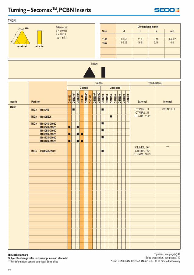
78
Turning – Secomax™, PCBN Inserts
Inserts Part No.
Grades Toolholders
Coated Uncoated
CH
0550
CB
N01
0P
CB
N06
0K
CH
2540
CB
N16
0C
CH
3515
CB
N30
0P
CB
N40
0C
CB
N01
0
CB
N15
0
CB
N17
0
CB
N20
0
CB
N30
0
CB
N50
0
CB
N60
0
External Internal
TNGNTNGN 110304E [ [ CTJNR/L..11
CTFNR/L..11
CTGNR/L..11-PL
..-CTUNR/L11
TNGN 110308E25 [
TNGN 110304S-01020 [
110304S-01525 [ [
110308S-01020 [
110308S-01525 [ [ [
110312S-01020 [
110312S-01525 [ [ [
TNGN 160304S-01020 [
CTJNR/L..16*
CTFNR/L..16*
CTGNR/L..16-PL
***
[ Stock standard
Subject to change refer to current price- and stock-list
***For information, contact your local Seco offi ce
Tolerances:
d = ±0,025
s = ±0,13
rep = ±0,1
Size
Dimensions in mm
d l s rep
1103 6,350 11,0 3,18 0,4-1,2
1603 9,525 16,5 3,18 0,4
TNGN
TNGN
Tip sizes, see page(s) 44
Edge preparation, see page(s) 42
*Shim UTN160412 for insert TNGN1603.., to be ordered separately
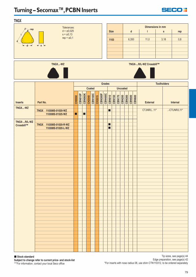
79
Turning – Secomax™, PCBN Inserts
Inserts Part No.
Grades Toolholders
Coated Uncoated
CH
0550
CB
N01
0P
CB
N06
0K
CH
2540
CB
N16
0C
CH
3515
CB
N30
0P
CB
N40
0C
CB
N01
0
CB
N15
0
CB
N17
0
CB
N20
0
CB
N30
0
CB
N50
0
CB
N60
0
External Internal
TNGX...-WZTNGX 110308S-01020-WZ [ CTJNR/L..11* ..-CTUNR/L11*
110308S-01525-WZ [ [
TNGX-...R/L-WZ
Crossbill™ TNGX 110308S-01020-R-WZ [
110308S-01020-L-WZ [
[ Stock standard
Subject to change refer to current price- and stock-list
***For information, contact your local Seco offi ce
Tolerances:
d = ±0,025
s = ±0,13
rep = ±0,1
Size
Dimensions in mm
d l s rep
1103 6,350 11,0 3,18 0,8
TNGX...-WZ TNGX-...R/L-WZ Crossbill™
TNGX
Tip sizes, see page(s) 44
Edge preparation, see page(s) 42
*For inserts with nose radius 08, use shim CTN110312, to be ordered separately
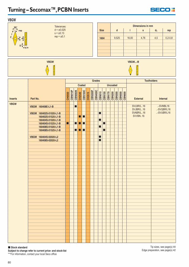
80
Turning – Secomax™, PCBN Inserts
Inserts Part No.
Grades Toolholders
Coated Uncoated
CH
0550
CB
N01
0P
CB
N06
0K
CH
2540
CB
N16
0C
CH
3515
CB
N30
0P
CB
N40
0C
CB
N01
0
CB
N15
0
CB
N17
0
CB
N20
0
CB
N30
0
CB
N50
0
CB
N60
0
External Internal
VBGWVBGW 160408E-L1-B [ SVLBR/L..16
SVJBR/L..16
SVABR/L..16
SVVBN..16
..-SVMBL16
..-SVQBR/L16
..-SVUBR/L16VBGW 160402S-01020-L1-B [
160402S-01525-L1-B [ [
160404S-01020-L1-B [
160404S-01525-L1-B [ [ [ [ [
160408S-01020-L1-B [
160408S-01525-L1-B [ [ [ [
VBGW 160404S-02020-L2 [
160408S-02020-L2 [
[ Stock standard
Subject to change refer to current price- and stock-list
***For information, contact your local Seco offi ce
Tolerances:
d = ±0,025
s = ±0,13
rep = ±0,1
Size
Dimensions in mm
d l s d1 rep
1604 9,525 16,00 4,76 4,5 0,2-0,8
VBGW VBGW...-B
VBGW
Tip sizes, see page(s) 44
Edge preparation, see page(s) 42
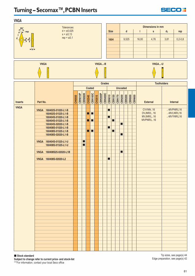
81
Turning – Secomax™, PCBN Inserts
Inserts Part No.
Grades Toolholders
Coated Uncoated
CH
0550
CB
N01
0P
CB
N06
0K
CH
2540
CB
N16
0C
CH
3515
CB
N30
0P
CB
N40
0C
CB
N01
0
CB
N15
0
CB
N17
0
CB
N20
0
CB
N30
0
CB
N50
0
CB
N60
0
External Internal
VNGAVNGA 160402S-01020-L1-B [ CVVNN..16
DVJNR/L..16
MVJNR/L..16
MVPNR/L..16
..-MVPNR/L16
..-MVLNR/L16
..-MVYNR/L16160402S-01525-L1-B [ [
160404S-01020-L1-B [
160404S-01525-L1-B [ [ [
160404S-02020-L1-B [
160408S-01020-L1-B [
160408S-01525-L1-B [ [ [
160408S-02020-L1-B [
VNGA 160404S-01525-L1-U [
160408S-01525-L1-U [
VNGA 160408S25-02020-L1B [
VNGA 160408S-02020-L2 [
[ Stock standard
Subject to change refer to current price- and stock-list
***For information, contact your local Seco offi ce
Tolerances:
d = ±0,025
s = ±0,13
rep = ±0,1
Size
Dimensions in mm
d l s d1 rep
1604 9,525 16,00 4,76 3,81 0,2-0,8
VNGA VNGA...-B VNGA...-U
VNGA
Tip sizes, see page(s) 44
Edge preparation, see page(s) 42
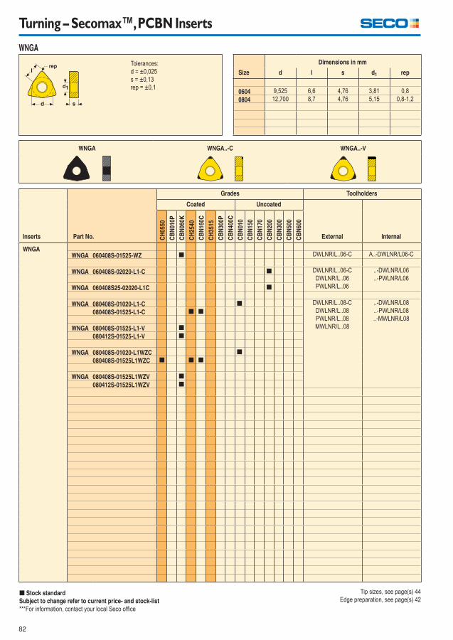
82
Turning – Secomax™, PCBN Inserts
Inserts Part No.
Grades Toolholders
Coated Uncoated
CH
0550
CB
N01
0P
CB
N06
0K
CH
2540
CB
N16
0C
CH
3515
CB
N30
0P
CB
N40
0C
CB
N01
0
CB
N15
0
CB
N17
0
CB
N20
0
CB
N30
0
CB
N50
0
CB
N60
0
External Internal
WNGAWNGA 060408S-01525-WZ [ DWLNR/L..06-C A..-DWLNR/L06-C
WNGA 060408S-02020-L1-C [ DWLNR/L..06-C
DWLNR/L..06
PWLNR/L..06
..-DWLNR/L06
..-PWLNR/L06
WNGA 060408S25-02020-L1C [
WNGA 080408S-01020-L1-C [ DWLNR/L..08-C
DWLNR/L..08
PWLNR/L..08
MWLNR/L..08
..-DWLNR/L08
..-PWLNR/L08
..-MWLNR/L08080408S-01525-L1-C [ [
WNGA 080408S-01525-L1-V [
080412S-01525-L1-V [
WNGA 080408S-01020-L1WZC [
080408S-01525L1WZC [ [ [
WNGA 080408S-01525L1WZV [
080412S-01525L1WZV [
[ Stock standard
Subject to change refer to current price- and stock-list
***For information, contact your local Seco offi ce
Tolerances:
d = ±0,025
s = ±0,13
rep = ±0,1
Size
Dimensions in mm
d l s d1 rep
0604 9,525 6,6 4,76 3,81 0,8
0804 12,700 8,7 4,76 5,15 0,8-1,2
WNGA WNGA..-C WNGA..-V
WNGA
Tip sizes, see page(s) 44
Edge preparation, see page(s) 42
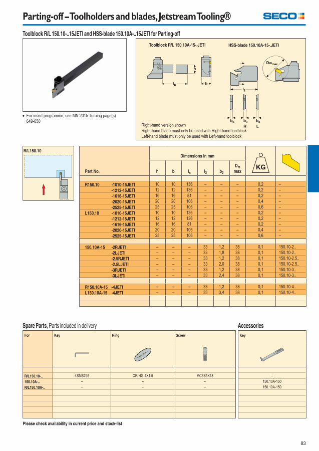
83
Parting-off – Toolholders and blades, Jetstream Tooling®
Part No.
Dimensions in mm
h b lc l2 b2
Dm
max
R150.10 -1010-15JETI 10 10 136 – – – 0,2 –
-1212-15JETI 12 12 136 – – – 0,2 –
-1616-15JETI 16 16 81 – – – 0,2 –
-2020-15JETI 20 20 106 – – – 0,4 –
-2525-15JETI 25 25 106 – – – 0,6 –
L150.10 -1010-15JETI 10 10 136 – – – 0,2 –
-1212-15JETI 12 12 136 – – – 0,2 –
-1616-15JETI 16 16 81 – – – 0,2 –
-2020-15JETI 20 20 106 – – – 0,4 –
-2525-15JETI 25 25 106 – – – 0,6 –
150.10A-15 -2RJETI – – – 33 1,2 38 0,1 150.10-2..
-2LJETI – – – 33 1,8 38 0,1 150.10-2..
-2.5RJETI – – – 33 1,2 38 0,1 150.10-2.5..
-2.5LJETI – – – 33 2,0 38 0,1 150.10-2.5..
-3RJETI – – – 33 1,2 38 0,1 150.10-3..
-3LJETI – – – 33 2,4 38 0,1 150.10-3..
R150.10A-15 -4JETI – – – 33 1,2 38 0,1 150.10-4..
L150.10A-15 -4JETI – – – 33 3,4 38 0,1 150.10-4..
For insert programme, see MN 2015 Turning page(s)
649-650
Please check availability in current price and stock-list
HSS-blade 150.10A-15-.JETI Toolblock R/L 150.10A-15-.JETI
R/L150.10
Right-hand version shown
Right-hand blade must only be used with Right-hand toolblock
Left-hand blade must only be used with Left-hand toolblock
Toolblock R/L 150.10-..15JETI and HSS-blade 150.10A-..15JETI for Parting-off
For Key Ring Screw
R/L150.10-.. 4SMS795 ORING-4X1.5 MC6S5X18
150.10A-.. – – –
R/L150.10A-.. – – –
Spare Parts, Parts included in delivery
Key
–
150.10A-150
150.10A-150
Accessories
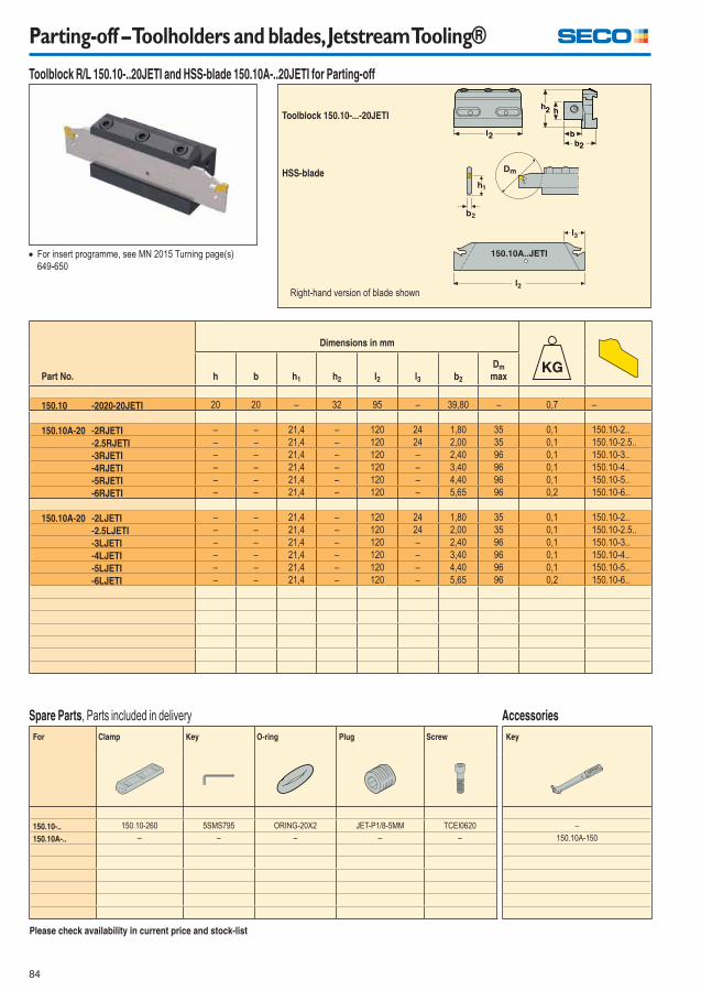
84
Parting-off – Toolholders and blades, Jetstream Tooling®
Part No.
Dimensions in mm
h b h1 h2 l2 l3 b2
Dm
max
150.10 -2020-20JETI 20 20 – 32 95 – 39,80 – 0,7 –
150.10A-20 -2RJETI – – 21,4 – 120 24 1,80 35 0,1 150.10-2..
-2.5RJETI – – 21,4 – 120 24 2,00 35 0,1 150.10-2.5..
-3RJETI – – 21,4 – 120 – 2,40 96 0,1 150.10-3..
-4RJETI – – 21,4 – 120 – 3,40 96 0,1 150.10-4..
-5RJETI – – 21,4 – 120 – 4,40 96 0,1 150.10-5..
-6RJETI – – 21,4 – 120 – 5,65 96 0,2 150.10-6..
150.10A-20 -2LJETI – – 21,4 – 120 24 1,80 35 0,1 150.10-2..
-2.5LJETI – – 21,4 – 120 24 2,00 35 0,1 150.10-2.5..
-3LJETI – – 21,4 – 120 – 2,40 96 0,1 150.10-3..
-4LJETI – – 21,4 – 120 – 3,40 96 0,1 150.10-4..
-5LJETI – – 21,4 – 120 – 4,40 96 0,1 150.10-5..
-6LJETI – – 21,4 – 120 – 5,65 96 0,2 150.10-6..
For Clamp Key O-ring Plug Screw
150.10-.. 150.10-260 5SMS795 ORING-20X2 JET-P1/8-5MM TCEI0620
150.10A-.. – – – – –
For insert programme, see MN 2015 Turning page(s)
649-650
Please check availability in current price and stock-list
Toolblock 150.10-...-20JETI
Spare Parts, Parts included in delivery
Toolblock R/L 150.10-..20JETI and HSS-blade 150.10A-..20JETI for Parting-off
150.10A..JETI
HSS-blade
Key
–
150.10A-150
Accessories
Right-hand version of blade shown
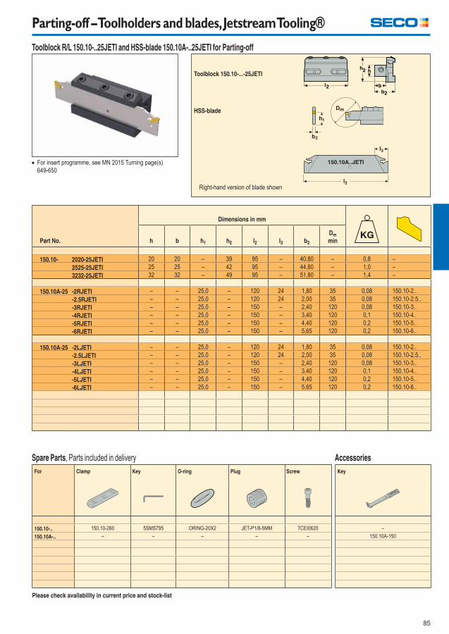
85
Parting-off – Toolholders and blades, Jetstream Tooling®
Part No.
Dimensions in mm
h b h1 h2 l2 l3 b2
Dm
min
150.10- 2020-25JETI 20 20 – 39 95 – 40,80 – 0,8 –
2525-25JETI 25 25 – 42 95 – 44,80 – 1,0 –
3232-25JETI 32 32 – 49 95 – 51,80 – 1,4 –
150.10A-25 -2RJETI – – 25,0 – 120 24 1,80 35 0,08 150.10-2..
-2.5RJETI – – 25,0 – 120 24 2,00 35 0,08 150.10-2.5..
-3RJETI – – 25,0 – 150 – 2,40 120 0,08 150.10-3..
-4RJETI – – 25,0 – 150 – 3,40 120 0,1 150.10-4..
-5RJETI – – 25,0 – 150 – 4,40 120 0,2 150.10-5..
-6RJETI – – 25,0 – 150 – 5,65 120 0,2 150.10-6..
150.10A-25 -2LJETI – – 25,0 – 120 24 1,80 35 0,08 150.10-2..
-2.5LJETI – – 25,0 – 120 24 2,00 35 0,08 150.10-2.5..
-3LJETI – – 25,0 – 150 – 2,40 120 0,08 150.10-3..
-4LJETI – – 25,0 – 150 – 3,40 120 0,1 150.10-4..
-5LJETI – – 25,0 – 150 – 4,40 120 0,2 150.10-5..
-6LJETI – – 25,0 – 150 – 5,65 120 0,2 150.10-6..
For Clamp Key O-ring Plug Screw
150.10-.. 150.10-260 5SMS795 ORING-20X2 JET-P1/8-5MM TCEI0620
150.10A-.. – – – – –
For insert programme, see MN 2015 Turning page(s)
649-650
Please check availability in current price and stock-list
Toolblock 150.10-...-25JETI
Spare Parts, Parts included in delivery
Toolblock R/L 150.10-..25JETI and HSS-blade 150.10A-..25JETI for Parting-off
150.10A..JETI
HSS-blade
Key
–
150.10A-150
Accessories
Right-hand version of blade shown
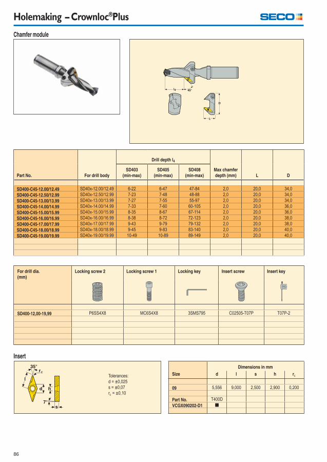
86
Holemaking – Crownloc®Plus
Chamfer module
Part No. For drill body
Drill depth l4
Max chamfer
depth (mm) L D
SD403
(min-max)
SD405
(min-max)
SD408
(min-max)
SD400-C45-12.00/12.49 SD40x-12.00/12.49 6-22 6-47 47-84 2,0 20,0 34,0
SD400-C45-12.50/12.99 SD40x-12.50/12.99 7-23 7-48 48-88 2,0 20,0 34,0
SD400-C45-13.00/13.99 SD40x-13.00/13.99 7-27 7-55 55-97 2,0 20,0 34,0
SD400-C45-14.00/14.99 SD40x-14.00/14.99 7-33 7-60 60-105 2,0 20,0 36,0
SD400-C45-15.00/15.99 SD40x-15.00/15.99 8-35 8-67 67-114 2,0 20,0 36,0
SD400-C45-16.00/16.99 SD40x-16.00/16.99 8-38 8-72 72-123 2,0 20,0 38,0
SD400-C45-17.00/17.99 SD40x-17.00/17.99 9-43 9-79 79-132 2,0 20,0 38,0
SD400-C45-18.00/18.99 SD40x-18.00/18.99 9-45 9-83 83-140 2,0 20,0 40,0
SD400-C45-19.00/19.99 SD40x-19.00/19.99 10-49 10-89 89-149 2,0 20,0 40,0
For drill dia.
(mm)
Locking screw 2 Locking screw 1 Locking key Insert screw Insert key
SD400-12,00-19,99 P6SS4X8 MC6S4X8 3SMS795 C02505-T07P T07P-2
Insert
Tolerances:
d = ±0,025
s = ±0,07
r = ±0,10
Dimensions in mm
Size d l s h r
09 5,556 9,000 2,500 2,900 0,200
Part No. T400D
VCGX090202-D1 [
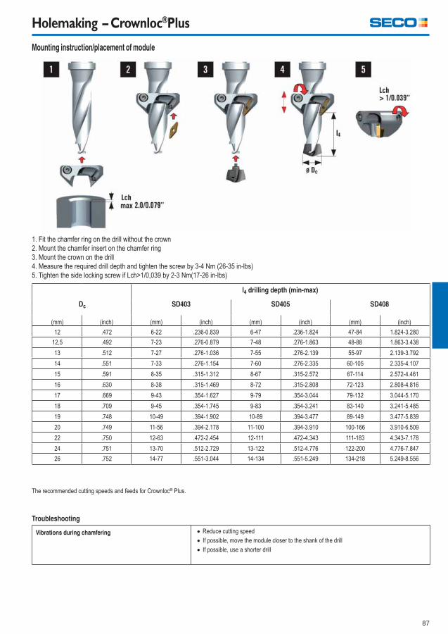
87
Holemaking – Crownloc®Plus
Mounting instruction/placement of module
1. Fit the chamfer ring on the drill without the crown
2. Mount the chamfer insert on the chamfer ring
3. Mount the crown on the drill
4. Measure the required drill depth and tighten the screw by 3-4 Nm (26-35 in-lbs)
5. Tighten the side locking screw if Lch>1/0,039 by 2-3 Nm(17-26 in-lbs)
l4 drilling depth (min-max)
Dc SD403 SD405 SD408
(mm) (inch) (mm) (inch) (mm) (inch) (mm) (inch)
12 .472 6-22 .236-0.839 6-47 .236-1.824 47-84 1.824-3.280
12,5 .492 7-23 .276-0.879 7-48 .276-1.863 48-88 1.863-3.438
13 .512 7-27 .276-1.036 7-55 .276-2.139 55-97 2.139-3.792
14 .551 7-33 .276-1.154 7-60 .276-2.335 60-105 2.335-4.107
15 .591 8-35 .315-1.312 8-67 .315-2.572 67-114 2.572-4.461
16 .630 8-38 .315-1.469 8-72 .315-2.808 72-123 2.808-4.816
17 .669 9-43 .354-1.627 9-79 .354-3.044 79-132 3.044-5.170
18 .709 9-45 .354-1.745 9-83 .354-3.241 83-140 3.241-5.485
19 .748 10-49 .394-1.902 10-89 .394-3.477 89-149 3.477-5.839
20 .749 11-56 .394-2.178 11-100 .394-3.910 100-166 3.910-6.509
22 .750 12-63 .472-2.454 12-111 .472-4.343 111-183 4.343-7.178
24 .751 13-70 .512-2.729 13-122 .512-4.776 122-200 4.776-7.847
26 .752 14-77 .551-3.044 14-134 .551-5.249 134-218 5.249-8.556
Troubleshooting
The recommended cutting speeds and feeds for Crownloc® Plus.
Vibrations during chamfering Reduce cutting speed
If possible, move the module closer to the shank of the drill
If possible, use a shorter drill
max
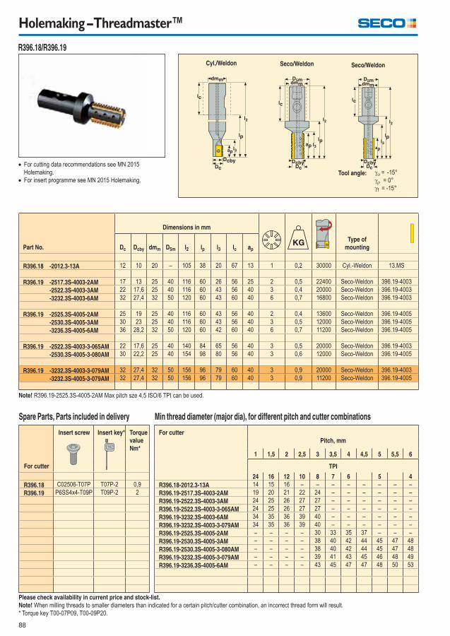
88
Holemaking – Threadmaster™
Spare Parts, Parts included in delivery Min thread diameter (major dia), for different pitch and cutter combinations
For cutter
Insert screw Insert key* Torque
value
Nm*
For cutter
Pitch, mm
1 1,5 2 2,5 3 3,5 4 4,5 5 5,5 6
TPI
24 16 12 10 8 7 6 5 4
R396.18 C02506-T07P T07P-2 0,9 R396.18-2012.3-13A 14 15 16 – – – – – – – –
R396.19 P6SS4x4-T09P T09P-2 2 R396.19-2517.3S-4003-2AM 19 20 21 22 24 – – – – – –
R396.19-2522.3S-4003-3AM 24 25 26 27 27 – – – – – –
R396.19-2522.3S-4003-3-065AM 24 25 26 27 27 – – – – – –
R396.19-3232.3S-4003-6AM 34 35 36 39 40 – – – – – –
R396.19-3232.3S-4003-3-079AM 34 35 36 39 40 – – – – – –
R396.19-2525.3S-4005-2AM – – – – 30 33 35 37 – – –
R396.19-2530.3S-4005-3AM – – – – 38 40 42 44 45 47 48
R396.19-2530.3S-4005-3-080AM – – – – 38 40 42 44 45 47 48
R396.19-3232.3S-4005-3-079AM – – – – 39 41 43 45 46 48 49
R396.19-3236.3S-4005-6AM – – – – 43 45 47 47 48 50 53
For cutting data recommendations see MN 2015
Holemaking.
For insert programme see MN 2015 Holemaking.
Please check availability in current price and stock-list.
Note! When milling threads to smaller diameters than indicated for a certain pitch/cutter combination, an incorrect thread form will result.
* Torque key T00-07P09, T00-09P20.
Note! R396.19-2525.3S-4005-2AM Max pitch sze 4,5 ISO/6 TPI can be used.
Part No.
Dimensions in mm
Type of
mountingDc Dcby dmm D5m l2 lp l3 lc ap
R396.18 -2012.3-13A 12 10 20 – 105 38 20 67 13 1 0,2 30000 Cyl.-Weldon 13.MS
R396.19 -2517.3S-4003-2AM 17 13 25 40 116 60 26 56 25 2 0,5 22400 Seco-Weldon 396.19-4003
-2522.3S-4003-3AM 22 17,6 25 40 116 60 43 56 40 3 0,4 20000 Seco-Weldon 396.19-4003
-3232.3S-4003-6AM 32 27,4 32 50 120 60 43 60 40 6 0,7 16800 Seco-Weldon 396.19-4003
R396.19 -2525.3S-4005-2AM 25 19 25 40 116 60 43 56 40 2 0,4 13600 Seco-Weldon 396.19-4005
-2530.3S-4005-3AM 30 23 25 40 116 60 43 56 40 3 0,5 12000 Seco-Weldon 396.19-4005
-3236.3S-4005-6AM 36 28,2 32 50 120 60 42 60 40 6 0,7 11200 Seco-Weldon 396.19-4005
R396.19 -2522.3S-4003-3-065AM 22 17,6 25 40 140 84 65 56 40 3 0,5 20000 Seco-Weldon 396.19-4003
-2530.3S-4005-3-080AM 30 22,2 25 40 154 98 80 56 40 3 0,6 12000 Seco-Weldon 396.19-4005
R396.19 -3232.3S-4003-3-079AM 32 27,4 32 50 156 96 79 60 40 3 0,9 20000 Seco-Weldon 396.19-4003
-3232.3S-4005-3-079AM 32 27,4 32 50 156 96 79 60 40 3 0,9 11200 Seco-Weldon 396.19-4005
Cyl./Weldon
= -15°
= 0°
f = -15°
R396.18/R396.19
Seco/Weldon Seco/Weldon
Tool angle:
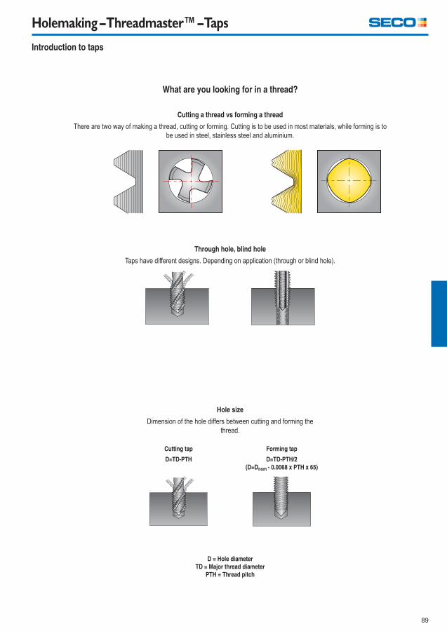
89
Holemaking – Threadmaster™ – Taps
What are you looking for in a thread?
Cutting a thread vs forming a thread
There are two way of making a thread, cutting or forming. Cutting is to be used in most materials, while forming is to
be used in steel, stainless steel and aluminium.
Introduction to taps
Through hole, blind hole
Taps have different designs. Depending on application (through or blind hole).
Hole size
Dimension of the hole differs between cutting and forming the
thread.
Cutting tap Forming tap
D=TD-PTH D=TD-PTH/2
(D=Dnom - 0.0068 x PTH x 65)
D = Hole diameter
TD = Major thread diameter
PTH = Thread pitch
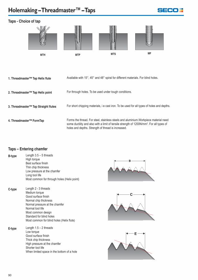
90
Holemaking – Threadmaster™ – Taps
Taps - Choice of tap
1. Threadmaster™ Tap Helix fl ute Available with 15°, 45° and 48° spiral for different materials. For blind holes.
2. Threadmaster™ Tap Helix point For through holes. To be used under tough conditions.
3. Threadmaster™ Tap Straight fl utes For short chipping materials, i e cast iron. To be used for all types of holes and depths.
4. Threadmaster™ FormTap Forms the thread. For steel, stainless steels and aluminium.Workpiece material need
some ductility and also with a limit of tensile strength of 1200N/mm2. For all types of
holes and depths. Strength of thread is increased.
MTH MTS MF
B-type Length 3.5 – 5 threads
High torque
Best surface fi nish
Thin chip thickness
Low pressure at the chamfer
Long tool life
Most common for through holes (Helix point)
C-type Length 2 - 3 threads
Medium torque
Good surface fi nish
Normal chip thickness
Normal pressure at the chamfer
Normal tool life
Most common design
Standard for blind holes
Most common for blind holes (Helix fl ute)
E-type Length 1.5 – 2 threads
Low torque
Good surface fi nish
Thick chip thickness
High pressure at the chamfer
Shorter tool life
When limited space in the bottom of a hole
Taps – Entering chamfer
MTP
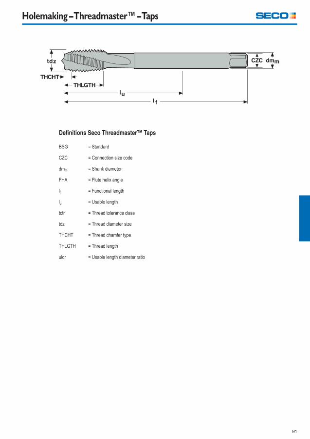
91
Holemaking – Threadmaster™ – Taps
Defi nitions Seco Threadmaster™ Taps
BSG = Standard
CZC = Connection size code
dmm = Shank diameter
FHA = Flute helix angle
lf = Functional length
lu = Usable length
tctr = Thread tolerance class
tdz = Thread diameter size
THCHT = Thread chamfer type
THLGTH = Thread length
uldr = Usable length diameter ratio
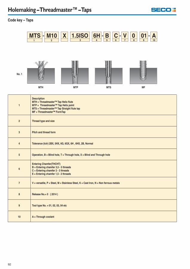
92
Holemaking – Threadmaster™ – Taps
Code key – Taps
1.5ISOX B V1
A0C 01MTS M10 6H2 3 4 5 6 7 8 9 10
1
Description
MTH = Threadmaster™ Tap Helix fl ute
MTP = Threadmaster™ Tap Helix point
MTS = Threadmaster™ Tap Straight fl ute tap
MF = Threadmaster™ FormTap
2 Thread type and size
3 Pitch and thread form
4 Tolerance (tctr) 2BX, 5HX, 6G, 6GX, 6H , 6HX, 2B, Normal
5 Operation, B = Blind hole, T = Through hole, X = Blind and Through hole
6
Entering Chamfer(THCHT)
B = Entering chamfer 3,5 - 5 threads
C = Entering chamfer 2 - 3 threads
E = Entering chamfer 1,5 - 2 threads
7 V = versatile, P = Steel, M = Stainless Steel, K = Cast Iron, N = Non ferrous metals
8 Release No.= 0 ( 2014 )
9 Tool type No. = 01, 02, 03, 04 etc
10 A = Through coolant
MTH MTS MF
No. 1
MTP
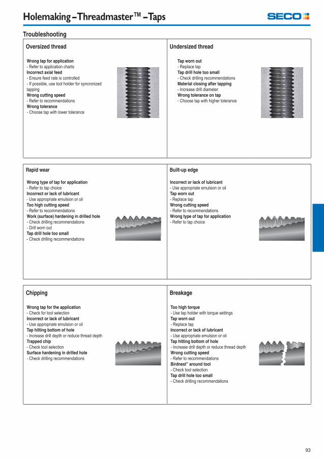
93
Holemaking – Threadmaster™ – Taps
Oversized thread Undersized thread
Wrong tap for application
- Refer to application charts
Incorrect axial feed
- Ensure feed rate is controlled
- If possible, use tool holder for syncronized
tapping
Wrong cutting speed
- Refer to recommendations
Wrong tolerance
- Choose tap with lower tolerance
Tap worn out
- Replace tap
Tap drill hole too small
- Check drilling recommendations
Material closing after tapping
- Increase drill diameter
Wrong tolerance on tap
- Choose tap with higher tolerance
Troubleshooting
Rapid wear Built-up edge
Wrong type of tap for application
- Refer to tap choice
Incorrect or lack of lubricant
- Use appropriate emulsion or oil
Too high cutting speed
- Refer to recommendations
Work (surface) hardening in drilled hole
- Check drilling recommendations
- Drill worn out
Tap drill hole too small
- Check drilling recommendations
Incorrect or lack of lubricant
- Use appropriate emulsion or oil
Tap worn out
- Replace tap
Wrong cutting speed
- Refer to recommendations
Wrong type of tap for application
- Refer to tap choice
Chipping Breakage
Wrong tap for the application
- Check for tool selection
Incorrect or lack of lubricant
- Use appropriate emulsion or oil
Tap hitting bottom of hole
- Increase drill depth or reduce thread depth
Trapped chip
- Check tool selection
Surface hardening in drilled hole
- Check drilling recommendations
Too high torque
- Use tap holder with torque settings
Tap worn out
- Replace tap
Incorrect or lack of lubricant
- Use appropriate emulsion or oil
Tap hitting bottom of hole
- Increase drill depth or reduce thread depth
Wrong cutting speed
- Refer to recommendations
Birdnest” around tool
- Check tool selection
Tap drill hole too small
- Check drilling recommendations
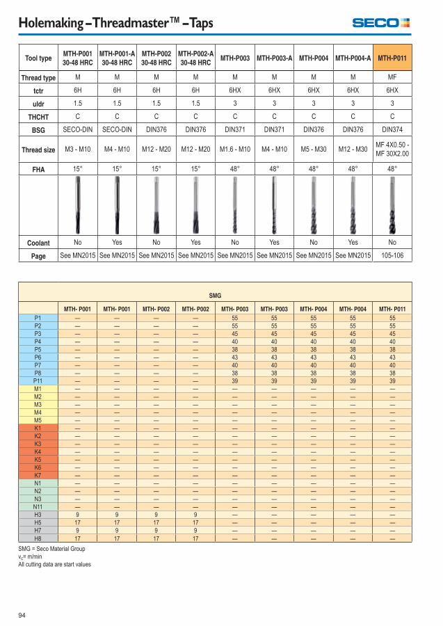
94
Holemaking – Threadmaster™ – Taps
Tool typeMTH-P001
30-48 HRC
MTH-P001-A
30-48 HRC
MTH-P002
30-48 HRC
MTH-P002-A
30-48 HRCMTH-P003 MTH-P003-A MTH-P004 MTH-P004-A MTH-P011
Thread type M M M M M M M M MF
tctr 6H 6H 6H 6H 6HX 6HX 6HX 6HX 6HX
uldr 1.5 1.5 1.5 1.5 3 3 3 3 3
THCHT C C C C C C C C C
BSG SECO-DIN SECO-DIN DIN376 DIN376 DIN371 DIN371 DIN376 DIN376 DIN374
Thread size M3 - M10 M4 - M10 M12 - M20 M12 - M20 M1.6 - M10 M4 - M10 M5 - M30 M12 - M30MF 4X0.50 -
MF 30X2.00
FHA 15° 15° 15° 15° 48° 48° 48° 48° 48°
Coolant No Yes No Yes No Yes No Yes No
Page See MN2015 See MN2015 See MN2015 See MN2015 See MN2015 See MN2015 See MN2015 See MN2015 105-106
SMG
MTH- P001 MTH- P001 MTH- P002 MTH- P002 MTH- P003 MTH- P003 MTH- P004 MTH- P004 MTH- P011
P1 — — — — 55 55 55 55 55
P2 — — — — 55 55 55 55 55
P3 — — — — 45 45 45 45 45
P4 — — — — 40 40 40 40 40
P5 — — — — 38 38 38 38 38
P6 — — — — 43 43 43 43 43
P7 — — — — 40 40 40 40 40
P8 — — — — 38 38 38 38 38
P11 — — — — 39 39 39 39 39
M1 — — — — — — — — —
M2 — — — — — — — — —
M3 — — — — — — — — —
M4 — — — — — — — — —
M5 — — — — — — — — —
K1 — — — — — — — — —
K2 — — — — — — — — —
K3 — — — — — — — — —
K4 — — — — — — — — —
K5 — — — — — — — — —
K6 — — — — — — — — —
K7 — — — — — — — — —
N1 — — — — — — — — —
N2 — — — — — — — — —
N3 — — — — — — — — —
N11 — — — — — — — — —
H3 9 9 9 9 — — — — —
H5 17 17 17 17 — — — — —
H7 9 9 9 9 — — — — —
H8 17 17 17 17 — — — — —
SMG = Seco Material Group
vc= m/min
All cutting data are start values
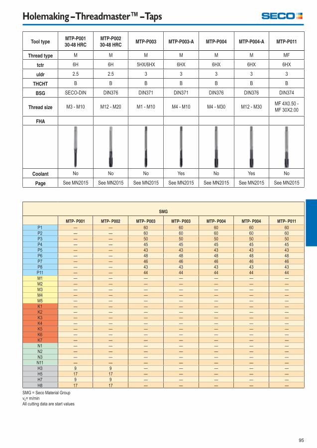
95
Holemaking – Threadmaster™ – Taps
Tool typeMTP-P001
30-48 HRC
MTP-P002
30-48 HRCMTP-P003 MTP-P003-A MTP-P004 MTP-P004-A MTP-P011
Thread type M M M M M M MF
tctr 6H 6H 5HX/6HX 6HX 6HX 6HX 6HX
uldr 2.5 2.5 3 3 3 3 3
THCHT B B B B B B B
BSG SECO-DIN DIN376 DIN371 DIN371 DIN376 DIN376 DIN374
Thread size M3 - M10 M12 - M20 M1 - M10 M4 - M10 M4 - M30 M12 - M30MF 4X0.50 -
MF 30X2.00
FHA
Coolant No No No Yes No Yes No
Page See MN2015 See MN2015 See MN2015 See MN2015 See MN2015 See MN2015 See MN2015
SMG
MTP- P001 MTP- P002 MTP- P003 MTP- P003 MTP- P004 MTP- P004 MTP- P011
P1 — — 60 60 60 60 60
P2 — — 60 60 60 60 60
P3 — — 50 50 50 50 50
P4 — — 45 45 45 45 45
P5 — — 43 43 43 43 43
P6 — — 48 48 48 48 48
P7 — — 46 46 46 46 46
P8 — — 43 43 43 43 43
P11 — — 44 44 44 44 44
M1 — — — — — — —
M2 — — — — — — —
M3 — — — — — — —
M4 — — — — — — —
M5 — — — — — — —
K1 — — — — — — —
K2 — — — — — — —
K3 — — — — — — —
K4 — — — — — — —
K5 — — — — — — —
K6 — — — — — — —
K7 — — — — — — —
N1 — — — — — — —
N2 — — — — — — —
N3 — — — — — — —
N11 — — — — — — —
H3 9 9 — — — — —
H5 17 17 — — — — —
H7 9 9 — — — — —
H8 17 17 — — — — —
SMG = Seco Material Group
vc= m/min
All cutting data are start values
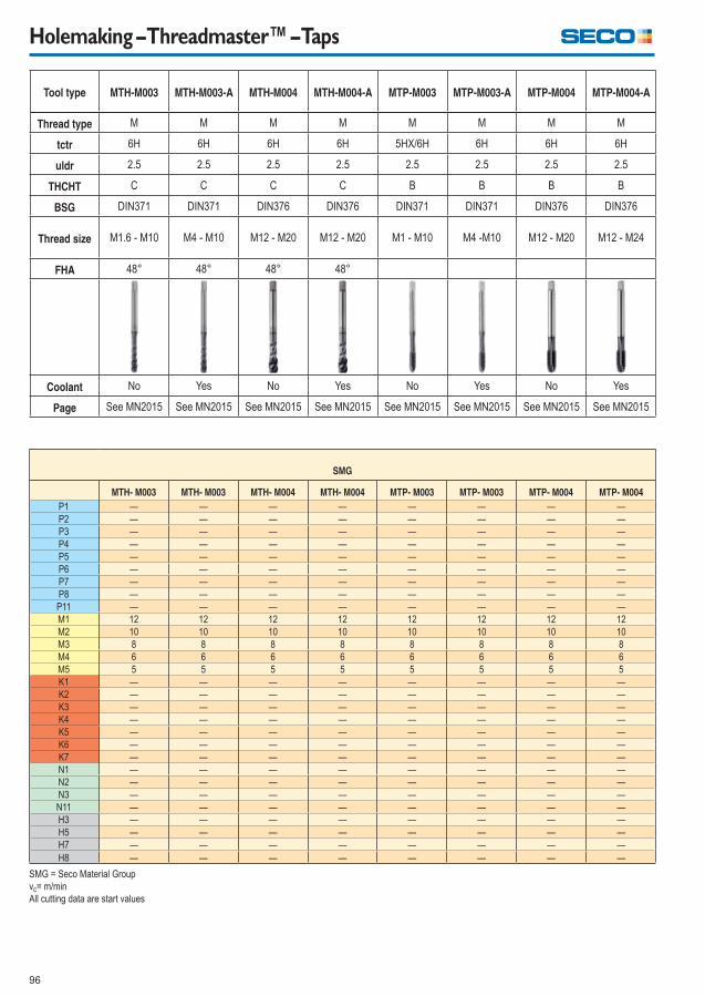
96
Holemaking – Threadmaster™ – Taps
Tool type MTH-M003 MTH-M003-A MTH-M004 MTH-M004-A MTP-M003 MTP-M003-A MTP-M004 MTP-M004-A
Thread type M M M M M M M M
tctr 6H 6H 6H 6H 5HX/6H 6H 6H 6H
uldr 2.5 2.5 2.5 2.5 2.5 2.5 2.5 2.5
THCHT C C C C B B B B
BSG DIN371 DIN371 DIN376 DIN376 DIN371 DIN371 DIN376 DIN376
Thread size M1.6 - M10 M4 - M10 M12 - M20 M12 - M20 M1 - M10 M4 -M10 M12 - M20 M12 - M24
FHA 48° 48° 48° 48°
Coolant No Yes No Yes No Yes No Yes
Page See MN2015 See MN2015 See MN2015 See MN2015 See MN2015 See MN2015 See MN2015 See MN2015
SMG
MTH- M003 MTH- M003 MTH- M004 MTH- M004 MTP- M003 MTP- M003 MTP- M004 MTP- M004
P1 — — — — — — — —
P2 — — — — — — — —
P3 — — — — — — — —
P4 — — — — — — — —
P5 — — — — — — — —
P6 — — — — — — — —
P7 — — — — — — — —
P8 — — — — — — — —
P11 — — — — — — — —
M1 12 12 12 12 12 12 12 12
M2 10 10 10 10 10 10 10 10
M3 8 8 8 8 8 8 8 8
M4 6 6 6 6 6 6 6 6
M5 5 5 5 5 5 5 5 5
K1 — — — — — — — —
K2 — — — — — — — —
K3 — — — — — — — —
K4 — — — — — — — —
K5 — — — — — — — —
K6 — — — — — — — —
K7 — — — — — — — —
N1 — — — — — — — —
N2 — — — — — — — —
N3 — — — — — — — —
N11 — — — — — — — —
H3 — — — — — — — —
H5 — — — — — — — —
H7 — — — — — — — —
H8 — — — — — — — —
SMG = Seco Material Group
vc= m/min
All cutting data are start values
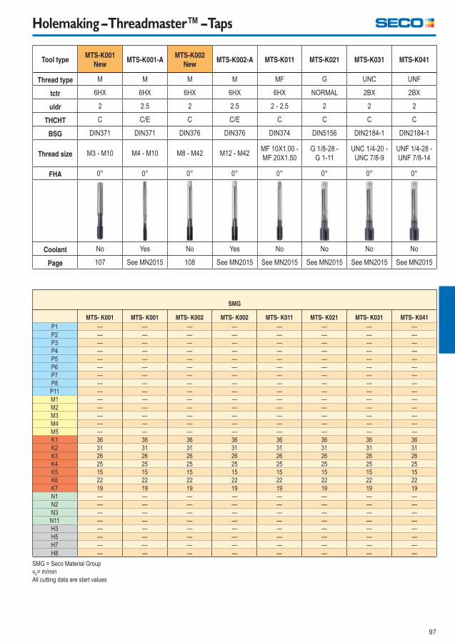
97
Holemaking – Threadmaster™ – Taps
Tool typeMTS-K001
NewMTS-K001-A
MTS-K002
NewMTS-K002-A MTS-K011 MTS-K021 MTS-K031 MTS-K041
Thread type M M M M MF G UNC UNF
tctr 6HX 6HX 6HX 6HX 6HX NORMAL 2BX 2BX
uldr 2 2.5 2 2.5 2 - 2.5 2 2 2
THCHT C C/E C C/E C C C C
BSG DIN371 DIN371 DIN376 DIN376 DIN374 DIN5156 DIN2184-1 DIN2184-1
Thread size M3 - M10 M4 - M10 M8 - M42 M12 - M42MF 10X1.00 -
MF 20X1.50
G 1/8-28 -
G 1-11
UNC 1/4-20 -
UNC 7/8-9
UNF 1/4-28 -
UNF 7/8-14
FHA 0° 0° 0° 0° 0° 0° 0° 0°
Coolant No Yes No Yes No No No No
Page 107 See MN2015 108 See MN2015 See MN2015 See MN2015 See MN2015 See MN2015
SMG
MTS- K001 MTS- K001 MTS- K002 MTS- K002 MTS- K011 MTS- K021 MTS- K031 MTS- K041
P1 — — — — — — — —
P2 — — — — — — — —
P3 — — — — — — — —
P4 — — — — — — — —
P5 — — — — — — — —
P6 — — — — — — — —
P7 — — — — — — — —
P8 — — — — — — — —
P11 — — — — — — — —
M1 — — — — — — — —
M2 — — — — — — — —
M3 — — — — — — — —
M4 — — — — — — — —
M5 — — — — — — — —
K1 36 36 36 36 36 36 36 36
K2 31 31 31 31 31 31 31 31
K3 26 26 26 26 26 26 26 26
K4 25 25 25 25 25 25 25 25
K5 15 15 15 15 15 15 15 15
K6 22 22 22 22 22 22 22 22
K7 19 19 19 19 19 19 19 19
N1 — — — — — — — —
N2 — — — — — — — —
N3 — — — — — — — —
N11 — — — — — — — —
H3 — — — — — — — —
H5 — — — — — — — —
H7 — — — — — — — —
H8 — — — — — — — —
SMG = Seco Material Group
vc= m/min
All cutting data are start values
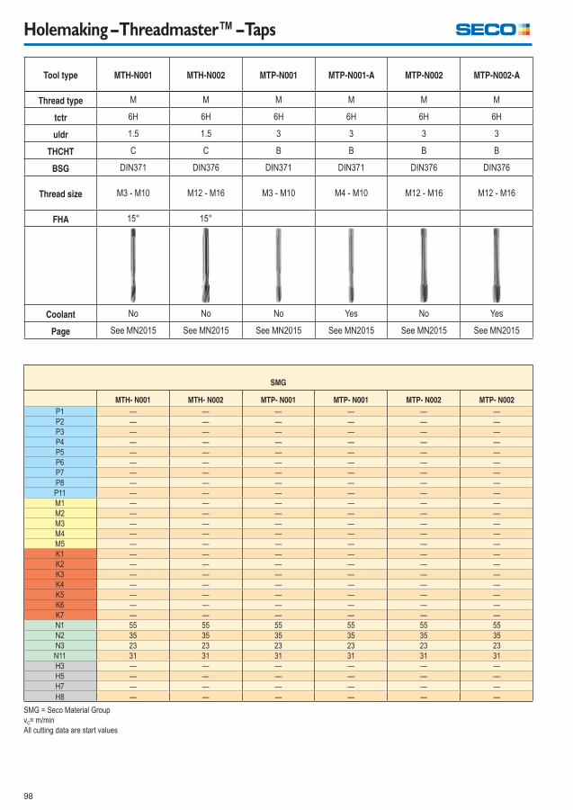
98
Holemaking – Threadmaster™ – Taps
Tool type MTH-N001 MTH-N002 MTP-N001 MTP-N001-A MTP-N002 MTP-N002-A
Thread type M M M M M M
tctr 6H 6H 6H 6H 6H 6H
uldr 1.5 1.5 3 3 3 3
THCHT C C B B B B
BSG DIN371 DIN376 DIN371 DIN371 DIN376 DIN376
Thread size M3 - M10 M12 - M16 M3 - M10 M4 - M10 M12 - M16 M12 - M16
FHA 15° 15°
Coolant No No No Yes No Yes
Page See MN2015 See MN2015 See MN2015 See MN2015 See MN2015 See MN2015
SMG
MTH- N001 MTH- N002 MTP- N001 MTP- N001 MTP- N002 MTP- N002
P1 — — — — — —
P2 — — — — — —
P3 — — — — — —
P4 — — — — — —
P5 — — — — — —
P6 — — — — — —
P7 — — — — — —
P8 — — — — — —
P11 — — — — — —
M1 — — — — — —
M2 — — — — — —
M3 — — — — — —
M4 — — — — — —
M5 — — — — — —
K1 — — — — — —
K2 — — — — — —
K3 — — — — — —
K4 — — — — — —
K5 — — — — — —
K6 — — — — — —
K7 — — — — — —
N1 55 55 55 55 55 55
N2 35 35 35 35 35 35
N3 23 23 23 23 23 23
N11 31 31 31 31 31 31
H3 — — — — — —
H5 — — — — — —
H7 — — — — — —
H8 — — — — — —
SMG = Seco Material Group
vc= m/min
All cutting data are start values
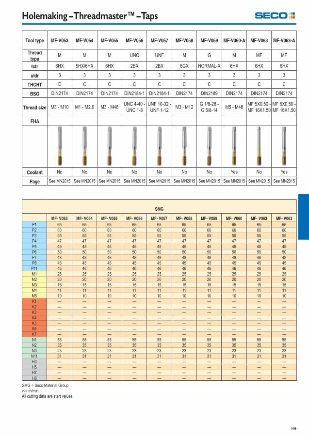
99
Holemaking – Threadmaster™ – Taps
Tool type MF-V053 MF-V054 MF-V055 MF-V056 MF-V057 MF-V058 MF-V059 MF-V060-A MF-V063 MF-V063-A
Thread
typeM M M UNC UNF M G M MF MF
tctr 6HX 5HX/6HX 6HX 2BX 2BX 6GX NORMAL-X 6HX 6HX 6HX
uldr 3 3 3 3 3 3 3 3 3 3
THCHT E C C C C C C C C C
BSG DIN2174 DIN2174 DIN2174 DIN2184-1 DIN2184-1 DIN2174 DIN2189 DIN2174 DIN2174 DIN2174
Thread size M3 - M10 M1 - M2.6 M3 - M48UNC 4-40 -
UNC 1-8
UNF 10-32 -
UNF 1-12M3 - M12
G 1/8-28 -
G 5/8-14M5 - M48
MF 5X0.50 -
MF 16X1.50
MF 5X0.50 -
MF 16X1.50
FHA
Coolant No No No No No No No Yes No Yes
Page See MN2015 See MN2015 See MN2015 See MN2015 See MN2015 See MN2015 See MN2015 See MN2015 See MN2015 See MN2015
SMG
MF- V053 MF- V054 MF- V055 MF- V056 MF- V057 MF- V058 MF- V059 MF- V060 MF- V063 MF- V063
P1 65 65 65 65 65 65 65 65 65 65
P2 60 60 60 60 60 60 60 60 60 60
P3 55 55 55 55 55 55 55 55 55 55
P4 47 47 47 47 47 47 47 47 47 47
P5 45 45 45 45 45 45 45 45 45 45
P6 50 50 50 50 50 50 50 50 50 50
P7 48 48 48 48 48 48 48 48 48 48
P8 45 45 45 45 45 45 45 45 45 45
P11 46 46 46 46 46 46 46 46 46 46
M1 25 25 25 25 25 25 25 25 25 25
M2 20 20 20 20 20 20 20 20 20 20
M3 15 15 15 15 15 15 15 15 15 15
M4 11 11 11 11 11 11 11 11 11 11
M5 10 10 10 10 10 10 10 10 10 10
K1 — — — — — — — — — —
K2 — — — — — — — — — —
K3 — — — — — — — — — —
K4 — — — — — — — — — —
K5 — — — — — — — — — —
K6 — — — — — — — — — —
K7 — — — — — — — — — —
N1 55 55 55 55 55 55 55 55 55 55
N2 35 35 35 35 35 35 35 35 35 35
N3 23 23 23 23 23 23 23 23 23 23
N11 31 31 31 31 31 31 31 31 31 31
H3 — — — — — — — — — —
H5 — — — — — — — — — —
H7 — — — — — — — — — —
H8 — — — — — — — — — —
SMG = Seco Material Group
vc= m/min
All cutting data are start values
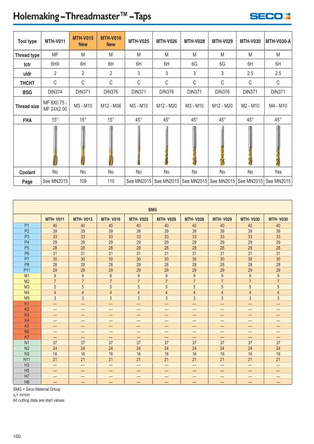
100
Holemaking – Threadmaster™ – Taps
Tool type MTH-V011MTH-V015
New
MTH-V016
NewMTH-V025 MTH-V026 MTH-V028 MTH-V029 MTH-V030 MTH-V030-A
Thread type MF M M M M M M M M
tctr 6HX 6H 6H 6H 6H 6G 6G 6H 6H
uldr 2 2 2 3 3 3 3 2.5 2.5
THCHT C C C C C C C C C
BSG DIN374 DIN371 DIN376 DIN371 DIN376 DIN371 DIN376 DIN371 DIN371
Thread sizeMF 8X0.75 -
MF 24X2.00M3 - M10 M12 - M36 M3 - M10 M12 - M20 M3 - M10 M12 - M20 M2 - M10 M4 - M10
FHA 15° 15° 15° 45° 45° 45° 45° 45° 45°
Coolant No No No No No No No No Yes
Page See MN2015 109 110 See MN2015 See MN2015 See MN2015 See MN2015 See MN2015 See MN2015
SMG
MTH- V011 MTH- V015 MTH- V016 MTH- V025 MTH- V026 MTH- V028 MTH- V029 MTH- V030 MTH- V030
P1 40 40 40 40 40 40 40 40 40
P2 39 39 39 39 39 39 39 39 39
P3 33 33 33 33 33 33 33 33 33
P4 29 29 29 29 29 29 29 29 29
P5 28 28 28 28 28 28 28 28 28
P6 31 31 31 31 31 31 31 31 31
P7 30 30 30 30 30 30 30 30 30
P8 28 28 28 28 28 28 28 28 28
P11 29 29 29 29 29 29 29 29 29
M1 9 9 9 9 9 9 9 9 9
M2 7 7 7 7 7 7 7 7 7
M3 5 5 5 5 5 5 5 5 5
M4 4 4 4 4 4 4 4 4 4
M5 3 3 3 3 3 3 3 3 3
K1 — — — — — — — — —
K2 — — — — — — — — —
K3 — — — — — — — — —
K4 — — — — — — — — —
K5 — — — — — — — — —
K6 — — — — — — — — —
K7 — — — — — — — — —
N1 37 37 37 37 37 37 37 37 37
N2 24 24 24 24 24 24 24 24 24
N3 16 16 16 16 16 16 16 16 16
N11 21 21 21 21 21 21 21 21 21
H3 — — — — — — — — —
H5 — — — — — — — — —
H7 — — — — — — — — —
H8 — — — — — — — — —
SMG = Seco Material Group
vc= m/min
All cutting data are start values
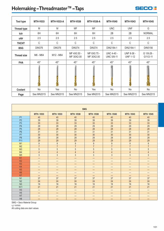
101
Holemaking – Threadmaster™ – Taps
Tool type MTH-V033 MTH-V033-A MTH-V038 MTH-V038-A MTH-V040 MTH-V043 MTH-V045
Thread type M M MF MF UNC UNF G
tctr 6H 6H 6H 6H 2B 2B NORMAL
uldr 2.5 2.5 2.5 2.5 2.5 2.5 2.5
THCHT C C C C C C C
BSG DIN376 DIN376 DIN374 DIN374 DIN2184-1 DIN2184-1 DIN5156
Thread size M6 - M64 M12 - M64MF 4X0.50 -
MF 30X2.00
MF 6X0.75 -
MF 30X2.00
UNC 4-40 -
UNC 5/8-11
UNF 8-36 -
UNF 1-12
G 1/8-28 -
G11/2-11
FHA 45° 45° 45° 45° 45° 45° 45°
Coolant No Yes No Yes No No No
Page See MN2015 See MN2015 See MN2015 See MN2015 See MN2015 See MN2015 See MN2015
SMG
MTH- V033 MTH- V033 MTH- V038 MTH- V038 MTH- V040 MTH- V043 MTH- V045
P1 40 40 40 40 40 40 40
P2 39 39 39 39 39 39 39
P3 33 33 33 33 33 33 33
P4 29 29 29 29 29 29 29
P5 28 28 28 28 28 28 28
P6 31 31 31 31 31 31 31
P7 30 30 30 30 30 30 30
P8 28 28 28 28 28 28 28
P11 29 29 29 29 29 29 29
M1 9 9 9 9 9 9 9
M2 7 7 7 7 7 7 7
M3 5 5 5 5 5 5 5
M4 4 4 4 4 4 4 4
M5 3 3 3 3 3 3 3
K1 — — — — — — —
K2 — — — — — — —
K3 — — — — — — —
K4 — — — — — — —
K5 — — — — — — —
K6 — — — — — — —
K7 — — — — — — —
N1 37 37 37 37 37 37 37
N2 24 24 24 24 24 24 24
N3 16 16 16 16 16 16 16
N11 21 21 21 21 21 21 21
H3 — — — — — — —
H5 — — — — — — —
H7 — — — — — — —
H8 — — — — — — —
SMG = Seco Material Group
vc= m/min
All cutting data are start values
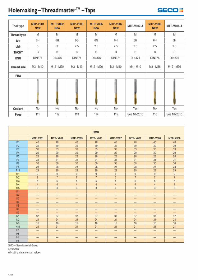
102
Holemaking – Threadmaster™ – Taps
Tool typeMTP-V001
New
MTP-V002
New
MTP-V005
New
MTP-V006
New
MTP-V007
NewMTP-V007-A
MTP-V008
NewMTP-V008-A
Thread type M M M M M M M M
tctr 6H 6H 6G 6G 6H 6H 6H 6H
uldr 3 3 2.5 2.5 2.5 2.5 2.5 2.5
THCHT B B B B B B B B
BSG DIN371 DIN376 DIN371 DIN376 DIN371 DIN371 DIN376 DIN376
Thread size M3 - M10 M12 - M20 M3 - M10 M12 - M20 M2 - M10 M4 - M10 M3 - M36 M12 - M36
FHA
Coolant No No No No No Yes No Yes
Page 111 112 113 114 115 See MN2015 116 See MN2015
SMG
MTP- V001 MTP- V002 MTP- V005 MTP- V006 MTP- V007 MTP- V007 MTP- V008 MTP- V008
P1 40 40 40 40 40 40 40 40
P2 39 39 39 39 39 39 39 39
P3 33 33 33 33 33 33 33 33
P4 29 29 29 29 29 29 29 29
P5 28 28 28 28 28 28 28 28
P6 31 31 31 31 31 31 31 31
P7 30 30 30 30 30 30 30 30
P8 28 28 28 28 28 28 28 28
P11 29 29 29 29 29 29 29 29
M1 9 9 9 9 9 9 9 9
M2 7 7 7 7 7 7 7 7
M3 5 5 5 5 5 5 5 5
M4 4 4 4 4 4 4 4 4
M5 3 3 3 3 3 3 3 3
K1 — — — — — — — —
K2 — — — — — — — —
K3 — — — — — — — —
K4 — — — — — — — —
K5 — — — — — — — —
K6 — — — — — — — —
K7 — — — — — — — —
N1 37 37 37 37 37 37 37 37
N2 24 24 24 24 24 24 24 24
N3 16 16 16 16 16 16 16 16
N11 21 21 21 21 21 21 21 21
H3 — — — — — — — —
H5 — — — — — — — —
H7 — — — — — — — —
H8 — — — — — — — —
SMG = Seco Material Group
vc= m/min
All cutting data are start values
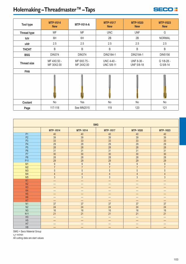
103
Holemaking – Threadmaster™ – Taps
Tool typeMTP-V014
NewMTP-V014-A
MTP-V017
New
MTP-V020
New
MTP-V023
New
Thread type MF MF UNC UNF G
tctr 6H 6H 2B 2B NORMAL
uldr 2.5 2.5 2.5 2.5 2.5
THCHT B B B B B
BSG DIN374 DIN374 DIN2184-1 DIN2184-1 DIN5156
Thread sizeMF 4X0.50 -
MF 30X2.00
MF 6X0.75 -
MF 24X2.00
UNC 4-40 -
UNC 5/8-11
UNF 8-36 -
UNF 5/8-18
G 1/8-28 -
G 5/8-14
FHA
Coolant No Yes No No No
Page 117-118 See MN2015 119 120 121
SMG
MTP- V014 MTP- V014 MTP- V017 MTP- V020 MTP- V023
P1 40 40 40 40 40
P2 39 39 39 39 39
P3 33 33 33 33 33
P4 29 29 29 29 29
P5 28 28 28 28 28
P6 31 31 31 31 31
P7 30 30 30 30 30
P8 28 28 28 28 28
P11 29 29 29 29 29
M1 9 9 9 9 9
M2 7 7 7 7 7
M3 5 5 5 5 5
M4 4 4 4 4 4
M5 3 3 3 3 3
K1 — — — — —
K2 — — — — —
K3 — — — — —
K4 — — — — —
K5 — — — — —
K6 — — — — —
K7 — — — — —
N1 37 37 37 37 37
N2 24 24 24 24 24
N3 16 16 16 16 16
N11 21 21 21 21 21
H3 — — — — —
H5 — — — — —
H7 — — — — —
H8 — — — — —
SMG = Seco Material Group
vc= m/min
All cutting data are start values
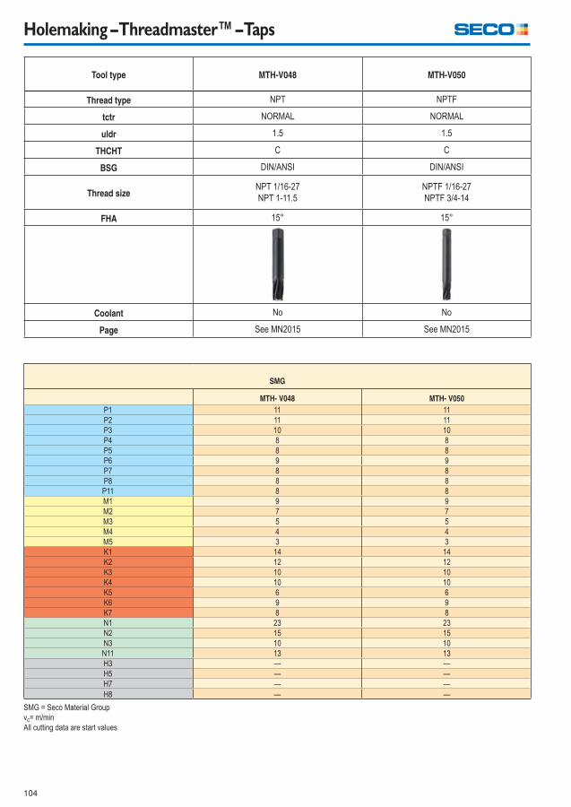
104
Holemaking – Threadmaster™ – Taps
Tool type MTH-V048 MTH-V050
Thread type NPT NPTF
tctr NORMAL NORMAL
uldr 1.5 1.5
THCHT C C
BSG DIN/ANSI DIN/ANSI
Thread sizeNPT 1/16-27
NPT 1-11.5
NPTF 1/16-27
NPTF 3/4-14
FHA 15° 15°
Coolant No No
Page See MN2015 See MN2015
SMG
MTH- V048 MTH- V050
P1 11 11
P2 11 11
P3 10 10
P4 8 8
P5 8 8
P6 9 9
P7 8 8
P8 8 8
P11 8 8
M1 9 9
M2 7 7
M3 5 5
M4 4 4
M5 3 3
K1 14 14
K2 12 12
K3 10 10
K4 10 10
K5 6 6
K6 9 9
K7 8 8
N1 23 23
N2 15 15
N3 10 10
N11 13 13
H3 — —
H5 — —
H7 — —
H8 — —
SMG = Seco Material Group
vc= m/min
All cutting data are start values
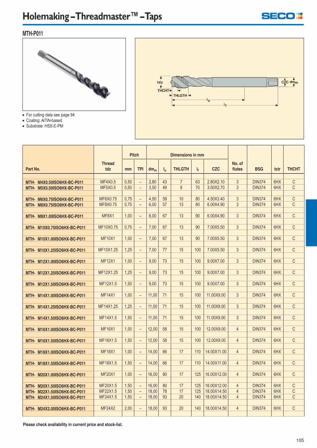
105
Holemaking – Threadmaster™ – Taps
MTH-P011
Part No.
Thread
tdz
Pitch Dimensions in mm
No. of
fl utes BSG tctr THCHTmm TPI dmm lu THLGTH lf CZC
MTH- M4X0.50ISO6HX-BC-P011 MF4X0.5 0,50 – 2,80 43 7 63 2.80X2.10 3 DIN374 6HX C
MTH- M5X0.50ISO6HX-BC-P011 MF5X0.5 0,50 – 3,50 49 8 70 3.50X2.70 3 DIN374 6HX C
MTH- M6X0.75ISO6HX-BC-P011 MF6X0.75 0,75 – 4,50 59 10 80 4.50X3.40 3 DIN374 6HX C
MTH- M8X0.75ISO6HX-BC-P011 MF8X0.75 0,75 – 6,00 57 13 80 6.00X4.90 3 DIN374 6HX C
MTH- M8X1.00ISO6HX-BC-P011 MF8X1 1,00 – 6,00 67 13 90 6.00X4.90 3 DIN374 6HX C
MTH- M10X0.75ISO6HX-BC-P011 MF10X0.75 0,75 – 7,00 67 13 90 7.00X5.50 3 DIN374 6HX C
MTH- M10X1.00ISO6HX-BC-P011 MF10X1 1,00 – 7,00 67 13 90 7.00X5.50 3 DIN374 6HX C
MTH- M10X1.25ISO6HX-BC-P011 MF10X1.25 1,25 – 7,00 77 15 100 7.00X5.50 3 DIN374 6HX C
MTH- M12X1.00ISO6HX-BC-P011 MF12X1 1,00 – 9,00 73 15 100 9.00X7.00 3 DIN374 6HX C
MTH- M12X1.25ISO6HX-BC-P011 MF12X1.25 1,25 – 9,00 73 15 100 9.00X7.00 3 DIN374 6HX C
MTH- M12X1.50ISO6HX-BC-P011 MF12X1.5 1,50 – 9,00 73 15 100 9.00X7.00 3 DIN374 6HX C
MTH- M14X1.00ISO6HX-BC-P011 MF14X1 1,00 – 11,00 71 15 100 11.00X9.00 3 DIN374 6HX C
MTH- M14X1.25ISO6HX-BC-P011 MF14X1.25 1,25 – 11,00 71 15 100 11.00X9.00 3 DIN374 6HX C
MTH- M14X1.50ISO6HX-BC-P011 MF14X1.5 1,50 – 11,00 71 15 100 11.00X9.00 3 DIN374 6HX C
MTH- M16X1.00ISO6HX-BC-P011 MF16X1 1,00 – 12,00 58 15 100 12.00X9.00 4 DIN374 6HX C
MTH- M16X1.50ISO6HX-BC-P011 MF16X1.5 1,50 – 12,00 58 15 100 12.00X9.00 4 DIN374 6HX C
MTH- M18X1.00ISO6HX-BC-P011 MF18X1 1,00 – 14,00 66 17 110 14.00X11.00 4 DIN374 6HX C
MTH- M18X1.50ISO6HX-BC-P011 MF18X1.5 1,50 – 14,00 66 17 110 14.00X11.00 4 DIN374 6HX C
MTH- M20X1.00ISO6HX-BC-P011 MF20X1 1,00 – 16,00 80 17 125 16.00X12.00 4 DIN374 6HX C
MTH- M20X1.50ISO6HX-BC-P011 MF20X1.5 1,50 – 16,00 80 17 125 16.00X12.00 4 DIN374 6HX C
MTH- M22X1.50ISO6HX-BC-P011 MF22X1.5 1,50 – 18,00 78 17 125 18.00X14.50 4 DIN374 6HX C
MTH- M24X1.50ISO6HX-BC-P011 MF24X1.5 1,50 – 18,00 93 20 140 18.00X14.50 4 DIN374 6HX C
MTH- M24X2.00ISO6HX-BC-P011 MF24X2 2,00 – 18,00 93 20 140 18.00X14.50 4 DIN374 6HX C
For cutting data see page 94
Coating: AlTiN-based
Substrate: HSS-E-PM
Please check availability in current price and stock-list.
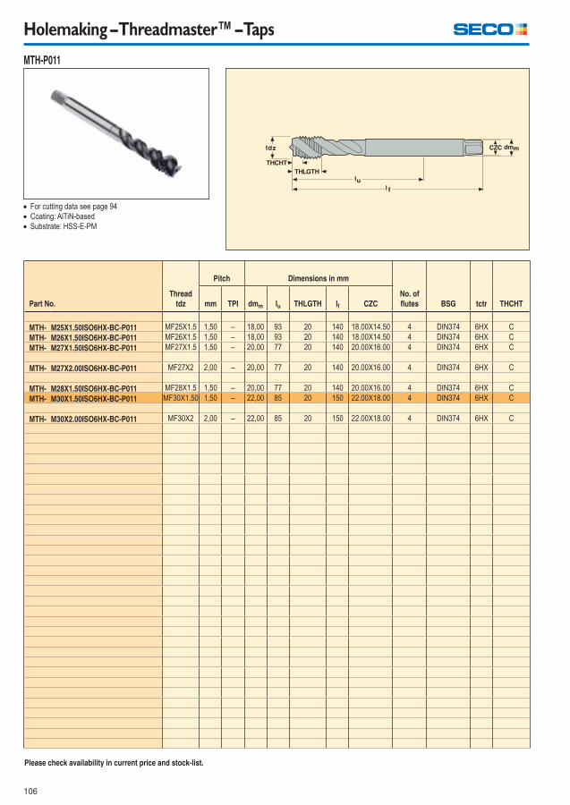
106
Holemaking – Threadmaster™ – Taps
MTH-P011
Part No.
Thread
tdz
Pitch Dimensions in mm
No. of
fl utes BSG tctr THCHTmm TPI dmm lu THLGTH lf CZC
MTH- M25X1.50ISO6HX-BC-P011 MF25X1.5 1,50 – 18,00 93 20 140 18.00X14.50 4 DIN374 6HX C
MTH- M26X1.50ISO6HX-BC-P011 MF26X1.5 1,50 – 18,00 93 20 140 18.00X14.50 4 DIN374 6HX C
MTH- M27X1.50ISO6HX-BC-P011 MF27X1.5 1,50 – 20,00 77 20 140 20.00X16.00 4 DIN374 6HX C
MTH- M27X2.00ISO6HX-BC-P011 MF27X2 2,00 – 20,00 77 20 140 20.00X16.00 4 DIN374 6HX C
MTH- M28X1.50ISO6HX-BC-P011 MF28X1.5 1,50 – 20,00 77 20 140 20.00X16.00 4 DIN374 6HX C
MTH- M30X1.50ISO6HX-BC-P011 MF30X1.50 1,50 – 22,00 85 20 150 22.00X18.00 4 DIN374 6HX C
MTH- M30X2.00ISO6HX-BC-P011 MF30X2 2,00 – 22,00 85 20 150 22.00X18.00 4 DIN374 6HX C
For cutting data see page 94
Coating: AlTiN-based
Substrate: HSS-E-PM
Please check availability in current price and stock-list.
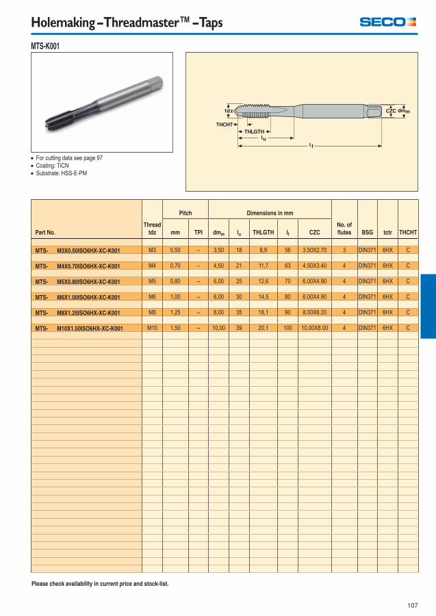
107
Holemaking – Threadmaster™ – Taps
MTS-K001
Part No.
Thread
tdz
Pitch Dimensions in mm
No. of
fl utes BSG tctr THCHTmm TPI dmm lu THLGTH lf CZC
MTS- M3X0.50ISO6HX-XC-K001 M3 0,50 – 3,50 18 8,9 56 3.50X2.70 3 DIN371 6HX C
MTS- M4X0.70ISO6HX-XC-K001 M4 0,70 – 4,50 21 11,7 63 4.50X3.40 4 DIN371 6HX C
MTS- M5X0.80ISO6HX-XC-K001 M5 0,80 – 6,00 25 12,6 70 6.00X4.90 4 DIN371 6HX C
MTS- M6X1.00ISO6HX-XC-K001 M6 1,00 – 6,00 30 14,5 80 6.00X4.90 4 DIN371 6HX C
MTS- M8X1.25ISO6HX-XC-K001 M8 1,25 – 8,00 35 18,1 90 8.00X6.20 4 DIN371 6HX C
MTS- M10X1.50ISO6HX-XC-K001 M10 1,50 – 10,00 39 20,1 100 10.00X8.00 4 DIN371 6HX C
For cutting data see page 97
Coating: TiCN
Substrate: HSS-E-PM
Please check availability in current price and stock-list.
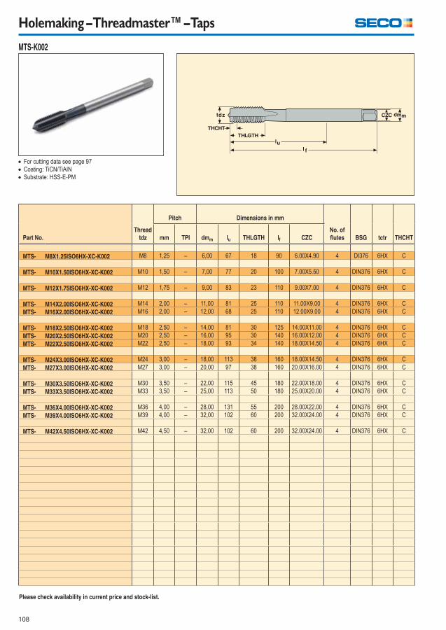
108
Holemaking – Threadmaster™ – Taps
MTS-K002
Part No.
Thread
tdz
Pitch Dimensions in mm
No. of
fl utes BSG tctr THCHTmm TPI dmm lu THLGTH lf CZC
MTS- M8X1.25ISO6HX-XC-K002 M8 1,25 – 6,00 67 18 90 6.00X4.90 4 DI376 6HX C
MTS- M10X1.50ISO6HX-XC-K002 M10 1,50 – 7,00 77 20 100 7.00X5.50 4 DIN376 6HX C
MTS- M12X1.75ISO6HX-XC-K002 M12 1,75 – 9,00 83 23 110 9.00X7.00 4 DIN376 6HX C
MTS- M14X2.00ISO6HX-XC-K002 M14 2,00 – 11,00 81 25 110 11.00X9.00 4 DIN376 6HX C
MTS- M16X2.00ISO6HX-XC-K002 M16 2,00 – 12,00 68 25 110 12.00X9.00 4 DIN376 6HX C
MTS- M18X2.50ISO6HX-XC-K002 M18 2,50 – 14,00 81 30 125 14.00X11.00 4 DIN376 6HX C
MTS- M20X2.50ISO6HX-XC-K002 M20 2,50 – 16,00 95 30 140 16.00X12.00 4 DIN376 6HX C
MTS- M22X2.50ISO6HX-XC-K002 M22 2,50 – 18,00 93 34 140 18.00X14.50 4 DIN376 6HX C
MTS- M24X3.00ISO6HX-XC-K002 M24 3,00 – 18,00 113 38 160 18.00X14.50 4 DIN376 6HX C
MTS- M27X3.00ISO6HX-XC-K002 M27 3,00 – 20,00 97 38 160 20.00X16.00 4 DIN376 6HX C
MTS- M30X3.50ISO6HX-XC-K002 M30 3,50 – 22,00 115 45 180 22.00X18.00 4 DIN376 6HX C
MTS- M33X3.50ISO6HX-XC-K002 M33 3,50 – 25,00 113 50 180 25.00X20.00 4 DIN376 6HX C
MTS- M36X4.00ISO6HX-XC-K002 M36 4,00 – 28,00 131 55 200 28.00X22.00 4 DIN376 6HX C
MTS- M39X4.00ISO6HX-XC-K002 M39 4,00 – 32,00 102 60 200 32.00X24.00 4 DIN376 6HX C
MTS- M42X4.50ISO6HX-XC-K002 M42 4,50 – 32,00 102 60 200 32.00X24.00 4 DIN376 6HX C
For cutting data see page 97
Coating: TiCN/TiAIN
Substrate: HSS-E-PM
Please check availability in current price and stock-list.
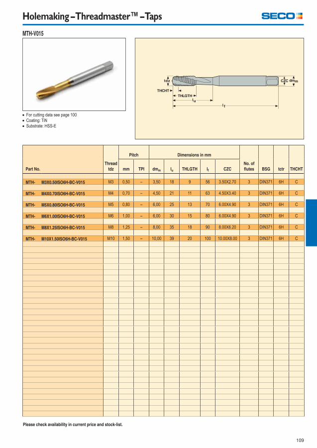
109
Holemaking – Threadmaster™ – Taps
MTH-V015
Part No.
Thread
tdz
Pitch Dimensions in mm
No. of
fl utes BSG tctr THCHTmm TPI dmm lu THLGTH lf CZC
MTH- M3X0.50ISO6H-BC-V015 M3 0,50 – 3,50 18 9 56 3.50X2.70 3 DIN371 6H C
MTH- M4X0.70ISO6H-BC-V015 M4 0,70 – 4,50 21 11 63 4.50X3.40 3 DIN371 6H C
MTH- M5X0.80ISO6H-BC-V015 M5 0,80 – 6,00 25 13 70 6.00X4.90 3 DIN371 6H C
MTH- M6X1.00ISO6H-BC-V015 M6 1,00 – 6,00 30 15 80 6.00X4.90 3 DIN371 6H C
MTH- M8X1.25ISO6H-BC-V015 M8 1,25 – 8,00 35 18 90 8.00X6.20 3 DIN371 6H C
MTH- M10X1.50ISO6H-BC-V015 M10 1,50 – 10,00 39 20 100 10.00X8.00 3 DIN371 6H C
For cutting data see page 100
Coating: TiN
Substrate: HSS-E
Please check availability in current price and stock-list.
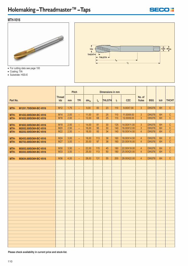
110
Holemaking – Threadmaster™ – Taps
MTH-V016
Part No.
Thread
tdz
Pitch Dimensions in mm
No. of
fl utes BSG tctr THCHTmm TPI dmm lu THLGTH lf CZC
MTH- M12X1.75ISO6H-BC-V016 M12 1,75 – 9,00 83 23 110 9.00X7.00 3 DIN376 6H C
MTH- M14X2.00ISO6H-BC-V016 M14 2,00 – 11,00 81 25 110 11.00X9.00 3 DIN376 6H C
MTH- M16X2.00ISO6H-BC-V016 M16 2,00 – 12,00 68 25 110 12.00X9.00 3 DIN376 6H C
MTH- M18X2.50ISO6H-BC-V016 M18 2,50 – 14,00 81 30 125 14.00X11.00 3 DIN376 6H C
MTH- M20X2.50ISO6H-BC-V016 M20 2,50 – 16,00 95 30 140 16.00X12.00 3 DIN376 6H C
MTH- M22X2.50ISO6H-BC-V016 M22 2,50 – 18,00 93 34 140 18.00X14.50 4 DIN376 6H C
MTH- M24X3.00ISO6H-BC-V016 M24 3,00 – 18,00 113 38 160 18.00X14.50 4 DIN376 6H C
MTH- M27X3.00ISO6H-BC-V016 M27 3,00 – 20,00 97 38 160 20.00X16.00 4 DIN376 6H C
MTH- M30X3.50ISO6H-BC-V016 M30 3,50 – 22,00 115 45 180 22.00X18.00 4 DIN376 6H C
MTH- M33X3.50ISO6H-BC-V016 M33 3,50 – 25,00 113 50 180 25.00X20.00 4 DIN376 6H C
MTH- M36X4.00ISO6H-BC-V016 M36 4,00 – 28,00 131 55 200 28.00X22.00 4 DIN376 6H C
For cutting data see page 100
Coating: TiN
Substrate: HSS-E
Please check availability in current price and stock-list.

111
Holemaking – Threadmaster™ – Taps
MTP-V001
Part No.
Thread
tdz
Pitch Dimensions in mm
No. of
fl utes BSG tctr THCHTmm TPI dmm lu THLGTH lf CZC
MTP- M3X0.50ISO6H-TB-V001 M3 0,50 – 3,50 18 9 112 3.50X2.70 3 DIN371 6H B
MTP- M4X0.70ISO6H-TB-V001 M4 0,70 – 4,50 21 12 112 4.50X3.40 3 DIN371 6H B
MTP- M5X0.80ISO6H-TB-V001 M5 0,80 – 6,00 25 13 125 6.00X4.90 3 DIN371 6H B
MTP- M6X1.00ISO6H-TB-V001 M6 1,00 – 6,00 30 15 125 6.00X4.90 3 DIN371 6H B
MTP- M8X1.25ISO6H-TB-V001 M8 1,25 – 8,00 40 18 140 8.00X6.20 3 DIN371 6H B
MTP- M10X1.50ISO6H-TB-V001 M10 1,50 – 10,00 50 20 160 10.00X8.00 3 DIN371 6H B
For cutting data see page 102
Coating: TiN
Substrate: HSS-E
Please check availability in current price and stock-list.
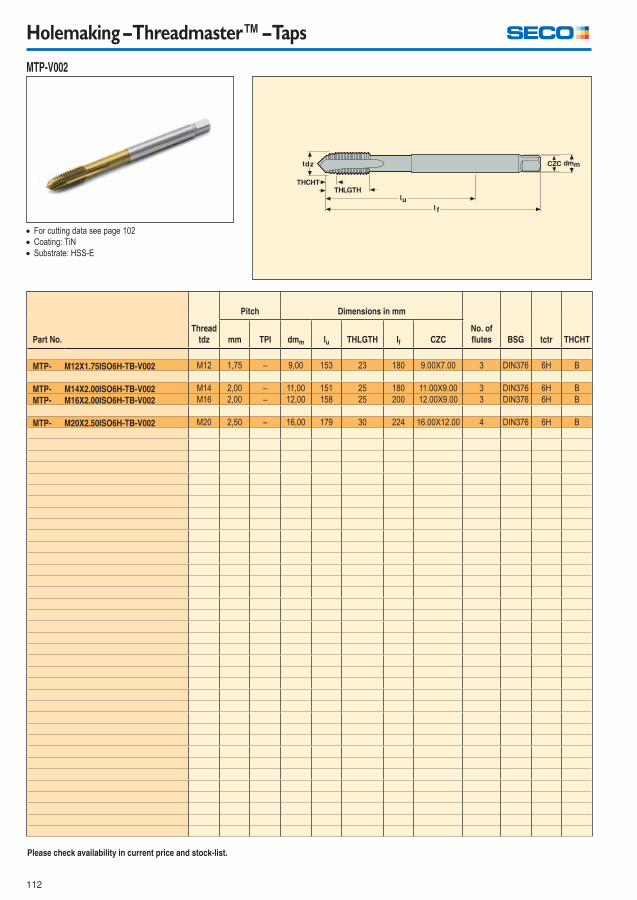
112
Holemaking – Threadmaster™ – Taps
MTP-V002
Part No.
Thread
tdz
Pitch Dimensions in mm
No. of
fl utes BSG tctr THCHTmm TPI dmm lu THLGTH lf CZC
MTP- M12X1.75ISO6H-TB-V002 M12 1,75 – 9,00 153 23 180 9.00X7.00 3 DIN376 6H B
MTP- M14X2.00ISO6H-TB-V002 M14 2,00 – 11,00 151 25 180 11.00X9.00 3 DIN376 6H B
MTP- M16X2.00ISO6H-TB-V002 M16 2,00 – 12,00 158 25 200 12.00X9.00 3 DIN376 6H B
MTP- M20X2.50ISO6H-TB-V002 M20 2,50 – 16,00 179 30 224 16.00X12.00 4 DIN376 6H B
For cutting data see page 102
Coating: TiN
Substrate: HSS-E
Please check availability in current price and stock-list.
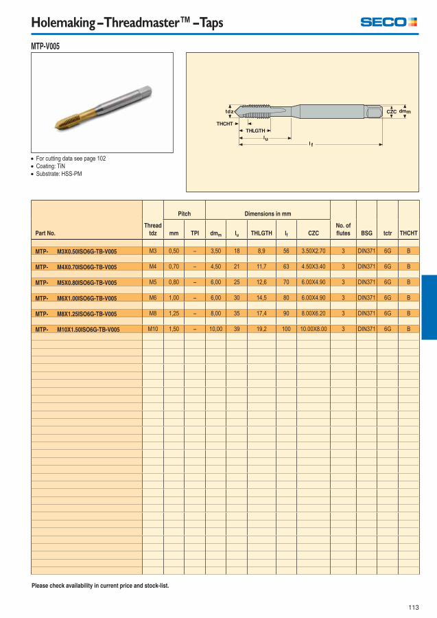
113
Holemaking – Threadmaster™ – Taps
MTP-V005
Part No.
Thread
tdz
Pitch Dimensions in mm
No. of
fl utes BSG tctr THCHTmm TPI dmm lu THLGTH lf CZC
MTP- M3X0.50ISO6G-TB-V005 M3 0,50 – 3,50 18 8,9 56 3.50X2.70 3 DIN371 6G B
MTP- M4X0.70ISO6G-TB-V005 M4 0,70 – 4,50 21 11,7 63 4.50X3.40 3 DIN371 6G B
MTP- M5X0.80ISO6G-TB-V005 M5 0,80 – 6,00 25 12,6 70 6.00X4.90 3 DIN371 6G B
MTP- M6X1.00ISO6G-TB-V005 M6 1,00 – 6,00 30 14,5 80 6.00X4.90 3 DIN371 6G B
MTP- M8X1.25ISO6G-TB-V005 M8 1,25 – 8,00 35 17,4 90 8.00X6.20 3 DIN371 6G B
MTP- M10X1.50ISO6G-TB-V005 M10 1,50 – 10,00 39 19,2 100 10.00X8.00 3 DIN371 6G B
For cutting data see page 102
Coating: TiN
Substrate: HSS-PM
Please check availability in current price and stock-list.

114
Holemaking – Threadmaster™ – Taps
MTP-V006
Part No.
Thread
tdz
Pitch Dimensions in mm
No. of
fl utes BSG tctr THCHTmm TPI dmm lu THLGTH lf CZC
MTP- M12X1.75ISO6G-TB-V006 M12 1,75 – 9,00 83 23 110 9.00X7.00 3 DIN376 6G B
MTP- M16X2.00ISO6G-TB-V006 M16 2,00 – 12,00 68 25 110 12.00X9.00 3 DIN376 6G B
MTP- M20X2.50ISO6G-TB-V006 M20 2,50 – 16,00 95 30 140 16.00X12.00 4 DIN376 6G B
For cutting data see page 102
Coating: TiN
Substrate: HSS-PM ≤ M16, HSS-E > M16
Please check availability in current price and stock-list.
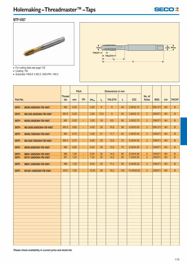
115
Holemaking – Threadmaster™ – Taps
MTP-V007
Part No.
Thread
tdz
Pitch Dimensions in mm
No. of
fl utes BSG tctr THCHTmm TPI dmm lu THLGTH lf CZC
MTP- M2X0.40ISO6H-TB-V007 M2 0,40 – 2,80 9 6 45 2.80X2.10 2 DIN 371 6H B
MTP- M2.5X0.45ISO6H-TB-V007 M2.5 0,45 – 2,80 12,5 8 50 2.80X2.10 2 DIN371 6H B
MTP- M3X0.50ISO6H-TB-V007 M3 0,50 – 3,50 18 8,9 56 3.50X2.70 3 DIN371 6H B
MTP- M3.50X0.60ISO6H-TB-V007 M3.5 0,60 – 4,00 20 10,8 56 4.00X3.00 3 DIN 371 6H B
MTP- M4X0.70ISO6H-TB-V007 M4 0,70 – 4,50 21 11,7 63 4.50X3.40 3 DIN371 6H B
MTP- M4.5X0.75ISO6H-TB-V007 M4.5 0,75 – 6,00 25 12,6 70 6.00X4.90 3 DIN371 6H B
MTP- M5X0.80ISO6H-TB-V007 M5 0,80 – 6,00 25 12,6 70 6.00X4.90 3 DIN371 6H B
MTP- M6X1.00ISO6H-TB-V007 M6 1,00 – 6,00 30 14,5 80 6.00X4.90 3 DIN371 6H B
MTP- M7X1.00ISO6H-TB-V007 M7 1,00 – 7,00 30 14,5 80 7.00X5.50 3 DIN371 6H B
MTP- M8X1.25ISO6H-TB-V007 M8 1,25 – 8,00 35 17,4 90 8.00X6.20 3 DIN371 6H B
MTP- M10X1.50ISO6H-TB-V007 M10 1,50 – 10,00 39 19,2 100 10.00X8.00 3 DIN371 6H B
For cutting data see page 102
Coating: TiN
Substrate: HSS-E ≤ M2,5, HSS-PM > M2,5
Please check availability in current price and stock-list.

116
Holemaking – Threadmaster™ – Taps
MTP-V008
Part No.
Thread
tdz
Pitch Dimensions in mm
No. of
fl utes BSG tctr THCHTmm TPI dmm lu THLGTH lf CZC
MTP- M3X0.50ISO6H-TB-V008 M3 0,50 – 2,20 37 9,5 56 2.20X1.80 3 DIN376 6H B
MTP- M4X0.70ISO6H-TB-V008 M4 0,70 – 2,80 43 11,9 63 2.80X2.10 3 DIN376 6H B
MTP- M5X0.80ISO6H-TB-V008 M5 0,80 – 3,50 49 13,2 70 3.50X2.70 3 DIN376 6H B
MTP- M6X1.00ISO6H-TB-V008 M6 1,00 – 4,50 59 15,1 80 4.50X3.40 3 DIN376 6H B
MTP- M8X1.25ISO6H-TB-V008 M8 1,25 – 6,00 67 18 90 6.00X4.90 3 DIN376 6H B
MTP- M10X1.50ISO6H-TB-V008 M10 1,50 – 7,00 77 19,8 100 7.00X5.50 3 DIN376 6H B
MTP- M12X1.75ISO6H-TB-V008 M12 1,75 – 9,00 83 23 110 9.00X7.00 3 DIN376 6H B
MTP- M14X2.00ISO6H-TB-V008 M14 2,00 – 11,00 81 25 110 11.00X9.00 3 DIN376 6H B
MTP- M16X2.00ISO6H-TB-V008 M16 2,00 – 12,00 68 25 110 12.00X9.00 3 DIN376 6H B
MTP- M18X2.50ISO6H-TB-V008 M18 2,50 – 14,00 81 30 125 14.00X11.00 4 DIN376 6H B
MTP- M20X2.50ISO6H-TB-V008 M20 2,50 – 16,00 95 30 140 16.00X12.00 4 DIN376 6H B
MTP- M22X2.50ISO6H-TB-V008 M22 2,50 – 18,00 93 34 140 18.00X14.50 4 DIN376 6H B
MTP- M24X3.00ISO6H-TB-V008 M24 3,00 – 18,00 113 38 160 18.00X14.50 4 DIN376 6H B
MTP- M27X3.00ISO6H-TB-V008 M27 3,00 – 20,00 97 38 160 20.00X16.00 4 DIN376 6H B
MTP- M30X3.50ISO6H-TB-V008 M30 3,50 – 22,00 115 45 180 22.00X18.00 4 DIN376 6H B
MTP- M33X3.50ISO6H-TB-V008 M33 3,50 – 25,00 113 50 180 25.00X20.00 4 DIN376 6H B
MTP- M36X4.00ISO6H-TB-V008 M36 4,00 – 28,00 131 55 200 28.00X22.00 4 DIN376 6H B
For cutting data see page 102
Coating: TiN
Substrate: HSS-PM ≤ M16, HSS-E > M16
Please check availability in current price and stock-list.
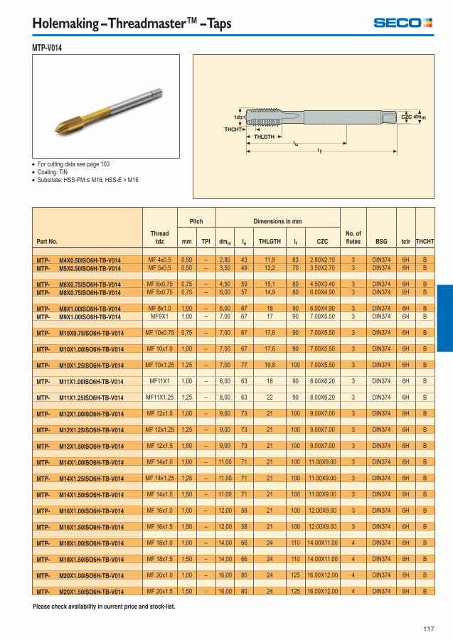
117
Holemaking – Threadmaster™ – Taps
MTP-V014
Part No.
Thread
tdz
Pitch Dimensions in mm
No. of
fl utes BSG tctr THCHTmm TPI dmm lu THLGTH lf CZC
MTP- M4X0.50ISO6H-TB-V014 MF 4x0.5 0,50 – 2,80 43 11,9 63 2.80X2.10 3 DIN374 6H B
MTP- M5X0.50ISO6H-TB-V014 MF 5x0.5 0,50 – 3,50 49 13,2 70 3.50X2.70 3 DIN374 6H B
MTP- M6X0.75ISO6H-TB-V014 MF 6x0.75 0,75 – 4,50 59 15,1 80 4.50X3.40 3 DIN374 6H B
MTP- M8X0.75ISO6H-TB-V014 MF 8x0.75 0,75 – 6,00 57 14,9 80 6.00X4.90 3 DIN374 6H B
MTP- M8X1.00ISO6H-TB-V014 MF 8x1.0 1,00 – 6,00 67 18 90 6.00X4.90 3 DIN374 6H B
MTP- M9X1.00ISO6H-TB-V014 MF9X1 1,00 – 7,00 67 17 90 7.00X5.50 3 DIN374 6H B
MTP- M10X0.75ISO6H-TB-V014 MF 10x0.75 0,75 – 7,00 67 17,6 90 7.00X5.50 3 DIN374 6H B
MTP- M10X1.00ISO6H-TB-V014 MF 10x1.0 1,00 – 7,00 67 17,6 90 7.00X5.50 3 DIN374 6H B
MTP- M10X1.25ISO6H-TB-V014 MF 10x1.25 1,25 – 7,00 77 19,8 100 7.00X5.50 3 DIN374 6H B
MTP- M11X1.00ISO6H-TB-V014 MF11X1 1,00 – 8,00 63 18 90 8.00X6.20 3 DIN374 6H B
MTP- M11X1.25ISO6H-TB-V014 MF11X1.25 1,25 – 8,00 63 22 90 8.00X6.20 3 DIN374 6H B
MTP- M12X1.00ISO6H-TB-V014 MF 12x1.0 1,00 – 9,00 73 21 100 9.00X7.00 3 DIN374 6H B
MTP- M12X1.25ISO6H-TB-V014 MF 12x1.25 1,25 – 9,00 73 21 100 9.00X7.00 3 DIN374 6H B
MTP- M12X1.50ISO6H-TB-V014 MF 12x1.5 1,50 – 9,00 73 21 100 9.00X7.00 3 DIN374 6H B
MTP- M14X1.00ISO6H-TB-V014 MF 14x1.0 1,00 – 11,00 71 21 100 11.00X9.00 3 DIN374 6H B
MTP- M14X1.25ISO6H-TB-V014 MF 14x1.25 1,25 – 11,00 71 21 100 11.00X9.00 3 DIN374 6H B
MTP- M14X1.50ISO6H-TB-V014 MF 14x1.5 1,50 – 11,00 71 21 100 11.00X9.00 3 DIN374 6H B
MTP- M16X1.00ISO6H-TB-V014 MF 16x1.0 1,00 – 12,00 58 21 100 12.00X9.00 3 DIN374 6H B
MTP- M16X1.50ISO6H-TB-V014 MF 16x1.5 1,50 – 12,00 58 21 100 12.00X9.00 3 DIN374 6H B
MTP- M18X1.00ISO6H-TB-V014 MF 18x1.0 1,00 – 14,00 66 24 110 14.00X11.00 4 DIN374 6H B
MTP- M18X1.50ISO6H-TB-V014 MF 18x1.5 1,50 – 14,00 66 24 110 14.00X11.00 4 DIN374 6H B
MTP- M20X1.00ISO6H-TB-V014 MF 20x1.0 1,00 – 16,00 80 24 125 16.00X12.00 4 DIN374 6H B
MTP- M20X1.50ISO6H-TB-V014 MF 20x1.5 1,50 – 16,00 80 24 125 16.00X12.00 4 DIN374 6H B
For cutting data see page 103
Coating: TiN
Substrate: HSS-PM ≤ M16, HSS-E > M16
Please check availability in current price and stock-list.
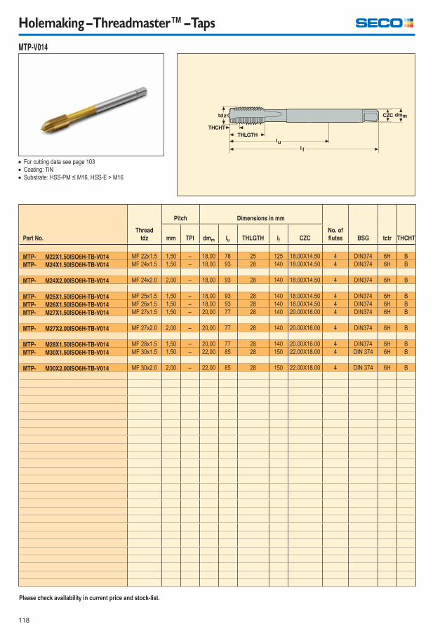
118
Holemaking – Threadmaster™ – Taps
MTP-V014
Part No.
Thread
tdz
Pitch Dimensions in mm
No. of
fl utes BSG tctr THCHTmm TPI dmm lu THLGTH lf CZC
MTP- M22X1.50ISO6H-TB-V014 MF 22x1.5 1,50 – 18,00 78 25 125 18.00X14.50 4 DIN374 6H B
MTP- M24X1.50ISO6H-TB-V014 MF 24x1.5 1,50 – 18,00 93 28 140 18.00X14.50 4 DIN374 6H B
MTP- M24X2.00ISO6H-TB-V014 MF 24x2.0 2,00 – 18,00 93 28 140 18.00X14.50 4 DIN374 6H B
MTP- M25X1.50ISO6H-TB-V014 MF 25x1.5 1,50 – 18,00 93 28 140 18.00X14.50 4 DIN374 6H B
MTP- M26X1.50ISO6H-TB-V014 MF 26x1.5 1,50 – 18,00 93 28 140 18.00X14.50 4 DIN374 6H B
MTP- M27X1.50ISO6H-TB-V014 MF 27x1.5 1,50 – 20,00 77 28 140 20.00X16.00 4 DIN374 6H B
MTP- M27X2.00ISO6H-TB-V014 MF 27x2.0 2,00 – 20,00 77 28 140 20.00X16.00 4 DIN374 6H B
MTP- M28X1.50ISO6H-TB-V014 MF 28x1.5 1,50 – 20,00 77 28 140 20.00X16.00 4 DIN374 6H B
MTP- M30X1.50ISO6H-TB-V014 MF 30x1.5 1,50 – 22,00 85 28 150 22.00X18.00 4 DIN 374 6H B
MTP- M30X2.00ISO6H-TB-V014 MF 30x2.0 2,00 – 22,00 85 28 150 22.00X18.00 4 DIN 374 6H B
For cutting data see page 103
Coating: TiN
Substrate: HSS-PM ≤ M16, HSS-E > M16
Please check availability in current price and stock-list.
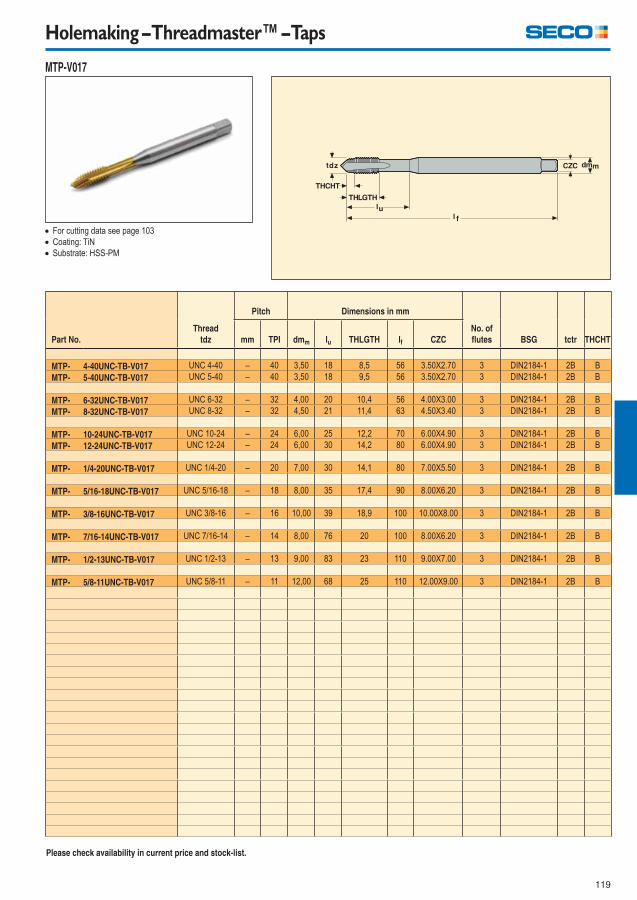
119
Holemaking – Threadmaster™ – Taps
MTP-V017
Part No.
Thread
tdz
Pitch Dimensions in mm
No. of
fl utes BSG tctr THCHTmm TPI dmm lu THLGTH lf CZC
MTP- 4-40UNC-TB-V017 UNC 4-40 – 40 3,50 18 8,5 56 3.50X2.70 3 DIN2184-1 2B B
MTP- 5-40UNC-TB-V017 UNC 5-40 – 40 3,50 18 9,5 56 3.50X2.70 3 DIN2184-1 2B B
MTP- 6-32UNC-TB-V017 UNC 6-32 – 32 4,00 20 10,4 56 4.00X3.00 3 DIN2184-1 2B B
MTP- 8-32UNC-TB-V017 UNC 8-32 – 32 4,50 21 11,4 63 4.50X3.40 3 DIN2184-1 2B B
MTP- 10-24UNC-TB-V017 UNC 10-24 – 24 6,00 25 12,2 70 6.00X4.90 3 DIN2184-1 2B B
MTP- 12-24UNC-TB-V017 UNC 12-24 – 24 6,00 30 14,2 80 6.00X4.90 3 DIN2184-1 2B B
MTP- 1/4-20UNC-TB-V017 UNC 1/4-20 – 20 7,00 30 14,1 80 7.00X5.50 3 DIN2184-1 2B B
MTP- 5/16-18UNC-TB-V017 UNC 5/16-18 – 18 8,00 35 17,4 90 8.00X6.20 3 DIN2184-1 2B B
MTP- 3/8-16UNC-TB-V017 UNC 3/8-16 – 16 10,00 39 18,9 100 10.00X8.00 3 DIN2184-1 2B B
MTP- 7/16-14UNC-TB-V017 UNC 7/16-14 – 14 8,00 76 20 100 8.00X6.20 3 DIN2184-1 2B B
MTP- 1/2-13UNC-TB-V017 UNC 1/2-13 – 13 9,00 83 23 110 9.00X7.00 3 DIN2184-1 2B B
MTP- 5/8-11UNC-TB-V017 UNC 5/8-11 – 11 12,00 68 25 110 12.00X9.00 3 DIN2184-1 2B B
For cutting data see page 103
Coating: TiN
Substrate: HSS-PM
Please check availability in current price and stock-list.
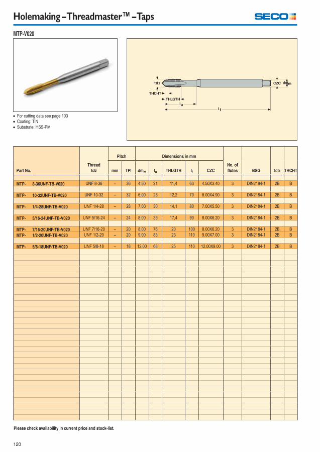
120
Holemaking – Threadmaster™ – Taps
MTP-V020
Part No.
Thread
tdz
Pitch Dimensions in mm
No. of
fl utes BSG tctr THCHTmm TPI dmm lu THLGTH lf CZC
MTP- 8-36UNF-TB-V020 UNF 8-36 – 36 4,50 21 11,4 63 4.50X3.40 3 DIN2184-1 2B B
MTP- 10-32UNF-TB-V020 UNF 10-32 – 32 6,00 25 12,2 70 6.00X4.90 3 DIN2184-1 2B B
MTP- 1/4-28UNF-TB-V020 UNF 1/4-28 – 28 7,00 30 14,1 80 7.00X5.50 3 DIN2184-1 2B B
MTP- 5/16-24UNF-TB-V020 UNF 5/16-24 – 24 8,00 35 17,4 90 8.00X6.20 3 DIN2184-1 2B B
MTP- 7/16-20UNF-TB-V020 UNF 7/16-20 – 20 8,00 76 20 100 8.00X6.20 3 DIN2184-1 2B B
MTP- 1/2-20UNF-TB-V020 UNF 1/2-20 – 20 9,00 83 23 110 9.00X7.00 3 DIN2184-1 2B B
MTP- 5/8-18UNF-TB-V020 UNF 5/8-18 – 18 12,00 68 25 110 12.00X9.00 3 DIN2184-1 2B B
For cutting data see page 103
Coating: TiN
Substrate: HSS-PM
Please check availability in current price and stock-list.
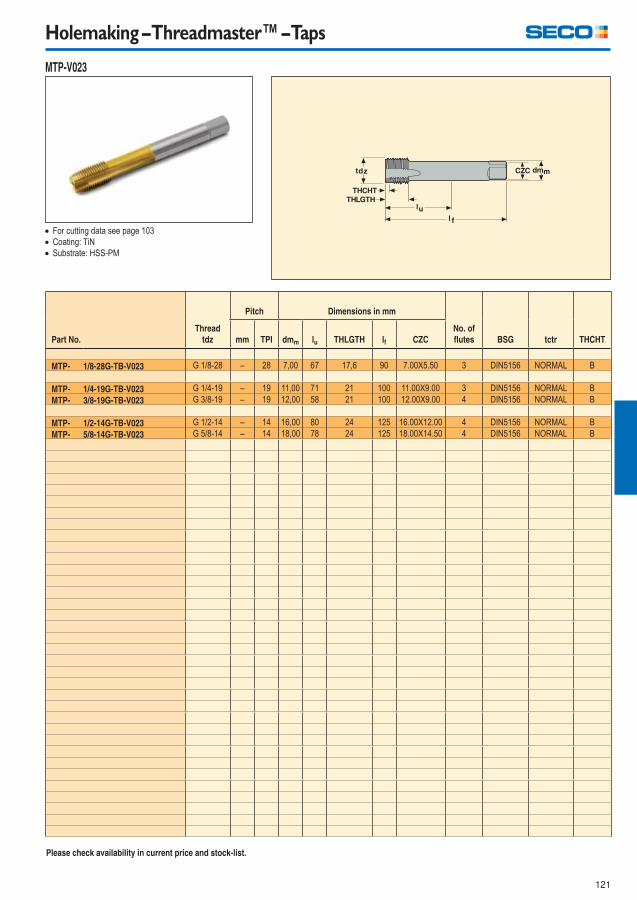
121
Holemaking – Threadmaster™ – Taps
MTP-V023
Part No.
Thread
tdz
Pitch Dimensions in mm
No. of
fl utes BSG tctr THCHTmm TPI dmm lu THLGTH lf CZC
MTP- 1/8-28G-TB-V023 G 1/8-28 – 28 7,00 67 17,6 90 7.00X5.50 3 DIN5156 NORMAL B
MTP- 1/4-19G-TB-V023 G 1/4-19 – 19 11,00 71 21 100 11.00X9.00 3 DIN5156 NORMAL B
MTP- 3/8-19G-TB-V023 G 3/8-19 – 19 12,00 58 21 100 12.00X9.00 4 DIN5156 NORMAL B
MTP- 1/2-14G-TB-V023 G 1/2-14 – 14 16,00 80 24 125 16.00X12.00 4 DIN5156 NORMAL B
MTP- 5/8-14G-TB-V023 G 5/8-14 – 14 18,00 78 24 125 18.00X14.50 4 DIN5156 NORMAL B
For cutting data see page 103
Coating: TiN
Substrate: HSS-PM
Please check availability in current price and stock-list.
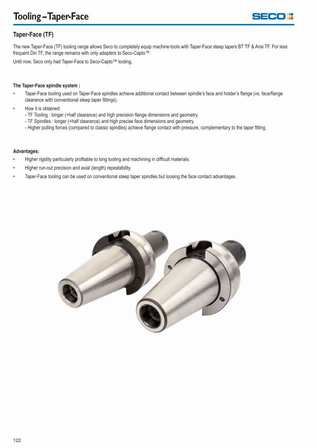
122
Tooling – Taper-Face
Taper-Face (TF)
The new Taper-Face (TF) tooling range allows Seco to completely equip machine-tools with Taper-Face steep tapers BT TF & Ansi TF. For less
frequent Din TF, the range remains with only adapters to Seco-Capto™.
Until now, Seco only had Taper-Face to Seco-Capto™ tooling.
The Taper-Face spindle system :
� Taper-Face tooling used on Taper-Face spindles achieve additional contact between spindle‘s face and holder’s fl ange (vs. face/fl ange
clearance with conventional steep taper fi ttings).
� How it is obtained:
- TF Tooling : longer (+half clearance) and high precision fl ange dimensions and geometry.
- TF Spindles : longer (+half clearance) and high precise face dimensions and geometry.
- Higher pulling forces (compared to classic spindles) achieve fl ange contact with pressure, complementary to the taper fi tting.
Advantages:
� Higher rigidity particularly profi table to long tooling and machining in diffi cult materials.
� Higher run-out precision and axial (length) repeatability.
� Taper-Face tooling can be used on conventional steep taper spindles but loosing the face contact advantages.
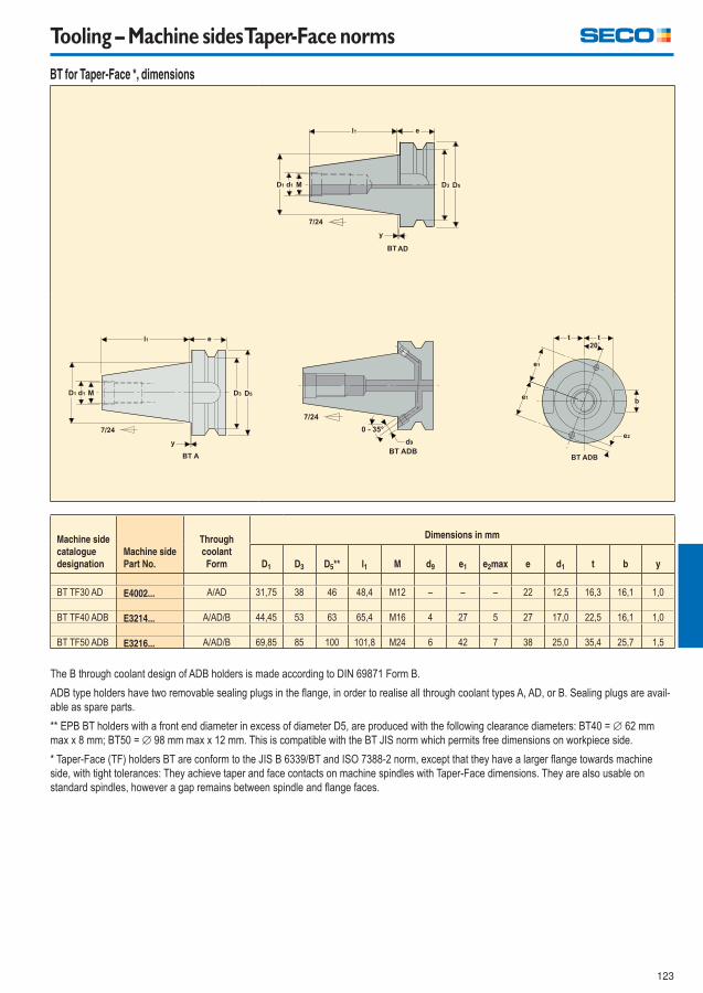
123
Tooling – Machine sides Taper-Face norms
BT for Taper-Face *, dimensions
Machine side
catalogue
designation
Machine side
Part No.
Through
coolant
Form
Dimensions in mm
D1 D3 D5** l1 M d9 e1 e2max e d1 t b y
BT TF30 AD E4002... A/AD 31,75 38 46 48,4 M12 – – – 22 12,5 16,3 16,1 1,0
BT TF40 ADB E3214... A/AD/B 44,45 53 63 65,4 M16 4 27 5 27 17,0 22,5 16,1 1,0
BT TF50 ADB E3216... A/AD/B 69,85 85 100 101,8 M24 6 42 7 38 25,0 35,4 25,7 1,5
The B through coolant design of ADB holders is made according to DIN 69871 Form B.
ADB type holders have two removable sealing plugs in the fl ange, in order to realise all through coolant types A, AD, or B. Sealing plugs are avail-
able as spare parts.
** EPB BT holders with a front end diameter in excess of diameter D5, are produced with the following clearance diameters: BT40 = ∅ 62 mm
max x 8 mm; BT50 = ∅ 98 mm max x 12 mm. This is compatible with the BT JIS norm which permits free dimensions on workpiece side.
* Taper-Face (TF) holders BT are conform to the JIS B 6339/BT and ISO 7388-2 norm, except that they have a larger fl ange towards machine
side, with tight tolerances: They achieve taper and face contacts on machine spindles with Taper-Face dimensions. They are also usable on
standard spindles, however a gap remains between spindle and fl ange faces.
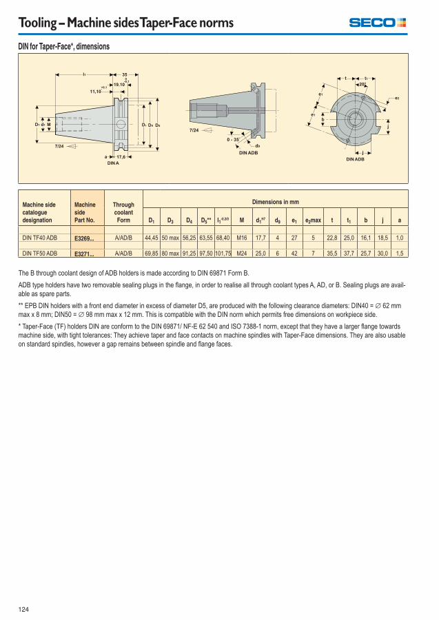
124
Tooling – Machine sides Taper-Face norms
DIN for Taper-Face*, dimensions
Machine side
catalogue
designation
Machine
side
Part No.
Through
coolant
Form
Dimensions in mm
D1 D3 D4 D5** l1-0,2/0 M d1
H7 d9 e1 e2max t t1 b j a
DIN TF40 ADB E3269... A/AD/B 44,45 50 max 56,25 63,55 68,40 M16 17,7 4 27 5 22,8 25,0 16,1 18,5 1,0
DIN TF50 ADB E3271... A/AD/B 69,85 80 max 91,25 97,50 101,75 M24 25,0 6 42 7 35,5 37,7 25,7 30,0 1,5
The B through coolant design of ADB holders is made according to DIN 69871 Form B.
ADB type holders have two removable sealing plugs in the fl ange, in order to realise all through coolant types A, AD, or B. Sealing plugs are avail-
able as spare parts.
** EPB DIN holders with a front end diameter in excess of diameter D5, are produced with the following clearance diameters: DIN40 = ∅ 62 mm
max x 8 mm; DIN50 = ∅ 98 mm max x 12 mm. This is compatible with the DIN norm which permits free dimensions on workpiece side.
* Taper-Face (TF) holders DIN are conform to the DIN 69871/ NF-E 62 540 and ISO 7388-1 norm, except that they have a larger fl ange towards
machine side, with tight tolerances: They achieve taper and face contacts on machine spindles with Taper-Face dimensions. They are also usable
on standard spindles, however a gap remains between spindle and fl ange faces.
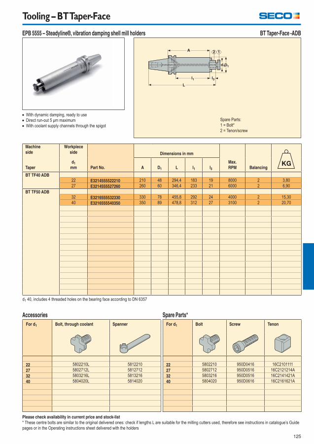
125
Tooling – BT Taper-Face
EPB 5555 – Steadyline®, vibration damping shell mill holders BT Taper-Face -ADB
Please check availability in current price and stock-list
* These centre bolts are similar to the original delivered ones: check if lengths L are suitable for the milling cutters used, therefore see instructions in catalogue’s Guide
pages or in the Operating instructions sheet delivered with the holders
With dynamic damping, ready to use
Direct run-out 5 μm maximum
With coolant supply channels through the spigot
Machine
side
Workpiece
side
Part No.
Dimensions in mm
Max.
RPM BalancingTaper
d1
mm A D1 L l1 l3
BT TF40 ADB22 E3214555522210 210 48 294,4 183 19 8000 2 3,80
27 E3214555527260 260 60 346,4 233 21 6000 2 6,90
BT TF50 ADB32 E3216555532330 330 78 455,8 292 24 4000 2 15,30
40 E3216555540350 350 89 478,8 312 27 3100 2 20,70
d1 40, includes 4 threaded holes on the bearing face according to DN 6357
Spare Parts:
1 = Bolt*
2 = Tenon/screw
For d1 Bolt, through coolant Spanner
22 5802210L 5812210
27 5802712L 5812712
32 5803216L 5813216
40 5804020L 5814020
Accessories
For d1 Bolt Screw Tenon
22 5802210 950D0416 16C2101111
27 5802712 950D0516 16C2121214A
32 5803216 950D0516 16C2141421A
40 5804020 950D0616 16C2161621A
Spare Parts*
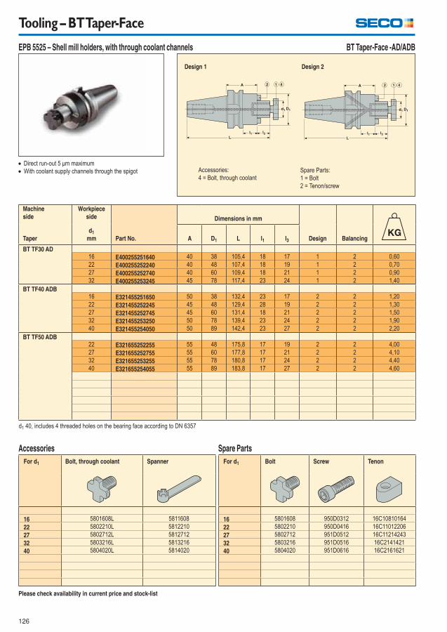
126
Tooling – BT Taper-Face
EPB 5525 – Shell mill holders, with through coolant channels BT Taper-Face -AD/ADB
Direct run-out 5 μm maximum
With coolant supply channels through the spigot
Machine
side
Workpiece
side
Part No.
Dimensions in mm
Design BalancingTaper
d1
mm A D1 L l1 l3
BT TF30 AD16 E400255251640 40 38 105,4 18 17 1 2 0,60
22 E400255252240 40 48 107,4 18 19 1 2 0,70
27 E400255252740 40 60 109,4 18 21 1 2 0,90
32 E400255253245 45 78 117,4 23 24 1 2 1,40
BT TF40 ADB16 E321455251650 50 38 132,4 23 17 2 2 1,20
22 E321455252245 45 48 129,4 28 19 2 2 1,30
27 E321455252745 45 60 131,4 18 21 2 2 1,50
32 E321455253250 50 78 139,4 23 24 2 2 1,90
40 E321455254050 50 89 142,4 23 27 2 2 2,20
BT TF50 ADB22 E321655252255 55 48 175,8 17 19 2 2 4,00
27 E321655252755 55 60 177,8 17 21 2 2 4,10
32 E321655253255 55 78 180,8 17 24 2 2 4,40
40 E321655254055 55 89 183,8 17 27 2 2 4,60
d1 40, includes 4 threaded holes on the bearing face according to DN 6357
Please check availability in current price and stock-list
For d1 Bolt, through coolant Spanner
16 5801608L 5811608
22 5802210L 5812210
27 5802712L 5812712
32 5803216L 5813216
40 5804020L 5814020
Accessories
For d1 Bolt Screw Tenon
16 5801608 950D0312 16C10810164
22 5802210 950D0416 16C11012206
27 5802712 951D0512 16C11214243
32 5803216 951D0516 16C2141421
40 5804020 951D0616 16C2161621
Spare Parts
Design 2 Design 1
Spare Parts:
1 = Bolt
2 = Tenon/screw
Accessories:
4 = Bolt, through coolant
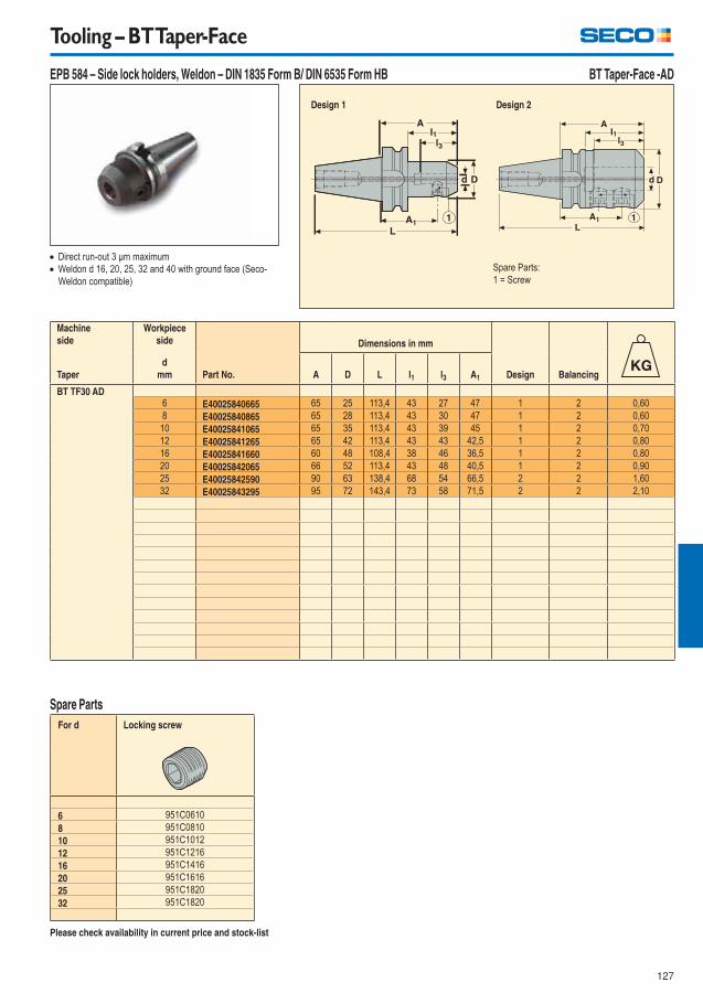
127
Tooling – BT Taper-Face
EPB 584 – Side lock holders, Weldon – DIN 1835 Form B/ DIN 6535 Form HB BT Taper-Face -AD
Direct run-out 3 μm maximum
Weldon d 16, 20, 25, 32 and 40 with ground face (Seco-
Weldon compatible)
Machine
side
Workpiece
side
Part No.
Dimensions in mm
Design BalancingTaper
d
mm A D L l1 l3 A1
BT TF30 AD6 E40025840665 65 25 113,4 43 27 47 1 2 0,60
8 E40025840865 65 28 113,4 43 30 47 1 2 0,60
10 E40025841065 65 35 113,4 43 39 45 1 2 0,70
12 E40025841265 65 42 113,4 43 43 42,5 1 2 0,80
16 E40025841660 60 48 108,4 38 46 36,5 1 2 0,80
20 E40025842065 66 52 113,4 43 48 40,5 1 2 0,90
25 E40025842590 90 63 138,4 68 54 66,5 2 2 1,60
32 E40025843295 95 72 143,4 73 58 71,5 2 2 2,10
Please check availability in current price and stock-list
For d Locking screw
6 951C0610
8 951C0810
10 951C1012
12 951C1216
16 951C1416
20 951C1616
25 951C1820
32 951C1820
Spare Parts
Design 2 Design 1
Spare Parts:
1 = Screw
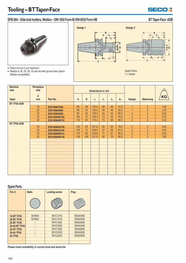
128
Tooling – BT Taper-Face
EPB 584 – Side lock holders, Weldon – DIN 1835 Form B/ DIN 6535 Form HB BT Taper-Face -ADB
Direct run-out 3 μm maximum
Weldon d 16, 20, 25, 32 and 40 with ground face (Seco-
Weldon compatible)
Please check availability in current price and stock-list
For d Balls Locking screw Plug
16 BT TF40 901B04 951C1416 950A0406
20 BT TF40 901B04 951C1616 950A0406
25 BT TF40 – 951C1820 950A0406
32-40 BT TF40 – 951C2020 950A0406
25 BT TF50 – 951C1820 950A0606
32-40 TF50 – 951C2020 950A0606
50 TF50 – 951C2425 950A0606
Spare Parts
Machine
side
Workpiece
side
Part No.
Dimensions in mm
Design BalancingTaper
d
mm A D L l1 l3 A1
BT TF40 ADB16 E32145841665 65 48 130,4 38 46 41,5 1 2 1,40
20 E32145842065 65 52 130,4 38 48 40,5 1 2 1,50
25 E32145842590 90 63 155,4 63 54 66,5 2 2 2,20
32 E321458432100 100 72 165,4 73 58 76,5 2 2 2,70
40 E321458440110 110 80 175,4 75 68 80,5 2 2 3,20
BT TF50 ADB25 E321658425100 100 63 201,8 62 54 76,5 2 2 4,90
32 E321658432105 105 72 206,8 67 58 81,5 2 2 5,30
40 E321658440115 115 80 216,8 77 67 88,5 2 2 5,80
50 E321658450130 130 100 231,8 92 78 95,5 2 2 7,60
Design 2 Design 1
Spare Parts:
1 = Screw
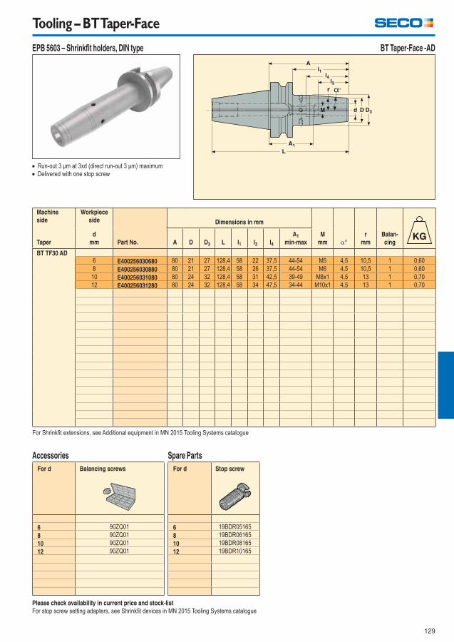
129
Tooling – BT Taper-Face
EPB 5603 – Shrinkfi t holders, DIN type BT Taper-Face -AD
Run-out 3 μm at 3xd (direct run-out 3 μm) maximum
Delivered with one stop screw
Machine
side
Workpiece
side
Part No.
Dimensions in mm
M
mm °
r
mm
Balan-
cingTaper
d
mm A D D3 L l1 l3 l4
A1
min-max
BT TF30 AD6 E400256030680 80 21 27 128,4 58 22 37,5 44-54 M5 4,5 10,5 1 0,60
8 E400256030880 80 21 27 128,4 58 26 37,5 44-54 M6 4,5 10,5 1 0,60
10 E400256031080 80 24 32 128,4 58 31 42,5 39-49 M8x1 4,5 13 1 0,70
12 E400256031280 80 24 32 128,4 58 34 47,5 34-44 M10x1 4,5 13 1 0,70
For Shrinkfi t extensions, see Additional equipment in MN 2015 Tooling Systems catalogue
Please check availability in current price and stock-list
For stop screw setting adapters, see Shrinkfi t devices in MN 2015 Tooling Systems catalogue
For d Balancing screws
6 90ZQ01
8 90ZQ01
10 90ZQ01
12 90ZQ01
Accessories
For d Stop screw
6 19BDR05165
8 19BDR06165
10 19BDR08165
12 19BDR10165
Spare Parts
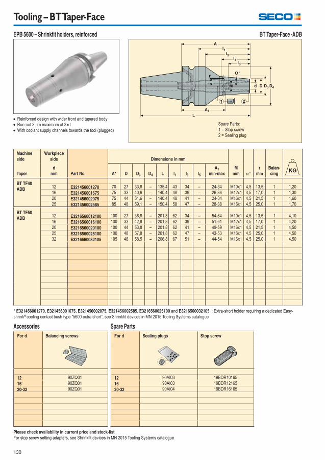
130
Tooling – BT Taper-Face
EPB 5600 – Shrinkfi t holders, reinforced BT Taper-Face -ADB
Please check availability in current price and stock-list
For stop screw setting adapters, see Shrinkfi t devices in MN 2015 Tooling Systems catalogue
For d Balancing screws
12 90ZQ01
16 90ZQ01
20-32 90ZQ01
Accessories
For d Sealing plugs Stop screw
12 90AI03 19BDR10165
16 90AI03 19BDR12165
20-32 90AI04 19BDR16165
Spare Parts
Reinforced design with wider front and tapered body
Run-out 3 μm maximum at 3xd
With coolant supply channels towards the tool (plugged)
Machine
side
Workpiece
side
Part No.
Dimensions in mm
M
mm °
r
mm
Balan-
cingTaper
d
mm A* D D3 D4 L l1 l3 l5
A1
min-max
BT TF40
ADB12 E321456001270 70 27 33,8 – 135,4 43 34 – 24-34 M10x1 4,5 13,5 1 1,20
16 E321456001675 75 33 40,6 – 140,4 48 39 – 26-36 M12x1 4,5 17,0 1 1,30
20 E321456002075 75 44 51,6 – 140,4 48 41 – 24-34 M16x1 4,5 21,5 1 1,60
25 E321456002585 85 48 59,1 – 150,4 58 47 – 28-38 M16x1 4,5 25,0 1 1,70
BT TF50
ADB12 E3216560012100 100 27 36,8 – 201,8 62 34 – 54-64 M10x1 4,5 13,5 1 4,10
16 E3216560016100 100 33 42,8 – 201,8 62 39 – 51-61 M12x1 4,5 17,0 1 4,20
20 E3216560020100 100 44 53,8 – 201,8 62 41 – 49-59 M16x1 4,5 21,5 1 4,50
25 E3216560025100 100 48 57,8 – 201,8 62 47 – 43-53 M16x1 4,5 25,0 1 4,50
32 E3216560032105 105 48 58,5 – 206,8 67 51 – 44-54 M16x1 4,5 25,0 1 4,50
* E321456001270, E321456001675, E321456002075, E321456002585, E3216560025100 and E3216560032105 : Extra-short holder requiring a dedicated Easy-
shrink® cooling contact bush type “5600 extra short”, see Shrinkfi t devices in MN 2015 Tooling Systems catalogue
r
Spare Parts:
1 = Stop screw
2 = Sealing plug
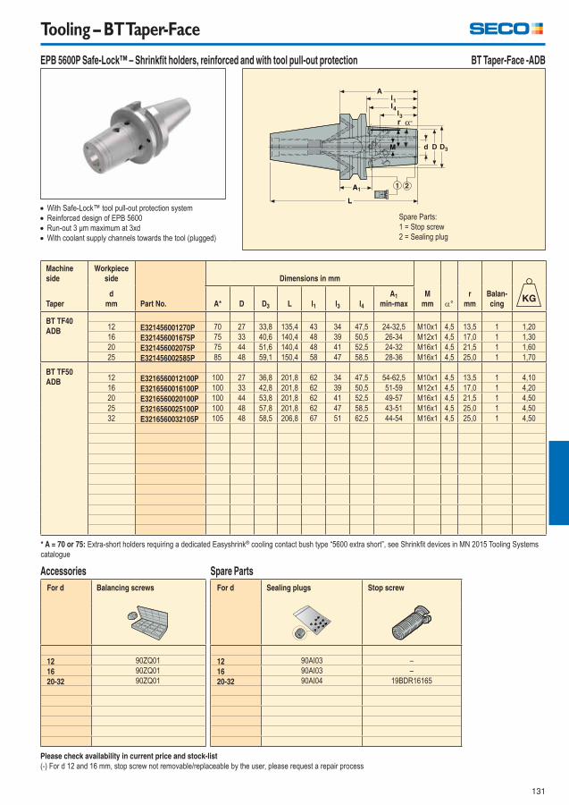
131
Tooling – BT Taper-Face
EPB 5600P Safe-Lock™ – Shrinkfi t holders, reinforced and with tool pull-out protection BT Taper-Face -ADB
Please check availability in current price and stock-list
(-) For d 12 and 16 mm, stop screw not removable/replaceable by the user, please request a repair process
For d Balancing screws
12 90ZQ01
16 90ZQ01
20-32 90ZQ01
Accessories
For d Sealing plugs Stop screw
12 90AI03 –
16 90AI03 –
20-32 90AI04 19BDR16165
Spare Parts
With Safe-Lock™ tool pull-out protection system
Reinforced design of EPB 5600
Run-out 3 μm maximum at 3xd
With coolant supply channels towards the tool (plugged)
Machine
side
Workpiece
side
Part No.
Dimensions in mm
M
mm °
r
mm
Balan-
cingTaper
d
mm A* D D3 L l1 l3 l4
A1
min-max
BT TF40
ADB12 E321456001270P 70 27 33,8 135,4 43 34 47,5 24-32,5 M10x1 4,5 13,5 1 1,20
16 E321456001675P 75 33 40,6 140,4 48 39 50,5 26-34 M12x1 4,5 17,0 1 1,30
20 E321456002075P 75 44 51,6 140,4 48 41 52,5 24-32 M16x1 4,5 21,5 1 1,60
25 E321456002585P 85 48 59,1 150,4 58 47 58,5 28-36 M16x1 4,5 25,0 1 1,70
BT TF50
ADB12 E3216560012100P 100 27 36,8 201,8 62 34 47,5 54-62,5 M10x1 4,5 13,5 1 4,10
16 E3216560016100P 100 33 42,8 201,8 62 39 50,5 51-59 M12x1 4,5 17,0 1 4,20
20 E3216560020100P 100 44 53,8 201,8 62 41 52,5 49-57 M16x1 4,5 21,5 1 4,50
25 E3216560025100P 100 48 57,8 201,8 62 47 58,5 43-51 M16x1 4,5 25,0 1 4,50
32 E3216560032105P 105 48 58,5 206,8 67 51 62,5 44-54 M16x1 4,5 25,0 1 4,50
* A = 70 or 75: Extra-short holders requiring a dedicated Easyshrink® cooling contact bush type “5600 extra short”, see Shrinkfi t devices in MN 2015 Tooling Systems
catalogue
Spare Parts:
1 = Stop screw
2 = Sealing plug

132
Tooling – BT Taper-Face
EPB 5672 – High precision collet chucks BT Taper-Face -AD
Run-out 3 μm maximum at 3xd
High transmittable torque
High RPM suitable
Please check availability in current price and stock-list
** When using a stop screw, its tapered contact onto the tool shank can increase the tool run-out defect
For tightening torques, see Operating instructions delivered with the holder or in MN 2015 Tooling Systems catalogue
For size Socket Spanner Torque key
HP 11 03EF567211 03B567211 03DYD010100
HP 16 03EF567216 03B567216 03DYD010100
HP 25 03EF567225 03B567225 03DYD020200
Accessories**
For size Nut
HP 11 08B567211
HP 16 08B567216
HP 25 08B567225
Spare Parts
Machine
sideWorkpiece
side
Part No.
Chuck &
Collet Size
Dimensions in mm
BalancingTaper
Capacity d
mm A D D1 L l1
A1
min-max*
BT TF30 AD1-7 E400256721150 HP 11 50 16 16 98,4 28 6-32 1 0,50
1-10 E400256721660 HP 16 60 30 30 108,4 38 15-30 1 0,60
2-16 E400256722570 HP 25 70 40 40 118,4 48 16-32 1 0,70
For ER HP collets type 5672, see Additional equipment in MN 2015 Tooling Systems catalogue
* A1 setting length onto stop screw when possible, or total available setting length for chucks without thread for stop end screw
Spare Parts:
1 = Nut
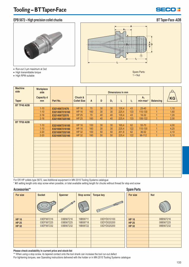
133
Tooling – BT Taper-Face
EPB 5672 – High precision collet chucks BT Taper-Face -ADB
Run-out 3 μm maximum at 3xd
High transmittable torque
High RPM suitable
Please check availability in current price and stock-list
** When using a stop screw, its tapered contact onto the tool shank can increase the tool run-out defect
For tightening torques, see Operating instructions delivered with the holder or in MN 2015 Tooling Systems catalogue
For size Socket Spanner Stop screw Torque key
HP 16 03EF567216 03B567216 19B58711 03DYD010100
HP 25 03EF567225 03B567225 19B58718 03DYD020200
HP 32 03EF567232 03B567232 19B58722 03DYD020200
Accessories**
For size Nut
HP 16 08B567216
HP 25 08B567225
HP 32 08B567232
Spare Parts
Machine
sideWorkpiece
side
Part No.
Chuck &
Collet Size
Dimensions in mm
BalancingTaper
Capacity d
mm A D D1 L l1
A1
min-max*
BT TF40 ADB1-10 E321456721670 HP 16 70 30 30 135,4 43 25-40 1 1,10
1-10 E3214567216160 HP 16 160 30 30 225,4 133 115-130 1 1,60
2-16 E321456722570 HP 25 70 40 40 135,4 43 16-32 1 1,20
2-16 E3214567225160 HP 25 160 40 40 225,4 133 106-122 1 2,00
BT TF50 ADB1-10 E3216567216100 HP 16 100 30 30 165,4 62 55-70 1 4,00
1-10 E3216567216160 HP 16 160 30 30 225,4 122 115-130 1 4,20
2-20 E3216567232100 HP 32 100 50 50 201,8 62 36-52 1 4,10
2-20 E3216567232160 HP 32 160 50 50 225,4 122 96-112 1 5,10
For ER HP collets type 5672, see Additional equipment in MN 2015 Tooling Systems catalogue
* A1 setting length onto stop screw when possible, or total available setting length for chucks without thread for stop end screw
Spare Parts:
1 = Nut
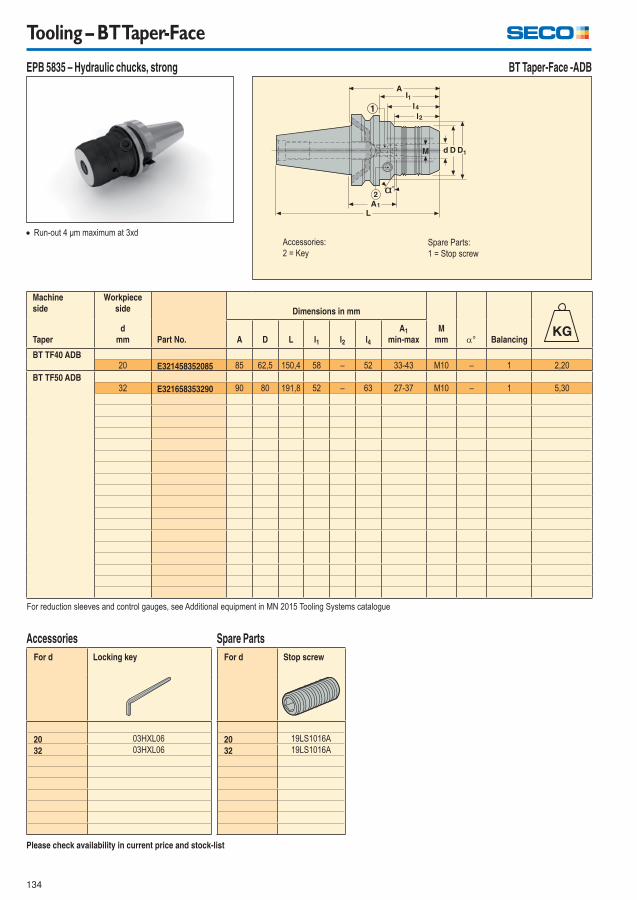
134
Tooling – BT Taper-Face
EPB 5835 – Hydraulic chucks, strong BT Taper-Face -ADB
Run-out 4 μm maximum at 3xd
Machine
side
Workpiece
side
Part No.
Dimensions in mm
M
mm ° BalancingTaper
d
mm A D L l1 l2 l4
A1
min-max
BT TF40 ADB20 E321458352085 85 62,5 150,4 58 – 52 33-43 M10 – 1 2,20
BT TF50 ADB32 E321658353290 90 80 191,8 52 – 63 27-37 M10 – 1 5,30
For reduction sleeves and control gauges, see Additional equipment in MN 2015 Tooling Systems catalogue
Please check availability in current price and stock-list
For d Locking key
20 03HXL06
32 03HXL06
Accessories
For d Stop screw
20 19LS1016A
32 19LS1016A
Spare Parts
Accessories:
2 = Key Spare Parts:
1 = Stop screw
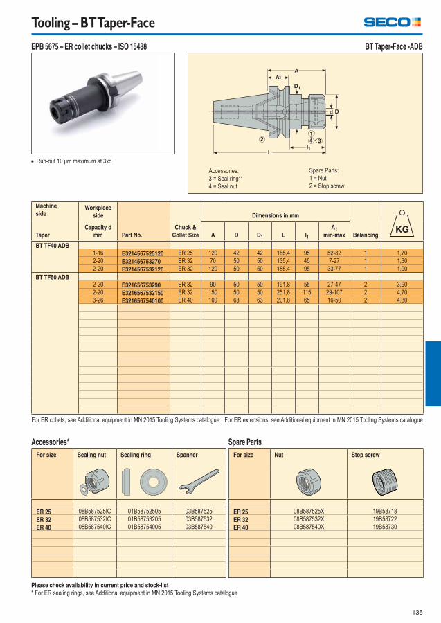
135
Tooling – BT Taper-Face
EPB 5675 – ER collet chucks – ISO 15488 BT Taper-Face -ADB
Run-out 10 μm maximum at 3xd
Please check availability in current price and stock-list
* For ER sealing rings, see Additional equipment in MN 2015 Tooling Systems catalogue
Machine
sideWorkpiece
side
Part No.
Chuck &
Collet Size
Dimensions in mm
BalancingTaper
Capacity d
mm A D D1 L l1
A1
min-max
BT TF40 ADB1-16 E3214567525120 ER 25 120 42 42 185,4 95 52-82 1 1,70
2-20 E321456753270 ER 32 70 50 50 135,4 45 7-27 1 1,30
2-20 E3214567532120 ER 32 120 50 50 185,4 95 33-77 1 1,90
BT TF50 ADB2-20 E321656753290 ER 32 90 50 50 191,8 55 27-47 2 3,90
2-20 E3216567532150 ER 32 150 50 50 251,8 115 29-107 2 4,70
3-26 E3216567540100 ER 40 100 63 63 201,8 65 16-50 2 4,30
For ER collets, see Additional equipment in MN 2015 Tooling Systems catalogue For ER extensions, see Additional equipment in MN 2015 Tooling Systems catalogue
For size Sealing nut Sealing ring Spanner
ER 25 08B587525IC 01B58752505 03B587525
ER 32 08B587532IC 01B58753205 03B587532
ER 40 08B587540IC 01B58754005 03B587540
Accessories*
For size Nut Stop screw
ER 25 08B587525X 19B58718
ER 32 08B587532X 19B58722
ER 40 08B587540X 19B58730
Spare Parts
Accessories:
3 = Seal ring**
4 = Seal nut
Spare Parts:
1 = Nut
2 = Stop screw
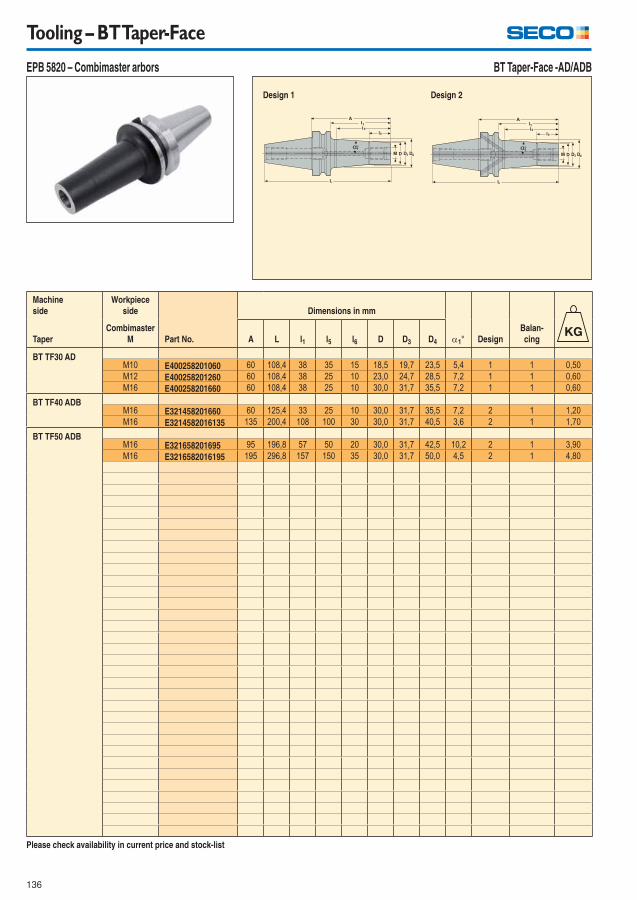
136
Tooling – BT Taper-Face
EPB 5820 – Combimaster arbors BT Taper-Face -AD/ADB
Design 2 Design 1
Machine
side
Workpiece
side
Part No.
Dimensions in mm
1° Design
Balan-
cingTaper
Combimaster
M A L l1 l5 l6 D D3 D4
BT TF30 ADM10 E400258201060 60 108,4 38 35 15 18,5 19,7 23,5 5,4 1 1 0,50
M12 E400258201260 60 108,4 38 25 10 23,0 24,7 28,5 7,2 1 1 0,60
M16 E400258201660 60 108,4 38 25 10 30,0 31,7 35,5 7,2 1 1 0,60
BT TF40 ADBM16 E321458201660 60 125,4 33 25 10 30,0 31,7 35,5 7,2 2 1 1,20
M16 E3214582016135 135 200,4 108 100 30 30,0 31,7 40,5 3,6 2 1 1,70
BT TF50 ADBM16 E321658201695 95 196,8 57 50 20 30,0 31,7 42,5 10,2 2 1 3,90
M16 E3216582016195 195 296,8 157 150 35 30,0 31,7 50,0 4,5 2 1 4,80
Please check availability in current price and stock-list
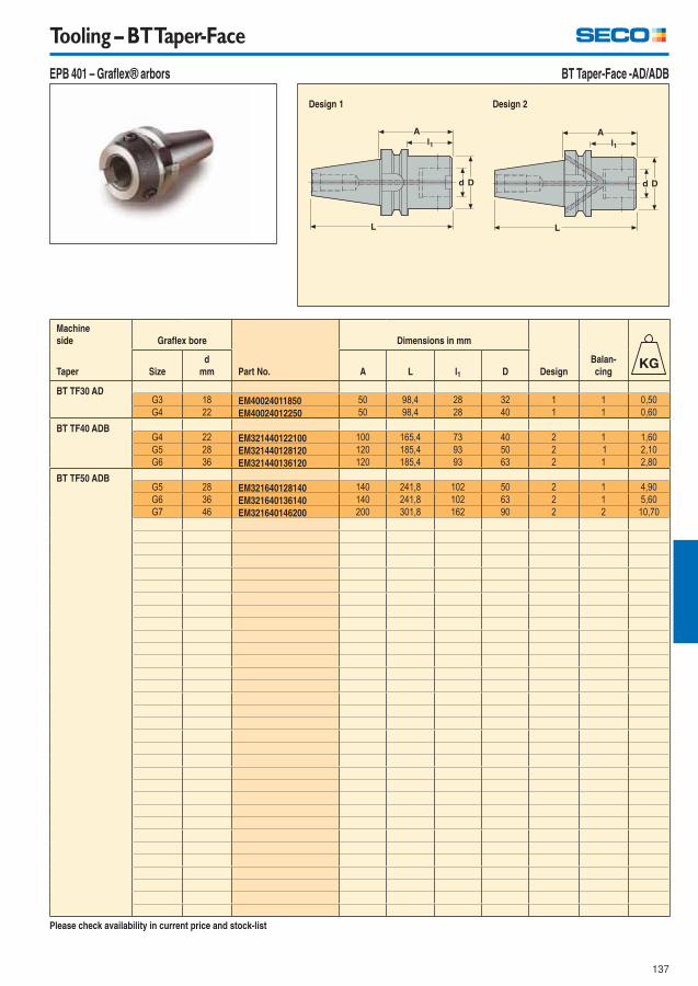
137
Tooling – BT Taper-Face
EPB 401 – Grafl ex® arbors BT Taper-Face -AD/ADB
Design 2 Design 1
Machine
side Grafl ex bore
Part No.
Dimensions in mm
Design
Balan-
cingTaper Size
d
mm A L l1 D
BT TF30 ADG3 18 EM40024011850 50 98,4 28 32 1 1 0,50
G4 22 EM40024012250 50 98,4 28 40 1 1 0,60
BT TF40 ADBG4 22 EM321440122100 100 165,4 73 40 2 1 1,60
G5 28 EM321440128120 120 185,4 93 50 2 1 2,10
G6 36 EM321440136120 120 185,4 93 63 2 1 2,80
BT TF50 ADBG5 28 EM321640128140 140 241,8 102 50 2 1 4,90
G6 36 EM321640136140 140 241,8 102 63 2 1 5,60
G7 46 EM321640146200 200 301,8 162 90 2 2 10,70
Please check availability in current price and stock-list
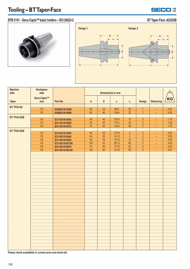
138
Tooling – BT Taper-Face
EPB 5191 – Seco-Capto™ basic holders – ISO 26623-2 BT Taper-Face -AD/ADB
Design 2 Design 1
Machine
side
Workpiece
side
Part No.
Dimensions in mm
Design BalancingTaper
Seco-Capto™
size A D L l1
BT TF30 ADC3 E400251913240 40 32 88,4 22 1 – 0,45
C4 E400251914060 60 40 108,4 22 1 – 0,65
BT TF40 ADBC4 E311451914040 40 40 105,4 13 2 – 1,10
C5 E311451915050 50 50 115,4 23 2 – 1,20
C6 E311451916375 75 63 140,4 48 2 – 1,70
BT TF50 ADBC4 E311651914040 40 50 141,8 2 2 – 3,60
C5 E311651915040 40 50 141,8 2 2 – 3,50
C6 E311651916350 50 63 151,8 12 2 – 3,60
C6 E3116519163100 100 63 201,8 62 2 – 4,63
C8 E311651918070 70 80 171,8 32 2 – 4,20
C8 E3116519180120 120 80 121,8 82 2 – 5,91
Please check availability in current price and stock-list
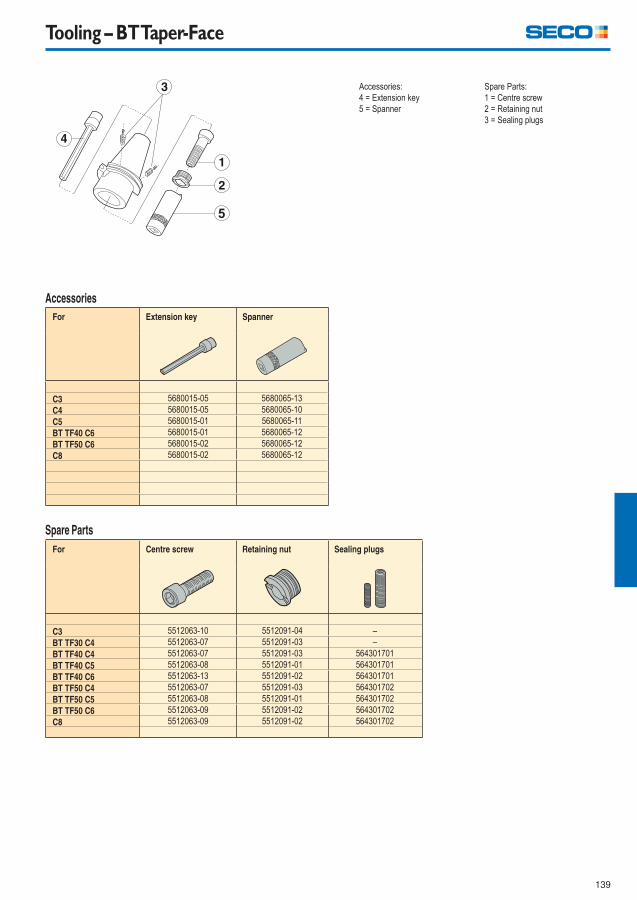
139
Tooling – BT Taper-Face
Accessories:
4 = Extension key
5 = Spanner
Spare Parts:
1 = Centre screw
2 = Retaining nut
3 = Sealing plugs
Accessories
For Extension key Spanner
C3 5680015-05 5680065-13
C4 5680015-05 5680065-10
C5 5680015-01 5680065-11
BT TF40 C6 5680015-01 5680065-12
BT TF50 C6 5680015-02 5680065-12
C8 5680015-02 5680065-12
For Centre screw Retaining nut Sealing plugs
C3 5512063-10 5512091-04 –
BT TF30 C4 5512063-07 5512091-03 –
BT TF40 C4 5512063-07 5512091-03 564301701
BT TF40 C5 5512063-08 5512091-01 564301701
BT TF40 C6 5512063-13 5512091-02 564301701
BT TF50 C4 5512063-07 5512091-03 564301702
BT TF50 C5 5512063-08 5512091-01 564301702
BT TF50 C6 5512063-09 5512091-02 564301702
C8 5512063-09 5512091-02 564301702
Spare Parts
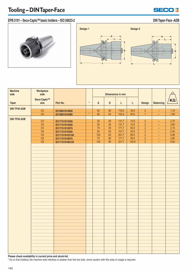
140
Tooling – DIN Taper-Face
EPB 5191 – Seco-Capto™ basic holders – ISO 26623-2 DIN Taper-Face -ADB
Design 2 Design 1
Machine
side
Workpiece
side
Part No. *
Dimensions in mm
Design BalancingTaper
Seco-Capto™
size A D L l1
DIN TF40 ADBC5 E316951915050 50 50 118,4 30,9 2 – 1,10
C6 E316951916385 * 85 63 153,4 65,9 1 – 1,90
DIN TF50 ADBC4 E317151914030 30 40 131,7 10,9 2 – 2,70
C5 E317151915030 30 50 131,7 10,9 2 – 2,80
C5 E317151915070 70 50 171,7 50,9 2 – 3,15
C6 E317151916350 50 63 151,7 30,9 2 – 2,40
C6 E3171519163100 100 63 201,7 80,9 2 – 4,08
C8 E317151918070 70 80 171,7 50,9 2 – 3,90
C8 E3171519180120 120 80 221,7 100,9 2 – 5,62
Please check availability in current price and stock-list
* As on that holde(s) the machine side interface is weaker than the tool side, some caution with this area of usage is required

141
Tooling – DIN Taper-Face
Accessories:
4 = Extension key
5 = Spanner
Spare Parts:
1 = Centre screw
2 = Retaining nut
3 = Sealing plugs
Accessories
For Extension key Spanner
C4 5680015-05 5680065-10
C5 5680015-01 5680065-11
C8 5680015-02 5680065-12
TF40 C6 5680015-01 5680065-12
TF50 C6 5680015-02 5680065-12
For Centre screw Retaining nut Sealing plugs
E316951915050 5512063-08 5512091-01 564301701
E316951916385 5512063-13 5512091-02 564301701
E317151914030 5512063-07 5512091-03 564301702
E317151915030 5512063-08 5512091-01 564301702
E317151915070 5512063-08 5512091-01 564301702
E3171519163100 5512063-09 5512091-02 564301702
E317151916350 5512063-09 5512091-02 564301702
E3171519180120 5512063-09 5512091-02 564301702
E317151918070 5512063-09 5512091-02 564301702
Spare Parts

142
Tooling – Additional Steadyline® GL – Guide
Extension of the Steadyline® GL tooling range, with additional machine sides :
� Steadyline GL bars with Seco-Capto C8 machine side
� Steadyline GL bars with HSK-T/A63 and HSK-T/A100 machine side
Description of HSK-T/A
Tooling with HSK-T/A machine sides are suitable for static & rotating operations on machines with:
� HSK-T spindles (eg. spindles and turrets on turning and multi-task machines).
� HSK-A spindles (eg. machining centres).
HSK-T/A is conform to the HSK-T ISO standard, and compatible for the HSK-A spindles : eg. diameter D of Steadyline GL holders are inside the
HSK-fl ange clearance diameter d9 max allowed by HSK-A ISO standard.
Description of Seco-Capto C8
See Guide pages 213-217 in MN 2015 Tooling Systems catalogue.
Steadyline damping system, general information
See Guide page 27 in MN 2015 Tooling Systems catalogue.
GL connection
See Guide pages 386-387 in MN 2015-2 Update catalogue.
Turning & Threading heads GL are shown in the Turning catalogue; Boring heads GL are shown in MN 2015-2 Update catalogue.
Other features
Balancing: Holders are pre-balanced (see Product pages ‘Balancing’ columns).
New HSK-T/A machine side Seco-Capto machine side Cylindrical machine side
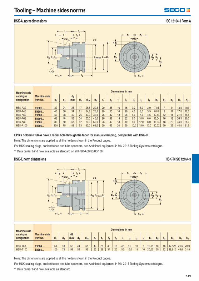
143
Tooling – Machine sides norms
HSK-A, norm dimensions
Machine side
catalogue
designation
Machine side
Part No.
Dimensions in mm
d1 d2
d9
max d3 d10 d4 f1 f2 f3 l1 l2 l3 l4 b1 b2 b3 h1 h2
HSK-A32 E9301... 32 24 26 17 26,5 20,5 20 35 16 16 3,2 5,0 3,0 7,05 7 9 13,0 9,5
HSK-A40 E9302... 40 30 34 21 34,8 25,5 20 35 16 20 4,0 6,0 3,5 8,05 9 11 17,0 12,0
HSK-A50 E9303... 50 38 42 26 43,0 32,0 26 42 18 25 5,0 7,5 4,5 10,54 12 14 21,0 15,5
HSK-A63 E9304... 63 48 53 34 55,0 40,0 26 42 18 32 6,3 10,0 6,0 12,54 16 18 26,5 20,0
HSK-A80 E9305... 80 60 67 42 70,0 50,0 26 42 18 40 8,0 12,0 8,0 16,04 18 20 34,0 25,0
HSK-A100 E9306... 100 75 88 53 92,0 63,0 29 45 20 50 10,0 15,0 10,0 20,02 20 22 44,0 31,5
EPB’s holders HSK-A have a radial hole through the taper for manual clamping, compatible with HSK-C.
Note: The dimensions are applied to all the holders shown in the Product pages.
For HSK sealing plugs, coolant tubes and tube spanners, see Additional equipment in MN 2015 Tooling Systems catalogue.
** Data carrier blind hole available as standard on all HSK-A50/63/80/100.
ISO 12164-1 Form A
HSK-T, norm dimensions
Machine side
catalogue
designation
Machine side
Part No.
Dimensions in mm
d1 d2
d9
max d3 d10 d4 f1 f2 f3 l1 l2 l3 l4 b1 b2 b3 b5 h1 h2
HSK-T63 E9364... 63 48 62 34 55 40 26 30 18 32 6,3 10 6 12,54 16 18 12,425 26,5 20,0
HSK-T100 E9366... 100 75 99 53 92 63 29 34 20 50 10,0 15 10 20,02 20 22 19,910 44,0 31,5
Note: The dimensions are applied to all the holders shown in the Product pages.
For HSK sealing plugs, coolant tubes and tube spanners, see Additional equipment in MN 2015 Tooling Systems catalogue.
** Data carrier blind hole available as standard.
HSK-T/ ISO 12164-3
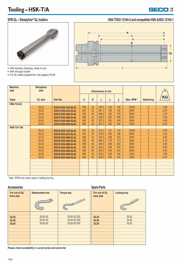
144
Tooling – HSK-T/A
EPB GL – Steadyline® GL holders HSK-T/ISO 12164-3 and compatible HSK-A/ISO 12164-1
With dynamic damping, ready to use
With through coolant
For GL heads programme, see page(s) 50-68
Please check availability in current price and stock-list
Machine
side
Workpiece
side
Part No.
Dimensions in mm
Max. RPM * BalancingTaper GL size A D L l1 l5
HSK-T/A 63GL32 E9374-D32-160-GL32 160 32 197,3 134 128 10000 2 1,60
GL32 E9374-D32-224-GL32 224 32 261,3 198 192 8000 2 2,00
GL40 E9374-D40-208-GL40 208 40 246,3 182 176 8000 2 2,70
GL40 E9374-D40-288-GL40 288 40 326,3 262 256 6000 2 3,50
GL50 E9374-D50-268-GL50 268 50 307,3 242 240 6000 2 4,80
GL50 E9374-D50-368-GL50 368 50 407,3 342 340 4000 2 6,40
HSK-T/A 100GL32 E9376-D32-160-GL32 160 32 215,3 131 125 10000 2 3,00
GL32 E9376-D32-224-GL32 224 32 279,3 195 189 8000 2 3,40
GL32 E9376-D32-288-GL32 288 32 343,3 259 253 6000 2 3,80
GL40 E9376-D40-208-GL40 208 40 264,3 179 173 8000 2 4,10
GL40 E9376-D40-288-GL40 288 40 344,3 259 253 6000 2 4,90
GL40 E9376-D40-368-GL40 368 40 424,3 339 333 5000 2 5,80
GL50 E9376-D50-268-GL50 268 50 325,3 239 234 6000 2 6,20
GL50 E9376-D50-368-GL50 368 50 425,3 339 334 4000 2 7,80
GL50 E9376-D50-468-GL50 468 50 525,3 439 434 2500 2 9,70
* Max. RPM only when used in rotating boring
For nut of GL
bore size
Replaceable end Torque key
GL32 SL00-32 SL00-32.250
GL40 SL00-40 SL00-40.350
GL50 SL00-50 SL00-50.550
Accessories
For nut of GL
bore size
Locking key
GL32 SL32
GL40 SL40
GL50 SL50
Spare Parts

145
Tooling – Seco-Capto™
EPB GL – Steadyline® GL holders Seco-Capto™/ ISO 26623-1
Please check availability in current price and stock-list
For nut of GL
bore size
Replaceable end Torque key
GL32 SL00-32 SL00-32.250
GL40 SL00-40 SL00-40.350
GL50 SL00-50 SL00-50.550
Accessories
For nut of GL
bore size
Locking key
GL32 SL32
GL40 SL40
GL50 SL50
Spare Parts
With dynamic damping, ready to use
With through coolant
For GL heads programme, see page(s) 50-68
Machine
side
Workpiece
side
Part No.
Dimensions in mm
Max. RPM * Balancing
Seco-Capto™
shank size GL size A D L l1 l5
C4GL32 C4-D32-160-GL32 160 32 189,3 140 137 4000 2 1,20
GL32 C4-D32-224-GL32 224 32 253,3 204 201 4000 2 1,70
GL32 C4-D32-288-GL32 288 32 317,5 268 265 4000 2 2,10
C5GL32 C5-D32-160-GL32 160 32 195,5 140 136 4000 2 1,40
GL32 C5-D32-224-GL32 224 32 259,5 204 200 4000 2 1,80
GL32 C5-D32-288-GL32 288 32 323,5 268 264 4000 2 2,20
GL40 C5-D40-208-GL40 208 40 244,5 188 184 3500 2 2,50
GL40 C5-D40-288-GL40 288 40 324,3 268 264 3500 2 3,30
GL40 C5-D40-368-GL40 368 40 404,5 348 344 3500 2 4,30
C6GL32 C6-D32-160-GL32 160 32 203,5 135 129 4000 2 1,80
GL32 C6-D32-224-GL32 224 32 267,3 199 193 4000 2 2,20
GL32 C6-D32-288-GL32 288 32 331,5 263 257 4000 2 2,60
GL40 C6-D40-208-GL40 208 40 252,5 183 177 3500 2 2,90
GL40 C6-D40-288-GL40 288 40 332,3 263 257 3500 2 3,70
GL40 C6-D40-368-GL40 368 40 412,5 343 337 3500 2 4,60
GL50 C6-D50-268-GL50 268 50 313,5 243 238 2500 2 5,00
GL50 C6-D50-368-GL50 368 50 413,5 343 338 2500 2 6,60
GL50 C6-D50-468-GL50 468 50 513,5 443 438 2500 2 8,50
* Max. RPM only when used in rotating boring
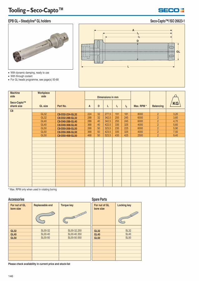
146
Tooling – Seco-Capto™
EPB GL – Steadyline® GL holders Seco-Capto™/ ISO 26623-1
Please check availability in current price and stock-list
For nut of GL
bore size
Replaceable end Torque key
GL32 SL00-32 SL00-32.250
GL40 SL00-40 SL00-40.350
GL50 SL00-50 SL00-50.550
Accessories
For nut of GL
bore size
Locking key
GL32 SL32
GL40 SL40
GL50 SL50
Spare Parts
With dynamic damping, ready to use
With through coolant
For GL heads programme, see page(s) 50-68
Machine
side
Workpiece
side
Part No.
Dimensions in mm
Max. RPM * Balancing
Seco-Capto™
shank size GL size A D L l1 l5
C8GL32 C8-D32-224-GL32 224 32 277,5 191 181 8000 2 3,20
GL32 C8-D32-288-GL32 288 32 342,5 255 245 6000 2 3,60
GL40 C8-D40-288-GL40 288 40 342,5 255 245 6000 2 4,70
GL40 C8-D40-368-GL40 368 40 422,5 335 325 4000 2 5,60
GL50 C8-D50-268-GL50 268 50 323,5 235 225 6000 2 5,90
GL50 C8-D50-368-GL50 368 50 423,5 335 325 4000 2 7,50
GL50 C8-D50-468-GL50 468 50 523,5 435 425 2500 2 9,40
* Max. RPM only when used in rotating boring
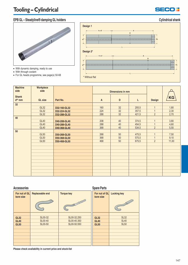
147
Tooling – Cylindrical
EPB GL – Steadyline® damping GL holders
Please check availability in current price and stock-list
Cylindrical shank
With dynamic damping, ready to use
With through coolant
For GL heads programme, see page(s) 50-68
Machine
side
Workpiece
side
Part No.
Dimensions in mm
Design
Shank
dh5 mm GL size A D L
32GL32 D32-160-GL32 160 32 293,5 1 1,80
GL32 D32-224-GL32 224 32 357,5 1 2,30
GL32 D32-288-GL32 288 32 421,5 2 2,70
40GL40 D40-208-GL40 208 40 374,5 1 3,80
GL40 D40-288-GL40 288 40 454,5 1 4,60
GL40 D40-368-GL40 368 40 534,5 2 5,50
50GL50 D50-268-GL50 268 50 475,5 1 7,50
GL50 D50-368-GL50 368 50 575,5 1 9,10
GL50 D50-468-GL50 468 50 675,5 2 11,00
Design 2*
Design 1
* Without fl at
For nut of GL
bore size
Replaceable end Torque key
GL32 SL00-32 SL00-32.250
GL40 SL00-40 SL00-40.350
GL50 SL00-50 SL00-50.550
Accessories
For nut of GL
bore size
Locking key
GL32 SL32
GL40 SL40
GL50 SL50
Spare Parts
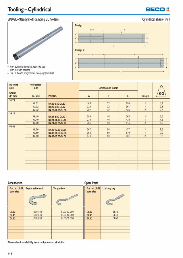
148
Tooling – Cylindrical
EPB GL – Steadyline® damping GL holders
Please check availability in current price and stock-list
Cylindrical shank - inch
With dynamic damping, ready to use
With through coolant
For GL heads programme, see page(s) 50-68
Machine
side
Workpiece
side
Part No.
Dimensions in mm
Design
Shank
dh5 mm GL size A D L
31.75GL32 DA20-6.50-GL32 165 32 298 1 1,8
GL32 DA20-9.00-GL32 229 32 361 1 2,3
GL32 DA20-11.50-GL32 292 32 425 2 2,7
38.10GL40 DA24-8.00-GL40 203 40 362 1 3,5
GL40 DA24-11.00-GL40 279 40 438 1 4,3
GL40 DA24-14.00-GL40 356 40 515 2 5,2
50.80GL50 DA32-10.50-GL50 267 50 477 1 7,6
GL50 DA32-14.50-GL50 368 50 579 1 9,2
GL50 DA32-18.50-GL50 470 50 681 2 11,1
Design 2
Design1
For nut of GL
bore size
Replaceable end Torque key
GL32 SL00-32 SL00-32.250
GL40 SL00-40 SL00-40.350
GL50 SL00-50 SL00-50.550
Accessories
For nut of GL
bore size
Locking key
GL32 SL32
GL40 SL40
GL50 SL50
Spare Parts
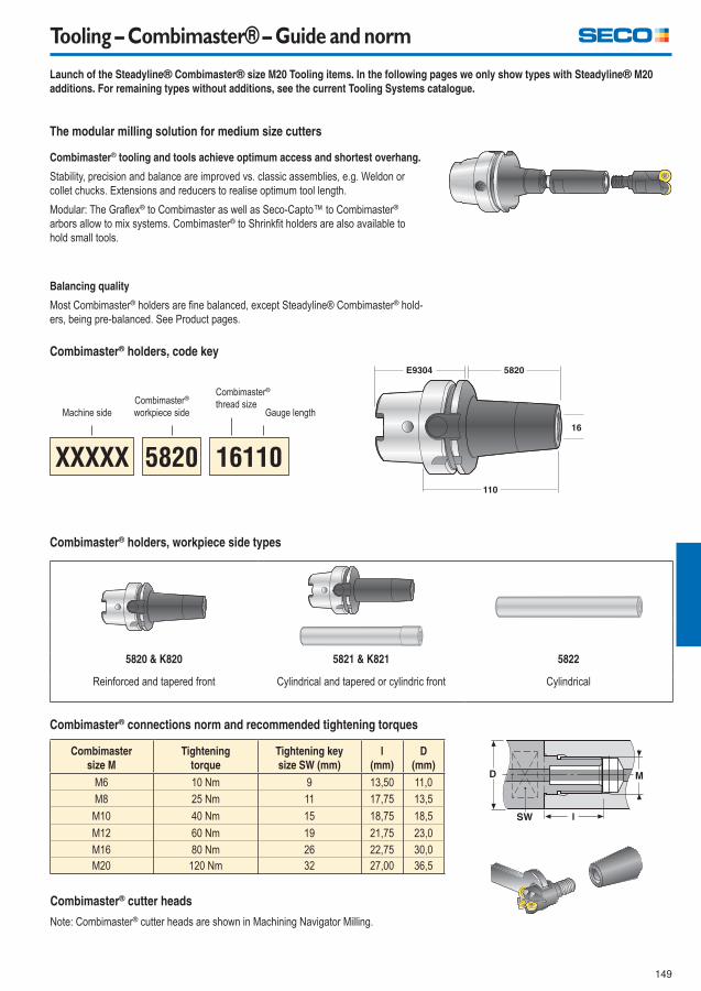
149
Tooling – Combimaster® – Guide and norm
Launch of the Steadyline® Combimaster® size M20 Tooling items. In the following pages we only show types with Steadyline® M20
additions. For remaining types without additions, see the current Tooling Systems catalogue.
The modular milling solution for medium size cutters
Combimaster® tooling and tools achieve optimum access and shortest overhang.
Stability, precision and balance are improved vs. classic assemblies, e.g. Weldon or
collet chucks. Extensions and reducers to realise optimum tool length.
Modular: The Grafl ex® to Combimaster as well as Seco-Capto™ to Combimaster®
arbors allow to mix systems. Combimaster® to Shrinkfi t holders are also available to
hold small tools.
Balancing quality
Most Combimaster® holders are fi ne balanced, except Steadyline® Combimaster® hold-
ers, being pre-balanced. See Product pages.
Combimaster® holders, code key
Machine side
Combimaster®
workpiece side
Combimaster®
thread sizeGauge length
5820 & K820 5821 & K821 5822
Reinforced and tapered front Cylindrical and tapered or cylindric front Cylindrical
Combimaster® holders, workpiece side types
Combimaster® connections norm and recommended tightening torques
Combimaster
size M
Tightening
torque
Tightening key
size SW (mm)
l
(mm)
D
(mm)
l
M6 10 Nm 9 13,50 11,0
M8 25 Nm 11 17,75 13,5
M10 40 Nm 15 18,75 18,5
M12 60 Nm 19 21,75 23,0
M16 80 Nm 26 22,75 30,0
M20 120 Nm 32 27,00 36,5
Combimaster® cutter heads
Note: Combimaster® cutter heads are shown in Machining Navigator Milling.
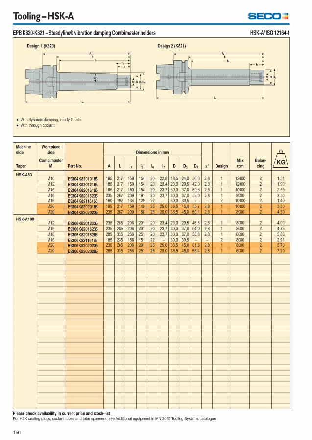
150
Tooling – HSK-A
EPB K820-K821 – Steadyline® vibration damping Combimaster holders
With dynamic damping, ready to use
With through coolant
Design 1 (K820)
HSK-A/ ISO 12164-1
Design 2 (K821)
Machine
side
Workpiece
side
Part No.
Dimensions in mm
° Design
Max
rpm
Balan-
cingTaper
Combimaster
M A L l1 l5 l6 l7 D D3 D4
HSK-A63M10 E9304K82010185 185 217 159 154 20 22,8 18,5 24,0 36,6 2,8 1 12000 2 1,51
M12 E9304K82012185 185 217 159 154 20 23,4 23,0 29,5 42,0 2,8 1 12000 2 1,90
M16 E9304K82016185 185 217 159 154 20 23,7 30,0 37,0 59,5 2,8 1 10000 2 2,59
M16 E9304K82016235 235 267 209 191 20 23,7 30,0 37,0 53,0 2,8 1 8000 2 3,50
M16 E9304K82116160 160 192 134 129 22 – 30,0 30,5 – – 2 10000 2 1,40
M20 E9304K82020185 185 217 159 140 25 29,0 36,5 45,0 55,7 2,8 1 10000 2 3,30
M20 E9304K82020235 235 267 209 186 25 29,0 36,5 45,0 60,1 2,8 1 8000 2 4,30
HSK-A100M12 E9306K82012235 235 285 206 201 20 23,4 23,0 29,5 46,6 2,8 1 8000 2 4,00
M16 E9306K82016235 235 285 206 201 20 23,7 30,0 37,0 54,0 2,8 1 8000 2 4,78
M16 E9306K82016285 285 335 256 251 20 23,7 30,0 37,0 58,8 2,8 1 6000 2 5,86
M16 E9306K82116185 185 235 156 151 22 – 30,0 30,5 – – 2 8000 2 2,91
M20 E9306K82020235 235 285 206 201 25 29,0 36,5 45,0 61,6 2,8 1 8000 2 5,70
M20 E9306K82020285 285 335 256 251 25 29,0 36,5 45,0 66,4 2,8 1 6000 2 7,20
Please check availability in current price and stock-list
For HSK sealing plugs, coolant tubes and tube spanners, see Additional equipment in MN 2015 Tooling Systems catalogue
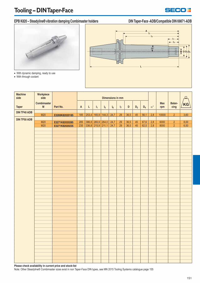
151
Tooling – DIN Taper-Face
EPB K820 – Steadyline® vibration damping Combimaster holders
Machine
side
Workpiece
side
Part No.
Dimensions in mm
°
Max
rpm
Balan-
cingTaper
Combimaster
M A L l1 l5 l6 l7 D D3 D4
DIN TF40 ADBM20 E3269K82020185 185 253,4 165,9 144,3 24,7 29 36,5 45 56,1 2,8 10000 2 3,60
DIN TF50 ADBM20 E3271K82020285 285 386,8 265,9 264,0 24,7 29 36,5 45 67,6 2,8 6000 2 8,00
M20 E3271K82020235 235 336,8 215,9 211,1 24,7 29 36,5 45 62,5 2,8 8000 2 6,50
With dynamic damping, ready to use
With through coolant
Please check availability in current price and stock-list
Note: Other Steadyline® Combimaster sizes exist in non Taper-Face DIN types, see MN 2015 Tooling Systems catalogue page 155
DIN Taper-Face -ADB/Compatible DIN 69871-ADB

152
Tooling – BT JIS Taper-Face
EPB K820 – Steadyline® vibration damping Combimaster holders
Machine
side
Workpiece
side
Part No.
Dimensions in mm
°
Max
rpm
Balan-
cingTaper
Combimaster
M A L l1 l5 l6 l7 D D3 D4
BT TF40 ADBM20 E3214K82020185 185 250,4 158 156,1 24,7 29 36,5 45 57,2 2,8 10000 2 3,70
BT TF50 ADBM20 E3216K82020235 235 336,8 197 192,2 24,7 29 36,5 45 60,7 2,8 8000 2 7,10
M20 E3216K82020285 285 386,8 247 242,2 24,7 29 36,5 45 65,5 2,8 6000 2 8,50
With dynamic damping, ready to use
With through coolant
Please check availability in current price and stock-list
Note: Other Steadyline® Combimaster sizes exist in non Taper-Face BT types, see MN 2015 Tooling Systems catalogue page 157
BT Taper-Face -ADB/Compatible BT JIS 6339-ADB
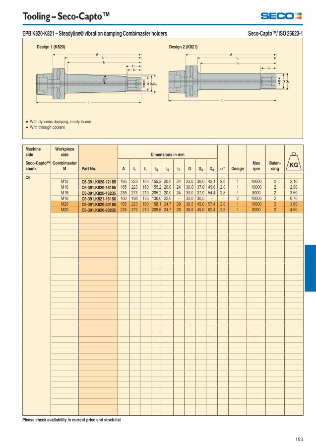
153
Tooling – Seco-Capto™
EPB K820-K821 – Steadyline® vibration damping Combimaster holders
With dynamic damping, ready to use
With through coolant
Design 1 (K820)
Seco-Capto™/ ISO 26623-1
Design 2 (K821)
Machine
side
Workpiece
side
Part No.
Dimensions in mm
° Design
Max
rpm
Balan-
cing
Seco-Capto™
shank
Combimaster
M A L l1 l5 l6 l7 D D3 D4
C6M12 C6-391.K820-12185 185 223 160 155,2 20,0 24 23,0 30,0 42,1 2,8 1 10000 2 2,10
M16 C6-391.K820-16185 185 223 160 155,2 20,0 24 30,0 37,0 49,6 2,8 1 10000 2 2,80
M16 C6-391.K820-16235 235 273 210 205,2 20,0 24 30,0 37,0 54,4 2,8 1 8000 2 3,60
M16 C6-391.K821-16160 160 198 135 130,0 22,0 – 30,0 30,5 – – 2 10000 2 0,70
M20 C6-391.K820-20185 185 223 160 158,1 24,7 29 36,5 45,0 57,4 2,8 1 10000 2 3,60
M20 C6-391.K820-20235 235 273 210 209,6 24,7 29 36,5 45,0 62,4 2,8 1 8000 2 4,60
Please check availability in current price and stock-list
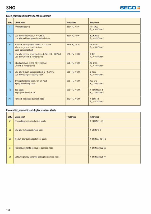
154
SMG
Steels, ferritic and martensitic stainless steels
SMG Description Properties Reference
P1 Free-cutting steels 360 < Rm < 880 11 SMn30
Rm = 385 N/mm2
P2 Low alloy ferritic steels, C < 0.25%wt
Low alloy weldable general structural steels
320 < Rm < 600 S235JRG2
Rm = 420 N/mm2
P3 Ferritic & ferritic/pearlitic steels, C < 0.25%wt
Weldable general structural steels
Case hardening steels
430 < Rm < 610 16 MnCr 5
Rm = 550 N/mm2
P4 Low alloy general structural steels, 0.25% < C < 0.67%wt
Low alloy Quench & Temper steels
520 < Rm < 1200 C 45E
Rm = 660 N/mm2
P5 Structural steels, 0.25% < C < 0.67%wt
Quench & Temper steels
550 < Rm < 1200 42 CrMo 4
Rm = 700 N/mm2
P6 Low alloy through hardening steels, C > 0.67%wt
Low alloy spring and bearing steels
520 < Rm < 1200 C 100S
Rm = 600 N/mm2
P7 Through hardening steels, C > 0.67%wt
Spring and bearing steels
600 < Rm < 1200 100 Cr 6
Rm = 650 N/mm2
P8 Tool steels
High Speed Steels (HSS)
600 < Rm < 1200 X 40 CrMoV 5 1
Rm = 700 N/mm2
P11 Ferritic & martensitic stainless steels 415 < Rm < 1200 X 20 Cr 13
Rm = 675 N/mm2
Free-cutting, austenitic and duplex stainless steels
SMG Description Properties Reference
M1 Free-cutting austenitic stainless steels X 10 CrNiS 18 9
M2 Low alloy austenitic stainless steels X 5 CrNi 18 9
M3 Medium alloy austenitic stainless steels X 2 CrNiMo 18 14 3
M4 High alloy austenitic and duplex stainless steels X 2 CrNiMoN 22 5 3
M5 Diffi cult high alloy austenitic and duplex stainless steels X 2 CrNiMoN 25 7 4
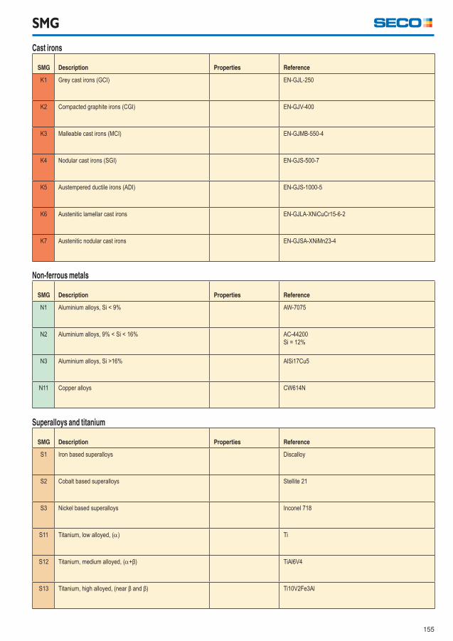
155
Cast irons
SMG Description Properties Reference
K1 Grey cast irons (GCI) EN-GJL-250
K2 Compacted graphite irons (CGI) EN-GJV-400
K3 Malleable cast irons (MCI) EN-GJMB-550-4
K4 Nodular cast irons (SGI) EN-GJS-500-7
K5 Austempered ductile irons (ADI) EN-GJS-1000-5
K6 Austenitic lamellar cast irons EN-GJLA-XNiCuCr15-6-2
K7 Austenitic nodular cast irons EN-GJSA-XNiMn23-4
SMG
Non-ferrous metals
SMG Description Properties Reference
N1 Aluminium alloys, Si < 9% AW-7075
N2 Aluminium alloys, 9% < Si < 16% AC-44200
Si = 12%
N3 Aluminium alloys, Si >16% AlSi17Cu5
N11 Copper alloys CW614N
Superalloys and titanium
SMG Description Properties Reference
S1 Iron based superalloys Discalloy
S2 Cobalt based superalloys Stellite 21
S3 Nickel based superalloys Inconel 718
S11 Titanium, low alloyed, () Ti
S12 Titanium, medium alloyed, (+β) TiAl6V4
S13 Titanium, high alloyed, (near β and β) Ti10V2Fe3Al
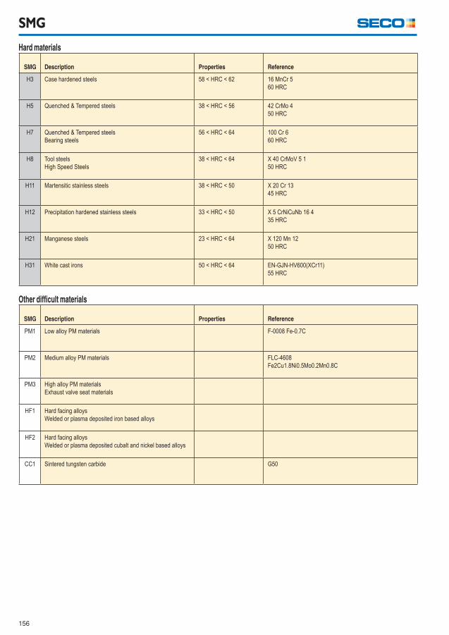
156
SMG
Hard materials
SMG Description Properties Reference
H3 Case hardened steels 58 < HRC < 62 16 MnCr 5
60 HRC
H5 Quenched & Tempered steels 38 < HRC < 56 42 CrMo 4
50 HRC
H7 Quenched & Tempered steels
Bearing steels
56 < HRC < 64 100 Cr 6
60 HRC
H8 Tool steels
High Speed Steels
38 < HRC < 64 X 40 CrMoV 5 1
50 HRC
H11 Martensitic stainless steels 38 < HRC < 50 X 20 Cr 13
45 HRC
H12 Precipitation hardened stainless steels 33 < HRC < 50 X 5 CrNiCuNb 16 4
35 HRC
H21 Manganese steels 23 < HRC < 64 X 120 Mn 12
50 HRC
H31 White cast irons 50 < HRC < 64 EN-GJN-HV600(XCr11)
55 HRC
Other diffi cult materials
SMG Description Properties Reference
PM1 Low alloy PM materials F-0008 Fe-0.7C
PM2 Medium alloy PM materials FLC-4608
Fe2Cu1.8Ni0.5Mo0.2Mn0.8C
PM3 High alloy PM materials
Exhaust valve seat materials
HF1 Hard facing alloys
Welded or plasma deposited iron based alloys
HF2 Hard facing alloys
Welded or plasma deposited cubalt and nickel based alloys
CC1 Sintered tungsten carbide G50
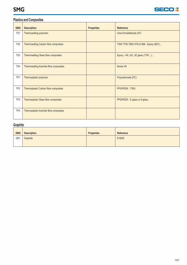
157
Plastics and Composites
SMG Description Properties Reference
TS1 Thermosetting polymers Urea formaldehyde (UF)
TS2 Thermosetting Carbon fi bre composites T300 T700 T800 HTA-S IMA - Epoxy (M21)...
TS3 Thermosetting Glass fi bre composites Epoxy - HX..(42..)/E glass (7781...)...
TS4 Thermosetting Aramide fi bre composites Kevlar 49
TP1 Thermoplastic polymers Polycarbonate (PC)
TP2 Thermoplastic Carbon fi bre composites PPS/PEEK - T300..
TP3 Thermoplastic Glass fi bre composites PPS/PEEK - E glass or A glass...
TP4 Thermoplastic Aramide fi bre composites
SMG
Graphite
SMG Description Properties Reference
GR1 Graphite R 8500
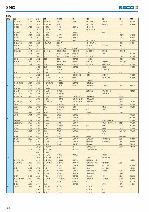
158
SMG
SMG SMG EN EN-Nr W.-Nr DIN AFNOR BS UNI JIS SS UNS
P1
11 SMn30 1.0715 1.0715 9 SMn 28 S 250 230 M 07 CF 9 SMn 28 SUM 22 1912 G12130
11 SMnPb30 1.0718 1.0718 9 SMnPb 28 S 250 Pb CF 9 SMnPb 28 SUM 22 L 1914 G12134
10 S 20 1.0721 1.0721 10 S 20 10 F 1 210 M 15 CF 10 S 20
1.0722 10 SPb 20 10 PbF 2 CF 10 SPb 20
15 SMn13 1.0725 1.0723 15 S 20 210 A 15 SUM 32 1922
35 S20 1.0726 1.0726 35 S 20 35 MF 4 212 M 36 1957 G11400
46 S20 1.0727 1.0727 46 S 20 45 MF 4 212 M 44 1973 G11460
11 SMn37 1.0736 1.0736 9 SMn 36 S 300 240 M 07 CF 9 SMn 36 G12150
11 SMnPb 37 1.0737 1.0737 9 SMnPb 36 S 300 Pb CF 9 SMnPb 36 1926 G12144
P2
S235JR 1.0037 1.0037 St 37-2 E 24-2 Fe 360 B STKM 12 C 1311
S235JRG2 1.0038 1.0116 St 37-3 E 24-3, E 24-4 4360-40 C Fe 360 D FF 1312, 1313
S275J2G3 1.0144 1.0144 St 44-3 N E 28-3, E 28-4 4360-43 C Fe 430 D FF SM 41 C 1412, 1414
C 10 1.0301 1.0301 C 10 AF 34 C 10, XC 10 045 M 10 C 10 S 10 C G10100
1.0401 C 15 AF3 7 C 12, XC 18 080 M 15 C 15, C 16 1350 G10170
C22+N 1.0402 1.0402 C 22 C 20 050 A 20 C 20, C 21 1450 G10200
S355JR 1.0570 1.0570 St 52-3 E 36-3, E 36-4 4360-50 C Fe 510 B SM 50 YA 2172, 2132
C 15R 1.1141 1.1141 Ck 15 XC 15, XC 18 080 M 15 C 15, C 16 S 15 C, S 15 CK 1370 G10170
1.1158 Ck 25 XC 25 060 A 25 C 25 S 25 C G10250
P3
1.2162 21 MnCr 5 20 NC 5 SCR 420 H
16 Mo 3 1.5415 1.5415 15 Mo 3 15 D 3 1501-240 16 Mo 3 2912
1.5423 16 Mo 5 1503-245-420 16 Mo 5 SB 450 M G45200
14 NiCr 14 1.5752 1.5752 14 NiCr 14 12 NC 15 655 M 13 SNC 815 (H) G33106
1.5919 15 CrNi 6 16 NC 6 S 107 16 CrNi 4
18 NiCrMo 7 6 1.6587 1.6587 18 CrNiMo 7 6 18 NCD 6 820 A 16 18 NiCrMo 7
16 MnCr 5 1.7131 1.7131 16 MnCr 5 16 MC 5 527 M 17 16 MnCr 5 SCR 415 2511 G51170
16 MnCrS 5 1.7139 1.7139 16 MnCrS 5
20 MnCr 5 1.7147 1.7147 20 MnCr 5 20 MC 5 20 MnCr 5 SMnC 420 (H) G51200
20 MnCrS 5 1.7149 1.7149 20 MnCrS 5 20 MnCrS 5 SMnC 21 H
13 CrMo 4 5 1.7335 1.7335 13 CrMo 4 4 15 CD 3.5 1501-620 Gr. 27 14 CrMo 4 5 2216
1.7337 16 CrMo 4 4 15 CD 4.5 1501-620 Gr. 27 14 CrMo 4 5 2216
10 CrMo 9 10 1.7380 1.7380 10 CrMo 9 10 10 CD 9.10 1501-622 Gr. 31 12 CrMo 9 10 2218 J21890
P4
C35+N 1.0501 C 35 AF 55 C 35 060 A 35 C 35 1550 G10350
E 335 1.0503 1.0503 C 45 AF 65 C 45 80 M 46 C 45 S 45 C 1650 G10430
C40+N 1.0511 C 40 AF 60 C 40 080 M 40 C 40 S 40 C
E 360 1.0070 1.0535 St 70-2 A 70-2 Fe 690 1655
C60+N 1.0601 1.0601 C 60 CC 55 080 A 62 C 60 G10600
1.1157 40 Mn 4 35 M 5 150 M 36 G10390
G 28 Mn6 1.1165 1.1165 30 Mn 5 120 M 36 SMn 1 H, SCMn 2 G13300
G 28 Mn6+QT 1.1165 1.1167 36 Mn 5 40 M 5 150 M 36 SMn 438 (H), SCMn 3 2120 G13350
C 35E 1.1181 1.1181 Ck 35 XC 38 H1 080 M 36 C 35 S 35 C 1572 G10340
C 45E 1.1191 1.1191 Ck 45 XC 42 080 M 46 C 45 S 45 C 1672 G10420
C 60E 1.1221 1.1221 Ck 60 XC 60 080 A 62 C 60 S 58 C 1665, 1678 G10640
1.1740 C 60 W Y3 55 SK 7
P5
55 SiCr7 1.7100 1.0904 55 Si 7 55 S 7 250 A 53 55 Si 8 2085, 2090
42 CrMo 4 1.7225 1.1201 42 CrMo 4 42 CD 4 708 M 40 42 CrMo 4 SCM 440 (H) 2244 G41400
42 CrMo 4 1.7225 1.1201 42 CrMo 4 42 CD 4 708 M 40 42 CrMo 4 SCM 440 (H) 2244 G41400
1.2330 35 CrMo 4 34 CD 4 708 A 37 35 CrMo 4 2234 T51620
1.2542 45 WCrV 7 BS 1 45 WCrV 8 KU 2710 T41901
1.2714 1.2714 56 NiCrMoV 7 BH 224-5 56 NiCrMoV7-KU SKT 4 T61206
1.5121 46 MnSi 4
1.5710 36 NiCr 6 35 NC 6 640 A 35 SNC 236
1.5736 36 NiCr 10 35 NC 11 35 NiCr 9 SNC 631 (H)
36CrNiMo4+TA 1.6511 36 CrNiMo 4 40 NCD 3 816 M 40 38 NiCrMo 4 (KB) G98400
34 CrNiMo 6 1.6582 1.6582 34 CrNiMo 6 35 NCD 6 817 M 40 35 NiCrMo 6 (KW) SNCM 447 2541
34 Cr 4 1.7033 1.7033 34 Cr 4 32 C 4 530 A 32 34 Cr 4 (KB) SCr 430 (H) G51320
41 Cr 4 1.7035 1.7035 41 Cr 4 42 C 4 530 M 40 41 Cr 4 SCr 440 (H) G51400
25 CrMo 4 1.7218 1.7218 25 CrMo 4 25 CD 4 S 708 M 25 25 CrMo 4 (KB) SCM 425 2225 G41300
1.7361 32 CrMo 12 30 CD 12 722 M 24 32 CrMo 12 2240
50 CrV 4 1.8159 1.8159 50 CrV 4 50 CV 4 735 A 50 51 CrV 4 SUP 10 2230 H61500
41 CrAlMo 7 10 1.8509 1.8509 41 CrAlMo 7 40 CAD 6.12 905 M 39 41 CrAlMo 7 SACM 645 2940 K24065
P6
C 67S 1.1231 1.1231 Ck 67 XC 68 060 A 67 C 70 1770 G10700
C 100S 1.1274 1.1274 Ck 101 060 A 96 SUP 4 1870 G10950
C 105U 1.1545 1.1545 C 105 W1 Y1 105 C 100 KU 1880
1.1645 C 105 W2 Y1 105 C 100 KU SK 3
1.1663 C 125 W Y2 120 C 120 KU SK 2
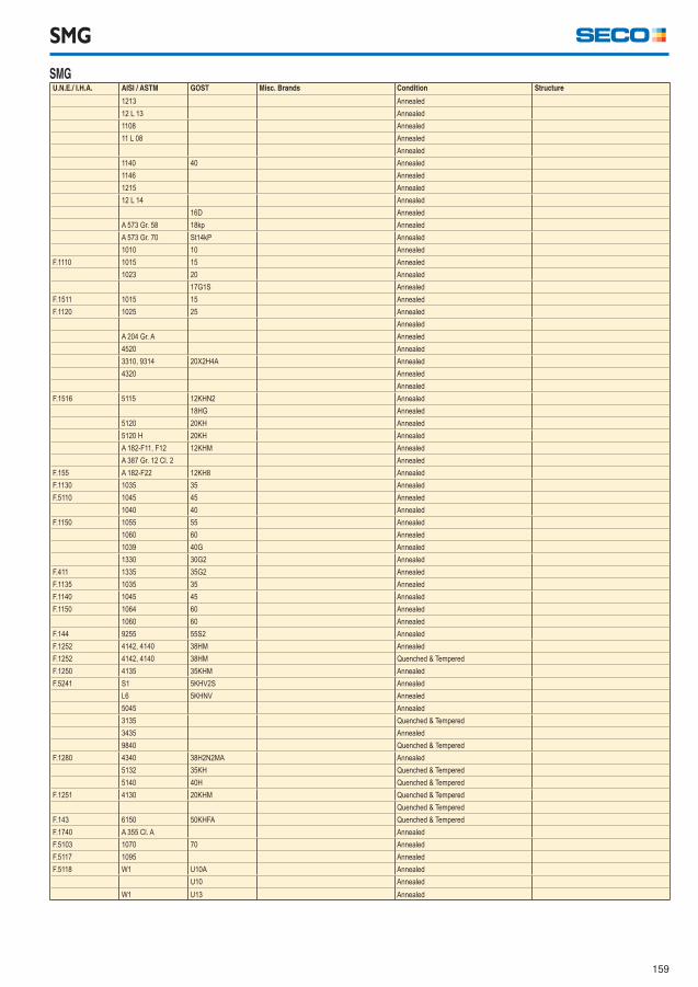
159
SMG
SMG U.N.E./ I.H.A. AISI / ASTM GOST Misc. Brands Condition Structure
1213 Annealed
12 L 13 Annealed
1108 Annealed
11 L 08 Annealed
Annealed
1140 40 Annealed
1146 Annealed
1215 Annealed
12 L 14 Annealed
16D Annealed
A 573 Gr. 58 18kp Annealed
A 573 Gr. 70 St14kP Annealed
1010 10 Annealed
F.1110 1015 15 Annealed
1023 20 Annealed
17G1S Annealed
F.1511 1015 15 Annealed
F.1120 1025 25 Annealed
Annealed
A 204 Gr. A Annealed
4520 Annealed
3310, 9314 20X2H4A Annealed
4320 Annealed
Annealed
F.1516 5115 12KHN2 Annealed
18HG Annealed
5120 20KH Annealed
5120 H 20KH Annealed
A 182-F11, F12 12KHM Annealed
A 387 Gr. 12 Cl. 2 Annealed
F.155 A 182-F22 12KH8 Annealed
F.1130 1035 35 Annealed
F.5110 1045 45 Annealed
1040 40 Annealed
F.1150 1055 55 Annealed
1060 60 Annealed
1039 40G Annealed
1330 30G2 Annealed
F.411 1335 35G2 Annealed
F.1135 1035 35 Annealed
F.1140 1045 45 Annealed
F.1150 1064 60 Annealed
1060 60 Annealed
F.144 9255 55S2 Annealed
F.1252 4142, 4140 38HM Annealed
F.1252 4142, 4140 38HM Quenched & Tempered
F.1250 4135 35KHM Annealed
F.5241 S1 5KHV2S Annealed
L6 5KHNV Annealed
5045 Annealed
3135 Quenched & Tempered
3435 Annealed
9840 Quenched & Tempered
F.1280 4340 38H2N2MA Annealed
5132 35KH Quenched & Tempered
5140 40H Quenched & Tempered
F.1251 4130 20KHM Quenched & Tempered
Quenched & Tempered
F.143 6150 50KHFA Quenched & Tempered
F.1740 A 355 Cl. A Annealed
F.5103 1070 70 Annealed
F.5117 1095 Annealed
F.5118 W1 U10A Annealed
U10 Annealed
W1 U13 Annealed
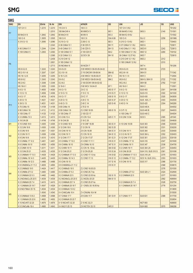
160
SMG
SMG SMG EN EN-Nr W.-Nr DIN AFNOR BS UNI JIS SS UNS
P7
107 CrV 3 1.2210 1.2210 115 CrV 3 100 C 3 107 CrV 3 KU T61202
1.2510 100 MnCrW 4 90 MWCV 5 BO 1 95 MnWCr 5 KU SKS 3 2140 T31501
90 MnCrV 8 1.2842 1.2842 90 MnCrV 8 90 MV 8 BO 2 90 MnVCr 8 KU T31502
100 Cr 6 1.3505 1.3505 100 Cr 6 100 C 6 534 A 99 100 Cr 6 SUJ 2 2258 G51986
P8
X 210 Cr 12 1.2080 1.2080 X 210 Cr 12 Z 200 C 12 BD 3 X 210 Cr 13 KU SKD 1 T30403
1.2343 X 38 CrMoV 5 1 Z 38 CDV 5 BH 11 X 37 CrMoV 5 1 KU SKD 6 T20811
X 40 CrMoV 5 1 1.2344 1.2344 X 40 CrMoV 5 1 Z 40 CDV 5 BH 13 X 40 CrMo 5 1 1 KU SKD 61 2242 T20813
X 100 CrMoV 5 1.2363 1.2363 X 100 CrMoV 5 1 Z 100 CDV 5 BA 2 X 100 CrMoV 5 1 KU SKD 12 2260 T30102
1.2365 X 32 CrMoV 3 3 32 DCV 28 BH 10 30 CrMoV 12 27 KU SKD 7 T20810
1.2436 X 210 CrW 12 X 215 CrW 12 1 KU SKD 2 2312
1.2601 X 165 CrMoV 12 X 165 CrMoW 12 KU 2310
1.2713 55 NiCrMoV 6 55 NCDV 7 SKT 4 T61206
HS 6-5-2-5 1.3243 1.3243 S 6-5-2-5 Z 85 WDKCV 06-05-05-04-02 HS 6-5-2-5 SKH 55 2723
HS 2-10-1-8 1.3247 1.3247 S 2-10-1-8 Z 110 DKCWV 09-08-04 BM 42 HS 2-9-1-8 SKH 51 T11342
HS 18-1-2-5 1.3255 1.3255 S 18-1-2-5 Z 80 WKCV 18-05-04-01 BT 4 HS 18-1-1-5 SKH 3 T12004
HS 6-5-2 1.3343 1.3343 S 6-5-2 Z 85 WDCV 06-05-04-02 BM 2 HS 6-5-2 SKH 9, SKH 51 2722 T11302
HS 2-9-2 1.3348 1.3348 S 2-9-2 Z 100 DCWV 09-04-02-02 HS 2-9-2 SKH 58 2782 T11307
HS 18-0-1 1.3355 1.3355 S 18-0-1 Z 80 WCV 18-04-01 BT 1 HS 18-0-1 SKH 2 T12001
P11
X 6 Cr 13 1.4000 1.4000 X 6 Cr 13 Z 6 C 12 403 S 17 X 6 Cr 13 SUS 403 2301 S41008
X 12 Cr 13 1.4006 1.4006 X 10 Cr 13 Z 10 C 13 410 S 21 X 12 Cr 13 SUS 410 2302 S41000
X 6 Cr 17 1.4016 1.4016 X 6 Cr 17 Z 8 C 17 430 S 15 X 8 Cr 17 SUS 430 2320 S43000
X 20 Cr 13 1.4021 1.4021 X 20 Cr 13 Z 20 C 13 420 S 37 X 20 Cr 13 SUS 420 J 1 2303 S42000
X 39 Cr 13 1.4031 1.4031 X 40 Cr 13 Z 40 C 14 420 S 45 X 40 Cr 14 SUS 420 2304 S40280
X 70 CrMo 15 1.4109 1.4109 X 65 CrMo 14 Z 70 D 14 SUS 440 A S44002
X 90 CrMoV 18 1.4112 1.4112 X 90 CrMoV 18 Z 2 CND 18 05 409 S 19 X CrTi 12 SUS 440 B 2327 S44003
X 105 CrMo 17 1.4125 1.4125 X 10⁵ CrMo 17 Z 100 CD 17 X 105 CrMo 17 SUS 440 C S44004
X 3 CrNIMo 13 3 1.4313 1.4313 X 5 CrNi 13 4 Z 5 CN 13.4 425 C 11 X 6 CrNi 13 04 SCS 5 2385 J91540
X 18 CrN 28 1.4749 1.4749 X 18 CrN 28 Z 18 C 25 2322 S44600
M1 X 10 CrNiS 18 9 1.4305 1.4305 X 10 CrNiS 18 9 Z 10 CNF 18.09 303 S 31 X 10 CrNi 18 09 SUS 303 2346 S30300
M2
X 12 CrNi 18 8 1.4300 1.4300 X 12 CrNi 18 8 Z 12 CN 18 302 S 25 SUS 302 2331 S30200
X 5 CrNi 18 9 1.4301 1.4301 X 6 CrNi 18 10 Z 6 CN 18.09 304 S 31 X 5 CrNi 18 11 SUS 304 2333 S30400
X 2 CrNi 19 11 1.4306 1.4306 X 2 CrNi 19 11 Z 2 CN 18.10 304 S 12 X 3 Cr Ni 18 11 SUS 304 L 2352 S30403
X 9 CrNi 18 8 1.4310 1.4310 X 12 CrNi 17 7 Z 12 CN 17.07 301 S 21 X 12 CrNi 17 07 SUS 301 (2331) S30100
X 5 CrNiMo 17 12 2 1.4401 1.4401 X 5 CrNiMo 17 12 2 Z 3 CND 17.11.1 316 S 31 X 5 CrNiMo 17 12 SUS 316 2347 S31600
X 6 CrNiNb 18 10 1.4550 1.4550 X 6 CrNiNb 18 10 Z 6 CNNb 18.10 347 S 31 X 6 CrNiNb 18 11 SUS 347 2338 S34700
M3
X 2 CrNiN 18 10 1.4311 1.4311 X 2 CrNiN 19 11 Z 2 CN 18 .10 Az 304 S 62 X 2 CrNiN 18 11 SUS 304 LN 2371 S30453
X 12 CrNi 25 21 1.4335 1.4335 X 12 CrNi 25 21 Z 12 CN 25.20 310 S 24 X 6 CrNi 26 20 SUH 310, SUS 310 S 2361 S31008
X 2 CrNiMoN 17 13 3 1.4429 1.4429 X 2 CrNiMoN 17 13 3 Z 2 CND 17.13 Az 316 S 62 X 2 CrNiMoN 17 13 3 SUS 316 LN 2375 S31653
X 2 CrNiMo 18 14 3 1.4435 1.4435 X 2 CrNiMo 18 14 3 Z 2 CND 17.13 316 S 12 X 2 CrNiMo 17 13 2 SCS 16, SUS 316 L 2353 S31603
X 3 CrNiMo 18 12 3 1.4466 1.4466 X 5 CrNi 18 15 317 S 16 X 5 CrNi 18 15 SUS 317 2366 S31700
X 9 CrNiSiNCe 21 11 2 1.4835 1.4893 X 9 CrNiSiNCe 21 11 2 310 S 31 2368 S30815
M4
X 2 CrNiMoSi 19 5 1.4424 1.4417 X 2 CrNiMoSi 19 5 Z 2 CND 18.05.03 2376 S31500
X 3 CrNiMo 27 5 2 1.4460 1.4460 X 4 CrNiMo 27 5 2 Z 3 CND 25.7 Az X 3 CrNiMo 27 5 2 SUS 329 J 1 2324 S32900
X 2 CrNiMoN 22 5 3 1.4462 1.4462 X 2 CrNiMoN 22 5 Z 2 CND 22.05 Az 332 S 15 X 2 CrNiMoN 22 5 2377 S31803
X 2 NiCrMoCu 25 20 5 1.4539 1.4539 X 2 NiCrMoCu 25 20 5 Z 2 NCDU 25 20 904 S 13 2562 N08904
M5
X 2 CrNiMoN 25 7 4 1.4410 1.4410 X 2 CrNiMoN 25 7 4 Z 3 CND 25.07 Az X 2 CrNiMoN 25 7 4 2328 S32750
X 1 CrNiMoN 20 18 7 1.4547 1.4529 X 1 CrNiMoN 20 18 7 Z 1 CNDU 20.18.05 Az X 1 CrNiMoN 20 18 7 2778 S31254
X 6 NiCrTiMoV 25 15 1.4534 1.4534 X 3 CrNiMoAl 13 8 2 S13800
1.4540 1.4540 X 4 CrNiCuNb 16 4 Z 4 CNUNb 16.4 M S15500
X 3 CrNiMoAl 13 8 2 1.4568 1.4568 X 7 CrNiAl 17 7 Z 9 CAN 17.7 301 S 81 X 7 CrNiAl 17 7 SUS 631 2388 S17700
X 1 CrNiMoN 25 22 8 1.4652 1.4652 X 2 CrNiMoN 25 22 7 S32654
X 10 NiCrAlTi 32 20 1.4876 1.4876 X 10 NiCrAlTi 32 20 Z 10 NC 32.21 NCF 800 N08800
X 5 CrNiCuNb 16 4 1.4980 1.4943 X 4 NiCrTi 25 15 Z 6 NCTDV 25.15 HR 51 SUH 660 2570 S66286
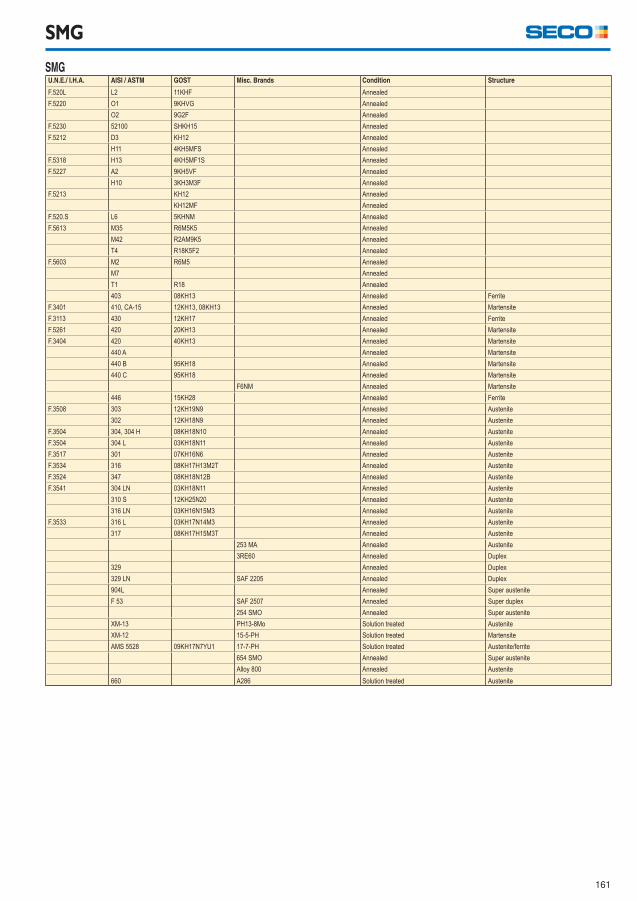
161
SMG
SMG U.N.E./ I.H.A. AISI / ASTM GOST Misc. Brands Condition Structure
F.520L L2 11KHF Annealed
F.5220 O1 9KHVG Annealed
O2 9G2F Annealed
F.5230 52100 SHKH15 Annealed
F.5212 D3 KH12 Annealed
H11 4KH5MFS Annealed
F.5318 H13 4KH5MF1S Annealed
F.5227 A2 9KH5VF Annealed
H10 3KH3M3F Annealed
F.5213 KH12 Annealed
KH12MF Annealed
F.520.S L6 5KHNM Annealed
F.5613 M35 R6M5K5 Annealed
M42 R2AM9K5 Annealed
T4 R18K5F2 Annealed
F.5603 M2 R6M5 Annealed
M7 Annealed
T1 R18 Annealed
403 08KH13 Annealed Ferrite
F.3401 410, CA-15 12KH13, 08KH13 Annealed Martensite
F.3113 430 12KH17 Annealed Ferrite
F.5261 420 20KH13 Annealed Martensite
F.3404 420 40KH13 Annealed Martensite
440 A Annealed Martensite
440 B 95KH18 Annealed Martensite
440 C 95KH18 Annealed Martensite
F6NM Annealed Martensite
446 15KH28 Annealed Ferrite
F.3508 303 12KH19N9 Annealed Austenite
302 12KH18N9 Annealed Austenite
F.3504 304, 304 H 08KH18N10 Annealed Austenite
F.3504 304 L 03KH18N11 Annealed Austenite
F.3517 301 07KH16N6 Annealed Austenite
F.3534 316 08KH17H13M2T Annealed Austenite
F.3524 347 08KH18N12B Annealed Austenite
F.3541 304 LN 03KH18N11 Annealed Austenite
310 S 12KH25N20 Annealed Austenite
316 LN 03KH16N15M3 Annealed Austenite
F.3533 316 L 03KH17N14M3 Annealed Austenite
317 08KH17H15M3T Annealed Austenite
253 MA Annealed Austenite
3RE60 Annealed Duplex
329 Annealed Duplex
329 LN SAF 2205 Annealed Duplex
904L Annealed Super austenite
F 53 SAF 2507 Annealed Super duplex
254 SMO Annealed Super austenite
XM-13 PH13-8Mo Solution treated Austenite
XM-12 15-5-PH Solution treated Martensite
AMS 5528 09KH17N7YU1 17-7-PH Solution treated Austenite/ferrite
654 SMO Annealed Super austenite
Alloy 800 Annealed Austenite
660 A286 Solution treated Austenite
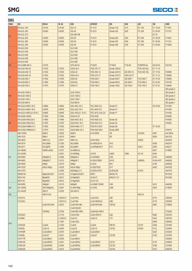
162
SMG
SMG SMG EN EN-Nr W.-Nr DIN AFNOR BS UNI JIS SS UNS
K1
EN-GJL-150 0.6150 0.6150 GG-15 Ft 15 D Grade 150 G15 FC 150 01 15-00 F11601
EN-GJL-200 0.6200 0.6200 GG-20 Ft 20 D Grade 220 G20 FC 200 01 20-00 F12101
EN-GJL-215 GG-220 HB 02 19
EN-GJL-250 0.6250 0.6250 GG-25 Ft 25 D Grade 260 G25 FC 250 01 25-00 F12401
EN-GJL-300 0.6300 0.6300 GG-30 Ft 30 D Grade 300 G30 FC 300 01 30-00 F13101
EN-GJL-350 0.6350 0.6350 GG-35 Ft 35 D Grade 350 G35 FC 350 01 35-00 F13502
K2
EN-GJV-300 GJV-300
EN-GJV-350 GJV-350
EN-GJV-400 GJV-400
EN-GJV-450 GJV-450
EN-GJV-500 GJV-500
K3 EN-GJMB-550-4 0.8155 GTS-55-04 P 540/5 P 540/5 P 55-04 PCMP55-04 08 54-00 F24130
K4
EN-GJS-350-22 0.7033 0.7033 GGG-35.3 FGS 370-17 Grade 350/22 FCD 350-22L 07 17-15
EN-GJS-400-15 0.7040 0.7040 GGG-40 FGS 400-12 Grade 420/12 GS 400-12 FCD 400-18L 07 17-02 F32800
EN-GJS-400-18 0.7043 0.7043 GGG-40.3 FGS-370-17 Grade 370/17 GSO 42/17 07 17-12 F32800
EN-GJS-500-7 0.7050 0.7050 GGG-50 FGS 500-7 Grade 500/7 GS 500-7 FCD 500-7 07 27-02 F33800
EN-GJS-600-3 0.7060 0.7060 GGG-60 FGS 600-3 Grade 600/3 GS 600-3 FCD 600-3 07 32-03 F34100
EN-GJS-700-2 0.7070 0.7070 GGG-70 FGS 700-2 Grade 700/2 GS 700-2 FCD 700-2 07 37-01 F34800
K5
- ADI grade 5
EN-GJS-1000-5 GJS-1000-5 ADI grade 2
EN-GJS-1200-2 GJS-1200-2 ADI grade 3
EN-GJS-1400-1 GJS-1400-1 ADI grade 4
EN-GJS-800-8 GJS-800-8 ADI grade 1
K6
EN-GJLA-XNiCr 20-2 0.6660 0.6660 GGL-NiCr 20 2 FGL Ni20 Cr2 Grade F2 05 23-00 F41002
EN-GJLA-XNiCr 30-3 0.6676 0.6676 GGL-NiCr 30 3 FGL Ni30 Cr3 Grade F3 F41004
EN-GJLA-XNiCuCr15-6-2 0.6655 0.6655 GGL-NiCuCr 15 6 2 FGL Ni15 Cu6 Cr2 Grade F1 F41000
K7
EN-GJSA-XNi35 0.7683 0.7683 GGG-Ni 35 FGS Ni35 F43006
EN-GJSA-XNiCr20-2 0.7660 0.7660 GGG-NiCr 20 2 FGS Ni20 Cr2 Grade S2 F43000
EN-GJSA-XNiCr30-3 0.7676 0.7676 GGG-NiCr 30 3 FGS Ni30 Cr3 Grade S3 F43003
EN-GJSA-XNiMn13-7 0.7652 0.7652 GGG-NiMn 13 7 FGS Ni13 Mn7 Grade S6 07 72-00 -
EN-GJSA-XNiMn23-4 0.7673 0.7673 GGG-NiMn 23 4 FGS Ni23 Mn4 Grade S2M F43010
N1
AW-1050A Al99.5 3.0255 Al99.5 A-5/1050A 1B (A1050) 4007 AA1050A
AW-3103 AlMn1 3.0515 AlMn1 N3 4054 AA3103
AW-3003 AlMn1Cu 3.0517 AlMn1Cu A-M1/3003 A3003 AA3003
AW-2014 AlCuSiMn 3.1255 AlCuSiMn A-U4SG/2014 H15 4338 AA2014
AW-2011 AlCuBiPb 3.1655 AlCuBiPb A-U5PbBi/2011 FC1 A2011 4355 AA2011
AC-46200 AlSi8Cu3(Si) 3.2161 G-AlSi8Cu3 4251 A13800
AC-42000 3.2341 G-AlSi5Mg A-S7G LM25 3599 AC 4C 4244
AW-6060 AlMgSi0.5 3.3206 AlMgSi0.5 A-GS/6060 (H9) 4103 AA6060
AW-6063 AlMgSi0.7 3.3210 AlMgSi0.7 A-GSUC/6061 (H10) (A6063) 4104,4107 AA6005
AW-5005 AlMg1 3.3315 AlMg1 A-G0.6 N41 4106 AA5005
AW-7020 AlZn4.5Mg1 3.4335 AlZn4.5Mg1 A-Z5G/7020 H17 4425 AA7020
AW-7075 3.4365 AlZnMgCu1.5 A-Z5GU/7075 2L95/2L96 A7075 AA7075
MN65120 MgSe3Zn2Zr1 3.5103 G-MgSe3Zn2Zr1 ZRE1 MAG6-TE M12330
MG-P-63 MgAl6Zn 3.5612 G-MgAl6Zn G-A6-Z1 MAG-E-121 M11600
MG-P-61 MgAl8Zn 3.5812 G-MgAl8Zn (G-A7-Z1)
N2
AW-6082 AlMgSi1 3.2315 AlMgSi1 A-SGM0.7/6082 H30 4212 AA6082
AC-43400 AlSi10Mg(Fe) 3.2381 G-AlSi10Mg A-S10G LM9 4253 A13600
AC-44200 AlSi12 3.2382 GD-AlSi12
N3 AlSi17Cu5 ADC14
N11
CC331G 2.0940.01 CuAl10Fe CuAl10Fe AB1 5710 C95200
CC333G 2.0975.01 CuAl10Ni CuAl10Ni5Fe5 AB2 5716 C95500
CuNi10Fe1Mn 2.0872 CuNi10Fe1Mn CuNi10Fe1Mn CN102 5667 C70600
CuNi10Zn45
CW408J 2.0790 CuNi18Zn19Pb CuNi18Zn19Pb1 C76300
CW352H 2.1176 CuPb10Sn CuSn10Pb10 LB2 5640 C93700
CC480K 2.1050.01 CuSn10 CuSn10 CT1 5443 C90700
2.1087 CuSn10Zn 5458 C90500
CW452K CuSn6 2.1020 CuSn6 CuSn6 PB103 C5191 5428 C51900
CW502L CuZn15 2.0240 CuZn15 CuZn15 CZ102 C2300 5112 C23000
CW706R CuZn28Sn1 2.0470 CuZn28Sn1 CuZn29Sn1 5220 C44300
CW508L CuZn37 2.0321 CuZn37 CuZn37 CZ108 5150 C27200
CW717R CuZn38Sn1 2.0530 CuZn38Sn1 C46400
CW614N CuZn39Pb3 2.0401 CuZn39Pb3 CuZn39Pb3 CZ121 5170 C38500
CW612N CuZn40Pb2 2.0402 CuZn40Pb2 CuZn39Pb2 CZ120 5168 C37800
CW622N CuZn44Pb2 2.0410 CuZn44Pb2 CZ104 5272 C68700
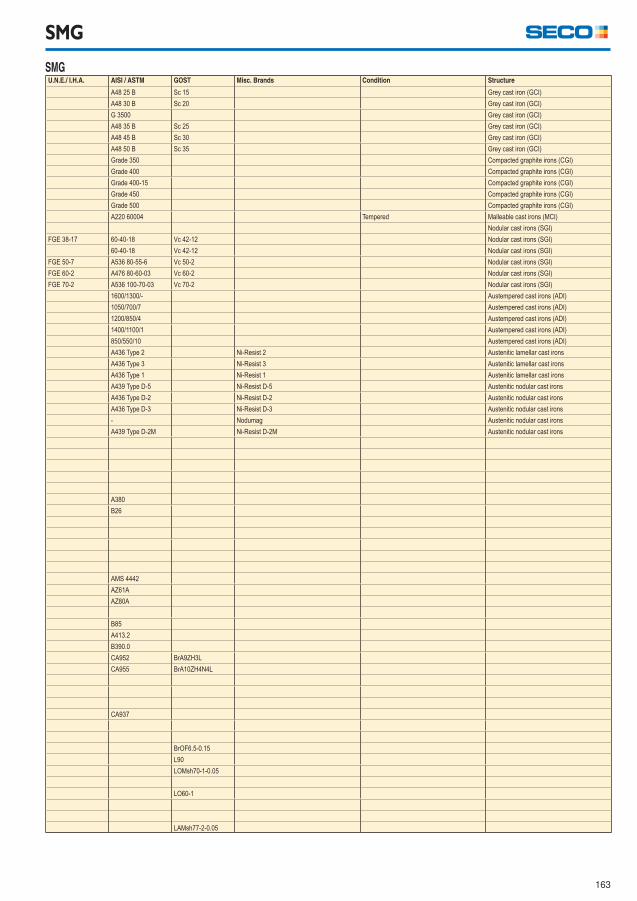
163
SMG
SMG U.N.E./ I.H.A. AISI / ASTM GOST Misc. Brands Condition Structure
A48 25 B Sc 15 Grey cast iron (GCI)
A48 30 B Sc 20 Grey cast iron (GCI)
G 3500 Grey cast iron (GCI)
A48 35 B Sc 25 Grey cast iron (GCI)
A48 45 B Sc 30 Grey cast iron (GCI)
A48 50 B Sc 35 Grey cast iron (GCI)
Grade 350 Compacted graphite irons (CGI)
Grade 400 Compacted graphite irons (CGI)
Grade 400-15 Compacted graphite irons (CGI)
Grade 450 Compacted graphite irons (CGI)
Grade 500 Compacted graphite irons (CGI)
A220 60004 Tempered Malleable cast irons (MCI)
Nodular cast irons (SGI)
FGE 38-17 60-40-18 Vc 42-12 Nodular cast irons (SGI)
60-40-18 Vc 42-12 Nodular cast irons (SGI)
FGE 50-7 A536 80-55-6 Vc 50-2 Nodular cast irons (SGI)
FGE 60-2 A476 80-60-03 Vc 60-2 Nodular cast irons (SGI)
FGE 70-2 A536 100-70-03 Vc 70-2 Nodular cast irons (SGI)
1600/1300/- Austempered cast irons (ADI)
1050/700/7 Austempered cast irons (ADI)
1200/850/4 Austempered cast irons (ADI)
1400/1100/1 Austempered cast irons (ADI)
850/550/10 Austempered cast irons (ADI)
A436 Type 2 Ni-Resist 2 Austenitic lamellar cast irons
A436 Type 3 Ni-Resist 3 Austenitic lamellar cast irons
A436 Type 1 Ni-Resist 1 Austenitic lamellar cast irons
A439 Type D-5 Ni-Resist D-5 Austenitic nodular cast irons
A436 Type D-2 Ni-Resist D-2 Austenitic nodular cast irons
A436 Type D-3 Ni-Resist D-3 Austenitic nodular cast irons
- Nodumag Austenitic nodular cast irons
A439 Type D-2M Ni-Resist D-2M Austenitic nodular cast irons
A380
B26
AMS 4442
AZ61A
AZ80A
B85
A413.2
B390.0
CA952 BrА9ZH3L
CA955 BrА10ZH4N4L
CA937
BrOF6.5-0.15
L90
LOMsh70-1-0.05
LO60-1
LАMsh77-2-0.05
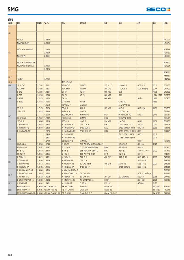
164
SMG
SMG SMG EN EN-Nr W.-Nr DIN AFNOR BS UNI JIS SS UNS
S1
S2
S3
NiMo30 2.4810 N10002
NiMo16Cr15W 2.4819 N10276
NiCr19Fe19Nb5Mo3 2.4668 N07718
2.4669 N07750
NiCr20TiAl 2.4631 N07080
NiCr19Co18Mo4Ti3Al3 N07500
NiCr20Co13Mo4Ti3Al 2.4654 N07001
S113.7024
R54620
S12R56320
TiAl6V4 3.7164 R56400
S13 TiV10Fe2Al3
H3 16 MnCr 5 1.7131 1.7131 16 MnCr 5 16 MC 5 527 M 17 16 MnCr 5 SCR 415 2511 G51170
H5
42 CrMo 4 1.7225 1.1201 42 CrMo 4 42 CD 4 708 M40 42 CrMo 4 SCM 440 (H) 2244 G41400
C 67S 1.1231 1.1231 Ck 67 XC 68 060 A 67 C 70 1770 G10700
C 75S 1.1248 1.1248 Ck 75 XC 75 060 A 78 C 75 1774, 1778 G10780
C 100S 1.1274 1.1274 Ck 101 060 A 96 SUP 4 1870 G10950
C 105U 1.1545 1.1545 C 105 W1 Y1 105 C 100 KU 1880
1.2550 60 WCrV 7 55 WC 20 55 WCrV 8 KU
55 Cr 3 1.7176 1.7176 55 Cr 3 55 C 3 527 A 60 55 Cr 3 SUP 9 (A) 2253 G51550
H7
107 CrV 3 1.2210 1.2210 115 CrV 3 100 C 3 107 CrV 3 KU T61202
1.2510 100 MnCrW 4 90 MWCV 5 BO 1 95 MnWCr 5 KU SKS 3 2140 T31501
90 MnCrV 8 1.2842 1.2842 90 MnCrV 8 90 MV 8 BO 2 90 MnVCr 8 KU T31502
100 Cr 6 1.3505 1.3505 100 Cr 6 100 C 6 534 A 99 100 Cr 6 SUJ 2 2258 G51986
H8
X 40 CrMoV 5 1 1.2344 1.2344 X 40 CrMoV 5 1 Z 40 CDV 5 BH 13 X 40 CrMo 5 1 1 KU SKD 61 2242 T20813
X 100 CrMoV 5 1.2363 1.2363 X 100 CrMoV 5 1 Z 100 CDV 5 BA 2 X 100 CrMoV 5 1 KU SKD 12 2260 T30102
X 155 CrVMo 12 1 1.2379 X 155 CrVMo 12 1 Z 160 CDV 12 BD 2 X 155 CrVMo 12 1 KU SKD 11 T30402
1.2436 X 210 CrW 12 X 215 CrW 12 1 KU SKD 2 2312
1.2601 X 165 CrMoV 12 X 165 CrMoW 12 KU 2310
1.2713 55 NiCrMoV 6 55 NCDV 7 SKT 4 T61206
HS 6-5-2-5 1.3243 1.3243 S 6-5-2-5 Z 85 WDKCV 06-05-05-04-02 HS 6-5-2-5 SKH 55 2723
HS 2-10-1-8 1.3247 1.3247 S 2-10-1-8 Z 110 DKCWV 09-08-04 BM 42 HS 2-9-1-8 SKH 51 T11342
HS 6-5-2 1.3343 1.3343 S 6-5-2 Z 85 WDCV 06-05-04-0 BM 2 HS 6-5-2 SKH 9, SKH 51 2722 T11302
HS 18-0-1 1.3355 1.3355 S 18-0-1 Z 80 WCV 18-04-01 BT 1 HS 18-0-1 SKH 2 T12001
H11
X 20 Cr 13 1.4021 1.4021 X 20 Cr 13 Z 20 C 13 420 S 37 X 20 Cr 13 SUS 420 J 1 2303 S42000
X 70 CrMo 15 1.4109 1.4109 X 65 CrMo 14 Z 70 D 14 SUS 440 A S44002
X 90 CrMoV 18 1.4112 1.4112 X 90 CrMoV 18 Z 2 CND 18 05 409 S 19 X CrTi 12 SUS 440 B 2327 S44003
X 105 CrMo 17 1.4125 1.4125 X 10⁵ CrMo 17 Z 100 CD 17 X 105 CrMo 17 SUS 440 C S44004
H12
X 3 CrNiMoAl 13 8 2 1.4534 1.4534 X 3 CrNiMoAl 13 8 2 S13800
X 5 CrNiCuNb 16 4 1.4548 1.4542 X 5 CrNiCuNb 17 4 Z 6 CNU 17.4 SCS 24, SUS 630 S17400
X 7 CrNiAl 17 7 1.4568 1.4568 X 7 CrNiAl 17 7 Z 9 CAN 17.7 301 S 81 X 7 CrNiAl 17 7 SUS 631 2388 S17700
X 6 NiCrTiMoV 25 15 1.4980 1.4943 X 4 NiCrTi 25 15 Z 6 NCTDV 25.15 HR 51 SUH 660 2570 S66286
H21 X 120 Mn 12 1.3401 1.3401 X 120 Mn 12 Z 120 M 12 BW 10 SC MnH 1 2183
H31
EN-GJN-HV520 0.9620 G-X330 NiCr 4 2 FB Ni4 Cr2 BC Grade 2 A Grade 2 A 05 12-00 F45001
EN-GJN-HV550 0.9625 G-X260 NiCr 4 2 FB Ni4 Cr2 HC Grade 2 B Grade 2 B 05 13-00 F45000
EN-GJN-HV600(XCr11) 0.9630 G-X300 CrNiSi 9 5 2 FB Cr9 Ni5 Grade 2 C, D, E Grade 2 C, D, E 04 57-00 F45003
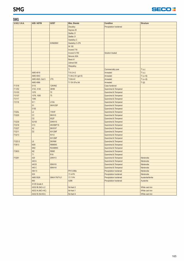
165
SMG
SMG U.N.E./ I.H.A. AISI / ASTM GOST Misc. Brands Condition Structure
Discalloy Precipitation hardened
Haynes 25
Stellite 21
Stellite 31
Hastelloy C
KHN65MV Hastelloy C-276
IN 100
Inconel 718
Inconel X-750 Solution treated
Nimonic 80A
René 41
Udimet 500
Waspalloy
Ti Commercially pure Ti ()
AMS 4919 Ti 6-2-4-2 Annealed Ti ()
AMS 4943 Ti 3Al-2.5V (grd 9) Annealed Ti (+β)
AMS 4920, Grd 5 VT6 Ti 6Al-4V Annealed Ti (+β)
AMS 4986 Ti 10V-2Fe-3Al Annealed Ti (β)
F.1516 5115 12KHN2 Case hardened
F.1252 4142, 4140 38HM Quenched & Tempered
F.5103 1070 70 Quenched & Tempered
F.5107 1078, 1080 75 Quenched & Tempered
F.5117 1095 Quenched & Tempered
F.5118 W 1 U10A Quenched & Tempered
S1 5KHV2SF Quenched & Tempered
5155 Quenched & Tempered
F.520L L2 11KHF Quenched & Tempered
F.5220 O1 9KHVG Quenched & Tempered
O2 9G2F Quenched & Tempered
F.5230 52100 SHKH15 Quenched & Tempered
F.5318 H13 4KH5MF1S Quenched & Tempered
F.5227 A2 9KH5VF Quenched & Tempered
F.5211 D2 KH12MF Quenched & Tempered
F.5213 KH12 Quenched & Tempered
KH12MF Quenched & Tempered
F.520.S L6 5KHNM Quenched & Tempered
F.5613 M35 R6M5K5 Quenched & Tempered
M42 R2AM9K5 Quenched & Tempered
F.5603 M2 R6M5 Quenched & Tempered
T1 R18 Quenched & Tempered
F.5261 420 20KH13 Quenched & Tempered Martensite
440 A Quenched & Tempered Martensite
440 B 95KH18 Quenched & Tempered Martensite
440 C 95KH18 Quenched & Tempered Martensite
XM-13 PH13-8Mo Precipitation hardened Martensite
630 17-4-PH Precipitation hardened Martensite
AMS 5528 09KH17N7YU1 17-7-PH Precipitation hardened Austenite/ferrite
660 A286 Precipitation hardened Austenite
A128 Grade A
A532 IB (NiCr-LC Ni-Hard 2 White cast iron
A532 IA (NiCr-HC) Ni-Hard 1 White cast iron
A532 ID (Ni-HiCr) Ni-Hard 4 White cast iron
166
Declaration of conformity
Cemented carbide inserts and insert carriers
Cemented carbide inserts and cemented carbide insert carriers from Seco Tools are not included in the product range intended for the following
requirements. Nevertheless Seco Tools can make the following declaration.
These products meet all requirements in RoHS (Restriction of the use of certain Hazardous Substances in electrical and electronic equipment),
WEEE (Waste Electrical & Electronic Equipment) and ELV (End of Life Vehicles) requirements.
Products do not contain mercury, lead, hexavalent chromium, cadmium, CFC, HCFC, fl ame retardants or solvents in concentrations that exceed
specifi cations in the regulations.
Regrinding:
Wet or dry grinding can produce potentially hazardous dusts or mists that can irritate skin, eyes, nose, throat and result in lung damage or disease.
To avoid injury use proper safety precautions and protective equipment.
Disposal:
Seco Tools will buy back used inserts and solid carbide tools for recycling. Inserts and solid carbide tools should be separated from other metal
waste (steel, aluminium, copper etc).
All packing material is fully recyclable.
CBN and PCD inserts
Inserts from Seco Tools are not included in the product range intended for the following requirements. Nevertheless Seco Tools can make the
following declaration.
This product meets all requirements in RoHS (Restriction of the use of certain Hazardous Substances in electrical and electronic equipment),
WEEE (Waste Electrical & Electronic Equipment) and ELV (End of Life Vehicles) requirements.
Products do not contain mercury, lead, hexavalent chromium, cadmium, CFC, HCFC, fl ame retardants or solvents in concentrations that exceed
specifi cations in the regulations.
Regrinding:
Wet or dry grinding can produce potentially hazardous dusts or mists that can irritate skin, eyes, nose, throat and result in lung damage or disease.
To avoid injury use proper safety precautions and protective equipment.
Disposal:
Seco Tools will buy back used CBN- or PCD-tipped inserts for recycling. Inserts should be separated from other metal waste (steel, aluminium,
copper etc). Solid CBN-inserts may be discarded as landfi ll waste.
All packing material is fully recyclable.
Black oxide insert carriers
Insert carriers from Seco Tools are not included in the product range intended for the following requirements. Nevertheless Seco Tools can make
the following declaration.
This product meets all requirements in RoHS (Restriction of the use of certain Hazardous Substances in electrical and electronic equipment),
WEEE (Waste Electrical & Electronic Equipment) and ELV (End of Life Vehicles) requirements.
Products do not contain mercury, lead, hexavalent chromium, cadmium, CFC, HCFC, fl ame retardants or solvents in concentrations that exceed
specifi cations in the regulations.
Disposal:
Used insert carriers may be sent for recycling together with ordinary steel waste (swarf and discarded steel scrap) for recycling.
All packing material is fully recyclable.
167
Declaration of conformity
Cermet inserts
Inserts from Seco Tools are not included in the product range intended for the following requirements. Nevertheless Seco Tools can make the
following declaration.
This product meets all requirements in RoHS (Restriction of the use of certain Hazardous Substances in electrical and electronic equipment),
WEEE (Waste Electrical & Electronic Equipment) and ELV (End of Life Vehicles) requirements.
Cermet grade C15M inserts do contain nickel and will leach nickel when in contact with the skin. Amount of leaching is higher than specifi ed in
norm SS-EN 1811 Reference test method for release of nickel from products intended to come into direct and prolonged contact with the skin.
These norms are intended for products that are in direct and prolonged contact with the skin and are therefore not directly applicable for cermet
inserts. Persons with known allergic reactions to nickel are advised to wear protective gloves when handling cermet inserts.
Regrinding:
Wet or dry grinding can produce potentially hazardous dusts or mists that can irritate skin, eyes, nose, throat and result in lung damage or disease.
To avoid injury use proper safety precautions and protective equipment.
Disposal:
Used inserts may be recycled. Inserts should be separated from other metal waste (steel, aluminium, copper, etc) including cemented carbide
inserts.
All packing material is fully recyclable.
Nickel coated insert carriersInsert carriers from Seco Tools are not included in the product range intended for the following requirements. Nevertheless Seco Tools can make
the following declaration.
This product meets all requirements in RoHS (Restriction of the use of certain Hazardous Substances in electrical and electronic equipment),
WEEE (Waste Electrical & Electronic Equipment) and ELV (End of Life Vehicles) requirements.
Products do not contain mercury, lead, hexavalent chromium, cadmium, CFC, HCFC, fl ame retardants or solvents in concentrations that exceed
specifi cations in the regulations.
Insert carriers do contain nickel and will leach nickel when in contact with the skin. Amount of leaching is not higher then norm SS-EN 1811 Refer-
ence test method for release of nickel from products intended to come into direct and prolonged contact with the skin.
These norms are intended for products that are in direct and prolonged contact with the skin and are therefore not directly applicable for insert
carriers. Persons with known allergic reactions to nickel are advised to wear protective gloves when handling nickel coated insert carriers.
Disposal:
Used tools maybe sent for recycling together with ordinary steel waste (swarf and discarded steel scrap) for recycling.
All packing material is fully recyclable.
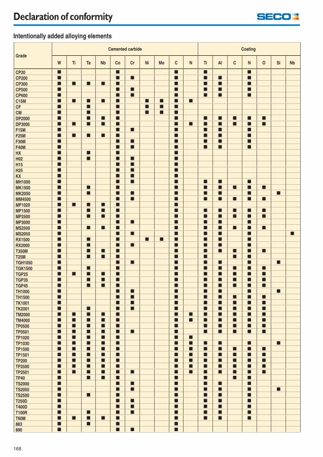
168
Declaration of conformity
Grade
Cemented carbide Coating
W Ti Ta Nb Co Cr Ni Mo C N Ti Al C N O Si Nb
CP20 [ [ [ [ [
CP200 [ [ [ [ [ [ [
CP300 [ [ [ [ [ [ [ [ [
CP500 [ [ [ [ [ [ [
CP600 [ [ [ [ [ [ [
C15M [ [ [ [ [ [ [ [ [
CF [ [ [ [ [ [
CM [ [ [ [ [ [
DP2000 [ [ [ [ [ [ [ [ [ [
DP3000 [ [ [ [ [ [ [ [ [ [ [ [
F15M [ [ [ [ [ [ [
F25M [ [ [ [ [ [ [ [ [
F30M [ [ [ [ [ [ [
F40M [ [ [ [ [ [ [
HX [ [ [ [
H02 [ [ [ [ [
H15 [ [ [ [
H25 [ [ [ [
KX [ [ [ [
MH1000 [ [ [ [ [ [ [
MK1500 [ [ [ [ [ [ [ [ [
MK2050 [ [ [ [ [ [ [ [ [
MM4500 [ [ [ [ [ [ [ [ [
MP1020 [ [ [ [ [ [
MP1500 [ [ [ [ [ [ [ [ [ [
MP2500 [ [ [ [ [ [ [ [ [ [
MP3000 [ [ [ [ [ [ [
MS2500 [ [ [ [ [ [ [ [ [ [
MS2050 [ [ [ [ [ [ [ [
RX1500 [ [ [ [ [ [ [ [ [
RX2000 [ [ [ [ [ [ [ [
T350M [ [ [ [ [ [ [ [ [ [
T25M [ [ [ [ [ [ [ [
TGH1050 [ [ [ [ [ [ [ [
TGK1500 [ [ [ [ [ [ [ [ [
TGP25 [ [ [ [ [ [ [ [ [ [ [
TGP35 [ [ [ [ [ [ [ [ [ [
TGP45 [ [ [ [ [ [ [ [ [ [
TH1000 [ [ [ [ [ [ [ [
TH1500 [ [ [ [ [ [ [ [ [
TK1001 [ [ [ [ [ [ [ [ [
TK2001 [ [ [ [ [ [ [ [ [ [
TM2000 [ [ [ [ [ [ [ [ [ [ [ [
TM4000 [ [ [ [ [ [ [ [ [ [ [ [
TP0500 [ [ [ [ [ [ [ [ [ [ [
TP0501 [ [ [ [ [ [ [ [ [ [ [ [
TP1020 [ [ [ [ [ [ [
TP1030 [ [ [ [ [ [ [ [ [ [ [
TP1500 [ [ [ [ [ [ [ [ [ [ [ [
TP1501 [ [ [ [ [ [ [ [ [ [ [ [
TP200 [ [ [ [ [ [ [ [ [ [ [ [
TP2500 [ [ [ [ [ [ [ [ [ [ [ [
TP2501 [ [ [ [ [ [ [ [ [ [ [ [ [
TP40 [ [ [ [ [ [ [ [
TS2000 [ [ [ [ [ [ [
TS2050 [ [ [ [ [ [ [ [
TS2500 [ [ [ [ [ [ [
T250D [ [ [ [ [ [ [
T400D [ [ [ [ [ [ [
T100R [ [ [ [ [ [ [ [
T60M [ [ [ [ [ [ [ [ [
883 [ [ [ [
890 [ [ [ [
Intentionally added alloying elements

This work is published with the understanding that Seco Tools and its editors are supplying
information aimed to present a general orientation and direction of metal cutting and related
sciences. If professional services are required for specific applications, the assistance of an
appropriate professional should be acquired.
The information is provided “as is”;
Seco Tools and its editors disclaim all representations and warranties, express or implied, of any
kind, including, without limitations, any warranties of merchantability, fitness for a particular
purpose, title, or non-infringement. In no event will Seco Tools or its editors be liable to any party
for any direct, indirect, special or other consequential damages for any use of the information, even
if Seco Tools or its editors are advised of the possibility of such damage.
The information provided herein is for reference purposes only. Actual prices, specifications, and
product descriptions are finalised at the time of sale and may vary by location. The information
provided herein is subject to change without prior notice.

WWW.SECOTOOLS.COM
03007101, ST20156524 GB,
© SECO TOOLS AB, 2015. All rights reserved.
Technical specifications are subject to
change without notice.
Printed by Elanders 2015.
GB