universal ip multicast delivery - ucla computer science
TRANSCRIPT

Universal IP multicast delivery
Beichuan Zhang a,*, Wenjie Wang b, Sugih Jamin b, Daniel Massey c,Lixia Zhang d
a Computer Science Department, University of Arizona, Tucson, AZ 85721-0077, USAb EECS Department, University of Michigan, Ann Arbor, MI 48109-2122, USA
c Computer Science Department, Colorado State University, Fort Collins, CO 80523-1873, USAd Computer Science Department, UCLA, Los Angeles, CA 90095-1596, USA
Available online 2 September 2005
Abstract
A ubiquitous and e!cient multicast data delivery service is essential to the success of large-scale group communica-tion applications. The original IP multicast design is to enhance network routers with multicast capability [S. Deering,D. Cheriton, Multicast routing in datagram internetworks and extended LANs, ACM Transactions on Computer Sys-tems 8(2) (1990) 85–110]. This approach can achieve great transmission e!ciency and performance but also poses acritical dependency on universal deployment. A di"erent approach, overlay multicast, moves multicast functionalityto end hosts, thereby removing the dependency on router deployment, albeit at the cost of noticeable performance pen-alty compared to IP multicast. In this paper we present the Universal Multicast (UM) framework, along with a set ofmechanisms and protocols, to provide ubiquitous multicast delivery service on the Internet. Our design can fully utilizenative IP multicast wherever it is available, and automatically build unicast tunnels to connect IP Multicast ‘‘islands’’ toform an overall multicast overlay. The UM design consists of three major components: an overlay multicast protocol(HMTP) for inter-island routing, an intra-island multicast management protocol (HGMP) to glue overlay multicastand native IP multicast together, and a daemon program to implement the functionality at hosts. In addition to per-formance evaluation through simulations, we have also implemented parts of the UM framework. Our prototype imple-mentation has been used to broadcast several workshops and the ACM SIGCOMM 2004 conference live on theInternet. We present some statistics collected during the live broadcast and describe mechanisms we adopted to supportend hosts behind Network Address Translation (NAT) gateways and firewalls.! 2005 Elsevier B.V. All rights reserved.
Keywords: IP multicast; End-host multicast; Overlay multicast
1389-1286/$ - see front matter ! 2005 Elsevier B.V. All rights reserved.doi:10.1016/j.comnet.2005.07.016
* Corresponding author.E-mail addresses: [email protected] (B. Zhang), [email protected] (W. Wang), [email protected] (S. Jamin),
[email protected] (D. Massey), [email protected] (L. Zhang).
Computer Networks 50 (2006) 781–806
www.elsevier.com/locate/comnet

1. Introduction
IP multicast [16] is designed to provide e!cientand high performance data delivery to potentiallylarge numbers of receivers. However, its deploy-ment not only requires router support from all Inter-net service providers, but also raises new issues andchallenges in network control and management. Asa result, the full deployment of IPmulticast has beenlong in coming. Although alternate approaches(e.g., [36,29,40,14,19]) have been proposed to sim-plify IP multicast implementation and alleviate themanagement issues, they do not remove the routerdependency. Today!s Internet only has spotted IPmulticast deployment within local area networks,at individual campuses, and by a handful of serviceproviders. Lack of ubiquitous IP multicast supportin today!s Internet hinders the development of mul-ticast applications, which in turn reduces incentivesfor IP multicast deployment.
In response to the slow deployment of IP multi-cast, a number of application-layer multicastmechanisms have been developed. We can sortthese mechanisms into two categories: end-hostmulticast and multicast server overlay. In end-hostmulticast, group members (usually end-hosts) areorganized to replicate and forward packets to eachother, without any reliance on router support.However this approach incurs performance penal-ties because, depending on the locations of individ-ual hosts, packets are likely to travel alongsub-optimal paths, and packets may traverse thesame links multiple times. Furthermore, sinceend-hosts are owned by individual users, they areless stable and less trustworthy than routers. Inmulticast server overlay, dedicated servers need tobe placed over the Internet by application serviceproviders. These servers receive packets from thedata source and forward them to individual receiv-ers via unicast delivery. Multicast server overlaycan provide better performance and stability, atthe expense of deployability. None of these ap-proaches makes use of native IP multicast deliverythat is available in multicast-enabled islands whichwidely exist, including enterprise networks, campusnetworks, or last hop Ethernet connectivity.
In this paper we propose the Universal Multi-cast (UM) framework and its associated set of
mechanisms and protocols. Our goal is to provideubiquitous multicast delivery service and to utilizeIP multicast wherever it is available. UM o"ersscalable and e!cient end-host multicast supportin places where native IP multicast does not exist,and incorporates various infrastructure multicastsupport automatically. This approach enablesubiquitous multicast delivery service immediately,thus breaking the deadlock between applicationdevelopment and network deployment. At thesame time, it utilizes existing multicast infrastruc-ture support to improve both end-user perfor-mance and bandwidth usage e!ciency, thusencouraging further infrastructure support deploy-ment where such support provides benefit. Insteadof debating whether the Internet infrastructurewould, or should, deploy IP multicast support,UM simply takes advantages from existing sup-port and leaves the final decision to the need ofapplications and service providers as the Internetevolves. In addition, although this paper presentsa specific end-host multicast protocol, the UMframework does not rely on any specific end-hostmulticast protocol or IP multicast routing proto-col. As both end-host multicast and networkmulticast are in constant development anddeployment, protocol independence gives UMgreat flexibility to accommodate di"erent net-work environments and new protocols in thefuture.
Our partial prototype implementation of theUM framework has been used to broadcast severalworkshops and the ACM SIGCOMM 2004 con-ference live on the Internet. Quite unexpectedly,a major stumbling block we had to overcome inrolling out a universal multicast framework turnedout to be supporting hosts behind firewalls andNetwork Address Translation (NAT) gateways[17]. We call such hosts guarded hosts. We alsodid not fully appreciate the large and increasingnumber of hosts whose access links have asymmet-ric bandwidths. Supporting both guarded hostsand hosts with asymmetric bandwidths led us toaugment our multicast tree building protocol withvarious network measurement and topology con-straint detection mechanisms. One lesson learnedis that overlay multicast protocols must take intoaccount whether a host is a guarded host or one
782 B. Zhang et al. / Computer Networks 50 (2006) 781–806

with asymmetric bandwidth when building multi-cast trees or meshes.
The rest of the paper is structured as follows.Section 2 describes the overall architecture andsystem components, Section 3 presents a simpleand scalable end-host multicast protocol, HMTP,and Section 4 presents a management protocolthat glues end-host multicast and native IP multi-cast together. Section 5 describes our prototypeimplementation and live broadcasting experimentson the Internet. We discuss related work in Section6, and conclude in Section 7.
2. Overview
Like IP multicast, Universal Multicast is notmade of a single protocol but a set of componentsat various levels. Fig. 1 shows a sample UM groupillustrating the architecture. In UM!s view, theInternet is composed of multiple IP-multicast-en-abled ‘‘islands’’, which are separated by unicast-only routers. Every group member runs a daemonprogram (Agent) in user space to provide the UMfunctionality. Of each multicast group, one ormore group members in each island are electedas designated members (DM) which build dynamicunicast tunnels connecting to other islands. Appli-cation data are transmitted via native IP multicastinside islands and encapsulated in unicast packetsto flow through tunnels from one island to an-other. The current UM design focuses on provid-ing the best-e"ort multicast data delivery serviceon the Internet. As demonstrated in our real-worldexperiments, it is also important to consider thequality of service for applications. Adding QoS
support will be a major future work in the UMarchitecture.
2.1. Island
An island is a network of any size that supportsIP multicast. It can be as large as a network withmultiple domains (e.g., the MBone), or as smallas a single host. If a host is totally isolated fromIP multicast connectivity, it is an island by itself.An island!s boundary does not need explicit con-figuration; it is simply the furthest extent that anIP multicast packet can reach in the network. Ifadministrators enable more IP multicast routers,the island boundary will automatically expandaccordingly as IP multicast packets reach a widerarea.
2.2. Designated member
Of each multicast group, one or more membersare automatically elected as designated members(DM) in each participating island. A DM!s maintasks are running an end-host multicast routingprotocol to build inter-island tunnels to reachDMs in other islands, and forwarding packets inand out of the island on behalf of the group. Whenthere are multiple DMs in the same island, coordi-nation is needed among them.
2.3. Rendezvous point (UMRP)
UM uses a ‘‘rendezvous point’’ to achieve thegoal of dynamic group membership support. Eachgroup has a rendezvous point, called universalmulticast rendezvous point (UMRP), whose mainpurpose is to help a new DM join the inter-islandoverlay. UMRP keeps information of which end-host multicast protocol the group is using, andcorresponding protocol-specific information. Anew DM queries the UMRP first to learn the rout-ing protocol and its parameters. It then runs theprotocol to join the inter-island overlay. UMRPis only used to bootstrap new DMs; it is not in-volved in subsequent overlay construction or datapacket forwarding, thus its location has no impacton the performance of data delivery. One UMRPcan serve multiple multicast groups. It can be a
IP Multicast Island
Unicast TunnelDesignated Member
Multicast Router
Host
DM
DMDM
UMRP
Rendezvous Point
Normal Member
Host
Host
Fig. 1. Universal multicast architecture.
B. Zhang et al. / Computer Networks 50 (2006) 781–806 783

normal end host, a dedicated server, or a cluster ofservers. Failure of UMRP prevents new DMs fromjoining the inter-island overlay, but does not a"ectdata dissemination among existing islands. Forimportant groups, UMRP!s reliability can be im-proved by adding some redundancy.
2.4. Group identifier (GID)
Since the current Internet lacks a global addressallocation scheme for multicast, we cannot simplyuse traditional class D IP addresses to identifygroups. Instead, UM uses the combination ofUMRP!s unicast IP address and a 32-bit groupnumber as the group identifier, called GID. Thegroup number is assigned by UMRP upon the cre-ation of the group and is unique among all groupsserved by the same UMRP. Therefore, GID canuniquely identify a group globally. If a user-friendly group name is used in place of the groupnumber, UMRP will be responsible for resolvinggroup name to group number. The GID is obtainedo"-line by users or applications, and passed to themulticast application to join the group. For exam-ple, to join a UM group named forest.cs.ucla.edu/mytalk, applications will use DNS to resolve theUMRP forest.cs.ucla.edu to 131.179.96.162, andthen contact the UMRP to resolve the group namemytalk to a group number 1234. Thus the GID is131.179.96.162/1234. It is then used in both datapacket and routing packet header to identify thegroup.
2.5. Local multicast groups
Though GID uniquely identifies a UM group,IP multicast enabled applications, operating sys-tems and routers only understand class D IP ad-dresses. Within each island we use native IPmulticast groups for multicast delivery. For eachUM group, every island with active group mem-bers will have three local IP multicast groups:DATA_GROUP for transmitting data packets,ASSERTION_GROUP for electing DMs, andDM_GROUP for coordinating multiple DMs.These local groups are created by the DM in eachisland using any address allocation scheme avail-able in the island. Local multicast groups of one is-
land are totally independent from those of otherislands. The mapping between a GID and the cor-responding three local groups is done by the GroupDirectory. Similar to the multicast session direc-tory [26], the Group Directory is a well-knownIP multicast address plus a well-known port num-ber. In each island, the DM multicasts the map-ping information to this special group, and othermembers can tune in to learn the mappinginformation.
The key di"erence between the MBone and UMis that the former is manually configured and man-aged by network administrators, while the latter isfully self-organized by end hosts. We designed twoprotocols to accomplish this: host multicast treeprotocol (HMTP) (Section 3) for dynamicallyestablishing/removing tunnels, and host groupmanagement protocol (HGMP) (Section 4) forautomatically electing and coordinating DMs.
3. Host multicast tree protocol (HMTP)
Existing end-host multicast protocols can becategorized into tree-based and mesh-based proto-cols by the type of overlay they build. A tree is anoverlay where there is a single path between anynode pair, while a mesh may support more thanone path between any node pair. BTP [28], TBCP[33], and Yoid [21] are examples of tree-based pro-tocols; Narada [12] and Hypercast [31] are exam-ples of mesh-based protocols. A mesh makes useof more overlay links; thus it can provide shorterend-to-end delay. However, it incurs more routingoverhead and requires that each node maintainmore routing states. HMTP is a tree-based end-host multicast protocol, which builds an e!cientand scalable group-shared tree for multicast deliv-ery. If there is a need for shorter end-to-end delay,as [43] has shown, a mesh can be ‘‘grown’’ on topof HMTP tree by adding some additional overlaylinks.
To reduce routing ine!ciency, an overlayshould be congruent to the underlying networktopology to the furthest extent possible. In our de-sign, however, we assume that members have noknowledge of the underlying physical network.While tools such as traceroute are available
784 B. Zhang et al. / Computer Networks 50 (2006) 781–806

for discovering such information, they are usuallynot very dependable because intermediate routerscould block their probes. Furthermore, runningsuch tools prior to data delivery may take longerthan the data delivery time itself. Hence withoutknowing the underlying physical network topol-ogy, end-hosts use end-to-end measurements ofsome network properties to serve as distance met-ric. Currently we use member-to-member round-trip time (rtt) as the only distance metric in treebuilding. End-hosts can obtain rtt estimates by ac-tively probing other hosts, querying distance ser-vices like IDMaps [23], or calculating from nodecoordinates [35,15], etc. In the future we mayadd bottleneck bandwidth as a second metric.
3.1. Protocol design
3.1.1. JoinSo as to reduce the total cost of the tree and to
maintain a maximum degree constraint at everyhost, HMTP tries to cluster nearby members to-gether. The simplest way to achieve such clusteringwould be to let each newmember1 choose as its par-ent an existing member closest to it. This simplescheme, however, requires someone to maintain alist of all group members. Such a list is not neces-sary if each new member chooses as its parent onlythe closest from a random subset of existing mem-bers. A tree so generated, however, will have a veryrandom (and most likely grossly sub-optimal)structure. In HMTP we define some rules to gener-ate a partial list of existing members. The rules en-sure that when a new member joins the tree bychoosing the closest member from this list as itsparent, the resulting tree will not be totally random.
In Fig. 2, node H is a newcomer joining agroup. It knows of the group!s UMRP from thegroup!s GID. By querying the UMRP, it learnsthat node A is the root of the tree. H sets A asits potential parent and asks A for a list of A!s chil-dren. From the list of A and A!s children, H picksthe closest one, in this case D, as a new potentialparent. H repeats this process and finds the next
potential parent, F. In the next iteration, H findsthat the new potential parent remains F. So H at-tempts to make F its parent by sending a join re-quest to F. It is the potential parent who decideswhether to accept a join request, based on its pol-icy, bandwidth, tra!c load, etc. If F rejects H!s re-quest, H marks F as invalid and goes back up onelevel and resumes the search for a parent. It even-tually finds G. The detail algorithm is described inFig. 3. A node normally is configured with a max-imum degree constraint to prevent it from accept-ing too many children. It is not a protocol designparameter, but a tunable factor based on eachindividual node!s bandwidth. Larger maximumnode degree makes the tree structure more com-pact, thus shortening the delay, but it requiresmore bandwidth for the application.
To summarize, a newcomer tries to find a goodparent by searching a small part of the tree. Itstops when it reaches a leaf node, or a node thatis closer than all its neighbors. The algorithmscales to the number of group members. It doesnot guarantee that the parent chosen is the nearestone among all members; however, since all mem-bers follow the same rule, the distance informationis encoded into the tree structure and should helpevery newcomer. For example, two nearby hostswill have similar delay to other hosts, so they arelikely to make the same decision at each step.When one of them joins the tree, it may not choosethe nearest existing member. But when the secondone joins, it probably will choose the first one as itsparent. Therefore nearby members are more likelyto be clustered together.
Clustering nearby members makes the treestructure congruent to the network topology to
1 In UM, only designated members participate in treeconstruction and maintenance. In this section, we use ‘‘mem-ber’’ to mean ‘‘designated member’’ for ease of exposition.
Fig. 2. H joins a tree consisting of A–G.
B. Zhang et al. / Computer Networks 50 (2006) 781–806 785

the first order. Links with large latency will be tra-versed fewer times. Members behind such links(e.g., members on dial-up lines) are likely to bepushed to the edges of the tree. Given the sameset of members but di"erent join sequences, theprotocol will produce di"erent trees. However,with periodic tree improvement (Section 3.1.4)run by every member, these trees will eventuallyconverge to some stable structures that have simi-lar gross qualities. For example, if a group has adial-up host with large last-hop delay, and someother well-connected hosts with relatively short de-lay, the well-connected hosts should form the coreof the tree and the dial-up host will connect to thecore by a single link after the tree stabilizes,regardless of the members! join order. Even if thedial-up host is the first member to join the treeand becomes the root, the shape of the resultingtree should be similar with similar gross quality.This is confirmed by our simulations with randomjoin sequences.
3.1.2. MaintenanceStates in HMTP are refreshed by periodic mes-
sage exchanges between neighbors. Every childsends REFRESH messages to its parent. The par-ent replies by sending back PATH messages. Fromthe root of the tree to each member, there is onlyone, loop-free path along the tree. The member listof this path is called the root path. The PATH mes-sage sent by the parent contains the root path ofthe parent. By appending itself to its parent!s root
path, a member constructs its own root path.Every member must maintain the freshness of itslist of children and its root path. The root sendsREFRESH messages to UMRP, so that UMRPalways knows who is the current root.
3.1.3. LeaveWhen a member leaves a group, it notifies its
parent and children. Its parent simply deletes theleaving member from its children list. It is the leav-ing member!s children!s responsibility to find newparents. A child looks for a new parent by runningthe join algorithm in reverse order (Fig. 4). If theroot is leaving, its children contact UMRP aftera random delay. The first member to contactUMRP will be assigned as the new root.
3.1.4. ImprovementAs network conditions and group membership
change over time, members may need to restruc-ture the tree, by switching to new parents, to im-prove performance. Parent switching in HMTP isdone by periodically re-running the join procedure(Fig. 3). To reduce not only the workload of mem-bers near the root, but also the time needed tocomplete tree restructuring, members do not startthe re-joining procedure from the root, but froma randomly picked node in their root paths. Fur-thermore, in step 4 of the re-join procedure, amember other than the closest one could be pickedas the next potential parent. This will allow mem-bers to explore other branches of the tree for a
Fig. 3. Join algorithm.
Fig. 4. Repair algorithm.
786 B. Zhang et al. / Computer Networks 50 (2006) 781–806

better parent. After finding a new parent, a mem-ber may switch to it if the new parent is closer thanthe current one.
Periodically running tree improvement raises astability concern. The fundamental trade-o" is be-tween keeping the tree structure stable and adapt-ing it to the changing network environment. InHMTP, tree improvement runs every several min-utes. The actual frequency varies for each member.A member that already has a close parent can runtree improvement less often. We also enforce athreshold on delay gain in triggering a parentswitch. This can avoid oscillation caused by tran-sient network changes. After the parent switch, amember should push a PATH message down toits sub-tree to update its descendants! root pathsquickly, instead of waiting for regularly scheduledPATH messages. These tune-ups make the HMTPtree both stable and adaptive.
3.1.5. Partition recoveryWhen a non-leaf member crashes, the tree is
partitioned. Surviving members must be able todetect the failure and repair the tree. Repairingthe tree upon a member crash is similar to han-dling a member leave. For example, when the rootnode fails, its children will contact UMRP, andone of them will be assigned as the new root.The di"erence in this case is that surviving mem-bers usually do not receive prior notification ofthe crash. Hence node failure is detected by notic-ing repeatedly missing REFRESH or PATH mes-sages. When a node failure is detected, the parentof the failed node simply updates its children list;the children of the failed node must run the repairalgorithm (Fig. 4). As long as a node on its rootpath or the UMRP is available, a partitionedmember can always re-join the tree.
In the rare cases when all hosts in a member!sroot path and the UMRP fail at the same time,the best thing this member can do is to try con-necting to other group members in its cache. Inthe process of joining the tree or during treeimprovement, a member learns of members inother branches of the delivery tree. These memberscan be cached and used for partition recovery.Members with short root path may want to cachemore such members. Using cached members does
not, however, guarantee that the tree can be recon-nected. In the worst case, the group could be par-titioned into pieces that cannot find each other.Existing end-host based overlay networks usuallyrequire every member to maintain an accurateand complete member list to guarantee partitionrecovery. Such a requirement limits the scalabilityof these protocols. HMTP achieves partitionrecovery as long as there is a surviving host in amember!s root path or the UMRP is not down.
3.1.6. Loop detection and resolutionIf a member switches to one of its descendants,
a routing loop is formed. Members in a loop willsee itself in its root path. To prevent loop forma-tion, a member checks that it is not in its potentialparent!s root path before settling on a new parent.With this simple algorithm, loops can still beformed if there are concurrent topology changes,e.g., in Fig. 2, if C joins F and D joins E at thesame time, a loop will form. When there is a loop,a member in the loop will detect it after seeingitself in the root path. In a tree structure the exis-tence of a loop also means a tree partition. Hencethe member detecting a loop immediately breaksthe loop by leaving its current parent, and re-joinsthe tree starting from the root node. If multiplemembers detect the loop at the same time, the loopwill be broken into multiple pieces, each piece isloop-free and will re-join the tree independently.The loop detection and resolution will take sometime. For detection, it depends on how frequentlythe root path is updated (by the PATH messages);for resolution, it is the same as that of joining thetree. With HMTP, the formation of a loop re-quires multiple conflicting topology changes hap-pen at (relatively) the same time. Thus loops, ifthey occur at all, should be relatively rare, andthe overall overhead of loop detection and resolu-tion should be small.
3.1.7. Join delay and foster careOne problem of the basic join algorithm is long
join latency, especially for large group size andsparse groups. To reduce join latency, we allownew members to temporarily attach to a randommember. Existing members must accept a limitednumber of temporary (foster) children for a short
B. Zhang et al. / Computer Networks 50 (2006) 781–806 787

period of time. After that time, the parent can re-move the foster children. Data packets are for-warded to all of a node!s children, including itsfoster children. However, a node does not list itsfoster children in reply to a join query (step 3 ofFig. 3).
3.1.8. U-turn and triangle optimizationSuppose there are three hosts A, B, and C, at-
tached to three routers X, Y, and Z respectively(Fig. 5), and the delays between A, B, and C areDAC > DAB > DBC. When constructing a spanningtree among these three hosts, we prefer to discardthe longest overlay link AC. However, since endhosts do not have knowledge about the routertopology (i.e., there is no physical link between Xand Z), they may make wrong decisions; for exam-ple, suppose A initiates a new multicast group. It isthe first member of the group and becomes thetree!s root. If C joins before B, the tree becomesA–C–B. Packets from A go to C first, then are for-warded back to B. We call this the U-turn problem.Since B is currently a child of C, C will never use Bas a potential parent. And since the B–C distanceis smaller than the B–A distance, B will alwayspick C as parent. So tree improvement cannotsolve this U-turn problem.
Our solution is to give B more information tomake the correct decision when it joins the tree.When A passes its children list to B, it also in-cludes the delay from A to all its children (in thiscase, DAC). B measures the delay DAB and DBC fol-lowing the join algorithm. Now B knows all threelink delays. The triangle optimization states that, Bwill choose A as its parent unless DAB is the lon-gest one among the three virtual links. After Bjoins A, C will discover B during tree improvement
and since DBC is shorter than DAC, C will switch toB, thus the U-turn problem is avoided. In general,a node!s latencies to all of its children are alwaysavailable because of the periodic exchanges of RE-FRESH and PATH messages. The triangle optimi-zation is applied at each step of the join and treeimprovement processes. In the case that the poten-tial parent has more than one existing children, thenewcomer shall apply triangle optimization be-tween the potential parent and the child who isthe nearest to the newcomer.
3.1.9. Server backboneUsing end users! computers to forward packets
makes the design deployable. For applicationswhere performance and stability are critical, how-ever, there is a need of using dedicated servers toprovide the multicast delivery service. UM doesnot require the use of dedicated servers, but it caneasily incorporate them if there are servers avail-able. One approach is to associate each host witha rank when it joins the HMTP tree. A node willonly join a parent whose rank is equal to or higherthan its own. A parent can ask a child to leave ifthere is a need to make room for another child withhigher rank than the old child!s. Normal end hostshave default the lowest rank, while servers are con-figured with higher rank. Security measures may beimplemented to prevent false claims of one!s rank.But, it is up to applications and is orthogonal toUM design. After joining the HMTP tree, dedi-cated servers will occupy the top of the tree, whileregular hosts are pushed down to the edge. Thuswe will automatically have a stable server back-bone as the core to serve the group.
3.2. Performance evaluation
We conducted simulations to evaluate the per-formance of HMTP against naive unicast and IPmulticast. For IP multicast, we use both shortestpath source tree (SPST, as used by DVMRP)and shortest path group tree (SPGT, as used byCBT).
3.2.1. MetricsThe quality of a tree is judged by the following
metrics: tree cost, delay penalty, and link load.
A C
B
X Z
Y
Fig. 5. X, Y and Z are routers; A, B and C are end hosts;DAC > DAB > DBC.
788 B. Zhang et al. / Computer Networks 50 (2006) 781–806

Tree cost is the sum of all the tree link latencies.It is a convenient, though somewhat simplified,metric to capture total network resource consump-tion of a tree. The ratio of a tree!s cost to that of acorresponding SPST is the tree!s cost ratio.
Delay penalty measures how much the overlaystretches end-to-end latency. Relative delay penalty(RDP) is the ratio of the latency between a nodepair on the overlay to the latency between themon the physical network. ARDP is then the averageRDP over all node pairs: The smaller the delaypenalty, the closer node-pair latencies on the over-lay are to latencies on the physical network. Groupdiameter is the maximum delay between any nodepair. It represents the time after which packets areassured to reach every member. The ratio of groupdiameter to the diameter of an SPST is the groupdiameter inflation.
Link load of a physical link is the number ofduplicates the link has to carry when a packet ismulticast to the group. IP multicast has load of 1on all links, while overlay multicast has load great-er than 1 on some links.
Results presented in this section are based onsimulations on a network topology consisting of1000 routers, and 3300 links. Some additionalnodes as end hosts are randomly attached to rou-ters. The maximum node degree constraint whenrunning HMTP is set to eight. Except for some re-sults from a single run (Figs. 6, 8, and 11), datapoints represent averages over 100 runs with 95%confidence interval.
3.2.2. SimulationsFig. 6 shows the result from a typical run to
construct an HMTP tree with 100 members. Mem-bers join the group one by one within the first min-ute of simulated time, causing the sharp initialincrease in tree cost ratio (y-axis). In the simula-tions, members run the tree improvement algo-rithm once every 30 s. By the second minute, treecost ratio has decreased to a stable point, meaningthe tree structure has converged. In most of oursimulations, the tree stabilizes and there is no morechanges to the tree structure after four to five runsof tree improvement algorithm by each member.Note that even without running the tree improve-ment algorithm, the tree cost ratio is relatively lowat peak (about 1.5 times that of SPST). We attri-bute this to how the join algorithm itself helpsnewcomers find a close-by parent. In the simulatedscenario, 50 members leave the tree in randomorder during the fifth minute of simulated time.After the 50 departures, it takes the remainingmembers less than a minute to settle upon anotherstable tree. We conclude that a HMTP tree canconverge quickly in the face of drastic group mem-bership changes.
We next experimented with various multicastdelivery trees connecting 20–500 members to com-pare their tree costs. For each delivery tree, werandomly pick a member to serve as the source(for SPST and naive unicast) or rendezvous host(for SPGT) or root (for HMTP), and calculatethe tree cost of the resulting tree. As expected,SPST and SPGT have a cost ratio of 1, while naiveunicast have large cost ratio which also increasessignificantly with larger group size (Fig. 7).HMTP!s cost ratio is slightly greater than 1 and in-creases very slowly with larger group size. There-fore, in terms of tree cost, HMTP!s e!ciency isclose to that of IP multicast. More analysis of costratio results can be found in [45].
Group-shared trees such as SPGT and HMTPincur penalty on end-to-end delay. Fig. 8 showsthe probability density function (pdf) of RDPamong all pairs of members in an HMTP tree.Most pairs have RDP less than 5, but the worstone reaches 12. Note however, high delay ratiodoes not necessarily mean large absolute delay.Large absolute delay is reflected in large group
1
1.1
1.2
1.3
1.4
1.5
1.6
0 60 120 180 240 300 360 420 480
Cos
t Rat
io
Time (second)
Fig. 6. HMTP tree cost ratio vs. time, with members join andleave.
B. Zhang et al. / Computer Networks 50 (2006) 781–806 789

diameter inflation. Fig. 9 shows the average and90%-tile RDP from our simulations as we increasethe group size. The corresponding group diameterinflation is shown in Fig. 10. As delay ratio in-creases in the former graph, the group diameterinflation stays largely flat in the latter graph. Moreanalysis of RDP results can be found in [45].
Fig. 11 compares the link load of HMTP andnaive unicast in a multicast tree connecting agroup with 100 members. Though most of thelinks have a load of 1, naive unicast has a very highload on a few links. The worst case happens at thelast hop to the source, where the link load is al-most the same as the group size, as expected. Ifone link is congested because of high link load,all the downstream members see performance deg-
0.5
1
1.5
2
2.5
3
3.5
4
0 100 200 300 400 500
Cos
t Rat
io
Group Size
naive unicastHMTP
Fig. 7. Cost ratio of HMTP and unicast star.
0
0.01
0.02
0.03
0.04
0.05
0.06
1 2 3 4 5 6 7 8 9 10 11 12 13
RDP
Fig. 8. Distribution of RDP in a HMTP tree of 100 members.
1
2
3
4
5
6
7
8
9
0 100 200 300 400 500
RD
P
Group Size
HMTP 90%-tileHMTP meanSPGT 90%-tileSPGT mean
Fig. 9. Tree delay of HMTP and SPGT tree.
1
1.5
2
2.5
3
3.5
4
4.5
5
5.5
0 100 200 300 400 500
Infla
tion
of G
roup
Dia
met
er
Group Size
HMTPSPGT
Fig. 10. Inflation of group diameter for HMTP and SPGT tree.
1
2
4
8
16
32
64
128
256
1 2 4 8 16 32 64 128
Num
ber
of P
hysi
cal L
inks
Physical Link Load
naive unicastHMTP
Fig. 11. Link load of a HMTP and naive unicast tree, with 100members.
790 B. Zhang et al. / Computer Networks 50 (2006) 781–806

radation. HMTP avoids this problem by reducingworst case link load significantly. Under HMTP,an end host can control the load on its last hoplink by adjusting the number of neighbors it con-nects to. We use a maximum degree constraint ofeight throughout our simulations. In reality, thedegree constraint can be adjusted according toavailable bandwidth. Smaller degree constraint re-sults in a deeper tree, which may have a higher costand higher delay, but with lower load on physicallinks.
In addition to simulations on random topolo-gies, we also run simulations on a snapshot of realInternet topology. To construct the Internet topol-ogy, we downloaded one day!s (March 1st, 2001)worth of traceroute data from the NLANR site[34]. The traceroutes were conducted among everypair of more than 100 US sites. After removingincomplete measurements, we obtained a topologyconsisting of 978 routers and 96 hosts. We thenran 1000 simulations on this topology using thesame parameters as the simulations we ran onthe randomly generated topologies. Comparingthe trees constructed by HMTP against that con-structed by IP multicast2 we computed values forour various metrics, averaged over the 1000 runs.Our results are:
• tree cost ratio: 0.99,• average RDP: 1.76,• 90%-tile RDP: 2.50,• group diameter inflation: 2.40, and• worst link load: 8.
3.3. Improving end-to-end latency
Fig. 12 compares HMTP with two other proto-cols, Yoid and Narada. It is clear that HMTP hasshorter end-to-end latency than Yoid, but longerthan Narada. Compared with Yoid, HMTP usesseveral heuristics to avoid local minima and tryto cluster nearby nodes together in tree construc-tion. Therefore HMTP is able to achieve shorter
end-to-end latency than Yoid. Narada is a mesh-based protocol. It uses many more overlay links,which can serve as ‘‘shortcuts’’ between nodes,thus it has shorter latency than HMTP. In anotherwork [43], we show that adding some additionaloverlay links to HMTP trees can result in a meshstructure (TMesh) that has shorter latency thanNarada. Generally TMesh uses less overlay linksthan Narada, but as the group size increases,TMesh!s advantage on end-to-end latency be-comes more pronounced (Fig. 12). Applying thesame TMesh algorithm on a randomly generatedtree does not have similar results (Fig. 13). Thisdemonstrates that HMTP can be a good substratefor more sophisticated protocols if there is such aneed.
2 IP multicast does not create a minimum spanning tree,which explains the cost ratio below 1 in our result.
1
1.5
2
2.5
3
3.5
4
4.5
5
0 100 200 300 400 500 600 700 800 900 1000
AR
DP
Group Size
YoidHMTP
NaradaTMesh w/HMTP
Fig. 12. ARDP performance of various overlays.
1
1.5
2
2.5
3
3.5
4
4.5
5
0 100 200 300 400 500 600 700 800 900 1000
AR
DP
Group Size
TMesh w/ Random TreeNarada
Fig. 13. ARDP of TMesh overlay built on random tree.
B. Zhang et al. / Computer Networks 50 (2006) 781–806 791

4. Host group management protocol (HGMP)
In HMTP or any other end-host multicast pro-tocol, the basic assumption is that every memberhost is isolated in terms of network multicast con-nectivity. Considering IP Multicast is available inevery Ethernet, many campus networks, enterprisenetworks, and a few ISPs, the assumption of allhosts are isolated is certainly too pessimistic inthe current Internet, not to mention in the future.Taking advantage of the installed base of native IPmulticast will not only improve the service perfor-mance and scalability, but also encourage furtherdeployment of native IP multicast.
HGMP expands every single node in end-hostmulticast into a multicast island. On one hand,HGMP must retain the deployability of end-hostmulticast. It cannot require any administrativeconfiguration in DM election, DM coordinationand island management, which would be mucheasier otherwise. On the other hand, HGMP mustalso allow the evolution of multicast service, beingable to automatically take advantage of any infra-structure support, such as network multicast, ded-icated servers, etc., if available.
One important feature we achieved in the designof HGMP is its protocol independence: HGMP as-sumes the existence of an intra-island IP multicastprotocol (e.g., DVMRP) and an inter-island multi-cast protocol (e.g., HMTP), but it does not makeany assumption on which particular protocol isin use as long as they provide multicast functional-ity at network layer and application layer respec-tively. In practice, network operators chooseintra-island multicast protocols, and applicationschoose inter-island multicast protocols. Since bothnetwork multicast and end-host multicast are inconstant development and deployment, protocolindependence gives HGMP great flexibility toaccommodate di"erent network environmentsand future progresses.
4.1. Single designated member
4.1.1. End-host onlyWhen a host joins a UM group with the group
identifier G, it first checks the well-known groupdirectory in its local island for an announcement
for G. If no such announcement is present, it as-sumes that it itself is the first group member in thisisland and becomes the local DM for G. It thencreates three new IP multicast groups, DATA_GROUP, ASSERTION_GROUP and DM_GROUP, in the local island, associates them withG, and announces the mappings to the groupdirectory. The DATA_GROUP, ASSERTION_GROUP and DM_GROUP are not well-knowngroups like the group directory. Instead, they aredynamically allocated and specific to each UMgroup G.
The DATA_GROUP is used for transmittingdata packets. Applications send to DATA_GROUP their data packets, which will be receivedby all the group members in the same island,including the DM. The DM then sends thesepackets out to other islands through tunnels andmulticast incoming tunneled packets to DATA_GROUP. Therefore applications still send andreceive native IP multicast packets without beingconcerned about how they are transmitted in thenetwork (Fig. 14).
The ASSERTION_GROUP is used for DMelection. The DM of a group G periodically sendsASSERTION messages to G!s ASSERTION_GROUP. All members of G must continuously lis-ten to its local ASSERTION_GROUP. When theDM leaves G, it sends a QUIT message to theASSERTION_GROUP. Remaining members willstart an election upon receiving the QUIT messageby scheduling sending their own ASSERTIONmessages after random delays. The first memberto send out its ASSERTION message becomesthe new DM, and others cancel their message
Source Island
E1
G1
A0
F1
H1
unicast IP Multicast
A4A3
A1 A2
Fig. 14. Single-DM island.
792 B. Zhang et al. / Computer Networks 50 (2006) 781–806

sending. A tie can be resolved by picking the mem-ber with the smallest IP address. When theASSERTION message is continuously missingfor a number of periods, a new election will betriggered.
Since the DM is a normal user!s computer, usu-ally there is no incentive to sharing its bandwidthand computing power with others when the ownerno longer has interest in the multicast group.Therefore when all applications on a local hostleave the group, the DM will leave the grouptoo. For some types of groups the DM is likelyto change as members join and leave the groupcontinuously. To reduce packet loss during changeof DM, the old DM should continue to forwardpackets after sending its QUIT message for a shortperiod of time. To ensure smooth transition, eachASSERTION message carries information on in-ter-island routing (e.g., the parent and childrennodes on the HMTP tree). With this information,the new DM can quickly establish necessary tun-nels to other islands or repair the inter-island mul-ticast tree if the old DM crashes.
One enhancement to the basic DM election cri-terion is to favor hosts that have more resources.Each host has a priority computed as a functionof its resources. This priority is included in theASSERTION message. A message with higher pri-ority always wins over, or suppresses, a messagewith lower priority, regardless of the messages! rel-ative sent order. Therefore a host with Ethernetconnection can take over the role of DM from ahost with only a dial-up connection. Howevertoo many priority levels could slow down the elec-tion process and also lead to many DM changes asmembers join and leave the multicast group.Hence we stipulate the use of only a small numberof priority levels, e.g., based only on the type ofnetwork access technology a host has.
4.1.2. Dedicated serverUsing normal hosts as DM is necessary to
meet UM!s deployability requirement. Neverthe-less, when a dedicated server with more computingpower and network bandwidth is available, usingit as the DM can improve performance and stabil-ity of data delivery. While a DM of normal hostwould leave a group when applications running
on it are no longer interested in the group, a DMof a dedicated server can keep forwarding agroup!s tra!c until the last group member in thelocal area network leaves the group. This reducesthe number of DM changes and enhances the sta-bility of the forwarding service.
A dedicated server can be set up to serve certainmulticast groups within a service area (e.g., adepartmental network). The server is configuredwith an election priority higher than that of nor-mal hosts. The server periodically sends scopedmulticast messages to its service area to query localmembership, and normal members send back re-ports via multicast too, much like the IGMPquery/report mechanism in IP multicast. In fact,if the service area is a local area network (LAN)and has a multicast router in it, the server can justpassively monitor the IGMP tra!c to learn groupmembership in the network. When there are groupmembers in its service area, the server will partici-pate in the DM election by sending its higher-pri-ority ASSERTION messages, so that it will alwayssupersede normal hosts in becoming a DM. A ser-ver ceases its role as DM when there is no longerany host in its service area interested in the group,even if there are still some group members in othernetwork areas. This design decision removes a pos-sible disincentive network operators may have inhosting a UM server.
Backup servers can be configured with a prior-ity higher than normal hosts! but lower than thatof the primary server of the same service area.During DM election, backup servers automaticallytake over if the primary server does not send outan ASSERTION message. If all servers are down,a normal host will be elected as DM accordingto the election algorithm. Thus the deploymentof servers is totally transparent to hosts, exceptperformance improvement experienced by appli-cations.
4.2. Multiple designated members
When there is only one DM in an island, all thegroup tra!c coming into or going out of the islandmust go through the DM. This leads to two poten-tial problems in large IP multicast islands: longerlatency and tra!c concentration. For example, in
B. Zhang et al. / Computer Networks 50 (2006) 781–806 793

Fig. 14, even if E1 is close to A1, packets from E1must take a detour via A0 before reaching A1. IfA1 is chosen as the DM, longer delay will occurto packets coming from other islands. In general,these two problems become worse for large islandswith many members scattering in the islands,which means that the design cannot take fulladvantage when IP multicast is widely deployed.
A natural solution is to allow multiple DMs perisland. In Fig. 15, island A has four DMs. Theyshare the workload of packet forwarding as eachmaintains one unicast tunnel. Packets coming intoor going out of island A now take shorter pathsthan always having to detour through a singleDM. In order to have multiple DMs per island,we need mechanisms to elect multiple DMs, andcoordinate them with each other.
4.2.1. Multi-DM electionIn the single-DM model, an ASSERTION mes-
sage travels the full extent of an IP multicast is-land. Thus the DM!s ASSERTION messages cane"ectively suppress all the other members frombecoming a DM. To enable multiple DMs per is-land, we allow a smaller scope for sending theASSERTION message. In this case, members out-side the assertion scope will not hear the ASSER-TION message, hence they will start electing a newDM among themselves, resulting in multiple DMsin the same island, and each DM has an assertioncoverage around its network neighborhood. TheseDMs, however, share the same island-wide datascope, which means data packets multicast byone DM will still reach all group members (seeFig. 16).
The ideal way to set assertion scope is to letevery DM dynamically adjust its assertion scope,so that there is no overlap between any two asser-tion scopes while the entire island is covered bythe union of all assertion scopes. However, sinceIP multicast scoping is either a circular coverage(i.e., generic IP TTL scoping) or administrativelyconfigured (TTL threshold and administrativescope), a host cannot define a scope to cover anarbitrary network area, and in many cases overlapof assertion scopes is inevitable. Therefore wechoose to tolerate overlap of assertion scopes.The only overhead is redundant ASSERTIONmessages in the overlapped areas, which shouldbe low volume tra!c. There will be no duplicationof data packets since HGMP ensures that datapackets enter an island only once and only via asingle DM (see next subsection). Not requiring per-fectly separated scopes enables HGMP to use anymulticast scoping scheme available, which is inline with our deployment requirement. Betterscoping schemes like administrative scope giveHGMP more choices in setting a suitable assertionscope.
How to choose an assertion scope appropriateto a given network environment remains an openissue. Very small assertion scopes may generatean excessive number of DMs, which will compli-cate the inter-island topology and cause overheadto routing. Appropriate assertion scopes shouldgive rise to a number of DMs adequate to servethe large island, yet not excessive to incur muchoverhead in inter-island routing. In an ASSER-TION message, its initial IP TTL value is carriedin the payload. By comparing the initial TTL valueand the received TTL value, a receiver can esti-
Source Island
Transit Island
E1
G1
A1F1
H1
unicast IP Multicast
A2
A4A3
Host
Host
Host
Fig. 15. Multi-DM Island.
Source Island
Transit Island
E1
G1
A1F1
H1
A2
A4A3
Host1
Host3
Host2
Fig. 16. Election of multiple DMs.
794 B. Zhang et al. / Computer Networks 50 (2006) 781–806

mate how many hops away a DM is. If a DM seesanother DM which is very close by, it can cease tobe a DM. Conversely, if a normal member findsthat its current DM is too far away, it can becomea new DM. In this way, even if a DM is mis-con-figured with an assertion scope too small or toolarge, others can o"set the e"ect to maintain anappropriate number of DMs in an island. In thecurrent implementation, DMs use a pre-configuredassertion scope corresponding to organizationscope. More experiments and practical experi-ences are needed to refine how to set the assertionscope.
4.2.2. Inter-island routing with multiple DMsA single-DM island has only one point for
packets entering or exiting the island, thereforean island can be abstracted as a single node ininter-island topology. In contrast, a multi-DMisland can have multiple entrances and exits forpackets. In this case, IP multicast transmission be-comes a transit part of the data delivery path,rather than just the last hop as in a single-DM is-land. The multiple DMs in the same island areconnected by IP multicast implicitly, but theseDMs are not aware of each other. This invisibleconnectivity breaks the inter-island routingregardless of which end-host multicast protocol isin use.
For example, in Fig. 17, assume island A!sDMs, A1 through A4, run an end-host multicastprotocol independently and build tunnels to otherislands as shown. When a data packet is originatedby E1, it will reach both A1 and A3. Not aware of
the other!s behavior, A1 and A3 will both acceptthe same packet and multicast it into island A.When the multicast packet reaches A4, it will beforwarded to H1, F1 and back to A2, resultingin more duplicates in island A due to the routingloop.
Therefore, explicit coordination among multi-ple DMs in the same island is necessary for pre-venting routing loops and packet duplicates. Thiscoordination is done via the local multicast groupDM_GROUP. We designed di"erent coordinationschemes for tree-based and mesh-based inter-is-land routing.
4.2.3. Tree-based inter-island routingIn tree-based end-host multicast protocols, such
as HMTP and Yoid, multicast delivery is achievedby simply flooding the shared-tree. In order tokeep this working with multi-DM islands, theDMs need to be organized into a ‘‘mini-tree’’ asfollows.
All DMs in the same island use the DM_GROUP to dynamically elect one DM as the HeadDM, while others are Tail DMs. The Head DMperiodically sends ALIVE messages to DM_GROUP and sends a LEAVE message before itleaves the group. Tail DMs start a round of elec-tion upon receiving the LEAVE message or miss-ing ALIVE message continuously. The HeadDM runs the inter-island routing protocol as usualto find its parent in other islands. Tail DMs, on theother hand, must always take the Head DM astheir parent, as illustrated by the dotted lines inFig. 18 between Head DM A1 and Tail DMs
Source Island
Transit Island
E1
G1
A1F1
H1
A2
A4A3
Host
Host
Host
unicast IP Multicast
Fig. 17. Routing problems for multi-DM island.
Source Island
Transit Island
E1
G1
F1
H1
unicast IP Multicast
A2
A4A3Host
A1
Fig. 18. Multi-DM island with shared-tree inter-island routing.
B. Zhang et al. / Computer Networks 50 (2006) 781–806 795

A2, A3 and A4. From another island!s point ofview, island A now has only one parent (i.e., E1)and multiple children (i.e., F1, G1, and H1), justas in a single-DM island. When all DMs run theinter-island routing protocol with this restriction,there will be no link E1–G1 or F1–H1 in Fig. 18,because considering the dotted lines they formloops explicitly, which is not allowed by the in-ter-island routing protocol. Therefore, the treestructure, composed of both unicast tunnels andIP multicast, is preserved through multi-DM is-lands, which ensures that the same forwardingscheme can be used without routing loop or packetduplicate. Note that the parent–children relation-ship between Head DM and Tail DMs is only log-ical. There is no actual unicast tunnels betweenthem, and data packets are still transmitted viaIP multicast inside the island.
Initially, the first DM in an island becomes theHead DM. When there are multiple DMs, the elec-tion of Head DM takes network latency into ac-count. Every DM runs the inter-island routingprotocol independently to determine its potentialparent in other islands and measures rtt to the po-tential parent. The Head DM includes its rtt valuein its ALIVE messages. If a Tail DM has a smallerrtt than that advertised by the Head DM, it as-sumes the role of Head DM by sending its ownALIVE message with the smaller rtt value. The re-sult is that the Head DM is always the DM withthe shortest rtt to its extra-island parent. This elec-tion criterion favors DMs at island edge over DMsinside the island, thus IP multicast is utilized betteras packets are multicast at the earliest point intoan island.
Techniques used in single-DM election (Section4.1) can also be used to improve the stability ofpacket forwarding service during Head-DMelection.
4.2.4. Mesh-based inter-island routingMesh-based end-host multicast protocols need
to periodically exchange routing updates betweenneighbor nodes, and apply a specific forwardingrule based on routing table to achieve loop-freemulticast delivery. For example, in Narada andTMesh, every node exchanges path vector routingtables with neighbors, and uses reverse path for-
warding (RPF)3 to decide how to forward datapackets. Other protocols may use very di"erentrouting information (e.g., a node!s logical address)and forwarding rule, but the basic behavior is thesame: exchange routing updates and apply the for-warding rule.
To keep it working in multi-DM islands, inaddition to regular routing exchange with neigh-bors in other islands, DMs also periodically multi-cast their routing exchanges to the DM_GROUP,so that all DMs in the same island will learn oth-ers! connectivity information. Take Fig. 19 as anexample, and assume Narada is used as the inter-island routing protocol. After the inter-islandrouting exchange and intra-island routing ex-change, all DMs in island A (i.e., A1, A2, A3and A4) know that the shortest path from islandE to island A is via link E1–A1. Similarly, F1knows the shortest path from island E goesthrough A2, and H1 knows the shortest path fromisland E goes through A4. When E1 sends a pack-et, the copy going through E1–G1–A3 will bedropped because it fails the RPF checking. Simi-larly, the copy between H1 and F1 will be droppedtoo. Now, for the purposes of inter-island routingand packet forwarding, every island can be viewedas a single node, and every DM has complete rout-ing information to apply the forwarding rule cor-
Source Island
Transit Island
E1
G1
A1F1
H1
A2
A4A3
Host
Host
Host
unicast IP Multicast
Fig. 19. Multi-DM island with source-tree inter-island routing.
3 In RPF, a packet originated by source S is forwarded by Fto a receiver R only if R uses F as the next hop in R!s shortestpath to S. The distribution tree generated by RPF is the reverseshortest path tree rooted at the source. This technique is used insome IP multicast routing protocols like DVMRP and PIM-DM.
796 B. Zhang et al. / Computer Networks 50 (2006) 781–806

rectly. More details of the protocol operations arediscussed in [46].
4.3. Simulation
We use simulations to evaluate the performancegain of the multi-DM model over the single-DMmodel. Results presented here are from simula-tions of 100 islands with 20 group members in eachisland. The number of routers in an island variesfrom 50 to 500, but is the same for all islands inthe same simulation run. Intra-island IP multicastrouting assumed a per-source shortest path treesimilar to that used in DVMRP; Inter-island rout-ing uses HMTP. In the single-DM model, the DMis randomly selected from member hosts with uni-form probability. In the multi-DM mode, half ofthe members in an island are randomly selectedas DMs, again with uniform probability. Clearlywe do not expect half of an island!s populationto serve as DMs in practice. Since in our simula-tions DMs that are not very well placed, perfor-mance-wise, will not be selected by the end-hostmulticast protocol to be on the inter-island multi-cast tree, their existence does not e"ect the perfor-mance metrics studied. It does mean, however,that the performance numbers reported corre-spond to cases in which we can find well-placedhosts to serve as DMs. This is a topic of our futurework.
Fig. 20 shows that as the island size increases,ARDP under the single-DM model case increases
whereas those under the multi-DM model actuallydecreases. We attribute this to the increasing sig-nificance of intra-island latency as the island sizeincreases. The multi-DM model can factor outlarge intra-island delays in inter-island latencies.Fig. 21 shows that while having multiple DMsper island clearly reduces the maximum node load,for the scenarios simulated the e"ect of island sizeon maximum node load is not apparent.
5. Implementation and deployment
We have implemented HMTP together with theTMesh protocol [43]. The implementation consistsof three components: a rendezvous server, an over-lay daemon, and an overlay library. The rendez-vous server runs on the rendezvous host(UMRP), whose main purpose is to bootstrapnewly joining members into the multicast group.The UMRP replies to members! queries with thecurrent root of the HMTP tree and a list of mem-bers already in the multicast group. The overlaydaemon performs tree construction and mainte-nance functionality, such as join, improvement,partition recovery, triangle optimization, etc. Theoverlay library provides a list of APIs (e.g.,join_group, send_to_group, recv_from_group and quit_group) for applications to uti-lize our multicast protocol.
By leveraging the overlay library, it is straight-forward to build a multicast application. Fig. 22
1.8
2
2.2
2.4
2.6
2.8
3
3.2
50 100 150 200 250 300 350 400 450 500
AR
DP
Island Size
Single-DM ModelMulti-DM Model
Fig. 20. ARDP vs. island size.
4
6
8
10
12
14
16
18
50 100 150 200 250 300 350 400 450 500
Wor
st N
ode
Load
Island Size
Single-DM ModelMulti-DM Model
Fig. 21. Worst link load vs. island size.
B. Zhang et al. / Computer Networks 50 (2006) 781–806 797
shows the framework of TMeshV, a video/audiobroadcasting tool we developed to run on ouroverlay network. (The UMRP is not shown inthe framework as it does not participate in the treeoverlay.) As shown in the Stream Server part ofFig. 22, we employ Quicktime Broadcaster [3] toencode the video/audio input from a camera intoRTP/RTCP streams [38]. The overlay proxy,which utilizes our library, captures these RTPmessages, wraps them up in TMesh data packets,and sends them to the overlay daemon. The over-lay daemon then relays these TMesh data packetsto other members in the multicast group. Whenthe overlay daemon of a group member receivesthese packets, it forwards them to the overlayproxy, which feeds the application-level data tothe media player. Since the encode softwareand media player share the same session descrip-tion protocol (SDP) [27] setting, our overlayproxies can handle the network transmissionpart transparently, and there is no need tochange either the encode software nor the mediaplayers.
We used TMeshV to broadcast the NetGames2003 and 2004 workshops, the Network Trouble-shooting 2004 workshop, and the ACM SIG-COMM 2004 conference live online [5,6]. Inthis section, we present some details of our imple-mentation in the context of our TMeshV tool, to-gether with statistics of the SIGCOMM 2004broadcast.
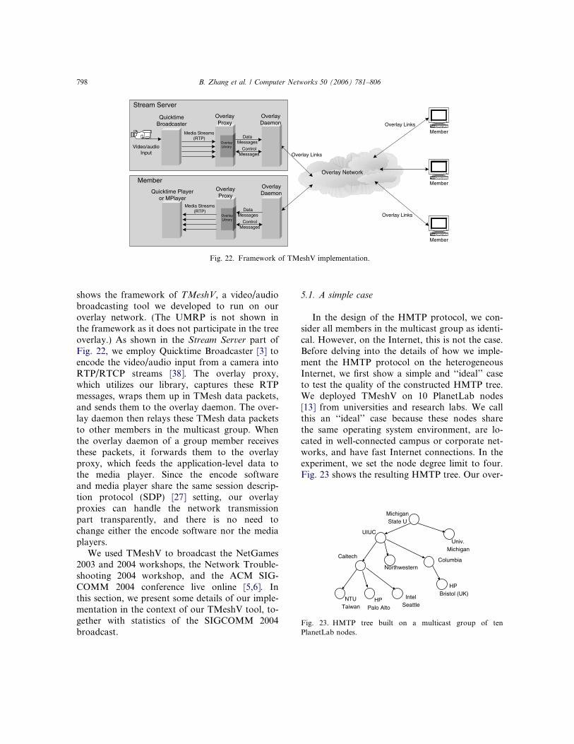
5.1. A simple case
In the design of the HMTP protocol, we con-sider all members in the multicast group as identi-cal. However, on the Internet, this is not the case.Before delving into the details of how we imple-ment the HMTP protocol on the heterogeneousInternet, we first show a simple and ‘‘ideal’’ caseto test the quality of the constructed HMTP tree.We deployed TMeshV on 10 PlanetLab nodes[13] from universities and research labs. We callthis an ‘‘ideal’’ case because these nodes sharethe same operating system environment, are lo-cated in well-connected campus or corporate net-works, and have fast Internet connections. In theexperiment, we set the node degree limit to four.Fig. 23 shows the resulting HMTP tree. Our over-
MichiganState U
CaltechColumbia
Univ.Michigan
HPBristol (UK)Intel
Seattle
UIUC
Northwestern
HPPalo Alto
NTUTaiwan
Fig. 23. HMTP tree built on a multicast group of tenPlanetLab nodes.
Member
Member
Member
Overlay Links
Overlay Links
Video/audioInput
Media Streams(RTP)
ControlMessages
Overlay Network
OverlayDaemon
QuicktimeBroadcaster
Stream Server
Overlay Links
DataMessages
OverlayProxy
OverlayLibrary
Media Streams(RTP)
ControlMessages
OverlayDaemonQuicktime Player
or MPlayer
Member
DataMessages
OverlayProxy
OverlayLibrary
Fig. 22. Framework of TMeshV implementation.
798 B. Zhang et al. / Computer Networks 50 (2006) 781–806

lay daemons can successfully organize themselvesinto an e!cient tree as expected.
Compared to PlanetLab deployment, deployingTMeshV on the broader Internet is far morecomplex.We have to consider various network con-ditions, system configurations, and operating-system-dependent problems. Furthermore, sincewe run a video/audio broadcast application, wealso need to tune some parameters of our protocolto provide better user perceived quality.
5.2. Bandwidth measurement
Due to the high bandwidth requirement of vi-deo/audio streaming, a host!s available bandwidthis more likely to determine user!s perceived videoquality. This is particularly the case for end-hostmulticast where one host!s bandwidth is not onlyused to receive the video but also to relay it toother hosts in the multicast group. Saroiu et al.studied the speed of Internet connections of hostsin the Gnutella [4] peer-to-peer file-sharing net-work and found that about 70% of the peers hadconnection speed between 100 Kbps and 10 Mbps[37]. This range of bandwidth indicates that a largenumber of these hosts use asymmetric Internetconnections, such as DSL and cable modem. Theymay have su!cient bandwidth to receive the videostream, but may not have enough upstream band-width to serve content to other peers. Having suchhosts act as internal nodes in the multicast tree willa"ect the video quality perceived by all their down-stream peers. Therefore, we need to set a low limit(e.g., zero) on the number of peers these hostsserve.
To check whether a host (H) is behind a slowupstream connection, our overlay daemon con-ducts a simple bandwidth measurement when Hinitially joins the group. The daemon first sendsa small (64 KB) packet to a randomly selectedmember of the group. If the time needed to sendthis packet is above a certain threshold, H!s up-stream speed is considered slow. Otherwise, thedaemon sends a second, larger (256 KB) packetto the same target host. H!s upstream bandwidthis estimated based on the time needed to transmitboth packets. The estimated bandwidth is reportedto the UMRP and is used to determine how many
peers H can serve. To overcome inaccurate mea-surements caused by transient congestion, the dae-mon repeats this bandwidth measurementperiodically at a low frequency. From their do-main names and whois database information, weestimated that during the broadcast of SIG-COMM 2004, 39.4% of the 221 remote attendeeswere behind either DSL or a cable modem.
5.3. Firewalls and NAT gateways
Besides network capacity, we also have to dealwith another heterogeneity of the Internet—theexistence of guarded hosts. A host is guarded if itis unable to accept incoming connections fromthose outside its local area network. This mayhappen if the host is behind a NAT gateway [17]or a firewall. A host that permits incoming connec-tions as well as outgoing connections is consideredopen.
In the presence of guarded hosts, networkreachability is no longer symmetric for every pairof overlay hosts. This complicates our overlayimplementation in two ways. An overlay link can-not always be formed between any given pair ofoverlay nodes. Trying and failing to connect toguarded hosts unnecessarily lengthen new mem-bers! join latency. Furthermore, these guardedhosts cannot receive data from the group unlessit initiates TCP connections to its peers. We havelimited choices on how to transmit data to theseguarded hosts.
We studied the prevalence of guarded hosts onthe Internet by conducting measurements on twoexisting peer-to-peer networks, eDonkey [1] andGnutella. As many as 36% of the 180,000 peersencountered in our experiment were guarded [42].Clearly, the lack of two-way communication capa-bility is prevalent in the current Internet. Chu et al.reported even higher percentages of guarded hostsin their Internet overlay multicast experiments[11], even as high as 76%. As shown in Table 1,74.2% out of the 221 remote attendees of SIG-COMM 2004 were on guarded hosts. To supportguarded hosts in HMTP/TMesh, we implementeda guarded host detection mechanism and intro-duced several mechanisms to accommodate them,as described below.
B. Zhang et al. / Computer Networks 50 (2006) 781–806 799

Guarded host detection is handled by theUMRP. To identify whether a host H is behind aNAT gateway, the UMRP compares the IP ad-dress it gets from the host!s TCP connection withthe source IP address H sets in its packet header.H is behind a NAT gateway if these two addressesare di"erent. In most cases, hosts behind NATgateways have known internal IP addresses, suchas 10.0.0.0/8, 172.16.0.0/12, 192.168.0.0/16, or169.254.0.0/16. We also handled cases where anopen host uses the loopback address (127.0.0.1)as its source address. Detecting hosts behind fire-walls is not as straightforward as detecting aNAT-ted host. When a new member H joins thegroup, the UMRP randomly picks three openhosts in the group that are not in H!s subnet toconnect back to H. If any of these connections suc-ceeds, the host is considered open. To passthrough NAT gateways and firewalls, we useTCP instead of UDP to transmit both control mes-sages and the multicast content. Once a guardedhost initiates a TCP connection to another host,two-way communications can be establishedthrough this TCP connection.
If there are more guarded hosts than the totalcapacity of open hosts to serve them, new mem-bers will not be able to join the multicast group.To alleviate this problem, we seeded the multicasttree with a number of PlanetLab nodes to ensuresu!cient number of resource-rich hosts residingon the open network. Next, we give open hostshigher priority in the tree construction process.When a new member H that is an open host triesto join the tree at a potential parent that alreadyhas its maximum number of children, if the parenthas a child that is a guarded host, it can accept H
as its new child and direct its guarded child toswitch its parent to H.
The root of the HMTP tree obviously must beon an open host. To ensure a shallow tree, whichreduces delivery latency, we further prefer the mostresource-rich host as the root. To this end, weinstrumented the UMRP with a root-contentionmechanism. Hosts are assigned priorities basedon their network reachability. The UMRP main-tains a list of ‘‘trusted’’ hosts. These hosts havethe highest priority. Guarded hosts have the lowestpriority. When member H joins the group, if H hasa higher priority that of the current root (R), in-stead of providing H with the current root, theUMRP accepts H as the new root, and instructsR to re-join the tree.
Finally, when possible, we direct hosts behindNAT gateways to connect to existing membersthat are located in the same subnet. When a hostH that is behind a NAT gateway tries to join thetree, the UMRP returns both the root of the treeand a list of all members co-residing behind thesame NAT gateway as H. Our daemon runningon host H first tries to attach itself to the tree asa child of one of these co-located members. Usu-ally hosts behind the same NAT gateway are opento each other, and also close to each other in termsof latency. Although we have not implementedHGMP in our TMeshV tool, this approach is sim-ilar to HGMP in essence. We did observe severalhosts behind the same NAT gateway during ourbroadcast of SIGCOMM 04. Employing IP multi-cast in such a scenario per HGMP would havebeen more e!cient.
Several mechanisms to accommodate guardedhosts have been proposed in the literature. IP next
Table 1Statistics of the broadcast of SIGCOMM 2004
Conference Broadcasthours
Total number ofremote attendees
Attendees on NAT/firewallhosts (percentage)
Maximum concurrentattendees
NetGames 2004 09:25 70 49 (70.0%) 15SIGCOMM04 Day1 10:01 85 53 (62.4%) 23SIGCOMM04 Day2 09:59 62 47 (75.8%) 20SIGCOMM04 Day3 11:01 59 44 (74.6%) 22Network troubleshooting 2004 08:41 25 18 (72.0%) 12
Total 49:07 221 164 (74.2%)
800 B. Zhang et al. / Computer Networks 50 (2006) 781–806

layer (IPNL) extends the current Internet architec-ture by adding a layer above IPv4 to identify andaddress hosts behind NAT gateways [22]. We didnot adopt IPNL in our implementation becauseit requires modifications to end-host systemand the NAT gateways. Guha et al. design amechanism that allows TCP connections to beestablished between guarded hosts in di"erentNAT-ted subnets [25]. Their approach requiresadministrator privileges on end systems to run.Ganjam et al. propose a protocol in which openhosts give preference to guarded hosts in choosinga parent [24]. We did not adopt this protocol be-cause we assume that a large number of guardedhosts will be behind DSL or cable modems andare thus not suitable parents anyway. Instead, wepropose a location-based clustering algorithm,e*, to make e!cient use of resources available onopen hosts [44]. The cluster centers in e* are theninter-connected using HMTP.
While hosts behind NAT gateways and firewallsare usually not restricted in the port number towhich they can open a TCP connection, some net-works now allow outgoing TCP connections onlyto well-known ports, e.g., SMTP and HTTP portsonly. Such restrictions are usually found in corpo-rate or government-controlled networks. Theusual method to support hosts behind such re-stricted networks is to run an HTTP proxy onthe Internet that acts as a relay for the application.From Table 3, we see that only 10.4% of the SIG-COMM 2004 attendees were from corporate net-works. Anecdotal evidence suggests that wewould have seen a higher level of attendance fromcorporate and government-controlled networks ifwe had an HTTP proxy for TMeshV.
5.4. Portability issues
TMeshV currently runs on four operating sys-tems: FreeBSD, Linux, MacOS X, and MicrosoftWindows. To playback themedia content, we lever-age the Apple Quicktime player on MacOS X andWindows, andMPlayer [2] on FreeBSD and Linux.On Windows, Quicktime player is a very CPU-intensive application. To display streamed videoin 320 · 240 frame size with 400 Kbps of data,Quicktime player alone consumes over 70% CPU
on a 1.13 GHz PentiumIII machine with 512 MBof memory. When the CPU is fully utilized, a clientcannot relay data fast enough even with adequatebandwidth. In such cases, the CPU power becomesthe bottleneck. Although this kind of bottleneck cli-ents does not appear frequently, it may compromisea large portion of the group if the bottleneck clientappears near the top of the multicast tree.
To address this problem, the TMeshV daemoncollects the hardware configuration of the Win-dows hosts from the system Registry and adjuststhe node degree limit accordingly. Alternatively,a host can compare its received data rate againsta published broadcast rate and switch parent ifthe received rate is too far below the publishedrate. Or we can monitor the real-time CPU loadinformation and adjust a host!s degree limitdynamically. Similar to the approach we take forhosts with low bandwidth, we assign a low (e.g.,zero) node degree to these slow or busy machinesso that they would stay at the fringes of the overlayand not slow down other members.
5.5. Statistics from the SIGCOMM 2004 broadcast
For the SIGCOMM 2004 broadcast, ourstream server runs on a MacOS X laptop, whichis connected to the Internet through a DSL with1 Mbps upstream bandwidth. For the broadcastmedia streams, we set the video codec to MPEG4with resolution 320 · 280 and the audio codec toMPEG4 32 kHz Stereo. The configured data rateis around 400 Kbps. When there are only smallmovements in the video, which happened quite of-ten since we pointed our camera at the projectorscreen, Quicktime Broadcaster may producestreams with lower bit rate than the configureddata rate. The broadcast lasted five days: threedays for the main conference, one day for Net-Games 2004 workshop, and one day for NetworkTroubleshooting 2004 workshop. The second col-umn in Table 1 shows the durations of our broad-cast for each day.
During the SIGCOMM 2004 broadcast, a totalof 221 unique hosts joined the broadcast. Of these,164 (74.2%) were guarded hosts (behind NAT orfirewall). The maximum number of concurrent re-mote attendees was 23, which occurred during the
B. Zhang et al. / Computer Networks 50 (2006) 781–806 801

first day of the main conference. We also had thelargest number of total remote attendees (85) inthe first day. Since we employed about 26 Planet-Lab nodes to accommodate the expected highnumber of guarded hosts, the maximum group sizewe encountered during the live broadcast was 49.Fig. 24 shows the number of concurrent remoteattendees (not including PlanetLab nodes) for eachday of the main conference.
Fig. 25 shows the total viewing time of each re-mote attendees. We sort the remote attendees innon-increasing order based on their total viewingtime during the broadcast. Each remote attendeeis then assigned an ID based on its rank. Of the221 remote attendees, 78 (35.3%) of them watchedthe broadcast over one hour. Each remote atten-dee sends an ‘‘alive’’ message to the UMRP aboutonce every 60 seconds. Hosts with IDs above 199left the group before their first ‘‘alive’’ messages,which explains the flat tail on the ‘‘Total viewingtime’’ graph. Of the 221 remote attendees, 136(61.5%) of them joined the broadcast multipletimes. Fig. 25 also shows the average viewing timeper visit of each remote attendee, while Fig. 26shows the number of visits of each remoteattendee.
Tables 2 and 3 present the geographic distribu-tions of the remote attendees and the locationsthey connected from (the locations of remoteattendees are obtained from their domain namesand their whois database information). The major-ity of the attendees were from the US (79.6%),
about 11.3% from Europe, 5.9% from Asia, and3.2% from Australia. Not surprisingly, the major-ity of remote attendees (57.0%) are from campusnetwork or research labs. More interestingly, ahigh percentage (39.4%) were connected throughDSL or cable modem.
0
5
10
15
20
25
30
19:0017:0015:0013:0011:009:00
Con
curr
ent R
emot
e A
ttend
ees
Time of the Day
SIGCOMM 2004 Day 1SIGCOMM 2004 Day 2SIGCOMM 2004 Day 3
Fig. 24. Number of concurrent remote attendees for SIG-COMM 2004.
1
10
100
1000
10000
100000
1e+06
0 50 100 150 200 250
Vie
win
g T
ime
(Sec
)
Remote Attendee ID
Total viewing timeAverage time per visit
Fig. 25. Viewing time of remote attendees.
Table 2Geographic distribution of the remote attendees
Country Remote attendees
USA 176Japan 9Australia 7France 6Netherlands 6Canada 4Belgium 3Italy 3China 2Korea 2Sweden 2Germany 1
Table 3Locations of remote attendees
Location Number ofattendees
Universities and educational institutions 103 (46.6%)Corporations and research labs 23 (10.4%)Government (.gov) 5 (2.3%)Home/o!ce with broadband(DSL/cable modem)
87 (39.4%)
Unknown 3 (1.4%)
802 B. Zhang et al. / Computer Networks 50 (2006) 781–806

5.6. Discussions
As currently implemented, TMeshV providesdelivery service without any transport layer con-trol beyond those provided by TCP. Due to theloss-tolerant characteristic of audio/video applica-tions, we simply throw away new data when theTCP socket bu"er is full (i.e., when the socket isnot ready for writing). One future direction wecan pursue is to allow the application to set di"er-ent levels of priority for its packets. For example,it may be more important to have audio packetsdelivered at the expense of video packets. Whenthe TCP socket is full, high priority packets canbe bu"ered at the daemon for later transmission.Several issues are immediately obvious with sucha scheme. First, if congestion persists, bu"ereddata may become outdated and it may becomemore useful to transmit new data. Second, thevideo and audio streams will become de-synchro-nized and receivers will need to re-synchronizethem. Our implementation currently does not at-tempt to do any re-synchronization of the videoand audio streams.
Under our current implementation, when anode switches parent in the multicast tree, datatransmission may be interrupted. We did notanticipate how disruptive this interruption is tothe audio/video playback. Instead of a few cor-rupted frames, playback completely freezes for aperiod of time that is clearly noticeable to theviewer. We will need to implement a smootherhand-o" mechanism when switching parent.
As indicated earlier, HGMP is not currentlyimplemented. Our experience from the SIG-COMM 2004 broadcast indicates that there willbe opportunity to take advantage of native IPmulticast on local subnets, where IP multicast ismore likely to be available. Our future work onTMeshV includes implementing HGMP, addingbetter QoS support, and testing on a much largerscale.
6. Related work
The MBone [18] was designed to facilitate thedeployment of IP multicast. It connects IP multi-cast islands using tunnels, obviating IP multicastsupport on intermediate routers between the is-lands. Nevertheless, setting up the tunnel requiresmanual configuration and administrative privi-leges on routers at both ends, which makes con-necting to the MBone an expensive proposition.There are several proposals to automate the pro-cess of establishing tunnels to MBone. UMTP[20] uses an intermediate source-specific multicast(SSM) router to intercept group join requests sentto the source, and create tunnels on demand. AMT[41] uses dedicated servers (gateways and relays)and IGMP to set up tunnels for SSM. Castgate[32] uses a DNS-like hierarchical, distributed data-base to support tunnel management. These pro-posals automate only the setup of static tunnels;none of them support dynamic auto-reconfigura-tion of the tunnels. Furthermore, they all requireoperational support from routers or dedicatedservers. Since UM makes use of native IP multi-cast networks, the entire MBone can be viewedas the biggest island in UM.
End-host multicast has minimal deploymentbarriers because the only requirement is for theusers to install a program on their own computers.There are a plethora of end-host multicast proto-cols, which di"er in their target applications androuting algorithms. Judging by the type of multi-cast overlay they use, these protocols can be catego-rized as either tree-based protocols or mesh-basedprotocols. Generally speaking, tree-based proto-cols maintain less state information at eachnode and have less overhead, while mesh-based
1
2
4
8
16
32
64
0 50 100 150 200 250
Num
ber
of V
isits
Remote Attendee ID
Fig. 26. Number of visits for each remote attendee.
B. Zhang et al. / Computer Networks 50 (2006) 781–806 803

protocols utilize more overlay links and are able toachieve shorter end-to-end delay. Tree-based pro-tocols include BTP [28], HMTP, NICE [7], TBCP[33], Yoid [21], etc., mesh-based protocols includeNarada [12], Hypercast [31], Gossamer [9], TMesh[43], etc. UM uses end-host multicast protocolsfor inter-island routing. Due to HGMP!s protocolindependence, applications can choose the end-hostmulticast protocol that fits application needs thebest.
Since end-hosts are less stable and less trustwor-thy, there are many proposals for building multi-cast server overlays, including Scattercast [9],Overcast [30], AMcast [39], OMNI [8], BroadcastFederation [10], etc. In order to provide multicastservice, an application service provider places ded-icated servers all over the Internet, runs an end-host multicast protocol among these servers, andconnects end users by unicast. The design issues in-clude server placement, and making routing deci-sions with the knowledge about server locations,tra!c load and bandwidth. Multicast serveroverlays are expected to provide better multicastservice than pure end-host multicast, but itsdeployability is compromised because it requiresdeploying a large number of servers by an applica-tion service provider. UM does not require dedi-cated servers, but both HMTP and HGMP cantake advantage of them when they are available.
7. Conclusion
In this work, we designed and implemented theuniversal multicast (UM) framework to provideubiquitous multicast delivery service on the Inter-net. As a basic service common to most groupcommunication applications, multicast should beimplemented as part of the network infrastructurefor the sake of performance and scalability. Fromthe deployment point of view, however, the path ofleast resistance evolves from network edges to-wards the core. UM solves this dilemma by havinga flexible design that provides applications multi-cast delivery immediately, and allows infrastruc-ture support to spread gradually at the sametime. We designed HMTP for inter-island rout-ing, HGMP for intra-island management, imple-
mented a prototype, and conducted liveconference broadcasting. In deploying our proto-type implementation, we encountered and ad-dressed several unexpected stumbling blocks withregards to guarded hosts and hosts with asymmet-ric bandwidth. To the best of our knowledge, thisis the first e"ort to integrate both end-host multi-cast and native IP multicast for ubiquitous multi-cast delivery on the Internet that also takes intoaccount the realities of security barriers on theInternet. Our framework is not limited to a partic-ular routing protocol: HMTP can be the substratefor more sophisticated protocols, and HGMP canbe integrated with other routing protocols.
References
[1] Edonkey Network. Available from: <http://www.edonkey2000.com>.
[2] Mplayer. Available from: <http://www.mplayerhq.hu/>.[3] Quicktime Broadcaster. Available from: <http://www.
apple.com/quicktime/products/broadcaster/>.[4] Wellcome to gnutella. Available from: <http://gnutella.
wego.com>.[5] Netgames 2003. Second Workshop on Network and
System Support for Games. Available from: <http://confman.eecs.umich.edu/netgames2003>.
[6] SIGCOMM 2004. ACM SIGCOMM 2004 Conference.Available from: <http://www.acm.org/sigcomm/sigcomm2004/>.
[7] S. Banerjee, B. Bhattacharjee, C. Kommareddy, Scalableapplication layer multicast, in: Proceedings of ACMSIGCOMM, September 2002.
[8] S. Banerjee, C. Kommareddy, K. Kar, B. Bhattacharjee, S.Khuller, Construction of an e!cient overlay multicastinfrastructure for real-time applications, in: Proceedings ofIEEE INFOCOM, April 2003.
[9] Y. Chawathe, Scattercast: An Architecture for InternetBroadcast Distribution as an Infrastructure Service, Ph.D.Thesis, University of California, Berkeley, December 2000.
[10] Y. Chawathe, M. Seshadri, Broadcast federation: anapplication-layer broadcast internetwork, In Proc. of theInt!l Workshop on Network and Operating SystemsSupport for Digital Audio and Video (NOSSDAV), May2002.
[11] Y. Chu, A. Ganjan, T. Ng, S. Rao, K. Sripanidkulchai, J.Zhan, H. Zhang, Early experience with an Internetbroadcast system based on overlay multicast, in: USENIXAnnual Technical Conference, 2004.
[12] Y. Chu, S.G. Rao, H. Zhang, A case for end systemmulticast, in: Proceedings of ACM SIGMETRICS, June2000, pp. 1–12.
804 B. Zhang et al. / Computer Networks 50 (2006) 781–806

[13] B. Chun, D. Culler, T. Roscoe, A. Bavier, L. Peterson, M.Wawrzoniak, M. Bowman, Planetlab: an overlay testbedfor broad-coverage services, ACM Computer Communi-cation Review 33 (3) (2003) 3–12.
[14] L.H.M.K. Costa, S. Fdida, O.C.M.B. Duarte, Hop by hopmulticast routing protocol, in: Proceedings of ACMSIGCOMM, September 2001.
[15] F. Dabek, R. Cox, F. Kaashoek, R. Morris, Vivaldi: adecentralized network coordinate system, in: ACM SIG-COMM, 2004.
[16] S. Deering, D. Cheriton, Multicast routing in datagraminternetworks and extended LANs, ACM Transactions onComputer Systems 8 (2) (1990) 85–110.
[17] K. Egevang, P. Francis, The IP Network Address Trans-lator (NAT), 1994, RFC-1631.
[18] H. Eriksson, MBONE: the multicast backbone, Commu-nications of the ACM (August) (1994).
[19] A. Fei, J. Cui, M. Gerla, and M. Faloutsos, Aggregatedmulticast: an approach to reduce multicast state, in:Proceedings of 6th Global Internet Symposium (GI2001)in Conjunction with Globecom, November 2001.
[20] R. Finlayson, R. Perlman, D. Rajwan, Accelerating thedeployment of multicast using automatic tunneling. Inter-net Draft, IETF, February 2001.
[21] P. Francis, Yoid: your own internet distribution. Availablefrom: <http://www.isi.edu/div7/yoid/>, March 2001.
[22] P. Francis, R. Gummadi, IPNL: A NAT-Extened InternetArchitecture, in: Proceedings of ACM SIGCOMM!01,2001.
[23] P. Francis, S. Jamin, C. Jin, Y. Jin, D. Raz, Y. Shavitt, L.Zhang, IDMaps: a global internet host distance estimationservice, ACM/IEEE Transactions on Networking (Octo-ber) (2001).
[24] A. Ganjam, H. Zhang, Connectivity restrictions in over-lay multicast, in: Proceedings of NOSSDAV, June2004.
[25] S. Guha, Y. Takeda, P. Francis, NUTSS: A SIP-basedapproach to UDP and TCP network connectivity, FutureDirections in Network Architecture Workshop, August2004.
[26] M. Handley, Session directories and scalable Internetmulticast address allocation, ACM Computer Communi-cation Review 28 (4) (1998) 105–116.
[27] M. Handley, V. Jacobson, SDP: Session DescriptionProtocol, 1998. RFC-2327.
[28] D. Helder, S. Jamin, End-host multicast communicationusing switch-trees protocols, in: Global and Peer-to-PeerComputing on Large Scale Distributed Systems (GP2PC),May 2002.
[29] H. Holbrook, B. Cain, Source-specific multicast for IP.Internet Draft, IETF, November 2000.
[30] J. Jannotti, D. Gi"ord, K. Johnson, M. Kaashoek, J.O!Toole, Overcast: reliable multicasting with an overlaynetwork, in: Proceedings of the Symposium on OperatingSystems Design and Implementation, October 2000.
[31] J. Liebeherr, T. Beam, HyperCast: a protocol for main-taining multicast group members in a logical hypercube
topology, in: Networked Group Communication, 1999,pp. 72–89.
[32] P. Liefooghe, CastGate: an auto-tunneling architecture forIP multicast, Internet Draft, IETF, November 2001.
[33] L. Mathy, R. Canonico, D. Hutchison, An overlay treebuilding control protocol, in: Proceedings of the Interna-tional Workshop on Networked Group Communication(NGC), May 2001.
[34] National Laboratory of Applied Network Research, NSFCooperative Agreement No. ANI-9807479, NLANRactive measurement project. Available from: <http://watt.nlanr.net/>.
[35] T.S.E. Ng, H. Zhang, Predicting Internet network distancewith coordinates-based approaches, in: IEEE INFOCOM,2002.
[36] R. Perlman, C. Lee, T. Ballardie, J. Crowcroft, Z. Wang,T. Maufer, C. Diot, J. Thoo, M. Green, Simple multicast: adesign for simple, low-overhead multicast, Internet Draft,IETF, March 1999.
[37] S. Saroiu, P.K. Gummadi, S.D. Gribble. A measure-ment study of peer-to-peer file sharing systems, in: MMCN!02, January 2002. Available from: <http://www.cs.washington.edu/homes/tzoompy/publications/mmcn/2002/abstract.html>.
[38] H. Schulzrinne, S. Casner, R. Frederick, V. Jacobson,RTP: A Transport Protocol for Real-Time Applications,1996, RFC-1889.
[39] S. Shi, J. Turner, Routing in overlay multicast networks,in: Proceedings of IEEE INFOCOM, June 2002.
[40] I. Stoica, T.S.E. Ng, H. Zhang, REUNITE: a recursiveunicast approach to multicast, in: Proceedings of IEEEINFOCOM 2000, March 2000.
[41] D. Thaler, M. Talwar, L. Vicisano, D. Ooms, IPv4automatic multicast without explicit tunnels (AMT),Internet Draft, IETF, February 2001.
[42] W. Wang, H. Chang, A. Zeitoun, S. Jamin, Characterizingguarded hosts in peer-to-peer file sharing systems, IEEEGLOBECOM Global Internet and Next Generation Net-works Symposim November. (2004).
[43] W. Wang, D. Helder, S. Jamin, L. Zhang, Overlayoptimizations for end-host multicast. in: Proceedings ofthe Int!l Workshop on Networked Group Communication(NGC), October 2002.
[44] W. Wang, C. Jin, S. Jamin, Network Overlay Constructionunder Limited End-to-End Addressability, TechnicalReport CSE-TR-489-04, EECS Department, Universityof Michigan, 2004.
[45] B. Zhang, S. Jamin, L. Zhang, Host Multicast: a frame-work for delivering multicast to end users, in: Proceedingsof IEEE INFOCOM, June 2002.
[46] B. Zhang, S. Jamin, L. Zhang, Universal IP multicastdelivery, in: Proceedings of the International Workshop onNetworked Group Communication (NGC), October 2002.
Beichuan Zhang is an Assistant Professor in the Department ofComputer Science at the University of Arizona. He received hisPh.D. in Computer Science from the University of California,
B. Zhang et al. / Computer Networks 50 (2006) 781–806 805

Los Angeles in 2003, and spent a year at USC/ISI as a Post-doctoral research associate. His research interests includeInternet routing, overlay networks, multicast, network mea-surement and performance evaluation.
Wenjie Wang is a Ph.D. candidate in Electronic Engineering andComputer Science Department at the University of Michigan,Ann Arbor. His areas of research interest include end-hostmulticast, peer-to-peer system, DDoS resilient overlays, net-work protocol and security, video/audio streaming. Previously,he got his B.S. degree in the Department of Computer Scienceand Technology of Peking University, and he received his M.S.degree in EECS department of the University of Michigan.
Sugih Jamin is an Associate Professor in the Department ofElectrical Engineering and Computer Science at the Universityof Michigan. He received his Ph.D. in Computer Science fromthe University of Southern California, Los Angeles in 1996 forhis work on measurement-based admission control algorithms.He spent parts of 1992 and 1993 at the Xerox Palo AltoResearch Center, was a Visiting Scholar at the University ofCambridge for part of 2002, and a Visiting Associate Professorat the University of Tokyo for part of 2003. He received theACM SIGCOMM Best Student Paper Award in 1995, theNational Science Foundation (NSF) CAREER Award in 1998,
the Presidential Early Career Award for Scientists and Engi-neers (PECASE) in 1999, and the Alfred P. Sloan ResearchFellowship in 2001.
Daniel Massey is an assistant professor at Computer ScienceDepartment of Colorado State University and is currently theprincipal investigator on DARPA and NSF funded researchprojects investigating techniques for improving the Internetrouting infrastructures. He received his doctorate from UCLAand is a member of the IEEE, IEEE Communications Society,and IEEE Computer Society. His research interests includefault-tolerance and security for large scale networkinfrastructures.
Lixia Zhang is a professor in computer science department atUCLA. She received her Ph.D. in computer science from MITand was on the research sta" at the Xerox Palo Alto ResearchCenter before joining UCLA in 1995. In the past she has servedas vice chair of ACM SIGCOMM and Co-Chair of IEEECommunication Society Internet Technical Committee. She iscurrently a member of the Internet Architecture Board. Herresearch interest includes resiliency for large scale distributedsystems such as Internet routing infrastructure and the globalDNS system.
806 B. Zhang et al. / Computer Networks 50 (2006) 781–806