united states department of the interior - bureau of reclamation
TRANSCRIPT
United States Department of the Interior)) BUREAU OF RECLAMATION
P.O. Box 25007Denver, CO 80225-0007
IN REPLY REFER TO:
86-68110PRJ-13.00 SEP 25 2018
MEMORANDUM
To: Technology Development Program Manager, Dam Safety OfficeAttn: 84-44000 (LKrosley)
From: Jerzy Salamon, Civil (Structural) EngineerWaterways & Concrete Dams Group 1 d ‘‘ L_1
Subject: Transmittal of Dam Safety Report DSO-2018-11, Developments for the ConcreteTensile Split Test
Attached for your tise is Report DSO-2018-11, Developments for the Concrete Tensile SpiltTest, that has been prepared by the Technical Service Center at the request of the Dam SafetyOffice. The report will be available in Adobe Acrobat Format on the Darn Safety website andwill be loaded into DSDaMS.
If you have any questions, please contact me at 303-445-3219 or via email [email protected].
Hard copy CC recipients:84-44000 (Dam Safety File Station)
(w/att)
Electronic copy CC recipients:[email protected] @ usbr.govKBartojay@ [email protected] @ [email protected]@usbr.gov
(w/att to each)
U.S. Department of the Interior Bureau of Reclamation Technical Service Center Denver, Colorado September 2018
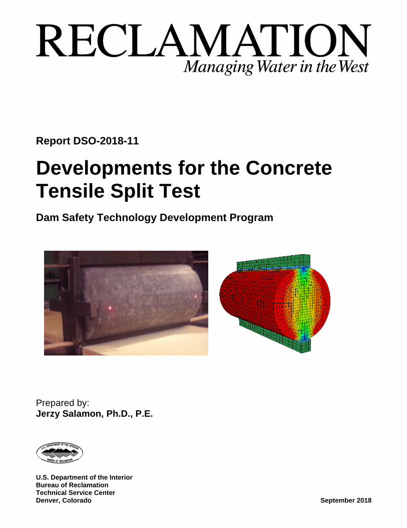
Report DSO-2018-11
Developments for the Concrete Tensile Split Test Dam Safety Technology Development Program
Prepared by: Jerzy Salamon, Ph.D., P.E.
MISSION STATEMENTS The U.S. Department of the Interior protects America’s natural resources and heritage, honors our cultures and tribal communities, and supplies the energy to power our future. The mission of the Bureau of Reclamation is to manage, develop, and protect water and related resources in an environmentally and economically sound manner in the interest of the American public.
Disclaimer:
Any use of trade names and trademarks in this document is for descriptive purposes only and does not constitute endorsement. The information contained herein regarding commercial products or firms may not be used for advertising or promotional purposes and is not to be construed as an endorsement of any product or firm.
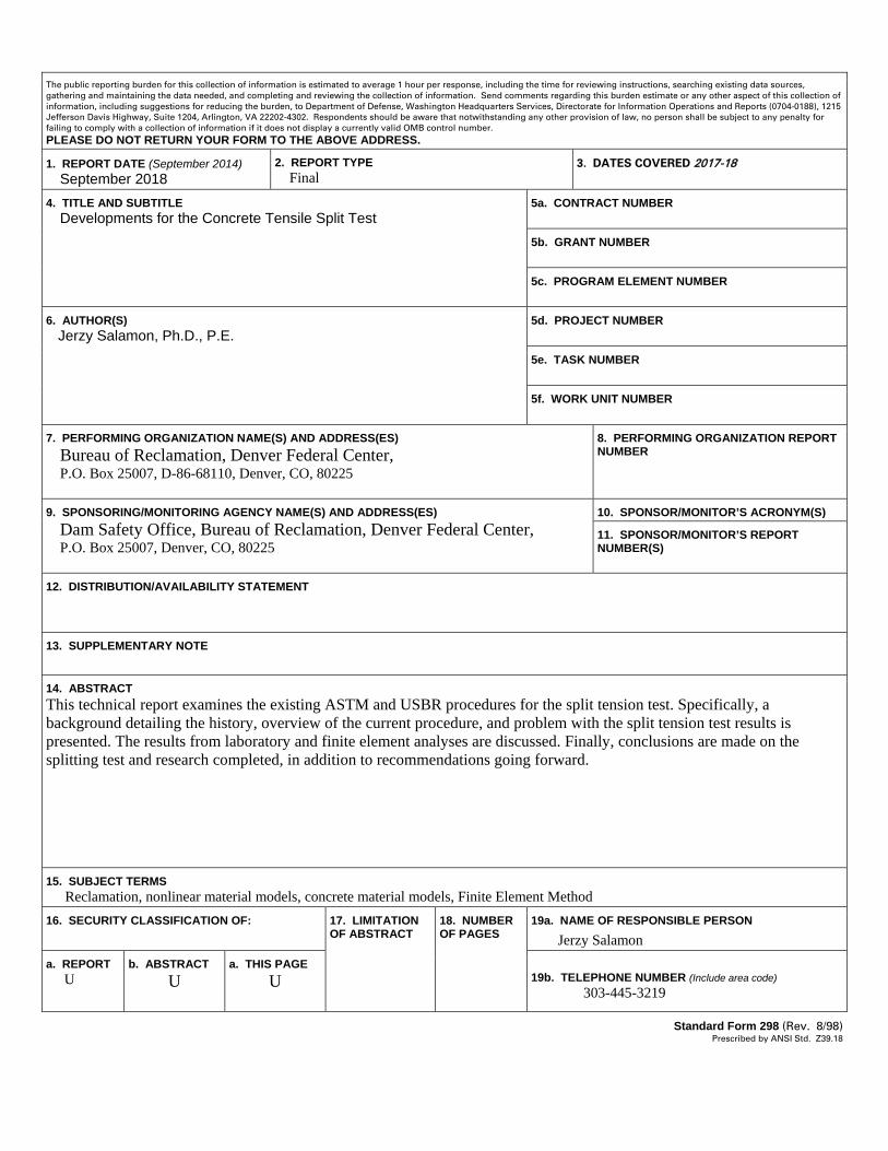
The public reporting burden for this collection of information is estimated to average 1 hour per response, including the time for reviewing instructions, searching existing data sources, gathering and maintaining the data needed, and completing and reviewing the collection of information. Send comments regarding this burden estimate or any other aspect of this collection of information, including suggestions for reducing the burden, to Department of Defense, Washington Headquarters Services, Directorate for Information Operations and Reports (0704-0188), 1215 Jefferson Davis Highway, Suite 1204, Arlington, VA 22202-4302. Respondents should be aware that notwithstanding any other provision of law, no person shall be subject to any penalty for failing to comply with a collection of information if it does not display a currently valid OMB control number. PLEASE DO NOT RETURN YOUR FORM TO THE ABOVE ADDRESS. 1. REPORT DATE (September 2014) September 2018
2. REPORT TYPE Final
3. DATES COVERED 2017-18
4. TITLE AND SUBTITLE Developments for the Concrete Tensile Split Test
5a. CONTRACT NUMBER 5b. GRANT NUMBER 5c. PROGRAM ELEMENT NUMBER
6. AUTHOR(S) Jerzy Salamon, Ph.D., P.E.
5d. PROJECT NUMBER 5e. TASK NUMBER 5f. WORK UNIT NUMBER
7. PERFORMING ORGANIZATION NAME(S) AND ADDRESS(ES) Bureau of Reclamation, Denver Federal Center, P.O. Box 25007, D-86-68110, Denver, CO, 80225
8. PERFORMING ORGANIZATION REPORT NUMBER
9. SPONSORING/MONITORING AGENCY NAME(S) AND ADDRESS(ES) Dam Safety Office, Bureau of Reclamation, Denver Federal Center, P.O. Box 25007, Denver, CO, 80225
10. SPONSOR/MONITOR’S ACRONYM(S)
11. SPONSOR/MONITOR’S REPORT NUMBER(S)
12. DISTRIBUTION/AVAILABILITY STATEMENT 13. SUPPLEMENTARY NOTE 14. ABSTRACT This technical report examines the existing ASTM and USBR procedures for the split tension test. Specifically, a background detailing the history, overview of the current procedure, and problem with the split tension test results is presented. The results from laboratory and finite element analyses are discussed. Finally, conclusions are made on the splitting test and research completed, in addition to recommendations going forward.
15. SUBJECT TERMS Reclamation, nonlinear material models, concrete material models, Finite Element Method 16. SECURITY CLASSIFICATION OF: 17. LIMITATION
OF ABSTRACT
18. NUMBER OF PAGES
19a. NAME OF RESPONSIBLE PERSON Jerzy Salamon
a. REPORT U
b. ABSTRACT U
a. THIS PAGE U
19b. TELEPHONE NUMBER (Include area code) 303-445-3219
Standard Form 298 (Rev. 8/98) Prescribed by ANSI Std. Z39.18
BUREAU OF RECLAMATIONDam Safety Technology Development Program
DSO-201 8-11
Developments for the Concrete TensileSplit Test
Digitally signed by JERZY
JERZY SALAMON,f Date: 2018.09.10 20:06:28 -0600
Prepared by: Jerzy Salamon, Ph.D., P.E.Waterways & Concrete Dams Group 1, 86-68110
Digitally signed by CATHERINECATHERINE LUCERO LUCERO
Date: 201 8.09.11 06:01:00 -0600
Checked by: Catherine Lucero, P.E.Concrete, Geotechnical & Structural Laboratory, 86-68530
J E RZV SA LA A Q NI Digitally signed by JERZY SALAMONI IVI ‘‘1 Date:2018.09.1020:07:06-06’OO
Technical Approval: Jerzy Salamon, Ph.D., P.E.Waterways & Concrete Darns Group 1, 86-681 10
STEPH ENI DOñ iriIc Digitally signed by STEPHEN DOMINICI l IVIII ‘ Date: 2018.09.11 07:40:07-0600
Peer Review: Stephen Dominic, P.E. DateWaterways & Concrete Darns Group 1, 86-68110
REVISIONS
IDate Description o U .
i
CONTENTS
Page 1.0 INTRODUCTION........................................................................................1
1.1 GENERAL ..............................................................................................1 1.2 OBJECTIVES AND SCOPE OF WORK .......................................................2 1.3 IMPORTANCE OF INVESTIGATIONS .........................................................2
2.0 TEST PROCEDURE ...................................................................................3 2.1 HISTORY OF SPLIT TEST DEVELOPMENT ...............................................3 2.2.1 ASTM C496 STANDARD ......................................................................3 2.2.2 USBR 4497 TEST PROCEDURE .............................................................3 2.2.3 ASTM D3967 STANDARD ....................................................................5 2.2.4 EN 12390 STANDARD ...........................................................................5 2.2.5 ISO 1920 STANDARD ............................................................................6 2.2.6 ACI-318 STANDARD .............................................................................6
3.0 OVERVIEW OF INVESTIGATIONS ON SPLIT TESTING ................7 3.1 KEY INVESTIGATIONS ...........................................................................7
4.0 ANALYTICAL MODEL...........................................................................21 4.1 ASTM AND USBR SPECIFICATIONS ...................................................21 4.2 TIMOSHENKO’S MODEL ......................................................................21 4.3 SOLUTIONS FOR COMPRESSED ELASTIC DISK .....................................22 4.4 EFFECT OF BEARING STRIP WIDTH .....................................................24
5.0 FINITE ELEMENT SIMULATIONS .....................................................25 5.1 FINITE ELEMENT MODEL ...................................................................25 5.2 RESULTS FOR ELASTIC ANALYSIS .......................................................26 5.3 RESULTS OF NONLINEAR MATERIAL ANALYSIS ..................................29
6.0 SUMMARY AND CONCLUSIONS ........................................................31 6.1 SUMMARY ...........................................................................................31 6.2 CONCLUSIONS .....................................................................................31
REFERENCES .....................................................................................................33

ii
Figures Figure Page Figure 2.1. — Split test arrangement per USBR 4497 Specification. .................... 4 Figure 2.2. — Split tensile strength as a function of lightweight concrete compressive strength per ACI-318. ........................................................................ 6 Figure 3.1. — Specimen failure sequence for split test [Hannant, 1973]. .............. 8 Figure 3.2. — Relation between modulus of rupture, tensile strength and the compressive strength of concrete [Raphael, 1984]. ................................................ 9 Figure 3.3. — Tensile split and direct tension versus compressive strength of concrete cores [Raphael, 1984]. ............................................................................ 10 Figure 3.4. — Tensile strength as a percentage of compressive strength for direct and splitting test comparing different NMSA ratio specimens. ............................ 17 Figure 4.1. —Timoshenko’s model of a disk loaded with force P. ...................... 22 Figure 4.2. — Frocht’s model of a disk loaded with force P. ............................... 23 Figure 4.3. — The distribution of the stress in a 2-inch diameter elastic disk [Jianhong, 2009]. .................................................................................................. 24 Figure 4.4. — Maximum tensile stresses as a function of the load strip width to the diameter of the specimen per Tang’s formula Eq. 4-8. ................................... 25 Figure 5.1. — Arrangement of the split test and the corresponding FE model. ... 26 Figure 5.2. — Vertical stresses (X-direction). ...................................................... 26 Figure 5.3. — Horizontal stresses (Y-direction). .................................................. 27 Figure 5.4. — Distribution of axial stresses (Z-direction) at the vertical cross section. .................................................................................................................. 27 Figure 5.5. — Distribution of maximum and minimum principal stresses at the central cross section. ............................................................................................. 28 Figure 5.6. — Distribution of Tresca (max. shear stresses). ................................. 28 Figure 5.7. — Distribution of lateral (Y-direction) displacements. ...................... 28 Figure 5.8. — Change of tensile stresses at the specimen center with test load increments. ............................................................................................................ 29 Figure 5.9. — Change of vertical stress at the specimen center with the load increments. ............................................................................................................ 30 Figure 5.10. — Horizontal strains before (left) and after (right)crack initiates as marked in Figure 5.8. ............................................................................................ 30
Developments for the Concrete Tensile Spilt Test
1
1.0 INTRODUCTION 1.1 General The tensile strength is one of the most important parameter used in the design and analysis of concrete dams and, as such, has been the topic of several internal Bureau of Reclamation’s (Reclamation) discussions. Currently, there are two traditional laboratory test methods, commonly used by Reclamation, to determine the tensile strength of concrete:
• Direct Tensile Strength Test per USBR Specification 4914-92, • Splitting Tensile Strength Test per USBR Specification 4496-92.
Direct tensile strength test is a uniaxial tensile test where the concrete samples, glued to steel plates, are stretched in the tensile test machine. Split Tensile Strength test, known also as Brazilian or indirect tension test, is a test where a tensile strength is indirectly determined in compression-splitting process of concrete specimens. The results between both tests differ significantly when the current USBR and ASTM specifications are followed therefore an uncertainty exists regarding the true concrete tensile strength that is used in the structural assessment of the concrete dams. The procedure for splitting tensile test has been investigated previously by the Technical Service Center (TSC) at Reclamation. The results of these investigations and publications by others show that the procedure for the splitting test, as it is currently specified by ASTM and USBR, report the maximum force leading to breaking the cylindrical specimen in compression (crushing) rather than tension (splitting). FE simulations of the split test, and the laboratory test results from testing conducted at the Reclamation’s Concrete, Geotechnical, and Structural Laboratory, indicate that the cracking (splitting) of the concrete specimens occurs well before the compression load breaks the sample. The above observations agree with the general engineering opinion that the splitting tensile test, conducted according to the current ASTM specification, “overestimate” the true tensile concrete strength and the splitting and direct test results differ on average by a factor of two (Dolen, 2014). Over past decades, several studies have been conducted to explore the proper means of estimating tensile strength of concrete. Authors have investigated test results and methods in order to narrow in on how to determine the best representative value with repeatability and confidence. Factors explored included specimen sizes, aggregate sizes, testing apparatuses, etc.

Developments for the Concrete Tensile Spilt Test
2
The procedure for direct tension test preparations is time-consuming and relatively expensive when compared with such process for splitting tensile test. This cost is primarily elevated by time spent by the laboratory personnel for specimen preparations, including gluing the concrete samples to the steel plates and safely loading the heavy samples into the upper portion of the testing frame. The cost increases significantly with the size of specimens. The relatively low-cost of splitting tensile test that requires testing of specimens in a compression machine without any extensive preparations, make this test very practical. 1.2 Objectives and Scope of Work The objectives of this investigation (funded under the Reclamation’s Dam Safety Technology Development Research Program) are:
• Overview historical developments of the split test procedures • Summarize the selected publications related to the split test • Identify limitations and discrepancies in the current standardized
specification for the split test • Perform a finite element analysis to simulate the splitting tensile test • Develop observations and conclusions
The scope of this technical report will examine the existing specifications for the split tension test. Specifically, background detailing the history of the test, an overview of the current test procedure, and identified problems with the split tension test will first be presented. Then the results from laboratory and analytical analyses will be discussed. Finally, conclusions will be made regarding the splitting test and research completed, in addition to recommendations going forward. 1.3 Importance of Investigations Tensile strength is a critical parameter in the analysis of concrete dams. It is vital to conduct a test that results are the most representative values of tensile strength. Although the direct tension test is considered very often to give the “true” tensile strength of concrete, it costs several times more to conduct than that the split tension test due to the time and materials it takes to prepare the specimens. As such can only be conducted for project with sufficient budget allocated for laboratory testing. When a comparison of results from the direct tension and split tests are made, significant differences can be observed in the tensile strength. As a result, further research, modeling, and testing are being conducted to determine the cause of these differences. If modifications to the existing split test procedure are made to correlate the results of both tests, the amount of time and budget spent on tensile strength testing could be reduced.
Developments for the Concrete Tensile Spilt Test
3
2.0 TEST PROCEDURE 2.1 History of Split Test Development A method for establishing the tensile strength of concrete by splitting was first presented by Carneiro during the 5th meeting of the Brazilian Association for Technical Rules on September 16, 1943 [Carneiro, 1943]. At about the same time, in November 1943, Akazawa [Akazawa, 1943] presented his dissertation in Japan on “New Testing Method to Find the Tensile Strength of Concrete.” Very soon after Carneiro and Akazawa published their research results, the indirect tensile strength testing procedure was adopted in major national standards and was implemented in many codes for design of concrete structures including ACI, European, and Japanese design codes. Although some minor modifications to the original split test procedure have been made in various standard and codes, all of these documents refer to the same formula, developed by Carneiro and Akazawa (Eq. 2-1), for converting the maximum compression force measured during the test in laboratories into the splitting tensile strength of concrete. 2.2.1 ASTM C496 Standard Reference: ASTM C496 / C496M -17 Standard Test Method for Splitting Tensile Strength of Cylindrical Concrete Specimens In 1962, the American Society for Testing and Materials (ASTM) originally approved the C496 procedure for Standard Test Method for Splitting Tensile Strength of Cylindrical Concrete Specimens. The most current edition was published in October 2017 and includes only minor modifications when compared with its original version published 55 year ago. The specification covers testing of both concrete molded cylinders and drilled cores. Since the split test procedures in ASTM C496 and USBR 4497 specifications are very similar, the test procedure is described in more detail in the following section. 2.2.2 USBR 4497 Test Procedure Following publication of the ASTM C496-71 Specification, Reclamation published the ninth edition of the Concrete Manual in 1982 which included USBR 4497-79 (reproved in 1992) a procedure for conducting the split test on concrete specimens. In general, the USBR test procedure and parameters including the load rate, the load bearing width, and the equation for determining the splitting tensile strength are the same as those defined in ASTM C496 Standard. However, the
Developments for the Concrete Tensile Spilt Test
4
bearing strip specified in USBR 4497-79 consists of thick balsa wood instead thick plywood as specified in ASTM C496. The USBR 4497 procedure adheres to USBR 4031 and USBR 4192 specimen requirements and USBR 1104 testing requirements. Using a testing machine, supplementary bearing bar or plate, bearing strips, and an aligning jig, a measured and positioned specimen is loaded at a constant rate until failure through the center.
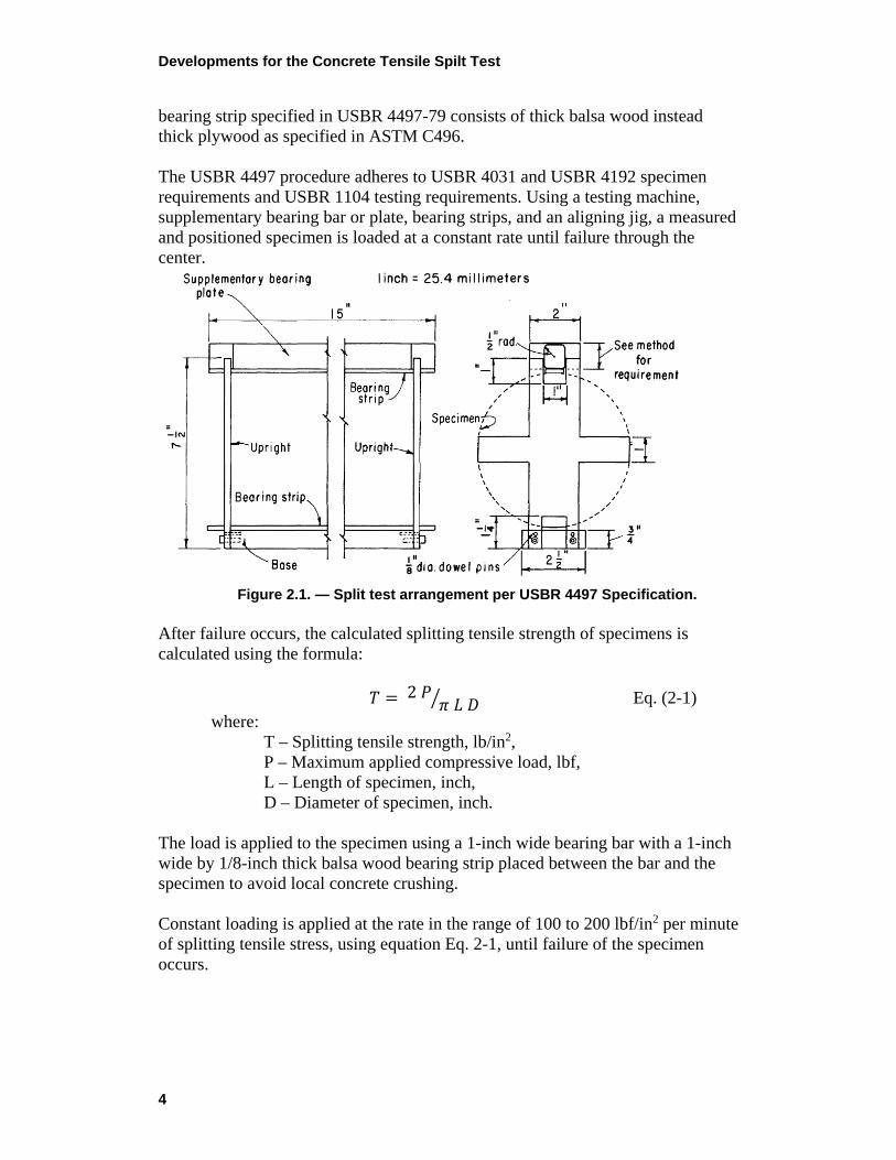
Figure 2.1. — Split test arrangement per USBR 4497 Specification.
After failure occurs, the calculated splitting tensile strength of specimens is calculated using the formula:
𝑇𝑇 = 2 𝑃𝑃𝜋𝜋 𝐿𝐿 𝐷𝐷� Eq. (2-1)
where: T – Splitting tensile strength, lb/in2, P – Maximum applied compressive load, lbf, L – Length of specimen, inch, D – Diameter of specimen, inch.
The load is applied to the specimen using a 1-inch wide bearing bar with a 1-inch wide by 1/8-inch thick balsa wood bearing strip placed between the bar and the specimen to avoid local concrete crushing. Constant loading is applied at the rate in the range of 100 to 200 lbf/in2 per minute of splitting tensile stress, using equation Eq. 2-1, until failure of the specimen occurs.
Developments for the Concrete Tensile Spilt Test
5
2.2.3 ASTM D3967 Standard Reference: ASTM D3967-01 Standard Test Method for Splitting Tensile Strength of Intact Rock Core Specimens The ASTM D2936 Standard defines a test method for the determination of the spitting tensile strength of intact cylindrical rock specimens. The testing procedure for rock is in general similar to procedure specified in ASTM C496 for testing concrete, including calculating the tensile strength of the specimen using equation (2-1), however, some differences exist, including:
• The rock testing is performed on disk samples with a thickness-to-diameter between 0.2 to 0.75.
• Allows for the use of a cardboard cushion in addition to plywood strip to reduce the stress concentration at the applied loads.
• The compressive load is applied at a constant rate of loading or deformation such that failure will occur within 1 to 10 minutes of loading, which is generally between 500 and 3000 lbf/in2 of loading rate.
• The procedure allows the use of flat or curved bearing blocks for transferring the load into the specimen. The curved block is used to reduce the contact bearing stresses in the specimen. The specified radius of curvature is such that the arc of contact with the specimen does not exceed 15 degrees or the width of contact is less than D/6, where D is the diameter of the specimen.
2.2.4 EN 12390 Standard Reference: EN 12390-6:2009 – Testing Hardened Concrete –Part 6: Tensile Split Strength of Test Specimens In 1983, the British Standard for Testing Concrete (Method for Determination of Tensile Splitting Strength) was published. In the general, the split test procedure in BS EN Standard is similar to ASTM C496. The BS EN standard allows the measurement of tensile splitting strength of cylindrical specimens used with hardboard packing strips that are 0.4 inch (10 mm) wide. The Standard discusses testing of concrete cubes and cylinders. It recognizes that cubes gave higher measured tensile strengths than cylinders, by approximately 10 percent and that larger 150 mm cubes gave lower measured tensile strengths than 100 mm cubes therefore the reference method is the use of cylinders of 6 inches diameter and 12 inches length. EN 12390-6:2009 European Standard has been prepared by Technical Committee CEN/TC 104, and is based on the International Standard ISO 4108 – Concrete Determination of Tensile Splitting Strength of Test Specimens. It is an international standard available in three official versions: English, French, and German.

Developments for the Concrete Tensile Spilt Test
6
The tensile strength is rarely determined by direct tensile testing and there is no European specified procedure for it. However, when the test is conducted in accordance with BS EN 12390-6 Standards, the tensile strength of concrete, fct, is calculated from the tensile splitting strength, fct,sp using the relation:
fct = 0.90 fct,sp Eq. (2-2) 2.2.5 ISO 1920 Standard Reference: ISO 1920-4:2005 – Testing of Concrete – Determination of Tensile Splitting Strength ISO 1920-4:2005 specifies a method for the determination of the tensile splitting strength of test specimens for hardened concrete. The standard includes requirements for describing test specimens, determination of apparent density, required apparatus, test procedure, expression of results, and test report requirements. 2.2.6 ACI-318 Standard Reference: ACI-318-2011 – Building Code Requirements for Structural Concrete – Determination of Tensile Splitting Strength The ACI Code [ACI Committee 318, 2008] defines the splitting tensile strength of lightweight concrete in accordance with ASTM C496 and ASTM C330 and provides a relationship between the splitting tensile strength, fct, and the compressive strength, fc as:
𝑓𝑓𝑐𝑐𝑐𝑐 = 6.7�𝑓𝑓𝑐𝑐 [𝑝𝑝𝑝𝑝𝑝𝑝] 𝑜𝑜𝑜𝑜 𝑓𝑓𝑐𝑐𝑐𝑐 = �𝑓𝑓𝑐𝑐 1.8� [𝑀𝑀𝑃𝑃𝑀𝑀] Eq. (2-3)
Figure 2.2. — Split tensile strength as a function of lightweight concrete compressive strength per ACI-318.
However, the ACI Code states that the splitting tensile strength test shall not be used as a basis for field acceptance of concrete.

Developments for the Concrete Tensile Spilt Test
7
3.0 OVERVIEW OF INVESTIGATIONS ON SPLIT
TESTING The test procedure to determine the splitting tensile strength uses a formula (Eq. 2-1) that assumes that the strength of concrete is independent from the specimen size, aggregate size, type of concrete material (compressive strength), the width of the load strip, the rate of the applied load to the specimen, and other test features. The formula was developed based on the theory of elasticity, assuming linear behavior of concrete throughout the entire time of testing. However, the results of various published investigations in several technical papers showed that these variables significantly influence the tensile strength determined in the splitting test. These limitations make the splitting test procedure unreliable for the use in the engineering practice. An overview of the selected publications, discussing the key aspects of splitting test are presented in this chapter. 3.1 Key Investigations The Effect of Aggregate Size on the Use of the Cylinder Splitting Test as a Measure of Tensile Strength – Hannant (1973) In 1973, D.J. Hannant [Hannant, 1973] published a technical paper that discussed the effect of aggregate size on the split test results. In the paper, Hannant noted that the cylinder splitting test has been a well-established indirect test method for determining tensile strength in the past 25 years and the test has become sufficiently well established to be included as a standard test procedure. Some key conclusions from Hannant’s paper are:
• The results of Hannant’s investigations show that aggregate size and volume concentration have an influence on the split / direct tensile strength ratio. For the range of the examined mixes for 2-inch diameter specimens, the ratio varied between 0.95 and 1.28.
• Specimens with larger aggregate particles of greater tensile strength than the concrete paste, results in failure cracks that must occur around the stronger aggregate (at the aggregate/paste contact or thought the paste). Therefore, the failure path must lengthen by going around the aggregate or through the aggregate, both of which increase the resistance to failure.
• The distribution of stresses in the biaxial compressive zone of the specimen is dependent on the stiffness and size of the packing strip (width of the load bearing area). Softer, thicker, packing strips cause an increase in the measured failure load. Packing strip effects are less significant as the cylinder diameter increases.
Developments for the Concrete Tensile Spilt Test
8
• At that time, investigations into the strain pattern using strain gages were also being conducted; however, measurements of strain at several different locations were determined to not be accurate.
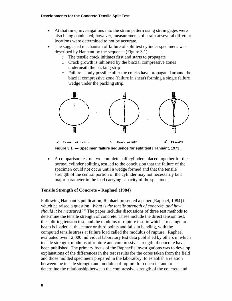
• The suggested mechanism of failure of split test cylinder specimens was described by Hannant by the sequence (Figure 3.1):
o The tensile crack initiates first and starts to propagate o Crack growth is inhibited by the biaxial compressive zones
underneath the packing strip o Failure is only possible after the cracks have propagated around the
biaxial compressive zone (failure in shear) forming a single failure wedge under the packing strip.
Figure 3.1. — Specimen failure sequence for split test [Hannant, 1973].
• A comparison test on two complete half cylinders placed together for the
normal cylinder splitting test led to the conclusion that the failure of the specimen could not occur until a wedge formed and that the tensile strength of the central portion of the cylinder may not necessarily be a major parameter in the load carrying capacity of the specimen.
Tensile Strength of Concrete – Raphael (1984) Following Hannant’s publication, Raphael presented a paper [Raphael, 1984] in which he raised a question “What is the tensile strength of concrete, and how should it be measured?” The paper includes discussions of three test methods to determine the tensile strength of concrete. These include the direct tension test, the splitting tension test, and the modulus of rupture test, in which a rectangular beam is loaded at the center or third points and fails in bending, with the computed tensile stress at failure load called the modulus of rupture. Raphael evaluated over 12,000 individual laboratory test data published by others in which tensile strength, modulus of rupture and compressive strength of concrete have been published. The primary focus of the Raphael’s investigations was to develop explanations of the differences in the test results for the cores taken from the field and those molded specimens prepared in the laboratory; to establish a relation between the tensile strength and modulus of rupture for concrete; and to determine the relationship between the compressive strength of the concrete and
Developments for the Concrete Tensile Spilt Test
9
its true and apparent tensile strength. The test results considered by Raphael included test data from nearly 40 years of testing as described below:
• Gonnerman and Shuman (1928): test included 1,760 moist cured 6-inch diameter cylinders and 7- x 10-inch beams with compressive strengths varying from 200 to 9200 lb/in2. Tensile strength was determined on 6- x 18-inch cylinders held at the end by steel strap grips with leather friction surfaces.
• Walker and Bloem (1960): related splitting tensile test and modulus of rupture test results to compressive strength of 576 specimens, using moist cured 6-inch cylinders and 6- x 6-inch beams.
• Grieb and Werner (1962): tested more than 600 specimens in compression and splitting tension. The specimens were 6- x 12-inch cylinders and 6- x 6- x 21-in beams.
• Houk (1965): tested 324 specimens. Direct tension tests were performed on 6-inch square prisms applied using ¾-inch diameter steel rods embedded on the center axis. Compression test specimens were 6- x 12-inch cylinders and flexural specimens were 6-inch square prisms.
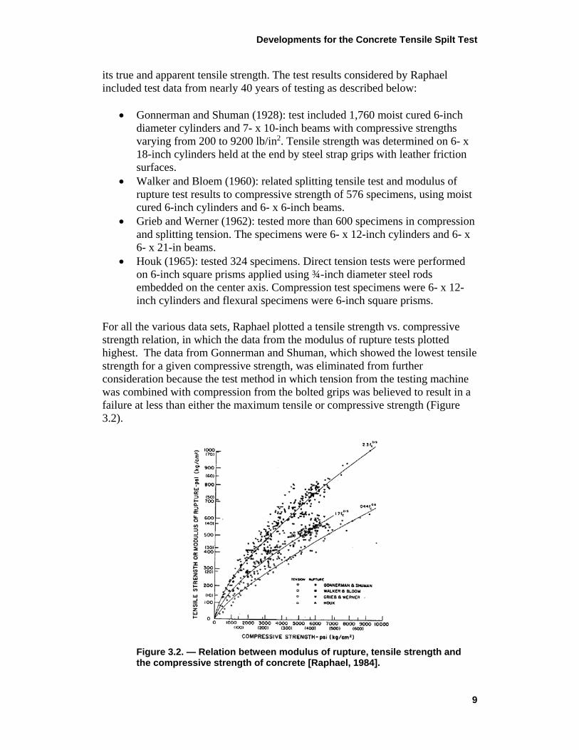
For all the various data sets, Raphael plotted a tensile strength vs. compressive strength relation, in which the data from the modulus of rupture tests plotted highest. The data from Gonnerman and Shuman, which showed the lowest tensile strength for a given compressive strength, was eliminated from further consideration because the test method in which tension from the testing machine was combined with compression from the bolted grips was believed to result in a failure at less than either the maximum tensile or compressive strength (Figure 3.2).
Figure 3.2. — Relation between modulus of rupture, tensile strength and the compressive strength of concrete [Raphael, 1984].
Developments for the Concrete Tensile Spilt Test
10
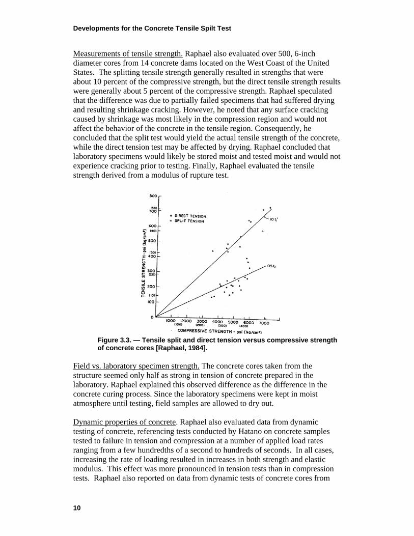
Measurements of tensile strength. Raphael also evaluated over 500, 6-inch diameter cores from 14 concrete dams located on the West Coast of the United States. The splitting tensile strength generally resulted in strengths that were about 10 percent of the compressive strength, but the direct tensile strength results were generally about 5 percent of the compressive strength. Raphael speculated that the difference was due to partially failed specimens that had suffered drying and resulting shrinkage cracking. However, he noted that any surface cracking caused by shrinkage was most likely in the compression region and would not affect the behavior of the concrete in the tensile region. Consequently, he concluded that the split test would yield the actual tensile strength of the concrete, while the direct tension test may be affected by drying. Raphael concluded that laboratory specimens would likely be stored moist and tested moist and would not experience cracking prior to testing. Finally, Raphael evaluated the tensile strength derived from a modulus of rupture test.
Figure 3.3. — Tensile split and direct tension versus compressive strength of concrete cores [Raphael, 1984].
Field vs. laboratory specimen strength. The concrete cores taken from the structure seemed only half as strong in tension of concrete prepared in the laboratory. Raphael explained this observed difference as the difference in the concrete curing process. Since the laboratory specimens were kept in moist atmosphere until testing, field samples are allowed to dry out. Dynamic properties of concrete. Raphael also evaluated data from dynamic testing of concrete, referencing tests conducted by Hatano on concrete samples tested to failure in tension and compression at a number of applied load rates ranging from a few hundredths of a second to hundreds of seconds. In all cases, increasing the rate of loading resulted in increases in both strength and elastic modulus. This effect was more pronounced in tension tests than in compression tests. Raphael also reported on data from dynamic tests of concrete cores from
Developments for the Concrete Tensile Spilt Test
11
five western dams. The results showed that at the rate of loading characteristic of an earthquake, compressive strength increased by an average of 31 percent and the tensile strength increased by an average of 56 percent. Raphael expressed his opinion in the paper that for establishing a concrete tensile strength to be used in stress analysis of mass concrete under a seismic load, the values from a splitting tensile test are the most reliable. Raphael discusses the limitations of a linear finite element analysis, which include the fact that a linear analysis is being used to predict the non-linear behavior of concrete. For the strain value at failure, the elastic analysis will predict higher stresses than the stress the concrete will actually experience. The higher predicted stress value is referred to as the “apparent tensile strength” and has been shown to be about 20 percent higher than the actual tensile stress value at failure. Raphael concludes that the results from a modulus of rupture test, which rely on a linearly derived modulus of rupture, can be compared directly to the stress results from a linear finite element analysis. For a dynamic analysis, he recommends increasing the estimated static tensile strength by 50 percent. Splitting tension test. Raphael stated that prior to failure (for a split test) the biaxial compression region immediately below the load bearing bar (while highly stressed) has greater resistance to failure because of its confined state. Seismic Design Provisions for Roller Compacted Concrete Dams - U.S. Army Corps of Engineers – EP 1110-2-12 – Canon (1995) Appendix E in the 1995 USACE Engineering Pamphlet [USACE, 1995] prepared by Cannon focuses on the tensile strength of roller compacted concrete (RCC). It starts, however, with a general discussion of the tensile strength for concrete. Canon refers to the 1984 Raphael’s paper and concludes that factors that were not considered by Raphael include the effect of aggregate size in mass concrete and the consideration of other factors beyond drying of cores including mixture proportions, tensile properties of the paste and aggregate, the bond of paste to aggregate, and the presence of any air voids and/or microcracking within the matrix. With normal weight aggregates, the bond of paste to aggregate generally controls the tensile strength of the concrete. Canon refers to Thomas and Slate investigations showing that the paste-aggregate tensile bond strength varied from 41 to 91 percent of the tensile strength of the paste, depending on the rock type, the surface roughness of the aggregate and the water to cement ratio. They also found that the mortar-aggregate tensile bond strength varied from 33 to 67 percent of the tensile strength of mortar. Bond can be enhanced by the roughness of crushed aggregate surfaces and may be influenced by differences in thermal properties of aggregate and paste as a result of microcrack formation during cooling of the concrete. Larger size aggregates are commonly used in mass concrete. The effect of increased proportions of larger
Developments for the Concrete Tensile Spilt Test
12
size aggregate on the tensile strength of concrete is that a larger proportion of the tensile load must be transmitted through the paste aggregate bond. Canon quotes Tynes publications who compared the splitting tensile strength of 6-in limestone aggregate mixtures in 20- by 40-in cylinders with wet screened 6- by 12-in cylinders. The effect of excluding aggregates larger than 1-½ in was an increase the tensile strength by a factor of 1.25 to 1.36. Canon explored the relationship of compressive strength to tensile strength. For compressive strengths greater than 3,500 psi equations based on the compressive strength raised to the powers of ½ or 2/3 are reasonably accurate in predicting tensile strengths of structural concrete. For compressive strengths less than 3,500 psi, tensile strengths vary in direct proportion to compressive strength. A possible explanation for this is that for lower strength concretes, the proportion of tensile strength transmitted through bond is higher than that for higher strength concretes. Canon explored the differences between direct tension tests and splitting tensile tests. He considered the orientation of casting in which cubes with the axis of casting vertical were stronger in compression by about 12 to 15 percent than cubes with the axis of casting horizontal. The behavior of concrete in tension was less documented but one study indicated that specimens with the axis of casting vertical were 8 percent weaker in tension that samples that were tested with the axis of casting horizontal. Bleed water on the underside of aggregate particles was the explanation for this behavior. For a splitting tensile test, the plane of failure is normally in line with the direction of casting. The failure surface passes through both aggregate and mortar and the amount of failed aggregate increases with the compressive strength of the concrete. Canon concluded that the over-strength associated with the controlled plane of failure is probably on the order of 10 to 15 percent for maximum aggregate size less than 1 inch and possibly substantially more for larger maximum aggregate size. Canon also revisits the data from Gonnerman and Human that Raphael discarded. He concluded that the concerns that Raphael had about the friction grips at the ends of the specimens were misguided and these tests may still be valid. Based on tests from Portugues Dam, he concluded that a 20 percent reduction may represent the difference between splitting tensile tests and direct tensile tests for the aggregate sizes investigated by Raphael. Direct tension test failures typically occur at the bond around the aggregate and always occur at the weakest cross section of the specimen. The failure is associated with the weakest axis and the weakest plane in the axis. The average of direct tensile test results may be assumed to represent the minimum tensile properties of the concrete. Canon discusses factors that can affect the strength of cores and he acknowledges that Raphael attributed the lower tensile strength from direct tension tests as compared to splitting tensile tests was the result of the formation of surface cracking due to differential drying shrinkage. He references other researchers that
Developments for the Concrete Tensile Spilt Test
13
question this conclusion. Canon does postulate that the coring process may initiate surface defects which act as stress raiser or crack initiators from which a crack can propagate at a stress lower than the tensile strength of the material. For a splitting tensile test, the orientation of the cracks due to the coring operation will be at right angles to the splitting failure plane and relatively unaffected by the orientation of the cracks compared with the in-line orientation in the direct tensile test. Canon concludes that direct tensile testing of vertical cores should be used in determining the tensile properties of horizontal construction joints or of concrete in the vertical direction. Canon provides recommendations for tensile strength of conventional mass concrete. Canon suggest the minimum design tensile strength for static analysis should be based on the direct tensile strength of the concrete. Canon further proposes equations for calculating the direct tensile stress from known compressive strength values:
• For compressive strengths less than 3,000 psi, the tensile strength of 6- by 12-in wet screened cylinders containing 1-½ in and smaller size aggregates may be expected to vary from 0.10 f’c to 0.15 f’c, depending on the type of aggregate.
• For compressive strength above 3,000 psi and MSA up to 1-½ in use either f’st = 1.7 (f’c)2/3 or f’st = 7 (f’c)1/2. For aggregates greater than 1-½ in, reduce strength by 10 percent.
Size Effects in Brazilian Split Cylinder Tests – Bazant (1997) Bazant in the paper titled “Size effects in Brazilian Split Cylinder Tests: Measurements and Fracture Analysis” introduces the concept of size effects to explain the differences in results for split tension test method. Prior to the maximum load, Bazant describes that a significant size effect is caused by macroscopic fracture growth. In general, other researchers have found that for specimen diameters less than 6 inches the split tension value decreases, while diameters greater than 6 inches have increased tension values. However, according to Bazant, “the tensile strength in Brazilian splitting tests increases and reaches a constant value as the cylinder diameter decreases” which could be a result of a failure mode change from brittle to ductile. Bazant explains that “the failure mode in the Brazilian test depends on various parameters including the material properties, stiffness of load platens, and the specimen size”. However, splitting cracks initiate within the uniform tensile zone, which infers that a properly controlled test involves both a peak splitting load and a peak “wedge formation” load. He further explains how the splitting test may exhibit large plastic deformations in small wedge shaped zones under the loading platens.
Developments for the Concrete Tensile Spilt Test
14
Other researchers observed that when flat platens were used, failure initiates under the loading points. Bazant describes that “due to heterogeneity of concrete, there is distributed micro cracking at the pre-peak stage along the load line diameter”. Bazant also notes that “it is possible that the load that produces the frictional slip may be lower or higher than the load that produces the actual splitting. If it is lower, the maximum load is reached when the splitting occurs; after that the load drops, but as displacement increases a second, lower peak corresponding to the plastic slip must be overcome. For a large cylinder size however, the size effect may cause the splitting load peak to become less than the plastic slip load peak, and in the case the maximum load is reached through a ductile mechanism, for which there should be no size effect”. Furthering with the mechanics of failure and the size-effect law, Bazant explains that the split test involves stable, distributed, and interface cracking on the micro- or meso- levels between aggregates and cement paste. “For large diameters, the size of the zone of stable micro cracking does not depend significantly on the structure size, and this makes the size-effect law inapplicable”. Overall, Bazant concludes that “the departure from the size effect law may be explained by the fact that either (1) the length of the splitting facture at maximum load ceases to increase proportionally with the diameter, or (2) the failure mechanism changes at large sizes to one in which the maximum load is reached by frictional plastic slip in a small highly confined wedge-shaped zone under the loading platens”. Size Effect and Boundary Conditions in the Brazilian Test: Experimental Verification – Rocco (1999) In 1999, another paper was published by Rocco investigating the effects of specimen size and width of the bearing strip on the Brazilian test. More specifically, two rupture modes were examined: “1) central crack growth, 2) cracks forming at both sides of the bearing strip.” Rocco explains how although there are two peak loads dependent on the specimen size and bearing strip width, according to ASTM, only the peak load associated with the principal crack is used to determine the tensile strength. However, in 1999, it was practice to use the larger of the two to estimate the tensile strength. Because of this, an adequate balance of specimen size and width of bearing strips was required to ensure that the largest peak correlated to the principal fracture mechanism. Rocco describes that in a rupture process “the first (load) peak appears once the cracking has been initiated in the central zone of the specimen. The unloading immediately after this peak load corresponds to the extension of the principal
Developments for the Concrete Tensile Spilt Test
15
crack. During reloading the secondary cracks appear and grow symmetrically. This continues until one of the secondary cracks begin to extend further, reaching the second peak of load, then the load decreases while the secondary crack continues opening. This secondary crack opening proceeds until the total fragmentation of the specimen.” Rocco noted that this type of cracking process had been observed in tests with other specimen sizes and bearing strip widths. Rocco concludes by further reinforcing that the maximum load measured must correlate to the first peak during the split test, or both the test itself and the determined tensile strength is invalid. Determination of Concrete Tensile Strength from the Split Tensile Test for Cylindrical Concrete Samples - (in German -”Ermittlung der Betonzugfestigkeit aus dem Spaltzugversuch an zylindrischen Betonproben”) – Malarics (2010) The research conducted by Malarics at the Karlsruher Institute of Technology (KIT) as a part of the Ph.D. thesis (Malarics, 2010) aimed at deriving a formula for the conversion of splitting tensile strength into uniaxial tensile strength for normal as well as high strength concretes. To achieve this goal, Malarics carried out extensive experimental and numerical investigations. The experimental program included five different strength types of concrete. Each type was prepared of gravel and of crushed aggregate, respectively. Therefore, in total ten types of concrete were tested. The focus of the experimental investigations was placed on the splitting tension tests to determine the effect of several parameters on the splitting tensile strength and on the failure mechanism. These parameters result from the concrete composition, the geometry and production, as well as from the load application. The experimental investigations revealed higher values for the uniaxial tensile strength than for the splitting tensile strength when obtained on specimens cast with forms, with decreasing compressive strength. Accordingly, the ratio of the uniaxial tensile and the splitting tensile strength decreases with increasing compressive strength, which contradicts, among others, the German standard DIN 1045-1 defining this ratio as a constant value equal 0.9. According to the results of this work, the DIN 1045-1 underestimates the uniaxial tensile strength especially for normal strength concretes. However, when the splitting tensile strength was determined on cores, both the uniaxial tensile strength and the splitting tensile strength increased uniformly with increasing compressive strength, thus revealing a constant relationship. Using splitting tensile strength values to calculate the uniaxial tensile strength, which were obtained on cores with D/L = 6/12 inches, the conversion using A=1.14 leads to considerably higher values of the uniaxial tensile strength than DIN 1045-1.
Developments for the Concrete Tensile Spilt Test
16
The results of the splitting tension tests indicated a significant size effect for a ratio of sample diameter to sample length D/L < 1. However, the splitting tensile strength approached a final value for a constant diameter of D = 6 inches with decreasing length L < 6 inches (D/L > 1) and consequently showed no size effect. With this boundary condition of D/L > 1, the material of the load bearing strips also had no influence on the splitting tensile strength. As an additional result of the investigations, the influence of the specimen size on the failure mechanism and the crack sequence was documented. For the samples with D/L = 6/12 inches the first cracks opened below the load application at the top and the bottom fourth of the height of the cross section, respectively. They widened towards the location of load application. In the samples with D/L = 6/12 inches, the crack opened directly below one load application point and ran towards the other. These findings are contrary to the assumptions of the theory of elasticity. According to the theory of elasticity, the cracks should initiate at the center of the sample cross section. The reason for this can be traced back to the assumptions of the theory of elasticity, which are different for certain stress levels from the actual concrete characteristics, load distribution, etc. Two dimensional numerical investigations were carried out considering the heterogeneity of as well as realistic constitutive laws for concrete, which confirmed the experimental observations. Based on the results of the experimental, fracture mechanical and numerical investigations, empirical models were derived to describe the relation of the uniaxial tensile strength and the splitting tensile strength considering various test parameters. Tensile Strength of Mass Concrete - Implication of Test Procedures and Size Effects on Structural Analysis of Concrete Dams – Dolen, et al. (2014) In the paper [Dolen, 2014], Dolen et al. includes a comprehensive overview of the direct tension and splitting tension tests, considering size effects of specimens during testing and examines two questions: (1) What is the true tensile strength of concrete, and (2) Should a dynamic increase factor, typically ranging from 1.25 to 1.5 times the static strength, be used in the dynamic analysis? The paper presents the results on direct tension and splitting tension results based on Reclamation test data and concludes that the observed tested splitting tensile strength is about twice the direct tensile strength for mass concrete. The paper focuses primary on the parent mass concrete test data, recognizing that the tensile strength of lift lines may only be about 80 percent of the parent concrete. A premise of the paper is that size effects for the splitting tensile test of mass concrete may help to explain the difference in the test results, especially for tests performed with smaller diameter cores and large nominal maximum size of aggregate (NMSA).

Developments for the Concrete Tensile Spilt Test
17
The paper includes a plot of data that relates tensile strength of concrete as a percentage of compressive strength to the specimen size: NMSA ratio as shown in Figure 3.3. The tensile strength as a percentage of the compressive strength value increases with specimen size: NMSA ratio for direct tension tests and decreases for the splitting tensile test. For a direct tension test, the failure is likely at the weakest plane. Increasing the specimen size relative to NMSA should tend to lessen this effect.
Figure 3.4. — Tensile strength as a percentage of compressive strength for direct and splitting test comparing different NMSA ratio specimens.
The three common test methods for determining the tensile strength of concrete are discussed and include the direct tensile test, the splitting tension test and the modulus of rupture or flexural test. The direct tensile strength of parent mass concrete cores tested by Reclamation average about 5.2 percent of the static compressive strength and ranges from about 2.9 percent to 7 percent for data with a minimum of four tests. Direct tension tests have been performed by Reclamation on core up to 18-inches in diameter. Factors that can affect the direct tensile strength of concrete are discussed in the paper including the direction of testing relative to the direction that the concrete was placed. Cores and cylinders cast vertically may be influenced by bleed water collecting under large size coarse aggregate consistent with the actual conditions existing in a dam. For mass cores drilled and tested from Flaming Gorge and Glen Canyon Dam, the average vertical core direct tensile strength is about 75 to 80 percent of that for horizontal cores. The paper also includes a discussion of drilled core test results versus results from cast cylinders. There are a few large-scale test programs that include

Developments for the Concrete Tensile Spilt Test
18
cast cylinders with small NMSA that show higher tensile strength as a percentage of compressive strength values than for drilled cores. The splitting tensile strength test is also discussed by Dolen. In the ASTM test, the load is transmitted to the cylinder through 1-inch wide bearing strips. The bearing strip width is not adjusted based on the diameter of the sample being tested. The modulus of rupture test is also discussed, and this test relies on the assumption of a linear stress distribution throughout the entire height of the beam. There is a detailed discussion of the drawbacks of the splitting tensile test referring to Wright’s comments (Wrigth, 1955) on discrepancies in the splitting tensile test. Wright notes some deviations from the theoretical basis of the test when testing mass concrete. These include the fact that concrete is not a homogeneous material as assumed in the theory; the theory assumes that strain is proportional to stress (Hooke’s law) but this does not apply for concrete where the apparent value of Young’s modulus decreases with increasing compression; and the fact that the load is applied through a strip and not as a point load as assumed in the theory. Wright concluded that the splitting tensile test results approach the average concrete strength while the direct tensile strength test would be closer to the minimum tensile strength. Work by Hannant is also discussed. They concluded that the there is a complex stress state that affects the splitting tensile strength of concrete. They postulated that the initial tensile crack upon loading is restrained by biaxial compressive zones under the packing strip and failure only occurs after the crack propagates around this zone or it fails as a wedge in shear or diagonal tension. The paper also includes a summary of work by Rocco, who examined the splitting tensile strength from a fracture mechanics point of view. Six different test methods were evaluated, in which the specimen size, specimen geometry and load bearing strip width were varied. The different test methods produced results that were within 6 percent of each other, if size effects are neglected. If size effects are considered, the variation was as much as 35 percent. The one-inch bearing strip was cited as significantly contributing to the overestimation of the tensile strength. Rocco concluded that due the size effects, the standardized splitting tensile strength should not be considered a material property of concrete. The paper builds on an approach developed by Rocco to adjust splitting tension test values for size effects and arrive at the true direct tensile strength of the concrete. The process uses the characteristic length of concrete, which is considered a material property of concrete and is related to the failure process zone (cracking zone that still carries tensile load) ahead of a crack, and increases in concrete with NMSA. Rocco relates size effects to the “reduced characteristic length” which was derived from the NMSA and the compressive strength of the concrete (the paper is not clear on how this relationship was developed or calculated). The reduced characteristic length is used in another set of graphs (as part of the ratio of the specimen diameter to the reduced characteristic length
Developments for the Concrete Tensile Spilt Test
19
along with the ratio of the bearing strop width to specimen diameter ratio to estimate the ratio of the splitting tensile strength to “true/direct” tensile strength. This last parameter can be used to “correct” the splitting tensile test values. It is not clear in the paper how the splitting tensile strength/true tensile strength ratio is determined and if the direct tensile strengths are also affected by some of the factors that are attributed to a reduction in the splitting tension strength values. This approach indicates that for the ASTM C496 test method and a 1-inch bearing strip width, small diameter cores and large NMSA can result in a large increase in the fst/ft ratio and that the splitting tensile strength value would have to be decreased significantly to approach a more realistic “true” tensile strength. The paper extrapolates the curves developed by Rocco to predict the results for mass concrete. Several assumptions were made to perform the extrapolations for the reduced characteristic length curves, including: (1) for a given compressive strength, doubling the size of coarse aggregate doubles the reduced characteristic length, and (2) for a given coarse aggregate size, decreasing the compressive strength from 5,800 to 2,900 lbf/in2 increases the reduced characteristic length by about 40 percent. The second set of curves developed by Rocco that provide the fst/ft ratios were also modified by extrapolating existing curves and adding a new curve. The curves were modified by “scaling” but it is not clear how this was done. Tensile strength values from several Reclamation dam testing programs were adjusted based on the fracture mechanics cohesive crack model. On average, the adjusted tensile strength was about 25 percent higher than the average direct tensile strength values and 35 percent lower than the average splitting tensile test values. Data from a number of testing programs indicate that the results of splitting tensile tests and direct tensile tests converge at a specimen size: NMSA ratio of about 7. Based on this, the paper concludes that specimens for 6 inch NMSA mass concrete would have to be about 3.5 to 4 feet in diameter. A graph is also provided in the paper that displays the tensile strength of concrete as compared to the compressive strength. Curves are drawn through the data to reflect direct tensile strength, splitting tensile strength, the adjusted tensile strength using the fracture mechanics cohesive crack model. The paper also summarizes some testing results from Reclamation on the dynamic tensile strength of mass concrete. The loading rates were based on the quarter peak cycles of earthquake waves ranging from about 2 to 10 Hz, resulting in failure times ranging from 0.05 to 0.25 seconds for compressive, direct tension and splitting tension tests. The direct tensile strength increased by an average of 40 percent under dynamic conditions compared to static tests. The average compressive strength increased by about 30 percent and the rapid splitting tensile strength increased by about 18 percent. The paper also presented results from several studies that investigated the effect of moisture conditioning on concrete strength. The tests showed that saturated test specimens are likely to increase in
Developments for the Concrete Tensile Spilt Test
20
strength under dynamic load rates. It was noted that the splitting tensile test results were quite variable for the moisture conditions studied. The paper discusses approaches for estimating the tensile strength of concrete for the structural analysis of dams. One approach is to use the fracture mechanics cohesive crack model method discussed in detail in the paper. Alternative approaches are to use the splitting tensile strength values directly under certain conditions. These include: (1) assuring that the tension values are compared to analysis results representing a comparable stress state, or (2) using the split cylinder test results with other data to form a failure surface for analysis or analysis results comparison. The paper discusses the need for judgement in the evaluation of concrete dams. It indicates that the potential uncertainties need to be understood and that one strength parameter should not be relied on too heavily when evaluating the ultimate stability of the dam. A conservative approach to the tensile strength of concrete is suggested. The paper concludes that size effects in tension testing of concrete are well understood and that the splitting tensile test may overestimate the “true” tensile strength. Small diameter cores with 2- to 6-inch NMSA may overestimate the apparent tensile strength by 40 to 80 percent. Ten to twelve inch diameter cores with 3- to 6-inch NMSA may overestimate the apparent tensile strength by 20 to 35 percent. The paper proposes the use of the cohesive crack model concepts for adjusting the splitting tensile strength of mass concrete. It also concludes that the dynamic tensile strength can reasonably be increased by a factor of 1.5 for saturated direct tension specimens but that this dynamic increase should not be used for air-dried test specimens. The paper concludes by proposing that more research be conducted to confirm the findings in the paper.
Developments for the Concrete Tensile Spilt Test
21
4.0 ANALYTICAL MODEL In this section, an overview of the most significant research investigations related to development of the split test analytical models is presented. This outline starts with its original test formulation that was based on the theory of elasticity and concludes with a discussion of the most current developments that are based on the theory of fracture mechanics for concrete. 4.1 ASTM and USBR Specifications Both, the current version of ASTM C-496-17 Standard and USBR 4497-92 Specification uses the same formula for determining the splitting tensile strength that was originally developed by Carneiro [Carneiro, 1943] and Akazawa [Akazawa, 1943] in the form:
𝜎𝜎𝑠𝑠𝑠𝑠 = 2𝑃𝑃𝑚𝑚𝑚𝑚𝑚𝑚𝜋𝜋𝜋𝜋𝜋𝜋
(Eq.4-1) where:
σsp = strength of concrete determined in split tensile test, psi, [Pa] Pmax = maximum applied load indicated by the testing machine, lbf, [n] L = length of the specimen, in, [mm] D = diameter of the specimen, in, [mm]
Akazawa developed the above formula based on the work of Timoshenko [Timoshenko, 1934] and Prescott for an elastic circular disk that is compressed by two concentrated loads, acting in opposite directions along the disk diameter. Carneiro conducted an independent investigation on the split tensile strength of concrete. His work was motivated by the activities related to relocation of a Baroque church that interfered with a planned a new road. Due to the Second World War, the availability of steel products was limited, so concrete rollers were considered. The outcome of Carneiro’s investigations resulted in a new test procedure in Brazilian Standards for indirect concrete strength for cylindrical samples. The approach selected by Carneiro was based on the theoretical solutions by Timoshenko [Timoshenko, 1934], Föppl, and Frocht for an elastic disk compressed by two forces distributed over a strip width b, applied to the disk perimeter. Carneiro noted that the relation (Eq. 4-1) describes correctly the split test results when the ratio of the load strip width, b, to the disk diameter, D, is smaller than 0.1. 4.2 Timoshenko’s Model The Timoshenko’s solution of a compressed disk of a unit thickness (Fig. 4.1) was derived from the well-known in the structural mechanics Boussinesq’s (1885)
Developments for the Concrete Tensile Spilt Test
22
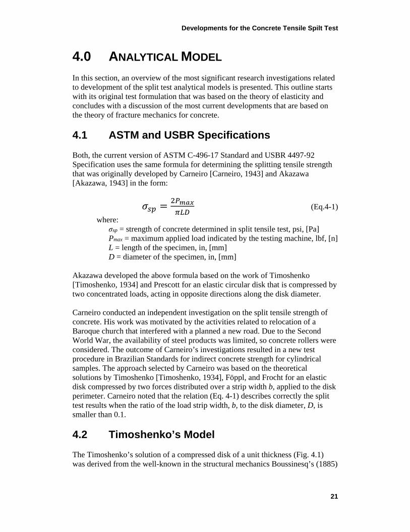
and Flamant’s (1892) formulations for a case of a concentrated force acting on a semi-infinite body.
Figure 4.1. —Timoshenko’s model of a disk loaded with force P.
In any element C (Fig. 4.1) at a distance r from the point of load application, O, the compression in radial direction is:
𝜎𝜎𝑟𝑟 = 2𝑃𝑃 𝜋𝜋
cos𝜓𝜓𝑟𝑟
(Eq.4-2) The tangential stress and the shear stress in element C are zero. Taking a circle with center at the Y axis, tangent to X axis at O, we have at any point the following relation: D cos ψ = r. Hence, the stress is the same at all points on the circle they can be expressed along axis Y by Eq. 4-1, for length of the disk L =1. The maximum compressive stress along the dimeter parallel to axis X at the center of the disk is equal to:
𝜎𝜎𝑦𝑦 𝑚𝑚𝑚𝑚𝑚𝑚 = 6𝑃𝑃 𝜋𝜋𝜋𝜋
(Eq.4-3) 4.3 Solutions for Compressed Elastic Disk Frocht [Frocht, 1948] formulated the stress distribution in an elastic disk along the diameter perpendicular to the line of action of two compressing concentrated forces (y = 0) (Fig. 4.2) by the following forms:
𝜎𝜎𝑚𝑚 = 2𝑃𝑃𝜋𝜋𝜋𝜋𝜋𝜋
�𝜋𝜋2−4𝑚𝑚2
𝜋𝜋2+4𝑚𝑚2�2 (Eq.4-4)
𝜎𝜎𝑦𝑦 = − 2𝑃𝑃𝜋𝜋𝜋𝜋𝜋𝜋
� 4𝜋𝜋4
(𝜋𝜋2+4𝑚𝑚2)2 − 1� (Eq.4-5)
Developments for the Concrete Tensile Spilt Test
23
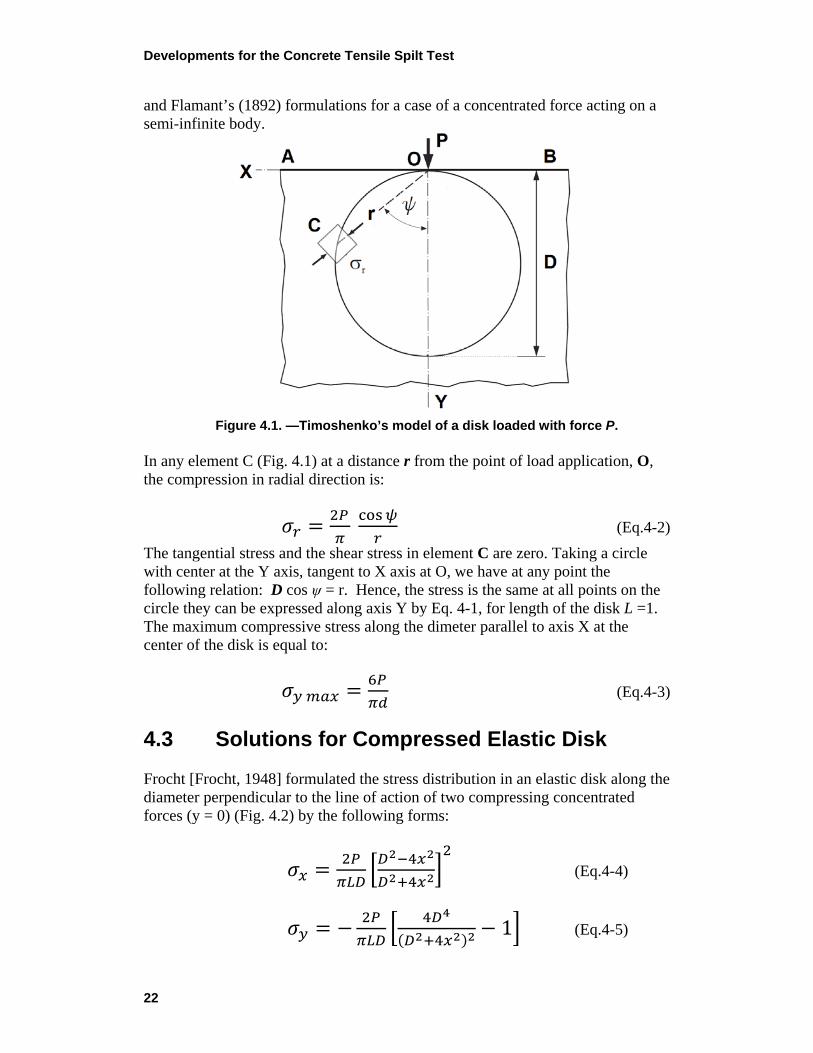
The stresses along the diameter parallel to the acting forces (x = 0), (Fig. 4.3) are as prescribed in the form:
𝜎𝜎𝑚𝑚 = 2𝑃𝑃𝜋𝜋𝜋𝜋𝜋𝜋
(Eq.4-6)
𝜎𝜎𝑦𝑦 = − 2𝑃𝑃𝜋𝜋𝜋𝜋𝜋𝜋
� 2𝜋𝜋
𝜋𝜋−2𝑦𝑦 + 2𝜋𝜋
𝜋𝜋+2𝑦𝑦 − 1� (Eq.4-7)
Figure 4.2. — Frocht’s model of a disk loaded with force P.
It can be observed from Fig. 4.2 that the vertical compressive stress intensity is 3 times higher than the horizontal tension stress intensity at the center of the disc. This observation is in an agreement with Timoshenko’s formula presented above. Muskhelishvili [Jianhong, 2009] developed the stress in an elastic disk expressed by the formula:
Developments for the Concrete Tensile Spilt Test
24
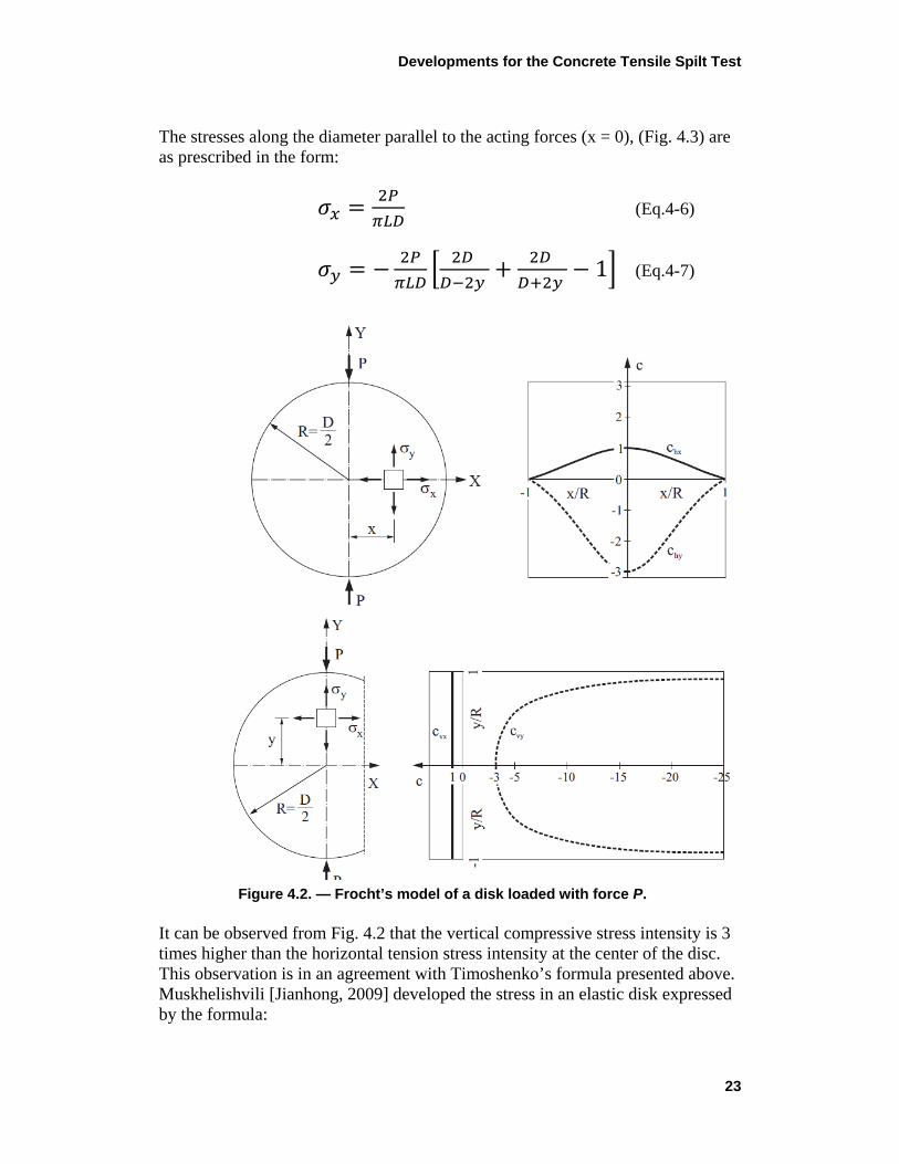
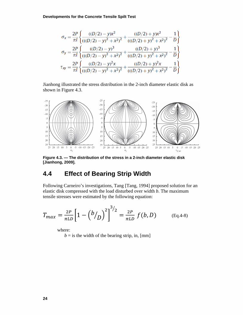
Jianhong illustrated the stress distribution in the 2-inch diameter elastic disk as shown in Figure 4.3.
Figure 4.3. — The distribution of the stress in a 2-inch diameter elastic disk [Jianhong, 2009]. 4.4 Effect of Bearing Strip Width Following Carneiro’s investigations, Tang [Tang, 1994] proposed solution for an elastic disk compressed with the load disturbed over width b. The maximum tensile stresses were estimated by the following equation:
𝑇𝑇𝑚𝑚𝑚𝑚𝑚𝑚 = 2𝑃𝑃𝜋𝜋𝜋𝜋𝜋𝜋
�1 − �𝑏𝑏 𝐷𝐷� �2�32�
= 2𝑃𝑃𝜋𝜋𝜋𝜋𝜋𝜋
𝑓𝑓(𝑏𝑏,𝐷𝐷) (Eq.4-8)
where:
b = is the width of the bearing strip, in, [mm]
Developments for the Concrete Tensile Spilt Test
25
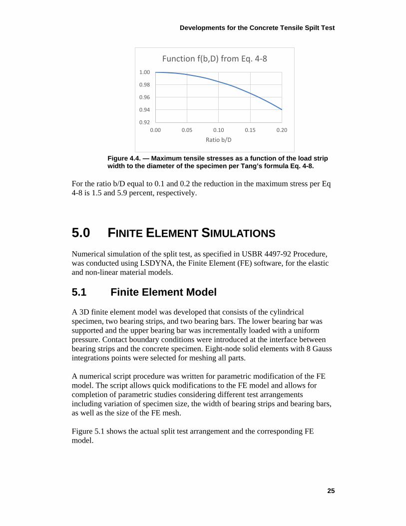
Figure 4.4. — Maximum tensile stresses as a function of the load strip width to the diameter of the specimen per Tang’s formula Eq. 4-8.
For the ratio b/D equal to 0.1 and 0.2 the reduction in the maximum stress per Eq 4-8 is 1.5 and 5.9 percent, respectively.
5.0 FINITE ELEMENT SIMULATIONS Numerical simulation of the split test, as specified in USBR 4497-92 Procedure, was conducted using LSDYNA, the Finite Element (FE) software, for the elastic and non-linear material models. 5.1 Finite Element Model A 3D finite element model was developed that consists of the cylindrical specimen, two bearing strips, and two bearing bars. The lower bearing bar was supported and the upper bearing bar was incrementally loaded with a uniform pressure. Contact boundary conditions were introduced at the interface between bearing strips and the concrete specimen. Eight-node solid elements with 8 Gauss integrations points were selected for meshing all parts. A numerical script procedure was written for parametric modification of the FE model. The script allows quick modifications to the FE model and allows for completion of parametric studies considering different test arrangements including variation of specimen size, the width of bearing strips and bearing bars, as well as the size of the FE mesh. Figure 5.1 shows the actual split test arrangement and the corresponding FE model.
0.92
0.94
0.96
0.98
1.00
0.00 0.05 0.10 0.15 0.20
Ratio b/D
Function f(b,D) from Eq. 4-8
Developments for the Concrete Tensile Spilt Test
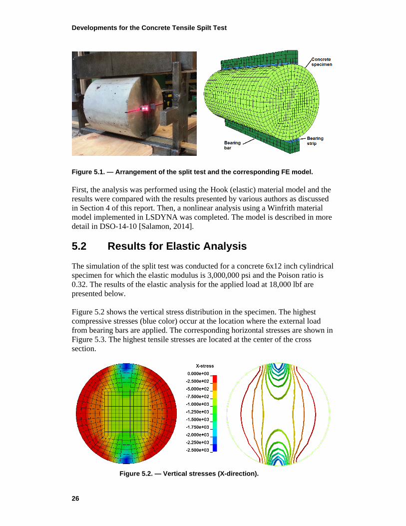
26
Figure 5.1. — Arrangement of the split test and the corresponding FE model. First, the analysis was performed using the Hook (elastic) material model and the results were compared with the results presented by various authors as discussed in Section 4 of this report. Then, a nonlinear analysis using a Winfrith material model implemented in LSDYNA was completed. The model is described in more detail in DSO-14-10 [Salamon, 2014]. 5.2 Results for Elastic Analysis The simulation of the split test was conducted for a concrete 6x12 inch cylindrical specimen for which the elastic modulus is 3,000,000 psi and the Poison ratio is 0.32. The results of the elastic analysis for the applied load at 18,000 lbf are presented below. Figure 5.2 shows the vertical stress distribution in the specimen. The highest compressive stresses (blue color) occur at the location where the external load from bearing bars are applied. The corresponding horizontal stresses are shown in Figure 5.3. The highest tensile stresses are located at the center of the cross section.
Figure 5.2. — Vertical stresses (X-direction).
Developments for the Concrete Tensile Spilt Test
27
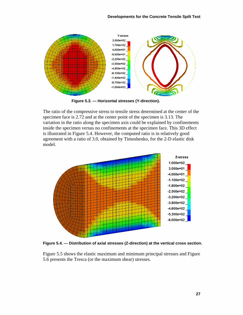
Figure 5.3. — Horizontal stresses (Y-direction).
The ratio of the compressive stress to tensile stress determined at the center of the specimen face is 2.72 and at the center point of the specimen is 3.13. The variation in the ratio along the specimen axis could be explained by confinements inside the specimen versus no confinements at the specimen face. This 3D effect is illustrated in Figure 5.4. However, the computed ratio is in relatively good agreement with a ratio of 3.0, obtained by Timoshenko, for the 2-D elastic disk model.
Figure 5.4. — Distribution of axial stresses (Z-direction) at the vertical cross section. Figure 5.5 shows the elastic maximum and minimum principal stresses and Figure 5.6 presents the Tresca (or the maximum shear) stresses.
Developments for the Concrete Tensile Spilt Test
28
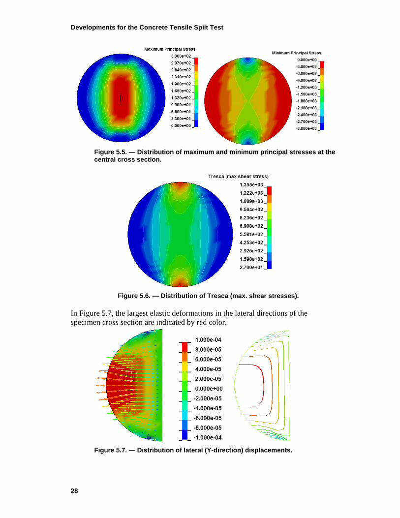
Figure 5.5. — Distribution of maximum and minimum principal stresses at the central cross section.
Figure 5.6. — Distribution of Tresca (max. shear stresses).
In Figure 5.7, the largest elastic deformations in the lateral directions of the specimen cross section are indicated by red color.
Figure 5.7. — Distribution of lateral (Y-direction) displacements.
Developments for the Concrete Tensile Spilt Test
29
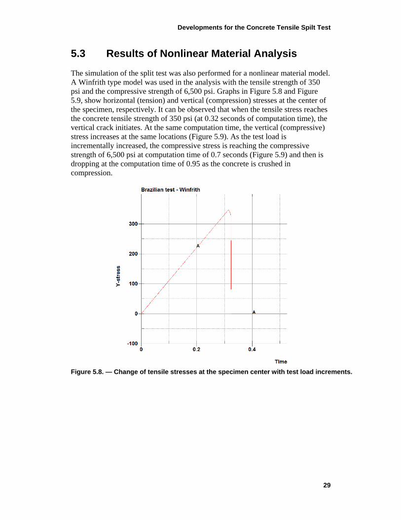
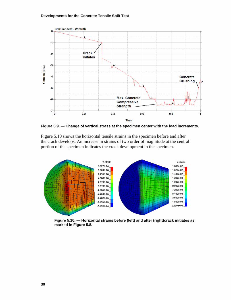
5.3 Results of Nonlinear Material Analysis The simulation of the split test was also performed for a nonlinear material model. A Winfrith type model was used in the analysis with the tensile strength of 350 psi and the compressive strength of 6,500 psi. Graphs in Figure 5.8 and Figure 5.9, show horizontal (tension) and vertical (compression) stresses at the center of the specimen, respectively. It can be observed that when the tensile stress reaches the concrete tensile strength of 350 psi (at 0.32 seconds of computation time), the vertical crack initiates. At the same computation time, the vertical (compressive) stress increases at the same locations (Figure 5.9). As the test load is incrementally increased, the compressive stress is reaching the compressive strength of 6,500 psi at computation time of 0.7 seconds (Figure 5.9) and then is dropping at the computation time of 0.95 as the concrete is crushed in compression.
Figure 5.8. — Change of tensile stresses at the specimen center with test load increments.
Developments for the Concrete Tensile Spilt Test
30
Figure 5.9. — Change of vertical stress at the specimen center with the load increments. Figure 5.10 shows the horizontal tensile strains in the specimen before and after the crack develops. An increase in strains of two order of magnitude at the central portion of the specimen indicates the crack development in the specimen.
Figure 5.10. — Horizontal strains before (left) and after (right)crack initiates as marked in Figure 5.8.
Developments for the Concrete Tensile Spilt Test
31
6.0 SUMMARY AND CONCLUSIONS 6.1 Summary The tensile strength of concrete is an essential characteristic in the structural assessment of concrete dams. Erroneous estimations of the concrete tensile strength may lead to underestimate safety of the structure or may result in its unnecessary modifications. The concrete tensile strength is most commonly determined by splitting tension or uniaxial compression tests after which the true tensile strength is calculated using conversion formulas. The popularity of both tests is related to their simplicity and economy. For several projects, splitting tension and compression tests are generally the only feasible methods in estimation tensile strength of concrete. Alternatively, a uniaxial tensile test is conducted to determine the tensile strength of concrete. Although, the results of this test are often called a “true tensile strength of concrete”, some doubt has been cast upon the accuracy of the test for the cores taken from the existing structures. Since the direct tension test preparation is labor intensive and requires a special laboratory arrangement, its usage is limited to large projects were the uniaxial test procedure is predominantly specified. 6.2 Conclusions
The split tensile test was developed in 1940’s and it was adopted in its original form by several national standards. Since then the original test procedure has been commonly used for decades. The differences observed in the test results when compared with the direct tension test results raises doubts about the pertinence of the split test for strength determination of concrete. The primary factors identified in this research that influence mostly the split test results of the test specified in the ASTM C-496 and USBR 4496 are:
• In the split test, the maximum compressive load is recorded at failure. This load is then converted to the maximum tensile stress using a simple formula, develop based on the theory of elasticity. The use of an elastic model to describe non-linear behavior of concrete is one of the reasons for the observed discrepancies in the test results.
• The formula for determining split tensile strength does not account for the specimen size effect and compressive strength of concrete, which may have a dominating influence on the test results, as showed by various researchers.
• The laboratory test results and the FE analysis results for non-linear concrete model showed that the crack initiates in the specimen before the maximum compressive load is recorded and the specimen is crushed.

Developments for the Concrete Tensile Spilt Test
32
Based on this observation it could be stated, that the tensile strength determined in the Brazilian test is overestimated.
• The width of the bearing strip of 1 inch is specified in ASTM and USSD test procedure whereas, the width of the bearing strip 0.625 inches or even 0.5 inch in the latest version of the European Code. As the FE analysis results show, confirmed by the laboratory test data, the width of the bearing area is one of the most significant factor influencing the test results. It is observed the smaller bearing width results in lower measured compressive load applied during the test and consequently lower reported splitting tensile strength of concrete.
• The specified by ASTM and USSD rate, the load is applied in the split test, ranges between 100 to 200 lbf/in2 per minute. The initial test results performed in the Reclamation’s laboratory showed, that the splitting tensile strength obtained at the load rate of 100 and 200 lbf/in2 per minute differs by about 10 percent and about 20 percent for concrete 6,000 lbf/in2 and 4,000 lbf/in2, respectively. Even higher difference is expected for lower strength concrete.
Considering all the factors discussed above, it appears that some revisions to the current ASTM and USBR procedures for splitting tensile test are required.
Future research that combine the testing program conducted at Reclamation’s Laboratory with the test simulations using FE analysis is recommended to further verify and improve the current split test procedure. The positive outcome from these investigations would benefit Reclamation and the engineering community when a more reliable method for determining the tensile strength of concrete using splitting tests is established.
Developments for the Concrete Tensile Spilt Test
33
References
[1] ASTM C496/C496M-17: Standard test method for split tensile strength of cylindrical concrete specimens. ASTM International, 2017.
[2] AKAZAWA T.: New testing method to find the tensile strength of concrete.
In: Journal of Japan Society of Civil Engineers 29, pp. 777-787, 1943. [3] AKAZAWA T.: Splitting tensile test of cylindrical specimens. In: Journal of
Japan Society of Civil Engineers 6, Nr 1, pp. 12-19, 1943. Republished: Tension test method for concrete. In: Bulletin RELEM 16, Paris, pp. 13-23, 1953.
[4] BAZANT, Z.P., PLANAS J.: Fracture and Size Effect in Concrete and Other
Quasibrittle Materials, CRC Press, New York 1997. [5] CARNEIRO F. L. L. B.: A new method to determine the tensile strength of
concrete. In Proceedings of the 5th meeting of the Brazilin Association for Technical Rules, Sec. 3, pp. 126-129, 16 September 1943.
[6] DOLEN T.P., HARRIS D.W., NUSS, L.K.: “Tension Strength of Mass
Concrete – Implications of Test Procedures and Size Effects on Structural Analysis of Concrete Dams,” United States Society on Dams, 34th Annual Meeting and Conference, held in San Francisco, CA on April 7–11, 2014.
[7] DESAYI P.: Strength of concrete under combined compression and tension-
determination of interaction curve at failure form cylinder split test” developed a formula, Matériaux et Constructions, Vol.2-No.9, 1969.
[8] DIN EN 12390-6: Prüfung von Festbeton. Teil 6: Spaltzugfestigkeit von
Probeköpern. Beuth Vergalg, Berlin, 2006. [9] FROCHT M. M.: Photoelasticity. John Wiley & Sons Inc., Vol. II, 1948. [10] GARCIA V. J., MARQUEZ C.O., ZUNIGA-SUAREZ A.R., ZUNIGA-
TORRES B. C., VILLATA_GRANDA L.J.: Brazilian test of concrete specimen subject to different loading geometries: Review and new insights. International Journal of Concrete Structures and Materials, Vol. 11, No. 2, pp. 343-363, June 2017.
[11] HANNA D.J., BUCKLEY K. J., CROFT J.: The effect of aggregate size on
the use of the cylinder splitting test as a measure of tensile strength, Matériaux et Construction, Volume 6, Issue 1, pp 15–21, 1973.
Developments for the Concrete Tensile Spilt Test
34
[12] JIANHONG Y., WU F.Q., SUN J.Z.: Estimation of the tensile elastic
modulus using Brazilian disc by applying diametrically opposite concentrated loads. International Journal of Rock Mechanics & Mining Sciences 46, pp. 568-576, 2009.
[13] JIS A 1113: Method for test for splitting tensile strength of concrete.
Japanese Standard Association, 2006. [14] MALÁRICS V.: Ermittlung der Botonzugfestigkeit aus dem Spaltzugversuch
an zylindrischen Betonproben. Karlsruher Institut für Technologie, Heft 69, KIT Scientific Publishing, 2010.
[15] MALÁRICS V., Müller H. S.: Evaluation of the splitting tension for concrete
from fracture mechanical point of view. Fracture Mechanics of Concrete Structures, ISBN 978-89-5708-181-5, Korea Concrete Institute, Seoul, 2010.
[16] MALÁRICS V., Müller H. S.: Experimental and numerical analysis of the
fracture process in the splitting tension test of concrete. In: 6th International Conference on Fracture Mechanics of Concrete and Concrete Structures, Catania, Italy, June 2007.
[17] PN EN 12390-6: Wytrzymałość na rozciąganie przy rozłupywaniu próbek do
badań. 2011. [18] RAPHAEL J.M.: Tensile strength of concrete. ACI Journal, March-April
1984. [19] ROCCO C., GUINEA G.V., PLANAS J., ELICES J.: Size effect and
boundary conditions in the Brazilian test: theoretical analysis. Materials and Structures, Vol. 32, pp.437-444, July 1999.
[20] ROCCO C., GUINEA G.V., PLANAS J., ELICES J.: Size effect and
boundary conditions in the Brazilian test: experimental verification. Materials and Structures, Vol. 32, pp.210-217, April 1999.
[21] ROCCO C., GUINEA G.V., PLANAS J., ELICES J.: Mechanisms of rupture
in splitting test. ACI Materials Journal, January-February 1999. [22] ROCCO C., GUINEA G.V., PLANAS J., ELICES J.: Review of the
splitting-test standards form a fracture mechanics point of view. Cement and Concrete Research 31, 2001.
Developments for the Concrete Tensile Spilt Test
35
[23] RILEM.: Tension Splitting of Concrete Specimen, CPC6, 1975, Rilem Technical Recommendation for the Testing and Use of Construction Materials. E & FN Spon, London, pp. 21–22,1994.
[24] SALAMON J.W., HARRIS, D.W: Evaluation of Nonlinear Martial Models
in Concrete Dam Finite Element Analysis, US Bureau of Reclamation, Report DSO-2014-08, September 2014.
[25] TANG T.: Effects of load-distributed width on split tension of unnotched and
notched cylindrical specimens. In: Journal of Testing and Evaluation 22, pp. 401-409, 1994.
[26] TIMOSHENKO S.P., Goodier J.N., Theory of Elasticity, 1st Edition (1934),
3rd Edition (1970), McGraw-Hill Book Company, St. Louis, 1970. [27] USACE: Seismic design provisions for Roller Compacted Concrete Dams,
U.S. Army Corps of Engineers, EP 1110-2-12, Appendix E, 30 September 1995.
[28] USBR 1104-92: Procedure for Load Verification of Testing Machines, US
Bureau of Reclamation, Concrete Manual Part 2, 9th Ed., 1992. [29] USBR 4031-92: Procedure for Making and Curing Concrete Test Specimens
in Field, US Bureau of Reclamation, Concrete Manual Part 2, 9th Ed., 1992.
[30] USBR 4192-92: Procedure for Making and Curing Concrete Test Specimens
in Laboratory, US Bureau of Reclamation, Concrete Manual Part 2, 9th Ed., 1992.
[31] USBR 4914-92: Procedure for Direct Tensile Strength, Static Modulus of
Elasticity, and Poisson’s Ratio of Cylindrical Concrete Specimens in Tension, US Bureau of Reclamation, Concrete Manual Part 2, 9th Ed., 1992.
[32] USBR 4497-92: Procedure for Splitting Tensile Strength of Cylindrical
Concrete Specimens, US Bureau of Reclamation, Concrete Manual Part 2, 9th Ed., 1992.
[33] WRIGHT P.J.: Comments on an indirect tensile test on concrete cylinders.
In: Magazine of Concrete Research, No. 20, July 1955.