unit – i – maintenance and repair strategies – scia7003
TRANSCRIPT
1
SCHOOL OF BUILDING AND ENVIRONMENT
DEPARTMENT OF CIVIL ENGINEERING
UNIT – I – Maintenance and Repair Strategies – SCIA7003
2
I. Maintenance and Repair Strategies
Maintenance: Maintenance is preventive in nature. Activities include inspection and works
necessary to fulfill the intended function or to sustain original standard of service. The
maintenance of structure is done to meet the following objective:
Prevention of damages due to natural agencies and to keep them in good
appearance and working condition.
Repair of the defects occurred in the structure and strengthen them, if necessary.
The Maintenance work is broadly classified as
a) Preventive Maintenance
b) Remedial Maintenance
c) Routine Maintenance
d) Special Maintenance
a) Preventive Maintenance: The maintenance work done before the defects occurred or
damage developed in the structure is called preventive maintenance. It includes thorough
inspection, planning the programs of maintenance and executing the work It depends upon
the specifications, condition and use of structure.
b) Remedial Maintenance: It is the maintenance done after the defects or damage occurs
in the structure. It involves the following basic steps.
-Finding the deterioration
-Determining the causes
-Evaluating the strength of the existing structure
- Evaluating the need of the structure
-Selecting and implementing the repair procedure
c) Routine Maintenance: It is the service maintenance attended to the structure
periodically. The nature of work done and interval of time at which it is done depends upon
specifications and materials of structure, purpose, intensity and condition of use. It includes
white washing, parch repair to plaster, replacement of fittings and fixtures, binding of road
surface.
e) Special Maintenance: It is the work done under special condition and requires sanction
and performed to rectify heavy damage. It may be done for strengthening and updating of the
structure to meet the new condition of usage or to increase its serviceability. It may include
particular or complete renewal occurring at long interval, such as floors, roofs etc.
3
Necessity of maintenance: The causes which necessitate the maintenance effects the service
and durability of the structure as follows:
a) Atmospheric agencies
b) Normal wear and tear
c) Failure of structure
a) Atmospheric agencies
Rain: It is the important source of water, which affects the structure in the following ways;
Physical:
Dissolving and carrying away minerals as it is universal solvent.
Expansion and contraction – The materials is subjected to repetitive expansion and
contraction while they become wet and dry and develops the stresses.
Expansion of water – The variation of temperature causes the expansion and contraction
absorbed water and affects the micro-structures of the materials.
Erosion – Transportation, attrition and abrasion of the materials is quite evident effect of the
water.
Chemical: The water available in nature contains acids and alkaline and other compound in
dissolve form acts over the material to give rise, which is known as chemical weathering.
Wind: It is the agent, which transports the abrasive material and assists the physical
weathering Its action is aggravated during rains and, When it is moving with high speed, it
may contains acidic gases like CO2 fumes which may act over the material and penetrates
quite deeply in materials and structure.
Temperature: The seasonal and annual variation of the temperature, difference in temperature
in two parts of the materials and the surface of material causes expansion and contraction,
this movement of the material bond and adhesion between them is lost when it is repeated.
This is responsible for the development of cracks and the rocks may break away into small
units. Exploitation or peeling off the shell takes place if exterior layer are heated externally
with respect to internal layers. The temperature variation may also cause change in the
structure and chemical composition of the material.
b) Normal Wear and tear: During the use of structure it is subjected to abrasion and thereby
it loses appearance and serviceability.
c) Failure of structure: Failure is defined as the behavior of structure not in agreement with
expected condition of stability or lacking freedom from necessary repair or non-compliance
with desired use of and occupancy of the completed structure. In field it may result in visual
collapse of the structure or even suspension of the services e.g. the collapse of towers, sliding
or over turning of dam, settlement of foundation, crushing of columns etc.
The causes of failure may be broadly grouped as:
4
Improper Design: Due to incorrect, insufficient data regarding use, loading and
environmental conditions, selection of material and poor detailing.
Defective Construction: Poor materials, poor workmanship, lack of quality.
Facets of maintenance: Maintenance operations have many facets such as
Emergency maintenance: Necessitated by unforeseen breakdown drainage or damage
caused by natural calamity like fire, floods, cyclone earthquake etc.
Condition Based maintenance: Work initiated after due inspection
Fixed time maintenance: Activities repeated at predetermined intervals of time.
Preventive maintenance: This is intended to preserve by preventing failure and
detecting incipient faults (Work is done before failure takes place)
Opportunity maintenance: Work did as and when possible within the limits of operation
demand.
Day-to-Day care and maintenance
Shut down maintenance: Thorough overhaul and maintenance after closing a facility.
Improvement plans: This is essentially maintenance operation wherein the weak links
in the original construction are either replaced by new parts or strengthened.
Importance of Maintenance:
Improves the life of structure
Improved life period gives better return on
investment Better appearance and aesthetically
appealing
Better serviceability of elements and components Leads to quicker detection of
defects and hence remedial measures
Prevents major deterioration and leading to collapse
Ensures safety to occupants
Ensures feeling of confidence on the user
Maintenance is a continuous cycle involves every element of building science
namely
Structural
Electrical wiring
Plumbing-water-supply-sanitation
Finishes in floors and walls
Roof terrace
Service platform/verandah
Lifts
Doors windows and other elements
Various aspects Inspection: The following are the various maintenance aspects,
a) Daily Routine Maintenance
5
b) Weekly Routine Maintenance
c) Monthly Routine Maintenance
d) Yearly Routine Maintenance
a) Daily Routine Maintenance:
Basically an inspection oriented and may not contain action to be taken.
Helps in identifying major changes, development of cracks, identifying new
cracks etc
Inspection of all essential items by visual observation
Check on proper function of sewer, water lines, wash basins, sinks etc
Check on drain pipes from roof during rainy
season. b)Weekly Routine Maintenance:
Electrical accessories
Cob webs cleaning
Flushing sewer line
Leakage of water ling
c) Monthly Routine Maintenance:
Cleaning doors, windows‟ latches etc
Checking septic tank/ sewer
Observation for cracks in the elements
Cleaning of overhead tanks
Peeling of plaster, dampness, floor cracks
d) Yearly Routine Maintenance:
Attending to small repairs and white washing
Painting of steel components exposed to weather
Check of displacements and remedial measures
Repair: Repair is the technical aspect of rehabilitation. Refers to modification of a
structure partly or wholly which is damaged in appearance or serviceability.
Stages of repair: Repair of concrete structure is carried out in the following stages:
a) Removal of damaged concrete
b) Pretreatment of surfaces and reinforcement
c) Application of repair materials
d) Restoring the integrity of individual sections and strengthening of structure as a whole.
a) Removal of damaged concrete:
6
Prior to the execution of any repair, one essential and common requirement is that
the deteriorated or damaged concrete should be removed.
Removal of defective concrete can be carried out using tools and equipment the types
of which depend on the damage.
Normally, removal of concrete can be accomplished by hand tools, or when that is
impractical because of the extent of repair, it can be done with a light or medium
weight air hammer fitted with a spade shaped bit.
Care should be taken not to damage the unaffected concrete portions.
For cracks and other narrow defects, a saw-toothed bit will help achieve sharp edges
and a suitable under cut.
b) Pretreatment of surfaces and reinforcement:
The preparation of a surface/pretreatment for repair involved the following steps:
Complete removal of unsound material.
Undercutting along with the formation of smooth edges.
Removal of the cracks from the surface.
Formation of a well-defined cavity geometry with rounded inside corners.
Providing, rough but uniform surface for repair.
The cleaning of all loose particles and oil and dirt out of the cavity should be carried out
shortly before the repair. This cleaning can be achieved by blowing with compressed air,
hosing with water, acid etching, wire brushing, scarifying or a combination. Brooms or
brushes will also help to remove loose material.
c) Application of repair materials:
After the concrete surface has been prepared, a bonding coat should be applied to the
entire cleaned exposed surface.
It should be done with minimum delay.
The bonding coat may consist of bonding agents such ass cement slurry, cement sand
mortar, epoxy, epoxy mortar, resin materials etc.
Adequate preparation of surface and good workmanship are the ingredients of
efficient and economical repairs.
d) Repair procedure:
The repair of cracked or damaged structure is discussed under two distinct categories,
namely, ordinary or conventional procedures; and special procedures using the latest
techniques and newer materials such as polymers, epoxy resins etc.
A repair procedure may be selected to accomplish one or more of the following objective:
a) To increase strength or restore load carrying capacity.
b) To restore or increase stiffness.
7
c) To improve functional performance.
d) To provide water tightness.
e) To improve appearance of concrete surface.
f) To improve durability.
g) To prevent access of corrosive materials to reinforcement.
Durability of concrete Repair: The objective of any repair should be to produce
rehabilitation – which means a repair carried out relatively low cost, with a limited and
predictable degree of change with time and without premature deterioration and/or distress
throughout its intended life and purpose. To achieve this goal, it is necessary to consider the
factors affecting the durability of a repaired structural system as part of a whole, or a
component of composite system. Summarized some of the findings and recommendations
may be grouped into three categories:
1. Durable Repair Design
2. Durable repair application and
3. Evaluation of the repairs.
Assessment Procedure for Evaluating Damages in Structure and Repair techniques:
For assessment of damage of a structure the following general considerations have to be take
account.
1) Physical inspection of damaged structure.
2) Presentation and documenting the damage.
3) Collection of samples and carrying out tests both in situ and in lab.
4) Studying the documents including structural aspects.
5) Estimation of loads acting on the structure.
6) Estimate of environmental effects including soil structure interaction.
7) Diagnosis.
8) Taking preventive steps not to cause further damage.
9) Retrospective analysis to get the diagnosis confirmed.
10) Assessment of structural adequacy.
11) Estimation of future use.
12) Remedial measures necessary to strengthen and repairing the structure.
8
13) Post repair evaluation through tests.
14) Load test to study the behavior.
15) Choice of course of action for the restoration of structure.
Testing Techniques: A number of non-destructive, partially destructive and destructive
techniques for assessment of concrete structure and to predict the cause of deterioration of
the concrete in the existing structures are available. Interest in the field of Non-Destructive
Testing (NDT) of structure is increasing worldwide. These NDT techniques can be broadly
classified into following four groups:
Strength Tests:
Schmidt Hammer Test
Ultrasonic Pulse
Velocity Pull out and
Pull off Tests Break
off Core Test Windsor
Probe
Pulse Eco Technique
Durability Tests:
Corrosion Tests
Absorption and Permeability
Test for Alkali Aggregate Reaction
Abrasion Resistance Tests
Rebar Locator Test
Performance and Integrity Tests:
Infrared Thermograph Test
Radar Test Radiography and Radiometry Tests
Acoustic Emission Optical Fibre Test
Impact Echo Tests
Load Testing
Dynamic Response
X-Ray Diffraction
Chemical Tests :
9
Carbonation test
Sulphate Determination Test
Chloride Determination Test
Thermoluminescence Test
Thermo gravimetric analysis Test
Differential Thermal analysis
Dilatometric Test
With these tests it would be possible to know in-situ strength/quality of concrete to
precise identify the damage and causes of the deterioration of the structure, to predict the
residual life measures to enhance the life of the structure.
Details of few of the tests, which are commonly used in practice, are described below,
1. Schmidt Hammer Test: Schmidt Hammer Test is a quick method for assessing the
quality of concrete based on surface hardness indicated by the rebound number. If the
strength of concrete is high, then the rebound number is also high. The principal of this
test is that when the plunger of rebound hammer is pressed against surface of the concrete
the spring controlled mass rebounds and the extent of such rebound depends upon the
surface hardness of the concrete. The surface hardness and therefore the rebound number
is taken to be related to compressive strength of the concrete. Rebound number values
also depend on angle of measurement.
2. Ultrasonic Pulse Velocity test: Ultrasonic Pulse Velocity (USPV) method is being
extensively used to assess the quality concrete. This test is generally used for
measurement of concrete uniformity, determination of cracking and honeycombing, and
assessment of concrete deterioration. The principal of USPV measurement involves
sending electro-acoustic pulse through a concrete path and measuring the transit time
taken, for a known distance. Pulse velocity is then, computed. Pulse velocity depends
mainly on elastic modulus of concrete. Any factor, which influences the modulus of
elasticity of concrete, will also affect its pulse velocity. The direct method of testing is
the more reliable from the point of view of transmittance measurement, as maximum
pulse energy is transmit at right angles to the face of transmitter.
3. Carbonation Test :Concrete is having micro-pores and these pores are filled with liquid,
having PH –value as high 12.5. Thus, concrete is alkaline in nature. This alkaline of the
concrete is due to (OH) ions in pore water, which are produced by the dissolution of
Ca(OH)2 from the solid phase of the cement gel into pore water and from the caustic
alkalis present namely potassium and sodium oxides. Carbonation of the concrete is the
reaction of Ca(OH)2 with the atmospheric CO2, and its conversion into CaCO3. The
reaction lowers the pH-value of the pore water to about 8.3. The outer zone of concrete
is affected first out due to the passage of time, carbonation proceeds deeper into the mass
as carbon dioxide diffuses inwards from the surface. If carbonation depth becomes equal
to cover of concrete, steel reinforcement is then prone to corrosion damage. By
carbonation test, we measure the carbonated depth of concrete. To determine the depth
of carbonation drilling of a hole is done in stages and the phenolphalein solution is
10
sprayed in it after every stage. As soon as the color of the concrete becomes pink, drilling
is stopped and the depth of the hole measured.
4. Core Test :Core test is one of the best methods to assess the strength of the concrete in
reinforced concrete construction. Compression testing and petrographic examination of
cores, cut from hardened concrete, is a well established and most reliable method
enabling visual inspection of the interior regions and direct estimation of the strength.
The results obtained from the other nondestructive tests are generally verified using core
test.
5. Rebar Locator Test: By this test, bar diameter, cover to reinforcement, spacing of
reinforcement, number of reinforcing bars and any discontinuity in the reinforcing bars
can be detected. This test is performed using cover meter which is based on electro-
magnetic theory.
6. Chloride Determination Test: Small amount of chlorides will normally be present in
the concrete. Higher amount of chlorides may give rise to potential of corrosion risk.
Quantity of chlorides in the concrete is generally determined chemically and is expressed
in terms of percentage of chlorides by weight of concretes.
7. Thermo gravimetric and Dilatometric test: Thermo gravimetric and Dilatometry may
be used to assess temperature attained by concrete. As the concrete undergoes irreversible
chemical changes during fire there would be weight loss at about 5000C. Using thermo
gravity curves the temperature attained during fire can be obtained. In dilatometric test,
shrinkage of concrete due to process of dehydratrion is detected. By compaction
expansion with temperature lines that represents dialometric curves for fire damaged
concrete and unaffected concrete, the probable temperature to which concrete was
subjected can be established.
8. Thermo luminescence Test :Thermo luminescence test was proposed by placid and
elaborated by chew. This method is useful in finding out the temperature history of
concrete exposed to a temperature range from 3000C to 500 0C. This method utilizes the
concept that the intensity of emission of visible light on heating versus temperature curve
for a particular material depends on its thermal and radiation history.
9. Differential thermal Analysis Tests: Differential thermal Analysis test is based on
measurement of temperature curve of the concrete samples accompanying the
irreversible physic, chemical transformation at a temperature, heated in surface. This
method consists of heating of sample in platinum crucible with a thermocol embedded in
it. The time temperature curve of sample is compared with that of crucible containing in
material or without my samples. The differential thermal analysis of concrete samples
are conducted pulverized sample of mortar obtained from sound and unsound concrete
with granular size of the concrete passing a sieve of 150 microns and retained on 75
microns sieve.
Causes of Deterioration:
11
The following are the causes of failure of structure:
a) Occurrences incidental to construction stage. This could be attributed to
1. Local settlement of sub grade.
2. Movement of formwork.
3. Vibrations.
4. Internal settlement of concrete suspension.
5. Setting Shrinkage.
6. Premature removal forms.
b) Drying Shrinkage
c) Temperature stresses – This may be due to
1. Difference in temperatures between the inside of the building with its environment.
2. Variation in internal temperature of the building or structure.
d) Absorption of moisture by concrete
e) Corrosion of reinforcement – This could be caused by
1. Entry of moisture through cracks or pores.
2. Electrolytic action
f) Aggressive action of chemical
g) Weathering action
h) Action of shock waves
i) Erosion
j) Poor design details at
Re-entrant corners
Changes in cross section
Rigid joints in precast elements
Deflections
This leads to
1. Leakage through joints
12
2. Inadequate drainage
3. Inefficient drainage slopes
4. Unanticipated shear stresses in piers, columns and abutments etc
5. Incompatibility of materials of sections
6. Neglect in design
k) Errors in design
l) Errors in earlier repairs
m)Overloading
n) External influences such as
1. Earthquake
2. Wind
3. Fire
4. Cyclones etc.
Some of the major causes of deterioration of concrete structure are discussed in detail here.
Design and construction flaws: Design of the concrete structures governs the performance
of concrete structures. Well designed and detailed concrete structure will show less
deterioration in comparison with poorly designed and detailed concrete, in the similar
condition. The beam- column joints are particularly prone to defective concrete, if detailing
and placing of reinforcement is not done properly. Inadequate concrete cover may lead to
carbonation depth reaching upto the reinforcement, thus increasing the risk of corrosion of
reinforcement.
Environmental Effects :Micro-cracks present in the concrete are the source of ingress of
moisture and atmospheric carbondioxide into the concrete which attack reinforcement and
react with various ingredients of concrete. In aggressive environment concrete structures will
deteriorate faster and strength life of concrete structure will be severely reduced
Poor Quality material used: Quality of material to be used in construction, should be ensured
by means of various tests as specified by the IS codes. Alkali-aggregate reaction and sulphate
attack results in early deterioration. Clayey materials in the fine aggregate may weaken the
mortar aggregate bond and reduce the strength. Salinity causes corrosion of reinforcement
bars as well as deterioration of concrete.
Quality of supervision: Construction work should be carried out as per the l aid sown
13
specification. Adherence to specified water/cement ratio controls strength, permeability and
durability of concrete. Insufficient vibration may result in porous and honey combed concrete,
whereas excess vibration may cause segregation.
Deterioration due to corrosion
Spalling of concrete cover
Cracks parallel to the reinforcement
Spalling at edges
Swelling of concrete
Dislocation
Internal cracking and reduction in area of steel of reinforcement
Rehabilitation: Rehabilitation consists of restoring the structure to service level; it once
had and now lost. Strengthening consists in endowing the structure with a service level
higher than that initially planned by modifying the structure not necessarily damaged.
1
SCHOOL OF BUILDING AND ENVIRONMENT
DEPARTMENT OF CIVIL ENGINEERING
UNIT – II – Serviceability and Durability of Concrete – SCIA7003
2
II. Serviceability and Durability of Concrete
Quality assurances for concrete construction:
Quality management ensures that every component of the structure keeps performing
throughout its life span. In fact, quality is a measure of the degree of excellence and is indeed
related to fulfillment enjoyed by the user. In concrete construction, even if rigid quality is not
followed, the material performs for a short while without loss of strength. On account of this
forgiving property of concrete, many in the construction industry have been operating under
the illusion that rigid quality management, which is essential for mechanical industries, is not
so important for concrete manufacture. This is not correct. The quality management in the
current day context is based on the fact that the probability of failure of structure must be as
low as possible and definitely lower than a prefixed accepted limit. Hence, quality
management in essence is the management of uncertainties inherent in the construction
industry.
Need for Quality Assurance:
All involved with the construction and use of a concrete structure are concerned that the
quality is necessary to give good performance and appearance throughout its intended life. The
client requires it in promoting his next engineering scheme. The designer depends on it for his
reputation and professional satisfaction. The material producer is influenced by the quality of
work in his future sales. The building contractor also relies on it to promote his organization in
procuring future contracts, but his task is often considerably complicated by the problems of
time scheduling and costs. Finally the user is rewarded by a functionally efficient structure of
good appearance. It would seem to follow therefore that since all responsible parties gain by
quality it should be automatically achieved. Yet this is not so, and a considerable positive
effort must be employed to achieve it. This effort can best be expanded by instituting a quality
assurances scheme which involves each of the above parties.
The quality management system in a true sense should have the following three components
1) Quality assurance plan(QAP)
2) Quality control process(QC)
3) Quality Audit(QA)
Quality assurance plan
The following aspects should be addressed by any QAP:
Organizational Set-up
Responsibilities of personnel
Coordinating personnel
Quality control measure
Control norms and limit
3
Acceptance/rejection criteria
Inspection program
Sampling, testing and documentation
Material specification and qualification
Corrective measure for noncompliance
Resolution of disputed/difficulties
Preparation of maintenance record
The quality assurance plan starts right from the planning and design stage itself, and it can be
defined as a procedure for selecting a level of quality required for a project.
Quality Control Plan: It is a system of procedures and standards by which the contractor, the
product manufacture and the engineer monitor the properties of the product. Generally the
contracting agency is responsible for the QC process. A contractor responsible for quality
control incurs a cost for it, which is less than the uncontrolled cost for correcting the defective
workmanship or replacing the defective material. Hence it is prudent to introduce effective
quality control.
Quality Audit : This is the system of tracing and documentation of quality assurance and
quality control program. It is the responsibility of the process owner. Both design and
construction processes comes under this process. The concept of QA encompasses the project
as a whole. Each element of the project comes under the preview of quality audit.
Concrete Properties:
Strength : Strength of concrete is one of the most important factors. Concrete is used as a
structural element, and all structural uses are associated with its compressive strength. Strength
of concrete is defined as the resistance that concrete provides against load so as to avoid
failure. It depends on the water-cement ratio, quality of aggregates, compaction, curing etc.
The primary factor that affects the strength of concrete is the quality of cement paste, which in
turn, depends on the quality of water and cement used. Sometimes it is economical to add
pozzolana or use Portland pozzolana cement instead of ordinary cement concrete. Pozzolanas
are materials that have little cementing value but rich with calcium hydroxide to form
compounds that are cementitious. This reaction contributes to the ultimate strength and
watertightnesss of concrete. Pozzolanas also increases the plasticity and workability of
concrete. Excessive addition of pozzolanas affects durability. So it should be used along with
cement as a partial replacement or in small percentage. Generally construction industry needs
faster development of strength in concrete so that the projects can be completed in time or
before time. This demand is catered by high early strength cement, use of very low W/C
ratio through the use of increased cement concrete and reduced water content. But this
result in higher thermal shrinkage, drying shrinkage, modulus of elasticity and lower creep
coefficients. With higher quantity of cement content, the concrete exhibits greater cracking
tendencies because of increase in thermal and during shrinkage. As the creep coefficient is low
in such concrete there will not be much slope for relaxation of stresses. Therefore high early
strength concretes are more prone to cracking than moderate or low strength concrete. Of
course, the structural cracks in high strength concrete can be controlled by use of sufficient
4
steel reinforcement. But this practice does not help the concrete durability, as provision of
more steel reinforcement; will only results in conversion of the bigger cracks to smaller
cracks. And these smaller cracks are sufficient to allow oxygen, carbon dioxide and moisture
get into the concrete to affect the long term durability of concrete. Field experience have also
corroborated that high early strength concrete are more cracks-prone. According to a recent
report, the cracks in pier caps have been attributed to use of high cement content in concrete.
Contractors apparently thought that a higher than the desired strength would speed up the
construction time, and therefore used high cement content. Similarly, report submitted by
National Cooperative Highway Research Programme(NCHRP) of USA during 1995, based on
their survey showed that more than, 100000 concrete bridge decks in USA showed full depth
transverse cracks even before structures were less than one month old. The reasons given are
that combination of thermal shrinkage and drying shrinkage caused most of the cracks. It is to
be noted that deck concrete is made of high strength concrete. These concrete have a high
elastic modulus at an early age. Therefore, they develop high stresses for a given temperature
change or amount of drying shrinkage. The most important point is that such concrete creeps
little to relieve the stresses.
Permeability: Concrete is a permeable and a porous material. The rates at which liquids and
gases can move in the concrete are determined by its permeability. Permeability affects the
way in which concrete resists external attack and the extent to which a concrete structure can
be free of leaks. The permeability is much affected by the nature of the pores, both their size
and the extent to which they are interconnected. There can therefore be no one measure of
porosity which fully describes the way in which the properties of concrete or of hardened
cement paste are affected.
The high permeability of concrete in actual structures is due to the following reasons:
The large microcracks with generated time in the transition zone.
Cracks generated through higher structural stresses.
Due to volume change and cracks produced on account of various minor reasons.
Existence of entrapped air due to insufficient compaction.
Thermal Properties: Concrete is a material used in all climatic regions for all kinds of
structures. Thermal properties are important in structures in which temperature differentials
occur including those due to solar radiation during casting and the inherent heat of hydration.
Knowledge of thermal expansion is required in long span bridge girders, high rise buildings
subjected to variation of temperatures, in calculating thermal strains in chimneys, blast furnace
and pressure vessels, in dealing with pavements and construction joints, in dealing with design
of concrete dams and in host of other structures where concrete will be subjected to higher
temperatures such as fire, subsequent cooling, resulting in cracks, loss of serviceability and
durability.
The thermal properties of concrete are more complex than those of most other materials
because these are affected by moisture content and porosity.
To study about the thermal properties of concrete the following properties needs to be known,
5
Coefficient of thermal expansion
Thermal conductivity
Thermal diffusivity
Specific heat
Cracking
Plastic shrinkage cracks ;
Water from fresh concrete can be lost by evaporation, absorption of sub grade, formwork and
in hydration process. When the loss of water from the surface of concrete is faster than the
migration of water from interior to the surface dries up. This creates moisture gradient which
results n surface cracking while concrete is still in plastic condition. The magnitude of plastic
shrinkage and plastic shrinkage cracks are depending upon ambient temperature, relative
humidity and wind velocity.
Durability:
Definition: Durability of concrete may be defined as the ability of concrete to resist weathering
action, chemical attack, and abrasion while maintaining its desired engineering properties.
Different concretes require different degrees of durability depending on the exposures
environment and properties desired. For example, concrete exposed to tidal seawater will have
different requirements than an indoor concrete floor. Concrete ingredients, their proportioning,
interactions between them, placing and curing practices, and the service environment
determine the ultimate durability and life of concrete.
Some important degradation mechanisms in concrete structures include the following:
1. Freeze-thaw damage (physical effects, weathering).
2. Alkali-aggregate reactions (chemical effects).
3. Sulphate attack(chemical effects).
4. Microbiological induced attack (chemical effects).
5. Corrosion of reinforcing steel embedded in concrete (chemical effects).
a) carbonation of concrete
b) Chloride induced.
6. Abrasion (physical effects).
7. Mechanical loads (physical effects).
Effect of freezing and thawing:
The most severe climate attack on concrete occurs when concrete containing moisture
is subjected to cycles of freezing and thawing.
6
The capillary pores in the cement are of such a size that water in them will freeze
when the ambient temperatures is below 0 degree celsius.
The gel pores are so small that water in them does not freeze at normal winter
temperatures.
As water when freezing expands by 9% of its volume, excess water in the capillaries
has to move.
Since the cement paste is relatively impermeable, high pressures are necessary to
move the excess water even over quite small distance.
For normal strength concrete it has been found that movement of the order of 0.2mm
is sufficient to require pressures which approach the tensile strength of the paste.
Concrete can be protected from freeze – thaw damage, by the entrainment of
appropriate quantities of air distributed through the cement paste with spacing
between bubbles of not more than about 0.4mm.
The air bubbles must remain partially empty so that they can accommodate the excess
water moved to them.
This will generally be the case since the bubbles constitute the coarsest pore system
and are therefore the first to lost moisture as the concrete dries.
Fully saturated concrete, if permanently submerged, will not need protection against
freezing, but concrete which as been saturated and is exposed to freezing, as for
example in the tidal range, may not be effectively protected by air-entrainment.
Effect of Temperature:
The temperature difference within a concrete structure, result in differential
volume change.
When the tensile strain due to differential volume change exceeds the tensile
strain capacity of concrete, it will crack.
The temperature differentials associated with the hydration of cement, affect the
mass concrete such as in large columns, piers, footings, dams etc.
Whereas the temperature differentials due to changes in the ambient temperature
can affect the whole structure.
The liberation of the heat of hydration of cement causes the internal temperature
of concrete to rise during the initial curing period, so that is is usually slightly
warmer than its surroundings.
In thick sections and with rich mixes the temperature differential may be
considerable.
As the concrete cools it will try to contract. Any restraint on the free contraction
during cooling will result in tensile stresses which are proportional to the
temperature change, coefficient of thermal expansion, effective modulus of
elasticity and degree of restraint.
The more massive the structure, the greater is the potential for temperature
differential and degree of restraint.
Thermally induced cracking can be reduced by controlling the maximum internal
temperature, delaying the onset of cooling by insulating the formwork and
exposed surfaces, controlling the rate of cooling, and increasing the tensile strain
7
capacity of the concrete.
Special precautions need to be taken in the design of structures in which some
portions are exposed to temperature changes while the other portions of structures
are either partially or completely protected.
A drop in temperature may result in the cracking of the exposed element while
increase in temperature may cause cracking in the protected portion of the
structure.
Temperature gradients cause deflection and rotation in structural members; if
these are restrained serious stresses can result.
Allowing for movement by using properly designed contraction joints and correct
detailing will help alleviate these problems.If the cracks do form.
Remedial measures are similar to those for cracks that form after a structure in
service.
Effect of chemical:
The most important constituent of concrete namely cement is alkaline; so it will react with
acids or acidic compounds in presence of moisture, and in consequence the matrix becomes
weakened and its constituents may be leached out. The concrete may crack, as a result of
expansive reactions between aggregate containing active silica and alkalies derived from
cement hydration, admixture or external sources(e.g. curing water, ground water, alkaline
solutions stored). The alkali – silica reaction results in the formation of a swelling gel, which
tends to draw water from other portions of concrete. This causes local expansion and
accompanying tensile stresses which if large may eventually result in the complete
deterioration of the structure. Control measures include proper selection of aggregate, use of
low-alkali cement and use of pozzolana. Typical symptoms in unreinforced and highly
reinforced concrete are map cracking, usually in a rough hexagonal mesh pattern and gel
excluding from cracks. The alkali-carbonate reactions occurs with certain limestone aggregate
and usually results in the formation of alkali- silica product between aggregate particiles and
the surrounding cement paste. The problem may be minimized by avoiding reactive aggregate,
use of smaller size aggregate and use of low-alkali cement. When the sulphate bearing waters
come in contact with the concrete, the sulphate penetrates the hydrated paste and reacts with
hydrated calcium aluminate to form calcium suphoaluminate with a subsequent large increase
in volume, resulting in high tensile stresses causing the deterioration of concrete. The blended
or pozzolana cements impart additional resistance to sulphate attacks. The calcium hydroxide
in hydrated cement paste will combine with carbon dioxide in the air to form calcium
carbonate which occupies smaller volume tan the calcium hydroxide resulting called
carbonation shrinkage.
Effect of Corrosion:
Formation of white patches:CO2 reacts with Ca(OH)2 in the cement paste to form CaCO3.
The free movement of water carries the unstable CaCO3 towards the surface and forms white
patches. It indicates the occurrences of carbonation.
Brown patches along reinforcement: When reinforcement starts corroding, a layer a ferric
oxide is formed. This brown product resulting from corrosion may permeate along with
moisture to the concrete surface without cracking of the concrete.
Occurrence of cracks: The increase in volume exerts considerable bursting pressure on the
8
surrounding concrete resulting in cracking. The hair line crack in the concrete surface lying
directly above the reinforcement and running parallel to it is the positive visible indication
that reinforcement is corroding. These cracks indicate that the expanding rust had grown
enough to split the concrete.
Formation of multiple cracks: As corrosion progresses, formation of multiple layers of rust
on the reinforcement which in turn exert considerable pressure on the surrounding concrete
resulting in widening of hair cracks. In addition, a number of new hair cracks are also
formed. The bond between concrete and the reinforcement is considerably reduced. There
will be a hollow sound when the concrete is tapped at the surface with a light hammer.
Snapping of bars: The continued reduction in the size of bars results in snapping of the
bars. This will occur in ties/stirrups first. At this stage, size of the main bars is reduced.
Buckling of bars and bulging of concrete The spalling of the cover concrete and snapping
of ties causes the main bars to buckle. This results in bulging of concrete in that region. This
follows collapse of the structure. When corrosion of reinforcement starts, the deterioration is usually
slow but advances in geometrical progression. Corrosion can also cause structural failure due to
reduced C/S and hence reduced load carrying capacity. It is possible to arrest the process of corrosion
at any stage by altering the corrosive environment in the vicinity of the reinforcement.
Design Errors and Construction Errors:
Design Errors:
Design errors may be divided into two general types:
1. Those resulting from inadequate structural design
2. Those resulting from lack of attention to relatively minor design
details. Each of the two types of design errors is discussed below.
(1) Inadequate structural design. (
a) Mechanism:The failure mechanism is simple – the concrete is exposed to greater stress than
it is capable of carrying or it sustains greater strain than its strain capacity.
(b) Symptoms. Visual examinations of failures resulting from inadequate structural design
will usually show one of two symptoms.
1. First, errors in design resulting in excessively high compressive stresses will result in
spalling. Similarly, high torsion or shear stresses may also result in spalling or cracking.
2. Second, high tensile stresses will result in cracking.
To identify inadequate design as a cause of damage, the locations of the damage should be
compared to the types of stresses that should be present in the concrete. For example, if spalls
are present on the underside of a simple-supported beam, high compressive stresses are not
present and inadequate design may be eliminated as a cause. However, if the type and
9
location of the damage and the probable stress are in agreement, a detailed stress analysis will
be required to determine whether inadequate design is the cause. Laboratory analysis is
generally not applicable in the case of suspected inadequate design. However, for
rehabilitation projects, thorough petro graphic analysis and strength testing of concrete from
elements to be reused will be necessary.
(c) Prevention:
Inadequate design in prevented by thorough and careful review of all design calculations.
Any rehabilitation method that makes use of existing concrete structural members must be
carefully reviewed.
(2) Poor design details :
A structure may be adequately designed to meet loadings and other overall requirements,
poor detailing may result in localized concentrations of high stresses in otherwise satisfactory
concrete. These high stresses may result in cracking that allows water or chemicals access to
the concrete. In other cases, poor design detailing may simply allow water to pond on a
structure, resulting in saturated concrete. In general, poor detailing does not lead directly to
concrete failure; rather, it contributes to the action of one of the other causes of concrete
deterioration described in this chapter. Several specific types of poor detailing and their
possible effects on a structure are described in the following paragraphs. In general, all of
these problems can be prevented by a thorough and careful review of plans and specifications
for the project.
Construction Errors:
Failure to follow specified procedures and good practice or outright carelessness may lead to
a number of conditions that may be grouped together as construction errors. Most of these
errors do not lead directly to failure or deterioration of concrete. Instead, they enhance the
adverse impacts of other mechanisms. Each error will be briefly described along with
preventative methods. In general, the best preventive measure is a thorough knowledge of
what these construction errors are, plus an aggressive inspection program. It should be noted
that errors of the type described in this section are equally as likely to occur during repair or
rehabilitation projects as they are likely to occur during new construction.
(a) Adding water to concrete. Water is usually added to concrete in one or both of the
following circumstances:
1. First, water is added to the concrete in a delivery truck to increase slump and decrease
emplacement effort. This practice will generally lead to concrete with lowered strength and
reduced durability. As the w/c of the concrete increases, the strength and durability will
decrease.
2. In the second case, water is commonly added during finishing of flatwork. This practice
leads to scaling, crazing, and dusting of the concrete in service.
(b) Improper alignment of formwork.
10
Improper alignment of the formwork will lead to discontinuities on the surface of the
concrete. While these discontinuities are unsightly in all circumstances, their occurrence may
be more critical in areas that are subjected to high-velocity flow of water, where cavitations
erosion may be induced, or in lock chambers where the “rubbing” surfaces must be straight.
(c) Improper consolidation.
Improper consolidation of concrete may result in a variety of defects, the most common being
bugholes, honeycombing, and cold joints. “Bugholes” are formed when small pockets of air
or water are trapped against the forms. A change in the mixture to make it less “sticky” or the
use of small vibrators worked near the form has been used to help eliminate bugholes.
Honeycombing can be reduced by inserting the vibrator more frequently, inserting the
vibrator as close as possible to the form face without touching the form, and slower
withdrawal of the vibrator. Obviously, all of these defects make it much easier for any
damage-causing mechanism to initiate deterioration of the concrete. Frequently, a fear of
“overconsolidation” is used to justify a lack of effort in consolidating concrete.
Overconsolidation is usually defined as a situation in which the consolidation effort causes all
of the coarse aggregate to settle to the bottom while the paste rises to the surface. If this
situation occurs, it is reasonable to conclude that there is a problem of a poorly proportioned
concrete rather than too much consolidation.
(d) Improper curing.
Curing is probably the most abused aspect of the concrete construction process. Unless
concrete is given adequate time to cure at a proper humidity and temperature, it will not
develop the characteristics that are expected and that are necessary to pro-vide durability.
Symptoms of improperly cured concrete can include various types of cracking and surface
disintegration. In extreme cases where poor curing leads to failure to achieve anticipated
concrete strengths, structural cracking may occur.
(e) Improper location of reinforcing steel.
This section refers to reinforcing steel that is improperly located or is not adequately secured
in the proper location. Either of these faults may lead to two general types of problems.
1. First, the steel may not function structurally as intended, resulting in structural cracking or
failure. A particularly prevalent example is the placement of welded wire mesh in floor slabs.
In many case, the mesh ends up on the bottom of the slab which will subsequently crack
because the steel is not in the proper location.
2. The second type of problem stemming from improperly located or tied reinforcing steel is
one of durability. The tendency seems to be for the steel to end up near the surface of the
concrete. As the concrete cover over the steel is reduced, it is much easier for corrosion to
begin.
(f) Movement of formwork Movement of formwork during the period while the concrete is
going from fluid to a rigid material may induce cracking and separation within the concrete.
11
A crack open to the surface will allow access of water to the interior of the concrete. An
internal void may give rise to freezing or corrosion problems if the void becomes saturated.
(g) Premature removal of shores or reshores. If shores or reshores are removed too soon,
the concrete affected may become overstressed and cracked. In extreme cases there may be
major failures.
(h) Settling of the concrete. During the period between placing and initial setting of the
concrete, the heavier components of the concrete will settle under the influence of gravity.
This situation may be aggravated by the use of highly fluid concretes.
Effect of Cover Thickness;
There is a substantial experience which relates durability and the amount of water. The
thicker the cover over the steel is, the longer it will take the chloride ions to reach the steel
and reduce the pH and passivity provided by the cement. However, excessive cover can led to
the development of a few wide cracks under overstress, whereas a thinner cover results in
many small cracks

1
SCHOOL OF BUILDING AND ENVIRONMENT
DEPARTMENT OF CIVIL ENGINEERING
UNIT – III – Materials and Techniques for Repair – SCIA7003
2
III. Materials and Techniques for Repair
Special Mortar:
The following are the different types of special mortars available, they are
Cement-clay mortar
Light-weight and heavy mortars
Decorative mortar
Air-entrained mortar Gypsum mortar
Fire-resistance mortar Packing mortar
Sound absorbing mortar
X-ray shielding mortar
Cement-clay mortar:
Here clay is introduced as an effective finely ground additive in quantities ensuring a
cement-clay proportion of not over 1:1. The addition of clay improves the grain
composition, the water retaining ability and the workability of mortar and also increases the
density of mortar. This type of mortar has better covering power and can be used in thin
layers.
Lightweight and Heavy mortars Light weight mortars:
These are prepared form light porous sands fro pumice and other fine aggregates. They are
also prepared by mixing wood powder, wood shavings or saw dust with cement mortar or
lime mortar. In such mortars, fibres of jute coir and hair, cut into pieces of suitable size, or
asbestos fibres can also be used. These mortars have bulk density less than 15KN/m3 .
Heavy weight mortars:
These are prepared from heavy quartz or other sands. They have bulk density of 15 KN/m3
or more. They are used in load bearing capacity.
Decorative mortars:
These mortars are obtained by using Colour cements or pigments and Fine aggregate of
appropriate color, texture and surface.
Air-entrained Mortar ;
The working qualities of lean cement-sand mortar can be improved by entraining air in it.
The air bubbles increase the volume of the binder paste and help to fill the voids in the sand.
The air entraining also makes the mortar weight and a better heat and sound insulator.
Gypsum Mortar:
These mortars are prepared from gypsum binding materials such as building gypsum and
anhydrite binding materials.
3
Fire Resistant Mortar:
It is prepared by adding aluminous cement to a finely crushed power of
firebricks(Usually proportion being one part of aluminous cement to two parts of powder
of fire-bricks). This mortar being fire resistance, is used with fire-bricks for lining furnaces,
fire places, ovens etc.
Sound Absorbing mortar:
These mortarts may have binging materials such as cement, lime, gypsum slag etc and
aggregate(light weight porous materials( such as pumice, cinders etc. The bulk density of
such a mortar varies from 6 to 12KN/m3 . Noise level can be reduced by using sound
absorbing plaster formed with the help of sound absorbing mortar.
Concrete Chemicals:
Admixtures are used to modify the properties of fresh and hardened concrete. They are
classified as chemical and mineral admixtures. Chemical admixtures are used in
construction industry for building strong, durable and waterproof structures.
Depending on their use, chemical admixtures are used for the following four main purposes.
Some chemicals are mixed with concrete ingredients and spread throughout the body of
concrete to favorably modify the moulding and setting properties of the concrete mix.
Such chemicals are generally known as chemical admixtures Admixtures are added to
concrete to give it certain desirable properties in either the fresh or the hardened state.
Most admixtures result in modifying more than one intended property.
Some chemicals are applied on the surfaces of moulds used to form concrete to effect
easy mould-releasing operation.
Some chemicals are applied on the surfaces of concrete to protect it during or after its
setting.
Some chemicals are applied to bond or repair broken or chipped concrete.
Expansion cement :
Concrete made with ordinary Portland cement shrinks while setting due to loss of free
water. Concrete also shrinks continuously for long time. This is known as drying shrinkage.
Cement are used for grouting anchor bolts or grouting machine foundations or the cement
used in grouting the prestress concrete ducts, if shrinks, the purpose for which the grout is
used will be some extent defeated. There has been a search for such type of cement which
will not shrink while hardening and thereafter. As a matter of fact, a slight expansion with
time will prove to be advantageous for grouting purpose.
Polymer Concrete:
Polymer concrete is an aggregate bound with a polymer binder instead of Portland cement
as in conventional concrete. The main technique in producing PC is to minimize void
4
volume in the aggregate mass so as to reach the quantity of polymer needed for binding the
aggregates. This is achieved by properly grading and mixing the aggregates to attain the
maximum density and minimum void volume. The graded aggregates are prepacked and
vibrated in a mould. Monomer is then diffused up through the aggregates and
polymerization is initiated by radiation or chemical means. A silane coupling agent is
added to the monomer to improve the bond strength between the polymer and the
aggregate. In case polyester resins are used no polymerization is required. An important
reason for the development of this material is the advantage it offers over conventional
concrete where the alkaline Portland cement on curing, forms internal voids. Water can be
entrapped in these voids which on freezing can readily crack the concrete. Also the alkaline
Portland cement is easily attacked by chemically aggressive materials which results in
rapid deterioration, whereas polymers can be made compact with minimum voids and are
hydrophobic and resistant to chemical attack. The strength obtained with PC can be as high
as 140 MPa with a short curing method.
Advantages:
Advantages of polymer concrete include:
Rapid curing at ambient temperatures
High tensile flexural, and compressive
strengths Good adhesion to most surfaces
Good long-term durability with respect to freeze and thaw
cycles Low permeability to water and aggressive solutions
Good chemical resistance
Good resistance against corrosion
Lightweight
May be used in regular wood and steel formwork
May be vibrated to fill voids in forms
Allows use of regular form-release agents Dialectric.
Disadvantages:
Some safety issues arise out of the use of polymer concrete. The monomers can be volatile,
combustible, and toxic. Initiators, which are used as catalysts, are combustible and harmful
to human skin. The promoters and accelerators are also dangerous. Polymer concretes also
cost significantly more than conventional concrete.
Sulphur-Infiltrated concrete:
New type of composites have been produced by the recently developed techniques of
impregnating porous materials like concrete with sulphur. Sulphur impregnation has shown
great improvements in strength. Physical properties have been found to improve by several
hundred % and large improvements in water impermeability and resistance to corrosion
have also been achieved. In the past, some attempts have been made to use sulphur as a
building material instead of cement. Sulphur is heated to bring it into molten condition to
5
which coarse and fine aggregates are pored and mixed together. On cooling, this mixture
gave fairly good strength, exhibited acid resistance and also other chemical resistance, but
it proved to be costlier than ordinary cement concrete. Recently, use of sulphur was made
to impregnate lean porous concrete to improve its strength and other useful properties
considerably. In this method, the quantity of sulphur used is also comparatively less and
thereby the processes is made economical. It is reported that compressive strength of about
100 MPa could be achieved in about 2 day‟s time.
FerroCement:
Ferrocement is a type of thin reinforced concrete, constructed of cement mortar
reinforced with closely spaced layers of continuous and small diameter wire mesh. It is well
known that conventional reinforced concrete members are too heavy, brittle, which cannot
be satisfactorily repaired if damaged, develop cracks and reinforcements are liable to be
corroded. These disadvantages of normal concrete make it inefficient for certain types of
work. Ferrocement is a relatively new material consisting of wire meshes and cement
mortar. It consists of closely spaced wire meshes which are impregnated with rich cement
mortar mix. The wire mesh is usually of 0.5 to 1.0mm dia wire at 5mm to 10mm spacing
and cement mortar is of cement sand ratio of 1:2 or 1:3 with water/cement ratio of 0.4 to
0.45. The ferrocement elements are usually of order of 2 to 3 cm in thickness with 2 to
5mm external cover to the reinforcement. The steel content varies between 300 kg to 500
kg per cubic metre of mortar. The basic idea behind this material is that concrete can
undergo large strains in the neighbourhood of the reinforcement and the magnitude of
stains depends on the distribution and subdivision of reinforcement throughout of the mass
of concrete.
The main advantages are simplicity of its construction, lesser dead weight of the
elements due to their small thickness, its high tensile strength, less crack widths compared
to conventional concrete, easy reparability, noncorrosive nature and easier mouldability to
any required shape. This material is more suitable to special structures like shells which
have strength through forms and structures like roofs, silos, water tanks and pipelines.
Reinforcement: Skeletal reinforcement with closely spaced wires is the most commonly
used reinforcement in ferrocement. In the ferrocement a wire mesh is required to control
the cracking and skeleton steel to support the wire mesh. Use of fine meshes with thin
wires at closer spacings for effective crack control.
Fibre Reinforced Concrete :FRC can be defined as a composites material, consisting of
mixtures of cement mortar or concrete and discontinuous, discrete uniformly dispersed
suitable fibres. Fibre is a small piece of reinforcing material that can be circular or flat.
Properties of FRC: It have more tensile strength. Fibres improve the impact and abrasion
resistance of concrete. It posses high compressive strength. It posses low thermal and
electrical conductivity.
Aspect ratio: The fibre is often described by a convenient parameter called “aspect ratio”.
6
The aspect ratio of the fibre is the ratio of its length to its diameter. Typical aspect ratio
ranges from 30 to 150.
Types of Fibres:
1. Steel Fibres
2. Glass Fibres
3. Polypropylene Fibres
4. Slurry Infiltrated Fibre Concrete (SIFCON)
5. Asbestos fibre
6. Carbon fibre
Polymer Resin based Coating:
These are generally of two types,
1. Resins blended with organic solvents
2. Solvent free coating
Solvent-based coatings are subdivided into single and two component coatings. The
coatings on drying produce a smooth dense continuous film that provides a barrier to
moisture and mild chemical attack of the concrete. Because of the resistance to moisture
penetration, staining, and ease of cleaning, they are preferred for locations of high humidity
and those in which a lot of soiling occurs. Most products are low solids content materials
which require multiple coats to produce a continuous film over concrete, since the
materials are thermoplastic, and have a significant degree of extensibility they are capable
of bridging minor cracks which may develop in the concrete surface if they are applied in
sufficient thickness. The number of coats required depends on the surface texture, porosity
and the targeted dry film thickness. Although some of the newer products have some
moisture tolerance, enabling them to be applied over damp surfaces, in normal usage they
should be applied over dry surfaces. Due to their relative in permeability to water vapor,
they could blister. When applied to concrete surfaces with high moisture content or where
the opposite surface of the concrete is in constant contact with moisture. Careful control of
wet film thickness is therefore necessary during application. Two component polymer
coatings consist of a solution of a compounded polymer with or without solvent and a
reactive chemical component called the curing agent hardener or catalyst. The materials are
usually mixed just prior to use in accordance with the manufacturer‟s instructions.
When using two components polymer based coatings the following items are of importance
to the application of the materials.
1. Most produces are supplied as a kit containing the two components in the required
proportions. Therefore, in order to realize the full potential of the product the correct mix
7
ratio of the two components must be used.
2. To ensure a complete reaction of the two components they must be mixed thoroughly.
3. Some two component material require an induction period of 15 to 40 min after mixing.
Therefore, such products cannot be used immediately after mixing.
4. Viscosity reduction by the use of thinners should be resorted to only after the
manufacturers are consulted.
5. The storage temperature of solvent based coatings is not critical. They should be stored
are a temperature 16 to 32◦c just prior to use.
Vacuum Concrete:
It is well known that high water/cement ratio is harmful to the overall quality of
concrete, whereas low water/cement ratio does not give enough workability for concrete to
be compacted hundred percentage. Generally, higher workability and higher strength or
very low workability and higher strength do not go hand in hand. Vacuum process of
concreting enables to meet this conflicting demand. This process helps a high workable
concrete to get high strength. In this process, excess water used for higher workability, not
required for hydration and harmful in many ways to the hardened concrete is withdrawn by
means of vacuum pump, subsequent to the placing of the concrete. The process when
properly applied produces concrete of quality. It also permits removal of formwork at an
early age to be used in other repetitive work. It essentially consists of a vacuum pump,
water separator and filtering mat. The filtering consists of a backing piece with a rubber
seal all round the periphery. A sheet of expanded metal and then a sheet of wire gauge also
form part of the filtering mat. The top of the suction mat is connected to the vacuum pump.
When the vacuum pump operates, suction is created within the boundary of the suction mat
and the excess of water is sucked from the concrete through the fine wire gauge or muslin
cloth. At least one face of the concrete must be open to the atmosphere to create difference
of pressure. The contraction of concrete caused by loss of water must be vibrated.
The Gunite or shotcrete:
It can be defined as mortar conveyed through a hose and pneumatically projected at a
high velocity onto a surface. Recently this method has been further developed by the
introduction of small sized coarse aggregate into the mix deposited to obtain considerably
greater thickness in one operation and to make the process economical by reducing the
cement content. Normally fresh material with zero slump can support itself without sagging
or peeling off. The force of the jet impacting on the surface compact the material.
Sometimes use of set accelerators to assist overhead placing is practiced. The newly
developed “Redi-set cement” can also be used for shotcreting process. There is not much
difference between guniting and shotcreting. Gunite was first used in the early 1900 and
this process is mostly used for pneumatical application of mortar of less thickness, whereas
shotcrete is a recent development on the similar principle of guniting for achieving greater
thickness with small coarse aggregates.
8
There are two different processes in use, namely the “Wet-mix” process and the “dry-mix”
process. The dry mix process is more successful and generally used.
Dry-mix Process: The dry mix process consists of number of stages and calls for some
specialized plan. A typical small plant set-up is shown. This material is carried by
compressed air through the delivery hose to a special nozzle. The nozzle is fitted inside
with a perforated manifold through which water is sprayed under pressure and intimately
mixed with the sand/cement jet. The wet mortar is jetted from the nozzle at high velocity
onto the surface to gunited.
Wet-mix process:In the wet-mix process the concrete is mixed with water as for ordinary
concrete before conveying through the delivery pipe line to the nozzle, at which point it is
jetted by a compressed air, onto the work in the same way, as that of dry-mix process. The
wet-mix process has been generally discarded in favour of dry-mix process, owing to the
greater success of the latter. The dry-mix method makes use of high velocity or low
velocity system fully. The high velocity gunite is produced by using the small nozzle and a
high air pressure to produce a high nozzle velocity of about 90 to 120 meters/sec. This
results in exceptional good compaction. The lower velocity gunite is produced using large
diameter hose for large output. The compaction will not be very high.
General use of Shotcrete
1. It is useful where considerable savings and peculiar adaptability is needed and it is more
suitable than conventional placing methods.
2. Shuttering and formwork need be erected only on side of the work and hence there will
be considerable saving in the shuttering costs.
3. It can be conveyed over a considerable diameter pipe, makes this process suitable for
sites where access is difficult.
4. The maximum rate of deposition is about 15 m3 hr for the dry process but this can be
exceeded with the wet process.
5. The low water-cement ratio, the thinness of the section deposited and the fact that
normally only one side of the concrete is covered, necessitates careful attention to curing
more than with normal concrete.
6. The normal specifications with respect to cement, aggregate and water, also apply for
shotcrete, but it is desirable that the aggregate should be harder to allow for attrition.
7. Admixtures can be used in shotcrete to produce the same effects as in ordinary concrete.
8. The drying shrinkage will depend on the water content and may, therefore, be expected
to be fairly low for the dry process. The creep of the dry shocrete is similar to that of high
quality normally placed concrete but shrinkage and creep of wet shocrete is likely to be
high.
9
9. The durability or resistance to frost action and other agencies of dry shotcrete is good.
10. About half of the entrained air is likely to be lost while spraying.
Epoxy Injection:
The Injection of polymer under pressure will ensure that the sealant penetrates to the
full depth of the crack. The technique in general consists of drilling hole at close intervals
along the length of cracks and injecting the epoxy under pressure in each hole in turn until
it starts to flow out of the next one. The hole in use is then sealed off and injection is started
at the next hole and so on until full length of the crack has been treated. Before injecting the
sealant, it is necessary to seal the crack at surface between the holes with rapid curing resin.
For repairs of cracks in massive structures, a series of holes (Usually 20mm in dia and
20mm deep spaced at 150 to 300mm interval) intercepting the crack at a number of
location are drilled. Epoxy injection can be used to bond the cracks as narrow as 0.05mm.
It has been successfully used in the repair of cracks in buildings, bridges, dams and other
similar structures. However, unless the cause of cracking is removed, cracks will probably
recur possibly somewhere else in the structure. Moreover, in general this technique is not
very effective if the cracks are actively leaking and cannot be dried out. Epoxy injection is a
highly specialized job requiring a high degree of skill for satisfactory execution.
The general steps involved are as follows.
Preparation of the surface: The contaminated cracks are cleaned by removing all oil,
grease, dirt and fine particles of concrete which prevent the epoxy penetration and bonding.
The contaminants should preferably be removed by flushing the surface with water or a
solvent. The solvent is then blown out using compressed air, or by air drying. The surface
cracks should be sealed to keep the epoxy from leaking out before it has cured or gelled. A
surface can be sealed by brushing an epoxy along, the surface of cracks and allowing it to
harden. If extremely high injection pressures are needed, the crack should be routed to a
depth of about 12mm and width of about 20mm in V-shape, filled with an epoxy, and stuck
off flush with the surface.
Installation of entry ports: The entry port or nipple is an opening to allow the injection of
adhesive directly into the crack without leaking. The spacing of injection ports depends
upon a number of factors such as depth of crack, width or crack and its variation with
depth, viscosity of epoxy, injection pressure etc. and choice must be based on experience.
In case of V-grooving of the cracks, a hole of 20mm dia and 12 to25mm below the apex of
V-grooved section, is drilled into the crack. A tire-calue stren is bonded with an epoxy
adhesive in the hole. In case the cracks are not V-grooved, the entry port is provided by
bonding a fitting, having a hat-like croos-section with an opening at the top for adhesive to
enter, flush with the concrete face over the crack.
Mixing of epoxy: The mixing can be done either by batch or continuous methods. In batch
mixing, the adhesive components are premixed in specified proportions with a mechanical
stirrer, in amounts that can be used prior to the commencement of curing of the material.
10
With the curing of material, pressure injection becomes more and more difficult. In the
continuous mixing system, the two liquid adhesive components pass through metering and
driving pumps prior to passing through an automatic mixing head. The continuous mixing
system allows the use of fast-setting adhesives that have short working life.
Injection of epoxy: In its simplest form, the injection equipment consists of a small
reservoir or funnel attached to a length of flexible tubing, so as to provide a gravity head.
For small quantities of repair material small hand-held guns are usually the most
economical. They can maintain a steady pressure which reduces chances of damage to the
surface seal. For big jobs power-driven pumps are often used for injection. The pressure
used for injection must be carefully selected, as the use excessive pressure can propagate
the existing cracks, causing additional damage. The injection pressures are governed by the
width and depth of cracks and the viscosity of resin and seldom exceed 0.10Mpa. It is
preferable to inject fine cracks under low pressure in order to allow the material to be
drawn into the concrete by capillary action and it is a common practice to increase the
injection pressure during the course of work to overcome the increase in resistance against
flow as crack is filled with material. For relatively wide cracks gravity head of few hundred
millimeters may be enough.
Removal of surface seal: After the injected epoxy has occurred; the surface seal may be
removed by grinding or other means as appropriate. Fittings and holes at the entry ports
should be painted with an epoxy patching compound.
1
SCHOOL OF BUILDING AND ENVIRONMENT
DEPARTMENT OF CIVIL ENGINEERING
UNIT – IV – Strengthening and Stabilization Techniques – SCIA7003
2
IV. Strengthening and Stabilization Techniques
Introduction
Although hundreds of thousands successful reinforced concrete and masonry buildings
are annually constructed worldwide, there are large number of concrete and masonry structures
that deteriorate, or becomes unsafe due to changes in loading, changes in use, or changes in
configuration. Also, from the experiences of earthquakes happened that old structures are
designed for gravity loads and not able to withstand seismic forces and causes wide spread
damages. Repair of those structures is often difficult, expensive, hazardous and disruptive to the
operation of the building. The removal and transportation of large amount of concrete and
masonry material causes concentration of weight, dust, excessive noise and requires long period
of time to gain strength before the building can be reopened for service.
In order to repair those structures, Fibre Reinforced Composite (FRC) materials plays a
vital role due to its light weight, ease of handling and rapid implementation.
Structures damage due to earthquake
Earthquake generates ground motion both in horizontal and vertical direction. Due to the
inertia of the structure ground motion generates shear force and bending moments in the
structure framework. The bending moments and shear are maximum at the joints, so the joints
should be ductile to dissipate the earthquake forces. Most of the earthquake affected structures
are observed at the joints. If the concrete lacks confinement the joints may disintegrate and the
concrete may spall. If the shear reinforcement in the beam is insufficient there may be diagonal
cracks near the joints.
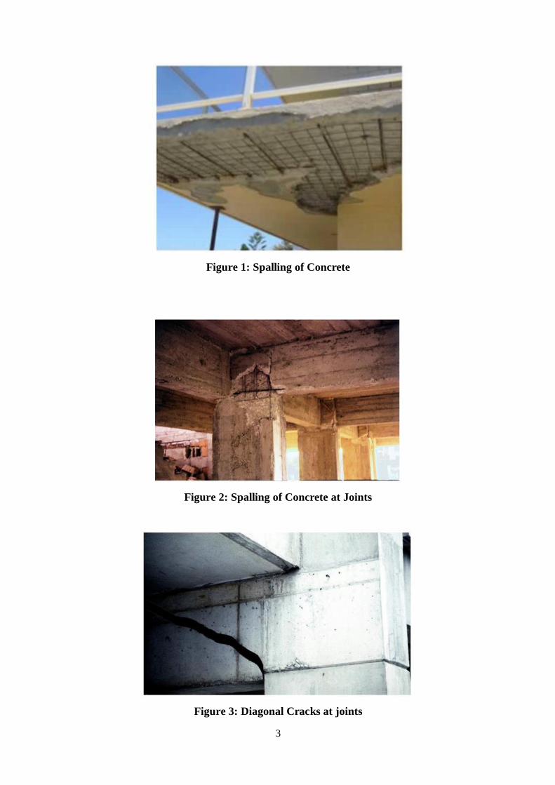
3
Figure 1: Spalling of Concrete
Figure 2: Spalling of Concrete at Joints
Figure 3: Diagonal Cracks at joints
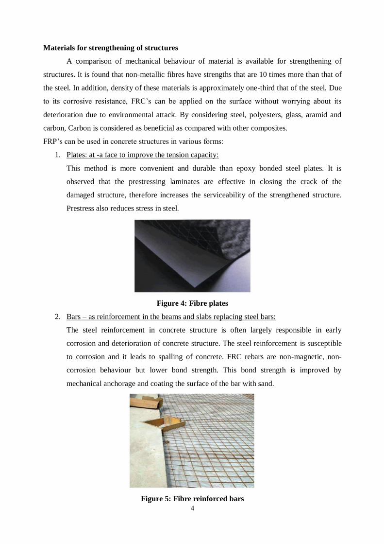
4
Materials for strengthening of structures
A comparison of mechanical behaviour of material is available for strengthening of
structures. It is found that non-metallic fibres have strengths that are 10 times more than that of
the steel. In addition, density of these materials is approximately one-third that of the steel. Due
to its corrosive resistance, FRC’s can be applied on the surface without worrying about its
deterioration due to environmental attack. By considering steel, polyesters, glass, aramid and
carbon, Carbon is considered as beneficial as compared with other composites.
FRP’s can be used in concrete structures in various forms:
1. Plates: at -a face to improve the tension capacity:
This method is more convenient and durable than epoxy bonded steel plates. It is
observed that the prestressing laminates are effective in closing the crack of the
damaged structure, therefore increases the serviceability of the strengthened structure.
Prestress also reduces stress in steel.
Figure 4: Fibre plates
2. Bars – as reinforcement in the beams and slabs replacing steel bars:
The steel reinforcement in concrete structure is often largely responsible in early
corrosion and deterioration of concrete structure. The steel reinforcement is susceptible
to corrosion and it leads to spalling of concrete. FRC rebars are non-magnetic, non-
corrosion behaviour but lower bond strength. This bond strength is improved by
mechanical anchorage and coating the surface of the bar with sand.
Figure 5: Fibre reinforced bars
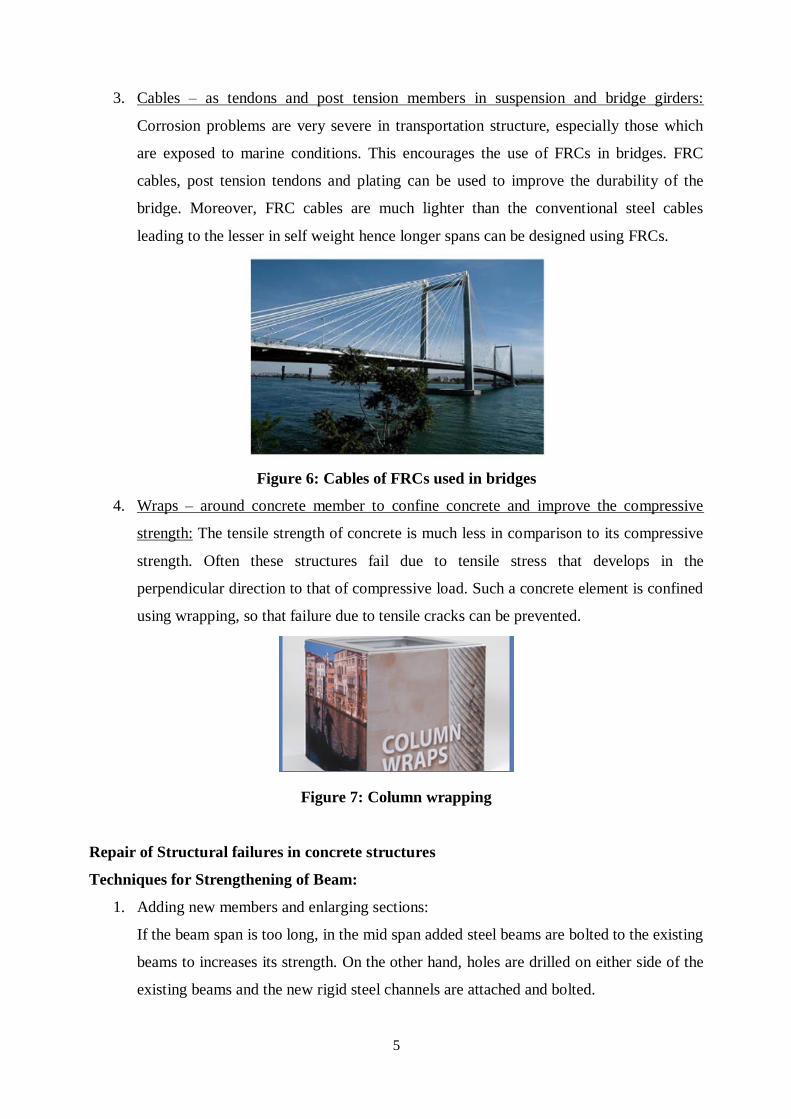
5
3. Cables – as tendons and post tension members in suspension and bridge girders:
Corrosion problems are very severe in transportation structure, especially those which
are exposed to marine conditions. This encourages the use of FRCs in bridges. FRC
cables, post tension tendons and plating can be used to improve the durability of the
bridge. Moreover, FRC cables are much lighter than the conventional steel cables
leading to the lesser in self weight hence longer spans can be designed using FRCs.
Figure 6: Cables of FRCs used in bridges
4. Wraps – around concrete member to confine concrete and improve the compressive
strength: The tensile strength of concrete is much less in comparison to its compressive
strength. Often these structures fail due to tensile stress that develops in the
perpendicular direction to that of compressive load. Such a concrete element is confined
using wrapping, so that failure due to tensile cracks can be prevented.
Figure 7: Column wrapping
Repair of Structural failures in concrete structures
Techniques for Strengthening of Beam:
1. Adding new members and enlarging sections:
If the beam span is too long, in the mid span added steel beams are bolted to the existing
beams to increases its strength. On the other hand, holes are drilled on either side of the
existing beams and the new rigid steel channels are attached and bolted.
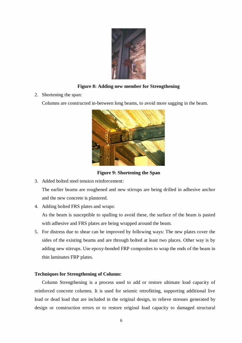
6
Figure 8: Adding new member for Strengthening
2. Shortening the span:
Columns are constructed in-between long beams, to avoid more sagging in the beam.
Figure 9: Shortening the Span
3. Added bolted steel tension reinforcement:
The earlier beams are roughened and new stirrups are being drilled in adhesive anchor
and the new concrete is plastered.
4. Adding bolted FRS plates and wraps:
As the beam is susceptible to spalling to avoid these, the surface of the beam is pasted
with adhesive and FRS plates are being wrapped around the beam.
5. For distress due to shear can be improved by following ways: The new plates cover the
sides of the existing beams and are through bolted at least two places. Other way is by
adding new stirrups. Use epoxy-bonded FRP composites to wrap the ends of the beam in
thin laminates FRP plates.
Techniques for Strengthening of Column:
Column Strengthening is a process used to add or restore ultimate load capacity of
reinforced concrete columns. It is used for seismic retrofitting, supporting additional live
load or dead load that are included in the original design, to relieve stresses generated by
design or construction errors or to restore original load capacity to damaged structural
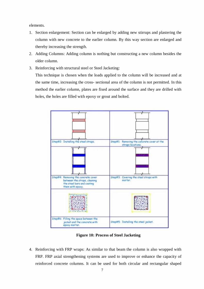
7
elements.
1. Section enlargement: Section can be enlarged by adding new stirrups and plastering the
column with new concrete to the earlier column. By this way section are enlarged and
thereby increasing the strength.
2. Adding Columns: Adding column is nothing but constructing a new column besides the
older column.
3. Reinforcing with structural steel or Steel Jacketing:
This technique is chosen when the loads applied to the column will be increased and at
the same time, increasing the cross- sectional area of the column is not permitted. In this
method the earlier column, plates are fixed around the surface and they are drilled with
holes, the holes are filled with epoxy or grout and bolted.
Figure 10: Process of Steel Jacketing
4. Reinforcing with FRP wraps: As similar to that beam the column is also wrapped with
FRP. FRP axial strengthening systems are used to improve or enhance the capacity of
reinforced concrete columns. It can be used for both circular and rectangular shaped
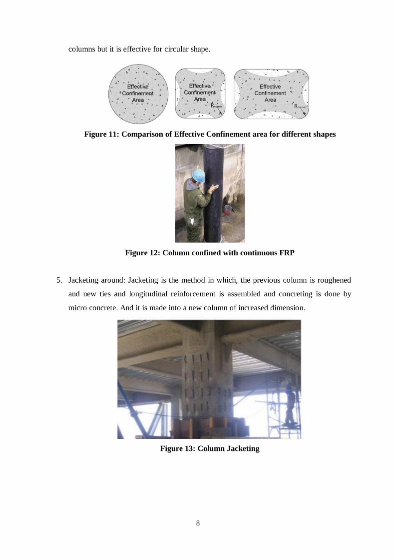
8
columns but it is effective for circular shape.
Figure 11: Comparison of Effective Confinement area for different shapes
Figure 12: Column confined with continuous FRP
5. Jacketing around: Jacketing is the method in which, the previous column is roughened
and new ties and longitudinal reinforcement is assembled and concreting is done by
micro concrete. And it is made into a new column of increased dimension.
Figure 13: Column Jacketing
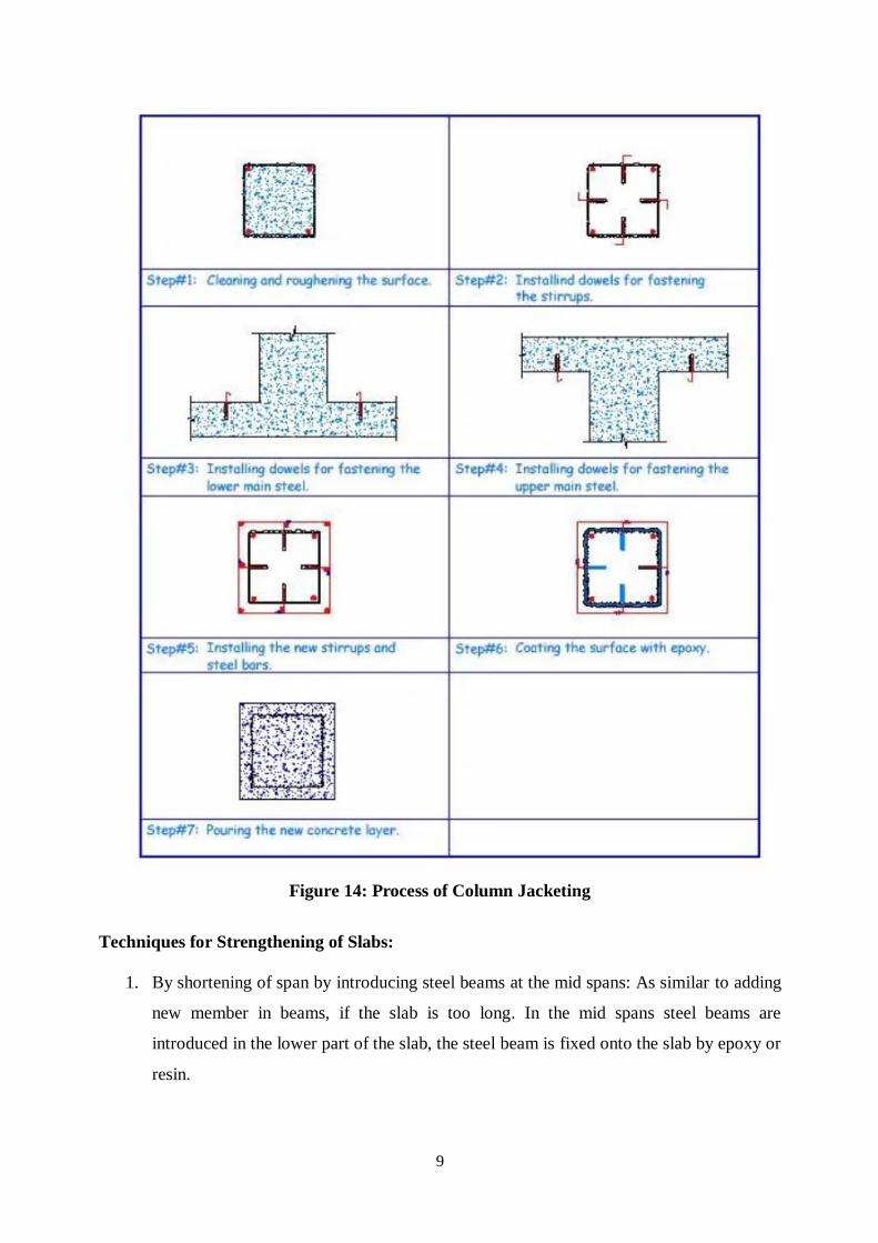
9
Figure 14: Process of Column Jacketing
Techniques for Strengthening of Slabs:
1. By shortening of span by introducing steel beams at the mid spans: As similar to adding
new member in beams, if the slab is too long. In the mid spans steel beams are
introduced in the lower part of the slab, the steel beam is fixed onto the slab by epoxy or
resin.
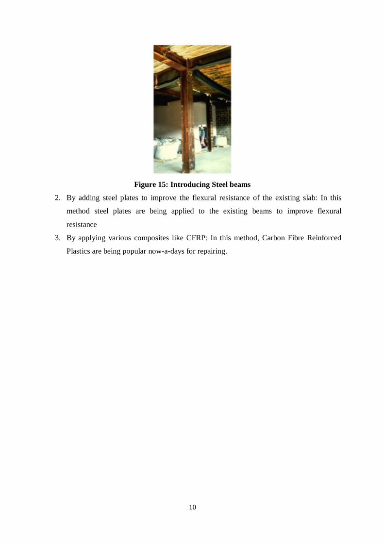
10
Figure 15: Introducing Steel beams
2. By adding steel plates to improve the flexural resistance of the existing slab: In this
method steel plates are being applied to the existing beams to improve flexural
resistance
3. By applying various composites like CFRP: In this method, Carbon Fibre Reinforced
Plastics are being popular now-a-days for repairing.
1
SCHOOL OF BUILDING AND ENVIRONMENT
DEPARTMENT OF CIVIL ENGINEERING
UNIT – V – NDT of Steel – SCIA7003
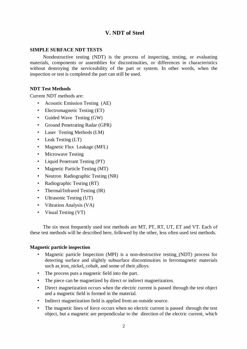
2
V. NDT of Steel
SIMPLE SURFACE NDT TESTS
Nondestructive testing (NDT) is the process of inspecting, testing, or evaluating
materials, components or assemblies for discontinuities, or differences in characteristics
without destroying the serviceability of the part or system. In other words, when the
inspection or test is completed the part can still be used.
NDT Test Methods
Current NDT methods are:
• Acoustic Emission Testing (AE)
• Electromagnetic Testing (ET)
• Guided Wave Testing (GW)
• Ground Penetrating Radar (GPR)
• Laser Testing Methods (LM)
• Leak Testing (LT)
• Magnetic Flux Leakage (MFL)
• Microwave Testing
• Liquid Penetrant Testing (PT)
• Magnetic Particle Testing (MT)
• Neutron Radiographic Testing (NR)
• Radiographic Testing (RT)
• Thermal/Infrared Testing (IR)
• Ultrasonic Testing (UT)
• Vibration Analysis (VA)
• Visual Testing (VT)
The six most frequently used test methods are MT, PT, RT, UT, ET and VT. Each of
these test methods will be described here, followed by the other, less often used test methods.
Magnetic particle inspection
• Magnetic particle Inspection (MPI) is a non-destructive testing (NDT) process for
detecting surface and slightly subsurface discontinuities in ferromagnetic materials
such as iron, nickel, cobalt, and some of their alloys.
• The process puts a magnetic field into the part.
• The piece can be magnetized by direct or indirect magnetization.
• Direct magnetization occurs when the electric current is passed through the test object
and a magnetic field is formed in the material.
• Indirect magnetization field is applied from an outside source.
• The magnetic lines of force occurs when no electric current is passed through the test
object, but a magnetic are perpendicular to the direction of the electric current, which
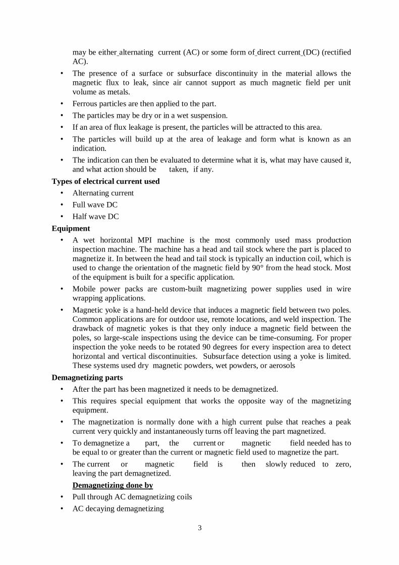
3
may be either alternating current (AC) or some form of direct current (DC) (rectified
AC).
• The presence of a surface or subsurface discontinuity in the material allows the
magnetic flux to leak, since air cannot support as much magnetic field per unit
volume as metals.
• Ferrous particles are then applied to the part.
• The particles may be dry or in a wet suspension.
• If an area of flux leakage is present, the particles will be attracted to this area.
• The particles will build up at the area of leakage and form what is known as an
indication.
• The indication can then be evaluated to determine what it is, what may have caused it,
and what action should be taken, if any.
Types of electrical current used
• Alternating current
• Full wave DC
• Half wave DC
Equipment
• A wet horizontal MPI machine is the most commonly used mass production
inspection machine. The machine has a head and tail stock where the part is placed to
magnetize it. In between the head and tail stock is typically an induction coil, which is
used to change the orientation of the magnetic field by 90° from the head stock. Most
of the equipment is built for a specific application.
• Mobile power packs are custom-built magnetizing power supplies used in wire
wrapping applications.
• Magnetic yoke is a hand-held device that induces a magnetic field between two poles.
Common applications are for outdoor use, remote locations, and weld inspection. The
drawback of magnetic yokes is that they only induce a magnetic field between the
poles, so large-scale inspections using the device can be time-consuming. For proper
inspection the yoke needs to be rotated 90 degrees for every inspection area to detect
horizontal and vertical discontinuities. Subsurface detection using a yoke is limited.
These systems used dry magnetic powders, wet powders, or aerosols
Demagnetizing parts
• After the part has been magnetized it needs to be demagnetized.
• This requires special equipment that works the opposite way of the magnetizing
equipment.
• The magnetization is normally done with a high current pulse that reaches a peak
current very quickly and instantaneously turns off leaving the part magnetized.
• To demagnetize a part, the current or magnetic field needed has to
be equal to or greater than the current or magnetic field used to magnetize the part.
• The current or magnetic field is then slowly reduced to zero,
leaving the part demagnetized.
Demagnetizing done by
• Pull through AC demagnetizing coils
• AC decaying demagnetizing
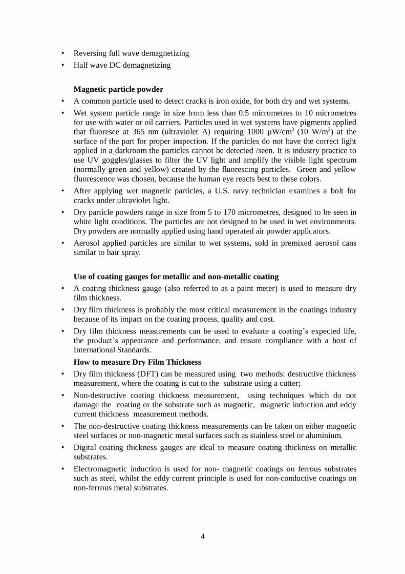
4
• Reversing full wave demagnetizing
• Half wave DC demagnetizing
Magnetic particle powder
• A common particle used to detect cracks is iron oxide, for both dry and wet systems.
• Wet system particle range in size from less than 0.5 micrometres to 10 micrometres
for use with water or oil carriers. Particles used in wet systems have pigments applied
that fluoresce at 365 nm (ultraviolet A) requiring 1000 µW/cm2 (10 W/m2) at the
surface of the part for proper inspection. If the particles do not have the correct light
applied in a darkroom the particles cannot be detected /seen. It is industry practice to
use UV goggles/glasses to filter the UV light and amplify the visible light spectrum
(normally green and yellow) created by the fluorescing particles. Green and yellow
fluorescence was chosen, because the human eye reacts best to these colors.
• After applying wet magnetic particles, a U.S. navy technician examines a bolt for
cracks under ultraviolet light.
• Dry particle powders range in size from 5 to 170 micrometres, designed to be seen in
white light conditions. The particles are not designed to be used in wet environments.
Dry powders are normally applied using hand operated air powder applicators.
• Aerosol applied particles are similar to wet systems, sold in premixed aerosol cans
similar to hair spray.
Use of coating gauges for metallic and non-metallic coating
• A coating thickness gauge (also referred to as a paint meter) is used to measure dry
film thickness.
• Dry film thickness is probably the most critical measurement in the coatings industry
because of its impact on the coating process, quality and cost.
• Dry film thickness measurements can be used to evaluate a coating’s expected life,
the product’s appearance and performance, and ensure compliance with a host of
International Standards.
How to measure Dry Film Thickness
• Dry film thickness (DFT) can be measured using two methods: destructive thickness
measurement, where the coating is cut to the substrate using a cutter;
• Non-destructive coating thickness measurement, using techniques which do not
damage the coating or the substrate such as magnetic, magnetic induction and eddy
current thickness measurement methods.
• The non-destructive coating thickness measurements can be taken on either magnetic
steel surfaces or non-magnetic metal surfaces such as stainless steel or aluminium.
• Digital coating thickness gauges are ideal to measure coating thickness on metallic
substrates.
• Electromagnetic induction is used for non- magnetic coatings on ferrous substrates
such as steel, whilst the eddy current principle is used for non-conductive coatings on
non-ferrous metal substrates.
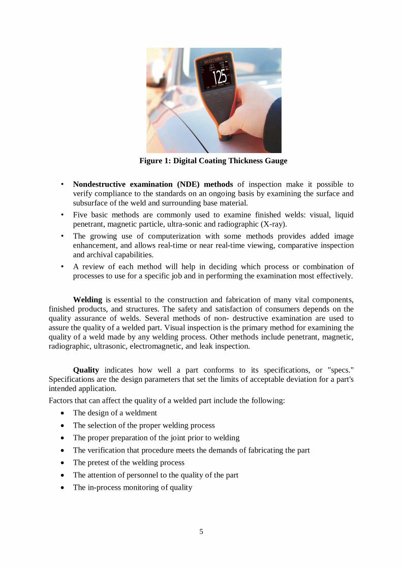
5
Figure 1: Digital Coating Thickness Gauge
• Nondestructive examination (NDE) methods of inspection make it possible to
verify compliance to the standards on an ongoing basis by examining the surface and
subsurface of the weld and surrounding base material.
• Five basic methods are commonly used to examine finished welds: visual, liquid
penetrant, magnetic particle, ultra-sonic and radiographic (X-ray).
• The growing use of computerization with some methods provides added image
enhancement, and allows real-time or near real-time viewing, comparative inspection
and archival capabilities.
• A review of each method will help in deciding which process or combination of
processes to use for a specific job and in performing the examination most effectively.
Welding is essential to the construction and fabrication of many vital components,
finished products, and structures. The safety and satisfaction of consumers depends on the
quality assurance of welds. Several methods of non- destructive examination are used to
assure the quality of a welded part. Visual inspection is the primary method for examining the
quality of a weld made by any welding process. Other methods include penetrant, magnetic,
radiographic, ultrasonic, electromagnetic, and leak inspection.
Quality indicates how well a part conforms to its specifications, or "specs."
Specifications are the design parameters that set the limits of acceptable deviation for a part's
intended application.
Factors that can affect the quality of a welded part include the following:
The design of a weldment
The selection of the proper welding process
The proper preparation of the joint prior to welding
The verification that procedure meets the demands of fabricating the part
The pretest of the welding process
The attention of personnel to the quality of the part
The in-process monitoring of quality
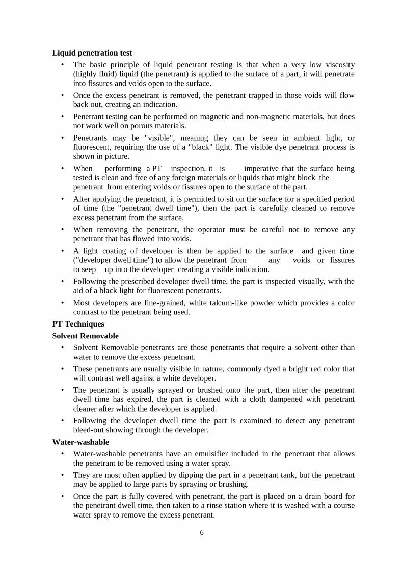
6
Liquid penetration test
• The basic principle of liquid penetrant testing is that when a very low viscosity
(highly fluid) liquid (the penetrant) is applied to the surface of a part, it will penetrate
into fissures and voids open to the surface.
• Once the excess penetrant is removed, the penetrant trapped in those voids will flow
back out, creating an indication.
• Penetrant testing can be performed on magnetic and non-magnetic materials, but does
not work well on porous materials.
• Penetrants may be "visible", meaning they can be seen in ambient light, or
fluorescent, requiring the use of a "black" light. The visible dye penetrant process is
shown in picture.
• When performing a PT inspection, it is imperative that the surface being
tested is clean and free of any foreign materials or liquids that might block the
penetrant from entering voids or fissures open to the surface of the part.
• After applying the penetrant, it is permitted to sit on the surface for a specified period
of time (the "penetrant dwell time"), then the part is carefully cleaned to remove
excess penetrant from the surface.
• When removing the penetrant, the operator must be careful not to remove any
penetrant that has flowed into voids.
• A light coating of developer is then be applied to the surface and given time
("developer dwell time") to allow the penetrant from any voids or fissures
to seep up into the developer creating a visible indication.
• Following the prescribed developer dwell time, the part is inspected visually, with the
aid of a black light for fluorescent penetrants.
• Most developers are fine-grained, white talcum-like powder which provides a color
contrast to the penetrant being used.
PT Techniques
Solvent Removable
• Solvent Removable penetrants are those penetrants that require a solvent other than
water to remove the excess penetrant.
• These penetrants are usually visible in nature, commonly dyed a bright red color that
will contrast well against a white developer.
• The penetrant is usually sprayed or brushed onto the part, then after the penetrant
dwell time has expired, the part is cleaned with a cloth dampened with penetrant
cleaner after which the developer is applied.
• Following the developer dwell time the part is examined to detect any penetrant
bleed-out showing through the developer.
Water-washable
• Water-washable penetrants have an emulsifier included in the penetrant that allows
the penetrant to be removed using a water spray.
• They are most often applied by dipping the part in a penetrant tank, but the penetrant
may be applied to large parts by spraying or brushing.
• Once the part is fully covered with penetrant, the part is placed on a drain board for
the penetrant dwell time, then taken to a rinse station where it is washed with a course
water spray to remove the excess penetrant.
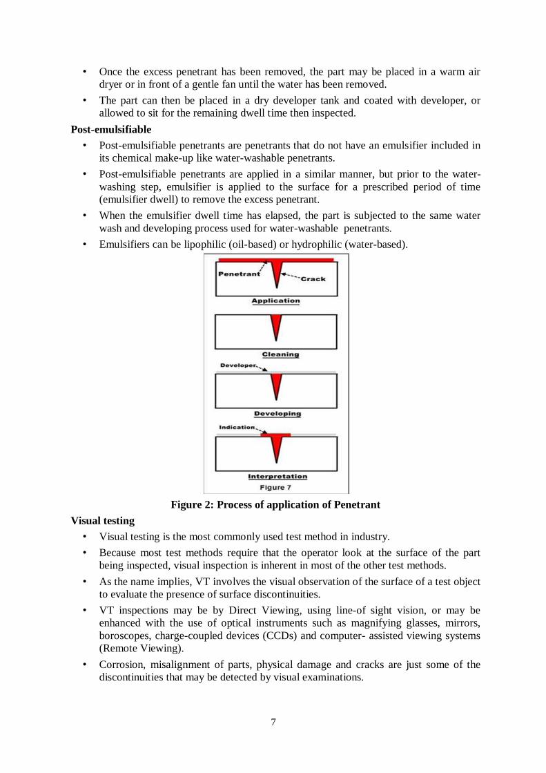
7
• Once the excess penetrant has been removed, the part may be placed in a warm air
dryer or in front of a gentle fan until the water has been removed.
• The part can then be placed in a dry developer tank and coated with developer, or
allowed to sit for the remaining dwell time then inspected.
Post-emulsifiable
• Post-emulsifiable penetrants are penetrants that do not have an emulsifier included in
its chemical make-up like water-washable penetrants.
• Post-emulsifiable penetrants are applied in a similar manner, but prior to the water-
washing step, emulsifier is applied to the surface for a prescribed period of time
(emulsifier dwell) to remove the excess penetrant.
• When the emulsifier dwell time has elapsed, the part is subjected to the same water
wash and developing process used for water-washable penetrants.
• Emulsifiers can be lipophilic (oil-based) or hydrophilic (water-based).
Figure 2: Process of application of Penetrant
Visual testing
• Visual testing is the most commonly used test method in industry.
• Because most test methods require that the operator look at the surface of the part
being inspected, visual inspection is inherent in most of the other test methods.
• As the name implies, VT involves the visual observation of the surface of a test object
to evaluate the presence of surface discontinuities.
• VT inspections may be by Direct Viewing, using line-of sight vision, or may be
enhanced with the use of optical instruments such as magnifying glasses, mirrors,
boroscopes, charge-coupled devices (CCDs) and computer- assisted viewing systems
(Remote Viewing).
• Corrosion, misalignment of parts, physical damage and cracks are just some of the
discontinuities that may be detected by visual examinations.
8
Magnetic particle testing
• Magnetic Particle Testing uses one or more magnetic fields to locate surface and near-
surface discontinuities in ferromagnetic materials.
• The magnetic field can be applied with a permanent magnet or an electromagnet.
• When using an electromagnet, the field is present only when the current is being
applied.
• When the magnetic field encounters a discontinuity transverse to the direction of the
magnetic field, the flux lines produce a magnetic flux leakage field of their own.
• Because magnetic flux lines don't travel well in air, when very fine colored
ferromagnetic particles ("magnetic particles") are applied to the surface of the part
the particles will be drawn into the discontinuity, reducing the air gap and producing
a visible indication on the surface of the part.
• The magnetic particles may be a dry powder or suspended in a liquid solution, and
they may be colored with a visible dye or a fluorescent dye that fluoresces under an
ultraviolet ("black") light.