ultraseal® product manual
TRANSCRIPT

L i n i n g T ec h n o Lo g i e s | Rem ed i aT i o n T ec h n o Lo g i e s | d R i L L i n g sY s T em s | B u i L d i n g en v eLo p e | c o n T R ac T i n g s eR v i c e s
► product manual for cast-in-place
concrete applications
Ultraseal® prodUct manUaladvanced apc waterproofing system

- 2 -
Ultraseal®
p r o d U c t m a n Ua l
advanced apc waterproofing technology
2870 Forbs Avenue Hoffman Estates, IL 60192 847.851.1800 | 800.527.9948
contentsWHAT IS ULTRASEAL?PRODUCT DESCRIPTIONASSOCIATED SYSTEM PRODUCTSACCESSORIESLIMITATIONS
INSTALLATION GUIDELINESSECTION 1: UNDERSLAB INSTALLATION 1.1 substrate preparation 1.2 installation 1.3 pile caps & grade Beams 1.4 slab penetrations 1.5 elevator pits 1.6EdgeofSlab,BackfilledWalls 1.7EdgeofSlab,PropertyLineWalls SECTION 2: PROPERTY LINE CONSTRUCTION 2.1 property Line installation guidelines 2.2 soldier pile & Lagging 2.3MetalSheetPilingRetainingWall 2.4 earth Formed shotcrete Retention 2.5AugerCastCaissonRetentionWall SECTION 3: BACKFILLED WALLS 3.1 surface preparation 3.2 installation 3.3BackfilledWallPenetrations 3.4 Terminations 3.5MasonryBlockWalls SECTION 4: SPECIAL CONDITIONS 4.1 precast concrete construction 4.2 contaminated conditions
THIS MANUAL CONTAINS THE INSTALLATION GUIDELINES FOR THE ULTRASEAL SP AND UL-TRASEAL BT WATERPROOFING SYSTEM FOR CAST-IN-PLACE CONCRETE APPLICATIONS, IN-CLUDING UNDERSLAB, PROPERTY LINE WALLS, AND BACKFILLED WALLS. THIS MANUAL DOES NOT COVER SHOTCRETE, MASONRY BLOCK, OR PRECAST CONCRETE APPLICATIONS. FOR AP-PLICATIONS NOT COVERED IN THIS MANUAL, CONTACT CETCO FOR SPECIFIC INSTALLATION GUIDELINES. BEFORE INSTALLATION, READ THIS MANUAL TO GAIN FAMILIARITY WITH SPECIFIC PROCEDURES AND APPLICATIONS.
what is Ultraseal?Ultraseal isauniquewaterproofingsystemthatutilizesanadvancedactive polymer core (apc) technology that is ten times less permeable and more chemically resistant than traditional hydrophilic membranes. TwoUltrasealmembranecomposites-BTandSP-eachwithspecificproductperformancefeatures,providethebestwaterproofingproper-tiesforunderslabs,backfilledfoundationwalls,andpositivepressureblind-side walls, such as soldier pile and lagging retaining walls.
prodUct descriptionultraseal sp is a three component composite membrane consisting of the apc layer between a geotextile and a geomembrane. ultraseal sp is primarily for under slab applications.
ultraseal BT is a two component composite membrane consisting of the apc layer integrally bonded to a high-strength geomembrane. ul-trasealBT isdesigned forbackfilled foundationwalls,earth-coveredstructures, and property line construction. property line construction applications include soldier pile and lagging, metal sheet piling, auger castcaisson,shotcrete,andstabilizedearthretentionwalls.
ULTRASEAL SP ULTRASEAL BT
geomembrane
active polymer core (apc) layer
geotextile
geomembrane
active polymer core (apc) layer
Figure 1 - ultraseal sp and ultraseal BT membrane composites. Both are supplied in 4-ft x 25-ft rolls (1.2 m x 7.6 m)

www.CETCO.com
installation of ultraseal is fast and easy. simply position the product into place and fasten. ultraseal can be installed on green concrete, in virtually any weather, without the need for primers or adhesives. it can be easily cut on site to form around corners and penetrations. The re-sult is always a consistent self-healing membrane.
advantagesCompared to traditional active waterproofing products, Ultraseal islighter, more impervious, and more resistant to contaminated water conditions.Withamassperunitareaofjustover0.3lbs/sq.ft.,Ultra-seal rolls are lightweight and easy to handle. despite the lighter weight, the apc is one order of magnitude less permeable than bentonite, meaning that it will deliver tenfold performance increase under most conditions. Finally, ultraseal has improved performance in salt water conditionsoverbentonitewaterproofingmembranes.
sUperior adhesionWhen concrete is poured against Ultraseal, a tenaciousmechanicalbond is created with the membrane composite. The mechanical bond will hold ultraseal in intimate contact with the concrete should any ground settlement occur, thereby preventing water migration between thewaterproofingandtheconcrete.
cost effective and time efficientultraseal sp is designed to be installed on a properly prepared sub-grade, without the need to pour a working slab. The product’s inherent flexibilityallowsforeasy installation.Ultrasealseamsareeasilyover-lapped without the need to roll out every small wrinkle or air pocket. ultraseal BT can be installed as soon as the forms are removed; there isnowaitingfortheconcretetocurebeforeinstallingthewaterproofing.
prodUcts for specific applicationsByutilizingtwouniquemembranes,Ultrasealmatchesthecorrectprod-uct features to an application to provide the best performance prop-ertiesforthatspecificapplication.Refertobackpageforapplicationmatrix.
associated system prodUctsWATERSTOP-RX®-expandingconcretejointwaterstopusedaroundpenetrationsandapplicableconcretejoints.Swellsuponhydration.AQUADRAIN® - foundation drainage composite consisting of a molded profilecoreandafilterfabric.Includessheetdrainageandbasedraincollection. CEMENTITIOUS BOARD:1/2"(12mm)thickcementitiouswallboardforprotectionofwaterproofingduringtheremovalofsteelsoldierpilecap and top lagging boards.
accessoriesBENTOSEAL® - trowel grade mastic used to detail around penetra-tions, corner transitions and terminations. CETSEAL - single-component polyether general sealant and adhesive.
HYDROBAR TUBES®-watersolublefilmtubingfilledwithactivegran-ular material.WATERSTOPPAGE® - active granular material used at detail areas that require additional protection.SEAMTAPE® - premium butyl rubber tape used to seal overlapped membrane edges of ultraseal BT. AKWASWELL® - caulk grade hydrophilic waterstop. TERMINATION BAR - min. 1” (25 mm) wide aluminum or stainless steelbarwithpre-punchedholeson12”(300mm)centeringforfasten-ing. CEMENTITIOUS BOARD - ½” (12 mm) thick cementitious wall board forprotectionofwaterproofingduringtheremovalofsteelsoldierpilecap and top lagging boards. GF-40SA - self-adheringflashingmembraneusedforgradeandthru-wallflashing.TB-BOOT - pre-formed, single piece cover for tie-back heads and soil nails.Threesizesavailable:TB-6SN,TB-8&TB-10.
limitationsultraseal should only be installed after proper substrate prepara-tion has been properly completed and is suitable to receive the waterproofingsystem.Concreteworkshoulduseconventionalcast-in-place forms that produce a smooth surface. do not use stay-in-place concrete forming; use removable forming products only.
Ultraseal is designed for below-grade waterproofing applicationswheretheproductisproperlyconfined.Ultrasealshouldnotbein-stalled in standing water or over ice. if ground water contains strong acids,alkalies,orisofaconductivityof2,500µmhos/cmorgreater,water samples should be submitted to the manufacturer for com-patibility testing.
ultraseal sp is designed for use under reinforced concrete slabs 4” (100mm)thickorgreateronacompactedearth/gravelsubstrate.UltrasealSPrequiresaminimum6”(150mm)thickreinforcedcon-crete slab if installed over a mud slab. ultraseal is not designed for split-slabplazadeckconstruction.ultraseal is capable of bridging typical shrinkage cracks in concrete upto1/16”(1.5mm). Ultraseal is not designed to waterproof expansion joints. Expansion joints are the responsibility of others. Consult CETCO for special installation guidelines that apply to shot-crete and precast concrete construction. Illustrations are not shown to scale.
- 4 -
Ultraseal®
p r o d U c t m a n Ua l
advanced apc waterproofing technology
2870 Forbs Avenue Hoffman Estates, IL 60192 847.851.1800 | 800.527.9948
installation gUidelinesBefore installing ultraseal read this installation manual to gain familiar-itywithspecificproceduresandapplications.Forapplicationsnotcov-eredinthismanual,contactCETCOforspecificinstallationguidelines.
ultraseal sp is engineered for use under reinforced concrete slabs 4” (100mm)thickorgreateronacompactedearth/gravelsubstrate.Ul-trasealSPrequiresaminimum6”(150mm)thickreinforcedconcreteslab if installed over a mud slab.
For hydrostatic conditions, ultraseal sp should be installed under foot-ingsandgradebeamsasshowninFigures1.6,1.7and1.8.Fornon-hydrostatic conditions, ultraseal sp should be installed around footings andgradebeamsasshowninFigures1.9,1.10and1.11.
prior to installing ultraseal sp the substrate must be properly prepared. complete all required elevator pit, sump pit, grade beam and piling work prior to installing ultraseal sp under main slab area. These areas must becorrectlytiedintotheunderslabwaterproofingtoformamonolithicseal.
1.1 sUbstrate preparationsubstrate may be concrete, earth, sand, or crushed stone. earth and sand substrates should be compacted to aminimum85%ModifiedProctordensity.Crushedstoneshouldbenolargerthan3/4”(18mm)insize.Substrateshouldbesmoothandwithoutsharpdeflectionsorpockets.
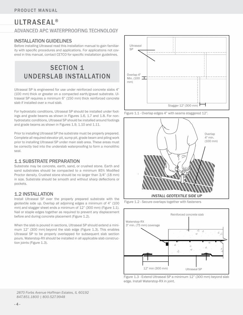
1.2 installationinstall ultraseal sp over the properly prepared substrate with the geotextilesideup.Overlapalladjoiningedgesaminimumof4”(100mm)andstaggersheetendsaminimumof12”(300mm)(Figure1.1).nail or staple edges together as required to prevent any displacement before and during concrete placement (Figure 1.2).
Whentheslabispouredinsections,UltrasealSPshouldextendamini-mum12” (300mm)beyond theslabedge (Figure1.3). Thisenablesultraseal sp to be properly overlapped for subsequent slab section pours.Waterstop-RXshouldbeinstalledinallapplicableslabconstruc-tionjoints(Figure1.3).
section 1 Underslab installation
INSTALL GEOTEXTILE SIDE UP
overlap 4"min. (100mm)
Figure 1.2 - secure overlaps together with fasteners
Figure1.3-ExtendUltrasealSPaminimum12”(300mm)beyondslabedge.InstallWaterstop-RXinjoint.
Figure 1.1 - overlap edges 4” with seams staggered 12”.
ultraseal sp
Overlap4"Min.(100mm)
Stagger12"(300mm)
Reinforced concrete slab
12"min(300mm) ultraseal sp
Waterstop-RX 3"min.(75mm)coverage

www.CETCO.com
Waterstop-RX 3"min.(75mm)coverage
Reinforced concrete slab aminimum4"(100mm)thick
ultraseal sp
compacted substrate
INSTALL GEOTEXTILE SIDE UP
Figure1.4-UltrasealSPinstalleddirectlyovercompactedearth/gravelsubstraterequiresaminimum4”(100mm)slab.
Reinforced concrete slab a minimum6"(150mm)thick
ultraseal sp
compacted substrate
concrete mud slab
INSTALL GEOTEXTILE SIDE UP
Figure1.5-UltrasealSPinstalledoveramudslabrequiresaminimum6"(150mm)thickreinforcedslab.
Waterstop-RX 3"min.(75mm)coverage

- 6 -
Ultraseal®
p r o d U c t m a n Ua l
advanced apc waterproofing technology
2870 Forbs Avenue Hoffman Estates, IL 60192 847.851.1800 | 800.527.9948
hydrostatic conditions non-hydrostatic conditions
ultraseal BT
ultraseal sp
hydrobar Tube
Figure 1.6 - slab on footing detail (hydrostatic)
ultraseal BT
Bentoseal
hydrobar Tube
ultraseal sp
mud slab
Figure 1.7 - Raised slab detail with mud slab (hydrostatic)
ultraseal sp
ultraseal BT
Figure1.8-Flushslabdetailpropertylinewall(hydrostatic)
ultraseal BT
hydrobar Tube
Figure 1.9 - slab on footing detail (non-hydrostatic)
ultraseal BT
Bentoseal
ultraseal sp
mud slab
Figure1.10-Raisedslabdetailwithmudslab(non-hydrostatic)
ultraseal BT
Term Bar & Bentoseal
12” (300mm)
Figure1.11-Flushslabdetailbackfilledwall(non-hydrostatic)
Waterstop-RX 3"min.(75mm)coverage
Waterstop-RX 3"min.(75mm)coverage
Waterstop-RX 3"min.(75mm)coverage Waterstop-RX
3"min.(75mm)coverage
Waterstop-RX 3"min.(75mm)coverage
Waterstop-RX 3"min.(75mm)coverage
Term bar and Bentoseal

www.CETCO.com
1.3 pile caps and grade beamsUltrasealSPistypicallynotinstalledoverpilecapsbutcuttofittightlyaroundpilecaps.Thenapplyaminimum3/4” (18mm) thickfilletofBentoseal at intersection of membrane and the piling (Figure 1.12) withWaterstoppageunderthemembraneatthepilingedge.Bentosealshouldextendontothemembraneandpilingaminimumof2”(50mm)at3/4” (18mm) thickness.Waterstop-RXshouldbe installedon topsurface of pile cap around reinforcing steel (Figure 1.12).
detail grade beams the same as pile caps (Figure 1.14) with a non-hydrostatic condition. For hydrostatic conditions, ultraseal sp should be installed under the entire grade beam (Figure 1.15). Line the grade beam formwork with ultraseal sp prior to placement of reinforcing steel.Leaveaminimum12”(300mm)ofUltrasealSPatthetopoftheformtotieintobelowslabwaterproofing.
Figure 1.12 - pile cap detail (hydrostatic condition).
Figure 1.13 - pile cap detail (non-hydrostatic condition).
Figure 1.14 - grade Beam (non-hydrostatic condition) Figure 1.15 - grade Beam (hydrostatic condition)
Waterstop-RX
concrete pile
Bentoseal
ultraseal sp
Waterstoppage
Waterstop-RX
metal i-beam
ultraseal sp
Waterstop-RX
2"(50mm)thickfilletofBentoseal
GranularWaterstoppage
Waterstop-RXWaterstoppage
ultraseal sp
Bentoseal
pile cap
Bentoseal
pile
Waterstop-RX Reinforcing steal Bentoseal
ultraseal sp
grade beam
2"(50mm)thick filletof Waterstoppage
grade beam
Reinforcing stealWaterstop-RX
ultraseal sp

- 8 -
Ultraseal®
p r o d U c t m a n Ua l
advanced apc waterproofing technology
2870 Forbs Avenue Hoffman Estates, IL 60192 847.851.1800 | 800.527.9948
1.4 slab penetrationsCutUltrasealSPtocloselyfitaroundpenetrations(Figure1.16).Trowelaminimum3/4”(18mm)thickfilletofBentosealaroundthepenetra-tiontocompletelyfillanyvoidareabetweenUltrasealSPandthepen-etration (Figure 1.17). The Bentoseal should extend up the penetration about1-1/2”(38mm)andextendontothemembrane.Inareaswheremultiple penetrations are close together, it may be impractical to cut
Ultraseal SP to fit around each penetration. Pour Waterstoppage aminimum1/4”(6mm)thickaroundthepenetrationscoveringtheen-tiresubstratearea.Withgravelsubstrate,installminimum8"(200mm)collarofUltrasealSParoundpenetrationprior toplacingWaterstop-page. Then apply a thick layer of Bentoseal around each penetration as detailed (Figure 1.19).
Figure 1.17 - Bentoseal troweled around penetrations. Figure1.18-Slabpenetrationcrosssectiondetail.
Figure 1.19 - multiple pipe penetrations. Trowel Bentoseal around pipes and covering area between the pipes.
ultraseal sp
pipe
Bentoseal
INSTALL GEOTEXTILE SIDE UP
ultraseal sp
Waterstoppage
Bentoseal
Waterstop-RX 3"min.(75mm)coverage pipe
Mud Slab Substrate Compacted Earth or Gravel Substrate
mud slab
Waterstop-RX
Bentoseal
continue ultraseal sp between pipes ultraseal sp
Waterstoppagemud slab substrate
continue ultraseal sp between pipes
Waterstop-RX
Bentoseal
gravel substrate
ultraseal sp collar Waterstoppage

www.CETCO.com
1.5 elevator pitsultraseal sp should be placed on vertical surfaces and on the substrate below the slab to form a continuous envelope around the elevator pit (Figure1.20).Iftheverticalsoilcutissmoothandstable,UltrasealSPmay be installed directly against the soil. contain unstable soils with
a retaining wall. install ultraseal sp directly against the retaining wall. due to various elevator piston plunger designs, consult ceTco for spe-cific installation and detailing recommendations for piston plungersthat penetrate the pit slab.
Figure1.20-UltrasealSPunderelevatorpitslabandonexcavationcutwalls
1.6 edge of slab, backfilled wallsWhentheinstallationreachestheouteredgeoftheslab,continueUl-traseal sp up to the top edge of the forms inside surface (Figure 1.21) or extend the ultraseal sp sheet out the top of the form a minimum of 12” (300mm) (Figure1.22). At the slab corner,UltrasealSP shouldremain in contact with the substrate and the inside surface of the con-creteform.Whentheslabedgeformisremoved,anyundamagedpor-tion of ultraseal sp extended outside the form should be positioned and secured to the top of the concrete footing.
damaged material outside the form should be cut off and disposed of. overlap the secured ultraseal sp edge on top of the footing a minimum 6”(150mm)withthesucceedingwallwaterproofing.InstallHydrobarTubes at wall-to-footing corner prior to installing overlapping wall water-proofing.
Waterstop-RXshouldbeinstalledintheperimeterwall/slabintersec-tionjointasillustratedinFigure1.23.
Figure 1.21 - ultraseal sp turned up and secured at top of concrete form
Figure 1.22 - extra tail of ultraseal sp extended out of form and later cut off after concrete pour.
ultraseal sp
compacted substrate
ultraseal sp ultraseal sp secured to top of form before concrete pour
slab edge form
compacted substrate
ultraseal sp
extra tail of ultraseal sp extended out of form. cut off damaged areas before installing ultraseal sp overlap
slab edge form
compacted substrate
Waterstop-RX 3"min.(75mm)coverage
12" (300mm)
min
- 10 -
Ultraseal®
p r o d U c t m a n Ua l
advanced apc waterproofing technology
2870 Forbs Avenue Hoffman Estates, IL 60192 847.851.1800 | 800.527.9948
1.7 edge of slab, property line constrUctionWherepropertylineretainingwalls,suchassoldierpileandlagging,areused as the outside form, it is very important to extend the waterproof-ingaminimum12"(300mm)abovethetopoftheslabsincethereisnoaccess to the outer edge of the slab after it is poured.
Slab to Wall Corner Transition:InstallUltrasealBTsheethorizon-tallyoriented(APCsidefacinginstaller)withaminimum12”(300mm)ofthesheetextendingoutontothehorizontalsubstrate.Thetopedgeofthesheetmustextendaminimum12”(300mm)abovethefinishedslab surface. secure ultraseal BT sheet to lagging wall with washer-headfastenermaximum24”(600mm)oncenter.Overlapedgesofad-jacentUltrasealBTsheetsaminimum4”(100mm).
Iftheslabthicknessisgreaterthan24”(600mm),installasecondfullsheetorcutstripofUltrasealBT,horizontallyoriented,tomeetthe12”(300mm)requirementabovetheslab.Overlaptopedgeofprevioussheetandedgesofadjacentsheetsaminimum4”(100mm).
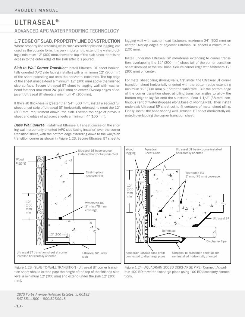
Base Wall Course:InstallfirstUltrasealBTsheetcourseontheshor-ingwallhorizontallyoriented(APCsidefacinginstaller)overthecornertransitionsheet,withthebottomedgeextendingdowntothewall/slabtransition corner as shown in Figure 1.23. secure ultraseal BT sheet to
laggingwallwithwasher-head fastenersmaximum24” (600mm)oncenter.OverlapedgesofadjacentUltrasealBTsheetsaminimum4”(100mm).
install underslab ultraseal sp membrane extending to corner transi-tion,overlappingthe12”(300mm)sheettailofthecornertransitionsheet installed at the wall base. secure corner edge with fasteners 12” (300mm)oncenter.
Formetalsheetpilingshoringwalls,firstinstalltheUltrasealBTcornertransitionsheethorizontallyorientedwiththebottomedgeextendingminimum12”(300mm)outontothesubstrate.Cutthebottomedgeof the corner transition sheet at piling transition angles to allow the bottomedgetolayflatontothesubstrate.Pour11/2”(38mm)con-tinuouscantofWaterstoppagealongbaseofshoringwall.TheninstallunderslabUltrasealSPsheetcuttofitcontoursofmetalsheetpiling.Finally,installthebaseshoringwallUltrasealBTsheet(horizontallyori-ented) overlapping the corner transition sheet.
Figure1.23-SLAB-TO-WALLTRANSITION-UltrasealBTcornertransi-tionsheetshouldextendpasttheheightofthetopofthefinishedslablevelaminimum12"(300mm)andextendundertheslab12"(300mm).
Figure1.24-AQUADRAIN100BDDISCHARGEPIPE-ConnectAquad-rain100BDtowaterdischargepipesusing100BDaccessoryconnec-tions.
ultraseal sp under slab
ultraseal BT transition sheet at corner installedhorizontallyoriented
cast-in-place concrete wall
ultraseal BT base course installedhorizontallyoriented
Woodlagging
12"(300mm) min
ultraseal BT base course installed horizontallyoriented
aquadrain sheet drain
Woodlagging
12"(300mm) min
Aquadrain100BDbasedrainconnected to discharge pipes
ultraseal BT transition sheet at cor-nerinstalledhorizontallyoriented
ultraseal sp
discharge pipe
Waterstop-RX 3"min.(75mm) coverage
Waterstop-RX 3"min.(75mm)coverage
12"(300mm)Bentoseal

www.CETCO.com
The use of construction techniques described in this section allow the exterior building dimensions to coincide with the property line, thereby maximizinguseof available land for building.UltrasealBThasbeenproventobeoneofthemosteffectivemeansforwaterproofingprop-erty line construction. cast-in-place property line construction methods include soldier pile & lagging, metal sheet piling, earth formed shot-crete retention walls, and auger cast caisson walls.
For all property line construction methods, Ultraseal BT is in-stalled to the shoring wall prior to concrete placement. Install Ultraseal BT with the APC side inward, facing the installer, away from the shoring wall. Refer to each applicable con-struction method in Section 2 for specific substrate prepara-tion and detailing installation guidelines.
Aquadrainsheetand100BDbasedraincompositesystemshouldbeconnected to an operative water discharge system (sump pump or grav-ity to daylight discharge).
Protectwaterproofingproductsfromhydratingbeforematerialiscon-tainedwithconcreteorbackfill.Afteranyprecipitation,standingwatershouldbepumpedoffwaterproofingassoonaspossible.
Shoring Wall: excavation work should provide shoring wall in good condition to receive waterproofing system. Wood lagging shoringshouldextendtothelowestlevelofthewaterproofinginstallationwithanyvoidsorcavitiesexteriorofthelaggingfilledwithcompactedsoilorcementitiousgrout.Voidsorcavitiesattie-backsshouldbefilledwithgrout or compacted soil prior to ultraseal BT installation. interior sur-face of lagging timbers should be monolithic and tight together with gaps less than 1” (25 mm). gaps in excess of 1” (25 mm) should be completelyfilledwithcementitiousgroutorothersolidmaterial.
cut rock excavations and concrete auger cast caisson retaining walls must be sufficiently planar. Typically a shotcrete or grout layer is re-quired to provide acceptable surface to install ultraseal BT.
Employconstructionmethodstostopwaterflowingthroughshoringwallprior towaterproofing installation. Ifonlywaterseepage, install6-milpolyethylene sheeting over the seepage area prior to installing ultra-seal BT. polyethylene sheeting should extend from seepage elevation tobaseofwalltoprotectentirewaterproofinginstallationatthatarea.
section 2 property line constrUction
Figure1.25-RAISEDSLABCONDITION-ConnectAquadrain100BDtowaterdischargepipesusing100BDaccessoryconnectors.
Figure 1.26 - metal sheet piling to slab transition detail.
cast-in-place concrete wall
aquadrain
ultraseal BTWood lagging
hydrobar tube
ultraseal sp
discharge pipe
Aquadrain100BDbasedrainconnectedtodischarge pipes
Waterstop-RX 3"min.(75mm)coverage
Waterstop-RX 3"min.(75mm)coverage
Bentoseal
ultraseal sp underslab
12"min (300mm)
Waterstoppagecantincorner over ultraseal BT corner transition sheet
metal sheetpiling
ultraseal BT base layerhorizontallyoriented
Retained earth
ultraseal BT corner transition sheethorizontallyoriented (install first)
ultraseal BT corner transition sheethorizontal-ly oriented (sliced to contour sheet piling)
ultraseal SPcuttofitcontours of sheet piles
mud slab
INSTALL GEOTEXTILE SIDE UP

- 12 -
Ultraseal®
p r o d U c t m a n Ua l
advanced apc waterproofing technology
2870 Forbs Avenue Hoffman Estates, IL 60192 847.851.1800 | 800.527.9948
2.1 property line wall installation gUidelinesafter the slab-to-wall corner transition sheet and bottom wall sheet course have been installed per Section 1.7 Page 10, Ultraseal BTsheetscanbe installedeither verticallyorhorizontallyoriented.Fas-ten the ultraseal BT into position with washer-head fasteners maximum 24” (600 mm)on center around the sheet edge. Install succeedingsheetoverlappingtheprevioussheetedge4”(100mm).(Note:Shinglelap seams so that the bottom edge of the upper sheet is over the lower sheets top edge).
Continueinstallationupwalluntilgradeelevationdetail,orasspecified,staggeringallsheetendsofadjacentrollsaminimum12”(300mm).Donotallowsheetoverlapjointstooccuratsameelevationasconcretecoldjoints.Planbychalkliningthelocationofconstructionjoints.
Penetrations: install a cut collar of ultraseal BT tightly around the penetration; extendingaminimum12” (300mm) radius. ApplyBen-toseal over ultraseal BT collar around penetration; extending Bentoseal a minimum 3” (75 mm) radius at ¼” (6 mm) thickness. Then install main course of ultraseal BT membrane tightly around the penetration. Finally, detailaroundpenetrationwith¾”(18mm)thickcantofBentoseal.Withsleevedpipes,Division3workshould includefillingthegapbetweenthe pipe and the sleeve with non-shrink cementitious grout, mechanical sealbyothersandinstallWaterstop-RXtooutsideofsleeve.
Tie-Back Covers:SelectappropriatesizeTB-Boottofitovertie-backplateandallowpropercast-in-placeconcretecoverageperprojectre-quirements. TB-Boot should fit over entire tie-backheadwithout thetie-back plate or cables in direct contact with the TB-Boot. prior to TB-Bootinstallation,fillvoidsinretentionwallsubstrateandtie-backheadassemblywithspray foam (min20psi)ornon-shrinkgrout.Fornon-hydrostatic conditions, install and secure aquadrain drainage compos-ite course per manufacturer’s guidelines to soil retention wall prior to installing TB-Boot. For hydrostatic conditions, install TB-Boot prior to UltrasealBTmembrane.Withsoldierpiles,strippileswithwaterproof-ing membrane prior to TB-Boot placement.
Fill pre-formed shape of TB-Boot with 2-part urethane spray foam (min 20PSI)andplaceovertie-backheadbeforefoamsetsup.SecureTB-Boot to soil retention system using washer head fasteners along the outsideedgeoftheflatbase.Apply¼”(6mm)thickbyminimum3”(75mm)widecontinuousringofBentosealontotheflatbasejustoutsideof the ½” (12 mm) raised collar. install 4-ft by 4-ft piece of ultraseal BT (withprecutholeincentertofittightaroundthe1/2”(12mm)raisedcollar)overtheentireflatbasewithoutsideedgesfastenedtothere-taining wall. secure inside ultraseal BT edge around raised collar with washer-head fasteners that pass through the Bentoseal ring; typical fastenerspacing6”(150mm).DonotinstallfastenersorpunctureTB-Boot insideof the1/2” (12mm)raisedcollar.Applycounterflashingof Bentoseal along ultraseal BT sheet edge around raised collar. Then installUltrasealBTfieldsheetoverlappingoutermembraneedgemini-mum4”(100mm).
Figure2.1-WALLPENETRATION-CutandsecureUltrasealBTtightlyaroundpenetrationsandthenapplyBentoseal3/4"(18mm)ringaroundpenetrationandextendovermembraneaminimum3"(75mm)radiusatminimum1/4"(6mm)thickness.
Figure2.2-SLEEVEDWALLPENETRATION-cut and secure ultraseal BTtightlyaroundpenetrationsandthenapplyBentoseal3/4" (18mm)ringaroundpenetrationandextendovermembraneamin.3"(75 mm).
12"(300mm) min
Woodlagging
12"UltrasealBTcollararound pipe penetration
3/4"Bentosealcant
Waterstop-RX
pipe
cast-in-place concrete wall
ultraseal BT
aquadrain sheet drain
Bentoseal ring 1/4"x3"min
12"(300mm) min
Woodlagging
12"UltrasealBTcollararound pipe penetration
3/4"Bentosealcant
Waterstop-RX
pipe
ultraseal BT
aquadrain sheet drain
Pipesleeve,filledwithnon-shrink grout
cast-in-place concrete wall
Bentoseal ring 1/4"x3"min
mechanical seal by others

www.CETCO.com
Soldier Pile Stripping: install a strip of ultraseal BT over all soldier piles with raised lagging hanger bolts, form tie rods, or other irregular surface.UltrasealBTstripshouldextendaminimum6”(150mm)tobothsidesofthepiling.ApplyBentoseal1/4”x2”(6mmx50mm)toultraseal BT strip surface along both edges of each soldier pile (Figure 2.9).
Cementitious Board: PriortoinstallingUltrasealBTtofinishedgrade,install ½” (12 mm) thick cementitious wall board centered over steel soldierpile fromfinishedgradeelevation tospecifieddepth that thetop of steel soldier pile and wood lagging will be removed (Figure 2.13).
Grade Termination: Terminate Ultraseal BT membrane 12” (300mm)belowfinishedgradeelevationwithwasher-headfastenersmaxi-mum12”(300mm)oncenter.InstallGF-40SAflashingtoprimedcon-crete substrate with bottom edge overlapping top edge of ultraseal BT membraneminimum4”(100mm).Overlapallrollendsaminimum4”(100mm)toformacontinuousflashing.Heightofflashingshallbeperprojectdetailsandspecifications.Installarigidterminationbaralong
top edge of GF-40SA; fastenedmaximum12” (300mm) on center.complete grade termination detail with tooled bead of ceTseaL along thetopedge,atallpenetrationsthroughtheflashing,andallexposedoverlap seams.
Where lagging timbers and the topendof steel soldier piles are re-moved, repair anywaterproofingdamagedby theexcavationand re-moval of the retention wall system. secure all excavated ultraseal BT overlapseamswithwasher-headfastenersmaximum24”(600mm)oncenter and then apply seamtape centered along overlap seams. Back-fillshallbeplacedandcompactedtominimum85%ModifiedProctordensitypromptlyafterwaterproofinginstallation.Backfillshouldconsistofcompactablesoilorangularaggregate(3/4”orless)freeofdebris,sharpobjects,andstones larger than¾” (18mm). See terminationdetails, Figure 3.11 and 3.12, page 22.
Figure 2.3: Tie-BacK deTaiL - install TB-Boot centered over tie-back then install main course of ultraseal BT with Bentoseal detailing. do not fasten boot inside of raised collar around center formed area.
shoring wall
ultraseal BT
aquadrain sheet drain
2-part urethane expanding spray foam (min.20PSI)
soldier pile
Fastener
use spray foamtofillall voids behind tie-back
do not fasten boot inside of raised collar
Tie-back head with cables
ceTco pre-formed TB-Boot
Bentoseal1/4"x3" (6mmX75mm)min
ultraseal BT Field sheet
concrete wall
Fastener
Raised collar
Figure 2.3a: Tie-BacK deTaiL - install TB-Boot centered over tie-back then install ultraseal BT with Bentoseal detailing. do not fasten boot inside of raised collar around center formed area
shoring wallsoldier pileFastener
ultraseal BT pile strip
ultraseal BT
Raised collar
TB-Boot
Fastener
soldier pile
ultraseal BT fieldsheet
use spray foamtofillall voids behind tie-back
do not fasten boot inside of raised collar
ultraseal BT pile strip
ultraseal BT pile strip
Tie-back head with cables
ceTco pre-formed TB-Boot
2-part urethane expanding spray foam (min.20PSI)
ultraseal BT fieldsheet
Bentoseal 1/4"x3"(6mmX75mm) min
non-hydrostatic conditions hydrostatic conditions
Bentoseal
soldier pile
aquadrain
Bentoseal
Bentoseal
Bentoseal

- 14 -
Ultraseal®
p r o d U c t m a n Ua l
advanced apc waterproofing technology
2870 Forbs Avenue Hoffman Estates, IL 60192 847.851.1800 | 800.527.9948
Figure 2.7 - ultraseal BT installed directly to wood lagging with gaps filled.(Cast-in-placeconcretewall)
Figure2.8-Aquadrainusedtocov-er gaps in lagging less than 2.5” (63 mm). (cast-in-place concrete wall)
Woodlagging
ultraseal BT
grout caps larger than 1” (25 mm)
Waterstop-RX
Woodlagging
ultraseal BT
aquadrain
Waterstop-RX
2.2 soldier pile & lagging retaining wallverify the following substrate preparation work has been completed. Then install ultraseal BT following the property line installation guide-lines in section 2.1 on page 12 and 13.
Preparation: gaps between the wood lagging must be no wider than 1"(25mm).Ifthegapsbetweenlaggingareinexcessof1"(25mm),thegapsshouldbecompletelyfilledwithcementitiousgrout,wood,ex-trudedpolystyrene(40psimin.)orcompactedsoil(Figure2.7).Ifwaterisflowingthroughthelagging,a6-mil(0.15mm)polyethylenesheetingcan be installed over the area before ultraseal BT is installed.
In areas with large gaps (up to 2-1/2" (63 mm)) between lagging,aquadrain sheet drainage composite can be installed over the lagging to provide a uniform surface tomountUltrasealBT (Figure2.8). Se-curely fasten aquadrain to the lagging surface with washerhead nails beforeinstallingUltrasealBT.Gapslargerthan2-1/2"(63mm)betweenlaggingshouldbecompletelyfilledwithgrout,wood,extrudedpolysty-rene(40psimin.)orcompactedsoilevenifAquadrainisinstalledpriorto ultraseal BT. do not use plywood or other surface treatment over largelagginggapsthatleavesthecavityvoid.Details2.10through2.12on page 15 illustrate the installation of ultraseal BT over the different wood lagging positions relative to the soldier piling.
Figure 2.9 - install ultraseal BT onto soldier pile and wood lagging retaining wall prior to cast-in-place concrete wall.
Bentoseal troweled over surface of ultraseal BT strip at both edges of the soldier pile
ultraseal BT strip cen-tered over soldier pile Bentoseal
TB-Boot over tie-back plate
ultraseal BT corner transi-tionsheetinstalledhorizon-tally oriented
ultraseal BT base wall course installedhorizontallyoriented
INSTALL ULTRASEAL BT WITH APC SIDE FACING INSTALLER
Wood lagging
Tie-back head
soldier pile
ultraseal BT section
4” (100mm)

www.CETCO.com
Wood lagging
steel piling
ultraseal BT main course
ultraseal BT strip over pile prior to main course
Waterstop-RX (3"min(75mm) coverage)
Bentoseal
cast-in-place concrete wall
Woodlagging
steel piling
Retained earth
ultraseal BT main course
Bentoseal between sheets of ultraseal
ultraseal BT strip over pile prior to main course
Fill gap with solid material
cast-in-place concrete wall
plate & bolts secure lagging
Waterstop-RX (3"min(75mm) coverage)
Figure2.11-Laggingsecuredtoinsidesurfaceoffrontpileflange.In-stall ultraseal BT strip to cover mounting plates and bolts prior to main course (plan view).
Figure2.10-Laggingsecuredtooutsidesurfaceoffrontpileflangepro-viding smooth surface (plan view).
Figure2.12-Laggingsecuredtoinsidesurfaceofbackpileflange.install Bentoseal and ultraseal BT strip prior to main ultraseal BT course and inward Bentoseal cant. (plan view).
steel piling
Woodlagging
ultraseal BT main course
Bentoseal, apply two cants - one be-fore ultraseal BT strip and one after main course
cast-in-place concrete wall
Waterstop-RXtoexteriorof cut rebar hole in steel piling
Rebar
ultraseal BT strip over pile prior to main ultraseal BT course
Anyvoidareamustbefilledwithwoodor solid material
Waterstop-RX (3"min(75mm) coverage)
Figure2.13 -WALLEXCAVATIONATGRADE-Cementitiousboardpro-tectswaterproofingduringexcavationandremovalofsteelpiletopandwood lagging.
ultraseal BT cementitious board
Woodlagging
steel h-pile, top removed with excavation work
aquadrain sheet draincast-in-place concrete wall

- 16 -
Ultraseal®
p r o d U c t m a n Ua l
advanced apc waterproofing technology
2870 Forbs Avenue Hoffman Estates, IL 60192 847.851.1800 | 800.527.9948
Figure 2.14 - sheet pile interlock detail.
Figure 2.15 - install ultraseal BT onto metal sheet piling retaining wall with powder-actuated fasteners.
2.3 metal sheet piling retaining wallverify the following substrate preparation work has been completed. Then install ultraseal BT following the property line installation guide-lines in section 2.1 on page 12 and 13. special knurled powder-actu-ated fasteners (hilti type) are recommended to secure ultraseal to the metal sheet piling.
Preparation:Trowela1/2"(12mm)thicklayerofBentosealalongallsheet piling knuckles. Fill voids or cavities at tie-back plates with ce-mentitious grout or compacted soils. if excessive water is penetrating thesheetpilingknuckles,Bentogroutcanbeinjectedtotheoutsideoftheknuckletostopwaterflow(Figure2.14).ConsultCETCOforBento-grout applications and installation guidelines.
Alternate Plywood MethodAlternatively,1/2"(12mm)plywoodmaybefastenedtothesheetpil-ingtocreateaflatsurfaceuponwhichUltrasealBTisfastened.Allvoidspacesbetweentheplywoodandsheetpilingmustbefilledwithcom-pacted earth or concrete. apply ultraseal BT to plywood following “prop-erty Line construction” guidelines in section 2, page 11.
Bentogroutinjectedtoexteriorside of sheet pile interlock (per projectrequirements)
Retained earth
sheet piling
ultraseal BTBentosealsheet pile interlock
cast-in-place concrete wall
ultraseal BT vertical seams should not occur at interlocking of sheet piling
ultraseal BT
Waterstop-RX (3"min(75mm)coverage)
Retained earth
metal sheet piling
Completelyfillareabehind plywood with compacted soil or concrete
optional technique: plywood fastened to sheet piling to form flatsurfacetomountultraseal BT
Install APC side facing installer

www.CETCO.com
2.4 earth formed shotcrete retaining wallverify the following substrate preparation work has been completed. Then install ultraseal BT following the property line installation guide-lines in section 2.1 on page 12 and 13.
Preparation: The surface of the earth formed diaphragm wall must besufficientlyplanartoprovideanadequatelysmoothsurfacetoapplyultraseal BT. ultraseal BT can be applied over large, relatively shallow indentations. The surface should not contain voids or sharp protrusions inexcessof1"(25mm).Fillallvoidswithcementitiousgroutandre-moveprotrusionspriortomountingUltrasealBT(Figure2.18).
Figure 2.17 - earth formed concrete retention wall with concrete caisson supports. (plan view)
Figure2.18-UltrasealBTinstallationoveranearthformedshotcreteretentionwallpriortocast-in-placeconcretewall.
Figure 2.16 - grout void area and remove protrusions to provide smooth surface for ultraseal BT.
Waterstop-RX (3"min(75mm)coverage)
grout irregular areas
ultraseal BT
cast-in-place concrete wall
shotcrete retaining wall (non-structural)
shotcrete retaining wall (non-structural)
ultraseal BT
Waterstop-RX
cast-in-place concrete wall
Retained earth concrete caisson
Retained earth
shotcrete retaining wall (non-structural)
ultraseal BT
ultraseal BT corner transition sheethorizontallyoriented
grouted depressions and irregular surfaces
4"(100mm)
4"(100mm)Install APC side facing installer

- 18 -
Ultraseal®
p r o d U c t m a n Ua l
advanced apc waterproofing technology
2870 Forbs Avenue Hoffman Estates, IL 60192 847.851.1800 | 800.527.9948
Figure 2.19 - cut Rock excavation with shotcrete applied to provide a smoothsurfaceforwaterproofinginstallation.
Figure2.20-Fillinrecessesbetweencastcaissonswithgrouttopro-vide smooth surface (plan view).
2.5 aUger cast caisson wallsverify the following substrate preparation work has been completed. Then install ultraseal BT following the property line installation guide-lines in section 2.1 on page 12 and 13.
Preparation: The surface of auger cast caisson and cut rock excava-tionwallsmustbesufficientlyplanartoprovideanadequatelysmoothsurface to apply ultraseal BT. ultraseal BT can be applied over large, relatively shallow indentations where it can conform tight against the surface. The surface should not contain voids or sharp protrusions in excessof1"(25mm).Fillalllargerecessesbetweencaissonswithce-mentitiousgroutpriortoinstallingUltrasealBT(Figure2.20).Cutrockexcavations typically require shotcrete or grout work to provide accept-able surface to install ultraseal BT (Figure 2.19).
Figure 2.21 - ultraseal BT installation over an auger cast concrete retention wall prior to cast-in-place concrete wall.
Retained earth side concrete caisson
ultraseal BT grout recesses
Retained earth
ultraseal BT
4"(100mm)
ultraseal BT corner transi-tionsheethorizontallyoriented
shotcrete retaining wall (non-structural)
grouted depressions and irregular surfaces
cut rock formation from excavation
shotcrete applied to cut rock surface (non-structural)
ultraseal BT TB-6snultraseal BT
Waterstop-RX
Bentoseal detailing
Install APC side facing installer

www.CETCO.com
install ultraseal BT with the APC side against the concrete wall (white geomembrane side facing installer) on cast-in-place con-cretefoundationwallspriortobackfilling.UltrasealBTmaybeappliedas soon as the forms are removed. it is not necessary to wait for the concrete to completely cure. use ultraseal BT with concrete cast with conventional forms that produce a smooth surface.
3.1 sUrface preparationFooting should be swept clean of silt, rocks and debris to provide ultra-seal BT with direct contact to the concrete in the application area. The wall surface must be properly prepared before ultraseal BT is installed. Areasofsurfacehoneycombingorvoidsshouldbefilledwithcementi-tious grout orBentoseal. Protrusionsof over1/4" (6mm) shouldbeknocked off smooth with the concrete surface. concrete work should includecompletelyfillingtaper-tieholeswithnon-shrinkcementitiousgroutandapieceofWaterstop-RXcenteredinthewall.ApplyBentosealover exterior grouted surface of all form tie holes (Figure 3.1).
3.2 installationBeforeinstallingthefirstcourseofUltrasealBT,placeHydrobarTubesatthewall/footinginsidecorner(Figure3.2).“Butt”theendsofHydro-bar Tubes together to form a continuous line.
Beginningatthebottomofthewall,installUltrasealBThorizontallyori-ented with the bottom edge over the hydrobar Tubes and extending out aminimum6"(150mm).AtcornerscutthebottomedgeofUltrasealBT so that it can be extended onto the footing. secure ultraseal BT intopositionwithwasher-headfastenersamaximum24"(600mm)oncenter. Then cut and install a section over the uncovered footing corner area. apply Bentoseal at the corner section to the overlaps. (Figure 3.2).
InstalladjacentUltrasealBTrollsofthebottomcoursehorizontallyori-ented.Each roll shouldoverlap thepreceding rollaminimum2" (50mm)andshouldextendontothefootingaminimum6"(150mm).Atvertical insidecornersapplyacontinuous3/4" (18mm)filletofBen-toseal directly in the corner prior to installing membrane (Figure 3.3). Staggerallverticaloverlapjointsminimum12"(300mm)(Figure3.4).Whenhydrostaticconditionsexist,theverticalwallUltrasealBTshouldcovertheentirefootingandoverlaptheunderslabwaterproofingamini-mum6"(150mm)(Figure3.6).Succeedingmembranecoursescanbeinstalledeitherverticallyorhorizontallyoriented.Tapeallmembraneoverlap seams with ceTco seamtape.
section 3 backfilled walls
Figure3.2-StartUltrasealBTatthecornerhorizontally.Placecutsec-tion at corner and apply Bentoseal at laps.
Figure 3.1 - concrete form tie details.
Figure3.3-ApplyfilletofBentosealtoinsidecorner.
Snap-Tie Taper-Tie
non-shrink groutconcrete Tile Bentoseal exterior
face of form tie
non-shrink grout
ultraseal BT
install ultraseal BT around corner
hydrobar Tube under ultraseal BT
ultraseal BT
Bentoseal
install ultraseal BT tofitcorner
install ultraseal BT tofitcorner
3/4"(18mm)filletofBentoseal
Inside corner of cast-in-place concrete wall
Waterstop-RX

- 20 -
Ultraseal®
p r o d U c t m a n Ua l
advanced apc waterproofing technology
2870 Forbs Avenue Hoffman Estates, IL 60192 847.851.1800 | 800.527.9948
Figure3.4-UltrasealBTinstalledoncast-in-placebackfilledwall,overlapedges2"(50mm)andinstallSeamtape.
Backfill: The excavated area should be backfilled and compactedpromptlyafterUltrasealBTisinstalled.Useplacedbackfillasaplat-forminapplyingsucceedingUltrasealBTcourses. Thebackfillmustbecompactedtoaminimumof85%ModifiedProctordensity.Backfillshouldconsistofcompactiblesoilsorangularaggregate(3/4"orless)freeofdebris,sharpobjectsandstonelargerthan3/4"(18mm).
Figure 3.5 - minimum ultraseal BT overlap detail.
Figure 3.6 - step by step detail of outside wall base corner installation (hydrostatic condition).
Trowel Bentoseal over grouted form-tie holes
Ultraseal BT
hydrobar Tubes placed under ultraseal BT at transition at footing
Install Ultraseal BT with APC side against the concrete (white geomembrane side facing installer
stagger end seams a minimum 12"(300mm)
Mechanically fasten Ultraseal BT maximum 24" (600 mm) on center
install ceTco seamtape at membrane overlaps
2"(50mm)overlap
Waterstop-RX(min3"(75 mm) coverage)
6"(150mm)
min. 2"(50mm)
cast-in-place concrete wall
Washer-headmechanicalfastener
ultraseal BT
ceTco seamtape
Step 1. Step 2.
Step 3. Step 4.
ultraseal BT turned up from underslab
Trowel Bentoseal at corner
Cutandfoldfirstultraseal BT section
cut and fold second ultraseal BT section
place third ultraseal BT piece over the previous two sections
Term bar and Bentoseal

www.CETCO.com
3.3 backfilled wall penetrationsCutUltrasealBTtocloselyfitaroundpenetrations.Afterinstallingmembrane,trowelaminimum3/4"(18mm)thickfilletofBentosealaround the penetration and the membrane. extend Bentoseal onto thepenetration1-1/2"(38mm)andcovermembraneedge(Figure3.7). in areas where multiple penetrations are close together, it maybeimpracticaltocutUltrasealBTtofitaroundbaseofeachpenetration.Therefore,applya3/4"(18mm)thickfilletofBentosealaround each penetration and cover the entire surface between the penetrations(Figure3.8).ExtendBentoseal1-1/2"(38mm)ontothepenetrations.
Figure 3.7 - single penetration cast-in-place wall detail.
Figure3.10-InstallUltrasealBTbetweenpenetrationswithaccessibility. Trowel Bentoseal around penetrations.
Figure3.8-CutUltrasealBTtofitaroundpenetrations.
Figure 3.9 - close multiple penetrations. Trowel Bentoseal around and between penetrations.
ultraseal BT
cast-in-place concrete wall
Bentoseal troweled around penetration
pipe
Waterstop-RX(min.3"(75mm)coverage)
ultraseal BT apply Bentoseal to cut out area
ultraseal BT cut out around multiple penetrations
Waterstop-RX
ultraseal BT
Bentoseal
pipe
Bentoseal
pipe
ultraseal BT
Waterstop-RX
Waterstop-RX
ultraseal BT
Bentoseal
pipe
Bentoseal
ultraseal BT
Bentoseal
pipe
ultraseal BT
Waterstop-RX

- 22 -
Ultraseal®
p r o d U c t m a n Ua l
advanced apc waterproofing technology
2870 Forbs Avenue Hoffman Estates, IL 60192 847.851.1800 | 800.527.9948
3.4 grade terminationsTerminateUltrasealBTmembrane12"(300mm)belowfinishedgradeelevation with washer-head fasteners maximum 12" (300 mm) oncenter. Install GF-40SA flashing to primed concrete substrate withbottom edge overlapping top edge of ultraseal BT membrane minimum 4"(100mm).Overlapallrollendsaminimum4"(100mm)toformacontinuousflashing.Heightofflashingshallbeperprojectdetailsandspecifications. Install a rigid termination bar along top edge of GF-40SA; fastenedmaximum12" (300mm)oncenter.Completegradetermination detail with tooled bead of ceTseaL along the top edge, at allpenetrationsthroughtheflashing,andallexposedoverlapseams.grade terminations are illustrated in Figures 3.11 and 3.12.
3.5 masonry block wallsultraseal BT can be used to waterproof masonry block foundation walls. Install Ultraseal BT following “BackfilledWall InstallationGuidelines”section 3, with seamtape applied to all overlap seams.
4.1 precast concrete constrUctionconsult ceTco regarding products and special installation guidelines for precast concrete plank decks, precast earth covered roofs, and precast wall construction.
4.2 contaminated conditionsuse ultraseal in conditions where the groundwater contains high concentrations of chemicals or saline. These conditions are typically encountered at industrial sites and coastal regions. if groundwater containsstrongacids,alkalies,orhasaconductivityof2,500μmhos/cm or greater (high salt concentration), water samples should be submitted to ceTco for compatibility testing.
For compatibility testing, provide one quart (one liter) of site groundwater inaclean,unbreakablecontainer.Shipwatersampleto:CETCO2870ForbsAvenue,HoffmanEstates,IL60192,ATTN:BMGFieldServices.upon analysis, ceTco will provide a written report evaluating the water’s compatibility with ultraseal.
Figure3.11-Terminationatfinishedgrade.
Figure 3.12 - Termination at grade with brick veneer.
section 4 special conditions
important noticeFOR SHOTCRETE, PRECAST CONCRETE, AND OTHER APPLI-CATIONS NOT COVERED IN THIS MANUAL, CONTACT CETCO FOR TECHNICAL ASSISTANCE AND INSTALLATION GUIDE-LINES.Brick veneer
Weephole
ceTseaL
Finished grade
GF-40SAgradeflashing
ultraseal BT
GF-40SAgradeflashing
ultraseal BT
4"(100mm) min
Finished grade
Tooled bead of ceTseaL
Terminationbarfastened12"(300mm)maximumoncenter
Tooled bead of ceTseaL
Terminationbarfastened12"(300mm)maximumoncenter

www.CETCO.com
The information and data contained herein is believed to be accurate and reliable.Specificationsandotherinformationcontainedhereinsupersedeallpreviouslyprintedmaterialandaresubjecttochangewithoutnotice. manufacturer’s warranty of installed system is available. contact seller for terms and sample documents including all limitations. all goods sold by seller are warranted to be free from defects in material and workmanship. The foregoing warranty is in lieu of and excludes all other warranties not expressly set forth herein, whether expressed or implied by operation of law or otherwise including but not limited to any implied warranties of merchant-abilityorfitness. seller shall not be liable for incidental or consequential losses, damages or expenses, directly or indirectly arising from the sale, handling or use of the goods, or from any other cause relating thereto, and seller’s liability hereun-der in any case is expressly limited to the replacement (in the form originally
shipped) of goods not complying with this agreement or at seller’s election, to the repayment of, or crediting buyer with, an amount equal to the purchase price of such goods, whether such claims are for breach of warranty or neg-ligence. any claim by buyer with reference to the goods sold hereunder for any cause shall be deemed waived by buyer unless submitted to seller in writing within thirty(30)daysfromthedatebuyerdiscoveredorshouldofdiscovered,anyclaimed breach. materials should be inspected and tested by purchaser prior to their use if productqualityissubjecttoverificationaftershipment.Performanceguaran-tees are normally supplied by the applicator.
Note:Ultrasealwaterproofingsystemisnotanexpansionjointmaterial.Ex-pansionjointsshallbetheresponsibilityofOthers.
limited warranty
Product aPPlication matrixappLicaTion pRoducTunder structural Floor slabs ultraseal spBackfilledConcreteFoundationWalls ultraseal BT
SoldierPile&LaggingRetentionWalls ultraseal BT
MetalSheetPilingRetentionWalls ultraseal BTConcreteCaissonRetentionWalls ultraseal BTearth covered Roofs ultraseal BTMasonryBlockFoundationWalls ultraseal BT
important noticeContact CETCO for verification of specification and instal-lation requirements to comply for eligibility of HydroShield Warranty.

ceTco, a wholly owned subsidiary of amcoL international corp.
2870 Forbs Avenue, Hoffman Estates, IL 60192 847.851.1700 | 800.527.9948 | cetco.com
amcol.com
amcol® international headQUarters
headquartered in hoffman estates, iL, amcoL operates over
68facilitiesinAfrica,Asia,Australia,Europe,NorthAmericaand
SouthAmerica.Thecompanyemploysapproximately1,750+
employees in 26 countries. The company, established in 1927,
currently trades on the new York stock exchange under the
symbol “aco”. amcoL international produces and markets a
wide range of specialty mineral products used for industrial,
environmentalandconsumer-relatedapplications.Withmore
than68world-widelocations,AMCOLmanagesaglobalsupply
chain to deliver world-class quality. our full range of products
and services allow us to bring value to our customers, but
ultimately, we believe our commitment to understanding
customers’ needs is what sets us apart in our industry.
IMPORTANT: The information contained herein supersedes all previous printed versions, and is believed to be accurate and reliable. For the most up-to-date information, please visit www.CETCO.com. CETCO accepts no responsibility for the results obtained throughout application of this product. CETCO reserves the right to update information without notice.
©2010CETCO|PRINTEDINTHEUSAONRECyCLEDPAPER|FORM:USPM-07/2010
JULY 2010