\u003ctitle\u003egemini all-sky camera for laser guide star operation\u003c/title\u003e
TRANSCRIPT

Gemini All-Sky Camera for Laser Guide Star Operation
Matthieu Beca, Francois J. Rigaut
a, Gelys Trancho
a, Maxime Boccas
a, Fabian Collao
a, Felipe
Daruicha, Céline D’Orgeville
a, Manuel Lazo
a, Diego Maltes
a, Gabriel Perez
a, Vicente Vergara
a,
Tomislav Vucinaa, Michael P. Sheehan
b
aGemini Observatory, Colina El Pino S/N, La Serena Chile
bGemini Observatory, 670 North A’Ohoku Place, Hilo, Hawai’i U.S.A.
ABSTRACT
As part of its Safe Aircraft Localization and Satellite Acquisition System (SALSA), Gemini is building an All Sky
Camera (ASCAM) system to detect aircrafts in order to prevent propagation of the laser that could be a safety hazard for
pilots and passengers. ASCAM detections, including trajectory parameters, are made available to neighbor observatories
so they may compute impact parameters given their location. We present in this paper an overview of the system
architecture, a description of the software solution and detection algorithm, some performance and on-sky result.
Keywords: Laser guide star operation, Aircraft detection.
1. INTRODUCTION
The All Sky Camera system consists of two CCD cameras located in a small independent enclosure close by the Gemini
telescope. The cameras operate in the visible. As such, only aircrafts equipped and using their position lights will be
detected. One of the top requirements for the system is to detect aircraft before they enter a 30 degrees elevation zone.
To avoid false positive, a certain amount of redundancy is allowed in the detection algorithm. The time between the first
detection and positive confirmation shall be less than 10 seconds.
Results of the detection, including trajectory parameters expressed as azimuth and elevation versus time, are posted on a
web server URL and made available to all observatories. It is the responsibility of each interested observatory to
compute impact parameters given their beacon pointing and site location. It is important to note the altitude of the
aircrafts is not provided by the ASCAM system, thus it is expected that a certain amount of padding will be necessary to
deal with the altitude uncertainty. It is therefore the responsibility of respective observatory client software to process
trajectory parameters with their own pointing and policies to decide whether propagation of their laser beacon should be
stopped and for how long.
ASCAM is only one aspect of the SALSA system, for example very low flying, fast aircraft cannot be detected. The
detection of these aircrafts shall be secured by another tier of the safety system (thermal camera). It is not a requirement
for ASCAM to detect satellites, nor the International Space Station. This will be dealt with through Space Command.
Advanced Software and Control for Astronomy II, edited by Alan Bridger, Nicole M. RadziwillProc. of SPIE Vol. 7019, 70192C, (2008) · 0277-786X/08/$18 · doi: 10.1117/12.788190
Proc. of SPIE Vol. 7019 70192C-12008 SPIE Digital Library -- Subscriber Archive Copy

2. SYSTEM OVERVIEW
2.1 CAMERAS
The design of ASCAM includes two identical cameras facing zenith reading out their sensors in direction 90 deg from
each other. This arrangement was specially designed to mitigate pixel-bleeding effects under bright moon night.
Figure 1. ASCAM image exhibiting the moon blooming effect.
Figure 2. Time sequence of two cameras operated synchronously. The camera read out channels for each CCD are
perpendicularly arranged one to another. The cameras start taking image half way through the other camera exposure.
As a result, the pixel regions affected by the blooming effect alternates horizontally and vertically. Every two frames, the
overall system ‘blindness’ is limited: stacked saturated pixels limit themselves to a small portion of the full sky image
confined around the moon itself.
Using two cameras allows the overall system to operate at effectively twice the frame rate and leaves no blind time due
to camera readout overhead.
Quantum efficiency (effectively increasing by a factor two the integration time needed to get the same amount of light
on the CCD) decided against the adoption of an anti-blooming CCD, beside the benefits listed here of having 2 cameras
The first camera tested by Gemini for the ASCAM system was a Santa Barbara Instruments Group (SBIG) STL 1001E.
This camera is equipped with a 1k x 1k pixels detector and interface to a personal computer with USB. Tests showed the
CCD1
CCD2
Time
Proc. of SPIE Vol. 7019 70192C-2

J
overhead to readout and transfer the image to be over 6 seconds. Using a nominal exposure time of 3 seconds, new
images from a single camera would arrive at 9 seconds interval.
We tested another camera: an Apogee Alta-U6. The camera is equipped with the same sensor; it has a more compact
design and offers high speed USB2.0 connectivity. New tests showed the overhead was reduced down to 1.3 seconds per
image. In similar condition, new frames come every 4.3 seconds. This model was selected for the final design and a
second camera ordered.
2.2 LENS
Each ASCAM Camera is equipped with a 8mm f/2.8 Nikkor Auto fish-eye professional quality lens. The lens produces a
circular image with a 180deg field of view adopting the equidistant projection formula. The front element of this lens has
a very large diameter of 123mm but the lens weighs only 1 kg. Mounted on the detector, the pixel scale on the sky is
between 0.1 and 0.2 degree/pixel. This corresponds to the angular size of a commercial airplane detected at low
elevation (between 20deg and 30deg elevation).
2.3 DOME
Transparent protective domes protect the cameras. The initial dome was an Edmund part, 12” in diameter, 1/8” thick and
67% transmissive. It had numerous surface scratches, producing glare and bright speckles under bright moon condition,
further impacting the reliability of detection. A new 6” diameter acrylic dome (same thermoform and injection technique
as Edmund’s), with UV-cured hard coat on the exterior surface and 90% transmissivity was purchased from Criterion
Technology in Thomaston, GA. A/R coating was not available in mid-2007. The new dome was tested and did not create
more ghosts than the fish-eye lens itself. It has good transmission and the halo around the moon is as clean as with the
lens alone.
2.4 ENCLOSURE
2.4.1 Mechanical design
The ASCAM enclosure has been designed to accommodate two cameras. The enclosure is weather proof and built to
withstand conditions found at 14000ft. on Mauna Kea. The enclosure has been carefully crafted to protect all ASCAM
internal components against wind up to 160 Km/h, ambient temperatures (-10 to 30 deg C), dust, falling rain, sleet,
snow, external ice formation and internal water condensation.
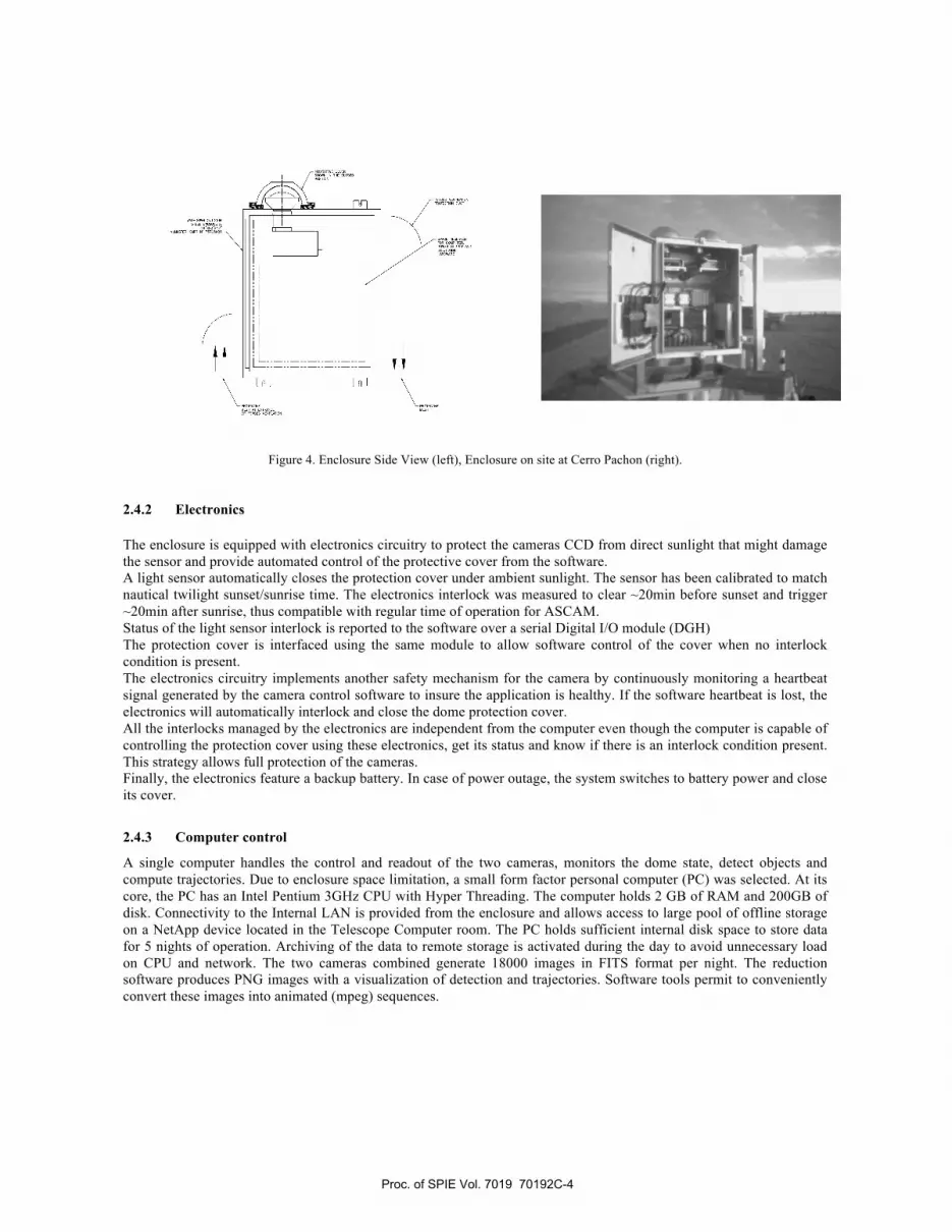
Figure 3. Enclosure Top view (left) Enclosure End view (right)
Proc. of SPIE Vol. 7019 70192C-3
I
Figure 4. Enclosure Side View (left), Enclosure on site at Cerro Pachon (right).
2.4.2 Electronics
The enclosure is equipped with electronics circuitry to protect the cameras CCD from direct sunlight that might damage
the sensor and provide automated control of the protective cover from the software.
A light sensor automatically closes the protection cover under ambient sunlight. The sensor has been calibrated to match
nautical twilight sunset/sunrise time. The electronics interlock was measured to clear ~20min before sunset and trigger
~20min after sunrise, thus compatible with regular time of operation for ASCAM.
Status of the light sensor interlock is reported to the software over a serial Digital I/O module (DGH)
The protection cover is interfaced using the same module to allow software control of the cover when no interlock
condition is present.
The electronics circuitry implements another safety mechanism for the camera by continuously monitoring a heartbeat
signal generated by the camera control software to insure the application is healthy. If the software heartbeat is lost, the
electronics will automatically interlock and close the dome protection cover.
All the interlocks managed by the electronics are independent from the computer even though the computer is capable of
controlling the protection cover using these electronics, get its status and know if there is an interlock condition present.
This strategy allows full protection of the cameras.
Finally, the electronics feature a backup battery. In case of power outage, the system switches to battery power and close
its cover.
2.4.3 Computer control
A single computer handles the control and readout of the two cameras, monitors the dome state, detect objects and
compute trajectories. Due to enclosure space limitation, a small form factor personal computer (PC) was selected. At its
core, the PC has an Intel Pentium 3GHz CPU with Hyper Threading. The computer holds 2 GB of RAM and 200GB of
disk. Connectivity to the Internal LAN is provided from the enclosure and allows access to large pool of offline storage
on a NetApp device located in the Telescope Computer room. The PC holds sufficient internal disk space to store data
for 5 nights of operation. Archiving of the data to remote storage is activated during the day to avoid unnecessary load
on CPU and network. The two cameras combined generate 18000 images in FITS format per night. The reduction
software produces PNG images with a visualization of detection and trajectories. Software tools permit to conveniently
convert these images into animated (mpeg) sequences.
Proc. of SPIE Vol. 7019 70192C-4

3. SOFTWARE ARCHITECTURE
New software was developed to control the new cameras, the automation of the dome and implement the logic for the
interlocks. Gemini is using an Alta-U camera for a different application. The vendor provides an open source driver for
its cameras and the effort needed to adapt our application for ASCAM turned out to be minimal. The modifications
mainly confined around adding support for two cameras working in parallel. The multi-threaded nature of the original
application helped arrange synchronous overlap of open shutter time.
Developing the software components needed to interface with the enclosure and light sensor was also minimal. The
device we selected (DGH) uses a simple ASCII protocol over serial for communication. A similar driver had already
been developed for a different monitoring project.
The data stream coming from the camera was conserved. Yorick is a high level mathematical language for complex and
intensive computation, the language was selected to perform the detection. It provides C-like performance and a
convenient mechanism to create extensions (plug in). This feature allowed us to use the shared-memory interface
provided by the original design, a fast and efficient way to pass data between processes. Control of the camera is
accomplished using EPICS, the standard control framework used at Gemini.
The User Interface was developed using Glade, a generic GUI builder and Python. The interface between control,
reduction and detection tasked is accomplished using a simple and effective pipe.
Figure 5. Software Architecture
Proc. of SPIE Vol. 7019 70192C-5

4. DETECTION ALGORITHM
The problem of detection of moving sources/aircrafts can be approached with various methods. One could try to detect
every new brightness perturbation in an incoming image, possibly using selecting criteria like the "spot" shape
(allegedly, it should be elongated as the aircraft is supposed to move during the exposure). This approach is tempting as
it delivers an instant warning. However, it is prone to delivering many false positives, by e.g., cosmic rays or stars being
in turn obscured and revealed by clouds. It is important to detect aircrafts with high reliability and as quickly as possible,
but it is also important to trigger as few false positive as possible. Therefore we opted for a trajectory
approach/algorithm, in which we only trigger an alarm if we detect events that form a trajectory that will intersect our
danger zone. A valid trajectory is a fit to at least 3 points/detections with qui-square lower than a certain threshold. This
approach is very effective in removing false positive. It has the drawback of requiring at least 3 consecutive images
before an alarm can be raised; hence the need for a relatively fast frame rate (the Gemini ASCAM, with its 2 interleaved
cameras, achieves 4.3/2 = 2.15 sec frame rate).
Below, we detail the various step of image processing, and trajectory processing we go through for aircraft detection.
4.1 Image processing
When a new image arrives, it is processed as follow:
• A background is subtracted; build from the penultimate image (last but one). As the star motion is slow, this
subtracts well all stellar components, and is particularly effective for the slowly varying background like the
milky way.
• The image is multiplied by a mask form from the five previous images: for each image, a binary image is
formed (larger than threshold or not), and this binary mask is enlarged by gaussian FFT convolution. The five
previous image mask are stacked (OR) to produce the single mask used for the current image. To gain time, and
because we do not use the mask for the current image yet (next iteration), the masks are computed once the
trajectories are determined and output, and before waiting for the next image.
• A moon masking is applied. We build a mask of pixels larger than a certain threshold (usually close to
saturation) and erode the mask by convolving by a gaussian kernel to make it slightly larger than the saturated
part. This is mostly to get rid of blooming in columns, which can widely vary, depending on how the moon is
centered on a cluster of pixel (at least with our hardware). We are aware that anti-blooming CCD exist, but you
pay a price in QE that we were not ready to pay (about a factor of 2 in QE/equivalent exposure time). Hence
this fix.
• We multiply by a pre-determined mask that masks out regions of the images like below horizon, domes,
meteorological towers, etc...
• The image is "binarized", i.e. every pixel above a certain threshold is set to 1, the others at zero. The chosen
threshold is typically about 3 to 4 times the CCD read out noise (or sky noise, depending which dominates).
• This binary image is searched for clusters of connex "1" pixels. The groups are sorted, largest first.
• A first selection is applied on the basis of number of pixel per group: We filter cluster smaller than a certain
threshold, but we also filter cluster larger than another threshold, just to make extra sure we don't select things
like moon or glare on a dome, even though this should have been filtered out. This might be also useful to filter
out large cosmic events. After this filtering, only the largest 4 clusters are kept. This is to reduce CPU load, as
we will see below, because we try every different combination of current/past event to fit trajectory, the
problem is essentially combinatory, and therefore the cpu time will grow as Cn
n.
• The centroid of each retained pixel clusters is computed.
Proc. of SPIE Vol. 7019 70192C-6

4.2 Trajectories processing
• We then take each centroid (detection), one by one, and combine them with previously detected events. Said,
we fit trajectories in the event space. The last 6 frame events are considered. All possible combinations are
fitted, and the best are retained as possible trajectories. A threshold is applied to the resulting chi2 to determine
the validity of the result trajectory. The possibility the aircraft was undetected in one or several of the last 6
frames is included. The final results weight the fit by the number of point used (out of the last 6 frames), to
favor a trajectory fit that contains the largest number of point. On top of the last 6 frames detection, we keep in
memory the valid trajectories (trajectories that had valid point in the last 10 frames), and compare them with the
current detections. This allow to keep trajectory/pas points valid over the whole passage of an aircraft, and get
very precise trajectory parameters: generally, we get a single trajectory for an aircraft crossing, including 50
points/detections/frames or more.
• Trajectories are compared with the current telescope pointing (laser propagation coordinates) to determine if
there is a danger of collision. We basically have three level of warning:
a) The aircraft trajectory highest elevation is lower than 30 degrees. This will not trigger any
warning/danger state.
b) The aircraft trajectory will bring it above 30 degrees elevation but not within the 15 degrees danger
radius around the direction of laser propagation. This triggers an "orange state", which bring the
attention of the operator on the event but does not affect/prevent the continuation of operation.
c) The aircraft trajectory will bring it within 15 degrees of the laser propagation. The operator is warned,
and a close shutter is sent to the AO/laser system for ETA < 60 seconds.
Each rules has priority over the previous rule. For instance, (c) will win on (a) when the propagation elevation
is low (between 30 and 45 degrees, in case the plane highest elevation is, say, 28 degrees).
5. USER INTERFACE
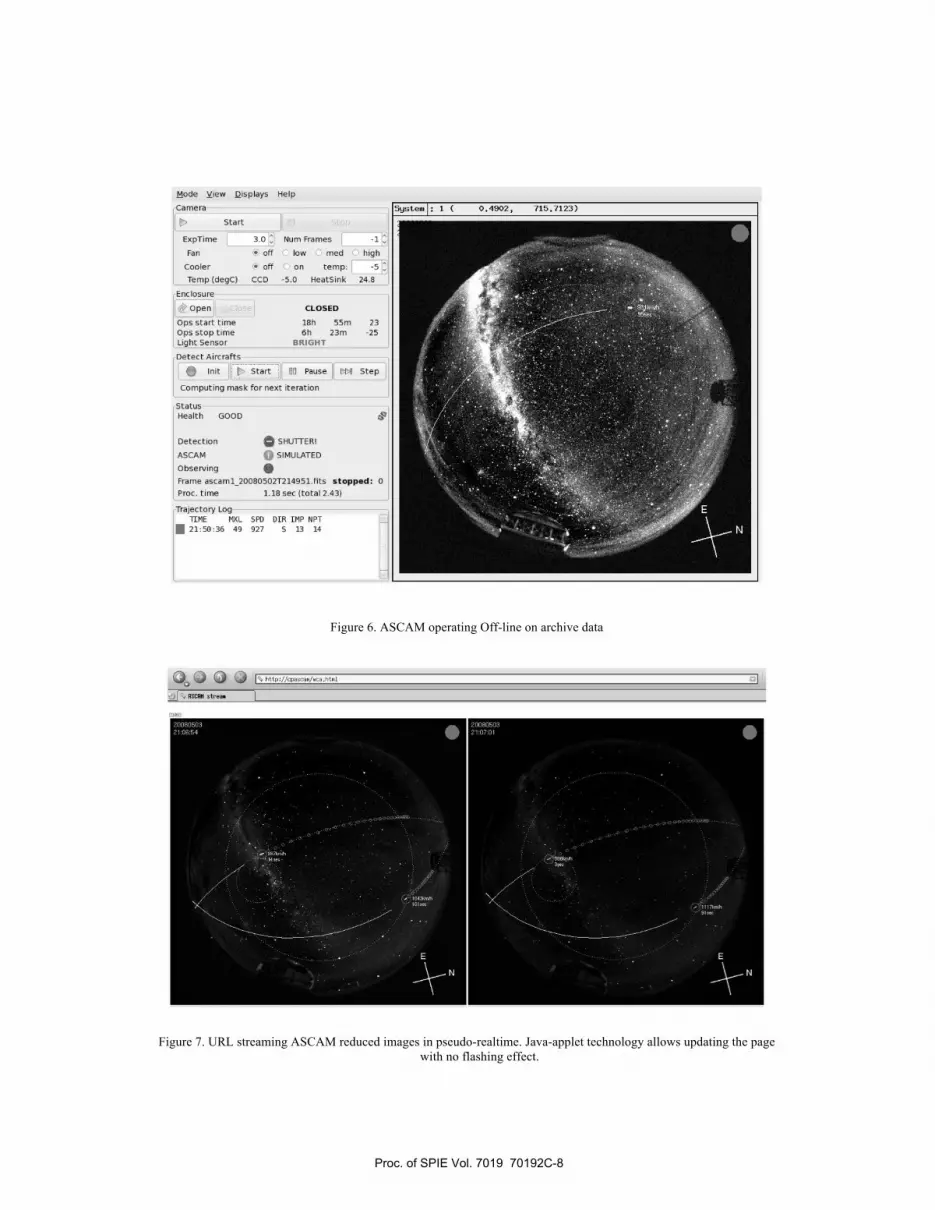
Operation of ASCAM is fully automated and little interaction is expected from the user once the system has been started.
A graphical user interface (Figure 6) has been created to provide the necessary control over the system.
This interface offers two modes of operation
• ‘on-line’ where the application connects to the real cameras to produce real-time detections (the normal mode
of operation)
• ‘off-line’ to allow reprocessing images from the archive
The side pane on the GUI can be configured to hide controls and provide more display estate to the detection log. A web
based interface (Figure 7) provides access to logs and streams real-time images for convenient access during operation
Proc. of SPIE Vol. 7019 70192C-7
Mode View Displays Help
_______ — C 0.4102, flJ.fl23)—[ Start
Explime 3.0 Sum Frames -1
Fan off low med high
Cooler off on temp:Temp (degc) CCD -5.0 HeatSink 24.8
Enclosure
ioperi CLOSED
Opt start tine ish 55n 23Ops stop time Oh 23m -25
I Light Sensor ERIGHT
Detect Aircrafts
0 Init Start 3 Pause LH Step
Computing mask For next iteration
StatusHealth GOOD
Detection SHWTERI
ASCAM ij SIMULATED
ObservingFrame ascami_20080507r214951.flts stopped:Proc. time lie set (total 2.431
Trajectory Log-TtME FIXL SPO DLII IMP NPJ
• 21:55:36 49 927 S 13 14
Figure 6. ASCAM operating Off-line on archive data
Figure 7. URL streaming ASCAM reduced images in pseudo-realtime. Java-applet technology allows updating the page
with no flashing effect.
Proc. of SPIE Vol. 7019 70192C-8

6. PERFORMANCE AND ON-SKY RESULT
We plan to keep in archive the images collected by the two ASCAM cameras over a month period. This will allow us to
assess the performance of the system under different moon illumination conditions. At the time of this writing, our
information system group is procuring the offline storage capability needed hence we only have partial datasets to work
with to present results.
7. SUMMARY
ASCAM development is getting close to completion. We expect the system to ship to Hawai’i before the end of the year
to be fully integrated with Altair/LGS operations and made available to the LTCS community atop Mauna Kea. The
system will be replicated for Gemini MCAO laser operations at Cerro Pachon in Chile.
ACKNOWLEDGEMENTS
We acknowledge all the Gemini Staff members who contributed in the elaboration of the ASCAM system. We thank the
members of the Laser Guide Star Operation Working Group from Gemini, Keck, Palomar and CTIO for their insights
and support.
The Gemini Observatory is operated by the Association of Universities for Research in Astronomy, Inc., under a
cooperative agreement with the NSF on behalf of the Gemini partnership: the National Science Foundation (United
States), the Science and Technology Facilities Council (United Kingdom), the National Research Council (Canada),
CONICYT (Chile), the Australian Research Council (Australia), Ministério da Ciência e Tecnologia (Brazil), and
SECYT (Argentina).
REFERENCES
[1]
Yorick, an interpreted programming language for large scientific simulation
http://www.maumae.net/yorick/doc/index.php [2]
EPICS, the Experimental Physics and Industrial Control System http://www.aps.anl.gov/epics/about.php [3]
Slow Focus Sensor, Observatory Sciences Ltd.- William James House, Cowley Road, Cambridge CB4 0WX U.K.
http://www.observatorysciences.co.uk/ [4]
ESO SkyCat, A. Brighton, T. Herlin, M. Albrecht, D. Durand, P. Biereichel http://archive.eso.org/skycat/ [5]
Skycalc, an astronomical almanac calculator and calendar programs – J. Thorstensen
http://www.dartmouth.edu/~physics/faculty/thorstensen.html [6]
WebCamApplet, a free applet for webcams, P. Sidnell http://webcamapplet.sourceforge.net/ [7]
Linux, a free operating system originally created by L. Torvalds http://www.linuxfoundation.org/ [8]
GTK+, a highly usable feature rich toolkit for creating graphical user interfaces. http://www.gtk.org/ [9]
Glade, a user interface designer for GTK+ and Gnome http://glade.gnome.org/ [10]
Python, a dynamic object-oriented programming language http://www.python.org/
Proc. of SPIE Vol. 7019 70192C-9