two different approaches for georadar data processing: a case study in archaeological prospecting
TRANSCRIPT

Available online at www.sciencedirect.com
sics 64 (2008) 1–13www.elsevier.com/locate/jappgeo
Journal of Applied Geophy
Two different approaches for georadar data processing:A case study in archaeological prospecting
Luciana Orlando a,⁎, Francesco Soldovieri b
a Dipartimento di Idraulica Trasporti e Strade, La Sapienza University, Via Eudossiana, 18 Rome, Italyb Istituto per il Rilevamento Elettromagnetico dell'Ambiente, Consiglio Nazionale delle Ricerche, Via Diocleziano 328, 80124 Napoli, Italy
Received 8 January 2007; accepted 12 October 2007
Abstract
This paper deals with the application of two different processing methods of the georadar data aimed at improving the results in the caseof bad quality data. The georadar data are referred to two areas located in the Axum archaeological park (Ethiopia) and were acquired prior tothe reinstallation of the returned Stele from Italy to the Ethiopian Government. In the area the schist formation is covered by an outcroppingsandy silt formation about 6–8 m thick. The archaeological excavations, performed before the georadar data acquisition, revealed that tombsand catacombs were dug into the superficial layer. Because the complexity of the georadar data interpretation based on standard dataprocessing, some of the collected measured data are also processed by an innovative microwave tomographic approach which permits toachieve clearer diagnostic results with respect to the classic radaristic techniques in 2D and 3D representation. We take into account the dataacquired for the East stele 2 with 100 MHz antenna and in the parking area of the archaeological park with 200 MHz antenna. The data wereacquired on profiles 1 m apart. Comparing the data processed with the two different approaches, we obtained an improvement of the verticalresolution and of the quality of image on time slices using the tomographic approach compared to the results obtained with the classic radarone.© 2007 Elsevier B.V. All rights reserved.
Keywords: Georadar; Archaeology; 3D data; Spatial resolution; Microwave tomography
1. Introduction
Due to its enormous weight (150 tons), the transportation ofthe Axumite-age stele from Italy to Ethiopia was a real en-deavour. The Stele had to be restored to its original site that wasdeclared Heritage of Humanity by UNESCO in 1984. However,the fact there might still undetected archaeological ruins orartefacts buried under the site further complicates the restorationoperations.
The Stele is the second largest in the archaeological park ofAksum and probably collapsed in the XII century. In 1937, itwas brought to Italy and was set in front of the Ministry of theColonies in Rome. In April 2005, it was returned to theEthiopian Government.
⁎ Corresponding author.E-mail addresses: [email protected] (L. Orlando),
[email protected] (F. Soldovieri).
0926-9851/$ - see front matter © 2007 Elsevier B.V. All rights reserved.doi:10.1016/j.jappgeo.2007.10.002
Thus, before re-erecting the Stele, georadar data wereacquired with the aim of reconstructing the features of theunderground; this was needed to preserve the potentially un-detected fragile archaeological structures buried near the Stele 2site during its re-erection. In particular, it is known fromarchaeological investigations (Munro-Hay, 1991; Phillipson,1991) that several tombs and catacombs are buried around theoriginal stele site. These archaeological structures were built inpart on silty–sand alluvial sediments, about 6–8 m thick and inpart on Precambrian schist formation. The top of the discoveredarchaeological structures have their top at a depth between onemeter and 3–5 m from the topographic level. However, now theexact location of the most structures and the archaeologicalsuperposition of structures are relatively unknown; in fact, inthe past the area has been excavated many times and recoveredwith sediments by archaeological excavation and robbery.Therefore, before the reinstalling of the Stele, non invasiveprospecting of the subsurface has been necessary to prevent

2 L. Orlando, F. Soldovieri / Journal of Applied Geophysics 64 (2008) 1–13
damage to the any unknown archaeological structures buriedunderneath (Orlando, 2006).
Given the geo-archaeological setting of the area, which con-sists of structures built with stone and/or cavities enclosed insilty–sand sediments located above the water table, the georadarwas identified as the most suitable geophysical method for thehigh resolution of the first meters below the topographic level. Inparticular, the georadar surveys were carried out mainly in thearea surrounding the original site of the Stele 2.
The exploitation of georadar in archaeological applications isvery common (Barone et al., 2007;Martino et al., 2006; Abbas etal., 2005; Orlando, 2005; Tallini et al., 2004; Leckebusch, 2003;Piro et al., 2002; Basile et al., 2000; Conyers and Goodman,1997; Malagodi et al., 1996). The georadar is usually exploitedin a configuration, where the receiving and transmitting antennasare separated by a small fixed offset and are moved very close toor in contact with the ground-interface and for each position atime domain trace is collected. The traces are then joined andprocessed in order to visualize vertical profiles; in archaeologymore and more frequently the profiles are acquired one close tothe other so as to perform a 3D cube data and time slices thatrepresent sections of data at a constant depth.
When the structures are well preserved and the embeddingstrata are electromagnetically homogeneous the time sliceallows to perform an easy interpretation of anomalies in termsof archaeological structures (Piro et al., 2002; Malagodi et al.,1996). However, in some cases the anomalies are not easilyinterpretable and so it is very useful to make a joint interpre-tation of the time slices and of the vertical profiles. In fact, whenmany structures are superimposed it is difficult to separatedifferent interfaces; this arises because of the limited depthresolution due to the time-signature of the transmitting antenna.In fact, the depth resolution depends on the frequency and onthe electromagnetic velocity of the probing radiation of theinvestigated structures; moreover thin resistive structures,depending on the thickness as function of frequency of electro-magnetic signal, can originate resonance phenomena. Thelateral resolution depends on antenna frequency, depth and dis-tance of profiles, the latter can induce on the time slices astretching of the anomalies in the normal direction of profiles(Orlando, 2005) because of the different sampling of the under-ground. Also, it is necessary to account the role of the losses inthe investigated medium, which entails to reducing the peakantenna frequency in order to achieve a good penetration depth.Therefore, in georadar surveys the choice of the antenna fre-quency must be performed in order to achieve a compromisebetween the depth resolution and the extent in depth of thedomain to be investigated.
In order to improve the depth resolution, deconvolutiontechniques (Yilmaz, 2001), commonly exploited for the seismicdata, can be exploited; however, as the radar signal has a not zerophase and its wide band is about 1.5 octave, often bad results areachieved with the application of such techniques.
Recently, in order to improve the quality of georadar diag-nostic results, microwave tomographic approaches are gainingan increasing interest (Persico and Soldovieri, 2004; Soldovieriand Persico, 2004; Cui and Chew, 2002; Meincke, 2001).
Microwave tomography approaches are based on the solution ofan inverse scattering problem (Soldovieri and Persico, 2004)with the aim of determining the spatial distribution of the die-lectric and/or conductive characteristic of a subsurface regionfrom scattered field data gathered at the air-soil interface. Thistechnique permits not only to detect the target but also toaccurately locate it and determine its geometrical features interms of extent and shape.
In particular, in this paper we compare the results of a 1Dmicrowave tomographic processing applied to the measureddata collected in the Aksum Park with those achieved by theclassic georadar processing.
The paper is organised as follows. In Section 2, the micro-wave tomographic approach is briefly described and some re-construction results with synthetic data are presented. Section 3is devoted presenting the geoaradar survey in Aksum and themain results processed by the classic radar technique. Then, inSection 4, we show the results obtained by the tomographicapproach and compare them with the classic radar results pre-sented in Section 2. Finally, conclusions follow.
2. The microwave tomographic approach
This Section is devoted to presenting the microwavetomographic approach exploited in the processing of themeasurements.
The microwave tomography technique has become anincreasingly popular interpretational tool for Ground Penetrat-ing Radar (GPR) applications. The possibility of recasting thedata processing as an inverse scattering problem (Colton andKress 1992) can improve the interpretation of simpler “radar-grams” (Daniels, 2004). Indeed it allows to obtain more focal-ized and clearer images of the subsurface in order to have amore objective representation of the investigated area in termsof presence, location and geometrical properties of the targets(Persico and Soldovieri, 2004; Soldovieri and Persico, 2004). Inaddition, the adoption of more accurate models of the elec-tromagnetic scattering phenomenon, can help us understandcrucial aspects of a specific problem at a much deeper inter-pretational level.
In this paper, we exploit an inverse scattering algorithm thatworks in the frequency domain and is able to face the problemin 1D-geometry in order to process the single traces collected bythe georadar. Then, the vertical profiles are achieved by joiningthe tomographic reconstruction of the single traces of the samemeasurement line. The 3D description of the investigated area isobtained by joining the vertical profiles; finally the time slicesare achieved as interpolated sections of the 3D cube at a con-stant depth.
In particular, the inverse scattering algorithm here consideredassumes the 1D half-space geometry where one of the media isthe air (where the antenna is located) and the other one is the soilwhere the targets are buried (see Fig. 1).
We assume both the two half-spaces as homogeneous mediaand the soil has been considered with conductive losses. The firstmedium is air and has a relative dielectric permittivity ε1=1. Thesoil has a relative equivalent complex dielectric permittivity

Fig. 1. Geometry of the inverse scattering problem for the 1D geometry.
3L. Orlando, F. Soldovieri / Journal of Applied Geophysics 64 (2008) 1–13
eeqb ¼ e0eb � j rb2pf e0
where εb and σb are the relative dielectricpermittivity and the conductivity of the soil and f is the workfrequency. The magnetic permeability is everywhere equal tothat of the free space μ0.
We assume that an unitary plane wave, whose electric field isgiven by e − jk0 z , being k0 the wave-number in the air-half-space, normally impinges on the investigation domain atdifferent frequencies in a fixed range Ω=[fmin, fmax]. For eachfrequency in the band Ω=[fmin, fmax], the scattered field isgathered at the interface air/soil located at z=0−.
The scattered field is defined as the difference between thetotal field and the incident field. The total field is the field
Fig. 2. Behavior of the singular value for the synthetic data. A knee (indica
reflected by the soil when also the buried target is present aswell. The incident field is the field reflected by the soil only andin absence of the target and accounts only the reflection from theinterface air/soil.
The problem at hand is concerned with the determination ofthe one-dimensional dielectric profile εeq(z) in the probingdomain D=[z1, z2] embedded in the soil, starting from theknowledge of the scattered field. To solve such an inversescattering problem is, in general, a complicated task due to ill-posedness and non-linearity (Bertero and Boccacci, 1998; Pierriet al., 2002). Ill-posedness means that the problem of the“stability” of the solution against noise and uncertainties must beaccounted for; this entails the adoption of regularization schemes(Bertero and Boccacci 1998) that allow to achieve anapproximate version of the unknown represented by a finitenumber of parameters. The non-linearity implies that, due to theproblem of possible false solutions (local minima) within thesolution algorithm, the diagnostic results might be very differentfrom the “true situation” also in the “ideal case” of noiseless data.
The above mentioned difficulties can be overcome by adopt-ing a simplified model of the electromagnetic scattering; in thispaper we deal with an inversion approach that exploits a linearmodel of the electromagnetic scattering based on the BornApproximation (BA) (Persico and Soldovieri, 2004; Soldovieriand Persico, 2004; Cui and Chew, 2002; Meincke, 2001). Theadoption of Born Approximation mainly consists in neglectingthe mutual interactions between the buried targets and betweenthe targets and the air/soil interface. The adoption of BA allowsthe following advantages: the problem of the false solutions isavoided; the computational burden is reduced and thus it ispossible to investigate large domains, in terms of probingwavelength, in a reasonable computational time. In addition, the
ted by the arrow) appears around the singular value index equal to 21.

4 L. Orlando, F. Soldovieri / Journal of Applied Geophysics 64 (2008) 1–13
simpler linear model allows analyzing the reconstruction capa-bilities of the solution algorithm in terms of the spatial varia-tions of the unknown that can be retrieved and ultimately of theachievable resolution limits as it is shown below.
Under the BA, a linear integral relationship between thecontrast function (the unknown of the problem) and the scat-tered field (the datum of the problem) is achieved as
Es fð Þ ¼ k2s
ZDGe z0; fð ÞEinc z0; fð Þv z0ð Þdz0 faX ð1Þ
where the actual unknown of the problem is the contrast func-tion defined by
v z Vð Þ ¼ eeq z Vð Þ � eeqbeeqb
ð2Þ
and
eeq z Vð Þ ¼ e0eD z0ð Þ � jrD z0ð Þ2p f e0
ð3Þ
εD(z') and σD(z') being the relative dielectric permittivity andthe conductivity of the unknown layers in the investigationdomain D. The “contrast” function is the relative differencebetween the unknown dielectric profile and the electromagneticproperties of the background medium. By its definition, χ(z') isdifferent from zero only within the investigation domain D=[z1,z2]. ks ¼ 2pf
ffiffiffiffiffiffiffiffiffiffiffiffiffiffiffiffie0eeqbA0
pis the wave number of the soil. Einc(z',
f) is the incident field in the investigation domain, i.e., the fieldpresent in the investigation domain D when layers (targets) arenot present; it is given by:
Einc z0; fð Þ ¼ T21exp �jksz0ð Þ ð4Þ
where T21 ¼ 2k0k0þks
denotes the transmission coefficient from the
air to the soil half space.Ge is the external Green's function of the background and
represents the electric field radiated at the interface air/soil by a1D impulsive source located at depth z'. Its expression is:
Ge z0; fð Þ ¼ �jT122ks
exp �jksz0ð Þ ð5Þ
where T12 ¼ 2ksksþk0
denotes the transmission coefficient from the
soil to the air half space.By substituting the expressions of the Green's function and
of the incident field in Eq. (1), we obtain the integral expressionof the scattered field:
Esl fð Þ ¼ F fð ÞZDv z0ð Þexp �j2ksz
0ð Þdz0 faX ð6Þ
where F(f)=− jT12T21ks / 2 is the quantity outside of the integralthat depends only on the frequency.
Therefore, the problem at hand is cast as the inversion of thelinear integral equation in (6); in order to find a stable solution
of the inversion of the integral relation, a regularized inversionscheme is used at the cost of renouncing to an extremelydetailed resolution in the reconstruction (Bertero and Boccacci1998). In this paper, the stability of the solution is imposed bymeans of a Truncated Singular Value Decomposition (TSVD)(Bertero and Boccacci 1998) of the matrix accounting forrelationship (6). The matrix is achieved by the discretization ofrelation (6) thanks to the method of the moments where theunknown contrast function is discretized by rectangular pulsefunctions and the scattered field is collected in the workfrequency band Ω=[fmin, fmax] at an uniform step.
In particular, the Truncated SVD solution is approximatedas:
v ¼XNn¼0
1rn
bEs; vn N un ð7Þ
where ⟨·,·⟩ denotes the scalar product with respect to thefrequency, the set {σn}n=0
∞ denotes the singular values orderedin a non increasing sequence, un and vn are the basis functionswithin the space of the “visible” unknowns (i.e., the functionsthat can be retrieved by the noise-free data) and the space of thenoise-free data for the linear integral operator (relationship)defined in Eq. (6), respectively (Bertero and Boccacci 1998). Ingeneral, the regularization is performed by choosing a trun-cation index N in the summation (7) according to the availablesignal-to-noise ratio, i.e., it consists in summing up only thoseterms in (7) corresponding to singular values for which σn/σ0 islarger than the signal-to-noise ratio.
The SVD allows also a thorough analysis of the reconstruc-tion capabilities of the solution algorithm in dependence of thedielectric permittivity of the host medium and of the workfrequency band. It is worth noting that the problem in Eq. (6)very similar, apart the factor F(f) outside the integral, to theinversion of a Fourier Transform with limited data. For such aproblem an analytical determination of the singular system ispossible in the case of lossless soil (Pierri et al., 2002) and thisgives guidelines in theoretically providing an estimate of thenumber of singular values to be retained in TSVD as
N ¼ z2 � z1ð Þ ffiffiffiffieb
pc0p
2p fmax� fminð Þ ¼ 2 z2 � z1ð Þ ffiffiffiffieb
pc0
fmax� fminð Þð8Þ
where c0 ¼ 1=ffiffiffiffiffiffiffiffiffie0A0
pis the electromagnetic velocity in air.
In fact, for the case at hand, the singular values exhibit “step-like” behavior, and this leads to the choice of an “optimal valueof N” weakly dependent on the noise level on data. As matter offact, it is sufficient to choose as N index the one correspondingto the knee of the curve of the singular values. In fact, even asignificant increase in the signal-to-noise ratio would not lead toa meaningful increase of the singular values to be retained inTSVD expansion (7), due to the fast exponential decay of thesingular values after the knee.
The above consideration is made clear by considering a testcase where a background scenario represented by a homo-geneous half space with relative dielectric permittivity εb=10

Fig. 3. Tomographic reconstruction of a slab with synthetic data. Fig. 3a and b depict the modulus of the retrieved contrast function normalized with respect to itsmaximum.
5L. Orlando, F. Soldovieri / Journal of Applied Geophysics 64 (2008) 1–13
and an investigation domain D=[0,2.5]m are assumed. Thework frequency band ranges from 100 to 500 MHz with a stepof 10 MHz. Fig. 2 depicts the behavior of the singular values; asexpected the singular values behavior is step like with anasymptotic exponential decay. It is worth noting that for the thiscase, the estimate in Eq. (8) provides N=21 that is consistentwith the singular values behavior presented in Fig. 2, where theknee is about the index equal to 21.
The estimate (8) also makes it possible to give an estimate ofthe resolution distance, according to the Rayleigh's criterion, as(Pierri et al., 2002)
R ¼ c02 fmax � fminð Þ ffiffiffiffi
ebp ð9Þ
It is worth noting that the estimate in (9) agrees with the wellknown rule used in radar approaches where the range resolutionis a quantity inversely proportional to the bandwidth.
Let us turn now to present two numerical inversion results thatconsider the background scenario described above.Noisy data areconsideredwith a signal to noise ratio equal to 20 dB; accordinglyfor the computation of the solution we retain in the TSVDsummation of Eq. (5) the terms corresponding to the singularvalues 0.1 times larger than the maximum singular value.
The first reconstruction refers to a homogeneous target withrelative dielectric permittivity εr=36 and with a thickness of0.4m (Fig. 3a). The first interface of the target is located at 0.3m;thus the locations of the two interfaces are zL=0.3 m zH=0.7 m.The modulus of the contrast function reconstructed through the

6 L. Orlando, F. Soldovieri / Journal of Applied Geophysics 64 (2008) 1–13
TSVD is depicted in Fig. 3a. The location of the reconstructedpeak corresponding to the second interface is at about 1.1 m. Thedifference between the position z of the position of thereconstructed peak and of the actual interface's location zH canbe easily justified. The difference arises since the velocityassumed in the inversion model and given by vb ¼ c0=
ffiffiffiffieb
pis
different from the actual electromagnetic velocity in the slabgiven by vr ¼ c0=
ffiffiffiffier
p. In particular, when the relative dielectric
permittivity of the slab is larger than the one of the host medium,i.e. εrNεb, the propagation velocity of the electromagnetic waveassumed in the model vb ¼ c0=
ffiffiffiffieb
pis larger than the actual
velocity vr ¼ c0=ffiffiffiffier
p; this leads to a delocalization in depth
of the second interface of the defect z N zH. It is possible todetermine the correct location of the second interface byexploiting the relation z ¼ zH þ ffiffiffiffiffiffiffiffiffiffiffiffiffiffiffiffiffiffi
er=eb � 1p
zH � zLð Þ wherethe knowledge of εr is assumed a priori; this relation allowsto correctly determining the location zH=0.7.
The reconstruction result allows us to state that despite of anot negligible model error, the inversion of Eq. (6) allowslocalizing the fast discontinuities of the contrast profile thatcorrespond to the interfaces of the layer (Pierri et al., 2002,Persico and Soldovieri, 2004; Soldovieri and Persico, 2004).This kind of reconstruction result is consistent with the fact thatthe inversion of Eq. (6) permits to achieve a band-pass filteredversion of the contrast function; this entails that in the recon-struction the fast spatial variation of the unknown are pri-vileged. Accordingly, the reconstruction algorithm is able todetect and localize the two interfaces of the penetrable target.
The second numerical results is concerned with a layer thathas a relative dielectric permittivity εr=5. The modulus of thecontrast function via TSVD is depicted in Fig. 3b. Now, we haveεrbεb; in this case the difference in the velocity of theelectromagnetic wave in the slab and in the host medium entailsa reconstructed peak which “anticipates” the actual location ofthe second interface, i.e., zb zH. It is still possible to determinethe correct location of the second interface by exploiting therelation z ¼ zH þ ffiffiffiffiffiffiffiffiffiffiffiffiffiffiffiffiffiffiffiffiffiffiffiffiffiffiffiffiffiffiffiffiffiffiffiffiffiffi
er=eb � 1Þ zH � zLð Þp�where the knowledge
of εr is assumed a priori.For both the cases, the relation of Eq. (9) provides an estimate
of the resolution distance R equal to 0.12 m. Thus, for the twonumerical reconstructions we have the peaks (corresponding tothe interfaces) spaced at distance (0.8 m and 0.28 m for the firstand second case, respectively) greater than the resolutiondistance R.
We stress that the inversion algorithm is exploited in thispaper to process data collected by a commercial time domaingeoradar (see the section below), therefore, the actual measure-ments collected by the georadar are in time-domain andaccounts also for the reflection by the air/soil interface and ofthe “desired response” from the buried targets. Therefore, theproblem of extracting the scattered field (response only of theburied targets) from the total one (response of the air/soilinterface plus response of the buried targets) arises. In this paper,this extraction is performed by time gating the measurementscollected by the georadar. Then, these gated measurementsundergo to a Fourier Transform to achieve frequency datasuitable for the inversion code.
Finally, we roughly justify the adoption of a simple 1Dinversion algorithm in the realistic cases presented below. Firstof all, we recall that the electromagnetic field radiated by theantenna can be given under a spectral representation (Soldovieriet al., 2005); therefore, the radiated field (i.e., the incident fieldin our inversion) can be “physically interpreted” as the super-position of plane waves of different propagation directions.Differently in our inversion scheme we consider as incidentfield a plane wave with normal incidence (i.e., incidence direc-tion along the z-axis). Therefore, an approximation arises in theevaluation of the incident field. However, we can state that thisapproximation is roughly valid since the reflected field in thewave directions near normal incidence provides in most casesthe biggest contribution to reflected energy for small-offsetantenna configurations.
3. Georadar prospecting, processing and radargramanalyses
The data were collected using the instrument PulseEkko100of Sensor & Software Corporation equipped with a 100 MHzantenna and the IDS Instrument equipped with 200 MHzantenna. The goal of the survey was to carry out a detailedreconstruction of the underground structures present, so that adistance between the profiles of 1 m was chosen. Also, profilesin both x and y directions (Fig. 4) were performed in order toavoid any ambiguity due to the direction of profiles with respectto the features of structures.
The data were acquired in continuous mode in a timewindow of 500 ns, with a sampling rate of 0.8 ns for the100 MHz antenna. The time window was selected to investigatethe maximum possible depth in dependence on the antennafrequency bandwidth and the ground attenuation of sediments.The antenna position along the profile was obtained thanks tomarkers located at an uniform step of 2 meters. For the200 MHz antenna, the sampling rate of 0.2 ns and a timewindow of 200 ns were adopted; the scan positions werecontrolled by an odometer.
CMP data were gathered with a transmitter-receiver offsetincrement of 0.1 m with the PulseEkko instrument. The root-mean-square wave velocity of about 0.085–0.09 m/ns wascalculated from CMP (Common Mid Point) and diffractionhyperbola. The velocity of 0.09 m/ns was used for the time/meter conversion in the diagnostic results. A theoreticalvertical resolution of 0.25–0.35 m was obtained for thiselectromagnetic velocity and for a pulse frequency of 120–150 MHz.
The classic georadar data processing consisted in timesetting, time pass-band filter, mix traces and exponential gain.Since the spatial step along the profiles acquired withPulseEkko Instrument was not constant, these profiles werespatially re-sampled prior the 3D representation is performed(Conyers and Goodman, 1997, Malagodi et al., 1996, Whitinget al., 2000).
In this paper we will show the results for the two grey areasof Fig. 4: the first one is located at the right of Stele 2 and wasinvestigated with 100 MHz antenna and the second is located inthe parking area of the archaeological site and was investigated

Fig. 4. Location of georadar profiles. The grey areas were discussed. The dots lines are the location of profiles shown in the Figs. 5 and 13.
7L. Orlando, F. Soldovieri / Journal of Applied Geophysics 64 (2008) 1–13
with the 200 MHz antenna. In the both area we analyse only theprofiles acquired in x direction.
The data will be analysed with the objective of highlightingthe differences of information that can be obtained via the twodifferent approaches, i.e., microwave tomography and usualgeoradar data processing, and not with the main aim of inter-preting all the archaeological structures buried in the area.
Fig. 5. Vertical georadar profile: a) Amplitude of data achieved via the classic GPR prcontrast function retrieved by the microwave tomographic approach. For the locationdepth resolution is obtained with the two different approaches.
Therefore, let us turn now to show some of themain results of theusual processing for these two areas; the results will be comparedwith those achieved by the microwave tomograpic approachdescribed in Section 2.
In the East Stele 2 area, the georadar survey shows a usefulsignal up to 40–60 ns (2–3 m) of the subsurface. Below theprofiles are shown for lag-time windows depending on the
ocessing approach; b) Normalized amplitude with respect to its maximum of theof the vertical profile see Fig. 4. The numbers indicate the zones where different

Fig. 6. Vertical georadar profile: zoom of the lag 0–16 m of profile of Fig. 5. a) Absolute amplitude normalized with respect to its maximum achieved via the classicGPR processing approach; b) Normalized amplitude with respect to its maximum of the contrast function retrieved by the microwave tomographic approach.
8 L. Orlando, F. Soldovieri / Journal of Applied Geophysics 64 (2008) 1–13
penetration of signal. The analyses of profiles show a verycomplex setting of the underground characterized by the pre-sence of materials, structures, slabs and filled cavities.
The data interpretation, even if performed by jointly ex-ploiting vertical profiles, time slices and measurements acquiredin both perpendicular directions, was a difficult task and often itwas not possible to discriminate the anomalies due to archae-ological features from the noise effect.
The main anomalies were detected thanks to the exploitationof profiles acquired in x- and y- direction, but only in few casesit was possible to correlate anomalies with the archaeologicalstructures outlined in the images collected during previoussurveys in the park (Munro-Huy, 1991; Phillipson, 1991).
Let us turn now to show some results achieved by the usualradar processing; in particular we present in the figures belowthe modulus of the radargram.
In Fig. 5a we show the processed radargram for a verticalprofile with 628 spatial points equally spaced on a 48 m widedomain and on a 100 ns time window. The profile was collected
Fig. 7. Vertical georadar profile: zoom of lag 16- 32 m of profile of Fig. 5. a) Absoluteprocessing approach; b) Normalized amplitude with respect to its maximum of thedenotes zone where different spatial resolution is achieved by the microwave tomog
with a 100 MHz antenna at a distance of about 8 m from Stele 2(Fig. 4).
Figs. 6a–8a give a zoom of the vertical profile of Fig. 5 overthree regions 16 m wide. In particular, Figs. 6a–8a depict themodulus of the processed radargram that is normalized withrespect to its maximum. The vertical profile shows anomalieswhich are difficult to be interpreted since the structures are notwell preserved and more structures are superimposed. Forexample, it is very difficult to detect the upper and bottomboundaries of the structures 1 and 2 in Figs. 5, 7 and 8 becauseof the limited depth resolution and of the oscillating behavior ofthe radar signal.
The same problem arises if we analyse the time slices ofthe 3D representation. Such a 3D representation is achievedby joining 10 profiles 32 m long, spaced from each other by1 m and collected with 100 MHz antenna in East Stela 2area. The profiles consist in 480 equally spaced traces andeach single trace is made of samples spaced 0.8 ns. Figs. 9–12 adepict the time slices at 0.5, 0.75, 1.1 and 1.5 m where the
amplitude normalized with respect to its maximum achieved via the classic GPRcontrast function retrieved by the microwave tomographic approach. Label 1raphic approach.

Fig. 8. Vertical georadar profile: zoom of the lag 32–48 m of profile of Fig. 5. a) Absolute amplitude normalized with respect to its maximum achieved via the classicGPR processing approach; b) Normalized amplitude with respect to its maximum of the contrast function retrieved by the microwave tomographic approach. Label 2denotes zone where different spatial resolution is achieved by the microwave tomographic approach.
9L. Orlando, F. Soldovieri / Journal of Applied Geophysics 64 (2008) 1–13
absolute amplitude of the signal normalized with respect to itsmaximum is shown. The anomalies appear to be very scatteredand little organized and it is very difficult to assess from theirgeometries. Only the slice at 1.1 m (Fig. 11a) seems to havedetected a circular shaped anomaly (labelled with 1 in the figure)which could be correlated to a structure.
We show also the results concerned with a different arealocated in the parking area at front of the archaeological park(Fig. 4) in this area we consider 17 profiles about 20 m long andspaced from each other at 1 m. The profiles are collected withthe 200 MHz antenna and consist in 1040 equally spaced tracesby 0.02 m. Each single trace is made of 470 time samples with astep of 0.0104 ns for an overall time-range of about 49 ns.
Fig. 9. Time slices at 0.5 m: a) Absolute amplitude normalized with respect to itsamplitude with respect to its maximum of the contrast function retrieved by the mic
In this area the radar has investigated the depth of about 1.5 m(corresponding to a time widow of about 30 ns) and datainterpretation allows to identify several anomalies related to theutilities of a fountain and waterworks of the park built in thesixties and now buried. In particular, we investigate an areawhere the rest of a buried fountain structure is present.
In Fig. 13, a vertical profile (for location see Fig. 4) crossingthe modern fountain detects the edges (labelled with 1 in figure)and the bottom of the fountain. The figure is shown for a timewindows of 28 ns.
As already said, 3D representation of the area is achieved byjoining 17 profiles 20 m long, spaced from each other at 1 mallowed to perform the interpretation on time slices as well. The
maximum achieved via the classic GPR processing approach; b) Normalizedrowave tomographic approach.

Fig. 10. Time slices at 0.75 m: a) Absolute amplitude normalized with respect to its maximum achieved via the classic GPR processing approach; b) Normalizedamplitude with respect to its maximum of the contrast function retrieved by the microwave tomographic approach.
10 L. Orlando, F. Soldovieri / Journal of Applied Geophysics 64 (2008) 1–13
time slices at 0.25 and 0.40 m are shown in Figs. 14a and 15a,respectively. They show an anomaly with an ellipsoidal shapethat was attributed to the remains of the buried modern fountain.The non regular sampling of the underground given by an over-sampling along the profiles (antenna movement direction) andthe under-sampling along the direction normal to the profilesgiven the stretching effect on the image of time slices.
In both the considered areas, the anomalies are not clearenough to be interpreted and often the low vertical resolutionhas not allowed to properly outlining in a right way the boun-daries of the anomalies.
Fig. 11. Time slices at 1.1 m: a) Absolute amplitude normalized with respect to itsamplitude with respect to its maximum of the contrast function retrieved by the mic
In order to improve the quality of the results also in terms ofdepth resolution a microwave tomographic approach was ap-plied to the data.
4. The results of the microwave tomographic approach.
This Section is devoted to presenting the results achieved viathe tomographic approach and comparing them with the resultsof the classic radar processing approach in the two areas alreadydescribed in the section above: East Stele 2 and parking area ofthe archaeological site (Fig. 4).
maximum achieved via the classic GPR processing approach; b) Normalizedrowave tomographic approach.
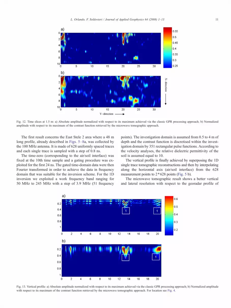
Fig. 12. Time slices at 1.5 m: a) Absolute amplitude normalized with respect to its maximum achieved via the classic GPR processing approach; b) Normalizedamplitude with respect to its maximum of the contrast function retrieved by the microwave tomographic approach.
11L. Orlando, F. Soldovieri / Journal of Applied Geophysics 64 (2008) 1–13
The first result concerns the East Stele 2 area where a 48 mlong profile, already described in Figs. 5–8a, was collected bythe 100 MHz antenna. It is made of 628 uniformly spaced tracesand each single trace is sampled with a step of 0.8 ns.
The time-zero (corresponding to the air/soil interface) wasfixed at the 10th time sample and a gating procedure was ex-ploited for the first 24 ns. The gated time-domain data were thenFourier transformed in order to achieve the data in frequencydomain that was suitable for the inversion scheme. For the 1Dinversion we exploited a work frequency band ranging for50 MHz to 245 MHz with a step of 3.9 MHz (51 frequency
Fig. 13. Vertical profile: a) Absolute amplitude normalized with respect to its maximwith respect to its maximum of the contrast function retrieved by the microwave tom
points). The investigation domain is assumed from 0.5 to 4 m ofdepth and the contrast function is discretised within the invest-igation domain by 351 rectangular pulse functions. According tothe velocity analyses, the relative dielectric permittivity of thesoil is assumed equal to 10.
The vertical profile is finally achieved by superposing the 1Dsingle trace tomographic reconstructions and then by interpolatingalong the horizontal axis (air/soil interface) from the 628measurement points to 2⁎628 points (Fig. 5 b).
The microwave tomographic result shows a better verticaland lateral resolution with respect to the georadar profile of
um achieved via the classic GPR processing approach; b) Normalized amplitudeographic approach. For location see Fig. 4.

Fig. 14. Time slices at 0.25 m: a) Absolute amplitude normalized with respect to its maximum achieved via the classic GPR processing approach; b) Normalizedamplitude with respect to its maximum of the contrast function retrieved by the microwave tomographic approach.
12 L. Orlando, F. Soldovieri / Journal of Applied Geophysics 64 (2008) 1–13
Fig. 5 a: the superficial reflector appears laterally discontinuousand the upper and bottom boundaries of anomalies 1 and 2 areclearly delineated. The air wave is removed.
Figs. 6–8b depict the tomographic reconstruction of thezoom of Fig. 5 a, reported in Figs. 6–8a in order to better pointout the differences compared to the classic geoardar dataprocessing. All the figures show an improving in the verticalresolution as clearly shown by the anomalies 1 and 2 of Figs. 7and 8.
Let us turn now to present the tomographic reconstruction forthe all 10 profiles 32 m long acquired by the 100 MHz antennaat East Stele 2. All profiles were processed in the same way ofthe profile described before; the reconstructions are then joinedto achieve the 3D cube of the surveyed area. Fig. 9–12b depictsthe modulus of the reconstructed function normalized withrespect to its maximum over the time slice at 0.5, 0.75, 1.1 and
Fig. 15. Time slices at 0.4 m: a) Absolute amplitude normalized with respect to itsamplitude with respect to its maximum of the contrast function retrieved by the mic
1.5 m, respectively. We observe a similarity between the resultsof the two approaches. However, the result achieved by thetomographic approach gives a more detailed representation ofthe anomalies; this behaviour is more evident on the slice at1.1 m where the circular anomaly appears to be better depictedin Fig. 11 b. The tomographic approach reduces slightly thestretching of images due to the non regular sampling of theunderground.
The processing described above was applied to the dataacquired in the second area, i.e., the parking area (Fig. 4). Aprofile acquired on the fountain and processed with the tomo-graphic approach is shown in Fig. 13 b. The tomographicapproach allows to erase the oscillatory behaviour of the signaland thus to better point out the rest of the fountain structureburied in the area as it is visible comparing this results with thatobtained with the classic GPR data processing (Fig. 13 a).
maximum achieved via the classic GPR processing approach; b) Normalizedrowave tomographic approach.

13L. Orlando, F. Soldovieri / Journal of Applied Geophysics 64 (2008) 1–13
Finally, we applied the microwave tomographic approach towhole data acquired in this area. For this area (and hence alsofor the already shown vertical profile of Fig. 13), in 1D in-version we exploit a work frequency band ranging for 50 MHzto 350 MHz with a step of 6 MHz (51 frequency points). Theinvestigation domain is assumed from 0.05 to 1 m of depth andthe contrast function is discretised within the investigationdomain by 201 rectangular pulse functions. According to thevelocity analyses, the relative dielectric permittivity of the soilis assumed equal to 10. The reconstructed slices at a constantdepth of 0.25 m and 0.40 m are shown in Figs. 14 b and 15 b.The comparison between the tomographic result and the classicGPR data processing shows how the microwave tomographyprovides an improvement of signal noise ratio, a reduction ofimage stretch and a more detailed description of the investigatedzone mainly for the slice at depth of 0.40 m (Fig. 15).
5. Conclusions
Georadar prospecting was used to investigate the first 1.5–2.5 m of the underground close to the original site of the stele 2and the parking area of the archaeological site. The georadardetected several anomalies same of which were associated towalls, cavities and shafts while others were difficult to be inter-preted, even if the interpretation was performed on vertical andhorizontal profiles and using profiles acquired at 1 m apart fromeach other in x- and y- direction. At first the data interpretationwas obtained through the joint interpretation of vertical profilesand 3D data cube. To test the quality of results in term of verticalresolution, the data were processed and compared according twodifferent approaches: the radar and tomographic one. The latteris an innovative processing algorithm based on microwavetomography. This approach is based on a more refined model ofthe electromagnetic scattering; it casts the problem as a linearinverse scattering one that is regularized by the SVD tool. Theresults were compared on vertical profiles and time slices aswell. The comparison has shown an improvement of the verticalresolution and a better delineation of the shape of anomalieswhen the tomographic approach was used. In fact, for the Eaststele 2 area the anomaly at depth of 1.1 m is better delineated andin the parking area the buried structure of a modern fountain iscleaner compared to the results performed via the radarapproach.
Acknowledgments
The research is under the sponsorship of UNESCO.We thankProf. Claudio Margottini for his help in the data acquisition andDr. Giuseppina Nuzzo for her help in revising the Englishlanguage.
References
Abbas, A.M., Kamei, H., Helal, A., Atya, M.A., Shaaban, F.A., 2005. Con-tribution of geophysics to outlining the foundation structure of the IslamicMuseum, Cairo, Egypt. Archaeological Prospection 12, 167–176.
Barone, P.M., Graziano, F., Pettinelli, E., Ginanni Corradini, R., 2007. Ground-penetrating radar investigations into the construction techniques of theConcordia Temple (Agrigento, Sicily, Italy). Archaeological Prospection,Published Online: 8 Jan 2007, pp. 47–59.
Basile, V., Carrozzo, M.T., Negri, S., Nuzzo, L., Quarta, T., Villani, A.V., 2000.A ground-penetrating radar survey for archaeological investigations in anurban area (Lecce, Italy). Journal of Applied Geophysics 44, 15–32.
Bertero, M., Boccacci, P., 1998. Introduction to Inverse Problems in Imaging.Institute of Physics Publishing, Bristol.
Colton, D., Kress, R., 1992. Inverse acoustic and electromagnetic scatteringtheory. Springer Verlag.
Conyers, L.B., Goodman, D., 1997. Ground-penetrating radar –An introductionfor archaeologists. Alta Mira Press, Walnut Creek.
Cui, T.J., Chew,W.C., 2002. Diffraction tomographic algorithm for the detectionof three-dimensional objects buried in a lossy half-space. IEEE Trans.Antennas Propagation 50, 42–49.
Daniels, D., 2004. Ground penetrating Radar, 2nd Ed. IEE Press, London. U.K.Leckebusch, J., 2003. Ground-penetrating radar: a modern three-dimensional
prospection method. Archaeological Prospection 10, 230–240.Malagodi, S., Orlando, L., Piro, S., Rosso, F., 1996. Location of archaeological
structures using GPR method. Three-Dimensional data acquisition and radarsignal processing. Archaeological Prospecting 3, 13–23.
Meincke, P., 2001. Linear GPR inversion for lossy soil and a planar air-soilinterface. IEEE Trans. on Geoscience and Remote Sensing 39, 2713–2721.
Martino, L., Bonomo, N., Lascano, E., Osella, A., Ratto, N., 2006. Electrical andGPR prospecting at Palo Blanco archaeological site, northwestern Argentina.Geophysics 71 (6), B193–B199.
Munro-Hay, S., 1991. Aksum, an African Civilization of Late Antiquity,(Dedicated to the late H. Neville Chittick). British Library Cataloguing inPublication Data.
Orlando, L., 2005. Joint interpretation of geophysical data for archaeology.A case study. Subsurface Sensing Technologies and Applications 6 (2),235–250 Published online August 9, 2005.
Orlando, L., 2006. Environmental impact assessment for the re-erection of thereturned stela to the Axum achaeological park (Ethiopia). 11th InternationalConference on Ground Penetrating Radar, June 19-22, 2006, Combus OhioUSA. CD-Rom.
Phillipson, D.W., 1991. Archaeology at Aksum, Ethiopia. Memories of theBritish Institute in Eastern Africa: number 17, report 65, research committeeof the Society of Antiquaries of London.
Persico, R., Soldovieri, F., 2004. Reconstruction of a slab embedded in a threelayered medium from multifrequency data under Born approximation.Journal of the Optical Society of America, Pt. A 21, 35–45.
Pierri, R., Brancaccio, A., Leone, G., Soldovieri, F., 2002. Electromagneticprospection via homogeneous and inhomogeneous plane waves: the case ofan embedded slab, AEÜ. International Journal of Electronics and Commu-nications 56, 11–18.
Piro, S., Goodman, D., Nishimura, Y., 2002. The location of Emperor Traiano'svilla altopiani di Arcinazzo-Roma) using high-resolution GPR surveys.Bollettino di Geofisica Teorica ed Applicata 43, 143–155.
Soldovieri, F., Persico, R., 2004. Reconstruction of an embedded slab frommultifrequency scattered field under Born approximation, IEEE Trans.Antennas and Propagation 52, 2348–2356.
Soldovieri, F., Persico, R., Leone, G., 2005. Effect of source and receiverradiation characteristics in subsurface prospecting within the distorted Bornapproximation. Radio Science 40 (3) Art. No. RS3006.
Tallini, M., Giamberardino, A., Ranalli, D., Scozzafava, M., 2004. GPR surveyfor investigation in building foundations. Proceedings of GPR 2004, 10thInternational Conference on Ground Penetrating Radar, Delft, The Nether-lands, pp. 395–397. Expanded Abstracts.
Yilmaz, Ö., 2001. Seismic data analysis. In: Doherty, S.M. (Ed.), Society ofExploration Geophysics.
Whiting, B.M.,McFarland, D., Douglas, P., Hackenberger, S., 2000. Preliminaryresults of three-dimensional GPR-based study of a prehistoric site inBarbados, West Indies. SPIE Proceedings Series 4084, 260–267.