tokamak concept innovations
TRANSCRIPT

IAEA-TECDOC-373
TOKAMAK CONCEPTINNOVATIONS
REPORT OF A SPECIALISTS' MEETINGON TOKAMAK CONCEPT INNOVATIONS
ORGANIZED BY THEINTERNATIONAL ATOMIC ENERGY AGENCYAND HELD IN VIENNA, 13-17 JANUARY 1986
A TECHNICAL DOCUMENT ISSUED BY THEINTERNATIONAL ATOMIC ENERGY AGENCY, VIENNA, 1986

The IAEA does not maintain stocks of reports in this series. However,microfiche copies of these reports can be obtained from
IN IS ClearinghouseInternational Atomic Energy AgencyWagramerstrasse 5P.O. Box 100A-1400 Vienna, Austria
Orders should be accompanied by prepayment of Austrian Schillings 80.00in the form of a cheque or in the form of IAEA microfiche service couponswhich may be ordered separately from the INIS Clearinghouse.

TOKAMAK CONCEPT INNOVATIONSIAEA, VIENNA, 1986IAEA-TECDOC-373
Printed by the IAEA in AustriaApril 1986

PLEASE BE AWARE THATALL OF THE MISSING PAGES IN THIS DOCUMENT
WERE ORIGINALLY BLANK

FOREWORD
On the way of achieving fusion energy, the tokamak is at present themost developed fusion reactor concept. Although the most advanced, thisconcept is not without its problems. A solution for some of them can befound on the operating machines JET, TFTR and JT-60. But most of theseproblems should be solved within the ongoing R and D studies for the nextgeneration of tokamaks.
The INTOR Workshop - a collaborative effort among Euratom, Japan,the USA and the USSR - makes its attempt to find ways of solving theexisting problems and sufficiently improving the tokamak concept in orderto meet the requirements of a tokamak-based fusion test reactor.
The International Fusion Research Council (IFRC) recommended thatthe INTOR Workshop analyze the submitted innovative ideas with the aim ofan evaluation of their final feasibility and, if it applies, thepossibility of their incorporation into the already near-term tokamakproject.
This task was the main objective of the IAEA Specialists' Meeting onTokamak Concept Innovations held 13-17 January 1986 in Vienna, Austria.The results of this INTOR-related meeting were highly appreciated by theIFRC and recommended to be published as an IAEA TECDOC to provide thefusion specialists with the material which defines the main directions ofongoing and future activities in the field.

EDITORIAL NOTE
In preparing this material for the press, staff of the International Atomic Energy Agencyhave mounted and paginated the original manuscripts as submitted by the authors and givensome attention to the presentation.
The views expressed in the papers, the statements made and the general style adopted arethe responsibility of the named authors. The views do not necessarily reflect those of the govern-ments of the Member States or organizations under whose auspices the manuscripts were produced.
The use in this book of particular designations of countries or territories does not imply anyjudgement by the publisher, the IAEA, as to the legal status of such countries or territories, oftheir authorities and institutions or of the delimitation of their boundaries.
The mention of specific companies or of their products or brand names does not imply anyendorsement or recommendation on the part of the IAEA.
Authors are themselves responsible for obtaining the necessary permission to reproducecopyright material from other sources.

CONTENTS
Introduction .................................................................................................................... 7Table: Evaluation of innovations .................................................................................... 9Appendix 1: Innovations contributed ............................................................................ 14Appendix 2: Group composition .................................................................................... 15Appendix 3: Agenda — Specialists'Meeting .................................................................... 16List of participants ............................................................................................................ 17
Group 1: Impurity control ............................................................................................ 19Group 2: Beta and confinement enhancement ................................................................ 107Group 3: Heating and current drive ................................................................................ 175Group 4: Advanced magnetics ........................................................................................ 243Group 5: Plasma engineering ............................................................................................ 285Group 6: Configuration and maintenance ........................................................................ 331Group 7: Advanced blanket/first wall/shield .................................................................... 393Group 8: Advanced materials ........................................................................................ 505Group 9: General — compact reactor concepts ................................................................ 551

INTRODUCTION
An IAEA Specialists' Meeting on Tokamak Concept Innovations was heldJanuary 13 - 17, 1986. The purpose of this meeting was to identifyinnovations that would significantly improve the prospects of tokamakdevelopment leading to an attractive end product - a viable tokamak fusionreactor. Emphasis was placed upon innovations that would lead to substantialimprovements in a tokamak reactor, even if they involved a radical departurefrom present thinking. For the most part, such innovations are not yetsupported by the existing data base.
Innovations were contributed to the Meeting in nine categories, asindicated in Appendix 1. Summaries of contributed innovations are giventogether with group conclusions.
The meeting was organized as indicated in Appendix 2. The agenda isgiven in Appendix 3.
The participants to the Meeting discussed and evaluated the contributedinnovations and identified those which had a high priority for furtherconsideration on the basis of two criteria:
1) it would lead to a substantial improvement in the tokamak as areactor concept; and
2) it is feasible that it could be successfully developed within areasonable time.
Factors considered in the evaluation of each innovation were
1) how substantial an improvement would it lead to;2) what is the feasibility of it being successfully developed;3) what is the impact on other tokamak components; and4) what further steps are required to evaluate its feasibility.
The Specialists' Meeting was an INTOR-related meeting. The mostpromising innovations that were identified at the Meeting will be consideredby the INTOR Workshop in defining the tasks of the Workshop for 1986-87.

SUMMARY
The innovations contributed to the meeting were evaluated on the basisof substance and feasibility, and those innovations which have a high priorityfor further consideration were identified. In order to provide a focus anda common basis for the evaluations, a quantitative rating system was adoptedas follows:
SUBSTANCE (Assuming that the innovation can be successfully developed,how sustantial an improvement would it lead to in a commercialtokamak reactor?)
1 - substantial improvement2 - moderate, but worthwhile, improvement3 - questionable net improvement
FEASIBILITY (It is feasible to successfully develop the innovation forimplementation on a reasonable time scale?)
1 - feasible to develop for implementation on the INTOR time scale_ 95)
2 - feasible to develop for implementation on commercial reactortime scale ( ~ 2000 - 2050)
3 - questionable feasibility for successful development
The evaluation of innovations or groups of innovations is summarizedin the following Table. A discussion of this evaluation together with theinnovations are given in the following chapters. Those innovations which arejudged to have a high priority for further consideration are also indicatedin the Table.

TABLE: EVALUATION OF INNOVATIONS
IMPURITY CONTROL (1)
Title
NBI Impurity FlowReversalLimiter BiasingErgodic Edge Layer
Radiatively Cooled Edge P.1.7Helium BurialThin Film Pumping Surface P.1.9Oxygen GetteringPlasma-Assisted He &
Impurity PumpingLiquid Metal FilmsLiquid Pool
In-situ Boron Deposition P.1.15Molybdenum Divertor Plate P.1.16
Title
Contributions
P. 1.1P. 1.2P. 1.3, P. 1.4P. 1.5, P. 1.6P. 1.7P. 1.8P. 1.9P. 1.10
P. 1.11
P. 1.12, P. 1.13P . 1 . 14
P. 1.15
P. 1.16
Substance
132
123
23
11
2
Feasibility HUh Priority
1-2 yes
11 yes
2 yes1 yes31 yes2
33
1 yes(not innovation)
, AND CONFINEMENT ENCHANCEMENT (2)
ContributionsP. 2.1, P. 2. 2
P. 2. 3, P. 2. 4P. 2. 5
Substance2
1
Feasibility High Priority1 yes
2 yes
Use of Indented Crosssection
Second Stability RegimeWithout Indentation
Conducting ShellSuppression of Sawteeth
Disruption Control byHelical Conductors
Profile ControlConfinement Enhancement
P. 2.1, P. 2. 2
P. 2. 3, P. 2. 4P. 2. 5P. 2. 6
P. 2. 7, P. 2. 8P. 2. 9
P . 2 . 10
P. 2. 11, P. 2. 12
P. 2. 13
2
1
2
1
2
2
2
1
2
1
1-2
2
1
2
yes
yes
yesyes
yes
yes:
by Pellet Fueling
"ongoing research area
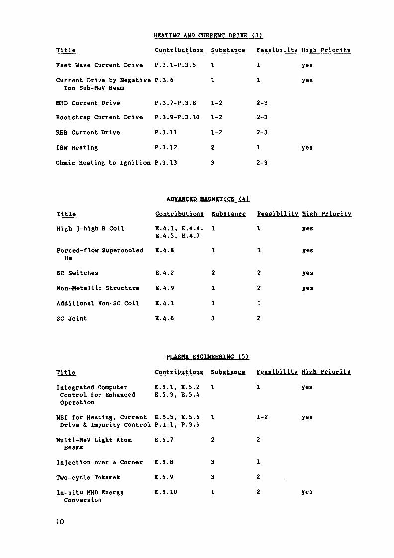
HEATING AND CURRENT DRIVE (3)
TitleFast Wave Current DriveCurrent Drive by Negative
Ion Sub- Me V BeamHHD Current DriveBootstrap Current DriveREB Current DriveIBW HeatingOhmic Heating to Ignition
ContributionsP.3.1-P.3.5P. 3. 6
P.3.7-P.3.8P.3.9-P.3.10
P. 3. 11
P. 3. 12
P. 3. 13
Substance1
1
1-21-21-22
3
Feasibility11
2-3
2-3
2-3
1
2-3
HiRh Priorityyesyes
yes
ADVANCED MAGNETICS (A)
TitleHigh j-high B Coil
Forced-flow SupercooledHe
SC SwitchesNon-Metallic StructureAdditional Non-SC CoilSC Joint
ContributionsE.A.I, E.4.4.E.4.5, E.4.7E.4.8
E.4.2
E.4.9
E.4.3
E.4.6
Substance1
1
2133
Feasibility1
1
2212
High Priorityyes
yes
yesyes
PLASMA ENGINEERING (5)
TitleIntegrated ComputerControl for Enhanced
ContributionsE.5.1, E.5.2E.5.3, E.5.4
Substance1
Feasibility1
High Priorityyes
OperationNBI for Heating, Current E.S.S, E.5.6 1Drive & Impurity Control P.1.1, P.3.6
1-2 yes
Multi-MeV Light AtomBeams
Injection over a CornerTwo-cycle ToltamakIn-situ MHD EnergyConversion
E.5.7
E.5.8
E.5 .9
E.5.10
3
3
1
1
2
2 yes
10

CONFIGURATION AND MAINTENANCE (6)
Title Contributions Substance FeasibilityModular Magnet System E. 6.1 3 2Vertical Maintenance, E.6.2, E.6.3, 2 2Modular Blanket and E.6.A, E.6.12TFC Inside Vacuum
Memory Shape Alloy E.6.5 2 1Ferromagnetic Inserts E.6.6 2 1New PFC Configuration E.6.7 2 2PFC Redundancy E.6.8 2 1Elongated Internal PFC E.6.9 3 2Top Loading Internal E.6.10 2 1Segments
Torus Near to Plasma E.6.11 3 2Tokamak Reactor withFree Access E.6. 13 3 2
ADVANCED BLANKET/FIRST WALL/SHIELD (7)
TitleLiquid Metal BlanketsBlanket with LiquidMetal CoolantSelf-cooled LiquidMetal BlanketSelf-cooled FLINABEBlanketFlow Channel Insertto Reduce MHD
He-Cooled Solid Breeder
Contributions
E.7.1
E.7.2
E.7.3
E.7.4
BlanketsPebble Bed Cannister/ E.7.5.E.7.6Composite PinHigh-T He-cooled blanket E.7.7Pebble Bed Blanket E.7.8
E.7.9
Substance
2
1
2
2
2
122
Feasilitv
1
2
2
1
1
2
21
High Priority
yesyesyesyes
yes
High Priority
yes
yes
yes
yes
Li7Pb2 Breeding E.7.10 2 1 yesMaterial
11

ADVANCED BLANKET/FIRST WALL/SHIELD (7)
Title Contributions Substance Feasility High PriorityFirst Wall/Divertor Plate Protection with Solid MaterialsBonded Protection E.7.11 2 1 yesMaterialsBonded Protection Tiles E.7.12 2 2
W Tile Divertor E.7.13 2 1 yes
Radiatively Cooled Tiles E.7.14 2 1 yesHeat Tube Protective E.7.15 2 3Element
Liquid Metal Protected DivertorsLiquid Metal Protected E.7.16 2 3DivertorDroplet Contact Device E.7.17 1 2 yesLiquid Metal Film E.7.18 2 3Protective Films E.7.19 2 2 yesProtective Device E.7.20 2 3
Other
In-situ Anneal Ferritic E.7.21 2 1 yesSteel
Super-heated Steam E.7.2? 2 1TurbineSteam-water Accumulator E.7.23 2 1
12

ADVANCED MATERIALS (8)
TitleFerri fie /Martens i ticAlloys
Vanadium AlloysMolybdenum AlloysLow- Act i vat ion MaterialsHigh Strength Cu AlloysFiber Reinforced Polymers
ContributionsE. 8. I.E. 8. 2
E.8.3
E.8.4
E.8.5.E.8.6
E.8.7, E.8.8
E.8.9
Tritium Permeation Barriers E.8.10Li20 PebblesShape Memory AlloysFLINABE
E.8.11
E.8.12
E.8.13
Substance2
111-2221-2
2
2
2
Feasibility1
22-3212
2
2
2
2
High Priorityyes
yesyesyes
yesyesyesyes
COMPACT REACTOR CONCEPTS (9)
Title Contributions Substance Feasbility High PriorityCopper MagnetsTokamak With Warm Coils E.9.1 3 1
Tokamak With Small E.9.2,E.9.3 1 2Aspect Ratio E.9.4Elongated Tokamak E.9.5 1 2
Superconducting MagnetsCompact SC Steady-State E.9.6 1 2 yesTokamak
Microwave Tokamak E.9.7 2 2 yesOtherCumulative Impact of E.9.8 (Not Innovation)Innovations
13

Appendix 1Innovations Contributed
Group123
A5678
Topic
Impurity ControlBeta & Confinement EnhancementHeating & Current Drive
Advanced MagneticsPlasma EngineeringConfiguration & MaintenanceAdvanced FW/B/SAdvanced Materials
EC
502
21312tt
Japan3b6
31255
USA USSR
3 (*
*• 32 2
1 32 6<• 31 83 1
Total15
1312
910122613
New Concepts & Other 10
30 32 120

Appendix 2
Croup Composition
GROUP
Organizing Committee
PHYSICS1 Impurity Control
2 Beta ConfinerontEnhancement
3 Heating and Current Drive
ENGINEERING4 Advanced Magnets
5 Plasma Engineering6 Configuration and
Maintenance7 Advanced Blanket/First Wall/
Shield
8 Advanced MaterialGENERAL
9 Other
G.
M.G.
K.F.
M.
P.
J.
G.F.
M.D.S.
P.
A.
EC
Grieger
HarrisonFuchsBorrassBriscoe
Cox
Komarek
RaederCasiniFarfalet ti-CasaliDalle-DanneLegerMa langSchiller
Knobloch
JAPAN
S. Mori
T. MizoguchlN. FujisawaT. Tsunematsu
K. MlyamotoN. Fujisawa
S. ShlmamotoK. IkegamiK. IkegamiM. KondoH. lidaSelji Mori
T. Kondo
Y. Shimomura
W.
D.W.P.D.
D.
C.
G.
T.C.
D.
D.
D.G.C.
USA
Stacey
SigmarStaceyRutherfordJassbyEhst
Henning
LoganShannonHenningSmith
Smith
JassbyLoganHenning
USSR
B. Kadomtsev
A.I. Keldianov
V. Para ilB. Kadomtsev
V. Parail
A. Kostenko
R. LitunovskyS. Sadakov
G. Shatalov
G. Shatalov
B. Kadomtsev

Appendix 3
AGENDA - SPECIALISTS' MEETING
Monday 1/13
9:30 - 10:30 PLENARY
(Introduction, Purpose of Meeting)
11:OO - 12:00
2:00 - 5:005:00 - 6:00
Reading of Abstracts and Summaries
CROUPS 1 - 9
COORDINATING COMMITTEE
Tuesday 1/149:00 - 12:00
2.-OO - 5:00
5:00 - 6:00
CROUPS 1-9
ENGINEERING PLENARY
PHYSICS PLENARY
COORDINATING COMMITTEE
Wednesday 1/15
9:00 - 12:OO
2:00 - 5:00
5:OO - 6:00
CROUPS 1 - 9
PLENARY (STATUS)
COORDINATING COMMITTEE
Thursday 1/169:00 - 12:00
2:00 - 5:00
CROUPS 1-9PREPARATION OF REPORT
Friday 1/17
9:00 - 12:00
2:00 - 5:00
PREPARATION OF REPORT
PLENARY (CONCLUSIONS AND RECOMMENDATIONS)
16

List of Participants
EC JAPAN USA USSR
OrganizingCommittee G. Grieger S. Mori W.U. Stacey, Jr. B.B. Kadomtsev
K. BorrasF. BriscoeG. CasiniM. CoxM. Dalle-DanneF. Farfaletti-Casali
G. FuchsH. F. A. HarrisonA. F. KnoblochP. KomarekD. LegerS. MalangM.J. RaederP. Schiller
N. FujisawaH. lidaK. IkegamiH. KondohT. KondoK. MiyamotoT. MizoguchiSeiji MoriS. ShimamotoY. ShimomuraT. Tsunematsu
D.C.D.B.T.D.D.P.
EhstHenningJassby
G. LoganE. ShannonJ. SigmarL. SmithH. Rutherford
A.I. KostenkoR.N. LitunovskyA.I. MeldianovS.N. SadakovG.E. ShatalovV.V. Parail
IAEA Scientific Secretary: A.A. Shurygin
17

Group 1
IMPURITY CONTROL
G. Fuchs (EC)M.F.A. Harrison (EC)A. Meldianov (USSR)
T. Mizaguchi (Japan)D.J. Sigmar (USA)
19

INTRODUCTION
All problems of impurity control are mitigated if it is possible(a) to reduce impurity release from the walls (e.g. by lowering theplasma edge temperature) and (b) to preferentially drive the remainingimpurity ions out of the hot core of a tokamak plasma. The latter can beachieved by establishing a radial electric field within the plasma whichtransports ions in the outward direction. Thus innovative proposalsaimed at controlling impurity transport rank high in respect to theirimpact upon impurity control.
The establishment of a cool radiating plasma edge would verysubstantially reduce peak power loading at the plasma collection surfaceof a divertor or limiter. Furthermore it would permit safe operation inconditions where substantial sputtering occurs at the surface. Thecondition is essential for a pumped-1imiter device and it is probablyessential for a divertor in tokamak reactor operating at power levels inexcess of INTOR. Its impact on impurity control strongly is dependentupon the ability to control impurity transport.
It is envisaged that the production of an ergodic edge layer willlower the peak power loading at a plasma collection, surface and also setup a zone of localised recycling somewhat comparable to that within adivertor. It ranks third in the order of innovative priorities and isprobably only of significance in the case of a puraped-limiter.
The use of a liquid protected divertor or limiter plate implies thatthe component need not be replaced during the lifetime of the reactor.It ranks high in respect to its potential for reduction of engineeringproblems but its physical credibility is questionable.
The most important issue in helium exhaust is the requirement thatthe He ions be driven to the divertor or limiter plates. This againstresses the importance of control of impurity transport. Innovationsaimed at reducing the helium pumping requirements during burn are ofinterest only in continuous burn devices because the helium gas exhaust rateof existing concepts does not exceed the pumping speed needed to maintaingood vacuum during the dwell and start-up phases. One exception ishelium burial which could be beneficial in regions where it isinconvenient to pump directly, e.g. the inner region of a single-nulldivertor or the top divertor of a double-null configuration.
21

The apparently stringent requirement for low Z plasma facingsurfaces during start-up could be met by routine deposition of a thin(i.e. short-lived) layer of boron which is rapidly deposited during eachdwell phase.
There have been contributions in all these areas of impuritycontrol. These are discussed in the following sections and assessmentsof their impact upon a reactor and their feasibility are presented inTable 1.1.
2. Control of Impurity Transport
Flow Reversal and Plasma Potential Control (Papers P.1.1 and P.1.2}
Reversal of the natural inward flow of impurities by N.B. injectedtoroidal momentum in the same direction as the plasma current has beenobserved in several major tokamak experiments and has an adequate base oftheoretical understanding. A main consequence of the induced toroidalplasma rotation is to produce an outward directed radial electric field,thereby preventing inward impurity flow. (In this respect, the flowreversal principle is one aspect of the more general quest for impuritycontrol via plasma potential modification. At present, with the possibleexception of ECRH applied at the plasma edge, no reactor viable methodother than momentum injection is known.) Flow reversal tends to keep theburning plasma core free of impurity ions (thereby reducing the centralradiation loss) and it favours the establishment of a radiating plasmaedge. If flow reversal is feasible these features make it a substantialinnovation.
Recent advances in the development of steady state 500 keV neutralbeam injection, using negative ion sources and which have high efficiencyand low beam divergence, provide the technological basis for near termfeasibility. The N.B.I, flow reversal system could also provide a costeffective reliable combination of plasma heating, current drive andimpurity control provided that the differing requirements for injectionenergy, deposition profile and pulse length can be reconciled.Furthermore, the prevention of plasma core contamination allows greaterflexibility in the choice of wall materials, and it aids the action ofother concepts such as the ergodic limiter (Section 3) and He burial in
22

layers of introduced metals (Section 5.1). Moreover, the ability tocontrol the radial radiation profile implies that there could be somedegree of disruption control.
Unresolved issues include the need for continuous operation of theneutral beams during the burn phase and the concomitant increase of powerloading on the plasma collection surfaces (mitigated possibly by theradiating edge which is aided by flow reversal.) Preliminary modellingresults predicts between 25-100 MW of N.B.I., preferably tangential tothe magnetic field, for flow reversal in INTOR. The impact of such asystem on blanket and shielding needs to be assessed for the newgeneration of negative ion beams. More detailed optimal design modellingof the above mentioned multifunction role of the NBI-system is alsoneeded.
3. Ergodic Edge Layer
Physics Considerations
Although good plasma confinement is needed to insulate the burningcore plasma from the wall the good confinement is undesirable in theboundary layer because it leads to a thin layer and a peaked powerloading. It is therefore advantageous to degrade confinement near thewall in order to cause rapid recycling which leads, due to the large fluxof particles, to heat transport at low particle energies.
The confinement can be rather easily "scrambled" by small, resonantmagnetic perturbation fields produced by helical conductors arrangedparallel to the magnetic field lines (not to be confused with stellaratorwindings). These perturbation fields create magnetic islands on therespective resonant q surface. The width of the perturbed zone can beadjusted either by choice of the diameter of the islands in a singleisland chain or by overlapping of islands on neighbouring q surfaces; thelatter leading to an ergodic (or more precisely to a stochastic) fieldline pattern.
The radial transport of particles and heat Kr can thus take placealong magnetic field lines taking advantage of the fact that parallelheat conductivity K,^ exceeds the perpendicular and K^ by orders of
23

magnitude. We getK = *!_ K|lr B
where 6 B and B are the perturbation field and the main field(088=^ 10~ ). For more elaborate calculations of the heattransport in ergodized layers see P 1.3.
It is important to realize that a stochastic layer will notintrinsically lead to a uniform wall loading for the following reasons:
I. The density of points on a Poincare map is not a constant, the sameholds for the associated flow.
II. There exist bundles of field lines inbedded in the stochastic layerbut not linked to those in other areas, similar to the private fluxarea in bundle divertors.
III. Whereas the complete stochastic field line mixing process takes3 4about 10 ..10 toroidal revolutions the same field line
intersects the limiter or wall after about 20 turns so that themixing is incomplete.
The non-uniform wall loading is an undesirable effect as far as heatremoval is considered, for particle removal, however, it is advantageousbecause it can be used to guide the outflux of plasma preferentially tothe pumping ducts.
The axisymmetry of surface loading can be recovered (at least on thetime average) by rotating the perturbing field structure at a lowfrequency [p 1.41 fp 1.51 fp 1.61. The loading pattern will be mainlydetermined from limiter and wall design together with the perturbationcoil configuration and currents; it will not be sensitive to minorchanges in plasma position.
Because each perturbation field coil system has to be wound forparticular set of helical mode numbers, the scheme works only for theparticular q (a) for which it is designed. Although several coil systemstailored for different q (a) are conceivable, their number is verylimited for practical reasons. Because of toroidal effects it is, inprinciple, possible to create an ergodic boundary even when the resonantq surface lies outside the torus, the required perturbation currents are,however, larger, and make more likely the distortion of flux surfaceswhich, in such places, is undesirable.
24

The ergodic limiter might replace the divertor if it turns out that,either the impurity release from the limiter or wall can be made so smallthat accumulation is not serious, or if the impurities can be recycledwithin the ergodic layer and redeposited on the limiter or wall. It isalso conceivable that the ergodic limiter could aid the establishment ofa radiative edge.
Coil design and power requirements
There are two conceivable alternatives for mounting the perturbingfield coils.I. Close to the plasma i.e. behind the first wall. For this case it is
proposed that the mode numbers m = 12 and n = 6 (poloidal andtoroidal mode numbers respectively) might be used forq(a) = 2.0 ...2.2 or m = 10 and n = 4 if q(a> * 2.5...2.7.
II. Behind the blanket where the mode numbers should be lowered becauseotherwise the power requirements make the scheme less competitive.The choice could be m = 6 and n = 3 or m = 5 and n = 2 for thepreceding ranges of q(a).
From the physics point of view there are several reasons to favourlocation close to the plasma:
a. The distortion to the plasma core is smaller, and it is likelynegligible for INTOR.
b. Particle recycling time within the ergodic layer is shorter, due tothe smaller extension of the islands in poloidal direction.
c. The ergodic layer is less bumpy on its surface.
The perturbation field coils can be of modular design such as to fitinto the torus sectors. There is a large degree of freedom regardingwhich part of the surface is covered with the conductors making itpossible to leave enough space for other items such as antennas. Asmentioned in [p 1.51, a few precautions should be taken in coil design.In particular net dipoles should be avoided because this renders the nettorque moment to the module almost zero and greatly reduces thedistortion to the core, confirmation of the validity of the designrequires field line tracing calculations.
25

Depending on the particular solution chosen for the coil design, thenecessary power can be in the range of 1....15 MW. The power suppliescan be programmable making it possible to switch between the rotating andstationary mode of operation so that the system can be optimized eitherfor uniformity of power load or for maximum pumping. The power suppliesare state of the art.
Experimental experience
The first tokamak which demonstrated the applicability of theergodic limiter was TORIUT, a small machine in Tokyo University. On alarger scale, experimental results are also available from TEXT whichshow that:
a) ergodization does indeed lower the edge plasma temperature
b) it reduces the core radiation by metallic impurities, this isattributed to a reduction of impurity release in the boundary
c) it reduces the radiation from both carbon and oxygen, probably dueto a reduction of the inward transport.
Experiments have just started on TEXTOR which is equiped with arather localized coil system, that excites a multitude of modes some ofwhich resonate in the core. One encouraging initial observation is thatergodization does not invaidate RF heating (up to 2 MW has been applied).
In near further results are to be expected from JIPP-T2U and TORE-SUPRA.
Summary
Improvements;
Enhances credibility of the pumped limiter concept by:
(a) Reducing power load.(b) Reducing sputtering of impurities (due the to low plasma edge
temperature).(c) Requires only modular coils located inside toroidal coils.
The envisaged current requirements are substantially less thanfor a poloidal divertor.
26

Feasibility
Experimental physics data base may be developed on a time scale of3-5 years (TEXT, TEXTOR, JIPP-T2U, TORE-SUPRA).No substantial engineering problems are envisaged if coils can belocated outside the vacuum vessel.
Impact on other components
In principle windings located either close to the plasma (behindfirst wall) or more widely spaced (outside blanket) may be used.
Location of limiter requires consideration q(a) becomes fixed.The concept is applicable to a fixed q(a).
Further work
Improved knowledge of transport in ergodized layers.Demonstration that confinement in plasma core is undisturbed.Performance at higher densities together and at high auxiliaryheating.
4. Radiatively cooled edge (Paper P.1.7)
A radiatively cooled edge reduces power load, plasma edgetemperature and consequently sputtering yield of medium to high Zmaterials. The improvements are probably essential for use of apumped-1imiter and it is also useful in reducing limiter "tip" powerload. The feasibility depends upon a localized enhancement of edgeradiation which is predicted to be uncertain unless there is also somecontrol of inward impurity transport (irrespective of the method usedIP.1.71). One method is impurity flow reversal by neutral beam injection[P.1.1] and so the time scale for demonstrating the feasibility of theradiative edge may be linked to that for improvements of neutral beamtechnology (for example, negative-ion based NBI systems [E.5.6]).
Since the plasma power is radiated to the first wall instead ofbeing partially removing at the divertor plate, the radiating edgeincreases the power load on the wall. RF antenae located at the wall arealso exposed to the increased power load.
27
Experiments in large tokamaks are required to evaluate thefeasibility of the radiatively cooled edge and these could be combinedwith studies of impurity flow reversal. In conclusion, the concept wouldhave substantial impact upon reactor design and it merits continuousassessment.
5. Particle Exhaust
5.1 Helium Burial and Non-permeable Barrier (Papers P.1.8 and P.1.9)
The concept of thermalized alpha ash burial in renewable surfaces ofspecially selected metals rather than exhaust by the vacuum pump systemis attractive because of its apparently simple technology and itsbeneficial (and cost reducing) impact on He-pumping requirements (duringthe burn phase). It can also be used to reduce the concentration ofHe + in the divertor or edge plasma thereby reducing the He-producedcomponent of sputtering. This is particularly useful if the targetregion canot be directly pumpted (e.g. the inner target plate of asingle-null or the top target of a double null divertor). Amongst therisks inherent in the introduction of metals in the edge plasma (asproposed in P.1.8) are the danger of self sputtering if the plasma edgetemperature exceeds 50-100 eV, serious contamination of the main plasmawith radiating impurities and difficulties of heat removal through theaccumulated layer of introduced metal (typically having a lower heatconductivity than tungsten). For these reasons the method seems bestsuited to regions that are unlikely to be exposed to high heat loads andto energetic particles and which are shielded from the main plasma, e.g.the wall of the divertor pump duct or the underface of a pumped-limiter.
A second approach (P.1.9) consists of a thin metallic trapping layerdeposited on a pumped substrate of (glassy) porous material. Therenewable layer is chosen to be super-permeable for He but has lowpermeability for hydrogen; helium is pumped through the power substrate.
The helium burial concept in particular would reduce the gaseouspumping requirements during the burn-phase and thus it offers thepossibility of reduction in the size of both the vacuum ducts and tritiumsystem. However, some gaseous pumping is required in order to aid thecontrol of fueling, etc.
28

Further work needed centers on testing the principle in situ in highpower density tokamaks, in selection of burial materials and avoidance ofthe impurity questions mentioned above.
5.2 Exhaust of Oxy&en
Oxygen is a particularly troublesome impurity because of its highchemical activity. On the one hand, even low energy (~ few eV) oxygenions give rise to chemical sputtering, but on the other hand, oxygen canstick to and migrate along cool surfaces so that it is difficult toexhaust completely as gas. The effect of chemical sputtering by lowenergy oxygen ions can substantially mitigate against the low rates ofimpurity release envisaged for high Z materials in a high recycling_3divertor, for example, an oxygen ion concentration of ~10 woulddouble the tungsten release rates predicted for INTOR. Oxygen getteringpanels (e.g. of the materials discussed in P.1.10) which are located inthe pumping ducts offer a credible method of enhancing the exhaust rateof oxygen. The panels are shielded from the plasma but directly exposedto the neutral oxygen which is released from the divertor target.
All issues which impact significantly upon the reduction of oxygencontamination strongly merit further consideration.
5.3 Plasma Screen Assisted Pumping (Paper P.1.11)
The objective is to set up additional, toroidally symmetric plasmacolumns in the gap between the divertor plasma channels and the wall ofthe divertor chamber. These "plasma screens" ionize neutral atoms whichare released from the plate and escape from the main divertor channel.Ions formed in this screening plasma are directed to pumped-limiters andthe subsequent compression reduces the pumping speed necessary to exhaustneutral particle.
It is propososed in P.1.11 that the plasma screens are formed usingadditional RF heating of about 2 MW (but in principle, the pumped limiteraspect of the proposal is equally applicable to the outer perifery of aconventional divertor plate where the divertor plasma power is adequatelylow). The pumped limiters (shutter type) are coupled to conventionalpumping equipment. The parameters of screening plasma columns are chosenin a way to provide effective helium ionization (but they could in some
29

measure be adjusted to suit hydrogen or impurities). The total heliumpumping speed predicted for INTOR is 5 x 10 1/s.
This approach offers the propspect of:
- a smaller vacuum system for a continuously burning reactor
- the possibility of selective pumping of helium, hydrogen andimpurities
Questions of feasibility relate to:
- development of the additional heating system for the plasmascreens;
- design of the pumped limiters;
- lack of both theoretical and experimental understanding ofdivertor channel boundary instabilities.
6. Boundary Surfaces
6.1 Liquid Protection of Divertor/Limiter Surfaces
Only physics issues which relate to plasma-liquid interactions arediscussed here (engineering issues are discussed in Group 7). The moltenliquids which have been proposed for protection are lithium, gallium andtin and these have large sputtering yields (~10~ atoms/D or T ions)in the regime of incident ion energy relevant to divertor/limiteroperation. Furthermore, in all cases the threshold energy for sputteringlies above the lowest credible incident energy of D /T ions.
2Sputtering rates are therefore likely to be ~10 times greater thanthose predicted for a tungsten divertor in INTOR. Thus the credibilityof liquid protection is greatly enhanced if it can be invoked inconjunction with some method for control of impurity increases into themain plasma (see Section 2).
The allowable concentration of lithium ions in the plasma core islimited by their contribution to useless ß but both gallium and tin
30

ions are powerful sources of atomic radiation power losses. Althoughthere have as yet been no quantitative assessments; it is reasonable toaccept that the credibility of liquid lithium is substantially greaterthan any other molten metal.
The liquid surface is exposed to the electric field of the plasmasheath (~ 5 x 10⁵ V/cm for INTOR), and this may driveRayleigh-Taylor instabilities on the liquid surface. The consequencesare, firstly, emission of liquid droplets and secondly, the generation ofunipolar arcing sites on the surface. Both processes are likely toresult in impurity release rates which are orders of magnitude largerthan those for sputtering. A further issue, which is particularlyrelevant to fast flowing liquid films, is that the liquid may not becomesaturated with D/T atoms and consequently it acts as a pump for plasmaparticles and thereby reduces the degree of plasma recycling at thesurface. In such conditions, the local plasma temperature will berelatively high but the flux of recycling ions will be relatively low.This effect might bebeneficial for sputtering of liquid metals whose sputtering thresholdenergy lies well below the energy of incident D /T . Any absorbtionof incident D/T and helium ions will also impact upon the vacuum pumpingrequirements in an, as yet, unquantified manner.
There are two categories of liquid protection, namely in the form ofa film (Papers P.1.12 and P.1.13) or a pool (P.1.14). The film conceptinvokes a number of physics issues which are related to wetting of thesubstract and hence to the overall coverage of the protective film. Thefirst issue is the momentum carried by the plasma ions. This tends to"snow-plough" the film away from the surface region exposed to peakplasma heat load. A second issue is "re-wetting" after a plasmadisruption has locally blasted the film away from the substract and hasalso cratered the substract. Fortunately the mechanism of redeposition,(by which ions of sputtered surface liquid are recycled to the surface)will be a powerful adjunct to re-wetting but this is unlikely to wet abadly cratered surface. Thus, in these respects, the concept of a liquidpool is markedly superior to a film.
The preceeding discussion is in no way complete but it serves toshow that the credibility of liquid protection layers is uncertain but aliquid pool rank higher than a liquid film. Understanding of
31

plasma-liquid interaction is at an embryonic stage and deeper knowledgeof these processes (both experimental and theoretical) is required beforethe feasibility of liquid protection can be confirmed.
6.2 Protection of First Wall and Plasma Collection Surfaces During Startup
Evidence from large tokamaks (e.g. TFTR, JT-60 and JET) indicates thatthe presence of medium or high Z impurities is extremely deleterious to plasmaconditions during start-up especially whilst the energy content of the plasmais low. Another general observation is that there is a strong probability ofcross contamination when different materials are used for plasma facingcomponents. The gist of the proposal P.1.15 is to deposit in-situ a thinlayer of low Z material over the plasma facing components during each dwellphase. The layer need only have sufficient thickness to allow for erosionduring the start-up phase. The concept is based upon the in-situ depositionof about 32 mm of boron by dissociation of diborane,
2B
on the hot (300-400 ) plasma facing surfaces. The deposition time isestimated to be a few seconds.
The pump down time for the deuterium gas produced by the reaction in an3INTOR size device is about 10s for a volumetric pumping rate of 250m /s.The general concept of short lived but rapidly deposited protection layers isworthy of further consideration.
32

Table 1.1 Impurity Control Group - Ranking of proposed innovations.
Substance Feasibility High Priority
Control of Impurity TransportMomentum induced flow reversal (P.1.1) 1 1.5 yesLimiter Massing (P.1.2) 3 1Ergodic Edge LayerPapers: P.1.3, P.1.4, P.1.5, P.1.6 2 1 yesRadiatively Cooled EdgePaper P.1.4 1 2 yes
Particle ExhaustHelium burial (P.1.8) 2 1 yesThin film pumping surface (P.1.9) 3 3Oxygen gettering (P.1.10) 2 1 yesPlasma assisted helium and 3 2
impurity pumping (P.1.11)Protection of SurfacesLiquid metal films (P.1.12, P.1.13) 1 3Liquid pool (P.1.14)In-situ deposition of boron (P.1.15) 2 1 yes
Molybdenum divertor plate (P.1.16) (already considered for INTOR)
33

p.1.1KEUTRAL BEAM DRIVEN IMPURITY FLOW REVERSAL
W.M. Stacey, Jr.Georgia Institute of Technology
INTRODUCTIONDirected (CO or CTR) neutral beam injection (NBI) imparts toroidal momentum
to the plasma species, as well as heating the plasma. By thus altering themomentum balance, directed NBI alters radial particle transport la such a waythat co-injection produces a radially outward flux of impurities, and converselyfor counter-injection. Thus, iu principle, co-injection can be used to preventimpurities from penetrating to the center of a tokamak plasma or even to driveimpurities out of the center of the plasma. This introduces the possibility ofusing co-injected neutral beams as an impurity control scheme to maintain thecenter of the plasma relatively free of impurities and at the same time causingImpurities to accumulate in the outer region to produce a cold, radiating edgewhich would lead to reduced sputtering and thereby cake the pumped limiter aviable concept.
THEORETICAL BASIS
Directed NBI produces a number of effects that alter Impurity transport. Thedirect momentum-exchange between the beam particles and impurity ions has an effecton impurity transport that is analogous to the collisional momentum exchange amongplasma ion species [1]. The NBI toroidal momentum imput and the radial transfer ofthat momentum alter the lowest order particle flows in the flux surface and theradial electric field [2], which in turn alter the radial particle transport, and*the particle transport, and the radial momentum transport produces a radial particletransport proportional to the radial electric field [2]. The NBI toroidal momentuminput causes a toroidal rotation of the plasma. When there is strong rotation(v, v ,), inertial effects produce a poloidal asymmetry in the impurity density,ç — tnwhich alters the transport flux [3]. All of these effects have been incorporated ina self-consistent formulation [4].
The radial transport of toroidal momentum in tokamak plasmas with directed NBIIs an Important element in the NBI impurity flow reversal theory. Classicalgyroviscosity, modified to take into account toroidal geometry effects, has beendemonstrated [5,6] to be capable of accounting for the experimentally Inferredradial momentum transport rates and to lead te a representation of the viscous "drag"force which is consistent with the form that was used in the impurity flow reversaltheory [4].
35

EXPERIMENTAL BASIS
Experimental observations in ISX-B and PLT indicate that the centralimpurity accumulation is substantially greater with counter-injection thanwith co-injection of neutral beams, in qualitative agreement with the flowreversal theory.
In ISX-B[7-9], measurement of chordal radiation intensities correspondingto different atomic transitions showed clearly that counter—injection leads toa substantial central accumulation of impurities, leading in most cases to adisruption. In contrast, co-injection does not cause any Increase in thecentral accumulation of Impurities, and with sufficient beam power actuallyreduces the central accumulation of impurities.
Chordal ultra-soft x-ray measurements in PLT discharges with a tungstenlimiter were Abel-inverted to estimate local tungsten densities and fluxes [10).The inferred tungsten particle fluxes over the inner 20 cm were inward in theabsence of NBI, inward and enhanced by an order of magnitude with counter-injection, and outward with co-injection.
Chordal measurements in PLT of radiation intensities corresponding todifferent atomic transitions showed that counter—Injection leads to substantiallygreater central impurity concentrations than did co-injection [11,12].
All of these experimental data are in qualitative agreement with thetheoretical prediction that counter-injection leads to enhanced inward impuritytransport and that co-injection leads to reduced inward or, with sufficient beampower, outward impurity transport.
ANALYSIS OF EXPERIMENTS
Analysis of the above experiments is complicated, and to date onlypreliminary analyses are available. The trends observed in ISX-B are consistentwith transport analysis of those experiments [9] and with tiodel-problem calculationsfcr ISX-B [4]. Similarly, model-problem calculations for rLT [4,13] predict theobserved experimental trends [10-12]. It should be noted that the authors of Ref.[12] believe their results are due to effects (unspecified) other than transport,but this interpretation is open to question [14]. An analysis of these experimentsis in progress.
PREDICTIONS FOR INTOR
Impurity (Fe) transport fluxes were calculated for a model problem withcharacteristics similar to those of INTOR for 150 keV NBI. An inverse momentumconfinement time, or radial momentum transport rate, of 10s"1 was estimated from
36

the gyroviscosity theory [51. The impurity transport flux is shown in fig. (1) asa function of minor radius for several values of the co-injected NBI power. Thetransport flux is generally outward in the central region, where the NBI effectsdominate the pressure gradient effects, and the flux is Inward in the outer regionswhere the pressure gradient effects become dominant. It appears that _25 MWof co-injected power would prevent penetration of impurities to the central -1/3(in radius) of the core, while .100 MW would prevent penetration inside of r=90 cm.
REACTOR IMPLICATIONS
The results obtained for the INTOR model are representative — about 25-100 MW of co-injected NBI power should be sufficient to prevent impurities fron •penetrating to the central plasma core region.
The engineering disadvantages of NBI with positive-ion sources are wellknown. Many of these disadvantages could be substantially reduced with a negative-ion NBI system.
If negative-ion NBI could be used for plasma heating, cur r en t-drive and inconjunction with a pumped-liraiter for impurity control» it is possible that sucha system would be more attractive overall than the presently envisioned systenof ICRF for plasma heating, LHR for current drive and poloidal divertor forimpurity control.
REFERENCES1. T. Ohkawa, Kakuyugo Kenkyn, 32, 1 (1974).2. W.M. Stacoy. Jr. & D.J. Sigmar, Phys. Fluids, 22. 2000 (1979); Nucl. Fus., 19,
1665 (1979).3. K.H. Burrell, T. Ohkawa, S.K. Wong, Phys. Rev. Lett., 47, 511 (1981).4. W.M. Stacey, Jr. & D.J. Sigmar, Phys. Fluids, 27, 2078 (1984); Nucl.
Fus., 25, 463.(1985).5. W.M. Stacey, Jr. & D.J. Sigmar, Phys. Fluids, 28, 2800 (1985).6. W.M. Stacey, Jr., C.M. Ryu, M.A. Malik, Nucl. Fus., to be published.7. R.C. Isler, et il., Phys. Rev. Lett., 47, 649 (1981).8. C.E. Bush, et al., Nucl. Fus., 23, 67 (1983).9. R.C. Isler, et al., Nucl. Fus., 23_ 1017 (1983).10. D.R. Eames, Ph.D. Thesis, Princeton Univ. (1981).11. S. Suckewer, et al., Nucl. Fus.. 21. 981 (1981).12. S. Suckewer, et al., Nucl. Fus., 24. 815 (1984).13. R.B. Bennett t, W.M. Stacey, Jr., NS&E, 88, 475 (1984).14. R.C. Isler, P.D. Morgan, N.J. Peacock, Nucl. Fus., 25. 386 (1985).
37

»7»0 -
Mto -
«of-
#-x~MA• 11
ff 10-^x
^f
u-13
-lo_>•£S2- IH* -\0-
1C-K)-
^
«6-10,
n-to.
™"^**1"*--.
.-« ~~~"~^ ^^^~>. \ N
N \Xv ' >\ * *\ \ » \« ^ 1 » *
F.= lffHW\ SO ~1S\ U>0\
\ * « '\ • » *• \ « . 1 OUTv l » « 4.• ', T
• i • ,! 'i i : • » • l : •0-7. o-q. \ 0-6 ( o-« l-o V-Î.. 4. \-
1 1 i W
t MINOR 'RADIUS [ m }
N \ l
\ \ t* * i\ » *V v *
V \ V
X- V\ \"--v^-K~-VX**
«• •
?«;F\l.C »t« »«To«
38

PLASMA POTENTIAL AND IMPUHITY BUILD-UP P-l-2AT THE PLASMA EDGE.K.A.Razumova, V.A.Vershkov
In so called *B' regimes (see P.2.4.) impurities are ac-«-cuoulated at the plasma axis according to neoclassical confi-nement »therefore it is of imperative importance to find meansfor the wall-plasma impurity flux restriction.
Since the divertor option implies a considerably compli-cated reactor design with divertor winding current exceedingthat in plasma, it is of great interest to consider a diverto:less impurity control feasibility. For the standard tokamakregime it has been shown with 10C$» accuracy that the majorpart of particles leaving plasma is collected at the limitJr.That means -he limiter can provide control of particle balanceSome experiment results give evidence for the electron tempe-rature near the limiter surface not being always proportionalto the deposited heat load. The temperature turns out suffici-ently low, thus it should not be excluded from considerationthat conditions may be feasible for formation a reradiatinglayer near the limiter surface similar to that on the divertoiplate. Then probably the 'pumped limiter1 instead of divertorcan be counted on.
Besides this some hopes can be connected with formationof an auxiliary barrier at the plasma edge for the ionized 121-
c/purity in-flux by nieansNa positive potential gradient. Such apotential distribution can be achieved either with electrode:::or by charged beam injection (as in Llacrotcr), or through ab-rupt local electron confinement decrease, e.g. by magneticsurface destruction«)
39

P. 1.3
J3RGODIC LHlITJa PCR IHTOR
A.V.IJedospacov, ÎÛ.Z.Tokar1
1. Recently, on the base of detailed numerical [l"] and sim-ple half-analitical [2,3] models calculations of I1JTOR
plasir.a parameters for both, divert or and pumped limiter regi-mes v/cre performed. It was shown that if Bohra coefficients aretaken for transvcrs transfer in til 2 s crape-off -lay er (SOL) thenheat outflow to the collector plate is concentrated within a nar-row layer of about 1 cm width thus causing operational difficul-ties associated with high specific thermal loads on the plates.Besides, in the most favourable hi h recycling regime the meanplacma density in the SOL, tts , is of the order of 10 ^cm"-3,thus being close to that expected for the main plasma. Since that;the problem is hov/ to agree theso parameters.
2. In a high recycling regime heat transfer along magneticfield lines in the main part of SCL is due to electron thermalconductivity. In this case functional dependencies of ft, and spe-cific thermal load Q on both total heat flux in SOL, Q andtransvers température conductivity coefficient, /[, are astoll«™ [2.3] -
( n$ and Qp versus £^ , calculated in the framework of themodel described in [2~] , are given, or. J?ig.1 for IHTOR \vith pumped limiter. Points A and B are associated with Bohm coeffici-ents).
It follcv/.T from (1) that tlaer? c.re at least two ways todecrease /.' L_ni :% . On one ha;:;;, i- can be achieved by Q0
40

reduction v/i t h kelp of additional power dissipation in COL. Twowoll known m-thods can be used: "gas target" and "radiative ed-ge" both of then are under investigation on ASDJH and D-IIl[4,5J.On the other hand, the same result can be achieved by increasein transport coefficients transvers to a magnetic field linesin the edge plasraa. V/ith this aim in view artificial plasma tur-bulisation was proposed by means of an additional current pas-sing [6J . Another approach is associated with perturbation ofmagnetic field in the edge plasma with help of external windings.The first proposition to use external helical windings in orderto generate magnetic field in resonance with magnetic field inthe edge plasraa was made in [7J • In so doing, magnetic islandstructure is created. V/ithin magnetic islands plasraa rather fre-ely moves transvers to the undisturbed magnetic surfaces. In to-roidal geometry magnetic islands arise both at the resonant sur-face and at the surfaces with safety factor 0, differing from
k Y
Très by T , where k - integer, 1 - the smallest integer whichallows presentation --,- iVl (m-integer). It is obvious, that/ J7GS
perturbation helical winding is to bo closed on itself after(m.n) major rounds and (n.l) minor rounds. Intersection of mag-netic islands associated with different resonances results instochastic instability of magnetic field with an appropriate in-stant behaviour of r-iagnotic field lines within the intersectionregion. In réf. [8J higher magnetic field harmonic as comparedwith réf. [?] were taken into account and it was shown that sto-chastization can bo achieved with lower currents passing throughthe windings than it follows from [?J •
Artificial r.::, nc'tic fluid n «och:1, ski 3 a.1; ion in the oil r 2 plc.srr.Cihas boon considered on IÎ7TOR workslisr already [9] with an aim inview to produce turbulent plasma blsr-iec (both divertor - and
41

liniterless configurations v/ith high, plasma recycling at thefirst \vall). Here stochastisation of t lia regnetic field is consi-dered as a mean to increase tronsvers transport coefficients inIÎÎTOR SOL thus creating configuration rrith so called ergodic li-miter. Such a configuration is investigated experimentally onT.2XT, where unique winding is used providing a model of helicalwinding [lo] . Diffuser type winding ^cnsidered in [11] whichrepresents in fact a part of full rescr.ant helical winding (seeFig.2) io more appropriate for large -rokaraks.
llagnetic field line diffusion ccsfficient within stochastic[ T12 :
where &** » !&**IeXp(t(*y~ 5ty a~2 the winding magneticfield radial component harmonics, L^s — perturbation correlati-onal length, (SJy51 - poloidal and toroiial angles,/^- toroidal mag-netic field. Let us consider diffuser type sinding consisting ofequidistant conductors, the currents in the neighbouring conduc-tors flowing in tho opposite dirocticr.2. Ilagnetic field radial
Cl-cojnponent in aero appi'oximation v.'itr. ra^pact to z =• ~pT (a,R -nir.or and major radii of tho rosor.c.r.7 3v.rrao2) include only thoseharmonics, which arc in resonance v;irh rjî netic surface characte-
T> ¥riaed by q «= q ,, = £ oT. therefore all r ietic islands are sym-metric with respect to this surface ar.i stochastiaation regionwidth does not exceed that of the larrssT island* In the firstapproximation there aro haraonicc ir. r scr.ar.ce v/ith differentunperturbed r.a netic surfacos:
/•»''_ ^ 5T~J- .,, / «7^ /•;•?. /v i .,.. - '''A
c;ictt.'tls. fc*,; ?.;;tf.-i£ l^lt'i ~USpfCL
42

where p - la integer, N = —7— (2p+1), d - distance between twoneighbouring conductor, I - current passing through a conductor,X - distance from winding in the minor radius direction, L -correlational length for p - harmonic.
To calculate D v/e pass over to integral in (2) to obtain
«f, - (4)v/here $- -7-7 — - - magnetic field shear, A- distance from sto-chastization winding conductor axises to resonance surface, I -plasma current.
Transvers electron temperature conductivity in the case ofmagnetic field stochastization is given by j/lj} :
à / t
€ i ———v/here Vy — v le/We, " electron thermal velocity, factoraccounts for Coulomb collisions and is in fact the root of thefollowing equation:
v/here /O, - electron Larmor radius, ^ - Coulomb free-path-length,pe - characteristic p for stochastization region considered.
\Vhen dimensions Chight II and length L) of a diffusor v/in-ding are small compared to torus dimensions, characteristic timeis dictated by heat transfer process in an unperturbed region:
, where ^ - is the longitudinal electron* O /^
temperature conductivity, /, -^ ———— r~ magnetic field line* H 'Icngth betv/een periodical "falls" into diffusor region. The depthof electron heat transfer into cliff unor rogion r can bD obtai-ned from thermal balance equation a/ j ' X [_^ . Here fac-tor ÏÏ = —— ar _ . accounts for deviation of electron distribu-( 1 T 'jû/y -tion function fron I.:a:avell functicr, cr.oe characteristic length
43

of temperature variation docs not escesi (0)3 JJ4-] • Finally\ve obtain for effective transvers t =r.:pe rature conductivity coef-ficient
L a (5)The \vidth of magnetic field £tc2h=.3tis£ition region, Or, is
defined by hamonic number o , for v.-hich the distance betwe-en the axises of the neighbouring islands ia comparable v;ith theisland v/idtli:
/? Jjo / (6)
Electrical pov/er needed to launch riagnetic field stochastiîïation \vindins system is defined by ps.ssir.2 current and conductordimensions. As it follov/s from (4) to achieve higher efficiencyof stochastiaation system the conductors are to be placed asclose as possible to resonance magnetic surface. Limit & - is aconductor halfv/idth in radial direction, hence
where P - in a cpecific resistanc3 of a conductor. In what fol-lows, the conductor width 1 vd.ll be chosen from the condition thatthe current density in a conductor, J./%A£ equals 1 kA/cn (thatis, when water cooling of a winding can still be used).
6. Calculations of stochastiss.7io.-i system parameters were car-ried out for Iirj?OR-scale tokamak:a = 1.7. n; 3 = 5.2 n, I? = 6.4 :-., '. = 2, qrss« 2.5.Dimensions of a cupper winding are prcpcrtional to torus dimensi-
23J~a- _ ?r£ _ / /ons: ft ~ L - f> — 'J. . Pig. 3 shows £ eff , ng and qg ver-sus the ratio of citxrcnt in \vinding to plasma current I/I forh = 0.4, £ = 2ca, d = 25 cm. Pig. 4 shows the dependences of total
44

power supplied to winding, \7, and stochastize.tion region width,S + versuo •
7. Consider Seers'magnetic field stochastization effects onimpurity influx to be reactor volume and on plasma confinement.It is shown in [2J that in high recycling regimes at the pumpedlimiter collector plates impurity influx in the main plasma willbe mainly in the form of ions, since neutrals have a chance to beionized in ÜOL. Besides, only those ions will fall into the mainplasma which have an oppotunity to diffuse across magnetic fieldlines as far as to the magnetic surface at the boundary with themain plasna within their lifetime in SOL, *C . The mean distance
F"*"*- J?* /*T( 7~^ n-(} for ions to pass is therefore c = \'oO± L , where îu^is the impurity transvers diffusion coefficient in the SOL. Cha-racteristic time T' ig defined by impurity ion retardation timeunder the action of plasma flux coming in opposite direction
•3/2_ _-„i — p)r VT ~ n<* ^ »where m, V - the mass and ini-tial velocity of impurity ions along the magnetic field, /fy and -
plasraa concentration and temperature in limiter vicinity. DenotingS *"probability for impurity ion to fall into the nain plasma \Vj = -^ —
where 00 is the SOL v/idth, and assuming 2), X A^>*» we finally• v
obtained tv'r ^ eff ^* i-3 seen that 10 times increase in "résulta only in 2 tines increase of impurity influx into the mainplasma. It is believed that decrease in confinement time also isnot expected since stochastisation v;inding magnetic field sharp-ly decrease on laave Tror; the odre ylacnia.
COHCLUSIONS:a) I.'agnetic field stochastization at the discharge peri-
phery by means of diffusor type windings in high r cycling regi-mes at pumped limiter (or divertor) collector plates may assure
45
13 —3plasma concentration in SOL of the order of 5-10 cm and ther-2nal loads on the plates less than 300 V7/cm .
b) In this case v/inding ocupies less than 16 5 of the firstwall surface, current passing through the winding does not exce-ed Q.yt> of plasna current, the power supplied - 3^ of total re-actor power. Cooling is by mater.
c) Llagnetic field stochastization effect in SOL on bothplasma confinement and impurity influx to the main plasma isbelieved to be small.
d) iSrgodic limiter concept for tokamak - reactor requirsfurther theoretical and experimental considerations as well asengineering research and development.
1. Igitkhanov Yu.L. et al. in U33R Contribution to thcs TUTORWorkshop. :iop. Kurchatov Institute of Atomic rJ^ergy, LIos-cow, 1904* .
2. Tokcr« 11.3., ibid3. Harbav/ P.J. Bud .Fusion, 1984, 24, IT 9, 1211
4. Shinonura Y. et al. Rep. IPP 111/80, Garching, 1982.
5. Ohyabu IÎ. ot al. J.IJucl.lfater., 1904, 128/129, 275.
6. îlodocpasov A.V. in 7-th Jurop.Conf. on Contr. Fusion and
Planrca Physics, Laussanne, 1975, 1, 129.
7. Peneberg \V. in: 3-th liurop. Conf. on Contr. Fusion and Pla-
sma Physics, Praque, 1977» 1, 4.
8. Tokar' li.Z. Fioilca Plasny, 1979, v.5, ÎI 2, p.454.
9- Vasilyev 11.11. ot al. in U3SR Contribution to the IIITOR
V/orkshop, Rop Kurchatov Institute, IIoscov/, 1980.
10. Ohyabu II. J.lTucl.Hater. 1904, 121, 363a
46

11. Llartin T.J., Taylor J.B., Preprint CLLI-P698, Abingdon, 1983.
12. Rosonbluth U.U. et al. Hucl. Fusion, 1966, jS, II 2, 297.13. b'kitt K.&. t» t/ie tec k "Ma s tn* r/ici'c Tcu-ndcitîeni "
14. Ohbav:a T. G t ni. Pliys.iîov.Lott . , 1903, J5i> II 23.
8
0
Pi£.1. Moan plarsna density infie thermal loads on limitivity coefficient.
1l limiter layer and speci-.- versus temperature conduc-
Pig.2. Diffuaer-typo windings for -static field stochastization.
47

rt ,1.5
• ->>,./£' 0,17
d.000
lu - 4c j^Fi£.3. Koon density, specific thomal load and moan transvers
temperature conclxxctivu/y versus sinding current.
Fig.4« Stochastization region v/iclth c:ii pov;or supplied to
v.'indinr; vercus v/in,lir.~ current.
48

P.1.4Ergodic Magnetic Limiter
T. KawamuraInstitute of Plasma Physics, Nagoya University,
Nagoya 464, Japan.
SI. General Discription on the Concept.Ergodic Magnetic Limiter is considered as an alternative concept
for tokamak impurity control except a magnetic divertor. However, itsperformance and effectiveness have not been ensured at present,therefore, it is worth while to study the issues related to this co'ticeptin greater detail both theoretically and experimentally.
Ergodic Magnetic Limiter is made with a subsidiary helical coilsystem added to a tokamak configuration . The helical field with amode number (n, &) produces the principal magnetic islands on the flux*surface where the resonance condition q(r )=£/n is satisfied where q(r)expresses a safety factor depending on the small radius r. In addition,the toroidal effect also produces some satellite harmonic modes withrespect to the principal mode. Therefore, if these satellite islandsoverlap principal islands, magnetic surfaces in the region includingthese islands are destroyed. The field ergodization can be alsoperformed actively by applying another helical field (n1, £') in
2)addition to the above mode . If these resonance region is arranged inthe periphery of a tokamak and the helical field can be taken as weak asit does not affect the inner field, the ergodic magnetic limiter isrealized to produce a scrape-off layer outside the main plasma becausemagnetic field lines in this layer wander and intersect the first wallat last.
In order that the scrape-off layer produced by ergodic magneticlimiter could be effective for impurity control, it should be performedthat neutral impurities released from the first wall could be rapidlyionized inside the scrape-off layer and a considerable fraction ofionized impurities would come back to the wall due to rapid radialdiffusion and be guided into an appropriate exhausr system installed inthe vacuum vessel wall. In the steady state of impurity recycling inthe scape-off layer, we have
rQin - - Dj. dnj/dr, (1)
where r in is a radial influx of neutral impurities from the first wall,
49

D is the radial diffusion coefficient of charged impurities across thescrape-off layer, and n is the charged impurity density. Here, for acrude estimation, we replace dnT/dr by -nT/A in Eq.(l) where A is thionization mean free path of neutral impurities. Then we have
ni * ro xi 7 DrThis result shows that a short ionization mean free path and a largediffusion coefficient can reduce a charged impurity density near themain plasma surface, which also is the condition necessary for thescrape-off layer to have good efficiency on impurity control .Therefore, it is necessary to investigate the scrape-off plasma in anergodic magnetic layer in detail for the performance analysis of theergodic magnetic limiter.
§2. The Issues and Tasks for Innovation Study.From the viewpoints discussed above, the issues and tasks for
innovation study on an ergodic magnetic limiter are summarized in thefollowing.
(a) Optimization for Coil System.If we take a resonance surface closely under the helical coils, we
can destroy the magnetic surfaces effectively by very snail helicalcurrent as compared with tokamak plasma current . The main component
£—1of helical field falls by (r/a) where a is a minor radius of toroidalhelical coil, therefore, we can choose an appropriate coil system andcurrent value with no serious influence on inner magnetic surfaces.However, it cannot be avoided that inner rational surfaces are modifiedto some extent and inner islands turn out to have finite widths. Then,it is needed to clarify how these islands on the inner rational surfacesaffect plasma transport in the main region.
The magnetic field ergodization is also to be performed with localhelical coils which are wound in localized regions along the toroidaldirection of a torus . In some cases such a coil system will be ofgreat practical convenience.
The ergodic magnetic limiter works to disseminate the heat fluxfrom the main plasma all over the area of the first wall of a tokamak,so that the heat load per unit area can be much reduced as compared with
50

the case of a solid limiter or a divertor plate and the evaporation anderosion of wall materials will be greatly suppressed. If the heatdeposition on the first wall cannot be equalized by an ergodic magneticlimiter due to a simple helical coil system, we can rotate the resonanceislands by the sets of helical coils with alternating currents of lowfrequency and equalize the local heat deposition actively ' . Thisidea is cited as a wall-lapping plasma.
In all cases including application to a tokamak with non-circularcross section, the optimization of a coil system and detailed numericalcalculation are required for concrete device planning.
(b) Transport Analysis on Scrape-off Plasma.The particle and energy transport analysis is important for the
performance study of an ergodic magnetic limiter. The radial diffusioncoefficient of charged ions in the ergodic magnetic layer in thecollisionless limit is crudely estimated as D v_, where
2 m TD = <(Ar) >/Az, Ar is a radial displacement of a wandering magneticfield line in the distance Az along the toroidal direction, the bracketsmean an ensemble average, and v is the parallel thermal velocity of4) iions . The value D , which is so called magnetic diffusion constant,• mshould be calculated numerically referring to the coil system. The heat5)conductivity can also be estimated from the neoclassical viewpointHowever, it is anticipated that the scrape-off layer produced by anergodic magnetic limiter would be turbulent and transport coefficientsnight be anomalous as referred to the scrape-off layer produced by asolid limiter. Then we need to investigate plasna transport phenomenain an ergodic magnetic layer by appropriate preparatory experiment aswell as by simulation study.
(c) First Wall Materials and Exhaust System.In the study on an ergodic magnetic limiter the plannings of the
first wall and the exhaust system installed in it will become important,because the particle and heat flux are disseminated over all surfacearea of the wall facing the main plasma. Low Z materials should bechosen to avoid severe cooling in a central plasma. However, impurityexhaust is also needed in this case, because the accumulation of low Zimpurities in the center reduces a fuel ion density relatively when aß-value is fixed.
The optimization of an exhaust system must also be done for controlof fuel particle recycling and helium ash disposal. An example of the
51

exhaust system for an ergodic magnetic limiter is proposed, in whichmodified mechanical values are installed in the wall and the channelv 6^part of an ergodic edge is introduced into value openings .
VAs the selection of the first wall materials and planning of an
exhaust system are closely related with efficiency of an ergodicmagnetic limiter, these issues will become important assignments in theprospective innovation study.
References1) T. Kavamura, Y. Abe and T. Tazima, J. Nucl. Mater., Vol. Ill & 112,
pp. 268 (1982).2) T. Ohkawa, GA-A 16051 (1980).3) T. Kawamura, A. Miyahara and K. Okamoto, J. Nucl. Mater., Vol. 93 &
94, pp. 192 (1980).4) T. H. Stix, Nucl. Fusion, Vol. 18, pp. 353 (1978).i5) A. B. Rechester and M. N. Rosenbluth, Phys. Rev. Lett., Vol. 40,
pp. 38 (1978).6) T. Tazima and M. Sugihara, JAZRI-M 8390 (1979).
52

P . 1 . 5
Ergodic Magnetic Limiter
G.Fuchs,.K.H.Dippel and G.H.VolfInstitut für Plasmaphysik der Kernforschungsanlage Jülich
Association EURATOH-KFA P.O.B. 1913, D-517 Jülich
Ergodic magnetic limiters have been proposed as a tool to increase theoutflux of plasma from the boundary region of tokamaks to the wall and toallow in this manner the energy-flux being transported by large particle-fluxes together with small average energy per particle. The goals are toreduce sputtering, to spread the energy outflux over a larger area and toimprove pumping.The proposed method is to erode the magnetic surfaces in the plasma bound-ary by creating magnetic island structures wich can be more or less inter-mixed by overlapping, making the field line structure ergodic.The phaenomenon of ergodicity is common to many branches of physics themost visual example beeing the kicked unharmonic oscillator (pendulum).Numerous examples and the theoretical background may be found in [1J. Con-cerning the ergodic magnetic limiter one means that a magnetic fieldstructure is created in the plasma boundary such that neighboring bundlesof field lines are shuffled as one travels along their trajectories. Theresulting pattern is more precisely called stochastic.Another process leading to stochasticity is ordinary diffusion due to col-lisions. In both cases the rate at which mixing is achieved is measured bythe rate of increase of the entropy of the system. It is clear that thecombination of the two processes will speed up the mixing. While theplasma streams along the mixing field lines it will also be mixed. Thereis, however, a marked difference between plasma mixing and field line mix-ing. For the plasma the mixing procedure is interrupted at the limiter orwall, limiting the obtainable amount of equidistribution. Concerning theapplication, this effect can be either advantageous e.g. if the particleoutflux is to be guided to localized pumping sections or disadvantageouse.g. if an equal distribution of the energy flux is desired.Three different approaches have been proposed:
1. The helical divertor [2], where a single island chain of lowpoloidal mode number is produced. The goals are to guide the outfulxpreferentially onto pump-limiters and to alleviate the leading edgeproblem. Because of the low mode number, the conductors could bemounted outside the vessel. The helical divertor is a divertor conceptof its own it seems to be less suitable to go together with anaxissymmetric divertor,it could, however, replace it.2. The stationary ergodic limiter [3], where high mode number islands,created on different rational surfaces are overlapping. The goal is tocreate a cold boundary of a thickness, which can be adjusted to theabsorption of recycling particles and therefore optimized by a properchoice of the topology and strength of the disturbing field.3. The rotating ergodic limiter [4], where in addition to 2. the dis-turbing field is rotated at a low frequency using a set of differentlyphased coils. This arrangement will probably avoid localized over-loading .
53

The desired field line patterns can be created by using resonant perturba-tion fields which are small (.001) as compared to the main field. Thesefields are helical multipoles produced by conductors arranged parallel tothe magnetic field lines in the boundary. These multipoles can be of modu-lar design in order to ease the assembly and disassembly of the machine.To keep their influence in the plasma core low, these multipoles should beof high order and the conductors should be mounted close to the plasma.Fig.l shows the principle of the conductor configuration for a helicalmultipole, which gives the following advantages:
Among those portions of the conductors, which are normal to the mainfield the sign of the current changes in between subsequent poloidalsections such that the net force is almost zero.The low order multipole moments are minimized, keeping the distortionto the plasma core small.The two feeds come at the same place and can be coaxial, whereby theforces cancel.
The concepts of the statianary and of the rotating ergodic limiter can useesentially the same geometry of the disturbing field coils. For this rea-son it is possible to switch between these two states by programming thepower supplies of the different coil modules (even during a discharge) us-ing a 4 quadrant rectifier. This opens the possibility to use with thesame hardware the advantages of both systems, e.g. power spread duringflat top and enhanced pumping during current ramp down.The difficulties of providing the currents necessary to create theditsurbing magnetic fields scale inversely with machine dimensions. More-over the disturbance to the plasma core scales inversely to the power ofmultipole order. Therefore this effect becomes neglegible for machines ofINTOR size, providing no serious mistakes are made with the coil design.The currents needed to generate the disturbance field (configuration offig.l) are about 1.5 kA*B*/m/f, where B is the main field measured inTesla, m is the mode number and f is the fraction of the surface coveredwith multipole modules.Disturbing field coils are mounted on the tokamaks: TORIUT-4, TEXT, TEXTORand JIPP-TII. They are planned for TORE-SUPRA. In all these cases thefields are stationary. Results are published for TORIUT-4 and TEXT, onTEXTOR first experiments have been started recently. The perturbationcoils on TEXTOR are localized to an area of 600x415 mm2.They excite a mul-titude of modes whereby the distortion to the plasma core is notneglegible.First results show that the plasma conditions in the boundary layer andglobal confinement can be changed. Depending on machine settings likelimiter positions, plasma current and gas feed these changes can lead toincreases or decreases of one and the same parameter. In most cases theboundary layer becomes structurized. This can be optically observed with aTV-camera but is also evident from the fact that quantities, such as e.g.H-a luminescence, may increase or decrease depending on the position ofthe obervation device on the surface. TEXTOR is equipped with a pumplimiter (ALT I). Again it was found, that ergodization may either increasethe particle removal rate by up to more than a factor of 2, or that it maylead to a decrease (up to 30%) of the removal rate.The experimental experience gained up to now is not conclusive. In partic-ular it has to be learned wether and how the beneficial effects, e.g. good
54

confinement together with increased pumping from the surface and evenlypower distribution can be combined; there is reason to suspect that thiscannot be achieved all together with one and the same concept. The desiredthickness of the ergodic boundary layer depends on quantities such as meanfree path, which are rather independent from machine size. For this reasonthe experiance gained from smaller machines should be applicable forINTOR.
To come to a concept for the design of an ergodic limiter needs to take thefollowing steps:
Selection of the desired mode pattern.Selection of the surface fraction which can be used for mounting thedisturbance coils» whereby it is desirable but not mandatory that themodules extend all around the poloidal circumference.Calculation of Poincare plots from field line tracing calculations tomake sure that the disturbance to the core is minimized. The necessarycurrents will result from these calculations.
1. Ä.J. Lichtenberg and H.A. Liebermann; Regular and Stochastic Motion,Appl.Math.Sci.38 Springer (1983)
2. F.Karger and K.Lackner; Phys. Lett. 61A, 385 (1977)3. W.Feneberg and G.H.Wolf; Nucl.Fusion 21, 669 (1981)4. T.Tozima; JAERI - M8390 (1979)
Tdi
Topotogy o£ a he£icat mu&Upote. modate.
55

P.1.6
CONSIDERATION OF ERGODIC AND RESONANT MAGNETIC
DIVERTORS FOR TOKAMAK REACTOR*
N. OHYABU AND J.S. deGRASSIE
G A Technologies Inc., P.O. Box 85608, San Diego, Calif. 921S8
SUMMARY
Application of resonant helical magnetic field perturbations to the tokamak boundary
may provide substantial improvement in performance. Here we consider two variations
of the perturbed magnetic structure, one with ergodic regions and the other consisting of
essentially a pure magnetic island layer. Such magnetic structures offer the possibility of
improved tokamak performance in impurity reduction and unproved confinement in large
reactor-grade devices. The necessary perturbation coils are relatively easy to produce,
requiring current of —1/10 that of an axisymmetric poloidal divertor and need only cover
~1/10 of the surface of the torus.
The edge ergodic field structure can be used to create a low tempearture (< 100 eV)
plasma mantle surrounding the core with sufficient volume to radiate essentially all of the
power. For INTOR parameters, the cold radiative boundary volume will be ~10% of the
core volume, thus not degrading the total stored energy. Other possibilities for divertor-like
action are impurity shielding and build up of high edge plasma density, although natural
cross field diffusion may reduce these effects compared to a conventional divertor. An
intriguing possibility is the attainment of H-mode simultaneously with the cold radiative
boundary with a simple coil set.
Actually, the pure mode geometry is best suited for H-mode. This resonant island
divertor, as it was called by Karger and Lackner, creates a geometry like that of the
mechanically-tightly closed ASDEX divertor, which exhibits the best H-mode results. Im-
purity shielding will also occur in this structure.
* Thii work lupported by DOE Contract DE-AC03-84ER53158. Report to b« lubmitted for the IAEASpecialist*' Meeting on Tokamak Concept Innovation«, 13-17 JAN 1986.
56

1. ERGODIC BOUNDARY
1.1. Heat Deposition Profile on the Plate or Wall
It is generally postulated that an ergodic magnetic structure will spread out the heat
flux fairly uniformly over the wall. However, this requires a degree of ergodicity which
probably will not exist in an actual device. Even the Tore Supra design, with relatively
high mode density, indicates that a spatially-modulated heat deposition pattern will be
produced.1 The degree of localization of the deposition depends on X||/X-L and the detailed
magnetic structure. Higher heat flux is expected at the séparatrices of the overlapping
islands. As shown in TEXT experiments,3 the heat flux at a position on the wall depends
on how deeply a field line moves into the inner region while making a toroidal excursion of
~ £\/X||/X-Li where 6 is the island half width. Such localization can be easily mitigated
by rotating the ergodic structure or simply oscillating plasma current by ~5% with a
frequency of a few Hz.
1.2. Generation of the Cold Radiative Boundary
A more attractive solution of the heat removal and impurity problems is to generate a
cold radiative boundary where nearly the entire heat flow is converted into radiative power
at the boundary.3 The condition for successful radiative cooling is that the radiative power
at the boundary must be larger than that in the core. Otherwise, the energy confinement
deteriorates, i.e.,
ML/»?) AT.) vc - 'where Pnd> nei f*/m, V, and / are radiative power, electron density, impurity density,
volume, and the impurity cooling rate, respectively.
In conventional tokamak operation, this condition is difficult to satisfy. With ergodic
magnetic structure at the edge of the plasma, a large volume, VB, of cold plasma can be
maintained because the temperature there can be suppressed below 100 eV, where the
impurity radiation cooling rate is higher.4
57

For creating a stable, radiative boundary, a high degree of ergodization should not
be necessary; rather, overlapping of a few island layers should be adequate. However, the
poloidal mode number, m, of the applied helical field must be high (m > 6) so as not to
destroy the flux surface in the confining region and avoid disruption.5
The condition (1) can be satisfied in INTOR parameters using a conservative estimate
(nf /n- ~ 0.5, (nfm/nf )/(nfm/nf) ~ 1, f(TB)/f(Tc) ~ 100, and VB/VC ~ 0.1). To
obtain large VB for INTOR conditions, VT in the ergodic region must be <10 eV/cm. VB
is determined by the radial extent of the low temperature edge region. It must be large to
satisfy condition (1) yet not so large as to reduce the confinement volume seriously. Since
the plasma is collisional in the ergodic region, the effective thermal conductivity6 is given
by nxeff « (^)2nx||. The heat flux is then estimated to be nx«ffVT ~ 0.6 MW/m3 with
*j- = 2 x 10~3, Vr = 10 eV/cm, and T = 100 eV. This power flux is adequate to handle
the projected INTOR flux of ~ 0.3 MW/m2, thus VBJVC ~ 0.1 is reasonable and satisfies
condition (l). (Note that nxeff is more than an order of magnitude higher than typical
empirical values from nonperturbed tokamaks.)
1.3. High Boundary Density Regime
In the present divertor experiments, a high density, cold plasma is observed near
the divertor plate when the average density exceeds a threshold value.7 Such an effect
also helps to enhance the boundary radiation, i.e., high (n^/n^). This penomena is
well understood8'9 and the threshold value of the density is estimated to scale9 as n* a
boundary value is again an important parameter for
lower and, hence, achievable n*. The critical assumptions for this argument are that
(1) the electron parallel heat transport dominates the heat transport, (2) the pressure is
constant, (3) the sheath boundary condition is valid at the plate, and (4) the recycled
neutrals must be ionized in the divertor channel.
The above argument may be applied to the ergodic boundary. The critical density,
n*, for INTOR is ~ 5 x 1013 cm"3 even without radiative power (P^d = 0), which is
readily achievable. The key question here is whether pressure is constant in the ergodic
boundary. If diffusion and viscosity are classical, the pressure should be constant. If they
58

are ~1 m2 /s (a typical value of transport coefficient in the tokamak edge) the assumption
of constant pressure is marginal.
Even without such an edge density enhancement, the electron density ratio, nj^/n^,
is expected to be higher because the recycling neutrals are ionized in the ergodic (open flux
surface) region. In the TEXT ergodic divertor experiments, the ionization mean-free-path
is longer than the thickness of the ergodic region and that may be the reason why an edge
density increase does not appear as clearly as in the expanded-boundary poloidal divertor
experiment on Dm.
1.4. Impurity Transport
If impurities accumulate in the ergodic region, as observed in the expanded boundary
divertor experiments,10 the effectiveness of boundary radiative cooling improves even fur-
ther. In the collisional plasma, impurity flow velocity along the field line should be equal
to that of the bulk ion because of friction. Since there is a natural outward flow of the
bulk ions, then impurities tend to flow outward along the field lines. However, impurities
can also diffuse perpendicularly. If the thickness of the ergodic region, where bulk plasma
flow exists, is longer than D/(^v\\), where uj| is the outward velocity of the bulk ion, then
impurities would accumulate in the boundary. This favorable impurity transport requires
that the impurity diffusion coefficient, Dt must be low. For INTOR parameters, D must
be below 0.5 m2/s. When this argument is applied to TEXT, D must be below 0.2 m2/s,
an unrealistic value. The reduction of the impurities observed on TEXT may not be due
to this effect but rather due to a source reduction through lower edge temperature.
1.5. Flexibility of the Operation
As described, the prospect for radiative cooling due to an ergodic boundary is good
with INTOR parameters. Another important aspect of this approach is flexibility. In
a reactor, the operating parameters are fixed and, thus, the boundary condition must
be adjusted. For the ergodic boundary case, this can be done easily by controlling VB
primarily through a minor adjustment of q.
59

1.6. Possibility of H-Mode11"13
The cold edge plasma may conflict with the high edge temperature seemingly required
to generate the H-mode discharge. However, the last well defined flux surface between the
confining region and the er go die regions is the edge of the main plasma corresponding to
the separatrix in the poloidal divertor configuration. Thus, the function of the ergodic
boundary is very similar to that of the expanded boundary configuration in Dm. That
is, the main plasma does not contact the wall or plate directly but is surrounded with
cold plasma in the boundary with open field lines, where parallel transport dominates
and particle recycling is localized. Thus, there is a reasonable possibility that an H-mode
discharge can be created with the ergodic boundary, making it an ideal boundary condition
(H-mode plus radiative cooling).
2. GENERATION OF H-MODE IN A HELICAL RESONANT
ISLAND DIVERTOR
As far as the H-mode is concerned, it may be more effective to use a pure island struc-
ture rather than the ergodic structure. The resonant island divertor, previously proposed
by Karger and Lackner14 to pump bulk hydrogen and shield impurities is indeed nearly
identical to the poloidal divertor in terms of the magnetic geometry and the expected
function. The only difference is that a magnetic island divertor utilizes resonant helical
fields to create a helical separatrix flux surface and the magnetic shear associated with
this separatrix is substantially weaker than that of the axisymmetric poloidal divertor.
The island structure with a pump limiter-like divertor chamber (the limiter head at the 0-
point of the island) is like an ASDEX-type poloidal divertor (mechanically-closed divertor)
rather than the expanded boundary (XB) type (plasma-plugged divertor). It is observed
that TE in the H-mode discharge on ASDEX is a fact of two higher than that of the XB on
Dill. The difference seems to be the divertor configuration and, thus, the island divertor
should create an ASDEX-type H-mode discharge. An open question is whether the shear
associated with the poloidal divertor plays a critical role in the H-mode mechanism, but
the recent theoretical work of Hint on15 makes no use of the level of shear.
60

Whether the heat and particle flux can be guided into the small, pumped, divertor-
like chamber depends upon the perpendicular spreading of these fluxes as they flow from
the z-point of the separatrix to the plate. The total field line length required for it to
circulate an island circumference is ~ a/(nA), where A is the island half width. The
distance between the x-point and the plate is ~100 m for INTOR parameters and the
perpendicular spreading of the heat and particle flux is expected to be a few centimeters.
Thus, the majority of the particle and heat flux can be guided into the small chamber.
The most attractive part of the bland divertor concept is that the required coil current
is an order of magnetitude lower than that of the poloidal divertor and, furthermore, the
coil system may cover only ~10% of the torus surface. (This is also true for the ergodic
boundary.) Because of this advantage, it can be readily implemented on current large
devices (i.e., TFTR and D EU-D) with a modest cost. (A major cost of this system is
that of the pumped limiter-like divertor hardware rather than that of the magnetic coil
system.) The island with mode number m/n = 3/1 may be optimal for this purpose. For
INTOR parameters, the full size of the island for the divertor is ~10 cm and the coil can
be designed to limit the m = 2 island size below 5 cm. In order to have a large surface area
to handle the high heat load, the plate must cover a substantial fraction of the plasma
surface and, of course, it is not axisymmetric but helical.
3. REFERENCES
1 Private communitcation with A. Samain (1985).2N. Ohyabu, J.S. deGrassie, et ed., to be published in Nucl. Fusion in Dec. 1985.3N. Ohyabu, Nucl. Fusion 21, 519 (1981).4D.E. Post, ctal., At. Data Nucl. Data Tables, Nov. (1977).5F. Karger, et a/., in Proc. 6th Int. Conf. Berchtesgarden Plasma Phys. Contr. Nucl. Fus.
Res., 1, 207 (1976).6A.B. Rechester, M.N. Rosenbluth, Phys. Rev. Lett. 40, 38 (1978).7M.A. Mahdavi, etal., Phys. Rev. Lett. 47,1602 (1981).8M. Petravic, ctal., Phys. Rev. Lett. 48, 326 (1982).
61

9N. Ohyabu, eta/., GA Technologies Report GA-A16434 (1982).10N. Ohyabu, etal., Nucl. Fusion 23, 295 (1983).nF. Wagner, etal., Phys. Rev. Lett. 49, 1408 (1982).12N. Ohyabu, etal., Nucl. Fusion 25, 49 (1985).13R.J. Fonbe, eta/., in Proc. 4th Intern. Symp. on Heating in Toroidal Plasmas, Rome, 37
(1984).14F.Karger and K. Lackner, Phys. Lett. 61A, 385 (1977).15F.L. Hinton, to be published in Nucl. Fusion.
62

P.1.7
Large scale radiation loss from plasma edge
T. Hirayama, T. Mizoguchi*
Japan Atomic Energy Research Institute* on leave from Hitachi Ltd.
1. IntroductionSince the impurity production, mainly due to plasma-wall interaction,
depends on the energy transport to the wall, the plasma contaminationcould be reduced by converting most of input power into impurity radiation.In order to avoid the unfavourable effect on the global energy confinementthis energy conversion has to take place in a relatively narrow boundarylayer. If proper conditions could be chosen, it would be obtained such anequilibrium state that an inclease of impurity content and radiation wouldreduce the bombarding energy to the wall and consequently reduce the furtherimpurity production. It was shown that radiation cooling by light impuri-ties was expected to cool the edge plasma and divert the energv flux to thewall without a serious adverse effect on the main plasma.( '>T2),(3)
However, there are two serious difficulties for evaluating the feasi-bility of impurity control by large radiation near the plasma edge. First,impurity transport is strongly anomalous and the phenomena are fairly com-plex since obscure atomic physics have to be taken into account with plasmaphysics in the interpretation of the experimental phenomena. Secondaly, theimpurity production mechanism due to the plasma-wall interaction is alsofairly complex and less understood.
At this point in time, it is necessary to develop an empirical modelfor the impurity transport and the atomic processes of ionization andrecombination which can be described as generally as possible to underlyingphysical phenomena. We have developed such a one-dimensional time-dependent,multi-species impurity code and an impurity production model along with one-dimentional tokamak transport code. ' This code will be able to solve theimpurity behavior self-consistently including plasma-wall interaction.There are two directions for investigating a self-limitation of impurityproduction by radiation cooling at the edge. One is to investigateappropriate limiter/wall materials assuming that the emprical impuritytransport being correct. In this case, the impurity production mechanismand cross sectional geometry of plasma and limiter/wall become critical.The other is to represent anomalous impurity transport as a. simple parame-trized functional form and to evaluate the necessary impurity transport toperform the equilibrium state of self-limited impurity production withparticular limiter/wall materials. To obtain such anomalous transportproperties it may be necessary to control the impurity transport by usingexternal momentum to remove impurities from the center and accumulatethem in the edge or by ergodizing the magnetic surfaces at the peripheryof plasma surface to improve large radiation efficiency, and so on. Hence,this approach can provide the necessary data base for the control of theimpurity transport.
2. Impurity transport and impurity production modelTo simulate the impurity transport, a multi-species model with both
diffusive and convective particle transport fluxes is required. Assumingcylindrical symmetry, the time evolution of a given impurity charge statedensity is given by
63

3n. . a n._.L=.I^(rr.)+s. -JLA ^1j = i,k r± = -DA -^ (2)
rk = -Dk*TT + Vnkwhere n, is the impurity density with (k-l)th charge state, S^ is theimpurity source term, F^ is the impurity flux, and n^/Ty is the loss termalong the magnetic field lines in the scrape-off region.
In the plasma periphery, a limiter scrape-off model is employed. Theimpurity ions along the field lines beyond a specified radius are assumedto be lost to the limiter with an averaged flow velocity Vf close to thesound speed.
Impurities are produced at the limiter by sputtering by charged parti-cles and at the wall by both charged particles and charge exchanged neutralof hydrogen. Other production mechanism such as arcing and evaporationare neglected. The impurities lost by parallel flow and by cross fielddiffusion are recycled by self-sputtering. Steady Boltzman equation forsputtered neutral atoms is solved in cylindrical geometry.
3. Preliminary resultsWe investigate the possibility of the self-limited impurity production
with various limiter/wall materials for JT-60. Major parameters of JT-60are the following: Major radius Rt = 3.03 m, minor radius a = 0.95 m,toroidal magnetic field Bt = 4.5 T, plasma current Ip = 2.7 MA, and totalheating power P^ = 30 MW. 20 MW of neutral beam at 100 KeV is injected inmain plasma. In additions to that, 10 MW of a magic heating power as acrude representation of.RF heating power is given to ions and electrons.In the ras.in plasma region, the IKTOR-type thermal conductivity is used foranomalous electron heat conduction and three time of neoclassical thermelconductivity for ion heat conduction. Particle diffusion is assumed onefifth of electron heat conduction. The observed transport is often farfrom neoclassical, so in order to make progress it is reasonable to choosea useful parameterization for empirically derived anomalous D^ and V. Inhere, we study the cases that DK " 1.0 (m2/s) and convective flow velocityV is the neoclassical V^C (Samain's formula(5)) or -4(m/s) corresponding to the"shape" parameter Cy = 2.0' '. In the scrape-off plasma, we assume a halfof the Bohm diffusion for particle diffusion, electron and ion heat conduc-tivities. The plasma flow velocity is also assumed to the ion sound velocityCg. A multiplication factor of parallel heat flow is 5.8 for electron and2.0 for ions from the simple sheath theory.
Fig. 1 through Fig. 4 show plasma parameter profiles in the case oftitanium carbide used as limiter/wall materials. Global energy confinementtime, radiation power and electron temperature at the limiter are shown inTable 1. About 80 to 90 percentage of input power is radiated and theelectron temperature at the limiter head is reduced to about 60 eV. Howevereven with conventional transport, D « 1.0 and V » V ^, the energy confine-ment time is only 0.34 sec.
Fig. 5 through Fig. 8, on the other hand, show the case of carbonlimiters. The chemical sputtering yield of carbon is much larger thanthe physical sputtering yield. Hence, we assumed that it is 0.05 in thejoule phase and 0.1 in the NB heating phase. The results shows that theradiation from light impurities such as carbon is too small to cool theedge plasma so that the electron temperature at the limiter head is rela-tively high, about 200 eV. However the contamination of carbon is low,
64

about 3%, and zeff is about 1.8. Energy confinement time is about 0.5sec which is comparable with the one of impurity free.
As conclusions, for the case of TiC and Fe as the wall material largeradiation cooling at the edge is obtained but the main plasma is alsoheavily contaminated by these impurities assuming the conventional plasmatransprot. On the other hand, the radiation power of light impurities suchas carbon is too small to cool the edge plasma even though they are lessaffected to the flobal energy confinement. Medium or heavy impuritiescould be favorable to cool down the plasma edge by the self-limitation ofimpurity production, if some kind of control of the impurity transportcould be adopted. We have extended this concept to the reactor-gradeplasma such as INTOR and FER parameters.
References(1) Y. Shimomura, Nuclear Fusion 17. U977) 626.(2) A. Gibson, M. Z. Watkins, In Controlled Fusion and Plasma Physics.
Proc. 9th Rurop. Conf., Pragne (1977) Vol. 1, 31.(3) J. Neuhauser, K. Lackner and R. Wunderlich, In Plasma Physics
(Proceedings Int. Conf. Göteborg) 443.(4) T. Hirayama, To be represented at 7th Inter. Conf. Plasma-Surface
Interaction in Controlled Fusion Device Princeton, (1986).(5) A. Samain, F. Werkoff, Nucl. Fusion JJ (1977) 53.(6) R. A. Hülse, Nucl. Tech./Fusion 3 (1983) 259.
TABLE. 1. SUMMARY OF COMPUTATIONAL PJESULTS
FP
T rTjC
C
ab
nb
nb
-E <s)0.330.20
0,340.20
0.480.52
PR (WO
2528
2427
119
PL (W)
11
33
1111
C (%)
0.080.15
0.200.29
3.05.0
ij (eV)
~30
~60
~200
Z
~8 (Fp)&
~5 (0)
~9 ( T j )-4 (C)•"5 (0)
vH (c)
E^teV)
0.4
5.6
0 :b :
65

O\
T,C / Oxygen ( I X ) t • 3.0 s
Fin. i. OEN5ITT. lenpeRfliunc «no
DM - 1.0VNC
1.0 4.0 I.« 1.0 10.0• l R I -I«-1
p«cuj-»4 lo-rru i «s-ij-n i ncc
ri«. 2. PLRSHR ppRoneuas IN jiso (RflOinilONiHMIAtlON rO«CH
FIC. 3. DENSITY, TCnPfRntURC RNO NROIRItON
DA - 1.0
VA - -1.0
4.4 « U 1-0• lui MUI1-V4 io-»n i •
FIG. 4. PLflSflP PflRRnETCRS IN JT60 IROOinriONIfo.t«
1.0
VA - -1.0 m2/s

Corbon / Chemical sputtering t- 2.75 sTir.. 5. OEHMM, wo ntwmtcm »1C. i. IN
FIR. 7. OCNSITT. UflPCRfllUnC »NO RBOIflllOH
CT\
Tin. i. PLPJnfl PPRSnETERJ IN JT60 IRflOlflTIOM)«mimiOM fou«
VA
1.0
-M.O m/s

P.1.8
Self-Pumping Impurity Control by In-Situ Metal DepositionSummary for Tokamak Innovations Activities Workshop
J. N. Brooks, R. F. Mattas, and D. L. SmithArgönne National Laboratory
Abstract
The self pumping concept uses vanadium, nickel, or certain other materi-als to selectively trap impinging helium from the plasma, in-situ, on a sur-face. No vacuum ducts or pumps are used. The trapping materials are added tothe surface at an average rate of 3-4 times the o-production rate. Trappingmaterial can be added by injecting pellets or exposing rods, etc. to the edgeor scrapeoff plasma where it is ablated, vaporized and transported to thetrapping surface.
Several self-pumping systems have been examined - a first wall/lira!ter,self-pumped divertor, slot limiter, and a slot divertor. The first two con-cepts trap helium on the front surface (i.e., first wall or divertor plate)directly exposed to the edge plasma. The slot systems trap helium on partial-ly hidden surfaces thus minimizing the heat flux on the trapping surfaces andthe plasma contamination potential.
In general, the required or desirable plasma edge temperatures and theplasma impurity contamination issue for self-pumping is similar to pumped sys-tems. An edge temperature of <^ 100 eV appears adequate to minimize self-sputtering and overall erosion.
Plasma contamination due to the addition of trapping material is pre-dicted, by transport code analysis, to be low for medium-Z trapping materialsadded to the plasma edge region. The slot self-pumped systems appear to fur-ther minimize the contamination potential even for unfavorable impurity trans-port. For all systems, the elimination of hydrogen pumping is favorable,tending to lower edge temperatures .due to the higher edge recycling.
Although there are clear uncertainties, due to the lack of reactor rele-vant data, self-pumping impurity control appears promising for improving thetokamak reactor. These improvements are a cost savings, of the order of 125M$ for a STARFIRE size reactor (~ 100 M$ In reduced shielding costs and ~ 25M$ in reduced tritium system costs), a substantial increase in the mass utili-zation factor, a long (~ 10 year) limiter or divertor lifetime, a reduction intritium processing and inventory, and the elimination of several reactorcomponents.
68

Summary
The self-pumping concept was proposed^ ' as a means of simplifyingimpurity control in a fusion reactor. The basic concept is to remove heliumin-situ by trapping in freshly deposited metal surface layers of a limiter ordivertor. A key requirement is for the deposited material to trap helium muchbetter than hydrogen. It has been demonstrated experimentally that nickelpreferentially traps helium^) and that several other materials (iron, vana-dium, niobium, molybdenum, and tantalum) are believed to be capable of prefer-ential trapping. The selective trapping in certain metals is a result of thenegligible solubility of helium in the lattice. The injected helium willdiffuse through the lattice until it reaches a nearby trapping site where itcan come out of solid solution. Hydrogen, on the other hand, remains in solidsolution until it diffuses to the surface and escapes. Other plasma contami-nants, notably oxygen, can be removed by the self-pumping system by chemicallycombining with the deposited metal.
Protium, formed by the D-D reaction, also needs to be removed. It hasbeen calculated that diffusion into the coolant is more than adequate toremove the protium, typically resulting in a protium concentration of <^ 0.52.
Benefits of the self-pumping system, for a commercial tokamak reactor,are the elimination of vacuum ducts, pumps, and penetration shielding (exceptfor a very small startup system), and the reduction of tritium recycle andrefueling.
There are a number of requirements for the self-pumping material; theseare discussed generally in Ref. (l). Two key requirements pertaining to life-time are (1) the fraction of helium capable of being trapped in the material,and (2) the maximum surface temperature at which the material will still traphelium. Based on extrapolation from limited experimental data, and from the-oretical arguments, we have estimated these and other parameters as listed inTable 1. The first three parameters are optimistic but hopefully realisticvalues which need to be verified by further experimental work.
We have examined four embodiments of self-pumping. These are (1) firstwall/ limiter; (2) slot limiter, (3) self-pumped divertor, and (4) slot diver-tor.
The first wall/limiter concept combines the functions of first wall andlimiter into a single first wall structure. The wall Is shaped in accordancewith the outermost plasma flux surface. Trapping material is added to theplasma scrapeoff or edge region where it is transported to the wall. Theentire wall area is used for helium trapping. A vanadium structural material,
69

TABLE 1. ESTIMATED PROPERTIES OF HELIUM TRAPPING MATERIALS
Parameter Value
1) He trapping fraction (average) 30 at%
2) Maximum temperature for trapping 0.73) He sticking coefficient (at -100 eV) 0.254) Unity - self-sputtering threshold energy £1*55) Plasma edge temperature limit -100 eV6) Density of deposited material .8 p7) Thermal conductivity of deposited material .7 k0
TABLE 2. SLOT SELF-PUMPED LIMITER - TYPICAL PARAMETERS
Parameter Value
Location InboardShape FlatHeight 2 mFront face area 60 mArea of trapping surface(s) 120Base material TantalumLeading edge material TantalumTrapping material Ni, V, or FeSlot width 15 cmFraction of plasma outflux to slot 15%Power to slot ~ 6 MWHeat load - front face and leading edges3 1.5 MW/raHeat load - trapping surfaces < 0.1 MW/m2Slot plasma temperature ~ 10 eVHelium removal efficiency 7.5ZMaximum trapping thickness 3 + 3 - 6 cm (Ni)Operating lifea 10 years
a For qn = 2.5 MW/m2, 75% availability.
vanadium trapping material system would yield a lifetime of 10 years at 2.5MW/m2 neutron wall loading, using a deposition rate of 1.5 mm/yr.
The slot limiter is similar to a pumped limiter except that there are novacuum ducts. The limiter is toroidally continuous and located at one poloi-dal location. Helium trapping is done in the slot region to which trappingmaterial is added. Most of the heat flux is taken on the front face. The
70

3-
150
PLASMA
-200
L
PJ!• *
<
t-
h3 Fig-lith
/F«. Ni. V
ALL DIMENSIONS IN cm
J0.82
15
PLASMA 0.2
_Lt '[ ][ || _ |_"1 / ~s / / 0-^l .a f 27 L_ ' —J *^^ j"
Fig. 1. Schematic and dimensions of alithium cooled slot self-pumped limiter.
slot system essentially separates the functions of helium removal and heatremoval. Also, material added to the slot plasma is more likely to be keptout of the main plasma. A design and typical parameters for a slot limiterfor a ~ 5 m major radius commercial tokamak reactor are shown in Fig. 1 andTable 2. Lifetime of this system scales approximately inversely with neutronwall loading, and is about equal to the lifetime of the first wall, blanket,and shield.
The divertor based systems are analogous to the limiter systems. Heliumtrapping can be done on the divertor plate(s) by adding material near theplate. Pellets, for example, can be injected into the plasma stream. Themain difference in impurity injection and hydrogen injection is the higherbinding energy ~ 5 eV (versus 0.005 eV). Also, the shielding could be sig-
onificantly greater because of the ~ "L dependence of impurity radiation in theappropriate temperature range. To a first approximation, the lifetime ofimpurity pellets over hydrogen pellets would be longer by the ratio:
.005 ~ 1000.
Thus, the pellets can go quite slowly or can be small, e.g. blown in likedust.
71

The effects of adding trapping material to the plasma and other aspectsof self-pumping have been studied with impurity and plasma transport codes.These results (e.g. Ref. 3) can be summarized as follows: (1) The effects of100Z recycling of hydrogen with a self-pumped limiter (i.e. where only heliumis removed), as judged by the evolution of the density and temperatureprofiles, together with pellet fueling to make up for the DT burnup, areacceptable and in fact tend in the right direction. Both higher centraltemperatures and lower central densities (desirable for current drive) arepredicted, as well as lower edge temperatures (desirable for minimizingsputtering). Provided some pellet fueling is employed, no hydrogen needs tobe removed by the impurity control system. (2) The transport of sputtered andinjected impurities depends greatly on whether such transport is governed byneoclassical or non-neoclassical mechanisms. Neoclassical transport resultsin unacceptable central impurity concentrations for front surface trapping.The negative consequences of neoclassical transport are due to the well knowntendency of collisional momentum exchange to sweep impurities into the plasmainterior. Fortunately, there is little or no evidence for neoclassicalimpurity transport. (3) For non-neoclassical impurity transport, the totalinventory of a given impurity in the plasma is found to be equal to ~ 0.25Seff, where S ff is the total influx of sputtered and injected atoms to theplasma edge/total outflux of D-T ions. We attribute the difference of theimpurity concentration from S -- to the fact that the impurity source is atthe plasma edge, whereas much of the fuel ion source is comprised of moredeeply injected pellets (the remainder being supplied by recycling, which isalso a source in the context of this discussion). Thus, a newly introducedimpurity atom has a greater chance of being promptly lost than the averagefuel atom and, as confirmed by the code output, the impurity confinement timesare coramensurately shorter.
For example, for a 1000 MW (qn =2.5 MW/m2) fusion reactor with edge con-ditions of T0 - 30 eV and NQ - 1 x 10²⁰ m~3, the following are typical para-meters for a front-face trapping system. The current of DT ions to thelimiter is IDT - 2.5 x 10²* s~" . The current of injected material is Iz -1.05 x 10²¹ s"1 which is only 4.2 x 10~4 of the DT current.
The resulting impurity concentration in the (main) plasma varies fromN,/Njyj. » 6.5 x 10 - 1.2 x 10 (for non-neoclassical transport) depending onthe assumed deposition physics. This results in a range of Zeff m 1.00 - 1.06and enchanced radiation power of ~ 1 MW - 10 MW.
Plasma contamination for the slot systems has not been analyzed quanti-tatively but would appear to ameliorate most concerns about the effects oftrapping material on the plasma. This is so because (by design) there is
72

almost no line-of-sight path for injected trapping material to reach theplasma and secondly, the incoming plasma along the line-of-sight path wouldtend to entrain impurity ions back to the surface. The disadvantage of theslot systems is that they are more complex mechanically. Thus, the firstwall/limiter and divertor plate trapping systems would be the first prefer-ence.
In summary, the self-pumping concept appears to offer an attractiveoption for simplifying the impurity control system of a tokamak reactor. Afairly wide range of materials and design options are possible. Key requiredwork for this concept are materials related experiments and continued inte-grated design efforts.
References1. J. N. Brooks and R. F. Mattas, J. Nucl. Mater. 121 (1984) 392.2. A. E. Pontau, W. Bauer, and R. W. Conn, J. Nucl. Mater. 93&94 (1980) 564.3. W. K. Terry, et al., Fusion Tech. 7 (1985) 158.
Much of the work summarized here is described more fully in:
C. C. Baker, et al., "Tokamak Power Systems Studies - FY 1985," ANL/FPP-85-2, Argonne National Laboratory (1985).
73

P.1.9
TOKAÏAK HJLTING SURFACE
A.I.Iivshits, Yu.M.Ristovojt
The principle feasibility of the fhctf helium membranepumping out has been neither studied experimentally nor evenannlized in detail theoretically (v;ith the exception of a pa-per by G.Carter et al. which suggests ideas that seem to bewrong). Thus this innovation should be considered as auch losssubstantiated in comparison with the hydrogen membrane pumpingout.
The kinetic idea of a 'hot1 gas superpermeability is ro-ther universal and can be considered for any particular gas-
/l °/solid body system7 *c/. There are titrée necessary conditions:1) 'hot1 gas particles must be implanted into the membrane ma-terial with the probability close to unity; 2) there should beat the nembrans inn-a' boundary an obstacle for the backward re-lease of thermalissed particles, such that the probability fcrthe implanted particles to reach the membrane outer boundarywould be close to unit} ; 3) the release from the outer bounciar;must be easier as comp&red with the inner one. For inert g^ssïthat are rot bound chemically (uniil.e hydrcgen)within the solidmaterial,condition (2) ic the most problematic to bo sufficed.Though helium in this point has a favourable peculiarity: ithas rather good solubility in glasses ( due to its small ato-mic radius and the presence of corresponding voids in the £,1 .3n.oleculur structure) -,vhile it is practically insoluble in me -t.-.lc. That "^-irr- r-,-.t if tl-re is o 7.stsllin ?il.T at the ir-;.-c'^e cf -j. rl>.-ss .n-^J-raac thsr. t.'.î-; pc-f-f-nti^I crcfilo o:¥ the ;:.-li-:m-m?mbrane cystnir. has the felle;,ing fera:
74

me-
0
(here the fcero enersy level is taken to be that of an equilib-rium helium atom in the gas'phase).
Thus the metallic film provides a potential barrier andif the fhct' particle energy is high enough to penetrate thro-ugh the metallic layer into the glass then the stated condi-tions can be probably sufficed.
If the superpermeability in such a system is feasible inprinciple then the question arises about parameter limits (QQSflux, membrane thickness, temperature) within which the menb-rone pumping out can be realized. The gas flux through the ^3m-brane unit is governed by Pick's lav/:
~ *"7>(lJ r^fv- i — \ • •—-/ }/.»wenwhere C is the h*liuai maximum permissible concentration inmaxthe glass, L . is the minimum permissible membrane thickness,D is the helium diffusion coefficient in the glass, Tmax is
A!/the maximum permissible membrane temperature. If we admit
18-0.01 c~t Gmo »5-1021caT3j T =600 Xx), thenJffiuTw'"" *•-* vmax=-'lv yiu j Amax=rjww Ä » u<ucil Jmaxs1 <1°that is approximately the flux value that has to be—2 —1
.it hijher tfr.^or.^^-iros tha iaotallic f:?.ii dissolution ir. •':':-^la^G car. bft uy-i-cct-^-.l, ?ltl:cu-/h i'; in r.o1: impossible that Incase of tungsten the permissible temperature may be sonev;hat•increased.
75

punped out. Though this result has been obtained v;ith a ver;.'high helium concentration in the glass (about 10 at.$). '.VLc-nuniformly dissolved such a helium concentration corresponds tcpressure of hundreds atmospheres, therefore a number of damp-ing effects (blistering-like material destruction, metallicfilra séparation, glass diffusion properties change) is highlyprobable. We know of no references to any studies of glasseswith such helium concentrations produced by non-equilibriun r.e-thods.
Though it is ^orth mentioning that in realizing the 'hot'helium supcrpermeabi]ity the glass is needed only as a surfacebarrier (metallic film) carrier. A free film without any sub-layer would be an ideal case. But the film thickness that canbe shot through by helium ions with energy as high as about 1
_7keV does net exceed 20 atomic layers (5*10 y<m). A porous sub-layer can be considered as a cciapromise with the use of any su:table material including meta's (under the condition that thevoid fraction is higher than that of the compact material).
If the membrane thickness, L=0.1 era and pore diameter, d=eO.OlMra, then the gas flux through the membrane is
d - c Ï s>v.here C is helium concentration at the inlet side, Ü is the di-
1fusion coefficient in the pores, 4ssu:.iir.« D= w c?V, v^here Y^
cilO^cra/s is the helium atca thermal notion speed, we shall
find that to drive the flux o=1o'i;3atc.Tis/(cm2s), 0=3- 1013atoins/
cnr' (about 100 Torr) is needed v;hich see^s a reasonable value.
Any of the suggested systc-^n sop;as to be capable of effec-
tive heliua e^p^riticii frou t]-o i rv/ turc v;ith hydrogen, boc'iuce
•i metallic filr;. c- r. ce ro..cvl;; c''.:;,er: vl.ic'.h would r.ot prever.t
the backv/ard releose of implnr.t«! hydrogen, and so the ne:r.br-n-• \
76

beins'Tuperperineable v; i th. respect to 'hot1 heliun will havelow perneabilit:/ for 'hot fhydreien.
T a sirs.1. The dii'ect experiments are needed to demonstrate the foi..G:bility cf superpernieability with respect to *hot' helium, if
*\tL *i r ponly Tor relatively low fluxes (10 -10'•'atono/CccTa)).2. The permissible energy and particle fluxes should be dote:;rained as well as the fraction of reflected particles.3« Methods for the membrane (coating) material renewal aftersputtering have to be developed.
References.1. A.I.Livshits. Zhurnal tekhnich.fisiki, 1975, v.45,p.19152. A.I.Livchits - Vacuum, 1979, v.29, p.103.3. G.Carter et al. - Vacuum, 1975, v.25, p.315.1. W.G.Perkins - J.Vao.Technol, 1973, v.10, p.
77

P. 1.10
»t Onyati Inpurtty by
C.H. WuNET Team, c/o Max-Planck Institut für PlasmaphysikBoltsmannstraâe 2, D-8046 Garching bei MUnchen
Federal Republic of Germany
It has been shown in the present TOKAMAK, JET, TFTR, ASDEX and TSXTOR that theoxygen would be the major impurity and deserves critical consideration.Therefore, active removal of oxygen from plasma willbe an important issue.
Til- ol Lu ftcLLctiujj vS VA^&CU will lie Hie uivoL «fJovLlvc uielliuj lu leiluwe (.lie
oxygen level, e.g. Al-Zr or Zr-V-Fe may be considered because they could beeasily reactivated by thermal cycling.
1. Introduction
Gettering materials have found wide use in tokamaka to control the density ofhydrogenlc plasmas and to remove the chemically active residual impurity gasessuch as carbon monoxide, oxygen, nitrogen and water vapor* Pumping ofhydrogen isotopes proceeds via the reversible processes of absorption and bulkdiffusion. The pumping of oxygen, nitrogen, carbon monoxide, and water isirreversible, though at elevated temperatures diffusion of N, C, and 0 intothe bulk occurs. They combine with the getter ing material to form highlystable chemical compounds which are not desorbed. Thus it is possible tocontrol the oxygen impurity in the plasma. The Important question is how theaorpiton of oxygen Impurity affects the getter pumping speed for hydrogen,poisoning, and reactivation properties.
2. 07 initial sticking probability
1 BhBVfl rhr tnlHal BflntHma pi»»fc*kil,U, ~l WÄ/öc», ** junction of oxygencoverage and temperature of getter materials (Al-Zr). It ia seen that the•ticking probability decreases with the increase of surface coverage. At thefirst period, the sticking probability decreases very remarkably, and thenremains almost constant, meaning that the gettering material could absorboxygen over a long period of time.
78

3. ÇU Absorption of CO contaminated Al-Zr surface and the initial stickingprobability as & function of CO contamination on Al-Zr
The uptake of oxygen on a CO contaminated Al-Zr surface as a function of COcoverage' is shown in Fig. 2. It is seen that the oxygen absorption is notvery sensitive to pre-treatment of the clean Al-Zr surface with CO. The COpre-treatment is not very effective at blocking the surface to subsequent 0«adsorption.
4. Bulk transport of oxygen and carbon:Measurement of atomic diffusion coefflcelnt and activation energies
By analysis of the depth profile of CO contaminated Al-Zr, it is found thatthere le transport of C and 0 atoms Into the bulk even at room temperature.The transport of C and 0 atoms becomes more efficient at high temperatures.
The diffusion coefficeint of C and 0 atoms as a fuctlon of temperature isshown in Fig. 3, and this leads to the following results:
Dr - 3.9 x IQ'15 expt, *RT
D0 - 3.4 x 10RT
The activation energies are: 2.2 Kcal/raol, for C atom and 2.5 Kcal/mol. for 0atom.
5. Reaction of Al-2r Getter by Heat Treatment
B. Ferrario and Rosa! have reported that the Al-Zr getter can be regeneratedby heat treatment after the getter has been saturated with hydrogen. Thestudy of the regeneration of CO contaminated Al-Zr getter is important in theremoval of active gases in tokamaka. C and 0 Auger peak-to-peak height havebeen monitored continuously during the regeneration yfoceflfli Fignrp fi »howethe C and 0 peak-to-peak signals on Al-Zr as functions of time during thecourse of the experiment. Region A of Figure 4 shows the uptake of CO uponexposure to 1 x 10 Torr of CO at room temperature. Region B shows the rapiddecrease upon heating to a final temperature of - 700°C at a background
«*Qpressure of _ 10 Torr. As the sample cools (Region C) to room temperaturethe CO concentration slowly Increases, probably due to residual'gas*
79

contamination. Reexposure to 10 Torr of CO in Region D shows that thereactivated sample is able to absorb CO again.However, the initial sticking probability is decreased to SQ - 0.2.'
Mote detailed investigations are required to optimize the using of getterlngmaterials for In-Situ Oxygen removal.
Reference«?
1. Rosal L., Ferrario B. and Delia Porta,J. Vac. Sei. and Tech. 15, 746 (1978)
2* Wu C.H., Moore R. and Cohen S.A.,J. Vac. Sei. and Tach. 18, 1098 (1981)
3. Wu C.H.,A study of the kinetics of the Interactions of carbon monoxide and oxygenwith Al-Zr surfacePPPt-1725Princeton Plasm« Physics Laboratory,Princeton N.J., (October 1980)
4. Heimbach H., Ihle H.R. and Wu C.K.,Control of CO and 0^ impurities in hydrogen by metal getters.Proc. 12th Symposium on Fusion Technology,Jtfllch, pp.297-302 (1983)
80

COce
tozUJ
zLUO
XoNo CO Contaminat ion
4 8 12 16Oa EXPOSURE (Longmulr)
20
Fig. 2 . Thâ uptake of oxygen on a CO contaminated Al-Zr surface as afunction of CO' coverage.
1 2 3 4 5I03/T (IT1)
Pig. 3 The diffusion coefficient of C and 0 atoms as a function of
81

Loading i i i-«- ,n-6rrrH Heat On h*-Cooling-*-4-<-Gas In
I * IU w V * I I
CDce
IoÛJ
a.•va.
i i i i i i
.17.2 34.4TIMEtmin.)
51.6 68.8
Fig. 4 Th« variation of carton and oxygen Auger peak-to-peak heights asa function of time durina the course of the reactivation experiment.
82

p. 1.11
VACUUÎJ SYSTJÎJ
S.V.Himov
IIÎTOR vacuum system [l J is in fact combersomo. It v;as pro-posed in rof .[2'"] how to simplify it by means of pimped liniters«The proposition made v;as reffered to divertorloss IOTOR versi-on. Supplied by aome additions it may be spread over the IÏITORversion with poloidal divert or [ 1 ] * As a result a considerab-le decrease in pumping channels number and the required po'.vermay bo achieved.
Fig«1A shows IIITOR divert or chamber layout. ITeutral atoms(D,TtHe) and the gaseous products of the first wall erosion,reflected from divertor plates (1) give rise to rare gaseousshell around divertor channels (2). According to [l] it is pum-ped out by means of 12 vacuum modules providing total pumping
A" 9velocity 5-Krl/s through the channels with -1 m cross-secti-on each.
To evacuate the gas, additional heating may be used (by mo-anâ of RF methods or alternatively by utilizing a part of ther-mal flux from divertor channels) to set up screening plasma co-lumns in the rogion (4) v/ith the purpose to ionise neutral atomsoutflowing from divertor plates with further captxxre in plasmabottle.
Sach of the two screening columns are intersected via twocross-sections by pumped limiter [2-4J (see Pig. 13) supplied hyconventional pumping equipment (turbo-molecular pumps, for exa-
/mple) v/ith total pumping velocity 2.5' 1CTl/s pumping veloci-ty bo ing controlled by throttle
83

At the initial stage of reactor operation (the throttle isshut) neutral as is collected in divertor plates vicinity.Then with help of additional heating system the screening plasmacolumns are ignited. To obtain preset plasma density additionalgas puffing may be used. Further control of screening plasma co-lumn parameters is by means of additional heating pov/er and pu-mping velocity variation (?)•
The parameters of screening plasma columns are chosen in away to provide effective helium ionization. For a plasma columnA 10 cm in diameter the temperature is to be about 30 i 10 eV,
12 —3whereas plasma density^3-10 cm • loniaational free path length.in such a plasma is ^ He^ 10 cm, A« 5 cm. This means that in-ternal regions of plasma columns are enriched by helium. Heliumcan be evacuated by means of pumped limiter sectioning.
Pumped limiter may be of shutter type [2] . On the base ofcalculations shutter unit with dimensions 1x10x30 cm is believedto meet the requirements. \Vith a pressure on outlet (6) p =
_2«1.2-10 torr the reverse gas flow in IÏÏTOR chamber should notexceed 30# of direct plasma flow at the limiter inlet. ITecessa-
•5 Ory total square of pumped limiter facing plasma is 3.6-10^cm .It may be collected of 8 unified movable modules (?ig.1, ,B)with dimensions 10x30x1000 cm, each consisting of 30 shutteruniti Total pimping velocity (estimated with account of 2 cross-
A 131-}sections) is 5-10'1/s* Therewith 2-10 atoms/s is to be evacua-ted from IirrOIÎ charab&r.
Thermal conditions on shutters are governed by thermal pla-sma flows. V/ith account for double layer", thermal plasma flow is
, Qestjjuatod to be 300 t 50 W/cm . Direct measurements of the ed-ge plasma confirm this estimate.
84

Such haat loads may be exp3C7ed at the shutter edge, whileon the plates it is an order of ris iitude lower. Removal of such
.itheatSovs is of no problem.Total pov/er of additional hasting system is 2 LTJ; 0,5 HV/ -
on ionisation ani compensation of centred gas radiâtional losses,1,5 Uïï - on compensation of themal losses along^agnetic fieldlines. For this purpose RP—systez-s rjz*j be used. Electron heatingby means of ayrotrons is preferable. Alfven wave, magnetosonic,lov/or-hybrid and ion-cyclotron heatir.g may be used as well pro-viding Icv/er coots. Provided ca^cies vrith emission 5-7 A/cmarc developed, ohmic heating may be used.
The required heating power r.ay be decreased if direct pla-sma transportation from divertor channels to screening plasmacolumns can b2 made. V/hether it is possible or not depends onplasma instabilities at the edge of channels and on energy flowspace distributions in the divertrr plate vicinity.
The space, set free from extra, vacuum ports and channels(about 10 m4") may be filled by blanket for further electricityproduction. Total electro-energy production is believed tobe 6 I.r.7 which is in excess to ths.t needed for additional heating.
Refcrencies.1. INTOR, Piiarje Two A, Part I IASA 13S3. 3-10.2. Torus vacuum
Syat^in, p. 04-85.2. S.V.I.iirnov. Helium Removal in rhs conditions of Sorption
Diaphragm Operation in the Ilirc;-.._Suppl. on the 3d IIÏTOR Se SS ton"Impurities Control, Fueling ar.-i Z^liaust", LIoscow 1979.
3. Y.A.Vor£hï:ov, S.Y ïâimov, Hucl. Tus. ,1974,v. 1^,p. 3834. V/.Bieger et al. Proc. Int. Syr.:;. Plasma V/all Int. JÜlich,
18-22 Oct, 1ST76, p. 609.
85

2.
86

P.1.12
LIQUID METAL DIVERTORS
K.MakiEnergy Research Laboratory, Hitachi Ltd.
1168 Moriyama-cho, Hitachi, Ibaraki, 316, JAPAN
1. PurposeLiquid metal divertors are proposed in order to prolong
divertor .lifetime. With them it is unnecessary to exchange thedivertors since the divertor plate is achieved with liquid metalflow.2. Material selection
Selection guidelines are as follows :(1) Low melting point — It is desired that the operating
temperature range be as wide as possible and that the meltingpoint be lower than about 200 C from viewpoint of coolantoperating temperature ( 300 - 500°C ) in light water coolingcommercial type fusion reactors.
(2) Low vapor pressure -- The vapor pressure of liquid metals atoperating temperature must be lower than that in the plasmachamber( 10 -°mmHg) during operation.
(3) Low erosion -- In order to minimize the amount of impurity inthe plasma, a low erosion material is needed.
(H) Possibility of sufficient mass flow — The mass flow ofliquid metal must be sufficient to remove the heat under thecondition of a high magnetic field.
(5) Compatibility with 'structural materials -- The liquid metalsat operating temperature must be compatible with structuralmaterials, since the liquid metals are carried .in tubes whichare attached to other components.We do not have all the data necessary for evaluations using
the selection guidelines. Therefore, we chose the liquid metalson the of points 1 and 2 only. Tables 1 and 2 show vaporpressure, and nelting arid boiling points, respectively. Thematerials listed in Tables 1 and 2 are selected from the firstguideline and the 'need for a sufficiently higher boilingtemperature than the expected divertor operating temperature. Inaddition to these, vapor pressures of many materials at the fromroom temperature to 3700°C are pictured in Fig.1. It is difficultto apply liquid lithium to the divertor because its vapor pressureat temperatures above 300°C its higher than the pressure in theplasma chamber of (about .10~°mmHg) during plasma operation.Consequently, tin and gallium were selected.3. Effect of liquid metal divertor on plasma
3. 1 Erosion dataWe have no erosion data for liquid metals. Therefore, our
task is to measure the erosion data such as sputtering yield data.3. 2 Effect on Plasma
The sputtering yields are considered to be qualitativelydependent on the magnitude of vapor pressure. That is, materialshaving high a vapor pressure are considered to have a tendency to
87

release atoms on collisions with changed particles. From Fig.1, thetemperature dependency of vapor pressure in Sn is similar to that inFe, Cr, Co and Cu. And from Table 1 and Fig.1, the dependency in Gais also similar to those materials. Therefore, the sputteringcharacteristics of Ga and Sn are considered to be similar to Fe,etc. The existence of Ga or Sn in the plasma increases the radiationpower loss. Then, the effect of Ga on the plasma is predicted to bea little larger than. Fe, etc., but that of Sn much larger than Fe,etc., due to comparative or much larger charge numbers of Ga or Sn,31 or 50, respectively, as opposed to 26 of Fe. Accordingly, inorder to reduce the effect on the plasma, suppressing the erosion byachieving a low surface temperature plasma is an important task.
U. Behavior of liquid matal flow in high magnetic fieldWhen an electric conductive material moves in a magnetic field,
a force acts on the material to suppress the movement. The force isenhanced by increasing the velocity of the materials. Then, tomaintain the liquid metals at a certain velocity, an externalpressure must be applied on them. The relation between thevelocity and the magnitude of the magnetic field must beinvestigated experimentaly.
When liquid metals flow over on the guide plates, considerationof whether the flowing zone thicknesses and their velocties arerequired must be made.
Since the liquid metals work as coolants, certain velocitiesof flow which needed to remove the heat from the plasma radiationand nuclear heat must; be achieved.
Table 3 shows that tin and gallium have heat capacities lessthan 1/10 that of lithium, while their heat conductivties arecomparable to lithium. This means that tin or gallium flowvelocties must be ten times that of li-thium flow to remove acertain amount of heat under the same conditions. In the case oftin and gallium, the temperature difference between inlet andoutlet can be made larger than that for lithium because of theirlow vapor pressures. Then, ten times the lithium flow velocitymay not be necessary.
From the above discussion, experiments and ainalyses on heattransfer with liquid metal flow under high magnetic field areindespensable.
5. Compatibility with structural materialsThe chemical properties of gallium are similar to those of
aluminium. Liquid gallium is a very reactive metal, but it has noreaction with quartz, graphite and alumina at high temperatures.
Tin doesse not react with water and air, and it issufficiently unreactive at room temperature. But we have no dataon the properties of liquid tin.
Conseqently, investigation about the compatibility of liquidmetals, especially gallium and tin, with structural materials,such as SUS, vanadium alloy, molybdenum alloy, etc. must be made.
6. Applied examplesTwo types of liquid metal divertor are considered. One is the
guide plate type of liquid metal divertor as shown in F.ig.2. Thedivertor plates in this type are shown in Figs.3(a) and 3(b). Inthis type, the liquid metals flow in contact with the guide plate.Then, since the metals flow in high magnetic field, eddy currentsthrough the liquid metal and the guide plate have a large effect
88

on the flow resistance. To estimate this effect exactly,analytical and experimental investigations are needed.
The other type divertor is the free fall liquid metal showerdivertor as shown in Fig.H. In this type liquid metals flow bythe gravitational force.. The liquid metal flow makes many flowcolumns like a shower. The formation of a free fall flow and itsflow rate in high magnetic field must- be investigated.
Be'havior of liquid metal (tin and gallium) flow in highmagnetic field must to be clarified by analytical and experimentalstudies.
taole 1. Vapor pressurefanHr)
V 1\t«ecerature
eleeent ^-s
Sa
GaLi
300*C
1.51xlO-'91.Z1XIO- '6
2.33x10-*
«oo-c
I . S S x I O - ' S5 .50x lO- '3
2.57x10-*
5 0 0 S C
1.51x10-^2
2.78x10- '°£.22x10-3
7 C C * C
1.99x10-«1. «8xlO-°
0.957
S O C ' C
1 .0»x10-54 . l x 1 0 -"
21.2
Taeie 2. Melting ana boiling pointa
SnCaLi
seitir.g D o i n t23229.8197
boil inc point22702<J701327
Piiyaical properties
232 *C300
Sa 400500
1COO
100Ca 200
303
200Li «00
600loo
beat capacity<J/g*î>
0.2500.2420.2410.2«0.26
0.39«0.3980.398
».36«.22«.17».15
heat conauctirity(W/a'Z)
30.031.«23.»35.«-
30.035.02S.2
«7.253-857.558.fi
tltctrie resistanceCllTi a)
0.172C.«910.5170.5««0.67
0.270.280.30
0.24---
89

t «npe r» tu ra
300 400 500 GOO 800 100010'10 '
10
1
10-
10-10"
10
10-10-10-
iöö~2öö
2000 3000 40000
2000 3000400 300 1000taopar i tur« (*C)
Fig. 1 (a) Relation between temperature andvapor pressure of metala
t a m p e r a t u r o C * K )
..300 400 500600 800 1000____ 2000. 3000 4000
100 200 2000 3X200400 600 800TOOOtanper«tura-(*C)
Fig. 1 (b) Re la t ion b e t w e e n t e m p e r a t u r e and vaporpressure of metals

lnl«t
liquid »tUl
dlf«rtor
ahl«ld
plasa«-.
blanket.
dl»»rtor-pololdal «oil.
lnl«t nossl«./
liquid «»t«!new
'outlet notsl«\
liquid Mtal flow
outlet notxl«
2 Ould« put« t y p « liquid «it«l rieH dl»«rtor
lnl«t nottl«
liquid ••titlflow
guldt olat«
*lnl«t noxsl«
guldf pltt«
liquid «atilflow
outlet noizl« outltt nozsU*
Flg. 3 fluid« plat« trp« liquid ««til flow dlTtrtor
aho««r hoi«
ln l«t notz l« /l iquid B « t i i l pool 1 *
liquid ••tllahou«r liquid ««tal pool tray
liquid ««tal r«ô«lT« pooloutlet notil«
vo Fl|. * Fr«« Fall typ« liquid *«tal «how«r dlrirtor

7. ConclusionProposed materials for a liquid metal divertor are tin and
gallium based on their low melting points and low vapor pressures.But we have few data about them for erosion, flow properties in amagnetic field and compatibility with structural materials.Therefore, the following tasks must be undertaken;;
1) Examination and accumulation of physical property data oftin and gallium.
2) Measurement of sputtering yields of liquid tin and gallium.3) Investigation of low surface temperature plasma.i\) Experiments and Analyses of heat transfer with liquid tin
and gallium flow under high magnetic field.5) Examination of compatibility between liquid tin and..gallium
and structural materials.
92

P.1.13
A Liquid Metal Protected DivertorP.I.H. Cooke and A. Bond
Culham Laboratory, Abingdon, Oxon 0X14 3DB, U.K.(Euratom/UKAEA Fusion Association)
1. IntroductionThis paper describes a design concept for the target of a poloidal divertor
in a tokamak reactor. Although the design was carried out for a demonstrationreactor [l, 2] it could be adapted to provide a reactor-relevant divertor targetfor NET/INTOR. The background behind the design and reasons for the choice aregiven in Section 2 while the design itself is described in Section 3. Possibleproblems with the design are given in Section 4 along with a brief descriptionof a new concept which aims to overcome these drawbacks.2. Background
The target of a poloidal divertor in a tokamak reactor has to survive in avery harsh environment and must satisfy many severe constraints. The bestcurrent estimates from modelling of the boundary plasma are that abouttwo-thirds of the steady-state alpha heating power will be transported tothe divertor and that this power will be concentrated in a narrow band closeto the separatrix. The normal peak power loading is thus high, even when thetarget is inclined at an oblique angle to the plasma stream, around 5 MW/m2 forNET/INTOR and possibly > 10 MW/m2 for DEMO. In order to minimise both thethermal stresses and temperature differences in the target a thin-walledstructure is required. A further argument in favour of a thin divertor targetlies in the difficulty of attaining sufficient breeding blanket coverage toensure that a global tritium breeding ratio in excess of unity (which isessential for a power reactor) can be reached. This marginal situation willprobably necessitate the inclusion of breeding blanket behind the divertor.However, with conventional divertor designs, which employ several millimetres ofa high Z material, no significant contribution to the global tritium breedingratio can be achieved.
At the same time as providing a high heat flux, the incident plasma streamhas the potential to cause severe sputtering damage to the target. Althoughsteady-state calculations suggest that erosion rates will be low and that mostof the material sputtered from the target will be redeposited, it is notacceptable that the operation of the design should depend upon these conditionsapplying at all times during the long lifetime which is demanded of the target.Firstly, there is the problem of transient events, such as start-up and plasmadisruptions and, secondly, the mechanical properties of the redeposited materialand its distribution are unknown, but are unlikely to be identical to that ofthe original material. This last point can result in a net erosion of materialin some places (leading to a risk of failure) and a net accumulation in otherplaces (producing higher thermal stresses and high local temperatures).
Thus the basic problem underlying the divertor design is theincompatibility between the simultaneous desire for a thin target (to give goodheat transfer and good neutronics) and for a thick target, to provide adequateprotection against sputtering erosion.
3. Target designOur solution to the impasse described in the previous section has been to
decouple the issues of heat transfer and sputtering protection by providing a
93

renewable
has
-•served as the coolant
- •l ' 4J' the liquid
o r e . » b y t h .the materia! re»atns UquW. For the DEMO te»P««»re range over ShUh
b« , =
the reactor ls less tan kW "°Wer
L- J
"Sure 1 one sector « proposed «„„„ target „.^ TO ELECTROMAGNETIC PUMP
94

Compatibility with the liquid metal is the major factor governing thematerial selection for the substructure. With liquid tin only molybdenum andtungsten are known to give proper wetting and offer adequate resistance toattack; for DEMO tungsten was chosen because of the activation problem withmolybdenum [s], with an alloying addition of 5% rhenium to improve the ductilityat start-up temperatures. The high thermal conductivity of tungsten helps toreduce thermal stresses and temperature differences, but the chemical vapourdeposition techniques required to manufacture a large complex assembly oftungsten-rhenium coolant tubes pose a major development problem.
The coolant conditions and coolant tube dimensions can be optimised underthe heat transfer constraints imposed. For the very severe loadings consideredin [l] the use of very high pressure water close to its critical point wasproposed to give a heat transfer coefficient of 250 kW/m2K at an acceptablepumping power (6MW for the whole reactor); thin-walled (0.3 mm), narrow bore(internal diameter ~ 2 mm) coolant tubes were used to keep the thermal andpressure stresses in the tube wall within allowable stress limits. Theseconditions could be relaxed considerably for the NET/INTOR loadings permittingthe use of hydrogen (or perhaps helium) as the coolant in wider bore tubes, toreduce the total number required.
A major advantage of this thin-walled target design is that a breedingblanket can be usefully included beneath the divertor. A comparison in [2 j forthe DEMO design showed that the global tritium breeding ratio fell from 1.20 to1.03 if the breeder beneath the divertor were to be replaced with shieldingmaterial.4. Possible problems and a new design concept
It is clear that many uncertainties remain for the design described in theprevious section.
i) Film stability
A preliminary examination has suggested that the film should beelectromagnetically stable but experimental confirmation in the full magneticconfiguration is required. The varying surface tension over the film, caused bytemperature differences, may produce instabilities resulting in "dry spots" andthe toroidal momentum of the incident plasma may drive undesirable motions inthe film such as waves, for example. It would also be difficult to use thisdesign for the upper divertor in a double-null configuration.
ii) Disruption performance
During a plasma disruption large currents may be produced in the divertorand the liquid film may be ejected from the target.
iii) ImpuritiesImpurities from the first wall may react with the liquid and the reaction
products may interfere with the layer, preventing a uniform film from beingmaintained.
iv) Structural stabilityAlthough designed to accommodate severe thermal loadings the thin divertor
substructure may not be sufficient to withstand other forces imposed on it, suchas during a plasma disruption.
95

v) Manufacturing technologyAs mentioned earlier, if chemical vapour deposition is used to manufacture
a complex assembly of tungsten-rhenium tubes then a major development programmeis required to create the technology.
Many of these problems are associated with the presence of a freely flowinglayer on the target, but, for sputtering protection, only a few atomic layersare required. A new design concept is therefore being developed in which astatic liquid monolayer surface is produced using capillary action to stabilisethe viscous flow of a liquid through a porous wall.
A thin wall having porosity normal to its surface couples with a capillaryzone beneath, which distributes the molten metal to the wall. The fluid loop isunder slight pressure, which is balanced by surface tension at the wall vacuumboundary. Any ablation or sputtering loss will cause a make up flow to occur toreplace the expended material. The whole structure is sintered for strength andpromises to be very robust. It is to be brazed to a cooled substructure and asits thermal conductivity is intermediate between tungsten and tin, it gives verygood thermal performance. The liquid metal inventory is very small and flowsare negligible. It is expected that very high peak heat loads can be sustainedwithout permanent damage and also that if local damage does occur, the structurecan still perform adequately.
The design is receiving detailed study at present in order to understandmore fully its potential.
5. ConclusionsIn a design for a divertor target in a tokamak reactor the functions of
sputtering protection and heat transfer have been decoupled by using a thinlayer of a slowly flowing liquid to cover the cooled target substructure. Ifhigh, reactor-relevant temperatures are to be employed then the use of liquidtin in conjunction with a tungsten-rhenium substrate is suggested. Adevelopment of this design which is presently being evaluated and which providesa static monolayer liquid surface on a porous substructure has also been brieflydescribed.
6. References[l] A. Bond, P.I.H. Cooke and E-S. Hotston, Proceedings of the 13th Symposium
on Fusion Technology, Varese, September 1984, pp 1225-1230.[2] P.I.H. Cooke, P. Reynolds et al., Culham Laboratory Report CLM-R 254,
August 1985.
[3] B. Badger et al., University of Wisconsin Report UWFDM-68(1973).
[4] USSR Contributions to the INTOR Phase-Two-A(Part 2) Workshop, Rep.Kurchatov Institute, Moscow (1984).
[5] O.N. Jarvis, AERE Harwell Report AERE-R 10496 (1982).
96

P.1.14
LIQUID METAL POOL DIVERTOR
P.SCHILLER - J.R.C.-ISPRA
INTRODUCTION
In INTOR it is foreseen to control the impurity content of the burning plasmaby a pumped divertor. This impurity control system may also be used in laterTokamaks.The divertor has to work under a high peaked heat and particle flux. Soliddivertor plates have to be formed by an effective heat sink, most probably awater cooled copper structure, which has to be protected against sputteringby the impinging ions by a material with a low sputtering coefficient.The current theoris of the divertor plasma indicate a rather low énergie ofthe ions near the plate. Therefore tungsten would be an ideal protectionmaterial, since its sputtering threshhold lies above the energies of thehydrogen isotopes. Therefore only He and impurity ions would contribute to thesputtering erosion of the divertor protection plate. However, even then theerosion is considerable and threatens to poison the plasma.Solutions where the sputtered material is a low Z-material, for example Lihave been envisaged repeatedly Li. In these solutions the poisoning of theplasma would be less sevire, and if the lithium is liquid flowing lithiumcould easily replace the sputtered material.PROPOSAL
It is proposed to replace the solid divertor plates at the bottom of the toruschamber by a lithium pool which is internally cooled by a system of helium pipes.First calculations have shown, that it is possible for INTOR conditions tokeep the medium bathtemperature below 350°C at which the vapour pressure oflithium is 10~5 Torr.
OPEN PROBLEMS
The only data which is known up to-day is, that the extraction of 70 MW ispossible in a lithium pool which occupies roughly the space of the divertor.A considerable number of other problems and questions have to be solved.
Amongst others:. What would be the influence of the peaked heat flux to the surface. Thf-calculations till now are done for an homogeneous flux to the surface.. How do the incoming impurities, oxygen and sputtered wall material influencethe pool?-. What are the interactions of the plasma with the liquid lithium. The in-pinging ions transport a momentum which is partially transferee! to the lithium
97

and generates a circulation, which is beneficial. But it can also generateinstabilities of the surface.. Is there the possibility of the formation of unipolar arcs? Are theyenhanced by instabilities of the surface?. Most certainly the pool has to be divided in isolated compartments inorder to avoid a short circuit. Which electromagnetic problems during start-upand shut down exist?. How behaves the pool in case of disruptions?. Does the evaporation of lithium form a shield which distributes the heatload on a larger surface.. After longer operation the whole first wall will be covered by lithium.Is there a danger of unwanted reactions with the first wall material?What is the contribution of the pool to the breeding ratio?. What is the maximum power which can be extracted by such a pool divertor?. Does this divertor exhaust the impurity?. How fast has the circulation to be of the lithium for purification?
98

P.1.15
LOW Z FIRST WALL COATINGS - IN SITD DEPOSITIONRobert A Bond
Culham Laboratory, Abingdon, Oxon. 0X14 3DB U.K.(Euratom/UKAEA Fusion Association)
1. IntroductionAmong a number of critical issues facing the development of fusion reactors
the design of a credible first wall is one of the most prominent and results fromthe severe engineering difficulties associated with the first wall environment.Not only must the first wall structure be designed to cope with the large heat andneutron fluxes from the reacting plasma but it most also withstand significantsurface erosion resulting from intense bombardment by plasma neutral atoms. Inaddition, material eroded from the first wall must have a minimal impact on theplasma, a factor that is particularly important during start-up when the presenceof significant impurities may lead to unacceptable radiation loses.
In this paper we present a proposal for the in-situ coating of the first walland divertor target by a low Z material in an attempt to decouple or partiallydecouple the erosion and plasma impurity aspects of the first wall design from thestructural and thermal aspects. The proposal is aimed primarily at providing alow Z coating during the start-up phase of the reactor discharge when intermediateor high Z impurities must be avoided. If these coatings can be successfullyapplied and are stable over longer periods, however, they may offer a route to acompletely renewable first wall concept eliminating the problems associated withfirst wall erosion.
2. The déposition of a low-2 coating during start-upIt is widely recognized that during start-up the presence of intermediate or
high Z impurities (such as steel or molybdenum) from the first wall or divertortarget may produce unacceptable radiation losses in the plasma. Thus althoughsuch intermediate or high Z materials may be acceptable during the burn phaseideally a low Z first wall is required during start-up. In principle thissituation may be produced by depositing a very thin layer (~ few monolayers) of alow Z material during the dwell time so that all internal components, includingthe divertor target, are covered prior to the initiation of the discharge. Sincesputtering will remove this layer completely during the burn phase no specialstability or integrity are required other than being able to remain in-situ forthe 5s to 10s of the start-up phase.
The most obvious choice for such a low Z coating is carbon. However, inpractice, carbon can only be reliably deposited by either thermal decomposition ofmethane at temperatures above 1000°C or plasma vapour decomposition in a methanerich discharge. Both of these methods take considerable time to depositappreciable quantities and in the first case require temperatures greatly inexcess of that proposed for reactors such as INTOR.
As an alternative to using carbon it is possible to deposit a boron layerusing the thermal decomposition of diborane gas via the reaction /!/.
B2H6 •»• 2B + 3H2Diborane (boiling point: -92.5°C) is thermally unstable and will decomposespontaneously at temperatures above 300°C leaving pure boron and hydrogen gas.This low temperature makes thermally deposited boron films feasible, in principle,for NET and INTOR type reactors since most current first wall designs will operateat temperatures in the range 250°C to 400°C.
The basis of the proposed concept therefore is to pump into the plasmachamber a sufficient quantity of diborane gas during the dwell time (which istypically about 50s) to coat the surface of internal components and to remove theresulting hydrogen gas before the start of the next discharge. The main questionshowever concern the thickness of the deposited layer, which determines in part thequantity of gas used, the reaction rate on the first wall surface, the stabilityof the layer and its compatibility with the surface material and whether theresulting hydrogen gas can be pumped out of the chamber. In the followingsections an attempt is made to answer these questions.
99

2.1 Layer thickness and initial gas volumeThe thickness of the deposited layer required will depend on the rate of
erosion of the layer during the start-up phase which typically lasts about 10s.Unfortunately erosion rate values during start-up are not known and so we will usevalues applicable to the burn phase noting that they will probably beoverestimates. For a carbon surface the erosion rate is about 0.6xlO~3 in/yearduring steady state operation and for an equivalent boron layer will be similar.During the 10s start-up phase therefore this amounts to a loss of about 0.2 nm inthe layer thickness. When the discharge is initiated, however, the plasmaboundary is determined at first by a limiter on the inboard wall and later by themagnetic configuration of the divertor. Both limiter and divertor would beexpected to receive much higher particle fluxes than the first wall and hence theerosion rates will be higher. Typical values for carbon limiter erosion ratesduring the burn would be about 0.1 m/year or about 32 nm during the 10s start-upphase.
In order to keep the first wall and divertor covered during the start-upphase the depth of the deposited layer will need to be at least 32 nm, which isequal to about 50 atomic layers. Assuming a chamber area of 380 m2 thiscorresponds to 12 cm3 or 30 g of deposited boron and would required about 33X ofdiborane gas (at STP) to produce. Taking a chamber volume of 320 m3 this quantityof gas, if introduced in one go, would lead to a pressure of 10 Pa in thechamber.2.2 Reaction kinetics
The rate at which the decomposition of diborane on the first wall surfacetakes place is crucial to the success of the concept. If the surface reactionrate is too slow then insufficient deposition will take place in the allocatedtime. On the other-hand if the bulk reaction rate is too rapid the gas willdecompose before reaching the surface. Unfortunately very little information isavailable on the surface reaction rate.
A figure of 60 Urn per hour for deposition on graphite at 500°C and 13 Padiborane pressure has been reported in one experiment /2/. This corresponds toabout 16 nm/s and would allow deposition within 2s, although at lower temperaturesthe deposition may not be as rapid. If we assume that every diborane moleculethat strikes the surface decomposes then at 10 Pa pressure and 100°C thedeposition rate is about 5.3 x 10²³ B atomes m~2s~1 which amounts to about 3.4kgs"1. At this rate the deposition will take less than 1 ms which J.s probably agross underestimate and suggests that the surface sticking factor is very low or,in other words, that most molecules striking the surface return to the gas phase.Clearly determination of the surface reaction rate is a high priority and ideallyshould be addressed by experimental measurement at temperatures of interest.
More information is available concerning the thermal decomposition ofdiborane in the gaseous phase. Casadesus et al /3/ quote the following expressionfor the decomposition rate of diborane as a function of the initial gas pressure,PQ, and the fraction of gas, x, remaining:
In this expression the decomposition constant kT follows a Arrhenius law given bykT - k0 exp (-E/RT)
where E, the activation energy, is 102 kJ/mol and k0 has the value2.613 x 108 Pa V"1.Using this expression the time at which half the original diborane decomposes as afunction of temperature and at a pressure of 10 Pa is shown in Table 2.1. Thesehalf-times show a very strong temperature dependence.
Table 2.1 Diborane decomposition half-times at lOPa pressure.
T(°C)100250350500
H<«o2.8 x 105300.541.2 xlO'2
100

The above figures demonstrate that the diborane gas must be introduced intothe plasma chamber at low temperature in order to remain stable for sufficienttime to allow transport through the chamber and surface decomposition to takeplace. Furthermore it must be remembered that the hydrogen gas released duringthe surface decomposition will enter the bulk gas at the first wall temperatureleading to heating of the unreacted gas. In practice it may be necessary toarrange some form of continuous flow procedure to overcome this, whereby diboraneis introduced at the top of the chamber and unreacted diborane and hydrogen pumpedout at the bottom. This may be determined by calculation, however, once reliablesurface reaction rates have been obtained.2.3 Layer stability and substrate compatabitlity
Although the deposited boron layer need only remain in-situ for the start-upperiod it is nevertheless important to establish that the layer is stable overthis period. Also if boron is not compatible with the first wall material thenrepeated application of the layer may lead to unacceptable degradation of theproperties of the first wall.
Currently a number of studies of the characteristics of boron layersdeposited using thermal decomposition or plasma enhanced thermal decomposition ofdiborane have been performed. In general these studies have shown that layers ofthickness between 0.5 urn and 15|om, deposited above 400°C, are very hard andexhibit low porosity /2,4/. Below 400°C however the layers tended to have poorerstructural properties and increased porosity. In all cases the deposited borondisplayed amorphous structure although samples deposited at 500°C and annealedabove 1000°C transformed to the ß rhombohedral polymorph of boron 121•
One significant feature that is common in all these studies is bulk fractureand flaking on exposure of the layer to low pressure hydrogen plasmas and electronbeam heating (shock heating). Although the mechanism for this process is notknown it would have serious implications for the use of such layers in fusionreactors. On the other-hand these results are for layers substantially thickerthan those considered in the present proposal and the effect may be less importantfor very thin layers. In addition it is known that small quantities of impuritiescan stabilise the boron lattice /5/. This may be possible using siliconco-deposited with boron via the thermal decomposition of disilane above 300"C bythe reaction
Si2 H6 + 2Si + 3H2In this way silicon boride (SiB6), which is very hard and may offer advantagesover pure boron coatings, may be deposited although the amount of silicon usedwill depend on what increase in the effective Z of the layer is acceptable.
Finally, deposited boron layers adhere well to graphite, stainless steel andtitanium /5/. Boriding of steels is possible but this is generally at hightemperature (> 1000°C) /3/ and is not expected to occur significantly in the range3004C to 400°C.2.4 Effect of boron deposition on reactor systeas
In order for the proposed first wall coating concept to work it must becompatible with the operating scenario of the reactor.
During the deposition process a considerable amount of hydrogen gas isevolved which must be pumped out prior to the initiation of the discharge. Insection 2.1 calculations showed that a pressure of 10 Pa of diborane in the plasmachamber was required to deposit the specified thickness of boron. Completereaction of this quantity of gas would yield a hydrogen pressure of 30 Pa in thechamber which must be reduced to a level of, typical, 4 x 10~3 Pa before the startof the discharge. Using the following equation for the pressure P at time tresulting from an effective pumping speed, Seff, of 250 m3s~1:
P - P0 expwhere PQ is the initial pressure and V is the chamber volume, the 30 Pa pressuremay be reduced to the start-up pressure in about 11s. This is a small butnevertheless significant fraction of the total dwell time. If a continuous flowprocess is used at reduced diborane pressure, on the other-hand, the hydrogen pumpout time may be shorter.
The above calculation assumes that the hydrogen gas liberated in thedecomposition process is not absorbed by the boron layer during deposition. Thereis some experimental evidence, however, that hydrogen contents up to 0.2 at.Z are
101

retained in the deposited layer /&/. For the layer thickness proposed this wouldamount to about 12 mg of hydrogen which may be an unacceptable hydrogen sourceduring start-up. On the other-hand outgassing may occur during the dwell time orthe presence of impurities such us silicon may reduce the absorbed quantity. Itwill be advantageous to use deuterated diborane rather than normal diborane inorder to minimize the quantity of hydrogen in the plasma chamber.
Most fusion reactor concepts involve the use of some form of additionalheating such as RF heating with attendant antenae containing insulatingcomponents. The presence of the boron layer may be important if its electricalconductivity is significant. Typical result suggest that the boron layer issemi-conducting with a conductivity of about 2.5 x 10" 3 (Ü cm)"1. How importantthis is will depend on the design of the antenae and the temperature at which itoperates at. The same arguments will be true for other sensitive electricalcomponents.
Finally, due to neutron capture in B10 (a ~ 3837b) the isotope B11(a ~ 0.05b) may be used although due to the small thicknesses this is probably anInsignificant effect.3. Conclusions
The concept discussed in this paper proposes the use of the thermaldecomposition of diborane gas to deposit a thin boron layer on the first wall anddivertor target of a fusion reactor in order to provide a low Z coating duringstart-up. The concept involves pumping about 30£ of diborane gas at lowtemperature (to avoid decomposition in the bulk gas) into the plasma chamber andallowing the gas to decompose on the first wall and divertor target. The surfacesmust be at at least 300°C and preferably 400°C in order to obtain the depositionof the 30 nm thick boron layer.
Although the concept appears feasible, in principle, there are a number ofissues that require further investigation by experiment. These are, firstly, theerosion rate during the start-up phase which will determine the thickness of thelayer necessary. Secondly, the surface reaction rate which is important indetermining the length of time required to deposit the layer. Thirdly, thestability of the layer during exposure to the DT plasma and whether includingsmall quantities of silicon are necessary in order to stabilize the boron. Inaddition there are a number of other questions concerning hydrogen retention,material compatibility, component interaction and safety issues that requirefurther consideration.4. ReferencesIII Sidgwick N.V., 'The Chemical Elements and their Compounds', OUP, Oxford,
1950.121 Pierson H.O. and Mullendore A.W., Thin Solid Films, 63 (1979) 257./3/ Casadesus P., Frontz C. and Gantois M., Met. Trans. TT, 10A (1979) 1739./A/ Groner P., Gimzewski J.K. and Veprek S., J. Nucl. Mat. 1U3~& 104 (1981) 257./5/ Braganza C., Kordis J. and Veprek S., J. Nucl. Mat. 76 TT77 (T978) 612./6/ Braganza C. and Veprek S., J. Nucl. Mat. 85 & 86 (1979) 1T33.
102

P.1.16
IHTQR - "Inventive Innovation«".Molybdenum divertor plate design.
The NET teamF. Moons
General
Tha IKTOR désigne for divertor target plates are mostly of duplex nature : aBO-called plasma side, sputtering resistant material, backed by a heat-sinkplat«.A* plasma-side material«, beryllium, graphite, silicon carbide and berylliumoxide as well as tungsten, tantalum and molybdenum are considered. Tbe lastthree are favoured for the case of low plasma temperature at plate because oftheir low light-ion sputtering yields, their relatively high threshold energyfor sputtering by deuterium and tritium and their relatively high energy< «v700 eV) at which self-sputtering exceeds unity (/!/ p. 249-252). Copper,zirconium and vanadium alloys, as well as stainless steel are examined aspotential heat-sink materials«Theraomechanical analysis shows that for this designs of duplex nature (e.g.W/Cu) the bonding or attachment method becomes a weak point for heat loadsAtoBVe 2 to 3 MW/m2.
2. Hain input data for divertor plate lay-out2.1« Haat load
The heat load ott ttte target plates is very high : a peak power load of28 MW/m* is predicted foto the flux surfaces /2/.28 MW/m is predicted for a (outer) divertor target plate perpendicular
Placing the target plate at an angle of 15° to the field lines reduces2the load, by spreading it out, but the value is still 7 MW/m . At anangle of 10°t u is still 5 MW/m2.
2.2. Sputtering
The erosion rate, due to physical sputtering /3/, has been evaluated at afew mm per year for a W target plate /2/, The erosion rate due to
103

impurities (e.g. 0) in the impinging flux ad well as due to chemicalsputtering is not yet quantified, however, it is expected to be notnegligible.
3* Molybdenum divertor plate design
As already said, in the divertor target plate designs of duplex nature(e.g. W/Cu) the bonding or attachment may bs a weak point, particularly2for a 5 MW/m power load.
With a target plate out of one material, this problem could be overcome.
3.1. Material choice
Considering sputtering and thermo-mechanical characteristics, W would bethe best choice. However, it could not be retained for a one materialdesign because of its low machinabllity and the lack of Joiningtechniques. Ta, the second best for sputtering has been abandonedbecause of its low availability, its high getterlng properties and itslower thermo-mechanical properties. Mo (or TZM» a 99.3 % Mo alloy), hasthermo-mechanical properties close to W. It Is by far easier to machineand Joining techniques (Mo welding ; brazing to stainless steel) areused. The uncertainties on sputtering (specially if one considers alsochemical sputtering) make it hard to exclude Mo, even if it is inferiorto W considering physical sputtering.
3.2. Description of the divertor plate
For this alternative design, one can think of a divertor plate as anassembly of radially oriented Mo tubes with a rectangular cross sectionand an excentric coolant channel.
This tubes are connected to coolant headers. The whole, forms a targetplate, which can be supported by a structure required for mechanicalrigidity and allowing for handling, i.e. the design is compatible withthe so-called cassette maintenance concept for the divertor.
To cover the divertor surface, r*t 1200 tubes are required i.e. *v 2400Joints between tubes and headers. Attempting to increase reliability bydecreasing the number of Joints, a. divertor plate could be machined outof one monolitic bloc of Mo (or TZM) with integrated coolant channels and
104

headers. This would bring thé number of joints down to two times thenumber of cassettes'
3.3. Thermo-mechanlcal evaluation
Preliminary evaluations indicate that the proposed design can take apower load of 5 MW/n> as well with He as with H„0 coolant. With a
4t
sacrificial erosion layer of 5 mm the projected lifetime expectation(taking fatigue as life time limiting critérium) is 10 cycles. Lifetime predictions based on erosion are not performed because of theuncertainties on the sputtering rates.
3.4. Technology
The technology to machine rectangular Mo (or TZM) tubes of the requireddimensions ( I : r w 2 m ; o ) 3x3 cm ; p coolant channel ~ 1 cm) isavailable. Welding Mo to Mo, however not easy, has been done. BrazingMo to stainless steel has also been done. Fabrication of the monoloticplates (dimensions ; length ^ 2 m, width 0.6 ... 1.1 m) Is notstraightforward. First contacts with industry, however, did not revealedmajor difficulties.
3.5. Activation
Activation calculations, performed for NET III A /4/ on A1SI 316, W, Moand Cu as dlvertor materials, reveal that W shows the greatest activity,decay heat and contact dose at short times and till sever«! days aftershutdown.
No hands-on maintenance is possible on these materials before 100 yearsafter shutdown. Among the four materials, W provides the lowest and Cuthe highest activation parameters after 100 years cooling time.
3»6. Data basa
The required data base on Mo (or TZM), clearly, is not complete. Howeverthe situation is not worse than for the other refractory metals andsufficient data could be found to perform preliminary evaluations.
105

4. Conelue1on
A divertor plate design based on "one-material", Mo (or TZM) is proposed. Afirst round of thermo-hydrauliee, stresses, fabrication, plasmacompatibility,... did not reveal any point, strong enough to throw away thedesign.
Reference«
/!/ INTOR Phase Two A, Part 1, IAEA, Vienna 1983, ST1/PUB/638.Ill INTOR Workshop : 10th Session of Phase II A, Part 2, October 1984,
European contributions to group A, p. 85./3/ INTOR Phase Two A, Critical Issues, European contributions, Brussels,
December 1982, Vol. ill, p. vu 44, nim.njiSKU/Aii-iu/oi/jsuv.iu./4/ Ponti, C., JRC-Ispra, September 1985, Technical note Ko. 1.05.Bl.85*123.
106

Group 2
BETA AND CONFINEMENT ENCHANCEMENT
P. Rutherford (USA)K. Borras (EC)F. Briscoe (EC)D. Jassby (USA)B.B. Kadomtsev (USSR)V.V. Parail (USSR)T. Tsunematsu (JAPAN)
107

2.1 USE OF INDENTED CROSS SECTION
Papers included:
P.2.1 "Second-Stability-Region Operation Using Bean-ShapedPlasmas", by D.L. Jassby, et al.
P.2.2 "Beta Enhancement by Using Indentation with LargeTriangularity (Crescent Shaping)", by K. Yamazaki, et al.
2.1.1 Description
Tokamak plasmas with significant midplane indentation have strongimmunity against the ballooning and internal kink modes that, at leastpartially determine the beta limit in the first stability region.Indentation can both enhance the attainable beta in the first region, andallow access to the second stability region of very high beta. Theoptimal plasma cross section in the first region is a crescent shape withmodest indentation (d/2a5>0.1) and large triangularity (o>0.5), which canbe established by a set of "pusher" and "puller" coils located in thethroat of the tokamak (P.2.2). Stable access to the second region withq(0)=1.0 requires a strongly indented bean shape (d/2a = 0.15-0.35),which can be established by a high-current pusher coil and otherstabilizing coils all located in the inboard blanket/shield region(P.2.1). Analyses suggest that there is a continuum in operating pointsin going from the crescent-shaped first region to the highly indentedsecond region, with the transition not clear-cut.
The crescent-shaped first region configuration has K ~ 2 and3, with relatively high current, and beta can be about
than the Troyon value without indentation. The second regionconfiguration has K ~ 1.5 and qcurrent than in the first region.
q ~ 3, with relatively high current, and beta can be about 50% larger:han tconfiguration has K ~ 1.5 and q ~ A with much smaller plasma
In both cases, stability against external kink modes requires thepresence of a conducting partial shell, located within a distance0.2-0.3a from the plasma edge.
109

2.1.2 Evaluation
2.1.2.1 Substance
The attainable increase in beta ranges from a 50% enhancement ofthe Troyon limit in the first region using crescent-shaped configurationswith modest indentation effected by superconducting external pusher andpuller coils, to an enhancement several times greater in the secondregion using strong indentation, which requires an internal copper pushercoil and other internal stabilizing coils. The second region alsofeatures substantially reduced plasma current, which is advantageous fromengineering considerations and permits a long inductively driven pulse.However, there remains the question of whether the current is largeenough to insure adequate energy confinement and plasma density.
Drawbacks of the second region embodiment are the several tens ofMW of circulating power consumed by the internal shaping coils, thepossible need to modularize these coils, potentially increased reactormaintenance problems, and reduced tritium breeding in the inboard blanket.
2.1.2.2 Feasibility
The feasibility of bean-shaping in the first region withconcomitant enhanced current and beta-values up to 5% has beendemonstrated in the PBX device. Attempts will be made to access andexplore the second region using strongly indented bean-shaped plasmas inan upgraded version of PBX in the late 1980s.
2.1.2.3 Impact on other components
In the first region configuration, the external pusher coil mustbe integrated with the primary coil of the current-driving transformer.In the second region configuration, the internal pusher and stabilizingcoils will greatly reduce the tritium breeding attainable in the inboardblanket region. Unless the inboard coils have modular construction (e.g.the "saddle coil" design), the interlocked TF and PF coils may preventmodular design of the entire tokamak. In both cases, a stabilizingconducting shell is necessary and must be integrated with the first wall.
110

2.1.2.4 Further steps needed
(a) The existence of the second region of stability must be provenexper imentally.
(b) Engineering designs are needed for modular pusher coil conceptsintegrated with the TF coils.
(c) An engineering deeign IB needed of the second regionconfiguration with realistic triangularity and inclusion of apumped limiter or divertor.
(d) More information is needed on energy confinement and plasmadensity attainable with the relatively low plasma current insecond region operation.
(e) A programme of mechanical stress tests is needed for ceramicinsulation proposed for the internal PF coils.
(f) Conducting shell (See Section 2.3).
2.1.3 Priority Ranking
Substance: 2Feasibility: 1
High prority for further consideration? Yes
2.2 SECOND STABILITY REGIME WITHOUT INDENTATION"i.."
Papers included:
P.2.4,"Beta enhancement of tokamak plasmas with small elongation", byT. Tsunematsu, et al
P.2.5,"On high beta operation of conventionally shaped tokamakdischarges in the second region, etc.", by A.H.M. Todd, et al.
Ill

P.2.3,"Second stability region", by L.E. Zakharov.
(Also relevant, P.3.1 - USA, "Fast wave current drive for profilecontrol, etc.", by D.A. Ehst, et al.)
2.2.1 Description
Theoretical studies of ideal ballooning stability have predicteda second region of stability, where beta is apparently unlimited, for awide range of conventionally shaped tokamak discharges with 3 <A <9.Several mechanisms for accessing this second region have been proposed,including manipulation of the current profile and stabilization byenergetic particles or toroidal rotation, but so far only the first ofthese mechanisms has been investigated.
At present, the most promising scheme for direct access to thesecond region requires:(i) Current profiles with q >q , min ~ 1.5 (P.2.4). For q ~q , min,o o o o
it is predicted that the central part of the plasma passes intothe second region first and the outer part may not follow (P.2.3,P.2.5) and this leads to discontinuous profile. Higher valuesof q (~2) or larger aspect ratios which reduce this effect maybe preferred.
(ii) Pressure profiles with large gradient in low shear regions. Thecurrent profiles required for direct access are unfavourable tothe external kink instability due to the large shift of thecurrent peak to the outer part of the plasma. This mode willneed to be stabilized, possibly by further optimization of thecurrent profile near the plasma edge or by the inclusion of aconducting wall.
2.2.2 Evaluation
2.2.2.1 Substance
The improvement is potentially substantial since beta isapparently unlimited in the second region of stability, although otherunconsidered instabilities (e.g. resistive ballooning modes) will
112

presumably come into play at some point, to provide a new beta limit orto seriously degrade confinement. Significantly higher beta will allowlower currents and fields and lead to lower costs and stress. Lowercurrents also place smaller demands on any schemes for non-inductivecurrent drive in a steady-state reactor. The poorer confinementpredicted by present scaling laws at lower currents could be offset byhigher major radius, which might also have some engineering benefits.
2.2.2.2 Feasibility
The theoretical prediction of a second region of stability iswidely accepted but access to it has not yet been demonstratedexperimentally. However, good agreement between the same theory andexperimental observations of plasma behaviour in the first region ofstability provides some encouragement, and several experiments withconventionally shaped tokamak discharges will explore access to thesecond region during the next few years. The slow penetration of aplasma current in a clean plasma (e.g. JT-60 with divertor) may behelpful in producing the appropriate current profiles in discharges withduration less than the resistive skin time. Otherwise, it appears thatRF current drive techniques will be required to maintain the currentprofile with q >q , min.
At present, theoretical studies have used profiles which areoptimized for stable access without any detailed consideration of themeans of maintaining them;or have used profiles which are consistent withspecific RF schemes without any detailed stability analysis. Even if theappropriate profiles can be produced in experiments, it may be too costlyto apply the same techniques on a reactor scale where the RF currentdrive may need to compete with alpha particle heating. It appears thatthe most hopeful approach would be to use a common technique for profilecontrol and non-inductive current drive, since this would minimize theimpact on engineering and reduce the effect of alpha particle heating oncurrent profiles (to zero in the steady-state).
2.2.2.3 Impact on other components
a) A technique for very active profile control would be required,presumably RF and preferably common with the techniques fornon-inductive current drive in a steady-state reactor.
113

b) A conducting shell close to the plasma would probably be requiredto control external kink modes during access to the second region.
2.2.2.4 Further steps needed
a) Theoretical studies of stable access to investigate the range ofallowed profiles and confirm the need for a conducting wall.
b) Experimental verification of stable access for short durationdischarges.
c) Development and application of RF techniques for profile controlto support experimental investigation of stable access for longduration discharges.
d) Experimental studies of stability and confinement at high beta inthe second region of stability.
e) Development of RF techniques for profile control on a reactorscale and assessment of costs and impact.
f) Conducting shell - See Section 2.3.
2.2.3 Priority Ranking
Substance: 1Feasibility: 2High priority for further consideration? Yes ,
2.3 CONDUCTING SHELL
Papers Included:
P.2.6 "Stabilization of Free-Boundary Modes with OpenConductors", by M.S. Chance, et al.
2.3.1 Description
At the present time, the most effective method known forsuppressing the free-boundary ideal MHD kink mode in a tokamak is the
114

stabilization by a close-fitting conducting shell around the plasma. Thelogistics of the necessary hardware and accessibility to the plasma in areactor may require the presence of appropriate gaps in such a shell.The optimum placement of the gaps can be ascertained by examining theeddy currents generated in a close shell due to the motion of theplasma. For the two equilibria studied in this paper — a Dee-shapedplasma, with low safety factor profile (0.6<q<1.8), which is optimizedagainst ballooning modes for a beta value which exceeds the Troyon limit,and a bean-shaped plasma in the second region of stability — thepatterns suggest that an axisymmetric gap at the small major radius sidecan be present without much compromise on the stability. For the Dee, aclosed shell at about 0.15a (a is the plasma radius) from the plasma issufficient to render it ideally HHD stable, even against the axisymmetric(n=0) mode. With a gap present in a shell at O.la, stability is achievedwhen the angle subtended by the shell is about 140 degrees, but an angleof 90 degrees is sufficient to reduce the growth rate by a factor of 3from the free boundary value. The n=0 mode needs only a wall at l.Oa atan angle of 100 degrees for stability.
The bean-shaped plasma (1.03<q<4.2) has a larger free boundarygrowth rate than that of the Dee, but a closed wall at 0.3a is sufficientfor stability. At that distance, the wall need only subtend an angle of60 degrees to reduce the growth rate by a factor of 3. A moderate gapeven at the outer major radius side can also be tolerated in this case.
Previous calculations have indicated that a moderate amount ofresistivity in the shell can be tolerated, especially if the mode isrotating.
2.3.2 Evaluation
2.3.2.1 Substance
The use of a conducting shell to stabilize external kink modessupports other innovations that have stretched the plasma performancewith respect to other instabilities (e.g. ideal ballooning modes). Insome cases, suppression of the external kink instability may give amoderate additional gain in beta beyond that already achieved by therelated innovation; in other cases, it may be crucial in obtaining anyincrease in beta at all (e.g. by allowing access to the second region of
115

stability). The benefits and drawbacks of this innovation should then bejudged in conjunction with those of the related innovation.
2.3.2.2 Feasibility
The theory of the stabilizing effects of conducting walls is welldeveloped. The main reservations concern the effect of wall resistivity,plasma-wall separation, and finite gaps. Finite resistivity in walls ofreasonable thickness (~O.S cm) can only be tolerated if the mode isrotating sufficiently quickly to make the wall appear perfectlyconducting. It is not clear whether some modes are locked, or notrotating sufficiently quickly, or indeed become slowed down by theinteraction with the wall.
These questions will be addressed in the PBX-Upgrade device in1987-89, where a conducting shell will be simulated by a system of thickcopper plates whose positions and separations can be varied.
The engineering implications of the conducting shell in a reactorembodiment needs to be addressed.
2.3.2.3 Impact on other tokamak components
The conducting shell should be integrated with the first wallstructure, and must permit retention of reactor modularity.
If the thickness of the partial conducting shell is greater thanthe O.S cm presently calculated to be adequate for the stabilizationfunction, there would be an unfavourable impact on the attainable tritiumbreeding in the reactor blanket. This effect could perhaps beameliorated by fabricating the shell of a Cu-Be alloy, which has bothhigh conductivity and good neutron multiplication.
2.3.2.4 Further steps needed to evaluate feasibility
(a) Experimental verification of stabilization with a wall of finiteresistivity and appropriate thickness must be demonstrated.
(b) Computational analysis is needed to determine in more detail theextent of the toroidal and poloidal gaps permissible for theconducting shell to retain its effectiveness.
116
(c) Analysis is needed of the possibility that the conducting shellwill slow down certain modes without appreciably reducing theiramplitudes.
(d) An engineering design is needed to show how the conductingpartial shell can be modularized and integrated with the reactorfirst wall.
2.3.3 Priority ranking
Substance: 2Feasibility: 1High priority for further consideration? Yes.
2.4 SUPPRESSION OF SAWTEETH
Papers included:
P.2.7 "Control of m=l MHD Activity", by S. Yamamoto, et al.
P.2.8 "Tokatnak Regimes with q(0) < q(a) S 2", by L. Zakharov.
P.2.9 "The Sawtooth-Suppressed Tokamak", by P. Rutherford, et al.
2.4.1 Description
The successful suppression of the m=l mode and the associated;"sawteeth" would have substantial benefits for tokamak performance:
(i) It would provide a significant improvement in the limiting betavalue for ballooning instabilities by allowing q(0)-values belowunity and correspondingly reduced q(a)-values;
(ii) It would provide indirect otablllzation of m=2 external kinks byallowing more centrally-peaked j(r)-profiles than would otherwisebe possible at low q(a)-values;
(iii) It could provide an improvement in confinement by allowingincreased plasma current.
117

It has commonly been supposed that the q(0)-value in a tokamakcannot fall significantly below unity, except transiently, because ofresistively unstable m=l magnetic islands that grow to large amplitudeand lead to magnetic reconnection of the entire central region whereq(r)<l. However, analysis of experimental results from a number oftokamaks including T-10 and T-ll (P.2.8) provides distinct evidence thatq(0)-values below unity can be realized, and that internal disruptions(sawteeth) are not necessarily accompanied by an increase in q(0) tounity.
High-power heating with near-tangential neutral beams in JFT-2produces a sawtooth-suppressed regime above some critical value of ß(P.2.7). At low q(a)-values (~2.6-2.8), conventional sawteeth areobserved on soft x-ray signals at 3 -values about 1.2 but, at ß -valuesabove 1.6, the sawteeth are replaced by a continuous high-frequency m=loscillation (P.2.7). Several possible theoretical explanations for thisbehaviour have been investigated. Mode-coupling between the m/n = 1/1and 2/1 modes due to toroidicity does not produce a strong enoughstabilizing effect to prevent the internal disruption (P.2.7). Kineticeffects involving diamagnetic drifts also do not provide saturation ofthe m=l mode, if enough harmonics are included in the calculation(P.2.7). However, if corrections that allow the ideal-MHD m=l mode to gounstable are included in the cylindrical theory (or toroidal effects atfinite ß , so that the magnetic energy in the toroidal field isperturbed, then saturation of the m=l magnetic island is observed (P.2.7).
Faraday rotation has been used to provide direct measurements ofthe current profile in TEXTOR. In a case with q(a) = 2.1, the measuredcentral current density corresponds to a q(0)-value of 0.63, with apossible experimental error of ±15% (P.2.9). Small sawteeth areobserved, but the measured q(0)-value does not change appreciably duringa sawtooth cycle. Although a pronounced flattening of the j(r)-profilein the vicinity of the q=l surface may well be due to m=l magneticislands, the mechanism for saturation of such modes in this case inunclear.
If the dominant m/n = 1/1 resistive mode can be suppressed asq(0) is progressively lowered below unity, higher-order resistive kinkmodes will be encountered with resonant surfaces falling in the regionwhere q(r) <1. An optimized case with q(0) = 0.67 and q(a> = 1.65 is
118

shown to be stable to the m=2 external kink and all internal resistivekinks, without any conducting wall (P.2.9). Although ideal-MHD modes arestable for q(0)-values as low as 0.5 (P.2.8), it does not seem possibleto stabilize the m/n = 2/3 resistive mode, implying a lower limit on q(0)of about 0.67 (P.2.9).
The experimentally-measured current profile in TEXTOR ispredicted to be stable to all higher-order resistive modes, except for aweakly unstable m/n = 2/3 mode near the magnetic axis (P.2.9).
At higher <|3>-values, the sawtooth-suppressed tokamak might beexpected to exhibit a relatively flat pressure profile in the regionwhere q(r)<l, because of the action of pressure-driven localinstabilities. Nonetheless, a tokamak with a conventional INTOR-likemagnetic configuration (R/a = 3.2, K = 1.6, 6 = 0.3), operated in asawtooth-suppressed mode with q(0) = 0.6 and q(a) = 1.8, is shown toallow ballooning-stable <(3>-values as high as 10% (P.2.9), exceeding theTroyon value by a factor 1.35. The external kink mode, which has adominant m = 2 component, is stabilized by a conducting wall placed atr /a = 1.15.w
Feedback stabilization by localized heating or current drivewithin magnetic islands may be a feasible technique if active control ofthe m = 1 mode is required to realize the sawtooth suppressed regime. Ofthe two principal feedback options, island heating is predicted to beless efficient than island current drive, because the large cross-fieldthermal diffusivity in a tokamak limits the temperature perturbationsthat can be sustained within a small magnetic island. For a tokamak withsufficient shaping (triangularity) to stabilize the ideal-MHD internalkink, the resistive m = 1 mode is predicted to grow sufficiently slowlythat a feedback-modulated non-inductive current density of about 30% ofthe ambient current density should be sufficient to stabilize islandswith widths up to 10% of the radius of the q = 1 surface (P.2.9).Experiments on sawtooth suppression by lower-hybrid current driveindicate that some "natural" feedback mechanism may occur, obviating theneed for feedback-modulation of the rf source. If so, it may be possibleto suppress also the m/n = 2/3 mode, thereby allowing q(0)-values as lowas 0.5.
119

2.4.2 Evaluation2.4.2.1 Substance
An increase in the limiting <ß> -value to about 10% wouldrepresent a substantial improvement in tokamak reactor performance,especially if it could be achieved in a conventional, INTOR-like magneticconfiguration. In addition, the increase in plasma current implied by alowering of the allowed q(a)-value would provide a useful increase inconfinement. Suppression of sawteeth should also produce some directimprovement in central confinement, although there is a risk that thismay lead to excessive impurity accumulation.
2.4.2.2 Feasibility
The TEXTOR results provide encouragement that the q(0)<l regimecan be attained, even without special techniques for stabilizing them = 1 mode. An experimental programme on active sawtooth suppression byrf heating and current drive is underway on a number of tokamaks. TheT-10 device will soon be equipped with a dual-frequency ECH system, whichwill allow simultaneous heating on axis (or near the q=l surface) and inthe vicinity of the q=2 surface. On at lease two facilities (PLT,Petula), the lower-hybrid current-drive system has been equipped with acapability for feedback modulation. If these small-scale experiments aresuccessful, it is likely that the techniques will be applied to thelarger tokamak devices. The principal uncertainty in the application toreactor tokamaks lies in the need for a current-drive technique that iscapable of penetration to the center of high-density plasmas, and thathas the potential for localizable power deposition if needed.
2.4.2.3 Impact on other components
Realization of the highest possible <ß> -values may require aclose-fitting conducting shell to aid in the stabilization of externalkinks. Feedback modulation of the current-drive system at a frequency ofa few kHz may also be necessary.
2.4.2.4 Further steps
Present experiments on sawtooth suppression by rf heating (ECH)and current drive (LHCD) must continue. Direct measurements of the
120

current-density profile should be attempted on at least one of the largetokamaks. An improved theoretical understanding of sawtooth mechanismsis highly desirable.
2.4.3 Priority Ranking
Substance: 1Feasibility: 1-2High priority for further consideration? Yes,
2.5 DISRUPTION CONTROL
Papers included:
P.2,10 "M erupt ion Control by Uelng Local Helical Coil",by K. Yamazaki, et al.
2.5.1 Description
The successful suppression of the m = 2 resistive mode and theassociated "major disruptions" would have significant benefits fortokamak performance: (i) it would allow operation at somewhat reducedvalues of q(a), thereby improving the stablity of ballooning modes; and(ii) it would prevent the sudden terminations of plasma current thatconstitute one of the most critical issues in the design of tokamakreactors.
Several active techniques for control of the m = 2 mode have beenproposed from time to time, including the application of fast magneticfeedback using a resonant helical coil inside the vessel and the use ofrf feedback to heat or drive additional current within the magneticislands (see 2.4). However, since the stability of the m = 2 mode(unlike that of the m = 1 mode) is strongly influenced by the shape ofthe unperturbed current profile in the vicinity of the resonant surface,it seems more appropriate to develop some control technique that is basedon gradual but favourable changes in the current profile resulting frommodifications to the transport processes around the q = 2 surface. Thepresent proposal uses two quasi-steady-state, local helical coils forthis purpose.
121

Two local helical coils, operated so as to produce a dominantm/n = 3/2 helical component (P.2.10), have been successful in suppressingmajor disruptions in JIPP-T-IIU. A discharge with q(a) = 3.4, that wouldotherwise have terminated in a major disruption preceded by strong m/n =2/1 activity, is sustained through several "mini-disruptions", whichproduce a gradual central peaking of the current profile. The ramp-up ofcurrents in the helical coils produces first a stopping of rotation ofthe m = 2 mode, but the island width is not reduced substantially untilthe subsequent occurrence of a mini-disruption (P.2.10). Themini-disruptions have characteristics (rapid temperature drop, etc.)which suggest that some form of magnetic reconnection is involved, butthey are never severe enough for the plasma current to be terminated.
2.5.2 Evaluation
2.5.2.1 Substance
A highly-reliable technique for eliminating disruptiveterminations of the plasma current would be of significant benefit in anINTOR-type device, and may become essential in a commercial tokamakreactor. The present proposal, which only requires local, quasi-steadycoils, represents a notable advance over techniques that requirerapidly-pulsed and/or fully-helical coils inside the vessel.
2.5.2.2 Feasibility
Further tests will be needed on present-day tokamaks to determinethe reliability of the proposed technique. At some point, a test on areactor-prototypical tokamak will be needed — perhaps on INTOR itself.The time-table for the development of proposals in this area is likely tobe driven largely by the urgency of the perceived need for ahighly-reliable disruption control technique. Perhaps it will berequired only at the reactor level itself.
2.5.2.3 Impact on other components
If the mini-disruptions encountered on JIPP-T-IIU are an essentialfeature of this technique, there will be a sequence of pulses of enhancedheat flux to the first wall.
122

2.5.2.4 Further steps
More detailed studies are required to optimize the helical-coilconfiguration, to verify its engineering feasibility, and to determinethe physical mechanism that are responsible for the observed disruptioncontrol. Eventually, a test of reliability under reactor-prototypicalconditions will be needed. In parallel with the development of thisparticular proposal, other techniques for disruption control bycurrent-profile modification (e.g. ECH) should be pursued with comparablevigor.
2.5.3 Priority Ranking
Substance: 2Feasibility: 2High priority for further consideration?
2.6 CONFINEMENT IMPROVEMENT BY PROFILE CONTROL
Papers included:
P.2.11 "Confinement Enhancement by Profile Optimization" byK.A. Razumova, Yu.V. Esipchuk.
P.2.12 "Confinement Improvement and Disruption Control by ProfileOptimization Using Electron Cyclotron Heating" byEC. Hoshino, et al.
2.6.1 Description
The papers describe the use of ECH for profile control in JFT-2Mand T-10, respectively. Results from JFT-2M are reported where both theelectron temperature and current density were influenced at the centraland the off-center regions. The impact on confinement improvement isdiscussed with a view to the correlation between current density shapeand confinement observed in ASDEX H-mode discharges.
In T-10, it is observed that in a wide range K ~ 1/n q ~ I/ne e eholds (S regime). For low I /n , the profiles, in particular j(r),
123

shrink until some limiting profile is achieved (B regime) showing minimumK . In this regime, impurity accumulation is observed. Furthershrinking leads to an abrupt increase of K . It has been demonstratedthat for suitably chosen deposition of the ECH the B regime can bemaintained, thus keeping T at its ohmic value even for ?_„,./?«,, »1.£ ECH OH
2.6.2 Evaluation
2.6.2.1 Substance
Improvement of confinement by profile control has not yet a firmphysical basis, and a better data-base is needed for a final assessment.Tailoring of the current profile at acceptable power levels isconceivable. Tailoring of the temperature profile in reactor-gradeplasmas would, however, require power levels comparable to thealpha-power, leading probably to unacceptably low Q-values.
2.6.2.2 Feasibility
Applicability of ECH for profile control in reactor grade plasmasmainly would require the development of sources at the multi-megawattlevel.
2.6.2.3 Impact on other components
There is no particular impact, different from other heatingschemes, to be expected on other components.
2.6.2.4 Further steps needed
The topic is sufficiently covered by ongoing programmes.
2.6.3 Priority Ranking
Substance: 2Feasibility: 1High priority for further consideration?
124

2.7 CONFINEMENT ENHANCEMENT BY PELLET INJECTION
Papers included:
P.2.13 "Confinement Improvement by Particle FuelingOptimization", by S. Sengoku.
2.7.1 Description
Degradation of confinement time from the INTOR-Alcator scaling iswidely observed in high density beam-heated tokamak discharges. It wasshown in Doublet III that this degradation can be suppressed by particlefueling with D pellet injection.
In gas-fueled ohmic discharges, the energy confinement timesaturates in Doublet III around 60 ms, when the density is above
13 -34.10 cm . In contrast to that, in pellet fueled discharges theconfinement time continues to improve with increased density. This isattributed to the fact that, in the pellet fueled discharges, the edgepressure and the limiter recycling are maintained at relatively lowlevels, while a strong increase of recycling is observed in gas-puffeddischarges when the density exceeds the saturation level. As aconsequence, edge cooling leads to a low edge temperature, strongtemperature gradients and enhanced heat conduction losses. This pictureis confirmed by 1-D transport calculations.
In neutral-beam heated limiter discharges the energy confinementtime transiently improves for the first 60 ms, but then shows the usualdrop below the ohmic level. Following the above picture, this isexplained by the build-up of fast beam ions that enhance the pelletablation at the plasma periphery, thus leading to increased edgecooling. The increased pellet ablation in the outer 10 cm of the plasmacould be reduced by interrupting the beam for times exceeding the beamparticle slowing-down time (£10 ms) and injecting the pellet during thebeam dwell time. The ohmic confinement was then found to be restored.It is claimed by the author that no change in transport characteristicsfrom INTOR-Alcator before and after pellet injection is necessary tomodel the observed phenomena.
125

2.7.2. Evaluation
2.7.2.1 Substance
The scheme might offer the possibility to achieve H-mode-likeconfinement in limiter discharges. The relation to actual H-modedischarges remains, however, to be clarified. Validation of this schemein other devices is needed.
2.7.2.2 Feasibility
The pellet injector requirements do not exceed those formoderately deep, continuous refueling.
2.7.2.3 Impact on other components
There is no particular impact on other components.
2.7.2.A Further steps needed
No further steps beyond the ongoing development programme forpellet injectors are needed.
2,7 3 Priority Ranking
Substance: 2Feasibility: 2High priority for further consideration?
126

P.2.l
SECOND-STABILITY-REGION OPERATION USING BEAN-SHAPED PLASMASSUMMARY
A. OVERVIEWTokamak plasmas operating in the 2nd region of stability for ideal MHDmodes can have betas several times higher than allowed by the semi-empirical Troyon-Gruber criterion that applies to the 1st region ofstability [1]. One promising technique for accessing the 2nd region isby bean-shaping [2], as bean plasmas have strong immunity against theballooning and internal kink modes that at least partially determinethe beta limit in the first stability region. The bean shape is formedby strongly indenting the small-R side of the plasma with the aid of aspecial PF (poloidal-field) coil called a "pusher coil", located at themidplane in the inboard blanket/shield region. Other PF coils are usedto pull out the tips (lobes) of the plasma.The required bean indentation and consequent pusher-coil current canbe significantly reduced by optimizing the plasma current and pressureprofiles[3] during the transition from the 1st to 2nd region (Fig. 1).The tips of the 'bean should also be highly pointed. If these condit-ions are met, the indentation d/2a can be as small as 0.15 when theaspect ratio R/a ~ 4. High ß can be achieved at any R/a > 3.Vertical stability of the plasma against axisymmetric modes can beensured by locating passive conducting plates near the tips of the beanplasma, in addition to the usual active EF-coil system. A thin conduc-ting shell (with appropriate gaps for plasma heating, fueling andpumping) may be necessary to insure stability against free-boundary(external) kink modes. Figure 2 illustrates the various PF coilsrequired.
B. BENEFITSMore Compact Test and Power Reactors. High beta together with moderateB can result in more compact reactors, for a given power output.Numerous system studies have shown that the optimal range of ß , fromthe point of view of minimizing capital cost per kWe , is <fi > ~ 12-18%.In a test reactor with INTOR-sized plasma and magnetic field, operationat <ß > ~ 0.1 will permit sufficiently large density to insure that the
required for ignition can be achieved.In general it appears that a bean-shaped high-beta reactor offers onlymodest reduction in cost for <(3 > > 0.15. Potential further reductionin capital cost must be weighed against the difficulties of accommodat-ing increased first-wall heat fluxes and neutron wall loadings. Whatthe capability for higher-^ operation does offer is flexibility ofdesign and operation, as suggested in the following.Special Advantages of Low Magnetic Field. The lower field permitted byhigh ß substantially reduces the difficulty of using liquid-metalblanket coolants, and also allows the TF coils to be constructed ofNbTi, rather than the less tractable NbsSn or other more exotic mater-ials. Use of liquid lithium coolant allows the use of high-temperaturestructural materials such as vanadium, and therefore higher energyconversion efficiency.Tolerance for Fusion Ash Build-Up. As there is no hard limit on betain the 2nd region, considerable build-up of fusion alphas can be accom-
127

R/a-40
v Profile Used ByChance el ol[Ref î l
STMIIRECION
0.1 0.2 Û3I l D E « T « T l 0 « a/29
TF COIL
-S8UA
-093 MA
Fig. _!. Optimized p (r) and J(r) profilesallow access to 2nd stability region withminimum indentation (3).
Fig. 2. Elevation view of geometryfor ß = 11% bean-shaped plasma. PF-coil currents are noted.
modated simply by an increase in beta, without requiring a reduction infusion fuel density and concomitant fusion power output. A similarsituation exists for build-up of other impurities.Smaller Plasma Current. In the 2nd region, the effective edge q ~ 4,so that the plasma current Ip is significantly lower than in the firstregion for the same plasma size and fusion power, thus alleviating theengineering problems of working with large currents, as well as theconsequences of plasma disruptions. The pusher-coil system can alsoassist the OH transformer in starting up Ip. These factors togetherwith relatively large aspect ratio permit inductive-driven pulses of atleast a few hours in duration. (Note caveat below.)
C. COMPATIBILITY ASPECTSInterference With Blanket Performance. The large pusher coil reducesthe breeding capability of the inboard blanket, but this portion of thereactor tends to be the least productive for breeding in any case. Torecover the nuclear power incident on this region, the inboard PF coilsshould probably be run at elevated temperature.Maintenance. A serious problem is the feasibility of maintenanceof the pusher coil (and other inboard coils). A redundant set of coilsis a possible approach. Because of the interlocking PF and TF coils,a reactor system that is to have modular assembly/disassembly wouldrequire innovations in PF coil design, such as the proposed "saddle"PF coil [4].Conducting Wall. To ensure stabilization of free-boundary kink modes,it appears necessary to implement a conducting partial shell, whichcould be the first wall itself, or consist of discrete conductingplates on the outboard side of the plasma [5]. If the conducting shellwere more than a few cm thick, it would interfere with both tritiumbreeding and efficient fusion energy conversion. Fortunately, a thick-ness of 1 cm or less appears to be adequate. The conducting shell canhave both poloidal and toroidal gaps.
128

D. ILLUSTRATIVE PARAMETERSTable I gives parameters of 2power reactors with «Î > = 0.11and 0.16, respectively, bothusing bean-shaped plasmasoperating in the 2nd regionof stability. The inductively-driven pulse length is 2 to 3hours, assuming that Ip can bestarted up by an RF systemassisted by the poloidal fieldsof the EF and pusher-coilsystems. A poloidal magnet-ic divertor would be relativelystraightforward to implement.Using still higher ß with acorresponding reduction inmagnetic field is probablyimpractical, because the plasmacurrent • might well besubmarginal for energyconfinement. The physical sizeof these reactors for the samepower output could be reducedby going to a larger field atthe same ß, but for the 2500-MWcase neutron wall loadingsgreater than 5 MW/m2 would haveto be sustained, and in bothcases the inductive-drivenpulse length would be shorter.
Table 1ILLUSTRATIVE 2ND-REGION TOKAMAK REACTORS
PARAMETER
NOMINAL FUS PWRMAJOR RADMINOR RADASPECT RATIOHEIGHTINDENTATIONINBRD B/SMAX B- TFCOILSB AT PLASMA AXISINV ROT TRANSFPLASMA CURRENT<BETA><TEMP>< DENSITY)SOLEN. FLUXOH-LIM. PULSENTAU=MOD . NEOALCATNTftU= L -MODETF COIL MATRPUSHER COIL CURFUSION POWERFUSION PWR DENSSURF. HEAT FLUXN WALL LOADBLANK. MULT IPUSEFUL THERML PWRTHRM->ELEC CONVGROSS ELEC POWERNET ELEC POWERPLANT EFFIC
UNITssss
MWMM
MMMTT
MA
KEV
v-sS10 4s/cni1014s/cm3
MAMLJrwMW/MW/CM2MW/M2
MW
MWMW
REACTttl
= = S S S
15005.501.354.072.03.471. 1
7.403.90
45.35. 1115
1.26172
77934.255.46NBTI6.231483675
2.821. 1
1454.38552451.28
REACTH2
E = s= a25005.501.354.072.03.471. 1
7.003.69
45.S6. 1615
1.64184
87855.545.68NBTI6.472520
10123
4.801. 1
2470.38933835.31
E. DRAWBACKSProfile Optimization. Minimizing the bean indentation and pushercoil current requires optimization of the plasma current and pressureprofiles during the transition to the 2nd region. Achieving suchoptimization, if at all practical, might well involve the applicationof some additional plasma heating or current drive source not otherwiserequired.
Confinement Time. The plasma current IP in the 2nd region is typicallymuch smaller than in the first region for the same plasma size andfusion power density. If energy confinement scaling in alpha-heatedplasmas turns out to increase strongly with Ip, the plasma size orfield might have to be increased. (There might also be difficulty inproducing the required plasma density with a relatively small Ip. )Interference with Breeding. As noted in C, the inboard pusher coil andoutboard stabilizing conducting plates could interfere with tritiumbreeding.Increased Complexity. The added complexity of the PF coil systemrequired to produce and maintain a stable bean-shaped plasma aggravatesthe problem of reactor maintenance. Redundant coils would probablyhave to be provided, to minimize the need for repair in the event ofelectrical or thermal damage.Electric Power Consumption. Several tens of megawatts additional powerare consumed by the in-bore copper coils needed for bean-shaping andpositional stabilization.
129

F. R & D REQUIREMENTSSecond Stability Region. The PBX device at PPPL has already producedstable bean-shaped plasmas operating in the first region, where betasclose to the Troyon limit were observed. A reconstruction of PBX,called PBX-U (upgrade) will be carried out in 1986-87. The reconstruc-ted machine should be capable of entering the 2nd region of stabilityvia bean-shaping. The PBX-U plasma will have R/a » 3.5-4, which isnearly optimal for minimizing the required bean indentation, althoughindentations up to 0.3 will be studied. Large conducting plates willsimulate the copper shell necessary to stabilize the external kink.The results from this experiment should be available in 1987-88, andwill provide both physics and engineering data for evaluating theprospects of 2nd-region operation at <(î > > 0.1 in large tokamaks.Inorganic Insulation. The inboard copper PF coils would have onlyminimal neutron shielding, and must be constructed with inorganicinsulation such as SPINEL (magnesium aluminate), which can tolerate1013 rads. An R&D program is needed to construct prototypical PF coilswith such insulation, and to verify the integrity of the insulationwhen subjected to stresses comparable to those expected in the PF coilsof an actual tokamak.
References[1] F. Troyon et al., Plasma Physics and Contrl. Fusion 26 (1984) 209.[2] R. Miller and R. Moore, Phys. Rev. Lett. 4J3 (1979) 765.
M.S. Chance et al., Phys. Rev. Lett. 51 (1983) 1963.[3] M. Okabayashi et al., Plasma Physics and Controlled Nuclear Fusion
Research (IAEA, 1984), paper A-IV-3, p. 231.[4] S.L. Thomson et al., Proc. IEEE llth Symp. on Fusion Engin. (Austin,
Nov. 1985).[5] M.S. Chance et al., Trans. 1985 Sherwood Theory Conf. (April 1985).
130

P.2.2
Beta Enhancement by Using Indentation with Large Triangularity( "Crescent Shaping " )
K. Yamazaki, Y. Haroada, H. NaitouInstitute of Plasma Physics
Nagoya University, Chikusa-Ku, Nagoya 464 JAPAN
1. APPROACH TO HIGH-BETA CONFIGURATION
To make tokamak devices rather compact, several approaches tohigh-field and high-beta have been considered. Generally speaking,high-field moderate-^ (normally dee-shaped) compact designs give rise tothe difficulty of the TF coil design. On the other hand, as for high-/3concepts, a low-aspect-ratio system suffers from the difficulty of theOH coil design, a high-elongation trial leads to the violent verticalinstabilities and beta-saturation, and a high-indentation requiressophisticated pushing coil design.
Therefore, the plasma shape should be optimized not only from theview-point of the beta enhancement but also from the engineering aspectof the coil design and so on. The "crescent"-shaped design proposedhere r,ay be one cf the c?-ir,al configuration which is expendable fromthe present data-base to the ignition device, because it is easilymodified from the dee-shaping and does not rely on the second sLabilityproperty.
2. BETA SCALINGS FOR CRESCENT SHAPE
In order to check the difference between critical betas for dee-,bean- and crescent-shaped configurations, the following definition ofthe plasr.a shape is considered;
( 1 )
where, asterisk ( * ) means the quantity relevant to the plasma size onthe horizontal plane, and the global size parameters are shown without
131

asterisk. We can obtain the sharp-chip indented shape ( crescentshape ) with A. = 1 and 5* ~ 1 , while the round-chip indented shape( kidney-bean shape ) is obtained with A 2. and o* ~~ 1 (see Fig.l).It should be noted that the conventional bean shaping is characterizedmainly by the strong indentation, while this crescent shaping is givenby the small indentation but large triangurality.
The expected maximum beta value against n = °=> ballooning modes forthe dee- and crescent-shaped tokamak ( with -I = 1 ) is described by thenew beta scaling 1);
ß (% ) = 4.7IN ( l - bin ) ( 3 )where
b = 0.065-4= { 1VK( K - 1 - O.C55" V 1 - 1.55' N2.5 ,v ——— - ——— /• ;
It should be noted that the Troyon-type scaling ( /3 = 41N for ballooningmode } overestimate the beta values for elongated tokamak withouttriangularity but underestimate for crescent or bean shapings.
In order to clarify the high-beta properties of crescent shaping incomparison vith dee- and bean-shapings in the first-second transitionregime of stability, ballooning optimized beta values are plotted inFig.2, which clearly shows that the crescent shaping allows gradual butmere rapid access to the second stability regime than the kidney-beanshaping. As well as the ballooning analysis, the kink mode stabilityanalysis also proved the advantage of crescent shaping for betaenhancement.
3. DISCUSSION AND SUMMARY
The high-beta features of the crescent shaping are clarified in thetransition region of the first stability to the second stability! ).Some engineering considerations related to this configuration forreacting plasma experiments have already been carried out ).
132

Preliminary system studies related to compact ignitions are also carriedout to compare the crescent-shaped design and the normal dee-shapeddesign 3). It is concluded that this shaping makes the device morecompact than the normal dee-shaping, and is supposed to be a reasonableand reliable extension from the dee-shaping as a next-generationignition device, different from second-stability bean-shaped design.
To confirm these engineering advantages of this crescent shaping asveil as physics merits in beta value, more detailed analyses, especiallyrelated to pushing coil design, TF coil analysis with bending moment andpossible divertor scheme consideration, are required.
1). K. Yanazaki, T. Aniano, Y. Ramaca and M. Azumi, Nucl. Fusion 25No. II (1965) 1543.
2). Y. Kamada et al., in Fusion Technology (Proc. 13th Syispo. ,Varese.1984) vol.1, p. 735.
3). K. Yamazaki and V. T. Reiersen, Nagoya Report IP? J -754 (3 985)
C R E S CENT B E A.
.'/,
0
•^m^/fffft^1|iW/%%^^////////,Är
- ^^""/"/h, \'j^J^/x'1^x / /"%%~'-' V «:. x l HM///,..— - ^ ±
Fig.l Crescent- and bean-shaped configurations marginally stableagainst ballooning mode at A = 3.0, K = 2.0, QQ = 1.0 and qs =3.0 .Crescent; ß -* 17 %, i =0.\], ô = 0.78, ( 5* = 1.0. À = 1 )
Bean ; ß ~~ 11 », i =0.11, 6 * 0.56, ( 6" = 0.75, A = 2 )
133

S O -
20-
10
0
crescent
bean/i =0.11 \V 6*= 0.75'
deeo
2 A 6Ip/aBt (M A/T m)
Fig. 2 Ballooning beta limits for dee-, bean- and crescent- shapedconfigurations at A = 3.0, K = 2.0, and QQ = 1.0 . Theline denotes the Troycn-type scaling 41 .
straight
134

P. 2. 3
s *• \ BILT TY raye:: .L.E.7akharov
At the present time the plssma current level assumed forthe reference INTOR operati-on regime corresponds to q =2.1.a.
Hence at the plasma axis qCc) 1. Though there is no reasonsnow that sustaining q(o) "below 1 is impossible, it follows fro:
/1 2/the kink mode m/n«1/1 theory' * 'that without pressure gradientcontrol near plasma center this node will put q(o)=1 limit inDîTùR-like tokamaks v;ith high pressure. But in such case q&~ 2can not ensure plasma stability with respect to disruptions:after an island development en m/n=2/1 mode and its emergingto the plasma surface, 2/1 tearing mode is transformed intokink mode and followed by current disruption,.
With .q(o)>1 the conditions for disruption preventing canbe provided only by q„ increase up to 2.5-3. Then the problemcxof beta limit reduction due to plasma current decrease arises.
/?/According to first calculations on balloon modes'^' there iscertain probability of transition into the second stability re-gion with the pressure limirs 3-5 times higher than those wi-thin th-3 first region where Ii;TC?. is now supposed to operate.In this connection the fcllcv;ir.g problems should be studied:1) feasibility of continuous transition into the second stabi-lity region without ballccn mode generation by means of speci-al current ar.d pressure profiles ar.d artificial anisotropy atthe currf-nt rise sta^e;2) current profile contrcl for qCo^maintainins;3) pressure profile central.
135

q(o) decrease as v;ell s.s pressure gradients reduction insome plssna column parts can cau.se the balloon nodes generati-on and overall pressure drop dc^Ti to the first stability regi-on level.
References.1. K.N.Eussac, R.Pellat", D.Ederv, J.L.Soule. hys.Rev.Lett.,
35, 1633, 1975.2. L.E.Zakharov. Fizika plazny, 1973, v.4, p.898.3. L.E.Zakharov. In: Plasma Phys. and Contr.Nucl.Fusion Res.
1973, v.1, IAEA, Vienna, 1979, p.689.
136

P.2.4
Beta Ennanceaeat of Tokamak Plasma with Small Elongation
T. Tsunematsu. S. Seki, S. Tokuda, M .AzumiJapan Atomic Energy Research Institute
1. IntroductionThe method of the beta enhancement of a tokamak plasma with small
elongation is proposed including the second stability access. Thescaling low of the critical beta value of the conventional tokamak plasmais approximately given by &(?O=CIp(M4)/a(m)Br(T) (CN3-4){1}. Theenhancement of ßc depends on either the increase of Ip/aBr or of thefactor C. The maximum value of I>/oßt is limited by the constraint ofqs>2 , where qs is the (flux) safety factor at the plasma surface. Theelongation with triangularity or the decrease of the aspect ratio isnecessary to increase Ip/oßr for a given qs. The other method toincrease ßc is to find the stable equilibria with O4 . If we find thepath to such equilibria, we can have the access to the high beta state ofthe plasma with small elongation and medium I?/cS- . In this su -ary veshow the access to the high beta stable equilibria against the ballooningmode by increasing the safety factor at the magnetic axis, QÔ.
2. Second stability access in the plasaa with circular cross section {2}The n=S, 10 and 50 modes are studied as examples of low-, middle-,
and high-n ballooning mode. The dependence of the stability of modes onthe profile is investigated. Two series of FCT equilibria with peaked(case 1: p=p<)(\-y-) ) and fi*t (case 2: p=po(l-14'4}4 } pressure profile isused. The ratio , qs/qo= of 2.5 and the aspect ratio, A. of 3 areused. The profile of the safety factor is determined by the followingpressure p («t) and toroidal magnetic filed function TOI/):
cZp/d*=po(l-a*-(l-flO**), r(dT/d*)=0, (1)
where a is adjusted to a prescribed value of qs/qo - The stabilitydiagram in (qo-ß) -plane is shown in Figs la and b for cases 1 and 2,respectively. The figure shows that there is no second stability regionaround qo=l for case 1, whereas the equilibrium for case 2 has that of the
137

modes for qoel . The n=3 mode for case 2 is always stable in theregion qoèl . The dashed line in the figure is the stability limit ofn==« ballooning mode, The n==« mode is unstable at only a few magneticsurfaces up to 0=102 for the flat profile with qö 2 . Therefore theoptimization of the pressure derivative at unstable surfaces may increasesthe critical beta value of the n=«> ballooning mode.
3. Beta enhancement by using pressure optimizationTo increase the critical beta value due to the n==« ballooning mode,
the optimized pressure derivative is obtained by solving the ballooningmode equation vith zero grcvth rate and the Grad-Shafranov equationiteratively. The profile of the safety factor is given by the toroidalcurrent censitv at cere beta;
where f and g are determined such that {q(0.5)-qo;/(qs-q,;>;=0. 1 and qs=3.5for a fixed qo . The aspect ratio is chosen as A=3.65. Figure 2 showsthe pressure derivative as the function of the shear at each iterativestep. The pressure derivative becomes larger in flat q region, maybe,due to the negative local shear. The increase of the beta value in. theiteration is shown for different qn in Fig. 3. For qo~-l the beta valueis saturated at small value (/J- 2.6%), whereas the critical beta valueincreases as the increase of qo . As ß increases, the plasma crosssection becomes elongated spontaneously. The slightly elongated crosssection is expected to reduce the control power of the plasma shape. Asthe example of the slightly elongated shape, we choose the elongation,K=1.3 and the triangularity, 6=0.2. This shape gives higher criticalbeta value than that for the circular cross section (Fig. 4).
4. Conclusions and DiscussionsWe have shown the beta enhancement of the tokamak plasma with small
elongation by increasing qo • The second stability access has been shownfor finite n ballooning modes. For the purpose of easy accessibility alarge poloidal beta value for fixed ß (i.e. a small elongation or a largeaspect ratio ) is favourable. The critical beta value due to the n==«ballooning mode is also enhanced by using the pressure optimization andwith increasing qo - The low shear equilibria are dangerous to theexternal kink mode. The stability is under investigation. The external
138

kink mode is considered to be suppressed by optimizing toroidal currentprofile as well as the pressure near the plasma surface and (partiallylocated) conducting shell.
References{1} F.Troyon et al. Plasma Phys. 26 (19S4)20S.{2} T. Takeda et. al., 'Physics of Intensely Heated Tokamak Plasma", PlasrraPhysics and Controlled Nuclear Fusion. Research 1S82 (IAEA, Vienna)(1983)23.
1.5 2.0
2.0 G-0
Fig.l Stability diagram in (Qij./? -plane for (.a) easel and <.b; case2Left hand side of a line is the unstable region of each mode n=3mode for case2 is stable when q,Al Dashed line is stability limitof infinite-n ballooning mode
139

=1
_L l50 100iterations
150
Fig.3 Increase of beta value vs. iteration for K=1.0. Solid line anddashed line denote the cases of q0=1.5. and Qu=l-0, respectively.
Fig.2 Shear vs. pressure derivative for the case of circular cross sectionand qo=1.5. Large pressure derivative is allowed in low shearregion. SSO.5. The dashed line denotes the critical pressurederivative for qo=l .
Fig.4 Increase of beta value vs. iteration for K=i.3 and o=0 2. Solidline and cashed line denote the cases cj=1.5 and q,=l 0-respectively. 50 100 150
iterations200

P.2 .5
ON HIGH ß OPERATION OF CONVENTIONALLY SHAPEDTOKAMAK DISCHARGES IN THE SECOND REGION, AND AT LOW
q0 < 1 IN THE FIRST REGION OF BALLOONING STABILITY *
A. M. M. TODD, M. W. PHILLIPS, A. BHATTACHARJEE1 AND L. CHEN2
Grumman Corporation, 105 College Road East, Princeton, N.J. 08540
INTRODUCTION
The theoretical existence of a second region of stability for ideal MHD internal modes is now widelyaccepted. The resultant higher ß of Tokamak Reactors operating in this region would lead to improved economicsand reduced engineering stress through lower magnetic fields and currents. The principal uncertainties of suchoperation are methods of stable access to the second region, kink and other mode stability at the higher ß values, andconfinement properties of the second region. Presently, the only widely accepted theoretical access mechanisminvolves strong indentation to produce bean shaped plasmas that permit direct second region access at indentations onthe order of 20-30% of the plasma minor diameter. The PBX experiment is addressing this approach. However,bean shaping introduces its own set of additional complications that range from significantly exacerbating theengineering problems of Tokamak Reactor design, to greatly destabilizing the axisymmetric instability. This notereports briefly on preliminary results of alternate access mechanisms to the second region in conventionally shapedTokamak discharges from the standpoint of ideal MHD stability. We consider that reducing the predictedcomplexity of Fusion Reactors is just as important to the eventual realization of Fusion Power as improving theeconomics via high ß. Thus operating a large aspect ratio circular device ( A = 6 - 10 ) in the second regionconstitutes an attractive Fusion Reactor alternative from the standpoint of the related topics of simplicity, reliability,accessibility and maintainability; while still permitting adequate economics due to the high operating ß. Theanticipated confinement penalty for standard reactor parameters assuming current scaling laws is not great, given thelarger major radius but lower current of the large aspect ratio circle [ G. A. Navratil, Columbia Plasma Lab. Rept.98, (1985) ] . The following topics principally address the options for realizing such a Tokamak Reactor designpoint.
EXISTENCE AND PARAMETERIZATION OF THE SECOND REGION BOUNDARY
Coppi et al. [ Nuclear Fusion, 19 (1979) 715 ] postulated, and Strauss et al. [ Nuclear Fusion, 20 (1980)638 ] and Monticello [ Priv. Comm. ] numerically identified the existence of a second ballooning stability region inlarge aspect ratio circular discharges at values of e ßg ~ 1.5. In proposing the aspect ratio 9 circular SRX device [Second Region Experiment, Columbia University proposal to the U. S. DoE, August 1985 ], we reinvestigated thefirst and second region boundaries of such configurations using an internal mode optimization equilibrium andstability code. The internal mode stability boundaries are shown in Fig. 1, where the prior results are confirmed. Wefind as expected that the first region boundary conforms to the Troyon criterion [ F. Troyon and R. Gruber, EcolePolytechnique Federale de Lausanne Report, LRP 239/84, January 1984 ], and that a second region boundary existsabove e ßg - 1.0 -1.3. The reduction in e ß@ over the Monticello results is believed due to the use of an optimizedpressure profile. Further reduction in the second region ß boundary would result from using higher values of qg.This is relevant to the SRX experiment which seeks to minimize the second region ß boundary in order to studysecond region physics with a minimum of auxiliary power, provided the resultant current is sufficient forconfinement. It had been suggested previously that the second region might not exist at low aspect aspect ratio, butwe have identified a second region for an aspect ratio 4 circular equilibrium that has similar e ßg boundaries. Wehave also studied the requirements on a perfectly conducting shell to stabilize the external kink mode over the desiredrange of ß values. These results are shown in Fig. 2. It can be seen that a wall 0.15 minor radii beyond the plasmaedge is sufficient to stabilize the n=l external kink from zero ß to values deep in the second region. In the absenceof a wall, the kink mode seems to saturate around the second region boundary for the current profile used in this case.The drop and then increase of the mode growth rate near the second region boundary with remote walls, is believeddue to restabilization of the pressure driven contribution to the mode. Manickam ( submitted to J. Comp. Phys. ]has shown that reversing the sign of dJAty can lead to the existence of a second stable region for external kink modes.The practicality of creating and sustaining such current profiles is uncertain.
141

SECOND REGION ACCESS
It has been suggested [ SRX proposal ] that ballooning modes in a tokamak may be stabilized by inducingrapid toroidal rotation, with flow velocities of the order of the sound speed. The effect of such flows on anequilibrium is to produce an additional shift of the magnetic axis which has been shown by a model calculation [ B.J. Green and H. P. Zehrfeld, Nucl. Fusion 13, 750 (1983) ] to be comparable with the usual Shafranov shiftwithout flow. Numerical results from equilibrium codes with flow [ S. Semenzato, R. Gruber and H. P. Zehrfeld,Comp. Phys. Rpts. 1, 389 (1984) ] has confirmed the existence of this additional shift for a large class of profiles.This raises the interesting possibility that toroidal flow, by causing an additional shift, may dig a deeper diamagneticwell and thus aid the stable access to or reduce the second region stability boundary. The effect of sheared flows hasbeen investigated for ballooning modes [ E. Hameiri and P. Lawrence, J. Math. Phys. 25, 396 (1984) ] andsufficiency conditions for stability have been formulated. It has been shown that the effects of flow can be as large asthose due to magnetic curvature. By making an asymptotic expansion in inverse aspect ratio, it has been found thatunder certain classes of sheared flows, ballooning modes may disappear altogether. The results are preliminary, andneed further study, both analytically and numerically.
That energetic trapped particles could provide access to the 2nd region of MHD ballooning stability hasbeen theoretically demonstrated by Rosenbluth et al. [ Phys. Rev. Lett. 51, 1967 (1983) ]. Recently, Chen andHastie [ Bull. Amer. Phys. Soc. 30,1422 (1985) ] have analyzed such stability effects on the m = 1 internal kinkmode, and found rather favorable results if the energetic particles are either barely circulating or trapped and havemodest values of RQ ( hot BQ ~ 1 ). The corresponding ideal MHD stability is improved, typically, on the order ofthe aspect ratio. Currently, we are investigating these issues with respect to the production and maintenance of suchan energetic particle distribution via ICRF and beam heating. This result is relevant to the low q first regionresults described below.
Coppi et al. [ Comments on Plasma Physics and Controlled Fusion, 8 (1983) ] first proposed that raisingqQ above unity could provide a stable access trajectory to the second region of stability. This result was observednumerically but unexplained by Todd et al. [ Nuclear Fusion 19, 743 (1979) ] and is shown in Fig. 3. Secondregion access for qo > 2.2 is evident for this case. We have applied our optimization procedure to aspect ratio 4 andaspect ratio 9 circles, in an attempt to define the minimum q0 for second region access in an identical manner to thatused for the definition of the minimum bean indentation. Stable access at qo = 1.5 has been demonstrated, and theminimum qQ value is lower than this but at present undefined. However, there is a problem with the optimizedresults which is shown in Fig. 4 for a case with a Troyon constant of 6.34, that is at a ß value nearly twice the firstregion limit. It can be seen that the JH profile becomes discontinuous near the axis after stable passage to the secondregion. The development of the discontinuity begins near the Troyon ß limit. It occurs because axis surfaces areable to transition to the second region while edge surfaces remain in the first. The pressure gradient and hence thecurrent therefore become discontinuous, being larger near the axis than at the plasma edge. Since the optimizationalgorithm only constrains surfaces that bump against a first region limit, an initial small discontinuity is enhanced,and those central surfaces that transition produce a highly peaked pressure profile. It is well known that peakedpressure profiles are not optimum for high ß, and we find that the central peaking results in equilibrium surfaceintegral modification that apparently restrains the edge surfaces to the first region, even though the overall ß valuesignificantly exceeds the Troyon limit. This behaviour has been previously observed for low axis shear q profileswhere the central surfaces can slip through to to the second region, but in the present case, both high and low axisshear cases behave in a similar fashion. Such pressure profiles are considered experimentally unfeasible, andconsiderable work remains to connect the optimised behaviour with the previous satisfactory analytic behaviour,where the central surfaces are constrained, in order that appropriate access trajectories can be defined. Finally, we notethat the experimental methodology for raising q or otherwise manipulating the current profile is presently unclear,although current drive techniques might be applicable.
LOW q0 < 1 FIRST REGION OPERATION
In a related study, we have considered the effect o'f lowering qo below unity on the ideal MHD stability ofconventionally shaped discharges. Here it is assumed that the internal kink mode can be stabilized [ see P. H.Rutherford, this workshop ] We find that as qo is lowered below unity, high beta first region boundaries result, incontrast to some previous analytic pressure profile results. In fact, the Troyon criterion begins to be significantlyexceeded. This is not perhaps surprising since that criterion is based on qQ ~ 1 profiles. The dependence, as shownin Table 1, is not sufficient to yield a l/qo scaling on the Troyon constant. Such a scaling would imply the 1/q^dependence of connection length arguments, when added to the current scaling already present. Rather, the fewresults available seem to conform to an average q modification of the Troyon criterion for qQ < 1 equilibria, namely,
ß = 4.0 x l O - 8 ( I / a B 0 ) x ( l . + q e ) / ( q 0 + qe)It should be noted that the high qo > 1 results discussed above exhibit a lower than Troyon first region boundarywhich is also not inconsistent with the above scaling in the opposite direction. The low qo results have near flat
142

TABLE 1Variation of the first stable region Troyon constant CQ =^108 BQ a BQ /1 as a function of q
BO uses BQ as opposed to an averaged field. CQ* = CQ ( qo + qe ) / ( 1 + qe ).
10
0.60.81.0
<fe1.82.22.6
ßo9.867.426.04
Co4.65
4.274.09
Co*3.984.014.09
% + %
l + < f c0.86
0.941.00
optimized pressure profiles near the axis, as shown in Fig. 5, due to the restrictions of the Mercier criterion. In theabsence of such a loss of ß, a near inverse qo scaling might result. It should be noted that the shear becomessufficient to support finite pressure gradients while q is still less than unity.
Figure 1. Critical toroidal mode number, ncrjt, as a function of ß for two safety factor profiles. Hereq (*P) = 1. + ( qg -1 ) M* -^ in the SRX geometry of an aspect ratio 9 circle. The pressure profileis optimized to the first region boundary, and that functional form is frozen for higher ß values.
-Ü)
0 1 2 3 4 5 6 7 8 9 1 0
Figure 2. n = 1 growth rate, - co , as a function of ß and the location of a collocated encircling perfectly conductingwall, for the qe = 2.1 sequence of figure 1. Complete stability at all ß occurs for the wall at 0.1plasma minor radii.
143

Figure 3. n = °° stability boundary as a function of qQ and ß for an aspect ratio 4.6 circle with qe fixed at 3.8. Theanalytic pressure profile is quadratic in 4*. The explicit q (*?) dependence can be found in Todd et al. [Nuclear Fusion 19,743 (1979) ] since the q profile is not analytic. Direct stable access to the secondregion is apparent from the dotted lines above qe ~ 2.2. The simultaneous behaviour of other toroidalmodes, with and without shells ( W ), is also shown.
1.5
i.o
.5
.0
. Ul
p.04
.03
.02
.01
\\
\\\^\
^-^^
Figure 4. The parallel current and pressure profiles as functions of *P for an aspect ratio 4 circle withq (¥) = 2 + 1.1 4". The pressure profile has been optimized and shows a marked discontinuity in itsgradient about midway out in flux. The ß value of this internal mode stable case was6.34 xl(T8 I /aB„.
2.0
1.5
t . O
.04
p.OJ
.02
.01
Figure 5. The safety factor and optimized pressure profiles at the first region limit for an aspect ratio 3.22dee of elongation 1.6 and triangularity 0.3. There is a flat central pressure region driven by interchangeinstability where q < 1. The critical ß value for this configuration is 8.6% which corresponds to aTroyon constant of 4.57. All ß values quoted in this note are defined in terms of the volume averagedpressure divided by the volume averaged toroidal magnetic field. This results in lower ß values than theconventional use of BQ.
144

P.2.6
STABILIZATION OF FREE BOUNDARY MODESWITH OPEN CONDUCTORSt
M. S. Chance, A. M. M. Todd , J. Manickam and A. E. MillerPlasma Physics Laboratory, Princeton UniversityP. 0. Box 1)51, Princeton, New Jersey 08511
It is well known that a conducting shell has a strong stabilizing effecton the free boundary kink mode in a tokamak. At the present time this is thegenerally accepted phenomenon invoked to suppress this robust instability.Most calculations have assumed that a toroidal shell completely encloses theplasma. Often, however, the logistics of the hardware etc., in a tokamakreactor demand that an open conducting shell is more appropriate. This paperthus addresses the effect of the presence of an axisymmetric opening in theshell on the stability of the mode. It is found in general, that morestabilization is to be had if the gap is located on the inner major radiusside of the plasma as opposed to having it on the outer side.
The stabilizing mechanism is due to the image currents set up in theconducting shell because of the motion of the plasma. These currents ariseonly if the plasma boundary is in motion so that pure internal instabilitiesare unaffected by the shell. On the other hand, any instability which movesthe plasma boundary will be affected. An informative way to see how the wallaffects this mechanism is to examine the distribution of these eddy currentswhich should indicate where the shell is most effective. In a simple circularcylinder the eddy currents generated to suppress a helical mode wouldthemselves be helical. However, in present day tokamaks these currentpatterns can be more complicated, and can be used to design appropriatelyshaped stabilizing conductors. The distribution of the electromechanicalstresses in these can also be calculated. This could be relevant toengineering concerns.
Our model assumes that there is a vacuum region between the plasma and aperfectly conducting shell. Two equilibria are studied — a bean-shapedplasma, and a Dee-shaped plasma with low safety factor, q. The latterequilibrium is one in which the pressure profile is optimized to be just belowthe ballooning instability limit. Some of the properties of these equilibriaare shown in the table.
DEE BEANq on axis 0.6 1.03q at the surface 1.8 1.2aspect ratio, R/a 3.22 1.0elongation, b/a 1.6 1.38triangularity 0.3 beanindentation, d/2a dee .3volume av. beta 8.3Ï 8$vacuum tor. beta 10Ï \2%toroidal current, I .66RBQ Meg.Amps. -25RBQ Meg. Amps.The shapes of the plasma are shown in Figs. 1 and 2. From the table we
find for the DEE that I/aBQ = 2.13, so that, with a coefficient of 3.5 theequilibrium exceeds the Troyon limit by about 30%. The BEAN lies in thesecond region of stability.Dee-Shaped Plasmas
A dee-shaped plasma is the more conventional of the two shapes discussedhere, and is probably more amenable to engineering considerations. Of
145

particular Interest is the low q with the accompanying high current, and theoptimized stability against ballooning modes.
With no nearby conducting shell two unstable modes with n-1 are present,the more unstable being the familiar free boundary kink mode with a dominantm=2 component at the boundary, and growth rate given by Jl| - -0.1 39u> , o^being the hydromagnetic frequency. [w^ is typically about 1 or 2 y-secs. forINTOR-like parameters]. The other mode has a smaller growth rate, J12 = ~0.0039w , and could be a higher order free boundary kink, an internal kink, ora mixture of both. The effect of a closed conducting shell at a constantdistance away is shown in Fig. 5. Although the growth rates when the wall isfar away are moderately low, the shell has to be at 0.15a to stabilize both ofthe modes. This could be due to the finite current at the plasma edge in thisequilibrium, a problem which further tailoring of the profiles couldalleviate. The eddy current plot In Fig. 3 for the wall at D - 0.7a due tothe more unstable mode shows a characteristic helical-like pattern and isconcentrated around the outer equatorial region. The plasma displacement isshown in Fig. ^.
To exploit the latter observation quantitatively, we show the. results ofkeeping the shell at a fixed distance, D=0.1a, and opening the wall graduallyat its inner major radius side. The geometry is shown in Fig. 1 for which thehalf angle, ct, subtended by the wall is 117 degrees. The plot of the growthrate, £11 versus a, in Fig. 5 shows that the wall is more influential at theouter side of the torus. An a of about 90 degrees is needed to suppress Qj byan order of magnitude.
We have also studied the stability of the axisymmetric n=0 mode of thisequilibrium. With the wall at infinity, we find fl2 = -0.536 w^, the modebeing an almost pure vertical motion which is suppressed by the partial wallwith D » 0.1a and a * 117 degrees. The growth rate as a function of a withD - 1 .Oa is shown also in Fig. 5.
Although we have not tested for modes with finite n greater than unitythose modes are usually more benign than the n-1 modes. The external onesshould be also suppressed by the conducting shell as readily as thosedescribed above. Thus, provided we can keep a closed shell at a distance of.15a from the plasma or an open shell a little closer, this equilibrium can bestabilized against ideal MHD modes.Bean-Shaped Plasmas
Bean shaping makes the second region of stability against ballooningmodes accessible, and the internal n«1 kink mode is suppressed by thetriangularity offered by the shaping. The geometry of the bean shape is shownin Fig. 2. For illustration we choose an equilibrium which Is in the secondregion. With the wall at infinity the growth rate of the free boundary kinkis given by n -
The image current pattern in a closed shell again suggests that the shellis most effective at the outer side of the torus. Figure 6 shows thestabilizing effect of various types of conductors on this mode. Thecaricatures depict the type used for each curve. Here, a closed wall needonly be placed at about 0.3a for stabilization. The dashed curve correspondto the lower scale and the solid curve the upper. A wall placed on the rightwith D about 0.3a and a about 90 degrees almost stabilizes the mode. Also, ashell with a gap, g - b/3, at its outer side is still strongly stabilizing.Since that portion of the shell at the inner major radius side is virtuallyineffective, the hatched regions of the shells shown in Fig. 6 may be removedwithout affecting the stabilizing process too drastically.
146
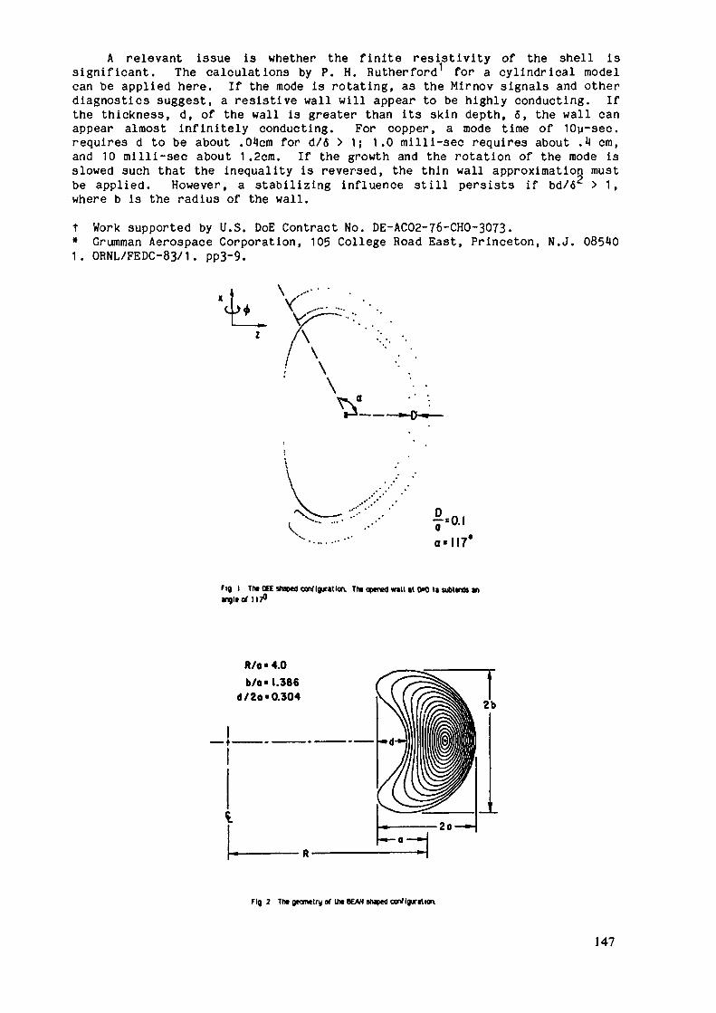
A relevant issue is whether the finite resistivity of the shell issignificant. The calculations by P. H. Rutherford1 for a cylindrical modelcan be applied here. If the mode is rotating, as the Mirnov signals and otherdiagnostics suggest, a resistive wall will appear to be highly conducting. Ifthe thickness, d, of the wall is greater than its skin depth, 6, the wall canappear almost infinitely conducting. For copper, a mode time of 10y-sec.requires d to be about .O^cm for d/6 > 1; 1.0 milli-sec requires about .M cm,and 10 milli-sec about 1.2cm. If the growth and the rotation of the mode isslowed such that the inequality is reversed, the thin wall approximation mustbe applied. However, a stabilizing influence still persists if bd/6 > 1,where b is the radius of the wall.t Work supported by U.S. DoE Contract No. DE-AC02-76-CHO-3073.* Grumman Aerospace Corporation, 105 College Road East, Princeton, N.J. 085 01. ORNL/FEDC-83/1. pp3~9.
fa,a = H 7 *
fig I The OEE shaped configuration. The opened wall »t 0=0 u suolenK anangle of 117°
R/o • 4.0b/o« 1.386
d/2o« 0.304
Fig 2 The geometry of U» BEAN shaped configuration.
147

1 '1 9
8
7
1
5
4
i
I
.1
.0
/11
• t JJ1J 1 • • / / / / / / / • • ^ / / / / « • • •/ / v / / < • » rfjjlff > • 1 1 1 1 ' ' • • • •i 4 1 1 . • • r f flfff r • > 11 j J J < • • •\ 11 i' r r r rt > • s Jjift.J j • • r r rr ' 'f f f r t • • j j j * / j j t • > T rrr r - •r r r r i • <;/./%//< • ' LT.fr ' • •r r r r ' • / //// /' " ' '/ //' * • •
• ' tJiti • ' ttfäf.r • • t t j j j /- ' ^ / / / / * • '///7/-" '/./v //- -
•
•
•
•
Fig 1. Eddy currents du» to the kink mo», in a closed shill it 0= 7a for In»DEE. projected recltlirearly on the tcroidal-poloidal pin TM outerequatorial line Is it .5 on the horizontal axis The currents are concentratedthere
Fig. 4. The plasma displacement due to the kink mode In the DEE wren theclosed shell Is at D=.7a
-0.12
-008
c»S
-0.04
JOWALL ANGLE, o.DECREES ————
60____90 120 150I I I r
DEEfl'l Kinks, &,*,&,*n<0 Aiisymmitric Uod«,fi0*
I__X0.2 0.4
WALL DISTANCE.DA) •0.6 0.6
WALL ANGLE a (Degrees)
30 60 90 120 ISO
0.5 1.0WALL DISTANCE D/o
1.5
Fig. 5. The square of the growth rates of the modes in the DEE. Og
correspond to the n=0 mode, and Q|.0j to the rvl mode«. The «olid curvesrefer to tne lower seal* and We dashed, the upper. For We latter U» wall Isopérai it tne small-R side (see Fig. I).
Fig. 6. The square at the growth rates In the BEAN Here the dasned curwrefer to the lower scale and the solid curve the upper. A shell with a gapextending almost to the tips or the plasma Is just as stabilizing es a closed«hell. A finite gap at tn» large-fl side can be tolerated. The hashed port loreof the shell mag be removed.
148

P.2.7
Control of n=l MHD Activity
S. Yamamoto, M. Azumi, Y. Tanaka*, T. TsuneaatsuJapan Atomic Energy Research Institute
* Fujitsu Ltd.
1. ExperimentIn the NBI-experiment of the JFT-2 tokamak, it was observed that the
sawtooth oscillation on soft X-ray signal was replaced by large amplitudem=l oscillations (Fig.l) {!}. This phenomenon is observed when thepoloidal beta value exceeds a certain value by the NBI-heating parallel tothe magnetic field line. The transition of the mode in (/3p-q*a) plane isshown in Fig.2 {2}.
2. TheorySeveral possible causes can be considered: (1 ) the mode coupling
between m/n = 2/1 and 1/1 resistive modes due to the toroidicity {3}, (2)the kir.etic effect en the m=l resistive mode {4,5}, (3) the instable c=lresistive internal kink mode {6},etc.. Figure 3 and 4 show the timeevolution of the magnetic energy and the magnetic island width,respectively, by using the reduced set of equations with the order of e( e :the inverse aspect ratio) based on the first model. The dashedlines denote the case without toroidal coupling. In this model the idealinternal kink mode is marginally stable. Due to the toroidal couplingthe other modes become more unstable. However, the toroidal couplingdoes not affect the evolution of the m=l mode and the internal disruptionoccurs. The other mechanism of the saturation of the m=l/n=l magneticisland was pointed out by Biskamp {4}. He has shown that the kineticeffect causes the saturation of the magnetic island by using thequasi-liner theory. However, the saturation level of the magnetic energyis shown to increase with increasing the number of higher modes (m/n =2/2. 3/3.....) , M (Fig.5) {5} . The change of the magnetic energy, -ô.Vn ,scales as M2 (Fig.6). This tendency indicates that internal disruptionoccurs even for cd*/7r>l , where a-,and 77 are the diamagnetic driftfrequency of ion and the growth rate of the m=l/n=l resistive mode. Theother candidate of the saturation mechanisms is the pressure-driven mode(ideal internal kink mode). The numerical study by using the cylindrical
149

model shows the saturation of the m=l/n=l magnetic island due to theisland formation of the toroidal flux (Fig.7, Fig.8) {6}. In this modelthe saturation occurs at a certain value of kz(=c) for a given magneticReynolds number, S, instead of the poloidal beta value. As pointed outby Bussac et al.{7} the internal kink mode is essentially toroidal node,the saturation may occur at a certain poloidal beta value if the toroidaleffect up to the order of e2 is taken into account {8}. This resultindicates the possibility of control of the internal disruption by usingthe neutral beam injection parallel to the magnetic field.
Reference{1} S. Yacanoto. et al. , Nucl. Fusion 21 (1S81 ) 993.{2} S. Ya.-a.-oto, et al. »"Transport Studies in the JFT-2 Tokanak", inPlasma Physics end Controlled Nuclear Fusion Research 1SS2 , Vcl I (IAEA.Vienna) (1S83) 73.{3} G. Kurita, M. Azuni, T. Tsuneraatsu. T. Takeda, Plasma Phys. 25 (1SS3)1097.{4} D. Biska.-r.p- Phys. Rev. Lett. 46 (1S81 ) 896.{5f T. Tsuneniatsu, G. Kurita. M. Azumi, T. Takizuka. T. Takeda. Proc. ofUS-Japan workshop on 3-D MHD Studies, CONF-840370 (1984) 158.{6} Y. Tanaka, M. Azumi, G. Kurita, T. Takeda, Plasma Phys, and PlasmaPhys, Controlled Fusion 27 (1985) 579.{7} M. N. Bussac, R. Pellat, D. Edery. J. L. Soule, Phys. Rev. Lett. 35(1975) 1638.{8} M. Azurai, T. Tsunematsu, T. Takeda, "Numerical Study of ResistiveInternal Kink Mode", in Proc. of the US-Japan Workshop on 3-D NHDSimulation (Nagoya, Japan) IPPJ-632 (1983).
TABLE 1.—CALCULATION PARAMETERS AND THEIR RESULTSCases
ABCDE
D: disruption.S: saturation.
5
5
5
7x HT5
0x 1(T5
0x 10-'
il-
l/31/31/41/40
ResultsSSDSD
150

( Q ) _, - ,- 2 ms (b)
(c)
IBKBI QUOI 3Zb SUU nSH SZCSII
= 0.9 - 1.2
5ms
5ms
3 = 1 . 3 - 1 . 4
"oRIpl-'ig.l Transition of soft X-ray signal.
= 1.6 - 1.9
= 2.6 - 2.8
" 2
-. OH ••• : • • • - ; • : -...,
Fig.2 Transition of the mode in (/3p-qa*) plane. Sawtooth oscillation ismainly observed in white region CI——p. Continuous mode is mainlyobserved in black region (BB). In hatched regions (EZZa), mixedmode is observed.
151

I ' l l
ÎO 100 150 200 250 300
09
08
07
06
r es
03
02
01
I/I
50 OO 150 200 2ÎO ÎOO
Fig.4 Evolution of the magnetic island widthfor the same case as in Fig.3.
-10
Fig.3 Evolution of the magnetic energy of each mode for the case ofe=0.1, )3p=1.0 and 5=2 - 104 . The solid and dashed lines denote thecases with and without toroidal coupling, respectively. Two casesare shifted due to the difference in initial perturbations. Theinternal disruption occurs at t--150 .

-4log(-6M )
-7
log(-6MQ)
-6
-7
200 400 600 800 200 400 600Fig.5 Time evolution of the magnetic energy change, -Ô.Vo , for (a; c../-,-T=0
and M=5 and (b; co,/-/-=3 , M=l, 5. 7 and 10.
Fig. 6
Maximum value of -5Mb vs- M for cu*/77=3This value scales as H2 .
M5 10
153

.o -i.o -û.5 o.o o.s i . o - i - o -o.s D'.o -j ; i .0
i,;____;____;____:____i |i-ii n- r - ' . ' . ' . ' ' . ""|"|i"M e n'____i————i————i————l mu.«————luiLj—i_i_JwuiilH-f .O -0.5 0.0 0.5 I .O- I ' -O -O.S B'.O O.s 1.0 -".o -0.£ 0.0 O.S l .0 -1 -0 -O.S C.O 0.5 1.0
6.2
E.l
e n '______ • '—* ' Illl-l . l n . r'l'- ——,IUJi.]l|l•o B:Y.o -O.E o.o c.s i .o - iVo -oTs ö-o 7.5 i.oG.2
6 . 1
5.0
1:240
ö MKS öTö ös T.o -i^ô""' -o: s o'.ö 5t'e""""T.o "-"Tö -0.5 öTö öTs T.o -i o •• " "o-s ' " i'.o
Fig. 7 Time evolution the toroidal current density, helical magnetic fluxand toroidal magnetic field for fcz=l/3 and S=2* 104 . The sharp peakof the current disappears at t=210 and the large magnetic island isformed at t =240.
-re=0.73
r,=0.093fi» 0.066
0 50 100 150 200 250 300TIME (t/tj
Fig.8 Time evolution of the shift of the magnetic axis.used in the calculations are described in Table 1.
The parameters
154

P.2.8
TOKAEAK H3GHIJS WITH q(0) < 1, q& £ 2
L.S.Zakharov
Necessity of detailed consideration of the regimes withq(0) <" 1 was repeatedly proposed by USSR group. It was empha-sized that commonly adopted opinion about supposedly theoreti-cal impossibility of such regimes is groundless. Steady-stateregimes with q & 2 obtained on a number of tokamak devices(T-11, T-10) provide (from a viewpoint of Kink instabilitytheory) distinct evidence, that
a) q(0) < 1 at the axisb) the processes of internal disruption are not accompa-
nied by increase in q(0) up to 1.Based on the analysis of experimental results conclusion
was made, that internal mode m/n =1/1 is not responsible forinternal disruption. However the reasons of it were not indica-ted. Another conclusion was that once q(0) increases to 1 dueto reconnection on the mode m/n = 1/1, external mode m/n = 2/1start to be unstable and the major disruption sets in . Detai-led study of q-radial distributions currently made provides di-rect experimental evidence in support of these two statesments.So that, conclusion can be made that the regime adopted forIirrOR (q(0) zz 1 , q& ~ 2) is in fact instable with respectto disruptive instability.
The consequences of disruptive instability theory £lJ ,developed in I.V.Kurchatov Institute of Atonic Energy in 1980-81, and direct measurements of q radial distributions current-ly made indicate explicitly that once qD ;~ 2, q(C) < 1.
Cw
155

In relation v/ith high pressure tokamak the following prob-lem requir further consideration.
1 ) Calculations of limit & for q radial distribution whenq(0). Such calculations (but with account for balloon modes on-ly) were performed earlier and were presented in USSIl contribu-tion to the III?OR Workshop. Advanced calculations accounting forlarge scale LLHD modes are needed.
2) Development of pressure gradient control methods for pla-sma core, Jvcn moderate pressure gradients ( & ( p± ) ~ 0.3) maygive rise to exit at ion of the mode m/n = 1/1 in the region whereq < 1 with the result that q(0) increases to 1 thus provo-king the major disruption. Therefore low pressure d-radient is tobe supported in the region with q(0) < 1, though it may behigh enough in the region with q(0) > 1.
Since the regimes with q(0) < 1 are by far more stablerespectively to external kink modes then those adopted for IÎJTOR,limit ,6 may be expected to decrease even when q& œ 2 ispreserved, natural limit for q(0) associated with the mode m/n=1/2 is 1/2 . In this case limit for qQ (boundary value) is 1. Sothat theory predicts that steady-state regimes can be achievedv/ith lower q^ than those adopted nowadays in IUTOR project. The-refore considerations mentioned above (p. 1,2) are also to be re-peated for the regimes v/ith q& < 1» Experimental studies of theregimes are also needed with an aim in view to clear up life-time degradation v/ith qD reduction.CL
1. L.3.Zakharov, Pizika Plasmy, 1981, v.7, p T295
156

p ? <!*.£.•
THE SAWTOOTH-SUPPRESSED TOKAMAK
P. H. Rutherford, M. L. Chance, H. P. Furth, A. H. Glasser t, H. Hsuan, D. W. Ignat,J. Manickam, W. Stodiek, A. M. Todd**, and R. B. White.Princeton Plasma Physics Laboratory, Princeton, New Jersey, U.S.A.
IntroductionThe successful suppression of the m = 1 mode and the associated "sawteeth" would have
substantial benefits for tokamak performance: (i) it would provide a significantimprovement in the limiting beta-value for ballooning instabilities by allowing reducedq(0)- and q(a)-values; (ii) it would provide indirect stabilization of m = 2 externalkinks by allowing more centrally-peaked j(r)-profiles than would otherwise be possible atlow q(a)-values; (iii) it could provide an improvement in confinement by allowingincreased plasma current; and (iv) it would enhance the maximum ohmic heating power.Ideal-MHD stability at q(0) < 1
The ideal-MHD stability of a D-shaped tokamak (K = 1.6, 6 = 0.3, R/a = 3.2) with qJO)= 0.6 and q^(a) = 1.8 has been examined using a code that adjusts local pressure gradients
1.8 Fig. 1. Profiles of p(iji) andq(iji) versus poloidal flux y fora D-shaped tokamak that iseverywhere marginally stable tolocalized pressure-driven modeswith q(0) = 0.6 and q(a) = 1.8.The radius of the q = 1 surfaceis / <r2>/a=0.72. The <ß>-valueis 10.0% and exceeds the "Troyonlimit" 0Tr by a factor 1.35.
to provide marginal stability against Mercier and ballooning modes (see Fig. 1). Whilethe Mercier criterion imposes the more demanding requirement over much of the region whereq(*) < 1, shear stabilization is strong enough to allow a substantial pressure gradient tobe supported in this central region (Fig. 1). The overall (stable) <8>-value is 10.0%,which exceeds the Troyon limit [<ß>Tr(%) = 3.5 I(MA)/a(m)B(T)] by a factor 1.35.
The n = 1 external kink, which has a dominant m = 2 component, is stabilized by aconducting wall placed at rw/a = 1.15, but would otherwise be strongly unstable;triangularity is sufficient to stabilize the n = 1 internal kink.
Resistive stability at q(0) < 1Tokamaks with q(0) < 1 generally exhibit "sawtooth" behavior, in which a strongly-
growing m = 1 resistive kink reconnects the magnetic surfaces 1n the central region of theplasma in such a way that q(0) is periodically restored to unity. If this dominantresistive mode can be suppressed while q(0) is progressively lowered below unity, higher-order resistive modes will be encountered with resonant surfaces falling in the regionwhere q(r) < 1; the most relevant of these will be modes with m/n = 4/5, 3/4, and 2/3.
157

Figure 2 shows an "optimized" case with q(0) = 0.67 and q(a) = 1.65 that is stable to them/n = 2/1 external kink and to all resistive-tearing modes {in the cylindrical, low-betaapproximation) without any conducting wall. Small "pedestals" on the current profile areneeded to stabil ize the m/n = 3/2 and 3/4 modes. It does not seem possible to stabilizethe m/n = 2/3 mode, implying a lower limit on q(0) of about 0.67.
Fig. 2. Profiles of j(r) andq(r) optimized for resistivetearing-mode stability assumingthat the m/n = 1/1 resistivemode can be suppressed by rf-feedback. The m/n = 2/1external kink is also stablewithout any conducting wall.Small "pedestals" on the currentprofile aid in the stability ofthe m/n = 3/2 and 3/4 modes.The m/n = 2/3 mode precludesstable operation below q(0) =0.67.
I I I I IPedestal toStabilize 3/4 Mode —
q(r
q (01=0.67q(a)=l.65No Wall
Pedestal to -Stabilize
3/2 ~Mode
.0
Feedback stabilization of the m = I modeFeedback stabilization of the m = 1 resistive mode by rf heating and/or current drive
has been proposed [1]. To produce a stabilizing effect, the feedback technique mustincrease the current density at the 0-point of the magnetic island associated with themode and decrease the current density at the X-point (separatrix). There are twoprincipal options for rf-feedback: (i) heat the magnetic island by localized rf heating,thereby lowering the local resistivity; and (ii) drive additional localized non-inductivecurrents within the magnetic island. In both cases, the rf power must be modulated inphase with the signal from a suitable detector, e.g., electron cyclotron emission.
Feedback techniques based on electron cyclotron heating and lower-hybrid current driveare capable of achieving the required localization of the absorbed power [2]. Experimentson sawtooth suppression by lower-hybrid current drive are presently underway on the PITtokamak; control of the m = 1 mode is apparently possible without feedback modulation —perhaps because of a "natural" feedback mechanism in which current-carrying suprathermalelectrons are preferentially confined near the 0-points of magnetic islands.
Of the two principal options for rf-feedback, island heating is predicted to be lessefficient than island current drive, because the large cross-field thermal diffusivity ina tokamak limits the temperature perturbations than can be sustained in a small magneticisland. Feedback stabilization by island current drive requires a non-inductively-drivencurrent density modulated in phase with the rotating island: j^ = jpfr cos(me-n4>-u)t) . Inthe applicable nonlinear regime, the island width w is found to grow according to:
dw _ , , r JVf 1,dt - n (A - Cd j
where Cd = 8(rjz/B9) (q/rq1 ) and A1 is the usual measure of tearing-mode instability. Allislands with widths less than some maximum width wmx are effectively stabilized.
In a "cylindrical" tokamak with circular cross-section, the ideal -MHD internal kink isonly marginally stable, with the result that the resistive m = 1 mode becomes strongly
158

unstable (i1 •*• «) and does not enter a slow-growing nonlinear phase. However, the ideal -MHD mode can become positively stable 1n a tokamak with a shaped (triangular) cross-section, in which case the A' is finite and the resistive mode will be slow-growing.
p(r)=Po(l-r2/a2
jz(r)=jzo(l-rV)
0.3
0.2
t—0.1
(b)
,= 1.0
Fig. 3. (a) Values ofthe effective A^TS forthe resist ive m = 1 modein the case of a D-shapedcross section withtriangular deformationC3a = 0.15 (6 = 0.45) andelliptical deformationc2a = 0.3 (* = 1.6). (b)Feedback current densityJrf required to stabil izethe m = 1 resistive modefor island widths up to a
0.6 0.8 0.9q(0)
0.6 0.7 0.8 0.9q(0)
1.0 maximum w.max/rs =0.1.
Figure 3a shows values of A1 for the m = 1 mode in a tokamak with parabolic currentand pressure profiles, an aspect ratio of 3.2, and a D-shaped plasma boundary of the formr/a = l-£2acos28+C3acos3e, where C2a = ^3 and ^a ~ ®-^ (corresponding to elongation < =1.6 and triangularity 6 = 0.45). Figure 3b shows the feedback current density j_^required to stabilize islands with widths up to wmax/rs = 0.1. We see that feedbackstabilization of the m = 1 mode at q(0) ~ 0.7 by rf current drive will require substantial— but perhaps not prohibitive -- feedback power (Jrf/Jzo ~ °-3)- For ttie resistive modeto enter a slow-growing phase requires S = TR/TH » (rs&s)3(a/rs)2(rsq^)~1 — arequirement that is satisfied at reactor-like tokamak parameters.
Experimental realization of the q(0) < 1 regime
Faraday rotation has been used to provide direct measurements of the plasma currentprofile in ohmically heated discharges in TEXTOR [3]. In the low-q(a) case shown in Fig.4, the measured central current density corresponds to a q(0)-value of 0.63; the possibleexperimental error in the j(0)-measurement is significant (± 15%), but corresponds only tothe range 0.54-0.73 in possible q(0)-values. Small sawteeth are apparent on theinterferometer density traces; the sawtooth inversion radius is in agreement with thelocation of the m/n = 1/1 resonance inferred from the measured j(r)-profile. The measuredq(0)-value does not change appreciably during a sawtooth cycle. Soft X-ray measurementsof the Te(r)-profi le indicate that the measured j(r)-profile is consistent withneoclassical resistivity with a uniform Zeff of 2. The ne(r)-profile is relatively flatwithin q(r) < 1. At higher q(a)-values (~ 4.4), the measured j(r)-profile is muchnarrower, with the result that the q(0)-value is again substantially below unity (-0.64).
The tearing modes whose resonances are indicated in Fig. 4 are all stable, except fora weakly unstable m/n = 2/3 mode and, of course, a strongly unstable m/n = 1/1 mode.Although the observed flattening of the j(r)-profile in the vicinity of the q = 1 surface
159

.0
Fig. 4. The j(r) and q(r)profiles measured by Faradayrotation in a low-q discharge inTEXTOR. The experimental error-bar on the j(r)-measurement nearr = 0 is shown. Using theexperimentally measured j(r)-profile, calculations of A'-values show that the tearingmodes whose resonances areindicated on the j(r)-curve areall stable (or marginallystable) except, of course, forthe m/n =1/1 mode.
may well be due to m = 1 magnetic islands, there is presently no theoretical explanationfor the saturation of such modes short of magnetic reconnection of the q(r) < 1 region.
The TEXTOR results provide encouragement that the m = 1 tearing mode can enter a slow-growing or saturated phase, even when stabilizing mechanisms such as triangular shapingare absent. If so, the control of this mode by rf feedback techniques should be feasible,leading to a "sawtooth suppressed" regime of the standard tokamak configuration.
[1] RUTHERFORD, P.H., in Course and Workshop on Basic Physical Processes of ToroidalFusion Plasmas (Varenna, Italy, Aug 26-Sept 3, 1985).
[2] IGNAT, D.W., RUTHERFORD, P.M., AND HSUAN, H., in Course and Workshop on Applicationof RF Waves to Tokamak Devices {Varenna, Italy, Sept 5-14, 1985).
[3] SOLTWISCH, H., STODIEK, W., et al., APS Plasma Phys. Div. (San Diego, Nov 4-8, 1985).
160

P.2.10
Disruption Control by Using Local Helical CoilK. Yamazaki and JIPP-T-IIU GroupInstitute of Plasma Physics
Nagoya University, Chikusa-Ku, Nagoya 464 JAPAN
l. APPROACH TO DISRUPTION CONTROL WITH HELICAL COILS
MHD activities and disruptions are.main obstacles to theacheivement of stable discharges in the tokamak, and resultant plasmacurrent termination is one of critical issues for the design of thelarge-scale tokamak devices. It has already been demonstratedexperimentally that plasma disruptions are suppressed by applyinghelical magnetic field resonant to m=2 MHD activities by fast feedbackscheme or quasi-steady scheme. The fast feedback scinario requiring them = 2 helical coil inside the vacuum vessel is expected to suppress them=2/n=l tearing mode when the phase of the helical field and theperturbed field is opposite. On the other hand, slow feedback schemewithout control of the phase of helical field is not supposed to beeffective, according to the theoretical prediction with the assumptionthat the energy confinement time is larger than the mode rotation time.In the real experiment, the gradual and global current profileEodification seems to be realized through the change in the transportprocess by the quasi-steady-state helical field application. The m = 2pure and clean spectrum of the helical field component is desireable forboth schemes, which requires pure 1=2 helical coils or saddle coils.
On the other hand by using compact local helical field coils,externally driven soft mini-disruptions can be available for gettingquick change in the plasma current profile and avoiding undesireablecatastrophic plasma current termination in tokamaks. It is demonstratedin the JIFF-T-IIU tokamak experiment that this mini-disruption behaveslike a "preventive inoculation" against major disruptions.
161

2. JIPP-T-IIU RESULTS
Two local poloidal coils ( we call " local helical coils"(Fig.1) )have been used to demonstrate this scinario, which are mounted on two 23degree vacuum vessel sectors at the opposite side of the torus. Bydriving two coil currents in the anti-parallel direction ( A-mode ), a3/2 helical component accompanying with 1/1, 2/2 and 4/2 side-bandcomponents is produced ( Fig.l ). On the other hand, by energizing thisdual coils in the parallel direction ( D-mode ) we can simulate mainlym=3/n=l helical field, and 2/1, 4/1 and 4/3 components are produced bythe toroidal effects.
The JIPP-T-IIU tokamak ( R= 91 cm, a = 24 cm ) was operated at IT< Bt < 3T and 100 kA < Ip < 300 kA. Typical stabilizing effects of theA-mode helical field on mildly unstable discharges were shown in Fig.2.
Without pulse application plasma current with qa -^ 3.4 wereterminated by the strong m=2/n=l activity and the resultant majordisruption. During this period, loop voltage becomes voilent andbcicnetric signals increase slightly, while the plasma position derivedfrom the magnetics and the mean electron density were almost constant.
cropped from 0.75 kev to 0.70 kev and the 2/1 mode rotation wasgradually stopped and then led to the disruption.
By the A-mode pulse application ( m=3./n=2 dominant ) during thisdisruptive period, the m = 2 mode rotation was slowly stopped andfinally more tightly locked in phase than in no-pulse case. The islandwidth of the m=2 mode does not seem to be reduced significantly on thisphase-locking stage. Some spikes on the Mirnov signal, bolometer., lightimpurity lines were observed which correspond to the ECE temperaturedrop. These spikes correspond to the quick rotation of the m=2/n=l modeand the quick temperature decay due to a mini-disruption. This ECEtemperature decay was initiated mainly near the q = 2 surface. The 2/1magnetic island seems to disappear on this mini-disruption stage. Afterone or two mini-disruptions the plasma current channel becomes morepeaked than without helical pulse, which often leads to the occurance ofsawtooth oscillations. This quick rearrangement of the magneticconfiguration seems to help avoid disruptive current terminations.
162

Different from the A-mode pulse, the D-mode helical pulse ( m=3/n=ldominant ) does not seem to be effective to suppress disruption in theJIPP-T-IIU tokamak.
More detailed analyses on the mechanism of the disruption controland some feedback trials to suppress disruption more effectively withthis pair of local helical coils are now under investigation in theJIPP-T-IIU tokamak.
3. DISCUSSION AND SUMMARY
It is demonstrated in the JIPP-T-IIU tokamak experiment that them=3/n=2 helical field perturbation produced by the toroidally localizedcoils induces one or two mini-disruptions in the tokamak plasma and thenagnetic island width of the m=2/n=l mode is reduced by this milddisruption, which prevents the catastrophic plasma currenttermination . In this scinario the compact local helical coil system isenough instead of complicated pure helical coils, which may beacceptable in the INTOR design to reduce the probability of disruptivecurrent terminations by means of the slow feedback scheme. Moredetailed studies are required to optimize the configuration of the"local" stability-control coil and to check the engineering feasibilityof this scinario in the INTOR program.
163

100
r/aFig.l Configuration of local helical coils and its radial field
components for A-mode ( anti-coil-current mode ) operation withIhel = 15 kA-
v. 4loop(V)
2iO'P l s or
( k A)
Ihel(KA) -iC
ICO
I I I I(I -^U I
200 0
M 11 i
200
he,
jay—LJ i
60 100t (ms)
uo so 100t (m
140
Fig.2 Stabilizing effects of the helical field perturbation on th;unstable tokamak discharge .
left ; without pulse,r^^rti with A~rncde oulse.
164

P.2.11
CONFINEMENT ENHANCEMENT BY PROFILEOPTIMIZATION.K.A.Razumova, Yu.V.Esipchuk
Experiments on tokamaks have shown the energy confine-ment to be essentially dependent on the current and pressureradial profiles. With lower J_/nV parameter the plasma para-P emeter profiles, in particular, j(r), become.narrower tillsome limiting profile is achieved. The regimes with extremelynarrow current profiles, called on T-10 *B'-regimes, are cha-racterized by minimum ?ee values for the plasma core and neo-classical behaviour of impurities that is build-up of high-Zions at the plasma axis. Exceeding the maximum permissible2&1J/Î1 value leads to an abrupt Xf and energy losses rise.So it is . very important to deposit the auxiliary heating po-wer over the radius in such a way that at the given AH(r)the critical j(r) and p(r) profiles would not be distorted. Ithas been demonstrated that, curtain requirements to ^AuCr) be-ing sufficed, the energy confinement at large PAJT/POH Ta^ioscan be kept similar to that in OH-regimes. It is not impossi-ble that such a pAjj(r) profile can be found which will resultin better energy confinement dependence on plasma parametersthan during OH.
J/ne.increase allows to operate wider j(r) profiles andlower q(a) but leads to 3-4 times higher 9£c at the plasma ax-is. Such regimes have been called on T-10 'S'-regimes, theyseem to be equivalent to 'L'-regimes during auxiliary heatingwith NB-injection.
165

Which regime has better prospects for the reactor?The reactor must have high n , so 'B1-regime with good
energy confinement seems preferable, though such regimes arestill not achievable at low q(a,-) < 3»5 and there is the pro-blem of impurity build-up at the plasma axis.
The instability controlling the energy confinement in*S'- and 'B'-regimes is expected to be identified in the nea-rest future. If as it is supposed it proves to be on MKD-in-stability, it probably can be stabilized and correspondinglylower q(aj) achieved without energy confinement deterioration.
Methods for plasma current and pressure profilecontrol«
1. ECR-auxiliary heating is the best method allowing -EVtj(r)profile control. The energy being supplied to electrons, T (r'6and j(r) are programmed.2. Some other methods of auxiliary heating can be employedto provide (r) profile control.3. KHD-instability stabilization via current profile correc-tion over radius near the resonance surface ; dynamic feed-bac>stabilization with local electron heating at the degeneratedmagnetic surface points encountered over the poloidal circum-ference, where the electron temperature minimums due to LIHD--mode development exist. ECR-heating is the most promising op-tion.
166

P.2.12
Confinement Improvement and Disruption Control byProfile Optimization using Electron Cyclotron Heating
K. Hoshino, T. Yamamoto and H. KawashiraaJapan Atomic Energy Research Institute
1. Experimental Results on JFT-2M TokamakIn the ECH experiment on JFT-2M tokamak which has major radius
R=1.31m and minor radius a=0.35m, the second harmonic (/=2/ce=59.BGHZ)extraordinary wave is launched nearly perpendicularly with slight parallelcomponent of the reflactive index n//=0.17. One can find by acalculation that single path absorption rate of the wave at the secondharmonic ECR layer is more than 50% {2,3} in the core of the tokamakplasma (r/a 0.7) with the line average density of n^l .Ox. 10I9m"3 inJFT-2M tokamak. The increase in the central electron temperature issensitive to the location cf the second harmonic ECR layer {2,3}. Sodoes the measured A-M/2(=ß>+ Zj/2-1/2) value, where ßp is the poloidalbeta value and l{ is expressed as !.;=4r/pox (internal self inductance perunit length of plasnia ). The measured AT 1/2 value increases by theapplication of ECH pulse (power P CH =SCKV, pulse length 70ms) when thesecond harmonic ECR layer locates at -the plasma core (center resonancecase), but AT 1/2 decreases when the ECR layer locates in the off-centerregion (off-resonance case) as shewn in Fig.l. Ve find from the measuredelectron temperature profile shown in Fig.2 and density that ßp does notdecrease in the off-center resonance case. This indicates that lidecreases in the off-center resonance case. The estimated change in l<is AIi^-0.22 {4-}. Namely, the current profile seems to broaden in theoff-center resonance case. In this case, the decrement of AT 1/2 doesnot saturate in 70ms, and it seems to continuously decrease if we extendthe pulse length. The calculated classical diffusion time of themagnetic filed is -v-90 ms (Te=300eV, scale length ~0.3m) assuming theSpitzer resistivity. Therefore, a few hundred ms should be needed for l^to be fixed at the final state.
2. Improvement of the Energy Confinement by Profile ControlIn the high ß study of the H-mode tokamak plasma, it was found that
broad electron-temperature/current profile is unfavourable for the energy
167

confinement {5}. The degradation is considered to be the result that theballooning /3-limit is exceeded locally in the H-mode flat profileregion. A peaked current/pressure profile seems to improve the stabilityand results the improved energy confinement in the high ß plasma. From aHHD calculation, there is an optimum current/pressure profiles against MHDinstabilities such as external/internal kink modes {6}. ECK must be agood candidate for the method of controlling current/pressure profilesbecause cf iis Iccalicec —•c*«"e<* c—~c.s~ .~'c~
3. Suppression cf the Disruption by ECHThe local modifications on the radial gradients of current density
can stabilize the lov order tearing modes in tokaniaks. It was shown thatthe absorption cf microwave power densities about llforf3 near the q=2singular surface can quench the low order tearing modes within a few tensof milliseconds {7}. Preliminary experiments in a few tokaaaks observethe suppression of m=2 oscillations by ECH.
References{1} M. Murakami, et al., In 12th European Conf. on Controlled Fusion andPlasma Physics, Budapest, Hungary (1985).(2} K. Hoshino, et al., ibid., in proceedings vol.2. 184 (1985){3} K. Hoshino, et al., JAERI-M Report 85-169 (1985).{4} K. Hoshino, et al., in Japan-US Work shop on Transport Phenomenaduring RF Heating and Current Drive, Dec. 16-18 at Kyoto univ. (1985).{5} M. Keilhacker, et al., in 12th European Conf. on Controlled Fusion andPlasma Physics, Budapest, Hungary (1985).(6} F. Troyon, et al., Plasma Physics and Controlled Fusion 26 209 (1984).{7} V. Chan, et al., Nuclear Fusion 22 272 (1982).
168

PECH =80 KW
.10
.05
0
-.05
-.10 -
l i l tIp=JOOkA
~ ÏÏe=1.0xld9m"3
0.6 ~OJ
IOJ
0.5 ^
0.4 _L
0.3
-0.2-40 (-30 -20 -10 0 10 20 30 j 40
limiterrccius
r res (cm) limiterradius
Fig.l Dependence of change in A-\/2(=ßp- ii/2-1/2) on the position of thesecond harmonic ECR layer. ECH power PïCa-50 KW, pulse length TCtcs.plassa current Ip=iOOKA, density ne=l .Ox 10'9m"3 .
( a ) ( b )
1.0Cü
0.5
0
\ i i rCenter Resonance
Ip=IOOkAïïe=I.OxldVPmr 80 KW.ECU
o
~ 1.0-
O)
0 10 15 20 25r (cm)
0.5
0
1 1 11 Off-center
•a Tr "" -v^ "r->
«S£
firesi i i0 5 10
i i iResonance
^r
151 1
20 25r ( c m )
Fig.2 Measured electron temperature profiles without (empty points ) andwith ECU (closed points) for (a) center resonance case, and (b)off-center résonance case. The electron temperature was measured bylaser scattering (represented by circles), soft X-ray energy analysis(squares), and l'-lŒ ( t r iangles) .
169

P.2.13
Confinement Improvement by Particle Fueling OptimizationS. Sengoku
Japan Atomic Energy Research Institute
1. Experimental BaseDegradation of confinement time from the INTOR scaling is widely
observed in high density beam-heated tokamak discharges. It is shownthat this degradation can be suppressed by direct particle fueling with DIpellet injection in Doublet III tokamak (pellet radius rp=0.65mm, velocityUp=SOOm/s ) {1,2}.
1-1 Joule heating caseEven in Joule-heated divertor configured discharges, the energy
confinement time is not increase linearly with the density if the plasmais fueled by conventional gas puffing as shown in Fig.l. Figure 1-a)shows that, in the gas-fueled discharges, the neutral pressure at thecivericr £**~ tî~e —a^t'c^e rec"rcr "n" level re—resente^ bv D eni 'ss o" bothat primary limiter (D~Ll^) and the divertor region (D<?!D') are increasencr.lir.ea.rly with the line-averaged electron density of the main plasma,n,, . Consequently, the energy confinement time is saturated around 60 mswhen the density is above 4* 30!3c.Tf3 as shown in Fig.l-b).
In contrast to that, the pellet fueled confinement times continue toimprove with increased density. This is probably due to the fact that inthe pellet fueled discharges both the edge pressure and the limiterrecycling light are maintained at relatively low levels (Fig.l) and/or thesuccessful density rise at the plasma center which has good confinementproperties.
1-2 Beam heating case ( H°-D';Eo=73KeV)In neutral-beam heated limiter discharges, the energy confinement
time shows transient improvement for first 60 ms, but then drops belowJoule-heating level, reaching a value which equal to that in a comparablegas-fueled plasma as shown is Fig.2-a). This is due to the build-up offast ions from the beam that enhance the pellet ablation at plasmaperiphery.
A scheme was tested to eliminate this effect and to enhance pelletpenetration by briefly interrupting the neutral beams just before each
170

pellet was injected. This is based on the relatively fast slowing-downtime of fast ions in the edge plasma which is less than 10 ms, and on theexpected dependence of the ablation on the fast ion population. Theenergy confinement time and pellet penetration are improved over thecontinuous beam case for delay times (time from beam turn-off to pelletinjection.' At) greater than 8 ms. Further delay shows little additionalimprovement (Fig.2-b)). Temporal deviation of the energy spectrum ofcharge-exchange neutrals coming from the plasma edge shows fast decay, <5ms, of lower energy components (Eo/2,Eo/3) after every beam turn-off.
—sA comparison of pellet ablation profiles for continuous vs.
interrupted beam (Fig.3) shows that there is no significant difference inpellet penetraticn. Kcv-ver, the pallet abiaticr. in the cuter lOcs cfthe plasma is reduced by interrupting the beam. The reduction in -theedge ablation with improved penetration results in lowered edge densityand slower._.central. density decay time as measured by the visiblebremsstrahiung array. Density profile information from this visiblebremsstrahlung emission measurement shows that there is no differencebetween the profiles for At=4 ms and 18 ms of interruption of neutral beaminjection shown in Fig.2-b) except at peripheral region (Fig.4) {3}.Both profiles are normalized at core plasma region. This reduction ofedge ablation and thus suppression of peripheral cooling may account forthe maintained improvement of the energy confinement time by keeping edgerecycling lower. Peripheral cooling is considered to lead to strongtemperature gradient and to the enhancement of the heat conduction loss.
2. Particle fueling optimization
2-1 Optimization for confinement improvementAbove experimental results imply that the control of edge fueling
(keeping the peripheral plasma in low density and high temperature) ismost responsible to improve energy confinement characteristics. In thisscheme, it is shown by 1-D tokamak code simulation that any change intransport characteristics (xe=5x 10l9/ne,%i=4^HH.UA=l/4 • Xe ) before andafter pellet injection are not necessary to improve the confinement asshown in Fig.l {4}. The pellet is not necessary to penetrate up to theplasma center, but it is necessary to reduce pellet ablation at plasmaperiphery. For a discharge of long duration, the combination of pelletfueling with interrupted beam, if necessary, and divertor or pump limiterfor exhaustion of excessive particles is the most promising method. The
171

slowing down time of fast ion in peripheral plasma (lKeV;iOI3cnf3) is about100 ES. If one fuels plasma by gas-puffing, it is necessary todistribute the locations of the puff systems in toroidal direction inorder to reduce strong localized cooling.
2-2 Neutron productionThe neutron production rate is drastically enhanced (--xlO) by
direct pellet fueling to hot core plasma even the energy confinement timedegrades {1.2}. This is presumably due to the maintained peaked-profile•with high density at central hot core region. A simulation of pelletfueled limiter discharge for JT-60 shows that the thermal Q value, Q-h ,assuming D-T reaction can easily exceed unity with 20MV beam heating, eventhough the pellets are injected before beam injection, whereas it isdifficult to reach Qth~0.9 by using comparable gas-fueled discharge {5}.
Pellet fueling is competent for obtaining high Q;j, values.
2-3 Tritium handlingHigh fueling efficiency ( SCK100") for pellet fueling is also
observed in D-III (2!. This value is more than 2~-3 times higher thanthat of gas-puff case. Therefore the total handling amount of tritiumcan be lessen by applying pellet injection.
References{1} S. Sengcku, M. Abe, K. Itoh, et al., in Plasma Physics and ControlledNuclear Fusion Research (Proc. 10th Int. Conf. London, 1S84) Vol.1, IAEA,Vienna (1885)405.{2} S. Sengoku, M. Nagami, M. Abe, et al., Nucl.Fusion 25 (1985)3475.{3} S. Sengoku, et al., to be appear in Japan Atomic Energy ResearchInstitute Rep., JAERI-M (19S6).{4} S. Sengoku, "Improvement of Confinement Characteristics of TokamakPlasma by Controlling Plasma-wall Interactions', Japan Atomic EnergyResearch Institute Re?., JAERI-M 65-102(1985).{5} S. Sengoku, T. Kirayama, M. Nagami, "Pellet Fueling Study for JT-60",I—ernatic-al Pellet Fueling Workshop (San Diego, USA, 1355;
172

D-I DIVERTOR (JOULE PHASE)
GAS FUEUNGca
sO_
100
Uf50
M-D TOKAMAK CODE-INTOR SCALING0.5
8 10 1213n,(x10 cnrs)
Fig.l Comparison of a) particle recycling at limiter and divertor asinferred from DaL/>lf and Da"/D and neutral pressure at divertor and b)the energy confinement time between gas- and pellet-fueled dischargesas functions of n« . Open symbols denote pellet-fueled, and solidsymbols gas-fueled discharges. Results of 1-D tokarak codesimulation is also presented.
"E
LU1-
vo -
60 -
30-
0 : - —— —
a) LIMITER P-mode (CONTINUOUS)
, i , S "S
M90- ———————
60 -
3 0 -
n -
bILIMITER
n*^
^Sf """ T- .—— JU / <* /
'^/////^/^//////
_ 3 PNB **». "** u MI 1 1 ii " CAS
t Lt t t l t t t t t tP - m o d e ^ ^ ( I N T E R R U P T E D )
PNB 'û t "«ms \ t -8msn 6 s=8. H)" c m-3 \T| j-j n n ;•-,t t, t ntfJt/ Itilttitn .
•10
-0
-10
-n500 600 700 800 900 1000
t lmslFig.2 Comparison of temporal deviation of average energy confinement time
for ax continuous-beam case and b) interrupted-beam case for ir=4-.Sand 18 ms. Pellet injection times are shown by arrows except forA:=4 and IS ms.
173

1.0r la0.5
b) INTERRUPTEDBEAM
20 40 20
XpUml
Fig.3 Da signals coining from pellet to SO* filtered photodiode (D/) aspellet ablation profiles: a) for continuous 1.3 MW beam heating andb) for interrupted beam heating (average beam power of 1.6 MV), inFig.2 At=8 ms. Penetration is measured from limiter surface, zp ,deduced from measured pellet velocity (800m • s~' ) . These pelletsare injected, between t=730 and 830 ms in both cases.
a) 6ms after pellet injection
t » 764msI____I____I
b) 36ms after pellet injection
it=18raA *
796-js
10 20r(cm)
30 40
Fig.4- Comparison of radial profiles of square root of Abel-invertedbremsstrahlung emission. Ig, as a relative density profiles for At=4ms and 18 ms for discharges in Fig.2. ( a) 6 ms and b) 38 ms afterlast pellet injection. )
174

Group 3
HEATING AND CURRENT DRIVE
M. Cox (EC)
D.A. Ehst (USA)
N. Fujisawa (Japan)
K. Miyamoto (Japan)
V.V. Parail (USSR)
175

1. INTRODUCTION
The eleven proposals for the current drive and two proposals for the
heating are presented in this meeting. They are categorized as follows:
a. Current drive by fast waves and lower hybrid waves
Fast wave current drive for profile control and beta enhancement
(p 3.1 - USA = p 3.1)
Stationary current drive by means of fast RF waves (p 3.1 - USSR =
p 3.2)
ICRF current drive (p 3.6 - J = p 3.3)
Current drive by fast magneto-sonic wave near the lower hybrid
frequency (p 3.3 - J = p 3.4)
Current drive by LH waves: problems and proposals (p 3.2 - USSR =
P 3.5)
b. Current drive by negative ion beam with sub-MeV energy
Heating, current drive and plasma control by negative ion based
sub-MeV beams (p 3.4 - J = p 3.6)
c. MHD current drive
Oscillating field current drive (p 3.2 - USA = p 3.7)
Analysis on 0 pumping for tokamak current drive (p 3.1 - J = p 3.8)
d. Bootstrap current drive
The bootstrap tokamak and MHD stability of bootstrap equilibria
( 7 - EC = p 3.9)
ECRH and bootstrap current for steady-state tokamak reactor
(p 3.3 - USSR = p 3.10)
e. REB current drive
Current drive with relativistic electron beam injection
(p 3.2 - J = p 3.11)
f. Heating
Ion Bernstein wave heating (p 3.5 - J = p 3.12)
"Ohmic" ignition on INTOR (p 9 - EC = p 3.13)
177

Paper p 3.6 on negative ion based sub-MeV beams is also combined with
"single NBI system for heating, current drive and impurity flow revers/^'1
in Group 5. Microwave Tokamak (p 3.3 - USA) in Group 9 is closely related
in bootstrap current drive.
2. SUMMARY
The possible improvement, the feasibility, the impact on the other
Tokamak component and the necessary further steps are discussed and evaluated
on each innovation proposal. They are summarized in Table 1; overall evaluation
and priority are listed in Table 2.
3. INNOVATIONS IN CURRENT DRIVE AND HEATING
3.1 Current Drive by Fast Waves and Lower Hybrid Waves
It was suggested to use fast waves (FW) for current drive. These waves
have the frequency C\^( < b) « Wj^ and interact with the superthermal electrons
like lower hybrid (LH) waves. The main advantages of the FW (in comparison
with slow LH waves) are the following:r<?«?»-.2 *? '»-• '- C
a. It bters no density limit, so it can be used in dense thermonuclear
plasma.
b. Even in the hot" INTOR sized plasmas, such waves easily penetrate into
the plasma core,
c. The efficiency of current generation by FW may be more than twice as
high than for LH waves (due to elongation of the plateau viid'm and
due to TTMPs effect),
d. Because of relatively low frequency of FW (about 100 MHZ) there are no
problems with power generators and coupling system.
But the use of the FW by itself for current generation has some
difficulties :
178

Table 1: Summary of Evaluation
Innovât ion
fast wavecurrent dirve(p 3.1)(p 3.2)(p 3.3)(p 3.4)(p 3.5)
negat iveion basedsub-MeV beam(p 3.6)
MHD currentdriveF-0 pumping(p 3.7)0 pumping(p 3.8)
Bootstrapcurrent drive(p 3.9)(p 3.10)
REB currentdrive(p 3.11)
Ion Bernsteinwave heating(p 3.12)
ohmic heatingto ignition(p 3.13)
Improvement and Impact
+ minimizes all fatigue
+ beta enhancement+ disruptions less likely
- requires large steadystate power (limit <j)
+ minimizes all fatigue
+ beta enhancement+ disruptions less likely- line of sight beam
lines, shielding- requires large steady
state power (limit CJ)
+ maximize^ Q+ minimizei thermal
fat igue- magnet coil fatigue- degrade confinement- requires OH coil
+ Minimizes all fatigue+ maximizes Q+ disruptions less likely- EC current drive for
seed current and profilecontrol
- central fueling (pellet)or power input
- coupled j.n. T profilesreduce flexibility oftailoring equilibrium
+ minimizes all fatigue+ maximizes Q+ good for start-up- degrade confinement
+ avoids loop antenna+ avoids nonthermal ions
+ beta and confinementenhancement whencombined with rf
+ reduces Prf- pulsed operation, fatigue- requires OH coil- large lp impact on EF
coil, overturning TFcoil moments, fatigue,disrupt ions
Feasibility
good
good
good ifit worksquest lonable
good ifit works
questionable
good forstart-updoubtfulfor steadystate CD
good(ACT,JIPPTIIU)
quest lonable
Further Step
Th: stability of RFequilibria, antennacoupling, minimumequilibrium current'
Eng. engineering analysisof antenna
Exp: JIPPT-lIU-raiseBt and f (1986)PLT, high power exp. (1986)PBX, /\ enhance ment (1988)TORE SUPRA (wl990)
Th: stability analysisof tailored equilibria
Eng: engineering analysisof maintenances,avai labil it y
Exp: demonstrate systemef f ic lent lyTFTR/JET (~ 1990)
Th: ideal and resistivestability (non-linear 3P)
Eng: super-conductor withcurrent variation
Exp: Encore (1986)JET, TFTR etc. (1990)
Th: stability of profilesincluding seed currentfrom ECH current drive,double tearing mode
Exp: high p/A with NB1or EC current driveTFTR, JET, JJ-iO, T-tf
Th: injection into pre-formed equilibrium withwith qa~j2, how topenetrate beyond diode
Exp: repeated rate, multi-pulse injection intoIp > 200kA
Th : antenna optimizationAnisotropie pressureExp: PLT high power (1986)TFTR/JET/JT-60high power
Th:Tie together ideas asmore consistent designsapply results to areactor
Exp: need I > IOMAK~2, new tokamak(1995)
179

Table 2: Overall Evaluations
Innovât ion
fast wave current drive
current drive by negativeion based sub-MeV beam
MHD current drive
bootstrap current drive
REB current driveion Bernstein wave heating
ohmic heating to ignition
A Subst ance
1
1
l-'Z1- 2l-'l23
B Feasibility
1
1
2-3
2-32-3
1
2-3
High Priority
yes
yes
yes
a. Those waves, due to high group velocity and relatively small damping rate,
can hardly produce current at the initial stage of the discharge (start-
up , ramp-up).
b. The same peculiarity of the FW has to give rise to a very peaked curent^
profile (J - €>p - {u>/k„ ('0 )•
So it seems much more reasonable to combine FW and slow LH waves for
current drive in reactors. Such a combined use has the following main
advantages :
i. The possibility of operating in a very wide range of plasma parameters
(including start-up ramp-up and DC) with the maximum efficiency,
ii. The possibility of changing the current profile over a wide range.
Preliminary calculations along these lines have begun. It appears possible,
by a careful selection of wave frequencies and power spectra, to generate a
large variety of toroidal equilibria. One possibility, hopefully, is that
current profiles and safety factors may be created which correspond to
equilibria in the second stability regime. Such equilibria are attractive
for steady state current drive because the toroidal current, and thus the
current drive power, can be relatively small. For example, an equilibrium
with (9^ 0.08 and I = 3.2MA has been calculated with about 50MW total of FW
and LH current drive power into an INTOR-sized tokamak. High Q (A 30) operation
of reactors may be achievable with combined FW and LH current drive.
180

Small-scale experiments have started to test FWCD. On JUPP-T II-U
and ACT-I currents 0 .3 kA) have been achived at densities above the critical
value at which LHCD is not possible. The scaling with power and density is
consistent with Fisch-Karney theory.
Our assessment is that this innovation is quite promising in that steady
state operation is obtained, minimizing structural fatigue in a reactor. Like-
wise, profile control may permit operation at beta above the Troyon value
and disruptions may be less likely. Of course, a considerable investment in
rf power will be necessary.
The following problems seem necessary to be solved, theoretically and
experimentally:
a. The problem of coupling, penetration and damping of FW + LH in the
toroidal plasma (including poloidal mode coupling),
b. The mechanism of anomalous leakage of fast electrons from the discharge is
sometimes seen on the experiments of LHCD.
c. The possibility of sawtooth suppression by LH and FW (also observed in
some experiments).
d. The coupling structures for FW and LHW methods for feedback control and
variation of the waves spectrum.
3.2 Current Drive by Sub-MeV Neutral Beams
The possibility of sub—MeV negative ion beam system has been investigated
as a current driver, which is probably attainable by a conventional
a.c. accelerator. If we choose the beam energy optimized by an average
electron temperature of plasmas, this energy will be in a range of
2-3 MeV and the optimized beam pass is given by R less than
the major radius of plasma center RQ,
where R is the minimum major radius of plasma column. The currenttang J F
driven by such beam has usually a strongly peaked profile. Here, the
other way of optimization has been done using the sub-MeV beams in
a range of 0.5 to 1 MeV, and the favourable parameters have been found.
181

The current drive efficiency and the current profile are estimated
by a 2D beam power deposition code and a ID current drive analysis
code. The beams are injected into a demo-class reactor, which has
a major radius of 8 m, a minor radius of 2 m, and a plasma current
of 9.5 MA. A beta value is assumed to be 6%, which includes contributions
only from thermal electrons, ions and impurities. The optimized parameters
for various beam energies are listed in the following table.
C
Q
fs
102.
/f
1,0
67
2.13
3.O
/*L
4-c
Here, Pb is beam power, Q is approximately a ratio of fusion power
to beam power injected into a torus, I/J5> is the current drive efficiency
and fg is the shine through fraction. The plasma has average temperature20 —3of 32.5 keV, density of 0.59 x 10 m and its fusion power of 1.34 GW.
Comparing the sub-MeV beams with the 3 MeV, the Q-value and the efficiencyare about 50% (for 0.5 MeV) and 75% (for 1 MeV) of the 3 MeV beam. The snine
through fraction is considerably improved for the sub-MeV beam.
The current profiles strongly depend on R and the profilestangchange from peaked to hollow one when the R is varied from R totang oR > RQ. The combination of multi-beams having different major radius Rtang
and different powers have been found to be able to control the current
profile, which is indispensable to get a high beta plasma. The average
182

efficiency of multi-beams is not decreased^because of its weak dependence
on R . The total shine through power is only 1.3%.
The sub-MeV NB might ramp up and sustain the plasma current and
realize the steady-state operation. The multi-beams with different
R , power, and energy can control the current profile, which leadstangto a high beta plasma. The plasma rotation induced by the beam injection
could be utilized to control impurity transport. The Q-value is not
high, but acceptable. The good beam divergence could remove ion sources
far away from the torus and ease maintenance of them. The good beam
divergence will also decrease an opening space of the torus for beams,
compared with conventionalNB injectors, however, there are still problems
to be solved, e.g. shielding,accessibility to the torus.
The above studies are applied to the DEMO-class reactor larger
than the present INTOR. Applicability of the sub-MeV beams to the
INTOR is not clear yet and further studies are needed. The current drive
by the NBI was demonstrated in tokamaks, e.g. DITE, but its data base is very
limited. The experimental studies in large tokamaks are necessary. The sub-MeV
beam system based on negative ions is now being developed and its realizability
seems to be promising.
3.3 MHP CURRENT DRIVE
MHD current drives are relatively new concepts in tokamak researches.
The idea of F - 9 pumping was originally proposed to sustain the plasma
current of reversed field pinch (RFP). In F - 9 pumping, the toroidal loop
voltage and the toroidal field coil current are forced to oscillate together
with appropriate phase. If the RFP plasma behaves linearly, the profile of
the internal plasma current must be skin like profile. However, the RFP
plasma attends to relax to Taylor's state, whereas the tokamak does not.
This relaxation process causes a non-linear coupling of the toroidal flux
and poloidal flux and brings a net DC component to drive the plasma current.
183
The utlization of the non-linear inverse relaxation process in tokamak
discharge was recently suggested for the current sustaining.
Pae>t?& A> 3 "2 (p 3.2 - USA) presents an estimation of the magnitude
of the effect to be expected in toikamaks and investigates replacing modulation
of plasma elongations. Both the toroidal field and the shaping field modulation
change the toroidal flux in the plasma and beat with the simultaneous modula-
tion of poloidal flux to produce a DC current,
f3/3f^£-/r> /-? ,3 •& (.P 3.1-J) presents an estimation of externally applied
oscillating toroidal loop voltage to drive the plasma current. When the
induced oscillating plasma current is parallel to the stationary plasma current
and the local current density exceeds the average density of total plasma
current, an anomalous diffusion of the induced plasma current takes place.
This inverse relaxation phenomenon will not occur when the induced current
is anti-parallel. This rectifying effect produces a DC current.
These concepts have not been tested experimentally yet and the theoretical
study is still premature. However, the preliminary analysis indicates that
the Q value can be large compared with that of current drive by rf or beam.
Therefore, MHD current drive is a promising concept to be pursued in a long-
range time scale.
3.4. The Bootstrap Current Drive
The Bootstrap Effect (BE) has been a long standing prediction
of neo-classical theory which offers the potential of a "free" means
of generating toroidal current in a tokamak plasma. The effect is intimately
linked to the increased cross-field diffusion which arises in low collisionality,
toroidal plasmas and thus relies on subtle neo-classical processes.
Simple physical considerations show that the BE cannot create poloidal
flux from zero and, therefore, it is necessary to provide a "seed current"
which it then "amplifies", at best, therefore, the BE can only increase
the efficiency of another current drive scheme.
184

The original theory assumed an isothermal plasma in which the
BE arises because of the cross-field particle transport. In this case
the amplification of the seed current takes place predominantly in
regions where the particle source is strong, i.e. near the edge of the
plasma. Early studies showed that amplification of the seed currentby a factor ^i 10 was feasible but in this case the majority of the
diffusion current flows near the plasma surface (i.e. a skin current).
Later calculations showed that centrally peaked heat sources, such
as those that would arise naturally from </ — particle heating could
replace the particle source. In this case the amplification is more
modest ( ~/ a factor of 2) and is distributed over a wider range of
the plasma cross-section. This results in more acceptable, though
still hollow current profiles.
Despite numerous experimental studies on various machines, the
BE has not yet been observed in a tokamak. The most detailed study
so far, which was carried out by Hogan %t al on ISX - B, concluded
that the current arising from the BE could not have been more than
25% of the value predicted by neo-classical theory in the plasmas studied.
After a period of indifference about the BE due to these negative results,
interest has been revived by recent experiments on the Stellarator
and Octupole machines at Wisconsin which showed detailed agreement
between theory and experiment.
Paper P 3.9 (7-EC) summarises the existing state of the theory
of the BE. More importantly, however, it proposes that a realistic
study of the stability of Bootstraf. equilibria should be undertaken
to resolve the apparently contradictory statements that exist concerning
the stability of "hollow" or "skin-current" profiles. Despite doubts
that the BE will ever be important (or even observed) in tokamaks it
is thought that such stability studies should be undertaken in any
case since the results will probably aid understanding of the stability
185

of the hollow current profiles required to optimise ^> under certain
circumstances (e.g. see paper P 3.1 - USA)
The paper P 3.10 (P.3.3 - USSR) considers the possible impact
that anomalous radial particle transport might have on the radial variation
of the BE. Although the results are preliminary, it appears that proper
account of the anomalous transport will result in broader, more "natural"
current profiles. Clearly this new idea should be encouraged because
of the importance of steady state operation. The paper also comments
on the possible sources of seed current and concludes that ECRH current
drive is probably the most convenient.
In summary, therefore, it is thought that further theoretical
work should be undertaken to resolve the issues mentioned above. The
feasibility of improving current-drive efficiency by the BE must, however,
remain questionable until either tokamaks can be made to behave neo-
classically or the BE can be shown to occur even when transport is
anomalous.
3.5 Current Drive with Relativistic Electron Beam Injector
Relativistic electron beam (REB) injection is proposed for driving a
plasma current with a high efficiency. The total production efficiency
of REB is as high as 80%, when a hot cathode with a high electron emissibility
is used. The necessary injection power (typicallyr'IO MW in theory)
is easily attainable with developments of repetitive REB injector.
Experimental studies on the REB injection have been performed
in a few small tokamaks. A very low q toroidal configuration (such
as Spherator) has been observed on SPAC-VII by injection of the pulsed
REB.
Electron beams with moderate energy (^ 2keV) were injected into
a currentless plasma in a small tokamak, WT-2 and succeeded in creating a
plasma current of 4kA, which was nine times the cathod current. Additionally,
186

the electron beams were injected into a plasma carrying a current and the
beams were observed to increase the plasma current. The REB injection
was also tested in a tokamak, Macrotor, and the plasma current was
observed to increase.
Numerical studies are performed to investigate the trapping
mechanism of the REB and the interaction of the REB with plasmas.
Behaviour of the REB is investigated by a macroscale particle code,
which treats plasma ions and electrons, and beam electrons, coupled
with full Maxwell equations. The preliminary results show some
indications that the REB, injected from the bottom, is accessible to
the inner region and the current itself increases. The time evolution
of the net current was also examined numerically, taking account of
a return current and beam-plasma waves interaction by a relativistic
Fokker-Planck equation. The results show that in the early stage of
the injection the beam electron energy is consumed to generate more
current. However, the penetration of the REB into a steady stateequilibrium is still questionable.
The REB could initiate the plasma current with good efficiency, but
ramp up and steady-state operations are questionable. The REB diode
and transmission line will be compact, so that interactions with other
components are small. The application of the REB needs further experimental
and theoretical studies.
3.6 ION BERNSTEIN WAVE HEATING
Ion Bernstein wave heating is an ion-cyclotron-resonance-frequency heating
concept that utilizes directly launched ion-Bernstein waves to carry the
RF power deep into the reactor plasma core.
Ray-Tracing calculations predict that Ion-Bernstein waves (IBW) have
excellent accessibility to the hot, dense core of reactor-like plasmas.
187

Because its short-wave length nature makes the perpendicular wave phase
velocity comparable to the ion thermal velocity, IBW is expected to heat
bulk ions even at relatively high ion cyclotron harmonics of fusion ions.
Because of lower-hybrid wave-like polarization and propagation properties
at the antenna-plasma interface, a wave guide coupler similar to the one used
for lower-hybrid heating can be employed.
Experimental data bases are already available in -vlOO KW power range.
From these considerations, IBW heating may well be an attractive means to
heat the reactor plasma.
3.7 "OHMIC" HEATING TO IGNITION
Conventional ignition scenarios for INTOR-like machines rely on additional
heating at power levels greatly in excess of the ohmic heating (OH) power.
Paper P3.13 (9-EC) points out two features of electron cyclotron resonance (ECR)
heated, low collisionality plasmas which, if achieved simultaneously may
allow ignition using additional heating comparable to or less than the OH
power.
The first key observation is that the energy confinement time of ECR
heated plasmas in the CLEO tokamak exceeds the OH value by a factor of 2-3
at low collisionality. The reasons for this enhanced confinement are not
yet clear but it is experimentally observed that such behaviour is associated
with the production of a non-thermal electron distribut ion -' with Ta > TH'
An additional feature of a plasma which has T> T-Q is that its resis-
tivity is expected to be higher than the Spitzer value due to the increased
fraction of trapped particles. The experimental evidence from CLEO implies
that the plasma resistivity (and hence the OH power for a given plasma current)
I/ Similar behaviour has also been seen in Lower Hybrid heated and 'biide-away'plasmas in which the electron distribution is again non-thermal (althoughT T in these cases).
188

is indeed up to four times larger than the Spitzer value at the highest
values of TX > T^.
This is roughly in agreement with the resistivity enhancement predicted
by simple theory.
The OH power resulting from driving a 10-12 MA plasma current through
such an increased resistivity plasma is predicted (from 0-D modelling) to
bring INTOR close to ignition provided that the enhanced confinement discussed
above can be achieved at the same time. The ECRH power used to achieve the
required conditions is predicted to provide sufficient additional heating to
ignite the plasma.
The proposal is attractive at first sight due to the low power needed to
reach ignition. Additional benefits might result from using the ECRH power
to aid either high (3 or high density operation. However, the features of ECR
heated plasmas required to achieve "ohmic" ignition have only been demonstrated
in a small mahcine operating at low col 1isionality. The feasibility of the
scheme must, therefore, remain questionable until a self-consistant calculation
is undertaken to assess the ECRH power levels needed to reach the desired
conditions in either INTOR or especially in a reactor. In addition, it is
necessary for a simulation of the pre-ignition phase to be performed to
determine whether the necessary volt-second consumption is feasible.
189

P.3.l
Fast Wave Current Drive for Profile Control and Beta Enhancement
David A. Ehst and Kenneth Evans, Jr.ARGONNE NATIONAL LABORATORY
1. MHD Equilibria in the Second Stability Regime
In the absence of noninducttve current drive it may be necessary toemploy strong bean shaping to access second stability. However, we have foundthe requisite pusher coil to be undesirable in a fusion reactor due to itsproximity to the first wall. Fortunately, ideal stability can instead beachieved by safety factor tailoring'*»*', and we thus concentrate on Dee-shaped plasmas which have been found stable in previous studies' ' of highbeta. Our reactor plasma is mildly elongated (ic-1.6) and strongly triangular(d=0.5). Higher ic may actually be unstable to ballooning modes in the secondstability region.^^ The choice of aspect ratio, A, is motivated by variousconsiderations. For a fixed major radius, Ro, the maximum field at thetoroidal field coil, Bm, decreases relative to Bo (the field at Ro) as Aincreases. If beta is an Inverse function of A (e.g., ßt a .25/A), then moststudies of reactor economics indicate A»4 is optimum for inductively driventokamaks. However, for steady state, rf driven reactors our economic analysisshows A > 4 is needed to minimize total capital costs for realistic currentdrive efficiency. (5»6) More importantly, though, the second stable region iseasier to access at large A,'*' and therefore we select A-6.0 for our study.
Studies have generally found that stability can improve If the currentprofile is rather broad or hollow, provided the tokamak has a conducting firstwall.(7»8> Figure I shows « high beta (ß-0.19) equilibrium (with A-6.0,qfi-l.l at the magnetic axis, q -5.1 at the limiter, K-2.0, and d-0.25) whichdisplays the strongly tailored toroidal current density profile, Jt(R),typical of equilibria for which q(T) « Y. Note Jt is sharply peaked at theoutboard edge and reverses sign inboard, due to the Pfirsch-Schluter current.For Ro-5.25 m and Bo-3.8IT this equilibrium requires Io-4.3MA. The equili-brium is stable to ideal ballooning and kink modes in the presence of aconducting wall at a beta many times the Troyon value. The surface currentconcentration in this example is extreme, and further analysis of its stabil-ity properties may be desirable. An alternative method of access to secondstability might be achieved by raising qa to about 1.5. This enhancesstability to ballooning' » ^ » ' and low n internal kinks.^ » ' However,neither surface current density peaks nor q > 1.5 can be maintained in a
A *s*
191
steady state with inductively driven current, so rf current drive may be verybeneficial in order to achieve high beta operation.
2. Fast Wave Current Drive (FWCD) Generated Equilibria
Axisymmetric toroidal equilibria are found by solving the Grad-Shafranovequation with specified pressure, and diamagnetism, F=RBt, profiles. In ourcalculations, we solve the following equation, which assumes high phase speedcurrent drive (u/k, ve»l), for F:
1 dF __l dp. G nUd? + f-2-dt]F + 27" ° '
\.o y
The source of the diaraagnettsra is
G(1C) - <j,B>/<B2> - C(T /n) [j/pB] <p r f>,• 66 r
where <> denotes the flux surface average.' ^ Through an iterative procedurewe can compute the consistent wave driven equilibrium for which G Is found byray tracing on the ¥(R,Z) contours generated by the FWCD. The bootstrapcurrent, which may be included in the calculation, has been neglected in ourpresent work. The normalized j/p assumes^ ' linear Landau damping and 2eff "J-
In a reactor the slow wave may not penetrate to the magnetic axis, so wefocus attention on.the fast wave. The merits of this driver candidate havebeen discussed previously.(12-16) Here we consider 0^ «iu«fle.
Our original investigation assumed narrow spectra with only a single modelaunched at the antenna. Figure 2 is a typical result for a wave at f-0.400GHz and n,-2.4, launched with a total power Pedge"50 MW. This equilibrium hasßt-0.079 and IQ-2.45 MA; and, due to the localization of G obtained with anarrow spectrum, Jt(R) has pronounced local peaks off axis, which yield anonmonotonic q(f) profile.
For a given wave, variation of the plasma properties will lead to differ-ent wave propagation and damping and hence different equilibria. Figure 3shows, for example, that lower central density increases IQ/Pedge, as Fisch'stheory requires. However, in this case the FWCD peaks on axis with only amodest ßtra0.04. Going to higher nß reduces IQ but forces the jt peaks towardsthe periphery. This increases ßj. by broadening the pressure profile, since jtsupports the pressure gradient in equilibrium. From our expression for G weexpect current generation to increase with Tg. This is borne out by Fig. 4.Note that I < 0.05 P , - 3-4 MA. This is a low current (attractive foro ~ edgereactor design), but the ßc values are quite high.
192

It is difficult with a single-ray spectrum to get a broad jc profile witha monotonie q(y), which is needed to avoid double tearing modes. Thus we havebegun to calculate multi-ray FWCD-equilibria. Figure 5 shows an example withfast waves launched from two arrays, at f=0.30 GHz and at f»0.60 GHz. Bothfrequencies have power distributed among several modes. The lower frequencyrays propagate completely into the magnetic axis, whereas the higher frequencyprovides current drive over the bulk of the plasma. The fast wave radialgroup velocity is so large, though, that it is not possible to achieve currentdrive near the surface. In consequence, a slow wave spectrum has also beenadded at f-1.5 GHz, centered around n.=2.3. As in the STARFIRE reactor thiswave only generates current near the surface. By adjusting the relative powerto the three launchers, it is possible to modify jt and the equilibrium 0twhile maintaining a monotonie q(Y).
3. ConclusionsAlthough our results are preliminary, it seems that a combination of
several fast and slow wave antennas might be employed in order to duplicatethose equilibria which have been previously studied and found stable In thesecond regime.
Our reactor studies show that an INTOR-size tokamak (Ro-5.25m) showsgreat promise if ßt."0.25 is achievable. At low neutron wall loads,2W « 2.3 MW/m , such a device would require modest toroidal colls with Bm*5.4T. This reactor would produce fusion power P£»850 MW with <£*Pf/Prf*l2. Thelow toroidal field permits the use of a liquid lithium coolant, and we projectthe net plant power production would be Pnetnt300 MW» resulting in a possiblenear-term goal for a fusion power plant. Should future technology permit the
Ouse of very high wall loads, W m 8.0 MW/m , the same reactor could producepower similar to STARFIRE, Pf - 3600 MW, Pnet - 1400 MW, with quite reasonablemagnets, requiring 8 7.4 T. This long-terra reactor goal, with a Q~30,represents a very desirable improvement in the tokamak concept, delivering thesame performance as STARFIRE in a more compact, more economical configuration.
More effort is needed with respect to FWCD for high beta operation. Inparticular, we must assess the impact of low I values on energy confinement.Also, we must avoid perpendicular Landau damping of the fast waves by hotions. Finally, antenna structures must be developed which can deliver thedesired power spectra in a reactor environment.
193

vo
<J P R O F I L E
Pig. 1
'-1.5 -0.5 O.S 1.5(R - M («0
Polold«! projection of r*y trajectory; dotted curve« «ret - 0.33 and 0.67.
Pig. 2a
i.J ÏV*ÏT4.« S. I S.I S.I S.6 S.I «.0R im
tmUal arre« «emit? fer the r«f«r<K. CM«.the «UclaM (t - 0).
Pig. 2b0.10
0.08
0.0«
0.0«
0.02
J____li,« <*'»>I
O.i 1.0 1.2 1.4 1.6Po (MPo)
I________|______|________|__0.8 1.0 1.2 1.4
«, 110'° m''l
Eftwtllhctw« wti «"4 t*r«l««> c«rr»At l«r »«tlw** r«.k taMI-tl*t «•« »rt*i«r*i: «II «(fetf Mr***c*fa «t« tkwM «f tW
Pig. 3
0.10
0.01
0.0«
0.040.09
OA*
0.03
on i
I I I
U
1 1 1 140 SO SO TO
.( «*»C*»timi*« Wl« «M*J t•«•!•]*I c*rt**4 •«»•* «4««
«ItrftinM *l*«tr<M t««jf*jr«C«r«a; «W««llf U MU c
(«. * I.« • »" •**) «W fto U *4}.«l*4 (• k*w»«4MCIM« (*« », • I.M I»«). All M
•* tta «(»r»*« <••«,
Pig. 4
J TOROIOflL
.31.4 14 4.« 5.1 1.2 S.« 5.» J.I t.0 f
5.0
LJ
V)
3.0-
1.0
0.04.0 4.5 S.O S.5 8.0 6.S
R
Pig. 5

P.3.2
STATIONARY CURIUIJT DRIVii BY 1L3AUSOP PAST RP-.YAVZ3
It is well küown that efficiency of current drive by meansof LII waveo vd.th an optimal wave spectrum (P^ ^ ic'1- ) ia ra-
07 £ */ 5 +Z
ther high
disadvantage of the method is the limitation put on maximum pha-se velocity V2 z c/IJ(| Eiin by ßtix-Golant acessability condition
~ 1 + W AL • I" the reactor regimes r/&c£ 1 ,oo that VL - c /2. Spreading of "plato" on electron distributionfunction up to the light velocity would double current drive ef-ficiency. To achieve phase velocities that high fast magneto-so-nic (PUS) waves were proposed in the frequency region ci' <tO«u^Dispersion relation for the P1I3 waves with {C„ <<: k; is knownto be [l
PLI3 waves interact with subthermal electrons in analogousway as LII waves d° •• However there are some critical issues inhe-rent to PUG waves which require detailed study before PL'S wavescon be rcconmended as a method of current drive in a tokamak-re-actor.
The first critical issue is concerned v/ith theory of PUS wa-ve launching and ray -tracing. Disliko LH wave, PI.IS wave hybridresonance zone is located at the plasma edgo, where & p-C ~ ^ •If CO cr 3 -r4 CJcf end ^^t, (0) - < ce , thon t ho resonance zonr
_owhere plac^a concentration is about fi£-lO Tlç Q^ possibly conbe considered as nonquasiclasical in tokanak-reactor. In this ca-se energy losses essiciated v/ith the wave transformation pro-cess must be negligibly small.
195

The second critical issue is related with FLI3 wave energydissipation due to collisions with resonant particles. As it fol-lows from (1) decrement of FI.IS wave damping on electrons is &> ti-mes as email as that of LH waves. Taking into account that PUSgroup velocity is higher than that of LH waves one come to conclu-sion that it ±3 not easy to achieve one-pass-^bsorption of the FI.1Swave even in tokanak with reactor parameters. The consequencesareas follows: first, long distance travelling of PtIS via torusmay cause considerable spectrum transformation due to toroidalharmonic gcaringfas it takes place in analogous circumstancesfor LH waves), second, weak damping of the PI.1S waves result inaccumulation of inductive HP energy in plasma which give rise tononlinear processes. The same reason may cause fast stochastic ionheating« These peculiarities of PUS waves are to be more pronoun-ced at the temperature ramp-up stage, when fe <,< P> „„. So that it* j j ma cis not reasonable to use PLIS v/aves for current drive at the initi-al stage of plasma discharge. However at stationary burn phasePL',3 v/aves (alone, or together with LH waves) are believed to beefficient. One more reason of decrease in current drive efficien-cy to be mentioned - is instability due to anomalous Doppler ef-fect. It is known that if plato on electron distribution functionis wide enough, such that V^ > Vi ( 4 + CA3tt7/£ope) • thenelectrons with Vn > V^, dissipate their o»ôï|=y in elasticcollisions with oscillations, the process which is equivalent toenhanced electron-ion collisions. For PUS v/aves Vj. =2,5 Vc , ,-C.To avoid instability the following condition must be fulfilled
&. - -~ <. * + f^Vi 3.5TVÇ«, ^ - ——— (2)
It follo-.vs that in plasma with ^^%0 ~ 1 » TO^ 2mc210~2^ 10 keV. So that this condition is easy to be fulfilled in
reactor regimes and PI.ÎS wave current drive efficiency is not re-stricted by "vt-T er" instability.
1. D.K.Bhedra, et al., Plasma Phys., 25, 361 (1983)
196

P.3.3
ICRF Curent Drive for TokamakT. Watari
Institute of Plasma Physics, Nagoya University
Abstract
A high phase speed magneto sonic wave is examined for a currentdrive in high density plasma. The r.f. frequency is chosen much higherthan the ion cyclotron frequency with a plasma density high enough fora fast wave to propagate. In order to avoid the mode conversion from
2 2fast wave to slow wave, the condition U < Ü . „ (edge) is required. TheL Hharmonic number ß should be taken high enough to escape from harmonicion cyclotron resonances.
On the other hand, the plasma parameters must be in the rangeallowed by the Marakami's empirical law (nj10 °) ~- * BC/(^R).
Preliminary results of the current ramp up experiments inJIPP T II U show that the observed current drive efficiency is withinthe framework of the Fisch-Karney theory. The electron density— 1 2 - 3V\ ~ 2 x 10 cm under the experiment is far exceeding the valuee — 1 0 - 3predicted for lower hybrid slow wave current drive ( ..H C|, ~ 3 x 10 cm
A reactor relevant set of possible parameters followed by? ? — 20W < U LH (edge) and ( ne/io ) ~ oi. B t /(?AR > is
e.-• '•'"»*where £ is the ratio of the scrape off density and the mean density( £ - 1/20). For £ = 1/20, A = 2, Z = 1, 4=8
9n( Tle /lf/° / (Bf /R) = ( °< / ÎA ) - 1, Bt ^ 5.IT.For B = 5T, and 4 = 8 , the r.f frequency is f = 300 MHz.
The current drive by high phase speed magneto sonic wave is examinedfor a possible candidate of the current drive in high density regions.Here rf frequency is chosen much higher than ion cyclotron frequency witha plasma density high enough for a fast wave to propogate.
In order to avoid the mode conversion from fast wave to slow wave,the condition
2 1 W •W < W (edge) =LH 6 + » Vpe ce edge
197

is required, that is
(N./1020; > 0,52 x 10~4 1 1 & 2B2 ______ (MKS unit)A *• ! -J-JSe £ 2 (1)A m *•P
where J? is the harmonic number and L is the ratio of the scrape offdensity and the mean density ( £ ~ 1/20).
The harmonic number X should be taken high enough to escape fromharmonic ion cyclotron resonances but small enough compared to(A M Im )**,P e
The preliminary experiments of the current ramp up were conductedon JIPP T-II U tokamak (R = 0.9) m, a = 0.23m, f = 40 MHZ, B = 0.2 T,W ~ 13 W , for hydrogen using 5 loop antennas with N. =5. Themaximum ramp up current I of 3.5 kA was obtained by a programmed verticalfield. Fig. 1 shows the power dependence of the driven current, where
— 1 2 - 3the plasma density is fixed to n = 2 x 10 cm . The electrontemperature is estimated to be around 10 eV.
The observed current drive efficiency is within the framework1 2 - 3of the Fisch-Karney Theory. The electron density n, - 2 x 10 cm under
the experiment is far exceeding the value predicted for lower hybrid slowwave current drive ( . „ _,„ ~ 3 x 10 cm ). However the ramp upLH , \j 9current is limited by the onset of the fluctuation in the measuredpol oi da 1 field.
There is no adequate theory for explaining this instability with4/. ~ 10 and S - number ~ 2.1 x 10 . A possible conjecture is«5
that the instability is due to the evolution of the plasma parameters'n and c[, violating the range allowed by the Murakami's empirical low
(V
Efforts have been made to stabilize this instability but so far they havenot been successful. If this is due to the violation of the Murakami's law,it is due to the inadequately chosen low frequency and the correspondinglylow B . So it is worthwhile to look at how this current drive scheme willbe scaled up.
If there arc no other serious obstacles, a reactor relevant setof possible parameters is given by eqs. (1) and (2) that is
198

n c1020
fcv t = 1/20, A = 2, 2 = 1, Jt = 8, ( 7/;/102°)/)Bt/R) =the right hand side of eq. (3) is 5.1 T. For B = 5T and £the rf frequency is 300 MHz.
0 250 500Prt (kW)
199

P.3.4
Current Drive by Fast MagnetosonicWaves near the Lower Hybrid Frequency
K. Ohkubo and JIPP T-IIU groupInstitute of Plasma Physics, Nagoya University, Nagoya 464, Japan.
1) Present status and purpose for reserchExtensive studies of sustaining, ramp-up and start-up of the plasma
current by the slow waves in lower hybrid (LH) frequency range '~9 showthe existence of the density limit beyond which current cannot be driven10 . It has been shown theoretically that the profile of current driven bythe slow waves tends to be hollow when it is applied to the large tokamaksconfining a high temperature plasma " . Recently, current drive by fastwave has started to attract attension because the fast wave may drive theplasma current even in large tokamak with the high temperature and highdensity plasmas where slow wave may not be feasible I2 . The main reasonlies in the different characteristics of the fast wave near the LHfrequency to the slow wave; no mode-conversion to electrostatic warmplasma wave and less absorption owing to the weak Landau damping in theframe of linear theory. The nonlinear effects might be weakened becausethe electric field of fast wave is weak and no resonance cone exists inthe propagation.2) Critical issues and R&D for realization
To realize the current drive by fast wave near the LH frequency apreliminary trial in the small tokamaks which now are being operating isrequired. Our JIPP T-IIU group has developed an antenna for fast wavecurrent drive and carried out the expreiment13 . Here, we took intoaccount the following critical issues when we start on the experiment;first, comparision of current drive efficiency with that of slow wave,second, evaluation of density limit and related physics of current driveby fast wave.
The experiment was carried out in the JIPP T-IIU tokamak'D with minorradius c= 0.25 m and major radius R= 0.93 m at ßt = 10.9-29.5 kG. Welaunch, 50 kV of the net RF power PRF at /o = 800 MHz into hydrogen plasmain the "slide-away" regime from a movable four-element dipole antennaarray with the double Faraday shield. The experiments are carried out inthe fast magnetosonic (FMS)-wave region of Bt = 26.4 kG The accessiblewindow of .Vu to the core of plasma is A-'nacc < AMI < A'nCut » whereAMI ace (=1-2) and Nncut (=2.3) are the refractive indexes determined by theaccessibility and cutoff condition, respectively.
Figures 1 (a)-(g) show typical time evolution^ of loop voltage VL ,plasma current Ip , line-averaged electron density n,. , intensity of thesecond harmonic of the electron cyclotron emission (BCE) 1^ at thefrequency of ~ 150 GHz, X-ray counts A'x integrated over the energy rangeof 10 - 300 keV with the Ge detector, electron temperature Teov deducedfrom the intensity ratio of OV(2s-3p) line to OV'"(2s-2p) line and net RFpower Ppvr . The solid (dashed) curves show the traces in the presence(absence) of RF. The RF pulse is switched on at t = 80 ms with the plusewidth of 80 ms. Here, injected RF fields between adjacent dipole antennasare adjusted to the same phase. The plasma current of about 40 kA issustained by 50 kW of RF power keeping the loop voltage negative in asmall extent. During current drive, the measured X-ray spectrum shows anexponentially decreasing tail with Tetaii - 50 keV and it extends out toaround 300 keV (i.e. Arn0in = 1.3 ) which corrensponds roughly to
200

Miacc =1-2. Because the electron temperature Teov decreases during anapplication of RF (Fig. 2(f )), the RF-induced changes in the plasmacurrent and the loop voltage do not result from bulk electron heating butfrom FMS current drive. Therefore, the observed plasma current is beingcarried by tail electrons produced by the RF. The efficiency on currentdrive by FMS-wave 77 =IpneR/PftF is 2x 10¹⁴ A/V/cm2 and the same valuealmost as effective as that in the case of slow wave.
Relative change in loop voltage, ECE emission, integrated counts ofX-rays during RF, decrease in electron temperature and intensity of pumpRF Jpump received by the electrostatic RF probe are measured as functionsof the phase Ap between the adjacent dipole antennas. The RF-drivenchanges reach maxima when A<p = 0 and decreases with the phasing up toAp^ ± 90 degrees. In addition, an amplitude of Ipu0p decreases by -25 dbwith the phasing. The decrease in Iptmp is likely to result from theincrease in the evanecent length toward the cutoff. It is noted that thepeak N« in RF power spectrum at A<p = 90 degrees is about 2.6 which roughlyagrees with Nucut and that no clear effect on directivity of wavepropagation in FMS-current drive is observed.
In Figs.2 (a)-(d) changes in loop voltage, integrated X-ray countsduring the RF pulse, ECE emission intensity and total tail flux rtaii offast ions measured by a perpendicular charge exchange analyser during RFare plotted as functions of electron density. The RF-induced changes in-AV/_/VI_ , NX and Iece disappear at T^UO = 7x 1012cm"3 . This behaviour issimilar to the well-known "density limit' above which current cannot bedriven by slow LH wave 10 . In contrast to the other signals, total fluxof tail ions with energies extending out to 20 keV increases and saturatesat the electron density above r^nm. From the view point of the lineardispersion relation no FMS-wave interacts with ions. To solve themechanism of density limit we must examine why RF power which drivesplasma current is not absorbed by electrons beyond this density. As thecandidates, we can indicate that RF power is absorbed by ions, or that RFpower mode-conversioned by density fluctuation from fast to slow branchesis being carried toward the plasma edge and is absorbed there. Tounderstand the mechanism on formation of ion tail, it is examined whetheror not parametric decay instability (PDI) occurs. Figures 2 (e) and (f)show the frequency spectra arounci pump RF detected by RF probe fordifferent electron densities of n,, = 2x 1012 cm"3 and 2x 1013 cm"3 ,respectively. With increasing electron density, the spectrum of receivedsignal changes from a monochromatic pump RF to a pump RF coupled with lowfrequency fluctuation accompanied with very weak sideband at 770 MHz.Direct parametric excitation by fast wave occurs in the very high power RFand high density14 . Near the antenna, the small amounts of slow wavecreated by parasitic effects15 may excite PDI. Slow wave mode-converteddirectly by density fluctuation may also excite that instability16 . It isnoted that increase in band width of RF pump is related the densityfluctuation. Within the frame of the present results, it is difficult todescribe both identification of waves exciting the PDI and the mechanismfor density limit.
3) Possible impact on reactor conceptThe success in fast wave current drive near the lower hybrid
frequency with high efficiency will influence studies on the stady stateoperation of tokamak. But the unexpected density limit for current driveis observed at the almost same density as that in slow current drive. Wemust examined how the efficiency and density limit in fast magnetosoniccurrent drive increase when RF frequency is changed. To remove thedensity limit, it is neccessary to solve the reason why the current cannot be driven by slow and fast wave at high density.
201

K)Oto
oW-1
? 800
^ /,0
7p 0
dj 0.5oc-\e' o
2D'ri 1^-fi, '-S! o*3 400dJ 200^x 0
31 140
(d)
o »^«
(g)
100 200Time t (ms)
Fig. l
1.00.8
ÇJ 0.6^J 0.4? 02
0_2x103
D
S, ixio3
032
O»O 1
K* 1
0_ 4a 3€ 2
L^ 1k o.
DÖL
-0-0
Ib) J
(Cj J
r</;_
0 ^2 4 6 8 10 12Electron density ne (lO^crrT3)
R . PMI
750 800 750 800Frequency f (MHz)
Fig. 2

ReferencesC 1) Bernabei,S. et al. Phys. Rev. Lett.4a 1255 (1982).C 2] Ohkubo.K. et al. Nucl. Fusion 22 1085 (1982).[ 3] Melin,G. et al. in Proceedings of International Conference on Piosnia
Physics, Lausanne, 1934, (Commission of the European Communities,Brussels) Vol.1 p.225.
[4] Porkolab.M., Schuss,J.J. et al. Phys. Rev. Lett. 53 (1985) 450.[ 5] Motley,R. et al. in Proceedings of the Tenth International Conference
on Pisoma Physics and Controlled Nuclear Fusion Research, London,1984 (International Atomic Energy Agency, Vienna, 1985) Vol.1, p.473.
[6] Kubo.S. et al. Phys. Rev. Lett. 5Q 1994 (1983).[73 Toi.K. et al., Phys. Rev. Lett. 522144 (1984).[8] Jobes.F. et al., Phys. Rev. Lett. 52 1005 (1984).(9) Ohkubo.K. et al., Nucl. Fusion 25732 (1985).[ 10] Wegrowe,J-G., Engelmann,F., Comments Plasma Phys. Controlled Fusion
£231 (1984).[11] Ehst,D., in Proceedings of IAEA Technical Comittee Meeting on
Non-inductive Current Drive in Tokamaks, Abingdon, United Kingdom,1983, (Culham Laboratory, Culham, 1983) Vol.1 p442.
[ 12] Wong,K.L., Ono,M., Nucl. Fusion 24 615 (1984).[ 13] Ohkubo,K. et al. Current Drive by Fast Wagnetosonic Waves in the
JIPP T-IIU tofcarflafcIPPJ-746 (Insitute of Plasma Physics, Nagoya Univ.Japan, Oct. 1985).
[ 14] Tripathi.V.K., Phys. Fluids 2Z 2869 (1984).f 151 Skiff.F. et al., Phys. Fluids 23. 2453 (1985).[ 16] Andrews,R.L. et al., Phys. Rev. Lett.54 2022 (1985)
Figure CaptionsFig. l : Time evolution of (a) loop voltage; (b) plasma current; (c)
line-averaged electron density; (d) microwave emission near thesecond electron cyclotron harmonic; (e) integrated counts of X-rays(10 - 300 keV); (f ) electron temperature deduced from the ratio ofthe 0V lines; (g) RF power. The solid (dashed) curves show waveformsin the presence (absence) of RF.
Fig. 2 : Density dependence of (a) relative change of loop voltage ; (b)integrated counts of X-rays during RF; (c) microwave emission nearsecond electron cyclotron harmonic; (d) total flux of tail ionscounted by the perpendicular charge exchange analyser. Frequencyspectra of the signal picked-up by the electrostatic RF probe at (e)DC = 2x 10¹² cof3 and (f ) ng = 2x 1013 cm"3 . All the data are obtainedin the discharge of Ip = 80 kA except solid circles corresponding toIP = 40 kA.
203

P.3.5
CURRJÏIT DRIVJ; 3Y LH Y/AV3S: PROBLEMS AIT'J PROPOSALSK.V.Ivancv, V.T.Parail
Recently experiments on LH v/ave current drive were carriedout on a number of tokamaks in the wide range of plasma pararae-ters. These experiments provide experimental data for comparisonwith theory predictions and also for attempts to consider LH wa-ve current drive perspective for steady-state tokamak-reactor.Current drive dynamic and dependence of current drive efficiencyon plasma density observed experimentally in the main featuresare in agreement with theory predictions« However some new ques-tions arose and without solving them one can not consider perspe-ctive of LH wave current drive in tokamak-reactor. These questi-ons are:
1. Can we rely upon theory prediction about »? increase intokamak with reactor parameters?(In contrast to theory predicti-ons scaling of modern experimental >lata flz I/p = const//? e * R gi-ves acceptably high value of power needed to drive a current intokamak reactor).
2. Can "density limit" observed in a number of experimentsbe overcome to drive a current in a plasma with fig >, 10 cm"" .(Experiment on Alcator-C partly provides optimistic answer onthis question).
3. What strong (and predictable) in the influence of toro-idal effects en LH longitudinal wave spectrum.
4. In a number of experiments with high level of launchingenergy bomgardment of the limiter by high energetic electron be-ams was occurcd resulting in limiter sputtering and sharp incro-as-' in «off '..1:ether «his affect can bo avoided in reactor ornot?
204

5. In modern experiments v-> foils faster v/ith decrease ofa magnetic field than it nay be expected from Stix-Golant acces-sibility condition. Jbctrapolation of these experimental resultsto reactor parameters ( IV :> 10 cra"" ) gives too high estimatefor magnetic induction values ( 6 "5-10T).
In what follov/s we make an attempt to answer these questi-ons.
1. .Efficiency of current drive by means of LH waves v/ith anoptimal spectrum ( P<u " f2J) in uniform plasma is governedby the following relation [ÎJ;i.e. theoretical efficiency is a function of both the "plato"width and 2Q^f as compared v/ith experimental scalling £/7<.*9 == const. Pig«1 shov/s experimental data on current drive effici-ency versus longitudinal refraction coefficient IÎJT- It is se-en that they are in good agreement v/ith theoretical predictionsonce it is assumed that V,> = c/N/f I^J1. Using the expression for
Yl and assigning V^ = 2V"Te we obtain the value of driven cur-rent which is also in agreement v/ith experimental data (see Pig.2). Using theoretical expression for Y? with account for "pla-to" width and Z «- we obtain that the power required to drivethe current I = 6,4 HA. in tokainak v/ith HITOR parameters (Te=10 keV) is about P-^ 80 I.ÏÏ7, which is believed to be feasiblefron coinr.iercic.1 point of view. The main benefit in efficiency( 3) is due to increase in plasma temperature Te. Concluding,it is to be noted that today's experiments allow favourable e:ct-trapolation of >? on reactor parameters. Heedless to say, thattemperature dependence of *9 is to be checked experimentally.
2. Pig. 3 chows experimental "density limit" versus tlieorD-, vtical one, which was calculated by the formula >}<Tr
obtained fron condition oo^ = 4oJ " Tt,. It is seen that even to-
205

day's experiments demonstrate possibility of effective currentdrive in a placr i v/ith reactor parameters, magnetic induction b;3-ing however very high BQ ^ 10T.
3. It is well known that majority of launching systems usednowadays in current drive experiments provide LH longitudinalwave spectruns impoverished in the lov/ phase velocity region
/ic(i - (~-f3/ VT<^ and therefore high efficiency of currentdrive is not to be expected« Toroidal effects l_3~] may be thoughtof as one of the possible reasons of discrepancy betv/een quasi-linear theory predictions and experimental results, since theyare responsible for LH wave K „ spectrum transformation in theprocess of wave propagation in plasma. Results obtained withhelp of ray-tracing method indicate that LH longitudinal wavespectrum is considerably modified after several passes of LH wa-ve over major round of torus, namely it is shifted to the region
tof larger K (( .On one hand this fact explanes results of to-day's experiments whereas on the other - prodives difficultiesin prediction of a reliable forecast of spectrum behaviour (andhence current; drive efficiency) in tokaraak-reactor. It is to beremer/oerod, hov/ever, that considerable spectrum transformationis observed only after many small round passes. Calculations show(27 that one-pass absorbtion of the wave in easy to be achievedin plasma v/ith reactor parameters. In this case a reliable pre-diction of wave spectrum behaviour is possible.
4-. The phenomenon of high energy electron beam impingementon a limiter is badly understood nowadays. The only thing to bementioned is that this process is explicitly uiiclaasic, since;collisional mechanism of fast electron diffusion is a very unef-ficicnt. There are several possible loss mechanisms, associatedv/ith electromagnetic field fluctuations in a plasma.
206

r«/.o.
.6.
.Z.
•TM)
200.
\6 8 X,
y
t O«
Comparison between fast electron lifetime estimated fronAlcator scaling lav; and characteristic electron decelerationtine shows that in today's experiments the latter exceeds thefomer. However in reactor conditions inverse relation is truedue to increase in dimensions and plasma density. This ensureus to some extent that the phenomenon \vill not develope in re-actor conditions. However final conclusion is believed to beprer.ature.
5. Effect of anormalous dependence of efficiency on magne-tic induction to our opinion is associated with fan-instability[4], which result in fast electron tail cut-off at the veloci-ty V2 = V.,(1 ), in which case ft*-
In hot reactor plasma fan instability is suppressed since velo-
207

city Vp is associated with the region of undecelerated LH \va-ves.
The analysis leads us to optimistic conclusion about LHwave currant drive perspective for steady-state tokaniak.
References
1. Fisch K.J., Boozer A.H., Phys.Rev.Lett., 1930, v.45. 7202. Parail V.V., Pereversev G.V., Fisika Plasmy, 1933, v.9, 5653. Baranov Yu.?., Pedorov V.l., Pis'iTia v JTP, 1978, v.4, 8004. Voitsechovich I.A., Parail V.V., Pereverzev G.V., Proce-
edings X Int.Conf. London, 1984, v.1, p.605.
208

P.3.6
HEATING, CURRENT-DRIVE AND PLASMA CONTROLBY NEGATIVE ION BASED SUB-MEV BEAMS
K.Okano, M.Masusawa (Toshiba corp.)R.Saito, S.Yamamoto (JAERI)
1. INTRODUCTIONContinuous operation of tokamaks by the beam driven
currents proposed by Ohkawatl] are discussed by many authors,but their conclusion usually requires a multi-MeV beam system.The recent development in negative ion beam-system allows us todesign high energy and high efficiency neutral beam injector(NBI) if the beam energy is in a range where a conventional d.c.accelerator is available. A conceptual design of 500 keVnegative ion based NBI system with the conventional d.c.accelerator has been proposed for FER (Fusion EngeneeringReactor) by JAERI. If the multi-MeV beams, however, isindispensable for the future large reactor, such beam must beaccelerated by another new technique, for example R.F.Q.. etc.,and the prospects for such technique is quite unknown.
In this study, we will investigate the possibility ofsub-MeV negative ion beam system as the current-driver, which isprobably attainable by the conventional d.c. accelerator. If wechoose the beam energy optimised by the average electrontemperature of plasma, this energy will be multi-MeV range andthe optimised beam pass is given by R-tang less than R , whereR-tang is the minimum major radius along the beam pass and R isthe ma"ior radius of plasma coluinm. The current driven by sucHbeam have usually a strongly peaked profile. In this study, wetake another way, that is, we optimise R-tang with the sub-MeVbeams in range of 500 keV to 1 MeV. And we found out anotheroptimised solution in the regime of R-tang larger than R . Inthis case, the current-profiles are hollow and the current-driveefficiencies of the 1 MeV beam is lower by 25-30% than thar of 3Mev beam. On the other hand, the shine trough fraction cfsub-MeV beams is very small in the wide range of H-tang whilethat of 3 MeV beam for R-tang larger than R is not acceptable.Although the hollow current-profile is undesirable for the MHDstability as well as the strongly peaked profile by multi-MeVbeams, this should be overcome by preparing several beam lineswhich have various R-tang larger than R . The low shine throughfraction of sub-MeV beams allows us to use such profile shapingsystem. It will be shown that, in this srudy, a paraboliccurrent profile can be formed with 4 beam-lines.
The conceptual design of the 500 keV beam system for FERshows that a high energy NBI can be very compact, due to itssmall beam-divergence and the low beam-current in comparisonwith the low energy beams on date. If the conventional d.c.accelerator is available for the sub-MeV beams, the feasibilityof this kind of NBI current-driving and heating system forfuture large tokamak is very high, and also the NBIcurrent-driver seems to be superior in the controllability ofcurrent-profile than the r.f. current-driver.
209

2. CALCULATION MODELSIn order to analyse the current-drive efficiency and the
current-profile, we have developed a 2-D beam power depositioncode DPOSIT and an 1-D NBI current-drive analysis code DRIVER.These codes are used with 0-D or quasi 1-D transport code.
The DPOSIT code includes not only the cross-section data ofatomic process in D,T plasma but also the cross-section forvarious impurities. Through out this study, we assume Xeimpurity to control Z ff and 5 % He concentration. In the DRIVERcode, we have used the solution of 2-D Fokker-Planck equation toestimate the toroidal current density of circulating fast ions,so that the calculation includes the average drag on electronsand ions as well as pitch-angle diffusion, the trapped electroneffects on the back streaming electron currents are taking intoaccount, where we have used the results of the finite aspectratio calculation by Start et al. [2] and its functionalapproximation [3].
We have assumed a model reactor large enough for thetokamak power plant. The parameters are as follows;major radius R = 8 m, minor radius a = 2 m, elongation rate k= 1.6, toroidal field B = 5 Tesla, Ip = 9.5 MA (q-psai=2 . 34 ) .
We assume a critical beta limit as beta-t( termal) = 6 %,which includes the pressure of electrons, fuel ions and thermalimpurities. Notice that there is a non-negligible contributionto beta-t by fast alpha-particles and fast beam-ions. The aboveparameter gives be ta-p( thermal) = 2.95.
Through out the temperature-optimisation, these thermalbeta values and the plasma current are keeped constant bychanging the average electron density and the beam power. Inmost cf the cases, the spatial profile of the temperature andthe density we assume are;Ti = Te = Vl-U/a)]', ne = no[l- (r/a) ] ' .
We will discuss here the deutrium beam only, while we arenot negative for other kinds of beam-particles (hidrogen,tritium etc.). The half beam width cf 0.1 m is assumed. Thisis enough to inject the power cf several ten mega-watts for thehigh energy beam system.
3. EFFICIENCY OF SINGLE BEAM PASS.To understand the basic beam characteristics, we discuss
here the case of the single beam pass, where all the beam lineshave a same R-tang. If we maximise Q =(p-F+?ahs )//pb' wnere Pf *sthe fusion power, P, is the beam power, the aosoroed beam powerP , = (1-f )P, and f is the shine_through fraction, theoptimised temperature appears near T = 30 keV to 32.5 keV. Butit is questionable whether such maximum Q operation is realy thebest point for the commercial power plant, because the fusion_output at this point (1.34 GW) is much less than the case of T =20 îceV.
When we consider to maximize th_e output power, anotheroptimised temperature appears near T = 2_0 keV, where P^ attain2.4 GW, but the required beam power at T = 20 keV is_ twicelarger in comparison with the maximum Q operation (T = 32.5kev).
In both of the cases, the pressure due to the fastalpha-particles attains 30 to 40 % of the thermal pressure. The
210

beam pressure is comparably small, less than 10% of the thermalpressure.
Figure 1 shows the dependence of current-drive efficiencyand other parameters on R-tang, where T - 32.5 keV, n =0.59x10 m , Z ff - 2.2, E, = l MeV are assumed. There is ahigh efficient fegion arouna R-tang = 8.5 m. Two reasons ispossible for the existence of this efficient region. The beamenergy of 1 MeV is much less than optimum energy forcurrent-drive in the central region of plasma but it can beoptimum value at the region of r larger than a/2. The energy of1 MeV is optimum for T of about 5 to 30 keV (efficiency max +/-10%), in the present tlmperature profile, the local temperaturebecomes this value at r/a = 0.6 to 0.9. On the other hand theefficiency also depends on T/n , which decreases with r/a, sothat the efficiency near the periphery of plasma should bereduced. These two effects compensate each other and theefficient region appears at r/a = 0.3 to 0.5.
Another possible reason of this efficient region is theeffects of trapped electron. Since the reduction of returnelectron current due to this effects is striking at periphery ofplasma columm, the hollow current-profile should enhance thecurrent-drive efficiency. Here we have shown only the case of T=32.5 keV in Fig. 2, but the situation is not so different inthe case of T = 20 keV, i.e. an optimum injection pass apears atR-tang = 8.5 to 8.75 m.
Due to the dependence of the current-drive efficiency onT/n, these situations depend on the profile of temperature anddensity. In above calculation is dene with a parabolictemperature profile and a broad density profile as descrived insection 2. When we assume a parabolic density profile same tothat of the temperature, the optimum R-tang increases (9 to 9.25m) but the current-drive efficiency is slightly improved (2._5%).On the other hand, the Q-value increases by 48% (Q = 31 for T =32.5 keV, 1 MeV beam), because the fusion output increases by 46% due to the peaked profile. Througth out this study after here,we still use a broad density profile as described in section 2.But recent large tokamak experiments are usually showingparabolic density profiles. If these results are valid even inthe future large reactor, the current-drive efficiency of thesub-MeV beams can be further improved.
The optimised parameters of our beam-driven reactor forvarious beam energies are listed in Table 1 and Table 2. Table 1is the gase, of the maximum Q operation (T = 32.5 keV, n =0.59x10 m _)_ and Table 2 is the casenof-,the large fusion outputoperation ( T = 20 keV, n = 0.96x10 m ). We calculated for 3beam energies 0.5, 1.0 ana 3 MeV.
For the maximum Q operation, the Q value of 1 MeV beamattains 21.0 while we have assumed the very broad densityprofile. In the case of large fusion output, the Q value is16.7. The shine through fraction of 3 MeV beam are notnegligible while those of 0.5 MeV and 1 MeV beams are verysmall. We can not choose R-tang larger than R for 3 MeV driverbecause of this shine through power to first wall. Theperformance of 0.5 MeV beam is naturally inferior to that of 1MeV beam. The Q-value of 0.5 MeV beam seems to be insufficientfor the reactor design.
The above results are obtained with Z ,, - 2.2, but theeffects of Z f on the driver performance fre very small in therange of Z^ff = 1.6 to 2.7, because the reduction of return
211

H————h H———h
o ..
I/P/(A/W)I
H————I————I———I————I————H
—— i ——— 1 —— 1 ———
'.— • —— •
Q
i ——— i ——— i ——— i ———
1 ——— 1 ———— 1 ———— ! ———
6.0 o.o
Fig.l. Efficiency, Q and shine through fraction fig.2. Current-profil es driven with single beara pass.as functions of P-tar . T • 30 keV, E._ « i MeV, 2 r-r» 2 J 2 .7" • 32 .S keV, Eb « l*MeV, Ze££- 2 . 2 . " **~
Beam No.
rig.3. Current-profile driver, with four beam passes.T « 32.S keV, Eb » 1 MeV, Ieff- 2.2.
9.5 MA, T7F - 0.13
Pb/MWi234
8 .03.18 . 2 38. S
3. 5* ~ rtA > * U
2 6 . 622.1
electron cSrfent and the reduction of toroidal ion current dueto the pitch angle diffusion of beam ions compensate each otheras Z ff. increases. The shine through fraction can be reduced bythe increase of Z ff but also the fusion power decreasesslightly. err
In the case of no trapped-electron effect, the efficiencyof current-drive is reduced by about 25 % and the optimumappears near 3.0. 'eff
212

Tail« 1
Hixisui S opirâtioa vit h iov b»i pov«?.
T-32.5 k.V. i •0.59«lC"ï"'. î,-1.34 CW
T»si« 2
fuiion output tad hlfh b«a* pov.r opération.
T-20 k.Y, aê-0.95»1fl"«"'. Ff'2.i1 CV.
it (:<••.•)
Star.f (ï)
P fc (MU)
;
'. <"I /P ( A / W )
0.5
8.75
102.0
11.1
0.21«
0.093
1.!
8.75
67.0
21.0
2.73
0.112
3.0
7.5
K.I
28.7
11.1
0.19«
Eb ( M . V )
"t»Bt l»'
P f c ( K W )
a
.-. (*>I/P (A/W)
C.J
«.75
222.0
11.8
0.00111
0.0128
1.C
8.7}
153.7
14.7
C.«3
0.061«
3.5
7.}
110.5
22. S
2. «5
0.0860
4. CURRENT PROFILE SHAPING BY MILTI-BEAM PASSESThe current-profiles strongly depend on R-tang, especially
when R-tang is larger than R . We show, in Fig. 2, the currentprofilesnfor R-tang = 7.5, 870 and 8.5 m, where T = 30 keV n =0.64x10 m , Z ff ~ 2.2 and E, = 1 MeV. When R-tang less thinR , the profile! are usually peaky and for R-tang larger thanR°, hollow profiles are obtained. If the hollow current-profilei§ acceptable for the tokamak ( for example STARFIRE design [4])a single beam pass of the sub-MeV beam is available and mostefficient. But, if a parabolic current-profile is desirable,several beam passes of R-tang larger than R should be required.
Figure 3 is an example of current profile by combination ofdifferent four beam-lines, where T = 32.5 keV, E, = l MeV, Z ff= 2.2. The beam-powers and R-tang's of beam lines are 3.5, 17.6,26.0, 22.1 MW and 8.0, 8.1, 8.25, 8.5 m, respectively. The totaldriven current is 9.5 MA and the averaged efficiency of allbeams is 0.138 A/W. Comparing to the optimised single beam line,the reduction of efficiency due to the profile shaping isnegligible. The total shine through power is only 0.9 MW (1.3%).In the case of 3 MeV beams, the current-profile shaping by suchmilti-beain lines is difficult because the injection with R-tanglarger than R^ causes too much shine through power (about 10MW) '. If R-i :anc is less than R , the profile is usually peakingnear the plasma center.
5. CONCLUSIONOur study presented here shows that the sub-MeV beam
systems (up to I MeV) by the conventional d.c. acceleration ofnegative ions are available as the current driver of the futuretokamak power plants. The beam energy of 0.5 MeV is too low forthe reactor design, but, if 1 MeV beam is used, the acceptablecurrent-drive efficiency (I/?=0.14 A/W) and the Q value of 21(for broad density profile) or 31 (for parabolic densityprofile) is obtained with our model reactor. One of superioritiesof the sub-MeV beams is the controllability of current-profile.Shaping the current-profile should be indispensable to sustainthe high beta plasma in disruption free condition.
[1] T.Ohkawa, Nucl. Fusion 10,185(1970).[2] D.F.E. Start, J.G.Cordey, Phys . Fluids 2_3,1477 (1980 ).[3] D.R.Mikkelsen,C.E.Singer, Nucl. Technol./Fusion £,237(1983)[4] C.C.Eaker,M.A.Abdou et al., Argonne National Laboratory
Report, ANL/FPP-80-1 (1980).
213

P.3.7
OSCILLATING FIELD CURRENT DRIVEJohn Hogan
Oak Ridge National LaboratoryOak Ridge, TN 37831
Tokamak Applications of F-9 PumpingThe idea that simultaneous oscillation of toroidal and poloidal
flux would yield a nonlinear beating of vra(jial and B i -d -, to
yield a net DC current in the toroidal direction has been partiallydemonstrated on ZT-40 [2].
Recent slab model calculations by Liewer, Bellan and Gould [4]suggest that the quasi-linear model for OFDC (I c a sin 5/w>&: phasebetween poloidal and toroidal flux modulation, w frequency) isreplaced by a nonlinear saturation at low current level with theoscillating coil current always larger than the driven current.One-D calculations using a nonlinear model, which includes bothresistivity modulation and an equilibrium poloidal field, (absent in[4]) suggest that reasonable levels of current production may beobtained. Figure 1 shows the results of calculations for theproposed STX device. The application of ~10V oscillations in loopvoltage, and 500C oscillation of the TF (B c = 5000G) would produce ahalt in the L/R decay of the plasma, and maintenance of ~300kA inthis device, depending on the phase.
Oscillation of the TF is more restrictive than oscillation ofthe shaping field SF. Elongation pumping can also produce a changein the toroidal flux enclosed and this can beat with the poloidalflux modulation. The induced electric field is (in the cylindricalmodel discussed by Zakharov and Shafranov [5]).
214
<E> = - <v x B>7 = - zv • 7A = _« L ~ 3twhere
(X - 1)(X2 + 1)(1 + X) '
A - <JP1 x>and X (s b/a) and j and I are functions of t.
If we modulate bo th the net toroidal current (proportional toj X) and the elongation, then the net toroidal electric field is<E.> = IQX f(w, 5), with I and X the varying components. Thepossibility of bifurcation has been noted by Zakharov andShafranov [5]. They observe that multiple values of X are possiblefor a fixed coil current, for X > Xcrit = 2.89. For the caseconsidered here, with fixed plasma current, this criterion becomesXcrit s 1.83, which is near the axisymmetric stability limit forlarge aspect ratio.
The same effects on plasma expansion and contraction (adiabaticcompression and decompression) are produced as in the B, modulationexample shown earlier. Hence, ~1Q% modulation in elongation shouldproduce the same effect as -10% modulation in B*.
Two-D numerical simulation of the elongation pumping scheme isshown in Figure 2. The evolution of the coil currents and resultingelongation modulation are shown in Figure 2b, c. The time evolutionof the current density is shown (showing only the resistive response)in Fig. 2d.
Issues with OFCDThe detailed mechanism of current penetration has not been
established for tokamak applications. Recent theoretical work byFinn et al. [6] has suggested that double tearing relaxation willlead to current penetration to the axis, but the concommitant effects
215

STX CURRENT MAINTENANCE VIA OFCD400
300
Z 200
100 -
o 8 = 0
STX
SV, MO,Vdc
SB, = 500C,
_L0 50
t-tstort (ms)
100
STARTING AT EQUILIBRIUM,400 kA,VLOOP IS REDUCED TO 0.01 V
Figure 1. Current drive v i th V^, B^ modulat ion calculated from a ID
radial evolution model for the proposed STX device. Start ing
vith a plasma current at 4001cA, 3 cases are shown: the f i rs t
(H ) the loop voltage is reduces to 0.1V and the current L/R
decays in -80 msec. In the second, (A) the loop voltage and
toroidal field are in phase, and the current decrease is
halted at ~300kA. In the third (o) , the loop voltage and
toroidal field are 90° out of phase, and the L/R decay
proceeds without nonlinear beating.
on transport have not been calculated. The RFP model for F-9 pumping
relies on the specific dynamics of the Taylor state. The m = 1,
n = 10-14 modes which relax the (negative) q-pofile produce a flux
change which yields a positive electric field assisting current. The
same mode in a tokamak produces a negative current, retarding current
drive. Recent calculations [2] have shown that no DC current is
216

(a) COIL CONFIGURATION (t>) INNER, OUTERCOIL CURRENTS
069
035
-035
-069
16 59x103
12 44 -
829 -
032 067 1 01 1 36 170MAJOR RADIUS
025 050 075 100
4 15 -
(<r) ELONGATION vs TIME (d) RESISTIVE RESPONSE FOR j
1 6
12
o 08zoUJ
04
0 25 050TIME
0 75 I 00 0 0 50 100RADIUS
Figure 2. (a) Illustration of elongation pumping flux surface shape and
model coil configuration. Inner and outer coil currents are
modulated (b) to produce a sin wt variation in the elongation
(c). The resulting current density evolution (as a funct ion
of toroidal flux and t) shows the resistive response to the
external f lux modulation (d) .
possible in the tokamak unless the nonlinear penetration process
couples to the m = l/n = 1, (i.e., moves the axis).
Recent ideal MHD work suggests that skin current profiles, such
as those produced by OFCD, may be beneficial to stability [7]. The
positive skin profiles, which are shown to diminish the external kink
217

growth rate in [7] could be viewed as a form of dynamic conductingshell. The added stability of these profiles would be a hindrance tocurrent penetration. Recent calculations with the ERATO codesuggest, though, that negative skin profiles of the type produced oneach cycle during V. oscillation, have increased growth rates [8].Detailed MHD 3D, nonlinear calculations of the penetration processwill be required to resolve the issue.
The reactive power requirements are, of course, of major concernin application to large scale systems. If OFCD is to be more than anartifice to allow 1st -> 2nd stability transition in elongated (orbean-shaped) plasma, the current generation/penetration process willhave to be highly efficient.
References
1. R. Bellan, Phys. Rev. Lett., 54 1381 (1985).2. R. A. Scardovelli, R. A. Nebel, K. A. Werley and G. H. Miley,
Bull. Am. Phys. Soc. 30 1401 (1985).3. D. S. Darrow, M. Ono, H. K. Park, Bull. Am. Phys. Soc. 30 1624
(1985).4. P. Liewer, P. Bellan, R. Gould, Bull. Am. Phys. Soc. 30 1625
(1985).5. L. Zakharov, V. Shafranov, Voprosii Teorii Plazmii, Vol. II,
Energoizdat, Moscow, 1982.6. J. M. Finn, J. F. Drake, T. M. Antonsev, R. G. Kleva,
Bull. Am. Phys. Soc. 30 1625 (1985).7. J. Manickam, Bull. Am. Phys. Soc. 30 1479 (1985).8. L. Charlton, private communication.
218

P. 3. 8
1 . Diffusion of Externally Applied Oscillating Electric Fieldinto Tokamak Plasma
For the current drive of RFP and Spheromak configuration, F- &pumping was proposed previously. This mechanism is caused by thenon-linear couping of F- 0 circuits due to the relaxation processin the RFP and Spheromak plasmas. Recently possibility of MHDcurrent drive in the tokamak was also pointed out by use ofinverse relaxation process. Analytical results on Q pumping fortokamak current drive are presented by use of a simplified model.
When the electric field Ez(a,t) is externally applied in zdirection (toroidal direction) to a cylindrical tokamak plasmawith the minor radius a, the electric field E„(r,t) and the<6
toroidal current density jz(r,t) inside the plasma are describedby Maxwell equation and Ohm's law. When the externally appliedelectric field is
Ez c*.t) - B0 •+ E, etpf-r^i") 'Othe stationary components of E_(r,t) and j_(r,t) are
•
and their oscillating components EZ-| (r)exp(-i vj t),j 2-j (r)exp(-i tO t) are given by
Introducing non-dimensional radial coordinate f - r/a, they areexpressed by
The function y( ( p ) = ^. r( p ) + i o^ ( ) is the solution of- ix^i^tD = ^n + o / r p ) t ot<f)/f , co
where f(f ) = Te(f )/Te(0) and ^= u)^<0a2/ 1 (0) = (a/^(0))2
^\(0) being the skin depth of plasma conductor at the center.
219

2. Anomalous Diffusion of Electric Field due to MHDInstability Caused by_ Presence of Extreme Value in Safety Factor
When the local current density j(f,t) = J0(f ) + J 21 ( f /t)exceeds the average current density j"( f ,t) within the radius f
j cp, t) =(//TT p*0 f/ ; <p', t ; ZK?'** p', (7;the maximum in the profile of the safety factor appears. Thissituation will occur if
j'P.O £ J(p,t> Xcp)= ( '/7T f aj> £ j9Lt')ttf'Ap'. t»}
Such a configuration is possible only when the direction ofthe oscillating current is parallel to that of stationarycurrent. When the amplitude E<\ of external oscillating electricfield becomes large to satisfy the condition (8), the extremevalue appears in the q( f ,t) profile of the safety factor and theshear becomes zero at the position and the double tearing mode orballooning mode may be excited. The anomalous diffusion of theskin current density localized in the plasma boundary region willtake place. It is assumed that the anomalous current densityjA(ßO) becomes
/ff.O - 7.C&) TBU) <f?fy) COso that the extreme value in q( f ,0) profiles disappears (referFig.1 (a) , (b). However the plasma is assumed to be normal (withSpitzer resistivity) in the region inside the radius f *( f^f*).
When the profile of the anomalously dissused electric fieldis expressed by E^( f/t), the value of E^( f */0) at t=0 is
E» ffiu,*) = ftft^Totßo. ÖD)The average value <E^( f*,t)> of E^( f*/t) can be estimated to be
<^<k,o>- TfoItftX '- A, (3^0) cowhere
= c t/27c ) C ; -
220

v P) (3)
(b)
(O
(d)
Fig. l
3. Condition of Tokamak Current Drive by & PumpingThe condition of tokamak current drive by (9 pumping is that
the average value <E^(f*,t)> is larger than EQ given by
that is
A - P /fF /P^ 'AiO - P /f E *> OnHI - t, / ^tp/ p f CQ j - t| / t co r c11
This is the condition for the posit ion of f* of anomalous
diffusion. The evaluation of f* is d i f f icu l t since the dynamic
process of MHD instability is closely related. Therefore a
221

phénoménologies 1 assumption is introduced to evaluate the valueof ?* that the profile qÄ( f ,0) of the safety factor is given asshown in Fig. 1(b). Then we have
As a numerical examle, the following parameters are chosen; Te(0)= 20 keV, £ = Te(1)/Te{0) = 1CT2, f < f ) = ( 1 - E. )(1- f 2) + £ , a= 1.2 ~, T= 2QO ( = 2.8 s~1 ). In order that f * given by Eq.(13) satisfies the condition (16), the value A-J must exceed aboutu. 3.
222

P.3.9
The Bootstrap Tokamak and MHD Stability of Bootstrap EquilibriaJ. W. Connor
Culham Laboratory,Abingdon, Oxfordshire, OX14 3DB, UK.(UKAEA/EURATOM Fusion Association)
1. The Diffusion Driven CurrentA prediction of neo-classical transport theory is the existence of a
unidirectional toroidal electron current in the banana-plateau collisionalregimes, driven by radial gradients of density and temperature alone. Thiscurrent is an Onsager conjugate to the Ware Pinch and, in the banana regime,takes the form
1/2 1 dpJD= - 2'44 £ B^df ' E=a/R (1)
for a large aspect ratio, isothermal plasma. Its existence is intimatelyrelated to the presence of trapped electrons. These carry only a smallcurrent, j ~ e j , but collisions between electrons which are justtrapped and those which are just passing with an effective collisionfrequency v /e, transfer momentum to passing electrons at a ratea e~l j . Balancing this against momentum loss to ions o v j yields(1).
The existence of such a unidirectional diffusion driven toroidalcurrent in the absence of an inductive toroidal electric field suggested thepossibility of a natural steady-state mode of tokamak operation - the
(1 )bootstrap tokamak .
2. Experimental EvidenceExisting tokamaks do not exhibit neo-classical behaviour, in particular
the electron cross-field transport shows a large anomaly. It is therefore(2)not surprising that an attempt to infer the bootstrap current on ISX-B
indicated it must, if present, have a value less than 25% of the predictedvalue. However stellarator and toroidal octuple experiments at Wisconsin
(3a,3b)claim correspondence with the neo-classical prediction
Exploitation of the bootstrap concept thus requires one to findoperating conditions under which a tokamak behaves neo-classically or one
223
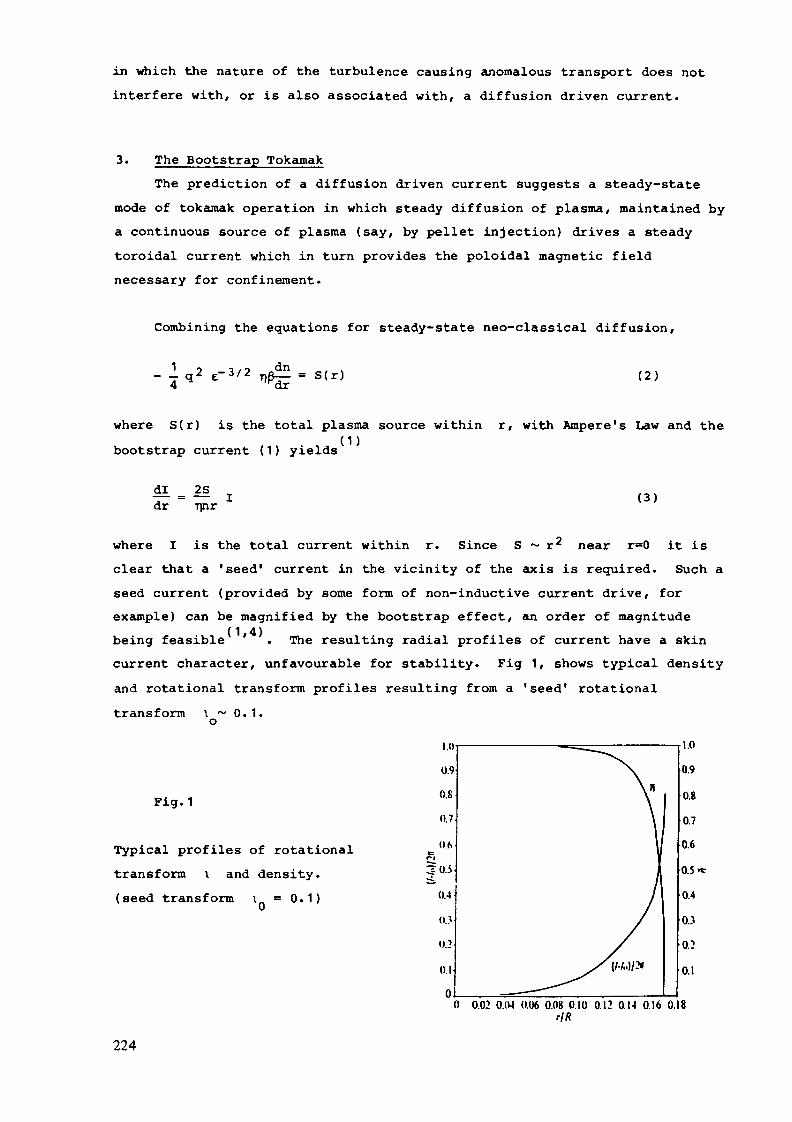
in which the nature of the turbulence causing anomalous transport does notinterfere with, or is also associated with, a diffusion driven current.
3. The Bootstrap TokamakThe prediction of a diffusion driven current suggests a steady-state
mode of tokaraak operation in which steady diffusion of plasma, maintained bya continuous source of plasma (say, by pellet injection) drives a steadytoroidal current which in turn provides the poloidal magnetic fieldnecessary for confinement.
Combining the equations for steady-state neo-classical diffusion,
^q2£-3/2nß|=s(r) (2)
where S(r) is the total plasma source within r, with Ampere's Law and thebootstrap current (1) yields
dl _ 2Sdr nnr
(1)
(3)
where I is the total current within r. Since S ~ r2 near r=0 it isclear that a 'seed' current in the vicinity of the axis is required. Such aseed current (provided by some form of non-inductive current drive, forexample) can be magnified by the bootstrap effect, an order of magnitudebeing feasible ' . The resulting radial profiles of current have a skincurrent character, unfavourable for stability. Fig 1, shows typical densityand rotational transform profiles resulting from a 'seed1 rotationaltransform 0. 1.
Fig. 1
Typical profiles of rotationaltransform \ and density.(seed transform 0.1)
0 0.02 0.(M (1.06 0.08 0.10 0.12 O.M 0.16 0.18rIK
224

(4)Consideration of energy balance as well as particle balance showsthat the need for a continuous source of plasma can be dispensed with infavour of a centrally peaked energy source, as would occur naturally inthermo-nuclear burning - more acceptable current profiles result in thissituation. However this study depended on still more subtle features ofneo-classical thermal forces! More recent studies of a-particle orbitlosses indicate that the a-particles themselves could provide the necessaryseed current naturally in a burning plasma . In this case hollow currentprofiles appear necessary for mhd stability. These developments suggestthat a simple steady-state tokamak could be a natural mode of operation, butit is necessary to assess the mhd stability of these bootstrap equilibria.
4. StabilityThese large aspect ratio studies tend to predict skin currents or
hollow current profiles whose mhd stability has not been widely explored,although often thought to be unfavourable.
Further, constraints on q, such as the Kruskal-Shafranov limit, orinternal kink stability, imply, as a result of the link between toroidalcurrent and pressure gradient in a bootstrap tokamak, ' a ß limitß~(a/R)3/2, irrespective of ballooning stability. However INTOR designsinvolve tight aspect ratio, shaped cross-section toroids and thesegeometrical features may significantly modify the equilibrium and stabilityproperties of a bootstrap tokamak.
5. ProposalIt is proposed to examine realistic bootstrap equilibria in a tight
aspect ratio shaped cross-section appropriate to INTOR and to investigatethe mhd stability characteristics of their equilibria.
6. ConclusionThe neo-classical bootstrap concept offers the possibility of a simple
and natural steady-state mode of tokamak operation. There has, however,been no observation of the effect in tokamaks, nor is it known how toachieve the conditions under which it would appear. Nevertheless it isproposed to calculate self-consistent bootstrap equilibria in a tightaspect ratio torus characteristic of INTOR and to examine the mhd stabilitycharacteristics.
In short, this innovation would lead to a most important improvement inthe tokamak reactor concept but its feasibility is uncertain.
225
REFERENCES
1. R.J.Bickerton, J.W.Connor, J.B.Taylor Nat. Phys. Sei. 22g, 110 (1971).
2. J.T.Hogan. Nucl. Fusion 2J_ 365 (1981).
3(a) M.C.Zarnstorff & S.C.Prager. Phys. Rev. Letts. 5_3, 454 (1984)(b) J.D.Treffert & J.L.Shohet., Phys. Rev. Letts. j>3_ 2409 (1984)
4. D.J.Sigmar & P.H.Rutherford Nucl. Fusion, 13, 17 (1973)
5. Ya Kolesnichenko, D.Anderson, M.Lisak & H.Wilhelmsson. Phys. Rev.Letts. 53 1825 (1984).
226

P.3.10
ÜCIIR A1TD BOOTSTRAP CURRJOT FORSTATJ TOKAIIAK RECTORV.V.Parail
Possibility of ECHR and "bootstrap current use for steady-state version of IÎITOR is considered. Recently £l,2j it was shownthat 0t -particles - the product of therrao-nuclear reaction -are responsible for priming current in the centre of plasma co-lumn due to asayraetric radial displacement of <*^ -particles withdifferent Vn . Priming current is very important for steady-state regime. The idea is very much attractive, but detailedconsideration is required. The point is that radial asymmetryof o( -particles (just as in the case of conventional bootstrapcurrent) is proportional to B* in the region from v.'here c^ —particles originate. Therefore generation of ß& "from "sero"can't be achieved. This problem is not discussed hoz'e, Insteadwe consider conventional method of bootstrap current use - pri-ming current initiation by means of J3JCH waves in the centre ofplasnia column. JCH waves are the most adequate for this purposedue to their unique property of local action on plasma. All theother methods though being more effective result in '.vide currentprofiles. It is to be noted that ECH waves can be used as wellfor central plasma heating.
Consider at first conventional bootstrap current scheme inthe simplest hydrodynamic model under the assumption that trans-port coefficients are neoclasical {"3-4"! • To describe bootstrapcurrent the following equations are used
227

where
together with Maxwell equation end continuity equation
where S( 2.) is the particle source,Let us assume that the force P(r) is due to ICH waves, and
is localized vrithin the region r rQ < <. a. Then for r < rbootstrap current J can be neglected and J~0 = 9 QH CH* v/lie~re y,.'cj| - is the efficiency of current drive by means of ^GHwaves, the expression for it being well known £5_j • ?or r > rQJQ » 0, B £.(r = rQ) = •—- T, X> .In stationary case it follows from (1-3): 7
(5,Equations (4,5) describe plasma density and poloidal magneticfield radial distributions versus v/ource _f}ower. Besides that,plasma parameters are to fit jSrusfeal-Shafranov equilibrium con-dition
It follo7/s from (4) that bootstrap current give rise tomagnetic induction Bg_. V/ithout account for J^ its value obta-ined from relation ( /) is not far from equilibrium oneand further detailed calculations are necessary. Consider now2q.(5). It is obvious that the case of small initial current,when 6>e(a) *3> G>£- L^y ~ -^- °^ ±a the most attractive.Ilov/over it follow« from (5) that in this case 6, '- c;-:p (r) andmagnetic induction is forced out to plasma column periphery(v/e do not consider here the exotic case when S(r) is picked
228

strongly at the axis). This is due to the strong dependence ofneoclassical diffusion coefficient on B^. • It can be easily soenfrom (4« 5) tiiat plasma density depends exponentially on r and S(i.e. is badly controllable). This is unacceptable from steady-state reactor point of view. However it is known that in modernexperiments plasma diffusion is anormalous. In what follows weintroduce the simplest model of anoC-malous diffusion in equati-ons considered, associated with electric fields fluctuations.liquation (1) with account of such electric fields takes theforci:
« . - . . h (6)where v^ and £-^_ - are plasma, density and 3Z fluctuations res-pectively. Assuming that electrostatic oscillations with «,~ 0
r— ~- nare responsible for anoraalous diffusion, we obtain 2 ^ 2 ,\=?±.z j- Then from continuety equation we get
Substituting (7) in (6) we obtain
where ^ c\^ N T S7 J EÙ. «14 > ) ^ > - averaging over sta-tistical wave ensemble» It can be easily seen that in this case
changes for ^ f
6, = p.V/ith the large parameter £ QQ^ —r^ (which by theorder of magnitude equals to the ratio of skin time to particlelifetirr.'3) equations for narTietic induction and plasma densitycan be decoupled. I7amely, plasma density in this case is gover-ned by the following equation:
00)whereas magnetic induction B can be obtained from q.(5). In
229

this case plesma parameters are no more exponentially dependedon S. Therefore bootstrap current can be considered as realisticsupport in for current drive in the steady-state tokamak-reac-tor. One of the main advantages of bootstrap current is that itdoes not require considerable power expenditures (with excepti-on of priming current initiation). However prior to practicalapplication of the method several problems are to be solved.Among them - the problems associated v/ith anormalous transporteffects on bootstrap current pick value and its radial distribu-tion. Detailed study of L2ID stability versus initial current andparticle source parameters is also necessary.
R2F3RJ2ICI3S
1. Ya.I.Kolesnichenko et al., ITucl.Fus., v.20, 1041 (1938).2. Ya.I.Kolesnichenko et al., Pizika Plasmy, v.4, 803 (1983).3. B.B.Kadontsev, V.S.Shafranov. Proc.Int.Conf. (Lladison,
1971), v.2, IAJIA, Vienna, 479 (1971).4. R.J.Bickerton, J.\7.Connor, J.B.Taylor, Nature, Phys.Sci.,
v.229, 110 (1971).5. C.F.P.Cordey, K.J.Fisch, IIucl.Fusion, v.21, 1549 (1981).
230

P.3.11
CURRENT DRIVE WITH RELATIVISTIC ELECTRON BEAM INJECTIONA. MOHRI (Institute of Plasma Physics, Nagoya University, .Nagoya)M. Tanaka (Institute for Fusion theory, Hiroshima University, Hiroshima)T. Michishita (College of Liberal Arts, Kyoto University, Kyoto)
Direct momentum injection of relativistic electron beam (REB)into tokamak has been considered a highly efficient method to drivethe non-inductive toroidal current. This method has been provensuccessful to form REB rings in low toroidal fields[l] and to drivethe current in a small tokamak [2], However, there is needed furtherstudy when REB is injected into a large tokamak like INTOR. Key issuesfor study are:1. Useful trapping mechanism of injected REBThe orbit of an injected beam is affected by the electro-
magnetic self-field and also by.other fields of the tokamak.The return current induced at the injection makes the beambehaviour more complex. Thus, the orbit becomes much differentfrom the one imagined in the frame of single particle picture.In other words, there may be a potential mechanism making beamdrift deep inside the plasma across the closed magnetic surfaces.*This possibility was proven by computer simulation using a newlydeveloped macroscale particle 3D-code as presented later.
2. Optimization of parameters of REBInteractions of an injected REB with the plasma and/or with
the REB itself change the distribution function of the REB withthe passage of time. Thus, the condition of REB injection shouldbe optimized in order to realize highly efficient current drive.*Dynamics of an injected REB was analyzed numerically and theresult shows that current ramp-up by REB injection is promising.
3. Development of efficient injection methodAn REB injection system applicable to a large tokamak should bedeveloped. The system is required to have a performance whichassures reliable operation and excellent maintainability.*Some discussion on the system will be given later based onexperiences gotten so far.
Global simulation of injected REB by macroscale particle code tosee the trapping
Large scale behavior of the injected relativistic electron beamis investigated by newly developed macroscale particle code (submittedto 0. Corcp. Physics, 1985). In this simulation both plasma ions,electrons and beam electrons are treated as charged particles beingcoupled with full Maxwell equations. In order to deal with large scalephenomena, implicit time differencing method is employed. Beforesimulation runs are started, a rectangular simulation box (no toruseffect so far) is filled with the same number of collisional plasmaions and electrons. In the following runs, the plasma system isimmersed either in the applied toroidal and vertical magnetic field(corresponding to the current start-up phase: case A), or in theclosed magnetic field produced by the plasma current itself (corre-sponding to the current sustainment phase: case B). Then, the REB is
231
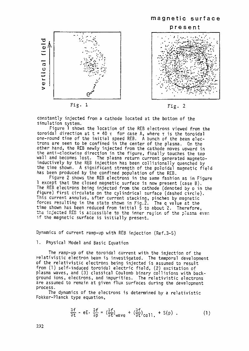
magne t i c s u r f a c ep r e s e n t
•u .öCOü
CD>
• . • /...••.f. »...- '...:.-;.'-<-/.cvts.-;. .':.. % *. i *'^-• • 't~'"'•*-. '-ÄlÖfe';ï''fc-&..:.'^:JÏJx X*:\ • •'•
Fie. 1 Fig. 2
constantly injected from a cathode located at the bottom of thesimulation system.Figure 1 shows the location of the REB electrons viewed from the
toroidal direction at t = 40 T for case A, where T is the toroidalone-round time of the initial speed REB. A bunch of the beam elec-trons are seen to be confined in the center of the plasma. On theother hand, the REB newly injected from the cathode moves upward inthe anti-clockwise direction in the figure, finally touches the topwall and becomes lost. The plasma return current generated magneto-inductively by the REB injection has been collisionally quenched bythe time shown. A significant strength of the poloidal magnetic fieldhas been produced by the confined population of the REB.
Figure 2 shows the REB electrons in the same fashion as in Figure1 except that the closed magnetic surface is now present (case B).The REB electrons being injected from the cathode (denoted by o in thefigure) first circulate on the cylindrical surface (dashed circle).This current annulus, after current stacking, pinches by maaneticforces resulting in the state shown in Fig.2. The q value at thetime shown has been reduced from initial 5 to about 2. Therefore,the injected REB is accessible to the inner regier, of the plasma evenif the magnetic surface is initially present.
Dynamics of current ramp-up with REB injection (Ref.3-5)1. Physical Model and Basic Equation
The ramp-up of the toroidal current with the injection of therelativistic electron beam is investigated. The temporal developmentof the relativistic electrons being injected is assumed to resultfrom (1) self-induced toroidal electric field, (2) excitation ofplasma waves, and (3) classical Coulomb binary collisions with back-ground ions, electrons, and impurities. The relativistic electronsare assumed to remain at given flux surfaces during the developmentprocess.
The dynamics of the electrons is determined by a relativisticFokker-Planck type equation,
3t..r of / of \- eE- T-- = (r-r)3p 'coll S(p) (1)
232
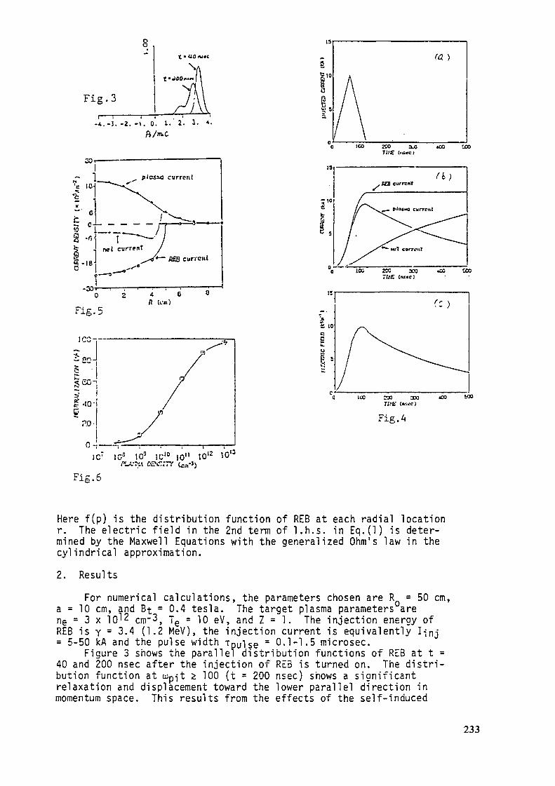
Fig. 3
-A.-J. -2. -\. 0. L.' 2. 1. •*•
30 r-
plcsao cwrrcnl
current
-30-»0 Z
Fig. 5 (OB)
JC: 10° 10° iü10 10" 1C'2f"_X-ri\ eu\.T;7Y (Ca-Jj
Fis. 6
3 5'
ico zoo xoT/;C (IIMO
•oo uo
r
o8— lou zx xo «oo tcorue («te;
a io'£-,5Cu
s:
230 XOn.'t: <«K«)
Fig.
100 WO
Here f(p) is the distribution function of REB at each radial locationr. The electric field in the 2nd term of l.h.s. in Eq.(l) is deter-mined by the Maxwell Equations with the generalized Ohm's law in thecylindrical approximation.2. Results
For numerical calculations, the parameters chosen are R = 50 cm,a = 10 cm, and Bt = 0.4 tesla. The target plasma parameters arene - 3 x 10^2 cm"3, Te = 10 eV, and Z = 1. The injection energy ofREB is y = 3.4 (1.2 MeV), the injection current is equivalently I-;nj= 5-50 kA and the pulse width Tpuise = 0.1-1.5 microsec.
Figure 3 shows the parallel distribution functions of RE3 at t =40 and 200 nsec after the injection of RE5 is turned on. The distri-bution function at Wp-jt 2 100 (t = 200 nsec) shows a significantrelaxation and displacement toward the lower parallel direction inmomentum space. This results from the effects of the self-induced
233

DC electric field and the excitation of the plasma waves. Neverthelessthe current of REB still remains approximately constant in time due tothe relativistic effect as is shown in Fig.4(b). The net currentincreases gradually together with decreasing in the plasma currentinduced by the return DC electric field (Fig.4(c)). The turn-on timeof the net current is determined by the plasma skin time. This effectis also pronounced in the spatial profiles of the currents as isshown in Fig.5. It is noted that the neutralization of the currentis very high when REB is injected into the target plasma with ne >10^2 cm" 3 with the pulse width much smaller than the skin time (Fig.6).
In conclusion, the current drive with the injection of RE3 ispromising in spite of the relaxation in momentum which is caused bythe slef-induced DC electric field and by the excitation of the plasmawaves.
Injection systemThe injection system of REB is mainly composed of a head of beam
ejector, a transmission line and a high voltage source with itscontroller. The transmission line and the high voltage source arecommercially available even in the present stage of technology if thevoltage is lower than 1 MV. The component which should be developedis the electron beam ejector. To produce energetic electrons, acombination of cold cathode and plasma anode was tested [2], butstrong production of impurities from the cathode polluted the mainplasma. Therefore, the future beam ejector must adopt a hot cathodewith a high electron emissibility which reduces the necessary cathodearea. The emissibility available at the present is about 10 A/cm^.Therefore, the input power of 10 MW level is easily attainable onlywith a single beam injector. In the case of the hot cathode, ionbombardment on the cathode surface is not necessary, so that thelife of cathode may be much prolonged. This would promise the goodmaintainability of the system.References[1] A. Mohri et al., Experiment on REB-RING-CORE SPHERATOR (SPAC-VII),Proc. 10th Int. Conf. Plasma Phys. & Controlled Nuclear Fusion
Res., London, 1984 (IAEA, Vienna, 1985) Vol.3, p.395.[2] H. Tanaka et al., Preliminary Experiment on Electron Beam Injection
for Tokamak Current Drive, Jpn. J. Appl. Phys. 24_ (1985) L644.[3] T. Michishita and H. Nishihara, Relaxation of Runaway Electron
Energies due to Excitation of High Frequency Waves, 0. Phys. Soc.Jpn. 52 (1983) 2371.
[4] T. Michishita, Numerical Calculation on Dynamics of Injected REBwith Excitation of Plasma Waves, (in Japanese) Data ProcessingCenter, Kyoto Univ. (1985).
[5] M. Yamagiwa, T. Michishita, and M. Okamoto, Numerical Calculationon a Mechanism of Current Sustainment during LHCD, J. Phys. Soc.Jpn. 54 (1985) 2146.
234

P.3.12
Ion Bernstein Wave HeatingT. Watari
Institute of Plasma Physics, Nagoya University
1. Present StatusIon-Bernstein wave heating was investigated in JIPP T-II-U
tokamak with a major radius R = 91 cm and a minor radius a = 23cm. ' Fig. 1(a) shows a schematic of the IBW antenna, which is aBe loop antenna with poloidal Faraday shield to simulate a EZ-waveguide antenna.
The wave-power absorption is provided by the third ion-cyclotron harmonics of deuteriumlike ions. In JIPP T-II-Uexperiment, He is introduced to the hydrogen gas. A 40 MHztransmitter has been used at 1.8 T toroidal field BQ which isgiven at R = 91 cm. The calculated wave-power depositionprofiles are shown in Fig. 1(b) for the typical plasma parametersfor the optimum field BQ = 1.8 T and for the off-axis case BQ =1.89 T. The representative traces of the Ohinic discharge used inthe experiment are shown in Fig. 1{c), I ~ 110 kA [q(a) = 4.0],~ne = 1.5 x 1 O1 3 cm"3, Te0^ 700 eV and T^Q 300 eV. In Fig. 2,typical ion-heating data obtained in a hydrogen discharge with~ 60 kW of the loaded RF power. The hydrogen-ion temperatureevolution monitored by a perpendicular charge-exchange analyzeris shown as open circles in Fig. 2(a) [T^ = 300 —?• 800 eV]. Thevelocity distribution appears to be Kaxwellian with nosignificant tail being observed. The T^ charge-exchange datataken in a similar plasma discharge through a tangential port areshown with open triangles in Fig. 2(a). A significanttemperature difference between T^j_ suggests the presence of adirect hydrogen-ion heating process.
235

The observed ion heating depends strongly on the magneticfield as shown by Fig. 3(a), where the perpendidicular ion-heatingquality factor is plotted as a function of magnetic field withuse of data in the 60-80 kW power range. The ion-heating qualityfactor peaks near BQ = 1.8 T, corresponding to the (3/2)J~IH layernear the center of the plasma (R = 93 cm). At this field level,the hydrogen harmonic resonance layer fl^ and 2^H are completelyoutside of the plasma and therefore the usual resonantacceleration of hydrogen ions can be ruled out. An addition ofhelium ions that can provide 312He resonance absrption at thesame location has not produced significant changes in the ionheating as shown in Fig. 3(a). The measured ion-temperatureincrease as a function of the RF power for various He minorityconcentrations. T.J , appears to go up linearly with RF power. Onthe other hand, T ;/ show a very nonlinear rise which appears tosaturate at high power range.
2. IBW Heating MchanismIn order to compare the observed heating results in JI??T-
IÏ-U with theory, a series of model ion power-balancecalculations was performed using tokamak transport codes. If oneassumes a direct power deposition into the hydrogen ions, the T^xrise time matches well with the experimental value (solid line inFig. 2(a)). If an indirect heating through collision is assumed,the rise time is slower similar to the T^x/ rise time. Themagnetic field dependence of T^j_ can be reproduced, if the raysare assumed to be absorbed at the {3/2)Jf2^ layer by thecomponent with an effective radial absorption spread of ~ 4 cm.This result is shown by solid curve in Fig. 3(a). Finally thecalculated ^Tj_, and ^TJ as a function of RF power as solid anddashed curves in Fig. 3(b). The T - T-lt difference increases
236

(o)
10 cm Minor A x i s
miter
IBW Antenna (Type HI) 11 Feed
10
1C 15RAOIUS(cm)
20
100
50
ICCT I M E (msec)
200
FIG. 1. (a) Schematic of IBW £,-loop antenna, (b)Power déposition pronies of IBW for 5o—1.8 T (solidcurve) and for fic-l-89 T (dashed curve). r/0-300 eV,7,0-700 eV. n,- 1.5x10» cm'3, 10% Ht, /-40 MHz,and /V—60 kW. Inset: Rays with / I N — ±3 released fromeach poloidal position for 5C— 1.8 T case, (c) Typical Ohmicheating current and line-averaged plasma-density time evo-lutions.
100 120 140TIME(msec)
£ icrn-2r>
o 10CE
-ID'3
'KT
(b)
2 3 4E j ( k e V )
FIG. 2. (a) Ion-temperature time evolution with andwithout rf. Inset: rf power (loaded). Solid curve: Simula-tion with the assumption of direct hydrogen heating, (b)Charge-exchange raw signal before and during rf. B«- 1.8 T,lf - 110 kA, n0 = 1-5 x 10'3 cm~J, and /- 40 MHz!
£ 12-
40 60RF POWER ( k W )
FIG. 3. (a) Ion-heating quality far.cr, ir,j.no/^rf(«v
x 1013 cm"3/kW), as a function of toroidal magnetic field,£0(R -91 cm). He concentrations as labeled 7-40 MHzand ?rf(loaded)-60-80 kW. Solid curve: Simulation valuewith the assumption of AKpower deposition) = 4 cm at•J-ÛH layer, (b) A7U and AT/« vs rf power for various He-H gas-mixture concentrations (as labeled). 7-40 MHz andBQ— 1.8 T. Solid and dashed curves are simulation valuesfor A TU and A T",«, respectively.
237

with power, since the higher temperature means the lowercollisional coupling. The observations are generally consistentwith presence of a direct hydrogen-heating process at the 3/2 52. Hlayer.
An ion-heating process at 3/2#H has been observed inparticle-simulation investigation of IBW heating. This non-linear process due to a type of stochastic acceleration at 3/2IÎHcan directly heat the bulk ion distribution at' relatively lowpower threshold (>15 kW for the JIPPT-II-U experimentalcondition). Also a possibility of nonlinear Landau damping at(3/2).$ has been pointed out showing that this process can occurat low power level. The absorption mechanism of nonlinearprocess may be attractive, since it can be utlized to heatdirectly the bulk- distribution of the majority fusion ions forbetter thermalization and confinement. It is therefore importantto undersand fully this (3/2)Jl - heating mechanism for bettercntrol and extrapolation toward further heating experiments.
3. Modeling of loading I3W by waveguide launching andestablishment of experimental data basesBecause of lower-hybrid wave like polarization and
propagation properties at the antenna-plasma interface, awaveguide coupler similar to the one used for lower-hybridheating can be employed. This waveguide coupler is tall butnarrow and may fit well between toroidal field coils and mayprovide possibility to reduce the antenna-plasma interaction.
Reference1) M. Ono, T. V.'atari et.al.: Phys. Rev. Lett. 54, 2339 (1935)
238

P.3.13
"OHMIC" IGNITION ON INTOR
D C Robinson and T N ToddCul ham Laboratory, Abingdon, Oxon, UK
UKAEA/Euratom Fusion Association
Summary
We propose four principal features which individually have goodexperimental and/or theoretical backing and could permit INTOR toachieve ignition and sustained burn with ohmic heating and a smallamount of radio frequency heating. These are
(i) enhanced ohmic heating power input by increased trappedparticle fraction,
(ii) improvement of confinement by achieving a non-thermalelectron distribution,
(iii) increased ß limit in the burn phase by achieving p /ppeaked in the region of favourable curvature,
(iv) use of localised heating or current drive to stabilise lowm modes.
1. Improvement of confinementConfinement substantially better than the neo-Alcator (OH) or
L-mode (auxiliary heated) seal ings can be achieved by distorting theelectron distribution function using either ECRH or LHH when thecollisionality of the plasma is sufficiently low [1,2]. This regimeof operation gives a confinement time some 2-3 times better than thatexpected from such scaling laws. PIT and ASDEX results suggest thatthe power needed to produce the appropriate distortion of theelectron distribution function is comparable to or less than theohmic heating power. This power could be applied using a developmentof the existing 140 GHz gyrotrons (ECRH) or equivalent lower hybrid
239

sources in plasmas at densities a little below those requiredultimately for the burn phase. We would predict that instead of theL-mode or neo-Alcator confinement of a few seconds at 10 MA, a timein excess of 10 seconds could be achieved with the present INTORdimensions.
2. Increase of ohmic powerIt has been shown theoretically and observed experimentally for
ECRH plasmas with significant anisotropy of the plasma pressure thatthe electrical conductivity of the plasma is substantially decreased[3]. With T /T = 2 and the INTOR aspect ratio, the enhancement inj. nthe resistivity is 3-4 times. A similar factor of up to four isimplied by ECRH results on CLEO with the resonance on the outsideflux surfaces [4]. Thus by enhancing the trapped particle populationit is possible to enhance substantially the ohmic input power. TheCLEO 28 GHz results show that anomalous trapped particle populationswith large T /T are not incompatible with good energy confinementtimes: electron neo-classical losses would have to be inordinatelyenhanced to compete with the observed anomalous losses even with"high confinement" operation. With the enhanced resistivity andI ~ 12 MA made possible by a slight increase in elongation, there issufficient ohmic power when combined with the improved confinement tocome close to ignition. A zero dimensional model of the ignitionprocess reveals that for the above improvements, ignition is achievedwith 8 MW of radio frequency power including a safety margin of a twofold enhancement in Bremsstrahlung radiation, with n~ 1.5 1020m~3,B ~ 5T and ß. ~ 5%. The burn was stabilised using a ß limitscaling for the confinement of the form
with ß 40% larger than the Troyon value. The arbitrary choice ofC
this soft type of ß saturation to stabilise the burn causes aconfinement degradation which inhibits the ignition unless the ßlimit is significantly higher than ßTrovon-
However if the non-thermal type of high confinement mode followsthe same trends as the divertor related H-mode it will suffer very
240

little confinement degradation until the ß-limit is encountered, asseen in ASDEX and PDX. Taking the high confinement mode to scalelike the L-mode [4] but with an enhancement factor ~ 3.0 until the ß-lirni't is encountered, an ignition scenario with a = 1.2m, R = 5.2m,K = 1.9, ô = 0.48, q = 2.7, I = 12.3MA, B = 5T is possible, producinga peak n<T>-c ~ 180 x 1013 keV s cnr3 with a ß .. (GA) of 5%. This
^ I I Lr
scenario demands a peak power input (OH + RF) of ~ 18 MW.
3. ß-limit enhancementAs shown above this is only necessary if progressive saturation
towards a ß-limit is anticipated, otherwise confinement at ignitionis insensitive to the ß-limit and raising it will just increase theburn phase fusion power (or supply a margin for ash contaminationetc). If required then, the device could have improved ß-limits ie ß> ßyro 0 ~ 5% by using a conducting wall/mantle to diminish andstabilise the free-boundary kink modes. In addition the anisotropyproduced by the radio frequency can be switched to the inside of theflux surfaces during the burn phase, by using a different gyrotronfrequency for example, so that it is in a region of favourablecurvature ie
?L = PQ (1 + n cos e), Ti < 0.
This would increase the ballooning mode stability limit by up to~ 50% [5]. This effect and high temperature effects also allow thecentral q (ie q ) value to decrease below unity, further enhancingthe ballooning limit. The higher plasma current allowed byincreasing the elongation to « 2.0 also contributes to raising theß-limit. There is good evidence from numerical codes and experimentsnow that the vertical position instability can be safely controlledat this elongation.
4. Mode controlOn present density limit scaling, namely I/N ~ I/Tta2< ~ 10~11* Am
for ohmically heated tokamaks (with a weak improvement usingadditional heating), INTOR can almost achieve its operating densitywithout a problem. However we propose that the radio frequency powerused for start up and to assist ignition with improved confinementand OH power is also used during the burn phase for control of theactivity at the q=2 surface by local current drive to increase thesafety margin for the burn sustainment.
241

Conceivably phased localised heating or current drive couldassist in achieving q < 1 by stabilisation of the 1,1 mode.
5. ConclusionsWe believe that the achievement of some or all of the above
features would permit INTOR to ignite with very small auxiliary powerrequirements supplied by high frequency RF. Clearly further work isrequired to show that a suitable combination of the above featurescan be achieved sel f-consistently in a reactor configuration.
At such high ß values it should be noted that it might bepossible to sustain the plasma current during the burn phase throughthe bootstrap effect, if the anomalous scattering process of theelectrons can be minimised sufficiently.
References[1] A C Riviere et al, Proc 4th Int Symp on Heating in Toroidal
Plasmas, Rome, 1984, p 795 Vol II.[2] F Soldner et al, Proc 12th EPS Conf on Cont Fusion and Pl Phys,
Vol II p 244, Budapest, 1985[3] CM Bishop, Culham Theoretical Physics Note TPN(84)12[4] T N Todd, Proc 2nd Euro Tok Wkshp, Saulx-les-Chartreux, 1983[5] CM Bishop and R J Hastie, Culham Theoretical Physics Note
TPN (85)9
242

Group 4
ADVANCED MAGNETICS
S. Shimamoto (Japan)G. Henning (USA)P. Komarek (EC)A.I. Kostenko (USSR)
243

1. INTRODUCTION
Based on the domestic discussions in each country, the participantbrought excellent innovations to this specific item. The total number ofthe innovations is 9: USA 1, USSR 3, Euratom 2, Japan 3. All the titlesare listed in Table 1. They can be grouped principally into twocategories: The first one contains the innovations which are aiming togive an impact to smaller reactor size. The second one containsinnovations improving superconducting magnets themselves.
Innovations on magnet system which are more related to machineconfiguration and maintenance have been discussed in working group 6 inthis meeting.
2. EVALUATION OF THE PROPOSED INNOVATIONS
2.1 Major content:
A majority of the innovations is based on the potential of theadvanced superconducting materials, under development now, to reachhigher maximal field, or to allow larger temperature margins. Togetherwith the potential of advanced structural materials with higher strength,this results in the possibility to increase coil current densities ormaximal field levels, both for TF and PF-coils. Further innovationsdescribe means which are supporting the possibility to apply the highercurrent density of field values. These means are the use of forced flowHe II and the use of internal superconducting switches. The grouptherefore decided to group those innovations together to one major one.
Three other innovations, namely the use of non-metallic structuralmaterial, the normal conducting inserts to TF-coil and thesuperconducting joints, have been treated seperately.
2.2 Means for realization of the major innovation:
The present designs are based on NbTi and Nb Sn as superconductorsand nitrogen alloyed stainless steel (304 LN, 316 LN) as structuralmaterials. As Table 2 indicates, the proposed increase on maximal field,or an current density, for the magnet design is based on the expecteddata of advanced superconductors and high strength steels, like manganesesteel.
245

All these materials are under development, thus their engineeringuseability within a decade can be considered as favourable.
2.3 Envisaged key parameters for magnet systems resulting fromthe major innovation:
Due to the fact that the different magnet parameters as field,current density, operating temperature, a.c. losses, dump voltage,mechanical load etc., are closely interlinked, the group has tried tosummarize the different combinations on possibilities for the coil datain Table 3. For TF-coils there exist either the possibility to increasethe peal field or the current density. To ensure this advanced data theincrease of dump voltage has to be accepted and subcooling of the He,perhaps down to He II, needs to be considered. For OH-coils the use of115-conductors can provide higher maximal fields there, while EF coil caneither be built out of NbTi or also out of Mb Sn if the desired coolingchannel length calls for a large temperature margin, not available withNbTi.
For some designs ultra high field coils for plasma shaping have tobe foreseen in the OH-space region. Due to their DC operation mode andtheir pure solenoidal mechanical load condition and size, field levels upto 18 T seem to be not out of scope.
To support the major innovation f high current density in thewindings without the need of very high discharge voltages in case of fastenergy dump, one innovation suggests to use superconducting switches withtemporary operated leads.
All members of the group favoured forced flow cooling as the basisfor the winding design, due to the advantages for electrical andmechanical integrity. In that case subcooling of the far below 4.2K is afurther possibility to improve magnet data. If subcooling down to Hell(<2.16K) is desirable, present experimental investigations indicate thatforced flow is still a potential possibility, but the winding design hasto be somewhat different due to limits in channel length to few hundredmeters typically.
246

2.4 VALUE OF OTHER INNOVATIONS
2.4.1 Non-metallic Structural Materials
The use of the non-metallic structural materials in the magneticsystem structures are highly attractive. It would lead to substantialreduction of eddy current losses in the cold structures and facilitatethe poloidal field penetration. An additional attractive feature is theelimination of considerable amounts of highly activated steel in themagnetic system. There is a limited data base on the fabricationtechnology and performance of non-metallic materials in the magneticsystem conditions (cryogenic temperature, high stresses, cyclic load,complicated three-dimensional force conditions). To prove thefeasibility of non-metallic materials for the tokamak use, appropriatedevelopment work is required and strongly recommended.
2.4.2 Additional Non-Superconducting TF Coils
The proposal provides the possibility to increase the toroidal fieldup to 6.5 T on the plasma axis with existing superconducting magnettechnology. Additional coils improve the toroidal field ripple and maybe used to vary slightly toroidal field required for burning temperaturecontrol. The feasibility of the coils is evident, the influence on formsconfiguration needs to be studied. There are no substantial improvementsenvisaged for the future tokamak reactor if there would be no urgentnecessity for burning temperature control by toroidal field variation.
2.4.3 Joints in Superconducting Coils
The potential advantage of this proposal is the provision of thepossibility to manufacture the large poloidal field coils in a factoryand to amplify their assembly. The main drawbacks are the additionalheat losses and the requirement of large space for joint area volume,with designs known so far. To achieve the reasonable level of heatgenerated in joints, it is necessary to develop joint with a resistanceof about 10 ohm which is a difficult task. If no genius designideas can be developed to minimize the mentioned disadvantages, the netbenefit of this proposal might be questionable.
247

3. QUALIFICATION OF IMPROVEMENT. FEASIBILITY AND IMPACT OF THE INNOVATIONS
The discussed results of qualification on the innovations weresummerized on Table 4. Additional explanations on feasibility and impactsare as follows.
High current density and high field coils: The new materials such asNb Al, NbN which have been prepared in laboratory scale areintrinsically showing very high critical field at practical currentdensity over 20 T. The application of these materials to magnet dependsonly on industrial production techniques and performance of conductorsresulting from that development. Thus, feasibility looks good.Forced Flow Cooling with Hell: A lot of investigation on thermalbehaviour of stationary superfluid helium have been carried out. Thethermo-hydraulic investigations of forced flow Hell are proceeding wellin different countries indicating that successful development inreasonable time could be expected.
Superconducting switches: There were some development works ofsuperconducting switch for low current application several years ago Theresult showed the long term stability of the switch in superconductingstate is a key technical problem. Therefore, the feasibility dependsstrongly on long term practical improvement in this area.
Non-metallic structural materials: The idea for extensive use ofsuch material as fiber reinforced plastics have been proposed since longtime ago. However, there has been limited use so far due to insufficientmechanical properties for this application and less advanced fabricationtechnique for thick wall structural components. In addition, to getreliable mechanical data for engineering use at AK is not easy due tothe anisotropic characteristics and identified differences of the datafollowing laboratory samples in comparison to practically fabricatedcomponents. Much effort should be spent for the development.
Additional non-superconducting coils: There is no apparent technicaldifficulty to construct such coil. The question is the balance betweenthe benefit for ripple control and complication of torus configuration.
Superconducting joints: Such joints could be used only under theconditions of limited additional space requirement, low Joule losses in
248

spite of demountability. Therefore, in order to get out real advantagesfor tokamak concept, very ingenious design would be required for which noindications are existing yet.
4. RECORD OF DISCUSSIONS
Nothing of sophisticated or exotic innovation such as hightemperature superconductor was proposed. All the proposed innovationsare reasonable and can be extrapolated from present state of art.
The comments on priority and feasibility have been accepted in thegroup without objections.
Table 1: List of Proposed Innovations
1. High Current Density Conductors - by C. Henning (USA)2. Superconducting Switches for TF System
Quench Protection Discharge - by A.I. Kostenko, N.A. Monoszon,R.E. Spevakova (USSR)
3. Additional Non-Superconducting TF Coilsby A.I. Kostenko, N.A. Monozon, S.N. Sadakov A.S. Simakov (USSR)
4. Nb Sn Conductor for all the PF Coils instead of Nb-Ti Conductorby Yu. P. Batakov, V.V. Kalinin, A.I. Kastenko (USSR)
5. High Field Superconductors for Central Solenoid Applicatonby A.F. Knobloch, P. Komarek (Euratom)
6. Joints in Superconducting Coilsby A.F. Knobloch, P. Komarek (Euratom)
7. High Field and High Current Density Superconducting Coilby T. Ando, F. lida, Y. Sanada, K. Toyoda, Y. Itou, S. Shimamoto(Japan)
8. Forced Flow Superfluid Superconducting Coilby Y. Sanada, F. lida, K. Toyoda, Y. Itou, S. Shimamoto (Japan)
9. Non-mettalic Structural Materialsby H. Nakajima, K. Yoshida, S. Shimamoto (Japan)
249

Table 2; Potential impact of advanced materials on masnet data
Items Present designbasis
Design basis due to theinnovation
peak field 12T 16 ~ 1ST
current density at 12T 25A/mm2 35 -40A/ mm*
S.C. material TF-coils (Nb+Ti)3SnTa
Nb3AlNbN
and others
PF-coils NbTi Nb3Sn+ NbTi
Structural materials 304LN316LN
High manganese steelHigh Cr-Ni steels
Table 3: Possible Range of Coil Data Due to the Major Innovation
TF Coil
Priority I Priority IIPF Coil
Current Density ~40A/mm ~25A/mm 2 -30 A/mm
Peak Field 12 T 16 T 12-1AT for OHCoil
desirable fieldfor EF coil
Operating Temp 1.8 K-4.5K 1.8K-4.5K . 1.8K for OH coil
. large AT for EF coilbetween inlet & outlet
Dump voltage 20 kV 20 kV 20 kV
* Current Density defined in non-structural part of the coil cross section** by advanced structural material with advanced knowledge on stablization*** by advanced superconducting material
**** DC operated plasma shaping coil is expected to have a field over 1ST
250

Table A. Qualification of the Innovations
Unified Title of InnovationsAfter Discussion
High Current Density andHigh Field SuperconductingCoils
ClassifiedPaper No.
E.A.IE.A.AE.A.5E.4.7
Substance* Feasibility* Priority Purpose of Impact on Otherof Innovation Components
1 1 yes compact machine plasma physicspotential improve- 1st wall loadingments for plasma neutron shielding
Forced Flow SuperfluidSuperconducting Coils
E.4.8 yes supporting innov- see aboveation to the firstone
Superconducting Switches for E.A.2TF Coil System/QuenchProtection
yes supporting innov- see aboveations to thefirst one
Non-metallic StructuralMaterials
E.A.9 yes substantialreduction of AClosses in coldstructureslower activation ofmagnet structure
reduced require-ments on thecryogenic system
Additional Non-superconducting E.A.3TF Coils
no support to thefirst innovation,field ripple improvementfield ripple variationfor burn temperaturecontrol
configuration
toJoints in SuperconductingCoils
E.A.6 no facilitate assemblyand maintenance
space

E.4.l
TOKAMAK INNOVATION (IAEA)
Carl D. HenningLawrence Livermore National Laboratory
Livermore, California
E.1.1 High Current Density Conductors
SUMMARYIn spite of the inherent attractiveness of fusion power for producingelectric energy, the several reactor studies which use superconductingmagnets have not resulted in sufficiently economical designs. Therefore,for reactors, a prime issue is cost reduction by improving masseffectiveness to the value of 100 KW /ton. For near-term ignitionexperiments the current density of the windings must be increased to allow asmall low-cost experiment. This requires the following:
0 Doubling the winding current density at 10 T to 40 A/mm . The Largecoil Task (LCT) and MFTF-B have conductor pack current densities about220 A/mm at 8 T. Improvements in superconductor current densities andreductions in stabilizing copper can reduce future magnet weight bymore than a factor of two.
0 Tripling the design values of A.^ conductor design strain from 0.1$ to0.3$ (intrinsic strain of 0.3 to 0.9$) so that higher strengthstructural materials can be used with small masses.
0 Developing insulator and conductors that are resistant to radiation12 21 2damage up to 10 rads and 10 neutrons/cm . The resulting thinner
neutron shielding would reduce machine sizes and costs significantly.However, magnets must be designed and demonstrated to updatereliability at the higher neutron fluences and nuclear heating rates of
2up to 10 mW/cm .
Major advances in the quality (and cost per A«m) of superconductors camefrom experiences of fabricating superconductors on a repetitive productionbasis (e.g., for MFTF and MRI magnets), together with basic scientificstudies that have discriminated between extrinsic limits to conductor
253

performance (e.g., filament sausaging and prereaction) and intrinsic limits(e.g., fluxoid-microstructure interactions). These studies have given usmajor increases in working current density of a factor of two between theHigh-Field Test Facility (HFTF) and the Mirror Fusion Test Facility (MFTF)Nb_Sn coils. However, even the very best of today's commercial Nb_Sn
J Jconductors have intrinsic current densities about half that of the bestresearch laboratory conductors shown in Figure 1. Further potentialadvances are available if the strong flux-pinning shown by Nb-Ti can beachieved in Nb,Sn. For example, Nb-Ti conductors have flux-pinning forcesabout 60% of their maximum at 80$ of H 9, while Nb,Sn conductors have onlyGc. jabout 20$ at a corresponding value of H ». Such scientific considerationsof Nb^Sn indicate the potential to increase the current density of Nb_Snconductor by factors of 2 to 5.
NbN is a superconductor worth further study. It has critical field valuesof 20-40 T, the upper limit being twice that of Nb.Sn. Additionalattractive features of NbN are that the critical current is strain-independent up to rupture, the radiation tolerance is expected to be high,and the compound can be made on high-modulus carbon fibers. Very little isyet known, however, of the variables controlling J and H ?. If a conductorfabrication process were developed for this material, future reactors couldhave still better winding pack current densities.
Structural materials and processing technology are being developed forsteels with 1200 MPa yield strength and 200 MPa /m toughness at 1° K.Reviews of recent tokamak designs, as well as tandem mirror designs haveindicated that the use of stronger cryogenic structures can materiallyreduce the mass of "inert" structure and increase the space available foraccess to the fusion core. Emerging classes of structural alloys includethe Fe-Cr-Ni-N (shown in Fig. 2) and Fe-Mn-Cr-N austensities, with 4-Ktoughness/strength combinations at least 75% above those of currentstainless steels. There is a program in Japan and in the U.S. tocharacterize their mechanical properties, to develop welding-consumables,qualify production-welding processes, and to specify statistically-basedmechanical property design allowables.
As an example of the advantages of high-current densities, the TokamakIgnition/Burn Experimental Reactor (TIBER) was designed. In place of theusual ohmic heating coil, a high-field (14 T) plasma-shaping coil was used
254

FIGURE 1. Critical current vs. field for superconductors.
^ «00
12 200
100
XSSy^-NUCr T-'«- >s\X »irt»nWeft»»U J
12Cr-12NI-10Mn-CMo28Mn • IBCr - INc - 1Mb - 1C«
I I•00 «00
YfeU strength, •,1600
FIGURE 2. Yield strength and fracture toughness of austenistic steels,
255

to produce a modest indentation of the inner plasma profile. Such plasmashaping allows a 10J plasma beta to achieve ignition and burn in a 2.6 metermajor radius tokamak. All inner-leg components of the tokamak had to bekept as small as possible to preserve the flux configuration and limit themajor radius. Accordingly, both the toroidal field and plasma shaping (OH2equivalent) coil .had current densities above 40 A/mm . Structural stressesup to 550 MPa were calculated in the inner TF coil case. Neutron shieldingon the inner leg was limited to 45 cm, resulting in 8 mW/cm average (22mW/cm peak) nuclear heating in the superconducting TF coil windings.Important assumptions in the TIBER design were steady-state current drive,deep pellet injection for fueling , and a vented-port pumped limiter. Theresultant design had a direct cost of 963 M$, without contingency,escalation or R&D costs.
256

E.4.2
SUPERCONDUCTING SWITCHES FOR TP SYSTEM QUENCHPROTECTION DISCHARGE
Authors: A.I.Kostenko, N.A.Monoszon, R.E.Spevakova
In the modified design of INTOR TF coils (see Final inter-national report on Phase IIA (part II) chapter 12) the windingpack current density compared with the reference design isefficiently increased. There is a tendency to its furtherincrease. Here the current density in the stabilizer risesalso. For example, in 07 it is suggested to increase thecurrent density in the stabilizing metal up to 3 = 1.32x10⁴A/cm ,At the limits on the TKJ voltage (5 kV) and the maximum conduc-tor temperature rise (100 K) during protection energy dischar-ge the stabilizer current density growth requires to increasedischarge rate and the TFC system section number needed forprotection energy discharge correspondently. In table 1 J.thethreshold values of the discharge time constants and currentdensity in the stabilizer for different options of coil sepa-ration into sections are given. Helium evaporation rate due toheat input to current leads is also given.
Table 1.1.
Secti-onspercoil
3468
Totalsecti-on num-ber
3648729b
Dischargetime con-stant ,t • s
11.18.35.64.2
ftStabilizercurrentdensityA/cm2
1x1041.1&X1041.4x1041.63*104
•Heliumevaporationrate,I/hour2700360054007200
As seen from table 1.1.when outer breakers and hence statio-nary current leads for each section are used in the protectionsystem, .currentdensity growth is followed by considerableincrease of liquid helium consumption, which leads to compli-cation and higher cost of the cryogenic system.
257

To reduce helium consumption it is suggested to use super-conducting switches, series-alternating connected with coilsections instead of the outer breakers. Current into TPC systemis supplied through a pair of stationary current leads andprotection energy discharge is made through pulsed currentleads with reduced heat input, connected to superconductingswitches. The pulsed current leads may be of a detachable typeQr with thermal disconnects.
Estimation of superconducting switch parameters-is givenbelow. As in this case, superconducting switches, triggerrather seldom, then it is reasonable to define the supercon-ductor volume needed for their fabrication on conditions oftolerable temperature rise of switch material within thedischarge. Then, the superconducting volume I/ for all swit-ches may be estimated as follows;
2 & *
where C, , J - stored energy;Hi. , £. - discharge time constant;j, A/cm - operating current density'in superconductor;p, Ohm cm - superconductor resistivity at the normal0 state;U , J/cnr - superconductor enthalpy from heliumtemperature to tolerable value.
The estimated data for superconducting switches are givenin tablel.2.
Table 1.2.Superconducting switches data
(energy 25x10° J)Supercon-ductingswitchnumber
36487296
Dischargetime con-stantt , s
11.18.35.64.2
Sumsupercon-ductor.volume,V, m^0.0970.1120.1360.163
Supercon-ductorweight perswitch,k*
16.21411.310.2
Energylossesin switchesE/E
2.33X10"32.67x10~33.26x10"33.91x10"3
258

While estimating the data of table 1.2. the tolerable heatingtemperature for the switch superconductor is adopted 300 K,Whe" u
In principle the tolerable temperature may be raised up toTlimit = ^°° K» when U T e .Q0 K ex 1000 J/cur and the super-conductor volume required is varied proportionally to—0 5U respectively. • 2. H "2In/2/availability to get the value J f = 2x10'A Ohm/cmis shown experimentally on the models of NbTi foil supercon-ducting switches with currents up to 6 kA and resistance up to40 Ohm. This value has been used in the calculations. Infuture, new materials for superconducting switches with higher
• nvalues of l P may be expected, resulting in reduction of^ —1 —0 5specific superconductor consumption, proportional to j $> .In the protection energy discharge circuit, the damp
resistors may be connected in two ways:1) damp resistors shunt superconducting switches;2) damp resistors shunt coil sections.In the first case the currents of all the coil sections
are identical in contrast to the second version, when thecurrents aro not identical in a transient conditions. Thiscurrent non-identity in sections is explained by that of dampresistors shunting coil sections.
Coil to ground voltage may be twice lowered in both caseswith mid points of damp resistors being grounded. Such groun-ding may be stationary or be accomplished just beforedischarge by means of switches. Under stationary ground thereis no advantage of current identity in sections, as in thefirst case. At the same time grounding by means of switchesreduces safety conditions of protection energy discharge.
To realize the proposal some problems are needed to besolved:
to develop high effective superconducting switches with25-30 kA operating currents and to incorporate them intoINTOR TPC system design;to develop superconducting switch control system;
- to estimate safety conditions of the protection energydischarge system with superconducting switches.
259

References
1. Japanese Contributions to IflTOR Workshop, Phase IIA (Part 2),Chapter XII, JAERI, April, 1985.
2. Results of Investigations of High Specific Breaking PowerSuperconducting Switches. In: Proc. 7-= Symp. on Eng.Probl. of i-'usion Research 1977, pp.912-915.Auth.: Glukhikh V.A., Kostenko A.I«, -Monoszon H.A. et al.
260

E. 4. 3
ADDITIONAL NONSUPERUONUUCTIWG TP COILSAuthors: A.I.Kostenko, N.A.Monoszon, S.N.Sadakov,
A.S.Simakov
In the INTOR reference design toroidal field is limited bythe value 5-5 T on the plasma chamber axis, as the maximumfield on the Nb^Sn conductor of the TP coil should not exceed/\x1t T. The increase of toroidal field' is desirable from theview point of fusion power density increase and improvementof ignition conditions. One of the ways to increase the fieldis to use superconductors with higher critical parameters(Nb^Ge, V~Ga etc.), the fabrication technology of which inlarge magnets is not mastered yet.
To increase TP additional normal coils placed inside mainsuperconducting ones are offered to be used. Some approximateestimations made on base of the reference machine of theradial build are given below.
The schematic diagram of the additional coils is givenin fig. 2.1.• 24 additional coils are non-uniformly distributed over the
/azimuth. Radial coil size is 0.3 in and the azimuthal coil sizepis - 0.75 m. With conductor current density 3=0.8 kA/cm andthe filling factor of the coil section by the conductor ,A =0.6,the total current of additional coils is ^J= 26.10 A, whichcorresponds to field increase 1T at the plasma chamber axis.Thus, the magnetic field at the plasma chamber axis is increasedfrom 5-5 T to 6.5 T due to additional coils. In this case thevalue B grows by 1.95 times. The estimated resistive powerlosses in additional coils are 110-120 MW when for example bron-— Rze with electrical resistivity D & 2.2x10" Ohm. m is used asa conductor material. As additional coils are placed closerto plasma, than the main ones, the former influence greatlythe toroidal field ripple. The calculation shows, that withadditional coils placed as in fig. 2.1, the toroidal fieldripple is reduced from 1.1% to 0.65 on plaoma edge and from-0.1% to ~ 0.05/£ in the plasma center. Apparently, variationof additional coil configuration and the current ratio of thesecoils and the main ones may more effectively influence the toro-
261

idal field ripple. In this connection, further study are neededto reduce the main Ttf coil number while keeping ripple withinpreset limitation and not much changing the main coil sizes.This study should be made together with design work on addi-tional coil in-corporation into the torus structure, takinginto account its assembly and maintenance.
it is important to note the fact, that additional coils maybe used to vary ripple, required for burn temperature control,by means of current redistribution in them. Here, the effectof the variable magnetic field on the main TF coils conductoris lower compared with the case, when ripple variation is gotby means of current redistribution in the main superconductingTP coils.
In the outside machine region additional coils may be placedoutside the shield not changing its efficiency. In the center-post region the shield thickness is reduced. Taking into acco-unt possible decrease of the divertor layer thickness by 10 cm,the shield thickness is reduced by 20 cm, giving neutronfluence growth on the main coil superconductor. The additionalcoils themselves give some screening effect but with lowerefficiency, which is needed to be estimated. Apparently, newimproved materials should be used in the inner shield toprovide screening needed for superconducting coils with reducedshield thickness.
Another problem is incorporation of additional coils intothe torus structure and providing of their mechanical strength.Besides, it is required to choose insulation for coils andconductor material.
It is advisable to consider the possibility to placeadditional coils closer to plasma, for example, a liquid-lithium blanket may be used as a conductor. In this case,additional coil effect on toroidal field ripple would behigher and apparently their electrical power supply require-ments would be reduced.
262

Pig.2.1. Location of the additional nonsuperconducting TP coils
263

E.4.4
Nb.jSn CONDUCTOR FOR ALL THE PF COILSINSTEAD OP NbTi CONDUCTOR
Authors: Yu.P.Batakov, V.V.Kalinin, A.I.Kostenko
In the reference INTOR design the well-mastered supercon-ductor NbTi with high technological properties is used in thePP coils. In the modified INTOR design (see Final internationalreport on Phase IIA (part II), chapter 12) plasma, current isincreased up to 8 MA. In addition to, the duration of theinitial current ramp-up period is increased from 5 s to 13 sand additional heating time is increased from 6s to 10 s.The changes mentioned cause increase in inductor volt-secondsrequired and the central solenoid field from 'v? T to 9+10 Trespectively. Here, it is inevitable to use Nb^Sn instead ofNbTi in the central solenoid coils. This problem has beenalready discussed at the last INTOR sessions. The most pro-mising conductor for the central solenoid is IOCS - typeconductor, developed in recent years in the USA and used« inparticular, in the Westinghouse coil for LCT. One of the mainproblems of using such a conductor in the central solenoid isconnected with a small radius of the conductor bending at coilwinding; then the following scheme of coil fabrication willapparently be needed; winding - reacting - potting.
In ring coils tue fields may be 6-7 T and from this viewpoint Nb~Sn may not be used. At the same time, there is nolimit on Nb~Sn application, associated with the conductorbending at coil winding.
The main disadvantage of the WbTi conductor with forced-flow cooling, requiring its replacement for Nb-jSn, is asfollows: preliminary development of the ring coil design hasshown, that the minimum length of the cooling channel in themedium-size ring coils is Z = 500 m and in the larger-radiuscoils is Z = 1000 m. In the IcCS-type conductors helium flowrate is comparatively small and constitutes 0.2 m/s.Thus, during the total time of helium flow through the channel10*20 plasma pulses take place. And energy losses, includinglosses in composite wire and conduit due to variable magneticfields associated with these plasma pulses and helium friction
264
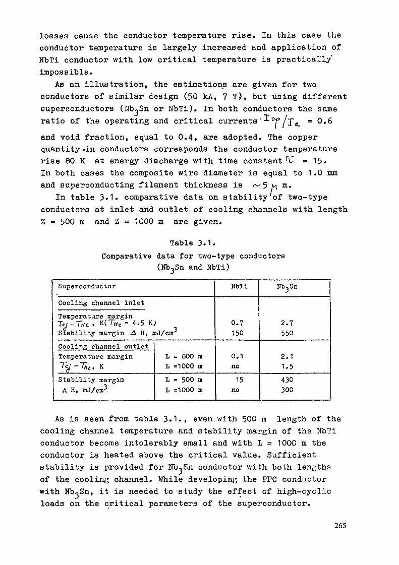
losses cause the conductor temperature rise. In this case theconductor temperature is largely increased and application ofNbTi conductor with low critical temperature is practically'impossible.
As an illustration, the estimations are given for twoconductors of similar design (50 kA, 7 T), but using differentsuperconductors (Nb-jSn or NbTi). In both conductors the sameratio of the operating and critical currents'-^0P/J^ = 0.6and void fraction, equal to 0.4, are adopted. The copperquantity -in conductors corresponds the conductor temperaturerise 80 K at energy discharge with time constant '"C = 15«In both cases the composite wire diameter is equal to 1.0 mmand superconducting filament thickness is ^ 5 M m.
In table 3.1» comparative data on stability of two-typeconductors at inlet and outlet of cooling channels with lengthZ = 500 m and Z = 1000 m are given.
Table 3.1.Comparative data for two-type conductors
(Nb-jSn and NbTi)SuperconductorCooling channel inletTemperature marginTe/-7~Ht . K(T«C= 4.5 K)Stability margin .a H, mJ/cnrCooling channel outletTemperature marginTy-Tat, KStability marginA H, mJ/cm .
L = 800 mL =1000 mL = 500 mL =1000 m
NbTi
0.7150
0.1no15
no
Nb^Sn
2.7550
2.11.5430300
As is seen from table 3. L, even with 500 m length of thecooling channel temperature and stability margin of the NbTiconductor become intolerably small and with L = 1000 m theconductor is heated above the critical value. Sufficientstability is provided for Nb^Sn conductor with both lengthsof the cooling channel. While developing the PPC conductorwith Nb^Sn, it is needed to study the effect of high-cyclicloads on the critical parameters of the superconductor.
265
E.4.5
HIGH FIELD SUPERCONDUCTORS FOR CENTRAL SOLENOID APPLICATION*
A.F. KnoblochMax-Pianck-Institut für Plasmaphysik, D-8046 Garching
P. KomarekKernforschungszentrum Karlsruhe, Postfach 3640, D-7500 Karlsruhe 1
Compactness and reduced outlay for a tokamak reactor can be improved by mini-mizing the radial thickness of all components which contribute to the radialbuild up. Whereas the toroidal field coils, the inner shield of INTOR and eventhe plasma wall distance have been checked with respect to such a reduction,the central solenoid has yet to be considered. It is clear that this means toachieve the largest possible magnetic flux swing for any given outer solenoidradius.
Hence the flux density should be as high as possible, the same holds for theoverall winding current density, and the operating scenario is included inthose boundary conditions. The operating scenario determines the necessaryrate of field change, hence has an impact on the cooling requirements, and thecyclic stress loading to be coped with for a defined life time. (In laterphases the cooperative function of the inductive system together with non-inductive methods of plasma current drive should be studied.)
Since high field A15 superconductors have been foreseen for the toroidal fieldcoils in most designs, their consideration for the central solenoid applicat-ion seems a natural further step, but already a brief consideration identifiesseveral problems due to the specific intrinsic conditions (mainly the brittle-ness) of these conductors.
1. Limited smallest bending radius
If, as usual, the fabrication of the OH-coil out of a prereacted conductor isforeseen, the bending radius is very limited.As example, in the NET-TF-coils the preliminary conductor designs are aimingfor 16 - 20 kA at 12 T. As Fig. 1 shows for one design, those designs are
Contribution to the IAEA Specialists" Meeting on Tokamak Concept Innovations,Vienna, 13 - 17 January 1986
266

based on a flat reacted cable positioned at the neutral bending axis surround-ed by a stabilizer and He-cooling zone, well distributed to minimize a.c.losses and optimize heat transfer /!/. For a cable thickness of about 5 mm,which probably cannot be reduced much more, a minimum bending radius of 1,7 mwould already result in 0,2 % strain, just by bending. This is considered asan upper limit.
The current for OH-coils is desired to be even much higher than 20 kA, thusthe cable must be a very flat one with a large aspect ratio. This is difficultto fabricate.
The other possibility would be to fabricate the OH-coil in wind and reacttechnique. This is not out of scope for the simple solenoidal geometry and thedimensions, because it is acceptable to build it up by several subcoils of fewmeters length each. In this case another conductor design is needed, e. g. asquared conductor, as the US-design of cable in conduit conductors (applied tothe Westinghouse LCT-coil), could be considered. With its loosly packed inter-nal cable, it could already in react and wind technique come down to a bendingradius of perhaps about 1 m.
2. Design for minimal a.c. losses
- Small filament diameters.The a.c. loss minimization requires to have very small diameters of theA15-filaments in the conductor strands (few microns or even less). Todayseveral methods for the fabrication of basic AlS-conductors are used. Notall of them result in such small filament sizes. Very promising looks e. g.the internal tin-diffusion, it simultaneously results in favourably currentdensities. Thus, such fabrication processes will be preferable. Develop-ments on this subject are going on worldwide.
- Incorporation of stabilizer and reinforcement.The present designs of A15-conductors are mostly based on adding stabilizerand reinforcement after reaction of the A15-cable. Due to the fact that thestabilizer must be in good electrical and thermal contact with the super-conductor, but must also include resistive barriers for a.c. loss limi-tations, a design for reaction of the complete winding seems to be ratherdifficult. So far only the mentioned US-cable in conduit conductor seems tobe suited for reaction of a complete winding.
267

Cu Profiles, 3 6x2.2.2/,%
in
CNCO
ino
He channels// 3.6x10.13'
/Z /
min
strands11.92x36.12%Steel Conduit,33%Insulation.8%CuNi Barrier. 4%Folded Strip. 2%
/
37.0/•I./,
/,7.3
LT>0
2.450.5
Fiq. 1: An A15-conductor design for NET-TF-coils (20 kA rated current, at12 T) /!/
3. Mechanical load.
The degradation of the critical data of Mb Sn-conductors under mechanical loadis in the meantime well known and understood. It can be taken into account forthe design and fabrication. Not known is yet the behaviour under cyclicloading, specifically for the complicated composite conductor.
The stress level in the solenoid may be lowered by supporting it from theexisting vault or bucking structure of the toroidal field coil system, and theoverall solenoid winding thickness may be reduced in this way. Selecting thissolution tolerances have to be checked both for a proper force transmissionfrom the solenoid to the vault or bucking structure and for assuring the pos-sibility to install and withdraw the solenoid from the central bore. Asprevious INTOR studies have shown the compression of the vault or buckinqcylinder when exciting the toroidal field coil system may just provide themeans of adjustment between the no load condition in which the solenoid can beremoved and the load condition with force transmission from the solenoid.
4. Joints between different subcoils.
The brittleness of the reacted A15-conductor enhances the difficulty ofjoining the subcoils with very low contact resistivity. To avoid overbendingthe conductor ends have probably to be prepared for the right geometric shapealready before reaction. Further on, there seems to be hardly space for joints
268

in low field regions, a field level of 8 T or more has to be taken intoaccount.
Conclusion
While there exist several new problems it looks feasible to construct a highfield OH-coil, assuming the positive outcome of some development effort.
The tendency to look for such a solution is further supported by the fact thatincreasing elongation of the plasma cross section allows to drive a largerplasma current through a toroidal configuration of any given outer diameterand also by the principal desire to go to long burn pulses, which mostefficiently can be driven by inductive means.
References
/!/ R. Flukiger et al.: "An A15 Conductor Design and its Implications for thpNET-II TF-Coils", KfK 3937 (1985) and NET-Report No. 37
269

E.4.6
JOINTS IN SUPERCONDUCTING COILS*
A.F. KnoblochMax-Planck-Institut für Plasmaphysik, D-8046 Garching
P. KomarekKernforschungszentrum Karlsruhe, Postfach 3640, D-7500 Karlsruhe l
The possibility to split superconducting coils and to apply demountable con-tacts that could be used repetitively in principle appears attractive since itwould provide additional flexibility in the design of a complex tokamak magnetsystem as required for INTOR. There are, however, some boundary conditions,which make the issue rather difficult. Very high fields and forces exist insuch a magnet system, and the low temperature environment calls for nearlysuperconducting contact arrangements as the only way for restricting the addi-tional cooling requirements, as discussed in more details later on. In largecross section multiturn windings such as in a tokamak which are enclosed in astrong casing, demountable contacts for each individual conductor are ademanding task.
It is quite likely that good enough contacts can only be made by welding,brazing or at least soldering well prepared conductor ends together. Thismeans that sufficient space must be made available for access to the conductorends and for supporting and cooling them. As example, Fig. 1 shows the contactzone of the Euratom-LCT-coil with a forced flow conductor /!/. Hence possiblecoil candidates in the magnet system must have sufficient free space aroundthemselves and/or allow some growing of their cryostat contour. Any time onewants to get access to the contacts (yet to be developed) the magnet or magnetsystem has to be warmed up and later on to be cooled down again which formagnet systems of interest takes several weeks.
The existing INTOR design incorporates a separation between the integralmagnet system and the rest of the reactor in the sense that almost the entiretoroidal and poloidal magnet system is enclosed in a common dewar. Only onelarge outside ring coil has its separate cryostat. The common dewar has pene-trations that allow the removal of the reactor torus elements without the needfor warming up the magnets inside.
Contribution to the IAEA Specialists* Meeting on Tokamak Concept Innovations,Vienna, 13 - 17 January 1986
270

Fig. 1: The contact zone of the Euratom-LCT-coil as example for needed extraspace in contact areas /!/. (Photograph from Siemens Company.)
Hence, as long as the concept of a common cryostat is kept any rearrangementin the magnet system including linked poloidal field coils and/or demountablecontacts does not alter the maintenance times as estimated for the presentscheme, except for inclusion of manipulating the contacts.
In contrast maintenance schemes that imply the removal of entire reactorsectors including coils would be burdened by the additionally required warm-upand cool-down periods for torus maintenance.
Considering the above points it seems that- the toroidal field coils of a tokamak reactor are not particularly suited
for being split and contacted;- rather the poloidal field coils could be candidates for applying demountablecontacts, namely:the large outside ring coil, that could be assembled much more easily fromsectors transported to the site instead of handling one large heavy piece tobe manufactured in a factory on site;the large poloidal field coils inside the common cryostat, which in the same
271
way could be more easily assembled without having a factory on site;the poloidal field coils inside the common cryostat in general if they areplanned inside the toroidal field coils for saving PF system outlay.
- repetitive closing and opening of the contacts is a rather remote possibi-lity, whereas their use in the construction process, for removal of damagedmagnet units and their replacement appears quite useful, provided theirhandling can be made in a reasonable time.
Within the Euratom programme the development of PF-coils is carried outjointly by CEA and KfK. As example which kind of joint technique is foreseenat present, Fig. 2 shows the conductor cross section and Fig. 3 the design forthe pancake connections /2/. This connection is in principle of the type whichcan be opened and closed again (by cutting and rewelding the outer tube andwarming up and resoldering the subcable connections), but not easily andquickly.
Another major sophisticated constraint will be the contact resistance. If oneassumes that 50 7 100 kA are the upper limits for achievable rated currentsfor PF-coil conductors, the large outer ring coil of INTOR would require about100 joints within the cross section for one contact zone. To keep the cryo-genic losses in an acceptable level of several 100 W, the resistivity of onejoint (turn to turn) must not exceed about 10 ft - a very demanding valuefor demountable designs.
Conclusions
While demountable joints for the superconducting coils of INTOR seem to bedesirable, only limited application (PF-coils) with some drawbacks (additionalspace in the contact area, additional heat losses) seems to be possible. Thedevelopment of demountable joints with a resistivity of not more than about10 ü would be required. Due to fabrication limits, conductor currents ofmore than 100 kA are hardly feasibly, so that about 100 joints would be neededfor one contact zone. Their opening and closing will probably be time con-suming, if not very ingenious designs can be developed.
References
/!/ C. Albrecht et al.: "Final Design Report of the Euratom-LCT-Coil", SiemensReport to KfK (1984)
/2/ S. Förster et al.: "A 2 MJ, 150 T/s Pulsed Rinq Coil", Proc. MT-9 Con-ference, Zürich 1935
272

g 25.2 0.25superconductorinsulation
Fig. 2: The conductor for a PF-coil under development at Euratom/KfK 111
Fig. 3: Design of the pancake connection for a PF-model coil with the conduc-tor of Fig. 2 /2/.
273

E.4.7
High Field and High Current Density Superconducting Coil
* ** ***T. Ando, F. lida , Y. Sanada , K. Toyoda , Y. Itou and S. Shimamoto
Japan Atomic Energy Research Institute* Hitach Ltd.
** Toshiba Corp.
*** Mitsubishi Electric Corp.
1. Status of high field coil developments
As superconducting toroidal coil developments for tokomak fusion
machines, three 11-12 T projects - CLUSTER (Japan), HFTF (USA) and SULTAN
(Euratom) - and IEA-LCT (International colloboration project) are nowunder way. Furthermore, plans of 16 T coil development have beenproposed by JAPAN-JAERI and USA-LLNL, recently. Fig. 1 shows a progress
of maximum magnetic field obtained in high field development programs at
JAERI . Like this, the developments of toroidal coils are smoothlyperformed toward high field. In 1988, a magnetic field of 16 T could beachieved in 1 m size coil and 20 T in 0.1 m size coil.
22
20
18
~ 16HOÛJ 14£uP 12Uj ' *Zo<S 10
Jan. 1988
PHOENIX(-0.1m size) /'
BO-180'
BO-15«
CLUSTER
A..--'' LCT
•— (~4m size).
Fig. l A progress of maximum
magnetic field obtained
in the high field develop-
ment at JAERI.
78 BO 82 84YEAR
88 88 BO
274

2. Critical current density of high field conductors and its strain
dependenceFig. 2 shows critical current density versus magnetic field for
several superconductor. The critical current density of (NbTi) Sn whichwas made by a tube method, was defined in the area without copper in a
conductor. Until now, the critical current density value used in design2of ignition reactors such as INTOR and EPR, was 400 A/mm at 12 T.
2However, at present it is practically possible to design with 600 A/mmat 16 T in (NbTi) Sn conductor. With development efforts, Nb Al, Nb Ge
and NbN could be applied to coils of over 18 T in near future. Fig. 3shows normalized upper critical field as a function of intrisic strain
2)for several high field conductors . Among several canditates, Nb Al and
NbN conductors are hopeful.
1064
106
: 4< 2
•10*64
10
NbaAI
(NbTi)3Sn .
V3Ga\N
42 K
Cln-illuK
\
(In-iltu) v.
\ —
i _ i13 14 15 16 17 18 19 20
B(T)
Fig. 2 Critical current density
versus magnetic field
curves for high field
superconductors.
NbN
-0.6 -0.4 -0.2 0.2 0.4 0.6 O.SINTRINSIC STRAIN (%)
Fig. 3 Normalized upper critical
field versus intrisic strain
for high field conductors.
275

3. Development of new cryogenic stainless steel at JAERI.
The realization of high field and high current density coil
requires, on the other hand, stractural materials with high strength.Therefore, JAERI has been developing new stainless steel which have yield
strength of more than 1,200 MPa and plain-strain fracture toughness of200 MPa m. Fig. 4 shows this target and the results of development .We found that several developed stainless steels satisfied this target.
350
_ 300cQ-
coCO
to=5O
o<c:
250
200
150
100
50
Target> !200MPa .
/ Klc> 200MPavm"
Japanese LCT Coil- (S.S. 304LN!
_ NBS Trend Line(Ordinary Austcnitic Stainless Steel)
O High Manganese Austenitic Stainless Steel
Ausîenific Stainless Steeli i i
rig.
400 600 800 1000 1200 1400 1600 1800YIELD STRENGTH C'y (MFc)
4 Fracture toughness and yield strength of new
cryogenic stainless steels at 4 K.
1. Conclusions
In the last several years, the development of high field and high
current density coil was highly advanced. It will contribute to a higherperformance and lower cost fusion machine. Now, we can have a view ofhigh field coil development as follows.
(1) 15-16 T coil using (NbTi) Sn, at present,
276

(2) 18-20 T coil using Nb Al, in five years from now,
(3) up to 20 T coil using NbN, Mb Ge, in future.
In parallel, a stractural material and an insulator which have high
properties are steadily being developrd to support such coils.
References1) T. Ando, et al. :"Development of high field superconducting coil
for the tokomak fusion machine in JAERI", presented at llth
Symposium on Fusion Engineering in Austin, Nov. 18
2) J. W. Ekin :"Strain effects -in superconding compounds" Advances
in Cryogenic Eng. ^2 (1984)
3) K. Nakajima, et al.:"Results of fracture toughness tests on newly
developed structual materials for superconducting coils of fusion
experimental reactor" presented at ICMC-85 in Cambridge, Aug. 14
277

E.4.8
Forced Flow Superfluid Superconducting CoilY. Sanda*, F. lida**, K. Toyoda***, Y. Itou and S. Shimamoto
Japan Atomic Energy Research Institute* Toshiba Corp.** Hitachi Ltd.*** Mitsubishi Electric Corp.
High toroidal field makes plasma radius smaller but makes alsoTF coil thickness larger when the current density in TF coil is constant.In order to reduce reactor size it is very effective to have high fieldand high current density magnet at the same time.
To achieve high field and high current density magnet, a forcedflow superfluid superconducting magnet system is a promising approach.
The superconducting coil cooled by forced flow superfluid heliumat 1.8 K has the following advantages.
(1) Use of superconductor (Nb-Ti or Nb3Sn) at 1.8 K increases itscritical current density by over 40% in the high field region comparingwith the values at 4.2 K as shown in Fig. 1.
(2) The effective thermal conductivity and diffusivity of superfluidhelium is several thousand times larger than that of copper (about2 xio6 W/m.K at 1.8 K), and the specific heat of superfluid helium(about 3xlo 3 J/kg.K at 1.8 K) increases rapidly near the lambda-pointtemperature Ti. Then coils have a large stability margin.
(3) The forced flow cooling windings have good characteristics inboth mechanical rigidity and electrical insulation comparing withpool-cooling winding.
The simplified flow diagram of forced flow superfluid helium coolingsystem are shown in Fig. 2 (a), (b). The superfluid helium at 1.8 K issupplied to the coil inlet through the two heat exchangers of 4 K and1.8 K using cryogenic pumping system. The 1.8 K heat exchanger has aevacuated line with high flow rate vacuum pumping.
It should be noted also that the efficiency of required electricpower for the cryogenic system of superfluid helium is lower thanthat of usual liquid helium. And, following R & D tasks are inevitable.
(1) Development of large flow rate cryogenic pump system for bothcirculation of superfluid helium and evacuation of helium.
(2) Development of high strength support material against a large electro-magnetic force produced by high field and high current density magnet.
(3) Development of contamination free helium loop, especiallyevacuation line.
278

1000
EE
i 00
io
5.5 K 5.0 K
1000
IE
100
, —— L_5
(o)
1 1 1 16 7 0 9
B (T)
Nb-Ti JC(B. T) Curves
1
1010
8 9 10B m
Il 12 13
|b) NbaSn JC(B, T) Curves
Fig. l Jc ( B, T) Curves of Nb-Ti and Nb3Sn Conductor
(O

He 11 Evacuation line/ ( l~2atm, 1 BK)/
1 8 K
tLf1
( 1 8 K He K )
, Heat Exchanuor
-T \'olve
4K
— VvWWW-
.^VvWVW—
Heat Exchanger
( 4.2 K
^
He I)
cryosenic pump
culls
Fig. 2(a) Flow diagram of Cooling System
To Refrigerator
To Refrigerator
lo II (l~2atni. 1DK)
coils
r-WVWVWWV
( 1 8 K He II )
-WWVWWV
I8K heat Exchanger
^K. heat Exchangercryogenic pump
Fig. 2(b) Flow diagram of Cooling System
280

E.4.9
Non-metallic Structural Material Development
H. Nakajima, K. Yoshida, S. Shimamoto
Japan Atomic Energy Research Institute
1 Requirements for non-metallic materialsRequirements for non-metallic structural materials are low loss, high
strength and high rigidity. In view point of low loss, ordinary GFRP has goodcharacteristics. But FRF has not enough performances in strength, rigidity andfracture toughness.
1.1 StrengthCryogenic mechanical properties of conventional FRP are shown in Table 1.
G-10CR and G-11CR were evaluated by NBS for cryogenic service.1' VL-E200 wasused in the Japanese LCT coil.2) The required properties of advanced FRP forthe future fusion reactor are also shown in Table 1. The design stress of non-
metallic material should be four or five hundred MPa. G-11CR, the highestperformance, has still lower characteristic than our requirements.
Table 1 Mechanical Properties of Typical FRP at 4 K
FRP
G-10CR
G-11CR
VL-E200
Requirements
TS (MPa)
862
872
383
1200
CS (MPa)WARP
862
730
1200
NORMAL
749
776
103Ô1
1200
TFS (%)
3.7
3.5
3.2
10
TS : Tensile StrengthCS- :• Compresslve- StrengthTFS :• Tensile Failure Strain
Orientation :• Warp*1 : at 77 K
281
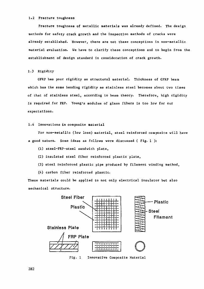
l>2 Fracture toughnessFracture toughness of metallic materials was already defined. The design
methods for safety crack growth and the inspection methods of cracks werealready established. However, there are not these conceptions in non-metallicmaterial evaluation. We have to clarify these conceptions and to begin from the
establishment of design standard in consideration of crack growth.
1.3 RigidityGFRP has poor rigidity as structural material. Thickness of GFRP beam
which has the same bending rigidity as stainless steel becomes about two timesof that of stainless steel, according to beam theory. Therefore, high rigidity
is required for FRF. Young's modulus of glass fibers is too low for ourexpectations.
1.4 Innovations in composite materialFor non-metallic (low loss) material, steel reinforced composite will have
a good nature. Some ideas as follows were discussed ( Fig. 1 ):(1) steel-FRP-steel sandwich plate,(2) insulated steel fiber reinforced plastic plate,(3) steel reinforced plastic pipe produced by filament winding method,(4) carbon fiber reinforced plastic.
These materials could be applied to not only electrical insulator but alsomechanical structure.
Steel Fiber
Plastic
Stainless Plate
FRP PlateA
I i — Plastic
SteelFilament
Fig. 1 Innovative Composite Material
282

2^ How to develop non-metallic material
2.1 Data baseNon-metallic materials have unhomogeneity in production process in addition
to its anisotropy. Evaluation methods of non-metallic materials are not yetestablished at cryogenic temperature. There are many evaluation methods atdifferent institutes. However, we have to built up the standard of mechanicalevaluation methods of non-metallic material at cryogenic temperature: tensilespeed, sample size, direction of sample in composite.
2.2 Design standard
The design standard of metallic materials is not yet well established atcryogenic temperature, but there are some experimental data base ( LCT, MFTF and
Tore-supra). Structural design using non-metallic materials is too much safetydue to its brittleness and anisotropy. It is not simple to determine safetymargin in different load condition because non-metallic materials are bettercharacteristics in bending condition than those in tensile condition. It isstill difficult to design whole the system in the condition of cyclic operation.We need more data base of non-metallic materials. Table 2 shows designdifficulties in composite material.
Table 2 Design Difficulties in Composite Material
DATA BASE DESIGN STANDARD* Production of Composite
Unhomogenelty* Evaluation of
Mechanical PropertiesTest-MethodShape' and- DimensionLocation-and OrientationLoading- Rate
Material PropertiesBrittlenessAnisotropy
Loading CaseTensileBending
Crack ProblemFracture- Toughness-Crack Propagation
283

3 Conclusion
The heat load due to AC loss of structure must be reduced in order to
produce low running cost machine. Therefore, the developments of low loss
structural material at cryogenic use are indispensable to realize the efficientfusion power reactor. Non-metallic material in replacing of conventional
stainless steel, which are high strength, high rigidity and low loss, arerequired in the superconducting coils. And the data base and the design
standard of non-metallic materials should be established during the development
of superconducting coils for fusion power.In case of the development of high strength and high fracture toughness
stainless steel, it took four years to develop only base metal. Accordingly, itwill take several years to use practically non-metallic materials in magnet
system. A project to develop non-metallic materials for cryogenic service isstrongly expected.
4 References1) M. B. Käsen et al., Mechanical, Electrical, and Thermal Characterization
of G-10CR and G-11CR Glass-cloth/epoxy Laminates between Room
Temperature and 4 K, in: "Advances in Cryogenic Engineering -
Materials," Vol.26, Plenum Press, New York, (1980), pp. 235-2442) K. Koizumi et al., Mechanical Properties of an Insulator for the
Japanese LCT Coil, in: "Advances in Cryogenic Engineering -Materials," Vol.28, Plenum Press, New York, (1982), pp. 223-230
284

Group 5
PLASMA ENGINEERING
G.B. Logan (USA)
K. Ikegami (JAPAN)
R.N. Litunovsky (USSR)
J. Raeder (EC)
285

SUMMARY OF EVALUATIONS OF GROUP 5 INNOVATIONS
Table 1 lists ten innovations submitted to the plasma engineering
group, and indicates their evaluation by the group in terms of substance,
feasibility, and priority for further consideration, according to
the criteria set forth in the overall summary of this IAEA specialists
meeting. Innovations E.5.1, E.5.2, E.5.3, and E.5.4 were combined
into one innovation called "Integrated Computer Control for Enhanced
Tokamak Operation", and innovations E.5.5 and E.5.6 were combined with
innovations P.3.6 and P.1.1 into a single innovation called "Single
NBI System for Heating, Current Drive, and Impurity Flow Reversal".
Thus, the reduced number of innovations considered was six, and of these,
three are recommended with a high priority for further consideration,
as indicated in Table 1. In the following summary of the evaluation
of these innovations by the plasma engineering group, we emphasize
the recommended innovations, but also discuss briefly the reasons for
not highly recommending the other innovations. The following text
will explain the evaluation in the order of Table 1. For descriptions
of these innovations, including reference to associated figures and
tables, please refer to the 4-page summaries of each innovation which
are attached to this IAEA report. In this evaluation summary, we highlight
the major improvements expected from each recommended innovation to
tokamak reactors, the associated major issues requiring further work,
including impacts on other tokamak components, and on the development
potential and special requirements, as was discussed in the plasma
engineering group.
Integrated Computer Control for Enhanced Tokamak Operation
This combined innovation seeks to enhance tokamak operation through the
simultaneous computer control of several fuelling, heating and poloidal
287

field coil systems. The major improvements to tokamak reactors are
expected in the areas of:
lower q(0), q , higher beta operation
vertical position control at higher elongation
disruption control at higher elongation
disruption control
improved confinement and possibly higher beta operation
through control of n(r), T(r), and j(r) profiles
movement of divertor null point locations to reduce peak heat
loads on the divertor plates.
The challenge posed by this innovation is to simultaneously control,
using a multilevel with respect to different time scales of response
with different systems, multiloop computer control system, many plasma
parameters together, plasma current, vertical and horizontal position,
plasma shape, ion temperature, plasma density, pressure and current
density profiles, edge plasma parameters, and maybe others. Some of
these, such as plasma shape and profiles, need slow control with 0.1
to 1 second time delay, and others, such as MHD /(ink modes, would need
fast, real time response (0.1 to 5 milliseconds). The control system
inputs come from any diagnostics including electromagnetic probes,
interferometers, Thomson scattering, neutral particle and neutron
measurements, radiometry and bolometry. The control system outputs
would manipulate poloidal and refuelling profiles (by pellet injection,
and gas puffing). As work on a dedicated experiment has just started
this ambitious task needs much systematic analysis beyond that currently
done for various tokamaks. Particularly important is the actual operating
stability of several control systems, acting on a plasma which non-
linearly couples many of the parameters.
One key component needed in such a control system are sets of
poloidal field coils which are capable of rapid response (3-5 kHz)
288

to plasma MHD motion with several poloidal and toroidal mode numbers.
This requires the fast-control Pf coils to be subdivided into several
modular coils in the poloidal and toroidal directions, each coil with
an independent power supply. To minimize the required supply power,
these coils must be as close to the plasma as possible. However, neutron
damage considerations, particularly to insulators, may force the need
to provide some space for shielding between the coils and the plasma.
The plasjma engineering group suggests that a detailed design for reactors
with such coils and with consideration of the necessary tritium-breeding
blankets and impact of disruptions on the coils sets be undertaken
immediately to determine the engineering feasibility of placing such
coils inside the blankets. In addition, consideration of the benefits
of adding passive conducting elements to slow down the MHD modes is
suggested.
Another key component in the proposed control system is a multi-
component system of pellet injectors using light gas, centrifugal and laser
acceleration methods to provide a wide range of variable pellet dimensions
and velocities (1 to 5 mm, 1 to 10 km/sec). To control the plasma density
and temperature profile deep penetration and therefore development of new types
of pellet injectors (assumed to be laser-driven) are needed to achieve
the highest (10 km/sec) velocities.
Most aspects of this proposed innovation can be tested in a near-term
modest size new experiment (Rfvlm, Brj2T) now planned as a joint experiment
by the Efremov and Physico-Technical institutes in Leningrad, USSR. Such
an experiment could verify most of these concepts in time for application
to INTOR.
Single NBI System for Heating, Current Drive, and Impurity Flow Reversal
This combined innovation seeks to simplify a steady-state Tokamak
reactor as a whole by accomplishing heating, burn-control, current-drive,
289

and impurity flow reversal by a single negative ion beam system of 500 KeV
to 1000 KeV, and 102 to 67 MW power, respectively, for a reactor (^ 20 to 40 MW
for INTOR). This is considered to lead to a more attractive tokamak reactor
than one in which ICRH is used for heating, LHRH is used for current drive,
something else is used for burn control, and a divertor is used for impurity
control. Compared to the latter, this proposal would provide the following
major improvements:
(1) Higher driver efficiency (U system ^> 60%)
(2) Current drive at higher densities possible (no accessibility
problem, f? current drive .-^ 0.14 A/Watt at 1 MeV)
(3) Reduced impurities only where needed in the burning core (by
using counter-injection.
(4) Remote sources (high voltage components removed "30 meters from
the plasma)
(5) Simplicity with a common system.
The feasibility of this proposal with regard to confidence in the physics
of heating, current drive, and impurity-flow reversal with such beams is
considered by both the physics groups 2 and 3, and by this plasma engineering
group, to be fairly well established both in theory and experimental evidence.
The engineering feasibility of this proposal is considered to be most
dependent on the outcome of future work on the following major issues concerning
the development of the NBI system itself, namely,
Can presently-low beam divergence be preserved at lower gas
pressures?2
Can reliable, CW negative ion sources with;^, 50 mA/cm be developed?
Can TF coils, blankets and shields be designed to accommodate tangential
injection required for efficient current drive and impurity-flow-reversal?
* assuming E <1 1000 KeV so that DC accelerators can be used with plasma
neutralizers .
290

Can divertors or limiters handle the extra beam power loading?
Is 30 meter beam line length sufficient to protect the sources from
neutron damage?
The plasma engineering aroup recognised both the desirability and the
feasibility to design such an NBI system with the ability to vary the
beam energy over at least a factor of two range, so that during initial
plasma build-up, the beam voltage can be increased with the plasma density
so as to mitigate shine-through.
The present data base already achieved is not so far from requirementsfor INTOR:
2 _(1) Current Density: 15 mA/cm with a volume production source (H )
(2) Beam Divergence: 0.8-0.9 degrees at 18 keV (H~)0.18 degree at 200 keV (He*)
(3) Beam Energy: 200 keV (He+)
(4) Source Operating Pressure: 0.7 Pa (H~)
The plasma engineering group believes that extrapolation from theseachievements to a beam system suitable for reactors is very probablyachievable. However, the present lack of a 500 keV, multi-megawatt negativeion beam test facility anywhere makes the time-scale for application of thisconcept on INTOR uncertain, and this is why the concept is rated between 1 and2 for feasibility in Table 1.
Multi-MeV Light Atom Beams
Compared to 500-1000 keV D~ beams as discussed above, this proposal touse higher energy, lower current light atom beams (2 amps of 16 MeV 0beams, for example) is judged by the plasma engineering groups to have lesssubstance (rated 2 instead of 1) because its projected current driveefficiency may be too low to be used as a single NBI system for heatng andcurrent drive. Also, the projected system efficiency (17 to 33%) is lower
291

than for the D beams (45 to 60%), primarily because DC accelerators aremore efficient than RF accelerators. While the energetic light atom beamscould achieve a potentially very high power density, the access requirementsfor the D beams (0.4 m x l m beam ports) may be already reasonable even forrelatively compact INTOR/FER designs. As to this proposal's lower rating of 2for feasibility relative to the rating of 1 for the D beam case, the reasonfor this was the groups' judgment that the overall technology developmentrequirements (particularly the laser photoneutralizers) are more numerous andsevere as compared to the D beam case.
Injection Over A Corner
This proposal to bend a positive IM NBI around the corner of a shieldusing a magnet was judged by the plasma engineering group to be feasible, butof such minor impact to improve a tokamak reactor that it would not satisfythe criteria for priority in further consideration.
Two-Cycle Tokamak
This proposal to alternate pulsed tokamak discharges in opposite ends ofa strongly elongated plasma chamber/blanket was not judged to diminish cyclicfatigue sufficient to offset the disadvantage of larger reactor size; i.e. thenet advantage of this scheme was considered to be questionnable.
In-Situ MHD Energy Conversion
This innovation seeks to reduce balance-of-plant capital costs in atokamak power plant by using MHD energy conversion inside the TF coils, inwhich non-equilibrium ItmUatlon of the MHD channel vapour is enhanced byinjection of synchroton radiation produced by a high-electron-temperaturetokamak plasma. Such synchrotron emission radiation produced to enhance theMHD energy conversion can also be used to drive current in the tokamak plasma,and so this innovation is compatible with the "Microwave Tokamak" concept,E.9.7. The major improvements to the tokamak reactor expected for the in-situMHD concept are:
o Potential to significantly lower total power plant capital cost byeliminating need for a steam-cycle balance-of-plant. (A potential costreduction up to a factor of two in the total costs.)
292

o Elimination of the need to interface tritium-contaminated blanketcoolants with high temperature steam generators (reduced tritiumcontamination of water, and higher availability with no steam generatorsor turbine maintenance).
o The synchrotron emission radiation can also be used to drive "free"current (higher steady state tokamak reactor Q).
There are many major issues with this concept which will require adetailed tokamak reactor design coupling plasma physics (production ofsynchrotron radiation) to the MHD generators, integrated with suitable hightemperature tritium-breeding blankets and TF coil design:
(1) Can the tokamak plasma confinement in the reactor case be sufficient toallow a substantial fraction of the 3-heating power to be convertedinto useful synchrotron radiation? (requires a "normal" confinementignition margin è 2). Will transport (electron conduction) lossesscale be acceptable to the significantly-higher required plasmatemperatures?
(2) Can the synchrotron radiation (up to 200 MW in a reactor) be coupledthrough suitable waveguides in the plasma chamber walls, be guided to theMHD generators, be transmitted through the channel ceramic walls, and bedamped within the MHD channel plasma?
(3) Can high temperature blankets suitable for the MHD generators be designedto breed tritium with TBR >1?
(4) Can suitable refractory materials such as vanadium, molybdenum, andsilicon carbide be developed with è 100 dpa life at e!000°K in thetritium-breeding zone and with <£ 1 dpa life at è 1500 K in thehigh temperature pebble-bed zone in the back of the blanket?
(5) Can suitable geometries accomodating the blankets and MHD generatorswithin the TF coils be designed for remote replacement?
(6) Will leakage currents in the MHD channel insulator walls (ceramic-1000 to 1500°K) behind the blanket be spresence of neutron and gamma radiation?~1000 to 1500°K) behind the blanket be sufficiently small in the
293

The development and resolution of these and other issues associated withthis concept will take a considerably long time, and so the feasibility ofdeveloping this technology for INTOR time scales was judged not likely,although a small generator module might be tested in one of the INTOR testparts. It was recognized, on the other hand, that a considerable data base onMHD generators already exists, and that it should be possible to use microwavesources such as gyrotrons available in many fusion laboratories, to test theuse of microwave heating in MHD generator experiments. In this way thedevelopment of MHD energy conversion specific to fusion application could beundertaken in parallel with INTOR and thus be available for later use inreactors.
Table 1. Evaluation of Group 5 Plasma EngineeringConcept Substance Feasibility Priority for further
Consideration
Combined Innovation to be called"Integrated Computer Control forEnhanced Tokamak Operaton"E.5.1 "Plasma Parameters Control
System" 1 1 yesE.5.2 "Control Coil System Near
Plasma" 1 1 yes
E.5.3 "Multi-Component PelletInjection" 1 1 yes
E.5.4 "Impurity Control by PF Coil" 1 1 yes
Combined Innovation with P.3.6-Japanand P.l.l-USA to be called "SingleNBI System for Heating, CurrentDrive, and Impurity Flow Reversal"E.5.5 "Linear NBI Using Negative
Ions" 1 1.5 yesE.5.6 "Neutral Beam Heating of
INTOR" 1 1.5 yes
E . 5 . 7 "Multi-MeV Light Atom Beams" 2 2 n o
E.5 .8 "Injection Over a Corner" 3 1 n o
E.5 .9 "Two-Cycle Tokamak" 3 2 n o
E.5.10 "In-Situ MHD EnergyConversion" 1 2 yes
294

E.5.l
PLASM PARAMETER CONTROL SYSTEM
Authors: V.G.Ivkin, R.N.Litunovskij, V.A.Guliaev, V.S.Strelkov
At present two main disadvantages are obvious in the previouslydeveloped concept of the INTOR reactor, they are
- comparatively low /Rvalues- low ignition store due to confinement degradation, being
observed in the majority of experiments with powerful highplasma heating and low O^, values.
In realizing regimes with u,v,< 2 at fair energy confinementthe present tokamak-reactor concept becomes attractive. Withcomparatively slight changes in geometry (less aspect ratio elongationincrease) and plasma current to obtain /3C/T' 50/5 becomes possible.
According to present-day ideas it is possible to realize aregime with n = 1.6 at tf^oj<:1. Energy confinement degradationis due to the achievement of some maximum density profile ofplasma current, optimum energy contribution profile close to currentprofile being disturbed (as in the case of ON regime with not toohigh plasma densities). In the case of energy contribution profiledisturbance and corresponding rebuilding of plasma current densityprofile the latter tends to relax to some "canonical" profilefalling monotonously to the periphery. In so doing the energytransfer sharply increases. This additional transfer is sensitiveto the profile details. The regimes with <2^< 2 have been obtainedon a number of devices (T-11, DIVA, T-10, PLT) and this is basedjust on optimum current density profile formation by changingelectron temperature profiles and effective charge while controllinggas puffing on the plasma periphery.
One of the powerful control means is profiled ECR heating(T-10, TFR-600). It is possible as well for pellet- injection toinfluence on energy contribution profile along the radius.The profiles are rather sensitive to periphery plasma parameters.Hence there is a possibility of controlling energy confinementregimes by affecting I/JlD-activity level in the periphery (ECR,helical
With optimum profiles being determined it becomes possibleto experimentally realize tham by means of a multilevel, multiloop
295

system controlling plasma parameters with a computer net.The system is realized as a combination of program-adaptive loopsand feedback loops. Plasma current, position and cross-sectionshape, ion temperature, density, temperature profiles plasmacurrent density, impurity level, periphety plasma densitytemperature may be chosen as control parameters.
The system is functionally divided into separate loopsaccording'to an employed effector, time scale (operating frequence),accuracy. In the loop controlling' the. temperature profile and theplasma current density the profile information (laser diagnostics,e/m diagnostics) may be used in the forwaird loop for comparativelyslow control. In feedback loops the following parameters may beused: plasma current, position and shape» density, main plasmatemperature, periphery plasma temperature and density and someothers.
The following diagnostics are used: electromagnetic, interfero-metry. Thomson scattering, neutral, neutron, radiometry, bolometryand others.
The following effectors are considered: poloidal fields,controlled ICR-heating, profiled FCR-heating, profiled pellet-injection (see proposal £-5.4), gas puffing.
The application of controlling coil system located near theplasma holds promise (see proposal E-5.2).
The main tasks to be considered are formulated as follows:1. To assess advantages of regime realization with Q/(_Q) <~ 1»= U6-2. To determine steady profile class.3. To assess requirements for the control system.4. To determine the control system structure.
296

E.5.2
CONTROL COIL SYSTEM NEAR THE PLASMA
Authors: R.N.Litunovskij, V.G.Ivkin
The idea to use the first conducting wall in a tokamak is wellknown. It gives a possibility to suppress disruptions and/orMHD-activity related to tearing instability development. Theconducting v/all nearing is favourable for suppressing balloonmodes as well. Experiments on active controlling MHD-activitylevel by helical coils are known too. The erogodization of outermagnetic surfaces is intended for the same purpose. It is possibleto control plasma position along the vertical at several MW feedingpower by coils neared to plasma (see, for example, papers of theINTOR international working group, phase IIA. Section II). Activecontrol of radial plasma position with its short but rapiddisplacement (ex.gr. resulting from microdisruption development)also assumes coil arrangement near plasma. At last active controlover poloidal fields combined with controlled gas puffing allows torealize well controlled development of a discharge on its startaccording to a given scenario.
In all the above tasks an isolated coil system controlledaccording to a chosen parameter (ex.gr. vertical plasma displacement)is considered. But it is possible to realize all these tasks in asingle system. Control coils are designed on the modular principle(see. Fig.1). Every coil section has an indépendant power supply.In this case it is possible to form any, including helicalconfiguration of the magnetic field with a desirable poloidal anglepitch. The total number of coils io n^A/ where tis is a number ofpoloidal sections and N ia a number of modules. Aa a powersupply a capacitor bank with a rapid thyristor switch with3+5 kHz operating frequency may be used. The frequency of 2+3 kHzhas been achieved on a number of devices. This range of frequenciescorresponds to the frequency controlling a kinkmodo level. Thesummary supply power is aooesaed in~/t-A/MV/. An information aboutplasma current, croaa-ooction ohape, plasma position, MIID-activitylevel is uoed for control. The information ia procesaod in amicroprocessor -complex with several frequency ranges of control.The necessary memory is assessed to be 20 mB. Control signals
297

are transferred to the entry of executing devices throughinformation channels.
Coils near plasma provide balloonmode suppression.In realizing the proposal the mechanical strength and the
radiation resistance represent a serious problem. Applicationof copper with beryllium coating is possible.Kain proposals of the investigation are as follows:- An assessment of advantages of regime realization v/ith O^ 2- An assessment of technical requirements for the control system
v/ith account of assembly and maintenance conditions, supplysystem, computer complex.
- A development of possible control algorithms.
Pig.1. Control coils system near, the plasma
298

E.5.3
MULTICOMP0NENT PELLET-INJECTION SYSTEM
G.A.Baranov, V.N.Skripunov, R.N.Litunovskij, A.P.Andreev,B.V.Kuteev
Pellet~inj.ec-tion system is, used for a number of tasks:1. For dosed fueling of plasma in a steady-state operation
of the reactor.2. For active 'influence on density and temperature profiles
oT plasma,3. As a controlled method of impurity introduction into
plasma.Depending on aims and purpose the pellet-injection system
is realized with different methods of pellet acceleration andhas various parameters and design.
Characteristic features of the system according to the INTORreference design are: pellet rate from 2 to 5 km/s and more, fuelfrequency of 5+15 Hz, pellet dimension of cL-h~- 3-4 mm. Withthese rates pellets penetrate into the plasma region whereTo penetrate into the central region where o < 1 the pellet rateneeds to be increased up to several tens of kilometers per second.Technical difficulties of pellet-particle acceleration are farbeyond the possibilities of .today. On the other hand the patternof interaction of this pellet-particle with plasma whilepenetrating into the central plasma region is not clear. Inparticular it is necessary to assess high speed pellet-particlepassage influence on density and temperature profile.
To provide the most significant parameter of the injectionsystem, i.e. pellet rate, pneumatic, centrifugal laser and plasmamacroparticle accelerators are being developed in the USSR.
A number of experiments on hydrogen pellet injection by alightgas injector has been carried out on tokamak T-10. Hydrogenpellets of d-^-n^ = 1.35 mm characteristic dimension wereaccelerated up to velocity of 700 m/s by helium. Injection didnot result in discharge disruptions and allowed to increase themaximum concentration of particles up to "- 30+5075. The penetrationdepth of macroparticles into plasma is of 14-15 cm constituting0.5 plasma radius.Hydrogen pellets of-4 mm were accelerated up toabout 1.5 km/s by a cryoballistic device (with pulse heatingof accelerating gas by electrical discharge)
299

A single-barreled high frequency light -gas injector has beendeveloped that allows to increase the frequency of pelletdelivery up to 10 Hz.
To increase it up to 20*30 Hz and more with their rate up to2 km/s limited by mechanical strength of the construction acentrofugal pellet injector has been developed.
Lightgas and centrofugal injectors are provided with uniformpellet shapers allowing to produce pellets according to wastelesstechnology in a continuous regime.
Above the foregoing methods of pellet injection it is necessaryto consider the possibility of using laser and rail-type methodsof acceleration for deeper plasma probing with rates more than5 km/s+10 km/s.
It is necessary here to disentangle the complexity of producingaccelerators of this kind as well as to solve a number of problemscorrelated with strength characteristics of accelerated pelletmaterial consisting of both "pure" deuterium and tritium and theircompounds.
To provide satisfactorily scientific and practical tasks as toexamining systems for fuel entry by pellet injection it seemsnecessary to develop a unit consisting of different, more convenientand reliable accelerators v/ith a common (or unifo"im) and economical(from the point of view of hydrogen isotope and cryoagentsconsumption) system to form an undistractable pellet.
According to the following tanks of pellet-injection, i.e. (1)fueling,(2) density profile control (temperature profile too atthe expense of plasma cooling) pellet, interacting v/ith mainplasma, (3) temperature density profile control by pellets in-fluence on peripheral plasma, it is suggested to analyse thepossibility of density control, density /temperature control,temperature/density control peripheral plasma by means of multi-component system of pellet-injecU on v/ith a wide range of pelletdimensions and rates, operation frequence.Some injection systems are functionally divided according topellet-plasma interaction.
The injector system is controlled on the basis of incominginformation about plasma parameters, the net of real-time micro-processor being used.
300

E.5.4
IMPURITY CONTROL BY POLOIDAL- FIELDS
Authors: R.N.Litunovskij, V.H.Piatov, G.I.Shmalko
The removal .of fusion burning products and the reduction ofimpurity flux into plasma in a classical scheme of a tokanak-reactor are suggested to solve by means of a divertor (or by apumping limiter). The experiments on ASDEX, PDX, Doublet IIIdemonstrated major ad-vantage's of*this technique. During theseexperiments parameters of the main plasma were found .to be sensi-tive to a periphery/divertor plasma. Heavy heat loads alongdivertor plates, their erosion and the increase of a backwardimpurity flux represent an essential technical difficulty inrealizing this scheme.
Considerable changes in the field topography are known to beachieved by current changes in poloidal field coils. It ispossible to put forward the task of a local field change in theplasma periphery region without considerable changes of the fieldconfiguration in the main plasma region. It is possible as wellto change profiles in the central region in stabilizing peripheryplasma parameters. Pig. 1. illustrates calculation results ofpressure density profiles (dotted line in Pig. 1a) and plasmacurrent (solid line in Pig.5.1b), outer flux (Pig. 1b) and fluxchanges ATc_ (Pig. 1c) for device "Tuman-3". It is clear thatchange (L(&) at Q = const demands simultaneous control overplasma heating / cooling near the centre and poloidal fields.The control over periphery and divertor plasma with profilestabilization in the centre being a task, it is possible toachieve considerable changes in the field configuration in thisregion by sufficiently simple means of periphery heatings/cooling.The results of the control are shown in Pig. .2. and Pig. 3.
As can be seen the considerable changes in magnetic surfacetopography are observed in the plasma periphery region. In themain plasma region the influence of current changes in poloidalfield coils is sufficiently lower. Thus the task of precisioncontrol over periphery plasma condition, divertor operation withslight parameter changea of the main placma (concentration,temperature) may be put forward. Temperature, pressure and plasmacurrent density profilos change with periphery parameters.
301

?t ?/0>
ISO.
m.
so.
so
• 25
~20
, c/nPig.la. Pressure density profile (dotted line)and plasma current density profile (solid line)
control n^= 2.65,a(0)= 1.45, 1,25 and 1.05
J5000.
SO" foc 150Fig.lb. Outer flux for I variant
350'
Pig.lc. for 2 and 3 variants
302

Pig.2. Magnetic field pictureCD Jks. « -0,25 MA J, a -0.42 Ii « 1.0 Js » -0.74(2) JT«4=» -0.25 MA _T, = -0.15 »1.2 Zj » -1.1= 0»0.15
f:f:!/;'j/;;r;' ~~ .' ,/' j l"ij'~' r .""/ / 'J-i- J,v44VUtV.iU]11
r 1 .
Pig.3. Magnetic field pictureXAft .J . UiO.fiJIU kit XJ.OJ.U p^VfeUAO _ ,»
(3) JC1 - -0.26 MA J, . 0.47 /. - 0.5 /. - -0.7 •/* " °(4) /cs - -0.26 1IA j( . 0.7 j^ • 0.44 2t " -0.7 Jy » 0
303

The task of regime realization of slow heat flux displacementalong divertor plates may be posed as well.
While analysing the possibilities of the proposed method forthe impurity control and divertor operation regime the followingtasks are to be solved:- An assessment of processes developing in the main and periphery
(divertor) plasma, the poloidal field configuration being changed- An assessment of technical parameters of an electromagnetic systemand supply systems with different control scenarios.
- An enunciation of a possible control algorithm.- Calculations of loads along divertor plates, poloidal fieldsbeing controlled.
304

E.5.5
Linear NBI Utilizing Negative Ion sources
Y. Ohara, S. Matsuda and R. SaitoJapan Atomic Energy Research Institute
1. Introduction
The primary objective of the Linear NBI is to realize steadystate Tokamak for fusion power plant utilizing simpler heatingand current driving system, rather than RF system. It is dis-cussed in P.3.5-J that the steady state power reactor using 500keV D° injector would be achievable ( Q = 20 ).
A negative ion beam was proved experimentally to have thevirtue of the much smaller divergence than positive ion.[1]
By this feature, the length of the negative ion NBI can bevery long (>30 m) and leads to advantages as follows;
(1) No large equipments are necessary around the torus unlike NBIutilizing positive ion beam. This will lead to easier mainte-nance of the source assembly.(2) High gas efficiency and small gas loading to the cryo-pumpsare expected.(3) Single beamline can handle as much as 500keV/20MW neutralsinto the Tokamak. This will allow us to construct a systemeconomically.(4) Energy changeable tangential injection has advantages ofmeeting various requirements; efficient heating with minimizingshine through, profile control and current drive.(5) Complex couplers with plasma, one of the most vulnerablecomponents to be damaged, are not necessary.
2. Design Example and Data Bases
Negative-ion based injector was designed for FusionExperimental Tokamak Reactor (FER). The design includes almostall the basic necessary considerations;ion beam characteristics, extractor design, gas flow and gaspumping, stray field from tokamak and its shielding, beam dumpand other thermal components.
305

WoOs
1 .2.3.4.5.6.7.8.9.10.11 .12.13.14.15.16.
Plasma CenterDrift DuctFlexible JointNeutron ShutterGate ValveCalorimeterIon DumpCryo-pumpNeutron ShieldMagnetic ShieldNeutralizerBeam MonitorRetractable TargetAcceleratorD~ SourceCryo-pump
\IyT_beam limitter
Drift Duct
jacket(SUS)
Neutralizer
Fig.1 Drawing of negative-ion based injector for FER.

Figure 1 shows the drawing of negative-ion based injectorfor FER. A simple gas cell was chosen for neutralizer to avoidcomplexity. This system has advantages described before. Thebasic performance is summarized in table 1.
These disign criteria was determined on the basis of presentengineering level of the negative ion source development. Conse-quently, the NBI system of this design will come to be realizedwith high probability. The data bases which were used in thisdesign are presented as follows;(1) Current Density ; 15 mA/cm2 with a volume produc-
tion source.( H~ ); 0.8 - 0.9 degree at 18 keV ( H~ )
0.18 degree at 200 keV ( He"1" ); 200 keV ( He"1" )
(2) Beam Divergence
(3) Beam Energy(4) Source Operating pressure; 0.7 Pa ( H )
Table 1 PERFORMANCE OF A 500keV/20MW NEGATIVE-ION-BASED INJECTOR
OverallNeutral.Beam PowerPower DensityBeam EnergyPulse LengthIon SpeciesPower Efficiency
(average)22.5 MW56.3 MW/m2
200 - 500 keVquasi-continuous
D45 % (at 500 keV)
Ion SourceNumberType of D SourceSizeCurrentCurrent DensityDivergence
Volume Production0.2m 2.4m (extraction grid)
100 A50 mA/cm25 mrad
Cryo-PumpSource ChamberInjection Chamber
750 m3/s200 m3/s
Injection PortSizePressureGas Flow into Torus
0 . 4m x 1 . Om x 9m4 x lO~ 3 Pa
0.03 Pa in3/s
Neutralizer
SizeLine DensityPressureShield
0.3inx (2.4-1.4)m x 30m7.4xl0 1 5 molecules/cm2
1.5xiO~ 2 Pa (at entrance)20 cm iron
307

The important issue to be confirmed experimentally is towhat low gas pressure does the negative ion beam maintain its lowdivergence value against space charge expansion.
3. Long Term Efforts
Higher beam energy up to 1 MeV is preferable in order toobtain higher current drive efficiency, then larger Q-value (=30)and smaller circulating electric power ratio. Higher powerefficiency of NBI system is also impotent to obtain large Q-value, which may be realized by plasma neutralizer and/or anenergy converter system.
References
[1] Y. Okumura, et al.; 11th Symp. on Fusion Engineering, Austin,Texas, Nov. 18-22, 1985.
308

E.5.6
NEUTRAL BEAM HEATING OF INTOR
M. Cox, T. S. Green, D. P. Hammond and A. J. T. HolmesCulham Laboratory, Abingdon, Oxon, England, 0X14 3DB
(Euratom/UKAEA Fusion Association)
SUMMARY
Recent results from negative ion neutral beam development programmes havebeen sufficiently encouraging to raise the possibility of using neutral beamheating (NBH) on INTOR.It is suggested that a system based on a - 400 keV electrostaticallyaccelerated D~ beam is the most readily implemented NBH scheme. Theadvantages include:(1) Moderate power density in each beam (- 100 MW m~2) so that
"shine-through" is unlikely to cause excessive power loading of the firstwall.
(2) Efficient transport of unneutralised beam over distances 2 20 m.(3) No deliberate injection of low Z impurities. Very pure beams could be
produced by using bending magnets for mass analysis.(4) Very high overall efficiencies especially if plasma neutralisers are
used.(5) Variable energy beams are possible to allow optimisation of the
deposition profile if necessary.All of these items have experimental backing but confirmation atmulti-megawatt power levels is clearly desirable. Planning of a facility toallow this is needed. In parallel with the experimental programme, a studyof the implications for the design of the reactor is required to allowdetailed comparison with other heating schemes.
1. INTRODUCTION
The use of negative ions rather than positive ions in a neutral beam injectorcreates opportunities which have not always existed in positive ion systems,the most fundamental of which relate to the well known possibility of usinghigher voltage without loss of neutralisation efficiency.
309

For a given beam power requirement, the ion source beam current, I, clearlyscales inversely as the energy, E. Thus a unit for injecting 3 MW wouldrequire a source of 25 A at 200 keV and a source of 12.5 A at 400 keV(assuming a neutraliser/transport efficiency of just over 60%). As wediscuss below, a single source operating at 10 - 20 A may now be consideredfeasible, though higher currents are more problematic.
A further consideration derives from the fact that the so-called perveance (ameasure of space-charge, I/E3/2) scales as E"5/2. This parameter isimportant for several reasons:
(i) The electrical stresses in the accelerator decrease as the perveancedecreases, leading to higher reliability.
(ii) A low perveance multi-electrode accelerator can be used, giving moreflexibility in design for decoupling voltage and current. Suchflexibility has already been demonstrated to a limited extent by thepositive ion injectors developed at JAERI( , and results from thenegative ion accelerator at Culham indicate that either the H~energy or beam current can be varied by at least a factor of twowithout defocussing the beam.
(iii) At low perveance, beam transport is more predictable and controllable,with significant impact on beam line design.
To some extent the latter points have been partially demonstrated withpositive ion beams, as we discuss below. However, as we also show, there areother advantages in transport deriving from the use of negative ions.
2. CURRENT CAPABILITY OF SOURCES
The initial demonstration by Bacal et al of high fractions of negative ionin plasma sources to exploit such sources for beam production has led to aconsiderable effort. It is clear that a source of at least the size
COof that used on the JET positive ion beam line would be necessary. Thelatter gives 60 A of positive hydrogen ions at a current density of200 mA/cm2. We have therefore taken as an objective at Culhara the productionof 10 - 20 A of D~ at a current density of 30 - 60 mA/cm2. Experimentally wehave shown that 25 mA/cm2 can be achieved in deuterion with reasonableuniformity over 1000 cm2. These results indicate that one is approaching thecurrent requirement for a multi-megawatt beam of high energy.
310

3. BEAM TRANSPORT3-1 Global Transport Considerations
A reasonable objective in injected power per unit is 3 MW at a power densityof 100 MW m~2. The beam radius (1/e) at the torus then has to be 10 cm. Fora beam line length of L metres the corresponding angular divergence of theion beam, 8, is 100/L milliradians.
30 r
10
•oo
aeo<u
CO
0-3
0 1
JET at 160 keV
JETal 400keV(extra potated )
He»beam at 200 keV(JAERJ)
Torus edge powerdensity = 100 M W/ m
10 100Beam Line Length (m)
This relation is shown in Fig. 1, together with a number of values of 6already obtained or assessed as achievable, for positive ions. Lowerperveance beams should lead to lower beam divergences.
These results already indicate, as proposed by the Japanese developmentgroup, that large values of L, i.e. several tens of metres, can be used onthe basis of positive ion results alone.
It also has to be recognised that there is a significant difference betweenpositive ions and negative ions in their response to space charge fieldswhich dominate in general the beam motion. These are generally repulsive forpositive ions in order that the slow positive ions created by beam-gascollisions are expelled. Consequently they cause expansion for positive ionbeams, but contraction for negative ion beams. The equation of motion of the
311

ion beam is:
a" - — + kla»
('a' is the beam radius, e the emittance, and k a factor relating the spacecharge forces to the beam current). When k is negative as for a negative ionbeam, the beam contracts to an equilibrium value of radius. This has beenobserved in experiments at Culham. When the beam becomes neutral the spacecharge force vanishes and the beam expansion is governed by the emittance.Such considerations offer the potential for transport of negative ion beamswith low divergence over long distances, provided that the conditions forestablishing the compressive plasma potential do not lead to such high gaspressures that stripping becomes important. The theory and experimental workon such beams is still at a modest level for multi-megawatt beams. Theachievement of low divergent negative ion beams would offer scope to placethe sources well outside the radiation shield of the reactor, thuseliminating problems of radiation for the source.
3.2 Transport in Magnetic Analysers
An important implication of the production of low perveance beams fromquiescent ion sources is that they can be transported through magneticfocussing elements with minimal degredation of beam quality. As an example,
T A —V,a beam with a perveance (———) equal to 8.9 x 10~9 A.V~'/a (a.m.u.) hasE3/2
been mass analysed with a resolution of Z 5 * 10~2 and good beam optics. Theequivalent current for D~ at 400 keV would be 1.6 A.The implication is that the separate beamlets of a mutli-aperture beam of D~can be successfully mass analysed to eliminate metal impurities.
3.3 Transport of Neutral Beams
As stated above, it is a consequence of the self-focussing of a negative ionbeam that the subsequent expansion of the neutral beam depends only on theemittance of the beam and on its diameter in the neutraliser. This givesscope for optimisation of the neutral beam transport, not previouslyexamined. This is very different from the situation for positive ion beams.
4. PLASMA NEUTRALISERS
The possibility of using plasmas as efficient neutralisers was reviewed atthe IAEA workshop on negative ion beams. Some progress in concepts wasreported:-
312

(i) The use of high atomic mass gases (e.g. Xenon) can offer advantages -already adequate plasma densities have been reached in plasmagenerators, albeit of low values: further multiple ionisation leads tohigher stripping efficiencies.
(ii) High degrees of ionisation (ion density/neutral density) can beachieved even in metal vapours.
(iii) A significant feature of these developments is the move to elementswhich are easily pumped, thus overcoming the previously recognisedproblem of operating cryopumps to pump hydrogen in a gas neutralisernear a reactor.
5. CONCLUSION
Advances in the development of H~ and D~ sources have significantly changedthe credibility of building multi-megawatt beam lines for neutral injection.Single units giving 3 MW of neutrals at 400 kV D0 are realistic objectives:this compares with the present JET injectors which produce less than 1 MW offull energy 160 keV D0 neutrals. Equally important is that gains in beambrightness arising from both increased energy and the use of negative ions inprinciple minimise radiation problems by allowing the source to be removedsome distance from the torus and also minimise apertures in shielding and theblanket.
Planning is now needed for a multi-megawatt beam line test facility todemonstrate that these potentials can be realised. A parallel and continuingstudy of the implications for the engineering design of the reactor is alsoneeded.
References
1. Okumura Y. et al. Heating in Toroidal Plasmas, Rome 1984 p. 1225.2. Holmes A. J. T. et al. Proc. Int. Ion Engineering Congress, p.71, 1983-3. Bacal M. et al. J. Appl. Phys., 52, p.1247, 1981.4. Green T. S. et al. Symp. Fusion Technology, ISPRA 1984, Vol. 1 p.693.
313

E.5.7
PLASMA HEATING WITH MOLTI-MeVLIGHT ATOM BEAMS
L. R. Grisham, D. E. Post, and D. R. MikkelsenPrinceton University, Plasma Physics Laboratory
P.O. Box 451, Princeton, N. J. 08544
INTRODUCTION
In this paper, we briefly review our studies of the plasma heatingprospects and production technology for light atoms (f><A<_45) at energies of1-2 MeV/amu. The principle advantage of these beams relative to D° beamsis that, while producing equally good central heating, they allow much higherpower densities at lower beam currents, and thus significantly reducerequirements on access ports on the tokamak. In addition, the ion sourcescould be located behind shielding many meters from the tokamak. The beamswould be formed from negative ions, accelerated in a radio frequency quadrupoleaccelerater, and neutralized.
DESCRIPTION OP THE HEATING TECHNIQUE
In the past Dawson and McKenzie-*- and Grand^ proposed injection of positiveions (B+, Ne+, etc.) as an alternative to neutral hydrogen injection. Theions would be accelerated to about 1 MeV/amu, at which energy the nuclei,once fully stripped in the plasma, would be as well confined as the fusionproduct alpha particles. As the ions undergo successive ionizations thevdrift further into the plasma. The use of elements heavier than hydrogenalows one to increase the energy carried per particle without degradationin confinement for energies up to 1-2 MeV/amu. This then reduces the currentrequired to achieve a given power. Positive ion beams are technologicallyattractive, since the source can be relatively simple and no neutralizer orion dump is required. However, transporting the ions across the spatiallyand temporally varying magnetic fields surrounding the plasma is a difficultproblem which has not been solved.
As an alternative, and as a natural extension of the beam required forthe lithium beam alpha diagnostic which we proposed (see réf. 3), we haveconsidered the possibility of using light atom beams to heat tokamak plasma(see réf. 4). The attraction is, of course, that as neutrals these beamsexperience fewer difficulties in traversing the region around the plasma.The accompanying difficulty is that it is more difficult and less efficientto make neutrals. Since one is limited by confinement constraints to energiesin the region of 1-2 MeV/amu, there is a premium on going to higher masses.However, in going to very massive elements the ion's confinement in its earlvstages of ionization degrades, since its Larmor radius is then very large.Accordingly, in our past studies we primarily considered possible negativeions with A <_ 40. *
Figure 1 shows that these beams should be effective in heating an TNTORplasma. This shows the calculated heating deposition profile for 16 MeV oxygeninjected as 0°, and for comparison 46 MeV sodium injected as Na+, 2 MeV D°,and 150 keV D°. We also show the initial ionization profile of 0°—) O+.The 0° itself does not penetrate to the plasma center, but the subseauentinward drifting results in strong central peaking by the time the oxygen becomesO+s. Since almost all the energy transfer occurs after the oxygen is fullyionized, the heating is also concentrated in the core. We see that the 46MeV Na"1" and the 2 MeV D° (the final deposition profiles are shown) both heatthe plasma core about as well as the 0°. Thus, if one eventually chose touse one of these approaches, the choice would probably be determined moreby technical considerations then by plasma interactions. In this examplethe Na+ was assumed to be introduced at the edge of the plasma, withoutreference to how it arrived there.
314

46 MeV Na
150 KeV D°16 MeV O+From 0°
Figure 1. Heating deposition profiles in an INTOR-sized plasma for 2 MeV D° (madefrom D~), 46 MeV Na+, 150 keV D° (made from D+ yielding neutral powerfractions of 60% at full energy, 24% at one-half energy and 16% at one-third energy), 2 MeV D° made from D~, the initial birth profile of the16 MeV O+ resulting from the ionization of coiniected O° , and the finalprofile of the O+B resulting from infection of the O°. [Ref. 4].
Light atom beams could also be used to drive current in a tokamak.However, the current drive efficiency of such beams relative to high energyD° beams depends critically upon -how substantial trapped electron effectsare. If they are insignificant, then the heavier atoms are more efficient,but 2-3 MeV D° becomes more attractive the larger the trapped electron effectsare.4 At this time it is not possible to say how important trapped electroneffects will be.
TECHNOLOGICAL CONSIDERATIONS
The technological base for light atom beams has been discussed in réf.4. It appears probable that ion sources could be developed to produce~100mA of Li~, ampere level currents of 0~, and hundreds of mA of C~ or Si".A Li~ current of 100 mA, taken in conjunction with its low mass, would meanthat multiple beams would be required for the heating application. Thesebeams might be carred inside a single resonator structure. An ampere of O~,on the other hand, that was accelerated to 2 MeV/amu would carry 32 MW. Thiswould be sufficient for heating purposes, but only if most of it could beneutralized.
The combination of voltage and current requirements seems to precludethe use of electrostatic accelerators. However, as discussed in réf. 4,electric-quadrupole-focussed RF accelerators should be suitable.
These accelerators would be quite long. A RFC) accelerator for 0~ might,for instance, run several tens of meters. Thus the ion sources could be locatedfar from the tokamak and, since the beam could be bent before and after theaccelerator, the ion sources could be shielded. It thus might be possibleto perform maintenance on one source while its alternate was supplying therelatively small current required.
The simplest type of neutralizer would be a thin cell of some easilycondensed gas. Recent measurements show that at 6-7 MeV ~46% of Li~ can beneutralized using nitrogen5'6 and that as much as 54% can be neutralized ifone is willing to use hydrogen (which has a higher vapor pressure). However,the maximum neutral fractions are much lower for heavier ions5: ~ 27% forC~,~20% for 0~, and ~22% for Si~ when the neutralizer gas is something easilycondensable such as argon, nitrogen, or carbon dioxide. This efficiency might
315

be improved somewhat if hydrogen were substituted as the neutralizer, althoughno measurements have been done with this. Clearly a more efficientneutralization method would be desirable. Lorentz neutralization by passagethrough an electric or a magnetic field appears infeasible at these lowvelocities (1.3-2.2 x 10^ cm sec~^ ) ; as the ions become neutralized aftertransversing different path lengths through the field the divergence wouldbe greatly increased. A plasma neutralizer should give greater neutralfractions of all these elements, and preliminary experiments with partiallyionized neutralizers have shown some improvement^. In principle the mostdesirable type of neutralizer might be one which used photodetachment and,indeed, one should be feasible-''^ for Li~ with extensions of existing lasertechnology. Li~ is less bound than H~ (0.62 eV versus 0.75 eV) and thephotodetachment cross section for Li~ has been calculated to be quite similarin overall shape to that of H~, but larger^*. Accordingly, any photodetachmentneutralizer which works for D~ should neutralize an even larger fraction ofLi~. Unfortunately the other negative ions we have mentioned - C~, 0~, andSi~ - all have larger electron affinities (which is why they are easier toproduce) and would require a laser in the 3000-6500 A region, where no efficientcommercial high power CW laser systems presently operate. This situationmay change, however, as free electron lasers and excimer lasers are perfected.
CONCLUSION
The single biggest problem of multi-MeV light atom beams is their poorefficiency, which with existing technologies would be fairly low. Theefficiency of a 1-2 A RPQ has been projected to be 35-38% (wall plug to beam).With a gas neutralizer a Li° beam would then have an overall efficiency of17%, and for heavier ions this would decline to 9%. The Li~ system efficiencycould approach that of the accelerators with a chemical laser photodetachmentneutralizer of the type being studied for D~ beams. With extrapolations ofpresent technology it appears that Li~ might have an acceptable efficiency( 35%) for tokamak heating if used with a chemical laser photodetachmentcell similar to one for D~. However, for Li° beams to offer any attractivenessin simplicity over D° beams it would be necessary to increase the Li~ currentwell beyond the presently anticipated 100 mA so that the power per beam systemcould be increased beyond the 0.6-1.2 MW which this would imply. The heavierand more tightly bound negative ions (C~, 0~, or Si~) would be attractivefor tokamak heating if efficient lasers of suit.able wavelengths becomeavailable, or if plasma neutralizers should prove to be efficient. Currentdrive in a tokamak would require even greater efficiency, and requires moreinformation about trapped particle effects.
The attractiveness of multi-MeV light atom beams for these applicationscould be greatly improved if developments were to occur in a number of areas.Any development of more efficient plasma or photodetachment neutralizers wouldbe significant, as would alternative accelerators with greater efficiency.In addition, development of high current sources of weakly bound negativeions which could be photodetached by existing chemical lasers would be highlywelcome. For heating or current drive an even more desirable developmentwould be a Na~ source capable of at least a few hundred mA. Na~ is boundby only 0.46 eV, has a calculated photodetachment cross section similar tothat of Li~, and could thus be easily neutralized with any photodetachmentcell suitable for D~. With a mass of 23, sodium could be accelerated to 30-50MeV and still be confined, so a beam of a few hundred mA could carry a largeamount of power. A 46 MeV Na~ carries 230 times as much energy as a 200 keVD~. While the sodium's dwell time in a photodetachment neutralizer wouldbe reduced by a factor of 4.5 relative to that of the deuterium, thephotodetachment cross section of the sodium is calculated to be 4 times greaterthan that of D~ at 1.3 microns.^ Thus the amount of beam power neutralizedfor a given amount of laser exciting power could be much greater providedthe final accelerated beam current densities are not too dissimilar.
316

REFERENCES
1. J. M. Dawson and K. R. McKenzie, "Heating of Tokamak Plasmas by Meansof Energetic Ion Beams with Z > 1," PPG-470, Plasma Physics Dept.,U. of Cal., L.A. (19RO).
2. Pierre Grand, private communication (1979).
3. L. R. Grisham, D. E. Post, D. R, Mikkelsen, Nuclear Technology/Fusion.3, 121 (1983).
4. L. R. Grisham, D. E. Post, D. R. Mikkelsen, and H. P. Eubank,Nuclear Technology/Fusion 2, 199 (1982).
5. L. R. Grisham, D. E. Post, B. M. Johnson, K. W. Jones, et.al.,Rev. Sei. Instru. 53, 281 (1982).
6. J. P. Aldridge and J. D. King, "Charge-Exchange Cross-Sections forLi~ Ions at 6 MeV," LA-8682-MS, Los Alamos National Laboratory (19R1).
7. A. Herschcovitz, et.al., Rev-Sci. Inst. 55, 1744 (1984).
8. D. W. Norcross and D. L. Norres, in Atomic Physics 3:Proc. Third Int.Conf. Atomic Phy., Boulder, Colo., August 1972, S. J. Smith andG. K. Walter, Eds., Plenum Press, New York (1973).
9. H. S. W. Massey, Negative Ions, 3rd Ed. Cambridge Univ. Press (1976),422 and 427.
317

E.5.8
INJECTION OVER A CORNER.N.N.Semashko, V.M.Kulygin, A.A.Panasenkov, G.N.Tilinin,Yu.M.Pustovojt, V.S.Svishchev, I.A.Chukhin, V.A.Arsent'ev,V.A.Nikulin
INTOR NB~injection system is to provide plasma heatingpower up to 75 MW at the deuterium atom energy of 160 keV wi-thin the pulse length up to 8 s. The system includes 4 injec-tors, each having 4 independent sources.
The injector is based on the concept of direct charge ex-change transformation of a positive deuterium ion into atom,For better ion source protection against direct neutron stre-am from plasma and to provide delivering to plasma a monoenergetic neutron beam, the injector design modification is sug-gested as shown in Fig.1. The ion beam consisting of D^, D*,Dt at the ion source outlet gets into the bending magnet whe-re the atomic ions D* are deviated by 180°and passed into theneutralizer while D+ and D| molecular ions being deviated by90° and 45° respectively come to a collector.
The injector has two vacuum chambers, each of 2.5x2.5x4.5 m dimensions. On the side wall of the first chamber 4 ionsources are installed in a lino, there are also four bendingmagnets in this chamber, the molecular ion collectors and getter panels. Between the two chambers four neutralizers are IPcated, where D* ions are transformed into D° atoms via chargeexchange within a gas cell filled by auxiliary deuterium puf-fing at the middle part of the cell.
In tho second chamber an electronagnet is aounted whichdeviates the non-neutralized DÎ ions to the collecting recupe •
318
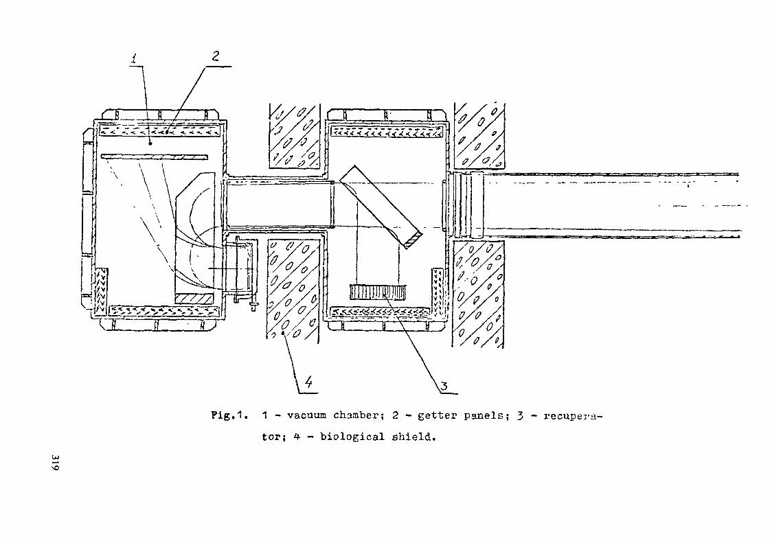
Pig.1. 1 - vacuum chamber; 2 - getter panels; 3 - recupera-tor; 4 - biological shield.
\o

rators. The D^ atom beams go through the drift duct and 50xt150 cm" beam aperture into plasma.The efficient beam transportation through the injector
is provided by a high capacity differential pumping systemwith getter pumps.
The ion sources and recuperators are located within thebiological shield shadow.
Ion sources with périphérie magnetic field are supposedto be employed. Each source must provide a deuterium ion beamwith 120A steady-state current at l60keV, of the initial 10x?0cm cross-section and -0.3 divergence along the slits arid-1f1.5° across the slits. The source gas efficiency is about50/£, the D2 gas supply into the source is 25 1-Torr/s.
2The neutraliser tube is 2m long, with 15x11Ocm cross--section. At the middle of the tube molecular deuterium ispuffed in to provide the gas target. To increase the vacuum
2resistivity a number of scrapers with 10cm pitch and 12x90cmaperture for the beam passing is installed. The tube wallsare cooled by liquid nitrfcgen. At the puffing rate of 6 1-Tori/s in each neutralizer the gas target optical thickness is
16 21.5-10 mol/cm which ensures 27% charge exchange efficiencyat 160k<iV D^ energy. The neutralizer has a magnetic screen re-ducing the stray magnetic field down to permissible -^ 50.
Dt and ut ion collectors have to absorb about 8 MV/ fromthe four ion sources. The collecting surface is inclined tothe beam under an angle providing the heat flux density reduc-
ption down to " 1kW/cm .The recuperators for 160 keV non-neutralized ut ions
should handle about 48 M'.V from four ion beams with an effici-ency up to 80$. The collector potential in the recuperator iswithin 30-140 kV.
320

tA higlrspeed is to maintain low flB losses due to chargeexchange. About 70 1-Torr/s of Dg molecular gas gets into thefirst injector chamber from the source, neutraliser and mole-cular ion collectors. To maintain pressure at 3»5'10 Torr
2level (Dt ion losses about 370 getter panels with ^23 m ef-fective pumping surface are installed in the chamber provid-ing * 2 106l/s pumping rate.
The second chamber recieves about 40 1-Torr/s of D°> mo-lecular gas from the neutralizers and recuperators. This flux
2is pucped out differentially; in the upper section 12 m ofC _Cgetter panels providing 10 1/s pumping rate maintain 2.5*10 ^
Torr pressure, in the lower section the pumping surface is2 5 —56 m t pumping rate is 5 -10 1/s and pressure is 4-10 •'Torr.The drift tube is also equiped with the getter panels
providing about 5-1° 1/s pumping rate, and the effective gastarget thickness between the neutraliser and plasma is reduc-ed so that D^ atom beam losses amount to less than 5#»
The getter panel capacity, determined as a limit withinwhich tho pulping rate at 5-10~^Torr is not affected yet, is
c pabout J'lO-u-Torr/cm that is the panels have to be regenera-ted after 50 hours of operation.
The electric supply system has a modular design? eachion source and its supporting systems are fed from separateddevices including the electric oupply for the emission and ,T;-celerating electrodes, the ion source aisch-arGO and cathodeheating, the recupex'ators and the bending magnets. The powersupply for one ion source channel is 11 MW, and with respectto the power supply system efficiency the power required fromthe energy supply grid V.Ü1 be about 12 KW. The total power
321

required for the injection' system is 190 M'.Y at the system ef-ficiency of 37#.
The energy supply devices for cathode heating, ion sourcedischarge and recuperator operate under 160 kV potential.
322

E.5.9
"TWO-CYCLE" TOKAMAK-REACTORAuthors N.I.Doinikov, N.A.Monoszon, O.G.Filatov
One of the main disadvantages of tokamak is cyclic operation,i.e. interchange of operating phases -(fusion burning) and pauses.The principal restriction of operating phase duration in tokamakis due to maximally possible volt-second reserve the poloidalsystem /1/ can provide. This restriction may be avoided in theconcept of a two-cycle tokamak-reactor (TTR) /2/, its mode ofoperation is described below (the name is correlated to an operatingprinciple of a two-cycle internal-combustion engine).
The scheme of TTR is depicted in Pig. ,1, where two dischargechambers 1•and 2 surrounded by a common blanket and magnet coilsare shown. TTR operates in the following sequence. Suppose at themoment-t = 0 one of the chambers, chamber 1 for example, is readyfor a discharge, and inductor current corresponds to some voltsecondreserve (Pig. 2). With the first inductor field reversal(interval A in Pig. 2) plasma column ought to be generated onlyin chamber I. This may be achieved by different techniques, forexample by properly preparing vacuum conditions in chambers 1 and2 or by forming poloidal magnetic fields in the chamber area.Then during time interval A blanket will bo radiated by neutron::genei'ating in chamber 1 while in chamber 2 it is possible toprepare "vacuum conditions. V/hen interval A is over current in theinductor becomes equal but opposite in sign to the initial one.By this instant chamber 2 ought to be prepared for a discharge.Then in the initial time interval B with back field reversal thedischarge is suppressed in chamber 1 and generated in chamber 2.Thus in the main interval B the discharge is generated only inchamber 2, T- ~~—n ' Then the sequence of chamber operationrepeats, ZT* - "CQ The sequence of chamber 1 and 2 operation iscontrolled by pressure regulating and /or poloidal controllingfields.
For TTR it is possible to use tokamak concept with stronglyelongated plasma (K-K10 KT) /3/. Pig. 3 illustrates variants ofthis TTR with and without an intermediate solenoid.It is followed from the above that in TTR levelling of blanketoperating conditions is possible in time, as it may be radiated
323

by neutrons either from one or another chamber. Twot-cycle principleallows to consider tokamak-reactor with a high output factorwithout 'a divertor,. By choosing time intervals £\ and £7Qto be too low so that by their end the level impurity and thedepth of fuel burning do not exceed a limiting allowed value, itis possible not to use a divertor (and may be the whole systemof solid fuel pellet injection). It is worth noting that theenergy accumulated in TTR inductor by the end of every act offield reversal may be directly used to generate the next plasmacolumn in the next chamber prepared for a new discharge.
R E F E R E N C E1. INTOR, Phase One, IAEA, Vienna 1982.2. V.A.Glukhikh et al. Prom Proc. 2nd All-Union Conference
on engineering problems of fusion reactors (June 23-25, 1981)v.1, p.150-155.
3. P.A.Politzer. The' Elongated Tokamak (ET) - Report on US-USSRMeeting "Prospects of Fusion Reactor Devices with Non-Super-conducting coils" FEDC, Oak-Ridge, Tennesse, 11-13 Febr.1985.
Pig.1. Schematic representation of two-cycle tokamak--reactor1 - inductor, 2 - control coils, 3 - toroidalfield coil, 4 - blanket
324

lf/)
T iT£=i
Pig.2. Inductor and plasma currents 1 andversus time in TTR chambers H
i \ 2 !.XXxxiX
Pig.3. Two-cycle tokamak-reactor with strongly elongatedplasma
325

E. 5. 10
IN-SITU MHD ENERGY CONVERSION - SUMMARY
B. G. LoganLawrence Livermore National Laboratory
Livermore, CA 9*1550
About half of the capital cost of a typical tokamak power plant (suchas STARFIRE ) is associated with energy conversion, including the blanket,main heat transport loop, coolant pumps, steam generators, turbinegenerators, large cooling towers, and associated buildings. This conceptproposes to lower energy conversion costs by using radiation from chargedparticles to enhance efficiency of neutron heat conversion with MHDgenerators inside the TF coils, called in-situ MHD energy conversion(Fig. 1). Some of the charged particle energy escapes as 25-50 keV x-raybremsstrahlung, and some as 100-1000 GHz electron synchrotron radiation.The x-ray bremsstrahlung could be transmitted through low-Z first walls toenhance ionization of high Z working vapors (such as mercury) withinradially-oriented MHD channels viewing the plasma. The x-ray bremsstrahlungwould be most usable in high beta DD reactors. The synchrotron radiationescapes from the plasma chamber through over-moded vacuum waveguides andthrough the MHD channel ceramic walls, heating the collisional channel
20 —3 — J)plasma electrons (n ^ 10 m , n /n. 10 ) to T » T . Thee e 0 e gasSynchrotron radiation would be most usable in moderate beta DT reactors,where waveguides could be routed around tritium-breeding zones covering mostof the first wall. In both applications, the radiation enhances the MHDconversion by superheating the vapor in-situ to temperatures well above thelocal wall temperatures, and by enhancing the vapor conductivity throughnon-equilibrium ionization (T » T ).6
As depicted in Fig. 1 , MHD generators would be built into remotely-maintainable modules extending radially in-between the magnet coils of thereactor. To minimize piping and machinery external to the reactor (tominimize total plant capital costs), this concept employs a Rankine cyclewith a working fluid circulating within the reactor. Thus most of theblanket neutron energy supplies heat of vaporization for a relatively smallliquid flow, so that the pump work to return the liquid back to the firstwall is very small. Non-equilibrium ionization requires monatomic vaporsseeded with small admixtures (< 1$) of alkali metal. Candidate vapors wouldbe mercury (b.p. 630°K), cadmium (b.p. 1040°K), zinc (b.p. 1186°K), andmagnesium (b.p. 1376 K). Lowest ionization-potential seeds are cesium orpotassium, although lithium 6 seed would have the added benefit of direct
326

ionization via the exothermic charged-particle Li6(n,a)T reaction in thevapor. Selected isotopes of cadmium and mercury with low neutron capturecross sections would need to be used in DT reactors.
While integrated blanket designs have not yet been completed for thisnew concept, the thermodynamic efficiency of binary cadmium-mercury Rankinecycles has been surveyed as functions of temperature and pressure shown inFig. 2. Joule dissipation losses, heat loss to cooler walls, and frictionlosses at Mach 2 in the channels are included. In these binary Rankinecycles, condensation at 770 K in cadmium MHD channels is used to boilmercury to feed adjacent mercury MHD channels. Note that efficiency favorslower pressures at the channel condensers, whose cross-sectional areas willbe constrained by available space between magnet coils. The nozzlepressures are about 0.5 atm, conducive to low stress, high.temperature,2pebble-bed type blankets. The results of Fig. 2 suggest, for vapor-stagna-
o otion temperatures in the range of 1500 K to 2000 K, typical tokamak blanket2fields of 5T, heat fluxes of 2-5 MW ,/m > and 1°5& synchrotron heating
fractions extractable from DT plasmas, that net cycle efficiencies competi-tive with steam cycles might be achieved with in-situ MHD, without any steambottoming cycles. The relatively high heat rejection temperatures (150 to220 C) can be exploited either for valuable process heat, or large AT, smallsurface area natural-draft air cooling. Total plant capital cost reductionswhich might be credited to in-situ MHD conversion for a STARFIRE-sizetokamak are speculated in Table 1.
This concept requires Tokamak plasmas of high temperature (T - 30-UOkeV) and moderate beta (<ß„> - 5~10/E) to produce the synchrotron radiationin DT reactors. This regime is compatible, actually synergistic, forefficient ECH heating and current drive, and self-current drive from thesynchrotron radiation extracted in a toroidally preferential direction (seethe related concept called the Microwave Tokamak proposed in the physicsinnovations). Without costly energy storage, in-situ MHD conversion wouldrequire steady state. Shielding and maintenance requirements would favor,maybe require, modular Tokamak architecture and non-personal-entry "silo"vaults proposed in the configuration innovations. The MHD generators aresufficiently bulky that extensions of the outer TF coil legs may be required(- 10t stored energy increase). Tritium breeding must be accomplished nearthe first wall at temperatures near the boiling point of cadmium (- 1000 K).The vapor produced in such tritium breeding zones must be superheated inhigher temperature pebble beds (- 1500 to 1800 K) behind the tritium-breeding zones. The high temperature pebble-bed zone, even with separatelycooled walls, will probably require development of refractory materials suchas vanadium, molybdenum, and silicon carbide.
327

Development of in-situ MHD for Tokamak reactors should be quiteconsistent with the development of fusion itself. The basic ingredients aresimilar: plasmas, large magnets, radiation, and high performance materials.There already exists a large data base on MHD generators which haveachieved up to 10-15$ efficiency, at temperatures (3000 K) twice as high ascontemplated here, for many hours at a time. To help achieve the modest(but important) efficiency improvement factors of 2 to 3i this conceptproposes a new ingredient - synchrotron radiation - which is unique tomagnetic fusion. Experiments with microwave heating in MHD channels couldbe done in advance with gyrotrons and magnets available in many fusionlaboratories.
(1) C. C. Baker, et al., "STARFIRE - A Commercial Tokamak Fusion PowerPlant Study," Argonne National Laboratory report ANL/FPP-80-1 (twovolumes) Sept. 1980.
(2) B. G. Logan, et al., "MARS - Mirror Advanced Reactor Study," LawrenceLivermore National Laboratory Report UCRL-53^80 (three volumes) July1981; see Sec. 3 of Vol. 2).
(3) R. J. Rosa, "Magnetohydrodynamic Energy Conversion," McGraw-Hill 1968.See also 5th International Conference on Magnetohydrodynamic ElectricalPower Generation, Munich, 1971, Vol. II, "Closed-Cycle Plasma MHDSystems."
2158
TABLE 1. PROJECTED COST SAVINGS FOR IN-SITU MHD
COMMENTS
INCLUDES ADDED COST OF MHDGENERATORS IN THE BLANKET
REDUCED FOR NON-PERSONNELENTRY INTO SILO VAULTADVANCED MAGNETS
2X HIGHER Q DUE TO SYNCHROTRONDRIVE * BOOTSTRAP CURRENT
FUSION POWER CORE COST ONLYSLIGHTLY REDUCED
REDUCED DUE TO COMPACT -SILO"VAULT AND NO T-G BUILDING
REDUCED DUE TO MHD ENERGYCONVERSION
- SAME DIRECT CAPITAL COSTAS FISSION-»30Ï LOWER COE DUE TO LOWERFUEL COST
•MICROWAVE'STARFIRE TOKAMAKDIRECT
121
271
331
127
15868
»37
853
COSTS (MILLIONS 83»(BLANKETS)
(SHIELDING)
(MAGNETS *STRUCTURE)(HEATING ANDPOWER SUPPLY)(OTHER)(FUSION POWERCORE)(BUILDINGSAND LAND)(BALANCEOF PLANT)
200
137
280
60
-J5692
150
180
1022
328

Liquid pump
Coil
|To heat rejection system
CondensationMHD electrodes
BOut of paper
Boiling inthe shiel
First wall(towZ)
Microwavesynchrotron
Ionizing x-raybrem sstrahlung
FIG. 1. In-Situ MHD Concept
1*o1
SisIo
48464442403836343230282624
(1000) (Walls) (1000)[1500] [Pebble bed][1750]
Power/areacalculated
at thisradius
Hg generatorsCdgenerators
BlanketFirst wall Plasma
1500 1750 vapor 2000Peak temperatures ("Kelvin) -*•
FIG. 2. Cd/Hg MHD - rankine cycle efficiency vs Hgcondenser power/area and peak vapor stagnation,[pebble bed], (wall) temperatures<Bin * 5 T'
329
Group 6
CONFIGURATION AND MAINTENANCE
T. SHANNON USA
H. IIDA JAPAN
M. KONDOR JAPAN
S. SADAKOV USSR
G. CASINI EC, Chairman
F. FARFALETTI-CASALI EC
331

1. REVIEW OF THE PROPOSALS
The group has first proceeded to the screening of the variousproposals in order to collect those which appeared similar for thepurpose of the evaluation. In some cases the original content wasalso modified in order to extract only those parts which have an in-novative character. In the following,a short description of the re-viewed proposals, on which the evaluation has been finally made, ispresented.
E.6.1 Modular TOKAMAK magnetic system
A novel new concept is proposed which combines the OH, TF andPF coil systems in such a way to form the complete magnetic system ofthe tokamak in modular sectors. In order to provide such modules,both the OH and PF windings are wrapped around the TF coils. For theOH system, a very thin conductor is wound directly onto the TF coil.The PF coil system consists of loops around and through a module ofseveral TF coils which form the overall modular magnetic system. Inthe assembly of the modules there are no continuous toroidal loops.
Significant reductions in OH and PF current, stored energy andelectromagnetic forces are shown for a specific reactor design whena totally external OH/PF system is replaced with this quasi internalmodular coil system.
E.G.2 - E.6.3 - E.6.4 - E.G.12 Modular TOKAMAK with vertical main-tenance and external vacuum boundary
Two proposals (E.6.4 and E.6.12) for an external vacuum boun-dary were found to be very similar in basic principal and were there-fore considered together as a single innovation. In addition, twoother proposals (E.6.2 and E.6.3) were found to complement each otherespecially when combined with the external vacuum boundary concept.All four of these proposals have thus been combined under this head-ing in order to maximize the overall improvement to a new power
333

reactor configuration. The resulting concept, based on vertical main-tainability, has the potential to improve availability and reduce theplant capital cost. Vertical disassembly is designed as self-contain-ed modules which can be lifted directly into a hot cell area. Itappears that the reactor building volume may be reduced by up to afactor of four compared to horizontal extraction of torus sectors.The need for specialized transporters is eliminated and only theoverhead crane is required for disassembly and handling.Poloidal field coils may be placed closer to the plasma centerlinethereby reducing their MAT requirements and the out-of-plane forceson the TF cois.Replacement of a TF coil, should a failure occur, can be accomplishedin one tenth of the time normally estimated for horizontal accessconfigurations. Although access to the tokamak chamber is reducedsignificantly commercial power reactors should not require the fre-quent adjustments and maintenance operations of experimental machi-nes.
The vacuum boundary is the inside surface of the reactor cell.This is expected to eliminate the need for vacuum joints at the to-rus sector allowing the reactor to be designed as modular unitswhich can be vertically disassembled. All service penetrations intothe cell must be vacuum-tight, and special consideration must begiven to the electrical joints to prevent arcing. The large surface
area exposed to vacuum conditions will require special treatment toavoid outgassing problems. The TF coils, which are an integral partof the reactor modules, must be enclosed in separate cryostats, ca-pable of transmitting out-of-plane loads to the surrounding warmstructure. If the outgassing and penetration problems can be solved,the external vacuum boundary and independent TF coils will greatlysimplify the topology of the vacuum chamber, so increasing theavailability of the power reactor.
334

E.6.5 Shape memory alloys in reactor maintenance
Application of Shape Memory Alloys (SMA) to fusion reactors isproposed with a few examples, namely: attachment of protectivetiles on the first wall, mechanical connections between reactorsegments, and vacuum seals of access doors.
The combination of these applications allows quick in-situ re-placement of a damaged first wall tile without removing a heavycomponent and without breaking reactor vacuum seals. Therefore,maintenance time can be greatly reduced in comparison with thatneeded in conventional methods.
E.6.6 Ferromagnetic metal inserts for reducing toroidal field ripple
When the TF coils bore is reduced to the minimum, with the out-board legs placed just outside a minimum shield in order to reducePF coils current, power supply and reactor cost, the toroidal fieldripple tends to be too large.
It is proposed the insertion of ferromagnetic iron just insidethe outboard legs of the TF coils to reduce the toroidal fieldripple. This insert, placed inside the shield, also acts as radia-tion shielding.
E.G.7 PF-coils system configuration
In the reference INTOR design with horizontal maintenance, thevertical position of the outermost PF ring coils is determined bythe torus maintenance requirements and consequently is not optimumfrom the magnetic energy point of view.
A new PFC system configuration is suggested, the main featuresof which are:
- the outermost PF ring coils are placed near to the optimum position;- all the central solenoid windings are supplied by uniform currents;- the PF ring coils number is reduced.
It is proposed to install the outermost PF coils at the optimumposition, each one in a separate mobile cryostat, which can be dis-
335

placed in case of horizontal maintenance. In the case of the verticalmaintenance approach, the outermost PF coils can be directly installedin fixed position, inside a common cryostat.
The expected gain is about a factor 2 in magnetic energy stored,1.5 in superconductor material and 3 to 4 in peak power.
E.6.8 PF-coils redundancy
In a fusion reactor the magnetic system reliability willstrongly depend on that of the PF coils, particularly of thoseplaced in lower position, because in case of damage ofthese coils, their replacement will be extremely complex and timeconsuming.
Systems are proposed to make these coils redundant, so ensuringtheir operation during the whole reactor life time.
E.6.9 Elongated sections of the internal PF coils
A concept is proposed to locate part of the PF coils inside theTF coils, in order to improve the overall efficiency of the magneticsystem, as compared to the INTOR reference solution.
This is realized by inserting sectorized coils into the internalvolume of the TF coils system, then turning these coils round by 90°and fixing them in the operation position inside the common cryostat.These PF coils sectors are bean shaped. In case of fault, they canbe replaced without TF coils disassembly, though it is needed to firstremove most of the torus and internal cryostat cavity structure.
E.G.10 Top loading of internal segments
A reactor concept based on handling from the top the componentsinside the vacuum vessel and shield (i.e. the internal removablesegments of first wall, blanket and divertor region), which is de-veloped in Europe for the NET design, is proposed for extension tothe commercial power stations.
336

In the proposed design, with reference to the double null NETconfiguration, the internal segments and the corresponding inboardprotective panels (including inboard first wall and divertor plates)are 48 in number, 3 for each of the 16 TF coils. Access ports bet-ween the TF coils, at the top of the reactor, serve eachone 3 internalsegments and inboard protective panels.
Windows are foreseen at the top, in the upper shielding plug ofevery central internal segment, which enable, without removing theinternal segments, to disconnect the supply lines of the inboardprotective panels and to withdraw them by means of an appropriateremote handling manipulator.
E.G.11 Torus near to the plasma
The proposed concept is based upon present-day Tokamak designs,in which the toroidal vacuum boundary is placed near to the plasma.The torus is made of thin metal structure, to eliminate the need forresistive bellows and includes an active cooling system. Protectivetiles or armors are foreseen in order to enable the torus to standfor the whole reactor lifestime.
The blanket and shield are placed outside the torus and aredivided into pieces small enough to be removed for maintenance pur-poses.
E.6.13 Tokamak reactor with free access
This innovation suggests the possibility of a torus with freeaccess inside the TF coils system, in order to facilitate the main-tenance operations. This is obtained by increasing the TF coils sizeand by reducing their number. The PF coils are located inside the TFcoils, near the torus.
337

2. EVALUATION
The evaluation has proceeded in three steps.
a) Analysis of the factors which need to be considered for each inno-vation in order to satisfy the requirements of the meeting, asprepared in the Introductory plenary session, namely:1. How substantial an improvement would it lead to?2. What is the feasibility of it being successfully developed in
a reasonable time?3. What is the impact of it on other tokamak components?4. What further steps are required to evaluate its feasibility?
b) Quantitative evaluation on "substance" and "feasibility" of theproposals, according to the rules given in the general introduction.
c) Judgement on the priority for further consideration.
The results of the analysis related to (a) are presented in 2.1and those related to (b) and (c) are in the form of a table (Table 1).In 3., remarks are presented on how one could proceed to implementthe actions corresponding to the priorities established during theevaluation.
2.1 Factors considered for each innovation
E.6.1 Modular Tokamak magnetic system
1. Marginal because the reduction in OH and PF currents and storedenergy is offset by a greater complexity of the entire magneticsystem and by expected difficulties in the fabrication of theproposed coils.
2. Mock-up and experimental programs are required on top of morerefined design analyses. Extensive time and effort required toprove feasibility.
3. Expected severe impact on TF-coil structural design and reactorsystem.
338

4. Detailed design of the magnetic system and related strucutralsupport. Evaluation of the fabrication and assembling problemsand preliminary tests on mock-ups.
E.G.2/3/4/12 Modular Tokamak with vertical maintenance and externalvacuum boundary
1. Substantial cost reduction for power reactor as compared to thehorizontal maintenance concept.As compared to the solution of top loading of internal segments(NET), the lower time for TF-coil replacement is offset by theneed of integral segments with independent cryostats and higherweight of the sectors to be removed.Not attractive for next step machines.
2. The modular design concept requires large aspect ratio for Toka-mak Structural Design.A conceptual design can be carried out in a reasonable time (2years). Attention has to be given to the problems of penetrationsthrough the external vacuum boundary.
3. All reactor components are involved in the new design.4. Analysis of the compatibility of the proposed concept with power
reactor reference plasma requirements. Study of the mainte-nance operations and integral modules fabrication.Detailed thermal/structural investigation of the capacity todeal with independent segments including TF-coils and cryostats.Definition of the vacuum system requirements and related problems.
E.6.5 Shape memory alloys in reactor maintenance
1. Substantial innovation for commercial reactors.Of interest for application to low fluence parts in experimentalreactors.
2. Potential problems with radiation damage.Feasibility for the application to reactor components alreadyproven.
339

3. Impact on the design of blanket, shield and vacuum vessel.4. Irradiation tests. Selection of the most favourable alloys.
E.G.6 Ferromagnetic metal inserts for reducing toroidal field ripple
1. Relevant for TF-coils and PF-coils size reduction without in-creasing number of TF-coils.Of equal interest for commercial and experimental reactors.
2. High probability of success.3. Impact on shield design.4. Development of codes for optimum shaping of the ferromagnetic
inserts.
F.6.7 PF-coils system configuration
1. Substantial for reduction of PF coils currents and stored energy.Of equal interest for commercial and experimental reactors.
2. No problems for application to configurations with vertical main-tenance schemes.Difficult to apply to configurations with horizontal maintenancescheme, because in this case it requires mobile outer PF coils.
3. Impact on PF coils design and maintenance operations.4. It can be immediately applied to vertical maintenance schemes.
Before application to horizontal maintenance it requires detailedanalysis of the PF coils supports and of their thermal insulatingstructure.
E.6.8 PF-coils redundancy
1. Significant improvement but in general foreseen in the coil designs(e.g. JET).
2. Feasible with present day technology.3. No impact on other tokamak components.4. Define the reliability of PF-coils and develop appropriate design
of the current lead units.
340

E.6.9 Elongated sections of the internal PF-coils
1. Allows reduction is the PF-currents and energy stored but thebenefit is offset by the difficulties in disassembly and bypossible increase of the TF-coil bore dimensions.
2. Requires development of superconducting coil conductor which canbe wound with a small radius of curvature.
3. Impact on TF-coil shield design and assembly, maintenance scheme.4. Complete design of the internal PF magnetic structure and eva-
luation of the required maintenance operations.
E.G.10 Top loading on internal segments
1. Substantial for an experimental reactor in several aspects (powersupply, dimensions and cost reduction, etc.). Of interest forextrapolation to a commercial reactor.The reduced toroidal span of the blanket segments requires veri-fication of the integration of the RF plugs.
2. Analysis in progress for NET has already shown the possibility ofthe overall concept. The feasibility of attaching and independentlyremoving the inboard protective panel (including inboard first walland divertor plates) has to be verified.
3. Marginal impact on the technologies used for the major components.Strong impact on the overall machine architectural configuration.
4. Comparable to those required for the present INTOR reference design.
REMARK: The proposal of top loading has been already retained forconsideration in the INTOR workshop as a critical issue.
E.6.11 Torus near to the plasma
1. Promising for an experimental reactor in respect to vacuum pumpingand plasma stability requirements. Benefit is offset by difficul-ties in the design of the vacuum torus (first wall) and on in-board blanket maintenance.Not compatible with present concepts of commercial reactors.Expected to lower breeding ratio.
341

2. Capability for removing inboard blanket and shield must be provedbefore deciding on the feasibility of the concept.
3. Strong impact on blanket and shield design.
4. Structural analysis of the thin vacuum torus, taking into accountcoolant requirements. Needs life-time verification and the use ofprotective tiles or armours.Needs detailed mechanical design with emphasis on maintenance ca-pability.
E.6.13 Tokamak reactor with free access
1. Allows to improve the access to torus and to enable in-situ assemblyof the PF coils, by increasing the TF coil size and decreasing thenumber. This benefit is balanced by the increasing of the TF energystored, electromagnetic loads and superconductor quantity needed.
2. Development of realistic cost parametric study is needed.3. Large impact on overall machine design and parameters.4. New complete calculation and design of the reactor and new analysis
of the maintenance operation.
2.2 Quantitative evaluation and priorities
See Table 1.
3. FINAL REMARKS
As a conclusion the group made the following remarks for fur-ther actions related to the proposed innovations. In this respect,they can be subdivided into the following categories:
I. DESIGN IMPROVEMENTSII. TECHNOLOGICAL INNOVATIONS
III. NEW OVERALL CONCEPTIV. PROPOSALS NOT RETAINED
342

TABLE 1 - Configuration and maintenance innovations.Quantitative evaluation and priorities.
PROPOSALS NUMBER
E. 6.1E. 6. 2/3/4/12
E. 6. 5E. 6. 6E. 6. 7E. 6. 8E. 6. 9
E. 6. 10E. 6. 11E. 6. 13
PROPONENTS
USAUSA/EC
JJUSSRUSSRUSSR
ECECUSSR
SUBJECT
Modular magnetic systemVertical maintenance of modular blanket/TFC-sectors inside exter. vacuumShape memory alloysFerromagnetic inserts for ripple reductionPF coils system configurationPF coils redundancyElongated sections of the internal PFcoilsTop loading of internal segmentsTorus near to the plasmaTokamak reactor with free access
SUBSTANCE
3
22222
3233
FEASIBILITY
2
2]_**
1
2/1***1
2122
PRIORITY FORCONSIDERATION
NO
_*
YESYESYES****YES
NOYESNONO
Notes :* These four proposals logically combine into a single new concept for a power reactor configuration.The motivation for further consideration depends on the plasma parameters requiring a much higher aspect ratiothan present reactor concepts.
** Without considering radiation damage,*** 2 in case of horizontal maintenance, 1 in case of vertical maintenance.**** Without mobile cryostats.

The first category is comprehensive of ideas which can be di-rectly applied to the today designs and which rely on the existingdata base, namely E.6.6, E.6.7 and E.6.8. These proposals could beincluded already in the next phase of the INTOR work and later ap-plied to commercial reactors.
The second category concerns proposals for the application tofusion reactors of techniques developed in other fields. This applies,in particular, to the memory shape alloys (E.6.5) which have a po-tential for general use in fusion reactor components, namely:
- cooling pipe connections- mechanical connections- metal packing for vacuum seal .
The group noted, however, that the data base for these alloysconcerning behaviour under neutron irradiation is still lacking. Itis recommended to increase the experimental effort in this area, inparallel with the identification of the most attractive applicationsto the fusion reactor design and operation.
The third category deals with new concepts for the overall lay-out and maintenance of commercial reactors.
The first one (E.G.10), based on the extension of the phylosophyapplied in NET of removing by the top the renewable components asfirst wall, blanket, divertor limiter plates, looks attractive forextension to commercial power reactors.
The second concept (E.6.2/3/4 and 12) also involves verticalmaintenance but in this case the segments removed include also theTF coils. This implies a modular design with independent cryostatsand an external vacuum boundary. The group recognized the high po-tential benefit of this concept. However it noted that this designapproach requires a rather large aspect ratio tokamak in order toprovide space for the thermal insulation required to transfer forcesfrom the cold superconducting magnets to the warm surface of the mo-dule and then to the reactor building structure. A new concept fortokamak current drive using the fast wave was discussed in the phy-
344

sics group (P.3.1) and it is a good example of such a large aspectratio reactor.
Four concepts were presented which in the judgement of the groupdo not appear to offer sufficient improvement in the tokamak conceptto warrant further evaluation.
The modular tokamak magnetic system proposed by the USA (E.6.1)is a new idea for winding the OH, PF and TF systems in modular assem-blies. However, the problems associated with the thermal/structura]design of the total assembly appear to outweigh the advantages ofimproved magnets performance and modularity.
The elongated PF coil system for assembly inside the TF coilsproposed by the USSR (E.6.9) is also a novel idea. However, the impactof this concept on the overall configuration and maintenance approachappears to outweigh the advantage of improved magnet performance.
It is recommended that the advocates of these two innovationsevaluate them in the context of an overall reactor design with con-sideration for access, maintenance and structural design.
The concept of placing the vacuum torus near the plasma proposedby the EC does not seem advantageous for commercial reactors fromdesign and operation point of view. It could be needed if more strin-gent requirements will appear in future for plasma impurity controland stabilization. Therefore, for the moment being, it is not consi-dered of interest to revise the results of the analysis alreadymade on this concept during INTOR-Phase I, which are largely validalso for the commercial reactor case.
The concept of a Tokamak reactor with free access for facili-tating the maintenance operations on the torus (E.6.13), does notappear to bejustified by some expected design difficulties in the to-day's maintenance scheme.
345

E.6.l
Modular Tokamak Magnetic SystemT. F. Yang
Massachusetts Institute of TechnologyPlasma Fusion Center
Cambridge, MA 02139 USA
Summary
1. Advanced OH Coil Concepts
To study the OH and PF system the TFCX Lite-Rl version is chosen as our model.The parameters for Lite-R2 are: B0 = 6.1 T with moderate field, Ip = 8.11 MA, R0 = 2.44m, a = .84 m, q = 3.5, ß = 5% , and V-S = 12.6 This device has a major radius of2.40 m and can produce 600 MW of fusion power. Lite-R2 has been designed for water-cooled copper TF coils. For the convenience of this study the TF coil is assumed to bea D-shaped superconducting magnet as shown in Fig. 1. The OH coil is in the centralbore and requires 80 MA of current to produce 12.6 volt-sec. The flux of such a short OHsolenoid is shown in Fig. 2. Some flux lines are passing through the plasma. This reducesthe effective volt-sec and also distorts the plasma. Therefore additional shaping coils haveto be added to compensate for effects of the flux leakage. The ideal OH coil which gives theleast flux leakage is an infinitely long solenoid, but it is not practical to use. Next to theideal case is to bend the solenoid into a toroidal-like coil as shown in Fig. 3. Most of theflux lines are confined inside the OH bore and the leakage is very small as shown in Fig. 5.Clearly the advantages would be the increase of volt-sec and complete decoupling of OHand PF coils. It would be very interesting to see what would happen if the central borewas removed (Fig. 4) and the OH coil now looks like a horseshoe. The flux lines wouldno longer be straight, but would bulge out radially at the midplane (Fig. 5). However,these Hux lines are not passing through the plasma; therefore, the effective volt-sec is notreduced. The central core space now becomes available for many other purposes. Onedrawback for these two types of coils is that the minor radius is large and the coil appearsbulky. To solve this problem a multi-toroidal coil arrangement can be used as shown inFig. 6. Now the OH coil is no longer a continuous winding in the poloidal direction andbecomes discrete. It is now apparent that these OH coils can be wound around the TFcoils (Fig. 7). The magnetic flux produced by this OH coil is parallel to the current pathin the TF coil winding as shown in Fig. 4. The only space occupied by the OH coil is theconductor. The TF and OH coils form a single uni t . This arrangement is equivalent loan internal OH coil with an external return conductor in the central core. The area insidethis new OH coil is four times larger than the area in the central solenoidal OH coil. Toproduce the same amount of flux the magnetic field intensity and the current are both afactor of four less.
2. Modular PF Coil
It is a well known fact that an internal PF coil requires much less current than an ex-ternal coil because internal coils are in close proximity to the plasma. The major drawbackis that the continuous internal PF winding and TF coils are interlocked. One can takeadvantage of the opposite current carried by divertor-like and EF coils to form a windowframe or saddle coil. However, the current in each set of coils is not always equal to eachother. We can put a set of coils of equal current in the opposite direction to the divertor-like coil on the top and at a distance from the TF coil to serve as the return conductoras shown in Fig. 9. By the same token a return conductor can be used for the EF coilset. Since these return conductors are far away from the plasma and have very small (orzero) net current, the effect on the plasma is minimal. Figure 10 shows the plasma shapingwith an all internal PF coil and the internal PF coil with returning conductors. There is avery small coil outside the TF coil to compensate for the non-vanished effect of the returnconductors. Now the PF coil can be broken into discrete loops around each TF coil orseveral TF coils.
347

3. Modular Tokamak System
At present the concept of winding OH coils continuously on the TF coils looks veryattractive. These types of OH coils can provide the same amount of volt-sec as the straightsolenoid in the central core with much less current and field. A modular magnetic sectorcan be made from combined OH and TF units and a PF loop. One can choose to use one,or as many as half of the total TF coils to form one OH-TF coil set. There should be atleast two 180° sectors such that the system can be separated for maintenance. However,a two 180° sector system would still be too heavy and bulky to maneuver. To build themodule from one TF coil set would result in too many sectors. The modular unit withtwo OH-TF sectors seems a reasonable choice. Such a sector detached from the tokamakis shown in Fig. 10. The entire sector will be housed in a vacuum can. A section ofblanket and vacuum vessels will be inserted into the inboard space. The tokamak reactorassembled with these sectors with one detached is shown in Fig. 10. When one of themodules needs repair, it can be removed to a hot cell for service, A spare can be rolledinto it's place. This will greatly enhance the availability. The comparison of key values ofthe conventional external PF and OH system and the modular system is given in Table 1.
TABLE 1Comparison of Conventional/Modular PF Systems
Total PF CurrentTotal OH CurrentCurrent DensityOH Conductor WidthStored Energy in PF SystemOutplane Force
Conventional ExternalPF Design38.58 MA82.5 MA
4.0 kA/cm 2
30 cm1.13 x 10° j
12 MN
ModularDesign
26.32 MA21 MA^
5 kA/cm 2
1.2 cm2.6 x 108 j
7.8 M N
The total current in the PF is reduced by one-third. The OH current is reduced In afactor of four. The OH coil thickness for the conventional design is 30 cm, whereas forthe modular design it is only 1.5 cm. The stored energy is nearly a factor of five less.The outplane force is only half of the external case. The internal PF system wi l l alsobenefit the design of a poloidal divertor because a much smaller current in the diverlor i.srequired. The divertor flux is spread out horizontally such that the heat load on the targetis reduced.
AcknowledgmentThis work was supported by the US Department of Energy under Contract No. DE-
AC02-78ET-51013.
References[1] T. F. Yang, P. W. Wang, PFC and IEEE llth Symp. on Fusion Eng., paper 5CO.>.
Austin, TX (1985).
348

IF COIL'
VMTIUUT SIMIMtOWIMt-TTW CM COIL
Fig. 1 Fig. 2 Fig. 3
ON COILS
Fig. A Fig. 5 Fig. 6
OH COIL ÎHCM1SG»RAPPING 1KOI.NDIF COILS 'F COILS OOOOO 01
Fig. 7 Fig. 8 Fig. 9
349

Figure 10: Modular tokamak system showing a detached module.
350

E.6:2
ALL-REMOTE VERTICAL MAINTENANCE IN PIT*
S. L. Thomson (FEDC/Bechtel)G. T. Bussell (FEDC/Stone & Webster)
P. T. Spampinato (FEDC/Grumman)
SUMMARYConventional experimental tokamak configurations are designed for horizontaldisassembly and maintenance of the plasma chamber. This approach requires atest cell which is considerably larger than the reactor and the utilization ofspecialized transport equipment for component removal. Additionally, poloidalfield coils are externally located above and below large window openings forthe removal of torus sectors, hence these coils may be larger than if theywere located closer to the mid-plane of the plasma. For power reactorapplications, a vertical maintenance approach is proposed with three primaryobjectives: (1) reduction of the building size for the tokamak and itsmaintenance operations, (2) simplified maintenance operations by theelimination of vacuum welds on the tokamak (see innovation E.S.'O and by thedirect use of the overhead crane for disassembly, (3) reduction of the PF coilcurrents due to better access to the plasma mid-plane.Test Cell SizeThe vertical assembly and maintenance approach appears to minimize the floorarea of the concrete cell which houses the tokamak. Horizontal maintenancehas been preferred for tokamaks because the access space between toroidalfield coils is greatest at the horizontal midplane. However, a modular designthat includes the toroidal field coil in the module allows verticaldisassembly and module removal. Since present tokamak building designs allowfor both vertical and horizontal maintenance, the vertical approach may resultin substantial reductions to a major cost element of the plant. Figure 1shows an elevation of the reactor in a minimum size test cell. The buildingwall location is determined by the position of the PF coils and not by thehorizontal removal of torus sectors. The total volume required for thereactor, the primary heat transport system, and the maintenance area is90,000 m^ which is one-fourth that required for a previous reactor buildingdesign with horizontal maintenance and a comparable fusion power outputof - 1000 MWe .Disassembly OperationsIn order for vertical disassembly of the torus to be possible, the reactormust be divided into modules which contain both TF coils and torus chambersectors. In the conventional configuration, it is the feature of independencebetween the torus and the TF coils which requires horizontal disassembly. InFig. 1, the TF coil is shown closely wrapped around the blanket/shieldstructure with coil structure reacting out-of-plane loads through wedge blocksand keys to the building structure. Figure 2 is an isometric drawing of onecomplete reactor module containing two TF coils. Note that serviceconnections are at the top of the reactor and after removal of the pipeinterfaces for rf, coolant, and electrical, and removal of a pair of wedgeblocks, the module is ready for vertical lifting. Figure 3 shows theorientation of the service connections and the wedge blocks. To provide•Research sponsored by the Office of Fusion Energy, U.S. Department of Energy,under Contract No. DE-AC05-840R21400 with Martin Marietta Energy Systems, Inc.
351

clearance for removal, all services are directed radially inward into thebucking cylinder region except the primary cooling lines which are outward.Using the overhead crane, the module is lifted into a hot cell area for repairor replacement of subsystem components such as the blanket.The hot cell is located directly above the test cell and is separated by meansof removable shield covers. Hence, both cells share a common crane system,and the crane is inherently protected from neutron induced activation.Figures *» and 5 show a general arrangment of the facilities at the test celllevel and the hot cell level.Maintenance OperationsThe total downtime to remove a sector for the vertical configuration isexpected to be at most the same as that of the conventional design because allinterfaces are readily accessible at the top of the reactor and becausehorizontal extraction prior to using the overhead crane is eliminated.Table 1 summarizes torus sector replacement for the INTOR reference design forboth personnel access and all-remote operations. Downtime is expected to beapproximately 300 h. Note that the downtime in Table 1 does not requirethermally cycling the TF coils since they are independent of the sectors. Forthe vertical approach, sectors can be removed with the coils kept at liquidhelium temperature since they are in independent cryostats.
Table 1. Sector Replacement for the INTOR Reference Design
Total downtime (h)Man-hours in test cell
Personnel Access33526Ü
All-Remote328
The vertical approach using modular reactor components is particularlyadvantageous if a TF coil should ever require replacement. Clearly, a coilcan be replaced as quickly as a spare module can be installed. Compared toestimates for the INTOR reference design, shown in Table 2, the 300 h modulereplacement time is a significant saving in downtime.
Table 2. TF Coil Replacement for the INTOR Reference DesignPersonnel AccessAll-Remote
Total downtime (days) 1W 196Man-hours in test cell 10,900
PF Coil SizeMinimizing the window opening to the torus allows the PF coils to be closer tothe reactor midplane and therefore closer to the plasma. The result is thatthe PF coil currents cross-section is reduced along with a reduction in out-of-plane loads on the TF coils. Earlier work done for the TFCX designestimated that locating the PF coils inside the window region reduced the MA-meters by -H5$ , with a cost reduction of ~HO% . The reduced TF coilstructure may be an additional cost saving which has not yet been estimated.
352

Fig. 1. Tokamak reactor in a minimum size test cell,
INC POSTf MVEGU1K
COOUWT
MODULE ENCLOSURE
PORT OPENING
Fig. 2. Tokamak reactor module containing toroidal field coils.
Fig. 3. Plan view of service and structural interfaces at the top ofthe reactor.
353

STEAMGEN ITYP)
TRANSFERCARRIAGE
Fig. 4. Tokamak building - lower level.
STEAMGENERATORITYPI
•TRANSFERTUNNELACCESS SECTOR
MAINTENANCEBAY (TYPI
•PITSHIELDCOVERLAYDOWN
PITSHIELDCOVERITYP)
Fig. 5. Tokamak building operating floor.
354
E.6.3
INTEGRAL FIRST WALL/BLANKET SHIELD/COIL/MODULE*
S. L. Thomson (FEDC/Bechtel)T. G. Brown (FEDC/Grumman)
SUMMARYA modular tokamak configuration is proposed which is expected to significantlyreduce tokamak power reactor plant cost and maintenance complexity. In thisapproach, the reactor consists of discrete modules containing first wall,blanket, shield and TF coils. One advantage of the modular tokamak approachis the ability to design the entire reactor in independent modules that can befactory fabricated. The modules are self-contained and designed to minimizethe site installation labor. The module size is determined by thetransportation requirements from the factory to the site. Estimates forlimitations on size and weight for transporting modules are 7 mdiameter x 24 m long and approximately 700 tonnes. These appear to be morethan sufficient for even large power reactor designs. Factory fabricationshould result in lower unit costs and higher reliability due to the controlledenvironment at the factory. If multiple units are fabricated in the samefactory, then further cost reductions will be realized by learning effects,special tooling, and simplified inspection and licensing.The minimiurn size reactor cell, coupled with all-remote maintenance operations(see innovation E.3.2), lends itself to a remove-and-replace maintenancephilosophy for the entire module. This approach has not been selected forprevious tokamak designs because major parts of the device (superconductingmagnets, bulk shielding, and structure) are expected to last the life of theplant. Other components, such as limiter plates, first walls, and blankets,may require frequent replacement, depending on the design. A modularmaintenance approach has been used for the life-limited components, in whichthe modules are removed from a permanent magnet and structural assembly. Forthe internal module configuration, the advantages of the small reactor celland the simplicity of the modular assembly justify a more detailedinvestigation of adopting a maintenance approach where complete modules areremoved-and-replaced.Module Design DescriptionA key requirement of the integral module concept is to include the toroidalfield coil in the module. Figure 1 is an isometric view of a reactor modulecontaining all of the components. The module contains two TF coils located atthe module sides so that peripheral equipment such as rf antennae can beeasily interfaced with the plasma by means of penetrations between the TFcoils. When adjacent modules are assembled, the resulting torus contains anarray of TF coils with two different spacings. The bucking post shown in Fig.1 is not an integral part of the reactor module.Fig. 2 is an isometric drawing showing the disassembly of the blanket and asaddle PF coil from the module. The TF coil, the shield, and the modulesupport are expected to be lifetime components. The toroidal field coils areenclosed in individual dewars, requiring that loads must be transmittedthrough the dewar to the surrounding room temperature structure. It was foundthat a 25-cm-thick thermal insulator, composed of alumina polyimide chocks
•Research sponsored by the Office of Fusion Energy, U.S. Department of Energy,under Contract No. DE-AC05-840R21100 with Martin Marietta Energy Systems, Inc.
355

with a nitrogen cold shield would result in acceptable peak and average heatloads on the coils. The toroidal field coils and shield of each module arethereby tied together to form a monolithic structure, and the forces betweenmodules are carried at the module interfaces. The net twisting force on thetokamak is transmitted to the reactor cell by the keys and wedges that supportthe module.In the modular configuration, it is possible to locate PF coils closer to theplasma midplane since large horizontal window access is not a requirement.Outboard poloidal coils are mounted on the cell wall, and inboard coils can belocated inside the bucking cylinder. Other poloidal field requirements can bemet by saddle coils which are located within the module.Application to Advanced ReactorThe modular tokamak configuration was developed at the FEDC for the TokamakPower Systems Study (TPSS) project. The reference design has a major radiusof 6 m, a minor radius of 1 m and a vertical elongation of 2. The plasma isindented by 20%, and the tokamak is assumed to operate in the secondstability region. For a maximum toroidal field of 6 T and an assumed beta of25%, the net electric power is estimated to be 1000 MW(e). Equilibrium wasdetermined without using coils above or below the reactor, so that reactormodules can be vertically removed without disturbing the poloidal fieldcoils. Plasma indentation is achieved by a set of copper saddle coils mountedin the shield, while the superconducting outboard magnets are mounted to thecell wall (Fig. 3).The installation of the outboard poloidal field coils and of the buckingcylinder are the first steps in reactor assembly. The tokamak modules arelowered into the frames formed by the bucking post and outboard keys in thecell wall and then wedged together and to the wall. The connection to thevacuum systems beneath the reactor and the seals between modules aresimplified by maintaining the reactor cell at vacuum during operation (seeinnovation E.S.'O. Other service connections are made at the top of thereactor, and the cell is sealed by installing the removable shield sectorsthat form the roof (see Fig. 1).
1N6 POSTOF WAVEGUIDE
HA6NET LEADSPR1HARY COOUNT
Fig. 1. Reactor module containing the first wall/blanket/shield/coil.
356

»PUSHER COIL
Fig. 2. First wall/blanket and saddle coil are readily disassembledfrom the module.
Fig. 3. Outboard PF coils are mountedto the cell wall,independent of the module.
Fig. 4. Plan view of the reactor modules installed.
357

E.6.4
EXTERNAL VACUUM BOUNDARY, INDEPENDENT TF COILS*
S. L. Thomson (FEDC/Bechtel)P. T. Spampinato (FEDC/Grumman)
S. S. Kalsi (FEDC/Grumman)
SUMMARY
A tokamak power reactor configuration is proposed which locates the primaryvacuum boundary away from the plasma chamber. The vacuum boundary is theinside surface of the reactor cell. This is expected to eliminate the needfor vacuum joints at the torus sector allowing the reactor to be designed asmodular units which can be vertically disassembled. All service penetrationsinto the cell must be vacuum-tight, and special considerations must bedesigned into electrical joints to prevent arcing. The large surface areaexposed to vacuum conditions will require special treatment to avoidoutgassing problems. The TF coils, which are an integral part of thereactormodules, must be enclosed in separate cryostats, capable oftransmitting out-of-plane loads to the surrounding warm structure. It wasfound that a 25-cm-thick thermal insulator composed of alumina polyimidechocks with a nitrogen cold shield would result in acceptable peak and averageheat loads to the coils. If the outgassing and penetration problems can besolved, the external vacuum boundary and independent TF coils will greatlysimplify the topology of the vacuum chamber theme by increasing theavailability of the power reactor. Figure 1 is an elevation of the reactorcell vacuum boundary. The removable shield cover (Fig. 2) separates thereactor cell from the maintenance cell. All coolant and electricalpenetrations into the reactor are vacuum tight.Primary vacuum pumping is on the plasma chamber; secondary pumping maintainsthe cell at roughly 10 torr, thereby eliminating the need for vacuum jointsat the torus sector. It is the elimination of the sealed torus joint which isa key feature for vertically removing torus sectors.Achieving high vacuum in the test cell is not considered to be a majorobstacle for this approach. Existing vacuum facilities in the U.S. largeenough to house an INTOR size reactor have been routinely pumped down to10~6 torr in 24 h.In the modular design approach, the toroidal field coils are enclosed inindividual cryostats. All loads must be transmitted through the cryostat tothe surrounding room temperature structure. It was found that a 25-cm-thickthermal insulator, composed of alumina polyimide chocks with a nitrogen coldshield would result in acceptable peak and average heat loads on the coils.The toroidal field coils and shield of each module are thereby tied togetherto form a monolithic structure, and the forces between modules are carried atthe shield interfaces. The net twisting force on the tokamak is transmittedis transmitted to the reactor cell by the keys and wedges that support themodule.
•Research sponsored by the Office of Fusion Energy, U.S. Department of Energy,under Contract No. DE-AC05-8HOR21400 with Martin Marietta Energy Systems, Inc.
358

.VAC. SEAL
]—.;.* 'il.- .-.>•• fr.*..'.- -•..'••.1 *".'-•*?]•• • • EEMOVABIE SHiriD • '' -I1- •••.•':- : •____•.• <••''_•) '-______»• • MiBMiauBâiiiBr'< ' '
T "**' 'SiMÂRYT*"""' J;;.:';-'l'\'';i\; •'1
Fig. I. Primary vacuum boundary in the reactor test cell.
BULK •*/J|:':^SHIELD • • . •" ' '
r.ao »ALL PLANM60SCALE «;rrT°P,-ftA
.SECT. P Pcao SCALE.
Fig. 2. Plan view of the removable shield cover.
359

E.6.5
Simplification of maintenance on reactor core structuresby using shape memory alloys
M. Kondoh*, H. Itoh*** TOSHIBA Corporation** Japan Atomic Energy Research Institute
1. Introduction
It is widely recognized that the simplification of maintenanceprocedures in reactor core structure is one of the important programsfor operating a D-T fusion reactor effectively. Here we propose a newconcept of applying shape memory alloys (SMA) to pipe connections,mechanical connections and vacuum seals to replace first wall tiles ordivertor plates very easily. The advantage is that only a damagedfirst wall tile is replaced in-situ with new one.The basic principle of SMA connectors proposed is described in Sec.2.
The concept of in-situ replacement of the first wall tile withoutbreaking the reactor vacuum seal is described in Sec.3. The currentstatus of SMA R & D in Japan and the database on SMA irradiated byneutrons are described in Sec.4.
2. Application of shape memory alloys
In this paper we define the transformation temperatures of SMA as M ,Mf, A and Af, respectively: M and Mf are the start and finishtemperatures of martensitic transformation, and A and Af are those ofreverse transformation. A certain temperature of SMA is given asTSMA*1) Cooling pipe connector
The structure of the first wall tile is shown in Fig.l. The tileis connected to the blanket by double pipes for cooling the tile.Both outer pipes are connected to each other by a sleeved SMA pipeconnector. This SMA connector has a reversible shape memoryeffect. It is set to contract radially at a temperature over A,and set to expand at a temperature under Mf. Therefore, thesedouble pipes are tightly connected mechanically and water-sealedduring reactor operation if T is held over A-. When a firstwall tile is damaged, it is replaced with a new one by cooling theSMA connector to a temperature under M, after drainage of thecoolant.
2) Mechanical quick connector
A mechanical quick connector is shown in Fig.2. A pair ofparallel, interlocking C-shaped plates is connected by several SMAbolts. A hydraulic jack is installed on the inner side of one ofthe plates. Each SMA bolt is set to a certain length and has aone-way shape memory effect.This connector is installed in an opening, where a connection isto be made, after the bolts have been stretched by using thehydraulic jack. The load of the jack is then removed. If the SMA
360

4F
1 --- First wall 2 — Blanket 3 —SMA pipe connector4,5 —Cooling pipe 6 —Cover 7— Coolant line 8 —Hole
Fig.l SMA pipe connector contracts when TsMA = Af.
Connecting part
-SUA bolt-C-shaped plate-B
Hydraulic jack
C-shaped plate-A
(a) Connecting (SMA bolts contract when TSMA = Af.)
\|
(b) Disconnecting (SMA bolts are expanded byhydraulic jack when TsMA = Mr.)
Fig.2 Mechanical quick connector
361

bolts are heated to a temperature of A, in this state, a verystrong recovery force is generated which causes the bolts tocontract to the set length. Mechanical connecting is performed bythis recovery force.Removal of the connector can be done easily if the bolts are
stretched by the jack after cooling the bolts to a temperature ofM,. It is possible .to substitute a conventional bolt connectionfor this quick connector. The jack is needless when reversibleSMÀ bolts are used.
3) Metal packing for vacuum sealFigure 3 shows a vacuum seal structure using SMÂ metal packing.
This metal packing has a one-way shape memory effect and is set tobe square in cross section. It is hung on the inside of the coverplate. When the metal packing is compressed between the coverplate and the vacuum vessel, it is deformed. Then a very strongrecovery force is generated to recover the set shape (square) byheating the packing to a temperature of Af. The vacuum seal isperformed by this recovery force. This SMA metal packing,therefore, can be used repeatedly because it recovers its setshape by heating to A,.
3. In-situ replacement of first wall tilesFigure 4 shows a concept of in-situ replacement of a damaged first
wall tile with new one without breaking vacuum seal by using the threeSMA applications mentioned above. An articulated boom having an SAS(Self Approach System) at its tip is curled up in a vacuum cell of avehicle. The vacuum cell is kept vacuum by a vacuum seal door havingan SMA metal packing.The vacuum vessel of the reactor is also kept vacuum by anothervacuum seal door (also having an SMA metal packing) on the maintenanceport during reactor operation. When maintenance work is to beperformed, the vehicle joins with the maintenance port and is sealedwith SMA metal packing between them. Then the articulated boom entersthe vacuum vessel through the maintenance port after the two vacuumseal doors and shield plug have been opened. The vacuum seal is neverbroken during maintenance work.
4. Database on SMA1) Application of a fusion reactor in Japan
TOKIN Corporation has developed reversible pipe connectors.TOSHIBA Corporation is applying SMA bolts to quick connectors.Several kinds of applications for SMA are being investigated inother companies and universities.
2) Database on neutron irradiationOnly experiments on SMA (TiNi) irradiated by JMTR (Japan MaterialsTesting Reactor) at JAERI have been reported in Japan. Althoughneutron fluence and spectrum are different in fission and fusionreactors, it is reported that M temperature of irradiated SMAfalls in comparison with that of no neutron irradiation. However,the amount of data is small and why Me falls is unknown. Weshould make more inneutron irradiation.
362
should make more irradiation tests to 'understand the effects of

5. Conclusion
As an application of SMA to fusion reactors, a new concept ofmaintenance, that a damaged first wall tile is replaced in-situwithout breaking reactor vacuum seals, is proposed. It is found thatthe maintenance time is much reduced compared with that necessary forconventional maintenance on which very heavy modules consisting of thefirst wall, blanket and shield are removed and reassembled. However,we have to investigate the effects of SMA irradiated by 14 MeVneutrons.
Vacuum vesselSMA metal packing
(square shape)
(a)
Cover plate
SMA is set to be squarein cross section.
Mechanical connection
(b)
XSMA metal packing
SMA is deformed bymechanical connections.
(c)
Recovery force
SMA recovers to the initialshape(square) when SMA isheated to a temp, over Af.Vacuum seal is done byrecovery force.
Fig.3 SMA metal packing
363

Shield plug
Vacuum seal uoor (SMA)
Vehicle
SAS \\\\\\\\\\
Articulated boom
Fig.4 In-situ replacement of first wall tile

E.6.6
Minimum bore TF coil reactor conceptT. Uchida*. M. Kondoh*, T. Honda*, H. lida**
* TOSHIBA Corporation** Japan Atomic Energy Research Institute
1. Introduction
In minimum bore TF coil bore reactor, the shield structures areseparated to two parts: one is for protecting the TF coils, the otheris for permitting the personell access. The shield for TF coils arelocated in TF coil bore, the biological shield for personnel access islocated at the outside of TF coil bore.An example is a double wall belljar dome containing water as a shield
which allows a reduction radioactive waste.TF coil is designed to be as close as possible to the shield
protecting TF coil in order to realize the minimum bore TF coil.Instead of the larger member of TF coil, the ferromagnetic iron in theplane of the TF coils radially inward from the outer leg of the TFcoils are placed in order to reduce the TF ripple.The advantages of this reactor concept are the overall cost reductionby reducing the TF coil size and the reduction of radioactive waste ofshield.
2. Reactor structure and maintenance concepts (See Fig. 1 & 2)The main structural features of the minimum bore TF coil reactor
concept are as follows.
(1) The shielding structures are separated to two parts: one part islocated in TF coil bore for protecting the TF coil againstirradiation, the other part is located at the outer side of TFcoil as biological shield. An example is a double wall belljardome containing water as a shield material.
(2) The reduction of TF coil bore size can be performed by the shieldwith sufficient thickness for protecting TF coils, which leads toreduction of an overall reactor size.
(3) The increase of TF ripple is compensated by locating theferromagnetic irons at the innerside of the TF coil outer leg.
(4) Belljar type vacuum boundary is used for TF and PF coils. Thevacuum bourdary for plasma is combined type vacuum boundaryserving also for TF and PF coils.
(5) Assembly/disassembly for maintenance will be carried out by fullremote system. The first wall and divertor plate will bereplaced in-situ by using Self Approaching System (rnulti-jointedinspection rebot).
(6) The blanket torus structure is segmented as 3 sectors/T? coil.The side sectors are retracted with 2 straight line motions, thecentral sector is rectracted with one straight line motion.
(7) As the divertor structure is integrated in blanket structure, thedivertor structure will be retracted with blanket structure.
365

23,000
CRYOSTAT ( SHIELD )
FIELD RIPPLE INSEHT
ACCESS DOOR ( PLUG )
Fig.l Structure of minimum bore TF coil reactor concept
SEMI-PERMANENT SHIELD
ACCESS DOOR( PLUG )
BLANKET SECTOR SECTIONED ATMID PLANE
FIELD RIPPLEINSERT
Fig.2 Plan view of reactor structure
366

(8) In the case of maintenance, the water filled in plug for mainte-nance or in access door plug will be evacuated for easierhandling.
Sheild conceptIn this concept, the shield structure is separated to two parts: onefor TF coil protection, the other for biological shield.
(1) TF coil shieldSince TF coils are irradiated by neurtrons from plasma duringoperation, the shield structure is required to protect the TFcoils against radiation damage.The following shielding criteria for TF coil are adopted forestimating the shield thickness.- Maximum neutron fluence (E> 0.1 MeV) in the superconductor:
<1010 n/cm2- Maximum induced resistivity in the copper stabilizer:
<9 x 10" fl on- Maximum dose in the insulator: 10 rads
The outboard shield inside TF coil bore is estimated to be 55 cmin thickness to satisfy above criteria (neutron well loading:1.3 MW/m , neutron fluence: 6 MW.y/m ).
(2) Biological shield
Since reactor structures are radioactivated by neutrons fromplasma during operation, it is required to reduce inducedactivity below the level where personnel access is not preventedafter reactor shutdown. The design criteria for dose rate at theout side the biological shield is adopted as 2.5 mrem/hr one dayafter reactor shutdown.
The results of one dimensional calculation of gamma dose ratedistribution in the outboard system one day after reactor shut-down are shown in Fig.3. The calculations are carried out for30cm and 50cm water shield thickness. As shown in Fig.3, thedose rate behind the water shield is 187 mrem/hr for 30 cm, 41mrem/hr for 50cm. In order to satisfy the dose rate 2.5 mrem/hr,the thickness of the water shield will be 95 cm.
4. Ripple reduction method
The ripple in the toroidal field of a tokamak reactor due to thefinite number of toroidal field coil causes particle and energy lossesfrom the plasma. This ripple can be held to a tolerable level, -vl%,in general by using a relatively larger TF coils than would benecessary with the outerleg of the TF coils far from the plasmaregion. Larger TF coil increases the size of the overall systemincreasing the cost of the reactor.However, instead of larger TF coils, if ferromagnetic iron is placed
radially inward of the outer leg of a TF coil, the iron will produce aflux that increases the field in the gap between coils and diminishesit in the plane of the coil.
367

The use of ferromagnetic irons as field ripple insert permits toaccomplish the following objectives,
v (i) To reduce the size of TF coil which leads to saving in the cost.
(ii) To place the poloidal field coils as close to the plasma aspossible in order to control the shape of the plasma and theposition of the separatrix more accurately with less current.
Furthermore, since the blocks of iron replace part of the neutronshielding, they need little or no additional space and they add littleor nothing to the cost of the system.
5. Conclusions
(1) The minimum thickness of shield necessary for TF coil protectionleading to minimum TF coil bore size reduces the overall reactorsize and cost.
(2) The ripple reduction can be accomplished with block of ferro-magnetic iron at the inside of each TF coil. Since the ferro-magnetic iron serves a dual role as neutron shielding, its useadds little or nothing to the cost of the tokamak reactor.
(3) A double wall belljar dome filled with water as a biologicalshield has a reasonable thickness and allows a reduction of costand radioactive waste of shield.
£<UloCX
oO
c:ioEc
Distança f r o m the Plasma C e n t e r ( c m )Fig.3 Gamma-ray dose rate distribution one day after reactor shutdown.
368

E.6.7
PPG SYSTEM CONFIGURATIONA.I.Kostenko, N.A.Monoszon, S.N.Sadakov, P.M.Spevakova,
O.G.Pilatov, G.P.Churakov
In the reference INTOR design with horizontal maintenanceconcept the vertical position of the largest ring coils isspecified by the requirements of assembly and maintenance ofthe torus. The estimations made during Phase IIA (part I) haveshown, that the largest ring coils displacement to the TPG systemmid-plane compared with their position in the reference designmay essentially reduce the energy stored in the PP coils aswell as the superconductor material required. Optimum positionof the largest ring coils ia provided by their location inseparate movable cryostats and if required, to move them beyondthe region of assembly and maintenance of the torus.
In fig.1.1 the PPG system configuration is shown, PP coilsdimensions and their coordinates are given in Table 1.1.Together with the optimum location of the largest coils, coilnumber is reduced to simplify the power supply system. The mainparameters for the PP coil system calculated on the base of thereference operating scenario are presented in Table 1.2. Theenergy stored in .the PP coils is reduced from 10.3 GJ to 4»4 GJ.The superconductor material needed to fabricate the coils iareduced by 1.45 times.
The analysis of the requirements to the power supply systemshows, that the peak power is essentially reduced compared withthe reference case: at t=5 s from 2300 MVA to 450 MVA,at t=1! s from 1800 MVA to 320 MVA; at t=211 s from 1900 MVAto 540 MVA.
To reduce peak power demand on the utility line it isreasonable to feed coila 1 and 4 from inertial storage. If acombined power supply system is used, when a part of energyis supplied to coils by utility line (maximum power is 350 MVA)and a part of energy is supplied by inertial storage, then thevalue of energy, consumed from the storage is 1.5 GJ, as inthe reference case it constitutes 10 GJ.
Sensitivity of separatrix position to plasma parametervariation has not been checked in the PP system calculations.If separatrix position stabilization is required, then, an
369

Table 1.1.PP coil dimensions and coordinates
A/
12345
#C
m
1.355.5
11.011.05.5
Zc
m0.05.852.5
-2.5-5.85
ARm
0.681.01.01.01.5
AZm
9.00.50.51.51.0
Table 1.2.Main parameters of the PP coil system(divertor case)
t (s)
Parameters ?Plasma current (MA)
Elongation
Triangu-larity
Self-inductance
topbottom
topbottom
( H)
Inductor flux (V.s)Resistive plas-ma flux (V.s)Total plasma-*coupled flux (V.s)Stored energy (GJ)
0.0
-
0.0
_-
-
-40.0
-
40.0
1.063
0.30.5
0.6
1.21.3
0.050.1
13.22
36.31
2.0
30.00.7104
5.00.5
5.4
1.41.6
0.10.2
12.7416.52
8.5
-37.332.252
11.02.6
6.4
1.41.6
0.10.2
13.8610.9
10.0
-58.724.124
211.02.6
6.4
1.41.6
0.10.2
13.860.89
20.0
-58.72
4.383
370

1UM
5
0
_r
5;
i§X
s
ZI
5 s ,H
Pig.1.1. PPG system configuration
Pig.1.2. PP ring coil in separate movablecryostat
additional coil may be placed near the coil 5 (fig.1.1.), asfor example in the project NET/1/C
Initial distribution of the inductor currents provides lowlevel of poloidal field in the central region of- the plasmachamber required for plasma pulse initiation»
371

One of the possible options of the reactor design withmovable ring coils is illustrated in fig.1.2. Two largestPP ring coils are placed in separate movable cryostats and arefixed directly to the TF coil supporting cases by means ofthermally insulated support structures. In .operation conditionsthe ring coils overlap partially radial access to the toruscomponents through the radial windows; during the blanketmodule replacement or maintenance they may be moved beyond theradial windows.
Reference1. INTOR, Phase IIA (second part) - Critical issues, European
Contributions to the INTOR - Phase IIA Workshop, vol.1,August 1985.
372
E. 6.8
LOWER PP RING COIL REDUNDANCYA.I.Kostenko, S.N.Sadakov
The objective of the proposal is to increase reliability ofthe PP system operation and to avoid the reactor disassemblyat damage of separate sections of the lower ring coil.
In the reference INTOR design the principle feasibility toreplace the central solenoid and most of the PP ring coils iaprovided avoiding disassembly of the TP coils and the torusstructure, with the exception of the lower PP ring coils,placed between the TP coils and the reactor base. To replacethem the whole reactor should be practically disassembled. Thereactor repair time by estimations is 500 days/1/. The optionsconsidered to replace the lower ring coils through a specialtunnel under the reactor complicate the base structure to agreat extent.
Thus, the reactor magnetic system reliability depends largelyon that of the lower ring coils. Therefore, it is suggested toprovide several spare sections of these coils in the structure(see fig.2.1.). Current leads of all sections are placed in aspecial current commutation unit; its design gives the possi-bility to connect the spare sections instead of the damagedones v/ithout vacuum breaking of the common cryostat and thecoil warming.
In future, the following problems need further development:- to define the reasonable level of redundancy of the lower
ring coil and possibly of the other magnetic system coils;- to develop the design of the current commutation unit;- to make calculations of the PPC system current scenarios
with various options of spare coil sections connections.
Reference1. USSR Contribution to the Phase IIA of the INTOR Workshop,
Vol.3. Moscow October 1982.
373

nnrw-,
nrru
y
Pig, 2.1. Lover PP ring coil redundancy
374

E.6.9
ELONGATION SECTIONS OP THE INTERNAL PP COILSN.A.Monoszon, A.I.Kostenko, S.N.Sadakov,G.P.Churakov
The objective of the proposal is:- reduction of superconductor material, energy stored in PP
and the poloidal field level in the TP coils;- provision of space sufficient to arrange interlinkage support
structures between the coil sections ends;- provision of conditions to form equilibrium field configura-
tion without the lower ring coil and in this way to makeeasier the magnetic system repair.As is known, creation of multipole components of the
equilibrium PP by means of sectorized coils internal to theTP coil system improves the main parameters of the PP system(reduction of superconductor material, stored energy andelectrical power etc.). This effect is explained by efficiencyof coils, creating multipole components of the field at theirapproach to plasma column.
Some serious problems, however, are met in realizing inter-nal superconducting coils due to many sections of these coils.In the tokamak-reactoro existing foldness of internal coilsectioning corresponds to that of blanket or the v/hole reactorsubdivision per assembly modules. In this case azimuthalelongation of sections is about • °^s ~7T/6 .
The possibility to increase azimuthal elongation of thesections of the internal PP coils up to o(s =s: 7" is providedwith the magnetic system assembly as follows (see fig.3.1):- the TP coils are placed and tested;- the PP internal coil sections in the position va t h vertical planesurfaces are inserted into the internal area of the TP system,then are turned round by 90° and are fixed in the operationposition;
- after the internal coil sections having been installed andtested, assembly of the internal cryostat cavity and torusis started.Elongation of the PP internal coil sections gives the
merits that follow:
375

the portion of the azimuthal length occupied by interlinksbetween section ends is reduced and as a result the coilefficiency is raised;
- it is possible to round coil section ends over the maximumpossible radius (fig.3.1), which promotes technology impro-vement in superconducting coil fabrication;
- there is sufficient area to place support structures forinterlink fixing of section ends, as fixing may be intwo opposite gaps between the TP coils;
- the possibility to avoid lower PP ring coils.In this case all the PP coils may be replaced without TP
coil disassembly,. though to take one of the internal PP coilsout is needed to disassemble most of the torus and internalcryostat cavity structure.
7\
1
Pig.3.1. Elongation sections of the internal PP coils
376

E.6.10
STUDY OF A REACTOR CONFIGURATION WHICH ALLOWS THE EASY REMOVAL OF THEINBOARD FIRST WALL AND OF THE DIVERTOR PLATES
P. FARPALBTTI - CASALIJHC Ispra - SBR Division
The present experience in the big machines such as JET indicates thatthe inboard first wall constitutes the part of the first wall which ismost subject to damage as a consequence of the interaction with plasma.It is well known that the divertor plates are among the componentswhich have the shortest lifetime because of the high erosion. Conse-quently, inboard first wall and divertor plates are the plasma-facingcomponents for which it is mandatory to study procedures for theireasy and quick removal.
In the framework of the NET studies, a configuration has been identi-fied which allows the easy and quick removal of all the inboard surfaceparts of rhe plasma chamber, including the divertor plates, withoutremoving the other components of the reactor. This configuration isrepresented in the annexed figures 1 (elevation view) and 2 (plane view)It is based on a plasma configuration with double null divertor andhigh elongation, and on the oblique removal from the top of the inter-nal components, according to the NET concept.
The particularly high elongation symmetric plasma configuration, with0.65 triangularity, allows to have the two null points inwards thecentre of the machine, in such a way that the divertor plates, bothwith their inboard and outboard sections, can be arranged in nearlyvertical position, at a radius close to that of the inboard first wall.Consequently, in every internal segment, it is possible to realize anactively cooled panel which includes the upper divertor plate, theinboard first wall and the lower divertor plate.
In the proposed design, represented in figures 1 and 2, the internalsegments and the corresponding inboard protecting panels are 48 innumber, 3 for each of the 16 reactor sectors (16 being the number ofTF coils and of the upper access ports according to the NET concept) .Every access port serves 3 internal segments, and consequently 3 in-board protective panels.
377

10m
378

379

In the proposed design concept, it is foreseen to have a hole insidethe inboard part of the upper shielding plug of the central internalsegment, through which it will be possible - without removing theinternal segments - to disconnect the supply lines of the inboard pro-tective panels and to withdraw them by means of an appropriate remotehandling manipulator. The three protective panels of the same sectorcan be removed in the proper sequence, first the central one, followedby the two lateral ones..In such a way it is possible to ensure easyand quick substitution of the most damageable plasma facing components.
380

E.6.11
TORUS NEAR TO THE PLASMAP. Reynolds
Culham Laboratory, Abingdon, Oxon. 0X14 3DB. U.K.(Euratom/UKAEA Fusion Association)
1. IntroductionThe proposed concept is based upon present day tokamak design, in which the
toroidal vacuum boundary is placed very near to the plasma. In preliminary workfor INTOR in 1979, one of the Japanese designs used this concept, but it was notpursued further in the INTOR study.
In this present proposal, the torus is made of thin metal, both toeliminate the need for resistive bellows and to allow the passage of neutrons.The tritium breeding blanket and shield are placed outside the torus.
2. DescriptionFig.l outlines the design scheme. The thin metal torus, protected by
tiles, is placed close to the plasma in a position corresponding approximatelyto that of the first wall in the Phase 2A INTOR design. The blanket and shieldare placed outside the torus in the space between the torus and the inner wallof the coil cryostat, and for assembly and maintenance reasons, are divided intopieces small enough to be moved into positions corresponding to the accesstunnels through the coil cryostat. During assembly and maintenance operationsthe space between the torus and cryostat wall would be evacuated to a pressurelow enough to give thermal isolation of the hot blanket components. The pumpingof this region would also serve to compensate for any small leaks in the blanketcoolant system.
Assuming that the complexity of the blanket/shield arrangement isacceptable, the next question is whether a torus of such large dimensions withits associated cooling system, can be made of thin metal. The thickness has tobe small enough to give the required toroidal resistance and neutrontransparency and yet strong enough to withstand atmospheric pressure duringservicing of the blanket and a few atmospheres magnetic pressure during a plasmadisruption. A thickness of the order of 1 cm is required. Although this isvery thin, a torus of this type has been considered for at least two reactors.In réf. [l] the resistive and pressure requirements are considered for theANL-EPR-77 design which has a torus of INTOR dimensions for use with about thesame plasma current. It has an irregular polygon shape (Fig.2) made of 16sections corresponding with the number of TF coils of this reactor and may needto be made of Inconel 625 or titanium alloy for the required resistance to beattained. The cooling system for the torus was not discussed in this reference.The second design of torus [2] is somewhat smaller than for INTOR and wasintended for the Princeton Ignition Test Reactor (PITR) and is shown in Figs.3and 4 and is of a double-walled construction. The two 3 mm thick titanium alloyshells are separated by a distance of 6 cm by poloidal rings spaced to provideadequate structural stability and water cooling channels.
3. Advantages relative to the current INTOR design3.1) Efficient passive stabilization of the plasma position.3.2) Efficient active stabilising coils can be placed outside the torus.
381

3.3) The elimination of resistive bellows removes the large magnetic turningmoments on the rigid torus sectors during a plasma disruption and asource of possible vacuum leaks.
3.4) The plasma region is protected from leaks in the very complex highpressure coolant system of the blanket.
3.5) The surface area of material which "sees" the plasma is much reduced, soeasing outgassing.
3.6) Servicing of the blanket can be carried out without admitting gas at tothe torus with a consequent reduction in "down time".
4. Disadvantages relative to the current INTOR design4.1) The thin torus must be capable of withstanding atmospheric pressure during
the servicing of the blanket and the magnetic pressure during a plasmadisruption. The thin-walled torus designs referred to, do not have largedivertor pumping apertures.It should be noted that the limitation on maximum thickness of the torusimposed by resistive and neutronic requirements would be removed for a DCtokamak operating on the D-D reaction.
4.2) The mechanical strength and vacuum integrity of the torus have to bemaintained in the face of severe radiation, but this requirement alsoapplies to the first wall of the current INTOR design.
4.3) The torus wall would have to be protected by tiles which might have to beinstalled or replaced remotely through apertures in the torus.
4.4) The blanket and shield components placed between the torus and cryostatwall would have to be divided into much smaller pieces than in the currentdesign of INTOR, or even than in the latest NET, in order to allowmovement in poloidal as well as and toroidal directions.
4.5) The torus would probably have to be replaced during the lifetime of thereactor after first removing the blanket and shield components. Thisshould however been feasible, because initial assembly has to be doneinside the cryostat, albeit under non-active conditions. The possibilityof evacuating the torus region would enable the welding to be done undervacuum conditions.
5. SummaryThe proposed design entails considerable difficulties in construction and
maintenance. Although construction might just be possible using present-daymaterials, it is likely that the development of some new wonder material isrequired, combining the properties of great strength, high electricalresistivity and high resistance to neutron irradiation. However, the conceptappears to have several advantages relative to the present INTOR design and theproposal is therefore made in the hope that its consideration will help in thesolution of some of the fundamental difficulties encountered in the presentINTOR design.
6. References[l] J.N. Brooks et al., "Resistive requirements for the vacuum wall of a
tokamak fusion reactor" ANL/FPP/TM 103, pi, Jan 1978.[2] S.L. Gradnick et al., "Vacuum vessel design for a tokamak ignition test
reactor" Proc. 3rd Topical Meeting on the Technology of Controlled NuclearFusion, Sante Fe 1978, Vol 2, plll9.
382

Blanket•nd shieldsegment
Figure 1 INTOR Phase 2A - Reference solution with modified torus, blanket andshield
383

CIOIOII PANELS
mai WALL
KAM PORT
VESSEL SUPPORTS(A0J8STAOLE)
VESSEL SUBMSEMBIY12 SECTIONS I
IET PUN
Figure 2 k»lc V«cuua Wall D«*lgii.
Fig. 3 PITR-3 vacuum vessel plan, elevationsection and isometric views.
Fig. 4 Vacuum vessel section showing coolingchannels.
384

E.6.12
A TOKAMAK EMBODIMENT WITH PRACTICAL MAINTENANCE PROCEDURES
R S ChallenderRisley Power Development Establishment, UKAEA, Risley,
Warrington, Cheshire, WA3 6AT, England
1. Introduction
Most tokanak fusion reactor design studies have led us to embodiments which aregenerally similar to each other and also similar to the early laboratory machineswhich were their progenitors. This traditional interlocking geometry of coilsencircling a toroidal vacuum vessel has resulted in difficult and time-consumingmaintenance procedures even on the early non-radioactive experimental machines.For a reactor plant which will become highly active, the problems of maintenanceand first wall replacement in this geometry become formidable indeed. In mostcases such problems have been met by proposing methods of "remote maintenance"using automated robot systems for servicing and repairing the plant; we,however, are highly sceptical of the ability of such robot equipment reliably toperform the duties required of it, we therefore propose a scheme which is arevival of earlier reactor concepts (l) & [2]
2. Plant Layout (Figs 1, 2)
To break the Gordian knot which renders present tokamaks Impractical for powerstation plant either each toroidal coil must be capable of being split into twoor more parts, or the toroidal vacuum vessel must be capable of disconnectionbetween each coil. Because the problems of remotely operated connections forsuper-conducting toroidal coil components appear to be intractable, we havechosen the latter alternative.Even so, the feasibility of making and breaking a bakeable vacuum seal in thetorus manually in a highly radioactive environment is highly doubtful. We are,therefore, proposing that the toroidal vessel sectors are not sealed; eachtoroidal coil would be associatead with its own section of blanket, primaryshield and sector of toroidal shell and this would be handled as one completeassembly and moved vertically into position by crane. The edges of adjacenttoroidal shell sectors would be close to each other, but a gap would exist toprovide a clearance when lifting in or out. The main vacuum boundary would beprovided by a large cylindrical vessel with dished ends which encloses thecentral reactor plant; it would have a removeable cover to gain access to thecomponents inside it and a number of standpipes would depend from the lowerdished end through which would pass coolant ducts to the blanket sections andservices to the coils. A secondary shield of boron steel against the inner
385

U)ooo\
,-J
PART SECTION ON BB
aTi«G COnulTlOfl
* Mt M*tM VfttlL *' '*"

«tflKM *UCl UM.
OJoo

surface of the vessel would surround the reactor plant and ensure that the nainvacuum boundary (ie the vessel) would always be manually accessible for leaktesting and repair if necessary. It would also enable manual disconnection ofthe services to any toroidal sector of the reactor at the standpipes below thevessel before removing and replacing the sector by Mans of the overhead crane.Horizontal, radially disposed ctandpipes at the »id-height of the vessel would beprovided for plasiia heating by neutral injection and for connection to the mainvacuum pumps.
1. Tho Vacuum Syn1«>m
The main outer vacuum vessel would first be evacuated to 10"" or 10*' torr. Thesurface of the segmented toroidal inner vessel would then be raised to bakingtemperature and the inner vessel reduced to a pressure of 10"* or 10** torr. Itis clear that the pumping rate requirements are sensitive to the gaps between thetorus sectors and considerable advantages would accrue if the gaps could bereduced after the sectors had been placed in position. To achieve this, themating edge of each torus sector would be formed by • relatively narrow,electrically insulating, ceramic "joint" ring mounted on a bellows/diaphragmassembly around the edge of the elliptical cross-section of the torus Fig 2. Thespace inside the bellows and diaphragm would be maintained at a partial vacuum ofabout 0.3 ats so that, when surrounded by normal atmospheric pressure, thebellows/diaphragm assembly and joint ring would be retracted. The torus sectorswould be loaded into position and as the main vessel was evacuated the adjacentjoint rings assemblies would extend generally to reduce the gap between them,closing the gap entirely in place.
A. Conclusions
If the first generation of fusion reactors is based on the Tokamak principle webelieve that a different layout from that being perpetuated in the largeexperimental machines now being built will have to be developed. The embodimentdescribed in this note is unlikely to be the final answer, but if it stimulatessome thought towards a more accessible arrangement, it will have served itspurpose.
5. References
(1) R S Chailender and P Reynolds. "Accessibility and replacement as primeconstraints in the design of large experimental tokamaks" 9th SOFT, pA77, 1976.(2) WIG Realini. (Editor) "FINTOR-D, a demonstration tokamak reactor"(1977-80). EUR 7322 EN.
388

E.6.13
DFà?'AK REACTOR WITH FREE ACCESS.V.V.Orlov, V.I.Pistunovich, A.ï.iïdlrdîanov
HTTOR Workshop efforts have made their contribution to re-vealing tokamak advantages and drawbacks as compared with otiv--er magnetic confinement systems? stellarators and mirror machi-nes. Among the advantages in the first instance high enough lc-vel of plasma physics understanding should be mentioned aswell as the reached plasma parameters close to the reactor re-levant ones and an experimental reactor feasibility at the cur-rent state of technology.
As to the drawbacks, besides the low beta and cyclic modeof operation, there is there the poor access for maintenance-both at the inboard and outboard sides of torus (under the T7CA single cryostat results in a still more difficult access toplasma chamber from the top and bottom of the machine. The ex-ternal PFC position with respect to TFC requires high powersupply levels to provide an elongated plasma cross-section andpoloidal v'ivertor configuration. The non-stationary regiae ofoperation causes thermoeyeling and considerably complicatedv.-orking conditions for the supporting structures of magnets,blanket and shield.
The main advantage of a stellarator as compared with to-kamik is its steady-state mode of operationî then due to largeaspect ratio, the access conditions are equal for both inboardand outboard sides of the torus.
The advantages of e mirror machine originate from its li-near E^o-etry, that provides ^ood corriiticns for Eand the steady-state operation mode.
389

îcer.tly experimental and theoretical works appeared con-firming the possibility of current drive by RF v/aves and fea-sibility of steady-state operation tokamak. Further develop-ment of these efforts should give the final answer wether thistechnique can be realized in the near future. The feasibility. .of a steady-state tokamak puts this concept into a still morPadvantageous position before stellarators and mirror machines.In this case the complicated geometry and poor access to theinboard parts of the torus will remain as the ma^or tokanakdisadvantages.
This innovation suggests a possibility of a tokamak reac-tor with free access for maintenance. At the same time someways are considered for improving the reactor parameters- ascompared with the reference INTOR ones, namely by means ofachieving higher plasma cross-section elongation and smalleraspect ratio.
To produce an elongated plasma cross-section a considera-ble power has to be supplied to the PFC system and the corres-pondingly large amounts of superconductor are needed. Computa-tion analysis has shown that the PFC system, located insideIKTCR TFC system will do with 4- times lower ampere-turns andconsequently have 15 times lower stored energy.All other con-ditions being equal,required amount of superconductor for thePFC system in this case will be less than one tenth of that fo.the external PFC system option.
Let us consider the reactor design with free access formaintenance. The main specific feature of this option is ^n!\r-sei T?C dimensions, v/hich are chosen to suffice the follcv.-ir.;:requirements. Firstly, the TFC bore size must allow free ac-cess to any part of the torus. Secondly, there should be underthe T?C enough room to winding in situ the PFC. The third con-
390

dition is. connected with the toroidal field ripple limit atthe plasma. And finally the required amount of superconductor 'should be as low as possible. Comromizing among these«require-ments the following TFC dimensions csn be suggested: RC« 15m>Z « lOffl, number of TFC, K » 6, plasma parameters can be iden-ctified using Fig.lb.
Presented TFC dinensions may not be optimal depending onthe reactor objectives. Thus in case of an experimental reac-tor the coil sizes can be smaller while the coil number larger.For a conuaertial reactor a superconducting coil with alumini-um stabilizer option is worth consideration. Then the amountof materials needed for TFC system will not present a crutialfactor in cost assessment as it is in case of copper. The en-lorged TFC dimensions will have no major effect on the totalreactor cost as in case of INTOR.
Fig. 1a Reactor calculation scheme
391

Q, mi
is-ß=5T
-t-5
Fig. 1b 1 - TFC number=6, TF Ripple, f (a"? »
~rr
- 2.1, Z - S, Z. 1.5, Xef He 5 ,T - 7 k200 si
Iso-lines:- total beta, ft, %\- toroidal field, B, T;- fusion power, P~, M.V;- ir.ductcr r:<rch?r.ical stress, £*, M Pcf î- jajor reactor systems capital cost, C, a.U. ;- ignition carsin for twolü^ scalir.rs: T-11 and ASDEX, Ï1.
392

Group 7
ADVANCED BLANKET/FIRST WALL/SHIELD
M. DALLE-DONNE (EC)
D. LEGER (EC)
S. MALANG (EC)
SEIJI MORI (Japan)
D. SMITH (USA)
G. SHATALOV (USSR)
393

Introduction
Twenty-three innovations in areas of advanced blanket concepts,first wall protection, design of divertor/limiter targets and some otherswere discussed and evaluated by the group during the meeting. Theseinnovations were categorized into five major areas.
1. Self-cooled liquid metal (salt) blankets2. Helium cooled solid breeder blankets3. First wall/divertor plates protection with the means of solid
materials4. Liquid metal protected divertors5. Others
The brief results of the discussion are presented below. Anevaluation of all innovations was done on the basis of substance andfeasibility of the proposal and priorities for further consideration wererecommended. The results of the evaluation are presented in Table 1 andin the summary of the group report.
E.7.1 SELF-COOLED LIQUID METAL (SALT) BLANKETS
Innovations concerning this topic were presented in four proposals:
E.7.1: Blanket with Liquid Metal Coolant
E.7.2: Self-Cooled Liquid Metal Blanket
E.7.3: Self-Cooled FLINABE (60 Li BeF - 40 Na BeF )Liquid Blanket with Beryllium Multiplier
E.7.4: Flow Channel Insert for Reduction of MHD Pressure Dropin Liquid Metal Flow
The first three concepts considered general aspects of blanketdesign which contained a number of innovative features. The first twoproposals both focussed on liquid lithium as the breeder/coolant; thelatter with an advanced vanadium alloy structure for high performance.The third proposal suggested the use of Li BeF - Na?BeF , whichhas a lower-melting temperature than FLIBE, as the breeder/coolant. The
395

fourth proposal suggested an innovative approach for incorporating anelectrically insulating wall into a liquid metal blanket to reduce theMHD pressure drop.
Proposed advantages of the self-cooled liquid metal blanketspresented include:
Design Simplicity associated with
- Multifunction Coolant (Breeder, Coolant, T-Recovery)- Good T-Breeding Performance
Advanced Structural Alloy (Vanadium) for High Performance
- High Temperature Operation Providing High Energy ConversionEfficiency
- Long Blanket Lifetime (low swelling structure)- Ferritic Steel Structure is Possible at Reduced Performance
Environmentally Attractive Features
- Low Activation (structure, breeder)- Good Tritium Containment in Lithium
Safety Aspects
- Low Pressure Coolant (Insulated Walls)- High Conductivity/Heat Capacity Blanket
In addition, the salt blanket (FLINABE) will provide a low pressurecoolant with a lower melting temperature than FLIBE.
The detailed innovative features incorporated into the self-cooledblanket designs include:
Insulated wall/insert to reduce MHD pressure drop in liquidmetal coolants
Use of nitrogen cover gas in reactor room to eliminate chemicalreactivity concerns associated with lithium
396

- High temperature shield utilizing blanket coolant, whicheliminates separate H?0 coolant in shield
Lower melting temperature salt (FLINABE) with low viscosity.
The key issues and/or development problems identified for theself-cooled blanket concepts include:
- Development of the advanced vanadium structural alloy- Resolve the liquid metal MHD concerns, possibly with the use
of electrically insulated walls or inserts- Compatibility issues associated with liquid metals and salts
and contamination of vanadium- Development of a data base for FLINABE (60 L BeF -
40 Na BeF )- Radioactive release associated with activation of Na in
FLINABE and tritium.
The evaluation of the individual proposals concerning theself-cooled liquid metal (salt) blankets are given in Table 7.1. It isrecommended that development of self-cooled liquid metal blankets bepursued with an emphasis on liquid lithium as the breeder/coolant andvanadium alloy as the structure. The proposed flow channel insert mayprovide significant advantages for liquid metal blankets and isrecommended for further development.
E.7.2 HELIUM COOLED SOLID BREEDER BLANKETS (E.7.,$~to E.7.10)
Helium cooled blankets are based on the experience gained fromhelium cooled fission reactors. All the proposals, except E.7.9 arebased on a ceramic breeder material and on beryllium as neutronmultiplier.
Two proposals (E.7.5, E.7.6) can be considered as near term as theyare based on austenitic stainless steel as structural material. Theobtainable helium temperatures (T. = 200 C T = 450°C) allowa moderate plant efficiency (=^ 30%).
397

Proposal E.7.5 is characterized by the following innovatons:
Use of Li SiO as breeding material. Recent experimentshave shown that this material allows low tritium inventories inthe blanket even with relatively low minimum blankettemperatures (300 C).
Separation of beryllium and ceramic to avoid possiblecompatibility problems. Presence in the front of the blanketof a thin ceramic material layer (high TBR) .
Use of self-sustaining breeder canisters.
Proposal E.7.6 is characterized by the use of breeder rods composedof an alternate stack of beryllium and y-LiAlO pellets. This offersthe advantage of intimate mixing of breeder and multiplier and of the useof the high thermal conductivity of beryllium to transfer the heat(breeder rods with larger diameters).
The proposals of references (E.7.7, E.7.8) may be considered aslonger term designs as they are based on the use of Mo-Re alloys asstructural materials. These allow higher helium temperatures T. =400°C, T = 700°C) and therefore high plant efficiencies (up to47%).
Three designs are proposed:
A BOT (breeder out of tube) design formed by a mixture of Li 0and Be particles surrounding the helium coolant tubes and aseparate helium purge flow system.
A BIT (breeder inside the tube) design with a mixture of Be andcarbon coated Li 0 particles contained inand no separate helium purge flow system.carbon coated Li 0 particles contained in the coolant tubes
A design with 20 mm graphite pebbles containing 1 mm Li 0 andBe particles.
The compatibility problems (Li 0, Be, C) have yet to beinvestigated, as well as the problems of the high pressure drops caused
398

by the pebble bed. The tritium recovery from carbon coated Li 0 is aconcern.
The E.7.9 is based on an intermetalic solid breeder material(Li Pb ), which offers the potential advantage of a high breedingratio and does not need a separate neutron multiplier. This material isnot very well known and requires extensive investigations to obtain therelevant physical and chemical properties.
Design efforts to increase the tritium breeding ratio have beenperformed by using the excellent neutronic characteristics of berylliumand helium. In the design with He/Be/ceramic breeder (Li^O, LiAlO ,Li SiO ) blanket, new material configurations have been proposed:
a mixture of Be and breeder pebbles (E.7.5, E.7.7)an alternate stack of Be and breeder pellets (E.7.6)triple layer (breeder/Be/breeder sandwiched type) (E.7.5, E.7.10)
With these systems, local tritium breeding ratio in the range from1.5 to 2 can be obtained. This high tritium breeding ratio will give alarge design margin to neutronic prediction. This is important becausethe uncertainties in neutronic calculations and in plasma and engineeringparameters of the reactor system are rather large at present and probablyin the future in spite of theoretical and experimental efforts in thesefields.
Furthermore, the high local tritium breeding ratio will assure aconsiderable simplification of the reactor configuration. For instance,the blanket installation at the outboard region only (i.e. coverage <60%)may be enough to achieve a net tritium breeding ratio larger than unity.This will offer significant advantages in terms of reduction of reactorsize and improvement of reactor reliability.
The following critical issues were identified with regard to the useof beryllium:
chemical compatibility with breeder, structure and coolant or purgegas atmosphere (e.g. TO, HTO, T , H , etc.)mechanical properties under irradiation such as swelling
399

beryllium resource limitation and high costhigh Li burn-up rate, especially in the front part of the blanket.
Concluding, it can be stated that the helium cooled blanket designswith beryllium multiplier offer considerable advantages as far as goodneutronic performance and for the steel solution environmental impact.The solutions with Mo-Re structural material offer a very goodperformance, but require a large development effort. The near termsolutions with austenitic stainless steel have a lower performance,however require a less extensive development work. A high breeding ratioimplies a considerable flexibility in the blanket design and a largemargin against uncertainties in the neutronic calculations. It isrecommended, therefore, that development of the helium cooled ceramicbreeder blanket concept should be further considered with an emphasis onhigh tritium breeding capability.
E.7.3 PROTECTON OF FIRST WALL AND DIVERTOR PLATE BY MEANS OF SOLIDMATERIALS
Five proposals were presented in this area:
Bonded protection materials on the first wall andlimiter/divertor (E.7.11)
Bonded protection tiles for first wall components (E.7.12)
Gas cooled divertor concept using small tungsten tiles (E.7.13)
First wall concept with radiatively cooled protection tiles(E.7.14)
First wall protective elements incorporating heat tubes (E.7.15)
Different mechanisms are suggested in the five proposals for theheat transfer from tile to heat sink.
Metallic bonding is used in proposals E.7.11 and E.7.12, employing acompliant material as an intermediate layer between tile and heat sink.Tile temperatures are minimized by metallic bonds. The main problems are
400
the mechanical stresses in tile, bond and wall caused by differentthermal expansion and the fabrication of the bonds. It is probably notpossible to replace tiles when the bond fails. The reliability can beincreased by a suitable compliant material as proposed in E.7.11 but theinfluence of irradiation damages on that copper-carbon fiber compositehas to be investigated.
The proposal E.7.13 does not depend on the integrity of brazedjoints. Higher tile temperatures caused by a larger gap resistance leadto an increased contact pressure and consequently to a reduction in gapresistance. The design concept minimizes the mechanical stresses in thetiles and allows for gas or water cooling of divertor plates, providing adouble containment for the coolant.
The proposal E.7.14 is an attempt to optimize the design ofradiatively cooled protection tiles. Its main features are:
A large ratio of radiating surface to plasma facing surface in orderto minimize tile temperatures.
- Small tile dimensions and unrestricted thermal expansion orirradiation induced swelling in order to minimize mechanicalstresses.
The possibility to replace broken or eroded tiles.
The design allows roughly either twice the power loading or areduction of tile temperatures of a few hundred degrees compared to otherconcepts using radiation cooling. This temperature reduction may bedecisive for the lifetime of tiles but the maximum temperature is stillhigh (T > 1100 C), limiting the material selection. Materials underconsideration are graphite and SiC. The use of massive SiC-tiles may bepossible in spite of the rather low resistance to thermal shocks becausethermal stresses are minimized by the design.
Proposal E.7.15 employs the heat pipe principle to transport theheat from the tile surface to the heat sink, resulting in a minimumtemperature difference across the tile. One wall of the coolant channelis designed as membrane which is pressed against the tile, using the
401

coolant to provide contact pressure. It remains to be seen if theresulting heat transfer coefficient is high enough. Other concerns arethe fabrication and the influence of the magnetic field on the heat pipe.
All proposals have been judged as moderate improvements forapplications in power reactors. The development in the INTOR time frameis feasible for the proposals E.7.11 to E.7.14 and a high priority hasbeen assigned to these proposals.
E.7.4 LIQUID METAL PROTECTED DIVERTORS
Four innovations were presented on these areas
A liquid metal protected divertor (E.7.16)
Droplet contact device of divertor (E.7.17)
Liquid metal film limiter (E.7.18)
Divertor plates with a protective film (E.7.19)
The related innovation "Liquid metal divertor" was discussed in theimpurity control group.
The main advantage of all proposed devices is a permanent divertortarget design. An additional advantage is the increase of tritiumbreeding ratio either due to the use of lithium and/or the breeding ratioin the blanket parts with decreasing thickness of the target.
The main problems yet to be solved are
the stability of the liquid metal film or of the droplet screenthe integrity of the liquid metal film or screen under disruptionssorption and desorption processes of hydrogen isotopes by liquidmetalsthe extraction of the D-T mixture and of the impurities from liquidmetalsvacuum pumping in the divertor regionplasma contamination due to liquid metal vapourization.
402

All proposed designs may provide heat removal of 50-80 MW from thedivertor region. The possibility to create permanent (non-removable)divertor targets is a significant improvement of the whole torus designand therefore could be recommended for further study for commercialtokamak reactors.
The proposal of a droplet device looks as the most"revolutionary" idea but the final choice between designs could be doneon the basis of a comparison study.
Closely related to the considered proposals is an innovation forfirst wall protection against disruptions (E.7.20) by means of a porousmaterial filled with liquid metal. The proposal looks promising howeverits feasibility is questionnable.
E.7.5 OTHERS
The periodic in situ annealing of ferritic steel blanket structuresis proposed in E.7.21.
One of the most important problems using ferritic steels forF.W./blanket structures is the strong decrease of fracture toughnesscaused by irradiation. That can be characterized by the ductile brittletransition temperature (DBTT). Irradiation with fast neutrons lowers thefracture energy and shifts the DBTT to higher values. At the moment, thepossibility cannot be excluded, that for irradiation temperatures below300°C the DBTT may become higher than the operating temperature.
To solve this serious problem it is proposed to recover periodicallythe embrittlement by annealing treatments. First tests to determineannealing procedures necessary to recover a shift in DBTT have beenperformed with specimens of steel 1.4914 irradiated to 0.6 x22 210 n/cm (E > 0.1 MeV). The results show that a thermal treatment
of 2h at 420°C has no effect, but a treatment of 20h at 500°Crecovers nearly fully the irradiation damages. Such an annealing couldbe done using the coolant circuit raising slowly the temperature to thedesired level by adjusting the heat sink in the primary heat exchanger,using pumping power and after heat as heat input, during maintenancetimes.
403

From the operational point of view it seems possible to perform thisannealing procedure quite frequently.
More questionnable are the frequency required for this treatment andthe effects on the material properties.
This innovation is recommended for development.
Two innovations deal with this specific topic of temperaturevariation stabilization during the dwell time; one using an intermediateliquid metal loop (E.7.22), the other using life steam to maintain thetemperature or to minimize its variations into the blanket (E.7.23).
In the first of these innovations an intermediate liquid metalcoolant loop is used so that during the burn, a small fraction of thecoolant flow is derived into an intermediate storage tank, the main flowbeing directed to the steam generator. During the dwell time a smallflow rate continues to cool the blanket to remove the after heat and themain flow to the steam generator comes from the intermediate storagetank. A second intermediate storage is utilized to store the cooledliquid metal. In such a way it is possible to have a continuouselectricity production and to diminish the deterious dwell time effect.
The second proposal is applied to a water cooled blanket. Thecooling process is such that, during the burn, the water inlettemperature into the blanket is some degrees below the boilingconditions, and that the blanket works at a constant temperature usingthe heat of vaporization. During the dwell time, without heat input, thesteam fraction of the coolant mixture in the secondary circuit decreasesbut a constant temperature is maintained. At the same time, the steamgeneration for electricity production is maintained using the steamproduced by the accumulator.
These processes are both of interest for future commercial reactorsand their feasibility is not a concern. Judgments of their prioritiesare reported in Table 7.1.
404

Summary of the Group 7 innovations
All the innovations considered by the group were grouped into fiveareas. The brief description and evaluation of them is presented below(see also Table 1.)
1. Self-cooled liquid metal (Salt) blankets (E.7.1-E.7.4). Mainadvantages are design simplicity, possibility to use advancedstructural alloys, good environmental and safety aspects. The mostpromising proposal is the blanket cooled by liquid lithium metal(E.7.2) which can substantially improve tokamak reactor concept.
2. Helium-cooled, solid breeder blanket (E.7.5-E.7.10). High plantefficiency can be achieved with this type of blanket by using anadvanced structural material with helium operating at a temperatureof ~ 700 C. From the neutronic standpoint helium cooledblankets have a possibility of high tritium breeding ratio. Tritiumbreedng ratios from 1.5 to 2.0 may be achieved by using a berylliummultiplier. Substantial improvement of blanket performance can beachieved by using these blankets. Evaluation of the proposal E.7.7is an example. The proposed designs with an austenitic steelstructural material are considered attractive for near-term fusionreactors.
3. Protection of first wall and divertor plates with the means of solidmaterials (E.7.11-E.7.15). Two groups of proposals were considered:the first refers to the bonded protection for the first wall anddivertor plates and the second to radiatively cooled protectiontiles. Proposals E.7.11, E.7.13 and E.7.14 show moderate, butworthwhile improvements of the first wall/divertor target design andare recommended for further consideration and development.
4. Liquid metal protected divertors (E.7.16-E.7.20). Using a liquidmetal film or screen permits to develop a nonreplaceable divertortarget which is a substantial improvement of the whole torusdesign. The most promising is the proposal of a droplet contactdevice (E.7.17) for its design simplicity.
5. Other proposals (E.7.21-E.7.23). The most interesting proposal isthe periodic in situ annealing of ferritic steel blanket structure
405

Table 1 of proposed innovations and evaluation
Substance Feasibility Priority
E.7.1 Blanket with liquid metal coolant 2 1E.7.2 Self-cooled liquid metal blankets 1 2 yesE.7.3 Self-cooled FL1NABE with Be multiplier
blanket 2 2E.7.4 Flow channel insert for the
reduction of MHD pressure dropin liquid metal flow 2 1 yes
E.7.5 Pebble bed canister; a ceramicbreeder blanket for high tritiumbreeding ration 2 1 yes
E.7.6 Composite berillium/ceramicsbreeder pin elements for agas cooled solid blanket 2 1 yes
E.7.7 High temperature helium cooledblanket 1 2 yes
E.7.8 Pebble bed blanket 2 2
E.7.9 New breeding blanket using thesolid Li-/Pb2 as a breedermaterial 2 1
Metallic breeding material Li-/Pb2E.7.10 High tritium breeding blanket 2 . 1 yes
E.7.11 Bonded protection materials on thefirst wall and limiter/divertor 2 1 yes
E.7.12 Bonded protection tiles for thefirst wall components 2 *
E.7.13 Gas cooled divertor concept usingsmall tungsten tiles 2 1 yes
E.7.14 First wall concept with radiativelycooled protection tiles 2 1 yes
E./.15 First wall with protective elementincorporating heat tube 2 3
E.7.16 A liquid metal protected divertor 2 3
E.7.17 Droplet contact device for divertor 1 2 yes
E.7.18 Liquid metal film limiter 2 3
406

Substance Feasibility Priority
E.7.19 Divertor plates with protectivefilms 2 2 yes
E.7.20 First wall protective device 2 3E.7.21 Periodic in situ annealing of
ferritic steel blanketstructures 2 1 yes
E.7.22 Blanket structure temperature andcoolant parameters stabilizationfor a superheated steam turbineenergy conversion system 2 1
E.7.23 Blanket structure temperature andcoolant parameters stabilizationwith the use of steam-wateraccumulator 2 1
(E.7.21) which could permit recovering of the ductility of thematerial. It was estimated as a moderate improvement andrecommended for further development.
407

E.7.l
BLANKET WITH LIQUID METAL COOLANT
V.B.Zhinkina, K.A.Zhokhov, B.O.Karasev, P.M.Paramonov,A.V.Saltykovaki, A.Y.Tanan'iev, E.D.Fedorovich, B.V.Pirsova,B.S.Pokin, A.M.Shapiro
The main puipose of construction of a fuaion reactor le energyproduction. Its blanket is designed to generate thermal energy andtritium breeding. With this in mind in designing the INTOR reactorit is wise to uao in it blai.\et modules similar to energy-producingblanket.
At present gises and liquid metals are considered «is coolantsr .>r enc gy-producing blankets. Both types of coolants have theiraerUo and drawbacks.
A r'-in drawback of liquid motals Is high ICID-resistances wh^nthoy c^ -.'>lato in the reactor. In circulating gases there is noMIID-rc. ' ; tance, but the pov:or required to circulate the coolant int: o gnjeous blanket is much higher than in the liquid metal onebecause of low &as density.
The use of the gas coolant in the blanket reactor will require ahigher volume cooling system operating at high pressures whichmarkedly decreases the cooling syatem and blanket safety.
In the proposed design for cooling the blanket liquid metal isadopted, which at the same t'..e serves «a a coolant and tritiumbreeding material.
To simplify the blanket design and to reduce its nydraulloresistance, each blanket section la divided Into three modules:outer, inner upper and inner lower (see fig.5«1.J. The Inner nodulescan be made as a single construction divided by a partition into twoparts.
In a metal-cooled blanket the Inner modules are In more hardconditions than outer ones because of enhanced Magnetic Induction,inner zone restricted thickness and remoteness from feed and outletpipes. Therefore it is expedient to consider first of all theconstruction of inner modules. Based on conditions of their operationIn the blanket, a collector construction of inner nodules was adoptedfacilitating the blanket operation in the inner zone.
The blanket of collector construction is conventionallydivided into lithium heating and transport regions. The heatingregion is located on the plasma side. It consists of components,where the main heating of lithium Is effected. The transport regionis situated outside the blanket modules. It consists of picking-up
409

faeeder ;
Pig. 5-1 Lithium-cooled blanket
and distributing collectors through which lithium flows and ladistributed between heating elements. In this region heat releaseand lithium heating also take place* Schematic diagram and calcula-tion of the collector construction are given in /5.1»"5.2/,
Blanket inner modules are steel boxes curved by the shape ofdischarge and divertor chambers and separated by partitions andties into 8 cell:*. The blanket iff made of ferritic-martensitic steelDistributing and picking-up collectors of e?oh cell are connectedwith each other through by-pass cî.annels located between ties andinsulating walls of plcking-up colic-;tors and through the heatingregion between the front wall ribs«
Lithium is fed to (or removed from) the collectors through thepipes welùed to the outer end wall of the module. Cold lithiumflowing through the pipes enter the distributing collector, flowsin it along the blanket module and is slightly heated. As lithium
410

flows some amount of it is all the time removed from the distributingcollector, passes through by-pass channels and the heating regionand enters the plcking-up collector. Some amount of lithium at smallflow rate passes from the distributing in the picking-up collectornoar the inner end wall. During its motion through by-pass channelsand heating region lithium is heated to a large degree and enters thepicking-up collector. In the latter it flows in the ;ppposltedirection to the exit and flows out .through outlet pipes* Xn theplcking-up collector the lithium temperature Is kept constant andequal to the blanket outlet temperature. The full /low rate oflithium takes place only at inlet, (outlet) cross-sections of thecollectors. Its flow rate steadily decreases along the collectorlength from maximum to minimum at the end of the collector» '&•cross-section area of collectors also decreases «long the lengthbut to a lesser degree than the flow rate, ttuis, the rate ofcoolant gradually decreases along the collector length« the lithiumrate decreases in the collector In the region of 'maximum magneticinduction which largerly promotes a decrease in the blanketMHD resistance.Approximate calculations show that at the blanket thermal powerof 500 MW and lithium temperature difference of 200°C at reactorinlet and outlet the rate of lithium at inlet of distributedcollector Is 0.05 m/s and at, its end 0.02 m/s (in picking-upcollector the rates are smaller). The blanket MHD resistance isabout 1 MPa.
Prom the neutronica point of view the following should be noted.Raw pure lithium provides /lV>1 due to the reaction5 U (i t i'd. ) T in the blanket without the breeder. The
breeder PSÔ used in such a blanket provides the high breadingratio of tritium ( Ar > 1.5). In this case neutron power releasedby the reactor is approximately equal to thermal power released inthe blanket. In general, at various possible blanket designs withliquid metal coolant the energy release per one thermonuclearneutron la inrather narrow ranges (15-20 MeV/neutron).
Breeding properties of PbO are almost similar to those of Pb, an<a possible wide variation of breader zone thickness eliminates themelting temperature limitations (t « 890°C). Moderating capacity ofCaH2 is 82% moderating capacity of HgO. Thus, PbO and CaHg haveperfect neutron-physical characteristics.
Neutron-physical calculations of blanket with liquid metalcoolant shows as follows. In the blanket with pure raw lithium andthree-layer moderator of CaïI2 Kj is 1.1, and energy release is17 MeV/neutron. The use of eutectic Li Pb with 50/6 enrichment
411
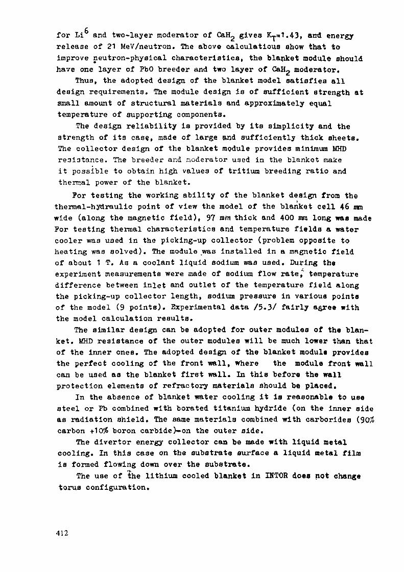
for Li and two-layer moderator of CaHp gives K~.a1.43, and energyrelease of 21 MeV/neutron. The above calculations show that toimprove neutron-physical characteristics, the blanket module shouldhave one layer of PbO breeder and two layer of CaH2 moderator.
Thus, the adopted design of the blanket model satisfies alldesign requirements. The module design is of sufficient strength atsmall amount of structural materials and approximately equaltemperature of supporting components.
The design reliability is provided by its simplicity and thestrength of its case, made of large and sufficiently thick sheets.The collector design of the blanket module provides minimum MHDresistance. The breeder and moderator used in the blanket makeit possible to obtain high values of tritium breeding ratio andthermal power of the blanket.
For testing the working ability of the blanket design from thethermal-hydraulic point of view the model of the blanket cell 46 mmwide (along the magnetic field), 97 mm thick and 400 mm long was madeFor testing thermal characteristics and temperature fields a watercooler was used in the picking-up collector (problem opposite toheating was solved). The module was installed in a magnetic fieldof about 1 T. As a coolant liquid sodium was used. During theexperiment measurements were made of sodium flow rate," temperaturedifference between inlet and outlet of the temperature field alongthe picking-up collector length, sodium pressure in various pointeof the model (9 points). Experimental data /5.3/ fairly agree withthe model calculation results.
The similar design can be adopted for outer modules of the blan-ket. MHD resistance of the outer modules will be much lower than thatof the inner ones. The adopted design of the blanket modult providesthe perfect cooling of the front wall, where the module front wallcan be used as the blanket first wall. In this before the wallprotection elements of refractory materials should be placed.
In the absence of blanket water cooling it Is reasonable to usesteel or Pb combined with borated titanium hydride (on the inner sideas radiation shield. The same materials combined with carboridescarbon +10 boron carbide)-on the outer side.
The divertor energy collector can be made with liquid metalcooling. In this case on the substrate surface a liquid metal filmis formed flowing down over the substrate.
The use of the lithium cooled blanket in IHTOR does not changetorus configuration.
412

R E F E R E N C E S
5.1. .P.A.Andreev, K.A.Zhokhov, N.M.Markov, I.K.Terentjev..Blanket design for fusion tokamak-reactor. Scientifio andtechnical collection "Problems of atomic Science andEngineering". Ijlft/e /(3), Moscow-TAE, 1979, pp.72-87.
5.2. I.K.Terent'ev, E.D.Pedorovich, P.M.Paramonov. Blanket ofhybrid fusion reactor with liquid metal cooling. "Proceedingsof 2nd All-Union Conference on Engineering, Problems ofFusion Reactors. V.4, Leningrad, 1982, p.311-318.
5.3. V.B.Zhinkina, K.A.Zhokhov, E.V.Pirsova. Testing of blanketmodule of fusion reactor with liquid metal coolant« Proceedingsof 3rd Ail-Union Conference on Engineering Problems of FusionReactors. V.4, Leningrad, 1984, pp.274-281.
413

E.7.2
Self-Cooled Liquid Metal Blankets
Dale L. Smith,Argonne National Laboratory
SUMMARY
The self-cooled liquid metal blanket concept provides several inherentfeatures that can potentially improve the attractiveness of the tokaraak as apower reactor. With respect to the engineering considerations, self-cooledblankets provide significant advantages related to design simplicityassociated with the use of the same fluid as both breeder and coolant. Also,most of the fusion energy is deposited directly in the coolant, therebyreducing heat transfer problems, and the coolant can also serve as the tritiumrecovery fluid. In terms of economics, self-cooled liquid metal blankets canprovide high energy conversion efficiencies and potentially long blanketlifetimes. Potential advantages related to safety and environmental impactinclude radioactive effluent control, particularly tritium in the lithiumsystems; possible low long-term residual radioactivity; and inherent safetyadvantages associated with the high conductivity and high heat capacity of thebreeder/coolant.
Liquid metal MHD effects and corrosion/compatibility are the primaryconstraints related to self-cooled liquid metal blanket designs. Chemicalreactivity of the liquid metal, particularly lithium, and a meltingtemperature above ambient provide additional design constraints.
Liquid lithium as the breeder/coolant with a vanadium alloy structure iscurrently proposed as the leading concept. A ferritic steel structure and theLiPb eutectic alloy are considered as backup options. Key features of a self-cooled liquid metal blanket design include use of electrically insulatedwalls, integration of the manifolds into the blanket, and/or flow parallel tothe magnetic field to accommodate the MHD problems. A vanadium alloystructure provides for high temperature operation (mechanical properties andcorrosion), potentially long blanket lifetime, and low long-term activation.Utilization of nitrogen or an inert gas in the reactor room provides a designsolution to the reactivity problem for lithium.
The schematic diagrams in Figures 1 and 2 represent two design conceptsconsidered for self-cooled liquid metal blankets. Both configurationsintegrate the manifold into the blanket in order to reduce the MHD effects.The configuration in Figure 1 provides for high velocity coolant flow parallelto the toroidal field in the first wall region to accommodate the high surface
414

\
:igure 1. Schematic of the reference design for the self-cooled liquid-metalblanket (poloidal/toroidal flow) of a tokamak reactor.

28O°C550-C
55O°C
550°C28O"C
FW AND BLANKLET:
92% LITHIUM
8% VANADIUMALLOY
REFLECTOR:IO% LITHIUM10% VANADIUM
ALLOY8O% STEEL
"igure 2.
HIGH TEMPERATURE SHIELD:10% LITHIUM10% VANADIUM
ALLOY8O% STEEL
DESIGN A. Reversed poloidnl flow concept. Each flowpath shown in the figure consists of several coolantducts, depending on ncutronic and thermal considera-tions. If separate removal of the blanket and firstwall is required, the reflector will be provided withan inflow region similar to that of the blanket.
heat flux. The concept in Figure 2 utilizes insulated walls to reduce the MHDpressure drop and to allow higher coolant velocities.
Analyses of these blanket design configurations with lithium as thebreeder/coolant and a vanadium alloy structure indicate that attractiveperformance characteristics are achievable. Based on the evaluation criteriadeveloped as part of the Blanket Comparison and Selection Study, the followingconclusions can be made:
416

Engineering Evaluation
• High rating for complexity since the liquid metal serves as breeder,coolant, and tritium recovery fluid.
• High tritium breeding performance (TBR > 1.3 is attainable).» High neutron wall loadings (>5 MW/ra^) can be accommodated.
Economic Evaluation
• High temperature capability with vanadium alloy structure provideshigh energy conversion efficiency (~42%).
• Potential for long blanket lifetime (> 6 years at 5 MW/m2).• Reasonable blanket shield thickness « 1.2 ra).
Safety/Environmental
• Vanadium alloy provides for high temperature capability.• Vanadium alloy provides for low long-term activation.• Low-moderate tritium inventory.« Lithium rates high for effluent (tritium) containment.» Reactivity of lithium can be controlled by design (eliminate water
and use nitrogen in reactor room).
417

E.7 .3
Self-Cooled FLINABE (60 Li2EeFa.-40Na Be-Es)Liquid Blanket with Berylium Mult ipl ier - ( A )
Hiroji KatsutaJapan Atomic Energy Research Institute
Seiji Mori, T. KurodaKAWASAKI Heavy Industires, Ltd.
1. BackgroundMolten salts have been known to have some attractive features in
application to fusion blanket in regard of their chemcial stability,immunity to the magneto hydro dynamic (MHD) effect , ease of separatingt r i t ium, lower hazard potentiali ty etc. For the moment the fo l lowingsalts are being considered as potentially applicable:(A) 66LiF-34BeF/melting point: 460°C(B) 47LiF-53BeF/melting point: 363'C
The concept of the mol t en salt b lanke t , however , has not alwaysbeen prefered as the tritium breeding material in conventional liquidblanket design because of the f a t a l low breeding ra t io . In addi t ionneither of those two can sat isfy simultaneously the requirements of lowmelting temperature and low viscosity. The salt(A) will require theoperating temperature as high as 700°C, at which the structural metalsthat can wi ths tand such chemical env i ronmen t may be scarce. Thematerial such as Hastelloy N, which was developed for the molten saltreactors may have some feasible corrosion resistance, while it can byno means be considered as an appropriate material to be used under theirradiation environment specific to fusion reactors. On the other handthe sal t (B) has much lower mel t ing tempera ture and would make theoperat ing tempera ture around 600°C, but this salt has been found tohave rather high viscosity in such a temperature range, eg. 39.3 CP. at600"C. Possible design temperature, therefore, can not be reduced to adesirable lower level by using either of those two types of FL1BE.
2. Outline of InnovationBased on the constitutional diagram as shown in Fig. 1 for the
system of LizBeF^.(FLlBE) and NaiBeF^(FNABE), an eutectic composition atthe ratio of 60 to 40 respectivelv is expected to of fer a low meltingpoint mixture . Re la t ive to' FLIBE, the mixture is g iven its name,l ikewise, "FLINABE".
FLINABLE has a me l t ing t empera tu re as low as about 350°C and theviscos i ty has been es t imated to give va lues close to these of thesalt(A) mentioned above as shown in Table 1. Although many of the datavalues are generated by estimating from those of the two consti tuentsalts, those approximate values present at tractive features of the saltmixture in application to fusion blanket costituent, part icularly as aheat transport medium to work with structural metals at reasonably lowt empera tures . Possible reduc t ion of the design t e m p e r a t u r e foropera t ion to around 600°C wil l cause a s igni f icant widening of therange of material selection for the blanket structure as the corrosionrate of matais in molten salts has a sharp temperature dependence.
The intrinsic demeri t of the low t r i t ium breeding is covered byusing an appropriate neutron multiplier such as beryllium metal or itscompound. Use of graphite for either coating or canning material would
418

protect the multiplier material from corrosion or disintegration if anyby intense neutron irradiation, since graphite has been known by itshigh compatibilty with molten salt environment.
3. Features of Self-Cooled FLINABE Blanket System1) Preliminary design of the blanket
Schematic drawing of the FLINABE blanket is shown in Fig.2. Internalstructure(beryl1ium and graphite) and FLINABE paths are arranged alternatelyin the blanket cell. FLINABE is fed into the blanket from the inlet headerlocated at the rear of the blanket. FLINABE flows forward in the radialdirection of the reactor and turns along the path of a circular arc. Then itflows backward into the outlet header.
In the preliminary thermal-hydraulic design, pressure loss of thecoolant and the maximum temperature of the first wall(HT9) were estimated.Relation between coolant velocity(v). the maximum temperature(T) andpressure loss of the coolant through the first wallWP) is summarized asfollows :
vlm/s) Tl"C) 4HlMHa)5 600 0.08
10 550 0.32(neutron wall loading : 3.3 MU/m2.inlet temperature of FLINABE : 370°C)
When the velocity becomes low, the pressure loss becomes small, but thefilm temperature drop becomes large and consequently the maximum temperatureof HT9 becomes high. Trade-off study is required to select the proper designparameters. For the velocity in the range 5 to 10 m/s, the temperature riseof the coolant through the first wall is estimated to be only a few degrees.To obtain a reasonable outlet temperature of the coolantte.g. 450 C) .reentrant flow scheme should be considered, in which the coolant first coolsthe first wall and then the internal structure.
One dimensional neutronics calculation using the relatively simplemodel was performed to evaluate tritium breeding ratio of the FLINABEblanket. Results are summarized in Table 2. When *.he internal structure iscomposed of only beryllium, local tritium breeding ratio is about 1.65. Ifthe rear half of the internal structure is replaced by graphite, breedingratio is reduced to about 1.35.2) Higher compatibility with structural materials
Lowering of operating temperature can basically reduce corrosionrate in any combination of materials and environment. In addition the
419

replacement of Li in FLIBE with Na by 40% may cause some suppression ofagressiver.ess of the chemical environment to s t ructural meta ls , whichmay make the use of i ron-based a l loys such as a u s t e n i t i c or f e r r i t i cstainless steels possible as the s t ruc tura l mater ial . In general iron-based alloys are considered more resistant to the irradiation-inducedd u c t i l i t y loss at e l e v a t e d t e m p e r a t u r e s as compared to nickel r ichalloys such as Hastelloy N. Use of FLINABE will open a wider room fornew innovat ive materials that would appear in f u t u r e part icularly wi thimproved resistance to the high energy neutron irradiation damage.5) Immunity to the MHD e f f e c t
There is no need of concern w i t h the MHD e f f e c t which is acritical issue in liquid lithium blanket.4) Hazard
In regard to the chemical r e a c t i v i t y h a z a r d s , m o l t e n sa l t sgeneral ly have relat ively low potential as compared to liquid metals.5) Tritium recovery
Because of the very low solubility of tr i t ium in the mol ten salt ,tri t ium formed in the f lood can be separated easily by simple heliumgas bubbling process.6) Operation
In contrast withthe gas-or water-cooled systems no high pressureis r equ i r ed in the m o l t e n salt sys tem, which makes the s t r u c t u r a ldesign simpler and safer as compared to the pressurized system. It isalso poss ib le to feed con t inuous ly the s u p p l e m e n t a r y l i t h ium as i tburns up during operation.
4. Tasks1) Preparation of basic properties data
For the moment on ly l imited amount of exper imenta l d a t a areavailable, which are more or less of preliminary nature covering somep a r t s o f m e l t i n g p o i n t s , i o n i c d i f f u s i o n r a t e s a n d e l e c t r i cconduc t iv i ty . The va lue s shown in Tab le 1 were m o s t l y ob t a ined byinterpolating the values for FLIBE and FNABE. Data based on accurateexperimental measurements are necessary.2) Corrosion Studies
A l t h o u g h FLINABE is expected to be milder in respect of corrosionof steels, careful confirmative experiments are needed to see whetherany unexpected chemical e f f ec t s could be involved or not. Series ofl ong- t e rm cor ros ion kinet ics d a t a wi l l be r equ i r ed in o r d e r tha tmaterial system using FLINABE and s tructural metals is designed withconfidence.3) Design optimization
The drawing shown in Fig. 2 gives on ly a concep tua l m a t e r i a larrangement. Detailed studies in o p t i m i z i n g the sys tem by rea l i s t i ccomponent arrangement are necessary.4) Safety consideration in trit ium release
Since estimated trit ium solubility in the molten salt is very low,the partial pressure of tritium in the salt will increase sharply as itis produced by neutron irradiation, which will provide high potentialfo r pe rmea t ion o f t r i t i um through the boundary m a t e r i a l s . A c c u r a t aassessment of the t r i t i um escape f r o m the s y s t e m is r equ i r ed . Somee f f e c t i v e means of p r e v e n t i n g the pe rmea t ion by se t t i ng d i f f u s i o nbarriers must be developed, eg. oxide coating or surface oxidation.
420

Table 1 Physical Properties of FL1NABE Table 2 Calculated Tritium Breeding(estimate) Compared with FLIBE and FNABE Ratio for FLINABE Blanket
sola :
CO
400 'C
300'C600*C
7co •::Vlacoalty t?)
400*C500' C600'C700 'C
SpecificConeuccanca
400 'C300'C600'C700*C
Baac Capacityc? _ t> _ i
conductivity
(W.C.-C-')
(47-53)
-ta-n:3E
363
2.052.011.971.93
503.311«. 3
39.316.2
0.270.611.021..9
2.33
0.008
(66-3»)
orcho-=XI3£
460
.
2.001.961.32
-
14.9
8.63.5
-1.532.142.73
2.38
0.010
1(39. a-26. ,-3,) (66 - 34)
F1IHAJC FXA1E
350 395
2.142.082.02 2.111.97 2.03
32.013 .3a. 8 9.03.7 5.9
0.321.231.7* 1.152.23 1.60
2.31 2.2
0.010 0.010
•lo.
1
2
3
4
3
3r««din( Zanm
Fli3«(471iF-333«f,)*too:
n.U«(47lir-33»««,) 4013« SOI
rLi-tjLi«' 4o:3« 601
Fii.N»a« 4o:3« S3:HT9 5:
FLiNaa« 40:
BT9 3:
TS»
1.103
1.794
1.764
1.656
Cocoicnc
•*ii 100:inrlc~a«at
*
«
. »cnjccur«
•'11 IOO: antich-
' 3« for Irctdai 1C for 3rt<Q«r 2
Breeder 1 Breeder 2
0 1.2S (ca)
Fig. 1 Sys tem Li BeF -Na BeF Fig. 2 Structure Concept of FLINABE Blanket
421

E.7.4
FLOW CHANNEL INSERT FOR THE REDUCTION OF MHD PRESSURE DROPIN LIQUID METAL FLOW
S. Ma langKernforschungszentrum Karlsruhe
Problem
Blanket concepts using the samp liquid metal both as breeder material and ascoolant have a number of attractive features. Such selfcool cd blankets arecharacterized by a simple mechanical design with a much smaller number ofducts and welds than any other blanket concept. The main problem involved inl i q u i d metal cooling o? a blanket is the large MI1D pressure dron.
If liquid metal flows perpendicular to a magnetic field, a potential diffe-rence across the flow channel is induced. This potential difference causes anelectrical current flowing in the liquid metal and the walls, if the wallsare not insulated against the liquid metal. A generally used assumption is toneglect the electrical resistance in the liquid metal and in the walls par-allel to the magnetic field. This leads to the following equation for thepressure gradient in a straight duct perpendicular to a uniform magneticfield:
Ap/L = B2 - v ow • tw/aB = magnetic inductionv = liquid metal velocitycr., = electrical conductivity of the wallw J
t = thickness of the wall perpendicular to Ba = tube radius or half width of a rectancular channel (measured
in the direction of B)
The equation shows, that the pressure drop increases linearly with the wallthickness.
Usually, the allowable pressure drop in a blanket is limited by the requiredpumping power. The mechanical stress in the duct walls can be limited to anallowable value by adjusting the wall thickness accordingly to the equation
422

This adjustment, however, is not possible in the case of a liquid metalcooled blanket where an increase In the wall thickness in order to lower themechanical stress would increase the pressure drop.If for simplification the maximum pressure P is set equal to the pressureïïlrt 5Cdrop AP, the maximum mechanical stress S „ becomes independent of the wallUlrt A
thickness as a c o m b i n a t i o n of the two equations mentioned above shows
Smax = PHI^ = L B2 V - aw2rw
The maximal allowable velocity in uninsulated ducts and consequently theachievable power density are therefore limited by the allowable stress in theHue t walls.The only way to avoid this limitation is to insulate electrically the loadcarrying walls from the liquid metal.
Methods to reduce HMD pressure dropa) Insulated wallAn electrically insulating layer between the liquid metal and the wall woulda"oid any short circuiting of the potential difference induced in the liquidmetal. The MUD pressure drop would become nearly zero. Unfortunately, thereis no material known which is compatible with the liquid metal and will notcrack under the cyclic loading conditions. Cracks in the insulating layerwould allow the liquid metal to contact the thick load carrying wall, result-ing in a large MHD pressure drop.
b) Laminated wallThe basic idea is to have a thin metallic liner between the liquid metal andthe insulater. This liner is mechanically supoorted by a thick load carryingwall via a layer of ceramic material. Electrical current flow is restrictedto the thin liner and the thickness of the outer wall has no influence on thepressure drop. This concept reduces larglv the MHD pressure drop and has beenproposed therefore in a number of blanket studies. The problems involved inthis method are:- Fabrication of the liner.
. The thin liner itself has nearly no strength. It can survive the coolantpressure only if it is supported at the entire surface. This requiresvery precise fabrication in order to avoid excessive deformations priorto be supported by the outer wall.
. This is especially difficult to achieve for non-uniform flow channelgeometries.
423

. All segments of the liner have to be welded together with a high reliabi-lity in order to avoid coolant leaks destroying the insulation.
- Stresses caused by different thermal expansion.The thermal expansion of the insulator material is smaller than the linerexpansion. Changes in the temperature level will therefore lead to ten-sile/compression stresses in liner and insulator. There will be an addi-tional differential thermal expansion between liner and load carryingwall if the temperature of the liquid metal changes. This results infriction and shear stresses between liner, insulator and outer wall.
c) Flow channel insertThe problems involved in laminated wall concepts can be avoided if flow chan-nel inserts (FCI) are used as shown in Fig. 1. These inserts are fabricatedseperately from the duct fabrication, using a composite material where aceramic layer is sandwiched between two metallic sheets. All edges of thismaterial are welded in order to avoid any contact between liquid metal andinsulator.
The FCI are fitted loosely into the flow channels. There are either longitu-dinal slots or small holes in the wall of the FCI, providing a pressureequalization between the inner flow region and the outer gap. This pressureequalization avoids any substantial mechanical loading of the FCI with theexception of the coolant pressure which, however, is equal on all surfaces.The slots or holes along one axis of the FCI do not influence the MHD pres-sure drop.
Mechanical stresses in the FCI are very small not only for steady stateoperations but also for transient cases with changing liquid metal tempera-tures.
The temperature difference across the FCI wall is small which leads togetherwith an unrestricted thermal expansion to negligible small thermal stresses.Additionally, the FCI acts together with the liquid metal gap as a thermalsleeve to diminish the thermal shocks of the load carrying wall .
The MHD pressure drop depends only on the conductivity of the liner facingthe inner flow region. The outer liner and the outer gap have no influence onthe pressure drop because there is no voltage driving a current through thisregion. In rectangular channels the FCT have to cover only three of the four
424

sides as it can be seen in Fig. 2. This may be an advantage for the plasmafacing channels because no additional thermal resistance is caused by theFCI.
It can be stated as a conclusion, that the FCI concept avoids some doubts onthe feasibility of laminated wall concepts, improving the feasibility ofselfcooled liquid metal blankets itself.
-Longitudinal slot orholes for pressureequalization betweeninner flow region and
outer gap
1 0,1 1.
magnetic field B
wall
Fig. 1 Flow Channel Inserta.
7/////// /7
Fig. 2 Insert in the Plasma Facing Channel
425

E.7.5
PEBBLE BED CANISTER: A CERAMIC BREEDER BLANKET FOR HIGH BREEDING RATIOS
M. Dalle Donne and U. Fischer, INRE. Bojarsky and H. Reiser, IMF IIIKernforschungszentrum Karlsruhe, Germany
1. INTRODUCTION
A design with poloidally running pressure tubes containing the ceramic breedermaterial and the beryllium multiplier in form of a pebble bed has been previouslyinvestigated /!/. The resulting tritium breeding ratio of 1.08 (based on 100%torus surface converage) was relatively low. This value was based on a 10 mmthick steel erosion layer on the first wall. Calculations using more recentdata on the neutral particle spectrum near the first wall have shown that a2 mm thick steel erosion layer would have been sufficient for the requiredneutron fluence of 3 MWa/nn /2/. This 8 mm decrease in the thickness wouldimprove the tritium breeding ratio to about 1.16. On the other side, however,the proposal of mixing the beryllium and the ceramic breeder pebbles which isthe optimum solution from a neutronic point of view, has been questioned:thermodynamic considerations would indicate that the beryllium is oxidized bythe ceramic /3/. At this stage, it is not clear if a protective beryllium oxidelayer is formed or not and experimental investigations are clearly required.Separation of the ceramic breeder and of the beryllium into two regies wouldcause a decrease of the breeding ratio.This order of considerations has induced us to investigate other blanket formswith a better coverage factor of the torus surface. Indeed the poloidalsolution, although very good for other aspects, is rather leaky for the neutrons,and this is the main reason of the rather modest breeding ratio. We startedtherefore to investigate the "lobular" blanket design proposed by GeneralAtomic /4/, which promises to have a good coverage of the torus surface. Thisdesign is based on the BIT (breeder-inside-tube) concept and on the assumptionthat the lobules support each other in poloidal direction. This solution isvery difficult to realize and we have decided to put forward for NET a newdesign made of self-supporting canisters and based on the BOT (breeder-out-of-tube) concept /5/.
2. DESCRIPTION OF THE PRESENT DESIGN
Fig.1 shows a 15 segment of the outboard section of the proposed design. Thefirst wall is separated from the blanket and it is similar to that proposedby Ansaldo-Ispra /6/. It can be manufactured by electron-beam welding ofpreviously bended steel plates (Fig.2) or it can be manufactured in one piece.The coolant tubes are running in radial and toroidal direction and are brazed(nico-brazing) on the back of the first wall. The first wall is cooled by heliumat 60 b which comes from three poloidally running feeding tubes. After havingleft the first wall region the cooling helium is collected in poloidal manifolds,then it goes into toroidal distribution tubes contained in the blanket canistersand finally in radially-poloidally running tubes immerged in a bed formed by0.5 mm Li4SiU4 pebbles (BOT = breeder-outside-tube concept (Fig.2)). Afterwardsthe helium is collected in toroidal manifolds and flows out of the blanket infour poloidal tubes. The helium purge flow at the pressure of Ib follows asimilar path (Fig.2). It is fed by tubes in the front part of the canistersand flows radially through the front portion of the Li4Si04 pebble bed,through lateral channels in the region of the beryllium multiplier and thenagain in the breeder pebble bed region. The canisters have to contain the heliumpurge flow pressure of Ib. Their flat walls are supported by stiffening plates,
426

so that they can withstand for a short time an internal overpressure of 6b.Fig.3 shows a poloidal-radial section of an outboard canister and of the firstwall. The beryllium slab is separated from the Li^SiO^ pebbles by thin steelsheets. Fig.4 shows a poloidal-toroidal section of an outboard canister.
3. NEUTRONIC AND THERMOHYDRAULIC CALCULATION S
The neutronic calculations are based on a one-dimensional model of the torus incylindrical geometry. The axis of the torus is chosen as the axis of the infinite-ly, long cylinders. Thus inboard and outboard blankets are represented bycylindrical rings. Each ring is divided into subzones. Within each subzone thematerials are homogenized according to their volume fractions in the midplaneof the torus where the calculation is performed. For all neutronic calculationsthe KfK version of the one-dimensional transport code ONETRAN has been appliedin Sg approximation. The nuclear data used were those of the VITAMIN-C librarycondensed into a 25 neutron/21 gamma group structure in P_ approximation.The thermohydraulic calculations have been performed in a way similar to thatillustrated in Ref. /?/. The radial power density distribution has been takenfrom results of the nuclear calculations and the poloidal power distributionis from Ref. /8/.
4. CALCULATION RESULTS AND DISCUSSION
Table I shows the results of the neutronic calculations. For the blanketreference design, with an erosion layer on the plasma side of the first wallof 2 mm stainless steel thickness, the tritium breeding ratio for 100% torussurface coverage is 1.35. With an erosion layer thickness of 10 mm stainlesssteel the tritium breeding ratio would decrease to a value of 1.27. A 20 mmthick graphite layer on the inboard side of the torus, corresponding to thesuggestion of Ref. /9/ would result in a tritium breeding ratio of 1.33.
Tables II shows the results of the thermohydraulic calculations. With a heliumpressure of 60b the helium pumping power for the whole helium primary circuitis 4% of the total thermal output, a value similar to that obtained for ahelium cooled fission reactor of similar power/10/. The temperatures in thestainless steel structural material and in the beryllium appear to beacceptable.Table III shows the calculated tritium inventories and the effects on theceramic material. The chosen purge helium mass flow, equal to 0.1% of thetotal helium, flow is similar to that suggested for a projected fission reactorof similar power /10/. The resulting equilibrium Ï2Û partial pressure of 0.31and 0.24 Pa in the inboard and outboard blanket regions respectively"1" causeformation of a stable LiOT phase for temperatures lower than the minimum pebblebed temperature (300°C), even if the relevant thermodynamic properties ofLi/(Si04 are assumed equal to those of Li2U, which are the only availableexperimentally /I I/. This is a pessimistic assumption. The tritium dissolvedin the Li^SiO^ pebbles is only 91g. This has been evaluated using, again pessi-mistically, the data for Li£Û /12/. The tritium inventory due to diffusivity inthe pebbles is negligibly small /13/. The tritium inventory due to adsorbtion,would be for the same temperatures and Ï2Û partial pressures about 2000g for
It is assumed that practically all tritium produced is present in the blanketin oxidated form. This is required to control the tritium permeation lossesand probably requires passivation of the stainless steel walls at high tem-peratures, which otherwise act as a reducing agent.
427

with a specific surface of 0.57 m^/g /14/+. The LiOT evaporation rate hasbeen assessed for the front region of the Li^SiO^ bed, assumed at the maximumtemperature of 900°C and using the data of Ref. /15/. The resulting LiOT trans-port due to the LiOT evaporation-condensation process of 0.03% per year ofoperation appears to be acceptable.
Assuming a helium leakage into the plasma equal to 0.025%-0.05%/d of the blankethelium inventory /16/, which again may be pessimistic, we obtain a leakage intothe plasma of less of 10~3 g/sec, which is within the NET requirements /Ml.This indicates that double containement of the blanket, although for certainaspects desirable, is not necessary with this design.
5. ADVANCED DESIGNS WITH HIGH BREEDING RATIOS
Intimate mixing of the beryllium multiplier with the Li^SiO^ would improve thebreeding ratio. This implies that either the compatibility between the twomaterials reveals not to be a problem or that a thin protective coating (forinstance a vapor deposited stainless steel layer) is applied on the berylliumpebbles. We have investigated a solution with a bed of beryllium and Li4SiU4pebbles in the optimum volume ratio of 85% to 15% and with a bed filling factorof 85%, which requires particles of different sizes. With the same geometricalrestrictions of the reference NET design, we obtain a tritium breeding ratio of1.47. Addition of ZrHj^y to the back of the blanket would result in a furtherincrease of TBR to the value 1.53. This high breeding ratio could allow a de-crease of the blanket thickness, if a lower TBR value is sufficient. With athinner blanket the importance of the ZrHj y would increase.
REFERENCES
/!/ M. Dalle Donne, U. Fischer and M. Küchle: A Helium-Cooled Poloidal Blanketwith Ceramic Breeder and Beryllium Multiplier for the Next European Torus,Nucl. Technol., 7J_, 15-28, 1985.
/2l M. Dalle Donne and M. Küchle: unpublished, 1985.
/3/ D. Vollath and H. Wedemayer: Kernforschungszentrum Karlsruhe, Privatecommunication, 1984.
/4/ Blanket Comparison and Selection Study, Fusion Power Program, ANL/FPP-83-1,Argonne National Laboratory, 1983.
/5/ M. Dalle Donne, U. Fischer, E. Bojarsky and H. Reiser: Pebble Bed Canister:A Ceramic Breeder Blanket Design with Radial Helium Cooling, NET-BlanketEngineering Meeting on Solid Breeder Blankets, Karlsruhe 26-29 November 1985.
/6/ F. Farfalletti-Casali, M. Biggio and A. Cardella: A First Wall Concept forINTOR and NET Experimental Power Reactor, 13th SOFT Meeting, Varese,Sept. 24-28, 1984.
Il/ M. Dalle Donne, S. Dorner and S. Taczanowski: Conceptual Design of Two HeliumCooled Fusion Blankets (Ceramic and Liquid Breeder) for INTOR, KfK-3584,EUR7987e, Kernforschungszentrum Karlsruhe, 1983.
/8/ C. Ponti: Poloidal Distribution of Neutronic Responses on the First Wall, NETWorking Party on Blanket Engineering, Ispra, Nov. 27, 1984.
/9/ S. Malang: First Wall Concept with Radiatively Cooled Tubes, NET Meeting onFirst Wall Components, Culham, 18-20, June 1985.
The recent in pile LISA experiments in Grenoble indicate that the tritiuninventory due to solution and adsorbtion would be Cor Li.SiO, an order ofmagnitude less than this value.
428

/ l ü / General Atomic Project S ta f f : 300 MW(e) Gas-Cooled Fast Breeder ReactorDemonstration Plant, GA-A 13045, 1974.
/l l/ M. Tetenbaum and C.E. Johnson: Partial Pressures of 1^0 above the DiphasicLi20(l)-LiOH(s,l) System, J. Nucl. Mat. 126, 25-29, 1984.
/12/ J. Norman and G. Hightower: Measurements of the Activity Coefficient of LiCDissolved in Li2U(s) for an Evaluation of LÏ2Û as a Tritium Breeding Material ,J. Nucl. Mat. 122&123, 913-920, 1984.
/13/ D. Briining, D. Guggi, H.R. Ihle and A. Neubert: Diffus ion of Tritium in, andThermochemistry of Lithium-ortho-silicate, 13th SOFT Meeting, 24-28 Sept. 1984,Varese.
/14/ H. Yoshida et al.: Water Adsorbtion of Lithium Oxide Pellets in Helium SweepGas Stream, J. Nucl. Mat. 122&123, 934, 1984.
/15/ A. Fischer and C.E. Johnson: Thermodynamics of Li„0 and Other Breeders forFusion Reactors, J. Nucl. Mat. 133&134, 186-191, 1985.
/16/ B.C. Chapman: Dragon Operating Experience, Proc. Gas-Cooled Reactor In fo rma t ionMeeting, Oak Ridge, Tenn., CONF-700401, April 27-30, 1970.
/17/ G. Vieider: Summary of Boundary Conditions for NET First Wal l , NET Meet ingon First Wall Components, Culham, 18-20 June 1985.
TABLE I: Results of Neutron Calculations
Tritium breeding ratioTritium production rate
Referencesolutions*=2 mm s.s.
1.35
111 g / d
Solutionwith
s=l 0 mm s.S.
1.27
Solution with20 mm graphitelayer on in-board side
1.33
s = thickness of erosion layer on the plasma side of the first wall
TABLE II: Results of Thermohydraulic Calculations (Reference Solution)
Breeding material : Li^SiO^ (0.5 mm diam. particles)LÎ4SiC>4 blanket inventory: 104tMultiplier: berylliumStructural material: austenitic stainless steelTotal blanket power: 610 MW (+70 MW in the shield)Coolant helium pressure: 60bFW and Blanket pressure drop: 1.9bPressure drop in rest of helium primary circuit: 0.6bHelium mass f low for F.W. and blanket cooling: 470 kg/secHelium pumping power: 21 MW (+6.6 MW for rest of helium primary c i rcui t ) ,First wall: helium inlet temp.: 200°C
helium outlet temp. : 233°CF.W. max. temp.: 440°C
Blanket: helium inlet temp.: 233°Chelium outlet temp.: 450°Cmax. temp, in pressure tubes : 540°Cmax. temp, in beryllium: 550°Cmax. temp, in particle bed: 900°Cmin. temp, in particle bed: 300°C
429

TABLE III: Tritium Inventories and Effects on Ceramic Material
Purge helium pressure: IbPurge helium mass flow: 0.47 kg/sec (0.1% of coolant helium flow)
partial pressure in purge helium:inboard blanket: 0.31 Pa (Tmin=288°C, Li20 /11/)
outboard blanket: 0.24 Pa (Tmin=284°C, Li20 /I I/)Tritium dissolved in 1 48104=9 Ig (Li20, /12/)Tritium inventory due to diffusivity in Li^SiO^ particles < 1g /13/Tritium inventory due to adsorbtion: f» loo f 200 g (LISA)Max. lithium transport due to LiOT evaporation/condensation:
0.03% per year (Li4Si0Helium losses from purge flow system and from helium primarysystem: 0.025% f 0.05%/d of helium inventory (Dragon reactor, /16/)Total F.W. and blanket helium inventory: 128 kg _Helium leakage into plasma region: (0.37 f 0.74)xlO g/secTotal tritium losses from plant < 10 curie/d
/15/)
Pebble BedBreeder Canister
First Wall
Coolant InletCoolant Outlet
Purge Gas RowInlet and Outlet
Breeder Cooling
Shielding andSupport Structure
First WallCooling
lig. 1 Helium tooled ceramic breederblanket (outboard segment)
Purge Gas Collector Grid Plate
Helium Coolant Inlet
Purge Gas SupplyTubes
Helium Coolant Outlet
Purge Gas FlowOutlet Inlet
Pebble BedCoolant Tubes
First Wall HeliumCoolant Tubes
Ceramic Pebble BedRrst Wall
Beryllium Layer
Stilfing Plate
Hg. 2 Pebble bed canisters
430

Fig. 4 Poloidal-Coroidal section ofoutboard canister
KUroi.,* 2ou& +». 27—M
Tig. 3 Poloidal-radial section ofoutboard canister
431

E . 7 . 6
COMPOSITE BERYLLIUM/CERAMICS BREEDIN PIN ELEMENTS
FOR A GAS COOLED SOLID BLANKET
F. CARRE, G. CHEVEREAU, F. GERVAISE and E. PROUSTCentre d'Etudes Nucléaires de Saclay
IPDI-DEDR-DEMT-SERMA91191 GIF-sur-YVETTE CEDEX (FRANCE)
I/ LIMITED BREEDING POTENTIAL OF USUAL HELIUM COOLED PIN BLANKETS
The moderate pressure of helium as coolant (5 to 8 MPa) makes it pos-sible to contain the pressure in blanket modules rather than in pressure tubes,and hence enables visualizing concepts based on canned breeder elements ; theactively cooled cladding ensures the geometrical and mechanical integrity ofeach breeder pin and permits an efficient control of the breeder temperature,what is essential to minimize uncertainties in tritium recovery.
In return, the low helium density implies a high coolant volumetricflow rate and results in large coolant cross section to mitigate the pumpingpower requirements. This, combined with the use of pins, results in increasedhelium and structure volume fractions and hence in a limited breeder fillingfactor, that detrimentally reacts upon the breeding performances of most blan-kets based on these options : TBR ^ 1.06 for UWMAK II [1], TBR * 1.04 forLiA102/Be/Ferritic Steel concept considered in the BCSS [2 ] .
The development of attractive helium cooled blankets based on pinbreeder assemblies [3,4,5] has been essentially made possible by the derivationfrom recent CEA neutronic studies of an optimized composite Beryllium/Ceramicsbreeder arrangement capable of excellent neutronic performances [6,7].
2/ DESCRIPTION OF THE PROPOSED COMPOSITE Be/Ceramics BREEDER ELEMENTS
Two blanket concepts were successively developed by the CEA, with theorientation of the cooling lines optimized to maintain the breeder workingwithin an as narrow as possible temperature range ; this was intended to allowsome margin to accommodate possible temperature drifts caused by blanket powerswings and by changes in thermal properties and heat transfer characteristicsunder irradiation.
Even though characterized by different module arrangements (radialcanister [3,4] and in series cooled tubular rows [5]) , both blanket concepts
432

adopt a breeding zone made of hexagonal pin bundles, composed of an alternatestack of Beryllium and y LiAlCL hollow pellets externally cladded and equippedwith wire wrap spacers (Figures 1 and 2) ; the optimization of the breedercomposition leads to respective volume fractions of 20% y LiAlCL (60% enriched
c <-in Li) and 80% of Beryllium, which acts simultaneously as moderator and asneutron multiplier.
The excellent thermal conductivity of Beryllium minimizes the radialtemperature gradient AT in the breeder material and makes it possible to considerbreeder rods larger than 3 cm in external diameter and hence to minimize thevolume fraction of cladding material and the associated parasitic captures ;
2usual blanket conditions (AT < 200 °C, Pn ^ 2 MW/ m ) would restrict to about1.5 cm the upper limit for the diameter of pure ceramics rods placed in frontposition.
A low pressure purge gas enters the central cavity (1 cm in diameter)of each breeder pin, sweeps the grooved surface of the LiA102 pellets and isfinally collected in large grooves machined in the Beryllium pellets outersurface.
Fully heterogenous 3D Monte Carlo calculations proved both blanketconcepts developed by the CEA, to be capable of breeding performances in excessof 1.5 with a 70 cm thick breeder zone [6,7,8] ; this is achieved in spite ofsuch a moderate Be/LiA102 filling factor as 42% and with such high void andstructure proportion as 41-46% and 12-14% respectively.
The adaptation of the toroidal concept to the restricted blanket thick-ness of NET (35 cm inboard + 65 cm outboard) still exhibits a neutronic potentialin excess of 1.2 with a comparable blanket composition and with a First wal lcontaining 1.5 cm of steel protected by 1.5 cm thick Graphite Tiles.
3/ ATTRACTIVE FEATURES OF THE COMPOSITE Be/Ceramics BEEPER ELEMENTS
3.1. Neutronic properties of Beryllium
The exceptionally low energy threshold of the (n,2n) reaction onBeryllium (^ 2 MeV), makes the multiplication accessible not only to 14 MeVneutrons but also to neutrons having already experienced a few collisions.This is especially important for breeder ceramics as inelastic scattering onoxygen results in slowing down most 14 MeV neutrons below the energy threshold
433

CO-t».
I I«4- j_ft 11^»>> *-f«> i4?*''<**€1,.___ tgft ^J l^«tl,«^l g^**««»
Figure 1 : Proposed Beryllium/Ceramics BreederPin lay-out [5].

L».^»«^r _•.»«».• A C •«*•>>>••• «el«f*V_ <OSO( \»W*«J U»-h«K
l*..'*,. U.»U ) » - «ifa.«« 20aO(0«tb««4 **-i»V
OJFigure 2 : Possible arrangement of proposed BeryHi urn/Ceramics pins into————— breeder bundles housed in tubular containers, liable to be
organized in a tight lattice of toro'idal breeder rows [5]

of the multiplication reaction of all alternative multiplier materials (^ 7 MeVfor Lead and Zirconium). Moreover neutronic studies proved the substitution ofBeO for metallic Beryllium to totally spoil the attractive breeding performancesof the proposed breeder assembly [8].
Beryllium is also the only neutron multiplier, that also acts as anefficient moderator. The massive use of Beryllium in the blanket thereforeminimizes the distance covered by the incident 14 MeV neutron until it beslowed down enough to be captured ; this assures a minimum neutron leakage fora given blanket thickness and breeder filling factor.
Neutronic sensitivity studies [7] proved the reemitted neutrons byBeryllium to be efficiently captured by Iron. The attractive breeding perfor-mance of the proposed breeder element is subject to rapid degradation as thevolume fraction of steel increases (- 0.75% on TBR with each additional 1% ofblanket structure and - 1.4% on TBR with each additional mm of structure inthe First Wall [7]). Minimization of parasitic captures in Steel then resultsin the incentive to gather both multiplier and breeder materials inside thesame cladding.
The massive use of Beryllium in the blanket also enhances the Fusionenergy multiplication factor beyond 1.4.
3.2. Thermal properties of Beryllium
The relatively high melting temperature of Beryllium (^ 1280 °C) andthe large difference of enthalpy at the melting point (A H 1300 kj/kg), arewell adapted to most solid blanket working conditions and totally relax thecooling difficulties associated with change of phase for Lead to be avoided.
The excellent thermal conductivity of Beryllium (^ 1 W/m/°C), signi-ficantly improves the effective thermal conductivity of the composite Be/Ceramicsbreeder element and consequently greatly reduces the temperature gradient asso-ciated with a given thermal load. No longer the ceramics pellet radius controlsthe temperature gradient across the rod, as the heat deposited in y LiAlOp isaxially conducted to the adjacent Beryllium pellet, that acts as a heat sink andflattens the temperature profile. Adjusting the breeder working temperature tothe requisite temperature window for adequate Tritium release, is thereforeeasier for composite Be/Ceramics rods than for plain ceramics pins ; the proposedbreeder composition consequently permits larger pin diameters and hence reducedstructure volume fraction.
436

Beryllium is also featured by the highest specific heat among thesolids (2.25 kJ/kg/°C) ; the massive use of Beryllium in solid blankets minimizestemperature swings and thermal cycling of the ceramics, in case of pulsed opera-tion and significantly increases the thermal inertia of the breeder elements.The later consideration is of particular importance for the safety of gas cooledsystems subject to loss of coolant accidents.
3.3. Respective volume fractions of Beryllium and Ceramics
Neutronic optimization studies of Be/Ceramics breeder elements provethe breeding capability to be maximum for respective volume fractions of 80-85%of metallic Beryllium and 20-15% of lithiated ceramics (60% enriched in Li).
However, reduction of the Beryllium inventory can be considered withlimited impact upon the breeding capability :
- as 80% of the neutron multiplication reactions occur in a 35 cm thick regionin the front of the blanket, the replacement of Beryllium (that mainly actsas a moderator beyond this point) by any alternative moderator materials can beenvisaged with little degradation of the neutronic performances,
- if the depletion in Li and the associated damages are shown to endanger theceramics integrity, a slight decrease of the Beryllium content (e.g. from 80to 70%) and a subsequent increase of the ceramics inventory (e.g. from 20 to30%), may be expected to partly slow down the burn up integration rate, thas isaccelerated by a factor of 5 to 6 in the proposed blanket concept, comparedwith others designs based on separate neutron multiplier and breeder materials.
The TBR exhibits only a slow degradation with the depletion in Li2 2(- 0.4%/MWy/m with average and peak depletion rates of (- 5.0%/MWy/m
and - 6.9%/MWy/m2 [9]) respectively).
4/ CRUCIAL ISSUES OF COMPOSITE Be/Ceramics BREEDER ELEMENTS
The viability of composite Be/Ceramics breeder elements, as illustratedin Figures land 2, is subject to the demonstration of satisfactory behaviour ofcanned Beryllium in the Fusion blanket environment. This includes the demonstra-tion of acceptable chemical compatibility :
- with the breeder, and verification that either the oxidation of metallic Beryl-lium can be inhibited or that the kinetics is slow enough to be tolerated ; ofimportance is also the assurance that no low temperature melting alloys (suchas Be Al Si eutectic) is likely to form,
437

- with the structure, and inhibition of possible corrosion of austeniticstainless steel caused by the affinity of Beryllium for Nickel,
- with the atmosphere of the purge gas, containing moisture (T^O, HTO), hydrogen(H2, T2) and possibly 0,, addings. Previous studies [10] already demonstratedthe benefit of 0.4% Ca addings for resistance to oxidation. The possible for-mation of Beryllium hydride (BehL that decomposes at 125 °C) needs to beassessed.
Of crucial importance for the integrity of the proposed breeder elementand hence for the recoverability of the regenerated Tritium, is the possibilityto overcome the anticipated swelling and degradation of mechanical properties ofBeryllium under irradiation. This can be achieved either through a sufficientdesign flexibility or through the development of Beryllium metallic alloys ofimproved performances.
Uncertainties in Tritium release under irradiation, must also be provednot likely to cause the accumulation of excessive Tritium inventory, that wouldoffset the benefit of tailored temperature conditions for enhancement of the Tri-tium release and would raise potential safety concerns.
Beryllium ressource limitation, was shown by the BCSS [2], not to be sodrastic as to exclude the use of Beryllium as reference neutron multiplier mate-rial for the first and second generations of Fusion reactor service (^ 1800 and3000 GWe-y, respectively).
5/ PROSPECTS OF BERYLLIUM/CERAMICS BREEDER ELEMENTS
Even though they may not be credible as illustrated on Figure 1,Beryllium/Ce ramies breeder elements exhibit definite neutronic and thermaladvantages that reactivated in Europe the interest for Helium cooled pin blan-kets, affected so far by breeding performances ranging from poor to fair. Eventhough, particularly attractive for this type of blanket, suffering from alarge structure content and from a low breeder filling factor, the inherentadvantages of the considered original Breeder/Multiplier assembly can alsobe extended to any type of solid blanket, irrespectively of the cooling options,provided the structure and the breeder contents be kept acceptable.
It is therefore important that European breeder experimental programmethoroughly addresses the specific issues of this breeder element and generates
438

data to check the viability of the concept,and recommendations for the designto gain in realism.
6/ REFERENCES
[1] R.W. CONN, G.L. KULCINSKI and C . W . MAYNARD, "The UWMAK-II Study :a Conceptual Design of a Helium Cooled, Solid Breeder, TokamakFusion Reactor System", Nuclear Engineering and Design 39, 5-44 (1976)
[2] M. ABDOU, C. BAKER.& al., "Blanket Comparison and Selection Study",ANL/FPP-84-1, Argonne National Laboratory (1984).
[3] F. CARRE, G. CHEVEREAU, F. GERVAISE and E. PROUST, "Conceptual Studyof a Helium Cooled Ceramics/Beryllium Blanket for a Power Reactor",Proc. 13th Symposium on Fusion Technology (1984).
[4] G. CHEVEREAU, "Adaptation to NET of a Beryllium Canister BlanketConcept", Proc. 13th Symposium on Fusion Technology (1984).
[5] G. CHEVEREAU and L. BARAER, "A Helium Cooled Toroidal Blanket for NETwith Li Ceramic Breeder and Beryllium Multiplier", CEA-DEMT-SERMAReport Nr 85/718 T.
[6] F. CARRE, F. GERVAISE and L. GIANCARLI, "Fusion Reactor BlanketNeutronic Studies in France", Proc. 5th Topical Meeting on theTechnology of Fusion Energy (1983).
[7] F. GERVAISE and L. GIANCARLI, "Progress in Neutronic Analysis ofFusion Reactor Blanket", Proc. 13th Symposium on Fusion Technology(1984).
[8] F. GERVAISE, "Etudes neutroniques de couvertures de réacteur à fusion.Calculs complémentaires sur la solution Be/LiA102 à refroidissementradial en hélium", CEA-DEMT-SERMA Report Nr 85/1667 T.
[9] L. GIANCARLI, "Atomic Burn Up Effects on Tritium Regeneration",.UKAEAPresentation at the NET-Blanket Engineering Meeting on Solid BreederBlankets (Karlsruhe 26-28 Nov. 1985).
[10] G. CHEVEREAU, "Revue bibliographique des propriétés du Béryllium envue de son utilisation dans la couverture de réacteurs à Fusion",CEA-DEMT-SERMA Report Nr 84/1639 T.
439

E . 7 . 7
High Temperature Helium Cooled Blanket
Seiji Mor i , T. Kuroda , T. Suzuki ,KAWASAKI Heavy Industries, Ltd.
T. Kobayash i , T. Tone,Japan Atomic Energy Research Insti tute
1. IntroductionFor a fusion commercial reactor, high temperature (>400°C) helium
cooled blanket of fe rs several advantages such as:1) No t e m p e r a t u r e cont ro l mechanism for the minimum t e m p e r a t u r e of
the sol id breeder (Li20) is necessary for the purpose of con t inuoustritium recovery.2) High temperature helium ( 700°C) makes the electricity conversion
efficiency higher.3) Because he l i um shows excel lent n e u t r o n economy, high t r i t i u m
breeding ratio is possible.A) Tritium recovery from the helium stream is relat ively easy.5) Because hel ium is one of the mos t iner t gas, chemical r eac t ions
with the breeding material and structural material are not of concern.6) No special cons ide ra t i on is r equ i r ed for the MHD e f f e c t to the
coolant f l o w and the e l ec t romagne t i c e f f e c t to the p l a sma becausehelium is nonmagnetic and nonconductine ellectrically.
7) Helium technology is well developed next to the water technology inthe field of nuclear fission reactor. Thermal-hydraulic properties arewell known and power conversion equipments are well developed.
This paper describes the design s tudy for hel ium cooled t r i t i u mbreed ing b lankets with solid breeders . The design is based on thedesign study of the Tokamak commercial reactor (fusion power:3200 MW)at Japan Atomic- Energy Research Institute.
2. Design Description2.1 Material selection
(1) Structural materialsThe s ta inless steel to be improved in the f u t u r e appears to be
limited to the maximum operating temperature to <450t, which limits thethermal-to-electrical conversion efficiency to <36% with use of watercoolant. Helium coolant has the potential for operations at very hightemperatures to achieve a higher conversion efficiency. In addition tothe stainless steel with the water coolant, molybdenum alloys have beenselected as a structural material among refractory metals to realizethe advantage of a helium coolant. Vanadium and niobium alloys weree x c l u d e d because of t he i r s u s c e p t i b i l i t y to ox ida t ion at h ightemperatures and incompatibility with a helium coolant.
The major concerns associated with the use of molybdenum alloys asthe s t r u c t u r a l m a t e r i a l are the loss of d u c t i l i t y due to n e u t r o ni r rad ia t ion and the weldabi l i ty . The new m o l y b d e n u m a l loys beingdeve loped in JAERI , to which are added smal l amounts of rhen ium,vanadium and niobium to control interstitial impurities such as oxygen,nitrogen and carbon in grain boundaries, show better ductility afterneutron irradiation and welding.
The Mo-Re a l l o y s w e r e i r r a d i a t e d at 590 °C to 8 x 10L y
neutrons/cm (E > 1 MeV). The ductile-brittle transition temperature
440

(DBTT), assumed as the temperature at which elongation is above 2% intensile tests, is below room temperature in the Mo-1.0% Re alloy. TheDBTTs of Mo-V-B alloys which were irradiated at lower temperature at220°C to 4 x 10 neutrons/cm are in between room temperature and 300
"C. As for the duc t i l i t y a f te r we ld ing , the new al loys show goodweldability. The Mo-0.56 Nb alloy was irradiated at 800'C to 6 x 10¹⁹
n e u t r o n s / c m a f t e r e lec t ron-beam we ld ing . The DBTT of the a l loy isshown to be wel l be low room tempera tu re a f t e r weld ing and neu t ronirradiation. These improvements in ductility of the new alloys couldbe u n d e r s t o o d in terms of the re la t ion be tween c leavage and yei ldstress.
The response of the new molybdenum alloys to neutron exposure andwelding seems to indicate their potential for use in fusion reactors,though the neutron fluences available in present experiments are low.
(2) Breeding materialsThe solid lithium oxide Li20 was selected as a reference breeding
material for the both water-cooled and helium-cooled blankets in viewof its high breeding and t r i t i um release pe r fo rmances . The masst r a n s p o r t f e a t u r e of Li20 duetothe enhanced vapo r i za t i on at hightemperature in the presence of moisture makes it diff icul t to cool theLi20 d i r ec t ly by he l ium f low. The t r i t i um released f r o m Li20 isremoved by a low-pressure ( 0.1 MPa) he l ium purge gas for both wa te rand ind i rec t he l ium cooling concepts , where the Li20 loss out of ablanket by the mass transport is acceptably small based on the currentexperiments.
In a b l anke t des ign concept in which the breeder is d i r e c t l ycooled by helium, tritium is recovered by the helium coolant, which caneliminate purge gas loops. A solid breeding material, Li20 was coveredwith graphite coating for the purpose of reducing the mass transport.
2.2 Thermal-hydraulic design(1) Operating conditions
Major design parameters of first-wall/blanket are shown in TABLE1. In case of water coolant, the operating coolant conditions employedare s imilar to those of pressur ized water f i ss ion reac to r s . Themaximum coolant temperature of 320°C is consistent with the temperaturel imit on s tainless s teel (<450°C) . The he l ium ou t l e t t empera tu re of700°C is determined with consideration for providing steam conditionsof latest steam-power plants and for the molybdenum alloy temperaturel imi t of 1000°C because of r e c ry s t a l iza t ion . The he l i um inlett e m p e r a t u r e is set to 400°C to keep breeder t e m p e r a t u r e above 400"Cfrom the viewpoint of continuous tritium recovery.
(2) First wall and blanket structure1) First wall
As shown in Fig. 1, the f irst wall is structurally integral withthe b lanket to enhance the t r i t i u m breeding ra t io and s i m p l i f y thesupport structure in front of the blanket. Circular cross sections areselected for the f i r s t wall coolant channels in terms of r e l i ab lepressure boundaries and manufacturing feasibility. The coolant flowsin toroidal d i rect ion. The calcula ted maximum t empera tu re of thes t ruc tu ra l ma te r i a l is 852°C for the heat f l u x of 90 W/cm 2 and thenuclear heating of 27 W/cnA
441

2) BlanketTwo blanket designs were chosen from the viewpoint of the location
of the breeding material with respect to the helium coolant. In thefirst design, referred to as BOGT (Breeder Outside Coolant Tube), thebreeding material (Li20) located outside the coolant tube is indirectlycooled by hel ium, which is a similar concept to the water -cooledblanket except for no thermal resistant layer around the coolant tubes.The second design (Fig. 2) referred to as BICT (Breeder Inside CoolantTube) , uses hel ium to d i rec t ly cool the breeding mater ia l (graphi tecoated Li20 pebble) located inside the coolant tube. The opera t ingt empe ra tu re range of the breeder is narrower (400~'730°C) than in theBOGT concept since temperature change in a pebble is small.
A 5cm-thick be ry l l ium neut ron mu l t ip l i e r is placed be tween thebreeding' region and the f irst wall for the reference design •
2.3 Tritium breeding ratioFor the reference design a local t r i t i um breeding ra t io around
1.35 can be achieved and a net breeding rat io larger than 1.05 can beeasily obtained. If Li20 and beryllium pebbles are homogeneously mixedinstead of placing the beryllium plate, a local tritium breeding ratiowill be much improved (up to 1.9) for the both HTB designs (see Fig. 2and Fig. 3).
2.4 Heat transport and energy conversionThe heat deposited in the first wall/blanket is delivered via the
heat transport system to the energy conversion system which generateselectricity. primary coolant operating conditions are shown in TABLE1. In case of the water coolant-operating conditions similar to thosefor pressurized water fission reactors are employed. Based on a steamtempera ture of 280°C and a pressure of 6.5 MPa , the gross e lec t r icpower was ca lcula ted as 1340 MWe ( thermal conversion e f f i c i ency of34.4%). On the other hand turbine sys tems of la test power p lantsoperating under super-cri t ical-pressure s team genera t ion condi t ionswere applied to the helium coolant case. (The critical temperature andpressure of water are 345.15PC and 22.12 MPa , respect ive ly . ) W i t hsteam conditions of 538°C and 24.6 MPa to the high pressure turbine thegross thermal convers ion e f f i c i ency was ca lcu la ted as 47.2%, whichprovides the e lectr ic i ty of 1790 and 1690 MWe for the indirect anddirect he l ium cooling cases, respec t ive ly . The pumping power forhelium is around 100 MW.
The pumped l imiter is cooled by water wi th low t empera tu re andpressure because its good heat transfer characteristics and to minimizestresses. Utilization of the heat deposited in the pumped limiter asf e e d w a t e r heat ing w?5 es t imated to enhance the thermal convers ione f f i c i e n c y by 1%. W i t h regard to the use of the l imi te r heat , at r ade-of f study should be made for s a f e t y and cost issues r e su l t ingf rom additional coolant piping systems and the conversion efficiencyenhancement.
3. Issues and Further Tasks(1) Development of r e f r a c t o r y metals is the f i r s t issue to the hightemperature helium cooled blanket.(2) R e d u c t i o n m e t h o d of t r i t i u m permea t ion t h r o u g h high t e m p e r a t u r ecoolant pipes and heat exchangers must be considered.(3 ) E f f e c t o f g r a p h i t e c o a t i n g on L i20 as t r a n s f e r m u s t beinvestigated.
442

(4) Feasibility study of helium cooled divertor/limiter design must bedone to complete helium cooled reactor design.
Table 1 Major Design Parameters of the Reference Blanket and PrimanyCoolants Conditions
Blanket typeThermal power/gross electric
power (MW)Neutron wall loading (MW/m2)Coolant (pressure: MPa)Inlet/Outlet temperatures (°C)Coolant flow directionNumber of primary cooling loopsHeat flux on the first wall (MW/m2)Nuclear heating in the first wall(MW/m3)
Structural materialBreeder/neutron multiplierBreeder contl<»urationTemperature range of breeder('C)Tritium recoveryNet/local breeding ratio(6Li enricled: 2)
WaterCooling
3900/13403.3
H20 (15.5)280/320Poloidal
A0.943
Ti-modified SSLi20/Be
Outside tube450 - 950
He purge stream1.05/1.20(30)
Indiect HeCooling3790/1790
3.3He (9)400/700Poloidal
70.927
Molybdenum alloyLi20/Be
Outside tube400 - 950
He purge stream1.21/1.37(30)
Driect HeCooling3800/1790
3.3He (9)400/700Toroidal
70.927
Molybdenum alloyLi20/Be
Inside tube400 - 730He coolant
1.22/1.38(50)
LI,O PEBBLE
I l l ' I I I I I ' I l**lll* I I I I I I I • I I I I I I I I I f ?,
0 1 1 1 1 1 1 1 I 1 > I 1 1 1
» 1 1 1 1 1 1 1 1 16 9 0 0 0 0 0 « *
1 1 -M l '-+-I-HM
'H 1 1 1 1 1 i 1 «1 1 1
1 1 i 1 « f1 M t f
1 1 1 H1 1 M 1 1 1 !1 1 l-t- 1 1— i- 1 •• l t tt-l -n-i I--I l - J - f T1 (-1 1 1 1 l-l f t~
Fig. l Helium Indirect Cooling- Reference Design
FIRST WALL
Fig. 3 Helium IndirectCooling - HTB Design
CARBON COATING
Fig. 2 H e l i u m Direct Cooling - HTB Design
443

E.7 .8
Pebble Bed Blanket
Seiji Mori, T. Kuroda,KAWASAKI Heavy Industries, Ltd.
T. Kobayashi , H. lida,Japan Atomic Energy Research Institute
1. IntroductionSince solid breeder is generally fixed to a blanket vessel, the
blanket vessel must be disassembled when replacing the breeder whichundergoes high Li burnup or damages. While replacing of liquid breederis easy because the breeder itself circulates between the inside andthe outside of the reactor. This paper describes the reactor structurein which solid breeder can circulate and continuous replacement of thebreeder 'is possible. This concept is the application of the pebble bedreactor of nuclear f i s s ion reactor (e.g. the high t e m p e r a t u r e gas-cooled reactor, AVR).
Preliminary study for the blanket concept, thermal-hydraulic andneutronic properties were performed. The reactor was assumed to be thecommercial power reactor of 3200 MW fusion power.
2. Design Description2.1 Total process
Reactor concept of the pebble bed blanket is illustrated in Fig.1. Solid-breeder (graphi te coated Li20 pebble) and hel ium coolantenter the blanket at the top of the reactor and go out at the bottom ofthe reactor. Helium circulates continuously for heat removal. While,the breeder is withdrawn and refilled periodically. Tritium bred inthe breeder pebbles is continuously recovered in helium coolant.
The breeder pebbles withdrawn from the blanket are transfered tothe residual t r i t ium recovery system and t r i t ium remaining in thebreeder pebble is recovered by heating-up. The breeder pebbles arethen transfered to the separation system in which damaged or high burnup pebb les are separa ted f r o m the sound and less burn up pebbles .D a m a g e d o r h i g h b u r n u p p e b b l e s a r e t r a n s f e r e d t o t h er ep roces s ing /was t e sys tem. The sound and less burn up pebbles areloaded to the blanket again. To keep the breeder inventory constant,new breeder pebbles must be introduced.
2.2 Blanket conceptThe solid breeder is f o r m e d to the pebble of 2 cm d iamete r . As
shown in Fig. 2, the breeder (Li20) is contained in the graphite shellfor the purpose of reducing LiOH mass t r a n s f e r and of lubr ica t ingpebb le su r f ace . To increase t r i t i u m breed ing ra t io and thermalconductivity of the breeder pebbles, small spheres (<lmm) of beryl l iumand Li20 are homogeneously mixed in the graphite shell.
Hori^ntal cross section of the blanket is i l lustrated in Fig. 3.Two rows of pressure tubes (25cm diameter) are arranged. The inside ofthe tube is subdivided by the grid structure. The breeder pebbles arefi l led in the subdivided paths and helium flows between pebbles and thegrid s t ruc ture . Packing f r a c t i o n of pebbles is about 30% (i.e. voidfraction 70%) from the consideration about pressure loss of the helumcoolant.
444

S t r u c t u r a l m a t e r i a l is assumed to be m o l y b d e n u m a l l oy . Spacebe tween the p ressure tubes is f i l l e d wi th b e r y l l i u m and g r a p h i t e toincrease tr i t ium breeding capability and shielding capability.
2.3 Thermal-hydraulic design(1) Size of the breeder pebble
If the maximum t empe ra tu r e of he l ium is assumed to be 700°C andthe maximum allowable temperature of Li20 is assumed to be 1000°C, thesum of the f i lm temperature drop and the temperature difference in thepebble is l imi ted to 300°C. To increase thermal c o n d u c t i v i t y of thematerial in the graphite shell, small ( Imm^) spheres of beryllium andLi20 is mixed by the ra t io , 85:15. Re la t i on be tween the d iamete r ofthe pebble and the sum of the temperature difference is as follows:
DB(mm) T f B (*C5 13.1
1Q 43.1 (nuclear heating rate20 149 of 90 W/cm 3 is assumed)30 31140 525
From the table , it is found that the diameter 20 to 30 mm meetsthe limitation of 1000°C. Maximum temperature difference in the smallspheres (Imm^) of Li20 in the graphi te shell is es t imated to be about100°C and it may cause thermal crack. Thermal crack is however ,allowed to some extent because small spheres of Li20 are contained inthe graphite shell.
(2) Pressure loss and circulator powerFor estimation, the following values are assuemd:
Thermal power: 3300 MWInlet/outlet temperature of helium: 400°C/700°CHelium pressure: 9 MPaNuclear heating rate: 90 W/cmPressure tube
Diameter : 25 cmLength : 20 m
Relation between the pebble diameter (Dp) and the pressure loss is asfollows
A P(MPa)Dp(mm) £ = 0 . 4 £ = 0.7
5 21.6 3.5210 10.8 1.7620 5.40 0.88050 2.13 0.347
100 1.07 0.174(£ : void fraction)
When the diameter is 20 mm, the pressure loss is too large ( 5MPa) for the pebble packing f r ac t i on of 60%. If the pebble packingfraction is reduced to 30%, the pressure loss is decreased to 0.88 MPa.C i r c u l a t o r power is es t imated to be about 300 MW for this pressureloss.2.4 Tritium breeding ratio
Dimensions and material compositions of the one dimensionalcalculational model are shown in Table 1.
445

Table 1 Dimension and Material Composition ofthe Pebble Bed Blanket
First wallBreeder zone
Thickness (cm)
1.25
43.25
Material conposition(Volume fraction)Mo(0.733),Mo (0.05)
He(0.267)
Breeder(0.22) wHe(0.39) £Space between tubes(0.34)
End wall 5.5 Mo(0.9). He(O.l)
Q Mixture of beryllium and lithium oxide.Mixing ration is variable
© Void or filled with beryllium
Table 2 Calculated TBR's for the Pebbled BedBlanket
Case Material Configuration TSR
1 Breeder peoble: Be:LijO -85:15Space betveen tubes: Void
2 Breeder pebble: Be:Li20 - 50:50DF - 100Z 1.22
Space between tubes: Void3 Breeder pebble: Be:LiaO - 50:50
DF - 100Z 1.34Space between tubes: filled with Be
4 Breeder peoble: LijO 100"DF • 100Z 1.73
Space between tubes: filled with 3e5 Breeder pebble: Be:Li20 - 85:15
DF - 70S 1.34Space between tubes: filled with Be
a. 'Li enrichment in LijO is assumed to be 100X.
Calculated TBR's are shown in Table 2. When the space between thepressure tubes is void, TBR;[ocai is rather small, 1.12. If the spaceis f i l l ed wi th be ry l l i um. TBR is increased to be 1.34 though in thiscase, the dens i ty f a c t o r of the breeder pebble is reduced to 70%. Ifthe mixing ratio of beryllium and Li20 in the breeder pebble comes 1:1,TBR is increased to be 1.84. This means that Li20 i n v e n t o r y is toosmall in the reference design (i.e. Be:Li20=85:15).
3. Issues and Further Tasks(1) Further design work is necessarv to reduce the pressure loss andcirculator power.(2) Tempera tu re in the breeder pebble should be analyzed in de ta i l .The mechanical integrity of the breeding material and the strength ofthe graphite shell should be studied.( 3 ) F u r t h e r n e u t r o n i c s s t u d y c o n s i d e r i n g va r ious m e c h a n i c a lcon f igu ra t i ons of the b lanket (e.g. pebble size, void f r a c t i o n ,material composition) is required to determine proper TBR.
446

«= : FLOW OF H E L I U M+. : FLOW OF BREEDER
/MULTIPLl ER PEBBLSTORAGE TANK OFB R E E D E R / M U L T I P L I E R PEBBLES
Graphite shell
Fig. 2 Breeder Pebble
FIRST WALL- EE5YLUUM
FE5BLS
PRESSURE TUBE
Fig. 3 Cross Section of thePebble bed Blanket
Fig. 1 Reactor Structure Conceptof the Pebble Bed Blanket
(4) Design should be done for mechanism for breeder pebble supply andremoval, and the auxiliary systems required.(5) The same problems as the high temperature helium cooled blanket areidentified;
- development of refractory alloy- reducing tritium permeation through coolant pipes and heat
exchangers
447

E.7.9.l
STUDY OF A NEW BREEDING BLANKET USING THE SOLID Li7Pb2 AS A BREEDERMATERIAL
F. Farfaletti-CasaliJRC Ispra - SER Division
In spite of its very appealing tritium breeding potential, because ofthe relatively high lithium density and the presence of lead multiplier,the solid compound Li7Pb2 has never been considered for INTOR. Thereason was due to some negative properties and some uncertainties con-cerning the behaviour of such a compound, in particular:- the high swelling;- the relatively low melting temperature (^ 726°C) and the consequentlimitations on the operational temperatures ;
- the uncertainties concerning the tritium extraction;- the uncertainties concerning the possible changes of properties asa consequence of the stoichiometry changes ;
- the high reactivity of the compound in contact with water and air;- the relatively high Li vapour pressure; etc.
Now, the problems raised in designing the breeding blankets with solidbreeder materials, such as the difficulties in attaining satisfactorilyhigh breeding ratio, and the complexity of the design due to the ne-cessity of using multipliers (usually beryllium), can push to reconsiderLi7Pb2 by using proper design solutions which could overcome the maininconvénients of the material previous listed.
A workable design of a breeding blanket using Li7Pb2 can be probablyfound if some uncertainties related to the employment of such a materialcan be taken away.
The main features of such a design could be :- use of an inert gas (helium) for cooling the breeder out of thecooling tubes (BOT concept);
- use of an independently controlled inert atmosphere in contact withthe breeder for tritium sweeping;
- use of an assembly of relatively small breeding units, in such a waythat the consequences of a high swelling could be minimized;
- proper distribution of the cooling tubes in such a way as to minimizethe differences in temperature between coolant and breeder.
448

•A POSSIBLE
Possible layouts of the breeding blanket could be those schematicallyindicated in the annexed figures 1 and 2. In every blanket segment,inside the tight envelope constituted by a helium-cooled first wall,where a controlled atmosphere can be created for tritium sweeping, thebreeder material in proper form can be set around cooling tubes whichare arranged in radial/toroidal direction, in such a way as to minimizethe differences in temperature between coolant and breeder.
449

/V Poss/ßit LfrfovT foß
450

E.7 .9 .2
Li^Pb, a« « «folid breeder material
C.H. WuNET Team, c/o Max-Planck Institut für PlasmaphysikBoltzmannstraße 2, D-8046 Garching bei München
Federal Republic of Germany
Lithium-lead alloys of various compositions are potential blanket materials offusion reactors for tritium breeding. The compositions most likely are:"Li7 Pb" as a solid blanket, and "Li ,Pb " as a liquid blanket, which hasbeen proposed as liquid breeder material for INTOR and NET."Li7Pb2H has low lithium activity, high lithium density, high thermalconductivity, and particularly, it should be pointed out that the solubilityof tritium below the melting point of Li^Pb« is lower by a fact»r of « few*hundred than that above the melting point. This property could play asignificant role with regard to tritium removal end safety issues.
1. Hydrogen isotopes interactions with "Ll-.Pb,,Because of the increasing Interest in the use of Li,Pb„ alloy as a solidblanket material, the measurement of the solubility of hydrogen isotopes hasbeen carried out, and the results are shown in Fig.l. Fig.l. shows thesolubility expressed as Sievert's constant as a function of temperature bothin the solid and liquid phases, it has been shown, that the solubility ofdeuterium below the malting point of Li^Pb» is lower by a factor of a fewhundred than that above the melting point.The Siewerts' constant:
as a function of temperture is expressed by the following equations:
r v (2.520 - 0.056) x 10* + (5.51 ~ 0.631)In K_ « ~ —' " " •••—————————T
for liquid Li7Pb_' T
and
_ _ (8f231 Î 0.116) x IP* +In Kt
for solid Li-Pb,
451

The diffusivlty of the tritium In Li7Pb- has been estimated as high as 5.102cm at a temperatue of 873K«sAa far as the tritium removal is concerned, the tritium release rat« is alsothe Important parameter« Fig 2« shows the tritium release as a function oftemperature. The tritium release rate even could be a llttle«hlgher than theceramic materials. As far as tritium removal is concerned "Li^PT»«" la anattractive breeding material.
2. Physical chemical properties
Table I shows the comparison on the relevant properties between L1A10, and* 3LiyPb,, it is seen, that the lithium density in Li-Pb» is aa high as 0.49/cm ,one could expect the high breeding ratio. The "Li^Pb " has the highestthermal conductivity araoungst all the potential candidates for solid breedingmaterials, this is important from the engineering point of view.
Table 1. Physical Chemical Properties of LiA102 and L1yPb2
L1A10, L1?Pb,
Melting point 1880 K 999 K
Density 2.69g/cm 4.59g/cm3
Lithium atomic (L27g/cm 0.49g/cmdensity
Lithium pressurer -4.6 x 10⁴ 4«-*.P .
Thermal conductivity
Diffusion Coefficientof Tritium
at 073 K at 873 K
452
4
T(atm)
3W/m-grd
7)JO'8 cm2s
(atm) ,20W/m-grd
5.10"7 cm2s
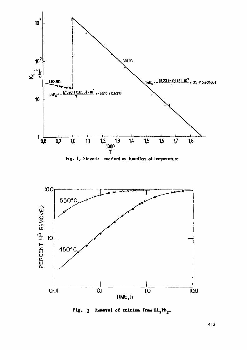
10J
Mv:
10
1
LIQUID
lnKfi= _ £520*0.056)-IP3 . {5J510 ±o631,
0,8 0 1,0 1,1 1,2 1,3 1A 1,5 1,6 1,71000
TFig. 1, Sieverts constantes Function of température
,15>06l0>tt6,
—————L
100
TIME, h
Fig« 2 Rénovai of tritium fron LUPb ,
453
Conclusions;
The attractive properties of Li^Pb» using a solid breeding materials asfollows:- high lithium density(high tritium breeding ratio)
- high solubility for tritium, less problem for tritium confinement.
- relatively low lithium activity <JvlO~ )- high thermal conductivity- high rate of tritium release
- difference in Sieverta* constant by a factor of a few hundred at thetemperature above and below the malting point.
- metallic compound, no change in properties with regard to porosity ascompared to ceramic compounds»
The temperature window of "Li-Pb" is uncertain, but the first estimationshows an acceptance value of 590K'* 900K.
References ;1. Ihle H.R., Neubert A. and Wu C.H.,
Proc- 10th Symposium on Fusion Technology,Padua, Italy pp.639-644 (1979)
2. Vu C.H. - Physical Chemical Properties of Breeding Materials.JUlich Blanket Workshop 1981.
3. Wu C.H. - J. Nucl. Mat. 114.30 (1983)4. Wiswall R. and Wirsing E.,
BNL30748, 19775. Wu C.H. et al«
"Chemcial Aspects of Fusion Technology"Nuclear Fusion, 935.23 (1983)
6. Wu C.H.J. Nucl. Mat. 122 & 123. 941 (1984)
454

E.7.10
High Tritium Breeding Blanket
Seiji Mori, T. Kuroda,KAWASAKI Heavy Industries, Ltd.
T. Kobayashi , H. lida,Japan Atomic Energy Research Institute
1. IntroductionFor a DT fusion commercial reactor, the net tritium breeding ratio
(TBR t) must exceed uni ty by some margin to a t ta in fue l self-sufficiency and to complete fuel cycle of DT fusion energy. While, ithas been made clear through the design studies that to attain theTBRne t larger than uni ty is not so easy because possible area forblanket installment (i.e. coverage) will be reduced if the realisticconfiguration of the reactor components and maintenance proceudre areconsidered.
To speak this conversely, if a blanket configuration having veryhigh TBR^ o c a ^ is developed, f lex ib i l i ty of the reactor engineeringdesign will be enlarged in terms of blanket coverage.
This paper describes a blanket conf igura t ion having very highTBRlocal (>2 '°) with use o f be ry l l ium (Be) and l i th ium oxide (Li20).High tritium breeding (HTB) blanket offers advantages such as:1) TBR
net larger than unity can be achieved with the blanket coverageof about 50% (see Fig. 1). This means that it is unnecessary toinstall the blanket in the inboard region of the torus and in theoutboard region where maintenance access is d i f f i c u l t . It becomespossible to reduce the reactor size, to s imp l i fy the reactorconfiguration and the maintenance procedure.2) It is possible to develop a relatively thinner blanket (<15cm) as avariat ion of the HTB blanket . It is of great advantage to reducingthe breeder (Li20) inventory and consequently tritium inventory.3) It is possible to predict the TBRnet with large design margin. Thisis impor tant because uncer ta int ies in the neutronics calculation anduncer ta in t ies in the plasma and the engineer ing parameters of thereactor system are large at present and probably in the future.
2. Neutronics StudyTo achieve high tritium breeding ratio, one must select-1) high Li
density breeder, 2) effective neutron multiplier and 3) structural andcoolant mterials of small neutron absorption. It is easy to select thecombination of LI20/Be/He or D20. As for the structural material it isgenerally selected from the other viewpoints than neutronics. In thiss tudy, s tainless steel (SS), f e r r i t i c steel (HT9), mo lybdenum al loy(Mo), and zirconium ally (Zr) were investigated.
Neutron transport calculations were performed by one-dimensionalSu, code, ANISN using a 42-neutron g r o u p and 21 gamma-ray g r o u p crosssection set, GICX40.
Results of the study are summarized below.(1) Location of neutron multiplier
Neutron multiplication and Albedo of beryllium for 14 MeV neutronare shown in Fig. 2. It was found f r o m the f igure that the backwardcomponents ( re f lec ted) are larger than hte forward components .
455

T h e r e f o r e , i t is e f f e c t i v e to the t r i t i u m p r o d u c t i o n to place thebreeding material before the beryl l ium (i.e. behind the f i rs t wall).O t h e r w i s e , it is also effective to place the b reed ing ma te r i a l andb e r y l l i u m in the same zone as a homogeneous mix ture . Based on theseresults , we d e v e l o p e d a L i 2 0 - B e p e b b l e m i x e d b l a n k e t and aL i 2 0 / B e / L i 2 0 sandwi t ched b lanke t in the course of the des igns forJapanese INTOR and the Japanese fusion experimental reactor (FER).(2) Calculated TBR's for HTB Blanket
Dimensions and zone m a t e r i a l compos i t ions of the calculationalmodels are summarized in Table 1. Atomic densities of materials usedin the study are shown in Table 2.
C a l c u l a t e d TBR's for HTB blanket are summarized in Table 3together with the blanket configuration.1) 1st breeder zone
Around one cent imeter is the op t imum for the thickness of thef i r s t b reede r z o n e . I f the th i ckness i s i n c r e a s e d , n e u t r o nmultiplication effect of the next beryll ium zone is decreased. It isbetter that this zone is composed of only breeding material, Li20 (i.e.no beryllium mixing.)2) beryllium zone
Optimum thickness of the beryllium zone is around 15 cm3) 2nd breeder zone
The rest of the blanket thickness is the second breeder zone. Toobtain higher TBR,o c an » this zone consists of the mixture of berylliumand Li20. The op t imum mixing ratio is 90% Be and 10% Li20 (vo lumepercent). Relation of the breeder thickness with TBR achieved is shownin Fig. 3. ^BRi , around 1.4 can be ob ta ined w i t h about 1 cm thickbreeder zones before and behind the beryllium zone.4) Li enrichment
To obtain higher TBRiocai and because of high °Li burn up ra te ,Li must be enriched'.
5) Packing density of the materialsA l t h o u g h high packing densi ty is des i r ab le , mechanical and
fabrication considerations make it d i f f icul t , T^Ri ^ ^ar§er tnan two
can be obtained wi th packing densi ty of 70% which seems easy toachieve.6) Structure and coolant material
TBR-, -, larger than two can be achieved wi th ei ther He or D20.Neu t ron absorpt ion by s t ruc tu ra l mater ia l a f f e c t s t r i t i u m breeding.The result is TBRgg < TBRHTg < TBRMQ < TBRZr. It is useful to developstructural material with small neutron absorption cross section such asZr alloy.
3. Blanket Structural ConsiderationS t r u c t u r a l concept of the HTB b lanke t is i l l u s t r a t e d in Fig. 4
Li20 and Be pebbles are packed b e f o r e and behind the b e r y l l i u m zone.Cooling tubes are arranged in the breeder bed and the beryll ium zone.Thermal resistant layer is necessary in the case of D20 cooling for thecontrol of the minimum temperature (>400°C) of Li20.
Packing dens i ty of the breeder pebbles is assumed to be 70%consider ing easiness of breeder loading and r ep lacemen t . As burnunrate of Li is very high in the HTB blanket, periodical replacement of
•the breeder is necessary. Mechanical consideration for easy replacementof the breeder is, therefore , inevitable for HTB blanket design. Onesolution to this is to separate the blanket into the fore part and therear par t as shown in Fig. 5. The fore par t i n t e g r a t e d wi th the f i r s t
456

wall can be replaced separately. In the case of the thin blanket, therear part is the non breeding (hot shield) zone.
4. Issues and Further Tasks(1) From be ry l l i um resource l imitat ion and its high cost, t rade-offstudy between beryllium inventory and required TBR is necessary.(2) Easy replacement methods of the breeder must be considered becauseof high Li burnup rate.( 3 ) T o a s s u r e s t r u c t u r a l i n t e g r i t y o f t h e b l a n k e t , m e c h a n i c a lconsideration for irradiation swelling of the beryllium must be done,though it is not structure material.(4) Exper imenta l ve r i f i c a t i on of neutron multiplication by berylliumshould be donebecause some negative results were reported.
Table 1 Dimension and Material Compositionof the Blanket
Table 2 Atomic Number Densitiesof Materials
CoaponcnCJ Thlckn*»!(en) Macerial Coapoiiclon(Volum« üraccioa. ')
lie Srecd«r ion«
Neutron oultiplitrion«
2nd Br«e4er ion«
Scructur« (73.3Z)Coolant (26.71)
Coo Un t (6.1Z)Scructur« (3.4Z)Btrylliu« ( — )b
LiChlua oxidt ( —— )b
B«rylUua ( — )b
Cooline (l.SZ)Scruecur« (0.3*)Berylliua ( — )bLichlua oxide ( ——)b
Cooljnc (10X)Struccuri (901)
Katerlal
3165S
Vater
Lltium oxidetasrn)
BerylllumUOOITS)
Molybdenum
Zirconium
Lead
Copper
Niobium
Heavy water
HT9
F113«(«TLLF-SJBeP,)
FLlNaBe
Carbon (p-1.6 o,/cn3)
Element
HoCrMl? e
0
•LI'LI0
'Se
«0
Zr
Pb
Cu
So
D0
CrHoFe
•u'LIMaBe
•LI'LINaBeF
C
dumber Density<n/e» J>
1.255 «10"1.575 »10"9.484 «10"Î.3CS «10"
6.686 «10"3.343 «10"
5.118 »10"6.385 «10"3.4,8 »10"
1.236 ' 10"
6.518 » 10"
4.291 «10"
3.296 »10"
S...64 « 10"
5.549 «10"
6.S-0 » 10"3.320 » 10"
1.070 «10"«.333 « 10"7.03d ' 10"
1.135 » 10:1
1. .20»10- J
1.729 » 10"1.991 » 10"
9.77 « 10:*1.22 « 10"8.30 » 10"1.10 » 10"4..0 « 10"
8.023 » 10"
F I X E D SHIELD
NEUTRON MULTIPLIER______/REFLECTOR
REMOVABLE SHIELD
HIGH TRIT IUMB R E E D I N G B L A N K E T
Fig. 1 Partially Installed Blanket Reactor
457

Table 3 Calculated TBR's for HTB Blanket
HO.
'
2
3
4
S
6
T
8
9
10
11
12
1st Sreeder Zone Be ZoneBe:Li»«v.F.)
(f.F.) (r-.F.)(Thickness) (Thickness)
loosTotal breeder
75:3100tS a
7S:2S100ÎSo
75:3100Î1 Ci
75:3100SI ca
-75:3. ..100Î1 a
75:3looti a
75:3loot1 a
75:3loot1 a
75:3loot1 cm0:10010011 a
0:iOO70S1 a
notes: V.F.=VolunCoolant is
none
thickness
lOOSISO
toot15 a
ICOtISO
100Î15 cm
loot10 a
100S15 a
lootIS a
lootIS Œ
loot15 a
lootISO
9SSIS a
2nd Breeder ZoneBe:LliO(V.F.) T8S
<P.F.)(Thickness)
75:3loot
: 43.3d
7S.-3lootbalance
75:31001balance
100Îbalance
. 75:3 .loosbalance
. 75:3IOOSbalance
0:100IOOSbalance
IOCSbalance
75:25IOOSbalance
75:3IOOSbalance
90:iOtoo:balance
90:10TO:balance
1. S6S
1.948
2.002
2.0T2
2.118
2.112
I.9S1
2.218
2.177
2.102
2.169
2.106
Owent
All iiitureSS srtucturenatural 'ti
SS structurenatural 'Li
SS structureIOOS 'Li
SS structureIOOS 'Li
no structureIOOS Hi
no structureIOOS 'Li
no structureicot 'LI
Zr structure1001 'Ll
Zr structureIOOS 'LiM cooled
HT9 structureIOOS 'Li
no structureIOOS 'Li
Ho structureIOOS 'Li
! Fraction. P. F. Packing Fraction.a-ga^ni t£ be hetiui except Case 9.
1076
10cm
{Incident)
1.620
Au.-0.084
30cm
M - L974A • 1.076
Ab.-0.272
0466M • 2.358A • 1.620
(Inofcnt) 10.1732
60cm0136
Ab.-0.S28 M • 2.396A • 1.732
Fig. 2 Neutron Multiplicationand Albedo of Beryllium
Fig.as a
2.0£
= 1.0t—S.3
Structure : MolybdenumCoolant : Helium
'First vwil
, first bfeeder zone/(UZ0,FF70%)
End woll
Be zone(PF9SR)
Second breeder »ne(8e:UjO = 9:l,PF70%)
0 10 20 30 40 50
Distance from the First Wall ( cm)
3 Tritium Breeding RatioFunction of Blanket Thickness
FIRST WALLFIRST BREEDER ZONE
FIRST WALL FIRST BREEDER ZONE
O O O O O O O O O O O IO O O O O O O O O O 4o o o o o o o o o do o o o o o o oO O O O O O O O CO O O O O O O O Oo o o o o o o o co o o o o o o o
O O O O O O O Oo o o o o o oo o o o o o o
:L1,0 PEBBLE
COOLING TUBE
SECOND SflEEDES ZONE
LliO PEBBLE
=L
=|5\s—
B<
Î^^XK^O^^XHX-SS
to ô O 0 O <3 J ö Ö fl 5'!( O O O C O O O O
a o o o o o oo o o o o o o o 4>
O O O O O O O O X
O O O OOO iO 0 OOO O
O O O O O O O
O O O O O O
/ Ui jO PCB8LE
^^ ^XcOOLlNSTUBE
^ t ^ /\ X> _/" IL. L i jO PEBBLE
\ luaiEL Be PEBBLE
\SECONO BREEDER ZONE
\ HOT SHIELD
Fig. 4 Blanket Concept of HTB Blanket Fig. 5 Thin Blanket and Par t ia l lyReplaceable Blanket
458

E.7.11
Bonded Protection Materials on the First Wall and Liraiter/Diverter* **T. Mizoguchi , S. Itoh
* Japan Atomic Energy Research Instituteon leave from Hitachi Ltd.
** Hitachi Works, Hitachi Ltd.
1. IntroductionFor fusion reactors, some sort of first wall protection will be
required against plasma disruption. Graphite or a ceramic materials islikely to be the most effective for very high heat load. As one of thecandidate protection materials, the silicon carbide of which both thermalconductivity and electrical resistivity are very high has been developed.Considering a long pulse operation or steady state operation of the reactor,it would be a very considerable advantage to use metallic bonding forkeeping the surface temperature of the protection material as low aspossible. However, metallic bonding causes very high stresses at thebrazed joints between the protection material and heat sink metal due tosuppressed thermal expansion. To overcome this problem, an appropriatecompliant material must be developed.
2. Comliant material(2)The developed compliant material is a copper-carbon fiber composite.
A large amount of copper-plating carbon fibers of which diameter areabout 7 ym are disposed into copper metrix. The thickness of compliantlayer is about one to two millimeter. The thermal expansion coefficientof the cornliant layer is altered arbitrary in a range of 5 ~ 12 x 10~°/°Cby changing the composition rate of copper and carbon fiber. For example,the expansion coefficients are 4.5 x10~6/°C for Cu: C =46:54, 6.5xlO-6/°Cfor Cu:C =55:45, and 9.5 x 10~6/°C for Cu:C = 65:35.
3. Bonding method and bonding mechanismFig. 1 shows the shape and dimensions of bonding test specimen. The
alloy of copper and manganese is used for a brazing filler metal. Thebonding specimen is heated up to 870°C very rapidly in a microwave oven underargon gas atmosphere and pressed with 0.05 kg/mm2 simultaniously. Fig. 2shows the X-ray mico-analysis of manganese and silicon elements of thebonding layer. When the bonding time is one second, the manganese ismostly concentrated at the brazing layer. On the other hand, the manganese
459

Table. I Physical properties of experimental materials
""-- ^ Mlt«nalPhysical ^^~~- ^^
constant **"** ^^
Density (g/cm4)
Thermal expansioncaerfic'entf lfl"*/CJ
Thermal conductivity(W/m-K)
Electrical resistivity(Q. en.)
Bending strength(kgf/mm')
Ceramics
SiC
3 2
3.7
270
£10"
45
Compliant layer
Cu • C finer composite(Cu 3SC)
6 1
9 5
240
3 3x10-«
20
Banningmetal
Cu
8.9
17.7
390
1 7x10-*
—
Grazingmetal
Cu- 35 MnAllay
8.3
20
120
36x10-*
—
SiC Ceramics
Cu- 35 Wt%Mn Alloy
( Brazing filler metal \SOfim j
-Copper block- Copper-Carbon fiber ggrnposite
(Compliant material)
Fig. 1 Shape and dimensions of bonding test specimen
Bonding time : 1 sec Bonding time : 180sec
SiC^jCu-35Mn(-Cu
-
( b )Fig. 2 X-ray micro analysis of Mn and Si elements of the
bonding layer bonded at 1 sec and 180sec(Bonding temperature : 870'C)
IQOpn
SiC — II —— Cu-35C FiberBonding
zone(Cu-35Mn Layer)
£N!1V$J
'•ti. *tt--hi
ü-l.sr ——— | |— Cu
Bondingzone
(Cu-35Mn Layer)
Fig. 3 Microscopic observation of SiC/Cu bonded zone

Cu-3£C/Cu-<5C-20mm — I
SiC |2100-500'C N-10 Q Tension
CuIQO-C
E
2.5
2.0
1.5t
1.0
0.5
Q
870'C, 1 secBonding
.aj a~5fninb — 2min
Heat cycle Tensile test(Room temp.)
0 100 200 300 400 500Heat cycle temperature ("C)
Fig. 4 Relation between heat cycle temperature and tensile strength
23 or 35mm
Cu-C fiberComposit.
Fig. 5 Cross section and appearance of SiC/Cu bondedelement
Heat flux(0il combustion plasma)2000'C
1200
1000
800
600
' 400
200
SiC
\CuVSurface temperatureoTSiC(Ta
-CU.35C•Cooling waterU l "—" «• '^
35mm—| (O.lkgf/,
Temperature ofCu.35C(Tb)
0 100 200 300 400 500 600Heat flux (W/cm1)
Fig. 6 Relation between surface temperature ofSiC ceramics and heat flux
Heat flux(0il combustion plasma)"2000'C
pÜ5
UCL
t)
u)
KI »«•Heat flux (W/cm1)
Fig. 7 Relation between surface temperature ofSiC ceramics and heat flux

diffuse out to copper zone when the bonding time is 180 sec. Peel strengthof the brazing layer is 2.0 kg/mm for the former and 1.5 kg/mm for thelatter. Hence, the bonding mechanism seems to the diffusive reaction ofmanganese and silicon.
Fig. 3 shows the microscopic observation of SiC/Cu bonded zone ofthis composite.
4. Test results and discussionPhysical properties of the composite is shown in Table 1. We examine
the reliability of the SiC/Cu-C/Cu composite. Fig. 4 shows the relationbetween heat cycle temperature and tensile strength and the procedure ofthe heat cycle test. This test result shows that the maximum allowabletemperature at the compliant layer is about 300°C.
We also examine cooling property of the composite. Fig. 5 shows thecross section and appearance of the sample to use the test and Fig. 6shows the relation between surface temperature of SiC ceramics and appliedheat flux. The surface temperature of SiC is up to only 800°C even if500 W/cin2 of heat flux generated by oil combustion plasma is applied.However, the temperature at the compliant layer exceeds over 300°C. Tokeep the maximum temperature at the compliant layer less than 300°C, theallowable heat flux on the surface of SiC will be 400 W/cm2 at most.
The first wall structure material would be the stainless steelinstead of the copper as heat sink. We successfully bond the SiCceramic on the stainless steel also. However, cooling property isless effective and the allowable heat flux on the SiC surface will be200 W/cm2 as shown in Fig. 7.
To conform the reliability of the composite, additional tests suchas thermal shock test and irradiation test must be done.
Reference(1) Nakamura et al., Proc. Ceramics (1982).(2) Kuniya, Arakawa, Nihon Kinzoku Gakkaishi 49(1985) 291.
462

E.7.12
BONDED PROTECTION TILES FOR FIRST WALL COMPONENTS
J.M. Dupouy,The NET Team, c/o Max-Planck Institut für Plasmaphysik,
Boltzmannstraûe 2, D-8046, W. Germany
It is currently felt that some sort of protection will be required on thefirst wall of the fusion machine especially because of the possibility ofexistence of disruptions.
A system of tiles, rather thick, is likely to be most effective against thedisruptions and the various erosion phenomena.
It would be a very considerable advantage to be able to keep the temperatureof the tiles as low as possible. This can only be achieved through the use ofa good conducting bond between the protection material and the metallicsubstrate.
Such a bond will have to sustain very difficult operating conditions inparticular to accommodate the cycled differential thermal dilations, and theeventual differential swelling. It must be compatible with the protectionmaterial and the metallic substrate during the long term contract betweenthem.
The development of a satisfactory bond between 316 and 4914 steels and theprotection material graphite + Si or SiC is a major task.
The advantage would be considerable if one could realize a good conductingbondbetween the tile and the metallic substrate, essentially because theoperatingtemperature would be much reduced, hopefully down to the 500-600 C ranp.e.
The consequences of this temperature decrease are:- decrease of sublimation with the consequent decrease in plasma
contamination and in the required initial thickness.
- decrease In the thermal stresses because of the lower temperatureand of the smaller thickness
- decrease of the hydrogen isotope absorption and potential releasewith the consequent suppression of the need for coating ifgraphite was used.
463

- decrease In the length variation of graph!tedue to irradiation,less contraction and increase of the maximum fluence at which theswelling becomes unacceptable, possibly up to the level of thetarget fluence of NTET, thus avoiding replacement oc theprotection system during its life.
In addition to the temperature decrease, suppression of the mechanicalattachment means the suppression of the stress concentration Inevitablyassociated with It and also allows n somewhat thinner metallic wall.
All these considerable advantages roly on the achievement of a Rood heatconducting bond. The operating conditions will be very severe since thebond nust withstand the cycled differential thermal expansions and thedifferential expansion due to swelling.
There must certainly be an Intermediate layer made of a very plasticmaterial; one may think of a sandwich structure or of a material having acontinuously varying thermal expansion coefficient. Such n material mustnot swell excessively at the 20 dpa which it will receive, and remaincompatible with both the tile material and the steel for some 20,000 hoursat nn operating temperature of about 500 to fiOO C.
1) Graphite
The temperatures are within the range of the chemical sputtering by hydro^etherefore, here also, a Si impregnation would be desirable.
Actions- Identification of the suitable conbinatlon of graphite ami Si
Development of the bonding technique
- Mechanical testing(thermal fatigue) of the sandwich
- Irradiation of the sandwich and mechanical testingafter Irradlntion.
2) jiC (or TiC)
The use of a thick SiC or TiC tile necessitated by the erosion, appearsunlikely due to probable heavy cracking. This may not be however if the
464

erosion, which is now only due Co sputtering and no longer to sublimation.,could be small enough and would parait the use of rather thin tiles.
Finding a suitable SIC(preferably a good heat conducting variety)
- Development of the bonding
Evolution of the heat conductivity after irradiation (a few1022/cni2 at 600°C).
Mechanical testing in thermal fatigue of the sandwich
Long term compatibility of the bond with the steel.
465

E.7.13
GAS COOLED DIVERTOR PLATE CONCEPT USING SMALL TUNGSTEN TILESS. Malang
Kernforschungszentrum Karlsruhe
Introduction
A high erosion rate caused by the high energy particle flux and thermalfatigue caused by the cyclic high surface heat flux lirait the lifetime ofdivertor plates. Periodical replacement may be necessary and a design allow-ing a quick exchange is mandatory. A critical issue is the connection ofcooling lines, especially in the case of water cooling. Divertor cassettesare proposed where the plates including the supply lines can be withdrawnwithout opening any cooling connection inside the plasma chamber. This, how-ever, is not possible in the case of a double null conHRuration due to spacelimitations. It nay bo possible to use an articulated boom for the replace-ment of divertor platr>s but it remains to be seen if the r e l i a b i l i t y ofremotely operated connections for water supplv lines is high enough under thesevere conditions inside the plasma chamber. An other concern is the reliabi-lity of a rather large number of cooling tubes and there manifolds itself.This was an incentive to investigate the possibility of gas cooling with theadditional goal to provide a double containment for all cooling lines.
Tungsten is used in most divertor plate designs due to its high sputteringresistance. High strength copper alloys serve as heat sink material. Theconnection between erosion layer and heat sink is made by brazing. The ther-mal expansion coefficient of copper is three times higher than the one oftungsten, causing high shear stress at the interface. Allowable surface heatfluxes and the lifetime of the divertor plates arc limited by thermal fatigueHue to the high stresses. No design of this k'nd provides a double contain-ment for the high pressure cooling water.
There is a new proposal of a divertor plate design by Mr. Moons from the NET-team. It is characterized by the use of a massive molybdenum plate where allcooling channels and manifolds are machined into. Brazings between erosionlayer and heat sink are avoided. There is an intention to provide a kind ofdouble containment by pressing niobium tubes into the cooling channels in themolybdenum plate.
466

Design description
The» divertor plate design proposed höre can be seen in Fig. I which shows theevolution from a simple molybdenum plate to the new design.
In this design the divertor plate consists of three different materials:- tungsten "stones" facing the high energy particle flux- a closed box of molybdenum, providing a second containment for the coolant- copper serving as thermal bonding between the plate surface and the coolant.
WTungsten
MoMolybdenum(TZM)
CuCopper
Fig. 1 Evolution steps of the divertor platedesign concept
The copper is casted into the molybdenum box. Pure copper can be used becausethe mechanical stresses are low.
Fig. 2 shows the manifold repion of the plate. It can be seen that a doubleconta'nment is provided in t h « s region too. Concentric tubes are used assupply line and the annulus is connected to the interior of the divertorplates allowing permanent evacuation.
An important feature of the concept is the attachment of the tungsten stonesto the heat sink. The cylindrical part of the stones is fitted into cupshaood cavities in the surfaces of the divertor plate.
This results in a highly reliable heat transfer meachnism because an increas-ing contact resistance would increase stone temperature, thermal expansion,contact pressure between stone and molybdenum ring and therefore the gapconductance. The design does not depend on the integrity of the brazing be-tween tungsten and molybdenum.
467

cross section B-B
Fig. 2 Manifold region of the divertor plate
•Y >,}
\\
a) bayonet joint
Fig. 3 Tile attachement without brazing
b) snap fastener
468

There are even versions possible without brazing where the stones are kept Intheir position by a bayonet joint or a snap fastener as shown In Fig. 3.
Fins at the wall of the coolant channels are Indicated in Fig« 3. They arenecessary over a short length only at the position of the maximum heat flux.Scoping calculations using a helium pressure of 80 bar have Indicated, thatpressure drop and temperatures (copper, molybdenum, tungsten) do not exceedallowable limits. A more detailed analysis of temperature field and stressesis necessary to judge the viability of the concept.
The features and the advantages of the pronosed concept can be summarizes asfol lows :
p- Cas cooling is possible for surface heat fluxes up to 5 MW/m .- Double'containment of all cooling lines including the manifolds and perma-nent evacuation of the gaps avoid the need for divertor plate replacementin the case of small leaks.
- The erosion layer made of tungsten is divided into small pieces, minimizingthe thermal stresses in thr< tungsten and in the heat sink.
- There is a high, seifreiuila t\np contact pressure between the tungstenstones and the heat sink. Therefore, the heat transfer does not depend onthe integrity of brazed ioints.
- The compression caused by this contact nressuro is the onlv external forceapplied on the tungsten stones.
- The strength requiremonts for the copner servi m* as a bonding material arem i n i ma 1 .
- The fabrication of the divertor plates should be possible with known tech-nology.
469

E.7.14
FIRST WALL CONCEPT WITH RADIATIVELY COOLED PROTECTION TILESS. Malang
Kernforschungszentrum Karlsruhe
Introduction
Protection of the first wall against plasma disruption and the protection ofthe plasna against an untolerable high impurity flux may reouire an inter-mediate layer of graphit or a ceramic material between the structural ma-terial and the plasma.
One way to provide such a orotection is to coat thn plasma facing surfacewith a thin layer of a suitable material. Such layers, however, are eitherendangered to spall of or they are not thick enough to have sufficient lifetime without periodic recoattng.
The use of tiles which are attached to the surface is probably a more pro-missing way. Tile materials under consideration are granhit and ceramics suchas SiC. Attachment concepts are characterized by the heat transfer mechanismemployed. Metallic bonding, i.e. brazing of the tiles to the structural ma-terial, leads to the lowest temperature because there is no additional gapresistance for the heat flow. Such ioints, however, are difficult to fabri-cate ami there are high stresses caused by the different thermal expansion.Tt remains to be seen, whether brazed joints survive the high cyclic loadingtypical for tokamak operation.
Attachment concepts without metallic bonding depend on either a certaincontact pressure in order to minimize thermal resistance or on radiationcooling only. Contact pressure provided by bolts or similar devices decreaseswith operating time due to thermal or neutron radiation induced creep.
Radiation cooling is therefore the most reliable heat transfer mechanism.High tile temperatures, however, are necessary to transfer the heat from thetiles to the heat sink. This study has been concentrated on the optimizationof a first wall concept using radiatively cooled protection tiles.
470

Design concept
The life time of protection tiles is limited by erosion and by the growthrate of cracks. Erosion is mainly caused by physical and chemical sputteringand by vaporization. All these mechanisms are temperature dependent and leadto higher erosion rates for increasing temperatures. Crack growth is causedby cyclic mechanical stresses which are mainly due to thermal expansion.Larger tiles and attachment concepts where the thermal expansion is restric-ted lead to higher thermal stresses.
These considerations result in the following requirements for an optimizeddesign concept:
- The ratio of radiating surface to plasma facing surface should be as largeas possible in order to lower tile temperatures for a given power level.
- The tile dimensions should be small and the thermal expansion unrestrictedin order to minimize thermal stresses.
- The heat flow pathes in the heat sink should be short and uniform in orderto minimize temperature and thermal stresses in the structural material.
An additional requirement which may become very important is the possibilityto replace broken or worn tiles by remote handling.
Fig. 1 shows four different concepts for the attachment of tiles cooled byradiation. The more "conventional" concepts shown in Fig. la) to le) userelatively large tiles with a radiating surface to the heat sink roughlyequal to the plasma facing surface. The proposed concept shown in Fig. Id) ischaracterized by small "stones" which are fitted loosely between coolingtubes. It is possible to make the gaps between stones and tubes large enoughto allow free thermal expansion and radiation induced swelling. This mini-mizes thermal stresses and may therefore allow the use of massive stones ofSiC, a material much less thermal shock resistant than graphit. The radiatingsurface is roughly twice as large as the plasma facing surface which leadstheoretically to a reduction of the temperature at the radiating surface bymore than 200 K as it can be seen in Fig. 2. In the real case the temperatureat the radiating surface is not constant which lowers the benefit of thelarger surface. But on the other hand, the tile thickness for the otherattachment concepts is larger than the thickness of the sacrifical layer,causing an additional increase in maximum temperatures.
471

Temperature field calculations performed with a finite element code showedthat the maximum tile temperature is 1180 °C if the proposed design is usedat the inboard section of NET (£= 0.5). This is roughly 200 K lower than thetemperature calculated for the other designs shown in Fig. 1. For a givenmaximum temperature, the new design allows nearly twice the power level com-pared to the other designs.
No stress calculations have been performed until now. It is obvious, however,that the design minimizes all stresses because it avoids any external forcesand reduces thermal stresses by reducing the tile dimensions. There is hopethat the design allows for the use of less thermal shock resistant materialsthan graphit. This has to be verified by detailed stress calculations andcyclic tests.
Fig. 3 shows two typical applications of the protection concept. In the firstcase the protection stones are fitted between the front channels of a self-cooled liquid metal blanket. The second case is a separate first wall as itcan be used for all blanket concepts. It looks possible for both cases todesign a remotely operated machine to exchange brooken or worn stones. Thismay be the most important advantage of the proposed design.
a] Dove tail
b) Active cooled support rail(INTOR)
c) Attachment bolts d) Small Tiles between cooling tubes
fig. 1 Attachment Concepts for Radiatively Cooled Tiles
472

60-
so-1
co
-l 30'ce
2 0 -
10 -
0 '—
I I Mi l I I | | l l q "
q" = 15 W/cm2
q'"= 8 W/cm3
°C
1200 14ÛO 1600 1800
Radiation Temperature, °C
Fig. 2 Influence of radiating sur face area on tile temperature
65 mmCO mm
^////////////#/////////#//s///////>y////,
Liquid mefal flowing in L Liquid tnefal flowing inpoloidal direction toroidal direction
a) Integral First Wall for a Liquid Metal b) Separate First Wall (Gas Cooled)Cooled Blanket
Fig. 3 Radiafively cooled protection tiles
473
E.7.15
FIRST WALL WITH PROTECTIVE ELELTEUTSINCORPORATING HEAT TUBE.S.A.Moshkin, E.V.Murav'ev
1. General considerations.1.1. Differentiation of loads and functions among the firstwall structural components. Firstly, a vacuum-tight load-car-rying wall is differentiated to separate the blanket froia theplasma chamber, and secondly, protective elenents facing pi?:—ma are envisaged.1.2. The protective elements can be made of refr3ctory metalswith low sputtering yield (Jüo, W) or with low-Z (carbon basée)materials.1.3» The vacuum wall can be thin and made of material with go-od mechanical properties and resistance to radiation damage.1.4. The essential condition to realize the advantages of thesuggested design is to provide a relative independence of theprotective elements and the vacuum wall in taking their ther-momechanical loads.
2. Requirements to the protective element.2.1. Each protective element should be an isolated module \vhiccan be replaced independently from the vacuum wall.2.2. The protective element must ensure effective heat trans-port from the plasma facing surface to the cooled vacuum wall.
/fi2.3.vThe interface between, the protective element and the va-cuum v;all adequate clamping should be provided to get a goodthermal contact during working regime while during assenbly--disasscibly operations the corresponding technological clea-rances are needed.
474

. . . „ A.-. .X J V .i.x i ^•' • •' ' / ' / / / / / 7 / / / /.,/ / /.' /
Fig.1. 1 - protective element; 2 - wick structure; 3 - vacu-um wall; 4 - meabrane; 5 - coolant channel.
3. The stated requirements can be sufficed in the followingway.3.1. The vacuum wall has T-shaped grooves wh-;rein separateprotective elements are Inserted with their corresponding T--shaped tails.3.2. Each protective element is made in the form of a heattube with a vaporization and condensing sections of a flatten-ed bcx r.hape connected by a slot heat-transfer channel.3.3. The vacuum wall groove bottom is made as a flexible mem-brane that can buckle out under the coolant pressure.
4. The suggested first wall schematic design is presented inPig.1.
475

5. The estimated parameters of the first wall design are asfollows:
Protective element heat tube working agent potassiumWorking temperatureWick structure
Mach nunber in the slot heat-transfer2channel at 5 O/m heat flux on thefirst wail surfacePermissible heat flux on the firstwall surface under the capillarytransport limit
550° Cwire gauz-wire diam.0.1 mm
0.165
7 M'A/m*6. Conclusion. The suggested first wall design can bear heatload at 5 O'/m level with margin.
476

E.7.16
A potential ceramic breeding material Li.SiO.4 4
C.H. WuNET Team, c/o Max-Planck Institut fUr Plasmaphysik
BoltrmannstraJie 2, D-8046 Garching bei MünchenFederal Republic of Germany
Several ceramic lithium compounds are envisaged as candidates for solid CTR-blanket breeder materials. The ceramic lithium compounds are expected to havea low solubility and sufficiently high mobility of tritium at operatingtemperatures» The diffusive hold up of tritium in the breeder materialsvaries inversely proportional to the diffusion coefficient. Therefore, thediffusivity of tritium in breeding materials is a very Important physicalchemcial property for the selection of breeder materials. The lithiummetasilicate Li-SlO, has been considered as solid breeder material for INTOR.The lithium orthosillcate Li.SiO, has higher lithium density, and morerecently, it has been confirmed, that the diffusion coefficient of tritium inLi.SiO, is particularly high, e.g. at relevant temperature of 600°C. The
—6 2 —1diffusion coefficeint of tritium in Li.SiO, Is 3.13.10 cm .s , this is2around 10 times higher than that of other ceramic materials. This
distinguished high diffusion coefficient could offer two major advantages: 1)efficient tritium recovery, 2) low tritium inventory.
a) The Thermal Stability of Ceramic Lithium Compound
Lithium Oxide, because of its refractory nature and high lithium atomdensity is of interest as a solid breeder materials for deuterium-tritiumfusion power reactor, but its thermal stability is the lowest. Inaddition it is highly reactive to water. Detailed study on the thermalstability of Li,0 has been published
A number of ternary ceramic compounds containing lithium are considered assolid breeding materials, mainly because they offer the advantage of ahigh thermal stability than that of Li-O. The ternary ceramics are alsoexpected to be less sensitive to water vapour than is Li-0. The reactionenthalpies for the formation of the ceramic lithium compounds per mol ofLi-0 for comparisons are given in Table 1.
In general, in all systems, the thermal stability increased in reversedorder of the Li-0 content of the ceramics as does their breeding
477

Table 1. Reaction enthalpy of formation of ceramic lithium compounds permol Li.,0;
A H°(298.15K)
Kcal/mol
Li20 + 0.201- A1203 -*• 0.4fl-Li5A104 - 4.0 _+_ 1L±20 + 0U A1203 •*• 2 -LiA102 -25.0 4^2
10 -«-2 LiAlO -40.0 4 3
Li-0 + 0.25 ZrO,-»-0.25 LinZrO,2 Z o o - 4.3 + 1—L120 •*• 0.5 Zr02*-0.5 Li4Zr04 - 8. 3 4 2Li20 -f Zr02 - L12Zr°3 -14. 2 +.2
Li20 •*• 0.5 Si02 *- 05 L14S104 -27.3^3Si02 •*- Li2«i03 -34.4+^3
capability aslo. Of the useful breeding material«, the lithium lilicateshare the highect thermal stability.
b) Reactivity with water
The knowledge on the reaction of H20 with breeding materials is thereforeinteresting, not only from the safety and environment point of view butalso from the aspect of tritium separation. The information on theexperimental study is scarce. It is possible by using the existingdata, to predict the reactivity of the ceramic material with water. Ingeneral, lithium reacts with water vapour, leading to the formation ofgaseous LiOH or condensed LiOH.
Table 2. The lithium activity in ceramic lithium compounds at 900KCompound Li-activity
Li20 6.5 x 10"10Li2Si03 4.9 x 10"11Li4Si04 5.7 x 10"11
Li2Zr03 1.7 x 10"11Li.ZrO. 1.22 x 10~104 4LiftZrO, 1.07 x 10
-12LiAl-Oa 1.1 x 10⁻¹³LiA102 2.5 x 10
478

Table 2 shows the lithium activity of breeding material« at a temperatureof 900 X. The sequences of the reactivity of compound« to H.O will be:
Li20
c) Diffusion of Tritium in Ceramic Breeders
Besides the thermal stability of the solid ceramic breeding materials, thediffusion of tritium in these materials is also of significance withregard to tritium recovery in fusion reactor«. It can be shown resultingfrom experimental studies that the average residence time of a tritium2atom, e.g. in spherical particles of radius R, is proportional to R /D,where D is the diffusivity. The diffusions coefficients as a function oftemperature are given in table 3.
Table 3» Diffusion of Tritium in Ceramic Breeders
compound°o
Kcal K
2.66xlO~3 19.5 850-1150T-LiA102 3.09x1O"3 19.3 878-1178ß-Li5A104 3.02xlO~2 25.0 813-1278Li4Si04 1.89xlO"2 15.1 573-898
D(T) - DO . exp <-EA/RT)
The combination of rapid tritium diffuison, relatively high thermalstability make Li^SiO^ an interesting material for use in CTR blankets.
References
J. Vu C.H,, Kudo H. and Ihle H.R.,J. Chem. Phys. 70, 1915 (1979).
2. Kudo H., Wu C.H. and Ihle H.R.,J. Nucl. Mater. 78 (1978) 380.
3. Ihle H.R and Vu C.H.,J. Nucl. Mat. 130, 454 (1985).
479

E.7.17
DROPLET CONTACT DEVICE OF DIVERTORV.O.Vodyanuk, B.G.Karasev, A.P.Kolesnichenko, I.V.Mazul',
E.V.Muravjev, V.N.Odintsov, A.M.Shapiro
Divertor contact devices in INTOR design made aa cooled plateahave restricted lifetime which requires their frequent roplacementand greatly worsens operating characteristics of the reactor» As adivertor contact device it is proposed to use a liquid metal dropletscreen formed at plasma path in a divertor chamber. This deviceprovides the removal of heat associated with the plasma and canoperate during the reactor lifetime.
The droplet screen is a flow of liquid metal droplets, forminga curtain which moves at a high rate (5*30 m/s). No interactionbetween freely moving droplets and magnetic field should take placebecause of the droplet snail size and the absence of conditions forcurrent closing in liquid metals. For this reason the droplet curtainis more preferable than liquid metal film.
To evaluate heat accumulating capacity of droplet flow, a modelproblem on heating by a flat heat flux of multilayer droplet curtain,formed by spherical particles, was aolved in /1.1/. Solution resultsof this problem for droplet screen and plasma incident flux mutualorientation presented in fig.1.1 are given in Table 1.1. At givenorientation all the heat is removed by first or three layers of thescreen, and highest allowable effective density of the heat flux tothe screen surface is defined by the first layer. Several layera(5-*-6) of such a screen ensure a completely opaque contact devicefor the plasma. The continuous droplet screen formed on the path ofinternal and external fluxes of divertor plasma ensures heat removalof 60 MW (Lithium droplets move at about 10 m/s rate).Others versions of screen orientation are possible providing thescreening of walls against divertor plasma.
Droplet flux can be formed by a special MHD-device /1.2/.This device is based on controlled separation of conducting liquidfree jeta into droplets of on equal and predetermined size and shape«MHD-device employs the magnetic field of tokamak and consist ofliquid metal and alternating current metallic supplies and of anactive zone having a perforated wall or nozzles, through whichliquid metal flows as separate free jets. (F<.a 12.)
480

Pig.1.1. Droplet contact device of the divertor
Pig.1.2. Forming device of droplet curtain
The droplet curtain is prefarable to the film contact devicewith regard to conaequencies of metal sputtering by plaaroa ions*Sputtered metal atoms in such a curtain may return to the dropletourface before they strike the plasma. To collect sputtered andevaporated atoms it is wise to install cooled sceens In the divertorchamber. Lithium and gallium are chosen for their low meltingtemperature and perfect thermal properties. Besides, lithium has alow atomic number and hallium has a high allowable heating tempera-ture and presents no risk at contact with v/ater.
The presence of lithium in torus requires to consider theproblem of preventing its contact with water. The most reliablesolution of thi-e problem is to discard water in all torus systems.The average outlet temperature of metals at contact device is not
481

TabTo 1.1.
^~~^~~~-~-~>^^_^ta 1Screen parametera^~~~— — _^____^
Metal inlet temperature, KDroplet surface maximum! "inpfirature, K
V.- *n liquid metal outlet tora-ppvatitre at vftxi.MUiu thormalload, K
Screen height, m
Droplet rate, m/3
Droplet diameter d, mmNoi-.slo hoad pifcoh t L *?d, mm
Jot cepfn :tion pitch . o?.4<1,nun
inchest allowable effectivedensity of heat flux onncrecn surface, MW/m
uaximura power r^oved by-•croen running meter, ?.iW
Ketal conoumption at aix--layer ocreen por one -running meter, 10-3 nr/a
Li
480
623
5000.5
10 20
4 38 6
9.6 7.2
2 3.2
1 1.6
. 2 4 3 0
Ga
330
773
4000.5
5 104.5 3.29 6.4
10.8 7.7
4 5.6
2 2.8
26 20
very high and corrosion of materials will be of no unsolvableproblem.
Impurity removal at the use of the droplet screen instead ofdivertor plate can have some special features associated with thepumping action of the faat Jet or with the selective capture ofplasma particles by metal droplets (D-T particle capture by lithium).At present it is impossible to identify these features. In any casethe problem of impurity removal will not be more complicated thanin divertor version.
To solve the problem on the possibility und efficiency of usingthe liquid raettil droplet screen the following ie required:- study of plasiiu. contamination at screen contact vith divertorplasma, liquid metal transfer to the walls and efficiency of itaremoval;
- study of sorption and desorption processes of hydrogen and heliumisotopes by liquid metals, including those in dynamic conditionsj
482

- atudy of formation and reception of dcnf,e droplet screen at strongmagnetic fieldo;
-. atudy of problems concerning the extraction of D-T mJ lure ar-dimpurities from liquid metals.
R E V K R E N C E S
1.1. M.Yu.Lipov, E.V.rumvjov. Ort the development of higli-c. "fectivedlvertor eyetema for power reactora. Prcpri*;'. IAliî-3-9''/' .K?- :ov/, 1900.
1.2. A. P. Kolesnichenko Techr^Oofjjcul MI1D proceooes andinstallfttiono, Kiev, Kaukovo ÎXunka, 1900»
483

E.7.18
LIQUID ,\ïETAIj FILM l, IM l TER
B.G.Karaoev, I.V.Mazul' , E.V.Muraviev, A.V.Tanana^v,A.M.Ohapiro
In INTOR environment aolid-state limiters (divertor andi_ imping limiter platen) have a restricted life time due to thethinning of contact plates resulted from erosion. Their replacementrequires multiple rhut-dovm decreasing the reactor a/- flabilityand involving complicated »'.evicts for the replacement. It 10propooed to uoe several rn.il-t.ype limitons for plaoma reatriction'.•ose cc. ''.'::t uurface ia a hi^h-Lpoed fllu of liquid metal. The K.-JOof u chang-:--blé film eliininatcro the erosion and thermal atrengthproblem of contact platée and provides the liinitor operation duringthe actor lifet.! -,e.
The propc-rod device ia ehov/n in Fig.2.1 /2.1/. Liquid metalunder pressure ia conducted aci'oaa the magnetic field through acentral «lit channel, at whoce exit il Is decelerated,spreads pl^ngthe magnetic field and forms a free surface as a film. On theworking area «.HO metal film flows along a conducting substrate andflowa down into two outlet channels located symmetrically aboutthe central feeding channel. In oiJor to press the film to theauboIrate and to purap out liquid metal across the magnetic field,polential difference is externally produced and current is conductedbetv/een side walls (electrodes) of the working area and inlet - outletchannels, i.e. the outlet channels io made as a conductionelectioraagnetic pumps operating in the tokamak magnetic field. Prornthe viewpoint of M'ID-film stability the length of the working areaie desired to be about 10 cm at the film thickneas O of 1-2 mm.
The most important characteristics of this facility is a heataccumulating capacity or a value of allowable heat flux on theworking surface. This value is defined from the relation
whore pC - specific heat of liqMd metal,u7* - allowable healing of liquid metal at the film
surface,2T - contact time with plasma,00 - effective depth of heating.
484

The value of 00 depends on liquid metal properties and contacttime with plaoma
If we use liquid lithium with flow rate of about 10 m/s atthe working area 10 cm long \vith allowable metal heating 4?*~ 150 K,we can obtain « 10-15 MV//m2
At the limiter width of 0.2,m, ita length of 1 m and optimizedprofiling of the contact enrface tl.a maximum power ..'.sich ran bor." r.ovod l. y a limiter .is 2-3 MW. The accumulation of total boatannociated with the periphery plasma (50-00 M\V) v/ill require f j. >m^0 to 40 limitera. In this c\ae the etimwary metal conw-^nptloji v/illbo about 1 m/s, and the output mean motal temperature about 500°K.The proposed devices are compact and can be eaeily located at thebottoropart of tor.>a uniformly along the toroidal direction (Fig. 2. 2).
Lithium 3s chooen among other liquid metals for its small atomicnumber and perfect thermal properties. At high pumping ratescorrosion of materials of liquid metal circuit may occur whichapparently will be of no problem, oince the mass average temperatureiß not high. Tho presence of lithium in torus requires to considerthe problem of preventing the contact of lithium with water. The mosteffeotive solution of this problem is to dincard v/ater In all torusey.itcms. As an alternative hallium can bo used Instead of lithium,
The problems of impurity removal when using the given limitersrequire special consideration. The use of liquid lithium willprovide an effective pumping of D-T particles by the film. Y/hetheror not helium will be removed together with the fuel is not yetclear, if helium leaves the liquid metal film before it willbe entrained by the film into the liquid metal circuit then at thecontact surface the reqion of higher helium concentration la formed,This condition should be used to pump out helium from this regionthrough the channels similar to those for the divertor and pumpinglimiter. Here the helium fraction in particle flow pumped out byvacuum pumps will be higher than that in the solid-state version andthe pumping system will be more effective.The capture of fuel pai-ticles by the lithium film ?/ill requirea hi^h-production system for its extraction or will lead toundesirable increase 1n fuel store. An extonalve analysis ofparticle balnnce in the limiter region is needed in order todecide whether the divortor configuration can be rejected.
To motivate the possibility nnd efficiency of using liquidmetal film limiters the following is needed:
485

/-.inlet channel2 - outlet channel3 - working area^ - electrode5*- current lead6 - insulating partition
Fig.2.1. Liquid mf-tal film limiter
Pig.2.2. Lay-out of limitera
486

- study of plasma contamination intensity at plasma contact withliquid metal surface, working material transfer to the walla andefficiency of its removal;
- study of MHD-stability of liquid metal open surface in variousoperation modes of the reactor;
- otudy of oorption and deaorption pi'ocessea of hydrogen ri:idhelium ieoTopes by liquid metal films, including those indynamic conditions;
- study the problems of D-T mixture and impurity removal fromliquid metm.s;
- ütudy of fctructurnl material corrosion in Mquid metal coolantsin condit:r>ns, typical for thermonuclear fusion.
R E F E R E N C E :2.1» E.V,Muravjev. Liquid metal devices for impurity control
and first wall protection in fusion tokamak-reactors.Proceedings of III All-Union Conference on engineeringproblems of fislon reactors, June, 20-22, 1984, Leningradv.4, pp.49-56.
487

E.7.19
DIVERTOR PLATES WITH A PROTECTIVE FILMT.N.Aitov, A.B.Ivanov, E.M.Kirillina, B.G.Karaaev,
E.V.Muravjev, A.V.Tananaev
Innovation for the divertor system of INTOR io propoued« Itsbase ±3 a protective liquid metal film flowing down along thed.ivertor plate and providing heat removal and protection of thecollecting plate against erosion (see Pig.4.1). Main parameters ofthe system are given. Problems associated with the organization ofmotion of thin liquid metal layers in strong magnetic fields areanalized.
Erosion failure requires a frequent replacement (~ 1 year ) ofdivertor collecting plates and sputtered material contaminates theplasma. The proposed innovation eliminates these drawbacks. Thedivertor heat removal and its protection against erosion isaccomplished by.a protective liquid metal film (Li). The presenceof continuosly flowing liquid metal layer makes it possible to avoidthe replacement of divertor plates. Besides, lithium deposited at thedivertor walls can be more readily removed and lithium impuritieshavo a leaser detrimental effect on plasma than refractory materialimpurities of solid-state plates. The use of the liquid metalprotection poses a number of specific engineering problems associatedwith the interaction of moving electroconducting media with anexternal magnetic field.
Dissipative effects (friction and Joule dissipation) lead to anincrease in thickness of the film at its motion downstream. Itcan be shown that in the absence of field normal component at theplate and at high numbers of Fr and /fe* ( /?<?* -ß fa , ß~S?a/&ha - initial depth, O - dimension along field).
/ 2 Hawhere j^ - / 7~ - with insulated lateral walls( *?£// - with current conducting lateral walls
and -d^^/ôê , du/ /*, - wall conductance and thickness,Hartman /JoL and Reynolds tfe numbers are calculated for Sdimension. If walls are insulated, than ~ 1 , therefore atß ~ 10"-3 from (4.1) it follows that dh/</x ^ 10~3 and film
488

Pig.4.1. Divertor plates with protective films
thickness variation can be neglected. In the presence of the thinelectroconducting wall £ ~ 10" * 10 and o#/£/r~10 in reactorconditions. Assuming the substrate length is about 100 gauges(in terms of h0 ), from the last estimation we obtainA/T*. %3 * • 100^10, here &" is the relative change of the
thickness from the input to output portion. The estimation obtainedAshows that even small electric conductance (£~ 10" ) of lateral
walls results in 10-fold "swelling" of the liquid metal film. Thesane effect gives taken into account influence of field poloidalcomponent. The retarding action of electromagnetic force can be oostrong that the high-speed film may fail to get the substrate end.Let us estimate the ultimate length of the film "hitting range"under retarding action of PP electromagnetic forces.
Let us assume that the substrate provides ideal shunting, thenj^öÜoj. and Ft^^&j-GiS&î, Â is the poloidal
component normal to the plate. At film retardation the work ofelectromagnetic force on the path L is equal to the initial kineticenergy, j>(L -tS(Jßj[Qv b^Ut where Ta*J>/CßL is the time of Jouledissipation. For the reactor ?o ~ 10~ s and taking U~ 10 m/s,
2one obtains L ~ 10 m. Thus, with an electroconducting substratethe initial pulse is suppressed at distances of some gauges andthe further flowing down is effected only under gravity. With the
489

electroconducting substrate the typical rate of flowing down issmall. At the vertical wall 6u£/j> ' * $ or <f^ where
to is as above the typical time of Joule dissipation. Promthe latter estimation it follows that U~ 10 m/s. Note, that theflowing down rate greatly increases when the substrate is electricallyinsulated.In this case
At /v 5. 10""-* m from the latter estimation it follows thatCf~ 1.5 m/s. Low electric conductance £"-10 of the substrategives (J*- 1 m/s.
Temperature distribution in the liquid layer is subjected toskin-effect. By equating the skin-layer thickness cf to thethickness defined by the Pourie law, one obtains Z~J)chfar) /Jwhere C is the heat capacity, &T is the allowable temperaturedrop, Û is the heat flow taken by the film, and £* la thetypical residence time of the film in the energy removal zone.Asouming &T » 150° and Û « 1.7*10 W/ra2 we obtain Z~~ 1 s andf- „3 / .0~ 5*10 m. Assuming the length &<*- 0.5 ra, we obtain the
required velocity U~L/K ~ 0.5 m/s. The total consumptionfor the whole reactor '^tot w* •*••*• be a^ou* 1 0~ m/J ( t v/o plates).The to+.al heat removal will be defined by a J^c^ 0 complex.
The substitution of Li j araiu. tin^a gives the \ lue of JPC A T<?of about 50 MW. Thus, the complete heat removal is provided.
The vertically flowing down film Jn the coplaiiar field lias alov/er boundary c(, *• \*/o according to wave numbers not dependingon induction value, dere V/z *&/J>M * ' is the V/eber number,£ - is the curface tension, and ci - is the v.uve nuinl-er. Since
&** 6/b v/here / ^s the substrate length, 6 * /? &%'^ rtAt A ~- 5»10~ m and U/e 2*10 ^ should not exceed the value
of L£ 10" rn. It is clear that at I/- 0.5 m stability conditionlo violated wiich gives rl^e the flow having wave motion of thesurface.
Power consumption for pumping can be estimated by the expressionU£ ~ f> O Assuming &fi 10 atm.^ (maximum allowable
pressure drop in a zone affected by the field), we obtain •" 0.1MW.The liquid lithium film 5*10~3 m thick flowing at a rate of
0.5 m/s atJ4500 provides the protection and heat removal of 50 MWfor two plates. V/ith an electrically insulated substrate (graphite),the provision of the required rate of flowing down restrictsnormal induction component B^ within 1 T.490

E.7.20
FIRST WALL PROTECTIVE DEVICE
V.A.Divavin, S.P.Gurin, V.N.OdintaovThe durability of the tokamak-reactor first wall ia defined
by a number of factors among which of great significance are plnornadisruption consequencies. In this case the surface materialevaporates and the melting layer ia formed and high temperaturegradients take place. All these processes can lead to prematuredamage of the first wall and, thus, greatly reduce its reliability.For the purpose of increasing the first wall reliability and durabilityit is proposed to mount collectors at inner, upper and lower partsof the first wall which receive the energy flux at plaoma disruptionsand protect the first wall.
The collectors should protrude over the first wall surface butshould not contact the main plasma. The surface area of theseprotective devices will not exceed 20% the first wall area, andthe value of heat flow per unit surface area of these elements can be
Q f)extremely high (2*15) 10 W/m . In order to reduce the collectorsurface temperatures and temperature gradient induced thermalstresses, collecting elements are madu of porous high-otrongthmaterials whose pores are filled with liquid metal. Under a shortbut intense pulne at plasma disruption liquid metal will evaporatefrom the pore surfaces which leade to a reduction in the temperatureof the skeleton material compared to that of a monollthio aample ofthe same material. At a sufficient length of the pulse a deepeningqf evaporation area into the porous body io possible. At thia periodthe exposed skeleton will be cooled by vapours of liquid metal beingsqueezed through pores on the side of deepened evaporation area.The pressure at this area is not equal to plasma pressure on thewall, and depends only on the shape and size of pores and onresistance factors of samples when filtering the vapours. The vapourcloud of liquid metal filler above the collecting surface promotesthe decay of plasma column because of impurities entering the plaomaand decreases local nonuniformities of heat release on the surface.Fig.3.1 shows one of the possible versions of protective devicewhen the collecting surface is made as a plane porous plate beingflown over on the opposite side by the liquid metal flow.Wer.k circulation of metal 5a accompli ohed to remove heat incidenton the collector in normal operation. The porooity of wauls can be
491

Pig. 3.1. Pirat wall protective device-
so, that liquid metal is not squeezed out from pores underthe pressure inaide the channel and can be held by surface tensionforcea, However, even if it ooepa Jn come placea through the wall,making a liquid film on the em'face, this will not change a conceptof cooling by filler-evaporation at current d'ioruption. Calculationsshow, that ablation of the filler .alter at evaporation is proportio-nal in the first approximation to tie ; oroaity of collecting elements«At the same time the 1m >^aoed porooity (and finally the formationf liquid film) deormcioa "'"he temperature of the oupi/f rtlng ntructure(poroua okeleton). At power role »so times of 20 ma cvon for porc-îltylésa than 100 % and in 11 e abar-r-oo of the film the our face tonnera-
•ture of the skeleton doea not achieve melting point becuuue ofevaporation effect ( i he uae of filler e^-ou-tion).
As nkel.. toi irm' •„•? ' ils tungblen, molybdenum or . ' "dnless steelcan be uoed. As an evaporating filler lithium is ^ropouod. Lithiumova.1 -nted dMring plat .a disrupt J on and sputtered in no1 „al opc-j^Honia condensed at the chamber walla and pumping out cL . nels. Estin. • toir'how, that at 50$ porosity the lithl'im ejection at the end of
n Qdisruption (t => 20 ms) will be 2.5.10 kg/m (on the surface ofcollecting elements) at Q a 2.108 W/m2 and 7.10~2 kg/m2 at8 ?3 » 4» 10 W/ra » In thio <jase the condenued litliium layerdistributed over the whole chamber surface will be 10y///; and
492

respectively. The lithium film florae micron« thick covering all theelements of the discharge chamber, will promote the protection ofthe structure from' sputtering and will not lead to considerableplaoma contamination. The low molting température, relatively highsputtering yield of lithium (10~1 - 1(T2) and hot firat wall (350°C)will prevent the accumulation of large amounts of lithium on surfacesfaced the plasma. As the amount of lithium Increases in the chambercold places, the measures should be "taken for its removal.
In further developing the porous protection device the followingis required:1 * Study of a therraal-gas-dynamic model of pulse energy effect on a
porous composite element.2. Study of holding the liquid filler in pores by surface tension
forces.3. Analysis of nputlerfng the liquid filler out of pores Curing
operation "<id subsequent contairaination of the plasma column.4. Gludy of metal vapour condensation from a cloud above the
element surface and metal deposition on the working surfaces ofthe chamber and puraped-out devices.
493

E.7.21
PERIODIC IN SITU ANNEALING OF FERRITIC STEEL BLANKET STRUCTURESS. Ma lang, K. Anderko
Kernforschungszentrum Karlsruhe
Problem
Tempered martensitic steels with a chromium content of 12 % show superiorthermophysical properties compared to austenitic steels. Especially theirhigher thermal conductivity and their lower thermal expansion coefficientresult in much lower thermal stresses than in austenitic steel structures.Additional reasons why ferritic steels such as HT-9 or 1.4914 are consideredas structural material for future fusion reactors are the higher resistanceto irradiation induced void swelling and, in the case of liquid metal breedermaterials, the better combatibility with lithium and lithium-lead. One of themost important problems in using ferritic steels for first wall and blanketstructures is the strong decrease of fracture toughness caused by irradia-tion. The fracture toughness can be characterized by the fracture energymeasured on impact probes and the ductile brittle transition temperature(DBTT).
Irradiation with fast neutrons lowers the fracture energy and shifts the DBTTto higher values. This is probably due to the development of irradiationinduced tiny dislocation loops and of segregation effects. There is experi-mental evidence that ADBTT increases strongly with decreasing irradiationtemperature and may assume values of up to 300 K for temperatures of 300 °Cor lower. This can be seen in Figs. 1 and 2 which show the influence of irra-diation temperature and irradiation dose on ADBTT. Probes of steel 1.4914,irradiated to 4 dpa at = 280 °C, showed a shift in DBTT of 220 K. Probes ofpressure vessel steel irradiated at 300 °C indicate a ADBTT of 280 K for airradiation dose below 1 dpa. There is some speculation that the shift inDBTT may be saturated at roughly 10 dpa.
Nearly all data points shown in Fig. 2 are obtained for pressure vesselsteels. More data on HT-9 and 1.4914 in the irradiation temperature rangebetween 250 °C and 400 °C are necessary to verify the influence of irradia-tion temperature and dose. At the moment, however, the possibility can not beexcluded, that for irradiation temperatures below 300 °C the DBTT may becomehigher than the operating temperature.
494

O FI + FV448X FV607A AISI401& AISI403* HT9
Normal or miniature CharpyV-notch specimens
400 600 800
Irradiation temperature. °C
Fig. 1 Shift in DBTT as a function of irradiation temperatureIK. Ehrlich. K. Anderko. IAEA Int. Sympos. on FastBreeder Reactors. Lyon. 1985. paper SM-284/171
COQ
A212iteel. NRL." * USA <n«i ici
Pachur'l dm.Germany (Rel 16)
0 HT 9 «eel. NHL.USA (Rel. 16)
0 01 01 10 10
Dose, displacement per atom
Fig 2 Shift in OBTT as a function of irradiation dose(Ref.: Mirror Advenced Reactor Study. UCRL-53É.80, 198*,. Fig. 12 - 15)
Ox t = 0 6 x 10²² n/cm2, E > 0 1 MeV. Tirf = 2/,8 - 281 °CSpécimen - size 3 x ^ x 27 mm, N= ^20 ppm
No- Heat No unirr irr1.4914 8-820 û A * A
Heat treatment1075 °C / 30' Ar + 675 °C / 2 h
l Postirradiation heat treatment! 11420 °C - 2 h | •» 500 °C - 20 h |
-100
100
80 ^(LI
60 2
c20 |
\A>>
0 i±0 RT »100 +200 »300
Test temperature, °CFig. 3 Ductile - Brittle transit ion behaviour of unirradialed and irradiated 1.4914 for
sub - size V - notch impact specimens
In situ annealing of first wall blanket structure
One way to avoid a brittle first wall or blanket structure would be to set ahigh enough minimum temperature l i m i t for ferritic steels. A value of 300 °Chas been proposed in the US-Blanket comparison and selection study (ANL/FPP-84-1). This is a severe limitation if helium or liquid metals are used as
495

coolant because it requires a high coolant inlet temperature and therefore anincreased pumping power. A minimum temperature of 300 C, however, may out-rule the use of water cooling because already the saturation pressure at thistempérature is 9 MPa.
To solve this very serious problem it is proposed to "recover" periodicallythe eribri ttloment by annealing treatments. A low temperature annealing opera-tion usually referred to as a "wet annealing" was carried out recently on theBR3 reactor vesse] at Mol, Belgium. The temperature of the water in theprimary loop was increased to 343 °C, whereas during normal operation, theaverage temperature of the primary water in the reactor vessel is 262 °C.This temperature of 343 °C was kept stable for a period of 168 hours. Thepressure of the primary loop was increased to 17 MPa, whereas during normaloperation it is maintained at 14 MPa (Nuclear Europa 6 (1984)).
Irradiation conditions and damages in the case of this présure vessel aredifferent from the case of a fusion reactor blanket. Therefore, differentannealing temperatures and durations may be required for a fusion reactorblanket. First scoping tests to determine anneal ing procedures necessary torecover a shift in DBTT have been performed with two specimens of steel1.4914, irradiated to 0.6 x 10²² n/cm2 (E > 0.1 MeV) at T = 250 - 280 °C. Theresults are shown in Fig. 3. It can be seen that a thermal treatment of 2 hat 420 °C has no effect, but 20 h at 500 °C recovers nearly fully the irra-diation damage and restores widely the properties of the unirradiated mate-rial. If these values for temperatue and duration are confirmed by moresystematic tests, an in situ annealing of ferritic steel blanket and firstwall structures would be possible. In the case of liquid metal or gas coolingsuch a heat treatment can be performed during maintenance periods withoutcausing additional down time.
Due to the low after heat level (1 - 2 % of full power) during "plasma off"conditions the structural temperatures in blanket and first wall can be main-taned nearly isothermal bv circulating the coolant. Thr coolant temperaturecan bf> r-n'snd slowlv to the desired value bv adjusting thr> hr-at sink in theprimary heat exchanger, using pumping power and a fter heat as heat input. Themechanical stresses in the structural material can be lowered by dr-cerasincthe coolant pressure during this period. An upper l i m i t for the allowableannealing temperature is therefore dictated not by stress consderations butby combatibi1ity problems between coolant and structural material. A tempera-
496

ture of 500 °C causes no problems for durations in the order of one day, evenfor the case of the most corrosive coolant Li.yPh^-i.
From tin? operational point of view it scorns possible to oerform this nnneal-i nrr nrocoduro quite frequently, especta] ly in the case of a liquid metalcooled blanket. Tt has to be ascertained, however, how periodically repeatedirradiations and recovering treatments will affect the material properties.
497

E. 7. 22
ELAÎTT3T STRUCTURE TEMPERATURE AKT) COPIANT
JST^HS C-TABILIZATIC:; FÜR A oUFEIZKEATZJ
STEAhî TURBINS ENERGY CONVERSION SYSTEM OPTION.
There is no heat accumulating materials, such as alurai-int'Eofnium or other^ased alloys compatible with structural materi-
als end suitable for realization of the phase-transition typeheat accumulator. On the other hand, a considerable uncert^ir.-ty exists connected with the life time of the thermal capaci-ty type heat accumulator piping and vessel under the conditionof thermal cycling with temperature variations over 200 C.Thus, further effort in search of acceptable technological andcej;'p,.n options for structure temperature and coolant parame-ters stabilization is needed.
Fig.1 presents a flow sheet of the suggested option. Itsspecial feature is the intermediate liquid metal coolant loopwith heat accumulators. The system operates as follows.
Blanket (1) is cooled by the primary loop gas coolantpumped by a gas blower (3). At the end of the working cycleactive phase the regulator R1 guides the major gas flow intobypass (6) providing for the blanket only a minor part of theflow to remove the after-heat. In the heat-exchanger (2) ther-mal power from the primary loop is transfered to the interme-diate loop liquid metal coolant, which is circulated by purnp(7). During the active phase some excess of the intermediateloop coolant flow is dumped through the regulator R2 into thehot coolant accumulator (8), while the main flow goes to thesteam generator (4) , the regulator R4 being closed, the regu-lator R5 providing the only connection with the cold coolant
498

V*0
Fig.1. Flow sheet of a system with intermediate uol -.-. \ <_ ,with heat accumulators.1 - blanket; 2 - heat-exchangerj 3 - gas-blower; 4 -steam generator; 5 - steam turbine» 6 - bypass; 7 -pumpj 8 - hot coolant accumulator; 9 - cold coolantaccumulator; 10 — flow regulators«
accumulâtor(9), the regulator R6 being open« After the steamgenerator (4-) and accumulator (9) the coolant is directed bypump (7) through the heat-exchanger (2), the regulator R3 pro-venting coolant dumping into the accumulator (9). The latterat the end of the active phase contains a minimal volume ofthe coolant while the hot coolant accumulator (8) is full.
At the beginning of dwell time the regulator R2 stopscoolant dumping into the hot accumulator (8), the regulatorR4 is opened, the regulator R3 starts coolant dumping into thecold accumulator (9) and provides some flow through the heat--exchanger (2) to remove the after-heat from the blanket, theregulator R5 is opened to the pump (7) but prevents dumping
499

into the cold accumulator (9)» "the regulator R6 is closed. Du-ring dwell time the accumulated hot coolant is spent and thecold coolant accumulator (9) Tilled up.
The utilization of liquid metal in the intermediate loopallow to apply a system of MIID-regulators. Their speed of res-ponse can be varied with the use of thyristor voltage regula-tors controlled by a computer. Besides this the power supplyfor the intermediate loop preheating and coolant melting canbe used also for the primary loop structure preheating inclu-ding blanket.
500
E.7.23
BLANKET STRUCTURE TEMPERATURE AND COOLANT PARAMBTSRSSTABILIZATION WITH TEE USE OP A STEAM-WATER ACCULÏULATOR.
For a boiling water cooled blanket incorporated into a .single-loop energy conversion system it is expedient to emp-loy a steam-water accumulator (Fig.la).
In this case the steam-water mixture from the blanket(1) is directed into the accumulator (2) which has also func-tions of separator. The dry steam goes through the regulatingthrottle (3) to the turbine-generator (4-) and then to the cordenser (5). The condensate pump (6) circulates the flow thro-ugh a series of low-pressure heaters (7) into the deaeratcr
(12)(9). The feeding pumpAdelivers water from the deaerator intothe liquid volume of the accumulator (2). The feed water isheated up to nominal temperature in the high-pressure heat-ers (8) and then excessively heated in the auxiliary heat--exchanger (10) by live steam. The live steam condensate frcrthe heat-exchanger (10) is pumped into the accumulator liquûvolume by the pump (11). The feed water after mixing with theaccumulated water is pumped into blanket at a temperatureclose to boiling (with 3~5CC underlie at ing).
During the reactor dwell time the steam content in thestean-water mixture at the blanket outlet decreases due tothermal power drop, but at practically constant temperature.Eence pressure in the circuit starts to somewhat fall. Thesteaa generation is sustained with boiling of relatively su-perheated water in the accumulator, while the amplitudes oftemperature and pressure variation are determined mainly by
501

r.>P
Horn
KO/
Fig.1. Flow sheet of a single-loop energy conversion syate:nwith a steam-water accumulator for a fusion reactor.1 - blanket; 2 - steam-water accumulators; 3 - regu-lating throttle; 4 - turbine-generator; 5 - dry con-denser; 6 - condensate pump; 7 - low-pressure heater.1
8 - hißh-pressure heaters; 9 - deaerator ; 10 - auxi-liary heat-exchanger; 11 - live steam condensate pu-mp; 42 -
502

the accumulated water mass, in accordance ,*•:.- h the heat balnce equation:
where M.,.; is mass of accumulated water, kg;AM
i,., ip is water enthalpy in the accumulator at the ex-cessive and nominal pressure respectively, J/kg;G is the steam output, kg/s;SG-r,,, is the feed water flow rate, kg/s;r Ai^ is the feed water inlet enthalpy, J/kg?f, is the dwell time duration, s;r is the heat of vaporization, JAg.If there is no need for electricity production then the
steam-turbine circuit can be replaced by a dry condenser(Fig.lb.). In this case the auxiliary heat-exchanger and thalive steam condensate pump are employed all the same, whilethe produced steam is condensated in the dry condenser thro-ugh which air is pumped by ventilators.
According to our estimates the steam-water accumulatorscan have the following parameters.'
Volume Pressuren^_________MPa
10 000 2.0
5 000 2.03.5
The steam-water accumulator design studies have beendone for pressure up to 6.2 MPa and t - 2?6tfC.
503

Group 8
ADVANCED MATERIALS
T. KONDO
P. SCHILLER
G. SHATALOV
D. SMITH
505

8. ADVANCED MATERIALS
8.1 Introduction
Fourteen proposals have been submitted for an evaluation during theworkshop. Since there was overlapping between some of them, they havebeen considered under eleven headings. Most of the proposals are ofevolutionary character in that they consider the application of knownmaterials for new tasks. Therefore, it is necessary to build up anadditional data base for the designs under the new operationalconditions. The proposals for new first wall and structural materials(about 30%) tend to give solutions for specific blanket systems. Theredoes not appear to be a specific alloy for general use as first wall andblanket structures. The other proposals are related to a variety oftechnological problems. This diversity makes a ranking among theproposals from a pure materials point of view rather difficult.
8.2 Ranking of the Proposals
Table 8.1 gives the list of topics and the ranking of theproposals. The proposals submitted can be divided into structural andfirst wall materials, materials for plasma facing components, materialsfor tritium breeding, materials for magnets, and materials for other uses.
It is still felt that first wall/blanket structure materials remainone of the most important issues for fusion development. The possibleimprovements have been judged in this ranking with respect to the use ofAISI 316 austenitic steel. Primary objectives for the structuralmaterials include increased lifetime, higher performance characteristics,and improved environmental characteristics. Improved performance for thebreeder materials relate to expanded operating range, low tritiuminventory and ease of tritium recovery. In general, the performancerequirements, and hence a basis of reference for improved performance, isless well-established for the other materials proposals. Also, otheraspects, such as engineering considerations, influence the evaluation ofthese materials applications.
Ferritic alloys hold the promise of longer lifetimes but arelimited in temperature. The data base is currently being expanded. Thevanadium alloys could allow higher temperatures, longer lifetimes and be
507

Table 8.1 Evaluation of InnovationsAdvanced Materials
Topic Numbers Substance Feasibility Priorityfor furtherconsideration
8
8
8
8
8
.2
.2
.2
.2
.2
.1
.2
.3
.4
.5
Ferri tic /Mar tens it iceAlloysVanadium Alloys
Molybdenum AlloysLow ActivationMaterialsHigh Strength CopperAlloys
EE
E
E
EE
EE
.8
.8
.8
.8
.8
.8
.8
.8
.1
.2
.3
.4
.5
.6
.7
.8
2
1
1
1-2
2
1
2
3
2
1
yes
yesyesyes
8.2.6 Fiber ReinforcedPolymers
8.2.7 Tritium PermeationBarriers
8.2.8 Li20 Pebbles8.2.9 Shape Memory Alloys8.2.10 Flinabe
8.2.11 Li4SiOA
E.8.9
E.8.10 1-2 yes
E.8.11
E.8.12
E.8.13
E.8.14
2
2
2
2
2
2
2
2
yes
yes
yes
yes
a low activation material, but the database is still very limited.Molybdenum Rhenium alloys could allow high temperatures but theirradiation behaviour is essentially unknown. Low activation materialscover a large variety of components, where the impact may be quitedifferent. There exists the concern that with the introduction of lowactivation materials, the performance of some components may be morerestricted. High strength copper alloys/compos its exist but theirradiation data base is limited. They are of interest for INTOR typedevices, but their application in power reactors is uncertain.
Fiber reinforced polymers have found only very limitedapplication. The assessment of the importance for the system is anengineering task.
508

Tritium diffusion barriers are important in some blanket system,also not all. The proposal is rather wide, the stability of Cr 0 isof concern under the conditions of interest. The implementation of animplantation system may be difficult in many geometries.
Cladding of ceramic breeders may provide a means for controllingundesired mass transport of the breeder. Probably the permeation oftritium through graphite layers is questionable.
Connections with shape memory alloys would be beneficial in thehigh radiation region, but there the radiation damage will have a stronginfluence.
The FLINABE provides a lower melting salt breeder option; however,the database is very limited.
Lithium orthosilicate is currently being evaluated in the solidbreeder programmes and should be continued to be evaluated together withthe other solid breeder materials.
8.3.1 Ferritic/Martensitic Steels as Structural Materials(E.8.1 and E.8.2, reference to E.7.21)
Claims. The data base collected in the different Fast Breeder programmes onFerritic/Martensitic steels indicates that the steels containing 9-13% Cr havethe potential to allow the construction of first wall and blanket structureswith longer lifetimes than those built with austenitic steels. This is due tohigher swelling resistance, higher yield and tensile strength at temperaturesë 550 C, higher resistance to thermal stresses, better compatibility wthcooling water and some breeder materials, and lower radiation creep rates.Intermittant annealing can reduce radiation damage (E.7.21).
Special Conditions. The improved properties refer mainly to temperaturesbelow 550 C. The choie*compatibility problems.below 550 C. The choice of breeder materials is restricted due to
Uncertainties and Drawbacks. A number of properties have still to beevaluated under fusion reactor operation conditions. Amongst others there arethe shift in ductile-brittle transition temperature, the influence of He
509

production on swelling, the influence of the ferromagnetism, the weldingprocedures, and hydrogen embrittlement.
Feasibility. Large programmes are underway in the fast breeder programmes.There will be an extended data base in a rather short time. However, data onthe specific damage by high energy neutrons will be missing.
Impact on other components. The influence of large ferromagnetic structureson the magnetic field and the coil system has to be evaluated.
General Comments and Ranking. The Ferritic/Martensitic alloys hold thepromise to furnish a solution for longer first wall lifetimes in therelatively near future. Since the first wall lifetime is considered of greatimportance, the development of this idea is supported with high priority.
8.3.2 Vanadium-Base Alloys for Structural Applications (E.8.3)
Claims. Vanadium-base alloys exhibit several inherent properties that areconsidered attractive for fusion reactor structural applications. Notableamong these are: (1) physical properties that provide for a low thermalstress factor and a relatively high melting temperature, (2) good hightemperature mechanical properties, (3) apparent resistance toradiation-induced swelling, (4) good compatibility with liquid metals, and(5) potential for low long-term activation. In comparison with the steels, itis projected that vanadium-base alloys will permit higher temperatureoperation; higher wall loading and longer lifetime (at least compared toaustenitic steels).
Special Conditions. The attractive features of vanadium-base alloys can beused to greater advantage with liquid metal (and perhaps molten salt)breeder/coolants. It is questionable whether vanadium-base alloys can be usedwith helium coolant.
Uncertainties and Drawbacks. Of primary concern related to the use ofvanadium-base alloys is the limited data base, possible radiation-inducedembrittlement, and embrittlement due to contamination by interstitial elementssuch as oxygen, nitrogen and hydrogen. Fabrication and welding requirefurther development.
510

Feasibility. The development effort on vanadium-base alloys has increasedsubstantially in the last two years. Effects due to 14 MeV neutrons will bedifficult to determine.
Impact on Other Components. It will be necessary to protect vanadium-basealloys from exposure to air at high temperatures.
General Comments and Ranking. Successful development of vanadium-base alloysfor fusion reactor structural applications offers a potential forsubstantially improving fusion by providing higher blanket temperatures,higher wall loading and longer first wall/blanket lifetimes. In addition,candidate vanadium-base alloys may substantially reduce radioactive wastemanagement requirements. Continued development of vanadium-base alloys issupported with high priority.
8.3.3 Molybdenum-Rhenium Alloys for First Wall and Blanket Structures(E.8.4)
Claims. The limitation of the design temperatures of the blanket system orplasma facing components can be improved substantially by use of refractorymetal alloys. Alloying of small amounts of rhenium to molybdenum (to tungstenas well in principle) makes the alloys more weldable and possibly improves theresistance to irradiation embrittlement.
Special Conditions. Heating in highly oxidizing environment, (e.g. air) mustbe avoided.
Uncertainties and Drawbacks. Response to neutron irradiation is known onlyfor very low fluence levels. The molybdenum alloy will be highly activated by14 MeV neutron irradiation.
Feasibility. Improvement of weldability and ductile-brittle transitioncharacteristics of molybdenum and tungsten has been a general demand and isnot restricted to fusion application, which makes the accumulation oftechnological experiences rather easy. Establishment of data base on theirradiation response may require considerable effort and time.
Impact. The design window of tokamak reactors can be extended in terms ofboth the temperature and the choice of coolant, e.g. helium and molten salts.
511

General Comments and Ranking. The improvement will benefit at least thechoice of material for plasma-facing components. For application toblanket-structures the activation problem will become a more critical issue.Including the low activation version, i.e. alloys of the W-Re system, theapproach can be a potentially significant long time subject.
8.3.A Low Activation Materials (Proposals E.8.5 and E.8.6)
Claims. By elemental and, under certain conditions, isotopic tailoring of thecomposition of the construction materials, the decay-time of the inducedradioactivity of the different components can be reduced. It is possible tohave decay-times which allow a recycling of the materials after cooling timesequal or smaller than 100 years, under the condition that the activity at thesurface is smaller than 2.5 m rem/h.
Special Conditions. There exists a restricted number of elements for whichthis condition is satisfied (E.8.5). High purity is necessary in general.For some elements as Ag and Eu, only very small impurity levels are permitted.
Uncertainties and Drawbacks. The choice of possible elements is ratherrestricted. The recycling of slightly active materials is not yetestablished. The development of new materials without a 14 MeV neutron sourceis loaded with some uncertainties. Extensive development of new alloys willbe necessary.
Impact. Since fusion reactors have large volumes, a simplification ofhandling and storage of the waste material is highly desirable and wouldinfluence the economy of the overall energy system.
Feasibility. As a first step, the elimination and the replacement ofundesired elements as Mo and Ni in existing steels can be envisaged. Inparallel the development of vanadium alloys should be pursued. Thedevelopment of low Z ceramics for structural applications is probably a taskwhich will require very long times.
Generation of highly activated materials with long decay times willprobably be unavoidable in certain components.
General Comments and Ranking. It is recommended to envisage the use anddevelopment of low activation materials for those parts which have large
512

volumes as shield and magnet casings. It is highly desirable to develop lowactivation materials also for first wall/blanket components applications, withacceptable radiation damage resistance and lifetime.
8.3.5 Copper Alloys for High Heat Flux Applications (E.8.7 and E.8.8)
Claims. Copper is unique compared to other candidate structural alloys forhigh-heat flux applications because of its very high thermal conductivity.Although the strength properties of high purity copper are poor attemperatures of interest, existing data indicate that dispersion strengthenedalloys and/or copper composites provide relatively high strength with onlymodest reductions in thermal conductivity relative to pure copper.Preliminary results indicate that these properties are not significantlyreduced after irradiation to 15 dpa for the dispersion strengthened alloys.
Special Conditions. The operating temperatures for these alloys are probablylimited to $ 400°C. Ciliquid metal coolants.limited to S 400 C. Copper is generally not considered compatible with
Uncertainties and Drawbacks. The radiation damage resistance of copper alloysis uncertain. Estimates suggest that lifetimes of optimized copper alloys mayreach those of austenitic steels. Welding may alter the microstructure, whichcould significantly affect the properties. Copper is not considered as a lowactivation material with regard to waste management.
Feasibility. Significant development of high-strength copper alloys willlikely be conducted in support of near-term reactors. In addition, relevantdata may also be obtained from other programmes.
Impact on Other Components. The temperature and compatibility limitationswill restrict the applications to selected coolants.
General Comments and Ranking. Copper alloys appear to be of greater interestfor near-term machines than for commercial applications. The ratings for thisidea are given in Table 8-1. In general, development of high-strength copperalloys for commercial reactor applications is not given a high priority atthis time.
513

8.3.6 Fiber Reinformced Polymers (E.8.9)
Claims. The use of fiber reinforced polymers is considered to reduce the eddycurrent losses in cold magnet system structures. Additional advantages wouldbe lower weight and reduction in activation.
Special Conditions. The use of these materials is acceptable in rather wellshielded regions.
Uncertainties and Drawbacks. Very little experience exists on the productionand behaviour of massive structures of reinforced polymers. The largedifference in mechanical compliance between metals and polymers may present anengineering problem. The data base for operation at low temperatures andunder mechanical and thermal cycling is very small.
Impact. The use of these materials would strongly influence the design of thestructure of the magnet system. Therefore, in parallel to the materialsdevelopment, extended engineering developments will be necessary.
Feasibility. The principles of reinforced polymers and their application areknown. However, substantial development work on materials and on theengineering side are necessary. It is surely of medium term nature.
General Comments and Ranking. The proposal could lead to advantages withrespect to the weight of the magnet structure and the eddy current losses.However, it would also ask for a new type of design.
8.3.7 Tritium Permeation Barriers (E.8.10)
Claims. Surface barriers of Cr00_ and Al„0„ on first wall coolant and———— 23 23breeding blanket structural components could inhibit the permeation of tritiumto the cooling system. This influences the safe operation, the cost ofcoolant detritiation system and the tritium inventory.
Special Conditions. The barrier must be applicable to several thousand squaremeters including weldments. It has to adhere to the substrate under prolongedisothermal conditions and during thermal cycling. The importance of thetritium barrier is dependent on the concept.
514

Uncertainties and Drawbacks. The formation and stability of the oxides mustbe maintained under conditions of interest. It may be necessary to useprocedures as ion implantation, which might be difficult and expensive to beexecuted in structures like long thin tubes. It is necessary to ascertainthat no tritium traps are formed which would increase the inventory or whichcould induce hydride formation.
Impact. A successful application would increase the safety of the reactor.
Feasibility. There exists a number of procedures for surface coating whichcould be applied. The feasibility of some of them can be investigated in arelatively short time. A complete evaluation of all necessary properties andthe development of reliable production procedures may need considerable time.
General Comments and Ranking. The proposal aims at an improvement of thesafety and a cost reduction of the reactor. It is not changing the concept.There are no major disadvantages detectable.
8.3.8 Pebbles of Solid Breeder Materials Protected by Carbon Coating orGraphite Shells (E.8.11 (a), (b))
Claims. In solid breeder blanket systems with high breeding ratio, possibleloss of mechanical integrity under high burn-up irradiations is combatted bycladding lithium oxide breeder granules. The cladding concept can also beused to separate compacts of mixed powders of the breeder and multiplier.Graphite and/or pyrocarbon are proposed as claddings. The protecting coatingor shell can serve also to isolate lithium oxide from moisture which otherwisecauses serious corrosion and mass transfer problems.
Special Conditions. Both types of cladded material are placed in heliumenvironment. The smaller carbon coated granular type is designed forstationary use in pressurized tubes. The larger graphite shelled type is forcontinuous charging and discharging pebble bed design.
Uncertainties and Drawbacks. Compatibility of the constituents with metallicberyllium for extended time has not been clarified yet. Concerning tritium,its permeability through the pyrocarbon layers and reactivity with carbon orgraphite is questionable. Irradiation resistance of the materials, berylliumand graphite in particular, must be critically examined.
515

Impact. Basis of solid breeder blanket can be strengthened with betterprospect for substantial tritium breeding ratios.
Feasibility. The method of producing the material composite is based on thewell established present day technology for pebble-bed type HTR. Closeexamination of the performance under neutron irradiation may give a practicaljudgment for their viability.
General Comment and Ranking,. The sort of innovation proposed is a necessaryprocess for implementing the solid breeder development now under way.Improved solid breeder blanket designs can be developed with this concept.
8.3.9 Shape Memory Alloys for Fusion Reactors (E.8.12 reference to E.6.1-J)
Claims. A method of joining and dismantling of pressure tight componentswithout welding and cutting off.
Special Conditions. After mounting the component has to be kept above acertain temperature except for dismantling.
Uncertainties and Drawbacks. The temperature has to be controlled carefully.The shape memory effect is a property of the atomic structure and thereforemay be sensitive to radiation damage.
Impact. By adequate design many joints could be prepared for the use of shapememory alloys and by that for easy joining and dismantling.
Feasibility. From the materials point of view it could be relatively easy totest, on existing alloys, the influence of radiation damage and to determinethe maximum allowable fluence. In the case of a positive response,considerable development and testing would be required.
General Comments and Ranking. The proposal aims at an improvement of theconstruction and maintenance scheme. Even if it does not change the reactorconcept the promises are considerable.
516

8.3.10 Self-Cooled "FLINABE" (60 Li BeF^ - 40 Na BeF ) Liquid Blanketwith Beryllium Multiplier (E.8.13)
Claims. By the use of a molten salt with the new composition, the operationtemperature of the self-cooled molten salt (FLIBE) blanket system can bereduced by at least 100 C. Such reduction can overcome the major drawbackof using molten salt, i.e. low compatibility with structural materials, andwiden substantially the number of candidate structural materials. This saltoffers the advantages of (i) chemical stability, (ii) no MHD pressure drop,(iii) easy tritium recovery.
Uncertainties and Drawbacks. Prediction of the material behaviour in thissalt environment is mainly based on the past experience of the existing salts,which constitute the new mixture. Activation of sodium is a concern.Stability of beryllium under irradiation is also a critical problem.
Impact. This low melting salt provides wider design possibilities forblankets and the possible use of lower temperature structures.
Feasibility. A substantial technology base for molten salt handling has beendeveloped from fission reactor development (MSR). The issues could beclarified in comparatively short time, although significant work inaccumulating the data base must follow. Use of metallic beryllium as themultiplier requires further development.
General Comments and RankinR. The innovation has attractive features inproviding new area for future tokamak concept in terms of selecting blanketand materials. Evaluation of the use of this material must involve severalsteps of developmental activity. This proposal is recommended for furtherdevelopment.
8.3.11 Li SiO/ A Potential Ceramic Breeder Material (E.8.14)
Claims. The lithium orthosilicate has higher lithium density thanmetasilicate, it has at 600 C a high tritium diffusion coefficient
2(10 times higher than the lithium oxide) and it has a rather highthermodynamic stability.
517

Special Conditions. Due to a relatively low activation energy, the advantageof high tritium diffusivity is valid at temperatures a 600°C.
Uncertainties and Drawback. The data base on lithium orthosilicate islimited. This ceramic has a lower melting temperature than most other ceramicbreeders.
Feasibility. The small data base on Li,SiO, will ask for considerable——————— 4 4experimental work.
Impact. This ceramic is rather similar to the other candidate ceramic breedermaterials, therefore will provide only a moderate improvement.
General Comments and Ranking. It is currently being developed in the existingprogrammes. Its further evaluation is recommended.
518

E.8.l
FERRITIC STEELS
J. W. DavisMcDonnell Douglas Astronautics Company
St. Louis, MO
SUMMARYThe ferritic steels, particularly those containing 9-13$ chromium are
of considerable interest for use in the first wall and blanket structurebecause of their resistance to neutron induced swelling, elevatedtemperature strength, liquid metal compatibility, and thermal stressresistance. While swelling resistance of these steels has been known for anumber of years, this class of materials was largely ignored by the magneticfusion community because of concern that their ferromagnetic characteristicswould adversely affect the plasma performance. Subsequent studies revealedthat the perturbations to the plasma were minimal and as a result this classof steels could be evaluated on their own merit.
While the austenitic stainless steels have been used extensively infusion reactor experiments and possess probably the most developed data basefor nuclear applications, the data base for ferritic steels are rapidlycatching up both in the area of unirradiated and irradiated data bases. Theunirradiated data base for some of these steels, primarily because of exten-sive usage in steam generators of power plants, is such that they are in-cluded in the ASME nuclear pressure vessel code. Comparison of the tensilestrengths of the 20% cold worked type 316 stainless steel with normalizedand tempered HT-9 shows that up to 300 C the strengths are comparable, andwhile the stainless steels gain a strength advantage above this temperature,this strength advantage cannot be explored because of temperature con-straints imposed on the stainless steel as a result of liquid metal compati-bility and helium embrittlement.
Examination of the irradiated properties of 2-1/l4Cr—1Mo and HT-9ferritic steels reveal that both of these steels have greater resistance to
519

swelling and irradiation creep than 20% cold worked 316 and the titaniummodified 316 called PCA. However, ferritic steels experience a radiationinduced shift in their ductile-to-brittle transition temperature (DBTT)which is not present in the austenitic steels (i.e., 316). Analysis ofrecent experimental results coupled with theoretical predictions indicatethat the swelling rate for these ferritic steels will be approximately anorder of magnitude less than that for austenitic steels. While high fluencedata with helium generation rates appropriate to fusion do not exist, datafor neutron damages > 100 dpa with very low helium contents show that theswelling rates appear to be roughly an order of magnitude lower than stain-less steel. While the irradiation creep of ferritic steels has not been asextensively examined as for stainless steels, limited data suggest that thecreep rates are below that of the austenitic steels. Studies which factorin swelling resistance and irradiation creep correlations indicate that thecomponent life for a ferritic steel structure to be roughly M-5 timesgreater than a comparable stainless steel structure.
The irradiation induced shift in the DBTT has been a source of concernin the nuclear industry ever since it was found that in some ferritic steelsirradiation could increase this temperature to well above room temperature.As a result a number of studies have been conducted in this area. Thesestudies indicate that the substantial change in DBTT of the low alloypressure vessel steels saturates at relatively low damage levels (- 10 dpa)due to the precipitation of a copper-rich strengthening phase. As the alloymatrix is depleted of copper, there is a corresponding increase in the DBTT.Since the shift in DBTT in ferritic steels is probably due to the hardeningthat occurs during irradiation, it is thought that the DBTT will approach alimiting value as the matrix depletes itself of the elements needed in theprecipitate. For the HT-9 alloy, the irradiation strengthening effect is
probably due to the formation of a silicon rich G-phase, and as a result theshift in the DBTT for this alloy may diminish at higher damage levels. Data
520

of HT-9 irradiated at 390°C to 13 dpa show a shift of roughly 150°C. Assum-ing that the initial DBTT is either at or below room temperature, then theminimum operating temperature for the irradiated components should be keptabove 200 C. While for liquid metal cooled components this does not appearto be a serious obstacle, a critical question remains as to whether agreater shift in the DBTT occurs for HT-9 at lower irradiation temperatures(as observed in some pressure vessel steels).
In addition to examining the irradiation properties of ferritic steels,a considerable amount of effort has been devoted to determining the weldingcharacteristics of HT-9. While the ferritic steels are now as easy to weldas the austenitic steels, investigations have shown that the HT-9 alloy canbe readily welded with welds capable of meeting ASME code requirements. Inwelding high strength ferritic steels such as HT-9, preheat of the weld zoneis needed to minimize cracking. However, it has been found from Y-grooveweld cracking tests that the weld procedures recommended by Sandvik ofpreheat/interpass temperatures of between 250 and ^00 C are unnecessarilyrestrictive, and that lower preheats of around 100 C could be used on weldsin many of the blanket designs. The requirement for post weld heat treat-ments have also been examined and found that there were no technologicalconstraints but rather engineering and design constraints. The implicationsof this are that an assessment of the method of fabricating a specific com-ponent include the requirement of accessibility of the welds for post weldheat treatments and the associated fixtures to maintain structural shape.
In addition to offering the potential for longer life components, italso appears possible to develop a ferritic steel capable of reducing thelong term radioactive storage requirements. For ferritic steels theelements that contribute to the long range radioactivity are molybdenum andnickel which are currently used as alloying elements and niobium, whichexists as an impurity. While molybdenum has traditionally been used as anelevated temperature strengthener, primarily because of its low cost and
521

potency as a carbide former, it appears feasible to substitute tungsten forthe molybdenum and titanium and vanadium for carbide formation. Whileresearch melts have been made of these low activation compositions,virtually no information exists on their radiation response and asinformation exists on their radiation response and as a consequence, it istoo early to make a judgement regarding the viability of a low activationferritic steel.
In summary, ferritic steels seem to offer the potential for longercomponent lifetimes than comparable austenitic steels. However, there willbe penalties regarding their use, particularly with regard to the DBTT andthe necessity for post weld heat treatments. Also, before one uses them inthe next experimental machine, one needs to examine the risks vs. perfor-mance of the experiment very carefully.
522

E.8.2
MARTENSITIC STEELS AS STRUCTURAL MATERIALS
D.R. Harries
AISI Type 316 and titanium-modified 316 austenitic steels in the solutionannealed or cold worked conditions have hitherto been considered as the primecandidate materials for first wall and breeder structural componentapplications in fusion reactors. However, increased attention should be givento the use of quenched and tempered martensitic steels, containing 9-12%chromium with additions of molybdenum, vanadium, tungsten and/or niobium, forthese structural components in the next step fusion devices.
These martensitic steels are being evaluated and developed for core componentand steam generator applications in fast breeder reactors in Europe and theU.S.A. and the data generated to date in these and other programmes have shownthat they possess the following advantages over the austenitic steels : (1)
(a) Higher tensile yield and ultimate strengths at temperatures of < 550 C.
(b) Improved resistance to thermal stress development because of their higherthermal conductivity and lower thermal expansion. Whilst the total strainranges to produce failure in about 10 cycles in strain controlled lowcycle fatigue tests at high temperatures are comparable for the austeniticand martensitic steels ( a- 0.4%), the fatigue endurance of the first wallof a given thickness in a fusion reactor will be greater if constructed ofthe martensitic steel than of an austenitic steel because of the reducedthermal strains developed.
(c) Higher resistance to localised corrosion effects such as stress corrosionand caustic cracking in high pressure water and superior compatibilitywith the liquid Lij^Pbg., tritium breeding material.
(d) Superior resistance or immunity to irradiation induced void swelling asevidenced by the results of fast reactor irradiations to fluences ofä 100 dpa.
(e) High resistance to irradiation-induced high temperature (helium)embrittlement; the creep-rupture lives and ductilities of the austeniticsteels at = 500 C are significantly reduced during or followingirradiaiton as a result of the precipitation and growth of intergranularhelium bubbles, leading to premature grain boundary fracture.
523

(f) Lower "in-reactor" creep rates by about an order of magnitude at 280°C,the differences being smaller at higher temperatures of ^ 500 C.
However, it still has to be demonstrated for the martensitic steels that :
(i) They can be routinely welded in the required section thicknesseswithout incipient crack formation. The intermittent hot cracking alongtungsten inert gas weld centre lines, which has been observed in theniobium containing martensitic steels and attributed to the presence ofmassive particles of undissolved NbC and the formation of low meltingpoint austenite-NbC eutectics, can be circumvented by reducing theniobium content and controlling the austenitising temperature andwelding parameters.
(ii) They have adequate general corrosion resistance in the high temperaturewater coolant.
(iii) The ductile-brittle transition temperatures and upper shelf energies ofthe wrought steel and welds, as measured in a Charpy V-notch impacttest, are not increased and decreased respectively by irradiation tothe extents that there would be a high probability of failure of thestructure by fast brittle or ductile fracture during fusion reactorstart-ups and shut-downs and transients. That is, the steels have toretain a high degree of fracture toughness during service.
(iv) Their void swelling resistance is not affected by the increased gas(helium and hydrogen) concentrations produced in a fusion relative to afission neutron spectrum.
(v) Their ferromagnetism does not produce unsurmontable problems in termsof Tokamak start-up operation and plasma shape and control.
Reference
1. D.R. Harries,Proc. Topical Conf. on "Ferritic Alloys for Use in Nuclear EnergyTechnologies" Snowbird, Utah, June 1983, Met. Soc. AIME, 1984, p. 141,
524

E.8.3
Vanadium-Base Alloys for Fusion Reactor Applications
D. L. SmithArgonne National Laboratory
SUMMARY
Selected vanadium-base alloys offer potentially significant advantagesover other candidate alloys as a fusion reactor structural material. Althoughthe data base is more limited than that for the other leading candidate struc-tural materials, viz., austenitic and ferritic steels, vanadium-base alloysexhibit several properties that make them particularly attractive for thefusion reactor environment. Table 1 presents a summary of critical structuralmaterial requirements and a qualitative evaluation of selected vanadium-basealloys. The performance characteristics for which vanadium-base alloys arebelieved to provide significant advantages compared to other candidate alloys,viz., austenitic and ferritic steels, include: high temperature operations,higher surface heating capability, superior neutronic properties, potentially
Table 1.Summary Evaluation of Critical Requirements for
Vanadium Alloy Structure (V-Cr-Ti)
Evaluation ofPerformance Characteristics Selected Alloys
Resources/Availability AFabricability/Welding APhysical Metallurgy/Composition Sensitivity S, AHigh Temperature Operation SHigh Surface Heat Load Capability SNeutronic Properties SLow Activation S, ARadiation Damage Resistance S, ALiquid Metal Corrosion Resistance SHydrogen Compatibility AReactivity with Air ACompatibility with Water ACompatibility with He (impurities) U
S: Potentially superior to other candidate alloys.A: Considered acceptable or can be accommodated by design.U: Considered unacceptable based on current data/design.
525

Table 2.Properties of Structural Alloys
Candidate AlloysAustenitic Steel
PCA-CWFerritic Steel
HT-9VanadiumV-15Cr-5Ti
Physical PropertiesMelting Temp. ( °C)
Nuclear Properties3
1400 1420 1880
dpa/MW Y/m2
appm He/MW Y/m2apprn H/MW Y/m2
Heating Rate (W/cm3)T-Breeding Ratioa
Thermal Stress Factor
MW/m2-mm (500°C)Max. Surf. Heat Flux, MW/m
Design Stress Limit
Sffl (MPa) 500Sm (MPa) 550Smt (MFa) (2 x 10* h« 10° dPa'500550700
1117460240
1.23
3.20.3
205192
110085——
1113050540
1.23
4.80.4
175160
155100——
1157240251.28
9.81.8
220235
165165165
aFor lithium blanket.bldealized flat plate 5 mm thick with 50°C film coefficient, T - 400°C.
better radiation damage resistance, and superior corrosion resistance inliquid metals. In addition, vanadium offers some safety advantage because ofits high melting temperature and lower vapor pressure at high temperatures.Areas where vanadium-base alloys are considered acceptable or the desiredperformance characteristics can be accommodated by design include: resources,fabrication, welding, and compatibility with hydrogen, air, and water. Basedon current data and/or design philosophy, use of vanadium-base alloys withhelium coolant does not appear feasible.
The solid solution strengthened vanadium-chromium-titanium alloy systemis regarded as the leading alloy type for fusion applications. Table 2 pre-
526

sents a comparison of data for the austenitic and ferrltic steels with select-ed properties of vanadium-chroraium-titaniura alloys. Moderate fluence fastreactor irradiations and high-damage level ion irradiations have demonstratedan inherent resistance of certain vanadium alloys to void swelling in compari-son to most other candidate alloys. For example, negligible swelling wasobserved after irradiation of V-15Cr-5Ti alloy to 250 dpa.
The relatively high thermal conductivity and low thermal expansioncoefficient, which result in lower thermal stresses for a given heat fluxcompared to most other candidate alloys, should enhance the wall load andlifetime limitations. The thermal stress factor and calculated surface heatflux limits (for specific designs) are compared in Table 2 with those for thesteels.
Since the mechanical strength of vanadium alloys is retained at relative-ly high temperatures, higher operating temperatures are projected for vanadiumalloys than for the austenitic or ferritic steels. Vanadium alloys producethe least impact on tritium breeding of the primary candidate alloys andselected vanadium alloys offer the potential for low long terra (>30 y) radia-tion-induced activation.
Major concerns regarding the use of vanadium-base alloys relate primarilyto their chemical reactivity with nonmetallic elements such as oxygen andnitrogen; for example, as impurities in liquid metal systems, during acciden-tal exposure to air at high temperature, and contamination during welding orfabrication. Other concerns include the relatively limited materials database for this alloy system, the limited experience with fabrication andwelding, and the material cost.
527

E.8.4
Advanced Molybdenum Base Alloys for First Wall Blanket structural MaterialsK. Watanabe and A. HishinumaJapan Atomic Energy Research InstituteTokai Research Establishment
1. BackgroundIn the present state of art, only realistic materilas for first
walls and blanket structures are either austenitic stainless steels or,with some risk, ferritic steels. Regarding the design windows that thosealloys can provide, the maximum service temperatures around 550°C wouldbe a realistic limit. At elevated temperatres they are predicted to sufferfrom either swelling, creep or mechanical properties degradations specificto each type of material.
For designs of structures to be operated at temperatures above 600°C,where helium cooling systems are favored, some innovative materials mustbe developed. For high temperature applications, refractory metals, e.g.Mo and W, and their alloys have been considered to be potential. Theirapplication, however, has been interrupted by their generally high sensitivityto DBTT shift by either recrystallization at welding or neutron irradiation.
2. Outline of innovationUse of Mo-Re alloys for high temperature structure of fusion reactors
is proposed. The critical issues of DBTT shift and welding embrittlenientcan be moderated by alloying Re. The effects of alloying Re to Mo havebeen known to be beneficial in decreasing DBTT(see Fig.1 ) and its
(2)sensitivity to neutron irradiation(see Fig.2) . Recent tests show thatthe ductility of weldment can be also improved. By the use of an highpurity Mo-Re alloy, design of fusion first wall with operating temperaturesas high as 1000°C can be conceivable. The low coefficient of thermal expansionof the Mo based alloys and very high creep resistance(see Fig.3) 'willprovide additional attractive features of the application.
3. Issues(1) The industrial scale and available productive size for refractorymetals are limited as compared to that for steels.(2) Hot workability may also be much lower than general metals and alloys.(3) Formation of long life radioactive isotopes will cause waste management
528

(Duct i le) o
8trTJO)
CO
I '2I'c
16
(Br i l l le) 20
X Twinning observedO No twinning
observed
-273 -200 -100 0 100Temperolure,C
200 300
Fig.l Effect of rhenium on the ductile-to-brittle bend transitiontemperature of molybdenum (ref . l )
30
20
Mo-Re alloytotal fluence : 8xl01 9 n/cm2
temperature : 590 °C
oz3LU
O
10
0
Mo - 0.5 w t % Re
Mo-l .Owt % Re
0 500TEST TEMPERATURE (°C)
1000
Fig.2 Total elongation versus test temperature for neutron irradiatedMo-Re alloy
529

1210987
- 6
CO</>O
5£.
3
2
1.5
10090807060
50
8 ^i__i1/3
20
15
1010
M o - 5 . 9 R f
Mo - 3.9 Re
Oo- 7. 7 Re
OOMo
Open symbols fenoU worted mater ia lSolid symfcols oende mate r ia l annealed 1 hour
at 1425° C (26CO° FJ
-8 ,-7 10" 10-5 10" 10 -3
Steady creep rote/ sec-1
Fig.3 Creep behavior of molybdenum and molybdenum-rhenium alloys at 1315C (2400F)(réf.3)
4. Tasks(1) Optimization of alloy composition by turn-round operations of alloydesigning and testing.(2) Systematic irradiation tests in assessing the DBTT shift for theneutron wall loading expected in service.(3) Accumulation of experience and test data on welding and the performanceof the weldment respectively.(4) Development of manufacturing technique for large component withparticular stress placed on hot working.
References(1) W. D. Klopp et al., edit. G. T. Hahn et al. Refractory Metals andAlloys II, Interscience Publ. (1963).(2) M. P. Tanaka, et al., to be published.(3) W. D. Klopp and W. R. Witzke, NASA-TM-X-2576,1972.
530

E.8.5
LOW ACTIVATION MATERIALS
D.R. Harries
It is highly desirable to identify and/or develop advanced materials for firstwall and structural applications in DEMO and Civil fusion reactors which notonly possess an appropriate balance of the required physical, chemical andmechanical properties but also exhibit enhanced radioactive decaycharacteristics so as to permit component handling, storage and recyclingscenarios to be established.
The principal elements and isotopes which may be permitted as constituents ofstructural materials to be used in D-T fusion reactors if certain criteriaconcerning the production of long-lived activity are to be met in terms of (i)the re-use of the waste materials in future reactors, and (ii) the safe, butpermanent, disposal of the waste materials, have been identified. A list ofselected references is appended.
Whilst it is necessary to consider methods of disposing of the active waste inthe event that it proves uneconomic to recycle irradiated components evenafter a prolonged cooling period in a waste repository, it is not possible tobe too specific about this matter at this stage because :
(i) Legislation and guidelines for the disposal of radioactive waste aredifferent in different countries.
(ii) Legislative framework governing the disposal of radioactive waste, whendisposal of fusion reactor radioactive waste will have to be consideredmany decades hence, may well be different to that now in force.
Consequently, the materials aspects relating to permanent waste disposal arenot addressed here and the considerations are restricted to the problem ofrecycling of reactor component materials.
For re-melting and fabrication, it has been assumed that the dose rate from alarge volume of material must be S 2.5 mr/h, the present maximum pertnissabledose to a radiation worker present for a 40 hour working week. Based on thisassumption and that the material would be recycled after a decay period of 100years, the maximum allowable elemental concentrations in a material to be usedfor the first wall of a D-T fusion reactor and subjected to an integrated
_2neutron loading of 20 MWy.m are given in Table I (O.N. Jarvis, AERE ReportR 10860, July 1983).
531

Table I : Elemental Acceptability for Recycling
A. Structural elements intended constituentsPrimary constituents:Major constituents (10-50%):Minor constituents (1-10%):Trace constituents (0.1-1%):Undesirable constituents (10-1000ppm):Troublesome constituents (1-10 ppm):
C, Mg, V, Cr, Mn, Fe, Ta, WSiCu, ZnTi, Co, NiAl, Zr, Mo, SnNb
B. Impurity elementsUnlimited ( > 10%)
Minor impurities (1-10%):Trace impurities (0.1-1%):Acceptable impurities (10-1000ppm);Troublesome impurities (l-10ppm):Unacceptable impurities ( < 1 ppm):
Li, Be, B, N, 0, F, Na, P, S,Ga, Ge, As, Se, Br, Y, Rh,Pd, Sb, Te, I, Cs, Ce, Pr,Nd, Sm, Ho, Yb, Lu, Hf, Os,Au, Hg, Tl, PbRu, InCl, Rb, La, Gd, PtCa, Sc, Sr, Cd, Dy, Er, Tm,K, BaAg, Eu, Tb, Ir, Bi, Th, U
Re
C. OmissionsHydrogen:Unstable elements:Inert gases:
H, DTc, PmHe, Ne, Ar, Kr, Xe
It is recommended that the following theoretical and experimental approachesshould be adopted in the evaluation and development of structural componentmaterials for advanced D-T fusion reactors and which could be recycled after asuitable decay period :
(a) Elemental tailoring of existing structural materials such as austeniticand martensitic steels; for example, the effects of substitutingundesirable (nickel and mobybdenum) by acceptable (manganese and tungstenrespectively) elements on their pre-and-post irradiation physical,chemical and/or mechanical properties would need to be established.
(b) Identification of existing non-ferrous alloys and/or development of newspecificaitons (for example, those base on vanadium and chromium) whichare potentially acceptable In terms of enhanced radioactive decay
532

characteristics followed by investigations of their structure andproperties as in (a) above.
(c) Evaluations of the possibilities of further enhancing the radioactivedecay by isotopic tailoring and of eliminating during initial melting andfabrication those elements such as niobium, silver and some of the rareearth which are detrimental in concentrations of 1 ppm or less.
(d) Assessments of the potential of using low-Z ceramic materials, which haveacceptable radioactive decay characteristics, as structural components.
Selected Reference List.
1. O.N. JARVIS, "Transmutation and Activation of Fusion Reactor Wall andStructural Materials", AERE - R 9298, 1979.
2. O.N. JARVIS, "Selection of Low Activity Elements for Inclusion inStructural Materials for Fusion Reactors", AERE - R 10496, June 1982.
3. H. BROCKMANN et al, "Neutronics Performances of Candidate First WallMaterials", EURFUBRU/XII-102/82 - NEUTR. 1, June 1982.
4. "Session on Radioactivation of Fusion Structures - II, 1982, Winter ANSMeeting, Washington, D.C.," Trans. Ann. Nucl. Soc.., 1982, 43, 300-307.
5. F.M. MANN, "Transmutation of Alloys in MFE Facilities as calculated byREAC", HEDL-TME 81-37, August 1982.
6. R.W. CONN et al, Panel Report on "Low Activation Materials for FusionApplications", U.S. D.O.E. PPG 728, June 1983.
7. O.N. JARVIS, "Low-Activity Materials: Reuse and Disposal", AERE-R10860,July 1983.
8. F.M. MANN, "Reduced Activation Calculations for the Stafire First Wall",HEDL-TME 83-27, October 1983.
9. C. PONTI and S. STRAMACCIA, "Problems Raised by the Neutron ActivationProducts in a Fusion Reactor", IAEA Technical Committee on Environmentaland Safety Aspects of Fusion, October 17-21, 1983, ISPRA.
10. C. PONTI, "Long-Term Radioactivity of Structural Materials in the NETFusion Reactor", JRC Ispra Technical Note No. 1.05 Bl, 84.68, May 1984.
533

E.8.6
LOW ACTIVATION MATERIALS FOR SHIELDING AND OUTSIDE STRUCTURESP.SCHILLER - J.R.C.-ISPRA
1.INTRODUCTION
Fusion makes a claim to be less dangerous with respect to radioactive waste.Therefore it is desirable to use in the most voluminous parts of a Fusionreactor, materials which have a fast decay of the induced radioactivity.Such parts are the shield and the structures of the superconducting magnets.Superconducting magnets are build with stainless steel of the 300 series.The nickel content and the normal metallic impurities confer to these steelsan activation which decays rather slowly. The development of alternativeaustenitic stainless steels could improve the situation.The shield materials have recieved till now only marginal attention. Due totheir large volume of several hundreds cubic meter they will constitute thelargest waste volume.Compositions with good shielding capacities, adequate compatibility with thecoolant and with a fast decaying radioactivity will surely be valuable fora fusion reactor which should have a lew environmental impact.
2.LOW ACTIVATION MATERIAL
ways for the development of low activation materials have been indicatedso far : isotopical and elemental tayloring. Considering the large volume ofthe shield only elemental tayloring appears possible.It has been shown that on the basis of our present knowledge the followingelements can be admitted as primary constituents of a low activation ma-terial ( 1 ) :
C, Mg, V, Cr, Mn, Fe, Ta, W, Si
This list shows that in practice only high purity nickel-free steels orTungsten-Tantalum alloys satisfy the conditions of low activation. Thereexist Tungsten-Tantalum alloys, however there production is difficult andexpensive, the fabrication methods are not yet developed, and little radiationexperience is available.Chrom Manganese austenitic steels have been developed and are available withindustrial purity. A number of properties are known. Therefore a developmentof lew activation material for shielding should start from the existing basisof Chrom Manganese austenitic steels and should follow as a second line thedevelopment of Ta-W alloys.
534

3. DATA BASE
3.1 . Iron-Chrom-Manganese alloys
Recently a number of studies have been proposed to develop low activationalloys of this type as first wall material. Two lines are followed : austeniticstainless alloys and ferritic/martensitic alloys. The advantages and disadvan-tages of both lines have been discussed frequently. The main advantage of theferritic/martensitic alloys is their high resistance against swelling.In the more remote region of the shield this property is less important, andtherefore austenitic alloys without ferromagnetism, and better weldabilitywill have an advantage with respect to the ferritic/martensitic alloys.High manganese austenitic alloys are in many respects comparable to the nickelcontaining austenites.At temperatures below 400°C they are stronger due to their more complexstructure (2). Therefore cold working is more difficult. They are weldable andtheir corrosion resistance is comparable to the nickel containing steels (3).Few radiation experiments are known (4).
3.2. Tungsten-Tantalum alloys
Tungsten, Tantalum and some of their alloys (for example Ta~lOV/) are producedfor high temperature applications. Tungsten as a shield material has thepotential to reduce the shield thickness and therefore reduce the cost of themachines.However its main advantage of a high melting temperature is not used in thisapplication. Therefore the search for an alloy with a reduced melting tempera-ture and therefore with a better fabricability is necessary. Tantalum as analloying element may have this effect but its high solubility for hydrogenis of concern for it may increase the tritium inventory of the plant.
4. PROGRAMME PROPOSAL
4.1. Nuclear-Assessement of the activation of the different elements across theshield thickness
. Comparison of the shielding capabilities of different alloys
. Consideration of the importance of different impurities
. Determination of maximum level for different waste scenarios.
4.2. Metallurgical
. On the basis of existing data, selection of a limited number of alloys ofeach type. Determination of normal level of impurities. Assessement of the possibility to produce high purity alloys
535

. Determination of property changes due to the reduced level of impurities
. Compilation of a data base for the different alloys
. Assessement of the possibility to use one of the alloys in INTOR.
5. REFERENCES
1. O.N.JARVISSelection of Low-activity Elements for Inclusion in Structural Materialsfor Fusion ReactorsAERE-R-10496
2. G.PIATTI-S.MATTEAZZI-G.PETRCNENucl.Design Eng. 1_ (1984)
3. V.COEN-P.FENICINucl. and Design/Fusion. 1_ (1984)
4. H.R.BRAGER-F.A.GAR^R-D.S.GELLIS-M.L.HAMILTONJ.Nucl.Mat. 133/134 (1985) 907-911.
536

E.8.7
HIGH STRENGTH COPPER ALLOYS
J. W. DavisMcDonnell Douglas Astronautics Company
St. Louis, MO
SUMMARY
Copper is of interest to fusion for a number of reasons; however, theleading application for copper alloys next to resistive magnets are as highheat flux components primarily because its higher thermal conductivityrelative to other candidate structural materials such as the ferritic steelsand vanadium base alloys. The data base for copper and copper alloys underthe anticipated operating conditions is surprisingly sparce, reflecting inpart, the fact that most conventional applications of copper alloys do notentail service much above 50-100? and, heretofore, radiation effects havenot been a significant factor. Assessments of the existing irradiation database indicates that the majority of the information developed to date hasbeen either at too low a fluence or too high an irradiation temperature tobe of value. The current effort on copper alloys is roughly two years oldand is essentially directed towards scoping studies using fast fissionreactors and dual ion simulation.
Fast reactor irradiations have been completed at 385 and ^50 C at adamage level of roughly 16 dpa. These studies examined 4 classes ofmaterials: pure copper, dispersion strengthened, solid solution strength-ened, and precipitation strengthened. These studies revealed that thedispersion strengthened alloys and the precipitation strengthened alloyswere relatively unaffected at this damage level which is expected since theirradiation temperatures are >_ 0.5 T and it is anticipated that somerecovery took place. Irradiations at lower temperatures using ionsimulation techniques essentially verified the neutron results but alsofound that at lower irradiation temperatures (i.e., < 450 C) substantiallymore swelling occurred with the peak swelling in the neighborhood of 350 C.It was also observed that the introduction of helium substantially increasedthe swelling rate. While firm conclusions cannot be drawn regarding therelative radiation resistance of copper alloys until low temperature neutronexperiments are performed to verify the ion simulation results, it doesappear that there is a possibility of developing radiation resistantcoppers. The likelihood of creating copper alloys with equivalent resis-tance of ferritic steels is very small. However, this does not mean oneshould ignore these materials since the payoff of using high thermalconductive materials is too great for them to be eliminated at this time.
537

E.8.8
High strength Metal Composites for First WallS. Jitsukawa
Japan Atomic Energy Research InstituteTokai Research Establishment
1. BackgroundEmployment of high thermal conductivity materials is
proposed for applications to the first wall components ofhigh energy density reactors, that are required to havehigh mechanical strength as well as high thermal conductivity.
2. Outline of innovationW-fiber reinforced Cu composite material is recommended
for the use as the material of high heat flux components.Tensile strength of 15 volume % W-continuous fiber reinforcedCu composite is beyond 400 MPa and thermal conductivityis expected to be only 10% lower than that of OFHC(Oxygenfree, high conductivity) cupper. These values are comparableor superior than those of high strength copper alloy of MZC(one of the most promising candidate Cu alloys for limiterand first wall of high energy density reactor). In addition,Cu/W-fiber composite is expected to have better irradiationproperties because of relatively high stability of secondphase of W-fiber.
As for the fatigue behavior of this material, fiberreinforcement also provides inproved resistance for fatiguecrack propagation not only by the strengthening but alsoby the blunting of crack tip at the fiber-matrix interface.
Although thermal cycling sometimes gives damage to metallic( 2 )composites by thermal expansion mismatch between fiber
and matrix, net difference of the order of 1x10" /K in thermalexpansion coefficient between Cu and W probably allow Cumatrix free of plastic strain adjacent to W-fibers underthermal cycling in the temperature range of 200K at around600K in average temperature.
Choice of appropreate composite material for specificdesign condition will provide a wide possibility of increasingthe life of structures.
538

3. IssuesCu/W-fiber composite can be made by liquid infiltration
technique. Fabrication of this type of composite is notconsidered substantially a critical issue even for the caseof large scale objects but the joining and machining maybecome problem.
There are variety of material combinations in sellctingthe matrix and dispersed phases. Ceramic-reinforcements inthe form either of fine dispersed particles or fibers canbe potential candidates for future innovations.
A. TasksFollowing subjects are required to be studied;
(1) Effect of thermal cycling during irradiation on dimensionalstability and mechanical properties.(2) Phase stability at the interface of matrix and dispersedphases under irradiation.(3) Identification of existing dispersed and matrix materialsand/or development of new specifications in terms of irradiaionperformance.(4) Disign methods (for example, optimization of fibe arrangement, joining and machining) for first wall and breeder structuralapplications.
References(1) S. Harris, S. V. Ramini, J. Material Sei. 10(1975)83.(2) S.Yoda et al,Met. Trans. A,9A(1978 ) 1229 .
539

E.8.9
USE OP REINFORCED POLYMER MATERIALS IN MAGNETICSYSTEM AND CRYOSTAT STRUCTURES
Sadakov S.N., Churakov G.P.
The aim of this proposal is to reduce eddy-current lossesin cold magnetic system structures, to reduce electrodynamicloads acting on the cryostat elements and to simplifyconstruction of coil bandages and intercoil supportingstructures.
Insulating barriers are integral parts of tokamak design.Their number and arrangement strongly influence on the levelof heat release induced by eddy currents in cold magneticsystem structures and on the level of electrodynamic loadsacting on cryostat structure.
At the same time the insulating barriers greatly complicatestructures of many reactor elements such as bandages of thecentral solenoid and PP ring coils, intercoil supportingstructures, various distance gaskets and thrusts, blanketcoolant collector, cryogenic communications, and cryostatplating.
The wide use of polymer reinforced materials as basicstructural materials for manufacturing the above reactorelements will make it possible to simplify their constructionand to avoid or cosiderably reduce eddy-current losses, andelectrodynamic loads.
Higher mechanical compliance of reinforced polymer materialscompared to metals is their drawback, but in definiteconditions it may play a positive role and provide moreuniform distribution of contact loads at conjugated surfaces.
The development and application of the proposal requiresthe realization of R&D program for the choice and extensivetests of reinforced polymer materials designed to operate inconditions of cyclic mechanical loading, thermal cycling inthe temperature range of 4*300°K and vacuum of 10-10" Torr.
540

E. 8. 10
TRITIUM PERMEATION BARRIERS
D. R. Harries
Several design alternatives and materials options are being evaluated for thenext step, magnetically confined D-T fusion reactor systems such as INTOR, NETand FER. These include liquid lithium-lead (Li 7Pbg3) eutectic, solid lithiumcontaining ceramic materials (oxide, silicate, aluminate and zirconate) andmetallic Li7Pb~ for the tritium breeding, with pressurised water or heliumcooling. Solution annealed or cold worked Type 316 austenitic and quenched andtempered 10-12% chromium martensitic steels are being evaluated as potentialfirst wall and breeder structural component materials.
The first wall and breeder structural components in these systems willprobably operate at temperatures in the range 250 to =500 C. However, the useof a solid breeding material may, depending on its tritium releasecharacteristics, necessitate a somewhat higher operating temperature in theblanket structure. Due to the pulsed nature of the reactor operation, thetemperature will decrease from the maximum during the plasma burn (Si 500°C) toa value approaching that of the coolant (%250°C) during the off-burn period.
In addition to the tritium produced in the breeding blanket, tritium (anddeuterium) will be injected into the first wall from the plasma. Recentassessments (1-3) have indicated that tritium gas permeation from a liquidmetal breeding material into the cooling water may be in the range 1-5 g/d foran INTOR like device. This has led to concern for the effects of thispermeation on the safe operation, high cost of coolant detritiation and hightritium inventory in the system.
The development of surface barrier layers, which can be applied to the firstwail. coolant and breeding blanket structural components, is thereforenecessary to inhibit the permeation of tritium. Such coatings must possesshigh adherence to the sub-strates (that is, low spalling tendencies) and goodthermal shock resistance and be compatible with the coolant and/or tritiumbreeding material, in addition to reducing the tritium permeation by at leasttwo orders of magnitude if the loss to the coolant and the inventory are to bemaintained at tolerable levels.
It has been established previously (4)> (5), based on work in support of theWest German Programme on the High Temperature Gas Cooled Reactors for processheat applications, that "pure" Cr.O, surface films produced by controlled
541

oxidation (for examplle, annealing in wet hydrogen) inhibit the permeation oftritium in high nickel-chromium alloys by factors of more than three orders ofmagnitude at temperatures of about 800 C. Furthermore, it has been found thatthe formation of an Al_0, surface film on an aluminium containing ferriticstainless steel by oxidation at 800 C reduces the permeation of hydrogen by afactor of 1000 (6); such films are also resistant to thermal shock.
Several potential barrier layers and production techniques may therefore beconsidered for inhibiting the tritium permeation through the austenitic andmartensitic steel structural components at the relevant temperatures in thenext step D-T fusion devices. These include:
(a) "Pure" Cr_0_ coatings produced by oxidation at 1050 -1100 C in wethydrogen.
(b) Al„0_ and other compounds deposited by thermal or plasma sprayingtechniques.
(c) Surface oxide films formed by oxidation following ion implantation.
It is recommended that the processes for producing these films on the wroughtand welded steels be optimised, their influence on the tritium permeation beestablished and their stability and adherence to the sub-strates under bothprolonged isothermal conditions and during thermal cycling (600 •«- 250 C) beinvestigated. Cognizance must also be taken of the fact that the selected filmand process must be capable of being applied to components in the fusionsystem with a total surface area of several thousand square metres.
References.
1. E. Proust, Report EMT/SERMA/BP/84/No. 583"T" 3591-21-000, January 1984.
2. E. Proust, Proc. 13 Symposium on Fusion Technology, Varese, ItalySepember 1984, Vol. 2, p. 1419.
3. G. Pierini, ibid, p. 1059
4. H.J. Leyers et al, ibid, Vol. 1, p. 447..
5. H. Huschka et al, Nuclear Technology, 1984, 66, 562.
6. K.S. Forcey et al, Z. Physik Chemie, to be published.
542

E.8.11.l
Pebbles of Carbon-Coated Lithium Oxide and Beryllium for Pressure TubeType Blanket
Hitoshi WatanabeJapan Atomic Energy Research InstituteTokai Research Establishment
1. BackgroundLithium oxide, Li2U, can provide the highest tritium breeding ratio(TBR)among several potential solid breeder materials, e.g. LiAIOz> Li2SiOa andLiitSiOi,. Recently increasingly high local TBRs are requested, (typically2 or above) due to the facts that large uncertainty remains in theestimation of the TBR values of a given blanket design and that thefraction of non-breeding components has a tendency of decreasing the TBRvalue as design proceeds to a réaliste phase.
Despite many attractive features of the use of LÎ2Û as the solid breedermaterial, at least the following technical barriers need to be overcome;(1) Possible cracking and eventual disintegration due to repeated thermal
shocks and high burn-up irradation.(2) Formation of lithium hydroxide, LiOH, which causes trapping of
tritium, mass transfer leading to flow blockage and loss of materialcompatibility.
2. Outiline of InnovationThe innovation consists of the following two aspects;(1) Mixed pebbles of the breeder, LiaO, coated with buffering and
protective carbon layers and the neutron multiplier, Be, to achievecontrolled high TBR of a solid blanket system.
(2) Coating a LiaO core with two pyrolytic carbon layers of differentfunction to increase the resistance to high burn-up irradiation andthe chemical stability in the service environment.
3. OperationThe following procedures are involved in implementing the concept;(1) The cores of LigO particles (about 3 mm dia.) are coated with
thermally decomposed carbon powder mixed with organic binder to form
543

a comparatively low density layer for buffering purpose. Thesubsequent outer coating is achieved by a fluidizing bed processwhere high density pyrolytic carbon layer of about 200 ym thick isformed for mechanical protection purpose.
(2) Be pebbles of 3 mm dia. are produced without coating.(3) The strength of the coating is dependent on the manufacturing
condition. Some typical value can be about 17 MN/m2 for isotropicpyrocarbon produced at 1400C with density 1.4 g/cm3 (T.D. 2.2 g/cm3)(réf. K.Koizlik, KFARept. Jul-1106-RW(Sept. 1974)).
(4) Both types of pebbles are packed in pressure tubes, through whichcoolant gas (helium, about 9 MN/m2) is passed to sweep the releasedtritium.
(5) The ratio of mixing the pebbles of LizO and Be is varied within thetube so that efficient neutron multiplication and tritium breedingcan be achieved, namely by increasing the ratio of Be in the plasmaside.
The carbon-coated LiaO pebble and Be pebble are shown in Fig. 1, and theconcept of blanket is drawn in Fig. 2.
4. TasksThe following R&D efforts should be devoted;(1) Irradiation tests of pyrolytic carbon coatings using high neutron
flux reactor.(2) Feasibility examination of the concept through blanket design
approach.(3) Examination of tritium release through pyrolytic carbon layers.
Control of the porosity and strength must be exercised in the casethat the tritium permeation turns out to be insufficient foreffective sweeping with helium, or otherwise, a process of batchrecovery by crushing the pebble can be preferred.
(4) Examination of the performance of Be pebbles under irradiation, inwhich the effect of helium formation by the transmutation reactionought to be critically checked.
(5) Compatibility among the materials that consist of the blanket system.(6) Reaction of cabon and tritium and formation of hydrocarbons.(7) Establishing of the technique for mass-production of the pebbles.(8) Management of the health hazard with Be.
(Related innovation: E.7.2.-J)
544

Dense pyro-Carbon Lave
Porous PyroCarbpn
Fig. l
CARBON COATING
Fig. 2
545

E.8.11.2
Pebble Containing Mixed Powder of Lithium Oxide and Beryllium in GraphiteShell for Application to a Pebble Bed Type Blanket
—— an alternative version of proposal described in E.8.4(a)-J. ——
Hitoshi WatanabeJapan Atomic Energy Research InstituteTokai Research Establishment
1. BackgroundThe proposal made in E.8.4(a) has risks of uncertainty among the pebblesand perphaps high cost for forming coated pebbles. It may be also a limita-tion that the mixture of the breeder and multiplier pebbles can not be usedfor continuously feeding pebble bed system. If the materials of those twodifferent functions are mixed in the form of powder and compact in thegraphite matrix, a possibility of designing a blanket of the type of con-tinuously feeding pebble bed system can be generated. The existing tech-nique of the pebble bed type HTGR fuel can be a very good background.
2. Outline of Innovation(1) Mechanical strength, chamical stability and irradiation resistance are
secured by encasing the graphite-based compact sphere containing LÏ2Ûand Be powder.
(2) The pebbles are used for a blanket system with contiuous and automaticfeeding.
(3) Control of TBR is made by appropreately controlling the mixing ratio ofthe powders of the breeder and multiplier within the compact.
(4) No particular control of blanket temperature for through recovering oftritium is required. Tritium remaining in low temperature pebbles canbe recoverd by reheating them after removal from the blanket systen.
(5) The existing technology for HTGR can be applied for manufacturing ofthe pebbles.The pebble containing mixed powder of Li2U and Be in graphite shell,i.e. breeding pebble, is shown in Fig. 1 and the crosssectional viewof blanket is drawn in Fig. 1.
3. Operation(1) Uniform mixture of Li20, Be and graphite of appropreate mixing ratio
is compacted in the form of sphere and encased in a graphite shell tofinish with a pebble of 20 mm dia.
546
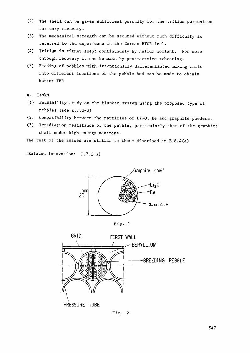
(2) The shell can be given sufficient porosity for the tritium permeationfor eary recovery.
(3) The mechanical strength can be secured without much difficulty asreferred to the experience in the German HTGR fuel.
(A) Tritium is either swept continuously by helium coolant. For morethrough recovery it can be made by post-service reheating.
(5) Feeding of pebbles with intentionally differentiated mixing ratiointo different locations of the pebble bed can be made to obtainbetter TBR.
4. Tasks(1) Feasibility study on the blanket system using the proposed type of
pebbles (see E.7.3-J)(2) Compatibility between the particles of Li2d, Be and graphite powders.(3) Irradiation resistance of the pebble, particularly that of the graphite
shell under high energy neutrons.The rest of the issues are similar to those discribed in E.8.A(a)
(Related innovation: E.7.3-J)
Graphite shell
Graphite
GRID\
Fig. 1
FIRST WALL_/__I/ BERYLLIUM
BREEDING PEBBLE
PRESSURE TUBEFig. 2
547

E.8.12
Shape Memory Alloys for Joining and Removal of Fusion Reactor ComponentsK. SuzukiJapan Atomic Energy Research InstituteTokai Research Establishment
1. BackgroundIn most nuclear energy system, joining of pressure tight components
has been accomplished by extensive use of welding. Welding inevitablyaccompanies various microstructural changes either by melting or excessive
heating, the associated generation of residual stresses and, in somecases, formation of structural defects or flaws specific to the welding.On the other hand, the maintainance of fusion reactor takes into accountthe planned repair or replacement of components in the design, whichrequires reasonably simplified and quick practices. Moreover large fractionof R&D works on fusion materials will have to be invested in characterizingthe weld metals and the heat affected zones of the weldments, particularywith respect to their response to the neutron irradiation.
A method of joining and dismantling the components without weldingand machine cutting is proposed, by which joining of pressure-tightcomponents is made by the use of coupling devices made of the shape memoryalloys.
2. Outline of innovationShape memory alloys are the materials that show the so-called pseudo
elesticity behavior and can recover their original shape form deformedstate(normally to the level well over 10%) by either heating or removingthe imposed stresses. A coupling device that makes use of such effectcan either tighten or loosen the seal portions of the structure by simpleoperation of changing temperature. Table 1 shows some examples of theexisting shape memory alloys. For the present purpose either of Fe-baseor Ni-base alloys will be potentially suited.
3. Features of the shape memory type couplingThe joint coupled by use of the shape memory effect will have the
folloing merits;(1) No weld metal is innovated in the joint structure.(2) Nearly all kinds of dissimilar metals can be joined.(3) Ease of remote operation provides convenient handling of radioactivecomponents.
548

Table 1 Transition temperature and atomic compositions ofshape memory alloys.
Alloys
TiNi
Cu-Zn
Cu-Al
Cu-Au-Zn
Cu-Sn
Ni-AlAg-CdAu-Cd
la-TlIn-Cd
Fe-Mn
Compositions( w t . % )
Ti-50NiTi-SINiTi-20Ni-30CuTi-47Ni-3FeCu-39.1Zn
Cu-11.9Zn-17.1Al
Cu-28.5Al-4.ONiCu-27.8Al-3.8Ni
Au-21Cu-49ZnAu-29Cu-45ZnCu-15.3Sn
NÏ-36.6A1
Ag-45Cd
Au-47.5Cd
In-21TlIn-4.4CdFe-28.7Ma-n.2Si
Ms(°C)60-3080
-90-120146
-1402.5
-15357-4160-7453604080
As('C)78
-1285-72——
-10920-———
-80746550125
T < M fT>A f
J O I N I N GFig. 1 A simple example of the coupling with
a fitting shape memory alloy.
(4) Absense of intensive heating avoids undefined change of materials.(5) Better sealing is obtained relative to the process like the pressurebonding. Fig.1 illustrates a simple example of the coupling with a fittingshape memory alloy.
4. Issues to be solvedThe shape memory effect is a reflection of the athermal phase
transformation. Therefore, possible influence of service enviroment suchas neutron irradiation on the phase stability is suspected to affect theshape memory characteristics of alloys. With some exceptions, the shapememory alloys contain some ordered structure. The microstructural damage
549

to be introduced by neutron irradiation would add some complication tothe ordered structure.
5. TasksThe following subjects are required to be studied;
(1) Examination of the metallurgical parameters that may influence theresponse of materials to neutron irradiation. The parameters includedegree of ordering, grain size, annealing during and after irradiationand thermal-mechanical history.(2) Studies on the deformation behavior under intense neutron irradiationand thermal cycling, particularly the creep and fatigue behaviors.(3) Performance of joints under simulated enviroment and operationaleffects.
Related innovation : E.6.1-J
550

Group 9
GENERAL - COMPACT REACTOR CONCEPTS
C.7). HENNING (USA)
B.B. KADOMTSEV (USSR)
A.F. KNOBLOCH (EC)
Y. SHIMOMURA (JAPAN)
551

Introduction
Eight concepts were evaluated by Group 9 covering innovative reactor
concepts. As summarised in Table 9, the concepts were divided into two
sub-groups: copper, and super conducting coil options. Three of the
copper concepts were closely related and deal with the Spherical Tokamak
and Low Aspect Ratio Beta enhancement. Accordingly the evaluation comments
for one may apply to the others as well. Similarly, the superconducting
concepts - TIBER, Microwave Tokamak, and Cummulative Impacts of Innovations -
suggest smaller, steady-state reactors. Efficient current drive is the
most uncertain feature, but it may be essential for attractive fusion
reactors.
G9.1 Tokamak with Warm Coils
This proposal is aimed at diminishing the cost of the next step device.Namely this reason together with the increasing 0 value at small aspectratio leads to installation with a total fusion power of about 500 MW, average
2neutron load to the first wall 1,25 MW/m , major plasma radius R = 3,5 m andminor plasma radius a = 1,5 m. The concept assumes that toroidal field coilsare made of copper and aluminum elements with the possibility to demountthem. Poloidal field coils and inductor soleroid are placed inside thetoroidal field coils. The central part of TFC has ceramic electricinsulation, the blanket 9 shielding are supposed to be not thick.
From a plasma physics point of view, this tokamak is similar toconventional one, with the beta value of 6,5%. The group has the opinion thatcompact tokamak with the warm coils has to be advanced in plasma physics.That is why this proposal is considered as not substantial in improving thetokamak concept.
Tokamak with small aspect ratio
G9.2 Spherical torus (ST) concept and the reactor implicationsG9.3 Tokamak with small aspect ratioG9.4 Beta enhancement by using small aspect ratio plasma
553

A very small aspect ratio tokamak (spherical torus) is proposed in threepapers (G9.2, G9.3, and G9.4). The dependence of the critical beta value onthe plasma current, _ CI [MAj is shown to be valid even in the cases
' C% = a[m] BT [T]of small aspect ratio, A a 2. The constant C is about 4 for both low andhigh shear cases (G9.4). A higher value is obtained in (G9.3). Thereforehigh toroidal beta is expected in the first stability region in the sphericaltorus. The spherical torus plasmas with an edge safety factor q > 2 arecharacterized not only by high toroidal beta (ß > 0.2) but also lowpoloidal beta (ß < 0.3), naturally large elongation (K = b/a > 2), largeplasma current with I /aß ) up to higher than 7 MA/mT, strongparamagnetism (B /B > 1.5), and strong magnetic helical pitch (0comparable to F). These features combine to engender the spherical torusplasma in a unique physics regime which permits compact fusion at low fieldand modest cost (G9.2).
Preliminary design assessments of an advanced fusion reactor conceptbased on spherical torus are carried out (G9.4). The concept includesresistive demountable toroidal field coils, poloidal divertor for impuritycontrol, oscillating-field current maintenance, RF initiation and ramp-up ofthe plasma current, and a flowing liquid-metal breeding blanket. With K = 3,an average toroidal beta of 0.29, and a net electric power of 1000 MWe, anadvanced spherical torus is estimated to have R =2.7m, A =1.8, B. =2.7T, I = 46 MA, a current maintenance power of 30 MW via oscillating fields,a recirculating power fraction of 0.25, and a fusion power core weighing 6500tonnes. These results compare favorably with the STARFIRE reactor concept andhas 1/3 the mass power density and a similar cost of electricity under thesame basis.
These papers (G9.2, G9.3 and G9.4) suggest that substantial improvementof tokamak is expected in the spherical torus, but data on plasma currentdrive and high beta confinement in a spherical torus have to be provenexperimentally before judging on the feasibility for an attractive fusionreactor.
G9.5 The Elongated Tokamak
The concept of tokamak with the very elongated plasma shape benefits totokamak operation and performance resulting from extreme shaping of the plasma.
554

The idea of high elongation firstly proposed by Artsimovich and Shafranovwas aimed to diminishing neoclassical transport in such a geometry. Inaddition to this evidence accumulated indicating that high current density atmoderate magnetic field strengths with high beta value of plasma could lead tosignificant improvements in tokamak concept.
E.T. concept looks like ignition device, ETI, with the major radius of1.25 m, an elongation of 8, and toroidal field strength of 5,7. The toroidalcurrent of 17 ixa is sufficient to heat plasma to ignition without auxiliaryheating.
The reactor of such type with 500 MWe has an elongation 9,3, a majorradius of 2,73 m, and a toroidal field of 4,1 T. The neutron wall loading is
27 MW/m and the mass power density is 115 KWe/tonne.
The ET concept demands the implementation of a thin blanket. Shaping ofplasma requires the use of a PF coil set, which is close to the plasmasurface. The feasibility of such strongly shaped plasma is not clear. Theshaping was tested before by Doublet IIA and T-9 devices. T-9 device hadprovision to get K=4 but it failed to reach this high value of elongation.New attempts are necessary to prove the physical feasibility of ET concept.
With the high wall loading and very thin blanket (30 cm), it will be verydifficult to achieve a good tritium breeding ratio and power conversionefficiency. The neutron damage to the coils and a high recirculating powerfraction suggests that the reactor concept is not attractive. Projected costsof electricity are about the same as other concepts with modest reductions incapital cost. This concept might be best suited to a smaller ignitionexperiment in which reactor considerations are not so important.
G 9.6____Compact Superconducting Steady-State Tokamaks
By minimising the inner radial dimensions of the tokamak center post,
coil, and shielding region, sufficient plasma shaping by the central PF coil
can be achieved to raise beta above ten percent in the first stability
regime. The high field (14 T) PF or plasma shaping coil requires steady-state
operation and current drive. Accordingly this compact superconducting reactor
concept is linked to the development of efficient current drive methods
555

such as negative ion beams, lower hybrid RF, ECH, synchrotron and bootstrap2current. Magnet current densities of 4 KA/cm about 10 - 14 T with
minimum neutron shielding on the inner leg maximizes the plasma shaping.
If successful this concept leads to small 2.6 m major radius Tokamak Ignition
and Burn Experimental Reactor (TIBER) and a steady-state reactor of high
power-to-mass ratio. Non-linking toroidal and poloidal field coils promote
easy maintenance together with a single external vacuum shell. Cryogenic
structures with low fatigue requirements allows high design stresses and
minimum structural mass.
The substance of this innovation is rated to be substantial (1) because
of the steady-state and high Beta design. However, the feasibility is
rated intermediate (2) because the current drive technology is not yet
established. Presently there are experiments to demonstrate lower hybrid,
neutral beam, and small ECH current drive. Efficient, large-scale current
drive systems remain to be developed.
G 9 . 7____Microwave Tokamak
The Microwave tokamak proposes a steady-state, high-Q reactor with
ECH current drive amplified by synchrotron emission and bootstrap effects.
Advantages of ECH include strong localized electron interactions, small
launching structures, and non-absorption by alpha particles. It provides
for current drive, start-up, plasma profile control for confinement, and
disruption avoidance. Stabilization of internal sawtooth disruptions and
m = 2 MHD instabilities have been studied in T-10 using localized heating to
change the current profile. Together with studies by Hsuan of feedback
stabilization of m = 1, 2 magnetic islands, ECH may allow disruption free
tokamak operation with q (o)<.l. Only small ECH currents have been achieved
in experiments at Culham, limited by available ECH source powers. Theoretical
efficiencies are good (0.25 amps per watt) with the ECH resonance tuned to
556

the inner plasma surface, thereby avoiding trapped electrons which do not
contribute to the net plasma current.
The high plasma temperatures implied for ECH current drive leads to synchrotron
radiation from the plasma. Two purposes are envisioned: First, to preferentially
reflect the synchrotron to enhance the current drive, and second, to utilize
synchrotron radiation to catalyze magnets hydrodynamic power generation in
the blanket. This MHD power conversion would eliminate the need for a separate
thermal power plant.
The substance of the microwave tokamak is rated to be substantial (21,
but the feasibility is moderate (2). The ECH current drive can be
demonstrated in current tokamaks, but more efficient gyrotrons and other
microwave sources need to be developed.
G 9.8____Cumulative impact of innovations
It can be shown by calculation that e.g. the INTOR design can be improved
in the direction of lower outlay without sacrificing its mission, provided
some innovative proposals can be applied simultaneously. Improvements have
already been added in Phase IIA-2, but there are more innovations possible.
The leading aspect in engineering improvements must be reliability and
maintainability; the impact is mainly a reduction in machine size. On the
physics side a solid knowledge of the scalings involved is the leading aspect.
The impact here can be of a very substantial nature, and the cumulative effects
can be large.
Especially with an INTOR-like reactor design, a simultaneous application
of all major improvements can easily lead either to an undesirable modification
of the reactor data (large wall load, small plasma minor radius e.g.) or - if
those modifications would be judged acceptable - to a substantial change of the
overall machine concept and also part of its mission. Hence an early assessment
of the cumulative impact of possible innovations appears desirable. It would
557

provide an insight into the need and degree of application of individual
innovations and into their interaction. Some of the improvements are mutually
in support, others are contradictory in certain respects. There are
innovations that are costly to include or increase the risk for machine
operation. It is essential to understand their combined impact on the
resulting reactor parameters and configurations.
The cumulation of innovations is an approach that provides for balanced
improvements that is necessary quite frequently in order to get an overall
positive effect, which is mainly outlay reduction. Since the paper
does not show details of improvements, however, in the table it is not
given rankings.
SUMMARY
The group considered eight contributions which were all dealing
with making a Tokamak reactor more compact, some including the desirable
feature of continuous operation by NB or RF current drive.
In principle this tendency is important, both for a next step device such
as INTOR and for a full scale reactor.
The proposals received were grouped into those with warm copper magnets and
others with superconducting coils where the first are characterized by
the rather large magnet power supply of several 100 MW, the latter by a
relative size increase deriving from more demanding shielding requirements.
Whereas G.9.1 refers to a conventional reactor design using warm copper magnets
which in terms of capital cost may be about 407» cheaper than with super-
conducting magnets, G.9.2 through G.9.5 imply strong fy enhancement to
about 25 - 30% based on either very low aspect ratio or very large
elongation. Associated with that they show very large plasma currents
or high wall loading values respectively. Since the feasibility will yet
have to be proven in smaller scale physics experiments, these proposals have
not been assigned high priority for further consideration.
558

Among the proposals with superconducting magnets that all attain a
of about 10% , G.9.7 is a very innovative study that even tries to avoid
the usual power plant and replaces it by an integrated MHD power conversion
system. High temperature plasma operation produces enough synchroton
radiation for partial current drive and mercury vapour ionizationj the
nuclear heat being used for the vaporization. In addition, the bootstrap
current concept has to be proven to work efficiently for the concept to
function. Since the main innovations are interesting, although needing
demonstration taking long term programmes, high priority was assigned
to this proposal.This leaves G.9.6 and G.9.8 which imply reduced plasma dimensions
with enhanced elongation. G.9.6 gives a reactor power design including
current drive which is needed for steady state operation primarily but
also because the central solenoid space is occupied by shaping coils for
a slightly indented plasma cross section. The direction indicated by
the two contributions could lead to an INTOR-like machine of about 400 MW
fusion power with a 30 - 50% larger neutron wall load than in INTOR.
Since this direction is in direct pursuit of both the next step
designs and the reactor requirements, it was assigned high priority
for further consideration.
559

Table 9. Compact reactor concepts
G 9.1
G. 9. 2
G. 9. 3
G. 9. A
G. 9. 5
G. 9. 6
G. 9. 7
G. 9. 8
A. Copper Magnets
Tokamak with warmcoils
Spherical Torus (ST)concept and itsreactor implications
Tokamak with smallaspect ratio
Beta enhancement byusing small aspectratio plasma
The elongated tokamak
COCO
CO
coco
z0-,
CO
Cost ~ 0.6 INTOR6=6 . 5%1 = 10 MA
FÔ drive cost 6=29%1 = 46 MA
6=25%
T^ =7MW/m2cost K~10ß=32% I = 10 M/0
Subs
tanc
e
3
Fea
sib
ilit
y
1
Pri
ori
! y
1 2
2 3
B. Superconducting Magnets
Compact superconductingsteady-state tokamaks
The microwave tokamak
Cumulative impact ofinnovations
CO
CO
uW
R=6m current drive1 = 25 MA n=A MW/m2
1 = 15 MA 6=10%ECHbootstrap synchrotron
general, no specificinnovation
1
2
2
2
yes
yes
therefore no ranking
560

G.9.l
TCKA:.:AK WITH WARH COILS.A.I.l'.el'diar.ov, E.V.Kursv'ev, V.V.Orlov, V.I.Pistunovich
This innovation is concerned with the search of reactordesign options allowing higher beta values and, consequently,lower cost, es well as simplified reactor design and mainte-nance.
Specific features of the suggested concept of the tokamalcreactor with warm coils are as follows (Fig.1)î
•unloaded' TFC system consists of the central copper columnwith necessary number of sectors, each of them being the inbo-ard part of a winding, and the outboard C-shaped aluminium, ele-ments completing each winding the electric contact between thxcopper and aluminium parts of the windings is supposed to beflexible so that the tension load from the outboard part is notapplied to the central column but is taken by a special exter-nal supporting structure;- PFC and inductor solenoid are placed inside TFC;- the central part cf TFC has ceramic electric insulation;- low temperature blanket and the inboard shield of min ins lthickness c. noun t to 40 cm;- double-null poloidal divertor.
Fi .2 shows the results of the reactor physical, engineer-ing and economical characteristic calcul-dations for various ne-utron locids, i? , with plasma cross-section elongation, K = 1.3• X
ar.d safety factor at the plasma edge, q.j= 2.3. The burning
phase d"Titicn of J-CO s has been assumed. Belo'.v the main fea-I* i
•r-'\'"f.H C ^ 4~^ -• C •' ~- ~\ f" c.'~' r- *\C' £• ~\ ' ' Z,~r*C^ T".1*- » I3- • • '
561
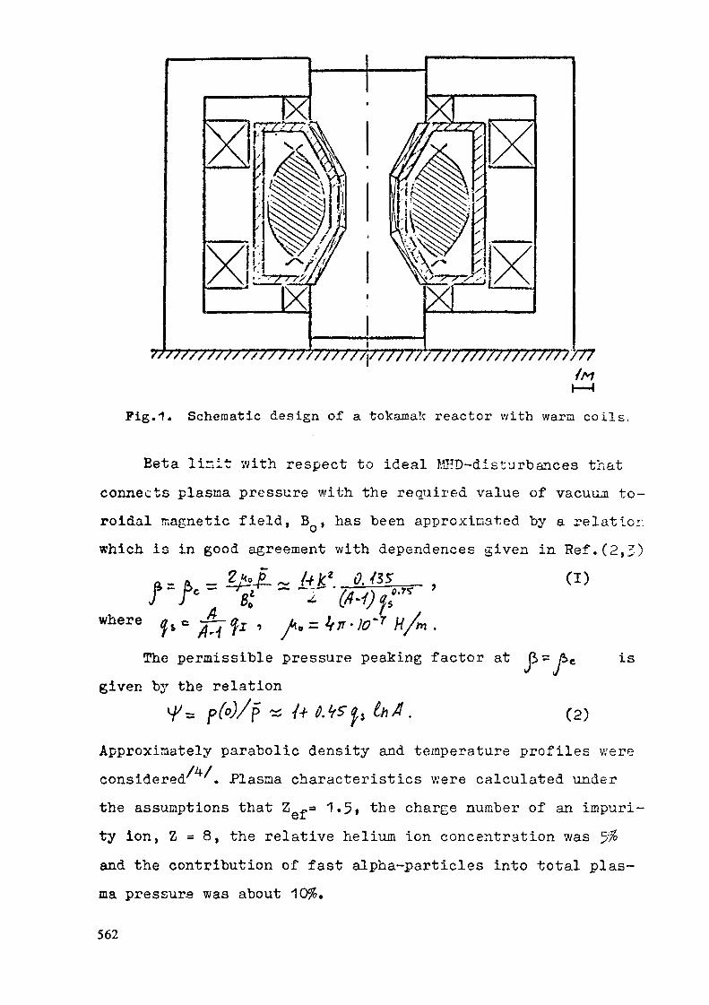
Y ////////////////// ///v/77
Fig.'î. Schematic design of a tokamak reactor with warm coils.
Beta lir.it v/ith respect to ideal MHD-disturbances thatconnects plasma pressure with the required value of vacuum to-roidal magnetic field, B , has been approximated by a relationwhich is in good agreement with dependences given in Ref.(2,3)
__ . (D
m7 H/m.The permissible pressure peaking factor at ß= &
given "by the relationis
(2)
Approximately parabolic density and temperature profiles were/4/considered . Plasma characteristics were calculated under
the assumptions that 2 ~=» 1.5» the charge number of an impurity ion, Z = 8, the relative helium ion concentration was ^%and the contribution of fast alpha-particles into total plas-ma pressure was about
562

W
a. m
/.U
0,5
* P^m °a) average neutron load to the first wall, W » 1 U.V/c
2.0
•/.O
0.5
0
1-5
Fig. 2. Iso-lines of fusion power, Pf , capital cost, C, totalrequired power supply, P£ , vacuum toroidal magneticfield, B , aspect ratio, A, beta, rj , and ignitionmargin, M, at q-j-» 2.8, K= 1.3, <T>n= 9 keV, TTj.» 300 sin R, a-coordinates.

The ignition margin was determined from the plasmabalance'
"———• > (3)
where^T> is mass average plasma temperature, c< is energy/ n 'confinement time, P^ is fusion power yield in alpha-particles,Pj is ohrr.ic heating power density, Pg is radiation losses po-wer density.
Two scalings for 7^ were considered:- T-11 scaling
TÇ - ^°" (&\fi<"j w«- ASDEX scaling
T£ ~ Û.06 R[t*l30[MA]
Here M = 2.5f n is cross-section average electron density in6plnsmc, Ï is the plasma current.
The total reactor power supply, P^ includes the ohmic lorses in magnets, the power supply for plasma heating and forblanket and magnet cooling systems, with the power sources ef-ficiences taken into account.
Capital costs were determined only for the major reactorsystems, such asî- magnetic system;- blanket and shield;- plasma heating system;- vacuum-tritium complex;- reactor cooling system;- support structure for the magnetic system.
One can see from Fig.2(a, b) that the main reactor charac-teristics are improved with the decrease of plasma major rodiualong the lines of constant fusion power, Pp=const. This is
564
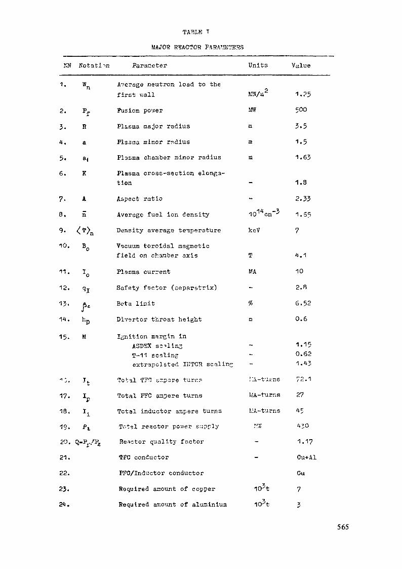
TABLE T
MAJOR REACTOR FARV'.fläTSSS
NN
1.
2.
3.4.
5.6.
7.8.
9.1Û.
11.12.
13.14.
15.
*:.17.18.
19-20.
21.
22.
23.24.
Notation Parameter
W Average neutron load to thefirst wall
Pj, Fusion po'.verxR Plasma major radiusa Plasma minor rsdiusa( Plasma chamber minor radius
K Plasma cross-section elonga-tion
A Aspect ration Average fuel ion density
^TXi Density average temperatureB Vacuum toroidal magnetic
field on chamber axis
T Plasma currentq-j- Safety factor (separatrix)
&c Beta limit
hp Divertor throat height
M Ignition margin inASDEX scalingT-11 scalingextrapolated IITTCH scaling
Ifc Total T?0 tr.psre turn?
I Total PFC ampere turns
I. Total inductor ampere turnsPj_ Tot?l reactor pcy/er supply
Q-P../p£ Reactor quality factor
TFC conductor
PFC/Inductor conductor
Required amount of copper
Required amount of aluminium
Units Value
KW/iß 1 . 2.5m 500in 3.5m 1.5m 1.63
1.3
2.3310 cm 1.65
keV 7
T 4.1
MA 10
2.8
% 6.52
m 0.6
1.150.621.43
r:A-tuj.-ns 72.1
Iv'A-turns 27
î,:A-turns 45r w 430
1.17Cu+Al
Ou
103t 7I03t 3
565

the result of (Sc increase and TPC volume reduction. Though atvery lev; aspect ratios, A, plasma current, I , rises ccnside-
V
rably, that causes the corresponding rise in PFG and inductorcurrents and decrease of the TFC central column radius. In theend that trend results in the required power supply, Pg , ar.dcapital cost, C, growth. Thus both PZ and C values have mini-mums at sufficiently low aspect ratios. In Fig.2(a, b) the ig-nition curves M=1 are shown either for two Tf scalings at 9 keVdensity average plasma temperature.
An example of possible characteristics for a reactor v;ithwarn coils is given in Table 1. It should bo stressed thy t ?.'-:.
3 reactor has moderate pcr.ver supply requirssent while itscapital cost; is approximately twice lower than that of a re-actor with the sane fusion pov-er and superconducting coils.£3-sides this the warn dismantable TFC can substantially facili-tate '„rc-Bct-or maintenance and provide bettor conditions for ex-periments. All these advantages combined with high beta feasi-bility make this reactor concept rather attractive.
REFERENCES.1. D.K.Xurbatov, A.I.Kel'dianov, B.V.Kurav'ev, V.V.Orlov.
Principles of natheaatic modelling of a fusion power plantReport to seminar at Siberian Energy Institute of SiberianDivision of Academi of Sciences of the USSR, Irkutsk, June 1935.
2. L.M.Degtyarev, V.V.Drozdov, A.A.Martynov et al. Voprosyatorjio^ nauki i tekhniki. Series: Teri&cyadernyj Sinte-z,i3H4(17), 1934.
1). H.IIaitou, K.Yamoüü^i, V.Tatemoto et al. IPPJ-694, Nagoya,Japan, 1934.
4. V.I.Bugarya, N.L.Vasin, V.A.Vershkov. Pizilta plazrsy, v.9,iss.5, 1985, P.91^.
566
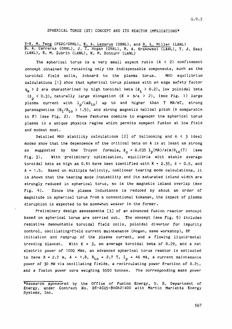
G.9.2
SPHERICAL TORUS (ST) CONCEPT AND ITS REACTOR IMPLICATIONS*
Y-K. M. Peng (FEDC/ORNL), E. A. Lazarus (ORNL), and R. L. Miller (LANL)B. A. Carreras (ORNL), J. T. Hogan (ORNL), R. A. Krakowski (LANL), T. J. Seed(LAND, R. M. Zubrin (LANL), N. M. Schnurr (LANL)
The spherical torus is a very small aspect ratio (A < 2) confinementconcept obtained by retaining only the indispensable components, such as thetoroidal field coils, inboard to the plasma torus. MHD equilibriumcalculations [1] show that spherical torus plasmas with an edge safety factorqa > 2 are characterized by high toroidal beta (ß > 0.2), low poloidal beta(E < 0.3), naturally large elongation (K - b/a > 2), (see Fig. 1) large
plasma current with I /(aBtQ) up to and higher than 7 MA/raT, strongparamagnetism (Bt/Bto > 1.5), and strong magnetic helical pitch (6 comparableto F) (see Fig. 2). These features combine to engender the spherical torusplasma in a unique physics regime which permits compact fusion at low fieldand modest cost.
Detailed MHD stability calculations [2] of ballooning and n < 3 idealmodes show that the dependence of the critical beta on A is at least as strongas suggested by the Troyon formula, ß » 0.035 I_(MA)/a(m)Bto(T) (seeFig. 3). With -preliminary optimization, equilibria with stable averagetoroidal beta as high as 0.41 have been identified with K » 2.35, <5 = 0.5, andA » 1.5. Based on multiple helicity, nonlinear tearing mode calculations, itis shown that the tearing mode instability and its saturated island width arestrongly reduced in spherical torus, so is the magnetic island overlap (seeFig. 4). Since the plasma inductance is reduced by about an order ofmagnitude in spherical torus from a conventional tokamak, the impact of plasmadisruption is expected to be somewhat weaker in the former.
Preliminary design assessments [3] of an advanced fusion reactor conceptbased on spherical torus are carried out. The concept (see Fig. 5) includesresistive demountable toroidal field coils, poloidal divertor for impuritycontrol, oscillating-field current maintenance (Hogan, same workshop), RFinitiation and ramp-up of the plasma current, and a flowing liquid-metalbreeding blanket. With K « 3, an average toroidal beta of 0.29, and a netelectric power of 1000 MWe, an advanced spherical torus reactor is estimatedto have R - 2.7 m, A - 1.8, BtQ - 2.7 T, I - 46 MA, a current maintenancepower of 30 MW via oscillating fields, a recirculating power fraction of 0.25,and a fusion power core weighing 6500 tonnes. The corresponding mass power
«Research sponsored by the Office of Fusion Energy, U. S. Department ofEnergy, under Contract No. DE-AC05-840R21400 with Martin Marietta EnergySystems, Inc.
567
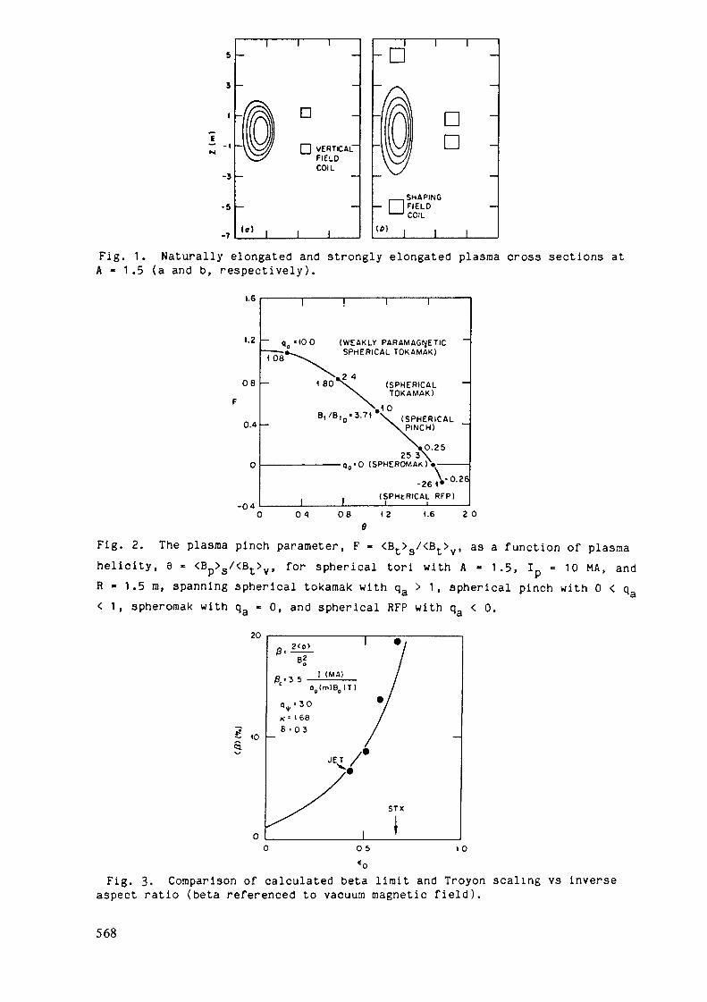
-3
-5
-7
i r
D
VERTICALFIELDCOIL
"" 1 1
-Di r
DD
SHAPINGFIELD
' COIL
(tilI I
Fig. 1. Naturally elongated and strongly elongated plasma cross sections atA - 1.5 (a and b, respectively).
1.6
(.2
08
0.4
-04
' q «100 (WEAKLY PARAMAGNETIC——-»^ SPHERICAL TOKAMAK)I 08
1 8012 4
(SPHERICALTOKAMAK)
"VoBi/B,0«3.71 \ (SPHERICAL
25 3-q0 '0 (SPHEROMAK)
(SPHtRICAL RFP)
08 12e
1.6 2 0
Fig. 2. The plasma pinch parameter, F - <Bt>g/<Bt>v, as a function of plasmahelicity, 8 » <Bp>s/<Bt>v> for spherical tori with A - 1 .5, Ip = 10 MA, andR - 1.5 m, spanning spherical tokamak with qa > 1, spherical pinch with 0 < q< 1 , spheromak with qa - 0, and spherical RFP with qa < 0.
202 < p >e!
I ( M A )o < m ) B „ ( T )
K-- (688 = 03
JET /
STX
0 5 I 0
Fig. 3. Comparison of calculated beta limit and Troyon scaling vs inverseaspect ratio (beta referenced to vacuum magnetic field).
568

1.0
p 0.5
Fig. 4. Dependence of magnetic island overlap on aspect ratio based on 2/13/2 nonlinear tearing mode interaction model for tokamak major disruptions.
TFCJOINT TFC
CENTRAL WATERCOLUMN ^COOLANT
HEADERS
IFC
PtoLI COOLANTHEADER
SUPPORTINGCOLUMNS
VACUUMPUMP
PtU COOLANTMANIFOLD
DIVERTORCHAMBERS
PtLI BLANKET
INBOARD SHIELD
:'.-•-' VACUUM VESSEL
« i tACCESS TUNNEL OPENING
Fig. 5. Advanced Tokamak Reactor based on Spherical Torus (ATR/ST) Concept.•o
•ouiOu
40
20
«0Ou
1 ' I ' ' • • 1 • ' ' 'CONSTANT «MO DOLLARS
r, (MW»)too
• TARFIRE (1200)
CRFPR
«00 200 »00 400MASS POWER DENSITY (kW«/lonn«)
too
Fig. 6. Dependence of minimized COE on FPC mass power density for thecompact RFP reactor, CRFPR, and an advanced tokamak reactor based on thespherical torus.
569

density is estimated to be above 150 kWe/tonne with a cost of electricityabout 38 mills/kWeh in 1980 dollars (see Fig. 6). These results comparefavorably with the STARFIRE reactor concept, which has 1/3 the mass powerdensity and a similar cost of electricity under the same basis.
The required confinement time is estimated to be 1/3 that predicted byKaye-Goldston scaling in this concept. An ignition-level, low fluencespherical torus engineering test reactor is thus expected to have R < 2 m anda fusion power up to a few times 102MW
REFERENCES
[1] Peng, Y-K. M., Strickler, D. J., Features of Spherical Torus Plasmas, OakRidge National Laboratory Report ORNL/FEDC-85/6 (December 1985).
[2] Lazarus, E. A., Attenberger, F. E., Baylor, L. R., Borowski, S. K.,Brown, R. L., et al., Feasibility Study for the Spherical TorusExperiment, Oak Ridge National Laboratory Report ORNL/TM-9786(November 1985).
[3] Miller, R. L., Krakowski, R. A., Bathke, C. G., Copenhaver, C.,Engelhardt, A., Advanced Tokamak Reactors Based on the Spherical Torus(ATR/ST): Preliminary Design Summary, Los Alamos National LaboratoryReport LA-UR-85-3744 (Rev.).Peng, Y-K. M., Strickler, D. J., Borowski, S. K., Hamilton, W. R., Reid,R. L., et al., Spherical Torus: An Approach to Compact Fusion at LowField - Initial Ignition Assessments, Fusion Tech. _8_ (1985) 338.
570

G. 9. 3
TOFAIÜK WITH Sf.'ALL ASPECT RATIOS.G.Eespoludennov, L.M.Degtysrev, S.Yu.Medvedev, A.I.Mel'dianov
Computational analysis results for tokamak plasma stabili-/1-4/ty with respect to ideal MED-nodes' ' allow to estimate beta
limit from the formula:g,c(#)=CIN; 0=2.4 f 3-2, (I)
I is plasma current; Q. is plasna minor radius j B is the va-cuum toroidal magnetic field strength at the plasma axis »wherer-R; R is the major plasma radius. For INTOR (I * 6.4 MA, BO«= 5«5 T, ÜL - 1.2 m) Ijj- 1.2 v;hich corresponds to the upper va-lue of beta limit of 3.8% that is much lower than the earlierassumed 5» 5#«
No stable pressure rise can be achieved by means of Bincrease because of T7C design restrictions. The way to higherplasma current through plasna cross-section elongation increas(K >1.6) seems to have poor prospects due to vertical insta-bility which is rather unlikely to be stabilized at K ** 2. andA»R/d^5» With plasma cross-section shape variation, namelywith higher triangularity ar:c. tean-shape assumption the beta
C*olimit with respect to ballccr. modes can be risen up to ft «• 4.5 I^T that means transition into the second stability rangeBut in this case a conducting -»all at 0.20. from the plasraaedge is needed to stabilize the «rternal kink modes ^ . Thusthe mentioned possibility cf têts, liait rise also seenis to tedoubtful. So the single feasible ?;ay to substantial beta li^iuincrease is connected with reducing the aspect ratio, A' .
571
To support this suggestion a computational analysis hasbeen carried out wherein the beta limit dependence on aspectratio at A 2 was studied with the use of two step plasmapressure profile optimization' ' . The following ma^or resultsof this study should be noted.
1. For small aspect ratio* A £ 2 the universal necessarystability condition qg 3^ 2(0 > 1) has to be replaced by thecondition q ^ q*(A) > 2, violation of which results in the in-Sstability of unloaded configuration (p=0).
2. Scaling (I) with C= 3.0 -r 3.5 gives a good approxima-tion for the beta limit. At A £ 1.5 the depressions, characte-ristic for A 2, between the integer a values disappear inSftc(Ijj) dependence ' ' (see Fig.1).
3« From computational results a formula for the normaliz-ed current, I— has been obtained which is valid in a wide ra-nge of the initial equilibrium parameter variation(q = 1.1, 2 £ qo < 10, 1.2 £ A 5, 1.5 £ K £ 1.8):w S
T * (2)This formula gives a simple relation between qg and
s M* **' (3)
q ;> q*(A) condition impose an upper limit to I T in the4»stable equilibrium. Nevertheless the maximum IN value grows
with A decrease. So the values q >q*~4- at A 1.5 do notmake the concept of a tokamak reactor v/ith smaller at io less at-ractive. It should be mentioned also that according to our cal-culations the peaking factor for the limiting pressure profileincreases with a at any A.
Thus the presented results confirm the feasibility of asubstantial beta limit rise if a tokamak reactor with A<-2 is
572

g ï 6 5 k
realized. In the machines with A>2 the maximum beta limit va-lues can be achieved only near ineger a values, this fact setSting some restrictions on the parameter choice and higher re-quirements to the accuracy of their maintaining.
REFERENCES.1. Troyon F., Gruber £., Saurenmann H., Semenzato S., Succi £
Plasna Phys.Contr.Fusion 26 (Special issue: Proc. 11th Ea-rop.Conf.Contr.Fusion and Plasma Phys., Aachen, 1983), 209.
513

2. Bernard L., Heiton F., Moore R., Todd T. NucI.Fusion 23,(1983), 1475.
3. Sykes A., Turner M., Patel S. Proc. of 11th Europ.Conf. onContr.Fusion and Plasma Physics, Aachen, 1983» v.II, 3S5.
4. Degtyärev l.M., Drozdov V.V., Martynov A.A., Medvedev S.Yu.Proc.Invited Papers of International Conf. on Plasma Phy-sics, Lausanne, 1984
5. Manickam J., Grinm R., Okabayashi M. Phys.Rev.Lett., v. 51»O983), 1959.
6. Peng Y. -K.M. EPS Meeting on Plasma Physics and Controlled.Fusion, Budapest, 1985» paper 3S3.
574

G. 9. 4
Beta Enhancement by using Low Aspect Ratio Tokamak Plasma
T. Tsunematsu, T. Nemoto*, S. TokudaJapan Atomic Energy Research Institute
* on leave from Fujitsu Ltd.
1 . IntroductionTne scaling law of the critical beta value of a tokamak plasma is
approximately given by /3e (?O=CIP GVM )/oBT CO {1} for the case of moderate orhigh shear and moderate elongation, where C is about 3 to 4 and J?,a andBT are the total plasma current, the minor radius and the toroidal fieldat the plasma center. It is seen that the beta value increases eitherwith increasing the elongation , K, or vith decreasing the aspect ratio,A, for a given safety factor at the plasma edge, qs . The latterconfiguration is proposed by Peng {2} and called by "Spherical torus".In this su.T.-ary, the validity of the beta scaling in Ip is studied and theattainable beta value due to the n=°° ballooning mode is shown in theregier, of s-all aspect ratio. The dependencies cf the beta value and ofthe plasma current for given qs on the aspect ratio are also shown.
2. EquilibriumWe optimize the pressure profile for an equilibrium with a given
plas-a shape and the profile of the safety factor (FCT process). Then==c ballooning equation with zero growth rate and the Grad-Shafranovequation are solved iteratively to obtained the marginal pressuregradient. The plasma shape is specified by the functions:
fl=flû+acos(8-rô'sine), (l)
Z=Kasind, (2)where Rj , and a are the radius of the plasma center and the miner radius.respectively, and 6' specifies the triangularity. The free boundaryequilibrium with infinite boundary is solved by fixing 6 points at theplasma surface, i.e. 0 = 0,-, r:/2:r0.15 , a/4, and -/3. The profile ofthe safety factor is chosen as follows;
l), (3)
where a=2 and 4 correspond to the cases of low and high shear ,
575

60
50 •
40
30 .
20 4
10
8 10 12
Fig. l &(?») vs. lpOV-O/a(m}ßr<D . The symbols 0 and x denote the casesof low and high shear. The points of ß>20% are for A<2 and K^l .5 .
&(%)
50 ,
40
30 ,
20 •
10 •
00 10 20 30 40 50
Fig.2 ßc vs. the formula V5' for low shear case.
576

12
10
00 2 4 6 3 10 12
Fig.3 Jp/aßr vs formula (6) for low shear case.
I /aBT(fit)
1.8
1.6
1.01.5 2.0 2.5
Fig.4 Contour of p in '.ic-.4) plane f.or low shear case with 0-0.3.solid and dashed curves denote the cases of q^=3 and 2.2.
The
577

respectively. The critical beta value are obtained for the parametersO^/c^l.8, O^o'SO.3, and 2 qs 4.
3. Results and ConclusionsFigure 1 shows the dependence of ßc on the normalized current
Ip(M4)/a(m)ßt(T) , where the beta value is defined by
The symbols 0 and x denote the cases of 0=2 (lov shear ) and a=4 (highshear). Fcr sar.e shape and qs , the lev shear case gives the highercritical beta value than the high shear case. The simple scaling lowholds for ßc=20 *'» and C --3.6. For higher beta, the obtained valuesdeviate from -the-• straight line. These points are for A<2.0 andK^l.5. In the region of snail aspect ratio, the critical beta values ofhighly elongated plasma are much affected by the triangularity. By thefits with the numerical results, the following scaling lows are obtained:
for 0 = 2.
(A-1.37)0-65
(1_. „^,.„,«._, -.--,,-r- +0.05(1 +(K-l)ô) ), (8)
for 0=4,where ô=-cos(-/2-i-ô" ) . Figure 2 and 3 show that the beta value and theplasma current are well represented by eqs.(5) and (6). Due to the sixpoints fit of the plasma surface, the shape of the cross section deformsat inside of the torus from the eqs. (1) and (2) for A ~~ 1.5. Thisdeformation increases the critical beta value. If the plasma shape isrigidly fixed, the dependence of the beta value on the aspect ratio may be
578

04-1 r0-65 . The contours of 0=5, 10, 20, and 30% in Oe-A) plane for5=0.3 are shown in Fig.4. The solid and cashed curves denote the casesof qs=3 and qs=2.2, respectively. The stable region with ß>2Q% arealmost located in Ae2 .
References{1} F.Troyon, R. Gruber, H. Saurenraann, S. Semenzato, S. Succi, PlasmaPhys. 26 (1984) 209.{2} Y-K. M. Peng. "Spherical torus, compact fusion at low field",CRNL/FEDC-84 7.
579

G.9.5
THE ELONGATED TOKAMAK'
P. A. Politzer & GA Technologies StaffGA Technologies, Inc., P.O. Box 85608, San Diego, California 92138
Abstract
One of the few tokamak plasma parameters amenable to external control is theplasma shape. Evidence has accumulated indicating that there are significant benefitsto tokamak operation and performance resulting from extreme shaping of the plasma,in particular from the use of high elongation.
High elongation permits operation with good confinement, high ß, and high plasmacurrent density at moderate magnetic field strengths and stresses in a compact device.A particularly important consequence of the high current density is the capability ofohmic ignition, removing the need for auxiliary power systems. The elongated geometrylends itself to significant improvements hi ease of maintenance and repair using rapidlydemountable toroidal field coils which provide vertical access and removal of all com-ponents. Elongation leads to reactor systems with high power density, moderate wallloading, and good mass utilization.
These advantages of elongation and shaping are based on the premise that thebehavior of highly elongated plasmas (K > 4) is consistent with and predicted by theexisting tokamak data base (K < 2). The primary issues for the development of thisconcept are the verification of this assumption, and the demonstration of practicalcontrol techniques for highly elongated plasmas. These questions can be resolved in thenear future, at moderate expense.
Conceptual designs have been developed for an ignition physics experiment andfor a small reactor based on the E.T. concept. The ignition device, ETI, has a majorradius of 1.25 m, an elongation of 8, and a toroidal field strength of 5.7 T. The toroidalcurrent of 17 MA is sufficient to heat the plasma to ignition without auxiliary heating.The reactor has been parametrized in terms of the net electrical power output. The 500MWe reactor has an elongation of 9.3, a major radius of 2.73 m, and a toroidal fieldof 4.1 T. The neutron wall loading is 7 MW/m2, and the mass power density is 115k We/tonne.
Implementation of the E.T. concept would provide a path for the development oftoroidal reactors using existing technology. It makes possible a reactor that could bebuilt in "demonstration" size (~100 MWe), and that would be scalable to large systemswithout change in physics or technology.
Prepared for IAEA Specialists Meeting on Tokamak Innovations - Vienna - 13-17 January 1986
580

Physics
The first consequence of high elongation and shaping of a tokaxnak plasma is thepossibility of a very high ß limit, without the invocation of second stability regimes,and without the awkward geometric constraints of very low aspect ratio. With highelongation, the plasma current, current density, and poloidal field strength can be madelarge, while maintaining the safety factor at stable values. The current is approximately
thus, the current density is -proportional to K, as is the poloidal field strength. TheTroyon ß Emit estimate gives
ßmaz ~ 0.035 I/aBT
si 0.07 K2(a/R)
This clearly cannot hold for arbritrarily large elongation, but it indicates the possibilityof ß limits in the range of 20-40%, for elongations in the range of 5-10. Analyses to datehave shown that ballooning mode ß limits of at least 45% can be achieved for examplesof 6:1 elongation and significant curvature.
We have found that curvature of the plasma - so that it is a section of an ellipsoidalshell rather than of a straight cylindrical shell - improves both the equilibrium andstability properties. The curved equilibria tolerate a wide range of plasma currentprofiles, and are insensitive to variations in shaping coil currents. They also indicateimproved stability to long wavelength (n = 0 and n = 1) ideal MHD instabilities.
The other major consequence of elongation and shaping for the physics of toka-mak plasmas is an improvement in confinement. The neoclassical energy and particleconfinement times are proportional to the square of the poloidal field strength, andso should increase as /c2. Also, the curvature of the E.T. plasma leads to coincidencebetween the flux surfaces and the \B\ contours, except at the ends of the plasma. Thisreduces the radial excursion of trapped particle orbits.
As an ohmically heated device, the elongated tokamak is expected to follow theempirical "neo-Alcator" energy confinement scaling relation, TE oc naR2. In this case,the confinement cannot be increased without limit because of the empirical "Murakami"density limit. Experimental data indicates, however, that the density limit, in ohmicallyheated plasmas is proportional to the plasma current density. Thus, E.T. plasmas canhave high density and long confinement times, both increasing linearly with K.
Technology
The technological benefits of elongation result from the simplified geometry of theplasma and from the high plasma ß. The plasma shape leads to a reactor which consistsessentially of nested cylindrical structures. An example of an elongated tokamak deviceis shown in Figure 1.
581

The device shown here illustrates theignition physics device, ETI. The layout ofa reactor would be similar, with the addi-tion of a blanket adjacent to the vacuumvessel and of additional shielding. At theaxis of the device is the toroidal field (TF)coil centerpost. Surrounding this is the in-ner set of poloidal field (PF) coils, followedby the plasma chamber, the outer PF coils,and the outer legs of the TF coils. The pri-mary support structure is interleaved withthe outer TF legs, and serves as shielding aswell.
Access to these components for assem-bly, maintenance, and repair is provided byremoval of the top legs of the TF coils, al-lowing vertical insertion and extraction ofmajor components. This geometry, and thevertical access, make the E.T. tokamak par-ticularly suited to compact, silo-like under-ground enclosures.
Because of the high plasma /?, onlymoderate magnetic field strengths are re-
quired. Thus the fprces are not large, and stresses may be taken up in relatively simple,inexpensive structures.
Ohmic Ignition
A particularly important and useful feature of the E.T. concept is that it allowsohmic heating to ignition. Balancing the ohmic power input and heating from ther-monuclear Q-particles against conduction and radiation losses results in an ignitioncondition which depends on the product of elongation and magnetic field strength. Indevices proposed previously for ohmic ignition the elongation was close to one, and therequired magnetic field strength was in the 15-20 T range. Increasing the elongation tothe range of 6-10 allows the E.T. reactor to ignite at a magnetic field strength of theorder of 5 T.
There are several significant consequences of ohmic ignition which are beneficialfor tokamak reactors. With ohmic ignition, the complex and expensive auxiliary heatingsystems are not needed. This reduces the cost of the reactor, improves its reliability,and affects the design of the tokamak itself. Without auxiliary heating, there is no needfor large ports in the plasma chamber or for large penetrations through the blanketand shield. The number and sizes of such apertures are determined in E.T. devices bypumping requirements. The space around the tokamak usually reserved for auxiliaryheating apparatus is not needed. This allows a much smaller reactor building, andenhances the attractiveness of underground siting of the tokamak.
Reactor Features
A parametric analysis of an E.T. commercial reactor has been carried out. Exam-ining the cost of electricity as a function of neutron wall loading for various net electric
582

power levels, an optimum is seen in the range of 5-10 MW/m2. As a function of netpower output, the economy of scale is seen, but attractive reactors with Pnet in therange of 400 MWe are found.
To assess the impact of high elongation on reactor components and operation, aspecific reference configuration was selected for further examination. The parametersof this device are listed below:
Net electric power 513 MWeGross electric power 826 MWeThermonuclear power 1750 MWt/,Major radius 2.73 mElongation 9.3Plasma current 10.1 MAToroidal magnetic field 4.1 TNeutron wall loading 7 MW/m2
Mass power density 115 kWe/tonne
One of the important issues for the design of an E.T. reactor is the implementationof a high efficiency, thin blanket. Shaping the plasma requires the use of a PF coil setwhich is close to the plasma surface. Otherwise the control capability becomes uncertain,and the control power requirement becomes, large. For this reactor, a helium cooled,static liquid lithium breeder blanket with integral first wall is used. The completeblanket is 0.3 m thick. The blanket contains beryllium for neutron multiplication,and the structural material is vanadium to allow high operating temperature and lowactivation.
The requirement of closely fitting poloidal field coils makes the E.T. reactor apossible application of integral blanket/coil systems, for example the GA Blitz-coil(Beryllium-lithium-tritium zone). This coil can be made of a beryllium alloy, cooledby lithium, and is capable of adequate tritium breeding without additional blankets.
Research Issues
The research issues associated with implementation of the E.T. concept fall intotwo categories. The extrapolation of these ideas to fusion reactor scale has been basedon the premises that highly elongated plasmas can be stably maintained for the dura-tion of a pulse, and that the existing ohmically heated tokamak data base applies toplasmas with high elongation. Preliminary analyses of the stability of E.T. plasmas toaxisymmetric (n = 0) instabilities indicate that ideal MHD perturbations are stablewith a conducting wall at approximately one-third of the minor radius from the plasmasurface. This implies that stability can be maintained in a real device with a resistivewall and an actively controlled PF plasma shaping system. Further research will berequired to determine the PF configuration "which ensures control with ininirmim. powerrequirement, while allowing sufficient room for blanket and shield.
The experimental data base is broader and more consistent for ohmically heatedtokamaks than for any other confinement scheme. However, only the regime of elonga-tion less than two has been thoroughly explored. The extrapolation of this data baseto E.T. elongations requires verification.
583

The other area requiring further study is the optimization of the overall powerbalance of an E.T. reactor system. As presently conceived, the concept incorporatesresistive magnet coils. Reduction of the power consumption in these coils will improvethe attractiveness of the concept. Further development of integral blanket/coil systemsis also indicated.
584

G.9.6
Compact Superconducting Steady-State TokamaksCarl D. Henning
Lawrence Livermore National Laboratory*Livermore, California
SUMMARY
The cost of a tokamak reactor or intermediate ignition and burn experimentvaries about linearly with fusion power or about the square of the majorradius. Accordingly, first-generation reactors or next-generationexperiments would be easier to fund if the design were compact. Thisengineering innovation proposes to combine (1) high-magnet currentdensities, (2) stronger cold structures, (3) a common external vacuum shell,(4) high-field plasma shaping coils (external, not linking the TF coils),(5) minimum neutron shielding, and (6) steady-state operation (assumingcurrent drive, no OH, reduced fatigue), with the purpose of achieving - inan all-superconducting design:
(a) minimum major radius(b) strong plasma shaping (elongation K > 2, triangularity > 0.5)
As a result of a and b, we expect to approximately double the beta in thefirst stability regime (from H-5% obtainable in conventional superconductingdesigns, to 8-1OÏ). The benefits of high-beta in a commercial reactor wouldbe either higher wall loading and power density, or the ability to operateat higher Te to enhance current drive efficiency and synchrotron radiationproduction for MHD energy conversion. The benefits in a test reactor likeINTOR would be in reduced size and cost. As an example, the TokamakIgnition/Burn Experimental Research (TIBER) reactor is summarized inTable I. To reduce the size and cost of the tokamak requires a number ofaggressive design assumptions. For example, plasma shaping is used toachieve a high-plasma beta (the ratio of plasma pressure to magnetic fieldpressure). In addition, neutron shielding is minimized by radiationhardening of the magnets to achieve the desired small device size (majorradius of 2.6 m, plasma height of about 0.8 m). However, thesuperconducting toroidal-field magnet must still be shielded sufficiently toreduce the neutron heat load and the gamma-ray dose to various components ofthe device. In particular, the insulation should retain adequate strengthand electrical properties after irradiation to high end-of-life neutron
585

Table I. TIBER reference case parameters.
Fixed parameter»
Major radius R - 2.60 •Minor radius a - 0.73 •Aspect ratio A » 3.6
Elongation 1.94Triangularity 0.60Indentation 0.05
Variable parameters
Plasna current, I (HA)Are. toroidal beta. »T«)Ignition margin, HIon/electron transport, X./Jt.Ion température, Tj(keV)Electron temperature, T (keV)Ave. edge safety factor, qeNeutron wall load, rn(peak)
(MW/m2)Fusion power.ATB. density, n (10 B)Current drive, PC(J(MW)
Toroidal field 5 TFractional radiation losses (1 - f )QIon confinement: Neoclassical/2
Electron confinement: Neoalcator/2
Beta: 0.0« I /(a BT)
Pulsed ignition »ode
9.710.61.51.1
10102.2
4.0 (1.6 ave)4403.30
Steady state cur-rent drive »ode
7.4B.I0.600.130243.2
2.1 (0.6 ave)2220.9422.4
19 2fluences (greater than 10 neutrons/cm ) and gamma-ray doses (above10 rads), especially in those portions of the magnet adjacent to theshield penetrations required for diagnostics and plasma-heating systems.For TIBER, the peak fusion heating rate in the superconducting toroidal-field coil is calculated to be 22 mW/cm , for a total system heat load of50 kW.
A high-field (1H-T) plasma-shaping coil is used in the usual ohmic heatingcoil position as shown in Figure 1. Shaping the plasma profile with thecoil to produce a modest indentation achieves a plasma beta of 10Jt in thefirst stability regime. All inner-radius components of the tokamak must bekept as small as possible so that the plasma major radius can be minimizedand plasma shaping can be maximized. Accordingly, high-magnet current
2densities of ^ kA/cm and an integrated structural design are required.Non-linking toroidal and poloidal field coils are used for easy maintenancealong with a single external vacuum shell. Internal sealing is achieved bya remotely expandable tube joint to prevent excessive accumulation oftritium from the plasma onto the cryogenic coil surfaces. Data in Figure 2
586

Pint MM
FIGURE 1. Compact Shaped-Plasma Tokamak with Current Drive
i i i i Vr i t ir. MM. MMMMi «NO
FIGURE 2. Hydraulic Vacuum Seal
indicates that tritium leakage past an inflated stainless steel tube isreduced to insignificant levels if the internal pressure is increased to2 ksi (13.6 MPa). Alternately, an aluminum surface can be used to reducesealing pressure to half that amount.
587

To achieve the high-magnet current densities required suggests the use ofinternally-cooled Nb_Sn conductors similar to those used by the WestinghouseLCP coil. Stability is achieved primarily by the enthalpy of the heliumrather than the resistivity of the copper. An added benefit is the relativeindependence from neutron damage effects on the copper, since low-resistivity is a second-order consideration in stability. High-quenchvoltages can be achieved with radiation-resistant polimide tape for reliablecoil performance. A sample design is given in Table I. The greatestchallenge in assembling the TF coils is to Join them near the center post ina manner that permits shear stresses to be transmitted between adjacent coilcases. The tendency to "overturn" is thus resisted. One solution would beto machine a number of pilot semicircular grooves in the case sides. Thecenter lines of the grooves must point toward the centerline of the postafter all the TF coils are in position. Adjacent case sides would havemirror-image grooves and, if alignment were perfect, a pin could be insertedin the "hole" so formed. That level of precision is certainly too costlyand probably impossible. Instead we would rough-machine the grooves toabout 75Ï of their final diameter. After the TF coils were located againstthe post, the holes would be enlarged and reamed, using the small andmismatched grooved as a "pilot hole." Calculations of shear indicate that20 of the 2.5-cm-diameter dowels at each case interface would develop theneeded balancing shear force at a stress level of 330 MPa. Since no otherloading exists on the dowels, this should be a tolerable stress level.
588

G.9.7
THE MICROWAVE TOKAMAK
R. W. Conn, J. M. DawsonUniversity of California at Los Angeles
B. G. LoganLawrence Livermore National Laboratory
A. BoozerPrinceton Plasma Physics Laboratory
J. D. Gordon, C. WagnerTRW, Inc.
SUMMARY
Current DriveThe Microwave Tokamak concept (TMT) seeks an attractive, high Q steady state
reactor in which the total plasma current is driven non-inductively by a combinationof three sources: 1) continuously injected ECH, 2) anisotropic wall reflection ofsynchrotron emission, and 3) amplification of the ECH and synchrotron emissioncurrent sources by the bootstrap effect. ECH was recently proposed and studied asan approach to a steady-state tokamak. ECH is the common RF system for heating andfor current drive. Advantages of ECH current drive include: a) Strong localizeddamping by electrons; b) Small size and relatively simple launching structures; c) No2wave absorption by alpha particles. Current drive efficiency using ECH, withallowance for trapped electrons at moderate aspect ratios,
,„20 -3 <T >*1CD (.o»» o., (|s, ,lS_a_, (jjiy) ,AS, „,would optimize at relatively higher average electron temperatures (<T > = 20 to
19 20e -310 keV) and lower average electron densities «n > = 5 x 10 to 10 m ) than would6normally be considered for fusion reactors. Under these conditions, density cutofffor ECH is generally higher than optimum operating densities (no density cutoffproblem).
Dawson and Kaw analyzed current drive using anisotropic wall reflection ofsynchrotron emission from a high electron temperature tokamak. They find a signifi-cant current
8 B3/2(T) <T>9/2(keV) (1 -R)1/2a3/2(m)'sync (MA)ur 2'5 x 10 ———————~———-—————TUT————————— (2)
eff <BT>
can be driven by absorption of the synchrotron emission in a toroidally preferentialdirection using "fish-scale" walls in which the absorbing surface area fraction ofthe first wall is (1 - R ) ci 0.2. The reflectivity of the reflecting (nonabsorbing)portions of the first wall must be large compared to 1 - R , implying metals withsurface nonuniformities small compared to the typical synchrotron emission wave-
Alengths (A - 0.3 mm). The "free" current by eq.(2), assuming T - 2<T > for aparabolic temperature profile, implies an equivalent current drive efficiency (amps
589

driven per watt of synchrotron emission) comparable to Eq. 1 , so that again,operation at high T and moderate densities is favored as with ECH current drive.The synchrotron-driven current should tend to peak near the axis, due to the strongT dependence of the emission.
In reactor regimes of low collisionality and high beta poloidal, the bootstrap4effect would tend to amplify any ECH and synchrotron emission-driven seed current.The amplification of a seed current by the bootstrap effect is limited by thedevelopment of a non-monotonie q profile. With the constraint of a monotonie qprofile, the minimum seed current is roughly proportional to the area around themagnetic axis in which the seed current is driven. To obtain the minimal seedcurrent, the pressure must drop across the area of current drive concentration by anamount roughly equal to the square root of the aspect ratio times the pressure of thepoloidal magnetic field. With reasonable constraints, bootstrap current amplifica-tion factor of about two might be expected, i.e.,
Ip (total)* 2 [^ (ECH) PECH + Isync]. (3)
Using relations (1), (2), and (3), Table 1 presents some example parameters forsteady state microwave tokamaks using the combination of ECH, synchrotron emission,and bootstrap current drive. Highly shaped plasmas (elongation < > 2) withmoderately low aspect ratios (R/a < 3-6), and feedback control of sawteeth anddisruptions is assumed to yield moderately high beta in the first stability regime:<ß„> = 0.01 I /(aB_) = 0.10. Other common parameters assumed in Table 1 are B„ =6.0 T, <q_, > - 2.1, B (max) = 12 T, Z =1.5, <n > = 102° m~3, and T = 75 keV
eQge il 1/2l ®«T > = 38 keV, <T > =50 keV). The most important result exhibited in Table 1 isQ Q
that very high steady state Q > 20 is possible, even for very large currents (I >20 MA) which may be needed for high first stability regime betas and for adequateconfinement. Such high Q with high currents might not be attainable with ECH alone,
TABLE 1. Example parameters for steady state Microwave Tokamaks usingECH, synchrotron emission, and bootstrap current drive
Parameter INTOR 600 MWe reactor 1200 MWe reactorPfusion (MW)P (MW)syncPECH (MW)QI (MA) totalP
I (MA)syncI (MA)ECHbootstrap
R (m)a (m)F n (MW/m2)
60060262315
il3.67.43.61.02.1
18001503650217
3.610.65.01.43.3
31002304372259
3.612.66.01.73.9
590

synchrotron emission alone, or bootstrap effects alone, and this is why the MicrowaveTokamak concept proposes to use them in combination.
Although synchrotron emission plus bootstrap might be sufficient to drive allthe current in principal (Q « a>), in practical reactors one needs a minimum of 20 toHO MW of auxiliary RF heating for startup in any case, and using ECH for such startupheating and initial current ramp up would also permit important profile control andstability functions to be provided by the same ECH system during the steady state, asdiscussed next.
Synergistic Impact of Microwave Tokamaks with Other Tokamak InnovationsParticular uses of ECH, in addition to heating and current drive, include:
1) Stabilization of internal sawtooth disruptions and suppression of the m - 2 MHDinstabilities. This has been studied in the T-10 tokamak using localized heating tochange the current profile. Recently, Hsuan et al. have studied the much moreefficient alternative of using feedback stabilization in which the ECH is synchronouswith the m - 1 or m = 2 magnetic islands. This will offer the possibility ofdisruption-free tokamak operation with q(0) < 1 and low values of q(a). See USAinnovation P.1.6 "Feedback Stabilization of Magnetic Islands" for more details. 2)Improved central energy confinement and ignition. Suppression of sawtooth oscilla-7tions has already been achieved experimentally with LH current drive on PLT evenwith q(0) < 1. During sawtooth-free operation, the temperature profile insideq(0) = 1 is peaked. This same result should be possible with ECH at higher values ofplasma density and will therefore make it easier to achieve central ignition. 3) Useof ECH to control both the plasma pressure and current profiles. This could enhancethe likelihood of achieving second stability, high ß operation.
A particular use of synchrotron emission, in addition to self-current drive,Q
would be to enhance in-situ MHD energy conversion within the TF coils. Thesynchrotron emission from the high T fusion plasma can be used to maintain non-equilibrium conditions in a working vapor within the MHD generators which, in turn,can enhance efficient, direct MHD power conversion of fusion energy within the TFcoils. See USA innovation E.2.1 "In-Situ MHD" for more details.
It appears to us that these additional benefits of ECH and synchrotron emissioncould possibly be attainable with little or no additional expense in suitable reactordesigns, so we propose to include these functions within the overall MicrowaveTokamak concept.
There are, of course, further tasks required to develop The Microwave Tokamak,incorporating ECH power, the MHD blanket, and synchrotron current drive concepts:1) Relating to ECH itself, tasks include: a) Improved predictions of current driveefficiency at high T ; b) Use of ray tracing calculations to optimize reactor design,including profile effects. 2) Relating to synchrotron current drive, key tasks are:a) Assess the current drive efficiency using synchrotron spectrum radiation;b) Assess the influence of the electron temperature profile on the emission andtransport of synchrotron radiation; c) Examine practical designs for anisotropic(fishscale) first walls, consistent with the needs of current drive.
591

References1. M. Firestone, T. K. Mau, R. W. Conn, "The ECH Tokamak," Comments on Plasma
Phys. and Cont. Fusion 9, 149 (1985).2. J. G. Cordey, "A Review of Non-inductive Current Drive Theory," Plasma
Phys. & Cont. Fusion 26, 123 (19810.3. J. Dawson, P. Kaw, "Current Maintenance in Tokamaks by Use of Synchrotron
Radiation," Phys. Rev. Letts. 48, 1730 (1982).4. A. Boozer, Princeton Plasma Physics Lab (private communication).5. V. V. Alikaev et al., "Electron Cyclotron Heating and Plasma Confinement in
the T-10 Tokamak," in Plasma Phys. and Cont. Nuclear Fusion Res. 1984(IAEA, Vienna, 1985) J_, 419.
6. H. Hsuan, A. H. Kritz, P. H. Rutherford, R. B. White, "ECH Application inFeedback Stabilization of Magnetic Islands," Bull. Amer. Phys. Soc. 30,1572 (1985).
7. A. Cavallo et al., "Suppression of the Sawtooth Oscillation on PLT Using2.45 CHz Lower Hybrid Current Drive Heating, ibid., 1572. See also, M.Porkolab et al., "Lower Hybrid Heating and Sawtooth StabilizationExperiments in Alcator-C at Moderate Magnetic Fields," ibid., 1493.
8. B. G. Logan, L. J. Perkins, "Radiation-Catalyzed MHD Generators forFusion," ibid., 1475.
592

G.9.8
Cumulative impact of innovationsA.F.Knobloch (IPP.D-8046 Garching, FRG)
Calculations based on present state of the art in plasma physics andtechnology can show that the design of an INTOR like reactor can beimproved - preferably in the direction of lower outlay - wi thout sacri-ficing the mission as adopted for INTOR. For achieving that improvementsome of the innovative proposals have to be applied simultaneously.A number of improvements have already been added in Phase lIA part 2to the INTOR design as of Phase IIA part 1 which is considered here a.-the reference. There are improvements which could still be enhanced,and there are further innovations possible that could be added in future.The following Table gives examples.
Table 1: List of examples for improvements/innovations for INTOR
TopicPhysics- increased elongation- decrease of safety factor q- increase of ß by shaping- less margin to ß limit- decrease of impurity ß fraction- minimization of n TV, T
JD
- othersTechnology/Engineering- reduced SC winding thickness- increased field level- decrease of shield/blanket build- decrease of overall size- lower PF system outlay
- larger T breeding ratio- others
Comment
yet to be appliedcould be enhancedtriangularity could be largerconcept of soft ß-limit TßDcould be enhanced with increasing ßrequires to know the TL-scaling
yet to be applied for central solenoidyet to be applied for central solenoid
needs appropriate maintenance schemeneeds optimization including non-in-ductive current driveby material selection, better coverage
The leading aspect for engineering improvements must be reliability of thecomponents designed and maintainability of the configuration such that theexpected availability may be achieved. The impact to be expected is a certain
593

reduction in machine size and overall outlay. On the plasma physics sidea solid knowledge of the scalings involved is the leading aspect. Suchknowledge will allow substantial improvements and the cumulative impact ofthe individual innovations could be large.Fig. 1 shows some calculated design data, namely TI (the relative fusion power)I/I (the relative plasma current) and a/a (the relative minor plasma radius)versus 9 (the relative major plasma radius) with the data of INTOR Phase HApart 1 as reference respectively. The relative wall loading o is mentionedas needed. The individual design points are connected to show how the cumul-ative impact of stepwise improvements gradually modify the reactor.First the g-factor of the ß-scaling is corrected to 0.6 which corresponds toabout 3.5 in absolute terms. An increase in the ignition margin, followedby raising g to about 4 restores the reactor power but not yet the wall load.A reduction of the safety factor, a decrease in engineering dimensions (magnetwindings, shield) of about 10% and a reduction in impurity contribution tobeta are then required to restore the wall load at somewhat reduced reactorpower and dimensions as compared to the reference. This point roughly cor-responds to INTOR Phase IIA part 2. At the same time both the plasma currentand the minor plasma radius have undergone important modifications. Especiallythe plasma current at intermediate steps reaches very large values, and forthe Phase IIA part 2 design is still about 25% larger than in the reference.There are further modifications possible, however! Depending on wether theINTOR mission is to remain exactly as specified so far or not, different waysmay be taken. Just two examples are indicated in Fig.l. One assumes that themission remains unchanged . Then, as an example,for o- I and assumingI'F= 1, by dropping the ß-requirement to about g = 3.5 again, but raising theelongation to about 2.1 , the outlay can be reduced considerably. Note thatthe plasma current also can be reduced again to about what it was in thereference case. In the other example the wall load is allowed to reach o= 1.5.This requires to reduce q to about 1.49 (which still permits a surface q ofSabout 2.3), to decrease the ignition margin again to 1.0 and to go to a per-haps extreme elongation of 2.64. In this case the minor plasma radius getsvery small.The resulting central solenoid will not be able to supply the fullrequired flux swing any more. Hence non-inductive current drive is called for.The plasma current drops below the reference value.It is needless to say that many more cases could be proposed in such a repres-entation. The examples shown serve to demonstrate e.g. that a simultaneousapplication of all improvements to their full possible degree may lead tosubstantial, maybe even undesirably strong modifications(large wall load,
594

1.5-
n
-
1.0 —
0.5-
0 -C
1.5 -
B /B = l .max maxo
T /T = I/I - ph E0 o
INTOR I IA-1 ..•-'
R e f . C.isc/
INTO? IIA-2 ..-A/r/ , l
k/k--' '= 1.65 k/k = 1.323Yf>-' - 1 yß ° - )
.-•6 - 1 . 5 6 = 1.-•'' q/q - 0 .715 g/g = 0.609
/' C - 1.235
R/p 1.0 -0 .61} 6 " 1.0 - 0.6
2) Y6 1 .0 •+ 1 . 15
-,) P/r,n 0.6 - 0.7'6 0.6 -> 0.7
4) q/qo 1 .0 -» 0.85
5) Eng. Diri . : ^ -10%
,, C : 1.0 -» 1 . 1 56) 6 : 0.7 - 1.0
7) k/k : 1 .0 -* 1 . 15———— i ———— i ———— i ———— i ———— i ———— i ———— i ———— i ———— r ———— t ———— i ———— r i i
0.5 1.0 ———— p
-1.5
I/I
1.0--1.0
0.5-J-0.5
a/a. r/i
a/a
0 0.5 1.0 ——— oFig. I Cumulative impact of stepwise improvements on INTOR data
595

small minor plasma radius) or, if these modifications would appear acceptable,to a change of the machine concept and its operating scenario.The representation provides insight into the need and degree of applicationof individual improvements and their mutual interaction. Some of them aremutually in support, others are contradictory in certain respects. Thereare innovations that are costly to include or others that may increasethe risk for machine operation.Soon a selection process among the innovations that will be proposedconcerning their desirability and feasibility will be necessary anyway,and it is not just the innovations themselves that have to be judged buttheir combined impact on all reactor parameters and the configuration.Therefore an early assessment of the cumulative impact of possible innov-ations appears desirable.Taking the present information and the usual extrapolations togetherwith the reference INTOR n Tx T, one can design INTOR alternatives thatbare considerably more compact than even INTOR Phase IIA part 2, not know-ing yet all innovations that may be proposed. Which of the many directionsin improvement should be chosen?
inoID
596