the west bengal power development corporation ltd - bharat
TRANSCRIPT
THE WEST BENGAL POWER DEVELOPMENT CORPORATION LTD (WBPDCL)
SAGARDIGHI THERMAL POWER PROJECT, 1 X 660 MW UNIT NO 5, STAGE III
TECHNICAL SPECIFICATION FOR TG HALL– AB BAY 160/25T
DOUBLE GIRDER EOT CRANES
SPECIFICATION NO.: PE-TS-445-501-A001 Rev 0
BHARAT HEAVY ELECTRICALS LIMITED
POWER SECTOR
PROJECT ENGINEERING MANAGEMENT
NOIDA, INDIA
1 of 424
288672/2021/PS-PEM-MAX7
SAGARDIGHI THERMAL POWER PROJECT, 1 X 660 MW UNIT NO 5, STAGE III.
TG HALL– AB BAY 160/25T DOUBLE GIRDER EOT CRANES
SPECIFICATION No: PE-TS-445-501-A001
SECTION
REV. 00 09-05-2021
SHEET : 1 OF 1
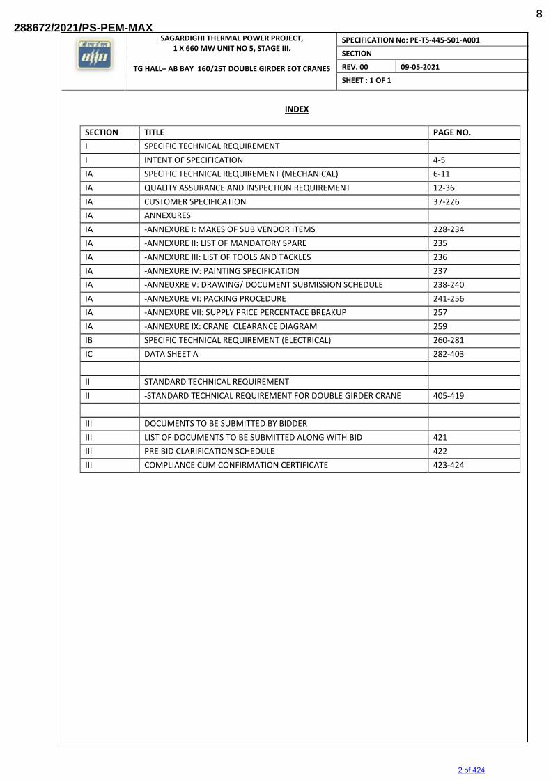
INDEX
SECTION TITLE PAGE NO.
I SPECIFIC TECHNICAL REQUIREMENT
I INTENT OF SPECIFICATION 4-5
IA SPECIFIC TECHNICAL REQUIREMENT (MECHANICAL) 6-11
IA QUALITY ASSURANCE AND INSPECTION REQUIREMENT 12-36
IA CUSTOMER SPECIFICATION 37-226
IA ANNEXURES
IA -ANNEXURE I: MAKES OF SUB VENDOR ITEMS 228-234
IA -ANNEXURE II: LIST OF MANDATORY SPARE 235
IA -ANNEXURE III: LIST OF TOOLS AND TACKLES 236
IA -ANNEXURE IV: PAINTING SPECIFICATION 237
IA -ANNEUXRE V: DRAWING/ DOCUMENT SUBMISSION SCHEDULE 238-240
IA -ANNEXURE VI: PACKING PROCEDURE 241-256
IA -ANNEXURE VII: SUPPLY PRICE PERCENTACE BREAKUP 257
IA -ANNEXURE IX: CRANE CLEARANCE DIAGRAM 259
IB SPECIFIC TECHNICAL REQUIREMENT (ELECTRICAL) 260-281
IC DATA SHEET A 282-403
II STANDARD TECHNICAL REQUIREMENT
II -STANDARD TECHNICAL REQUIREMENT FOR DOUBLE GIRDER CRANE 405-419
III DOCUMENTS TO BE SUBMITTED BY BIDDER
III LIST OF DOCUMENTS TO BE SUBMITTED ALONG WITH BID 421
III PRE BID CLARIFICATION SCHEDULE 422
III COMPLIANCE CUM CONFIRMATION CERTIFICATE 423-424
2 of 424
288672/2021/PS-PEM-MAX8
SAGARDIGHI THERMAL POWER PROJECT, 1 X 660 MW UNIT NO 5, STAGE III.
TG HALL– AB BAY 160/25T DOUBLE GIRDER EOT CRANES
SPECIFIC TECHNICAL REQUIREMENTS
SPECIFICATION No: PE-TS-445-501-A001
SECTION I
REV. 00 09-05-2021
SECTION I SPECIFIC TECHNICAL REQUIREMENTS
SUB-SECTION IA : Specific Technical Requirements (Mechanical) SUB-SECTION IB : Specific Technical Requirements (Electrical) SUB-SECTION IC : Data Sheet-A
3 of 424
288672/2021/PS-PEM-MAX9
SAGARDIGHI THERMAL POWER PROJECT, 1 X 660 MW UNIT NO 5, STAGE III.
TG HALL– AB BAY 160/25T DOUBLE GIRDER EOT CRANES
SPECIFIC TECHNICAL REQUIREMENTS
SPECIFICATION No: PE-TS-445-501-A001
SECTION I
REV. 00 09-05-2021
1. SCOPE OF ENQUIRY/ INTENT OF SPECIFICATION
1.1 This specification includes, but not limited to SUPPLY PART, SERVICE PART & MANDATORY SPARES comprising of design (i.e. preparation and submission of drawing /documents including “As Built” drawings and O&M manuals), engineering, manufacture, fabrication, assembly, inspection / testing at vendor's & sub-vendor’s works, painting, maintenance tools & tackles, fill of lubricants & consumables along with spares for erection, start up and commissioning as required, forwarding, proper packing, shipment and delivery at site, unloading, handling, transportation & storage at site, in-site transportation, assembly, erection & commissioning, trial run at site and carrying out Performance Guarantee/Functional/Demonstration tests at site (as applicable) & final handing over to end Customer in flawless condition of crane (s) for project and package specified above complete with all accessories for the total scope defined as per BHEL NIT & tender technical specification, amendment & agreements till placement of order.
1.2 The contractor shall be responsible for providing all material, equipment & services, which are required to fulfil the intent of ensuring operability, maintainability, reliability and complete safety of the complete work covered under this specification, irrespective of whether it has been specifically listed herein or not. Omission of specific reference to any component / accessory necessary for proper performance of the equipment shall not relieve the contractor of the responsibility of providing such facilities to complete the supply, erection &commissioning and load testing of the cranes and its accessories.
1.3 It is not the intent to specify herein all the details of design and manufacture. However, the equipment shall conform in all respects to high standards of design, engineering and workmanship and shall be capable of performing the required duties in a manner acceptable to purchaser who will interpret the meaning of drawings and specifications and shall be entitled to reject any work or material which in his judgement is not in full accordance herewith.
1.4 The extent of supply under the contract includes all items shown in the drawings, notwithstanding the fact that such items may have been omitted from the specification or schedules. Similarly, the extent of supply also includes all items mentioned in the specification and /or schedules, notwithstanding the fact that such items may have been omitted in the drawing.
1.5 The general term and conditions, instructions to tenderer and other attachment referred to elsewhere are made part of the tender specification. The equipment materials and works covered by this specification is subject to compliance to all attachments referred to in the specification. The bidder shall be responsible for and governed by all requirements stipulated herein.
1.6 While all efforts have been made to make the specification requirement complete & unambiguous, it shall be bidders’ responsibility to ask for missing information, ensure completeness of specification, to bring out any contradictory / conflicting requirement in different sections of the specification and within a section itself to the notice of BHEL and to seek any clarification on specification requirement in the format enclosed under Section-III of the specification. In absence of any such clarifications, in case of any contradictory requirement, the more stringent requirement as per interpretation of Purchaser/Customer shall prevail and shall be complied by the bidder without any commercial implication on account of the same. Further in case of any missing information in the specification not brought out by the prospective bidders as part of pre-bid clarification, the same shall be furnished by Purchaser/ Customer as and when brought to their notice either by the bidder or by purchaser/ customer themselves. However, such requirements shall be binding on the successful bidder without any commercial & delivery implication.
1.7 The bidder’s offer shall not carry any sections like clarification, interpretations and /or assumptions.
1.8 Deviations, if any, should be very clearly brought out clause by clause in the enclosed deviation schedule along with cost of withdrawal; otherwise, it will be presumed that the vendor's offer is strictly
4 of 424
288672/2021/PS-PEM-MAX10
SAGARDIGHI THERMAL POWER PROJECT, 1 X 660 MW UNIT NO 5, STAGE III.
TG HALL– AB BAY 160/25T DOUBLE GIRDER EOT CRANES
SPECIFIC TECHNICAL REQUIREMENTS
SPECIFICATION No: PE-TS-445-501-A001
SECTION I
REV. 00 09-05-2021
in line with NIT specification. If no cost of withdrawal is given against the deviation, it will be presumed that deviation can be withdrawn without any cost to BHEL/its customer.
1.9 In the event of any conflict between the requirements of two clauses of this specification documents or requirements of different codes and standards specified, more stringent requirement as per the interpretation of the owner shall apply.
1.10 In case all above requirements are not complied with, the offer may be considered as incomplete and would become liable for rejection.
1.11 Unless specified otherwise, all through the specification, the word contractor shall have same meaning as successful bidder /vendor and Customer/ Purchaser/Employer will mean BHEL and /or customer including their consultant as interpreted by BHEL in the relevant context. For details refer the relevant clause in GCC.
1.12 Manufacturing Quality Plan for reference is included in this specification to enable the bidder to understand the extent of inspection and testing requirements to execute this job. The successful bidder has to follow the quality plan’s minimum requirement during manufacturing and testing. Further all checks and tests indicated in Quality Assurance Requirement as detailed in Customer’s specification etc have to be followed.
Note:
Bidder to note that BHEL reserves the right for drawing/document submission through web based Document Management System. Bidder would be provided access to the DMS for drawing/document approval and adequate training for the same. Detailed methodology would be finalized during the kick-off meeting. Bidder to ensure following at their end.
• Internet explorer version – Minimum Internet Explorer 7.
• Internet speed – 2 Mbps (Minimum preferred).
• Pop ups from our external DMS IP (124.124.36.198) should not be blocked.
• Vendor’s internal proxy setting should not block DMS application’s link (https://pem.bhel.com/wrenchweb).
5 of 424
288672/2021/PS-PEM-MAX11
SAGARDIGHI THERMAL POWER PROJECT, 1 X 660 MW UNIT NO 5, STAGE III.
TG HALL– AB BAY 160/25T DOUBLE GIRDER EOT CRANES
SPECIFIC TECHNICAL REQUIREMENT (MECHANICAL)
SPECIFICATION No: PE-TS-445-501-A001
SECTION IA
REV. 00 09-05-2021
SECTION IA SPECIFIC TECHNICAL REQUIREMENT (MECHANICAL)
6 of 424
288672/2021/PS-PEM-MAX12
SAGARDIGHI THERMAL POWER PROJECT, 1 X 660 MW UNIT NO 5, STAGE III.
TG HALL– AB BAY 160/25T DOUBLE GIRDER EOT CRANES
SPECIFIC TECHNICAL REQUIREMENT (MECHANICAL)
SPECIFICATION No: PE-TS-445-501-A001
SECTION IA
REV. 00 09-05-2021
1.0.0. SCOPE OF WORK (SUPPLY & SERVICES)
1.1.0. SCOPE OF SUPPLY
1.1.1. Equipment and services to be furnished by the bidder for the EOT CRANE with accessories
as per the details given in the technical specification and data sheet A. Any equipment /
accessories not specified but required to make the EOT crane complete for efficient &
reliable operation shall also be under the bidder’s scope of work.
1.1.2. Compliance with this specification shall not relieve the bidder of the responsibility of
furnishing material and workmanship to meet the specified working/duty conditions.
1.1.3. Two (2) numbers 160T/25T Double Girder Crane for TG hall – AB bay shall include but not
be limited to the following: -
a. Bridge girders with platform
b. End carriages with wheels
c. Crab (trolley)
d. Cross Travel & Long Travel drive arrangement.
e. Operator’s cabin.
f. All electrical equipment including cables, junction box, VVVF drive, pendent,
RRC, panels etc.
g. PVC insulated shrouded bus bar Copper conductor type DSL.
h. Rail complete including all accessories and end stopper.
i. Main Isolating switch/Changeover in enclosure at operating floor for
disconnecting supply to DSL. Termination of incoming cable (from BHEL) into
isolating switch shall be in bidder’s scope. For maintenance of cranes, two (2)
nos. isolating switches are to be provided at extreme ends of bay.
j. Slings and cradle for load testing at site (on returnable basis).
k. Storm brake: Hydraulic rail clamp, two (2) nos per crane.
l. Earthing arrangement.
m. Fill of lubricant till commissioning of crane.
n. Painting of cranes and accessories.
o. Two (2) nos. 3.5/4 Core power copper flexible cable (Half the bay length +
25m) of suitable size as per load calculation for commissioning, testing &
operation of EOT Cranes till such time the DSL is charged.
p. Maintenance tools & Tackles.
q. Erection & Commissioning spares.
r. Mandatory Spares.
7 of 424
288672/2021/PS-PEM-MAX13
SAGARDIGHI THERMAL POWER PROJECT, 1 X 660 MW UNIT NO 5, STAGE III.
TG HALL– AB BAY 160/25T DOUBLE GIRDER EOT CRANES
SPECIFIC TECHNICAL REQUIREMENT (MECHANICAL)
SPECIFICATION No: PE-TS-445-501-A001
SECTION IA
REV. 00 09-05-2021
1.1.4 Makes of Sub - Vendor items Makes of bought out items detailed Annexure-I, section IA of the specification is for reference
only. Sub vendor list shall be subject to customer approval and same shall not have any
impact on manufacturing, delivery schedule and cost of the crane.
1.1.5 Mandatory Spares A complete unused and new set of Mandatory Spare parts shall be supplied. Each part shall
be stamped so as to be identified, easy for it use. The items supplied shall be of the best
quality. The requirement of mandatory spare parts referred at Annexure –II Section-IA of
this specification.
1.1.6 Maintenance Tools and Tackles
Refer Annexure III, Section-IA of this specification.
1.1.7 PAINTING & COLOUR SCHEME
Refer Annexure IV, section-IA of this specification.
1.1.8 Erection and Commissioning spares
The Bidder shall also supply erection & commissioning spares along with the main
equipment as per their experience, for replacement of damaged or unserviceable parts
during the execution of the project at site, to avoid delay in the project schedule. This shall
form part of the main equipment supply. Oil and grease required for first filling along with ten
(10%) percent excess quantity. The bidder shall deliver to the Owner all equipment
complete with initial fill of fluids, grease or lubricants, in drums / containers. Bidder shall
supply minimum following spares
i) Oil seal for each gear box 1 Set
ii) Indicating Lamps 1 no. of each type 1 Set
iii) Push Button 1 no. of each type 1 Set
iv) Aux. contactor 1 no. of each size 1 Set
v) Limit switches- 1 no. of each type 1 Set
vi) Any other spare/s, as per experience of bidder
Note:
a. Any spare, not quoted by bidder, but required during erection & commissioning shall
be supplied by bidder without any additional cost to purchaser.
b. One set means 100% requirement of one crane.
1.1.9 Any supplies to be done under warranty clause & any other clause of NIT, GCC, SCC as
relevant to the package.
1.1.10 Packing as per Annexure VI, forwarding and transportation to delivery address as per SCC.
8 of 424
288672/2021/PS-PEM-MAX14
SAGARDIGHI THERMAL POWER PROJECT, 1 X 660 MW UNIT NO 5, STAGE III.
TG HALL– AB BAY 160/25T DOUBLE GIRDER EOT CRANES
SPECIFIC TECHNICAL REQUIREMENT (MECHANICAL)
SPECIFICATION No: PE-TS-445-501-A001
SECTION IA
REV. 00 09-05-2021
1.2.0 Services to be provided by the bidder 1.2.1. Packing, forwarding and transportation to site. 1.2.2. Development of storage space including ward & watch of the equipment and handling at
site.
1.2.3 Unloading, storage and handling at site.
The Bidder shall provide means for all unloading and reloading for all consignments of plant;
both during transport to Site and on the Site. Consignments shall be unloaded immediately
on arrival at Site. The Bidder is required to take the necessary steps in order to provide the
carriage, special supporting structures for heavy loads, etc. The following parts shall be
stored inside enclosed warehouses:
Bolts, pins, packing, tools, insulation materials, electrical parts with electrical devices
attached, electric motors and excitation equipment, instruments, welding material and
equipment, all small parts and all parts of the crane which already have been finally painted.
If large parts are stored in the open air, they shall be provided with weather resistant and
fire & resistant covers. Electrical parts, which are not packed in heavy duty polyethylene foil
and those so packed, but whose packing has been damaged shall be kept in suitable places
from the moment of storage to the moment of installation. All insulation materials which will
be taken from the warehouse for installation and which are stored temporarily in the station
shall be protected from weather or humidity. All the equipment shall be stored as per
standard storage and preservation instructions etc. of the suppliers.
1.2.4 Arranging test load at site Collecting the test load at site within a radius of 1-2 kms from owner’s storage to final testing
bed of crane shall be under bidder’s scope of work. Test load in the form of rolled steel,
plates, girder, angle etc as available at the site shall be made available by the purchaser.
The test load shall be put back to the place from where it was lifted by the vendor, after the
load testing. Load testing sling, cradles and any other item required by the vendor during
the load testing shall be arranged by the vendor at no extra cost to the purchaser. Slings &
cradles will be allowed to be taken back by the vendor, after completion of the test at site.
1.2.5 Erection and Commissioning of EOT cranes and all accessories.
1.2.6 Demonstration / Load test at bidder’s Works and at Site.
1.2.7 Obtaining clearance and acceptance certificate from the concerned competent Authority
after site test and as and when required as per Government Norms /Statutory body till the
time of final handling over to Customer. Necessary fees/expenditure as required shall be
borne by the supplier.
1.2.8 Training to Customer’s Operation & Maintenance staff.
1.2.9 Any service mentioned in GCC & SCC as relevant to the package.
9 of 424
288672/2021/PS-PEM-MAX15
SAGARDIGHI THERMAL POWER PROJECT, 1 X 660 MW UNIT NO 5, STAGE III.
TG HALL– AB BAY 160/25T DOUBLE GIRDER EOT CRANES
SPECIFIC TECHNICAL REQUIREMENT (MECHANICAL)
SPECIFICATION No: PE-TS-445-501-A001
SECTION IA
REV. 00 09-05-2021
1.3.0. Works Excluded
Supply feeder and cable from feeder / MCC to isolating switch.
Steel Gantry girder.
Dead load for load/ overload testing at site.
Space for storage.
Exclusion, if any, mentioned in GCC, SCC.
2.0.0 Drawing and documents submission schedule along with number of prints. Drawing and documents submission schedule along with number of prints / copies required
for various drawing and documents are listed in Annexure –V, Section-C, Volume II-B of this
specification.
3.0.0 Deviations If the offer submitted has got any deviation from the technical stipulations in the tender
document, bidder shall tabulate the same in the format of “Cost of withdrawal of deviation”
attached in Sec III and furnishing full particular of such deviations. Deviations are to be
furnished with mention to specific clause number (reasons / explanations for such
deviations shall be furnished). Notes / comments etc. is not acceptable. If there are no
deviations from the tender document, bidder shall mention “NO DEVIATION’ in cost of
withdrawal of deviation format.
4.0.0 Performance Test requirement EOT crane along with its drives, controls and other accessories shall be checked for the rated
capacity against the rated speed of motions and for the service conditions specified.
The bidder shall have the full responsibility for the safe and efficient operation of the crane
with associated accessories as a single unit. If the site performance tests indicate the failure
of any of the components to achieve the desired performance, the deficiency shall be made
good at bidder’s cost. Performance test shall be carried out each time after the rectification
/modification is carried out. Performance test of the crane shall include load tests and speeds
in various motions at site.
4.1.0 Testing at Works Refer section IA: QUALITY ASSURANCE AND INSPECTION REQUIREMENT.
4.2.0 Testing at Site 4.2.1 Completely assembled crane at site shall be check for misalignment of gears, shafts and
other items. Following minimum tests shall be conducted on the crane at the site under
supervision of bidder’s representative.
i. Deflection test of bridge girder at rated load.
ii. Load test and Overload test (running of CT and Hoisting mechanism at 125% of the rated
10 of 424
288672/2021/PS-PEM-MAX16
SAGARDIGHI THERMAL POWER PROJECT, 1 X 660 MW UNIT NO 5, STAGE III.
TG HALL– AB BAY 160/25T DOUBLE GIRDER EOT CRANES
SPECIFIC TECHNICAL REQUIREMENT (MECHANICAL)
SPECIFICATION No: PE-TS-445-501-A001
SECTION IA
REV. 00 09-05-2021
load). Capability of crane to lift the overload from mid-air shall be demonstrated. Electrical
tests for brakes, panel, electrical equipment etc as per IS 3177.
iii. Speed test at rated load for hoisting, CT and LT mechanism. iv. Brake test.
v. Any other test as per IS-3177
Note: The test shall be carried out with actual panels, RRC, pendent push button station, master
controller etc.
5.0 Consumables
The Bidder’s scope includes requirements of consumables such as oils, lubricants including grease,
servo fluids, gases and essential chemicals etc. till handing over. Consumption of all these
consumables till handing over shall also be included in the scope of the Bidder. Bidder shall also
supply a quantity of the full charge of each variety of lubricants, servo fluids, gases, chemicals etc.
used which is expected to be utilized till handing over. This additional quantity shall be supplied in
separate containers.
11 of 424
288672/2021/PS-PEM-MAX17
SAGARDIGHI THERMAL POWER PROJECT, 1 X 660 MW UNIT NO 5, STAGE III.
TG HALL– AB BAY 160/25T DOUBLE GIRDER EOT CRANES
SPECIFIC TECHNICAL REQUIREMENT (MECHANICAL)
SPECIFICATION No: PE-TS-445-501-A001
SECTION IA
REV. 00 09-05-2021
SECTION IA
QUALITY ASSURANCE AND INSPECTION REQUIREMENT
12 of 424
288672/2021/PS-PEM-MAX18
SAGARDIGHI THERMAL POWER PROJECT, 1 X 660 MW UNIT NO 5, STAGE III.
TG HALL– AB BAY 160/25T DOUBLE GIRDER EOT CRANES
SPECIFIC TECHNICLA REQUIREMENT (MECHANICAL)
SPECIFICATION No: PE-TS-445-501-A001
SECTION IA
REV. 00 09-05-2021
1.1.0. Inspection and Testing
Bidder shall submit Manufacturing Quality Plan (MQP) based on the guidelines given in the
specification & MQP enclosed herein. Format shall be as agreed with Customer in line with
Customer’s specification “FORMAT OF QUALITY ASSURANCE PROGRAMME” Volume: II-
A Section : VIII.
1.1.1. Inspection and testing at Manufacturer’s works Copy of approved documents with stamp and signature (one set) shall be available at the place
of Inspection which shall be ensured by supplier.
Shop inspection and tests will include but not limited to the following –
STAGE INSPECTION Stage inspection of various components of crane shall be guided by the MQP approved during
detail engineering. Indicative MQP is attached in the specification. However, following shall be
ensured and read in conjunction with relevant clause of MQP w.r.t. stage inspection:
i. All test certificates shall be in original and legible. Photocopies certified by Mill/ manufacturer of
raw material used, are acceptable. ii. For tensile testing of hooks/ forgings, samples shall be drawn from the full cross section of the
shank diameter of hooks/ forgings Samples forged to reduced cross section for testing
purposes is not acceptable. Hooks shall be manufactured from Blooms, billets, rounds by
forging with forging ratio of at least 3:1. Hooks manufactured from plates are not acceptable. iii Radiographs shall be inspected to a sensitivity of 2%.
iv Ultrasonic test on forgings and casting of critical components like cross head (hook suspension
block), Hooks, Shafts, Axles, Gears, Wheels, Pulleys etc. Ultrasonic test on forgings shall be
carried out as per norms given below. UT shall be carried out in Proof machined condition
(single diameter/ Flat surface without steps, keyways, teeth cutting or other profile machining
which can create difficulty in ultrasonic testing). Components shall be identified with Heat
number and serial number by punching). Hardening operation shall be carried out prior to
Ultrasonic testing.
Unacceptable defects in forgings are as given below:
1. Cracks, flakes, seams and laps
2. Defects giving indication larger than „4 (four) mm diameter equivalent flaw‟ except for
wheels for which Defects giving indication larger than „6 (six) mm diameter equivalent
flaw.
3. Group of defects with maximum indication less than that from a 4 mm diameter
equivalent flaw which cannot be separated at testing sensitivity if the back echo is
reduced by 50% except for wheels for which Group of defects with maximum indication
less than that from a 6 mm dia. equivalent flaw which cannot be separated at testing
sensitivity if the back echo is reduced by 40%.
13 of 424
288672/2021/PS-PEM-MAX19
SAGARDIGHI THERMAL POWER PROJECT, 1 X 660 MW UNIT NO 5, STAGE III.
TG HALL– AB BAY 160/25T DOUBLE GIRDER EOT CRANES
SPECIFIC TECHNICLA REQUIREMENT (MECHANICAL)
SPECIFICATION No: PE-TS-445-501-A001
SECTION IA
REV. 00 09-05-2021
4. Defects giving indication of 2 to 4 mm dia. equivalent flaw, separated by a distance less
than 4 (four) times the size of the larger of the adjacent flaws except for wheels for which
Defects giving indication of 3 to 6 mm dia. Equivalent flaw, separated by a distance less
than 4 (four) times the size of the larger of the adjacent flaws Ultrasonic test on Castings
shall be carried out as per ASTME 609.
Wherever, the Quality plan calls for witness of Ultrasonic test by BHEL or BHEL‟s
representative, the material shall be offered for UT in proof machined condition as stated
above and hard stamping and subsequent stamp transferring by BHEL shall be followed
at subsequent stages to ensure trace ability.
v. Gear boxes shall be checked at No load for backlash, tooth contact, noise, temperature rise
and vibration as per attached Procedure No. PEM (Q)/001.
vi. Test certificates shall be furnished for verification of Type tests including environmental tests -
for electrical and electro-mechanical items. If Type tests for items with similar / identical
construction are not available, arrangement shall be made to conduct the same in the presence
of BHEL/ Customer‟s representative (as required).
vii. Acceptance and routine tests (HV and insulation) for all electrical and electro-mechanical
components and system as per governing specification
FINAL INSPECTION OF CRANES- (TESTING OF CRANES AT SUPPLIER’S WORKS)
Cranes shall be completely assembled at manufacturer‟s works to check the misalignment of
gears, shafts and other items. Gears shall be run idle for at least 4 (four) hours. Following
minimum tests shall be conducted on the crane at the works of the manufacturer:
a) Deflection test of bridge girder at rated load. Crane shall rest on centerline of LT wheels.
b) Load test and Overload test (running of CT and Hoisting mechanism at 125% of the rated
load). Capability of crane to lift the overload from mid-air shall be demonstrated.
c) Electrical tests for brakes, panel, electrical equipment etc. as per IS - 3177
d) All Other tests as per IS-3177.
14 of 424
288672/2021/PS-PEM-MAX20
SAGARDIGHI THERMAL POWER PROJECT, 1 X 660 MW UNIT NO 5, STAGE III.
TG HALL– AB BAY 160/25T DOUBLE GIRDER EOT CRANES
SPECIFIC TECHNICLA REQUIREMENT (MECHANICAL)
SPECIFICATION No: PE-TS-445-501-A001
SECTION IA
REV. 00 09-05-2021
Procedure No. PEM (Q)/001 SHOP TEST PROCEDURE FOR GEAR BOX
1.0.0 Scope: Acceptance Norms for Crane Gear Boxes
1.1.0 This procedure lays down the Acceptance norms for the Gear boxes for EOT crane. This
standard also covers vertical gear boxes.
Reduction Gears shall be tested for reduction ratio, backlash & contact pattern. Gear Box
shall also be subjected to No load run test to check for oil leakage, temp. rise, noise and
vibration.
2.0.0 The following dimensions shall be checked:
2.1.0 i. Diameter and keyway dimensions of input and output shafts.
ii. Projection of input and output shafts beyond foundation holes and Centre lines of gear
box.
iii. Centre distance between input and output shafts.
iv. Centre Height.
v. Distance between foundation holes with respect to center line of the output shaft and
distance of foundation holes from center line of the gearbox.
vi. Overall dimensions
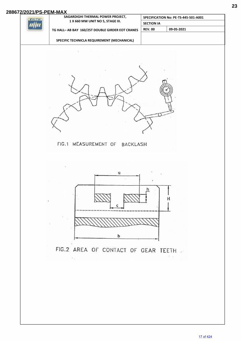
3.0.0 Backlash 3.1.0 The back lash shall be checked by dial gauge preferably (refer Figure –1). Lead wire may be
also be used but final decision in case of dispute shall be taken by using dial gauge. The
backlash shall be within the limits specified in the drawing. If the value of the backlash allowed
is not specified in the drawing, the allowed backlash shall be a given in Table-1
4.0.0 Area of Contact: 4.1.0 Area of contact shall be taken by applying Prussian blue. The contact area shall be within the
limits mentioned below (refer Figure –2)
For final stage of Hoist gearing:
h / H shall be more than 30%
(a – c) / b shall be more than 40%
For all other gears:
h / H shall be more than 40%
(a – c) / b shall be more than 50%
5.0.0 Running Test
5.1.0 1.1.1 The gear boxes shall be run under no-load condition at the rated speed for
15 of 424
288672/2021/PS-PEM-MAX21
SAGARDIGHI THERMAL POWER PROJECT, 1 X 660 MW UNIT NO 5, STAGE III.
TG HALL– AB BAY 160/25T DOUBLE GIRDER EOT CRANES
SPECIFIC TECHNICLA REQUIREMENT (MECHANICAL)
SPECIFICATION No: PE-TS-445-501-A001
SECTION IA
REV. 00 09-05-2021
minimum four hours in each direction and the following are to be checked:
i. All bolts at the joints remain tight
ii. All gear mesh lines are getting enough lubrication
iii. All bearings are getting enough lubrication
iv. Bearing temperatures after running for four hours shall not exceed 50 deg. Centigrade
or 15 deg. centigrade above ambient whichever is higher. Temperature shall be
checked after every hour.
v. Vibration: Maximum limit 125 microns (peak to peak)
vi. Sound: The gearbox shall not emit unusual sound as obtained under conditions of
hard meshing, high spots etc. Maximum sound level shall be 85 dBA at a distance of
1000mm and 91 dBA at a distance of 300 mm.
vii. There shall be no Oil leakage at parting lines, bearing housings or inspection covers.
6.0.0 1.1.2 General
6.1.0 1.1.3 In addition to the above specific points, the following general points shall be
ensured:
i. Inspection pockets are provided as required.
ii. Gear box casings are provided with at least two fit bolts/dowels at the parting line.
iii. Dip sticks with minimum / maximum level markings are provided.
iv. Drain plugs are provided at convenient locations preferably at vertical wall of the
housing.
v. Breathers are provided.
vi. Lifting lugs or eye bolts ar provided as required.
vii. Wherever bearings have splash lubrication, oil retainers are provided.
viii. Gear boxes are painted as per specification outside and inside. Inside surfaces shall
be painted with Oil proof paint.
ix. In case of vertical gear boxes having more than two stage reduction, forced lubrication
is also provided.
1.1.4 Name plate should provide information eg. Ratio, KW rating, Bearing details
and manufacturers name.
16 of 424
288672/2021/PS-PEM-MAX22
SAGARDIGHI THERMAL POWER PROJECT, 1 X 660 MW UNIT NO 5, STAGE III.
TG HALL– AB BAY 160/25T DOUBLE GIRDER EOT CRANES
SPECIFIC TECHNICLA REQUIREMENT (MECHANICAL)
SPECIFICATION No: PE-TS-445-501-A001
SECTION IA
REV. 00 09-05-2021
17 of 424
288672/2021/PS-PEM-MAX23
SAGARDIGHI THERMAL POWER PROJECT, 1 X 660 MW UNIT NO 5, STAGE III.
TG HALL– AB BAY 160/25T DOUBLE GIRDER EOT CRANES
SPECIFIC TECHNICLA REQUIREMENT (MECHANICAL)
SPECIFICATION No: PE-TS-445-501-A001
SECTION IA
REV. 00 09-05-2021
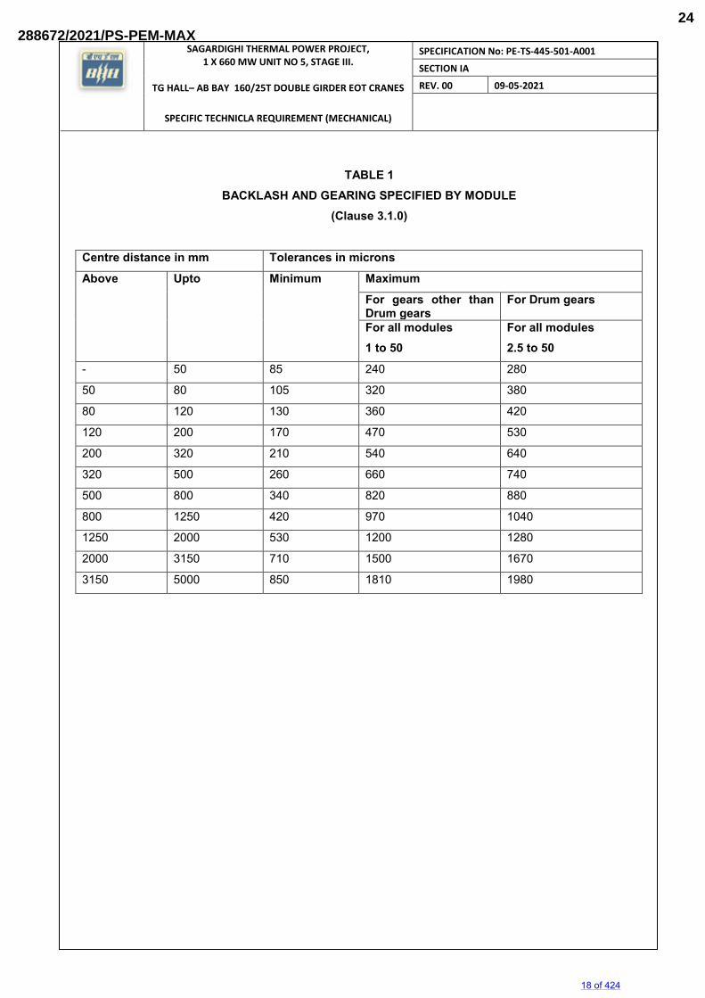
TABLE 1 BACKLASH AND GEARING SPECIFIED BY MODULE
(Clause 3.1.0)
Centre distance in mm Tolerances in microns Above Upto Minimum Maximum
For gears other than Drum gears
For Drum gears
For all modules 1 to 50
For all modules 2.5 to 50
- 50 85 240 280
50 80 105 320 380
80 120 130 360 420
120 200 170 470 530
200 320 210 540 640
320 500 260 660 740
500 800 340 820 880
800 1250 420 970 1040
1250 2000 530 1200 1280
2000 3150 710 1500 1670
3150 5000 850 1810 1980
18 of 424
288672/2021/PS-PEM-MAX24
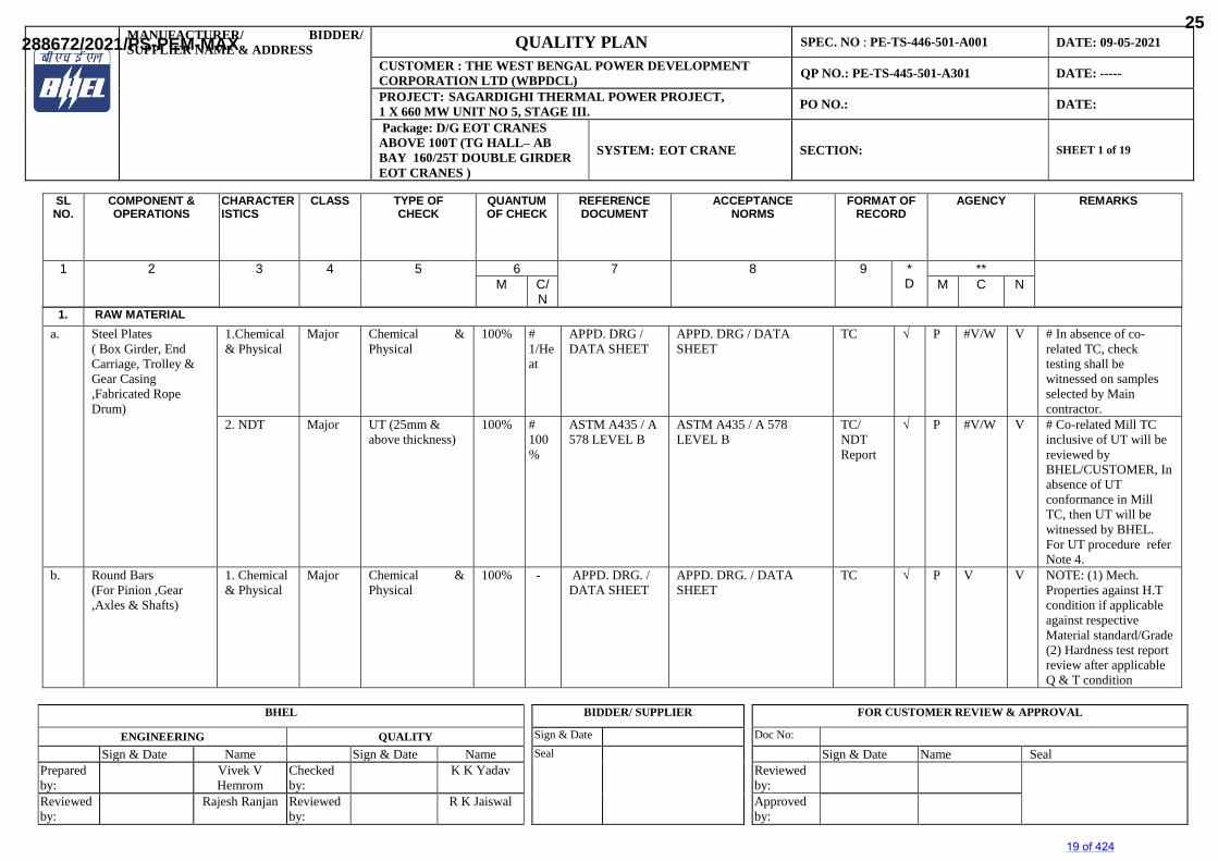
MANUFACTURER/ BIDDER/SUPPLIER NAME & ADDRESS QUALITY PLAN SPEC. NO : PE-TS-446-501-A001 DATE: 09-05-2021
CUSTOMER : THE WEST BENGAL POWER DEVELOPMENT CORPORATION LTD (WBPDCL) QP NO.: PE-TS-445-501-A301 DATE: -----
PROJECT: SAGARDIGHI THERMAL POWER PROJECT,1 X 660 MW UNIT NO 5, STAGE III. PO NO.: DATE:
Package: D/G EOT CRANES ABOVE 100T (TG HALL– AB BAY 160/25T DOUBLE GIRDER EOT CRANES )
SYSTEM: EOT CRANE SECTION: SHEET 1 of 19
BHEL BIDDER/ SUPPLIER FOR CUSTOMER REVIEW & APPROVAL
ENGINEERING QUALITY Sign & Date Doc No:
Sign & Date Name Sign & Date Name Seal Sign & Date Name SealPrepared by:
Vivek VHemrom
Checked by:
K K Yadav Reviewed by:
Reviewed by:
Rajesh Ranjan Reviewed by:
R K Jaiswal Approved by:
1. RAW MATERIALa. Steel Plates
( Box Girder, End Carriage, Trolley & Gear Casing ,Fabricated Rope Drum)
1.Chemical & Physical
Major Chemical & Physical
100% #1/Heat
APPD. DRG / DATA SHEET
APPD. DRG / DATA SHEET
TC √ P #V/W V # In absence of co-related TC, check testing shall be witnessed on samples selected by Main contractor.
2. NDT Major UT (25mm & above thickness)
100% #100%
ASTM A435 / A 578 LEVEL B
ASTM A435 / A 578 LEVEL B
TC/NDT Report
√ P #V/W V # Co-related Mill TC inclusive of UT will be reviewed by BHEL/CUSTOMER, In absence of UT conformance in Mill TC, then UT will be witnessed by BHEL.For UT procedure refer Note 4.
b. Round Bars (For Pinion ,Gear ,Axles & Shafts)
1. Chemical & Physical
Major Chemical & Physical
100% - APPD. DRG. / DATA SHEET
APPD. DRG. / DATA SHEET
TC √ P V V NOTE: (1) Mech. Properties against H.T condition if applicable against respective Material standard/Grade (2) Hardness test report review after applicable Q & T condition
SLNO.
COMPONENT &OPERATIONS
CHARACTERISTICS
CLASS TYPE OFCHECK
QUANTUMOF CHECK
REFERENCEDOCUMENT
ACCEPTANCENORMS
FORMAT OFRECORD
AGENCY REMARKS
1 2 3 4 5 6 7 8 9 *D
**M C/
NM C N
19 of 424
288672/2021/PS-PEM-MAX25
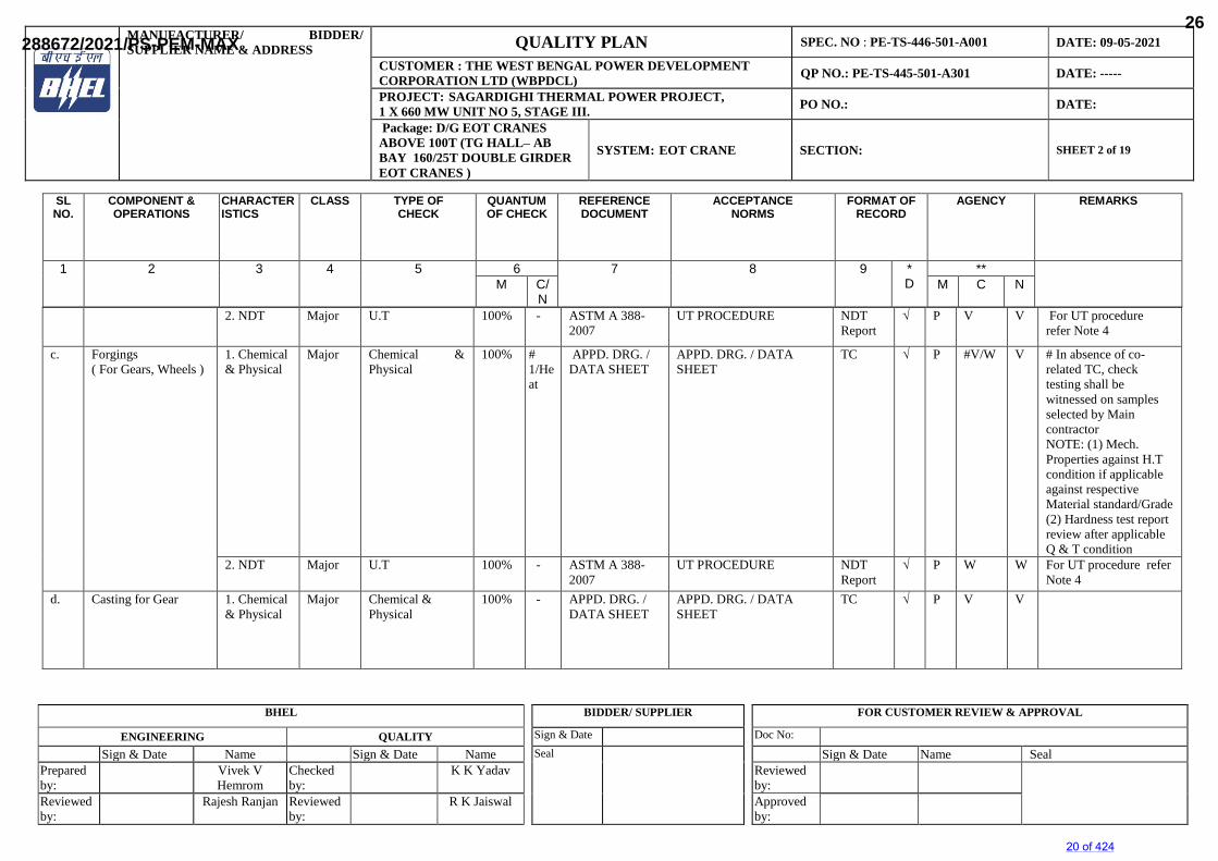
MANUFACTURER/ BIDDER/SUPPLIER NAME & ADDRESS QUALITY PLAN SPEC. NO : PE-TS-446-501-A001 DATE: 09-05-2021
CUSTOMER : THE WEST BENGAL POWER DEVELOPMENT CORPORATION LTD (WBPDCL) QP NO.: PE-TS-445-501-A301 DATE: -----
PROJECT: SAGARDIGHI THERMAL POWER PROJECT,1 X 660 MW UNIT NO 5, STAGE III. PO NO.: DATE:
Package: D/G EOT CRANES ABOVE 100T (TG HALL– AB BAY 160/25T DOUBLE GIRDER EOT CRANES )
SYSTEM: EOT CRANE SECTION: SHEET 2 of 19
BHEL BIDDER/ SUPPLIER FOR CUSTOMER REVIEW & APPROVAL
ENGINEERING QUALITY Sign & Date Doc No:
Sign & Date Name Sign & Date Name Seal Sign & Date Name SealPrepared by:
Vivek VHemrom
Checked by:
K K Yadav Reviewed by:
Reviewed by:
Rajesh Ranjan Reviewed by:
R K Jaiswal Approved by:
2. NDT Major U.T 100% - ASTM A 388-2007
UT PROCEDURE NDT Report
√ P V V For UT procedurerefer Note 4
c. Forgings ( For Gears, Wheels )
1. Chemical & Physical
Major Chemical & Physical
100% #1/Heat
APPD. DRG. / DATA SHEET
APPD. DRG. / DATA SHEET
TC √ P #V/W V # In absence of co-related TC, check testing shall be witnessed on samples selected by Main contractor NOTE: (1) Mech. Properties against H.T condition if applicable against respective Material standard/Grade (2) Hardness test report review after applicable Q & T condition
2. NDT Major U.T 100% - ASTM A 388-2007
UT PROCEDURE NDT Report
√ P W W For UT procedure refer Note 4
d. Casting for Gear 1. Chemical & Physical
Major Chemical & Physical
100% - APPD. DRG. / DATA SHEET
APPD. DRG. / DATA SHEET
TC √ P V V
SLNO.
COMPONENT &OPERATIONS
CHARACTERISTICS
CLASS TYPE OFCHECK
QUANTUMOF CHECK
REFERENCEDOCUMENT
ACCEPTANCENORMS
FORMAT OFRECORD
AGENCY REMARKS
1 2 3 4 5 6 7 8 9 *D
**M C/
NM C N
20 of 424
288672/2021/PS-PEM-MAX26
MANUFACTURER/ BIDDER/SUPPLIER NAME & ADDRESS QUALITY PLAN SPEC. NO : PE-TS-446-501-A001 DATE: 09-05-2021
CUSTOMER : THE WEST BENGAL POWER DEVELOPMENT CORPORATION LTD (WBPDCL) QP NO.: PE-TS-445-501-A301 DATE: -----
PROJECT: SAGARDIGHI THERMAL POWER PROJECT,1 X 660 MW UNIT NO 5, STAGE III. PO NO.: DATE:
Package: D/G EOT CRANES ABOVE 100T (TG HALL– AB BAY 160/25T DOUBLE GIRDER EOT CRANES )
SYSTEM: EOT CRANE SECTION: SHEET 3 of 19
BHEL BIDDER/ SUPPLIER FOR CUSTOMER REVIEW & APPROVAL
ENGINEERING QUALITY Sign & Date Doc No:
Sign & Date Name Sign & Date Name Seal Sign & Date Name SealPrepared by:
Vivek VHemrom
Checked by:
K K Yadav Reviewed by:
Reviewed by:
Rajesh Ranjan Reviewed by:
R K Jaiswal Approved by:
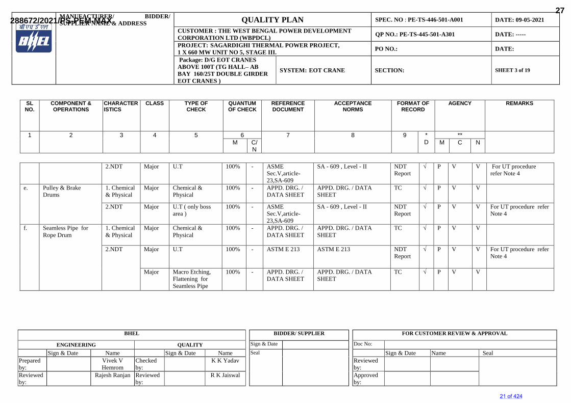
2.NDT Major U.T 100% - ASME Sec.V,article-23,SA-609
SA - 609 , Level - II NDT Report
√ P V V For UT procedure refer Note 4
e. Pulley & Brake Drums
1. Chemical & Physical
Major Chemical & Physical
100% - APPD. DRG. / DATA SHEET
APPD. DRG. / DATA SHEET
TC √ P V V
2.NDT Major U.T ( only boss area )
100% - ASME Sec.V,article-23,SA-609
SA - 609 , Level - II NDT Report
√ P V V For UT procedure refer Note 4
f. Seamless Pipe for Rope Drum
1. Chemical & Physical
Major Chemical & Physical
100% - APPD. DRG. / DATA SHEET
APPD. DRG. / DATA SHEET
TC √ P V V
2.NDT Major U.T 100% - ASTM E 213 ASTM E 213 NDT Report
√ P V V For UT procedure refer Note 4
Major Macro Etching, Flattening for Seamless Pipe
100% - APPD. DRG. / DATA SHEET
APPD. DRG. / DATA SHEET
TC √ P V V
SLNO.
COMPONENT &OPERATIONS
CHARACTERISTICS
CLASS TYPE OFCHECK
QUANTUMOF CHECK
REFERENCEDOCUMENT
ACCEPTANCENORMS
FORMAT OFRECORD
AGENCY REMARKS
1 2 3 4 5 6 7 8 9 *D
**M C/
NM C N
21 of 424
288672/2021/PS-PEM-MAX27
MANUFACTURER/ BIDDER/SUPPLIER NAME & ADDRESS QUALITY PLAN SPEC. NO : PE-TS-446-501-A001 DATE: 09-05-2021
CUSTOMER : THE WEST BENGAL POWER DEVELOPMENT CORPORATION LTD (WBPDCL) QP NO.: PE-TS-445-501-A301 DATE: -----
PROJECT: SAGARDIGHI THERMAL POWER PROJECT,1 X 660 MW UNIT NO 5, STAGE III. PO NO.: DATE:
Package: D/G EOT CRANES ABOVE 100T (TG HALL– AB BAY 160/25T DOUBLE GIRDER EOT CRANES )
SYSTEM: EOT CRANE SECTION: SHEET 4 of 19
BHEL BIDDER/ SUPPLIER FOR CUSTOMER REVIEW & APPROVAL
ENGINEERING QUALITY Sign & Date Doc No:
Sign & Date Name Sign & Date Name Seal Sign & Date Name SealPrepared by:
Vivek VHemrom
Checked by:
K K Yadav Reviewed by:
Reviewed by:
Rajesh Ranjan Reviewed by:
R K Jaiswal Approved by:
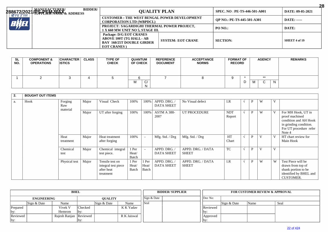
2. BOUGHT OUT ITEMS
a. Hook Forging Raw material
Major Visual Check 100% 100% APPD. DRG. / DATA SHEET
No Visual defect I.R √ P W V
Major UT after forging 100% 100% ASTM A 388-2007
UT PROCEDURE NDT Report
√ P W V For MH Hook, UT in proof machined condition and AH Hook in grinding condition.For UT procedure refer Note 4
Heat treatment
Major Heat treatment after forging
100% - Mfg. Std. / Drg Mfg. Std. / Drg HT Chart
√ P V V HT chart review for Main Hook
Chemical test
Major Chemical integral test piece.
1 Per Heat/Batch
- APPD. DRG. / DATA SHEET
APPD. DRG. / DATA SHEET
TC √ P V V
Physical test Major Tensile test on integral test piece after heat treatment
1 Per Heat/Batch
1 Per Heat/Batch
APPD. DRG. / DATA SHEET
APPD. DRG. / DATA SHEET
I.R √ P W W Test Piece will be drawn from top of shank portion to be identified by BHEL and CUSTOMER.
SLNO.
COMPONENT &OPERATIONS
CHARACTERISTICS
CLASS TYPE OFCHECK
QUANTUMOF CHECK
REFERENCEDOCUMENT
ACCEPTANCENORMS
FORMAT OFRECORD
AGENCY REMARKS
1 2 3 4 5 6 7 8 9 *D
**M C/
NM C N
22 of 424
288672/2021/PS-PEM-MAX28
MANUFACTURER/ BIDDER/SUPPLIER NAME & ADDRESS QUALITY PLAN SPEC. NO : PE-TS-446-501-A001 DATE: 09-05-2021
CUSTOMER : THE WEST BENGAL POWER DEVELOPMENT CORPORATION LTD (WBPDCL) QP NO.: PE-TS-445-501-A301 DATE: -----
PROJECT: SAGARDIGHI THERMAL POWER PROJECT,1 X 660 MW UNIT NO 5, STAGE III. PO NO.: DATE:
Package: D/G EOT CRANES ABOVE 100T (TG HALL– AB BAY 160/25T DOUBLE GIRDER EOT CRANES )
SYSTEM: EOT CRANE SECTION: SHEET 5 of 19
BHEL BIDDER/ SUPPLIER FOR CUSTOMER REVIEW & APPROVAL
ENGINEERING QUALITY Sign & Date Doc No:
Sign & Date Name Sign & Date Name Seal Sign & Date Name SealPrepared by:
Vivek VHemrom
Checked by:
K K Yadav Reviewed by:
Reviewed by:
Rajesh Ranjan Reviewed by:
R K Jaiswal Approved by:
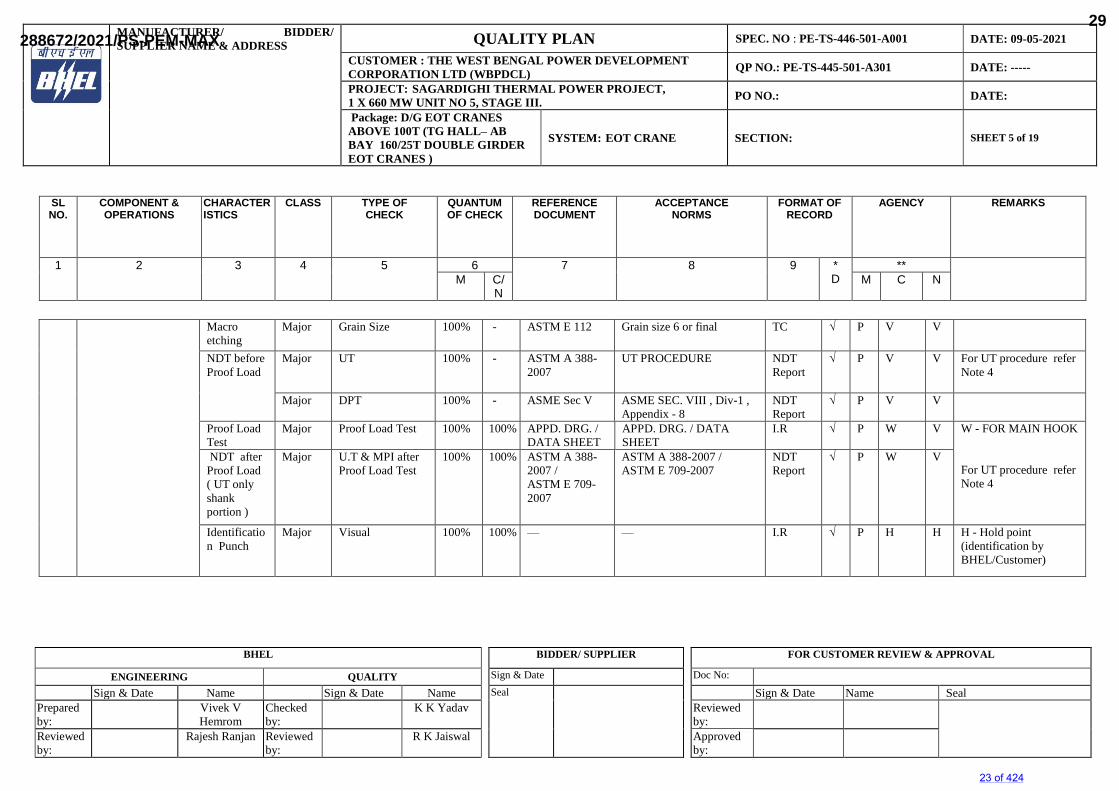
Macro etching
Major Grain Size 100% - ASTM E 112 Grain size 6 or final TC √ P V V
NDT before Proof Load
Major UT 100% - ASTM A 388-2007
UT PROCEDURE NDT Report
√ P V V For UT procedure refer Note 4
Major DPT 100% - ASME Sec V ASME SEC. VIII , Div-1 , Appendix - 8
NDT Report
√ P V V
Proof Load Test
Major Proof Load Test 100% 100% APPD. DRG. / DATA SHEET
APPD. DRG. / DATA SHEET
I.R √ P W V W - FOR MAIN HOOK
For UT procedure refer Note 4
NDT after Proof Load ( UT only shank portion )
Major U.T & MPI afterProof Load Test
100% 100% ASTM A 388-2007 / ASTM E 709-2007
ASTM A 388-2007 / ASTM E 709-2007
NDT Report
√ P W V
Identification Punch
Major Visual 100% 100% — — I.R √ P H H H - Hold point (identification by BHEL/Customer)
SLNO.
COMPONENT &OPERATIONS
CHARACTERISTICS
CLASS TYPE OFCHECK
QUANTUMOF CHECK
REFERENCEDOCUMENT
ACCEPTANCENORMS
FORMAT OFRECORD
AGENCY REMARKS
1 2 3 4 5 6 7 8 9 *D
**M C/
NM C N
23 of 424
288672/2021/PS-PEM-MAX29
MANUFACTURER/ BIDDER/SUPPLIER NAME & ADDRESS QUALITY PLAN SPEC. NO : PE-TS-446-501-A001 DATE: 09-05-2021
CUSTOMER : THE WEST BENGAL POWER DEVELOPMENT CORPORATION LTD (WBPDCL) QP NO.: PE-TS-445-501-A301 DATE: -----
PROJECT: SAGARDIGHI THERMAL POWER PROJECT,1 X 660 MW UNIT NO 5, STAGE III. PO NO.: DATE:
Package: D/G EOT CRANES ABOVE 100T (TG HALL– AB BAY 160/25T DOUBLE GIRDER EOT CRANES )
SYSTEM: EOT CRANE SECTION: SHEET 6 of 19
BHEL BIDDER/ SUPPLIER FOR CUSTOMER REVIEW & APPROVAL
ENGINEERING QUALITY Sign & Date Doc No:
Sign & Date Name Sign & Date Name Seal Sign & Date Name SealPrepared by:
Vivek VHemrom
Checked by:
K K Yadav Reviewed by:
Reviewed by:
Rajesh Ranjan Reviewed by:
R K Jaiswal Approved by:
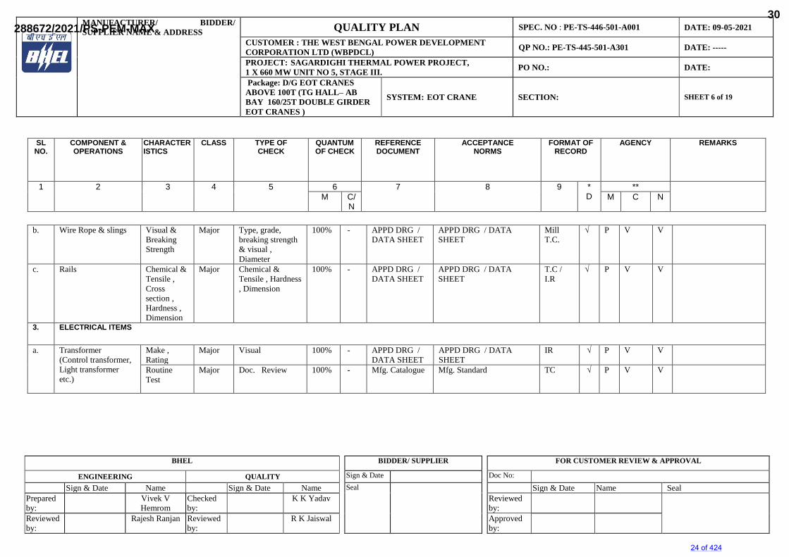
b. Wire Rope & slings Visual & Breaking Strength
Major Type, grade, breaking strength & visual , Diameter
100% - APPD DRG / DATA SHEET
APPD DRG / DATA SHEET
Mill T.C.
√ P V V
c. Rails Chemical & Tensile , Cross section , Hardness , Dimension
Major Chemical & Tensile , Hardness , Dimension
100% - APPD DRG / DATA SHEET
APPD DRG / DATA SHEET
T.C / I.R
√ P V V
3. ELECTRICAL ITEMS
a. Transformer (Control transformer, Light transformer etc.)
Make , Rating
Major Visual 100% - APPD DRG / DATA SHEET
APPD DRG / DATA SHEET
IR √ P V V
Routine Test
Major Doc. Review 100% - Mfg. Catalogue Mfg. Standard TC √ P V V
SLNO.
COMPONENT &OPERATIONS
CHARACTERISTICS
CLASS TYPE OFCHECK
QUANTUMOF CHECK
REFERENCEDOCUMENT
ACCEPTANCENORMS
FORMAT OFRECORD
AGENCY REMARKS
1 2 3 4 5 6 7 8 9 *D
**M C/
NM C N
24 of 424
288672/2021/PS-PEM-MAX30
MANUFACTURER/ BIDDER/SUPPLIER NAME & ADDRESS QUALITY PLAN SPEC. NO : PE-TS-446-501-A001 DATE: 09-05-2021
CUSTOMER : THE WEST BENGAL POWER DEVELOPMENT CORPORATION LTD (WBPDCL) QP NO.: PE-TS-445-501-A301 DATE: -----
PROJECT: SAGARDIGHI THERMAL POWER PROJECT,1 X 660 MW UNIT NO 5, STAGE III. PO NO.: DATE:
Package: D/G EOT CRANES ABOVE 100T (TG HALL– AB BAY 160/25T DOUBLE GIRDER EOT CRANES )
SYSTEM: EOT CRANE SECTION: SHEET 7 of 19
BHEL BIDDER/ SUPPLIER FOR CUSTOMER REVIEW & APPROVAL
ENGINEERING QUALITY Sign & Date Doc No:
Sign & Date Name Sign & Date Name Seal Sign & Date Name SealPrepared by:
Vivek VHemrom
Checked by:
K K Yadav Reviewed by:
Reviewed by:
Rajesh Ranjan Reviewed by:
R K Jaiswal Approved by:
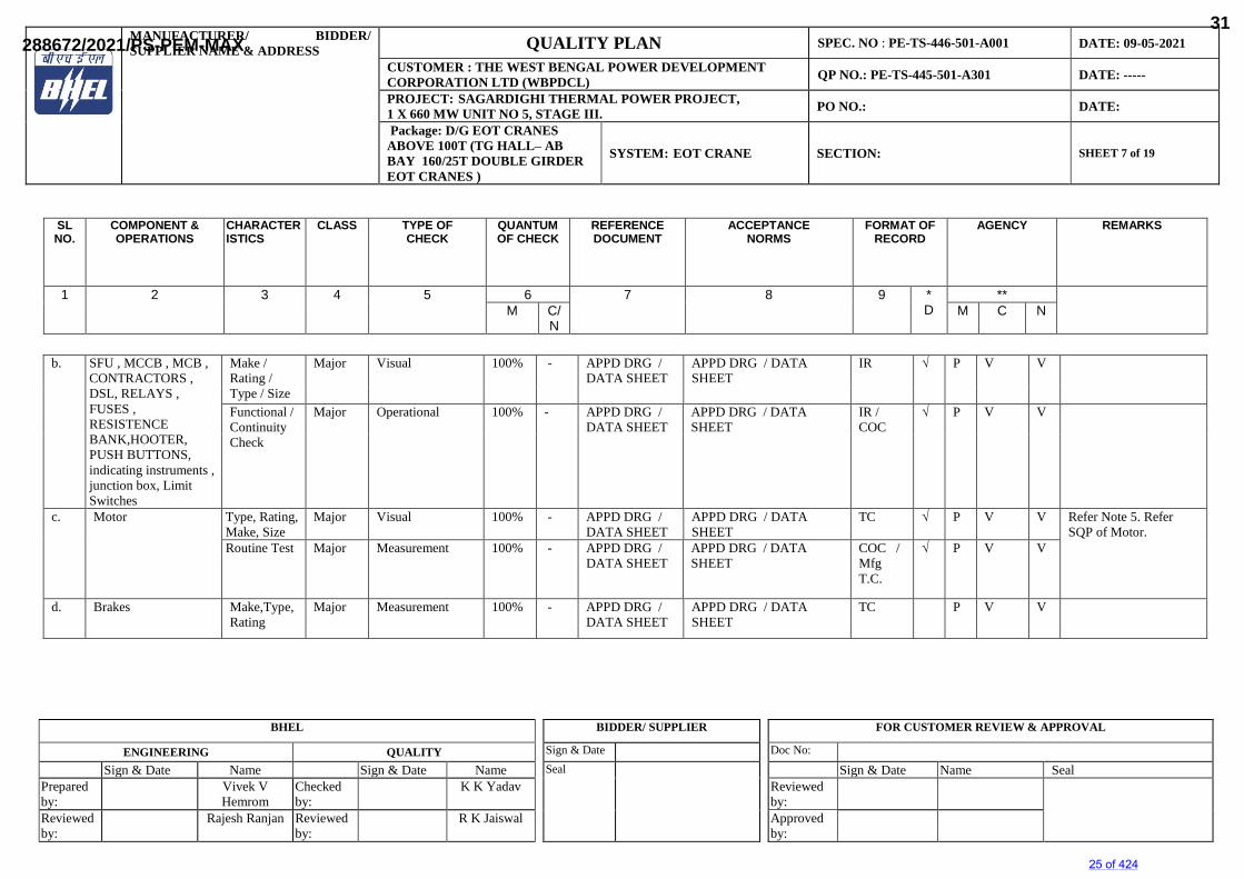
b. SFU , MCCB , MCB , CONTRACTORS , DSL, RELAYS , FUSES , RESISTENCE BANK,HOOTER, PUSH BUTTONS, indicating instruments , junction box, Limit Switches
Make / Rating / Type / Size
Major Visual 100% - APPD DRG / DATA SHEET
APPD DRG / DATA SHEET
IR √ P V V
Functional / Continuity Check
Major Operational 100% - APPD DRG / DATA SHEET
APPD DRG / DATA SHEET
IR / COC
√ P V V
c. Motor Type, Rating, Make, Size
Major Visual 100% - APPD DRG / DATA SHEET
APPD DRG / DATA SHEET
TC √ P V V Refer Note 5. Refer SQP of Motor.
Routine Test Major Measurement 100% - APPD DRG / DATA SHEET
APPD DRG / DATA SHEET
COC / Mfg T.C.
√ P V V
d. Brakes Make,Type,Rating
Major Measurement 100% - APPD DRG / DATA SHEET
APPD DRG / DATA SHEET
TC P V V
SLNO.
COMPONENT &OPERATIONS
CHARACTERISTICS
CLASS TYPE OFCHECK
QUANTUMOF CHECK
REFERENCEDOCUMENT
ACCEPTANCENORMS
FORMAT OFRECORD
AGENCY REMARKS
1 2 3 4 5 6 7 8 9 *D
**M C/
NM C N
25 of 424
288672/2021/PS-PEM-MAX31
MANUFACTURER/ BIDDER/SUPPLIER NAME & ADDRESS QUALITY PLAN SPEC. NO : PE-TS-446-501-A001 DATE: 09-05-2021
CUSTOMER : THE WEST BENGAL POWER DEVELOPMENT CORPORATION LTD (WBPDCL) QP NO.: PE-TS-445-501-A301 DATE: -----
PROJECT: SAGARDIGHI THERMAL POWER PROJECT,1 X 660 MW UNIT NO 5, STAGE III. PO NO.: DATE:
Package: D/G EOT CRANES ABOVE 100T (TG HALL– AB BAY 160/25T DOUBLE GIRDER EOT CRANES )
SYSTEM: EOT CRANE SECTION: SHEET 8 of 19
BHEL BIDDER/ SUPPLIER FOR CUSTOMER REVIEW & APPROVAL
ENGINEERING QUALITY Sign & Date Doc No:
Sign & Date Name Sign & Date Name Seal Sign & Date Name SealPrepared by:
Vivek VHemrom
Checked by:
K K Yadav Reviewed by:
Reviewed by:
Rajesh Ranjan Reviewed by:
R K Jaiswal Approved by:
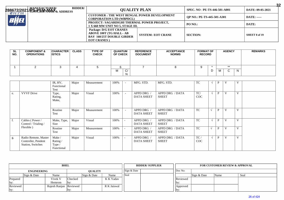
IR, HV,Functional Test
Major Measurement 100% - MFG. STD. MFG. STD. TC √ P V V
e. VVVF Drive Type, Rating, Make,
Major Visual 100% - APPD DRG / DATA SHEET
APPD DRG / DATA SHEET
TC/ COC
√ P V V
Routine Test
Major Measurement 100% - APPD DRG / DATA SHEET
APPD DRG / DATA SHEET
TC √ P V V
f. Cables ( Power / Control / Trialing / Flexible )
Make, Type, Size
Major Visual 100% - APPD DRG / DATA SHEET
APPD DRG / DATA SHEET
TC √ P V V
Routine Test
Major Measurement 100% - APPD DRG / DATA SHEET
APPD DRG / DATA SHEET
TC √ P V V
g. Radio Remote, Master Controller, Pendent Station, Switches
Make / Rating / Type / Functional
Major Visual 100% - APPD DRG / DATA SHEET
APPD DRG / DATA SHEET
TC / COC
√ P V V
SLNO.
COMPONENT &OPERATIONS
CHARACTERISTICS
CLASS TYPE OFCHECK
QUANTUMOF CHECK
REFERENCEDOCUMENT
ACCEPTANCENORMS
FORMAT OFRECORD
AGENCY REMARKS
1 2 3 4 5 6 7 8 9 *D
**M C/
NM C N
26 of 424
288672/2021/PS-PEM-MAX32
MANUFACTURER/ BIDDER/SUPPLIER NAME & ADDRESS QUALITY PLAN SPEC. NO : PE-TS-446-501-A001 DATE: 09-05-2021
CUSTOMER : THE WEST BENGAL POWER DEVELOPMENT CORPORATION LTD (WBPDCL) QP NO.: PE-TS-445-501-A301 DATE: -----
PROJECT: SAGARDIGHI THERMAL POWER PROJECT,1 X 660 MW UNIT NO 5, STAGE III. PO NO.: DATE:
Package: D/G EOT CRANES ABOVE 100T (TG HALL– AB BAY 160/25T DOUBLE GIRDER EOT CRANES )
SYSTEM: EOT CRANE SECTION: SHEET 9 of 19
BHEL BIDDER/ SUPPLIER FOR CUSTOMER REVIEW & APPROVAL
ENGINEERING QUALITY Sign & Date Doc No:
Sign & Date Name Sign & Date Name Seal Sign & Date Name SealPrepared by:
Vivek VHemrom
Checked by:
K K Yadav Reviewed by:
Reviewed by:
Rajesh Ranjan Reviewed by:
R K Jaiswal Approved by:
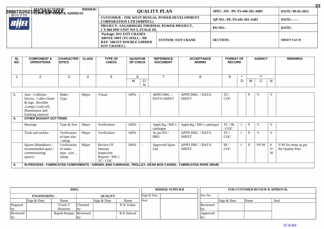
h. Anti - Collision Device , Cable Gland & lugs , Rectifier ,Lamps, Load cell, Illumination and Earthing material
Make / Type
Major Visual 100% - APPD DRG / DATA SHEET
APPD DRG / DATA SHEET
TC/COC
P V V
4. OTHER BOUGHT OUT ITEMS
Bearings Type & Size Major Verification 100% - Appd.drg./ Mfr’s catalogue
Appd.drg./ Mfr’s catalogue TC / IR / COC
√ P V V
Tools and tackles Verification of type size / rating
Major Verification 100% - As per PO / BBU
APPD DRG / DATA SHEET
TC /COC
√ P V V
Spares (Mandatory / recommended spare / commissioning spares)
Verification of make, type, size , rating
Major Review Of Internal Inspection Reports / Mfr’s TC / COC
100% - Approved Spare List
APPD DRG / DATA SHEET
IR / COC
√ P #V/W #V/W
V/W for items as per the Quality Plan
5. IN PROCESS : FABRICATED COMPONENTS : GIRDER, END CARRIAGE, TROLLEY, GEAR BOX CASING , FABRICATED ROPE DRUM
SLNO.
COMPONENT &OPERATIONS
CHARACTERISTICS
CLASS TYPE OFCHECK
QUANTUMOF CHECK
REFERENCEDOCUMENT
ACCEPTANCENORMS
FORMAT OFRECORD
AGENCY REMARKS
1 2 3 4 5 6 7 8 9 *D
**M C/
NM C N
27 of 424
288672/2021/PS-PEM-MAX33
MANUFACTURER/ BIDDER/SUPPLIER NAME & ADDRESS QUALITY PLAN SPEC. NO : PE-TS-446-501-A001 DATE: 09-05-2021
CUSTOMER : THE WEST BENGAL POWER DEVELOPMENT CORPORATION LTD (WBPDCL) QP NO.: PE-TS-445-501-A301 DATE: -----
PROJECT: SAGARDIGHI THERMAL POWER PROJECT,1 X 660 MW UNIT NO 5, STAGE III. PO NO.: DATE:
Package: D/G EOT CRANES ABOVE 100T (TG HALL– AB BAY 160/25T DOUBLE GIRDER EOT CRANES )
SYSTEM: EOT CRANE SECTION: SHEET 10 of 19
BHEL BIDDER/ SUPPLIER FOR CUSTOMER REVIEW & APPROVAL
ENGINEERING QUALITY Sign & Date Doc No:
Sign & Date Name Sign & Date Name Seal Sign & Date Name SealPrepared by:
Vivek VHemrom
Checked by:
K K Yadav Reviewed by:
Reviewed by:
Rajesh Ranjan Reviewed by:
R K Jaiswal Approved by:
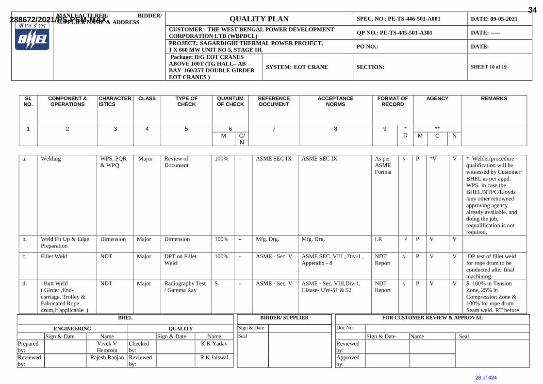
a. Welding WPS, PQR& WPQ
Major Review of Document
100% - ASME SEC IX ASME SEC IX As per ASME Format
√ P *V V * Welder/procedure qualification will be witnessed by Customer/ BHEL as per appd. WPS. In case the BHEL/NTPC/Lloyds /any other renowned approving agency already available, and doing the job, requalification is not required.
b. Weld Fit Up & EdgePreparation
Dimension Major Dimension 100% - Mfg. Drg. Mfg. Drg. I.R √ P V V
c. Fillet Weld NDT Major DPT on Fillet Weld
100% - ASME - Sec. V ASME SEC. VIII , Div-1 , Appendix - 8
NDT Report
√ P V V DP test of fillet weld for rope drum to be conducted after final machining.
d. Butt Weld ( Girder ,End-carriage, Trolley & Fabricated Rope drum,if applicable )
NDT Major Radiography Test / Gamma Ray
$ - ASME - Sec. V ASME - Sec. VIII,Div-1, Clause- UW-51 & 52
NDT Report
√ P V V $ 100% in Tension Zone, 25% in Compression Zone &100% for rope drum Seam weld. RT before
SLNO.
COMPONENT &OPERATIONS
CHARACTERISTICS
CLASS TYPE OFCHECK
QUANTUMOF CHECK
REFERENCEDOCUMENT
ACCEPTANCENORMS
FORMAT OFRECORD
AGENCY REMARKS
1 2 3 4 5 6 7 8 9 *D
**M C/
NM C N
28 of 424
288672/2021/PS-PEM-MAX34
MANUFACTURER/ BIDDER/SUPPLIER NAME & ADDRESS QUALITY PLAN SPEC. NO : PE-TS-446-501-A001 DATE: 09-05-2021
CUSTOMER : THE WEST BENGAL POWER DEVELOPMENT CORPORATION LTD (WBPDCL) QP NO.: PE-TS-445-501-A301 DATE: -----
PROJECT: SAGARDIGHI THERMAL POWER PROJECT,1 X 660 MW UNIT NO 5, STAGE III. PO NO.: DATE:
Package: D/G EOT CRANES ABOVE 100T (TG HALL– AB BAY 160/25T DOUBLE GIRDER EOT CRANES )
SYSTEM: EOT CRANE SECTION: SHEET 11 of 19
BHEL BIDDER/ SUPPLIER FOR CUSTOMER REVIEW & APPROVAL
ENGINEERING QUALITY Sign & Date Doc No:
Sign & Date Name Sign & Date Name Seal Sign & Date Name SealPrepared by:
Vivek VHemrom
Checked by:
K K Yadav Reviewed by:
Reviewed by:
Rajesh Ranjan Reviewed by:
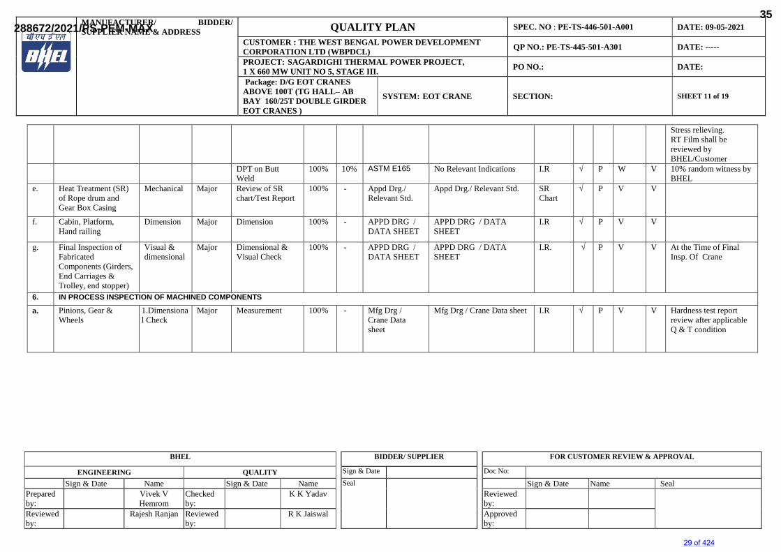
R K Jaiswal Approved by:
Stress relieving. RT Film shall be reviewed by BHEL/Customer
DPT on Butt Weld
100% 10% ASTM E165 No Relevant Indications I.R √ P W V 10% random witness by BHEL
e. Heat Treatment (SR) of Rope drum and Gear Box Casing
Mechanical Major Review of SR chart/Test Report
100% - Appd Drg./ Relevant Std.
Appd Drg./ Relevant Std. SR Chart
√ P V V
f. Cabin, Platform, Hand railing
Dimension Major Dimension 100% - APPD DRG / DATA SHEET
APPD DRG / DATA SHEET
I.R √ P V V
g. Final Inspection of Fabricated Components (Girders, End Carriages & Trolley, end stopper)
Visual & dimensional
Major Dimensional & Visual Check
100% - APPD DRG / DATA SHEET
APPD DRG / DATA SHEET
I.R. √ P V V At the Time of Final Insp. Of Crane
6. IN PROCESS INSPECTION OF MACHINED COMPONENTS
a. Pinions, Gear & Wheels
1.Dimensional Check
Major Measurement 100% - Mfg Drg / Crane Data sheet
Mfg Drg / Crane Data sheet I.R √ P V V Hardness test report review after applicable Q & T condition
29 of 424
288672/2021/PS-PEM-MAX35
MANUFACTURER/ BIDDER/SUPPLIER NAME & ADDRESS QUALITY PLAN SPEC. NO : PE-TS-446-501-A001 DATE: 09-05-2021
CUSTOMER : THE WEST BENGAL POWER DEVELOPMENT CORPORATION LTD (WBPDCL) QP NO.: PE-TS-445-501-A301 DATE: -----
PROJECT: SAGARDIGHI THERMAL POWER PROJECT,1 X 660 MW UNIT NO 5, STAGE III. PO NO.: DATE:
Package: D/G EOT CRANES ABOVE 100T (TG HALL– AB BAY 160/25T DOUBLE GIRDER EOT CRANES )
SYSTEM: EOT CRANE SECTION: SHEET 12 of 19
BHEL BIDDER/ SUPPLIER FOR CUSTOMER REVIEW & APPROVAL
ENGINEERING QUALITY Sign & Date Doc No:
Sign & Date Name Sign & Date Name Seal Sign & Date Name SealPrepared by:
Vivek VHemrom
Checked by:
K K Yadav Reviewed by:
Reviewed by:
Rajesh Ranjan Reviewed by:
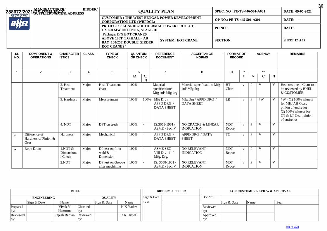
R K Jaiswal Approved by:
2. Heat Treatment
Major Heat Treatment chart
100% - Material specification/ Mfg std/ Mfg drg
Material specification/ Mfg std/ Mfg drg
HT Chart
√ P V V Heat treatment Chart to be reviewed by BHEL & CUSTOMER
3. Hardness Major Measurement 100% 100% Mfg Drg / APPD DRG / DATA SHEET
Mfg Drg / APPD DRG / DATA SHEET
I.R √ P #W V #W - (1) 100% witness for MH/ AH Gear, pinion of entire lot(2) 100% witness for CT & LT Gear, pinion of entire lot
4. NDT Major DPT on teeth 100% - IS:3658-1981 / ASME - Sec. V
NO CRACKS & LINEAR INDICATION
NDTReport
√ P V V
b. Difference of Hardness of Pinion & Gear
Hardness Major Mechanical 100% - APPD DRG / DATA SHEET
APPD DRG / DATA SHEET
TC √ P V V
c. Rope Drum 1.NDT & Dimensional Check
Major DP test on fillet weld & Dimension
100% - ASME SEC VIII Div -1 / Mfg. Drg.
NO RELEVANT INDICATION
NDT Report
√ P V V
2.NDT Major DP test on Groove after machining
100% - IS: 3658-1981 / ASME - Sec. V
NO RELEVANT INDICATION
NDT Report
√ P V V
SLNO.
COMPONENT &OPERATIONS
CHARACTERISTICS
CLASS TYPE OFCHECK
QUANTUMOF CHECK
REFERENCEDOCUMENT
ACCEPTANCENORMS
FORMAT OFRECORD
AGENCY REMARKS
1 2 3 4 5 6 7 8 9 *D
**M C/
NM C N
30 of 424
288672/2021/PS-PEM-MAX36
MANUFACTURER/ BIDDER/SUPPLIER NAME & ADDRESS QUALITY PLAN SPEC. NO : PE-TS-446-501-A001 DATE: 09-05-2021
CUSTOMER : THE WEST BENGAL POWER DEVELOPMENT CORPORATION LTD (WBPDCL) QP NO.: PE-TS-445-501-A301 DATE: -----
PROJECT: SAGARDIGHI THERMAL POWER PROJECT,1 X 660 MW UNIT NO 5, STAGE III. PO NO.: DATE:
Package: D/G EOT CRANES ABOVE 100T (TG HALL– AB BAY 160/25T DOUBLE GIRDER EOT CRANES )
SYSTEM: EOT CRANE SECTION: SHEET 13 of 19
BHEL BIDDER/ SUPPLIER FOR CUSTOMER REVIEW & APPROVAL
ENGINEERING QUALITY Sign & Date Doc No:
Sign & Date Name Sign & Date Name Seal Sign & Date Name SealPrepared by:
Vivek VHemrom
Checked by:
K K Yadav Reviewed by:
Reviewed by:
Rajesh Ranjan Reviewed by:
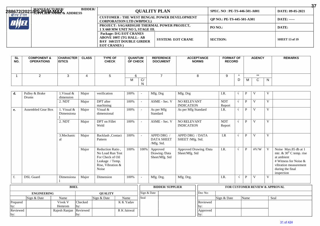
R K Jaiswal Approved by:
d. Pulley & Brake Drums
1.Visual & dimension
Major verification 100% - Mfg. Drg Mfg. Drg I.R. √ P V V
2. NDT Major DPT after machining
100% - ASME - Sec. V NO RELEVANT INDICATION
NDT Report
√ P V V
e. Assembled Gear Box 1. Visual & Dimensional
Major Visual & dimensional
100% - As per Mfg Standard
As per Mfg Standard I.R. √ P V V
2. NDT Major DPT on Fillet Weld
100% - ASME - Sec. V NO RELEVANT INDICATION
NDT Report
√ P V V
3.Mechanical
Major Backlash ,Contact Pattern
100% - APPD DRG / DATA SHEET /Mfg. Std.
APPD DRG / DATA SHEET /Mfg. Std.
I.R √ P V V
Major Reduction Ratio , No Load Run Test For Check of Oil Leakage / Temp. Rise, Vibration & Noise
100% 100% Approved Drawing /Data Sheet/Mfg. Std
Approved Drawing /Data Sheet/Mfg. Std
I.R. √ P #V/W V Noise Max.85 db at 1mtr. & 300 C temp. rise at ambient # Witness for Noise & vibration measurement during the final inspection
f. DSL Guard Dimensional
Major Dimension 100% - Mfg. Drg. Mfg. Drg. I.R. √ P V V
SLNO.
COMPONENT &OPERATIONS
CHARACTERISTICS
CLASS TYPE OFCHECK
QUANTUMOF CHECK
REFERENCEDOCUMENT
ACCEPTANCENORMS
FORMAT OFRECORD
AGENCY REMARKS
1 2 3 4 5 6 7 8 9 *D
**M C/
NM C N
31 of 424
288672/2021/PS-PEM-MAX37
MANUFACTURER/ BIDDER/SUPPLIER NAME & ADDRESS QUALITY PLAN SPEC. NO : PE-TS-446-501-A001 DATE: 09-05-2021
CUSTOMER : THE WEST BENGAL POWER DEVELOPMENT CORPORATION LTD (WBPDCL) QP NO.: PE-TS-445-501-A301 DATE: -----
PROJECT: SAGARDIGHI THERMAL POWER PROJECT,1 X 660 MW UNIT NO 5, STAGE III. PO NO.: DATE:
Package: D/G EOT CRANES ABOVE 100T (TG HALL– AB BAY 160/25T DOUBLE GIRDER EOT CRANES )
SYSTEM: EOT CRANE SECTION: SHEET 14 of 19
BHEL BIDDER/ SUPPLIER FOR CUSTOMER REVIEW & APPROVAL
ENGINEERING QUALITY Sign & Date Doc No:
Sign & Date Name Sign & Date Name Seal Sign & Date Name SealPrepared by:
Vivek VHemrom
Checked by:
K K Yadav Reviewed by:
Reviewed by:
Rajesh Ranjan Reviewed by:
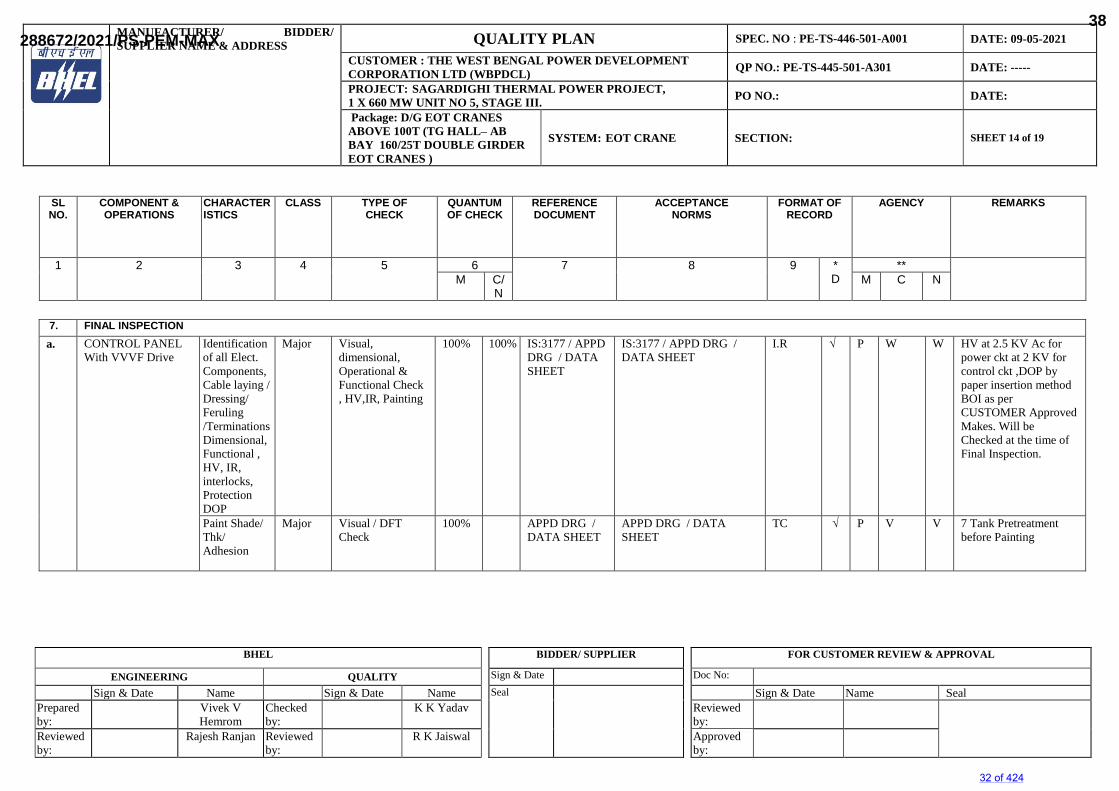
R K Jaiswal Approved by:
7. FINAL INSPECTIONa. CONTROL PANEL
With VVVF DriveIdentification of all Elect. Components, Cable laying / Dressing/Feruling/Terminations Dimensional,Functional , HV, IR, interlocks, Protection DOP
Major Visual, dimensional, Operational & Functional Check , HV,IR, Painting
100% 100% IS:3177 / APPD DRG / DATA SHEET
IS:3177 / APPD DRG / DATA SHEET
I.R √ P W W HV at 2.5 KV Ac for power ckt at 2 KV for control ckt ,DOP by paper insertion method BOI as per CUSTOMER Approved Makes. Will be Checked at the time of Final Inspection.
Paint Shade/ Thk/ Adhesion
Major Visual / DFT Check
100% APPD DRG / DATA SHEET
APPD DRG / DATA SHEET
TC √ P V V 7 Tank Pretreatment before Painting
SLNO.
COMPONENT &OPERATIONS
CHARACTERISTICS
CLASS TYPE OFCHECK
QUANTUMOF CHECK
REFERENCEDOCUMENT
ACCEPTANCENORMS
FORMAT OFRECORD
AGENCY REMARKS
1 2 3 4 5 6 7 8 9 *D
**M C/
NM C N
32 of 424
288672/2021/PS-PEM-MAX38
MANUFACTURER/ BIDDER/SUPPLIER NAME & ADDRESS QUALITY PLAN SPEC. NO : PE-TS-446-501-A001 DATE: 09-05-2021
CUSTOMER : THE WEST BENGAL POWER DEVELOPMENT CORPORATION LTD (WBPDCL) QP NO.: PE-TS-445-501-A301 DATE: -----
PROJECT: SAGARDIGHI THERMAL POWER PROJECT,1 X 660 MW UNIT NO 5, STAGE III. PO NO.: DATE:
Package: D/G EOT CRANES ABOVE 100T (TG HALL– AB BAY 160/25T DOUBLE GIRDER EOT CRANES )
SYSTEM: EOT CRANE SECTION: SHEET 15 of 19
BHEL BIDDER/ SUPPLIER FOR CUSTOMER REVIEW & APPROVAL
ENGINEERING QUALITY Sign & Date Doc No:
Sign & Date Name Sign & Date Name Seal Sign & Date Name SealPrepared by:
Vivek VHemrom
Checked by:
K K Yadav Reviewed by:
Reviewed by:
Rajesh Ranjan Reviewed by:
R K Jaiswal Approved by:
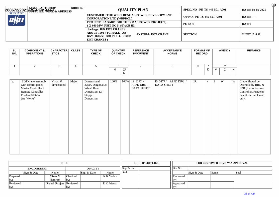
b. EOT crane assembly with control panel, Master Controller / Remote Controller Pendent Station (At Works)
Visual & dimensional
Major Dimensional ,Span, Diagonal & Wheel Base Dimension, LT Stopper Dimension
100% 100% IS 3177 / APPD DRG / DATA SHEET
IS 3177 / APPD DRG / DATA SHEET
I.R. √ P W W Crane Should be Operable by RRC &PPB (Radio Remote Controller, Pendent)meant for that Crane only.
SLNO.
COMPONENT &OPERATIONS
CHARACTERISTICS
CLASS TYPE OFCHECK
QUANTUMOF CHECK
REFERENCEDOCUMENT
ACCEPTANCENORMS
FORMAT OFRECORD
AGENCY REMARKS
1 2 3 4 5 6 7 8 9 *D
**M C/
NM C N
33 of 424
288672/2021/PS-PEM-MAX39
MANUFACTURER/ BIDDER/SUPPLIER NAME & ADDRESS QUALITY PLAN SPEC. NO : PE-TS-446-501-A001 DATE: 09-05-2021
CUSTOMER : THE WEST BENGAL POWER DEVELOPMENT CORPORATION LTD (WBPDCL) QP NO.: PE-TS-445-501-A301 DATE: -----
PROJECT: SAGARDIGHI THERMAL POWER PROJECT,1 X 660 MW UNIT NO 5, STAGE III. PO NO.: DATE:
Package: D/G EOT CRANES ABOVE 100T (TG HALL– AB BAY 160/25T DOUBLE GIRDER EOT CRANES )
SYSTEM: EOT CRANE SECTION: SHEET 16 of 19
BHEL BIDDER/ SUPPLIER FOR CUSTOMER REVIEW & APPROVAL
ENGINEERING QUALITY Sign & Date Doc No:
Sign & Date Name Sign & Date Name Seal Sign & Date Name SealPrepared by:
Vivek VHemrom
Checked by:
K K Yadav Reviewed by:
Reviewed by:
Rajesh Ranjan Reviewed by:
R K Jaiswal Approved by:
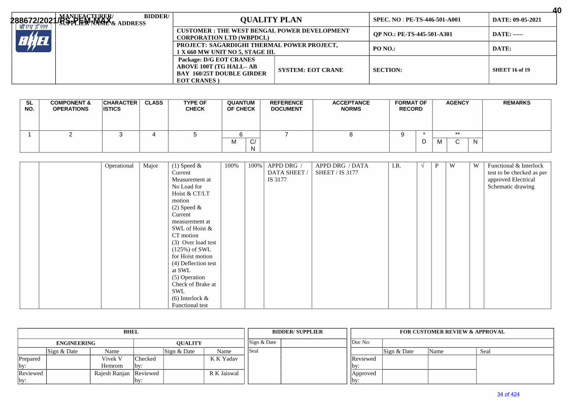
Operational Major (1) Speed & Current Measurement at No Load for Hoist & CT/LT motion (2) Speed & Current measurement at SWL of Hoist & CT motion (3) Over load test (125%) of SWL for Hoist motion (4) Deflection test at SWL (5) Operation Check of Brake at SWL (6) Interlock & Functional test
100% 100% APPD DRG / DATA SHEET /IS 3177
APPD DRG / DATA SHEET / IS 3177
I.R. √ P W W Functional & Interlock test to be checked as per approved Electrical Schematic drawing
SLNO.
COMPONENT &OPERATIONS
CHARACTERISTICS
CLASS TYPE OFCHECK
QUANTUMOF CHECK
REFERENCEDOCUMENT
ACCEPTANCENORMS
FORMAT OFRECORD
AGENCY REMARKS
1 2 3 4 5 6 7 8 9 *D
**M C/
NM C N
34 of 424
288672/2021/PS-PEM-MAX40
MANUFACTURER/ BIDDER/SUPPLIER NAME & ADDRESS QUALITY PLAN SPEC. NO : PE-TS-446-501-A001 DATE: 09-05-2021
CUSTOMER : THE WEST BENGAL POWER DEVELOPMENT CORPORATION LTD (WBPDCL) QP NO.: PE-TS-445-501-A301 DATE: -----
PROJECT: SAGARDIGHI THERMAL POWER PROJECT,1 X 660 MW UNIT NO 5, STAGE III. PO NO.: DATE:
Package: D/G EOT CRANES ABOVE 100T (TG HALL– AB BAY 160/25T DOUBLE GIRDER EOT CRANES )
SYSTEM: EOT CRANE SECTION: SHEET 17 of 19
BHEL BIDDER/ SUPPLIER FOR CUSTOMER REVIEW & APPROVAL
ENGINEERING QUALITY Sign & Date Doc No:
Sign & Date Name Sign & Date Name Seal Sign & Date Name SealPrepared by:
Vivek VHemrom
Checked by:
K K Yadav Reviewed by:
Reviewed by:
Rajesh Ranjan Reviewed by:
R K Jaiswal Approved by:
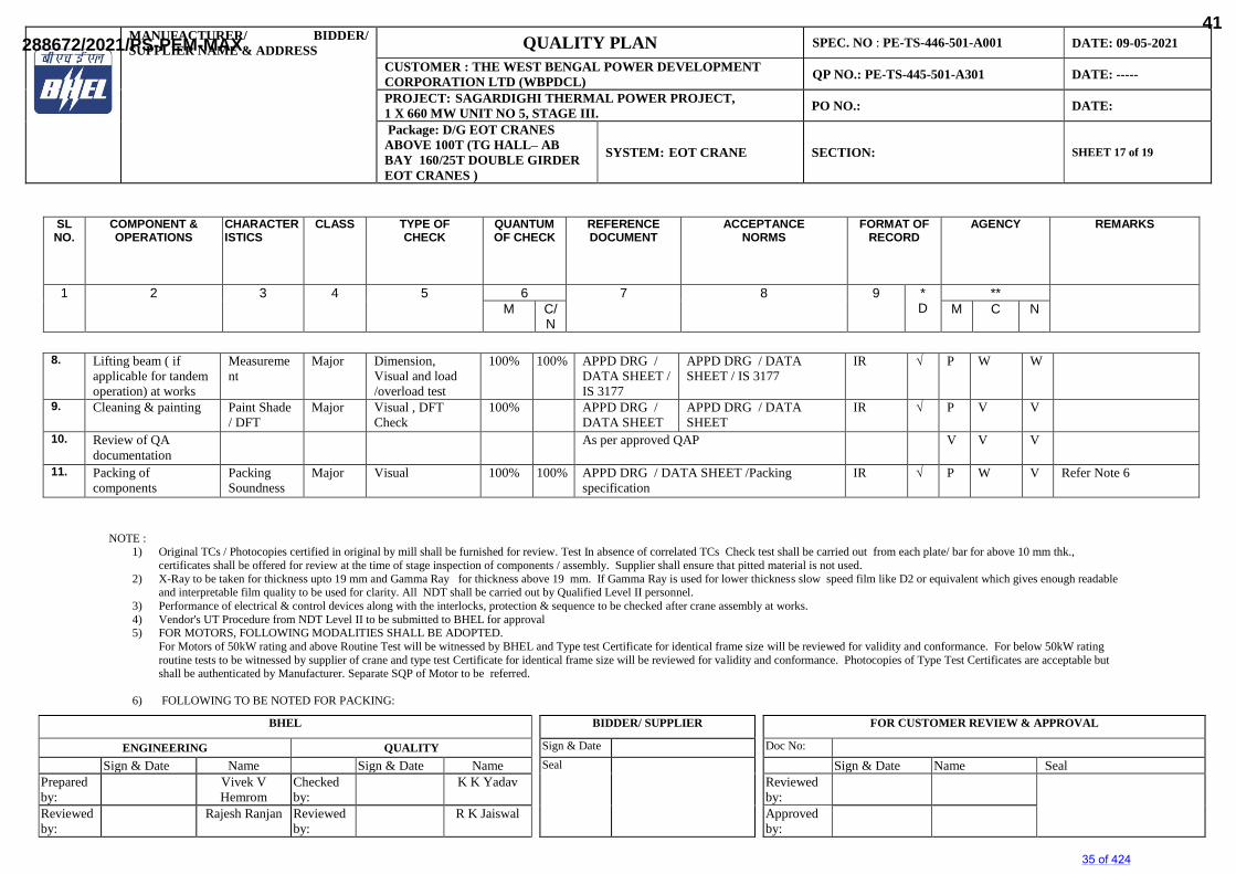
8. Lifting beam ( if applicable for tandem operation) at works
Measurement
Major Dimension, Visual and load /overload test
100% 100% APPD DRG / DATA SHEET /IS 3177
APPD DRG / DATA SHEET / IS 3177
IR √ P W W
9. Cleaning & painting Paint Shade / DFT
Major Visual , DFT Check
100% APPD DRG / DATA SHEET
APPD DRG / DATA SHEET
IR √ P V V
10. Review of QA documentation
As per approved QAP V V V
11. Packing of components
Packing Soundness
Major Visual 100% 100% APPD DRG / DATA SHEET /Packing specification
IR √ P W V Refer Note 6
NOTE : 1) Original TCs / Photocopies certified in original by mill shall be furnished for review. Test In absence of correlated TCs Check test shall be carried out from each plate/ bar for above 10 mm thk.,
certificates shall be offered for review at the time of stage inspection of components / assembly. Supplier shall ensure that pitted material is not used. 2) X-Ray to be taken for thickness upto 19 mm and Gamma Ray for thickness above 19 mm. If Gamma Ray is used for lower thickness slow speed film like D2 or equivalent which gives enough readable
and interpretable film quality to be used for clarity. All NDT shall be carried out by Qualified Level II personnel. 3) Performance of electrical & control devices along with the interlocks, protection & sequence to be checked after crane assembly at works. 4) Vendor's UT Procedure from NDT Level II to be submitted to BHEL for approval 5) FOR MOTORS, FOLLOWING MODALITIES SHALL BE ADOPTED.
For Motors of 50kW rating and above Routine Test will be witnessed by BHEL and Type test Certificate for identical frame size will be reviewed for validity and conformance. For below 50kW rating routine tests to be witnessed by supplier of crane and type test Certificate for identical frame size will be reviewed for validity and conformance. Photocopies of Type Test Certificates are acceptable but shall be authenticated by Manufacturer. Separate SQP of Motor to be referred.
6) FOLLOWING TO BE NOTED FOR PACKING:
SLNO.
COMPONENT &OPERATIONS
CHARACTERISTICS
CLASS TYPE OFCHECK
QUANTUMOF CHECK
REFERENCEDOCUMENT
ACCEPTANCENORMS
FORMAT OFRECORD
AGENCY REMARKS
1 2 3 4 5 6 7 8 9 *D
**M C/
NM C N
35 of 424
288672/2021/PS-PEM-MAX41
MANUFACTURER/ BIDDER/SUPPLIER NAME & ADDRESS QUALITY PLAN SPEC. NO : PE-TS-446-501-A001 DATE: 09-05-2021
CUSTOMER : THE WEST BENGAL POWER DEVELOPMENT CORPORATION LTD (WBPDCL) QP NO.: PE-TS-445-501-A301 DATE: -----
PROJECT: SAGARDIGHI THERMAL POWER PROJECT,1 X 660 MW UNIT NO 5, STAGE III. PO NO.: DATE:
Package: D/G EOT CRANES ABOVE 100T (TG HALL– AB BAY 160/25T DOUBLE GIRDER EOT CRANES )
SYSTEM: EOT CRANE SECTION: SHEET 18 of 19
BHEL BIDDER/ SUPPLIER FOR CUSTOMER REVIEW & APPROVAL
ENGINEERING QUALITY Sign & Date Doc No:
Sign & Date Name Sign & Date Name Seal Sign & Date Name SealPrepared by:
Vivek VHemrom
Checked by:
K K Yadav Reviewed by:
Reviewed by:
Rajesh Ranjan Reviewed by:
R K Jaiswal Approved by:
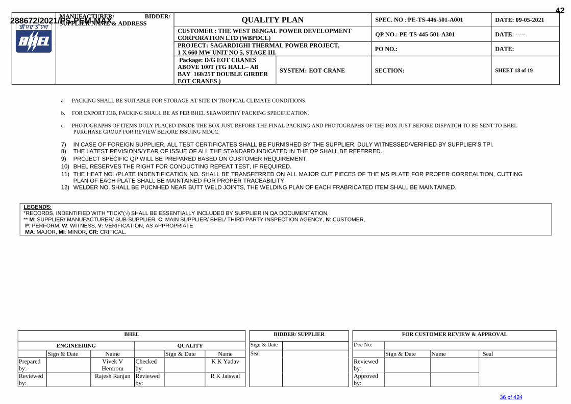
a. PACKING SHALL BE SUITABLE FOR STORAGE AT SITE IN TROPICAL CLIMATE CONDITIONS.
b. FOR EXPORT JOB, PACKING SHALL BE AS PER BHEL SEAWORTHY PACKING SPECIFICATION.
c. PHOTOGRAPHS OF ITEMS DULY PLACED INSIDE THE BOX JUST BEFORE THE FINAL PACKING AND PHOTOGRAPHS OF THE BOX JUST BEFORE DISPATCH TO BE SENT TO BHEL PURCHASE GROUP FOR REVIEW BEFORE ISSUING MDCC.
7) IN CASE OF FOREIGN SUPPLIER, ALL TEST CERTIFICATES SHALL BE FURNISHED BY THE SUPPLIER, DULY WITNESSED/VERIFIED BY SUPPLIER’S TPI.8) THE LATEST REVISIONS/YEAR OF ISSUE OF ALL THE STANDARD INDICATED IN THE QP SHALL BE REFERRED. 9) PROJECT SPECIFIC QP WILL BE PREPARED BASED ON CUSTOMER REQUIREMENT. 10) BHEL RESERVES THE RIGHT FOR CONDUCTING REPEAT TEST, IF REQUIRED. 11) THE HEAT NO. /PLATE INDENTIFICATION NO. SHALL BE TRANSFERRED ON ALL MAJOR CUT PIECES OF THE MS PLATE FOR PROPER CORREALTION, CUTTING
PLAN OF EACH PLATE SHALL BE MAINTAINED FOR PROPER TRACEABILITY 12) WELDER NO. SHALL BE PUCNHED NEAR BUTT WELD JOINTS, THE WELDING PLAN OF EACH FRABRICATED ITEM SHALL BE MAINTAINED.
LEGENDS:*RECORDS, INDENTIFIED WITH "TICK"(√) SHALL BE ESSENTIALLY INCLUDED BY SUPPLIER IN QA DOCUMENTATION,** M: SUPPLIER/ MANUFACTURER/ SUB-SUPPLIER, C: MAIN SUPPLIER/ BHEL/ THIRD PARTY INSPECTION AGENCY, N: CUSTOMER,P: PERFORM, W: WITNESS, V: VERIFICATION, AS APPROPRIATEMA: MAJOR, MI: MINOR, CR: CRITICAL.
36 of 424
288672/2021/PS-PEM-MAX42
SAGARDIGHI THERMAL POWER PROJECT, 1 X 660 MW UNIT NO 5, STAGE III.
TG HALL– AB BAY 160/25T DOUBLE GIRDER EOT
CRANES
SPECIFIC TECHNICLA REQUIREMENT (MECHANICAL)
SPECIFICATION No: PE-TS-445-501-A001
SECTION IA
REV. 00 09-05-2021
SUB-SECTION IA
CUSTOMER’S SPECIFICATION
37 of 424
288672/2021/PS-PEM-MAX43
WBPDCL
EPC Bid DocumentSagardighi Thermal Power Project
1x660 MW Unit No. 5, Phase – III
Development Consultants Pvt. Ltd.
Volume : II-ALead Specification
VOLUME : II-A
LEAD SPECIFICATION
38 of 424
288672/2021/PS-PEM-MAX44
WBPDCL
EPC Bid DocumentSagardighi Thermal Power Project
1x660 MW Unit No. 5, Phase – III
Development Consultants Pvt. Ltd.
Volume : II-ALead Specification
CONTENTS VOLUME : II-A LEAD SPECIFICATION SECTION-I : INTENT OF SPECIFICATION SECTION-II : NOT USED SECTION-III : PROJECT SYNOPSIS AND GENERAL INFORMATION SECTION-IV : SCOPE OF SUPPLY & SERVICES SECTION-V : GENERAL TECHNICAL REQUIREMENTS SECTION-VI : PROJECT MANAGEMENT & SITE SERVICES SECTION-VII : ENGINEERING SERVICES SECTION-VIII : QUALITY ASSURANCE REQUIREMENTS SECTION-IX : PERFORMANCE GUARANTEES AND TESTS SECTION-X : REQUIREMENT OF SPARES, TOOLS & TACKLE SECTION-XI : PROTECTIVE COATING AND PAINTING SECTION-XII : SALIENT DESIGN DATA
39 of 424
288672/2021/PS-PEM-MAX45
WBPDCL
EPC Bid DocumentSagardighi Thermal Power Project
1x660 MW Unit No. 5, Phase – III
Development Consultants Pvt. Ltd.
Volume : II-ASection : I
Intent of Specification
SECTION-I
INTENT OF SPECIFICATION
40 of 424
288672/2021/PS-PEM-MAX46
WBPDCL
EPC Bid DocumentSagardighi Thermal Power Project
1x660 MW Unit No. 5, Phase – III
Development Consultants Pvt. Ltd.
Page 1 of 2
Volume : II-ASection : I
Intent Of Specification
SECTION-I
INTENT OF SPECIFICATION 1.00.00 This specification is intended to cover design, engineering, manufacture,
inspection and testing at manufacturer's works, packing and shipment and delivery at site, unloading, storage and handling at site of all equipment and materials, all necessary civil/structural/ architectural works, erection of all mechanical / electrical / control& instrumentation equipment and materials, site testing, commissioning, trial run, performance and guarantee tests and other services including supply co-ordination, engineering and project management related to the equipment/systems comprising 1 x 660 MW Unit, as specified hereinafter and in accordance with the requirements, conditions, annexures, drawings etc. stated in Volume-I and Volumes II-B to II-L which shall be considered as a part of this volume as completely as if bound herewith.
The specification consists of Volumes-I, II, III detailed index of which has been
furnished elsewhere. This specification shall be read and construed in conjunction with the drawings and annexures to determine the scope of work. The quantities shown on drawings and annexures are indicative. Any variation arising during detailed engineering stage will be taken into account by the Contractor without any extra cost and time to the owner.
The Bidder shall be responsible for providing all material, equipment and
services, specified or otherwise which are required to meet the intent of this specification, ensuring high degree of reliability and ease of operation and maintenance. The equipment and system/sub-systems shall conform to all aspects of high standards of engineering, design and workmanship and shall be capable of performing in continuous commercial operation, in a manner acceptable to the Owner and shall also be in line with the current practice for reliable and efficient functioning of the plant.
Owner shall interpret the meaning of the specification, drawings, requirement of
operation, maintenance, redundancy etc., and shall have a right to reject or accept any work or material which in his assessments is not technically complete to meet the requirements of this specification and/or applicable National and International standards mentioned elsewhere in this specification.
Bidder is required to carefully examine and understand the specifications and
seek clarifications, if required, to ensure that he has understood the specifications as intended by the Owner. In the absence of any specific clarifications made by the Owner during bidding stage, the interpretation of Owner shall be final. The Bidder's offer should not carry any sections like clarifications, interpretations and/or assumptions. All such points are required to be clarified during bidding stage.
In the event of conflict between requirements of any two clauses of this
specification/documents or requirements of different codes/standards, specified, the more stringent requirement as per the interpretation of the Owner shall apply.
41 of 424
288672/2021/PS-PEM-MAX47
WBPDCL
EPC Bid DocumentSagardighi Thermal Power Project
1x660 MW Unit No. 5, Phase – III
Development Consultants Pvt. Ltd.
Page 2 of 2
Volume : II-ASection : I
Intent Of Specification
In case all the above requirements are not complied with, the offer may be considered as incomplete and liable to be treated as non-responsive.
2.00.00 Whenever a material or article is specified or described by the name of a
particular brand, manufacturer or vendor, the specific items mentioned shall be understood as establishing type, function and quality desired.
42 of 424
288672/2021/PS-PEM-MAX48
WBPDCL
EPC Bid DocumentSagardighi Thermal Power Project
1x660 MW Unit No. 5, Phase – III
Development Consultants Pvt. Ltd.
Volume : II-ASection : II
Equipment Provenness Criteria
SECTION-II
NOT USED
43 of 424
288672/2021/PS-PEM-MAX49
WBPDCL
EPC Bid DocumentSagardighi Thermal Power Project
1x660 MW Unit No. 5, Phase – III
Development Consultants Pvt. Ltd.
Volume : II-ASection : III
Project Synopsis and General Information
SECTION-III
PROJECT SYNOPSIS AND GENERAL INFORMATION
44 of 424
288672/2021/PS-PEM-MAX50
WBPDCL
EPC Bid DocumentSagardighi Thermal Power Project
1x660 MW Unit No. 5, Phase – III
Development Consultants Pvt. Ltd.
Volume : II-ASection : III
Project Synopsis and General Information
CONTENTS
CLAUSE NO. DESCRIPTION PAGE NO. 1.00.00 INTRODUCTION 1 2.00.00 APPROACH TO SITE 1 3.00.00 LAND 1 4.00.00 SOURCE OF COAL 2 5.00.00 SOURCE OF WATER 2 6.00.00 ASH DISPOSAL AREA 2 7.00.00 DETAILS OF EXISTING 3 FACILITIES OF PHASE-II 8.00.00 SALIENT DESIGN DATA 16
45 of 424
288672/2021/PS-PEM-MAX51
WBPDCL
EPC Bid DocumentSagardighi Thermal Power Project
1x660 MW Unit No. 5, Phase – III
Development Consultants Pvt. Ltd.
Page 1 of 17
Volume : II-ASection : III
Project Synopsis and General Information
SECTION-III
PROJECT SYNOPSIS AND GENERAL INFORMATION 1.00.00 INTRODUCTION The West Bengal Power Development Corporation Limited (WBPDCL)
proposes to extend their on-going Phase-II extension project of 2x500 MW at Sagardighi by adding one super critical unit of 660 MW as Phase-III extension unit. Sagardighi TPS is located in the village Manigram in Murshidabad district of West Bengal, India. The West Bengal Power Development Corporation Limited, a Company fully owned by the Government of West Bengal formed in the year 1985, have commissioned 2x300 MW Thermal Power Plant together with all other infrastructure at Sagardighi Thermal Power Project. Presently WBPDCL is also working on their under-construction Phase- II extension project of 2x500 MW at Sagardighi.
The Bidder shall acquaint himself, by visiting the site, with the conditions
prevailing at site. The information given here in under is for general guidance only.
2.00.00 APPROACH TO SITE
Sagardighi Super Thermal Power Station site is located at Manigram village, 13 KM north of Sagardighi town by the side of the SMGR (Sagardighi-Manigram-Gankar-Raghunathganj) Road at a distance 20 KM from National Highway 34 in Murshidabad District, West Bengal and around 240 KM from Kolkata, India. The nearest rail station is Manigram adjacent to the site on Bandel - Barhawara branch line and 6.5 KM from Sagardighi Railway Station on Sainthia - Azimgunj line of Eastern Railway. From Sagardighi railway station a railway line will branch off to the site for material unloading and coal marshalling. The equipment will be normally transported by rail only and under exceptional cases by road. The material consignments shall be as per the restrictions of rail and road transportation prevailing in the country.
Nearest Airport – Kolkata. Nearest Seaport –Haldia. 3.00.00 LAND
The total land available for the Power Station and Plant auxiliaries will be generally as per the Site Location Plan (12A05-DWG-M-002) enclosed and flexibility will remain to make the final equipment layout based on equipment sizes.
All construction material, heavy equipment, over dimensioned consignments
(ODC) for the station during construction may be transported through road/rail access. During operation stage, coal would be transported through rail access.
46 of 424
288672/2021/PS-PEM-MAX52
WBPDCL
EPC Bid DocumentSagardighi Thermal Power Project
1x660 MW Unit No. 5, Phase – III
Development Consultants Pvt. Ltd. Page 2 of 17 Volume : II-A
Section : III Project Synopsis and General
Information
The total land, approximately 706 hectares, has already been acquired for the present and proposed extension. The locations of various facilities and plant auxiliaries for Unit 1 & 2 under Phase-I and Units 3 & 4 in Phase-II and the space provision for extension unit no. 5 (660 MW) will be as per the General Layout enclosed. About 456 acre of land has been kept for disposal of ash. The Bidder shall accommodate equipment offered under this specification generally within the spaces allocated for such equipment in the General Layout. Specific approval from Owner/Consultant shall be taken by the contractor prior to any revision or relocation.
Except where stated otherwise, the plinth levels of all buildings shall be 300 mm above the corresponding developed grade level and the road level shall be 150 mm above the developed grade.
4.00.00 SOURCE OF COAL
The Power plant shall receive coal from ECL mines. Coal is planned to be transported in rake loads through the existing Pakur- Tildanga-Dhulian-Monigram broad gauge line or through Pakur- Nalhati (proposed)–Takipara-Gosaingram-Poradanga-Monigram broad gauge line. The coal would be carried in rake loads of BOBR/BOX-N wagons.
It is considered that coal would be received from the same source as the plant under Phase-I and Phase-II station with similar characteristics and a new mine at Pachwara (north) in Jharkhand being developed by WBPDCL. These sources being connected by B.G. rail track, coal would be transported by rail only. For coal unloading, crushing and storage facility it is proposed that a new Wagon tippler along with crusher houses, conveyors will be installed in addition to existing coal handling plant of Phase-II station with suitable extension from the end of Transfer Point (TP-19).
5.00.00 SOURCE OF WATER
The source of water for this project is the River Bhagirathi (5 km) through the proposed intake pump house under implementation for Phase-II station. The water from the River Bhagirathi will be transferred and stored in the five (5) nos. Plant Raw Water Reservoirs by augmentation of the Intake water transportation system for phase - II for meeting the requirement of Phase-III Sagardighi TPS.
The Power station will operate on semi open recirculating condenser cooling system using cooling towers. In addition all water conservation and recycling measures will be adopted to minimize requirement of make up water. The proposed project will adopt zero effluent discharge philosophy.
6.00.00 ASH DISPOSAL AREA
Bottom Ash (BA) shall be extraction in wet form and conveyed to the disposal area in lean slurry form. Whereas Fly Ash (FA) shall be extracted in dry form and stored in dry form for onward usage. However, arrangement shall be also
47 of 424
288672/2021/PS-PEM-MAX53
WBPDCL
EPC Bid DocumentSagardighi Thermal Power Project
1x660 MW Unit No. 5, Phase – III
Development Consultants Pvt. Ltd.
Page 16 of 17
Volume : II-ASection : III
Project Synopsis and General Information
CIVIL, STRUCTURAL AND ARCHITECTURAL WORK (BUILDINGS
CONSTRUCTED WITH SPACE FOR PHASE III)
Necessary Walkway connection between operating floors of Power House of Phase – II (Existing) and Phase – III shall be considered by Bidder. Few civil foundations have already been constructed for future equipment. Such existing foundation details including bolts, inserts etc. to be studied in detail before procurement of specific equipment for respective purposes so that the same can safely be placed over the existing foundations complying all technical compatibility. In case this is not at all possible, new foundations need to be constructed after complete demolition of existing foundations. For further details regarding the existing facilities of Phase – II, please refer Volume – II G1, G2 and G2: Technical Specifications for Civil, Structural and Architectural..
8.00.00 SALIENT DESIGN DATA 8.01.00 For implementation of the project, the Bidder shall consider the following Site
and Meteorological data:-
a) Location : Manigram village, Sagardighi, Raghunathganj sub-division, Murshidabad District, West Bengal.
b) Latitude and Longitude : 240 22’ 13.7” N, 880 6’ 15.8” E (Topo sheet No.78/D/3) c) Nearest Towns : Ajimganj, Jangipur, Raghunathganj. d) District Head Quarters : Berhampore - 40 km. e) Approach Road : 20 km from National Highway (NH-34) f) Nearest Railhead : Manigram railway station on Bandel-
Barhawara branch line 1 km from site. g) Source of Water : Bhagirathi River - 5 km h) Source of Coal : Pachwara (North) mine block in
Jharkhand.
i) Fuel Transportation : By rail in rake loads of BOBR/BOX-N wagons.
j) Surrounding Habitations : Villages - Manigram, Chhamugram,
Karaia, Thakurpara on the south; Bhumhar, Khasittor, Ekrakhi on the west;
48 of 424
288672/2021/PS-PEM-MAX54
WBPDCL
EPC Bid DocumentSagardighi Thermal Power Project
1x660 MW Unit No. 5, Phase – III
Development Consultants Pvt. Ltd.
Page 17 of 17
Volume : II-ASection : III
Project Synopsis and General Information
Dhalo, Bagpara, Santoshpur on the north and Harirampur, Chandparam, Dogachhi on the east.
k) Level : Within 34.5 m contour. Land is above
HFL (highest flood level) of the area. l) Soil : Less fertile alluvial soil. m) Land Use : Within existing plant boundary of
WBPDCL.
Meteorological data of site is given below: a) Design ambient
dry bulb temperature : 50 ºC maximum 5 ºC minimum b) Highest wet bulb temp : 26.9 ºC c) Maximum relative humidity : 84% d) Average relative humidity : 73% e) Average annual Rainfall : 1389 mm f) Wind load : In accordance with IS-875 for a basic
wind speed of 47 m/sec, up to a height of 10 metres above mean ground level.
g) Seismic Zone : Zone III as per IS: 1893 latest edition. h) Altitude : 34M above MSL
49 of 424
288672/2021/PS-PEM-MAX55
WBPDCL
EPC Bid DocumentSagardighi Thermal Power Project
1x660 MW Unit No. 5, Phase – III
Development Consultants Pvt. Ltd.
Volume : II-ASection : IV
Scope Of Supply and Services
SECTION-IV
SCOPE OF SUPPLY AND SERVICES
50 of 424
288672/2021/PS-PEM-MAX56
WBPDCL
EPC Bid DocumentSagardighi Thermal Power Project
1x660 MW Unit No. 5, Phase – III
Development Consultants Pvt. Ltd.
Volume : II-ASection : IV
Scope Of Supply and Services
CONTENTS
CLAUSE NO. DESCRIPTION PAGE NO. A. SUPPLY OF EQUIPMENT AND SYSTEMS 1 B. SERVICES TO BE RENDERED BY THE BIDDER 11 C. EXCLUSIONS 12 D. TERMINAL POINTS 12 ATTACHMENT
ANNEXURE-I TERMINAL POINTS 13
51 of 424
288672/2021/PS-PEM-MAX57
WBPDCL
EPC Bid Document Sagardighi Thermal Power Project
1x660 MW Unit No. 5, Phase – III
Development Consultants Pvt. Ltd.
Page 11 of 16
Volume : II-ASection : IV
Scope Of Supply and Services
the present specification. For further details refer Volume: IIG/1, G/2 & G/3 of this specification. One set of spares for all plants and equipment for all systems, as
recommended by the respective manufacturer/bidder for regular reliable operation of minimum three (3) years. Bidder is to develop recommended list of spare parts with prices by items and this shall be furnished separately in the prescribed format. Sufficient description and drawings are to be provided to permit analysis and evaluation of spares recommended.
One set of tools and tackle, fixtures etc. in new condition, as required for
regular operation and maintenance of the plant and equipment offered. Adequate means shall be provided for lifting and handling of each item of plant and equipment including slings etc. Except turbine room crane handling arrangement for all equipment like BFP, Mill, Fans etc. are to be provided; and above 3 tonnes load, handling equipment shall be motor operated type. Price for such tools & tackle, fixtures etc. shall be furnished separately in the prescribed format.
B. SERVICES TO BE RENDERED BY THE BIDDER The services to be rendered by the Bidder shall include but not be limited to the
following: 1.00.00 Services for complete engineering, co-ordination and project management as
detailed in Section-VI of this specification volume. 2.00.00 Services for shop tests and quality assurance, etc. as detailed elsewhere in this
specification. 3.00.00 Services for construction, fabrication, equipment erection, testing as well as trial
run & commissioning of various equipment and accessories under the contract. The details of such services are indicated in Section-VI of this specification volume. Bidder shall arrange tower crane for erection and construction work, wherever necessary. Moreover, all erection tools and tackles necessary for generator stator handling and erection shall be arranged by the bidder.
4.00.00 Supply of all mandatory, erection/commissioning and recommended spares,
special tools & tackle including required after-sales services during and after the warranty period.
5.00.00 Supply of all consumables required for the works as per provision of respective
clauses specified in conditions of contract. 6.00.00 Furnishing of all document, drawings, design basis reports, optimization, study
reports, instruction manuals, etc. including "As built" drawings, as called for in the specification both in requisite no. of hard copies and in soft form (CD).
7.00.00 Operation and Maintenance training. 8.00.00 Obtaining approval from statutory bodies in India.However, Purchaser shall
52 of 424
288672/2021/PS-PEM-MAX58
WBPDCL
EPC Bid Document Sagardighi Thermal Power Project
1x660 MW Unit No. 5, Phase – III
Development Consultants Pvt. Ltd.
Page 12 of 16
Volume : II-ASection : IV
Scope Of Supply and Services
provide assistance to do so. 9.00.00 Equipment shop painting. For details of painting, please refer section-XI of volume-IIA. For painting of
large diameter piping, please refer section-V of Vol. II-J1. 10.00.00 Any other service, although not specifically called for but required for a turn-key
contract of the size and nature indicated in this specification. 11.00.00 For details of services under clause B, subsequent sections of this Lead
specification may be referred. C. EXCLUSIONS Intake Water System. Raw Water System including raw water reservoir. Clarified Water Pumping System including reservoir DM Plant including DM water Storage Tanks Potable water System beyond terminal point as specified in Annexure-I. Fuel Oil Unloading System. CHP upstream of Transfer Point -19 Cooling Tower
Chimney (However, supply, erection & commissioning of all the `On line Stack Monitoring' equipment are under Bidder's scope. Bidder shall furnish the cut out details of the same to the owner well in advance to facilitate the design & construction work).
Material Handling section of FGD Plant Ash Dyke Area Workshop
Power evacuation and transmission system beyond the sub-station/switchyard. Necessary coordination with Transmission package supplier shall be the responsibility of the Bidder under this contract
D. TERMINAL POINTS The terminal points shall be as specified in Annexure-I of this section. For all
terminal points scope of this contract shall include making the joint including supply of mating flanges, gaskets, bolts, nuts etc. and including any isolation valve.
53 of 424
288672/2021/PS-PEM-MAX59
WBPDCL
EPC Bid DocumentSagardighi Thermal Power Project
1x660 MW Unit No. 5, Phase - III
Development Consultants Pvt. Ltd.
Volume : II-ASection : V
General Technical Requirements
SECTION-V
GENERAL TECHNICAL REQUIREMENTS
54 of 424
288672/2021/PS-PEM-MAX60
WBPDCL
EPC Bid DocumentSagardighi Thermal Power Project
1x660 MW Unit No. 5, Phase - III
Development Consultants Pvt. Ltd.
Volume : II-ASection : V
General Technical Requirements
CONTENTS CLAUSE NO. DESCRIPTION PAGE NO. 1.00.00 CODES AND STANDARDS 1 2.00.00 RESPONSIBILITY FOR DESIGN 1 3.00.00 NAME PLATES (RATING PLATES) 2 4.00.00 SAFETY AND SECURITY 2 5.00.00 GUARDS 3 6.00.00 LOCATION AND LAYOUT REQUIREMENTS 3
7.00.00 OPERATION AND MAINTENANCE 5 8.00.00 MATERIALS 5 9.00.00 LUBRICATION 6 10.00.00 LUBRICANTS, SERVO FLUIDS AND CHEMICALS 6 11.00.00 PLANT LIFE AND MODE OF OPERATION 7 12.00.00 PACKAGING & MARKING 7 13.00.00 PROTECTION 7 14.00.00 PAINTING 8 15.00.00 COLOUR CO-ORDINATION AND FINISH 12 16.00.00 ENVIRONMENT PROTECTION AND NOISE 13 LEVEL REQUIREMENT 17.00.00 INSPECTION AND TESTING 14 18.00.00 TRAINING OF OWNER’S PERSONNEL 16 ATTACHMENTS ANNEXURE-I LIST OF STANDARDS FOR REFERENCE 19 ANNEXURE-II CRITERIA FOR LAYOUT 21
55 of 424
288672/2021/PS-PEM-MAX61
WBPDCL
EPC Bid DocumentSagardighi Thermal Power Project
1x660 MW Unit No. 5, Phase - III
Development Consultants Pvt. Ltd.
Page 1 of 27
Volume : II-ASection : V
General Technical Requirements
SECTION-V
GENERAL TECHNICAL REQUIREMENTS 1.00.00 CODES AND STANDARDS 1.01.00 Except where otherwise specified, the Plant shall comply with the appropriate
Indian Standard or an agreed internationally accepted Standard Specification as listed in the annexure to this Section and mentioned in detailed specifications, each incorporating the latest revisions at the time of tendering. Where no internationally accepted standard is applicable, the Bidder shall give all particulars and details as necessary; to enable the Owner to identify all of the Plant in the same detail as would be possible had there been a Standard Specification.
1.02.00 Where the Bidder proposes alternative codes or standards he shall include in
his tender one copy (in English) of each Standard Specification to which materials offered shall comply. In such case, the adopted alternative standard shall be equivalent or superior to the standards mentioned in the specification.
1.03.00 Wherever specified or required the Plant shall conform to various statutory
regulations such as Indian Boiler Regulations, Indian Electricity Rules, Indian Explosives Act, Factories Act etc. Wherever required, approval for the plant supplied under the specification from statutory authorities shall be the responsibility of the Successful Bidder.
1.04.00 In the event of any conflict between the codes and standards referred above,
and the requirements of this specification, the requirements, which are more stringent, shall govern.
1.05.00 In case of any change of code, standards and regulations between the date of
purchase order and the date the Successful Bidder proceeds with manufacturing the Owner shall have the option to incorporate the changed requirements. It shall be the responsibility of the Successful Bidder to advise Owner of the resulting effect.
2.00.00 RESPONSIBILITY FOR DESIGN 2.01.00 The Bidder shall assume full responsibility for the design of the whole and
every portion of the Plant, whether or not the design work was undertaken specifically in relation to the Contract and whether or not the Successful Bidder was directly involved in the design work.
2.02.00 Notwithstanding the Owner's wish to receive the benefits of new, advanced and
improved technologies, a prime requirement is that all the systems and components proposed shall have been already adequately developed and shall have demonstrated good reliability under similar, or more arduous conditions elsewhere, at least for continuous 2 years in two different power station.
2.03.00 The Bidder shall carry out optimization studies for selection of pipe size and
equipment wherever required. The result of such studies shall be included as part of bid proposal.
56 of 424
288672/2021/PS-PEM-MAX62
WBPDCL
EPC Bid DocumentSagardighi Thermal Power Project
1x660 MW Unit No. 5, Phase - III
Development Consultants Pvt. Ltd.
Page 2 of 27
Volume : II-ASection : V
General Technical Requirements
The successful Bidder shall have to carry out surge analysis and other transient
condition studies as may be necessary and as required by the Owner as per proven engineering practice.
2.04.00 The Bid shall include a detailed discussion on the development status of and
the reasons for any changes made in proposed systems or components for the Plant, as compared with similar items previously supplied in other installations cited by the bidder as reference plants.
2.05.00 The Bidder may also make alternate offers, provided such offers are superior in
his opinion in which case adequate technical information, operating feedback, etc. are to be enclosed with the offer, to enable the Owner to assess the superiority and reliability of the alternatives offered. In case of each alternative offer, its implications on the performance, guaranteed efficiency, auxiliary power consumptions, etc. shall be clearly brought out to the Owner to make an overall assessment. In any case, the base offer shall necessarily be in line with the specifications i.e. Base offer shall be as per the technical specifications and the same will be considered for techno-commercial evaluation.
3.00.00 NAME PLATES (RATING PLATES) 3.01.00 Instruction plates, nameplates or labels shall be permanently attached to each
main and auxiliary item of plant in a conspicuous position. These plates shall be engraved with the identifying name, type and manufacturers serial number, together with the loading conditions under which the item of plant has been designed to operate.
3.02.00 Items such as valves, etc. which are subject to hand operation, shall be
provided with nameplates so constructed as to remain clearly legible throughout the life of the plant giving due consideration to the difficult climatic conditions to be encountered. Nameplates shall be securely mounted where they will not be obscured in service by insulation, cladding, actuators or other equipment. Direction of flow is also to be engraved.
3.03.00 All trade nameplates and labels shall be in English language. All
measurements shall be in M.K.S. Units. 3.04.00 The size and location of nameplates shall be subject to Approval of the
Owner/Owner’s Engineer. 4.00.00 SAFETY AND SECURITY 4.01.00 The design shall incorporate every reasonable precaution and provision for the
safety of all personnel and for the safety and security of all persons and property. The design shall comply with all appropriate statutory regulations relating to safety. All structures and equipment shall be designed and constructed to withstand every foreseeable static and dynamic loading condition, including loading under earthquake conditions, with an adequate margin of safety.
4.02.00 Ready and safe access with clear headroom shall be provided to all parts of the
plant for operation, inspection, cleaning and maintenance.
57 of 424
288672/2021/PS-PEM-MAX63
WBPDCL
EPC Bid DocumentSagardighi Thermal Power Project
1x660 MW Unit No. 5, Phase - III
Development Consultants Pvt. Ltd.
Page 3 of 27
Volume : II-ASection : V
General Technical Requirements
4.03.00 Escape routes and clear ways shall be provided to allow speedy evacuation of
the plant in the event of fire or explosion, and the plant layout shall allow for ease of access to all parts of the Works by rescue and fire fighting teams. The Plant layout shall be designed to localize and minimise the effects of any fire or explosion. The recommendations of NFPA, OSHA, and TAC etc. as necessary shall be followed in all respects.
4.04.00 The use of corrosive, explosive, toxic or otherwise hazardous materials shall be
kept to a minimum during construction and the design of the plant shall minimise the requirement for such materials during operation and maintenance. Where such materials must be used, all necessary precautions shall be taken in the design, manufacture and layout of equipment to minimise the resulting hazard, and all equipment necessary for the protection and first-aid treatment of personnel in the event of accidents shall be provided. Particular attention is drawn to avoid the use of materials containing asbestos in any form.
5.00.00 GUARDS 5.01.00 Effective guards and fences must be provided to prevent injury to operators
through accident or malpractice. 5.02.00 Mesh guards which allow visual inspection of equipment with the guard in place
are generally preferable. The guards shall be constructed of mesh attached to a rigid framework of mild steel rod, tube, or angle and the whole galvanised to prevent loss of strength by rusting or corrosion. The guards shall be designed to facilitate removal and replacement during maintenance.
5.03.00 All drive belts, couplings, gears, sharp metallic edges and chains must be
safely guarded. Any lubricating nipple requiring attention during normal running must be positioned where they can be reached without moving the guards.
5.04.00 Guards for couplings and rotating shafts shall be in accordance with BS
5304-1975 or similar approved standard. All rotating shafts and parts of shafts must be covered.
5.05.00 Suitable fencing shall be provided to enclose all openings or doorways used for
the hoisting and lowering of machinery etc. This fencing must be securely fixed but quickly detachable when required. A secure handhold must be provided on each side of the opening or doorway.
6.00.00 LOCATION AND LAYOUT REQUIREMENTS The majority of plant and equipment shall all be of indoor installation. A broad
list of buildings housing such equipment is given In Vol-II-G2 Section I. Layout shall facilitate access for operation-maintenance and inspection of any one or more equipment/components at a time without disturbing the operation or installation of rest of the plant. Further, Bidder should comply with the criteria given under the various equipment and system specifications as well as those stipulated in Annexure-II attached to this section.
Enclosed General Layout and other tender layout drawings enclosed in Vol-II-L
show the location of major installations and auxiliary buildings. The Bidder
58 of 424
288672/2021/PS-PEM-MAX64
WBPDCL
EPC Bid DocumentSagardighi Thermal Power Project
1x660 MW Unit No. 5, Phase - III
Development Consultants Pvt. Ltd.
Page 4 of 27
Volume : II-ASection : V
General Technical Requirements
shall try to retain these locations as far as practicable. The layout of equipment within the power house as shown in the tender drawings is indicative. The Bidder may, subject to Owner's acceptance alter the same to suit the space requirement of the equipment offered.
While developing the layout of buildings the following criteria shall be given
effect: a) The minimum width of clear access corridors around equipment shall be
1.2 meters. b) Each building shall have an identified vacant space for equipment
unloading and maintenance and preferably a separate bay altogether in buildings housing heavy equipment. Provision for handling equipment by monorail hoist and/or overhead crane shall be made as required.
c) The plinth level with respect to the existing grade level shall be as
indicated elsewhere in Vol-II-A Section-V/Annexure-II. d) The minimum clear height available between two consecutive floor
slabs shall not be less than five (5) meters. A clear head room of 2.2 meters shall be maintained between the floor and any overhead piping/cables or other obstruction. Adequate provision for natural ventilation and illumination shall be made as per good engineering practices.
e) There shall be at least two (2) nos. main access doors, one on either
side of each building, of which one shall be minimum 3 meters wide with rolling shutters for equipment entry. For multistoried buildings, at least two (2) nos. regular staircases diagonally opposite to each other shall be provided connecting all the floors and roof. These minimum requirements shall be augmented as required depending on the floor area, statutory requirements and TAC recommendations.
f) All buildings shall have provision for toilet and associated effluent
discharge system together with facility for drinking water. The criteria for ventilation, fire protection and illumination of building spaces shall be as specified in Vol-II-A Section-V/Annexure-II.
g) All rail/road crossings for pipe/cable racks shall be constructed with
minimum 8 meters headroom from top of rail/road to bottom of rack. Similarly top cover over underground pipes/cables shall be minimum one (1) meter. For other detail refer to Annexure-II of this section.
h) Cubicle for operating personnel shall be located at safe place near the
equipment. i) Pipe rack, cable rack and Pipe cum Cable rack shall have hand railings
( not less than 1200 mm high) in walkways (min. 800 mm wide) on both sides at appropriate heights.
59 of 424
288672/2021/PS-PEM-MAX65
WBPDCL
EPC Bid DocumentSagardighi Thermal Power Project
1x660 MW Unit No. 5, Phase - III
Development Consultants Pvt. Ltd.
Page 5 of 27
Volume : II-ASection : V
General Technical Requirements
7.00.00 OPERATION AND MAINTENANCE CONSIDERATIONS 7.01.00 Space for ease of operation and maintenance including equipment removal,
tube bundle/cartridge/rotor pulling etc. shall be provided. All valves, gates, dampers and other devices shall be located and oriented in such a way that they are accessible from operating floor levels. Where this cannot be adhered to, platforms and walkways with access ladders shall be provided to facilitate operation and maintenance.
7.02.00 Lifting devices i.e. hoists, chain pulleys, jacks, etc. shall be provided for
handling of any equipment and/or part having weight in excess of 100 Kg during erection and maintenance activities. Suitable beams, hooks etc. for this purpose shall be provided in the buildings and clear space provided below to a platform or floor which will allow normal risk free transport means to be used.
Lifting tackles, slings, etc. to be connected to hook of the hoist/crane shall also
be provided by the Bidder for lifting the various equipments and accessories covered under this specification.
7.03.00 All similar parts of the equipment shall be made to gauge and shall be
interchangeable with and shall be made of same material and workmanship as the corresponding parts of the equipment. Where feasible common components shall be employed in different pieces of equipment in order to optimize the spares inventory and utilization.
8.00.00 MATERIALS 8.01.00 In selecting materials of construction of equipment, the Bidder shall pay
particular attention to the atmospheric conditions existing at the Site and the nature of material/fluid handled.
All materials shall be new and shall be of the quality most suited to the
proposed application. 8.02.00 Materials used for various components shall be those which have already
proven operating experience in similar type of applications. 8.03.00 All parts which could deteriorate or corrode under the influence of the
atmospheric, meteorological or soil conditions at the Site, or under the influence of the working conditions shall be suitably and effectively protected so that such deterioration or corrosion is a minimum over the life of the plant.
8.04.00 Prohibited Materials The use of the following materials is prohibited: a) High alumina cement in structural elements b) Wood wool slabs in permanent framework to concrete c) Calcium chloride in mixtures for use in concrete works
60 of 424
288672/2021/PS-PEM-MAX66
WBPDCL
EPC Bid DocumentSagardighi Thermal Power Project
1x660 MW Unit No. 5, Phase - III
Development Consultants Pvt. Ltd.
Page 6 of 27
Volume : II-ASection : V
General Technical Requirements
d) Naturally occurring aggregate for use in reinforced concrete that does
not comply with the applicable codes and standards. e) Cast iron for any oil service f) Carcinogenic material and suspected carcinogenic materials by World
Health Organization. g) Asbestos or any other fibrous form of hydrated magnesium silicate h) Any other material generally known to be deleterious if used or
incorporated in such project like the facility. 9.00.00 LUBRICATION 9.01.00 Provision shall be made for suitable efficient lubrication where necessary to
ensure smooth operation free from undue wear. 9.02.00 Non ferrous capillary tubing shall be used throughout. 9.03.00 Gear boxes and oil baths shall be provided with filling and drain plugs, both of
adequate size. An approved means of oil indication including level switches and temperature indication shall be provided.
9.04.00 All high speed gears shall be oil bath lubricated. Low speed gears shall be
lubricated by means of soft grease. Removable and accessible drip pans shall be provided to collect lubricant, which may drop, from operating parts.
9.05.00 All lubrication points shall be conveniently situated for maintenance purposes. It
must be possible to carry out lubrication from a gangway or landing and without the removal of guarding or having to insert the hand into it. Where accessibility to a bearing for oiling purposes would be difficult a method of remote lubrication shall be fitted.
9.06.00 The Bidder shall supply grease gun equipment suitable to service each type of
nipple fitted. . 10.00.00 LUBRICANTS, SERVO FLUIDS AND CHEMICALS 10.01.00 The Bidder shall provide a detailed and comprehensive specification for all
lubricating oils, greases and control fluids required for the entire plant. A sufficient supply of these shall be provided by the Successful Bidder for initial commissioning, first fill and till completion of facilities and handing over of respective units.
10.02.00 The Bidder shall supply a detailed schedule giving the lubricant testing,
cleaning and replacement procedures. All equipment and facilities necessary for the testing, cleaning and changing of lubricants and control fluids shall be provided. The Successful Bidder shall endeavor to reduce the verities and grades of required lubricants and control fluids to a minimum, matching them where possible to those already in use in the generating station in order to simplify procurement and minimise storage requirements. All lubricants and control fluids shall be of internationally recognized standards and shall be easily
61 of 424
288672/2021/PS-PEM-MAX67
WBPDCL
EPC Bid DocumentSagardighi Thermal Power Project
1x660 MW Unit No. 5, Phase - III
Development Consultants Pvt. Ltd.
Page 7 of 27
Volume : II-ASection : V
General Technical Requirements
obtainable from a large number of Indian suppliers. Bidder shall also indicate the equivalent Indian Standard for the above for easy procurement in future.
10.03.00 No lubricant or control fluid shall have toxic or other harmful effects on
personnel or on the environment. 11.00.00 PLANT LIFE AND MODE OF OPERATION The complete plant including all the equipment and systems individually and
collectively shall be designed for continuous operation for an economic service life of thirty (30) years under the prevailing site conditions and for the type of duty as specified in relevant sections of the specification.
The critical components of the Steam Generator, Turbine-Generator and Auxiliary equipment, the life of which is limited by time and temperature dependent mechanisms such as thermal stress, creep and low cycle fatigue, are to be designed considering expected (hot, warm and cold) start-up, shut-down and cyclic load variations. (Details are specified in the Volume IIB – Specification of Steam Generator and Auxiliaries and Volume IIC – Specification of Steam Turbine and Auxiliaries and)
The units would be operated on base load with cyclic load variation. The load variation is expected to be as per schedule depending on power demand.
12.00.00 PACKAGING & MARKING All the equipment shall be suitably protected, coated, covered or boxed and
crated to prevent damage or deterioration during transit, handling and storage at site till the time of erection. While packing the materials, the limitations from the point of view of availability of railway wagon sizes in India should be taken account of. The details of various wagons normally available with Indian Railways for transportation of heavy equipment shall be considered by the Bidder. The Bidder shall be responsible for all loss or damage during transportation, handling and storage due to improper packing.
Bidder shall conduct his own route survey and transportation logistics for transportation of the equipments to project site by road/rail/sea and indicate the same in his proposal.
Each package shall have identification marking indicating the name and address of the consignee shall be clearly marked in indelible ink on two opposite sides and top of each of the packages. In addition the Bidder shall include in the marking gross and net weight, outer dimension and cubic measurement. Each package shall be accompanied by a packing note (in weather proof paper) quoting specifically the name of the Bidder, the number and date of contract and names of the office placing the contract, nomenclature of contents and Bill of Material.
13.00.00 PROTECTION Equipment having antifriction or sleeve bearings shall be protected by weather-
tight enclosures. Coated surfaces shall be protected against impact, abrasion, discoloration and other damages. Surfaces that are damaged shall be repainted.
62 of 424
288672/2021/PS-PEM-MAX68
WBPDCL
EPC Bid DocumentSagardighi Thermal Power Project
1x660 MW Unit No. 5, Phase - III
Development Consultants Pvt. Ltd.
Page 8 of 27
Volume : II-ASection : V
General Technical Requirements
Electrical equipment, controls and insulations shall be protected against
moisture and water damages. All external gasket surfaces and flange faces, couplings, rotating equipment shafts, bearings and like items shall be thoroughly cleaned and coated with rust preventive compound as specified above and protected with suitable wood, metal or other suitable covering to ensure their full protection. All exposed threaded parts shall be greased and protected with metallic or other suitable protectors.
All piping, tubing and conduit connections on equipment and other equipment
openings shall be closed with rough usage covers or plugs shall be sealed and taped. Male threaded openings shall be closed with rough usage covers or plugs shall be sealed and taped. Female threaded openings shall be closed with forged steel plugs.
Returnable containers and special shipping devices shall be returned by the
Bidder. 14.00.00 PAINTING 14.01.00 General All exposed metallic and wooden surfaces subject to corrosion shall be
protected by shop application of suitable coatings. Surfaces not easily accessible after shop assembly shall be treated before-hand and protected for life of the equipment. Surfaces to be finish painted after installation shall be shop painted with at least two (2) coats of primer. Steel surfaces, which are not to be painted, shall be coated with suitable rust preventive compound subject to the acceptance of the Owner.
All paints shall be used in accordance with the manufacturer's instructions. No
thinners or other substance shall be added to the coating material without the prior notification and specific acceptance of the Owner. The quality and vendor of the paints shall require acceptance of the Owner.
Procedure for painting of any item, if not indicated in the relevant specification,
shall be developed by the Bidder. This procedure and quality of paint shall be subject to Owner’s acceptance
All paints shall be applied in a normal full coat, shall be free from runs, sags,
wrinkles, patchiness, brush marks or other defects. All primers shall be properly applied on to the surface and the first priming coat
shall be applied as soon as possible after cleaning, within four hours maximum. The paint shall be applied by brush, roller or airless spray, according to the manufacturer's instructions. Spray painting shall be carried out by operators trained and thoroughly experienced in the use of the spray painting equipment.
If the drying interval between successive coats of paint or primer exceeds the
manufacturer’s recommendations, the paint already applied shall be completely and uniformly abraded with fine abrasive paper before putting on the next coat.
63 of 424
288672/2021/PS-PEM-MAX69
WBPDCL
EPC Bid DocumentSagardighi Thermal Power Project
1x660 MW Unit No. 5, Phase - III
Development Consultants Pvt. Ltd.
Page 9 of 27
Volume : II-ASection : V
General Technical Requirements
Paint spraying on large surfaces shall not be done indoors, without the prior
notification and specific acceptance of the Owner. Spray guns shall not be used outdoors in windy weather nor near unprotected surfaces of a contrasting colour and under no circumstances shall spray guns be used where spray may be carried into or onto exposed electrical equipment or unprotected humans.
The Bidder shall provide suitable protection for adjacent plants from air borne
materials during cleaning and spraying to the satisfaction of Owner Paint containers shall not be opened until required and the paint shall be
mechanically mixed thoroughly before use, and agitated occasionally during use.
Electrical equipment shall be shop finished with one or more coats of primer
and two coats of high-grade oil resistant enamel. The interior of all panels’ cabinets and enclosures shall be finished with gloss white enamel. For detail please refer relevant electrical sub-section Volume II F1 & F2.
The Bidder shall furnish sufficient touch-up paint for one complete finish coat
on all exterior factory surfaces of each item of equipment. The touch-up paint shall be of the same type and colour as the factory applied paint and shall be carefully packed to avoid damage during shipment. Complete painting instructions shall be furnished.
Shop primer for steel and iron surfaces which will have a continuous operating
temperature below 35°C shall be selected by the Bidder, in accordance to the relevant standard. Special high temperature primer shall be used on surface exposed to operating temperature above 35°C.
The colour scheme shall be submitted during execution of contract for acceptance by the Owner.
14.02.00 Surface Preparation The grade of surface preparation shall be classified as indicated in Annexure-
I of this section.
Sl. No. Type of Preparation Reference Standards
SSPC SIS BS 4232 1. Solvent cleaning SP1 - - 2. Hand Tool Cleaning SP2 St-2 - 3. Power Tool Cleaning SP3 St-3 - 4. Flame cleaning of new steel SP4 - - 5. White metal blast cleaning SP5 Sa-3 First Quality 6. Commercial blast cleaning SP6 Sa-2 Third Quality 7. Brush-off blast cleaning SP7 Sa-1 - 8. Pickling SP8 - -
64 of 424
288672/2021/PS-PEM-MAX70
WBPDCL
EPC Bid DocumentSagardighi Thermal Power Project
1x660 MW Unit No. 5, Phase - III
Development Consultants Pvt. Ltd.
Page 10 of 27
Volume : II-ASection : V
General Technical Requirements
9.
Weathering followed by blast cleaning
SP9 - -
10. Near white blast cleaning SP10 Sa-2.5 Second Quality
Oil and grease shall be removed from the surface by washing with a suitable
detergent, rinsing with clean water, and drying. The abrasive to be used shall be metal grit.
The surface preparation of all steel surfaces to be coated shall be free from all mill scales, rust corrosion products, oxides, paints, oil or other foreign matter.
All welded areas and appurtenances shall be given special attention for removal of welding flux in crevices. Welding splatter, slivers, laminations and underlying mill scale exposed during shot blasting shall be removed or repaired.
No acid/solvents/other cleaning solutions shall be used on surfaces after they have been blasted.
14.03.00 Application of Primer and Paint
Primer shall be applied immediately after surface preparation has been completed.
Brushing, spraying, roller coating or other suitable method shall be adopted for application of primer and paint and the work shall be carried out strictly as per the recommendation given by the paint manufacturer.
Primarized surfaces shall be faultless and shall not have mudcracking, dripping over thickness and dry sprays.
Before application of paint/primer, the following shall be particularly checked for conformance to this specification and recommendation of the paint manufacturer:
a) Surface preparation profile. b) Catalysis ratio for two component paints. c) Pot life. d) Minimum and maximum top coating times.
e) Type and quantity of thinners (if required)
f) Viscosity g) Soundness of previous coating. h) Ambient conditions (temperature, humidity, etc)
65 of 424
288672/2021/PS-PEM-MAX71
WBPDCL
EPC Bid DocumentSagardighi Thermal Power Project
1x660 MW Unit No. 5, Phase - III
Development Consultants Pvt. Ltd.
Page 11 of 27
Volume : II-ASection : V
General Technical Requirements
Depending on the degree of contamination by foreign matters, the surfaces primed at shop shall be washed as follows to the satisfaction of the Owner:
a) With clean water under a pressure of a least 7 Kg/cm2 (g) using
suitable nozzles. During washing broom of corn brushes shall be used.
b) With suitable solvents, (such as Carbon Tetrachloride,
Trichloroethylene etc.) if necessary, to remove traces of grease, oil etc. Coated parts shall be carefully handled using hemp ropes, cloth belts, pendulum conveyors or suitable means as instructed by the Owner.
Surfaces which cannot be painted after fabrication shall be primed and provided with suitable rust preventive oil before boxing up.
Paints shall be stored in well-ventilated rooms, far away from heat sources, open flames, sparks and protected from sun. Outdoor storage is not permitted. Storage life shall be clearly indicated on the container. Paints, which have thickened or gelled or contained in non-original containers or in unsealed containers shall not be used. Owner’s decision in this regard shall be final and binding.
The requirements for the dry film thickness (DFT) of paint and the materials to be used shall be as per Table I & II of this section.
For detail painting on building & structural steel elements refer Section-IIG/1 & IIG/2 of this specification.
14.04.00 Damaged Paintwork Any damaged paintwork shall be made good as follows: a) The damaged area, together with an area extending 25mm around its
boundary, shall be cleaned down to bare metal. b) A priming coat shall be immediately applied, followed by a full paint
finish equal to that originally applied and extending 50mm around the perimeter of the original damage.
c) The repainted surface shall present a smooth surface. This shall be
obtained by carefully chamfering the paint edges before and after priming.
14.05.00 Surface preparation and painting work shall not be carried out under the
following weather conditions:
a) When the surface is wet or expected to become wet before the paint/primer has dried up due to impending rain, fog or mist.
b) High winds.
c) Ambient temperature below 5deg.C or surface temperature less than 3
deg.C above dew point.
66 of 424
288672/2021/PS-PEM-MAX72
WBPDCL
EPC Bid DocumentSagardighi Thermal Power Project
1x660 MW Unit No. 5, Phase - III
Development Consultants Pvt. Ltd.
Page 12 of 27
Volume : II-ASection : V
General Technical Requirements
d) Relative Humidity is more than 85%.
14.06.00 Inspection and Testing of Painting
The following inspection and testing shall be performed during and on completion of paint systems.
- Shot blasting profile shall be checked using a suitable profile-meter.
Acceptable profile shall be 25-30 microns. - Check of time of top coating and drying, in accordance with the
recommendation of paint manufacturer.
- Check of Dry Film thickness by suitable Non Destructive Equipment. The painting shall be rejected if any of the spot measurement shows thickness to be less than 80% of the specified thickness.
- Check of adhesion of Paint Material by "Chequering" or another
suitable method.
- Check of porosity of coating for internals, by the use of a suitable instrument.
- Visual inspection of appearance and uniformity of the surfaces
painted. If during above inspection, painting defects are observed, the Bidder shall
carry out rectification to bring the faulty surface to the acceptable degree.
The areas where defective or damaged coatings have been repaired or replaced shall be re-inspected to the original requirements. Surface temperature and humidity readings shall be taken prior to application of each coat. The work shall not proceed if the ambient temperature parameters are outside the requirements of this specification. If more stringent, the coating manufacturer’s requirement shall dictate. The dry film thickness shall be tested with a micro test film gauge or an accepted equivalent. The testing method shall be in accordance with SSPC – PA 2.
15.00.00 COLOUR CO-ORDINATION & FINISH 15.01.00 Exterior surfaces throughout the plant shall be finished in colours and textures
which will blend harmoniously together and with the surrounding landscape. 15.02.00 Interior surfaces throughout the plant shall be finished in colours and textures
which will blend harmoniously together and which will be conducive to; the comfort, well-being and high productivity of the operators. Operating plant and services provided shall be colour coded for ease of identification.
15.03.00 All finishes shall be durable and as far as possible maintenance free. Finishes
shall be easily cleaned.
67 of 424
288672/2021/PS-PEM-MAX73
WBPDCL
EPC Bid DocumentSagardighi Thermal Power Project
1x660 MW Unit No. 5, Phase - III
Development Consultants Pvt. Ltd.
Page 13 of 27
Volume : II-ASection : V
General Technical Requirements
15.04.00 Final colours and finishes shall be to the acceptance of the Owner. 16.00.00 ENVIRONMENT PROTECTION AND NOISE LEVEL REQUIREMENT 16.01.00 Environment Protection The plant shall be designed for installation and operation in harmony with the
surrounding environment and all measures of pollution control shall be ensured by the Bidder to restrict pollution from the liquid effluent and stack emission within the limits as given below with due consideration of Environment (Protection) Rules 1986 as amended till date.
The Plant shall be designed meeting the latest environmental requirement
issued by MoEF, GOI. In the event of Ministry of Environment & Forest stipulate any other conditions not specified hereunder, the Bidder shall comply with those requirements.
16.01.01 Liquid Effluent Discharge a) Provision laid down in schedule-I for Thermal Power Plants and also in
Schedule-VI. General Standards for discharge of Environmental pollutants Part-A: Effects of Environmental (protection) Rules 1986, as amended till date.
b) Any specific requirement of State Pollution Authorities over and above
the above stipulation. 16.01.02 Air Quality Emissions a) Suspended Particulate Matter at chimney outlet - Maximum 30 mg/Nm3
b) Oxides of Nitrogen (NOx) - 100 mg/Nm3 . c) Sulphur di-Oxide(SO2) - 100 mg/Nm3 d) Mercury (Hg) - 0.03 mg/Nm3
e) The Efflux velocity from boiler stack(s) shall not be less than 25 m/sec.
g) Outlet dust emission level of bag filter installed in AHP and CHP shall be restricted to 30 mg/NM3 .
h) For The Coal Handling Plant, areas covered under Dry Fog Dust Suppression (DFDS) shall be designed to control the dust emission level in the working area measured at distance of 2m from the dust generation sources, over and above the atmosphere background dust level to shall be within 5 mg/NM3
The Bidder shall include in his scope all necessary equipment and measuring instruments to comply with above requirements. Location and accessibility of the instruments shall be properly coordinated.
68 of 424
288672/2021/PS-PEM-MAX74
WBPDCL
EPC Bid DocumentSagardighi Thermal Power Project
1x660 MW Unit No. 5, Phase - III
Development Consultants Pvt. Ltd.
Page 14 of 27
Volume : II-ASection : V
General Technical Requirements
16.02.00 Noise Level Requirement The plant shall be designed, constructed and provided with suitable acoustic
measures to ensure the noise level criteria as per the following stipulations.
a) Maximum noise level shall not exceed 85 dB (A) when measured at 1.0M away from the noise emission source.
b) Maximum noise level from its source within the premises shall not
exceed 70 dB (A) as per Environment (Protection) Rules 1986, Schedule-III, `Ambient Air Quality Standards’ in respect of noise.
c) Any statutory changes in stipulations regarding noise limitation that may
occur in future according to State Pollution Control Board or Central pollution Control Board or Ministry of Environment & Forest regulation during tenure of the contract, the Successful Bidder shall comply with the requirement.
17.00.00 INSPECTION AND TESTING 17.01.00 Inspection and Tests during Manufacture 17.01.01 The method and techniques to be used by the Successful Bidder for the control
of quality during manufacture of all plant and equipment shall be agreed with the Owner prior to the Award of Contract.
17.01.02 The Owner’s general requirements with respect to quality control and the
required shop tests are set out elsewhere in this specification. 17.01.03 Before any item of plant or equipment leaves its place of manufacture the
Owner shall be given the option of witnessing inspections and tests for compliance with the specification and related standards.
17.01.04 Advance notice shall be given to the Owner as agreed in the Contract, prior to
the stage of manufacture being reached, and the piece of plant must be held at this stage until the Owner has inspected the piece, or has advised in writing that inspection is waived. If having consulted the Owner and given reasonable notice in writing of the date on which the piece of plant will be available for inspection, the Owner does not attend the Successful Bidder may proceed with manufacture having forwarded to the Owner duly certified copies of his own inspection and test results.
The Successful Bidder shall forthwith forward to the Owner’s Engineer duly
certified copies of the Test Certificates in Three (3) copies for approval. 17.01.05 Under no circumstances any repair or welding of castings be carried out
without the consent of the Engineer. Proof of the effectiveness of each repair by radiographic and/or other non-destructive testing technique, shall be provided to the Engineer.
17.01.06 All the individual and assembled rotating parts shall be statically and
dynamically balanced in the works.
69 of 424
288672/2021/PS-PEM-MAX75
WBPDCL
EPC Bid DocumentSagardighi Thermal Power Project
1x660 MW Unit No. 5, Phase - III
Development Consultants Pvt. Ltd.
Page 15 of 27
Volume : II-ASection : V
General Technical Requirements
Where accurate alignment is necessary for component parts of machinery normally assembled on site, the Successful Bidder shall allow for trial assembly prior to dispatch from place of manufacture.
17.01.07 All materials used for the manufacture of equipment covered under this
specification shall be of tested quality. Relevant test certificates shall be made available to the Purchaser. The certificates shall include tests for mechanical properties and chemical analysis of representative material.
17.01.08 All pressure parts connected to pumping main shall be subjected to hydraulic
testing at a pressure of 150% of shut-off head for a period not less than one hour. Other parts shall be tested for one and half times the maximum operating pressure, for a period not less than one hour.
17.01.09 All necessary non-destructive examinations shall be performed to meet the
applicable code requirements. 17.01.10 All welding procedures adopted for performing welding work shall be qualified
in accordance with the requirements of Section-IX of ASME code or IBR as applicable. All welded joints for pressure parts shall be tested by liquid penetrant examination according to the method outlined in ASME Boiler and Pressure Vessel code. Radiography, magnetic particle examination magnuflux and ultrasonic testing shall be employed wherever necessary/ recommended by the applicable code. At least 10% of all major butt welding joints shall be radiographed. Statutory payments in respect of IBR approvals including inspection shall be made by the Successful Bidder. Successful Bidder’s scope and responsibility shall also include preparation of all necessary documents in the specific formats stipulated by the statutory bodies, coordination and follow up for above approvals.
17.02.00 Performance Tests at Site 17.02.01 The full requirements for testing the system shall be agreed between the
Owner and the Bidder prior to Award of Contract. The completely erected System shall be tested by the Successful Bidder on site under normal operating conditions. The Successful Bidder shall also ensure the correct performance of the System under abnormal conditions, i.e. the correct working of the various emergency and safety devices, interlocks, etc.
17.02.02 The Bidder shall provide complete details of his normal procedures for testing,
for the quality of erection and for the performance of the erected plant. These tests shall include site pressure test on all erected pipe work to demonstrate the quality of the piping and the adequacy of joints made at site.
17.02.03 The Successful Bidder shall furnish the quality procedures to be adopted for
assuring quality from the receipt of material at site, during storage, erection, pre-commissioning to tests on completion and commissioning of the complete system/equipment.
17.03.00 For details of specific tests required on individual equipment refers to
respective section of this specification.
70 of 424
288672/2021/PS-PEM-MAX76
WBPDCL
EPC Bid DocumentSagardighi Thermal Power Project
1x660 MW Unit No. 5, Phase - III
Development Consultants Pvt. Ltd.
Page 16 of 27
Volume : II-ASection : V
General Technical Requirements
18.00.00 TRAINING OF OWNER'S PERSONNEL The Successful Bidder shall extend all possible assistance and co-operation to
the Purchaser regarding the transfer of technology and developing expertise in the area of engineering operation and maintenance of the Plant.
Number of man-days of training as mentioned below shall be included in his
Tender. 18.01.00 Training at Successful Bidder's Premises The Successful Bidder shall conduct training of Sixty Five (65) engineers of the
Purchaser on engineering, operation and maintenance of the Plant at the Successful Bidder's or Associates or Sub Vendor's premises where adequate training facilities are available during the design and manufacturing stage of the successful Bidder.
The total man-months for training of engineers shall be maximum sixty (60),
having following indicative break-up:
71 of 424
288672/2021/PS-PEM-MAX77

WBPDCL
EPC Bid DocumentSagardighi Thermal Power Project
1x660 MW Unit No. 5, Phase - III
Development Consultants Pvt. Ltd.
Page 17 of 27
Volume : II-ASection : V
General Technical Requirements
Discipline No. of Engineers No. of Man-month Operation 25 heads 25 Maintenance 25 heads 25 Boiler, Turbine, Electrical Maintenance 5 heads 5 Control & Instrumentation 10 heads 5 ------------- -------- 65 heads 60 ------------- -------- However, the details of the training programme will be discussed and finalised
with the successful Bidder. The training may also be arranged by the Successful Bidder in any Plant where
the equipment manufactured by the Successful Bidder or his Associates is under installation, operation or testing to enable the trainees to become familiar with the equipment being furnished by the Successful Bidder. All expenses inherently related to the training shall be borne by the Successful Bidder and shall include but not limited to travel expenses in case of off-shore training (international and inland fares), lodging and per diem charges as well as medical insurance, instructors fee, programme and miscellaneous cost to be incurred during the training.
The training programme shall be adequate for the trainees to acquire the
necessary expertise and competence in the area of engineering, operation and maintenance and as trainers for in-house technology transfer programme of the Purchaser.
The Successful Bidder shall be responsible for the development of the Training
Module and Programme Schedule, which shall be submitted to the Purchaser for approval.
The components of the training modules shall include but not be limited to the
training procedures/methodology, instructional materials such as audio visual materials, CDs and slides and manuals for each trainee.
Three (3) sets of the materials included in the training modules shall be handed
over to the Purchaser upon completion of the training. An evaluation shall be jointly undertaken by the Successful Bidder and the Purchaser's representative on the adequacy, appropriateness and relevance of the training and the programme effectiveness after the training. The training material shall be in English language only.
The content of the training programme shall include but not be limited to : 1. Coal fired thermal plant principles in management and practice for
operators, technicians and maintenance personnel.
72 of 424
288672/2021/PS-PEM-MAX78

WBPDCL
EPC Bid DocumentSagardighi Thermal Power Project
1x660 MW Unit No. 5, Phase - III
Development Consultants Pvt. Ltd.
Page 18 of 27
Volume : II-ASection : V
General Technical Requirements
2. Plant operation and systems training for operators including simulator training as applicable.
3. Maintenance training programme covering electrical, mechanical and
instrumentation and control. Said training programme shall be submitted to the Purchaser for approval. The timing of the training should be such that the participants will be conversant
with sufficient know-how to participate in the pre-commissioning and commissioning tests of the Plant.
The Successful Bidder shall provide qualified English speaking instructors and
training coordinator(s) during the tenure of the training programme. 18.02.00 Operation and Maintenance Training at Site The Successful Bidder shall provide a comprehensive training programme
related to design application, plant management, operation and maintenance, including trouble shooting, of the Successful Bidder's supplied system and equipment at the Site starting from Start of Commissioning and thereafter up to
the Final hand over of the Unit.. The following instructors shall be at the Site continuously during the training : a) One (1) for Steam Generator and Auxiliaries b) One (1) for Turbine Generator and Auxiliaries c) One (1) for Electrical Works d) One (1) for Instrumentation and Control (Boiler and Auxiliaries) e) One (1) for Instrumentation and Control (Turbine and Auxiliaries) 18.03.00 On-the-Job Training During the period of pre-commissioning, commissioning and trial operation, the
Purchaser shall provide operation and maintenance personnel to assist the Successful Bidder in the operation and maintenance of his supply and work under the direction of the Successful Bidder for the purpose of on-the-job training.
The Purchaser shall have the right to send to the Site his employees later
intended to operate and maintain the equipment supplied under this Contract. The successful Bidder shall, without additional cost, use his site staff to instruct these employees on the operation and maintenance of the equipment. All instructions shall be in the English language.
73 of 424
288672/2021/PS-PEM-MAX79
WBPDCL
EPC Bid DocumentSagardighi Thermal Power Project
1x660 MW Unit No. 5, Phase - III
Development Consultants Pvt. Ltd.
Page 19 of 27
Volume : II-ASection : V
General Technical Requirements
ANNEXURE-I
LIST OF STANDARDS FOR REFERENCE
a) International Standards Organisation (ISO). b) International Electro-technical Commission (IEC). c) American Society of Mechanical Engineers (ASME). d) American National Standards Institute (ANSI). e) American Society for Testing and Materials (ASTM). f) American Institute of Steel Construction (AISC). g) American Welding Society (AWS). h) Architecture Institute of Japan (AIJ). i) National Fire Protection Association (NFPA). j) National Electrical Manufacturer's Association (NEMA). k) Japanese Electro-technical Committee (JEC). l) Institute of Electrical and Electronics Engineers (IEEE). m) Federal Occupational Safety and Health Regulations (OSHA). n) Instrument Society of America (ISA). o) National Electric Code (NEC). p) Heat Exchanger Institute (HEI). q) Tubular Exchanger Manufacturer's Association (TEMA). r) Hydraulic Institute (HIS). s) International Electro-Technical Commission Publications. t) Performance Test Code (PTC). u) Applicable German Standards (DIN). v) Applicable British Standards (BS). w) Applicable Japanese Standards (JIS). x) Electric Power Research Institute (EPRI).
74 of 424
288672/2021/PS-PEM-MAX80
WBPDCL
EPC Bid DocumentSagardighi Thermal Power Project
1x660 MW Unit No. 5, Phase - III
Development Consultants Pvt. Ltd.
Page 20 of 27
Volume : II-ASection : V
General Technical Requirements
y) Standards of Manufacturer's Standardization Society (MSS). z) Bureau of Indian Standards Institution (BIS). aa) Indian Electricity Rules. bb) Indian Boiler Regulations (IBR). cc) Indian Explosives Act. dd) Indian Factories Act. ee) Tariff Advisory Committee (TAC) rules. ff) Emission regulation of Central Pollution Control Board (CPCB). gg) Pollution Control regulations of Ministry of Environment & Forests, Govt. of
India. hh) Central Board of Irrigation and Power (CBIP) Publications. ii) National Building Code (NBC).
jj) Indian Road Congress (IRC).
kk) Latest guidelines of Railway Authority.
75 of 424
288672/2021/PS-PEM-MAX81
WBPDCL
EPC Bid Document Sagardighi Thermal Power Project
1x660 MW Unit No. 5, Phase - III
Development Consultants Pvt. Ltd.
Page 21 of 27
Volume : II-ASection : V
General Technical Requirements
ANNEXURE-II
CRITERIA FOR LAYOUT PLOT PLAN LAYOUT REQUIREMENTS The guidelines shall be applied in general, unless otherwise stated in other technical Volumes. In addition to these guidelines, Bidder shall refer the attached Plot Plan, drawing no. 12A05-DWG-M-003A, for tentative arrangement of the various facilities under this package. ITEM SPECIFICATION REQUIREMENT A. Site conditions to be considered 1. Prevalent wind direction during summer (for deciding Cooling Refer wind-rose in plot plan. Tower orientation) 2. Prevalent wind direction(s) during dry
seasons (for deciding the location of coal stock pile and ash dump/ unloading Refer wind-rose in plot plan areas, minimising the pollution effect due to dust)
. 3. Location of: a) Water intake point. Towards South. b) Water discharge point. -. c) Plant drainage outfall point(s). Towards East. d) Railway entries & exits. Towards South. e) Road entries & exits. Towards North & North-East. f) Electrical power transmission grid system. Towards East. g) selected ash dump area. Towards North. h) Nearest residential area. Towards South.
76 of 424
288672/2021/PS-PEM-MAX82
WBPDCL
EPC Bid Document Sagardighi Thermal Power Project
1x660 MW Unit No. 5, Phase - III
Development Consultants Pvt. Ltd.
Page 22 of 27
Volume : II-ASection : V
General Technical Requirements
ITEM SPECIFICATION REQUIREMENT B. Layout Requirements 1. Maximum permissible slope in a) Rail track 1 in 400 b) Road 1 in 30 c) Sides of unpaved embankment 1 in 2 2. Required road width a) Main roads 8.0 Metres with 2.5m wide
shoulders on either side. b) Auxiliary interconnections 4.0 Metres with 1.0m wide
shoulders on either side. c) Road to the power house unloading bay : • Only for entry to the unloading bay Yes. • To pass through the unloading bay No. 3. Required minimum horizontal distance between the nearest points of a) Plant boundary and the boundary of (Local municipality/factory rule) residential area b) Electrical transformer and any other As per the Tariff Advisory
building/facility Committee Rules. c) Fire water supply installation and any As per the Tariff Advisory building/facility subject to fire risk. Committee Rules. d) Inflammable liquid (fuel oil, etc.) storage Rules of the Indian Explosive & handling installation and their fencing (Indian Explosives Act) and and other buildings/facilities. Indian Petroleum Code. 4. Required minimum vertical clearance a) Under pipes/cable racks at road crossings 8.0 Metres. b) Soil coverage over underground pipes 1.0 Metre (minimum). c) Pipe/Cable trench No Trench. Pipe/Cable Racks shall be used exclusively.
77 of 424
288672/2021/PS-PEM-MAX83
WBPDCL
EPC Bid Document Sagardighi Thermal Power Project
1x660 MW Unit No. 5, Phase - III
Development Consultants Pvt. Ltd.
Page 23 of 27
Volume : II-ASection : V
General Technical Requirements
ITEM SPECIFICATION REQUIREMENT
5. Railway Wagon clearance As per the rules of the Indian
Railways. 6. Minimum Clearance between any road edge 3 Metres. and building/structure/ any fixed installation. 7. Required level, above the local developed grade level, of a) top of all roads 150 mm. b) all outdoor paved areas 150 mm. c) Temporary storage areas, workshops, offices, residence etc. required at the time of erection work. Yes.
78 of 424
288672/2021/PS-PEM-MAX84
WBPDCL
EPC Bid Document Sagardighi Thermal Power Project
1x660 MW Unit No. 5, Phase - III
Development Consultants Pvt. Ltd.
Page 24 of 27
Volume : II-ASection : V
General Technical Requirements
BUILDING/ EQUIPMENT LAYOUT REQUIREMENTS ITEM SPECIFICATION REQUIREMENT A. Minimum clear space required at all working and walking areas for operating & maintenance personnel 1. Horizontal, in all directions a) Adjacent to any electrical equipment, electrical cables, running (rotating/reciprocating) equipment, safety valve or vent/drain pipe outlet, pipe/ equipment of surface temperature exceeding 60C. 1200 mm. b) Adjacent to any other plant facilities (including walls/structures) 1000 mm. 2. Vertical (head-room clearance) a) Under any pipe/equipment surface of temperature exceeding 60C and any electrical cables or other electrical items. 2.2 Meters. b) Under any other plant facilities (including structures, pipes etc.) 2.2 Meters. 3. For all areas where any equipment (including Minimum 500 mm trucks, trolleys and other material handling clear in all direction equipment) will move or maneuver. from the outer edges of the equipment. 4. Minimum clear hand space required for a) The application of thermal insulation 100 mm b) Welding work 150 mm c) Bolt tightening 150 mm
79 of 424
288672/2021/PS-PEM-MAX85
WBPDCL
EPC Bid Document Sagardighi Thermal Power Project
1x660 MW Unit No. 5, Phase - III
Development Consultants Pvt. Ltd.
Page 25 of 27
Volume : II-ASection : V
General Technical Requirements
B. Floors, platforms, staircase, ladders, walls, doors & windows 1. Statutory Requirement As per the regulations of OSHA,
Tariff Advisory Committee, Indian National Building Code, Indian Factories Act, Local Municipal Rules, etc.
2. Operation & Maintenance Requirement a) Adequate floor space shall be kept to permit dismantling, temporary storing and in-situ maintenance of plant & equipment parts, satis- fying the clear space requirements stated above. A separate unloading bay for such purpose is required. Yes b) Floors or fixed/portable platforms with stairs/ ladders shall be provided for easy approach to any plant item, including valves, instruments, etc. to be operated, observed and/or to be frequently (more than once a month) maintained. Yes 3. Plinth level of all buildings, above 300 mm. However, 500 mm the Finished Ground Level (FGL) for power house building. 4. Minimum access opening required 3.5 m wide x 4 m high or, more (with rolling shutter) wherever entry of loaded truck is
envisaged, depending upon the equipment size to be handled.
C. Other Maintenance Requirement C. Other Maintenance Requirement 1. Generator stator handling In case the Generator stator cannot be handled by the turbine house crane, all provisions for its overhauling, including the arrangement to slide the stator on the turbine house floor, the foundation work for stator jacking /lowering assembly, dismantling of building end walls/structures etc. shall be kept. Yes
80 of 424
288672/2021/PS-PEM-MAX86
WBPDCL
EPC Bid Document Sagardighi Thermal Power Project
1x660 MW Unit No. 5, Phase - III
Development Consultants Pvt. Ltd.
Page 26 of 27
Volume : II-ASection : V
General Technical Requirements
2. Maintenance of the internals/impellers of Shall be possible without all important equipment, like boiler feed pumps, disconnecting or dismant- feed water heaters, Surface Condenser, fans ling any piping/ducting. of the boiler draft plant, Intake and circulating water pumps, cooling water pumps, coal mills, air compressors, blowers, heat exchangers, fuel oil pumps, filters etc. 3. Overhauling and handling of the casings for the Shall be possible without above items disturbing/dismantling any
piping/ducting not directly connected to them.
4. Crane Approach Wherever required the unobstructed approach of the crane hook/other hoisting equipment hook to various plant & equipment shall be possible. Yes D. Central Control Room All electronic equipment other than those directly associated with control, operation or presentation of displays shall be mounted external to the control room in air conditioned control equipment room. Yes The bidder shall describe in his bid the proposed layout philosophy of the Central Control Room and Control Equipment Room and the arrangement of equipment best suited for the system offered by him and as per good ergonomically consideration. However, as a guide line, following features are given : a) False ceiling and false flooring shall be provided. b) Uniform height, colouring schemes for cabinets etc. shall be available. c) The total area of floor space covered by Control Consoles/Panels in the Control Room shall not exceed 15% of floor area. d) No opening shall be provided from Boiler side. e) Two double leaf doors, suitably located for entering the Control room shall be provided with opening towards the turbine floor.
81 of 424
288672/2021/PS-PEM-MAX87
WBPDCL
EPC Bid Document Sagardighi Thermal Power Project
1x660 MW Unit No. 5, Phase - III
Development Consultants Pvt. Ltd.
Page 27 of 27
Volume : II-ASection : V
General Technical Requirements
f) Cable entry for the panels/consoles shall be from bottom and suitable openings shall be provided. g) The Control Room lighting shall be designed to provide a glare free uniform illumination. The level of illumination shall be minimum 400 LUX. h) Necessary Air Conditioning shall be provided for Central Control room, Control Equipment Room and SWAS room etc. i) Basic amenities like toilet, Tiffin rooms, wash basins, rest rooms etc. shall be provided near the Control Room. D. Toilet and drinking water facility Required in all buildings and on
all floors wherever operating personnel are to be deployed.
82 of 424
288672/2021/PS-PEM-MAX88
WBPDCL
EPC Bid Document Sagardighi Thermal Power Project
1x660 MW Unit No. 5, Phase – III
Development Consultants Pvt. Ltd.
Volume : II-ASection : VI
Project Management and Site Services
SECTION-VI
PROJECT MANAGEMENT AND SITE SERVICES
83 of 424
288672/2021/PS-PEM-MAX89
WBPDCL
EPC Bid Document Sagardighi Thermal Power Project
1x660 MW Unit No. 5, Phase – III
Development Consultants Pvt. Ltd.
Volume : II-ASection : VI
Project Management and Site Services
CONTENT CLAUSE NO. DESCRIPTION PAGE NO. 1.00.00 PROJECT MANAGEMENT SERVICES 1 2.00.00 SITE SERVICES 9 3.00.00 PROTECTION & CARE 18 ANNEXURE-I LIST OF SUB-VENDORS
84 of 424
288672/2021/PS-PEM-MAX90
WBPDCL
EPC Bid Document Sagardighi Thermal Power Project
1x660 MW Unit No. 5, Phase – III
Development Consultants Pvt. Ltd.
Page 1 of 18
Volume : II-ASection : VI
Project Management and Site Services
SECTION-VI
PROJECT MANAGEMENT AND SITE SERVICES 1.00.00 PROJECT MANAGEMENT SERVICES 1.01.00 Responsibility The Bidder shall identify a separate and independent project management
team headed by a Project Manager for the execution of this project. Responsibilities of this project Management team shall cover the areas listed below :
a) Planning and Monitoring b) Owner’s Engineering Management c) Contracts Management d) Quality Assurance, Inspection & Expediting e) Construction Management f) Spares Management g) Commissioning Management Detailed responsibilities in the above areas are discussed below : 1.02.00 Organisation 1.02.01 Headquarters The project management team shall be stationed at the organizational
headquarter and headed by a senior level executive designated as the Project Manager who shall be responsible to Owner for the execution of the project. . He should have adequate financial power and authority to give decision.
Separately, designated leaders shall be identified for each of the areas
mentioned under 1.01.00, who, in turn, will report to the Project Manager for all matters related to this contract.
1.02.02 Central Co-ordination Cell The central coordination/ cell shall be based in Kolkata and shall have sufficient
technical personnel to coordinate technical matters and to quickly resolve day to day queries or references made by Owner and his Consultants without having the need to refer to his headquarters each time.
85 of 424
288672/2021/PS-PEM-MAX91
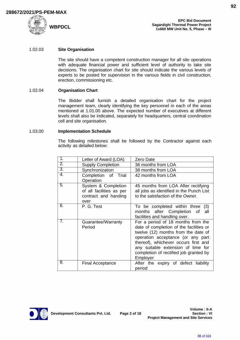
WBPDCL
EPC Bid Document Sagardighi Thermal Power Project
1x660 MW Unit No. 5, Phase – III
Development Consultants Pvt. Ltd.
Page 2 of 18
Volume : II-ASection : VI
Project Management and Site Services
1.02.03 Site Organisation The site should have a competent construction manager for all site operations
with adequate financial power and sufficient level of authority to take site decisions. The organisation chart for site should indicate the various levels of experts to be posted for supervision in the various fields in civil construction, erection, commissioning etc.
1.02.04 Organisation Chart The Bidder shall furnish a detailed organisation chart for the project
management team, clearly identifying the key personnel in each of the areas mentioned at 1.01.00 above. The expected number of executives at different levels shall also be indicated, separately for headquarters, central coordination cell and site organisation.
1.03.00 Implementation Schedule
The following milestones shall be followed by the Contractor against each activity as detailed below:
1. Letter of Award (LOA)
Zero Date 2. Supply Completion
36 months from LOA 3. Synchronization
38 months from LOA 4. Completion of Trial
Operation
42 months from LOA
5. System & Completion of all facilities as per contract and handing over
45 months from LOA After rectifying all jobs as identified in the Punch List to the satisfaction of the Owner.
6. P. G. Test
To be completed within three (3) months after Completion of all facilities and handling over.
7. Guarantee/Warranty Period
For a period of 18 months from the date of completion of the facilities or twelve (12) months from the date of operation acceptance (or any part thereof), whichever occurs first and any suitable extension of time for completion of rectified job granted by Employer
8. Final Acceptance
After the expiry of defect liability period
86 of 424
288672/2021/PS-PEM-MAX92
WBPDCL
EPC Bid Document Sagardighi Thermal Power Project
1x660 MW Unit No. 5, Phase – III
Development Consultants Pvt. Ltd.
Page 3 of 18
Volume : II-ASection : VI
Project Management and Site Services
1.03.01 Owner’s Engineering Schedules These schedules shall cover various design submissions indicating different
Owner’s Engineering activities to be performed. Such schedules shall be furnished by the Bidder for each and every plant/systems/ equipment/ item covered in the scope of this specification.
1.03.02 Manufacturing Schedule The Contractor shall submit to the Owner’s Engineer his manufacturing and
delivery schedules for all equipment within thirty (30) days from the date of issue of the Letter of Award (LOA). Such schedules shall be in line with the detailed network for all phases of the work of the Contractor. Such schedules shall be reviewed, updated and submitted to the Owner’s Engineer, once in every two months thereafter, by the Contractor. Schedules shall also include the materials and equipment purchased from outside suppliers.
1.03.03 Erection Schedules In order to achieve the overall completion schedule, the Contractor shall
provide the Owner all the information covering erection sequence, testing and commissioning activities. These schedules may be based on the recommended erection procedures and will be subject to discussions/agreements with the Owner subsequent to the award of contract.
1.03.04 The successful Bidder shall have to provide all the above schedules (i.e.
1.03.01, 1.03.02 & 1.03.03) in a tabular form in addition to that in the form of L2 & L3 networks and these shall necessarily include information not limited to the earliest and latest dates for various activities/submissions and also any related constraints. However, the Bidder shall include in his proposal a Level-1 (L-1) network showing the major activities and various milestones to achieve the above mentioned completion schedule.
1.03.05 The Contractor shall provide the Owner the original disc/software for all such
schedules along with requisite no. of copies (as required by the Owner) within an agreed time schedule. This time schedule will be agreed between Owner/Bidder at the time of award of Contract. The Contractor's project management software shall be compatible with that of the Owner and the input data shall be furnished to the Owner in a manner compatible with Owner's project management software, Primavera.
1.04.00 Detailed Responsibilities 1.04.01 Planning & Monitoring a) Planning The Bidder shall prepare a Master Network Schedule in the form of
PERT network consisting of at least 500 activities.
87 of 424
288672/2021/PS-PEM-MAX93

WBPDCL
EPC Bid Document Sagardighi Thermal Power Project
1x660 MW Unit No. 5, Phase – III
Development Consultants Pvt. Ltd.
Page 4 of 18
Volume : II-ASection : VI
Project Management and Site Services
The network shall be prepared on a Work Breakdown Structure for the
project which sub-divides the project into a set of manageable systems/sub-systems. The master network will identify milestones of key events for each system/package in the areas of Owner’s Engineering, procurement, manufacture and despatch and erection and commissioning. The master network shall represent the Level-I plan and will form the basis for development of detailed second and third tier execution plans. The master network shall conform to the overall schedule prescribed by Owner.
The master network should be submitted along with the bid, which
would be mutually discussed and finalised before the Award of Contract. This master network would clearly indicate the responsibility of the Bidder and project management team. This master network would form a part of the contract. The master network shall also identify a complete list of inputs to be furnished by the Owner which may be required for proper interfacing and tie-up. Scheduled dates for providing such inputs shall also be indicated, which will be mutually discussed and finalised.
b) Monitoring & Progress Reporting The progress reports would be emanated every month, one from the
head office of the Contractor and another from the site office. The progress report emanating from the head office should necessarily include the following sections:
i) Report on key milestones. ii) Management summary indicating critical areas with details of
actions initiated and effect of any on the project. iii) Action needing attention of the Owner/Consultant. iv) Detailed package wise status of Owner’s Engineering
submissions, quality plan submissions and approval, procurement manufacture and despatch.
The monthly report generated from the site office should necessarily
include: i) Report on key milestones. ii) Management summary indicating critical areas with details of
actions initiated and effect if any on the project. iii) Action needing attention of the Owner/Consultant.
88 of 424
288672/2021/PS-PEM-MAX94
WBPDCL
EPC Bid Document Sagardighi Thermal Power Project
1x660 MW Unit No. 5, Phase – III
Development Consultants Pvt. Ltd.
Page 5 of 18
Volume : II-ASection : VI
Project Management and Site Services
iv) This report would also cover the areas pertaining to the receipt of the equipment at the port, port clearance, transport, receipt at site, erection and commissioning.
In addition to the above, as the project execution progresses, the
Contractor shall also be responsible for generating more frequent reports in the form of fax/e-mail information on progress in critical areas so that actions can be expedited. The exact format of the progress report shall be finalised after award of Contract.
1.04.02 Owner’s Engineering Management Based on the master network for the project (L-1) the Contractor will prepare an
exhaustive list of Owner’s Engineering activities for the equipment/systems covered in his scope and a detailed programme of accomplishing the same within the time frame specified in the master network. This schedule will form the Level-2 (L-2) network for Owner’s Engineering activities.
Based on (L-2) network, the Bidder shall further develop the Level-3 (L-3)
network for Owner’s Engineering activities which will indicate schedule for data availability, drawing release date and document submission dates.
Detailed (L-2) and (L-3) networks would be submitted sequentially by the
Contractor within two months from the date of issue of Letter of Award and finalised within one (1) month thereafter.
All such networks shall be provided in MS PROJECT software. The Owner’s Engineering management team should also co-ordinate all
interface Owner’s Engineering activity between the Contractor and the equipment sub-vendors so as to ensure the correctness and completeness of related Owner’s Engineering documentation before the same is submitted to the Owner.
1.04.03 Contracts Management Based on the master network, the Contractor shall submit L-2 programmes of
manufacture and despatch. In addition, the master network shall also include periods considered for site activities viz. erection, commissioning etc. These L-2 programmes would be submitted in 2 months time from the date of award of contract and finalised within one (1) month thereafter. The Contractor will also submit site mobilisation plan. This programme would be submitted at the time of finalisation of award of contract and agreed immediately thereafter so that immediate development of the various activities at site could take place.
The Contractor should also submit L-3 programmes for the manufacturing,
despatch of the various items. These networks shall also show the customer hold points (CHP) which have to be cleared by Owner or their authorised representative(s) before further manufacturing can take place. These L-3 programmes for the manufacture and despatch would clearly identify responsibilities of the Contractor, sub-Contractor and Owner. These networks
89 of 424
288672/2021/PS-PEM-MAX95

WBPDCL
EPC Bid Document Sagardighi Thermal Power Project
1x660 MW Unit No. 5, Phase – III
Development Consultants Pvt. Ltd.
Page 6 of 18
Volume : II-ASection : VI
Project Management and Site Services
shall be submitted within one (1) month of the date of finalisation of the various sub-contracts by the Contractor.
In case all the manufacture is being done by the Contractor then the L-2
programmes would be themselves amplified to cover details of the manufacture, inspection, clearance by Owner and despatch.
The Contractor shall also submit the programme for procurement of bought out
items, detailed shipping schedule and cash flow statement for Owner's approval.
1.04.04 Quality Assurance, Inspection and Expediting The Contractor shall submit the list of manufacturers/sub-vendors from whom
the equipment are expected to be procured and the quality assurance plans thereof for the manufacture shall be approved by the QA group of Owner before the manufacturing is commenced. The list of major suppliers would be submitted along with the bid and this shall be mutually discussed and approval will be given by the Owner during contract negotiation meeting prior to placement of Letter of Award. This approved list will be binding to the bidder. In the said list, Owner reserves the right to include reputed/reliable vendors of his own choice. Regarding the various other sub-vendors, the list would be submitted within six (6) months of the award of the contract that shall be scrutinized by the Owner to accord approval. In such list Owner reserves the right to include vendors of his own choice. No further vendor approval will be given after six (6) months. On the quality plans, the customer hold points will also be identified based on which Owner would give clearance for the manufacture to proceed further.
Quality assurance/Inspection group of Owner or its representative would issue
a material despatch clearance certificate (MDCC) after the inspection clearance which will enable the Contractor to despatch the equipment and claim the payment. In the despatch programme, the Contractor shall indicate a schedule of estimated programme, tonnages specifically identifying various oversize dimensioned consignments (ODC). Further the Contractor will also be required to ensure at all stages of shipment that packing of all shipments despatched are suitable for ocean freight to India, handling at the port of entry, inland transportation and preservation at site up to erection. All despatch details & item lists shall be made available to both Owner & site immediately after shipping.
The Contractor shall also expedite all despatches from their own works/works
of their sub-vendors, so as to match with the various activities mentioned at 1.04.03 above.
1.04.05 Construction Management Based on the L-1 Master Network Programme, within two (2) months of the
issue of Letter of Award, the Contractor shall submit a programme of construction/erection/commissioning, either in continuation with the manufacture and despatch or separately for the implementation. These
90 of 424
288672/2021/PS-PEM-MAX96
WBPDCL
EPC Bid Document Sagardighi Thermal Power Project
1x660 MW Unit No. 5, Phase – III
Development Consultants Pvt. Ltd.
Page 7 of 18
Volume : II-ASection : VI
Project Management and Site Services
programmes would be amplified showing when the civil drawings shall be released by him and construction of civil works shall be completed by him to facilitate start of erection and subsequent activities and shall form the basis for site execution and detailed monitoring. The three monthly rolling programme with the first month's programme being tentative based on the site conditions would be prepared based on these L-3 programmes. The Contractor shall also be involved along with the Owner to tie up detailed resource mobilisation plan over the period of time of the contract matching with the performance targets.
The L-3 programme would be jointly finalised by the site in-charge of the
Contractor with the Owner's project coordinator as well as the site planning representative. The erection programme will also identify the sequential erectable tonnages that are required for various equipment which should be taken care of in the despatch programmes.
Erection and commissioning of the equipment shall also be done under the
supervision of experts from the respective equipment/ system supplier. 1.04.06 Spares Management Along with the proposal for the plant and equipment, the Contractor shall also
submit proposals/schedule for the following: a) Mandatory spares b) Recommended spares While the award for mandatory spares will be finalised at the time of the award
of contract, recommended spares will be finalised within twelve (12) months thereafter.
1.05.00 Project Progress Review Meetings Keeping in mind the overall responsibility of the Contractor it is intended that
periodic progress reviews on the entire activities of execution in respect of Sagardighi Thermal Power Plant unit #5 will be held initially at least once in two (2) months at Kolkata/site. During peak period it may be held once in a month. These meetings will be attended by reasonably higher officials of the Contractor and their leading sub- contractors and will be used as a forum for discussing all areas where progress needs to be speeded up. Actions will be placed on the concerned agencies and decisions will be taken to expedite/speed up the progress. Minutes of such meetings will be issued reflecting the major discussions and decisions taken and circulated to all concerned for reference and action. The Contractor shall be further responsible for ensuring that suitable steps are taken to meet various targets decided upon such meetings.
In addition to the above, and to streamline the construction and erection at site,
a suitable frequency and forum of periodic meetings between the Contractor and the Owner will be decided upon as part of erection coordination procedure. Site co-ordination meeting may be held on weekly basis.
91 of 424
288672/2021/PS-PEM-MAX97
WBPDCL
EPC Bid Document Sagardighi Thermal Power Project
1x660 MW Unit No. 5, Phase – III
Development Consultants Pvt. Ltd.
Page 8 of 18
Volume : II-ASection : VI
Project Management and Site Services
1.06.00 Owner's Consultant The Owner would appoint a consultant to assist him in some of the areas
mentioned at 1.01.00 above. The details of interaction and procedures for coordination between Owner/Owner's Consultant and Contractor/Contractor's project management team shall be finalised during contract negotiations.
1.07.00 Commissioning Management 1.07.01 For commissioning of the various equipment/system covered under the scope
of contract, Owner will form an organisation structure which may consist of the following committees. The Contractor shall nominate his representative on one or more of the committee as decided by the Owner:
a) Commissioning Teams. b) Testing Teams. 1.07.02 Commissioning documents shall be prepared by the Contractor in the following
manner and submitted for Owner's approval : a) Paper of Principle This document shall be prepared for the various equipment/ systems
under commissioning and shall have the following objectives to fulfill and shall be submitted for Owner's approval at least six (6) months before their actual commissioning :
i) Establish design data against which Plant Performance will be
compared. ii) Set-out the testing objectives and proposals. iii) Define the documentation required. b) Testing/Commissioning Schedule These shall be prepared for the various equipment/systems under
consideration and shall contain sections like detailed testing method, programme, safety, individual responsibility and results.
c) Standard Check Lists Standard checklists are intended for use at the completion of erection to
ensure correct erection, testing and to a limited extent operation for repetitive items.
92 of 424
288672/2021/PS-PEM-MAX98
WBPDCL
EPC Bid Document Sagardighi Thermal Power Project
1x660 MW Unit No. 5, Phase – III
Development Consultants Pvt. Ltd.
Page 9 of 18
Volume : II-ASection : VI
Project Management and Site Services
1.07.03 Test Reports After the completion of commissioning activity of equipment/ systems, the
Contractor shall prepare the test reports which shall include all the relevant information related to various commissioning checks, tests carried out, any deviations/commissions noticed with respect to the intended design requirements, sequence of various commissioning activities as actually adopted vis-à-vis as recommended in the procedures, programme schedules achieved and any other such information as required. These test reports shall be submitted in requisite number of copies to the Owner and this should be duly signed jointly by the Owner/Consultant and the Contractor/Equipment supplier, who are involved during the commissioning activities.
2.00.00 SITE SERVICES These services shall be rendered by the Bidder as part of the overall project
management service. The services shall broadly include but not be limited to the following :
2.01.00 Arranging material despatch from the shop by rail/road and/or sea as
applicable. 2.02.00 Monitoring movement of materials & follow-up as necessary with Railways,
road transport, port clearance etc. from the time of despatch F.O.R. works/F.O.B. port of shipment by Contractor till receipt of the same at site.
2.03.00 Unloading of materials at Railway Station/Railway Siding inside project area,
transportation to site store, assessment of lost/damaged items in transit and arranging insurance claims and replacement of lost/damaged items. The Contractor shall submit to the Owner’s Engineer a report detailing all the receipts during the week.
2.04.00 Issuing materials from site store/open yard from time to time for erection as per
the construction programme. The Contractor shall be the custodian of all the materials issued till the plant is officially taken over by the Owner after complete erection and successful trial run & commissioning.
2.05.00 Transportation of materials to their respective places of erection and erection of
the complete plant & equipment as supplied under this specification. 2.06.00 Trial run and commissioning of individual equipment/sub-systems and the plant
as a whole to the satisfaction of the Owner, including supply of temporary equipment & services for chemical cleaning, steam blowing as well as performance guarantee tests.
For Coal Handling Plant, satisfactory operation of the system, amongst
others, shall consist of operation without spillage or choking anywhere even during monsoon.
93 of 424
288672/2021/PS-PEM-MAX99
WBPDCL
EPC Bid Document Sagardighi Thermal Power Project
1x660 MW Unit No. 5, Phase – III
Development Consultants Pvt. Ltd.
Page 10 of 18
Volume : II-ASection : VI
Project Management and Site Services
Provision for preservation of individual equipment after trial run and
commissioning e.g. Nitrogen blanketing etc. as necessary shall also be in the scope of the Bidder.
2.07.00 Supply and application of the final paints lubricating oils and all consumable till completion of facilities and hand over.. 2.08.00 For the purpose of erection and commissioning the Contractor's scope of work
shall include but not be limited to the following : 2.08.01 Deployment of all skilled and unskilled manpower required for erection,
supervision of erection, watch & ward, commissioning and other services to be rendered under this specification.
2.08.02 Deployment of all erection tools & tackle, construction machinery,
transportation vehicles and all other implements in adequate number and size, appropriate for the erection work to be handled under the scope of this specification.
Supply of commissioning spares. 2.08.03 Supply of all chemicals and consumables, e.g. Regeneration chemicals, alum,
lime, polyelectrolyte, resin, welding electrodes, cleaning agents, diesel oil, grease, lubricant etc. as well as materials required for temporary supports, scaffolding etc. as necessary for such erection commissioning work till completion of facilities and hand over, except those listed under exclusion elsewhere in this specification.
2.08.04 Construction of all civil/structural/architectural works, including construction of
foundation for all equipment supplied as required, grouting of equipment on foundation after alignment, and all other incidental civil activities as detailed elsewhere.
2.08.05 All structural steel fabrication and erection work as detailed elsewhere in the
specification. 2.08.06 Providing support services for the Contractor's erection staff e.g. construction of
site offices, temporary stores, residential accommodation and transport to work site for erection personnel, insurance cover, watch & ward for security and safety of the materials under the Contractor's custody etc. as required.
2.08.07 Maintaining proper documentation of all the site activities undertaken by the
Contractor as per the proforma mutually agreed with the Owner; submitting monthly progress reports as also any such document as and when desired by the Owner; taking approval of all statutory authorities e.g. Boiler Inspector, Factory Inspector, Inspector of Explosives etc. for respective portions of work under the jurisdiction of such statutes or laws.
2.08.08 The Contractor shall provide `Industrial Relations' unit and `Medical' unit to take
care of his erection staff and the Owner shall have no obligation in this regard.
94 of 424
288672/2021/PS-PEM-MAX100
WBPDCL
EPC Bid Document Sagardighi Thermal Power Project
1x660 MW Unit No. 5, Phase – III
Development Consultants Pvt. Ltd.
Page 11 of 18
Volume : II-ASection : VI
Project Management and Site Services
2.09.00 Site Organisation The Contractor shall maintain a site organisation of adequate strength in
respect of manpower, construction machinery and other implements at all times for smooth execution of the contract. This organisation shall be reinforced from time to time, as required, to make up for slippages from the schedule without any commercial implication to the Owner. The site organisation shall be headed by a competent construction manager having sufficient authority to take decisions at site.
On award of contract, the Contractor shall submit to the Owner a site
organisation chart indicating the various levels of experts to be deployed on the job. The Owner reserves the right to reject or approve the list of personnel proposed by the Contractor. The persons, whose bio-data have been approved by the Owner, will have to be posted at site and deviations in this regard will not generally be permitted.
The Contractor shall also submit to the Owner for approval a list of construction
equipment, erection tools, tackle etc. prior to commencement of site activities. These tools & tackle shall not be removed from site without written permission of the Owner.
2.10.00 General Guidelines for Field Activities 2.10.01 The Contractor shall execute the works in a professional manner so as to
achieve the target schedule without any sacrifice on quality and maintaining highest standards of safety and cleanliness.
2.10.02 The Contractor shall co-operate with the Owner and other Contractors working
in site and arrange to perform his work in a manner so as to minimise interference with other Contractors' works. The Owner's Owner’s Engineer shall be notified promptly of any defect in other Contractor's works that could affect the Contractor's work. If rescheduling of Contractor's work is requested by the Owner's Owner’s Engineer in the interest of overall site activities, the same shall be complied with by the Contractor. In all cases of controversy, the decision of the Owner shall be final and binding on the Contractor without any commercial implication to owner.
2.10.03 The Owner’s Engineer shall hold weekly meetings of all the Contractors
working at Site at a time and a place to be designated by the Owner’s Engineer. The Contractor shall attend such meetings and take notes of discussions during the meeting and the decisions of the Owner’s Engineer and shall strictly adhere to those decisions in performing his Work. In addition to the above weekly meeting, Owner’s Engineer may call for other meetings either with individual contractors or with selected number of contractors and in such a case the Contractor, if called will also attend such meetings.
2.10.04 Time is the essence of the Contract and the Contractor shall be responsible for
performance of his Work in accordance with the specified construction schedule. If at any time the Contractor is falling behind the schedule, he shall
95 of 424
288672/2021/PS-PEM-MAX101
WBPDCL
EPC Bid Document Sagardighi Thermal Power Project
1x660 MW Unit No. 5, Phase – III
Development Consultants Pvt. Ltd.
Page 12 of 18
Volume : II-ASection : VI
Project Management and Site Services
take necessary action to make good of such delays by increasing his work force or by working overtime or otherwise accelerate the progress of the work to comply with the schedule and shall communicate such action in writing to the Owner’s Engineer, satisfying that his action will compensate for the delay. The Contractor shall not be allowed any extra compensation for such action.
2.10.05 The Owner’s Engineer shall however not be responsible for provision of
additional labour and or materials or supply or any other services to the Contractor except for the co-ordination work between various Contractors as set out earlier.
2.10.06 The works under execution shall be open to inspection & supervision by the
Owner's Owner’s Engineer at all times. The Contractor shall give reasonable notice to the Owner before covering up or otherwise placing beyond the reach of inspection any work in order that same may be verified, if so desired by the Owner.
2.10.07 Every effort shall be made to maintain the highest quality of workmanship by
stringent supervision and inspection at every stage of execution. Manufacturer's instruction manual and guidelines on sequence of erection and precautions shall be strictly followed. Should any error or ambiguity be discovered in such documents, the same shall be brought to the notice of the Owner's Owner’s Engineer. Manufacturer's interpretation in such cases shall be binding on the Contractor.
2.10.08 The Contractor shall comply with all the rules and regulations of the local
authorities, all statutory laws including Minimum Wages, Workmen Compensation etc. The contractor shall engage maximum number of local unskilled and semi skilled labours for construction works. All registration and statutory inspection fees, if any, in respect of the work executed by the Contractor shall be to his account.
2.10.09 All the works such as cleaning, checking, leveling, blue matching, aligning,
assembling, temporary erection for alignment, opening, dismantling of certain equipments for checking and cleaning, surface preparation, edge preparation, fabrication of tubes and pipes as per general Owner’s Engineering practice at site, cutting grinding, straightening, chamfering, filling, chipping, drilling, reaming, scrapping, shaping, fitting-up bolting/welding, etc., as may be applicable in such erection and are necessary to complete the work satisfactorily, are to be treated as incidental and the same shall be carried out by the Contractor as part of the work.
2.10.10 In case of any class of work for which there is no such specification as laid
down in the contract such as, blue matching, welding of stainless steel parts, etc., the work shall be carried out in accordance with the instructions and requirements of the Owner’s Engineer.
2.10.11 It may sometimes be necessary to remove some of the erected structural
members to facilitate erection of bigger/pre-assembled equipment. In such cases, the removal and re-erection of such members, which are essential, and if so agreed by the Owner’s Engineer, will have to be done by the Contractor.
96 of 424
288672/2021/PS-PEM-MAX102
WBPDCL
EPC Bid Document Sagardighi Thermal Power Project
1x660 MW Unit No. 5, Phase – III
Development Consultants Pvt. Ltd.
Page 13 of 18
Volume : II-ASection : VI
Project Management and Site Services
2.10.12 Attachment welding of necessary instrumentation tapping points, thermocouple
pads, root valves, condensing vessels, flow nozzles and control valves etc., both for regular measurement and performance testing to be provided on equipment, its auxiliaries or pipelines covered within the scope of this tender, will also be the responsibility of the Contractor and the same will be done as per the instructions of Owner’s Engineer. The erection and welding of all above items will be the Contractor's responsibility, even if :
a) Product groups under which these items are re-leased are not covered
in the scope of this tender. b) Items are supplied by an agency other than the Contractor. 2.10.13 Preservation of all materials/equipment under custody of the Contractor during
storage, pre-assembly & erection, commissioning etc., shall be the responsibility of the Contractor. All necessary preservatives and consumables like paints, etc., shall be arranged by the Contractor. Necessary touch up painting, periodic application of preservatives/paints on pressure parts/other equipment even after erection until completion of work shall be carried out by the Contractor. The Contractor shall fabricate piping, install lub oil systems and carry out the acid cleaning of fabricated piping. The Contractor shall also service the lub oil system, carryout the hydraulic test of oil coolers, etc.
2.10.14 It is responsibility of the Contractor to do the alignment etc. if necessary,
repeatedly to satisfy Owner’s Engineer, with all the necessary tools & tackles, manpower, etc. The alignment will be complete only when jointly certified so, by the Contractor's Owner’s Engineer & Owner. Also the Contractor should ensure that the alignment is not disturbed afterwards.
2.10.15 Additional platforms for approaching different equipment as per site
requirement, which may not be indicated in drawings, shall be fabricated and erected by the Contractor. The materials required for these works shall be supplied by the Contractor and he will have to fabricate them to suit the requirement.
2.10.16 Equipment and material, which are wrongly installed, shall be removed and
reinstalled to comply with the design requirement at the Contractor's expense, to the satisfaction of the Owner/ Consultant.
2.10.17 Before erection of any equipment on a foundation, the Contractor shall check
and undertake if necessary rectification of foundation bolts, reaming of holes, drilling of dowels, matching of bolts and nuts, making new dowel pin, etc.
2.10.18 Assistance for calibrating/testing the power cylinders, valves, gauges, instruments, etc., and setting of actuators coming under various groups shall be provided by Contractor.
2.10.19 It shall be the responsibility of the Contractor to provide ladders on columns for
initial works till such time stairways are completed. For this, the ladder should not be welded on the column and should be prefabricated clamping type. No
97 of 424
288672/2021/PS-PEM-MAX103
WBPDCL
EPC Bid Document Sagardighi Thermal Power Project
1x660 MW Unit No. 5, Phase – III
Development Consultants Pvt. Ltd.
Page 14 of 18
Volume : II-ASection : VI
Project Management and Site Services
temporary welding on any structural member is permitted except under special circumstances with the approval of Owner.
2.10.20 Structural materials required for the supporting/operating platforms required for
the valves at various levels for the safe operation of valves will be arranged by the Contractor.
2.10.21 For civil, structural and architectural works, volume IIG/1 & IIG/2 may be
referred. For Instrumentation and Electrical works Vol. IIE and Vol. IIF1 & F2 may be referred.
2.11.00 Safety 2.11.01 Safety and overall cleanliness of work site shall be given top priority. The
Contractor shall ensure the safety of all workmen, materials and equipment either belonging to him or to others working at site. He shall observe safety rules & codes applied by the Owner at site without exception.
2.11.02 The Contractor shall notify the Owner of his intention to bring to site any
equipment or material which may create hazard. The Owner shall have the right to prescribe the conditions under which such equipment or material may be handled and the Contractor shall adhere to such instructions. The Owner may prohibit the use of any construction machinery, which according to him is unsafe. No claim for compensation due to such prohibition will be entertained by the Owner.
2.11.03 Storage of petroleum products & explosives for construction work shall be as
per rules and regulation laid down in Petroleum Act, Explosive Act and Petroleum and Carbide of Calcium Manual. Approvals as necessary from Chief Inspector of Explosives or other statutory authorities shall be the responsibility of the Contractor.
2.11.04 The Contractor shall be responsible for safe storage of his and his
sub-contractor's radioactive sources. 2.11.05 All requisite tests & inspection of handling equipment, lifting tools & tackle shall
be periodically done by the Contractor. Defective equipment shall be removed from service. Any equipment shall not be loaded in excess of its recommended safe working load.
2.11.06 All combustible waste and rubbish shall be collected and removed from the
worksite at least once each day. Use of undercoated canvas paper, corrugated paper, fabricated carton, plastic or other flammable materials shall be restricted to the minimum and promptly removed.
2.11.07 The Contractor shall provide adequate number of fire protection equipment of
the required types for his stores, office, temporary structures, labour colony etc. Personnel trained for fire-fighting shall be made available by the Contractor at site during the entire period of the Contract.
98 of 424
288672/2021/PS-PEM-MAX104
WBPDCL
EPC Bid Document Sagardighi Thermal Power Project
1x660 MW Unit No. 5, Phase – III
Development Consultants Pvt. Ltd.
Page 15 of 18
Volume : II-ASection : VI
Project Management and Site Services
2.11.08 All electrical appliances used in the work shall be in good working condition and
shall be properly earthed. No maintenance work shall be carried out on live equipment. The Contractor shall maintain adequate number of qualified electricians to maintain his temporary electrical installation.
2.11.09 All workmen of the Contractor working in construction site shall wear safety
helmets, safety boots and safety belts. The Contractor shall take appropriate insurance cover against accidents for his workmen as well as third party.
2.11.10 All the worksites shall be provided with adequate lighting facilities e.g. flood
lighting, hand lamps, area lighting etc. by the Contractor for proper working environment during night times.
2.11.11 Adequate number of temporary toilets/urinals (men & women separate) shall be
provided at work places with soak pits. Adequate drinking water facilities and rest rooms shall be provided for workers to take food and rest.
2.11.12 All safety precautions shall be taken for welding and cutting operations as per
IS-818. 2.11.13 All safety precautions shall be taken for foundation and other excavation marks
as per IS-3764. 2.12.00 Taking Delivery & Storage 2.12.01 The Contractor shall arrange issue of all equipment and materials to be erected
under the contract from the stores/open yard at site by signing on standard indent forms. After completion of work, detailed auditing of the materials so issued shall be submitted to the Owner.
2.12.02 The Contractor shall arrange for proper and safe storage of materials till the
same are taken over by the Owner as per terms of the contract. Manufacturer's instructions for preservation shall be strictly followed.
2.12.03 All empty containers, packing materials, gunny bags, transport frames and also
surplus and unused materials reconciliation prior to completion of contract shall be the property of the Owner and returned to the Owner by the Contractor.
2.13.00 Site Welding & Heat Treatment 2.13.01 Welding shall be done in accordance with IS-813, IS-816, IS-9595 & other
relevant IS/International standards and as per instructions of Contractor. Only those welders, who are qualified as per IS-817 for ordinary welds and as per IBR/ASME Section-IX for high pressure welds, shall be employed in the job.
2.13.02 All welders shall be tested and approved by Owner’s Engineer before they are
actually engaged on the work even though they may possess the requisite certificates. The Owner reserves the right to reject any welder without assigning any reason. The welder identification code as approved by the Owner’s Engineer shall be stamped by the welder on each joint done by them. The
99 of 424
288672/2021/PS-PEM-MAX105
WBPDCL
EPC Bid Document Sagardighi Thermal Power Project
1x660 MW Unit No. 5, Phase – III
Development Consultants Pvt. Ltd.
Page 16 of 18
Volume : II-ASection : VI
Project Management and Site Services
Contractor will be responsible for the periodic renewal, re-testing of the welders as demanded by Owner.
2.13.03 The Owner’s Engineer is entitled to stop Contractor's any welder from his work
if his work is unsatisfactory for any technical reason or there is a high percentage of the rejection of joints welded by him, which in the opinion of Owner’s Engineer will adversely affect the quality of welding even though the welder has earlier passed the tests. The welders having passed the tests do not relieve the Contractor from his contractual obligations, to check the performance of the welders.
2.13.04 All charges for testing of welders including destructive and non- destructive
tests if conducted by Owner or by the inspection authority at site shall have to be borne by the Contractor. The necessary test materials and consumables will have to be arranged by the Contractor and all testing facility made available, as required.
2.13.05 All welded joints shall be subject to acceptance by Owner’s Engineer.
Inspection of welds shall be in accordance with IS-822 or equivalent code. 2.13.06 Preheating/post-heating and stress relieving after welding are part of fabrication
and erection work and shall be performed by the Contractor in accordance with the instruction of Owner’s Engineer. Contractor shall arrange to supply heating equipment with automatic recording devices. Also the Contractor shall have to arrange for the labour, heating elements, thermocouples, compensating cables, insulation materials like mineral wools, asbestos cloth, ceramic beads, asbestos rope, etc. required for the heat-treatment and stress relieving works. During pre- heat/stress relieving operations, the temperature shall be measured at one or more points as required by attaching thermocouples and recorded on a continuous printing type recorder. All the record graphs for the heat treatment works carried out shall be got signed by the Owner’s Engineer prior to the commencement of each cycle and handed over to Owner’s Engineer on completion. The graphs will be the property of Owner. The Contractor has to provide thermo-chalks temperature recorders, thermocouple attachments, units, graph sheets, etc. required for the job and maintain them in good condition.
2.13.07 All electrodes shall be baked and dried in the electric/electrode drying oven to
the required temperature and for the period specified by the Owner’s Engineer before they are used in erection work. The electrodes used shall be as per IS-814, IS-815, IS-1442, IS-7280 and other codes as applicable, and shall be of approved reputed manufacture. The electrodes shall meet the requirement of the pipe material. No electrode manufactured more than 12 months ago and the type covered under certificate issued after conducting tests more than 6 months ago shall be used. All electrodes shall be preserved at works and at site as per manufacturer's recommendations.
2.13.08 Oxy-acetylene flame or Exothermic chemical heating for stress relieving is not
permitted. Heating shall be by means, of electric induction coil or electric resistance coil.
100 of 424
288672/2021/PS-PEM-MAX106
WBPDCL
EPC Bid Document Sagardighi Thermal Power Project
1x660 MW Unit No. 5, Phase – III
Development Consultants Pvt. Ltd.
Page 17 of 18
Volume : II-ASection : VI
Project Management and Site Services
2.13.09 It may become necessary to adopt inter layer radiography/MPT/UT depending upon the site/technical requirement necessitating interruptions in continuation of the work and making necessary arrangement for carrying out the above work.
2.13.10 Gas tungsten arc welding process (TIG) shall be adopted for all root pass
welds except for structural works until 4.75 mm thickness is deposited. Subsequent welding after root pass can be carried out by manual metal arc welding with coated electrodes. For pipes of thickness less than 6 mm the entire welding has to be carried out by TIG welding.
Fillet weld shall be made by shielded metal arc process as per applicable
codes. However, the Owner’s Engineer will have the option of changing the method of
welding as per site requirement. The method adopted for manual arc welding shall be weaving technique and the width of weaving shall not exceed 1.5 times of the dia. of the electrode.
In case of deviation from welding process and electrodes, the Contractor shall
take approval of the Owner prior to adoption of same. 2.13.11 The root pass for butt joints shall be such as to achieve full penetration with
complete fusion of root edges. 2.13.12 Each pass shall be cleared and freed of slag before the next pass is deposited. 2.13.13 On completion of each run, craters, weld irregularities, slag etc. shall be
removed by grinding or chipping. 2.13.14 Each layer of welding shall have an even and smooth appearance. 2.13.15 Welding sequence shall be adjusted in such a way that distortion due to
welding shrinkage is minimised. Further any movement, shock or vibration during welding shall be avoided to prevent weld cracks.
2.13.16 Proper protection of welders and the work shall be taken during periods of rain.
No welding shall be carried out when surfaced to be welded are wet from any cause.
2.13.17 Following will be stages of inspection during welding: a) Two pieces to be joined shall be individually checked for the weld edge
preparation and profile dimensionally and to the template. Dye penetrant check shall be carried out on edge prepared surfaces at random. The percentage will depend upon on criticality as specified by Owner’s Engineer.
b) Joint fit up will be a stage of inspection. Misalignment after fit up may
vary from 0.3 mm to 1.6 mm depending on outside diameter and thickness.
101 of 424
288672/2021/PS-PEM-MAX107
WBPDCL
EPC Bid Document Sagardighi Thermal Power Project
1x660 MW Unit No. 5, Phase – III
Development Consultants Pvt. Ltd.
Page 18 of 18
Volume : II-ASection : VI
Project Management and Site Services
c) All joints shall be offered for visual inspection after root run. Subsequent
welding should be made only after the approval of root run. 2.13.18 All welded joints shall be painted with anti-corrosive paint immediately on
completion of radiography and stress-relieving. 2.14.00 For further details on procedures of work at site on civil, architectural, electrical
and instrumentation & control services, refer Volume: II-E, II-F1 & F2 and II-G/1 G/2 & G/3 of this specification.
3.00.00 PROTECTION AND CARE 3.01.00 All construction and erection activities for this project are to be carried out in the
plant premises. 3.02.00 Generator Stator Lifting may be considered by either of the two options as
mentioned below:
a) With the help of two (2) nos. turbine room cranes.
b) With the help of separate lifting arrangement to be provided by the Bidder from outside the TG building A-row column before the construction of A-row building wall.
102 of 424
288672/2021/PS-PEM-MAX108
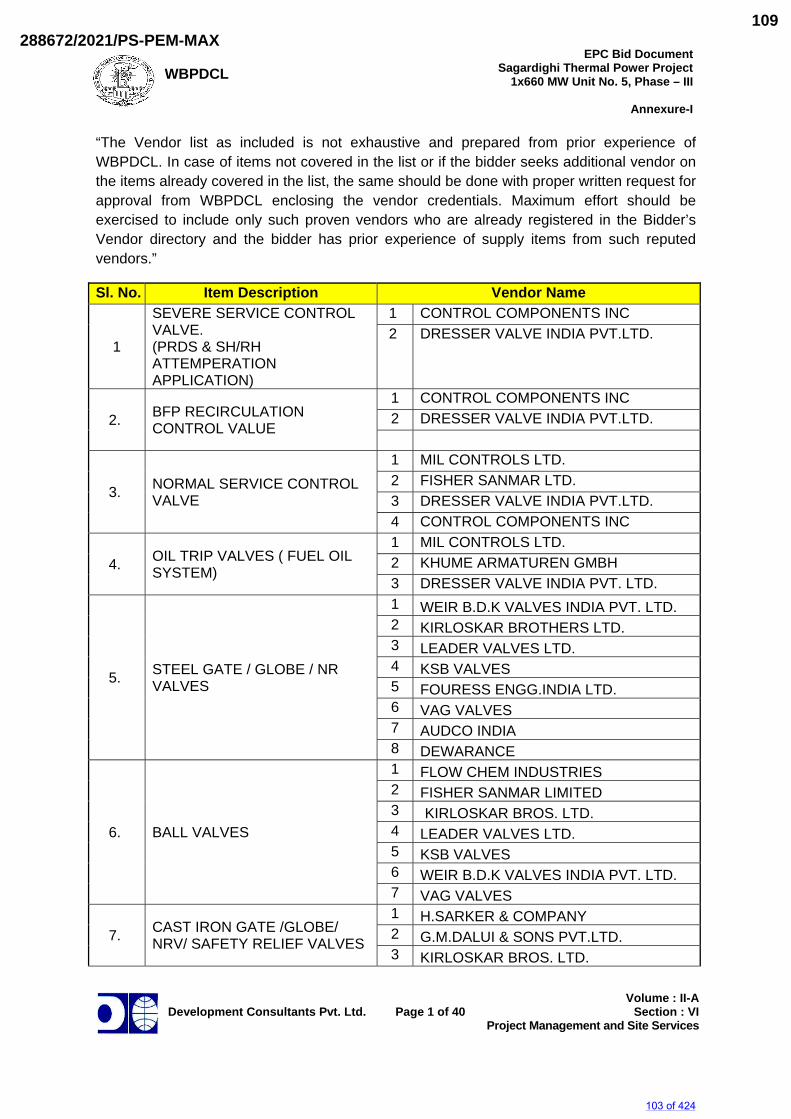
WBPDCL
EPC Bid DocumentSagardighi Thermal Power Project
1x660 MW Unit No. 5, Phase – III
Annexure-I
Development Consultants Pvt. Ltd.
Page 1 of 40
Volume : II-ASection : VI
Project Management and Site Services
“The Vendor list as included is not exhaustive and prepared from prior experience of WBPDCL. In case of items not covered in the list or if the bidder seeks additional vendor on the items already covered in the list, the same should be done with proper written request for approval from WBPDCL enclosing the vendor credentials. Maximum effort should be exercised to include only such proven vendors who are already registered in the Bidder’s Vendor directory and the bidder has prior experience of supply items from such reputed vendors.”
Sl. No. Item Description Vendor Name
1
SEVERE SERVICE CONTROL VALVE. (PRDS & SH/RH ATTEMPERATION APPLICATION)
1 CONTROL COMPONENTS INC 2 DRESSER VALVE INDIA PVT.LTD.
2. BFP RECIRCULATION CONTROL VALUE
1 CONTROL COMPONENTS INC 2 DRESSER VALVE INDIA PVT.LTD.
3. NORMAL SERVICE CONTROL VALVE
1 MIL CONTROLS LTD. 2 FISHER SANMAR LTD. 3 DRESSER VALVE INDIA PVT.LTD. 4 CONTROL COMPONENTS INC
4. OIL TRIP VALVES ( FUEL OIL SYSTEM)
1 MIL CONTROLS LTD. 2 KHUME ARMATUREN GMBH 3 DRESSER VALVE INDIA PVT. LTD.
5. STEEL GATE / GLOBE / NR VALVES
1 WEIR B.D.K VALVES INDIA PVT. LTD. 2 KIRLOSKAR BROTHERS LTD. 3 LEADER VALVES LTD. 4 KSB VALVES 5 FOURESS ENGG.INDIA LTD. 6 VAG VALVES 7 AUDCO INDIA 8 DEWARANCE
6. BALL VALVES
1 FLOW CHEM INDUSTRIES 2 FISHER SANMAR LIMITED 3 KIRLOSKAR BROS. LTD. 4 LEADER VALVES LTD. 5 KSB VALVES 6 WEIR B.D.K VALVES INDIA PVT. LTD. 7 VAG VALVES
7. CAST IRON GATE /GLOBE/ NRV/ SAFETY RELIEF VALVES
1 H.SARKER & COMPANY 2 G.M.DALUI & SONS PVT.LTD. 3 KIRLOSKAR BROS. LTD.
103 of 424
288672/2021/PS-PEM-MAX109
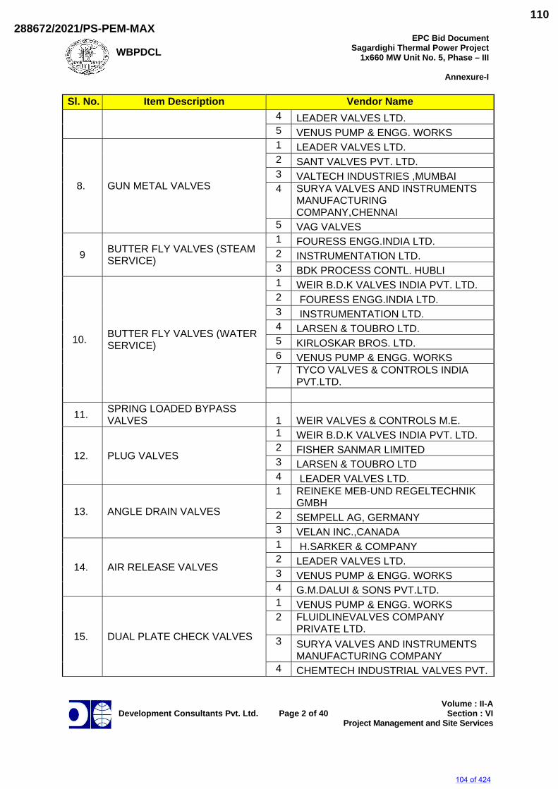
WBPDCL
EPC Bid DocumentSagardighi Thermal Power Project
1x660 MW Unit No. 5, Phase – III
Annexure-I
Development Consultants Pvt. Ltd.
Page 2 of 40
Volume : II-ASection : VI
Project Management and Site Services
Sl. No. Item Description Vendor Name 4 LEADER VALVES LTD. 5 VENUS PUMP & ENGG. WORKS
8. GUN METAL VALVES
1 LEADER VALVES LTD. 2 SANT VALVES PVT. LTD. 3 VALTECH INDUSTRIES ,MUMBAI 4 SURYA VALVES AND INSTRUMENTS
MANUFACTURING COMPANY,CHENNAI
5 VAG VALVES
9 BUTTER FLY VALVES (STEAM SERVICE)
1 FOURESS ENGG.INDIA LTD. 2 INSTRUMENTATION LTD. 3 BDK PROCESS CONTL. HUBLI
10. BUTTER FLY VALVES (WATER SERVICE)
1 WEIR B.D.K VALVES INDIA PVT. LTD. 2 FOURESS ENGG.INDIA LTD. 3 INSTRUMENTATION LTD. 4 LARSEN & TOUBRO LTD. 5 KIRLOSKAR BROS. LTD. 6 VENUS PUMP & ENGG. WORKS 7 TYCO VALVES & CONTROLS INDIA
PVT.LTD.
11. SPRING LOADED BYPASS VALVES 1 WEIR VALVES & CONTROLS M.E.
12. PLUG VALVES
1 WEIR B.D.K VALVES INDIA PVT. LTD. 2 FISHER SANMAR LIMITED 3 LARSEN & TOUBRO LTD 4 LEADER VALVES LTD.
13. ANGLE DRAIN VALVES
1 REINEKE MEB-UND REGELTECHNIK GMBH
2 SEMPELL AG, GERMANY 3 VELAN INC.,CANADA
14. AIR RELEASE VALVES
1 H.SARKER & COMPANY 2 LEADER VALVES LTD. 3 VENUS PUMP & ENGG. WORKS 4 G.M.DALUI & SONS PVT.LTD.
15. DUAL PLATE CHECK VALVES
1 VENUS PUMP & ENGG. WORKS 2 FLUIDLINEVALVES COMPANY
PRIVATE LTD. 3 SURYA VALVES AND INSTRUMENTS
MANUFACTURING COMPANY 4 CHEMTECH INDUSTRIAL VALVES PVT.
104 of 424
288672/2021/PS-PEM-MAX110
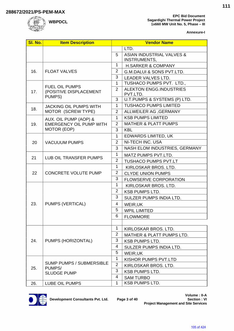
WBPDCL
EPC Bid DocumentSagardighi Thermal Power Project
1x660 MW Unit No. 5, Phase – III
Annexure-I
Development Consultants Pvt. Ltd.
Page 3 of 40
Volume : II-ASection : VI
Project Management and Site Services
Sl. No. Item Description Vendor Name LTD.
5 ASIAN INDUSTRIAL VALVES & INSTRUMENTS,
16. FLOAT VALVES 1 H.SARKER & COMPANY 2 G.M.DALUI & SONS PVT.LTD. 3 LEADER VALVES LTD.
17. FUEL OIL PUMPS (POSITIVE DISPLACEMENT PUMPS)
1 TUSHACO PUMPS PVT. LTD., 2 ALEKTON ENGG.INDUSTRIES
PVT.LTD. 3 U.T.PUMPS & SYSTEMS (P) LTD.
18. JACKING OIL PUMPS WITH MOTOR (SCREW TYPE)
1 TUSHACO PUMPS LIMITED 2 ALLWEILER AG ,GERMANY
19. AUX. OIL PUMP (AOP) & EMERGENCY OIL PUMP WITH MOTOR (EOP)
1 KSB PUMPS LIMITED 2 MATHER & PLATT PUMPS 3 KBL
20 VACUUUM PUMPS 1 EDWARDS LIMITED, UK 2 NI-TECH INC. USA 3 NASH ELOM INDUSTRIES, GERMANY
21 LUB OIL TRANSFER PUMPS 1 MATZ PUMPS PVT.LTD. 2 TUSHACO PUMPS PVT.LT
22 CONCRETE VOLUTE PUMP 1 KIRLOSKAR BROS. LTD. 2 CLYDE UNION PUMPS 3 FLOWSERVE CORPORATION
23. PUMPS (VERTICAL)
1 KIRLOSKAR BROS. LTD. 2 KSB PUMPS LTD. 3 SULZER PUMPS INDIA LTD. 4 WEIR,UK 5 WPIL LIMITED 6 FLOWMORE
24. PUMPS (HORIZONTAL)
1 KIRLOSKAR BROS. LTD. 2 MATHER & PLATT PUMPS LTD. 3 KSB PUMPS LTD. 4 SULZER PUMPS INDIA LTD. 5 WEIR,UK
25. SUMP PUMPS / SUBMERSIBLE PUMPS/ SLUDGE PUMP
1 KISHOR PUMPS PVT.LTD 2 KIRLOSKAR BROS. LTD. 3 KSB PUMPS LTD. 4 SAM TURBO
26. LUBE OIL PUMPS 1 KSB PUMPS LTD.
105 of 424
288672/2021/PS-PEM-MAX111
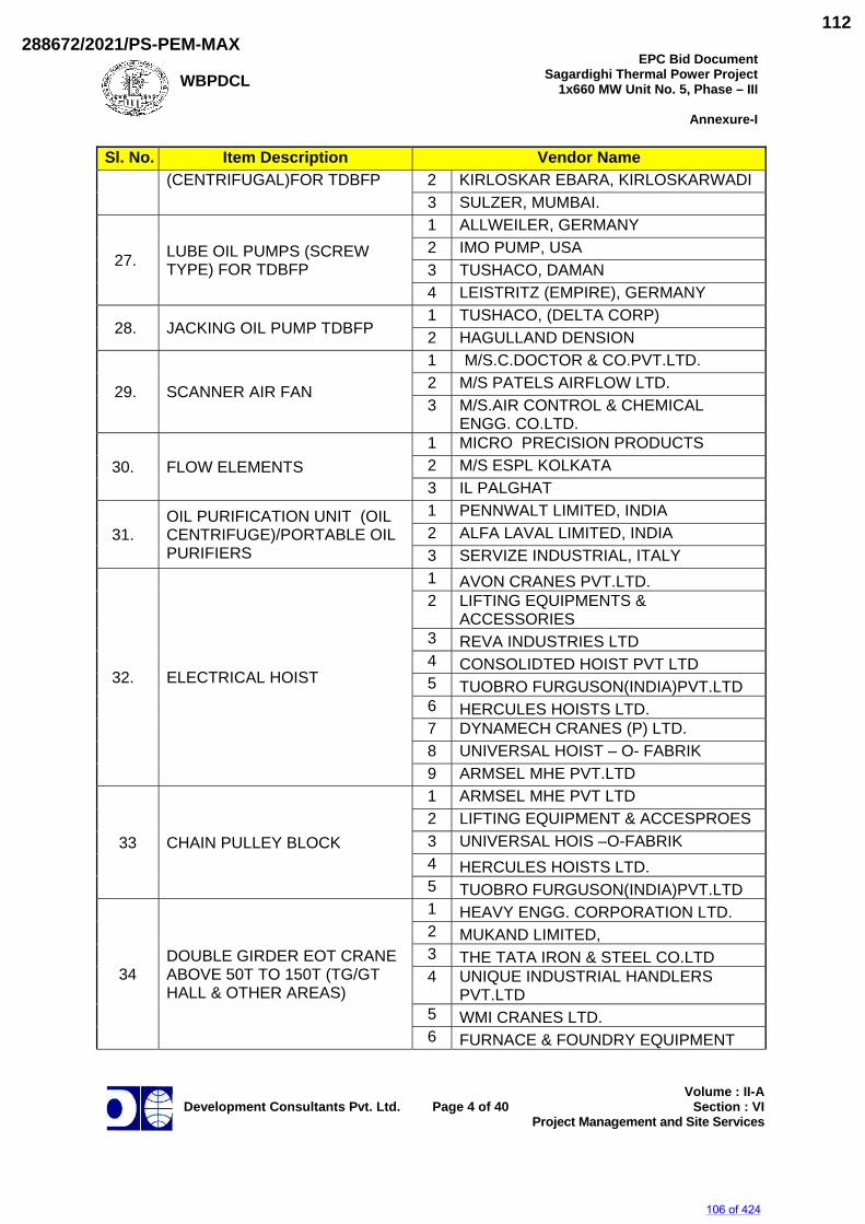
WBPDCL
EPC Bid DocumentSagardighi Thermal Power Project
1x660 MW Unit No. 5, Phase – III
Annexure-I
Development Consultants Pvt. Ltd.
Page 4 of 40
Volume : II-ASection : VI
Project Management and Site Services
Sl. No. Item Description Vendor Name (CENTRIFUGAL)FOR TDBFP 2 KIRLOSKAR EBARA, KIRLOSKARWADI
3 SULZER, MUMBAI.
27. LUBE OIL PUMPS (SCREW TYPE) FOR TDBFP
1 ALLWEILER, GERMANY 2 IMO PUMP, USA 3 TUSHACO, DAMAN 4 LEISTRITZ (EMPIRE), GERMANY
28. JACKING OIL PUMP TDBFP 1 TUSHACO, (DELTA CORP) 2 HAGULLAND DENSION
29. SCANNER AIR FAN
1 M/S.C.DOCTOR & CO.PVT.LTD. 2 M/S PATELS AIRFLOW LTD. 3 M/S.AIR CONTROL & CHEMICAL
ENGG. CO.LTD.
30. FLOW ELEMENTS 1 MICRO PRECISION PRODUCTS 2 M/S ESPL KOLKATA 3 IL PALGHAT
31. OIL PURIFICATION UNIT (OIL CENTRIFUGE)/PORTABLE OIL PURIFIERS
1 PENNWALT LIMITED, INDIA 2 ALFA LAVAL LIMITED, INDIA 3 SERVIZE INDUSTRIAL, ITALY
32. ELECTRICAL HOIST
1 AVON CRANES PVT.LTD. 2 LIFTING EQUIPMENTS &
ACCESSORIES 3 REVA INDUSTRIES LTD 4 CONSOLIDTED HOIST PVT LTD 5 TUOBRO FURGUSON(INDIA)PVT.LTD 6 HERCULES HOISTS LTD. 7 DYNAMECH CRANES (P) LTD. 8 UNIVERSAL HOIST – O- FABRIK 9 ARMSEL MHE PVT.LTD
33 CHAIN PULLEY BLOCK
1 ARMSEL MHE PVT LTD 2 LIFTING EQUIPMENT & ACCESPROES 3 UNIVERSAL HOIS –O-FABRIK 4 HERCULES HOISTS LTD. 5 TUOBRO FURGUSON(INDIA)PVT.LTD
34 DOUBLE GIRDER EOT CRANE ABOVE 50T TO 150T (TG/GT HALL & OTHER AREAS)
1 HEAVY ENGG. CORPORATION LTD. 2 MUKAND LIMITED, 3 THE TATA IRON & STEEL CO.LTD 4 UNIQUE INDUSTRIAL HANDLERS
PVT.LTD 5 WMI CRANES LTD. 6 FURNACE & FOUNDRY EQUIPMENT
106 of 424
288672/2021/PS-PEM-MAX112
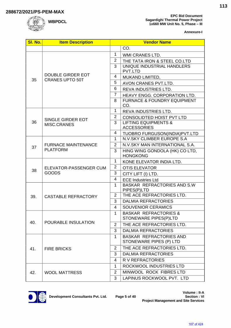
WBPDCL
EPC Bid DocumentSagardighi Thermal Power Project
1x660 MW Unit No. 5, Phase – III
Annexure-I
Development Consultants Pvt. Ltd.
Page 5 of 40
Volume : II-ASection : VI
Project Management and Site Services
Sl. No. Item Description Vendor Name CO.
35 DOUBLE GIRDER EOT CRANES UPTO 50T
1 WMI CRANES LTD. 2 THE TATA IRON & STEEL CO.LTD 3 UNIQUE INDUSTRIAL HANDLERS
PVT.LTD 4 MUKAND LIMITED, 5 AVON CRANES PVT.LTD. 6 REVA INDUSTRIES LTD. 7 HEAVY ENGG. CORPORATION LTD. 8 FURNACE & FOUNDRY EQUIPMENT
CO.
36 SINGLE GIRDER EOT MISC.CRANES
1 REVA INDUSTRIES LTD. 2 CONSOLIDTED HOIST PVT LTD 3 LIFTING EQUIPMENTS &
ACCESSORIES 4 TUOBRO FURGUSON(INDIA)PVT.LTD
37 FURNACE MAINTENANCE PLATFORM
1 N.V.SKY CLIMBER EUROPE S.A 2 N.V.SKY MAN INTERNATIONAL S.A. 3 HING WING GONDOLA (HK) CO LTD,
HONGKONG
38 ELEVATOR-PASSENGER CUM GOODS
1 KONE ELEVATOR INDIA LTD. 2 OTIS ELEVATOR 3 CITY LIFT (I) LTD. 4 ECE Industries Ltd
39. CASTABLE REFRACTORY
1 BASKAR REFRACTORIES AND S.W PIPES(P)LTD
2 THE ACE REFRACTORIES LTD. 3 DALMIA REFRACTORIES 4 SOUVENIOR CERAMICS
40. POURABLE INSULATION
1 BASKAR REFRACTORIES & STONEWARE PIPES(P)LTD
2 THE ACE REFRACTORIES LTD. 3 DALMIA REFRACTORIES
41. FIRE BRICKS
1 BASKAR REFRACTORIES AND STONEWARE PIPES (P) LTD
2 THE ACE REFRACTORIES LTD. 3 DALMIA REFRACTORIES 4 R V REFRACTORIES
42. WOOL MATTRESS 1 ROCKWOOL INDUSTRIES LTD 2 MINWOOL ROCK FIBRES LTD 3 LAPINUS ROCKWOOL PVT. LTD
107 of 424
288672/2021/PS-PEM-MAX113
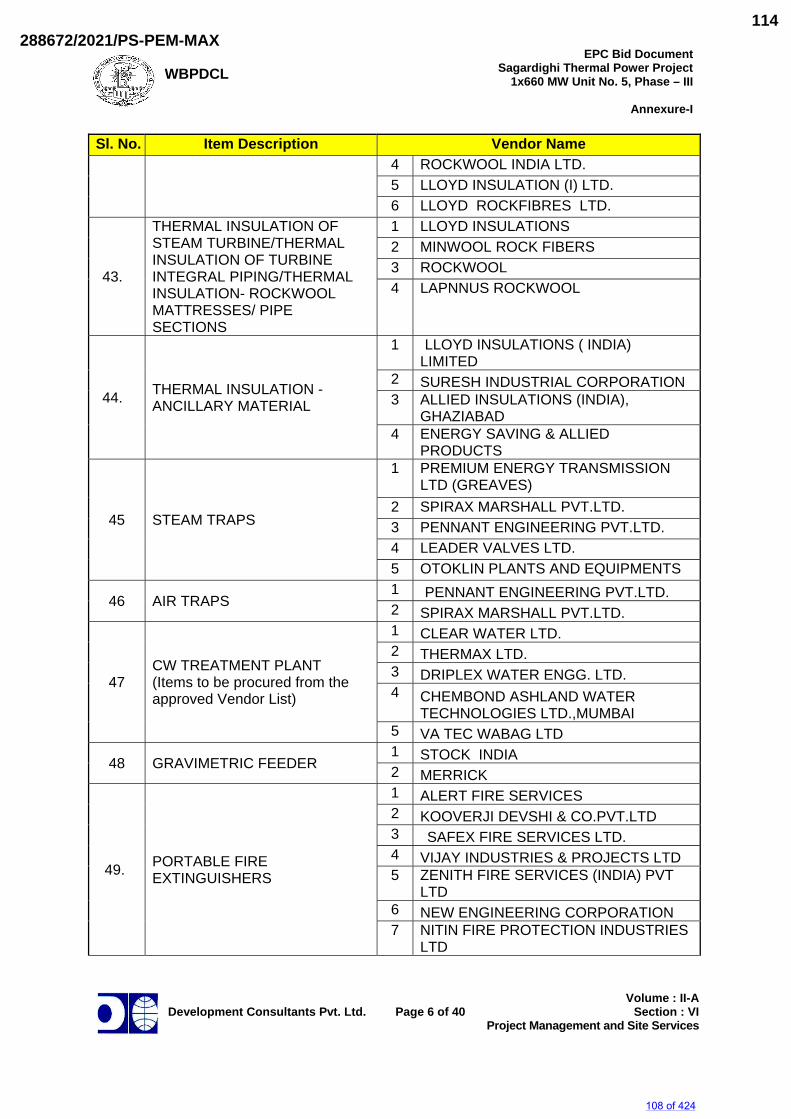
WBPDCL
EPC Bid DocumentSagardighi Thermal Power Project
1x660 MW Unit No. 5, Phase – III
Annexure-I
Development Consultants Pvt. Ltd.
Page 6 of 40
Volume : II-ASection : VI
Project Management and Site Services
Sl. No. Item Description Vendor Name 4 ROCKWOOL INDIA LTD. 5 LLOYD INSULATION (I) LTD. 6 LLOYD ROCKFIBRES LTD.
43.
THERMAL INSULATION OF STEAM TURBINE/THERMAL INSULATION OF TURBINE INTEGRAL PIPING/THERMAL INSULATION- ROCKWOOL MATTRESSES/ PIPE SECTIONS
1 LLOYD INSULATIONS 2 MINWOOL ROCK FIBERS 3 ROCKWOOL 4 LAPNNUS ROCKWOOL
44. THERMAL INSULATION - ANCILLARY MATERIAL
1 LLOYD INSULATIONS ( INDIA) LIMITED
2 SURESH INDUSTRIAL CORPORATION 3 ALLIED INSULATIONS (INDIA),
GHAZIABAD 4 ENERGY SAVING & ALLIED
PRODUCTS
45 STEAM TRAPS
1 PREMIUM ENERGY TRANSMISSION LTD (GREAVES)
2 SPIRAX MARSHALL PVT.LTD. 3 PENNANT ENGINEERING PVT.LTD. 4 LEADER VALVES LTD. 5 OTOKLIN PLANTS AND EQUIPMENTS
46 AIR TRAPS 1 PENNANT ENGINEERING PVT.LTD. 2 SPIRAX MARSHALL PVT.LTD.
47 CW TREATMENT PLANT (Items to be procured from the approved Vendor List)
1 CLEAR WATER LTD. 2 THERMAX LTD. 3 DRIPLEX WATER ENGG. LTD. 4 CHEMBOND ASHLAND WATER
TECHNOLOGIES LTD.,MUMBAI 5 VA TEC WABAG LTD
48 GRAVIMETRIC FEEDER 1 STOCK INDIA 2 MERRICK
49. PORTABLE FIRE EXTINGUISHERS
1 ALERT FIRE SERVICES 2 KOOVERJI DEVSHI & CO.PVT.LTD 3 SAFEX FIRE SERVICES LTD. 4 VIJAY INDUSTRIES & PROJECTS LTD 5 ZENITH FIRE SERVICES (INDIA) PVT
LTD 6 NEW ENGINEERING CORPORATION 7 NITIN FIRE PROTECTION INDUSTRIES
LTD
108 of 424
288672/2021/PS-PEM-MAX114
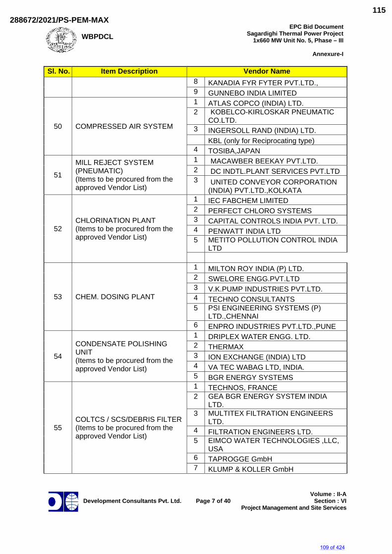
WBPDCL
EPC Bid DocumentSagardighi Thermal Power Project
1x660 MW Unit No. 5, Phase – III
Annexure-I
Development Consultants Pvt. Ltd.
Page 7 of 40
Volume : II-ASection : VI
Project Management and Site Services
Sl. No. Item Description Vendor Name 8 KANADIA FYR FYTER PVT.LTD., 9 GUNNEBO INDIA LIMITED
50 COMPRESSED AIR SYSTEM
1 ATLAS COPCO (INDIA) LTD. 2 KOBELCO-KIRLOSKAR PNEUMATIC
CO.LTD. 3 INGERSOLL RAND (INDIA) LTD. KBL (only for Reciprocating type) 4 TOSIBA,JAPAN
51
MILL REJECT SYSTEM (PNEUMATIC) (Items to be procured from the approved Vendor List)
1 MACAWBER BEEKAY PVT.LTD. 2 DC INDTL.PLANT SERVICES PVT.LTD 3 UNITED CONVEYOR CORPORATION
(INDIA) PVT.LTD.,KOLKATA
52 CHLORINATION PLANT (Items to be procured from the approved Vendor List)
1 IEC FABCHEM LIMITED 2 PERFECT CHLORO SYSTEMS 3 CAPITAL CONTROLS INDIA PVT. LTD. 4 PENWATT INDIA LTD 5 METITO POLLUTION CONTROL INDIA
LTD
53 CHEM. DOSING PLANT
1 MILTON ROY INDIA (P) LTD. 2 SWELORE ENGG.PVT.LTD 3 V.K.PUMP INDUSTRIES PVT.LTD. 4 TECHNO CONSULTANTS 5 PSI ENGINEERING SYSTEMS (P)
LTD.,CHENNAI 6 ENPRO INDUSTRIES PVT.LTD.,PUNE
54
CONDENSATE POLISHING UNIT (Items to be procured from the approved Vendor List)
1 DRIPLEX WATER ENGG. LTD. 2 THERMAX 3 ION EXCHANGE (INDIA) LTD 4 VA TEC WABAG LTD, INDIA. 5 BGR ENERGY SYSTEMS
55 COLTCS / SCS/DEBRIS FILTER(Items to be procured from the approved Vendor List)
1 TECHNOS, FRANCE 2 GEA BGR ENERGY SYSTEM INDIA
LTD. 3 MULTITEX FILTRATION ENGINEERS
LTD. 4 FILTRATION ENGINEERS LTD. 5 EIMCO WATER TECHNOLOGIES ,LLC,
USA 6 TAPROGGE GmbH 7 KLUMP & KOLLER GmbH
109 of 424
288672/2021/PS-PEM-MAX115
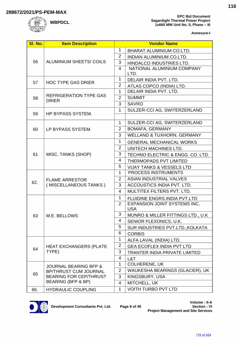
WBPDCL
EPC Bid DocumentSagardighi Thermal Power Project
1x660 MW Unit No. 5, Phase – III
Annexure-I
Development Consultants Pvt. Ltd.
Page 8 of 40
Volume : II-ASection : VI
Project Management and Site Services
Sl. No. Item Description Vendor Name
56 ALUMINIUM SHEETS/ COILS
1 BHARAT ALUMINIUM CO.LTD. 2 INDIAN ALUMINIUM CO.LTD. 3 HINDALCO INDUSTRIES LTD. 4 NATIONAL ALUMINIUM COMPANY
LTD.
57 HOC TYPE GAS DRIER 1 DELAIR INDIA PVT. LTD. 2 ATLAS COPCO (INDIA) LTD.
58 REFRIGERATION TYPE GAS DRIER
1 DELAIR INDIA PVT. LTD. 2 SUMMIT 3 SAVRO
59 HP BYPASS SYSTEM. 1 SULZER-CCI AG, SWITERZERLAND
60 LP BYPASS SYSTEM. 1 SULZER-CCI AG, SWITERZERLAND 2 BOMAFA, GERMANY 3 WELLAND & TUXHORN, GERMANY
61 MISC. TANKS (SHOP)
1 GENERAL MECHANICAL WORKS 2 UNITECH MACHINES LTD. 3 TECHNO ELECTRIC & ENGG. CO. LTD. 4 THERMOPADS PVT LIMITED 5 VIJAY TANKS & VESSELS LTD
62. FLAME ARRESTOR ( MISCELLANEOUS TANKS )
1 PROCESS INSTRUMENTS 2 ASIAN INDUSTRIAL VALVES 3 ACCOUSTICS INDIA PVT. LTD. 4 MULTITEX FILTERS PVT. LTD.
63 M.E. BELLOWS
1 FLUIDINE ENGRS.INDIA PVT.LTD 2 EXPANSION JOINT SYSTEMS INC.
USA 3 MUNRO & MILLER FITTINGS LTD., U.K 4 SENIOR FLEXONICS, U.K. 5 SUR INDUSTRIES PVT.LTD.,KOLKATA 6 CORBIS
64 HEAT EXCHANGERS (PLATE TYPE)
1 ALFA LAVAL (INDIA) LTD. 2 GEA ECOFLEX INDIA PVT LTD 3 TRANTER INDIA PRIVATE LIMITED 4 L&T
65
JOURNAL BEARING BFP & BP/THRUST CUM JOURNAL BEARING FOR CEP/THRUST BEARING (BFP & BP)
1 COLHERENE, UK 2 WAUKESHA BEARINGS (GLACIER), UK 3 KINGSBURY, USA 4 MITCHELL, UK
66. HYDRAULIC COUPLING 1 VOITH TURBO PVT LTD
110 of 424
288672/2021/PS-PEM-MAX116
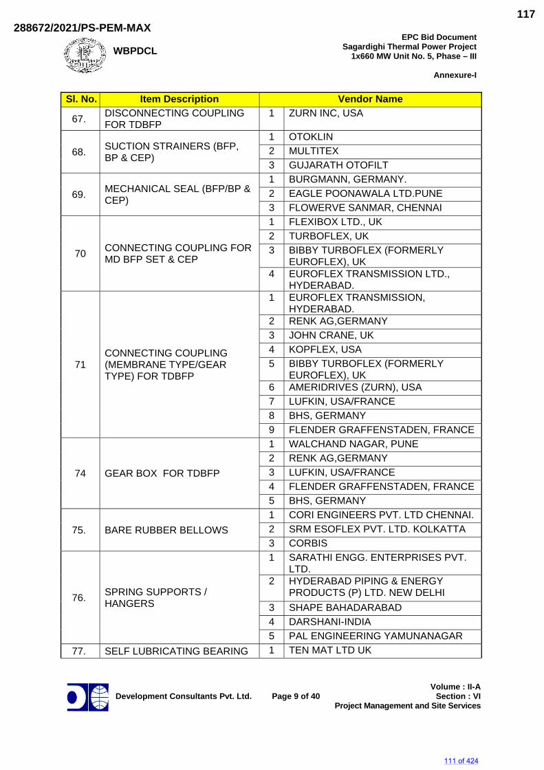
WBPDCL
EPC Bid DocumentSagardighi Thermal Power Project
1x660 MW Unit No. 5, Phase – III
Annexure-I
Development Consultants Pvt. Ltd.
Page 9 of 40
Volume : II-ASection : VI
Project Management and Site Services
Sl. No. Item Description Vendor Name
67. DISCONNECTING COUPLING FOR TDBFP
1 ZURN INC, USA
68. SUCTION STRAINERS (BFP, BP & CEP)
1 OTOKLIN 2 MULTITEX 3 GUJARATH OTOFILT
69. MECHANICAL SEAL (BFP/BP & CEP)
1 BURGMANN, GERMANY. 2 EAGLE POONAWALA LTD.PUNE 3 FLOWERVE SANMAR, CHENNAI
70 CONNECTING COUPLING FOR MD BFP SET & CEP
1 FLEXIBOX LTD., UK 2 TURBOFLEX, UK 3 BIBBY TURBOFLEX (FORMERLY
EUROFLEX), UK 4 EUROFLEX TRANSMISSION LTD.,
HYDERABAD.
71 CONNECTING COUPLING (MEMBRANE TYPE/GEAR TYPE) FOR TDBFP
1 EUROFLEX TRANSMISSION, HYDERABAD.
2 RENK AG,GERMANY 3 JOHN CRANE, UK 4 KOPFLEX, USA 5 BIBBY TURBOFLEX (FORMERLY
EUROFLEX), UK 6 AMERIDRIVES (ZURN), USA 7 LUFKIN, USA/FRANCE 8 BHS, GERMANY 9 FLENDER GRAFFENSTADEN, FRANCE
74 GEAR BOX FOR TDBFP
1 WALCHAND NAGAR, PUNE 2 RENK AG,GERMANY 3 LUFKIN, USA/FRANCE 4 FLENDER GRAFFENSTADEN, FRANCE 5 BHS, GERMANY
75. BARE RUBBER BELLOWS 1 CORI ENGINEERS PVT. LTD CHENNAI. 2 SRM ESOFLEX PVT. LTD. KOLKATTA 3 CORBIS
76. SPRING SUPPORTS / HANGERS
1 SARATHI ENGG. ENTERPRISES PVT. LTD.
2 HYDERABAD PIPING & ENERGY PRODUCTS (P) LTD. NEW DELHI
3 SHAPE BAHADARABAD 4 DARSHANI-INDIA 5 PAL ENGINEERING YAMUNANAGAR
77. SELF LUBRICATING BEARING 1 TEN MAT LTD UK
111 of 424
288672/2021/PS-PEM-MAX117
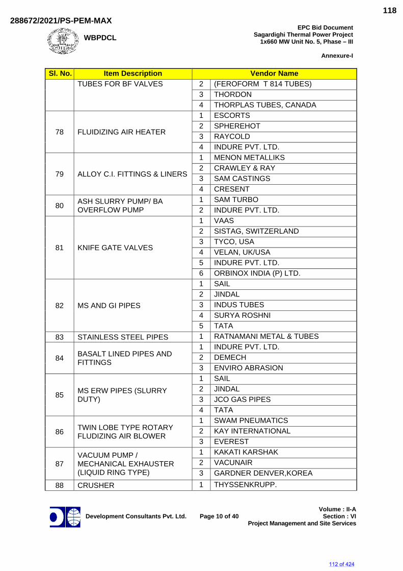
WBPDCL
EPC Bid DocumentSagardighi Thermal Power Project
1x660 MW Unit No. 5, Phase – III
Annexure-I
Development Consultants Pvt. Ltd.
Page 10 of 40
Volume : II-ASection : VI
Project Management and Site Services
Sl. No. Item Description Vendor Name TUBES FOR BF VALVES 2 (FEROFORM T 814 TUBES)
3 THORDON 4 THORPLAS TUBES, CANADA
78 FLUIDIZING AIR HEATER
1 ESCORTS 2 SPHEREHOT 3 RAYCOLD 4 INDURE PVT. LTD.
79 ALLOY C.I. FITTINGS & LINERS
1 MENON METALLIKS 2 CRAWLEY & RAY 3 SAM CASTINGS 4 CRESENT
80 ASH SLURRY PUMP/ BA OVERFLOW PUMP
1 SAM TURBO 2 INDURE PVT. LTD.
81 KNIFE GATE VALVES
1 VAAS 2 SISTAG, SWITZERLAND 3 TYCO, USA 4 VELAN, UK/USA 5 INDURE PVT. LTD. 6 ORBINOX INDIA (P) LTD.
82 MS AND GI PIPES
1 SAIL 2 JINDAL 3 INDUS TUBES 4 SURYA ROSHNI 5 TATA
83 STAINLESS STEEL PIPES 1 RATNAMANI METAL & TUBES
84 BASALT LINED PIPES AND FITTINGS
1 INDURE PVT. LTD. 2 DEMECH 3 ENVIRO ABRASION
85 MS ERW PIPES (SLURRY DUTY)
1 SAIL 2 JINDAL 3 JCO GAS PIPES 4 TATA
86 TWIN LOBE TYPE ROTARY FLUDIZING AIR BLOWER
1 SWAM PNEUMATICS 2 KAY INTERNATIONAL 3 EVEREST
87 VACUUM PUMP / MECHANICAL EXHAUSTER (LIQUID RING TYPE)
1 KAKATI KARSHAK 2 VACUNAIR 3 GARDNER DENVER,KOREA
88 CRUSHER 1 THYSSENKRUPP.
112 of 424
288672/2021/PS-PEM-MAX118
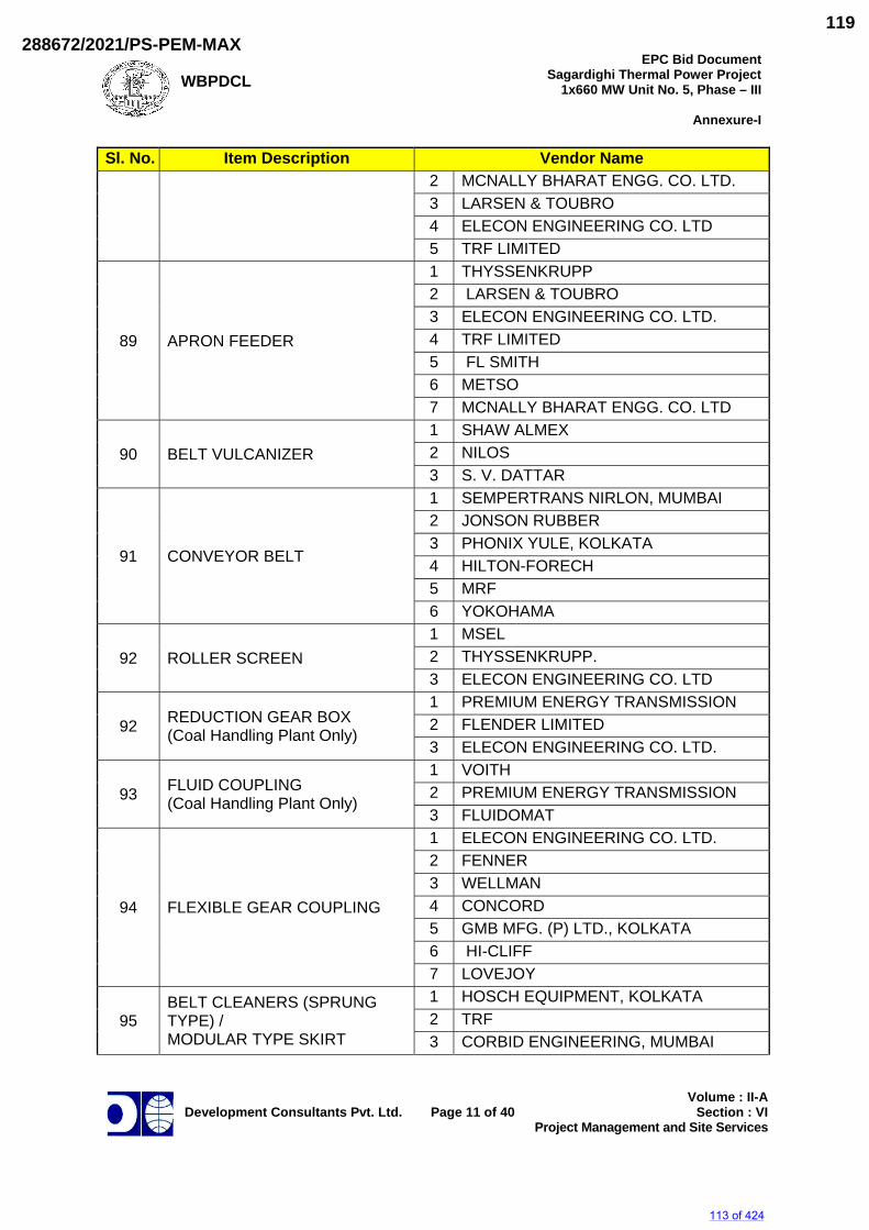
WBPDCL
EPC Bid DocumentSagardighi Thermal Power Project
1x660 MW Unit No. 5, Phase – III
Annexure-I
Development Consultants Pvt. Ltd.
Page 11 of 40
Volume : II-ASection : VI
Project Management and Site Services
Sl. No. Item Description Vendor Name 2 MCNALLY BHARAT ENGG. CO. LTD. 3 LARSEN & TOUBRO 4 ELECON ENGINEERING CO. LTD 5 TRF LIMITED
89 APRON FEEDER
1 THYSSENKRUPP 2 LARSEN & TOUBRO 3 ELECON ENGINEERING CO. LTD. 4 TRF LIMITED 5 FL SMITH 6 METSO 7 MCNALLY BHARAT ENGG. CO. LTD
90 BELT VULCANIZER 1 SHAW ALMEX 2 NILOS 3 S. V. DATTAR
91 CONVEYOR BELT
1 SEMPERTRANS NIRLON, MUMBAI 2 JONSON RUBBER 3 PHONIX YULE, KOLKATA 4 HILTON-FORECH 5 MRF 6 YOKOHAMA
92 ROLLER SCREEN 1 MSEL 2 THYSSENKRUPP. 3 ELECON ENGINEERING CO. LTD
92 REDUCTION GEAR BOX (Coal Handling Plant Only)
1 PREMIUM ENERGY TRANSMISSION 2 FLENDER LIMITED 3 ELECON ENGINEERING CO. LTD.
93 FLUID COUPLING (Coal Handling Plant Only)
1 VOITH 2 PREMIUM ENERGY TRANSMISSION 3 FLUIDOMAT
94 FLEXIBLE GEAR COUPLING
1 ELECON ENGINEERING CO. LTD. 2 FENNER 3 WELLMAN 4 CONCORD 5 GMB MFG. (P) LTD., KOLKATA 6 HI-CLIFF 7 LOVEJOY
95 BELT CLEANERS (SPRUNG TYPE) / MODULAR TYPE SKIRT
1 HOSCH EQUIPMENT, KOLKATA 2 TRF 3 CORBID ENGINEERING, MUMBAI
113 of 424
288672/2021/PS-PEM-MAX119
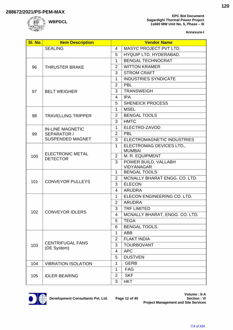
WBPDCL
EPC Bid DocumentSagardighi Thermal Power Project
1x660 MW Unit No. 5, Phase – III
Annexure-I
Development Consultants Pvt. Ltd.
Page 12 of 40
Volume : II-ASection : VI
Project Management and Site Services
Sl. No. Item Description Vendor Name SEALING 4 MASYC PROJECT PVT LTD.
5 HYQUIP LTD, HYDERABAD.
96 THRUSTER BRAKE 1 BENGAL TECHNOCRAT 2 WITTON KRAMER 3 STROM CRAFT
97 BELT WEIGHER
1 INDUSTRIES SYNDICATE 2 PBL 3 TRANSWEIGH 4 IPA 5 SHENEICK PROCESS
98 TRAVELLING TRIPPER 1 MSEL 2 BENGAL TOOLS 3 HMTC
99 IN-LINE MAGNETIC SEPARATOR / SUSPENDED MAGNET
1 ELECTRO-ZAVOD 2 PBL 3 ELECTROMAGNETIC INDUSTRIES
100 ELECTRONIC METAL DETECTOR
1 ELECTROMAG DEVICES LTD., MUMBAI
2 M. R. EQUIPMENT 3 POWER BUILD, VALLABH
VIDYANAGAR
101 CONVEYOR PULLEYS
1 BENGAL TOOLS 2 MCNALLY BHARAT ENGG. CO. LTD. 3 ELECON 4 ARUDRA
102 CONVEYOR IDLERS
1 ELECON ENGINEERING CO. LTD. 2 ARUDRA 3 TRF LIMITED 4 MCNALLY BHARAT, ENGG. CO. LTD. 5 TEGA 6 BENGAL TOOLS.
103 CENTRIFUGAL FANS (DE System)
1 ABB 2 FLAKT INDIA 3 TOURBOVANT 4 APC 5 DUSTVEN
104 VIBRATION ISOLATION 1 GERB
105 IDLER BEARING 1 FAG 2 SKF 3 HKT
114 of 424
288672/2021/PS-PEM-MAX120
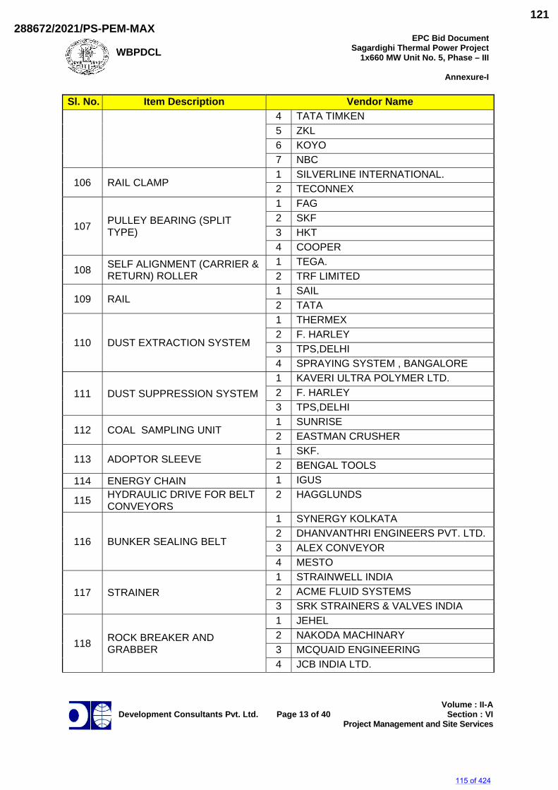
WBPDCL
EPC Bid DocumentSagardighi Thermal Power Project
1x660 MW Unit No. 5, Phase – III
Annexure-I
Development Consultants Pvt. Ltd.
Page 13 of 40
Volume : II-ASection : VI
Project Management and Site Services
Sl. No. Item Description Vendor Name 4 TATA TIMKEN 5 ZKL 6 KOYO 7 NBC
106 RAIL CLAMP 1 SILVERLINE INTERNATIONAL. 2 TECONNEX
107 PULLEY BEARING (SPLIT TYPE)
1 FAG 2 SKF 3 HKT 4 COOPER
108 SELF ALIGNMENT (CARRIER & RETURN) ROLLER
1 TEGA. 2 TRF LIMITED
109 RAIL 1 SAIL 2 TATA
110 DUST EXTRACTION SYSTEM
1 THERMEX 2 F. HARLEY 3 TPS,DELHI 4 SPRAYING SYSTEM , BANGALORE
111 DUST SUPPRESSION SYSTEM 1 KAVERI ULTRA POLYMER LTD. 2 F. HARLEY 3 TPS,DELHI
112 COAL SAMPLING UNIT 1 SUNRISE 2 EASTMAN CRUSHER
113 ADOPTOR SLEEVE 1 SKF. 2 BENGAL TOOLS
114 ENERGY CHAIN 1 IGUS
115 HYDRAULIC DRIVE FOR BELT CONVEYORS
2 HAGGLUNDS
116 BUNKER SEALING BELT
1 SYNERGY KOLKATA 2 DHANVANTHRI ENGINEERS PVT. LTD. 3 ALEX CONVEYOR 4 MESTO
117 STRAINER 1 STRAINWELL INDIA 2 ACME FLUID SYSTEMS 3 SRK STRAINERS & VALVES INDIA
118 ROCK BREAKER AND GRABBER
1 JEHEL 2 NAKODA MACHINARY 3 MCQUAID ENGINEERING 4 JCB INDIA LTD.
115 of 424
288672/2021/PS-PEM-MAX121
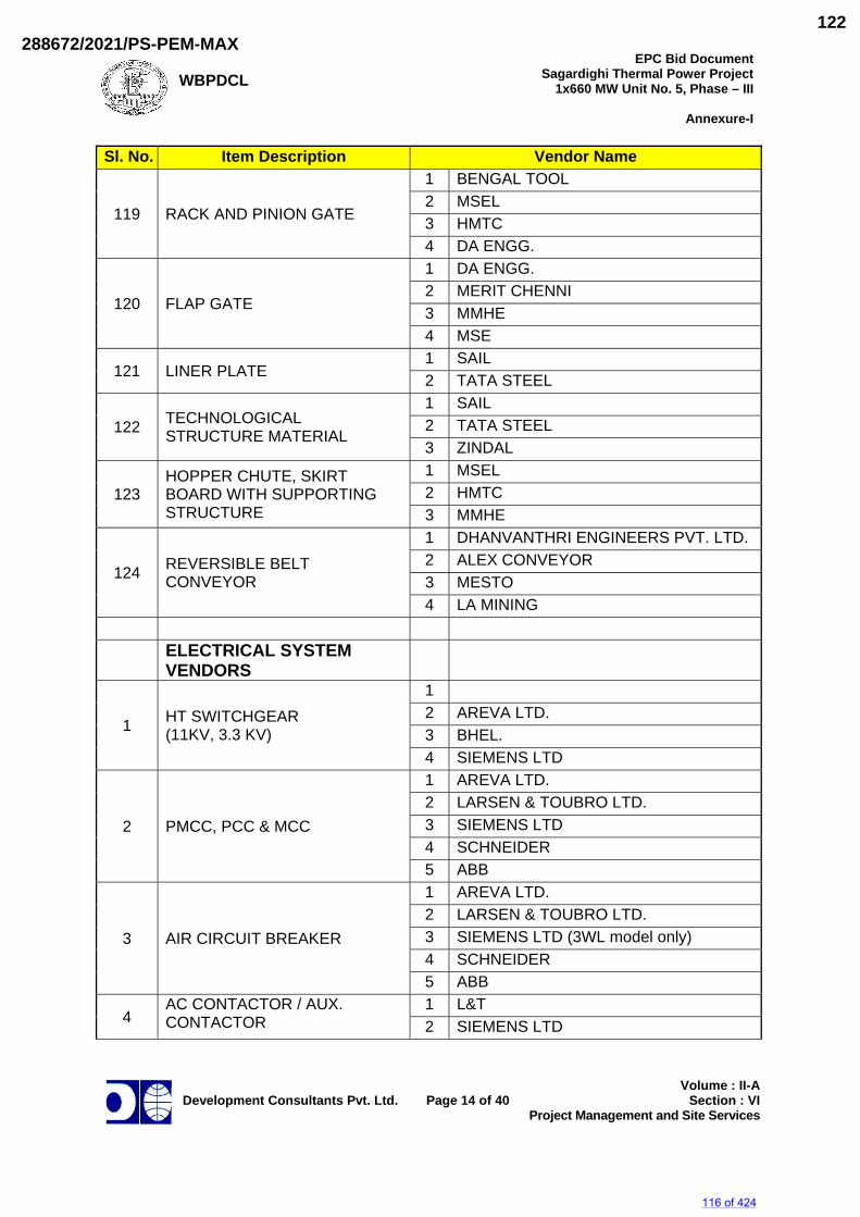
WBPDCL
EPC Bid DocumentSagardighi Thermal Power Project
1x660 MW Unit No. 5, Phase – III
Annexure-I
Development Consultants Pvt. Ltd.
Page 14 of 40
Volume : II-ASection : VI
Project Management and Site Services
Sl. No. Item Description Vendor Name
119 RACK AND PINION GATE
1 BENGAL TOOL 2 MSEL 3 HMTC 4 DA ENGG.
120 FLAP GATE
1 DA ENGG. 2 MERIT CHENNI 3 MMHE 4 MSE
121 LINER PLATE 1 SAIL 2 TATA STEEL
122 TECHNOLOGICAL STRUCTURE MATERIAL
1 SAIL 2 TATA STEEL 3 ZINDAL
123 HOPPER CHUTE, SKIRT BOARD WITH SUPPORTING STRUCTURE
1 MSEL 2 HMTC 3 MMHE
124 REVERSIBLE BELT CONVEYOR
1 DHANVANTHRI ENGINEERS PVT. LTD. 2 ALEX CONVEYOR 3 MESTO 4 LA MINING
ELECTRICAL SYSTEM VENDORS
1 HT SWITCHGEAR (11KV, 3.3 KV)
1 2 AREVA LTD. 3 BHEL. 4 SIEMENS LTD
2 PMCC, PCC & MCC
1 AREVA LTD. 2 LARSEN & TOUBRO LTD. 3 SIEMENS LTD 4 SCHNEIDER 5 ABB
3 AIR CIRCUIT BREAKER
1 AREVA LTD. 2 LARSEN & TOUBRO LTD. 3 SIEMENS LTD (3WL model only) 4 SCHNEIDER 5 ABB
4 AC CONTACTOR / AUX. CONTACTOR
1 L&T 2 SIEMENS LTD
116 of 424
288672/2021/PS-PEM-MAX122
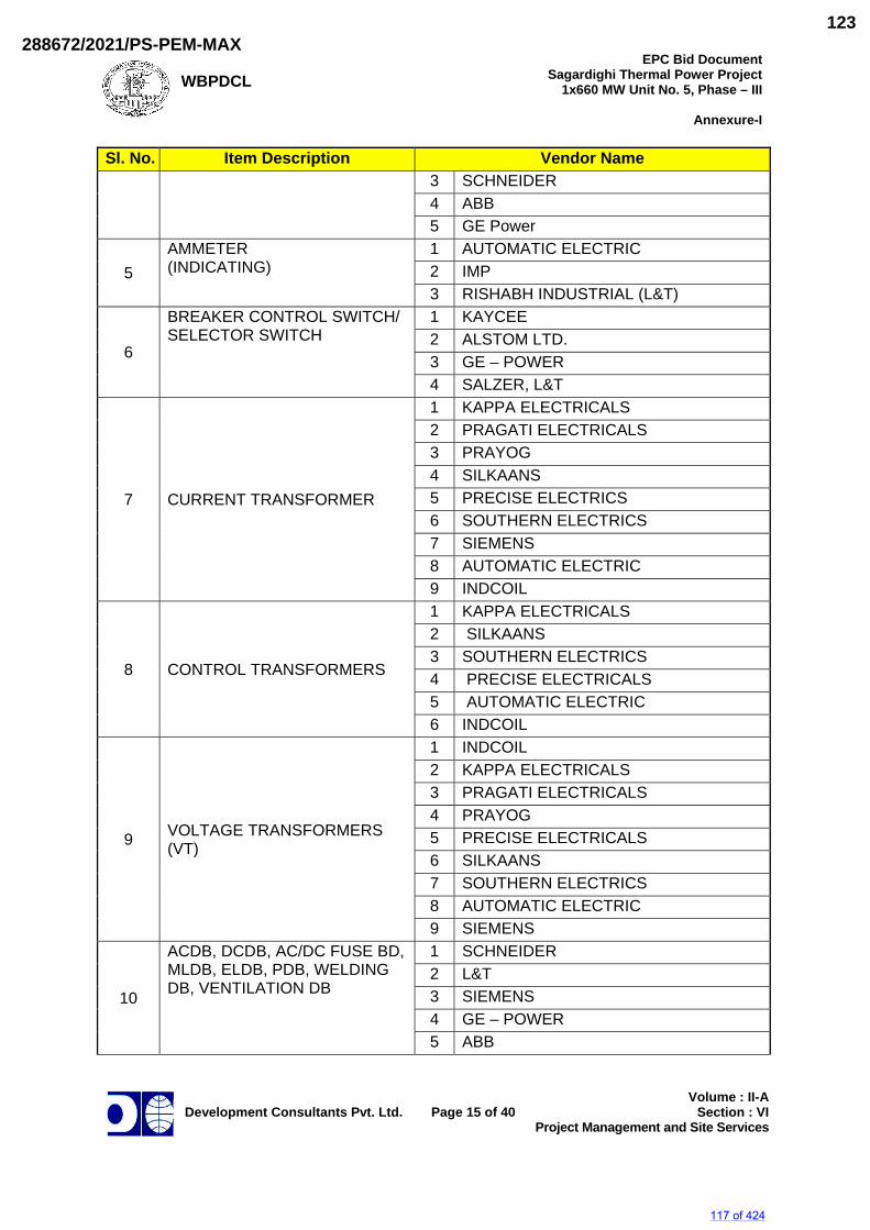
WBPDCL
EPC Bid DocumentSagardighi Thermal Power Project
1x660 MW Unit No. 5, Phase – III
Annexure-I
Development Consultants Pvt. Ltd.
Page 15 of 40
Volume : II-ASection : VI
Project Management and Site Services
Sl. No. Item Description Vendor Name 3 SCHNEIDER 4 ABB 5 GE Power
5 AMMETER (INDICATING)
1 AUTOMATIC ELECTRIC 2 IMP 3 RISHABH INDUSTRIAL (L&T)
6
BREAKER CONTROL SWITCH/ SELECTOR SWITCH
1 KAYCEE 2 ALSTOM LTD. 3 GE – POWER 4 SALZER, L&T
7 CURRENT TRANSFORMER
1 KAPPA ELECTRICALS 2 PRAGATI ELECTRICALS 3 PRAYOG 4 SILKAANS 5 PRECISE ELECTRICS 6 SOUTHERN ELECTRICS 7 SIEMENS 8 AUTOMATIC ELECTRIC 9 INDCOIL
8 CONTROL TRANSFORMERS
1 KAPPA ELECTRICALS 2 SILKAANS 3 SOUTHERN ELECTRICS 4 PRECISE ELECTRICALS 5 AUTOMATIC ELECTRIC 6 INDCOIL
9 VOLTAGE TRANSFORMERS (VT)
1 INDCOIL 2 KAPPA ELECTRICALS 3 PRAGATI ELECTRICALS 4 PRAYOG 5 PRECISE ELECTRICALS 6 SILKAANS 7 SOUTHERN ELECTRICS 8 AUTOMATIC ELECTRIC 9 SIEMENS
10
ACDB, DCDB, AC/DC FUSE BD, MLDB, ELDB, PDB, WELDING DB, VENTILATION DB
1 SCHNEIDER 2 L&T 3 SIEMENS 4 GE – POWER 5 ABB
117 of 424
288672/2021/PS-PEM-MAX123
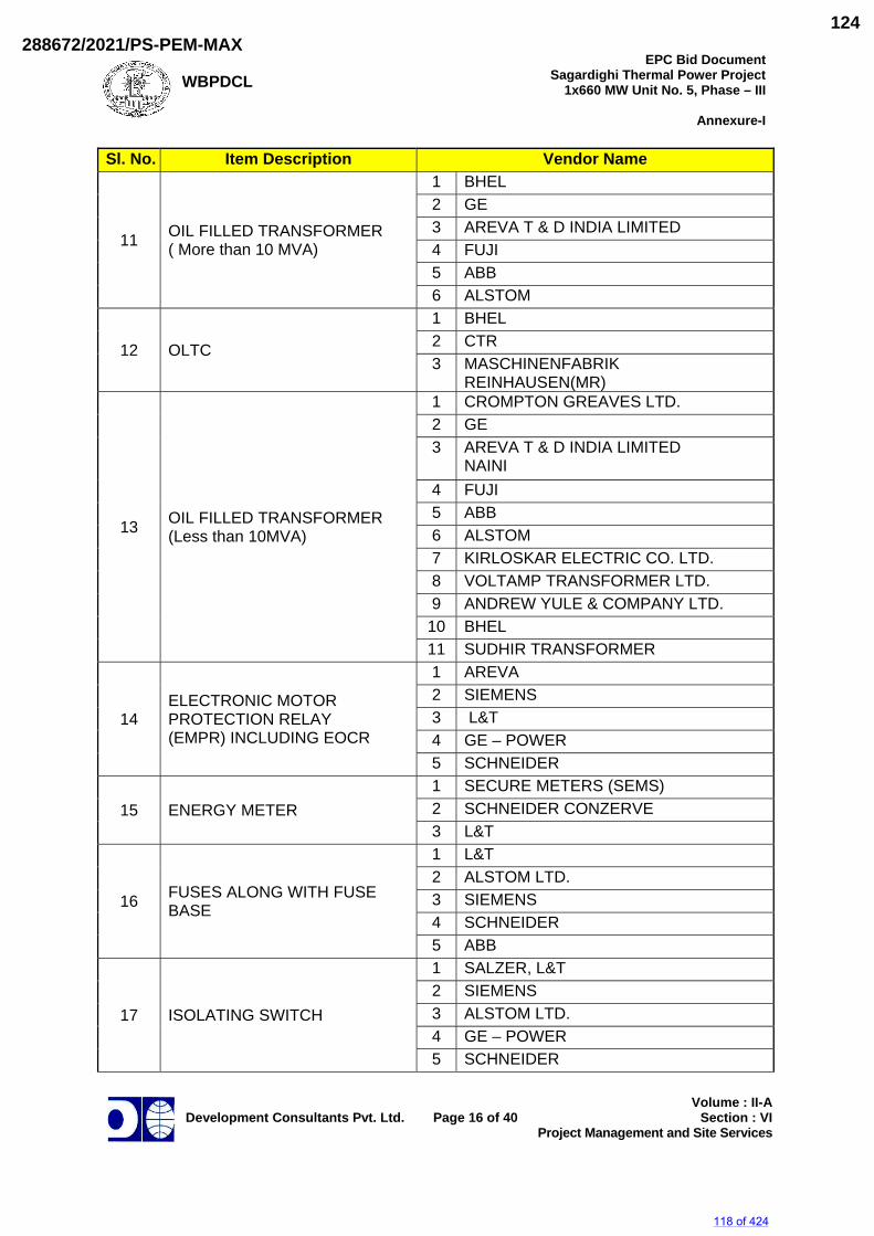
WBPDCL
EPC Bid DocumentSagardighi Thermal Power Project
1x660 MW Unit No. 5, Phase – III
Annexure-I
Development Consultants Pvt. Ltd.
Page 16 of 40
Volume : II-ASection : VI
Project Management and Site Services
Sl. No. Item Description Vendor Name
11 OIL FILLED TRANSFORMER ( More than 10 MVA)
1 BHEL 2 GE 3 AREVA T & D INDIA LIMITED 4 FUJI 5 ABB 6 ALSTOM
12 OLTC
1 BHEL 2 CTR 3 MASCHINENFABRIK
REINHAUSEN(MR)
13 OIL FILLED TRANSFORMER (Less than 10MVA)
1 CROMPTON GREAVES LTD. 2 GE 3 AREVA T & D INDIA LIMITED
NAINI 4 FUJI 5 ABB 6 ALSTOM 7 KIRLOSKAR ELECTRIC CO. LTD. 8 VOLTAMP TRANSFORMER LTD. 9 ANDREW YULE & COMPANY LTD.
10 BHEL 11 SUDHIR TRANSFORMER
14 ELECTRONIC MOTOR PROTECTION RELAY (EMPR) INCLUDING EOCR
1 AREVA 2 SIEMENS 3 L&T 4 GE – POWER 5 SCHNEIDER
15 ENERGY METER 1 SECURE METERS (SEMS) 2 SCHNEIDER CONZERVE 3 L&T
16 FUSES ALONG WITH FUSE BASE
1 L&T 2 ALSTOM LTD. 3 SIEMENS 4 SCHNEIDER 5 ABB
17 ISOLATING SWITCH
1 SALZER, L&T 2 SIEMENS 3 ALSTOM LTD. 4 GE – POWER 5 SCHNEIDER
118 of 424
288672/2021/PS-PEM-MAX124
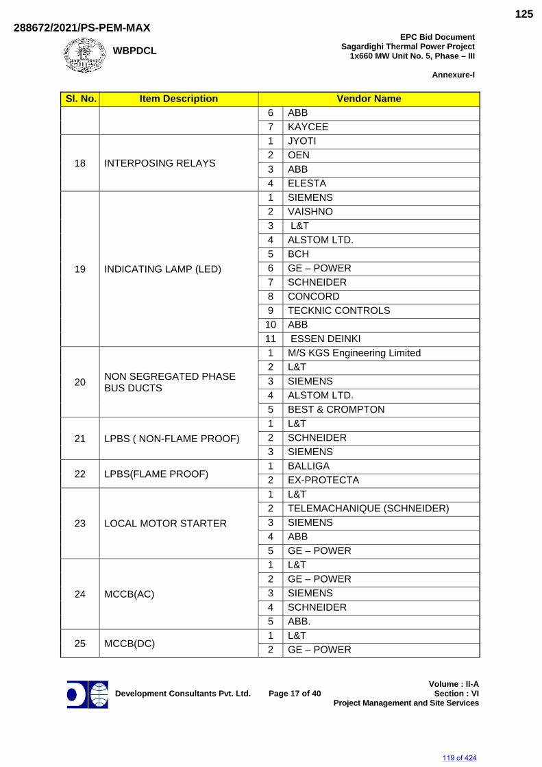
WBPDCL
EPC Bid DocumentSagardighi Thermal Power Project
1x660 MW Unit No. 5, Phase – III
Annexure-I
Development Consultants Pvt. Ltd.
Page 17 of 40
Volume : II-ASection : VI
Project Management and Site Services
Sl. No. Item Description Vendor Name 6 ABB 7 KAYCEE
18 INTERPOSING RELAYS
1 JYOTI 2 OEN 3 ABB 4 ELESTA
19 INDICATING LAMP (LED)
1 SIEMENS 2 VAISHNO 3 L&T 4 ALSTOM LTD. 5 BCH 6 GE – POWER 7 SCHNEIDER 8 CONCORD 9 TECKNIC CONTROLS
10 ABB 11 ESSEN DEINKI
20 NON SEGREGATED PHASE BUS DUCTS
1 M/S KGS Engineering Limited 2 L&T 3 SIEMENS 4 ALSTOM LTD. 5 BEST & CROMPTON
21 LPBS ( NON-FLAME PROOF) 1 L&T 2 SCHNEIDER 3 SIEMENS
22 LPBS(FLAME PROOF) 1 BALLIGA 2 EX-PROTECTA
23 LOCAL MOTOR STARTER
1 L&T 2 TELEMACHANIQUE (SCHNEIDER) 3 SIEMENS 4 ABB 5 GE – POWER
24 MCCB(AC)
1 L&T 2 GE – POWER 3 SIEMENS 4 SCHNEIDER 5 ABB.
25 MCCB(DC) 1 L&T 2 GE – POWER
119 of 424
288672/2021/PS-PEM-MAX125
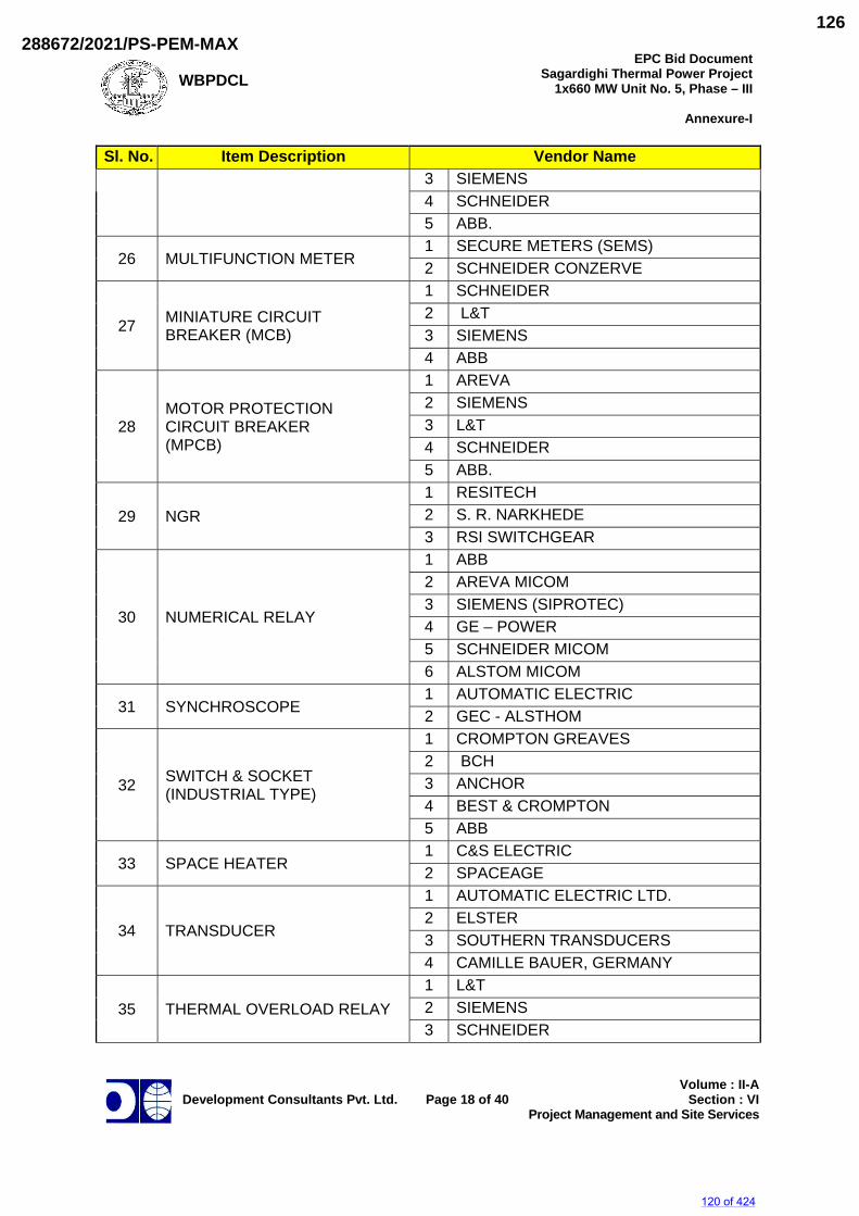
WBPDCL
EPC Bid DocumentSagardighi Thermal Power Project
1x660 MW Unit No. 5, Phase – III
Annexure-I
Development Consultants Pvt. Ltd.
Page 18 of 40
Volume : II-ASection : VI
Project Management and Site Services
Sl. No. Item Description Vendor Name 3 SIEMENS 4 SCHNEIDER 5 ABB.
26 MULTIFUNCTION METER 1 SECURE METERS (SEMS) 2 SCHNEIDER CONZERVE
27 MINIATURE CIRCUIT BREAKER (MCB)
1 SCHNEIDER 2 L&T 3 SIEMENS 4 ABB
28 MOTOR PROTECTION CIRCUIT BREAKER (MPCB)
1 AREVA 2 SIEMENS 3 L&T 4 SCHNEIDER 5 ABB.
29 NGR 1 RESITECH 2 S. R. NARKHEDE 3 RSI SWITCHGEAR
30 NUMERICAL RELAY
1 ABB 2 AREVA MICOM 3 SIEMENS (SIPROTEC) 4 GE – POWER 5 SCHNEIDER MICOM 6 ALSTOM MICOM
31 SYNCHROSCOPE 1 AUTOMATIC ELECTRIC 2 GEC - ALSTHOM
32 SWITCH & SOCKET (INDUSTRIAL TYPE)
1 CROMPTON GREAVES 2 BCH 3 ANCHOR 4 BEST & CROMPTON 5 ABB
33 SPACE HEATER 1 C&S ELECTRIC 2 SPACEAGE
34 TRANSDUCER
1 AUTOMATIC ELECTRIC LTD. 2 ELSTER 3 SOUTHERN TRANSDUCERS 4 CAMILLE BAUER, GERMANY
35 THERMAL OVERLOAD RELAY 1 L&T 2 SIEMENS 3 SCHNEIDER
120 of 424
288672/2021/PS-PEM-MAX126
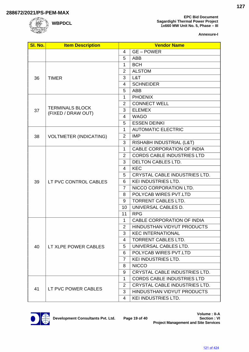
WBPDCL
EPC Bid DocumentSagardighi Thermal Power Project
1x660 MW Unit No. 5, Phase – III
Annexure-I
Development Consultants Pvt. Ltd.
Page 19 of 40
Volume : II-ASection : VI
Project Management and Site Services
Sl. No. Item Description Vendor Name 4 GE – POWER 5 ABB
36 TIMER
1 BCH 2 ALSTOM 3 L&T 4 SCHNEIDER 5 ABB
37 TERMINALS BLOCK (FIXED / DRAW OUT)
1 PHOENIX 2 CONNECT WELL 3 ELEMEX 4 WAGO 5 ESSEN DEINKI
38 VOLTMETER (INDICATING) 1 AUTOMATIC ELECTRIC 2 IMP 3 RISHABH INDUSTRIAL (L&T)
39 LT PVC CONTROL CABLES
1 CABLE CORPORATION OF INDIA 2 CORDS CABLE INDUSTRIES LTD 3 DELTON CABLES LTD. 4 KEC 5 CRYSTAL CABLE INDUSTRIES LTD. 6 KEI INDUSTRIES LTD. 7 NICCO CORPORATION LTD. 8 POLYCAB WIRES PVT.LTD 9 TORRENT CABLES LTD.
10 UNIVERSAL CABLES D. 11 RPG
40 LT XLPE POWER CABLES
1 CABLE CORPORATION OF INDIA 2 HINDUSTHAN VIDYUT PRODUCTS 3 KEC INTERNATIONAL 4 TORRENT CABLES LTD. 5 UNIVERSAL CABLES LTD. 6 POLYCAB WIRES PVT.LTD 7 KEI INDUSTRIES LTD. 8 NICCO 9 CRYSTAL CABLE INDUSTRIES LTD.
41 LT PVC POWER CABLES
1 CORDS CABLE INDUSTRIES LTD 2 CRYSTAL CABLE INDUSTRIES LTD. 3 HINDUSTHAN VIDYUT PRODUCTS 4 KEI INDUSTRIES LTD.
121 of 424
288672/2021/PS-PEM-MAX127
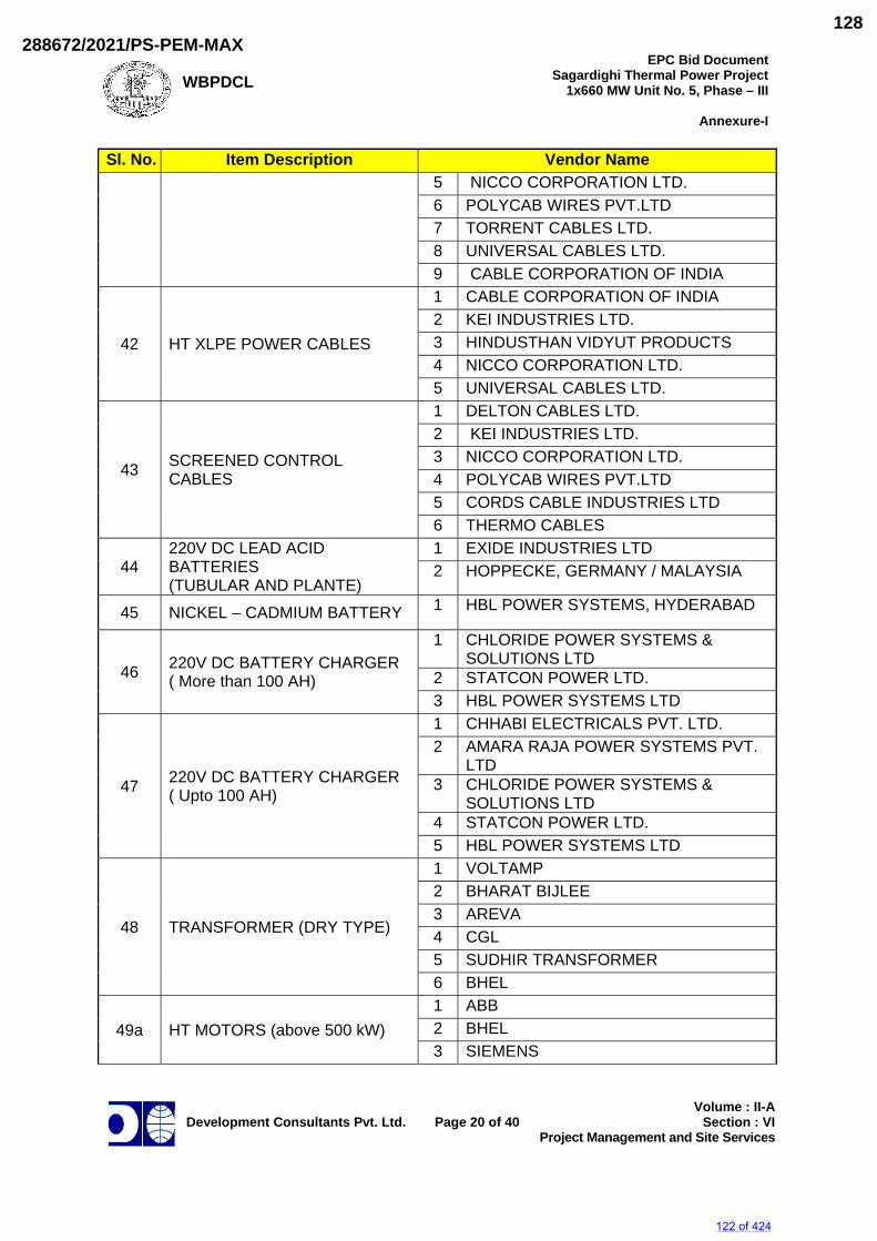
WBPDCL
EPC Bid DocumentSagardighi Thermal Power Project
1x660 MW Unit No. 5, Phase – III
Annexure-I
Development Consultants Pvt. Ltd.
Page 20 of 40
Volume : II-ASection : VI
Project Management and Site Services
Sl. No. Item Description Vendor Name 5 NICCO CORPORATION LTD. 6 POLYCAB WIRES PVT.LTD 7 TORRENT CABLES LTD. 8 UNIVERSAL CABLES LTD. 9 CABLE CORPORATION OF INDIA
42 HT XLPE POWER CABLES
1 CABLE CORPORATION OF INDIA 2 KEI INDUSTRIES LTD. 3 HINDUSTHAN VIDYUT PRODUCTS 4 NICCO CORPORATION LTD. 5 UNIVERSAL CABLES LTD.
43 SCREENED CONTROL CABLES
1 DELTON CABLES LTD. 2 KEI INDUSTRIES LTD. 3 NICCO CORPORATION LTD. 4 POLYCAB WIRES PVT.LTD 5 CORDS CABLE INDUSTRIES LTD 6 THERMO CABLES
44 220V DC LEAD ACID BATTERIES (TUBULAR AND PLANTE)
1 EXIDE INDUSTRIES LTD 2 HOPPECKE, GERMANY / MALAYSIA
45 NICKEL – CADMIUM BATTERY 1 HBL POWER SYSTEMS, HYDERABAD
46 220V DC BATTERY CHARGER ( More than 100 AH)
1 CHLORIDE POWER SYSTEMS & SOLUTIONS LTD
2 STATCON POWER LTD. 3 HBL POWER SYSTEMS LTD
47 220V DC BATTERY CHARGER ( Upto 100 AH)
1 CHHABI ELECTRICALS PVT. LTD. 2 AMARA RAJA POWER SYSTEMS PVT.
LTD 3 CHLORIDE POWER SYSTEMS &
SOLUTIONS LTD 4 STATCON POWER LTD. 5 HBL POWER SYSTEMS LTD
48 TRANSFORMER (DRY TYPE)
1 VOLTAMP 2 BHARAT BIJLEE 3 AREVA 4 CGL 5 SUDHIR TRANSFORMER 6 BHEL
49a HT MOTORS (above 500 kW) 1 ABB 2 BHEL 3 SIEMENS
122 of 424
288672/2021/PS-PEM-MAX128
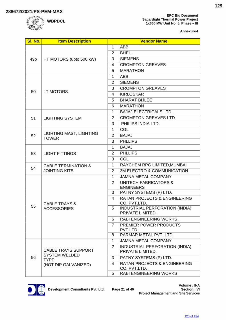
WBPDCL
EPC Bid DocumentSagardighi Thermal Power Project
1x660 MW Unit No. 5, Phase – III
Annexure-I
Development Consultants Pvt. Ltd.
Page 21 of 40
Volume : II-ASection : VI
Project Management and Site Services
Sl. No. Item Description Vendor Name
49b HT MOTORS (upto 500 kW)
1 ABB 2 BHEL 3 SIEMENS 4 CROMPTON GREAVES 5 MARATHON
50 LT MOTORS
1 ABB 2 SIEMENS 3 CROMPTON GREAVES 4 KIRLOSKAR 5 BHARAT BIJLEE 6 MARATHON
51 LIGHTING SYSTEM 1 BAJAJ ELECTRICALS LTD. 2 CROMPTON GREAVES LTD. 3 PHILIPS INDIA LTD.
52 LIGHTING MAST, LIGHTING TOWER
1 CGL 2 BAJAJ 3 PHLLIPS
53 LIGHT FITTINGS 1 BAJAJ 2 PHLLIPS 3 CGL
54 CABLE TERMINATION & JOINTING KITS
1 RAYCHEM RPG LIMITED,MUMBAI 2 3M ELECTRO & COMMUNICATION
55 CABLE TRAYS & ACCESSORIES
1 JAMNA METAL COMPANY 2 UNITECH FABRICATORS &
ENGINEERS 3 PATNY SYSTEMS (P) LTD. 4 RATAN PROJECTS & ENGINEERING
CO. PVT.LTD. 5 INDUSTRIAL PERFORATION (INDIA)
PRIVATE LIMITED. 6 RABI ENGINEERING WORKS , 7 PREMIER POWER PRODUCTS
PVT.LTD. 8 PARMAR METAL PVT. LTD.
56
CABLE TRAYS SUPPORT SYSTEM WELDED TYPE (HOT DIP GALVANIZED)
1 JAMNA METAL COMPANY 2 INDUSTRIAL PERFORATION (INDIA)
PRIVATE LIMITED. 3 PATNY SYSTEMS (P) LTD. 4 RATAN PROJECTS & ENGINEERING
CO. PVT.LTD. 5 RABI ENGINEERING WORKS
123 of 424
288672/2021/PS-PEM-MAX129
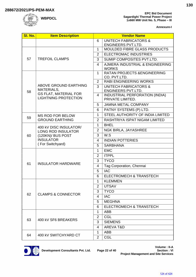
WBPDCL
EPC Bid DocumentSagardighi Thermal Power Project
1x660 MW Unit No. 5, Phase – III
Annexure-I
Development Consultants Pvt. Ltd.
Page 22 of 40
Volume : II-ASection : VI
Project Management and Site Services
Sl. No. Item Description Vendor Name 6 UNITECH FABRICATORS &
ENGINEERS PVT.LTD.
57 TREFOIL CLAMPS
1 MOULDED FIBRE GLASS PRODUCTS 2 ELECTROMAC INDUSTRIES 3 SUMIP COMPOSITES PVT.LTD. 4 AJMERA INDUSTRIAL & ENGINEERING
WORKS
58
ABOVE GROUND EARTHING MATERIALS, GS FLAT, MATERIAL FOR LIGHTNING PROTECTION
1 RATAN PROJECTS &ENGINEERING CO. PVT.LTD.
2 RABI ENGINEERING WORKS 3 UNITECH FABRICATORS &
ENGINEERS PVT.LTD. 4 INDUSTRIAL PERFORATION (INDIA)
PRIVATE LIMITED. 5 JAMNA METAL COMPANY 6 PATNY SYSTEMS (P) LTD.
59 MS ROD FOR BELOW GROUND EARTHING
1 STEEL AUTHORITY OF INDIA LIMITED 2 RASHTRIYA ISPAT NIGAM LIMITED
60
400 kV DISC INSULATOR/ LONG ROD INSULATOR (120KN)/ BUS POST INSULATOR ( For Switchyard)
1 BHEL 2 NGK BIRLA, JAYASHREE 3 W.S 4 INDIAN POTTERIES 5 SARBHANA
61 INSULATOR HARDWARE
1 EMC 2 ITPPL 3 TYCO 4 Tag Corporation, Chennai 5 IAC 6 ELECTROMECH & TRANSTECH
62 CLAMPS & CONNECTOR
1 KLEMMEN 2 UTSAV 3 TYCO 4 IAC 5 MEGHNA 6 ELECTROMECH & TRANSTECH
63 400 kV SF6 BREAKERS
1 ABB 2 CGL 3 SIEMENS 4 AREVA T&D
64 400 kV SWITCHYARD CT 1 ABB 2 CGL
124 of 424
288672/2021/PS-PEM-MAX130
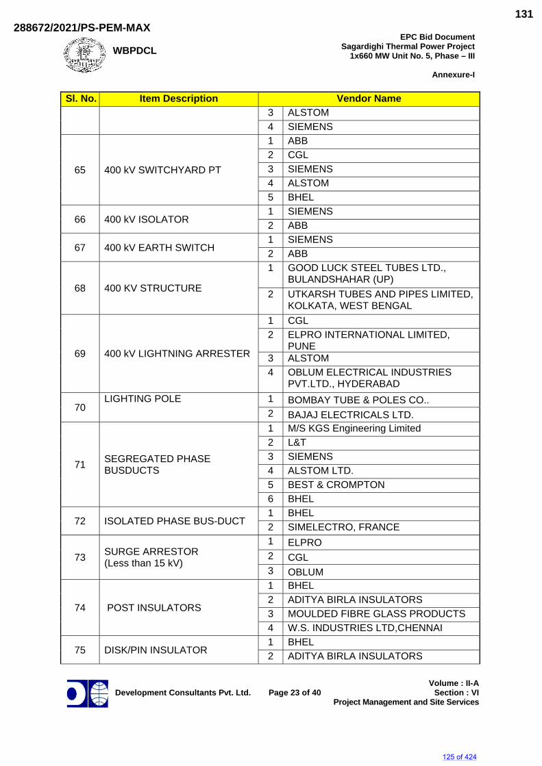
WBPDCL
EPC Bid DocumentSagardighi Thermal Power Project
1x660 MW Unit No. 5, Phase – III
Annexure-I
Development Consultants Pvt. Ltd.
Page 23 of 40
Volume : II-ASection : VI
Project Management and Site Services
Sl. No. Item Description Vendor Name 3 ALSTOM 4 SIEMENS
65 400 kV SWITCHYARD PT
1 ABB 2 CGL 3 SIEMENS 4 ALSTOM 5 BHEL
66 400 kV ISOLATOR 1 SIEMENS 2 ABB
67 400 kV EARTH SWITCH 1 SIEMENS 2 ABB
68 400 KV STRUCTURE
1 GOOD LUCK STEEL TUBES LTD., BULANDSHAHAR (UP)
2 UTKARSH TUBES AND PIPES LIMITED,KOLKATA, WEST BENGAL
69 400 kV LIGHTNING ARRESTER
1 CGL 2 ELPRO INTERNATIONAL LIMITED,
PUNE 3 ALSTOM 4 OBLUM ELECTRICAL INDUSTRIES
PVT.LTD., HYDERABAD
70 LIGHTING POLE 1 BOMBAY TUBE & POLES CO..
2 BAJAJ ELECTRICALS LTD.
71 SEGREGATED PHASE BUSDUCTS
1 M/S KGS Engineering Limited 2 L&T 3 SIEMENS 4 ALSTOM LTD. 5 BEST & CROMPTON 6 BHEL
72 ISOLATED PHASE BUS-DUCT 1 BHEL 2 SIMELECTRO, FRANCE
73 SURGE ARRESTOR (Less than 15 kV)
1 ELPRO 2 CGL 3 OBLUM
74 POST INSULATORS
1 BHEL 2 ADITYA BIRLA INSULATORS 3 MOULDED FIBRE GLASS PRODUCTS 4 W.S. INDUSTRIES LTD,CHENNAI
75 DISK/PIN INSULATOR 1 BHEL 2 ADITYA BIRLA INSULATORS
125 of 424
288672/2021/PS-PEM-MAX131
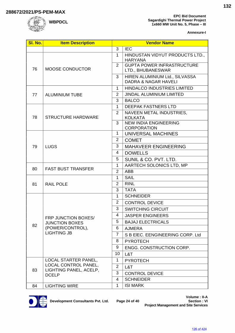
WBPDCL
EPC Bid DocumentSagardighi Thermal Power Project
1x660 MW Unit No. 5, Phase – III
Annexure-I
Development Consultants Pvt. Ltd.
Page 24 of 40
Volume : II-ASection : VI
Project Management and Site Services
Sl. No. Item Description Vendor Name 3 IEC
76 MOOSE CONDUCTOR
1 HINDUSTAN VIDYUT PRODUCTS LTD., HARYANA
2 GUPTA POWER INFRASTRUCTURE LTD., BHUBANESWAR
3 HIREN ALUMINIUM Ltd., SILVASSA DADRA & NAGAR HAVELI
77 ALUMINIUM TUBE 1 HINDALCO INDUSTRIES LIMITED 2 JINDAL ALUMINIUM LIMITED 3 BALCO
78 STRUCTURE HARDWARE
1 DEEPAK FASTNERS LTD 2 NAVEEN METAL INDUSTRIES,
KOLKATA 3 NEW INDIA ENGINEERING
CORPORATION
79 LUGS
1 UNIVERSAL MACHINES 2 COMET 3 MAHAVEER ENGINEERING 4 DOWELLS 5 SUNIL & CO. PVT. LTD.
80 FAST BUST TRANSFER 1 AARTECH SOLONICS LTD, MP 2 ABB
81 RAIL POLE 1 SAIL 2 RINL 3 TATA
82
FRP JUNCTION BOXES/ JUNCTION BOXES (POWER/CONTROL), LIGHTING JB
1 SCHNEIDER 2 CONTROL DEVICE 3 SWITCHING CIRCUIT 4 JASPER ENGINEERS 5 BAJAJ ELECTRICALS 6 AJMERA 7 S B ElEC. EENGINEERING CORP. Ltd 8 PYROTECH 9 ENGG. CONSTRUCTION CORP.
10 L&T
83
LOCAL STARTER PANEL, LOCAL CONTROL PANEL, LIGHTING PANEL, ACELP, DCELP
1 PYROTECH 2 L&T 3 CONTROL DEVICE 4 SCHNEIDER
84 LIGHTING WIRE 1 ISI MARK
126 of 424
288672/2021/PS-PEM-MAX132
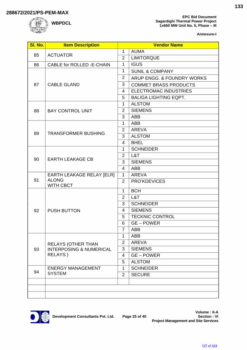
WBPDCL
EPC Bid DocumentSagardighi Thermal Power Project
1x660 MW Unit No. 5, Phase – III
Annexure-I
Development Consultants Pvt. Ltd.
Page 25 of 40
Volume : II-ASection : VI
Project Management and Site Services
Sl. No. Item Description Vendor Name
85 ACTUATOR 1 AUMA 2 LIMITORQUE
86 CABLE for ROLLED -E-CHAIN 1 IGUS
87 CABLE GLAND
1 SUNIL & COMPANY 2 ARUP ENGG. & FOUNDRY WORKS 3 COMMET BRASS PRODUCTS 4 ELECTROMAC INDUSTRIES 5 BALIGA LIGHTING EQPT.
88 BAY CONTROL UNIT 1 ALSTOM 2 SIEMENS 3 ABB
89 TRANSFORMER BUSHING
1 ABB 2 AREVA 3 ALSTOM 4 BHEL
90 EARTH LEAKAGE CB
1 SCHNEIDER 2 L&T 3 SIEMENS 4 ABB
91 EARTH LEAKAGE RELAY [ELR] ALONG WITH CBCT
1 AREVA 2 PRO’KDEVICES
92 PUSH BUTTON
1 BCH 2 L&T 3 SCHNEIDER 4 SIEMENS 5 TECKNIC CONTROL 6 GE – POWER 7 ABB
93 RELAYS (OTHER THAN INTERPOSING & NUMERICAL RELAYS )
1 ABB 2 AREVA 3 SIEMENS 4 GE – POWER 5 ALSTOM
94 ENERGY MANAGEMENT SYSTEM
1 SCHNEIDER 2 SECURE
127 of 424
288672/2021/PS-PEM-MAX133
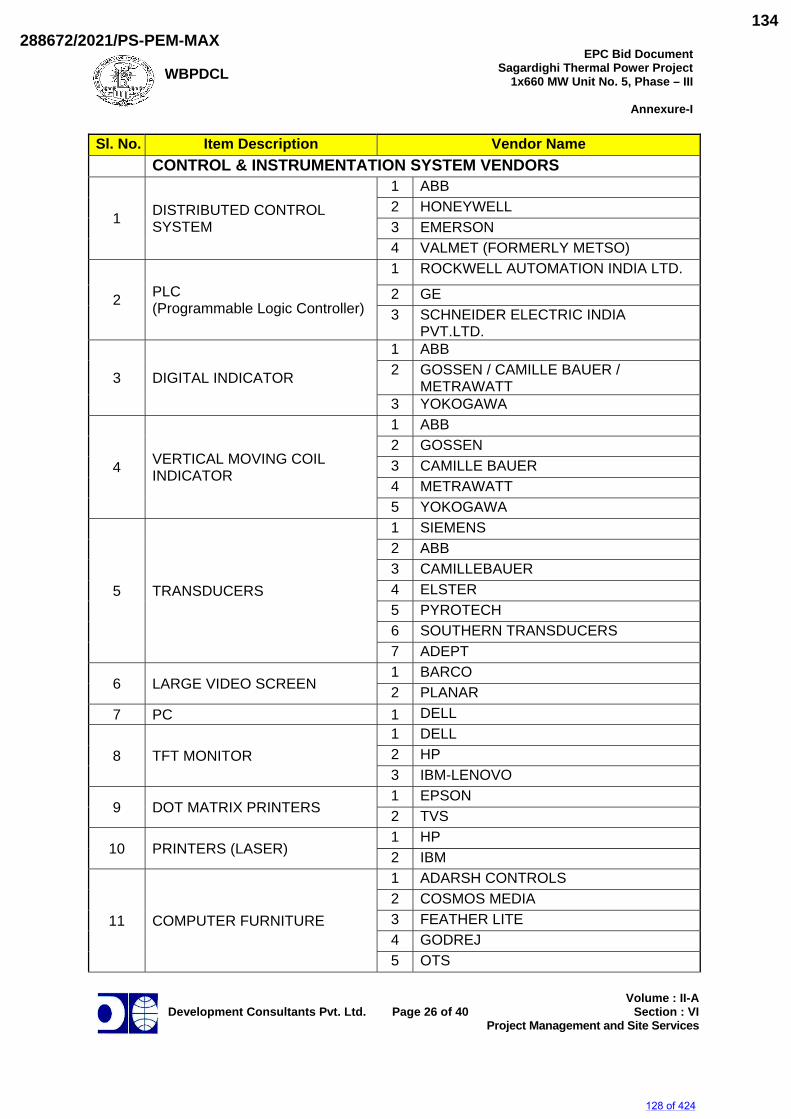
WBPDCL
EPC Bid DocumentSagardighi Thermal Power Project
1x660 MW Unit No. 5, Phase – III
Annexure-I
Development Consultants Pvt. Ltd.
Page 26 of 40
Volume : II-ASection : VI
Project Management and Site Services
Sl. No. Item Description Vendor Name CONTROL & INSTRUMENTATION SYSTEM VENDORS
1 DISTRIBUTED CONTROL SYSTEM
1 ABB 2 HONEYWELL 3 EMERSON 4 VALMET (FORMERLY METSO)
2 PLC (Programmable Logic Controller)
1 ROCKWELL AUTOMATION INDIA LTD.
2 GE 3 SCHNEIDER ELECTRIC INDIA
PVT.LTD.
3 DIGITAL INDICATOR
1 ABB 2 GOSSEN / CAMILLE BAUER /
METRAWATT 3 YOKOGAWA
4 VERTICAL MOVING COIL INDICATOR
1 ABB 2 GOSSEN 3 CAMILLE BAUER 4 METRAWATT 5 YOKOGAWA
5 TRANSDUCERS
1 SIEMENS 2 ABB 3 CAMILLEBAUER 4 ELSTER 5 PYROTECH 6 SOUTHERN TRANSDUCERS 7 ADEPT
6 LARGE VIDEO SCREEN 1 BARCO 2 PLANAR
7 PC 1 DELL
8 TFT MONITOR 1 DELL 2 HP 3 IBM-LENOVO
9 DOT MATRIX PRINTERS 1 EPSON 2 TVS
10 PRINTERS (LASER) 1 HP 2 IBM
11 COMPUTER FURNITURE
1 ADARSH CONTROLS 2 COSMOS MEDIA 3 FEATHER LITE 4 GODREJ 5 OTS
128 of 424
288672/2021/PS-PEM-MAX134
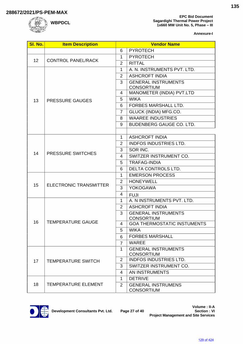
WBPDCL
EPC Bid DocumentSagardighi Thermal Power Project
1x660 MW Unit No. 5, Phase – III
Annexure-I
Development Consultants Pvt. Ltd.
Page 27 of 40
Volume : II-ASection : VI
Project Management and Site Services
Sl. No. Item Description Vendor Name 6 PYROTECH
12 CONTROL PANEL/RACK 1 PYROTECH 2 RITTAL
13 PRESSURE GAUGES
1 A. N. INSTRUMENTS PVT. LTD. 2 ASHCROFT INDIA 3 GENERAL INSTRUMENTS
CONSORTIUM 4 MANOMETER (INDIA) PVT.LTD 5 WIKA 6 FORBES MARSHALL LTD. 7 GLUCK (INDIA) MFG.CO. 8 WAAREE INDUSTRIES 9 BUDENBERG GAUGE CO. LTD.
14 PRESSURE SWITCHES
1 ASHCROFT INDIA 2 INDFOS INDUSTRIES LTD. 3 SOR INC. 4 SWITZER INSTRUMENT CO. 5 TRAFAG-INDIA 6 DELTA CONTROLS LTD.
15 ELECTRONIC TRANSMITTER
1 EMERSON PROCESS 2 HONEYWELL 3 YOKOGAWA 4 FUJI
16 TEMPERATURE GAUGE
1 A. N INSTRUMENTS PVT. LTD. 2 ASHCROFT INDIA 3 GENERAL INSTRUMENTS
CONSORTIUM 4 GOA THERMOSTATIC INSTUMENTS 5 WIKA 6 FORBES MARSHALL 7 WAREE
17 TEMPERATURE SWITCH
1 GENERAL INSTRUMENTS CONSORTIUM
2 INDFOS INDUSTRIES LTD. 3 SWITZER INSTRUMENT CO. 4 AN INSTRUMENTS
18 TEMPERATURE ELEMENT 1 DETRIVE 2 GENERAL INSTRUMENS
CONSORTIUM
129 of 424
288672/2021/PS-PEM-MAX135
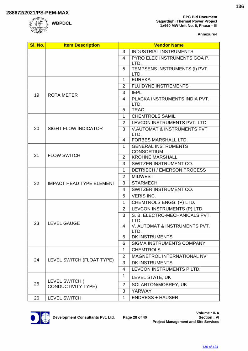
WBPDCL
EPC Bid DocumentSagardighi Thermal Power Project
1x660 MW Unit No. 5, Phase – III
Annexure-I
Development Consultants Pvt. Ltd.
Page 28 of 40
Volume : II-ASection : VI
Project Management and Site Services
Sl. No. Item Description Vendor Name 3 INDUSTRIAL INSTRUMENTS 4 PYRO ELEC INSTRUMENTS GOA P.
LTD. 5 TEMPSENS INSTRUMENTS (I) PVT.
LTD.
19 ROTA METER
1 EUREKA 2 FLUIDYNE INSTREMENTS 3 IEPL 4 PLACKA INSTRUMENTS INDIA PVT.
LTD. 5 TRAC
20 SIGHT FLOW INDICATOR
1 CHEMTROLS SAMIL 2 LEVCON INSTRUMENTS PVT. LTD. 3 V.AUTOMAT & INSTRUMENTS PVT
LTD. 4 FORBES MARSHALL LTD.
21 FLOW SWITCH
1 GENERAL INSTRUMENTS CONSORTIUM
2 KROHNE MARSHALL 3 SWITZER INSTRUMENT CO.
22 IMPACT HEAD TYPE ELEMENT
1 DETRIECH / EMERSON PROCESS 2 MIDWEST 3 STARMECH 4 SWITZER INSTRUMENT CO. 5 VERIS INC.
23 LEVEL GAUGE
1 CHEMTROLS ENGG. (P) LTD. 2 LEVCON INSTRUMENTS (P) LTD. 3 S. B. ELECTRO-MECHANICALS PVT.
LTD. 4 V. AUTOMAT & INSTRUMENTS PVT.
LTD. 5 DK INSTRUMENTS 6 SIGMA INSTRUMENTS COMPANY
24 LEVEL SWITCH (FLOAT TYPE)
1 CHEMTROLS 2 MAGNETROL INTERNATIONAL NV 3 DK INSTRUMENTS 4 LEVCON INSTRUMENTS P LTD.
25 LEVEL SWITCH ( CONDUCTIVITY TYPE)
1 LEVEL STATE, UK 2 SOLARTON/MOBREY, UK 3 YARWAY
26 LEVEL SWITCH 1 ENDRESS + HAUSER
130 of 424
288672/2021/PS-PEM-MAX136
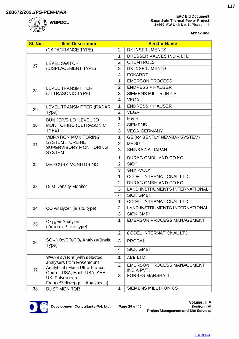
WBPDCL
EPC Bid DocumentSagardighi Thermal Power Project
1x660 MW Unit No. 5, Phase – III
Annexure-I
Development Consultants Pvt. Ltd.
Page 29 of 40
Volume : II-ASection : VI
Project Management and Site Services
Sl. No. Item Description Vendor Name (CAPACITANCE TYPE) 2 DK INSRTUMENTS
27 LEVEL SWITCH (DISPLACEMENT TYPE)
1 DRESSER VALVES INDIA LTD. 2 CHEMTROLS 3 DK INSRTUMENTS 4 ECKARDT
28 LEVEL TRANSMITTER (ULTRASONIC TYPE)
1 EMERSON PROCESS 2 ENDRESS + HAUSER 3 SIEMENS MIL TRONICS 4 VEGA
29 LEVEL TRANSMITTER (RADAR Type)
1 ENDRESS + HAUSER 2 VEGA
30 BUNKER/SILO LEVEL 3D MONITORING (ULTRASONIC TYPE)
1 E & H 2 SIEMENS 3 VEGA-GERMANY
31
VIBRATION MONITORING SYSTEM /TURBINE SUPERVISORY MONITORING SYSTEM
1 GE (for BENTLY NEVADA SYSTEM) 2 MEGGIT 3 SHINKAWA, JAPAN
32 MERCURY MONITORING 1 DURAG GMBH AND CO KG 2 SICK 3 SHINKAWA
33 Dust Density Monitor
1 CODEL INTERNATIONAL LTD. 2 DURAG GMBH AND CO KG 3 LAND INSTRUMENTS INTERNATIONAL 4 SICK GMBH
34 CO Analyzer (in situ type) 1 CODEL INTERNATIONAL LTD. 2 LAND INSTRUMENTS INTERNATIONAL 3 SICK GMBH
35 Oxygen Analyzer (Zirconia Probe type)
1 EMERSON PROCESS MANAGEMENT
36 SO2-NOx/CO/CO2 Analyzer(Insitu Type)
2 CODEL INTERNATIONAL LTD
3 PROCAL
4 SICK GMBH
37
SWAS system (with selected analysers from Rosemount Analytical / Hack Ultra-France, Orion – USA, Hach-USA. ABB – UK, Polymetron-France/Zeltwegger -Analyticals)
1 ABB LTD.
2 EMERSON PROCESS MANAGEMENT INDIA PVT.
3 FORBES MARSHALL
38 DUST MONITOR 1 SIEMENS MILLTRONICS
131 of 424
288672/2021/PS-PEM-MAX137
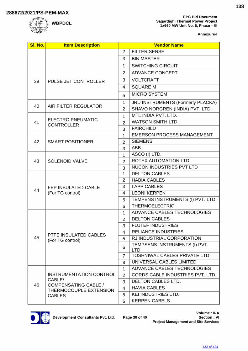
WBPDCL
EPC Bid DocumentSagardighi Thermal Power Project
1x660 MW Unit No. 5, Phase – III
Annexure-I
Development Consultants Pvt. Ltd.
Page 30 of 40
Volume : II-ASection : VI
Project Management and Site Services
Sl. No. Item Description Vendor Name 2 FILTER SENSE 3 BIN MASTER
39 PULSE JET CONTROLLER
1 SWITCHING CIRCUIT 2 ADVANCE CONCEPT 3 VOLTCRAFT 4 SQUARE M
5 MICRO SYSTEM
40 AIR FILTER REGULATOR 1 JRU INSTRUMENTS (Formerly PLACKA)2 SHAVO NORGREN (INDIA) PVT. LTD.
41 ELECTRO PNEUMATIC CONTROLLER
1 MTL INDIA PVT. LTD. 2 WATSON SMITH LTD. 3 FAIRCHILD
42 SMART POSITIONER 1 EMERSON PROCESS MANAGEMENT 2 SIEMENS 3 ABB
43 SOLENOID VALVE 1 ASCO (I) LTD. 2 ROTEX AUTOMATION LTD. 3 NUCON INDUSTRIES PVT LTD
44 FEP INSULATED CABLE (For TG control)
1 DELTON CABLES 2 HABIA CABLES 3 LAPP CABLES 4 LEONI KERPEN 5 TEMPENS INSTRUMENTS (I) PVT. LTD. 6 THERMOELECTRIC
45 PTFE INSULATED CABLES (For TG control)
1 ADVANCE CABLES TECHNOLOGIES 2 DELTON CABLES 3 FLUTEF INDUSTRIES 4 RELIANCE INDUSTEIES 5 RJ INDUSTRIAL CORPORATION
6 TEMPSENS INSTRUMENTS (I) PVT. LTD
7 TOSHNIWAL CABLES PRIVATE LTD 8 UNIVERSAL CABLES LIMITED
46
INSTRUMENTATION CONTROL CABLE/ COMPENSATING CABLE / THERMOCOUPLE EXTENSION CABLES
1 ADVANCE CABLES TECHNOLOGIES 2 CORDS CABLE INDUSTRIES PVT. LTD. 3 DELTON CABLES LTD. 4 HAVIA CABLES 5 KEI INDUSTRIES LTD. 6 KERPEN CABELS
132 of 424
288672/2021/PS-PEM-MAX138
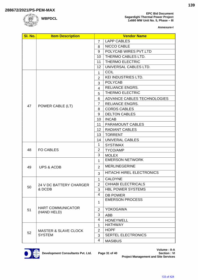
WBPDCL
EPC Bid DocumentSagardighi Thermal Power Project
1x660 MW Unit No. 5, Phase – III
Annexure-I
Development Consultants Pvt. Ltd.
Page 31 of 40
Volume : II-ASection : VI
Project Management and Site Services
Sl. No. Item Description Vendor Name 7 LAPP CABLES 8 NICCO CABLE 9 POLYCAB WIRES PVT.LTD
10 THERMO CABLES LTD. 11 THERMO ELECTRIC 12 UNIVERSAL CABLES LTD.
47 POWER CABLE (LT)
1 CCIL 2 KEI INDUSTRIES LTD. 3 POLYCAB 4 RELIANCE ENGRS. 5 THERMO ELECTRIC 6 ADVANCE CABLES TECHNOLOGIES 7 RELIANCE ENGRS. 8 CORDS CABLES 9 DELTON CABLES
10 INCAB 11 PARAMOUNT CABLES 12 RADIANT CABLES 13 TORRENT 14 UNIVERAL CABLES
48 FO CABLES 1 SYSTIMAX 2 TYCO/AMP 3 MOLEX
49 UPS & ACDB
1 EMERSON NETWORK
2 MERLINEGERINE
3 HITACHI HIREL ELECTRONICS
50 24 V DC BATTERY CHARGER & DCDB
1 CALDYNE 2 CHHABI ELECTRICALS 3 HBL POWER SYSTEMS 4 DB POWER
51 HART COMMUNICATOR (HAND HELD)
1 EMERSON PROCESS
2 YOKOGAWA 3 ABB 4 HONEYWELL
52 MASTER & SLAVE CLOCK SYSTEM
1 HATHWAY 2 HOPF 3 SERTEL ELECTRONICS 4 MASIBUS
133 of 424
288672/2021/PS-PEM-MAX139
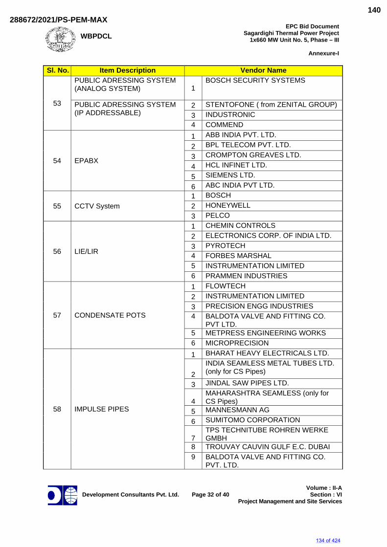
WBPDCL
EPC Bid DocumentSagardighi Thermal Power Project
1x660 MW Unit No. 5, Phase – III
Annexure-I
Development Consultants Pvt. Ltd.
Page 32 of 40
Volume : II-ASection : VI
Project Management and Site Services
Sl. No. Item Description Vendor Name
53
PUBLIC ADRESSING SYSTEM (ANALOG SYSTEM) 1
BOSCH SECURITY SYSTEMS
PUBLIC ADRESSING SYSTEM (IP ADDRESSABLE)
2 STENTOFONE ( from ZENITAL GROUP) 3 INDUSTRONIC 4 COMMEND
54 EPABX
1 ABB INDIA PVT. LTD. 2 BPL TELECOM PVT. LTD. 3 CROMPTON GREAVES LTD. 4 HCL INFINET LTD. 5 SIEMENS LTD. 6 ABC INDIA PVT LTD.
55 CCTV System 1 BOSCH 2 HONEYWELL 3 PELCO
56 LIE/LIR
1 CHEMIN CONTROLS 2 ELECTRONICS CORP. OF INDIA LTD. 3 PYROTECH 4 FORBES MARSHAL 5 INSTRUMENTATION LIMITED 6 PRAMMEN INDUSTRIES
57 CONDENSATE POTS
1 FLOWTECH 2 INSTRUMENTATION LIMITED 3 PRECISION ENGG INDUSTRIES 4 BALDOTA VALVE AND FITTING CO.
PVT LTD. 5 METPRESS ENGINEERING WORKS 6 MICROPRECISION
58 IMPULSE PIPES
1 BHARAT HEAVY ELECTRICALS LTD.
2 INDIA SEAMLESS METAL TUBES LTD. (only for CS Pipes)
3 JINDAL SAW PIPES LTD.
4 MAHARASHTRA SEAMLESS (only for CS Pipes)
5 MANNESMANN AG 6 SUMITOMO CORPORATION
7 TPS TECHNITUBE ROHREN WERKE GMBH
8 TROUVAY CAUVIN GULF E.C. DUBAI 9 BALDOTA VALVE AND FITTING CO.
PVT. LTD.
134 of 424
288672/2021/PS-PEM-MAX140
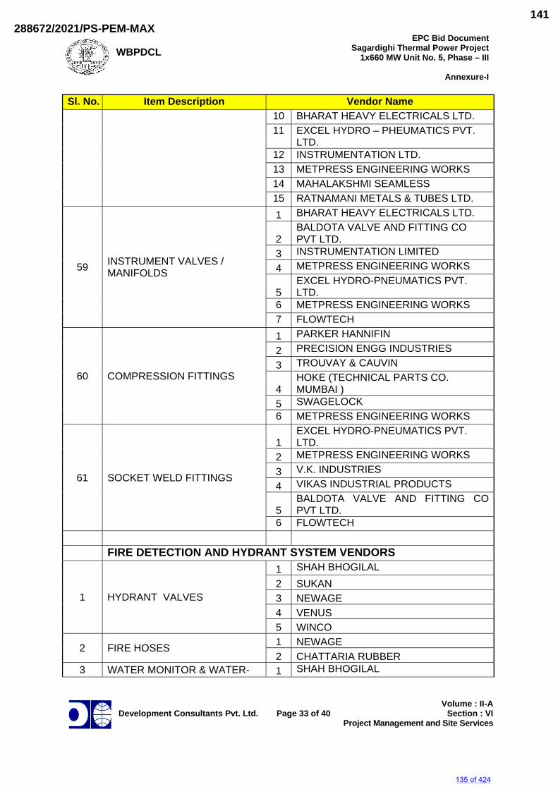
WBPDCL
EPC Bid DocumentSagardighi Thermal Power Project
1x660 MW Unit No. 5, Phase – III
Annexure-I
Development Consultants Pvt. Ltd.
Page 33 of 40
Volume : II-ASection : VI
Project Management and Site Services
Sl. No. Item Description Vendor Name 10 BHARAT HEAVY ELECTRICALS LTD. 11 EXCEL HYDRO – PHEUMATICS PVT.
LTD. 12 INSTRUMENTATION LTD. 13 METPRESS ENGINEERING WORKS 14 MAHALAKSHMI SEAMLESS 15 RATNAMANI METALS & TUBES LTD.
59 INSTRUMENT VALVES / MANIFOLDS
1 BHARAT HEAVY ELECTRICALS LTD.
2 BALDOTA VALVE AND FITTING CO PVT LTD.
3 INSTRUMENTATION LIMITED 4 METPRESS ENGINEERING WORKS
5 EXCEL HYDRO-PNEUMATICS PVT. LTD.
6 METPRESS ENGINEERING WORKS 7 FLOWTECH
60 COMPRESSION FITTINGS
1 PARKER HANNIFIN 2 PRECISION ENGG INDUSTRIES 3 TROUVAY & CAUVIN
4 HOKE (TECHNICAL PARTS CO. MUMBAI )
5 SWAGELOCK 6 METPRESS ENGINEERING WORKS
61 SOCKET WELD FITTINGS
1 EXCEL HYDRO-PNEUMATICS PVT. LTD.
2 METPRESS ENGINEERING WORKS 3 V.K. INDUSTRIES 4 VIKAS INDUSTRIAL PRODUCTS
5 BALDOTA VALVE AND FITTING CO PVT LTD.
6 FLOWTECH FIRE DETECTION AND HYDRANT SYSTEM VENDORS
1 HYDRANT VALVES
1 SHAH BHOGILAL 2 SUKAN 3 NEWAGE 4 VENUS 5 WINCO
2 FIRE HOSES 1 NEWAGE 2 CHATTARIA RUBBER
3 WATER MONITOR & WATER- 1 SHAH BHOGILAL
135 of 424
288672/2021/PS-PEM-MAX141
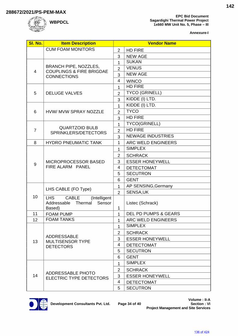
WBPDCL
EPC Bid DocumentSagardighi Thermal Power Project
1x660 MW Unit No. 5, Phase – III
Annexure-I
Development Consultants Pvt. Ltd.
Page 34 of 40
Volume : II-ASection : VI
Project Management and Site Services
Sl. No. Item Description Vendor Name CUM FOAM MONITORS 2 HD FIRE
3 NEW AGE
4 BRANCH PIPE, NOZZLES, COUPLINGS & FIRE BRIGDAE CONNECTIONS
1 SUKAN 2 VENUS 3 NEW AGE 4 WINCO
5 DELUGE VALVES 1 HD FIRE 2 TYCO (GRINELL) 3 KIDDE (I) LTD.
6 HVW/ MVW SPRAY NOZZLE 1 KIDDE (I) LTD. 2 TYCO 3 HD FIRE
7 QUARTZOID BULB SPRINKLERS/DETECTORS
1 TYCO(GRINELL) 2 HD FIRE 3 NEWAGE INDUSTRIES
8 HYDRO PNEUMATIC TANK 1 ARC WELD ENGINEERS
9 MICROPROCESSOR BASED FIRE ALARM PANEL
1 SIMPLEX 2 SCHRACK 3 ESSER HONEYWELL 4 DETECTOMAT 5 SECUTRON 6 GENT
10
LHS CABLE (FO Type) 1 AP SENSING,Germany 2 SENSA,UK
LHS CABLE (Intelligent Addressable Thermal Sensor Based) 1
Listec (Schrack)
11 FOAM PUMP 1 DEL PD PUMPS & GEARS 12 FOAM TANKS 1 ARC WELD ENGINEERS
13 ADDRESSABLE MULTISENSOR TYPE DETECTORS
1 SIMPLEX 2 SCHRACK 3 ESSER HONEYWELL 4 DETECTOMAT 5 SECUTRON 6 GENT
14 ADDRESSABLE PHOTO ELECTRIC TYPE DETECTORS
1 SIMPLEX 2 SCHRACK 3 ESSER HONEYWELL 4 DETECTOMAT 5 SECUTRON
136 of 424
288672/2021/PS-PEM-MAX142
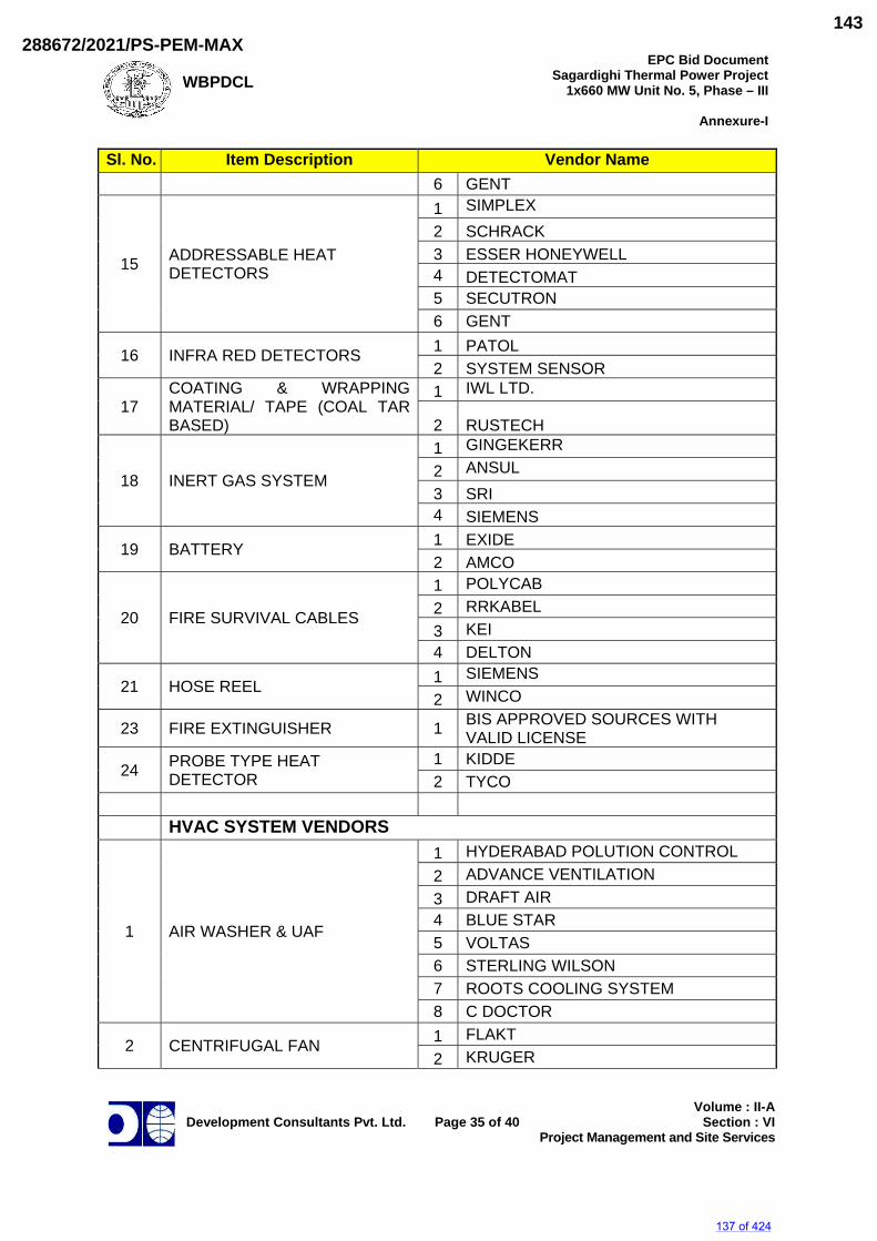
WBPDCL
EPC Bid DocumentSagardighi Thermal Power Project
1x660 MW Unit No. 5, Phase – III
Annexure-I
Development Consultants Pvt. Ltd.
Page 35 of 40
Volume : II-ASection : VI
Project Management and Site Services
Sl. No. Item Description Vendor Name 6 GENT
15 ADDRESSABLE HEAT DETECTORS
1 SIMPLEX 2 SCHRACK 3 ESSER HONEYWELL 4 DETECTOMAT 5 SECUTRON 6 GENT
16 INFRA RED DETECTORS 1 PATOL 2 SYSTEM SENSOR
17 COATING & WRAPPING MATERIAL/ TAPE (COAL TAR BASED)
1 IWL LTD.
2 RUSTECH
18 INERT GAS SYSTEM
1 GINGEKERR 2 ANSUL 3 SRI 4 SIEMENS
19 BATTERY 1 EXIDE 2 AMCO
20 FIRE SURVIVAL CABLES
1 POLYCAB 2 RRKABEL 3 KEI 4 DELTON
21 HOSE REEL 1 SIEMENS 2 WINCO
23 FIRE EXTINGUISHER 1 BIS APPROVED SOURCES WITH VALID LICENSE
24 PROBE TYPE HEAT DETECTOR
1 KIDDE 2 TYCO
HVAC SYSTEM VENDORS
1 AIR WASHER & UAF
1 HYDERABAD POLUTION CONTROL 2 ADVANCE VENTILATION 3 DRAFT AIR 4 BLUE STAR 5 VOLTAS 6 STERLING WILSON 7 ROOTS COOLING SYSTEM 8 C DOCTOR
2 CENTRIFUGAL FAN 1 FLAKT 2 KRUGER
137 of 424
288672/2021/PS-PEM-MAX143
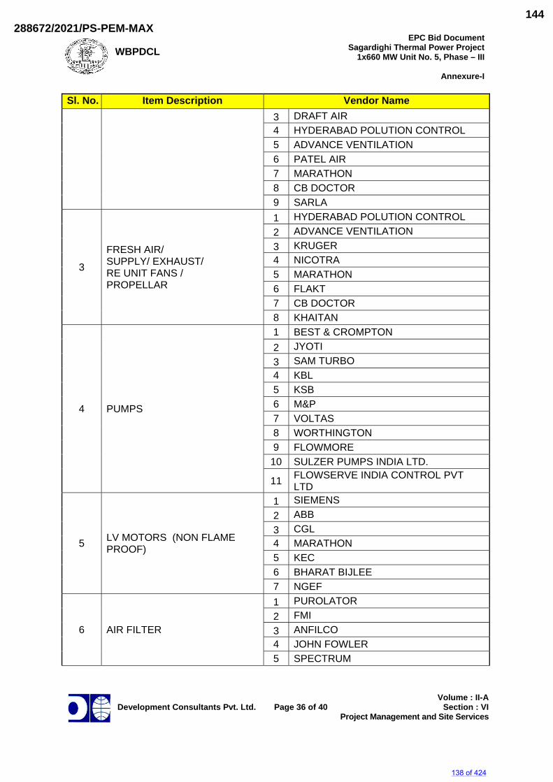
WBPDCL
EPC Bid DocumentSagardighi Thermal Power Project
1x660 MW Unit No. 5, Phase – III
Annexure-I
Development Consultants Pvt. Ltd.
Page 36 of 40
Volume : II-ASection : VI
Project Management and Site Services
Sl. No. Item Description Vendor Name 3 DRAFT AIR 4 HYDERABAD POLUTION CONTROL 5 ADVANCE VENTILATION 6 PATEL AIR 7 MARATHON 8 CB DOCTOR 9 SARLA
3
FRESH AIR/ SUPPLY/ EXHAUST/ RE UNIT FANS / PROPELLAR
1 HYDERABAD POLUTION CONTROL 2 ADVANCE VENTILATION 3 KRUGER 4 NICOTRA 5 MARATHON 6 FLAKT 7 CB DOCTOR 8 KHAITAN
4 PUMPS
1 BEST & CROMPTON 2 JYOTI 3 SAM TURBO 4 KBL 5 KSB 6 M&P 7 VOLTAS 8 WORTHINGTON 9 FLOWMORE
10 SULZER PUMPS INDIA LTD.
11 FLOWSERVE INDIA CONTROL PVT LTD
5 LV MOTORS (NON FLAME PROOF)
1 SIEMENS 2 ABB 3 CGL 4 MARATHON 5 KEC 6 BHARAT BIJLEE 7 NGEF
6 AIR FILTER
1 PUROLATOR 2 FMI 3 ANFILCO 4 JOHN FOWLER 5 SPECTRUM
138 of 424
288672/2021/PS-PEM-MAX144
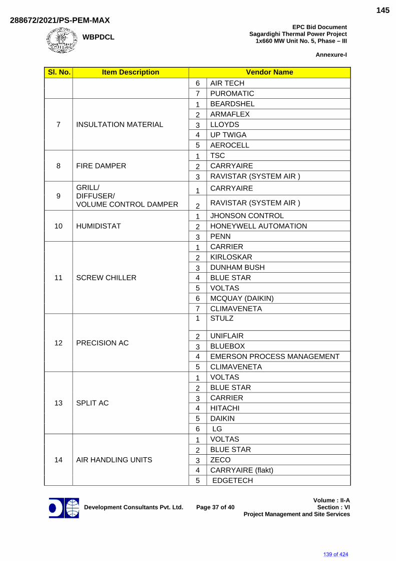
WBPDCL
EPC Bid DocumentSagardighi Thermal Power Project
1x660 MW Unit No. 5, Phase – III
Annexure-I
Development Consultants Pvt. Ltd.
Page 37 of 40
Volume : II-ASection : VI
Project Management and Site Services
Sl. No. Item Description Vendor Name 6 AIR TECH 7 PUROMATIC
7 INSULTATION MATERIAL
1 BEARDSHEL 2 ARMAFLEX 3 LLOYDS 4 UP TWIGA 5 AEROCELL
8 FIRE DAMPER 1 TSC 2 CARRYAIRE 3 RAVISTAR (SYSTEM AIR )
9 GRILL/ DIFFUSER/ VOLUME CONTROL DAMPER
1 CARRYAIRE
2 RAVISTAR (SYSTEM AIR )
10 HUMIDISTAT 1 JHONSON CONTROL 2 HONEYWELL AUTOMATION 3 PENN
11 SCREW CHILLER
1 CARRIER 2 KIRLOSKAR 3 DUNHAM BUSH 4 BLUE STAR 5 VOLTAS 6 MCQUAY (DAIKIN) 7 CLIMAVENETA
12 PRECISION AC
1 STULZ
2 UNIFLAIR 3 BLUEBOX 4 EMERSON PROCESS MANAGEMENT 5 CLIMAVENETA
13 SPLIT AC
1 VOLTAS 2 BLUE STAR 3 CARRIER 4 HITACHI 5 DAIKIN 6 LG
14 AIR HANDLING UNITS
1 VOLTAS 2 BLUE STAR 3 ZECO 4 CARRYAIRE (flakt) 5 EDGETECH
139 of 424
288672/2021/PS-PEM-MAX145
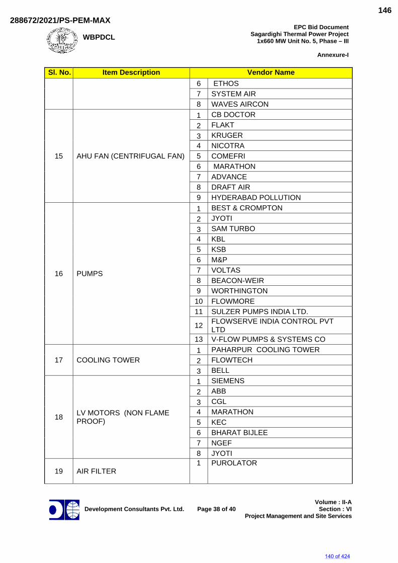
WBPDCL
EPC Bid DocumentSagardighi Thermal Power Project
1x660 MW Unit No. 5, Phase – III
Annexure-I
Development Consultants Pvt. Ltd.
Page 38 of 40
Volume : II-ASection : VI
Project Management and Site Services
Sl. No. Item Description Vendor Name 6 ETHOS 7 SYSTEM AIR 8 WAVES AIRCON
15 AHU FAN (CENTRIFUGAL FAN)
1 CB DOCTOR 2 FLAKT 3 KRUGER 4 NICOTRA 5 COMEFRI 6 MARATHON 7 ADVANCE 8 DRAFT AIR 9 HYDERABAD POLLUTION
16 PUMPS
1 BEST & CROMPTON 2 JYOTI 3 SAM TURBO 4 KBL 5 KSB 6 M&P 7 VOLTAS 8 BEACON‐WEIR 9 WORTHINGTON
10 FLOWMORE 11 SULZER PUMPS INDIA LTD.
12 FLOWSERVE INDIA CONTROL PVT LTD
13 V‐FLOW PUMPS & SYSTEMS CO
17 COOLING TOWER 1 PAHARPUR COOLING TOWER 2 FLOWTECH 3 BELL
18 LV MOTORS (NON FLAME PROOF)
1 SIEMENS 2 ABB 3 CGL 4 MARATHON 5 KEC 6 BHARAT BIJLEE 7 NGEF 8 JYOTI
19 AIR FILTER 1 PUROLATOR
140 of 424
288672/2021/PS-PEM-MAX146
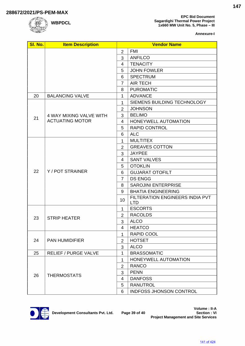
WBPDCL
EPC Bid DocumentSagardighi Thermal Power Project
1x660 MW Unit No. 5, Phase – III
Annexure-I
Development Consultants Pvt. Ltd.
Page 39 of 40
Volume : II-ASection : VI
Project Management and Site Services
Sl. No. Item Description Vendor Name 2 FMI 3 ANFILCO 4 TENACITY 5 JOHN FOWLER 6 SPECTRUM 7 AIR TECH 8 PUROMATIC
20 BALANCING VALVE 1 ADVANCE
21 4 WAY MIXING VALVE WITH ACTUATING MOTOR
1 SIEMENS BUILDING TECHNOLOGY 2 JOHNSON 3 BELIMO 4 HONEYWELL AUTOMATION 5 RAPID CONTROL 6 ALC
22 Y / POT STRAINER
1 MULTITEX 2 GREAVES COTTON 3 JAYPEE 4 SANT VALVES 5 OTOKLIN 6 GUJARAT OTOFILT 7 DS ENGG 8 SAROJINI ENTERPRISE 9 BHATIA ENGINEERING
10 FILTERATION ENGINEERS INDIA PVT LTD
23 STRIP HEATER
1 ESCORTS 2 RACOLDS 3 ALCO 4 HEATCO
24 PAN HUMIDIFIER 1 RAPID COOL 2 HOTSET 3 ALCO
25 RELIEF / PURGE VALVE 1 BRASSOMATIC
26 THERMOSTATS
1 HONEYWELL AUTOMATION 2 RANCO 3 PENN 4 DANFOSS 5 RANUTROL 6 INDFOSS JHONSON CONTROL
141 of 424
288672/2021/PS-PEM-MAX147
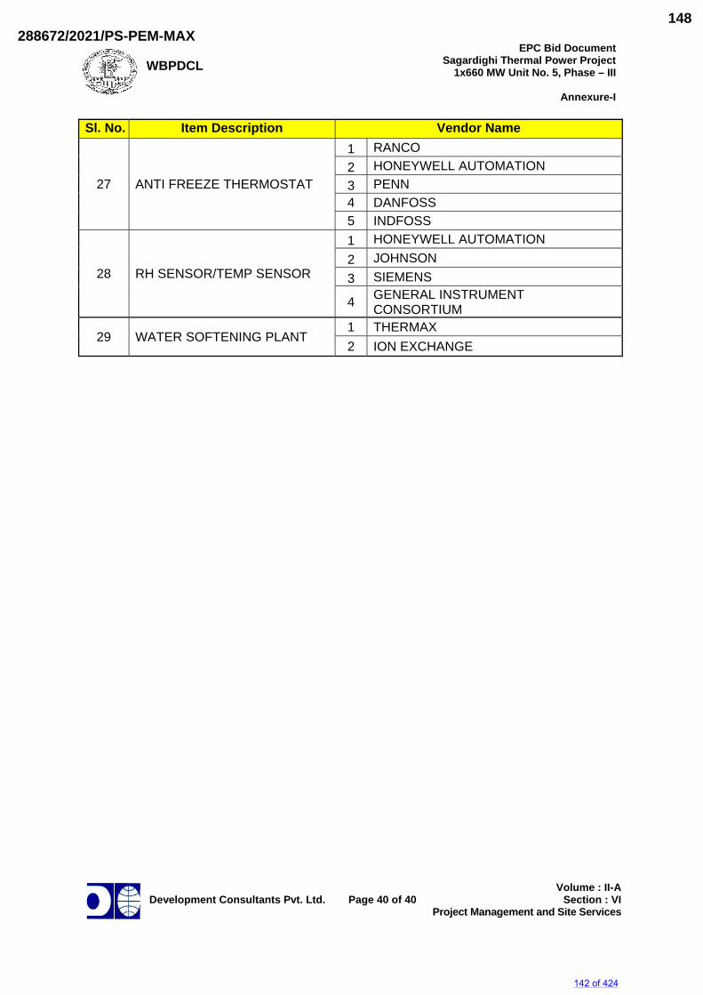
WBPDCL
EPC Bid DocumentSagardighi Thermal Power Project
1x660 MW Unit No. 5, Phase – III
Annexure-I
Development Consultants Pvt. Ltd.
Page 40 of 40
Volume : II-ASection : VI
Project Management and Site Services
Sl. No. Item Description Vendor Name
27 ANTI FREEZE THERMOSTAT
1 RANCO 2 HONEYWELL AUTOMATION 3 PENN 4 DANFOSS 5 INDFOSS
28 RH SENSOR/TEMP SENSOR
1 HONEYWELL AUTOMATION 2 JOHNSON 3 SIEMENS
4 GENERAL INSTRUMENT CONSORTIUM
29 WATER SOFTENING PLANT 1 THERMAX 2 ION EXCHANGE
142 of 424
288672/2021/PS-PEM-MAX148
WBPDCL
EPC Bid DocumentSagardighi Thermal Power Project
1x660 MW Unit No. 5, Phase – III
Development Consultants Pvt. Ltd.
Volume : II-A
Section : VII Engineering Services
SECTION-VII
ENGINEERING SERVICES
143 of 424
288672/2021/PS-PEM-MAX149
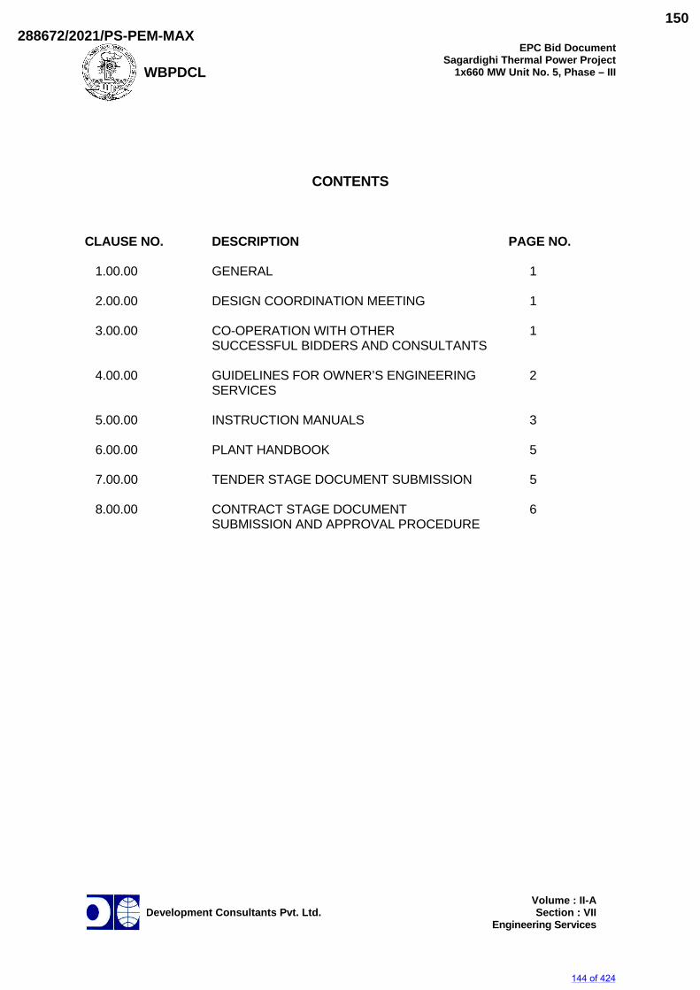
WBPDCL
EPC Bid DocumentSagardighi Thermal Power Project
1x660 MW Unit No. 5, Phase – III
Development Consultants Pvt. Ltd.
Volume : II-A
Section : VII Engineering Services
CONTENTS CLAUSE NO. DESCRIPTION PAGE NO. 1.00.00 GENERAL 1 2.00.00 DESIGN COORDINATION MEETING 1 3.00.00 CO-OPERATION WITH OTHER 1 SUCCESSFUL BIDDERS AND CONSULTANTS 4.00.00 GUIDELINES FOR OWNER’S ENGINEERING 2 SERVICES 5.00.00 INSTRUCTION MANUALS 3 6.00.00 PLANT HANDBOOK 5 7.00.00 TENDER STAGE DOCUMENT SUBMISSION 5 8.00.00 CONTRACT STAGE DOCUMENT 6 SUBMISSION AND APPROVAL PROCEDURE
144 of 424
288672/2021/PS-PEM-MAX150
WBPDCL
EPC Bid DocumentSagardighi Thermal Power Project
1x660 MW Unit No. 5, Phase – III
Development Consultants Pvt. Ltd.
Page 1 of 8
Volume : II-ASection : VII
Engineering Services
SECTION-VII
OWNER’S ENGINEERING SERVICES
1.00.00 GENERAL 1.01.00 As part of the overall project management activity, the Successful Bidder shall
be responsible for proper Owner’s Engineering and co-ordination of activities during various phases of execution of the contract. The Successful Bidder shall identify a person, designated as Project Manager, with whom the Owner, the Consulting Owner’s Engineer or the Review Consultant shall interact on matters related to Owner’s Engineering as well as execution of the contract. The Project Manager shall be the single-point contact person on behalf of the Successful Bidder and shall be responsible for all Owner’s Engineering co-ordination. The Owner /Consultant /Review Consultant shall interact with the Project Manager only on all matters of co-ordination between the Owner and the Successful Bidder or on matters involving the Successful Bidder, his manufacturing units and sub-vendors. For the purpose of expediting the Owner or his representative may sometimes interact with the manufacturing units or sub-vendors of the Successful Bidders. However such interaction will not, under any circumstance, dilute the responsibility of the Successful Bidder to provide a fully Owner’s Engineered and coordinated package under this contract.
1.02.00 On finalization of the contract, a procedure for exchange of Owner’s
Engineering information will be mutually agreed and finalized between the Owner and the Successful Bidder.
2.00.00 DESIGN COORDINATION MEETING The Successful Bidder and his sub-vendors will be called upon to attend design
co-ordination meetings with the Owner’s Engineer, other Successful Bidders and the Consultants of the Owner during the period of execution of contract. The Successful Bidder including his sub-vendors shall attend such meetings at their own cost at Owner's or Consultant’s office in Kolkata/ or at mutually agreed venue as and when required and fully cooperate with such persons and agencies involved during those discussions.
3.00.00 CO-OPERATION WITH OTHER CONTRACTORS AND CONSULTING
OWNER’S ENGINEERS The Successful Bidder shall agree to cooperate with the Owner's other
Contractors and Consulting Owner’s Engineers and freely exchange with them such technical information as is necessary to obtain the most efficient and economical design and to avoid unnecessary duplication of efforts. The Owner’s Engineer shall be provided with copies of all correspondences addressed by the Successful Bidder to other Sub- Vendors and Consulting Owner’s Engineers in respect of such exchange of technical information.
145 of 424
288672/2021/PS-PEM-MAX151
WBPDCL
EPC Bid DocumentSagardighi Thermal Power Project
1x660 MW Unit No. 5, Phase – III
Development Consultants Pvt. Ltd.
Page 2 of 8
Volume : II-ASection : VII
Engineering Services
4.00.00 GUIDELINES FOR OWNER’S ENGINEERING SERVICES 4.01.00 Prior to commencement of the Owner’s Engineering work as part of design
submissions, all aspects of design viz., criteria for selection and sizing of all equipment and systems, design margins etc. including that for structural steel and civil work shall be outlined and these shall form the basis for the detailed Owner’s Engineering work.
4.02.00 Owner’s Engineering work shall be performed on modern and proven concepts
and internationally accepted good Owner’s Engineering practices but fully compatible with the Indian environments. Owner shall have the right to review and approve the Owner’s Engineering work by themselves and/or through consultant and ask for any clarifications and changes/modifications to the work performed by Successful Bidder.
4.03.00 At any stage during the performance of assignment, the Successful Bidder may
be required to make certain changes/modification/improvements in design/ drawing/other documents, which in the opinion of the Owner could result in better improved design, layout, operability, plant availability, maintainability, reliability or economy of the plant and its systems/sub-systems in view of revised and more accurate information/data available at a later date(s) or feedback(s) received during execution/operation of similar units. Such changes/ modifications/improvements required could be identified by Owner and/or consultant and mutually discussed. Owner requires the Bidder to incorporate such action in the subject assignment appropriately without any additional cost liability and time implication to the Owner and same shall be within the responsibilities and Scope of the Successful Bidder.
4.04.00 During the course of review of detailed Owner’s Engineering stages, it may be
essential in the opinion of Owner to obtain certain classified data for review purposes only. In case Owner so desires, the Bidder shall submit such data to Owner.
4.05.00 During the course of review of detailed Owner’s Engineering, it may be
essential in Owner's opinion to obtain data and information on similar equipment and plants Owner’s Engineered by the Bidder. In case Owner so desires the Bidder shall submit such data and information to the Owner.
4.06.00 It is not the intent to give details of every single task covered in the total
Owner’s Engineering work to be carried out by Successful Bidder, however, all Owner’s Engineering work required for the satisfactory completion of the plant/systems as specified shall be carried out by the Successful Bidder. Broadly, the following are the minimum requirements in respect of scope of major items of work:
4.06.01 Preparation, updating and finalisation of scheme drawings, control and interlock
diagrams, detailed and fully dimensioned layout drawings (plant layout and equipment layout detailed plan, elevation and cross-sectional drawings at different elevations/ floor levels) covering all mechanical, electrical, C&I, civil and structural items, equipment, systems and facilities. Drawings and Schedules prepared by the Successful Bidder from time to time, as detailed
146 of 424
288672/2021/PS-PEM-MAX152
WBPDCL
EPC Bid DocumentSagardighi Thermal Power Project
1x660 MW Unit No. 5, Phase – III
Development Consultants Pvt. Ltd.
Page 3 of 8
Volume : II-ASection : VII
Engineering Services
designs are developed, shall be submitted for Owner's/ Consultant's approval before the work is taken up. Revisions, corrections, additions to drawings and schedules shall not be considered to change the scope of work.
4.06.02 Preparation of detailed technical specifications including data sheets, tender
drawings and bill of material for all bought out items, as also finalisation of corresponding sub-Vendors.
4.06.03 Review of sub-Vendor's data, drawings, design calculations, schedules, bill of
materials, instruction manuals etc. for all equipment, before forwarding them to Owner/Consultant for approval.
4.06.04 Preparation of civil construction drawings for all equipment showing foundation
details and full details regarding equipment loads, floor openings, details of embedments, etc. required for preparation of civil construction drawings and also as referred at relevant sections of Scope & Exclusions. These documents shall be preceded by appropriate design calculations, static and dynamic analysis as necessary.
4.06.05 Preparation and finalisation of process piping and instrumentation diagrams
and schematics, complete in all respects for all systems/packages of the power plant.
4.06.06 Preparation of consolidated schedules and bills of materials, including line
numbers, tag numbers, source of supply, service conditions, specifications, materials, types and connections details, quantities for items of the plant including dampers, steam traps, strainers, instrumentations, ducting.
4.06.07 Sizing of all piping and equipment as per the stipulated design criteria; carrying
out of flexibility analysis/dynamic analysis as necessary; hangers & support Owner’s Engineering.
4.06.08 Final revision of all documents including preparation and compilation of
Instruction Manuals for installation, commissioning, operation and maintenance for all equipment and systems. Refer clause 5.00.00 for the specific requirement in this regard.
4.06.09 Certification and submission of final as-built drawings for all areas. 4.06.10 Preparation and compilation of all drawings, schedules and instructions which
may be required at site, whether separately mentioned or not. 4.06.11 All erection and assembly drawings which may be required at site. 5.00.00 INSTRUCTION MANUALS 5.01.00 The Bidder shall provide all necessary instruction manuals for the Owner’s
review, comment, and final acceptance as required in the contract. The instruction manual shall contain full details required for erection, commissioning, operation and maintenance of each equipment. The instruction manual shall be submitted in the form of one (1) soft copy in CD and 15 hard copies.
147 of 424
288672/2021/PS-PEM-MAX153
WBPDCL
EPC Bid DocumentSagardighi Thermal Power Project
1x660 MW Unit No. 5, Phase – III
Development Consultants Pvt. Ltd.
Page 4 of 8
Volume : II-ASection : VII
Engineering Services
5.02.00 Erection Manuals 5.05.01 The erection manuals shall be submitted at least three (3) months prior to
commencement of erection activities of particular equipment/system. The manuals shall contain the following as a minimum:
a) Erection strategy. b) Sequence of erection. c) List of tools, tackles, heavy equipments like cranes, dozers etc required
for erection. d) Bill of Materials. e) Safety precautions to be followed during erection. f) Erection instructions. g) Critical checks and permissible deviation/tolerances. h) Check-list for pre-commissioning activities i) Check-list for commissioning of the system. j) Procedure for initial checking, testing and acceptance norms. 5.03.00 Operation & Maintenance Manuals 5.03.01 The operating and maintenance instructions together with drawings of the
equipment, as completed, shall be in sufficient detail to enable the Owner to operate, maintain, dismantle, reassemble, and adjust all parts of the equipment. They shall outline a step-by-step procedure for all operations likely to be carries out during the life of the plant/ equipment. Each manual shall include a complete set of drawings together with performance/ rating curves of the equipment and test certificates wherever applicable.
5.03.02 If after commissioning and initial operation of the plant, the manuals require any
modification/ additions in the view of the Owner or Bidder, the same shall be incorporated and the updated final manuals shall be submitted to the Owner.
5.03.03 The manuals shall include the following: a) List of spare parts along with their drawing and catalogue and Pro-
forma for ordering spares. b) Location and identification guide for bearings of various equipments and
lubrication schedule including charts showing lubrication checking, testing and replacement procedure.
148 of 424
288672/2021/PS-PEM-MAX154
WBPDCL
EPC Bid DocumentSagardighi Thermal Power Project
1x660 MW Unit No. 5, Phase – III
Development Consultants Pvt. Ltd.
Page 5 of 8
Volume : II-ASection : VII
Engineering Services
c) Wherever applicable, fault location charts shall be included to facilitate fault detection.
d) Detailed specification for all consumables (including lubricating oils,
greases, chemicals etc.) required for each equipment. 6.00.00 PLANT HANDBOOK The Bidder shall provide the plant handbook to the Owner as per provision of
the contract. The Plant Handbook shall contain the following as a minimum: a) Design and performance data b) Process & instrumentation diagrams c) Single line diagrams d) Sequence & Protection interlock schemes e) Alarm and trip values f) Performance curves g) General layout plan and layout of Balance of Plant building and auxiliary
buildings h) Important Do’s and Don’ts. 7.00.00 TENDER STAGE DOCUMENT SUBMISSION 7.01.00 The Bidder shall submit along with his bid all documents/drawings as specified
in RFP and respective sections of the Technical Specifications in Vol-II and Vol-III. The documents shall include but not be limited to the following:
a) All Bid proposal sheets duly filled up. b) Detailed experience list and financial resources of the Prime Bidder his
collaborators/associates in this bid as well as the sub-vendors proposed.
c) Scheme drawings indicating scope of supply and service as offered by
the Bidder indicating clearly exclusions, if any. d) List of terminal points of the package offered together with quality and
quantity of various input (i.e. water, air, electricity etc.) as required from the Owner at such interfaces.
e) Equipment GA, Layout, Design Calculations, interlock and other
write-up, catalogues/literature etc. as required for clear understanding of the bid submitted.
149 of 424
288672/2021/PS-PEM-MAX155
WBPDCL
EPC Bid DocumentSagardighi Thermal Power Project
1x660 MW Unit No. 5, Phase – III
Development Consultants Pvt. Ltd.
Page 6 of 8
Volume : II-ASection : VII
Engineering Services
f) High level project schedule network indicating target dates for
intermediate milestones and final commissioning of plant systems; This network shall be supplemented by a detailed write-up on proposed sequence and method of execution for project implementation, deployment schedule for Key personnel with their bio-data, schedule of construction machinery etc.
8.00.00 CONTRACT STAGE DOCUMENT SUBMISSION AND APPROVAL
PROCEDURE 8.01.00 Owner’s Engineering schedule shall be submitted by the Bidder as indicated in
the RFP. Owner’s Engineering schedule shall be developed in format as desired by the Owner/consultant.
The documents shall be divided into two categories: a) for approval and b) for
information/further Owner’s Engineering and co-ordination by the Consultant. In preparing this schedule, the Bidder shall allow one (1) week from date of
receipt for review and comments by the Consultant for each submission of a document.
This document submission schedule shall require acceptance by the
Owner/Consultant. Bidder shall also develop and submit a Master drawing list to the
Owner/consultant. 8.02.00 All contract documents shall be marked with the name of the Owner, the
Project, the specification title and number and the unit designation. All dimensions shall be in metric units. All notes, markings etc. shall be in English. 8.03.00 Documents/Drawings, submitted during tender stage, shall be revalidated or
revised as required and submitted as certified contract document for approval/information of the Owner/Consultant.
8.04.00 Unless specified otherwise, the following categories of documents/drawings
would require approval of the Owner/Consultant: a) System scheme and Process & instrumentation Diagrams (P & IDs). b) Design basis documents / memoranda / calculations justifying sizing
and selection of equipment, vessels, tanks, piping, valves & specialities as well as the process parameters.
c) Equipment data sheets and general arrangement drawings. d) Materials of construction.
150 of 424
288672/2021/PS-PEM-MAX156
WBPDCL
EPC Bid DocumentSagardighi Thermal Power Project
1x660 MW Unit No. 5, Phase – III
Development Consultants Pvt. Ltd.
Page 7 of 8
Volume : II-ASection : VII
Engineering Services
e) General Arrangement and Layout drawings.
f) Typical control schemes, circuit diagrams, drive/ feeder-wise control scheme showing all external interfaces.
g) Control System Configuration
g) Shop Inspection and Testing Procedures, Test Set-up & Instrumentation, Acceptance Criteria and Codes / Standards followed, correction curves / charts, etc.
h) Performance Test Procedures, Instrumentation, Acceptance Criteria
and Codes / Standards followed, correction curves / charts, etc. i) Schedules covering equipment delivery schedules, erection, testing and
commissioning schedules at L1 and L2 levels. 8.05.00 Unless specified otherwise, the following categories of documents / drawings
would be treated for information/further Owner’s Engineering by the Owner/Consultant. The Bidder shall, however, incorporate all additional information and clarifications in these documents/ drawings as and when desired by the Owner/ Consultant.
a) Equipment foundation drawings. b) Equipment cross-section drawings, product literature etc. which are of
proprietary nature. c) Predicted performance curves of equipment. d) Various bills of quantity, schedules etc. e) Piping fabrication drawings, isometrics etc. f) Panel wiring diagrams. g) Instruction/Operation manuals. h) Service manuals and trouble shooting guide for C & I system including
field instruments. i) Operation logic diagrams. j) Cable schedule and interconnection chart.
In essence, the Bidder is solely responsible for corrections and adequacy of design & Owner’s Engineering for documents under this category.
8.06.00 Upon review, the Consultant shall put his remarks and one of the following
action stamps on the drawing / document: a) Approved.
151 of 424
288672/2021/PS-PEM-MAX157
WBPDCL
EPC Bid DocumentSagardighi Thermal Power Project
1x660 MW Unit No. 5, Phase – III
Development Consultants Pvt. Ltd.
Page 8 of 8
Volume : II-ASection : VII
Engineering Services
b) Approved except as noted, forward final drawing c) Approved except as noted, resubmission required. d) Disapproved. e) For information/reference only. For action stamps in category (c) & (d), documents must be resubmitted for
review by the Owner/Consultant. For action stamp in category (b), further review by Owner/Consultant would not be necessary provided the Bidder agrees & incorporates the minor comments made on the document.
Except for action stamp under category (c) & (d), the Bidder can proceed with
manufacturing and other sequential activities for those areas of a drawing/document which do not have any review comment by the Owner/ Consultant.
The Consultant may accord approval in category (c) or (d) in more than one
submission of a document till he is satisfied that the intent of the specification has been fully complied with. The Bidder shall be responsible for delay in such cases and no extension of time shall ordinarily be allowed on such grounds.
The Bidder's work shall be in strict accordance with the finally approved
drawings and no deviation shall be permitted without written approval of the Consultant.
8.07.00 Except key plan/general yard plan, any layout drawing requiring scrutiny shall
not be drawn to a scale less than 1:50. 8.08.00 For review by the Consultant, the Bidder shall furnish three (3) prints of each
drawing (only for first submission). There upon all transaction of drawings including reviewed comments and stamping shall be done in soft. All transaction of drawings shall be accompanied by a reference letter mentioning the date, revision no. and document status. Only on receiving the Approval Stamping, bidder shall distribute 6 sets of drawings (2 at WBPDCL corporate office and 4 sets at WBPDCL site office).. The Bidder shall furnish three (3) CDs of all as built/final drawings for Owner/Consultant site.
8.09.00 In case of contradiction between the stipulations above and those stated
elsewhere in the specification, the stipulations herein shall prevail.
152 of 424
288672/2021/PS-PEM-MAX158
WBPDCL
EPC Bid DocumentSagardighi Thermal Power Project
1x660 MW Unit No. 5, Phase - III
Development Consultants Pvt. Ltd.
Volume : II-ASection : VIII
Quality Assurance Requirements
SECTION-VIII
QUALITY ASSURANCE REQUIREMENTS
153 of 424
288672/2021/PS-PEM-MAX159
WBPDCL
EPC Bid DocumentSagardighi Thermal Power Project
1x660 MW Unit No. 5, Phase - III
Development Consultants Pvt. Ltd.
Volume : II-ASection : VIII
Quality Assurance Requirements
CONTENT CLAUSE NO. DESCRIPTION PAGE NO. 1.00.00 QUALITY ASSURANCE PROGRAMME 1 2.00.00 GENERAL REQUIREMENTS QUALITY ASSURANCE 2 3.00.00 QUALITY ASSURANCE DOCUMENTS 4 4.00.00 INSPECTION, TESTING & INSPECTION 5 CERTIFICATES
154 of 424
288672/2021/PS-PEM-MAX160
WBPDCL
EPC Bid DocumentSagardighi Thermal Power Project
1x660 MW Unit No. 5, Phase – III
Development Consultants Pvt. Ltd.
Page 1 of 8
Volume : II-ASection : VIII
Quality Assurance Requirements
SECTION-VIII
QUALITY ASSURANCE REQUIREMENTS
1.00.00 QUALITY ASSURANCE PROGRAMME 1.01.00 To ensure that the equipment and services under the scope of Contract
whether manufactured or performed within the Successful Bidder's works or at his Sub-Vendor's premises or at the Owner's site or at any other place or work are in accordance with the specifications, the Successful Bidder shall adopt suitable quality assurance programme to control such activities at all points, as necessary. Such programmes shall be outlined by the Successful Bidder and shall be finally accepted by the Owner/Authorised representative after discussions before the award of contract. A quality assurance programme of the Successful Bidder shall generally cover the following :
a) His organisation structure for the management and implementation of
the proposed quality assurance programme. b) Documentation control system. c) Qualification data for Bidder's key personnel. d) The procedure for purchase of materials, parts, components and
selection of Sub-Vendor's services including vendor analysis, source inspection, incoming raw-material inspection, verification of materials purchased etc.
e) System for shop manufacturing and site erection control including
process controls and fabrication and assembly controls. f) Control of non-conforming items and system for corrective actions. g) Inspection and test procedure both for manufacture and all site related
works. h) Control of calibration and testing of measuring and testing equipments. i) System for quality audit. j) System for indication and appraisal of inspection status. k) System for authorising release of manufactured product to the Owner. l) System for handling storage and delivery.
m) System for maintenance of records.
155 of 424
288672/2021/PS-PEM-MAX161
WBPDCL
EPC Bid DocumentSagardighi Thermal Power Project
1x660 MW Unit No. 5, Phase – III
Development Consultants Pvt. Ltd.
Page 2 of 8
Volume : II-ASection : VIII
Quality Assurance Requirements
n) Furnishing of quality plans for manufacturing and field activities detailing out the specific quality control procedure adopted for controlling the quality characteristics relevant to each item of equipment/component as per format enclosed at Annexure-A to this section.
2.00.00 GENERAL REQUIREMENTS - QUALITY ASSURANCE 2.01.00 All materials, components and equipment covered under this specification shall
be procured, manufactured and tested at all the stages, as well as Services provided for erection, commissioning and testing shall be as per a comprehensive Quality Assurance Programme. An indicative programme of inspection/tests to be carried out by the Bidder for some of the major items is given in the respective technical specification. This is however, not intended to form a comprehensive programme as it is the Bidder's responsibility to draw up and implement such programme and reviewed by by the Owner/Consultant. The detailed Quality Plans for manufacturing and field activities should be drawn up by the Bidder, separately in the format attached at Annexure-I and will be submitted to Owner/Owner’s representative for review. Schedule of finalisation of such quality plans will be finalised before award.
2.02.00 Manufacturing Quality Plan will detail out for all the components and
equipment, various tests/inspection, to be carried out as per the requirements of this specification and standards mentioned therein and quality practices and procedures followed by Bidder's Quality Control organisation, the relevant reference documents and standards, acceptance norms, inspection documents raised etc., during all stages of materials procurement, manufacture, assembly and final testing/performance testing.
2.03.00 Field Quality Plans will detail out for all the equipment, the quality practices and
procedures etc. to be followed by the Bidder's site Quality Control organisation, during various stages of site activities from receipt of materials/equipment at site.
2.04.00 The Bidder shall also furnish copies of the reference documents/plant
standards/acceptance norms/tests and inspection procedure etc., as referred in Quality Plans along with Quality Plans. These Quality plans and reference documents/standards etc. will be subject to Consultant's approval without which manufacture shall not proceed. In these approved quality plans, Owner/Authorised representative/Consultant shall identify Customer Hold Points (CHP), test/checks which shall be carried out in presence of the Owner/Consultant/Owners Owner’s Engineer or his Authorised Representative and beyond which the work will not proceed without consent of Owner/Authorised representative/Consultant in writing. All deviations to this specification, approved quality plans and applicable standards must be documented and referred to Owner/Authorised Representative/Consultant for acceptance and dispositioning.
2.05.00 The Bidder shall provide adequate notice to the Owner for inspection before the
material is dispatched as per the provisions of the Contract. No material shall be despatched from the manufacturer's works before the same is accepted subsequent to pre-despatch final inspection including verification of records of
156 of 424
288672/2021/PS-PEM-MAX162
WBPDCL
EPC Bid DocumentSagardighi Thermal Power Project
1x660 MW Unit No. 5, Phase – III
Development Consultants Pvt. Ltd.
Page 3 of 8
Volume : II-ASection : VIII
Quality Assurance Requirements
all previous tests/inspections by Owner's Owner’s Engineer/Authorised representative, and duly authorised for despatch issuance of Material Despatch Clearance Certificate (MDCC).
2.06.00 All materials used or supplied shall be accompanied by valid and approved
materials certificates and tests and inspection report. These certificates and reports shall indicate the sheet numbers or other such acceptable identification numbers of the material. The material certified shall also have the identification details stamped on it.
2.07.00 All the individual and assembled rotating parts shall be statically and
dynamically balanced in the works. Where accurate alignment is necessary for component parts of machinery
normally assembled on site, the Bidder shall allow for trial assembly prior to despatch from place of manufacture.
2.08.00 Castings and forgings used for construction shall be of tested quality. Details of
results of chemical analysis, heat treatment record, mechanical property test results shall be furnished.
2.09.00 All welding and brazing shall be carried out as per procedure drawn and
qualified in accordance with requirements of ASME Section-IX/BS-4870 or other International equivalent standard acceptable to the Owner.
All brazers, welders etc. employed on any part of the contract at
Bidder's/Sub-Vendor's works or at site shall be qualified as per ASME Section-IX or BS-4871 or equivalent international standard approved by the Owner. Such qualification tests shall be conducted in presence of Owner/his authorised representative.
For welding of pressure parts and high pressure piping the requirements of IBR
shall also be complied with. Under no circumstances any repair or welding of castings be carried out
without the consent of the Owner. Proof of the effectiveness of each repair by radiographic and/or other non-destructive testing technique, shall be provided to the Owner.
All pressure parts shall be subjected to hydraulic testing as per the
requirements of IBR. Other parts shall be tested for one and half times the maximum operating pressure, for a period not less than thirty (30) minutes.
2.10.00 All non-destructive examination (NDT) shall be carried out in accordance with
approved international standard. The NDT operator shall be qualified as per SNT-TC-IA (of American Society of non- destructive examination). Results of NDT shall be properly recorded and submitted for acceptance.
All welding procedures adopted for performing welding work shall be qualified
in accordance with the requirements of Section-IX of ASME code or IBR as applicable. All welded joints for pressure parts shall be tested by liquid
157 of 424
288672/2021/PS-PEM-MAX163
WBPDCL
EPC Bid DocumentSagardighi Thermal Power Project
1x660 MW Unit No. 5, Phase – III
Development Consultants Pvt. Ltd.
Page 4 of 8
Volume : II-ASection : VIII
Quality Assurance Requirements
penetrant examination according to the method outlined in ASME Boiler and Pressure Vessel code. Radiography, magnetic particle examination and ultrasonic testing shall be employed wherever necessary/ recommended by the applicable code. At least 10% of all major butt welding joints shall be radiographed. Statutory payments in respect of IBR approvals including inspection shall be made by Bidder. Bidder’s scope and responsibility shall also include preparation and submission of all necessary documents in the specific formats and manner stipulated by the statutory bodies, coordination and follow up for above approvals.
2.11.00 All the Sub-Vendors proposed by the Bidder for procurement of major bought
out items including castings, forgings, semi-finished and finished components/equipment list of which shall be drawn up by the Bidder and finalised with the Owner shall be subject to Owner's review. Quality Plans of the successful Sub-Vendors shall be discussed, finalised and accepted by the Owner/Authorised representative and form part of the Purchase Order between the Bidder and the Sub-Vendor.
2.12.00 All the purchase specifications for the major bought-out items, list of which shall
be drawn up by the Bidder and finalised with the Owner shall be furnished to the Owner for comments and subsequent acceptance before orders are placed.
Owner reserves the right to carry out quality audit and quality surveillance of
the systems and procedures of the Bidder's or their Sub-Vendor’s quality management and control activities. The Bidder shall provide all necessary assistance to enable the Owner carry out such audit and surveillance.
Quality audit/acceptance of the results of tests and inspection will not prejudice
the right of the Owner to reject equipment not giving the desired performance after erection and shall not in no way limit the liabilities and responsibilities of the Bidder in earning satisfactory performance of equipment as per specification.
2.13.00 Quality requirements for main equipment shall equally apply for spares and
replacement items. 2.14.00 Repair/rectification procedures to be adopted to make any job acceptable shall
be subject to the acceptance of the Owner. 2.15.00 For quality assurance of all civil works refer to the specifications for civil works. 3.00.00 QUALITY ASSURANCE DOCUMENTS 3.01.00 The Bidder shall be required to submit two (2) copies and two (2) sets of
microfilms of the following Quality Assurance documents within three (3) weeks after despatch of the equipment:
a) Material mill test reports on components as specified by the
specification.
158 of 424
288672/2021/PS-PEM-MAX164
WBPDCL
EPC Bid DocumentSagardighi Thermal Power Project
1x660 MW Unit No. 5, Phase – III
Development Consultants Pvt. Ltd.
Page 5 of 8
Volume : II-ASection : VIII
Quality Assurance Requirements
b) The inspection plan with verification, inspection plan check points, verification sketches, if used and methods used to verify that the inspection and testing points in the inspection plan were performed satisfactorily.
c) Non-destructive examination results /reports including radiography
interpretation reports. d) Factory tests results for testing required as per applicable codes and
standards referred in the specification. e) Welder identification list listing welder's and welding operator's
qualification procedure and welding identification symbols. f) Sketches and drawings used for indicating the method of traceability of
the radiographs to the location on the equipment. g) Stress relief time temperature charts. h) Inspection reports duly signed by QA personnel of the Owner and
Bidder for the agreed inspection hold points. During the course of inspection, the following will also be recorded :
i) When some important repair work is involved to make the job
acceptable. ii) The repair work remains part of the accepted product quality. i) Letter of conformity certifying that the requirement is in compliance with
finalised specification requirements. 4.00.00 INSPECTION, TESTING AND INSPECTION CERTIFICATES 4.01.00 The Successful Bidder shall give the Owner’s Engineer/Inspector fifteen (15)
days written notice of any material being ready for testing. Such tests shall be to the Successful Bidder's account except for the expenses of the Inspector. The Owner’s Engineer/Inspector, unless the witnessing of the tests is virtually waived, will attend such tests within fifteen (15) days of the date on which the equipment is notified as being ready for test/inspection failing which the Successful Bidder may proceed with test which shall be deemed to have been made in the Inspector's presence and he shall forthwith forward to the Inspector duly certified copies of test reports in six (6) copies.
4.02.00 The Owner’s Engineer or Inspector shall within fifteen (15) days from the date
of Inspection as defined herein give notice in writing to the Successful Bidder, or any objection to any drawings and all or any equipment and workmanship which is in his opinion not in accordance with the contract. The Successful Bidder shall give due consideration to such objections and shall either make modifications that may be necessary to meet the said objections or shall confirm in writing to the Owner’s Engineer/Inspector giving reasons therein, that no modifications are necessary to comply with the contract.
159 of 424
288672/2021/PS-PEM-MAX165
WBPDCL
EPC Bid DocumentSagardighi Thermal Power Project
1x660 MW Unit No. 5, Phase – III
Development Consultants Pvt. Ltd.
Page 6 of 8
Volume : II-ASection : VIII
Quality Assurance Requirements
4.03.00 When the factory tests have been completed at the Bidder's or sub-Vendor's
works, the Owner/Inspector shall issue a certificate to this effect fifteen (15) days after completion of tests but if the tests are not witnessed by the Owner/ Inspectors, the certificate shall be issued within fifteen (15) days of the receipt of the Bidder's test certificate by the Owner/Inspector. Failure of the Owner/Inspector to issue such a certificate shall not prevent the Bidder from proceeding with the works. The completion of these tests, or the issue of the certificates shall not bind the Owner to accept the equipment should it, on further tests after erection be found not to comply with the contract.
4.04.00 The Bidder shall furnish quarterly inspection programme indicating schedule
dates of inspection at customer hold point and final inspection stages. Updated quarterly inspection plans will be made for each three consecutive months and shall be furnished before beginning of each calendar month.
160 of 424
288672/2021/PS-PEM-MAX166
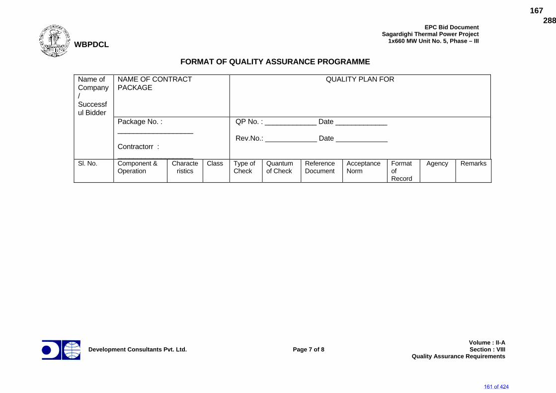
WBPDCL
EPC Bid DocumentSagardighi Thermal Power Project
1x660 MW Unit No. 5, Phase – III
Development Consultants Pvt. Ltd.
Page 7 of 8
Volume : II-A Section : VIII
Quality Assurance Requirements
FORMAT OF QUALITY ASSURANCE PROGRAMME
Name of Company/ Successful Bidder
NAME OF CONTRACT PACKAGE
QUALITY PLAN FOR
Package No. : ___________________ Contractorr : ___________________
QP No. : _____________ Date _____________ Rev.No.: _____________ Date _____________
Sl. No. Component & Operation
Characteristics
Class Type of Check
Quantum of Check
Reference Document
Acceptance Norm
Format of Record
Agency
Remarks
161 of 424
288672/2021/PS-PEM-MAX167
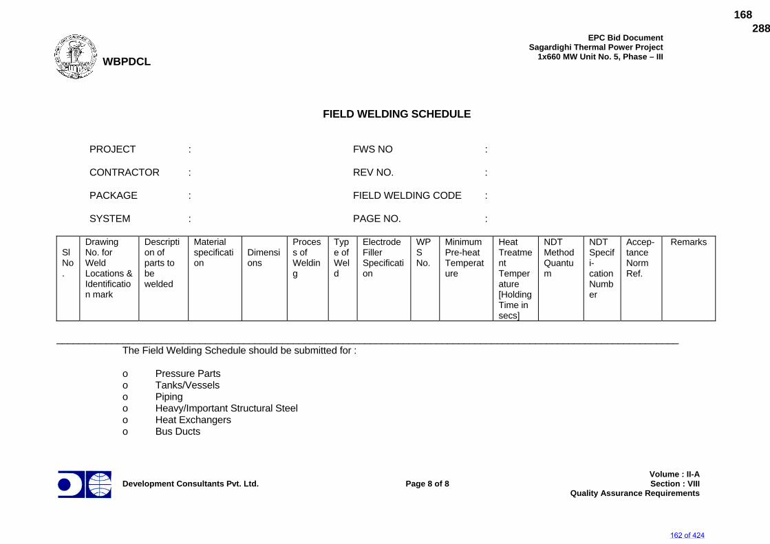
WBPDCL
EPC Bid DocumentSagardighi Thermal Power Project
1x660 MW Unit No. 5, Phase – III
Development Consultants Pvt. Ltd.
Page 8 of 8
Volume : II-A Section : VIII
Quality Assurance Requirements
FIELD WELDING SCHEDULE
PROJECT : FWS NO : CONTRACTOR : REV NO. : PACKAGE : FIELD WELDING CODE : SYSTEM : PAGE NO. :
Sl No.
Drawing No. for Weld Locations & Identification mark
Description of parts to be welded
Material specification
Dimensions
Process of Welding
Type of Weld
Electrode Filler Specification
WPS No.
Minimum Pre-heat Temperature
Heat Treatment Temperature [Holding Time in secs]
NDT Method Quantum
NDT Specifi-cation Number
Accep- tance Norm Ref.
Remarks
_________________________________________________________________________________________________________________ The Field Welding Schedule should be submitted for : o Pressure Parts o Tanks/Vessels o Piping o Heavy/Important Structural Steel o Heat Exchangers o Bus Ducts
162 of 424
288672/2021/PS-PEM-MAX168
WBPDCL
EPC Bid DocumentSagardighi Thermal Power Project
1x660 MW Unit No. 5, Phase - III
Development Consultants Pvt. Ltd.
Volume : II-ASection : IX
Performance Guarantees And Tests
SECTION-IX
PERFORMANCE GUARANTEES AND TESTS
163 of 424
288672/2021/PS-PEM-MAX169
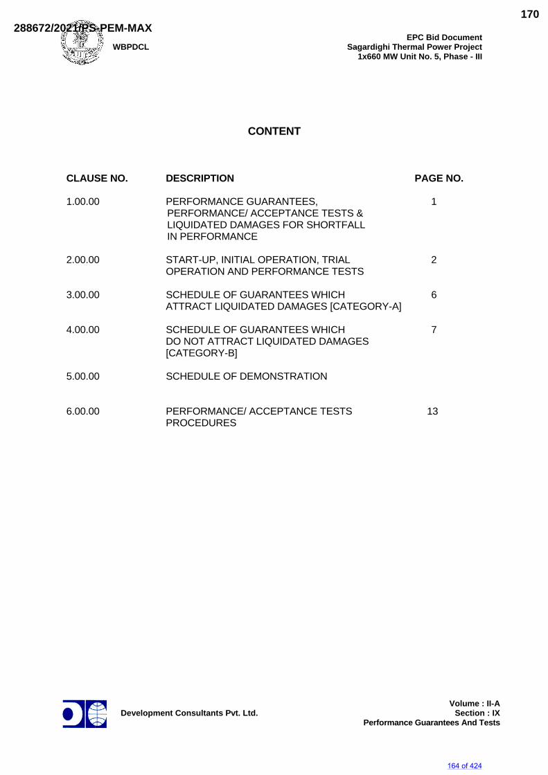
WBPDCL
EPC Bid DocumentSagardighi Thermal Power Project
1x660 MW Unit No. 5, Phase - III
Development Consultants Pvt. Ltd.
Volume : II-ASection : IX
Performance Guarantees And Tests
CONTENT CLAUSE NO. DESCRIPTION PAGE NO. 1.00.00 PERFORMANCE GUARANTEES, 1
PERFORMANCE/ ACCEPTANCE TESTS & LIQUIDATED DAMAGES FOR SHORTFALL IN PERFORMANCE
2.00.00 START-UP, INITIAL OPERATION, TRIAL 2 OPERATION AND PERFORMANCE TESTS 3.00.00 SCHEDULE OF GUARANTEES WHICH 6 ATTRACT LIQUIDATED DAMAGES [CATEGORY-A] 4.00.00 SCHEDULE OF GUARANTEES WHICH 7 DO NOT ATTRACT LIQUIDATED DAMAGES [CATEGORY-B] 5.00.00 SCHEDULE OF DEMONSTRATION 6.00.00 PERFORMANCE/ ACCEPTANCE TESTS 13 PROCEDURES
164 of 424
288672/2021/PS-PEM-MAX170
WBPDCL
EPC Bid Document Sagardighi Thermal Power Project
1x660 MW Unit No. 5, Phase – III
Development Consultants Pvt. Ltd.
Page 1 of 19
Volume : II-ASection : IX
Performance guarantees and Tests
SECTION-IX
PERFORMANCE GUARANTEES AND TESTS 1.00.00 PERFORMANCE GUARANTEES, PERFORMANCE/ACCEPTANCE TESTS
& LIQUIDATED DAMAGES FOR SHORTFALL IN PERFORMANCE 1.01.00 The Bidder shall guarantee that the equipment offered shall meet the ratings
and performance requirements stipulated for various equipment covered in this specification. The guarantees are categorised as:
a) Those, which attract liquidated damages, as listed below
(Category-"A"). The Bidder shall furnish signed declarations in the manner prescribed in the bid proposal schedules for these guarantees.
b) Those, which do not attract liquidated damages, as listed below
(Category-"B"). This guarantee list indicated in this section is not exhaustive and the Owner reserves the right to call upon the Bidder to demonstrate any parameter, operation, etc. of any equipment as specified and as required to meet the duty conditions.
1.02.00 The Bidder shall demonstrate all the guarantees as specified in this section. In
case during tests it is found that the equipment/system has failed to meet the guarantees, the Contractor shall carry out all necessary modifications to make the equipment/systems comply with guaranteed requirements. However, if the Contractor is not able to demonstrate the guarantees, even after the modifications within ninety (90) days of notification by the Owner, the Owner will at his discretion:
i) reject the equipment and recover the payment already made or engage
other agencies for making good all the deficiencies, the cost to be borne & recovered from the contractor or accept the equipment only after levying liquidated damages upto a ceiling 10% of contract price as identified in this section for those guarantees which are covered under category "A".
ii) reject the equipment and recover the payment already made or engage
other agencies for making good all the deficiencies, the cost to be borne & recovered from the contractor or accept the equipment only after assessing and deducting from the contract price an amount equivalent to the deficiency of the equipment/system as assessed by the Owner, for those guarantees which are covered under Category-B.
For equipment/systems not covered under this section Bidder shall
demonstrate the functionality and the rated performance for such equipment/systems before handover to the owner.
1.03.00 All guaranteed parameters shall necessarily be quoted by the Bidder based on
the established proven results obtained from similar units in successful operation. Evidence for this shall necessarily include the test codes used, acceptance test results, and accuracies of various instruments used for the
165 of 424
288672/2021/PS-PEM-MAX171
WBPDCL
EPC Bid Document Sagardighi Thermal Power Project
1x660 MW Unit No. 5, Phase – III
Development Consultants Pvt. Ltd.
Page 2 of 19
Volume : II-ASection : IX
Performance guarantees and Tests
performance test, details of tolerances, if allowed, etc. While quoting the guaranteed parameters, the Bidder shall keep in view the requirements specified in the specification especially regarding the reliability, operability and maintainability of the equipment proposed. The Owner reserves the right to evaluate the parameters quoted by the Bidder based on his experience and published material available.
1.04.00 The liquidated damages shall be calculated prorata for the fractional parts of
the unit unless stated otherwise. 1.05.00 The turbine generator, boiler, auxiliaries, and all other plant equipment and
system shall perform continuously without the noise level (individual or collectively) exceeding the values specified in respective equipment specification over the entire range of output and operating frequencies.
1.06.00 Performance/Acceptance Tests 1.06.01 The performance/acceptance tests for various equipment and systems shall be
carried out as specified under the respective equipment specifications and those specified below shall be specifically applicable. All the guarantees shall be tested together as far as practicable.
1.06.02 In case of systems with stand-by equipment the liquidated damages for
non-performance will be levied for normal operating number of equipment only. However, for this purpose all the equipment including standby equipment shall be tested and average values arrived at.
1.06.03 For instrument in-accuracies during PG Test, refer subsequent clauses of this
section. 1.06.04 For Total Auxiliary Power Consumption of BTG island, Off site BOP facilities
and the transformers listed under the respective clauses, shall be taken together for purposes of guarantee and not individually.
2.00.00 START-UP, INITIAL OPERATION, TRIAL OPERATION AND
PERFORMANCE TESTS 2.01.00 The Contractor shall provide commissioning & start-up supervisory engineering
staff specially identified for the period commencing with start-up and extending through initial & trial operation and all performance tests. During this period, the Contractor shall furnish the calibration devices, special test instruments, etc. required to prepare for and conduct the performance tests. The Owner will associate his operating personnel and necessary supporting staff and shall
make available fuel, and the system electrical load. Contractor's commissioning, & start-up supervisory engineering personnel shall conduct training for the Owner's personnel prior to and during this period and shall train them so that they will be able to operate and maintain the new equipment satisfactorily after acceptance by the Owner.
2.02.00 The Owner proposes to carry out in association with the Contractor, the
following field inspections and tests in the sequence detailed below, and the
166 of 424
288672/2021/PS-PEM-MAX172
WBPDCL
EPC Bid Document Sagardighi Thermal Power Project
1x660 MW Unit No. 5, Phase – III
Development Consultants Pvt. Ltd.
Page 3 of 19
Volume : II-ASection : IX
Performance guarantees and Tests
successful performance and completion of all the tests taken together shall constitute the Owner acceptance tests. The Contractor shall provide supervisory services during field inspection and tests.
2.02.01 Inspection and Checking of the Unit After completion of erection and/or installation, and before being put into
operation, the unit and all its appurtenances shall be thoroughly cleaned and then inspected, for correctness and completeness of installation and acceptability for placing in operation. All piping system shall be flushed, chemically cleaned; steam blown, air blown as required and cleanliness demonstrated using acceptable industry standards. Procedures to accomplish this work shall be subject to Owner's approval.
The checkouts during the pre-commissioning period should be programmed to
follow the construction completion schedule. Each system, as it is completed by construction and turned over to the commissioning (start-up) engineer(s), should be checked out and cleaned. The checking and inspection of individual systems should then follow a prescribed schedule. Also refer specification clause on commissioning management specified elsewhere.
On completion of inspection, checking and after the pre-commissioning tests
are satisfactorily over, the complete equipment shall be placed on Initial Operation during which period the complete equipment shall be operated integral with sub-systems and supporting equipment as a complete plant.
When the equipment is operating properly, its characteristics shall be recorded
on the start-up report sheets. Copies of typical start-up report shall be given to the Owner. Start-up reports for all equipment shall be completed before the start of the trial operation period.
2.02.02 Initial Operation, Reliability Run/Trial Run The plant shall be on Trial Operation during which period all necessary
adjustments shall be made while operating over the full load range enabling the plant to be made ready for performance and guarantee tests.
The duration of Trial Operation of the complete equipment, systems, sub-
systems and their control system shall be in Automatic mode for fourteen (14) days out of which at least seventy two (72) hours shall be in continuous operation on full load or any other duration as may be agreed to between the Engineer, and the Contractor. The Trial Operation shall be considered successful, provided such item of the equipment can be operated, continuously at the specified operating characteristics for the period of Trial Operation.
For the period of Trial Operation, the time of operation with any load shall be
counted; minor interruptions not exceeding four (4) hours at a time caused during the continuous operation shall not affect the total duration of trial operation. However, if in the opinion of the Owner, the interruption is long, the Trial Operation shall be prolonged for the period equivalent to the duration of interruption.
167 of 424
288672/2021/PS-PEM-MAX173
WBPDCL
EPC Bid Document Sagardighi Thermal Power Project
1x660 MW Unit No. 5, Phase – III
Development Consultants Pvt. Ltd.
Page 4 of 19
Volume : II-ASection : IX
Performance guarantees and Tests
A trial Operation report comprising observations and recordings of various parameters to be measured, in respect of the above Trial Operation shall be prepared by the Contractor. This report besides recording the details of the various observations during trial run shall also include the dates of start and finish of the Trial Operation and shall be signed by the representatives of both the parties. The report shall have sheets, recording and print out of all the details of interruption occurred, adjustments made, any minor repairs done during the Trial Operation. Based on the observations, necessary modifications/ repairs to the plant shall be carried out to the full satisfaction of the Engineer to enable the later to accord permission to carry out Performance and Guarantee Tests on the plant. However, it is the prerogative of the Owner to grant permission for aforesaid test with minor defects, which do not endanger the safe operation of the equipments. .
Should any major failure or interruption occur in any portion of the plant due to
or arising from faulty design, materials, workmanship or omissions or incorrect erection, sufficient to prevent safe and full commercial use of the plant, the reliability run shall be considered void and the reliability test period of 14 days shall recommence after the Contractor has remedied the cause of defect to the satisfaction of the owner
2.02.03 Performance and Guarantee Test a) The final tests as to the performance and guarantees shall be
conducted at site, by the Contractor with full involvement of the Owner. The necessary operating inputs shall be provided by the Owner. The Contractor's engineering staff for commissioning and start-up shall ensure that the equipment are ready for such tests. The Owner shall associate his necessary supporting staff with the Contractor to carry out the various activities related to P-G tests.
The necessary labour/supporting staff etc. shall be provided by the
Contractor. Such tests will be conducted within a period of three (3) months after the successful completion of Trial Operation. Any extension of time beyond the above three (3) months shall be mutually agreed upon.
b) These tests shall be binding on both the parties of the Contract to
determine compliance of the equipment with the performance guarantees.
The Contractor shall submit the test procedure for Owner's approval
within thirty six (36) months from the date of letter of award of the contract. The test shall be carried out by the test grade instruments as stipulated in the applicable test code. These instruments shall be calibrated by the Contractor in a laboratory duly approved by Owner. Batch calibration will not be acceptable. The available instrumentation and control equipment in the plant if found suitable could also be used with the prior approval of the Owner after calibrations in the plant/outside laboratory. The tests will be conducted at the specified load points, and as near the specified cycle conditions as practicable. Proper corrections in calculations to take into account the conditions
168 of 424
288672/2021/PS-PEM-MAX174
WBPDCL
EPC Bid Document Sagardighi Thermal Power Project
1x660 MW Unit No. 5, Phase – III
Development Consultants Pvt. Ltd.
Page 5 of 19
Volume : II-ASection : IX
Performance guarantees and Tests
which do not correspond to the specified conditions will be applied in the test report as brought out under the respective sections of the specification.
c) All special test grade instruments, equipment, tools and tackles,
required for the successful completion of the Performance and Guarantee Tests shall be brought for the purpose of test, free of cost by the Contractor.
d) The guaranteed performance figures of the equipment shall be proved
by the Contractor during these Performance and Guarantee Tests. The Contractor shall submit a detailed test report in the manner, already agreed to within one (1) month time of completion of the test, for Owner's approval. Should the Owner's assessment of these tests show any deterioration from the guaranteed values the Contractor/Owner shall modify the equipment as required to enable it to meet the guarantees to the satisfaction of the Owner. In such case, the Performance and Guarantee Tests shall be repeated within one (1) month, from the date the equipment is ready for retest and all costs for modifications including labour, materials and the cost of additional testing to prove that the equipment meets the guarantees, shall be borne by the Contractor.
e) The specific tests to be conducted on equipment have been brought out
in the technical specifications. The procedure to be submitted by the Contractor should include the detailed methodology to conduct these tests/verify the guarantees offered by the Contractor notwithstanding whether these attract liquidated damages or not.
f) Instrument accuracies shall be in accordance with the relevant test
codes. All instrument in-accuracies if applicable shall be computed as per the code and values will be corrected to the advantage of the Owner. No negative tolerance will be allowed. For example, if the inaccuracy of instrumentation has been worked out to be 1%, the measured values will be assessed to be 1% inferior for purpose of LD.
g) The Bidder shall establish the following modes of operation to the
satisfaction of the Owner before acceptance test : i) Operation of each system by remote manual control. ii) Operation of the entire system in integrated manner on auto
control. iii) Operation of the entire plant with auto-control loops fully
implemented including different modes of load control with the help of control system.
h) Ten (10) copies of the test reports are to be furnished by the Contractor
to the Owner backed up with jointly signed data sheets. .
169 of 424
288672/2021/PS-PEM-MAX175
WBPDCLEPC Bid Document
Sagardighi Thermal Power Project 1x660 MW Unit No. 5, Phase – III
Development Consultants Pvt. Ltd. Page 19 of 19 Volume : II-A
Section : IX Performance guarantees and Tests
The test for TG test capacity shall be carried out along with the heat rate test. Instrumentation and other details shall comply as above.
6.04.06 Condenser
Performance test for the condenser shall be conducted in accordance with the latest edition of ASME PTC-12.2. The condenser pressure shall be measured at 300 mm above the top row of tubes under VWO condition, estimated make-up and design CW flow and CW inlet temperature of 33 Deg. C. The cleanliness factor shall be determined in accordance with the latest edition of ASME PTC-12.2.
6.04.07 Feed Water Heaters and Drain Cooler
Performance test for feed water heaters shall be conducted in accordance with the latest edition of ASME PTC-12.1.
6.04.08 Deaerator
Performance test for deaerator shall be conducted in accordance with the latest edition of ASME PTC-12.3.
The dissolved oxygen content in feed water at outlet of deaerator shall be determined by ASME-D 888. Reference Method A and any recognised modification thereof.
Free carbon dioxide content of deaerator effluent shall be measured by APHA method.
6.05.00 Remaining Plant and Equipment
For other equipment, plants and systems, the performance test shall be carried out as per the respective equipment specification and the applicable codes.
170 of 424
288672/2021/PS-PEM-MAX176
WBPDCL
EPC Bid DocumentSagardighi Thermal Power Project
1x660 MW Unit No. 5, Phase - III
Development Consultants Pvt. Ltd.
Volume : II-ASection : X
Requirements Of Spares, Tools & Tackles
SECTION-X
REQUIREMENTS OF SPARES, TOOLS & TACKLES
171 of 424
288672/2021/PS-PEM-MAX177
WBPDCL
EPC Bid DocumentSagardighi Thermal Power Project
1x660 MW Unit No. 5, Phase - III
Development Consultants Pvt. Ltd.
Volume : II-ASection : X
Requirements Of Spares, Tools & Tackles
CONTENTS CLAUSE NO. DESCRIPTION PAGE NO. 1.00.00 TOOLS AND TACKLE 1 2.00.00 SPARES 1 ATTACHMENT ANNEXURE-I MANDATORY SPARES LIST ANNEXURE-II LIST OF TOOLS & TACKLES
172 of 424
288672/2021/PS-PEM-MAX178
WBPDCL
EPC Bid DocumentSagardighi Thermal Power Project
1x660 MW Unit No. 5, Phase - III
Development Consultants Pvt. Ltd.
Page 1 of 2
Volume : II-ASection : X
Requirements Of Spares, Tools & Tackles
SECTION-X
REQUIREMENTS OF SPARES, TOOLS & TACKLE 1.00.00 TOOLS & TACKLE The Bidder shall supply with the equipment one complete set of special tools
and tackles required for the erection, assembly, dis-assembly & proper maintenance of the plant and equipments and systems (including software). These special tools shall also include special material handing equipment, jigs & fixtures for maintenance and calibration/ re-adjustment, checking & measurement aids etc. A list of such tools & tackles shall be submitted by the Bidder along with the offer. Detailed description of each tool/tackles, its function along with the equipment/part for which it is meant for, shall also be indicated in the offer. These tools & tackles shall be separately packed and sent to site before the first unit commissioning. The Bidder shall also ensure that these tools are not used for erection, commissioning and initial operation. For this period, the Bidder shall bring his own tools and tackles. All the tools and tackles shall be of reputed make acceptable to Owner.
2.00.00 SPARES 2.01.00 General The Bidder shall indicate and include in his scope of supply all the necessary
start-up, commissioning and recommended spares in addition to mandatory spares as specified elsewhere in the specification. The Bidder shall also state for each item of spares both mandatory and recommended, the normal expected service life.
2.01.01 All spares supplied under this contract shall be strictly interchangeable with the
parts for which they are intended to replace. The spares shall be treated and packed for long storage under the climatic conditions prevailing at the site, e.g. small items shall be packed in sealed transparent plastic bags with dessicator packs as necessary.
2.01.02 Each spare part shall be clearly marked or labelled on the outside of the
packing with the description. When more than one spare part is packed in a single case, a general description of the contents shall be shown on the outside and a detailed list enclosed. All cases, containers and other packages must be suitably marked and numbered for the purposes of identification.
2.01.03 All cases, containers or other packages are liable to be opened for examination
as may be considered necessary by the Owner. 2.01.04 The Bidder shall also guarantee supply of spare parts, which shall be made,
based on manufacturer's drawings on special order from the Owner for 30 years after commissioning of the plant.
2.01.05 Warranty period for all kinds of spares shall be six thousand (6000) hours of
operation.
173 of 424
288672/2021/PS-PEM-MAX179
WBPDCL
EPC Bid DocumentSagardighi Thermal Power Project
1x660 MW Unit No. 5, Phase - III
Development Consultants Pvt. Ltd.
Page 2 of 2
Volume : II-ASection : X
Requirements Of Spares, Tools & Tackles
2.01.06 Design & Engineering details of all spares (make, model, rating, drawing, data
sheet etc.) shall be submitted to the Owner prior to dispatch from manufacturers’ works.
2.02.00 Recommended Spares 2.02.01 The Bidder shall provide a list of recommended spares for 3 years of normal
operation of the plant for spares of indigenous origin, and for 5 years of normal operation for spares of non-indigenous origin. This list shall take into consideration the mandatory spares specified elsewhere in the specification and should be a separate list.
2.03.00 Start-up Commissioning Spares 2.03.01 Start-up commissioning spares are those spares which may be required during
the start-up and commissioning of the equipment/system. The list of commissioning spares to be brought by the Bidder to ensure smooth commissioning of the plant shall be subject to the Owner's approval. All spares used until the plant is handed over to the Owner shall come under this category. Said spares, properly marked, shall be supplied together with the main equipment and shall be used by the Bidder, if needed, during erection & commissioning stage. All such spares which remain unused till issuance of Taking Over Certificate by the Owner, along with an equipment-wise quantitative consumption report shall be returned to the Owner during time of handover.
2.04.00 Mandatory Spare Parts 2.04.01 The Owner considers some of the spares are essential for running the
equipment irrespective of whether they are included in the list of recommended spares by the Bidder as mentioned above.
Since the components involved can not be foreseen at the bidding stage, only
broad requirements of the Owner in this respect are outlined hereinafter. The bidder shall include his proposal, on the basis of these guidelines, an item-wise list of all components recommended as mandatory spares with the quantity. This list shall be separate from the list of recommended spares and shall be used for bid evaluation purposes. Any clarification in this respect may be obtained by the Bidder at the pre-bidding stage. During finalization of detailed engineering if some component, equipment, system, sub-system found to undergo change, then the Owner/Consultant shall revise the list for compliance by the Bidder without any implication to the Owner.
2.04.02 For Mandatory Spares refer Annexure-I of this section.
174 of 424
288672/2021/PS-PEM-MAX180
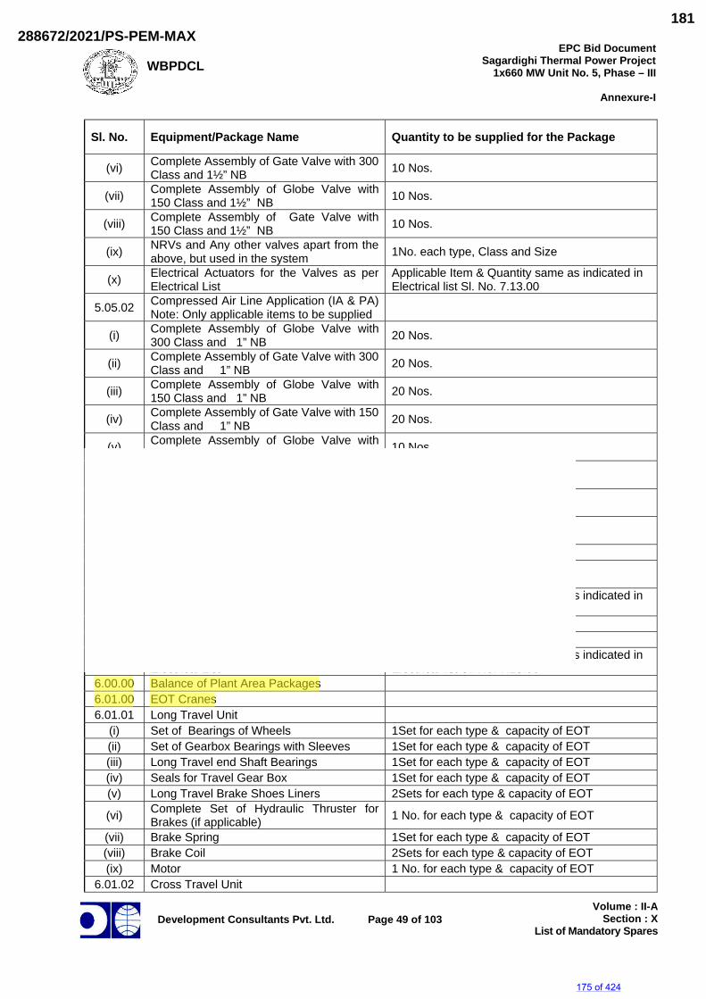
WBPDCLEPC Bid Document
Sagardighi Thermal Power Project 1x660 MW Unit No. 5, Phase – III
Annexure-I
Development Consultants Pvt. Ltd.
Page 49 of 103
Volume : II-ASection : X
List of Mandatory Spares
Sl. No. Equipment/Package Name Quantity to be supplied for the Package
(vi) Complete Assembly of Gate Valve with 300 Class and 1½” NB 10 Nos.
(vii) Complete Assembly of Globe Valve with 150 Class and 1½” NB 10 Nos.
(viii) Complete Assembly of Gate Valve with 150 Class and 1½” NB 10 Nos.
(ix) NRVs and Any other valves apart from the above, but used in the system 1No. each type, Class and Size
(x) Electrical Actuators for the Valves as per Electrical List
Applicable Item & Quantity same as indicated in Electrical list Sl. No. 7.13.00
5.05.02 Compressed Air Line Application (IA & PA)Note: Only applicable items to be supplied
(i) Complete Assembly of Globe Valve with 300 Class and 1” NB 20 Nos.
(ii) Complete Assembly of Gate Valve with 300 Class and 1” NB 20 Nos.
(iii) Complete Assembly of Globe Valve with 150 Class and 1” NB 20 Nos.
(iv) Complete Assembly of Gate Valve with 150 Class and 1” NB 20 Nos.
(v) Complete Assembly of Globe Valve with 300 Class and 1½” NB 10 Nos.
(vi) Complete Assembly of Gate Valve with 300 Class and 1½” NB 10 Nos.
(vii) Complete Assembly of Globe Valve with 150 Class and 1½” NB 10 Nos.
(viii) Complete Assembly of Gate Valve with 150 Class and 1½” NB 10 Nos.
(ix) NRVs 1No. each type, Class and Size
(x) Any other valves apart from the above, but used in the system 1No. each type, Class and Size
(xi) Electrical Actuators for the Valves as per Electrical List
Applicable Item & Quantity same as indicated in Electrical list Sl. No. 7.13.00
5.06.00 Butterfly Valve 5.06.01 Complete Assembly 1No. for each type, Class and Size
5.06.02 Electrical Actuators for the Valves as per Electrical List
Applicable Item & Quantity same as indicated in Electrical list Sl. No. 7.13.00
6.00.00 Balance of Plant Area Packages 6.01.00 EOT Cranes 6.01.01 Long Travel Unit
(i) Set of Bearings of Wheels 1Set for each type & capacity of EOT (ii) Set of Gearbox Bearings with Sleeves 1Set for each type & capacity of EOT (iii) Long Travel end Shaft Bearings 1Set for each type & capacity of EOT (iv) Seals for Travel Gear Box 1Set for each type & capacity of EOT (v) Long Travel Brake Shoes Liners 2Sets for each type & capacity of EOT
(vi) Complete Set of Hydraulic Thruster for Brakes (if applicable) 1 No. for each type & capacity of EOT
(vii) Brake Spring 1Set for each type & capacity of EOT (viii) Brake Coil 2Sets for each type & capacity of EOT (ix) Motor 1 No. for each type & capacity of EOT
6.01.02 Cross Travel Unit
175 of 424
288672/2021/PS-PEM-MAX181
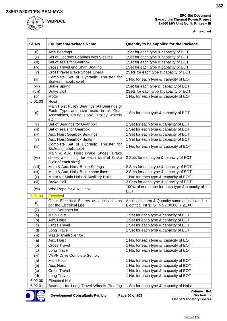
WBPDCLEPC Bid Document
Sagardighi Thermal Power Project 1x660 MW Unit No. 5, Phase – III
Annexure-I
Development Consultants Pvt. Ltd.
Page 50 of 103
Volume : II-ASection : X
List of Mandatory Spares
Sl. No. Equipment/Package Name Quantity to be supplied for the Package
(i) Axle Bearings 1Set for each type & capacity of EOT (ii) Set of Gearbox Bearings with Sleeves 1Set for each type & capacity of EOT (iii) Set of seals for Gearbox 1Set for each type & capacity of EOT (iv) Cross Travel end Shaft Bearing 1Set for each type & capacity of EOT (v) Cross travel Brake Shoes Liners 2Sets for each type & capacity of EOT
(vi) Complete Set of Hydraulic Thruster for Brakes (if applicable) 1 No. for each type & capacity of EOT
(vii) Brake Spring 1Set for each type & capacity of EOT (viii) Brake Coil 2Sets for each type & capacity of EOT (ix) Motor 1 No. for each type & capacity of EOT
6.01.03 Hoist
(i)
Main Hoist Pulley Bearings [All Bearings of Each Type and size used in all Gear Assemblies, Lifting Hook, Trolley wheels etc.]
1 Set for each type & capacity of EOT
(ii) Set of Bearings for Gear box 1 Set for each type & capacity of EOT (iii) Set of seals for Gearbox 1 Set for each type & capacity of EOT (iv) Aux. Hoist Gearbox Bearings 1 Set for each type & capacity of EOT (v) Aux. Hoist Gearbox Seals 1 Set for each type & capacity of EOT
(vi) Complete Set of Hydraulic Thruster for Brakes (if applicable) 1 No. for each type & capacity of EOT
(vii)Main & Aux. Hoist Brake Shoes [Brake shoes with lining for each size of brake (Pair of each size)]
2 Sets for each type & capacity of EOT
(viii) Main & Aux. Hoist Brake Springs 2 Sets for each type & capacity of EOT (ix) Main & Aux. Hoist Brake shoe liners 2 Sets for each type & capacity of EOT (x) Motor for Main Hoist & Auxiliary Hoist 1 No. for each type & capacity of EOT (xi) Brake Coil 2 Sets for each type & capacity of EOT
(xii) Wire Rope for Aux. Hook 100% of one crane for each type & capacity of EOT
6.01.04 Electrical
(i) Other Electrical Spares as applicable as per the Electrical List
Applicable Item & Quantity same as indicated in Electrical list 'B' Sl. No.7.08.00, 7.21.00.
(ii) Limit Switches for: (a) Main Hoist 1 Set for each type & capacity of EOT (b) Aux. Hoist 1 Set for each type & capacity of EOT (c) Cross Travel 1 Set for each type & capacity of EOT (d) Long Travel 1 Set for each type & capacity of EOT (iii) Master Controller for : (a) Aux. Hoist 1 No. for each type & capacity of EOT (b) Cross Travel 1 No. for each type & capacity of EOT (c) Long Travel 1 No. for each type & capacity of EOT (iv) VVVF Drive Complete Set for: (a) Main Hoist 1 No. for each type & capacity of EOT (b) Aux. Hoist 1 No. for each type & capacity of EOT (c) Cross Travel 1 No. for each type & capacity of EOT (d) Long Travel 1 No. for each type & capacity of EOT
6.02.00 Electrical Hoist 6.02.01 Bearings for Long Travel Wheels [Bearing 1 Set for each type & capacity of Hoist
176 of 424
288672/2021/PS-PEM-MAX182
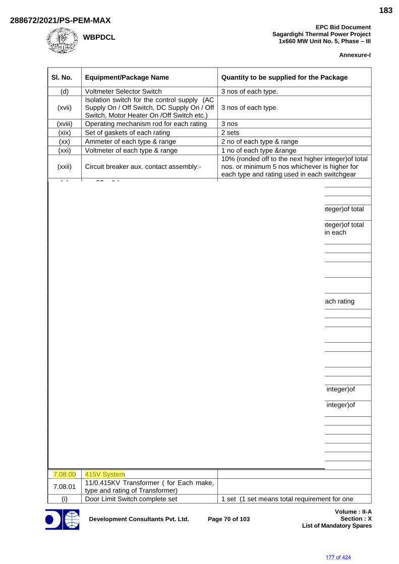
WBPDCLEPC Bid Document
Sagardighi Thermal Power Project 1x660 MW Unit No. 5, Phase – III
Annexure-I
Development Consultants Pvt. Ltd.
Page 70 of 103
Volume : II-ASection : X
List of Mandatory Spares
Sl. No. Equipment/Package Name Quantity to be supplied for the Package
(d) Voltmeter Selector Switch 3 nos of each type.
(xvii)Isolation switch for the control supply (AC Supply On / Off Switch, DC Supply On / Off Switch, Motor Heater On /Off Switch etc.)
3 nos of each type.
(xviii) Operating mechanism rod for each rating 3 nos (xix) Set of gaskets of each rating 2 sets (xx) Ammeter of each type & range 2 no of each type & range (xxi) Voltmeter of each type & range 1 no of each type &range
(xxii) Circuit breaker aux. contact assembly:- 10% (ronded off to the next higher integer)of total nos. or minimum 5 nos whichever is higher for each type and rating used in each switchgear
(a) 52 a & b (b) 52 c & d
(xxiii) Indicating Lamps
(a) Indicating lamps (Red, amber, green, white, blue)
5% (ronded off to the next higher integer)of total nos. for each type
(b) Indicating lamp covers of all colours, lamp resistors & holders
5% (ronded off to the next higher integer)of total nos. for each type and rating used in each switchgear
(xxiv) Fuse base and holder of each type & rating 6 nos. of each type. (xxv) MCB & Fuse of each type & rating 12 nos of each.
(xxvi) Maintenance tools and accessories for maintenance (bidder to list) 1 set.
(xxvii) Carbon brushes for spring charging motor (if applicable) 20 sets
(xxviii) Breaker jaw contact (Bus -end & breaker-end) assembly 2 sets (1 set consists of 3 nos.)of each rating
(xxix) Terminal blocks 12 nos. of each type and rating (xxx) Arc chute (if applicable for each rating) 3 nos.
(xxxi) DC Supply Source Selector Switch (3-position) 3 nos.
(xxxii) Bearings for spring charging motor 6 sets
(xxxiii) Multiple pin plug contact assy. with cables (male & female) 6 sets
(xxxiv) Guide for moving contact set 6 sets (complete) (xxxv) Interphase barrier 3 nos. for each type
(xxxvi) Contactors with HRC fuses 10 % (ronded off to the next higher integer)of each type and rating
(xxxvii) Aux. contactors 10 % (ronded off to the next higher integer)of each type and rating
(xxxviii) Control supply transformers (If applicable) 1 no of each type. (xxxix) Dash pot complete assembly 1 no. with each type (XL) Surge Arrester 5 nos. of each type and rating (XLI) Transducer 2 nos. for each type and Rating (XLII) Energy Meter 1 no of each type and rating (XLIII) HT fuse of PT 3 nos. of each type and rating
7.08.00 415V System
7.08.01 11/0.415KV Transformer ( for Each make, type and rating of Transformer)
(i) Door Limit Switch complete set 1 set (1 set means total requirement for one
177 of 424
288672/2021/PS-PEM-MAX183
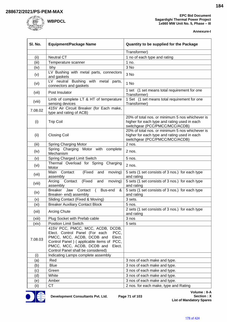
WBPDCL
EPC Bid DocumentSagardighi Thermal Power Project
1x660 MW Unit No. 5, Phase – III
Annexure-I
Development Consultants Pvt. Ltd.
Page 71 of 103
Volume : II-ASection : X
List of Mandatory Spares
Sl. No. Equipment/Package Name Quantity to be supplied for the Package
Transformer) (ii) Neutral CT 1 no of each type and rating (iii) Temperature scanner 1 no. (iv) bhy 3 No
(v) LV Bushing with metal parts, connectors and gaskets 3 No
(vi) LV neutral Bushing with metal parts, connectors and gaskets 1 No
(vii) Post Insulator 1 set (1 set means total requirement for one Transformer)
(viii) Limb of complete LT & HT of temperature sensing devices
1 Set (1 set means total requirement for one Transformer)
7.08.02 415V Air Circuit Breaker (for Each make, type and rating of ACB)
(i) Trip Coil 20% of total nos. or minimum 5 nos whichever is higher for each type and rating used in each switchgear (PCC/PMCC/MCC/ACDB)
(ii) Closing Coil 20% of total nos. or minimum 5 nos whichever is higher for each type and rating used in each switchgear (PCC/PMCC/MCC/ACDB)
(iii) Spring Charging Motor 2 nos.
(iv) Spring Charging Motor with complete Mechanism 2 nos.
(v) Spring Charged Limit Switch 5 nos.
(vi) Thermal Overload for Spring Charging Motor 2 nos.
(vii) Main Contact (Fixed and moving) assembly
5 sets (1 set consists of 3 nos.) for each type and rating
(viii) Arcing Contact (Fixed and moving) assembly
5 sets (1 set consists of 3 nos.) for each type and rating
(ix) Breaker Jaw Contact ( Bus-end & Breaker- end) assembly
5 sets (1 set consists of 3 nos.) for each type and rating
(x) Sliding Contact (Fixed & Moving) 3 sets. (xi) Breaker Auxiliary Contact Block 5 nos.
(xii) Arcing Chute 2 sets (1 set consists of 3 nos.) for each type and rating
(xiii) Plug Socket with Prefab cable 3 nos (xiv) Position Limit Switch 5 sets
7.08.03
415V PCC, PMCC, MCC, ACDB, DCDB, Elect. Control Panel (For each PCC, PMCC, MCC, ACDB, DCDB and Elect. Control Panel ) ( applicable items of PCC, PMCC, MCC, ACDB, DCDB and Elect. Control Panel shall be considered)
(i) Indicating Lamps complete assembly (a) Red 3 nos of each make and type. (b) Blue 3 nos of each make and type. (c) Green 3 nos of each make and type. (d) White 3 nos of each make and type. (e) Amber 3 nos of each make and type. (ii) CT 2 nos. for each make, type and Rating
178 of 424
288672/2021/PS-PEM-MAX184
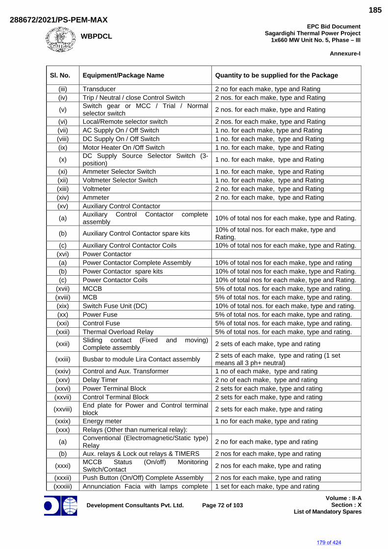
WBPDCL
EPC Bid DocumentSagardighi Thermal Power Project
1x660 MW Unit No. 5, Phase – III
Annexure-I
Development Consultants Pvt. Ltd.
Page 72 of 103
Volume : II-ASection : X
List of Mandatory Spares
Sl. No. Equipment/Package Name Quantity to be supplied for the Package
(iii) Transducer 2 no for each make, type and Rating (iv) Trip / Neutral / close Control Switch 2 nos. for each make, type and Rating
(v) Switch gear or MCC / Trial / Normal selector switch 2 nos. for each make, type and Rating
(vi) Local/Remote selector switch 2 nos. for each make, type and Rating (vii) AC Supply On / Off Switch 1 no. for each make, type and Rating (viii) DC Supply On / Off Switch 1 no. for each make, type and Rating (ix) Motor Heater On /Off Switch 1 no. for each make, type and Rating
(x) DC Supply Source Selector Switch (3-position) 1 no. for each make, type and Rating
(xi) Ammeter Selector Switch 1 no. for each make, type and Rating (xii) Voltmeter Selector Switch 1 no. for each make, type and Rating (xiii) Voltmeter 2 no. for each make, type and Rating (xiv) Ammeter 2 no. for each make, type and Rating (xv) Auxiliary Control Contactor
(a) Auxiliary Control Contactor complete assembly 10% of total nos for each make, type and Rating.
(b) Auxiliary Control Contactor spare kits 10% of total nos. for each make, type and Rating.
(c) Auxiliary Control Contactor Coils 10% of total nos for each make, type and Rating. (xvi) Power Contactor (a) Power Contactor Complete Assembly 10% of total nos for each make, type and rating (b) Power Contactor spare kits 10% of total nos for each make, type and Rating. (c) Power Contactor Coils 10% of total nos for each make, type and Rating.
(xvii) MCCB 5% of total nos. for each make, type and rating. (xviii) MCB 5% of total nos. for each make, type and rating. (xix) Switch Fuse Unit (DC) 10% of total nos. for each make, type and rating. (xx) Power Fuse 5% of total nos. for each make, type and rating. (xxi) Control Fuse 5% of total nos. for each make, type and rating. (xxii) Thermal Overload Relay 5% of total nos. for each make, type and rating.
(xxii) Sliding contact (Fixed and moving) Complete assembly 2 sets of each make, type and rating
(xxiii) Busbar to module Lira Contact assembly 2 sets of each make, type and rating (1 set means all 3 ph+ neutral)
(xxiv) Control and Aux. Transformer 1 no of each make, type and rating (xxv) Delay Timer 2 no of each make, type and rating (xxvi) Power Terminal Block 2 sets for each make, type and rating (xxvii) Control Terminal Block 2 sets for each make, type and rating
(xxviii) End plate for Power and Control terminal block 2 sets for each make, type and rating
(xxix) Energy meter 1 no for each make, type and rating (xxx) Relays (Other than numerical relay):
(a) Conventional (Electromagnetic/Static type) Relay 2 no for each make, type and rating
(b) Aux. relays & Lock out relays & TIMERS 2 nos for each make, type and rating
(xxxi) MCCB Status (On/off) Monitoring Switch/Contact 2 nos for each make, type and rating
(xxxii) Push Button (On/Off) Complete Assembly 2 nos for each make, type and rating (xxxiii) Annunciation Facia with lamps complete 1 set for each make, type and rating
179 of 424
288672/2021/PS-PEM-MAX185
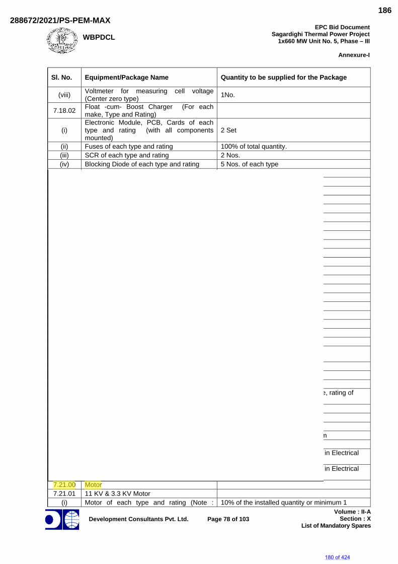
WBPDCLEPC Bid Document
Sagardighi Thermal Power Project 1x660 MW Unit No. 5, Phase – III
Annexure-I
Development Consultants Pvt. Ltd.
Page 78 of 103
Volume : II-ASection : X
List of Mandatory Spares
Sl. No. Equipment/Package Name Quantity to be supplied for the Package
(viii) Voltmeter for measuring cell voltage (Center zero type) 1No.
7.18.02 Float -cum- Boost Charger (For each make, Type and Rating)
(i) Electronic Module, PCB, Cards of each type and rating (with all components mounted)
2 Set
(ii) Fuses of each type and rating 100% of total quantity. (iii) SCR of each type and rating 2 Nos. (iv) Blocking Diode of each type and rating 5 Nos. of each type (v) Potentiometer of each type and rating 1 Set (vi) Pulse transformer 1 Set of each type (vii) Main and Aux. transformer 1 no of each type and rating (viii) Capacitor 2 no of each type and rating (ix) Meters 1 No of each type (x) Transducer 1 No of each type (xi) Selector Switch 1 no of each type (xii) Control Switch 1 no of each type (xiii) Current transformer(if applicable) 1 no of each type and rating (xiv) Push button complete set 1 no of each type (xv) Annunciation window 1No.(xvi) Indicating Lamps complete assembly 2 Nos of each type.
7.19.00 24V DC System 7.19.01 Battery
(i) Battery Cell (Uncharged, Dry) 10Nos(ii) Inter connecting cell strips 10Nos(iii) Vent plug 5Nos (iv) Teak wood cable clamps with hardware 2Nos (v) Hydrometer 1No.(vi) Rubber gloves 1pair
(vii) Voltmeter for measuring cell voltage (Center zero type) 1No.
(viii) Insulated socket spanner with handle 1No.(ix) Thermometer 1No.
7.20.02 Float -cum- Boost Charger
(i) Fuses & fuse links 100% of total quantity for each type, rating of fuses used in the system
(ii) SCR 100% Used in the System (iii) Diode 100% Used in the System (iv) Indicating lamps 100% Used in the System (v) All types of Electronic Module/ PCB/Card 2Nos. each type used in the system (vi) pulse transformer 1 set
7.20.03 Othe DCDB Spares items as applicable as per the Electrical List
Item & Quantity same as indicated in Electrical list Sl. No.7.09.00
7.20.04 Other Electrical Spares as applicable as per the Electrical List
Item & Quantity same as indicated in Electrical list Sl. No.7.08.00 & 7.12.00
7.21.00 Motor7.21.01 11 KV & 3.3 KV Motor
(i) Motor of each type and rating (Note : 10% of the installed quantity or minimum 1
180 of 424
288672/2021/PS-PEM-MAX186
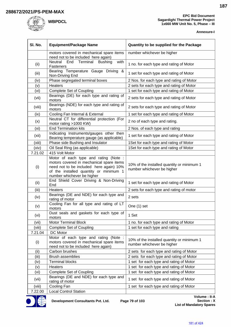
WBPDCL
EPC Bid DocumentSagardighi Thermal Power Project
1x660 MW Unit No. 5, Phase – III
Annexure-I
Development Consultants Pvt. Ltd.
Page 79 of 103
Volume : II-ASection : X
List of Mandatory Spares
Sl. No. Equipment/Package Name Quantity to be supplied for the Package
motors covered in mechanical spare items need not to be included here again)
number whichever be higher
(ii) Neutral End Terminal Bushing with Fasteners 1 no. for each type and rating of Motor
(iii) Bearing Temperature Gauge Driving & Non-Driving End 1 set for each type and rating of Motor
(iv) Phase segregated terminal boxes 2 Nos. for each type and rating of Motor (v) Heaters 2 sets for each type and rating of Motor (vi) Complete Set of Coupling 1 set for each type and rating of Motor
(vii) Bearings (DE) for each type and rating of motors 2 sets for each type and rating of Motor
(viii) Bearings (NDE) for each type and rating of motors 2 sets for each type and rating of Motor
(ix) Cooling Fan Internal & External 1 set for each type and rating of Motor
(x) Neutral CT for differential protection (For motor rating >1000 KW) 2 no of each type and rating.
(xi) End Termination kits 2 Nos. of each type and rating
(xii) Indicating Instruments/gauges other then Bearing temperature gauge (as applicable) 1 set for each type and rating of Motor
(xiii) Phase side Bushing and Insulator 1Set for each type and rating of Motor (xiv) Oil Seal Ring (as applicable) 1Set for each type and rating of Motor
7.21.02 415 Volt Motor
(i)
Motor of each type and rating (Note : motors covered in mechanical spare items need not to be included here again) 10% of the installed quantity or minimum 1 number whichever be higher
10% of the installed quantity or minimum 1 number whichever be higher
(ii) End Shield Cover Driving & Non-Driving End 1 set for each type and rating of Motor
(iii) Heaters 2 sets for each type and rating of motor
(iv) Bearings (DE and NDE) for each type and rating of motor 2 sets
(v) Cooling Fan for all type and rating of LT motors One (1) set
(vi) Dust seals and gaskets for each type of motors 1 Set
(vii) Motor Terminal Block 1 no. for each type and rating of Motor (viii) Complete Set of Coupling 1 set for each type and rating
7.21.04 DC Motor
(i) Motor of each type and rating (Note : motors covered in mechanical spare items need not to be included here again)
10% of the installed quantity or minimum 1 number whichever be higher
(ii) Carbon brushes 2 sets for each type and rating of Motor (iii) Brush assemblies 2 sets for each type and rating of Motor (iv) Terminal blocks 1 set for each type and rating of Motor (v) Heaters 1 set for each type and rating of Motor (vi) Complete Set of Coupling 1 set for each type and rating of Motor
(vii) Bearings (DE and NDE) for each type and rating of motor 1 set for each type and rating of Motor
(viii) Cooling Fan 1 set for each type and rating of Motor 7.22.00 Local Control Station
181 of 424
288672/2021/PS-PEM-MAX187
WBPDCL
EPC Bid DocumentSagardighi Thermal Power Project
1x660 MW Unit No. 5, Phase – III
Development Consultants Pvt. Ltd.
Volume : II-ASection : XI
Protective Coating and Painting
SECTION-XI
PROTECTIVE COATING AND PAINTING
182 of 424
288672/2021/PS-PEM-MAX188
WBPDCL
EPC Bid DocumentSagardighi Thermal Power Project
1x660 MW Unit No. 5, Phase – III
Development Consultants Pvt. Ltd.
Volume : II-ASection : XI
Protective Coating and Painting
CONTENTS CLAUSE NO. DESCRIPTION PAGE NO. 1.00.00 INTENT OF SPECIFICATION 1
2.00.00 CODES AND STANDARDS 1
3.00.00 GENERAL REQUIREMENTS 2
4.00.00 EQUIPMENT, MATERIAL AND SERVICES TO BE FURNISHED BY THE BIDDER 3
5.00.00 COATING PROCEDURE AND APPLICATION 5
6.00.00 TEST REQUIREMENTS 6
7.00.00 INFORMATION/DATA REQUIRED 10
183 of 424
288672/2021/PS-PEM-MAX189
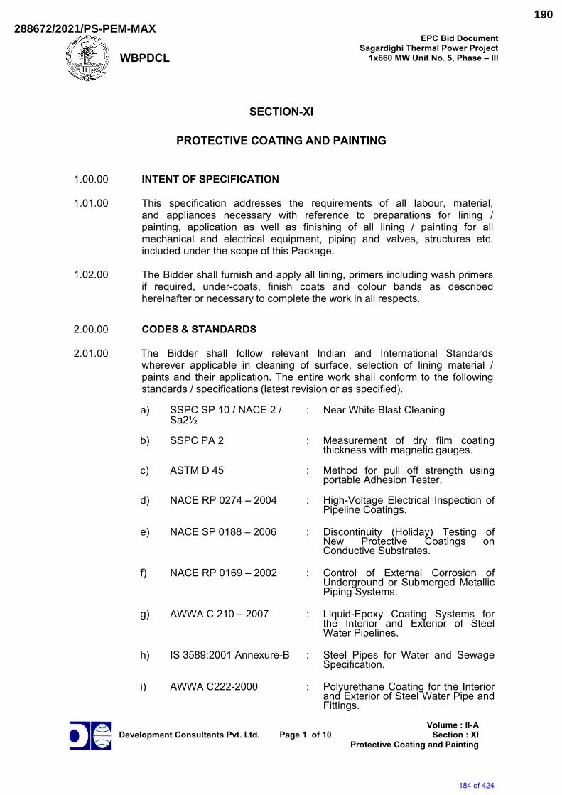
WBPDCL
EPC Bid DocumentSagardighi Thermal Power Project
1x660 MW Unit No. 5, Phase – III
Development Consultants Pvt. Ltd.
Page 1 of 10
Volume : II-ASection : XI
Protective Coating and Painting
SECTION-XI
PROTECTIVE COATING AND PAINTING
1.00.00 INTENT OF SPECIFICATION
1.01.00 This specification addresses the requirements of all labour, material,
and appliances necessary with reference to preparations for lining / painting, application as well as finishing of all lining / painting for all mechanical and electrical equipment, piping and valves, structures etc. included under the scope of this Package.
1.02.00 The Bidder shall furnish and apply all lining, primers including wash primers
if required, under-coats, finish coats and colour bands as described hereinafter or necessary to complete the work in all respects.
2.00.00 CODES & STANDARDS
2.01.00 The Bidder shall follow relevant Indian and International Standards
wherever applicable in cleaning of surface, selection of lining material / paints and their application. The entire work shall conform to the following standards / specifications (latest revision or as specified).
a) SSPC SP 10 / NACE 2 / : Near White Blast Cleaning
Sa2½ b) SSPC PA 2 : Measurement of dry film coating
thickness with magnetic gauges.
c) ASTM D 45 : Method for pull off strength using portable Adhesion Tester.
d) NACE RP 0274 – 2004 : High-Voltage Electrical Inspection of Pipeline Coatings.
e) NACE SP 0188 – 2006 : Discontinuity (Holiday) Testing of
New Protective Coatings on Conductive Substrates.
f) NACE RP 0169 – 2002 : Control of External Corrosion of
Underground or Submerged Metallic Piping Systems.
g) AWWA C 210 – 2007 : Liquid-Epoxy Coating Systems for
the Interior and Exterior of Steel Water Pipelines.
h) IS 3589:2001 Annexure-B : Steel Pipes for Water and Sewage
Specification.
i) AWWA C222-2000 : Polyurethane Coating for the Interior and Exterior of Steel Water Pipe and Fittings.
184 of 424
288672/2021/PS-PEM-MAX190
WBPDCL
EPC Bid DocumentSagardighi Thermal Power Project
1x660 MW Unit No. 5, Phase – III
Development Consultants Pvt. Ltd.
Page 2 of 10
Volume : II-ASection : XI
Protective Coating and Painting
j) IS 13213 : 2000 : Polyurethane Full Gloss Enamel
(Two pack)
k) ISC HD 20 (11902) : Polyurethane coating for Interior and Exterior of steel pipe and fittings.
l) ISC HD 20 (11055) : Solvent less Liquid epoxy system by
application of Interior and Exterior surface of steel pipeline.
3.00.00 GENERAL REQUIREMENTS
3.01.00 The steel surface preparation prior to actual commencement of coating
shall conform to SSPC SP 10 / NACE 2 / Sa2½ (near white metal) with sand blasting.
3.02.00 The contractor shall submit a detailed written description in the form of
a manual covering coating equipment, procedures, materials inspection test, and repair etc. to Owner/Consultant for approval.
3.03.00 The contractor shall also provide copies of test reports from NABL
approved laboratory (like National Test House, Kolkata) in support of the paint/primer materials to be used shall conform to the specification requirement.
3.04.00 The contractor shall also provide certificates from paint/primer
manufacturer mentioning the batch numbers, date of manufacture and shelf life etc. of the materials to be used. In addition to that Manufacturing Quality Plan (MQP) and Field Quality Plan (FQP) shall also be submitted prior to commencement of supply of material and field application.
3.05.00 Paint/coating application work at site shall be done either by
paint manufacturer or by their authorized applicator. The authorized applicator shall have proper training & certification from manufacturer. Applicator sha l l possess all the necessary specialized equipment and manpower experienced in similar job.
3.06.00 Applied coating shall be tested for dry film thickness, holiday
(electrical inspection for continuity) and adhesion as per relevant standard such as SSPC PA 2, NACE RP 0274 and ASTM D 4541.
3.07.00 If necessary, the material may be heated and applied by airless spray /
plural component spray system. 3.08.00 Manufacturer's specific recommendation, if any, shall be followed during
application of lining / paints. 3.09.00 In areas where there is danger of spotting automobiles or other finally
finished equipment or building by wind borne particles from paint spraying, a Purchaser approved method shall be adopted.
185 of 424
288672/2021/PS-PEM-MAX191
WBPDCL
EPC Bid DocumentSagardighi Thermal Power Project
1x660 MW Unit No. 5, Phase – III
Development Consultants Pvt. Ltd.
Page 3 of 10
Volume : II-ASection : XI
Protective Coating and Painting
3.10.00 The colour scheme of the entire Plant, covered under this specification
shall be approved by the Purchaser in advance before application. 3.11.00 All indoor and outdoor piping, insulated as well as uninsulated will
have approved colour bands painted on the pipes at conspicuous places throughout the system, as approved by Purchaser.
3.12.00 Inside surfaces of vessels / tanks shall be protected by anticorrosive paints
or rubber lining as required / specified elsewhere in the specification. External surfaces of all vessels / tanks shall be protected by anti-corrosive painting.
3.13.00 For vessels / tanks requiring lining and epoxy painting all inside surface
shall be blast cleaned using non-siliceous abrasive after usual wire brushing. 3.14.00 Natural rubber lining shall be provided on the inside of vessels / tanks
as required / specified elsewhere in the specification, in three layers resulting in a total thickness not less than 4.5 mm.
3.15.00 Surface hardness of rubber lining shall be 65 +/- 5 deg. A (shore).
3.16.00 After the lining is completed, the vessels / tanks shall not be subjected to
any prolonged exposure to direct sunlight in course of its transportation, erection etc. They shall not be stored in direct sunlight. No further lining or burning shall be carried out on the vessel, after application of the lining.
3.17.00 All lining projecting outside of the vessel shall be protected adequately
from mechanical damages during shipment, handling storage etc. 3.18.00 Suitable warnings, indicating the special care that must be taken with
respect to these lined vessels shall be stenciled on their outside surface with the letters at least 12 mm high.
3.19.00 All insulated piping shall have aluminium sheet jacketing.
4.00.00 EQUIPMENT, MATERIAL AND SERVICES TO BE FURNISHED BY
THE BIDDER 4.01.00 After erection at site, the outside surfaces of all equipment having a shop
coat shall be given further priming coat and finished coats of paint as detailed in following clauses. However, if the painting system is such that the shop coat and primer coat to be applied at site are not compatible, then shop coat has to be removed from the surface of equipment before application of primer coat with prior blasting.
All factory finished paints shall be touched up at site as required.
All uninsulated piping shall be finished with final paintings after use of proper wash primer and primer. Aluminium sheet jacketed piping need not be painted. Colour bands of Purchaser's approved shade shall however be
186 of 424
288672/2021/PS-PEM-MAX192
WBPDCL
EPC Bid DocumentSagardighi Thermal Power Project
1x660 MW Unit No. 5, Phase – III
Development Consultants Pvt. Ltd.
Page 4 of 10
Volume : II-ASection : XI
Protective Coating and Painting
applied on jacketed piping near walls or partitions, at all junctions, near valves and all other places as instructed by the Purchaser. All structures shall be painted with approved paint.
4.02.00 Surface Preparation
4.02.01 Unless mentioned otherwise, all rust and mill scale shall be removed
by blasting up to SSPC SP10/NACE2/Sa2½ level to get “near white metal” surface before applying the primer.
4.02.02 Special care shall be taken to remove grease and oil by means of
suitable solvents like Trichloroethylene or Carbon Tetrachloride. 4.03.00 Painting
4.03.01 Specification for application of paints for external surfaces protection
of vessels / tanks / equipment / piping / fittings / valves shall be as follows :
a) Surface preparation shall be done by means of sand blasting,
which shall conform to SSPC SP10/NACE 2/Sa2½ Standard.
b) Primer Coat shall consist of one coat (minimum DFT of 100 microns) of epoxy resin based zinc phosphate primer.
c) Intermediate Coat (or Under Coat) shall consist of one coat
(minimum DFT of 100 microns) epoxy resin based paint pigmented with Titanium Dioxide.
d) Top Coat shall consist of one coat (minimum DFT of 75 microns)
of epoxy paint of approved shade and colour with glossy finish. Additional one coat (minimum DFT of 25 microns) of Finish Coat of polyurethane shall be provided.
e) Total DFT of paint system shall not be less than 300 microns.
4.03.02 Specification for application of paints for external surfaces protection of
steel pipes and fittings which are buried underground / laid inside a Hume Pipe & or submerged Under Water and laid under Pipe Trenches (in road/rail/pipe or trench crossings) shall be as follows :
a) Surface preparation by means of sand blasting and shall conforms to SSPC SP10/NACE2/ Sa2½.
b) External surface of the pipe, fittings, specialties etc. handling raw water/ clarified water/filter water shall be painted with one coat of two part chemically cured polyurethane primer of min 50 micron dry film thickness followed by three or maximum four coats of two part solvent less polyurethane to build up coating of dry film thickness of 1500 micron including primer coat.
187 of 424
288672/2021/PS-PEM-MAX193
WBPDCL
EPC Bid DocumentSagardighi Thermal Power Project
1x660 MW Unit No. 5, Phase – III
Development Consultants Pvt. Ltd.
Page 5 of 10
Volume : II-ASection : XI
Protective Coating and Painting
4.03.03 Specification for application of paints for internal surface protection of large diameter pipes, if any, shall be as follows :
a) Surface preparation by means of sand blasting which shall
conforms to SSPC SP10/NACE2/Sa2½ standard.
b) All Internal surfaces of steel pipes, fittings, specialties etc. buried underground or located within pipe trenches shall be given epoxy coating to protect them from (except for drinking water service, where the compatible painting shall be so selected to meet relevant quality standards) corrosion.
c) Internal surface of the pipe should be coated with one coat of two
part epoxy primer with not less than 50 micron DFT (dry film thickness) followed by two part polyamide cured solvent less epoxy.
d) The minimum dry film thickness (DFT) of internal lining shall be
500 micron. 4.03.04 Specification for application of paints for protection of internal surfaces of
DM Water Storage Tank(s) shall be as follows :
a) Primer - One coat of epoxy primer containing high level of Zinc Phosphate anticorrosive pigment. Total Dry Film Thickness (DFT) of primer shall not be less than 125 microns.
b) Finish Paint - Three (3) coats Polyamine HB Epoxy Paint. Total
Dry Film Thickness (DFT) of finish paint shall not be less than 125 microns per coat.
c) Total thickness of primer and paint should not be less than
500 microns. 4.03.05 All motors, local push button stations, cable racks, structures used
for supports etc. are to be painted with acid proof paint. 4.03.06 The following surfaces shall not be painted - stainless steel, galvanized
steel, aluminum, copper, brass, bronze and other nonferrous materials. 4.03.07 No painting or filler shall be applied until all repairs, hydrostatic tests and
final shop inspection are completed. 4.03.08 All machined surfaces shall have two (2) coats of water repellant grease
after thorough cleaning. 5.00.00 COATING PROCEDURE AND APPLICATION
5.01.00 Surface preparation :
Pipe shall be blast cleaned by sand. The cleanliness achieved prior to application shall be in accordance with the requirement of SSPC SP 10 /
188 of 424
288672/2021/PS-PEM-MAX194
WBPDCL
EPC Bid DocumentSagardighi Thermal Power Project
1x660 MW Unit No. 5, Phase – III
Development Consultants Pvt. Ltd.
Page 6 of 10
Volume : II-ASection : XI
Protective Coating and Painting
NACE 2 / Sa2½ of ISO 8501 (near white metal)
a) The blast pattern or profile depth shall be 40 to 100 micron and shall be measured by dial micrometer.
b) Before sand blasting is started or during blasting or
coating, temperature of the pipe surface should be more than 3°C above dew point temperature. Blast cleaned surface should be primed within 4 hours and shall be protected from rainfall or surface moisture and shall not be allowed to flash rust. If the rust occurs, the surface again to be prepared by sand blasting or wire brushing.
5.02.00 Application of Epoxy Coating
a) Coating shall be applied when
i) When the pipe surface temperature shall be at least 3°C
above dew point temperature.
ii) The temperature of mixed coating material and the pipe at the time of application shall not be lower than 10°C or greater that 50°C.
b) Material p repa ra t i on sha l l b e i n a c c o r d a n c e w i th
m a n u f a c t u r e r ’ s recommendations.
c) Application of epoxy coating system :
The epoxy coating system shall be applied as per recommendation of the manufacturer and shall be applied by airless spray / plural component spray machine. For more than one coat, the second shall be applied with the time limits as recommended by the manufacturer.
5.03.00 Application of PU Coating
a) PU coating shall be applied when the pipe surface temperature
at least 3°C above dew point temperature (when R.H is more than 85%).
b) Material preparation and application shall be done as per manufacturer recommendation.
6.00.00 TEST REQUIREMENTS
6.01.00 Measurement of dry film thickness
Measurement of dry film thickness of coating: Coating thickness shall be in the range of ±20% and as per SSPC PA 2.
189 of 424
288672/2021/PS-PEM-MAX195
WBPDCL
EPC Bid DocumentSagardighi Thermal Power Project
1x660 MW Unit No. 5, Phase – III
Development Consultants Pvt. Ltd.
Page 7 of 10
Volume : II-ASection : XI
Protective Coating and Painting
6.01.01 Apparatus / Instrument
The instrument used for dry film thickness may be Type 1 pull of gauges or Type 2 electronic gauges.
6.01.02 Procedures
a) Number of measurements
For 100 square feet (9.29 square meters), five (5) spots per test area (each spot is 3.8 cm) in diameter. Three gauge readings per spot (average becomes the spot measurement).
b) If the structure is less than 300 square feet, each 100 square
feet should be measured.
c) If the structure is between 300 and 1000 sq ft, select 3 random 100 square feet test areas and measure.
d) For structure exceeding 1000 square feet, select 3 random
100 square feet testing areas for the first 1000 sq ft and select 1 random 100 square feet testing area for each additional 1000 square feet
e) Coating thickness Tolerance: Individual reading taken to get
a representative measurement for the spot are unrestricted (usually low or high readings are discarded). Spot measurements (the average of 3 gauge readings) must be within 80% of the minimum thickness and 120% of the maximum thickness.
Area measurement must be within specified range.
6.02.00 Electrical Inspection (Holiday) Test
6.02.01 All the coated / lined pipes shall be tested with an approved high
voltage holiday detector preferably equipped with an audio visual signaling device to indicate any faults, holes, breaks or conductive particles in the protective coating.
6.02.02 The applied output voltage of holiday detector shall have a spark discharge
of thickness equal to at least twice the thickness of the coating to assure adequate inspection voltage and compensate for any variation in coating thickness. The electrode shall be passed over the coated surface at approximately half the spark discharge distance from the coated surface only one time at the rate of approximately 10 to 20m/min. The edge effect shall be ignored. Excessive voltage shall be avoided as it tends to induce holiday in the coated surface thereby giving erroneous readings.
6.02.03 While selecting test voltages, consideration should be given to the
tolerance on coating thickness and voltage should be selected on the basis of maximum coating thickness likely to be encountered during testing of a particular pipe.
190 of 424
288672/2021/PS-PEM-MAX196
WBPDCL
EPC Bid DocumentSagardighi Thermal Power Project
1x660 MW Unit No. 5, Phase – III
Development Consultants Pvt. Ltd.
Page 8 of 10
Volume : II-ASection : XI
Protective Coating and Painting
The testing voltage shall be calculated by using following formula. (as per NACE 0274 : 2004)
Testing Voltage V = 7900 √T ± 10 percent where T is the average coating thickness in mm.
6.02.04 Any audio visual sound or spark leads to indicate pinhole, break or
conductive particle. 6.03.00 Adhesion Pull off Test
After holiday the coated surface is subjected to adhesion pull off test as per ASTMD 4541.
6.03.01 Apparatus / Instrument: Adhesion tester consists of three basic components:
A hand wheel, a black column containing a dragging indicator pin and scale in the middle and a base containing three legs and a pulling “Jaw” at the bottom and also dollies.
6.03.02 Prepare the test surface
Once test area is selected, test area shall be free of grease, oil, dirt, water. The area should be flat surfaces and large enough to accommodate the specified number of replicate test.
6.03.03 Prepare Dolly (Test Pull Stub)
The dolly is a round, two sided aluminium fixture. Both sides of the dolly looks same, however, one side sloped on top surface while flat on bottom surface. As the surface of the dolly is polished aluminium, roughen the same using a coarse sand paper.
6.03.04 Select an adhesive
Use araldite, a 100% solid epoxy adhesive. This adhesive requires at least 24 hours at room temperature to cure.
6.03.05 Attach the dolly to the surface
a) Using a wooden stick, apply an even layer of adhesive to the
entire contact surface area of the dolly.
b) Carefully remove the excessive adhesive by using a cotton swab. Allow the adhesive to fully cure before performing the adhesion test.
c) Attach the dolly to the coated surface and gently push downward
to displace any excessive adhesive.
d) Push the dolly inward against the surface, then apply tape across the head of the dolly.
191 of 424
288672/2021/PS-PEM-MAX197
WBPDCL
EPC Bid DocumentSagardighi Thermal Power Project
1x660 MW Unit No. 5, Phase – III
Development Consultants Pvt. Ltd.
Page 9 of 10
Volume : II-ASection : XI
Protective Coating and Painting
6.03.06 Adhesion Test Procedure
a) Attach the adhesion tester to the dolly by rotating the hand
wheel counter clockwise to lower the jaw of the device.
b) Slide the jaw completely under the head of the dolly. Position the three legs of the instruments so that they are sitting flat on the coated surface.
c) Slide the dragging indicator pin on the black column to zero
by pushing it downward.
d) Firmly hold the base of the instrument in one hand and rotate the hand wheel clockwise to raise the jaw of the device that is attached to the head of the dolly. The dragging indicator pin will move upward on the black column as the force is increased and will hold the reading. Apply the tension using a moderate speed. Continue to increase the tension on the head of the dolly until (a) the minimum PSI/MPa/Kg/cm² required by project specification is exceeded and the test is discontinued, (b) the maximum PSI/MPa/Kg/cm² of adhesion tester has been achieved and dolly is still attached, (c) The force applied by the adhesion tester causes the dolly to dislodge.
e) Read the scale and record the adhesion value.
6.04.00 Coating Repair
Defective Coating shall be repaired in accordance with the following subsections.
6.04.01 Surface Preparation
Accessible areas of pipe requiring coating repairs shall be cleaned to remove debris and damaged coating using surface grinders or other means. The adjacent coating shall be feathered by sanding, grinding or other method. Accumulated debris shall be removed by blowing with contaminant free air or wiping with clean rags.
6.04.02 Areas not accessible for coating repair such as interior surfaces of
small diameter pipe shall be reprocessed and recoated. 6.04.03 Coating Application
The coating system shall be applied to the prepared areas in accordance with procedure.
6.04.04 Repair Inspection:
Repaired portion shall be electrically inspected using a holiday detector.
192 of 424
288672/2021/PS-PEM-MAX198
WBPDCL
EPC Bid DocumentSagardighi Thermal Power Project
1x660 MW Unit No. 5, Phase – III
Development Consultants Pvt. Ltd.
Page 10 of 10
Volume : II-ASection : XI
Protective Coating and Painting
6.05.00 Welded Field Joints 6.05.01 Preparation
The weld joints shall be cleaned so as to be free from mud, oil, grease, welding flux, weld spatter and other foreign contaminants. The cleaned metal surfaces of the weld joint shall then be blasted or abraded using rotary abrading pads. The adjacent liquid Epoxy / PU coating shall be feathered by abrading the coating surface for a distance of 25 mm.
6.05.02 Electrical Inspection
After curing the coating system applied to the welding joints shall be holiday tested. Any holidays indicated by the detector shall be marked with chalk to identify the area of repair.
7.00.00 INFORMATION/DATA REQUIRED
The Bidder shall submit complete list of paints and primers proposed, giving detail information, such as, chemical composition, drying time etc. and also unit rates for application of each type of paint along with supply shall be furnished.
193 of 424
288672/2021/PS-PEM-MAX199
WBPDCL EPC Bid Document
Sagardighi Thermal Power Project 1x660 MW Unit No. 5, Phase - III
Development Consultants Pvt. Ltd.
Volume : II-KSection : II
Miscellaneous Cranes
VOLUME : II-K
SECTION-II
MISCELLANEOUS CRANES
194 of 424
288672/2021/PS-PEM-MAX200
WBPDCL EPC Bid Document
Sagardighi Thermal Power Project 1x660 MW Unit No. 5, Phase - III
Development Consultants Pvt. Ltd.
Volume : II-KSection : II
Miscellaneous Cranes
CONTENT
CLAUSE NO.
DESCRIPTION PAGE NO.
1.00.00 GENERAL INFORMATION 1
2.00.00 CODES AND STANDARDS 1
3.00.00 SCOPE OF WORK 2
4.00.00 SPECIFIC PERFORMANCE REQUIREMENTS 2
5.00.00 DESIGN & CONSTRUCTION 3
6.00.00 INSPECTION AND TESTING 21
7.00.00 DRAWINGS, DATA AND INFORMATION 22
ATTACHMENTS ANNEXURE-I LIST OF E.O.T. CRANES 25
ANNEXURE-II DATA SPECIFICATION SHEET FOR ELECTRIC
OVERHEAD TRAVELLING CRANE
26
195 of 424
288672/2021/PS-PEM-MAX201
WBPDCL EPC Bid Document
Sagardighi Thermal Power Project 1x660 MW Unit No. 5, Phase - III
Development Consultants Pvt. Ltd.
Page 1 of 31
Volume : II-KSection : II
Miscellaneous Cranes
SECTION-II
MISCELLANEOUS CRANES 1.00.00 GENERAL INFORMATION This section covers the Electric Overhead Traveling (EOT) Cranes, which will
be required for handling various power plant equipments under the scope of the entire package for erection and maintenance purposes. An indicative list of such cranes has been provided in Annexure-I. Apart from these locations, E.O.T cranes may also be provided to other locations, which the Bidder feels necessary subject to approval of Consultant/Owner.
2.00.00 CODES AND STANDARDS The design, manufacture and testing of the crane shall conform to the latest
editions of the following codes and standards 2.01.00 IS : 807 - Code of Practice for Design, Manufacture, Erection and Testing
(Structural Portion) of Cranes and Hoists. 2.02.00 IS : 3177 - Code of Practice for Design of Overhead Traveling Cranes and
Gantry Cranes other than Steel Works Cranes. 2.03.00 IS : 1835 - Round Steel Wires for Ropes. 2.04.00 IS : 2266 - Steel Wire Ropes for General Engineering Purposes. 2.05.00 IS : 3443 - Crane Rail Sections. 2.06.00 IS : 15560 - Point Hook with Shank up to 160 tones - Specification. 2.07.00 IS : 5749 - Forged Ramshorn Hooks. 2.08.00 IS : 816 - Code of Practice for Use of Metal Arc Welding for General
Construction in Mild Steel. 2.09.00 IS : 1323 - Code of Practice for Oxy-Acetylene Welding for Structural Work
in Mild Steel. 2.10.00 IS : 9595 - Recommendations for metal arc welding of carbon & carbon -
manganese steel. 2.11.00 All electrical installation work shall comply with the provisions of Indian
Electricity Act and Indian Electricity Rules as amended up to date. 2.12.00 ANSI-830.2.0 - Safety codes for overhead and Gantry Cranes. 2.13.00 IS 3815: Point hook with shanks for general Engineering purpose. 2.14.00 IS 823: Code of practice for use of metal arc welding of mild steel.
196 of 424
288672/2021/PS-PEM-MAX202
WBPDCL EPC Bid Document
Sagardighi Thermal Power Project 1x660 MW Unit No. 5, Phase - III
Development Consultants Pvt. Ltd.
Page 2 of 31
Volume : II-KSection : II
Miscellaneous Cranes
2.15.00 IS 1181: Qualifying tests for metal arc welders (Engaged in welding structure
other than pipe). 2.16.00 CMNA - Crane manufactures association of America. In case of any contradiction between the above-mentioned codes and
standards (item 2.01.00 thru' 2.16.00 above) and this technical specification, the later will prevail. However, nothing in this specification shall be construed to relieve the Bidder of his responsibility to comply with what is mentioned against item 2.11.00 above.
3.00.00 SCOPE OF WORK 3.01.00 Scope of work includes supply of the following: 3.01.01 The required no. of E.O.T cranes as indicated in Annexure-I having duty and
service conditions as specified hereinafter along with all accessories. 3.01.02 Runway rails for entire runway length along with rail clamps, all inserts, insert
plates, anchor bolts, nuts, buffers & stops, limit switches etc. as required. 3.01.03 Runway conductors for the entire runway length complete with all insulators,
supports, support brackets, fixing clamps, bolts, nuts etc. as specified and as required to complete the installation. Power supply cabling including isolating switch complete along with electrical items, attachments and accessories as required to feed power to the runway conductor.
3.01.04 All protective devices, anti-collision limit switches etc. as required for the
crane. 3.01.05 All facilities, accessories and attachments for operation of the cranes. 3.01.06 Bridge and trolley current collectors and bridge cross conductors along with
all wirings etc. for the crane as specified and as required to complete the scope of work.
3.01.07 Crane components shall be provided with lifting lugs, eye-bolts etc. at suitable
locations for handling assembling, lifting and placing into position. 4.00.00 SPECIFIC PERFORMANCE REQUIREMENTS 4.01.00 Capacity 4.01.01 The safe working load (X) for each EOT crane shall be computed as
X = 1.25 x a where a = Single heaviest equipment expected to be handled by the crane. (excluding Generator Stator and subject to a minimum capacity of
125 Tonnes for Turbine Hall EOT cranes).
197 of 424
288672/2021/PS-PEM-MAX203
WBPDCL EPC Bid Document
Sagardighi Thermal Power Project 1x660 MW Unit No. 5, Phase - III
Development Consultants Pvt. Ltd.
Page 3 of 31
Volume : II-KSection : II
Miscellaneous Cranes
Note: As per standard practice, the stator of generator which is the heaviest
single- piece component in Power house to be handled shall be erected with strand jack. As such the EOT crane capacity in power house shall be determined considering other components of turbine, generator and accessories to be handled in single piece.
4.02.00 Highest Position 4.02.01 The highest position reached by the lifting hooks should be such that during
operation, the minimum vertical critical clearance between bottom of the equipment being handled and the top of any permanent structure or equipment in the operating area should be at least one metre.
4.03.00 Lowest Position 4.03.01 The lifting hooks should reach up to the floor of its operating area or sump
pits as necessary. 4.04.00 Horizontal clearance 4.04.01 The lifting hooks in vertical position should reach at least up to 2.5m from the
end stopper. 4.04.02 Either the main or the auxiliary hook in vertical position should reach at least
upto 1.0 m from the runway rails. 4.05.00 If safe and reliable handling necessitates more operating space for the E.O.T.
cranes, the same shall be provided. 5.00.00 DESIGN & CONSTRUCTION 5.01.00 General 5.01.01 In the design of components on the basis of strength, factor of safety shall not
be less than five (5) based on ultimate strength. Impact, fatigue, wear and stress concentration factors shall be taken into account, wherever applicable. Mechanism class shall be as indicated in the Data Specification Sheet.
5.01.02 The crane shall be rigid in construction and all movements shall be smooth
and non-jerky. 5.01.03 Drives shall be designed with adequate margin to give best performance and
efficiency. Safety arrangements shall be incorporated to prevent damage to motors on account of mechanical overload and electrical faults and to gearing, shafts, etc. due to over-stressing and other detrimental conditions.
5.01.04 All materials shall be of tested quality and shall conform to the specification
requirements and standards mentioned and shall be new and first class in all respects.
198 of 424
288672/2021/PS-PEM-MAX204
WBPDCL EPC Bid Document
Sagardighi Thermal Power Project 1x660 MW Unit No. 5, Phase - III
Development Consultants Pvt. Ltd.
Page 4 of 31
Volume : II-KSection : II
Miscellaneous Cranes
5.01.05 Castings and forgings shall be of tested quality and shall conform to their respective material specifications and shall be free from flaws and objectionable imperfections, machined true and in a workman like manner.
5.01.06 No wood or other combustible material shall be used unless specifically
approved by the Owner/Consultant. 5.01.07 Proposals for repair or any similar operations involving plugging, welding,
boring or addition of metal to the original castings or forgings shall be submitted to the Owner and his approval must be obtained before any such work is carried out. Drawing showing details and location of such repairs shall be submitted to the Owner.
5.01.08 All fabrication by welding shall be carried out by qualified and certified
welders. 5.01.09 Design shall provide for easy maintenance of all parts, particularly the wheel
bearings on end-trucks. 5.01.10 Temperature Effects Where any portion of the structure is not free to expand or contract under
variation of temperature, allowance shall be kept for stress resulting from these conditions; the co-efficient of expansion for each degree centigrade variation of temperature above and below normal being taken as 0.000012 for mild steel. The maximum range of variation of temperature shall be as given in the Lead Specification. Clause 3.4 of Section 3 of IS: 800-2007 Code of practice for use of structural steel in General Building construction - shall also apply.
5.01.11 Maximum use shall be made of shop fabricated sub-assemblies. 5.01.12 Not used. 5.01.13 Material of Construction The material of construction of the major components of the crane shall be as
indicated in the Data Specification Sheet. Manufacturers are however free to use alternative material, which are superior for the intended service. But in all cases they are required to obtain prior concurrence of Owner after furnishing chemical and physical properties of the offered material and any other information that may be asked for by the Owner.
5.01.14 Load Indication The crane bridge shall have permanent inscription in English on each side,
readily legible from operating floor, stating manufacturer's name, serial no., the year of manufacture and the safe working load.
199 of 424
288672/2021/PS-PEM-MAX205
WBPDCL EPC Bid Document
Sagardighi Thermal Power Project 1x660 MW Unit No. 5, Phase - III
Development Consultants Pvt. Ltd.
Page 5 of 31
Volume : II-KSection : II
Miscellaneous Cranes
5.02.00 Structural Design Consideration 5.02.01 Minimum thickness of metal For load carrying members the component plates, bars, angles and other
rolled sections shall be minimum 8 mm thick. For tubes having both ends sealed the minimum thickness shall be 4.9 mm (6
SWG). For unsealed tubes the minimum thickness shall be 8 mm. The chequered plates for platforms shall be minimum 6 mm thick over plain.
5.02.02 Accessibility for maintenance All structural parts shall be designed so that they are accessible for periodic
cleaning, brushing and painting. All rivets/bolts shall also be accessible for periodic checking.
5.02.03 Ruling dimensions and ratio a) For compression members, the slenderness ratio shall not exceed
120. In case of other load carrying members and subsidiary members the slenderness ratio shall not exceed 180.
b) For girders, the following values of maximum span to depth ratio shall
be governing: Plate girders : Span/depth = 18 Lattice girders : Span/depth = 12 5.02.04 Connections a) Unless otherwise specified, only rivetted or welded joints shall be used. b) Where welding is not practicable, turned and fitted bolts shall be used,
preferably as per IS-1364 and IS-1367. c) Minimum number of turned and fitted bolts in a connection shall not be
less than two. d) Black bolts shall not be used in main structures and high tensile bolts
shall not be used unless approved by the Owner. Bolts shall preferably be not used in tension.
e) Where bolts pass through sections having tapered flanges, tapered
flats shall be welded to inside of the flanges. Tapered washers shall not be used.
f) Transverse fillet welds on load carrying members shall be avoided. If
side fillets are used in end connections, the length of each side fillet
200 of 424
288672/2021/PS-PEM-MAX206
WBPDCL EPC Bid Document
Sagardighi Thermal Power Project 1x660 MW Unit No. 5, Phase - III
Development Consultants Pvt. Ltd.
Page 6 of 31
Volume : II-KSection : II
Miscellaneous Cranes
should not be less than the edge distance between the fillets. g) Butt welds on structural members under tensile stress shall be
checked by Radiographic examination as and when directed by the Owner.
h) Splices shall be designed to resist one and half times the forces and
moments to which it is subjected, but in no case it shall be less than 2/3rd of the effective strength of the material spliced except that splices in the webs of the plate girders shall be designed for full strength of the web in shear as well as bending.
For splicing tension members, the net section of the splice plate shall
be ten percent more than that of the material spliced. Splices shall be proportioned and arranged, so that the gravity axis of the splices is in line with the gravity axis of the member to avoid eccentricity.
5.02.05 Deflections and Camber a) The total maximum vertical deflection of the girders produced by the
dead load, weight of trolley and the rated load shall not exceed limit of Span/900.
b) The girders shall be cambered by an amount equal to the maximum
deflection due to dead load plus one half the live load and trolley. 5.03.00 Bridge Girder and End Carriage 5.03.01 The crane shall have single girder upto 20 Tonnes SWL, and above that it
shall have double girder.. 5.03.02 The bridge girder shall be box section type or braced I beam type as per
standard design of the manufacturer. The exterior surface shall be smooth and as free from projections etc. as possible to minimise dust collection on it.
5.03.03 Single girder cranes shall be provided with suitable truss for supporting the
bridge drive machinery and motor. 5.03.04 The crane bridge shall be carried on end trucks of suitable design. Each end
truck shall be built up from steel plates welded together to form a closed box section with opening at each end to receive the wheels. Welded to the trucks shall be steel sections to form bearings for the wheel axles and the driving shaft. End trucks shall be provided with rail sweep and bumper. They shall also be provided with suitable jacking pads for maintenance of the wheel and bearings. The location of the jacking pads shall be such that it will not interfere with the maintenance of the wheels and its bearing.
5.03.05 Driving wheels shall be of the double flange and taper tread type and shall be
ground to equal diameter in pairs. Wheel axles may be either of the stationary or rotating type as per standard of the manufacturer. If stationary type, they shall be prevented from turning in the truck by means of a key plate fitting into
201 of 424
288672/2021/PS-PEM-MAX207
WBPDCL EPC Bid Document
Sagardighi Thermal Power Project 1x660 MW Unit No. 5, Phase - III
Development Consultants Pvt. Ltd.
Page 7 of 31
Volume : II-KSection : II
Miscellaneous Cranes
a slot in the end of the axle and if rotating type, wheels shall be keyed to them.
5.03.06 Where more than two bridge wheels are used per end truck, the end truck
shall be split into two sections, each carrying one bridge independent of other. Two sections of the end truck shall be joined by suitable joining device that will ensure uniform wheel loading. Steel pads shall be welded on the top of end trucks where the girder rests and shall be machined to receive the girder ends.
5.03.07 Trolley travel rail ends shall be curved upwards to stop the trolley smoothly
and prevent it from leaving the rails in case of over travel at its maximum speed.
5.03.08 End trucks shall be equipped with spring/rubber buffers and rail sweep for
bridge travel. The rail sweep shall be such that it can push away any object that may fall on the runway. The buffers shall be of substantial design and suitable for engaging the stops at the end of runway.
5.03.09 Breathing holes shall be provided in completely enclosed welded box type
girders. Drain holes shall be provided in all places where water or oil is likely to collect. Where practicable, means of access shall be provided for inside inspection of completely enclosed box girders.
5.03.10 In bridge girder strength calculations, the trolley rails and chequered plates
shall not be considered as load carrying members. 5.04.00 Trolley Frame 5.04.01 The trolley frame shall be built up from heavy steel plates, angles and
channels adequately braced to resist vertical, lateral and torsional strains, welded to form a rigid one piece frame. Alternatively, it may be of cast steel construction.
On bottom of trolley frame, on each side shall be a double spring bumper to
engage stops at each end of the bridge. 5.04.02 Equaliser sheaves shall be mounted on the trolley frame in such a manner
that deflection resulting from the force on the sheaves are not directly transmitted to the hoisting mechanism.
5.04.03 Sheaves shall be so arranged on the trolley that rope-revving arrangement
resulting there from will ensure a lifting of the load in almost a vertical line with minimum of swing or side-movement.
5.05.00 Platforms and Ladders 5.05.01 Safe means of access shall be provided to the operator's cab and to every
place where any person engaged in the examination or maintenance of the crane has to work. Adequate handholds and footholds shall be provided as necessary.
202 of 424
288672/2021/PS-PEM-MAX208
WBPDCL EPC Bid Document
Sagardighi Thermal Power Project 1x660 MW Unit No. 5, Phase - III
Development Consultants Pvt. Ltd.
Page 8 of 31
Volume : II-KSection : II
Miscellaneous Cranes
5.05.02 One metre high double tier handrail and suitable toe-boards shall be provided
along the entire length of platform (on the bridge), which shall not be less than 750 mm wide.
5.05.03 Every platforms shall be provided with steel chequered plate top and be
securely fenced with one metre high double tier hand rails and toe boards. Platforms shall be of sufficient width to enable normal maintenance work to be undertaken safely.
5.05.04 Not used. 5.05.05 Access to operator's cabin from bridge girder platform shall be by staircase
having adequate width and proper sloping. 5.06.00 Operation The crane shall be operated either from cabin in the crane bridge or from a
pendant control station as specified in Data Specification Sheet. 5.06.01 Operator's Cabin a) The operator's cabin shall be open type, suitable for indoor service
and complete with light, fan and seat. The cabin shall be located on one end of the crane bridge, on the opposite side of Down Shop Lead (DSL) and under one of the bridge girders, so that it is offset to one side. The cabin shall be provided with guarding handrails and the floor shall be covered with electric insulating carpet. Clear headroom of 2400 mm shall be ensured within the cabin.
b) A foot operated type-warning gong shall be provided within the cabin.
The cabin shall be of ample size to contain controllers, protective panel, main isolating switch and other accessories required for operating the crane. A 4.5 kg capacity portable CO2 fire extinguisher shall be provided in the cabin. Flash lights with hooter shall be provided to indicate the crane is travelling
c) Provision shall be there for emergency exit of the Crane Operator at
three convenient positions in case of power failure. 5.06.02 Pendant Station a) The pendant station shall locate the push buttons for controlling the
various motions of the crane and shall be hung from the crane trolley to a height of approximately 1 metre above the operating floor.
b) With pendant operation, foot operated bridge travel brake and the
drum controllers need not be provided.
203 of 424
288672/2021/PS-PEM-MAX209
WBPDCL EPC Bid Document
Sagardighi Thermal Power Project 1x660 MW Unit No. 5, Phase - III
Development Consultants Pvt. Ltd.
Page 9 of 31
Volume : II-KSection : II
Miscellaneous Cranes
5.07.00 Repair Cage 5.07.01 A repair cage shall be provided on the inside of the end carriage for attending
the main current collectors. In case, the trolley current collectors are located below trolley rail level on the inside webs of the bridge girders, guards shall be provided on the trolley to prevent the hoisting ropes from coming in contact with conductors as well as a repair cage shall be provided on the trolley to attend these conductors.
5.07.02 Repair cages shall also be provided at the corners of the crane, if required, to
facilitate removal and replacement of long travel wheels. 5.07.03 The repair cages shall be adequately sized, guarded for safety and correctly
located for the intended service. Suitable access to the cages shall be provided.
5.08.00 Lifting Hook Block Assembly The lifting hook block assembly shall be ramshorn type or approved quality
for capacity greater than 40 Tonnes and point hook with shank for capacity below 40 Tonnes and shall be of steel construction. Each hook shall be supported on ball or roller thrust bearing and shall rotate freely on its bearings.
The sheaves of the hook block shall be encased in an oil tight casing
permitting generous lubrication of wire ropes and sheaves and also preventing accidental tapping of hands.
All sharp edges on the hooks shall be eliminated to prevent damage to the
sling ropes. The hooks shall conform to the requirements of IS: 3177. 5.09.00 Gearing 5.09.01 Gears in the speed reducer unit for bridge drive and also all hoists and trolley
drive gearing shall be enclosed in substantial housing and shall operate in oil bath. The oil shall have additives of approved quality and shall be of approved viscosity at standard temperature (say 60ºC). The housing shall be of sufficient design not to permit a temperature in excess of 90ºC for the oil bath and shall be adequately supported and readily removable without disturbing the gear assembly.
5.09.02 Gears shall be of cast or forged steel and pinions shall be forged steel and
shall be machine cut. Gear and pinion teeth shall be treated for resistance to wear.
5.09.03 Gears shall have tooth form and modules as recommended in IS-3681 and
they shall be adequately designed to stand shock load and vibration and shall not be excessively noisy in operation. The ratings of gears shall be established as per IS : 4460.
204 of 424
288672/2021/PS-PEM-MAX210
WBPDCL EPC Bid Document
Sagardighi Thermal Power Project 1x660 MW Unit No. 5, Phase - III
Development Consultants Pvt. Ltd.
Page 10 of 31
Volume : II-KSection : II
Miscellaneous Cranes
5.09.04 Spur and helical gears only shall be used for reduction gearing. 5.09.05 Mounting of the gears shall be such that axial thrust on the bearing is
minimum. Centre distance of the connecting shafts shall be as close as possible to the theoretical value. Shafts shall be designed to keep their deflections within permissible limits.
5.10.00 Bearing 5.10.01 The type of bearings for various parts shall be as per IS-3177 and standard of
manufacturer. 5.10.02 Provision shall be made for service lubrication of all bearings. Bearing
enclosures shall be designed as far as practicable to exclude dirt and prevent leakage of oil or grease.
Arrangement for centralised lubrication of bearings shall be tried to the
maximum extent possible and a detailed scheme for the same shall be furnished along with the Bid.
5.10.03 Suitable drip pans shall be provided as required to collect oil and grease,
which may drop, from operating parts. All drip pans shall be accessible for draining and cleaning.
5.10.04 All bearings of the gearing shall be antifriction type. Angular contact ball or
taper roller bearings shall be used wherever necessary. The bearings shall correctly locate the shafts while allowing for thermal expansion of the shafts.
Bearings shall be enclosed in suitable housing with proper holes and plugs to
prevent any ingress of dirt and to permit easy lubrication of the bearings. 5.11.00 Guarding 5.11.01 Guards of an approved design, which will push forward or off the rail track any
object placed across it, such as person's foot or arm, shall be attached to each end of the end carriage.
5.11.02 Protection guards to live electrical wirings/conductors shall be provided. 5.11.03 Suitable guards to revolving shafts and coupling, long travel cross shafts and
gears, shall be provided. 5.11.04 The sheaves of the hook block fitted with two sheaves or fewer shall be
guarded to prevent tapping of a hand between a sheave and the running rope. 5.11.05 Effective means of guiding the wire ropes over the sheaves shall be provided
so as to prevent dismounting of rope from the sheave grooves even when a slack rope condition is developed.
5.11.06 All openings in foot walk flooring, for access to bottom chord platform, if any,
205 of 424
288672/2021/PS-PEM-MAX211
WBPDCL EPC Bid Document
Sagardighi Thermal Power Project 1x660 MW Unit No. 5, Phase - III
Development Consultants Pvt. Ltd.
Page 11 of 31
Volume : II-KSection : II
Miscellaneous Cranes
and to other inspection platforms, shall be provided with covers having suitable locking means to avoid any accidental opening.
5.11.07 All electrical panels, resistance boxes shall have suitable rain/ dust hoods
over them to prevent water and building construction material falling on them, as it is apprehended that erection and commissioning of the crane might have to be taken up before completion of the building roof.
5.12.00 Runway Rails 5.12.01 Crane runway rails with bolts and nuts and complete with shims, anchor bolts,
inserts and other fixtures for fixing the rails to crane girders shall be under the scope of supply of the present specification.
5.12.02 The length of the rail supplied shall be sufficient to cover the whole of runway
length. Gap between successive rails shall not exceed 2 mm and end rails shall be provided with stoppers to prevent longitudinal shifting.
5.12.03 The rail section shall be as per IS: 3443. 5.13.00 Trolley Rail 5.13.01 The specification includes the supply of trolley travel rails complete with
fixtures for fixing the rails to the body of crane. 5.13.02 The length of the rail supplied shall be adequate for maximum permissible
trolley travel. Gap between successive rails shall not exceed 2 mm and end rails shall be provided with stoppers to prevent longitudinal shifting.
5.14.00 Rail Joints and Fixing 5.14.01 The rails shall be butt jointed by either thermit welding or fusion welding
process. The Bidder shall get his proposal for edge-preparation of rails, welding procedure and sequence, approved in advance by the Owner/Consultant.
5.14.02 The schemes of securing the rails to the gantry girder/bridge structure with
clamps, bolts and nuts, their alignment etc. shall be subject to the approval of the Owner/Consultant.
5.15.00 Tolerances The limits of tolerance as specified in the Data Specification Sheet shall be
observed. 5.16.00 Rail End Stops Rail end stops of adequate design shall be provided on both ends of the
runway. The end stop location and arrangement shall be such that the unavailable length of runway (for crane operation) on any end is a minimum.
206 of 424
288672/2021/PS-PEM-MAX212
WBPDCL EPC Bid Document
Sagardighi Thermal Power Project 1x660 MW Unit No. 5, Phase - III
Development Consultants Pvt. Ltd.
Page 12 of 31
Volume : II-KSection : II
Miscellaneous Cranes
5.17.00 Drive Mechanism 5.17.01 Equal driving effort shall be applied at each drive wheel of bridge and trolley
to prevent one end from travelling faster than the other. 5.17.02 For bridge, the torsional deflection in the cross shaft shall be limited to safe
value as per applicable code. 5.17.03 For bridge drive, the motor shall be located at mid position of the span. If twin
motors are used for drive, motors shall be equidistantly located at each wheel end. Suitable interlock shall be provided to prevent single motor operation at any time.
5.17.04 Trolley drive shall be achieved by single motor in which the motor shall drive
a common output shaft through proper gearbox and tractive power shall be transmitted to the geared wheels by means of pinions mounted on both ends of the output shaft.
5.17.05 All machineries for the drive unit shall be properly aligned. Self-aligning type
gear couplings shall be used between connection shafts to take care of transverse as well as axial movement wherever necessary.
Wherever components of considerable amount of inertia is directly mounted
on the high-speed shaft (e.g. brake drum, couplings, etc.) they shall be balanced statically to minimise vibration.
5.17.06 Motor ratings shall be calculated keeping margin of at least 25% over the
maximum power requirement. Further, the hoist motors shall be rated to lift 120% of the design load on the hook at the rated speed. For other details the Clause no. 5.19.00 below shall be referred to.
5.17.07 Along with the drive mechanisms adequate brakes shall be provided as
detailed in Clause no. 5.20.00 below. Selection and design of brakes shall be complete responsibility of the manufacturer. The brakes shall be of accurate rating to stop each motion within a very short distance and in a safe and smooth manner.
5.18.00 Crane Electricals 5.18.01 The crane(s) shall be furnished complete with all electrical equipment,
accessories (like drive motors with VVVF Drives, conductors, insulators, protective & operating devices, cables, current collectors etc.) and cabling/wiring as may be necessary for the efficient and safe operation of the crane.
5.18.02 The crane electricals shall be designed for satisfactory operation from the
available power supply as given in the Data Specification Sheet. 5.18.03 If power supply other than that specified is required, the Bidder shall have to
make his own arrangement by furnishing all necessary conversion, rectification and transformation equipment and accessories.
207 of 424
288672/2021/PS-PEM-MAX213
WBPDCL EPC Bid Document
Sagardighi Thermal Power Project 1x660 MW Unit No. 5, Phase - III
Development Consultants Pvt. Ltd.
Page 13 of 31
Volume : II-KSection : II
Miscellaneous Cranes
5.18.04 Unless otherwise specified, the crane electricals shall be designed for ambient
air temperature of 50ºC relative humidity of 100% and site elevation less than 1000 metres above mean sea level.
5.18.05 All electrical equipment, accessories and wiring shall have tropical protection
involving special treatment of insulation and metal against fungus, insects and corrosion.
5.18.06 All electrical equipment shall be laid out so that they are readily accessible for
inspection and maintenance. 5.18.07 The hoist structures, motor frames & metal comes of all electrical equipment on
EOT crane/hoist shall be effectively grounded as per Indian Electricity Rules. 5.18.08 If the pendent control is of metal, it shall be earthed. 5.18.09 All equipment offered shall have suitable provisions for termination and
connection of Owner’s power and control cable inclusive of cable end box, brass compression glands terminal lugs and terminals. Incoming switch-fuse shall be provided at each panel for incoming AC/DC power supplies.
5.19.00 Drive Motors 5.19.01 All crane motors shall be totally enclosed, fan cooled type, having class-F
insulation with temperature rise limited to class-B operation in all cases. 5.19.02 Motor enclosures shall conform to the degree of protection IP-55. 5.19.03 Motors shall be Squirrel Cage type, designed for crane duty requirement of
frequent starting. Reversing and plugging motors of single girder EOT crane shall also be squirrel cage type. All motors shall be suitable for VVVF operation.
5.19.04 Motors shall suit the duty class S4, cyclic duration factor (CDF) 40% and
number of cycles per hour 150. Motor pull out torque shall not be less than 2.75 times rated torque.
5.19.05 The motor shall be capable of operating satisfactorily at full load for 5 minutes
without injurious heating with 75% rated voltage at motor terminals. Motor shall not stall during operation at voltage dip of 70% for 2 sec.
5.19.06 The motor shall be designed to withstand 120% of rated speed for two minutes
without any mechanical damage. 5.19.07 Starting current shall not exceed 6 times full load current. 5.19.08 The motor shall be capable of withstanding the stresses imposed if started at
110% rated voltage. 5.19.09 Motor shall start with rated load and accelerate to full speed with 80% rated
voltage at motor terminals.
208 of 424
288672/2021/PS-PEM-MAX214
WBPDCL EPC Bid Document
Sagardighi Thermal Power Project 1x660 MW Unit No. 5, Phase - III
Development Consultants Pvt. Ltd.
Page 14 of 31
Volume : II-KSection : II
Miscellaneous Cranes
5.19.10 The starting torque developed by motor at minimum permissible voltage at start
i. e. 80% of rated voltage shall be more than the starting torque requirement of driven equipment by margin of at least 10% throughout the range of starting in order to account for higher starting torque required during service due to wear and tear.
5.19.11 Motors shall be suitable for both forward and reverse rotation. 5.19.12 Motor subject to reverse rotation shall be designed to withstand the stresses
encountered when starting with non-energised shaft rotating at 125% rated speed in reverse direction.
5.19.13 The motor shall start smoothly and rapidly and maintain steady operation. The
motor characteristic such as speed, starting torque, acceleration time etc. shall be properly coordinated with requirement of driven equipment. Maximum torque shall not generally be below 200% of full load torque.
5.19.14 Breakaway torque and pullout torque shall be properly coordinated with speed
torque characteristic of the driven equipment. The torque speed characteristic of motor super imposed thereon, driven equipment torque speed characteristic at 100%, 90%, 80% and 110% of rated voltage shall be furnished to establish capability to start the motor successfully with load connected.
5.19.15 The locked rotor withstand time under hot condition at 110% rated voltage shall
be more than motor starting time by at least 3.0 seconds for motors up to 20 seconds starting time.
5.19.16 Starting time mentioned above is at minimum permissible voltage of 80% rated
voltage. 5.19.17 Hot thermal withstand curve shall have a margin or at least 10% over the full
load current of the motor to permit relay setting utilizing motor rated capacity. 5.19.18 Each motor rated 30 KW and above shall be provided with space heater, sized
to maintain motor internal temperature above dew point when the motor is idle. 5.20.00 Brakes Selection and design of brakes shall be such as to meet the following
requirements: 5.20.01 Service Brake a) Double-shoe type service brakes shall be provided for each motion of
the crane and its hoists. The service brakes shall apply automatically when power supply to the drive motor is cut-off or fails.
b) Service brakes for main hoist motion shall be electro-hydraulic thrustor
type, for all double girder cranes either cabin or pendant operated and electromagnetic disc. type for single girder crane; adequately sized to
209 of 424
288672/2021/PS-PEM-MAX215
WBPDCL EPC Bid Document
Sagardighi Thermal Power Project 1x660 MW Unit No. 5, Phase - III
Development Consultants Pvt. Ltd.
Page 15 of 31
Volume : II-KSection : II
Miscellaneous Cranes
arrest motion and hold at rest any load up to and including test load at any position of the lift.
5.21.00 Main Disconnect Switch 5.21.01 Main disconnect switch shall be metal-clad, 3-pole, load-break type in IP-54
enclosure, complete with compression brass glands and lugs. 5.21.02 The switch shall be provided with "Power On" red indication lamp (LED type)
and shall be suitably located so that it can be manually operated from the operating floor level.
5.21.03 Power leads shall run from the main disconnect switch to the runway
conductors. 5.22.00 Runway Conductors (Down Shop Leads) 5.22.01 The runway conductors shall be four (4) in number for three phase supply and
ground. 5.22.02 The runway conductors shall be of M.S. angle sections, liberally sized so as
not to exceed current density of 0.42 Amps/sq.mm. Alternatively, shrouded bus bar with copper type DSL may be used.
5.22.03 Sufficient allowance (minimum 20%) for wear and tear shall be provided over
the calculated conductor size. 5.22.04 The runway conductors shall be supported on brackets and insulators from
the crane girder with sufficient spacing in between the conductors. 5.22.05 The collector system per conductor shall be top-running type having spring
loaded cast iron/carbon metallic shoes to maintain adequate contact pressure. 5.23.00 Cross-Conductors on Bridge 5.23.01 Cross conductors on bridge shall be flexible trailing cable system mounted on
retracting supports (festoon type). 5.23.02 Alternatively cross conductors of M.S. angles with shoe collectors, similar to
the arrangement of runway conductors may be offered. 5.24.00 Power Distribution Equipment 5.24.01 From the main collector shoes, wiring shall be extended to two (2) nos.,
3-pole, load-break, safety disconnect switches -one at the bridge near the collector and the other in operator's cabin within easy reach.
5.24.02 The safety switches shall be capable of cutting-off the supply to all power
driven and associated equipment of the crane but not the auxiliary loads such as fans, lights etc.
210 of 424
288672/2021/PS-PEM-MAX216
WBPDCL EPC Bid Document
Sagardighi Thermal Power Project 1x660 MW Unit No. 5, Phase - III
Development Consultants Pvt. Ltd.
Page 16 of 31
Volume : II-KSection : II
Miscellaneous Cranes
5.24.03 From the safety disconnect switches, wiring shall be extended to a protective panel, containing the following as a minimum :
a) One triple pole incoming supply disconnect switch. b) One triple pole main magnetic contactor with HRC fuse backup,
ON-OFF push buttons and RED-GREEN indication lamps (LED type). c) Motor feeders, each comprising of triple pole fuse switch unit with
thermal overload (hand reset) relays for short circuit and over load protection in all three phases of the motor.
d) Outgoing feeders with double-pole switch fuse units for auxiliary loads
such as control supply, lights, fans, etc. with at least one spare feeder. 5.25.00 Voltage Drop 5.25.01 All conductors and cables/wires shall be so sized that the voltage drop
measured between the main disconnect switch and motor terminals shall not exceed 3% of rated voltage.
5.25.02 The voltage drop shall be computed using the total running current of all
crane motors that can operate simultaneously and with rated crane load. 5.26.00 Safety Interlocks 5.26.01 Disconnect Switch a) The operating handle of the main/ safety disconnect switch shall be
mechanically interlocked with enclosure cover such that the same can not be opened unless the switch is in OFF position.
b) Main/ safety disconnect switch shall have provision of pad-locking in
OFF position. 5.26.02 Main Contactors a) The main contactor shall be electrically interlocked so that it cannot
close unless all the motor overload relays are RESET and all controllers are in OFF position.
b) The main contactor shall be also opened by means of emergency
push buttons and hoist limit switches. 5.27.00 Emergency Switch Mushroom type emergency STOP push buttons to open the main contactor
shall be furnished - at least one in operator's cabin and two on bridge platform within easy reach.
211 of 424
288672/2021/PS-PEM-MAX217
WBPDCL EPC Bid Document
Sagardighi Thermal Power Project 1x660 MW Unit No. 5, Phase - III
Development Consultants Pvt. Ltd.
Page 17 of 31
Volume : II-KSection : II
Miscellaneous Cranes
5.28.00 Crane Controls The VVVF Drive control shall be used for control of each motion. The VVVF
drive shall be provided with step less speed control from 0 to 100%. The VVVF Drive shall be equipped at least with 1024 Pulse in card, droop control for synchronization and crane software. The rating of VVVF shall be decided considering 250% of full load current of respective drive motor.
The VVVF drive shall be suitable for continuous operation. For long travel,
motor shall be grouped in two groups and one VVVF drive for each group shall be considered.
5.29.00 Controllers 5.29.01 Master controllers for all motions shall be so arranged in the operator's cabin
as to provide maximum convenience and view of the operator. 5.29.02 All controllers shall be provided with spring return to OFF position feature.
When in OFF position, the controller shall disconnect power supply to the respective motor.
5.29.03 Each controller shall bear suitably engraved inscription of motions controlled
in English and of direction of motions by arrows. 5.30.00 Radio remote Control of EOT Crane: 5.30.01 The system shall have facility to control EOT crane by radio frequency based
wireless remote unit and shall be based upon the microprocessor based digital technology with almost nil hard wiring.
5.30.02 The remote unit shall communicate up to the distance of approximately 100
meters and it shall have two different sections viz. Transmitting Section & Receiving Section. The Transmitting section can be mounted on shoulder by suitable belt. Main controls can be of single joystick movement or double joystick movement type stepped control with spring return. The Micro control should be toggle switch type or push control type.
5.30.03 The Transmitting section shall consist of microprocessor, keypad for remote
operation for the movement of the crane, LCD Display, Transmitter, power supply with battery unit etc.
5.30.04 The receiving section shall consist of microprocessor, LCD Display, receiver and relay group to control crane action. The system shall integrate with the control system of crane, which operates at 110V AC, Single Phase.
5.30.05 The transmitting section & Receiving section shall have their own frequency and address code & own security code with each system so that one particular set becomes unique and there is no interference from any other remote unit device. Frequency allotment for radio remote unit from Govt. of India, Department of Telecommunication or any other agency shall be the responsibility of supplier.
212 of 424
288672/2021/PS-PEM-MAX218
WBPDCL EPC Bid Document
Sagardighi Thermal Power Project 1x660 MW Unit No. 5, Phase - III
Development Consultants Pvt. Ltd.
Page 18 of 31
Volume : II-KSection : II
Miscellaneous Cranes
5.30.06 The remote unit shall have safety key to prevent any unauthorized operation.
All the crane operations shall stop at once the communication breakdown occurs.
5.30.07 On local unit (receiver side), the system shall be provided with one selector
switch so that EOT crane can be operated either from Operator Cabin or Radio Remote Unit. The Receiving section shall be able to bear the vibrations and shocks encountered in normal usage of EOT crane. The system shall have very fast response time.
5.30.08 The systems shall be programmed through software on a PC so that the
Transmitting & Receiving sections may be configured as per Crane’s electrical drawings.
5.31.00 Limit Switches 5.31.01 The limit switches shall be totally enclosed type IP-55 with properly designed
actuators and shall be readily accessible for adjustment and repair. 5.31.02 Each hoist shall be furnished with two (2) limit switches: a) A screw type limit switch with self-resetting features, which will act in
case of over-hoisting. b) A gravity operated hand-reset type limit switch as a back-up protection
against over-hoisting. 5.31.03 Track type limit switches shall be provided on the bridge and trolley to prevent
over-traveling in either direction. 5.32.00 Panels 5.32.01 Protective and control panels shall have IP-54 gasketed enclosure, fabricated
from sheet steel, minimum 2 mm thick, suitably reinforced to provide structural rigidity.
5.32.02 The panels shall be front connected type with front hinged door for access to
wiring and terminals. Engraved nameplates shall be furnished for all panels and also for the equipment and device mounted thereon.
5.32.03 All panels shall be factory wired and terminated on suitable terminal blocks for
external cable connection. All internal wiring shall be identified with numbering ferrules at both ends as per relevant wiring diagram. Terminal blocks shall have 20% spare terminals.
5.32.04 Control wiring shall be carried out with 1100 Volt grade flexible, heat resistant,
insulated switchboard wires with minimum 2.5 sq.mm stranded copper conductor.
5.32.05 Incoming switch-fuse shall be provided at each panel for incoming AC/DC
213 of 424
288672/2021/PS-PEM-MAX219
WBPDCL EPC Bid Document
Sagardighi Thermal Power Project 1x660 MW Unit No. 5, Phase - III
Development Consultants Pvt. Ltd.
Page 19 of 31
Volume : II-KSection : II
Miscellaneous Cranes
power supplies. 5.32.06 Each panel shall have internal illumination with fluorescent lamp and
thermostat controlled space heater, suitable for operation on 240V 1-ph 50 Hz supply. Lamps and heater circuits shall have individual ON-OFF switches.
5.33.00 Switch 5.33.01 All switches shall be hand operated, air break, heavy duty, quick make-quick
break type, capable of safely breaking the full load current of connected motor/feeder.
5.33.02 Incoming supply disconnect switch shall be interlocked with panel door so
that the same cannot be opened unless the switch is in OFF position. Device to defeat this interlock shall also be included.
5.34.00 Fuse 5.34.01 All fuses shall be of HRC cartridge type, mounted on plug-in fuse base and
provided with visible operation indicator. 5.34.02 All accessible live parts shall be adequately shrouded so as to eliminate the
danger of accidental contacts with live parts while changing the fuse. 5.35.00 Contactors 5.35.01 Contactor shall be suitable for crane duty, with current rating not less than
connected motor full load current. All reversing contactors shall be mechanically and electrically interlocked.
5.35.02 Contactors shall have facility for easy inspection and replacement of parts.
Arc chutes shall be provided where necessary. 5.35.03 Each contactor shall be provided with three positive acting, ambient
temperature compensated, thermal overload relays with adjustable settings to suit the motor current.
5.35.04 The relays shall be hand-reset type, suitable for resetting with compartment
door closed. 5.36.00 Push Button and Lamp 5.36.01 Push button shall be spring return type, with 2 NO + 2 NC contacts, rated 10A
240V A.C. 5.36.02 Indicating lamps shall be LED type with series resistor. Lamps and lens shall
be replaceable from front. 5.37.00 Illumination 5.37.01 Crane lighting and space heating systems shall be designed for 240V 1ph 50
214 of 424
288672/2021/PS-PEM-MAX220
WBPDCL EPC Bid Document
Sagardighi Thermal Power Project 1x660 MW Unit No. 5, Phase - III
Development Consultants Pvt. Ltd.
Page 20 of 31
Volume : II-KSection : II
Miscellaneous Cranes
Hz supply and receptacle system 24V 1ph 50 Hz supply. Suitable dry type transformers shall be furnished for the purpose, complete with isolation facility and primary/secondary fuses.
5.37.02 The lighting distribution board shall be located in the operator's cabin. Branch
circuits for lighting and receptacles shall be individually protected by switch fuse units.
5.37.03 40W Fluorescent fixtures shall be used for lighting operator's cabin and bridge
platform. Four (4) 250W high-bay sodium vapour fixtures shall be provided below bridge for illumination of the working zones.
5.37.04 All lighting fixtures shall be mounted with anti-vibration mounting and shall be
easily accessible for maintenance. 5.37.05 24V - 5A - 3 pin industrial socket outlets shall be provided – two (2) in
operator's cabin and minimum four (4) on the bridge along the walkway. 5.37.06 One (1) portable 40W hand lamp with plug shall be furnished with adequate
length of flexible cable for inspection of crane components. 5.37.07 Operator's cabin shall be provided with one (1) electric fan. 5.37.08 One (1) heavy-duty type industrial siren shall be provided with each crane.
The siren shall be operated from foot-switch in the operator’s cabin. 5.37.09 Conduit wiring system shall be used for lighting circuits. 5.38.00 Wiring 5.38.01 All power, control and auxiliary circuit wiring shall be furnished and installed
as per best installation practice. The design shall be such as to maximise shop wiring and minimise field wiring.
5.38.02 All wiring shall be done with 1100V grade PVC insulated wire in conduits or
by 1100V grade PVC cables with extruded inner sheath. 5.38.03 Conductors shall be stranded aluminium for power and stranded copper for
control. Minimum conductor size shall be not less than 2.5 sq.mm copper or equivalent. For selecting the cable rating, motor duty, ambient temperature, grouping, position of cables, voltage drop etc. shall be considered.
5.38.04 Conduits shall be heavy gauge, rigid steel, hot-dip galvanised, cut square,
reamed, threaded and screwed tight at all joints. Conduit entry to pull box or enclosure shall have double locknuts and insulating bushing. No running thread shall be used.
5.38.05 Solderless connectors shall be used for all connections. No splices shall be
permitted in wire or cable. No taps or connections shall be made in fittings or junction boxes.
215 of 424
288672/2021/PS-PEM-MAX221
WBPDCL EPC Bid Document
Sagardighi Thermal Power Project 1x660 MW Unit No. 5, Phase - III
Development Consultants Pvt. Ltd.
Page 21 of 31
Volume : II-KSection : II
Miscellaneous Cranes
5.38.06 All wires and cables shall be identified with permanent markers at terminations as per approved wiring diagram.
5.39.00 Grounding 5.39.01 The crane rails, structures, motor frames, metal enclosures of all electrical
equipment, conduit and tray system shall be effectively grounded in accordance with Indian Electricity Rules.
5.39.02 Bonding of structures and crane rails shall be provided as required to ensure
electrical continuity. 5.39.03 The crane grounding system shall be connected to station ground mat. 6.00.00 INSPECTION AND TESTING 6.01.00 The Bidder shall submit his Shop and Field Quality Plan as per stipulations of
Volume IIA of this specification. The Quality Plan shall indicate all the tests to be carried out in line with the relevant codes. All forgings and castings shall be subjected to ultrasonic examination. DPT/MPI shall be carried out where-ever necessary.
6.02.00 Tests at shop 6.02.01 The cranes shall be subject to full load and overload tests as per IS-3177.
Otherwise the crane shall be subject to 'no-load' test after complete assembly and wiring.
6.02.02 The crane shall be subject to deflection test as per IS : 3177. 6.02.03 If the hoisting drum offered is of welded construction, the seams shall be fully
radiographed. 6.02.04 The inspection and testing of butt welded joints shall be performed in
accordance with the provisions of the relevant Indian Standards or other equivalents. But welded joints subject to direct tension shall be 100% radiographed. All 'T' joints shall be covered with spot radiography. Should any of the spots be found defective then radiography to be extended to 100% area.
6.02.05 All electrical equipment and components thereof shall be subject to routine
tests as per relevant Indian Standards. Type test certificate on any electrical equipment shall be submitted if desired by the Owner. Otherwise, type tests shall have to be performed on the equipment to prove the design.
6.02.06 Reports of all shop tests shall be submitted to the Owner/Consulting
Consultant for review.
216 of 424
288672/2021/PS-PEM-MAX222
WBPDCL EPC Bid Document
Sagardighi Thermal Power Project 1x660 MW Unit No. 5, Phase - III
Development Consultants Pvt. Ltd.
Page 22 of 31
Volume : II-KSection : II
Miscellaneous Cranes
6.03.00 Tests at site 6.03.01 After assembly and erection at site, the crane shall be subject to the following
tests : a) All tests as per IS-3177, including insulation test and tests for
operation. b) Deflection tests as per IS-3177 c) Overload tests at 125% of working load as per IS-3177 6.03.02 Dead loads as required for conducting the tests at site shall have to be
arranged by the Bidder at his own cost. 7.00.00 DRAWINGS, DATA AND INFORMATION 7.01.00 The following drawings and data are required with the proposal. 7.01.01 Crane clearance diagram filling in the various dimensions. 7.01.02 General Arrangement Drawings of the E.O.T. crane assembly. 7.01.03 Detail drawing showing the features of the components of the crane bridge
and trolley. 7.01.04 Drawings and data on the crane runway rail, and its method of attachment to
runway main girder and general arrangement of runway rail end stops. 7.01.05 Schematic drawings of hoisting mechanism, cross travel mechanism and long
travel mechanism indicating all components as well as rope receiving arrangement and relative positions of equaliser sheaves.
7.01.06 A detailed write-up on the crane control system operation. Drawings and data
sheets showing the particulars of the controllers, switches, contactors, relays, other control devices and limit switches.
7.01.07 A comprehensive write-up and/or Brochure on the details of the
manufacturing facilities and the test facilities in the shop of the supplier. 7.01.08 Other relevant data and particulars. 7.02.00 The following drawings and data shall be submitted for review of Owner/
Consultant by the successful bidder. 7.02.01 Drawings showing general arrangement, clearance requirement, assembly,
cross sectional data and materials of construction for : a) E.O.T. Crane Unit b) Bridge Assembly and Components
217 of 424
288672/2021/PS-PEM-MAX223
WBPDCL EPC Bid Document
Sagardighi Thermal Power Project 1x660 MW Unit No. 5, Phase - III
Development Consultants Pvt. Ltd.
Page 23 of 31
Volume : II-KSection : II
Miscellaneous Cranes
c) Bridge End Trucks and Wheel Assembly d) Trolley e) Trolley Wheel Assembly f) Drive and Transmission Unit for Bridge Travel, Trolley Travel, Main
Hoist and Auxiliary Hoist. g) Suspension Unit for Main Hook Block and Auxiliary Hook Block. h) Main Hook Block i) Auxiliary Hook Block 7.02.02 Drawing showing layout of controllers and protective panels inside the
operator’s cabin/pendant station. 7.02.03 Leaflets on proprietary items such as motors, brakes, gear box, coupling etc. 7.02.04 Design calculation of the following : Bridge girder, Rope drum, Machinery shafts, Gear box, Motor rating, Brake
capacity, Bearing life, Wheel loading etc. 7.02.05 Drawings, characteristics curves and other data for each drive motor. 7.02.06 Material test certificates for all items including hooks and wire rope. 7.02.07 Reports on various tests at shop and at site. 7.02.08 Control and protection scheme along with crane wiring drawing as well as a
schematic drawing of control wiring indicating ratings and specifications for motors, contactors, resistors, fuses, etc.
7.02.09 As built drawing/electrical control schematic. 7.03.00 Instruction Manual 7.03.01 The Instruction manuals shall present the following basic categories of
information in a comprehensive manner prepared for use by operating and/or maintenance personnel:
i) Instruction for erection ii) Instruction for pre-commissioning check up, operation, abnormal
conditions, maintenance, repair and protection. iii) A detail write up on the crane control system and also on the
interlocks provided.
218 of 424
288672/2021/PS-PEM-MAX224
WBPDCL EPC Bid Document
Sagardighi Thermal Power Project 1x660 MW Unit No. 5, Phase - III
Development Consultants Pvt. Ltd.
Page 24 of 31
Volume : II-KSection : II
Miscellaneous Cranes
iv) Recommended inspection points and periods of inspection. v) Schedule of preventive maintenance. vi) Replaceable part's list with ordering information. vii) Recommendation for type of lubricants, lubricating points, frequency
of lubrication and lubricant changing schedule.
219 of 424
288672/2021/PS-PEM-MAX225
WBPDCL EPC Bid Document
Sagardighi Thermal Power Project 1x660 MW Unit No. 5, Phase - III
Development Consultants Pvt. Ltd.
Page 25 of 31
Volume : II-KSection : II
Miscellaneous Cranes
ANNEXURE-I
LIST OF EOT CRANES Sl. No. Location
1. Turbine Hall - 2 Nos. (However, if BFP cannot be handled by the TG hall EOT Crane, as per final layout requirement, then separate EOT crane shall be provided for BFP area.)
2. CW & ACW Pump House (Inside) – 2 Nos. EOT cranes
3. CW & ACW Pump House (Outside) – 1 No. Semi-gantry crane 4. Coal mill area to cover all mills - 2 Nos. EOT cranes
5. AHP Vacuum pump cum compressor – 1 No. EOT crane
House
6. Wagon Tippler Complex - 1 No. EOT crane 7. DG Building - 1 No. EOT crane
8. Any other area as envisaged by the EPC Bidder.
Note :
1. Exact requirement of E.O.T Cranes shall be decided during detail Engineering.
2. All EOT cranes performance test shall be certified by govt. approved agency.
220 of 424
288672/2021/PS-PEM-MAX226
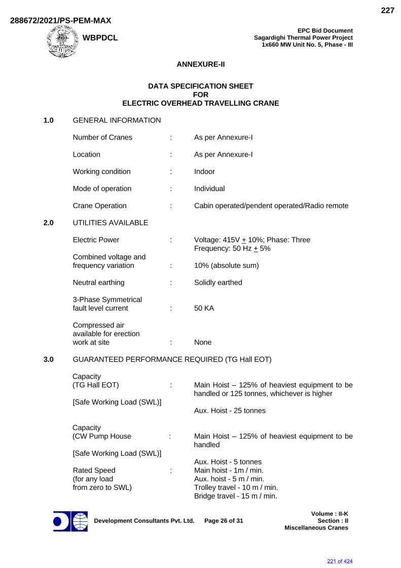
WBPDCL EPC Bid Document
Sagardighi Thermal Power Project 1x660 MW Unit No. 5, Phase - III
Development Consultants Pvt. Ltd.
Page 26 of 31
Volume : II-KSection : II
Miscellaneous Cranes
ANNEXURE-II
DATA SPECIFICATION SHEET FOR
ELECTRIC OVERHEAD TRAVELLING CRANE
1.0 GENERAL INFORMATION
Number of Cranes : As per Annexure-I Location : As per Annexure-I Working condition : Indoor
Mode of operation : Individual Crane Operation : Cabin operated/pendent operated/Radio remote
2.0 UTILITIES AVAILABLE
Electric Power : Voltage: 415V +_ 10%; Phase: Three
Frequency: 50 Hz +_ 5% Combined voltage and frequency variation : 10% (absolute sum) Neutral earthing : Solidly earthed 3-Phase Symmetrical fault level current : 50 KA Compressed air available for erection work at site : None
3.0 GUARANTEED PERFORMANCE REQUIRED (TG Hall EOT)
Capacity (TG Hall EOT) : Main Hoist – 125% of heaviest equipment to be
handled or 125 tonnes, whichever is higher [Safe Working Load (SWL)]
Aux. Hoist - 25 tonnes
Capacity (CW Pump House : Main Hoist – 125% of heaviest equipment to be
handled [Safe Working Load (SWL)]
Aux. Hoist - 5 tonnes Rated Speed : Main hoist - 1m / min. (for any load Aux. hoist - 5 m / min. from zero to SWL) Trolley travel - 10 m / min. Bridge travel - 15 m / min.
221 of 424
288672/2021/PS-PEM-MAX227
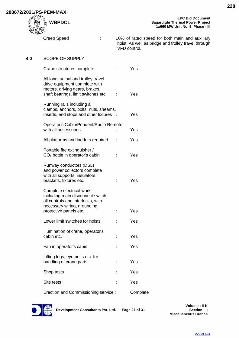
WBPDCL EPC Bid Document
Sagardighi Thermal Power Project 1x660 MW Unit No. 5, Phase - III
Development Consultants Pvt. Ltd.
Page 27 of 31
Volume : II-KSection : II
Miscellaneous Cranes
Creep Speed : 10% of rated speed for both main and auxiliary hoist. As well as bridge and trolley travel through VFD control.
4.0 SCOPE OF SUPPLY
Crane structures complete : Yes All longitudinal and trolley travel
drive equipment complete with motors, driving gears, brakes, shaft bearings, limit switches etc. : Yes
Running rails including all
clamps, anchors, bolts, nuts, sheams, inserts, end stops and other fixtures : Yes
Operator's Cabin/Pendent/Radio Remote with all accessories : Yes All platforms and ladders required : Yes
Portable fire extinguisher / CO2 bottle in operator's cabin : Yes Runway conductors (DSL)
and power collectors complete with all supports, insulators, brackets, fixtures etc. : Yes
Complete electrical work
including main disconnect switch, all controls and interlocks, with necessary wiring, grounding, protective panels etc. : Yes
Lower limit switches for hoists : Yes Illumination of crane, operator's cabin etc. : Yes Fan in operator's cabin : Yes Lifting lugs, eye bolts etc. for handling of crane parts : Yes Shop tests : Yes Site tests : Yes Erection and Commissioning service : Complete
222 of 424
288672/2021/PS-PEM-MAX228
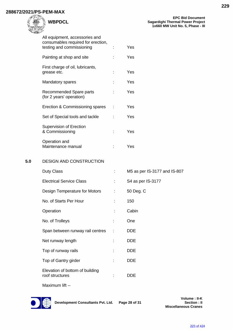
WBPDCL EPC Bid Document
Sagardighi Thermal Power Project 1x660 MW Unit No. 5, Phase - III
Development Consultants Pvt. Ltd.
Page 28 of 31
Volume : II-KSection : II
Miscellaneous Cranes
All equipment, accessories and consumables required for erection, testing and commissioning : Yes
Painting at shop and site : Yes First charge of oil, lubricants, grease etc. : Yes Mandatory spares : Yes Recommended Spare parts : Yes (for 2 years' operation) Erection & Commissioning spares : Yes Set of Special tools and tackle : Yes Supervision of Erection
& Commissioning : Yes Operation and
Maintenance manual : Yes
5.0 DESIGN AND CONSTRUCTION Duty Class : M5 as per IS-3177 and IS-807
Electrical Service Class : S4 as per IS-3177 Design Temperature for Motors : 50 Deg. C No. of Starts Per Hour : 150
Operation : Cabin No. of Trolleys : One Span between runway rail centres : DDE
Net runway length : DDE Top of runway rails : DDE Top of Gantry girder : DDE Elevation of bottom of building roof structures : DDE Maximum lift --
223 of 424
288672/2021/PS-PEM-MAX229
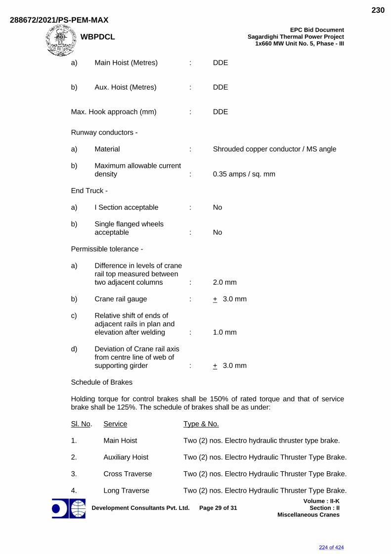
WBPDCL EPC Bid Document
Sagardighi Thermal Power Project 1x660 MW Unit No. 5, Phase - III
Development Consultants Pvt. Ltd.
Page 29 of 31
Volume : II-KSection : II
Miscellaneous Cranes
a) Main Hoist (Metres) : DDE b) Aux. Hoist (Metres) : DDE
Max. Hook approach (mm) : DDE
Runway conductors - a) Material : Shrouded copper conductor / MS angle b) Maximum allowable current density : 0.35 amps / sq. mm End Truck - a) I Section acceptable : No b) Single flanged wheels acceptable : No Permissible tolerance -
a) Difference in levels of crane rail top measured between two adjacent columns : 2.0 mm b) Crane rail gauge : +_ 3.0 mm c) Relative shift of ends of adjacent rails in plan and elevation after welding : 1.0 mm d) Deviation of Crane rail axis
from centre line of web of supporting girder : +_ 3.0 mm
Schedule of Brakes Holding torque for control brakes shall be 150% of rated torque and that of service
brake shall be 125%. The schedule of brakes shall be as under: Sl. No. Service Type & No. 1. Main Hoist Two (2) nos. Electro hydraulic thruster type brake. 2. Auxiliary Hoist Two (2) nos. Electro Hydraulic Thruster Type Brake. 3. Cross Traverse Two (2) nos. Electro Hydraulic Thruster Type Brake. 4. Long Traverse Two (2) nos. Electro Hydraulic Thruster Type Brake.
224 of 424
288672/2021/PS-PEM-MAX230
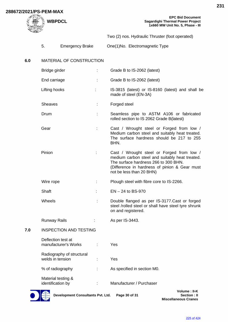
WBPDCL EPC Bid Document
Sagardighi Thermal Power Project 1x660 MW Unit No. 5, Phase - III
Development Consultants Pvt. Ltd.
Page 30 of 31
Volume : II-KSection : II
Miscellaneous Cranes
Two (2) nos. Hydraulic Thruster (foot operated) 5. Emergency Brake One(1)No. Electromagnetic Type
6.0 MATERIAL OF CONSTRUCTION Bridge girder : Grade B to IS-2062 (latest) End carriage : Grade B to IS-2062 (latest)
Lifting hooks : IS-3815 (latest) or IS-8160 (latest) and shall be made of steel (EN-3A)
Sheaves : Forged steel Drum : Seamless pipe to ASTM A106 or fabricated
rolled section to IS 2062 Grade B(latest)
Gear : Cast / Wrought steel or Forged from low / Medium carbon steel and suitably heat treated. The surface hardness should be 217 to 255 BHN.
Pinion : Cast / Wrought steel or Forged from low /
medium carbon steel and suitably heat treated. The surface hardness 266 to 300 BHN. (Difference in hardness of pinion & Gear must not be less than 20 BHN)
Wire rope : Plough steel with fibre core to IS-2266.
Shaft : EN – 24 to BS-970
Wheels : Double flanged as per IS-3177.Cast or forged steel /rolled steel or shall have steel tyre shrunk on and registered.
Runway Rails : As per IS-3443.
7.0 INSPECTION AND TESTING
Deflection test at manufacturer's Works : Yes Radiography of structural welds in tension : Yes % of radiography : As specified in section M0. Material testing &
identification by : Manufacturer / Purchaser
225 of 424
288672/2021/PS-PEM-MAX231
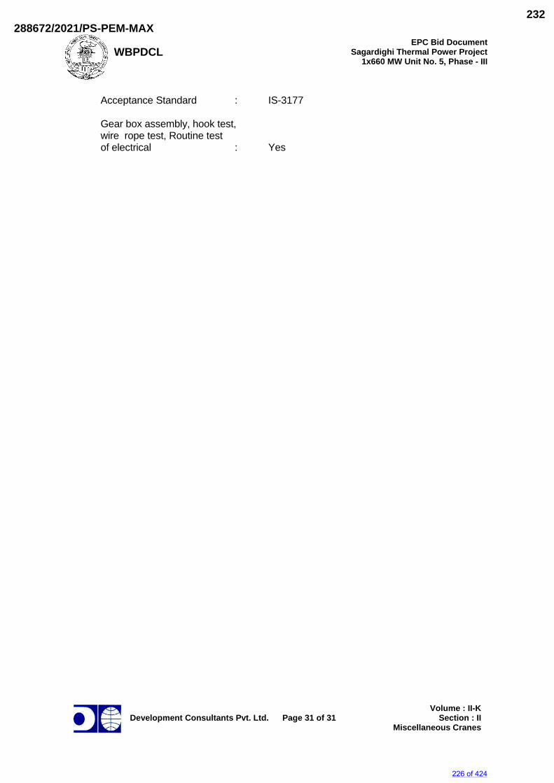
WBPDCL EPC Bid Document
Sagardighi Thermal Power Project 1x660 MW Unit No. 5, Phase - III
Development Consultants Pvt. Ltd.
Page 31 of 31
Volume : II-KSection : II
Miscellaneous Cranes
Acceptance Standard : IS-3177 Gear box assembly, hook test,
wire rope test, Routine test of electrical : Yes
226 of 424
288672/2021/PS-PEM-MAX232
SAGARDIGHI THERMAL POWER PROJECT, 1 X 660 MW UNIT NO 5, STAGE III.
TG HALL– AB BAY 160/25T DOUBLE GIRDER EOT CRANES
SPECIFIC TECHNICAL REQUIREMENT (MECHANICAL)
SPECIFICATION No: PE-TS-445-501-A001
SECTION IA
REV. 00 09-05-2021
SECTION IA ANNEXURES
227 of 424
288672/2021/PS-PEM-MAX233
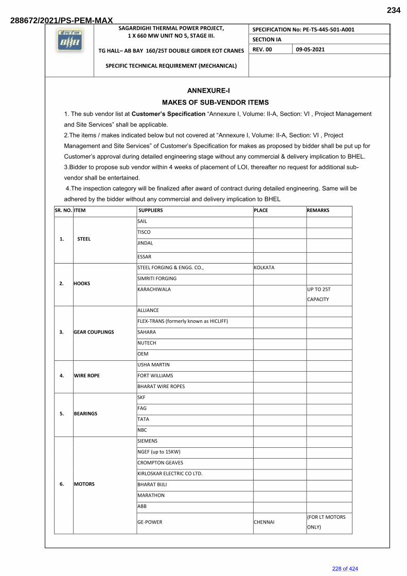
SAGARDIGHI THERMAL POWER PROJECT, 1 X 660 MW UNIT NO 5, STAGE III.
TG HALL– AB BAY 160/25T DOUBLE GIRDER EOT CRANES
SPECIFIC TECHNICAL REQUIREMENT (MECHANICAL)
SPECIFICATION No: PE-TS-445-501-A001
SECTION IA
REV. 00 09-05-2021
ANNEXURE-I MAKES OF SUB-VENDOR ITEMS
1. The sub vendor list at Customer’s Specification “Annexure I, Volume: II-A, Section: VI , Project Management
and Site Services” shall be applicable.
2.The items / makes indicated below but not covered at “Annexure I, Volume: II-A, Section: VI , Project
Management and Site Services” of Customer’s Specification for makes as proposed by bidder shall be put up for
Customer’s approval during detailed engineering stage without any commercial & delivery implication to BHEL.
3.Bidder to propose sub vendor within 4 weeks of placement of LOI, thereafter no request for additional sub-
vendor shall be entertained. 4.The inspection category will be finalized after award of contract during detailed engineering. Same will be
adhered by the bidder without any commercial and delivery implication to BHEL SR. NO. ITEM SUPPLIERS PLACE REMARKS
1. STEEL
SAIL
TISCO
JINDAL
ESSAR
2. HOOKS
STEEL FORGING & ENGG. CO., KOLKATA
SIMRITI FORGING
KARACHIWALA
UP TO 25T
CAPACITY
3. GEAR COUPLINGS
ALLIANCE
FLEX-TRANS (formerly known as HICLIFF)
SAHARA
NUTECH
OEM
4. WIRE ROPE
USHA MARTIN
FORT WILLIAMS
BHARAT WIRE ROPES
5. BEARINGS
SKF
FAG
TATA
NBC
6. MOTORS
SIEMENS
NGEF (up to 15KW)
CROMPTON GEAVES
KIRLOSKAR ELECTRIC CO LTD.
BHARAT BIJLI
MARATHON
ABB
GE-POWER CHENNAI (FOR LT MOTORS
ONLY)
228 of 424
288672/2021/PS-PEM-MAX234
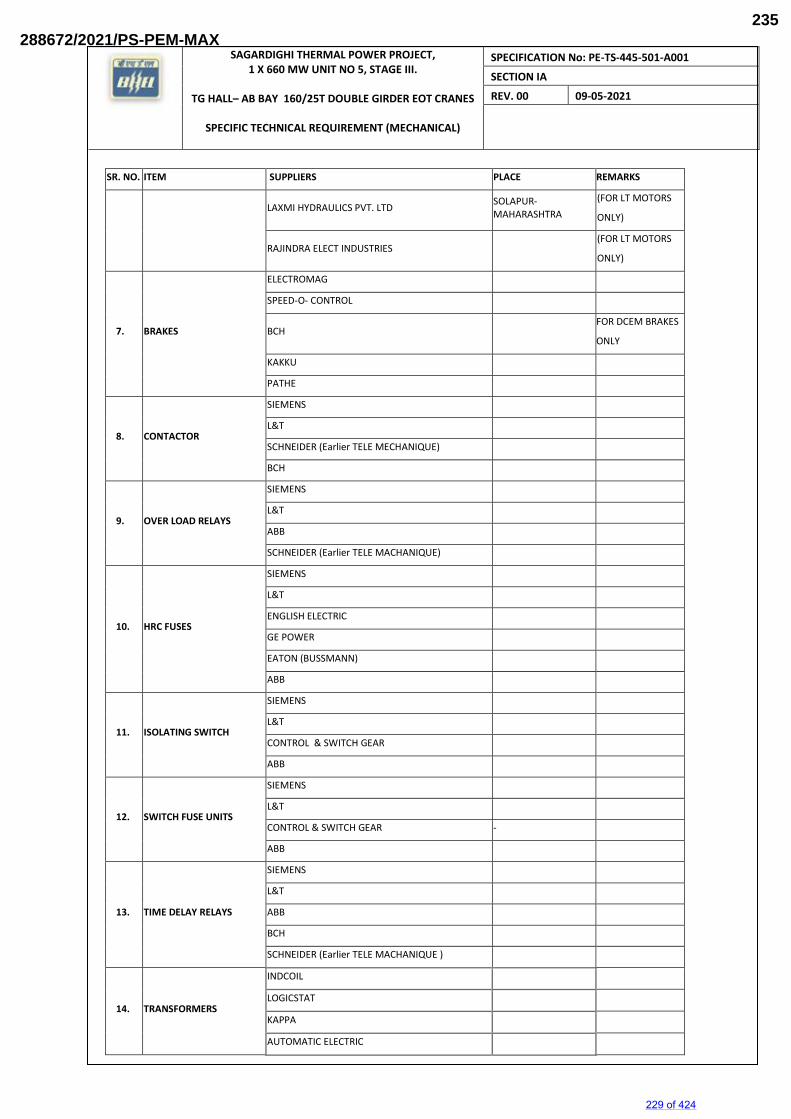
SAGARDIGHI THERMAL POWER PROJECT, 1 X 660 MW UNIT NO 5, STAGE III.
TG HALL– AB BAY 160/25T DOUBLE GIRDER EOT CRANES
SPECIFIC TECHNICAL REQUIREMENT (MECHANICAL)
SPECIFICATION No: PE-TS-445-501-A001
SECTION IA
REV. 00 09-05-2021
SR. NO. ITEM SUPPLIERS PLACE REMARKS
LAXMI HYDRAULICS PVT. LTD SOLAPUR‐ MAHARASHTRA
(FOR LT MOTORS
ONLY)
RAJINDRA ELECT INDUSTRIES (FOR LT MOTORS
ONLY)
7. BRAKES
ELECTROMAG
SPEED-O- CONTROL
BCH FOR DCEM BRAKES
ONLY
KAKKU
PATHE
8. CONTACTOR
SIEMENS
L&T
SCHNEIDER (Earlier TELE MECHANIQUE)
BCH
9. OVER LOAD RELAYS
SIEMENS
L&T
ABB
SCHNEIDER (Earlier TELE MACHANIQUE)
10. HRC FUSES
SIEMENS
L&T
ENGLISH ELECTRIC
GE POWER
EATON (BUSSMANN)
ABB
11. ISOLATING SWITCH
SIEMENS
L&T
CONTROL & SWITCH GEAR
ABB
12. SWITCH FUSE UNITS
SIEMENS
L&T
CONTROL & SWITCH GEAR -
ABB
13. TIME DELAY RELAYS
SIEMENS
L&T
ABB
BCH
SCHNEIDER (Earlier TELE MACHANIQUE )
14. TRANSFORMERS
INDCOIL
LOGICSTAT
KAPPA
AUTOMATIC ELECTRIC
229 of 424
288672/2021/PS-PEM-MAX235
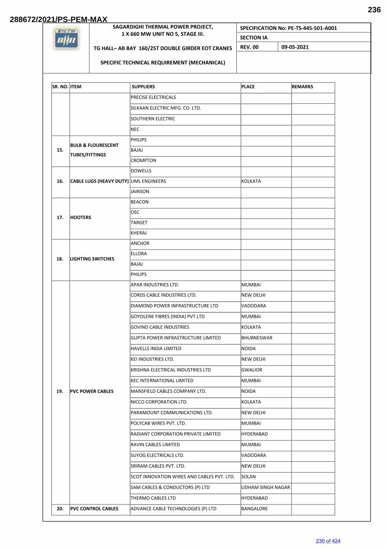
SAGARDIGHI THERMAL POWER PROJECT, 1 X 660 MW UNIT NO 5, STAGE III.
TG HALL– AB BAY 160/25T DOUBLE GIRDER EOT CRANES
SPECIFIC TECHNICAL REQUIREMENT (MECHANICAL)
SPECIFICATION No: PE-TS-445-501-A001
SECTION IA
REV. 00 09-05-2021
SR. NO. ITEM SUPPLIERS PLACE REMARKS
PRECISE ELECTRICALS
SILKAAN ELECTRIC MFG. CO. LTD.
SOUTHERN ELECTRIC
NEC
15. BULB & FLOURESCENT
TUBES/FITTINGS
PHILIPS
BAJAJ
CROMPTON
16. CABLE LUGS (HEAVY DUTY)
DOWELLS
UML ENGINEERS KOLKATA
JAINSON
17. HOOTERS
BEACON
OSC
TARGET
KHERAJ
18. LIGHTING SWITCHES
ANCHOR
ELLORA
BAJAJ
PHILIPS
19. PVC POWER CABLES
APAR INDUSTRIES LTD. MUMBAI
CORDS CABLE INDUSTRIES LTD. NEW DELHI
DIAMOND POWER INFRASTRUCTURE LTD VADODARA
GOYOLENE FIBRES (INDIA) PVT.LTD MUMBAI
GOVIND CABLE INDUSTRIES KOLKATA
GUPTA POWER INFRASTRUCTURE LIMITED BHUBNESWAR
HAVELLS INDIA LIMITED NOIDA
KEI INDUSTRIES LTD. NEW DELHI
KRISHNA ELECTRICAL INDUSTRIES LTD GWALIOR
KEC INTERNATIONAL LIMITED MUMBAI
MANSFIELD CABLES COMPANY LTD. NOIDA
NICCO CORPORATION LTD. KOLKATA
PARAMOUNT COMMUNICATIONS LTD. NEW DELHI
POLYCAB WIRES PVT. LTD. MUMBAI
RADIANT CORPORATION PRIVATE LIMITED HYDERABAD
RAVIN CABLES LIMITED MUMBAI
SUYOG ELECTRICALS LTD. VADODARA
SRIRAM CABLES PVT. LTD. NEW DELHI
SCOT INNOVATION WIRES AND CABLES PVT. LTD. SOLAN
SAM CABLES & CONDUCTORS (P) LTD UDHAM SINGH NAGAR
THERMO CABLES LTD HYDERABAD
20. PVC CONTROL CABLES ADVANCE CABLE TECHNOLOGIES (P) LTD BANGALORE
230 of 424
288672/2021/PS-PEM-MAX236
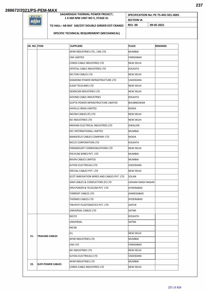
SAGARDIGHI THERMAL POWER PROJECT, 1 X 660 MW UNIT NO 5, STAGE III.
TG HALL– AB BAY 160/25T DOUBLE GIRDER EOT CRANES
SPECIFIC TECHNICAL REQUIREMENT (MECHANICAL)
SPECIFICATION No: PE-TS-445-501-A001
SECTION IA
REV. 00 09-05-2021
SR. NO. ITEM SUPPLIERS PLACE REMARKS
APAR INDUSTRIES LTD., CMI LTD MUMBAI
CMI LIMITED FARIDABAD
CORDS CABLE INDUSTRIES LTD NEW DELHI
CRYSTAL CABLE INDUSTRIES LTD KOLKATA
DELTON CABLES LTD NEW DELHI
DIAMOND POWER INFRASTRUCTURE LTD VADODARA
ELKAY TELELINKS LTD NEW DELHI
GEMSCAB INDUSTRIES LTD NEW DELHI
GOVIND CABLE INDUSTRIES KOLKATA
GUPTA POWER INFRASTRUCTURE LIMITED BHUBNESWAR
HAVELLS INDIA LIMITED NOIDA
INCOM CABLES (P) LTD NEW DELHI
KEI INDUSTRIES LTD NEW DELHI
KRISHNA ELECTRICAL INDUSTRIES LTD GWALIOR
KEC INTERNATIONAL LIMITED MUMBAI
MANSFIELD CABLES COMPANY LTD NOIDA
NICCO CORPORATION LTD KOLKATA
PARAMOUNT COMMUNICATIONS LTD NEW DELHI
POLYCAB WIRES PVT. LTD MUMBAI
RAVIN CABLES LIMITED MUMBAI
SUYOG ELECTRICALS LTD VADODARA
SPECIAL CABLES PVT. LTD NEW DELHI
SCOT INNOVATION WIRES AND CABLES PVT. LTD SOLAN
SAM CABLES & CONDUCTORS (P) LTD UDHAM SINGH NAGAR
SPM POWER & TELECOM PVT. LTD HYDERABAD
TORRENT CABLES LTD AHMEDABAD
THERMO CABLES LTD HYDERABAD
TIRUPATI PLASTOMATICS PVT. LTD JAIPUR
UNIVERSAL CABLES LTD SATNA
21. TRAILING CABLES
NICCO KOLKATA
UNIVERSAL SATNA
INCAB
ICL NEW DELHI
APAR INDUSTRIES LTD MUMBAI
CMI LTD FARIDABAD
KEI INDUSTRIES LTD NEW DELHI
SUYOG ELECTRICALS LTD VADODARA
22. XLPE POWER CABLES APAR INDUSTRIES LTD MUMBAI
CORDS CABLE INDUSTRIES LTD NEW DELHI
231 of 424
288672/2021/PS-PEM-MAX237
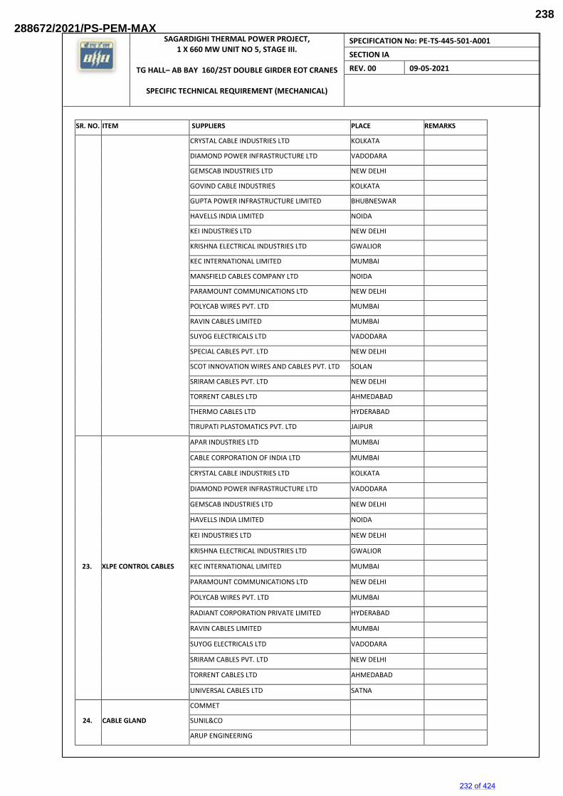
SAGARDIGHI THERMAL POWER PROJECT, 1 X 660 MW UNIT NO 5, STAGE III.
TG HALL– AB BAY 160/25T DOUBLE GIRDER EOT CRANES
SPECIFIC TECHNICAL REQUIREMENT (MECHANICAL)
SPECIFICATION No: PE-TS-445-501-A001
SECTION IA
REV. 00 09-05-2021
SR. NO. ITEM SUPPLIERS PLACE REMARKS
CRYSTAL CABLE INDUSTRIES LTD KOLKATA
DIAMOND POWER INFRASTRUCTURE LTD VADODARA
GEMSCAB INDUSTRIES LTD NEW DELHI
GOVIND CABLE INDUSTRIES KOLKATA
GUPTA POWER INFRASTRUCTURE LIMITED BHUBNESWAR
HAVELLS INDIA LIMITED NOIDA
KEI INDUSTRIES LTD NEW DELHI
KRISHNA ELECTRICAL INDUSTRIES LTD GWALIOR
KEC INTERNATIONAL LIMITED MUMBAI
MANSFIELD CABLES COMPANY LTD NOIDA
PARAMOUNT COMMUNICATIONS LTD NEW DELHI
POLYCAB WIRES PVT. LTD MUMBAI
RAVIN CABLES LIMITED MUMBAI
SUYOG ELECTRICALS LTD VADODARA
SPECIAL CABLES PVT. LTD NEW DELHI
SCOT INNOVATION WIRES AND CABLES PVT. LTD SOLAN
SRIRAM CABLES PVT. LTD NEW DELHI
TORRENT CABLES LTD AHMEDABAD
THERMO CABLES LTD HYDERABAD
TIRUPATI PLASTOMATICS PVT. LTD JAIPUR
23. XLPE CONTROL CABLES
APAR INDUSTRIES LTD MUMBAI
CABLE CORPORATION OF INDIA LTD MUMBAI
CRYSTAL CABLE INDUSTRIES LTD KOLKATA
DIAMOND POWER INFRASTRUCTURE LTD VADODARA
GEMSCAB INDUSTRIES LTD NEW DELHI
HAVELLS INDIA LIMITED NOIDA
KEI INDUSTRIES LTD NEW DELHI
KRISHNA ELECTRICAL INDUSTRIES LTD GWALIOR
KEC INTERNATIONAL LIMITED MUMBAI
PARAMOUNT COMMUNICATIONS LTD NEW DELHI
POLYCAB WIRES PVT. LTD MUMBAI
RADIANT CORPORATION PRIVATE LIMITED HYDERABAD
RAVIN CABLES LIMITED MUMBAI
SUYOG ELECTRICALS LTD VADODARA
SRIRAM CABLES PVT. LTD NEW DELHI
TORRENT CABLES LTD AHMEDABAD
UNIVERSAL CABLES LTD SATNA
24. CABLE GLAND
COMMET
SUNIL&CO
ARUP ENGINEERING
232 of 424
288672/2021/PS-PEM-MAX238
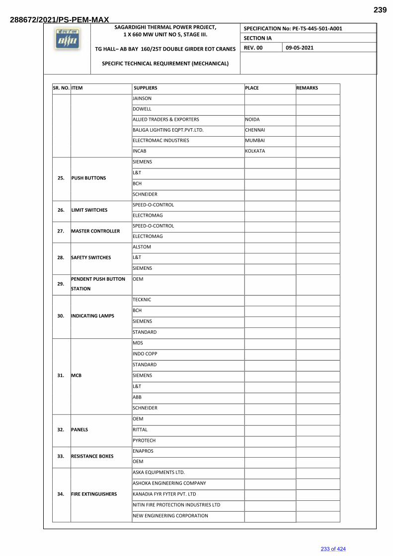
SAGARDIGHI THERMAL POWER PROJECT, 1 X 660 MW UNIT NO 5, STAGE III.
TG HALL– AB BAY 160/25T DOUBLE GIRDER EOT CRANES
SPECIFIC TECHNICAL REQUIREMENT (MECHANICAL)
SPECIFICATION No: PE-TS-445-501-A001
SECTION IA
REV. 00 09-05-2021
SR. NO. ITEM SUPPLIERS PLACE REMARKS
JAINSON
DOWELL
ALLIED TRADERS & EXPORTERS NOIDA
BALIGA LIGHTING EQPT.PVT.LTD. CHENNAI
ELECTROMAC INDUSTRIES MUMBAI
INCAB KOLKATA
25. PUSH BUTTONS
SIEMENS
L&T
BCH
SCHNEIDER
26. LIMIT SWITCHES SPEED-O-CONTROL
ELECTROMAG
27. MASTER CONTROLLER SPEED-O-CONTROL
ELECTROMAG
28. SAFETY SWITCHES
ALSTOM
L&T
SIEMENS
29. PENDENT PUSH BUTTON
STATION
OEM
30. INDICATING LAMPS
TECKNIC
BCH
SIEMENS
STANDARD
31. MCB
MDS
INDO COPP
STANDARD
SIEMENS
L&T
ABB
SCHNEIDER
32. PANELS
OEM
RITTAL
PYROTECH
33. RESISTANCE BOXES ENAPROS
OEM
34. FIRE EXTINGUISHERS
ASKA EQUIPMENTS LTD.
ASHOKA ENGINEERING COMPANY
KANADIA FYR FYTER PVT. LTD
NITIN FIRE PROTECTION INDUSTRIES LTD
NEW ENGINEERING CORPORATION
233 of 424
288672/2021/PS-PEM-MAX239
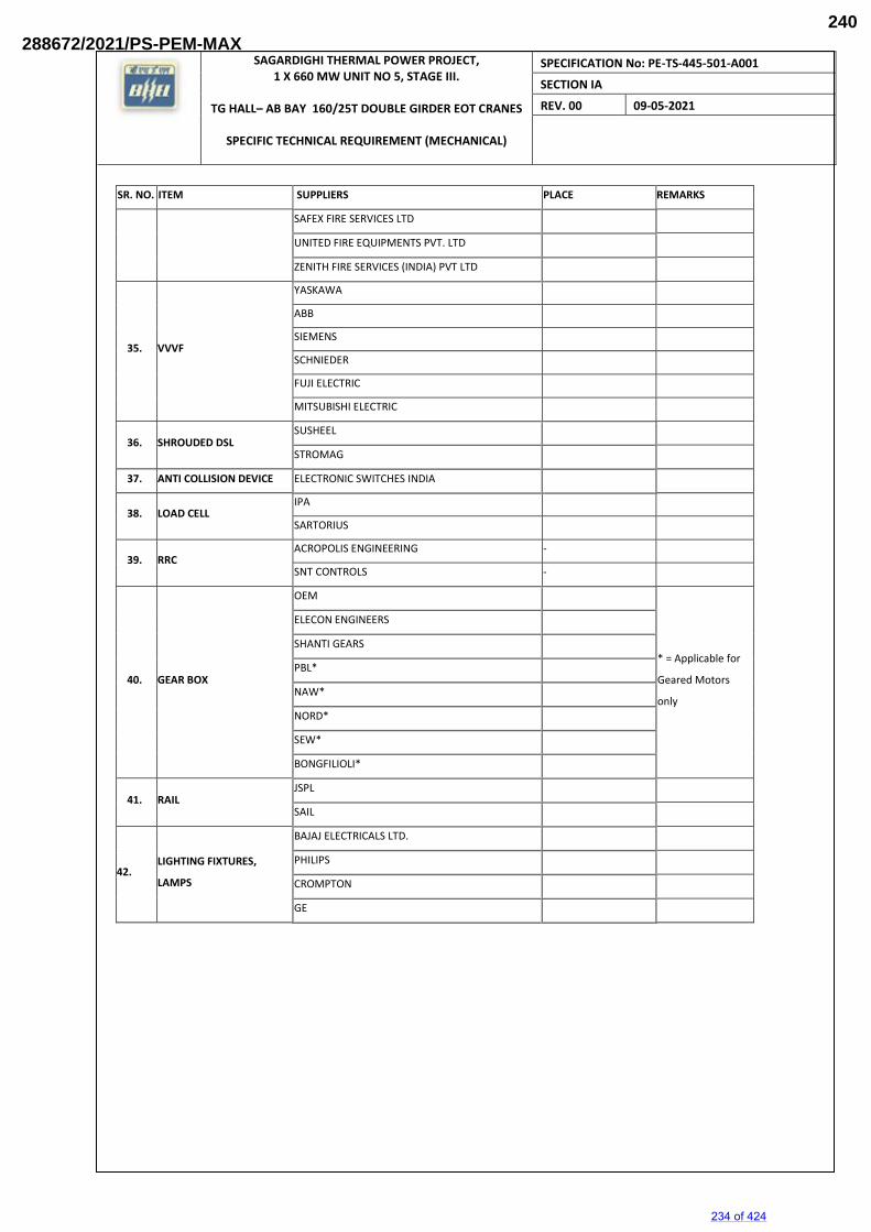
SAGARDIGHI THERMAL POWER PROJECT, 1 X 660 MW UNIT NO 5, STAGE III.
TG HALL– AB BAY 160/25T DOUBLE GIRDER EOT CRANES
SPECIFIC TECHNICAL REQUIREMENT (MECHANICAL)
SPECIFICATION No: PE-TS-445-501-A001
SECTION IA
REV. 00 09-05-2021
SR. NO. ITEM SUPPLIERS PLACE REMARKS
SAFEX FIRE SERVICES LTD
UNITED FIRE EQUIPMENTS PVT. LTD
ZENITH FIRE SERVICES (INDIA) PVT LTD
35. VVVF
YASKAWA
ABB
SIEMENS
SCHNIEDER
FUJI ELECTRIC
MITSUBISHI ELECTRIC
36. SHROUDED DSL SUSHEEL
STROMAG
37. ANTI COLLISION DEVICE ELECTRONIC SWITCHES INDIA
38. LOAD CELL IPA
SARTORIUS
39. RRC ACROPOLIS ENGINEERING -
SNT CONTROLS -
40. GEAR BOX
OEM
* = Applicable for
Geared Motors
only
ELECON ENGINEERS
SHANTI GEARS
PBL*
NAW*
NORD*
SEW*
BONGFILIOLI*
41. RAIL JSPL
SAIL
42. LIGHTING FIXTURES,
LAMPS
BAJAJ ELECTRICALS LTD.
PHILIPS
CROMPTON
GE
234 of 424
288672/2021/PS-PEM-MAX240
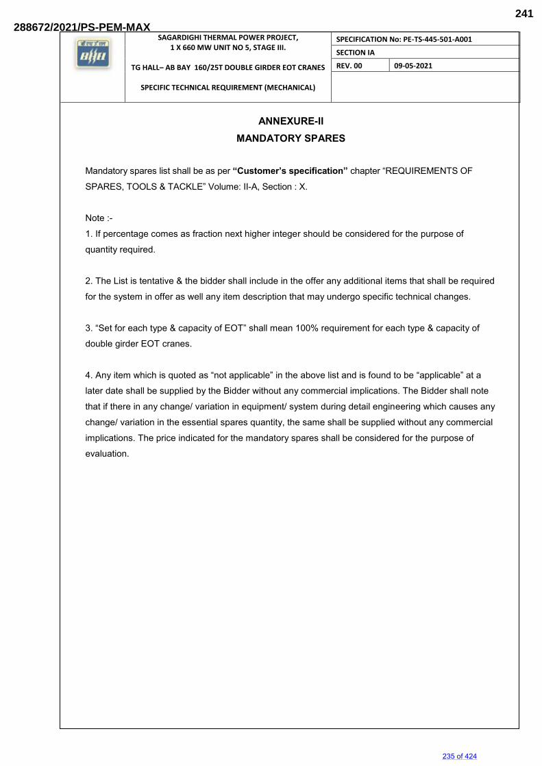
SAGARDIGHI THERMAL POWER PROJECT, 1 X 660 MW UNIT NO 5, STAGE III.
TG HALL– AB BAY 160/25T DOUBLE GIRDER EOT CRANES
SPECIFIC TECHNICAL REQUIREMENT (MECHANICAL)
SPECIFICATION No: PE-TS-445-501-A001
SECTION IA
REV. 00 09-05-2021
ANNEXURE-II MANDATORY SPARES
Mandatory spares list shall be as per “Customer’s specification” chapter “REQUIREMENTS OF
SPARES, TOOLS & TACKLE” Volume: II-A, Section : X.
Note :-
1. If percentage comes as fraction next higher integer should be considered for the purpose of
quantity required.
2. The List is tentative & the bidder shall include in the offer any additional items that shall be required
for the system in offer as well any item description that may undergo specific technical changes.
3. “Set for each type & capacity of EOT” shall mean 100% requirement for each type & capacity of
double girder EOT cranes.
4. Any item which is quoted as “not applicable” in the above list and is found to be “applicable” at a
later date shall be supplied by the Bidder without any commercial implications. The Bidder shall note
that if there in any change/ variation in equipment/ system during detail engineering which causes any
change/ variation in the essential spares quantity, the same shall be supplied without any commercial
implications. The price indicated for the mandatory spares shall be considered for the purpose of
evaluation.
235 of 424
288672/2021/PS-PEM-MAX241
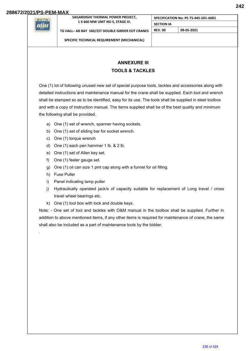
SAGARDIGHI THERMAL POWER PROJECT, 1 X 660 MW UNIT NO 5, STAGE III.
TG HALL– AB BAY 160/25T DOUBLE GIRDER EOT CRANES
SPECIFIC TECHNICAL REQUIREMENT (MECHANICAL)
SPECIFICATION No: PE-TS-445-501-A001
SECTION IA
REV. 00 09-05-2021
ANNEXURE III TOOLS & TACKLES
One (1) lot of following unused new set of special purpose tools, tackles and accessories along with
detailed instructions and maintenance manual for the crane shall be supplied. Each tool and wrench
shall be stamped so as to be identified, easy for its use. The tools shall be supplied in steel toolbox
and with a copy of instruction manual. The items supplied shall be of the best quality and minimum
the following shall be provided.
a) One (1) set of wrench, spanner having sockets.
b) One (1) set of sliding bar for socket wrench.
c) One (1) torque wrench
d) One (1) each pen hammer 1 lb. & 2 lb.
e) One (1) set of Allen key set.
f) One (1) feeler gauge set.
g) One (1) oil can size 1 pint cap along with a funnel for oil filling.
h) Fuse Puller
i) Panel indicating lamp puller
j) Hydraulically operated jack/s of capacity suitable for replacement of Long travel / cross
travel wheel bearings etc.
k) One (1) tool box with lock and double keys.
Note: - One set of tool and tackles with O&M manual in the toolbox shall be supplied. Further in
addition to above mentioned items, if any other items is required for maintenance of crane, the same
shall also be included as a part of maintenance tools by the bidder. .
236 of 424
288672/2021/PS-PEM-MAX242
SAGARDIGHI THERMAL POWER PROJECT, 1 X 660 MW UNIT NO 5, STAGE III.
TG HALL– AB BAY 160/25T DOUBLE GIRDER EOT CRANES
SPECIFIC TECHNICAL REQUIREMENT (MECHANICAL)
SPECIFICATION No: PE-TS-445-501-A001
SECTION IA
REV. 00 09-05-2021
ANNEXURE IV
PAINTING SPECIFICATION
1.0 PAINTING shall be as per “Customer’s specification” Volume: II-A, Section: XI , “Protective Coating and Painting”
2.0 Color Shade:
Sl no Components Color IS 5 shade no Color band
a. Crane structure & trolley Golden yellow 356
b. Bottom block assembly Golden yellow 356 With black strips
c. Hook Golden yellow 356 With 100 mm wide
black zebra strip
d. Platforms, galleries, ladders and
handrails.
Dark Admirality Grey 632
e. Panels Light grey/ As per
manufacturer’s standard
631
f. Motor Light grey/As per
manufacturer’s standard
631
237 of 424
288672/2021/PS-PEM-MAX243
SAGARDIGHI THERMAL POWER PROJECT, 1 X 660 MW UNIT NO 5, STAGE III.
TG HALL– AB BAY 160/25T DOUBLE GIRDER EOT CRANES
SPECIFIC TECHNICAL REQUIREMENT (MECHANICAL)
SPECIFICATION No: PE-TS-445-501-A001
SECTION IA
REV. 00 09-05-2021
ANNEXURE-V
DRAWINGS/ DOCUMENTS TO BE SUBMITTED AFTER AWARD OF CONTRACT
The successful bidder shall submit the following drawings / documents during detail engineering for
Customer’s/Consultant’s approval /information:
The ( * ) marked drawings are basic engineering drawings. After CAT 1, Cat 1*, Cat 2, Cat 3 & Cat 5
approval /BHEL clearance on these drawings, manufacturing/procurement activities shall be initiated.
Sl no
BHEL drawing No. Title
Category Scheduled
submission ( No
of weeks from
LOI/LOA)
1 PE-V0-445-501-A301* Manufacturing Quality Plan with sub vendor list FOR D/G EOT CRANES
ABOVE 100T (TG HALL)
A 21
2 PE-V0-445-501-A302* Mechanism Sizing Calculation Including storm brake calculation FOR
D/G EOT CRANES ABOVE 100T (TG HALL)
A 21
3 PE-V0-445-501-A303* General arrangement FOR D/G EOT CRANES ABOVE 100T with CT DSL
details (TG HALL)
A 21
4 PE-V0-445-501-A305 Data sheet with painting details FOR D/G EOT CRANES ABOVE 100T
(TG HALL)
A 42
5 PE-V0-445-501-A310* Structural calculations FOR D/G EOT CRANES ABOVE 100T (TG HALL) A 21
6 PE-V0-445-501-A312 Cable & DSL Sizing and Schedule FOR D/G EOT CRANES ABOVE 100T
(TG HALL)
A 28
7 PE-V0-445-501-A313 General Arrangement of a) Protective panel
b) Main hoist panel c) Aux. hoist panel d) Cross Traverse panel e) Long
Traverse panel f) Pendent g) Remote Radio Control FOR D/G EOT
CRANES ABOVE 100T (TG HALL)
I 28
8 PE-V0-445-501-A315* Data sheet of motors FOR D/G EOT CRANES ABOVE 100T (TG HALL) A 42
9 PE-V0-445-501-A320 Mandatory spare parts list FOR D/G EOT CRANES ABOVE 100T (TG
HALL)
A 56
10 PE-V0-445-501-A321 O & M Manual FOR D/G EOT CRANES ABOVE 100T (TG HALL) I 56
11 PE-V0-445-501-A311* SCHEMATIC CIRCUIT DIAGRAM OF a) PROTECTIVE PANEL, MAIN AND LIGHTING CIRCUIT & BOM b) MAIN HOIST PANEL & BOM c) AUX. HOIST PANEL & BOM d) CROSS TRAVERSE & BOM E) LONG TRAVERSE & BOM INCLUDING EARTHLING DIAGRAM & WRITE UP FOR ABOVE 100 T CRANE (TG HALL)
I 28
12 PE-V0-445-501-A304* CRAB SUB ASSEMBLY FOR D/G EOT CRANES ABOVE 100T with CT wheel assembly ( TG HALL)
I 21
238 of 424
288672/2021/PS-PEM-MAX244
SAGARDIGHI THERMAL POWER PROJECT, 1 X 660 MW UNIT NO 5, STAGE III.
TG HALL– AB BAY 160/25T DOUBLE GIRDER EOT CRANES
SPECIFIC TECHNICAL REQUIREMENT (MECHANICAL)
SPECIFICATION No: PE-TS-445-501-A001
SECTION IA
REV. 00 09-05-2021
13 PE-V0-445-501-A318 Electrical equipment layout in cabin FOR D/G EOT CRANES ABOVE
100T (TG HALL) I 35
14 PE-V0-445-501-A309*
Main and Auxiliary hook block assembly with details of hook, nut and
check plate for D/G EOT CRANES ABOVE 100T (TG HALL) I 28
15 PE-V0-445-501-A350
Crane lubrication drawing for D/G EOT CRANES ABOVE 100T (TG
HALL) I 42
16 PE-V0-445-501-A321
Type test certificate (for motors) for D/G EOT CRANES ABOVE 100T
(TG HALL) A 56
17 PE-V0-445-501-A332 Gantry Rail installation FOR D/G EOT CRANES ABOVE 100T (TG HALL) I 21
18 PE-V0-445-501-A333
Manufacturing Quality plan of motors (above 50KW) for D/G EOT
CRANES ABOVE 100T (TG HALL) A 35
19 PE-V0-445-501-A308
General arrangement for PVC shrouded DSL for D/G EOT CRANES
ABOVE 100T (TG HALL) I 28
20 PE-V0-445-501-A310*
Long travel Machinery Assembly with LT wheel assembly for D/G EOT
CRANES ABOVE 100T (TG HALL) I 28
21 PE-V0-445-501-A320
Crane Operational write up for D/G EOT CRANES ABOVE 100T (TG
HALL) I 35
Notes:
1. The above drawing list is tentative and shall be finalized with the successful bidder after placement
of order. While some of the drawings indicated above may not be applicable, some additional
drawings may also be required based on scope of work.
2. Drawings shall be prepared to the scale in Auto-CAD latest edition. Required no. of hard and soft
copies (editable) of the drawings shall be furnished as per requirement specified elsewhere in the
specification.
3. Only manual calculation with authentic supporting literature (e.g. extracts of hand Book/
standard/codes) shall be acceptable. All design calculations and drawings shall be in SI system
only.
4. Bidder to note that all values/dimensions/elevations etc. without supporting back up data
adopted/assumed by the successful bidder (during contract stage) in the design
calculation/drawings shall be taken by the customer/owner to be correct unless they are stipulated
in the specification. Any problem arising later in this regard shall be made good by the successful
bidder at his cost and no extension of time shall be granted for the same.
5. All the drawings and documents including general arrangement drawing, data sheet, calculation etc.
to be furnished to the customer during detailed engineering stage shall include / indicate the
following details for clarity w.r.t. Inspection, construction, erection and maintenance etc.:-
a) All drawings and documents shall indicate the list of all reference drawings including
general arrangement.
239 of 424
288672/2021/PS-PEM-MAX245
SAGARDIGHI THERMAL POWER PROJECT, 1 X 660 MW UNIT NO 5, STAGE III.
TG HALL– AB BAY 160/25T DOUBLE GIRDER EOT CRANES
SPECIFIC TECHNICAL REQUIREMENT (MECHANICAL)
SPECIFICATION No: PE-TS-445-501-A001
SECTION IA
REV. 00 09-05-2021
b) All drawings shall include / show plan, elevation, side view, cross - section, skin section,
blow - up view; all major self-manufactured and bought out items shall be labeled and
included in BOQ / BOM in tabular form.
c) Painting schedule shall also be made as a part of general arrangement drawing of each
equipment / items indicating at least 3 trade names.
d) All the drawings required to be furnished to customer during detailed engineering stage
shall include technical parameters, details of paints and lubrication, hardness and BOQ /
BOM in tabular form indicating all major components including bought out items and their
quantity, material of construction indicating its applicable code / standard, weight, make
etc.
e) Drawings/ documents to be submitted for purchasers review/ approval shall be under
Revision A, B, C… etc. while drawings /documents to be submitted thereafter for
customer’s approval after purchaser’s approval shall be under R-0, 1, 2, 3 ….etc.
f) Drawings and documents not covered above but required to check safety of machines/
system, shall be submitted during detailed engineering stage without any commercial
implication.
g) All drawings shall include "B.O.M" and indicate quantity, material of construction, make
along with IS/BS No., Technical parameters, dimensions, hardness, machining symbol and
tolerance, requirement of radiography and hydraulic tests, painting details, elevation, side
view, plan, skin section and blow-up view for clarity.
h) All drawings shall be prepared as per BHEL's title block and shall bear BHEL's drawing
No.
i) Schedule of drawings submissions, comment incorporations & approval shall be as
stipulated in the specifications. The successful bidder shall depute his design personnel to
BHEL’s/ Customer’s/ Consultant’s office for across the table resolution of issues and to get
documents approved in the stipulated time.
j) Bidder to follow the following the drawing submission schedule:
i. 1st submission of drawings as per the submission schedule.
ii. Every revised submission incorporating comments – within 10 days.
k) Bidder to submit revised drawings complete in all respects incorporating all comments.
Any incomplete drawing submitted shall be treated as non-submission with delays
attributable to bidder’s account. For any clarification/ discussion required to complete the
drawings, the bidder shall himself depute his personal to BHEL for across the table
discussions/ finalizations/ submissions of drawings.
240 of 424
288672/2021/PS-PEM-MAX246
SAGARDIGHI THERMAL POWER PROJECT, 1 X 660 MW UNIT NO 5, STAGE III.
TG HALL– AB BAY 160/25T DOUBLE GIRDER EOT CRANES
SPECIFIC TECHNICAL REQUIREMENT (MECHANICAL)
SPECIFICATION No: PE-TS-445-501-A001
SECTION IA
REV. 00 09-05-2021
ANNEXURE VI – PACKING PROCEDURE
COMMON GUIDELINES FOR PACKING 1. GENERAL:
The Components/Assemblies need to be packed suitably to avoid physical damage & corrosion during transit & storage. This packing shall be suitable for different handling operations and for the adverse conditions during transportation and during indoor / outdoor storage of materials. All the equipment shall be suitably protected, coated, covered or boxed and crated to prevent damage or deterioration during transit, handling and storage at site till the time of erection. The Contractor shall be responsible for all loss or damage during transportation, handling and storage due to improper packing. The identification marking indicating the name and address of the consignee shall be clearly marked in indelible ink on two opposite sides and top of each of the packages. In addition the Contractor shall include in the marking gross and net weight, outer dimension and cubic measurement. Each package shall be accompanied by a packing note (in weather proof paper) quoting specifically the name of the Contractor, the number and date of contract and names of the office placing the contract, nomenclature of contents and Bill of Material.
2. TYPES OF PACKING:
The following 5 types of packing have been standardized for packing of General Components/ Assemblies. 1) 'OP' - Open Type.
2) 'PP' - Partially Packed.
3) 'CP' – Crate/Box Packing - Components/Equipment requiring physical protection.
4) „CQ' - Case Packing – Machined components-Small & Medium Components/ Assemblies/ Equipment which require corrosion & physical protection.
5) ‘CR’ - Case Packing – Electrical/Electronic Components/ Assemblies, which require special packing viz. Water Proof, Shock Proof etc…
3. DESCRIPTION OF TYPES OF PACKING:
The various types of packing, as standardized above, are described below.
3.1 'OP’ - Open Type In case, of components which are not affected by water & dust and do not require special protection, are generally not machined, shall be sent as open packages. However, these components may be sent in crates, wherever necessary.
3.2 'PP’ - Partially Packed Components which need special protection at selected portions only shall be despatched partially packed. Machined surfaces should not be allowed to come directly in contact with the wood. Such surfaces should be protected with 100GSM(Colourless) Multi Layered Cross Laminated Polyethylene Film. All sharp corners and edges shall be protected by rubber mats to prevent damage to the polyethylene film.
3.3 'CP’ - Crate Packing
Assemblies/Components which need only physical protection from the point of view of handling shall be despatched duly packed in crates.
3.4 ‘CQ’ - Case Packing - Machined Components/Assemblies/Equipment
Small and medium sized components/assemblies/equipment due to size/weight and to avoid handling and pilferage problems shall be packed in Case/Containers. Wherever required adequate quantity of silica gel or VCI Powder/Tablets, packed in thin muslin cloth cotton bags shall be suitably placed. Small machines/components of less weight shall be provided with suitable cushioning by Rubberised coir. The
241 of 424
288672/2021/PS-PEM-MAX247
SAGARDIGHI THERMAL POWER PROJECT, 1 X 660 MW UNIT NO 5, STAGE III.
TG HALL– AB BAY 160/25T DOUBLE GIRDER EOT CRANES
SPECIFIC TECHNICAL REQUIREMENT (MECHANICAL)
SPECIFICATION No: PE-TS-445-501-A001
SECTION IA
REV. 00 09-05-2021
components inside the case shall be entirely covered with100GSM(Colourless) Multi Layered Cross Laminated Polyethylene Film, wherever required. This may be prescribed for electronic parts/critical machined components/surfaces. For mechanical product like valves where motors are separately securely wrapped in polyethylene, the requirement of individual component wrapping shall be exempted.
3.5 'CR’ - Case Packing - Electrical & Electronic Components/Assemblies
Delicate components likely to be damaged e.g. Gauges, Instruments etc. are to be wrapped in waxed paper or polyethylene air bubble film and packed in cartons. Adequate quantity of Silica gel packed in cotton bags of 100grams each are to be suitably placed in the cartons. The cartons shall be entirely covered with 100GSM(Colourless) Multi Layered Cross Laminated Polyethylene Film before being packed in the cases. VCI Powder/Tablets can be used as an alternative to Silica Gel. Empty space in the cartons shall be filled with rubberized coir to get proper cushioning effect. The cartons shall be manufactured from corrugated Fiber Board.
4 PREPARATION OF PACKING CASES 4.1 DIMENSIONS:
a) Thickness of planks for Front, rear, top and bottom sides and binding, jointing battens shall be 25/20mm +2/-3 mm as per applicable drawings of the respective units.
b) Width of all planks including the tongue shall be more than 125mm and after plaining it shall be minimum 100mm.
c) Minimum number of planks shall be used for a shook.
d) Horizontal, vertical, diagonal planks shall be given for binding (number of such planks depend on the dimension of panel.
e) Width of binding planks shall be minimum 100mm.
f) Distance between any 2 binding planks shall be less than 750mm.
g) diagonal planks shall be used in between vertical binding planks when distance between inner to inner of vertical planks is more than 750mm
h) Distance of the outer edges of these planks from the edge of case shall be less than 250mm.
i) Diagonal planks are not required for top planks and width side, if the width of pallet is less than 750mm.
4.2 JOINTING OF PLANKS
Single length planks shall be used for cubicles whose overall length is less than 2400mm. For cubicles of length more than 2400mm, jointing is permitted. The jointing shall be done with one single or maximum of 2 planks of wood same as other planks of width 250 mm (minimum) with two rows of nails on either side of the joint in zigzag manner. From the joint along height side, it shall be of lap joint with overlap of at least the width of plank.
4.3 TONGUE AND GROOVE JOINTS
Two consecutive planks shall be joined by tongue and groove joint. Depth of tongue shall be 12+1 mm, thickness of tongue shall be 8 +1 mm. The groove dimensions shall be such that the tongue fits tightly into the groove to make a good joint. This type of joint can be done based on the product requirement wherever required.
4.4 PERMISSIBLE DEFECTS
Wood shall be free from knots, bows, visible sign of infection and any kind of decay caused by insects, fungus, etc.
End splits: Longest end splits at each end shall be measured and lengths added together. The added length shall not exceed 60mm per meter run of shook‟s. Wood pins shall be used to prevent further development of split. Surface cracks: Surface cracks with a maximum depth of 3mm are permissible. A continuous crack of any depth all along the length is not allowed.
242 of 424
288672/2021/PS-PEM-MAX248
SAGARDIGHI THERMAL POWER PROJECT, 1 X 660 MW UNIT NO 5, STAGE III.
TG HALL– AB BAY 160/25T DOUBLE GIRDER EOT CRANES
SPECIFIC TECHNICAL REQUIREMENT (MECHANICAL)
SPECIFICATION No: PE-TS-445-501-A001
SECTION IA
REV. 00 09-05-2021
4.5 OTHER MATERIALS 4.5.1 NAILS
The dia. of the nails shall be 3.15mm. The length of the nails shall be 65mm wherever two planks of 25mm thickness are joined and 75mm wherever a 25mm planks is joined to a 50mm plank.
4.5.2 BLUE NAILS
These are used for nailing bituminized Kraft paper/hessian cloth to the planks. The length of the nails shall be 16mm.
4.5.3 HOOP IRON STRIPS
These are used for strapping the boxes. The width of the strips shall be 19+1mm and thickness 0.6+0.01mm. The material shall be free from rust.If sufficient nailing is done for bigger boxes, strapping need not be done.
4.5.4 CLIPS
These shall be used for strapping the hoop iron strips on the boxes. 4.5.5 BRACKETS
These brackets are used for nailing to the corners of cubicle boxes. The brackets shall be of mild steel of thickness min 2mm and width 25+1mm. The brackets shall be of “L" shape, the length of each side being 100+2mm. Two holes shall be provided towards the end of each side for screwing /nailing.
4.5.6 FASTENERS
Bolts, double nuts, spring washers will have to be used for packing of some special items like transformers, reactors, breakers, etc., to hold the job to the bottom plank of the box. The bolts, nuts, washers will be provided by the vendor. Drilling of holes will have to be done using contractor's tools.
4.5.7 MULTI LAYERED CROSS LAMINATED POLYTHELENE FILM
100GSM (Colourless) Multi Layered Cross Laminated Polythelene Film are used to make covers to the jobs individually. The cross lamination gives qualities of extra toughness, together with flexibility and lightness coupled with good weather resistance to ultra violet rays.
4.5.8 RUBBERISED COIR:
The rubberized coir is used as cushioning material. For the packing of loose items, items are to be arrested by using rubberized coir. For the packing of cubicles rubberized coir of thickness 25mm and width 75mm shall be used.
4.5.9 FOAM RUBBER / 'U' FOAM:
This is used for covering the delicate items. This material is provided by the vendor. 4.5.10 MARKING PLATE:
This shall be of anodized aluminium sheet. Size of the marking plate shall be maintained minimum of size as per the details specified in the Figure 4.
4.5.11 PACKING SLIP HOLDER:
This shall be of galvanized iron tinned sheet /Aluminium sheet 4.5.12 SILICA GEL:
Silical gel shall be used for such products only where moisture needs to be avoided. 4.5.13 COTTON BAGS:
These are used for holding silica gel. The bags shall have the following matter indicated on them: ------------------------------------------------------------------------------------------------------------------------------
BHEL-UNIT NAME PLACE -PINCODE SILICA GEL -INDICATING TYPE
BLUE : -ACTIVE ROSE : -REDUCED ACTIVITY WHITE : -NO ACTIVITY. TO BE REPLACED WITH FRESH SILICA GEL
243 of 424
288672/2021/PS-PEM-MAX249
SAGARDIGHI THERMAL POWER PROJECT, 1 X 660 MW UNIT NO 5, STAGE III.
TG HALL– AB BAY 160/25T DOUBLE GIRDER EOT CRANES
SPECIFIC TECHNICAL REQUIREMENT (MECHANICAL)
SPECIFICATION No: PE-TS-445-501-A001
SECTION IA
REV. 00 09-05-2021
----------------------------------------------------------------------------------------------------------------------------- --- 4.5.14 COTTON/ PLASTIC TAPE:
This is used for tying small items. And also to prevent vibrations of moving parts within the cubicles. 4.5.15 MARKING INK:
The ink used normally is black in color. In some special cases other color also will have to be used. The ink shall be non-fading/indelible and non-washable by water.
4.5.16 POLYETHYLENE BAGS:
These are to be used for keeping the Packing slips. The bag shall be of size 70mm X 100mm (minimum). 4.5.17 Hessian cloth, twine thread, paint will have to be used in packing certain items. 4.5.18 Mechanical Latching clamps:
For CLW Railway panels and similar Panels self-locking clamps can also be used on need basis in conjunction with or apart from regular bolt and nut fixing arrangement. For reusable boxes, these clamps provide easy locking and unlocking arrangement. These clamps will be made available from BHEL in some cases.
4.5.19 STICKERS The following stickers to be put by the vendor on cubicles/Boxes after packing.
1) Case No sticker: 2 nos. Size 25.Cm x 0.45Cm
2) BHEL Monogram sticker: 1 no. Size 1.75Cm x 2.3Cm
3) Address sticker: 2 nos. Size 3.8Cm x 3.0Cm
4) Direction sticker “Front” & “Back” - 4 nos. Size 2.0Cm x 0.75Cm
5) Chain Mark Sticker: 4 Nos. Size – 3.0Cm x 0.75Cm
6) "Fragile” sticker: 2 Nos. Size. 2.1Cm x 1.5Cm
7) "DO NOT STACK” sticker - 2 Nos. Size 3.0Cm x 2.2Cm
In place of stickers, writing all the details legibly with paint shall be allowed & respective units may take decision accordingly.
5. PACKING OF CUBICLES: 5.1 The packing is to be done as per clause 4 in all respects. 5.2 The cubicles are already fixed on wooden pallets. Hence the contractor need not arrange the bottom pallets
normally. 5.3 The cubicles will be of different sizes both width wise and lengthwise. The cubicles may be made up of
single suite, 2 Suite, 3 Suite, 4 Suite, etc., The width of the cubicles generally varies from 400 mm to 1650mm.The length of the cubicle, generally varies from 1500 mm to 4800 mm. The height is normally 2430 mm. In some cases, the height may be less/more.
5.4 MULTI LAYER CROSS LAMINATED POLY FILM
The inner surface of 4 sides of shook's shall be nailed with Multi-layer cross laminated poly film (as per 4.5.7) using blue nails (as per 4.5.2) wherever 2 pieces of Cross laminated poly film are used, the joint shall have an overlap of minimum 20mm. The inner surface of top cover shall be nailed with Multi-layer cross laminated poly film (as per 4.5.7). This sheet shall project outside on 4 sides by at least 100mm and shall be nailed properly on sides. Joining of sheets should have overlap of minimum 20mm. The cubicles shall be covered with Multi-layer cross laminated poly film (as per 4.5.7).
5.5 SILICA GEL:
Silica gel (as per 4.5.12) packed in cotton bags shall be kept at different places inside the cubicle as per
244 of 424
288672/2021/PS-PEM-MAX250
SAGARDIGHI THERMAL POWER PROJECT, 1 X 660 MW UNIT NO 5, STAGE III.
TG HALL– AB BAY 160/25T DOUBLE GIRDER EOT CRANES
SPECIFIC TECHNICAL REQUIREMENT (MECHANICAL)
SPECIFICATION No: PE-TS-445-501-A001
SECTION IA
REV. 00 09-05-2021
BHEL-Unit directions. Each suit of cubicle shall be provided with 1 kg of Silica gel (for a 4 suit cubicle 4 kgs of Silica Gel to be used. The bag containing silica gel to be as per 4.5.13).
5.6 LOOSE PARTS:
Any loose parts in the cubicles shall be tied using cotton/ plastic tape. Wooden battens shall be provided wherever necessary.
5.7 WOODEN BATTENS:
In case of cubicle which are not rectangular in shape like control desks, sufficient number of wooden rafters/battens of proper size shall be provided to give strength to the package.
5.8 RUBBERISED COIR:
Gap between the cubicle and the case shall be filled with rubberized coir (as per 5.5.8) with distance between consecutive layers less than 500mm.
5.9 CLAMPING:
Packing shall be bound at edges by nailing M.S. Clamps / Brackets (as per 5.5.5). Each vertical edge shall have minimum 3 clamps. Top horizontal edges will have one clamp for every meter length of package. However, minimum 4 clamps shall be nailed at the top for any cubicle.
5.10 PACKING SLIP:
Packing slip kept in the polyethylene bag (As per 5.5.16) shall be placed in the box at appropriate place. In addition, one more packing slip covered in polyethylene cover and packing slip holder (as per 5.5.11) shall be nailed to front / rear of case.
5.11 MARKING PLATE:
One no. (As per 5.5.10) shall be nailed to the front side of the case. 5.12 CASE MOUNTING:
After complete packing, stencil marking of various details and marking of symbols shall be done as per BHEL instructions using indelible / non washable marking ink.
5.13 Different types (Typical) of Cubicles with sizes for Packing
1. Single suite cubicle - 900 x 950 x2500 2. Two suite cubicle - 1650 x 950 x 2500
3. Three suite cubicle - 2400 x 950 x2500
4. Four suite cubicle - 3150 x 950 x 2500
5. Regulation cub - 1300 x 1350 x 2500
6. Thy cub - 2870 x 1350 x 2500
7. VFD Cub - 3800 x 1550 x 2500 6 PACKING OF LOOSE ITEMS/SPARES
1) Shape of cases shall be square, rectangular with single gabled roof or with double gabled roof depending on the nature of the job to be packed. Construction shall be as per drawings enclosed. Only gable will be additional as required.
2) Wood with Tongue and Groove joint as per clause 4.3.
3) Width of planks shall be at least 100 mm. Width of binding planks (battens) shall be at least 75mm.
4) External surface of planks on front and rear shall be plane 100% (except bottom plank).
5) Inner surfaces of all 6 sides shall be lined with Multi Layered Cross Laminated Polythelene Film (as per clause 4.5.7) using blue nails.
6) Rubberized coir of minimum 25mm thickness and 100 mm width shall be nailed to inner surfaces of bottom and 4 sides of box.
245 of 424
288672/2021/PS-PEM-MAX251
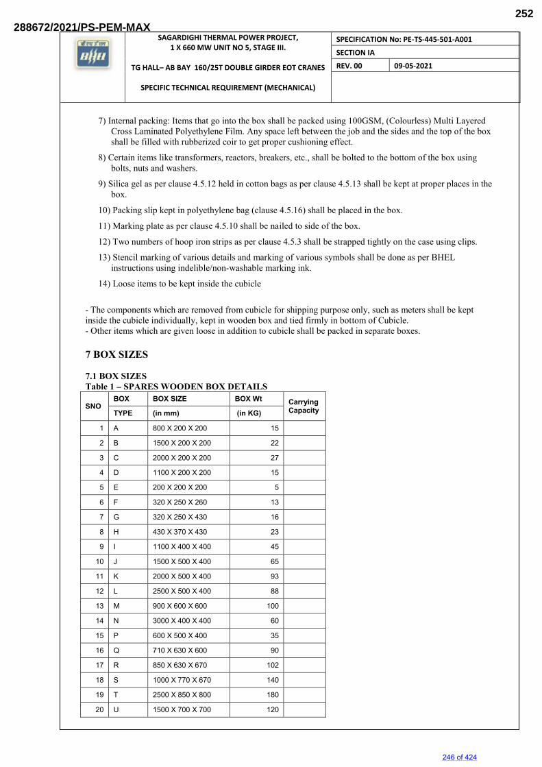
SAGARDIGHI THERMAL POWER PROJECT, 1 X 660 MW UNIT NO 5, STAGE III.
TG HALL– AB BAY 160/25T DOUBLE GIRDER EOT CRANES
SPECIFIC TECHNICAL REQUIREMENT (MECHANICAL)
SPECIFICATION No: PE-TS-445-501-A001
SECTION IA
REV. 00 09-05-2021
7) Internal packing: Items that go into the box shall be packed using 100GSM, (Colourless) Multi Layered Cross Laminated Polyethylene Film. Any space left between the job and the sides and the top of the box shall be filled with rubberized coir to get proper cushioning effect.
8) Certain items like transformers, reactors, breakers, etc., shall be bolted to the bottom of the box using bolts, nuts and washers.
9) Silica gel as per clause 4.5.12 held in cotton bags as per clause 4.5.13 shall be kept at proper places in the box.
10) Packing slip kept in polyethylene bag (clause 4.5.16) shall be placed in the box.
11) Marking plate as per clause 4.5.10 shall be nailed to side of the box.
12) Two numbers of hoop iron strips as per clause 4.5.3 shall be strapped tightly on the case using clips.
13) Stencil marking of various details and marking of various symbols shall be done as per BHEL instructions using indelible/non-washable marking ink.
14) Loose items to be kept inside the cubicle
- The components which are removed from cubicle for shipping purpose only, such as meters shall be kept inside the cubicle individually, kept in wooden box and tied firmly in bottom of Cubicle. - Other items which are given loose in addition to cubicle shall be packed in separate boxes. 7 BOX SIZES 7.1 BOX SIZES Table 1 – SPARES WOODEN BOX DETAILS
SNO BOX BOX SIZE BOX Wt Carrying
Capacity TYPE (in mm) (in KG)
1 A 800 X 200 X 200 15
2 B 1500 X 200 X 200 22
3 C 2000 X 200 X 200 27
4 D 1100 X 200 X 200 15
5 E 200 X 200 X 200 5
6 F 320 X 250 X 260 13
7 G 320 X 250 X 430 16
8 H 430 X 370 X 430 23
9 I 1100 X 400 X 400 45
10 J 1500 X 500 X 400 65
11 K 2000 X 500 X 400 93
12 L 2500 X 500 X 400 88
13 M 900 X 600 X 600 100
14 N 3000 X 400 X 400 60
15 P 600 X 500 X 400 35
16 Q 710 X 630 X 600 90
17 R 850 X 630 X 670 102
18 S 1000 X 770 X 670 140
19 T 2500 X 850 X 800 180
20 U 1500 X 700 X 700 120
246 of 424
288672/2021/PS-PEM-MAX252
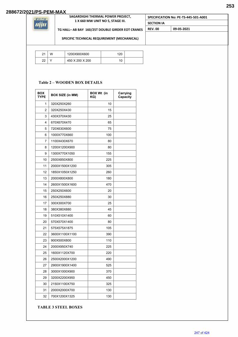
SAGARDIGHI THERMAL POWER PROJECT, 1 X 660 MW UNIT NO 5, STAGE III.
TG HALL– AB BAY 160/25T DOUBLE GIRDER EOT CRANES
SPECIFIC TECHNICAL REQUIREMENT (MECHANICAL)
SPECIFICATION No: PE-TS-445-501-A001
SECTION IA
REV. 00 09-05-2021
21 W 1200X900X600 120
22 Y 450 X 200 X 200 10
Table 2 – WOODEN BOX DETAILS BOX TYPE BOX SIZE (in MM) BOX Wt (in
KG) Carrying Capacity
1 320X250X260 10
2 320X250X430 15
3 430X370X430 25
4 670X670X470 65
5 720X630X600 75
6 1000X770X660 100
7 1100X430X670 80
8 1200X1200X900 80
9 1300X770X1050 155
10 2500X850X800 225
11 2000X1500X1200 305
12 1850X1050X1250 260
13 2000X800X800 180
14 2600X1500X1600 470
15 250X250X600 20
16 250X250X880 30
17 300X300X700 25
18 380X380X880 45
19 510X510X1400 60
20 570X570X1400 80
21 575X575X1875 105
22 3600X1100X1100 390
23 900X500X800 110
24 2000X950X740 225
25 1600X1120X700 220
26 2500X2000X1200 490
27 2900X1900X1400 525
28 3000X1000X900 370
29 3200X2200X950 450
30 2150X1100X750 325
31 2000X2000X700 130
32 700X1200X1325 130
TABLE 3 STEEL BOXES
247 of 424
288672/2021/PS-PEM-MAX253
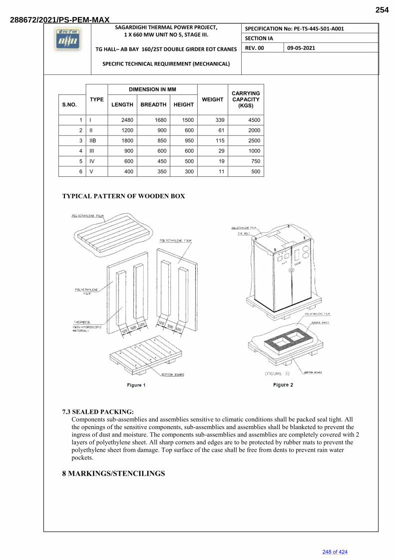
SAGARDIGHI THERMAL POWER PROJECT, 1 X 660 MW UNIT NO 5, STAGE III.
TG HALL– AB BAY 160/25T DOUBLE GIRDER EOT CRANES
SPECIFIC TECHNICAL REQUIREMENT (MECHANICAL)
SPECIFICATION No: PE-TS-445-501-A001
SECTION IA
REV. 00 09-05-2021
TYPE
DIMENSION IN MM
WEIGHT CARRYING CAPACITY
(KGS) S.NO. LENGTH BREADTH HEIGHT
1 I 2480 1680 1500 339 4500
2 II 1200 900 600 61 2000
3 IIB 1800 850 950 115 2500
4 III 900 600 600 29 1000
5 IV 600 450 500 19 750
6 V 400 350 300 11 500
TYPICAL PATTERN OF WOODEN BOX
7.3 SEALED PACKING:
Components sub-assemblies and assemblies sensitive to climatic conditions shall be packed seal tight. All the openings of the sensitive components, sub-assemblies and assemblies shall be blanketed to prevent the ingress of dust and moisture. The components sub-assemblies and assemblies are completely covered with 2 layers of polyethylene sheet. All sharp corners and edges are to be protected by rubber mats to prevent the polyethylene sheet from damage. Top surface of the case shall be free from dents to prevent rain water pockets.
8 MARKINGS/STENCILINGS
248 of 424
288672/2021/PS-PEM-MAX254
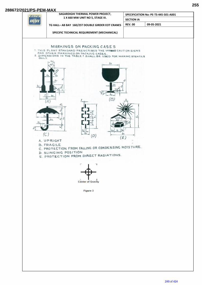
SAGARDIGHI THERMAL POWER PROJECT, 1 X 660 MW UNIT NO 5, STAGE III.
TG HALL– AB BAY 160/25T DOUBLE GIRDER EOT CRANES
SPECIFIC TECHNICAL REQUIREMENT (MECHANICAL)
SPECIFICATION No: PE-TS-445-501-A001
SECTION IA
REV. 00 09-05-2021
249 of 424
288672/2021/PS-PEM-MAX255
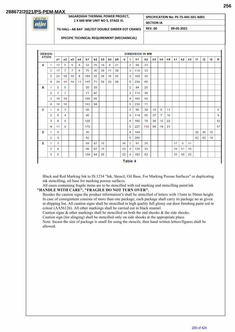
SAGARDIGHI THERMAL POWER PROJECT, 1 X 660 MW UNIT NO 5, STAGE III.
TG HALL– AB BAY 160/25T DOUBLE GIRDER EOT CRANES
SPECIFIC TECHNICAL REQUIREMENT (MECHANICAL)
SPECIFICATION No: PE-TS-445-501-A001
SECTION IA
REV. 00 09-05-2021
Black and Red Marking Ink to IS:1234 "Ink, Stencil, Oil Base, For Marking Porous Surfaces" or duplicating ink stencilling, oil base for marking porous surfaces. All cases containing fragile items are to be stencilled with red marking and stencilling paint/ink
"HANDLE WITH CARE", "FRAGILE DO NOT TURN OVER". Besides the caution signs the product information‟s shall be stencilled of letters with 13mm to 50mm height. In case of consignment consists of more than one package, each package shall carry its package no as given in shipping list. All caution signs shall be stencilled in high quality full glossy out door finishing paint red in colour (AA56126). All other markings shall be carried out in black enamel. Caution signs & other markings shall be stencilled on both the end shooks & the side shooks. Caution sign (for slinging) shall be stencilled only on side shooks at the appropriate place. Note: Incase the size of package is small for using the stencils, then hand written letters/figures shall be allowed.
250 of 424
288672/2021/PS-PEM-MAX256
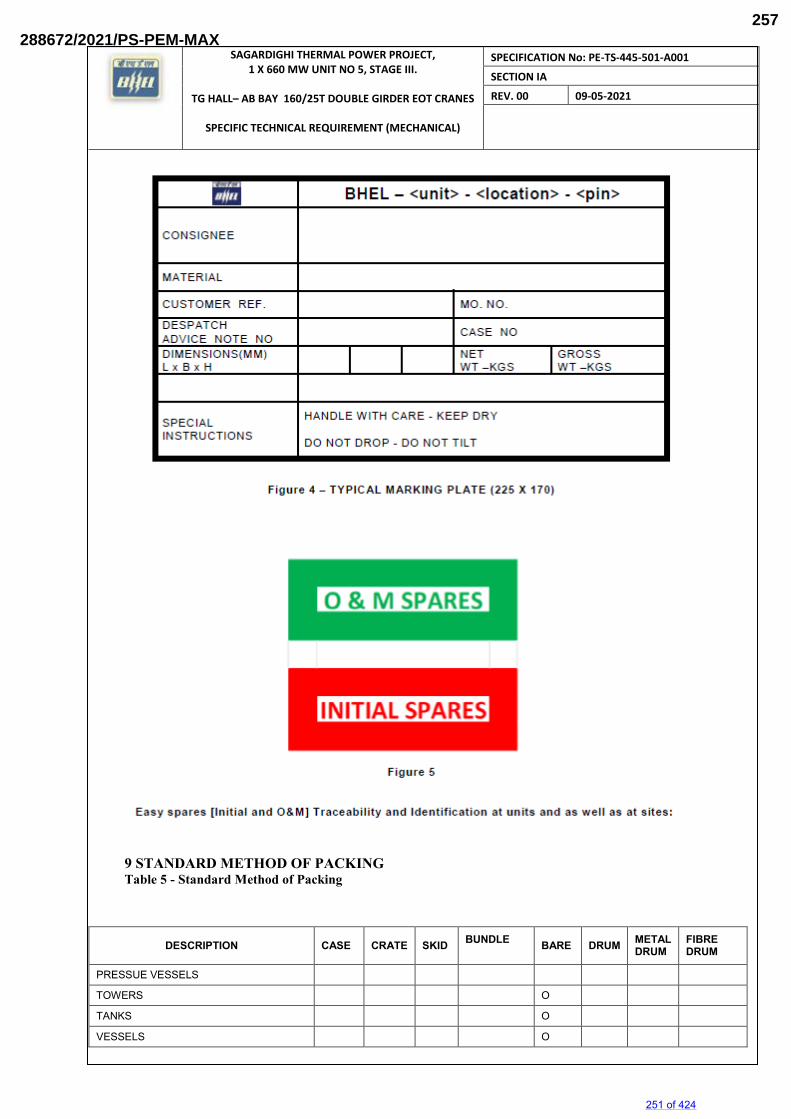
SAGARDIGHI THERMAL POWER PROJECT, 1 X 660 MW UNIT NO 5, STAGE III.
TG HALL– AB BAY 160/25T DOUBLE GIRDER EOT CRANES
SPECIFIC TECHNICAL REQUIREMENT (MECHANICAL)
SPECIFICATION No: PE-TS-445-501-A001
SECTION IA
REV. 00 09-05-2021
9 STANDARD METHOD OF PACKING Table 5 - Standard Method of Packing
DESCRIPTION CASE CRATE SKID BUNDLE
BARE DRUM METAL DRUM
FIBRE DRUM
PRESSUE VESSELS
TOWERS O
TANKS O
VESSELS O
251 of 424
288672/2021/PS-PEM-MAX257
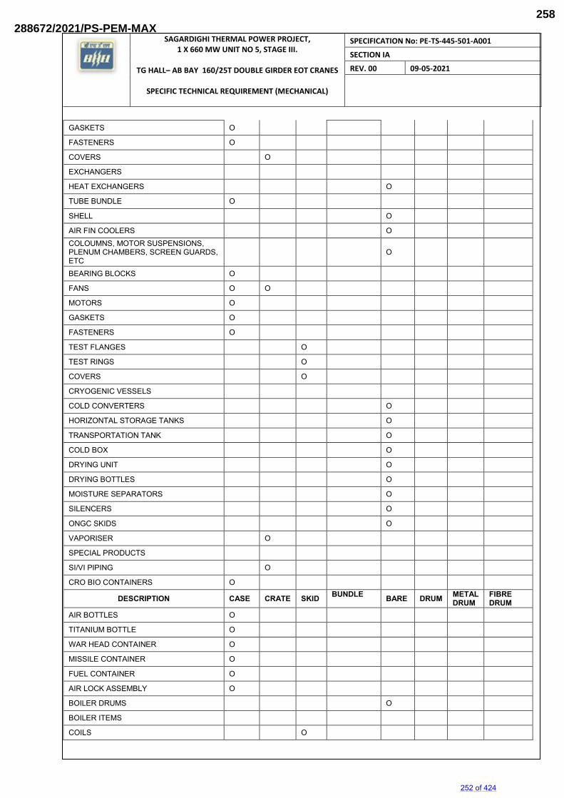
SAGARDIGHI THERMAL POWER PROJECT, 1 X 660 MW UNIT NO 5, STAGE III.
TG HALL– AB BAY 160/25T DOUBLE GIRDER EOT CRANES
SPECIFIC TECHNICAL REQUIREMENT (MECHANICAL)
SPECIFICATION No: PE-TS-445-501-A001
SECTION IA
REV. 00 09-05-2021
GASKETS O
FASTENERS O
COVERS O
EXCHANGERS
HEAT EXCHANGERS O
TUBE BUNDLE O
SHELL O
AIR FIN COOLERS O COLOUMNS, MOTOR SUSPENSIONS, PLENUM CHAMBERS, SCREEN GUARDS, ETC
O
BEARING BLOCKS O
FANS O O
MOTORS O
GASKETS O
FASTENERS O
TEST FLANGES O
TEST RINGS O
COVERS O
CRYOGENIC VESSELS
COLD CONVERTERS O
HORIZONTAL STORAGE TANKS O
TRANSPORTATION TANK O
COLD BOX O
DRYING UNIT O
DRYING BOTTLES O
MOISTURE SEPARATORS O
SILENCERS O
ONGC SKIDS O
VAPORISER O
SPECIAL PRODUCTS
SI/VI PIPING O
CRO BIO CONTAINERS O
DESCRIPTION CASE CRATE SKID BUNDLE BARE DRUM METAL
DRUM FIBRE DRUM
AIR BOTTLES O
TITANIUM BOTTLE O
WAR HEAD CONTAINER O
MISSILE CONTAINER O
FUEL CONTAINER O
AIR LOCK ASSEMBLY O
BOILER DRUMS O
BOILER ITEMS
COILS O
252 of 424
288672/2021/PS-PEM-MAX258
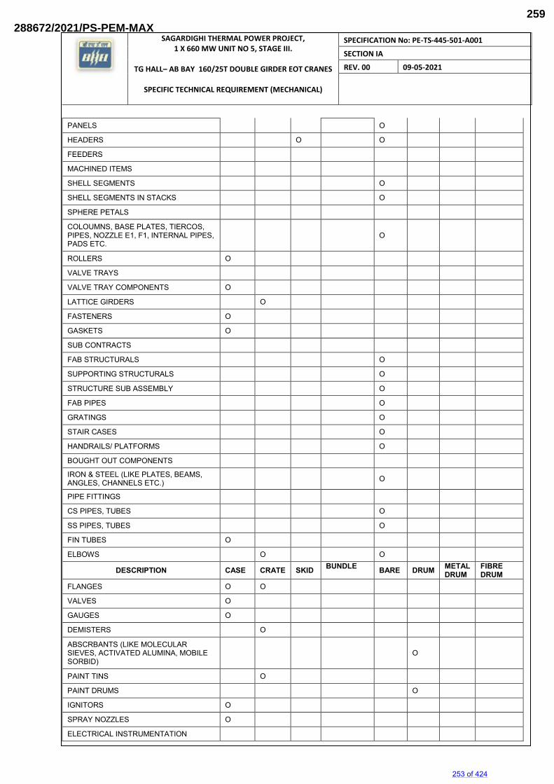
SAGARDIGHI THERMAL POWER PROJECT, 1 X 660 MW UNIT NO 5, STAGE III.
TG HALL– AB BAY 160/25T DOUBLE GIRDER EOT CRANES
SPECIFIC TECHNICAL REQUIREMENT (MECHANICAL)
SPECIFICATION No: PE-TS-445-501-A001
SECTION IA
REV. 00 09-05-2021
PANELS O
HEADERS O O
FEEDERS
MACHINED ITEMS
SHELL SEGMENTS O
SHELL SEGMENTS IN STACKS O
SPHERE PETALS
COLOUMNS, BASE PLATES, TIERCOS, PIPES, NOZZLE E1, F1, INTERNAL PIPES, PADS ETC.
O
ROLLERS O
VALVE TRAYS
VALVE TRAY COMPONENTS O
LATTICE GIRDERS O
FASTENERS O
GASKETS O
SUB CONTRACTS
FAB STRUCTURALS O
SUPPORTING STRUCTURALS O
STRUCTURE SUB ASSEMBLY O
FAB PIPES O
GRATINGS O
STAIR CASES O
HANDRAILS/ PLATFORMS O
BOUGHT OUT COMPONENTS
IRON & STEEL (LIKE PLATES, BEAMS, ANGLES, CHANNELS ETC.) O
PIPE FITTINGS
CS PIPES, TUBES O
SS PIPES, TUBES O
FIN TUBES O
ELBOWS O O
DESCRIPTION CASE CRATE SKID BUNDLE BARE DRUM METAL
DRUM FIBRE DRUM
FLANGES O O
VALVES O
GAUGES O
DEMISTERS O
ABSCRBANTS (LIKE MOLECULAR SIEVES, ACTIVATED ALUMINA, MOBILE SORBID)
O
PAINT TINS O
PAINT DRUMS O
IGNITORS O
SPRAY NOZZLES O
ELECTRICAL INSTRUMENTATION
253 of 424
288672/2021/PS-PEM-MAX259
SAGARDIGHI THERMAL POWER PROJECT, 1 X 660 MW UNIT NO 5, STAGE III.
TG HALL– AB BAY 160/25T DOUBLE GIRDER EOT CRANES
SPECIFIC TECHNICAL REQUIREMENT (MECHANICAL)
SPECIFICATION No: PE-TS-445-501-A001
SECTION IA
REV. 00 09-05-2021
MOTORS, PUMPS, COMPRESSORS, TURBINES O
SWITCH BOARDS, DISTRIBUTION BOARDS, STARTERS, JUNCTION BOXES O
INDICATORS, VIBRATOR SWITCHES O
CABLE BUNDLES, CABLE DRUMS O CABLE TRAYS, CABLE RACKS, EARTHING MATERIAL O
OPERATIONAL SPARES O
10 PROCEDURE FOR HANDLING OF COMPONENTS The purpose of this procedure is to protect the quality of the components/equipment while handling in various stages of manufacturing packing & despatching.
10.1 Adequate care shall be taken in handling the material, and components to avoid damage during receipts, storage issue manufacture & despatch operations.
10.2 Appropriate material handling equipment like fork lifters, cranes etc. shall be used where needed.
10.3 Lifting by crane and transportation by trolley of critical items and large components like rotors castings etc. shall be done carefully.
10.4 For critical items, where specified, special handling fixtures shall be used for lifting.
10.5 Slings and shackles used for lifting the components/equipment shall be checked for fitness and suitability before use.
10.6 Slings used on machined surfaces shall be suitably padded. No slings shall be used on journal surfaces.
10.7 Precision machined components like blades, catches, rollers etc. shall be lifted using suitable wooden pallets.
10.8 HANDLING OF COMPONENTS ON RECEIPT/DESPATCH Before loading/unloading a packing case from the carrier look for the following shipping instructions painted on the packing case.
a) The markings showing the upright position.
b) The markings showing the sling position
c) Markings showing the fragile contents.
d) Other required markings as per clause no.10 10.8.1 Appropriate cranes and slings should be used for different components/ cases. Slings should normally
make an angle as minimum as possible (width wise) but in no case more than 15º. 10.8.2 Handling and lifting should be done without jerks or impacts. 10.8.3 Immediately after receipt of the goods, the packing should be examined all-round for any sign of damage.
If necessary, lift the cover or a number of boards of the case so as to make the contents visible. In the
254 of 424
288672/2021/PS-PEM-MAX260
SAGARDIGHI THERMAL POWER PROJECT, 1 X 660 MW UNIT NO 5, STAGE III.
TG HALL– AB BAY 160/25T DOUBLE GIRDER EOT CRANES
SPECIFIC TECHNICAL REQUIREMENT (MECHANICAL)
SPECIFICATION No: PE-TS-445-501-A001
SECTION IA
REV. 00 09-05-2021
event of sealed packing being used the plastic sheeting should not be damaged. It is imperative that the packing material is restored in original condition after the inspection.
10.8.4 On receipt of the equipment it should be checked with the shipping list and missing or damage if any
should be reported immediately. It is important to arrange for immediate examination to determine the extent of the damage, the cause of the damage and where applicable the person or persons responsible for the damage. According to general practice when transporting by railway or by road vehicle the carrier concerned should be immediately called upon (within specified periods) for jointly establishing a statement of the damage. This is essential as a basis for a subsequent claim and possible damage report to the insurance company.
10.8.5 Protective coating applied on machined surfaces should not be disturbed. The plastic covering should be
put back carefully so that it prevents ingress of dust and moisture. Some packing may have vapour phase inhibitor (VPI) paper enclosed inside the packing cases. This should be restored to its original place as far as possible.
10.8.6 Silica gel and such other chemicals kept in the box as desiccants and indicators should also be left in the
box itself. 11 GENERAL GUIDELINES FOR ODC TRANSPORTATION/DESPATCH Based on the Dimensions/Weight indicated in the Transportation Sketch, the type of Trailer is decided and indicated in the Tender Enquiry. 11.1 TRANSPORTATION:
1. LOW BED TRAILERS (LB 8):
Well Bed Length : 10000mm Over Gooseneck : 13000mm Width : 3000mm Carrying Capacity : 40MT
2. LOW BED TRAILERS (LB 16):
Well Bed Length : 12000mm Over Gooseneck : 16000mm Width : 3000mm Carrying Capacity : 75MT
3. TOW TYPE TRAILERS (WITH FRONT DOLLEY 16 TYRES): 12000MM length (for Exceptional equipment length: 30000mm and above)
Bigger Dia equipment are loaded in the Well with overhanging. Smaller Dia equipment with excess length are loaded over Gooseneck with rear hanging. The Vehicle Dimensions are defined above are only guidelines for selection based on actual Dimensions/ Weight of the Consignment
11.2 PACKING:
For all ODCs, Wooden Saddles are cut to the diameter of equipment as per the Transportation Sketch.
255 of 424
288672/2021/PS-PEM-MAX261
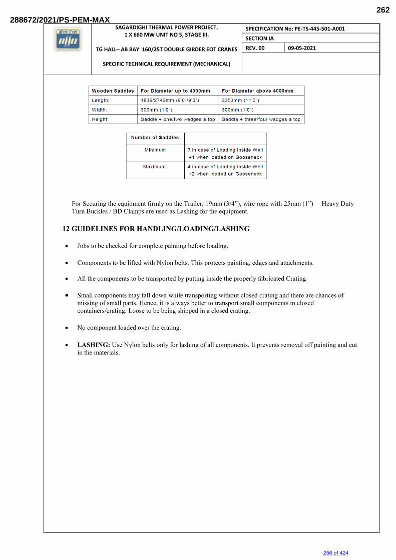
SAGARDIGHI THERMAL POWER PROJECT, 1 X 660 MW UNIT NO 5, STAGE III.
TG HALL– AB BAY 160/25T DOUBLE GIRDER EOT CRANES
SPECIFIC TECHNICAL REQUIREMENT (MECHANICAL)
SPECIFICATION No: PE-TS-445-501-A001
SECTION IA
REV. 00 09-05-2021
For Securing the equipment firmly on the Trailer, 19mm (3/4”), wire rope with 25mm (1”) Heavy Duty Turn Buckles / BD Clamps are used as Lashing for the equipment.
12 GUIDELINES FOR HANDLING/LOADING/LASHING Jobs to be checked for complete painting before loading.
Components to be lifted with Nylon belts. This protects painting, edges and attachments.
All the components to be transported by putting inside the properly fabricated Crating
Small components may fall down while transporting without closed crating and there are chances of
missing of small parts. Hence, it is always better to transport small components in closed containers/crating. Loose to be being shipped in a closed crating.
No component loaded over the crating.
LASHING: Use Nylon belts only for lashing of all components. It prevents removal off painting and cut
in the materials.
256 of 424
288672/2021/PS-PEM-MAX262
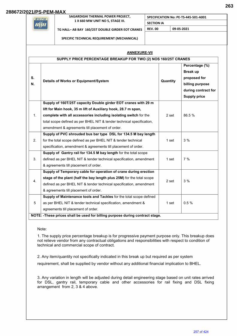
SAGARDIGHI THERMAL POWER PROJECT, 1 X 660 MW UNIT NO 5, STAGE III.
TG HALL– AB BAY 160/25T DOUBLE GIRDER EOT CRANES
SPECIFIC TECHNICAL REQUIREMENT (MECHANICAL)
SPECIFICATION No: PE-TS-445-501-A001
SECTION IA
REV. 00 09-05-2021
ANNEXURE-VII SUPPLY PRICE PERCENTAGE BREAKUP FOR TWO (2) NOS 160/25T CRANES
S. N.
Details of Works or Equipment/System Quantity
Percentage (%) Break up proposed for billing purpose during contract for Supply price
1.
Supply of 160T/25T capacity Double girder EOT cranes with 29 m lift for Main hook, 35 m lift of Auxiliary hook, 28.7 m span, complete with all accessories including isolating switch for the
total scope defined as per BHEL NIT & tender technical specification,
amendment & agreements till placement of order.
2 set 86.5 %
2.
Supply of PVC shrouded bus bar type DSL for 134.5 M bay length
for the total scope defined as per BHEL NIT & tender technical
specification, amendment & agreements till placement of order.
1 set 3 %
3.
Supply of Gantry rail for 134.5 M bay length for the total scope
defined as per BHEL NIT & tender technical specification, amendment
& agreements till placement of order.
1 set 7 %
4.
Supply of Temporary cable for operation of crane during erection stage of the plant (half the bay length plus 25M) for the total scope
defined as per BHEL NIT & tender technical specification, amendment
& agreements till placement of order.
2 set 3 %
5
Supply of Maintenance tools and Tackles for the total scope defined
as per BHEL NIT & tender technical specification, amendment &
agreements till placement of order.
1 set 0.5 %
NOTE: -These prices shall be used for billing purpose during contract stage.
Note:
1. The supply price percentage breakup is for progressive payment purpose only. This breakup does not relieve vendor from any contractual obligations and responsibilities with respect to condition of technical and commercial scope of contract.
2. Any item/quantity not specifically indicated in this break up but required as per system
requirement, shall be supplied by vendor without any additional financial implication to BHEL.
3. Any variation in length will be adjusted during detail engineering stage based on unit rates arrived for DSL, gantry rail, temporary cable and other accessories for rail fixing and DSL fixing arrangement from 2, 3 & 4 above.
257 of 424
288672/2021/PS-PEM-MAX263
SAGARDIGHI THERMAL POWER PROJECT, 1 X 660 MW UNIT NO 5, STAGE III.
TG HALL– AB BAY 160/25T DOUBLE GIRDER EOT CRANES
SPECIFIC TECHNICAL REQUIREMENTS (MECHANICAL)
SPECIFICATION No: PE-TS-445-501-A001
SECTION IA
REV. 00 09-05-2021
CRANE CLEARANCE DIAGRAM
258 of 424
288672/2021/PS-PEM-MAX264
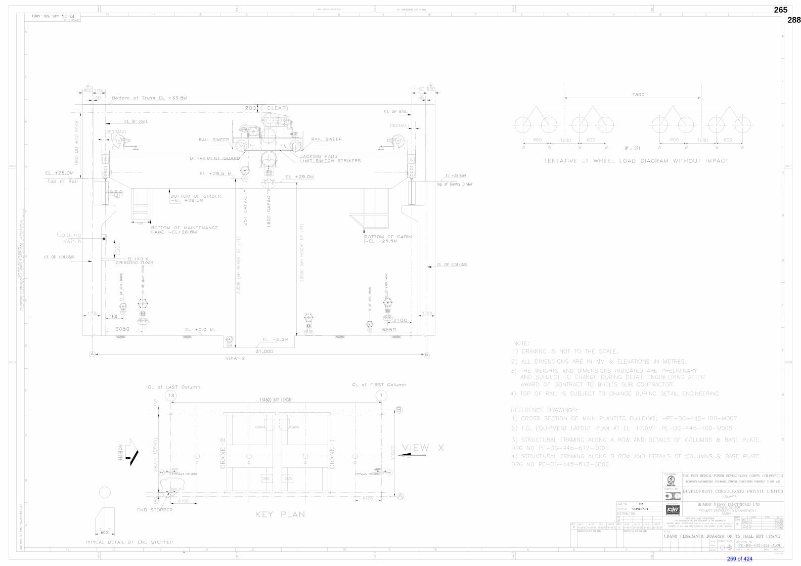
259 of 424
288672/2021/PS-PEM-MAX265
SAGARDIGHI THERMAL POWER PROJECT, 1 X 660 MW UNIT NO 5, STAGE III.
TG HALL– AB BAY 160/25T DOUBLE GIRDER EOT CRANES
SPECIFIC TECHNICAL REQUIREMENTS (ELECTRICAL)
SPECIFICATION No: PE-TS-445-501-A001
SECTION IB
REV. 00 09-05-2021
SECTION IB
SPECIFIC TECHNICAL REQUIREMENTS (ELECTRICAL)
260 of 424
288672/2021/PS-PEM-MAX266
THE WEST BENGAL POWER DEVELOPMENT CORPORATION LIMITED
SAGARDIGHI THERMAL POWER PROJECT 1 x 660 MW UNIT NO. 5, PHASE – III
DOUBLE GIRDER CRANE (ELECTRICAL PORTION)
BHARAT HEAVY ELECTRICALS LIMITED POWER SECTOR
PROJECT ENGINEERING MANAGEMENT, NOIDA, U.P., INDIA
261 of 424
288672/2021/PS-PEM-MAX267
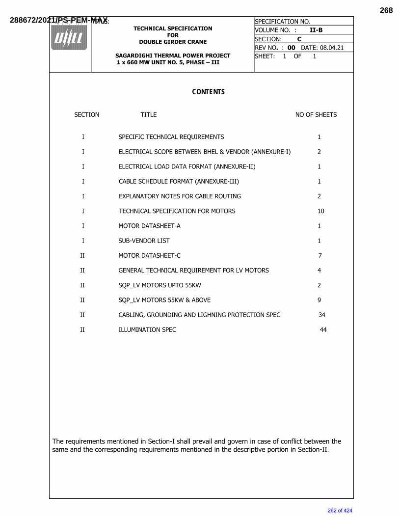
TITLE: TECHNICAL SPECIFICATION
FOR DOUBLE GIRDER CRANE
SAGARDIGHI THERMAL POWER PROJECT 1 x 660 MW UNIT NO. 5, PHASE – III
SPECIFICATION NO. VOLUME NO. : II-B SECTION: C REV NO. : 00 DATE: 08.04.21 SHEET: 1 OF 1
CONTENTS SECTION TITLE NO OF SHEETS I SPECIFIC TECHNICAL REQUIREMENTS 1 I ELECTRICAL SCOPE BETWEEN BHEL & VENDOR (ANNEXURE-I) 2
I ELECTRICAL LOAD DATA FORMAT (ANNEXURE-II) 1 I CABLE SCHEDULE FORMAT (ANNEXURE-III) 1 I EXPLANATORY NOTES FOR CABLE ROUTING 2 I TECHNICAL SPECIFICATION FOR MOTORS 10
I MOTOR DATASHEET-A 1 I SUB-VENDOR LIST 1 II MOTOR DATASHEET-C 7
II GENERAL TECHNICAL REQUIREMENT FOR LV MOTORS 4 II SQP_LV MOTORS UPTO 55KW 2 II SQP_LV MOTORS 55KW & ABOVE 9 II CABLING, GROUNDING AND LIGHNING PROTECTION SPEC 34 II ILLUMINATION SPEC 44
The requirements mentioned in Section-I shall prevail and govern in case of conflict between the same and the corresponding requirements mentioned in the descriptive portion in Section-II.
262 of 424
288672/2021/PS-PEM-MAX268
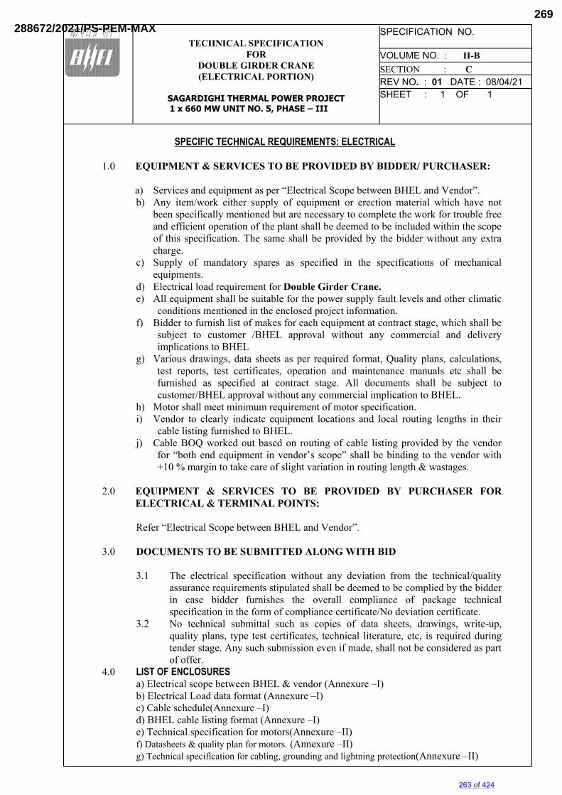
TECHNICAL SPECIFICATION
FOR DOUBLE GIRDER CRANE (ELECTRICAL PORTION)
SAGARDIGHI THERMAL POWER PROJECT 1 x 660 MW UNIT NO. 5, PHASE – III
SPECIFICATION NO. VOLUME NO. : II-B SECTION : C REV NO. : 01 DATE : 08/04/21 SHEET : 1 OF 1
SPECIFIC TECHNICAL REQUIREMENTS: ELECTRICAL
1.0 EQUIPMENT & SERVICES TO BE PROVIDED BY BIDDER/ PURCHASER:
a) Services and equipment as per “Electrical Scope between BHEL and Vendor”. b) Any item/work either supply of equipment or erection material which have not
been specifically mentioned but are necessary to complete the work for trouble free and efficient operation of the plant shall be deemed to be included within the scope of this specification. The same shall be provided by the bidder without any extra charge.
c) Supply of mandatory spares as specified in the specifications of mechanical equipments.
d) Electrical load requirement for Double Girder Crane. e) All equipment shall be suitable for the power supply fault levels and other climatic
conditions mentioned in the enclosed project information. f) Bidder to furnish list of makes for each equipment at contract stage, which shall be
subject to customer /BHEL approval without any commercial and delivery implications to BHEL
g) Various drawings, data sheets as per required format, Quality plans, calculations, test reports, test certificates, operation and maintenance manuals etc shall be furnished as specified at contract stage. All documents shall be subject to customer/BHEL approval without any commercial implication to BHEL.
h) Motor shall meet minimum requirement of motor specification. i) Vendor to clearly indicate equipment locations and local routing lengths in their
cable listing furnished to BHEL. j) Cable BOQ worked out based on routing of cable listing provided by the vendor
for “both end equipment in vendor’s scope” shall be binding to the vendor with +10 % margin to take care of slight variation in routing length & wastages.
2.0 EQUIPMENT & SERVICES TO BE PROVIDED BY PURCHASER FOR
ELECTRICAL & TERMINAL POINTS: Refer “Electrical Scope between BHEL and Vendor”.
3.0 DOCUMENTS TO BE SUBMITTED ALONG WITH BID
3.1 The electrical specification without any deviation from the technical/quality assurance requirements stipulated shall be deemed to be complied by the bidder in case bidder furnishes the overall compliance of package technical specification in the form of compliance certificate/No deviation certificate.
3.2 No technical submittal such as copies of data sheets, drawings, write-up, quality plans, type test certificates, technical literature, etc, is required during tender stage. Any such submission even if made, shall not be considered as part of offer.
4.0 LIST OF ENCLOSURES a) Electrical scope between BHEL & vendor (Annexure –I) b) Electrical Load data format (Annexure –I) c) Cable schedule(Annexure –I) d) BHEL cable listing format (Annexure –I) e) Technical specification for motors(Annexure –II) f) Datasheets & quality plan for motors. (Annexure –II) g) Technical specification for cabling, grounding and lightning protection(Annexure –II)
263 of 424
288672/2021/PS-PEM-MAX269
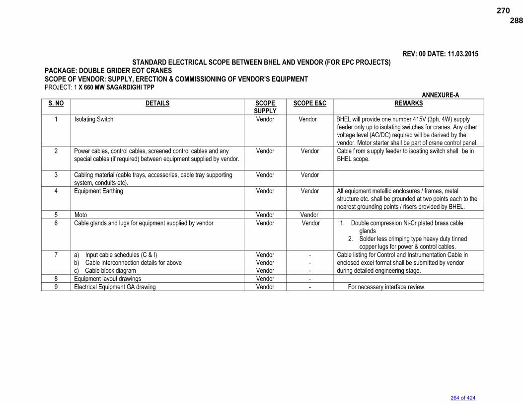
REV: 00 DATE: 11.03.2015
STANDARD ELECTRICAL SCOPE BETWEEN BHEL AND VENDOR (FOR EPC PROJECTS) PACKAGE: DOUBLE GRIDER EOT CRANES SCOPE OF VENDOR: SUPPLY, ERECTION & COMMISSIONING OF VENDOR’S EQUIPMENT PROJECT: 1 X 660 MW SAGARDIGHI TPP
ANNEXURE-A S. NO DETAILS SCOPE
SUPPLY SCOPE E&C
REMARKS
1 Isolating Switch
Vendor Vendor BHEL will provide one number 415V (3ph, 4W) supply feeder only up to isolating switches for cranes. Any other voltage level (AC/DC) required will be derived by the vendor. Motor starter shall be part of crane control panel.
2 Power cables, control cables, screened control cables and any special cables (if required) between equipment supplied by vendor.
Vendor Vendor Cable f rom s upply feeder to isoating switch shall be in BHEL scope.
3 Cabling material (cable trays, accessories, cable tray supporting system, conduits etc).
Vendor Vendor
4 Equipment Earthing Vendor Vendor All equipment metallic enclosures / frames, metal structure etc. shall be grounded at two points each to the nearest grounding points / risers provided by BHEL.
5 Moto Vendor Vendor 6 Cable glands and lugs for equipment supplied by vendor
Vendor Vendor 1. Double compression Ni-Cr plated brass cable
glands 2. Solder less crimping type heavy duty tinned
copper lugs for power & control cables. 7 a) Input cable schedules (C & I)
b) Cable interconnection details for above c) Cable block diagram
Vendor Vendor Vendor
- - -
Cable listing for Control and Instrumentation Cable in enclosed excel format shall be submitted by vendor during detailed engineering stage.
8 Equipment layout drawings Vendor - 9 Electrical Equipment GA drawing Vendor - For necessary interface review.
264 of 424
288672/2021/PS-PEM-MAX270
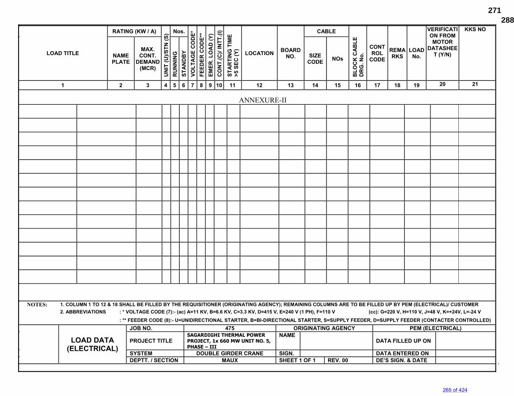
LOAD TITLE
RATING (KW / A)
UN
IT (
U)/
ST
N (
S) Nos.
VO
LT
AG
E C
OD
E*
FE
ED
ER
CO
DE
**
EM
ER
. L
OA
D (
Y)
CO
NT
.(C
)/ IN
TT
.(I)
ST
AR
TIN
G T
IME
>
5 S
EC
(Y
)
LOCATION BOARD
NO.
CABLE
BL
OC
K C
AB
LE
D
RG
. No
.
CONTROL
CODE
REMARKS
LOAD No.
VERIFICATION FROM MOTOR
DATASHEET (Y/N)
KKS NO
NAME PLATE
MAX. CONT.
DEMAND (MCR)
RU
NN
ING
ST
AN
DB
Y
SIZE CODE
NOs
1 2 3 4 5 6 7 8 9 10 11 12 13 14 15 16 17 18 19 20 21
NOTES: 1. COLUMN 1 TO 12 & 18 SHALL BE FILLED BY THE REQUISITIONER (ORIGINATING AGENCY); REMAINING COLUMNS ARE TO BE FILLED UP BY PEM (ELECTRICAL)/ CUSTOMER
2. ABBREVIATIONS : * VOLTAGE CODE (7):- (ac) A=11 KV, B=6.6 KV, C=3.3 KV, D=415 V, E=240 V (1 PH), F=110 V (cc): G=220 V, H=110 V, J=48 V, K=+24V, L=-24 V
: ** FEEDER CODE (8):- U=UNIDIRECTIONAL STARTER, B=BI-DIRECTIONAL STARTER, S=SUPPLY FEEDER, D=SUPPLY FEEDER (CONTACTER CONTROLLED)
LOAD DATA
(ELECTRICAL)
JOB NO. 475 ORIGINATING AGENCY PEM (ELECTRICAL)
PROJECT TITLE SAGARDIGHI THERMAL POWER PROJECT, 1x 660 MW UNIT NO. 5, PHASE – III
NAME DATA FILLED UP ON
SYSTEM DOUBLE GIRDER CRANE SIGN. DATA ENTERED ON DEPTT. / SECTION MAUX SHEET 1 OF 1 REV. 00 DE’S SIGN. & DATE
ANNEXURE-II
265 of 424
288672/2021/PS-PEM-MAX271
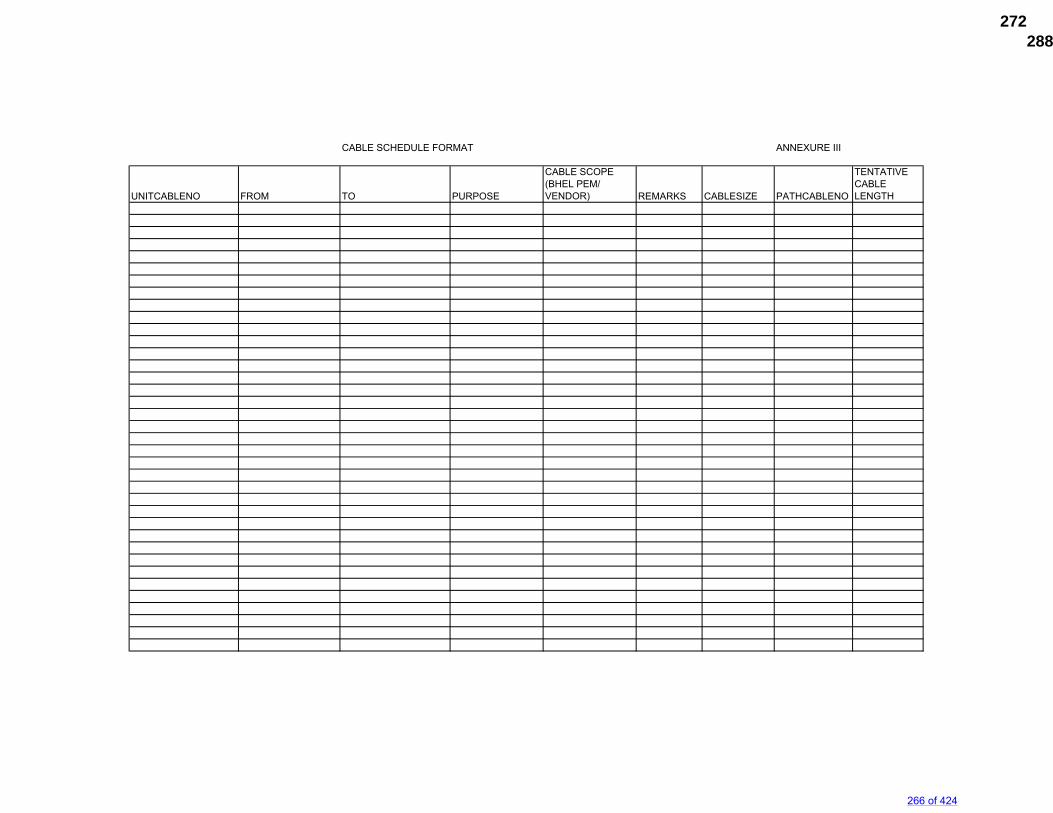
CABLE SCHEDULE FORMAT ANNEXURE III
UNITCABLENO FROM TO PURPOSE
CABLE SCOPE (BHEL PEM/ VENDOR) REMARKS CABLESIZE PATHCABLENO
TENTATIVE CABLE LENGTH
266 of 424
288672/2021/PS-PEM-MAX272
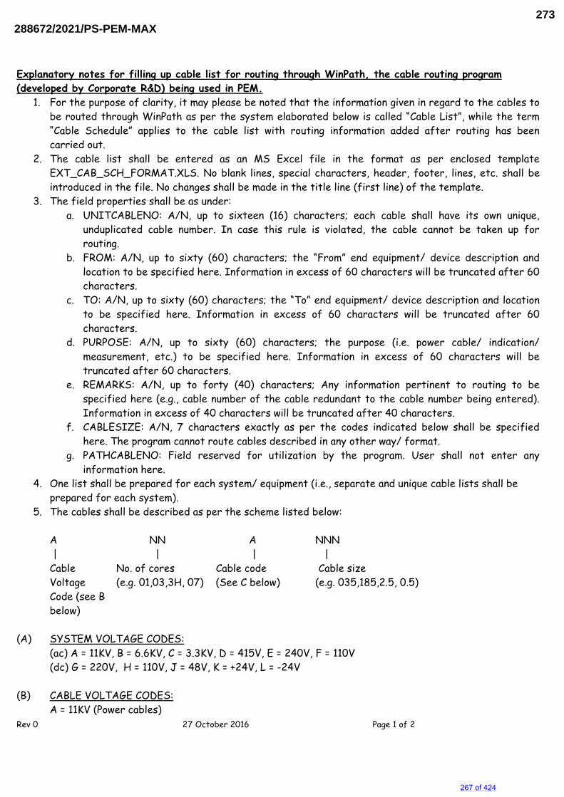
Explanatory notes for filling up cable list for routing through WinPath, the cable routing program (developed by Corporate R&D) being used in PEM.
Rev 0 27 October 2016 Page 1 of 2
1. For the purpose of clarity, it may please be noted that the information given in regard to the cables to be routed through WinPath as per the system elaborated below is called “Cable List”, while the term “Cable Schedule” applies to the cable list with routing information added after routing has been carried out.
2. The cable list shall be entered as an MS Excel file in the format as per enclosed template EXT_CAB_SCH_FORMAT.XLS. No blank lines, special characters, header, footer, lines, etc. shall be introduced in the file. No changes shall be made in the title line (first line) of the template.
3. The field properties shall be as under: a. UNITCABLENO: A/N, up to sixteen (16) characters; each cable shall have its own unique,
unduplicated cable number. In case this rule is violated, the cable cannot be taken up for routing.
b. FROM: A/N, up to sixty (60) characters; the “From” end equipment/ device description and location to be specified here. Information in excess of 60 characters will be truncated after 60 characters.
c. TO: A/N, up to sixty (60) characters; the “To” end equipment/ device description and location to be specified here. Information in excess of 60 characters will be truncated after 60 characters.
d. PURPOSE: A/N, up to sixty (60) characters; the purpose (i.e. power cable/ indication/ measurement, etc.) to be specified here. Information in excess of 60 characters will be truncated after 60 characters.
e. REMARKS: A/N, up to forty (40) characters; Any information pertinent to routing to be specified here (e.g., cable number of the cable redundant to the cable number being entered). Information in excess of 40 characters will be truncated after 40 characters.
f. CABLESIZE: A/N, 7 characters exactly as per the codes indicated below shall be specified here. The program cannot route cables described in any other way/ format.
g. PATHCABLENO: Field reserved for utilization by the program. User shall not enter any information here.
4. One list shall be prepared for each system/ equipment (i.e., separate and unique cable lists shall be prepared for each system).
5. The cables shall be described as per the scheme listed below:
A NN A NNN | | | | Cable No. of cores Cable code Cable size Voltage (e.g. 01,03,3H, 07) (See C below) (e.g. 035,185,2.5, 0.5) Code (see B
below) (A) SYSTEM VOLTAGE CODES:
(ac) A = 11KV, B = 6.6KV, C = 3.3KV, D = 415V, E = 240V, F = 110V (dc) G = 220V, H = 110V, J = 48V, K = +24V, L = -24V
(B) CABLE VOLTAGE CODES:
A = 11KV (Power cables)
267 of 424
288672/2021/PS-PEM-MAX273
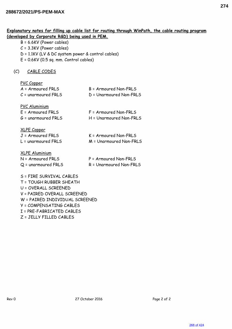
Explanatory notes for filling up cable list for routing through WinPath, the cable routing program (developed by Corporate R&D) being used in PEM.
Rev 0 27 October 2016 Page 2 of 2
B = 6.6KV (Power cables) C = 3.3KV (Power cables) D = 1.1KV (LV & DC system power & control cables) E = 0.6KV (0.5 sq. mm. Control cables)
(C) CABLE CODES
PVC Copper A = Armoured FRLS B = Armoured Non-FRLS C = unarmoured FRLS D = Unarmoured Non-FRLS PVC Aluminium E = Armoured FRLS F = Armoured Non-FRLS G = unarmoured FRLS H = Unarmoured Non-FRLS XLPE Copper J = Armoured FRLS K = Armoured Non-FRLS L = unarmoured FRLS M = Unarmoured Non-FRLS XLPE Aluminium N = Armoured FRLS P = Armoured Non-FRLS Q = unarmoured FRLS R = Unarmoured Non-FRLS
S = FIRE SURVIVAL CABLES T = TOUGH RUBBER SHEATH U = OVERALL SCREENED V = PAIRED OVERALL SCREENED W = PAIRED INDIVIDUAL SCREENED Y = COMPENSATING CABLES I = PRE-FABRICATED CABLES Z = JELLY FILLED CABLES
268 of 424
288672/2021/PS-PEM-MAX274
WBPDCLEPC Bid Document Sagardighi Thermal Power Project 1x660 MW Unit No. 5, Phase - III
Development Consultants Pvt. Ltd. Page 1 of 10 Volume : II-F/1 Section : II A.C. & D.C. Motors
SECTION - II
A.C. & D.C. MOTORS
1.00.00 SCOPE
1.01.00 This specification covers the general requirements of the electric motors for plant auxiliary equipment except for special application like crane, lift, submersible pump etc., motors for which are covered in individual equipment specifications.
1.02.00 Motors shall be furnished in accordance with both this general specification and the accompanying driven equipment specification.
1.03.00 In case of any discrepancy, the driven equipment specification shall govern.
2.00.00 STANDARDS
2.01.00 All motors shall conform to the latest applicable IS, IEC and CBIP Standards/Publications except when otherwise stated herein or in the driven equipment specification.
2.02.00 Equipment and materials conforming to any other standard, which ensures equal or better quality may be accepted. In such case, copies of the English version of the standard adopted shall be submitted along with the bid.
3.00.00 SERVICE CONDITIONS
3.01.00 The motors will be installed in hot, humid and tropical atmosphere, highly polluted area.
3.02.00 Unless otherwise noted, electrical equipment/system design shall be based on the service conditions and auxiliary power supply given in the annexure of this specification.
3.03.00 For motor installed outdoor and exposed to direct sun rays, the effect of solar heat shall be considered in the determination of the design ambient temperature.
4.00.00 TYPE AND RATING
4.01.00 A.C. Motors
4.01.01 Motors shall be general purpose, constant speed, squirrel cage, three/single phase, induction type.
4.01.02 All motors shall be either totally enclosed fan cooled (TEFC) or totally enclosed tube ventilated (TETV) or closed air circuit air cooled (CACA) or closed air water cooled (CACW) type. Temperature rise shall be limited to 70 deg C by resistance method.
4.01.03 All motors shall be rated for continuous duty. They shall also be suitable for long period of inactivity.
269 of 424
288672/2021/PS-PEM-MAX275
WBPDCLEPC Bid Document Sagardighi Thermal Power Project 1x660 MW Unit No. 5, Phase - III
Development Consultants Pvt. Ltd. Page 2 of 10 Volume : II-F/1 Section : II A.C. & D.C. Motors
4.01.04 All LT motor shall conform to minimum efficiency performance standards (MEPS) of IE2 mentioned in IS: 12615. All HT motors shall have efficiency andpower factor higher than 90% and 0.83 respectively.
4.01.05 The motor name-plate rating at 50�C shall have at least 15% margin for LT system and 10% margin for HT system, over the input power requirement of the driven equipment at rated duty point and also covering the maximum load demand of the driven equipment under entire operating range, including voltage and frequency variations, unless stated otherwise in driven equipment specification or in general electrical specification.
4.01.06 The motor characteristics shall match the requirements of the driven equipment so that adequate starting, accelerating, pull up, break down and full load torques are available for the intended service. The direction of rotation of motor and its cooling fan should be properly matched with the driven equipment.
4.02.00 AC motor for VFD application (If applicable)
4.02.01 Inverter duty motors are designed according to the requirements of IEC/TS- 60034 part17 & part 25 or NEMA MG-1, Part-30, Part 31 and have performance characteristics match with the driven equipment and variable speed requirement.
4.02.02 Induction motors to be operated in adjustable-speed drive applications should be de-rated as per NEMA/IEC standard due to the reduction in cooling resulting from any reduction in operating speed and the effect of additional losses introduced by harmonics generated by the control.
4.02.03 Inverter duty motors shall have VPI/improved insulation systems that do not degrade readily due to transient voltage spikes and have an adequate thermal margin.
4.02.04 Inverter duty motors shall be self ventilated without any auxiliary blower. Force ventilation shall be subject to purchaser approval.
4.02.05 Inverter motor shall be suitable for scalar (open loop) control, without any speed feedback signal, where fast response is not required. Vector (closed loop) control will be used with encoder if specified.
4.02.06 The breakdown torque at any frequency within the defined frequency range shall be not less than 150% of the rated torque at that frequency when rated voltage for that frequency is applied.
4.02.07 The motor should be capable of producing a breakaway torque of at least 140% of rated torque requiring not more than 150% rated current when the voltage boost is adjusted to develop rated flux in the motor and when the inverter is able to produce the required minimum fundamental frequencies
4.02.08 The motor shall be provided with insulated bearing on one side.
4.02.09 Normally the maximum safe speed shall be as per IEC/NEMA, however it should be coordinated with VSD requirement.
270 of 424
288672/2021/PS-PEM-MAX276
WBPDCLEPC Bid Document Sagardighi Thermal Power Project 1x660 MW Unit No. 5, Phase - III
Development Consultants Pvt. Ltd. Page 3 of 10 Volume : II-F/1 Section : II A.C. & D.C. Motors
4.02.10 In case of a conflict, the requirement mentioned under clause no. 4.02.00 for motors for VFD application shall supersede the corresponding requirement for standard motors.
4.03.00 D. C. Motors
4.03.01 D.C. motor provided for emergency service shall be shunt wound type. It can also be of compound-wound type with the series field shorted.
4.03.02 Motor shall be sized for operation with fixed resistance starter for maximum reliability. Starter panel complete with all accessories shall be included in the scope of supply.
5.00.00 PERFORMANCE
5.01.00 Running Requirements
5.01.01 Motor shall run continuously at rated output over the entire range of voltage and frequency variations as given in the annexure.
5.01.02 The motor shall be capable of operating satisfactorily at full load for 5 minutes without injurious heating with 75% rated voltage at motor terminals.
5.02.00 Starting Requirements
5.02.01 Motor shall be designed for direct on line starting at full voltage. Starting current at rated voltage for LT motors shall be 6 times of full load current plus IS tolerance. For 3.3KV and 11KV motor except BFP, starting current shall be maximum 6 times of full load current inclusive IS tolerance. For Boiler feed pump motor, starting current shall be limited to 4.5times of full load current plus IS tolerance.
For D.C. Motors the starting current shall be limited to 2 times full load current.
5.02.02 The motor shall be capable of withstanding the stresses imposed if started at 110% rated voltage.
5.02.03 Motor shall start with rated load and accelerate to full speed with 80% rated voltage at motor terminals without exceeding acceptable winding temperature.
5.02.04 Motor shall be capable of three equally spread starts per hour, two starts in quick succession from cold condition and one restart from hot condition.
5.02.05 Pump motor subject to reverse rotation shall be designed to withstand the stresses encountered when starting with non-energized shaft rotating at 125% rated speed in reverse direction.
5.03.00 Stress During Bus Transfer
5.03.01 The motor may be subjected to sudden application of 150% rated voltage during bus transfer, due to the phase difference between the incoming voltage and motor residual voltage.
5.03.02 The motor shall be designed to withstand any torsional and/or high current stresses, which may result, without experiencing any deterioration in the normal life and performance characteristics.
271 of 424
288672/2021/PS-PEM-MAX277
WBPDCLEPC Bid Document Sagardighi Thermal Power Project 1x660 MW Unit No. 5, Phase - III
Development Consultants Pvt. Ltd. Page 4 of 10 Volume : II-F/1 Section : II A.C. & D.C. Motors
5.04.00 Locked Rotor Withstand Time
5.04.01 For motors with starting time upto 20 secs, starting time at minimum permissible voltage should be less than the locked rotor withstand time under hot condition at highest voltage limit by at least 2.5 secs.
For motors with starting time more than 20 secs. and upto 45 secs, starting time at minimum permissible voltage should be less than the locked rotor withstand time under hot condition at highest voltage limit by at least 5 secs.
For motors with starting time more than 45 secs, starting time at minimum permissible voltage should be less than the locked rotor withstand time under hot condition at highest voltage limit by at least 10% of the starting time
5.04.02 To prevent unwanted tripping of a high inertia load at start-up, there may be need to shunt out the motor’s overload trip device. Speed switches mounted on the motor shaft may be provided in such case. Heating experienced during start-up must still be considered when sizing the motor.
5.04.03 Hot thermal withstand curve shall have a margin of at least 10% over the full load current of the motor to permit relay setting utilising motor rated capacity.
5.05.00 Torque Requirements
5.05.01 Accelerating torque at any speed with the lowest permissible starting voltage shall be at least 10% motor full load torque.
5.05.02 Pull out torque at rated voltage shall not be less than 205% of full load torque.
6.00.00 SPECIFIC REQUIREMENTS
6.01.00 Enclosure
6.01.01 Enclosures for the motor and the cable box shall conform to the degree of protection IP-55 unless otherwise specified.
6.01.02 Motors like circulating water pumps of large output ratings, located inside a building and not directly exposed to coal dust or fly ash, could have screen protected drip proof enclosure conforming to IP-23.
6.01.03 Motor located in hazardous area shall have flameproof enclosure conforming to IS: 2148 /Equiv. as detailed below:
a) Fuel Oil area : Group IIB b) Hydrogen generation
plant area : Group IIC (or Group-I, Div-II as per NEC or Class-1, Gr-B, Div-II as per NEMA/IEC60034)
Separate Canopy shall be provided for LT motors located in outdoor or semi-outdoor area.
272 of 424
288672/2021/PS-PEM-MAX278
WBPDCLEPC Bid Document Sagardighi Thermal Power Project 1x660 MW Unit No. 5, Phase - III
Development Consultants Pvt. Ltd. Page 5 of 10 Volume : II-F/1 Section : II A.C. & D.C. Motors
6.02.00 Cooling
6.02.01 The motor shall be self ventilated type, either totally enclosed fan cooled (TEFC) or closed air circuit air cooled (CACA).
6.02.02 For large capacity motors, totally enclosed tube ventilated (TETV) may be considered for acceptance. In case of motors rated 3000kW and above, closed air circuit water cooled (CACW) motors may be offered for consideration before proceeding with design and manufacturing.
6.03.00 Winding and Insulation
6.03.01 All insulated winding shall be of copper.
6.03.02 HT motors shall have Class F insulation with winding temperature limited to 120ºC. Windings shall be impregnated to make them non-hygroscopic and oil resistant. The lightning impulse and coil inter-turn insulation surge withstand level shall be as per IEC-60034 – Part 15.
6.03.03 LT motors shall have Class F or higher insulation with temperature limited to 120ºC.
6.04.00 Tropical Protection
6.04.01 All motors shall have fungus protection involving special treatment of insulation and metal against fungus, insects and corrosion.
6.04.02 All fittings and hardware shall be corrosion resistant.
6.05.00 Bearings
6.05.01 Motor rated above 1000kW shall have insulated bearings to prevent flow of shaft currents.
6.05.02 Vertical shaft motors shall be provided with thrust and guide bearings.
6.06.00 Noise & Vibration
6.06.01 Noise level shall not exceed 85 db (A) except for BFP motor for which the maximum limit shall be 90 db (A).
6.06.02 Peak amplitude of vibration shall be limited within the values prescribed in IS:12075 / IEC 60034-14.
6.07.00 Motor Terminal Box
6.07.01 Motor terminal box shall be detachable type, made of cast iron or pressed steel and located in accordance with Indian Standards clearing the motor base- plate/ foundation.
6.07.02 Terminal box shall be capable of being turned 360o in steps of 90o, unless otherwise approved.
6.07.03 Terminal box for all LT motors shall be diagonally split type and shall have the same degree of protection as motor.
273 of 424
288672/2021/PS-PEM-MAX279
WBPDCLEPC Bid Document Sagardighi Thermal Power Project 1x660 MW Unit No. 5, Phase - III
Development Consultants Pvt. Ltd. Page 6 of 10 Volume : II-F/1 Section : II A.C. & D.C. Motors
6.07.04 The terminal box shall have sufficient space inside for termination /connection of suitable sized HT cables. Where the specified main cable size demands, adopter/extension box of suitable size shall be provided as a part integral to the motor, for easy termination of the cable.
6.07.05 Terminals shall be stud or lead wire type, substantially constructed and thoroughly insulated from the frame.
6.07.06 The terminals shall be clearly identified by phase markings, with corresponding direction of rotation marked on the non-driving end of the motor.
6.07.07 The terminal box shall be capable of withstanding maximum system fault current for a duration of 0.25 sec.
6.07.08 For HT motor, the terminal box shall be phase segregated type. The neutral leads shall be brought out in a separate terminal box (not necessarily phase segregated type) with shorting links for star connection.
6.07.09 Motor terminal box shall be furnished with suitable cable lugs and double compression brass glands to match Owner's cable. All threads shall be ISO metric thread only.
6.07.10 The gland plate for single core cable shall be non-magnetic type.
6.08.00 Grounding
6.08.01 The frame of each motor shall be provided with two separate and distinct grounding pads complete with tapped hole, GI bolts and washer.
6.08.02 The grounding connection shall be suitable for accommodation of ground conductors as follows:
Motor above 90 kW 50 x 6 mm GI Flat Motor above 30 kW upto 90 kW 35 x 6 mm GI Flat Motor above 5 kW upto 30 kW 25 x 3 mm GI Flat Motor upto 5 kW 8 SWG GI Wire
The above sizes shall be superseded by different sizes if so indicated in the relevant clause of the General Electrical Specification.
6.08.03 The cable terminal box shall have a separate grounding pad.
6.09.00 Rating Plate
In addition to the minimum information required by IS, the following information shall be shown on motor rating plate :
a. Temperature rise in oC under rated condition and method of measurement.
b. Degree of protection. c. Bearing identification no. and recommended lubricant. d. Location of insulated bearings.
274 of 424
288672/2021/PS-PEM-MAX280
WBPDCLEPC Bid Document Sagardighi Thermal Power Project 1x660 MW Unit No. 5, Phase - III
Development Consultants Pvt. Ltd. Page 7 of 10 Volume : II-F/1 Section : II A.C. & D.C. Motors
7.00.00 ACCESSORIES
7.01.00 General
Accessories shall be furnished, as listed below, or if otherwise required by driven equipment specification or application.
7.02.00 Space Heater
7.02.01 Motor of rating 30 kW and above shall be provided with space heaters, suitably located for easy removal or replacement.
7.02.02 The space heater shall be rated 240 V, 1 phase 50 Hz and sized to maintain the motor internal temperature above dew point when the motor is idle.
7.03.00 Temperature Detectors
7.03.01 All HT motors shall be provided with minimum four (4) numbers simplex or two (2) numbers duplex platinum resistance type winding temperature detectors per phase.
7.03.02 Each bearing of HT shall be provided with minimum one (1) duplex or two (2) simplex type temperature detectors.
7.03.03 The temperature detector mentioned above shall be resistance type, 3 wire, platinum wound, 100 Ohms at 0oC.
7.04.00 Indicator/Switch
7.04.01 Dial type local indicator with alarm contacts shall be provided for the following: -
a) HT motor bearing temperature.
b) Hot and cold air temperature of the closed air circuit for CACA and CACW motor.
7.04.02 Flow switches shall be provided for monitoring cooling water flow of CACW motor and oil flow of forced lubrication bearing, if used.
7.04.03 Alarm switch contact rating shall be minimum 0.5 A at 220V D.C. and 5A at 240V A.C.
7.05.00 Current Transformer for Differential Protection
7.05.01 Motor above 1000 kW shall be provided with three differential current transformers (PS class) mounted over the neutral leads within the enclosure. Matching three (3) numbers PS class CTs shall be mounted on the switchgear end.
7.05.02 The arrangement shall be such as to permit easy access for C.T. testing and replacement. Current transformer characteristics shall match Owner's requirements to be intimated later.
275 of 424
288672/2021/PS-PEM-MAX281
WBPDCLEPC Bid Document Sagardighi Thermal Power Project 1x660 MW Unit No. 5, Phase - III
Development Consultants Pvt. Ltd. Page 8 of 10 Volume : II-F/1 Section : II A.C. & D.C. Motors
7.06.00 Accessory Terminal Box
7.06.01 All accessory equipment such as space heater, temperature detector, current transformers etc., shall be wired to and terminated in terminal boxes, separate from motor (power) terminal box.
7.06.02 Accessory terminal box shall be complete with double compression brass glands and pressure type terminals to suit owner's cable connections.
7.07.00 Drain Plug
Motor shall have drain plugs so located that they will drain the water, resulting from the condensation or other causes from all pockets of the motor casing.
7.08.00 Lifting Provisions
Motor weighing 25 kg. or more shall be provided with eye bolt or other adequate provision of lifting.
7.09.00 Dowel Pins
The motor shall be designed to permit easy access for drilling holes through motor feet or mounting flange for installation of dowel pins after assembling the motor and driven equipment.
7.10.00 Painting
Motor including fan shall be painted with corrosion proof paints. The paint shade shall be as specified in the Annexure.
8.00.00 TESTS
8.01.00 Upon completion, each HT & LT motor shall be subject to routine tests as per Schedule-C of Section -I. In addition, any special test called for in the driven equipment specification shall be performed.
8.02.00 Unless and otherwise stated, Six (6) copies of routine test certificates shall be submitted for approval prior to the despatch of the motors from works.
8.03.00 The following type test reports shall be submitted for each type and rating of HT motor:
a) Degree of protection test for the enclosure followed by IR, HV and no load run test.
b) Fault level withstand test for each type of terminal box.
c) Lightning impulse withstand test on the sample coil as per IEC 60034, part-15.
d) Surge withstand test on inter-turn insulation as per clause no. 5.1.2 of IEC 60034, part-15.
8.03.04 The following type tests shall be performed on a representative sample of 11000V and 3300V motor of each type & rating, even if type test certificates of these tests are submitted by the Bidder for Purchaser's approval:
276 of 424
288672/2021/PS-PEM-MAX282
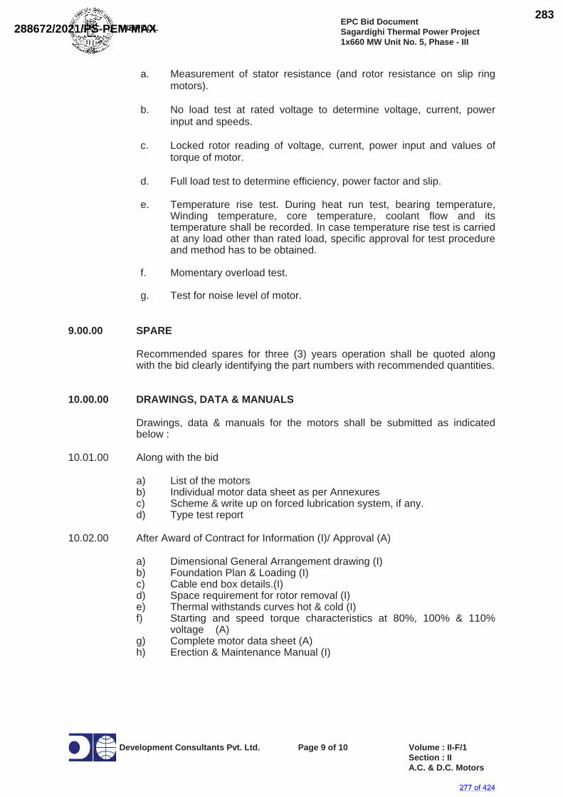
WBPDCLEPC Bid Document Sagardighi Thermal Power Project 1x660 MW Unit No. 5, Phase - III
Development Consultants Pvt. Ltd. Page 9 of 10 Volume : II-F/1 Section : II A.C. & D.C. Motors
a. Measurement of stator resistance (and rotor resistance on slip ring motors).
b. No load test at rated voltage to determine voltage, current, power input and speeds.
c. Locked rotor reading of voltage, current, power input and values of torque of motor.
d. Full load test to determine efficiency, power factor and slip.
e. Temperature rise test. During heat run test, bearing temperature, Winding temperature, core temperature, coolant flow and its temperature shall be recorded. In case temperature rise test is carried at any load other than rated load, specific approval for test procedure and method has to be obtained.
f. Momentary overload test.
g. Test for noise level of motor.
9.00.00 SPARE
Recommended spares for three (3) years operation shall be quoted along with the bid clearly identifying the part numbers with recommended quantities.
10.00.00 DRAWINGS, DATA & MANUALS
Drawings, data & manuals for the motors shall be submitted as indicated below :
10.01.00 Along with the bid
a) List of the motors b) Individual motor data sheet as per Annexures c) Scheme & write up on forced lubrication system, if any. d) Type test report
10.02.00 After Award of Contract for Information (I)/ Approval (A)
a) Dimensional General Arrangement drawing (I) b) Foundation Plan & Loading (I) c) Cable end box details.(I) d) Space requirement for rotor removal (I) e) Thermal withstands curves hot & cold (I)
f) Starting and speed torque characteristics at 80%, 100% & 110% voltage (A)
g) Complete motor data sheet (A) h) Erection & Maintenance Manual (I)
277 of 424
288672/2021/PS-PEM-MAX283
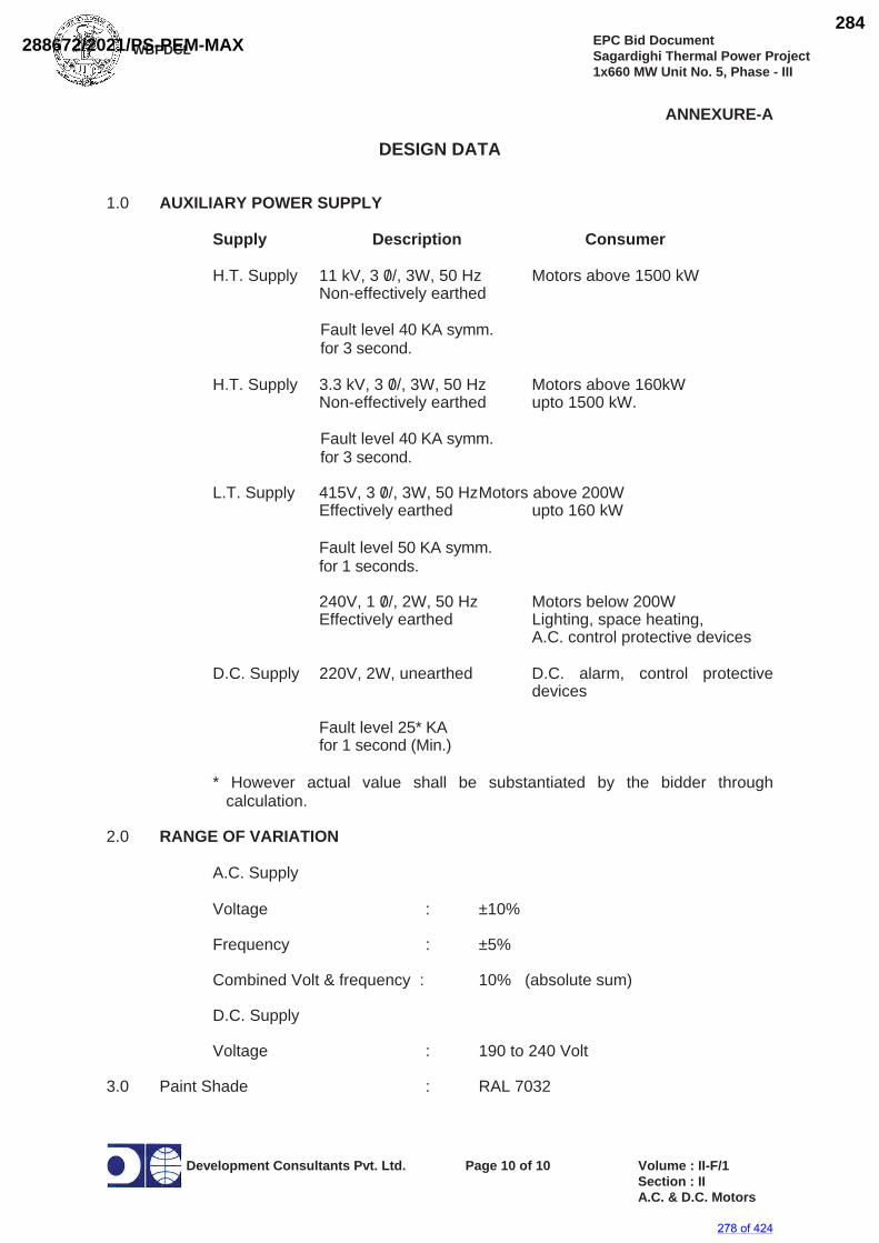
WBPDCLEPC Bid Document Sagardighi Thermal Power Project 1x660 MW Unit No. 5, Phase - III
Development Consultants Pvt. Ltd. Page 10 of 10 Volume : II-F/1 Section : II A.C. & D.C. Motors
ANNEXURE-A
DESIGN DATA
1.0 AUXILIARY POWER SUPPLY
Supply Description Consumer
H.T. Supply 11 kV, 3 0/ /, 3W, 50 Hz Motors above 1500 kW Non-effectively earthed
Fault level 40 KA symm. for 3 second.
H.T. Supply 3.3 kV, 3 0/ /, 3W, 50 Hz Motors above 160kW Non-effectively earthed upto 1500 kW.
Fault level 40 KA symm. for 3 second.
L.T. Supply 415V, 3 0/ /, 3W, 50 Hz Motors above 200W Effectively earthed upto 160 kW
Fault level 50 KA symm. for 1 seconds.
240V, 1 0/ /, 2W, 50 Hz Motors below 200W Effectively earthed Lighting, space heating, A.C. control protective devices
D.C. Supply 220V, 2W, unearthed D.C. alarm, control protective devices
Fault level 25* KA for 1 second (Min.)
* However actual value shall be substantiated by the bidder through calculation.
2.0 RANGE OF VARIATION
A.C. Supply
Voltage : ±10%
Frequency : ±5%
Combined Volt & frequency : 10% (absolute sum)
D.C. Supply
Voltage : 190 to 240 Volt
3.0 Paint Shade : RAL 7032
278 of 424
288672/2021/PS-PEM-MAX284
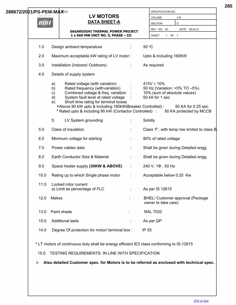
TITLE
LV MOTORS DATA SHEET-A
SAGARDIGHI THERMAL POWER PROJECT 1 x 660 MW UNIT NO. 5, PHASE – III
SPECIFICATION NO. VOLUME II B SECTION D REV NO. 00 DATE 08.04.21 SHEET 1 OF 1
1.0 Design ambient temperature : 50 oC 2.0 Maximum acceptable kW rating of LV motor : Upto & Including 160KW 3.0 Installation (Indoors/ Outdoors) : As required 4.0 Details of supply system a) Rated voltage (with variation) : 415V 10% b) Rated frequency (with variation) : 50 Hz (Variation: +5% TO –5%) c) Combined voltage & freq. variation : 10% (sum of absolute values) d) System fault level at rated voltage : 50 kA for 1 sec
e) Short time rating for terminal boxes *Above 90 kW upto & including 160kW(Breaker Controlled) : 50 KA for 0.25 sec. * Rated upto & including 90 kW (Contactor Controlled) : 50 KA protected by MCCB
f) LV System grounding : Solidly 5.0 Class of insulation : Class ‘F’, with temp rise limited to class B. 6.0 Minimum voltage for starting : 80% of rated voltage
7.0 Power cables data : Shall be given during Detailed engg. 8.0 Earth Conductor Size & Material : Shall be given during Detailed engg. 9.0 Space heater supply (30KW & ABOVE) : 240 V, 1Φ , 50 Hz 10.0 Rating up to which Single phase motor : Acceptable below 0.20 Kw
11.0 Locked rotor current
a) Limit as percentage of FLC : As per IS 12615 12.0 Makes : BHEL/ Customer approval (Package owner to take care) 13.0 Paint shade : RAL 7032 15.0 Additional tests : As per QP
14.0 Degree Of protection for motor/ terminal box : IP 55
* LT motors of continuous duty shall be energy efficient IE3 class conforming to IS-12615 15.0 TESTING REQUIREMENTS: IN LINE WITH SPECIFICATION
Also detailed Customer spec. for Motors is to be referred as enclosed with technical spec.
279 of 424
288672/2021/PS-PEM-MAX285
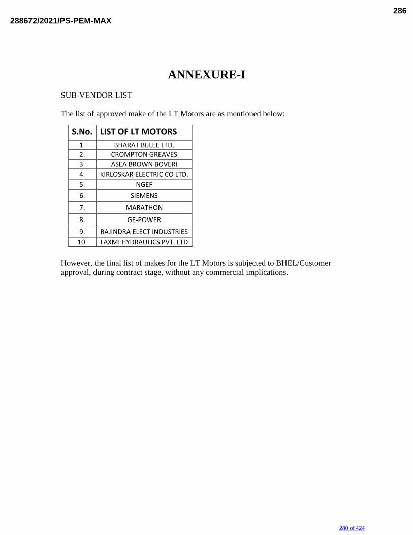
ANNEXURE-I SUB-VENDOR LIST The list of approved make of the LT Motors are as mentioned below:
However, the final list of makes for the LT Motors is subjected to BHEL/Customer approval, during contract stage, without any commercial implications.
S.No. LIST OF LT MOTORS 1. BHARAT BIJLEE LTD. 2. CROMPTON GREAVES 3. ASEA BROWN BOVERI 4. KIRLOSKAR ELECTRIC CO LTD. 5. NGEF
6. SIEMENS
7. MARATHON
8. GE-POWER
9. RAJINDRA ELECT INDUSTRIES 10. LAXMI HYDRAULICS PVT. LTD
280 of 424
288672/2021/PS-PEM-MAX286
WBPDCL EPC Bid Document
Sagardighi Thermal Power Project 1x660 MW Unit No. 5, Phase – III
Development Consultants Pvt. Ltd. Page 1 of 7 Volume : IIID
Sch-IIID/1A.C & D.C Motors
SCHEDULE-IIID/1
A.C. AND D.C. MOTORS
A. A.C. MOTOR 1.0 GENERAL 1.1 Application : 1.2 Quantity : 1.3 Make : 1.4 Frame Size : 1.5 Applicable Standard : 2.0 TYPE AND RATING 2.1 Type of Motor : 2.2 Service : 2.3 Duty Cycle/Designation : 2.4 Rated Continuous Output At 40 Deg.C ambient KW : At 50 Deg.C ambient KW : 2.5 Rated Speed r.p.m. : 2.6 Rated Voltage & % variation : 2.7 Rated Frequency & % variation : 2.8 Combined voltage and frequency variation % (absolute sum) : 2.9 Full load current Amps : 2.10 No load current Amps : 2.11 Rated Power Factor :
281 of 424
288672/2021/PS-PEM-MAX287
WBPDCL EPC Bid Document
Sagardighi Thermal Power Project 1x660 MW Unit No. 5, Phase – III
Development Consultants Pvt. Ltd. Page 2 of 7 Volume : IIID
Sch-IIID/1A.C & D.C Motors
2.12 Efficiency at rated voltage and frequency: a) Full load % : b) 3/4 load % : c) 1/2 load % : 3.0 PERFORMANCE 3.1 Method of Starting : 3.2 Starting current at 110% voltage % f.l.c : 3.3 Starting Current at rated voltage % f.l.c. : 3.4 Starting Torque at rated voltage kg.m : a) Pull out torque kg.m : b) Full load torque kg.m : 3.5 Starting time at 80% 100% 110% Voltage Voltage Voltage a) With load sec. : b) Without load (driven equipment Coupled) sec : 3.6 Safe stall time at 80% 100% 110% Voltage Voltage Voltage a) Hot condition sec. : b) Cold condition sec. : 3.7 a) Heating time constant min : b) Cooling time constant min : 4.0 CONSTRUCTION 4.1 Degree of Protection of Enclosure : 4.2 Method of Cooling : 4.3 Insulation Class : 4.4 Temperature Rise Over 50 Deg.C ambient (by resistance) :
282 of 424
288672/2021/PS-PEM-MAX288
WBPDCL EPC Bid Document
Sagardighi Thermal Power Project 1x660 MW Unit No. 5, Phase – III
Development Consultants Pvt. Ltd. Page 3 of 7 Volume : IIID
Sch-IIID/1A.C & D.C Motors
4.5 Tropicalised Yes/No: 4.6 Winding Connection : 4.7 Bearings D.E. N.D.E. a) Make : b) Type : c) Recommended lubricant : 4.8 Motor Terminal Box a) Type : b) Fault withstand Current KA : c) Fault Current Withstand Time Sec. : d) Cable lugs & glands furnished Yes/No : e) Position : 5.0 ACCESSORIES 5.1 Space Heaters a) No. x Watt : b) Volt, phase, frequency : 5.2 Winding temperature detector a) Type : b) Nos. furnished : 5.3 Bearing temperature detector a) Type : b) Nos. furnished : 5.4 Temperature Indicators a) Type : b) Nos. provided : c) Locations :
283 of 424
288672/2021/PS-PEM-MAX289
WBPDCL EPC Bid Document
Sagardighi Thermal Power Project 1x660 MW Unit No. 5, Phase – III
Development Consultants Pvt. Ltd. Page 4 of 7 Volume : IIID
Sch-IIID/1A.C & D.C Motors
5.5 Temperature Alarm Contact a) Nos. provided : b) Locations : c) Contact rating : 5.6 Flow Switch a) Type : b) Nos. provided : c) Locations : d) Contact Rating : 5.7 Current Transformer for differential protection a) Nos. provided : b) Current Ratio : c) Class : d) Knee point voltage : e) Excitation current at VK/2 : 5.8 Accessory Terminal Box a) No. provided : b) Cable glands furnished Yes/No: 5.9 Speed Switch a) Type : b) Nos. provided : c) Locations : d) Contact Rating :
284 of 424
288672/2021/PS-PEM-MAX290
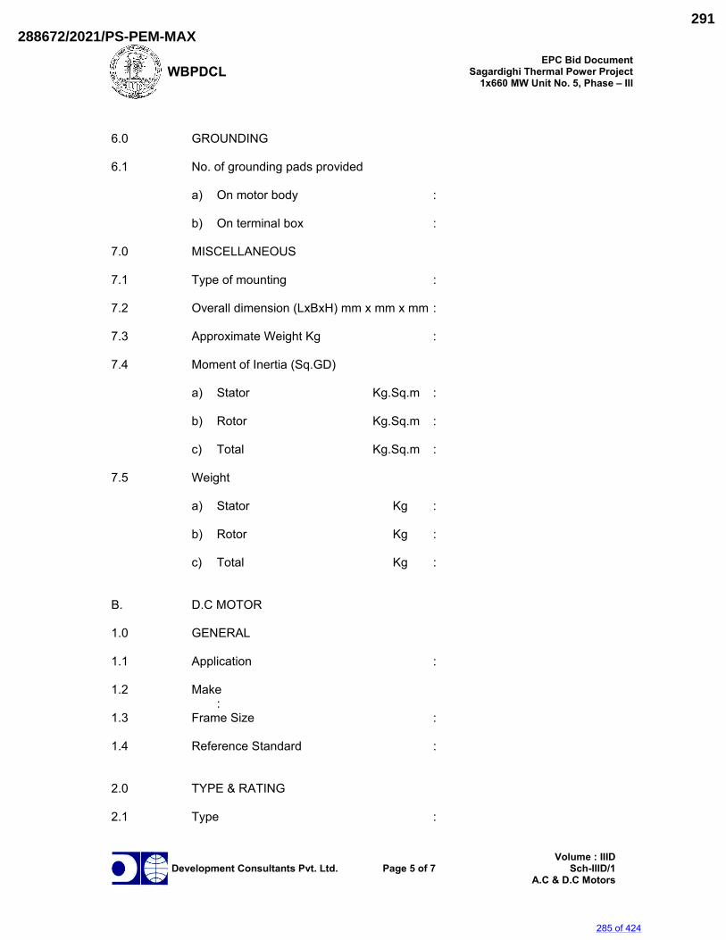
WBPDCL EPC Bid Document
Sagardighi Thermal Power Project 1x660 MW Unit No. 5, Phase – III
Development Consultants Pvt. Ltd. Page 5 of 7 Volume : IIID
Sch-IIID/1A.C & D.C Motors
6.0 GROUNDING 6.1 No. of grounding pads provided a) On motor body : b) On terminal box : 7.0 MISCELLANEOUS 7.1 Type of mounting : 7.2 Overall dimension (LxBxH) mm x mm x mm : 7.3 Approximate Weight Kg : 7.4 Moment of Inertia (Sq.GD) a) Stator Kg.Sq.m : b) Rotor Kg.Sq.m : c) Total Kg.Sq.m : 7.5 Weight a) Stator Kg : b) Rotor Kg : c) Total Kg : B. D.C MOTOR 1.0 GENERAL 1.1 Application : 1.2 Make : 1.3 Frame Size : 1.4 Reference Standard : 2.0 TYPE & RATING 2.1 Type :
285 of 424
288672/2021/PS-PEM-MAX291
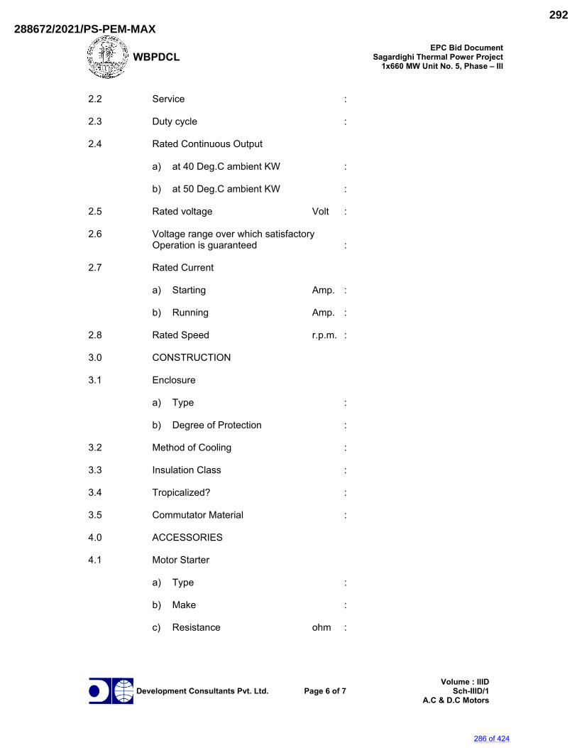
WBPDCL EPC Bid Document
Sagardighi Thermal Power Project 1x660 MW Unit No. 5, Phase – III
Development Consultants Pvt. Ltd. Page 6 of 7 Volume : IIID
Sch-IIID/1A.C & D.C Motors
2.2 Service : 2.3 Duty cycle : 2.4 Rated Continuous Output a) at 40 Deg.C ambient KW : b) at 50 Deg.C ambient KW : 2.5 Rated voltage Volt : 2.6 Voltage range over which satisfactory Operation is guaranteed : 2.7 Rated Current a) Starting Amp. : b) Running Amp. : 2.8 Rated Speed r.p.m. : 3.0 CONSTRUCTION 3.1 Enclosure a) Type : b) Degree of Protection : 3.2 Method of Cooling : 3.3 Insulation Class : 3.4 Tropicalized? : 3.5 Commutator Material : 4.0 ACCESSORIES 4.1 Motor Starter
a) Type :
b) Make :
c) Resistance ohm :
286 of 424
288672/2021/PS-PEM-MAX292
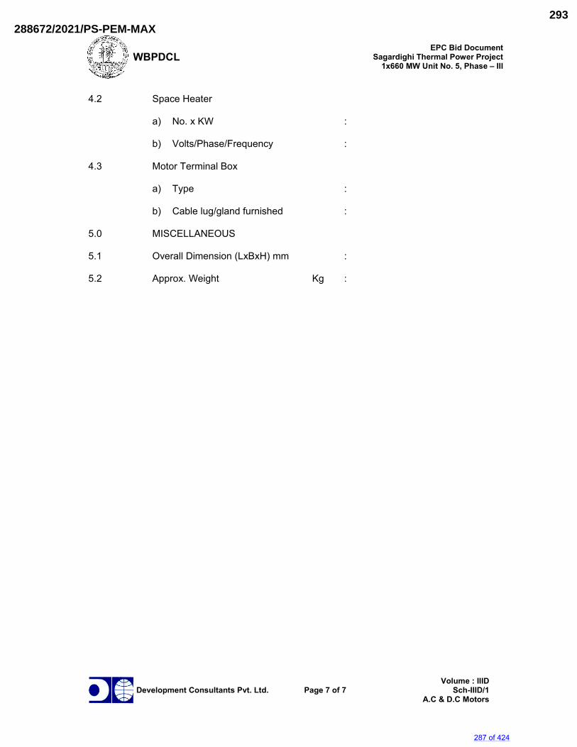
WBPDCL EPC Bid Document
Sagardighi Thermal Power Project 1x660 MW Unit No. 5, Phase – III
Development Consultants Pvt. Ltd. Page 7 of 7 Volume : IIID
Sch-IIID/1A.C & D.C Motors
4.2 Space Heater
a) No. x KW :
b) Volts/Phase/Frequency : 4.3 Motor Terminal Box
a) Type :
b) Cable lug/gland furnished : 5.0 MISCELLANEOUS 5.1 Overall Dimension (LxBxH) mm : 5.2 Approx. Weight Kg :
287 of 424
288672/2021/PS-PEM-MAX293
SECTION : D
TITLE : GENERAL TECHNICAL REQUIREMENTs
FOR
LV MOTORS
SPECIFICATION NO. PE-SS-999-506-E101 VOLUME NO. : II-B
REV NO. : 00 DATE : 29/08/2005SHEET : 1 OF 1
GENERAL TECHNICAL REQUIREMENTS
FOR
LV MOTORS
SPECIFICATION NO.: PE-SS-999-506-E101 Rev 00
288 of 424
288672/2021/PS-PEM-MAX294
TITLE : GENERAL TECHNICAL REQUIREMENTs
FOR
LV MOTORS
SPECIFICATION NO. PE-SS-999-506-E101 VOLUME NO. : II-B SECTION : D REV NO. : 00 DATE : 29/08/2005SHEET : 1 OF 4
1.0 INTENT OF SPECIFIATION
The specification covers the design, materials, constructional features, manufacture, inspection and testing at manufacturer’s work, and packing of Low voltage (LV) squirrel cage induction motors along with all accessories for driving auxiliaries in thermal power station.
Motors having a voltage rating of below 1000V are referred to as low voltage (LV) motors. 2.0 CODES AND STANDARDS Motors shall fully comply with latest edition, including all amendments and revision, of following
codes and standards: IS:325 Three phase Induction motors IS : 900 Code of practice for installation and maintenance of induction motors IS: 996 Single phase small AC and universal motors IS: 4722 Rotating Electrical machines IS: 4691 Degree of Protection provided by enclosures for rotating electrical machines IS: 4728 Terminal marking and direction of rotation rotating electrical machines IS: 1231 Dimensions of three phase foot mounted induction motors IS: 8789 Values of performance characteristics for three phase induction motors IS: 13555 Guide for selection and application of 3-phase A.C. induction motors for
different types of driven equipment IS: 2148 Flame proof enclosures for electrical appliance IS: 5571 Guide for selection of electrical equipment for hazardous areas IS: 12824 Type of duty and classes of rating assigned IS: 12802 Temperature rise measurement for rotating electrical machnines IS: 12065 Permissible limits of noise level for rotating electrical machines IS: 12075 Mechanical vibration of rotating electrical machines In case of imported motors, motors as per IEC-34 shall also be acceptable.
3.0 DESIGN REQUIREMENTS 3.1 Motors and accessories shall be designed to operate satisfactorily under conditions specified in data
sheet-A and Project Information, including voltage & frequency variation of supply system as defined in Data sheet-A
3.2 Motors shall be continuously rated at the design ambient temperature specified in Data Sheet-A and
other site conditions specified under Project Information Motor ratings shall have at least a 15% margin over the continuous maximum demand of the driven equipment, under entire operating range including voltage & frequency variation specified above.
3.3 Starting Requirements 3.3.1 Motor characteristics such as speed, starting torque, break away torque and starting time shall be
properly co-ordinated with the requirements of driven equipment. The accelerating torque at any speed with the minimum starting voltage shall be at least 10% higher than that of the driven equipment.
3.3.2 Motors shall be capable of starting and accelerating the load with direct on line starting without
exceeding acceptable winding temperature.
289 of 424
288672/2021/PS-PEM-MAX295
TITLE : GENERAL TECHNICAL REQUIREMENTs
FOR
LV MOTORS
SPECIFICATION NO. PE-SS-999-506-E101 VOLUME NO. : II-B SECTION : D REV NO. : 00 DATE : 29/08/2005SHEET : 2 OF 4
The limiting value of voltage at rated frequency under which a motor will successfully start and
accelerate to rated speed with load shall be taken to be a constant value as per Data Sheet - A during the starting period of motors.
3.3.3 The following frequency of starts shall apply
i) Two starts in succession with the motor being initially at a temperature not exceeding the rated load temperature.
ii) Three equally spread starts in an hour the motor being initially at a temperature not exceeding
the rated load operating temperature. (not to be repeated in the second successive hour)
iii) Motors for coal conveyor and coal crusher application shall be suitable for three consecutive hot starts followed by one hour interval with maximum twenty starts per day and shall be suitable for mimimum 20,000 starts during the life time of the motor
3.4 Running Requirements 3.4.1 Motors shall run satisfactorily at a supply voltage of 75% of rated voltage for 5 minutes with full load
without injurious heating to the motor. 3.4.2 Motor shall not stall due to voltage dip in the system causing momentary drop in voltage upto 70% of
the rated voltage for duration of 2 secs. 3.5 Stress During bus Transfer 3.5.1 Motors shall withstand the voltage, heavy inrush transient current, mechanical and torque stress
developed due to the application of 150% of the rated voltage for at least 1 sec. caused due to vector difference between the motor residual voltage and the incoming supply voltage during occasional auto bus transfer.
3.5.2 Motor and driven equipment shafts shall be adequately sized to satisfactorily withstand transient
torque under above condition. 3.6 Maximum noise level measured at distance of 1.0 metres from the outline of motor shall not exceed
the values specified in IS 12065. 3.7 The max. vibration velocity or double amplitude of motors vibration as measured at motor bearings
shall be within the limits specified in IS: 12075. 4.0 CONSTRUCTIONAL FEATURES 4.1 Indoor motors shall conform to degree of protection IP: 54 as per IS: 4691. Outdoor or semi-indoor
motors shall conform to degree of protection IP: 55 as per IS: 4691and shall be of weather-proof construction. Outdoor motors shall be installed under a suitable canopy
4.2 Motors upto 160KW shall have Totally Enclosed Fan Cooled (TEFC) enclosures, the method of
cooling conforming to IC-0141 or IC-0151 of IS: 6362.
Motors rated above 160 KW shall be Closed Air Circuit Air (CACA) cooled 4.3 Motors shall be designed with cooling fans suitable for both directions of rotation.
290 of 424
288672/2021/PS-PEM-MAX296
TITLE : GENERAL TECHNICAL REQUIREMENTs
FOR
LV MOTORS
SPECIFICATION NO. PE-SS-999-506-E101 VOLUME NO. : II-B SECTION : D REV NO. : 00 DATE : 29/08/2005SHEET : 3 OF 4
4.4. Motors shall not be provided with any electric or pneumatic operated external fan for cooling the
motors. 4.5 Frames shall be designed to avoid collection of moisture and all enclosures shall be provided with
facility for drainage at the lowest point. 4.6 In case Class ‘F’ insulation is provided for LV motors, temperature rise shall be limited to the limits
applicable to Class ‘B’ insulation. In case of continuous operation at extreme voltage limits the temperature limits specified in table-1 of IS:325 shall not exceed by more than 10°C.
4.7 Terminals and Terminal Boxes 4.7.1 Terminals, terminal leads, terminal boxes, windings tails and associated equipment shall be suitable
for connection to a supply system having a short circuit level, specified in the Data Sheet-A. Unless otherwise stated in Data Sheet-A, motors of rating 110 kW and above will be controlled by
circuit breaker and below 110 kW by switch fuse-contactor. The terminal box of motors shall be designed for the fault current mentioned in data sheet “A”.
4.7.2 unless otherwise specified or approved, phase terminal boxes of horizontal motors shall be positioned
on the left hand side of the motor when viewed from the non-driving end. 4.7.3 Connections shall be such that when the supply leads R, Y & B are connected to motor terminals A B
& C or U, V & W respectively, motor shall rotate in an anticlockwise direction when viewed from the non-driving end. Where such motors require clockwise rotation, the supply leads R, Y, B will be connected to motor terminals A, C, B or U W & V respectively.
4.7.4 Permanently attached diagram and instruction plate made preferably of stainless steel shall be
mounted inside terminal box cover giving the connection diagram for the desired direction of rotation and reverse rotation.
4.7.5 Motor terminals and terminal leads shall be fully insulated with no bar live parts. Adequate space
shall be available inside the terminal box so that no difficulty is encountered for terminating the cable specified in Data Sheet-A.
4.7.6 Degree of protection for terminal boxes shall be IP 55 as per IS 4691. 4.7.7 Separate terminal boxes shall be provided for space heaters.. If this is not possible in case of LV
motors, the space heater terminals shall be adequately segregated from the main terminals in the main terminal box. Detachable gland plates with double compression brass glands shall be provided in terminal boxes.
4.7.8. Phase terminal boxes shall be suitable for 360 degree of rotation in steps of 90 degree for LV motors. 4.7.9 Cable glands and cable lugs as per cable sizes specified in Data Sheet-A shall be included. Cable lugs
shall be of tinned Copper, crimping type. 4.8 Two separate earthing terminals suitable for connecting G.I. or MS strip grounding conductor of size
given in Data Sheet-A shall be provided on opposite sides of motor frame. Each terminal box shall have a grounding terminal.
4.9 General
291 of 424
288672/2021/PS-PEM-MAX297
TITLE : GENERAL TECHNICAL REQUIREMENTs
FOR
LV MOTORS
SPECIFICATION NO. PE-SS-999-506-E101 VOLUME NO. : II-B SECTION : D REV NO. : 00 DATE : 29/08/2005SHEET : 4 OF 4
4.9.1 Motors provided for similar drives shall be interchangeable. 4.9.2 Suitable foundation bolts are to be supplied alongwith the motors. 4.9.3 Motors shall be provided with eye bolts, or other means to facilitate safe lifting if the weight is 20Kgs.
and above. 4.9.4 Necessary fitments and accessories shall be provided on motors in accordance with the latest Indian
Electricity rules 1956. 4.9.5 All motors rated above 30 kW shall be provided with space heaters to maintain the motor internal air
temperature above the dew point. Unless otherwise specified, space heaters shall be suitable for a supply of 240V AC, single phase, 50 Hz.
4.9.6 Name plate with all particulars as per IS: 325 shall be provided 4.9.7 Unless otherwise specified, the colour of finish shall be grey to Shade No. 631 and 632 as per IS:5 for
motors installed indoor and outdoor respectively. The paint shall be epoxy based and shall be suitable for withstanding specified site conditions.
5.0 INSPECTION AND TESTING 5.1 All materials, components and equipments covered under this specification shall be procured,
manufactured, as per the BHEL standard quality plan No. PED-506-00-Q-006/0 and PED-506-00-Q-007/2 enclosed with this specification and which shall be complied.
5.2 LV motors of type-tested design shall be provided. Valid type test reports not more than 5 year shall
be furnished. In the absence of these, type tests shall have to be conducted by manufacturer without any commercial implication to purchaser.
5.3 All motors shall be subjected to routine tests as per IS: 325 and as per BHEL standard quality plan. 5.4 Motors shall also be subjected to additional tests, if any, as mentioned in Data Sheet A. 6.0 DRAWINGS TO BE SUBMITTED AFTER AWARD OF CONTRACT a) OGA drawing showing the position of terminal boxes, earthing connections etc. b) Arrangement drawing of terminal boxes. c) Characteristic curves: (To be given for motor above 55 kW unless otherwise specified in Data Sheet). i) Current vs. time at rated voltage and minimum starting voltage. ii) Speed vs. time at rated voltage and minimum starting voltage.
iii) Torque vs. speed at rated voltage and minimum voltage. For the motors with solid coupling the above curves i), ii), iii) to be furnished for the motors coupled with driven equipment. In case motor is coupled with mechanical equipment by fluid coupling, the above curves shall be furnished with and without coupling.
iv) Thermal withstand curve under hot and cold conditions at rated voltage and max. permissible voltage.
292 of 424
288672/2021/PS-PEM-MAX298

MANUFACTURER/ BIDDER/ SUPPLIER NAME & ADDRESS STANDARD QUALITY PLAN SPEC. NO : DATE:
CUSTOMER : QP NO.: PE-QP-999-Q-006, REV-02 DATE: 17.04.2020
PROJECT: PO NO.: DATE:
ITEM: AC ELECT. MOTORS UPTO 55KW (LV (415V)) SYSTEM: SECTION: II SHEET 1 of 2
BHEL BIDDER/ SUPPLIER
FOR CUSTOMER REVIEW & APPROVAL
ENGINEERING QUALITY Sign & Date Doc No:
Sign & Date Name Sign & Date Name Seal Sign & Date Name Seal Prepared by:
HEMA KHUSHWAHA
Checked by:
KUNAL GANDHI Reviewed by:
Reviewed by:
PRAVEEN DUTTA
Reviewed by:
RITESH KUMAR JAISWAL
Approved by:
S. NO.
COMPONENT &
OPERATIONS
CHARACTERISTICS
CLASS
TYPE OF CHECK
QUANTUM OF CHECK
REFERENCE DOCUMENT
ACCEPTANCE NORMS
FORMAT OF
RECORD
AGENCY
REMARKS
1 2 3 4 5 6
7 8 9 * D
** M C/ N M C N
1.0 ASSEMBLY
1.WORKMANSHIP
MA VISUAL 100% - MFG. SPEC. MFG. SPEC. LOG BOOK
P - -
2.DIMENSIONS MA VISUAL 100% - MFG. DRG./ MFG. SPEC.
MFG. DRG./ MFG. SPEC.
LOG BOOK
P - -
3.CORRECTNESS COMPLETENESS TERMINATIONS/ MARKING/ COLOUR CODE
MA VISUAL 100% - MFG.SPEC./ MFG.SPEC. LOG BOOK
P - -
2.0 PAINTING 1.SHADE MA VISUAL SAMPLE
- MFG. SPEC/ APPROVED DATASHEET
MFG. SPEC/ APPROVED DATASHEET
LOG BOOK
✔
P V -
3.0 TESTS
1.ROUTINE TEST INCLUDING SPECIAL TEST
MA VISUAL 100% -
IS-325 / IS-12615/ APPROVED DATA SHEET
IS-325 / IS-12615/ APPROVED DATA SHEET
TEST/ INSPN. REPORT
✔ P V*
- * NOTE -1
2.OVERALL DIMENSIONS & ORIENTATION
MA MEASUREMENT & VISUAL
100% - APPROVED DRG/ DATA SHEET
APPROVED DRG/ DATA SHEET
TEST/ INSPN. REPORT
✔ P V*
- * NOTE -1
& NOTE-2
KUSHWAHAHEMA KUSHWAHA
Digitally signed by HEMA KUSHWAHA DN: cn=HEMA KUSHWAHA, o=BHEL, ou=PEM-ELECT, [email protected], c=IN Date: 2020.10.08 12:07:07 +05'30'
PRAVEEN DUTTA
Digitally signed by PRAVEEN DUTTA DN: c=IN, o=BHARAT HEAVY ELECTRICALS LIMITED, ou=PS PEM, postalCode=201301, st=UTTAR PRADESH, 2.5.4.20=da8948aa0c3e2703a98a0aacaa2aedd61dd68dbef4c976429c5c374e3b47b930, cn=PRAVEEN DUTTA Date: 2020.10.08 18:43:51 +05'30'
Digitally signed by Kunal Gandhi DN: cn=Kunal Gandhi, o=BHEL, ou=PEM, [email protected], c=IN Date: 2020.10.09 10:20:18 +05'30'
RITESH KUMAR JAISWAL
Digitally signed by RITESH KUMAR JAISWAL DN: c=IN, o=Bharat Heavy Electricals Ltd, ou=BHEL / PS-PEM, postalCode=201301, st=Uttar Pradesh, 2.5.4.20=16692a281523bf78b46a8e18c5cd0bb189777532609b5349ae8d7191a9e51174, serialNumber=8cfaddf001b4875a8b03a31b000e93ff205304f62c650e6d5f9d9980e09bc448, cn=RITESH KUMAR JAISWAL Date: 2020.10.09 10:25:03 +05'30'
293 of 424
288672/2021/PS-PEM-MAX299
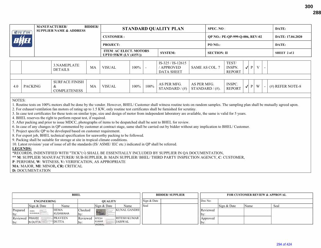
MANUFACTURER/ BIDDER/ SUPPLIER NAME & ADDRESS STANDARD QUALITY PLAN SPEC. NO : DATE:
CUSTOMER : QP NO.: PE-QP-999-Q-006, REV-02 DATE: 17.04.2020
PROJECT: PO NO.: DATE:
ITEM: AC ELECT. MOTORS UPTO 55KW (LV (415V)) SYSTEM: SECTION: II SHEET 2 of 2
BHEL BIDDER/ SUPPLIER
FOR CUSTOMER REVIEW & APPROVAL
ENGINEERING QUALITY Sign & Date Doc No:
Sign & Date Name Sign & Date Name Seal Sign & Date Name Seal Prepared by:
HEMA KHUSHWAHA
Checked by:
KUNAL GANDHI Reviewed by:
Reviewed by:
PRAVEEN DUTTA
Reviewed by:
RITESH KUMAR JAISWAL
Approved by:
3.NAMEPLATE DETAILS
MA VISUAL 100% - IS-325 / IS-12615 / APPROVED DATA SHEET
SAME AS COL. 7 TEST/ INSPN. REPORT
✔ P V -
4.0 PACKING SURFACE FINISH & COMPLETENESS
MA VISUAL 100% 100% AS PER MFG. STANDARD / (#)
AS PER MFG. STANDARD / (#).
INSPC. REPORT ✔ P W - (#) REFER NOTE-8
NOTES: 1. Routine tests on 100% motors shall be done by the vendor. However, BHEL/ Customer shall witness routine tests on random samples. The sampling plan shall be mutually agreed upon. 2. For exhaust/ventilation fan motors of rating up to 1.5 KW, only routine test certificates shall be furnished for scrutiny. 3. In case test certificates for these tests on similar type, size and design of motor from independent laboratory are available, the same is valid for 5 years. 4. BHEL reserves the right to perform repeat test, if required. 5. After packing and prior to issue MDCC, photographs of items to be despatched shall be sent to BHEL for review. 6. In case of any changes in QP commented by customer at contract stage, same shall be carried out by bidder without any implication to BHEL/ Customer. 7. Project specific QP to be developed based on customer requirement. 8. For export job, BHEL technical specification for seaworthy packing to be followed. 9. Packing shall be suitable for storage at site in tropical climate conditions. 10. Latest revision/ year of issue of all the standards (IS/ ASME/ IEC etc.) indicated in QP shall be referred. LEGENDS: *RECORDS, INDENTIFIED WITH "TICK"(√) SHALL BE ESSENTIALLY INCLUDED BY SUPPLIER IN QA DOCUMENTATION, ** M: SUPPLIER/ MANUFACTURER/ SUB-SUPPLIER, B: MAIN SUPPLIER/ BHEL/ THIRD PARTY INSPECTION AGENCY, C: CUSTOMER, P: PERFORM, W: WITNESS, V: VERIFICATION, AS APPROPRIATE MA: MAJOR, MI: MINOR, CR: CRITICAL D: DOCUMENTATION
KUSHWAHAHEMA KUSHWAHA
Digitally signed by HEMA KUSHWAHA DN: cn=HEMA KUSHWAHA, o=BHEL, ou=PEM-ELECT, [email protected], c=IN Date: 2020.10.08 12:07:43 +05'30'
PRAVEEN DUTTA
Digitally signed by PRAVEEN DUTTA DN: c=IN, o=BHARAT HEAVY ELECTRICALS LIMITED, ou=PS PEM, postalCode=201301, st=UTTAR PRADESH, 2.5.4.20=da8948aa0c3e2703a98a0aacaa2aedd61dd68dbef4c976429c5c374e3b47b930, cn=PRAVEEN DUTTA Date: 2020.10.08 18:44:21 +05'30'
Digitally signed by Kunal Gandhi DN: cn=Kunal Gandhi, o=BHEL, ou=PEM, [email protected], c=IN Date: 2020.10.09 10:20:31 +05'30'
RITESH KUMAR JAISWAL
Digitally signed by RITESH KUMAR JAISWAL DN: c=IN, o=Bharat Heavy Electricals Ltd, ou=BHEL / PS-PEM, postalCode=201301, st=Uttar Pradesh, 2.5.4.20=16692a281523bf78b46a8e18c5cd0bb189777532609b5349ae8d7191a9e51174, serialNumber=8cfaddf001b4875a8b03a31b000e93ff205304f62c650e6d5f9d9980e09bc448, cn=RITESH KUMAR JAISWAL Date: 2020.10.09 10:25:30 +05'30'
294 of 424
288672/2021/PS-PEM-MAX300
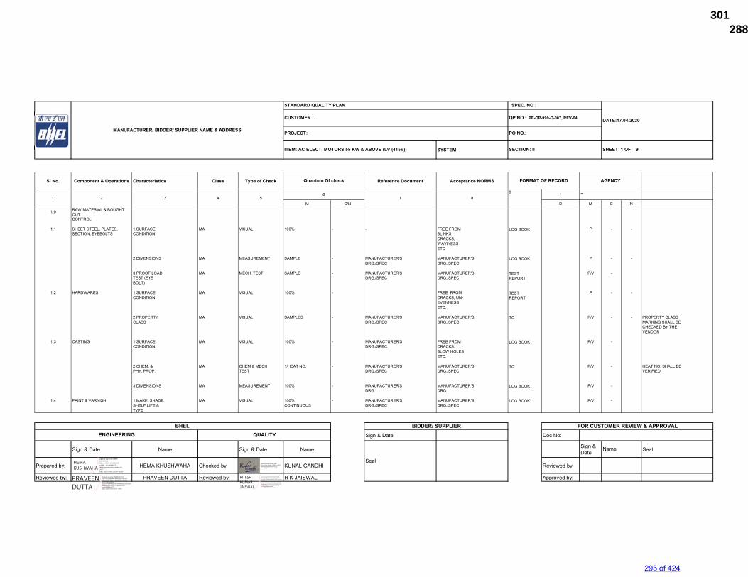
SYSTEM:
Sl No. Component & Operations Characteristics Class Type of Check Reference Document Acceptance NORMS
*
M C/N D M C N
1.0 RAW MATERIAL & BOUGHT OUTCONTROL
1.1 SHEET STEEL, PLATES, 1.SURFACE MA VISUAL 100% - - FREE FROM LOG BOOK P - -SECTION, EYEBOLTS CONDITION BLINKS,
CRACKS,WAVINESSETC
2.DIMENSIONS MA MEASUREMENT SAMPLE - MANUFACTURER'S MANUFACTURER'S LOG BOOK P - -DRG./SPEC DRG./SPEC
3.PROOF LOAD MA MECH. TEST SAMPLE - MANUFACTURER'S MANUFACTURER'S TEST P/V -TEST (EYE DRG./SPEC DRG./SPEC REPORTBOLT)
1.2 HARDWARES 1.SURFACE MA VISUAL 100% - FREE FROM TEST P - -CONDITION CRACKS, UN- REPORT
EVENNESS ETC.
2.PROPERTY MA VISUAL SAMPLES - MANUFACTURER'S MANUFACTURER'S TC P/V - - PROPERTY CLASS CLASS DRG./SPEC DRG./SPEC MARKING SHALL BE
CHECKED BY THEVENDOR
1.3 CASTING 1.SURFACE MA VISUAL 100% - MANUFACTURER'S FREE FROM LOG BOOK P/V -CONDITION DRG./SPEC CRACKS,
BLOW HOLESETC.
2.CHEM. & MA CHEM & MECH 1/HEAT NO. - MANUFACTURER'S MANUFACTURER'S TC P/V - HEAT NO. SHALL BEPHY. PROP. TEST DRG./SPEC DRG./SPEC VERIFIED
3.DIMENSIONS MA MEASUREMENT 100% - MANUFACTURER'S MANUFACTURER'S LOG BOOK P/V -DRG. DRG.
1.4 PAINT & VARNISH 1.MAKE, SHADE, MA VISUAL 100% - MANUFACTURER'S MANUFACTURER'S LOG BOOK P/V -SHELF LIFE & CONTINUOUS DRG./SPEC DRG./SPECTYPE
Sign & Date Doc No:
Sign & Date Name Sign & Date Name Sign & Date Seal
Prepared by: HEMA KHUSHWAHA Checked by: KUNAL GANDHI Reviewed by:
Reviewed by: PRAVEEN DUTTA Reviewed by: R K JAISWAL Approved by:
BIDDER/ SUPPLIER FOR CUSTOMER REVIEW & APPROVAL
DATE:17.04.2020
ITEM: AC ELECT. MOTORS 55 KW & ABOVE (LV (415V))
Quantum Of check FORMAT OF RECORD AGENCY
STANDARD QUALITY PLAN SPEC. NO :
CUSTOMER :
1 2 3 4 5
MANUFACTURER/ BIDDER/ SUPPLIER NAME & ADDRESS
QP NO.: PE-QP-999-Q-007, REV-04
PROJECT: PO NO.:
SECTION: II
67 8
9
SHEET 1 OF 9
Name
**
BHEL ENGINEERING QUALITY
SealHEMA KUSHWAHA
Digitally signed by HEMA KUSHWAHA DN: cn=HEMA KUSHWAHA, o=BHEL, ou=PEM-ELECT, [email protected], c=IN Date: 2020.10.08 12:02:30 +05'30'
PRAVEEN DUTTA
Digitally signed by PRAVEEN DUTTA DN: c=IN, o=BHARAT HEAVY ELECTRICALS LIMITED, ou=PS PEM, postalCode=201301, st=UTTAR PRADESH, 2.5.4.20=da8948aa0c3e2703a98a0aacaa2aedd61dd68dbef4c976429c5c374e3b47b930, cn=PRAVEEN DUTTA Date: 2020.10.08 19:00:37 +05'30'
Digitally signed by Kunal Gandhi DN: cn=Kunal Gandhi, o=BHEL, ou=PEM, [email protected], c=IN Date: 2020.10.09 10:13:39 +05'30'
RITESH KUMAR JAISWAL
Digitally signed by RITESH KUMAR JAISWAL DN: c=IN, o=Bharat Heavy Electricals Ltd, ou=BHEL / PS-PEM, postalCode=201301, st=Uttar Pradesh, 2.5.4.20=16692a281523bf78b46a8e18c5cd0bb189777532609b5349ae8d7191a9e51174, serialNumber=8cfaddf001b4875a8b03a31b000e93ff205304f62c650e6d5f9d9980e09bc448, cn=RITESH KUMAR JAISWAL Date: 2020.10.09 10:27:57 +05'30'
295 of 424
288672/2021/PS-PEM-MAX301
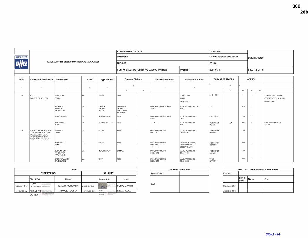
SYSTEM:
Sl No. Component & Operations Characteristics Class Type of Check Reference Document Acceptance NORMS
*
M C/N D M C N
1.5 SHAFT 1. SURFACE MA VISUAL 100% - - FREE FROM LOG BOOK P - - VENDOR'S APPROVAL
(FORGED OR ROLLED) COND. VISUAL IDENTIFICATION SHALL BE
DEFECTS MAINTAINED
2. CHEM. & MA CHEM. & 1/HEAT NO. - MANUFACTURER'S DRG./ MANUFACTURER'S DRG./ TC P/V -PHYSICAL PHYSICAL OR HEAT SPEC. STD.PROPERTIES TESTS TREATMENT
BATCH NO
3. DIMENSIONS MA MEASUREMENT 100% - MANUFACTURER'S DRG./ MANUFACTURER'S LOG BOOK P/V -SPEC. DRG.
4.INTERNAL CR ULTRASONIC TEST 100% - ASTM-A388 MANUFACTURER'S INSPECTION ✔ P/W V - FOR DIA OF 55 MM & FLAWS STD. REPORT ABOVE
1.6 SPACE HEATERS, CONNEC- 1. MAKE & MA VISUAL 100% - MANUFACTURER'S MANUFACTURER'S INSPECTION P/V - -TORS, TERMINAL BLOCKS, RATING DRG./STD. DRG./STD. REPORTCABLES, CABLE LUGS,CARBON BRUSH TEMP.DETECTORS, RTD, BTD'S
2. PHYSICAL MA VISUAL 100% - MANUFACTURER'S NO PHYS. DAMAGE, INSPECTION P/V - -COND. DRG./STD. NO ELECTRICAL REPORT
DISCONTINUITY
3.DIMENSIONS MA MEASUREMENT SAMPLE - MANUFACTURER'S MANUFACTURER'S INSPECTION P/V - -(WHEREVER DRG./ STD DRG. / STD. REPORTAPPLICABLE)
4.PERFORMANCE/ MA TEST 100% - MANUFACTURER'S MANUFACTURER'S TEST P/V - -CALIBRATION DRG./ STD DRG. / STD. REPORT
Sign & Date Doc No:
Sign & Date Name Sign & Date Name Sign & Date Seal
Prepared by: HEMA KHUSHWAHA Checked by: KUNAL GANDHI Reviewed by:
Reviewed by: PRAVEEN DUTTA Reviewed by: R K JAISWAL Approved by:
BIDDER/ SUPPLIER FOR CUSTOMER REVIEW & APPROVAL
AGENCY
6 **7 8
9
ITEM: AC ELECT. MOTORS 55 KW & ABOVE (LV (415V)) SECTION: II SHEET 2 OF 9
Quantum Of check FORMAT OF RECORD
STANDARD QUALITY PLAN SPEC. NO :
DATE:17.04.2020CUSTOMER : QP NO.: PE-QP-999-Q-007, REV-04
PROJECT: PO NO.:
1 2 3 4 5
MANUFACTURER/ BIDDER/ SUPPLIER NAME & ADDRESS
BHEL ENGINEERING QUALITY
Seal
Name
HEMA KUSHWAHA
Digitally signed by HEMA KUSHWAHA DN: cn=HEMA KUSHWAHA, o=BHEL, ou=PEM-ELECT, [email protected], c=IN Date: 2020.10.08 12:03:19 +05'30'
PRAVEEN DUTTA
Digitally signed by PRAVEEN DUTTA DN: c=IN, o=BHARAT HEAVY ELECTRICALS LIMITED, ou=PS PEM, postalCode=201301, st=UTTAR PRADESH, 2.5.4.20=da8948aa0c3e2703a98a0aacaa2aedd61dd68dbef4c976429c5c374e3b47b930, cn=PRAVEEN DUTTA Date: 2020.10.08 19:01:01 +05'30'
Digitally signed by Kunal Gandhi DN: cn=Kunal Gandhi, o=BHEL, ou=PEM, [email protected], c=IN Date: 2020.10.09 10:14:22 +05'30'
RITESH KUMAR JAISWAL
Digitally signed by RITESH KUMAR JAISWAL DN: c=IN, o=Bharat Heavy Electricals Ltd, ou=BHEL / PS-PEM, postalCode=201301, st=Uttar Pradesh, 2.5.4.20=16692a281523bf78b46a8e18c5cd0bb189777532609b5349ae8d7191a9e51174, serialNumber=8cfaddf001b4875a8b03a31b000e93ff205304f62c650e6d5f9d9980e09bc448, cn=RITESH KUMAR JAISWAL Date: 2020.10.09 10:28:25 +05'30'
296 of 424
288672/2021/PS-PEM-MAX302
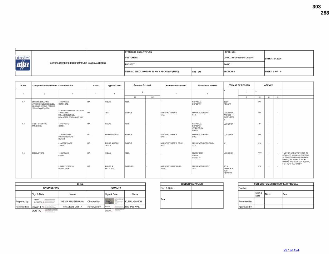
SYSTEM:
Sl No. Component & Operations Characteristics Class Type of Check Reference Document Acceptance NORMS
*
M C/N D M C N
1.7 OTHER INSULATING 1. SURFACE MA VISUAL 100% - - NO VISUAL TEST P/V - -MATERIALS LIKE SLEEVES, COND. ETC. DEFECTS REPORTBINDINGS CORDS, PAPERS,PRESS BOARDS ETC.
2.DIMENSION(BORE DIA, WALLTHICKNESS, MA TEST SAMPLE - MANUFACTURER'S MANUFACTURER'S LOG BOOK P/V - -BDV AS RECEIVED, STD. STD. AND ORBDV AFTER FOLDING AT 180º SUPPLIER'S
TC
1.8 SHEET STAMPING 1. SURFACE MA VISUAL 100% - - NO VISUAL LOG BOOK P - -(PUNCHED) COND. DEFECTS
(FREE FROM BURS)
2.DIMENSIONS MA MEASUREMENT SAMPLE - MANUFACTURER'S MANUFACTURER'S LOG BOOK P/V - -INCLUDING BURS DRG. . DRG. HEIGHT
3. ACCEPTANCE MA ELECT. & MECH SAMPLE - MANUFACTURER'S DRG./ MANUFACTURER'S DRG./ TC P/V - -TESTS TESTS STD. STD.
1.9 CONDUCTORS 1. SURFACE MA VISUAL 100% - - FREE FROM LOG BOOK *P/V - -FINISH VISUAL
DEFECTS
2.ELECT. PROP, & MA ELECT. & SAMPLES - MANUFACTURER'S DRG./ MANUFACTURER'S / TC & P/V - -MECH. PROP MECH.TEST SPEC. SPEC. VENDOR'S
TESTREPORTS
Sign & Date Doc No:
Sign & Date Name Sign & Date Name Sign & Date Seal
Prepared by: HEMA KHUSHWAHA Checked by: KUNAL GANDHI Reviewed by:
Reviewed by: PRAVEEN DUTTA Reviewed by: R K JAISWAL Approved by:
BIDDER/ SUPPLIER FOR CUSTOMER REVIEW & APPROVAL
Quantum Of check FORMAT OF RECORD AGENCY
SHEET 3 OF 9
7**
8
* MOTOR MANUFACTURER TO CONDUCT VISUAL CHECK FOR SURFACE FINISH ON RANDOM BASIS (10% SAMPLE) AT HIS WORKS AND MAINTAIN RECORD FOR VERIFICATION BY
SECTION: II
MANUFACTURER/ BIDDER/ SUPPLIER NAME & ADDRESS
STANDARD QUALITY PLAN SPEC. NO :
DATE:17.04.2020CUSTOMER : QP NO.: PE-QP-999-Q-007, REV-04
PROJECT: PO NO.:
ITEM: AC ELECT. MOTORS 55 KW & ABOVE (LV (415V))
1 2 3 4 56
Seal
Name
BHEL ENGINEERING QUALITY
9
HEMA KUSHWAHA
Digitally signed by HEMA KUSHWAHA DN: cn=HEMA KUSHWAHA, o=BHEL, ou=PEM-ELECT, [email protected], c=IN Date: 2020.10.08 12:03:48 +05'30'
PRAVEEN DUTTA
Digitally signed by PRAVEEN DUTTA DN: c=IN, o=BHARAT HEAVY ELECTRICALS LIMITED, ou=PS PEM, postalCode=201301, st=UTTAR PRADESH, 2.5.4.20=da8948aa0c3e2703a98a0aacaa2aedd61dd68dbef4c976429c5c374e3b47b930, cn=PRAVEEN DUTTA Date: 2020.10.08 19:01:33 +05'30'
Digitally signed by Kunal Gandhi DN: cn=Kunal Gandhi, o=BHEL, ou=PEM, [email protected], c=IN Date: 2020.10.09 10:14:42 +05'30'
RITESH KUMAR JAISWAL
Digitally signed by RITESH KUMAR JAISWAL DN: c=IN, o=Bharat Heavy Electricals Ltd, ou=BHEL / PS-PEM, postalCode=201301, st=Uttar Pradesh, 2.5.4.20=16692a281523bf78b46a8e18c5cd0bb189777532609b5349ae8d7191a9e51174, serialNumber=8cfaddf001b4875a8b03a31b000e93ff205304f62c650e6d5f9d9980e09bc448, cn=RITESH KUMAR JAISWAL Date: 2020.10.09 10:28:47 +05'30'
297 of 424
288672/2021/PS-PEM-MAX303
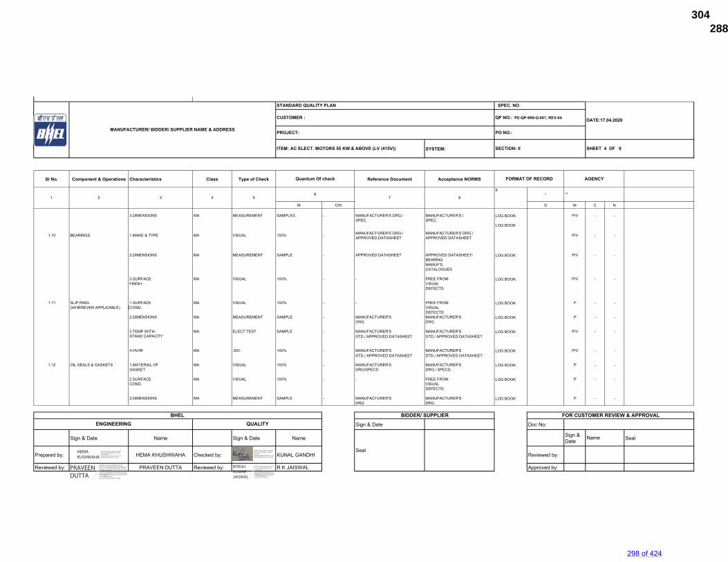
SYSTEM:
Sl No. Component & Operations Characteristics Class Type of Check Reference Document Acceptance NORMS
*
M C/N D M C N
3.DIMENSIONS MA MEASUREMENT SAMPLES - MANUFACTURER'S DRG./ MANUFACTURER'S / LOG BOOK P/V - -SPEC. SPEC.
1.10 BEARINGS 1.MAKE & TYPE MA VISUAL 100% - MANUFACTURER'S DRG./ APPROVED DATASHEET
MANUFACTURER'S DRG./ APPROVED DATASHEET
LOG BOOK
P/V - -
2.DIMENSIONS MA MEASUREMENT SAMPLE - APPROVED DATASHEET APPROVED DATASHEET/ LOG BOOK P/V - -BEARINGMANUF'SCATALOGUES
3.SURFACE MA VISUAL 100% - - FREE FROM LOG BOOK P/V - -FINISH VISUAL
DEFECTS
1.11 SLIP RING 1.SURFACE MA VISUAL 100% - - FREE FROM LOG BOOK P - -(WHEREVER APPLICABLE) COND. VISUAL
DEFECTS2.DIMENSIONS MA MEASUREMENT SAMPLE - MANUFACTURER'S MANUFACTURER'S LOG BOOK P - -
DRG DRG
3.TEMP.WITH- MA ELECT.TEST SAMPLE - MANUFACTURER'S MANUFACTURER'S LOG BOOK P/V - -STAND CAPACITY STD./ APPROVED DATASHEET STD./ APPROVED DATASHEET
4.HV/IR MA -DO- 100% - MANUFACTURER'S MANUFACTURER'S LOG BOOK P/V - -STD./ APPROVED DATASHEET STD./ APPROVED DATASHEET
1.12 OIL SEALS & GASKETS 1.MATERIAL OF MA VISUAL 100% - MANUFACTURER'S MANUFACTURER'S LOG BOOK P - -GASKET DRG/SPECS DRG./ SPECS.
2.SURFACE MA VISUAL 100% - - FREE FROM LOG BOOK P - -COND. VISUAL
DEFECTS
3.DIMENSIONS MA MEASUREMENT SAMPLE - MANUFACTURER'S MANUFACTURER'S LOG BOOK P - -DRG DRG
Sign & Date Doc No:
Sign & Date Name Sign & Date Name Sign & Date Seal
Prepared by: HEMA KHUSHWAHA Checked by: KUNAL GANDHI Reviewed by:
Reviewed by: PRAVEEN DUTTA Reviewed by: R K JAISWAL Approved by:
BIDDER/ SUPPLIER FOR CUSTOMER REVIEW & APPROVAL
MANUFACTURER/ BIDDER/ SUPPLIER NAME & ADDRESS
STANDARD QUALITY PLAN SPEC. NO :
DATE:17.04.2020CUSTOMER : QP NO.: PE-QP-999-Q-007, REV-04
PROJECT: PO NO.:
ITEM: AC ELECT. MOTORS 55 KW & ABOVE (LV (415V)) SECTION: II SHEET 4 OF 9
Quantum Of check FORMAT OF RECORD AGENCY
26
7 8
9**
Seal
Name
1 3 4 5
BHEL ENGINEERING QUALITY
HEMA KUSHWAHA
Digitally signed by HEMA KUSHWAHA DN: cn=HEMA KUSHWAHA, o=BHEL, ou=PEM-ELECT, [email protected], c=IN Date: 2020.10.08 12:04:13 +05'30'
PRAVEEN DUTTA
Digitally signed by PRAVEEN DUTTA DN: c=IN, o=BHARAT HEAVY ELECTRICALS LIMITED, ou=PS PEM, postalCode=201301, st=UTTAR PRADESH, 2.5.4.20=da8948aa0c3e2703a98a0aacaa2aedd61dd68dbef4c976429c5c374e3b47b930, cn=PRAVEEN DUTTA Date: 2020.10.08 19:02:03 +05'30'
Digitally signed by Kunal Gandhi DN: cn=Kunal Gandhi, o=BHEL, ou=PEM, [email protected], c=IN Date: 2020.10.09 10:15:21 +05'30'
RITESH KUMAR JAISWAL
Digitally signed by RITESH KUMAR JAISWAL DN: c=IN, o=Bharat Heavy Electricals Ltd, ou=BHEL / PS-PEM, postalCode=201301, st=Uttar Pradesh, 2.5.4.20=16692a281523bf78b46a8e18c5cd0bb189777532609b5349ae8d7191a9e51174, serialNumber=8cfaddf001b4875a8b03a31b000e93ff205304f62c650e6d5f9d9980e09bc448, cn=RITESH KUMAR JAISWAL Date: 2020.10.09 10:29:53 +05'30'
298 of 424
288672/2021/PS-PEM-MAX304
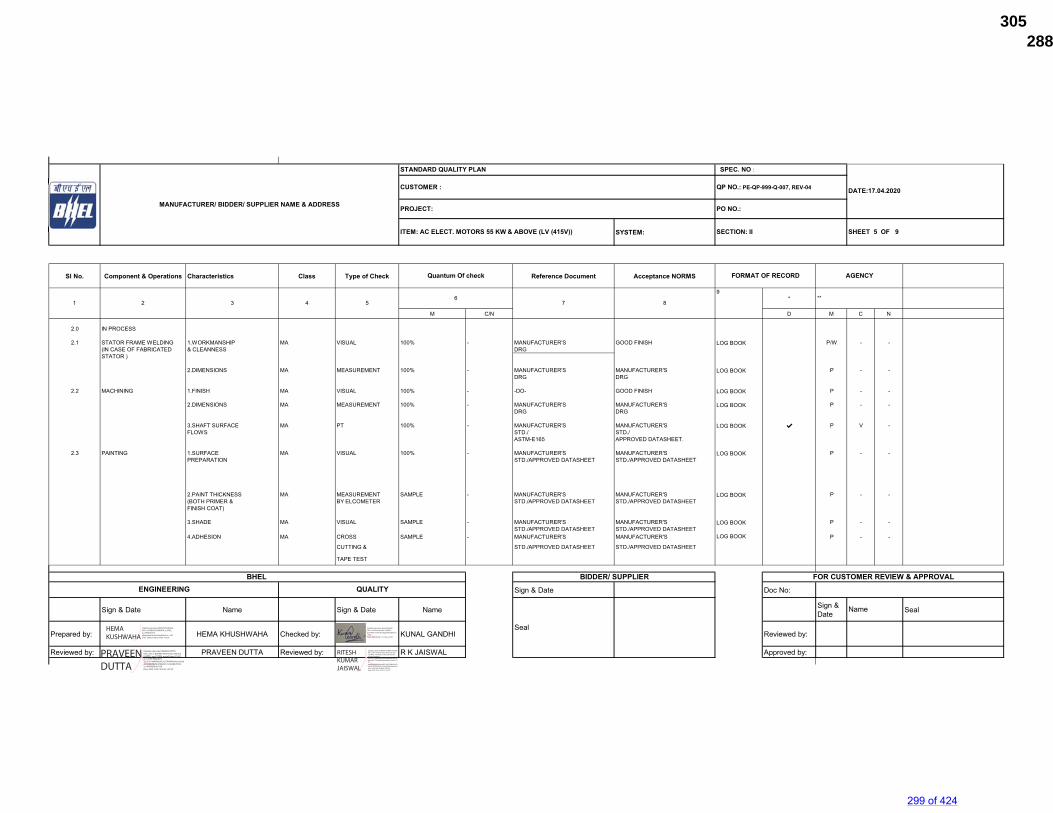
SYSTEM:
Sl No. Component & Operations Characteristics Class Type of Check Reference Document Acceptance NORMS
*
M C/N D M C N
2.0 IN PROCESS
2.1 STATOR FRAME WELDING 1.WORKMANSHIP MA VISUAL 100% - MANUFACTURER'S GOOD FINISH LOG BOOK P/W - -(IN CASE OF FABRICATED & CLEANNESS DRGSTATOR )
2.DIMENSIONS MA MEASUREMENT 100% - MANUFACTURER'S MANUFACTURER'S LOG BOOK P - -DRG DRG
2.2 MACHINING 1.FINISH MA VISUAL 100% - -DO- GOOD FINISH LOG BOOK P - -
2.DIMENSIONS MA MEASUREMENT 100% - MANUFACTURER'S MANUFACTURER'S LOG BOOK P - -DRG DRG
3.SHAFT SURFACE MA PT 100% - MANUFACTURER'S MANUFACTURER'S LOG BOOK ✔ P V -FLOWS STD./ STD./
ASTM-E165 APPROVED DATASHEET.
2.3 PAINTING 1.SURFACE MA VISUAL 100% - MANUFACTURER'S MANUFACTURER'S LOG BOOK P - -PREPARATION STD./APPROVED DATASHEET STD./APPROVED DATASHEET
2.PAINT THICKNESS MA MEASUREMENT SAMPLE - MANUFACTURER'S MANUFACTURER'S LOG BOOK P - -(BOTH PRIMER & BY ELCOMETER STD./APPROVED DATASHEET STD./APPROVED DATASHEETFINISH COAT)
3.SHADE MA VISUAL SAMPLE - MANUFACTURER'S MANUFACTURER'S LOG BOOK P - -STD./APPROVED DATASHEET STD./APPROVED DATASHEET
4.ADHESION MA CROSS SAMPLE - MANUFACTURER'S MANUFACTURER'S LOG BOOK P - -
CUTTING & STD./APPROVED DATASHEET STD./APPROVED DATASHEET
TAPE TEST
Sign & Date Doc No:
Sign & Date Name Sign & Date Name Sign & Date Seal
Prepared by: HEMA KHUSHWAHA Checked by: KUNAL GANDHI Reviewed by:
Reviewed by: PRAVEEN DUTTA Reviewed by: R K JAISWAL Approved by:
BIDDER/ SUPPLIER FOR CUSTOMER REVIEW & APPROVAL
MANUFACTURER/ BIDDER/ SUPPLIER NAME & ADDRESS
STANDARD QUALITY PLAN SPEC. NO :
DATE:17.04.2020
**
CUSTOMER : QP NO.: PE-QP-999-Q-007, REV-04
PROJECT: PO NO.:
ITEM: AC ELECT. MOTORS 55 KW & ABOVE (LV (415V)) SECTION: II
AGENCY
1 2 3 4 5 7 8
9
Quantum Of check FORMAT OF RECORD
SHEET 5 OF 9
6
Seal
Name
BHEL ENGINEERING QUALITY
HEMA KUSHWAHA
Digitally signed by HEMA KUSHWAHA DN: cn=HEMA KUSHWAHA, o=BHEL, ou=PEM-ELECT, [email protected], c=IN Date: 2020.10.08 12:04:39 +05'30'
PRAVEEN DUTTA
Digitally signed by PRAVEEN DUTTA DN: c=IN, o=BHARAT HEAVY ELECTRICALS LIMITED, ou=PS PEM, postalCode=201301, st=UTTAR PRADESH, 2.5.4.20=da8948aa0c3e2703a98a0aacaa2aedd61dd68dbef4c976429c5c374e3b47b930, cn=PRAVEEN DUTTA Date: 2020.10.08 19:02:42 +05'30'
Digitally signed by Kunal Gandhi DN: cn=Kunal Gandhi, o=BHEL, ou=PEM, [email protected], c=IN Date: 2020.10.09 10:17:42 +05'30'
RITESH KUMAR JAISWAL
Digitally signed by RITESH KUMAR JAISWAL DN: c=IN, o=Bharat Heavy Electricals Ltd, ou=BHEL / PS-PEM, postalCode=201301, st=Uttar Pradesh, 2.5.4.20=16692a281523bf78b46a8e18c5cd0bb189777532609b5349ae8d7191a9e51174, serialNumber=8cfaddf001b4875a8b03a31b000e93ff205304f62c650e6d5f9d9980e09bc448, cn=RITESH KUMAR JAISWAL Date: 2020.10.09 10:30:21 +05'30'
299 of 424
288672/2021/PS-PEM-MAX305
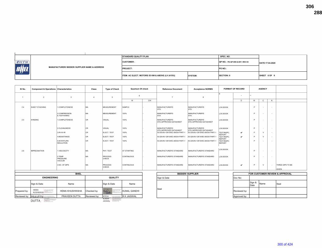
SYSTEM:
Sl No. Component & Operations Characteristics Class Type of Check Reference Document Acceptance NORMS
*
M C/N D M C N
2.4 SHEET STACKING 1.COMPLETENESS MA MEASUREMENT SAMPLE - MANUFACTURER'S MANUFACTURER'S LOG BOOK P - -STD. STD.
2.COMPRESSION MA MEASUREMENT 100% - MANUFACTURER'S MANUFACTURER'S LOG BOOK P - -& TIGHTENING STD. STD.
2.5 WINDING 1.COMPLETENESS CR VISUAL 100% - MANUFACTURER'S MANUFACTURER'S LOG BOOK P - -STD./APPROVED DATASHEET STD./APPROVED DATASHEET
2.CLEANLINESS CR VISUAL 100% - MANUFACTURER'S MANUFACTURER'S LOG BOOK P - -STD./APPROVED DATASHEET STD./APPROVED DATASHEET
3.IR-HV-IR CR ELECT. TEST 100% - IS-325//IS-12615/IEC-60034 PART-1 IS-325//IS-12615/IEC-60034 PART-1 TEST/INSPC. ✔ P V -REPORT
4.RESISTANCE CR ELECT. TEST 100% - IS-325//IS-12615/IEC-60034 PART-1 IS-325//IS-12615/IEC-60034 PART-1 TEST/INSPC. ✔ P V -REPORT
5.INTERTURN CR ELECT. TEST 100% - IS-325//IS-12615/IEC-60034 PART-1 IS-325//IS-12615/IEC-60034 PART-1 TEST/INSPC. P - -INSULATION REPORT
2.6 IMPREGNATION 1.VISCOSCITY MA PHY. TEST AT STARTING - MANUFACTURER'S STANDARD MANUFACTURER'S STANDARDLOG BOOK
P - -
2.TEMP. MA PROCESS CONTINUOUS - MANUFACTURER'S STANDARD MANUFACTURER'S STANDARD LOG BOOK P - -PRESSURE CHECKVACCUM
3.NO. OF DIPS MA PROCESS CONTINUOUS - MANUFACTURER'S STANDARD MANUFACTURER'S STANDARD LOG BOOK ✔ P V - THREE DIPS TO BE CHECK
GIVEN
Sign & Date Doc No:
Sign & Date Name Sign & Date Name Sign & Date Seal
Prepared by: HEMA KHUSHWAHA Checked by: KUNAL GANDHI Reviewed by:
Reviewed by: PRAVEEN DUTTA Reviewed by: R K JAISWAL Approved by:
FOR CUSTOMER REVIEW & APPROVAL
ITEM: AC ELECT. MOTORS 55 KW & ABOVE (LV (415V))
BIDDER/ SUPPLIER
STANDARD QUALITY PLAN
AGENCY
MANUFACTURER/ BIDDER/ SUPPLIER NAME & ADDRESS
SPEC. NO :
DATE:17.04.2020CUSTOMER : QP NO.: PE-QP-999-Q-007, REV-04
PROJECT: PO NO.:
SECTION: II SHEET 6 OF 9
1 2 3 4 5
Seal
Name
BHEL ENGINEERING QUALITY
Quantum Of check FORMAT OF RECORD
8
9**
76
HEMA KUSHWAHA
Digitally signed by HEMA KUSHWAHA DN: cn=HEMA KUSHWAHA, o=BHEL, ou=PEM-ELECT, [email protected], c=IN Date: 2020.10.08 12:05:02 +05'30'
PRAVEEN DUTTA
Digitally signed by PRAVEEN DUTTA DN: c=IN, o=BHARAT HEAVY ELECTRICALS LIMITED, ou=PS PEM, postalCode=201301, st=UTTAR PRADESH, 2.5.4.20=da8948aa0c3e2703a98a0aacaa2aedd61dd68dbef4c976429c5c374e3b47b930, cn=PRAVEEN DUTTA Date: 2020.10.08 19:03:18 +05'30'
Digitally signed by Kunal Gandhi DN: cn=Kunal Gandhi, o=BHEL, ou=PEM, [email protected], c=IN Date: 2020.10.09 10:17:59 +05'30'
RITESH KUMAR JAISWAL
Digitally signed by RITESH KUMAR JAISWAL DN: c=IN, o=Bharat Heavy Electricals Ltd, ou=BHEL / PS-PEM, postalCode=201301, st=Uttar Pradesh, 2.5.4.20=16692a281523bf78b46a8e18c5cd0bb189777532609b5349ae8d7191a9e51174, serialNumber=8cfaddf001b4875a8b03a31b000e93ff205304f62c650e6d5f9d9980e09bc448, cn=RITESH KUMAR JAISWAL Date: 2020.10.09 10:31:31 +05'30'
300 of 424
288672/2021/PS-PEM-MAX306
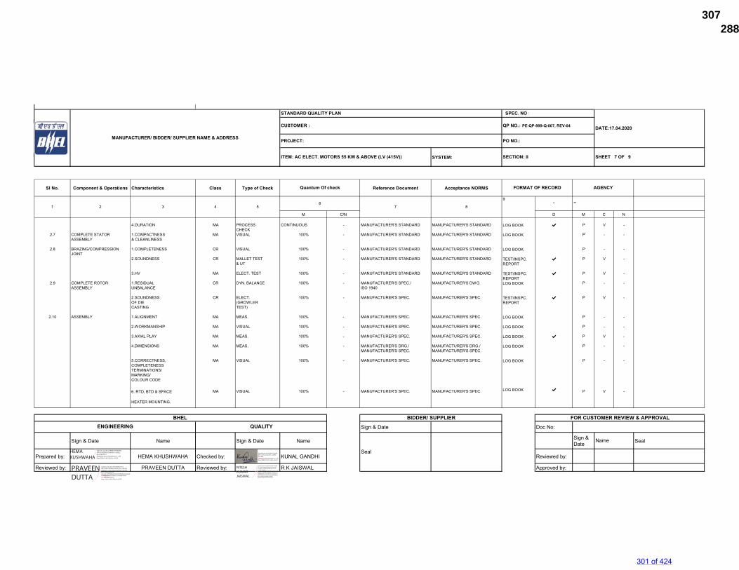
SYSTEM:
Sl No. Component & Operations Characteristics Class Type of Check Reference Document Acceptance NORMS
*
M C/N D M C N
4.DURATION MA PROCESS CONTINUOUS - MANUFACTURER'S STANDARD MANUFACTURER'S STANDARD LOG BOOK ✔ P V -CHECK
2.7 COMPLETE STATOR 1.COMPACTNESS MA VISUAL 100% - MANUFACTURER'S STANDARD MANUFACTURER'S STANDARD LOG BOOK P - -ASSEMBLY & CLEANLINESS
2.8 BRAZING/COMPRESSION 1.COMPLETENESS CR VISUAL 100% - MANUFACTURER'S STANDARD MANUFACTURER'S STANDARD LOG BOOK P - -JOINT
2.SOUNDNESS CR MALLET TEST 100% - MANUFACTURER'S STANDARD MANUFACTURER'S STANDARD TEST/INSPC. ✔ P V -& UT REPORT
3.HV MA ELECT. TEST 100% - MANUFACTURER'S STANDARD MANUFACTURER'S STANDARD TEST/INSPC. ✔ P V -REPORT
2.9 COMPLETE ROTOR 1.RESIDUAL CR DYN. BALANCE 100% - MANUFACTURER'S SPEC./ MANUFACTURER'S DWG. LOG BOOK P - -ASSEMBLY UNBALANCE ISO 1940
2.SOUNDNESS CR ELECT. 100% - MANUFACTURER'S SPEC. MANUFACTURER'S SPEC. TEST/INSPC. ✔ P V -OF DIE (GROWLER REPORTCASTING TEST)
2.10 ASSEMBLY 1.ALIGNMENT MA MEAS. 100% - MANUFACTURER'S SPEC. MANUFACTURER'S SPEC. LOG BOOK P - -
2.WORKMANSHIP MA VISUAL 100% - MANUFACTURER'S SPEC. MANUFACTURER'S SPEC. LOG BOOK P - -
3.AXIAL PLAY MA MEAS. 100% - MANUFACTURER'S SPEC. MANUFACTURER'S SPEC. LOG BOOK ✔ P V -
4.DIMENSIONS MA MEAS. 100% - MANUFACTURER'S DRG./ MANUFACTURER'S DRG./ LOG BOOK P - -MANUFACTURER'S SPEC. MANUFACTURER'S SPEC.
5.CORRECTNESS, MA VISUAL 100% - MANUFACTURER'S SPEC. MANUFACTURER'S SPEC. LOG BOOK P - -COMPLETENESSTERMINATIONS/MARKING/COLOUR CODE
6. RTD, BTD & SPACE MA VISUAL 100% - MANUFACTURER'S SPEC. MANUFACTURER'S SPEC. LOG BOOK ✔ P V -
HEATER MOUNTING.
Sign & Date Doc No:
Sign & Date Name Sign & Date Name Sign & Date Seal
Prepared by: HEMA KHUSHWAHA Checked by: KUNAL GANDHI Reviewed by:
Reviewed by: PRAVEEN DUTTA Reviewed by: R K JAISWAL Approved by:
ITEM: AC ELECT. MOTORS 55 KW & ABOVE (LV (415V)) SECTION: II
PROJECT: PO NO.:
DATE:17.04.2020CUSTOMER : QP NO.: PE-QP-999-Q-007, REV-04
AGENCY
FOR CUSTOMER REVIEW & APPROVALENGINEERING
1 2
MANUFACTURER/ BIDDER/ SUPPLIER NAME & ADDRESS
STANDARD QUALITY PLAN SPEC. NO :
SHEET 7 OF 9
BIDDER/ SUPPLIERBHEL
8
9
Quantum Of check FORMAT OF RECORD
QUALITY
63
**4 5 7
Seal
Name
HEMA KUSHWAHA
Digitally signed by HEMA KUSHWAHA DN: cn=HEMA KUSHWAHA, o=BHEL, ou=PEM-ELECT, [email protected], c=IN Date: 2020.10.08 12:05:25 +05'30'
PRAVEEN DUTTA
Digitally signed by PRAVEEN DUTTA DN: c=IN, o=BHARAT HEAVY ELECTRICALS LIMITED, ou=PS PEM, postalCode=201301, st=UTTAR PRADESH, 2.5.4.20=da8948aa0c3e2703a98a0aacaa2aedd61dd68dbef4c976429c5c374e3b47b930, cn=PRAVEEN DUTTA Date: 2020.10.08 19:03:54 +05'30'
Digitally signed by Kunal Gandhi DN: cn=Kunal Gandhi, o=BHEL, ou=PEM, [email protected], c=IN Date: 2020.10.09 10:18:20 +05'30'
RITESH KUMAR JAISWAL
Digitally signed by RITESH KUMAR JAISWAL DN: c=IN, o=Bharat Heavy Electricals Ltd, ou=BHEL / PS-PEM, postalCode=201301, st=Uttar Pradesh, 2.5.4.20=16692a281523bf78b46a8e18c5cd0bb189777532609b5349ae8d7191a9e51174, serialNumber=8cfaddf001b4875a8b03a31b000e93ff205304f62c650e6d5f9d9980e09bc448, cn=RITESH KUMAR JAISWAL Date: 2020.10.09 10:32:25 +05'30'
301 of 424
288672/2021/PS-PEM-MAX307
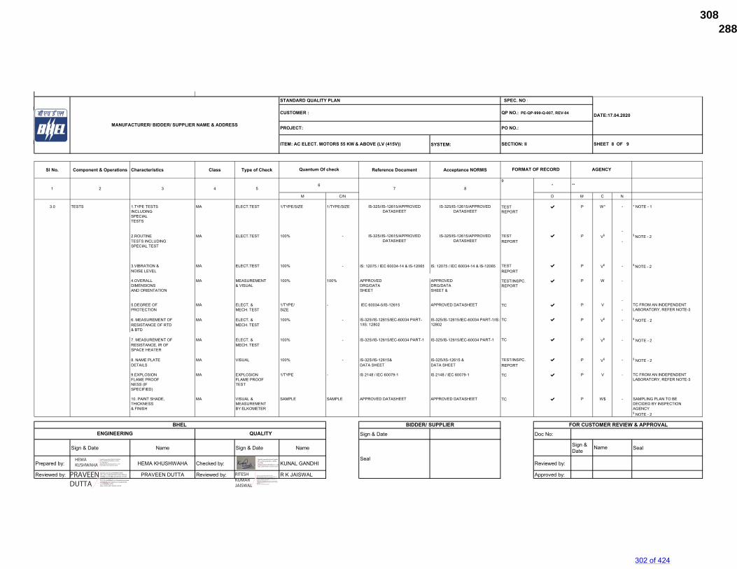
SYSTEM:
Sl No. Component & Operations Characteristics Class Type of Check Reference Document Acceptance NORMS
*
M C/N D M C N
3.0 TESTS 1.TYPE TESTS MA ELECT.TEST 1/TYPE/SIZE 1/TYPE/SIZE TEST ✔ P W* - * NOTE - 1INCLUDING REPORTSPECIALTESTS
-2.ROUTINE MA ELECT.TEST 100% - TEST ✔ P V$ $ NOTE - 2TESTS INCLUDING REPORT -SPECIAL TEST
3.VIBRATION & MA ELECT.TEST 100% - IS: 12075 / IEC 60034-14 & IS-12065 IS: 12075 / IEC 60034-14 & IS-12065 TEST ✔ P V$ - $ NOTE - 2NOISE LEVEL REPORT
4.OVERALL MA MEASUREMENT 100% 100% APPROVED APPROVED TEST/INSPC. ✔ P W -DIMENSIONS & VISUAL DRG/DATA DRG/DATA REPORTAND ORIENTATION SHEET SHEET &
-5.DEGREE OF MA ELECT. & 1/TYPE/ - IEC 60034-5/IS-12615 APPROVED DATASHEET TC ✔ P VPROTECTION MECH. TEST SIZE -
6. MEASUREMENT OF MA ELECT. & 100% - TC ✔ P V$ - $ NOTE - 2RESISTANCE OF RTD MECH. TEST& BTD
7. MEASUREMENT OF MA ELECT. & 100% - IS-325//IS-12615/IEC-60034 PART-1 IS-325/IS-12615/IEC-60034 PART-1 TC ✔ P V$ - $ NOTE - 2RESISTANCE, IR OF MECH. TESTSPACE HEATER
8. NAME PLATE MA VISUAL 100% - IS-325//IS-12615& IS-325//IS-12615 & TEST/INSPC. ✔ P V$ - $ NOTE - 2DETAILS DATA SHEET DATA SHEET REPORT
9.EXPLOSION MA EXPLOSION 1/TYPE - IS 2148 / IEC 60079-1 IS 2148 / IEC 60079-1 TC ✔ P V -FLAME PROOF FLAME PROOFNESS (IF TESTSPECIFIED)
10. PAINT SHADE, MA VISUAL & SAMPLE SAMPLE APPROVED DATASHEET APPROVED DATASHEET TC ✔ P W$ - SAMPLING PLAN TO BETHICKNESS MEASUREMENT DECIDED BY INSPECTION& FINISH BY ELKOMETER AGENCY
$ NOTE - 2
Sign & Date Doc No:
Sign & Date Name Sign & Date Name Sign & Date Seal
Prepared by: HEMA KHUSHWAHA Checked by: KUNAL GANDHI Reviewed by:
Reviewed by: PRAVEEN DUTTA Reviewed by: R K JAISWAL Approved by:
TC FROM AN INDEPENDENT LABORATORY, REFER NOTE-3
TC FROM AN INDEPENDENT LABORATORY, REFER NOTE-3
IS-325//IS-12615/APPROVED DATASHEET
IS-325/IS-12615/APPROVED DATASHEET
MANUFACTURER/ BIDDER/ SUPPLIER NAME & ADDRESS
STANDARD QUALITY PLAN SPEC. NO :
DATE:17.04.2020CUSTOMER :
AGENCY
8
9
1 2 3 4 56 **
QP NO.: PE-QP-999-Q-007, REV-04
PROJECT: PO NO.:
ITEM: AC ELECT. MOTORS 55 KW & ABOVE (LV (415V)) SECTION: II SHEET 8 OF 9
Quantum Of check FORMAT OF RECORD
7
BHEL ENGINEERING QUALITY
Seal
Name
FOR CUSTOMER REVIEW & APPROVALBIDDER/ SUPPLIER
IS-325/IS-12615/APPROVED DATASHEET
IS-325/IS-12615/IEC-60034 PART-1/IS: 12802
IS-325//IS-12615/IEC-60034 PART-1/IS: 12802
IS-325//IS-12615/APPROVED DATASHEET
HEMA KUSHWAHA
Digitally signed by HEMA KUSHWAHA DN: cn=HEMA KUSHWAHA, o=BHEL, ou=PEM-ELECT, [email protected], c=IN Date: 2020.10.08 12:05:48 +05'30'
PRAVEEN DUTTA
Digitally signed by PRAVEEN DUTTA DN: c=IN, o=BHARAT HEAVY ELECTRICALS LIMITED, ou=PS PEM, postalCode=201301, st=UTTAR PRADESH, 2.5.4.20=da8948aa0c3e2703a98a0aacaa2aedd61dd68dbef4c976429c5c374e3b47b930, cn=PRAVEEN DUTTA Date: 2020.10.08 19:04:18 +05'30'
Digitally signed by Kunal Gandhi DN: cn=Kunal Gandhi, o=BHEL, ou=PEM, [email protected], c=IN Date: 2020.10.09 10:18:39 +05'30'
RITESH KUMAR JAISWAL
Digitally signed by RITESH KUMAR JAISWAL DN: c=IN, o=Bharat Heavy Electricals Ltd, ou=BHEL / PS-PEM, postalCode=201301, st=Uttar Pradesh, 2.5.4.20=16692a281523bf78b46a8e18c5cd0bb189777532609b5349ae8d7191a9e51174, serialNumber=8cfaddf001b4875a8b03a31b000e93ff205304f62c650e6d5f9d9980e09bc448, cn=RITESH KUMAR JAISWAL Date: 2020.10.09 10:32:50 +05'30'
302 of 424
288672/2021/PS-PEM-MAX308
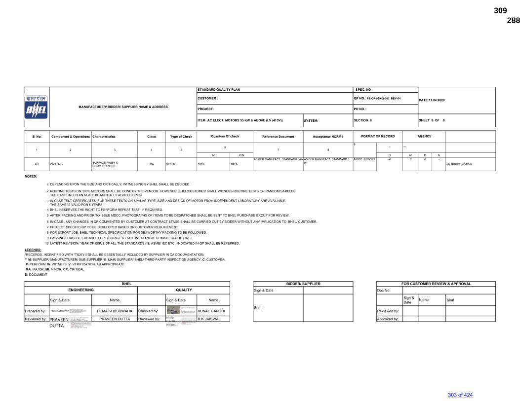
SYSTEM:
Sl No. Component & Operations Characteristics Class Type of Check Reference Document Acceptance NORMS
*
M C/N D M C N
4.0 PACKING SURFACE FINISH & COMPLETENESS
MA VISUAL 100% 100%
AS PER MANUFACT. STANDARD / (#) AS PER MANUFACT. STANDARD / (#)
INSPC. REPORT ✔ P W -
(#): REFER NOTE-8
NOTES:
1 DEPENDING UPON THE SIZE AND CRITICALLY, WITNESSING BY BHEL SHALL BE DECIDED.
2 ROUTINE TESTS ON 100% MOTORS SHALL BE DONE BY THE VENDOR. HOWEVER, BHEL/CUSTOMER SHALL WITNESS ROUTINE TESTS ON RANDOM SAMPLES.THE SAMPLING PLAN SHALL BE MUTUALLY AGREED UPON.
3 IN CASE TEST CERTIFICATES FOR THESE TESTS ON SIMILAR TYPE, SIZE AND DESIGN OF MOTOR FROM INDEPENDENT LABORATORY ARE AVAILABLE, THE SAME IS VALID FOR 5 YEARS.
4 BHEL RESERVES THE RIGHT TO PERFORM REPEAT TEST, IF REQUIRED.
5 AFTER PACKING AND PRIOR TO ISSUE MDCC, PHOTOGRAPHS OF ITEMS TO BE DESPATCHED SHALL BE SENT TO BHEL PURCHASE GROUP FOR REVIEW.
6 IN CASE , ANY CHANGES IN QP COMMENTED BY CUSTOMER AT CONTRACT STAGE SHALL BE CARRIED OUT BY BIDDER WITHOUT ANY IMPLICATION TO BHEL/ CUSTOMER.7 PROJECT SPECIFIC QP TO BE DEVELOPED BASED ON CUSTOMER REQUIREMENT.8 FOR EXPORT JOB, BHEL TECHNICAL SPECIFICATION FOR SEAWORTHY PACKING TO BE FOLLOWED.9 PACKING SHALL BE SUITABLE FOR STORAGE AT SITE IN TROPICAL CLIMATE CONDITIONS.
10 LATEST REVISION/ YEAR OF ISSUE OF ALL THE STANDARDS (IS/ ASME/ IEC ETC.) INDICATED IN QP SHALL BE REFERRED.
LEGENDS:*RECORDS, INDENTIFIED WITH "TICK"(√) SHALL BE ESSENTIALLY INCLUDED BY SUPPLIER IN QA DOCUMENTATION,** M: SUPPLIER/ MANUFACTURER/ SUB-SUPPLIER, B: MAIN SUPPLIER/ BHEL/ THIRD PARTY INSPECTION AGENCY, C: CUSTOMER, P: PERFORM, W: WITNESS, V: VERIFICATION, AS APPROPRIATE MA: MAJOR, MI: MINOR, CR: CRITICALD: DOCUMENT
Sign & Date Doc No:
Sign & Date Name Sign & Date Name Sign & Date Seal
Prepared by: HEMA KHUSHWAHA Checked by: KUNAL GANDHI Reviewed by:
Reviewed by: PRAVEEN DUTTA Reviewed by: R K JAISWAL Approved by:
SPEC. NO :
DATE:17.04.2020
ENGINEERING QUALITY
Seal
Name
PROJECT:
BHEL BIDDER/ SUPPLIER FOR CUSTOMER REVIEW & APPROVAL
SHEET 9 OF 9
FORMAT OF RECORD AGENCY
6
Quantum Of check
2
9**
SECTION: II
7 81
STANDARD QUALITY PLAN
ITEM: AC ELECT. MOTORS 55 KW & ABOVE (LV (415V))
QP NO.: PE-QP-999-Q-007, REV-04CUSTOMER :
3 4 5
PO NO.:MANUFACTURER/ BIDDER/ SUPPLIER NAME & ADDRESS
HEMA KUSHWAHADigitally signed by HEMA KUSHWAHA DN: cn=HEMA KUSHWAHA, o=BHEL, ou=PEM-ELECT, [email protected], c=IN Date: 2020.10.08 12:06:08 +05'30'
PRAVEEN DUTTA
Digitally signed by PRAVEEN DUTTA DN: c=IN, o=BHARAT HEAVY ELECTRICALS LIMITED, ou=PS PEM, postalCode=201301, st=UTTAR PRADESH, 2.5.4.20=da8948aa0c3e2703a98a0aacaa2aedd61dd68dbef4c976429c5c374e3b47b930, cn=PRAVEEN DUTTA Date: 2020.10.08 19:05:11 +05'30'
Digitally signed by Kunal Gandhi DN: cn=Kunal Gandhi, o=BHEL, ou=PEM, [email protected], c=IN Date: 2020.10.09 10:19:41 +05'30'
RITESH KUMAR JAISWAL
Digitally signed by RITESH KUMAR JAISWAL DN: c=IN, o=Bharat Heavy Electricals Ltd, ou=BHEL / PS-PEM, postalCode=201301, st=Uttar Pradesh, 2.5.4.20=16692a281523bf78b46a8e18c5cd0bb189777532609b5349ae8d7191a9e51174, serialNumber=8cfaddf001b4875a8b03a31b000e93ff205304f62c650e6d5f9d9980e09bc448, cn=RITESH KUMAR JAISWAL Date: 2020.10.09 10:33:43 +05'30'
303 of 424
288672/2021/PS-PEM-MAX309
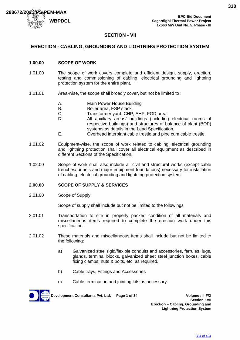
WBPDCL EPC Bid Document
Sagardighi Thermal Power Project 1x660 MW Unit No. 5, Phase - III
Development Consultants Pvt. Ltd. Page 1 of 34 Volume : II-F/2
Section : VII Erection – Cabling, Grounding and
Lightning Protection System
SECTION - VII
ERECTION - CABLING, GROUNDING AND LIGHTNING PROTECTION SYSTEM
1.00.00 SCOPE OF WORK 1.01.00 The scope of work covers complete and efficient design, supply, erection,
testing and commissioning of cabling, electrical grounding and lightning protection system for the entire plant.
1.01.01 Area-wise, the scope shall broadly cover, but not be limited to :
A. Main Power House Building B. Boiler area, ESP stack C. Transformer yard, CHP, AHP, FGD area. D. All auxiliary areas/ buildings (including electrical rooms of
respective buildings) and structures of balance of plant (BOP) systems as details in the Lead Specification.
E. Overhead interplant cable trestle and pipe cum cable trestle. 1.01.02 Equipment-wise, the scope of work related to cabling, electrical grounding
and lightning protection shall cover all electrical equipment as described in different Sections of the Specification.
1.02.00 Scope of work shall also include all civil and structural works (except cable
trenches/tunnels and major equipment foundations) necessary for installation of cabling, electrical grounding and lightning protection system.
2.00.00 SCOPE OF SUPPLY & SERVICES 2.01.00 Scope of Supply Scope of supply shall include but not be limited to the followings 2.01.01 Transportation to site in properly packed condition of all materials and
miscellaneous items required to complete the erection work under this specification.
2.01.02 These materials and miscellaneous items shall include but not be limited to
the following: a) Galvanized steel rigid/flexible conduits and accessories, ferrules, lugs,
glands, terminal blocks, galvanized sheet steel junction boxes, cable fixing clamps, nuts & bolts, etc. as required.
b) Cable trays, Fittings and Accessories c) Cable termination and jointing kits as necessary.
304 of 424
288672/2021/PS-PEM-MAX310
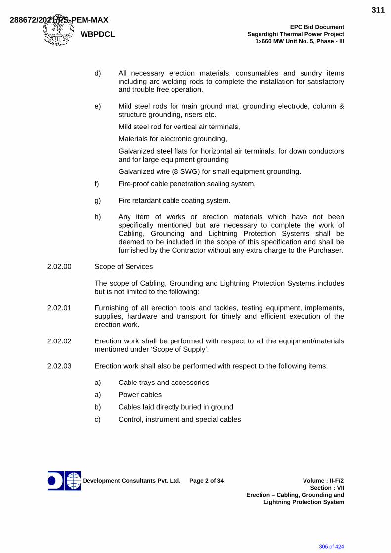
WBPDCL EPC Bid Document
Sagardighi Thermal Power Project 1x660 MW Unit No. 5, Phase - III
Development Consultants Pvt. Ltd. Page 2 of 34 Volume : II-F/2
Section : VII Erection – Cabling, Grounding and
Lightning Protection System
d) All necessary erection materials, consumables and sundry items
including arc welding rods to complete the installation for satisfactory and trouble free operation.
e) Mild steel rods for main ground mat, grounding electrode, column &
structure grounding, risers etc. Mild steel rod for vertical air terminals, Materials for electronic grounding, Galvanized steel flats for horizontal air terminals, for down conductors
and for large equipment grounding Galvanized wire (8 SWG) for small equipment grounding. f) Fire-proof cable penetration sealing system, g) Fire retardant cable coating system. h) Any item of works or erection materials which have not been
specifically mentioned but are necessary to complete the work of Cabling, Grounding and Lightning Protection Systems shall be deemed to be included in the scope of this specification and shall be furnished by the Contractor without any extra charge to the Purchaser.
2.02.00 Scope of Services
The scope of Cabling, Grounding and Lightning Protection Systems includes but is not limited to the following:
2.02.01 Furnishing of all erection tools and tackles, testing equipment, implements,
supplies, hardware and transport for timely and efficient execution of the erection work.
2.02.02 Erection work shall be performed with respect to all the equipment/materials
mentioned under ‘Scope of Supply’. 2.02.03 Erection work shall also be performed with respect to the following items: a) Cable trays and accessories a) Power cables b) Cables laid directly buried in ground c) Control, instrument and special cables
305 of 424
288672/2021/PS-PEM-MAX311
WBPDCL EPC Bid Document
Sagardighi Thermal Power Project 1x660 MW Unit No. 5, Phase - III
Development Consultants Pvt. Ltd. Page 3 of 34 Volume : II-F/2
Section : VII Erection – Cabling, Grounding and
Lightning Protection System
3.00.00 GENERAL REQUIREMENTS 3.01.00 Codes and Standards The electrical installation shall meet the requirements of Indian Electricity
Rules as amended up to date and relevant IS Code of Practice. In addition, other rules and regulations applicable to the work shall be followed.
3.02.00 Erection Schedule 3.02.01 The Bidder shall agree to adhere to the Owner’s Erection Schedule if such a
schedule is attached with the Specification. Alternatively, in case the target completion dates alone are indicated, the Bidder shall furnish detailed erection schedules (starting from zero date) with separate ‘S’ curves for Cabling, Grounding and Lightning Protection works.
3.02.02 The erection schedule, as approved by the OE shall be strictly followed by the
contractor. If the work is held-up for any reason, attributable to him or not, the same shall be brought immediately to the notice of the OE.
4.00.00 DESIGN CRITERIA 4.01.00 Grounding System 4.01.01 Grounding work shall be carried out in compliance to the following
standards/codes. All standards, specifications and codes of practice (COP) referred to herein shall be the latest editions including all amendments and revisions as on the date of opening of bid. In case of conflict between the specification and those standards/codes referred to herein, the former shall prevail:
a) Indian Electricity rules b) National Electrical Code c) Recommended practice for hot-dip galvanizing of iron and
steel IS 2629
d) Method of testing uniformity of coating on zinc coated articles IS 2633 e) COP for earthing IS 3043 f) Methods for determination of mass of zinc coating on zinc
coated iron and steel articles IS 6745
g) IEEE guide for safety in AC substation grounding IEEE 80 h) IEEE recommended practice for grounding of industrial and
commercial power systems IEEE 142
i) IEEE recommended practice for determining the electric power station ground potential rise and induced voltage from a power fault
IEEE 367
j) IEEE guide for instrumentation and control equipment grounding in generating stations
IEEE 1050
306 of 424
288672/2021/PS-PEM-MAX312
WBPDCL EPC Bid Document
Sagardighi Thermal Power Project 1x660 MW Unit No. 5, Phase - III
Development Consultants Pvt. Ltd. Page 4 of 34 Volume : II-F/2
Section : VII Erection – Cabling, Grounding and
Lightning Protection System
4.01.02 Basic design criteria are delineated below:
a) The station grounding system shall be an interconnected network of MS conductor and MS ground rods. The system shall (a) provide safety to personnel from contact of dangerous potential caused by ground fault, (b) ensure sufficient grounding current for effective relaying and (c) stabilize circuit potential with respect to ground.
b) The station grounding system shall be designed in compliance with the IEEE- 80/ IEEE- 665 considering fault current of 50kA for 1 sec. and shall be subject to approval of the Owner.
c) Actual soil resistivity measurement shall be carried out at proposed site during dry season.
d) The surface resistivity shall be considered as 3000 Ohm-meter for
gravel and 1000 Ohm-meter for concrete.
e) Major items of equipment, such as generator, switchgear, transformer, motor, relay panels and control panels etc shall have integral ground buses or connection points which shall be connected to the underground grid.
f) Electronic panels and equipment, where required, shall be grounded
utilizing an insulated ground wire connected in accordance with the manufacturer's recommendations. Where practical, electronics ground loops shall be avoided. Where this is not practical, isolation transformers shall be furnished. All indoor and outdoor electrical equipment and associated non-current carrying system, metal works, support structures, buildings columns, fence, neutrals, masts, arrestors, etc shall be connected to the plant ground system.
g) Instrumentation cable screens shall be single point bonded to the
instrument earth network to minimize the effects of electrical interference.
h) For Signal/case/intrinsically safe signal, grounding of control room
instruments, separate earth pit not connected to main ground grid shall be used. Control cabinets shall be connected to this separate earth pit.
i) A grounding conductor (steel wire armour in case of cables with outer
sheath) shall be routed parallel to all power conductors operating above 240 volts.
j) All ground wires installed in conduits shall be uninsulated.
k) Embedded grounding grid made of GI flat at basement/grade slab as
well as upper floor/suspended slabs shall be provided.
307 of 424
288672/2021/PS-PEM-MAX313
WBPDCL EPC Bid Document
Sagardighi Thermal Power Project 1x660 MW Unit No. 5, Phase - III
Development Consultants Pvt. Ltd. Page 5 of 34 Volume : II-F/2
Section : VII Erection – Cabling, Grounding and
Lightning Protection System
l) In addition mild steel ground pads at different locations i.e. on
wall/floor/ceiling inside the buildings/tunnels/trenches shall be provided. These pads will be in turn connected to below ground level earth mat through galvanized steel flat or riser. Each ground pad shall have provision for connection of at least two GI flats.
m) Treated earth pit shall be provided for system earthing at locations
where generator and transformer neutrals are grounded. Two pits shall be provided for each neutral.
n) Dedicated treated earth pit shall be provided for lightning protection
system.
o) Clean earthing for instrumentation shall be provided with dedicated earthing system and separate treated earth pits below the main control room, feed water pump house in turbine house etc.
p) Connection between the equipment earth lead and the grid conductor
shall be welded. For rust protection, the welds shall be treated with zinc chromate primer and coated with zinc rich paint.
In order to meet the above design criteria, ground grid mesh will be provided
for the main plant complex, viz., switchyard, transformer yard adjacent to power house building, power house building and boiler area up to stack, auxiliary buildings, etc. All electrical equipment, non-current carrying metal parts, structures, building steel, lightning protection system, generator/transformer neutrals will be connected to this station ground grid.
4.01.03 Other major design aspects that are to be considered for grounding system
are given below:
1. Ground Grid Conductor
i) Ground grid conductor of mild steel rod shall be used.
ii) The minimum conductor section is determined on the basis of ground fault current. This section is then increased by an allowance to account for the soil corrosion loss of 0.3 mm per year over the design life of 30 years. However, the minimum size shall be 1x40 mm dia mild steel conductor.
2. Underground Grid
i) The ground grid mesh is designed to keep the touch and step
voltages within safe limits as per recommendation of IEEE 80 & IEEE665.
308 of 424
288672/2021/PS-PEM-MAX314
WBPDCL EPC Bid Document
Sagardighi Thermal Power Project 1x660 MW Unit No. 5, Phase - III
Development Consultants Pvt. Ltd. Page 6 of 34 Volume : II-F/2
Section : VII Erection – Cabling, Grounding and
Lightning Protection System
ii) The ground grid conductors will be buried in earth at a minimum depth of 1000 mm. The length of ground conductors below earth will be sufficient to ensure a ground resistance less than 0.5 ohm.
iii) The ground grid conductor will be so laid as to provide short and
direct connection to building steel and major electrical equipment.
iv) Ground rods shall be provided at the points where system neutrals/lightning protections are connected to the ground grid.
v) All ground grid conductor connections will be welded type.
vi) Main Plant ground grid shall be connected with the other auxiliary
building /area ground grid at least at two (2) points.
vii) For test pits, the electrode will be 100 mm dia. Heavy duty C.I. pipe with perforations. Electrodes installed in test pits will have disconnecting facilities
3. Above-ground Connections
i) Galvanized steel flats shall be used for all connections above
earth.
ii) Inside building, ground conductors will be run for each floor supported on building steel and/or cable trays. These ground conductors in turn will be connected to the station ground grid through riser (at least two) coming up along building columns/cable shafts.
iii) Two separate and distinct ground connections will be provided for
each electrical equipment in compliance with I.E. Rules.
iv) All connections above ground will be welded type except connection to equipment/structures which shall be bolted type.
4. Equipment Ground Lead
Equipment ground connections will be sized to carry the available ground fault current. Considerations shall also be given to mechanical ruggedness of the connections and to limit the number of sizes.
5. Electronic Equipment Grounding
i) Internal ground connection of electronic panels shall be insulated
from the enclosure, frame, and chassis are to be terminated to an insulated ground bus.
ii) Insulated ground bus of all electronic panels shall be connected by insulated wire to an insulated common electronic ground bar.
309 of 424
288672/2021/PS-PEM-MAX315
WBPDCL EPC Bid Document
Sagardighi Thermal Power Project 1x660 MW Unit No. 5, Phase - III
Development Consultants Pvt. Ltd. Page 7 of 34 Volume : II-F/2
Section : VII Erection – Cabling, Grounding and
Lightning Protection System
iii) All connection made above shall be in the form of a radial
distribution system without any parallel ground paths.
iv) Electronic equipment and systems, metal enclosures of all electronic panels shall be connected to a grounding system with which is isolated and separate from the electrical equipment grounding system.
4.01.04 The minimum conductor sizes for connection of various equipment and
structures shall be as given in the attached Notes and Details for Grounding & Lightning Protection Systems.
4.01.05 Entire erection of grounding work shall be carried out in such a way as to be
capable of withstanding the intended services of carrying full short circuit level currents to ground mat without any damage / deformation.
4.02.00 Lightning Protection System 4.02.01 Lightning protection work shall be carried out in compliance to the following
standards/codes. All standards, specifications and codes of practice (COP) referred to herein shall be the latest editions including all amendments and revisions as on the date of opening of bid. In case of conflict between the specification and those standards/codes referred to herein, the former shall prevail:
a) Indian Electricity rules b) National Electrical Code c) COP for the protection of building and allied structures against
lightning IS 2309
d) Recommended practice for hot-dip galvanizing of iron and steel IS 2629
e) Method of testing uniformity of coating on zinc coated articles IS 2633 g) Methods for determination of mass of zinc coating on zinc
coated iron and steel articles IS 6745
k) IEEE guide for instrumentation and control equipment grounding in generating stations
IEEE 1050
4.02.02 Basic design criteria are delineated below:
a) The main purposes of the lightning protection system shall be (a) to provide protection to structures from lightning strokes and (b) to provide a low resistance-conducting path to lightning discharge.
b) Lightning protection shall be provided for Power House building,
auxiliary building of CHP, AHP, FGD etc. and other structures. c) Lightning protection will also be provided for building/ structures where
the overall rise factor exceeds 10-6 as per IS: 2309.
310 of 424
288672/2021/PS-PEM-MAX316
WBPDCL EPC Bid Document
Sagardighi Thermal Power Project 1x660 MW Unit No. 5, Phase - III
Development Consultants Pvt. Ltd. Page 8 of 34 Volume : II-F/2
Section : VII Erection – Cabling, Grounding and
Lightning Protection System
d) For metal structures which are electrically continuous down to the
ground level, no lightning protection is required except adequate grounding connections.
4.02.03 Other major design aspects that are to be considered for grounding system
are given below:
a) Air termination network with down conductors and earthing electrodes will be provided on the basis of IS Code of Practice.
b) Vertical air terminals shall be of 20mm dia galvanized steel rod on the
structure/building (except for chimney).
c) Horizontal air termination of 75x10 mm GS flat conductor on the roof of the installation shall be so laid out that no part of the roof will be more than 9 meters from the nearest conductor.
d) Shielding angle for one vertical air termination shall be 45 degrees. For
more than one rod, shielding angle between the rods shall be taken as 60 Degrees.
e) Down conductors of 75x10 mm GS Flat for all installations except for
conveyor gallery will run along the outer surfaces of the building and shall have a test joint about 1500 mm above ground. It shall be 25x3 mm GS flat for conveyor gallery.
f) An earth electrode of size 40 mm. diameter 3 metre long MS will be
provided at the connection point of the down conductor with the station ground.
g) All connections will be of welded type. h) Risers (for Lightning protection) shall be of 1x40 (minimum) mm dia. MS
rod from underground mat to minimum 300 mm above grade level/concrete floor level.
i) Shielding mast shall be provided at the top of steel columns cap plates of
power house building.
j) All other ancillary items in connection with the work described above shall be furnished to complete the work irrespective of whether such items may have been specifically mentioned or not.
4.02.04 All materials and accessories to be supplied by the Bidder shall be brand new
ones of reputed make. 4.02.05 Necessary drawings, data sheets and Technical leaflets for each piece of
shop produced/fabricated items.
311 of 424
288672/2021/PS-PEM-MAX317
WBPDCL EPC Bid Document
Sagardighi Thermal Power Project 1x660 MW Unit No. 5, Phase - III
Development Consultants Pvt. Ltd. Page 9 of 34 Volume : II-F/2
Section : VII Erection – Cabling, Grounding and
Lightning Protection System
4.03.00 Cabling System 4.03.01 Cabling work shall be carried out in compliance to the following standards/codes.
All standards, specifications and codes of practice (COP) referred to herein shall be the latest editions including all amendments and revisions as on the date of opening of bid. In case of conflict between the specification and those standards/codes referred to herein, the former shall prevail:
a) Indian Electricity rules b) National Electrical Code c) Steel tubes, tubulars and other steel fittings IS 1239
d) COP for installation & maintenance of power cables upto and including 33kV rating IS 1255
e) Degree of protection provided by enclosures for low voltage switchgear & control gear IS 2147
f) Recommended practice for hot-dip galvanizing of iron and steel IS 2629
g) Method of testing uniformity of coating on zinc coated articles IS 2633
h) Flexible steel conduits for electrical wiring IS 3480
i) Cable Glands BS 6121 / EN 50262
i) Methods for determination of mass of zinc coating on zinc coated iron and steel articles IS 6745
j) Compression type tubular in-line connectors for aluminium conductors of insulated cables
IS 8309
k) Conduits for electrical installation IS 9537
l) Joints & terminations for polymeric cables for working voltages from 3.3kV upto & including 33kV : performance requirements & type tests
IS 13573
m) Conduit systems for electrical and communication installation IS 14930
4.03.02 Erection of cabling work shall be carried out in such a way as to provide a reliable and assured electric power supply system to all station auxiliaries.
4.03.03 Cable routing will be done on unit basis as far as possible. 4.03.04 Cables will generally be laid on cable trays, cable trench, cable rack, overhead
supported from building steel/structures or cable bridge/cable trestle. Cables shall be run in concrete trenches in transformer yard and in those electrical rooms at ground level, which are without any spreader room below. However cable trench shall be avoided as far as possible in outdoor areas. Cables shall not be buried directly in ground unless explicitly permitted in some areas.
312 of 424
288672/2021/PS-PEM-MAX318
WBPDCL EPC Bid Document
Sagardighi Thermal Power Project 1x660 MW Unit No. 5, Phase - III
Development Consultants Pvt. Ltd. Page 10 of 34 Volume : II-F/2
Section : VII Erection – Cabling, Grounding and
Lightning Protection System
All cable trestle shall be provided with walkway by the side of cable tray for maintenance. Walkway shall have hand railing with 1200 mm minimum height.
4.03.05 Cables will generally be laid on cable trays, cable trench, cable rack, overhead
supported from building steel/structures or cable bridge/cable trestle. Cables shall be run in concrete trenches in transformer yard and in those electrical rooms at ground level, which are without any spreader room below.
4.03.06 Cable trench shall be avoided in boiler area and in outdoor areas as far as
practicable. Cable shall be laid on cable trays along overhead pipe bridges. Where such overhead pipe bridges are not available, overhead pipe trestles are to be erected for taking the cable racks/trays. Cables buried directly in ground are not acceptable.
4.03.06 In indoor mechanical equipment areas like pump houses, overhead cable trays
shall generally be used. 4.03.07 For underground crossing of railways, road, etc. additional protection shall be
provided in form of Hume pipe or concrete encased rigid steel conduits (duct bank).
4.03.08 A.C. and D.C. circuit will not be run in same cable. Further, separately fused
circuit will run in separate cables.
For Instrumentation cabling system, Bidder shall refer VOL-IIE, Section I of General Technical Requirement Under "C&I Cabling".
4.03.09 Cables for redundant equipment system shall be run in separate trays, as far as possible.
4.03.11 Erection of cabling work shall be executed keeping in view all necessities and
requirements of fire fighting codes for Generating Stations having an adverse industrial environment.
4.03.12 Suitable embedded steel inserts shall be provided on wall/floor/ ceiling
surfaces for welding of cable tray bracket in order to make the cable tray system withstand, in addition to normal tray cable loadings, horizontal/vertical accelerations due to seismic forces for indoor trays and also wind load for outdoor trays such as on Boiler platforms.
4.03.13 Erection work to be carried out under this specification shall conform to the
‘Notes and Details for Cabling System’ given in Annexure-A and the drawings attached to this specification.
313 of 424
288672/2021/PS-PEM-MAX319
WBPDCL EPC Bid Document
Sagardighi Thermal Power Project 1x660 MW Unit No. 5, Phase - III
Development Consultants Pvt. Ltd. Page 11 of 34 Volume : II-F/2
Section : VII Erection – Cabling, Grounding and
Lightning Protection System
5.00.00 SPECIFIC REQUIREMENTS - SUPPLY 5.01.00 Equipment and Material 5.01.01 Equipment and material shall comply with description, rating, type and size as
detailed in this specification, drawings and annexures. 5.01.02 All accessories, fittings, supports, hangers, anchor bolts etc. which form part
of the equipment or which are necessary for safe and satisfactory installation and operation of the equipment shall be furnished.
5.01.03 All parts shall be made accurately to standard gauges so as to facilitate
replacement and repair. All corresponding parts of similar equipment shall be interchangeable.
5.02.00 Conduits and Accessories 5.02.01 The contractor shall provide and install all conduits, mild steel pipes, flexible
conduits, rigid PVC pipes, etc. complete with accessories like tees, bends, adopters, locknuts, pull boxes, conduit plugs, caps, etc as required for the cabling work. Conduits shall be furnished in standard length of 5 metres, threaded at both ends.
5.02.02 Conduits diameter upto and including 25mm size shall be of 16 SWG and
conduits above 25 mm diameter shall be of 14 SWG. Minimum diameter of conduits shall be 20 mm.
5.02.03 Conduits shall be made of hot-dip galvanized steel with an organic corrosion
resistant ID coating. In chemical handling areas, battery room, etc., the exterior surface shall be further coated with chromate and polymer for better resistance to corrosion. Conduits, fittings & accessories shall have ISI mark.
5.02.04 For sizes above 63 mm, hot dip galvanized - both on inside and outside -
steel pipes with necessary fittings & accessories shall be provided and installed by the contractor. The pipes and fittings shall be of heavy duty class with relevant ISI mark.
5.02.05 Flexible conduits complying to relevant IS and made with bright, cold-rolled,
annealed and electro-galvanized mild steel strips shall be used between embedded conduits/pipes and the motor terminals. It shall also be used between fixed conduit and any equipment with vibration or equipment requiring regular removal.
5.02.06 Non-metallic conduits made of HDPE outer jacket with friction-reducing
permanent internal lining shall generally be used for control & instrumentation cables in some areas where cable trays do not exist and where the runs are
314 of 424
288672/2021/PS-PEM-MAX320
WBPDCL EPC Bid Document
Sagardighi Thermal Power Project 1x660 MW Unit No. 5, Phase - III
Development Consultants Pvt. Ltd. Page 12 of 34 Volume : II-F/2
Section : VII Erection – Cabling, Grounding and
Lightning Protection System
straight ones Necessary fittings & accessories as may be required for the installation shall also be provided.
5.03.00 Junction Box 5.03.01 Technical requirement for both non-metallic type and galvanized steel
Junction Boxes are given below. Unless the choice is specifically mentioned in the General / Lead Electrical Specification or elsewhere in the tender document, galvanized steel Junction Boxes shall be offered.
Non-metallic Junction Boxes:
a) Material of the Junction Boxes shall be halogen-free and silicon-free,
glass fibre-reinforced polycarbonate for outdoor use and/or for cable sizes more than 50 sq.mm. Material shall be ABS/ polycarbonate for indoor use and/or for cable sizes upto 50 sq. mm. Junction boxes for use with fire-survival cables shall be of Duro-plast / powder-coated metal.
b) Material of all non-metallic junction boxes shall be fire retardant and
self-extinguishing in accordance with UL 94 V0. It should be tested at Glow Wire test for 960º C.
c) Boxes shall be suitable for continuous operation at an ambient
temperature range of -10º C to +80º C. d) The impact strength of polycarbonate enclosures/boards i.e. the
degree of protection against mechanical shock load shall be in accordance with EN 50298-98 for IK 08 (5 Joule).
e) Degree of protection shall be IP 66 to EN 60529. Junction boxes shall
have integrally embedded gaskets made of Polyurethane. f) Allowing a minimum of 20% spare terminals after complete
termination, the terminal board for control and instrumentation JBs shall have 6 /12 / 24 / 36 / 48 ways.
g) Doors shall have stainless steel quick fastening screws. h) The boxes shall be complete with all brackets/fasteners as required
for installation on walls, columns and structure. 5.03.03 Steel Junction Boxes
a. Junction boxes with IP 55 (for Indoor) / IP 65 (for Outdoor) degree of protection, shall comprise of a rectangular parallelepiped case hinged door with Handle constructed from cold rolled sheet steel of minimum thickness 2mm. Top of the box shall be arranged to slope towards the rear of the box. Gland plate shall be 3mm thick sheet steel with neoprene/synthetic rubber gaskets. All junction boxes shall be of
315 of 424
288672/2021/PS-PEM-MAX321
WBPDCL EPC Bid Document
Sagardighi Thermal Power Project 1x660 MW Unit No. 5, Phase - III
Development Consultants Pvt. Ltd. Page 13 of 34 Volume : II-F/2
Section : VII Erection – Cabling, Grounding and
Lightning Protection System
adequate strength and rigidity, hot dip galvanized as per relevant IS with epoxy powder coating paint RAL 7032 with min painting thickness 80 micron and suitable for mounting on wall, column, structures etc. The boxes shall be complete with M8 earthing stud and all brackets/fasteners as required for installation.
b) No. of Ways: 6 / 12 / 24 / 36 / 48 with 20% spare terminals after termination.
c) All outdoor JBs shall be similar but with a canopy at the top. d) Doors shall be hinged and lockable and shall be made of the same
material as the case. The doors shall have industrial heavy-duty hinges. The doors shall be easily but firmly lockable with quick release fastener.
e) The junction boxes shall have the following indelible markings:
i) Circuit nos. on top by white-stenciled paint at site.
ii) Circuit nos. with ferrules (inside) as per approved drawing.
iii) Danger sign in case of 415V circuit. 5.04.00 Terminals 5.04.01 Multiway terminal blocks of approved type, complete with screws, nuts;
washers and marking strips shall be furnished for connection of incoming/outgoing wires.
5.04.02 Each control cable terminal shall be suitable for connection of 2 nos. 2.5
sq.mm. stranded copper conductors without any damage to the conductor or looseness of conductors.
5.05.00 Cable Termination & Straight through Joints 5.05.01 Bidder shall supply cable termination and jointing kits in requisite quantity for
H.T. Power Cables, L.T. Power, Control Cables, Instrumentation Cables, etc. along with all accessories & consumables required for making termination and joints complete. Those shall be of proven design and make which have already been extensively used and type tested.
5.05.02 Components shall be pre-moulded type, taped type or heat-shrinkable type.
11kV and 3.3kV grade joints and terminations shall be type tested as per IS: 13573.
5.05.03 Kits shall be complete with the alumunium solderless crimping type cable lugs
and ferrule as per DIN standard.
316 of 424
288672/2021/PS-PEM-MAX322
WBPDCL EPC Bid Document
Sagardighi Thermal Power Project 1x660 MW Unit No. 5, Phase - III
Development Consultants Pvt. Ltd. Page 14 of 34 Volume : II-F/2
Section : VII Erection – Cabling, Grounding and
Lightning Protection System
5.06.00 Cable Glands Cable shall be terminated using double compression type cable glands. Cable
glands shall conform to BS 6121 or to EN 50262. Ingress Protection rating for cable glands with seal, when offered conforming to EN 50262, shall be minimum IP 66 in line with BS. Cable glands shall be made of tinned brass gland, double compression type complete with necessary armour clamp and tapered washer, etc. Rubber components shall be of neoprene or better synthetic material and of tested quality. Cable glands shall match with the sizes of different cables supplied/erected.
5.07.00 Cable Lugs Cable lugs shall be suitable for termination of different cross-sections of
H.T./L.T./Control/Instrumentation cables and shall be of following types: i) Aluminium tubular terminal end for solderless crimping to aluminium
conductors. ii) Copper tubular terminal end for solderless crimping to copper
conductors. Solderless crimping of terminals shall be done by using corrosion
inhibiting compound. The cable lugs shall suit the type of terminals provided on the equipment. Lugs for control/instrumentation cables shall be PVC insulated/sleeved type.
iii) Cable lugs for control cable termination shall be insulated. These lugs
shall be pin type/flat type/ring type / U type to suit the terminals provided in the panels.
5.09.00 Cable Clamps and Straps 5.09.01 Trefoil clamps for single core cables shall be pressure die-cast aluminium or
fibre glass or nylon with necessary G I fasteners. Trefoil clamps shall have adequate mechanical strength to forces generated by peak value of maximum system short circuit current.
5.09.02 Cable clamps required for multicore cables on vertical run shall be made up
of 25x3mm size aluminium strip. For clamping the multicore cables, self-locking, de-interlocking type fire-resistant nylon clamps/straps of sufficient strength shall be used.
5.10.00 Consumables and Hardware 5.10.01 The Contractor shall furnish all erection materials, hardware and
consumables required to complete the installation. 5.10.02 The materials shall include but not be limited to the following:
317 of 424
288672/2021/PS-PEM-MAX323
WBPDCL EPC Bid Document
Sagardighi Thermal Power Project 1x660 MW Unit No. 5, Phase - III
Development Consultants Pvt. Ltd. Page 15 of 34 Volume : II-F/2
Section : VII Erection – Cabling, Grounding and
Lightning Protection System
Consumables : Welding rods & gas, oil and grease, cleaning fluids,
paints, electrical tape, soldering materials, etc. Hardware : Bolts, nuts, washers, screws, brackets, supports,
clamps, hangers, saddles, cleats, sills, shims, etc. 5.10.03 Supply of cement, sand, stone, etc. required for the execution of the contract
shall be the responsibility of the Contractor. 5.11.00 Testing Equipment 5.11.01 The major testing equipment that are required to be provided by the
Contractor are listed below: a) Insulation Tests i) Power operated Meggar - 1 KV and 10 KV grade
ii) Hand operated Meggar - 1 KV grade b) Hand driven earth Resistance Meggar, range 0-1/3/30 ohms. c) High potential testing set - roller mounted type d) Tong testers of suitable ranges. e) Contact resistance measuring set for micro-ohms. f) Torque wrench of various sizes. g) Multimeters, test lamp, field telephone with buzzer set, different
gauges, etc. 5.11.02 The list of equipment is indicative only. Any other test equipment required will
be arranged by the Contractor. 6.00.00 METHODS AND WORKMANSHIP 6.01.00 All work shall be installed in a first class, neat workmanlike manner by
mechanics/ electricians skilled in the trade involved. 6.02.00 The erection work shall be supervised by competent supervisors holding
relevant supervisory license from the Government. 6.03.00 All details on installation shall be electrically and mechanically correct. 6.04.00 The installation shall be carried out in such a manner as to preserve access
to other equipment installed.
318 of 424
288672/2021/PS-PEM-MAX324
WBPDCL EPC Bid Document
Sagardighi Thermal Power Project 1x660 MW Unit No. 5, Phase - III
Development Consultants Pvt. Ltd. Page 16 of 34 Volume : II-F/2
Section : VII Erection – Cabling, Grounding and
Lightning Protection System
7.00.00 INSTALLATION 7.01.00 General 7.01.01 Installation work shall be carried out in accordance with good engineering
practices and also as per manufacturer's instructions/ recommendations where the same are available.
7.01.02 Equipment shall be installed in a neat workmanlike manner so that it is level,
plumb, square and properly aligned and oriented. 7.01.03 Cable installation work shall mean erection of cable trays/racks, supports,
hangers, junction boxes, conduits, laying of cables either in ground or on trays inside trenches tunnels/overhead trays in conduits, etc. dressing and clamping, jointing and termination inclusive of supply of necessary jointing/ termination kits, lugs, glands, ferrules, tapes, etc. and other accessories, grounding of cable armour. In case of direct laying in ground, all excavation work, necessary back-filling, supply of bricks and protective concrete slabs, removal of excess earth shall be part of the installation work.
7.01.04 Grounding installation work shall mean erection, jointing/ brazing/ welding,
connection and painting, testing of ground conductors including supply of necessary steel/copper.
7.01.05 Lightning protection system installation work shall mean erection, jointing,
welding, connection and painting, testing of air termination network, down conductors, shielding masts, connection to ground grid, electrodes, risers, horizontal conductors, etc. of lightning protection system.
7.02.00 Cable Trays 7.02.01 Pre-fabricated cable trays and accessories shall be assembled & erected at
site. Adequate spaces will be provided to facilitate installation of cable system and to allow routine inspection and modification after installation.
7.02.02 Cable trays either inside concrete trenches or inside buildings and racks
inside cable shafts shall be aligned and leveled properly. All tray runs shall be installed parallel to the trench/building walls and floors except otherwise noted in the approved drawings.
7.02.03 As far as practicable, cable trays shall be supported from one side only in
order to facilitate installation and maintenance of cables from the other side. 7.02.04 The cable trays shall be supported in general at a span of exceeding 1.25
metres horizontally and 1.0 metre vertically. 7.02.05 Sufficient spacing not less than 250 mm shall be provided between trays and
maintained to permit adequate access, for installing & maintaining the cables.
319 of 424
288672/2021/PS-PEM-MAX325
WBPDCL EPC Bid Document
Sagardighi Thermal Power Project 1x660 MW Unit No. 5, Phase - III
Development Consultants Pvt. Ltd. Page 17 of 34 Volume : II-F/2
Section : VII Erection – Cabling, Grounding and
Lightning Protection System
7.02.06 Complete cable tray support structure after installation shall be inspected/
tested for welding strength, straightness, accuracy, use of proper sizes and compliance to drawings.
7.02.07 Complete cable tray and accessory installation work shall be inspected/tested
for proper alignment, leveling, use of proper accessories, high quality workmanship, etc.
7.02.08 The Contractor shall remove the RCC/steel trench covers whenever required
and shall again place the same in their positions after the erection work in the particular area is completed or when further work is not likely to be taken up for some time.
7.02.09 Whenever any pipe/conduit/cable tray emerges out or enters into a building
care should be taken to ensure that no water enters into the building. 7.02.10 Cable trays in areas subject to excessive coal dust, oil spillage, mechanical
damage or accessible to personal contact shall be provided with raised sheet metal tray covers, installed on upper tray in horizontal run and front in vertical run.
7.02.11 Cable trays/racks shall be so arranged that they do not obstruct or impair
clearances of passage way. 7.02.12 Cable tray/conduit system will be so designed as to accommodate maximum
pulling tension and minimum bending radius of cable. 7.02.13 Cable tray/conduit system will be constructed to prevent drainage of water
into equipment or building. 7.02.14 Cable tray/conduit system shall be electrically continuous and grounded. 7.02.15 Different voltage grade cables will be laid in separate trays when trays are run
in tier formation. Power cables will normally be on top trays and control/instrumentation cable on bottom trays.
7.03.00 Cable and Conduits 7.03.01 The Contractor shall install, terminate and connect up all cable and conduits
as per drawings and cable schedules. 7.03.02 The drawings shall be strictly followed except where obvious interference
occurs. In such cases, the routing shall be changed as directed and/or approved by the Engineer.
7.03.03 Approximate lengths of cable and conduit runs will be shown by the
contractor in the cable schedule for guidance only. Before commencement of work the Contractor shall take actual measurements and prepare his own cable-cutting schedule to reduce wastage to a minimum.
320 of 424
288672/2021/PS-PEM-MAX326
WBPDCL EPC Bid Document
Sagardighi Thermal Power Project 1x660 MW Unit No. 5, Phase - III
Development Consultants Pvt. Ltd. Page 18 of 34 Volume : II-F/2
Section : VII Erection – Cabling, Grounding and
Lightning Protection System
7.03.04 The Contractor shall also maintain and submit when requested, a record of
cable insulation value when drawn from store, after laying, before and after termination/jointing.
7.03.05 Where direct heat radiation exists, heat isolating barriers, shall be adopted for
cabling system. 7.03.06 Cabling/wiring in offices, laboratories, control rooms etc. shall be taken
through concealed G.I. or rigid PVC pipes as directed by the owner's Engineer.
7.03.07 At certain places where hazardous fumes/gasses may cause fire to the
cables, cable trenches after installation of cables shall be sand filled. 7.04.00 Conduit and Accessories 7.04.01 Conduit/pipes shall be used only in short lengths in certain areas where
required and/or as directed by the Engineer. 7.04.02 The Contractor shall furnish all conduits complete with accessories as
required. 7.04.03 Conduits shall be flexible type in general. However, rigid type steel conduit if
required shall also be supplied by the Contractor. 7.04.04 Except for inside an enclosure wherever the cable enters or leaves the
conduit, the conduit end shall be sealed by suitable sealing compound, having fire withstand capability.
7.04.05 The entire metallic conduit system, when embedded or exposed shall be
electrically continuous and grounded. 7.04.06 Where it is possible for water or other liquids to enter conduits, sloping of
conduit runs and drainage of flow points shall be considered. 7.04.07 Pull boxes will be installed between termination points where required to
facilitate cable pulling, but at a maximum interval of 30 meters. 7.04.08 Conduits shall be firmly fastened within 900 mm of each junction box/pull
box/cabinet/fitting, etc. Conduits shall be supported at least every 2000 mm. 7.05.00 Cables: Storage and Handling 7.05.01 Cable drums shall be stored on hard and well-drained surface so that they
may not sink. In no case shall the drum be stored on the flat, i.e., with flange horizontal.
7.05.02 Rolling of drums shall be avoided as far as practicable, for short distance, the
drums may be rolled provided they are rolled slowly and in proper direction as
321 of 424
288672/2021/PS-PEM-MAX327
WBPDCL EPC Bid Document
Sagardighi Thermal Power Project 1x660 MW Unit No. 5, Phase - III
Development Consultants Pvt. Ltd. Page 19 of 34 Volume : II-F/2
Section : VII Erection – Cabling, Grounding and
Lightning Protection System
marked on the drum. In absence of any indication, the drums may be rolled in the same direction as it was rolled during taking up the cable.
7.05.03 For unreeling the cable, the drum shall be mounted on jacks or on cable
wheel. The spindle shall be strong enough to carry the weight without bending. The drum shall be rolled on the spindle slowly so that the cable should come out over the drum and not below the drum.
7.05.04 While laying cable, cable rollers shall be used at an interval of 2000 mm. The
cables shall be pushed over the roller by a gang of people positioned in between rollers over a suitable distance. Care shall be taken so that kinks and twists or any mechanical damage does not occur in cables. Only approved cable pulling grips or other devices shall be used. Cables shall not be dragged on ground or along structure while laying out from cable drums. Cable shall not be pulled from the end without having intermediate pushing arrangement. Bending radius of the cable during installation shall not be less than what is specified by the manufacturer.
7.05.05 Empty cable drums shall be returned to the Owner. 7.06.00 Cable Laying 7.06.01 Cable shall generally be installed in ladder type prefabricated trays except for
some short run in rigid/flexible conduit for protection or crossings. 7.06.02 Cables laid on trays and risers shall be neatly dressed and clamped with
self-locking type fire resistant nylon ties at an interval of 750 mm. for horizontal and vertical runs, in case of both power, control and instrumentation cables.
7.06.03 Single core power cables for 3 Ph. AC circuits shall be laid in trefoil formation
and suitably clamped with self-locking type fire resistant nylon ties at an interval of 750 mm.
7.06.04 L.T. multicore power cables with cross-sectional area of 95 sq.mm and above and all H.T. multicore power cables and shall be clamped individually by self-locking type fire resistant nylon ties.
7.06.05 L.T. power cables of cross sectional area less than 95 sq.mm and all control
and Instrumentation cables shall be clamped in bunches with self-locking type fire resistant nylon ties. The number of cable in one bunch shall not exceed eight (8).
7.06.06 Prior to laying of cables inside the indoor and outdoor trenches, the contractor
shall properly clean the trenches. 7.06.07 In outdoor areas, buried cables shall be laid and covered with sand/riddled
earth and protected from damage by bricks at sides and precast slab at top.
322 of 424
288672/2021/PS-PEM-MAX328
WBPDCL EPC Bid Document
Sagardighi Thermal Power Project 1x660 MW Unit No. 5, Phase - III
Development Consultants Pvt. Ltd. Page 20 of 34 Volume : II-F/2
Section : VII Erection – Cabling, Grounding and
Lightning Protection System
7.06.08 When buried cables cross road/railway track, adequate protection shall be provided in the form of hume/galvanised iron pipes laid at a minimum depth of 1 meter below ground.
7.07.00 Cable Tags & Markers 7.07.01 Each cable and conduit run shall be tagged with numbers that appear in the
cable and conduit schedules. Cables and conduits shall be tagged at their entrance, bends, every 30.0M and exit from any equipment, junction box. When a cable/conduit passes through a wall, tags shall be fitted on both sides of the wall.
7.07.02 The tags shall be of aluminium with the number punched on it and securely
attached to the cable by not less than two turns of 16 SWG G.I. wire. For single core cable the wire shall be of non-magnetic material.
7.07.03 Location of cable joints, if any, shall be clearly indicated with cable marker
with an additional inscription 'cable-joint'. 7.07.04 Contractor shall furnish and install all tags and markers stated above. 7.07.05 For buried cable, the marker shall project 150 mm above ground and shall be
spaced at an interval of 30 meters and at every change of direction. 7.08.00 Cable Termination and Connection 7.08.01 Termination and connection of cables shall be done strictly in accordance
with manufacturer's instruction, drawings and/or as directed by the Engineer. 7.08.02 Work shall include all clamping, fitting, fixing, soldering, tapping, compound
filling, cable jointing, crimping, shorting and grounding as required for the complete job. All equipment required for all such operations shall be of Contractor's procurement. Furnishing of all consumable materials such as soldering material, electrical tape, sealing material as well as cable jointing kits shall be included in the offer.
7.08.04 Cable joint kits for all cables shall be supplied by Contractor under this
specification. Responsibility for proper termination shall lie on the contractor. Guarantee for termination shall also have to be given by Contractor.
7.08.05 The equipment will be generally provided with blank bottom plates for
cable/conduit entry and cable end box for power cables. 7.08.06 The Contractor shall perform all drilling, cutting on the blank plate and any
minor modification work required to complete the job. 7.08.07 If the cable end box or terminal enclosure provided on the equipment is found
unsuitable and requires major modification, the same shall be carried out by the contractor.
323 of 424
288672/2021/PS-PEM-MAX329
WBPDCL EPC Bid Document
Sagardighi Thermal Power Project 1x660 MW Unit No. 5, Phase - III
Development Consultants Pvt. Ltd. Page 21 of 34 Volume : II-F/2
Section : VII Erection – Cabling, Grounding and
Lightning Protection System
7.08.08 Control/instrumentation cable cores entering control panel/ switchgear/ MCC, etc. shall be neatly bunched and served with PVC perforated tape to keep it in position at the terminal block.
7.08.09 The Contractor shall put ferrules on all control cable cores in all junction
boxes and at all terminations. The ferrules shall carry terminal numbers as per drawings. All ferrules shall be coloured, plastic & interlocked type.
7.08.10 Spare cores shall be similarly ferruled, crimped with lug and taped on the
ends. Spare cores shall be ferruled with individual cable number. 7.08.11 Termination and connection shall be carried out in such a manner as to avoid
strain on the terminals. 7.08.12 All cable entry points shall be properly sealed and made vermin and dust
proof. Unusual opening, if any, shall be effectively closed. Sealing work shall be carried out with approved sealing compound having fire withstand capability for at least three hours.
7.08.13 Strips and special tools like manually or pneumatically driven gun/pistol for
termi-point/equivalent connection shall be supplied by the Contractor. 7.09.00 Cable Joints 7.09.01 Cable shall be installed without joints as far as practicable. 7.09.02 If however jointing becomes necessary, it shall be made only by qualified
cable jointer and strictly in accordance with manufacturer's recommendation. 7.10.00 Grounding 7.10.01 If supply and laying of the underground mat is included in the scope of the
Contractor, the Contractor will plan and organize works to lay the grounding mat in the same sequence in which the building and equipment foundation is being done.
7.10.02 Underground mat will be made of mild steel rods laid underground in length
and breadth of the area at a depth of minimum 1 metre below grade level. All crossings and straight run shall be arc welded for good electrical continuity. Ground conductors, when crossing underground trenches, directly laid underground pipe and equipment foundation, if any, shall be at least 300 mm below the bottom elevation of such trenches/pipes as shown in the relevant drawing.
7.10.03 Contractor shall carryout the interconnection among various peripheral
earthing grids/mats, steel structures, lightning protection system as well as grounding of all electrical equipment, etc. The grounding work shall be carried out as per provisions of I.E. rules, Indian standards and Annexure-E: Notes & Details for Grounding & Lightning Protection System.
324 of 424
288672/2021/PS-PEM-MAX330
WBPDCL EPC Bid Document
Sagardighi Thermal Power Project 1x660 MW Unit No. 5, Phase - III
Development Consultants Pvt. Ltd. Page 22 of 34 Volume : II-F/2
Section : VII Erection – Cabling, Grounding and
Lightning Protection System
7.10.04 Grounding shall be done by conductors of adequate sizes (size shall be selected by the bidder with supporting calculation, if not specified) and the same shall be connected to the risers of main ground mat.
7.10.05 For fabricated cable trays, a separate ground conductor (50x6 mm G.S. flat)
shall run along the entire length of each route of cable tray being suitably clamped on the cable tray. Individual cable trays of each section shall be connected to above ground conductor through 50x6 mm G.S. flat to maintain continuity of ground path.
7.10.06 All ground conductor connections shall be made by electric arc welding/
brazing unless otherwise specified. Ground connections shall be made from nearest available station ground grid risers. The rods/connection shall be coated with cold galvanizing /weather resistance anti corrosive paints.
7.10.07 All ground conductors shall be painted black for easy identification. 7.10.08 Equipment ground connections, after being checked and tested by the
Engineer, shall be coated with anti-corrosive paint. 7.10.09 Whether specifically shown or not in Project drawings, all conduits, trays,
cable armour and cable end box, electrical equipment such as motors, switchboards, panels, cabinets, junction boxes, lockout switches, fittings, fixtures, etc. shall be effectively grounded.
7.10.10 If there is no provision to ground the L.T. transformer neutral at transformer
end, to make an effectively earthed 415V system the neutral bus of all 415V distribution boards shall be connected to ground grid at two different and distinct points.
7.10.11 Ground Electrode Ground electrodes are to be fabricated and driven into the ground by the side
of mat conductor. All connections to the conductors shall be done by are wilding process.
7.10.12 Risers Risers are required for connecting the equipment and structures with the
ground mat. These will be 1x40 mm dia (minimum) M.S. rod. laid from ground mat to above ground level properly clamped or supported along the outer edge of the concrete foundation. Connection to the ground mat shall be done by arc welding and the other end is to be kept free at least 300 mm above grade level/concrete floor level unless otherwise shown.
7.10.13 Column Grounding All columns are required to be grounded by 1x40 mm dia ( minimum) M.S. rod
from ground mat. Laying, supporting along with foundation, connecting at ground mat are within the scope of this specification. At least 300 mm length
325 of 424
288672/2021/PS-PEM-MAX331
WBPDCL EPC Bid Document
Sagardighi Thermal Power Project 1x660 MW Unit No. 5, Phase - III
Development Consultants Pvt. Ltd. Page 23 of 34 Volume : II-F/2
Section : VII Erection – Cabling, Grounding and
Lightning Protection System
of the above rods shall be left free above the grade level/concrete floor level for connection with columns.
7.10.14 Electronic Equipment Grounding Internal ground connection of electronic panels shall be insulated from the
enclosure, frame, chasis and to be terminated to an insulated ground bus. Insulated ground bus of all electronic panels shall be connected by insulated
wire to an insulated common electronic ground bar. All connection made above shall be in the form of a radial distribution system
without any parallel ground paths. Electronic equipment and systems, metal enclosures of all electronic panels
shall be connected to a grounding system with which is isolated and separate from the electrical equipment grounding system. Separate Earth pit shall be made by 3M X 3M MS Rod.
7.11.00 Painting Contractor shall paint steel fabrications at site with two (2) coats of red oxide
primer and two (2) coats of battleship grey (shade no. 632 of IS:5) synthetic enamel paint. In case a different kind of primer or a finish shade is mentioned in the Lead/General Specification due to especially corrosive atmosphere, the same shall be followed.
7.12.00 Galvanizing Galvanizing shall be uniform, clean, smooth, continuous and free from acid
spots. Should the galvanizing of the samples be found defective, the entire batch of steel has to be re-galvanized, at Contractor's cost. The amount of zinc deposit shall not be less than 610 grams per square metre of surface area. Additionally, the thickness of the zinc deposit at any spot shall not be less than 75 microns. The Owner reserves the right to measure the thickness of zinc deposit by appropriate instrument and reject any component which shows thickness of zinc at any location less than 75 microns.
7.13.00 Excavation and Back Filling 7.13.01 Contractor shall perform all excavation and backfilling to the original level with
good consolidation as required for buried cable and ground connections. Sheeting and shoring shall be done as necessary for protection of the work.
7.13.02 Contractor shall make his own arrangements for pumping out any water that
may be accumulated in the excavation. 7.14.00 Steel Fabrication
326 of 424
288672/2021/PS-PEM-MAX332
WBPDCL EPC Bid Document
Sagardighi Thermal Power Project 1x660 MW Unit No. 5, Phase - III
Development Consultants Pvt. Ltd. Page 24 of 34 Volume : II-F/2
Section : VII Erection – Cabling, Grounding and
Lightning Protection System
7.14.01 All racks, trays, supports, hangers & brackets wherever necessary shall be fabricated by the Contractor.
7.14.02 Steel for fabrication shall be straightened and cleaned of rust and grease. All
fabrication shall be free of sharp edge and burns so as not to cause any damage to personnel or cables.
7.15.00 Cleaning up of Work Site 7.15.01 The Contractor shall, from time to time, remove all rubbish resulting from
execution of his work. No materials shall be stored or placed on passage or drive ways.
7.15.02 Upon completion of work, the Contractor shall remove all rubbish, tools,
scaffoldings, temporary structures and surplus materials etc. to leave the premises clean and fit for use.
8.00.00 TESTS 8.01.00 Shop Tests 8.01.01 All equipment shall be completely assembled, wired, adjusted and routine
tested as per relevant Indian Standards at manufacturer's works. 8.01.02 Tests on panels/junction boxes shall include: a) Wiring continuity tests. b) High voltage and insulation tests. c) Operational tests. 8.02.00 Site Tests 8.02.01 Contractor shall thoroughly test and meggar all cables, wires and equipment
to prove the same are free from ground and short circuit. 8.02.02 If any ground or short circuit is found, the fault shall be rectified or the cable
and/or equipment replaced. 8.02.03 All power cables after installation and prior to connections shall be subjected
to High Potential tests. Also the insulation resistance values shall be measured both before and after Hipot test for comparison. The leakage current shall also be measured during the Hipot test at site.
Cable cores shall be tested for : a) Physical damage b) Continuity c) Correctness of connections as per relevant wiring diagram d) Insulation resistance to earth e) Insulation resistance between conductors
327 of 424
288672/2021/PS-PEM-MAX333
WBPDCL EPC Bid Document
Sagardighi Thermal Power Project 1x660 MW Unit No. 5, Phase - III
Development Consultants Pvt. Ltd. Page 25 of 34 Volume : II-F/2
Section : VII Erection – Cabling, Grounding and
Lightning Protection System
f) Proper earth connections of cable glands, cable boxes, cable armour, screens etc.
8.02.04 All equipment shall be demonstrated to operate in accordance with the
requirements of this specification. 8.03.00 Test Certificates 8.03.01 Type test certificate on any equipment, if so desired by the Owner, shall be
furnished. Otherwise the equipment shall have to be type tested, free of charge, to prove the design.
9.00.00 DRAWINGS, DATA & MANUALS 9.01.00 To be submitted with the Bid 9.01.01 Make, type and catalogue number of different electrical items and
accessories along with technical leaflets, data sheets etc. 9.01.02 Typical General arrangement drawings showing constructional features, fixing
arrangement of pre-fabricated cable trays. 9.01.03 Bill of Materials for cable trays and accessories, conduits & accessories. 9.01.04 Layout of Grounding system & lightning protection system showing
connection and other details along with backup design calculations and detailed write up.
9.01.05 Bill of materials for grounding and lightning protection system. 9.01.06 Drawing showing details of equipment grounding. 9.02.00 To be submitted after Award of Contract 9.02.01 Make, type & catalogue number of cable termination kits, joints &
accessories. 9.02.02 Detail dimensional drawings showing constructional features, grounding,
fixing arrangement etc. 9.02.03 Bill of Materials for Pre-fabricated cable tray and accessories, Conduits &
accessories. 9.02.04 Dimensional G.A. drawings and data sheets for different equipment and items
supplied under this specification. 9.02.05 Layout drawing of Grounding system and Lightning protection system
showing connection details along with backup design calculation and detailed write up.
328 of 424
288672/2021/PS-PEM-MAX334
WBPDCL EPC Bid Document
Sagardighi Thermal Power Project 1x660 MW Unit No. 5, Phase - III
Development Consultants Pvt. Ltd. Page 26 of 34 Volume : II-F/2
Section : VII Erection – Cabling, Grounding and
Lightning Protection System
9.02.06 Bill of material for grounding system and lightning protection system. 9.02.07 Drawing showing details of equipment grounding system.
Annexure-A
DETAILS FOR FIRE-PROOF CABLE PENETRATION SEALING SYSTEM 1.00.00 General 1.01.00 The Fire proof sealing, fire stop system and fire protection coating system are
required to prevent spreading of fire from one place to other place (or one zone to other zone) through the openings in wall / floor, cables laid in trays / racks and openings below Electrical Switchgear, MCC, DB,/ Cabinets, Panels etc.
1.02.00 The fire-proof cable penetration (FPCP) sealing system shall conform to the requirement of BS: 476 Part 20 (latest edition with all amendments).
2.00.00 Scope of Work The scope of work includes but is not limited to the following items of supply
and installation:
i) Fire Stops in wall and floors ii) Fire stops below switchgear, MCC, Switchboards, DBs, junction boxes
/ panels / cabinets, etc. which are floor mounted type iii) Fire retardant coating to be applied for installed cables iv) Fire proof barrier walls v) Fire proof doors vi) Minor civil and structural works for installation of the entire work vii) Necessary erection materials, consumables and sundry items to
complete the work for satisfactory and trouble free operation viii) Any special tools & tackles ix) Conducting the type test of fire proof sealing system in presence of
Owner's Engineers x) All relevant Drawings, Data sheets and instruction manuals
3.00.00 Design Criteria 3.01.00 Fire Proof Cable Penetration Sealing System The material / components used for fire-proof sealing (FPCP) system shall be
provided to meet the following requirements:
329 of 424
288672/2021/PS-PEM-MAX335
WBPDCL EPC Bid Document
Sagardighi Thermal Power Project 1x660 MW Unit No. 5, Phase - III
Development Consultants Pvt. Ltd. Page 27 of 34 Volume : II-F/2
Section : VII Erection – Cabling, Grounding and
Lightning Protection System
i) The product shall be age tested for not less than 30 years. ii) Shall be free from shrinkage or cracking; should achieve smoke and
gas tightness during fire and should be modifiable.
iii) Not to generate toxic or corrosive gas and cause harm to the personnel handling the system.
iv) Prohibition of production of acid or alkali during gas generation. v) Shall be repellant to pest / rodent / termite. vi) Expansion co-efficient - very low which is to be comparable with
masonry concrete. vii) Not soluble / reactive to acid, water, alkali. viii) Thermal conductivity - low. ix) The material in contact with the cables in the FPCP sealing system
shall be compatible with the material used for outer sheath of cables. x) It should not have any adverse effect on the cables and should not
alter the current carrying capacity of the cables. xi) Retrofit in design to accommodate not less than 15% more addition of
cables depending upon the size of cables, physically and chemically stable.
xii) Capable of withstanding vibrations, drop-loads, foot traffics,
mechanical loads, etc. xiii) The sealing system shall maintain its integrity and perform
satisfactorily even after a. Remaining in water for a long time. b. Accelerated thermal aging. c. Sustaining vibrations. xiv) The design and construction of FPCP sealing system shall specifically
take into account the fact that under seismic disturbances, normal load, short circuit and fire conditions, the cable / cable trays will be subject to movement, expansion and oscillation and this shall not result in any damage or cause dislocation of the FPCP sealing system or the material constituting the FPCP sealing System.
xv) Non-hygroscopic, non-inflammable and shall not get affected over a
period of time due to humidity, moisture and ozone etc. and should not
330 of 424
288672/2021/PS-PEM-MAX336
WBPDCL EPC Bid Document
Sagardighi Thermal Power Project 1x660 MW Unit No. 5, Phase - III
Development Consultants Pvt. Ltd. Page 28 of 34 Volume : II-F/2
Section : VII Erection – Cabling, Grounding and
Lightning Protection System
contain volatile solvents which may cause a fire hazard during application.
xvi) The fire sealing system to be installed at floor openings below C&I
panels, control panels/boards etc. in Central Electrical Room, Central Control Room, Central Electronic Room shall have a fire rating of not less than two (2) hours. The fire sealing system to be installed at all other places like the rest of the wall and floor crossings of cables/cable trays, openings below Switchgears/Boards etc. shall have a fire rating of one (1) hour. The system shall be stable after application of water jet in the exposed side in order to extinguish fire.
3.02.00 Fire Protection coating to be applied on installed cables:
A. The cables shall be coated with fire protection material of 2 mm dry
thickness at the strategic locations as follows so as to limit the spread of fire:
i) At fire stops in walls and floors on either side upto 500 mm
length. ii) At fire stop below Electrical Switchgears/ MCCs/ Panels/
Cabins, etc. on one side coating of 500 mm length, i.e., on the cable vault side / cable trench side.
iii) Length of 500 mm on all sides of the junction/crossing of cabling work in open cable routes/ cable trench.
iv) In fire risk areas and where specified at suitable intervals as decided upon side conditions in open cable routes.
v) Where necessary and specified at site intervals along cable routes in cable trenches.
vi) The coating shall be applied evenly on the cables only.
B. The fire protection coating shall have the following properties/composition:
i) Asbestos-free, non-volatile, not eatable by vermin, harmless
and non-irritant to human skin. ii) Not affecting the current carrying capacity of the cables and
the properties of the installed cables. iii) It shall delay fire damage to cables and prevent flame
spreading meeting the requirement of IEC - 332. iv) Coating material shall show no signs of cracking and peeling
when the coated cable is bent to the radius of minimum 12 times the diameter of the maximum size cable at 180°C.
v) The limiting oxygen index of the material shall not be less than 60% as per ASTMD - 2863.
331 of 424
288672/2021/PS-PEM-MAX337
WBPDCL EPC Bid Document
Sagardighi Thermal Power Project 1x660 MW Unit No. 5, Phase - III
Development Consultants Pvt. Ltd. Page 29 of 34 Volume : II-F/2
Section : VII Erection – Cabling, Grounding and
Lightning Protection System
vi) Life expectancy equivalent to the cable installations. 3.03.00 The various openings in the cable vault, vertical, horizontal raceways of
cables penetrating walls, floors and the bottom of Electrical switchgears, MCCs, distribution boards, Cabinets, Panels shall be provided with fire stop systems. Cables passing through the openings at various locations are laid on various tiers of the cable trays/ racks in the bunch formation. Bidder shall visit the site to assess and get acquainted with the type of cable installation where fire stops and fire protection coating are to be provided. In case steel frames are required to be fabricated and fixed in the openings, the fabrication of frame & fixing of the same shall have to be done by the Contractor without any extra cost. The necessary steel section for fabrication of frames shall be supplied by the Contractor without any extra cost. Any civil works required to be done in the openings shall be carried out by the Bidder. Bidder shall also include one set of tools & accessories required for addition or removal of cables after the seal is made.
3.04.00 The bidder shall quote the unit rates for provision of supply, installation,
testing & commissioning of the fire proof seals as given in the specification. Bidder is requested to quote the unit rates per square metre (i.e., area) basis of the area of the fire sealing material.
4.00.00 Type Test on Penetration Seals 4.01.00 The type tests for fire proof/ penetration seal for floor and wall opening/ fire
stop system for bottom of electrical switchgear/ MCC/ panel base are as under:
i) Fire rating test ii) Hose Stream test iii) Accelerated aging test iv) Fire rating test on the penetration seal system built out of accelerated
aged components followed by hose stream test v) Temp. rise test for cable in the fire stop vi) Water absorption test followed by fire rating test vii) Flame Resistance test for fire retardant coating material viii) Anti-rodent test
4.02.00 Fire Rating Test This test shall be carried out to prove the guaranteed power rating duration of
the system in respect of stability, integrity and insulation characteristics of the complete system. The penetration seal system as a whole conforming to ASTM 814 and as per BS:476 Part-8 shall be built with the necessary component. The fire test shall be built with the necessary component.
332 of 424
288672/2021/PS-PEM-MAX338
WBPDCL EPC Bid Document
Sagardighi Thermal Power Project 1x660 MW Unit No. 5, Phase - III
Development Consultants Pvt. Ltd. Page 30 of 34 Volume : II-F/2
Section : VII Erection – Cabling, Grounding and
Lightning Protection System
The test specimen of the penetration seal built with 9-10 nos. armoured cables of various sizes passing through the seal shall be fitted to the gas fired furnace and shall form the upper most face of the furnace. The gas fired furnace shall have provision to achieve standard time temperature characteristics for fire tests as mentioned in BS-476 Part-8, according to which the temperature required to be maintained are as under:
Heating time (minute) 30 90 120 150 180 210 240
Furnace temp (°C) 821 886 1029 1062 1090 1113 1133 The pressure inside the furnace at the time of test shall be more than 2 mm
water gauge. The penetration shall be subjected to fire test with surface exposed to controlled fire in the furnace conforming to time / temperature characteristics as mentioned above. During the test, temperatures of both the faces of the penetration seal i.e. one which is exposed to fire and the other unexposed, shall be measured by calibrated thermocouples after regular interval of 5 minutes. At least 3 thermocouples shall be provided for temperature measurement of each face.
4.03.00 The results at the end of the tests shall be interpreted or failure criteria as
under: i) The system is deemed to have failed to maintain stability if there is a
total collapse of the penetration seal. ii) In case cracks are seen on the face of the penetration seal or cracks
through the seal system through which the flame / or gas can pass, the system is deemed to have failed to maintain integrity. The development of crack is characterized by ignition cotton wool held near the seal on the unexposed surface at a distance of about 30 mm from the aperture.
iii) In case the mean temperature rise of unexposed surface of seal
exceeds 140°C above the initial temperature or temperature of unexposed surface exceeds 180°C, the system shall deemed to have failed in respect of insulation characteristics.
iv) Temperature measurement on the unexposed side of the penetration
seal specimen shall be measured by the thermocouple on the surface of penetrating items and on fire stop material in accordance with ATME-814/UL 1479 at a distance of 25 mm from fire stop material and penetration items respectively.
4.04.00 Hose Stream Test: The intention of the hose stream test is to ascertain whether the penetration
seal assembly maintains its stability on application of water jet after withstanding the fire for 3 hours i.e. the guaranteed fire rating duration.
333 of 424
288672/2021/PS-PEM-MAX339
WBPDCL EPC Bid Document
Sagardighi Thermal Power Project 1x660 MW Unit No. 5, Phase - III
Development Consultants Pvt. Ltd. Page 31 of 34 Volume : II-F/2
Section : VII Erection – Cabling, Grounding and
Lightning Protection System
The test apparatus for this test shall be similar to the one used for carrying out the fire rating test. The penetration seal system shall be subjected to the action of hose stream at the nozzle pressure of 30 psi supplied for a duration of 1.5 sec./ sq.ft.. of exposed area. The hose stream shall be applied with 1.1/ 8" dia. nozzle at a perpendicular distance of approximately 17 ft. from the centre of the assembly on a line approximately 270 deg. from the line normal to the centre for the test assembly. The water stream shall be applied within 4 minutes and 30 seconds after completion of fire rating test.
However, this period shall not exceed more than 10 minutes in case of
practical difficulties experienced by testing stations. The application of water stream shall be maintained throughout the test duration and shall traverse the complete fire stop system.
The fire stop assembly is deemed to have passed the hose stream test
successfully if no through projection of water is noticed on the unexposed surface of the seal. Further on completion of hose stream test, the appearance of the penetration seal system shall not alter substantially indicating thereby that the stability of the system has been maintained.
4.05.00 Accelerated aging test The intention of accelerated aging test is to ascertain whether the artificial
aging of the systems and components thereof results into change in the mechanical properties or in the form. In order to simulate aging, artificial aging shall be resorted to.
For the purpose of subjecting the penetrations seal system components to
accelerated aging, the system / components shall be stored for 336 hours in air furnace where the temperature of the inside air, shall be maintained at 100° C. However, for system components in pliable form, system component shall be stored for 448 hours in air furnace where temp. of air inside the furnace shall be maintained at 75° C. It is assumed that the changes occurring during test period would roughly correspond to the effect on aging over a period of about 40 years.
After completion of 336 hours / 448 hours, the mechanical properties such as
tensile strength element, elongation and hardness of the material (as may be applicable) shall be tested. These results shall be compared with corresponding values before subjecting to accelerated aging test.
The change in the form of system / components shall also be compared with
the form before the tests to ascertain whether the system / components thereof have undergone any permanent change.
In case the mechanical properties before and after the accelerated aging do
not indicate substantial change, the system shall be deemed to have passed the accelerated aging test. Similarly the variation in the form of the system components at the end of the test shall not indicate permanent deformation which is likely to affect the ceiling properties of the system.
334 of 424
288672/2021/PS-PEM-MAX340
WBPDCL EPC Bid Document
Sagardighi Thermal Power Project 1x660 MW Unit No. 5, Phase - III
Development Consultants Pvt. Ltd. Page 32 of 34 Volume : II-F/2
Section : VII Erection – Cabling, Grounding and
Lightning Protection System
4.06.00 Fire Rating test After Accelerated Aging: Intention to this test is to ascertain whether the penetration seal built out of
components already subjected to accelerated aging still passes the fire rating test for guaranteed fire rating duration.
The test apparatus for this test shall be similar to the one used for fire rating
test mentioned above. The assembly or the penetration seal shall be carried out with the components which were subjected to accelerated aging test based on the test procedure mentioned above. In case there is a problem of co-ordination with the test station, the prototype assembly may be subjected to aging in manufacturer's works under the conditions mentioned above and live fire test should be carried out at manufacturer's works in presence of Owner's representative.
In live fire test, the temperature of fire shall be of the order of 1000° C at the
end of 3 hours. The test shall be carried out at atmospheric pressure. The interpretation of test results for failure shall be similar to those mentioned
under fire rating test/live fire test above. 4.07.00 Temperature rise test for cable in the fire stop: This test shall be carried out to ascertain whether due to inadequate
dissipation of heat at the location of fire stop, the temperature of cable conductor or outer sheath in contact with the fire stop, rises beyond the acceptable limits due to which whether any derating is required for cables.
Fire stop systems shall be erected with, at least 8-10 armoured cables,
specially power cables. While laying the cable through penetration seal, thermocouple shall be placed on the outer surface of cable in contact with the fire stop system. The location shall be selected where there exists possibility of inadequate dissipation of heat from cables to the atmosphere due to fire stop components. Two thermocouples shall also be located on the two surfaces of the fire penetration seal system. Similarly thermocouples shall also be placed on the other surface of cables where there exists contact of free air without any obstruction so as to enable adequate nature cooling.
In case the temperature of outer surface of the cable in contact or inside the
fire stop system does not exceed 75° C, it is inferred that no derating of cable is required for cable when used in conjunction with the particular fire stop system.
Test shall be repeated with reduced current till the temperature of cable outer
surface in contact with fire stop system is limited to 75°C. The rate of the current so guaranteed by the cable manufacturer as free air rating shall be the derating factor.
4.08.00 Water Absorption Test:
335 of 424
288672/2021/PS-PEM-MAX341
WBPDCL EPC Bid Document
Sagardighi Thermal Power Project 1x660 MW Unit No. 5, Phase - III
Development Consultants Pvt. Ltd. Page 33 of 34 Volume : II-F/2
Section : VII Erection – Cabling, Grounding and
Lightning Protection System
The test specimen shall be immersed in fresh clean water at a temp. of 20°C.
The test specimen must be separated from the bottom and sides of the soak tank by at least 10 mm and it shall be covered by approximately 25 mm of water. At the end of the 24 hours soak period, the specimen shall be removed from the water and moped up with a damp cloth.
Fire rating test after water absorption is to ascertain whether the penetration
seal subjected to water absorption still passes the fire rating test for guaranteed fire rating duration.
Test apparatus for this test shall be similar to the one used for fire rating test.
In case there is problem of coordination with test stations, the prototype assembly may be subject to water absorption test at manufacturer's works followed by live fire test which should be carried out at manufacturer's works in presence of Owner's representative. In line fire test, the temperature of furnace shall be of the order of 1000°C at the end of 3 hours. The test shall be carried out at atmospheric pressure.
4.09.00 Flame Resistance Test for fire Retardant Coating Material: Sample strips shall be of ½ " wide, 12" long and approximately 70 mills in
thick (without any reinforcement). Each strip shall be held vertically (clamped at the top) in a natural gas burner flame, (blue cone of flame touching bottom edge of sample) for 10 minutes. The flame shall then be removed and observation shall be recorded. In case, any flaming of the samples should cease after the removal of gas burner. White charred length of the sample should not exceed 1 & ½”.
4.10.00 Anti-Rodent Test: Physical tests:
a) This test shall be carried out to ascertain the anti-rodent properties of the components of the Fire proof sealing system.
b) This test shall be carried out at approved test station performing
sealing system tests on pharmaceutical products. The complete Fire Proof sealing system shall be subjected to attack of inspect / vermin such as rate for about 20 days.
c) At the end of the test condition of the surface of Fire Proof sealing
system the test material shall be compared with the surface condition before commencement of the test. The fire stop shall be deemed to have passed this test in case no marks of growth are seen on the surface.
336 of 424
288672/2021/PS-PEM-MAX342
WBPDCL EPC Bid Document
Sagardighi Thermal Power Project 1x660 MW Unit No. 5, Phase - III
Development Consultants Pvt. Ltd. Page 34 of 34 Volume : II-F/2
Section : VII Erection – Cabling, Grounding and
Lightning Protection System
5.00.00 Test Certificates 5.01.00 Certified copies of all tests carried out at works and at site shall be furnished
in requisite number of copies. 5.02.00 Test reports shall be complete with all details and shall also contain limit
valves specified in the relevant standards, wherever applicable, to facilitate review of Test Report/ Certificates.
5.03.00 The fire proof sealing system shall be installed only after receipt of approval
of the test reports.
337 of 424
288672/2021/PS-PEM-MAX343
WBPDCL EPC Bid Document
Sagardighi Thermal Power Project 1x660 MW Unit No. 5, Phase - III
Development Consultants Pvt. Ltd.
Volume : II-F/2 Section : VI
Illumination System
VOLUME : II-F/2
SECTION-VI
TECHNICAL SPECIFICATION
ILLUMINATION SYSTEM
338 of 424
288672/2021/PS-PEM-MAX344
WBPDCL EPC Bid Document
Sagardighi Thermal Power Project 1x660 MW Unit No. 5, Phase - III
Development Consultants Pvt. Ltd.
Volume : II-F/2 Section : VI
Illumination System
CONTENT CLAUSE NO. DESCRIPTION PAGE 1.00.00 SCOPE OF SUPPLY 1 2.00.00 CODES AND STANDARDS 2 3.00.00 DESIGN CRITERIA 2 4.00.00 SPECIFIC REQUIREMENTS – SUPPLY 8 5.00.00 SPECIFIC REQUIREMENTS - SERVICES 16 6.00.00 TESTS 26 7.00.00 SPECIAL TOOLS & TACKLE 27 8.00.00 SPARES 27 9.00.00 DRAWINGS DATA & MANUALS 27 ATTACHMENTS ANNEXURE-A AVAILABLE POWER SUPPLY 29 ANNEXURE-B AVERAGE LUX LEVEL OF DIFFERENT AREAS 30 ANNEXURE-C TYPES OF FITTINGS/ FIXTURES 33 AND OTHER AUXILIARIES ANNEXURE-D 1100V LV POWER CABLE (XLPE TYPE) 40 ANNEXURE- E CONTROL CABLES 41
ANNEXURE- F RATINGS & REQUIREMENT OF LIGHTING 42 TRANSFORMER
339 of 424
288672/2021/PS-PEM-MAX345
WBPDCL EPC Bid Document
Sagardighi Thermal Power Project 1x660 MW Unit No. 5, Phase - III
Development Consultants Pvt. Ltd.
Page 1 of 42
Volume : II-F/2 Section : VI
Illumination System
SECTION - VI
ILLUMINATION SYSTEM 1.00.00 SCOPE OF SUPPLY 1.01.00 The work involves timely procurement and transportation to site in properly
packed condition of all equipment, materials and miscellaneous items required to complete the project.
1.02.00 The equipment and materials within the scope of supply shall include but not
limited to:
a) Lamp and LED type lighting fixtures and related LED accessories.
b) Lighting panels/ boards : main lighting distribution boards, emergency lighting distribution boards, emergency DC lighting panels, street lighting panels. All panel shall be provided with energy saving system.
c) Street light poles, flood lighting towers/poles/high masts. d) Ceiling fans, receptacles, switches, switchboards, portable emergency
lights, portable 24V supply module including handset as maintenance equipment etc.
e) Cables, wires, splicing/termination/connection accessories including 4
way/3 way/2 way cable junction boxes with disconnecting devices on each way.
f) Conduit and accessories, junction and pull boxes, terminal blocks. g) Grounding materials and connections. h) All fittings, supports, brackets, anchors, clamps and connections. i) Steel for field fabrication of supports and brackets. 1.03.00 Carrying out of detail engineering, including detail design calculations,
preparation of lighting layouts showing location of fixtures, cable, wires conduit routing, indicating number and size of wires in each conduit and preparation of cable schedule and other related drawings as detailed in subsequent clauses consider the energy saving and energy efficient illumination system.
1.04.00 Preparation of “As built” drawings at the option of owner. 1.05.00 Special tools and tackle. 1.06.00 Spare parts 1.07.00 All relevant drawings, data and instruction manuals.
340 of 424
288672/2021/PS-PEM-MAX346
WBPDCL EPC Bid Document
Sagardighi Thermal Power Project 1x660 MW Unit No. 5, Phase - III
Development Consultants Pvt. Ltd.
Page 2 of 42
Volume : II-F/2 Section : VI
Illumination System
2.00.00 CODES AND STANDARDS 2.01.00 Major standards, which shall be followed, are listed below. Other applicable
Indian standards even if not covered in the listed standard shall be followed. a) IS-1913 b) IS-2148 c) IS-2147 d) IS-1944 e) IS-3646 f) IS-5572 g) IS-6665 h) National Electrical Code
i) Indian Electricity Rules
j) Indian Electricity Act. 3.00.00 DESIGN CRITERIA 3.01.00 Design Basis 3.01.01 The system provides lighting and electric power supply to Main Plant Boiler
Turbine, Generator area along with balance of plant areas (viz. CHP, AHP, FGD etc.). In addition, it also provides lighting to selected areas during plant emergency conditions.
3.01.02 The system will be installed in an adverse industrial environment. Equipment in
some areas will be subject to vibration, coal-dust, fly-ash, oil/water vapours as prevalent in a thermal generating plant.
3.01.03 The design shall be such as to provide minimum lighting levels as specified for
different areas. 3.01.04 The Bidder shall carefully consider these lighting levels and layouts in making
the offer and shall clearly indicate if any change is required to achieve the design lighting levels with the equipment offered.
3.01.05 The systems shall be suitable for operation on available power supply having
characteristics as given in the annexure. 3.01.06 All fittings of control room / office shall be automated control with energy
efficient type lighting fixture and lamps.
341 of 424
288672/2021/PS-PEM-MAX347
WBPDCL EPC Bid Document
Sagardighi Thermal Power Project 1x660 MW Unit No. 5, Phase - III
Development Consultants Pvt. Ltd.
Page 3 of 42
Volume : II-F/2 Section : VI
Illumination System
3.01.07 The main plant & auxiliary building and other BOP area shall generally be provided with
Main lighting system for full illumination under normal power supply
conditions and shall operate from 415V/240V AC power supply tapped from respective MLDB/lighting panels.
Emergency lighting system for reduced illumination operated by DG supply feeders during failure of main power supply. It shall cover 20% of fixtures in the building and associated area.
Minimum emergency lighting system for reduced illumination during
failure of main power supply with the help of 220V DC batteries/supply feeders. This is applicable for Coal Handling Plant also. Regarding lux level of emergency lighting in CHP area, please refer to Annexure-B.
3.01.08 Various lighting panel shall be fed directly from nearest Main Lighting Distribution
board. All MLDBs shall have duplicate incomers and a bus-section. These MLDBs shall be fed from respective 415V switchgear/PMCC through 2x100%, 100-150KVA, Dyn11, 1:1 Dry type, isolating transformers to reduce fault level below 9kA. Each MLDB shall have outgoing feeders TPN MCCB with earth leakage current protection. The transformers may, preferably, be located inside the MLDB itself.
3.02.00 System Concept The lighting system shall comprise following sub-systems: 3.02.01 Normal A.C. Lighting a) This will be provided by A.C. lighting fixtures distributed throughout the
plant area. These lights will be ON as long as the station / normal A.C. supply is available.
b) A.C. lighting fixtures will be fed from respective area lighting panels
(LP), which in turn will be connected to nearest main lighting distribution board (MLDB). The lighting panels shall be provided with at least 20% spare outlets.
c) Arrangement shall be made for automatic daylight controlling in
switchyard, boiler gallery, ESP area, turbine floor (high bay), transformer yard area as required.
3.02.02 Emergency A.C. Lighting a) On failure of normal A.C. Supply, emergency A.C. lighting will be
provided in selected areas for safe movements and operation of important auxiliaries.
b) Emergency A.C. lighting fixtures will be fed from respective area
emergency lighting panels (ELP) either through cable junction box or direct, which in turn will be connected to emergency AC Main Lighting Distribution Board (ACEMLDB). It should be fed from Emergency MCC
342 of 424
288672/2021/PS-PEM-MAX348
WBPDCL EPC Bid Document
Sagardighi Thermal Power Project 1x660 MW Unit No. 5, Phase - III
Development Consultants Pvt. Ltd.
Page 4 of 42
Volume : II-F/2 Section : VI
Illumination System
and same like MLDB. The emergency lighting panels shall be provided with at least 20% spare outlets.
These lights will be kept "ON" from normal power supply source. But
failure of normal power supply these will be fed from DG through 415V Emergency MCC. This change over of power supply will be done by automatic switching.
c) A.C. emergency lighting fixture [such as Power house(all area), ESP and ESP building, boiler(all areas and floors), switchyard, CW pump house control and switchgear room, transformer yard, auxiliary building etc.] will account for 20% of the total lighting fixtures except in main control room and DG room wherein 30% A.C. Emergency lighting shall be provided.
3.02.03 Emergency D.C. Lighting a) This will be provided by D.C. lighting fixtures located strategically in
critical operating areas and emergency exits. Emergency D.C. lighting fixtures will be fed from respective area DC lighting panels (DCLP) either through cable junction box or direct, which in turn will be connected to DC Emergency Lighting Distribution Board (DCELDB).
These lights will be ON all the time - normally from station A.C. Supply,
but on its failure from station D.C. supply through automatic switching. DC emergency lighting fixtures shall account for 10% of the total fixtures provided in critical operating areas.
Emergency D.C. Lighting (for CHP, AHP, FGD areas) a) This will be provided by emergency A.C / D.C. lighting fixtures located
strategically in critical operating areas and emergency exits. Emergency DC lighting will be catered by DC Emergency Lighting Distribution (DCELDB) boards. These DCELDBs will feed the DC emergency lighting fixtures directly and through a numbers of DC emergency lighting panels (DCLP) located suitably in respective areas.
b) The DC Emergency Lighting Distribution Boards will be fed from two
power sources, namely - i) Main Lighting Distribution Board (MLDB). ii) 220V DC distribution boards (DCDB).
These lights will be ON all the time - normally from station A.C. supply, but on its failure from respective DCDB through automatic switching.
3.02.04 Street/Area Lighting
Time switch will be used for controlling area/outdoor/coal yard/marshalling yard lights with provision for manual override and also have the provision of proven Energy Saving Systems.
Street light powered by solar energy for remote areas shall be preferred.
343 of 424
288672/2021/PS-PEM-MAX349
WBPDCL EPC Bid Document
Sagardighi Thermal Power Project 1x660 MW Unit No. 5, Phase - III
Development Consultants Pvt. Ltd.
Page 5 of 42
Volume : II-F/2 Section : VI
Illumination System
. Illumination shall be provided from cable/pipe bridge running parallel and closed
to the road instead of providing conventional lighting poles wherever possible. 3.02.05 Remote Emergency Lighting
This will be provided in isolated building/area/mobile equipment viz. stacker–reclaimer [where D.C. supply is not available] by self-contained battery/ automatic charger/inverter/flood light units. These portable emergency light units will be energized automatically on loss of normal A.C. supply.
3.02.06 Portable 24V supply module
24V power supply module complete shall be provided for 24V as maintenance lighting. (Not applicable for CHP)
3.02.07 Control Philosophy in Control Room / Offices with false ceiling only Automatic lighting control solutions shall be provided to reduce energy usage
by eliminating over-illumination. These solutions provide centralized control of lighting, allowing easy implementation of scheduling, occupancy control, daylight harvesting etc.
Occupancy sensors to allow operation for whenever someone is within the area
being scanned can control lighting. When motion can no longer be detected, the lights shut off. Passive infrared sensors react to changes in heat, such as the pattern created by a moving person. The control must have an unobstructed view of the building area being scanned. Ultrasonic sensors transmit sound above the range of human hearing and monitor the time it takes for the sound waves to return. A break in the pattern caused by any motion in the area triggers the control. Ultrasonic sensors can see around obstructions and are best for areas with cabinets and shelving, restrooms, and open areas requiring 360-degree coverage. Occupancy sensors utilizing both passive infrared and ultrasonic technology shall be used to control fixtures and lamps.
In addition Suitable LED fixture shall be provided near transformer, switchyard
equipment which shall be made ON during maintenance work. 3.03.00 Ratings & Requirements 3.03.01 All equipment and accessories shall be designed for continuous operation
under site conditions without exceeding permissible temperature rise as stipulated in relevant standards.
3.03.02 Switch, fuses, MCCB, miniature circuit breakers (MCB), busbar shall be fully
rated for short circuit level at the point of application. MCB shall have back-up HRC fuse if its rating is less than the available short circuit current.
3.03.03 All equipment and accessories shall have proper enclosure to suit the site
conditions. In hazardous areas all equipment and accessories shall have flame-proof enclosure.
344 of 424
288672/2021/PS-PEM-MAX350
WBPDCL EPC Bid Document
Sagardighi Thermal Power Project 1x660 MW Unit No. 5, Phase - III
Development Consultants Pvt. Ltd.
Page 6 of 42
Volume : II-F/2 Section : VI
Illumination System
3.03.04 Wiring from lighting panels to fixtures and from lighting panels to 5/15A receptacles shall be carried out by PVC insulated wires through G.I. Conduits.
3.03.05 Heavy duty XLPE FRLSH power cables as per IS 7098 will be used for
connections as follows: a) From Main Lighting Distribution Board (MLDB) to Area Lighting Panel. b) From Emergency Main Lighting Distribution Board (ACEMLDB) to
Emergency Lighting Panels (ELP). c) From DC Emergency Lighting Distribution Board (DCELDB) to DC
Lighting Panels (DCLP). d) From Street/Area lighting panel to street light poles / Flood Light Tower.
e) From welding DB to receptacles of 63A and above.
In main power house, Boiler, transformer yard, CWPH, ESP area and other areas like AHP, CHP, FGD etc. the 63A power receptacle shall be fed from separate Welding DBs. Each Welding DB shall be fed through 1:1, 100kVA isolating transformer. The transformer shall preferably be located inside the Welding DB panel itself. Maximum 12 nos. outgoing feeders shall be provided from each Welding DB. Minimum Number of welding DBs to be provided: a) Main Power House : 2 nos. b) AHP area : 1 no. c) CHP area : 1 no. d) Boiler area : 2 no. e) ESP area : 1 no. f) CW PH area : 1 no. g) FGD area : 1 no.
3.03.06 Inside Switchboards wiring shall be carried out with 1100V PVC stranded
copper wire. 3.03.07 Distinctive earth terminal shall be provided either inside or outside of each
equipment included under the scope of the bidder. 3.04.00 Method of Calculation 3.04.01 Standard Lumen method shall be adopted for interior & exterior lighting in order
to calculate the number of lighting fixtures for obtaining the desired average level of illumination.
3.04.02 The coefficient of utilization shall be considered to take care of Lumen loss due
to: a) Effect of room dimensions. b) Absorption of light in luminaires.
345 of 424
288672/2021/PS-PEM-MAX351
WBPDCL EPC Bid Document
Sagardighi Thermal Power Project 1x660 MW Unit No. 5, Phase - III
Development Consultants Pvt. Ltd.
Page 7 of 42
Volume : II-F/2 Section : VI
Illumination System
c) Absorption of light at various room surfaces i.e ceiling wall etc. d) Floor cavity, ceiling cavity.
e) Mounting height. 3.04.03 Moreover a maintenance factor shall also be considered to account for the fall
of illumination due to aging, pollution like dust deposit etc. Maintenance factors to be considered for various areas shall be as follows:
Area Maintenance factor Control Room 0.75 Switchgear/MCC Room 0.65 General indoor area 0.60
Dusty Area 0.55 Light loss Factor It is recommended that in interiors with fairly clean atmosphere, for example, offices, air conditioned factory interiors etc, a light loss factor of 0.8, in interiors which are prone to accumulate dust faster, for example, most in industrial interior an LLF of 0.7 and in high dirt prone interiors an LLF of 0.6 may be adopted for calculating the no. of luminaires to be installed for a particular service illuminance.
3.04.04 To achieve the recommended luminance relationship, it is necessary to select
the reflectance of all finishes of the room surfaces. The recommended reflectance values for industrial interiors and equipment are given bellow for bidder’s guide lines:
Reflectance values
(For station / other BOP area except CHP) Surface Reflectance Percentage Ceiling 80-90 Wall 40-60 Desk and Bench tops, machines 25-45 And equipment Floor not less than 20 CHP Requirement:-
For Dusty area such as conveyor galleries, TPs, crusher house etc.: Surface Reflectance Percentage
346 of 424
288672/2021/PS-PEM-MAX352
WBPDCL EPC Bid Document
Sagardighi Thermal Power Project 1x660 MW Unit No. 5, Phase - III
Development Consultants Pvt. Ltd.
Page 8 of 42
Volume : II-F/2 Section : VI
Illumination System
Ceiling 50 Wall 30 Floor 10 3.04.05 Lux level to be considered for various areas are given in Annexure-B. 3.04.06 Voltage drop at the fixture from the MLDB bus shall not exceed 3%. 3.04.07 Circuit loading of each lighting Panel shall be done as per relevant
codes/Indian Standards in such a way that almost balanced loading in all the phases i.e. R, Y & B is achieved.
3.04.08 At least two (2) sub circuits shall be used for illumination of a particular area. 3.04.09 Sub circuit loading of each lighting panel shall be restricted to 2000 Watts. 3.04.10 The working plane shall be considered at 0.85 m from the floor level. 3.04.11 Calculation can be done through proven software program by maintening
uniformity ratio as per relevant IS. 4.00.00 SPECIFIC REQUIREMENTS - SUPPLY 4.01.00 Equipment and Material 4.01.01 Equipment and material shall comply with description, rating, type and size as
detailed in this specification, drawings and annexures. 4.01.02 Equipment and materials furnished shall be complete and operative in all
details. 4.01.03 All accessories, control devices, internal wiring, fittings, supports, hangers,
anchor bolts etc. which form part of the equipment or which are necessary for safe and satisfactory installation and operation of the equipment shall be furnished.
4.01.04 All parts shall be made accurately to standard gauges so as to facilitate
replacement and repair. All corresponding parts of similar equipment shall be interchangeable.
4.02.00 Lighting Fixtures 4.02.01 Lighting fixtures shall be designed for minimum glare. The surface finish shall
be smooth, unobtrusive, scratch resistant and no bright spots are produced either by direct light source or by reflection. Fixture shall conform to latest IS / IEC and its latest amendment
4.02.02 All lighting fixtures shall be complete with LED (energy efficient type) for
lighting. LED lamp fixtures shall be complete with all necessary wiring such as control gear & it's accessories ignitor, power factor improvement capacitors (if required) etc. These shall be mounted in the fitting assembly only. The Contractor shall indicate starting time of these lamps to attain full light output. Curves for starting characteristics with varying supply voltage
347 of 424
288672/2021/PS-PEM-MAX353
WBPDCL EPC Bid Document
Sagardighi Thermal Power Project 1x660 MW Unit No. 5, Phase - III
Development Consultants Pvt. Ltd.
Page 9 of 42
Volume : II-F/2 Section : VI
Illumination System
etc. are to be furnished by the Contractor. 4.02.03 Flood lighting shall have suitable base plate/frame for mounting on structural
steel member. 4.02.04 Fixture shall be suitable for 20 mm conduit entry and 16 SWG G.I. earth wire
connection. 4.02.05 High bay fixtures shall have provision for vibration damper to ensure rated lamp
life. Cost of each damper shall be separately indicated. 4.02.06 Fixtures shall be fully wired up to respective terminal blocks, suitable for loop in
and loop out connection of PVC stranded wires of following sizes: a) Lighting fixture : 2.5 mm2 Copper - Two (2) Numbers b) Flood Light fixture : 2x2.5 mm2 Copper - Two (2) Numbers 4.02.07 Reflector shall be of sheet steel or aluminium, minimum 20 SWG thick,
securely fixed by fastening device of captive type. 4.02.08 Lamp holders
Lamp holders shall be for LED lamp.. Holders shall be designed and manufactured in accordance with relevant standard to give long and satisfactory service.
4.02.09 Capacitors
Capacitors shall have a constant value of capacitance and shall be connected across the supply of individual lamp circuits. Capacitors shall be suitable for operation at the supply voltage as specified and shall have a value of capacitance so as to correct the power factors of its corresponding lamp circuit. Capacitors shall be hermetically sealed in a metal enclosure.
4.02.10 Ballasts (if required)
Ballasts shall be designed, manufactured and supplied in accordance with latest edition of IS and function satisfactorily under site condition specified. The ballasts shall be designed to have a long service life. The power loss in ballasts (if required) for LED lamps shall not be more than the specified watts as per relevant standard. Ballasts shall be mounted using self-locking, anti-vibration fixing and shall be easy to remove without dismantling the fixtures. They shall be totally enclosed units. The ballasts shall be of the inductive, heavy duty type, filled with thermosetting, insulating, moisture repellent polyester compound filled under pressure or vacuum. The ballast wiring shall be of copper wire. Ballasts shall be designed for maximum winding temperature rise of 550C under rated conditions. They shall be free from hum. Ballasts for LED lamps shall be provided with suitable tapping to set the voltage within the range specified. End connections and taps shall be brought out in a suitable terminal block, rigidly fixed to the ballast enclosure. Separate ballasts for each lamp shall be
348 of 424
288672/2021/PS-PEM-MAX354
WBPDCL EPC Bid Document
Sagardighi Thermal Power Project 1x660 MW Unit No. 5, Phase - III
Development Consultants Pvt. Ltd.
Page 10 of 42
Volume : II-F/2 Section : VI
Illumination System
provided in case of multi-lamp fixtures. 4.03.00 Lamps
The LED lamps to be supplied shall conform to IS 9974 or latest edition. LED lamps shall be suitable for use in any position. Restrictions, if any, shall be clearly stated. The lamps shall be capable of withstanding small vibrations without breakage of connections at lead-in wires and filament electrodes. The Bidder shall furnish typical wiring diagrams for all fittings including all accessories. The diagrams shall include technical details of accessories i.e. ignitors, ballasts, capacitors etc.
4.05.00 Lighting Panel 4.05.01 Lighting panels shall be metal-enclosed, cabinet type, fabricated from CRCA
sheet steel minimum 2 mm thick, suitable for either wall/column mounting on brackets or floor mounting on channel sills.
4.05.02 Indoor Lighting Panels shall be dust and vermin-proof, IP-52; outdoor panels
shall be weather-proof with canopy, IPW-55 or better. 4.05.03 Lighting Panels shall be so constructed as to permit free access to the terminal
connections and easy replacement of parts. Front access doors shall have padlocking arrangements.
4.05.04 Lighting panels shall have provision of cable entry from top and bottom, as
required, with removable gland plates. Necessary double compression type brass cable glands, tinned copper/Aluminium cable lugs are to be furnished.
4.05.05 Two ground pads with M10 G.I. bolts and nuts shall be provided on each
Lighting Panel for connection to ground conductor. 4.05.06 Each Lighting Panel shall be complete with designation and caution notice
plates fixed on front cover and a circuit directory plate fixed on inside of the front cover. Circuit directory plate shall contain details of the points to be controlled by each circuit including the location of the point controlled, rating of the protective units and loading of each circuit.
The plates shall be of anodized aluminium with inscriptions indelibly etched on
it. 4.05.07 Bus bar shall be electrolytic grade hard drawn aluminium, colour coded for
easy identification and designed for a maximum temperature of 85ºC. Minimum size shall be 25 x 6 mm.
4.05.08 Incoming and outgoing circuits shall be terminated in suitable terminal blocks. 4.06.00 Panel Equipment 4.06.01 Each panel shall have an incoming triple pole MCCB with neutral link and a
number of outgoing miniature circuit breakers (MCB).
349 of 424
288672/2021/PS-PEM-MAX355
WBPDCL EPC Bid Document
Sagardighi Thermal Power Project 1x660 MW Unit No. 5, Phase - III
Development Consultants Pvt. Ltd.
Page 11 of 42
Volume : II-F/2 Section : VI
Illumination System
4.06.02 Panel access door shall be interlocked with incoming MCCB such that the door can be opened only when the MCCB is in OFF position. Means shall be provided to defeat this interlock.
4.06.03 All MCCB shall be single throw, air break, heavy duty type having quick-make
quick-break contacts. Contactors shall be air break electromagnetic type. Push buttons shall be push to actuate type.
4.06.04 MCB shall be suitable for manual closing and opening and also automatic trip
on overload and short circuit. 4.06.05 Time switch in street lighting panels shall be clock switch type with ON-OFF
time setting facility, which shall ensure respective ON-OFF operation in every 24 Hours cycle. Voltmeter/Ammeter shall be of accuracy class 2.0 or better as per IS: 1248. Voltmeter/Ammeter selector switch shall be of reputed make.
4.07.00 Receptacle 4.07.01 Receptacles shall be heavy duty, complete with individual plug and switch as
detailed in the annexure. For Residential building, Electrical room, Pump room, Control Room 16/6 Amp receptacles shall be considered.
4.07.02 The conduit box of the receptacle shall be provided with earthing screws with
washer and nuts welded on the surface for grounding with 16 SWG G.I. wire. Arrangement shall be provided inside the conduit box for grounding of third pin.
4.07.03 Shrouded type plug shall be provided with corresponding matching
arrangement at sockets to prevent accidental contact with finger during plug insertion.
4.07.04 63 Ampere three phase four pin receptacle shall be provided at each major
plant maintenance area. 4.08.00 Fans & Regulators 4.08.01 The fans shall have three well balanced metallic blades, and shall be
reasonably free from noise. Pedestal fans shall also be provided as per requirement.
4.08.02 Fan motor shall be totally enclosed type with copper winding and class E
insulation. 4.08.03 Regulator shall have minimum five steps in modular size. Electronic regulator
with smooth control is to be provided. 4.09.00 Switch & Switch Board
4.09.01 All switch boards/boxes shall be of bent steel construction, fabricated of 14 SWG M.S. sheet with 6 mm thick colour matching FRP/ Non- Hygroscopic Synthetic cover with brass fixing screws.
4.09.02 Switch boards/boxes located in control room and office areas shall be flush
mounted type on brick wall with only the switch knob projecting outside.
350 of 424
288672/2021/PS-PEM-MAX356
WBPDCL EPC Bid Document
Sagardighi Thermal Power Project 1x660 MW Unit No. 5, Phase - III
Development Consultants Pvt. Ltd.
Page 12 of 42
Volume : II-F/2 Section : VI
Illumination System
4.09.03 Switch boards/boxes shall have conduit knock outs on the sides. Adequate provision shall be made for ventilation of these boxes.
4.09.04 Flush type receptacles where provided shall be so located that only the plug
projects outside. 4.09.05 Switches shall have quick-make and quick-break mechanism operated by a
suitable external handle complete with position indicator. 4.10.00 Lighting Poles & Flood Light Tower 4.10.01 Street Light Poles a) Street light poles shall be swaged and welded steel pole, complete with
fixing brackets, weather-proof junction box and all other accessories. b) The pole shall be coated with bituminous preservative paint on inside as
well as embedded outside surface. Exposed surface shall be coated with two coats of metal primer (comprising of red oxide and zinc chromate in synthetic medium).
4.10.02 Flood Light Tower
a) Flood light tower shall be a lattice structure with maintenance platform
and approach ladder. All structural members and hardware shall be hot-dip galvanized.
b) Structures shall be designed for an additional load of 1500kg for
maintenance crew. Deflection under maximum wind pressure shall not exceed 1 in 360. Structural design shall be as per IS-800 and subject to Owner’s approval.
4.10.03 Lighting High Masts Applicable standards: The following shall be Reference Standards for loading of the High Mast:
a) IS-875 (Part-III) 1987 - Code and practice for design loads for Structures.
b) BSEN 10025/DIN 17100 - Grade of M.S. Plates. c) BSEN-1011 - Welding d) BS.ISO 1461 - Galvanizing
Structure:
Lighting High Mast shall be of continuously tapered polygonal cross section, at least 20 sided, hot dip galvanized and presenting a good and pleasuring appearance and shall be based on proven In-Tension design confirming to the standards referred to above, to give an assured performance, and reliable
351 of 424
288672/2021/PS-PEM-MAX357
WBPDCL EPC Bid Document
Sagardighi Thermal Power Project 1x660 MW Unit No. 5, Phase - III
Development Consultants Pvt. Ltd.
Page 13 of 42
Volume : II-F/2 Section : VI
Illumination System
service. The structure shall be suitable for wind loading as per IS-875 Part-III, 1987. The masts dimensions shall be as per standards.
The Mast shall be of 30M/20M height with lantern carriage to enable raising / lowering for ease of maintenance, including the Head Frame, Double Drum Winch, continuous stainless steel wire rope, in built power tool, luminaries, suitable lightning protection for high mast and lantern carriage of fixtures along with necessary power cables within the mast. The mast shall be delivered in three / two sections & shall be joined together by slip stressed fit method at site. No site welding or bolted joints shall be done on the mast.
High mast shall be complete with feeder pillar panel for power distribution to lighting fixtures and winch motor. Feeder pillar panel shall be outdoor type stand mounting with dust and vermin proof, IP 55 and constructed of 14 swg sheet steel.
4.11.00 Maintenance Equipment 4.11.01 The Bidder shall supply one (1) no. of wheel mounted adjustable aluminium
ladder for the maintenance of street lights. 4.11.02 For the maintenance of lighting fixtures within the power house, the Bidder
shall also supply four (4) nos. free standing adjustable aluminium ladder, adjustable from 5m. to 10m.
4.11.03 For the maintenance of lighting fixtures within the FGD, AHP, CHP area, the
Bidder shall supply at each area, two (2) nos. free standing adjustable aluminium ladder, adjustable from 5m. to 10m.
4.12.00 Special Requirement 4.12.01 All outdoor illumination fixtures, unless it is fed from photo cell/time switch
controlled lighting panel, has to be provided with outdoor type local switches. 4.12.02 In all the air filtration units and air handling units, one marine type lamp (of 100
Watt approx.) shall be provided and the wiring & fixing of the same has to be done by the Bidder.
4.13.00 Lighting Cables & Wires 4.13.01 Lighting Cable shall be heavy duty, 1100 Volt grade, multicore stranded copper
conductor, XLPE insulated, extruded PVC inner sheath, single round G.I. wire armoured and overall PVC sheathed with FRLSH conforming to IS 1554.
4.13.02 Lighting wires shall be 1100 Volt grade, PVC insulated, stranded conductor,
single core cable conforming to IS 694, colour coded as below : RED for R-Phase BLACK for Neutral YELLOW for Y-Phase WHITE for +'Ve D.C. BLUE for B-Phase GREY for -'Ve D.C.
352 of 424
288672/2021/PS-PEM-MAX358
WBPDCL EPC Bid Document
Sagardighi Thermal Power Project 1x660 MW Unit No. 5, Phase - III
Development Consultants Pvt. Ltd.
Page 14 of 42
Volume : II-F/2 Section : VI
Illumination System
4.13.03 Minimum size of lighting wires shall be as follows: From Lighting panel to Junction box : 1/C x 6 sq. mm (Cu) From Junction box to lighting fixture : 1/C x2.5 Sq.mm. (Cu) From Junction Boxes to Flood Light : 1C, 2x2.5 Sq. mm. (Cu) Fixtures From Lighting Panel to 230V AC, 5/15A : 1C, 6 Sq. mm.( Cu)
1-phase receptacle (Stranded) 4.14.00 Conduits and Accessories 4.14.01 Conduits shall be rigid steel, hot-dip galvanised, furnished in standard length of
3 metres, threaded at both ends. 4.14.02 Thickness of conduits up to and including 25 mm dia shall be of 16 SWG and
conduits above 25 mm shall be of 14 SWG. Minimum size of conduits shall be 20 mm.
4.14.03 Each piece of conduit shall be straight, free from blister and other defects and
covered with capped bushings at both ends. 4.14.04 Flexible conduits shall be made with bright, cold rolled annealed and
electro-galvanised mild steel strips and coated with PVC. 4.15.00 Junction Box 4.15.01 Junction boxes shall be of 16 SWG sheet steel hot-dip galvanised, dust and
damp proof, generally conforming to IP-55. 4.15.02 Junction boxes shall be complete with gasketed inspection cover, conduit
knock out/threaded hub and terminal blocks. 4.15.03 Junction box for outdoor use shall be weatherproof IPW-55. For hazardous
location junction box shall be flame-proof type suitable for a particular zone / gas group in compliance with IS: 2148 / IS: 13346 and shall have certification from CIMFR, Dhanbad.
4.15.04 Junction boxes shall have following indelible markings: Circuit nos. on top Circuit nos. with ferrules (inside) as per drawing DANGER sign in case of 415V circuit 4.16.00 Terminals
353 of 424
288672/2021/PS-PEM-MAX359
WBPDCL EPC Bid Document
Sagardighi Thermal Power Project 1x660 MW Unit No. 5, Phase - III
Development Consultants Pvt. Ltd.
Page 15 of 42
Volume : II-F/2 Section : VI
Illumination System
4.16.01 Multi way terminal blocks of approved type, complete with screws, nuts, washers and marking strips shall be furnished for connection of incoming/outgoing wires.
4.16.02 Each terminal shall be suitable for connection up to 2 nos. 10 Sq.mm stranded aluminium conductors without any damage to the conductor or looseness of connectors.
4.17.00 Portable Emergency Lighting Unit The portable emergency lighting unit shall be complete with 6 volt storage
battery (rechargeable), inverter, automatic charger, twin 6 watts fluorescents tube lamp and test switch. Bidder shall furnish make, type and catalogue.
4.18.00 24 V Supply Module Each 24V A.C. supply module shall have one (1) no air cooled two winding,
500VA, 1-phase, 50HZ, 240/24V transformer with 6A (240V side) and 16A (24V side) HRC fuse and necessary 240V and 24V terminals for incoming and outgoing connections. The 240V terminals of 24V AC supply module shall be fed from respective lighting panels. A group of 6A, 24V AC receptacles located near Boiler access doors and condenser area shall be wired up from 24V side of each 24V A.C. supply module.
The 24V A.C. supply modules shall be sheet steel enclosed with louvers and
shall be suitable for outdoor use. The 24V A.C. supply modules shall be suitable for wall/steel structure/column mounting. Switches shall be mounted at the front on sheet steel enclosure.
4.18.01 Portable 24 V AC supply modules having sheet steel enclosure with louvers as
per above shall be supplied. 24V halogen automobiles lamps with reflector along with 1100 V, twin core PVC sheathed, 2.5 mm2 stranded copper wire of 20 m lengths as handset.
4.19.00 Indication Lamp Lamps shall be clustered of LED type. LED lamp shall be made in accordance
with InP Technology (Aluminium Indium Gallium Phosphide Technology). The body shall be made of Poly Carbonate Unbreakable Lens. LED shall be protected by inbuilt fuse with surge suppressor or leakage voltage glow protection. LED circuit shall be PCB mounted. Intensity shall be greater than 200 mcd. All Push Button lamps shall be as per LED indicating lamp.
4.20.00 Contactors 4.20.01 Contactors shall be three pole, air break type, with non-bouncing silver/silver
alloy contacts. Contactor duty shall be class III - category AC3 for unidirectional drives and AC4 for bi-directional and inching drives/class I - category DC2.
4.20.02 Each contactor shall be provided with minimum two (2) N/O and two (2) N/C
auxiliary contacts rated 10 A at operating voltage. The exact requirement of contacts shall be decided by the Vendors taking into account the scheme requirements and spares.
354 of 424
288672/2021/PS-PEM-MAX360
WBPDCL EPC Bid Document
Sagardighi Thermal Power Project 1x660 MW Unit No. 5, Phase - III
Development Consultants Pvt. Ltd.
Page 16 of 42
Volume : II-F/2 Section : VI
Illumination System
4.20.03 Contactor starters shall comply with the requirements of IS-8544 (Part - 1) in
respect of co-ordination of the characteristics of contactor, overload relay, and fuse. The type of co-ordination shall be Type - C as per IS-8544.
4.21.00 Moulded Case Circuit Breaker (MCCB) 4.21.01 MCCB shall be heavy duty, triple pole, load break-fault-make type conform to
the duty as required. MCCB shall be provided with a common trip bar, so as to ensure opening of all phases even when fault occurs in only one phase.
4.21.02 MCCB shall have positive indication in ON and OFF position with indication on
each Module. 4.21.03 The MCCB should be housed in a heat resistant moulded insulated housing Overload and Magnetic release of MCCB shall be suitable for setting at site.
The Short Circuit release shall be of minimum of 12x In.
4.21.04 For Fuel Oil / hazardous area, one(1) no. 63Amp MCB shall be provided within a Flame-proof enclosure .The enclosure shall be Flame-proof as per the stipulations of relevant standard. It shall have a degree of protection of IPW-55. The enclosure front access door shall be interlocked with the MCB. It shall have grounding facility on opposite sides complete with designation and caution notice plates fixed on the front cover. It shall meet the requirement of IS 5571 & IS – 5572.The MCB enclosure shall suitable for entry of 4/Cx16 sq.mm XLPE Copper cable. The total unit shall have a valid certification for using in the specified zone from statuory authority preferably of CMRI and/or CE Ex II 2 G EEx-D IIB T4/T5/T6; CE Ex II2 2(1) G EEx-d (ia) IIB T5/T6; CE Ex II2 (1) GD EEx-d (ia)IIB T5/T6 or similar.
4.22.00 Nameplate Nameplates shall be furnished for identification of devices and circuits. All
switches, controls and indications shall be permanently and legibly marked in English as to clearly indicate their functions.
All lighting fixtures, receptacles, fans, junction boxes etc. shall be properly
marked up indelibly with corresponding circuit numbers. 4.23.00 Samples Owner reserves the right to call for samples if considered necessary and the
same shall be submitted by the Bidder free and without any obligation. 5.00.00 SPECIFIC REQUIREMENTS - SERVICES 5.01.00 Responsibility of Erection 5.01.01 The Bidder shall be fully and finally responsible for proper erection, safe and
satisfactory operation of plant and equipment under his scope of work to the entire satisfaction of the Engineer.
355 of 424
288672/2021/PS-PEM-MAX361
WBPDCL EPC Bid Document
Sagardighi Thermal Power Project 1x660 MW Unit No. 5, Phase - III
Development Consultants Pvt. Ltd.
Page 17 of 42
Volume : II-F/2 Section : VI
Illumination System
5.01.02 The work shall be executed in accordance with the directions, instructions, drawings and specifications which shall be supplied to the Bidder by the Engineer time to time.
5.01.03 If in the opinion of the Bidder any work is insufficiently specified or require
modification, the Bidder shall refer the same in writing to the Engineer and obtain his instruction/ approval before proceeding with the work.
5.01.04 If the Bidder fails to refer such instances any excuse for the faulty erection,
poor workmanship or delay in completion shall not be entertained. 5.01.05 Equipment and material which are wrongly installed shall be removed and
reinstalled to comply with the design requirement at the Bidder’s expense, to the satisfaction of the Engineer.
5.02.00 Supervision 5.02.01 The Engineer shall have the overall responsibility for co-ordination of Bidder’s
work and his direction shall be final. 5.02.02 Such direction and supervision however shall not relieve the Bidder of his
responsibility of correctness and quality of workmanship and of other obligation under the contract.
5.03.00 Drawings 5.03.01 Drawings and schedules enclosed with this specification are for general
guidance of the Bidder to asses the type and volume of the work involved. 5.03.02 These drawings and schedules will be revised to suit the actual requirement in
related system. Additional drawings and schedules will also be furnished to Bidder if/when necessary. Final drawings and schedules will be furnished to the Bidder time to time as detailed designs are developed.
5.03.03 Such supervision, correction and addition to drawings and schedule shall not
be considered to change the scope of work. 5.03.04 The Bidder shall mark in red on one (1) set of drawings all deviations/
alterations, not shown on drawing but carried out at field. After completion of work the Bidder shall furnish a set of marked up prints of “As built” drawings to the Owner.
5.04.00 Methods and Workmanship 5.04.01 All work shall be installed in a first class, neat workmanlike manner by
machines/ electricians skilled in the trade involved. 5.04.02 The erection work shall be supervised by competent supervisors holding
relevant supervisory license from the Government. 5.04.03 All details on installation shall be electrically and mechanically correct.
356 of 424
288672/2021/PS-PEM-MAX362
WBPDCL EPC Bid Document
Sagardighi Thermal Power Project 1x660 MW Unit No. 5, Phase - III
Development Consultants Pvt. Ltd.
Page 18 of 42
Volume : II-F/2 Section : VI
Illumination System
5.04.04 The installation shall be carried out in such a manner as to preserve access to other equipment installed.
5.05.00 Protection of work 5.05.01 The Bidder shall effectively protect his work, equipment and materials under his
custody from theft damage or tampering. 5.05.02 Finished work where required shall be suitably covered to keep it clean and
free from defacement of injury. 5.05.03 For protection of his work Bidder shall provide fencing and lighting
arrangement, connect up space heaters and provide heating arrangement as necessary and directed by Engineer.
5.05.04 Bidder shall be held responsible for any loss or damage to equipment and
material issued to him until the same is taken over by the Owner according to contract.
5.06.00 Safety Measure 5.06.01 All safety codes and rules as applicable to work shall be followed without
exception. 5.06.02 all safety appliance and protective devices including belt, hand gloves, aprons,
helmets, shields, goggles etc. shall be provided by the Bidder for his personnel. 5.06.03 The Bidder shall provide guards and prominently display caution notices if
access to any equipment/area is considered unsafe and hazardous. 5.07.00 Co-operation 5.07.01 The Bidder shall at all time work in close coordination with the Owner’s
supervising personnel and afford them every facility to become familiar with erection and maintenance of the equipment.
5.07.02 The Bidder shall arrange his schedule of work and method of operation to
minimize inconvenience to other Bidders working on the project. 5.07.03 In case of any difference between Bidders, the decision of the Engineer shall
be final and binding of all parties concerned. 5.08.00 Erection program and Progress 5.08.01 The Bidder shall submit at such times and in such forms as maybe requested
by the Engineer, schedule showing the program and the order in which the Bidder process to carry out the work with dates and estimated completion time for various parts of the work.
5.08.02 Such schedules shall be approved by the Engineer prior to starting the
erection. The Bidder shall adhere to this approved program for all practical purpose. If for any reason the work is held up, the Bidder shall bring it to the attention of the Engineer in writing without any delay.
357 of 424
288672/2021/PS-PEM-MAX363
WBPDCL EPC Bid Document
Sagardighi Thermal Power Project 1x660 MW Unit No. 5, Phase - III
Development Consultants Pvt. Ltd.
Page 19 of 42
Volume : II-F/2 Section : VI
Illumination System
5.08.03 During the progress of work the Bidder shall submit monthly progress report
and such other reports on erection work and organization as the Engineer may direct.
5.08.04 If in the of the Engineer the progress of erection work by the Bidder at any
stage needs expediting so as to ensure completion of work within stipulated time, the Engineer shall have the right to instruct the Bidder to increase Bidder’s manpower in appropriate categories and/or the working hours per day and/or erection tools and tackles and the Bidder shall comply with such instruction forthwith.
5.09.00 Consumables and Hardware 5.09.01 The Bidder shall furnish all erection materials, hardware and consumables
required for the complete installation. 5.09.02 The materials shall include but shall not be limited to the following: a) Consumables : Welding rods & gas, oil and grease, cleaning
fluids, paints, electrical tape, soldering materials etc.
b) Hardware : Bolts, nuts, washers, screws, brackets, supports,
clamps, hangers, saddles, cleats, sills, shims etc. c) Materials : Junction boxes, terminal blocks, connectors,
ferrules, lugs, brass glands, rigid/flexible conduits, cables, ground wires etc.
5.09.03 Supply of cement, sand, stone etc. required for the execution of the contract
shall be the responsibility of the Bidder. 5.10.00 Erection Tools & Tackle 5.10.01 The Bidder shall provide all tools, tackles, implements, scaffoldings, ladders etc
which are required for handling and erection of the equipment and materials. 5.11.00 Testing Equipment 5.11.01 The Bidder will provide such checking and testing equipment as test lamp,
buzzer, 500-volt meggar, earth meggar, lux-meter etc. with other testing equipment as required.
5.12.00 Taking Delivery 5.12.01 The Bidder shall take delivery of materials & brought to the erection site, stored
or erected as necessary. 5.12.03 The Bidder shall submit a detailed account of materials after completion of
each work. 5.13.00 Opening of Case
358 of 424
288672/2021/PS-PEM-MAX364
WBPDCL EPC Bid Document
Sagardighi Thermal Power Project 1x660 MW Unit No. 5, Phase - III
Development Consultants Pvt. Ltd.
Page 20 of 42
Volume : II-F/2 Section : VI
Illumination System
5.13.01 All packing cases and packages shall be opened in presence of Engineer or his
authorized representatives. 5.13.02 Packing cases shall be opened carefully to avoid damage to timber. Nails and
strips shall be collected separately in boxes and not to be thrown away in random.
5.13.03 All packing materials, timbers, nails and strips shall become property of Owner
and shall be delivered to the Owner or disposed of as directed by the Engineer. 5.14.00 Checking and Cleaning of Part 5.14.01 All lighting fixtures, lamps, accessories and materials shall be carefully
inspected and checked with packing list and identified with the erection drawings.
5.14.02 Any discrepancy shall be reported forthwith in writing to the Engineer and
repair carried out as described herein-before. 5.14.03 all parts shall be thoroughly cleaned, all rust removed and surface polished as
required. 5.14.04 Cleaned and polished parts shall be coated with anticorrosive paints where
necessary and stored with care, ready for erection. 5.15.00 Installation - General 5.15.01 Installation work shall be carried out in accordance with good engineering
practices and also manufacturer's instructions/ recommendations where the same are available.
5.15.02 Equipment shall be installed in a neat workmanlike manner so that it is level,
plumb, square and properly aligned and oriented. 5.16.00 Lighting Fixtures 5.16.01 In case of closed ceiling industrial premises generally a continuous mounting of
fittings is to be preferred, for tubular fluorescent lamps fittings, to an arrangement of reflectors at intervals to provide a more restful view.
5.16.02 In turbine hall, fixtures shall be mounted to maintain sufficient clearance from
the overhead travelling crane trolley. 5.16.03 In boiler galleries, mounting height of fixtures shall be about 2500 mm from
platforms except shown otherwise. Bracket for fixture mounting shall be fabricated at site from 40 mm conduits
with a reducing socket to suit the fixtures and clamped on to the handrails. The fixing shall be strong enough to withstand vibration and high wind velocity.
If a roof over platform is available, the fixture can be pendant mounted.
359 of 424
288672/2021/PS-PEM-MAX365
WBPDCL EPC Bid Document
Sagardighi Thermal Power Project 1x660 MW Unit No. 5, Phase - III
Development Consultants Pvt. Ltd.
Page 21 of 42
Volume : II-F/2 Section : VI
Illumination System
5.16.04 Floodlights shall be mounted on steel base facing the tentative direction shown on drawings. Fixing holes shall be provided with slot to turn the fixture about 5 Deg on both sides. Bolts shall be finally tightened with spring washer.
The Bidder shall supply and install the steel base for fixing the flood light on the
flood light towers. Terminal connection to the floodlight shall be made through PVC coated
flexible metallic conduits. 5.16.05 Fixtures shall be mounted on sub-station structures with suitable clamps. No
cutting or drilling of sub-station structures is permitted. It is preferable to provide separate structures in Switchyard and Substation.
5.16.06 The fixtures after erection shall be marked up indelibly with corresponding
circuit number for easy identification of lamp circuit. 5.17.00 Receptacles
Receptacles shall be installed at locations not more than 50 meter or as per approved drawings.
5.18.00 Lighting Panel 5.18.01 Lighting panels shall be erected at the convenient locations with cable junction
boxes as per approved drawing. 5.19.00 Street Lighting Poles Erection of street light poles, flood lighting towers/poles/high masts shall be at
the convenient locations with cable lying as per approved drawing. 5.20.00 Conduit System 5.20.01 In case of unarmoured cable, all conduits shall originate from the respective
lighting panel and terminate in lighting fixtures, receptacles etc. 5.20.02 Exposed conduits shall be run in straight lines parallel to building columns,
beams and walls as far as practicable. Unnecessary bends and crossings shall be avoided to present a neat appearance.
5.20.03 Conduit supports shall be provided at an interval of 750 mm for horizontal runs
and 1000 mm for vertical runs. 5.20.04 Conduits shall be clamped on to approved type spacer plates or brackets by
saddles or U-bolts. The spacer plates or brackets in turn, shall be fixed to the building steel by welding and to concrete or brick work by grouting as shown on drawings.
Wooden plug inserted in the masonry or concrete for conduit support is not
acceptable.
360 of 424
288672/2021/PS-PEM-MAX366
WBPDCL EPC Bid Document
Sagardighi Thermal Power Project 1x660 MW Unit No. 5, Phase - III
Development Consultants Pvt. Ltd.
Page 22 of 42
Volume : II-F/2 Section : VI
Illumination System
5.20.05 Embedded conduits shall be securely fixed in position to preclude any movement. In fixing embedded conduit, if welding or brazing is used, extreme care should be taken to avoid any injury to the inner surface of the conduit.
5.20.06 Spacing of embedded conduits shall be such as to permit flow of concrete
between them and in no case shall be less than 40 mm. 5.20.07 Where conduits are run on cable trays they shall be clamped to supporting
steel at an interval of 600 mm. 5.20.08 For directly embedding in soil, the conduits shall be coated with an asphalt -
base compound. Concrete pier or anchor shall be provided where necessary to support the conduit rigidly and to hold it in place.
5.20.09 Conduits shall be installed in such a way as to ensure against trouble from
trapped condensation. 5.20.10 Running threads shall be avoided as far as practicable. Where it is
unavoidable, check nuts shall be used. 5.20.11 Conduits shall be kept, wherever possible, at least 300 mm away from hot
pipes, heating device etc. when it is evident that such proximity may impair the service life of cables.
5.20.12 Slip joints shall be provided when conduits cross structural expansion joints or
where long run of exposed conduits are installed, so that temperature change will cause no distortion due to expansion or contraction of conduit run.
5.20.13 For long run, junction/pull boxes shall be provided at suitable intervals to
facilitate wiring. 5.20.14 Conduits shall be securely fastened to junction box or cabinets, each with a
locknut and insulated bushing inside the box and locknut outside. 5.20.15 Conduit lengths shall be joined by screwed couplers. Couplers shall be clearly
cut. 5.20.16 Conduit joints and connections shall be made thoroughly water-tight and
rust-proof by application of a thread compound which will not insulate the joints. White lead is suitable for application on embedded conduit and red lead for
exposed conduit. 5.20.17 The Battery Room installation shall be made with acid fume proof conduits. 5.20.18 Field bends shall have a minimum radius of four (4) times the conduit diameter.
All bends shall be free of kinks, indentations or flattened surfaces. Heat shall not be applied in making any conduit bend.
5.20.19 The entire metallic conduit system, whether embedded or exposed, shall be
electrically continuous and thoroughly grounded.
361 of 424
288672/2021/PS-PEM-MAX367
WBPDCL EPC Bid Document
Sagardighi Thermal Power Project 1x660 MW Unit No. 5, Phase - III
Development Consultants Pvt. Ltd.
Page 23 of 42
Volume : II-F/2 Section : VI
Illumination System
5.20.20 Lighting fixture shall not be suspended directly from junction box in the main conduit run.
5.20.21 Conduits and fittings shall be properly protected during construction period
against mechanical injury. Conduits ends shall be plugged or capped to prevent entry of foreign material.
5.20.22 After installation the conduits shall be thoroughly cleaned by compressed air
before pulling in the wire. 5.20.23 In control rooms and office areas provided with false ceiling conduit run shall
be concealed type, embedded in the walls. 5.21.00 Wiring/Cabling 5.21.01 Wiring shall be generally carried out by PVC wires in conduits. All wires in a
conduit shall be drawn simultaneously. No subsequent drawing is permissible. 5.21.02 Wire shall not be pulled through more than two equivalent 90º bends in a single
conduit run. 5.21.03 Wiring shall be spliced only at junction boxes with approved type connections
or terminal strips. Maximum two wires can be connected to each way of the terminal block. Splicing of only one phase shall be done in a junction box.
5.21.04 For lighting fixtures, connection shall be teed off through suitable round conduit
or junction box, so that the connection can be attended without taking down the fixture.
5.21.05 For vertical run of wires in conduit, wires shall be suitably supported by means
of wooden/hard rubber plugs at each pull/ junction box. 5.21.06 A.C. and D.C. circuits shall not be run in the same conduit and junction boxes.
Circuits fed from different transformers shall be run through different conduits and Junction boxes.
5.21.07 Receptacle circuits shall be kept separate and distinct from lighting and fan
circuits. 5.21.08 Separate neutral wire shall be provided for each circuit. Wiring throughout the
installation shall be such that there is no break in the neutral wire in form of switch or fuse.
5.22.00 Cabling 5.22.01 In outdoor areas, main runs from lighting panels shall be by means of XLPE
cables, directly buried in ground or laid in trenches for the underground portion and through conduit for the over ground portion.
5.22.02 Buried cables shall be laid and covered with sand/ riddled earth, and protected
from damage by bricks at sides and pre cast concrete slab at top. Buried cables shall have cable markers at 50M interval and projecting 150 mm above ground. At cable bends and joints markers shall be provided.
362 of 424
288672/2021/PS-PEM-MAX368
WBPDCL EPC Bid Document
Sagardighi Thermal Power Project 1x660 MW Unit No. 5, Phase - III
Development Consultants Pvt. Ltd.
Page 24 of 42
Volume : II-F/2 Section : VI
Illumination System
5.22.03 When buried cables cross road/railway track, additional protection to be
provided in form of hume / G.I. pipe. 5.23.00 Grounding 5.23.01 All lighting panels, junction boxes, receptacles, fixtures, conduit etc. shall be
grounded in compliance with the provision of I.E. Rules. 5.23.02 Ground connections shall be made from nearest available station ground grid.
All connections to ground grid shall be done by arc welding. 5.23.03 Lighting Panels shall be directly connected to ground grid by two nos. 35 x 6
mm G.S flats. 5.23.04 Street lighting Pole shall be grounded at two points by two nos. 50x6 mm G.I
flat risers from two (2) nos. earthing spike 40 mm dia & 3m long directly driven into ground at a depth of 1m from ground level. The junction box at each lighting pole is grounded at two (2) points from two (2) nos. earthing terminals by 16 SWG GI wire.
5.23.05 One 16 SWG G.I wire shall be taken up to the junction box from lighting fixtures
and connected to grounding point. 5.23.06 A continuous ground conductor of 16SWG GI Wire shall run along each
exposed metallic conduit run and bonded to it every 600 mm by not less than two turns of the same size of wire. This conductor shall be connected to each panel ground bus.
All junction boxes, receptacles, fixtures etc. shall be connected to this 16 SWG
ground conductor. 5.24.00 Foundation & Civil Works 5.24.01 Equipment foundations, panel foundations and all other civil work will be
provided by the Bidder at the option of owner. 5.25.00 Excavation and Back Filling 5.25.01 The Bidder shall perform all excavation and backfilling as required for buried
cable and ground connections. 5.25.02 Excavation shall be performed up to the required depth. Such sheeting and
shorting shall be done as may be necessary for protection of the work. 5.25.03 The Bidder shall make use of his own arrangements for pumping out any water
that may be accumulated in the excavation. 5.25.04 All excavation shall be backfilled to the original level with good consolidation. 5.26.00 Steel Fabrication
363 of 424
288672/2021/PS-PEM-MAX369
WBPDCL EPC Bid Document
Sagardighi Thermal Power Project 1x660 MW Unit No. 5, Phase - III
Development Consultants Pvt. Ltd.
Page 25 of 42
Volume : II-F/2 Section : VI
Illumination System
5.26.01 All supports, hangers & brackets shall be fabricated by the Bidder. Necessary steel shall be supplied by the Bidder (optional).
5.26.02 Steel for fabrication shall be straightened and cleaned of rust and grease. All
fabrication shall be free of sharp edge. 5.26.03 Every effort shall be made to minimize the wastage of steel as far as
practicable during fabrication. The wastage in no case shall exceed 3% of the total quantity of steel fabricated.
5.27.00 Painting
5.27.01 Street light poles shall be given two coats of aluminium paints after installation. 5.27.02 All steel fabrication shall be given two coats of red oxide primer followed by two
coats of battleship Siemens gray RAL-7032. 5.27.03 All equipment shall be given touch-up paint as required after installation. 5.28.00 Cleaning up of Work Site 5.28.01 The Bidder shall, from time to time, remove all rubbish resulting from execution
of his work. No material shall be stored or placed on passage or drive ways. 5.28.02 Upon completion of work, the Bidder shall remove all rubbish, tools,
scaffoldings, temporary structures and surplus materials etc. to leave the premises clean and fit for use.
5.29.00 Inspection & Testing 5.29.01 On completion of erection works, the Bidder shall request the Engineer for
inspection and tests with minimum fourteen (14) days advance notice. 5.29.02 The Engineer shall arrange for joint inspection of the installation for
completeness and correctness of the work. Any defect pointed out during such inspection shall be promptly rectified by the Bidder.
5.29.03 The installation shall be then tested and commissioned in presence of the
Engineer and put on trial run for stipulated contract period. 5.29.04 All rectification, repair or adjustment work found necessary during inspection,
testing, commissioning and trial run shall be carried out by the Bidder without any extra cost.
5.30.00 Taking Over of Installation 5.30.01 On successful testing, commissioning and trial run, the Bidder shall request
Engineer in writing for taking over the installation. 5.30.02 The Engineer, on receipt of the request, shall arrange to take over the
installation either wholly or in part as the case may be after a final inspection.
364 of 424
288672/2021/PS-PEM-MAX370
WBPDCL EPC Bid Document
Sagardighi Thermal Power Project 1x660 MW Unit No. 5, Phase - III
Development Consultants Pvt. Ltd.
Page 26 of 42
Volume : II-F/2 Section : VI
Illumination System
5.30.03 Till such taking over, the responsibility of the whole installation against theft or damage of any kind shall remain with the Bidder.
5.31.00 Guarantee In the installation if any trouble arises due to the use of defective or faulty
material and/or bad workmanship within a period of 12 months from the date of taking over, the Bidder shall guarantee to replace or repair the defective part(s) at site to the entire satisfaction of the Engineer free of charge.
6.00.00 TESTS 6.01.00 Shop Tests 6.01.01 All equipment shall be completely assembled, wired, adjusted and routine
tested as per relevant Indian Standards at manufacturer's works. 6.01.02 Tests on lighting Distribution Boards/Panels shall include: a) Wiring continuity tests. b) High voltage and insulation tests. c) Operational tests. 6.02.00 Site Tests 6.02.01 Bidder shall thoroughly test and meggar all cables, wires and equipment to
prove that the same are free from ground and short circuit. 6.02.02 If any ground or short circuit is found, the fault shall be rectified or the cable
and/or equipment replaced. 6.02.03 All equipment shall be demonstrated to operate in accordance with the
requirements of this specification. 6.02.04 Illumination in different areas are as per designed lux level should be
established. 6.03.00 Test Witness 6.03.01 all test shall be performed in presence of Owner’s representatives, if so desired
by the Owner. 6.03.02 The Bidder shall give at least thirty (30) days advance notice of shop test seven
(7) days advance notice of site tests. 6.04.00 Test Certificates a) Certified copies of all tests carried out at works and at site shall be
furnished in requisite no. of copies for approval of the Owner. b) The equipment shall be dispatched from works only after receipt of
Owner's written approval of shop test reports.
365 of 424
288672/2021/PS-PEM-MAX371
WBPDCL EPC Bid Document
Sagardighi Thermal Power Project 1x660 MW Unit No. 5, Phase - III
Development Consultants Pvt. Ltd.
Page 27 of 42
Volume : II-F/2 Section : VI
Illumination System
c) Type test reports LM79 and LM80 (not more than 5 years from the date
of opening of Techno-commercial BID) including Type test certificate on any equipment (if so desired by the Owner) shall be furnished. Otherwise the equipment shall have to be type tested, free of charge, to prove the design.
7.00.00 SPECIAL TOOLS AND TACKLE 7.01.00 A set of special tools and tackles which are necessary or convenient for
erection, commissioning, maintenance and overhauling of the equipment shall be supplied.
7.02.00 The tools shall be shipped in separate containers, clearly marked with the
name of the equipment for which they are intended. 8.00.00 SPARES The Bidder shall submit a list of recommended spare parts for three (3) years
satisfactory and trouble free operation, indicating the itemized price of each item of the spares.
9.00.00 DRAWINGS, DATA & MANUALS 9.01.00 Drawings, data and manuals shall be submitted in triplicate with the bid and in
quantities and procedures as specified in the General Condition of Contract and/or elsewhere in this specification for approval and subsequent distribution after the issue of Letter of Intent.
9.02.00 To be submitted with the Bid 9.02.01 Make, type and catalogue number of lighting fixtures, lamps and accessories
along with technical leaflets, data sheets, polar curves etc. 9.02.02 Typical outline drawings, showing constructional features, cable/ conduit entry,
fixing arrangements etc of: a) Lighting Panel/receptacles/junction boxes.
b) Street light pole. c) Flood light towers.
9.02.03 Technical leaflets and data sheet on each piece of equipment / device such as MCB, switch fuse, MCCB, receptacle etc.
9.02.04 Type test certificates on lighting fixtures and lighting panels, ballast, power
cables. 9.03.00 To be submitted after Award of Contract
366 of 424
288672/2021/PS-PEM-MAX372
WBPDCL EPC Bid Document
Sagardighi Thermal Power Project 1x660 MW Unit No. 5, Phase - III
Development Consultants Pvt. Ltd.
Page 28 of 42
Volume : II-F/2 Section : VI
Illumination System
9.03.01 Detail dimensional drawing showing constructional features, cable/ conduit entry, grounding, fixing arrangement etc. of:
a) Lighting panels.
b) Receptacles & Junction boxes.
c) Street light poles.
d) Flood light tower along with design calculations e) Lighting fixture complete with lamps and accessories. f) Non-integral/separate type control gearbox for lighting fixtures, as
applicable. 9.03.02 Data sheets for lighting panels 9.03.03 Data sheets for lighting fixture, lamps, accessories with light distribution curves,
co-efficient of utilization charts etc. 9.03.04 Control schematic and wiring diagram of 415V AC/220V DC lighting panel with
automatic changeover from AC to DC and back to AC normal supply on restoration, 415V normal AC Street/area lighting panel with automatic ON/OFF feature.
9.03.05 Technical leaflets and data sheet on each piece of equipment/ device such as
MCB, switch, fuse, receptacle etc. Type and routine test certificates of cables. 9.03.06 Lighting layouts showing the disposition of fixtures, lighting panels/boards,
circuit distributions, conduit & wire routing. 9.03.07 Key Single Line Diagram for lighting distribution, board wise single line diagram
with feeder loading, cable schedule and interconnection chart, design calculation for lighting.
9.03.08 AS-BUILT lighting layout and erection drawings, properly incorporating the
changes/alterations/field modifications, if any, as carried out at field along with circuit distribution schemes of all lighting panels, conduit and cable routing and as acceptable to the Owner.
9.03.09 Any other relevant drawings, data and manuals necessary for satisfactory
installation, operation and maintenance or as required by purchaser. 9.03.10 The Bidder may note that the drawings, data and manuals listed are minimum
requirement only. The Bidder shall ensure that all other necessary write-ups, curves and information required to fully describe the equipment offered are submitted with his bid.
367 of 424
288672/2021/PS-PEM-MAX373
WBPDCL EPC Bid Document
Sagardighi Thermal Power Project 1x660 MW Unit No. 5, Phase - III
Development Consultants Pvt. Ltd.
Page 29 of 42
Volume : II-F/2 Section : VI
Illumination System
Annexure-A
AVAILABLE POWER SUPPLY 1.0 System Voltage Lighting equipment and accessories shall be designed for satisfactory
operation from the following power supply sources: 1.1 A.C. Supply : 415 Volt, 3 phase, 50 Hz, 4 wire effectively
grounded system. Fault Level 50KA r.m.s. symmetrical. 1.2 D.C. Supply : 220 V, 2 wire, ungrounded system. Fault Level 25* KA 2.0 Permissible Variation Equipment and accessories shall be suitable for operation over the entire
range of voltage/frequency variations as listed below: 2.1 A.C. Supply : Voltage +_ 10% Frequency ±5%
Combined Voltage 10% (absolute sum) + Frequency D.C. Supply : Voltage 198 to 242 Volt. * Minimum only; actual value will be decided by the Bidder after substantiating the
same by calculation.
368 of 424
288672/2021/PS-PEM-MAX374
WBPDCL EPC Bid Document
Sagardighi Thermal Power Project 1x660 MW Unit No. 5, Phase - III
Development Consultants Pvt. Ltd.
Page 30 of 42
Volume : II-F/2 Section : VI
Illumination System
Annexure-B
AVERAGE LUX LEVEL FOR DIFFERENT AREAS
Sl. No. Location Lux Level 1. Central Control Room 400 and control equipment room
2. Other control Rooms (With false ceiling) 400 3. Other control Rooms
(Without false ceiling) 300 4. Turbine Hall 200 5. General Indoor for Power House
& other BOP areas 100 6. Transformer Yard for power house & other BOP areas 50 7. Area near large rotating Equipment /plant 250 8. Compressor Plant 200 9. Air Conditioning Plant Room 200 10. Switchgear/MCC/Electrical Equipment Rooms 250 11. Battery Rooms 150 12. UPS Room/DAS Room 250 13. Battery Charger & DCDB
Room 250 14. Excitation Cubicle Room 250 15. Air Washer Room 200 16. AHU Room 200 17. Elevator m/c Room 200 18. Shift Charge Engineers Room (With false ceiling) 250
369 of 424
288672/2021/PS-PEM-MAX375
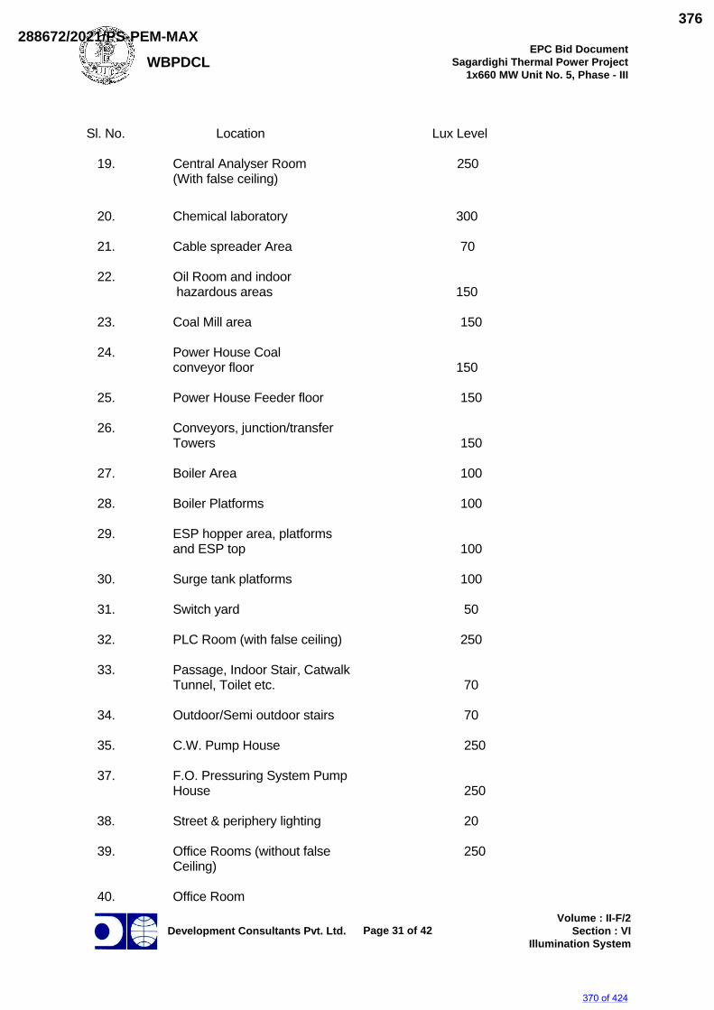
WBPDCL EPC Bid Document
Sagardighi Thermal Power Project 1x660 MW Unit No. 5, Phase - III
Development Consultants Pvt. Ltd.
Page 31 of 42
Volume : II-F/2 Section : VI
Illumination System
Sl. No. Location Lux Level 19. Central Analyser Room 250 (With false ceiling) 20. Chemical laboratory 300 21. Cable spreader Area 70 22. Oil Room and indoor hazardous areas 150 23. Coal Mill area 150 24. Power House Coal conveyor floor 150 25. Power House Feeder floor 150 26. Conveyors, junction/transfer Towers 150 27. Boiler Area 100 28. Boiler Platforms 100 29. ESP hopper area, platforms and ESP top 100 30. Surge tank platforms 100 31. Switch yard 50 32. PLC Room (with false ceiling) 250 33. Passage, Indoor Stair, Catwalk Tunnel, Toilet etc. 70 34. Outdoor/Semi outdoor stairs 70 35. C.W. Pump House 250 37. F.O. Pressuring System Pump House 250 38. Street & periphery lighting 20 39. Office Rooms (without false 250 Ceiling) 40. Office Room
370 of 424
288672/2021/PS-PEM-MAX376
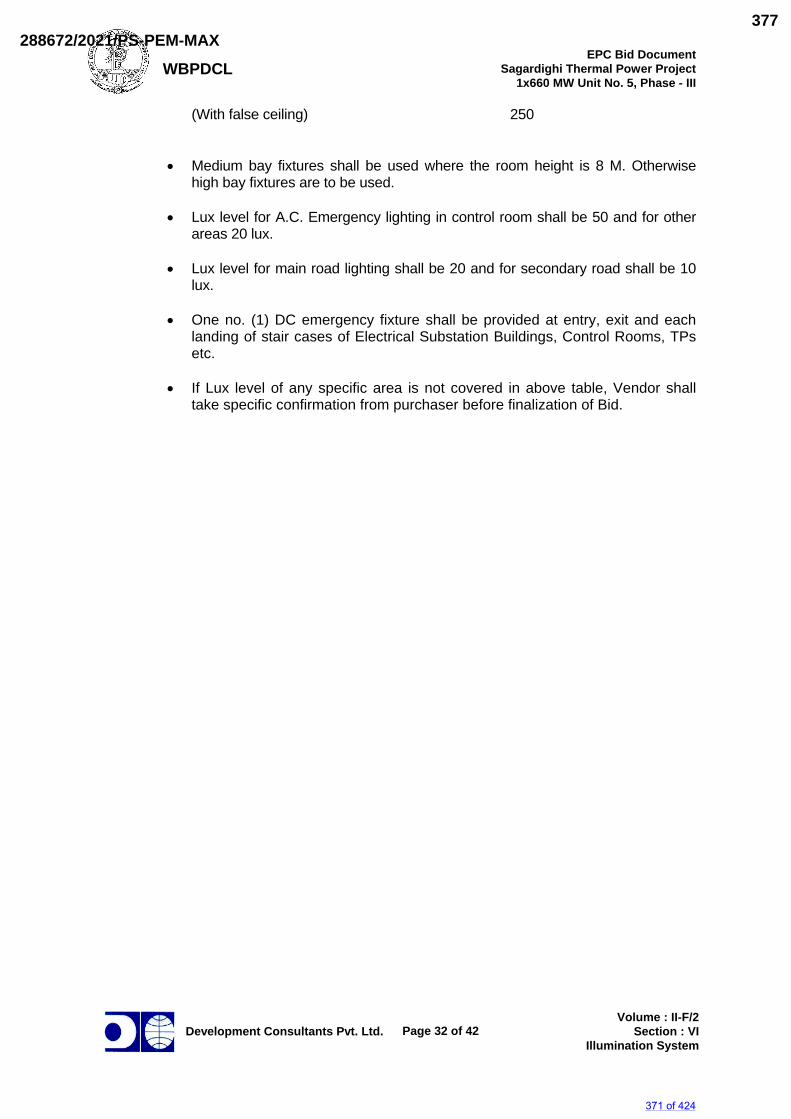
WBPDCL EPC Bid Document
Sagardighi Thermal Power Project 1x660 MW Unit No. 5, Phase - III
Development Consultants Pvt. Ltd.
Page 32 of 42
Volume : II-F/2 Section : VI
Illumination System
(With false ceiling) 250
Medium bay fixtures shall be used where the room height is 8 M. Otherwise high bay fixtures are to be used.
Lux level for A.C. Emergency lighting in control room shall be 50 and for other areas 20 lux.
Lux level for main road lighting shall be 20 and for secondary road shall be 10 lux.
One no. (1) DC emergency fixture shall be provided at entry, exit and each landing of stair cases of Electrical Substation Buildings, Control Rooms, TPs etc.
If Lux level of any specific area is not covered in above table, Vendor shall take specific confirmation from purchaser before finalization of Bid.
371 of 424
288672/2021/PS-PEM-MAX377
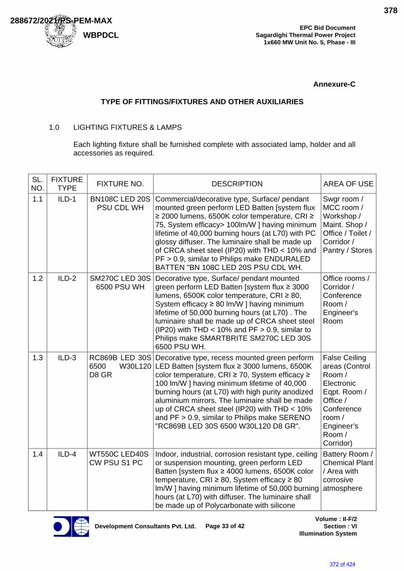
WBPDCL EPC Bid Document
Sagardighi Thermal Power Project 1x660 MW Unit No. 5, Phase - III
Development Consultants Pvt. Ltd.
Page 33 of 42
Volume : II-F/2 Section : VI
Illumination System
Annexure-C
TYPE OF FITTINGS/FIXTURES AND OTHER AUXILIARIES
1.0 LIGHTING FIXTURES & LAMPS Each lighting fixture shall be furnished complete with associated lamp, holder and all accessories as required.
SL. NO.
FIXTURE TYPE FIXTURE NO. DESCRIPTION AREA OF USE
1.1 ILD-1 BN108C LED 20S PSU CDL WH
Commercial/decorative type, Surface/ pendant mounted green perform LED Batten [system flux ≥ 2000 lumens, 6500K color temperature, CRI ≥ 75, System efficacy> 100lm/W ] having minimum lifetime of 40,000 burning hours (at L70) with PC glossy diffuser. The luminaire shall be made up of CRCA sheet steel (IP20) with THD < 10% and PF > 0.9, similar to Philips make ENDURALED BATTEN "BN 108C LED 20S PSU CDL WH.
Swgr room / MCC room / Workshop / Maint. Shop / Office / Toilet / Corridor / Pantry / Stores
1.2 ILD-2 SM270C LED 30S 6500 PSU WH
Decorative type, Surface/ pendant mounted green perform LED Batten [system flux ≥ 3000 lumens, 6500K color temperature, CRI ≥ 80, System efficacy ≥ 80 lm/W ] having minimum lifetime of 50,000 burning hours (at L70) . The luminaire shall be made up of CRCA sheet steel (IP20) with THD < 10% and PF > 0.9, similar to Philips make SMARTBRITE SM270C LED 30S 6500 PSU WH.
Office rooms / Corridor / Conference Room / Engineer's Room
1.3 ILD-3 RC869B LED 30S 6500 W30L120 D8 GR
Decorative type, recess mounted green perform LED Batten [system flux ≥ 3000 lumens, 6500K color temperature, CRI ≥ 70, System efficacy ≥ 100 lm/W ] having minimum lifetime of 40,000 burning hours (at L70) with high purity anodized aluminium mirrors. The luminaire shall be made up of CRCA sheet steel (IP20) with THD < 10% and PF > 0.9, similar to Philips make SERENO "RC869B LED 30S 6500 W30L120 D8 GR".
False Ceiling areas (Control Room / Electronic Eqpt. Room / Office / Conference room / Engineer’s Room / Corridor)
1.4 ILD-4 WT550C LED40S CW PSU S1 PC
Indoor, industrial, corrosion resistant type, ceiling or suspension mounting, green perform LED Batten [system flux ≥ 4000 lumens, 6500K color temperature, CRI ≥ 80, System efficacy ≥ 80 lm/W ] having minimum lifetime of 50,000 burning hours (at L70) with diffuser. The luminaire shall be made up of Polycarbonate with silicone
Battery Room / Chemical Plant / Area with corrosive atmosphere
372 of 424
288672/2021/PS-PEM-MAX378
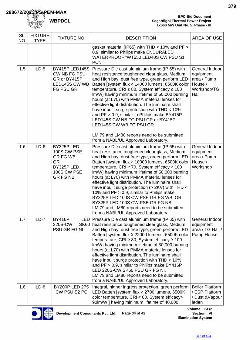
WBPDCL EPC Bid Document
Sagardighi Thermal Power Project 1x660 MW Unit No. 5, Phase - III
Development Consultants Pvt. Ltd.
Page 34 of 42
Volume : II-F/2 Section : VI
Illumination System
SL. NO.
FIXTURE TYPE FIXTURE NO. DESCRIPTION AREA OF USE
gasket material (IP65) with THD < 10% and PF > 0.9, similar to Philips make ENDURALED WATERPROOF "WT550 LED40S CW PSU S1 PC".
1.5 ILD-5 BY415P LED145S CW NB FG PSU GR or BY415P LED145S CW WB FG PSU GR
Pressure Die cast aluminium frame (IP 65) with heat resistance toughened clear glass, Medium and High bay, dust free type, green perform LED Batten [system flux ≥ 14000 lumens, 6500K color temperature, CRI ≥ 80, System efficacy ≥ 100 lm/W] having minimum lifetime of 50,000 burning hours (at L70) with PMMA material lenses for effective light distribution. The luminaire shall have inbuilt surge protection with THD < 10% and PF > 0.9, similar to Philips make BY415P LED145S CW NB FG PSU GR or BY415P LED145S CW WB FG PSU GR. LM 79 and LM80 reports need to be submitted from a NABL/UL Approved Laboratory.
General Indoor equipment area / Pump House / Workshop/TG Hall
1.6 ILD-6 BY325P LED 100S CW PSE GR FG WB, OR BY325P LED 100S CW PSE GR FG NB
Pressure Die cast aluminium frame (IP 65) with heat resistance toughened clear glass, Medium and High bay, dust free type, green perform LED Batten [system flux ≥ 10000 lumens, 6500K color temperature, CRI ≥ 70, System efficacy ≥ 100 lm/W] having minimum lifetime of 50,000 burning hours (at L70) with PMMA material lenses for effective light distribution. The luminaire shall have inbuilt surge protection (> 2KV) with THD < 10% and PF > 0.9, similar to Philips make BY325P LED 100S CW PSE GR FG WB, OR BY325P LED 100S CW PSE GR FG NB LM 79 and LM80 reports need to be submitted from a NABL/UL Approved Laboratory.
General Indoor equipment area / Pump House / Workshop
1.7 ILD-7 BY416P LED 220S-CW SK60 PSU GR FG NI
Pressure Die cast aluminium frame (IP 65) with heat resistance toughened clear glass, Medium and High bay, dust free type, green perform LED Batten [system flux ≥ 22000 lumens, 6500K color temperature, CRI ≥ 80, System efficacy ≥ 100 lm/W] having minimum lifetime of 50,000 burning hours (at L70) with PMMA material lenses for effective light distribution. The luminaire shall have inbuilt surge protection with THD < 10% and PF > 0.9, similar to Philips make BY416P LED 220S-CW SK60 PSU GR FG NI. LM 79 and LM80 reports need to be submitted from a NABL/UL Approved Laboratory.
General Indoor equipment area / TG Hall / Pump House
1.8 ILD-8 BY200P LED 27S CW PSU S2 PC
Integral, higher ingress protection, green perform LED Batten [system flux ≥ 2700 lumens, 6500K color temperature, CRI ≥ 80, System efficacy> 90lm/W ] having minimum lifetime of 40,000
Boiler Platform / ESP Platform / Dust &Vapour laden
373 of 424
288672/2021/PS-PEM-MAX379
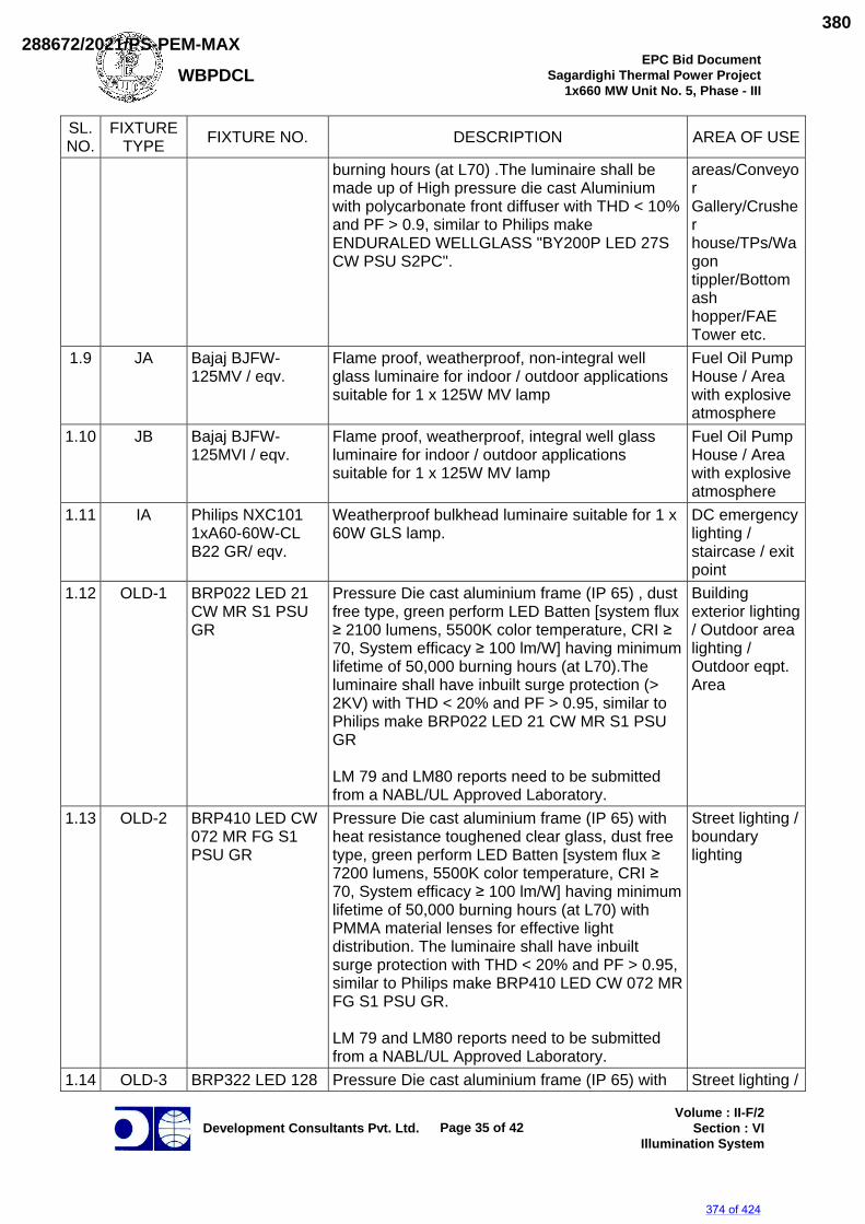
WBPDCL EPC Bid Document
Sagardighi Thermal Power Project 1x660 MW Unit No. 5, Phase - III
Development Consultants Pvt. Ltd.
Page 35 of 42
Volume : II-F/2 Section : VI
Illumination System
SL. NO.
FIXTURE TYPE FIXTURE NO. DESCRIPTION AREA OF USE
burning hours (at L70) .The luminaire shall be made up of High pressure die cast Aluminium with polycarbonate front diffuser with THD < 10% and PF > 0.9, similar to Philips make ENDURALED WELLGLASS "BY200P LED 27S CW PSU S2PC".
areas/Conveyor Gallery/Crusher house/TPs/Wagon tippler/Bottom ash hopper/FAE Tower etc.
1.9 JA Bajaj BJFW-125MV / eqv.
Flame proof, weatherproof, non-integral well glass luminaire for indoor / outdoor applications suitable for 1 x 125W MV lamp
Fuel Oil Pump House / Area with explosive atmosphere
1.10 JB Bajaj BJFW-125MVI / eqv.
Flame proof, weatherproof, integral well glass luminaire for indoor / outdoor applications suitable for 1 x 125W MV lamp
Fuel Oil Pump House / Area with explosive atmosphere
1.11 IA Philips NXC101 1xA60-60W-CL B22 GR/ eqv.
Weatherproof bulkhead luminaire suitable for 1 x 60W GLS lamp.
DC emergency lighting / staircase / exit point
1.12 OLD-1 BRP022 LED 21 CW MR S1 PSU GR
Pressure Die cast aluminium frame (IP 65) , dust free type, green perform LED Batten [system flux ≥ 2100 lumens, 5500K color temperature, CRI ≥ 70, System efficacy ≥ 100 lm/W] having minimum lifetime of 50,000 burning hours (at L70).The luminaire shall have inbuilt surge protection (> 2KV) with THD < 20% and PF > 0.95, similar to Philips make BRP022 LED 21 CW MR S1 PSU GR LM 79 and LM80 reports need to be submitted from a NABL/UL Approved Laboratory.
Building exterior lighting / Outdoor area lighting / Outdoor eqpt. Area
1.13 OLD-2 BRP410 LED CW 072 MR FG S1 PSU GR
Pressure Die cast aluminium frame (IP 65) with heat resistance toughened clear glass, dust free type, green perform LED Batten [system flux ≥ 7200 lumens, 5500K color temperature, CRI ≥ 70, System efficacy ≥ 100 lm/W] having minimum lifetime of 50,000 burning hours (at L70) with PMMA material lenses for effective light distribution. The luminaire shall have inbuilt surge protection with THD < 20% and PF > 0.95, similar to Philips make BRP410 LED CW 072 MR FG S1 PSU GR. LM 79 and LM80 reports need to be submitted from a NABL/UL Approved Laboratory.
Street lighting / boundary lighting
1.14 OLD-3 BRP322 LED 128 Pressure Die cast aluminium frame (IP 65) with Street lighting /
374 of 424
288672/2021/PS-PEM-MAX380
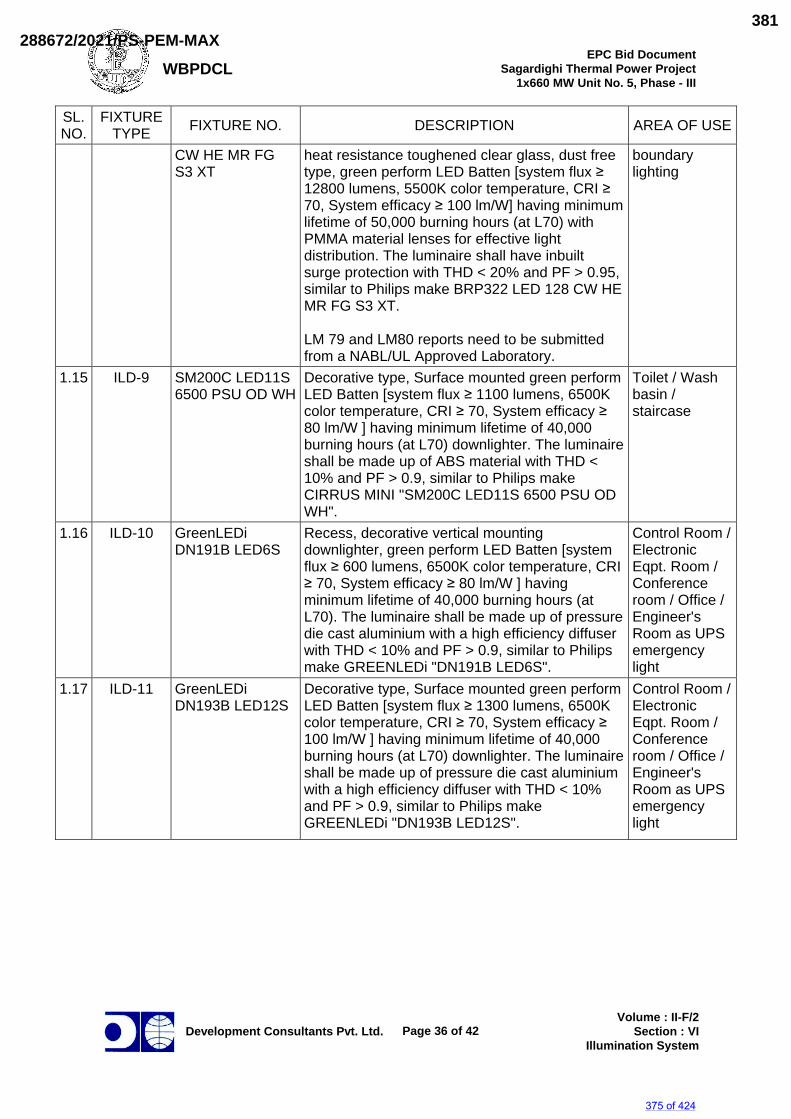
WBPDCL EPC Bid Document
Sagardighi Thermal Power Project 1x660 MW Unit No. 5, Phase - III
Development Consultants Pvt. Ltd.
Page 36 of 42
Volume : II-F/2 Section : VI
Illumination System
SL. NO.
FIXTURE TYPE FIXTURE NO. DESCRIPTION AREA OF USE
CW HE MR FG S3 XT
heat resistance toughened clear glass, dust free type, green perform LED Batten [system flux ≥ 12800 lumens, 5500K color temperature, CRI ≥ 70, System efficacy ≥ 100 lm/W] having minimum lifetime of 50,000 burning hours (at L70) with PMMA material lenses for effective light distribution. The luminaire shall have inbuilt surge protection with THD < 20% and PF > 0.95, similar to Philips make BRP322 LED 128 CW HE MR FG S3 XT. LM 79 and LM80 reports need to be submitted from a NABL/UL Approved Laboratory.
boundary lighting
1.15 ILD-9 SM200C LED11S 6500 PSU OD WH
Decorative type, Surface mounted green perform LED Batten [system flux ≥ 1100 lumens, 6500K color temperature, CRI ≥ 70, System efficacy ≥ 80 lm/W ] having minimum lifetime of 40,000 burning hours (at L70) downlighter. The luminaire shall be made up of ABS material with THD < 10% and PF > 0.9, similar to Philips make CIRRUS MINI "SM200C LED11S 6500 PSU OD WH".
Toilet / Wash basin / staircase
1.16 ILD-10 GreenLEDi DN191B LED6S
Recess, decorative vertical mounting downlighter, green perform LED Batten [system flux ≥ 600 lumens, 6500K color temperature, CRI ≥ 70, System efficacy ≥ 80 lm/W ] having minimum lifetime of 40,000 burning hours (at L70). The luminaire shall be made up of pressure die cast aluminium with a high efficiency diffuser with THD < 10% and PF > 0.9, similar to Philips make GREENLEDi "DN191B LED6S".
Control Room / Electronic Eqpt. Room / Conference room / Office / Engineer's Room as UPS emergency light
1.17 ILD-11 GreenLEDi DN193B LED12S
Decorative type, Surface mounted green perform LED Batten [system flux ≥ 1300 lumens, 6500K color temperature, CRI ≥ 70, System efficacy ≥ 100 lm/W ] having minimum lifetime of 40,000 burning hours (at L70) downlighter. The luminaire shall be made up of pressure die cast aluminium with a high efficiency diffuser with THD < 10% and PF > 0.9, similar to Philips make GREENLEDi "DN193B LED12S".
Control Room / Electronic Eqpt. Room / Conference room / Office / Engineer's Room as UPS emergency light
375 of 424
288672/2021/PS-PEM-MAX381
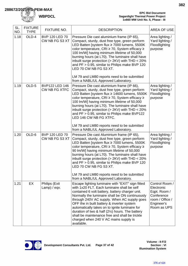
WBPDCL EPC Bid Document
Sagardighi Thermal Power Project 1x660 MW Unit No. 5, Phase - III
Development Consultants Pvt. Ltd.
Page 37 of 42
Volume : II-F/2 Section : VI
Illumination System
SL. NO.
FIXTURE TYPE FIXTURE NO. DESCRIPTION AREA OF USE
1.18 OLD-4 BVP 120 LED 70 CW NB FG S3 XT
Pressure Die cast aluminium frame (IP 65), Compact, sturdy, dust free type, green perform LED Batten [system flux ≥ 7000 lumens, 5500K color temperature, CRI ≥ 70, System efficacy ≥ 100 lm/W] having minimum lifetime of 50,000 burning hours (at L70). The luminaire shall have inbuilt surge protection (> 2KV) with THD < 20% and PF > 0.95, similar to Philips make BVP 120 LED 70 CW NB FG S3 XT. LM 79 and LM80 reports need to be submitted from a NABL/UL Approved Laboratory.
Area lighting / Yard lighting / Floodlighting purpose
1.19 OLD-5 BVP122 LED 146 CW NB FG XTFC
Pressure Die cast aluminium frame (IP 66), Compact, sturdy, dust free type, green perform LED Batten [system flux ≥ 14600 lumens, 5500K color temperature, CRI ≥ 70, System efficacy ≥ 100 lm/W] having minimum lifetime of 50,000 burning hours (at L70). The luminaire shall have inbuilt surge protection (> 2KV) with THD < 20% and PF > 0.95, similar to Philips make BVP122 LED 146 CW NB FG XTFC. LM 79 and LM80 reports need to be submitted from a NABL/UL Approved Laboratory.
Area lighting / Yard lighting / Floodlighting purpose
1.20 OLD-6 BVP 120 LED 70 CW NB FG S3 XT
Pressure Die cast Aluminium frame (IP 65), Compact, sturdy, dust free type, green perform LED Batten [system flux ≥ 7000 lumens, 5500K color temperature, CRI ≥ 70, System efficacy ≥ 90 lm/W] having minimum lifetime of 50,000 burning hours (at L70). The luminaire shall have inbuilt surge protection (> 2KV) with THD < 20% and PF > 0.95, similar to Philips make BVP 120 LED 70 CW NB FG S3 XT. LM 79 and LM80 reports need to be submitted from a NABL/UL Approved Laboratory.
Area lighting / Yard lighting / Floodlighting purpose
1.21 EX Philips (Exit Lamp) / eqv.
Escape lighting luminaire with “EXIT” sign fitted with 1x20 FLT. Each luminaire shall be self contained 6 volt battery, battery charger unit. Normally the luminaire shall be ON continuously through 240V AC supply. When AC supply goes OFF the in built battery & inverter system automatically takes on to ignite luminaire for duration of two & half (2½) hours. The battery shall be maintenance free and shall be trickle charged when 240 V AC mains supply is available.
Control Room / Electronic Eqpt. Room / Conference room / Office / Engineer's Room as UPS
376 of 424
288672/2021/PS-PEM-MAX382
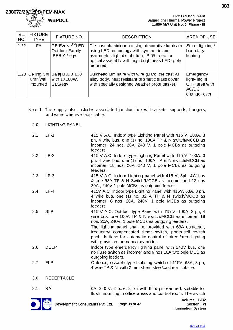
WBPDCL EPC Bid Document
Sagardighi Thermal Power Project 1x660 MW Unit No. 5, Phase - III
Development Consultants Pvt. Ltd.
Page 38 of 42
Volume : II-F/2 Section : VI
Illumination System
SL. NO.
FIXTURE TYPE FIXTURE NO. DESCRIPTION AREA OF USE
1.22 FA GE EvolveTMLED Outdoor Family IBERIA / eqv.
Die-cast aluminium housing, decorative luminaire using LED technology with symmetric and asymmetric light distribution, IP 65 rated for optical assembly with high brightness LED- pole mounted.
Street lighting / boundary lighting
1.23 Ceiling/Column/wall mounted
Bajaj BJDB 100 with 1X100W. GLS/eqv
Bulkhead luminaire with wire guard, die cast Al alloy body, heat resistant prismatic glass cover with specially designed weather proof gasket.
Emergency light- ing in CHP area with AC/DC change- over
Note 1: The supply also includes associated junction boxes, brackets, supports, hangers,
and wires wherever applicable.
2.0 LIGHTING PANEL
2.1 LP-1 415 V A.C. Indoor type Lighting Panel with 415 V, 100A, 3 ph, 4 wire bus, one (1) no. 100A TP & N switch/MCCB as incomer, 24 nos. 20A, 240 V, 1 pole MCBs as outgoing feeders.
2.2 LP-2 415 V A.C. Indoor type Lighting Panel with 415 V, 100A, 3 ph, 4 wire bus, one (1) no. 100A TP & N switch/MCCB as incomer, 18 nos. 20A, 240 V, 1 pole MCBs as outgoing feeders.
2.3 LP-3 415 V A.C. Indoor Lighting panel with 415 V, 3ph, 4W bus & one 63A TP & N Switch/MCCB as incomer and 12 nos 20A , 240V 1 pole MCBs as outgoing feeder.
2.4 LP-4 415V A.C. Indoor type Lighting Panel with 415V, 63A, 3 ph, 4 wire bus, one (1) no. 32 A TP & N switch/MCCB as incomer, 6 nos. 20A, 240V, 1 pole MCBs as outgoing feeders.
2.5 SLP 415 V A.C. Outdoor type Panel with 415 V, 100A, 3 ph, 4 wire bus, one 100A TP & N switch/MCCB as incomer, 18 nos. 20A, 240V, 1 pole MCBs as outgoing feeders.
The lighting panel shall be provided with 63A contactor, frequency compensated timer switch, photo-cell switch push- buttons for automatic control of street/area lighting with provision for manual override.
2.6 DCLP Indoor type emergency lighting panel with 240V bus, one no Fuse switch as incomer and 6 nos 16A two pole MCB as outgoing feeders.
2.7 FLP Outdoor, lockable type Isolating switch of 415V, 63A, 3 ph, 4 wire TP & N. with 2 mm sheet steel/cast iron cubicle.
3.0 RECEPTACLE
3.1 RA
6A, 240 V, 2 pole, 3 pin with third pin earthed, suitable for flush mounting in office areas and control room. The switch
377 of 424
288672/2021/PS-PEM-MAX383
WBPDCL EPC Bid Document
Sagardighi Thermal Power Project 1x660 MW Unit No. 5, Phase - III
Development Consultants Pvt. Ltd.
Page 39 of 42
Volume : II-F/2 Section : VI
Illumination System
shall be also flush mounted piano type. Degree of protection shall be IP 52 (for Indoor) / IP 65 (for outdoor).
3.2
RB
16A, 240V, 2 pole, 3 pin with third pin earthed, wall/ column mounted, metal clad gasketed construction, 20mm conduit entry, screwed metal cover tied to it by a metal chain, weatherproof suitable for indoor/outdoor installation.Degree of protection shall be IP 52 (for Indoor) / IP 65 (for outdoor).
3.3
RC
63A, 415 V, 3 phase, 4 pin interlocked plug and switch with earthing contact, wall/column mounted, metal clad gasketed construction, weatherproof, suitable for loop-in/loop-out connection of 4/C-35 Sq.mm XLPE cable. These shall be fed from AC Distribution Board/Station MCC. Degree of protection shall be IP 52 (for Indoor) / IP 65 (for outdoor).
3.4
RD
125 A, 415 V, 3 phase 5 pin interlocked plug & switch with fifth pin earthed, wall/column mounted metal clad gasketed construction, weatherproof, suitable for loop in and loop out connection of 3-1/2C -95 Sq.mm XLPE cable. These shall be fed from A.C-Distribution Board/Station MCC.Application at all Transformer Yard for Oil Filtration machines and other areas. Degree of protection shall be IP 65.
4.0
CEILING FANS
4.1 FA 1200 mm sweep ceiling fan with regulator, down rod and canopy.
4.2 FB 1400 mm sweep ceiling fan with regulator, down rod and canopy.
5.0 LIGHTING POLES 5.1 TA/TB Single arm/double arm swaged and welded steel pole with
junction box and all accessories. 6.0 SWITCHBOARD 6.1 S-1 Switch board with 1-6A switch. 6.2 S-2 Switch board with 3-6A switch and 1-6A receptacle. 6.3 S-3 Switch board with 6-6A switch and 1-6A receptacle.
7.0
MISCELLANEOUS ITEMS
7.1 M1 10 m high car wheel mounted aluminium ladder. 7.2 M2 Adjustable free-standing aluminium ladder height
adjustable from 5 m to 10 m.+ 7.3 M3 Portable Emergency light set complete with one 20W tube
light, battery, battery charger and all other accessories. 7.4 M4 24 Volt Supply Module with all accessories.
378 of 424
288672/2021/PS-PEM-MAX384
WBPDCL EPC Bid Document
Sagardighi Thermal Power Project 1x660 MW Unit No. 5, Phase - III
Development Consultants Pvt. Ltd.
Page 40 of 42
Volume : II-F/2 Section : VI
Illumination System
Annexure-D
1100V LV POWER CABLE (XLPE)
1.0 1100 V grade, 90ºC continuous rating under normal condition and 250°C under
short circuit condition rating, XLPE heavy duty, power cable conforming to following requirement and in line with IS 7098 Part-I. IS 8130 & IS 5831 and IS 3975.
1.1 Conductor : Stranded and compacted plain
aluminium of grade H2 and class 2 stranded, high conductivity annealed plain copper for cable sizes upto 2.5 mm2 conforming to IS:8130.
1.2 Insulation : Extruded cross-linked polyethylene
(XLPE) conforming to IS:7098 (Part-1)
1.3 Core Identification : By color coding 1.4 Inner Sheath : Extruded PVC compound conforming
to type ST2 of IS 5831 for multicore cable. Single core cable shall have no inner sheath. Filler shall be of same material as of inner sheath i.e. ST2
1.5 Armour : Galvanized single round steel wire
armour for twin and multicore cables. Non-magnetic hard drawn aluminum
single round wire conforming to H4 of IS-8130 latest for single core cables.
1.6 Overall Sheath : Extruded PVC compound conforming
to type ST2 of IS 5831 with FRLSH properties.
1.7 Drum : Conforming to IS-10418 (Wooden
drum)
379 of 424
288672/2021/PS-PEM-MAX385
WBPDCL EPC Bid Document
Sagardighi Thermal Power Project 1x660 MW Unit No. 5, Phase - III
Development Consultants Pvt. Ltd.
Page 41 of 42
Volume : II-F/2 Section : VI
Illumination System
Annexure-E
CONTROL CABLES 1.0 1100 V grade 70ºC continuous rating under normal condition and 160°C
under short circuit condition rating PVC Control cable (YWY) conforming to following requirement and in line with IS:1554, IS:8130, IS:5831 and IS:3975.
1.1 Conductor : Stranded, non-compacted & circular,
high conductivity annealed plain copper, generally conforming to IS: 8130.
1.2 Insulation : Extruded PVC compound conforming to
type A of IS: 5831. 1.3 Core Identification : By color coding and numbering at
interval of 100mm or less 1.4 Inner sheath : Extruded PVC compound conforming to
type ST1 of IS: 5831 for multicore cables. Single core cables shall have no inner sheath. Filler shall be of same material as of inner sheath i.e. ST1.
1.5 Armour : Galvanised single round steel wire for
twin and multicore cables.
1.6 Overall sheath : Extruded PVC compound conforming to type ST1 of IS 5831 with FRLSH properties.
1.7 Drum : Conforming to IS: 10418 (Wooden
drum)
380 of 424
288672/2021/PS-PEM-MAX386
WBPDCL EPC Bid Document
Sagardighi Thermal Power Project 1x660 MW Unit No. 5, Phase - III
Development Consultants Pvt. Ltd.
Page 42 of 42
Volume : II-F/2 Section : VI
Illumination System
ANNEXURE – F
RATINGS AND REQUIREMENTS OF
LIGHTING TRANSFORMER
Type : Dry type, no encapsulated VPI with nomex insulation KVA rating : 100-150 KVA Voltage rating : 415 V/415 V Cooling : AN P.V. Impedance : 0.04 +_ 10% Voltage control : Off load tap switch/link with
change of +_ 5% in step of 2.5% tapping full capacity.
Vector Group : Dyn11 Class of Insulation : F (1550C) Maximum Temperature rise over 50 Deg C. ambient in winding by resistance : 900C Neutral : Solidly grounded.
The secondary neutral of the transformer shall be brought out for getting a
grounded 4 wire supply. Each transformer shall be routine tested and one transformer shall be type tested in accordance with relevant standard.
The transformer shall be liable for rejection if the tolerance on the quoted
values of losses, impedance, temperature rise, etc. exceeds the specified values of relevant standard.
The transformer shall be mounted inside sheet steel enclosure, which shall
be an integral part of Lighting Distribution Board.
381 of 424
288672/2021/PS-PEM-MAX387
SAGARDIGHI THERMAL POWER PROJECT, 1 X 660 MW UNIT NO 5, STAGE III.
TG HALL– AB BAY 160/25T DOUBLE GIRDER EOT CRANES
DATASHEET A
SPECIFICATION No: PE-TS-445-501-A001
SECTION IC
REV. 00 23-03-2021
SUB-SECTION IC DATASHEET - A
382 of 424
288672/2021/PS-PEM-MAX388
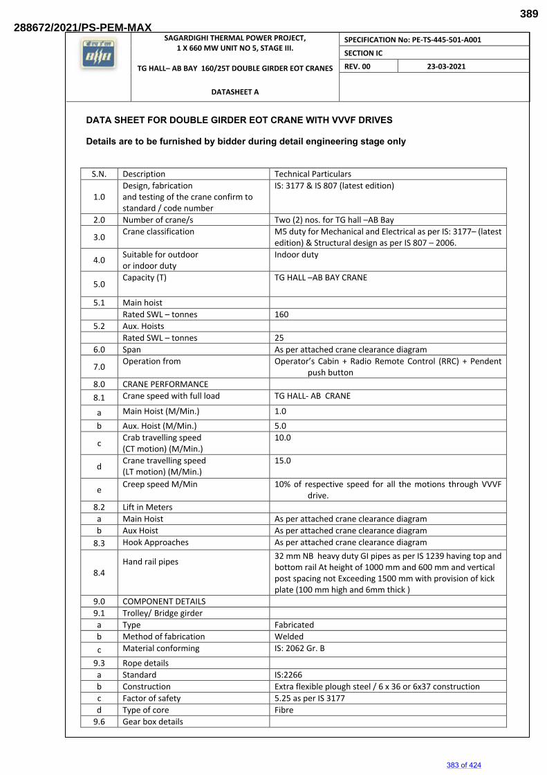
SAGARDIGHI THERMAL POWER PROJECT, 1 X 660 MW UNIT NO 5, STAGE III.
TG HALL– AB BAY 160/25T DOUBLE GIRDER EOT CRANES
DATASHEET A
SPECIFICATION No: PE-TS-445-501-A001
SECTION IC
REV. 00 23-03-2021
DATA SHEET FOR DOUBLE GIRDER EOT CRANE WITH VVVF DRIVES Details are to be furnished by bidder during detail engineering stage only
S.N. Description Technical Particulars
1.0 Design, fabrication and testing of the crane confirm to standard / code number
IS: 3177 & IS 807 (latest edition)
2.0 Number of crane/s Two (2) nos. for TG hall –AB Bay
3.0 Crane classification M5 duty for Mechanical and Electrical as per IS: 3177– (latest
edition) & Structural design as per IS 807 – 2006.
4.0 Suitable for outdoor or indoor duty
Indoor duty
5.0 Capacity (T) TG HALL –AB BAY CRANE
5.1 Main hoist
Rated SWL – tonnes 160
5.2 Aux. Hoists
Rated SWL – tonnes 25
6.0 Span As per attached crane clearance diagram
7.0 Operation from Operator’s Cabin + Radio Remote Control (RRC) + Pendent
push button
8.0 CRANE PERFORMANCE
8.1 Crane speed with full load TG HALL- AB CRANE
a Main Hoist (M/Min.) 1.0
b Aux. Hoist (M/Min.) 5.0
c Crab travelling speed (CT motion) (M/Min.)
10.0
d Crane travelling speed (LT motion) (M/Min.)
15.0
e Creep speed M/Min 10% of respective speed for all the motions through VVVF
drive.
8.2 Lift in Meters
a Main Hoist As per attached crane clearance diagram b Aux Hoist As per attached crane clearance diagram
8.3 Hook Approaches As per attached crane clearance diagram
8.4 Hand rail pipes
32 mm NB heavy duty GI pipes as per IS 1239 having top and bottom rail At height of 1000 mm and 600 mm and vertical post spacing not Exceeding 1500 mm with provision of kick plate (100 mm high and 6mm thick )
9.0 COMPONENT DETAILS
9.1 Trolley/ Bridge girder
a Type Fabricated
b Method of fabrication Welded
c Material conforming IS: 2062 Gr. B
9.3 Rope details
a Standard IS:2266
b Construction Extra flexible plough steel / 6 x 36 or 6x37 construction
c Factor of safety 5.25 as per IS 3177
d Type of core Fibre
9.6 Gear box details
383 of 424
288672/2021/PS-PEM-MAX389
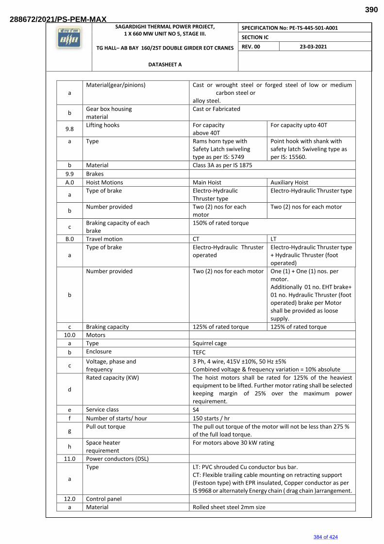
SAGARDIGHI THERMAL POWER PROJECT, 1 X 660 MW UNIT NO 5, STAGE III.
TG HALL– AB BAY 160/25T DOUBLE GIRDER EOT CRANES
DATASHEET A
SPECIFICATION No: PE-TS-445-501-A001
SECTION IC
REV. 00 23-03-2021
a Material(gear/pinions)
Cast or wrought steel or forged steel of low or medium carbon steel or
alloy steel.
b Gear box housing material
Cast or Fabricated
9.8 Lifting hooks For capacity
above 40T For capacity upto 40T
a Type Rams horn type with Safety Latch swiveling type as per IS: 5749
Point hook with shank with safety latch Swiveling type as per IS: 15560.
b Material Class 3A as per IS 1875
9.9 Brakes
A.0 Hoist Motions Main Hoist Auxiliary Hoist
a Type of brake Electro-Hydraulic
Thruster type Electro-Hydraulic Thruster type
b Number provided Two (2) nos for each
motor Two (2) nos for each motor
c Braking capacity of each brake
150% of rated torque
B.0 Travel motion CT LT
a Type of brake Electro-Hydraulic Thruster
operated Electro-Hydraulic Thruster type + Hydraulic Thruster (foot operated)
b
Number provided Two (2) nos for each motor One (1) + One (1) nos. per motor. Additionally 01 no. EHT brake+ 01 no. Hydraulic Thruster (foot operated) brake per Motor shall be provided as loose supply.
c Braking capacity 125% of rated torque 125% of rated torque
10.0 Motors
a Type Squirrel cage
b Enclosure TEFC
c Voltage, phase and frequency
3 Ph, 4 wire, 415V ±10%, 50 Hz ±5% Combined voltage & frequency variation = 10% absolute
d
Rated capacity (KW) The hoist motors shall be rated for 125% of the heaviest equipment to be lifted. Further motor rating shall be selected keeping margin of 25% over the maximum power requirement.
e Service class S4
f Number of starts/ hour 150 starts / hr
g Pull out torque The pull out torque of the motor will not be less than 275 %
of the full load torque.
h Space heater requirement
For motors above 30 kW rating
11.0 Power conductors (DSL)
a
Type
LT: PVC shrouded Cu conductor bus bar. CT: Flexible trailing cable mounting on retracting support (Festoon type) with EPR insulated, Copper conductor as per IS 9968 or alternately Energy chain ( drag chain )arrangement.
12.0 Control panel
a Material Rolled sheet steel 2mm size
384 of 424
288672/2021/PS-PEM-MAX390
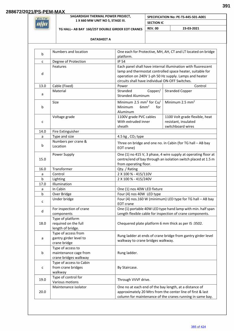
SAGARDIGHI THERMAL POWER PROJECT, 1 X 660 MW UNIT NO 5, STAGE III.
TG HALL– AB BAY 160/25T DOUBLE GIRDER EOT CRANES
DATASHEET A
SPECIFICATION No: PE-TS-445-501-A001
SECTION IC
REV. 00 23-03-2021
b Numbers and location One each for Protective, MH, AH, CT and LT located on bridge
platform.
c Degree of Protection IP 54
d
Features Each panel shall have internal illumination with fluorescent lamp and thermostat controlled space heater, suitable for operation on 240V 1-ph 50 Hz supply. Lamps and heater circuits shall have individual ON-OFF Switches.
13.0 Cable (Fixed) Power Control
a Material Stranded Copper/
Stranded Aluminum Stranded Copper
b Size Minimum 2.5 mm2 for Cu/
Minimum 6mm2 for Aluminum
Minimum 2.5 mm2
c Voltage grade 1100V grade PVC cables
With extruded inner sheath
1100 Volt grade flexible, heat resistant, insulated switchboard wires
14.0 Fire Extinguisher
a Type and size 4.5 kg , CO2 type
b Numbers per crane & Location
Three on bridge and one no. in Cabin (for TG hall – AB bay EOT crane)
15.0 Power Supply
One (1) no 415 V, 3 phase, 4 wire supply at operating floor at centre/end of bay through an isolation switch placed at 1.5 m from operating floor.
16.0 Transformer Qty. / Rating
a Control 2 X 100 % - 415/110V
b Lighting 2 X 100 % - 415/240V
17.0 Illumination
a In Cabin One (1) nos 40W LED fixture
b Over Bridge Four (4) nos 40W LED type
c Under bridge Four (4) nos.160 W (minimum) LED type for TG hall – AB bay
EOT crane
d For inspection of crane components
One (1) portable 40W LED type hand lamp with min. half span Length flexible cable for inspection of crane components.
18.0 Type of platform required on the full length of bridge.
Chequered plate platform 6 mm thick as per IS :3502.
a Type of access from gantry girder level to crane bridge
Rung ladder at ends of crane bridge from gantry girder level walkway to crane bridges walkway.
b Type of access to maintenance cage from crane bridges walkway
Rung ladder.
c Type of access to Cabin from crane bridges walkway
By Staircase.
19.0 Type of control for Various motions
Through VVVF drive.
20.0 Maintenance isolator One no at each end of the bay length, at a distance of
approximately 20 Mtrs from the center line of first & last column for maintenance of the cranes running in same bay.
385 of 424
288672/2021/PS-PEM-MAX391
SAGARDIGHI THERMAL POWER PROJECT, 1 X 660 MW UNIT NO 5, STAGE III.
TG HALL– AB BAY 160/25T DOUBLE GIRDER EOT CRANES
DATASHEET A
SPECIFICATION No: PE-TS-445-501-A001
SECTION IC
REV. 00 23-03-2021
Other requirements
1) Centralized grease lubrication with hand operated grease pump shall be provided.
2) DSL phase indicating lamps to be provided at both end of bay.
3) Girders shall be cambered to an amount approximately equal to the dead load deflection plus one-half the live load (rated load + trolley weight) deflection.
4) All motors shall be designed as 3-phase squirrel-cage motors suitable for crane duty and VVVF drive operation. Motors shall in general conform to IEC-60034. Crane motors shall suit the duty class S4 and shall not be energy efficient, cyclic duration factor (CDF) 40% and number of cycles per hour 150. Motor pull out torque shall not be less than 2.75 times rated torque. Number of poles / motor speed (rpm) shall be as per manufacturer’s design. The motor shall be capable of operating satisfactorily at full load for 5 minutes without injurious heating with 75% rated voltage at motor terminals. Motor shall not stall during operation at voltage dip of 70% for 2 sec.
5) Anti-collision device shall be provided between two cranes running on same gantry to prevent collision.
6) Storm brake: Hydraulic rail clamp, two (2 ) nos per crane suitable for wind speed as indicated at Customer’s Specification “PROJECT SYNOPSIS AND GENERAL INFORMATION” page
386 of 424
288672/2021/PS-PEM-MAX392
WBPDCL EPC Bid Document
Sagardighi Thermal Power Project 1x660 MW Unit No. 5, Phase - III
Development Consultants Pvt. Ltd. Volume: IIIG
Schedule : IIIG/8 Miscellaneous Cranes
VOLUME : IIIG
SCHEDULE-IIIG/8
MISCELLANEOUS CRANES
387 of 424
288672/2021/PS-PEM-MAX393
WBPDCL EPC Bid Document
Sagardighi Thermal Power Project 1x660 MW Unit No. 5, Phase - III
Development Consultants Pvt. Ltd. Page 1 of 16 Volume: IIIG
Schedule : IIIG/8 Miscellaneous Cranes
VOLUME : IIIG
SCHEDULE-IIIG/8
MISCELLANEOUS CRANES
Bidder to fill up the particulars in the format as specified below for each and every E.O.T. Crane offered, mentioning location. 1.00.00 GUARANTEED DATA 1.01.00 Crane Capacity
(Safe working load)
a) Main hoist, tonnes : b) Auxiliary hoist, tonnes : 1.02.00 Rated Speed (for any load from zero to S.W.L) a) Main hoist, m/min : b) Auxiliary hoist, m/min : c) Trolley travel, m/min : d) Bridge travel, m/min : 1.03.00 Tolerance of speed, % : 1.04.00 Creep speed (main hoist), m/min : 1.05.00 Range of speed control for each motion (load
from zero to S.W.L.) :
2.00.00 TECHNICAL PARTICULARS 2.01.00 Name Of Manufacturers 2.01.01 E.O.T. Crane Unit : 2.01.02 Crane Motors : 2.01.03 Control Equipment : 2.01.04 Runway Rail : 2.01.05 Runway Conductors : 2.02.00 Crane Clearance Diagram enclosed with all
data filled up ?
:
Yes/No
388 of 424
288672/2021/PS-PEM-MAX394
WBPDCL EPC Bid Document
Sagardighi Thermal Power Project 1x660 MW Unit No. 5, Phase - III
Development Consultants Pvt. Ltd. Page 2 of 16 Volume: IIIG
Schedule : IIIG/8 Miscellaneous Cranes
2.03.00
Weight of Equipment
:
Bare Weight (Kg)
2.03.01 Bridge Assembly : a) Bridge Girder each : b) End Truck each : 2.03.02 Trolley Assembly : a) Bare Trolley : 2.03.03 Total for E.O.T. Crane Unit : 2.03.04 Runway Rail With Accessories : 2.03.05 Runway Conductor with Accessories : 2.03.06 Total for equipment : 2.04.00 Design, fabrication and testing of crane
conform to standard/code no. (mention the name and serial no. of the code/ standards).
:
2.05.00 Crane service classification number (indicate
also the name of the code or standard adopting the classification).
:
2.06.00 Wheel Loading Data (Bridge) 2.06.01 Maximum wheel load with loaded trolley at
extreme position of crane bridge :
2.06.02 Wheel loading diagram submitted ? : Yes/No 2.07.00 Crane Bridge 2.07.01 Type of girder construction : 2.07.02 Girder particulars (indicate vertical deflection
etc. etc.)
a) Size (mm x mm x mm) : b) Number : c) Material of Construction : 2.07.03 Platform a) Type of Construction : b) Material of Construction : c) Width :
389 of 424
288672/2021/PS-PEM-MAX395
WBPDCL EPC Bid Document
Sagardighi Thermal Power Project 1x660 MW Unit No. 5, Phase - III
Development Consultants Pvt. Ltd. Page 3 of 16 Volume: IIIG
Schedule : IIIG/8 Miscellaneous Cranes
d) Length : e) Location : 2.07.04 Handrail a) Type of Construction : b) Material of Construction : c) Height : d) Length : e) Location : 2.07.05 Trolley Rail a) Type : b) Length : c) Material of Construction : d) Gap between successive rails : e) Rail ends provided with stoppers to
prevent longitudinal shifting ? :
Yes/No
2.07.06 Trolley Stops a) Type of Construction : b) Material of Construction : c) Number : 2.08.00 End Trucks 2.08.01 Type of Construction : 2.08.02 Material of Construction : 2.08.03 Number : 2.08.04 Wheel Axles a) Type : b) Number : 2.08.05 Bearings for Wheel Axles a) Type :
390 of 424
288672/2021/PS-PEM-MAX396
WBPDCL EPC Bid Document
Sagardighi Thermal Power Project 1x660 MW Unit No. 5, Phase - III
Development Consultants Pvt. Ltd. Page 4 of 16 Volume: IIIG
Schedule : IIIG/8 Miscellaneous Cranes
b) Make : c) IS/BS Specification : d) Lubrication Particulars : 2.08.06 Bridge Wheels a) Type : b) Size : c) Number per end truck : 2.08.07 Bridge Travel Buffers a) Number : b) Location : 2.08.08 Runway Rail Sweep a) Type of Construction : b) Location : c) Material of Construction : 2.09.00 Operator's Cab 2.09.01 Type of Construction : 2.09.02 Size : 2.09.03 Type of operator's seat : 2.09.04 Illumination : 2.09.05 Warning Gong a) Type : b) Location : 2.09.06 Ladder from cab. to bridge : 2.09.07 Fire Extinguisher : 2.10.00 Trolley Frame 2.10.01 Type of Construction : 2.10.02 Material :
391 of 424
288672/2021/PS-PEM-MAX397
WBPDCL EPC Bid Document
Sagardighi Thermal Power Project 1x660 MW Unit No. 5, Phase - III
Development Consultants Pvt. Ltd. Page 5 of 16 Volume: IIIG
Schedule : IIIG/8 Miscellaneous Cranes
2.10.03 Trolley Wheels a) Type : b) Size : c) Arrangement : d) Material of Construction : 2.10.04 Trolley Wheel Bearing a) Type : b) Make : c) IS/BS Specification : d) Lubrication Particulars : 2.10.05 Platform a) Type of Construction : b) Material : 2.10.06 Handrail a) Type of Construction : b) Material of Construction : c) Height : d) Length : e) Location : 2.11.00 Full Load Speed, Metres/Min. and Full Load
Acceleration, Metres/Sq. Sec
2.11.01 Bridge Travel a) Rated Speed : b) Acceleration : c) Speed Steps : 2.11.02 Trolley Travel a) Speed Speed Steps :
392 of 424
288672/2021/PS-PEM-MAX398
WBPDCL EPC Bid Document
Sagardighi Thermal Power Project 1x660 MW Unit No. 5, Phase - III
Development Consultants Pvt. Ltd. Page 6 of 16 Volume: IIIG
Schedule : IIIG/8 Miscellaneous Cranes
Rated Speed : b) Acceleration : 2.11.03 Main Hoist a) Speed Inching Steps : Rated Speed : b) Acceleration : 2.11.04 Auxiliary Hoist a) Speed Inching Steps : Rated Speed : b) Acceleration : 2.12.00 Bridge Drive Machinery and Trolley Drive
Machinery
2.12.01 Material of Construction a) Gears : b) Shaft : c) Chain Drives : d) Other components : 2.12.02 Lubrication particulars 2.12.03 Centralised lubrication arranged as specified ? Yes/No 2.12.04 Guards and enclosure provided as necessary ? Yes/No 2.12.05 Bearings a) Type : b) IS/BS Specification ? : c) Make : 2.13.00 Hoisting Mechanism Main Hoist Auxiliary Hoist 2.13.01 Winding drum type and size :
393 of 424
288672/2021/PS-PEM-MAX399
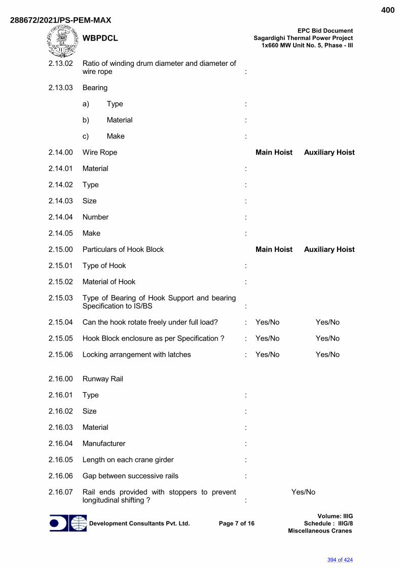
WBPDCL EPC Bid Document
Sagardighi Thermal Power Project 1x660 MW Unit No. 5, Phase - III
Development Consultants Pvt. Ltd. Page 7 of 16 Volume: IIIG
Schedule : IIIG/8 Miscellaneous Cranes
2.13.02 Ratio of winding drum diameter and diameter of wire rope
:
2.13.03 Bearing a) Type : b) Material : c) Make : 2.14.00 Wire Rope Main Hoist Auxiliary Hoist 2.14.01 Material : 2.14.02 Type : 2.14.03 Size : 2.14.04 Number : 2.14.05 Make : 2.15.00 Particulars of Hook Block Main Hoist Auxiliary Hoist 2.15.01 Type of Hook : 2.15.02 Material of Hook : 2.15.03 Type of Bearing of Hook Support and bearing
Specification to IS/BS :
2.15.04 Can the hook rotate freely under full load? : Yes/No Yes/No 2.15.05 Hook Block enclosure as per Specification ? : Yes/No Yes/No 2.15.06 Locking arrangement with latches : Yes/No Yes/No 2.16.00 Runway Rail 2.16.01 Type : 2.16.02 Size : 2.16.03 Material : 2.16.04 Manufacturer : 2.16.05 Length on each crane girder : 2.16.06 Gap between successive rails : 2.16.07 Rail ends provided with stoppers to prevent
longitudinal shifting ? :
Yes/No
394 of 424
288672/2021/PS-PEM-MAX400
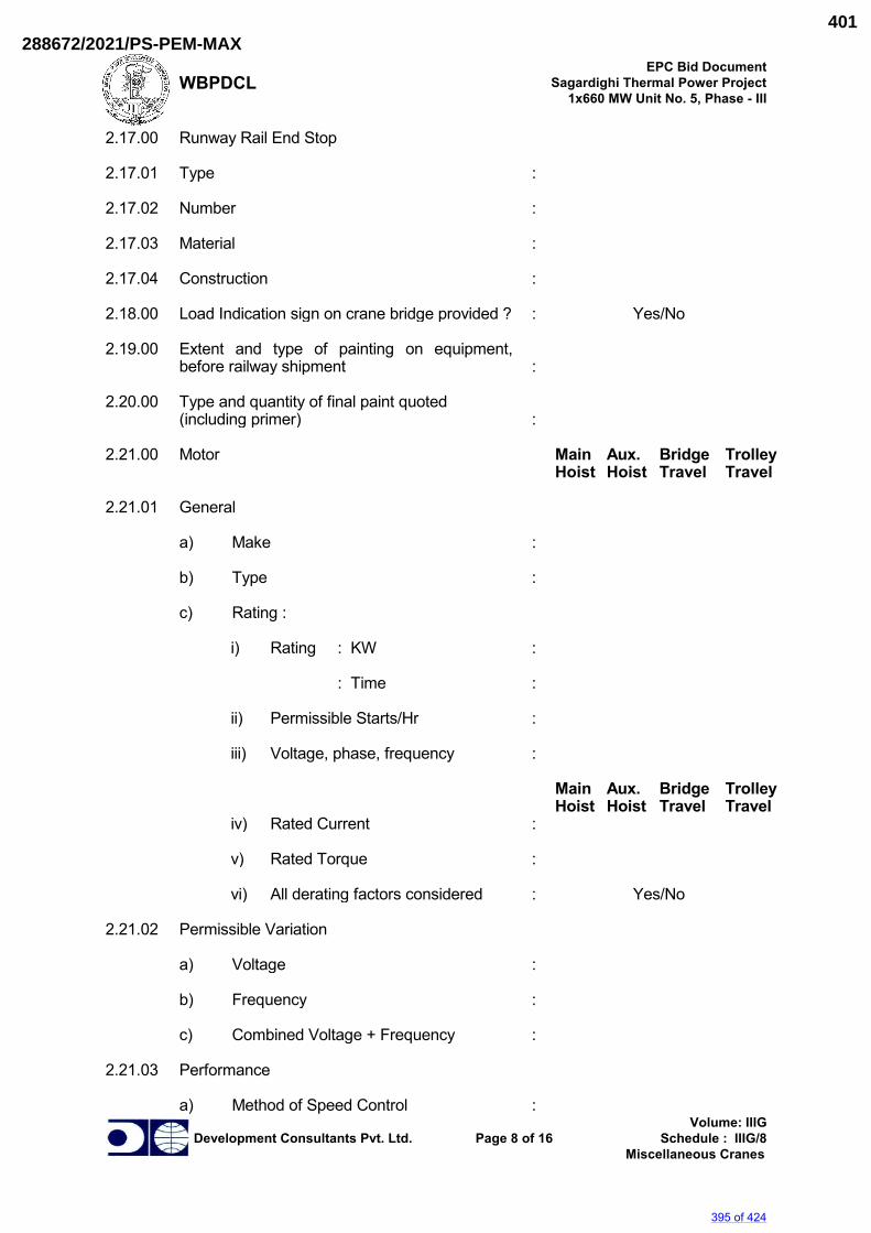
WBPDCL EPC Bid Document
Sagardighi Thermal Power Project 1x660 MW Unit No. 5, Phase - III
Development Consultants Pvt. Ltd. Page 8 of 16 Volume: IIIG
Schedule : IIIG/8 Miscellaneous Cranes
2.17.00 Runway Rail End Stop 2.17.01 Type : 2.17.02 Number : 2.17.03 Material : 2.17.04 Construction : 2.18.00 Load Indication sign on crane bridge provided ? : Yes/No 2.19.00 Extent and type of painting on equipment,
before railway shipment :
2.20.00 Type and quantity of final paint quoted
(including primer) :
2.21.00 Motor Main Aux. Bridge Trolley
Hoist Hoist Travel Travel 2.21.01 General a) Make : b) Type : c) Rating : i) Rating : KW : : Time : ii) Permissible Starts/Hr : iii) Voltage, phase, frequency : Main Aux. Bridge Trolley
Hoist Hoist Travel Travel iv) Rated Current : v) Rated Torque : vi) All derating factors considered : Yes/No 2.21.02 Permissible Variation a) Voltage : b) Frequency : c) Combined Voltage + Frequency : 2.21.03 Performance a) Method of Speed Control :
395 of 424
288672/2021/PS-PEM-MAX401
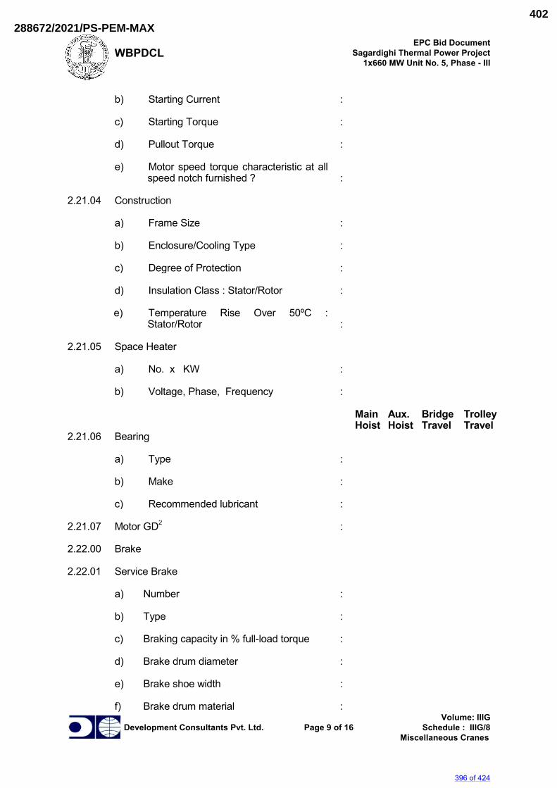
WBPDCL EPC Bid Document
Sagardighi Thermal Power Project 1x660 MW Unit No. 5, Phase - III
Development Consultants Pvt. Ltd. Page 9 of 16 Volume: IIIG
Schedule : IIIG/8 Miscellaneous Cranes
b) Starting Current : c) Starting Torque : d) Pullout Torque : e) Motor speed torque characteristic at all
speed notch furnished ? :
2.21.04 Construction a) Frame Size : b) Enclosure/Cooling Type : c) Degree of Protection : d) Insulation Class : Stator/Rotor : e) Temperature Rise Over 50ºC :
Stator/Rotor :
2.21.05 Space Heater a) No. x KW : b) Voltage, Phase, Frequency : Main Aux. Bridge Trolley
Hoist Hoist Travel Travel 2.21.06 Bearing a) Type : b) Make : c) Recommended lubricant : 2.21.07 Motor GD2 : 2.22.00 Brake 2.22.01 Service Brake a) Number : b) Type : c) Braking capacity in % full-load torque : d) Brake drum diameter : e) Brake shoe width : f) Brake drum material :
396 of 424
288672/2021/PS-PEM-MAX402
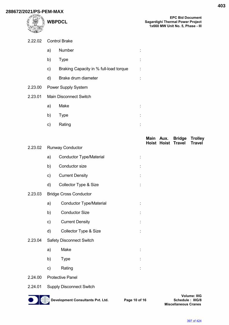
WBPDCL EPC Bid Document
Sagardighi Thermal Power Project 1x660 MW Unit No. 5, Phase - III
Development Consultants Pvt. Ltd. Page 10 of 16 Volume: IIIG
Schedule : IIIG/8 Miscellaneous Cranes
2.22.02 Control Brake a) Number : b) Type : c) Braking Capacity in % full-load torque : d) Brake drum diameter : 2.23.00 Power Supply System 2.23.01 Main Disconnect Switch a) Make : b) Type : c) Rating : Main Aux. Bridge Trolley
Hoist Hoist Travel Travel 2.23.02 Runway Conductor a) Conductor Type/Material : b) Conductor size : c) Current Density : d) Collector Type & Size : 2.23.03 Bridge Cross Conductor a) Conductor Type/Material : b) Conductor Size : c) Current Density : d) Collector Type & Size : 2.23.04 Safety Disconnect Switch a) Make : b) Type : c) Rating : 2.24.00 Protective Panel 2.24.01 Supply Disconnect Switch
397 of 424
288672/2021/PS-PEM-MAX403
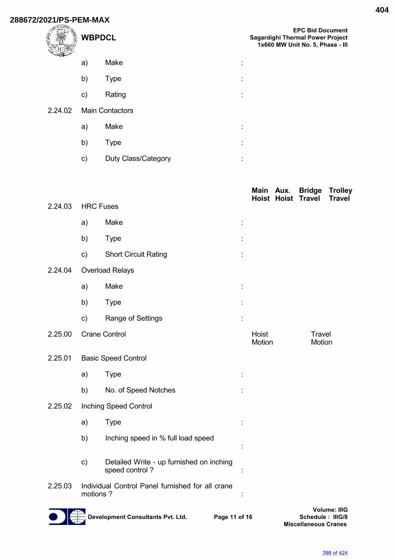
WBPDCL EPC Bid Document
Sagardighi Thermal Power Project 1x660 MW Unit No. 5, Phase - III
Development Consultants Pvt. Ltd. Page 11 of 16 Volume: IIIG
Schedule : IIIG/8 Miscellaneous Cranes
a) Make : b) Type : c) Rating : 2.24.02 Main Contactors a) Make : b) Type : c) Duty Class/Category : Main Aux. Bridge Trolley
Hoist Hoist Travel Travel 2.24.03 HRC Fuses a) Make : b) Type : c) Short Circuit Rating : 2.24.04 Overload Relays a) Make : b) Type : c) Range of Settings : 2.25.00 Crane Control Hoist Travel
Motion Motion 2.25.01 Basic Speed Control a) Type : b) No. of Speed Notches : 2.25.02 Inching Speed Control a) Type : b) Inching speed in % full load speed
:
c) Detailed Write - up furnished on inching
speed control ? :
2.25.03 Individual Control Panel furnished for all crane
motions ? :
398 of 424
288672/2021/PS-PEM-MAX404
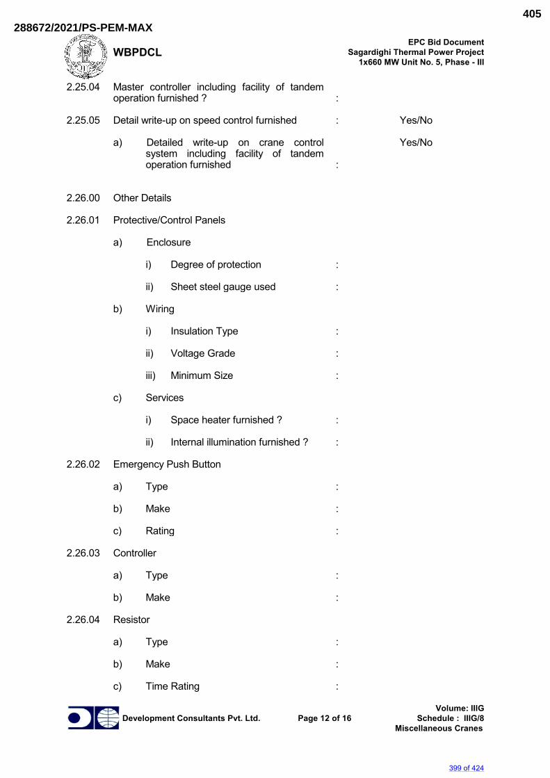
WBPDCL EPC Bid Document
Sagardighi Thermal Power Project 1x660 MW Unit No. 5, Phase - III
Development Consultants Pvt. Ltd. Page 12 of 16 Volume: IIIG
Schedule : IIIG/8 Miscellaneous Cranes
2.25.04 Master controller including facility of tandem operation furnished ?
:
2.25.05 Detail write-up on speed control furnished : Yes/No a) Detailed write-up on crane control
system including facility of tandem operation furnished
:
Yes/No
2.26.00 Other Details 2.26.01 Protective/Control Panels a) Enclosure i) Degree of protection : ii) Sheet steel gauge used : b) Wiring i) Insulation Type : ii) Voltage Grade : iii) Minimum Size : c) Services i) Space heater furnished ? : ii) Internal illumination furnished ? : 2.26.02 Emergency Push Button a) Type : b) Make : c) Rating : 2.26.03 Controller a) Type : b) Make : 2.26.04 Resistor a) Type : b) Make : c) Time Rating :
399 of 424
288672/2021/PS-PEM-MAX405
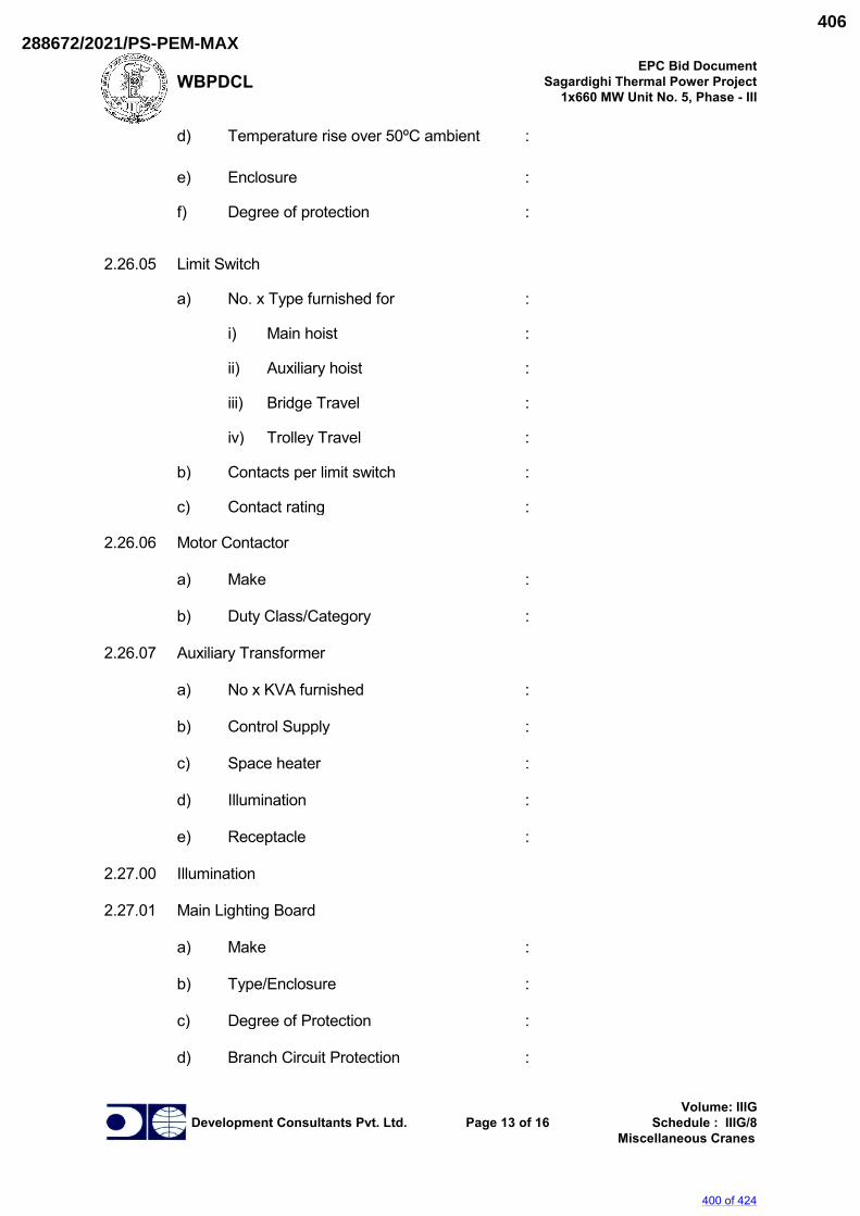
WBPDCL EPC Bid Document
Sagardighi Thermal Power Project 1x660 MW Unit No. 5, Phase - III
Development Consultants Pvt. Ltd. Page 13 of 16 Volume: IIIG
Schedule : IIIG/8 Miscellaneous Cranes
d) Temperature rise over 50ºC ambient : e) Enclosure : f) Degree of protection : 2.26.05 Limit Switch a) No. x Type furnished for : i) Main hoist : ii) Auxiliary hoist : iii) Bridge Travel : iv) Trolley Travel : b) Contacts per limit switch : c) Contact rating : 2.26.06 Motor Contactor a) Make : b) Duty Class/Category : 2.26.07 Auxiliary Transformer a) No x KVA furnished : b) Control Supply : c) Space heater : d) Illumination : e) Receptacle : 2.27.00 Illumination 2.27.01 Main Lighting Board a) Make : b) Type/Enclosure : c) Degree of Protection : d) Branch Circuit Protection :
400 of 424
288672/2021/PS-PEM-MAX406
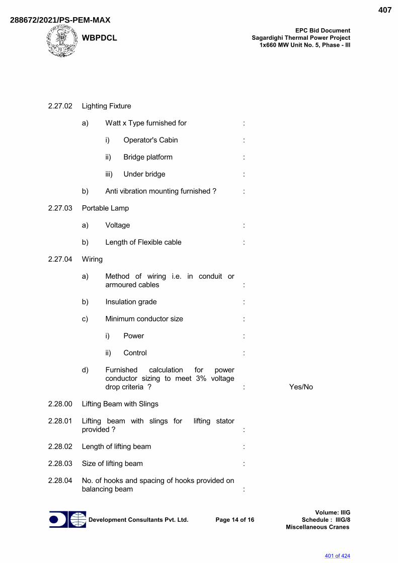
WBPDCL EPC Bid Document
Sagardighi Thermal Power Project 1x660 MW Unit No. 5, Phase - III
Development Consultants Pvt. Ltd. Page 14 of 16 Volume: IIIG
Schedule : IIIG/8 Miscellaneous Cranes
2.27.02 Lighting Fixture a) Watt x Type furnished for : i) Operator's Cabin : ii) Bridge platform : iii) Under bridge : b) Anti vibration mounting furnished ? : 2.27.03 Portable Lamp a) Voltage : b) Length of Flexible cable : 2.27.04 Wiring a) Method of wiring i.e. in conduit or
armoured cables :
b) Insulation grade : c) Minimum conductor size : i) Power : ii) Control : d) Furnished calculation for power
conductor sizing to meet 3% voltage drop criteria ?
:
Yes/No
2.28.00 Lifting Beam with Slings 2.28.01 Lifting beam with slings for lifting stator
provided ? :
2.28.02 Length of lifting beam : 2.28.03 Size of lifting beam : 2.28.04 No. of hooks and spacing of hooks provided on
balancing beam :
401 of 424
288672/2021/PS-PEM-MAX407
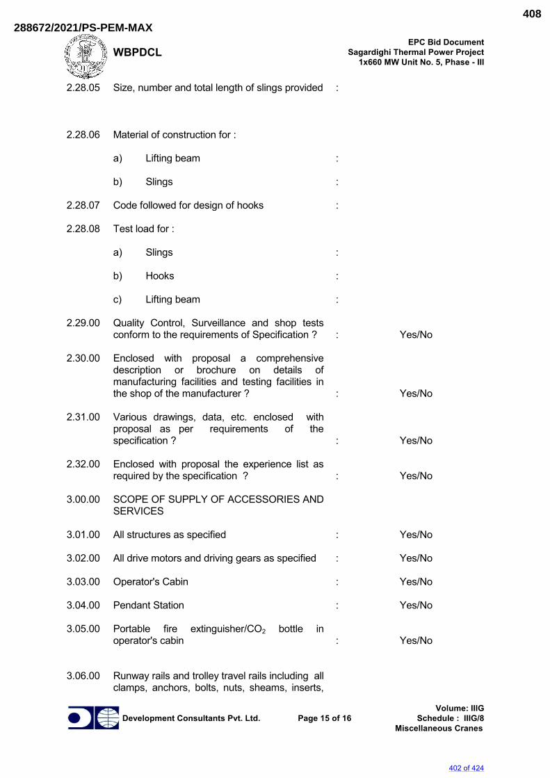
WBPDCL EPC Bid Document
Sagardighi Thermal Power Project 1x660 MW Unit No. 5, Phase - III
Development Consultants Pvt. Ltd. Page 15 of 16 Volume: IIIG
Schedule : IIIG/8 Miscellaneous Cranes
2.28.05 Size, number and total length of slings provided : 2.28.06 Material of construction for : a) Lifting beam : b) Slings : 2.28.07 Code followed for design of hooks : 2.28.08 Test load for : a) Slings : b) Hooks : c) Lifting beam : 2.29.00 Quality Control, Surveillance and shop tests
conform to the requirements of Specification ? :
Yes/No
2.30.00 Enclosed with proposal a comprehensive
description or brochure on details of manufacturing facilities and testing facilities in the shop of the manufacturer ?
:
Yes/No
2.31.00 Various drawings, data, etc. enclosed with
proposal as per requirements of the specification ?
:
Yes/No
2.32.00 Enclosed with proposal the experience list as
required by the specification ? :
Yes/No
3.00.00 SCOPE OF SUPPLY OF ACCESSORIES AND
SERVICES
3.01.00 All structures as specified : Yes/No 3.02.00 All drive motors and driving gears as specified : Yes/No 3.03.00 Operator's Cabin : Yes/No 3.04.00 Pendant Station : Yes/No 3.05.00 Portable fire extinguisher/CO2 bottle in
operator's cabin :
Yes/No
3.06.00 Runway rails and trolley travel rails including all
clamps, anchors, bolts, nuts, sheams, inserts,
402 of 424
288672/2021/PS-PEM-MAX408
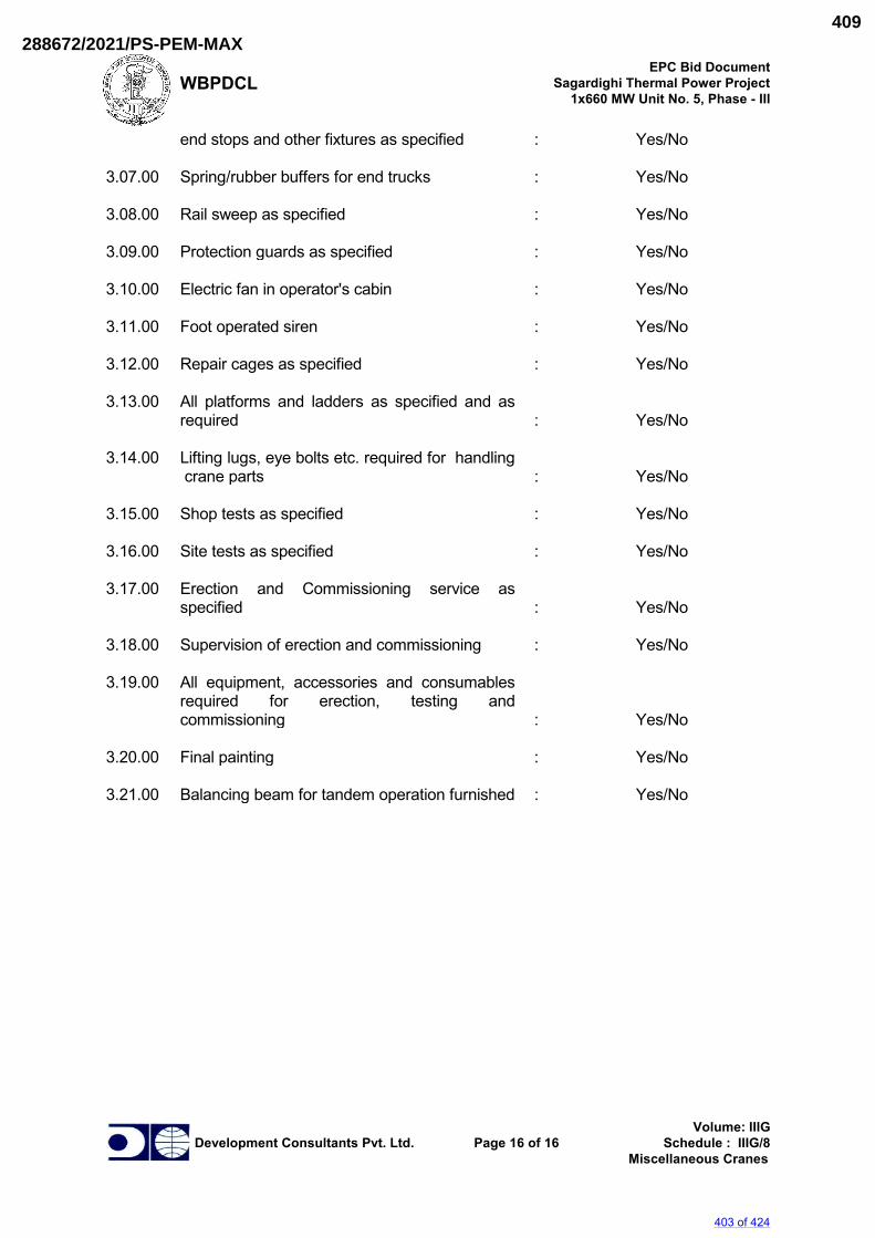
WBPDCL EPC Bid Document
Sagardighi Thermal Power Project 1x660 MW Unit No. 5, Phase - III
Development Consultants Pvt. Ltd. Page 16 of 16 Volume: IIIG
Schedule : IIIG/8 Miscellaneous Cranes
end stops and other fixtures as specified : Yes/No 3.07.00 Spring/rubber buffers for end trucks : Yes/No 3.08.00 Rail sweep as specified : Yes/No 3.09.00 Protection guards as specified : Yes/No 3.10.00 Electric fan in operator's cabin : Yes/No 3.11.00 Foot operated siren : Yes/No 3.12.00 Repair cages as specified : Yes/No 3.13.00 All platforms and ladders as specified and as
required :
Yes/No
3.14.00 Lifting lugs, eye bolts etc. required for handling
crane parts :
Yes/No
3.15.00 Shop tests as specified : Yes/No 3.16.00 Site tests as specified : Yes/No 3.17.00 Erection and Commissioning service as
specified :
Yes/No
3.18.00 Supervision of erection and commissioning : Yes/No 3.19.00 All equipment, accessories and consumables
required for erection, testing and commissioning
:
Yes/No
3.20.00 Final painting : Yes/No 3.21.00 Balancing beam for tandem operation furnished : Yes/No
403 of 424
288672/2021/PS-PEM-MAX409
SAGARDIGHI THERMAL POWER PROJECT, 1 X 660 MW UNIT NO 5, STAGE III.
TG HALL– AB BAY 160/25T DOUBLE GIRDER EOT CRANES
STANDARD TECHNICAL REQUIREMENT
SPECIFICATION No: PE-TS-445-501-A001
SECTION II
REV. 00 09-05-2021
SECTION – II STANDARD TECHNICAL SPECIFICATION
404 of 424
288672/2021/PS-PEM-MAX410
SAGARDIGHI THERMAL POWER PROJECT, 1 X 660 MW UNIT NO 5, STAGE III.
TG HALL– AB BAY 160/25T DOUBLE GIRDER EOT CRANES
STANDARD TECHNICAL REQUIREMENT
SPECIFICATION No: PE-TS-445-501-A001
SECTION II
REV. 00 09-05-2021
DOUBLE GIRDER EOT CRANE 1.0.0 SCOPE
This specification covers the design, material, manufacture, assembly, inspection and
testing at manufacturer works for EOT cranes and shall be applicable unless the
requirements are addressed otherwise in BHEL / Customer‟s documents in order sections.
2.0.0 CODES AND STANDARDS The equipment to be supplied under this specification shall conform to the following codes
and standards (latest revisions) unless otherwise specified hereinafter.
i) IS 807 Codes of Practice for Design, Manufacture,
Erection and Testing (Structural Portion) of
cranes and hoists
ii) IS: 3177 Code of Practice for Design of Overhead
Travelling Cranes and Gantry Cranes other than
steel work cranes.
iii) IS: 2266 Specification for steel wire ropes for general
Engineering purposes.
iv) IS: 4029 Guide for testing induction motor (for
temperature rise).
v) IS: 15560 Steel hooks for standard shank design.
vi) IS: 3443 Specification for crane rail section.
vii) IS: 325 Three phase induction motors.
viii) IS: 900 Code of practice for installation and
maintenance of induction motors.
ix) IS: 4237 General requirement of switchgear and Control
gear for voltage not exceeding 1000V.
x) IS: 434 (Part I) Copper conductors rubber insulated cables for
voltage up to 1000V.
xi) IS 1596 Polyethylene insulated PVC sheathed cables
xii) IS 3043 Code of practice Earthing
xiii) IS: 3938 Electric Wire Rope Hoists.
xiv) IS: 2147 Degree of protection provided by enclosures for
Low voltage switchgear and control gear.
xv) IS: 1554 Part I PVC insulated (Heavy-duty) electric cables for
working voltages up to and including 1100 volts.
xvi) IS: 691 Flexible trailing cables rubber insulated.
xvii) IS: 1653 Steel conduits for general engineering
purposes.
xviii) IS: 2509 Rigid non-metallic conduit for electric-
Installations
405 of 424
288672/2021/PS-PEM-MAX411
SAGARDIGHI THERMAL POWER PROJECT, 1 X 660 MW UNIT NO 5, STAGE III.
TG HALL– AB BAY 160/25T DOUBLE GIRDER EOT CRANES
STANDARD TECHNICAL REQUIREMENT
SPECIFICATION No: PE-TS-445-501-A001
SECTION II
REV. 00 09-05-2021
xix) IS: 2062 Steel for General Engineering purposes.
xx) IS: 1030 Carbon Steel castings for general engineering
purposes.
xxi) IS: 1570 Schedules for Wrought steels.
xxii) IS: 1875 Carbon steel billets, blooms, slabs and bars for
forgings.
xxiii) IS: 808 Dimensions for hot rolled steel beam, column,
channel and angle sections.
xxiv) IS: 1852 Rolling and cutting tolerances for Hot rolled
steel products.
xxv) IS: 2291 Tangential Keys and Keyways.
xxvi) IS: 2292 Taper Keys and Keyways.
xxvii) IS: 3961 Recommended current rating for cables.
xxviii) IS: 694 PVC insulated cables for working voltages up to
and including 1100V)
xxix) IS: 1554 (part-I) PVC insulated (heavy duty) electric cables:
Part 1: for working voltages up to and including
1100 volts.
xxx) IS: 4289 Flexible cables for lifts and other flexible
connections: Part 1: Elastomer insulated cables.
xxxi) BS: 970 Wrought steels in the form of blooms, billets,
bars and forgings.
xxxii) IS: 5749/ BS 3017 Specification for Forged Rams horn Hooks
Indian electricity rules - 1956. In the event of any conflict between the specification and standards mentioned above, the
more stringent of the two as per interpretation of BHEL/Customer shall govern.
3.0.0 DOUBLE GIRDER EOT CRANE 3.1.0 DESIGN REQUIREMENTS 3.1.1 The crane shall be designed in accordance with the latest edition of IS-3177, IS-807 and
any other standard as referred there in and subject to any modification and requirement as
specified herein after.
Class of crane mechanism shall correspond to that of the crane requirement and as
specified elsewhere.
3.1.2 Safety devices should be provided with all equipment/parts covered under this specification.
3.1.3 Parts requiring replacement or lubrication shall easily be accessible without dismantling the
other equipment or structures. All electrical cables shall be laid to comply with recognized
standards and purchaser‟s requirements.
406 of 424
288672/2021/PS-PEM-MAX412
SAGARDIGHI THERMAL POWER PROJECT, 1 X 660 MW UNIT NO 5, STAGE III.
TG HALL– AB BAY 160/25T DOUBLE GIRDER EOT CRANES
STANDARD TECHNICAL REQUIREMENT
SPECIFICATION No: PE-TS-445-501-A001
SECTION II
REV. 00 09-05-2021
3.1.4 For welded construction such as bridge girders, end carriages, rope drum, gearboxes etc.
steel shall be conforming to IS-2062 quality. Welding shall be carried out only by qualified
welders and subjected to NDT as specified in Quality Plan.
a. Welding shall be performed by shielded electric arc, gas or other approved methods.
The electrodes used for welding shall conform to AWS A5.1.
b. Wherever lateral welding of the main plates of box girders are required, it shall be butt-
welded.
c. Qualification of welding procedure and welder: These shall be carried out as per ASME
Boiler and Pressure vessel code Sec. IX - Welding and brazing qualifications.
d. Electrode designations and qualifications shall be as per AWS A 5.1.
e. Electrodes should be of radiography quality with heavy covering as per IS: 814 and
relevant requirement of ASME Sec IX and IIC.
f. Bare electrodes as per IS: 7280 and flux wire combination as per IS: 3613.4e
3.1.5 VOID
3.1.6 Guard shall be provided on crane to prevent the hoist ropes coming in contact with down
shop leads.
Guards/ rail sweep of an approved design, which will push forward or off the track any
object such as a person foot or arm, placed across it. Guards shall be attached to each end
of the end carriages.
Suitable guards shall be provided to revolving shafts, coupling etc.
3.1.7 All cables shall be clamped individually. All trailing cables shall be clamped with PVC or
non-metallic clamp.
3.1.8 Walkways of CT shall be of chequered plate minimum 6 mm thick O/P at least
800 mm clear inside with non-skid toe plates 8mm thick, projecting 100 mm above the floor.
Walkways shall be of rigid construction and designed to sustain a distributed load of not less
than 300 kg/ sq. mm.
Intermediate posts for supporting handrails shall not be spaced more than 1.5 meters apart.
Ladders provided shall have at least 450mm clear width with 20 mm rungs (rods) spaced
300 mm apart.
3.1.9 All wheels, couplings, open gear etc. shall be provided with covers.
3.1.10 All bolts except those with locknut shall be provided with grip lock nuts or spring washers.
3.1.11 Fasteners for pedestal blocks, motors, gearboxes etc. shall be easily removable from the
top. Studs shall not be used as fasteners for mechanical items except for fixing covers.
3.1.12 Defects in the material like fractures, cracks, blowholes, pitting etc. are not allowed.
Rectification of any such flaw is permissible only with the approval of the purchaser.
3.1.13 All parts of the crane shall be thoroughly cleaned of mill scales, rust or foreign matter and
then painted as per the specification requirements.
The permissible camber shall be shown in drawing or data sheet submitted for approval.
407 of 424
288672/2021/PS-PEM-MAX413
SAGARDIGHI THERMAL POWER PROJECT, 1 X 660 MW UNIT NO 5, STAGE III.
TG HALL– AB BAY 160/25T DOUBLE GIRDER EOT CRANES
STANDARD TECHNICAL REQUIREMENT
SPECIFICATION No: PE-TS-445-501-A001
SECTION II
REV. 00 09-05-2021
3.2.0 STRUCTURAL DETAILS 3.2.1.0 Crane structure shall be designed in accordance with the latest edition of IS-807
after taking the following additions/deviations as applicable.
3.2.1.1 Black bolts shall not be used in the main structure of the crane. The calculated strength of
other bolted joints in structural members shall not be less than net strength of member plus
25%.
3.2.1.2 The calculated strength of riveted joint or joints made by friction grip bolts in structure
members shall be not less than the calculated net strength of the member.
3.2.1.3 Bolts used in shear shall be fitted in to reamed hole.
3.2.1.4 Nuts and Bolts will be as per IS:1363, IS: 1364 and IS: 1367
High-tension friction grip bolts as per IS: 3757 and High- tension friction grip nuts as
per IS: 6623
3.2.1.5 Transverse filled welding on load carrying member shall be avoided.
3.2.1.6 All butt welds on structural members subjected to tensile stress shall be of radiographic
quality as ASME Sec VIII Div.1 acceptance norms.
3.2.1.7 Fillet welding on load carrying members shall be avoided.
3.2.1.8 For load carrying members the component plates, bars, angles and other rolled sections
shall be minimum 8mm thick. For tubes having both ends sealed the minimum thickness shall
be 4.9 mm (6 SWG). For unsealed tubes the minimum thickness shall be 8mm.
3.2.1.9 The cranes working out door or in corrosive environment, an allowance of 1.5 mm shall be
added to the calculated thickness.
3.2.1.10 Minimum thickness of chequered plates for platform shall be over 6 mm over plain.
Chequered plates shall not be considered for strength calculations of load carrying
members.
3.2.1.11 Splice shall be designed to resist all the forces and moments to which it is subjected to plus
50% thereof.
3.2.1.12 However, in no case the strength developed by the splice shall be less than 50% of the
effective strength of the material spliced. Splices shall be proportioned and arranged, so
that the gravity axis of the splice in line with the gravity axis of the member joined so as to
avoid the eccentricity of the loading.
3.2.1.13 The material of construction of the major components shall be as specified in the
specification/data sheet. Manufacturer are however free to use alternate material which are
superior for the intended service. But in all the cases, prior concurrence of the purchaser is
must.
3.2.1.14 Splices shall be designed to resist one and half times the forces and moments to which it is
subjected, but in no case it shall be less than 2/3rd of the effective strength of the material
spliced except that splices in the webs of the plate girders shall be designed for full strength of
the web in shear as well as bending. For splicing tension members, the net section of the
splice plate shall be ten percent more than that of the material spliced. Splices shall be
408 of 424
288672/2021/PS-PEM-MAX414
SAGARDIGHI THERMAL POWER PROJECT, 1 X 660 MW UNIT NO 5, STAGE III.
TG HALL– AB BAY 160/25T DOUBLE GIRDER EOT CRANES
STANDARD TECHNICAL REQUIREMENT
SPECIFICATION No: PE-TS-445-501-A001
SECTION II
REV. 00 09-05-2021
proportioned and arranged, so that the gravity axes of the splices are in line with the gravity
axis of the member to avoid eccentricity.
3.2.2 Bridge Girder 3.2.2.1 The bridge girder shall consist of a box construction with double Web plate girders and shall
be of adequate strength to withstand the rolling loads and other stresses it is subjected to..
The design of the girder shall be in accordance with latest edition of IS- 807.
3.2.2.2 Maximum deflection of the bridge girder, with safe working load, shall not exceed 1/900 of
the span or as per latest IS. The girder shall be supported on the centerline of LT wheels
during the deflection check. The girder shall be cambered by an amount by an amount
equal to the maximum deflection.
3.2.2.2 Box section shall be adequately reinforced by internal diaphragms and ribs to withstand the
most severe combination of load that may develop under different working conditions.
Additional Internal diaphragms shall be provided at points where external members are
welded for providing support to drives etc.
3.2.2.3 Box girders shall be provided with end plates sealing. Diaphragms inside the girder shall
extend to the full - width & depth of the girder and the web plates shall be reinforced by
angles all along the full length of the plates spaced midway between the diaphragms. Full
depth diaphragms or stiffeners shall be furnished at bridge drive supports and below the
line shaft bearings.
3.2.2.5 Short diaphragms shall be furnished and are required to transmit the trolley wheel loads to
the web plates. Trolley rail section shall not be considered into design of bridge girders.
3.2.2.6 Full length chequered platforms on both side shall be provided on the side of bridge girders
as specified in data sheet - A.
3.2.2.7 There should not be accumulation of water/oil inside the box girders. If required breathing
holes can be provided for expansion / contraction, due to change in temperature. Tapped
(threaded) holes shall be provided with ½” NPT plug in the bottom of the girders, at both
ends, to drain off any accumulation of water / Oil inside the girder. Instruction shall be
painted on the girders to remove the plug and check for water/oil before lifting. Plug shall be
replaced after installation.
3.2.2.8 All connection splices shall be designed for full strength of member of loads indicated
unless otherwise approved. Beams and connections shall be designed for 60% of shear
capacity of beam section plus additional axial load if any. Not more than one splice shall be
provided to make up full length of number.
3.2.2.9 Maximum Span/ Depth ratio for Plate Girder shall be 25 or as per IS 807 latest edition.
3.2.3 End carriage
3.2.3.1 End carriages shall be fabricated from rolled steel section or plates. End carriage shall be of
ample strength to resist all stresses likely to be imposed on them under service conditions
409 of 424
288672/2021/PS-PEM-MAX415
SAGARDIGHI THERMAL POWER PROJECT, 1 X 660 MW UNIT NO 5, STAGE III.
TG HALL– AB BAY 160/25T DOUBLE GIRDER EOT CRANES
STANDARD TECHNICAL REQUIREMENT
SPECIFICATION No: PE-TS-445-501-A001
SECTION II
REV. 00 09-05-2021
including collision with other cranes or stops. The length of the end carriages shall be such
that no other part of the crane is damaged in collision. End carriage shall be so designed as
to distribute the load evenly between the wheels from each bridge girders.
3.2.3.2 End carriage shall be fitted with safety stop to prevent the end carriage falling more than 25
mm in the event of breakage of a track wheel, bogies or axle.
3.2.3.3 Suitable jacking pads at a suitable height from rail level shall be provided on each crane for
crane jacking. Jacking pad dimensions shall be suitable for full seating of the jacking pad
seat without any instability. When changing the track wheel, jacking pads shall not interfere
with replacement of track wheel.
3.2.4 Crab (Trolley) 3.2.4.1 The crab frame shall be built from heavy steel section, welded properly to form single piece
frame & to resist vertical, lateral and torsional strain and to support all loads without undue
deflection. It should be properly machined to receive hoisting mechanism, cross traverse
arrangement/mechanism, wheels etc. etc.
3.2.4.2 Sheaves, part of hoisting mechanism, shall be so arranged on trolley that rope reeling
arrangement shall ensure lifting of load in vertical line with minimum of swing or side
movement. Trolley shall be provided with chequered plates all over except for opening
required for ropes and equipment foundation. Equipment foundation shall not be welded/
supported on chequered plates. Toe plates 100 mm high and 6mm thick shall be provided
around opening provided for movement of ropes. Suitable railing shall also be provided
around the opening for rope in case the opening is large.
3.2.4.3 Platforms and Ladders
a) Safe means of access shall be provided to every place where any person engaged in the
examination or maintenance of the crane has to work. Adequate handholds and footholds
shall be provided as necessary..
b) Every platform shall be provided with steel chequered plate top and be securely fenced
with 1000 mm high double tier hand rails and toe boards. Platforms shall be of sufficient
width to enable normal maintenance work to be undertaken safely
c) Safety hand railing of tubular construction 32 mm NB Medium class of IS: 1239 having top
and bottom rail at height of 1000 mm and 600 mm and vertical post spacing not exceeding
1500 mm with provision of kick plate (100 mm high and 6mm thick) shall be provided on
bridge walkways and on end carriages, staircases, trolley and at any other place where
access is provided. Bends shall be neat and made by machine. The top rail should be so laid
that there is no intermediate obstruction and hand need not be lifted from rail while walking
d) In case lattice riveted construction is offered for the bridge girder, full length chequered
plate platform with adequate headroom shall also be provided at bottom chord level for
periodic checking of all rivets/bolts and other items.
3.2.5.0 Brief description of crane operation, Maintenance and periodical lubrication etc. typed in
English and in local language neatly framed in a permanent frame for easy reference.
410 of 424
288672/2021/PS-PEM-MAX416
SAGARDIGHI THERMAL POWER PROJECT, 1 X 660 MW UNIT NO 5, STAGE III.
TG HALL– AB BAY 160/25T DOUBLE GIRDER EOT CRANES
STANDARD TECHNICAL REQUIREMENT
SPECIFICATION No: PE-TS-445-501-A001
SECTION II
REV. 00 09-05-2021
3.2.6.0 Suitable inspection cages to accommodate two persons to facilitate inspection of DSL.
3.3.0 MECHANICAL 3.3.1 Rope drums
Rope drums shall be of mild steel plate fabricated/ cast steel/ as per IS 3177. All fabricated
rope drums shall be stress relieved. The drum shall be so designed to take full length of
hoisting rope in single layers. The end of the rope shall be anchored to the drum in such a
way that the charger in readily accessible. Each rope shall have not less than two (2) full
turns on the drum when the hook is at lowest position not taking into consideration the turns
covered by the rope in charge. One spare groove shall be provided for each rope drum
when the hook is at the highest position. Each rope end shall be clamped with minimum two
clamping wedges with at least two bolts on each clamping arrangement.
The pitch diameter of the drum shall be as per IS - 3177 or as specified elsewhere. The
depth of the grove shall not be less than 0.35 times the rope diameter. Each rope shall be
clamped to drum with two clamp wedges with at least two numbers of bolts on each
clamping arrangement.
For evaluation of Radiography the designed thickness of the drum (top of crest to ID) shall
be taken into consideration and not the thickness of plate selected.
3.3.2 Hoist ropes Ropes of steel core as specified in Data sheet” A” shall be of 6x36 or 6x37 construction of
extra flexible plough steel as per IS 2266.
3.3.3 Rope sheaves Sheaves shall be of cast (Castings IS: 1030 Gr. II with Y.P. greater than 50% of UTS) or
forged steel. All sheaves shall be identical, however, exception may be made for equalizer
sheave. Sheave groove shall be ground finished for getting increase rope life. Equalizer
sheave shall be arranged to turn and swivel in order to maintain rope alignment under all
circumstances.
3.3.4 Wheels LT & CT wheels shall be double flanged with straight tread. The wheels shall be capable of
taking up misalignment in span. Solid wheel shall either be of forged steel or as specified in
Data sheet. The wheel rim shall be with minimum hardness of BHN 300-350. Wheels may
be either hardened on tread portion as per IS –3177 or Volume hardened. Contact stresses
between wheels and rails should be within permissible limits.
3.3.5 Buffer
411 of 424
288672/2021/PS-PEM-MAX417
SAGARDIGHI THERMAL POWER PROJECT, 1 X 660 MW UNIT NO 5, STAGE III.
TG HALL– AB BAY 160/25T DOUBLE GIRDER EOT CRANES
STANDARD TECHNICAL REQUIREMENT
SPECIFICATION No: PE-TS-445-501-A001
SECTION II
REV. 00 09-05-2021
Each End carriage shall be provided with buffer as per data sheet „A‟. Buffers should be so
located that removal is not required while changing wheels or bogies. Buffers shall have
sufficient tension on energy absorption capacity to bring the unloaded crane to rest from the
speed of 100% of the rated speed to zero speed. Buffer is to be fitted to each end of
carriage assembly and crab so that buffer contact takes place before the bridge or trolley
reaches the end of rail.
3.3.6 LT drive The bridge motion shall be achieved by suitable drive arrangement as specified
elsewhere. When twin drives are used, these shall be operating in unison to avoid skewing
effect. The drives shall be interlocked for simultaneous starting, stopping & speed control.
3.3.7 CT drive Trolley drive shall be achieved by suitable drives & power shall be transmitted to the geared
wheel by means of pinions mounted on both ends of the output shaft.
3.3.8. Gearing 3.3.8.1 Gears in speed reducer unit for bridge drive, hoists and trolley drive gearing shall be
enclosed in substantial housing and shall operate in oil bath. The housing shall be of
sufficient design not to permit temperature in excess of 90oC for the oil bath. Spur and
helical gearing shall normally be used for all motions. Worms and bevel gears shall not be
used. First high-speed reduction shall be through helical gears. All gears shall be hardened
and tempered and of alloy steel with machine cut teeth 1.6 Micron finish or better and
lapped with some minimum applied load to remove high spots and to improve tooth contact.
Cast alloy steel is acceptable only for gears in the last stage of speed reduction. Surface
hardening of teeth is not acceptable. Gear teeth shall preferably be cut in metric module
system. Gears shall be designed to meet requirement of crane duty as per IS: 3177. The
ratings of gears shall be established as per IS: 4660.
3.3.9 Gear Box 3.3.9.1 All gears shall be completely covered and enclosed in oil tight casing & sealed with gasket.
In case of totally enclosed gearboxes, splash or automatic lubrication system shall be used.
Covers shall be split horizontally at each shaft centre line, so that top half can be removed
for inspection and repair with out disturbing the bottom half. Gear shafts shall be supported
on ball/roller bearings mounted in gearbox unless specially agreed otherwise. The gear
boxes shall be provided with breather, air vent, oil level indicator, dip stick, drain plug and
lugs for lifting.
Radial clearance between the gear boxes inner surface and outside diameter of the gears
shall be at least 1.25 times the depth of larger gear tooth inside the gear box or 20mm
412 of 424
288672/2021/PS-PEM-MAX418
SAGARDIGHI THERMAL POWER PROJECT, 1 X 660 MW UNIT NO 5, STAGE III.
TG HALL– AB BAY 160/25T DOUBLE GIRDER EOT CRANES
STANDARD TECHNICAL REQUIREMENT
SPECIFICATION No: PE-TS-445-501-A001
SECTION II
REV. 00 09-05-2021
which ever in higher. Facial clearance between inner surface of gearbox and face of gear
or pinion shall be at least 20 mm. Gearbox shall be inspected in line with QP and as per
PEM (Q)/001 enclosed.
3.3.9.2 The gearboxes shall be of mild steel or cast steel. All fabricated gearboxes shall be stress
relieved at a temperature between 590 to 680 deg. C. The temperature shall be maintained
within + 20 deg. C and at no time during the soaking cycle the temperature shall fall below
590 deg. C or exceed 680 deg. C. Soaking shall be done for a period proportionate to 1
(one) hour/ 2.5 cm. of wall thickness.
3.3.10 Bearing 3.3.10.1 Ball and roller antifriction bearing of attached sub-vendor list, make shall be used
throughout, except where specified otherwise. Drive side bearing on Hoisting equipment
shall be ball / roller bearing type. Rated life of ball and roller bearing shall be not less than
total working life as per data sheet-A. Life of bearing shall be calculated in accordance with
manufacturer‟s recommendations.
3.3.10.2 Provision shall be made for service lubrication of all bearings. Lubrication arrangement and
clamping shall be done neatly. Bends in pipe shall be done with the help of machine.
Bearing enclosures shall be designed as far as practicable to exclude dirt and shall prevent
oil leakage. Accessibility should be such that parts may be safely lubricated from the
walkway or ladder when the crane is not in motion.
3.3.11. Shafts, Couplings and axles 3.3.11.1 Shafts and axles shall be made from solid rolled or forged steel bars and shall have ample
strength and rigidity and adequate bearing surface. If shouldered, they shall be provided
with fillets of ample radius and /or be tapered to avoid stress concentration.
Motor shafts shall be connected to gearbox input extension shafts through flexible
gear coupling. Solid coupling shall be used for connecting intermediate lengths of long
travel shafts. For driving hoist drum full-geared couplings shall be used between hoists
drum & hoist gearbox output shaft. Couplings shall be of cast steel/wrought steel
conforming to IS: 1030 grade 280-520 and shall be designed to suit service conditions.
3.3.11.2 Self-aligning type gear couplings shall be used between connection shafts to take care of
transverse as well as axial movement whenever necessary. Whenever components of
considerable amount of inertia are directly mounted on the high-speed shaft (e.g. brake
drum, coupling etc.) they shall be balanced statically to minimise vibration.
3.3.12 Repair Cage
A repair cage shall be provided on the inside of the end carriage for attending the main
current collectors. The repair cage shall be adequately sized to accommodate two persons.
413 of 424
288672/2021/PS-PEM-MAX419
SAGARDIGHI THERMAL POWER PROJECT, 1 X 660 MW UNIT NO 5, STAGE III.
TG HALL– AB BAY 160/25T DOUBLE GIRDER EOT CRANES
STANDARD TECHNICAL REQUIREMENT
SPECIFICATION No: PE-TS-445-501-A001
SECTION II
REV. 00 09-05-2021
And guarded for safety and correctly located for the intended service. Suitable access to
the cage shall be provided. Repair cage shall be provided at the corner of the crane.
3.3.13 Lifting hook
Standard hooks shall be used unless otherwise specified. These hooks shall conform to the
latest edition. All hooks used shall be in normalized condition only.
3.3.14 LIFTING HOOK BLOCK ASSY
3.3.14.1 Lifting hook block assembly shall be Ram shorn type or approved for capacity greater than
40 Tonnes and point hook with Shank for capacity upto 40 Tonnes and shall be of forged
steel construction. Hooks shall be manufactured from Blooms, billets, rounds by forging with
forging ratio of at least 3:1. Hooks manufactured from plates are not acceptable. All hooks
used shall be in normalized condition only. Each hook shall be supported on ball or roller
thrust bearing and shall rotate freely.
3.3.14.2 The sheaves of the hook block shall be enclosed in a casing permitting generous lubrication
of wire ropes, sheaves and also preventing accidental tapping of hands.
3.3.15 Brakes 3.3.15.1 Selection and design of brakes shall be such as to meet the requirement. Brakes shall be
designed to suit 150% of torque transmitted to the brake drum with full load for hoist
motions and 125% of motor rated torque before de-rating for LT/CT motion. Brakes shall be
provided as specified in Data Sheet „A‟. Brake drum shall be separately mounted and
coupling halves shall not be used as brake drum.
i) SERVICE BRAKE Double shoe types & disc type service brakes shall be provided for each motion of the crane
as/or as specified in Data Sheet. The service brakes shall apply automatically when power
supply to the drive motor is cut off or fails.
ii) HOIST CONTROL Hoist motion shall be provided with a self-contained sturdy braking system to control
the speed of hoisting as well as lowering motion. The braking system shall be reasonably
uniform and effective in all loads at any position.
3.4.0 ELECTRICAL 3.4.1 The scope of supply shall cover all electrical equipments comprising from Main isolating
switch, down shop leads, trolley conductors, current collectors etc.
3.4.1.1 Main Disconnecting/Isolating Switch fuse unit shall be provided at 1.5M above the operating
floor level at one end / at both the ends of bay length or in the middle as specified in the
data sheet A. Termination of incoming power supply cable to isolating switch fuse unit and
414 of 424
288672/2021/PS-PEM-MAX420
SAGARDIGHI THERMAL POWER PROJECT, 1 X 660 MW UNIT NO 5, STAGE III.
TG HALL– AB BAY 160/25T DOUBLE GIRDER EOT CRANES
STANDARD TECHNICAL REQUIREMENT
SPECIFICATION No: PE-TS-445-501-A001
SECTION II
REV. 00 09-05-2021
further cable from switch to down shop leads shall be included in the bidder‟s scope of work.
The switch shall be provided with Power ON Red indication lamp.
3.4.1.2 Run way conductors (Down shop leads) shrouded conductor as specified in the data sheet
A shall have four conductors. One of the conductors shall be connected to earth grid for
earthing connections of all electrical equipment on the crane and shall be connected to
suitable collecting gear of earth conductor. Voltage drop across the down shop leads shall
be less than 3% or specified in data sheet “A”. It shall be supplied with brackets.
Maintenance cage for DSL shall be provided on crane.
3.4.1.3 The current collectors shall be with adequate current carrying capacity and shall maintain
adequate contact pressure. Spacing between current collectors shall be such as to provide
sufficient quenching area for sparks coming out of collectors surface. The collector system
per conductor shall spring loaded CI/carbon metallic shoes to maintain adequate contact
pressure.
3.4.1.4 The cable, supplying power to crane trolley shall be flexible trailing cable as per
IS-9968 Part I (latest edition) and mounted on retracting supports (festoon type).
3.4.2 DRIVE MOTORS 3.4.2.1 Crane Motors shall be totally enclosed, fan cooled and as per data sheet „A‟. The starting
torque of motor shall not be less than 2.25 times the rated torque and pull out torque shall
not be less than 275% of the rated full load torque of motor. In case of VVVF drive system,
the creep speed will be achieved through VVVF drives and the motors for Main hoists,
Auxiliary hoist, CT and LT will be Squirrel cage. Hoisting drive motors shall be provided with
antifriction roller / ball bearings on the drive side.
3.4.2.2 Ambient correction factors as well as voltage /frequency correction factors depending up on
the ambient temperature and voltage /frequency variation shall be applied to de-rate the
motors. The minimum margin of 10% shall be considered over the calculated rating of the
motor. The protection class of the motors shall be as IP-55. Motors shall be tested at
manufacturer‟s works in accordance with IS-325/as per agreed Quality plan & Reports shall
be submitted for approval. Motors shall comply with the requirement of IS-325 or as per the
motor spec.
3.4.2.3 All the motors shall be provided with lifting lugs two earth terminals of adequate size to
accept the earthing conductors shall be provided at diametrically opposite points unless
specifically designed For higher speeds, motors shall be capable of with-standing 2.5 times
the rated speed.
3.4.2.4 Motors shall be painted in line with painting instructions specified in Painting Scheme
Annexure IV attached along with the technical specification.
3.4.3 Limit switches The hoist mechanism of the crane shall be provided with rotary type limit switch to open the
control circuit & in order to prevent the crane hook from over hoisting and over lowering, one
415 of 424
288672/2021/PS-PEM-MAX421
SAGARDIGHI THERMAL POWER PROJECT, 1 X 660 MW UNIT NO 5, STAGE III.
TG HALL– AB BAY 160/25T DOUBLE GIRDER EOT CRANES
STANDARD TECHNICAL REQUIREMENT
SPECIFICATION No: PE-TS-445-501-A001
SECTION II
REV. 00 09-05-2021
gravity type back up limit switch of hand reset type shall also be provided. This switch will
operate in the event of failure of main limit switch. Lever operated limit switches shall be
provided at both ends of longitudinal travel and cross traverse. These limit switches shall be
self-reset type. The limit switches shall be as per “Data Sheet A”
3.4.4 Switch
All switches shall be hand operated; air break, heavy duty, quick make and quick break
type. Incoming supply disconnect switch shall be interlocked with panel door so that the
same cannot be opened unless the switch is in OFF position. Safety Interlocks-Disconnect
Switch-The operating handle of the main/ safety disconnect switch shall be mechanically
interlocked with enclosure cover such that the same cannot be opened unless the switch is
in OFF position. Main/ safety disconnect switch shall have provision of pad locking in OFF
position
3.4.5. Contactors. Contactors shall be suitable for heavy duty, with current rating not less than connected
motor full load current. All reversing contactors shall be mechanically and electrically
interlocked.
Each contactor shall be provided with three positive acting ambient temp. Compensated
thermal overload relay with adjustable setting to suit the motor current. The relay shall be
hand reset type, suitable for current. The relays shall be replaceable from front. The main
contactor shall be electrically interlocked so that it cannot close unless all the motor
overload relays are RESET and all controllers are in OFF position. The main contactor shall
be also opened by means of emergency push buttons and hoist limit switches.
3.4.6 Push button and lamp Push button shall be spring return type with 2 NO + 2 NC contacts, rated 10A, 240 V AC.
Indicating lamps and lens shall be replaceable from front.
3.4.7 Protective Panel 3.4.7.1 The electrical protective panel shall be a cubicle fabricated from Cold rolled sheet steel not
less than 2.5mm for front & rear & 2mm for side, top & bottom portion with gland plate of
3mm thick with lockable-hinged door. The control cabinet‟s door shall be interlocked with
the operating handles of isolating switches of supply circuits so as to prevent opening of the
door when an isolating switch is closed. A device for bypassing the interlock shall also be
provided. It shall be dust and vermin proof with degree of protection as IP-54 or as specified
in data sheet A. All the equipment inside the panel shall have permanent identification. The
panels shall be front connected type with front-hinged door for access to wiring and
terminals. Engraved nameplate shall be furnished for all panels and also for the equipment
and devices mounted there on.
416 of 424
288672/2021/PS-PEM-MAX422
SAGARDIGHI THERMAL POWER PROJECT, 1 X 660 MW UNIT NO 5, STAGE III.
TG HALL– AB BAY 160/25T DOUBLE GIRDER EOT CRANES
STANDARD TECHNICAL REQUIREMENT
SPECIFICATION No: PE-TS-445-501-A001
SECTION II
REV. 00 09-05-2021
The following minimum equipment shall be provided.
a) One triple pole air break type main contactor with thermal overload relay.
b) One triple pole main line connecting/disconnecting switch.
c) Emergency push button at convenient height for the operation for interruption of the entire
power.
d) Thermal overload relay for each drive. It shall be ambient temperature compensated and
adjustable type.
e) Contactors, timer and auxiliary contactors.
f) Portable Lighting Transformer rated for 415/24V.
g) Lighting Voltage Transformer with fuse 415/24V.
h) Control transformer with fuses.
i) Indicating lamps to indicate the live condition of all three phases.
j) Main supply ON/OFF lamps on the door of the protective panel.
k) Electrical interlock shall be provided to prevent the main contactor being closed unless all
controllers are in OFF position.
l) Other equipment as per supplier‟s standard practice. Air break contactors shall conform to
category AC-4 duty. The main contacts shall have the rating for 5 Amps or as specified in
the data sheet A. The contactor drop off voltage shall be between 45-50% of rated voltage.
m) All internal wiring shall be identified with numbering rules at both ends as per the relevant
wiring diagram.
n) Each panel shall have internal illumination with fluorescent lamp. The inside of the
panel shall be painted white.
o) Separate terminal blocks shall be provided for terminating circuits of various voltage
classes. At least 20% spare terminals for the wire terminations shall be provided in the
cabinet.
3.4.8 Starter Panel Separate panels shall be provided for CT, LT & hoist motion (Main and Auxiliary), with
following type of items.
a) Contactors : AC4 duty for reversing applications
AC3 duty for non-reversing applications
b) Switches : AC23 for motor application.
AC22 for other application
c) Fuses : HRC
d) Overload relays: Temperature compensated bi-metallic with single phasing preventer.
3.4.9 MOTOR CONTROL PANEL
417 of 424
288672/2021/PS-PEM-MAX423
SAGARDIGHI THERMAL POWER PROJECT, 1 X 660 MW UNIT NO 5, STAGE III.
TG HALL– AB BAY 160/25T DOUBLE GIRDER EOT CRANES
STANDARD TECHNICAL REQUIREMENT
SPECIFICATION No: PE-TS-445-501-A001
SECTION II
REV. 00 09-05-2021
The motor control panels shall be dust and weatherproof to IP-54/55 or as specified in “Data
Sheet A” & shall be provided separate for each motion. The panel shall contain minimum
the following components.
a) Switch fuse unit with contacts of adequate rating for each motion.
b) Thermal overload relay for each drive. These shall be ambient temperature
compensated adjustable type.
c) Contactors, timers and auxiliary contactors.
d) The panel shall be provided with space heater. The space heater with thermostat
shall be located at the bottom of the panel and shall have individual ON/OFF switch.
e) Terminal blocks shall be stud or snap on type. A protective cover shall be fixed
on top of terminal blocks to prevent accidental contact. A minimum of 20%
spare terminals shall be provided.
f) Air break contactors shall be provided for main supply as well as for
motors. They shall confirm to category AC-4 as per IS-1322. These shall have
three main contacts and 2 No. & 2 NC auxiliary contacts.
g) The main contacts shall have the ratings as per duty requirement but auxiliary
contact shall be rated for 5 amp 240V AC. The contactor drop off voltage shall be
between 45-50% of rated voltage. The contactor coil shall be suitable for 240V AC
supply.
h) The auxiliary contactors shall have 4 No. + 4 NC contacts for control and
interlocking purposes. The contacts shall be convertible. The contacts rating shall
be suitable for 5 amps at 240 Volts AC.
i) Adequate protection for overload and short circuit shall be provided for all the three
phases of each motor.
j) Double pole switch fuse unit for control circuit of the contractor „START (push
button and a pilot lamp with the red lens for indicating the contactor “CLOSED” shall
be furnished.
3.4.11 Illumination
Crane lighting and space heating system shall be designed for 240V, 1Phase 50Hz supply
and receptacle system with 24V 1Phase 50Hz supply or as specified in the Data sheet A.
Suitable dry type transformers shall be furnished for this purpose, complete with isolation
facility and Primary/secondary fuses.
a) Branch Circuits for lighting and receptacles shall be individually protected by switch fuse
units.
b) CFL fixtures shall be used for lighting operator's cabin and bridge platform.
b) 40W LED lamp shall be used for lighting bridge platform.
c) Four (4) nos - 160 W LED lamps shall be provided under the bridge as specified in the data
sheet “A”
418 of 424
288672/2021/PS-PEM-MAX424
SAGARDIGHI THERMAL POWER PROJECT, 1 X 660 MW UNIT NO 5, STAGE III.
TG HALL– AB BAY 160/25T DOUBLE GIRDER EOT CRANES
STANDARD TECHNICAL REQUIREMENT
SPECIFICATION No: PE-TS-445-501-A001
SECTION II
REV. 00 09-05-2021
d) All lighting fixtures shall be mounted with anti-vibration mounting and shall be easily
accessible for maintenance.
e) 24V - 5A - 3 pin industrial socket outlets shall be provided. Minimum four (4) on the bridge
along the walk way on both sides of full length platforms.
f) One (1) portable 40 W LED hand lamp with min. half span length flexible cable for
inspection of crane components.
3.4.13 Grounding
3.4.13.1 The crane structure, motor frame and all other electrical equipment/s shall be grounded in
accordance with the Indian Electricity Rules. The connections from Crane Bridge to 4th
conductor of down shop leads shall be by means of current collector.
3.4.13.2 The equipment fed by flexible cables shall be grounded by means of fourth core provided in
the flexible trailing cable. Pendent push button station shall be earthed separately.
3.4.14 Red warning light 3 Nos. shall be provided at both ends of the gantry girder to indicate the
aliveness of DSL.
3.4.15 Wiring Systems
a) All electrical equipment, accessories and wiring shall have tropical protection involving
special treatment of insulation and metal against fungus, insects and corrosion. All cabling
shall be carried out using XLPE insulated fire resistant (FRLS) cables & wiring by Heat
resistance PVC wires with stranded conductor
b) All wiring shall be done with 1100V grade fire resistance PVC insulated wire in conduits or
by 1100V grade PVCA PVC cables with extruded inner sheath.
c) For selecting the cable rating, cable for power wiring, consideration shall be given to the
motor duty, ambient temperature grouping and disposition of the cables voltage drop etc.
d) Armoured cables or un-armoured running through the flexible conduits may be used for
power wiring / control and auxiliary circuit wiring shall run through flexible conduits.
e) Each motor shall be wired independently. Power and control wiring shall be effectively
separated.
f) Each wire shall be identified at both ends with wire designation in accordance with circuit
wiring diagram.
g) All wire termination to the panels shall be provided with clamp type connections screw.
Screw Type terminals with screw directly impinging on conductors are not acceptable.
h) Multi way terminal blocks complete with screw nut, washer and marking strips shall be
furnished for terminating the panel wiring.
i) Not more than two wires shall be connected to any terminal on either side of terminal block. If
necessary number of terminals shall be jumped together to provide the wiring points
j) Each terminal block shall be marked with designation in accordance with conductors wiring
diagram.
419 of 424
288672/2021/PS-PEM-MAX425
SAGARDIGHI THERMAL POWER PROJECT, 1 X 660 MW UNIT NO 5, STAGE III.
TG HALL– AB BAY 160/25T DOUBLE GIRDER EOT CRANES
SPECIFICATION No: PE-TS-437-501-A001
SECTION III
REV. 00 09-05-2021
SECTION III
1. DOCUMENTS TO BE SUBMITTED ALONG WITH BID 2. PRE-BID CLARIFICATION SCHEDULE 3. COMPLIANCE CUM CONFIRMATION CERTIFICATE
420 of 424
288672/2021/PS-PEM-MAX426
SAGARDIGHI THERMAL POWER PROJECT, 1 X 660 MW UNIT NO 5, STAGE III.
TG HALL– AB BAY 160/25T DOUBLE GIRDER EOT CRANES
LIST OF DOCS TO BE SUBMITTED ALONG WITH BID
SPECIFICATION No: PE-TS-445-501-A001
SECTION III
REV. 00 09-05-2021
DRAWINGS / DOCUMENTS TO BE SUBMITTED WITH THE BID
Bidder shall submit the following drawings / documents along with their bid for technical offer:
a) Deviation schedule with reference to specific clauses of the specification along with reason for
such deviation in the „Deviation Schedule‟ (Cost of withdrawal) format as attached in GCC.
b) Un-priced copy of price format indicating “quoted/ not quoted” against each row/column.
c) Copy of technical pre-bid clarifications/ amendment/ corrigendum issued by BHEL, if any, duly
signed & stamped.
d) Signed/ Stamped copy of Compliance cum Confirmation Certificate.
OFFER WILL BE CONSIDERED AS INCOMPLETE IN ABSENCE OF ANY OF ABOVE
DOCUMENTS. DOCUMENT OTHER THAN ABOVE, IF ANY, SUBMITTED WITH THE OFFER
WILL NOT FORM PART OF CONTRACT AND WILL NOT BE CONSIDERED FOR BID
EVALUATION.
421 of 424
288672/2021/PS-PEM-MAX427
SAGARDIGHI THERMAL POWER PROJECT, 1 X 660 MW UNIT NO 5, STAGE III.
TG HALL– AB BAY 160/25T DOUBLE GIRDER EOT CRANES
PRE-BID CLARIFICATION SCHEDULE
SPECIFICATION No: PE-TS-445-501-A001
SECTION III
REV. 00 09-05-2021
PRE-BID CLARIFICATION SCHEDULE
S. NO. SECTION/CLAUSE/PAGE NO. STATEMENT OF THE REFERRED CLAUSE
CLARIFICATION REQUIRED
The bidder hereby clarifies that above mentioned are the only clarifications required on the technical specification for the subject package.
Signature: ______________
Name: _________________
Designation: ____________
Company: ______________
Date: __________________
Company Seal
422 of 424
288672/2021/PS-PEM-MAX428
SAGARDIGHI THERMAL POWER PROJECT, 1 X 660 MW UNIT NO 5, STAGE III.
TG HALL– AB BAY 160/25T DOUBLE GIRDER EOT CRANES
COMPLIANCE CUM CONFIRMATION CERTIFICATE
SPECIFICATION No: PE-TS-445-501-A001
SECTION III
REV. 00 09-05-2021
COMPLIANCE CUM CONFIRMATION CERTIFICATE The bidder shall confirm compliance with following by signing / stamping this compliance certificate (every sheet) and furnish same with the offer.
a) The scope of supply, technical details, construction features, design parameters etc. shall be as per technical specification & there are no exclusions, other than those mentioned under “exclusion and those resolved as per ‘Schedule of Deviations’, with regard to same.
b) There are no other deviations w.r.t. specifications other than those furnished in the ‘Schedule
of Deviations’. Any other deviation, stated or implied, taken elsewhere in the offer stands withdrawn unless specifically brought out in the ‘Schedule of Deviations’
c) Bidder shall submit QP in the event of order based on the guidelines given in the
specification & QP enclosed therein. QP will be subject to BHEL / CUSTOMER approval & customer hold points for inspection / testing shall be marked in the QP at the contract stage. Inspection / testing shall be witnessed as per same apart from review of various test certificates/ Inspection records etc. This is within the contracted price without any extra implications to BHEL after award of the contract.
d) All drawings/ data-sheets / calculations etc. submitted along with the offer shall not be taken
cognizance off. e) The offered materials shall be either equivalent or superior to those specified in the
specification & shall meet the specified / intended duty requirements. In case the material specified in the specifications is not compatible for intended duty requirements then same shall be resolved by the bidder with BHEL during the pre-bid discussions, otherwise BHEL / Customer’s decision shall be binding on the bidder whenever the deficiency is pointed out.
For components where materials are not specified, same shall be suitable for intended duty, all materials shall be subject to approval in the event of order.
f) The commissioning spares shall be supplied on ‘As Required Basis’ & prices for same
included in the base price itself.
g) All sub vendors shall be subject to BHEL / CUSTOMER approval in the event of order.
h) Guarantee for plant/equipment shall be as per relevant clause of GCC / SCC / Other Commercial Terms & Conditions
i) In the event of order, all the material required for completing the job at site shall be supplied by the bidder within the ordered price even if the same are additional to approved billing break up, approved drawing or approved Bill of quantities within the scope of work as tender specification. This clause will apply in case during site commissioning, additional requirements emerges due to customer and / or consultant’s comments. No extra claims shall be put on this account
j) Schedule of drawings submissions, comment incorporations & approval shall be as
stipulated in the specifications. The successful bidder shall depute his design personnel to BHEL’s / Customer’s / Consultant’s office for across the table resolution of issues and to get documents approved in the stipulated time.
k) As built drawings shall be submitted as and when required during the project execution.
l) The bidder has not tempered with this compliance cum confirmation certificate and if at any
stage any tempering in the signed copy of this document is noticed then same shall be treated as breach of contract and suitable actions shall be taken against the bidder.
423 of 424
288672/2021/PS-PEM-MAX429
SAGARDIGHI THERMAL POWER PROJECT, 1 X 660 MW UNIT NO 5, STAGE III.
TG HALL– AB BAY 160/25T DOUBLE GIRDER EOT CRANES
COMPLIANCE CUM CONFIRMATION CERTIFICATE
SPECIFICATION No: PE-TS-445-501-A001
SECTION III
REV. 00 09-05-2021
m) Successful bidder shall furnish detailed erection manual for each of the equipment supplied
under this contract at least 3 months before the scheduled erection of the concerned equipment / component or along with supply of concerned equipment / component whichever is earlier.
n) Document approval by customer under Approval category or information category shall not
absolve the vendor of their contractual obligations of completing the work as per specification requirement. Any deviation from specified requirement shall be reported by the vendor in writing and require written approval. Unless any change in specified requirement has been brought out by the vendor during detail engineering in writing while submitting the document to customer for approval, approved document (with implicit deviation) will not be cited as a reason for not following the specification requirement.
o) In case vendor submits revised drawing after approval of the corresponding drawing, any
delay in approval of revised drawing shall be to vendor’s account and shall not be used as a reason for extension in contract completion.
424 of 424
288672/2021/PS-PEM-MAX430