the third generation of gravitational wave observatories and their science reach
TRANSCRIPT
The third generation of gravitational wave observatories and their science reach
This article has been downloaded from IOPscience. Please scroll down to see the full text article.
2010 Class. Quantum Grav. 27 084007
(http://iopscience.iop.org/0264-9381/27/8/084007)
Download details:
IP Address: 131.215.220.185
The article was downloaded on 21/10/2010 at 16:38
Please note that terms and conditions apply.
View the table of contents for this issue, or go to the journal homepage for more
Home Search Collections Journals About Contact us My IOPscience
IOP PUBLISHING CLASSICAL AND QUANTUM GRAVITY
Class. Quantum Grav. 27 (2010) 084007 (23pp) doi:10.1088/0264-9381/27/8/084007
The third generation of gravitational waveobservatories and their science reach
M Punturo1,2, M Abernathy3, F Acernese4,5, B Allen6, N Andersson7,K Arun8, F Barone4,5, B Barr3, M Barsuglia9, M Beker10, N Beveridge3,S Birindelli11, S Bose12, L Bosi1, S Braccini13, C Bradaschia13, T Bulik14,E Calloni4,15, G Cella13, E Chassande Mottin9, S Chelkowski16,A Chincarini17, J Clark18, E Coccia19,20, C Colacino13, J Colas2,A Cumming3, L Cunningham3, E Cuoco2, S Danilishin21, K Danzmann6,G De Luca22, R De Salvo23, T Dent18, R Derosa4,15, L Di Fiore4,15,A Di Virgilio13, M Doets10, V Fafone19,20, P Falferi24, R Flaminio25,J Franc25, F Frasconi13, A Freise16, P Fulda16, J Gair26, G Gemme17,A Gennai16, A Giazotto2,13, K Glampedakis27, M Granata9, H Grote6,G Guidi28,29, G Hammond3, M Hannam30, J Harms31, D Heinert32,M Hendry3, I Heng3, E Hennes10, S Hild3, J Hough4, S Husa33,S Huttner3, G Jones18, F Khalili34, K Kokeyama16, K Kokkotas27,B Krishnan33, M Lorenzini28, H Luck6, E Majorana35, I Mandel36,37,V Mandic31, I Martin3, C Michel25, Y Minenkov19,20, N Morgado25,S Mosca4,15, B Mours38, H Muller-Ebhardt6, P Murray3, R Nawrodt3,J Nelson3, R Oshaughnessy39, C D Ott40, C Palomba35, A Paoli2,G Parguez2, A Pasqualetti2, R Passaquieti13,41, D Passuello13,L Pinard25, R Poggiani13,41, P Popolizio2, M Prato17, P Puppo35,D Rabeling10, P Rapagnani35,42, J Read33, T Regimbau11, H Rehbein6,S Reid3, L Rezzolla33, F Ricci35,42, F Richard2, A Rocchi19, S Rowan3,A Rudiger6, B Sassolas25, B Sathyaprakash18, R Schnabel6,C Schwarz43, P Seidel43, A Sintes33, K Somiya40, F Speirits3, K Strain3,S Strigin34, P Sutton18, S Tarabrin34, J van den Brand10,C van Leewen10, M van Veggel3, C van den Broeck18, A Vecchio16,J Veitch16, F Vetrano28,29, A Vicere28,29, S Vyatchanin34, B Willke6,G Woan3, P Wolfango44 and K Yamamoto6
1 INFN, Sezione di Perugia, I-6123 Perugia, Italy2 European Gravitational Observatory (EGO), I-56021 Cascina (Pi), Italy3 Department of Physics and Astronomy, The University of Glasgow, Glasgow, G12 8QQ, UK4 INFN, Sezione di Napoli, Italy5 Universita di Salerno, Fisciano, I-84084 Salerno, Italy6 Max-Planck-Institut fur Gravitationsphysik, D-30167 Hannover, Germany7 University of Southampton, Southampton s0171BJ, UK8 LAL, Universite Paris-Sud, IN2P3/CNRS, F-91898 Orsay, France9 AstroParticule et Cosmologie (APC), CNRS; Observatoire de Paris–Universite DenisDiderot-Paris VII, France10 VU University Amsterdam, De Boelelaan 1081, 1081 HV, Amsterdam, The Netherlands11 Universite Nice-Sophia-Antipolis, CNRS, Observatoire de la Cote d’Azur, F-06304 Nice,France12 Washington State University, Pullman, WA 99164, USA13 INFN, Sezione di Pisa, Italy
0264-9381/10/084007+23$30.00 © 2010 IOP Publishing Ltd Printed in the UK & the USA 1
Class. Quantum Grav. 27 (2010) 084007 M Punturo et al
14 Astro. Obs. Warsaw Univ. 00-478; CAMK-PAM 00-716 Warsaw; Bialystok Univ. 15-424;IPJ 05-400 Swierk-Otwock; Inst. of Astronomy 65-265 Zielona Gora, Poland15 Universita di Napoli ’Federico II ’Complesso Universitario di Monte S. Angelo’,1-80126 Napoli, Italy16 University of Birmingham, Birmingham, B15 2TT, UK17 INFN, Sezione di Genova, I-16146 Genova, Italy18 Cardiff University, Cardiff, CF24 3AA, UK19 INFN, Sezione di Roma Tor Vergata 1-00133 Roma, Italy20 Universita di Roma Tor Vergata, I-00133, Roma, Italy21 Moscow State University, Moscow, 119992, Russia22 INFN, Laboratori Nazionali del Gran Sasso, Assergi l’Aquila, Italy23 LIGO, California Institute of Technology, Pasadena, CA 91125, USA24 INFN, Gruppo Collegato di Trento, Sezione di Padova; Istituto di Fotonica e Nanotecnologie,CNR–Fondazione Bruno Kessler, 38123 Povo, Trento, Italy25 Laboratoire des Materiaux Avances (LMA), IN2P3/CNRS, F-69622 Villeurbanne, Lyon,France26 University of Cambridge, Madingley Road, Cambridge, CB3 0HA, UK27 Theoretical Astrophysics (TAT) Eberhard Karls University of Tuebingen Auf der Morgenstelle10, 72076 Tubingen, Germany28 INFN, Sezione di Firenze, I-50019 Sesto Fiorentino, Italy29 Universita degli Studi di Urbino ’Carlo Bo’, I-61029 Urbino, Italy30 Department of Physics, University of Vienna, Boltzmanngass 5, A-1090 Vienna, Austria31 University of Minnesota, Minneapolis, MN 55455, USA32 Friedrich-Schiller-Universitat Jena PF 07737 Jena, Germany33 Max Planck Institute for Gravitational Physics (Albert Einstein Institute) Am Muhlenberg 1,D-14476 Potsdam, Germany34 Moscow State University, Moscow, 119992, Russia35 INFN, Sezione di Roma 1, 1-00185 Roma, Italy36 Department of Physics and Astronomy, Northwestern University, Evanston, IL 60208, USA37 NSF Astronomy and Astrophysics Postdoctoral Fellow38 LAPP–IN2P3/CNRS, Universite de Savoie, F-74941 Annecy-le-Vieux, France39 The Pennsylvania State University, University Park, PA 16802, USA40 Caltech-CaRT, Pasadena, CA 91125, USA41 Universita di Pisa, I-56127 Pisa, Italy42 Universita ’La Sapienza’, I-00185 Roma, Italy43 INFN, Sezione di Roma Tre and Universita di Roma Tre-Dipartimento di Fisica,I-00146 Roma, Italy44 Universita degli Studi di Firenze, I-50121, Firenze, Italy
E-mail: [email protected]
Received 12 November 2009, in final form 12 January 2010Published 6 April 2010Online at stacks.iop.org/CQG/27/084007
AbstractLarge gravitational wave interferometric detectors, like Virgo and LIGO,demonstrated the capability to reach their design sensitivity, but to transformthese machines into an effective observational instrument for gravitationalwave astronomy a large improvement in sensitivity is required. Advanceddetectors in the near future and third-generation observatories in more than onedecade will open the possibility to perform gravitational wave astronomicalobservations from the Earth. An overview of the possible science reaches andthe technological progress needed to realize a third-generation observatory arediscussed in this paper. The status of the project Einstein Telescope (ET),a design study of a third-generation gravitational wave observatory, will bereported.
2
Class. Quantum Grav. 27 (2010) 084007 M Punturo et al
PACS number: 04.80.Nn
(Some figures in this article are in colour only in the electronic version)
1. Introduction
The first generation of interferometric gravitational wave (GW) detectors (GEO600 [1],LIGO [2], TAMA [3], Virgo [4]) approximately reached their design sensitivities and thusdemonstrated the effectiveness of the working principle. The major detectors currentlyoperative are an enhanced version of the first generation (Virgo+ and E-LIGO), with largerlaser power and some technological improvements.
Advanced detectors (like ‘Advanced LIGO’ [5] and ‘Advanced Virgo’ [6]) will show asensitivity improved roughly by a factor of 10 with respect to the initial interferometers. Theyare based on technologies currently available, sometimes tested in reduced scale prototypes,but still to be implemented in full scale. According to the current models of GW sources,sensitivity of the advanced interferometers is expected to guarantee the detection of the signalsgenerated by astro-physical sources within months to a year at most. For example, at thenominal sensitivity of the advanced detectors, the expected detection rate of the GW signalgenerated by a binary system of coalescing neutron stars is about a few tens per year [7, 8]. Butapart from extremely rare events, the expected signal-to-noise ratio (SNR) of these detectionsobtained with the advanced detectors is too low for precise astronomical studies of the GWsources and for complementing optical and x-ray observations in the study of fundamentalsystems and processes in the universe.
These considerations led the GW community to start investigating a new (third)generation of detectors. With considerably improved sensitivity, these new machines willopen the era of routine GW astronomy. Since the first detection of a GW signal isexpected to occur in the advanced interferometers, it is especially the understanding andenhancement of the observational aspects that the planning of the third generation must focuson.
To realize a third-generation GW observatory with a significantly enhanced sensitivity(let us consider a target of a factor of 10 improvement in sensitivity with respect to theadvanced detectors in a wide frequency range), several limitations of the technologiesadopted in the advanced interferometers must be overcome and new solutions must bedeveloped to reduce the fundamental and technical noises that will limit the next-generationmachines.
In this paper, for lack of space availability, we will focus on a small subset of thepossible scientific goals of a third-generation GW observatory and give a short overview of thetechnological challenges introduced by this new generation of machines and under evaluationwithin the framework of the Einstein Telescope (ET) design study [9].
2. Science reaches
Figure 1 shows the typical expected sensitivity and the main noise sources of an advancedgravitational wave detector. If a third generation gravitational wave observatory is realizedwith a sensitivity of about a factor 10 more with respect to an advanced interferometer, asshown in figure 2 [10], it will possible to open a new avenue for understanding physics of theextreme phenomena in the universe [11, 12].
3
Class. Quantum Grav. 27 (2010) 084007 M Punturo et al
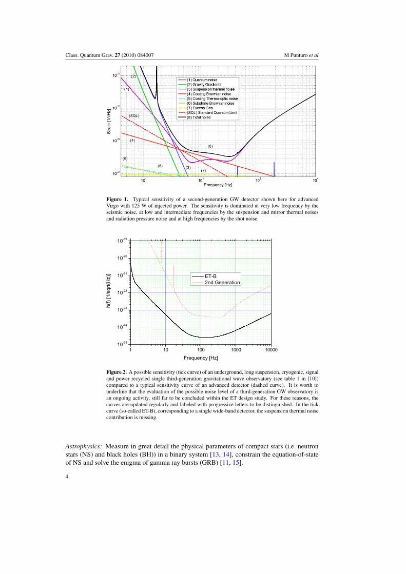
Figure 1. Typical sensitivity of a second-generation GW detector shown here for advancedVirgo with 125 W of injected power. The sensitivity is dominated at very low frequency by theseismic noise, at low and intermediate frequencies by the suspension and mirror thermal noisesand radiation pressure noise and at high frequencies by the shot noise.
Figure 2. A possible sensitivity (tick curve) of an underground, long suspension, cryogenic, signaland power recycled single third-generation gravitational wave observatory (see table 1 in [10])compared to a typical sensitivity curve of an advanced detector (dashed curve). It is worth tounderline that the evaluation of the possible noise level of a third-generation GW observatory isan ongoing activity, still far to be concluded within the ET design study. For these reasons, thecurves are updated regularly and labeled with progressive letters to be distinguished. In the tickcurve (so-called ET-B), corresponding to a single wide-band detector, the suspension thermal noisecontribution is missing.
Astrophysics: Measure in great detail the physical parameters of compact stars (i.e. neutronstars (NS) and black holes (BH)) in a binary system [13, 14], constrain the equation-of-stateof NS and solve the enigma of gamma ray bursts (GRB) [11, 15].
4
Class. Quantum Grav. 27 (2010) 084007 M Punturo et al
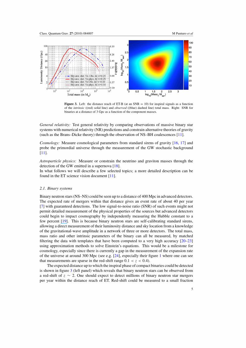
Figure 3. Left: the distance reach of ET-B (at an SNR = 10) for inspiral signals as a functionof the intrinsic ((red) solid line) and observed ((blue) dashed line) total mass. Right: SNR forbinaries at a distance of 3 Gpc as a function of the component masses.
General relativity: Test general relativity by comparing observations of massive binary starsystems with numerical relativity (NR) predictions and constrain alternative theories of gravity(such as the Brans–Dicke theory) through the observation of NS–BH coalescences [11].
Cosmology: Measure cosmological parameters from standard sirens of gravity [16, 17] andprobe the primordial universe through the measurement of the GW stochastic background[11].
Astroparticle physics: Measure or constrain the neutrino and graviton masses through thedetection of the GW emitted in a supernova [18].In what follows we will describe a few selected topics; a more detailed description can befound in the ET science vision document [11].
2.1. Binary systems
Binary neutron stars (NS–NS) could be seen up to a distance of 400 Mpc in advanced detectors.The expected rate of mergers within that distance gives an event rate of about 40 per year[7] with guaranteed detections. The low signal-to-noise ratio (SNR) of such events might notpermit detailed measurement of the physical properties of the sources but advanced detectorscould begin to impact cosmography by independently measuring the Hubble constant to afew percent [19]. This is because binary neutron stars are self-calibrating standard sirens,allowing a direct measurement of their luminosity distance and sky location from a knowledgeof the gravitational-wave amplitude in a network of three or more detectors. The total mass,mass ratio and other intrinsic parameters of the binary can all be measured, by matchedfiltering the data with templates that have been computed to a very high accuracy [20–23]using approximation methods to solve Einstein’s equations. This would be a milestone forcosmology, especially since there is currently a gap in the measurement of the expansion rateof the universe at around 300 Mpc (see e.g. [24], especially their figure 1 where one can seethat measurements are sparse in the red-shift range 0.1 < z < 0.4).
The expected distance up to which the inspiral phase of compact binaries could be detectedis shown in figure 3 (left panel) which reveals that binary neutron stars can be observed froma red-shift of z ∼ 2. One should expect to detect millions of binary neutron star mergersper year within the distance reach of ET. Red-shift could be measured to a small fraction
5
Class. Quantum Grav. 27 (2010) 084007 M Punturo et al
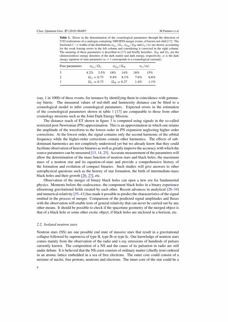
Table 1. Errors in the determination of the cosmological parameters through the detection of5192 realizations of a catalogue containing 1000 BNS merger events, of known red-shift [17]. Thefractional 1−σ widths of the distributions σ��
/��, σ�M/�M and σw/|w| are shown, accounting
for the weak lensing errors in the left column and considering it corrected in the right column.The meaning of these parameters is described in [17] and briefly hereafter: �M and �� are the(dimensionless) energy densities of the dark matter and dark energy, respectively; w is the darkenergy equation of state parameter (w = 1 corresponds to a cosmological constant).
Free parameters σ��/�� σ�M
/�M σw/|w|3 4.2% 3.5% 18% 14% 18% 15%2 �� = 0.73 9.4% 8.1% 7.6% 6.6%1 �� = 0.73 �M = 0.27 1.4% 1.1%
(say, 1 in 1000) of these events, for instance by identifying them in coincidence with gamma-ray bursts. The measured values of red-shift and luminosity distance can be fitted to acosmological model to infer cosmological parameters. Expected errors in the estimationof the cosmological parameters shown in table 1 [17] are comparable to those from othercosmology missions such as the Joint Dark Energy Mission.
The distance reach of ET shown in figure 3 is computed using signals in the so-calledrestricted post-Newtonian (PN) approximation. This is an approximation in which one retainsthe amplitude of the waveform to the lowest order in PN expansion neglecting higher ordercorrections. At the lowest order, the signal contains only the second harmonic of the orbitalfrequency while the higher-order corrections contain other harmonics. The effects of sub-dominant harmonics are not completely understood yet but we already know that they couldfacilitate observation of heavier binaries as well as greatly improve the accuracy with which thesource parameters can be measured [13, 14, 25]. Accurate measurement of the parameters willallow the determination of the mass function of neutron stars and black holes, the maximummass of a neutron star and its equation-of-state and provide a comprehensive history ofthe formation and evolution of compact binaries. Such studies will give answers to otherastrophysical questions such as the history of star formation, the birth of intermediate-massblack holes and their growth [26, 27], etc.
Observation of the merger of binary black holes can open a new era for fundamentalphysics. Moments before the coalescence, the component black holes in a binary experienceultrastrong gravitational fields created by each other. Recent advances in analytical [28–34]and numerical relativity [35–41] has made it possible to predict the characteristics of the signalemitted in the process of merger. Comparison of the predicted signal amplitudes and fluxeswith the observation will enable tests of general relativity that can never be carried out by anyother means. It should be possible to check if the spacetime geometry of the merged object isthat of a black hole or some other exotic object, if black holes are enclosed in a horizon, etc.
2.2. Isolated neutron stars
Neutron stars (NS) are one possible end state of massive stars that result in a gravitationalcollapse followed by supernova of type II, type Ib or type Ic. Our knowledge of neutron starscomes mainly from the observation of the radio and x-ray emissions of hundreds of pulsarscurrently known. The composition of a NS and the cause of its pulsation in radio are stillunder debate. It is believed that the NS crust consists of ordinary matter (chiefly iron) orderedin an atomic lattice embedded in a sea of free electrons. The outer core could consist of amixture of nuclei, free protons, neutrons and electrons. The inner core of the star could be a
6
Class. Quantum Grav. 27 (2010) 084007 M Punturo et al
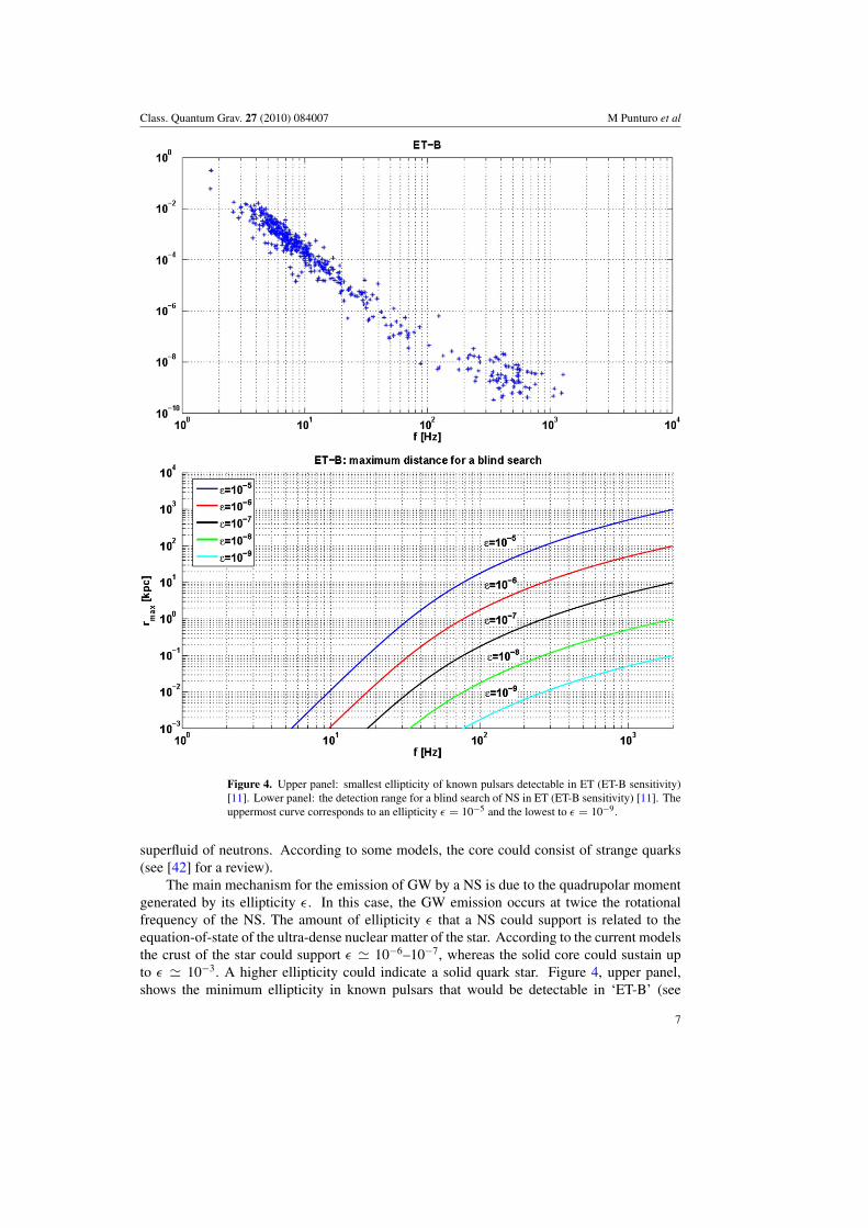
Figure 4. Upper panel: smallest ellipticity of known pulsars detectable in ET (ET-B sensitivity)[11]. Lower panel: the detection range for a blind search of NS in ET (ET-B sensitivity) [11]. Theuppermost curve corresponds to an ellipticity ε = 10−5 and the lowest to ε = 10−9.
superfluid of neutrons. According to some models, the core could consist of strange quarks(see [42] for a review).
The main mechanism for the emission of GW by a NS is due to the quadrupolar momentgenerated by its ellipticity ε. In this case, the GW emission occurs at twice the rotationalfrequency of the NS. The amount of ellipticity ε that a NS could support is related to theequation-of-state of the ultra-dense nuclear matter of the star. According to the current modelsthe crust of the star could support ε � 10−6–10−7, whereas the solid core could sustain upto ε � 10−3. A higher ellipticity could indicate a solid quark star. Figure 4, upper panel,shows the minimum ellipticity in known pulsars that would be detectable in ‘ET-B’ (see
7
Class. Quantum Grav. 27 (2010) 084007 M Punturo et al
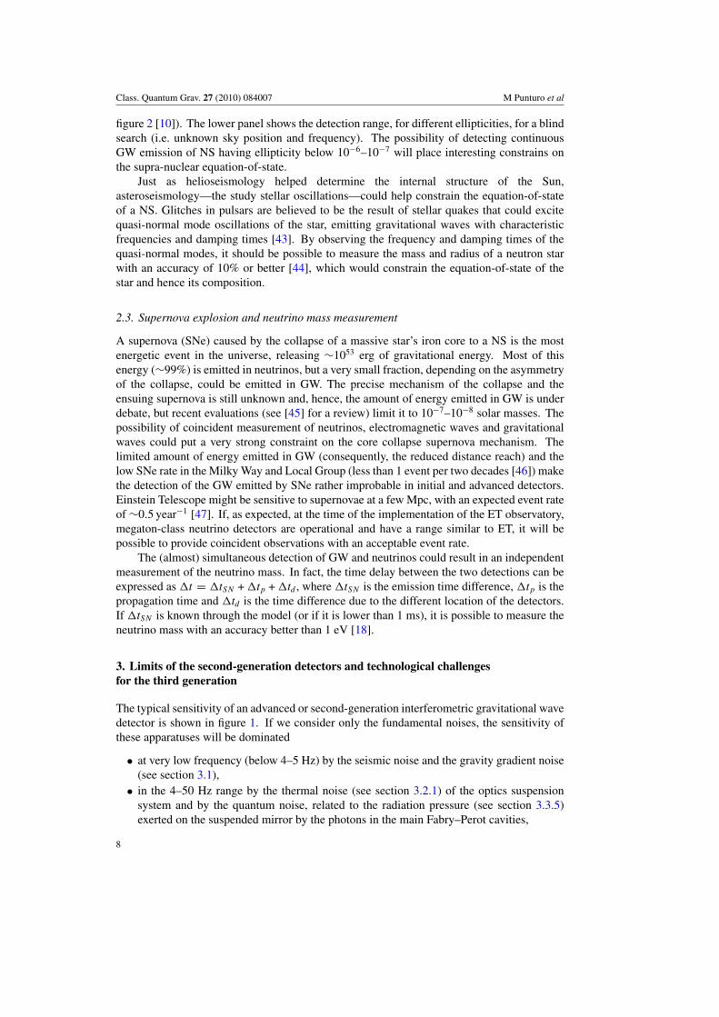
figure 2 [10]). The lower panel shows the detection range, for different ellipticities, for a blindsearch (i.e. unknown sky position and frequency). The possibility of detecting continuousGW emission of NS having ellipticity below 10−6–10−7 will place interesting constrains onthe supra-nuclear equation-of-state.
Just as helioseismology helped determine the internal structure of the Sun,asteroseismology—the study stellar oscillations—could help constrain the equation-of-stateof a NS. Glitches in pulsars are believed to be the result of stellar quakes that could excitequasi-normal mode oscillations of the star, emitting gravitational waves with characteristicfrequencies and damping times [43]. By observing the frequency and damping times of thequasi-normal modes, it should be possible to measure the mass and radius of a neutron starwith an accuracy of 10% or better [44], which would constrain the equation-of-state of thestar and hence its composition.
2.3. Supernova explosion and neutrino mass measurement
A supernova (SNe) caused by the collapse of a massive star’s iron core to a NS is the mostenergetic event in the universe, releasing ∼1053 erg of gravitational energy. Most of thisenergy (∼99%) is emitted in neutrinos, but a very small fraction, depending on the asymmetryof the collapse, could be emitted in GW. The precise mechanism of the collapse and theensuing supernova is still unknown and, hence, the amount of energy emitted in GW is underdebate, but recent evaluations (see [45] for a review) limit it to 10−7–10−8 solar masses. Thepossibility of coincident measurement of neutrinos, electromagnetic waves and gravitationalwaves could put a very strong constraint on the core collapse supernova mechanism. Thelimited amount of energy emitted in GW (consequently, the reduced distance reach) and thelow SNe rate in the Milky Way and Local Group (less than 1 event per two decades [46]) makethe detection of the GW emitted by SNe rather improbable in initial and advanced detectors.Einstein Telescope might be sensitive to supernovae at a few Mpc, with an expected event rateof ∼0.5 year−1 [47]. If, as expected, at the time of the implementation of the ET observatory,megaton-class neutrino detectors are operational and have a range similar to ET, it will bepossible to provide coincident observations with an acceptable event rate.
The (almost) simultaneous detection of GW and neutrinos could result in an independentmeasurement of the neutrino mass. In fact, the time delay between the two detections can beexpressed as �t = �tSN + �tp + �td , where �tSN is the emission time difference, �tp is thepropagation time and �td is the time difference due to the different location of the detectors.If �tSN is known through the model (or if it is lower than 1 ms), it is possible to measure theneutrino mass with an accuracy better than 1 eV [18].
3. Limits of the second-generation detectors and technological challengesfor the third generation
The typical sensitivity of an advanced or second-generation interferometric gravitational wavedetector is shown in figure 1. If we consider only the fundamental noises, the sensitivity ofthese apparatuses will be dominated
• at very low frequency (below 4–5 Hz) by the seismic noise and the gravity gradient noise(see section 3.1),
• in the 4–50 Hz range by the thermal noise (see section 3.2.1) of the optics suspensionsystem and by the quantum noise, related to the radiation pressure (see section 3.3.5)exerted on the suspended mirror by the photons in the main Fabry–Perot cavities,
8
Class. Quantum Grav. 27 (2010) 084007 M Punturo et al
• in the 40–300 Hz range by the thermal noise of the suspended mirrors (mainly the coatingcontribution, see section 3.2.2) and
• at higher frequencies by the shot noise component of the quantum noise (see section3.3.2).
3.1. Seismic noise
Ground based interferometric GW detectors are and will be limited, in the very low frequencyrange, by the natural and anthropomorphic vibration of the soil where the instrument is realized.
Seismic noise acts on the suspended test masses in two ways:
• through the suspension chain, shaking each stage according to its transfer function,• coupling the mass vibration in the soil layers, perturbed by the seismic waves, directly
with the test-mass displacement, via the mutual attraction force expressed by Newton’suniversal law of gravitation (so-called gravity gradient noise or Newtonian noise).
3.1.1. Seismic noise filtering. In a GW detector, the seismic vibrations must be sufficientlyfiltered by the suspension chain before it reaches the test masses. Currently the filtering systemis realized through a chain of harmonic oscillators that filter the seismic vibration horizontally(inverted and ‘normal’ pendulums) and vertically (blades). Virgo currently implemented themost sophisticated of such passive filtering systems and it shows the best sensitivity below40 Hz. The so-called Virgo Super-Attenuator pushes the residual seismic noise below thethermal noise of a first-generation detector like Virgo starting from about 4 Hz [48]. Recentevaluations [49], supported by direct measurements in the Virgo detector, demonstrated thefull validity of the passive filtering design also considering the stringent requirements of asecond-generation GW detector like Advanced Virgo, where the suspension thermal noise isreduced by an order of magnitude.
Passive filtering is not the only way attempted to fight the seismic noise in a GW detector;in the advanced LIGO design, an active philosophy [50] has been implemented: in a chainof three sub-systems, the displacement and the accelerations caused by the seismic noise areread through position and acceleration sensors and are actively and hierarchically suppressedthrough hydraulic and electromagnetic actuators.
In a third-generation GW detector, there are additional requirements that make theachievement of the sensitivity targets very challenging; in fact, the first requirement is theimprovement of the noise level in relation to the advanced detectors roughly by a factor of10 in the whole detection frequency band, but the second and more difficult requirement is toaccess the frequency region between 1 and 10 Hz, excluded in the advanced detectors. Theachievement of both these targets is too challenging to be requested from an improved seismicfiltering system and alternative (or better additive) solutions must be found. It is well knownthat underground sites are seismically quieter (i.e. see [51]) and the possibility of realizingan underground GW detector has been analyzed and selected by the LCGT [52] (Large ScaleCryogenic GW Telescope) collaboration in Japan. The comparison between the seismic noisein the TAMA [53] site (Tokyo) and in the LISM [54] site (Kamioka mine, the prime candidateas an LCGT site) shows a reduction in the low-frequency region, by going underground, by afactor of 100 in terms of acceleration and by two to three orders of magnitude in displacementspectral amplitude. A corresponding and even larger noise reduction has been reached inthe output of the LISM interferometer, due to the fact that going underground several other‘technical’ noises, induced by external disturbances like wind, scattered light or temperaturefluctuations, are suppressed by the quietness of the site.
9
Class. Quantum Grav. 27 (2010) 084007 M Punturo et al
Hence, an underground site can offer the possibility of achieving the desired sensitivityimprovement with respect to an advanced detector in the same frequency band. A preliminaryinvestigation [49] on the compliance of the Virgo Super-Attenuator with the requirements ofa third-generation detector has shown a satisfactory behavior above 4 Hz, whereas to accessthe 1–3 Hz frequency range, major technical upgrades of the suspension system must berealized.
3.1.2. Gravity gradient noise. In the GW interferometers, the suspended test masses aresubject to the random gravitational forces generated by seismic noise and by moving massivebodies [55–57]. Obviously the importance of this disturbance depends on the seismic noiselevel and on the contribution of the other low-frequency noise sources to the noise budget; itis evident that the seismic filtering chain doesn’t play any role for this noise source, since thegravitational force is a direct interaction between the suspended mirrors and the neighboringmasses. In the first generation of GW detectors, the gravity gradient noise does not playany role and in the advanced detectors (due to the improvement of the sensitivity at lowfrequencies), it starts approaching the overall noise level, but remaining negligible above10 Hz (see figure 1).
In the third generation of GW detectors, the more stringent requirements in terms ofsensitivity at low frequency enhance the importance of this noise source. The reduction ofthe seismic noise, due to the possibility of realizing the observatory in an underground site,opens new questions about the validity of the current noise modeling. Recent evaluations[58, 59] have shown the importance, in the noise modeling, of the surface seismic waves, theirrelevance of the experimental cavity shape and the attenuation, going deeply underground(�100 m), of the gravity gradient noise, at least above 1–2 Hz. If that very low frequencyrange needs to be accessed to fulfil the science requirements of a third-generation observatory,a major effort must be made to complement the seismic attenuation with the subtraction of theresidual gravity gradient noise through the signals extracted from a network of sensors locatedaround the detector [58].
3.2. Thermal noise
By thermal noise we indicate all those processes that modulate the optical path of the lightin the interferometer coupling it to the Brownian fluctuation or to the stochastic fluctuationof the temperature field in the optical components. It is common to distinguish between thesuspension thermal noise, affecting the position of the test masses (considered a rigid body)through the fluctuations of the suspension wires or fibers, and the mirror thermal noise, whichis the overlap of all the fluctuation and dissipation processes occurring in the test masses andin the high reflectivity coatings.
3.2.1. Suspension thermal noise. To model and understand the thermal noise in theinterferometers (in thermal equilibrium) two fundamental instruments are used: the equi-partition theorem, which relates the temperature of a system to its average energies, andthe fluctuation–dissipation theorem (FDT) [60], which relates the power spectrum of thefluctuations of a system (in thermal equilibrium) to its dissipation processes, described by themechanical impedance. The equi-partition theorem tells how much thermal energy is presentin a thermo-dynamical system, whereas the FDT describes how that energy is distributed infrequency. The strategies to reduce the thermal noise impact in the second-generation GWdetectors are essentially an evolution of what has been applied in the initial machines andare essentially based on the reduction of the dissipation in the suspension system, in order to
10
Class. Quantum Grav. 27 (2010) 084007 M Punturo et al
concentrate all the fluctuation energy into the normal modes of the system, resulting in a lownoise level off-resonance.
Already in the initial detectors, particular attention has been devoted to the reductionof the dissipation in the suspension by selecting the right material for the suspension wires[61–64], by optimizing the clamping [65] and the mirror-to-wire contact [66] design. Thanks tothe pioneering work of the Glasgow group in the GEO600 collaboration [67, 68], the secondgeneration of GW detectors will adopt the so-called monolithic [69] suspensions (alreadyoperative in GEO600 since 2001), fully realized in fused silica, which simultaneously reducesthe clamping losses and minimizes the losses in the suspension fibers, because of the lowmechanical dissipation of fused silica [70].
In addition to the minimization of the mechanical losses through the selection of thebest materials and geometries, another means for reducing the suspension thermal noise mustbe used in the third generation of GW detectors: the temperature. According to the equi-partition theorem, the temperature is directly proportional to the energy stored in each degreeof freedom of the suspended system allowing to reduce the fluctuation amplitude by loweringthe temperature. Furthermore, at low temperature, some materials show a suppression of thedissipation mechanisms.
Hence, cryogenics is one of the most appealing technologies to reduce the thermal noiseof the optics suspension in a third-generation GW detector. The first problem to be solved ina cryo-interferometer is how to cool down the test masses without introducing additionalvibrations that spoil the very low frequency performances. New technologies are nowavailable, for example based on cryo-cooling systems [71] that are actively damped to reducethe seismic vibration and that promise an easier achievement of low temperatures with lessimpact on the low-frequency performance of the interferometer than previous cryo-coolers.A special design of the suspension system is needed to cool down the test mass withoutintroducing additional vibration. Progress in channeling the heat transmission through asecond, parallel seismic filtering system has been made in the ILIAS [72] project.
Even more important is the right choice of the material for the realization of the last stageof the suspension system. The fused silica suspension, developed for the second-generationGW detectors, cannot be used in cryogenics because of its poor thermal conductivity andbecause of a well-known dissipation peak of that amorphous material at low temperature. Inorder to be a good candidate for a cryogenic suspension, the material must exhibit a highthermal conductivity at the operation temperature chosen, to permit an efficient heat extraction(which is crucial, because of the relatively high heating power deposited in the test masses bythe high light power stored in the interferometer cavities), a low mechanical dissipation angle(to reduce the Brownian thermal noise), a low thermal expansion coefficient (to minimizethe thermo-elastic noise) and a good breaking strength (to safely support the test masses).Currently there are two candidate materials for this role: sapphire and silicon. Sapphire hasbeen selected to realize the suspension fibers of LCGT [52] both for its dissipation [73] andfor its thermal conductivity properties [74]; silicon, on the other hand, has been preliminarilystudied within the ILIAS project and it has been found suitable to realize both suspensionfibers [75] and ribbons [76]. However, it is the matter of fact that currently only sapphire hasbeen used to realize a full cryogenic suspension and the usage of silicon still needs a successfulR&D activity.
3.2.2. Mirror thermal noise. The major limitation of the sensitivity of the second generationof GW detectors in the 40–200 Hz range will be the thermal noise related to the highreflectivity dielectric coating applied to the main cavities mirrors. While the mirror substratematerial chosen (synthetic fused silica) shows low mechanical dissipation, the high refraction
11
Class. Quantum Grav. 27 (2010) 084007 M Punturo et al
component in the dielectric coating (tantalum pentoxide Ta2O5) shows high mechanical lossesthat dominate the dissipation of the test mass [77, 78].
Third-generation GW detectors could benefit from all the R&D activities currentlyperformed to reduce the mirror coatings thermal noise contribution in the advanced GWdetectors (include titanium dopants in the tantalum layers [79], optimization of the amountof high dissipation material in the coating [80, 83]); but, unfortunately, we cannot expecta further reduction of the dissipation if a cryogenic-interferometer is realized (and tantala–silica-based coatings are used). In fact, measurements performed to characterize the coatingsfor the LCGT detectors have shown that the mechanical dissipation in a multi-layer tantalumpentoxide coating is rather independent of the temperature [81] and more recent measurements[82] have even shown a low-temperature dissipation peak in a single layer of Ta2O5 dopedwith TiO2.
Furthermore, because of the broad dissipation peak shown by fused silica at lowtemperature, in the cryo-interferometers it is impossible to choose the low mechanical loss,low optical absorption substrates developed for the advanced detectors. Hence, as a resultfrom the suspension development (see section 3.2.1), currently the best material candidateto realize the test masses are sapphire (selected in LCGT) and crystalline silicon, showinga very low mechanical dissipation angle (about 3–4 × 10⁻⁹) at low temperature. Sapphireis transparent to the standard wavelength adopted in the GW detectors (1064 nm). It showsrelatively small thermal lensing [84] due to its large thermal conductivity at low temperature(2330 W m−1 K−1 at 10 K), but its optical absorption is high (about 90 ppm cm−1 [85]),constraining the interferometer design and limiting the future light power increase in themain Fabry–Perot cavities. Silicon shows a similar thermal conductivity (1200 W m−1 K−1 at12.5 K), but it is transparent only at a longer wavelength (λ � 1500 nm), where it shows anincredibly low absorption (about 3×10⁻⁸ cm−1 at 1445 nm [86]), which requires to reconsiderall optical and electro-optical component choices in the interferometer.
To solve the coating problem, either a new high refraction index material with a lowdissipation at cryogenic temperature, suitable to realize the needed high reflectivity coating, isfound or a completely different solution must be developed. For example, a promising R&Dactivity is addressed to produce high reflectivity mirrors with just one dissipative layer ofdielectric coating material on the substrate [87] or even without any additional layer, realizingthe so-called resonant waveguide grating [88] by nano-structuring the surface of the siliconsubstrate. Other promising R&D activities, here not discussed because of the lack of spaceavailability, are addressed to realize the high finesse Fabry–Perot cavities, needed in the futureGW detectors, minimizing the dissipating coating layers (replacing the end mirror of the longFabry–Perot cavity with an additional anti-resonant cavity, the so-called Khalili cavity [89]),or eliminating them (using the total internal reflection phenomenon through the Brewster’sangle reflectors [90] or using the corner reflectors [91]).
The coupling of the mirror surface vibration, induced by the various thermal noise sources,with the GW detector sensitivity is affected by the beam size in the Fabry–Perot cavities (largeris better). Because of the finite size of the substrates, the requirements in terms of diffractionlosses and in terms of optical stability of the Fabry–Perot cavities, the beam size cannot growinfinitely and some other technique must be investigated. The potential in terms of thermalnoise reduction of Fabry–Perot cavities with resonant beams with a flatter radial distributionof the light intensity [92] is well known; some attention has been drawn toward the possibilityof using Laguerre–Gauss modes of orders higher than (0, 0) resonating in the Fabry–Perotcavities [93, 94]. According to the most recent results [95], in the case of a cryogenicinterferometer (10 K) adopting a silicon mirror with a diameter of 62 cm and a thickness of30 cm, resonating a (3, 3) Laguerre–Gauss mode with a beam waist radius of 7.2 cm it is
12
Class. Quantum Grav. 27 (2010) 084007 M Punturo et al
possible to suppress the cumulative mirror thermal noise by a factor 1.71 with respect to aGaussian beam with a waist size of 11.9 cm (beam sizes selected to give diffraction losses of1 ppm). These numbers show that it is important to push the development of such techniquesfor minimizing the thermal noise contributions to the overall noise budget.
3.3. Quantum noise
3.3.1. The origin of quantum noise. Quantum noise in interferometric gravitational wavedetectors arises from the quantization of the electromagnetic field. All first-generation (initial)and second-generation (advanced) interferometric gravitational wave detectors are based onthe Michelson principle. In all of them, the operating point is chosen such that all fieldcomponents symmetrically present (in amplitude and phase) in both interferometer arms(like the laser carrier light), returning from both arms, constructively interfere toward the input(symmetric) port and destructively interfere toward the output (asymmetric) port. Asymmetricfield components, i.e. introduced by a GW passing through the interferometer, show up at theasymmetric, output port. Due to phase relations (resulting from energy conservation) at thebeam splitter [96], fields entering the interferometer from the output port get split into the twointerferometer arms with a phase shift of ±π , w.r.t. the light entering from the symmetric portand cause asymmetric field components in the interferometer arms, which, returning to theasymmetric port, cannot be distinguished from a GW signal. Hence it is mostly fluctuatingfields entering the output port that we have to worry about. According to quantum mechanics,the lowest energy state of the quantized electromagnetic field (also called the zero-point fieldor vacuum state) still has energy fluctuations of hω/2 per mode of the field, distributed overboth quadratures, amplitude and phase. The level of fluctuations can be traded betweenthe quadratures as only the product is limited by Heisenberg’s uncertainty principle. Thesefluctuations can enter the interferometer through the output port, asymmetrically add to thelight field in the interferometer arms and cause noise inside the interferometer and in the outputfield: the quantum noise. A comprehensive description of the quantum noise and means tofight it can be found in [97] and references cited therein. The resulting strain noise spectraldensity for a simple Michelson interferometer is given by
Sh =(
1
κ+ κ
)h2
SQL
2with κ = 4I0ω0
c2M�2and hSQL =
√4h
M�2L2, (1)
where ω0 is the angular frequency of the laser light, � is the gravitational wave signal frequency,L is the arm length, c is the speed of light, M is the mirror masses and I0 is the laser power. Thequantum noise usually shows up in two forms: shot noise and radiation pressure noise. Shotnoise is the intensity quantum noise on the photo detector. Radiation pressure noise resultsfrom the impulse transfer of the photons upon reflection from a test mass. The (differential)quantum fluctuations in the power of the beams impinging on the mirrors lead to real mirrordisplacements having the same effect as that of a gravitational wave. In equation (1) the 1/κ
term represents the shot noise at the readout while the κ term stands for the radiation pressureeffect. The optimal sensitivity that can be reached for a given frequency by trading shot noiseversus radiation pressure by choosing the best light power is called the standard quantum limit(SQL).
The interferometric measurement of gravitational waves relies on the conversion of adifferential length change of the interferometer arms into a power change of the light atthe output of the interferometer. Phase noise of the vacuum fluctuations which can enterthe interferometer through the output port gets converted into intensity fluctuations of thelight returning to the output port, which is then measured by the photo-detector. Without
13
Class. Quantum Grav. 27 (2010) 084007 M Punturo et al
the vacuum fluctuations from the output port the signal from the interferometer would showonly negligible shot noise on the output beam. While the amount of the vacuum fluctuationsentering the interferometer through the output port is constant, the amount of carrier lightin the interferometer arms can be changed. This results in a shot noise level on the photo-detector that is proportional to the amplitude of the light leaving the interferometer output.The gravitational-wave signal on the other hand is proportional to the light power inside theinterferometer, which translates into a proportionality of the light power on the photo-detector,as long as no other power-dependent processes introduce additional noise. Hence the SNRscales with the square root of the light power in the interferometer.
3.3.2. Increasing the light power. So one solution for improving the sensitivity (forfrequencies where shot noise dominates) is to increase the light power inside the interferometerarms. High power in the interferometer arms is achieved by three different means:
• high power lasers• power recycling• arm cavities.
High power lasers. The most obvious way to increase the light power inside theinterferometer is to use a powerful laser. All first- and second-generation interferometricGW detectors use lasers with a wavelength of 1064 nm. During the construction and operationof the first generation, the available laser power increased from about 10–20 W in the firstgeneration to 200 W available for the second generation. According to current plans, solidstate 1 kW lasers will be available for the third generation. The use of high laser power givesrise to thermal problems with the light absorbed in auxiliary optics like modulators, Faradayrotators or polarizers. The absorbed light will lead to a local temperature increase whichthrough the temperature dependence of the refractive index will lead to thermal lensing. Thisin turn can lead to the reduced quality of mode matching to the optical resonators. Especiallythe main optics in the interferometer arms will show strong thermal lensing effects as they areexposed to light power levels in the MW range in future detector generations. Although theabsorption levels of fused silica have been cut down in the past to a level of 0.25 ppm cm−1
for bulk absorption and to the sub-ppm level for coating absorption, thermal lensing will stillpose a problem and elaborated thermal compensation systems are needed to compensate theeffect [98].
The need to achieve low absorption combined with good mechanical performance at lowtemperatures (see section 3.2.2) will require to select a new material for the test masses. Thephysical properties of silicon make it a good candidate. High power fiber lasers are currentlybeing developed but have not yet reached the performance level of solid state lasers. A currentoverview of available laser sources and prospects for the third generation of interferometricgravitational wave detectors is given in [99].
Power recycling. The carrier light and all common fluctuations returning from theinterferometer arms constructively interfere toward the input port where they can be reflectedwith a mirror located in the input, called the power recycling mirror. The interferometertogether with this mirror then forms an optical resonator where the light power can resonantlybe enhanced. This technique is called power recycling [100] and essentially has the sameeffect as directly increasing the laser power injected into the interferometer. All detectorsof the first and second generation use and will use power recycling. With a laser power ofabout 200 W, the second generation will reach power levels inside the arm cavities of around
14
Class. Quantum Grav. 27 (2010) 084007 M Punturo et al
Table 2. Typical light powers and mirror masses for different generations of GW interferometers.
Detector generation First Second Third
Laser power 10 W 200 W 1 kWLight power @ beam splitter 200 W 2 kW 20 kWLight power inside ifo arms 15 kW 800 kW 3 MWMirror mass 10 kg 40 kg 200 kg
800 kW. The third generation is aiming at a light power in the interferometer arms in the fewmegawatt range. With the promising prospect of 1 kW high-power lasers available for thethird generation there will be no need to increase the power recycling factor beyond what isforeseen in the second generation.
Arm cavities. Placing Fabry–Perot cavities in the interferometer arms resonantly enhancesthe light in the individual arms and with it the signals created by the GW. The amount of powerenhancement is limited by the fact that the linewidth of the optical resonator decreases withincreasing build-up until relevant parts of the frequency spectrum fall outside of the resonanceof the cavity and the GW signals do no longer get simultaneously enhanced with the carrierlight. The low transmission of the input mirror then causes a reduction of signal amplitudefor high frequency signals at the output port, i.e. a reduced sensitivity. The possible powerenhancement in the interferometer arms is hence a compromise between a low relative shotnoise level and bandwidth.
Approximate numbers for power requirements for the first to the third generation aregiven in the upper part of table 2.
3.3.3. Signal recycling. The second generation of interferometric gravitational-wavedetectors (in this sense treating GEO600 as a second-generation instrument) uses an additionaltechnique to lower the relative shot noise: signal recycling [101]. The signals being generatedby the GW (with a phase difference of π ) in the interferometer arms constructively interferetoward the output port. If these signals are sent back toward the interferometer with a recyclingmirror, they get reflected back to the output port by the interferometer, similar to the laserpower being reflected back to the input port. Together with the interferometer, this mirrorforms an optical resonator, the signal recycling cavity. By microscopic adjustment of theposition of the signal recycling mirror, the resonance of this cavity can be tuned to anydesired frequency. Depending on this tuning, the bandwidth of the interferometer can eitherbe narrowed (called signal recycling in the case where the carrier frequency is close to aresonance) or widened (called resonant sideband extraction in the anti-resonant case). Thetuning changes the resonance conditions of the fields in the signal recycling cavity and withit the phase relation between the signal sidebands and the carrier at the output port and insidethe interferometer arms. Signal recycling enhances the GW signal being generated inside theoptical cavity but does not enhance the fluctuations entering the cavity from the output port.
Besides the optical resonance, detuned signal recycling produces another opto-mechanicalresonance, typically at lower frequencies (see figure 1), which gives an improvement insensitivity and, through the correlations that it introduces between amplitude and phasefluctuations, even allows to beat the standard quantum limit [104, 105]. Already in theadvanced detectors this additional optomechanical resonance lets the quantum noise fall belowthe standard quantum limit, as can be seen in figure 1.
15
Class. Quantum Grav. 27 (2010) 084007 M Punturo et al
3.3.4. Squeezing. As indicated above, the fluctuations in the different quadratures of the fieldentering the output port can be traded against each other, still fulfilling the requirements ofHeisenberg’s uncertainty relation. If such a squeezed state, where the phase noise is loweredat the cost of the amplitude noise, is injected into the output port, the shot noise of the lightregistered by the photo-detector will be lowered. Squeezed light sources at 1064 nm were testedin many table-top experiments and at the suspended 40 m-prototype at the California Instituteof Technology [106–108]. Only recently squeezed shot-noise in the audio detection bandof gravitational wave detectors was demonstrated [109, 110], a detector compatible controlscheme was developed [111] and the strongest squeezing effect was ever observed [112, 113].At the same time as the shot noise is reduced, the radiation pressure contribution will increase.By appropriately rotating the phase angle of the squeezing as a function of frequency, whichcan be achieved by sending the squeezed state through filter cavities [114, 102, 103], theshot noise (at high frequencies) and the radiation pressure noise (at low frequencies) can besimultaneously reduced. In case of using squeezing together with a detuned interferometer(i.e. not tuned to zero frequency, which means that the laser carrier frequency is not resonantin the signal recycling cavity), the rotation of the squeezing ellipse with respect to the lightcoming from the interferometer (due to the dispersion of the Signal Recycling cavity) causesan increased amount of quantum noise outside of the signal recycling resonance due to theanti-squeezed quadrature of the injected squeezing [105]. Instead of filtering the squeezedstate similar to fighting the radiation pressure noise, as mentioned above, this effect can beavoided by using twin signal recycling [116]. In addition, twin signal recycling resonantlyenhances both signal sidebands, at positive and negative frequencies.
Squeezing is already being implemented in the current generation of interferometricgravitational-wave detectors in the case of GEO-HF, the upgrade of GEO600 [115], aiming ata squeezing level of 6 dB over the entire frequency range of interest. 6 dB effective squeezingat the photo-detector lowers the shot noise by a factor of 2 corresponding to a light powerincrease of a factor of 4. An overall gain from squeezing of about 10 dB, i.e. a factor of 3 innoise amplitude spectral density, for the third generation presently seems realistic. Squeezedlight injection may also be tested at one of the LIGO interferometers within the next years.
3.3.5. Radiation pressure noise. Whereas increasing the power in the interferometer lowersthe relative readout noise, i.e. the shot noise, it increases the radiation pressure noise. Theimpulse transfer of the photons onto the mirrors upon reflection causes a force acting ontothe mirrors, the radiation pressure p = 2I/c, where I is the light power and c the speedof light. The amplitude fluctuations on the light this way get converted into mirror motioncausing the so-called radiation pressure noise. The mechanical susceptibility of a free mass(or a pendulum mass well above its resonance frequency) to a force is (M�)−2, were M is themass of the test mirror and � the Fourier frequency of interest. Radiation pressure thereforeis more important at low frequencies, which also shows in equation 1. The worsening of thequantum noise at frequencies below about 20 Hz shown in figure 1 is due to this effect.
Increasing the mirror mass decreases the mechanical susceptibility and hence cuts downthe effect of radiation pressure on test mass movement. Consequently the mirror mass willincrease from the first to the second generation as indicated in table 2.
Reducing the differential amplitude fluctuations in the interferometer arms by usingsqueezed states replacing the vacuum fluctuations entering the output port can further lowerthe radiation pressure effect.
3.3.6. Parametric instabilities. The high laser power, stored in the main Fabry–Perot cavities,could bring another crucial problem: the parametric instabilities [117]. In this phenomenon,
16
Class. Quantum Grav. 27 (2010) 084007 M Punturo et al
the optical modes of the Fabry–Perot cavities couple with the acoustic models of the mirrorsspoiling the cavity’s performance, up to the unlock of the cavity. There are studies evaluatingthe effect on the advanced interferometers [118, 119] and on LCGT [120].
The relevance of the parametric instabilities issue strongly depends on the selected designoptions and it has been computed [121] that the number of the instable modes of the ETcavity is a few hundred times larger than that of the LCGT cavity (where the problem isnegligible) and it is probable that a method to suppress the parametric instabilities is necessary(i.e. introducing a localized mechanical dissipation in the mirror’s substrate, by applying adissipative coating on the barrel surface), but a dedicated R&D activity is needed.
4. Scenarios for the third-generation GW observatories
In this section, we will describe a possible evolution scenario that should lead us to the thirdgeneration of GW detectors. We will describe the most probable options based on currentlyknown technologies. For this reason, we will neglect (although they may be scientificallyinteresting) some new technical options or some new solutions such as atom-interferometers[122].
4.1. Single detector or multi-detector observatory
As described in the previous section, to realize a third-generation GW detector, the technologiescurrently operative in the initial and planned for the advanced detectors must be stressed andnew solutions must be adopted. Although the R&D advances may lead to a completelydifferent result, a third-generation GW detector could be based on the following technologies:
• long arms, probably about 10 km long, to enhance the sensitivity to the dimensionlessspacetime strain h;
• underground site, to suppress the seismic and gravity gradient noises;• long seismic filtering chains, to push the low frequency limit toward 1 Hz;• cryogenic test masses, to suppress suspension and mirror thermal noises;• large and flat beams, to suppress thermal noise and mitigate the mirror thermal lensing;• high power laser (about 1 kW), high finesse Fabry–Perot cavities, high power recycling
factor, signal recycling and squeezed light state injection, to suppress the quantum (shot)noise;
• heavy test masses and filtered squeezed state injection, to suppress radiation pressurenoise.
A first evaluation of the potential of a similar detector has been performed [10] within theET project, considering only conventional technologies. Targeting for a wide-band detector,the sensitivity (named ET-B) of an underground, long suspension, cryogenic, signal andpower recycled single Fabry–Perot enhanced Michelson detector has been evaluated (seetable 1 in [10]) and the resulting sensitivity is plotted in figure 2. In this evaluation, the cross-compatibility between the different technologies has been neglected, but the technologicaldifficulties are evident. For example, the need of high power in the Fabry–Perot cavities (about3 MW) conflicts with the requirement of a cryogenic suspension optimized for thermal noise,because of the opposite geometrical constraints given by the optimization of heat removaland the optimization of the geometrical dilution factor. Therefore, the option to realize awide-band third-generation observatory, combining two (or more) detectors, specialized ondifferent frequency bands, has been evaluated in [123]. Here the output of a low-frequency-specialized detector is combined with the output of a high-frequency machine. The former
17
Class. Quantum Grav. 27 (2010) 084007 M Punturo et al
100
101
102
103
104
10−25
10−24
10−23
10−22
Frequency [Hz]
Str
ain
[1/
sqrt
(Hz)
]
ET singleET Xylophone totalET−LFET−HF
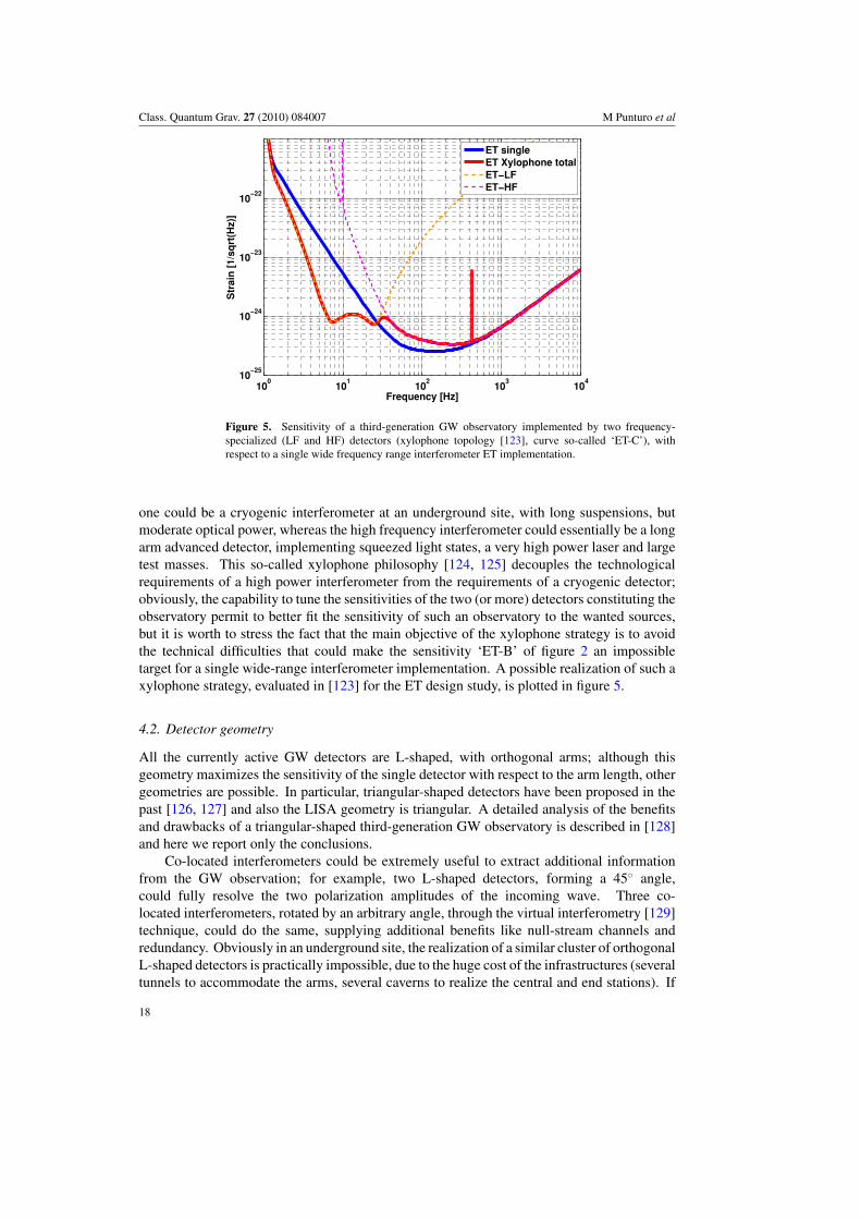
Figure 5. Sensitivity of a third-generation GW observatory implemented by two frequency-specialized (LF and HF) detectors (xylophone topology [123], curve so-called ‘ET-C’), withrespect to a single wide frequency range interferometer ET implementation.
one could be a cryogenic interferometer at an underground site, with long suspensions, butmoderate optical power, whereas the high frequency interferometer could essentially be a longarm advanced detector, implementing squeezed light states, a very high power laser and largetest masses. This so-called xylophone philosophy [124, 125] decouples the technologicalrequirements of a high power interferometer from the requirements of a cryogenic detector;obviously, the capability to tune the sensitivities of the two (or more) detectors constituting theobservatory permit to better fit the sensitivity of such an observatory to the wanted sources,but it is worth to stress the fact that the main objective of the xylophone strategy is to avoidthe technical difficulties that could make the sensitivity ‘ET-B’ of figure 2 an impossibletarget for a single wide-range interferometer implementation. A possible realization of such axylophone strategy, evaluated in [123] for the ET design study, is plotted in figure 5.
4.2. Detector geometry
All the currently active GW detectors are L-shaped, with orthogonal arms; although thisgeometry maximizes the sensitivity of the single detector with respect to the arm length, othergeometries are possible. In particular, triangular-shaped detectors have been proposed in thepast [126, 127] and also the LISA geometry is triangular. A detailed analysis of the benefitsand drawbacks of a triangular-shaped third-generation GW observatory is described in [128]and here we report only the conclusions.
Co-located interferometers could be extremely useful to extract additional informationfrom the GW observation; for example, two L-shaped detectors, forming a 45◦ angle,could fully resolve the two polarization amplitudes of the incoming wave. Three co-located interferometers, rotated by an arbitrary angle, through the virtual interferometry [129]technique, could do the same, supplying additional benefits like null-stream channels andredundancy. Obviously in an underground site, the realization of a similar cluster of orthogonalL-shaped detectors is practically impossible, due to the huge cost of the infrastructures (severaltunnels to accommodate the arms, several caverns to realize the central and end stations). If
18
Class. Quantum Grav. 27 (2010) 084007 M Punturo et al
the angle between the two arms of each detector is reduced to 60◦, three detectors canbe accommodated in a triangular-shaped underground site, minimizing the total length oftunnels, probably the number of caverns and recovering a sensitivity equivalent to two sets oforthogonal L-shaped double detectors, rotated by 45◦ (see figure B1 of [128]).
For these reasons and because of the relevant role that the cost of the infrastructures willplay in a third-generation GW underground observatory, the selection of the geometry willprobably be driven by the selection of the site and not vice versa: if a site that can accommodatea triangular observatory is found, the triple co-located interferometers will be the best choice,otherwise the two sets of orthogonal L-shaped double detectors will be more appealing.
4.3. Network of detectors
So far we assumed that a single site facility forms the third-generation observatory. Dependingon the astrophysical goals, the directionality of a detector could be of crucial importance,playing a role even larger than the sensitivity. This can be the case if a GW source needs to bespotted in a multitude of electromagnetic sources.
Currently a network of at least three well-separated detectors is needed to reconstruct thedirection in the sky of a coalescing binary star system, the most promising GW source. Insection 2.1, it has been anticipated that, thanks to the improved sensitivity, a third-generationGW observatory could gain a lot in directionality, using the additional information embeddedin the full-PN approximation. In principle, two detectors at the same site could fully resolvethe GW source. In practice, because of the limited accuracy, it may be advantageous tohave two or more detection facilities spaced as widely as possible. Although only one third-generation project is being studied now, there is hope that other projects, e.g. a LIGO successor,will follow, resulting in a worldwide network of third-generation detectors forming one bigobservatory. Using two distant detectors, the five parameters needed to reconstruct the sourcedirection can be extracted from the four amplitudes from two sites and the single time delay.
For the detection of the stochastic GW background, multiple co-located detectors wouldbe best suited. The distance should be big enough to rule out common environmental noisesources but close enough that stochastic background noise still shows up coherently in thedetectors.
4.4. Timelines
The evolution to the third generation of GW detectors has been, is and will be a long path.Currently the main effort is made in Europe and only the European scenario will be depicted.After a series of preliminary activities supported by the European Commission within theFramework Programme 6 (FP6), a conceptual design study is currently funded under FP7:the Einstein Telescope design study [9]. This proposal was approved and funded for 3 years,starting from May 2008. The major goal of the ET project is to deliver a conceptual designfor such a facility, investigating the technological feasibility, the science targets, the siterequirements and prepare a costing draft for the infrastructure.
Although the efforts and the attention of the worldwide GW scientific community arecurrently focused on the realization of the advanced detectors (Advanced LIGO, AdvancedVirgo and LCGT), the activities devoted to the third generation must continue with increasingspeed. In figure 6, the expected evolution of the GW detectors in the World is shown. The lastline of the table shows the long path still in front of the European project ET. After the currentconceptual design study phase, a preparatory phase is expected to be necessary to definethe technological details, and the legal and organizational issues. The start of construction
19
Class. Quantum Grav. 27 (2010) 084007 M Punturo et al
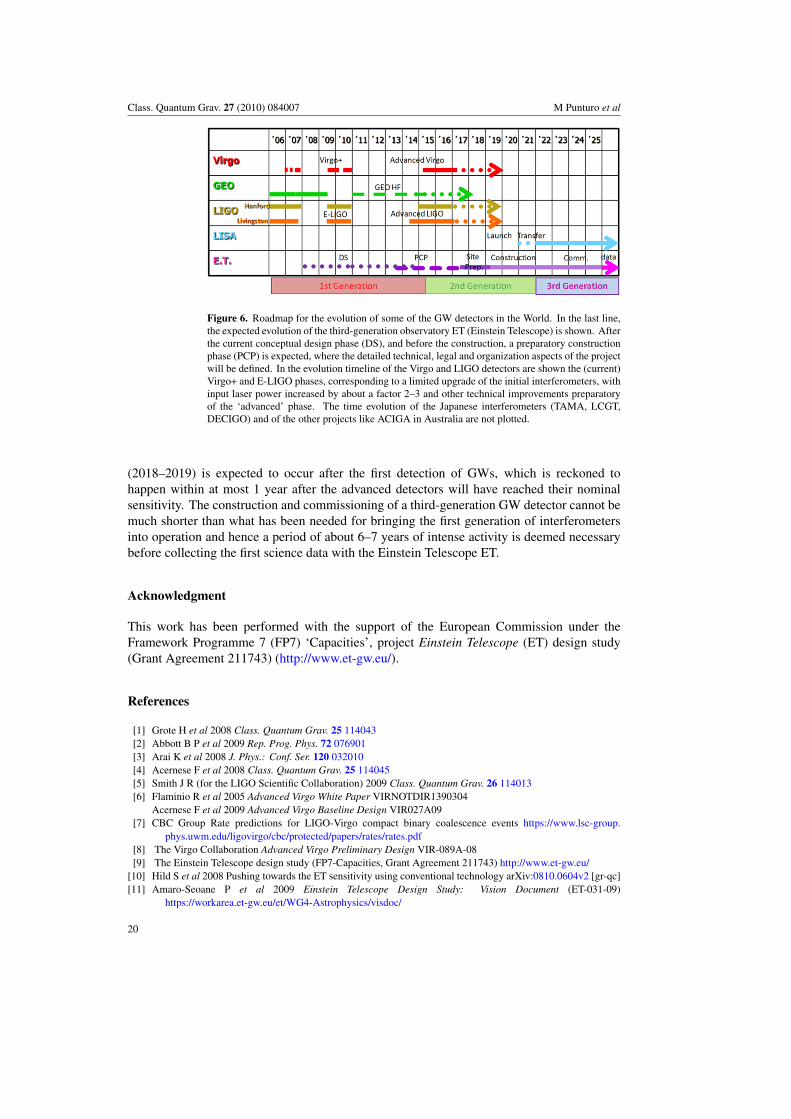
Figure 6. Roadmap for the evolution of some of the GW detectors in the World. In the last line,the expected evolution of the third-generation observatory ET (Einstein Telescope) is shown. Afterthe current conceptual design phase (DS), and before the construction, a preparatory constructionphase (PCP) is expected, where the detailed technical, legal and organization aspects of the projectwill be defined. In the evolution timeline of the Virgo and LIGO detectors are shown the (current)Virgo+ and E-LIGO phases, corresponding to a limited upgrade of the initial interferometers, withinput laser power increased by about a factor 2–3 and other technical improvements preparatoryof the ‘advanced’ phase. The time evolution of the Japanese interferometers (TAMA, LCGT,DECIGO) and of the other projects like ACIGA in Australia are not plotted.
(2018–2019) is expected to occur after the first detection of GWs, which is reckoned tohappen within at most 1 year after the advanced detectors will have reached their nominalsensitivity. The construction and commissioning of a third-generation GW detector cannot bemuch shorter than what has been needed for bringing the first generation of interferometersinto operation and hence a period of about 6–7 years of intense activity is deemed necessarybefore collecting the first science data with the Einstein Telescope ET.
Acknowledgment
This work has been performed with the support of the European Commission under theFramework Programme 7 (FP7) ‘Capacities’, project Einstein Telescope (ET) design study(Grant Agreement 211743) (http://www.et-gw.eu/).
References
[1] Grote H et al 2008 Class. Quantum Grav. 25 114043[2] Abbott B P et al 2009 Rep. Prog. Phys. 72 076901[3] Arai K et al 2008 J. Phys.: Conf. Ser. 120 032010[4] Acernese F et al 2008 Class. Quantum Grav. 25 114045[5] Smith J R (for the LIGO Scientific Collaboration) 2009 Class. Quantum Grav. 26 114013[6] Flaminio R et al 2005 Advanced Virgo White Paper VIRNOTDIR1390304
Acernese F et al 2009 Advanced Virgo Baseline Design VIR027A09[7] CBC Group Rate predictions for LIGO-Virgo compact binary coalescence events https://www.lsc-group.
phys.uwm.edu/ligovirgo/cbc/protected/papers/rates/rates.pdf[8] The Virgo Collaboration Advanced Virgo Preliminary Design VIR-089A-08[9] The Einstein Telescope design study (FP7-Capacities, Grant Agreement 211743) http://www.et-gw.eu/
[10] Hild S et al 2008 Pushing towards the ET sensitivity using conventional technology arXiv:0810.0604v2 [gr-qc][11] Amaro-Seoane P et al 2009 Einstein Telescope Design Study: Vision Document (ET-031-09)
https://workarea.et-gw.eu/et/WG4-Astrophysics/visdoc/
20
Class. Quantum Grav. 27 (2010) 084007 M Punturo et al
[12] Sathyaprakash B S and Schutz B F 2009 Physics, astrophysics and cosmology with gravitational waves LivingRev. Rel. 12 2
[13] van Den Broeck C 2006 Class. Quantum Grav. 23 L51[14] van Den Broeck C and Sengupta A 2007 Class. Quantum Grav. 24 155[15] Nakar E 2007 Phys. Rep. 442 166[16] Schutz B 1986 Nature 323 310[17] Sathyaprakash B S, Schutz B F and Van Den Broeck C 2009 arXiv:0906.4151[18] Arnaud N et al 2002 Phys. Rev. D 65[19] Nissanke S, Hughes S, Holz D E, Dalal N and Sievers J L 2009 Exploring short gamma-ray bursts as gravitational-
wave standard sirens arXiv:0904.1017[20] Blanchet L et al 1996 Class. Quantum Grav. 13 575[21] Arun K G et al 2004 Class. Quantum Grav. 21 3771
Arun K G et al 2005 Class. Quantum Grav. 22 3115 (erratum)[22] Blanchet L et al 2002 Phys. Rev. D 65 061501
Blanchet L et al 2005 Phys. Rev. D 71 129902 (erratum)[23] Blanchet L et al 2004 Phys. Rev. Lett. 93 091101[24] Choudhury T R and Padmanabhan T 2005 Astron. Astrophys. 429 807 (arXiv:astro-ph/0311622)[25] Arun K et al 2007 Phys. Rev. D 75 124002[26] Gair J R, Mandel I, Coleman Miller M and Volonteri M 2000 Exploring intermediate and massive black-hole
binaries with the Einstein Telescope arXiv:0907.5450[27] Gair J R, Sesana A and Vecchio A 2009 Probing seed black holes using future gravitational-wave detectors
arXiv:0907.3292[28] Buonanno A and Damour T 1999 Phys. Rev. D 59 084006 (arXiv:gr-qc/9811091)[29] Buonanno A and Damour T 2000 Phys. Rev. D 62 064015 (arXiv:gr-qc/0001013)[30] Damour T, Iyer B R and Sathyaprakash B S 2002 Phys. Rev. D 66 027502 (arXiv:gr-qc/0207021)[31] Damour T, Iyer B R, Jaranowski P and Sathyaprakash B S 2003 Phys. Rev. D 67 064028 (arXiv:gr-qc/0211041)[32] Damour T and Nagar A 2007 Phys. Rev. D 76 064028 (arXiv:0705.2519)[33] Buonanno A et al 2007 Phys. Rev. D 76 104049 (arXiv:0706.3732)[34] Damour T and Nagar A 2008 Phys. Rev. D 77 024043 (arXiv:0711.2628)[35] Brugmann B et al 2004 Phys. Rev. Lett. 92 211101[36] Pretorius F 2005 Phys. Rev. Lett. 95 121101[37] Campanelli M et al 2006 Phys. Rev. Lett. 96 111101[38] Baker J G et al 2007 Phys. Rev. Lett. 99 181101[39] Boyle M et al 2007 Phys. Rev. D 76 124038[40] Ajith P et al 2008 Phys. Rev. D 77 104017[41] Hannam M and Hawke I 2009 arXiv:0908.3139[42] Weber F, Negreiros R and Rosenfield P 2007 arXiv:0705.2708[43] Schutz B 2008 J. Phys.: Conf. Ser. 118 012005[44] Andersson N and Kokkotas K D 1998 Mon. Not. R. Astron. Soc. 299 1059[45] Ott C D 2009 Class. Quantum Grav. 26 063001[46] van den Bergh S and Tammann G A 1991 Annu. Rev. Astron. Astrophys. 29 363[47] Ando S, Beacom F and Yuksel H 2005 Phys. Rev. Lett. 95 171101[48] Braccini S et al 2005 Astropart. Phys. 23 557–65[49] Braccini S 2009 ET internal note ET-025-09 https://workarea.et-gw.eu/et/WG5-Management/et-codified-
documents/copy of et-document-codifier[50] Abbott R et al 2002 Class. Quantum Grav. 19 1591–7[51] Bialowons W et al 2007 Measurement of ground motion in various sites EUROTeV-Report-2007-011[52] Uchiyama T et al 2004 Class. Quantum Grav. 21 S1161[53] Ando M et al 2001 Phys. Rev. Lett. 86 3950[54] Sato S et al 2004 Phys. Rev. D 69 102005[55] Saulson P R 1984 Phys. Rev. D 30 732–6[56] Beccaria M et al 1998 Class. Quantum Grav. 15 3339–62[57] Hughes S A and Thorne K S 1998 Phys. Rev. D 58 122002[58] Cella G 2009 Low Frequency Limit Talk at the Fujihara Seminar http://gw.icrr.u-tokyo.ac.jp:8888/
fujihara seminar presentation/presentations/Fujihara2009-Cella.pdf[59] Cella G 2009 Gravity gradient noise: estimates and reduction strategies Talk at the 2nd ET Annual Meeting
http://www.et-gw.eu/2ndgeneralworkshop
21
Class. Quantum Grav. 27 (2010) 084007 M Punturo et al
[60] Callen H B and Welton T A 1951 Phys. Rev. 83 34[61] Kovalik J and Saulson P R 1993 Rev. Sci. Instrum. 64 2942[62] Braginsky V B et al 1993 Phys. Lett. A 175 82[63] Rowan S et al 1997 Phys. Lett. A 227 153[64] Cagnoli G et al 1999 Phys. Lett. A 255 230–5[65] Cagnoli G et al 1996 Phys. Lett. A 213 245–52[66] Cagnoli G et al 2000 Rev. Sci. Instrum. 71 2206–10[67] Robertson N et al 2000 Proc. of the Third E. Amaldi Conference AIP (New York) vol 313[68] Cagnoli G et al 2000 Phys. Rev. Lett. 85 2442–5[69] Rowan S et al 1998 Phys. Lett. A 246 471478[70] Cagnoli G et al 2002 Rev. Sci. Instrum. 73 3318–23[71] Kuroda K et al 1999 Int. J. Mod. Phys. D 8 557–79[72] Caparrelli S et al 2007 Report ILIAS-JR3-C1 activity http://www.ego-gw.it/ILIAS-GW/documents/
STREGAreport2007/Long reports/Report C1 2007 D10.doc[73] Uchiyama T et al 2000 Phys. Lett. A 273 310–5[74] Tomaru T et al 2002 Phys. Lett. A 310 215–9[75] Alshourbagy M et al 2006 Rev. Sci. Instrum. 77 044502[76] Reid S et al 2006 Phys. Lett. A 351 205–11[77] Crooks D R M et al 2004 Class. Quantum Grav. 21 S1059–65[78] Penn S D et al 2003 Class. Quantum Grav. 20 2917–28[79] Harry G M et al 2007 Class. Quantum Grav. 24 405–15[80] Agresti J et al 2006 Advances in thin-film coatings for optical applications III Proc. SPIE 6286 628608[81] Yamamoto K et al 2006 Phys. Rev. D 74 022002[82] Martin I et al 2008 Class. Quantum Grav. 25 055005[83] Pierro V et al 2009 Measurement of thermal noise in multilayer coatings with optimized layer thickness LIGO
P0900091-x0[84] Tomaru T et al 2002 Class. Quantum Grav. 19 2045[85] Tomaru T et al 2001 Phys. Lett. A 283 80–4[86] Green M A and Keevers M J 1995 Prog. Photovolt. Res. Appl. 3 189[87] Bruckner F et al 2009 Opt. Express 17 163–9[88] Bunkowski A et al 2006 J. Phys.: Conf. Ser. 32 333–8[89] Khalili F Ya 2005 Phys. Lett. A 334 67–72[90] Goßler S et al 2007 Phys. Rev. A 76 053810[91] Braginsky V B and Vyatchanin S P 2004 Phys. Lett. A 324 345–514[92] Agresti J and Salvo R De 2005 Flat beam profile to depress thermal noise LIGO-G050041-00-Z[93] Mours B et al 2006 Class. Quantum Grav. 23 5777–84[94] Chelkowski S, Hild S and Freise A 2009 Phys. Rev. D 79 122002[95] Franc J et al 2009 Effect of Laguerre Gauss modes on thermal noise Talk at the ET-WP3-Meeting
https://workarea.et-.gw.eu/et/WG3-.Topology/presentations/Franc-WP3-090609.ppt[96] Zeilinger A 1981 General properties of lossless beam splitters in interferometry Am. J. Phys. 49 882[97] Corbitt T R 2008 Quantum noise and radiation pressure effects in high power optical interferometers PhD Thesis
MIT[98] Vinet J-Y 2009 On Special Optical Modes and Thermal Issues in Advanced Gravitational Wave Interferometric
Detectors (Living Rev. Rel. vol 12) (cited on Jan. 2010) http://www.livingreviews.org/lrr-2009-5.[99] Mavalvala N, McClelland D E, Mueller G, Reitze D H, Schnabel R and Willke B 2009 Gen. Rel. Grav.
(submitted)[100] Schnier D et al 1997 Phys. Lett. A 225 210[101] Meers B J 1988 Phys. Rev. D 38 2317[102] Corbitt T et al 2004 Optical cavities as amplitude filter of squeezed fields Phys. Rev. D 70 022002[103] Khalili F Y et al 2009 Phys. Rev. D 80 042006[104] Buonanno A and Chen Y 2003 Phys. Rev. D 67 062002[105] Buonanno A and Chen Y 2004 Phys. Rev. D 69 102004[106] McKenzie K et al 2002 Phys. Rev. Lett. 88 231102[107] Vahlbruch H et al 2005 Phys. Rev. Lett. 95[108] Goda K et al 2008 Nat. Phys. 4 472[109] McKenzie K et al 2004 Phys. Rev. Lett. 93 161105[110] Vahlbruch H et al 2007 New J. Phys. 9 371[111] Vahlbruch H et al 2006 Phys. Rev. Lett. 97 011101
22
Class. Quantum Grav. 27 (2010) 084007 M Punturo et al
[112] Vahlbruch H et al 2008 Phys. Rev. Lett. 100 33602[113] Mehmet M et al 2009 Observation of squeezed states with strong photon number oscillations arXiv:0909.5386[114] Kimble H J et al 2001 Phys. Rev. D 65 022002[115] Willke B et al 2006 Class. Quantum Grav. 23 S207–14[116] Thuring A et al 2009 Opt. Lett. 34 825–6[117] Braginsky V B et al 2001 Phys. Lett. A 287 331[118] Ju L et al 2006 Phys. Lett. A 354 360[119] Ju L et al 2006 Phys. Lett. A 355 419[120] Yamamoto K et al 2008 J. Phys.: Conf. Ser. 122 012015[121] Yamamoto K 2009 Parametric Instability of a Cavity of Einstein Telescope ET-029-09[122] Dimopoulos S et al 2007 Gravitational Wave Detection with Atom Interferometry arXiv:0712.1250v1 [gr-qc][123] Hild S et al 2010 Class. Quantum Grav. 27 015003[124] Shoemaker D 2001 Presentation at Aspen Meeting http://www.ligo.caltech.edu/docs/G/G010026-00.pdf[125] Conforto G and DeSalvo R 2004 Nucl. Instrum. Methods Phys. Res. A 518 228–32[126] Winkler W et al 1985 Plans for a large gravitational wave antenna in Germany MPQ Report 101 Presented by
A Rudiger at the 4th Marcel Grossmann Meeting (Rome)[127] Maischberger K et al 1985 Vorschlag zum Bau eines großen Laser Interferometers zur Messung von
Gravitationswellen MPQ Report 96 (in German)[128] Freise A et al 2009 Class. Quantum Grav. 26 085012[129] Brillet A et al 2003 Phys. Rev. D 67 102006
23