the sticky-pad plane and other innovative concepts for
TRANSCRIPT
1
The Sticky-Pad Plane and other Innovative Concepts for
Perching UAVs
Michael L. Anderson1, Christopher J. Perry
2, Brandon M. Hua
3, Dakota S. Olsen
4, Jason R. Parcus
5, Kenneth M.
Pederson6 and Daniel D. Jensen
7
US Air Force Academy, Department of Engineering Mechanics, Colorado Springs, CO, 80840
A primary limiting factor in the design and operation of small, Unmanned Air Vehicles
(UAVs) is energy. Current models have unsatisfactory range and endurance, and other
enhanced capabilities must be omitted from their design because there is not sufficient
energy to power them. One proposed solution to this energy problem is to imitate birds by
“perching”, a definition which was broadly stated as any low-energy-expenditure state in
which Intelligence, Surveillance, and Reconnaissance (ISR) could be conducted. Over one-
hundred innovative perching UAV concepts were generated and assessed for feasibility and
potential mission enhancement. The most promising concepts were further analyzed and
prototyped. Among those, the Sticky-Pad Plane was the most successful and was prototyped
at the alpha and beta levels. It is able to attach to vertical surfaces from straight and level
flight, reposition to conduct ISR, then detach from the wall and re-launch into flight without
any additional power requirements. The Sticky-Pad Plane is a robust design that is
adaptable to a wide range of aircraft configurations and is capable of perching multiple
times in different locations during a given mission. The Sticky-Pad Plane has been
successfully demonstrated on three separate aircraft, and it has the potential to increase the
duration of ISR missions by an order of magnitude or more.
Nomenclature
Lmax = maximum line length
l = length of operating envelope
kl = ratio of workspace to operating envelope length
w = width of operating envelope
kw = ratio of workspace to operating envelope width
h = height of operating envelope
kh = ratio of workspace to operating envelope height
Fmax = maximum force
m = mass
g = acceleration due to gravity
k = stiffness
a = length of perching line
bcg = distance from aircraft c.g. to perching line attachment point
I. Introduction
MALL UAV’s, also known as Micro Air Vehicles (MAVs) have recently shown much promise in support of
small combat units. Their small, man-packable size enables individual units to have direct control over their own
ISR assets, enabling these units to be more flexible and independent. These small units no longer require
coordination with, or access to, more cumbersome ISR data collection systems. The ever increasing demand for
these devices and the growing list of desired capabilities from the user has recently made MAVs a fertile field of
scientific research.
1 Asst Professor, Dept of Engineering Mechanics, United States Air Force Academy, Member AIAA.
2-6 Cadet, Dept of Engineering Mechanics, United States Air Force Academy.
7 Professor, Dept of Engineering Mechanics, United States Air Force Academy.
S
47th AIAA Aerospace Sciences Meeting Including The New Horizons Forum and Aerospace Exposition5 - 8 January 2009, Orlando, Florida
AIAA 2009-40
This material is declared a work of the U.S. Government and is not subject to copyright protection in the United States.
2
One consistent request from the user community is for greater endurance. In fact, it has been dubbed the greatest
“target of opportunity” by US Air Force researchers1. In addition, numerous innovative capabilities have been
proposed for MAVs that would provide tremendous mission enhancement, yet these capabilities have so far been
omitted for want of the necessary power to operate them2,3
. This challenge of increasing energy efficiency of MAVs
is being attacked on many fronts by mostly traditional approaches such as incremental improvements in battery
capacity and efficiency, drive train efficiency, aerodynamic efficiency and lightweight components4.
In the Engineering Mechanics Department’s MAV research group at the US Air Force Academy, we have
intentionally avoided these traditional, incremental approaches. Instead, we deliberately follow non-traditional
problem solving methods in the hopes of developing innovative solutions that have the potential to provide order-of-
magnitude improvements by revolutionizing the way MAVs are employed. These approaches to innovative problem
solving, which will be presented, include customer needs research, several diverse concept generation techniques,
concept evaluation and selection, analysis, and prototyping.
One proposed solution to this endurance problem is to take a cue from birds, and attempt to perch. Unlike all
current UAVs, birds and insects do not remain airborne indefinitely; they rest in strategic locations, where they can
continue surveying their domain for predator and prey, all the while conserving energy for when it is most needed 5
.
Furthermore, it has been pointed out that as MAVs become smaller, the relevant scaling laws dictate a reduced
capacity for fuel, and thus a reduced range and/or mission duration6. Therefore, regardless of the improvements
made in the aforementioned traditional research areas, as MAVs inevitably shrink in size there will always be a
requirement for increased endurance. Therefore, our team set out to pioneer innovative MAV prototypes with the
ability to perch. To avoid design fixation we re-defined the term “perch” to mean any low energy expenditure state
in which effective ISR could be conducted. The team also chose to focus our efforts on perching in urban areas where
potential perches are more plentiful.
II. Innovative Design Methodology
Perhaps even more important than the new concepts themselves is the methodology that is used to develop them.
This methodology universally promotes innovation, and thus can be applied to any number of engineering problems
to produce extraordinary mission enhancement. Therefore, even if the particular problem addressed in this work is
not of interest, this process should be relevant to all engineers. With that in mind, what follows is a brief synopsis of
the Transformational Design Methodology employed in this research, for more detail see the cited references7,8
.
The single most unique element of this method is the persistent emphasis on innovation during every step of the
process. The mechanics of the process are important, but they will yield only mundane results without an
environment and attitude that encourages creativity, so this becomes our primary focus. This includes everything
from the words we choose to define the problem to how team members are selected to the clothes we wear during
brainstorming sessions. Every detail is choreographed to enhance innovation.
An example of this attitude of innovation is evident in the very first step of the process; that of determining the
key requirements, or customer needs, of the system. The team did not stop at the traditional customer needs
gathering techniques, but went one step further by brainstorming for new, unusual methods. One of the more
promising ideas, which the team implemented, was to role-play as a small combat team in an urban setting. This
exercise lent insights that would be difficult to gain in a conference room; specifically the team learned that users in
combat will have very little attention they can dedicate to commanding a system, so simplicity and autonomy are
critical. This finding was reinforced by USAF, USA, and USMC users that the team interviewed.
Several techniques were used to generate initial concepts for perching MAVs. Research has shown that the
greater number of concepts that are developed, the greater the chance that an innovative solution will result from the
process9. Therefore, the team kept the design space as wide as possible at this early stage of development by
broadening the definition of perching, as mentioned above, and ignoring feasibility. Brainstorming techniques
included traditional techniques such as Functional Decomposition, 6-3-5/C-Sketch, design by analogy, mind
mapping, and TIPS/TRIZ10
.
A novel approach we tested was to investigate renowned innovators to use as exemplars such as da Vinci, Martin
Luther King Jr., and ancient Greeks. The team focused not necessarily on the exemplars innovations, but on the
thought processes and attitudes that led to them. This exercise led to many interesting concepts, one being the
“Trojan MAV” described in section III. Another novel technique, called “far-field analogy” seeks to draw ideas
from fields that are seemingly unrelated to MAVs. For example, the team considered, what elements of literature, or
painting could be applied to MAVs. Finally, Transformational Design Cards (T-Cards)8 were very helpful in
refining the most promising concepts. These techniques were used repeatedly over several months to develop as
many concepts as possible, and to refine existing concepts.
3
After creating a pool of over 100 concepts, the team revisited the customer requirements research and evaluated
the concepts on the basis of their potential to fulfill the customer’s needs and be feasibly prototyped. A Pugh
selection matrix7 was used to evaluate the concepts and select those with the most promise, which are described in
the next section. Throughout the concept refinement phase, many of the brainstorming techniques described above
were applied again to solve acute design challenges.
III. Concept Variants
Through the brainstorming techniques described above, the team created 130 original concepts for low energy
expenditure ISR, or perching. Some concepts are more promising than others, and some concepts are simply not
feasible in the current technology climate. Those concepts that hold the most promise are presented below. The
concepts are grouped into two categories; Rev Tech and COTS. Rev Tech, short for revolutionary technology,
encompasses those concepts that depend on a key piece of technology that is not currently available, but is on the
horizon. COTS, or commercial-off-the-shelf, concepts are those that the team believes could be implemented
immediately with existing technology.
A. Rev Tech Concepts:
Gecko-feet Pad - Platform is a typical level flight aircraft with a pusher prop or twin wing props. Aircraft has a
hinged gecko foot pad on the nose. When the MAV flies into the structure the hinged pad rotates 90 degrees to
orient the MAV along the surface. It is capable of adhering to any surface at any orientation. The pad would be sized
to support the weight of the MAV. This technology is in early development and is not yet available for public or
commercial use, but has tremendous promise.
Hydrogen Generation - Plane carries two chemicals that react to create hydrogen. The airplane is configured
for straight, level flight and deploys a balloon to perch in midair with a gimbaled camera for ISR. The hydrogen is
used to inflate a balloon and the reaction byproducts/waste is released to reduce weight. Hydrogen generation
technology exists, but must be miniaturized before it will be useful for MAVs.
Bird Visual Manipulation Control - Numerous attempts have been made to utilize live birds outfitted with
sensors to perform ISR collection, but these attempts have so far involved manipulating neural control signals to
control the birds’ flight. This approach has significant implementation and ethical challenges. Our proposal,
visualization manipulation, takes a far different approach. Rather than manipulating brain waves, we propose
creating virtual reality goggles to be worn by birds that would display the necessary images to persuade the bird to
fly in the desired direction. For example, the bird would be trained to fly towards an image of their natural prey. If
the operator needed the bird to turn right, the goggles would create that image on the right side of the goggles, and
the bird would fly in that direction—effectively controlling the flight path of the bird. Control images could be
structures, predators, food sources, etc.
The advantages of this system are feasibility, cost, and applicability. The technology is within easy reach -
virtual reality is proven, but would need to be miniaturized. We predict the cost to develop and build a small pair of
goggles to be less than that of avian neurosurgery. Applicability is another advantage in that this system can be
implemented with bird species that are native to a certain area, and therefore have the necessary survival skills to
thrive in that environment. For example, a system could be designed to fit the Peregrine Falcon species (F.
peregrinus), a medium sized raptor that is prevalent throughout the world, and familiar to urban and rural habitats11
.
The system could then be mounted on an individual that is native to the theater of operation. ISR systems have been
successfully mounted on F. peregrinus, with the video images transmitted to a ground station, suggesting the
feasibility of this concept12
.
B. COTS Concepts:
Hugging Wings – The platform is a fixed wing aircraft, but with flexible, bifurcating wings. Their two positions
of equilibrium are outstretched for flight, and curled up for perching - similar to a tape measure. When triggered, the
wings would curl up to wrap around appropriate items such as poles, clotheslines or power lines. Numerous devices
exist which demonstrate this bifurcating action, but a means of easily unrolling the wings is needed. Piezo-electric
actuators or shape memory materials are possibilities. In addition the acrobatic maneuvers to attach to perch
platforms would need to be developed.
4
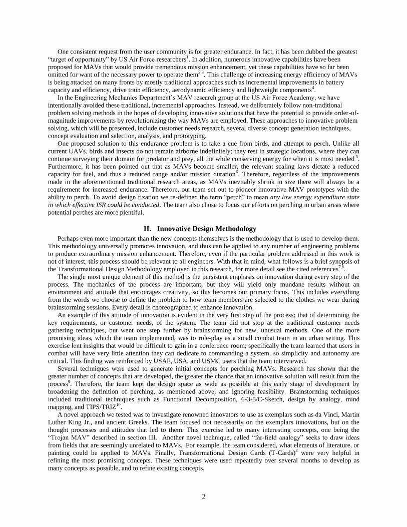
Figure 1. Perching sequence for the Weighted Tail Line Concept. In
the center diagram, the grappling hook is wrapping around a tree
branch, securing the MAV.
Helicopter with Sticky Ball Cannon – A rotary wing MAV would be equipped with a canon to fire projectiles.
To perch, the helicopter flies near a vertical surface and fires the projectile cannon that attaches an adhesive mount
on a tether. The rotors are stopped
and the helicopter is reeled against
the surface via the tether.
Weighted Tail Line - The
platform is a typical fixed wing
MAV, but it drags a grappling hook
counterweight from its tail, as
shown in Fig 1. When flown low
over power lines, tree branches, or
the like the tow line impacts the
perching platform above the
hanging weight. Upon impact, the
counterweight swings up to wrap
the line around the platform
multiple times—the vehicle is left
to perch, hanging by its tail where it
would conduct ISR. To re-launch,
the tow line would be released.
Trojan MAV – A typical MAV is equipped with ISR sensors that appear to be damaged. It is designed to crash
in a conspicuous area where it is likely to be recovered by the enemy. Once captured and brought back to an enemy
hideout, the Trojan MAV will begin transmitting vital intelligence, including video and audio feed, as well as GPS
coordinates for a future air strike. GWOT veterans indicate that enemy forces consistently recover damaged US
technology and re-use it, so this concept is highly feasible, though any ISR collected would be time sensitive.
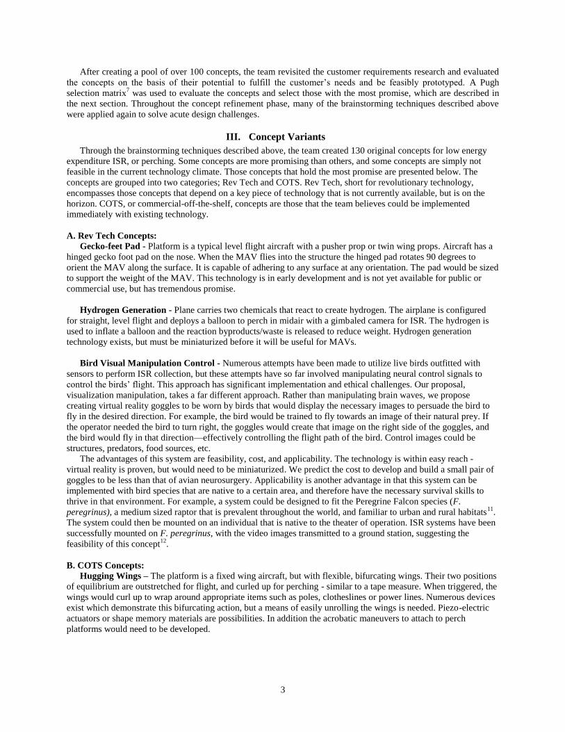
SpyderCam - The SpyderCam is a suspended ISR
system that uses an internal winching system to control the
length of 4 anchor lines, as shown in Fig. 2. The lines can
be anchored to any surface. Controlling the lengths of the
anchor lines will move the SpyderCam anywhere within the
3D space of the anchors. The SpyderCam will be equipped
with its own deployment mechanism to launch the anchors
to any surface. The SpyderCam can detach, then re-launch
its anchors allowing the MAV to move from one 3D space
to another 3D surveillance environment.
Hinged Sticky Pad Aircraft – A COTS MAV without
a nose prop (either push prop or twin wing props), and a
hinged adhesive pad is attached to the nose. To perch on a
vertical surface, the MAV simply flies into the surface. The
sticky pad will adhere to the wall, and then rotate via the
hinge, allowing the aircraft to hang parallel to the wall, decreasing the moment applied to the sticky pad. The MAV would re-launch by disconnecting from the sticky pad.
IV. Concept Analysis and Prototyping
Of the promising innovative concepts presented above, the team selected two to prototype. The concepts were
evaluated for feasibility and potential mission enhancement, and the Spydercam and Hinged Sticky Pad were
considered most promising. Over the course of three months, the team iterated through research, design,
manufacturing and testing of these potential perching solutions. The team was successful in demonstrating the
feasibility and capability of each concept.
A. SpyderCam
As described above, the SpyderCam is a COTS concept that operates much like existing suspended camera
systems: a camera unit is suspended in the air by 4 controlling lines as shown in Fig. X. The length of each line is
independently manipulated by external winching systems to control the movement of the unit. The SpyderCam
system has greater mission enhancement and has a more practical tactical ISR application over the existing
Figure 2. SpyderCam deployed in a city block.
5
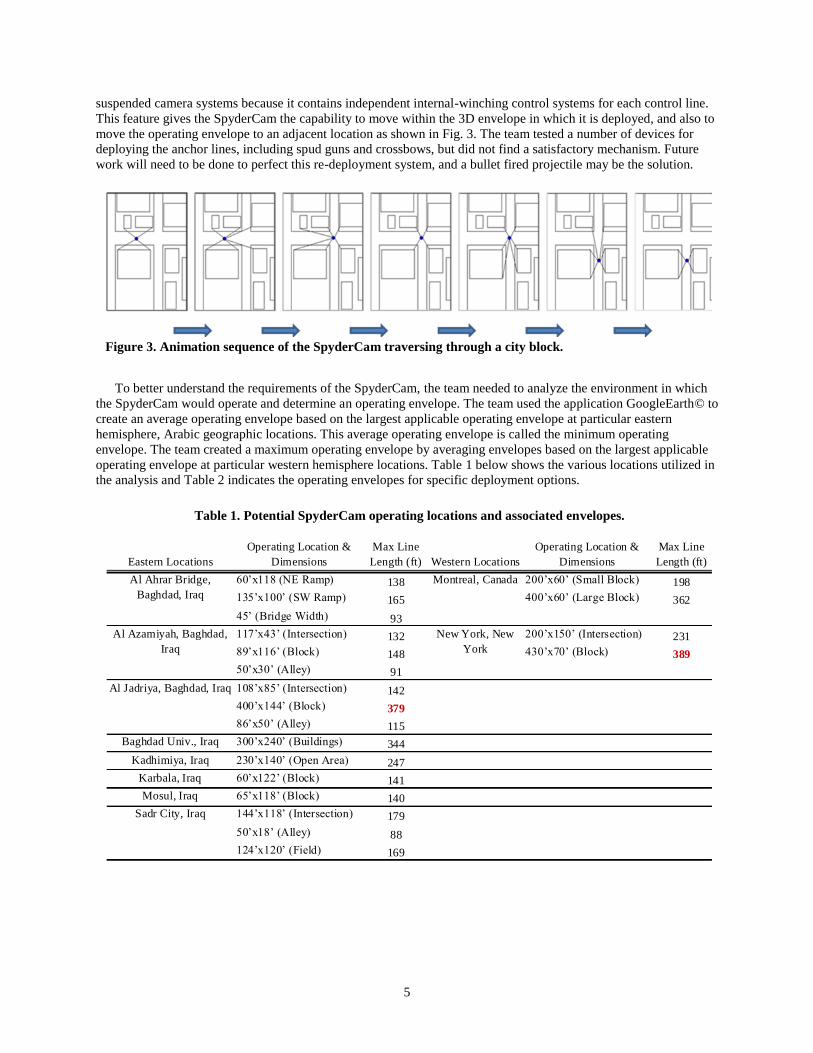
suspended camera systems because it contains independent internal-winching control systems for each control line.
This feature gives the SpyderCam the capability to move within the 3D envelope in which it is deployed, and also to
move the operating envelope to an adjacent location as shown in Fig. 3. The team tested a number of devices for
deploying the anchor lines, including spud guns and crossbows, but did not find a satisfactory mechanism. Future
work will need to be done to perfect this re-deployment system, and a bullet fired projectile may be the solution.
To better understand the requirements of the SpyderCam, the team needed to analyze the environment in which
the SpyderCam would operate and determine an operating envelope. The team used the application GoogleEarth© to
create an average operating envelope based on the largest applicable operating envelope at particular eastern
hemisphere, Arabic geographic locations. This average operating envelope is called the minimum operating
envelope. The team created a maximum operating envelope by averaging envelopes based on the largest applicable
operating envelope at particular western hemisphere locations. Table 1 below shows the various locations utilized in
the analysis and Table 2 indicates the operating envelopes for specific deployment options.
Table 1. Potential SpyderCam operating locations and associated envelopes.
Eastern Locations
Operating Location &
Dimensions
Max Line
Length (ft) Western Locations
Operating Location &
Dimensions
Max Line
Length (ft)
60’x118 (NE Ramp) 138 200’x60’ (Small Block) 198
135’x100’ (SW Ramp) 165 400’x60’ (Large Block) 362
45’ (Bridge Width) 93
117’x43’ (Intersection) 132 200’x150’ (Intersection) 231
89’x116’ (Block) 148 430’x70’ (Block) 389
50’x30’ (Alley) 91
108’x85’ (Intersection) 142
400’x144’ (Block) 379
86’x50’ (Alley) 115
Baghdad Univ., Iraq 300’x240’ (Buildings) 344
Kadhimiya, Iraq 230’x140’ (Open Area) 247
Karbala, Iraq 60’x122’ (Block) 141
Mosul, Iraq 65’x118’ (Block) 140
144’x118’ (Intersection) 179
50’x18’ (Alley) 88
124’x120’ (Field) 169
Sadr City, Iraq
Montreal, Canada
New York, New
York
Al Ahrar Bridge,
Baghdad, Iraq
Al Azamiyah, Baghdad,
Iraq
Al Jadriya, Baghdad, Iraq
Figure 3. Animation sequence of the SpyderCam traversing through a city block.
6
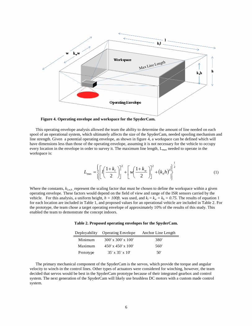
This operating envelope analysis allowed the team the ability to determine the amount of line needed on each
spool of an operational system, which ultimately affects the size of the SpyderCam, needed spooling mechanism and
line strength. Given a potential operating envelope, as shown in figure 4, a workspace can be defined which will
have dimensions less than those of the operating envelope, assuming it is not necessary for the vehicle to occupy
every location in the envelope in order to survey it. The maximum line length, Lmax needed to operate in the
workspace is:
2
1
2
22
max2
1
2
1
hk
kw
klL h
wl (1)
Where the constants, kl,w,h , represent the scaling factor that must be chosen to define the workspace within a given
operating envelope. These factors would depend on the field of view and range of the ISR sensors carried by the
vehicle. For this analysis, a uniform height, h = 100ft. was used, and kl = kw = kh = 0.75. The results of equation 1
for each location are included in Table 1, and proposed values for an operational vehicle are included in Table 2. For
the prototype, the team chose a target operating envelope of approximately 10% of the results of this study. This
enabled the team to demonstrate the concept indoors.
The primary mechanical component of the SpyderCam is the servos, which provide the torque and angular
velocity to winch-in the control lines. Other types of actuators were considered for winching, however, the team
decided that servos would be best in the SpyderCam prototype because of their integrated gearbox and control
system. The next generation of the SpyderCam will likely use brushless DC motors with a custom made control
system.
Table 2. Proposed operating envelopes for the SpyderCam.
Deployability Operating Envelope Anchor Line Length
Minimum 300' x 300' x 100' 380'
Maximum 450' x 450' x 100' 560'
Prototype 35' x 35' x 10' 50'
Figure 4. Operating envelope and workspace for the SpyderCam.
7
Figure 5. The SpyderCam prototype.
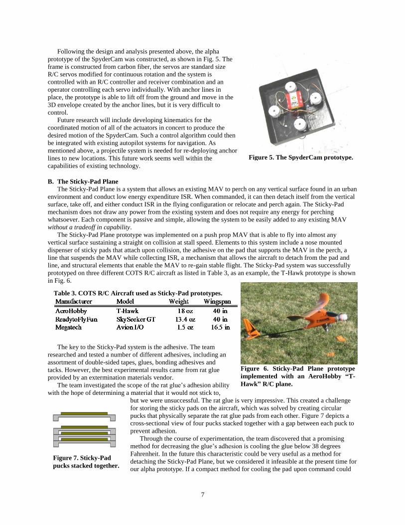
Following the design and analysis presented above, the alpha
prototype of the SpyderCam was constructed, as shown in Fig. 5. The
frame is constructed from carbon fiber, the servos are standard size
R/C servos modified for continuous rotation and the system is
controlled with an R/C controller and receiver combination and an
operator controlling each servo individually. With anchor lines in
place, the prototype is able to lift off from the ground and move in the
3D envelope created by the anchor lines, but it is very difficult to
control.
Future research will include developing kinematics for the
coordinated motion of all of the actuators in concert to produce the
desired motion of the SpyderCam. Such a control algorithm could then
be integrated with existing autopilot systems for navigation. As
mentioned above, a projectile system is needed for re-deploying anchor
lines to new locations. This future work seems well within the
capabilities of existing technology.
B. The Sticky-Pad Plane
The Sticky-Pad Plane is a system that allows an existing MAV to perch on any vertical surface found in an urban
environment and conduct low energy expenditure ISR. When commanded, it can then detach itself from the vertical
surface, take off, and either conduct ISR in the flying configuration or relocate and perch again. The Sticky-Pad
mechanism does not draw any power from the existing system and does not require any energy for perching
whatsoever. Each component is passive and simple, allowing the system to be easily added to any existing MAV
without a tradeoff in capability.
The Sticky-Pad Plane prototype was implemented on a push prop MAV that is able to fly into almost any
vertical surface sustaining a straight on collision at stall speed. Elements to this system include a nose mounted
dispenser of sticky pads that attach upon collision, the adhesive on the pad that supports the MAV in the perch, a
line that suspends the MAV while collecting ISR, a mechanism that allows the aircraft to detach from the pad and
line, and structural elements that enable the MAV to re-gain stable flight. The Sticky-Pad system was successfully
prototyped on three different COTS R/C aircraft as listed in Table 3, as an example, the T-Hawk prototype is shown
in Fig. 6.
The key to the Sticky-Pad system is the adhesive. The team
researched and tested a number of different adhesives, including an
assortment of double-sided tapes, glues, bonding adhesives and
tacks. However, the best experimental results came from rat glue
provided by an extermination materials vendor.
The team investigated the scope of the rat glue’s adhesion ability
with the hope of determining a material that it would not stick to,
but we were unsuccessful. The rat glue is very impressive. This created a challenge
for storing the sticky pads on the aircraft, which was solved by creating circular
pucks that physically separate the rat glue pads from each other. Figure 7 depicts a
cross-sectional view of four pucks stacked together with a gap between each puck to
prevent adhesion.
Through the course of experimentation, the team discovered that a promising
method for decreasing the glue’s adhesion is cooling the glue below 38 degrees
Fahrenheit. In the future this characteristic could be very useful as a method for
detaching the Sticky-Pad Plane, but we considered it infeasible at the present time for
our alpha prototype. If a compact method for cooling the pad upon command could
Figure 6. Sticky-Pad Plane prototype
implemented with an AeroHobby “T-
Hawk” R/C plane.
Table 3. COTS R/C Aircraft used as Sticky-Pad prototypes.
Figure 7. Sticky-Pad
pucks stacked together.
8
be developed, it would be very useful.
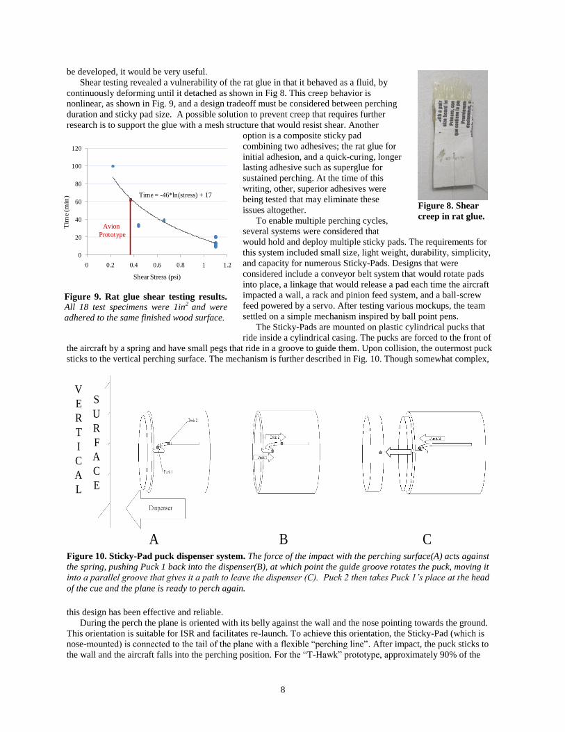
Shear testing revealed a vulnerability of the rat glue in that it behaved as a fluid, by
continuously deforming until it detached as shown in Fig 8. This creep behavior is
nonlinear, as shown in Fig. 9, and a design tradeoff must be considered between perching
duration and sticky pad size. A possible solution to prevent creep that requires further
research is to support the glue with a mesh structure that would resist shear. Another
option is a composite sticky pad
combining two adhesives; the rat glue for
initial adhesion, and a quick-curing, longer
lasting adhesive such as superglue for
sustained perching. At the time of this
writing, other, superior adhesives were
being tested that may eliminate these
issues altogether.
To enable multiple perching cycles,
several systems were considered that
would hold and deploy multiple sticky pads. The requirements for
this system included small size, light weight, durability, simplicity,
and capacity for numerous Sticky-Pads. Designs that were
considered include a conveyor belt system that would rotate pads
into place, a linkage that would release a pad each time the aircraft
impacted a wall, a rack and pinion feed system, and a ball-screw
feed powered by a servo. After testing various mockups, the team
settled on a simple mechanism inspired by ball point pens.
The Sticky-Pads are mounted on plastic cylindrical pucks that
ride inside a cylindrical casing. The pucks are forced to the front of
the aircraft by a spring and have small pegs that ride in a groove to guide them. Upon collision, the outermost puck
sticks to the vertical perching surface. The mechanism is further described in Fig. 10. Though somewhat complex,
this design has been effective and reliable.
During the perch the plane is oriented with its belly against the wall and the nose pointing towards the ground.
This orientation is suitable for ISR and facilitates re-launch. To achieve this orientation, the Sticky-Pad (which is
nose-mounted) is connected to the tail of the plane with a flexible “perching line”. After impact, the puck sticks to
the wall and the aircraft falls into the perching position. For the “T-Hawk” prototype, approximately 90% of the
Figure 8. Shear
creep in rat glue.
A
S
U
R
F
A
C
E
V
E
R
T
I
C
A
L
B C
Figure 10. Sticky-Pad puck dispenser system. The force of the impact with the perching surface(A) acts against
the spring, pushing Puck 1 back into the dispenser(B), at which point the guide groove rotates the puck, moving it
into a parallel groove that gives it a path to leave the dispenser (C). Puck 2 then takes Puck 1’s place at the head
of the cue and the plane is ready to perch again.
0
20
40
60
80
100
120
0 0.2 0.4 0.6 0.8 1 1.2
Shear Stress (psi)
Tim
e (m
in) Time = -46*ln(stress) + 17
Avion
Prototype
Figure 9. Rat glue shear testing results.
All 18 test specimens were 1in2
and were
adhered to the same finished wood surface.
9
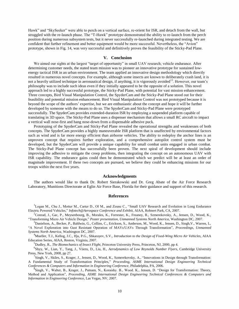
Figure 12. Razor blade fixed to the
elevator to sever the perching line.
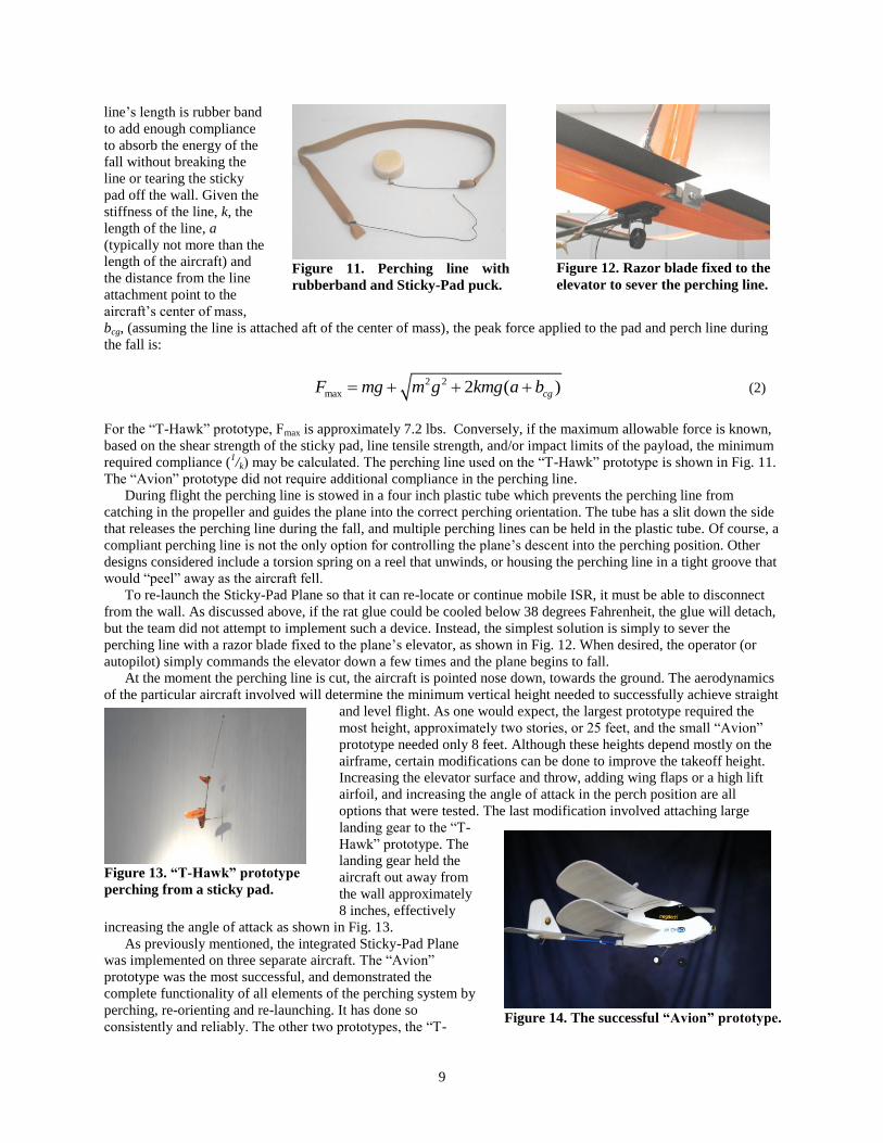
line’s length is rubber band
to add enough compliance
to absorb the energy of the
fall without breaking the
line or tearing the sticky
pad off the wall. Given the
stiffness of the line, k, the
length of the line, a
(typically not more than the
length of the aircraft) and
the distance from the line
attachment point to the
aircraft’s center of mass,
bcg, (assuming the line is attached aft of the center of mass), the peak force applied to the pad and perch line during
the fall is:
2 2
max 2 ( )cgF mg m g kmg a b (2)
For the “T-Hawk” prototype, Fmax is approximately 7.2 lbs. Conversely, if the maximum allowable force is known,
based on the shear strength of the sticky pad, line tensile strength, and/or impact limits of the payload, the minimum
required compliance (1/k) may be calculated. The perching line used on the “T-Hawk” prototype is shown in Fig. 11.
The “Avion” prototype did not require additional compliance in the perching line.
During flight the perching line is stowed in a four inch plastic tube which prevents the perching line from
catching in the propeller and guides the plane into the correct perching orientation. The tube has a slit down the side
that releases the perching line during the fall, and multiple perching lines can be held in the plastic tube. Of course, a
compliant perching line is not the only option for controlling the plane’s descent into the perching position. Other
designs considered include a torsion spring on a reel that unwinds, or housing the perching line in a tight groove that
would “peel” away as the aircraft fell.
To re-launch the Sticky-Pad Plane so that it can re-locate or continue mobile ISR, it must be able to disconnect
from the wall. As discussed above, if the rat glue could be cooled below 38 degrees Fahrenheit, the glue will detach,
but the team did not attempt to implement such a device. Instead, the simplest solution is simply to sever the
perching line with a razor blade fixed to the plane’s elevator, as shown in Fig. 12. When desired, the operator (or
autopilot) simply commands the elevator down a few times and the plane begins to fall.
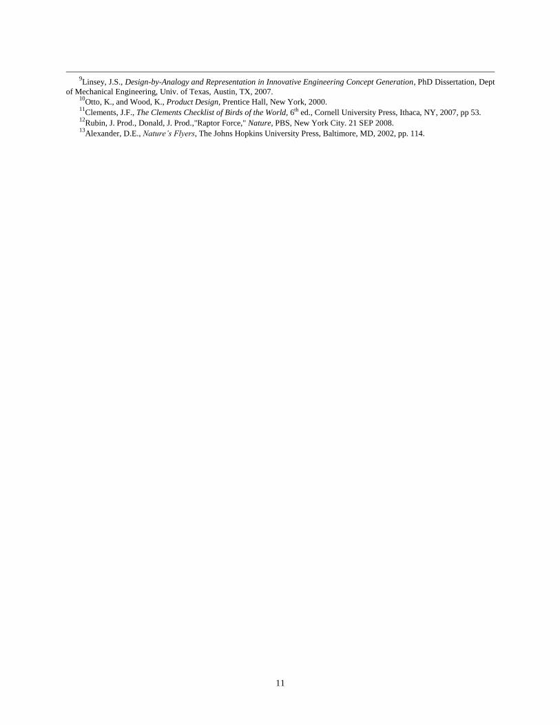
At the moment the perching line is cut, the aircraft is pointed nose down, towards the ground. The aerodynamics
of the particular aircraft involved will determine the minimum vertical height needed to successfully achieve straight
and level flight. As one would expect, the largest prototype required the
most height, approximately two stories, or 25 feet, and the small “Avion”
prototype needed only 8 feet. Although these heights depend mostly on the
airframe, certain modifications can be done to improve the takeoff height.
Increasing the elevator surface and throw, adding wing flaps or a high lift
airfoil, and increasing the angle of attack in the perch position are all
options that were tested. The last modification involved attaching large
landing gear to the “T-
Hawk” prototype. The
landing gear held the
aircraft out away from
the wall approximately
8 inches, effectively
increasing the angle of attack as shown in Fig. 13.
As previously mentioned, the integrated Sticky-Pad Plane
was implemented on three separate aircraft. The “Avion”
prototype was the most successful, and demonstrated the
complete functionality of all elements of the perching system by
perching, re-orienting and re-launching. It has done so
consistently and reliably. The other two prototypes, the “T-
Figure 11. Perching line with
rubberband and Sticky-Pad puck.
Figure 13. “T-Hawk” prototype
perching from a sticky pad.
Figure 14. The successful “Avion” prototype.
10
Hawk” and “SkySeeker” were able to perch on a vertical surface, re-orient for ISR, and detach from the wall, but
struggled with the re-launch phase. The “T-Hawk” prototype demonstrated the ability to re-launch from the perch
position during numerous subsystem tests, but it never successfully re-launched during integrated testing. We are
confident that further refinement and better equipment would be more successful. Nevertheless, the “Avion”
prototype, shown in Fig. 14, was very successful and definitively proves the feasibility of the Sticky-Pad Plane.
V. Conclusion
We aimed our sights at the largest “target of opportunity” in small UAV research; vehicle endurance. After
determining customer needs, the stated team mission was to pioneer an innovative prototype for sustained low-
energy tactical ISR in an urban environment. The team applied an innovative design methodology which directly
resulted in numerous novel concepts. For example, although some insects are known to deliberately crash land, it is
not a heavily utilized technique in aeronautical design, if anything, it is vigorously avoided13
. However, our team’s
philosophy was to include such ideas even if they initially appeared to be the opposite of a solution. This novel
approach led to a highly successful prototype, the Sticky-Pad Plane, with potential for vast mission enhancement.
Three concepts, Bird Visual Manipulation Control, the SpyderCam and the Sticky-Pad Plane stood out for their
feasibility and potential mission enhancement. Bird Visual Manipulation Control was not prototyped because it is
beyond the scope of the authors’ expertise, but we are enthusiastic about the concept and hope it will be further
developed by someone with the means to do so. The SpyderCam and Sticky-Pad Plane were prototyped
successfully. The SpyderCam provides extended-duration ISR by employing a suspended platform capable of
translating in 3D space. The Sticky-Pad Plane uses a dispenser mechanism that allows a small RC aircraft to impact
a vertical wall nose-first and hang nose-down from a dispensable adhesive puck.
Prototyping of the SpyderCam and Sticky-Pad Plane revealed the operational strengths and weaknesses of both
concepts. The SpyderCam provides a highly maneuverable ISR platform that is unaffected by environmental factors
such as wind and is far more energy efficient than airborne vehicles. The ability to redeploy the anchor lines is an
unproven concept that requires further exploration, and a comprehensive autopilot control system must be
developed, but the SpyderCam will provide a unique capability for small combat units engaged in urban combat.
The Sticky-Pad Plane concept has successfully been proven. The next spiral of development should include
improving the adhesive to mitigate the creep problems, then integrating the concept on an autonomous UAV with
ISR capability. The endurance gains could then be demonstrated which we predict will be at least an order of
magnitude improvement. If these two concepts are pursued, we believe they could be enhancing missions for our
troops within the next five years.
Acknowledgments
The authors would like to thank Dr. Robert Sierakowski and Dr. Greg Abate of the Air Force Research
Laboratory, Munitions Directorate at Eglin Air Force Base, Florida for their guidance and support of this research.
References
1Logan M., Chu J., Motter M., Carter D., Ol M., and Zeune C., “Small UAV Research and Evolution in Long Endurance
Electric Powered Vehicles,” Infotech@Aerospace Conference and Exhibit, AIAA, Rohnert Park, CA, 2007. 2Conrad, J., Gac, P., Meysenbourg, B., Morales, K., Forrester, K., Freaney, R., Szmerekovsky, A., Jensen, D., Wood, K.,
“Transforming Micro Air Vehicle Design,” Poster presentation, Unmanned Systems North America, Washington DC, 2007. 3Danielson, A., Becker, P., Baldwin, G., Collins, C., Erickson, S., Anderson, M., Wood, K., Jensen, D., Singh,V., Warren, L,
“A Novel Exploration into Gust Resistant Operation of MAVs/UAVs Through Transformation”, Proceedings, Unmanned
Systems North America, Washington DC, 2007. 4Mueller, T.J., Kellog, J.C., Ifju, P.G., Shkarayev, S.V., Introduction to the Design of Fixed-Wing Micro Air Vehicles, AIAA
Education Series, AIAA, Reston, Virginia, 2007. 5Dudley, R., The Biomechanics of Insect Flight, Princeton University Press, Princeton, NJ, 2000, pp 4.
6Shyy, W., Lian, Y., Tang, J., Viieru, D., Liu, H., Aerodynamics of Low Reynolds Number Flyers, Cambridge University
Press, New York, 2008, pp 27. 7Singh, V., Skiles, S., Krager, J., Jensen, D., Wood, K., Szmerekovsky, A., “Innovations in Design through Transformation:
A Fundamental Study of Transformation Principles,” Proceeding, ASME International Design Engineering Technical
Conferences & Computers and Information in Engineering Conference, Philadelphia, PA, 2006. 8Singh, V., Walter, B., Krager, J., Putnam, N., Koraishy. B., Wood. K., Jensen, D. “Design for Transformation: Theory,
Method and Application”, Proceeding, ASME International Design Engineering Technical Conferences & Computers and
Information in Engineering Conference, Las Vegas, NV, 2007.
11
9Linsey, J.S., Design-by-Analogy and Representation in Innovative Engineering Concept Generation, PhD Dissertation, Dept
of Mechanical Engineering, Univ. of Texas, Austin, TX, 2007. 10
Otto, K., and Wood, K., Product Design, Prentice Hall, New York, 2000. 11
Clements, J.F., The Clements Checklist of Birds of the World, 6th ed., Cornell University Press, Ithaca, NY, 2007, pp 53. 12
Rubin, J. Prod., Donald, J. Prod.,"Raptor Force," Nature, PBS, New York City. 21 SEP 2008. 13
Alexander, D.E., Nature’s Flyers, The Johns Hopkins University Press, Baltimore, MD, 2002, pp. 114.