the specialist committee on energy saving methods - ittc
TRANSCRIPT
1
The Specialist Committee on
Energy Saving Methods Final Report and Recommendations to the 29th
ITTC
2
Specialist Committee on Energy Saving Method
1. INTRODUCTION
1.1 Membership and Meetings
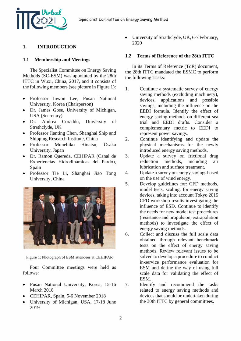
The Specialist Committee on Energy Saving Methods (SC-ESM) was appointed by the 28th ITTC in Wuxi, China, 2017, and it consists of the following members (see picture in Figure 1):
• Professor Inwon Lee, Pusan National University, Korea (Chairperson)
• Dr. James Gose, University of Michigan, USA (Secretary)
• Dr. Andrea Coraddu, University of Strathclyde, UK
• Professor Jianting Chen, Shanghai Ship and Shipping Research Institute, China
• Professor Munehiko Hinatsu, Osaka University, Japan
• Dr. Ramon Quereda, CEHIPAR (Canal de Experiencias Hidrodinámicas del Pardo), Spain
• Professor Tie Li, Shanghai Jiao Tong University, China
Figure 1: Photograph of ESM attendees at CEHIPAR
Four Committee meetings were held as follows:
• Pusan National University, Korea, 15-16 March 2018
• CEHIPAR, Spain, 5-6 November 2018 • University of Michigan, USA, 17-18 June
2019
• University of Strathclyde, UK, 6-7 February, 2020
1.2 Terms of Reference of the 28th ITTC
In its Terms of Reference (ToR) document, the 28th ITTC mandated the ESMC to perform the following Tasks:
1. Continue a systematic survey of energy saving methods (excluding machinery), devices, applications and possible savings, including the influence on the EEDI formula. Identify the effect of energy saving methods on different sea trial and EEDI drafts. Consider a complementary metric to EEDI to represent power savings.
2. Continue identifying and update the physical mechanisms for the newly introduced energy saving methods.
3. Update a survey on frictional drag reduction methods, including air lubrication and surface treatment.
4. Update a survey on energy savings based on the use of wind energy.
5. Develop guidelines for: CFD methods, model tests, scaling, for energy saving devices, taking into account Tokyo 2015 CFD workshop results investigating the influence of ESD. Continue to identify the needs for new model test procedures (resistance and propulsion, extrapolation methods) to investigate the effect of energy saving methods.
6. Collect and discuss the full scale data obtained through relevant benchmark tests on the effect of energy saving methods. Review relevant issues to be solved to develop a procedure to conduct in-service performance evaluation for ESM and define the way of using full scale data for validating the effect of ESM.
7. Identify and recommend the tasks related to energy saving methods and devices that should be undertaken during the 30th ITTC by general committees.
3
1.3 Liaison with Other Committees and overlap on TORs
We have been in contact with the Resistance and Propulsion (R&P) committee both by email and by joint meetings as follows;
• Attendance of chair (Inwon Lee) at the 4th meeting of R&P, KRISO, Daejon, 14 January 2020.
This was to clarify areas of overlap, decide who will move such areas forward and to discuss areas of common interest. Considering the termination of the committee after the 29th ITTC, the items of ToR which needs to be transferred to general committee were discussed.
1.4 General remarks
As the first item of our ToR implies, there exist various approaches to save energy for marine vessels. Although there has been recent progress in retrofit devices to enhance propulsion efficiency, which are commonly described as “energy saving devices”, it is also important to remember that the potential scope of energy saving methods are quite extensive including aspects of initial design and ship operation.
Good initial design for hull form and propeller with less power demand should always be addressed as a relevant energy saving method. It must be emphasized that design is aimed at good performance not only for the model test/trial condition in ‘calm seas’ but also for the service conditions with wind and waves. Optimised hull forms to minimise added resistance in waves is a good example of a design approach to energy saving.
Many energy saving methods can be characterised as suitable for retrofit with the aim of reducing drag or the propulsive losses for an existing design. In addition, these measures are often applicable to the initial design phase. Examples would include air lubrication and low frictional coatings for reducing skin frictional
resistance. On the other hand, there are devices designed to control the flow around the propeller to reduce propulsive losses. Use of renewable energy, such as wind and solar, also falls in this category.
The final category would correspond to the optimal operation. Being free from additional investment, this is often regarded as the most effective approach by ship operators. Examples of this category include slow steaming, hull/propeller cleaning, weather routing and trim optimization, etc.
2. SURVEY OF ENERGY SAVING METHODS
2.1 Categorization of energy saving methods
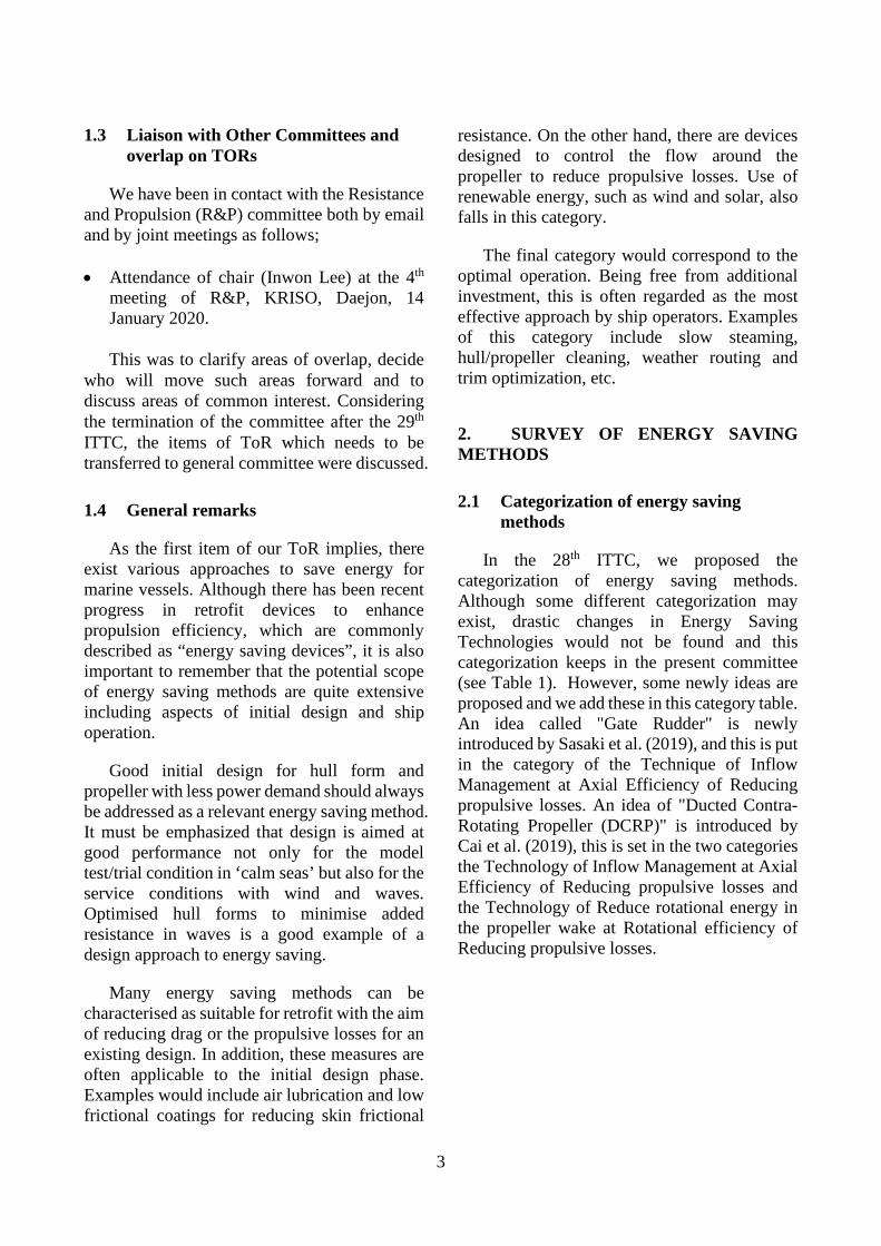
In the 28th ITTC, we proposed the categorization of energy saving methods. Although some different categorization may exist, drastic changes in Energy Saving Technologies would not be found and this categorization keeps in the present committee (see Table 1). However, some newly ideas are proposed and we add these in this category table. An idea called "Gate Rudder" is newly introduced by Sasaki et al. (2019), and this is put in the category of the Technique of Inflow Management at Axial Efficiency of Reducing propulsive losses. An idea of "Ducted Contra-Rotating Propeller (DCRP)" is introduced by Cai et al. (2019), this is set in the two categories the Technology of Inflow Management at Axial Efficiency of Reducing propulsive losses and the Technology of Reduce rotational energy in the propeller wake at Rotational efficiency of Reducing propulsive losses.
4
Specialist Committee on Energy Saving Method
Table 1: Categories of Energy Saving Methods
Principle Mechanism Technique Methodology
Direct drag reduction
frictional resistance less wetted sueface area less sheer force
air lubrication low friction paint
viscous pressure resistance boundary layer control generate local vortex by fins
hull form optimisation
wave-making resistance bow shaping bulbous bow hull form optimisation
wind drag reduction shaping of upper structures
corner rounding downsizing of upper structure
added wave resistance incident wave reflection bow shaping ship motion hull shape
Reducing Propulsive
losses
relative rotative efficiency
bilge vortex energy recovery
pre swirl stators vortex generators
hull efficiency hull-propeller interaction vortex generators hull-propeller optimisation
rotational efficiency reduce rotational energy in the propeller wake
pre swirl stators contra-rotating propeller reaction rudder rudder fin hub fins overlapping propeller
axial efficiency
hub vortex recovering hub fins rudder bulb
reduce tip vortex tip-fin propeller tip-rake propeller CLT propeller
inflow management ducts overlapping propeller
frictional efficiency coatings low friction paint injection
propeller design blade design area, thickness, section, tip loaded
propeller CFD, optimization
Use of renewable
energy
wave wing theory in waves forebody fin
wind energy thrusut by wing lift sail kite flettner rotor
solar energy energy change photovoltaic panels
Operation
optimisation in operation ICT weather routing
slow steaming
aging maintenance docking roughness treatment
5
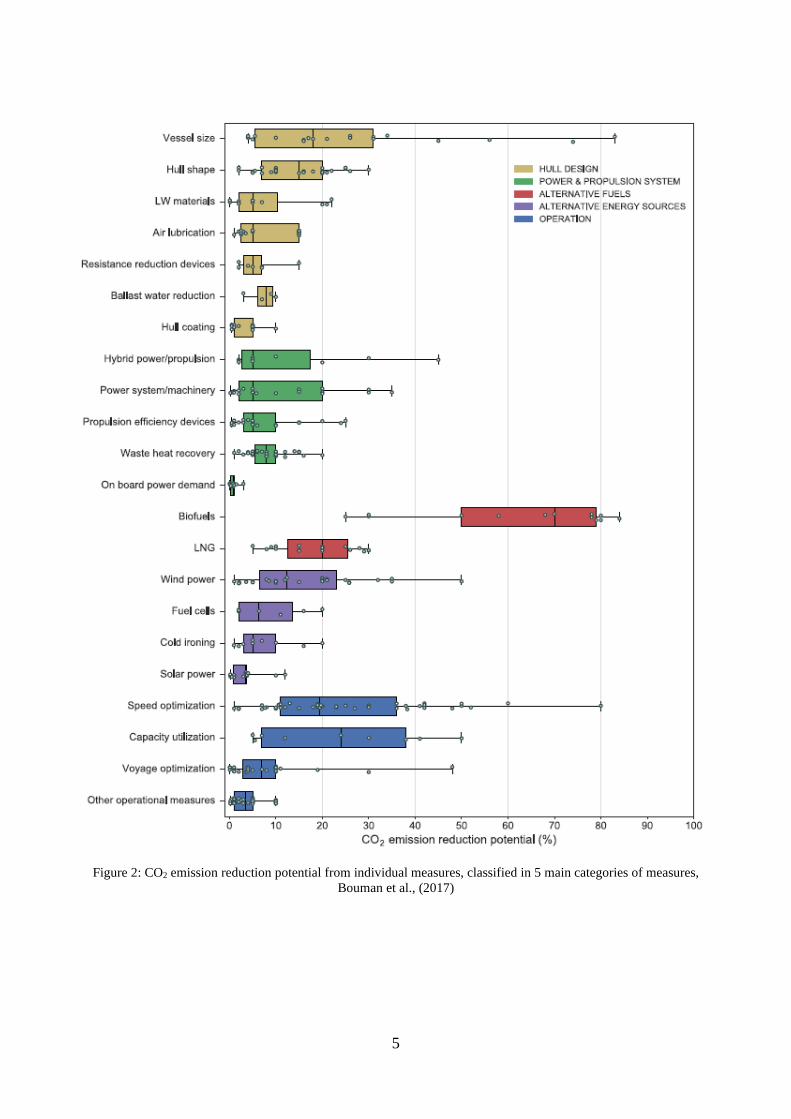
Figure 2: CO2 emission reduction potential from individual measures, classified in 5 main categories of measures, Bouman et al., (2017)
6
Specialist Committee on Energy Saving Method
Bouman et al., (2017) reviewed a lot of literatures, mainly issued in between 2009 and 2016, related to the energy saving and showed a very interesting chart (see Figure 2). They summarized the potential of the reduction of CO2 emission from individual measures. Although the potential of the reduction of CO2 emission spans widely for each measures, it may be useful for us to roughly understand the tendency of energy saving potential for each measure.
2.2 Review of recent research on ESM
In this section, recent work related to the energy saving methods are reviewed. The conferences we reviewed over the period 2017-2020 were:
• Applied Ocean Research (AOR) • China Ocean Engineering (COE) • International Shipbuilding Progress (ISP) • International Journal of Naval Architecture
and Ocean Engineering (IJNAOE) • Journal of Hydrodynamics (JHD) • Journal of Marine Science and Technology
(JMST) • Journal of Ship Research (JSR) • Ocean Engineering (OE) • Advanced Model Measurement Technology
for the Marine Industry (AMT) - 11-13 October (2017), Glasgow, UK - 9-11 October (2019), Rome, Italy
• Computer and IT Application in the Marine Industries (COMPIT) - 15-17 May (2017), Cardiff, UK - 14-16 May (2018) Pavone, Italy - 25-27 May (2019) Tullamore, Ireland - 17-19 August (2020), Pontignano, Italy
• Symposium on High-Performance Marine Vehicle (HIPER) - 17-19 October (2016), Cortona, Italy - 11-13 September (2017), Zevenwacht,
South Africa
• Hull Performance & Insight Conference (HullPIC) - 27-29 March (2017), Ulrichshusen,
Germany - 12-14 May (2018) Redworth, UK - 6-8 May (2019) Gubbio, Italy - 26-28 October (2020) Hamburg,
Germany • International Naval Architecture and
Maritime Symposium (INT NAM) - 24-25 April (2018), Istanbul, Turkey
• International Ocean and Polar Engineering Conference (ISOPE) - 25-30 June (2017), San Francisco, USA - 10-15 June (2018), Sapporo, Japan - 16-21 June (2019), Honolulu, USA - 11-16 October (2020), Shanghai, China
• International Conference on Computational Methods in Marine Engineering (MARINE) - 15-17 May (2017), Nante, France - 13-15 May (2019), Gothenburg, Sweden
• Technology and Science for the Ships of the Future, 19th International Conference on Ship & Maritime Research (NAV 2018): 20-22 June (2018), Torieste, Italy
• Numerical Towing Tank (NuTTS) - 1-3 October (2017), Wageningen, The
Netherlands - 30 September-3 October (2018), Cortna,
Italy - 29 September-1 October (2019), Tomar,
Portugal • International Conference on Ocean,
Offshore and Arctic Engineering (OMAE) - 25-30 June (2017), Tronheim, Norway - 17-22 June (2018), Madrid, Spain - 9-14 June (2019), Glasgow, UK
• International Symposium on Practical Design of Ships and Other Floating Structures (PRADS): 22-26 September (2019), Yokohama, Japan
• International Symposium on Marine Propulsors (SMP) - 12 - 15 June (2017), Espoo, Finland - 26 - 30 May (2019), Rome, Italy
• Symposium on Naval Hydrodynamics (SNH) - 5-10 August (2018), Hamburg, Germany
7
- 18-23 October (2020), Osaka, Japan
2.3 Direct drag reduction
2.3.1 Frictional resistance
Frictional resistance
Air lubrication is one of the typical direct frictional reduction methods and still many researchers have been working on this theme. As the development of computers, the research using CFD increases in number.
Rotte et al. (2018) carried out numerical simulation of the flat bottom boundary layer flow with air cavity and the results are compared with PIV data. Arakawa et al. (2018) carried out CFD simulation of ship flows in the air lubricated condition. They also simulated self-propelled condition at the air lubrication with/without pre-swirl duct, WAD.
Wang et al. (2017) showed the experiment using 5m-long flat bottom shallow draft vessel. In the experiment the injection position was changed and obtained up to 15.5% drag reduction in the model test. Wang et al. (2018), the same group, evaluated about 10-15% energy saving for the full scale ship without considering air supply power. In addition, Yang et al. (2018) analysed the Wang's same model test by CFD.
Kawakita (2018) summarized the air lubrication technology widely from the view point of actual ship design.
Mäkiharju & Ceccio (2018) investigated experimentally the behaviour of injected air on a flat bottom of ship with differing the number of injection point. Ikeda (2018) introduced his research on the bottom air cavity to reduce the bottom frictional resistance experimentally and numerically.
Ravina & Guidomei (2018) introduced the activity of drag reduction by use of air injection at Genova University, in which two types of simple flat plates and 1.8m-long ship model are
used for the experiment. Park & Lee (2018) investigated the spread of air injection pattern experimentally and derived an empirical formula to evaluate the spread angle of air injected area with air rate and ship speed. Kim et al. (2018) carried out the CFD simulation of air injection at the bottom of bulk carrier for model and full scale in order to verify methods to extrapolate the drag reduction from model test to full-scale. Kim et al. (2019) carried out numerical simulation of two-phase flow to evaluate the frictional resistance due to air injection. They also evaluated the drag reduction for LNG carrier and compared with sea trial data.
Zhao et al. (2020) numerically simulated micro air bubble flows over axisymmetric body and studied the drag reduction rate vs. bubble size, body speed as well as air injection rate. Charruault et al. (2019) studied the free surface deformation of air cavity as well as drag reduction.
When the application of the air lubrication method to an actual ship is considered, a use of scavenging gas of main engine for the air injection to a ship bottom is one of promising methods, especially for a deep draft ship. Bondarenko & Fukuda (2018) analysed the main engine plant system under scavenging bypass condition.
Yehia et al. (2019) investigated the drag reduction due to the air lubrication by CFD analysis using Series 60 ship hull and evaluated the drag reduction rate at the full load and ballast conditions. Furthermore, trim optimization is combined under the air lubricated condition. They showed the drag reduction rate increases at optimized trim condition quantitatively.
Super-hydrophobic surface (SHS) is often employed as the measure of drag reduction. Many works on this theme are to clarify the physical mechanism by use of numerical simulation. Here, we review the works focused on marine engineering. Peifer et al. (2020) studied the air injection method with super-hydrophobic surface. This is a kind of basic
8
Specialist Committee on Energy Saving Method
research to use a flat plate in a wind tunnel. They showed that the lower air injection rate for SHS can achieve the same drag reduction for non-SHS. Katsuno et al. (2018) carried out CFD simulation of flows with super-hydrophobic coating for 2D wing section and marine propeller. They solve RANS equations with k-ω SST with modified velocity boundary condition to aim at considering SHS effect.
Riblet is one of the well-known measures to reduce the frictional drag and once many researchers have studied. Zhan et al. (2017) carried out the numerical simulation of flows with riblet surface and discussed the mechanism of the drag reduction. Chen et al. (2017) studied the three dimensional scalloped riblet by CFD.
For the compliant coating, Delfos et al. (2017) reported their research, however, they could not find out the drag-reduced coating in their research. Very precise measurement of flows around compliant coating is reported by the same group, Greidanus et al. (2017). Schrader (2019) showed that about 3% drag reduction has been predicted in the boundary layer along the hull model of small search-and-rescue boat.
Low frictional hull coating is also another important method to save energy. This method has an advantage of no further installation work for setting appendages to the ship hull. Lee & Park (2017, 2018) showed about 10% decrease of ship speed by use of the frictional drag reduction self-polishing co-polymer (FDR-SPC), applied on 176k bulk carrier. Being annual conference dedicated to the effect of hull coating on ship performance, the HullPIC is worth being paid continued attention. Among many literature, Demirel (2018) gave a notable review on the antifouling marine coating. Goler et al. (2017) gave a notable report on the full-scale energy saving effect of hull coating in this conference.
Frictional drag reduction by active control of micro-objects on the surface is another method. Ge et al. (2017) carried out a numerical simulation of turbulent boundary flows
controlled by dimples/pimples distributed on the surfaces and demonstrated the decrease of frictional and total drag reduction and increase of slight pressure drag.
Viscous pressure resistance/hull form optimization
Owing to the rapid development of computers and CFD softwares, researches related to the hull form optimization has been increasing in number. More than 20 works are reported in the present survey of literatures. Many works are on the methodology of hull optimization. Wackers et al. (2018) showed the effectiveness of a multi-fidelity meta-modelling and adaptive local grid refinement method to refine a ship hull form. Scholcz & Veldhuis (2017) demonstrated a 𝐶𝐶𝑏𝑏 = 0.786 tanker hull optimization using a surrogate based global optimization to reduce computational time.
Tahara et al. (2019) presented their work on the hull optimization including pre-swirl duct or stator to minimize ship power using multi-objective optimization.
Wave making resistance/hull form optimization
Huang et al. (2017) studied a new vortex search algorithm, aiming at avoiding trap in the local optimum solution, and by use of this method, they modified the fore part of KCS hull for the decrease of wave resistance. Liu et al. (2017) also carried out the optimization of the fore part of KCS hull using variance-based sensitivity analysis, Sobol and kriging model-based tensor-product basis function methods. Goren & Calisal (2017) studied to rationalize the design concept of wave resistance reduction and developed a mathematical programming procedure based on Wolfe's algorithm. Guo et al. (2017) modified the ship bow part by adding a retrofitted structure to reduce the ship resistance in waves and carried out CFD simulation to show its effectiveness. Yu et al. (2017) carried out a ship bow form optimization at calm and
9
irregular head waves to achieve 13.2% reduction in the wave-making resistance and 9.5% reduction in the mean added resistance at sea state 5. Yang & Kim (2017) carried out CFD simulation of added wave resistance for VLCC with different type of bow form especially in shot waves and compared with experiment data.
Demo et al. (2018a) investigated a shape parametrization to refine the shape of sonar dome of combatant ship. His group also presented their work on the bulbous bow form optimization (Demo et al., 2018b). Yang et al. (2018) investigated a hull form optimization in order to reduce ship resistance at two different speeds using 3000 ton fishing boat. Raven (2018) showed the aft-body optimization to minimize wave resistance using multi-fidelity technique with a parametric blending of basis hull forms. Raven & Scholcz (2019) also summarized their optimization method. Zhang et al. (2017) investigated an optimization of sonar dome form of DTMB5415 using an improved particle swarm optimization (IPSO). Zhang et al. (2018) also studied the similar problem by use of a non-linear programming method to reduce wave making resistance.
Coppedè et al. (2017, 2018) demonstrated KCS hull form optimization based on a response surface approach. Their group also presented a surrogate model based approach for hull form sensitivity analysis. Wei et al. (2019) optimized the fore part of KCS using reliability-based robust design optimization. Heo et al. (2019) optimized the bow part of KVLCC2 hull form to reduce added wave resistance.
Park et al. (2020) carried out an optimization of hull form design parameters of a small LNG bunkering vessel (SLBV) such as longitudinal centre of buoyancy (LCB), fore-body shape and after-body shape to achieve 9.5% reduction of effective power.
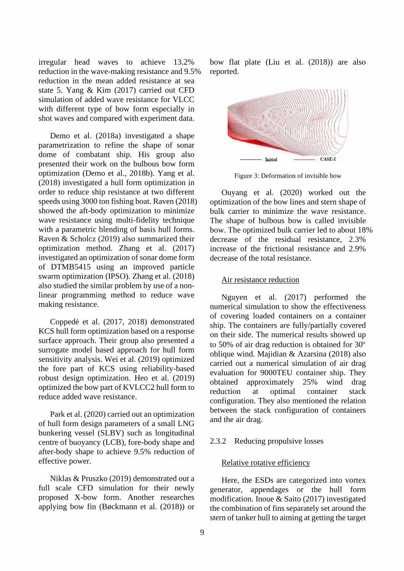
Niklas & Pruszko (2019) demonstrated out a full scale CFD simulation for their newly proposed X-bow form. Another researches applying bow fin (Bøckmann et al. (2018)) or
bow flat plate (Liu et al. (2018)) are also reported.
Figure 3: Deformation of invisible bow
Ouyang et al. (2020) worked out the optimization of the bow lines and stern shape of bulk carrier to minimize the wave resistance. The shape of bulbous bow is called invisible bow. The optimized bulk carrier led to about 18% decrease of the residual resistance, 2.3% increase of the frictional resistance and 2.9% decrease of the total resistance.
Air resistance reduction
Nguyen et al. (2017) performed the numerical simulation to show the effectiveness of covering loaded containers on a container ship. The containers are fully/partially covered on their side. The numerical results showed up to 50% of air drag reduction is obtained for 30° oblique wind. Majidian & Azarsina (2018) also carried out a numerical simulation of air drag evaluation for 9000TEU container ship. They obtained approximately 25% wind drag reduction at optimal container stack configuration. They also mentioned the relation between the stack configuration of containers and the air drag.
2.3.2 Reducing propulsive losses
Relative rotative efficiency
Here, the ESDs are categorized into vortex generator, appendages or the hull form modification. Inoue & Saito (2017) investigated the combination of fins separately set around the stern of tanker hull to aiming at getting the target
10
Specialist Committee on Energy Saving Method
wake pattern at the propeller plane. Furthermore, they combined these fins with pre-swirl duct to enhance the propulsive efficiency. Schrader & Marzi (2017) investigated their special appendages which are set on both side of ship stern aiming to deflect the outer streamlines in the after-body flow field towards the hull surface. Suryateja et al. (2019) studied an asymmetric stern form without adding any appendages using KVLCC2 for model and full scale ship to improve the propulsive efficiency.
Rotational efficiency
This category includes pre-swirl stators/duct, rudder bulb, rudder fin, PBCF, CRP and so forth. Quite a lot of researches categorized herein have been carried out. EU performed the project to study ESDs intensively in FP7 project GRIP (Green Retrofitting through Improved Propulsion) project from 2011 to 2015. In this project, pre-swirl stator, duct, rudder bulb and propeller boss cap fin are mainly focused to study. These results are issued in International Shipbuilding Progress Vol.63, Iss.3-4 as a special issue. In this volume, researches widely spanned in the above ESDs are reported. For instance, the working principle of pre-swirl stator is summarized by Streckwall & Yan (2017), and Schuilling & van Terwigsa (2017). The research of the strength of pre-swirl stator is presented by Paboeuf & Cassez (2017) and Hübler et al. (2017) introduced the retrofitting process of pre-swirl stator. The research of rudder bulb is reported by Coache & Meis Fernández (2017). Hasselaar & Yan (2017) reported the sea trial result with/without the pre-swirl stator and compared with full-scale simulation result. This gives very interesting and important information since the trial result of ESDs is scarcely published in open literature. Hence this issue worth being paid attention.
Besides this project, still many researches in a variety of organizations have been conducted study in relation to ESD. Most researches are involved in pre-swirl duct. Tacar & Korkut (2017) investigated the performance of the pre-swirl duct using 9 geometrically different ducts
and showed the most effective duct under equipped on 7000 DWT tanker. Furcas et al (2019) proposed a simulation-based design optimization, SBDO, approach for the design of a pre-duct type energy saving device. Pre-ducts reduce the wake losses, contribute to a better interaction between the propeller and the hull, and generate an additional thrust.
Wake Equalizing Duct (WED) maximizes the thrust delivered. Results from the design activity show sensible improvement of the overall propulsive efficiency. A Japan bulk carrier has been used to validate. Katayama et al. (2017), Kobayashi et al. (2017) carried out the investigation of the pre-swirl duct, named "Neighbor Duct", whose shape is vertically elongated oval. The experiment and CFD simulation are performed and about 4.4% energy saving in full scale ship is predicted.
Go et al. (2017) numerically simulated the pre-swirl duct and propeller combination in open water condition. Kume et al. (2018) performed to measure the pressure distribution around a pre-swirl duct in self-propelled condition in calm water. In order to do the measurement, they made the special duct model by use of 3D printer in which many built-in pressure holes and built-in pressure-lead small pipes are contained. They showed the difference of pressure on the duct due to the variation of propeller load. In order to develop the design method to obtain the optimal Mewis duct, Chang et al. (2019) carried out the numerical simulation of propulsive performance with the systematic variation of fan shape of Mewis duct and with systematic variation of duct location.
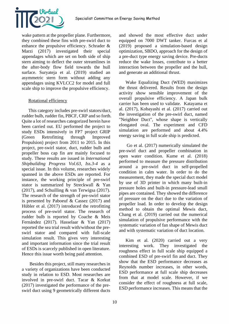
Kim et al. (2020) carried out a very interesting work. They investigated the roughness effect in full scale ship equipped a combined ESD of pre-swirl fin and duct. They show that the ESD performance decreases as Reynolds number increases, in other words, ESD performance at full scale ship decreases from that at model scale. However, if we consider the effect of roughness at full scale, ESD performance increases. This means that the
11
effect of the roughness is very important to estimate the ESD performance at full scale ship.
Figure 4: Possible DHP reduction predicted for different ESDs at varying rough surface conditions
Ikenoue et al. (2020) investigated the scale-up method for a pre-swirl duct. They compare the results from traditional scale-up method with those from direct full scale CFD method and show that the importance of the CFD simulation to evaluate ESD for the full-scale ship.
Next topic is the pre-swirl stator. Kim et al. (2017) proposed an extrapolation method for the analysis of self-propulsion test with a pre-swirl device. Due to the concerns on global warming and the establishment of the EEDI, energy saving devices are now widely employed. It was stated that the ITTC 1978 scaling method is not adequate for the prediction of ship performance for pre-swirl device because the counter swirl component results from inviscid mechanism. In this paper, an alternative scaling method to consider separately viscous axial wake and inviscid tangential wake is proposed.
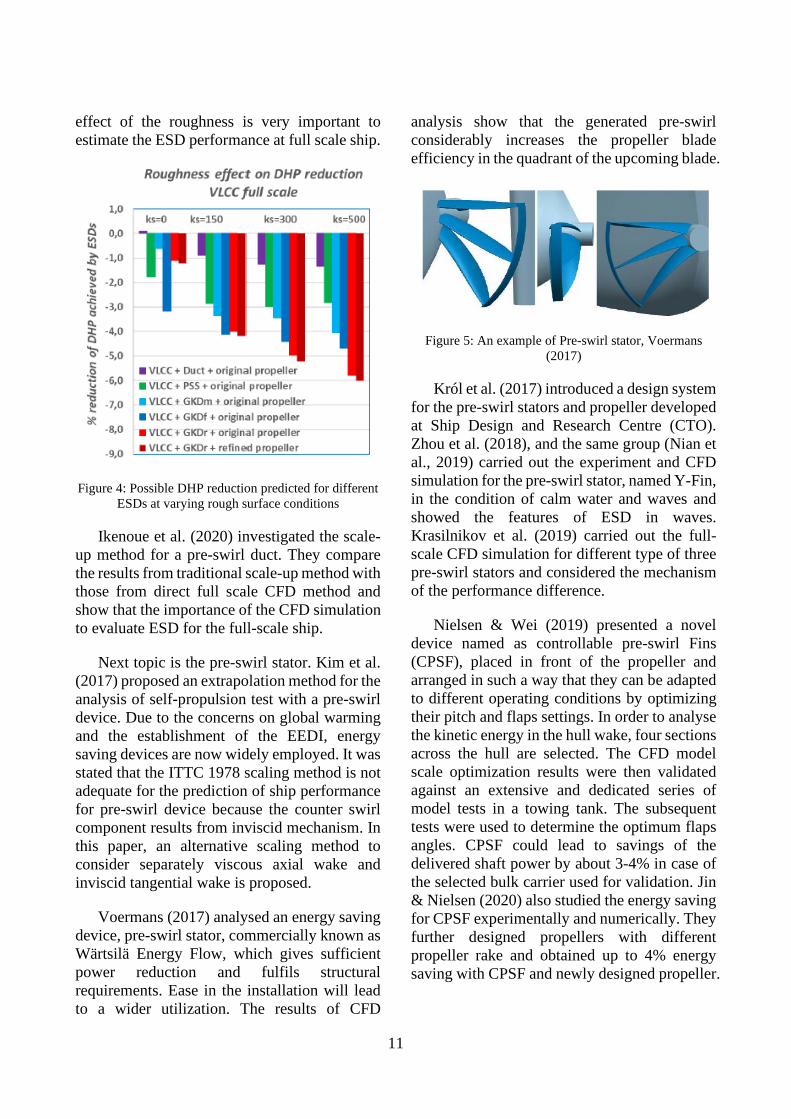
Voermans (2017) analysed an energy saving device, pre-swirl stator, commercially known as Wärtsilä Energy Flow, which gives sufficient power reduction and fulfils structural requirements. Ease in the installation will lead to a wider utilization. The results of CFD
analysis show that the generated pre-swirl considerably increases the propeller blade efficiency in the quadrant of the upcoming blade.
Figure 5: An example of Pre-swirl stator, Voermans (2017)
Król et al. (2017) introduced a design system for the pre-swirl stators and propeller developed at Ship Design and Research Centre (CTO). Zhou et al. (2018), and the same group (Nian et al., 2019) carried out the experiment and CFD simulation for the pre-swirl stator, named Y-Fin, in the condition of calm water and waves and showed the features of ESD in waves. Krasilnikov et al. (2019) carried out the full-scale CFD simulation for different type of three pre-swirl stators and considered the mechanism of the performance difference.
Nielsen & Wei (2019) presented a novel device named as controllable pre-swirl Fins (CPSF), placed in front of the propeller and arranged in such a way that they can be adapted to different operating conditions by optimizing their pitch and flaps settings. In order to analyse the kinetic energy in the hull wake, four sections across the hull are selected. The CFD model scale optimization results were then validated against an extensive and dedicated series of model tests in a towing tank. The subsequent tests were used to determine the optimum flaps angles. CPSF could lead to savings of the delivered shaft power by about 3-4% in case of the selected bulk carrier used for validation. Jin & Nielsen (2020) also studied the energy saving for CPSF experimentally and numerically. They further designed propellers with different propeller rake and obtained up to 4% energy saving with CPSF and newly designed propeller.
12
Specialist Committee on Energy Saving Method
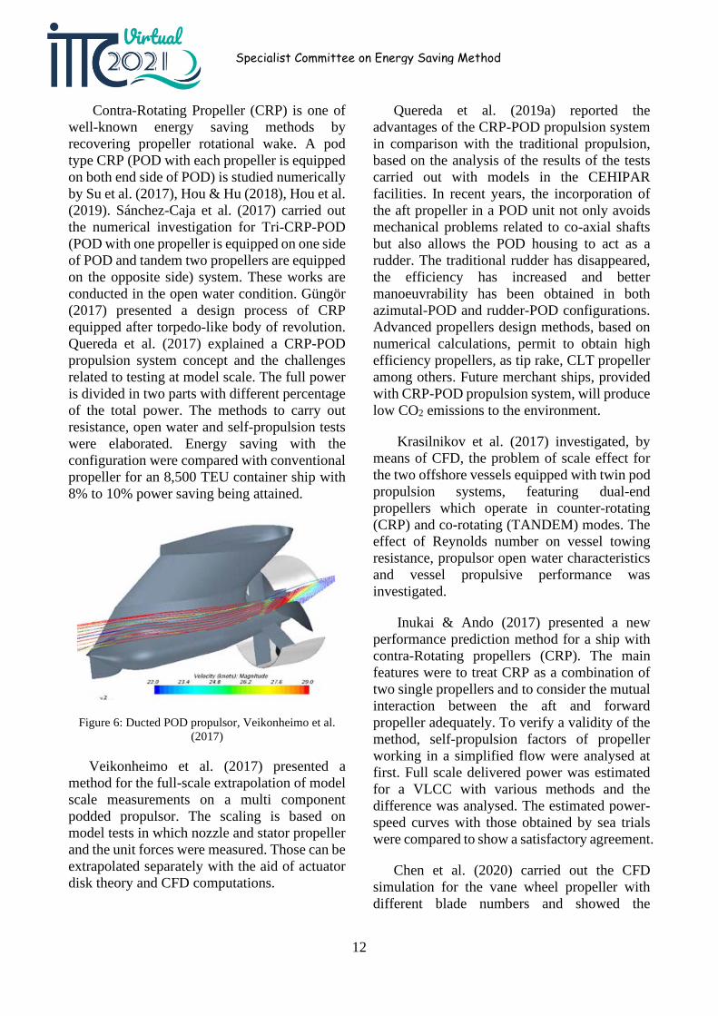
Contra-Rotating Propeller (CRP) is one of well-known energy saving methods by recovering propeller rotational wake. A pod type CRP (POD with each propeller is equipped on both end side of POD) is studied numerically by Su et al. (2017), Hou & Hu (2018), Hou et al. (2019). Sánchez-Caja et al. (2017) carried out the numerical investigation for Tri-CRP-POD (POD with one propeller is equipped on one side of POD and tandem two propellers are equipped on the opposite side) system. These works are conducted in the open water condition. Güngör (2017) presented a design process of CRP equipped after torpedo-like body of revolution. Quereda et al. (2017) explained a CRP-POD propulsion system concept and the challenges related to testing at model scale. The full power is divided in two parts with different percentage of the total power. The methods to carry out resistance, open water and self-propulsion tests were elaborated. Energy saving with the configuration were compared with conventional propeller for an 8,500 TEU container ship with 8% to 10% power saving being attained.
Figure 6: Ducted POD propulsor, Veikonheimo et al. (2017)
Veikonheimo et al. (2017) presented a method for the full-scale extrapolation of model scale measurements on a multi component podded propulsor. The scaling is based on model tests in which nozzle and stator propeller and the unit forces were measured. Those can be extrapolated separately with the aid of actuator disk theory and CFD computations.
Quereda et al. (2019a) reported the advantages of the CRP-POD propulsion system in comparison with the traditional propulsion, based on the analysis of the results of the tests carried out with models in the CEHIPAR facilities. In recent years, the incorporation of the aft propeller in a POD unit not only avoids mechanical problems related to co-axial shafts but also allows the POD housing to act as a rudder. The traditional rudder has disappeared, the efficiency has increased and better manoeuvrability has been obtained in both azimutal-POD and rudder-POD configurations. Advanced propellers design methods, based on numerical calculations, permit to obtain high efficiency propellers, as tip rake, CLT propeller among others. Future merchant ships, provided with CRP-POD propulsion system, will produce low CO2 emissions to the environment.
Krasilnikov et al. (2017) investigated, by means of CFD, the problem of scale effect for the two offshore vessels equipped with twin pod propulsion systems, featuring dual-end propellers which operate in counter-rotating (CRP) and co-rotating (TANDEM) modes. The effect of Reynolds number on vessel towing resistance, propulsor open water characteristics and vessel propulsive performance was investigated.
Inukai & Ando (2017) presented a new performance prediction method for a ship with contra-Rotating propellers (CRP). The main features were to treat CRP as a combination of two single propellers and to consider the mutual interaction between the aft and forward propeller adequately. To verify a validity of the method, self-propulsion factors of propeller working in a simplified flow were analysed at first. Full scale delivered power was estimated for a VLCC with various methods and the difference was analysed. The estimated power-speed curves with those obtained by sea trials were compared to show a satisfactory agreement.
Chen et al. (2020) carried out the CFD simulation for the vane wheel propeller with different blade numbers and showed the
13
dependence of blade number on the propeller performance and the vortical flow field.
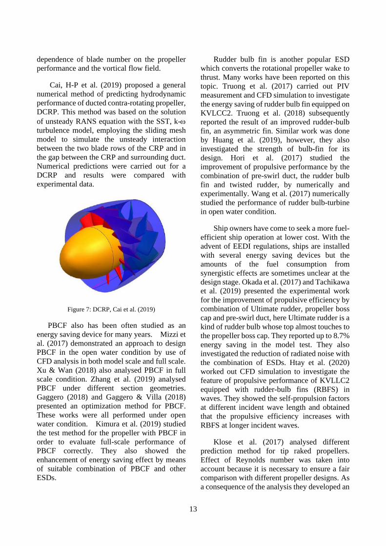
Cai, H-P et al. (2019) proposed a general numerical method of predicting hydrodynamic performance of ducted contra-rotating propeller, DCRP. This method was based on the solution of unsteady RANS equation with the SST, k-ω turbulence model, employing the sliding mesh model to simulate the unsteady interaction between the two blade rows of the CRP and in the gap between the CRP and surrounding duct. Numerical predictions were carried out for a DCRP and results were compared with experimental data.
Figure 7: DCRP, Cai et al. (2019)
PBCF also has been often studied as an energy saving device for many years. Mizzi et al. (2017) demonstrated an approach to design PBCF in the open water condition by use of CFD analysis in both model scale and full scale. Xu & Wan (2018) also analysed PBCF in full scale condition. Zhang et al. (2019) analysed PBCF under different section geometries. Gaggero (2018) and Gaggero & Villa (2018) presented an optimization method for PBCF. These works were all performed under open water condition. Kimura et al. (2019) studied the test method for the propeller with PBCF in order to evaluate full-scale performance of PBCF correctly. They also showed the enhancement of energy saving effect by means of suitable combination of PBCF and other ESDs.
Rudder bulb fin is another popular ESD which converts the rotational propeller wake to thrust. Many works have been reported on this topic. Truong et al. (2017) carried out PIV measurement and CFD simulation to investigate the energy saving of rudder bulb fin equipped on KVLCC2. Truong et al. (2018) subsequently reported the result of an improved rudder-bulb fin, an asymmetric fin. Similar work was done by Huang et al. (2019), however, they also investigated the strength of bulb-fin for its design. Hori et al. (2017) studied the improvement of propulsive performance by the combination of pre-swirl duct, the rudder bulb fin and twisted rudder, by numerically and experimentally. Wang et al. (2017) numerically studied the performance of rudder bulb-turbine in open water condition.
Ship owners have come to seek a more fuel-efficient ship operation at lower cost. With the advent of EEDI regulations, ships are installed with several energy saving devices but the amounts of the fuel consumption from synergistic effects are sometimes unclear at the design stage. Okada et al. (2017) and Tachikawa et al. (2019) presented the experimental work for the improvement of propulsive efficiency by combination of Ultimate rudder, propeller boss cap and pre-swirl duct, here Ultimate rudder is a kind of rudder bulb whose top almost touches to the propeller boss cap. They reported up to 8.7% energy saving in the model test. They also investigated the reduction of radiated noise with the combination of ESDs. Htay et al. (2020) worked out CFD simulation to investigate the feature of propulsive performance of KVLLC2 equipped with rudder-bulb fins (RBFS) in waves. They showed the self-propulsion factors at different incident wave length and obtained that the propulsive efficiency increases with RBFS at longer incident waves.
Klose et al. (2017) analysed different prediction method for tip raked propellers. Effect of Reynolds number was taken into account because it is necessary to ensure a fair comparison with different propeller designs. As a consequence of the analysis they developed an
14
Specialist Committee on Energy Saving Method
improved Reynolds number correcting method. Shin et al. (2017) compared the open water characteristics of tip modified propeller and conventional propeller designed for the same operating condition, by means of CFD. Model scale computations were performed using a larminar-turbulence transition model. Fully turbulent flow is considered for full scale computations. They concluded that the effects of the transition model show that laminar and transitional flow modelling is crucial in model scale computations. Lee et al. (2017) also studied the improvement of energy saving effect by combining several kinds of ESDs, such as twisted ruder, wavy twisted rudder, tip rake propeller and pre-swirl stator equipped on a container ship. Their test result showed up to 5.4% energy saving.
Pérez-Sobrino et al. (2016a) presented the so called SISTEMAR strip method in detail. The summary of the method is to obtain the OWT corrections by integration of the corrections obtained at each blade and eventually end plate sections. Taking into account the Reynolds number values on each section, the influence of the flow around the propeller sections was considered to analyse the corrections on different flows, laminar, turbulent and transitional zone on the blade surface. Quereda et al. (2019b) published a paper related to the validation of the strip method procedure by analysing a comprehensive set of OWT results, both for conventional and Contracted and Loaded Tip (CLT) propeller. They addressed that the strip method is practically equivalent to the application of ITTC’78-PPM for calculation of OWT scale effects of conventional propellers.
Kanemaru et al. (2017) proposed new types of rudder to aim at enhancing the propulsive performance. Two types of rudders were considered; one is the swept back rudder and the other is the high thrust rudder which has U-shaped notch at the leading edge of rudder at propeller boss positon.
Rear stator is the device to recover the propeller rotational wake to the thrust. Feng et al. (2019) performed the CFD simulation of the
rear stator just behind the ducted propeller working in the open water and evaluated the propulsive performance of this combined propulsor.
Axial efficiency
Shin & Andersen (2017) numerically investigated the scale effect of tip modified propeller in the open water condition and compared with the performance of a conventional propeller. For the podded propeller, Zhai et al. (2017) studied the optimization of casing form to increase the propulsive performance. González-Adalid et al. (2018) investigated the full-scale propulsive performance of Contracted and Loaded Tip (CLT) propeller retrofitted on 175,000 m3 LNG tanker and reported about 8% power saving compared with conventional propeller.
Researches on the ducted propeller can be found in SMP'17, NuTTS’19 and Ocean Engineering. Among others, Gaggero et al. (2017) and Remaud et al. (2019) are worth being mentioned, in which the relation between the propulsive performance and the sectional shape of duct is investigated.
Recently, Sasaki et al. (2016) carried out the research on "Gate Rudder", which is twin rudder system located aside propeller. Although a 6-8% energy saving from the tank test was reported, the raw results of tank test itself is not shown in the paper. Sasaki et al. (2018) demonstrated the effectiveness of Gate rudder by showing the sea trial result with sister ships, one is equipped with a conventional rudder and the other equipped with the Gate rudder. They stated 14% energy saving at Gate rudder. Sasaki et al. (2019) subsequently showed the voyage data of the sister ships to demonstrate the effectiveness of Gate rudder. They tried to clarify the reason of discrepancy and mentioned that the discrepancy would be due to the scale effect. Tacar et al. (2019), carried out the full-scale CFD simulation for Gate rudder. According to their computation, the propeller efficiency is not improved itself by setting Gate rudder, but, large
15
energy saving at Gate rudder equipped on the ship is obtained by comparing the numerically simulated power curves. The 14% energy saving for the actual ship is a tremendous value, but seems to be still too large since the model ship gain shows up to 8% energy saving. Much more disclosed data and discussion seems to be necessary and at the same time, the research at other organizations would be expected.
2.3.3 Propeller design
The search for increasing propulsive efficiency of ship propellers leads to the criterion of propeller blades with unconventional geometries like CLT and Tip Rake propellers. Sánchez et al. (2019) examines the effect of different tip configuration on the performance of the propellers. The tip region cannot be described with the traditional profiles’ sections. Cylindrical surfaces have used to define it. Viscous flow simulation such RANS and Detached Eddy Simulation (DES) were used to asses a generic test case. In order to reduce the frictional resistance acting on the propeller blade, a small area blade propeller is proposed as an effective measure. Lücke et al. (2017) summarized the test method and CFD simulation for a small area blade propeller. Tip modified propeller was also developed aiming at the increase of propulsive efficiency. Segawa et al. (2019) showed the method of optimum design of propeller which acts behind a pre-swirl duct as well as uniform flow. Kang et al (2019) employed a Kappel propeller, CLT propeller and Tip Rake propeller for the analysis. The parametric study for the optimum rake shape was conducted and the performance of the final design was verified by CFD and model tests. Zhang et al. (2020) also carried out the numerical simulation to investigate the propeller performance and propeller flow field for CLT propeller and Kappel propeller.
2.3.4 Use of renewable energy
As one of energy saving methods using wind energy, here, a couple of works for a kite and Flettner Rotor are briefly introduced. More
detailed review can be found in chapter 4. Duport et al. (2017) investigated the aerodynamic performance of kite using lifting line theory and RANS simulation. Turan et al. (2018) investigated the methodology of the optimal weather routing of the ship equipped Flettner Rotor.
The use of wave energy is another method. Matusiak & Rautaheimo (2017) carried out a feasibility study to use hull fins which convert wave energy to thrust. Chiu e al. (2018) studied on the active controlled bow fin on the ship going in irregular waves to augment the ship propulsion by converting the wave energy to the propulsive power.
2.3.5 Operation
Pertaining to the research of weather routing, review papers are mainly deal with the evaluation of methods of route optimization. Wang et al. (2017) compared Isochrone/Isopone algorithm, 2D/3D dynamic programing and Dijkstra algorithm for a North Atlantic route. Wang et al. (2018) also reported a study of route optimization using genetic algorithm. Zaccone et al. (2018a) investigated a voyage route optimization between near Denia, Spain and Geneva, Italy in consideration of the ship propulsive performance under real weather condition. Zaccone et al. (2018b) also studied a route optimization at North Atlantic route. Lin et al. (2018) showed the particle swarm optimization for a voyage route optimization. They applied this method to the route between Keelung and San Francisco. Orlandi et al. (2018) introduced PROFUME Demonstrator developed under ESA ARTES Integrated Applications Promotion (IAP) Project, which optimize a voyage route to minimize fuel consumption using on-board collected data. Mannarini et al. (2018) demonstrated a route optimization by refereeing EEOI for a North Atlantic route.
As another optimization of the operation, recently the study of trim optimization has been increasing in number. Liarokapis et al. (2017)
16
Specialist Committee on Energy Saving Method
carried out the experiment under several conditions combined by different displacement and trim angle. They used a model of high-speed small passenger vessel with chain. Drouet et al. (2017) investigated the trim optimization for a container ship at different sea state conditions as well as at calm water condition and showed that the optimal trim mainly depends on the draft and the sea-state. Braidotti et al. (2018) studied an optimal ballast water allocation system for the reduction of fuel consumption and demonstrated its effectiveness. Sogihara et al. (2018) evaluated the energy saving by taking the optimal trim in a sample voyage. Duan et al. (2019) carried out CFD simulation to show the relation between the ship resistance and trim for VLCC at design and ballast conditions. Wang et al. (2020) investigated numerically the flow field and propeller forces at several different trim conditions for ONR tumblehome ship model 5613. Fan et al. (2020) investigated numerically the difference of ship resistance at the different trim conditions for a bulk carrier.
As a unique method, Makino et al. (2017) proposed to control the propeller pitch angle optimally when the ship goes in waves to reduce total propeller power.
2.3.6 Others/design
Simulation based design system has been continuously studied at several organizations. Huang et al. (2017) investigated a homotopy method to optimize a container ship hull form in order to get a target wave resistance. Van der Ploeg et al. (2018) showed a method to deform the stern shape of container ship equipped a large area propeller, then the original stern has a tunnel stern, by adopting stern asymmetry concept. Wei et al. (2019) studied the resistance of four hull forms for high speed wave-piercing mono-hull ship at calm and incident wave conditions using CFD simulation. Ichinose et al. (2019) summarized a design system to optimize ship propulsive performance and cargo capacity by showing the sample simulation using 62k bulk carrier. Ichinose & Tahara (2019) also introduced a hull form design system based on a
database utilization to obtain a target wake. Xiong et al. (2019) applied a tunnel stern form with edge to a cruise ship and 2.6% of power reduction at design speed can be expected.
Krieg & Mohseni (2017) investigated a new concept of an underwater vehicle which utilizes a set of novel cephalopods inspired pulsed jet thruster. They suggest that the efficiency of this type of propulsor may be significantly higher than previously. There are many works to do, due to viscous dissipation of kinetic energy prior to measurement of the wake energy.
3. USE OF WIND ENERGY
3.1 Background
According to recent estimates, global shipping emits on average about 1 billion tonnes of carbon dioxide (CO2) on an annual basis, equivalent to over 3% of the global anthropogenic CO2 emissions. These figures are expected to increase significantly in the future despite market-driven and regulatory efficiency improvements, just due to the growth of the sector. Measures that can significantly reduce the CO2 emissions of the shipping sector will, therefore, have a crucial role in the future.
Several measures have been identified, or even applied, with the potential to achieve substantial emission reductions, like slow-steaming, bio-fuels, and alternative propulsion technologies. Slow steaming has been already analysed to a great extent, whereas bio-fuels have raised concerns about environmental impact and availability. Among alternative propulsion technologies, a resurgence on wind-assisted propulsion is observed in recent years, primarily due to its high-potential for fuel consumption and emission reduction.
Wind power is currently being developed through both conventional sails and modern alternatives. These include Flettner rotors, kites or spinnakers, soft sails, wing sails and wind turbines (Parker, 2013). The compatibility of different designs varies between ship classes
17
due to potential interference with cargo handling (Parker, 2013; Traut et al., 2014). However it is known that any current design alone cannot provide the typical ships propulsive power demand, but high wind speeds typically encountered in high seas (Staffell & Pfenninger, 2016) can allow for significant fuel savings, whilst maintaining full speed (Halim et al., 2018; Hirdaris & Cheng, 2012). Furthermore, research has shown that wind propulsion is most effective at slower speeds (e.g. less than 16 knots), and on smaller ships (3,000 - 10,000 tonnes) (Smith et al., 2016), which account for one-fifth of global cargo ships.
Various studies have estimated fuel savings across a wide range: 2-24% for a single Flettner rotor, 1-32% for a towing kite (Traut et al., 2014), up to 25% for the eConowind sails (which pack into a single container) (Traut et al., 2014) and some estimate savings from 10 to 60% at slow speeds (Smith et al., 2016). These results prompted several shipping companies to add sails to cargo vessels (Smith et al., 2016), however gradual uptake is not predicted until 2025, due to their relative immaturity of the market (Parker, 2013). Additional barriers for the wide adoption of these solutions in the industry have been identified by the scientific community, such as unfamiliarity with technology, safety and reliability concerns, and lack of demonstration (Rehmatulla et al., 2017). Of equal importance is the fact that no data on capital costs were found for the installation of wind assistance systems as they are at an early stage of development, but the potential fuel savings are large and further research is required to determine cost-effectiveness under different operational conditions and ship types.
3.2 Wing sails
Jo et al. (2013) investigated the performance of multiple wing sails to enhance ship thrust. They solve the flow around the wings using Computational Fluid Dynamics (CFD) to evaluate the generated thrust. (Ouchi et al., 2013) introduced a new concept of wind sail ship ”Wind challenger”, in which the motor-
assisted auxiliary system is applied, and they carried out a voyage simulation and evaluated the energy-saving rate of ”Wind Challenger”. Viola et al. (2015) developed a velocity prediction program for ships with propulsion assisted by wing sails. They used the ratio between the propeller thrust of a ship with and without wings as a measure of the energy efficiency and showed the possibility to reduce the propeller thrust of a KVLCC2 by up to 10% in cross winds. They concluded that the efficiency of the wing sails is crucial to achieving minimum savings with high aspect ratio wings performing best.
3.3 Towing kites
Naaijen & Koster (2007) performed a theoretical analysis of potential fuel savings for a kite propulsion system. The study included the effect of the propeller running in an off-design condition, and concluded that the additional resistance due to leeway angle is small. Dadd et al. (2011) assessed different kite trajectories, and they produced performance polar diagrams for a 300 m2 kite, assessing various operational parameters, such as aspect ratio and flight angle. Fagiano et al. ( 2012) investigated a high altitude kite system (200-600m) which is designed to generate electricity as the line is pulled as well as produce thrust, which can then be winched in during a de-powered condition producing a net energy production. Leloup et al., (2016) developed a performance prediction program, dedicated to merchant ships, in order to assess the fuel savings abilities of a kite. They concluded that using a 320 m2 kite on a 50,000 DWT tanker, the fuel savings predicted were about 10% for a Beaufort 5 sea state, and could reach values of 50% for wind velocities corresponding to a Beaufort 7 sea state. Leloup et al. (2014) developed a 6 degree of freedom sailboat dynamic simulation model, to evaluate kite performance in comparison with classical rig sailing. Their comparative results indicated that the boat towed by kite could achieve a significantly superior sailing performance.
18
Specialist Committee on Energy Saving Method
3.4 Flettner rotors
The most studied technology on wind-assisted propulsion is Flettner rotors. Pearson (2014) developed a model for assessing the performance gains from Flettner rotors and performed an initial assessment of the viability of retrofitting them to a specific ship. Craft et al. (2014) assessed Flettner-Thom rotors using RANS and LES with comparison to experimental data. They concluded that the Thoms multiple drums affected the boundary layer at low Reynolds numbers to improve the lift coefficients achieved. Lu & Ringsberg (2020) developed a four degree-of-freedom ship performance prediction model, to perform a parametric study of the Flettner rotor technology. The results showed that fuel savings ranging between 5.6% and 8.9% were achievable. The authors also underlined the sensitivity of the results with respect to vessel speed, voyage routes and weather conditions. Other effects on the performance of Flettner rotors were identified in the work of Bordogna et al. (2020). The study indicated that the aerodynamic performance of the two Flettner rotors was affected by their interaction, and generally, the effect is more noticeable when the devices are set closer to each other and are in alignment with the wind direction. Copuroglu & Pesman (2018) investigated the effects of Flettner rotors on the roll motion of ships and, subsequently the effects of roll motion on the performance of the rotors themselves.
3.5 In-service gains
Cui et al. (2016) developed performance prediction software that allows different wind assistance devices to be assessed. They assessed modern square rigged sails (DynaRig), rotors and kites on one coastal and one ocean route. They results showed that sails and kites delivered between 9-10 % fuel savings whereas Flettner rotors provided 23%. Little difference was observed between the two routes. However, both had similar mean true wind speeds. Traut et al. (2014) used numerical models of a Flettner rotor and a towing kite to assess their
performance over five different trade routes concluding that different technologies performed better on different routes. Bentin et al. (2016) assessed the optimal routing of a conventional multipurpose cargo ship with Flettner rotors operating in the north Atlantic and predicted energy saving between 20-50% depending on ship speed and wind conditions. Argyros (2017) provides a review of wind assisted shipping, summarising quoted energy saving potential of different technologies and a cost analysis of payback periods for different fuel prices, fuels savings and capital investment required. They concluded that wind assistance is one of the few technologies that has the potential to provide double digit fuel savings. Caughlan (2016) also provided a summary of wind assisted technologies concluded that a mean energy saving potential of 20% might be achievable.
3.6 Conclusions and future trends
The sustainability of the shipping industry, like any other industry, largely depends on the elasticity of demand for the service and the profitability through the minimisation of the operating costs. These costs in the past have largely depended on the price of marine fuels, but with environmental concerns now being in the forefront, this is subject to change. The assessment and understanding of the interdependencies and effects of environmentally optimised solutions and emission mitigation policies, along with the adaptation of more fuel efficient solutions will be paramount.
As a consequence, research on environmentally sustainable marine propulsion solutions in recent years has been intensified, to address precisely these issues. Wind energy was one of the key sources of propulsive power on ships in ancient times. However as a renewable, abundant and free source of energy, it has not been adequately exploited by the shipping industry in recent times. Wind-assisted propulsion for the marine sector has the potential of being the ”old but beneficial”
19
technology that could allow significant fuel and emission reduction (Talluri et al., 2016). As research studies suggest, compared to other renewable solutions, it has the advantage of being always available in the open sea, and it may be retrofitted on an already existing ship, as an alternative source of power.
The research community is in agreement that wind-assisted propulsion technologies can have a positive impact on the fuel consumption and emissions of commercial ships, however the fuel savings achieved are hard to quantify, as they are sensitive to a number of factors: Ship type and dimensions, operating speed, voyage route and corresponding weather conditions. Scientists and research engineers are actively advancing the related technologies and are developing the necessary computational frameworks to assess the technical, environmental, and economic feasibility. However, ship owners and operators are mostly concerned with the technical risks involved, and the hidden costs of a not yet matured technology (Rehmatulla & Smith, 2015). As such, the demand for, and importance of, holistic analyses that quantitatively establish the benefits of these solutions, and de-risk the technology at a preliminary design phase, is higher than ever, and is not expected to decrease in the future.
4. CFD, EFD AND SCALING METHODS
4.1 CFD Methods for ESD
4.1.1 Review of Tokyo 2015 CFD workshop
The Tokyo 2015 Workshop on CFD in Ship Hydrodynamics was held at National Maritime Research Institute (NMRI) in Tokyo on 2-4 December, 2015. The purpose of the workshop was the same as the preceding workshops and it was to assess state-of-the arts of the contemporary CFD codes for ship hydrodynamics. In the workshop, three ship hulls were selected and a total of 17 test cases were specified by the organizers. 30 groups
submitted their computed results for one or more cases.
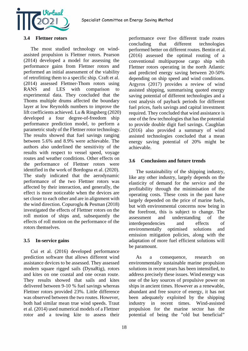
Figure 8: Surface mesh of the ESD considered for JBC in Tokyo 2015 CFD workshop (Shen and Korpus, 2015)
Among three ship hulls under consideration, the Japan bulk carrier (JBC) was associated with ESD (see Figure 8). CFD simulation on resistance and self-propulsion performance were carried out either with ESD and without ESD. The validation and verification (V&V) results drew attention of the committee, because they can shed some lights on the overall level of accuracy of CFD simulation. Comparison of numerical errors between the case with ESD and without ESD would imply how adequately the state of the art CFD simulation deal with the propulsive performance of ESD. In this regard, the V&V results for the JBC case 1.5a (without ESD) and the JBC case 1.6a (with ESD) are compared.
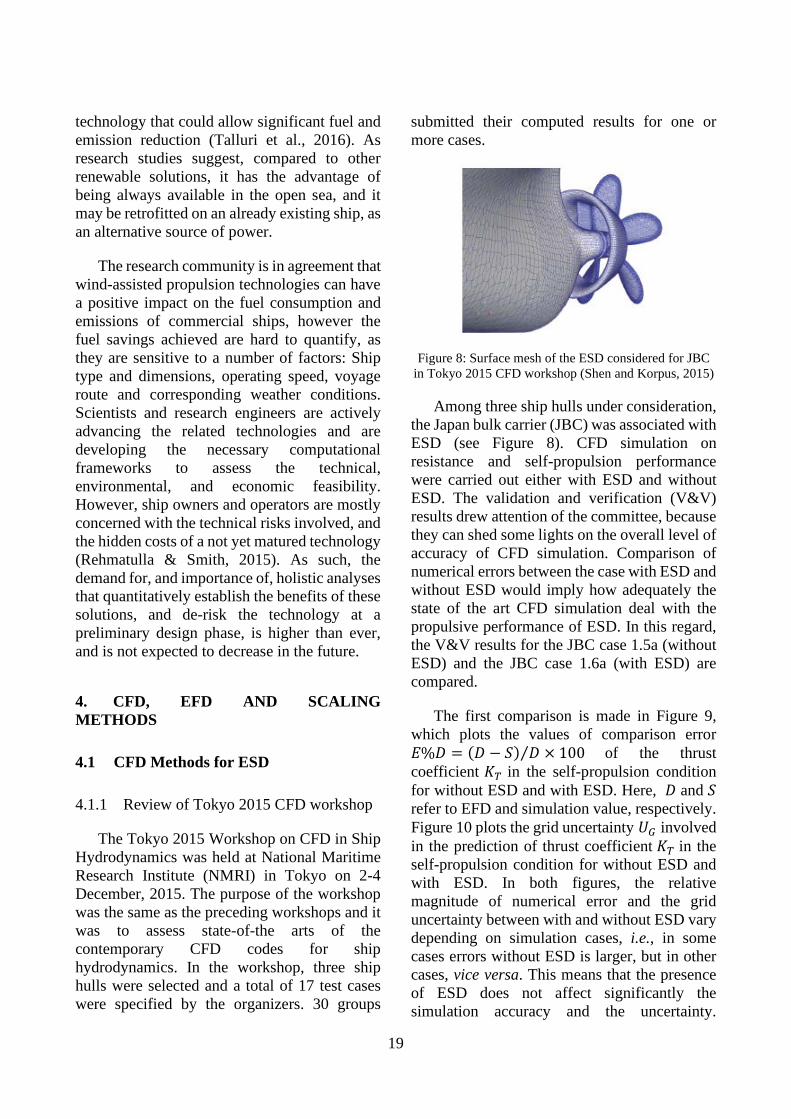
The first comparison is made in Figure 9, which plots the values of comparison error 𝐸𝐸%𝐷𝐷 = (𝐷𝐷 − 𝑆𝑆) 𝐷𝐷⁄ × 100 of the thrust coefficient 𝐾𝐾𝑇𝑇 in the self-propulsion condition for without ESD and with ESD. Here, 𝐷𝐷 and 𝑆𝑆 refer to EFD and simulation value, respectively. Figure 10 plots the grid uncertainty 𝑈𝑈𝐺𝐺 involved in the prediction of thrust coefficient 𝐾𝐾𝑇𝑇 in the self-propulsion condition for without ESD and with ESD. In both figures, the relative magnitude of numerical error and the grid uncertainty between with and without ESD vary depending on simulation cases, i.e., in some cases errors without ESD is larger, but in other cases, vice versa. This means that the presence of ESD does not affect significantly the simulation accuracy and the uncertainty.
20
Specialist Committee on Energy Saving Method
Depending on the CFD code considered, there appears a large variance in the accuracy and the uncertainty. Similar behaviour is found for the total resistance coefficient 𝐶𝐶𝑇𝑇 and the torque coefficient 𝐾𝐾𝑄𝑄 as well. If the cases with ESD had presented unambiguous increase in the level of CFD error and uncertainty over the counterpart cases without ESD, then it would have been reasonable to conclude that the state of the art CFD technique was inadequate for the ESD, which would necessitate a particular, dedicated CFD procedure for ESD. The results, however, indicate that there is no such inadequacy.
Figure 9: Comparison of % error in thrust coefficient 𝐾𝐾𝑇𝑇 in Tokyo 2015 Workshop
Figure 10: Comparison of the grid uncertainty associated with thrust coefficient 𝐾𝐾𝑇𝑇 in Tokyo 2015 Workshop
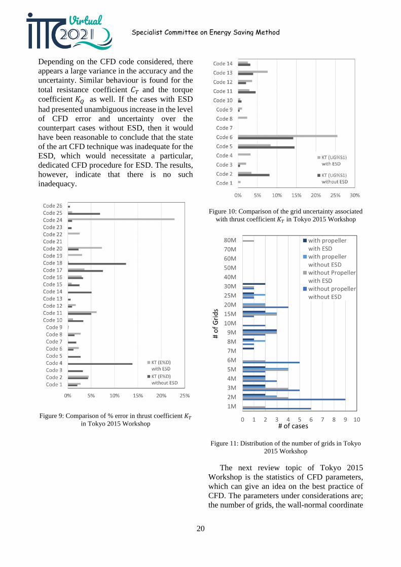
Figure 11: Distribution of the number of grids in Tokyo 2015 Workshop
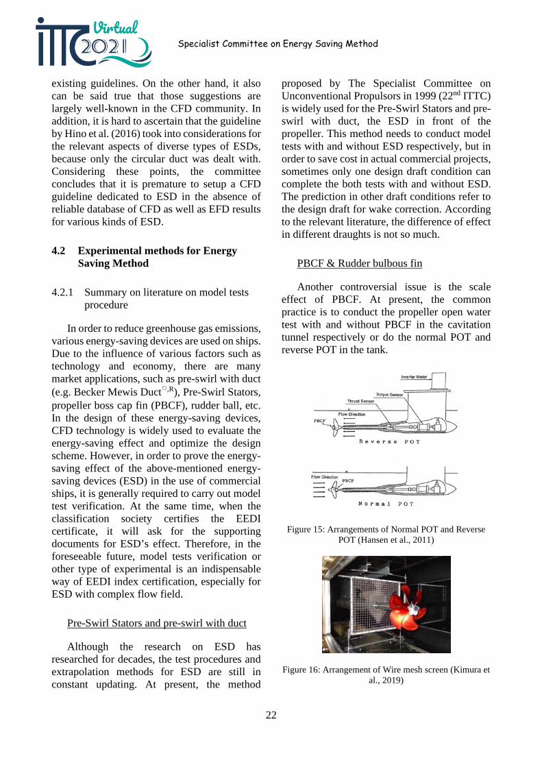
The next review topic of Tokyo 2015 Workshop is the statistics of CFD parameters, which can give an idea on the best practice of CFD. The parameters under considerations are; the number of grids, the wall-normal coordinate
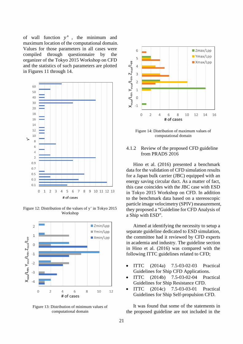
21
of wall function 𝑦𝑦+ , the minimum and maximum location of the computational domain. Values for those parameters in all cases were compiled through questionnaire by the organizer of the Tokyo 2015 Workshop on CFD and the statistics of such parameters are plotted in Figures 11 through 14.
Figure 12: Distribution of the values of y+ in Tokyo 2015 Workshop
Figure 13: Distribution of minimum values of computational domain
Figure 14: Distribution of maximum values of computational domain
4.1.2 Review of the proposed CFD guideline from PRADS 2016
Hino et al. (2016) presented a benchmark data for the validation of CFD simulation results for a Japan bulk carrier (JBC) equipped with an energy saving circular duct. As a matter of fact, this case coincides with the JBC case with ESD in Tokyo 2015 Workshop on CFD. In addition to the benchmark data based on a stereoscopic particle image velocimetry (SPIV) measurement, they proposed a “Guideline for CFD Analysis of a Ship with ESD”.
Aimed at identifying the necessity to setup a separate guideline dedicated to ESD simulation, the committee had it reviewed by CFD experts in academia and industry. The guideline section in Hino et al. (2016) was compared with the following ITTC guidelines related to CFD;
• ITTC (2014a) 7.5-03-02-03 Practical Guidelines for Ship CFD Applications.
• ITTC (2014b) 7.5-03-02-04 Practical Guidelines for Ship Resistance CFD.
• ITTC (2014c) 7.5-03-03-01 Practical Guidelines for Ship Self-propulsion CFD.
It was found that some of the statements in the proposed guideline are not included in the
22
Specialist Committee on Energy Saving Method
existing guidelines. On the other hand, it also can be said true that those suggestions are largely well-known in the CFD community. In addition, it is hard to ascertain that the guideline by Hino et al. (2016) took into considerations for the relevant aspects of diverse types of ESDs, because only the circular duct was dealt with. Considering these points, the committee concludes that it is premature to setup a CFD guideline dedicated to ESD in the absence of reliable database of CFD as well as EFD results for various kinds of ESD.
4.2 Experimental methods for Energy Saving Method
4.2.1 Summary on literature on model tests procedure
In order to reduce greenhouse gas emissions, various energy-saving devices are used on ships. Due to the influence of various factors such as technology and economy, there are many market applications, such as pre-swirl with duct (e.g. Becker Mewis Duct○,R
EA), Pre-Swirl Stators, propeller boss cap fin (PBCF), rudder ball, etc. In the design of these energy-saving devices, CFD technology is widely used to evaluate the energy-saving effect and optimize the design scheme. However, in order to prove the energy-saving effect of the above-mentioned energy-saving devices (ESD) in the use of commercial ships, it is generally required to carry out model test verification. At the same time, when the classification society certifies the EEDI certificate, it will ask for the supporting documents for ESD’s effect. Therefore, in the foreseeable future, model tests verification or other type of experimental is an indispensable way of EEDI index certification, especially for ESD with complex flow field.
Pre-Swirl Stators and pre-swirl with duct
Although the research on ESD has researched for decades, the test procedures and extrapolation methods for ESD are still in constant updating. At present, the method
proposed by The Specialist Committee on Unconventional Propulsors in 1999 (22nd ITTC) is widely used for the Pre-Swirl Stators and pre-swirl with duct, the ESD in front of the propeller. This method needs to conduct model tests with and without ESD respectively, but in order to save cost in actual commercial projects, sometimes only one design draft condition can complete the both tests with and without ESD. The prediction in other draft conditions refer to the design draft for wake correction. According to the relevant literature, the difference of effect in different draughts is not so much.
PBCF & Rudder bulbous fin
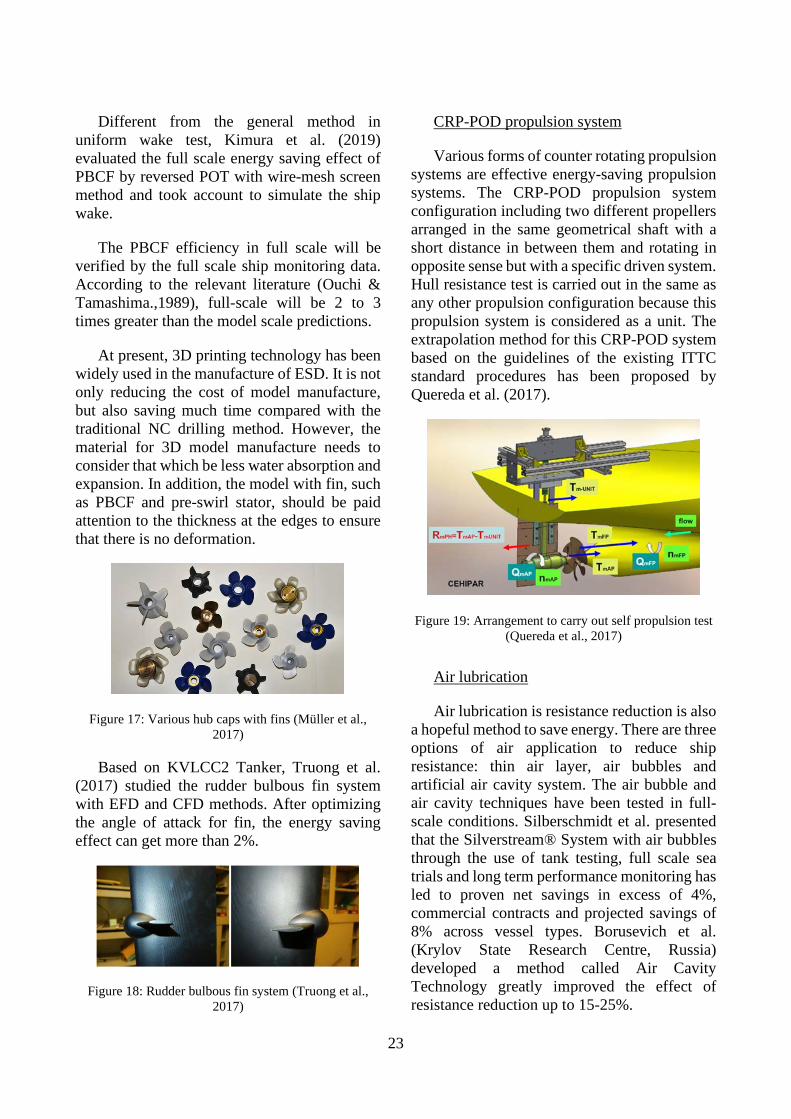
Another controversial issue is the scale effect of PBCF. At present, the common practice is to conduct the propeller open water test with and without PBCF in the cavitation tunnel respectively or do the normal POT and reverse POT in the tank.
Figure 15: Arrangements of Normal POT and Reverse POT (Hansen et al., 2011)
Figure 16: Arrangement of Wire mesh screen (Kimura et al., 2019)
23
Different from the general method in uniform wake test, Kimura et al. (2019) evaluated the full scale energy saving effect of PBCF by reversed POT with wire-mesh screen method and took account to simulate the ship wake.
The PBCF efficiency in full scale will be verified by the full scale ship monitoring data. According to the relevant literature (Ouchi & Tamashima.,1989), full-scale will be 2 to 3 times greater than the model scale predictions.
At present, 3D printing technology has been widely used in the manufacture of ESD. It is not only reducing the cost of model manufacture, but also saving much time compared with the traditional NC drilling method. However, the material for 3D model manufacture needs to consider that which be less water absorption and expansion. In addition, the model with fin, such as PBCF and pre-swirl stator, should be paid attention to the thickness at the edges to ensure that there is no deformation.
Figure 17: Various hub caps with fins (Müller et al., 2017)
Based on KVLCC2 Tanker, Truong et al. (2017) studied the rudder bulbous fin system with EFD and CFD methods. After optimizing the angle of attack for fin, the energy saving effect can get more than 2%.
Figure 18: Rudder bulbous fin system (Truong et al., 2017)
CRP-POD propulsion system
Various forms of counter rotating propulsion systems are effective energy-saving propulsion systems. The CRP-POD propulsion system configuration including two different propellers arranged in the same geometrical shaft with a short distance in between them and rotating in opposite sense but with a specific driven system. Hull resistance test is carried out in the same as any other propulsion configuration because this propulsion system is considered as a unit. The extrapolation method for this CRP-POD system based on the guidelines of the existing ITTC standard procedures has been proposed by Quereda et al. (2017).
Figure 19: Arrangement to carry out self propulsion test (Quereda et al., 2017)
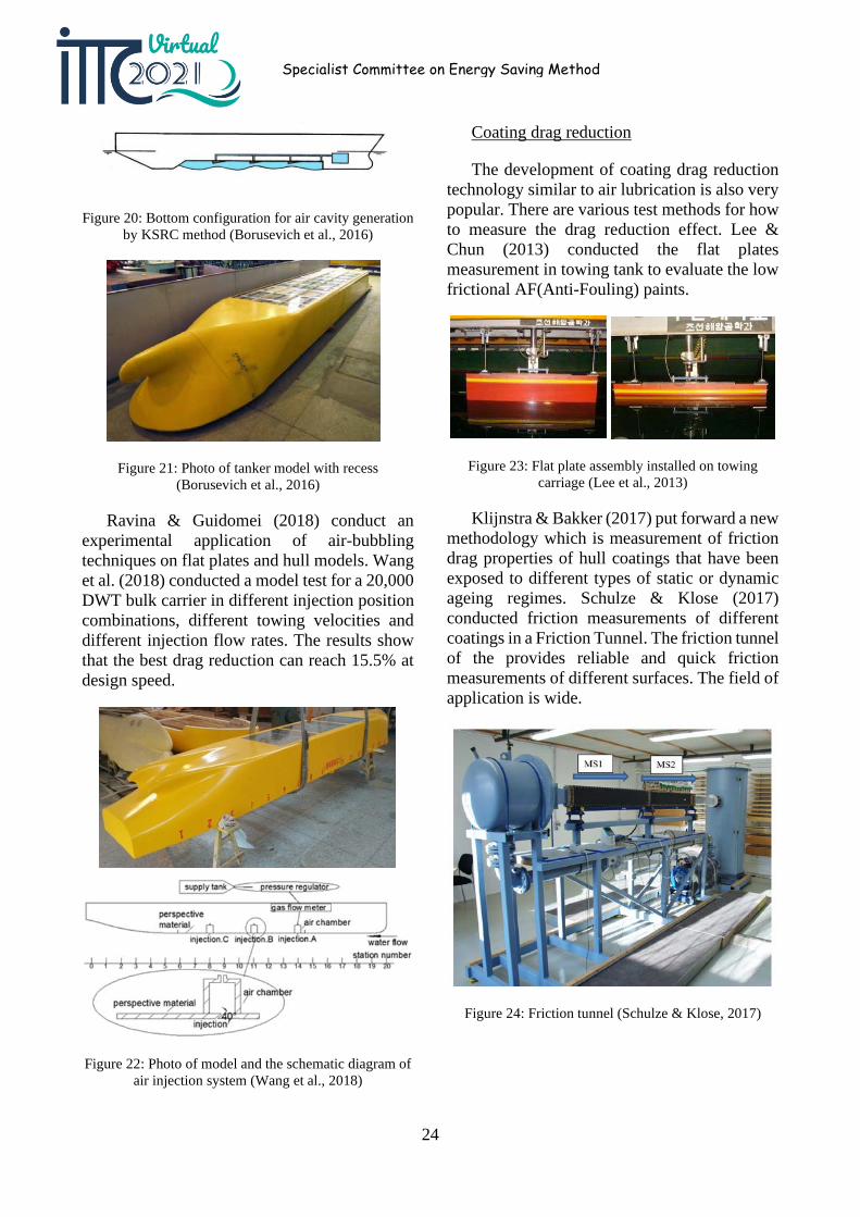
Air lubrication
Air lubrication is resistance reduction is also a hopeful method to save energy. There are three options of air application to reduce ship resistance: thin air layer, air bubbles and artificial air cavity system. The air bubble and air cavity techniques have been tested in full-scale conditions. Silberschmidt et al. presented that the Silverstream® System with air bubbles through the use of tank testing, full scale sea trials and long term performance monitoring has led to proven net savings in excess of 4%, commercial contracts and projected savings of 8% across vessel types. Borusevich et al. (Krylov State Research Centre, Russia) developed a method called Air Cavity Technology greatly improved the effect of resistance reduction up to 15-25%.
24
Specialist Committee on Energy Saving Method
Figure 20: Bottom configuration for air cavity generation by KSRC method (Borusevich et al., 2016)
Figure 21: Photo of tanker model with recess (Borusevich et al., 2016)
Ravina & Guidomei (2018) conduct an experimental application of air-bubbling techniques on flat plates and hull models. Wang et al. (2018) conducted a model test for a 20,000 DWT bulk carrier in different injection position combinations, different towing velocities and different injection flow rates. The results show that the best drag reduction can reach 15.5% at design speed.
Figure 22: Photo of model and the schematic diagram of air injection system (Wang et al., 2018)
Coating drag reduction
The development of coating drag reduction technology similar to air lubrication is also very popular. There are various test methods for how to measure the drag reduction effect. Lee & Chun (2013) conducted the flat plates measurement in towing tank to evaluate the low frictional AF(Anti-Fouling) paints.
Figure 23: Flat plate assembly installed on towing carriage (Lee et al., 2013)
Klijnstra & Bakker (2017) put forward a new methodology which is measurement of friction drag properties of hull coatings that have been exposed to different types of static or dynamic ageing regimes. Schulze & Klose (2017) conducted friction measurements of different coatings in a Friction Tunnel. The friction tunnel of the provides reliable and quick friction measurements of different surfaces. The field of application is wide.
Figure 24: Friction tunnel (Schulze & Klose, 2017)
25
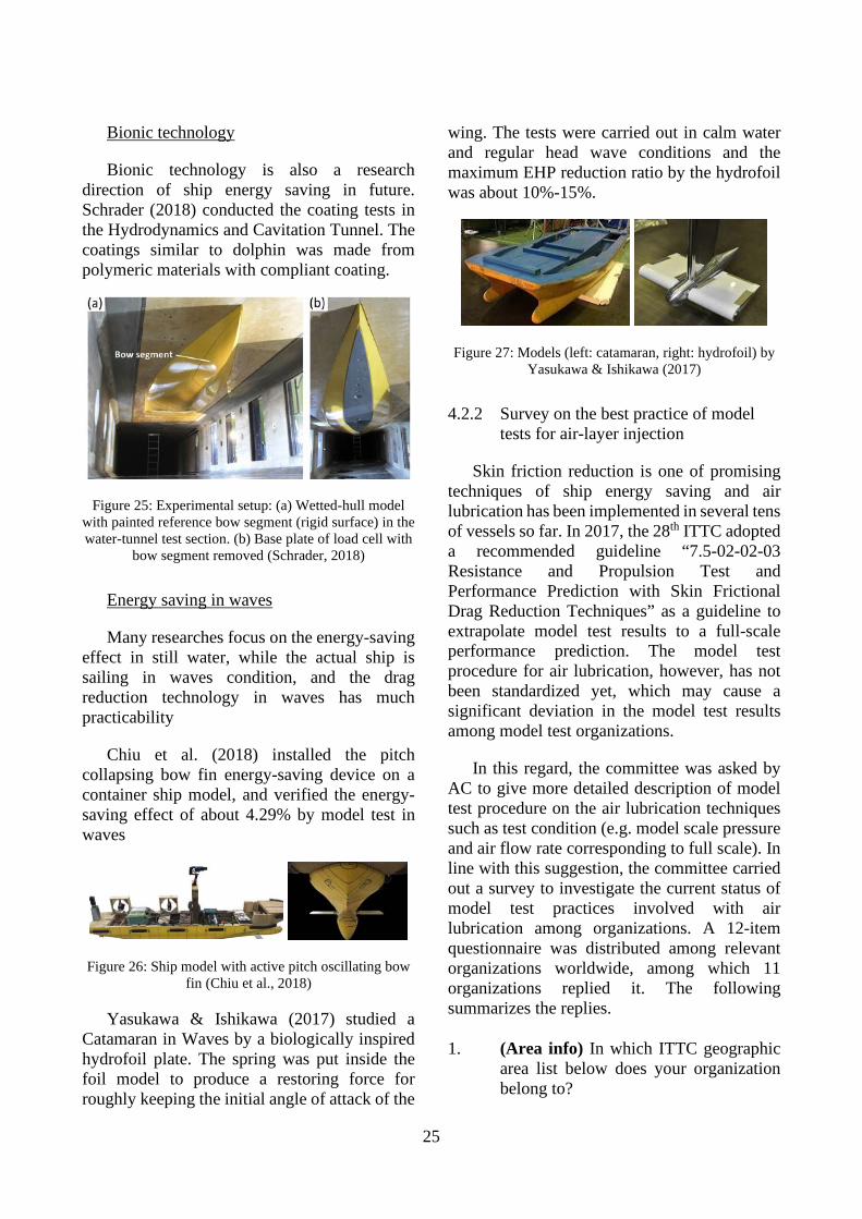
Bionic technology
Bionic technology is also a research direction of ship energy saving in future. Schrader (2018) conducted the coating tests in the Hydrodynamics and Cavitation Tunnel. The coatings similar to dolphin was made from polymeric materials with compliant coating.
Figure 25: Experimental setup: (a) Wetted-hull model with painted reference bow segment (rigid surface) in the water-tunnel test section. (b) Base plate of load cell with
bow segment removed (Schrader, 2018)
Energy saving in waves
Many researches focus on the energy-saving effect in still water, while the actual ship is sailing in waves condition, and the drag reduction technology in waves has much practicability
Chiu et al. (2018) installed the pitch collapsing bow fin energy-saving device on a container ship model, and verified the energy-saving effect of about 4.29% by model test in waves
Figure 26: Ship model with active pitch oscillating bow fin (Chiu et al., 2018)
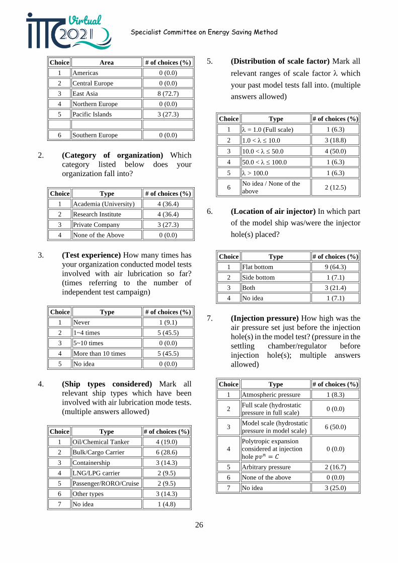
Yasukawa & Ishikawa (2017) studied a Catamaran in Waves by a biologically inspired hydrofoil plate. The spring was put inside the foil model to produce a restoring force for roughly keeping the initial angle of attack of the
wing. The tests were carried out in calm water and regular head wave conditions and the maximum EHP reduction ratio by the hydrofoil was about 10%-15%.
Figure 27: Models (left: catamaran, right: hydrofoil) by Yasukawa & Ishikawa (2017)
4.2.2 Survey on the best practice of model tests for air-layer injection
Skin friction reduction is one of promising techniques of ship energy saving and air lubrication has been implemented in several tens of vessels so far. In 2017, the 28th ITTC adopted a recommended guideline “7.5-02-02-03 Resistance and Propulsion Test and Performance Prediction with Skin Frictional Drag Reduction Techniques” as a guideline to extrapolate model test results to a full-scale performance prediction. The model test procedure for air lubrication, however, has not been standardized yet, which may cause a significant deviation in the model test results among model test organizations.
In this regard, the committee was asked by AC to give more detailed description of model test procedure on the air lubrication techniques such as test condition (e.g. model scale pressure and air flow rate corresponding to full scale). In line with this suggestion, the committee carried out a survey to investigate the current status of model test practices involved with air lubrication among organizations. A 12-item questionnaire was distributed among relevant organizations worldwide, among which 11 organizations replied it. The following summarizes the replies.
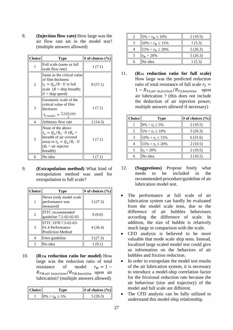
1. (Area info) In which ITTC geographic area list below does your organization belong to?
26
Specialist Committee on Energy Saving Method
Choice Area # of choices (%) 1 Americas 0 (0.0) 2 Central Europe 0 (0.0) 3 East Asia 8 (72.7) 4 Northern Europe 0 (0.0) 5 Pacific Islands 3 (27.3)
6 Southern Europe 0 (0.0)
2. (Category of organization) Which category listed below does your organization fall into?
Choice Type # of choices (%) 1 Academia (University) 4 (36.4) 2 Research Institute 4 (36.4) 3 Private Company 3 (27.3) 4 None of the Above 0 (0.0)
3. (Test experience) How many times has your organization conducted model tests involved with air lubrication so far? (times referring to the number of independent test campaign)
Choice Type # of choices (%) 1 Never 1 (9.1) 2 1~4 times 5 (45.5) 3 5~10 times 0 (0.0) 4 More than 10 times 5 (45.5) 5 No idea 0 (0.0)
4. (Ship types considered) Mark all relevant ship types which have been involved with air lubrication mode tests. (multiple answers allowed)
Choice Type # of choices (%) 1 Oil/Chemical Tanker 4 (19.0) 2 Bulk/Cargo Carrier 6 (28.6) 3 Containership 3 (14.3) 4 LNG/LPG carrier 2 (9.5) 5 Passenger/RORO/Cruise 2 (9.5) 6 Other types 3 (14.3) 7 No idea 1 (4.8)
5. (Distribution of scale factor) Mark all relevant ranges of scale factor λ which your past model tests fall into. (multiple answers allowed)
Choice Type # of choices (%) 1 λ = 1.0 (Full scale) 1 (6.3) 2 1.0 < λ ≤ 10.0 3 (18.8) 3 10.0 < λ ≤ 50.0 4 (50.0) 4 50.0 < λ ≤ 100.0 1 (6.3) 5 λ > 100.0 1 (6.3)
6 No idea / None of the above 2 (12.5)
6. (Location of air injector) In which part of the model ship was/were the injector hole(s) placed?
Choice Type # of choices (%) 1 Flat bottom 9 (64.3) 2 Side bottom 1 (7.1) 3 Both 3 (21.4) 4 No idea 1 (7.1)
7. (Injection pressure) How high was the air pressure set just before the injection hole(s) in the model test? (pressure in the settling chamber/regulator before injection hole(s); multiple answers allowed)
Choice Type # of choices (%) 1 Atmospheric pressure 1 (8.3)
2 Full scale (hydrostatic pressure in full scale) 0 (0.0)
3 Model scale (hydrostatic pressure in model scale) 6 (50.0)
4 Polytropic expansion considered at injection hole 𝑝𝑝𝑣𝑣𝑛𝑛 = 𝐶𝐶
0 (0.0)
5 Arbitrary pressure 2 (16.7) 6 None of the above 0 (0.0) 7 No idea 3 (25.0)
27
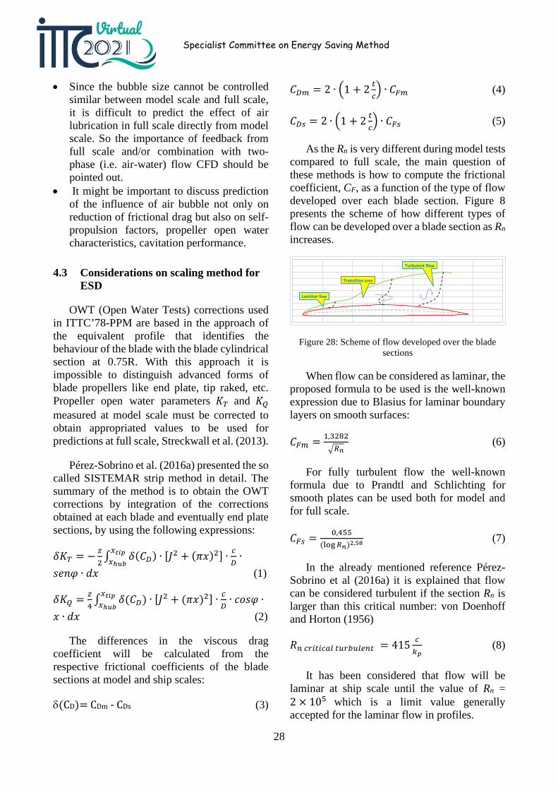
8. (Injection flow rate) How large was the air flow rate set in the model test? (multiple answers allowed)
Choice Type # of choices (%)
1 Full scale (same as full scale flow rate) 1 (7.1)
2
Same as the critical value of film thickness 𝑡𝑡𝑓𝑓 = 𝑄𝑄𝑎𝑎 𝐵𝐵 ∙ 𝑈𝑈⁄ in full scale (𝐵𝐵 = ship breadth; 𝑈𝑈 = ship speed)
8 (57.1)
3
Geometric scale of the critical value of film thickness 𝑡𝑡𝑓𝑓.𝑚𝑚𝑚𝑚𝑚𝑚𝑚𝑚𝑚𝑚 = 𝑡𝑡𝑓𝑓.𝑓𝑓𝑓𝑓𝑓𝑓𝑓𝑓 𝑠𝑠𝑠𝑠𝑠𝑠𝑓𝑓𝑠𝑠
𝜆𝜆
1 (7.1)
4 Arbitrary flow rate 2 (14.3)
5
None of the above 𝑡𝑡𝑎𝑎 = 𝑄𝑄𝑎𝑎 𝐵𝐵𝑎𝑎 ∙ 𝑈𝑈⁄ (𝐵𝐵𝑎𝑎 = breadth of air covered area) or 𝑡𝑡𝑏𝑏 = 𝑄𝑄𝑎𝑎 𝐵𝐵𝑖𝑖 ∙ 𝑈𝑈⁄ (𝐵𝐵𝑖𝑖 = air injector breadth)
1 (7.1)
6 No idea 1 (7.1)
9. (Extrapolation method) What kind of extrapolation method was used for extrapolation to full scale?
Choice Type # of choices (%)
1 Never (only model scale performance was measured)
3 (27.3)
2 ITTC recommended guideline 7.5-02-02-03 0 (0.0)
3 ITTC 1978 7.5-02-03-01.4 Performance Prediction Method
4 (36.4)
4 Own guideline 3 (27.3) 5 No idea 1 (9.1)
10. (RTM reduction ratio for model) How large was the reduction ratio of total resistance of model 𝑟𝑟𝑀𝑀 = 1 −𝑅𝑅𝑇𝑇𝑀𝑀,𝑎𝑎𝑖𝑖𝑎𝑎 𝑖𝑖𝑛𝑛𝑖𝑖𝑚𝑚𝑖𝑖𝑡𝑡𝑖𝑖𝑚𝑚𝑛𝑛 𝑅𝑅𝑇𝑇𝑀𝑀,𝑏𝑏𝑎𝑎𝑏𝑏𝑚𝑚𝑚𝑚𝑖𝑖𝑛𝑛𝑚𝑚⁄ upon air lubrication? (multiple answers allowed)
Choice Type # of choices (%) 1 0% < 𝑟𝑟𝑀𝑀 ≤ 5% 5 (26.3)
2 5% < 𝑟𝑟𝑀𝑀 ≤ 10% 2 (10.5) 3 10% < 𝑟𝑟𝑀𝑀 ≤ 15% 1 (5.3) 4 15% < 𝑟𝑟𝑀𝑀 ≤ 20% 5 (26.3) 5 𝑟𝑟𝑀𝑀 > 20% 5 (26.3) 6 No idea 1 (5.3)
11. (RTS reduction ratio for full scale) How large was the predicted reduction ratio of total resistance of full scale 𝑟𝑟𝑆𝑆 =1 − 𝑅𝑅𝑇𝑇𝑆𝑆,𝑎𝑎𝑖𝑖𝑎𝑎 𝑖𝑖𝑛𝑛𝑖𝑖𝑚𝑚𝑖𝑖𝑡𝑡𝑖𝑖𝑚𝑚𝑛𝑛 𝑅𝑅𝑇𝑇𝑆𝑆,𝑏𝑏𝑎𝑎𝑏𝑏𝑚𝑚𝑚𝑚𝑖𝑖𝑛𝑛𝑚𝑚⁄ upon air lubrication ? (this does not include the deduction of air injection power; multiple answers allowed if necessary)
Choice Type # of choices (%) 1 0% < 𝑟𝑟𝑆𝑆 ≤ 5% 2 (10.5) 2 5% < 𝑟𝑟𝑆𝑆 ≤ 10% 5 (26.3) 3 10% < 𝑟𝑟𝑆𝑆 ≤ 15% 6 (31.6) 4 15% < 𝑟𝑟𝑆𝑆 ≤ 20% 2 (10.5) 5 𝑟𝑟𝑆𝑆 > 20% 2 (10.5) 6 No idea 2 (10.5)
12. (Suggestions) Propose freely what needs to be included in the recommended procedure/guideline of air lubrication model test.
• The performance at full scale of air lubrication system can hardly be evaluated from the model scale tests, due to the difference of air bubbles behaviours according the difference of scale. In addition, the size of bubble is relatively much large in comparison with the scale.
• CFD analysis is believed to be more valuable that mode scale ship tests. Instead, localized large scaled model test could give us information on the behaviors of air bubbles and friction reduction.
• In order to extrapolate the model test results of the air lubrication system, it is necessary to introduce a model-ship correlation factor for the frictional reduction rate because the air behaviour (size and trajectory) of the model and full scale are different.
• The CFD analysis can be fully utilized to understand this model-ship relationship.
28
Specialist Committee on Energy Saving Method
• Since the bubble size cannot be controlled similar between model scale and full scale, it is difficult to predict the effect of air lubrication in full scale directly from model scale. So the importance of feedback from full scale and/or combination with two-phase (i.e. air-water) flow CFD should be pointed out.
• It might be important to discuss prediction of the influence of air bubble not only on reduction of frictional drag but also on self-propulsion factors, propeller open water characteristics, cavitation performance.
4.3 Considerations on scaling method for ESD
OWT (Open Water Tests) corrections used in ITTC’78-PPM are based in the approach of the equivalent profile that identifies the behaviour of the blade with the blade cylindrical section at 0.75R. With this approach it is impossible to distinguish advanced forms of blade propellers like end plate, tip raked, etc. Propeller open water parameters 𝐾𝐾𝑇𝑇 and 𝐾𝐾𝑄𝑄 measured at model scale must be corrected to obtain appropriated values to be used for predictions at full scale, Streckwall et al. (2013).
Pérez-Sobrino et al. (2016a) presented the so called SISTEMAR strip method in detail. The summary of the method is to obtain the OWT corrections by integration of the corrections obtained at each blade and eventually end plate sections, by using the following expressions:
𝛿𝛿𝐾𝐾𝑇𝑇 = − 𝑧𝑧2 ∫ 𝛿𝛿(𝐶𝐶𝐷𝐷) ∙ [𝐽𝐽2 + (𝜋𝜋𝜋𝜋)2] ∙ 𝑖𝑖
𝐷𝐷∙𝑥𝑥𝑡𝑡𝑡𝑡𝑡𝑡
𝑥𝑥ℎ𝑓𝑓𝑢𝑢𝑠𝑠𝑠𝑠𝑠𝑠𝑠𝑠 ∙ 𝑑𝑑𝜋𝜋 (1)
𝛿𝛿𝐾𝐾𝑄𝑄 = 𝑧𝑧4 ∫ 𝛿𝛿(𝐶𝐶𝐷𝐷) ∙ [𝐽𝐽2 + (𝜋𝜋𝜋𝜋)2] ∙ 𝑖𝑖
𝐷𝐷∙ 𝑐𝑐𝑐𝑐𝑠𝑠𝑠𝑠 ∙𝑥𝑥𝑡𝑡𝑡𝑡𝑡𝑡
𝑥𝑥ℎ𝑓𝑓𝑢𝑢𝜋𝜋 ∙ 𝑑𝑑𝜋𝜋 (2)
The differences in the viscous drag coefficient will be calculated from the respective frictional coefficients of the blade sections at model and ship scales:
δ(CD)= CDm - CDs (3)
𝐶𝐶𝐷𝐷𝑚𝑚 = 2 ∙ �1 + 2 𝑡𝑡𝑖𝑖� ∙ 𝐶𝐶𝐹𝐹𝑚𝑚 (4)
𝐶𝐶𝐷𝐷𝑏𝑏 = 2 ∙ �1 + 2 𝑡𝑡𝑖𝑖� ∙ 𝐶𝐶𝐹𝐹𝑏𝑏 (5)
As the Rn is very different during model tests compared to full scale, the main question of these methods is how to compute the frictional coefficient, CF, as a function of the type of flow developed over each blade section. Figure 8 presents the scheme of how different types of flow can be developed over a blade section as Rn increases.
Figure 28: Scheme of flow developed over the blade sections
When flow can be considered as laminar, the proposed formula to be used is the well-known expression due to Blasius for laminar boundary layers on smooth surfaces:
𝐶𝐶𝐹𝐹𝑚𝑚 = 1,3282�𝑅𝑅𝑛𝑛
(6)
For fully turbulent flow the well-known formula due to Prandtl and Schlichting for smooth plates can be used both for model and for full scale.
𝐶𝐶𝐹𝐹𝑏𝑏 = 0,455(log𝑅𝑅𝑛𝑛)2,58 (7)
In the already mentioned reference Pérez-Sobrino et al (2016a) it is explained that flow can be considered turbulent if the section Rn is larger than this critical number: von Doenhoff and Horton (1956)
𝑅𝑅𝑛𝑛 𝑖𝑖𝑎𝑎𝑖𝑖𝑡𝑡𝑖𝑖𝑖𝑖𝑎𝑎𝑚𝑚 𝑡𝑡𝑡𝑡𝑎𝑎𝑏𝑏𝑡𝑡𝑚𝑚𝑚𝑚𝑛𝑛𝑡𝑡 = 415 𝑖𝑖𝑘𝑘𝑡𝑡
(8)
It has been considered that flow will be laminar at ship scale until the value of Rn = 2 × 10⁵ which is a limit value generally accepted for the laminar flow in profiles.
Laminar flow
Transition zone
Turbulent flow
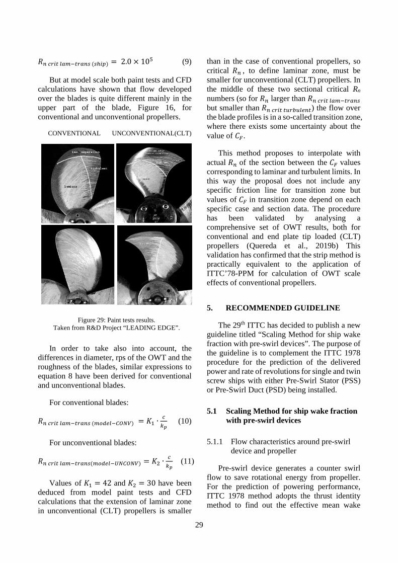
29
𝑅𝑅𝑛𝑛 𝑖𝑖𝑎𝑎𝑖𝑖𝑡𝑡 𝑚𝑚𝑎𝑎𝑚𝑚−𝑡𝑡𝑎𝑎𝑎𝑎𝑛𝑛𝑏𝑏 (𝑏𝑏ℎ𝑖𝑖𝑖𝑖) = 2.0 × 10⁵ (9)
But at model scale both paint tests and CFD calculations have shown that flow developed over the blades is quite different mainly in the upper part of the blade, Figure 16, for conventional and unconventional propellers.
CONVENTIONAL UNCONVENTIONAL(CLT)
In order to take also into account, the differences in diameter, rps of the OWT and the roughness of the blades, similar expressions to equation 8 have been derived for conventional and unconventional blades.
For conventional blades:
𝑅𝑅𝑛𝑛 𝑖𝑖𝑎𝑎𝑖𝑖𝑡𝑡 𝑚𝑚𝑎𝑎𝑚𝑚−𝑡𝑡𝑎𝑎𝑎𝑎𝑛𝑛𝑏𝑏 (𝑚𝑚𝑚𝑚𝑚𝑚𝑚𝑚𝑚𝑚−𝐶𝐶𝐶𝐶𝐶𝐶𝐶𝐶) = 𝐾𝐾1 ∙𝑖𝑖𝑘𝑘𝑡𝑡
(10)
For unconventional blades:
𝑅𝑅𝑛𝑛 𝑖𝑖𝑎𝑎𝑖𝑖𝑡𝑡 𝑚𝑚𝑎𝑎𝑚𝑚−𝑡𝑡𝑎𝑎𝑎𝑎𝑛𝑛𝑏𝑏(𝑚𝑚𝑚𝑚𝑚𝑚𝑚𝑚𝑚𝑚−𝑈𝑈𝐶𝐶𝐶𝐶𝐶𝐶𝐶𝐶𝐶𝐶) = 𝐾𝐾2 ∙𝑖𝑖𝑘𝑘𝑡𝑡
(11)
Values of 𝐾𝐾1 = 42 and 𝐾𝐾2 = 30 have been deduced from model paint tests and CFD calculations that the extension of laminar zone in unconventional (CLT) propellers is smaller
than in the case of conventional propellers, so critical 𝑅𝑅𝑛𝑛 , to define laminar zone, must be smaller for unconventional (CLT) propellers. In the middle of these two sectional critical Rn numbers (so for 𝑅𝑅𝑛𝑛 larger than 𝑅𝑅𝑛𝑛 𝑖𝑖𝑎𝑎𝑖𝑖𝑡𝑡 𝑚𝑚𝑎𝑎𝑚𝑚−𝑡𝑡𝑎𝑎𝑎𝑎𝑛𝑛𝑏𝑏 but smaller than 𝑅𝑅𝑛𝑛 𝑖𝑖𝑎𝑎𝑖𝑖𝑡𝑡 𝑡𝑡𝑡𝑡𝑎𝑎𝑏𝑏𝑡𝑡𝑚𝑚𝑚𝑚𝑛𝑛𝑡𝑡) the flow over the blade profiles is in a so-called transition zone, where there exists some uncertainty about the value of 𝐶𝐶𝐹𝐹.
This method proposes to interpolate with actual 𝑅𝑅𝑛𝑛 of the section between the 𝐶𝐶𝐹𝐹 values corresponding to laminar and turbulent limits. In this way the proposal does not include any specific friction line for transition zone but values of 𝐶𝐶𝐹𝐹 in transition zone depend on each specific case and section data. The procedure has been validated by analysing a comprehensive set of OWT results, both for conventional and end plate tip loaded (CLT) propellers (Quereda et al., 2019b) This validation has confirmed that the strip method is practically equivalent to the application of ITTC’78-PPM for calculation of OWT scale effects of conventional propellers.
5. RECOMMENDED GUIDELINE
The 29th ITTC has decided to publish a new guideline titled “Scaling Method for ship wake fraction with pre-swirl devices”. The purpose of the guideline is to complement the ITTC 1978 procedure for the prediction of the delivered power and rate of revolutions for single and twin screw ships with either Pre-Swirl Stator (PSS) or Pre-Swirl Duct (PSD) being installed.
5.1 Scaling Method for ship wake fraction with pre-swirl devices
5.1.1 Flow characteristics around pre-swirl device and propeller
Pre-swirl device generates a counter swirl flow to save rotational energy from propeller. For the prediction of powering performance, ITTC 1978 method adopts the thrust identity method to find out the effective mean wake
Figure 29: Paint tests results. Taken from R&D Project “LEADING EDGE”.
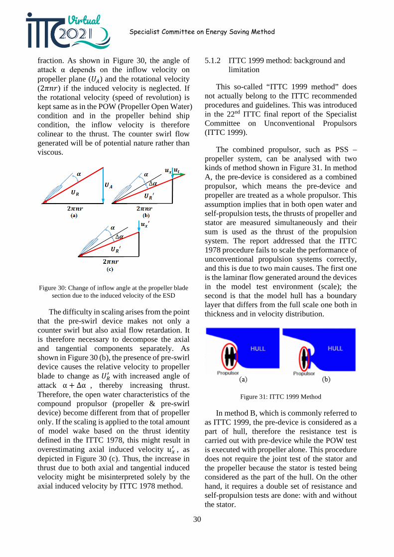
30
Specialist Committee on Energy Saving Method
fraction. As shown in Figure 30, the angle of attack α depends on the inflow velocity on propeller plane (𝑈𝑈𝐴𝐴) and the rotational velocity (2𝜋𝜋𝑠𝑠𝑟𝑟) if the induced velocity is neglected. If the rotational velocity (speed of revolution) is kept same as in the POW (Propeller Open Water) condition and in the propeller behind ship condition, the inflow velocity is therefore colinear to the thrust. The counter swirl flow generated will be of potential nature rather than viscous.
Figure 30: Change of inflow angle at the propeller blade section due to the induced velocity of the ESD
The difficulty in scaling arises from the point that the pre-swirl device makes not only a counter swirl but also axial flow retardation. It is therefore necessary to decompose the axial and tangential components separately. As shown in Figure 30 (b), the presence of pre-swirl device causes the relative velocity to propeller blade to change as 𝑈𝑈𝑅𝑅′ with increased angle of attack α + Δα , thereby increasing thrust. Therefore, the open water characteristics of the compound propulsor (propeller & pre-swirl device) become different from that of propeller only. If the scaling is applied to the total amount of model wake based on the thrust identity defined in the ITTC 1978, this might result in overestimating axial induced velocity 𝑢𝑢𝑥𝑥′ , as depicted in Figure 30 (c). Thus, the increase in thrust due to both axial and tangential induced velocity might be misinterpreted solely by the axial induced velocity by ITTC 1978 method.
5.1.2 ITTC 1999 method: background and limitation
This so-called “ITTC 1999 method” does not actually belong to the ITTC recommended procedures and guidelines. This was introduced in the 22nd ITTC final report of the Specialist Committee on Unconventional Propulsors (ITTC 1999).
The combined propulsor, such as PSS – propeller system, can be analysed with two kinds of method shown in Figure 31. In method A, the pre-device is considered as a combined propulsor, which means the pre-device and propeller are treated as a whole propulsor. This assumption implies that in both open water and self-propulsion tests, the thrusts of propeller and stator are measured simultaneously and their sum is used as the thrust of the propulsion system. The report addressed that the ITTC 1978 procedure fails to scale the performance of unconventional propulsion systems correctly, and this is due to two main causes. The first one is the laminar flow generated around the devices in the model test environment (scale); the second is that the model hull has a boundary layer that differs from the full scale one both in thickness and in velocity distribution.
Figure 31: ITTC 1999 Method
In method B, which is commonly referred to as ITTC 1999, the pre-device is considered as a part of hull, therefore the resistance test is carried out with pre-device while the POW test is executed with propeller alone. This procedure does not require the joint test of the stator and the propeller because the stator is tested being considered as the part of the hull. On the other hand, it requires a double set of resistance and self-propulsion tests are done: with and without the stator.
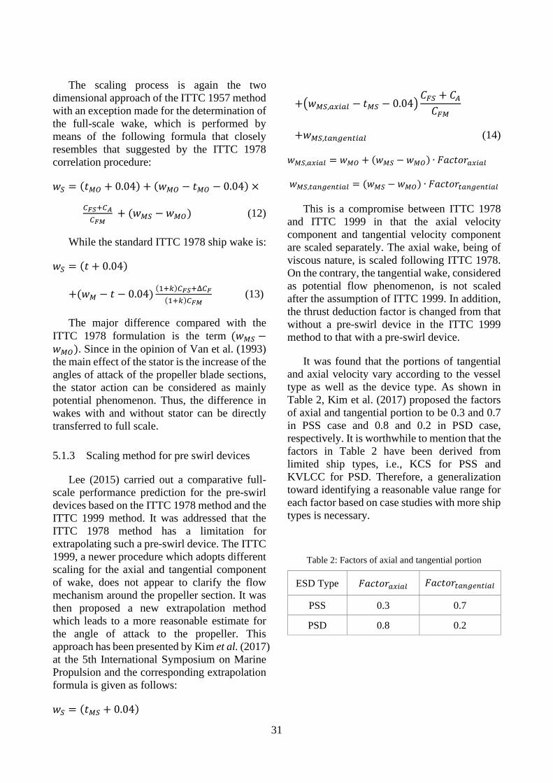
31
The scaling process is again the two dimensional approach of the ITTC 1957 method with an exception made for the determination of the full-scale wake, which is performed by means of the following formula that closely resembles that suggested by the ITTC 1978 correlation procedure:
𝑤𝑤𝑆𝑆 = (𝑡𝑡𝑀𝑀𝐶𝐶 + 0.04) + (𝑤𝑤𝑀𝑀𝐶𝐶 − 𝑡𝑡𝑀𝑀𝐶𝐶 − 0.04) ×
𝐶𝐶𝐹𝐹𝐹𝐹+𝐶𝐶𝐴𝐴𝐶𝐶𝐹𝐹𝐹𝐹
+ (𝑤𝑤𝑀𝑀𝑆𝑆 − 𝑤𝑤𝑀𝑀𝐶𝐶) (12)
While the standard ITTC 1978 ship wake is:
𝑤𝑤𝑆𝑆 = (𝑡𝑡 + 0.04)
+(𝑤𝑤𝑀𝑀 − 𝑡𝑡 − 0.04) (1+𝑘𝑘)𝐶𝐶𝐹𝐹𝐹𝐹+Δ𝐶𝐶𝐹𝐹(1+𝑘𝑘)𝐶𝐶𝐹𝐹𝐹𝐹
(13)
The major difference compared with the ITTC 1978 formulation is the term (𝑤𝑤𝑀𝑀𝑆𝑆 −𝑤𝑤𝑀𝑀𝐶𝐶). Since in the opinion of Van et al. (1993) the main effect of the stator is the increase of the angles of attack of the propeller blade sections, the stator action can be considered as mainly potential phenomenon. Thus, the difference in wakes with and without stator can be directly transferred to full scale.
5.1.3 Scaling method for pre swirl devices
Lee (2015) carried out a comparative full-scale performance prediction for the pre-swirl devices based on the ITTC 1978 method and the ITTC 1999 method. It was addressed that the ITTC 1978 method has a limitation for extrapolating such a pre-swirl device. The ITTC 1999, a newer procedure which adopts different scaling for the axial and tangential component of wake, does not appear to clarify the flow mechanism around the propeller section. It was then proposed a new extrapolation method which leads to a more reasonable estimate for the angle of attack to the propeller. This approach has been presented by Kim et al. (2017) at the 5th International Symposium on Marine Propulsion and the corresponding extrapolation formula is given as follows:
𝑤𝑤𝑆𝑆 = (𝑡𝑡𝑀𝑀𝑆𝑆 + 0.04)
+�𝑤𝑤𝑀𝑀𝑆𝑆,𝑎𝑎𝑥𝑥𝑖𝑖𝑎𝑎𝑚𝑚 − 𝑡𝑡𝑀𝑀𝑆𝑆 − 0.04�𝐶𝐶𝐹𝐹𝑆𝑆 + 𝐶𝐶𝐴𝐴𝐶𝐶𝐹𝐹𝑀𝑀
+𝑤𝑤𝑀𝑀𝑆𝑆,𝑡𝑡𝑎𝑎𝑛𝑛𝑡𝑡𝑚𝑚𝑛𝑛𝑡𝑡𝑖𝑖𝑎𝑎𝑚𝑚 (14)
𝑤𝑤𝑀𝑀𝑆𝑆,𝑎𝑎𝑥𝑥𝑖𝑖𝑎𝑎𝑚𝑚 = 𝑤𝑤𝑀𝑀𝐶𝐶 + (𝑤𝑤𝑀𝑀𝑆𝑆 − 𝑤𝑤𝑀𝑀𝐶𝐶) ∙ 𝐹𝐹𝐹𝐹𝑐𝑐𝑡𝑡𝑐𝑐𝑟𝑟𝑎𝑎𝑥𝑥𝑖𝑖𝑎𝑎𝑚𝑚
𝑤𝑤𝑀𝑀𝑆𝑆,𝑡𝑡𝑎𝑎𝑛𝑛𝑡𝑡𝑚𝑚𝑛𝑛𝑡𝑡𝑖𝑖𝑎𝑎𝑚𝑚 = (𝑤𝑤𝑀𝑀𝑆𝑆 − 𝑤𝑤𝑀𝑀𝐶𝐶) ∙ 𝐹𝐹𝐹𝐹𝑐𝑐𝑡𝑡𝑐𝑐𝑟𝑟𝑡𝑡𝑎𝑎𝑛𝑛𝑡𝑡𝑚𝑚𝑛𝑛𝑡𝑡𝑖𝑖𝑎𝑎𝑚𝑚
This is a compromise between ITTC 1978 and ITTC 1999 in that the axial velocity component and tangential velocity component are scaled separately. The axial wake, being of viscous nature, is scaled following ITTC 1978. On the contrary, the tangential wake, considered as potential flow phenomenon, is not scaled after the assumption of ITTC 1999. In addition, the thrust deduction factor is changed from that without a pre-swirl device in the ITTC 1999 method to that with a pre-swirl device.
It was found that the portions of tangential and axial velocity vary according to the vessel type as well as the device type. As shown in Table 2, Kim et al. (2017) proposed the factors of axial and tangential portion to be 0.3 and 0.7 in PSS case and 0.8 and 0.2 in PSD case, respectively. It is worthwhile to mention that the factors in Table 2 have been derived from limited ship types, i.e., KCS for PSS and KVLCC for PSD. Therefore, a generalization toward identifying a reasonable value range for each factor based on case studies with more ship types is necessary.
Table 2: Factors of axial and tangential portion
ESD Type 𝐹𝐹𝐹𝐹𝑐𝑐𝑡𝑡𝑐𝑐𝑟𝑟𝑎𝑎𝑥𝑥𝑖𝑖𝑎𝑎𝑚𝑚 𝐹𝐹𝐹𝐹𝑐𝑐𝑡𝑡𝑐𝑐𝑟𝑟𝑡𝑡𝑎𝑎𝑛𝑛𝑡𝑡𝑚𝑚𝑛𝑛𝑡𝑡𝑖𝑖𝑎𝑎𝑚𝑚
PSS 0.3 0.7
PSD 0.8 0.2
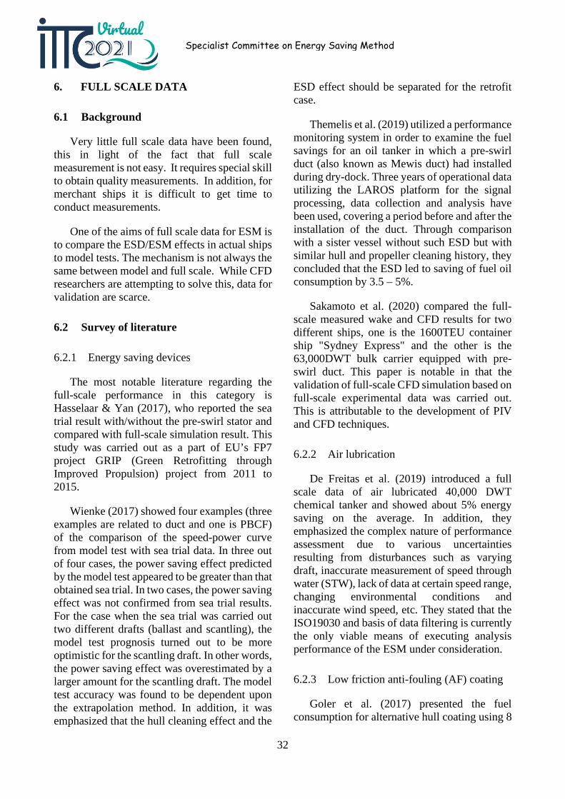
32
Specialist Committee on Energy Saving Method
6. FULL SCALE DATA
6.1 Background
Very little full scale data have been found, this in light of the fact that full scale measurement is not easy. It requires special skill to obtain quality measurements. In addition, for merchant ships it is difficult to get time to conduct measurements.
One of the aims of full scale data for ESM is to compare the ESD/ESM effects in actual ships to model tests. The mechanism is not always the same between model and full scale. While CFD researchers are attempting to solve this, data for validation are scarce.
6.2 Survey of literature
6.2.1 Energy saving devices
The most notable literature regarding the full-scale performance in this category is Hasselaar & Yan (2017), who reported the sea trial result with/without the pre-swirl stator and compared with full-scale simulation result. This study was carried out as a part of EU’s FP7 project GRIP (Green Retrofitting through Improved Propulsion) project from 2011 to 2015.
Wienke (2017) showed four examples (three examples are related to duct and one is PBCF) of the comparison of the speed-power curve from model test with sea trial data. In three out of four cases, the power saving effect predicted by the model test appeared to be greater than that obtained sea trial. In two cases, the power saving effect was not confirmed from sea trial results. For the case when the sea trial was carried out two different drafts (ballast and scantling), the model test prognosis turned out to be more optimistic for the scantling draft. In other words, the power saving effect was overestimated by a larger amount for the scantling draft. The model test accuracy was found to be dependent upon the extrapolation method. In addition, it was emphasized that the hull cleaning effect and the
ESD effect should be separated for the retrofit case.
Themelis et al. (2019) utilized a performance monitoring system in order to examine the fuel savings for an oil tanker in which a pre-swirl duct (also known as Mewis duct) had installed during dry-dock. Three years of operational data utilizing the LAROS platform for the signal processing, data collection and analysis have been used, covering a period before and after the installation of the duct. Through comparison with a sister vessel without such ESD but with similar hull and propeller cleaning history, they concluded that the ESD led to saving of fuel oil consumption by 3.5 – 5%.
Sakamoto et al. (2020) compared the full-scale measured wake and CFD results for two different ships, one is the 1600TEU container ship "Sydney Express" and the other is the 63,000DWT bulk carrier equipped with pre-swirl duct. This paper is notable in that the validation of full-scale CFD simulation based on full-scale experimental data was carried out. This is attributable to the development of PIV and CFD techniques.
6.2.2 Air lubrication
De Freitas et al. (2019) introduced a full scale data of air lubricated 40,000 DWT chemical tanker and showed about 5% energy saving on the average. In addition, they emphasized the complex nature of performance assessment due to various uncertainties resulting from disturbances such as varying draft, inaccurate measurement of speed through water (STW), lack of data at certain speed range, changing environmental conditions and inaccurate wind speed, etc. They stated that the ISO19030 and basis of data filtering is currently the only viable means of executing analysis performance of the ESM under consideration.
6.2.3 Low friction anti-fouling (AF) coating
Goler et al. (2017) presented the fuel consumption for alternative hull coating using 8
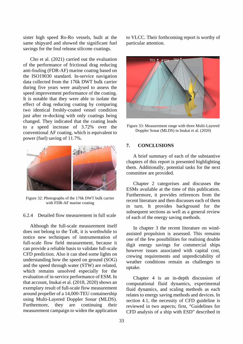
33
sister high speed Ro-Ro vessels, built at the same shipyard and showed the significant fuel savings for the foul release silicone coatings.
Cho et al. (2021) carried out the evaluation of the performance of frictional drag reducing anti-fouling (FDR-AF) marine coating based on the ISO19030 standard. In-service navigation data collected from the 176k DWT bulk carrier during five years were analysed to assess the speed improvement performance of the coating. It is notable that they were able to isolate the effect of drag reducing coating by comparing two identical freshly-coated vessel condition just after re-docking with only coatings being changed. They indicated that the coating leads to a speed increase of 3.72% over the conventional AF coating, which is equivalent to power (fuel) saving of 11.7%.
Figure 32: Photographs of the 176k DWT bulk carrier with FDR-AF marine coating
6.2.4 Detailed flow measurement in full scale
Although the full-scale measurement itself does not belong to the ToR, it is worthwhile to notice new techniques of instrumentation of full-scale flow field measurement, because it can provide a reliable basis to validate full-scale CFD prediction. Also it can shed some lights on understanding how the speed on ground (SOG) and the speed through water (STW) are related, which remains unsolved especially for the evaluation of in-service performance of ESM. In that account, Inukai et al. (2018, 2020) shows an exemplary result of full-scale flow measurement around propeller of a 14,000-TEU containership using Multi-Layered Doppler Sonar (MLDS). Furthermore, they are continuing their measurement campaign to widen the application
to VLCC. Their forthcoming report is worthy of particular attention.
Figure 33: Measurement range with three Multi-Layered Doppler Sonar (MLDS) in Inukai et al. (2020)
7. CONCLUSIONS
A brief summary of each of the substantive chapters of this report is presented highlighting them. Additionally, potential tasks for the next committee are provided.
Chapter 2 categorises and discusses the ESMs available at the time of this publication. Furthermore, it provides references from the recent literature and then discusses each of them in turn. It provides background for the subsequent sections as well as a general review of each of the energy saving methods.
In chapter 3 the recent literature on wind-assisted propulsion is assessed. This remains one of the few possibilities for realising double digit energy savings for commercial ships however issues associated with capital cost, crewing requirements and unpredictability of weather conditions remain as challenges to uptake.
Chapter 4 is an in-depth discussion of computational fluid dynamics, experimental fluid dynamics, and scaling methods as each relates to energy saving methods and devices. In section 4.1, the necessity of CFD guideline is reviewed in two aspects; first, “Guidelines for CFD analysis of a ship with ESD” described in
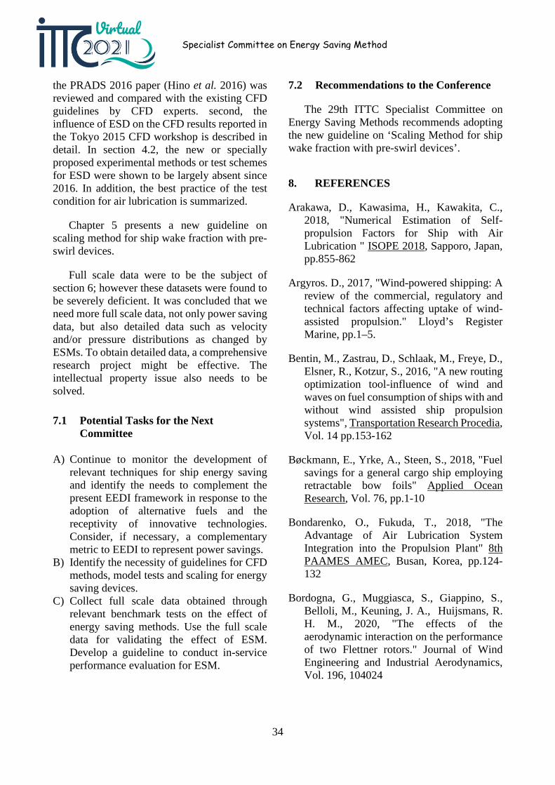
34
Specialist Committee on Energy Saving Method
the PRADS 2016 paper (Hino et al. 2016) was reviewed and compared with the existing CFD guidelines by CFD experts. second, the influence of ESD on the CFD results reported in the Tokyo 2015 CFD workshop is described in detail. In section 4.2, the new or specially proposed experimental methods or test schemes for ESD were shown to be largely absent since 2016. In addition, the best practice of the test condition for air lubrication is summarized.
Chapter 5 presents a new guideline on scaling method for ship wake fraction with pre-swirl devices.
Full scale data were to be the subject of section 6; however these datasets were found to be severely deficient. It was concluded that we need more full scale data, not only power saving data, but also detailed data such as velocity and/or pressure distributions as changed by ESMs. To obtain detailed data, a comprehensive research project might be effective. The intellectual property issue also needs to be solved.
7.1 Potential Tasks for the Next Committee
A) Continue to monitor the development of relevant techniques for ship energy saving and identify the needs to complement the present EEDI framework in response to the adoption of alternative fuels and the receptivity of innovative technologies. Consider, if necessary, a complementary metric to EEDI to represent power savings.
B) Identify the necessity of guidelines for CFD methods, model tests and scaling for energy saving devices.
C) Collect full scale data obtained through relevant benchmark tests on the effect of energy saving methods. Use the full scale data for validating the effect of ESM. Develop a guideline to conduct in-service performance evaluation for ESM.
7.2 Recommendations to the Conference
The 29th ITTC Specialist Committee on Energy Saving Methods recommends adopting the new guideline on ‘Scaling Method for ship wake fraction with pre-swirl devices’.
8. REFERENCES
Arakawa, D., Kawasima, H., Kawakita, C., 2018, "Numerical Estimation of Self-propulsion Factors for Ship with Air Lubrication " ISOPE 2018, Sapporo, Japan, pp.855-862
Argyros. D., 2017, "Wind-powered shipping: A review of the commercial, regulatory and technical factors affecting uptake of wind-assisted propulsion." Lloyd’s Register Marine, pp.1–5.
Bentin, M., Zastrau, D., Schlaak, M., Freye, D., Elsner, R., Kotzur, S., 2016, "A new routing optimization tool-influence of wind and waves on fuel consumption of ships with and without wind assisted ship propulsion systems", Transportation Research Procedia, Vol. 14 pp.153-162
Bøckmann, E., Yrke, A., Steen, S., 2018, "Fuel savings for a general cargo ship employing retractable bow foils" Applied Ocean Research, Vol. 76, pp.1-10
Bondarenko, O., Fukuda, T., 2018, "The Advantage of Air Lubrication System Integration into the Propulsion Plant" 8th PAAMES AMEC, Busan, Korea, pp.124-132
Bordogna, G., Muggiasca, S., Giappino, S., Belloli, M., Keuning, J. A., Huijsmans, R. H. M., 2020, "The effects of the aerodynamic interaction on the performance of two Flettner rotors." Journal of Wind Engineering and Industrial Aerodynamics, Vol. 196, 104024

35
Borusevich, V.O., Pustoshny, A.V., Sverchkov, A.V., Trincas, G., 2016, “Impact of Air Cavity Technology on Ship Drag Reduction: Experience from Research Studies”, 10th Symposium on High-Performance Marine Vehicles, HIPER’16, Cortona, Germany, 17-19 October 2016, pp. 94-107
Bouman, E., Lindstad, E., Rialland, A.I., Strømman, A. H., 2017, "State-of-the-art technologies, measures, and potential for reducing GHG emission from shipping –A review", Transportation Research Part D pp.408-421
Braidotti, L., Mauro, F., Sebastiani, L., Bisiani, S., Bucci, V., 2018, "A Ballast Allocation Technique to Minimize Fuel Consumption" NAV 2018, Trieste, Italy, pp.97-104
Cai, H.P., Hao, C.P., Zhang, H. et. al., 2019, “Hydrodynamic Performance Prediction Method for the Ducted Contra-Rotating Propeller”. 6th International Symposium on Marine Propulsors (SMP’19), Rome, Italy, May 2019
Carlton, J., Aldwinkle, J., Anderson, J., 2013, "Future ship powering options: exploring alternative methods of ship propulsion", Royal Academy of Engineering, London
Caughlan, S.A., 2016, Energy efficiency white paper, pp.1-115
Chang, X., Sun, S., Zhi, Y., Yuan, Y., 2019, "Investigation of the effects of a fan-shaped Mewis duct before a propeller on propulsion performance" Journal of Marine Sscience and Technology, Vol. 24, pp. 46–59
Charruault, F., Westerweel, J., van Terwisga, T., Breugem, W-P., 2017, "On the Drag Reduction Induced by an Air Cavity and Characterisation of Its Free Surface" AMT'17, Glasgow, UK, October 2017, pp.172-185
Chen, C. G., Hu, J., Zhang, W. P., Wang, Y. Z., 2020, "The Effects of Number of Blades of
Free Vane Wheel on Energy-saving" ISOPE 2020, Shanghai, China, pp.2048-2054
Chen, W., Zhang, H., Wang, L., Leng, W., Hou, G., 2017, "Drag Calculation of Macroscopic Objects with Riblet Microstructure" ISOPE 2017, San Francisco, USA, pp.858-864
Chiu, F. C., Huang, S. W., Wu, T. L., Guo, J. H., Tsai, J.F., 2018, "Ship Propulsion in Irregular Waves Augmented by an Active Pitch Oscillating Bow Fin" 8th PAAMES AMEC, Busan, Korea, pp.4-12
Cho, Y., Jeon, K. H., Lee, S. B., Park, H., Lee, I., 2021, "Evaluation of In-service Speed Performance Improvement by means of FDR-AF (Frictional Drag Reducing Anti-Fouling) marine coating based on ISO19030 standard" Scientific Reports, Vol. 11, article no. 1062
Coppedè, A., Gaggero, S., Vernengo, G., Villa, D., 2018, "Surrogate Model for Ship Resistance: A Sensitivity Analysis of Shape Deformation" NuTTS2018, Cortna, Italy
Coppedè, A., Gaggero, S., Vernengo, G., Villa, D., 2019, "Hydrodynamic shape optimization by high fidelity CFD solver and Gaussian process based response surface method" Applied Ocean Research, Vol. 90, pp.1-12
Copuroglu, H. I., Pesman, E., 2018, "Analysis of flettner rotor ships in beam waves", Ocean Engineering, Vol. 150, pp.352-362
Coache, S., Meis Fernández, M., 2017, “ESD design for a validation bulk carrier”, International Shipbuilding Progress, Vol. 63, Iss. 3-4, pp. 211-226
Craft, T., Johnson, N., Launder, B., 2014, "Back to the future- a re-examination of the aerodynamics of flettner-thom rotors for maritime propulsion", Flow, turbulence and combustion, Vol. 92 (1-2) pp.413-427
36
Specialist Committee on Energy Saving Method
Cui, T., Howett, B., Lu, R., Kim, M. Y., Demirel, Y. K., Turan. O., Day. S., Incecik. A., 2016, "Voyage Optimisation towards Energy Efficient Ship Operations." SCC2016: Shipping in Changing Climates Conference
Dadd, G. M., Hudson, D. A., Shenoi, R., 2011, "Determination of kite forces using three-dimensional flight trajectories for ship propulsion", Renewable Energy Vol. 36, Iss. 10, pp.2667-2678
De Freitas, L., Silberschmidt, N., Pappas, T., Connolly, D., 2019, "Full-Scale Performance Measurement and Analysis of the Silverstream Air Lubrication System" HullPIC'19, Gubbio, Italy, pp.201-210
Delfos, R., Greidanus, A., Charruault, F., Westerweel, J., 2017, "Wave Characteristics of a Compliant Coating under a Turbulent Flow" AMT'17, Glasgow, UK, October 2017, pp.141-156
Demirel, Y. K., 2018, "New Horizons in Marine Coatings" INT NAM 2018, Istanbul, Turkey, April 2018, pp.565-582
Demo, N., Tezzele, M., Gustin, G., Lavini, G., Rozza G., 2018a, "Shape Optimization by means of Proper Orthogonal Decomposition and Dynamic Mode Decomposition" NAV 2018, Trieste, Italy, June 2018, pp.212-219
Demo, N., Tezzele, M., Mola, A., Rozza, G., 2018b, "An efficient shape parametrisation by free-form deformation enhanced by active subspace for hull hydrodynamic ship design problems in open source environment" ISOPE 2018, Sapporo, Japan, pp.565-190
Drouet, A., Sergent, P., Causeur, D., Corrignan, P., 2017, "Trim optimisation in waves" MARINE 2017, Nante, France, May 2017, pp.592-603,
Duan, W., Zhang, H., Huang, L., Liu, J., Shao, W., Cao, G., Shi, Z., 2019, "Numerical Simulation of Trim Optimization on
Resistance Performance Based on CFD Method" OMAE2019-96181, Glasgow, UK
Duport, C., Deberque, M., Leroux, J-B., Roncin, K., Jochum, C., 2017, "Local Results Verification of a 3D Non-Linear Lifting Line Method for Fluid-Structure Interactions Simulation on a Towing Kite for Vessels" HIPER'17, Zevenwacht, S.Africa, pp.192-201
Fagiano, L., Milanese, M., Razza, V., Bonansone, M., 2012, "High-altitude wind energy for sustainable marine transportation", IEEE Transactions on Intelligent Transportation Systems, Vol. 13, Iss. 2, pp.781-791
Fan, X., Sun, H., Xiang, X., 2020, "Investigation on Trim Optimization of a Bulk Carrier Based on CFD Method" ISOPE 2020, Shanghai, China, pp.3845-3849
Feng, D., Zhang, H., Sun, Y., Wang, Q., Hu, X., 2019, "Studies about Design of Rear Stator of Ducted Propeller using CFD" OMAE2019-96020, Glasgow, UK
Furcas, F., Gaggero, S., Villa, D., 2019, "Duct-type ESD: a design application using RANSE-based SBDO" smp'19, Rome, Italy, May 2019
Gaggero, S., Villa, D., Tani, G., Viviani, M., Bertetta, D., 2017, "Design of ducted propeller nozzles through a RANSE-based optimization approach" Ocean Eng., Vol. 145, pp.444-463
Gaggero, S., 2018, "Design of PBCF energy saving devices using optimization strategies: A step towards a complete viscous design approach" Ocean Eng., Vol. 159 pp.517-538
Gaggero, S., Villa, D., 2018, "An Optimization Framework for PBCF Energy Saving Devices" OMAE2018-77921, Madrid, Spain
Ge, M. W., Fang, L., Liu, Y. Q., 2017, "Drag reduction of wall bounded incompressible
37
turbulent flow based on active dimples/pimples" Journal of Hydrodynamics, Vol. 29, Iss. 2, pp.261-271
Go, J. S., Yoon, H. S., Jung, J. H., 2017, "Effects of a duct before a propeller on propulsion performance" Ocean Eng., Vol. 136, pp.54-66
Goler, H., Bozkurt, K., 2017, "Speed Loss Analysis of High-Speed Ro-Ro Vessels Coated with New Antifoulıng Technologies" HullPIC'17, Ulrichshusen, Germany, pp.173-193
González-Adalid, J., Pérez Sobrino, M., Gennaro, G., 2018, "Retrofitting a High Efficiency CLT® Propeller on a 175K m³ LNG Tanker: Comparative Service Performance Before and After" 8th PAAMES AMEC, Busan, Korea, pp.191-197
Goren, O., Calisal, S.M., 2017, "Mathematical programming basis for ship resistance reduction through the optimization of design waterline" Journal of Marine Sscience and Technology, Vol. 22, Iss. 4, pp.772-783
Greidanus, A., Delfos, R., Westerweel, J., 2017, "Fluid-Structure Interaction of Compliant Coatings under Turbulent Flow Conditions: Force and PIV Analysis" AMT'17, October 2017, pp.157-171
Güngör, E., 2017, "Hybrid Design Method for a Generic Counter-Rotating Propeller" smp'17, Espoo, Finland, June 2017
Guo, B., Vartdal, B.J., Steen, S., 2017, "A Novel Measure to Reduce Ship Resistance in Waves" OMAE2017‑61949, Trondheim, Norway
Halim, R., Kirstein, L., Merk, O., Martinez, L., 2018, "Decarbonization pathways for international maritime transport: A model-based policy impact assessment", Sustainability, Vol. 10, Iss. 7, p.2243
Hartenberger, J., Gose, J., Ceccio, S., Perlin, M., 2018, “Flow and Drag Measurements over Soft Biofilm”, 32nd Symposium on Naval Hydrodynamics, Hamburg, Germany 5-10 August 2018
Hasselaar, T. W. F., Yan, X. K., 2017, "Evaluation of an energy saving device via validation speed/power trials and full scale CFD investigation" International Shipbuilding Progress., Vol. 63, Iss. 3-4, pp.169-195
Heo, J., Park, D., Berg-Jensen, J. H., Pan., Z., Vada, T. K., 2019, "Hull form Optimization to Fulfil Minimum Propulsion Power by Using Frequency and Time Domain Potential Flow Solvers" PRADS'19, Yokohama, Japan
Hino, T., Hirata, N., Ohashi, K., Toda, Y., Zhu, T., Makino, K., Takai, M., Nishigaki, M., Kimura, K., Anda, M., Shingo, S., 2016, Hull Form Design and Flow Measurements of a Bulk Carrier with an Energy-Saving Device for CFD Validations, PRADS2016, Copenhagen, Denmark
Hirdaris, S., Cheng, F., 2012, "The role of technology in green ship design", 11th International Marine Design Conference, pp.67-78
Hori, M., Kadowaki, T., Hinatsu, M., Toda, Y., 2017, "Development of Design procedure of Energy Saving Rudders Using Various Numerical Codes" ISOPE 2017, San Francisco, USA, pp.867-874
Hou, L. X., Hu, A.K., 2018, "Energy saving performance analysis of contra-rotating azimuth propulsor" Applied Ocean Research, Vol. 72, pp.12-22
Hou, L.X., Hu, A. K., Wang, S., 2019, "Energy saving performance analysis of contra-rotating azimuth propulsor. Part 2: Optimal matching investigation in model scale" Applied Ocean Research, Vol. 88, pp.29-36
38
Specialist Committee on Energy Saving Method
Howett, B., Turan, O., Day, S., 2015, "The use of wind assist technology on two contrasting route case studies", Shipping in Changing Climates Conference, pp.75-83
Htay, W. N., Truang, T. Q., Toda, Y., 2020, "A CFD based Comparison Study of Conventional Rudder and Rudder with Bulb-Fins System of KVLCC2 in Waves", ISOPE 2020, Shanghai, China, pp.3377-3384
Huang, Y., Hou, G., Cheng, X., Feng, B., Gao, L., Xiao, M., 2017, "A new vortex search algorithm with gradient-based approximation for optimization of the fore part of KCS container ship" Journal of Marine Science and Technology, Vol. 22, Iss. 3, pp 403–413
Huang, Y. J., Feng, B. W., Hou, G. X., Gao, L., Xiao, M., 2017, "Homotopy Method for Inverse Design of the Bulbous Bow of A Container Ship" China Ocean Eng., Vol. 31, No. 1, pp. 98–102
Huang, Y. T., Lin, B. C., 2019, "Design and Development of the Energy Saving Rudder-Bulb-Fin Combination by Using Computational Fluid Dynamics Technique" PRADS'19, Yokohama, Japan
Hübbler, M., Narayanan, D., Müller, M., 2017, “Efficient retrofitting of vessels by using simulation tools and reverse engineering technologies”, International Shipbuilding Progress, Vol. 63, Iss. 3-4, pp. 109-136
Ichinose, Y., Tahara, Y., 2019, "A wake field design system utilizing a database analysis to enhance the performance of energy saving devices and propeller" Journal of Marine Science and Technology, Vol. 24, Iss. 4, pp. 1119–1133
Ichinose, Y., Tahara, Y., Takami, T., Kaneko, A., Masui T., Arai D., 2019, "A Study of Multi-objective Optimization for Propulsion Performance and Cargo Capacity" PRADS'19, Yokohama, Japan
Ikeda, Y., 2018, "Development of an Air Circulating Tank Installed in the Double Bottom of a Ship to Reduce Frictional Resistance" INT NAM 2018, Istanbul, Turkey, April 2018, pp.109-122
Ikenoue, H., Hino, T., Takagi, Y., 2020, "Hydrodynamic Design of Energy Saving Device for Ship Scale Performance Improvement", 33rd SNH, Osaka, Japan, October 2020
Inoue, T., Saito, Y., 2017, "A Study on the Principle and Energy Saving Effect of Multi ALV-Fin" HullPIC'17, Ulrichshusen, Germany, pp.109-117
Inukai, Y., Ando J., 2017, "Full Scale Performance Prediction Method for a Ship with ContraRotating Propellers" smp'17, Espoo, Finland, June 2017
Inukai, Y., Sudo, Y., Osaki, H., Yanagida, T., Mushiake, M., Kawanami, S., 2018, "Extensive Full-Scale Measurement on Propeller Performance of 14000 TEU Container Ship" HullPIC’18, pp.27–35, Redworth, UK
Inukai, Y., Igarashi, N., Mushiake, M., Kawanami, S., 2020, "Summary of Full-Scale Measurement about Propeller Performance of 14k Container Ship" HullPIC’20, pp.126–135, Hamburg, Germany
ITTC, 1999, “Final report of the specialist committee on unconventional propulsors”, 22nd International Towing Tank Conference, Seoul Korea and Shanghai, China.
ITTC, 2014a, 7.5-03-02-03 Practical Guidelines for Ship CFD Applications. 27th International Towing Tank Conference, Copenhagen, Denmark
ITTC, 2014b, 7.5-03-02-04 Practical Guidelines for Ship Resistance CFD. 27th International Towing Tank Conference, Copenhagen, Denmark
39
ITTC, 2014c, 7.5-03-03-01 Practical Guidelines for Ship Self-propulsion CFD. 27th International Towing Tank Conference, Copenhagen, Denmark
Jin, W., Nielsen, J. R., 2020, "Development of Controllable Pre-Swirl Fins Adapted to Different Operation Conditions", ISOPE 2020, Shanghai, China, pp.87-93
Jo, Y., Lee, H., Choi, S., Kwon, J., Ahn, S., 2013, "Aerodynamic design optimization of wing-sails", 31st AIAA Applied Aerodynamics Conference, pp. 1-24
Kang, J. G., Kim, M. C., Kim, H. U., Shin, I. R., 2019, "Study on Propulsion Performance according to Variation of Rake Distribution at Propeller Tip" smp’19, Rome, Italy, May 2019
Kanemaru, T., Yoshitake, A., Ando, J., 2017, "Development of New Type Low Drag Rudders in Propeller Slipstream" smp'17, Espoo, Finland, June 2017
Katayama, K., Okada, Y., Ichinose, Y., Fukasawa, R., 2017, "Propulsion Performance Optimization of “Neighbour Duct” by CFD" MARINE 2017, Nante, France, May 2017, pp.529-537
Katsuno, E. T., Dozzi Dantas, J. L., Nelli Silva, E. C., 2018, "Analysis of Hydrophobic Painting in Model-Scale Marine Propeller" OMAE2018-78209, Madrid, Spain
Kawakita, C., 2018, "A Hydrodynamic Design Method of Ship Applying the Air Lubrication System" ISOPE 2018, Sapporo, Japan, pp.169-176
Kim, K., Leer-Andersen, M., Werner, S., 2020, "Hydrodynamic Design of Propulsion Devices taking into account Full Scale Roughness Effects", 33rd SNH, Osaka, Japan, October 2020
Kim, M. C., Shin, Y. J., Lee, W. J., Lee, J. H., 2017, “Study on Extrapolation Method for
Self-Propulsion Test with Pre-Swirl Device,” 5th International Symposium on Marine Propellers (SMP’17), Espoo, Finland, June 2017
Kim, D. Y., Lee, S. H., Paik, K. J., 2018, "Numerical Study on the Behavior of Air Layer for the Reduction of Frictional Resistance in a Model Ship" 8th PAAMES AMEC, Busan, Korea, pp.115-123
Kim, H. T., Kim, H. T., Kim, J. J., Lee, D. Y., 2019, "Study on the Skin-Friction Drag Reduction by Air Injection Using Computational Fluid Dynamics-Based Simulations" PRADS'19, Yokohama, Japan
Kimura, K., Ando, S., Ono, S., Tanaka, Y., 2019, "A Method to Predict Full Scale Performance of the Propeller Boss Cap Fins (PBCF)" smp'19, Rome, Italy, May 2019
Klijnstra, J., Bakker, M., 2017, “Drag Performance Testing in Selection of Fuel Saving Hull Coatings”, 2nd Hull Performance & Insight Conference, HullPIC’17, Ulrichshusen, Germany, 27-29 March 2017
Klose, R., Schulze, R., Hellwig-Rieck, K., 2017, “Investgation of Prediction Methods for Tip Rake Propellers”. smp’17, Espoo, Finland, June 2017
Kobayashi, Y., Okadak, Y., Katayama, K., Ichinose, Y., Fukasawa, R., 2017, "Optimization and Numerical Analysis of “Neighbor Duct” by CFD" NuTTS 2017, pp.115-120
Krasilnikov, V., Sileo, L., Steinsvik, K., 2017, "Numerical investigation into scale effect on the performance characteristics of twin-screw offshore vessels" smp'17, Espoo, Finland, June 2017
Krasilnikov, V., Koushan, K., Nataletti, M., Sileo, L., Spence, S., 2019, "Design and Numerical and Experimental Investigation
40
Specialist Committee on Energy Saving Method
of Pre-Swirl Stators PSS" smp'19, Rome, Italy, May 2019
Krieg, M., Mohseni, K., 2017, "Comparison of Different Methods for Estimating Energetics Related to Efficiency on an UUV with Cephalopod Inspired Propulsion". smp’17, Espoo, Finland, June 2017
Król, P., Bugalski, T., Wawrzusiszyn, M., 2017, "Development of numerical methods for marine propeller - pre-swirl stator system design and analysis" smp'17, Espoo, Finland, June 2017
Kume, K., Fukasawa, R., 2018, "Experimental Investigation of Surface Pressure Distribution of the Duct-Type Energy Saving Device for Ships both in Calm Water and in Wave Conditions" ISOPE 2018, Sapporo, Japan, pp.177-183
Lee, I., Chun, H. H., 2013, “Experimental Procedures toward the Performance Assessment for Low Frictional Marine Paints”, The 3rd International Conference on Advanced Model Measurement Technology for the EU Maritime Industry, Gdansk, Poland, 17-18 September 2013
Lee, I., Park, H., 2017, "In-Service Performance Evaluation of Low Frictional AF Marine Coating" ISOPE 2017, San Francisco, USA, pp.844-850
Lee, I., Park, H., 2018, "Prediction and Verification of Full-Scale Ship Performance of Low Frictional Marine Coating based on FDR-SPC" 32nd SNH, #35, Hamburg, Germany, August 2018
Lee, W. J., 2015, “Study on Full-Scale Performance Prediction for Pre-Swirl Device Model Test Results,” Ph. D. thesis, Pusan National University
Lee, J. H., Kim, M. C., Shin, Y. J., Kang, J. G., 2017, "Study on Performance of Combined Energy Saving Devices For Container Ship
by Experiments" smp'17, Espoo, Finland, June 2017
Leloup, R., Roncin, K., Bles, G., Leroux, J-B., Jochum, C., Parlier, Y., 2014, "Kite and classical rig sailing performance comparison on a one design keel boat", Ocean Engineering, Vol. 90, pp.39-48
Leloup, R., Roncin, K., Behrel, M., Bles, G., Leroux, J-B., Jochum, C., Parlier, Y., 2016, "A continuous and analytical modeling for kites as auxiliary propulsion devoted to merchant ships, including fuel saving estimation", Renewable Energy, Vol. 86, pp.483-496
Li, D. Q., Lindell, P., Werner, S., 2019, "Transitional flow on model scale propellers and their likely influence on performance prediction" smp’19, Rome, Italy, May 2019
Liarokapis, D. E., Kozadinos, G. E., Trachanas J. P., Tzabiras, G. D., 2017, "Experimental Investigation of the Trim Influence on the Resistance Characteristics of a Passenger Ship Model" AMT'17, 536 Glasgow, UK, October 2017, pp.526-536
Lin, Y. H., 2018, "The Routing Optimization of Transoceanic Voyages by Incorporating Particle Swarm Optimization Algorithm Into Weather Routing System" OMAE2018-78280, Madrid, Spain
Liu, Q., Feng, B., Liu, Z., Zhang, H., 2017, "The improvement of a variance-based sensitivity analysis method and its application to a ship hull optimization model" Journal of Marine Sscience and Technology, Vol. 22, Iss. 4, pp. 694-709
Lloyd's Register, 2015, "Wind-powered shipping: A review of the commercial, regulatory and technical factors affecting uptake of wind-assisted propulsion", London
Lu, R., Ringsberg, J. W., 2019, "Ship energy performance study of three wind-assisted
41
ship propulsion technologies including a parametric study of the flettner rotor technology", Ships and Offshore Structures Vol. 15, No. 3, pp.249-258
Lücke, T., Streckwall, H., 2017, "Experience with Small Blade Area Propeller Performance" smp'17, Espoo, Finland, June 2017
Majidian, H., Azarsina, F., 2018, "Aerodynamic Simulation of A Containership to Evaluate Cargo Configuration Effect on Frontal Wind Loads" China Ocean Eng., Vol. 32, Iss. 2, pp.196-205
Mäkiharju, S. A., Ceccio, S. L., 2018, "On multi-point gas injection to form an air layer for frictional drag reduction" Ocean Eng., Vol. 147, pp.206-214
Makino, H., Umeda, N., Ohtsuka, T., Ikejima, G., Sekiguchi, H., Tanizawa, K., Suzuki, J., Fukazawa, M., 2017, "Energy savings for ship propulsion in waves based on real-time optimal control of propeller pitch and electric propulsion" Journal of Marine Sscience and Technology, Vol. 22, Iss. 3, pp 546–558
Mannarini, G., Pinardi, N., Coppini, G., 2018, "Low Carbon Intensity Routes via Ocean Currents and Waves" NAV 2018, Trieste, Italy, June 2018, pp.340-347
Matusiak, J. F., Rautaheimo, P. P., 2017, "Feasibility Study on Thrust Produced by Stabilizing Fins in Waves" ISOPE 2017, San Francisco, USA, pp.1099-1103
Mizzi, K., Demirel, Y. K., Banks, C., Turan, O., Kaklis, P., Atlar, M., 2017, "Design optimisation of Propeller Boss Cap Fins for enhanced propeller performance" Applied Ocean Research, Vol. 62, pp.210-222
Müller, J., 2017, “‘HYTES’ – HYKAT TESTED ENERGY SAVING DEVICES”, The 5th International Conference on Advanced Model Measurement Technology
for the Maritime Industry (AMT’17), pp. 347-357
Naaijen, P., Koster V., 2007, "Performance of auxiliary wind propulsion for merchant ships using a kite", 2nd International Conference on Marine Research and Transportation, pp.45-53
Nguyen, T. V., Shimizu, N., Kinugawa, A., Tai, Y., Ikeda, Y., 2017, "Numerical studies on air drag reduction methods for a large container ship with fully loaded deck-containers in oblique winds" MARINE 2017, Nante, France, May 2017, pp.1040-1051
Nian, Y. J., Hsin, C. Y., Zhou, C. S., Wu, Y. H., Shieh S-A., 2019, "Investigations of the Propeller/Pre-swirl Stator Interactions in Calm Water and in Waves" PRADS'19, Yokohama, Japan
Nielsen, J. R., Wei, J., 2019, "Pre-Swirl Fins Adapted to Different Operation Conditions" smp'19, Rome, Italy, May 2019
Niklas, K., Pruszko, H., 2019, "Full scale CFD seakeeping simulations for case study ship redesigned from V-shaped bulbous bow to X-bow hull form" Applied Ocean Research, Vol. 89, pp.188-201
Okada, Y., Katayama, K., Okazaki, A., Okazak, M., Fukuda, K., Kobayashi, Y., Kajino, T., 2017, "The Battle Royal of Energy Saving Devices for a Ship" smp'17, Espoo, Finland, June 2017
Orlandi, A., Benedetti, R., Capecchi, V., Ortolani, A., Costalli, L., 2018, "Preliminary Assessment of Route Optimisation for Fuel Minimisation and Safety of Navigation by the Use of Cooperatively Collected Data at Sea" NAV 2018, Trieste, Italy, June 2018 pp.462-471
Ouchi, K., Uzawa, K., Kanai, A., Katori, M., 2013, "”Wind challenger” the next generation hybrid sailing vessel", 3rd
42
Specialist Committee on Energy Saving Method
International Symposiums on Marine Propulsors, pp.562-567
Ouyang, X., Chang, H., Yi, Y., Feng, B., Zhan, C., Zheng, Q., 2020, "Research on Hull Form Optimization of Invisible Bulbous Ship" ISOPE 2020, Shanghai, China, pp.3858-3865
Paboeuf, S., Cassez, A., 2017, “ESD syructural issue – Upstream device”, International Shipbuilding Progress, Vol. 63, Iss. 3-4, pp. 291-314
Park, S. H., Lee, I., 2018, "Optimization of Drag Reduction Effect of Air Lubrication for a Tanker Model" International Journal of Naval Architecture and Ocean Engineering, Vol. 10, No. 4, pp.427-438
Park, S. H., Park, S. C., Lee, I., 2018, "Air Lubrication Sweep Angle Estimation Based on Air Injection Condition Using Model Experimental Image Analysis" 8th PAAMES AMEC, Busan, Korea, pp.105-114
Park, K-R, Song, G-S., Kim, H-J., Son, H-J., Park, H-G., 2020, "Hull form design for resistance minimization of small-scale LNG bunkering vessels using numerical simulation", International Journal of Naval Architecture and Ocean Engineering, Vol. 12, pp.856-857
Parker, J., 2013, "Future ship powering options. Exploring alternative methods of ship propulsion." Royal Academy of Engineering, pp.1–94.
Pearson, D. R., 2014, "The use of Flettner rotors in efficient ship design." RINA, Royal Institution of Naval Architects - Influence of EEDI on Ship Design 2014, June 2014, 162–169.
Peifer, B. C., Callahan-Dudley, C., Mäkiharju, S. A., 2020, "Air Layer on Superhydrophobic Surface for Frictional Drag Reduction" Journal of Ship Research, Vol. 64, No. 2, pp. 118-126
Pérez-Sobrino, M., González-Adalid, J., Quereda, R., Soriano, C., Morán, A., Gennaro, G., 2016a, "Scale effects in open water test results for performance prediction of conventional and unconventional propellers" Ingeniería Naval Académica. 2016. (Nº 5). Download available in web: “http://sectormaritimo.es/numero-5-abril2016”. ISSN: 2340-4779.
Pérez-Sobrino, M., González-Adalid, J., Soriano, C., Morán, A., Gennaro, G., 2016b, "A New Performance Prediction Procedure for Propellers with Unconventional Tip Shape" 12th International Conference on Hydrodynamics, Paper ID: 73, Delft, The Netherlands, September 2016
Quereda, R., Sobrino, M. P., Gonzalez-Adalid, J., Soriano, C., 2017, "Conventional propellers in CRP-POD configuration. Tests and extrapolation" smp'17, Espoo, Finland, June 2017
Quereda, R., Pérez-Sobrino, M., González-Adalid, J., Soriano, C., 2019a, "CRP propulsion system for merchant ships. Past, present and future" smp'19, Rome, Italy, May 2019
Quereda, R., Bernal, L., Pérez-Sobrino, M., González-Adalid, J., 2019b, "Critical values of Rn defining transitional flow to be applied in the extrapolation of Open Water Tests (OWT) of unconventional tip shaped propellers" smp'19, Rome, Italy, May 2019
Raven, H. C., 2018, "Minimising Ship Afterbody Wave Making using Multifidelity Techniques" 32nd SNH, #84, Hamburg, Germany, August 2018
Raven, H. C., Scholcz, T. P., 2019, "An Assessment of Multifidelity Procedures for Ship Hull Form Optimisation" MARINE 2019, Gothenburg, Sweden, May 2019, pp.189-200
Ravina, E., Guidomei, S., 2018, "Experimental Investigation on Resistance Reduction by
43
Means of Air-Bubbling Technique" OMAE2018-77980, Madrid, Spain
Rehmatulla, N., Smith, T., 2015, "Barriers to energy efficient and low carbon shipping." Ocean Engineering, Vol. 110, pp.102–112.
Rehmatulla N., Parker S., Smith T., Stulgis V., 2017, "Wind technologies: Opportunities and barriers to a low carbon shipping industry", Marine Policy, Vol. 75, pp.217-226
Remaud, R., Guilcher, P. M., Leroux, J. B. Laurens, J. M., 2019, "Design of Ducted Propellers" NuTTS 2019, Tomar, Portgal
Rotte, G., Kerkvliet, M., van Terwisga, T., 2018, "An Investigation of Air Cavity Closure Mechanisms using Scale Resolving Simulations" NuTTS2018, Cortna, Italy
Sakamoto, N., Kobayashi, H., Ohashi, K., Kawanami, Y., Windén, B., Kamiirisa, H., 2020, "An overset RANS prediction and validation of fullscale stern wake for 1,600TEU container ship and 63,000 DWT bulk carrier with an energy saving device", Applied Ocean Research, Vol. 105, 102417
Sánchez-Caja, A. González-Adalid, J., Pérez-Sobrino M., Sipilä T., 2014, "Scale effects on tip loaded propeller performance using a RANSE solver", Ocean Engineering, Vol. 88, pp. 607-617
Sánchez-Caja, A., Rauti, T., Ramstedt, K., Sipilä, T., 2017, "Numerical Investigation of Multi-Component Podded Propulsor Performance in Straight Flow" smp'17, Espoo, Finland, June 2017
Sánchez Castro, L. F., von Zadow, H., Vesting, F., 2019, "Tip Geometry Effects on Performance and Erosion for Tip Rake Propellers" smp’19, Rome, Italy, May 2019
Sasaki N., Atlar M., Kuribayashi S., 2016, " Advantages of twin rudder system with asymmetric wing section aside a propeller"
Journal of Marine Sscience and Technology, Vol.21, pp.297-308
Sasaki, N., Kuribayashi, S., Atlar, M., 2018, "Gate Rudder" INT NAM 2018, Istanbul, Turkey, April 2018, pp.89-108
Sasaki, N., Atlar, M., 2019, "Scale Effect of Gate Rudder" smp'19, Rome, Italy, May 2019
Sasaki, N., Kuribayashi, S., Fukazawa, M., Atlar, M., 2019, "Gate Rudder Performance" AMT'19, Glasgow, October 2019
Scholcz, T. P., Veldhuis, C. H. J., 2017, "Multi-objective surrogate based hull-form optimization using high-fidelity RANS computations" MARINE 2017, Nante, France, May 2017, pp.231-242
Schrader, L. U., 2018, “Passive Drag Reduction via Bionic Hull Coatings”, 32nd Symposium on Naval Hydrodynamics Hamburg, Germany, 5-10 August 2018
Schrader, L.U., 2019, "Passive Drag Reduction via Bionic Hull Coatings" Journal of Ship Research, Vol. 63, Issue 3, September 2019, pp.206-218
Schrader, L. U., Marzi J., 2017, "A Novel Power-Saving Device for Full-Block Vessels" NuTTS 2017, pp.205-210
Schuilling, B., van Terwigsa, T., 2017, “Hydrodynamic working principles of Energy Saving Devices in ship propulsion systems”, International Shipbuilding Progress, Vol. 63, Iss. 3-4, pp. 255-290
Schulze, R., Klose, R., 2017, “Friction Measurements of Different Coatings in a Friction Tunnel”, 2nd Hull Performance & Insight Conference, HullPIC’17, Ulrichshusen, Germany, 27-29 March 2017
Segawa, K., Ikeda, T., Ando, S., Kimura, K., 2019, "Marine Propeller Optimum Design in
44
Specialist Committee on Energy Saving Method
Wake Flow of Energy Saving Devices" PRADS'19, Yokohama, Japan
Shin, K. W., Andersen, P., 2017, "CFD Analysis of Scale Effects on Conventional and Tip-Modified Propellers" smp'17, Espoo, Finland, June 2017
Silberschmidt, N., Tasker, D., Pappas, T., 2016, “Silverstream® System – Air Lubrication Performance Verification and Design Development”,10th Symposium on High-Performance Marine Vehicles, HIPER’16, Cortona, Italy, 17-19 October 2016, pp. 236-246
Smith, T., Raucci, C., Hosseinloo, S.H., Rojon, I., Calleya, J., De La Fuente, S., Wu, P., Palmer, K., "CO2 emissions from international shipping. possible reduction targets and their associated pathways", UMAS, London, UK
Sogihara, N., Tsujimoto, M., Fukasawa, R., Ohba, H., 2018, "Trim Optimization for Ship Performance in Actual Seas" INT NAM 2018, Istanbul, Turkey, April 2018, pp.551-564
Staffell I., Pfenninger S., 2016, "Using bias-corrected reanalysis to simulate current and future wind power output", Energy, Vol. 114 pp.1224-1239
Streckwall, H., Yan, X-K., 2017, “On the working principle of pre-swirl stators and on their application benefit and design targets”, International Shipbuilding Progress, Vol. 63, Iss. 3-4, pp. 87-107
Streckwall, H., Greitsch L., Müller, J., Scharf, M., Bugalski, T., 2013, “Development of a strip method proposed to serve as a new standard for propeller performance scaling”, Ship Technology Research, May 2013.
Su, Y., Kinnas, S.A., Jukola, H., 2017, "Application of a BEM/RANS Interactive Method to Contra-Rotating Propellers" smp'17, Espoo, Finland, June 2017
Suryateja, A., Srinivas, K. S., Bhattacharyya A., Sha O.P., 2019, "Asymmetric Stern Modifications for KVLCC2G" PRADS'19, Yokohama, Japan
Tacar, Z., Korkut, E., 2017, "Inflow Optmization with an Energy Saving Duct" AMT'17, Glasgow, October 2017
Tacar, Z., Sasaki, N., Atlar, M., Korkut, E., 2019, "Investigation of Scale Effects on Gate Rudder Performance" AMT'19, Glasgow, October 2019
Tachikawa, T., Okada, Y., Katayama, K., Okazaki, A., Okazaki, M., Fukuda, K., Kobayashi, Y., Kajino, T., 2019, "Efficiency improvement effect and water noise reduction by energy saving devices" MARINE 2019, Gothenburg, Sweden, May 2019, pp.603-612
Tahara, Y., Ichinose, Y., Kaneko., A., Kasahara Y., 2019, "Variable decomposition approach applied to multi-objective optimization for minimum powering of commercial ships" Journal of Marine Sscience and Technology, Vol. 24, Iss. 1, pp 46–59
Talluri, L., Nalianda, D., Kyprianidis, K., Nikolaidis, T., Pilidis, P., 2016, "Techno economic and environmental assessment of wind assisted marine propulsion systems", Ocean Engineering, Vol. 121, pp.301-311
Themelis, N., Spandonidis, C., Giordamlis, C., 2019, "Evaluating the Efficiency of an Energy-Saving Device by Performance Monitoring" HullPIC'19, Gubbio, Italy, pp.56-64
Traut, M., Gilbert, P., Walsh, C., Bows, A., Filippone, A., Stansby, P., Wood, R., 2014, "Propulsive power contribution of a kite and a flettner rotor on selected shipping routes", Applied Energy, Vol. 113, pp.362-372
Truong, T. Q, Wu, P. C., Aoyagi, K., Koike, K., Akiyama Y., Toda Y., 2017, "The EFD and CFD Study of Rudder-Bulb-Fin System in
45
Ship and Propeller Wake Field of KVLCC2 Tanker in Calm Water" ISOPE 2017, San Francisco, USA, pp.823-830
Truong, T. Q., Wu, P. C., Kishi, J., Toda, Y., 2018, "Improvement of Rudder-Bulb-Fin System in Ship and Propeller Wake Field of KVLCC2 Tanker in Calm Water" ISOPE 2018, Sapporo, Japan, pp.184-190
Turan, O., Cui, T., Howett, B., Day, S., 2018, "Assessing the Performance of Ships Fitted with Wind Assist Technologies: Flettner Rotor Case Study" INT NAM 2018, Istanbul, Turkey, April 2018, pp.217-230
van der Ploeg, A., Schuiling B., 2018, "Improving an Already Optimized Ship by Making its Stern Asymmetric" COMPIT'18, Pavone, Italy, pp.84-97
von Doenhoff, A. E., Horton, E. A., 1956, “A low-speed experimental investigation of the effect of a sandpaper type of roughness on boundary layer transition”, NACA Report 1349, August 1956.
Van, S. H., Kim, M. C., and Lee, J. T., 1993, “Some remarks on the powering performance prediction method for a ship equipped with a pre-swirl stator-propeller system” ITTC 1993, Vol. 2.
Viola, I. M., Sacher, M., Xu, J., Wang F., 2015, "A numerical method for the design of ships with wind-assisted propulsion", Ocean Engineering, Vol. 105 pp.33-42
Voermans, A., 2017, "Development of the Wärtsilä EnergoFlow: An innovative energy saving device" smp'17, Espoo, Finland, June 2017
Wackers, J., Jeanson, C-E., Queutey, P., Visonneau M., Pellegrini R., Serani A., Diez M., 2018, "Hull shape optimisation using multi-fidelity metamodels and adaptive grid refinement" NuTTS2018, Cortna, Italy
Wang, C., Han, F., Hu, A., 2017, "Design and Performance Investigation of the Energy Recovering Rudder Bulb-turbine Device" OMAE2017‑62485, Trondheim, Norway
Wang, L., He, S., Wang, J., Chen, S., Jin, Y., Li, Q., 2017, “Model Test Research of Low-speed Vessel on Gas Film Drag Reduction”, ISOPE 2017, San Francisco, USA, 25-30 June 2017, pp. 835-838
Wang, H., Chen, S., Wang, L., 2018, "Experimental Research on the Influence of Air film on Propulsion Performance and Power Forecast of Low-Speed ship" ISOPE 2018, Sapporo, Japan, pp.832-838
Wang, H., Mao, W., Eriksson, L., 2018, "MetOcean Data Drived Voyage Optimization Using Genetic Algorithm" ISOPE 2018, Sapporo, Japan, pp.697-705
Wang, H., Mao, W., Eriksson, L., 2017, "Benchmark Study of Five Optimisation Algorithms for Weather Routing" OMAE2017‑61022, Trondheim, Norway
Wang, L., He, S., Wang, J., Chen, S., Jin Y., Li Q., 2017, "Model Test Research of Low-speed Vessel on Gas Film Drag Reduction" ISOPE 2017, San Francisco, USA, pp.835-838
Wang, H., Chen, S., Wang, L., 2018, "Experimental Research on the Influence of Air film on Propulsion Performance and Power Forecast of Low-Speed ship" ISOPE 2018, Sapporo, Japan, pp.832-838
Wei, C. Z., Li, Y. H., Liang, X. F., Yi, H., 2019, "Hull forms of small high-speed wave-piercing monohull crafts and hydrodynamics study" Journal of Hydrodynamics, Vol.31, pp.814-826
Wei, X., Chang, H., Feng, B., Liu, Z., Huang, C., 2019, "Hull form reliability-based robust design optimization combining polynomial chaos expansion and maximum entropy
46
Specialist Committee on Energy Saving Method
method" Applied Ocean Research, Vol. 90, pp.1-12
Wienke, J., 2017, "Verification of the Effectiveness of Energy Saving Devices" HullPIC'17, Ulrichshusen, Germany, pp.102-108
Xiong, X., Chen, H., Yu, H., He, J., Feng, Y., 2019, "Optimization Design of Novel Afterbody Shape for a Cruise Ship" PRADS'19, Yokohama, Japan
Xu, L., Wan, D., 2018, "Numerical Investigation of Scale Effect for Propeller Boss Cap Fins" ISOPE 2018, Sapporo, Japan, pp.805-811
Yang, F., Wang, L., Wang, J., Chen, S., Luo, L., Wang, M., 2017, "Numerical Simulation on Drag Reduction of River-sea Bulk Cargo by Gas Film" ISOPE 2017, San Francisco, USA, pp.839-843
Yang, K. K., Kim, Y., 2017, "Numerical analysis of added resistance on blunt ships with different bow shapes in short waves" Journal of Marine Sscience and Technology, Vol. 22, Iss. 2, pp 245–258
Yang, L., Li, S. Z., Zhao, F., Ni, Q. J., 2018, "An integrated optimization design of a fishing ship hullform at different speeds" Journal of Hydrodynamics, Vol. 30, Iss. 6, pp.1174-1181
Yasukawa, H., Ishikawa, T., 2017, “Improvement of Propulsive Performance of a Catamaran in Waves by a Biologically Inspired Hydrofoil”, 11th Symposium on High-Performance Marine Vehicles, HIPER’17, Zevenwacht, South Africa, 11-13 September 2017
Yehia, W., Moustafa, M. M., Tawfik, A. A., Nasef A., 2019, "Shipboard Fuel Consumption Reduction by Air Lubrication and Trim Optimization" OMAE2019-96770, Glasgow, UK
Yu, J. W., Lee, C. M., Lee, I., Choi, J. E., 2017, "Bow hull-form optimization in waves of a 66,000 DWT bulk carrier" International Journal of Naval Architecture and Ocean Engineering, vol. 9, pp.499-508
Zaccone, R., Figari, M., Martelli, M., 2018a, "An Optimization Tool For Ship Route Planning In Real Weather Scenarios" ISOPE 2018, Sapporo, Japan, pp.738-744
Zaccone, R., Ottaviani, E., Figari, M., Altosole, M., 2018b, "Ship voyage optimization for safe and energy-efficient navigation: A dynamic programming approach" Ocean Eng., Vol. 153, pp.215-224
Zhang, B. J., Zhang, S. L., Zhang, H., 2018, "Optimization Design of Minimum Total Resistance Hull Form Based on CFD Method " China Ocean Eng., Vol. 32, Iss. 3, pp.323-330
Zhang, D., He, W., Li, Z., 2020, "Analysis of Hydrodynamic Performance of Tip Loaded Propellers" ISOPE 2020, Shanghai, China, pp.3789-3796
Zhang, H., Dong, X. Q., Li, W., Yang, C. J., Noblesse, F., 2019, "Effects of Section Geometry on the Energy-saving Rate of PBCF and Model/full-scale Correlation - A CFD Study" MARINE 2019, Gothenburg, Sweden, May 2019, pp.670-681
Zhang, S. L., Zhang, B. J., Tahsin, T., Xu, L. P., Lai, Y. Y., 2017, "Research on Bulbous Bow Optimization Based on the Improved PSO Algorithm" China Ocean Eng., Vol. 31, Iss. 4, pp.487-494
Zhang, Y., Turan, O., 2017, "Numerical investigation of shark skin inspired riblet drag reduction structure" ISOPE 2017, San Francisco, USA, pp.851-856
Zhao, X. J., Zong, Z., Jiang, Y. C., Pan, Y., 2019, "Numerical simulation of micro-bubble drag reduction of an axisymmetric body using
47
OpenFOAM" Journal of Hydrodynamics, Vol.31, pp.900-910
Zhao, X., Zong, Z., Jiang, Y., Sun, T., 2020, "A numerical investigation of the mechanism of air-injection drag reduction" Applied Ocean Research Vol. 94, 101978
Zhou, C. S., Mao, Y. T., Nian, Y. J., Hsin, C. Y., Shih M.M., Shieh S.A., 2018, "Analysis of the Pre-Swirl Stator Effects in Waves" 8th PAAMES AMEC, Busan, Korea, pp.13-21
Zhao, X-J., Zong, Z., Jiang, Y-C., Pan, Y., 2019, "Numerical simulation of micro-bubble drag reduction of an axisymmetric body using OpenFOAM" Journal of Hydrodynamics, Vol.31, pp.900-910
Zhao, X., Zong, Z., Jiang, Y., Sun, T., 2020, "A numerical investigation of the mechanism of air-injection drag reduction" Applied Ocean Research, Vol. 94, 101978
Zhou, C-S., Mao, Y-T., Nian, Y-J., Hsin, C-Y., Shih M-M., Shieh S-A., "Analysis of the Pre-Swirl Stator Effects in Waves" 8th PAAMES AMEC, Busan, Korea, pp.13-21