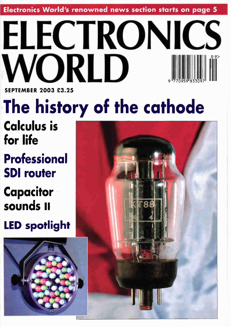
the history of the cathode
TRANSCRIPT
Electronics World's renowned news section starts on page 5
SEPTEMBER 2003 £3.25
The history of the cathode Calculus is for life
Professiona SDI router
Capacitor sounds II
LED spotlight
Te net Hewlett Packard 3314A Function Generator 20MHz £750 Hewlett Packard 3324A synth. function/sweep gen. (21MHz) £1950 Hewlett Packard 3325B Synthesised Function Generator £2500 Hewlett Packard 3326A Two-Channel Synthesiser £2500 H.P. 4191A R/F Imp. Analyser (1GHz) £3995 H.P. 4192A L.F. Imp. Analyser (13MHz) £4000 Hewlett Packard 4193A Vector Impedance Meter (4-110MHz) £2900 Hewlett Packard 4278A lkHz/IMHz Capacitance Meter £3500 H.P. 53310A Mod. Domain Analyser (opt 1/31) £3950 Hewlett Packard 8349B (2 - 20 GHz) Microwave Amplifier £2000 Hewlett Packard 8508A (with 85081B plug-in) Vector Voltmeter £2500
Hewlett Packard 8904A Multifunction Synthesiser (opt 2+4) £1750 H.P. ESG-D3000A 3GHz Signal Gen £6995 Marconi 6310 — Prog'ble Sweep gen. (2 to 20GHz) — new £2500 Marconi 6311 Prog'ble sig. gen. (I0MHz to 20GHz) £2995 Marconi 6313 Prog'ble sig. gen. (10MHz to 26.5GHz) £3750 R&S SMG (0.1-1GHz) Sig. Generator (opts B1+2) £2500 Fluke 5700A Multifunction Calibrator £12500 Fluke 5800A Oscilloscope Calibrator £9995
OSCILLOSCOPES Gould 400 20MHz - DSO - 2 channel Gould 1421 20MHz • DSO - 2 channel Gould 4068 150MHz 4 channel DSO Gould 4074 100MHz - 400 Ms s - 4 channel Hewlett Packard 54201A - 300MHz Digitizing Hewlett Packard 54502A - 400MHz - 400 MSS 2 channel Hewlett Packard 54520A 500MHz 2ch Hewlett Packard 54600A • 100MHz - 2 channel Hewlett Packard 54810A Infinium 500MHz 2ch Hitachi V152/V212N2221/302BN302FN353FN550BV650F Hitachi V1 100A - 100MHz • 4 channel Intron 2020 - 20MHz. Dual channel D.S.0 (new) lwatstu SS 5710 SS 5702 - Kikusui COS 5100 - 100MHz - Dual channel Lecroy 9314L 300MHz - 4 channels Meguro MSO 1270A - 20MHz - D S O. (new) Philips 3295A - 400MHz Dual channel Philips PM3070 - 100MHz - 2 channel - cursor readout Philips PM3392 200MHz - 200Ms/s - 4 channel Philips PM3094 - 200MHz - 4 channel Tektronix 468 - 100MHz D.S.O. Tektronix 2213/2215 - 60MHz - Dual channel Tektronix 2220 - 60MHz - Dual channel D.S.0 Tektronix 2221 - 60MHz - Dual channel D.S.0 Tektronix 2235 • 100MHz - Dual channel Tektronix 2245A 100MHz - 4 channel Tektronix 2430/2430A - Digital storage - 150MHz Tektronix 2445 • 150MHZ - 4 channel .DMM Tektronix 2445 24458 - 150MHz - 4 channel Tektronix 2465,2465A 2465B - 300MHz 350MHz 4 channel Tektronix 7104 • 1GHz Real Time - with 7A29 x2. 7810 and 7815 Tektronix TAS 475 - 100MHz - 4 channel Tektronix TDS 310 50MHz DSO - 2 channel Tektronix TOS 520 - 500MHz Digital Oscilloscope
SPECTRUM ANALYSERS Advantest 4131 (10kHz - 3.5GHz) AdvantestTAKEDA RI KEN - 4132 - 100KHz - 1000MHz Anntsu MS2613A 9kHz - 6.5GHz Spectum Analyser Ando AC 8211 - 1.7GHz Avcom PSA-65A - 2 to 1000MHz Farnell SSA-1000A 9KHz-1GHz Spec. An. Hewlett Packard 182T Mainframe . 8559A Spec.An. (0.01 to 21GHz) Hewlett Packard 853A Mainframe • 8559A Spec.An. (0.01 to 21GHz) Hewlett Packard 3582A (0.02Hz - 25 5kHz) dual channel Hewlett Packard 3585A 40 MHz Spec Analyser Hewlett Packard 3561A Dynamic Signal Analyser Hewlett Packard 8568A -100kHz - 1.5GHz Spectrum Analyser Hewlett Packard 8590A (opt 01. 021, 040) 1MHz-1.5MHz Hewlett Packard 8596E (opt 41. 101. 105.130) 9KHz - 12.8GHz Hewlett Packard 8713C (opt 1 El) Network An 3 GHz Hewlett Packard 8713B 300kHz - 3GHz Network Analyser Hewlett Packard 8752A - Network Analyser (1 3GHz) Hewlett Packard 8753A (3000KHz - 3GHz) Network An Hewlett Packard 87538.85046A Network An . S Param (3GHz) Hewlett Packard 8754A Network Analyser 4MHz -1300MHz) Hewlett Packard 8756A8757A Scaler Network Analyser Hewlett Packard 8757C Scalar Network Analyser Hewlett Packard 70001A 70900A/70906A 70902A70205A - 26.5 GHz Spectrum Analyser IFR A7550 - 10KHz-GHz - Portable Meguro - MSA 4901 - 30MHz - Spec Anaylser Tektronix 492P (opt1.2.3) 50KHz - 21GHz Wiltron 6409 - 10-2000MHz Rf Analyser Tek 496 (9KHz-1.8GHz)
£695 £425
£1250 £1100 £750 £1600 £2750 £675
£2995 from £100
£750 £450
from £125 £350
£2750 £450
£1400 £650
£1750 £1500 £500 £300 £850 £850 £500 £700
from £1250 £850 £800
from £1250 from £1950
£850 £750 £2500
£3750 £1350 £4950 £1500 £750
£1250 £2000 £2500 £1500 £3000 £3500 £3500 £2500 £9950 £6000 £5000 £4995 £3250 £6500 £1500
from £900 £3500
Quality second-user test 8. measurement equipment
Mal
Radio Communications Test Sets Hewlett Packard 8920B (opts 1.4,7,11,121
Hewlett Packard 8922M + 83220E
Marconi 2955
Marconi 2955A
Marconi 295513 ,60B
Marconi 2955R
Motorola R26008
Racal 6111 (GSM)
Racal 6115 (GSM)
Racal 6103 (opts1. 2)
Rohde & Schwarz SMFP2
Rohde & Schwarz CMT 90 (2GHz) DECT
Rohde & Schwarz CMTA 94 (GSM)
Schlumberger Stabilock 4015
Schlumberger Stabilock 4031
Schlumberger Stabilock 4040
Wavetek 4103 (GSM 900) Mobile phone tester
MISCELLANEOUS Ballantee 1b2OA 13iArrip Transconductance Amplifier EIP 545 Microwave Frequency Counter (18GHz) EIP 548A and B 26.5GHz Frequency Counter EIP 575 Source Locking Freq.Counter (18GHz) EIP 585 Pulse Freq.Counter (18GHz) Fluke 6060A and B Signal Gen. 10kHz • 1050MHz Genrad 1657.1658.1693 LCR meters Gigatronics 8541C Power Meter n 80350A Peak Power Sensor
Gigatronics 8542C Dual Power Meter • 2 sensors 80401A Hewlett Packard 339A Distortion measuring set Hewlett Packard 436A power meter and sensor (various) Hewlett Packard 438A power meter - dual channel Hewlett Packard 3335A - synthesiser (200Hz-81MHz) Hewlett Packard 3457A mull meter 6 1 2 digit Hewlett Packard 3784A - Digital Transmission Analyser Hewlett Packard 37900D - Signalling test set Hewlett Packard 34401A Multimeter Hewlett Packard 4274A LCR Meter Hewlett Packard 4275A LCR Meter Hewlett Packard 4276A LCZ Meter (100MHz-20KHz) Hewlett Packard 5342A Microwave Freq.Counter (18GHz) Hewlett Packard 5385A - 1 GHz Frequency counter Hewlett Packard 6033A - Autoranging System PSU (20v-30a) Hewlett Packard 6060A and B Electronic Load 300W Hewlett Packard 6622A - Dual O P system p.s.0 Hewlett Packard 6624A - Quad Output Power Supply Hewlett Packard 8350B - Sweep Generator Mainframe Hewlett Packard 8642A - high performance R•F synthesiser (0.1-1050MHz) Hewlett Packard 8656A - Synthesised signal generator Hewlett Packard 8656B - Synthesised signal generator Hewlett Packard 8657A - Synth. signal gen. 10.1-1640MHz) Hewlett Packard 8657B • 100MHz Sig Gen - 2060 MHz Hewlett Packard 8657D - XX DOPSK Sig Gen Hewlett Packard 8901B Modulation Analyser Hewlett Packard 8903A. B and E Distortion Analyser Hewlett Packard 11729B/C Carrier Noise Test Set Hewlett Packard 53131A Universal Frequency counter (3GHz) Hewlett Packard 85024A High Frequency Probe Hewlett Packard 6032A Power Supply (0-60V)-(0-50A) Hewlett Packard 53518 Microwave Freq. Counter (26.5GHz) Hewlett Packard 53528 Microwave Freq. Counter (40GHz) Keithley 220 Programmable Current Source Keithley 228A Prog'ble Voltage,Current Source IEEE. Keithley 237 High Voltage - Source Measure Unit Keithley 238 High Current • Source Measure Unit Keithley 486,487 Picoammeter (.volt.source) Keithley 617 Electrometer/source
Keithley 8006 Component Test Fixture Marconi 2840A 2 Mbit s Transmission Analyser Marconi 6950 6960 6960A6970A Power Meters 8 Sensors Philips 5515 TN - Colour TV pattern generator Philips PM 5193 - 50 MHz Function generator Phillips PM 6654C System Timer Counter
Panasonic VP 8175A Sig. Gen (100KHz-140MHz) AM•FM,CW Rohde 8 Schwarz FAM (opts 2.6 and 8) Modulation Analyser Rohde 8 Schwarz NRV'NRVD Power meters with sensors Tektronix 1720 Vectorscope
£7000 Tektronix 1735 Waveform Monitor £1750 Tektronix AM503 - AM503A - AM503B Current Amp's with M.F and probe £600 Wayne Kerr 3245 - Precision Inductance Analyser
£3500 Bias unit 3220 and 3225L Cal Coil available if required. £1250 Wayne Kerr 3260A . 3265A Precision Magnetics Analyser with Bias Unit £250Ç MSG PCM-4 PCM Channel measuring set
All equipment is used - with 30 days guarantee and 90 days in some cases.
Add carriage and VAT to all goods.
1 Stoney Court, Hotchkiss Way, Binley Industrial Estate Coventry CV3 2RL ENGLAND
Tel: 02476 650 702 Fax: 02476 650 773 Web: www.telnet.uk.com Email: [email protected]
£6750
£2000
£1250
£1750
£3500
£1995
£2500
£1250
£1750
£5000
£1500
£3995
£4500
£3250
£2750
£1300
£1500
£1250 £1000
from £1500 £1200 £1200 £950
from £500 £1250 £1995 £600
from £750 £1750 £1750 £850 £2950 £2500 £500 £1750 £2750 £1400 £850 £495 £750
from £750 £950
£1750 £1500 £2500 £750 £995
£1500 £3950 £3950 £1750
from £1000 from £2500
£850 £1000 £2000 £2750 £5250 £1750 £1950 £3950 £3750
£1350 £1850 £1950 £1750 £1100
from £400 £1400 £1350 £750
as new £650 £2500
from £1000 £950 £1100
from £800 £1750 (PO.A) £5500 £3750
SEPTEMBER 2003 VOLUME 109 NUMBER 1809
3 COMMENT Who knows your whereabouts?
5 NEWS • RF probe detects cancer
• Miniature engine
• Single photon transmission
reaches 100km
• Mosfets for no-adjust audio amplifiers
• Council raises the bar
• 3D transistor is fastest yet
• Wide band - low power
• Bistable LCD gets true grey-scale
• Government gets £7m for wireless
• Japan leads supercomputer race
• Mobile radar for the troops
14 THE CATHODE Patrick Mitchell gives us a quick history
lesson.
19 CIRCUIT IDEAS • Efficient lighting controller
• Control appliances remotely via
the telephone
• Porch light control
• Super-LED regulator
• Battery-operated lamp timer
23 NEW PRODUCTS The month's top new products.
31 CALCULUS IS FOR LIFE - NOT JUST FOR CHRISTMAS Leslie Green is appalled by the lack of knowledge of graduate job applicants. You could be in for a thousand lines.
36 PROFESSIONAL SDI ROUTER Emil N ludkov, concludes the serial digital video routing system project with a stand-alone control panel.
43 FUNCTION GENERATOR BASED ON CURRENT CONVEYORS Muhammad Abuelma'atti (et al) describes a novel function generator based on current conveyors.
46 CAPACITOR SOUNDS II Cyril Bateman continues to explain how dielectric absorption with DC bias determines capacitor sounds' second harmonic distortions with a practical project.
52 LETTERS • In praise of John Ellis
• Modern Impedance measurement
and de-bounce
• Robots
• Student knowledge and EMC
• Dinosaurs
• Praise indeed
• Kernels
• Class AB, VAS & C Dom
60 WEB DIRECTIONS Useful web addresses for electronics
engineers.
October issue on sale 4 September
September 2003 ELECTRONICS WORLD 1

Le oriort 1U uIh The Confplete Electronics Design System
Schematic & PCB Layout
•11.>-_• .•••••• roomed *JP • ,,,,,
,,, "
Schematic fr.e ! Capture
Is •
SPICE Simulation
!It1
II"
CPU h Models
g g
4.4 "
•11•1•••••••-•••elr•elni
PCB
•Arem•mossell
Auto Placement
Auto Routing
• Powerful & flexible schematic capture. • Auto-component placement and rip-up/retry PCB routing. • Polygonal gridless ground planes. • Libraries of over 8000 schematic and 1000 PCB parts. • Bill of materials. DRC reports and much more.
Mixed Mode SPICE Circuit Simulation
• Berkeley SPICE3F5 simulator with custom extensions for true mixed mode and interactive simulation.
• 6 virtual instruments and 14 graph based analysis types. • 6000 models including TTL, CMOS and PLD digital parts. • Fully compatible with manufacturers SPICE models.
• • te, • •
•
;•••••••,.,
•
- d
gale allni*
•
•
•
Virtual System Modelling
New Features in Version 6
• Drag and drop toolbars. • Visual PCB packaging tool. • Improved route editing. • Point and click DRC report. • Multiple design rules (per net). • Multiple undo/redo.
Call Now for Upgrade Pricing
Proteus VSM - Co-simulation and debugging for popular Micro-controllers
• Supports PIC, AVR, 8051. HC11 and ARM micro-controllers. • Co-simulate target firmware with your hardware design. • Includes interactive peripheral models for LED and LCD displays,
switches, keypads, virtual terminal and much, much more. • Provides source level debugging for popular compilers and
assemblers from Crownhill, IAR, Keil, and others.
F Tel: 01756 753440 C C fl C fl Fax: 01756 752857
Contact us for
Free Demo CD Electronics 53-55 Main Street, Grassington. BD23 5AA
Works with
PIC Basic Plus from Crownhill
Associates
www.labcenter.co.uk infoOlabcenter.co.uk
EDITOR
Phil Reed
CONSULTANT
Ian Hickman
CONTRIBUTING EDITOR
Martin Eccles
EDITORIAL ADMINISTRATION
Jackie Lowe
020 8722 6054
EDITORIAL E-MAILS
GROUP SALES
Reuben Gurunlian
020 8722 6028
ADVERTISEMENT
E-MAILS
EDITORIAL FAX
020 8722 6098
CLASSIFIED FAX
020 8722 6096
PUBLISHING DIRECTOR
Tony Greville
ISSN 0959-8332
SUBSCRIPTION QUERIES
Tel (0) 1 353 654431
Fax (0) 1 353 654400
Disclaimer We work hard to ensure that the information presented in Electronics World is accurate. However, Electronics World's publisher - Highbury Business Communications - will not take responsibility for any injury or loss of earnings that may result from applying information presented in the magazine It is your responsibility to familiarise yourself with the laws relating to dealing with your customers and suppliers, and with safety practices relating to working with electrical/electronic circuitry - particularly as regards electric shock, fire hazards and explosions.
Who knows your whereabouts? In Edinburgh, you can buy time on a parking meter with your mobile phone. You call the number displayed on the meter (with caller I.D. enabled), and a voice response system asks for the meter's I.D. number. This enables the parking system server to identify your location and activate the meter. The latter now lets you choose how long you want to pay for and prints out a ticket for you to place on view in your car. It also instructs the server to charge that amount to your credit card, or to a special account. Obviously, in the process, the system
knows just where you are. But this is not the only, or even the earliest system for locating you. Someone calling the U.K. emergency number 999 from a fixed line may be unable, or not in a fit state, to give his or her exact location. But the origin of the call can be traced via the exchange(s) involved, and the person thus located. In the United States, E911 (the 'Enhanced 911 mandate', passed 1996, revised 1999) requires all cell-phone operators to install facilities, able to locate a mobile caller dialling the 911 emergency number, to within 50 to 100 'meters', by 2005 (is the U.S. going metric at long last?). In Europe, wireless network operators
are already required by E112 to be able to locate a caller making a call to the emergency number 112. However, there is currently no accuracy specification, and most wireless network operators will simply return the location of the cell via which the call was set up - leaving a "fix" which could cover hundreds or even thousands of metres. The GSM system is now spreading in the U.S., and mobile network operators there use uplink time difference of arrival. This depends upon the mobile being received via at least three base-stations, and the system may presumably have to instruct the mobile temporarily to transmit at higher power, to reach enough base-stations. The dominant U.S. mobile technology, like GSM, also uses TDMA, and uplink time difference of arrival technology is appropriate there also. CDMA (code division multiple access) is a different problem as uplink time difference of arrival is not appropriate, and many CDMA mobiles have a GPS function built
in. This returns good position information if the user is outdoors, but less accurate if indoors or in a heavily built up area. These systems are designed to identify a caller's location in an emergency, but in principle could be used by the police continuously to track any suspect, or by national security services for the same purpose, building up a record of an individual's movements up to the present time. There are also other ways in which one's
location, either current or at some time in the past, could be determined. RFID (radio frequency identification) tags are set to become ubiquitous. The Gillette Company of Boston, USA, proposes to buy up to five hundred million or so tags, to mark its razors and packs of blades. These tags are already incorporated in product being sold there, in U.K. and Germany, and the resulting improved inventory management is expected to save billions annually. The tags, read by scanners, will provide records giving details of the time of the sale and outlet, but will remain in the product and be accessible in principle thereafter. Similar tags could appear hidden in the hem of clothes, the binding of books, car tyres and almost any merchandise you can think of. The tags cost tens of pennies today and this will drop to just a few pence each before long. Almost any purchased item will be able to identify the whereabouts of the purchaser either in the past or in some cases, currently, creating - or breaking - an alibi. Even the humble credit card will leave a trace whenever used, creating a record of what and when you bought what where. Japan is well ahead of the game and before long there you will be able to opt for personalised targeted advertising. Knowing where you are, the system could ring your mobile to alert you that the shop you are approaching sells your favourite brand of chewing gum. Some of these means of telling where
you are, are obviously beneficial, even potentially life-saving. But others can be expected to raise anxious representations from civil liberty groups. For more details on this story, see the July 2003 issue of Spectrum, (the journal of the IEEE.)
Ian Hickman
Electronics World is publIshed monthly . payments and general
,ondence to Jackie Lowe, Highbury Business Communications, Anne Boleyn House, 9-13 Ewell Road, Cheam, Surrey, SM3 8BZ
Newstrade Distributed by COMAG,
To. srocs Rood, West Drayton, Middlesex, UB7 70E Tel 01895 444055.
Subscriptions: Wyvern Subscription Services, link House, 8 Bartholomew's Walk, Ely Cambridge, CB7 42D. Telephone 01353 654431. Please notify change of address.
Subscription rotes . . £38.95 0/S £64.50
USS I 00 62 Euro 102.55
USA moiling agents: Mercury Airireight International Ltd Inc, 10(b) Englehord Ave, Avenel NJ 07001. Periodicals Postage Paid at Rahway NJ Postmaster. Send address changes to above Printed by Polestar (Colchester) Ltd, tilmsoning by Impress Repro by Design Al Parkway, Southgate Way, Orton Southgate, Peterborough, PE2 6YN
HIGHBURY Business Communications A SUISIDIARY 0111161151M MOLISE (Ctemusr(slasS PIC
September 2003 ELECTRONICS WORLD 3
Quasar Electronics Limited PO Box 6936, Bishops Stortford, CM23 4WP Tel: 0870 246 1826 Fax: 0870 460 1046 E-mail: [email protected]
Add £2.00 P&P to all UK orders. 1st Class Recorded -£4. Next day (insured £250) -£7. Europe -£5. Rest of World -£10. We accept all major credit/debit cards. Make cheques/PO's payable to Quasar Electronics Limited. Prices include 17.5% VAT. MAIL ORDER ONLY. Call now for our FREE CATALOGUE containing details of over 300 electronic kits, projects and modules.
VISA
• WarICARIa
414
C.) SOLO
QUASAR O a 71 CREDIT CARD SALES 717 7 e electronics
Motor Drivers/Controllers
Here are just a few of our controller and driver modules for AC, DC, unipolar/bipolar stepper motors and servo motors. See website for full details.
DC Motor Speed Controller (6A/100V) Control the speed of almost any common DC motor rated up to 100V/5A. Pulse width modulation output for maximum motor torque at all speeds. Supply: 5-15VDC. Box sup-plied. Dimensions (mm): 60Wx100Lx6OH. Kit Order Code: 3067KT - £12.96 Assembled Order Code: AS3067 - £19.96
PC / Standalone Unipolar Stepper Motor Driver Drives any 5, 6 or 8-lead unipolar stepper motor rated up to 6 Amps max. Provides speed and direc-
tion control. Operates in stand-alone or PC-controlled mode. Up to six 3179 driver boards can be connected to a single parallel port. Supply: 9V DC. PCB: 80x5Omm. Kit Order Code: 3179KT - £9.96 Assembled Order Code . AS3179 - £16.96
PC Controlled Dual Stepper Motor Driver Independently control two unipolar stepper motors (each rated up to 3 Amps max ) using PC parallel port and soft-
ware interface provided. Four digital inputs available for monitoring external switches and other inputs. Software provides three run modes and will half-step, single-step or man-ual-step motors. Complete unit neatly housed in an extended D-shell case. All components. case, documentation and software are sup-plied (stepper motors are NOT provided). Dimensions (mm), 55Wx70Lx15H. Kit Order Code: 3113KT - £16.96 Assembled Order Code: AS3113 - £24.96
Bi -Polar Stepper Motor Driver Drive any bi-polar stepper motor using externally sup-plied 5V levels for stepping and direction control. These usually come from software running on a computer.
Supply: 8-30V DC. PCB: 75x85mm. Kit Order Code: 3158KT - £12.96 Assembled Order Code: AS3158 - £26.96
Most items are available in kit form (KT suffix)
or assembled and ready for use (AS prefix).
KITS
Controllers 84 Logger-
Here are just a few of the controller and data acquisition and control units we have See website for full details. Suitable PSU for all units: Order Code PSU203 £9.95
Rolling Code 4-Channel UHF Remote State-of-the-Art. High security. 4 channels. Momentary or latching relay output. Range up to 40m. Up to 15 Tx's can be learnt by one Rx (kit in-cludes one Tx but more avail-able separately). 4 indicator LED 's. Rx. PCB 77x85mm, 12VDC/6mA (standby). Two and Ten channel versions also available, Kit Order Code: 3180KT - £41.96 Assembled Order Code: AS3180 - £49.96
Computer Temperature Data Logger
S 4-channel temperature log-. ger for serial port. °C or °F. tContinuously logs up to 4
separate sensors located 4- r Π200m+ from board. Wide
-7-- range of free software appli-cations for storing/using data. PCB Just 38x38mm. Powered by PC. Includes one DS1820 sensor and four header cables. Kit Order Code: 3145KT - £22.96 Assembled Order Code: AS3145 - £29.96 Additional DS1820 Sensors - £3.96 each
NEW! DTMF Telephone Relay Switcher Call your phone number using a DTMF phone from anywhere in the world and remotely turn on/off any of the 4 relays as desired. User settable Security Password, Anti-Tamper, Rings to Answer, Auto Hang-up and Lockout. Includes plastic case. 130x110x3Omm. Power 12VDC. Kit Order Code: 3140KT - f39.96 Assembled Order Code: AS3140 - £69.96
Serial Isolated I/O Module PC controlled 8-Relay Board. 115/250V relay outputs and 4 isolated digital inputs. Useful in a variety of control and sensing applications.
Uses PC serial port for programming (using our new Windows interface or batch files). Once programmed unit can operate without PC. Includes plastic case 130x100x3Omm. Power 12VDC/500mA. Kit Order Code: 3108KT - £64.96 Assembled Order Code: AS3108 - £64.96
Infrared RC Relay Board Individually control 12 on-board relays with included infrared remote control unit. Toggle or momentary. 15m+ range 112x122mm. Supply . 12VDC/0.5A Kit Order Code 3142KT - f41.96 Assembled Order Code. AS3142 - £69.96
go z. PIC 8, ATM EL Programmera
We have a wide range of low cost PIC and ATMEL Programmers. Complete range and documentation available from our web site
Programmer Accessories: 40-pin Wide ZIF socket (ZIF4OW) £16.00 18V DC Power supply (PSU201) £6.96 Leads: Parallel (LEAD108) £4.96 / Serial (LEAD76) f4.96 / USB (LEADUAA) £4.96
NEW' USB 'All -Flash' PIC Programmer USB PIC programmer for all 'Flash' devices No external power supply making it truly portable Supplied complete with 40-pin wide-slot ZIF socket, box and Windows Software. Kit Order Code: 3128KT - £49.96 Assembled Order Code: AS3128 - £64.96
Enhanced "PICALL" ISP PIC Programmer Will program virtually ALL 8 to 40 pin PICs plus a range of ATMEL AVR. SCENIX SX and EEPROM 24C de-vices. Also supports In Sys-
tem Programming (ISP) for PIC and ATMEL AVRs. Free software. Blank chip auto detect for super fast bulk programming. Requires a 40-pin wide ZIF socket (not included).
Kit Order Code: 3144KT - £64.96 Assembled Order Code: AS3144 - £69.96
ATMEL 89xxxx Programmer Uses serial port and any standard terminal comms program. 4 LED's display the status. ZIF sockets not included. Supply: 16-18VDC. Kit Order Code: 3123KT - £29.96 Assembled Order Code: AS3123 - £34.96
USB & Serial Port PIC Programmer di USB/Serial connection. Ideal for field use. Header cable for ICSP Free Windows software. See website for PICs supported. ZIF
"t, ---- socket not incl. Supply - 18VDC Kit Order Code: 3149KT - £29.96 Assembled Order Code: AS3149 - £44.96
www.quasarelectronics.corn Secure Online Ordering Faciliti- es Full Product Listing, Descriptions & Photos Kit Documentation & Software Downloads
Mosfets for n The need to adjust output device idle current in audio amplifiers following construction has been completely removed by Japanese component maker Sanken.
It has introduced 150V n and p-channel power mosfets with laser-trimmed internal compensating resistors and diodes which mean all devices are matched within ±1% for temperature and ±20% for bias current.
Initially designed for a Pioneer hi-fi, the devices are called LEXAM (legend of excellent audio mosfet). Temperature compensation is
achieved by including a string of diodes in the gate circuit of the n-device. The diodes are doped to give them a characteristic which matches the combined temperature curve of both n and p-fets together. Adding diodes in only one of the
pair works because both transistors dissipate equal power in a class-AB amplifier. Designers have to be
o-adjust audio amplifiers careful to heatsink both devices equally. Sanken claims the internal
compensation scheme is better than using a separate external sensing transistor mounted between the two devices, as is normal audio amplifier practice, because thermal lag is almost eliminated. Gate voltage adjustment is achieved
by mounting a laser-trinunable potentiometer alongside the semiconductor die in both n and p-fets. The pot is connected to the gate and
can is trimmed to match gate threshold voltage which, given a fixed idle voltage on the device gate during operation, sets quiescent current in the amplifier to 100mA (±20mA). "Other characteristics such as
forward transconductance are optimised to achieve the best possible audio performance," said Sanken.
In the UK, Sanken audio products are available from Magnatec, part of the Semelab Group.
Council raises the bar The UK's Engineering Council is to raise the Chartered Engineer and Incorporated Engineer entry requirements for professional engineers and also for engineering technicians. The latest rules will ensure that
engineers and technicians must demonstrate competence before registration. Firms will also be
encouraged to speed up the process and develop training and development schemes. "We have high hopes that this new
standard will help to ensure the UK continues to be recognised as one of the leading engineering nations of the 21st century," said council chairman Sir Colin Terry.
The three qualifications will remain the same: Chartered Engineer, Incorporated Engineer and Engineering Technician. The four-year MEng courses will still fast-track graduates towards CEng status. The Engineering Council contains
the national register for 250,000 professional engineers.
3D transistor is fastest yet A three dimensional transistor with a channel length of just 30nm (nanometres) has been demonstrated by Intel. The chip giant is claiming record performance and leakage figures for the NMOS device. Dubbed Trigate, the transistor has three gate contacts to the silicon channel, which makes the device easier to manufacture than planar devices. With planar transistors of the type
used in microprocessors, the silicon channel needs to be made very thin. For a device with 30nm gate this channel would be perhaps just lOnm
thick, creating what is known as a fully depleted transistor.
In Trigate, the silicon channel is the same thickness as the gate is long. "There isn't any particular
constraint now on lithography," said Ken David, co-director of the components research group at Intel. "It doesn't require unique modifications to the tooling."
Intel has so far characterised a 60nm device. At 1.3V it has a saturated drain current of 1.23mA/µm and an off current of 40nA/µm. The firm is planning to use the 3D
transistors when it reaches the 45nm
processing stage. Trigate is now moving from a research phase into full process development.
This 30nm transistor has its silicon channel running from left to right - source to drain - with the gate passing over the top. Thus it contacts the channel on three sides.
September 2003 ELECTRONICS WORLD 5
UPDATE
Bistable LCD gets true grey-scale ZBD Displays of Oxfordshire has produced a demonstrator to prove its bistable LCDs can produce multi-shade images. "This is an extremely exciting time
for ZBD. The development of the greyscale demonstrator shows the capabilities of our technology to offer both greyscale and eventually colour," said Henri-Luc Martin, CEO of ZBD. ZBD, named after its technology:
zenithal bistable displays, is developing and marketing technology which can be used in displays that use no power at all to maintain an image - only needing energy to change state. Previous bistable technologies have
had the problem that each pixel is either or off, producing images which are black or white with no shades of grey. There are ways around this: by
using several sub-pixels per pixel - which adds complexity, or rapidly turning the pixels on and off - which negates the power advantage. What ZBD has done is make a pixel
Wide band - low power A firm from Cambridge reckons it will soon be making wireless systems that can transmit 100Mbit/s of data across 20m using just 50pW of transmit power. Artimi claims its ultra wideband
(UWB) chips will be made purely from CMOS processing and will conform to US and European standards.
UWB is touted as the future for wireless home networks. In its present form the system uses the band between 3GHz and 10.6GHz. Pulses are spread across the whole band with very low transmit power. "Because you treat the entire
spectrum as one flat band it makes the analogue design simpler," said Mark Moore, chief technology
which can be set to one of several darkness settings and will hold the setting indefinitely. Behind the ZBD technology is an
in-pixel diffraction grating what aligns the liquid crystal within. By varying the grating across each
pixel, different parts of the pixel can be made to switch at different voltages - effectively making sub-pixels without needing separate connections to each. The firm is claiming four error-free
grey levels per pixel over a whole display - enough to make 64 colours if the technique was applied to, for instance, a colour display in a phone or PDA. "The path to greyscale and colour is
essential to match the requirements of e-books, electronic readers, shelf-edge labels, PDAs, mobile phones and smart watches," said Martin.
officer at Artimi. In fact the power limit of 50µW has
been defined by the US FCC for unlicensed communications in the band. "The EU is tracking that ruling, and
it's expected they'll grant a comparable licence," explained Moore. Until then, the firm has a licence from the Radiocommunications Agency.
In Brief
Liquid crystal lens varies focal length A liquid crystal lens with electronically variable focal length has been developed by researchers at CRL Opto and Durham University. Similar work has been carried out by
institutions such as University College London. However, the Durham lenses are much larger, with diameters of up to lOmm. Chris Hughes, senior principal engineer
at CRL Opto, said the lenses could be used in applications such as image zoom, wavefront correction and laser beam control.
"It could be used in variable focus optics systems and, depending on how clever you are, zoom elements with no mechanical components," he said. The lens has a focussing value between 0 and 2 dioptre, meaning it can focus a parallel beam of light between 50cm and infinity. The design is based on nematic liquid
crystal with electrodes around the edge. A
voltage potential is introduced across the lens that changes its refractive index. The clever, and secret, part is getting a
zero potential in the centre of the lens, which increases towards the outside edge. Both spherical and cylindrical lenses can
be made to focus light longer than 400nm.
Government gets ein for wireless The Government has completed its sale of licences for public fixed wireless access in the 3.4GHz band, raising £6.955m in the process.
After 41 rounds of bidding all fifteen licences were sold to just three bidders. Poundradio, owned by Hong Kong firm
PCCW, won thirteen licences, paying a total of £6.3m. This included nearly £2m for the London licence. Red Spectrum took the Northern Metropolitan licence paying £330,000, while Public Hub paid £330,000 for the Southern Provincial licence. "The aim of the auction was to see the
licences in the hands of the operators best able to take advantage of them, and in turn, to see consumers - including those in areas currently without ADSL or cable -
benefit from fixed wireless broadband access," said Stephen Timms, Minister for e-Commerce and Competitiveness
Twice the brightness, no more power Oxford display developed Ocuity has revealed a switchable brightness display which can double its intensity for almost no power increase. Based around something Ocuity calls a
'polarisation activated microlens', the add-on optics trade-off viewing angle for brightness when a boost is required. The microlenses are in a thin sheet and
can be switched between focussing and plain states by a voltage. They are also behind the company's other novel display which can be switched from normal 2D viewing to a 3D mode which does not need special glasses. "We are already talking to
manufacturers about licensing production," said company co-founder Graham Woodgate. The Company first publicly showed its
microlens technology, on a 2D/3D display, in February. www.ocuity.co.uk
6 ELECTRONICS WORLD September 2003

UPDATE
RF probe detects cancer Italian military electronics company Galileo Avionica has developed a non-invasive probe which it claims can find cancer and other anomalies in the body. Called TRIMprob (Tissue
Resonance InterferoMeter Probe), it uses an effect accidentally discovered by the physicist Dr Clarbruno Vedruccio who was working on a mine detector. "During laboratory experiments he
noted and investigated the interference of this probe with live biological substances and consequently pursued his studies until the development of a demonstrator," said Galileo. Inside the probe is an RF source,
invented by Vedruccio, called a hybrid-state maser which "generates highly coherent space and time electromagnetic fields," said Galileo, "and through miniaturised sensors interacts microscopically with the organic substance under examination." Operating in bands around 460,
930 and 1,390 MHz, it can detect in real time and at an early stage various disorders from inflammatory conditions to cancers, said the firm. "When the electromagnetic field
hits a biologically altered tissue, a phenomenon of interference with the analysed structure takes place. This phenomenon is interpreted by
specially-developed algorithms, and allows the detection of cancer and other pathologies: vascular disorders, joint and bone diseases, sinew and muscle injuries, inflammatory conditions, fibromas,"
claimed Galileo. TRIMprob is battery-powered and
about 30cm long. Working with a nearby receiver, it analyses the patient fully dressed and with no discomfort. Medical trials are underway and a
probe for prostate cancer is expected this summer. www.galileoavionica.it
Single photon transmission reaches 100km Scientists at Toshiba Research Europe and Cambridge University have transmitted quantum cryptography keys using single photons of light over 100km of fibre optic cable. "As far as we are aware, this is the first
demonstration of quantum cryptography over fibres longer than 100km," said Dr Andrew Shields, leader of the Toshiba group developing the system. Quantum cryptography uses the rules of
quantum mechanics to gives the highest level of secrecy yet found in a communications system. Shields says it offers "unconditional
secrecy", which is "independent of the computing power, fancy gadgetry or guile of an adversary". Toshiba creates single photons using an
attenuated laser and encodes data using the photon's phase. At the other end of standard fibre optic cable, avalanche photodiodes are used to detect the incoming photons. Due to the rules of quantum mechanics,
any interception of the photon by an eavesdropper has modify the phase (Heisenberg's uncertainty principle), so the receiver will be aware of tampering. An eavesdropper "cannot gain any
information about the encoded single photons without causing a detectable disturbance", said Shields. The quantum system is only used to send
the key, which is then used in a standard 3DES or AES encryption system, or perhaps a one-time-Pad system. "That extends the security, but is only suitable for
small amounts of data," added Shields. The group's success has led to
Government funding for a commercial system on unhackable communications. "They're funding part of the future
programme, to integrate a single photon source," said Shields. This quantum LED project has a budget of £1m, he said.
September 2003 ELECTRONICS WORLD
UPDATE
Japan leads supercomputer race The world's most powerful computer is still the Earth Simulator - according to the annual top 500 supercomputer list compiled by research labs in Germany and the US. The Earth Simulator, built by NEC
and installed in Yokohama, is rated at 35.86Tflop/s (teraflops or trillions of calculations per second) using the Linpack performance measure. Number two is Hewlett-Packard's
ASCI Q at Los Alamos with 13.88Tflop/s followed by the Intel Xeon-based MCR cluster at Lawrence Livermore Laboratory. This is the highest ever place for a cluster, which
uses a Quadrics interconnect and was manufactured by Linux Networx. Former world-fastest ASCI White
came fourth, and would probably have come third with this years slightly modified Linpack if the computer had been available to be re-tested. The upgraded 6,656-processor IBM
SP system at the US National Energy Research Scientific Computing Center, which is almost identical to 8,192 processor ASCI White, came fifth with 7.3Tflop/s. Away from Japan and the US,
France gets tenth spot with
Ranked twelfth in the world, this is the UK's most powerful computer. Called HPXc it is a cluster of IBM SMP nodes containing 1,280 POWER4 processors and delivering 6.6 teraflopis peak - around 3.5 teraflops/s sustained. It has 1.2811wte of memory and 18Tbyte of dick space.
Miniature engine Ceramic micro-engines just a fem, millimetres in length have been created by researchers at the University of Birmingham. "These micro-engines will be much more
energy efficient than standard batteries. It takes 2,000 times more energy to manufacture a battery than the battery dispenses while it is being used," said Dr Kyle Jiang, lead investigator at Birmingham's department of mechanical engineering. However, Jiang's engine is not a fuel cell.
"The difference is that a micro-engine gives a displacement, and produces electricity as well," he said. In fact the micro-engine is an internal
combustion engine, with the choice of fuel yet to be finalised. "At the moment the most likely fuel will be propane and a catalyst, platinum," said Jiang. In the presence of platinum the propane
will spontaneously combust, avoiding the need for an ignition source, Jiang explained. While hydrogen might be a better fuel
choice, he said, because of its high energy density, it would need an ignition source inside the combustion chamber. Manufacture of the engines is the
University's main achievement. "We use UV lithography. The construction material is a kind of polymer," said Jiang. This is then converted to ceramic. With conventional combustion
techniques there is a minimum size to the device. If the combustion chamber drops below lnun on a side, the gas will not bum, claimed Jiang. Micro-engines could be used to drive
micro air vehicles and micro-robots for reconnaissance purposes, communications relays, micro-cameras and other sensor carriers.
3.98Tflop/s for its nuclear research HP AlphaServer SC, followed by Germany, and the UK at 12 with its 3.241Tflop/s HPCx - an IBM pSeries 690 based Oxforahire (see picture). The number of systems in the top
500 list using Intel processors grew from 56 to 119 in the six months before the list was compiled, so Intel can at last join IBM (Power architecture) and HP (PA-RISC) as a big chip contributor. Two notable newcomers among the
top ten are Fujitsu's PrimePower HPC2500 system at the National Aerospace Laboratory of Japan, at seven the largest new Japanese system; and at eight, the highest ranked Itanium-based system, produced by Hewlett-Packard and installed at Pacific Northwest National Laboratory. Almost 4Tflop/s are now required
for a top ten position and 59 systems exceed 1Tflop/s.
If you add the performance of all 500 computers, IBM is producing 34.9 per cent of the power, HP 24.1 per cent and NEC 11.7 per cent. The number of clusters grew again,
to 149 systems of which 23 have been made by the organisations which use them.
It has been suggested the US Department of Defense's recent injection of almost $150m into US supercomputer research was prompted by Japan's dominance of the list.
8 ELECTRONICS WORLD September 2003
Station Road, Culiercoats,
Tyne a Wear, NE30 4PQ
Prices Exclude Vol D17 UK Carriage £.50 (less than lkg)
£3.50 greater than lkg Cheques / Postal orders payable lo
ESR Electronic Components. PLEASE ADD CARRIAGE & VAT TO ALL ORDERS
VISA
DIL
Stoissisefil Pin 6 Pin DIL 0.3' £0.07 8 Pin DIL 0.3" £0.06 14 Pin DIL 0.3 £0.11 16 Pin DIL Q.3" £0.11 18 Pin DIL o.3- £0.12 20 Pin DIL Q.3" £0.12 24 Pin DIL 0.3' £0.12 24 Pin DIL 0.6V £.17 28 Pin DIL 0.3' £0.13 28 Pin DIL 0.6' £13 32 Pin DIL 0.6' £0.13 401 1L0.6" £0.19
Pin 8 Pin DIL 0.3" £11 14 Pin DIL 0.3" £0.20 16 Pin DIL Q.3" £Q.23 18 Pin DIL 0.3' £0.25 20 Pin DIL £.28 24 Pin DIL £0.35 24 Pin DIL 0.6- £0.35 28 Pin DIL £0.3.? 28 Pin DIL O.6 £0.39 32 Pin DIL 0.6 £0.43 40 Pin OIL o.e £0.64
• Sockets Universal ZIF DIL Sockets 24 Way Q.3-3.6' £5.85 28 Way 0.3-o.e £6.60 32 Way Q.3-0.6 £7.5Q 40 Way 0.3-0.6' £8.93 Transistor letkets T018-4 Base Socket £0.24 TO5 Base Socket £0.24 SOC Cable feeds
10 Way Socket £0.26 14 Way Socket £0.35 16 Way Socket £0.38 20 Way Socket £37 26 Way Socket £0.36 34 Way Socket £0.39 40 Way Socket £0.55 50 Way Socket £0.80 SOC Cable Maps 10 Way Plug 14 Way Plug 16 Way Plug 20 Way Plug e Way Plug 34 Way Plug 40 Way Plug 50 Way Plug
PCB ilex Headers
10 Way 14 Way 16 Way 20 Way 26 Way 34 Way 40 Way 50 Way 10 Way 14 Way 16 Way 20 Way e Way 34 Way 41) Way 50 Way
Straight Straight Straight Straight Straight Straight Straight Straight 90' 9 . 9 . 9 .
$8: PC. Latch Headers
CS:A £62 £0.66
E88 £0.92 £1.12
2:îî £0f Riî E'Sî R:33 E8:2 R:g? £1.17 £1.14
1 11114 10 Way Straight £0.39 14 Way Straight ÇQ.45 16 Way Straight £0.51 20 Way freight 26 Way freight MI 34 Way Straight .e 40 Way Straight £0.92 50 Way Straight £1.27 10 Way 9Q. 2:1g 14 Way 90' 16 Way 219' £54 20 Way 90" £0.59 26 Way 991' £0.01 34 Way 90' £ .0 40 Way 9(1' £1.23 50 Way 90' £1.41 OIL deadens 4 16,1104 .
14 Way Dd. 16 Way CM. 24 Way OIL 40 Way OIL
£0.51 £0.53 £0.90 £1.37
38 Miniature 20 300mA 125V 20 7 x 15mm Mounting Hole 20 DFDT 7 x,23mm £0.17 20 Manolarti
20 5.5 x 12mm Mounting Hole 22 DPDT 12 x 35mm £0 27 2u DPDT do 12 x 35mm £0:25 68 68 ounany paddies
96 96 150mA 250V Make before 23 Break 22mm e î3 9.8mm 0 Mounting Hole 1 Pole 12 Way £0.84
10 2 Pole 6 Way £0.84 24 i Pole 4 Way £0.84
L
3
Translation Headers 10 Way Transistion £.42 14 Way Transistion £0.42 16 Way Transistion ÇQ.4$ 20 Way Transistion £0.48 26 Way Transistion ÇQ.52 34 Way Transistion £0.56 40 Way Transistion ÇQ.63 50 Way Transistion £0.84 Large Range et Connectors in stock - New Connectors Catalogue now available
see our web site tor details.
▪ Type Cenneders
Odder Musket 9 Way Male Plu411 £0.20 DC Plug 0.710 2.350D0.47 9 Way Female Jock& £,..2.,20 DC Plug 1.310 3.4Q0 £0.17 15 Way Male PluS1 DC Plug 1.7113 4.00D £0.44 15 Way Female socket £0.29 DC Plug 1.7113 4.750130.50 15 Way H.D. Plug £042 DC Plug 2.110 5.000 £0.24 15 Way H.D. Socket £0.45 DC Plug 2.5113 5.QQD £0.24 23 Way Mole Plug £60 DC Plug 3.110 6.30D £ .53 23 Way Female S-ocket £0.66 pc Line Socket mm £0.6e 25 Way Mole Plug £030 DC Line Socket 2.5mm £0.68 LW £°.35 DC Chassis Skt 2.1mm £0.44
• •••••r11 DC Chassis Skt 2 5mm £0.44 9 WaY Male PlY,11 11 •08 IRC Mahn 6A ASOVas 9 Way Female backlit £0.9 15 Way Male Plug £1.3 15 Way Female S-ocket£1.32 25 Way Mole Plu, £1.10 25 Way Female Sacket£1.1 tnc Crimp £11.8 • Anpitd 3 Pin IEÇ Line Socket £1.08
3 Pin IEC Line Plug £1.89 3 Pin Chassis Socket £Q.55 3_ Pin Chassis Plug £0.56 11 Way noggin
▪ Cenneeters
"eleggieleCçl BNC Plug 500 Solder £0.99 BNC Plug 500 Crimp £0.68 BNC Plug 750 Solder £1.08 BNC Plug 750 Crimp £0.69 BNC Chassis Socket ÇQ.76 F Plug - Twist £0.20 F Plug - Crimp £0.20 TNC Plug 500 Solder £1.08 TNÇ Plug 500 Crimp £1.04 TNC Plug 750 Solder £1.17 TNC Plug 750 Crimp £0.96 UHF Plug 5mm Cable £0.63 UHF Plug Ilmm Cable £0.72 UHF Chassis Skt- Sqr £0.54 UHF Chassis Skt- Rod £0.75 Extensive range of RF con-nectors in stock, inc.FME, SMA, Mini UHF & N T . Tensdnels
Colours Red, Black, Green, Blue, White or Yellow 2mm Solder Plugs £0.23 2mm Chassis Sockets £0.28 4mm Plugs - Solder ÇQ.34 4mm Plugs - Screw £0.38 4mm Stackable Plugs ÇQ.40 4mm Shrouded Plugs £0.74 4mm Chassis Sockets ÇQ.21 4mm Binding Posts £0.48 33mm Crocodile Clips £0.10
Fewer Conned«, DC Low Voltage
9 Way Male Plug £0.33 9 Way Female Socket £0.33 15 Way Male Plug 15 Way Female Socket £ . 2 .39 15 Way H.D. Socket ÇQ.58 25 Way Male Plug £.43 2.5 Wmr Female Secket £0.50 Maids Covers 9 Way Çover - Grey ÇQ.27 9 Way Cover - Black £0.30 15 Way Çover - grey ÇQ.30 23 Way Cover - Grey £0.40
3? ‘`Z`e Ckk 2:3! îleeë,oevrei S:l1) 25 to 25 Cover / Case £0 84 9 to 25 Cover / Case £0:80 Ludo Ceneteders
2.5mm Jack Plug 2.5mm Line Socket 2.5mm Chassis Socket 3.5mm Mono Plug 3.5mm Mono Line Skt 3.5mm Mono Chassis 3.5mm Stereo Plug 3.5mm Stereo Line Skt 3.5mm Stereo Chassis Y.' Mono Plug le Mono Line Socket SC Mono Chassis Skt SO Stereo Plug 14" Stereo Line Socket ▪ Stereo Chassis Skt
etc S_peakon Plug Phone Series
£0.25 £0.24 £0.12 £.24 £0.24 £0.14 £0.35 £0.36 £0.22
£0:32 S:U S:îî £2.83
4e01 Red Line Plug D3: Black Line !Tug Yellow Line Plug
S: White Line Plug Red Line Socket 0. Black Line Socket 0.
White Line Socket . Red Chassis Socket ÇQ. Black Chassis Socket £0. et ld Plated Plug Red . kl Plated Plug Blas
Series - Biel«
8 Pin Ljne Plug P551 £3.58 8 Pin ChassisSkt P552 £1.27
Teets
Salad/lid re 3A 125V IA 250V 5mm 0 Mounting Hole PST 5 x lOmm £0.47 SPDT 5 x lOmm £0.53 SPDT C/Off 5 x lOmm £1.01 eija9h2orxel Om m £0.63
6A 125V 3A 250V 6.2mm 0 Mounting Hole SPST 8 x 13mm £0.58 SPOT 8 x 13mm £0.55 SPDT c/off 8 x 13mm £0.65 SPOT do Biased 2 way£0.84 SPOT do Biased 1 way£1.15 DPDT 12 x 13mm £0.65 DPDT c/off 12 x 13mm £.88 DPDT c/o Biased 2W £1.20 VDT s/o J3ia sod 1W £1.28 standard 10A 250V Push on terminals 12mm 0 Mounting Hole SPST 18 x 30mm £1.05 SPDT 18 x 3Qmm £1.18 SPOT doff 18 x 30mm £1.18 DPDT 21 x 30mm £1.78 DPDT c/off 21 x 30mm £1.78
Side liwitdes
Miniature Round 250mA 125V 28 x lOmm 7mm 0 Mounting Hole Non Latching Push to Make Black, Red, Yellow, Green, Blue or White £0.23 Non Latching Push to Break Black PTB £0.24 Standard Square
IA 250V 39 x 15MM 12mm 0 Mounting Hole Non Latching Push to Make Black, Red, Blue or White £0.60 Latching -push On push Off Black, Red, Blue or White £0.65 Rodger Switahes Miniature 13 x 19mm Mounting Hole SPST 4A 250V £0.57 SPST 6A Red Noon £1.65 SPST 3A Red LED £1.92 SPOT 6A 250V £0.75 DPST 4A 250V £0.81 DPST 4A Red Neon £1.10 DPST 3A Amber Neon £1.40 gra'Saâreen Neon £1.32
10(SP),22(DP). x 30mm Mounting Hole PST 10A 250V £0.60 SPST 16A 250V £0.75 PST 15A Red Noon £0.90 SPOT 16A 250V £0.75 MT 10A 250V £0.90 DPST 15A Red Neon £1.18 DPST Amber Neon £1.25 DPST Green Neon £1.25 DPDT 10A 250V £0.90 Ways PCB Mounting IA 24Vdc DPDT 5V £1.38 IA 24Vdc DPDT 12V £1.35 3A 110V SPDT 6V £0.58 3A 110V SPDT 12V £0.60 5A 110V SPDT 6V £0.72 5A 110V SPDT 12V £0.72 5A 110V DPDT 6V £.93 5A 110V DPDT 12V £0.93 5A 240V DPDT 6V £1.76 5A 240V DPDT 12V £1.50 10A 240V SPOT 6V £1.20 10A 240V SPDT 12V . 10A 240V SPOT 24V £1.44 Cain peer Assessed« Adaptors
o
9M Gender Changer £1.73 9F Gender Changer £1.73 25M Gender Changer £2.20 25F Gender Changer £2.43 9 Male - 25 Female £1.73 9 Female - 25 Male £1.73 9M - 6 Mini Din Male £2.48 9F- 6 Mini Din Female£2.23 5M Din - 6F Mini Din £1.73 F Din - 6M Min' Din £1.73
Testers / Ilexes Mini Tester 7 LEDs £4.72 Check Tester 18 LEDs £6.32 Enhanced+ Switches £15.18 25D Patch Box M-F £2.64 Anti-Static Wrist Strap£4.76 5A Surge Protector £5.20_
4 Gang urge Block £10.50 Leeds OM«
13A Sur Protector £10.00
2m BD Printer Lead £2ii 1.5m Printe Lea
5m BD Printer Lead £4.98 10m BD Printer Lead £9.88 2m IEEE1284 Printer L £4.38 5m IEEE1284 Printer L £8.90 10m 1EEE1284 Printer £16.13 Serj.g1 Printer 25M-25F£4.38 Nun Medea, Leeds 9 Female - 9 Female £4.3$ 25 Female- 25 Female £6.48 9 Female - 25 Female £4.38 giàF to Ulu £4.88
25Male to 9Female £4.08 elate:role £3.78
e abil'nlkiîâ to 25M £2.88
Yellow Line Socket £0.20 IA 125V 25Male to 25Male
3 Pin Line Plug £0. 3 Pin Line Socket £0. 3 Pin Chassis Plug £1. 3 Pin Chassis Socket £1. Neutrik Line Plug £1. Neutrik Line Socket £2. Neutrik Chassis Plu L2._. 4 Pole 3 Wa £0.84
36Male to 36M le Internal Lea« Floppy Cable A/B £2.28 Hard Disk IrIDE £1.65 Hard Disk 2xATA66 £3.38 Power 1,4-2 x 3A £1.88 Power 5V.-2 x S36 £1.50 Power 5h-2 x 31,4 £1.88 Power 54-3%,5% £1.88 Networidna BNC T Piece FMF £1.71 BNC Coupler F £0.81 BNC Ratchet Crimper£15.68 500 BNC Terminator £0.98 Thinnet Cable per m £0.38
£3.60 £2.60
penes & Cases Many more sizes available
3.579545MHz £0.41 3.6864MHz £Q.41 4.0MHz £.45 4.194304MHz £0.41 4.433619MHz £0.41 4.9152MHz £0.41 6.0MHz £0.41 6.144MHz £0.41
emend Pe Mails 7.3728MHz £0.53 75 x 56 x 25mm £0.99 8.0MHz £0.49 75 x 51 x 22mm £0.99 8.867238MHz £0.39 III x 57 x 22mm £1.12 100MHz £0.38 79 x 61 x 40mm £1.70 11.0MHz £0.40 100 x 76 x 41mm £1.79 11.0592MHz £0.41 118 x 98 x 45mm £2.08 12.0MHz £13.41 150 x 100 x 60mm £2.77 14.7456MHz £Q.41 ISO x 80 x_50mm £2.72 16.0MHz £0.41 Mesas. AMINIIIIIIIIIIII 20.0MHz £0.42 50 x 50 x 31mm £2.67 100 x 50 x 25mm £3.50 Also In stock 112 x 62 x 31mm £4.18 Lew Profile Crystals, 120 x 65 x 40mm £4.61 2 & 3 Pin Ceramic Res-150 x 80 x 50mm £6.56 'motors 121 x 95 x 61mm £7.0.6 Details on our web site
102 Pp.. illitfrallite Yin fv. deb.. Web II»
Price per 305mm (1ft) 3mm White 900mcd £2.13 10 Way Grey Ribbon £0.10 3mm Red Led £0.07 16 Way Grey Ribbon £0.17 3mm Green Led £0.09 20 Way Qrey Ribbon ÇQ.24 3mm Yelow Led ÇQ.09 26 Way Grey Ribbon £0.29 3mm Orange Led £01.10 34 Way Grey Ribbon £.38 3mm Blue 4Orricd £0.78 40 Way Grey Ribbon £0.49 3mm Blue 60mcd £0.78 50 Way Grey Ribbon £0.52 3mm Blue 550mcd ÇQ.96 Learikery Ribbon S.1164 5mm White 300mcd £0.69
Per leg (2oz)Ree lleiree 3mm Bi -Colour £0.15 Wire 5mm White 1100mcd £2.05
5% reels available 3mm Tri-Colour £0.24 14 SWG Enamelled £1.03 5mm Red Led £0.07 16 SWQ Enamelled £1.03 5mm Green Led £0.08 18 SWG Enamelled £1.03 5mm Yelow Led £0.0$ 20 SWQ Enamelled £1.03 5mm Orang_e Led £0.1Q 22 SWG Enamelled £1.06 5mm Blue 60mcd £0.78 24 SWQ Enamelled £1.18 5mm Blue 80mcd ÇQ.78 26 SWG Enamelled £1.20 5mm Blue 100mcd £.78 28 SWG Enamelled £1.29 5mm Blue 450mcd £1.12 30 SWG Enamelled £1.31 5mm Blue 1000mcd £1.12 32 SWG Enamelled £1.33 5mm Red Flashing £.37 34 SWG Enamelled £1.35 5mm Green Flashing £0.37 36 SWG Enamelled £1.37 5mm Yellow Flashing ÇQ.37 38 SWG Enamelled £1.63 5mm Bi-Colour Led £0.15 QSW ejapmpe:4,fr £ .96 Led £0.15 lisis splays
Per 50g (2oz) geed 5% reels available 14 Wi/G Tinned £1.03 16 SWG Tinned £1.03 18 SWG Tinned £1.03 20 SWG Tinned £1.06 22 SWG Tinned £1.06 24 SWG Tinned £1.08 D SWG Tinned £1.08 Equipasestt Wire Black, Brown, Red, Orange, Yellow, Green, Blue, P_urPle, Grey & White. Per 100m Solid 1/0.6mm £2.67 Lie 7/0.2zie £2.44
wax c Black, Brown Red, Yellow, Green, Blue White. 25m 55/0.1mm Cable £2.16 Black & Red 20A I kV Dou-ble Insulated. 10m 260/0 07m rn £7.20 Crystals Off-311 Small Can 38.2e...74KHz
AI Case 1.8432MHZ 2.0MHZ 2.4576MHz 3.2768MHz
£0.39
£1.08 £1.46 £0.84 £0.51
Q.56 led Ç.Cathode ££ .65 0.56' Red C.Anode 0.65 0.3' Red C.Cathode £Q.65
ee.îdAcroteocyl feu £0.65
3mm IR Emitter £0.15 5mm IR Emitter £.30 3mm Photo-Transistor £0.15 5mm Photo-Transistor £.52 Photo Diode £0.76 4N25 ¡Date-Coupler £.25 4N26 Opto-Coupler £0.36 4N32 Opto-Coupler £0.366NI35 Opto-Coupler £0.96
6N136 Opto-Coupler £0.85 6NI37 Opto-Coupler £0.90 6N138 Qpto-Çoupler £84 6N139 Opto-Coupler £0.90 CNY17-1 1D-Coupler £0.38 CNYI 7-2 0-Coupler £0.32 ÇNY17-3 0-Coupler £0.48 IS-74 Opto-Coupler £0.40 ISP-74 Opto-Coupler £1.02 ISQ-74 Opto-Coupler £1.41 MOC3020 Opto-Triac£0.49 MOC3041 Opto-Triac£0.70 Mini LDR £0.45 ORP12 LDR £1 10
Technical Books & CD ROMs
Data Table & Equivalent charts from ICA. Characteristics, pin outs, equiva-lents & selector tables for semiconduc-tors. Demo version of the CD ROMs & full details of the complete range are available from our web site.
Sendoendecters Ilquivelents a Reference Covering. Transistors, Diodes, Thyristors, Triacs & ICs. These reference books series covers more than 115,000 types with more than 200,000 equivalent types. Each type is provided with information as to device family, short-form description and the salient electrical data, along with the dimensioned outline drawing and pin assignments. Split into two paper volumes or available on one CDROM. art volume 1 A...2 Device Codes £14.34 ISBN3881090339 1184 Pages, 14th Update 2002 ad velum« 2lig...60 000.44 Device Codes £14.34 ISBN3881090355, 720 Pages, 13th Update 2002
These books are zero vat rated, carriage for one OR both £3.50+vat
,
vat-disk 2003 CD ROM, £30 55-vat ISBN3881 090703 Windows 95/98/NT/2000/XP The software version ot the two vrt books in addition to pin assignments of all discrete semi-conductors this CD-ROM version con-tains the pin assignments for all disk standard CMOS 00/7400, TTL 7400 '-circuits, many operational amplifiers and some Audio- and Video IC's. Ex- a tensive search facility, Manufacturers Details, a 'Note-Function' to odd your own data for each device. Carriage for CD only £1.50-vat
Full details of UK, European or Worldwide Order information on our web site.
Tel: 0191 2314363 Fax: 0191 2322296 lissail: saleseesr.ce.uk //www.esr.ce.uk
UPDATE
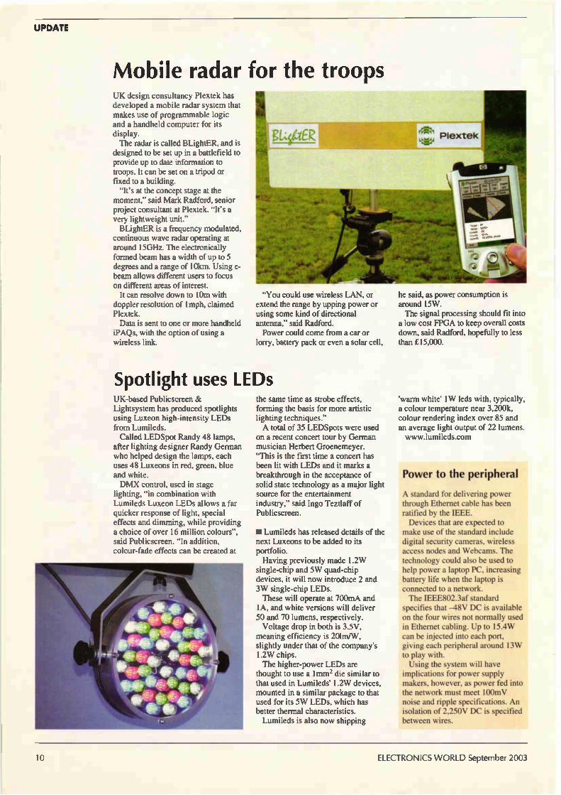
Mobile radar for the troops UK design consultancy Plextek has developed a mobile radar system that makes use of programmable logic and a handheld computer for its display. The radar is called BLightER, and is
designed to be set up in a battlefield to provide up to date information to troops. It can be set on a tripod or fixed to a building.
"It's at the concept stage at the moment," said Mark Radford, senior project consultant at Plextek. "It's a very lightweight unit." BLightER is a frequency modulated,
continuous wave radar operating at around 15GHz. The electronically formed beam has a width of up to 5 degrees and a range of 10km. Using e-beam allows different users to focus on different areas of interest.
It can resolve down to 10m with doppler resolution of lmph, claimed Plextek. Data is sent to one or more handheld
iPAQs, with the option of using a wireless link.
"You could use wireless LAN, or extend the range by upping power or using some kind of directional antenna," said Radford. Power could come from a car or
lorry, battery pack or even a solar cell,
Spotlight uses LEDs UK-based Publicscreen & Lightsystem has produced spotlights using Luxeon high-intensity LEDs from Lumileds. Called LEDSpot Randy 48 lamps,
after lighting designer Randy German who helped design the lamps, each uses 48 Luxeons in red, green, blue and white. DMX control, used in stage
lighting, "in combination with Lumileds Luxeon LEDs allows a far quicker response of light, special effects and dimming, while providing a choice of over 16 million colours", said Publicscreen. "In addition, colour-fade effects can be created at
the same time as strobe effects, forming the basis for more artistic lighting techniques." A total of 35 LEDSpots were used
on a recent concert tour by German musician Herbert Groenemeyer. "This is the first time a concert has been lit with LEDs and it marks a breakthrough in the acceptance of solid state technology as a major light source for the entertainment industry," said Ingo Teztlaff of Publicscreen.
• Lumileds has released details of the next Luxeons to be added to its portfolio. Having previously made I.2W
single-chip and 5W quad-chip devices, it will now introduce 2 and 3W single-chip LEDs. These will operate at 700mA and
1A, and white versions will deliver 50 and 70 lumens, respectively. Voltage drop in both is 3.5V,
meaning efficiency is 201m/W, slightly under that of the company's 1.2W chips. The higher-power LEDs are
thought to use a Inun2 die similar to that used in Lumileds' 1.2W devices, mounted in a similar package to that used for its 5W LEDs, which has better thermal characteristics. Lumileds is also now shipping
he said, as power consumption is around 15W. The signal processing should fit into a low cost FPGA to keep overall costs down, said Radford, hopefully to less than £15,000.
'warm white' 1W leds with, typically, a colour temperature near 3,200k, colour rendering index over 85 and an average light output of 22 lumens. www.lumileds.com
Power to the peripheral
A standard for delivering power through Ethernet cable has been ratified by the IEEE. Devices that are expected to
make use of the standard include digital security cameras, wireless access nodes and Webcams. The technology could also be used to help power a laptop PC, increasing battery life when the laptop is connected to a network. The IEEE802.3af standard
specifies that —48V DC is available on the four wires not normally used in Ethernet cabling. Up to 15.4W can be injected into each port, giving each peripheral around 13W to play with. Using the system will have
implications for power supply makers, however, as power fed into the network must meet 100mV noise and ripple specifications. An isolation of 2,250V DC is specified between wires.
10 ELECTRONICS WORLD September 2003

THERE IS INTERESTING NEWS
.01broie-
eke vse '
,wolees. \2:\ i---t10.50-eesee\le ee \tee
PC CONTROLLED MEASURING INSTRUMENT COMPLETE PACKAGE STARTING AT£435
FFT ANALYSER VOLTMETER
The Handyscope 3 is a powerful and versatile two channel measuring instrument with an integrated function generator.
HANDYSCOPE
° USB 2.0 connection (USB I. compatible) ° sample speed up to 100 MHz per channel ° 8 to 16 bit resolution (6 pVolt resolution)
° 50 MHz bandwidth ° input sensitivity from 200 mVolt up to 80 Volt ° large memory up to 131060 samples per channel o four integrated measuring devices
° spectrum analyser with a dynamic range of 95 dB ° fast transient recorder up to 10 kHz ° several trigger features ° auto start/stop triggering
° auto disk function up to 1000 files ° auto setup for amplitude axis and time base ° auto trigger level and hysteresis setting ° cursor measurements with 21 read-outs ° very extensive function generator (AWG) 0-2 MHz , 0- I 2 Volt
gagagme
Seaga la aw l.
I. .r.n. NY gam gar Ye gm
O18, :.31v IMIN MI=
40a/
I 1. lilt 1111, ge 1010 le gad
• I
228y 3132v
0.4LIv O. :3v
for more information, demo software, software, source code and DLL's visit our internet page: http://www.tiepie.n1
TieFie engineering (UK) 28. Stephenson Road. St. Ives
Cambridgeshire PE 1 7 3W.J, UK Tel: 01480-460028 Fax: 01480-460340
Copyright 2002 Ile% engineering. AF rights reserved.
HISTORY
The cathede
Since the rise of semiconductors, thermionic cathodes have been relegated to a few specialised areas such as cathode ray tubes (CRT), high power microwave
frequency circuits and high end audio amplifiers but much of the early development of electronics was intimately bound to cathode technology. After being sidelined for several decades, cathodes have again come to prominence with the accelerating development of cold field emission technology. During the valve era extensive research was dedicated to
devising cathodes with lower operating temperatures while maintaining or increasing their electron emissions. High cathode temperatures bring several drawbacks. One index of merit of a thermionic cathode is high emission current to required heating power ratio, which is a function of emissions per unit area, and operating temperature (Fig. 1 & 2). This is far lower for cathode types with cooler operating temperatures. High temperature filaments have a limited life because of increased vaporisation of atoms from their surface, and impose considerable constraints on the design of cathodes and their surrounding elements, requiring wide spacing to control the temperature of close electrodes.' A wide gap between anode and cathode means that a large anode voltage is necessary to create the necessary field in the immediate vicinity of the cathode to draw away the cloud of emitted electrons. Fig. 4. These electrons are then considerably accelerated as they pass to the anode. The energy they thus acquire is transferred to the anode on impact, heating it. Consequently high power valves often have hotter anodes than cathodes! The dividends from reducing cathode temperature are substantial.
Throughout the history of
thermionic valve manufacture there has been considerable
impetus to develop improved cathodes, as it is the cathode
that chiefly dictates a valve's
power handling capacity and
efficiency. Patrick Mitchell
elucidates
The history of thermionic cathodes can be conveniently divided into two phases. From the discovery of thermionic emission in the 1870s until around 1912, thermionic devices were one class of many under investigation by scientists and engineers but did not show outstanding potential. During this period development was driven by curiosity and isolated individuals and was consequently haphazard. This situation then changed to one where thermionic devices assumed great economic importance.
Up to 1912 - scientific curiosity The British physicist Frederick Guthrie advanced his theory of thermionic emission in 1873 following a series of experiments on hot charged bodies. When he placed a red-hot negatively charged metal sphere in a vacuum it discharged but a positively charged sphere did not. He thus concluded that hot metal bodies emit negatively charged particles. His hot spheres were the first thermionic emitters. In the 1880s, three researchers: Goldstein, Hittorf, and
Edison independently found that a current would flow between the heated filament of an incandescent light bulb and an extra electrode placed in the bulb. The light bulbs of the time (Swan and Edison types) used carbon filaments which formed the first thermionic filament cathodes. The first public description and demonstration of the effect was given on behalf of Edison by Edwin Houston in 1884 at the Philadelphia International Electrical Exhibition. William Preece, chief engineer of the British Post Office was present. He approached Edison for some sample valves and was generously given several. On his return to England he conducted a series of experiments into the
12 ELECTRONICS WORLD September 2003
HISTORY
phenomenon and published his results in 1885. He used the term "Edison effect" for the current flow between the filament and electrode in his paper and the name stuck. The nature of the current was not understood at the time. The discovery had been made in the course of investigating the blackening of bulbs due to the evaporation of carbon from the filament and condensation on the inside of the bulb. Early theories thus involved charged carbon vapour as the current carrier. In 1897 Ji Thompson measured the charge to mass ratio
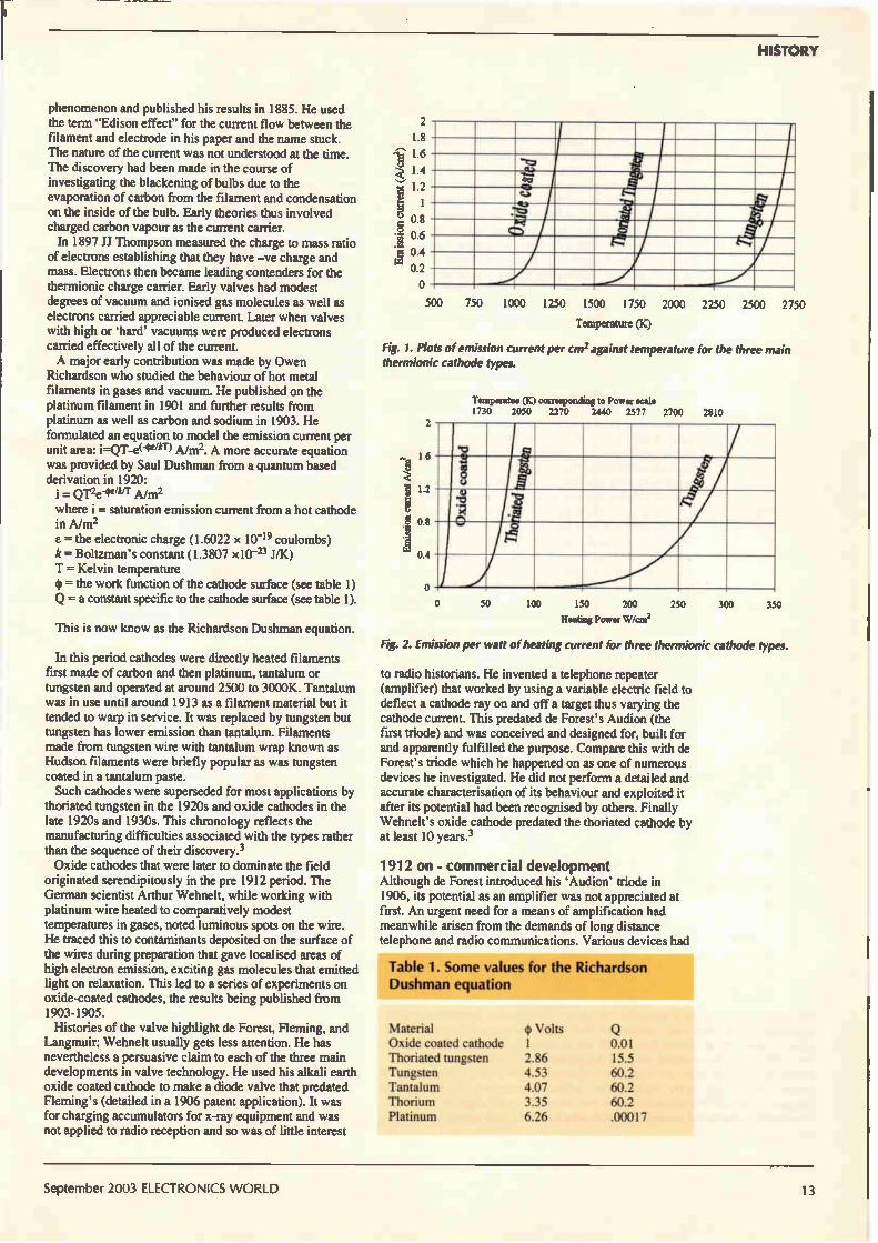
of electrons establishing that they have -ve charge and mass. Electrons then became leading contenders for the thermionic charge carrier. Early valves had modest degrees of vacuum and ionised gas molecules as well as electrons carried appreciable current. Later when valves with high or 'hard' vacuums were produced electrons carried effectively all of the current. A major early contribution was made by Owen
Richardson who studied the behaviour of hot metal filaments in gases and vacuum. He published on the platinum filament in 1901 and further results from platinum as well as carbon and sodium in 1903. He formulated an equation to model the emission current per unit Ahnz. area: i A more accurate equation was provided by Saul Dushman from a quantum based derivation in 1920:
grze-eüer Ahnz
where i = saturation emission current from a hot cathode in A/m2 = the electronic charge (1.6022 x 10⁻¹⁹ coulombs) k = Boltzman's constant (1.3807 x10⁻²³ J/K) T = Kelvin temperature = the work function of the cathode surface (see table 1) Q = a constant specific to the cathode surface (see table 1).
This is now know as the Richardson Dushman equation.
In this period cathodes were directly heated filaments first made of carbon and then platinum, tantalum or tungsten and operated at around 2500 to 3000K. Tantalum was in use until around 1913 as a filament material but it tended to warp in service. It was replaced by tungsten but tungsten has lower emission than tantalum. Filaments made from tungsten wire with tantalum wrap known as Hudson filaments were briefly popular as was tungsten coated in a tantalum paste. Such cathodes were superseded for most applications by
thoriated tungsten in the 1920s and oxide cathodes in the late 1920s and 1930s. This chronology reflects the manufacturing difficulties associated with the types rather than the sequence of their discovery.3 Oxide cathodes that were later to dominate the field
originated serendipitously in the pre 1912 period. The German scientist Arthur Wehnelt, while working with platinum wire heated to comparatively modest temperatures in gases, noted luminous spots on the wire. He traced this to contaminants deposited on the surface of the wires during preparation that gave localised areas of high electron emission, exciting gas molecules that emitted light on relaxation. This led to a series of experiments on oxide-coated cathodes, the results being published from 1903-1905. Histories of the valve highlight de Forest, Fleming, and
Langmuir; Wehnelt usually gets less attention. He has nevertheless a persuasive claim to each of the three main developments in valve technology. He used his alkali earth oxide coated cathode to make a diode valve that predated Fleming's (detailed in a 1906 patent application). It was for charging accumulators for x-ray equipment and was not applied to radio reception and so was of little interest
8 .Ê 0.6 ;5 0.4
0.2
2 1.8 1.6
1.4 1.2
g 1 0.8
500 750 1000 1250 1500 1750 2000 2250 2500 2750
Temperature (K)
Fig. 1. Plots of emission current per cm2 against temperature for the three main thermionic cathode types.
1.6
1.2
g 0.8
0.4
Temperable (K) corresponding to Power scale 1730 2050 2270 2440 2577 2700 2810
50 100 150 200 250 300 350
Heating Power Wicm2
Fig. 2. Emission per watt of heating current for three thermionic cathode types.
to radio historians. He invented a telephone repeater (amplifier) that worked by using a variable electric field to deflect a cathode ray on and off a target thus varying the cathode current. This predated de Forest's Audion (the first triode) and was conceived and designed for, built for and apparently fulfilled the purpose. Compare this with de Forest's triode which he happened on as one of numerous devices he investigated. He did not perform a detailed and accurate characterisation of its behaviour and exploited it after its potential had been recognised by others. Finally Wehnelt's oxide cathode predated the thoriated cathode by at least 10 years.3
1912 on - commercial development Although de Forest introduced his 'Audion' triode in 1906, its potential as an amplifier was not appreciated at first. An urgent need for a means of amplification had meanwhile arisen from the demands of long distance telephone and radio communications. Various devices had
Table 1. Some values for the Richardson Dushman equation
Material Oxide coated cathode Thoriated tungsten Tungsten Tantalum Thorium Platinum
4) volts 1 2.86 4.53 4.07 3.35 6.26
0.01 15.5 60.2 60.2 60.2 .00017
September 2003 ELECTRONICS WORLD 13
HISTORY
150
130
110
90
70
50
30
10
-10
-30
-50
Cathode
emerged to fill this need including magnetic amplifiers, relay based devices and repeaters along the lines of Wehnelt's, but none was satisfactory. Lowenstein publicly demonstrated unambiguous amplification using a triode for the first time in 1912 shortly followed by de Forrest. At the time the performance of triodes in this role was poor but it was realised that if they could be improved they had the potential to get round the problems of competing systems: low maximum frequency, low sensitivity and high distortion. Powerful commercial interests hungry for a solution to their amplification problems began to finance intensive research. Rapid progress was the result and within 15 years the pattern of valve manufacture to the present day had been defined. This process was not sudden but the year 1912 has as good a claim as any to being the watershed.4. 5. As far as the cathode is concerned, this second period in
valve history saw the replacement of the earlier high temperature cathodes with the more energy efficient oxide coated and thoriated types. Oxide coated cathodes had been in use for a decade by 1912 but the thoriated tungsten cathode was a product of General Electric's increased research effort. As with oxide cathodes their discovery was serendipitous. Early manufacturers of incandescent tungsten lamps found that at the operating temperature, tungsten formed into large crystals with correspondingly large boundaries between them. When used with AC, such boundaries gave rise to faults, hot spots, and early failure. Various additives were tried to keep the crystal structure fine and overcome this problem. Thorium nitrate and oxide proved to be effective. Thorium has a long association with the lighting industry as its oxide was the principal active component of gas lamp mantles! It has now been replaced in this role because thorium is weakly radioactive. General Electric used one of their lamp factories as a research base for thermionics. Valves under investigation used tungsten cathodes and by accident some thoriated tungsten was used for one batch. When tested, valves from this batch had greater than normal cathode currents. Sources differ-3,4 on the date but this probably happened in 1913. GE's Dr. Irving Langmuir spotted the potential of this observation and began investigation. In 1914 he filed a patent containing all the elements of thoriated cathode preparation. This included 'flashing' at 2900K for 1 minute, 'forming' at 2250K for a few
150
130
110
90
70
50
30
10
-10
-30
-50
Anode
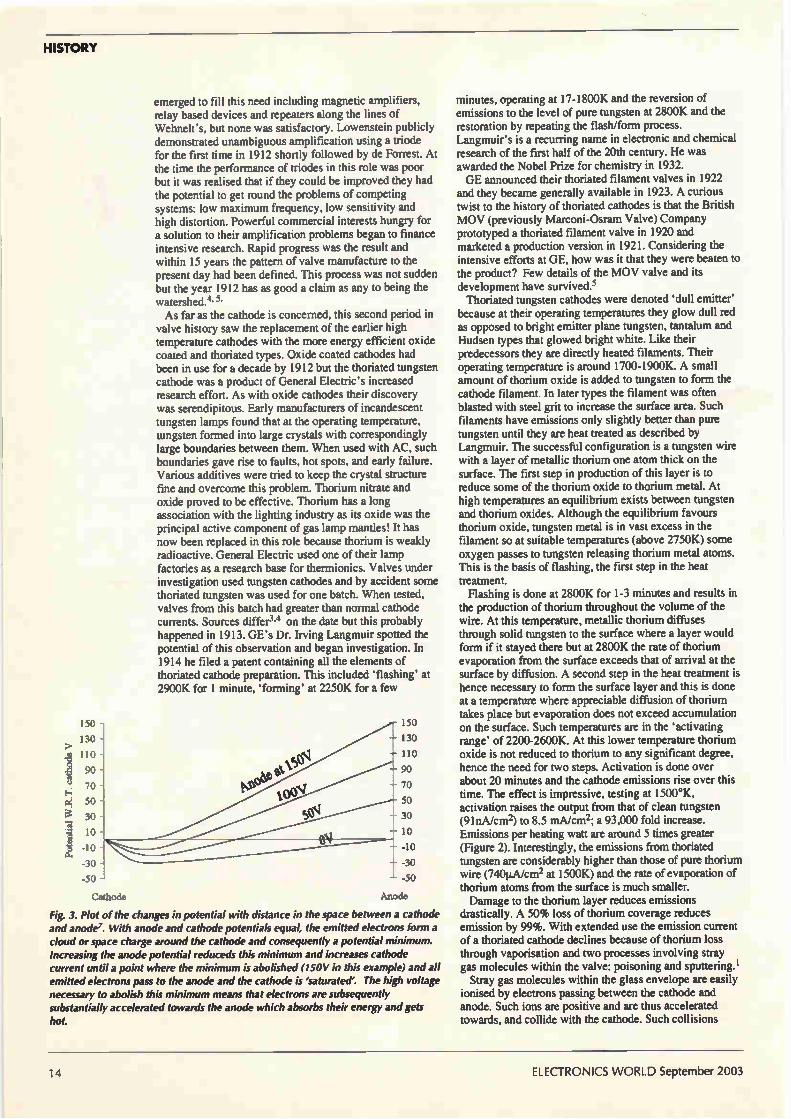
Fig. 3. Plot of the changes in potential with distance in the space between a cathode and anode'. With anode and cathode potentials equal, the emitted electrons form a cloud or space charge around the cathode and consequently a potential minimum. Increasing the anode potential reclucecls this minimum and increases cathode current until a point where the minimum is abolished (150V in this example) and all emitted electrons pass to the anode and the cathode is 'saturated'. The high voltage necessary to abolish this minimum means that electrons are subsequently substantially accelerated towards the anode which absorbs their energy and gets hot.
minutes, operating at 17-1800K and the reversion of emissions to the level of pure tungsten at 2800K and the restoration by repeating the flash/form process. Langmuir's is a recurring name in electronic and chemical research of the first half of the 20th century. He was awarded the Nobel Prize for chemistry in 1932. GE announced their thoriated filament valves in 1922
and they became generally available in 1923. A curious twist to the history of thoriated cathodes is that the British MOV (previously Marconi-Osram Valve) Company prototyped a thoriated filament valve in 1920 and marketed a production version in 1921. Considering the intensive efforts at GE, how was it that they were beaten to the product? Few details of the MOV valve and its development have survived.5 Thoriated tungsten cathodes were denoted 'dull emitter'
because at their operating temperatures they glow dull red as opposed to bright emitter plane tungsten, tantalum and Hudsen types that glowed bright white. Like their predecessors they are directly heated filaments. Their operating temperature is around 1700-1900K. A small amount of thorium oxide is added to tungsten to form the cathode filament. In later types the filament was often blasted with steel grit to increase the surface area. Such filaments have emissions only slightly better than pure tungsten until they are heat treated as described by Langmuir. The successful configuration is a tungsten wire with a layer of metallic thorium one atom thick on the surface. The first step in production of this layer is to reduce some of the thorium oxide to thorium metal. At high temperatures an equilibrium exists between tungsten and thorium oxides. Although the equilibrium favours thorium oxide, tungsten metal is in vast excess in the filament so at suitable temperatures (above 2750K) some oxygen passes to tungsten releasing thorium metal atoms. This is the basis of flashing, the first step in the heat treatment. Flashing is done at 2800K for 1-3 minutes and results in
the production of thorium throughout the volume of the wire. At this temperature, metallic thorium diffuses through solid tungsten to the surface where a layer would form if it stayed there but at 2800K the rate of thorium evaporation from the surface exceeds that of arrival at the surface by diffusion. A second step in the heat treatment is hence necessary to form the surface layer and this is done at a temperature where appreciable diffusion of thorium takes place but evaporation does not exceed accumulation on the surface. Such temperatures are in the 'activating range' of 2200-2600K. At this lower temperature thorium oxide is not reduced to thorium to any significant degree, hence the need for two steps. Activation is done over about 20 minutes and the cathode emissions rise over this time. The effect is impressive, testing at 1500°K, activation raises the output from that of clean tungsten (91nA/cm2) to 8.5 inA/cm2; a 93,000 fold increase. Emissions per heating watt are around 5 times greater (Figure 2). Interestingly, the emissions from thoriated tungsten are considerably higher than those of pure thorium wire (740µA/cm2 at 1500K) and the rate of evaporation of thorium atoms from the surface is much smaller. Damage to the thorium layer reduces emissions
drastically. A 50% loss of thorium coverage reduces emission by 99%. With extended use the emission current of a thoriated cathode declines because of thorium loss through vaporisation and two processes involving stray gas molecules within the valve: poisoning and sputtering.' Stray gas molecules within the glass envelope are easily
ionised by electrons passing between the cathode and anode. Such ions are positive and are thus accelerated towards, and collide with the cathode. Such collisions
14 ELECTRONICS WORLD September 2003

HISTORY
knock active surface atoms out of the cathode. This process is known as sputtering. Neon, argon, caesium and mercury are the chief offenders. Cathode poisoning is due to chemical contamination of
the cathode by gases, principally oxygen, which find their way into valves. Nitrogen actually temporarily enhances emissions from thoriated tungsten. A feature of thoriated filaments is that they can be
rejuvenated when emissions drop by repeat flashing and activating because the thorium oxide they contain is not expended by the first process. The other major development in cathodes of the post
1912 era was the oxide-coated cathode, or rather the reliable deployment of the oxide-coated cathode as the cathode itself dates from 1903. The delay was because of the difficulties in producing a consistent and durable cathode and in producing and maintaining a sufficiently hard vacuum. Once again the principle benefit was to bring down the operating temperature, this time to about 1050°K. Western Electric took an interest in oxide-coated cathodes and had successful valves in production by 1919. Early examples were expensive to make because platinum was used as the filament metal. This was soon changed to nickel alloy or tungsten.5 The chemistry of the oxide coating (usually barium,
strontium, calcium or a combination of these oxides) is complex. They are manufactured with an oxide coating and are then activated or 'formed' by simultaneously heating the cathode above its normal working temperature and drawing a large cathode current. The duration of forming varies from minutes to days depending on the temperature and thickness of the coating. This denudes the coating of oxygen, leaving an excess of barium, which is required to maximise emissions. Contamination with oxygen will reduce emissions so paradoxically oxide cathodes are poisoned by oxygen. The oxide cathode made indirect heating feasible and
consequently engineers had much more control over the design of the emitting surface. Hotter cathodes are more difficult to heat indirectly because of the high filament temperatures required and severe constraints are imposed on the materials used for the cathodes as well as the proximity of other electrodes. With oxide coating, operating temperatures fell below 1200K and this was achievable in an indirectly heated cathode. A tungsten or NiChrome filament could be coated in an insulating layer of aluminium oxide and located in a casing bearing the coating. Oxide cathodes improve the emission current: heater power ratio of cathodes by an order of magnitude over thoriated tungsten. Another advantage that was particularly important at the
time when oxide-coated cathodes were introduced concerned hum. Early electronic equipment was designed to be powered by batteries because mains electricity was not widely available. Large and expensive batteries were thus needed. AC mains became increasingly available during the first quarter of the twentieth century and was a far more attractive means of cathode heating than batteries but brought a problem with thoriated cathodes. The small mass and high temperature of thoriated cathodes means that they cool very quickly, quickly enough to suffer an appreciable temperature drop between peaks of the AC heating current at 50 to 60Hz. Thus the temperature and emission current, fluctuates with heating current giving rise to hum. Radiant heat loss of a 'black body' (to which a hot filament is a good approximation) is given by P = oT4 W/m2 where a (Stephan's constant) = 5.67x10⁻⁸ Wnr2K-4, so oxide cathodes with their lower temperature and larger mass are far less prone to this problem.5 These improvements come at a price. Oxide cathodes
35
30
25
E • 20
g 15 CS
10
o 20 40 60 80 100
Anode Vokage V
115mA
iorrIA
105mA
D0i.
Fig. 4. 4. Characteristic curves of a diode valve to illustrate emission behaviour6. Saturation currents are dependent on anode voltage. This is particularly pronounced with oxide cathodes.6
saturate poorly, i.e. they have a pronounced Schottky effect. Fig. 3. They also display a degree of instability of emissions
which can rise or fall after a large current has been drawn because current electrolyses the coating, liberating oxygen. Further, the thickness of the coating can give it a significant resistance and produce noise. They are best suited to applications where a high output is required and where these failings can be tolerated such as in CRTs. Before the semiconductor age, oxide cathode valves were widespread in domestic equipment but their place has been taken by transistors. Today if you buy a valve amplifier you will be paying for high-end audio technology where fidelity outweighs efficiency and consequently thoriated tungsten cathodes dominate. Oxide cathodes are fragile. Specifically they are highly
susceptible to damage by bombardment by the heavy
120 140
Fig. 5. Valves using oxide coated or thoriated tungsten cathodes appear silvery because of the use of a getter. This is a small amount of reactive metal that is vaporised during the valve manufacture and precipitates on the inside of the glass. Its function is to bind free gas molecules within the valve. It is called a getter because it gets' free gas molecules. For a similar reason it is sometimes referred to a 'keeper'.
September 2003 ELECTRONICS WORLD 15
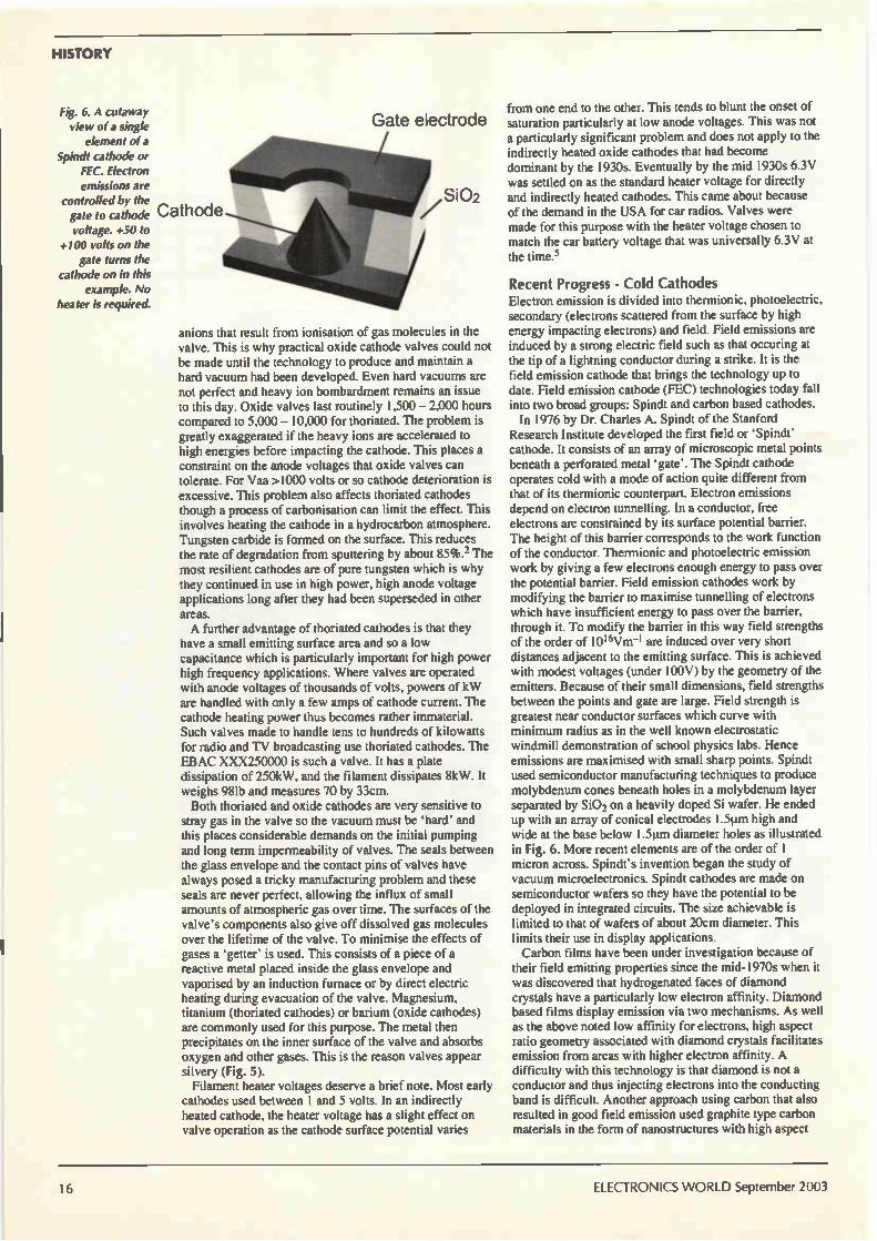
HISTORY
Fig. 6. A cutaway view oía single
element oía Spindt cathode or
FEC. Electron emissions are
controlled by the gate to cathode voltage. +50 to
+100 volts on the gate turns the
cathode on in this example. No
heater is required.
Gate electrode
SiO2
anions that result from ionisation of gas molecules in the valve. This is why practical oxide cathode valves could not be made until the technology to produce and maintain a hard vacuum had been developed. Even hard vacuums are not perfect and heavy ion bombardment remains an issue to this day. Oxide valves last routinely 1,500 — 2,000 hours compared to 5,000 — 10,000 for thoriated. The problem is greatly exaggerated if the heavy ions are accelerated to high energies before impacting the cathode. This places a constraint on the anode voltages that oxide valves can tolerate. For Vaa >1000 volts or so cathode deterioration is excessive. This problem also affects thoriated cathodes though a process of carbonisation can limit the effect. This involves heating the cathode in a hydrocarbon atmosphere. Tungsten carbide is formed on the surface. This reduces the rate of degradation from sputtering by about 85%.2 The most resilient cathodes are of pure tungsten which is why they continued in use in high power, high anode voltage applications long after they had been superseded in other areas. A further advantage of thoriated cathodes is that they
have a small emitting surface area and so a low capacitance which is particularly important for high power high frequency applications. Where valves are operated with anode voltages of thousands of volts, powers of kW are handled with only a few amps of cathode current. The cathode heating power thus becomes rather immaterial. Such valves made to handle tens to hundreds of kilowatts for radio and TV broadcasting use thoriated cathodes. The EBAC XXX250000 is such a valve. It has a plate dissipation of 250kW, and the filament dissipates 8kW. It weighs 98Ib and measures 70 by 33cm. Both thoriated and oxide cathodes are very sensitive to
stray gas in the valve so the vacuum must be 'hard' and this places considerable demands on the initial pumping and long term impermeability of valves. The seals between the glass envelope and the contact pins of valves have always posed a tricky manufacturing problem and these seals are never perfect, allowing the influx of small amounts of atmospheric gas over time. The surfaces of the valve's components also give off dissolved gas molecules over the lifetime of the valve. To minimise the effects of gases a 'getter' is used. This consists of a piece of a reactive metal placed inside the glass envelope and vaporised by an induction furnace or by direct electric heating during evacuation of the valve. Magnesium, titanium (thoriated cathodes) or barium (oxide cathodes) are commonly used for this purpose. The metal then precipitates on the inner surface of the valve and absorbs oxygen and other gases. This is the reason valves appear silvery (Fig. 5). Filament heater voltages deserve a brief note. Most early
cathodes used between 1 and 5 volts. In an indirectly heated cathode, the heater voltage has a slight effect on valve operation as the cathode surface potential varies
from one end to the other. This tends to blunt the onset of saturation particularly at low anode voltages. This was not a particularly significant problem and does not apply to the indirectly heated oxide cathodes that had become dominant by the 1930s. Eventually by the mid 1930s 6.3V was settled on as the standard heater voltage for directly and indirectly heated cathodes. This came about because of the demand in the USA for car radios. Valves were made for this purpose with the heater voltage chosen to match the car battery voltage that was universally 6.3V at the time.5
Recent Progress - Cold Cathodes Electron emission is divided into thermionic, photoelectric, secondary (electrons scattered from the surface by high energy impacting electrons) and field. Field emissions are induced by a strong electric field such as that occuring at the tip of a lightning conductor during a strike. It is the field emission cathode that brings the technology up to date. Field emission cathode (FEC) technologies today fall into two broad groups: Spindt and carbon based cathodes. In 1976 by Dr. Charles A. Spindt of the Stanford
Research Institute developed the first field or 'Spindt' cathode. It consists of an array of microscopic metal points beneath a perforated metal 'gate'. The Spindt cathode operates cold with a mode of action quite different from that of its thermionic counterpart. Electron emissions depend on electron tunnelling. In a conductor, free electrons are constrained by its surface potential barrier. The height of this barrier corresponds to the work function of the conductor. Thermionic and photoelectric emission work by giving a few electrons enough energy to pass over the potential barrier. Field emission cathodes work by modifying the barrier to maximise tunnelling of electrons which have insufficient energy to pass over the barrier, through it. To modify the barrier in this way field strengths of the order of 10 16Vm-I are induced over very short distances adjacent to the emitting surface. This is achieved with modest voltages (under 100V) by the geometry of the emitters. Because of their small dimensions, field strengths between the points and gate are large. Field strength is greatest near conductor surfaces which curve with minimum radius as in the well known electrostatic windmill demonstration of school physics labs. Hence emissions are maximised with small sharp points. Spindt used semiconductor manufacturing techniques to produce molybdenum cones beneath holes in a molybdenum layer separated by SiO2 on a heavily doped Si wafer. He ended up with an array of conical electrodes 1.5µm high and wide at the base below 1.5µm diameter holes as illustrated in Fig. 6. More recent elements are of the order of 1 micron across. Spindt's invention began the study of vacuum microelectronics. Spindt cathodes are made on semiconductor wafers so they have the potential to be deployed in integrated circuits. The size achievable is limited to that of wafers of about 20cm diameter. This limits their use in display applications. Carbon films have been under investigation because of
their field emitting properties since the mid-1970s when it was discovered that hydrogenated faces of diamond crystals have a particularly low electron affinity. Diamond based films display emission via two mechanisms. As well as the above noted low affinity for electrons, high aspect ratio geometry associated with diamond crystals facilitates emission from areas with higher electron affinity. A difficulty with this technology is that diamond is not a conductor and thus injecting electrons into the conducting band is difficult. Another approach using carbon that also resulted in good field emission used graphite type carbon materials in the form of nanostructures with high aspect
16 ELECTRONICS WORLD September 2003
HISTORY
ratios leading to high values of electric field enhancement rather low electron affinity. The discovery in 1991 by Japanese electron microscopist
Sumio lijima of carbon nanotubes began a worldwide research effort that has revealed extraordinary physical characteristics making them not only structures of inherent fascination but also giving them numerous potentially revolutionary applications. From the point of view of electronics, double wall nanotubes have the potential to form ̀ ultracapacitors' able to store 50 joules per centimetre cube. Extremely high thermal conductivity along the major axis raises the possibility of heat sinking. They have the potential to act as superconductors and at room temperatures metallic conductivity is achievable. This last property coupled with their extremely large aspect ratio makes them ideal for field emission applications. Current densities of over 1A/cm2 have been achieved with fields of 7V per gm in a cathode that shows less than 10% degradation after 2000 hours of continuous operation. This figure compares favourably with thermionic cathodes whose emissions range from around 0.1 to 3 amps per cm square depending on the type and the temperature. Unlike Spindt cathodes, carbon based field emission cathodes are made by coating substrates such as glass or metal sheets. They thus have the potential to be made to virtually any size. This feature is highly attractive in display technology. Field emission cathodes offer major advantages over
existing thermionic technology. One of the main forces driving their development is the large potential market for flat panel display products. Successful flat displays have been demonstrated using gated FECs between 0.2 and 5
millimetres behind a phosphorescent screen, each pixel having its own set of cathodes, the colour and brightness of the pixel being controlled with cathode gate voltages. They are brighter and faster than LCD technology and have a wider viewing angle. Large scale commercial production is awaited. Another potential use is in the manufacture of valves.
Durability will have to be improved before commercial exploitation but practical valves have been demonstrated, for example a lOGHz 27W travelling wave tube by Makishima et al of NEC, Japan.
Other diverse applications have been announced including electric thrusters for spacecraft, miniature X-ray tubes for medical robots, indicator and illuminator lights, and microwave devices. Cold cathodes look set to largely replace thermionic cathodes in the future. They also have the potential to make inroads into applications that are currently the domain of semiconductors and most significantly to extend the scope of electronics in general beyond what is now possible.
References and further reading I. Fred Rosebury, Handbook of electron tube and vacuum techniques. ISBN 1563961210 2. A V. Eastman, Fundamentals of Vacuum Tubes. McGraw-Hill, New York, 1941 3. History of Thermionic devices. Conference proceedings of the Newcomen Society,
23/4/1994, ISBN:0-904685-05-5 4. GFJ Tyne, Saga of the Vacuum Tube. ISBN: 0-672-21470-9 5. John W. Stokes, 70 years of radio tubes and valves. ISBN 1-886606-11-0 6. Morgan Jones, Valve Amplifiers. ISBN 0-7506-2337-3 7. Handbook of Wireless Telegraphy 1938 Admiralty HM Stationery Office London 1938.
[Easy-PC Jai
World Beating Value in PCB Design Software for Windows
from
£97
High performance Windows based PCB Design Capture, Simulation and Layout software at prices you'd expect from your local computer store!
NEW! in Easy-PC 7 • Library Databook • Step and repeat plotting • Swap Connection Mode • Dimensioning • Copy to Metafile
plus much more
_
[1'01 Number One Systems
Stop press... by customer demand, now with Tsien Boardmaker 2 design import...
Number One Systems delivers true 32 bit Windows software applications including features that a few short years ago would only have been available in software tools priced in the thousands!
Test drive Easy-PC and Easy-Spice for yourself and be prepared to be amazed at the super value...
Waffle.' Wlndow•XP 2604, Me. is Windows WM
Call for a brochure, price list and demo CD on +44 (0)1684 773662 or email [email protected]
Number One Systems Oak Lane, Bredon Tewkesbury, Glas GL20 7LR United Kingdom
or download from
www.numberone.com
September 2003 ELECTRONICS WORLD 17
LECTRONICS °RID
The world's leading electronics magazine, Electronics World is a technology- transfer magazine for the global electronics industry. It covers research, technology, applications, products and patents in areas such as audio, R.F., components, CAD design, circuit building, PC & Micro based products, tests & measurement, semiconductors, power sources and much, much more .
trustworthy source of reference each month for keeping ahead with the latest news and echnical developments in the electronics industry.
s the longest established magazine in the industry - 80 years xperience serving the electronics market, Electronics World is he leading technical journal for electronics professionals and igh-level enthusiasts.
- Make sure you receive your regular monthly • • by subscribing today
the c u on to: +44 1353 654400 I wish to subscribe for one year to Electronics World (12 issues) 1 year UK £38.95 El ois £64.50 E US$100.62 fl Euro 102.55 Ei
Please tick preferred method of payment E I enclose a cheque payable to Highbury Business Communications Ltd
Please invoice me E Purchase No (NB Purchase order must be included to validate invoice)
Please charge my: Master CardNisa/Amex/Diners Club/Switch/Delta (please circle)
Card No Expiry Date
(Switch/Delta Only) Valid from
Signature
E / Issue Number
Date
Name
Job Title
Company
Address
Postcode/Zip
Country
Telephone/ Fax
Please hi* here if you do not wish to be contacted by other businesses either by Mail E Telephone E Fax Ei
Please return to: Highbury Subscription Services, Link House, 8 Bartholomew's Walk, Ely, Cambridgeshire CB7 4ZD, UK.
Email: [email protected] (Quote Ref: EW1)
• HIGH BURY
Business Communications
1
18 ELECTRONICS WORLD September 2003
AIM
Fact: most circuit ideas sent to Electronics World get published
The best circuit ideas are ones that save time or money, or stimulate the thought process. This includes the odd solution looking for a problem — provided it has a degree of ingenuity. Your submissions are judged mainly on their originality and usefulness. Interesting modifications to existing circuits are strong contenders too — provided that you clearly acknowledge the circuit you have modified. Never send us anything that you believe has been published before though. Don't forget to say why you think your idea is worthy. Clear hand-written notes on paper are a minimum requirement: disks with separate drawing and text files in a popular form are best — but please label the disk clearly. Where software or files are available from us, please email Jackie Lowe with the circuit idea name as the subject. Send your ideas to: Jackie Lowe, Highbury Business Communications, Anne Boleyn House, 9-13 Ewell Road, Cheam, Surrey SM3 8BZ email [email protected]
Efficient lighting controller In most parts of the world, turning on street and garden lighting is done either manually or on a time basis. Since the number of hours of sunshine in a day varies from day to day and from one place to another, and since a manually controlled system is prone to error, an automatic control system that detects the intensity of light and turns on/off the system is a more efficient solution. This lighting controller is designed
to take care of this. It also provides a manual control feature. Light dependent resistors — LDRs — are placed at different parts of the garden/locality, taking care that shadows from nearby trees of light from nearby buildings does not impair the effectiveness of the LDRs.
In most parts of the world, during summer, the number of hours of sunshine varies from 10 hours to 6 hours and 12-15 hours during winter. The resistance of LDRs changes of the order of thousands of times when daylight turns to darkness and vice versa. This change is tapped using a potential divider. Outputs from all the sensors are
ANDed and NORed. These processed outputs are sent to an S-R bistable device shown in the diagram. Final output is sent to the relay via a transistor.
When sunlight fails on any of the sensors, the output of the bistable goes low and the relay is not activated. Lighting is activated only when outputs from all the sensors are low. Multiple sensors are used to make the system foolproof. If a bird sits on a sensor, or there's sudden clouds cover, etc., false triggering will not occur. Switch Si is used to select the type
of control to be used. For manual control, a 14-stage ripple counter, 4060B, is used as an RC oscillator whose resistance can be varied to get the necessary timeout, detailed in the Table. Pin 3 of the 4060B is ORed with
the reset switch S3 and fed into another SR bistable. Switch S2 is used trigger the oscillator. The output of this bistable triggers the relay. R. Subramanian Chennai India
Table. One resistor sets the on' period in 'manual' mode.
No of hours 6 8 10 12 14 16
Resistance (ka) 105 140 175 210 245 281
£50 WINNER
Street and garden lighting controllers usually use timers, which are rather crude as the onset of daylight of dark can vary considerably. Using distributed LDRs, this circuit makes sure that the lights are only turned on when they are needed.
12V
OV 10k
Trigger ci s2
12V
10k
19 September 2003 ELECTRONICS WORLD

CIRCUIT IDEAS
Porch light control Having once again found our porch light left on all night, it was time to try and design a circuit which would allow the lamp to be manually turned on but would automatically turn it off after a few min-utes. For convenience, it should also fit safely into a standard mains patress box.
It seems that the only practical switch available which provides this facility is mechanical. You press a sprung plunger which closes the switch. On release, air returns to the cylinder through a very small hole and so the switch opens some time later. The time delay is very variable and uncontrollable. Surely there must be an electronic solution? The problem is that behind every single
switch in normal house wiring are only two wires: live in and switched live out. You cannot get directly at the neutral. So producing a small DC voltage to run an electronic switch is a problem extending beyond squeezing into a standard switch box a mains transformer (or even a volt-age-dropping capacitor), rectification and smoothing. The circuit shown in the figure is a
solution. Pressing Si results in the lamp being
switched on via two diodes in the bridge and the 6.8V Zener. Across the Zener is full wave rectified 6.8 volts which is smoothed by Cl. IC1 is a frequency divider whose reset at pin 11 is briefly held high until C3 is charged. when the counter starts from zero to count the 50Hz pulses at its clock input, pin 10. C2 ensures that any
Fig. 1. Detail of the first part of the
remote switching circuit and outline
of the decoders and relay drivers.
Relay RL I keeps the phone 'off the
cradle' for a predetermined
period when the phone rings.
spurious spikes appearing on the mains are not counted. The used output on ICI is pin 3 where the resultant frequency is the clock divided by 213. This results in a wave-length of approximately 5_ minutes. The counting always starts from zero
and so the first half of this output wave-length results in pin 3 being low. Hence Ql is off and the LED in the MOC3041 optoisolator is lit via R5. At a zero-crossing point this switches on the triac in the isolator. In turn this provides gate current to the 400V triac and hence the circuit remains latched on with the lamp lit even when push-button Si is released. However, after approximately 2_ min-
utes the half wavelength ends, taking ICI pin 3 high. This switches on Ql which shorts out the internal LED in MOC3041,
LIVE IN
switching both triacs off, together with the lamp. This circuit runs directly from the mains
and the utmost care must be exercised in building, testing and fitting the circuit board into its switch box. Once the circuit board is fitted, it is potentially no more dangerous than the mechanical switch it replaces. Note that Si switches mains and there-
fore should be designed for 230 volts at no less than 1 amp. Further the Zener diode ZD1 carries all the current of the lamp, which means that it should be at least 5 watts and, for a good safety margin, only bulbs up to 100 watts should be used. David Ponting Bristol Uk
SWTCHED
LIVE OUT
Control appliances remotely via the telephone Remote control of selected electrically-operated home appliances by switching on and off for a chosen
5V
5k
Telephone lines
1 µ
k9
18V
Retriggerable monostable multivibrator
(555)
Counter (ring tone) 7493x2
DC BA DC BA
duration is desirable in many circumstances.
It may be useful, for instance, to
RLi B
• 1N4007 RL1A
+12V
R-L-11
Gyrator
I-
I-
Resistive bridge
I I 1 I
DTMF
1 1 1 1
Demultiplex
1 1 1 1
Latches
Relays
1
in um
in In
LC
RA
switch on a pump for watering the garden when you're away from home for a long period. While the house is empty, for security purposes, it is also wise to switch on a couple of lamps for a short time to give the impression that there's someone inside the house. This note describes a circuit that
exploits the home telephone to control appliances by switching them on or off using a digit dialled through the telephone. Figure 1 shows the schematic block
diagram of the circuit. When the caller dials the number of the telephone of his/her house from a remote place, the ringing signal is received at the home. The ring signal is 75V AC riding on
48V DC. When it arrives, the opto-coupler connected in one arm of the telephone cable produces impulses. The 555 re-triggerable monostable multivibrator produces the count' output to the counter chain, comprising two 7493s, and it
20 ELECTRONICS WORLD September 2003
CIRCUIT IDEAS
starts counting the ringing pulses. When 128 pulses are counted, the
most significant bit of the second counter, D, becomes 'high' and this operates the relay Rt.' which closes the contacts RL1A,B connecting the telephone lines to the rest of the circuit comprising the diode bridge, gyrator, resistive bridge, DTMF, demultiplexer, latches and relay circuits, to simulate the conditions of taking the telephone transceiver from its cradle. Ringing stops at this moment. When the telephone is taken from
the cradle, normally 40mA current flows through the loop and this is a requirement to stop the ringing tone. In order to get a more or less constant current of 40mA flowing in the loop, a gyrator circuit is employed. The equivalent resistance of the
gyrator circuit varies in accordance with the changes in the line voltage, drawing 40mA of current in the loop. As soon as the ringing stops, the caller dials the control digit assigned for an appliance. Figure 2 shows the detailed circuit,
starting with the gyrator. The control digit is picked up and fed to a DTMF (KT3170) receiver which in turn produces the digit in binary form at its output. The DSO output of the DTMF also
becomes high whenever a valid tone is received. This state enables the accompanying decoder (74LS138). The decoder and the associated logic gates demultiplex the bit Q1 of the DTMF to the latches in accordance with the code obtained in Q4, Q3 and Q2 and the latched outputs drive the relay circuits accordingly. The information in Table 1 is given to each relay circuit as per the code obtained. Only three appliances are
considered here. If needed, two or three more appliances could be included in the system by using the remaining digits and special characters available in the keyboard of the phone. The de-multiplexed bit is latched
(7474) in L. L1 and L4 and driven to
1µ
II 3.58MHz —
1µ
II
100k
5V-e-
VDD ST/GT EST GS IN- Vref IN+
DTMF KT3170 TDE-
01 02 03 04 DSO INH PWDM GND 1
A
52-C70
B C G1 0-30iiCZCZ 07
74LS138
G2A G2B
3 In
T L2 Out 7474
In T L3 Out
7474
—e
3 In
T L4 Out 7474
Fig. 2. DTMF decoding, latching and relay driving circuitry. With switching arranged as per the inset, it is possible to override the relay contacts manually if necessary
Power
131_2 M2
+12V
+12V
+12V
RL2A
H Lamp
M2 to 3
RL2A
R L3A
Pump 1-o'
M3
M4
RL3A
R
HFridge FeK
M4 RL4A
the relay drivers operating relays R/42, RL3 and RL4 respectively. Switching is arranged so that appliances can be turned on or off manually. The trigger logic for the latches is shown in Table 2. The control action is sustained for
half a minute, after which the control operation comes to an end. The re-
Table 1. Dialling a number causes one of three appliances to be turned on or oft; depending on the dialled number.
No dialled DTMF output 04 03 02 01
O 0 0 0 0 Lamp off 1 0 0 0 1 Lamp on 2 0 0 1 0 Pump off 3 0 0 1 1 Pump on 4 0 1 0 0 Fridge off 5 0 1 0 1 Fridge on
Control action
triggerable monostable multivibrator set for this half a minute delay clears the counter to open the contacts RLI A.B, simulating the condition of replacing the telephone on the cradle. K. Balasubramanian Mersin Turkish Republic of Northern Cyprus
Table 2. Number dialled versus the MOP lelltwitched.
Digit dialled 04 03 02 0,1 0 0 0 2,3 0 0 1 4,5 0 1 0
Latch L2 L3
September 2003 ELECTRONICS WORLD 21
CIRCUIT IDEAS
200mV reference buffer part of the LM10 which wired like this provides 200mV at pin 1. The 4.7kO resistor and 11(0 pot
divide this down to a variable 0-35mV which is fed to the non-inverting input of the op-amp /C, b. Feedback around the op-amp is
arranged so the voltage across the 0.10 resistor matches the 0-35mV from the reference section by varying the current through the 0.1Q resistor between 0 and 35OrnA. As all this current, except for the
small transistor base current, comes though the LED, it receives a regulated 0-350mA. The transistor must have a
low-saturation voltage at low base current as pin 6 cannot supply much current. Also, there is only 200mV headroom between the 3.6V NiMH battery voltage and the 3.4V Luxeon voltage — and 35mV of this is eaten by the 0.1Q resistor. I used a ZTX692B which was given
free with Electronics World some years ago. This saturates to under
Battery-operated lamp timer
'Super-LED' regulator This circuit was made out of oddments from my parts bin after someone gave me a Luxeon Star super LED as a present. It supplies the Luxeon with a variable regulated current enabling brightness to be set from 'off to on'. An LMIO op-amp plus voltage
reference is the main active component. Component /C,„ is the
Luxeon LEDs Luxeon is a range of high-brightness leds from Lumileds in California. Available in many colours, the white Star/0 variant also includes optics to give an approximately 10° beam which is just about perfect for a camping torch. Max device current is 350mA and dimming allows battery-life to be extended when less light is needed — when reading for instance. The heat sink built in to the LED needs plenty of
fresh air or conductive cooling if damage through overheating is to be avoided. www.futureelectron-ics.com will sell small quantities in the UK. See also www.luxeonstar.com
This regulator keeps the Luxeon super LED bright
as the battery voltage falls. At full power, it's
over 90°. efficient.
100mV at 350mA with 2mA base drive. As the battery flattens, the voltage
at pin 6 rises as the op-amp works harder to maintain Luxeon brightness. This is indicated by the 'battery low' led. Run on three NiMH cells, this
circuit is over 90% efficient at full power and tops 80% for most of the rest of its range. Although current is under lmA at
minimum brightness, the circuit will still needs an on-off switch.
The LM1 0 National Semiconductor's LMIO was designed by Bob Widlar, originator of many analogue building blocks including the bandgap reference, three-terminal regulator and two-stage op-amp. To me the LM10 is like a symphony, with all the components playing in perfect harmony. We probably won't see anything like that again: it took Widlar five years to design it," said Hans Camenzind, designer of the famous 555 timer.
Correction I would like to advise you that tracking transmitter circuit pub-lished in the June issue has an error: The 22g capacitor connects between the base of TR 1 and the collector of TR2. The 2.2K Resistor also connects to the collector of TR2.
Amrith Ramjewan
Operation of this lamp timer is fairly self-explanatory. The circuit turns off by virtue of the rise in drain voltage across the left-hand MOSFET as the capacitor discharges. This in turn switches on the right-hand MOSFET to completely discharge the capacitor. The 100Q resistors limit initial currents in the right-hand MOSFET and capacitor. Cheap battery-operated globe-
style lamps are readily available from market stalls. Used for short term illumination, such as stairway cupboards, they are prone to be left on and the four
AA cells employed discharge very quickly. The circuit shown is a minimal
component timer that can be fitted inside the existing casing. A similar non-latching type can either replace the original latching push button, or the latching mechanism removed from within the existing button. The circuit has many
applications for battery operated equipment. Henry Maidment Salisbury Wiltshire UK
Battery-operated lamps are popular for applications where it's difficult, or just not worth it, to run mains lighting. Intended to prevent discharge of the batteries if the lamp is left on accidentally, this circuit turns the lamp off after a preset period.
22 ELECTRONICS WORLD September 2003
Please quote Electronics World when seeking further information
Power module's three-phase inverter has gate drivers International Rectifier has launched the IRAMS1OUP60A PlugNDrive power module which is designed for electronic motor control circuits in home appliances and light industrial applications. The module incorporates a three-phase inverter power stage with gate drivers and auxiliary circuitry in an isolated package. Rated at
10A, the module is designed for 400W to 750W motor drives found in washing machines, in-room air conditioners and commercial refrigerators. According to the supplier, the module will support the design of multi-shunt current feedback for a vector control loop, in V/Hz control loop, with no circuit layout limitation. International Rectifier www.irf.com Tel: +44(0) 208 645 8003
GPS without seeing satellite U-blox, a Swiss supplier of GPS-based positioning technology, is offering a sensor-based GPS receiver with a proprietary dead reckoning algorithm which the company says can provide accurate
navigation regardless of whether satellites are visible or not. The SBR-LS includes a GPS positioning engine with a dead reckoning algorithm to use information from a gyroscope and vehicle odometer for accurate navigation without GPS for extended time periods. Once the satellites are visible again, the GPS receiver with its fast reacquisition time of less than 1 second resumes to GPS navigation immediately. It will also carry out automatic calibration and temperature compensation. The receiver provides an MCX type RF connector and a 2mm pitch connector with two serial inputs. U-blox www.u-blox.corn
PWM controller has quasi-resonant switch On Semiconductor has introduced a pulse width modulated (PWM) current-mode controller with quasi-resonant (QR) switching capability that is designed to reduce power consumption and component count. Intended for switch-mode power supply designs, the NCP1207's QR design allows
better efficiency compared to existing fixed frequency controllers, says the supplier. The QR design minimises EMI and reduces switching losses. An adjustable skipmode capability under light loads minimises audible noise generation. The high-voltage start-up-current source offers a clean loss less start-up sequence. The device is self-supplied from a 40V to 500V DC rail, so it requires no transformer auxiliary winding or associated passive components. It is offered in two packages - the 7.62 x lOrmn PDIP-8 package and the 5 x 6.2rrun SO-8 package. ON Semiconductor www.onsemi.com Tel: +44(0) 033 5346 11388
Amplifier draws just 120pA at 2.7V Fairchild Semiconductor is offering CMOS amplifiers for lower power applications. The LMV321 (single), LMV358 (dual), and LMV324 (quad) amplifiers consume a supply current of 120pA maximum at 2.7V and typically 100pA at 5V. The amplifiers also provide
Serdes for 6Gbit/s access routers
National Semiconductor has introduced a serialiser/deseraliser (serdes) chipset exceeding 6Gbit/s performance. Typical system applications for this chipset include terabit core routers, multi-service access routers, optical switches, high performance colour printers and copiers, and storage area network fault tolerant servers. The DS9OCR485 and DS9OCR486 serdes chipset supports a full 48-bit parallel bus interface. Instead of serialising 32 bits of data onto four differential pairs, the D590CR485/6 serialises as many as 48 data bits (between 66-133MHz) onto eight differential LVDS pairs. The clock is sent over
an additional 9th LVDS pair. This requires more serial data lines, but the lower data rates per line ease differential design requirements. In addition, the extra-wide 48-bit parallel bus not only serialises 32 data
rail-to-rail output and offer a supply voltage range of 2.5 to 5.5V (t1.25V to ±2.75V). With a gain bandwidth product of 1.4MHz at 5V and slew rate of 1.5V/ps at 5V, each amplifier is available in different package types. The single LMV321 is available in a SOT23-5 or SC70-5, the dual LMV358 in an SOIC-8 or MSOP-8, and the quad LMV324 is available in a SOIC-14 or TSSOP-14 package. Fairchild Semiconductor www.fairchildsemi.com
Remote sensing telemetry modules Adcon Telemetry's latest remote telemetry units (RTUs) include solar-powered devices for unattended and permanent monitoring of sensor
Lio
bits, but also extra data, control, and address signals. The devices are offered in a 100-pin TQFP package. National Semiconductor www.nationaLcom Tel: +44(0) 870 242171
September 2003 ELECTRONICS WORLD 23
NEWPRODUCTS
Please quote Electronics World when seeking further information
information from remote or isolated locations. Applications include water management, irrigation and environmental monitoring, these units can be supplied with low-power, licence-free communications capabilities, or with GSM function for communication over longer distances. Digital and analogue inputs and interface adapters for SDI-12 and standard 4-20mA inputs are available, the company has also developed a range of modern units and OEM modules for end users looking to add radios to their own sensor and monitoring applications. M868-500 PowerLink, for example, is a single-channel wireless modem that operates licence-free at the 868MHz ISM frequency band, and offers 4km line-of-site range. A board-level version is available for OEMs. In addition, addLINK is a low-power 'wireless connector' for licence-free use at data rates up to 10kbit/s. It includes a 868MHz transceiver, an 8-bit
microcontroller and an antenna in a 21x38x7mm surface mount module. Adcon Telemetry +44(0) 1442 263716
Flash micro draws luA Renesas Technology Europe has announced its lowest cost flash microcontroller to date. The H8/38004F offers low power consumption of 1pA with 32kbyte of on-chip flash memory and is the first in the series that is available in a 64-pin QFP (quad flat pack) package. The device is ideal for many battery-powered, line-
powered and metering applications. Operating voltage is 2.2 to 3.6V, with a fast oscillator start-up, typically about 20s using an external resonator. This makes it ideal for applications that spend the majority of time in the low power modes. The device has an eight channel 10-bit A/D converter. A peripheral set includes a 10MHz clock oscillator, a 16-bit timer and three 8-bit timers, a USART, and a 25 x 4 LCD display drive. Renesas www.renesas.corn +44(0) 1628 585161
Digital broadcast tester offers on-screen TV picture Rohde & Schwarz has introduced a first broadcast instrument in its recently announced lower price bench-top test system range. The EFL100 provides measurement functions for broadcast standards encountered in
Universal PCI cards for 3.3 and 5V buses Brainboxes has launched a range of two-port and four-port serial card products for the universal PCI standard which supports either 3.3V or 5V PCI buses. They are available in standard or low profile PCI
form factor and are intended for applications in point of sale, banking, kiosk, and test and measurement. Universal PCI is a relatively new standard for PCI cards that can accept signals at either 3.3V or
5V, and can therefore connect to any PCI slot. PCI cards have traditionally been powered by 5V but the 3.3V PCI standard has been adopted primarily by the server market. This 3.3V PCI bus is likely to move into, and become the standard for, all desktop PCs over the next two years, according to the company. 16550 UART provides a 16-byte input and 16 -byte output FIFO hardware buffer for each of the serial ports to permit high data rates without data loss or overrun errors, CC-701, CC-734, CC-712 and CC-260 half size cards (6.5cm x 12cm) all come with fully moulded cables using standard 9-pin male 'D' type connectors (25-pin versions of all are available) which provide connection using 4 of the four-port CC-701 or CC-712 cards installed in one. Brainboxes www.brainboxes.com +44(0) 151 2202500
analogue and digital TV and FM radio. The portable instrument includes an on-screen TV picture and built-in printer. In addition the instrument can receive and measure digital TV signals (DVB-Sat, cable, terrestrial) as well as analogue TV and FM radio signals. The on-screen TV picture, the built-in printer for measurement results and diagrams plus the integrated loudspeakers facilitate the operation of the EFL 100. Rohde & Schwarz www.rohde-schwarz.com +44(0) 1252 811377
Power supply has less than a watt standby power FSE Group, a Taiwanese power supply manufacturer, has a range of what it calls Green Power products which are designed to work with less than one watt stand-by. Four models will be available. The input power is less than 1W at PS-OFF (main power shut down) and Vsb 0.1A load (0.5W load) when input line is at AC 230V. It is a switching power supply with a passive PFC circuit (optional) to meet EN61000-3-2/1995 +A1/1998 +A2/1998 +A14/2000. The supplies incorporate a vacuum-impregnated transformer and include line input fuse protection. The power supplies operate up to 40deg C. It will exceed 70 per cent efficiency when power is at full load. Additionally they feature over voltage and short circuit protection for high system security and increased stability. FSP Group www.fspgroup.corn +44(0) 1721 873668
24 ELECTRONICS WORLD September 2003
WATCH SLIDES ON TV MAKE VIDEOS OF YOUR SLIDES DIGITISE YOUR SLIDES (using a video capture card)
'Liesgang diaty automatic slide viewer with built in high quality colour TV camera. It has a composite video output to a phono plug (SCART & BNC adaptors are available). They are in very good condition with few signs of use. For further details see www.diatvco.uk £91.91. vat = £108.00
Board cameras all with 512x582 pixels 8.5mm 1/3 inch sensor and composite video out. All need to be housed in your own enclosure and have fragile exposed surface mount parts. They all require a power supply of between 10 and 12v DC 150mA.
47MIR size 60x36x27mm with 6 infra red LEDs (gives the same illumination as a small
torch but is not visible to the human eye) £37.00 + vat = £43 48
30MP size 32x32x14mm spy camera with a fixed focus pin hole lens for hiding behind a very small hole £35.00 + vat = £41.13
40MC size 39x38x27mm camera for C* mount lens these give a much sharper image than with the smaller lenses £32.00 + vat = £37.60
Economy C mount lenses all fixed focus & fixed iris
VSL1220F 12mm F1.6 12x15 degrees viewing angle £15.97 + vat = £18.76
VSL4022F 4mm F1.22 63x47 degrees viewing angle £17.65 + vat = £20.74
VSL6022F 6mm F1.22 42x32 degrees viewing angle £19.05 + vat = £22.38
VSL8020F 8mm F1.22 32x24 degrees viewing angle £19.90 + vat = £23.38
Better quality C Mount lenses
VSL1614F 16mm F1.6 30x24 degrees viewing angle £26.43 + vat = £31.06
VWL813M 8mm F1.3 with iris 56x42 degrees viewing angle £77.45 . vat = £91.00
1206 surface mount resistors E12 values 10 ohm to 1M ohm 100 of 1 value £1.00 + vat
1000 of 1 value £5.00 + vat
866 battery pack originally intended to be used with an orbitel mobile telephone it contains 10 1.6Ah sub C batteries (42.22dia the size usually used in cordless screwdrivers etc.) the pack is new and unused and can be broken open quite easily £7.46+vat = £8.77
Please add 1.66 , vat = £1.95 postage & packing per order
JPG ELECTRONICS Shaws Row, Old Road, Chesterfield. S40 2RB
Tel 01246 211202 Fax 01246 550959 MastercardNisa/Switch Callers welcome 9:30 a.m .to 5:30 p.m. Monday to Saturday
AVR Controller Development System
• Based on the Atmel AVR controller
• Flexible and powerful
• Simple to configure
• Very compact
• Select from • wide range of modules • Up to 53 Digital and 10 Analogue I/O • RS232, 485, SPI, I2C, USB communication
• C compiler supplied • Compatible with most AVR de, tools • In-system programmable • Free Atmel debug simulator available
• Peripheral drivers and libraries supplied • Increasing range of expansion modules • Full website support
Check out Flexlt at wvvvv.ennovi.co.uk
erigp_va",j1tcl e +44 10)1425 478804
sabereennoyi.co.uk
Precision measurement Embedded control Intnn•it safety Internet embedded Systems USB interface
A QUANTUM LEAP IN DDED CON.TROLLERS
TROLLERS • (-
ur range provides:-The fastest 68000 based Core up to 66 Mhz.
Extensive I/O:- Serial, ' IrDA, SPI, I2C, Analogue,
Timers/Counters, RTC, etc.
!•• ; • Large Memory Capacity:-1 Flash, SRAM, DRAM.
• Supports:-Mono & Colour LCD's, Touch Panels & Keypads,
• Very Low Power.
ALSO LOW COST
DEVELOPMENT u. Target easily & quickly.
• Fu'C' compiler. assembler &•:1Mker all Windows32 based.
is Source Level Debug.
'Ii'F4•1 Time Multitasking OS with • ',pee run time licence.
• Free Unlimited email support.
www.cms.uk.coni see our web site for full details
CAMBRIDGE MICROPROCESSOR SYSTEMS LTD Unit 17-18 Zone 'D' Chelmsford Rd. Ind. Est. Great Dunmow, Essex CM6 1XG
Telephone: 01371 875644 email: [email protected]
September 2003 ELECTRONICS WORLD

NEWPRODUCTS
Please quote Electronics World when seeking further information
Stepdown converter goes to 0.75V An 800mA stepdown converter from Maxim Integrated Products can output voltages down to 0.75V. The MAX1572 includes a built-in 170ms DC-DC reset output with preset outputs for 0.75V to 2.5V, stepped in 50mV increments. Maxim says the part is ideal for smartphone and PDA applications. Switching frequency is 2MHz using a 2.2pH inductor and ceramic capacitors. Input voltage range is 2.6V to 5.5V for use with single lithium ion battery. Other features include analogue soft-start with zero inrush current. To maximise battery life for hand-held equipment, the quiescent current is 48pA in logic-controlled shutdown. The MAX 1572 comes in a 12-pin QFN package and is screened for the extended-industrial temperature range (-40°C to + 85°C). An evaluation kit is available to speed designs. Maxim www.maxim.com +44(0) 800 585048
SoC verification tools have API for profiling AXYS Design Automation has a new release of the MaxSim and MaxCore Developer Suites for
multi-core system on chip (SoC) simulation, debugging and verification. The v4.0 of MaxSim Developer Suite features efficient collection of simulation data for profiling purposes enabling designers to meet product requirements with the optimal architecture. An API (application programming interface) for profiling information has been introduced. which works with standard SystemC components as well. The MaxSim Developer Suite also offers visualisation for the performance impact of caches. memories, bus-systems and user-defined statistics. Compared with v.30 the v.40 of maxCore Developer Suite features performance improvements of up to 60 per cent for instruction accurate models. AXYS Design Automation www.axysdesign.corn
First DC-DC converter in sixteenth-brick sized module Astec Power has introduced its first industry standard sixteenth-brick isolated converter. Measuring 41.9 x 20.3mm with a 8.3mm profile, the 50W ALX series preserves the same quarter-brick pin location assignments. The ALX series
operates from a 36V to 75V input bus voltage and delivers up to 20A of current from the 1.8V and I.2V models, 18A from the 2.5V and 15A from the 3.3V units. According to the supplier, the power density is 114W per cubic inch. Power efficiencies can be up to 88 per cent for the 1.8V model. Astec Power www.astec-europe.com +44(0) 1384 842211
Analytical software adds MATLAB and Visual Basic The latest version of Maple, the analytical computation software from Canadian firm Maplesoft. is available from Adept Scientific. Maple 9 has added MATLAB and Visual Basic to the set of target languages in its code generation function, which already includes C. Fortran and Java. The function takes computational results and translates them into programming code for other languages. Other improvements include an API which enables users to harness the Maple maths engine from external programs. For example, a database program written in C or Visual Basic could invoke Maple 9 algorithms for data analysis. Algorithms are available for
Boost converter IC for batteries Zetex is offering a boost converter IC which, with an external switching transistor and diode, can be used in power supplies with 85 per
cent efficiency. ZXSC410 and 420 are voltage mode, operate from 1.65 to 8V, and aimed at portable equipment. Load and line regulation means, for the
full supply range of Lithium Ion cells said the supplier. output voltage typically changes by less than 1 per cent. Maximum output voltage depends on the VcE of the external transistor. Output current up to 300mA is available. The ZXSC420 swaps shut down for an end - of-regulation flag to indicate when the battery is approaching full discharge. Package is SOT23-6 and the company offers a companion transistor and Schottky device in a 3x2mm micro leaded package. Zetex www.zetex.corn Tel: +44(0)161 622 4444
EFT, integration and solving differential equations. Maple 9 has also integrated the GMP libraries that enable computations with up to millions of digits accuracy. The system is available for Windows. Macintosh (including Mac OS X). Linux and various UNIX platforms. Maple http//maple.adeptscience.co.uk +44(0) 1462 480055
2.4GHz radio module ready for the freezer Frequency hopping RF module supplier Aerocomm has upgraded its ACS 124 module with improved operating temperature performance, and improved range. The module is a digital RF transceiver employing frequency hopping. spread spectrum (FHSS) technology.
Operating in the 2.4GHz band, the module's operating temperature range now covers —40 to +80 deg C. The module contains temperature compensating hardware and software to adapt across the entire industrial temp range. The device's sensitivity has been improved from —90dB to —93dB to detect lower signal le veis. Aerocomm www.aerocomm.com Tel: +44(0) 1908 326342
Environment simplifies debugging applications Green Hills Software is offering an integrated development environment for embedded Linux systems. Providing an environment for debugging Linux applications, the Linux
26 ELECTRONICS WORLD September 2003

1 Use this coupon to order your copy of Pandora's drums
Please send me CD(s) at £11.99 each including VAT
Cheque
Credit card details 7-1 tick as appropriate
Name
Address
Phone number
Total amount
Make cheques payable to TELEVISION
Or, please debit my credit card.
Card type (MasterNisa) Card No
Expiry date
Please mail this coupon to Electronics World, together with payment. Address orders and all correspondence relating to this order to Pandora's drums, Electronics World, Highbury Business Communications, Nexus House, Azalea Drive, BR8 8HU
£11.99 Available from Electronics World All tracks on this CD were recorded on DAT
from cylinders produced in the early 1900s.
Considering the age of the cylinders, and the
recording techniques available at the time,
these tracks are of remarkable quality,
having been carefully replayed using
modern electronic technology by historian
Joe Pengelly.
21 tracks - 72 minutes of recordings made between 1900 and 1929. These electronically derived reproductions are no worse than - and in many cases better than - reproductions of early 78rev/min recordings - some are stunning...
Unique and atmospheric music recorded in the early
1900s - the days before 78s.
Track 1 Washington Post March, Band, 1909
2 Good Old Summertime, The American Quartet 1904
3 Marriage Bells, Bells & xylophone duet, Burckhardt & Daab with
orchestra, 1913
4 The Volunteer Organist, Peter Dawson, 1913
5 Dialogue For Three, Flute, Oboe and Clarinet, 1913
6 The Toymaker's Dream, Foxtrot, vocal, B.A. Rolfe and his
orchestra, 1929
7 As I Sat Upon My Dear Old Mother's Knee, Will Oakland, 1913
8 Light As A Feather, Bells solo, Charles Daab with orchestra, 1912
9 On Her Pic-Pic-Piccolo, Billy Williams, 1913
10 Polka Des English's, Artist unknown, 1900
11 Somebody's Coming To Ms House, Walter Van Brunt, 1913
12 Bonny Scotland Medley, Xylophone solo, Charles Daab with
orchestra, 1914
13 Doin' the Raccoon, Billy Murray, 1929
14 Luce Mia! Francesco Daddi, 1913
15 The Olio Minstrel, 2nd part, 1913
16 Peg O' My Heart, Walter Van Brunt, 1913
17 Auf Dem Mississippi, Johann Strauss orchestra, 1913
18 I'm Looking For A Sweetheart And I Think You'll Do, Ada Jones & Billy
Murray, 1913
19 Intermezzo, Violin solo, Stroud Haxton, 1910
20 A Juanita, Abrego and Picazo, 1913
21 All Alone, Ada Jones, 1911
NEWPRODUCTS
Please quote Electronics World when seeking further information
kernel and Linux device drivers, the development system called Multi works with existing GNU development tool chains. These include those used for native Intel/Pentium, embedded MIPS, and embedded PowerPC environments. It is designed to give Linux kernel developers, who are accustomed to debugging their code with primitive print statements and command-line gdb debuggers, an optimised and simplified debugging process. According to the supplier, it will enable users to debug full source code, interrupt service routines, loadable kernel modules, non-ISR kernel code (including
kernel threads), and complex device driver code that runs in the Linux kernel. It also provides debugging facilities such as its customisable Register Description Files (RDF), for example. The RDF considerably simplifiers driver development by allowing designers to create datablock-like views of on- and off-chip (e.g. PCI) device registers. The environment also provides full support for kernel breakpoints, enabling developers to save and restore breakpoints across debug sessions on a per-kernel-module basis. The debugger, hosted on a PC or Unix system, communicates with the Linux kernel on the target system through a high-speed probe (Green Hills Probe) attached to the target board's on-chip JTAG or BDM connector. Green Hills Software www.ghs.corn +44(0) 1844 267950
N-channel Mosfets take 1.8W power dissipation Fairchild Semiconductor has introduced the 30V, 9mW and the 100V, 70mW N-channel
Mosfets which are designed to handle I.8W of power dissipation. Intended for small form factor DC-DC power supplies, the FDC796N and FDC3616N offer low RD(on) ratings and low gate charge, typically 14nC and 23nC, respectively, in a package occupying 9mm2 of PCB area, a third the area of the SO-8 package, said the company. The devices incorporate the firm's patented FLMP packaging. Fairchild Semiconductor www.fairchildsemi.com +44(0) 1793 856831
Driver IC for colour LCDs in handsets National Semiconductor has introduced an active matrix LCD driver chipset for mobile phone colour displays, Comprised of two ICs, the FPD94128 controller/column driver and the FPD93140 power supply/gate driver, the chipset intended to core of a design for driving amorphous silicon active matrix LCD (AMLCD) panels used in mobile phones that support full colour graphics, video and still images. The chipset features an image
dependent backlight controller for the reduction of backlight intensity. National Semiconductor www.national.com +44(0) 870 242171
STB Platform uncovered IBM Microelectronics has teamed with Sony Semiconductor to offer a set-top box reference design platform for terrestrial and satellite digital TV standards. The firms said they aim to reduce time-to-market cycles for set-top designs to three months. Sony supplies the terrestrial and satellite tuner/demodulators, and interface elements including the
Monitor for multiplexed 3G infrastructure Tektronix has a passive network monitoring software which supports the use of inverse multiplexing for ATM (IMA) techniques on transitional next generation mobile phone networks. IMA is a technology that bundles present lower bandwidth (EI/DSI) network links to gain higher bandwidth (3G) backhaul capabilities on existing GSM network infrastructure. To employ IMA operators must have a non-intrusive monitoring tool that examines all lines without utilising additional test equipment. By combining innate protocol monitoring for specific interfaces with access to IMA links, this monitoring software enables users to perform upper-layer protocol analysis in addition to
retrieving information (statistics, alarms, etc.) from the lower-layer IMA links. GSM network operators own a vast infrastructure of EI/DSI hardware links connecting transceivers to the basestation controllers. These individual links lack the bandwidth to handle 3G UMTS traffic. IMA technology works by binding groups of these lower-bandwidth EI/DSI links to form "virtual" high-bandwidth. The non-intrusive monitoring tool can be connected to the EI/DSI lines with IMA at any time without affecting live traffic, and there is no need to disconnect or re-start the links being monitored. Tektronix www.tektronix.corn Tel: +44(0) 1344 392241
28 ELECTRONICS WORLD September 2003
GB 1907 OLSON ELECTRONICS LIMITED
OLSON HOUSE, 490 HONEYPOT LANE, STANMORE, MIDDX HA7 1JX TEL: 020 8905 7273 FAX: 020 8952 1232
e-mail: [email protected] web site: http://www.olson.co.uk
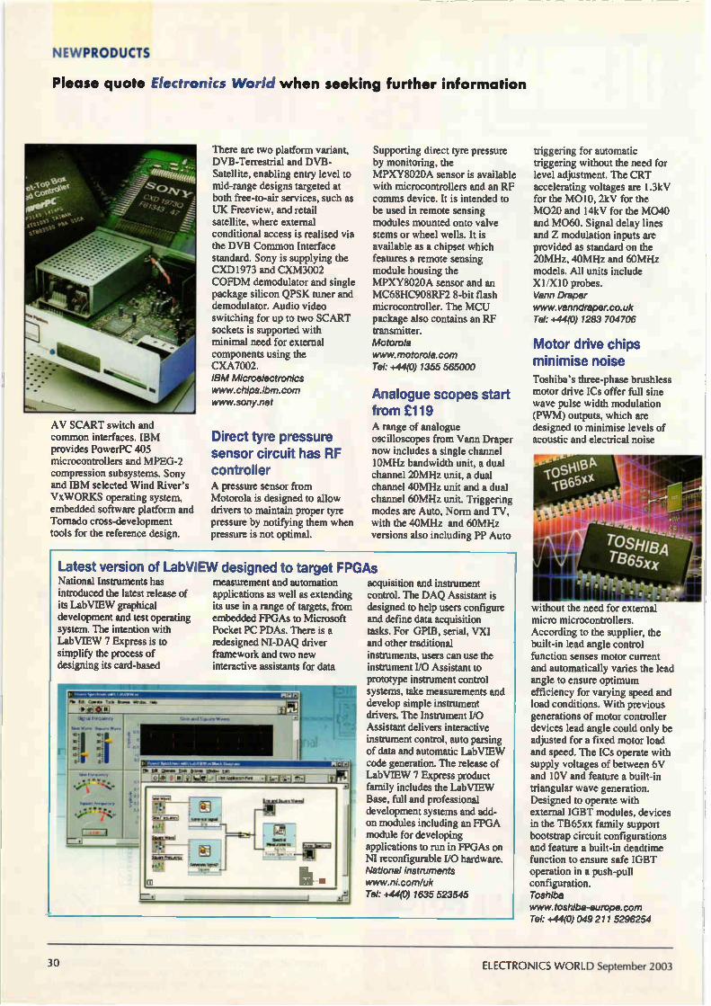
NEWPRODUCTS
Please quote Electronics World when seeking further information
AV SCART switch and common interfaces. IBM provides PowerPC 405 microcontrollers and MPEG-2 compression subsystems. Sony and IBM selected Wind River's VxWORKS operating system, embedded software platform and Tornado cross-development tools for the reference design.
There are two platform variant. DVB-Terrestrial and DVB-Satellite, enabling entry level to mid-range designs targeted at both free-to-air services, such as UK Freeview, and retail satellite, where external conditional access is realised via the DVB Common Interface standard. Sony is supplying the CXD1973 and CXM3002 COFDM demodulator and single package silicon QPSK tuner and demodulator. Audio video switching for up to two SCART sockets is supported with minimal need for external components using the CXA7002. IBM Microelectronics www.chips.ibm.corn www.sony.net
Direct tyre pressure sensor circuit has RF controller A pressure sensor from Motorola is designed to allow drivers to maintain proper tyre pressure by notifying them when pressure is not optimal.
Supporting direct tyre pressure by monitoring, the MPXY8020A sensor is available with microcontrollers and an RF comms device. It is intended to be used in remote sensing modules mounted onto valve stems or wheel wells. It is available as a chipset which features a remote sensing module housing the MPXY8020A sensor and an MC68HC908RF2 8-bit flash microcontroller. The MCU package also contains an RF transmitter. Motorola www.motorola.com Tel: +44(0)1355 565000
Analogue scopes start from £119 A range of analogue oscilloscopes from Vann Draper now includes a single channel 10MHz bandwidth unit, a dual channel 20MHz unit, a dual channel 40MHz unit and a dual channel 60MHz unit. Triggering modes are Auto, Norm and TV, with the 40MHz and 60MHz versions also including PP Auto
Latest version of LabVIEW designed to target FPGAs National Instruments has introduced the latest release of its LabVIEW graphical development and test operating system. The intention with LabVIEW 7 Express is to simplify the process of designing its card-based
measurement and automation applications as well as extending its use in a range of targets. from embedded FPGAs to Microsoft Pocket PC PDAs. There is a redesigned NI-DAQ driver framework and two new interactive assistants for data
acquisition and instrument control. The DAQ Assistant is designed to help users configure and define data acquisition tasks. For GPIB, serial, VXI and other traditional instruments, users can use the instrument I/0 Assistant to prototype instrument control systems, take measurements and develop simple instrument drivers. The Instrument I/O Assistant delivers interactive instrument control, auto parsing of data and automatic LabVIEW code generation. The release of LabVIEW 7 Express product family includes the LabVIEW Base, full and professional development systems and add-on modules including an FPGA module for developing applications to run in FPGAs on NI reconfigurable I/O hardware. National Instruments www.ni.com/uk Tel: +44(0)1635 523545
triggering for automatic triggering without the need for level adjustment. The CRT accelerating voltages are 1.3kV for the M010, 2kV for the M020 and 14kV for the M040 and M060. Signal delay lines and Z modulation inputs are provided as standard on the 20MHz. 40MHz and 60MHz models. All units include X1 /X 10 probes. Vann Draper www.vanndraper.co.uk Tel: +44(0)1283 704706
Motor drive chips minimise noise Toshiba's three-phase brushless motor drive ICs offer full sine wave pulse width modulation (PWM) outputs, which are designed to minimise levels of acoustic and electrical noise
without the need for external micro microcontrollers. According to the supplier, the built-in lead angle control function senses motor current and automatically varies the lead angle to ensure optimum efficiency for varying speed and load conditions. With previous generations of motor controller devices lead angle could only be adjusted for a fixed motor load and speed. The ICs operate with supply voltages of between 6V and 10V and feature a built-in triangular wave generation. Designed to operate with external IGBT modules, devices in the TB65xx family support bootstrap circuit configurations and feature a built-in deadtime function to ensure safe IGBT operation in a push-pull configuration. Toshiba www.toshiba-europe.corn Tel: +44(0)049 211 5296254
30 ELECTRONICS WORLD September 2003

THEORY
Calculus is for life not lust for Christmas In recent interviews of graduate applicants for the position of design engineer, I
have been appalled by their lack of understanding of elementary calculusl. If you
think your calculus is up to scratch, then there are two sets of simple test ques-
tions in this article. Do them. If you get any question wrong then your maths is
not even close to being acceptable. You need to read the whole article carefully
and try again. Leslie Green CEng MIEE, is handing out detentions....
Calculus is not something you should learn at school and then promptly forget; it is a general way of thinking that will outlast any technological changes that can
happen in your career. This article is to give adequate stress to the subject for those who didn't realise its importance and to act as a primer to those who never studied it in the first place. You will find all electrical engineering textbooks write
equations using calculus notation or simplified forms derived using calculus. It is therefore in your best interests to know the basics of the subject, so that you do not feel and act like a novice. As a teenager at school you would have done simple
problems such as calculating the power in a DC circuit or investigating the acceleration of a mass when a constant force was applied. The equations given were:
P=IxV
Power is the product of the current and the voltage.
F=mxA
Newton's second law of motion.
These equations are for steady conditions, with no change occurring in the driving forces. This is a nice simple introduction to science and lets the student feel that it is possible to learn about science and make calculations.
Changing Conditions Given the nice simple equation F=mxA, the student is never asked to think about what would happen if the force were to change with time, or if the mass were to change with time. What would happen to the acceleration in these cases? As soon as changes occur in these simple situations,
more advanced mathematics is called for. This step is not difficult to grasp if you understood the steps leading up to it. If you failed to get the earlier material, however, you get lost and confused. I was introduced to calculus in Advanced level maths classes by the simple statement that if y=x" the differential coefficient is given by,
dY — nx" -I dx
It was not even mentioned that we were now dealing with a subject called calculus'. With instruction like this, it is hardly
surprising that engineers are being trained who don't know what the subject is all about. We need to go right back to basics and start again.
Calculus for Engineers Once upon a time, charge was moved from one conductor to a nearby conductor. This caused a difference of potential between the two conductors. It was observed that moving twice as much charge created twice the potential difference. Using mathematical terminology it was said that the potential difference, V, was proportional to the charge, Q, which had been moved. This was written as, VacQ. Now all we have done here is to write an experimental observation in a concise mathematical form. The next step was to put in a constant to replace the
proportionality sign. We now say that Q=Cx V where we have a constant, C, for any particular system of two conductors. We call this the capacitance between the two conductors. There is now an equation, and a constant that we can measure. If charge moves with time we say that an electric current is flowing. More specifically we say that the rate of flow of charge past any fixed point is the definition of current. Now saying that "the rate of change of charge with respect to time is the current" is a very longwinded way of expressing the idea. So we use a mathematical notation instead and say:
. dQ = —
dt
This is the notation presented in 1684 by Leibniz, when he published the first paper on calculus2. We can apply this notation to the equation Q=Cx V and
we get,
dQ d(C x V)
dt dt
Now we can look at the special case where the conductors are not moving relative to each other. In this case the capacitance is constant and the C can be moved outside of the 'rate of change' expression. This now gives us a very important equation:
„ dV
dt
September 2003 ELECTRONICS WORLD 31
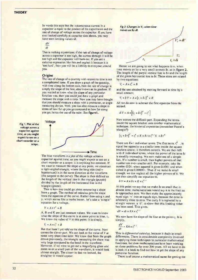
THEORY
Fig 1: Plot of the voltage across a
capacitor against time, as you might expect to see on a
chart recorder or a scope.
In w.ords this says that the instantaneous current in a capacitor is equal to the product of the capacitance and the rate of change of voltage across the capacitor. If you have ever looked carefully at capacitor data sheets, you may have seen limiting values of,
dV
di
This is nothing mysterious; if the rate of change of voltage across a capacitor is too high, the current through it will be too high and the capacitor will bum out. If you see a calculus expression like this and neglect it because it is 'too hard', then you will be a liability to everyone around you.
Origins The rate of change of a quantity with respect to time is not a complicated issue. If you draw a graph of the quantity, with time along the bottom axis, then the rate of change is simply the slope of the line, also known as its gradient. If you wanted to know what the slope of any particular function was, then you could just draw a graph and measure the slope with a ruler. Now you may have thought that you should measure a slope with a protractor, an angle measuring device. Well, you can also measure a slope in terms of how far up you go compared to how far along you go; hence the use of the ruler. See figure1.
>Time The blue waveform is a plot of the voltage across a capacitor against time, as you might expect to see on a chart recorder or a scope; it is anything but constant. If we want to measure the slope at any point, we construct a right-angled triangle, where the long side (red = hypotenuse) is in the same direction as the waveform (the tangent to the curve). The slope is then defined as the length of the vertical line in the triangle (purple) divided by the length of the horizontal line in the triangle (green). This is how one could go about measuring a slope
from a graph. The method of calculus gets the slope from the equation of the curve. Rather than using x and y, which seems like a maths lesson, let's take a 'simple' equation for a voltage,
V - A x tx + B
A, B and K are just constant values. We want to know what the slope of this curve is at some point in time, ti. We know the value of Vat this point; it is simply,
V, = A x t,K + B
But that hasn't yet told us the slope of the curve. Now comes the clever part. We can look at the value of Vat some very short time later. We know that from the graph drawn previously, the triangle measuring the slope was very large compared to the bend in the waveform. However, if we were to get out a magnifying glass and zoom in on a small part of the waveform, it would look almost straight. The closer in that we looked, the straighter it would appear.
Fig 2: Changes in VI when time moves on by dt.
Hence we are going to see what happens to y1 when time moves on by a very small amount St, as in figure 2. The length of the purple vertical line is bv and the length of the green horizontal line is bt. These sizes are related by two equations:
V, = A x + B
and the one obtained by moving forward in time by a small amount,
V, +6V Ax(t,+bt)K +B
All we do now is subtract the first equation from the second.
/5 V = A x[(t, + t)K — t
Now comes the difficult part. Expanding the terms inside the square bracket uses another mathematical technique, the binomial expansion (remember Pascal's triangle?)
(t, +6 - fie +Kxótxt; +biA
There are K+1 individual terms. The first term, i f' is equal but opposite to a similar term inside the square brackets above; it therefore cancels. We are then left with K individual terms, where the power of the term St is steadily increasing. We now make use of a simple fact. If a number is small, then higher powers of that number are even smaller still. For example, take the number 0.01: when squared it gives 0.0001 and when cubed it gives 0.000001. Thus if we make bt small enough, we can neglect all the higher powers of it. We can then simplify our equation to,
bV=Ax6txKx t,"
At this point we say that we make bt so small that is almost zero; mathematicians would say it is the limit as bt approaches zero. We then make the approximately equal sign 'P..?. into an equals sign, because the error is arbitrarily close to zero. The curly b is replaced by a straight version, a 'd', to show that this limiting value has been used. This gives,
dV = di x KA x
We now have the slope of the line at the point t1. It is simply,
dV — KA x t," di
This is differential calculus, because it deals in small differences. There is considerable complexity involved in applying these techniques to particular mathematical functions, but then mathematicians have been working on these problems for over 300 years. All we have to do is look in a book to find out how to get the slope of any particular function. There is of course a mathematical name for getting the
32 ELECTRONICS WORLD September 2003
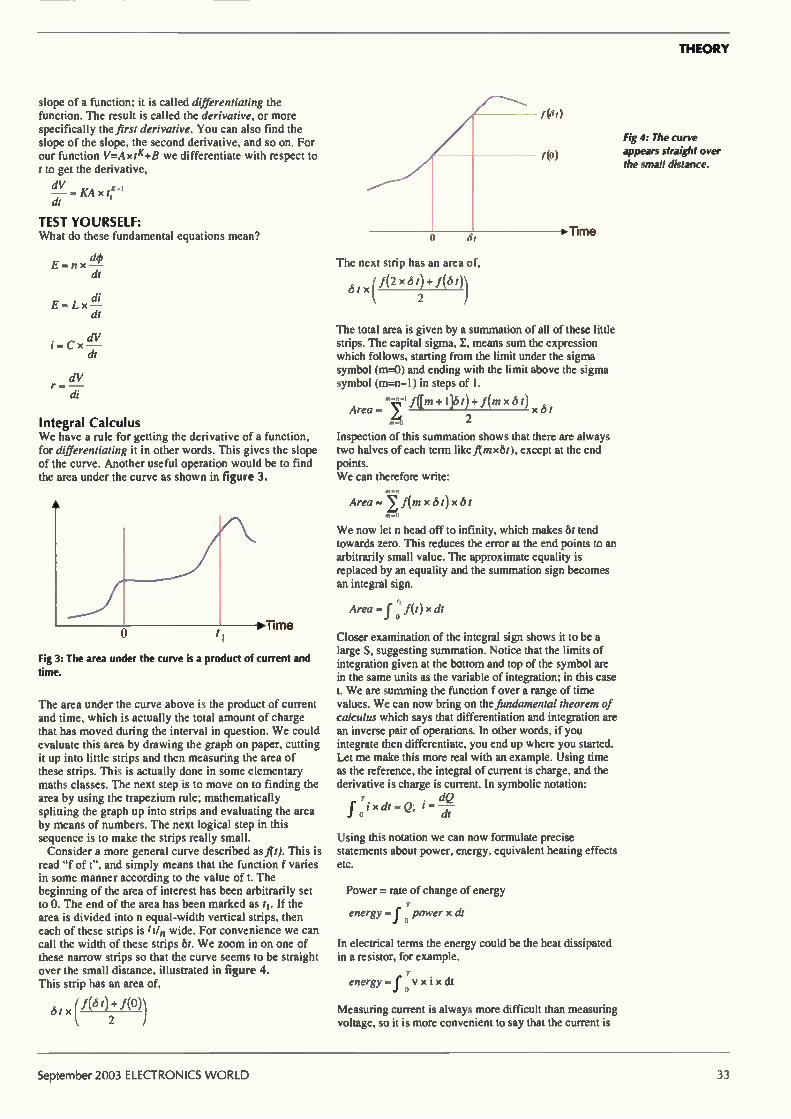
THEORY
slope of a function; it is called differentiating the function. The result is called the derivative, or more specifically the first derivative. You can also find the slope of the slope, the second derivative, and so on. For our function V=Axtie-i-B we differentiate with respect to t to get the derivative,
dV — — KA x di'
TEST YOURSELF: What do these fundamental equations mean?
E = n x —(14) dt
E - Lx di
dV
di
dV r
Integral Calculus We have a rule for getting the derivative of a function, for differentiating it in other words. This gives the slope of the curve. Another useful operation would be to find the area under the curve as shown in figure 3.
A
>Time
Fig 3: The area under the curve is a product of current and time.
The area under the curve above is the product of current and time, which is actually the total amount of charge that has moved during the interval in question. We could evaluate this area by drawing the graph on paper, cutting it up into little strips and then measuring the area of these strips. This is actually done in some elementary maths classes. The next step is to move on to finding the area by using the trapezium rule; mathematically splitting the graph up into strips and evaluating the area by means of numbers. The next logical step in this sequence is to make the strips really small. Consider a more general curve described as fit). This is
read "f of t", and simply means that the function f varies in some manner according to the value of t. The beginning of the area of interest has been arbitrarily set to O. The end of the area has been marked as t1. If the area is divided into n equal-width vertical strips, then each of these strips is ti/n wide. For convenience we can call the width of these strips 6t. We zoom in on one of these narrow strips so that the curve seems to be straight over the small distance, illustrated in figure 4. This strip has an area of,
d t x f(d t) + f(0)) 2
The next strip has an area of,
6tx (f(2 x 6t)+ »5/
2
The total area is given by a summation of all of these little strips. The capital sigma, I, means sum the expression which follows, starting from the limit under the sigma symbol (m.)) and ending with the limit above the sigma symbol (m=n-l) in steps of I.
Area gm +1]6 t)+ f(in x t) x t
2
Inspection of this summation shows that there are always two halves of each term like f(mxbt), except at the end points. We can therefore write:
Area = 7 f(m x 6 t)x 6 t
We now let n head off to infinity, which makes St tend towards zero. This reduces the error at the end points to an arbitrarily small value. The approximate equality is replaced by an equality and the summation sign becomes an integral sign.
Area = f(t) x dt o
Closer examination of the integral sign shows it to be a large S, suggesting summation. Notice that the limits of integration given at the bottom and top of the symbol are in the same units as the variable of integration; in this case t. We are summing the function f over a range of time values. We can now bring on the fundamental theorem of calculus which says that differentiation and integration are an inverse pair of operations. In other words, if you integrate then differentiate, you end up where you started. Let me make this more real with an example. Using time as the reference, the integral of current is charge, and the derivative is charge is current. In symbolic notation:
dQ f oixdt-Q; 1-7t
Using this notation we can now formulate precise statements about power, energy, equivalent heating effects etc.
Power = rate of change of energy
energy f power x di
In electrical terms the energy could be the heat dissipated in a resistor, for example,
energy -f ovxixdt
Measuring current is always more difficult than measuring voltage, so it is more convenient to say that the current is
Fig 4: The curve appears straight over the small distance.
September 2003 ELECTRONICS WORLD 33
THEORY
the voltage divided by the resistance.
T v 1 T 2 energy - f V X — xdt = — 4 v xdt
Jo R R 0
Often the waveform is cyclic, with a period of say T. In these cases we are interested in the average (or more specifically the mean) power. We then write:
mean power, P = energy per cycle cycle time
p 1 Ir T
dt
It would be nice to use a simplified form of this equation, where there was a voltage which when squared gave the same heating effect as the true calculus expression. It would then be:
V 2 p _E_QUI
This is then very similar to the simple DC case. You should be able to see that:
1 T V 2 a, = V2 X dt EQu o
By taking the square root of both sides we get:
1 VEQuA, _J f T v2 xdt - Vms o
The equivalent voltage is the square Root of the Mean value of the sum of the Squared voltage, or RMS for short. This is the most elementary of electrical engineering topics and yet you still get 'engineers' who are unable to recognise that RMS voltage and RMS current are valid quantities, but that use of the term 'RMS power' is technical illiteracy, as there is no such valid, useful quantity. This lack of understanding is not assisted by
manufacturer's adverts, which talk of "true RMS power" measuring devices. This is tricky. Power measuring devices can measure peak power, assume the signal is sinusoidal, and give a calibration of the actual mean (average) power. A better technique is to measure the RMS voltage across a resistance, which gives the true power. In this case the manufacturer is trying to say that their measurement method uses a true RMS voltage measuring technique, which is more difficult to do but gives a more accurate answer. The adverts truncate this to a "true RMS power" measuring device, which confuses those with inadequate understanding of their basics.
Rules of differentiation and integration Integration is somewhat harder than differentiation in terms of the mathematical manipulations. Often one has to see what function when differentiated gives the function we are trying to integrate. You almost guess the answer, differentiate it and see if you were correct!
In any case, most of the hard work has been done by our predecessors compiling tables of the difficult functions. What remains is for us to break any particular problem down into a form such that we can look the answer up in such a table. For both differentiation and integration, constant multipliers can be freely moved outside of the calculus part. For example, with a constant K;
d(K x i) di = K x —
di di
and,
fKxVxdt-KxfVxdt
Calculus operations can be split up between simple additions and subtractions. Thus:
d(V, + V2) dV, dV
dt = dt di and,
+ x dt xdt)+(f ipcdt)
A constant has no rate of change with respect to anything. Thus the derivative of a constant is always zero, regardless of the variable we are differentiating with respect to. Using the constant K again:
(1K — di
The integral of a constant gives the product of the constant and the variable of integration.
r TKxdt =KxT J o
This is obvious if you think about the integral as being the area under the curve. If the curve has a constant value, the area is rectangular and is simply the product of the height of the curve above the axis and the distance along the axis that we integrate over.
Limits of integration So far I have skilfully avoided the subject of the limits of the integration. If I were to differentiate a function such as V=K ixtn+ K2, the additive constant would 'disappear'.
dV — = nK, x e-. dt
This means that when I integrate some function, I always have to add on an arbitrary (unknown) constant. For example:
tn.1
.j? X dt = — + K n +1
The rule for integration is seen as being the rule for differentiation done 'backwards'. In differentiating I multiplied by the index (n), then reduced the index by one. For integration I increase the index by one (n+1) then divide by this new index. What I have given here is an integral without limits. This
is called an indefinite integral. I have asked the question, "What is the area under the curve up to a specified point?" but I have not given the starting point of the summation! This is a graphic explanation of why an indeterminate constant is required. The last rule required for integration is that the limits can
be split into parts. Suppose we have a waveform that is doing one thing up to a time tl, but then does something else up to the time T. We can split the integration up over these two intervals to make the integration easier.
T T il r ixdt = (f ixdt)+(1- ixdt) J o o ri
By splitting the integral up into these intervals, it is possible to look up the individual function pieces in tables.
34 ELECTRONICS WORLDSeptember 2003

THEORY
Table 1: This table uses time as the variable of integration. The derivatives are also done with respect to time.
Differentiate this to get that , Integrate this to get
--> <— that
Kxt Id,: xr I
K xt" K xt"
'1+1
sin(o xi) cox cos(a)xt)
ços(toxt) —toxsin(mxt)
e"." —Kxe-K4
This table uses time as the variable of integration. The derivatives are also done with respect to time. Now you are ready for the final test... These are very
basic questions actually; if you can't do them or get them wrong, after having read this article carefully, then you definitely need to dust off those text books and put in some extra study.
FINAL TEST What is the maximum slew rate of a 3V RMS 1MHz sinusoidal signal? What is the current flowing in a 0.1p F capacitor when a
voltage is applied to it which increases linearly from OV to 100V in the space of 1.5ps? What is the RMS value of a repetitive 25kHz rectangular
voltage waveform which is at 10V for lOps, then at IV for the rest of the cycle. What is the RMS power dissipated in a IQ resistor when
the voltage of #3 above is applied across it? Answers on page 51...
References 1. The Latin word calculus means 'a small pebble used
for counting', as well as 'the subject of reckoning'. The original presentation of this branch of mathematics was written in Latin.
2. "Nova Methodus Pro Maximis et Minimis, ...", Acta Eruditorum 1684 by G.Leibniz; pp466-473 of the 1682-1687 volume (1966 reprint). Unfortunately this is all in Latin.
High Resolution Oscilloscope
„facsCliiCE .'19e
• High speed, 5GS/s dual channel oscilloscope • 50M Hz, 80dB dynamic range spectrum analyser • PicoScope & PicoLog software supplied FREE • Plug into any desktop or laptop PC • High resolution - 12 bits • Large 128K memory • 1% DC accuracy
o
(E.,
,tpe- 2 1 2 voum mstrument
Request your FREE Test & Measurement catalogue and Software & Reference CD,
or visit our web site:
www.picotech.comiscopell5
Tel: +44 (0) 1480 396395 Fax: +44 (0) 1480 396296 E-mail: [email protected]
September 2003 ELECTRONICS WORLD
BROADCAST
Professional SDI router Known commercially as the 'DVRS-8x8', Emil Vladkov's stackable
serial digital interface router provides eight inputs and outputs for
digital video signals running at up to 400Mbit/s. This second article
covers additional circuits, software and a dedicated keypad for
controlling the router.
First I will outline the optional add-on section of the design for those of you who need the reclocking signals from outputs 2 to 8. Fig. 1. Although this is
add-on circuitry. I have designed the router's main PCB to accommodate it. The idea is, that if you don't need reclocking at outputs
2-8, the components of this section can be skipped. If they
are omitted, it is important that input ports DOxIn are shorted to the output ports DOxOut with wire bridges.
In my prototypes. I have implemented the full-featured version, so I will discuss this section too. The retimer/reclock circuits for outputs 2-8 are /C37_43. They have the same wiring as /C lo in Fig. 3 of last month's article with the same component values.
VCCA 0 13102 IF
1N4148
2 DO2In 0 DDI DO2In o 6 DDI
ICA2 19 cp
2p2+1pI c 117 MUTE
I CARS 100n
R174
1k 8
4
C118 VCCA0
1n: VCCA o 26
16 AUTO
7 VCC
VCC VEE VEE
11 • VEE 27
VEE < 0
IC37 SDO
CLC016 SDO SCO
SCO RD1
ROO
SER ACQ/WR RO
R1
R2
R3
RTN
(5)1 -n
0 103 1N4148
C125 R170 Rin lion 75 75
R172 75 75
R173
24
23 22 21
20
13 R175 6810
___•—misA-14 R176 5490
15 R178 2550 32458500
17 --vs/w—•
18
VCCA
°+1C119 IC120 IC121 76.80
— 151=1C'Als'is..-318 --c<0 74HCO4
7100n 7100n
C122 R181 0-11—&-WV\,—• 1000 500
C123
--H— VCC 0 \\ 82p 560
IC 2
LED-RDO Rin IC36F
560 12 13
DO2Out
DO2Out
C1002
II iOn
J26 SCLK2
Fig. 1. Additional circuitry for those of you who need the reclocking signals from outputs 2 to 8.
36 ELECTRONICS WORLD September 2003
BROADCAST
Main features of the router
Full specifications for the router were
presented in last month's article. Here's a summary of the router's main features.
8x8 digital cross-point switch capable of operating at data rates exceeding 360Mbit/s per channel;
Non-blocking architecture; Low channel-to-channel crosstalk; Channel jitter 200ps pk-pk typ.; Fast output edge speed: 650ps typ.; Input type: 800mV, 75Q, BNC; Output type: 800mV, 75Q, BNC (Belden
8281 or equivalent transmission lines);
Conforms to SMPTE 259M serial digital
interfaces: NTSC/PAL, 4:2:2 component, 360Mbit/s wide screen, also 540Mbit/s 4:4:4:4 (optional);
Clock and data recovery at all channels at fixed data rates: 143, 177, 270 and 360Mbit/s. The data rate of the reclocked signal is displayed at the front panel;
Carrier detection and output mute for all input channels. The carrier detected signal is displayed at the front panel;
Automatic equalisation of all input channels: up to 300 metres of Belden 8281 cable;
Control via button panel (with
indication) or Windows 95/98 graphical user interface;
Visual indication on the local front panel of the routing system (64 channel cross-point LEDs plus 8 input CD LEDs plus data rate indicators for output channels 1-8);
Lock control preventing accidental switching;
Stackable using standard RS-232 cables — up to four devices can be independently controlled via the PC user interface;
Start-up configuration selectable by user; Mains powered.
The active data rate LEDs are 13 116_129 and the driving buffers are /C36A.F and /C44.45. Power supply decoupling is provided at every chip with two ceramic and one tantalum capacitor.
Microcontroller Firmware The firmware is code residing in the microcontroller's external PROM. This code is presented in object code form in Listing 1. It is responsible for all configuration functions of the crosspoint matrix, for the LED indication at the front panel and for communication with the external keyboard or host PC. It also retransmits commands to any stacked devices connected at the slave port and it loads the start-up configuration. This is not the place to discuss the assembler source
code used to produce the object code shown, but but I should mention that this program is considerably large. I
consider it to be well thought through, providing redundancy and preventing lockups. Writing the software took a significant proportion of the system's total design time.
Device implementation and mechanical considerations The DVRS-8x8 router is housed in a 19in, I RU metal case. It's front panel with the LED indications and the back panel with the signal connectors and communication ports were shown on page 44 of last month's article. Good electrical contact should be provided between the
case base and the case lid to ensure good screening. A dedicated printed circuit board is available on request from me via the editorial offices of Electronics World. The price is dependant on demand email j.loweehighburybiz.com.
VCCA 0
D114 ir 1N4148
1,C178
Zion
DO8In o DDI IC37 DO8In o 6 DDI
iCA8 19 cc
2p2+1p7 C171 MUTE ll 2 CARS
R246 100n 4
—m.m.- SER 1k 8
„J„
C172 VCCA 0
in: VCCAo •
VCCA
o+,1,C 173
16
7
26
• * 11 27
CLC016
ACO/VVR AUTO
VCC VCC VEE
VEE VEE VEE <
0
SDO
SDO SCO
SCO RD1 RDO
2
D115
1N4148 —
J.C179
R242 R 243 ,I100 75 75
R244 7
R245
75
24
( lDO8Out —< I DO8Out
23 22
21
20
13 247 6810 RO
R1 --mm.-414 1:1248 54"
R 15 R249 3480
17 R250 2550 R3 — 1/s/VV--‘3
RTN 18
C)1
1C174 1.C175
76.8u 7100n 7100n
VCC o
e_C_i176 R253
1000 500 , 177
82p D128 LED-RDO
Di29 LED-RD1
560 1
R251 lc
560 12 o
R252 74HCO4
C 1008 J32
II SCLK8 10n
September 2003 ELECTRONICS WORLD 37
BROADCAST
Fig. 2. The router can be controlled via a PC host, but it is also designed to be a stand-alone router using this optional keypad.
VCC
C81 10µ/16V IC1
CR - 11.0592
5 XTAL2 33p C7 X XTAL1 Ai -1- 1
8k2 33p P3.7 it
VCC
R3
8k2
P3.5 P3.4 8 P3.3 7 P3.2 6
S65 Lock 3
RSTNPP P1.7 P1.6 P1.5 P1.4 P1.3 P1.2
P3.7 P1.1(AIN1) P1.0(AINO)
P3.5(T1) P3.4(TO) P3.3(INT1) P3.2(WIT) P3.1(TXD) P3.0(RXD)
19 P1.7 18 P1.6 17 P15 16 P1.4 15 P13 14 P1.2 13 P11 12 P1.0
AT89C2051
IC
i-1 C1+ C9+.
14/16V 3 ci-
clo 14/16V 75
C2-9 R2OUT
- ,R1OUT 10.721N 11
P3.3 P3.4 P3.5 P3.7
74HC138
Ivcc c1, +r7.101.4/16V
.1m. 12 4110u/16V
T1OUT 5 7 T2OUT >-
R1IN 13 R2IN L- e./ 6
P1.0
MAX232
9 DB9-M
YO
Y1
Y2
Y3
Y4
Y5
Y6
Y7
P1.7
The PCB is designed with microwave techniques in mind, although using conventional 1.5mm double-sided material. Connections between the signal ports at the PCB and the panel-mounted BNCs at the rear panel should be implemented with short - but not crossing - coaxial cables without any additional board connectors. Belden type 8281 or equivalent can be used for the connections.
If necessary, the backs of the BNC-connectors and the mounting points at the PCB can be screened with copper plates. Connections to the LEDs and communication ports are made with standard ribbon cable. There's a lot of cabling to fit inside the small 1RU case, so measure the lengths exactly and organise the cable to prevent running out of space.
Linear regulators 1C-,5 and /C,6 from Fig. 4b) in last month's article are mounted on separate heat sinks that are isolated from each other and the case. These are not mounted on the circuit board, but on the bottom of the case. The mains transformer mounts on the PCB. Mains is
fused at the back panel of the device near the mains switch. Don't forget to isolate carefully all wires carrying line voltage.
Controlling the router There are two of controlling the DVRS-8x8. One is a dedicated keyboard, the other a user interface program running on a host PC.
YO
vi
Y2
Y3
Y4
Y5
Y6
Y7
Check row 1
Check ow 3
Check row 4
Check ow 5
Check row 6
Check row 2
Microcontroller actions when
scrolling through row X
Check for pre „ed Compare
button with internal registers
Check row 7
Store if new and output at port PI
Update the
LEDs
Check ow 8
Fig. 3. As the keys of the stand-alone keypad are non-latching, software has to be used to scan them continually and 'remember' which one was pressed most recently. This diagram shows how the controller scans the keypad hardware.
38 ELECTRONICS WORLD September 2003
BROADCAST
The PVRS-2 8x8 keyboard. The dedicated keyboard has eight rows and eight columns of keys with a lock switch. It connects to the master serial port of the routeing system. Power for the keyboard is derived from the routeing system with a dedicated banana jack.
First Fil discuss the internal working of the PVRS-2 keyboard. Fig. 2. The button matrix is built from eight rows by eight
columns of standard non-latching push buttons. Scanning and interpretation of the keyboard is done in the Atmell microcontroller, /CI. The response of the keyboard to user actions is blocked -
i.e. the keyboard is locked - while switch S65 is closed. The 89C205 I looks at the level at this pin. If it sees a low level - i.e. switch closed - it loops, performing no action when a key is pressed. The lock feature is useful for preventing accidental
switching arising from operator error or inattention during live on-air applications of the router. Scanning the keypad takes place as follows: the
microcontroller. /CI. addresses sequential rows from top to bottom, asserting incrementing addresses through its P3.3, P3.4. P3.5 lines to the decoder, /C3. Outputs of the 74HCI38 decoder pull down the rows of
the keyboard sequentially so only one row is low at a time. As all columns have pull-up resistors. namely R4_11. when no key is pressed. port PI of the micro connected to the columns of the keypad sees only high levels. When a key is pressed. one of the port pins P1.7-P1.0
sees low level, and as the micro 'knows' which row is addressed it can identify exactly which button is pressed.
Software latch As the buttons are not latching, a software latch has to be implemented. This works as follows: when a key is pressed
Vec 0
D3-10 R1C1-R1C8
8 12-19 IC4 470
P1.0 3150 P1.1 4
P1.2 7
P1.3 8 P1.4 13
P1.5 14 P1.6 17
P1.7 18
„ v0 11
00
D1 01 D2 02
D3 03
D4 04 05 05
D6 06 07 07
OC CLK
2
6 9
12
15 16 19
• t t
74HC374
D59-661 R8C1-R1C8
868-75 ICii 470
2
5 6 9 12 15
16
P1.0 3 P1.1 4
- - - - P1.2 7
P1.3 8 P1.4 13
P1.5 14 P1.6 17
P1.7 18 1
+1, Y7 11
DO
D1
D2
D3 D4
D5
D6 D7
OC CLK
00 01 02
03 04
05
06
07
ttttt
74HC374
the microcontroller identifies the key and stores the information in its internal registers. Then the microcontroller puts out the key information to its Pl -port, which is also connected to all 74HC374 latches /C4_11. As the micro changes from one row to the next, it pulls
the P3.7 line to the /C3 first low and then high. This forces the formerly asserted row to go high, and after a time the next to go low, as depicted in timing diagram Fig. 3. As the former row goes high, so does the respective YO
to Y7 line too. This latches the valid key information on PI into the LED latches Note that the Y output lines of the decoder connect to the
clock-lines of the latches, which are edge triggered. Corresponding LEDs in the active row light to reflect the action on the button. Fig. 4. As the microcontroller scrolls down the rows looking for
new keys pressed, it also calls out the stored information
8k2,
Ji
•
IC,
Power in
c6 11.0592
,4-1 1 5 33p C7;11 x
-1- 1
33p P3.7 11
VCC
R3
8k2
P3.5
P3.4 8
P3.3
P3.2 6
S65 Lock
DI
1N4001 c2 C1 100n
220t1=1 25V
3
RSTNPP P1.7
P1.6
XTAL2 P1.5
XTAL1 P1.4
P1.3
P1.2
P3.7 P1.1(AIN1)
P1.0(AINO)
P3.5(T1)
P3.4(TO)
P3.3(FITI)
P3.2(Wir))
P3.1(TXD)
P3.0(RXD)
19 P1.7
18 P1.6
17 P15
16 P1.4
15 P1.3
14 P1.2
13 P1.1
12 P1.0
AT89C2051
Fig. 5. Power supply and decoupling capacitors, which are distributed around the main circuit of the keyboard.
IC2
9
In LM7805
Out .
Ondi IC12 11)C0n 4,1 c
C3+ 1 :100n5T 100u 16V I
02
TpceiéT-E71:1 'r e60/
-12 R1OUT T2OUT
10e 2IN RUN
Cl-
C2+
C2-
R2OUT T1OUT
11 erl IN R2IN
MAX232
VCC
oVCC
im VCC C11
+1P 10µ/16V
12 .1,14116V
D1 5
DL 13 *: DB9-M
8 le. 6
Pl
C13 T 100n C14 1C20 IC21 100n TiO0n7100n
Fig. 4. The router's keyboard's LED display matrix forms a map reflecting which signal's routed where.
September 2003 ELECTRONICS WORLD 39
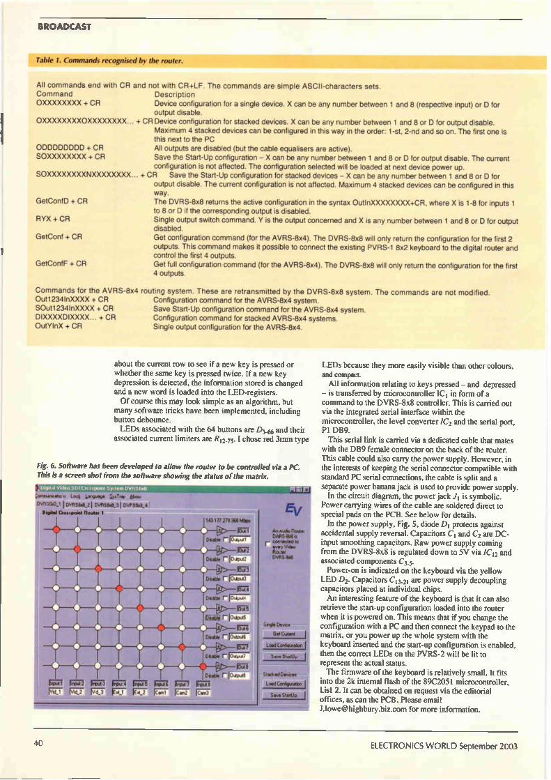
BROADCAST
Table 1. Commands recognised by the router.
All commands end Command OXXXXXXXX + CR
with CR and not with CR+LF. The commands are simple ASCII-characters sets. Description Device configuration for a single device X can be any number between 1 and 8 (respective input) or D for output disable.
OXXXXXXXXOXXXXXXXX + CR Device configuration for stacked devices. X can be any number between 1 and 8 or D for output disable. Maximum 4 stacked devices can be configured in this way in the order: 1-st. 2-nd and so on. The first one is this next to the PC
ODDDDDDDD + CR All outputs are disabled (but the cable equalisers are active). SOXXXXXXXX + CR Save the Start-Up configuration — X can be any number between 1 and 8 or D for output disable. The current
configuration is not affected. The configuration selected will be loaded at next device power up. SOXXXXXXXXNXXXXXXXX... + CR Save the Start-Up configuration for stacked devices — X can be any number between 1 and 8 or D for
output disable. The current configuration is not affected. Maximum 4 stacked devices can be configured in this way.
GetConfD + CR The DVRS-8x8 returns the active configuration in the syntax OutInXXXXXXXX+CR. where X is 1-8 for inputs 1 to 8 or D if the corresponding output is disabled.
RYX + CR Single output switch command. Y is the output concerned and X is any number between 1 and 8 or D for output disabled.
GetConf + CR Get configuration command (for the AVRS-8x4). The DVRS-8x8 will only return the configuration for the first 2 outputs. This command makes it possible to connect the existing PVRS-1 8x2 keyboard to the digital router and control the first 4 outputs.
GetConfF + CR Get full configuration command (for the AVRS-8x4). The DVRS-8x8 will only return the configuration for the first 4 outputs.
Commands for the AVRS-8x4 routing system. These are retransmitted by the DVRS-8x8 system. The commands are not modified. Out1234InXXXX + CR SOut1234InXXXX + CR DIXXXXDIXXXX... + CR OutYlnX + CR
Configuration command for the AVRS-8x4 system. Save Start-Up configuration command for the AVRS-8x4 system. Configuration command for stacked AVRS-8x4 systems. Single output configuration for the AVRS-8x4.
about the current row to see if a new key is pressed or whether the same key is pressed twice. If a new key depression is detected, the information stored is changed and a new word is loaded into the LED-registers. Of course this may look simple as an algorithm, but
many software tricks have been implemented, including button debounce. LEDs associated with the 64 buttons are D3_66 and their
associated current limiters are R12_75. I chose red 3rnm type
Fig. 6. Software has been developed to allow the router to be controlled via a PC. This is a screen shot from the software showing the status of the matrix.
6be.
I CIVFISIS4.31 DVPS80_4 Oo•tpomt Rowe; 1
nrorii ninw FK72
J 3rro—u n rto—ut 6 n ror7 F7( F.7_7" Ft7.7 Ici17;72
10.177270360 Ms
Diaoke r
Fat DUI* r lodw2
1 LI Diable r 10,-77—ut3
WI 4 DM*. r
r jo,Ip.45
Diable r no7( —on ert7
Dtatat r
Dzede r IChic,e8 rip—ut
rCe—n3
Slagle Dew> Curart
Load Coro
Save Stottly
Stacked Demces Load Conhguatan
Save S
LEDs because they more easily visible than other colours, and compact. All information relating to keys pressed — and depressed — is transferred by microcontroller ICI in form of a command to the DVRS-8x8 controller. This is carried out via the integrated serial interface within the microcontroller, the level converter /C2 and the serial port, Pl DB9. This serial link is carried via a dedicated cable that mates
with the DB9 female connector on the back of the router. This cable could also carry the power supply. However, in the interests of keeping the serial connector compatible with standard PC serial connections, the cable is split and a separate power banana jack is used to provide power supply.
In the circuit diagram, the power jack J1 is symbolic. Power carrying wires of the cable are soldered direct to special pads on the PCB. See below for details.
In the power supply, Fig. 5, diode DI protects against accidental supply reversal. Capacitors C1 and C2 are DC-input smoothing capacitors. Raw power supply coming from the DVRS-8x8 is regulated down to 5V via /C12 and associated components C3.5. Power-on is indicated on the keyboard via the yellow
LED D2. Capacitors C13.21 are power supply decoupling capacitors placed at individual chips. An interesting feature of the keyboard is that it can also
retrieve the start-up configuration loaded into the router when it is powered on. This means that if you change the configuration with a PC and then connect the keypad to the matrix, or you power up the whole system with the keyboard inserted and the start-up configuration is enabled, then the correct LEDs on the PVRS-2 will be lit to represent the actual status. The firmware of the keyboard is relatively small. It fits
into the 2k internal flash of the 89C2051 microcontroller, List 2. It can be obtained on request via the editorial offices, as can the PCB, Please email Lloweehighbury.biz.com for more information.
40 ELECTRONICS WORLD September 2003
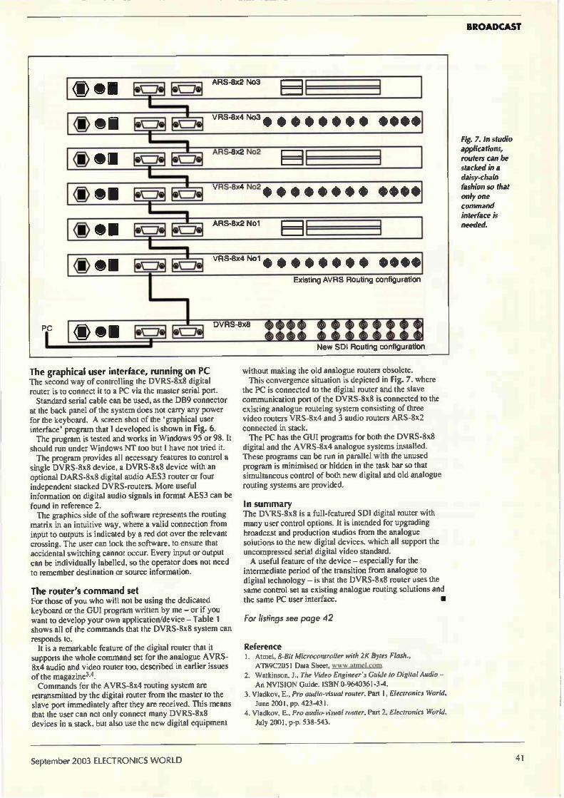
BROADCAST
PC
® c), n ARS-8x2 No3 e /0
® ICD .
VRS-8x4 No3 Pi` ۥ=e"
0 'CI a No2
4&=€, 0=0 ARS-8x2
'0' 0 n VRS-8x4 No2 $ $ $ $ $ $ $ $ $ $ $ $ le.ta .8,
0 C) II
ARS-8x2 Nol I* 0 0
® 0 a VRS-8x4 Nol $ $ $ $ $ $ $ $ $ $ c) $ 4\ le ‹e I
Existing AVRS Routing configuration
® 0 n DVRS-8x8
eaee tttoette e le lo
I New SDI Routing configuration
The graphical user interface, running on PC The second way of controlling the DVRS-8x8 digital router is to connect it to a PC via the master serial port. Standard serial cable can be used, as the DB9 connector
at the back panel of the system does not carry any power for the keyboard. A screen shot of the graphical user interface' program that I developed is shown in Fig. 6. The program is tested and works in Windows 95 or 98. It
should run under Windows NT too but I have not tried it. The program provides all necessary features to control a
single DVRS-8x8 device, a DVRS-8x8 device with an optional DARS-8x8 digital audio AES3 router or four independent stacked DVRS-routers. More useful information on digital audio signals in format AES3 can be found in reference 2. The graphics side of the software represents the routing
matrix in an intuitive way, where a valid connection from input to outputs is indicated by a red dot over the relevant crossing. The user can lock the software, to ensure that accidental switching cannot occur. Every input or output can be individually labelled, so the operator does not need to remember destination or source information.
The router's command set For those of you who will not be using the dedicated keyboard or the GUI program written by me — or if you want to develop your own application/device — Table 1 shows all of the commands that the DVRS-8x8 system can responds to.
It is a remarkable feature of the digital router that it supports the whole command set for the analogue AVRS-8x4 audio and video router too, described in earlier issues of the magazine3.4. Commands for the AVRS-8x4 routing system are
retransmitted by the digital router from the master to the slave port immediately after they are received. This means that the user can not only connect many DVRS-8x8 devices in a stack, but also use the new digital equipment
without making the old analogue routers obsolete. This convergence situation is depicted in Fig. 7, where
the PC is connected to the digital router and the slave communication port of the DVRS-8x8 is connected to the existing analogue routeing system consisting of three video routers VRS-8x4 and 3 audio routers ARS-8x2 connected in stack. The PC has the GUI programs for both the DVRS-8x8
digital and the AVRS-8x4 analogue systems installed. These programs can be run in parallel with the unused program is minimised or hidden in the task bar so that simultaneous control of both new digital and old analogue routing systems are provided.
In summary The DVRS-8x8 is a full-featured SDI digital router with many user control options. It is intended for upgrading broadcast and production studios from the analogue solutions to the new digital devices, which all support the uncompressed serial digital video standard. A useful feature of the device — especially for the
intermediate period of the transition from analogue to digital technology — is that the DVRS-8x8 router uses the same control set as existing analogue routing solutions and the same PC user interface.
For listings see page 42
Reference I. Atmel, 8-Bit Microcontroller with 2K Bytes Flash.,
AT89C2051 Data Sheet, www.atmel.coca.
2. Watkinson, J., The Video Engineer's Guide to Digital Audio —
An NVISION Guide. ISBN 0-9640361-3-4.
3. Vladlcov, E., Pro audio-visual router, Part 1, Electronics World. June 2001, pp. 423-431.
4. Vladkov, E., Pro audio-visual router, Part 2, Electronics World, July 2001, p-p. 538-543.
Fig. 7. In studio applications, routers can be stacked in a daisy-chain fashion so that only one command interface is needed.
September 2003 ELECTRONICS WORLD 41

BROADCAST
Listing 1. Object code for the DVRS-8x8's microcontroller. 0300000002008078
: 08000300323232323232323265
: 0800030032323232323232325D
: 08001300323232323232323255
: 0800 1B0032323232323232324D
: 080023001201F03232323232D8
: 1000800075A800D235D234C233C296C297C2B2C2EA
10009000D1E587C2E7F587758DFD758BFD758921E3
1000A000D28E759850D2ACD2AFE4C0E07980E4C370
1000300012082240F9B45A06DOE02401C0E0799039
1000C000E4C312082240F9345A06DOE02402C0E08A
1000D00079A0E4C312082240F9B45A06DOE02404FF
1000E00000EODOE01340003020111134070280030233
1000F00001BA1208FF78307900E4C312082240F9EF
: 10010000F60809340DF312027880FE8OFC8OFA8034
10011000F879007A4F1209F0E4C3D2D11207E34014
: 10012000F4097A441209F0E4C3D2D11207E340F48F
10013000097A441209F0E4C3D2D11207E340F4096A
100140007A441209F0E4C3D2D11207E340F4097AE9
10015000441209F0E4C3D2D11207E340F4097A440F
100160001209F0E4C3D2D11207E340F4097A441231
1001700009F0E4C3D2D11207E340F4097A4412092A
10018000F0E4C3D2D11207E340F4097A441209F033
10019000E4C3D2D11207E340F4097A531209F0E420
1001A000C3D2D11207E340F4097A0D1209F0E4C377
1001B000D2D11207E340F41208C879807A5A1209A2
: 1001C000F0E4C3D2D11207E340F479907A5A1209CD
1001D000F0E4C3D2D11207E340F479A07A5A1209AD
1001E000F0E4C3D2D11207E340F41209F00200F2A6
: 1001F000C2AC7830C298E599F608340DOFC29812D7
: 100200000278D2AC2278307613D2AC223098FDC274
: 1002100098E599F608386F027830340DEF8ODE22C9
: 10022000782F794F0809E6F7B6ODF922C2AC782F7E
: 1002300008C29986993099FDB6ODF5C299D2AC22C3
: 10024000C2AC783808C29986993099FDB6ODF5C2CE
: 1002500099D2AC22C2ACC2997599533099FDC2991A
:1002600075994F3099FD783A08C29986993099FD71
10027000360DF5C299D2AC227830364F1A08B675D1
: 100280001608367412080886490M/ 81366E090808133
:10029000360D0412022C227830364741308366547D3
1002A00008B6744308B6433F08B66F3308B66E37CE
1002B00008B6663308B60D32C2AC9009FE1209DDED
:1002C000C299797087993099FDC299900A051209EF
:1002DOOODDC299797187993099FDC29975990D3070
1002E00099FDC299D2AC220203A636465508360DB6
1002F00051C2AC9009FE1209DDC29979708799301C
1003000099FDC299900A051209DDC2997971879900
: 1003 10003099F DC29990 OAOC 1209DDC29979728751
10032000993099FDC299900A131209DDC299797327
1003300087993099FDC29975990D3099FDC299D26E
: 10034000AC2236446108360D5DC2AC900A1A12091F
10035000DDC299797087993099FDC299797 1879931
: 100360003099FDC299797287993099FDC299797354
: 1003700087993099FDC299797487993099FDC2990E
Listing 2. Object code for the PVRS-2 keyboard microcontroller. : 100000000200 2B1202ED32000000001202EE32005C
:100010000000001202F132000000001202F2320071
100020000 000001202F3 320000000075A800C2D1E7
:10003000758A00758C4CC28DD2A9120321D2B2757B
100040009OFF12043512041351204351204351204DF
10005000B51204B51204351204B51204B5120435F4
10006000C2AC9004F8 120401120 4B59004EEI204 IC
:1000700001D2AFD2ACD28C3ODIFDC28CC2A9C2ACFD
: 10008000C2AFC2B3C2B4C2B5D237797087901203FF
:10009000DB0987901203DB0987901203DB09879045
: 1000A0001203DB0987901203DB0987901203DB0937
1000B00087901203DB098790C2B77590FF30B2FDBD
1000C0001203DB759OFFE590B4FF06796077FF803F
: 1000D000301203B8B4FF028028797087F0B5F013AE
1000E000796037FF1C797077FF7960F774FF1204AD
1000F00022800E7960B7FF097970F77960F71204F2
:1001000022797087901203DB759OFFE590B4FF06AB
10011000796177FF80301203B834FF0280287971CB
10012 00087F0 35F0137961B7FF1C797177FF796 IBA
:10013000F774FF12042A800E7961B7FF097971F7OD
100140007961F712042A797187901203D3759OFFA9
: 10015000E590B4FF06796277FF803012033834FFF0
10016000028028797287F0B5F0137962B7FF1C79A5
100170007277FF7962F774FF120432800E7962B7EA
: 1001800OFF097972F77962F7 120432797287901257
: 1001900003DB759OFFE590B4FF06796377FF80304D
: 1001A0001203B8B4FF028028797387F0B5F0 137991
10038000797587993099FDC299797687993099FD69
10039000C299797787993099FDC29975990D3099ED
: 1003A000FDC299D2AC227830364F2908367525081F
: 1003B000B6742108B6311D0866321908B6331508CF
: 1003C0003634110836490D08366E09783D360D046D
:1003D00012022C22783036533408364F3008367566
:1003E0002C08B674280836312408B6322008B63373
:1003F0001C081363418081364914081366E10783EB614
:100400000D0412022C22B6490412022C227830B6B6
:100410004F6678391365361081360D5D7831E679706C
10042000F775F03112061308E67971F775F032129C
:10043000061308E67972F775F03312061308E679A9
1004400073F775F03412061308E67974F775F03512
1004500012061308E67975F775F03612061308E6EA
: 100460007976F775F03712061308E67977F775F0A5
: 1004700038120613120740227830364411083649E4
:100480000D783636440808136490412022C2278309A :1004900036440D0886490978361360D0412022C226E
1004A0007830B6534208B64F3E783AB60D3C7900E4
10043000783008E6FA1209F0E4C3D2D11207E34013
1004C000F409860DED197A531209F0E4C3D2D11232
:1004D00007E340F4097A0D1209F0E4C3D2D1120700
1004E000E340F41208C822020529364E3C79007890
1004F0003008E6FA1209F0E4C3D2D11207E340F45F
: 1005000009B64EED197A531209F0E4C3D2D112079D
: 10051000E340F4097A0D1209F0E4C3D2D11207E3E3
: 1005200040F41208C8120254227830B64F6278396B
: 10053000B60D607831E67970F775F0311206 130860
10054000E67971F775F03212061308E67972F775DD
: 10055000F03312061308E67973F775F034 12061338
: 1005600008E67974F775F03512061308E67975F721
: 1005700075F03612061308E67976F775F03712062D
100580001308E67977F775F0381206131207402240
100590000205F6B64F607831E67970F775F03112E2
1005A000061308E67971F775F03212061308E6793A
:1005300072F775F03312061308E67973F775F034A5
:1005C00012061308E67974F775F03512061308E673
:1005D0007975F775F03612061308E67976F775F037
1005E00037 12061308E67977F775F038 12061312FA
:1005F00007401202402278303652177833360D12F7
10060000783186F0E6243FF908E617120613120760
1006 1000402222C23334310474008038343204746E
10062000018031B433047402802AB434047403802A
10063000233435047404801C34360474058015134E6
1006400037047406800E3438047407800734445825
:100650007400D2B3C0E0E5F0B4310775FOOODOE02B
10066000804964320775F008DOE0803FB433077595
10067000F010DOE0803534340775F018DOE080234E
: 1006800034350775F020DOE0802134360775F02826
: 10 069000DOE0801734 370775F030DOE0800D343863
1006A0000775F038DOE08003DOE02245F0F590D215
: 1006300096000000C296540734000720333574FEBC
1006C0008033134010474FD802CB4020474FB8025D3
: 1006D000B4030474F7801EB4040474EF80173405E7
: 1006E0000474DF8010340604748F80093407047476
: 1006F0007F800274FFC0E0E5F0B4000590800080C8
1001B00063B7FFIC797377FF7963F774FF12043Al2
1001C000800E7963137FF097973F77963F712043A00
:1001D000797387901203DB759OFFE590B4FF067981
:1001E0006477FF80301203B8B4FF028028797487E7
:1001F000F0B5F0137964B7FF1C797477FF7964F771
1002000074FF120442800E7964B7FF097974F7799C
:1002100064F7120442797487901203DB759OFFE54E
1002200090134FF06796577FF803012033834FFO2FF
:100230008028797587F0B5F0137965B7FF1C79755B
1002400077FF7965F774FF12044A800E7965B7FF6E
100250 00097975F77965F712044A79758790120361
:10026000D3759OFFE59034FF06796677FF8030126A
: 1002700003B8B4FF028028797687F0B5F0 13796669
10028000B7FF1C797677FF7966F774FF1204528006
: 100290000E7966B7FF097976F77966F71204527915
: 1002A0007687901203DB759OFFE590B4FF067967BF
: 1002B00077FF80301203B8B4FF028028797787F087
: 1002C000B5F0137967B7FF1C797777FF7967F77413
: 1002DOOOFF12045A800E796737FF097977F77967BB
1002E000F712045A79778790C2B70200BA22D2D1A6
: 1002F000222222C2AC7830C298E599F608340DODDE
: 10030000C2981203362278307613D2AC223098FD88
10031000C298E599F608B84F027830340DEF80E046
1003200022E587C2E7F587758DFD758BFD75892 IFF
10033000D28E7598502278301364F1708136751308CC
1003400036740F0836490308366E07783D1360D0235
: 100350008003D2AC22783579701203820809120327
: 1003600082 0809 12 03 820809 120382 08 09 120 382 13
: 10037000080912038208091203820809120382D2B3
100700003334080590880080338410059090008089
:100710002334 1805909800802384200590A0008089
100720001384280590A80080133430059080008059
1007300001313438059013800800390E800DOEOF022138 10074000C297000000D297000000C2972212075DF6
:10075000C4C0E0E5F012075DD0F045F0221343003EC
10076000740022343 10374012234 3203740222B43F
100770003303740322134340374042213435037405C°
:100780002284360374062284370374072234380344
:10079000740822343903740922344103740A22B4E0
:1007A0004203740B22B44303740C22644403740D4B :1007300022344503740E221344603740F2213461033D
1007C000740A2213462037401322346303740C221345F
1007D0006403740D22B46503740E22B46603740FAF
1007E00022E422300121120848401A2344A0C2E05A
:1007F000120870400DE91208704007EA12087040B4
:1008000001C3120862C2D12212084840142344A036
10081000D2E0 12087 04007 1208951208B3C31208F4
:100820006222C0F0F5F0120848401A2344A0C2E04A
1008300012 0870400DE91208704007E5F011080237
100840000845120862D0F022D2B5D2134301351130CA
10085000340E00C2350000000000C2B4C302086138 10086000D322C2B50000D2B40000000000D23522ED
10087000C0F075F008339213500D2B400000000C299
10088000B4D5F0F1D2B50000D2B400000000A2B59A
10089000C2B4D0F022D2B5C0F075F008000000D28A
1008A0001340000A213533C2B4D5F0F1D0F022C2B585
:1008B0000000D2B400000000C2B422D2350000D2C1 1008C000B400000000C2B4221209F07900E4C3129F
1008D000082240F9FA742029F91209F0E4C3D2D1B0
:1008E0001207E340F4742029F91209F0E4C3D2D1CD
:1008F0001207E340F4E9C39440F9093A0DCF22E4AA
:10090000C0E07900E4C312082240F9F5F074202910
:10091000F9E4C312082240F9B5F00909B4ODE5D095
100920008004C0E07900E4C312 08224 OF9F5F07455
100930004029F9E4C312082240F9B5F00A091340DCO
:10094000E5DOE00404C0E07920E4C312082240F9B5
:10095000F5F0742029F9E4C312082240F9B5F001330
:1009600009340DE5DOE0040404COEODOEOB4000117
:1009700022040107790075F040801813402077900AD
1009800075F020800EB40307792075F0208029341B
:10099000060022E4C312082240F9FAE5F029F91210
:1009A00009F0E4C3D2D11207E340F4E9C395F0F9AA
:1009800009BAODDF1209F022E4C312082240F9FA45
1009C000E9C395F0F91209F0E4C3D2D11207E3406C
1009D000F4E5F029F909BAODDF1209F022E4933425
1009E0008002E422C299F5993099FDC299A380ED65
:1009F00075F025E4D5F00122D5E0FD80F7224F7592
100A00007431496E804F757432496E804F757433FE
100A1000496E804F757434496E804F7574496E808D
100A2000445652532D3878382C20436F70797269130
: 100A30006768742043203230303020456D696C2067
:070A4000566C61646B6F76D8
:0000000 IFF
10038000D122136310377FE22136320377FD22136338F
100390000377FB22B6340377F722B6350377EF22D3
1003A000B6360377DF22B6370377BF22B638037736
:1003130007F22136440077FF22B4FE0122B4FD012261
:1003C000B4FB0122B4F70122B4EF0122B4DF012211
:1003D000B4BF01221347F012274FF22C2B7C2E0A2DF
1003E0003392E0A213492E1A23592E205E0B4080281
:1003F000C2E0A2E092B3A2E192B4A2E292B5D2B777
1004000022C0E0E493B48004E4DOE022C299F599DC
100410003099FDC299A380EBC299F5993099FDC23C
10042 00099229004FF120401803690050212040103
10043000802E900505120401802690050812040103
: 10044000801E900508120401801690050E12040107
10045000800E90051112040180069005141204010B
: 10046000B4FE0474318036B4FD047432802FB4FBC2
10047 0000474 338028B4F70474 348021B4EF047416
100480003580 lAB4DF047436801313413F0474378027
100490000CB47F0474388005B4FF0074441204184F
1004A000740D12041812041351204135120435120426
:100413000135120413522C0E0C0F075F012E4D5F00525
:1004COOODOFODOE022D5E0FD8OF3D0F0DOE02212D1
: 1004D00004135120413512041351204135120405120421
: 1004E00013512041351204135120413512041352247655D
: 1004F00074436F6E66440D8044756D6D790D805246
: 10050000318052328052338052348052358052369C
:1005100080523780523880505652532D322C20430F
: 100520006F70797269676874204320323030312CE3
:0D05300020456D696C20566C61646B6F7620
:00000001 FF
42 ELECTRONICS WORLD September 2003
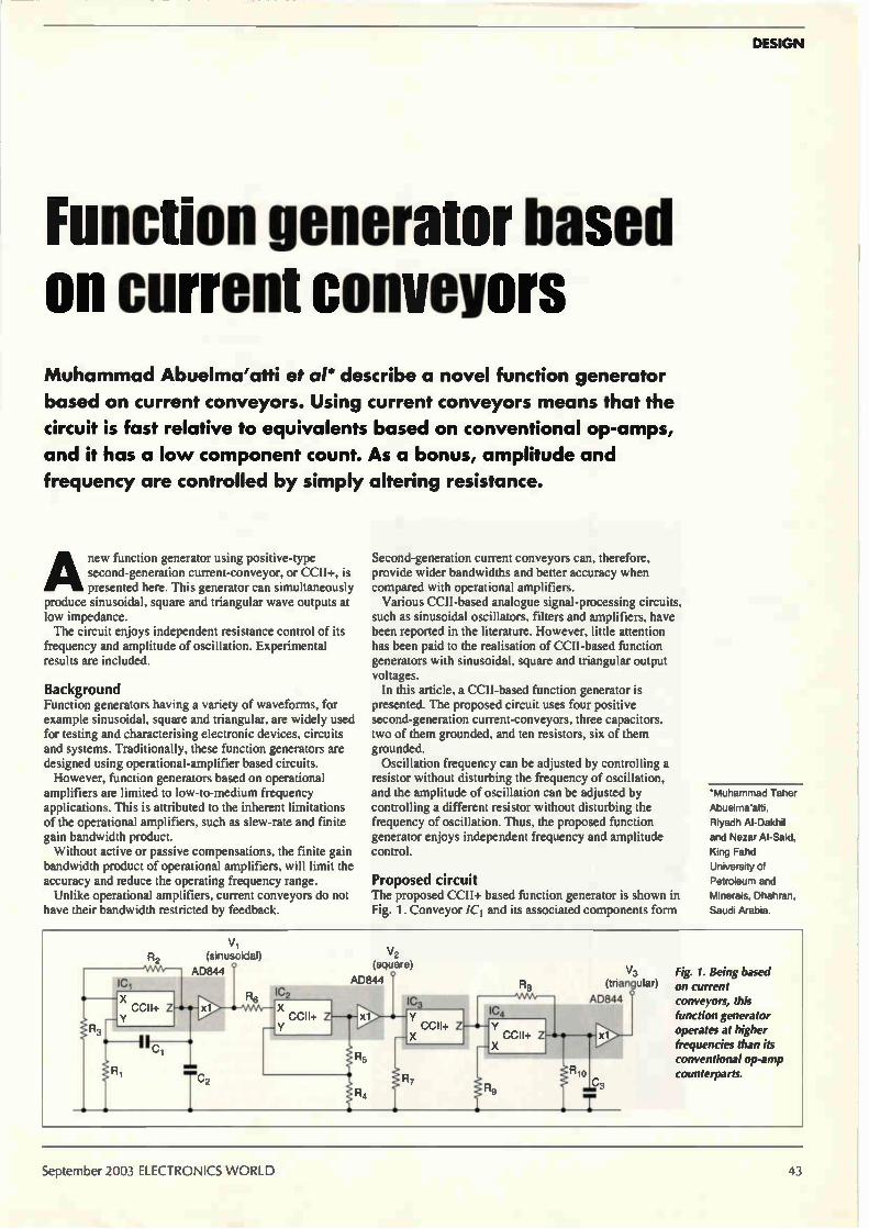
DESIGN
Function generator based on current conveyors Muhammad Abuelma'atti et al* describe a novel function generator
based on current conveyors. Using current conveyors means that the
circuit is fast relative to equivalents based on conventional op-amps,
and it has a low component count. As a bonus, amplitude and
frequency are controlled by simply altering resistance.
Anew function generator using positive-type second-generation current-conveyor, or CCII+, is presented here. This generator can simultaneously
produce sinusoidal, square and triangular wave outputs at low impedance. The circuit enjoys independent resistance control of its
frequency and amplitude of oscillation. Experimental results are included.
Background Function generators having a variety of waveforms, for example sinusoidal, square and triangular, are widely used for testing and characterising electronic devices, circuits and systems. Traditionally, these function generators are designed using operational-amplifier based circuits. However, function generators based on operational
amplifiers are limited to low-to-medium frequency applications. This is attributed to the inherent limitations of the operational amplifiers, such as slew-rate and finite gain bandwidth product. Without active or passive compensations, the finite gain
bandwidth product of operational amplifiers, will limit the accuracy and reduce the operating frequency range. Unlike operational amplifiers, current conveyors do not
have their bandwidth restricted by feedback.
Second-generation current conveyors can, therefore, provide wider bandwidths and better accuracy when compared with operational amplifiers. Various CCII-based analogue signal-processing circuits,
such as sinusoidal oscillators, filters and amplifiers, have been reported in the literature. However, little attention has been paid to the realisation of CCII-based function generators with sinusoidal, square and triangular output voltages.
In this article, a CCII-based function generator is presented. The proposed circuit uses four positive second-generation current-conveyors, three capacitors, two of them grounded, and ten resistors, six of them grounded. Oscillation frequency can be adjusted by controlling a
resistor without disturbing the frequency of oscillation, and the amplitude of oscillation can be adjusted by controlling a different resistor without disturbing the frequency of oscillation. Thus, the proposed function generator enjoys independent frequency and amplitude control.
Proposed circuit The proposed CCII+ based function generator is shown in Fig. 1. Conveyor /CI and its associated components form
'Muhammad Taher
Abuelma'atti,
Riyadh Al-Dakhil
and Nezar Al-Said.
King Fahd
University of
Petroleum and
Minerals, Dhahran,
Saudi Arabia.
ICI
Y
R2 VW,
vi
(sinusoidal)
AD844 °
R6 IC2
CCU+ ZI-•-•-• X*1 X CCII+ Z
Y
V2
(square)
AD844 °
X
R5
R4
IC3 Y
CCII+ Z
R8
IC4
Y
ÎR, CCII+ Z
Rlo
V3
(triangular)
AD844 °
xl
Fig. 1. Being based on current conveyors, this function generator operates at higher frequencies than its conventional op-amp counterparts.
September 2003 ELECTRONICS WORLD 43
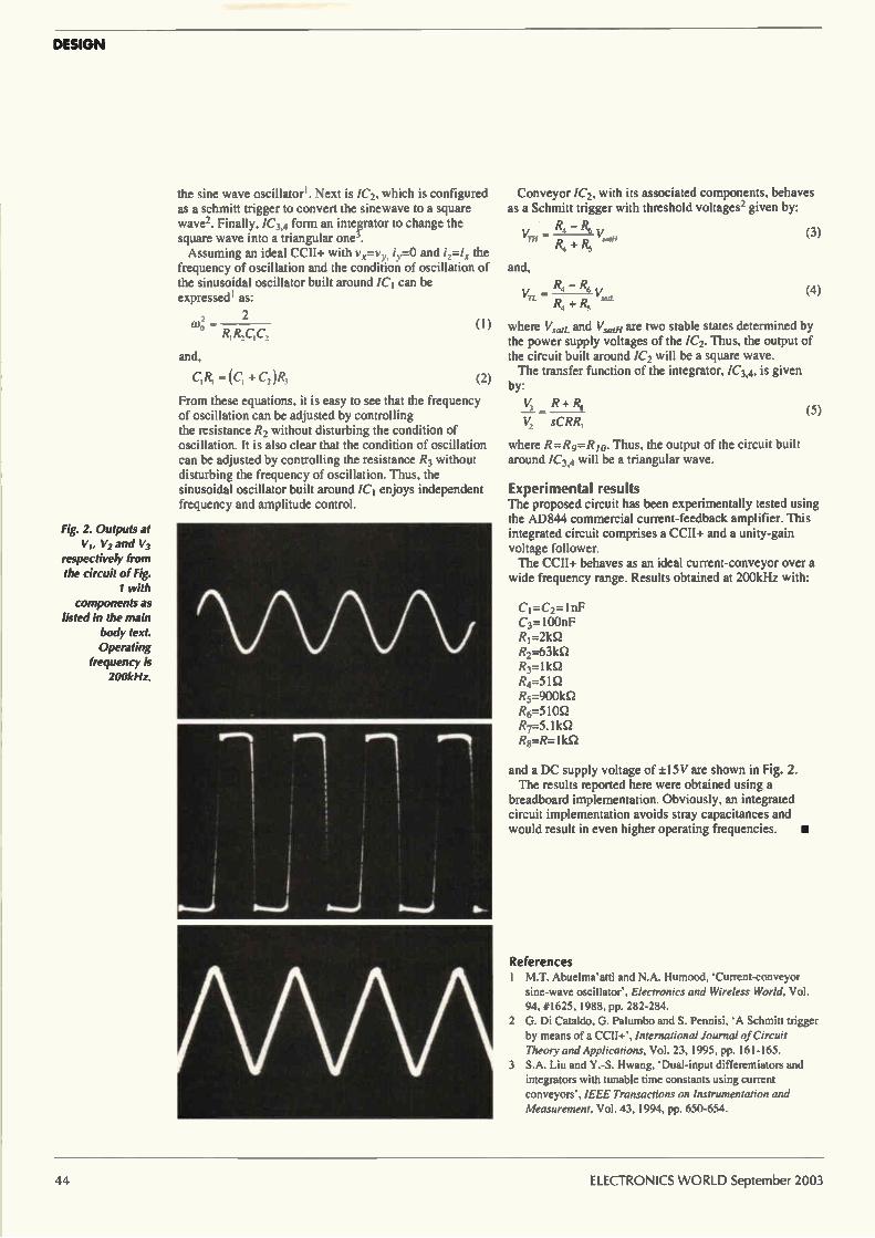
DESIGN
Fig. 2. Outputs at VI, V2 and V3
respectively from the circuit of Fig.
1 with components as
listed in the main body text. Operating
frequency is 200kHz.
the sine wave oscillator'. Next is /C2, which is configured as a schmitt trigger to convert the sinewave to a square wave2. Finally, /C34 form an integrator to change the square wave into a triangular one3. Assuming an ideal CCII+ with vx=vy, iy=0 and i=i, the
frequency of oscillation and the condition of oscillation of the sinusoidal oscillator built around ICI can be expressed' as:
, 2 co; -
R,R2C,C,
and,
C,R, (C, + C2)12,
(I)
(2)
From these equations, it is easy to see that the frequency of oscillation can be adjusted by controlling the resistance R2 without disturbing the condition of oscillation. It is also clear that the condition of oscillation can be adjusted by controlling the resistance R3 without disturbing the frequency of oscillation. Thus, the sinusoidal oscillator built around ICI enjoys independent frequency and amplitude control.
Conveyor /C2, with its associated components, behaves as a Schmitt trigger with threshold voltages2 given by:
R„ — R, Vn, = V (3) sarli
R, + Rs
and,
(4)
where %/sad and %/sae/ are two stable states determined by the power supply voltages of the /C2. Thus, the output of the circuit built around /C2 will be a square wave. The transfer function of the integrator, /C34, is given
by:
V, R + &
sCRIL,
where R=R9=R io. Thus, the output of the circuit built around /C34 will be a triangular wave.
Experimental results The proposed circuit has been experimentally tested using the AD844 commercial current-feedback amplifier. This integrated circuit comprises a CCII+ and a unity-gain voltage follower. The CCII+ behaves as an ideal current-conveyor over a
wide frequency range. Results obtained at 200kHz with:
CI =C2= 1nF C3=100nF Ri=21(51 R2=63kg R3=11d2 R4=51Q R5=9001d2 R6=510Q R7=5. 11d2 ReR=11d2
(5)
and a DC supply voltage of ±15V are shown in Fig. 2. The results reported here were obtained using a
breadboard implementation. Obviously, an integrated circuit implementation avoids stray capacitances and would result in even higher operating frequencies. •
References M.T. Abuelma'atti and N.A. Humood, 'Current-conveyor sine-wave oscillator', Electronics and Wireless World, Vol. 94, #I625, 1988, pp. 282-284.
2 G. Di Cataldo, G. Palumbo and S. Pennisi, 'A Schmitt trigger by means of a CCII+', International Journal of Circuit Theory and Applications, Vol. 23, 1995, pp. 161-165.
3 S.A. Liu and Y.-S. Hwang, 'Dual-input differentiators and integrators with tunable time constants using current conveyors', IEEE Transactions on Instrumentation and Measurement, Vol. 43, 1994, pp. 650-654.
44 ELECTRONICS WORLD September 2003
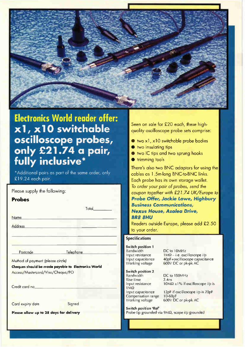
-
- . ;.-
%.":•j-:;à;,.. >V.3; .•‘..rist--Ceke"'".
"'lee •71"1".i•
;e"._ dge, • nu. - .e 'd":1•••'111.1e1e—!r
1:>;\
-
•
• :--es • - - • -- 4 - • - es- - •..,401%.7.- • -9 ' 01r.- - de' lie `4.'....:111erimré • slime. r - e
— ;et -7-eleebd-e 1"› eie-.7%." • e••• • ""e"--..,
vr
-49 -
••••=zie • «.
.„
I• •
•••
• •411-
-
fir
; ...Aril, • r 411M.
rt?
fer,dor•
4"
_ mar • _ eet.;e; e'-'•••• S 6- • 4,1 .a.
4-•
Electronics World reader offer: x 1 , x10 switchable oscilloscope probes, only £21.74 a pair, fully inclusive* *Additional pairs as part of the same order, only £19.24 each pair.
Please supply the following:
Probes
Nome
Total
Postcode Telephone
Method of payment (please circle) Cheques should be made payable to Electronics World
Access/Mastercard/Visa/Cheque/PO
Credit card no
Card expiry date Signed
Please allow up to 28 days for delivery
-Nuf
Seen on sale for £20 each, these high-quality oscilloscope probe sets comprise:
• two xl, x10 switchable probe bodies • two insulating tips • two IC tips and two sprung hooks • trimming tools
There's also two BNC adaptors for using the cables as 1 .5m-long BNC-to-BNC links. Each probe has its own storage wallet. To order your pair of probes, send the coupon together with £21.74 UK/Europe to Probe Offer, Jackie Lowe, Highbury Business Communications, Nexus House, Azalea Drive, BR8 8HU Readers outside Europe, please add £2.50 to your order.
ipecifications
;witch position 1 3andwidth nput resistance nput capacitance Vorking voltage
iwitch position 2 3andwidth Zise time nput resistance MO nput capacitance bmpensation range Vorking voltage
iwitch position 'Ref' 'robe tip grounded via 9MQ, scope i/p grounded
DC to 10MHz 1MS2 — i.e. oscilloscope i/p 40pF+oscilloscope capacitance 600V DC or pk-pk AC
DC to 150MHz 2.4ns 10MQ ±1% if oscilloscope i/p is
12pF if oscilloscope i/p is 20pF 10-60pF 600V DC or pk-pk AC
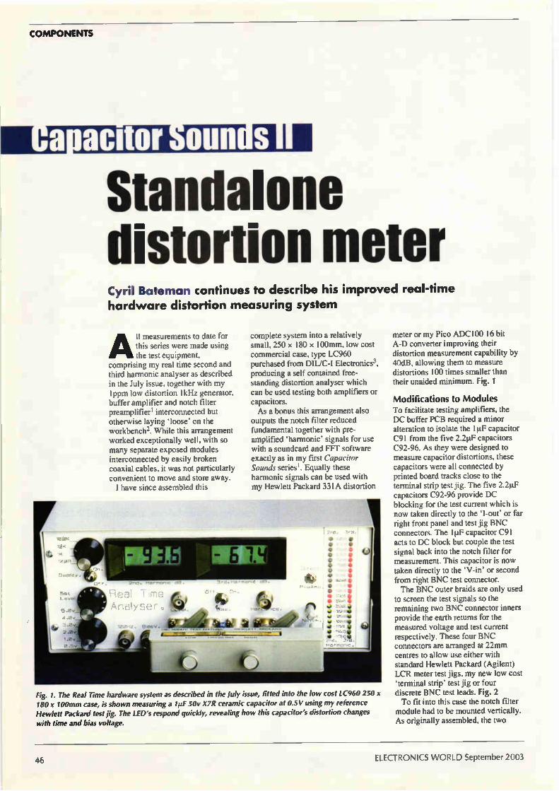
COMPONENTS
amtor 011111 S
Standalone distortion meter Cyril Bateman continues to describe his hardware distortion measuring system
All measurements to date for this series were made using the test equipment,
comprising my real time second and third harmonic analyser as described in the July issue, together with my I ppm low distortion IkHz generator, buffer amplifier and notch filter preamplifier' interconnected but otherwise laying 'loose' on the workbench2. While this arrangement worked exceptionally well, with so many separate exposed modules interconnected by easily broken coaxial cables, it was not particularly convenient to move and store away. I have since assembled this
improved real-time
complete system into a relatively small, 250 x 180 x 100mm, low cost commercial case, type LC960 purchased from DIL/C-I Electronics3, producing a self contained free-standing distortion analyser which can be used testing both amplifiers or capacitors. As a bonus this arrangement also
outputs the notch filter reduced fundamental together with pre-amplified 'harmonic' signals for use with a soundcard and EFT software exactly as in my first Capacitor Sounds series'. Equally these harmonic signals can be used with my Hewlett Packard 331A distortion
Fig. 1. The Real Time hardware system as described in the July issue, fitted into the low cost LC960 250 x 180 x 100mm case, is shown measuring a 1uF 50v X7R ceramic capacitor at 0.5V using my reference Hewlett Packard test jig. The LED's respond quickly, revealing how this capacitor's distortion changes with time and bias voltage.
meter or my Pico ADC10() 16 bit A-D converter improving their distortion measurement capability by 40dB, allowing them to measure distortions 100 times smaller than their unaided minimum. Fig. 1
Modifications to Modules To facilitate testing amplifiers, the DC buffer PCB required a minor alteration to isolate the I µF capacitor C91 from the five 2.2µF capacitors C92-96. As they were designed to measure capacitor distortions, these capacitors were all connected by printed board tracks close to the terminal strip test jig. The five 2.2µF capacitors C92-96 provide DC blocking for the test current which is now taken directly to the 'I-out' or far right front panel and test jig BNC connectors. The 1µF capacitor C91 acts to DC block but couple the test signal back into the notch filter for measurement. This capacitor is now taken directly to the 'V-in' or second from right BNC test connector. The BNC outer braids are only used
to screen the test signals so the remaining two BNC connector inners provide the earth returns for the measured voltage and test current respectively. These four BNC connectors are arranged at 22nrun centres to allow use either with standard Hewlett Packard (Agilent) LCR meter test jigs, my new low cost 'terminal strip' test jig or four discrete BNC test leads. Fig. 2 To fit into this case the notch filter
module had to be mounted vertically. As originally assembled, the two
46 ELECTRONICS WORLD September 2003
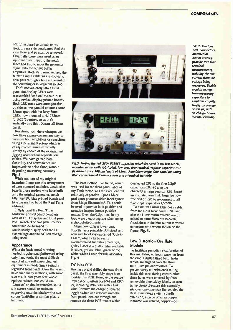
COMPONENTS
PTFE insulated terminals on its bottom case side would now foul the case floor and so must be removed. Originally these were used as an optional direct input to the notch filter and also to input the generator signal into the output buffer amplifier. Both were removed and the buffer's input cable was re-routed to now pass through a hole at the end of the screening case, adjacent to U45. To fit conveniently into a front
panel the display LEDs were reassembled 'end on' to their PCB using revised display printed boards. Both LED trees were arranged side by side as two parallel columns some 15nun apart with the forty 3mm LEDs now mounted at 4.1275inm (0.1625") centres, so as to fit vertically into this 100mm tall front panel. Resulting from these changes we
now have a more convenient way to measure both amplifiers or capacitors using a permanent set-up which is easily re-configured externally, simply by choice of the external test jigging used or four separate test cables. We have gained both flexibility and convenience and improved the noise floor, without degrading measuring accuracy. Fig. 3 While not part of my original
intention, I now see this arrangement of case mounted modules, would also benefit those readers who have built only the original generator, notch filter and DC bias printed boards and have no wish to build the Real Time add-ons. Simply omit the Real Time
hardware printed board complete with its LED displays and front panel level switch. The two panel meters could then be arranged to continuously display both the DC bias voltage and the AC test voltage being used.
Appearance While the basic metal working needed is quite straightforward using only hand tools, the most difficult aspect of any self assembled test equipment is producing a suitably legended front panel. Over the years I have tried many methods, with some success. In past years few viable options existed, one could use `Letraser or similar transfers, cut a silk screen stencil or make an engraving onto the black/white two colour Traffolite or similar plastic laminate.
Fig.3. Testing the lie 250v 832653 capacitor which featured in my last article, mounted in my easily fabricated, low cost, four terminal 'replica' capacitor test jig made from a 100mm length of 15mm Aluminium angle, four panel mounting HNC connectors at 22mm centres and a terminal test strip.
The best method I've found, which was used for the front panel label of my Tan6 meter, was the excellent but relatively expensive 'Quick Mark' peel apart photosensitive label system from Mega Electronics4. This could be used to provide both positive and negative images from a positive master. Even the 0.5pt lines in my logo were clearly legible when using a photoplotted-master. Mega now offer a lower cost,
directly laser printable, A4 sized self adhesive label system called 'Quick-Laser', which can be easily overlaminated for extra protection. Quick Laser is a plastic film available in silver, yellow, blue, green or the white which I used for this assembly. Fig. 4
DC bias PCB Having cut and drilled the case front panel, the first assembly stage is to modify this PCB. Remove the source impedance resistors R91-94 and R97-99, replacing R94 only with a link wire. Remove the charge discharge toggle switch and relocate onto the front panel, then cut through and remove the three PCB tracks which
connected C91 to the five 2.2p.F capacitors C92-96 also the charge/discharge resistor R95. Insert an insulated wire link from the now free end of R95 to re-connect to all five 2.2pF capacitors C92-96. To assist in earthing the coax cable
from the I-out front panel BNC and also the I-low return current wire, I added an extra Vero pin to earth, fitted close to the bias output terminal connector strip where shown on the figure. Fig. 5.
Low Distortion Oscillator Module
To facilitate periodic re-calibration of this oscillator, without removing from the case. I drilled three 6mrn holes which are aligned over the three multi-turn pre-set resistors. To prevent stray cut wire ends falling inside this case during construction, these holes were covered by three removable blue sticky labels, as seen in the photo. Because this assembly sits over one case side flange, also the Real Time range switch spindle extension, a piece of scrap copper laminate was affixed, copper side
Fig. 2. The four IINC connectors mounted at 22mm centres, provide true four terminal measurements, isolating the test current from the voltage being measured. Enable a quick change from measuring capacitors to amplifier circuits simply by change of test jig, with no change of any internal circuitry.
September 2003 ELECTRONICS WORLD 47
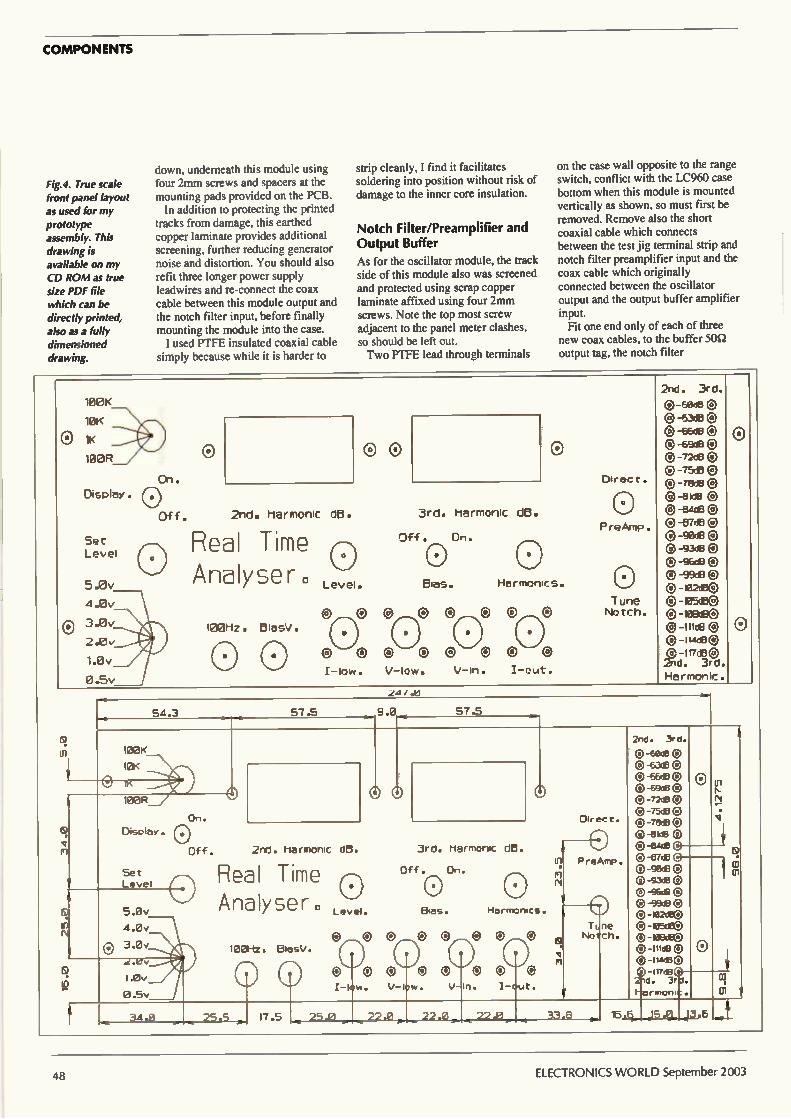
COMPONENTS
Fig.4. True scale front panel layout as used for my prototype assembly. This drawing is available on my CD ROM as true size PDF file which can be directly printed, also as a fully dimensioned drawing.
down, underneath this module using four 2mm screws and spacers at the mounting pads provided on the PCB.
In addition to protecting the printed tracks from damage, this earthed copper laminate provides additional screening, further reducing generator noise and distortion. You should also refit three longer power supply leadwires and re-connect the coax cable between this module output and the notch filter input, before finally mounting the module into the case. I used PTFE insulated coaxial cable
simply because while it is harder to
strip cleanly, I find it facilitates soldering into position without risk of damage to the inner core insulation.
Notch Filter/Preamplifier and Output Buffer
As for the oscillator module, the track side of this module also was screened and protected using scrap copper laminate affixed using four 2mm screws. Note the top most screw adjacent to the panel meter clashes, so should be left out. Two PTFE lead through terminals
on the case wall opposite to the range switch, conflict with the LC960 case bottom when this module is mounted vertically as shown, so must first be removed. Remove also the short coaxial cable which connects between the test jig terminal strip and notch filter preamplifier input and the coax cable which originally connected between the oscillator output and the output buffer amplifier input.
Fit one end only of each of three new coax cables, to the buffer 50Q output tag, the notch filter
100K
10K
IK
100R
Display .
Set Level
5.0v
21.13v
® 3.0v
2.0v
1.0v
0.5v
Off. 2nd. harmonic dB.
Real Time Analyser.
100Hz BiasV
o
Level.
3rd. harmonic d13.
Of+. On.
(1)
Bias. Harmonics.
Cl 0 @ Cl C) ® ®
C) e e ®
I-low. V-low. V-in. I-out.
Dir ec t
PreAmp
o Tune Notch.
2nd. 3rd.
0 -9,311B e ® -6343 ® 13 -66dB 0 ® -69dB 0 13 -72113 0 -75r113 ®
-ake 0
® Ante ® 0 -gee 0
-96d13 ® ®-99d13
e-e-o-®-Ifice® ®-Iude® 01 -117130 2nd. 3rd. Harmonic.
On. Direct.
100R
Display.
Set Level
Off.
e
2nd. harmonic
Real Time An
25.5
10-4z. BlasV.
o 17.5
dB.
Level.
e 0
24/
3rd. harmonic d.
Off. On. o Bias.
o oo eo e V- low. V- in . i-out .
25.0
HarmenIcs.
, 22.O,. ,22 .@,, .13._ J. .1
222., 33 13
o Pr eAMP
Ti,ne No 1 ch.
2nd. 3rd.
0-601B 0 -&3113 0 ® -€613 0 o -Ends o
-72as -75,113 C)
-• 131dB 0 0 -Etede e e -gee o 0. -93e 0
-96£1 0 C) -9913 C) -• pa2dao -• esce0
C) -169dBC) c-like 0-11.0130
0. 3r cq cn
48 ELECTRONICS WORLD September 2003
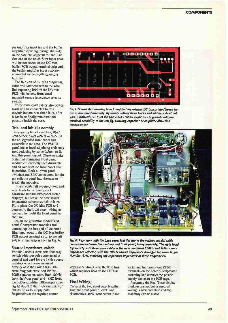
COMPONENTS
preamplifier input tag and the buffer amplifier input tag through the hole in the case end adjacent to U45. The free end of the notch filter input coax will be connected to the DC bias buffer PCB output terminal strip and the buffer amplifier input coax re-connected to the oscillator output terminal. The free end of the 50Q output tag
cable will later connect to the wire link replacing R94 on the DC bias PCB, via the new front panel mounted source impedance selector switch. Three more coax cables also power
leads will be connected to this module but are best fitted later, after it has been finally mounted into position inside the case.
Trial and initial assembly Temporarily fix all switches, BNC connectors, panel meters in place on the un-legended front panel and assemble to the case. The PM128 panel meter bezel adjoining ends may need reducing by some 0.5nrun to fit into this panel layout. Check to make certain all remaining front panel modules fit correctly then dismantle and fix and trim the front panel label in position. Refit all front panel switches and BNC connectors, but do not refit the panel into the case or install the modules. Fit and solder all required coax and
wire leads to the front panel hardware also the two panel meter displays, but leave the new source impedance selector switch to later. Fit in place the DC bias PCB and connect to the front panel wiring as needed, then refit the front panel to the case.
Install the generator module and notch filter/preamp modules and connect up the free end of the notch filter input coax to the DC bias buffer PCB output terminal strip, to the left side terminal strip as seen in Fig. 6.
Source impedance switch For this I used a three pole four way switch with two poles connected in parallel and used for the IlcHz source resistors which were mounted directly onto the switch tags. The remaining pole was used for the 100Hz source resistors. Both 100Hz from the front panel and licHZ from the buffer amplifier 50Q output coax tag go direct to their relevant resistor chains, so as to supply both frequencies at the required source
Fig.5. Screen shot showing how I modified my original DC bias printed board for use in this cased assembly. By simply cutting three tracks and adding a short link wire, I isolated C91 from the five 2.2tIF C92-96 capacitors to provide full four terminal capability to the test jig, allowing capacitor or amplifier distortion measurement
Fig. 6. Rear view with the back panel laid flat shows the various coaxial cable connecting between the modules and front panel, in my assembly. The right hand top switch, with three coax cables is the new combined 100Hz and ¡kHz source impedance selector, with the 100Hz source impedance arranged ten times larger than for 1 kHz, matching the capacitors impedance at these frequencies.
impedance, direct onto the wire link which replaces R94 on the DC bias PCB.
Final Wiring Connect the two short coax lengths from the front panel 'Level' and 'Harmonics' BNC connectors to the
meter and harmonics out PTFE terminals on the notch filter/preamp assembly and connect the power supply cables to the PCB tags. Assuming the Real Time display
modules are not being used, all wiring is now complete and the assembly can be tested.
September 2003 ELECTRONICS WORLD 49
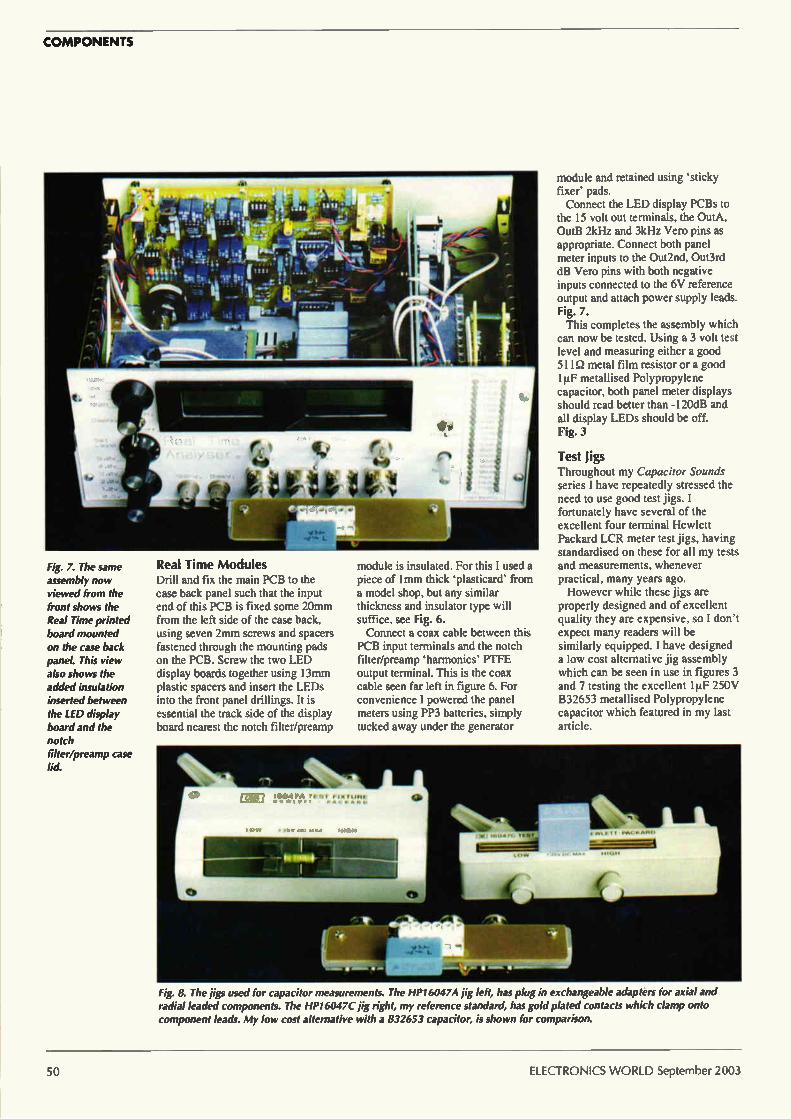
COMPONENTS
Fig. 7. The same assembly now viewed from the front shows the Real Time printed board mounted on the case back panel. This view also shows the added insulation inserted between the LED display board and the notch filter/preamp case lid.
Real Time Modules Drill and fix the main PCB to the case back panel such that the input end of this PCB is fixed some 2Orrun from the left side of the case back, using seven 2mm screws and spacers fastened through the mounting pads on the PCB. Screw the two LED display boards together using 13mm plastic spacers and insert the LEDs into the front panel drillings. It is essential the track side of the display board nearest the notch filter/preamp
module is insulated. For this I used a piece of lmm thick `plasticard' from a model shop, but any similar thickness and insulator type will suffice, see Fig. 6. Connect a coax cable between this
PCB input terminals and the notch filter/preamp 'harmonics' PTFE output terminal. This is the coax cable seen far left in figure 6. For convenience I powered the panel meters using PP3 batteries, simply tucked away under the generator
module and retained using 'sticky fixer' pads. Connect the LED display PCBs to
the 15 volt out terminals, the OutA, OutB 2kHz and 3kHz Vero pins as appropriate. Connect both panel meter inputs to the Out2nd, Out3rd dB Vero pins with both negative inputs connected to the 6V reference output and attach power supply leads. Fig. 7. This completes the assembly which
can now be tested. Using a 3 volt test level and measuring either a good 511Q metal film resistor or a good le metallised Polypropylene capacitor, both panel meter displays should read better than -120dB and all display LEDs should be off. Fig. 3
Test Jigs Throughout my Capacitor Sounds series I have repeatedly stressed the need to use good test jigs. I fortunately have several of the excellent four terminal Hewlett Packard LCR meter test jigs, having standardised on these for all my tests and measurements, whenever practical, many years ago. However while these jigs are
properly designed and of excellent quality they are expensive, so I don't expect many readers will be similarly equipped. I have designed a low cost alternative jig assembly which can be seen in use in figures 3 and 7 testing the excellent 1p.F 250V B32653 metallised Polypropylene capacitor which featured in my last article.
Fig. 8. The jigs used for capacitor measurements. The HP! 60474 jig left, has plug in exchangeable adapters for axial and radial leaded components. The HP16047C jig right, my reference standard, has gold plated contacts which clamp onto component leads. My low cost alternative with a 832653 capacitor, is shown for comparison.
50 ELECTRONICS WORLD September 2003

COMPONENTS
This jig was assembled using a 100mm length of 15mm Aluminium angle, four panel mounting BNC connectors. Farnell part 3650534. mounted at 22mm centres to match my front panel and another terminal block as used for my DC bias buffer. Fig. 8. The terminal block was mounted
on a scrap piece of laminate and its active or white terminals simply isolated by hand carving. The black common (low) terminal was connected to both the current and voltage 'low' BNC connectors using a short length of twisted pair wires, with the wires placed one on each side of the terminal pin solder.
In similar fashion the white (high) test terminal pins were connected to the 'high' BNC connectors with the voltage wire to the test terminal adjacent to the common terminal, the current wire going to the opposite end terminal pin. In this fashion full four terminal connections were maintained right up to these capacitor test jig terminals.
Performance Using a 3V test level and with the original module calibration unchanged. my ItIF 250v foil and Polypropylene FKP reference capacitor now reads better than —130dB both for 2nd and 3rd harmonics, a clear indication that the improved screening with the modules assembled inside the case has lowered noise levels and reduced extraneous noise pickup. Altogether a significant improvement on an already excellent measuring system.
In my next article I explore using this equipment to measure distortions in amplifier circuits.
References I. Capacitor Sounds. C. Bateman.
Electronics World. July, September, October 02.
2. Capacitor Sounds II. C. Bateman. Electronics World, July 2003.
3. DIL/C-I Electronics, Holland. email to dileeuronet.n1
4. Mega Electronics Ltd. http://www.megauk.com
Technical support
Full details of this new hardware test method and my original Capacitor Sounds series 1ppm low distortion oscillator, buffer amplifier, notch filter/preamplifier and DC bias assemblies, together with parts lists, assembly manuals and full size printed circuit board drawings. all as .PDF files arranged for easy viewing on screen or hardcopy. are provided in my new Capacitor Sounds CD. This CD ROM includes updated and much
expanded re-writes with very many more figures, of my recent series of six Capacitor Sounds articles. supported now by some ninety capacitor distortion measurement plots. Also on the CD are PDF re-writes of my earlier 'Understand Capacitors' series together with articles how to diagnose failed capacitors while still mounted on printed circuit boards and essential low cost capacitor measurement methods, more than twenty popular articles. The CD is now available, cost £15 Sterling
including post packing. Send cheques or postal/money orders in Pounds Sterling only to:-C.Bateman. 'Nimrod' New Road. ACLE. Norfolk. NR13 3BD. England.
Answers to Test Yourself from page 35 E n x —de)
di
This is Faraday's law of induction. For a coil of n turns, the EMF generated is
equal to the rate of change of the flux. multiplied by the number of turns. The law can also be stated as the rate of change of flux linkages, but this form
is more understandable for stationary devices such as transformers.
E L x dt
This is a key equation for an inductor, stating that the EMF across an inductor
is equal to the rate of change of current through it. multiplied by its inductance. The equation can be re-arranged to work out the rate of change of
current from an applied EMF. This is essential for an understanding of switched mode power supplies.
dV
di
This is the current in a capacitor caused by a changing potential difference
across its terminals. This was explained in the text.
dV r = —
di
The small signal resistance of a component is the slope of its voltage/current
curve. It is the small signal form of Ohm's law.
Answers to Final Test A sinusoidal voltage is mathematically represented by the equation. V=VmAxxsin(wxt). Now to is the angular frequency in radians/second. It has to
be in radians/second to make the calculus work correctly. The slew rate is the
derivative of the voltage with respect to time.
dV — —W x V x cos(a) x t) dt
The maximum value of a cosine function is one, so:
dV
di MAX - w x v.„,Ax
Remember that w=2/rf and that the peak value of a sinusoid is ,./2 times the
RMS value.
dV — = 2.7r x106 x x 3 26.66V / ms di
100 2) i = C x —dV = 0.1 x 10 -6 x - 6.667A
di 1.5 x 10 -6
25kHz is a period of 40ps. The waveform is therefore at 10V for 10ms and IV
for 30ps.
VRMS , [ lo -, x dt + r 1-, x dt 40 0 .1 10
v;„„ - —40 (pm x +[t x
RMS
VRi„s - 5.074V
As a quick check, we ensure that the RMS value is smaller than the maximum
voltage (10V) and larger than the minimum voltage (IV).
4) If you answered with just a number then you failed. If you were unsure, but thought it seemed wrong then you failed; you need a much better
understanding of the basics than that. The answer I am looking for is that the
question is faulty. The mean power in the resistor is of course 25.75Q. The peak power is 100W. The crest factor is 1.97. The question asks for a stupid quantity, which, if calculated, would give a meaningless result. If anyone asks
you for "RMS power" you have to interpret the request as being for mean
power and then point out the error.
September 2003 ELECTRONICS WORLD 51
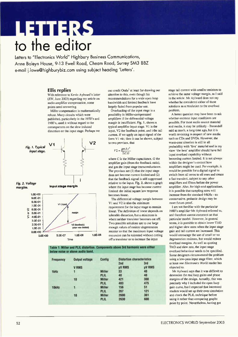
to the editor Letters to "Electronics World" Highbury Business Communications,
Anne Boleyn House, 9-13 Ewell Road, Cheam Road, Surrey SM3 8BZ
e-mail [email protected] using subject heading 'Letters'.
Ellis replies With reference to Kevin Aylward's letter (EW, June 2003) regarding my article on audio amplifier compensation, some points need answering.
Miller compensation is mathematically robust. Many circuits which were published, particularly in the 1970's and 1980's. used it without regard to the consequences on the slew induced distortion on the input stage. Perhaps we
Fig. 1. Typical vi input stage.
Fig. 2. Voltage margins.
1 0E+00 -
9.0E-01 -
8 0E-01 - 7 0E-01 60E-01
5.0E-01
4.0E-01
3 0E-01
2 0E-01
1 0E-01
0.0E+00
0 0E+00
Input stage margin
Vi (npit)
V2 (leecback)
(tie fete lontlecfl
5 0E-07 1 0E-06 1 5E-06
can credit Otalal at least for drawing our attention to this, even though his recommendations for a wide open loop bandwidth and limited feedback have largely faded from popular use. Overloading of the input stage is a
possibility in Miller-compensated amplifiers if the differential voltage margin is insufficient. Fig. 1. shows a typical amplifier input stage. VI is the input, V2 the feedback point, and i the tail
current. If we apply an input signal of the form VI =kt, then it can be shown, subject to two provisos, that
gm.ki2
2.C.G
where C is the Miller capacitance, G the amplifier gain (from the feedback ratio), and gm the input stage transconductance. The provisos are (1) that the input stage does not become current limited and (2) that the feedback signal is still suppressed relative to the input. Fig. 2. shows a graph where the input stage has become current
limited: the initial square law response becomes linear. The differential voltage margin between
VI and V2 is also the minimum requirement for the input stage to remain linear. The definition of linear depends on tolerable distortion, but a minimum is where neither transistor becomes cut off. Two possible solutions are to use large enough values of emitter degeneration resistor so that the maximum input voltage excursion can be tolerated without cutting off a transistor or to increase the input
Table 1: Miller and PLIL distortion. Components above 3rd harmonic were either below noise or above audio band.
Frequency Output voltage Contig Distortion characteristics 2nd
V RMS pi/ HMS 1kHz 1 Miller 33
PLIL 40 10 Miller 421
PLIL 483 10kHz 1 Miller 156
PLIL 267 10 Miller 2600
PLIL 2630
3rd pV RMS 40 40 300 475 51 121 361 600
stage tail current with smaller resistors to
achieve the same voltage margin, as I said in the article. Mr Aylward does not say whether he considered either of these solutions as a resolution to the overload
problem. A better question may have been to ask
whether extreme input conditions are possible. For most audio source material and media, it may be unlikely - Baxandall said as much, a long time ago, but it is worth revisiting in respect of new media such as CDs and DVDs. However, the worst-case situation is still in all probability with 'live' material and in my view 'the best' amplifier should have full input overload capability without becoming current limited. It is not always
within the designer's control how amplifiers might be used. For example, it would be possible for a digital signal to switch from all zeros to all ones and create a fast transient, subject to any other amplifiers and filters before the power amplifier. Also, for high-end applications, it is possible that sampling rates will increase from the standard 44kHz - so conservative, pedantic design may be more future-proof. I am not familiar with the particular
1980's amplifier Mr Aylward referred to, and therefore cannot comment on that particular model. However, in general terms, it is possible to obtain lower THD and higher slew rates when the input stage gain and tail current are increased. This would encourage the use of small or no degeneration resistors, but would reduce overload margins. As well as quoting THD and slew rate, the input stage overload behaviour needs to be specified. Some designers circumvented the problem using a low-pass input stage filter, which at least one Electronics World reader has
objected to. Mr Aylward says that it was difficult to
determine the real loop gains and phase margins of the design. Actually, this was precisely why I included the open loop gain curve, but I expected that interested readers would set up their own simulation and check the PLIL technique before using it rather than comparing graphs point by point. Nevertheless, having got
ELECTRONICS WORLD September 2003
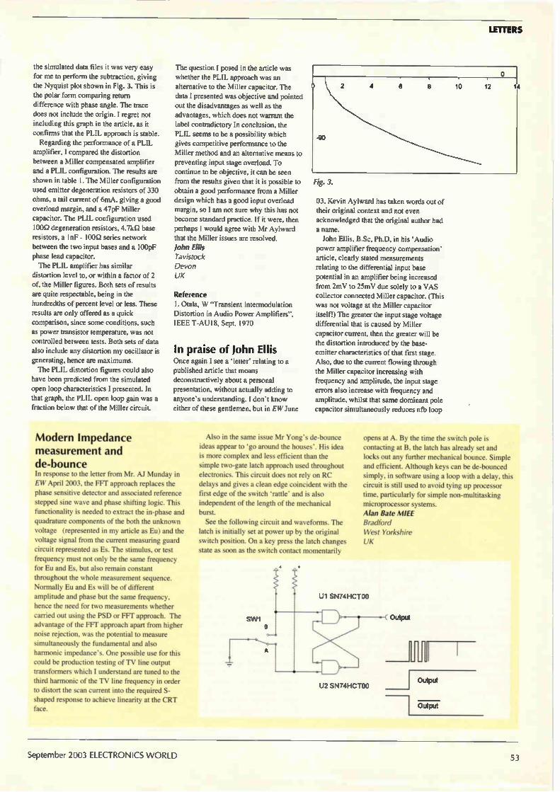
LETTERS
the simulated data files it was very easy for me to perform the subtraction, giving
the Nyquist plot shown in Fig. 3. This is the polar form comparing return
difference with phase angle. The trace does not include the origin. I regret not including this graph in the article, as it confirms that the PLIL approach is stable.
Regarding the performance of a PLIL amplifier, I compared the distortion between a Miller compensated amplifier and a PLIL configuration. The results are
shown in table I. The Miller configuration used emitter degeneration resistors of 330 ohms, a tail current of 6mA, giving a good overload margin, and a 47pF Miller capacitor. The PLIL configuration used
100Q degeneration resistors, 4.7kil base resistors, a 1nF - 100Q series network between the two input bases and a 100pF phase lead capacitor. The PLIL amplifier has similar
distortion level to, or within a factor of 2 of, the Miller figures. Both sets of results are quite respectable, being in the
hundredths of percent level or less. These results are only offered as a quick
comparison, since some conditions, such as power transistor temperature, was not controlled between tests. Both sets of data also include any distortion my oscillator is generating, hence are maximums. The PLIL distortion figures could also
have been predicted from the simulated open loop characteristics I presented. In that graph, the PLIL open loop gain was a fraction below that of the Miller circuit.
The question I posed in the article was whether the PLIL approach was an alternative to the Miller capacitor. The data I presented was objective and pointed out the disadvantages as well as the advantages, which does not warrant the label contradictory In conclusion, the PLIL seems to be a possibility which gives competitive performance to the Miller method and an alternative means to preventing input stage overload. To continue to be objective, it can be seen from the results given that it is possible to obtain a good performance from a Miller design which has a good input overload
margin, so I am not sure why this has not become standard practice. If it were, then perhaps I would agree with Mr Aylward that the Miller issues are resolved. John Ellis Tavistock Devon UK
Reference
I. Otala, W "Transient Interrnodulation Distortion in Audio Power Amplifiers", IEEE T-AU18, Sept. 1970
In praise of John Ellis Once again I see a letter relating to a
published article that moans deconstructively about a personal
presentation, without actually adding to anyone's understanding. I don't know either of these gentlemen, but in EW June
Fig. 3.
03, Kevin Aylward has taken words out of their original context and not even acknowledged that the original author had a name. John Ellis, B.Sc, Ph.D, in his 'Audio
power amplifier frequency compensation' article, clearly stated measurements relating to the differential input base potential in an amplifier being increased from 2mV to 25mV due solely to a VAS
collector connected Miller capacitor. (This was not voltage at the Miller capacitor itself!) The greater the input stage voltage differential that is caused by Miller capacitor current, then the greater will be the distortion introduced by the base-emitter characteristics of that first stage. Also, due to the current flowing through the Miller capacitor increasing with frequency and amplitude, the input stage errors also increase with frequency and amplitude, whilst that same dominant pole capacitor simultaneously reduces nib loop
Modern Impedance measurement and de-bounce In response to the letter from Mr. AI Munday in EW April 2003, the FFI' approach replaces the phase sensitive detector and associated reference stepped sine wave and phase shifting logic. This functionality is needed to extract the in-phase and quadrature components of the both the unknown voltage (represented in my article as Eu) and the voltage signal from the current measuring guard circuit represented as Es. The stimulus, or test frequency must not only be the same frequency for Eu and Es, but also remain constant
throughout the whole measurement sequence. Normally Eu and Es will be of different amplitude and phase but the same frequency,
hence the need for two measurements whether carried out using the PSD or FFT approach. The advantage of the FFT approach apart from higher noise rejection, was the potential to measure simultaneously the fundamental and also harmonic impedance's. One possible use for this could be production testing of TV line output transformers which I understand are tuned to the third harmonic of the TV line frequency in order to distort the scan current into the required S-shaped response to achieve linearity at the CRT face.
Also in the same issue Mr Yong's de-bounce ideas appear to 'go around the houses'. His idea is more complex and less efficient than the simple two-gate latch approach used throughout electronics. This circuit does not rely on RC delays and gives a clean edge coincident with the first edge of the switch 'rattle' and is also independent of the length of the mechanical burst. See the following circuit and waveforms. The
latch is initially set at power up by the original switch position. On a key press the latch changes state as soon as the switch contact momentarily
opens at A. By the time the switch pole is contacting at B. the latch has already set and locks out any further mechanical bounce. Simple and efficient. Although keys can be de-bounced simply, in software using a loop with a delay, this circuit is still used to avoid tying up processor time, particularly for simple non-multitasking microprocessor systems. Alan Sate MIEE Bradford West Yorkshire UK
SW1
U1 SN74HCTOO
U2 SN74HCTOO
September 2003 ELECTRONICS WORLD
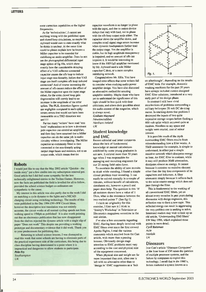
LETTERS
error correction capabilities at the higher
frequencies. As for 'technicalities', I cannot see
anything wrong with the published open
and closed loop simulations, so maybe Mr Aylward would care to state exactly what
he thinks is unclear. At the same time
could he please explain how he knows a
Miller capacitor to be essential for
stabilising an audio amplifier. Does he not see the photographed differential input
stage spikes of fig. 10a, which show
exactly how the considerable delaying
effect of a VAS collector connected
capacitor causes the nfb loop to induce input stage non-linearity, before that VAS
stage can itself complete nfb loop induced
correction? And of course increasing the
amount of nth cannot reduce the effect of
the Miller capacitor upon the input stage
either, for the extra closed loop gain
degeneration will merely lead to an
increase in the amplitude of the error
spikes. The PLIL distortion figures quoted are negligible compared to such spiky
errors; errors that would not have been
measurable on a THD distortion test sew,
Far too many 'writers' have read 'text book' explanations as to how a dominant
pole capacitor can control an amplifier, and then they have assumed that a Miller
capacitor can do the same job in audio circuitry without investigating. The Miller
capacitor so commonly fitted is then connected to the non-linearly acting
output stage bases and resistors, not to an
output node, which means that the
Robots I would just like to say that the May 2002 article "Quickie - the inside story" put a few credits into my subscription renewal pot.
Good article but I did feel some sympathy for the less
technically enlightened entries to the Techno Games. However, now the facts are published the field is levelled for all to follow,
provided the school science budget co-ordinators are
sympathetic to the cause. My interest in this article was also partly due to the work I did
on matching a cycle dynamo to the lights and a NICAD
charging circuit using switching technology. The results of this were published in the Dec 1994 EW+WW Circuit Ideas, however the descriptive text translation was not entirely
accurate, the circuit works at all normal cycling speeds not from walking speed to 15Mph as published! It is also worth pointing
out that an electronics publication that has now disappeared from the shelves rejected the dynamo article with a single slip of
paper "Does not work" This despite me providing a working prototype and documentary evidence that it did work. Thank you
to your predecessors for publishing this. Returning to school science lessons, I was dismayed to
read this week that some schools are having to eliminate parts of the practical experiment side of the curriculum, this being due to
class discipline having deteriorated to a point where it is
impractical and dangerous to allow students to participate.
Pete Fry Southampton
UK
capacitor waveform is no longer in phase with the input, and due to output device
delays that vary with load, not in phase
with the nfb loop output node either. The
capacitor slows the amplifier down, and complex small signal stage errors increase
when dynamic loudspeakers further load
the output stage. Yes the amplifier is
stable, but its high amplitude transparency
is impaired, and no amount of nfb can improve it. It would be interesting to
know if the 100V/g amplifier mentioned
by Mr. Aylward used a sole Miller
capacitor C.dom, or a more complex
stabilizing network. Congratulations Mr. Ellis. You have
imaged error effects that some writers fail
to consider when studying audio power amplifier design. You have also discussed
an alternative method for assuring amplifier stability. Maybe those who have
yet to understand the significance of this topic should be less quick with their criticisms, and others their grumbles about
the audio content of the magazine, which
is always novel.
Graham Maynard Newtownabbey
Northern Ireland
UK
Student knowledge and EMC Recent editorial and letter comments
about the lack of fundamental knowledge or mental calculations exhibited by some young graduates is
not new. It existed more than 30 years ago when I was responsible for managing and recruiting engineers for
our 25 strong field sales force. To ascertain the ability of new recruits
to think while standing, I found a simple
circuit problem most revealing. It can easily be solved mentally in a couple of minutes, without benefit of calculators,
simulators etc, however a pencil and
paper does help. The question is this 'If
all resistors shown have a value of 1 Ohm, what is the resistance between the
two marked points ?' (See fig 1).
I claim no originality for this exercise, I first saw it I think in
'Smitty's Workshop' in Television or
Electronics magazines sometime in the
mid sixties. I've also a few comments regarding
EMC. Having been deeply involved with
EMC filters ever since the first crewed Apollo flights, I read the various comments which resulted from the Catt article, with more than a passing
interest. Obviously design stage attention to EMC problems must vary
according to the cost and physical size of the equipment concerned. When physical size and weight are far
more important than cost, often one is left with no alternative other than to 'design in' EMC suppression as a 'bolt
on afterthought', depending on the results of EMC tests. For example, domestic
washing machines for the past 30 years
have always included custom designed EMC filter solutions, introduced at a very
early part of the design phase. In contrast I still have vivid
recollections of problems surrounding a
military helicopter 28 volt DC de-icing motor. In tracking down that problem I
destroyed the inputs of two quite expensive storage scopes before finding a
600 volt spike which occurred quite at
random. Needless to say space and
weight were crucial, cost of minor
interest. It is possible much of the myth
surrounding EMC filters results from misunderstanding how a filter works. A
50dB attenuator for example, is simple to understand, in effect just a simple
resistive network which dissipates energy
as heat. An EMC filter in contrast, while
it may still produce 50dB attenuation, dissipates almost no energy. It cannot because it contains no resistive element
other than the tiny loss components of its
capacitors and inductors. A filter attenuates simply because it reflects back to the noise source energy which does not
pass through the filter. This is fundamental to the working of
all conventional EMC filters, yet on
almost every occasion in past years during discussion with design engineers, this
reflection was to them a new topic. This
reflected energy can result in aggravating
the very problem one is seeking to solve. Interested readers may wish to look up an
old article, 'Understanding EMI filters' EW May 1996, which explained these
points in more detail.
Cyril Bateman
Acle Norfolk
UK
Dinosaurs Ivor Can's article "Dinosaur Computers"
in the lune issue of EW raises the question of multiple processor systems, and the
failure by companies to exploit this technology. I recall that in the 1980's. Inmos marketed a system known as a
54 ELECTRONICS WORLD September 2003

LETTERS
Transputer, which, if memory serves, was a parallel processing system. As far as I
am aware, it has disappeared without trace. (along with lnmos?).
As far as his complaints against
management generally, with their desire to keep power in their own reins and to
withhold it from the technocracy, there is,
no doubt truth in this, but I think it fair to
say that this is a fault of human nature in general rather than one of management in
particular. It is also true to say that whilst
some engineers are happy to make the
transition to management, many
(including me and. I suspect, Mr. Catt), prefer to remain on the technical side of
the fence, because by temperament and
training, we are happier dealing with a
world bounded by formulae, numbers and
established principles, rather than the
untidy one of company politics, changing situations, and fickle people. It is therefore
perhaps not surprising that engineering is
poorly represented at board level and that
the type of people who prefer this activity
are those perhaps from more of an arts or humanities background rather than a
science or engineering one. I am not defending the situation, merely offering a
possible explanation for it; like Mr. Can, I
find it deplorable that a company which
was originally established to pursue an
aspect of technology should subsequently
run away from it, (often handsomely
rewarding the defecting directors for their
failure).
Changing subject, it is obvious from the
letters in EW that many of the readers (and contributors) are, like me, in mid-life,
having cut our teeth on electronics in the
1960's and 70's. In those days electronics
hardware was much more accessible in the
sense that it could be opened up.
understood, modified and generally
experimented with in a way that is impossible now. What is a young person
who opens up a DVD player, computer or
mobile phone supposed to make of, or do
with, a multi-layer P.C.B. filled with
surface mounted components? Where does
he start? Perhaps our generation will be the last in which for so many of us, a
boyhood hobby has turned into a fulfilling
career. The new generation of electronics
designers will be. perhaps, professional in
the sense that their electronics education is wholly college or university acquired and
their electronics endeavors are purely a 9 to 5 activity. Progress? The recent series of articles on
capacitors by Cyril Bateman. and LCR measurement by Alan Bate were excellent
and just the sort of thing I want to read. I would also like to be able to learn in
general terms about subjects such as, digital broadcasting, Bluetooth. DVD recording etc. if there are any potential
contributors out there. Finally, there is no excuse for some of
the rather sloppy English which has
Class AB, VAS & C Dom Class AB has had a bad press user the past few
years. partly because of 'Gm Doubling'. Put simply, Gm Doubling has the effect of halving the open loop
output impedance of the amplifier whilst both output
devices are on during the 'A' phase at crossover. In
closed loop, this means that at the output of the
Voltage Amplifier Stage (VAS) the voltage gain and therefore the rate of change is modified by. for
example 3% with emitter resistors of 0.25Q and a
load of 4Q. The Quad 404 'Current Dumping
Amplifier' on the other hand, modifies this rate by many fold! and that sounded O.K. didn't it?
I personally have never liked the 'sound' of a
grounded common emitter VAS, preferring instead a much more linear amplifier consisting of a
symmetrical cascode stage with a relatively large
emitter resistor (100Q) and C Dom connected from
the collectors to ground. NOT in the 'Miller'
configuration to the bases (see Fig. I). Perhaps using a non-linear VAS to compensate for
non-linearity in the output stage, leads to
unnecessary Intermodulation Distortion? I know that
this configuration is more complex, however when good transistors like the FMMT493/593 only cost
about 10p. I think it is well worth it given the
smoother and more 'open' sound of amplifiers using
this configuration.
My point: I have successfully designed and built several 'pot-less' class AB amplifiers in recent
years, and realized that the home designer can build very good amps without the need for very expensive
distortion analysis equipment for setting the pot
required in class B amps. Class AB also has the
advantage that it is less temperature sensitive than
it's class B counterparts, especially during thermal
transients caused by peak current demands.
J. R. Charlesworth Wombleton York UK
appeared in EW recently: for instance. Ivor Catt's article was subtitled 'Personnel
view', which should surely have read
'Personal view'.
R. Harris,
Brislington,
Bristol
UK
Thankyou for your suggestions. Quite how we got 'Personnel' and 'Personal'
mixed up is beyond me - however I
must admit to being too reliant on Bill
Gates' excellent spell checker in Word
- which can lull one into a false sense of security. - Ed.
Kernels I have read Ivor Can's fascinating and vicious article about his work over the last
3 decades to break from the 'von Neuman
Bottleneck'. In the past. DDP arrays have been tried but SDP systems are the 'tried n' true' way, especially after the PC
revolution of the 1980's (blast them decadent 80's). One of the problems is coordinating the efforts of all those
parallel processors on to single task.
Organizing the actions of a single CPU is
far simpler than tasking many. A 'kernel'
used to be defined as the minimal utilities of a microprocessor based computer (cpu,
ram, op-rom, dma, pic).
Chad Castagana Woodland Hills
California
USA
Praise indeed I have been following the debate in your letters pages regarding the content of
Electronics World for some time, and I find myself in broad agreement with many readers who lamented the past lack of
informative and interesting articles published. I find myself in good company with the majority of people who decided
to stick with EW and wait for the old
Wireless World (though I understand that it is no longer permissible to call it that). I
am sure that those of us who have carried on with our subscriptions agree that your publication is improving monthly. Congratulations.
September 2003 ELECTRONICS WORLD 55
LETTERS
I am personally most pleased at the return of the redoubtable Ivor Can, whose recent piece on EMC was a godsend. Those who criticise him for his lack of presentational skills and diplomacy are missing the point entirely. Have they actually read anything on Associative Memory, the Can Spiral, or Kernel Machine? This innovative and creative engineer should be awarded a regular column, and given free rein to air his refreshing views about whatever subject he chooses. Keith W. Saxon, St. Helens, Merseyside.
EMC - A Fatally Flawed Discipline. Numerous letters commenting on my article in March 2003 EW have been published, and I have written lengthy replies which can be found at www.ivorcatt.com/31.htm. However, shortage of space in Electronics World causes me to write the following shorter reply for publication.
In May 2003, Graham Elvis argues that EMC regulations are primarily to drive out competition from outside Europe. This is similar to my feeling that they serve primarily to suppress small company competition. He also points out that the EMC community is indifferent to a major source of interference which occurs only occasionally; harmless enough in the days of analogue systems but disastrous for today's digital systems.
In the same issue of EW, "Name and address supplied" puts his finger on further key issues. "For each type of
• Complete set of boards, components and article reprints for the WW 1965 'High Quality Audio Amp' by J. Dinsdale. The copies also include all follow-up letters and modifications. These were discovered in a loft during a house clearance by a contributor. Cost will be about£15 to cover p&p. If interested please contact the editor, by mail or email, details on page 3.
• Does anybody have a schematic for a Grundig TK 120? If so, please contact C. Hotwill, 275 Laburnum Grove, North End, Portsmouth, Hants, UK.
• A deceased reader has left a large quantity of WW and Practical Wireless magazines dating back to 1962. There are also a small quantity of Radio Constructor, BRTR Service Engineer and the RSGB Bulletin. If interested please contact the editor, by mail or email, details on page 3.
al Does anybody have remember some years ago, a couple of articles in EW/WW magazine that dealt with electronic warfare during WWII? In subsequent issues each part of the sequel focused on another point, e.g. 'radar and countermeasures', 'enigma and breaking its code', and so forth. In my opinion, all the articles had been taken from a single book, but I cannot remember its title; can anyone help me? Wolf-Dietrich Molzow, c/o Fraunhofer-Institut für Nachrichtentechnik, Heinrich-Hertz-Institut, Einsteinufer 37, 10587 Berlin. Fon: +493031002678, Fax +493031002602.
product there is a committee of the great and the good from government departments, interested companies and 'EMC Magicians—. Only big "interested companies" could afford the time, and would not object to a bureaucratic way to drive out their small competitors, in Europe and abroad. Like Elvis, this writer regards EMC regulations as part of a dirty trade war by Brussels. I would like to give examples from the
past. In 1962, Ferranti's Head of the Drawing Office, who had never done any logic design and never would, was the man adjudged important enough to go on the committee which would devise the British Standard for logic diagrams. He was so important that he did not consult any of us. who were busy actually doing logic design and drawing logic diagrams. The result was a ridiculous British Standard which meant that all our logic diagrams had to be redrawn three times larger. so increasing his empire of draughtsmen. This ridiculous British Standard for logic diagrams soon disappeared without trace. There are limits to British patriotism. One of the minor issues at the core of
the matter was whether a logic diagram should emphasise the circuit or the logic. De Morgan's Theorem tells us that the same circuit can do an AND function or an OR function. The problem is, should the logic diagram tell us how the logic designer viewed the role of the particular circuit? The British Standard got it wrong. while US MIL STD got it right by siding with the logic designer. Regardless of any other committees, US MIL STD 806B became the de facto world standard, including Britain.
In June, Ian Darney also criticised the EMC community. However, he was mistaken when he proceeded to criticise me. I did exactly what he said I should have done at West Herts College. I designed a revolutionary mains filter, which got over the problem that conventional mains filters generate too much earth leakage. The revolutionary circuit was drawn in my March article. Eima Burdd, yet another joke name like
the many that buried me in Wireless World in the 1980s, wrote an incredibly long riposte to my article, giving me the Bird, ending by writing that ".... Mr. Can is miauwing up the wrong branch", in case we would not otherwise grasp the joke. which I did not at first. More of the animal names used in Wireless World can be found at www.ivorcatt.com/31.htm Michael O'Beirne began by saying he
was not a professional engineer, but then proceeded to write at length! David Bridgen, commenting on my torpedo-proof line printer, remembered a bomb blast-proof unit which plugged into a man-pack. John Blythe spoke up for GEC, ".... a fairly stable, profitable company for
many years ....", and called Mr. Cats incoherent.
In sharp contrast, in July. Roger Wilkins wrote; "(Caul still retains his deep technical understanding ....", and Ian Johnson wrote "I like (Can's] .... in depth knowledge and his ability to shrug his shoulders when confronted by the lesser brains of people who should know better. I read the article on EMC and agreed with every word, having also worked for the great GEC empire ...." So was pro-GEC Blythe (EW May) ever employed by GEC?
Finally, Leslie Green wrote a lengthy letter, in which he writes; "Good EMC textbooks always give guidance on .... correct design procedures to minimise both emission and immunity problems." As the author of EW articles, Green has stature. (He also figures on my new
website.) Please would he give the titles of "Good EMC textbooks", and we can go from there?
In August. Michael Turner wrote on ".... Catt's wearisome and paranoid rant ....". He seems to think that, when I
criticise today's EMC standards, it follows that I am opposed to having any standards. I suppose that if I criticised an accident black spot, it would follow that I thought we would be better off with no roads at all. Kenneth Gundry went deeper. He says that academics, not practising engineers, devised them. His has the interesting idea that susceptibility to interference should not be in Standards, but should be left to the market. I think I agree. He also says that I am wrong in that EMC regulation now involves entering inside the unit involved. I would repeat his final remark; ".... The EMC standards are seriously flawed, but (they have] imposed a needed discipline on designers ...." Chris Griffiths says the expensive
standards have driven new products out of the market. Michael Edinger write that Can ".... Sums up what many engineers feel about the EMC legislation and practice....." What is appalling it that, after all this
copy, my last paragraph in March has been comprehensively ignored; "I need assistance to winkle out the technocrats responsible for the present standards, to require them to defend the test standards. and to be accountable for them " The reason for my involvement in the
matter today is that these committees have the temerity to make it a criminal offence if we ignore their standards. The failure of our industry to organise the setting of standards competently means they have to be ignored and some of us have to be jailed, unless I gain enough support from you to identify and go after those who try to defend the EMC standards. "Name and address supplied" writes; ".... The prosecution only has to prove that the law has been broken ....". However, there are
56 ELECTRONICS WORLD September 2003
LETTERS
many ways to wipe out the power of a law
based on fantasy and ignorance, if I get
your support.
Do all of the readership of EW think
can do that on my own? Sorry, I won't. I
need the weight of aggrieved companies
and other institutions behind me before 1
would be willing to take up the cudgels. If
you want to see what Catt achieves on his
own against decadent institutions, do a
Google search for "Pepper FRS". On his
own, "A cat may look at a king," but if he
is alone, the Queen will merely say; "Off
with his head!" Nobody fears a
disembodied cat. If our profession does
not care enough, this problem will
continue, and even worsen. What a pity
the IEE is inert.
Ivor Catt
St. Albans
Hertfordshire
UK
More demise Ray Lee BSc. Wrote to you about the
demise of the electronics press. I have
noted this same falling away of once
famous titles, the main problem has been
the ease with which people can now
purchase well made items at low cost.
With more and more components
becoming hard to track down or just
completely obsolete. Even obtaining parts
to repair manufactured equipment is now a
major problem. Projects that once were
easily put together now have to be looked at very carefully before any ordering takes
place. Even if all can be found at a suitable
cost, there is the matter of what to put it all
in?
Often this is where it all falls apart
because the case can cost several times the total of the other components. Then there
are the switches, knobs, sockets, etc. to be
thought about. How many people have the
machinery to produce metal enclosures?
Then if all this is possible is the finished
item going to prove useful? After all you only need so many amplifiers, power
supplies and digital add-ons. A good publication should be a forum
where like-minded people can exchange
ideas and, learn from each others experi-
ence. The well-presented article helps
those who need some inspiration to achieve their ambition to complete a
project. Electronics World has always been a publication for professionals and those
studying electronics. I used to think it above my status, with many articles too complex for my experience at that time.
I feel sorry for you having to cater for a very diverse readership. We must frustrate
you with our comments. I used to mainly
read ET! Electronics Today International and other hobby publications now gone.
Too many magazines were trying to
compete for a rather small readership. Many shops and mail order companies
have gone, also much government surplus
had since been used up. Fewer
manufacturers exist to supply surplus, to
companies like Greenweld and Mainline
surplus to name but two.
Fewer people advertise in the few
publications now available. Maplin are the
main supplier to the hobbyist to purchase
from, the only thing is that they to continue
to cut the variety of components available. Manufacturers trim back on their output as
no one wants to keep stocks of any but the
most commonly used lines. If you're not a
manufacturer, ordering by the several
thousand, it is impossible to purchase
special parts at a reasonable cost if at
all.More surface mounted components are
used that do not lend themselves to home
use. Even ten years ago it was plain to see the writing was on the wall for all to read.
Too much reliance on all things digital,
computer, and PIC, has made many decide
to give up on electronics. People need to keep spending more to do less. This is
because many digital projects are very task specific, with a lot of software problems
attached. The future is uncertain as to where amateur electronics will be in the
next few years.
I hope EW will keep going despite a
diminishing readership.
Ian Johnson.
Kidderminster
Worcestershire
UK
We'll keep trying as long as you guys
keep reading. - Ed.
Enticing Ray Lee asks "whether an electronics magazine such as EW can find enough to
sustain it" to which many subscribers might answer "no!" for reasons that he
and others have outlined. Nigel mentioned circulation, upon which advertising
revenue is very much dependent, and vice
versa! The May issue of EW offers a CD
(Pandora's Drums) for £12, which may be
popular, but many journals and tabloids
have these on the front covers, free of
charge! My wife's built up quite a
collection already including two by
Andrea Bocelli, at el a time including an
all-colour 100 page magazine (Classic FM). If some publisher offers Bob Dylan or Kate Bush CDs, well. I'm sorry but I've
just gotta have 'em, even if they're on a computer journal. Gardening magazines have seeds and bulbs on the cover at a price less than they would cost if
purchased separately. So popular are the flowers that one cereal producer has
increased its range of freebies to include a choice of herbs along with the usual
Goeditia. Nigella, and Eschscholzia califomica. Can you imagine future issues
of EW with seeds on the cover? No, of
course not! Manuals, chips and various electronic items including CDs have been
Big Reductions With reference to the letter from A G Callegari the editorial
comment after this letter that use of word processing and email
helps to avoid transcription errors may be true - but this poor
chap's obviously only allowed to use crayon.
What is this incoherent nonsense doing in the pages of a respectable journal? The third paragraph (beginning "It's
interesting to note...") in particular reads as if he had forgotten to take his medication that day. Please reserve your valuable space
for rational contributors.
(I could do without Ivor Catt as well... His diatribes are
vaguely amusing, but convey far more information about his
personal grudges than anything in the way of useful or reliable
facts. I agree entirely with Orde Solomons: the "Catt Anomaly" is an artefact of Can's own psychology and failure of
understanding, and has no objective existence.)
Pigeon
tried, with what success, I'm not sure.
Solar panels, AAA rechargeables or
wheels for Robot Wars might be popular
with school kids, although they're heavily
overloaded with course work which leaves little time for the outside activities like we
had back in the 50s converting war surplus
equipment to amateur bands. EW readers
may have some better ideas for attracting
young blood, but for the moment, music CDs seem to be the best bet!
Tony Callegari BSc.
G30MD
Much Hadham Hertfordshire
UK
Readers will be interested to know that
we are working on 'freebies' for EW
and past results have been
encouraging. As to how to attract the
younger reader - we are devising a
new reader survey - that will also target
some non-reader groups to get their feedback. I will bear Kate Bush in mind
when thinking of material for our next
cover CD. But given your call sign -
would not 'Orchestral Manoeuvres in the Dark' be more appropriate? - Ed.
Hot valves Further to the interesting article on
German Warfare receivers in EW August, I was reminded of the remarkable valves
of the Third Reich by Ostar Ganz which
had 230V heaters. I experienced no
trouble with heater/cathode leakage. unlike some later CRTs. The insulation withstood the 326V peak potential difference without complaint. They used a 7-pin holder, C07, with an earthed plate
between heater, cathode and other elecrtrode pins to avoid hum pick-up. With no mains transformer, the result was
a very light and simple AC/DC chassis.
Graham Cox Bexhill-on-sea
East Sussex
UK
September 2003 ELECTRONICS WORLD 57

BOOKS ELECTRONICS WORLD
The Electronics World Book Service offers access to our team of specialist publishing experts. We can order any book or CD-ROM currently in print from War And Peace to the Reference Data for Engineers. All books are delivered free of charge within the UK unless otherwise stated. Contact us at the numbers below: Telephone: 01737 812727 or 01737 812676 Fax: 01737 813526 Email: [email protected]. co.uk
HIGH SPEED DIGITAL DESIGN Howard W Johnson Graham Martin
Focusing on the field of knowledge lying between digital and analog circuit theory, this text sets out to help engineers working with digital systems shorten their product development cycles and help fix their latest design problems. It covers signal reflection and crosstalk.
820 pages • HB
Code PEAR 0 13 395724 1 £44.99
ELECTRONIC PROJECTS FROM THE NEXT DIMENSION: PARANORMAL EXPERIMENTS FOR HOBBYISTS
Newton Braga A guide to making and USlng paranormal research electrones. It describes pawed electronecnuits to be used in experiments involving instrumentol transcommuntration 111(1, the electronic voice phenomenon lEVP) and paranormal experiments involving ESP auras and Kirlran photography White and pink noise generators foi use in instrumental tronuommunication IITO experiments, Kirlion photography plasma experiments extrasensory perception testers: magnetic fields sensors
Nov 2000 • 256 pages • P8 Code HBO 7506 7305 2 £28.50
.2;
BUILD AND UPGRADE YOUR OWN PC Ian Sinclair Br
.14..0
0,44
This third edition of Build and Upgrade Your Own PC based around building and upgrading to the very
latest systems running processors with speeds over 2.0 Ghz and ultrafast buses. It also covers upgrading to Windows XP and Windows Me.
3rd edition • Jul 2002 • 335 pages a PB Code HB 0 7506 5758 8 £22.50
FABRICATING PRINTED CIRCUIT BOARDS Jon Vorteresion
Engineers are often faced with the need for small quantities of a certain board design for construction of o small number of devices. This book describes the process of making o printed circuit board, from the conversion of a schematic diagram into a board layout to the making of the board itself.
Jul 2002 • 251 pages • PB
(ode 18 1 878707 50 7 £21.99
RF CIRCUIT DESIGN: THEORY & APPLICATIONS Reinhold Ludwig; Pavel firetchko
This practical guide intorduces RF circuit design fundamentals while emphasizing a circuit based approach It provides MATLAB routines to carry out simple transmission line computations and uses o PC. based commercial RF circuit simulation tool to demonstrate actual circuit behaviour.
Oct 1999 • 656 pages • HB
Code PIA 0 13 095323 7 £35.99
t BASIC AC CIRCUITS Clay Rawlins
A step-by-step approach to AC circuits 0 for beginners, providing thorough coverage of theory and practice. The text provides individualized learning goals covering electronics concepts, terms and the mathematics required to understand A( circuit problems.
2nd Edition • Oct 2000 a PB
Code HBO 7506 7173 4 £34.50
PRACTICAL ELECTRONICS HANDBOOK Ion Sinclair
A collection of all the key dato, facts, practical guidance and circuit design basics needed by a spectrum of students electronics enthusiasts, technicians and circuit designers. It provides explanations and practical guidance and includes new sections on SHE techniques and intruder alarms.
5th edition • Feb 2000o 571 pages • P8
Code HB 0 7506 4585 7 £16.99
REFERENCE DATA FOR ENGINEERS: RADIO, ELECTRONICS, COMPUTERS AND COMMUNICATIONS
Mac E Van Valkenburg
Written by professionals for professionals, this title is a complete reference for engineers, covering a broad range of topics As well as addressing rodio technology dato, this reference volume covers digital electronics, computers and communications.
9th edition • Aug 2001 a 1568 pages FIB 8 (D-ROM
Code HO 7506 7291 9 £90.00
THE ART OF ANALOG LAYOUT Roy Alan Hastings
This text aims to provide students with a brood understanding of the issues involved in successfully laying out analog-integrated circuits - ranging from the mechanics of layout to essential information about many related areas, such as device physics, processing and failure modes and effects.
Oct 2000 a559 poges a HB Code PEAR 0 13 087061 7 £30.99
VERILOG DEVELOPER'S LIBRARY Bob Zeidman
man 8110110WS
Verilog is one of the most used hardware description languages. This text contains o library of useful code for those users who do not want to recreate identical code for common tasks.
Jul 1999 a 450 pages • PB
(ode PEA° 13 081154 8 £79.99
INTERFACING WITH C (0-. Mike James 8. Howard Hutchings
An exploration of interfacing personal , *— computers using C. An introduction to C: *—* loops and dato conversion; dato acquisition using C; essential mathematics: convolution, digital filters: Fourier transforms; correlation; Kalman filters: data conversion; investigating the spectral and time-domain performance of z-transforms using computer. managed instruction; introducing audio signal processing using C; standard programming structures. Dewey: 005.71262
2nd edition • Dec 2000 a 308pages
Code H8 0 7506 4831 7 £20.50
ANALOG CIRCUIT a TECHNIQUES WITH DIGITAL INTERFACING Trevor Wilmshurst
Aimed at tumor undergraduates, this textbook offers comprehensive coverage of analogue electronic circuit design with two full chapters devoted to the use of SPICE in circuit simulations. programmes leading to lEng MSc Electronic conversion type courses.
Mar 2001 a 320 pages • PIS
(ode 880 7506 5094 X £19.99
PRACTICAL RF HANDBOOK Ian Hickman
A hands-on-guide for engineers, technicians, students and enthusiasts working in RF design, this comprehensive text covers all the key topics in RE, including: analogue design principles; transmission lines: transformers; couplers: amplifiers; oscillators; modualtion, and antennas.
FLIF
3rd edition • Feb 2002 • 289 pages 150 line drawings • PB
Code FIB 0 7506 5369 8 £19.99
DESIGN-FOR-TEST: mu« TEST
c=r—mmimm FOR DIGITAL INTEGRATED CIRCUITS AND EMBEDDED CORE Alfred L Crouch
An introduction to the basic oncepts of Design-For-Test, an area in chip design.
July 19990 350 pages gi CD ROM
Code PEAR 0 13 084827 1 £59.99
PASSIVE COMPONENTS FOR CIRCUIT DESIGN Ian Sinclair
Designed for technician engineers and anyone involved in circuit design, this text provides on introduction into a key area of analogue electronics. It covers all component types capable of power amplifications, including: resistors, capacitors, transformers solenoids and motors.
Nov 2000 • 301 pages • PB
(ode HBO 7506 4933 X £23.50
SELF ON AUDIO Douglas Self
This work offers a collection of Electronics Worldarticles, including self-build proiects. It aims to demystify amplifier design and establish empirical design techniques based on electronic design principles and experimental data.
Self Aix*,
Jul 20001. 256 pages • PB Code HBO 7506 4765 5 £28.50
ELECTRONICS FOR SERVICE ENGINEERS Joe Cieszynski 8 Dave Fox
From simple mathematics and circuit theory to transmission theory and aerials, this text provides the ronge of knowledge required to service electronic and electrical equipment. Questions and worked examples illustrate the concepts described in each chapter.
Mar 1999 • 294 pages • PB
(ode FI80 7506 34/6 6 £20.99
NEWNES TELEVISION AND VIDEO ENGINEER'S POCKET BOOK Eugene Trundle
This text provides a pocket tool for service engineers. It presents a range of essential information in a compact form covering television reception, satellite and cable television, video recorders, colour camera technology, teletext and fault-finding.
3rd edition • Oct 1999a 512 pages • FIB
(ode HBO 750641940 £17.99
re 01737 812727 01737 813526 [email protected]

ELECTRONICS WORLD BOOKS
!BEBOP TO THE BOOLEAN BOOGIE Clive Maxfield
Comprehensive introduction to contemporary electronics - friendly, funny and quirky. Whether you're an engineer, hobbyist, or student who needs a thorough and up-to-date electronics reference or a non-technical person who wants to understand more about this electron dance that has seemingly taken over the world, this book is the answer. Hundreds of diagrams that clarify even the most difficult subjects.
2nd Edition a Jan 2003
Code HBO 7506 7543 8 £27.50
SERVICING AND le ELECTRONIC
REPAIRS Trevor Linsley
Updates the previous text taking into account changes in the City and Guilds courses 2360 and 2240. Also features hardware topics, testing and fault diagnosis, PLCs and CAD software, and new chapters Health and safety; electronic omponent recognition; electronic circuit assembly techniques: electronic semi-conductor devices: electronic ircuits in action; testing electronic ircuits; digital electronics; electrical circle theory; electronic systems; communication systems; security systems; sensors and transducers.
3rd edition • Aug 2000 a 261 pages
Code HO 0 7506 5053 2 £18.99
ROBOTICS, MECHATRONICS, AND ARTIFICIAL INTELLIGENCE: EXPERIMENTAL CIRCUIT BLOCKS
FOR DESIGNERS
Newton C Braga
This work simplifies the process of finding basic circuits to perform simple tasks, such as how to control a DC or step motor, and provides instruction on creating moving robotic ports, such as an "eye" or an "ear".
Nov 2001 • 317 pages • P8
Code HB 0 7506 7389 3 £21.99
UNDERSTANDING AUTOMOTIVE ELECTRONICS W B Ribbens
Covering the most recent technological advances in operation and troubleshooting of electronic systems and components, including low-emission standards, on-board diagnostics and communications, digital instrumentation, and digital engine control. A practical text, suitable for the automotive technicial, student, ethusiost, or professional who wants to upgrade his or her background in electronic systems found in the automotive.
6th ed. Dec 2002
Code 118 0 7506 7599 3 £24.99
PIC IN PRACTICE: AN INTRODUCTION TO THE PIC MICROCONTROLLER David W Smith
An exploration of the PIC microcontroller, designed to be used at a variety of levels. It introduces the reader to the range of tasks the PIC can perform and makes use of readily available components. The PIC used in the examples is the re-programmable [EPROM 16(84/16184.
Apr 2002 a 261 pages • PB
Code HBO 7506 4812 0 £14.99
NEWNES GUIDE TO DIGITAL TV Richard Brice
Covering oil aspects of digital television (terrestrial, satellite and cable), this text has been updated with developments since the 2000 edition. Foundations of television; digital video and audio coding; digital signal processing; video data compression; audio data compression; digital audio production; digital video production; the MPEG multiplex; broadcasting digital video; consumer digital technology; the future.
2nd edition • Sep 2002 a 304 pages • HO
(ode FI80 7506 5721 9 £24.99
DIGITAL LOGIC DESIGN Brian Holdsworth 8. Woods
This undergraduate text on digital systems covers first and second year modules and HND units, and can also be used as a reference text in industry. Updated topics in the fourth edition include: EBCDIC, Grey code, practical applications of flip-flops, linear and shah encoders and memory elements.
4th edition a Aug 2002A 448 pages
Code HB 0 7506 4582 2 £19.99
EMBEDDED MICROPROCESSOR SYSTEMS: REAL WORLD DESIGN Stuart Ball
Providing an introduction to the design of embedded microprocessor systems, this edition covers everything from the initial concept through to debugging the final result, It also includes material on DMA, interrupts and an emphasis throughout on the real-time nature of embedded systems.
3rd edition • Nov 2002 a 368 pages • PB
Code H8 0 7506 7534 9 £35.00
DESIGNING EMBEDDED INTERNET DEVICES Brian DeMuth & Eisenreich
This guide to designing internet access and communications capabilities into embedded systems takes on integrated hardware/software approach, using the Java programming language and industry-standard microcontrollers. The CD-ROM has Java source codeando version of the text.
Aug 2002 • 320 pages
PB & CD-ROM
Code H8 1 878707 98 I £35.00
If you are ordering by credit cord, need further information
or would like to use our search facilities roll
01731 812721 Fax 01137 813526. 11dee/1res&iwisopmslraor9mnto5pm, whovayawur
order on our out of hours (insoluble or emai us at
soingeontetallinbooks.demon.couk
When pkring orders plane quote • Nome • Address ( home &delveryl • Davtif•M••••
number • Debit/Cretht cord number • Expiry dote • Demise( orderileose note dun prices may damp,
bin are correct at time of going to press.
Boffin Books ltd., 24 Walton Street,
Walton-on-the-Hill, Todworth, Surrey 1(T20 7RT, UK
NEWNES DICTIONARY OF ELECTRONICS SW Amos 8 R S Amos
Aimed at engineers, technicians and students working in the field of electronics, this dictionary provides clear and concise definitions, including TV, radio and computing terms, with illustrations and circuit diagrams.
4th edition a March 2002 • 394 pages a P8
Code H80 7506 5642 5 £12.99
NEWNES INTERFACING COMPANION: COMPUTERS, TRANSDUCERS, INSTRUMENTATION AND SIGNAL PROCESSING
Tony Fischer-Cripps
Provides the fundamentals of electronics, transducers, computer architecture and interfacing techniques needed to use o simple PC or PLC-based system for the collection of data previously only obtainable from expensive dedicated equipment
Aug 2002 a 320 pages a HB
Code HB 0 7506 5720 0
• --Mum laterteen Cm.ameMe
£24.99
POWER SUPPLY COOKBOOK Marty Brown
Providing an easy-to-follow, step-by-step design framework for a wide variety of power supplies, including linear, switching and quasi-resonant switching. There is also discussion of design topics such as magnetics, feedback loop compensation design and EMI/RFI control in straightforward terms.
IL.
2nd edition • Jun 2001 a 336 pages a HEI
Code H8 0 7506 7329 X £24.99
RSGB RADIO AND ELECTRONICS 11" 51
Rodio Society of Great Britain ligramre•
Only o basic knowledge of electronics is assumed for this collection of electronics projects, and it is ideal for all electronics and DIY enthusiasts and experimenters. Designed by the RSGB, the UK radio amateurs federation, the projects are clearly explained step by step.
COOKBOOK
Nov 2000 a 336 pages • PB
(ode NB 0 506 5214 4 £17.99
NEWNES RADIO AND RF ENGINEERING POCKET BOOK Steve Winder 8 Joseph J(arr
With a mass of information and data for students, radio and telecommunications engineers, RF circuit designers, radio hobbyists and technicians, this guide covers all aspects of rodio and communications engineering from low frequencies to microwaves, with on emphasis on mobile communications.
3rd edition • Jul 2002 a 352 pages • H8
Code H8 0 7506 5608 5 £16.99
MIXED-SIGNAL AND DSP DESIGN TECHNIQUES Walt Rester
Mixed-signal processing implies the use of analogue and digital in the some system; this is a specialized type of signal processing that requires a high level of experience and training. This book focuses primarily on signal processing hardware • how it works, how to interface it, and design it.
Oct 2002 • 336 pages a PB
Code HB 0 7506 7611 6 £39.99
ELECTRONICS WORLD ORDER FORM
Please order or search the following:
Code Description Oty Price
POSTAGE & PACKING FREE IN THE UK* TOTAL
Name
Address
Daytime Tel
Postcode
Delivery address (if different)
Postcode
I enclose a cheque/postal order value payable to 'Boffin Books Ltd'
Please debit my Access/Visa/Switch/Delta card Issue number (Switch only)
Card Number Expiry Date
Signed emaiTsalesteameboffinbooks demon co uk
'Postage charges outside the UK available upon request or email to salesteomeboHinbooksdemon.co.uk
Send order Bonn tr le& leeks Ud., 24 Waken Street, Wedterron-the-HIL Todwerth, Surrey KT20 7RI
art 01737 812727 01737 813526 [email protected]

Wilmslow Audio
Put your web address in front of
18.000 electronic fanatics.
Electronics World acknowledge
your company's needs to promote
your web site, which is why we are
dedicating 2 pages in every issue
to WEB ADDRESSES.
Linage only will cost £150 + vat for
a full year.
Linage with colour screen shot will
cost £350 + vat for a full year. this
will include the above plus 3cm
shot of your web site which we can
produce if required.
To take up this offer or for more
information telephone
Reuben Gurunlian
Tel 0208 722 6028
r.g u run I i an@h ighbu ryb iz. com
ANASOFT LTD
http://www.anasoft. co . uk
SuperSpice, the affordable, mixed-mode windows circuit simulator. Wrote by an analogue design engineer for those Teletubbies who like keeping things simple.
CHARLES HYDE & SON Ltd http://www.charleshyde.co.uk Search for both original and copy spare parts
in our extensive database covering Akai, Alba. Bush. Ferguson. Goldstar, Hitachi. LG, Marantz. Matsui, Nokia. Saisho. Sanyo, Sony. Sharp Thomson, Panasonic. Philips. Samsung, Tascam. Teac, Toshiba. Yamaha and many more. In addition huge ranges of Lasers. Lopts. Remote controls and Semiconductors may be accessed.
CHYGWYN http://www.chygwyn.com
ChyGwyn 1.1e. e01111.0nlewld LieCtfpne (nova.
ChyGwyn Limited offers electronic design and embedded software development for remote monitoring, embedded appliances, set-top boxes and similar devices. We are experts in customisation of Linux and write device drivers for custom hardware.
CONFORD ELECTRONICS http://www.confordelec.co.uk/ind ex.shtml
NU«. La wr reap • pudembeeel guler
Ud puce« cue,. predellà
SIM
• %a
Lightweight portable battery/mains audio units offering the highest technical performance. Microphone. Phantom Power and Headphone Amplifiers. Balanced/unbalanced signal lines with extensive RFI protection.
CRICKLEWOOD ELECTRONICS
http://www.cricklewoodelectronic s.co.uk Cricklewood Electronics stock one of the widest ranges of components, especially semiconductors including ICs. transistors, capacitors, all at competitive prices.
DB TECHNOLOGY
http://www.dbtechnology.co.uk/ EMC Testing and Consultancy. Anechoic chamber and open area test site. • Compliance Tests • Rapid, accurate pre-compliance tests. • Fixes included. FCC Listed.
dB Tachnole,gy
Taking the Den out of 174C
Elwin in EMC Testing and Consul Lem
TM:444 (0) 1104261974 1-7601 mailedbeachnology.co.uk
• Flexible hourly booking available
DESIGNER SYSTEMS CO.
http://www.designersystems.co. uk Electronic product design company with
over a decade of experience promoting it's own product range and designing and manufacturing innovative products for client companies/individuals.
EAGLE PCB DESIGN
SOFTWARE
http://www.puresoft.co.uk
• Professional PCB design made easy ,
imue • Fully functional freeware download. • Schematics, Layout & Autorouting. • Free tech support
Wig I
EasySync
http://www.easysync.co.uk
e &seem unto.
de
Iduemem
Dew« egeolme
drew ofee
.1•11•18,.././
tea.« 111.
EasySync supplies a wide range of USB-RS232 and USB-RS422/485 converters. It also specialises in USB test and measurement devices.
FELLER UK
http://www.f elle r-at. Corn Feller (UK) Ltd. manufacture Fully approved cordsets (Moulded mains plugs and connectors) and Power Supply Cables for all industrial Countries to National and International Standards
FUTURE TECHNOLOGY
DEVICES INTL. LTD.
http://www.ftdichip.com
FTDI designs and sells USB-UART and USB-FIFO interface i.c.'s. Complete with PC drivers these devices simplify the task of designing or upgrading USB peripherals
GREENWELD
http://www.greenweld.co.uk
Audio • Batteries & Chargers • Books • Communications • Computer • Cable • Capacitors* Car Equipment • Craft Goods • Disco Equipment • Enclosures • Electrical • Fuses • Graphic supplies • Hardware •Instrumentation • Kits • Lighting Mechanical • Optical • Photographic *Power supplies • Transformers Resistors • Semiconductors • Software • Soldering Irons • Surplus goods • Switches • Relays • Telephone Accessories • Tools • Plus much more. Whether your interest is in electronics, model engineering. audio, computer, robots or home and
60 ELECTRONICS WORLD September 2003

To reserve your web site space phone Reuben Gurunlian Tel: 020 8722 6028 Fax: 020 8722 6096
ire tr IllIVALROSOIS
-
,^. ~ - • r •
leisure products (to name lust a few) we have a wide range of new and surplus stock available
J W HARDY COMMUNICATIONS
http://www.jwhardy.co.uk
GB_
CM_
R.F. Network Specialist. Shop online - for R.F.network components. We supply a full range of TV. radio reception equipment to receive analogue/digital signals from both terrestrial and satellite sources. We provide a free planning service for your R.F. networks. MATV and SMATV etc
LOW POWER RADIO SOLUTIONS http://www.lprs.co.uk
LPRS produces radio modules with embedded "easy-Radio" software protocols for short range radio applications. We also represent Circuit Design narrow band modules in the UK
MATRIX MULTIMEDIA LTD www.matrixmultimedia.co.uk
Matrix Multimedia publishes a number of highly interactive CD ROMs for learning electronics including: Complete electronics course. Analogue filter design, and PlCmicro(R) microcontroller programming (C and assembly).
NORCALL Ltd http://www.tetra-com.co.uk e-mail NorcallUaol.com
Suppliers programmers and repairers of new and refurbished two-way radio equipment. Retuning and recrystalling service available. All types of batteries chargers and aerials supplied.
EASY-PC PCB DESIGN SOFTWARE http://www.numberone.com
UK s leading PCB design software Runs under 95/98/ME/NT4/2000 & XP Very easy to use • Schematic. • PCB. • Autorouting, • Simulation. Free professional UK based tech support 4 variants available to suit budget Demo CD available or download from web
QUASAR ELECTRONICS www.QuasarElectronics.com
Over 300 electronic kits. proiects and ready built units for hobby, education and industrial applications including PIC/ATMEL programming solutions. Online ordering facilities. Tel: +44 (0) 870 246 1826 Fax +44 (0) 870 460 1045 Email: saleseQuasarElectronics.com
RADIOMETRIX http://www.radiometrix.co.uk
Radlorryperbc C E ,.„
Engineers preferred choice for cost effective UHF • VHF
Low Power Radio module
160kbps Transmitters (7%2), Receivers (RX2)
and Transceivers EtiM2
• 1-W-L". -eta se
Radiometrix specialises in the design and manufacture of VHF & UHF. RF data modules. We offer a broad range of PCB mounted miniature transmit. receive and transceiver modules for OEM use. They comply with European harmonised standards EN300 220-3 and EN301 489-3 and are CE certified by an independent Notified Body.
SOFTCOPY http://www.softcopy.co.uk As a PC data base or hard copy. SottCopy can supply a complete index of Electronics World articles over the past ten years. Photo copies of articles from back issues are also available.
TELNET http://www.telnet.uk.com
Wairo •
MAL ;MP
..•4 • Woes ail Oren isehe blew Tex Iluiesul Ms'
To Mullane Nile al • Wage NUM Mien 114100 NIS OM -fa 1141 11P11111111113 -me
Top quality second-user Test and Measurement Equipment
eMail salesetelnet uk.com
TELEVES http://www.televes.com
Tel 44(0) 1633 875821 email hbotasitteleves.com
Televes website was launched as an easier way to keep in contact with our World-wide Network of Subsidiaries and Clients. This site is constantly updated with useful information/news plus you can download info on our range: TV Aerials & accessories. Domestic and Distribution amplifiers. Systems Equipment for DTT and Analogue TV. Meters and much more.
TEST EQUIPMENT SOLUTIONS
http://www.TestEguipmentH0.com
= re. Eg.e.r« Rent., Second Ueor 11••••
Test Equipment for rental or second user sale at the industry's lowest prices. All types of equipment from all leading manufacturers including general purpose. communications and industrial test. Items fully refurbished with 1 year warranty. Rental rebate given or purchases.
TELONIC
http://www.telonic.co.uk
111•1•_•-•••
o. • iurosw
Telonic specialists in laboratory AC & DC Power Supplies. Electronic AC & DC Loads. Electrical Safety Testing and complete test systems. Plus RF Filters. Attenuators, Diesel Engine Smoke Measurement. Quartz Crystal Microbalances. Tel +44 (0) 118 9786911
TECHNICAL AND SCIENTIFIC SUPPLIES http://www.technicalscientific.com Suppliers of pre-1985 equipment and components. • Test/Measurement equipment • Valves and semiconductors • Transducers and pressure gauges • Scientific books and catalogues • Manuals and data sheets
THOSE ENGINEERS LTD http://www.spiceage.com
Working evaluations of SpiceAge mixed-mode simulator. Spicycle PCB design tools and Superfilter demo (synthesises passive, active, digital filters). Tech support. sales links and price list.
TOTAL ROBOTS http://www.totalrobots.co.uk
Robot Kits and Control Technology products. including 00Pic the first Obect-Oriented Programmable Integrated Circuit. Secure on-line ordering and fast delivery.
Towafteserie 111.111«.... •
wee«.
cif
()1
September 2003 ELECTRONICS WORLD
ULTRA-CREA UY
http://www.ultra-crea.fi
1J_ .
tor-, 08.00
as Our business idea is to provide our
customers complete service, i.e. design from the customer specification to the delivery of finished and tested products.
Our offerings are as follows: • RF transmission line filters from
100MHz to 3GHz • Special antennas to frequencies as
above • Transmitter and Receiver modules • RF-subunits such as amplifiers.
oscillators, directional couplers etc.
VUTRAX PCB DESIGN SOFTWARE http://www.vutrax.co.uk
Vutrax electronic schematic and pcb design system for Windows 95/98. ME. NT. 2000, XP and Linux. Limited capacity FREE version downloads available, all upgradeable to various customised level.
WILMSLOW AUDIO
http://www.wilmslow-audio.co.uk
Wilmslow Audio
11k s largest supplier of high quality loudspeaker kits and drive units. Comprehensive range of components and accessories, including damping products. connectors and grilles materials. Demonstration facilities available.
Ten year index: new update
www.softcopy.co.uk
Hard copies and floppy-disk databases both available
Whether as a PC data base or as hard copy, SoftCopy can supply a complete index of Electronics World articles going back over the past nine years.
The computerised index of Electronics World magazine covers the nine years from 1988 to 1996, volumes 94 to 102 inclusive and is available now. It contains almost 2000 references to articles, circuit ideas and applications - including a synopsis for each.
Photo copies of Electronics World articles from back issues are available at a flat rate of £3.50 per article, £1 per circuit idea, excluding postage.
Hard copy Electronics World index Indexes on paper for volumes 100,101, and 102 are available at £2 each, excluding postage.
The EW index data base is easy to use and very fast. It runs on any IBM or compatible PC with 512K ram and a hard disk.
The disk-based index price is still only £20 inclusive Please specify whether you need 5.25in, 3.5in DD or 3.5in HD format.
Existing users can obtain an upgrade for £15 by quoting their serial number with their order.
Ordering details
The EW index data base price of £20 includes UK postage and VAT. Add an extra £1 for overseas EC orders or £5 for non-EC overseas orders Postal charges on hard copy indexes and on photocopies are 50p UK, £1 for the rest of the EC or £2 worldwide. For enquires about photocopies etc please send an sae to SoftCopy Ltd. Send your orders to SoftCopy Ltd, 1 Vineries Close, Cheltenham GL53 ONU. Cheques payable to SoftCopy Ltd, please allow 28 days for delivery.
62 ELECTRONICS WORLD September 2003
AS PART OF OUR PLANNED DISPOSAL PROGRAMME
FINAL MASSIVL CLEARANCE SALI ELECTRONIC TEST AND COMMUNICATION
EQUIPMENT
TEKTRONIX - HEWLETT PACKARD - AGILENT - MARCONI - PHILIPS - RACAL - W&G - R&S - ETC
Due to retirement closure and sale of our main Whitehall Works Trading Site. All stock is being moved over the next few weeks to our large bulk storage site - Smithies Mill - where we will hold a combined massive total clearance sale over the rest of the year. Starting now 20,000 sq ft full of electronics is being made ready over the coming weeks for complete disposal, either bulk or single item offers can be made by anyone - trade or private. The warehouse is being opened for callers all day on Saturdays 9.00am-5.00pm or weekdays by appointment.
Instructions have been given to start early September to help with this disposal by way of auction/tender sales on site and on line by:
www.teck-asset.co.uk E-mail: [email protected]
Details also of electronic items by www.johnradio-electronics.com www.johnradio-electronics.co.uk
www.johnradio.com
Johns Radio, Whitehall Works, 84 Whitehall Road East,
Birkenshaw, Bradford BD11 2ER. Tel: 01274 684007. Fax: 01274 651160
Smithies Mill Location M62 junction 27 A62 1 mile Birstall Smithies lights -
under Smithies Mill chimney topped wth aerials on left Tel: 01924 442905. Fax: 01924 446170
Our normal workshop repairs and calibration checks - plus all sales are still on going contact Pat
FRUSTRATED! Looking for ICs TRANSISTORS? A phone call to us could get a
result. We offer an extensive range and with a World-wide
database at our fingertips, we are able to source even more. We specialise in
devices with the following prefix
(to name but a few).
2N 2SA 2SB 2SC 2SD 2P 2Sj 2SK 3N 3SK 4N 6N 17 40 AD ADC AN AM AY BA BC BD BDT BDV BDW BDX BF BFR BFS BFT BFW BFX BFY BLY BLX BS BR BRX BRY BS BSS BSV BSW BSX BT BTA BTB BRW BU BUK BUT BUV BUW BUX BUY BUZ CA CD DX CXA DAC DG DM DS DTA DTC GL GM HA HCF HD HEF ICL ICM IRF J KA KIA L LA LB LC LD LF LM M M5M MA MAB MAX MB MC MDA J MJE MJF MM MN MPS MPSA MPSH MPSU MRF NJM NE OM OP PA PAL PIC FN RC S SAA SAB SAD SAJ SAS SDA SG SI SL SN SO STA STK STR STRD STRM SIRS SV1 T TA TAA TAG TBA TC TCA TDA TDB TEA TIC TIP TIPL TEA TL TLC TMP TMS TPU U UA UAA UC UDN ULN UM UPA UPC UPD VN X XR Z ZN ZTX + many others
Please ask for our Free CD Rom STOCK LIST. WE STOCK A MASSIVE RANGE OF
COMPONENTS! Mail, phone, Fax, Credit Card orders & callers welcome.
I VISA um" Connect
Cricklewood Electronics Ltd 40-42 Cricklewood Broadway, London NW2 3ET
Tel: 020 8452 0161 Fax: 020 8208 1441 www.cricklewoodelectronics.co.uk
E-mail: [email protected]
ADVERTISERS INDEX
CMS 25
Conford Electronics 63
Cricklewood Electronics 63
Ennovi Ltd 25
ESR Electronic Components 9
John's Radio 63
JPG Electronics 25
Labcenter 2
Olson 29
PC-Instrumentmart. Inc IBC
Pico Technology 35
Quasar Electronics 4
Telnet Ltd IFC
Test Equipment Solutions OBC
Tie Pie Engineering 11
Weastdev 17
The Balance Box Microphone or line level amplifier for balanced or unbalanced signal lines
Professional portable units operating from an internal
PP3 battery or external mains adaptor
* Precision true floating transformerless balanced input and
output at microphone or line level * Simple interfacing and
conversion between balanced and unbalanced signal lines
* Low noise and distortion * High common mode rejection
* Switchable gain selection * Extensive RFI protection
The Phantom Power Box - The Headphone Amplifier
Box - The OneStop DIN rail mounting radio
frequency interference filter and voltage transient protector
for voltage and current loop process signal lines
Conford Electronics Conford Liphook Hants GL307Qm Information line 01428 751469 Fax 751223
E-mail contacteconfordelec.co.uk
Web: www.confordelec.co.uk/
September 2003 ELECTRONICS WORLD

Service Link ARTICLES WANTED
BEST CASH PRICES PAID
FOR VALVES KT88, PX4 AND MOST AUDIO/OTHER
TYPES.
Tel: 01403 784961
Billington Export Ltd. Sussex RH14 9EZ Fax: 01403 783519
Email: [email protected] Visitors by appointment
TOP PRICES PAID For all your valves,
tubes, semi conductors and ICs.
Langrex Supplies Limited 1 Mayo Road, Croydon, Surrey CRO 20P
TEL: 020 8684 1166 FAX: 020 8684 3056
FOR SALE
RF DESIGN SERVICES All aspects of RF
hardware development considered from
concept to production.
1VATERBEACH ELECTRONICS
www.rlavendialpipex.com
TEL: 01223 862550 FAX: 01223 440853
FOR SALE
PRINTED CIRCUIT BOARDS DES GNED e; MANUFACTURED agar
!!!!!ctrc,,s ,J95 Jes.gneJ 'rom C Cu C a gra s t, -"os' a't computer acceplee ,29 asserrbty mechamce. assembly
product desrgn-rnarMacture.tesr.repar
Unit 5, East Belfast Enterprise Park 308 Albertbndge Rd, Belfast BT5 4GX TEL 028 9073 8897 FAX 028 9073 1802
into4agarcircults corn
SERVICES
POWER SUPPLY DESIGN Switched Mode PSL;
Power Factor Correction designed to your specification
Tel/Fax: 01243 842520 e-mail: eugen_kusecix.co.uk
Lomond Electronic Services
WESTDALE ELECTRONICS We would welcome the opportunity of quoting for your requirements.
If you have a problem with your semiconductors or relays,
give us a call and we will locate them for you.
We also have access to inventory Stateside le
Mil
Call: Bryan on • Tel/Fax:
0115 9402127
For a FREE consultation oTrI how best to market your products/services to a
professional audience ring
020 8722 6028
SERVICES
Coiieialent Production
2a aqua
Electronic design and manufacturing services for the new millennium:
• Embedded monitoring & control • PSTE1 telephones and test equipment • Datacom interfacing, line driving etc. • Switch Mode & linear PSU and battery
management • Gas detection systems • Printed Circuit Board design • Technical documentation, schematic
layout & language translation
• Wireless telemetry systems • Audio & Video processing • GSM telemetry via. SMS
or data (TCP/IP) • OVO player control systems • GPS positioning systems • Specialist cable looms • Small, medium & large scale
manufacturing
Email: [email protected] Tel/Fax: +44 (0) 1872 223306
Designen CS MICROCHIP e Systemsi
Pro,...ernbe•
PCBs Conv/PTH/Multi-Layer/Flexible • UK 8 Far East production • CAD Layout • Electronic Design • Assembly (prototype 8 production)
• SMD m/c assy n 18,500 cps/hr
Deliveries from
24.„ Tel: 01635 40347 Newbury Electronics Ltd faraday Road Newbury Beds RG14/AD Fax 01635 36143
e-mail circons.newbury tom co uk ht1p »nod newheryelechanics co.uk
romps. .
£40. SEE OUR VVE13 SITES
www.pcbtrain.com The low cost source for prototype PCB.,
from 1 to 6' layers
WANTED
WANTED Surplus or Obsolete Electronic Components Turn your excess stock into instant cash!
SEND OR FAX YOUR LIST IN STRICTEST CONFIDENCE
Will collect anywhere in the UK
IC « ." Mushroom ely. amr-onyrs
28 College Street. Kempston. Bedfordshire. MK42 8LU Tel: 01234 363611 Fax: 01234 326611
E-mail: [email protected] Internet: www.mushroom.co.uk
Service Link 64 ELECTRONICS WORLD September 2003
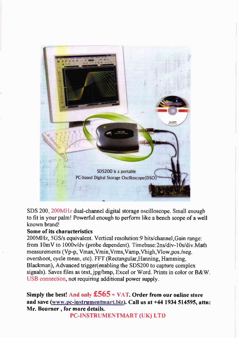
i•Oelr
SDS200 is a portable PC-based Digital Storage Oscilloscope(DSO
SDS 200, 200MHz dual-channel digital storage oscilloscope. Small enough to fit in your palm! Powerful enough to perform like a bench scope of a well known brand! Some of its characteristics 200MHz, 5GS/s equivalent. Vertical resolution:9 bits/channel,Gain range: from 10mV to 1000v/dv (probe dependent). Timebase:2ns/div-10s/div.Math measurements (Vp-p. Vmax,Vmin,Vrms,Vamp,Vhigh,Vlow,pos./neg. overshoot, cycle mean, etc). FFT (Rectangular,Hanning, Hamming, Blackman), Advanced trigger(enabling the SDS200 to capture complex signals). Saves files as text, jpg/bmp, Excel or Word. Prints in color or B&W. USB connection, not requiring additional power supply.
Simply the best! And only £565 + VAT. Order from our online store and save (www.pc-instrumentmart.biz). Call us at +44 1934 514595, attn: Mr. Bourner , for more details.
PC-INSTRUMENTMART (UK) LTD
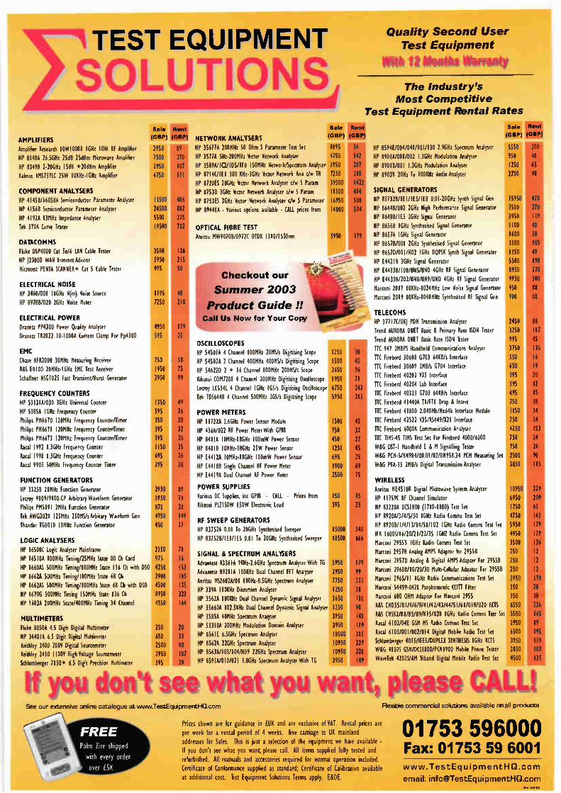
TEST EQUIPMENT
SOLUTIO AMPLIFIERS Amplifier Research 10W100013 I GHz IOW RF Amplifier
HP 8348A 26.5GHz 25d8 25dBm Microwave Amplifier
HP 83498 2-20GHz 15dB +20d8m Amplifier
Kalmus 8851311C 25W 10Kliz- I GElz Amplifier
COMPONENT ANALYSERS
HP 4145B/16058A Semiconductor Parameter Analyser
HP 41568 Semiconductor Parameter Analyser
HP 41920 13MHz Impedance Analyser
Tek 370A Curve Tracer
DATACOMMS
Fluke DSP4000 Cat 5e/6 LAN (able Tester
HP J2300D WAN Internet Advisor
Microtest PE NTA SCANNER+ Cat 5 Cable Tester
ELECTRICAL NOISE
HP 3468/001 18Gliz N(m) Noise Source
HP 89100/020 2GHz Noise Meter
ELECTRICAL POWER
Dranetz PP4300 Power Quality Analyser
Dranetz 182022 10-1000A Current Clamp For Pp4300 595
(GBP) (GBP)
2950
7500
2950
4750
13500
24500
5500
19500
3500
5950
975
89
270
107
171
486
882
275
702
126
215
I. I
1195
7250
EMC
Chase HF R2000 30MHz Measuring Receiver
RAS E8100 20MHz- I GH1 EMC Test Receiver
Schaffner NSG1025 Fast Transient/Burst Generator
FREQUENCY COUNTERS
HP 5313IA/030 3Gliz Universal Counter
HP 5385A I GHz Frequenry Counter
Philips P86670 120MHz Frequency Counter/Timer
Philips P86611 120MHz Frequency CounterTimer
Philips P86613 120MHz Frequency Counter/Timer
Racal 1992 136H: Frequency Counter
Racal 1998 I 3GHz Frequency Counter
Racal 9903 SOMHz Frequency Counter Timer
FUNCTION GENERATORS
HP 33250 2IMHz Function Generator
Lecroy 9109/9100-CP Arbitrary Waveform Generator
Philips P85191 28H: Function Generator
Tek AWG2021 125MHz 250MS/s Arbitary Wweform Gen
Thandar TG 1010 10MHz Function Generator
LOGIC ANALYSERS
HP 16500C Logic Analyser Mainframe
HP 16510A 100MHz Timing/25MHz State 80 Ch Card
HP 1660M 500MHz Timing/100MHz State 136 Ch with DSO
HP 16620 500MHz Timing/100MHz State 68 Ch
HP 1662M 500MHz Timing/100MHz State 68 Ch with DSO
HP 1610G 500MHz Timing 150MHz State 136 Ch
HP I 683A 200MHz State/400MHz Timing 34 Channel
MULTIMETERS
Fluke 80500 4.5 Digit Digital Multimeter
HP 344010 6.5 Digit Digital Multimeter
Keithley 2400 200V Digital Sourcemeter
Keithley 2410 1100V High Voltage Sourcemeter
Schlumberger 7150+ 6.5 Digit Precision Mulumeter
4950
750
1950
2950
1350
595
351
395
395
1150
295
2950
1950
875
4950
450
2350
975
4250
2900
4500
8950
4550
250
650
2500
2950
395
so,
25
38
15
99
49
26
28
32
20
35
26
20
89
71
28
149
27
71
36
151
105
135
323
164
20
33
90
107
29
Quality Second User Test Equipment
rffielt 41101ffl liottomy
The Industry's
Most Competitive Test Equipment Rental Rates
Sale Rent
NETWORK ANALYSERS (GBP) (GB14
HP 35677A 200MHz 50 Ohm S Parameter Test Set 1895 56
HP 35110 5Hz-200MHz *ctor Network Analyser 4750 142
HP 3589A/ I C2/105/1F0 150MHz Network/Spectrum Analyser 7950 287
HP 8714C/1E1 300 KHz-3GHz *ctor Network Ana cJw TO 7250 218
HP 8720ES 20Gliz ctor Network Analyser cfw S Param 39500 142t
HP 87530 3Gliz ctor Network Analyser c/w S Param 11500 414 HP 8753ES 3GHz ctor Network Analyser c/w S Parameter 16950 508
HP 894410 - Various options wadable - CALL prices from 14000 504
OPTICAL FIBRE TEST
Anntsu MW90708/0972C OTDR 1310/1550nm 5950 171‘
'S all ummer 2003 7*
Us Now for Your Copy Product Guide!! 1110
10.fr
Checkout our
OSCILLOSCOPES
HP 54501A 4 Channel 1008H: 20MS/s Digitising Scope
HP 54502A 2 Channel 400MHz 400MS/s Digitising Scope
HP 54622D 2 + 16 Channel 100MHz 200MS/s Scope
Kikusui CO87201 4 Channel 2008H: Digitising Oscilloscope
Lecroy 1.(5341. 4 Channel IGH: GS/s Digitising Oscilloscope
Tek TDS6440 4 Channel 500MHz 2GS/s Digitising Scope
POWER METERS
HP 11722A 2 6GHz Power Sensor Module
HP 436A/022 RF Power Meter With GPIB
HP 04810 10MHz-1891 100mW Power Sensor
HP 84810 10MHz-189z 25W Power Sensor HP E44 I 2A 10M111-18GH1 100mW Power Sensor
HP E441138 Single Channel OF Power Meter
HP E44 I 9A Dual Channel RF Power Meter
POWER SUPPLIES
Various DC Supplies, inc GPIB - (ALL - Prices From
Kikusui P1.1150W 150W Electronic Load
RF SWEEP GENERATORS
HP 837524 001 To 206H: Synthesised Sweeper
HP 83752B/1El/1E5 0.01 To 20GHz Synthesised Sweeper
SIGNAL it SPECTRUM ANALYSERS
Advantest R336 IA 9KHz-2.6GH: Spectrum Analyser With TG
Advantest R92I IA 100KHz Dual Channel FF T Analyser
Anritsu MS2602A/01 100Hz-8.5G111 Spectrum Analyser
HP 3394 I 10KHz Distortion Analyser
HP 3562A 100KHz Dual Channel Dynamic Signal Analyser
HP 356604 102.5011: Dual Channel Dynamic Signal Analyser
HP 3585A 40MHz Spectrum Analyser
HP 53310A 2008H: Modulation Domain Analyser
HP 8561E 6.5G111 Spectrum Analyser
HP 8562A 22GHz Spectrum Analyser HP 8563A/103/104/H09 22GHz Spectrum Analyser
HP 859 I A/0 10/021 186H: Spectrum Analyser With TG
1250
1500
2650
1950
6750
5950
1500
750
450
1250
695
1900
2500
ISO
595
I 5000
18500
5950
2950
7750
1250
3650
3250
3950
3950
10500
10950
10950
3950
31 45
96
II
31
27
45
25
69
540
66i
179
99
233
38
IlL
HP 8594E/004/041/101/130 2 9GHz Spectrum Analyser HP 890101001/002 1.3GHz Modulation Analyser
HP 89010/001 1.3GHz Modulation Analyser
HP 89038 20H: To 100KH: Audio Analyser
SIGNAL GENERATORS
HP 83132B/1E1/1E5/1E8 0.01-20GHz Synth Signal Gen
HP 864413/002 26H: High Performance Signal Generator
HP B648B/ I E5 2GHz Signal Generator
HP 865613 1 GH: Synthesised Signal Generator
HP 8657A 1 Gliz Signal Generator
HP 86518/001 2G111 Synthesised Signal Generator
HP 8651D/001/H02 1 GHz DQPSK Synth Signal Generator
HP E442IB 3GH: Signal Generator
HP [4433B/100/U15/U1D 49z RF Signal Generator
HP E44338/202/U18/UN9/UND 46H: RF Signal Generator
Marconi 2017 10KHz-1024MHz Low Noise Signal Generator
Marconi 2019 80101z-1040MHz Synthesised RF Signal Gen
TELECOMS
HP 377 1 1C/UKJ PDH Transmission Analyser
Trend AURORA DUET Basic & Primary Rate ISDN Tester
Trend AURORA DUET Basic Rate ISDN Tester TTC 147 2MBPS Handheld Communications Analyser
Fireberd 30608 6103 64KB/s Interlace
TTC Fireberd 30609 2MB/s 6704 Interface
TTC Fireberd 40202 1135 Interface
TTC Fireberd 40204 Lab Interface
TTC Fireberd 40323 6103 6400/s Interface
TIC Fireberd 414404 TUFT' Drop A, Insert
ITC Fireberd 41800 2.048Mb/1664k Interface Module
ITC Fireberd 42522 Y35/RS449/X21 Interface
TTC Fireberd 60000 Communication Analyser
TTC TIMS-45 TIMS Test Set For Fireberd 4000/6000
W&G DST- 1 Handheld E á M Signalling Tester
WAG PCM-5/9984/00.01/02/9958.24 PCM Measuring Set
WAG PFA-35 2MB/s Digital Transmission Analyser
WIRELESS
Anntsu ME451013 Digital Microwave System Analyser
HP 1 1159C RF Channel Simulator
HP 83220A DCS 1 800 (1710-1880) Test Set
HP 8920A/3/4/5/50 I GH1 Radio (prisms Test Set
HP 8920B/1/4/13/14/51/102 I GH1 Radio Comms Test Set
IFR 16000/16/20/21/22/35 I GH/ Radio Comms Test Set
Marconi 29558 1 GHz Radio Comms Test Set
Marconi 2957B Analog AMPS Adaptor for 29558
Marconi 2957D Analog & Digital AMPS Adapter For 29550
Marconi 29600/10/20/30 Multi-Cellular Adaptor For 2955B
Marconi 2965/11 1GHz Radio Communications Test Set
Marconi 54499-0421 Psophometric CCITT Filter
Marconi 600 OHM Adaptor for Marconi 2955
RAS CMD55/81/4/6/9/41/42/43/44/51/61/U18/U20 RCTS
MS 9552/B1/B5/B9/B15/B28 1 GHz Radio Comms Test Set
Racal 6102/04E GSM MS Radio Comms Test Set
Racal 6103/001/002/014 Digital Mobile Radio Test Set
khlumberger 4015/IEEE/DUPLEX SYNTHESIS 1 GH: ACTS
WAG 4107S GSM/DCS I 800/P(NI900 Mobile Phone Tester
WaveTek 4202S/AM tiband Digital Mobile Radio Test Set
Sale Rent
(GtElp) (GBP)
5550
950
1250
2750
15950
7500
)950
1100
1600
3500
1350
5500
8950
9950
950
900
2450
3250
995
3750
550
650
395
395
495
750
1150
750
4250
750
750
2500
3850
10950
6950
1750 4750
5950
4950
3500
250
250
250
5950
350
350
6550
5500
2950
6500
3950
2850
4500
200
48
45
98
- 300
88
08
88
117
45
135
16
19
5
9
9
6
12
12
178
28
18
236
165
89
195
119
103
135
If you dot* see what you want please CAW See our extensive online catalogue at venniv.TestEguipmentl-lacom
1
\
FREE Palm lire shipped
with every order
over ESK
Prices shown are for guidance in (UK and are exclusive of VAT. Rental prices are
per week for a rental period of 4 weeks. Free carriage to UK mainland
addresses for Sales. This is just a selection of the equipment we hate available -
If you don't see what you want, please call. All items supplied fully tested and
refurbished. All manuals and accessories required for normal operation included.
Certificate of Conformance supplied as standard; Certificate of Calibration available
at additional cost. ist Equipment Solutions Terms apply. [80E.
Flexible commercial solutions available on all products
01753 596000 Fax: 01753 59 6001 www.TestEquipmentHQ.com email: [email protected]