the geometry of the strasbourg façade, and the problem of erwin von steinbach
TRANSCRIPT
Robert Bork
The Geometry of the Strasbourg Façade, and the Problem of Erwin von Steinbach*
Introduction
The façade of Strasbourg Cathedral has enjoyed well-justified
fame ever since its construction as one of the most dazzling products
of the medieval architectural imagination (Fig. 1). Its pinnacle-clad
buttresses and elegant screens of openwork tracery defined a standard
of virtuosity that many later medieval builders sought to emulate.
But whose genius were they emulating? For many authors from the late
thirteenth century onwards, the brilliance of the Strasbourg façade
design has been associated with the name of Erwin von Steinbach.1 The
precise nature of his contribution to the Strasbourg workshop,
however, has long been controversial. The present article offers a
fresh perspective on this debate, informed by geometrical analysis of
the Strasbourg façade and the drawings associated with its design.
* This file gives the English text of an article that appeared in French as R.BORK, “La géométrie de la façade de Strasbourg et le problème Erwin von Steinbach,” Bulletin de la Société des Amis de la Cathédrale de Strasbourg 31, 2014, pp. 97-128. For reasons of copyright, and for deference to that original publication, its illustrations are reproduced only incompletely here; in this version, all photos and graphics are by the author, except as noted otherwise in the captions. To order a copy of the Bulletin, please visit http://www.amis-cathedrale-strasbourg.eu/nos-publications/ An earlier version of this basic argument, including more of the relevant illustrations, can also be found as R. BORK, “Plan B and the Geometry of Façade Design at Strasbourg Cathedral, 1250-1350,” Journal of the Society of Architectural Historians, 2005, pp. 442-73.1 For reviews of this tradition, see: Marie-Jeanne Geyer, “Le Mythe d’Erwinvon Steinbach,” in R. RECHT, 1989, pp. 322-9; J. SAUVÉ, 2012, pp. 135-42; andJ. BÖKER et al, 2013, pp. 149-50.
1
The earliest of these drawings, scholars agree, must be the so-
called Strasbourg Plan A, which shows the right-hand half of a boxy
façade block up to the top of its rose window story (Fig. 2c; shown here
only schematically in red outline). Plan A has usually been dated to circa
1260, both because its crisp detailing recalls the transept frontals
of Notre-Dame in Paris, and because its overall proportions and
prominent four-light windows recall the format of the Strasbourg
Cathedral nave, which was then under construction (Fig. 2b).2 The
geometrical and proportional relationship between the drawing and the
nave structure, however, cannot be called straightforward. The
triforium level in Plan A would have been distinctly lower than that
in the nave when the overall heights of the façade and nave vessel are
set equal, as comparison of Figures 2b and 2c reveals.3 As subsequent
discussion will demonstrate, similar misalignments between Plan A and
the cathedral vessel would also occur in the horizontal dimension.
The spectacular drawing known as Strasbourg Plan B presents a far
more elaborate design, in which richly detailed screens of openwork
tracery cover the entire lower façade, much as they do in the present
structure, whose construction was begun in 1277 (Fig. 3a; omitted here).
Plan B obviously marks a step beyond Plan A, not only in terms of its
formal complexity, but also in terms of its scale and degree of
2 Strasbourg, Musée de l'oeuvre Notre-Dame, Inv. No. 1. See, for example, R.Recht, 1989, p. 381; R. WORTMANN, 1997, p. 167; R. BORK, 2005, p. 449; J.SAUVÉ, 2012, p. 115. The literature on the drawing is usefully summarized inJ. BÖKER et al, 2013, pp. 159-62. 3 This issue was recognized already in the early twentieth century, as in H. Reinhardt, É. FELS, and K. STEHLIN, 1935, 15-27. Decades later, R. RECHT concluded that “une legère adaptation permet de superposer la structure de ce dessin à la coupe de la nef,” but the schematic illustration he provides clearly shows the misalignments seen here more clearly in Figure 2 and later in Figure 7. See R. RECHT, 1989, p. 381.
2
vertical integration.4 Instead of showing only the lower portion of
the façade on a single parchment sheet, it stretches across four
sheets to show the nearly complete vertical extent of a dramatically
towered façade; only the tip of the spire and the baseline of the
façade were trimmed off at some point in the drawing’s history. The
impression of vertical continuity is not complete, however, because of
obvious differences of execution between the upper and lower portions
of Plan B. The lower portions are drawn in reddish-brown ink, with a
consistently high level of detail. The spire zone, by contrast,
appears far more schematic, and it is drawn in black ink, as are some
of the upper buttress and gable details. Figure 3b shows a contrast
between the presumably original portions of the drawing, at left, and
the full scheme complete with the unusual pencil-like spire, at right.5
Since Plan B seems to be most important surviving precursor to the
present façade, its original portions have usually been dated to the
mid 1270s, while the dating of its upper portions has proven more
controversial.
The authorship of Plan B, and its relationship to the actual
Strasbourg façade, have been hotly debated for over two centuries.
Although a review of that literature would go far beyond the scope of
the present short article, a few highlights of this tradition deserve
mention here. Johann Wolfgang von Goethe, for example, attributed
both the drawing and the bulk of the present façade to Erwin von
Steinbach, even though he recognized that the façade diverged from the
drawing, especially in its upper reaches.6 Gustave Klotz, chief
4 Strasbourg, Musée de l'oeuvre Notre-Dame, Inv. No. 3. Plan B now measures 2750mm x 690mm even in its truncated state, while Plan A measures only 860mm x610mm. See J. BÖKER et al, 2013, pp. 159, 164.5 Figure 3 is based on Figure 1 from Liess, 1986.6 J. von GOETHE, Von Deutscher Baukunst. D.M. Erwin von Steinbach, Frankfurt, 1772; see
3
architect of the cathedral in the nineteenth century, was of much the
same mind. He produced an elaborated version of Plan B with added
tracery detailing in the spire zone, thus presenting the drawing as
the unified conception of Erwin von Steinbach (Fig. 3c).7 Klotz’s
homogenized redrawing remains the most widely reproduced version of
Plan B even today.
By the mid-twentieth century, scholars including Karl Stehlin,
Étienne Fels and Hans Reinhardt, had come to realize that the
proportions of Plan B differed from those of the actual façade even at
ground level.8 This disjunction led them to distinguish between the
original creator of Plan B, and the architect in charge of actually
building the façade. According to this logic, Erwin would not be the
author of Plan B. Otto Kletzl, Roland Recht and Reinhard Wortmann
also distinguished between Erwin and the author of Plan B, although
they believed that the original master had actually begun construction
of the façade.9 According to this scenario, the small proportional
differences between the drawing and the façade would be seen as
deliberate and essentially inconsequential adjustments made by the
original master, while the more obvious deviations from the drawing
seen in the second story of the façade would reflect new ideas
introduced by Erwin after he took over the project around 1284.
Reinhard Liess, writing in 1986, admitted that changes had been
introduced in between the creation of Plan B and the start of work on also P. Frankl, The Gothic: Sources and Literary Interpretations through Eight Centuries, Princeton, 1960, pp. 417-27; and J. GAGE, Goethe on Art, Berkeley, 1980, pp. 103-123.7 R. RECHT, 1989, p. 472.8 H. Reinhardt, É. FELS, and K. STEHLIN, 1935, p. 22; see also H. REINHARDT, 1972, p. 75.9 O. KLETZL, “Schaubild-Pläne und alte Ansichten der Westfassade des Münsters von Straßburg. Elsaß-Lothringisches Jahrbuch, 1936, 62-114, esp. 66; R. RECHT, 1989, pp. 386-88; R. WORTMANN, 1997, pp. 144, 169.
4
the façade in 1277, but he attributed all of these revisions of the
design to Erwin. He distinguished, though, between the carefully
drawn lower part of Plan B, which he saw as Erwin’s work, and the
portions added in black ink, which he saw as the work of a less
talented follower.10
Most recently, Hans Böker and his students have suggested that
Erwin von Steinbach was responsible for nearly everything of interest
in the Strasbourg workshop and its environs in the decades around
1300: not only the whole of Plan B, the lower portions of the
Strasbourg façade, and a set of other drawings associated with the
project, but also drawings associated with a variety of other building
projects in the region, including most notably the openwork spire of
Freiburg im Breisgau, which would thus also be Erwin’s work.11 One
might call this the Maximal Erwin theory. As the following discussion
will show, this extremely expansive vision of Erwin’s activity cannot
be easily reconciled with geometrical analysis of the designs in
question.
Since Gothic buildings embody complex systems of geometrical
order, geometrical analysis should, in principle, offer a great deal
to scholars interested in their design. Many attempts at such
analysis were made in the 19th and early 20th centuries, but most of
these studies lacked rigor, as Konrad Hecht demonstrated around 1970.12
In recent years, it has become possible to make far more precise 10 R. LIESS, 1986.11 According to this scenario, Erwin would have made decisive contributions inStrasbourg, Freiburg, Breisach, Bacharach, Thann, and perhaps Oppenheim. See J. BÖKER et al, 2013, pp. 8-9 (introduction); 82-103 (Freiburg); pp. 127-138 (Thann); pp. 164-187 (Strasbourg); pp. 265-7 (Bacharach).12 Hecht’s Maß und Zahl in der gotischen Baukunst first appeared as three successive issues of Abhandlungen der Braunschweigischen Wissenschaftlichen Gesellschaft: 21 (1969), 22(1970), and 23 (1970). The complete study has been republished as a single volume by Georg Olms Verlag (Hildesheim, 1979).
5
geometrical analyses, thanks especially to the widespread availability
of Computer-Aided Design (CAD) systems. Inspired by great potential
of this technique, the author of the present work began over a decade
ago to analyze the geometry of many Gothic buildings and the drawings
associated with them. The first results of this study, concerning the
Cathedral of Strasbourg, began to appear in 2003, followed by a more
in-depth essay in 2005, and by a more comprehensive book on Gothic
geometry in 2011.13 Although these publications have helped to
catalyze some interest in the study of Gothic geometry, their results
have thus far received little attention in the literature on the
Strasbourg façade. The main goals of the present essay are, first, to
bring these results to the attention of a local Strasbourgeois
audience for whom they should be highly relevant, and second, to add
some new thoughts about the geometry of the Strasbourg façade that may
shed light on the Erwin von Steinbach question.
The Geometry of the Strasbourg Nave and its French cousins
To set the stage for consideration of the Strasbourg façade
project, it is helpful to consider the design of the cathedral’s nave,
since the building of the nave introduced geometrical givens with
which the designers of the façade would have to contend. As a first
step in this direction, it is necessary to clarify the precise format
of the Strasbourg nave vessel. Figure 2a shows the cross-section of
the building, as published by Georg Dehio, while Figure 2b shows the
longitudinal section of a bay, as published by Johann Knauth.14 As the13 R. BORK 2003a, pp. 121-128; R. BORK, 2005; R. BORK, 2011, pp. 62-97.14 The source for Figure 2a is plate 5 in Georg DEHIO, Das Strassburger Münster, Munich, 1941. Figure 2b shows a digitally symmetrized standard bay of the Strasbourg nave, based on the half-bay shown by KNAUTH, “Bericht über die
6
horizontal lines connecting these images show, the heights shown in
the two sections agree very well in virtually every respect. The sole
exception to this rule is the height of the transverse arches in the
nave, whose keystones are almost two meters lower in Dehio’s version
than in Knauth’s, as the lightly shaded grey areas of Figures 2a and
2b show. This discrepancy attests to the difficulty of measuring the
ribs directly with the tools at their disposal in the early twentieth
century. Although a truly accurate modern survey of the nave section
has never been published, recent laser measurements confirm that Dehio
showed the transverse arches too low, while examination of the rib
profiles demonstrates that Knauth showed them too high, with less
salience from the vault webs than they actually have.15 The actual
curvature of the transverse arches in the high vaults, therefore,
closely matches the brown arcs shown in Figure 2a, which give a
Bauschäden am Turmpfeiler und ersten Arkadenpfeiler der Münsters,” Strassburger Münsterblatt 191, pp. 75-96.15 J. SAUVÉ, 2012, p. 103 (note 167) says that “La coupe de la nef que nous avons employée s’inspire de DEHIO. L’utilisation d’un distancemètre a toutefois confirmé que certains dimensions de la coupe qu’il avait publiée sont erronées. Tandis que la distance entre les piliers s’avérait juste, la travée portait à deux mètres sous les dimensions actuelles. Il semble que DEHIO ait modifié la porté de la voute afin de corroborer son hypothèse selon laquelle la coupe de la nef strasbourgeoise s’inscrit dans un triangle équilatéral.” The question of reliability that J. SAUVÉ raises obviously has great importance. The section that he illustrates, however, “s’inspire de DEHIO” only in a rather indirect sense, and not only because it incorporates adifferent vault height. It also shows the anomalous northwest buttress of thenave, rather than the more typical buttress shown by Dehio, and its relative proportions differ markedly from those shown by DEHIO and KNAUTH, even in terms of the relative heights of the arcade capitals, triforium, and main capitals, for example. Since DEHIO and KNAUTH agree well with each other in all these respects, the DEHIO section has been used as the basis for the present analysis, just as it was in R. BORK, 2005. The main arguments presented here and in R. BORK, 2005 involve heights seen in the wall structureonly, and they are thus not directly affected by uncertainty about the vault shape; the brown arcs shown in Figure 2a should provide a good approximation to this contested form. One hopes that a truly reliable modern survey of the nave structure may soon be undertaken.
7
transverse rib height intermediate between the values described by
Dehio and Knauth.
A valuable perspective on the geometry of the Strasbourg vessel
comes from consideration of two French buildings with closely related
designs: the abbey of Saint-Denis, and the church of Saint-Urbain in
Troyes. The cross-sections of the three edifices are shown in Figure
4. To facilitate geometrical comparison, the half-span of the naves
have been shown as equal in all three cases, and called one unit.
This understates the relative scale of Strasbourg, whose nave span of
roughly 16.00 meters is greater than that of Saint-Denis (13.30
meters) or Saint-Urbain (10.58 meters).16 Since thirteenth-century
campaigns at Saint-Denis have long been recognized as crucial
influences on the slightly later design of the Strasbourg nave, it
makes sense to begin by exploring that building, whose geometry can
now be discussed with great rigor thanks to a recent high-precision
laser survey.17
The height of the Saint-Denis central vessel, measured up to its
transverse arch keystones, is 4.000 units, or exactly twice the width
of the nave. The main vessel, in other words, fits precisely into a
double square. The side aisles at Saint-Denis are each 1.000 unit
wide. Their capitals fall at height 1.155, where a line of 30-degree
slope launched from floor level on this centerline intersects the
16 The author thanks Andrew Tallon for permission to use the highly accurate laser point-cloud data for Saint-Denis. The author also thanks Michael Davis for permission to reproduce Figure 4c, which originally appeared in M. DAVIS and L. NEAGLEY, “Mechanics and Meaning: Plan Design at Saint-Urbain, Troyes and Saint-Ouen, Rouen” Gesta, 2000, 173-184. 17 On the design of the Strasbourg nave, including its relationship to Saint-Denis, see Y. GALLET, “La nef de la cathédrale de Strasbourg, sa date et sa place dans l’architecture gothique rayonnante,” Bulletin de la Societé des Amis de la Cathédrale de Strasbourg, 2002, pp. 49-82. On Saint-Denis itself, see C. BRUZELIUS, The 13th-century Church at Saint-Denis, New Haven, 1985.
8
vertical defining the outer axis of the aisle, 2.000 units out from
the building centerline. When an equilateral triangle of side length
2.000 is placed on the floor of the building, as shown in red in
figure 4a, its tip reaches height 1.732, or √3, precisely locating the
height of the aisle keystones. When a slightly larger triangle is
constructed with height 2.000, as shown in tan in the figure, its tip
1.155 units to the left of the building centerline locates the axis of
the slender columns supporting the flying buttresses. The Saint-Denis
nave design also includes many other more subtle relationships that
cannot be discussed in the confines of this short essay, but these
observations already suffice to demonstrate that its section elegantly
ties together the geometries of the square and equilateral triangle.
Many of the same geometrical elements seen at Saint-Denis recur
in the Strasbourg nave section, and in Saint-Urbain. In all three
buildings, the main vessel fits within a double square, but in the two
latter cases, height 4.000 corresponds to the top of the framing walls
rather than to the keystone of the transverse arches. In the aisles
of Strasbourg and Troyes, similarly, height 1.732 corresponds to the
bosses of the vaults rather than to the keystones of the transverse
arches, but the basic ordering principle clearly relates to that seen
at Saint Denis. Strasbourg shares with Saint-Denis the placement of
the buttress-supporting column 1.155 units out from the building
centerline, but the most striking relationships are between Strasbourg
and Saint-Urbain. In both of these buildings, the main arcade
capitals fall at height 1.000, and the flying buttresses meet the nave
wall at height 3.000. At Strasbourg, the geometry of the flying
buttress is particularly lucid, since its intrados is defined by a
circle of radius 1.000 centered at height 2.000. Both Strasbourg and
Saint-Urbain include single batteries of flyers pierced by rosettes,
9
and both feature broad side aisles, considerably wider in proportion
than those of Saint-Denis. In view of these close relationships, it
probably makes sense to see the Strasbourg nave as one of the crucial
sources for the design of Saint-Urbain, which was conceived in 1262.
Every significant horizontal and vertical dimension in the
Strasbourg nave was determined by extensions of the basic triangle-
based scheme described above. As Figure 4b shows, for example, a line
falling from the top center of the Strasbourg nave vessel with a slope
of 60 degrees hits the ground at a point 2.310 out from the building
centerline, establishing the location of the aisle wall. The vertical
axis of the flyer-supporting column, 1.155 units from the centerline,
coincides closely with the outer margin of the arcade pier. The line
descending from the springing of the flying buttress, 2.155 out from
the building centerline, similarly locates the inner margin of the
shaft bundle on the aisle wall. The free aisle span between these
lines thus equals 1.000, the half-span of the nave. The interaxial
span of the aisles, though, equals fully 1.310, measured from the
arcade base to the inner surface of the outer wall at 2.310.
Further constructions based on the square and equilateral
triangle suffice to determine most of the remaining geometrical
structure of the Strasbourg nave section, as Figure 5a shows. The top
of the arcade zone and the base of the triforium fall at the
previously established height 1.732, where a line rising from the
middle of the nave floor at 60 degrees intersects the arcade axis. A
circle struck down to this level from the flying buttress center at
height 2.000 rises to the top of the triforium at 2.268, so that the
triforium occupies a belt in the exact middle of the elevation. An
analogous but slightly larger circle struck down to height 1.414,
where an arc swung up from the arcade capital hits the building
10
centerline, rises to a height of 2.586 to locate the springline of the
main vault. The point where the large circle describing the flying
buttress cuts the horizontal at this level, marked by a small brown
circle in Figure 5a, serves as the center for the brown arcs defining
the curvature of the transverse arches in the main vault. In the
horizontal dimension, a diagonal rising from the base of the arcade
piers to the height of the capitals can be swung down to define the
outermost surface of the aisle wall at a distance 2.414 out from the
building centerline. A similar but less steeply sloped line rising
from the arcade base to the point at height 1.000 on that outer wall,
finally, can be swept down to locate the outboard face of the main
buttress 2.732 out from the building centerline. On the outer margin
of the buttress finally, the first drip molding falls at height .500,
the second at 1.732, and the third at height 2.414.18 In sum,
therefore, it becomes clear that the design of the Strasbourg nave
section ties together the geometries of the square and the equilateral
triangle in an elegant manner similar to, but subtly distinct from,
that seen at Saint-Denis.
The Geometry of Strasbourg Plan A
The façade scheme shown in Strasbourg Plan A also has a
geometrical structure built up of squares and equilateral triangles,
but these elements combine differently than they do in the nave
section, as comparison of figures 5a and 5b reveals. The geometrical
seed of the drawing, so to speak, is an equilateral triangle that
shares its baseline with a square (shown shaded in Figure 5b). The sides of
18 These observations about the buttress structure extend and reinforce the arguments originally presented in R. BORK, 2005, pp. 448-49.
11
the square correspond with the baseline of the façade, the top of the
triforium, the centerline of the façade, and the inner margin of the
outer buttress. The tip of the triangle within the square, meanwhile,
sits just above the tip of the triangular gablet on the façade’s inner
buttress. The vertical centerline of this buttress divides the main
surface of the depicted wall into two equally wide vertical slices.
It is therefore convenient to call the side length of the square two
italicized units, recognizing that these units will not automatically be
the same as those described in the preceding discussion of the nave.
In this parlance, the tip of the triangle falls at height 1.732, a
level that corresponds to the springing of the arches in the
triforium. Diagonals struck down from the ends of this horizontal
line segment will intersect at height .732, a point that can be taken
as the center of a circle with radius .732 and diameter 1.464. The top
of the circle coincides with the bottom edge of the triforium, and the
diagonals cut the circle at height 1.250, the base of the small arcaded
passage beneath the triforium. The left intersection point, .482 units
from the building centerline, defines the vertical axis of a large
pinnacle separating the main portal zone from the traceried panel to
its right. The left and right points on the circle, located .268 and
1.732 units from the building centerline, locate the right-hand margins
of the main and side portals, respectively.
The overall proportions of Plan A depend on the establishment of
the side portal axis, whose construction is shown in Figure 6. First,
an arc of radius 1.000 concentric with the previous described circle
can be struck downward, starting from a position of tangency with the
outer façade buttress, until it intersects the right margin of the
side aisle door. Second, a horizontal line can be drawn through this
intersection point to define the height of the small dado running
12
along the base of the portals. Next, a diagonal can be struck up from
the trumeau base to meet the buttress axis at height 1.000, and finally
a line of 60-degree slope can be struck down from this intersection
point until it meets the horizontal dado line at a point 1.548 units out
from the building centerline. The axis of the side portal then rises
through this intersection point. Since the inner face of the buttress
to the right of the portal is 2.000 units to the right of the building
centerline, the half width of the portal is 2.000-1.548=.452 units; the
right-hand margin of the inboard buttress will therefore lie 1.548-.452=
1.096 units to the right of the building centerline. The half-width of
the forward-facing buttresses is thus .096 units. Symmetry about the
portal axis shows that the outer edge of the buttress to the right of
the portal will lie 2.192 units to the right of the building centerline,
while the outer surface of the presumably southern-facing outer
buttress will lie 2.192 + 2 x (.092) = 2.384 units to the right of the building
centerline.
The vertical dimensions of Plan A emerge readily from these
horizontal dimensions through the geometry of the equilateral
triangle. The overall height of the façade shown in the drawing, most
importantly, can be found by drawing a line of 60-degree slope up from
the edge of the front-facing buttress, 2.192 units from the building
centerline. From this apex, a line of 30-degree slope can be struck
down until it intersects the side portal centerline; this level marks
the base of the arched window head, which also has the proportions of
an equilateral triangle. The sloping 30-degree line also passes
tangent to the rose window, whose center lies three fourths of the way
up the façade. The tip of the main gable, meanwhile, lies one half,
or two fourths, of the way up the façade.
13
The subdivision of the Plan A façade into fourths obviously
recalls the similar subdivision of the nave cross-section. It is
therefore tempting to equate the intended height of the Plan A scheme
with that of the nave section, as shown in Figure 7. With this
scaling, the tip of the portal gable aligns with the center of the
circles describing the flying buttresses, the center of the rose
window aligns with the point where the flying buttresses meet the
wall, and the top of the walls align with each other. In the
nomenclature used to describe the nave section, these heights were
called 2.000, 3.000, and 4.000, respectively. These units, which
equal the half-span of the Strasbourg nave, differ slightly from the
italicized units that were convenient to describe Plan A. More
precisely, 1.000 of the italicized units equals 1.054 of the units used
to describe the nave section, as the labels along the bottom of Figure
7b show. The distance from the building centerline to the outer edge
of the Plan A façade, therefore, can be described as either 2.384
italicized units, or 2.513 unitalicized units, i.e. 2.513 times the
half-span of the Strasbourg nave. The span to the outer face of the
nave buttresses, though, was considerably larger, at fully 2.732 times
the half-span of the nave. As the right-hand margin of Figure 7b
clearly shows, therefore, the buttresses of the Strasbourg nave would
have protruded quite markedly beyond the façade shown in Plan A, if
the height of the façade had been equated with that of the nave
section in the straightforward manner illustrated here.19
19 As noted previously, these basic discrepancies have been observed by scholars from H. Reinhardt, É. FELS, and K. STEHLIN, 1935, to R. BORK, 2005. As R. RECHT, 1989, p. 381, notes, at least “une legère adaptation” is necessary in order to align “la structure de ce dessin à la coupe de la nef.” J. SAUVÉ, 2012, achieves the superficially adequate alignment seen in his planche VII not only by adjusting the proportions away from the DEHIO section,as noted in his p. 103 (note 167), but also by moving the centerline of the
14
The geometrical relationship between Strasbourg Plan A and the
cathedral’s nave design is thus both complex and contradictory. On
the one hand, the two designs clearly have a great deal in common, in
both formal and geometrical terms. Both use large four-light windows,
for example, and both involve geometries based on the interaction of
squares and equilateral triangles. The two designs appear at least
roughly compatible, in fact, because the overall outlines of each
depend on the proportions of the equilateral triangle. On the other
hand, though, close examination shows that the two designs differ
markedly in their internal formal and geometrical structure. As noted
previously, the triforium in Plan A would be lower than that of the
nave. The rose window in Plan A would rise significantly above the
vaults of the nave, the buttresses of the nave would protrude beyond
those of the façade, and none of the buttress axes in the façade would
align with the pier axes of the nave. While the two designs include
many of the same geometrical ingredients, the relationship between
them was hardly straightforward. So, while Plan A surely deserves to
be understood in connection with the early planning for the Strasbourg
façade project, actual construction based on the drawing would have
been extraordinarily difficult, and the results would have been
aesthetically unsatisfactory.20
nave section subtly to the left of the centerline of Plan A. These adjustments together bring the righthand façade buttress into alignment with the righthand nave buttress. Even in this scheme, however, the rose window ofthe façade would reach above the nave vaults, the triforium of the façade would be below that of the nave, and the axes of the façade buttresses would not align with the axes of the main arcade. The latter axis shift is also visible in his Figure 76, discussed in J. SAUVÉ, 2012, pp. 109-111. In light of these complexities, it is clear that the format of Plan A was not based on that of the nave section in any simple sense, which is why the geometrical analysis described in the present essay becomes necessary. 20 J. SAUVÉ argues that the Strasbourg workshop actually built a façade in conformity with Plan A; See J. SAUVÉ, 2012, pp. 109-122. While it is indeed
15
On a more broadly conceptual level, it is significant that Plan
A, like the cathedral’s buttress cross-section, involves geometries
only in the vertical plane. The drawing admittedly implies a certain
layering structure, in which the portal gables stand in front of the
triforium, for example, but the thickness of these layers could
diminish to zero without compromising the logic of the design. Plan A
makes no reference to the ground plan of the foreseen façade block, or
to the depth of the towers that might be built above the aisle bays.
It is unclear, in fact, whether the creator of Plan A meant for his
façade to be one bay deep, as most tower-carrying west blocks are, or
whether he meant to propose a flattened screen front like that of
Amiens Cathedral. In a sense, therefore, the façade shown in Plan A
appears to have been conceived as just another vertical plane,
comparable to those defining the frames of the flying buttresses, as
Figure 8 suggests (omitted here). The actual façade block, whose ground
plan appears at the lower right of the figure, was conceived using a
more three-dimensional approach to design whose traces can be seen in
Plan B, one of the most important drawings in the history of Gothic
architecture.
The geometry of Strasbourg Plan B
The creation of Strasbourg Plan B established the Strasbourg
workshop as one of the leading centers of Gothic design and
construction in Europe. As noted previously, though, the drawing
possible that some work was begun on a first façade, as his archaeological analysis suggests, the geometric analysis in the present article argues against a direct dependence on Plan A, while economic considerations argue against the idea that a freshly completed façade was immediately demolished tomake way for the present façade, begun in 1277.
16
presents several obvious puzzles. Its proportions differ subtly from
those of the actual façade, even at ground level. There is a striking
contrast between the careful detailing of its lower portions, and the
more cursory detailing of its upper portions, which suggests that work
on the drawing was undertaken in multiple phases, perhaps by multiple
draftsmen. Geometrical analysis of the drawing can contribute a
valuable perspective the production history of Plan B, and on its
relationship to the present façade design.
The best place to begin such an analysis of Plan B is at the top
of the boxy tower story. As Figure 3b indicated, the square-topped
tower story belongs to the original brownish section of the drawing,
as do the slender pinnacle doublets growing from its corners. The
slender spire and the two faceted drums beneath it belong to the
presumably later black section. The relative proportions of these
facets strongly suggest that these upper stories were meant to have
octagonal plans, as most scholars have traditionally assumed.21 More
surprisingly, an octagon-based geometry governed the proportions even
of the original section of the drawing. One important clue revealing
this geometry is a prominent compass prick point in the middle of the
lower drum story. As Figure 9 shows (only schematically here), a circle with
this center and framed by the main buttress axes of the façade
circumscribes an octagon that fits precisely within the frame
established by the flanking pinnacle doublets and the upper surface of
the boxy tower story. This octagon thus locks into the structure of
the drawing’s original portion, but it also corresponds precisely to
21 This interpretation seems to inform the illustration made by KLOTZ in the 19th century, for example, and it also has been accepted in most scholarly treatments of the drawing, including the digital reconstruction made by Nikolaus Koch, seen on p. 169 of J. BÖKER et al, 2013. Alternative interpretations will be discussed below.
17
the implied footprint of the lower tower drum, a relationship that
hints at geometrical links between the two zones.
Here, because both the buttress axes and the octagonal drum
footprint play fundamental roles in establishing the geometry of Plan
B, it will be helpful to consider two different sets of measuring
units. The non-italicized numbers in the left-hand half of Figure 9
are measured in a unit equal to the diameter of the circle framed by
the buttress axes. The left buttress axis, therefore, is shown .500 of
these units to the left of the tower centerline, and the top and
bottom edge of the circle are shown at heights 0 and 1.000
respectively. The italicized numbers in the right-hand half of the
figure are measured in units equal to the face-to-face diameter of the
inscribed octagon, which are therefore smaller than the left-hand
units by an factor of cos(22.5°) or .924, where 22.5° is the
characteristic angle between the main axes of an octagon and its
corner. In this italicized system, it is the inboard face of the tower
buttress rather than its axis that stands .500 units offset from the
tower centerline. And, in this system, it is the top edge rather than
the bottom edge of the molding terminating the boxy square-topped
story that falls .500 units below the compass prick point. The top of the
inscribed octagon, at height 1.000 italicized units, defines the level
where the pinnacles start to taper.
The fundamental importance of the octagon inscribed between the
pinnacles becomes even more obvious when its sides are extended to
form an 8-pointed star, whose outlines are shown with heavy lines in
the right-hand portion of Figure 9. The top point of this star, at
height 1.207 units, marks the level at which the pinnacle doublets
terminate. And the rightmost point on the star, .707 units to the right
of the tower centerline, aligns with the right-hand margin of the boxy
18
tower story at the base of the figure. These octagon-based
relationships deserve particular note because they involve elements
inked by the initiator of the drawing. Further evidence for this
draftsman’s use of this octagon-based scheme may be found in the
subtle but unmistakable inward bias of the tracery patterns in the
buttresses. This can be seen in the lower right corner of the (original)
figure, where the “centerline” of the tracery falls just .541 units to
the right of the tower centerline, which is less than halfway from the
left margin at .500 to the right margin at .604. This “centerline”
clearly was not located by equal subdivision of the buttress faces;
instead, it was located by drawing a vertical tangent to the circle
circumscribed about the original generating octagon.
Precisely the same octagon-based geometry seen in the pinnacle
zone of Plan B recurs in the lower stories of the drawing, as Figure
10 (schematically) shows. In this illustration, the units are set just as
in the left-hand side of Figure 9, so that one unit equals the span
between the buttress axes of the tower bay. Here, though, the heights
are shown beginning at the likely location of the original ground
line. Because the bottom of the drawing is cut off, however, it makes
sense to trace these geometrical relationships by moving downward from
the pinnacle zone. The boxy tower story is a perfect square filling
the space between heights 3.221 and 4.527. The bottom of the square
corresponds with the top rung of the strip-like balustrade running
between levels 3.121 and 3.221. A rotated square inscribed within this
square, together with verticals descending from the story above,
defines an octagon just like the one seen previously. Horizontal lines
drawn across from the key points on this octagon locate all the formal
punctuation points in the slender pinnacles over the rose window and
in the tower buttresses. These pinnacles, significantly, were drawn
19
in black ink, which shows that the later draftsman recognized and
actively used the geometrical figures developed by the initiator of
the drawing.22 This is not surprising, since the grid of uninked
horizontal and vertical construction lines still visible on the
drawing today was probably created by this original master,
establishing an armature on which later draftsmen could hang their
forms. The later additions may not reflect the original designer’s
intentions in every respect, but his geometries clearly retained their
importance even in the later phases of the drawing’s production.
Moving on down the façade, the same octagonal module repeats over
and over, but with variations in its deployment. In the tower bays,
star octagons centered at levels 2.414 and 1.000 define many of the
heights across the façade, including the heights of the triforium and
its pinnacles; the center of the rosette over the aisle portal
actually coincides with the center of the lowest octagon. In the
central portion of the façade, another such octagon centered at height
2.606 defines the geometry of the rose window. In a broad sense,
therefore, it makes sense to read the Plan B façade as three equally
wide vertical panels, separated by the narrow strips of the buttress
doublets and their pinnacles. Plan B manages to combine the conceptual
equivalence of the rose and tower spaces with its seeming opposite,
the greater interaxial width of the nave, because the main buttress
axes are asymmetrically positioned within the strips dividing the
three main vertical panels. These geometrical relationships together
mean that the aisle bay is .813 as wide as the nave, when both are
measured between the buttress axes. Equivalently, one can observe
along the bottom of the figure that the distance between the aisle
22 See Figure 3b above, and LIESS, 1986, which remains the most careful analysis to date of the drawing campaigns in Plan B.
20
center and the building centerline is 1.115 units, where one unit
equals the width of the aisle bay.23 The distance from the aisle
centerline to the outer face of the northern buttress is .854 units, a
dimension found by unfolding the half-diagonal of the aisle bay, as
the lower left corner of the graphic shows.24 As subsequent discussion
will show, the proportions of the present façade and its buttresses
were determined rather differently.
The preceding paragraphs, in clarifying the geometrical methods
used by the initiator of Plan B, establish a baseline or norm against
which to compare the geometrical structure of the drawing’s
controversial spire zone. Here, once again, it makes sense to begin
analysis at the level where the boxy tower story terminates, this time
working upwards to the spire tip. As Figure 11 (schematically) shows, the
same octagon that governed the articulation of the pinnacle doublets
drawn in the first phase of the drawing’s production also governs the
layout of the lower spire drum. Because this octagon has the shape and
size of the spire drum’s implied ground plan, verticals rising from
its inner corners define the corner flanges of the drum. Even the
seemingly convincing foreshortening of the window heads in the side
facets of the drum turns out to be surprisingly simple, since a single
semicircular arc defines these arches.25 The compass prick point used 23 For all the figures in this article, red plain text measures units that correspond to the half-width of the nave. For Figures 5, 6, and 7, the black italic text corresponds to units characteristic of Plan A. For Figures 9, 10, 11, and 15, the black italic text corresponds to units given by the diameter ofthe original generating octagon in Plan B. For these same Figures 9, 10, 11, and 15, the black plain text counts off units defined in terms of the width ofthe lateral bay in Plan B, measured between its buttress axes. In Figure 15, finally, distances measured in meters are indicated explicitly as such.24 In mathematical terms, .854= .500 + .250 √2. 25 There is thus no need to invoke postulate a decades-long gap between the original conception of Plan B and the creation of its upper section. For the 14th-century date of the spire zone, see R. RECHT, Le dessin d’architecture: Origine et
21
to strike this arc is still visible on the drawing at the top of the
octagon, as the close-up in (the original non-schematic) Figure 9 shows. The
draftsmen responsible for inking in the spire zone were using the same
geometrical tools as the initiator of the drawing, and they may have
even been using construction lines that he had scribed into the
parchment when first establishing the overall layout of Plan B.
Moving upwards, the modules defined by the original generating
octagon continue to govern the spire composition. It is therefore
convenient in this context to use the italicized units shown on the
right hand margin of Figure 11, each one of which equals the face-to-
face diameter of this octagon. When the diagonals of the original
square module between the pinnacle doublets are unfolded, the
resulting arcs reach up from level 1.000 to level 1.414. There, at level
1.414 on the tower centerline, sits the lower tip of the star octagon
circumscribed about the shaft; the top and bottom facet of the
associated octagon, at heights 1.621 and 2.621, respectively, define the
upper and lower ends of the slender shaft.
Since the total face-to-face width of the shaft equals the width
of just one facet of the lower spire drum, its own front faces could
only be located by constructing a small octagon with this same face-
to-face width. Precisely such a small octagon appears to have been
constructed between levels 2.621 and3.036, permitting the draftsman to
drop the two narrowly separated verticals that define the inner corner
flanges of the slender octagonal shaft. The strongest evidence for the
construction of this small octagon comes from the presence of a
prominent compass prick on the tower centerline at level 2.536. This
falls precisely at the bottom tip of the small star octagon built up fonctions, Paris, 1995, pp. 62-3. R. RECHT 1989, p. 388 explicitly criticizes LIESS, 1986, for his interpretation of the spire design as a product of the original designer’s vision.
22
around the octagon just described. Geometrical analysis of the
tapering spire section makes clear why there had to be a compass prick
at this point. The spire tip is now missing, because of the truncation
of the drawing, but its location can be easily determined: the sloping
spire sides converge to a point at height 4.536, exactly 2.000 units
above the compass prick. The construction of the small octagon atop
the slender vertical shaft, therefore, paved the way not only for the
definition of the shaft faces, but also for the establishment of the
main spire’s height.
With this fairly complete geometrical analysis of Plan B now in
hand, it becomes clear that the same modules and design principles
governed the entire drawing. Thus, despite the obvious differences of
facture between the meticulously detailed lower zone and the much more
cursorily rendered spire zone, it makes sense to attribute the whole
design to one guiding intelligence, or at least to one coherent
workshop tradition. The upper parts of Plan B may not have been inked
by the initiator of the drawing, but the draftsmen responsible for
these later portions appear to have used his ideas, and very probably
his construction lines.26 The most striking point about the geometry of
Plan B is that it derives almost entirely from the octagonal footprint
of the foreseen spire. Unlike Plan A, whose geometry involves only the
vertical plane, Plan B has a geometrical structure that links the
horizontal and vertical planes, since the octagonal module governing
the elevation of each story corresponds to the plan of the tower in
26 This validates the view of LIESS, 1986, more than that of RECHT, 1989, p. 388. According to J. BÖKER et al, 2013, p. 167, Bork claims that “beide Teilevon derselben Hand gezeichnet worden seien.” In fact, however, the quoted passage from BORK, 2003a, distinguishes between the original creator of the drawing and his less talented followers, who drew the spire zone more or less in accord with his intention. The same argument recurs in BORK, 2005, and BORK, 2011.
23
the horizontal plane, as Figure 12 shows.27 In an important sense,
therefore, Plan B can be seen as a precedent for the pinnacles
described in Matthaus Roriczer’s Fialenbuechlein, whose elevations
were extrapolated from their crystalline ground plans.28
The curious pencil-shaped spire format seen in Strasbourg Plan B
occupies an interesting and even problematic place in the history of
spire design. As Jean Bony observed decades ago, the Plan B spire
appears to have more in common with late thirteenth-century
microarchitectural monuments like the Montjoies of Saint Louis than it
does with full-scale spires of the period.29 The creators of Plan B
must have concluded that a simple pyramidal spire of the traditional
type seen at Chartres, for example, would have looked ridiculous atop
the intricately detailed façade that was being planned for Strasbourg.
The openwork spire type later seen at Freiburg would have provided an
optimal solution to this problem, but that daring format does not seem
to have been invented yet when Plan B was being developed.30 In this
context, borrowing ideas from the realm of microarchitecture would
have made good sense, at least in principle, and the use of drawing as
a tool of design would have allowed such cross-media influences to
flow rather freely. In practice, however, the exploitation of micro-
27 Indeed, there is good reason to believe that a ground plan once existed along the now-truncated bottom margin of the drawing, as proposed in R. RECHT,1989, 388.28 On Roriczer, see L. SHELBY, Gothic Design Techniques: The Fifteenth-Century Design Booklets of Mathes Roriczer and Hans Schmuttermayer, Carbondale, 1977.29 J. BONY, The English Decorated Style, Ithaca, 1979, pp. 20-21. The formal analogy between the Plan B spire scheme and the Montjoies comes through especially clearly if one accepts J. EVANS’s argument that the spire-like roadside markershown together with the meeting of the Magi in the Très Riches Heures of Jean de Berri (fol. 51v) actually represents one of the now-destroyed Montjoies on the outskirts of Paris. See idem, “A Prototype of the Eleanor Crosses,” Burlington Magazine, 1949, pp. 96-9. 30 See R. BORK, 2003b.
24
architectural prototypes had obvious drawbacks, since the designers of
pinnacles and free-standing roadside monuments like the Montjoies had
no need to unify their soaring creations geometrically or
aesthetically with a square tower base, as the Strasbourg spire
designers would have to. These difficulties are not adequately
resolved in Plan B. In the drawing itself, the lower spire drums
appears neatly framed by the slender pinnacle doublets rising from the
corners fo the towers. As many scholars have observed, however, and
as Figure 13 shows, there actually would have been substantial air
gaps between these components.31 Thus, while Plan B exhibits a
profound unity of geometrical conception, a diagonal view of the
foreseen façade evidently would have conveyed an impression of ad hoc
superposition, with the octagonal spire drums sitting awkwardly atop
the boxy towers. It is tempting to imagine, in fact, that it was
recognition of this problem that caused the initial creator of Plan B
to pause in his work before the inking of the spire zone.
A valuable perspective on the reception of this spire design can
be gleaned from consideration of the drawing known as Strasbourg Plan
B1, an elaborated copy of Plan B now preserved in Vienna (Figure 14; 31 On these gap spaces, see R. BORK, 2005, and J. BÖKER et al, 2013, pp. 167. The reconstruction presented here as Figure 13 shows only two pinnacles at each corner of the tower. The reconstruction given by J. BÖKER et al, 2013, p. 169, though, postulates the existence of a third pinnacle at each corner, which would be hidden in a front view, but which would reduce the size of the air gaps when seen from a diagonal. As its creator Nikolaus Koch rightly notes, Plan B proves somewhat ambiguous in this respect, and one must make certain assumptions in order to visualize its three-dimensional implications. The basic idea of Figure 13, however, was to introduce as few new hypotheses as possible above and beyond the information presented in the drawing itself, which explains why the facets of the spire drum are left as simple blanks, rather than being filled in with plausible tracery like that imagined by both Klotz and Koch. It is interesting in this connection that the initial description of Plan B given by J. BÖKER et al, 2013, p. 164 seems to describe Klotz’s elaborated 19th-century version rather than the original medieval drawing.
25
omitted here).32 Plan B1 includes many new features not seen in the
original, including most obviously slender stairway turrets flanking
the central shaft of the spire and embedded in the pinnacle doublets
in the story below. Particularly interestingly in light of the
preceding discussion, it shows tracery windows with an alternating 3-
4-3 pattern of lancets in the facets of the lower spire story. The
creator of Plan B1, therefore, evidently meant for these to be read as
facets with genuinely different length, rather than as identical
facets seen from different angles. One may well ask whether this
reading was intended by the initial creator of original Plan B.33
Several independent arguments suggest that it was not. First, there
is the obvious fact that the spire facets in Plan B have precisely the
proportions that they would in an octagonally symmetrical structure
viewed from the front, which can hardly be a coincidence; if a row of
three gables in one plane had been intended, they could have had any
relative widths. Second, the entire geometrical structure of Plan B
involves the geometry of octagons related to size of the spire base,
as the preceding paragraphs have shown; it would have been natural in
this context to express the octagon form explicitly in the spire plan.
Third, the gables of the three spire facets all reach the same height,
despite their different width. This detail is significant because it
differentiates the gable format of Plan B from that seen in
Strasbourgeois design when triplets of gables all lie in a single
32 Vienna, Wien Museum Karlsplatz, Inv. No. 105.069. The drawing measures 3267x697mm. See J. BÖKER et al, 2013, pp. 172-76. In this passage the drawing is attributed to Erwin von Steinbach. J. BÖKER previously suggested that the drawing was a 14th-century copy; see Architektur der Gotik: Bestandskatalog der weltgrössten Sammlung an gotischen Baurissen (Legat Franz Jäger) im Kupferstichkabinett der bildendenKunst Wien, Salzburg, 2005, p. 448.33 This is the alternative interpretation of the drawing presented in J. BÖKERet al, 2013, p. 171.
26
plane: in such cases the central gable generally rises higher than its
neighbors.34 On these bases, it seems clear that the author of B1
interpreted the spatial implications of Plan B differently than its
original creators would have intended. Plan B1 was evidently produced
at a time when the Plan B spire format was still seen as interesting,
before it had been decisively displaced by the emergence of the
openwork spire type, but its production seems to have been undertaken
by someone with only second-hand knowledge of the original designer’s
intentions.
The geometry of the current Strasbourg façade block
The most important monument to be influenced by Plan B was, of
course, the façade block of Strasbourg Cathedral itself. It has often
been suggested that Plan B actually guided the first campaigns of work
on the façade, but this cannot have been the case. As authors from
Stehlin to Liess have recognized, the aisles shown in the drawing are
markedly wider than those actually built, compared to the width of the
nave.35 Given the precision with which both the drawing and the
building were executed, this cannot have been a case of simple error
or ad hoc adjustment. Instead, there has to have been a comprehensive
rethinking of the façade design and its proportions between the
production of Plan B and the beginning of façade construction in 1277.
Geometrical analysis of the current façade block shows that it
embodies a fundamentally different conceptual vision than Plan B,
34 This is true in the tomb of Conrad von Lichtenberg, in the exterior walls of the Saint-Catherine Chapel, in the upper stories of the western façade block, and in the unexecuted design for the small shrinelike termination on the belfry drawing, Inv. No. 5 in Strasbourg’s Musée de l’œuvre Notre-Dame. 35 H. Reinhardt, É. FELS, and K. STEHLIN, 1935; R. LIESS, 1986.
27
despite many obvious links between the two designs. The creator of
Plan B clearly conceived his west block as a pair of spire-carrying
towers, rather than as a flat screen in front of the extant nave
structure. As the preceding discussion has shown, all of the
dimensions in Plan B, including the width of the nave and the span of
the buttresses, can be readily folded out from the tower plan. The
ground plan of the façade block implied by Plan B appears in the
bottom portion of Figure 15, which adds detail to the picture already
sketched in the bottom of Figure 12. This plan, with its three
overlapping star octagons, has real geometrical elegance. In this
system, however, the nave width emerges only as the indirect
consequence of interactions between circular and octagonal geometries
in the towers. For anyone charged with building the façade block,
however, the already established width of the cathedral’s nave would
have been a dimension of fundamental importance. The designer of the
actual façade block, therefore, seem to have taken the width of the
nave, rather than the plan of the towers, as his point of departure.
The first step in the generation of the revised façade plan was
probably the establishment of a large square with side length equal to
the nave span, in the area just to the west of the nave.36 As the top
36 It should be noted, however, that the distance between that axes of the façade buttresses (16.32 m) differs very slightly from the distance between the axes of the nave piers (approximately 16.00 m). These dimensions are basedon the plan of the cathedral seen here in the top section of Figure 15, originally published in G. DEHIO, Das Münster unser Lieben Frau, à Strasbourg und sein Bauten, Strasbourg, 1894, p. 141-228. It seesm clear, nevertheless, that the intention was for these dimensions to correspond. Moreover, the axis of the façade is at a slight angle to that of the nave, even though perfect alignmentwas surely intended. These small errors suggest that the construction of the façade proceeded from west to east; the connection between the present façade and the nave may have been blocked by the presence of an earlier façade, either a Romanesque structure, or perhaps by a previous Gothic structure, along the lines postulated by J. SAUVÉ, 2012.
28
portion of Figure 15 shows, the eastern face of this square lines up
with the eastern edge of the wide arches reinforcing the last set of
free-standing piers, while the western face of the square defines the
outer wall plane of the west façade. Construction of a set of rotated
squares within this large master square defined a central generating
octagon. Although analogous to the generating octagon encountered in
the discussion of Plan B, this one would be a tiny bit smaller
relative to the nave width, 70.7 percent of the nave width instead of
75.1 percent. Its eastern edge lines up with prominent indentation in
the free-standing piers, while its western edge lines up with the
plane of the doors in the façade.
The builders of the Strasbourg façade partially compensated for
this slight reduction in the size of their generating figure by
adjusting the relationship between the main geometrical figures
defining the ground plan. In the ground plan implied by Plan B, the
circles circumscribed around the tower octagons slightly overlap the
rotated square in the nave space. In the ground plan of the actual
façade block, the equivalent circles are pushed slightly outward, so
that they are tangent to the rotated square instead of being
overlapped by it. The net result of these changes is to produce
aisles that are .765 as wide as the nave, measured between their
buttress axes, instead of the .813 ratio seen in Plan B; these
relationships are highlighted in the middle right portion of Figure
15.
In both Plan B and the current facade block, the main buttresses
are very prominent, but they express the geometrical logic of the
designs in rather different ways. In Plan B, as noted previously, the
total width of the buttress can be found by unfolding the half-
diagonal of the aisle. This places the outer buttress face .854 units
29
to the left of the aisle centerline, as shown in the bottom left
portion of Figure 15, where the one unit equals the span of the
aisles. As the bottom right corner of Figure 15 shows, an octagon-
based construction sets proportions of the buttresses, whose depth
thus exceeds the width of their front faces by a factor of √2, or
1.414. The width of the buttress, in this instance, results from its
depth. In the current façade design, on the other hand, it is the
width of the buttress that has conceptual priority, since this
dimension precisely equals the interval between the great framing
square in the nave space and the octagon inscribed within it, as the
small red-shaded squares in Figure 15 indicate. And, as the diagonals
inscribed in these buttress show, each of the current buttresses is
exactly 1.500 times as deep as it is wide, instead of the 1.414
relationship seen in Plan B. The visual difference may appear rather
small, but the conceptual difference between the geometrical
relationship in Plan B and the arithmetical relationship in the
present design is quite striking. The current proportions of the
Strasbourg façade plan, then, reflect not simply arbitrary or
pragmatic deviations away from Plan B, but rather the imposition of a
new geometrical order in which the principles of Plan B were
decisively modified to suit a situation in which the nave span rather
than the spire width was taken as the main geometrical given.
The ground plan of the current façade block also reflects the
practical complexities of building the new façade against the existing
body of the cathedral’s nave. The eastern buttresses of the façade
block, most obviously, are shifted westward, so that they obscure only
half of the windows in the first aisle bay. While the western
buttresses on the northern and southern sides of the façade align with
the shaded mass of the western wall, in other words, those eastern
30
ones are displaced slightly to the west of the shaded bands describing
the eastern arches of the narthex. More specifically, their
centerlines are located 6.009m to the east of the center of the
generating square, as the upper right of Figure 15 indicates. This
dimension is equivalent to .736 times the half-span between the nave
buttresses, as the left side of the figure shows. These buttress
centerlines, in other words, fall halfway between the shaded arches
and the tangents to the black generating circles. As a consequence of
these buttress displacements, the lightly shaded bays of the narthex
are subtly rectangular rather than square, and their centers are
displaced .247 meters to the west of the center of the generating
square; Figure 16 shows a view up into these narthex vaults. In
addition to these clearly deliberate displacements, the whole façade
block is slightly rotated with respect to the nave. This seemingly
accidental misalignment strongly suggests that work on the façade
began from the west, with the challenging junction with the rest of
the cathedral being accomplished only after at least the foundations
of the western facade buttresses has been established.37
As work on the Strasbourg façade proceeded, the designers
diverged further and further from the Plan B scheme, but they
continued to draw inspiration from Plan B—and even from Plan A—
surprisingly late in the project. In purely stylistic terms, the
builders of the present façade chose to emphasize a strict interplay
of horizontal and vertical lines by eliminating many of the gabled
forms that had played such a prominent role in Plan B. This is
particularly obvious in the salient buttresses of the façade, which
37 J. SAUVÉ has convincingly shown, on archaeological rather than geometrical grounds, that the construction proceeded in this direction. See J. SAUVÉ, 2012, pp. 46-50 and 96-99.
31
are now punctuated by dramatic horizontal moldings, instead of the
rows of gablets seen in Plan B (Figures 1 and 3). The builders of the
façade also eliminated the gables over the triforium, which they
integrated into the rectilinear tracery screen of the lower façade.
As a consequence, the rose window falls much lower in the present
façade than it does in Plan B (Figure 17; omitted here). This revision,
of course, helped to make the rose more fully visible from within the
relatively squat nave vessel, something that original creator of Plan
B does not seem to have worried about. These changes might make it
appear that Plan B had been fully superseded by the time the rose zone
was constructed. In fact, however, the tower stories flanking the rose
rise almost exactly as high as those foreseen in Plan B; the prominent
balustrade that wraps around the tower buttresses at this level thus
corresponds quite closely to the balustrade over the rose in the
drawing. The gablets of the statue niches over the present rose occupy
this same horizontal strip. In several important senses, therefore,
the present façade still displays the proportions of Plan B. The only
major difference is that the rose and the gablets have exchanged
places; the rose has slipped downwards, displacing the gable row
upwards from the triforium zone into the strip over the rose window.
The lower placement of the rose window and the treatment of the
triforium as a solid horizontal base for the rose zone, though, recall
Plan A.
The geometry of the lower façade elevation confirms that Plan A
continued to inform the designers of the Strasbourg façade even after
they had assimilated and modified Plan B. This section of the west
front involves combinations of square and triangular geometry like
those seen in Plan A, rather than the octagonal geometries seen in
Plan B. Calling the nave span 2 N, matching the size of the units used
32
in the earlier discussion of the nave geometry, and defining S=.765 N
as the span between aisle axes in the present façade, one can see that
a simple set of relations between these modules governs the geometry
of the whole lower façade (Figure 18).38 Diagonals across squares of
side length S locate the lintels of the aisle portals at .50 S, and
the first major horizontal punctuation in the buttresses at 1.50 S.
Sixty-degree lines rising across the aisles define the crucial
horizontal of the triforium’s top margin at a height of 1.73 S; this
level is effectively the geometrical hinge between the lower façade
and the rose/clerestory zone. In the central nave space, a square of
height 2 N serves at the base for a tiny row of gablets. Crossing
sixty-degree lines locate the top of the portal arch at a height of
1.73 N. This triangle-in-square geometry echoes that seen in Plan A.
In the aisle bays, the tiny gablets rise to this same height. This
horizontal corresponds precisely to the height of the main arcade in
the nave structure, because both result from the application of the
triangular geometry across the nave width. These relationships
demonstrate that the elevation of the current lower façade embodies
many of the design principles of Plan A and the Strasbourg nave, even
though the ground plan of the west block relates more closely to Plan
B. At the level of the rose window and above, however, the influence
of Plan A diminishes, and the geometries become strictly octagon-
based, as the upper portions of Figure 18 show.
38 Figure 18 reproduces and image already published in R. BORK, 2005, p. 463, and R. BORK, 2011, p. 92. These older versions included an erroneous label, which suggested that the outboard pinnacle axis stood 3N from the building axis. In fact, the distance in question is 3.117N, as one sees here in the upper left corner of Figure 15.
33
Coda: Strasbourg, Freiburg, and the Erwin Problem
The preceding geometrical analysis of the Strasbourg Façade block
has interesting implications, not only for the study of Gothic design
practice in the abstract, but also for ongoing debates about the
relationship between the Strasbourg and Freiburg workshops, and about
the career of Erwin von Steinbach. These questions have come to the
forefront of recent scholarly discussion largely because of the work
of Hans Böker and his students. The publication of their massive
catalogs of architectural drawings from Vienna, from the Danube
region, and from the Rhineland certainly constitutes a tremendous
contribution to Gothic architectural scholarship. The catalogs are
valuable not only for their excellent illustrations and extensive
reviews of literature on the drawings, but also for the wealth of new
ideas they have brought into discussion, especially with respect to
dating and attribution.39 As noted previously, though, their embrace
of a “Maximal Erwin” theory strains credulity. Böker and his team ask
readers of their Rheinland catalog to believe that Erwin von Steinbach
was responsible, in Strasbourg alone, not only for the construction of
the façade’s lower stories, but also for the production of a host of
drawings, including the entirety of Plan B and the elaborated Plan B1.
They also credit Erwin with the design of many of the most innovative
structures in the region, including most notably the openwork spire of
Freiburg.40 This expansive interpretation of Erwin’s contribution
39 These catalogs are J. BÖKER, Architektur der Gotik: Bestandskatalog der weltgrössten Sammlung an gotischen Baurissen (Legat Franz Jäger) im Kupferstichkabinett der bildenden kunst Wien, Salzburg, 2005; J. BÖKER, with BREHM, A., HANSCHKE, J., and SAUVÉ, J., Architektur der Gotik: Bestandskatalog der mittelalterlicheng Zeichnungen aus Ulm, Schwäben, und dem Donaugebiet (Salzburg, Müry Salzmann, 2011); and J. BÖKER et al., 2013.40 J. BÖKER et al, 2013, pp. 8-9 (introduction), 82-103 (Freiburg); pp. 122-123 (Breisach) pp. 127-138 (Thann); pp. 164-187 (Strasbourg); pp. 265-7
34
accords only awkwardly with the geometrical analysis presented in this
essay.
As the preceding discussion has shown, the Strasbourg façade
project was dramatically reconceptualized at some point between the
production of Plan B and the start of construction in 1277. While
Plan B calls for a spire-based geometry with geometrically unfolding
buttresses, even the lowest courses of the present façade have a
different geometrical logic, based on the span of the nave, and
incorporating buttresses with a modular depth-to-width ratio of 1.500.
And, while the geometries of Plan B involve octagons almost
exclusively, the elevation of the present façade incorporates
geometries based on the equilateral triangle, harking back to Plan A
and the design of the Strasbourg nave section. In stylistic terms,
meanwhile, the restless gable-based articulation of Plan B was
rejected even in the first story of the façade in favor of a more
straightforward byplay between vertical and horizontal elements,
including the prominent horizontal moldings on the buttresses.
Because of these important differences, it seems prudent to
distinguish between the main author of Plan B, on the one hand, and
the author of the current façade, on the other. On the most
straightforward reading of this evidence, they would literally be two
different men, only one of whom could possibly be Erwin von Steinbach.
It is hard to imagine, after all, that the original creator of Plan B
would have abandoned his own aesthetic and geometrical principles
easily, especially after the production of such a magnificent drawing.
It is at least conceivable, though, that he might have revised his
design so dramatically in order to take account of the geometrical and
artistic situation in Strasbourg, if he had not been familiar with
(Bacharach).
35
them when he produced Plan B. On this reading, the precocious young
Erwin could have produced Plan B in some center other than Strasbourg,
offering the drawing as evidence of his talent, and revising the
façade design into its present form only after gaining first-hand
experience with the cathedral and drawing collection begun by his
predecessors in Strasbourg.41
Even where Plans B and B1 are concerned, at least two distinct
draftsmen seem to have been at work, if not more. Since the entire
geometrical armature of Plan B involves octagonal modules
corresponding in size to the spire base, it seems overwhelmingly
likely that the initiator of work on the drawing foresaw spires with
octagonal bases. Since the geometrical armature of the drawing seems
unified from the façade base to the spire tip, moreover, it seems
likely that the current format of the spire conforms at least in its
outlines to the original designer’s vision, even if the details in
black and the cursorily rendered crockets of the spire were inked by
his followers. Plan B1, on the other hand, appears to have been
produced by someone who either misunderstood or deliberately rejected
the original designer’s intention, since the 3-4-3 lancet pattern in
the tower facets suggests a square rather than octagonal spire base.
The pencil-like spire design seen in Plans B and B1 contrasts
very dramatically with the openwork spire design seen in Freiburg, an
obvious fact that suggests different artistic sources for the two
types. The artistic links between Strasbourg and Freiburg, though,
were obviously important, and relevant for the question of Erwin von
Steinbach’s possible involvement in both projects. Here once again, a
41 A version of this scenario was already proposed in O. KLETZL, “Die Kressberger Fragmente, zwei Werkrisse deutscher Hüttengotik. Marburger Jahrbuch für Kunstwissenschaft, 1944, p. 49. See also R. WORTMANN, 1997, p. 144.
36
geometrical perspective can prove helpful. Although the present short
essay cannot provide a detailed analysis of the Freiburg design, which
has been published elsewhere, it suffices in this context to make a
few brief points.42 First, and most crucially, there is a clear
geometrical and conceptual break in the Freiburg tower, suggesting
that two designers were at work. As Figure 19a shows, the blocky
tower base involves geometries like those of Strasbourg Plan A,
characterized by the deployment of equilateral triangles in the
vertical plane. The upper portions of the tower and spire, by
contrast, involve the stacking of octagonal modules, a design
principle seen in Strasbourg Plan B and in Cologne Plan F, which has
usually been seen as one of the oldest surviving drawings to depict an
openwork spire.43 This relative position has recently been called into
question by the Böker team, who propose a late fourteenth-century date
for Plan F, and dates around 1300 for early drawings of the Freiburg
spire that they attribute to Erwin von Steinbach and his circle. 44
The interesting fact remains, however, that the towers in all of
the earliest openwork spire designs terminate in gable crowns that
have a great deal in common with the articulation of the Cologne
choir, which was surely under construction by the 1270s (Figure 20).45
In the Freiburg tower itself, and in all of its drawn variants, these
42 R. BORK, 2011, pp. 140-65.43 See, most recently, M. STEINMANN, Die Westfassade des Kölner Domes: Der mittelalterliche Fassadenplan F, Cologne, 2003.44 On Cologne, see J. BÖKER et al., 2013, pp. 325-29, 348-353. On Freiburg, see J. BÖKER et al., 2013, pp. 82-103. The argument in favor of a late datingfor Plan F has a certain appeal, because the construction of the Cologne facade began only in the middle of the 14th century, as the discovery of a coin in its foundation proves. This has not prevented recent scholars from adopting earlier datings for the drawing, as one sees in M. STEINMANN, Die Westfassade des Kölner Domes: Der mittelalterliche Fassadenplan F, Cologne, 2003.45 M. LÜPNITZ, Die Chorobergeschosse des Kölner Domes, Cologne, 2011, p. 272.
37
gables are richly crocketed and filled with blind tracery like those
of the Cologne choir, rather than openwork tracery like those seen in
the Strasbourg façade. In all of these cases, a prominent horizontal
balustrade runs behind the gables, a feature not seen in the
physically implausible spire drum of Plan B. All of the variants of
the Freiburg design, moreover, include pinnacle clusters in which a
single shaft rises above a cluster of three lower ones, a format that
has a closer antecedent in the cruciform pinnacles of the Cologne
choir than in any part of the Strasbourg façade. These comparatively
broad pinnacles differ even more markedly from the slender, needle-
like pinnacles seen in Strasbourg Plan B. In terms of both overall
format and detail articulation, therefore, the openwork spire of
Freiburg marks a dramatic break from the tradition of Plan B.46 This
makes it very difficult indeed to credit Erwin von Steinbach with both
the creation of Plan B and the invention of the openwork spire type.
Despite these difficulties with the “Maximal Erwin” thesis, there
were definitely close links between the Strasbourg and Freiburg
workshops in the decades of Erwin’s recorded activity, links that
geometrical analysis can serve to illuminate. As Figure 19b shows,
the plan of the Freiburg spire superstructure includes elegant
combinations of squares, octagons, and equilateral triangles, arranged
in the horizontal plane. The same three figures appear together in
the vertical plane in the present Strasbourg façade block, as Figure
18 showed. The triangular geometry, by contrast, was wholly lacking
in Plan B. So, while the creation of Plan B appears to have taken
place in an artistic context far removed from both openwork spires and
triangle-based geometries, the design of the present Strasbourg façade
46 See R. BORK, 2003b.
38
block has even more in common with the Freiburg spire superstructure
than most previous authors have supposed.
On these bases, it is tempting to imagine that Erwin may have
been great synthesizer, who took ideas from Strasbourg Plan A,
Strasbourg Plan B, and from centers such as Cologne, blending them
together to form powerfully expressive works including the lower
portion of the Strasbourg façade and the upper portion of the Freiburg
spire. Such a designer would lack some of the Promethean creativity
attributed to the postulated “Maximal Erwin,” but he would still have
been a formidable contributor to Gothic architectural culture, and
someone well worth celebrating. While such narratives must remain
somewhat hypothetical today, some seven centuries after the death of
the real, historical Erwin von Steinbach, there can be no doubt that
close geometrical analysis can provide a valuable perspective on the
spectacular works that have been associated with his name.
39
Frequently cited sources
1935 Hans REINHARDT, Étienne FELS, and Karl STEHLIN, “La façade de la
cathédrale de Strasbourg. Étude comparative des anciens projets
d’execution,” Bulletin de la Societé des Amis de la Cathédrale de Strasbourg, 1935, 15-
27.
1972 Hans REINHARDT, La cathédrale de Strasbourg, Paris, 1972.
1986 Reinhard LIESS, “Der Riß B der Straßburger Münsterfassade: eine
baugeschictliche Revision,” in Orient und Okzident in Spiegel der Kunst: Festschrift
Heinrich Gerhard Franz zum 70 Geburtstag, Graz, 1986, pp. 171-202.
1989 Roland RECHT dir. Les Bâtisseurs des cathédrales gothiques, Strasbourg,
1989.
1997 Reinhard WORTMANN, “Noch einmal Straßburg-West,” Architectura, 1997,
pp. 129-72.
2003a Robert BORK, Great Spires: Skyscrapers of the New Jerusalem, Cologne, 2003.
2003b Robert BORK, “Into Thin Air: France, Germany, and the Invention
of the Openwork Spire, ” Art Bulletin, 2003, pp. 25-53
2005 Robert BORK, “Plan B and the Geometry of Façade Design at
Strasbourg Cathedral, 1250-1350,” Journal of the Society of Architectural Historians,
2005, pp. 442-73.
40
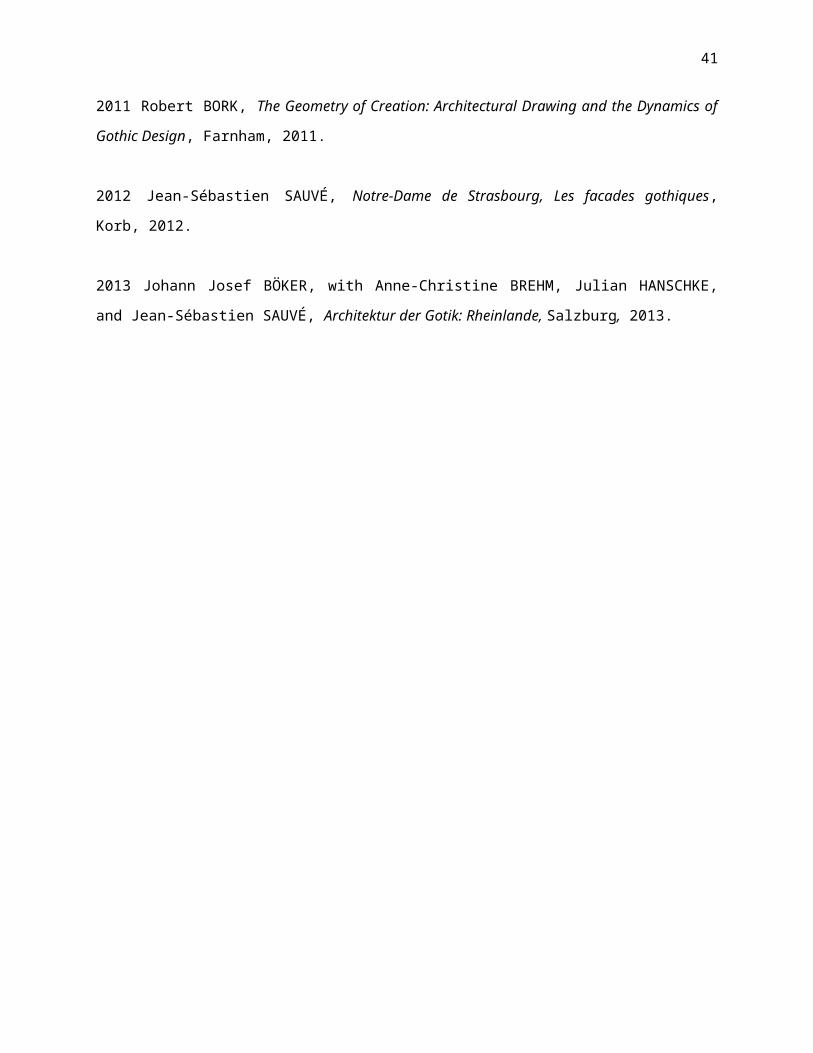
2011 Robert BORK, The Geometry of Creation: Architectural Drawing and the Dynamics of
Gothic Design, Farnham, 2011.
2012 Jean-Sébastien SAUVÉ, Notre-Dame de Strasbourg, Les facades gothiques,
Korb, 2012.
2013 Johann Josef BÖKER, with Anne-Christine BREHM, Julian HANSCHKE,
and Jean-Sébastien SAUVÉ, Architektur der Gotik: Rheinlande, Salzburg, 2013.
41
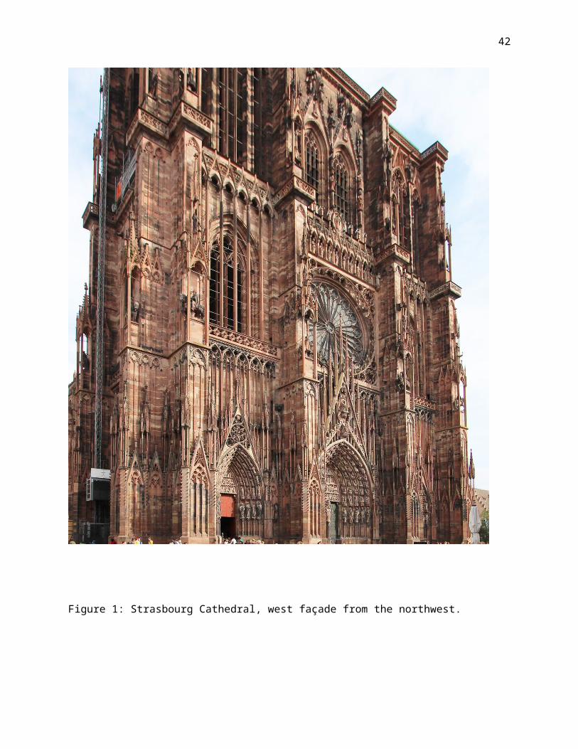
Figure 1: Strasbourg Cathedral, west façade from the northwest.
42
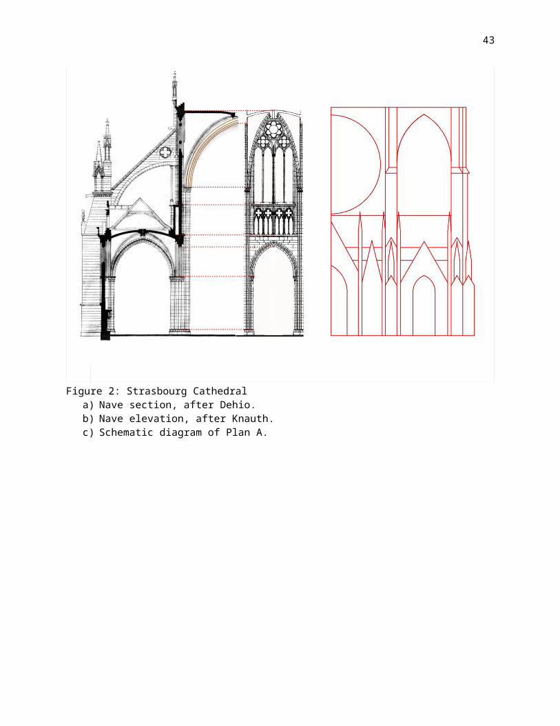
Figure 2: Strasbourg Cathedrala) Nave section, after Dehio.b) Nave elevation, after Knauth.c) Schematic diagram of Plan A.
43
Figure 3: Strasbourg Cathedral, versions of Plan Ba) Original drawing (omitted here).b) Asymmetrical version showing contrast between original portions
and full surviving scheme.
44
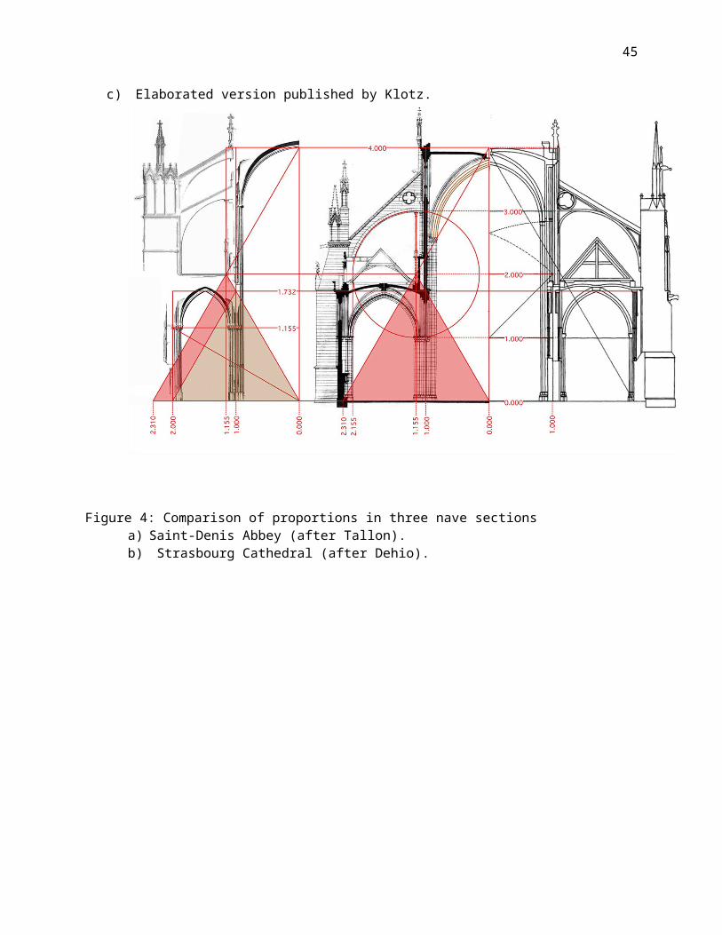
c) Elaborated version published by Klotz.
Figure 4: Comparison of proportions in three nave sectionsa) Saint-Denis Abbey (after Tallon).b) Strasbourg Cathedral (after Dehio).
45
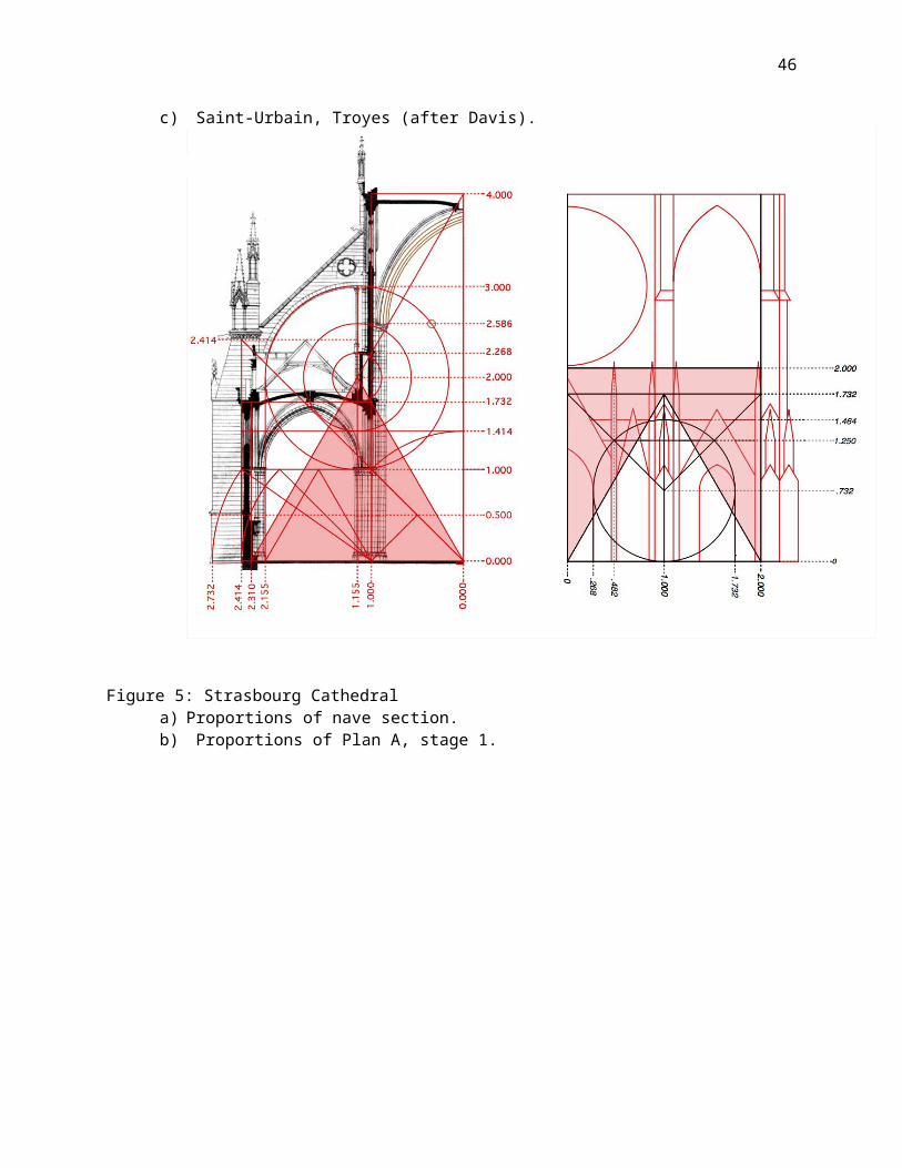
c) Saint-Urbain, Troyes (after Davis).
Figure 5: Strasbourg Cathedrala) Proportions of nave section.b) Proportions of Plan A, stage 1.
46

Figure 6 (next page): Strasbourg Cathedral, proportions of Plan A, stage
47
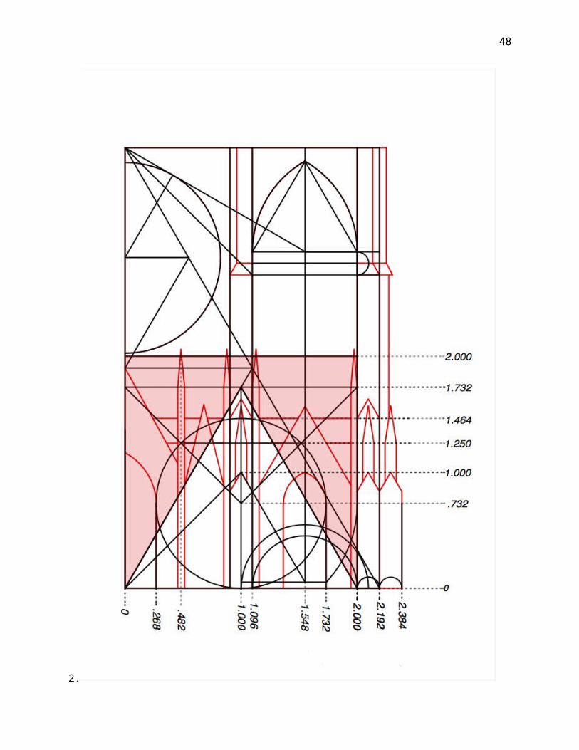
2.
48
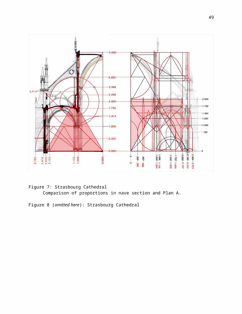
Figure 7: Strasbourg CathedralComparison of proportions in nave section and Plan A.
Figure 8 (omitted here): Strasbourg Cathedral
49
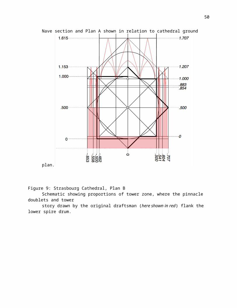
Nave section and Plan A shown in relation to cathedral ground
plan.
Figure 9: Strasbourg Cathedral, Plan BSchematic showing proportions of tower zone, where the pinnacle
doublets and tower story drawn by the original draftsman (here shown in red) flank the lower spire drum.
50
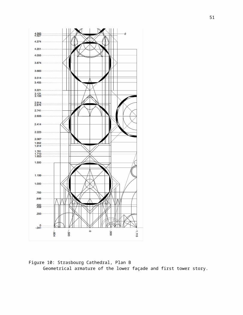
Figure 10: Strasbourg Cathedral, Plan BGeometrical armature of the lower façade and first tower story.
51
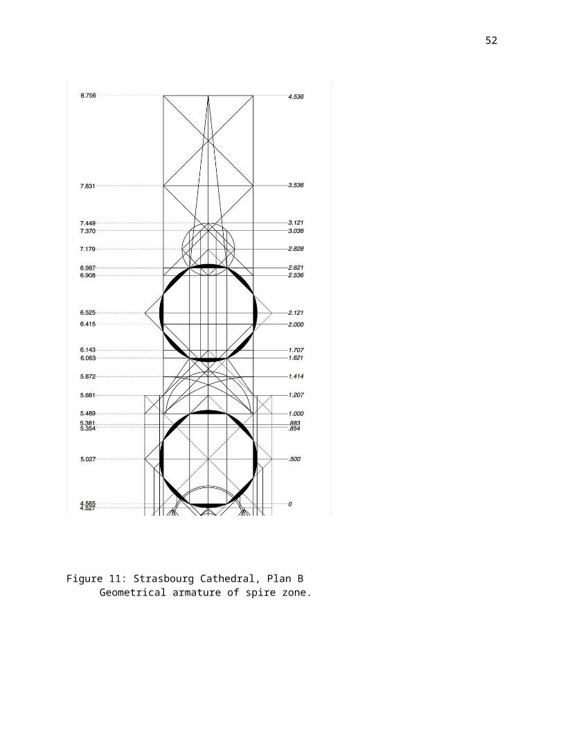
Figure 11: Strasbourg Cathedral, Plan BGeometrical armature of spire zone.
52
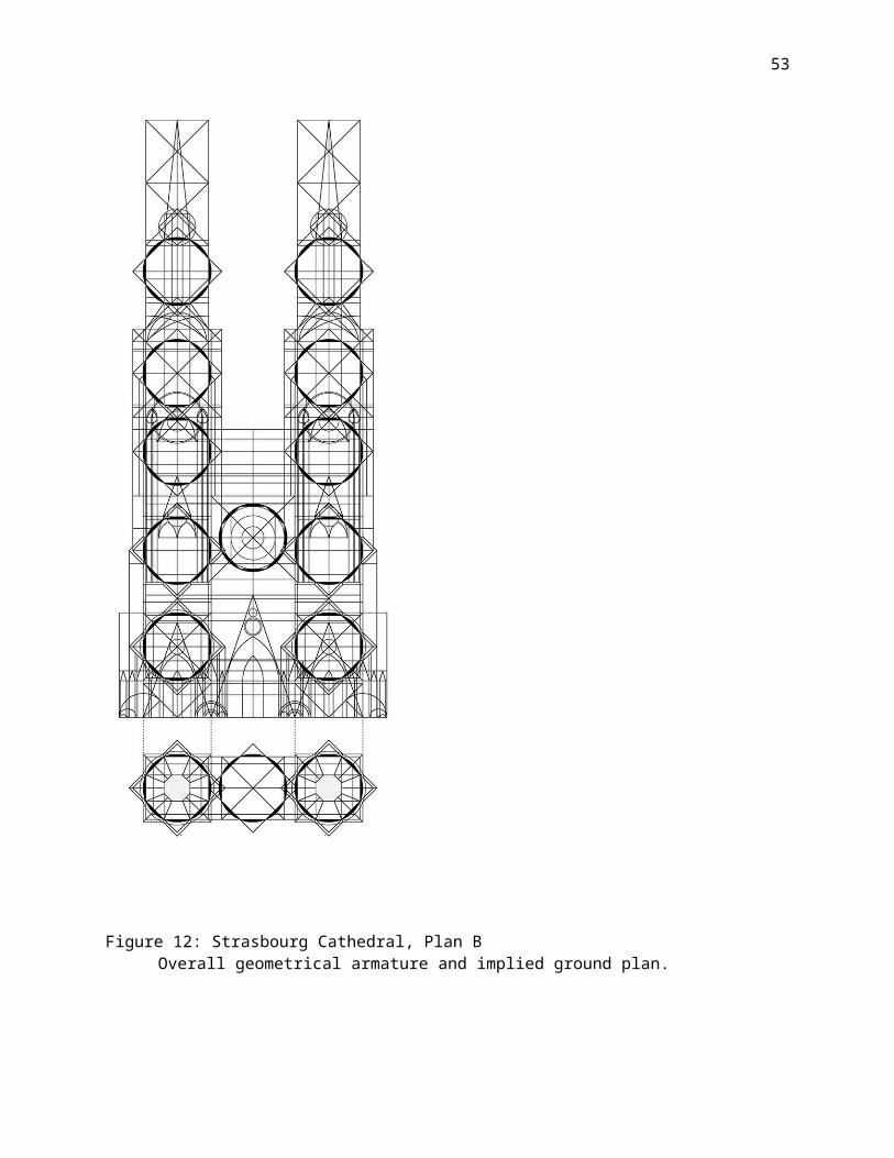
Figure 12: Strasbourg Cathedral, Plan BOverall geometrical armature and implied ground plan.
53
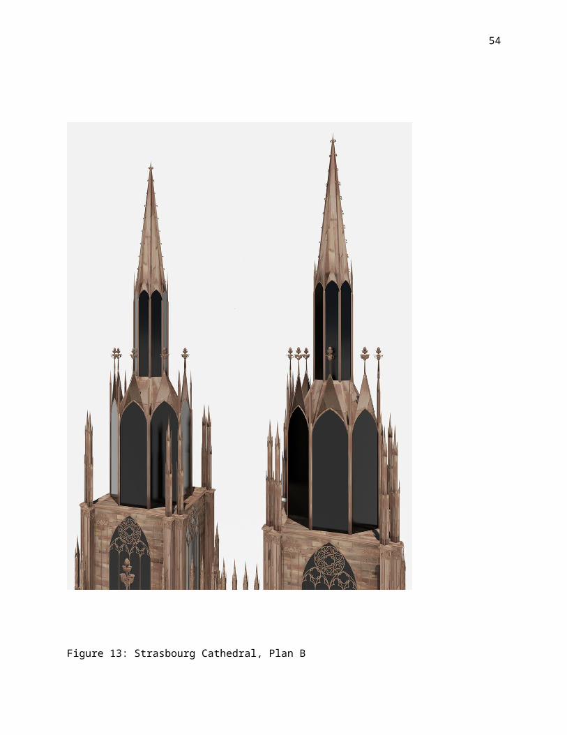
Figure 13: Strasbourg Cathedral, Plan B
54
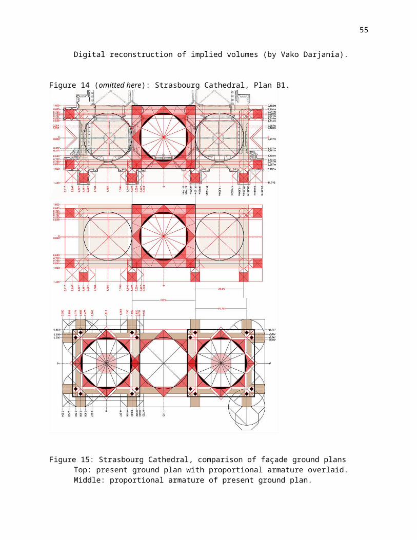
Digital reconstruction of implied volumes (by Vako Darjania).
Figure 14 (omitted here): Strasbourg Cathedral, Plan B1.
Figure 15: Strasbourg Cathedral, comparison of façade ground plansTop: present ground plan with proportional armature overlaid.Middle: proportional armature of present ground plan.
55
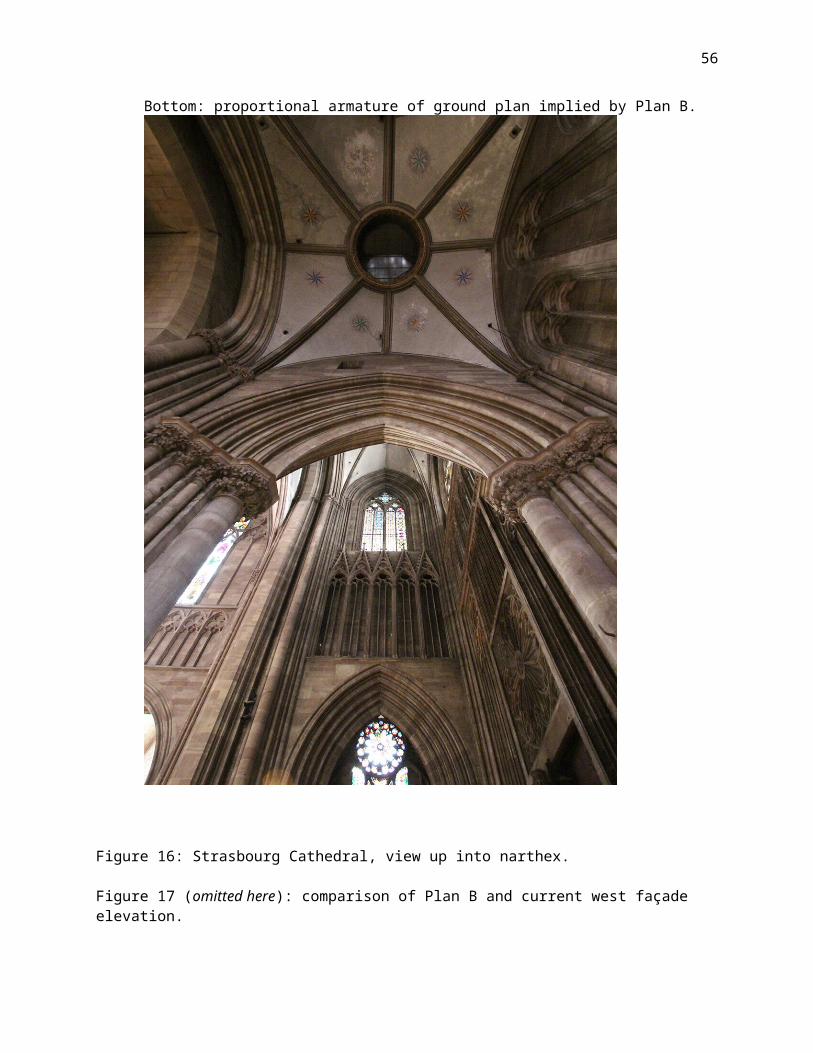
Bottom: proportional armature of ground plan implied by Plan B.
Figure 16: Strasbourg Cathedral, view up into narthex.
Figure 17 (omitted here): comparison of Plan B and current west façade elevation.
56

57
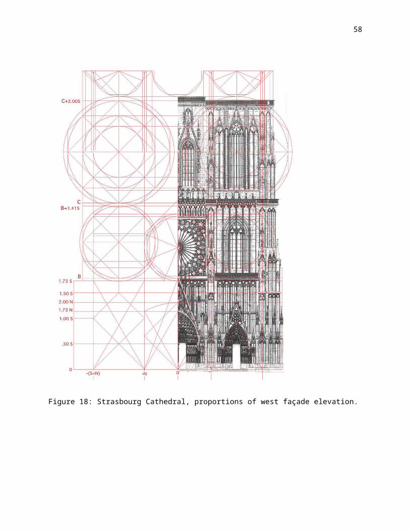
Figure 18: Strasbourg Cathedral, proportions of west façade elevation.
58
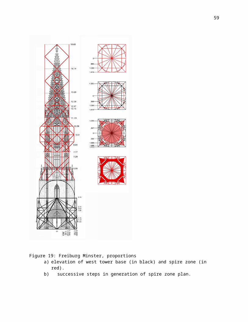
Figure 19: Freiburg Minster, proportionsa) elevation of west tower base (in black) and spire zone (in
red).b) successive steps in generation of spire zone plan.
59
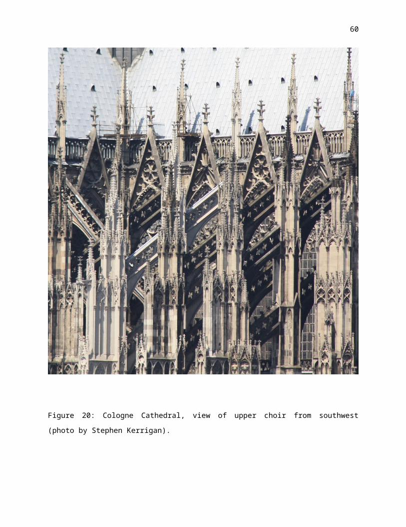
Figure 20: Cologne Cathedral, view of upper choir from southwest
(photo by Stephen Kerrigan).
60