the first naeh water treatment - afm safety
TRANSCRIPT

129 MM.1
Permutit The first naeh water treatment
MAINTENANCE MANUAL
FOR
WATER PURIFICATION EQUIPMENT
MRO-10. REVERSE OSMOSIS
DEPARTMENT OF‘ DEFENCE
(ARMY) CAP0 -- N143552
HEAD OFFICE: Cm Wattle Road & Short Street, PO. Rex 117, BROOKVALE, NSW. 2100 Telex: 24742. Facsimile No.: (02) 938 4202 Cables: PORTALS Sydney Australia. Telephone: (02) 938 4686
BRANCH omczs: vtcmRtA: 44 Koornetq Road. Scores& VICTORIA 3159
Tdlephone: (03) 763 6266 T&x: 31666 QUEENSLAND: Cnr. Bullockhead 8 Spne Streeta Sumner Park, QLD. 4074
Teleohone: fO7l5/8 6900. Telex: 41049 WEST Ausr.: 33 &id Eastern kiiig)Nal. Riwi~ale. W.A. 6103
Tdephone: (09) 362 6033. Telex: 96469 SOWN WST.: lap, Deeds Road. Camden Perk. SA. 5038
Telephone: (08) 294 7lT7 Telex: ~39789
Asscciated Company, William B&y and Co. (Ausbalia) F’ty. Ltd.
UN
CO
NT
RO
LLE
D W
HE
N P
RIN
TE
DELECTRICAL AND MECHANICALENGINEERING INSTRUCTIONS
ENGR EQUIP W 656-1Issue 1, May 08

&ImU& &&dh AmemkofthePortakGroup
(1)
(2)
(3)
(4)
(5)
(61
(7)
(8’)
(9-I
(10)
(11)
(12)
(13)
t.14 >
(15)
(16-j
(17)
MAINTENANCE MANUAL
INDEX
Maintenance Schedule Lubrication Schedule (Type) Lubrication Schedule (Frequency)
Generator - 30 KVa
Deutz Diesel Engine
Wheatley High Pressure Pump. ASEA Motor - 22 Kw 6 Pole
API Alloy Cleaning Pump- ASEA Motor G Kwt2 Pole,
Chemical Dosing Pump MPU-10 Controller
Valving
Hydraulic Jacking System.
BPW Axle and Brakes.
Reverse Osmosis Membranes.
Dosing Pump Compressor.
Asco Solenoid Valve.
Christie, Hydraulic Accumulator.
GEMU - Variable Area Flow Meter.
Pressure Switch.
TPS Conductivity Monitor and Cell.
Electrical Wiring Diagrams.
UN
CO
NT
RO
LLE
D W
HE
N P
RIN
TE
D

. 129 -t&w A member of the Portals Group
MAINTENANCE SCHEDULE
DAILY MAINTENANCE
See Operators Manual
MINOR SERVICE (150 hours - 6 months)
1. Tighten chassis suspension fasteners
2. Clean "dry" air- cleaner elements
3. Change engine oil and replace oil filter
4. Clean fuel strainer
5. Clean engine air cooling fins
6. Check exhaust system for security
7. Check V.belt tension KVa- and high pressure pump
8.. Check control linkages for wear and correct operation
9’; . Check all electrical' wirings and all lighting for service ability
10.
sl'.
12.
13.
14.
Carry out a complete functional check for fuel, oil leaks .and, operation, carry out a: road test and brake efficiency test
Check air hoses-and couplings for serviceability I Check towing eye for serviceability
Check brake adjustmeent
Check wheel bearing adjustment
MAJOR SERVICE (300 hours or 12 months)'
i.. Clean/replace. air cleaner elements
2. Change engine. oil - replace oil filter
3. Replace fuel filter
4. Clean fuel strainer
5. Drain and flush fuel tank
6. Clean engine cooling fins
7. Check exhaust system for security and serviceability .
8. -. Check all electric wiring and connectors for serviceability
UN
CO
NT
RO
LLE
D W
HE
N P
RIN
TE
D

Fermlltie A member of the Portals Group
9.
10.
11.
12.
13.
14.
15,
16.
17..
18.
19.
Carry out a complete functional check for fuel, oil leaks and operation, carry out a road test and brake.efficiency test
Test engine temperature warning device
Check intake and exhaust manifolds for tightness
Check for serviceability
(a> Tie down rails
(b) Springs and shackles
(cl Towing eyes
Check brake- system, shoes and drums for serviceabi with item 15) and adjust/replace as necessary
Check brake system for air leaks
.lity (in conjuuctidn
Inspect, replace as necessary and adj,ust, wheel bearings
RepIace hydraulic oil filter
Replace chemical injector diaphragm
Inspect ASCO solenoid components for wear
Check accumulator pressure
EVERY 500. HOURS [HYDRAULIC JACK OPERATION] OR TWICE YEARLY .
Hydraulic Jacking system - 1.. Change return line oil filter
EVERY 10,000 KMS
Brake Camshaft Bearings.
1. Top up with grease
EVERY 100,000 KMS OR TWICE YEARLY
Axle. Wheel Bearings
1 . Dissassemble, inspect, refill with new grease
UN
CO
NT
RO
LLE
D W
HE
N P
RIN
TE
D

wtk h,&dh AmemberofthePorcalsGroup 129 MM.4
WHEATLEY PUMP FIRST 140 HOURS RUNNING
Drain and refill crankcase
There after every 6 months.
Drain and refill crankcase
Wash crankcase air filter with kerosene.
LUBRICATION SCHEDULE (Type)
DEUTZ DIESEL ENGINE Engine Oil
Capacity 19 1
Type- OMD 115-
BPW AXLE WHEEL BEARINGS
Capacity/Hub: Inside rear bearing 160 g
Outside front bearing 310 g
Type: X G 274
BRAKE CAMSHAFT BEARING
Type: XG 274
UN
CO
NT
RO
LLE
D W
HE
N P
RIN
TE
D

&ImU& &Stdh AmembaofthePortalsGroup
MAINTENANCE SCHEDULE (CONT.D)
ABBEY HYDRAULIC JACKING SYSTEM HYDRAULIC OIL
WHEATLEY PUMP
Capacity:
Type:
CRANKCASE
Capacity:
Type:
50 1
OM 65
91
Amp01 Tegoma 150 Hydraulic
A.P.1 CLEANING PUMP MECHANICAL SEAL
BPLS3. Grease
UN
CO
NT
RO
LLE
D W
HE
N P
RIN
TE
D

&lIILl& w AmemberofthePordsGroup
LUBRICATION SCHEDULE (FREQUENCY)
DEUTZ DIESEL ENGINE CHANGE ENGINE OIL
Every 100 Hours.
BPW AXLE RE PACK WHEEL BEARINGS
Every six months
Top up brake camshaft bearings
Every 10,000 Km
ABBEY HYDRAULIC JACKING SYSTEM Keep reservior
topped up
I: WHEATLEY PUMP CHANGE'CRANKCASE OIL
I Every six months
A.P.I.. CLEANING PUMP MECHANICAL SEAL
UN
CO
NT
RO
LLE
D W
HE
N P
RIN
TE
D

Betriebsanleitung Operation Manual
__ -.---- _ _ _ _- -. - - ..__ __-_-- -.- - --- ____-.__-__-- - --
__-- -_I---- ---
----- ______-
UN
CO
NT
RO
LLE
D W
HE
N P
RIN
TE
D

. .
. . .
. . .
. . .
. .z
.
. .
,.._ . .
. . .
. .
_... .
c “. .
.
UN
CO
NT
RO
LLE
D W
HE
N P
RIN
TE
D

vorwot-t
Bevor Sie lhren neuen Motor in Betrieb setzen, lesen Sie bitte sorgfgltig den lnhalt dieser Betriebsanleitung
BeI der Konstruktion, Werkstoffauswahl und Herstellung lhres Motors wurden alle Sicherheits- vorschriften bertickslchtigt. DIG Leistung jedes Motors wlrd in unserem Werk durch elnen Probelauf uberprtift. Wie bei jedem technischen Gertit kann jedoch einwandfreies Betnebsver- halten tiber lange Zeit nur durch emen gewissen Aufwand an Wartung gesicherl werden. Dieser Aufwand 1st kleln und auf das wirkllch Notwendige beschrknkt Aber er ist Voraussetzung fiir eine fange Motorlebensdauer und die Erhaftung von Lelstung, Verbrauch und Abgas- quafitlt.
Urn die Betriebsslcherheit zu erhalten. sollten Reparaturen nur von ausgebildeten Fachleu- ten und unter Verwendung von Original-DEUTZ-Ersatzteilen durchgeflihrf werden. Beauflragen Sle mit solchen Arbeiten deshalb nur DEUTZ-Werksttitten. Das Personal dieser Werkslhtlen ist geschult, dart gibt es die nohgen Spezialelnnchtungen und die Onglnai-DEUTZ-Ersalztelle.
Auch unsere Vertnebsleitungen und Reparatunverksttitten, deren AnschriH wir auf Seite 51 auf- gefuhri haben. slehen lhnen federzelt zur Verfi.igung.
Achten Sie such darauf, daR nach Wartung oder Reparaturarbeiten alle Schutzeinrlchtun- gen (z. 8. Keilriemenschutzgitter) wieder montiert werden.
Sorgen Sie such dafiir, da8 Leckkraftstoff und Al161 umweltfreundlich aufgefangen werden.
Zur Bestellung der
A ;‘A
.Ym: fl.~pa~-c-;~----;r--
DEUTZ
Original-Ersatzteile
jedienen Sle sich bitte der zu lhrem Motor gehijrenden Ersatzleilliste oder wenden Sie sich an lhren DEUTZ-Handler.
Wenn Sie diese Hmweise beachten und lhren Motor immer mit den hier empfohlenen Kraftstoffen und Schmlerolen versorgen, werden Sie mit lhrem Motor zufrieden sein.
3ie lechnischen Angaben, Abbildungen und MaOe in dieser Anleitung sind unverbindlich. Irgend- ivelche Anspruche konnen daraus nicht abgeleitet werden. Wir behalten uns vor, Verbesserun- Jen am Motor vorzunehmen, ohne diese Anleitung zu tindern.
2
!I
II
I
i /I
Sicherheit durch iiberlegene Technik, richtigen Betrieb, sorgfaltige Wartung und Fflege
Dieses Symbol flnden Sic bei allen wichtrgen Slchetieitshinweisen in dieser Behebsan- leitung. Beachten Sie diese Hinweise beson- ders und verhalten Sie sich in allen diesen Fallen besonders vorsichhg. Geben Sle alle Sicherheitsanweisungen such an Ihr Bedie- nungspersonal weiler.
Allgemeine Sicherheits- und Unfallverhiitungsvorschriften Neben den Hinweisen in dieser Betrrebsan- leitung mussen die allgememen Sicherhelts- und UnfallverhiitungsvorschriHen des Gesetz- gebers beriicksichtigl werden, die je nach Land verschieden sein konnen.
Richticje Arbeitskleidung Die Arbeitskleidung sol1 fest anliegen, so daO sie sich nicht an drehenden oder vorstehen-. den Teilen verfangen kann.
vofwort
Wa’rtung und Pflege Ein wesentlicher Sicherheitsfaktor 1st die Ein- haltung der Wartungszelten (Wartungstabelle, Seite 21).
Versuchen Sie nie, Stdrungen zu beheben oder Reparaturen auszuftihren fijr die lhnen die natigen Erfahrungen und Spezialwerk- zeuge fehlen. Wenden Sie sich an lhre Deutz- Kundendienst-Werkstatf. Dorl haben Sle die Gewtihr, daf3 Ihr Motor von geschulten Fach- kraHen instandgesetzt wird.
Beachten Sie such die weiteren Sicherheits- hinweise in dieser Belriebsanleitung!
3
Vorsicht bel laufendem Motor Nur bei abgestelltem Motor tanken. Nur bei abgestelltem Motor Wartungsarbeiten oder Reparaturen durchftihren.
,
UN
CO
NT
RO
LLE
D W
HE
N P
RIN
TE
D

Motorbeschreibunq Motorbeschreibung
I,c] 6
Frg. 1
Motorbeschreibung (Bedienungsseite)
1 Kuhlluhgeblase 2 0lernfullstutzen : 3 Keilnemen (Geblase) 10
4 Spannrolle 5 Keilnemenscheibe i: 6 t)tablaf%chraube 13 7 Dlwanne 14
Kraftstoffrlter-Patrone Ufrlter-Patronen Kraftstotfvorreiniger Kraftstoff -FGrderpumpe Einspntzpumpe Luftfiihrungshaube Zyfinderkopfhaube
Motorbeschreibung (Abluftseite)
15 Luftansaugrohr 16 Abgasrohr 17 t)lkohler 16 Anlasser 19 AnschluOgehause 20 Generator 21 Keilriemen (Generator) 22 Enlliiftung
Zylinder-Numerierung
Fig. 3
5
UN
CO
NT
RO
LLE
D W
HE
N P
RIN
TE
D

Motorbeschreibung Motorbeschreibung I
Frg. 4
Schmierdkreislauf
1
32 4
i
ii 9
10 11
Ulwanne Ansaugleitung Schmrerolpumpe Dldruckregelventrl Druckollertung Thermostatventil C)lkiihler Schmierdlfilter Hauptolkanal Endregelventrl Spritzdtise fur Kolbenkirhlung
12 Kurbelwellenlager 13 Pleuellager 14 Nockenwellenlager 15 C)lrohr for Steuerungsteile 16 StBOel mrt Steuernut fur lmpulsochmierung
der Kipphebel 17 StoOstange (hohl, 0lzufluR zur Kipphebel-
schmierung) 18 Kipphebel 19 Riicklaufleitung, Zylinderkopfaufsatz zum
Kurbelgehause 20 Einspritzpumpe
7 -
8 9 6
Frg. 5
Kraftstoff schema
2 1 KraftstoffbeMlter
3 Zulaufleitung Kraftstoff-Fbrderpumpe
4 Kraftstoff-Filter 5 Einspritz umpe
P 6 Einspritz eltungen 7 Einspritzventil 8 Leckijlleitung 9 Uberstrbmleitung
10 Oberstromventil 11 Riicklaufleitung
6
UN
CO
NT
RO
LLE
D W
HE
N P
RIN
TE
D

Motorbeschreibung Motorbeschreibung
Bauart und Motornummer Technische Daten
Die Bauart A und die Motornummer B frnden Sie auf dem Frrmenschild (Fig. 6).
Das Frrmenschrld ist befestrgt am Kurbelgehause neben dem Schmierolfilteranbau links.
Dre Motornummer ist auRerdem noch auf dem Kurbelgehause eingeschlagen. Auf dem AnschluR- flansch fur Schmrerolfrlteranbau (Fig. 7).
Bauart . . . . . . . . . . . I F5L 413 FR I F6L 413 FR
Zylrnderzahl . . . . . . . . . . Bohrung 0 . . . . . mm Hub mm Hubra;m’::::::::::::::::::: cm3 Drehrichtung . , . . . . . . . . . Arbeitwerse . . . . . . . . . . Brennverfahren . . . . . _ . . . . .
Fig. 6
Fig. 7
ptiq
/
Gewicht (fe nach Ausfiihr.) nach VDMA . ca. k Motorleistung . . . . . . . . . Drehrahl
/
Schmierung 1 1 1 1 1 1 1 1 1 1 1 1 1 1 1 1 1
ky?J . . . .
Ulinhalt (GesamtolfiIlmenge”) Olwanne normal . . . . . . . . . . . . . . . ca. Ltr. Fiirderbeginn mit Spritzversteller . . . . . . ’ Kurbelwinkel v.OT ohne Spritzversteller bet 1500 - 1649 l/min bei 1650 - 1899 l/min bei 1900 - 2149 l/min
>
’ Kurbelwinkel v.OT bei 2150 - 2399 l/min bei 2400 - 2500 l/min
Ventrlspiel bei kaltem Motor EinlaBventil . Ausla8ventll . .
5 I
6 125 125 130 130
7976 I 9572 auf Schwungrad gesehen links
Viertakt-Diesel Direkternspritzung
623 I 740 . l
. .
Druckumlaufschmierung
17,s
23” 24”
25.5” + 1” 27” 2 1” 28,5” f 1” 30,5” f 1” 31,5”? 1”
. .
26.5” 2 1” 28” f 1” 29,5” + 1” 31.5” f 1” 32.5” 2 1”
0,2 mm 0,3 mm 22” 52 EF 0
EinlaOventil offnet . . . . . . . . . . . . KW v.OT EinlaOventil schlie8t
>
bei einem Kw” n.UT AuslaBventil offnet Ventilspiel von 0,2 mm KW”v.UT Ausla8ventil schlie8t . . . . . KW n.OT
Kolbenabstand (mit Blerdraht messen) . . . Abspritzdruck fiir Einspritzventil Betriebsdruck (Kontrolle zur Weiterverwendbarkert) Einstelldruck (Sollwerl fur dre Neuernstellung in Fertrgung dder’R&aratur) . Zundfolge des Motors 5-Zylinder . . . . . . . . . . . . .
6-Zylinder . . . . . . . . . . .
l Dre Leistung und Drehzahl des Motors sind auf Fimrenschild eingeschlagen. l * Ca.-Wert. Gilt fiir Normal-Clwanne.
MaOgebend ist immer die Clme8stabmarkrerung.
8 9
19
1.15 bis 1,3 mm
175 bar 180 bar l-2-4-5-3 l-5-3-6-2-4
UN
CO
NT
RO
LLE
D W
HE
N P
RIN
TE
D

Bedienung Bedienunq
Fur die lnbetriebnahme lhres neuen Motors sind Vorbereitungen notwendig. Einige dreser Tatigkeiten smd nicht nur beschrtinkt auf das erste Anlassen, sondern sic mussen such spaterzur regelma8rgen Warlung ausgefiihrl werden (Warlungsplan Seite 21).
1. Kraftstoff 1.1 Einftillen Verwenden Sle nur handelsiiblichen Marken-Dieselkraftstoff, dessen Schwefelgehalt unter 0,5 % liegen soll. und achten Sie beim Einfi.illen auf Sauberkeit. Hbherer Schwefelgehalt hat Auswirkungen auf die t)lwechselintervalle (Seite 29). Bei niedngen AuOentemperaturen nur Winter-Diesel-Kraftstoff verwenden (Seite 16). Der Kraftstoffvorrat sollte stets so rechtzeitig erganzt we&n, da8 der Behtilter nie leer&&, da sonsl Filter und Einspritzleitungen entltiftet werden miissen. Folgende Speziflkahbnen sind zugelassen: DIN 51601, Nato Codes F 54. F 75, F 76, BS 2869: A 1 und A 2’, ASTM D 975-78: 1-D und 2-D. VV-F-800a: DF-A, DF-1 und DF-2.
1.2 Entliiften
Tank nie leer fahren! In das Kraftstoffsystem elngedrungene Lufl ergibt unregelma8igen Motorlauf, Leistungs- abfall, fuhrl zum Stehenbleiben des Motors und macht elnen Start unmdglich. Deshalb nlcht nur nach teergefahrenem Tank, sondern such nach Wechsel des Kraftstoff- filters oder Arbeiten am Kraftstoffleitungs- system Entltiften: l ljberstromventil 1 (Fig. 8) am unteren (gr&
Oeren) Sechskant 2 - 3 Gtinge losen. l Handpumpe 2 am gerandelten Griff 3 durch
einige Llnksdrehungen aus verschraubler Stellung losen
8 Handpumpe so lange betatigen, bls aus dem gelosten Uberstromventil 1 blasen- freier Kraftstoff austntl
0 Uberstromventil wieder festzlehen, dabei noch welterpumpen. Fig. 8
0 Griff 3 weeder festschrauben.
2. Motor61 2.1 Einfiillen (Fig. 9) 2.2 Ulstand priifen (Fig 10) - siehe Selle 25 -
Fig. 9 Fig. 10
2.3 olqualitlt
Verwenden Sie bevorzugt t)le der API-Qualitatsklasse CD/SE oder CD/SF. DamIt erzielen Sic die griif3tmoglichen t)lwechselintervalle. ale der API-Qualit&sklasse CC/SE bzw. CC/SF kbnnen bei Halbierung der Olwechsellntervalle (siehe Seite 29) such verwendet werden. Beim Betrieb des Motors wird nicht nur ein Tell des zur Kolbenschmierung dienenden MotordIes verbrannt (~~verbraucht~~). sondern die Temperaturbeanspruchung und die in das 01 geratenden Verbrennungsprodukte des Kraftstoffes fbhren zu einem ~~Verschleil& insbesondere der cheml- schen Zusatze (~~Additives=) des C)les. Daher 1st dte gesamte t)lftillung In bestlmmten Abstanden zu erneuern. Da dieser ~~C)lverschleiO~~ von den Betriebsbedingungen, der Kraflstoff- und der t)lqualitdt (dem mLeistungsvermbgen<* des t3les) abhsngt, ergeben sich verschieden lange Olwechselfnsten. Beachten Sie daher unbedingt vorgeschriebenen C)lqualitlten und die davon abhangigen t)l- wechselfrislen. Ein Mischen verschiedener t)lsorten sollte mbglichst vermieden werden.
A ! l Schwefelgehalt beachten!
10
Achtung: Nur bei abgestelltem Motor tanken! Auf Sau- berkeit achten! Keinen Kraftstoff verschiitten!
11
UN
CO
NT
RO
LLE
D W
HE
N P
RIN
TE
D

Bedienunq Bedienung
2.4 Ulviskositlt
Da Schmierol seine Vrskosrtat (tihflussigkeil) milder Temperatur tindert, ist fur die Auswahl der Viskositatsklasse (SAE-Klasse) die Umgebungstemperatur am Betrlebsort des Motors maf3gebend (siehe Dragramm). Gelegentlrches Unterschreiten der Temperaturgrenzen (z. 6. Verwendung SAE 15 W/40 bis - 15 “C) kann zwar die Kaltstarffahigkeit beerntrachtrgen, fiihrf fedoch nicht zu Motorschaden.
:_..
E 20 W/20 1 : 1, ::.‘.:‘. ..: ;I SAE & .,:
/** SAE 5 WI30 Kiynlhetd
. . . SAE 10 WI30 SAE 10 WI40
.. : SAE 15 WI30 ..
:
Frg 11
* nur mrl Motorvorwarmung
Zu zahes Schmrerol fuhrf zu Startschwierigkerten, deshalb 1st fur die Viskositatsauswahl im Winterbetrieb die Temperatur wlhrend des Motorstarts ma6gebend. Temperaturbedingte Schmrerolwechsel konnen durch die Anwendung von Mehrbereichsdlen vermreden werden. Auch fur Mehrbererchsole gelten die auf Serte 29 genannten Dlwechselrnfervalle. Die bendtrgten Erslfullmengen fmden Sic unfer a>Technrsche Datenet auf Seite 9.
3. Ulbadluftfilter (falls angebaut) Mu6 vor lnbelriebnahme seine C)lfullung er- halten (Topf 1 Fig. 12). Hier ist das gleiche t)l wie fur den Motor zu verwenden. In den evtl. vorhandenen Staubsammelbehalter (2) des Vorabscheiders (3) darf kein t)l eingeftillt wer- den; er diem nur zur Aufnahme des ausge- schiedenen Staubes.
Ffg 12
4. Hinweis zur Leistung lhres Motors: Beim Dreselmotor sind Verbrennungsluflmenge und Kraftstoffeinspritzmenge sorgfaltig aufein- ander abgestrmmt und bestimmen Lerstung, Temperaturniveau und Abgasqualilal des Motors. Weil die Luftdrchle such mit dem Luffdruck - und damit such mrt der Hohenlage - und mlt der Temperalur andert, kann ein Verbrennungsmotor seine voile Nennlerstung nur ber erner beslimm- ten, von Normen festgelegten Hohenlage und Lufttemperatur abgeben: Fur Fahrzeugmotoren sind festgelegt nach DIN 70020. 1013 mbar (760 Torr entspricht 0 m Meereshdhe) und 20°C. Fur Motoren von Arbertsmaschrnen oder Schiffen grll DIN 6270. 981 mbar (736 Torr, entspncht 300 m Meereshohe) und 20 “C. Urn bei Betneb rn grdf3erer Hohenlage und/oder hoher Umgebungstemperatur dre Verbrennungs-
I 1 ualitat mcht zu verschlechtern und dre Temperaturbelastung der Bauteile nrcht zu erhohen, mu6 aher die eingesprffzte Kraftsloffmenge und damit die Leistung des Motors entsprechend ver-
ringerf - Bareduzierhd - werden. Fiir die GrdOe der Reduktron grbt es Tabellen in Abhangigkeit von Hbhenlage und AuOentemperatur.
Hinweis:
Sol&e e/so Ihr Motor cfauemd in -dtinner L&t- und mit voller Auslastung arbeiten miissen, fragen Sie lhren Motor- oder Gertitelieferanten, ob irn Interesse won Betriebssrcherheit, Lebensdauer und Abgasqualittit (Rauch!) die notwendrge Ruckblockierung durchgefiihrt wurde. Hdhen tiber 1000 m undloder Temperaturen won mehr a/s 30 ‘C iiberltingere Zeit erfordem in jedem Fall elne entsprechende Motoreinstellung!
12 13
UN
CO
NT
RO
LLE
D W
HE
N P
RIN
TE
D

Bedienung Bedienung
5. Anlassen 0 Motor durch Auskuppeln vonanzutrei-
benden Geraten trennen. @ Drehzahlverstellhebel 1 (Flg.13)
durch Hand- oder FuOhebelbetatigung auf etwa !a Drehzahlstellung bringen.
0 AnlaBschlussel 1 (Fig. 14) einstecken, nach rechts auf zur Raststellung drehen, wobei die Ladestrom-Kontrollampe 2 aufleuchten muf3, nun emdri.icken und gegen den Feder- druck weiter nach rechts drehen. Sobald der Motor ztindet, AnlaOschalter loslassen. Bei Ausflihrung mit GltihanlaBschalter 3: Zuerst den Schaltkastenschlussel4 his zum Anschlag einstecken, GliihanlaOschalter 3 tiber die Stellung 1 auf Stellung 2 drehen. Sobald der Motor ztindet, GltihanlaOschltis- sel loslassen.
0 Sobald der Motor rundlhuft, Drehzahl zu- ruckselzen. Kontrolleuchte 2 erlischt. Bei ma8iger Belastung mit wechselnder Dreh- zahl 1st der Motor In kurzer Zeit betnebs- warm.
Hinweis:
Hochstens 15 Sekunden ununterbrochen star-ten. S/e schonen lhre Batterie, wenn Sie zwischen den einzelnen Anl&vorgangen elne Pause won 1 Minute emlegen.
5.1 Anlassen bei niedrigen Umgebungstemperaturen
Slehe ~~Wmterbetneb~~. Seile 18
Fig. 13
Fig. 14
6. Betriebsiibetwachung 0 Motortildruck
Bei im mederen Leerlauf laufendem Motor mu8 die grDne Oldruckwarnlampe erloschen sein bzw. der Zetger eines evtl. vorhandenen Oldruckmanometers rm grimen Feld stehen Em Aufleuchten der Warnlampe Irn mederen Leerlaul b81 warmem Motor bzw eln Abfall des Zelgers ins rote Feld ISI
nochzulasslg, wennbelslelgenderDrehzahldle Lampewiedererllschl bzw derZergerslchmdasGrunleld bewegl Die Oldruckkonlrolle 1st nur au1 den medrlgen Leerlauf des Motors abgesllmml Sollen Moloren such Irn Arbetls- drehzahlberelch dauernd bezugllch des Oldruckes ubenvachl werden. slnd Sonderemrlchtungen edorderllch
0 Motortemperatur’ Im Fenster des Fernthermometers 1st bei normaler Betriebstemperatur das grune Feld zu sehen. 1st STOP lm roten Feld zu sehen, so wlrd der Motor zu helO und ist sofort abzustellen. Dann stellen Sie die Ursache der Uberhrtzung entsprechend un- serer St&ungstabelle auf den Seiten 46147 fest.
9 Kiihlgebllseantrieb’ Em KeilrremenriR wlrd der elektr. Schalter 1 (Fig. 15) durch die Spannrolle betatlgt und em akustisches Signal oder eln Lichtslgnal ausgelost. Der Motor ist dann soforl ab- zustellen, urn eine llberhitzung zu ver- meiden.
* Nicht bei allen Motorausftihrungen ange- baut.
7. Abstellen Fig. 15
0 Drehzahlverstellhebel 1 (Fig.16)aul medrige Drehzahl stellen. 1. . .
0 A b s t e I I h e be I 2 (Fig. 16) der Elnspntz- pumpe so lange betatigen, bis der Motor stillsteht. Die Kontrolleuchte 2 (Fig. 14) leuchtet nach Stillstand des Motors wieder auf.
9 Schaltschltissel 1 (Rg.14)nachlinks drehen und abziehen, wobei die Kontroll- leuchten erloschen.
Hinwels:
Wie alle Verbrennungsmotoren sol1 such der luftgektihlte Deuk-Dieselmotor moglichst mcht aus Vollast heraus plbklich ebgestellt werden. Besserist es, den Motorzum Tempe- raturausglelch vorher im Leer/auf 7 - 2 Minu- fen laufen zu lassen.
14
Fig. 16
15
UN
CO
NT
RO
LLE
D W
HE
N P
RIN
TE
D

Bedienung
8. Winterbetrieb
8.1 Winter-Motor61 verwendenl Zur Slcherstellung emes elnwandfreien Kalt- starts ist es wichhg, die Viskosittitsauswahl (SAE-Klasse) des Motoroles nach der Umge- bungstemperatur beim Start des Motors zu treffen (Vlskosit&vorschnAen siehe Seite 12). BeI den t)lwechselzelten 1st zu beachten, da8 bei Betneb unter - 10 “C im Winter die t]l- wechselmtervalle verkbrzt werden (siehe Seite 29, Motorol wechseln).
8.2 Kraftstoff Verwenden Sic im Winter nur Winter-Diesel- kraftstoff. damit keine Verstopfungen durch Paraffin-Ausscheidungen entstehen. Bei sehr tlefen Temperaturen ist such bei Winter-Die- selkraftstoff mil storenden Ausscheidungen zu rechnen Falls nur Sommer-Dieselkrafistofl zur Verfugung steht oder Winter-Dieselkraft- stoff bei sehr tiefen Temperaturen verwendet werden mut3, emptehlen wir nachfolgendes Dlagramm ftir die Beimlschun
a von Petroleum
oder Normalbenzin’ zu beat ten, wobei die Normalbenzin-Belmischung nur als Notbehelf zu betrachten ist. mrt der mehr als sine Tank- ftillung nlcht verbraucht werden dart.
Fig. 17
A ! Achtung! Eventuelle Mischun
a mit Normalbenzin’ nur
im Tankselbst vorne men. i’uerst nohvendige Benzrnmenge einftillen, dann Dieselkraftstoff nachgiel3en Be&n-Dieselkraftstoffgemisch ist so feuergeftihrfich wie Benzin.
Normalbenzinzumlschung’ htichstens 20 %, bei Zumlschungsprozentstitzen iiber 20 % -. nur Petroleum verwenden.
Meislens kann such ausrelchende Kdltefestigkeit durch Zugabe eines ~*FlieOverbesserers~~ (Kraftstoffadditive) erreicht werden. Fragen Sic hlerzu lhre DEUTZ-Service-Stelle.
‘) nie Superbenzin
16
Bedienung
8.3 Zusiitzllche Wartungsarbeiten 0 Aus Kraftstoffbehllter wbchentlich den dickfliissigen Schlamm ablassen, durch Losen
de( Schlamm-AblaOschraube. 0 Die Ulfiillung des Ulbadluftfilters - falls angebaut - ist wie das Motorol der AuOentempera-
tur anzupassen. 0 AnlaBzahnkranz am Schwungrad
Bei Umgebungstemperaturen unter - 20 "C evtl. nach Abnahme des Anlassers durch das Ritzelloch von Zeit zu Zest mit k8ltebesttindigem Fett, z. B. Bosch-Fen FT 1 V 31, schmieren, urn das voile Einspuren des Anlasserritzels zu errechen.
8.4 Kaltstarthilfsmittel
8.4.1 Flammgliihanlage (Fig. 18) Die Flammgltihanlage sol1 bei Temperaturen urn und unter dem Gefnerpunkt angewendet werden, denn Sie erniedngt nicht nur die Starl- grenztemperatur, sondem erleichteti such den Start beI Temperaturen, die eigentlich noch keine Starthilfsmlttel erfordern. Die Mbg- lichkeit des Nachflammens zur Startrauchver- htitung ist ebenfalls gegeben, wenn der Start von vorneherein mil Benutzung der Flamm- gliihanlage (BaVorgliihen.) erfolgte. Die Flammgltihanlage erwdrml die Verbren- nungslufl, mdem kleine Krattsloffmengen ml1 Hilfe einer am Anfang des Saugrohres sitzen- den Flammgl~hkerze verbrannt werden. Die Steuerung dteses Kraftstoffflusses von der Einspritzpumpe her, erfolgt durch ein Magnet- ventil.
Fig. 18 Hinweis: Die Kaltstarlftihigkeit eines Dieselmotors 1st u. a. von der Anlasserle~sfung und der Battenekapa- zitat und ggf. dem Durchdrehwiderstand des Getriebeslder Arbertsmaschine abhangig. Da die Startausrirstung des Motors je nach Einsatz verschieden se/n kann, werden in der Betnebsanlei- tung keine Angaben iiber Kaltstartgrenztemperaturen gemacht Sie kbnnen diese bei einer De&z-Servicestelle erfragen. Beachten Sle unbedingt die Viskositltsvorschriften fiir das Schmierbl bei niedrigen Tem- peraturen. Guter Kaltstati setzl elnen guten Ladezustand der Batterle voraus. Durch Anwhrmen der Batterie auf ca. + 20 “C (Ausbau der Batterie nach dem Abstellen des Motors und Aufbewahren in einem warmen Raum) kbnnen die Startgrenztemperaturen urn 4 - 5 “C abgesenkt werden. Beim Batterie-Einbau auf guten Kontakt der Klemmanschliisse achten (Kontaktflachen blank ha/ten; Klemmschrauben nur whandfestll anziehen, urn Verformungen der Klemmkonen zu ver- me/den)! Extremtemperaturen (unter - 30 “C) Bei Extremtemperaturen mu8 zur Sicherstellung des Motorstarts und einer ausreichenden Scmierblversorgung der Motor vorgewtirmt werden. Mit AnschluBteilen fur VorwBrmgera’te sind jedoch nur Motoren ausgeriistet, die fiir den Betrieb in extrem kalten Gegenden vorgesehen smd.
17
UN
CO
NT
RO
LLE
D W
HE
N P
RIN
TE
D

Bedienung Startvorgang l Motordurch Auskuppeln vonanzutrei-
benden Gerdten trennen. o Drehzahlverstellhebel 1 (Fig.19)
durch Hand- oder FufIhebelbetatigung auf etwa l/a Drehzahlstellung bnngen.
0 AnlaBschltissel4 IFia. 20) einstecken. nach rechts auf zur R&t<tellu’ng drehen, wobei di;;adestrom-Kontrollampe 2 aufleuchten
GluhanlaBschalter 3 auf Stellung 1 drehen und ca. 1 Minute festhalten (vorgltihen). Mul3 der Gltihtiberwacher 5 hell autleuch- ten. Gluhanlaflschalter 3 in AnlaRslellung II wei- terdrehen. Sobald der Motor aus eigener Kraft zu lau- fen beginnt, Schalter loslassen (geht auf Nullstellung zuriick). Lauft der Motor nach dem Stat-i noch nicht ganz rund oder qualm1 er grau-weiR, Motor- drehzahl nicht mil dem Drehzahlverstellhe- bell (Fig. 19) zu beschleunigen versuchen, sondern
0 Nachgluhen durch Festhalten des Gliihan- IaOschalters 3 In Steliung I. Hbchstzulassige Nachgluhzelt 3 Mlnuten
Hinweis: Anlasser nlchl /anger als 15 Sekunden unun- terbrochen starfen. Nur wenn einzelne Ztin- dungen das Drehen des Motors unlersMtzen, dart der Anlasser 30 Sekunden betBtigr wer- den. Spnngl der Motornicht beim ersten Start- versuch an, zur Schonung der Batterie eine Pause von 2 Mlnuten brs turn ndchsten Ver- such einlegen. Der nichste Startversuch muR dann wieder mit dem Vorgltihen (1 Minute) Segmnen.
Funhionsprtifung der Flammgliihanlage siehe Seite 40.
Fig. 19
Fig. 20
Wartung
Al/e Wartungsarbeiten nur bei abgestelltem Motor durch fijhren.
18 19
UN
CO
NT
RO
LLE
D W
HE
N P
RIN
TE
D

UN
CO
NT
RO
LLE
D W
HE
N P
RIN
TE
D

Wartung In nachfolgender Wartungstabelle konnen die ordnungsgema6 durchgefiihrten Wartungsarberlen In nachfolgender Wartungstabelle kdnnen die ordnungsgemaf3 durchgefuhrten Wartungsarbeiten etngetragen und gegebenenfalls bestatigt werden. etngetragen und gegebenenfalls bestatigt werden.
Ausgefiihrte Wartungsarbeiten Ausgefiihrte Wartungsarbeiten
Betr.-Std. Datum ; -
- 50
125
375 I
UnterschriH Setr.-Std. Datum 1
250
500
UnterschriH Eetr.-Std. Datum 6125
6375
6625
6875
UnterschriH Betr.-Std. Datum
6250
6500
6750
7000 1
5375 5500 5625 5750
1 5675 1 * Srehe Hinweise auf Serte 24
1 6000 1
22
Wartung
UnterschriH
7125 / 1 7250 )
7375 7500
7625 7750
23
UN
CO
NT
RO
LLE
D W
HE
N P
RIN
TE
D

Wartung
Achtung, bei lnbetriebnahme neuer und iiberholter Motoren:
Nach 30 Minuten Laufzeft:
l Keilriemen (Fig. 21): Nachspannen. Slehe Setten 34135.
Fig. 21
Nach 50 Betriebsstunden:
0 SchmierGlwechsel: Siehe Seite 29130.
AuRerdem slnd helm 1. Olwechsel nachfol- gende Arbeiten f&lllg.
0 Schmierijlfilterpatrone erneuern: (Pos 1, Fig. 22) Siehe Seite 36.
0 Schmierdlwanne: Verschraubung (2) nachzlehen.
0 Motorbefestigung nachzlehen.
Hinweis: Urn d/e Inrervalle aller werteren Olwechselund Regelwanungsarbeiten auf dre Gesamtlaut- zert des Motors abzustrmmen, empiehlen wir, nach der lnbetriebnahme nach 50 Bh die ndchsten Wartungsarbeiten nach 125. 250 bzw. 500 Bh usw. Gesamtlauheit des Motors durchzufihren.
0 Ansaug- und Auspuffrohrbefestigung (Pos. 3. Fig. 23) an den Zylinderktipfen nachzlehen. Siehe Selte 41.
l Ventilsplel priifen, ggf. nachstellen. (Pos 4, Fig. 23) Slehe Selte 37.
Priifen Sie, ob das lose mftgelieferte War- tungsbild an gut sichtbarer Stelle aufge- klebt ist (siehe Seite 52).
Wartuna
Regelwartungsarbeiten
Ulstand im Motor priifen
l Motor mu6 waagrecht stehen.
l OlmeOstab 1 (Fig. 24) ziehen,
l mit faserfreiem. sauberen Lappen abwischen,
0 vieder emstecken bis Arischlag.
l Olmel3stab wieder ziehen. Der Olstand soll zwischen den beiden Mar- kierungen 2 und 3 (Fig. 24) liegen. Liegt er nahe oder gar unter der Markierung 3. muO soforl 01, mdglichst his zur oberen Markie- rung 2. nachgeftillt werden, urn schwere Motorscheden zu vermeiden.
Fig. 24
Hinweis: Die &$andsprutung vor dem Anlassen des Motors sicherl ausreichenden O&and irn Motor fur den Start. Eine enaue Cjlstandskontrolle erforderl nochmaliges Abstellen des Motors nach ca. emer MI- nule ifi etnebszeit. Dann ist das ganze &sys~em aufgefiillt und bei einer nach dem Abslellen des Motors folgenden &standsirberprtifung ergrbt srch der wahrend des Motorbetnebes fatsachlrch zur Verfirgung stehende Cilwannenrnhalt Bei Motoren mrt angebauter Fahrerkabrnenherzong mltlels Motorenol mu0 wahrend der ca em- minutrgen Belriebszeit der Heizungsbedlenungshebel in d/e Stellung Jagrtiflte Helzlelstung~~ gebrachl werden. Wir emptehlen dringend, vor langeren Motorbetnebszelten drese Doppeluberprufung des. Ol- standes anzuwenden; msbesondere dann. wenn die Prufung vor dem Molorstalt emen O&and in der NChe der unteren Peilstabmarke ergeben hat Neue Motoren haben normalerweise einen hoheren Olverbrauch. Daher 1st wahrend der Einlauf- zeit (ca. 200 Betr.-Std.) der &land t;ig/rch zweimal zu prtiijfen. Nach der tnlaufzelt ist ein ein- maliges tagliches Priifen ausreichend.
Bel Motorbetrieb in Schrtiglagen Ulstand fmmer an der oberen Markierung des Peilstabes halten.
24 25
UN
CO
NT
RO
LLE
D W
HE
N P
RIN
TE
D

Wartung
.A’ .: I \’ I ,L
.:
Slaub III der Verbrennungsluft verursacht vor- i ’ ’ zeitigen MotorverschleiO. SorgfBllige und regelmafllge Filterwarlung ist deshalb fiir den j ‘.‘. Motor lebenswichhg. Zur Filterwartung ge- ,:.. htirt such die iiberpriifung der Verbin- ;:‘:>.: :‘o”h:ge”; und AnschluRstellen des Ansaug- 7. :,’ :.+2
Die Wariungsintervalle der LuHfilter sind vom Staubanfall abhanglg und kbnnen daher nicht allgemein festgelegt werden.
Fig. 24 a
1. tilbadluftfilter (falls angebaut, anderenfalls siehe Selte 27) 0 LuHfilterwarlung frtihestens 1 Stunde nach dem Abstellen des Motors, damit all% [3l aus dem
Flltergestrick abgetropH ist. 0 Schnellverschlusse 3 (Fig. 24a) Ibsen und I)ltopf 2 abnehmen.
0 Durch seitllchen Schlag mit der Handkante oder mit Hilfe eines Schraubendrehers Filterunter- IelI losen und abnehmen. Gummidichtung nicht beschtidigen!
0 Verschlammtes t)l im Otopf 2 erneuern. (Motoreniil, Viskositlt siehe Seite 12) Olstandsmar- klerung (Pfeil) beachten.
0 Filterunterteil4 In DieselkraHstoff (niemals in Benzinl) reinigen und griindlich abtropfen lassen.
0 Je nach Staubanfall such Filteroberteil 1 ein- bis zwelmal lahrlich abbauen und ebenfalls mil DieselkraHstoff auswaschen. Grirndlich abtropfen lassen.
0 BeI Wlederzusammenbau auf Dlchtheit aller Anschltisse achten.
1.1 Zyklon-Vorabschaider 5 (Fig. 24a) (falls angebaut)
0 Staubsammeltopf 6 beI halber Staubfiillung (Markierung) enileuren.
0 Niemals Staubsammeltopf mlt t)l fiillen.
26 27
Wartuna
2. Trockenluftfilter (falls angebaut)
Die Standzeit der Papierpatronen in Trocken- luftfiltern ist von der rechlzeitigen Entleerung des Staubsammelbehtilters 2 (Fig. 25) abhtin- gig. Unterbleibt diese Wartung, setzt sich die Patrone durch zu gro6en Staubanfall sehr schnell zu. Deshalb darf sich der Staubsam- melbehtilter 2 nie mehr als bls zur HIlfte mit Staub fiillen. Bei starkem Staubanfall erfor- dert das u. U. ein tlgliches Entleeren. Bei Filterausfiihrung mit Slaubentleerventll 6 entftillt dieser Wattungsvorgang, jedoch ist von Zeit zu Zeit der Austrageschlitz des Staub- entleerventils zu saubern.
2.1 Entleeren des Staubsammelbehllters:
0 Motor abstellen
0 Spannbiigel 1 (Fig. 25) aufklappen und Staubsammelbehtilter 2 zusammen mit Deckel3 abnehmen.
Fig. 25
0 Deckel3 von Staubsammelbehtilter entfernen und Behalter ausleeren.
0 In umgekehrler Reihenfolge wieder montleren; Aussparung am Deckel und Bockchen am Staubsammelbehtilter mtissen ineinandergrelfen, siehe Pfeile (Fig. 25).
0 Bei waagerechtem Fllteranbau auf Markierung ~~oben~~ achten.
2.2 Wartung der Fllterpatrone: Wir empfehlen dringend, die Fllterpatronen- wartung nur nach Wartungsanzeiger oder vom Kontrollicht abhangig zu machen. Durch hgufrgen Patronen-Aus- und Einbau kann die
: <.. :” y
Dichtung 7 (Fig. 25) zwischen Filteroatrone 5 und Filtergehduse 6 beeintrachtigi werden. Deshalb Patrone nur reinigen oder austau- schen, wenn es notwendig ist. Sptiitestens jedoch nach 12 Monaten bzw. bei Verschmut- zung durch Flu6 Patrone austauschen. Bleibt bei angebautem Wartungsanzelger (Fig. 26) das rote &ervicefeldst 1 bei abge- stelltem Motor voll sichtbar, oder leuchtet bel laufendem Motor das gelbe Luftfilter- Kontrollicht auf, Filterpatroneaustauschen oder reinigen. AuHretender Auspuffqualm oder nachlassende Motorleistung kbnnen Hin- weise fur verschmutzte LuHfilter sein.
‘.: .’
:.. ._ +--cl 1 .' _._ : ‘i
_- ?, Staubsammelbehtiller 2 (Fig. 25) wle unter !~.::~‘~~‘: : ,, ; : ,,
-. .: .,. Punkt 2.1 demontteren. < :’ _> .: .: .J
n.:, . . . .,,. ‘.. : ..- ; .:._..__. (Bei Filterausftihrung mit Staubentleerventil ;:I :;_;:, ::,.; i, _.,_ . . . . 6 Fltigelmutter 9 abschrauben und Deckel
___ piGi[J$ _, ,,
abqehmen). Fig. 26
UN
CO
NT
RO
LLE
D W
HE
N P
RIN
TE
D

Wattung
l Sechskantmutter 4 abschrauben, ver- schmutzte Ftllerpatrone 5 herausnehmen.
l Patrone entweder durch neue ersetzen oder remlgen.
0 Nach 5mallger Wartung der Fllterpatrone 5 mu8 such die durch die Sechskantmutter 10 mit dem Filtergehause 6 verschraubte Slcherheltspatrone 11 erneuerl werden. Spatestens ist die Sicherheitspatrone 11 nach zwel Jahren auszutauschen. Die An- zahl der Fllterpatronenwartungen is1 auf der Slcherheltspatrone 11 in den dafur vorge- sehenen Markierungsfeldern zu kennzelch- nen.
l Die Sicherheitspatrone 11 darf nicht ge- reinigt und wiederverwendet werden.
0 1st bei der Wartung der Fiiterpatrone 5 ein Wartungsfehler oder Defekt festgestelit worden, mu8 such die Sicherheitspatrone 11 ausgewechselt werden.
0 Setzt die Warlungsanzeige nach erfolgter War-lung der Fllterpatrone 5 gleich weeder ein, 1st ebenfalls die Sicherheltspatrone 11 zu erneuern.
0 a>Nur Original-Filterpatronen des Luft- filterherstellers einbauen. Fremdtabri- kate passen meist nicht und geflhrden den Motor.sl
2.2.1 Trockenreinigung: a) BeheltsmaOig: Filterpatrone 5 mit der Stlrnselte mehrmals senkrecht leicht gegen den Handballen oder auf ebener weicher Flache aulklopfen. damit der Staub abftillt. Stirnselre der Patrone darf dabei nrcht be- schadlgr oder verbeult werden. b) Intenslvremigung: Patrone mit trockner PreRlutr mlt nlcht mehr als 5 bar Druck schrdg von a&en und innen anblasen bis keln Staubaustritt mehr sichtbar ist (nicht mit PreOiuft das Filtergehtiuse 6 ausblasen).
2.2.2 NaOreinigung: Die Fllterpatrone 5 In handwarmem Wasser mit emem handelstiblichen Femwaschmittel durch Hln- und Herschwenken reinigen. AnschlleOend in klarem Wasser gut nach- spi.ilen, ausschleudern, und gut trocknen lassen
A ! Achtung! Keinesialls Benzin oder heiBe Fftissigkeiten zur Filterparronenreinigung verwenden!
28
Fig. 26
3. Kontrolle: Die gereinigte Filterpatrone 5 vor dem Einbau mit einer Handlampe durchleuchten und auf Beschtidigungen hin iiberprtifen (beschadigte Filterpatronen unbedmgt austauschen). Eben- falls die aufgeklebte Dichtung 7 auf Risse und Beschadigungen kontroliieren. Gegebenen- fails bei Wartungsanzeiger (Fig. 26) mit Sicht- anzeige Ausloseknopf 2 eindriicken. Dabei wird das rote ~~Servicefeld~~ weeder unsichtbar.
Wartung
, Motor61 wechseln
RegelmtiBige Schmieriilwechsel Die Ihn
R 9Jv ste zultissi e Verweildauer der Schmierolftillung im Motor betrtigt 1 Jahr. Werden also
die nac stehenden echselintervalle innerhalb eines Jahres nicht erreicht. smd unabhanglg von der erreichten Betriebsstundenzahl die
durchzufiihren. Schmierijlwechsei mindestens 1 x jlhrlich
Schmierijlwechselzeiten
Motoreinsatz bzw. Ausftihrung
Traktoren. Flurforderfahrzeuge. KrBne, Baumaschmen. Schlenenfahr zeuge, Schiffe, Elektroagg. fi,rr Dauerbetneb. Pumpen landw. Maschinen, (Saisoneinsatz) Untertagegertite, Kehrmaschtnen Winterdlenstgerate Notstromaggregate, Notpumpen
al-Bean- spruchungs
gww
A
B
t)lwechselintervalle (Bh) ber t)lqualltdt
API: CC/SE bzw. API: CD/SE bzw. CC/SF CD/SF
250 Bh I 500 Bh
125 Bh I 250 Bh
Achtung: Diese lntervalle gelten nur fur Verwendung elnes Dieselkraftstoffes mft hochstens 0,5 Gew. % Schwefel und ftir Umgebungstemperaturen oberhaib -10 “C. l Bei Verwendung von Kraftstoffen mit mehr als 0,5 % bis 1 % Schwefel oder 0 bei Umgebungstemperaturen unter - 10°C dauernd smd die O;iwechselintervalle derTabelle
zu halbieren. Bei KraHsloffen mlt elnem Schwefelgehalt uber 1 SO bls 1,5 % mu6 das Motoren- 61 bei halblerten Wechselintervallen elne TBN’ von ca. 12 x % S-Gehalt haben
Beispiele: 1) Tropeneinsatz, Motorenemsatzgruppe A, KraHstoff 0,8 % Schwefel, Schmlerol CD/SE, Ol-
wechsel alle 250 Bh. 2) Tropenelnsatz, Motorenemsatzgruppe A. KraHstoff 1.2 % Schwefel, Olwechsel alle 250 Bh,
Schmierdl CD/SE bzw. CD/SF mit TBN’ ca. 14 mg KOH/g.
SchmierijlqualitPtsklassen Ais Merkmal fi.ir die t)lqualitat wird die API-Klasstflkatlon verwendet (Siehe Kopt der Tabelle) Die Gewtihrlelstung, welcher Qualltatsklasse eln Produkt zuzuordnen ISI, ubernimmt alleln der t)iherstelier.
Hinweis Bei ifbergang auf elne hbherlegierte Olqualrtat nach fan ersten Wechsel des hbherwerligen O/es nach 20 Betr - 8
erer Berriebszeu emptehlen WM. den td.
Schmierbffrfter-Patrone zu erneuern. vorzunehmen G/e/chze/r/g 1st d/e
l TBN = “Total Base Number”, Angabe fur Neutrallsationsvermogen des Oles Vom Lieferanten angeben lassen.
29
UN
CO
NT
RO
LLE
D W
HE
N P
RIN
TE
D

Wartung
Motor61 wechseln nur bei warmen Motor, da warmes 01 besser ablauH. l AblaOschraube 1 (Fig. 27) herausschrau-
ben, ablaufendes 01 auffangen.
0 AblaOschraube 1 mit neuem Dichtnng 2 wieder erndrehen und festschrauben.
0 Durch den Ernfullstutzen 3 (Fig. 27) das neue 01 nur brs zur oberen Olmef3stabmar- krerung (Max, Fig. 28) einfulien.
0 Olstand nach err-rem kurzen Probelauf tiber- prufen, ggf. brs zur oberen Markierung (Max.) nachfullen.
Olernfiillmenge (ohne Filterpatronenwechsel) F5L 413 FA ca. 17,5 Ltr. F6L 413 FR ca. 19,0 Ltr.
Fig. 27
A ! Achtung! Belm Ablassen von heii3em &Ii Verbrirhungs- getahr! Altdl aufiangen. nrcht m den Boden versickern lassen!
30
Fig. 28
Wartuna
Verschmutzung des Kijhlsystems (Geblase- beschaufelung, Ktihlnppen an Zylmderkopfen, Zyiindern 1 oder Olkiihler 2, Rg. 29) bedeuten vermrnderte Kfihlung. Schmutzansammlun- gen an diesen Stellen werden durch ol- oder kraftstoffeuchte Oberflachen begunstrgt. Da- her eventuelle 01- oder KraHstoffundrchtheiten im Beretch des KtihlgeblBses, der Zylinder oder des Olktihlers immer sofort beseitigen und danach Kiihlftiichen reinigen. Ktihlsystem auf Verschmutzung gema nach- folgender VorschriH regelma8rg priifen, e- gebenenfalls reinigen. Dabei beachten, % a8 die Priifintervalle nur als Richtwerte fur nor- malen Betneb angegeben werden konnen und sich bei abnormal verschmutzter KiihlluH - bei angebauten Kfihlluflsrebkasten auf nchtigen Sitz und Unversehrtheit achten - die Notwen- digkeit zu wesentlich kiirzeren Pruf- bzw. Reinigungsrntervallen ergeben kann.
Fig. 29
Priifintervall (Rtchtwene)
Betr.-Std. Motoreneinsatzarl
2000 Schiffe, Elektroaogreqate rn oeschiossenen Raumen. Pumpen
1000 Fahrzeuge auf befestrgten StraOen
500 Traktoren, Gabelstapler. fahrbare Elektroaggregate
250 I
Fahrzeuge auf Baustellen und unbefestrgten StraRen. Baumaschrnen, Kompressoren, Untertagegerate
125 Landmaschinen, Traktoren im Ernteetnsatz
31
UN
CO
NT
RO
LLE
D W
HE
N P
RIN
TE
D

Wartung
Fur das Prufen und Retnigen sind auf der Ein- spntzpumpenseite dre Spannverschlusse 1 (Frg. 30) der Luftfuhrungshaube 2 zu losen und dre Haube abzunehmen.
Reinigungsarten 0 Trockene Reinigung durch Ausblasen mit
Druckluft. Mrt dem Ausblasen 1st von der Abluftseite her zu beginnen (Frg. 31). Evtl. tn den Luftfuhrungsraum hinerngebla- sener Schmutz mu3 danach selbstver- standlrch entfernt werden
l Verwendung von Kaltrelniger (z. B. P3 oder Nalfleet). Motor nach ausreichender ~~Einweichzeit~~ mit einem scharfen Wasser- strahl sauber spritzen.
0 Steht em Dampfstrahlrefniger zur Verfii- gung, so ist dtese Retnigungsart jeder an- deren vot-zuziehen
Hinweis: Bei der Fahrzeug- bzw. Motorremrgung mit- tels Kaltrermger oder Dampf ist die Einspritz- pumpe gegen drrekten Wasserstrahl abzu- decken. ebenso der Generator, Regferschal- ter und der Anlasser. Nach feder NaBrernrgung Motor warmlaufen lassen, dam/t die Wasserrtickstande ver- dampfen und Rostbildung vermieden wrrd.
A I Achtung! Remigungsarbeiten nie ber laufendem Motor durchfuhren!
Fig. 30
Fig. 31
32
Wartung
Batterie-Fliissigkeitsstand priifen
0 VerschluOkappen 1 (Fig. 32) entfernen.
0 Bei Vorhandensein von Kontrolleinsatzen 2: Fliissigkettsstand sol1 bis zu deren Boden reichen.
9 Sons1 sauberen Holzstab 3 bis auf Platten- oberkante einfuhren und herausziehen. Fliissigkeitsstand sol1 10 - 15 mm iiber Plattenoberkante reichen.
0 ~~~exmenfalls destllliertes Wasser nach-
l VerschluBkappen wieder einschrauben.
0 Winterhtnwetse siehe Seite 17.
A ! Bei Arbeiten an der Batterie, kein offenes Feuer, nicht rauchen! SIure nicht auf Haut oder Kfeidung kommen fassen! Schutzbrille tragen! Keine Werkzeuge auf Batter/e legen!
Warnanlage’ priifen
Bei KeilnemenriO wtrd der elektr. Schalter 1 (Fig. 33) durch die Spannrolle betatigt und em akustisches Srgnal oder ein Lichtsignal ausge- lost. l Stromversorgung des Motors elnschalten.
l Funkttonsprijfung durch Eindrijcken des Stiftes 1 (Rg. 33) mit dem Finger.
A ! Achtungt Funktionsprtifung wegen Unfaffgefahr n/e- ma/s bei laufendem Motor durchfiihren!
l Nur auf Wunsch und bei besonderen Aus- fuhrungen angebaut.
Fig. 32
Fig 33
33
UN
CO
NT
RO
LLE
D W
HE
N P
RIN
TE
D

Wartung
0 Srchtprufung des Kerlnemens am gesamten Umfang auf Beschadigungen oder Risse. Beschadrgte oder angerissene Keilriemen erneuern.
0 Prufen durch Daumendruck (Fig. 34), ob sich der Kerlnemen zwtschen den Keilne- menscheiben urn nicht mehr als ca. 10 - 15 mm erndriicken IaRt.
Nachspannen des Keilriemens: 0 Sechskantschrauben 1, 2 und 3 (Fig. 35)
leicht Idsen.
0 Generator 4 In Richtung A ziehen, bis rich- tige Spannung des Ketlnemens erretcht ist.
l Sechskantschrauben 1,2 und 3 wieder fest anzrehen.
Wechseln des Keilriemens: Gebllsekeilriemen 0 Spannrolle 1 (Fig. 36) kraftig nach innen
d&ken.
0 Kerlriemen auflegen.
Generatorkeilriemen 0 Geblasekeilriemen abnehmen.
l Sechskantschrauben 1, 2 und 3 (Fig. 35) leicht Idsen.
0 Generator 4 in Richtung B ganz an den Motor driicken. In dieser Stellung Ia6t sich der neue Keilriemen gut auflegen.
0 Keilriemen spannen wie oben beschrieben.
l Gebldsekeilriemen wieder auflegen.
Hinweis: Neue Keilriemen nach 30 Minuten Laufzeit nachspannen. (AuRer Ktihlgeblaseantneb mit automatfscher Spannroffe 1 Fig. 36).
Fig. 34
Fig. 35
Achtung! Fig. 36
! A ! Kekiemen nachspannen nur bei stehendem Motor! Ggf. Keilriemenschuh wieder I montieren!
34
Nachspannen bei Luftpresser-Aus- fiihrung mit Einfachkeilriemen:
0 Sechskantschrauben 1 (Fig. 37) abschrau- ben.
l AuOere Riemenscheibenhalfte 2 abneh- men.
0 Zum Nachspannen eine oder ggf. mehrere Zwischenscherben 3 (Fig. 38) innen entneh- men und die entnommenen Scheiben aut3en auf die abgenommene Riemenscheiben- halfte 2 legen.
l Schrauben 1 (Fig. 37) wieder festztehen und wahrend des Festztehens gletchzeitig Motor mit dem Durchdrehschlussel drehen, damtt der Keilnemen ntcht etngequetscht wtrd.
Nachspannen bei Luftpresser-Aus- fiihrung mit Doppelkeilriemen:
0 Sechskantmuttern 1 (Fig. 39) abschrauben.
0 Ketlriemenscheibenhdlften 2 und 5 mit den Zwtschenscheibenpaketen 6 und 7 und dem Zwischenstiick 4 herausnehmen.
l Zum Nachspannen eine oder ggf. mehrere Zwtschenscheiben der beiden Pakete 6 und 7 entnehmen und die entnommenen Schei- ben gem&3 Fig. 39 vor bzw. hinter die Keil- riemenschetbenhalften legen, damit die Riemenflucht gewahrleistet bleibt. Aus je- dem Paket darf immer nur die gleiche Zwi- schenscheibenzahl gleichzeitig entnommen
0 Sechskantmuttern 1 wieder festziehen und vylhrend des Festziehens Motor mit dem Durchdrehschliissel drehen, damit die Keil- rfemen nicht eingequetscht werden.
Hinweis: Bei Ausfiihrung m/t 2 Keilriemen slnd bei Ver- schleiL3 oder Beschadigung eines Keilrie- mens lmmer be/de Riemen satzweise zu er- neuern. Die Llngendkferenz der neuen Keil- riemen untereinander darfO,75 % nicht iiber- schreiten.
35
Fig. 37 .
i : Fig. 38 ::..
Fig. 39
UN
CO
NT
RO
LLE
D W
HE
N P
RIN
TE
D

Wartuna
Schmier6IfiIter-Patronen wechseln
l Spannschrauben 1 (Fig. 40) l&en, Spann- schellen 2 nach unten abnehmen.
0 Schmlerdlklter-Patronen 3 (Fig. 41) mit einem Liiseschliissel l&en und mit der Hand abschrauben.
0 Die Dichtflachen 4 von eventuellem Schmutz reinigen.
0 Gummidichtun en 5 der neuen Schmierijl- filter-Patronen elcht elnolen, von Hand ein-
8. . . .
drehen bis die Dichtung anliegt und mit wei- terer halber Umdrehung festziehen.
0 Spannschellen 2 (Fig. 40) befestigen.
Bestell-Nr. der Schmieralfilter-Patronen 117 4419 (AD 1,2 H 4123-R)
Fig. 40
Hinweis: Nach der Montage sind wahrend des Probe- laufs Oldruckanzeige und gut8 Abdichfung d8r neuen Schmiertilfilter-Patronen zu beach- ten.
Fig. 41
36
Wartung
6 f-7
k?J If++
Ventilspiel priifen ex.i+
0 Ventilspiel nur bei kaltem Motor priifen.
0 Es soll fDr die Einlagventlle 0,2 mm,
fiir die AuslaBventile 0,3 mm
betragen.
0 Zylinderkopfhauben abbauen.
0 Am vorderen KUrbefWelf8n8nd8 Motor dr8- hen, bis Ventile am einzustellenden Zylinder sich &x?rschneidena (AUSlaf&8ntil noch nicht ganz geschlossen, Einlaf3ventil beginnt zu iiffnen).
0 DaIa80ch genau elne Umdrehung weiter-
l Ventilspiel priifen: Zwischen Kipphebeldaumen 2 und Ventil3 (Fig. 42) mu6 sich eine Fiihllehre von 0,2 mm bzw. 0,3 mm Dlcke mit germgem Wi- derstand einschieben lassen.
e 1st d8r Spalt fiirdi8 Fiihllehre zu weit oder zu eng, muB nachgesteilt werden.
0 Ventilspiel nachstellen: Gegenmutter 4 urn 2 - 3 Umdrehungen Iii- sen. Mit Schraubendreher 7 (Fi stellschraube 5 so regulieren, da
. 43) Ein- B beI ange-
zogener Gegenmutter Ftihllehre 6 sich mit geringem Widerstand einschieben und her-, ausziehen 1X$1.
0 Prtif- bzw. Einstellarbeiten an jedem Zylin- der durchfiihren.
Fig. 42
Fig. 43
Hinwels: Das V8ntilspi8l ist d8rnOWandig8 Luftspalt 1 zwischen den Kipphebeldaumen 2 und Ventilen 3 (Fig. 42). Gut8r Motorlauf und voile Leislung zeugen von seiner richtigen Einstellung, die von 8in6m gewandtem Bedienungsmann nach obigen Angaben selbst vorgenommen werden. Anderenfalls Iii& man sic besser von einem Fachmann ausftihren. Des Einstellen bzw. oberprtifen aller Ventile m/t nur 2 verschiedenen Kurbelwellensteilungen ist nach folgender Method8 mliglich: Siehe Se&e 38.
37
UN
CO
NT
RO
LLE
D W
HE
N P
RIN
TE
D

Wartuna Wartuna
Steiiung der Kurbeiweiie zur Ventiispieieinsteiiung
Kurbelwellenstellung 1
Die Kurbelwelle sodrehen, bis sich am Zylinder 1 beide Ventile ~*iiberschneiden~~ (d. h. Auslag- ventrl ist noch nicht geschlossen, EinlaDventil beginnt zu offnen). Das Bild (Fig. 43 a) zeigt unter ~Kurbelwelleneinstellung lu, Welch8 Ventile nun eingestellt werden konnen.
Kurbelwellenstellung 2
Kurbelwelle eine Umdrehung (360”) weiter- drehen, siehe Bild ~jKurbelwelleneinstellung 2~ (Fig. 43 b). Nun konnen die anderen Ventile eingestellt werden.
Fig. 43 a
nrchl einslellbar einstellbar
Hlnweis: Zur Kontroffe 8mpf8hlen wir, das jewejls ejn- g8St8fft8 Ventil mit Kr8id8 zu markieren.
38 39
Fig. 43 b
Kraftstoffvorreiniger reinigen
0 Bei hochliegendem Tank Kraftstoffhahn schlie68n.
0 Spannmutter 2 (Fig. 44) I&en. 0 Drahtbijgel 1 zur Seite schwenken. 0 Filtergkxke 5 mit Siebfilter 4 abn8hm8n und
in Kraftstoff reinigen. 0 Nach Wiederzusammenbau auf Dichtheit
achten.
Hlnwels: Nachlassende Motorleistun
5! kann durch Ver-
schmutzung di8S8S Si8b lft8rS verursacht werden.
Kraftstoffiiter-Patrone wechsein
$, Bei hOChll8g8nd8m Tank Kraftstoffhahn schlieRen.
0 Kraftstoffilter-Patron8 1 (Fig. 45) ggf. mit LoS8W8rkz8Ug abschrauben.
!, Auslaufenden Kraftstoff auffangen. 0 Dichtflache reinigen. 0 Gummidichtung 2 der neuen Kraftsloffilter-
Patrone leicht einolen. 0 Kraftstoffilter-Patron8 von Hand anschrau-
ben bis Dichtung anliegt. 9 Weitere halbe Umdrehung festziehen. 0 Kraftstoffanlageentlijften (siehe Seite 10).
Hlnweis: Nachlassende Motorleistung kann durch ver- stopfte Kraftstoffi/t8r-Patron8 verursacht wer- den. Verstopft die Kraftstoffilter-Patron8 zu schnell, Kraftstoff auf Verschmut2ung priifen, Tank rernrgen, auf guten V8rSChlUB achten.
Fig. 44
Fig. 45
A ! mntungl B8i Arbeiten an der Kraftstoffanlage kein Off8- nes Feuer, nicht rauchen! Keinen Kraftstoff verschutten!
UN
CO
NT
RO
LLE
D W
HE
N P
RIN
TE
D
Wartung
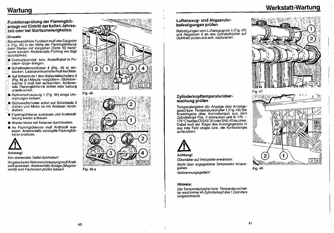
Funktionspriifung der Flammgliih- anlage vor Eintritt der kalten Jahres- zeit oder bei Startschwierigkeiten Hinwels: Bei ein wandfreier Funktion muB das Saugrohr 4 (Fig. 46) in der Nahe der Flammgliihkerze beim Star-ten mit Vorgliihen (Seite 18) hand- warm werden. Anderenfalls Priifung wie folgt dorchfuhren: 0 Drehzahlverstell- bzw. Abstellhebel in Po-
sition -Stop*< bringen. 0 Schaftkastenschlussel 4 (Fig. 46 a) ein-
stecken. Ladestromkontrolle mug leuchten. 0 Auf Schaltstufe 1 des GkihanlaOschalters 3
(Fig. 46 a) 1 Minute ~~vorglfihen~. Gliihiiber- wacher 5 mu6 hell aufleuchten. Anderen- falls Flammgliihkerze defekt oder Leitung unterbrochen.
0 Rohrverschraubung 1 (Fig. 46) einige Um- drehungen lockern.
0 GlijhanlaOschalter sofort auf Schaltstufe 2 drehen und Motor so mit Anlasser durch- drehen.
0 Flammgltihkerze ausbauen und Kraftstoff- leitung wieder anbauen.
0 Weeder Motor mit Anlasser durchdrehen. 0 An Flammgluhkerze mu6 Kraftstoff aus-
treten. Anderenfalls verstopfte Flammgliih- kerze ersetzen.
Achtung! Von drehenden Teilen femhalten! An gelockener Rohrverschraubung mu8 KraH- staff austreten. Anderenfalls An/age (Magnet- ventil) vom Fachmann prijfen lassen!
Fig. 46
Fig. 46 a
40
Werkstatt-Wartung
Luftansaug- und Abgasrohr- befestigungen priifen Befestigungen vom Luftansaugrohr 1 (Fig. 47) und Abgasrohr 2 an den Zylrnderkopfen auf Dichtheit priifen und evtt. nachziehen.
Zylinderkopftemperaturiiber- wachung priifen Temperaturgeber (fur Anzeige ijber Anzeiga- gerat) bzw. Temperaturschalter 1 (Fig. 48) (fur Kontakf abe iiber Kontrollampe) aus dem Zylinde a opf Pos. 2 schrauben und in 170 - 175°C heifles Cl SAE 3Ooder SAE 40 tauchen. Dabei mu6 der Zeiger des Anzeigegerates in das rote Feld zeigen bzw. die Kontrollampe aufleuchten.
A ! Achtungl Cllbehailter auf Heizplatte erwarmen. Nicht iiber angegebene Temperatur hinaus- gehen. Verbrennungsgefahr!
Hinweis: Der Temperafurgeber bzw. Temperaturschal- ter wird immer im Zylinderkopf des 1 Zyltnders eingeschraubt.
41
Fig. 47
Fig. 46
UN
CO
NT
RO
LLE
D W
HE
N P
RIN
TE
D

UN
CO
NT
RO
LLE
D W
HE
N P
RIN
TE
D

Motor-Konservierung Soll thr Motor ftir kingere Zeit stlllgesetzt werden (z. B. Oberwinterung), so empfehlen wir gegen Rostbildung folgende Motor-Konservierung:
1. Motor einschlieRlich KOhlsystem reinigen: Mit Kakretniger und Wasserstrahl oder besser Dampfstrahlgerit (vgl. Seite 32).
2. Motor warmfahren und dann abstellen. 3. Das noch warm8 Motorijl ablassen und Korrosionsschutz-Motor61 auffijllen. 4. Ggf. t)l aus t)lbad-Luftfilter ausgie6en, Unterteil reinigen und Korrosionsschutzljl einfiillen. 5. Kraftstoff aus Behalter ablassen, diesen mit 10 % KorrosionsschutzGI gut mischen und wieder
einftillen. Anstelle der Zumischung von KorrosionsschutzGI zum Kraftstoff kann such der Tank mit Einspntzpumpen-Priif61 mlt Korrosionsschutzeigenschaften (z. 8. Calibration Fluid 8) auf- gefi.illt werden.
6. Dann Motor 10 Minuten laufen fassen, so da6 Leitungen, Filter, Pumpe und D&en mit der Konservierungs-Mischung gefiillt sind und sich das neue Motor61 auf alle Telle verteilt hat.
7. Nach diesem Motorlauf Zylinderkopfhauben und seitfichen Deckel der Einspritzpumpe ab- nehmen. Kipphebelrtiume sowie Federraum der Einspritzpumpe mit einer Mischung aus Die- selkraftstoff und 10 % KorrosionsschutzGI einsptihen. Danach Hauben und Deckel wieder aufschrauben.
6. Nun Motor mehrmals von Hand ohne Ziindung zwecks Einsprtihung der Brennrtiume durch- drehen.
9. Keilriemen abnehmen und die Aillen der Keilriemenscheibe mit Korrosionsschutzbl einsprti- hen. Vor Wiederinbetriebnahme Korrosionsschutzal entfernen.
10. Ansaugoffnung am L&filter sowie Auspufftiffnung gut verschfi86en.
Fig. 52
Beachtef Dies8 KonssrvierungsmaBnahmen gelten je nach Witterungseinfiutl fiir ein8 Schufzdauer VOn ca. 6 - 12 Monaten. Vor Wiederinbetriebnahme ist das Konservierungsdf abzulassen und durch Motoreniif der API- (MI1 -) Kiassifika tion zu ersetzen. AIs Korrosionsschutziile gelten U/e die der Spezifikation M/L-L-27260 B oder TL 9150-03712 bzw. Nato Code C 64Of642 entsprechen. l Siehe Seite 29.
. 44
Stiirunaen. Ursache und 14 3 n I l* e
Stiirungen sind htiufig darauf zurtickzuftihren, dal3 der Motor nicht richtig bedient oder gewattet wurde. Lesen Sie deshalb bei jeder Stiirung noch einmal gut durch, was auf den wenigen Seiten 10 bis 43 in den Abschnitten iiber richtige Ekdienung und Wartung ge- schrieben steht. Kiinnen Sie die Ursache einer Stiirung nicht erken- nen oder eine St&ung nicht selbst beseitigen, dann wenden Sie sich am besten zuerst an lhren Hiindler bzw. an eine unserer Ver- tragswerkst~tten.
Stdrungstabelle siehe Seite 46 und 47.
45
UN
CO
NT
RO
LLE
D W
HE
N P
RIN
TE
D

UN
CO
NT
RO
LLE
D W
HE
N P
RIN
TE
D

Werkstatt-Information
Tabelle der Schraubenantuaswerte
Werkstatt-Information Das Werkstatthandbuch ftir die in dieser Be- tnebsanleitung beschriebene Motorbaureihe hat die Teilenummer 2911879 und kann im Stammhaus tiber die Ableilung MZAI bezogen werden.
I VOI- spannen
Nm T
Schraubenbezeichnung T Nachsp; 2. stuls
annen
50
Gesan
150”
Bemerkung SlUfS 3
Lagerdeckel BM 16 x 170 DIN 931-M 12.9 phos.
30” 60” 60”
30”
-
Anziehen hochbeanspruchter Schrauben Diese Hlnweise sind bei Instandsetzungsar- beiten besonders fiir solche F a c h I e u t 8 bestimmt, die keiner DEUTZ-Vertragswerk- statt angehdren. Urn Montagefehler zu ver- meiden, werden im folgenden einige Anwei- sungenzum Anziehen der hochbean- spruchten Schrauben gegeben,weil sle von den iiblichen Aegeln abweichen. Da es hierbei besonders auf den richtigen N a c h - span n w I n k e I ankommt, 1st in Fig. 53 ein-
Gegengewicht M 14 x 1,5 x 85 DIN 912 30”
60“
60”
30”
60”
60“
30”
30”
60”
30”
60”
60”
90”
150”
120”
90”
‘40
40
Kurbelwelle Antriebsteile vom M 16 x 1,5 x 150 DIN 912-10.9
Schwungrad-Befestigung M16x 1,5x 72 216 0313
40 60”
60”
gezechnet, wie man die verschiedetien Win- kelgrade nach dem Zifferblatt einer Uhr leicht feststellen kann. Man braucht hierbei den Schllissel nur urn den gleichen Wlnkel zu drehen, der zwischen kleinem und groRem Uhrzeiger gezeigt ist. Auch die BCP-Wnkel
Fig. 53
elnes Sechskantschraubenkoples kbnnen lhnen als Hinweis dlenen.
1. GewindeundAuflagefllchesindvordem Einschrauben mlt Motoreniil zu benet- zen
2. Schrauben eindrehen und alle glelch- mlOig leicht anziehen (BBbeidrehencc).
3. Schrauben vorspannen. Tabelle der Schraubenanzugswerte be- achten.
4. Schrauben nachspannen. Gemal Tabel- le, ggf. abwechselnd in Stufen, mit den an- gegebenen Nachspannwinkeln festziehen.
Schwungrad-Befestigung Ml6x1,5x55 216 3252
40
30
60
Pleuelstange M14x1,5x65 214 9326
60”
60”
60”
30”
60”
mil 12(P
Reihenfolge: Vorspannen l-2-3 Nachspannen 2-3-l 3-l-2 l-2-3
Zylinderkopf M 15,3 x 2 240 6592
60” 180”
90”
90”
Nockenwelle M 16 x 1,5x 70 DIN 912-10.9
40
30 30”
-
Mutter zum Kipphebelbock M 10 DIN 934
Diisenhalter M 10 DIN 934-M 10
120”
90”
IO NIT
30
30
-
60”
-
-
-
Ktihlgebl%e mech. M 12 x 180 DIN 931-M 9.8
Spritzversteller M 14 x 1,5
Beachte! Bei Neulagerungen oder nach Kolbenfressem m&sen Grundlager- und Pleuelschrauben erneuefi werden.
49 40
UN
CO
NT
RO
LLE
D W
HE
N P
RIN
TE
D

Werkstatt-Information
Bei der Monts fl
e eines neuen Kolbens dar- auf achten. da der auf dem Kolben einge- schlagene Pfeil zur Abluftseite zeigt (Fig. 54).
Zur Demontage der Elnspritzpumpe ist die Abziehvorrichtung Nr. i-1-034-0 erdorderlich, die bei Bedarf uber die Ftrma Wtlbar, 5630 Remscheid-Hasten, zu bezrehen 1st. Zum Lo- sender Spannmutter bei Antrieb mit Spritzver- steller ist ein Steckschlussel (Schlusselweite 13 mm), zum L&en der 4 Sechskantmuttern am Einspntzpumpenflansch ist ein Kardan- schlussel (Schlusselweite 17 mm) zu verwen- den.
Fig. 54
Anschriften
Vertriebsleitungen, Reparaturwerke und Ersatzteillager der KLC)CKNER-HUMBOLDT-DEUTZ AG
r---L- 5000 K6ln 80
5000 K&n 80
1000 Berlin 30
2000 Hamburg 1
2000 Hamburg 1
3014 Laatzen 1 .
8000 Miinchen 40
6370 Oberursel
7000 Stuttgart 1
8212 Obersee/Obb
-
V -
V
V
V
V
V
V
V
-
StraOe:
Auenweg 173
Deutz-Mulheimer Str. 107 Postfach800520
Marburger StraOe 10 Klbckner-Haus
AmsinckstraRe 70
AmsinckstraOe 70
Augsburger StraOe 2
Berg am Laim StraOe 47
HohemarkstraOe 60-70 Postfach 12 46
Ulmer StraOe 172 Postfach 12 21
WolferstraOe 21 Abholfach
Telefon-Nr.
(022l)822312
(02 21) 82 21
(030)21212
(0 40) 2 37 27-O
(0 40) 2 37 27-O
(05 11) 8 70 30
(0 89) 40 19 11
(0 61 71) 5 00-l
(0711)299821
(08642) 1971-75
T
I
5
i
1
8 812 243
8 873 201
183 765
2 162 547
2 162 548
9 230 595
5 216 893
410 727
7 23 732
56 825
50 51
UN
CO
NT
RO
LLE
D W
HE
N P
RIN
TE
D

Wartungsbild Opbratich Manual ACHTUNG!
Das auf dieser Seite abgebildete Wartungsbild wird in selbstkleben- der Ausfiihrung mit jedem Motor mitgeliefert. Es soll an gut sicht- barer Stelle am Motor oder am Get-tit aufgeklebt werden. Priifen Sie, dal3 das der Fall ist! Verlangen Sie anderenfalls bei lhrem Motor- oder Gertitelieferanten Ersatz!
I;! FL413 FR 297 3684
KHD DEUlZ
52
297 3879 D/E DEUTZ FL 413 FR
UN
CO
NT
RO
LLE
D W
HE
N P
RIN
TE
D

Contents Foreword
Foreword Page
Before Commissioning Your New Engine . . . . . 55 Safety Precautions . . . . . , . . . . . 56
Description of Engine Description of Engine . . . . . . . . . . 57 Numbering of Cyknders LubeOil Ctrcuit . . . . . : : : : : : : : : : : : : : : :
58 59
Layout of Fuel System
Before Commissioning Your New Engine: Surely you expect top service from your DEUTZ engine . . . So please give this manual your top attention1
Engine Modeland Engine Seriaf No. ’ : : : : : : : : : : :: Specification Data . . . . . . . . . . . . . . . . 62
Operation of Engine
All necessary safety precautions and regulatlons have been observed In the design, choice of material and manufacture of your engine, and before the engine left our factory, it stood up satisfactorily to the severest tests and trials.
Fuel (Filling-up/Air-venting) . . , . . . . . . . . . . , 63 Motor Oil Starting . : : : : : : : : : : : : : : : : : : : : : : : :
64 67
Stopping . . . . . . . . . . . . . . . . . . . . . 68 Winter Operation . . . . . . . . . . . . . . . . . . 69
Maintenance
Maximum engine performance is however not possible without a minimum of upkeep. Remember that even simple household appliances need some care and attentton once in a while. So be sure to maintain your engine as scheduled herein and to use the fuels and lube oils recommended. You will get a lot in return: a long lifespan of your DEUTZ engine, high power output and reliability, plus low consumption rates and exhaust emissions.
Maintenance Schedule . . . . . . . . . . . 74 Important: Commissionrng New or Overheuled Englnes . . . . . . . . . : . Checking Oil Level in Enjfne . . . . . . . . .
;;
Checking and Cleaning tr Cleaners Changing Motor Oil . . . . . . . : : : : : 1 1 : : :
~~
InspecttngKleaning the Cooling System . . . . . . . 84 Checking Electrolyte in Battery . . . . . . _ . . . 86 Checking Warning Device
Should, on the other hand, any trouble arise on engine calling for overhaul or repair, do not tamper with it but entrust the job to a workshop of the worldwide DEUTZ organization, where you will find a staff of DEUTZ-trained mechanics, the latest special tools and faciblies, and a full stock of
A \ Checking V-belt Tension . : : : : : : : : : : : : : : :
86 87
Renewing Lube Oil Filter Cartridges . . . . . . . 89 Checking Valve Clearance . . . . . . . . . 90 Cleaning Fuel Precleaner
/Ml mwD ) , .
DElJlZ
Genuine Spare Parts
Renewing FuelFilter Cartridge’ : : : : : : : : : : : : : 92 92
Testing Flame-type Heater Plug System . . . 93 Workshop Maintenance
Inspecting the Air intake and Exhaust Manifolds . 94 Checking Cylinder HeadTemperature Monitoring System 94 Testing Alternator/Starter Motor Testing injectors . . . 1 : : : : : : : : : : : E
Engine Preservation . . . . . . . . . . , 97 Trouble Shooting . . . . , , . . , . . . . 98
Workshop Information . . . . . . . . . . 102
For ordering such spares, please always refer to the relevant Parts Catalogue. Otherwise ask your local DEUTZ distributor.
By the way, you will agree with us that ‘Safety first” is a good slogan. So please be sure to refit any guards and protective devices that should have been removed for carrying out work on the engine.
To prevent pollution of the environment, please let old fuel and oil run Into a special recep- tacle.
54
Note: In view of the constant improvements to our englnes, the specification data as well as other information included in this manual are subject to change without notice.
55
UN
CO
NT
RO
LLE
D W
HE
N P
RIN
TE
D

Foreword Description of Engine
Dependability results from superior technology, correct operation, plus proper care and maintenance
When reading through this manual! you WIII ftnd the above symbol markrng all Important safety rnstruchons. Give parhcular heed to these instructrons and proceed with special care. Pass on these safety instructions to your operating personnel.
General Safety Rules Apart from the safety instructions given in this manual, rt is also necessary to observe the offrclal safety rules, which may vary from country to country.
The Right Work Clothing Work clothing should be closely fitting, so that it cannot be caught by rotating or projecting parts.
Beware of Running Engine Always stop the engine before refuelling. Always stop the engine before carrying out maintenance or repair work.
Care and Maintenance Reliability of the engine largely depends on close observance of the Maintenance Schedule (page 74).
Never attempt to rectify faults or carry out repairs for which you do not have the necessary experience and special tools. Entrust the job to your DEUTZ Service Station, where DEUTZ- trained personnel will give your engine expert attention.
Fig. 1
Description of Engine (service side) 1 Cookng arr blower 6 Fuel filter 2 Oil filler neck 9 Oil filters 3 V-belt (blower) 10 Fuel precleaner 4 Idler pulley 11 Fuel feed pump 5 V-belt pulley 12 Injection pump 6 Oil drain plug 13 Air cowling 7 Oil sump 14 Rocker chamber cover
56 57
UN
CO
NT
RO
LLE
D W
HE
N P
RIN
TE
D

UN
CO
NT
RO
LLE
D W
HE
N P
RIN
TE
D

Description of Engine
7 8 9 r.
Frg 5
Layout of Fuel System
1 Fuel tank 2 Fuel supply line 3 Fuel feed pump 4 Fuel frlter 5 Infectron pump 6 Injection lanes 7 Injector 6 Backleakage line 9 Overflow lrne
10 Overflow valve 11 Fuel return lrne
Descrbtion of Ermine
Engine fwlodel and Engine Serial No.
The model designation A and the engine senal No. 6 are given on the ratrng plate (Frg. 6)
Therating plate is attached to the crankcase at left of the lube oil filters.
The serial No. is also stamped into the crankcase at the flange for mounting the orl filters (F/g. 7).
Fig. 6 w
60
Fig. 7
61
UN
CO
NT
RO
LLE
D W
HE
N P
RIN
TE
D

Description of Engine
Specification Data
Model ...................... F5L 413 FR I F6L 413 FR
Number of cylinders ................. 5 6 Bore ...................... mn 125 125 Stroke .... mn Pistondlsplade’ment : : : : : : : : : : : : . cm
130 130 7976 9572
DirectIon of rotahon (facing flywheel) ........ counter-clockwise Working principle .................. four-stroke diesel Combuslion system ................. direct injection Weight (dep. on version) lo VDMA ...... ca. k! 623 I 740 Poweroutput’ ............... kW(HP see rating plate Speed’ .................. rev./mir see rating plate
Lubrlcatlon system ................ Oil capacity (total filling”) Standard oil sump ................ ca.
Commencement of delivery (crank angle) wllh advance unit .............. BTD( w/o advance unit at 1500 - 1649revImin .......... BTD( at 1650 - 1899revImin .......... BTD( at 1900 - 2149revImin .......... BTD( a(2150 - 2399revJmln .......... BTD( at 2400 - 2500 rev./mln .......... BTD(
forced-feed lubrication
17.5 19
23 24
25.5” 2 1” 26.5” f 1” 2P +l’ 28” It 1” 28.5” f 1” 29.5’ iz 1” 30.5: 2 1” 31.5”? 1” 31.5” f 1” 32.5” + 1”
Valve clearance (engine cold) >
Inlet valve Exhauslvalve : : : :
Valve timing Inlet opens Inlet closes Exhaust opens Exhaust closes >
at above valve clearances
Piston crown clearance (measured with lead wire)
lnjectlon release pressure - used infector (check for keeprng injector in use) . - new or overhauled injector (original setting) . Firing order: 5-cylinder engine . . . . . . .
6-cylinder engine . . . . . .
mm mm
BTDC ABDC BBDC ATDC
mm
bar 175 bar 180
. . . . l-2-4-5-3
. . . . l-5-3-6-2-4
l The power output and speed of the engine are stamped on the nameplate. ** Refers to standard oil sump (observe dlpstick marks!). * Observe sulphur conlentl
Caution: Stop engine before filling fuel tank! Observe strict cleanliness! Do not spill any fuel!
62 63
0.2 0.3
22”
27 2P
1.15 - 1.3
Engine Operation
Starting up a new engine for the first tlme involves a number of preparatory fobs, some of which must also be carried out later on in the course of routine maintenance (see Maintenance Schedule on page 74).
1. Fuel 1.1 Grade Always use a reputable branded grade of gas oil, the sulphur content of which should be below 0.5 %, and observe strict cleanliness when filling in. Higher sulphur contents affect Ihe oil- change intervals (page 82). At low ambient temperatures use winter-grade fuel only (see hints on page 69). The fuel must be replenished promptly to prevent the tank from running dry, otherwise fuel filter and injection lines will need air-venting. The following fuel specifications are approved: DIN 51601; NATO Codes F 54, F 75, F 76; BS 2869: A 1 and A 2’: ASTM D 975-78: 1-D and 2-D; VV-F-BOOa: DF-A, DF-1 and DF 2.
1.2 Air-venting
Never let the tank run dry1 Any air which has found its way into the fuel system can cause irregular running of the engine and decrease its performance, even leading to stopping of the engine and prevent- ing its restarting. Not only when the fuel tank has been run dry, but also aHer changing the fuel filter or work- ing on the fuel line system, is it therefore necessary to air-vent the system by: !, undoing the overflow valve 1 Fig. 8) at the
lower (larger) hexagon by 2 - 3 turns, 0 releasmg the knurled knob 3of hand pump 2
by turning anticlockwise a few times, 0 actuating the hand pump until fuel emerges
free of air bubbles at the loosened overflow valve 1,
0 and then tightening the overflow valve securely, while still pumping.
+ Finally, screw in knob 3.
A !
Rg. 8
UN
CO
NT
RO
LLE
D W
HE
N P
RIN
TE
D

UN
CO
NT
RO
LLE
D W
HE
N P
RIN
TE
D

Engine Operation
3. Oil Bath Air Cleaner (If mounted)
The arr cleaner bowl 1, Fig. 12, must be filled wrth 011 before starting up (use the same grade of motor oil as for the engine). Be sure not lo fill dust trap 2 of precleaner 3, rf provided, with oil as it IS exclusrvely meant for collectrng dust.
Frg. 12
4. Important for your Engine’s Power Output Power ou~pul. temperature level and exhaust gas qualrty of any diesel engine are governed by careful matchrng of combustion air and fuel infection volumes, and since the density of the com- bustron arr taken in vanes with the atmosphenc pressure and the ambient temperature, full rated power IS obtained only al standard reference condttrons in respect of atmospheric pressure (altrtude of engrne site) and ambient temperature. Standard reference condrtrons are as follows. (a) 1013 mbar = 760Torr (sea level) and 20°C (68°F)
for automotive engines to DIN 70020 (b) 981 mbar = 736 Torr (300 m above sea level) and 20 “C (68 ‘F)
for industrial and manne engines to DIN 6270. Where engines are operated at greater allrtudes and/or higher ambient temperatures, they must be de-rated (reduced fuel injectron and hence engtne loading) rn accordance with special Tables avatlable.
Note:
Therefore, never run your DEUTZ diesel in “thin air” under heavy-duty conditions unless your engrne has been de-rated accordingly, otherwise the engine’s Irfespan, ralrabilrty and exhaust emlSSrOns may be affected, especially at altrtudes above 7000 m and/or temperatures above 30 “C Be sure to contact us or your equipment supplier rn good time!
Enaine ODeration
5. Starting 0 Disengage the clutch. 0 Move speed control lever 1 (Fig. 13) to about
quarter speed by hand or foot. 0 Insert starter key 1 (Fig. 14), turn clockwise
to detent and check that charging pilot lamp 2 lights up Push key in deeper and turn farther clockwise against spring pressure; release key as engine starts firing. Design with heater plug/starter switch 3: Insert key 4 as far as it will go and turn switch 3 via position 1 to positron 2; release switch as engine starts firing.
0 Cut the speed back as soon as the engine is firing smoothly. The charging pilot lamp 2 should by now have gone out. A few minutes’ runnrng at moderate load and vary- ing speed will bring the engine up lo ds normal working temperature
Note:
Do not actuate the starter for more than 75 seconds at a trme. You willprotectyourbattery if you wait for 1 minute between each starting attempt.
5.1 Starting at Low Ambient Temperatures
See “Operation in Wrnter”, page 70.
Fig. 13
Rg. 14
66 67
UN
CO
NT
RO
LLE
D W
HE
N P
RIN
TE
D

Enaine ODeration
6. Attendance in Service 0 Motor Oil Pressure
Check that. at idling speed or at least as speed IS increased, the green oil pressure pilot lrghl has gone out or the pointer of the oil pressure gauge IS in the green sector, as the case may be. Where a contmuous monttormg 01 the oil pressure is dewed also wlhm the engme’s workmg speed range. lhls WIII require an optlonal extra
0 Temperature’ In the window of the temperature indicator a green sector is displayed when the engine is at working temperature. The appearance of a red sector with “Stop” in this window means that the engine is overheated and must be shut down immediately. In this case the cause of the overheating must like- wise be traced on the lines indicated in the trouble chart (see pages 991100).
l Fan Drive’ Should the Ian belt tall, switch 1 (Fag. 15) will release an audible or vrsual signal. Stop engine immediately, to pre- vent overheating!
’ Not mounted on all engine versions.
7. Stopping 0 Set speed control lever 1 (Fig. 16) to tdling
posHIon 0 Operate stoppmg lever 2 (Fig. 16) on the
injection pump until the engine stops, whereupon the pllot lamp 2 (Fig 14) should light up again.
0 Turn switchkey 1 or 4 (Fig 14) fully anti- clockwise and pull out; thrs will cause the pilot lamp to go out.
Note:
Like all rntemal combustion engines, the air- cooled DEUTZ diesel engrne should not be shut down suddenly from full-load running. If is better to let the engine rdle for 1 - 2 minutes to allow for temperature balance.
68
Fig. 15
Fig. 16
Enaine ODeration
8. Operation in Winter 8.1 Use winter-grade motor oil To ensure satisfactory cold starting, the choice of the oil viscosity grade (SAE-grades page 65) should be perature prevai ing at the time of statilng. 9
overned by the ambient tem-
Astotheoilchangeintervals,it&3uldbet0me in mind that operation below - 10 “C requires shorter oil change intervals (see page 82, “Changing Motor Oil”).
8.2 Fuel Use winter-grade fuel in winter because with ordinary fuel, clouding may occur at low tem- peratures and clog the fuel filter. At excessively low temperatures, even winter-grade fuel may tend to cloud. Therefore, if only summer-grade fuel is avall- able, or if winter-grade fuel IS used at exces- sively low temperatures, we recommend the followmg percentages ‘(see diagram) for mix- tures of diesel tuel and kerosene or regular- grade gasoline’. Admixture of the latter is how- ever not permissible tor more than one tank fill- Ing
0
t
0 10 20 30 40 50 60 -%-
Amben, lenvmnluet PetCCU?UgsbyKbT.8Ul-
m
Fig. 17
A ! Caution! Prepare the blend in the tank itself: fill m the gasoline first, then add diesel fuel. The blend IS as easily inflammable as pure gasoline.
Maximum admixture of regular-grade gasoline’ 20 46; when admtxing more than 20 %, use . kerosene only.
For using a commerctal additive, please consult your OEUTZ Service Station
l Never use premium fuel.
69
UN
CO
NT
RO
LLE
D W
HE
N P
RIN
TE
D

Enaine ODeration
8.3 Additional Maintenance Jobs l Drain off the thick sludge from the fuel tank once a week. Do thus by taking out the sludge
drain plug.
l The grade of oil in the oil bath alr cleaner - If fitted - should preferably suit the ambient temperature lusl like the engine 011.
0 The flywheel ring gear should be lubncaled, at temperatures below - 20 “C (- 4 “F). with low temperature grease, e.g. Bosch FT 1 V 31, from time to time through the pinion hole (if necessary remove starter). This WIII ensure full engagement of the pinion.
8.4 Cold Starting Aids
8.4.1 Flame-type Heater Plug (Fig. 18) The flame-type heater plug should be used at ambient temperatures near or below freezing pomt. I1 not only lowers the starting limit tem- perature, but proves also useful at temperatu- res normally not requiring a starting aid This plug can also be used for afterburning for the purpose of preventmg starting smoke if it is employed nghl from the beglnning of the start- ing operation (preheating). Lncaled at the inlet of the air intake pipe, the flame-type healer plug heals up the combust- Ion air by ourning small amounts of fuel from the lnlecllon pump as metered by a solenoid valve
Fig. 18 Note: Cold sfart/ng of a Diesel engine depends, among other thmgs, on Ihe capacity of the starter motor and that of me battery, as well as the turning resistance offered by the &an.smission and driven machme. Since fhe stamng equipment of the engine may differ according to this application, no data on limit temperaatures for cold starting are given in this Manual. Any DEURdistributor, how- ever, will furnish you with the desired informmatron on this subject. The viscosity specification for lube 011s should by all means be observed. Cold starting requires satisfactory condition of the battery. Lowering the kmil temperatures by 4 - 5 “C (39 - 41 “F) is possible by raismg the battery tem- perature lo about + 20 “C (68 “F). This is done by removing the battery with the engrne stopped and storing /I/n a warm room. Wheninstalling the battery, ensure satistactoryterminalcontact by keeping contact surfaces clean and bnght. To avord drstomon of terminal cones, be sure to tighten screws only moderalely. At very low temperatures (below - 30°C) In the case of extremely low temperatures, the engine is to be warmed up to ensure satisfactory starling and lube orl supply. Parts forconnectingpreheatmg umts, however, are provided OnlyOn engines /mended tar operaljon in very co/d regions.
70
Ensine ODeration
Starting Operation 0 Disengage driven equipment. 0 Set speed control lever 1 (Fig. 19) to about
quarter speed. 0 Insert switch key 4 (Fig. 20). turn clockwise
to Indent, whereupon charging control lamp 2 should light up.
$ Turn heater plu /starter swatch 3 to position I B and hold for a out 1 minute (prehealing).
The heater plug indicator 5 should llghl up brightly.
@ Turn heater plug/starter switch 3 to starting position II.
0 Once the engine fires smoothly, release switch, which will then return to neutral position.
0 Should the engine not fire smoothly or expel grey-white smoke, do not attempt to accel- ;r$e with the speed control lever 1 (Fig. 19),
0 Afterheat in position 1 for not more than 3 minutes.
Note: Contrnue starting attempt for not more than 15 seconds if no firing occurs. When stariing attempt is assisted by some firing, the attempt may be sustarned for 30 seconds. Inrervals between starting attempts should be 2 minutes orso. enabling the battery 10 recover. The next startmg aftempf has to begin again in pre- heating posibon (1 minute). For testing the flame-type heater plug, see page 93.
71
Fig. 19
Fig. 20
UN
CO
NT
RO
LLE
D W
HE
N P
RIN
TE
D

UN
CO
NT
RO
LLE
D W
HE
N P
RIN
TE
D

Maintenance Maintenance Schedule Maintenance
@ Check
Every’ 10
hours
Every 125
I hours _. , .-
Every 250
hours
Every 500
hours
Every 1000
hours
q Clean A Change
0 10 ml
See Nole
Job
86 1 Seepage
82 1 86 1 87 1 See page
ki bi h tntenance point
82 1 89 1 90 1 Seepage Job
Maintenance point
92 92 I
Workshop Maintenance
See page
Every 1000
hours Every 1500
hours Every 3000
_ hours 1
l Atr tnrake and exhaust manifolds 94
l Cylinder-head temperature mdlcator 94 8 Alternator 95 0 Starter motor 95
0 Injectors 96 I
74
I
The maintenance jobs duly completed can be recorded and certified n the schedule below.
Completed Maintenance Jobs
Hours r. Date 1 Signature Hours ) Date I Signature - -
* 50 -
125 250 375 500 625 750 875 1000
1125 1250 1375 1500 1625 I 1750 - 1875 I 2000 2125 2250 2375 2500 2625 I 2750 I
I 2875 1 3000 I 3125 3250 I
3375 3500 3625 3750 3875 4000 4125
4375
4625
4875
5125
5375
5625
5875 l Se& Instructions on page 77
4250
4500
4750
5000
5250
5500
5750 --___ 6000
75
UN
CO
NT
RO
LLE
D W
HE
N P
RIN
TE
D

Vlaintenance Maintenance
ihe maintenance fobs duly completed can be recorded and certified In the schedule below. Important: Commissioning New or Overhauled Engines
Completed Maintenance Jobs
Hours 1 Date 1 Slonature 1 Hours 1 Date 1 Signature 1 6125 6250 6375 6500 6625 6750
I I 1 6675 7000 1
7125 7250 I
7375 7500 I 7625 7750 7875 ( I 1 8000 1 1
8125 1 1 8250 1 ,
I 8375 8500 I I
6625 8750 1 j ! 8875 9000 1 I
9125 , 9250 I ; 9375 I I I 9500 I I
9625 9750 1
’ 9875 10000 10125 10250 10375 10500
’ 10625 10750 10875 11000 I 11125 11250 I 11375 I 11500 ! I
, 11625 11750 11875 12000 12125 12250 12375 12500
I
0
At the end of 30 minutes’ running: Retension V-belts (Fig. 21). See pages 87188.
f
At the end of 50 hours’ running: 0 Change oil.
See pages 82/83. At the first oil change, the following fobs are due In addition:
0 Renew lube oil filter cartridge (Item 1, Fig. 22). See page 89.
0 Oil sump: Relighten bolts (2).
0 Retighten engine mounting bolts.
Note: Wfh a v/ew to matching the intervals for sub- sequent oil changes and matntenance jobs to the total running time of the engine, we recom- mend, after the initial maintenance work at the end of 50 running hours, that the ensuing maintenance jobs be carriedoutafter 125,250 and 500 hours, etc.
0 Retighten bolts securing air intake and exhaust manifolds to the cylinder heads (item 3, Fig. 23). See page 94.
0 Check valve clearance (Item 4, Ftg. 23), readjusting If necessary. See page 90.
Make sure that the illustrated Maintenance Chart, supplied loose, is stuck at a conspic- uous point. (See page 104).
Fig. 21
Fig. 22
Fig. 23‘
76 77
UN
CO
NT
RO
LLE
D W
HE
N P
RIN
TE
D

Maintenance Maintenance
Routine Maintenance
Check Oil Level in Engine
0 Engine must be In honzontal position.
0 Pull out dIpstIck 1 (Ftg. 24). l wipe with clean, non-frayrng rag,
0 reinsert as far as it WIII go, and then
0 withdraw again. The 011 level should be between the marks 2 and 3. If the level is only up to or even below the lower mark, lop up wrth 011 immedialely. preferably up to the upper mark 2, in order to prevent serious damage being caused lo engine.
Fig. 24
Note: Chechrng Ine OI/ level prior ~CI startmg the engrne ensures a suMoenl engfne o///eve//or fhe slarf IO check fhe o//level accurarely. /I IS necessary lo shut down (he engme aher abour one mmute of operalron The enlrre or/ system w//l then be f;//ed. The rmmedrare or/ /eve/ check w/l/ lhen show the or/ sump frlhng volume acrually avarlable dunng operatron ol Ihe engrne On engmes w/rh engine or/ operated driver’s cab healer system. the heater acluarrng lever musl be set to the posrtion “maxrmum heahng capaaty” dunng subject operalrng time of about one minute. We strongly recommend (0 carry out (h/s double check of the of/ level before any prolonged engine operaBon, parircularly II the check pnor lo the engine slarf discloses an or/ level m the vlcm/ly of the lower or m/n/mum mark on (he dipstick. Normally, new engmes have a higher or/ consumpt/on. Dunng the runnmg-in penod (about 200 running hours) 11 is therefore essential lo check the or/ level fwrce a day. Aher Ihe running-In penod, one check per day IS suthclent
Where engines are inclined, oil level should reach top mark of dipstick.
Checking and Cleaning Air Cleaners
Dust in the combustion air can cause prema- ture wear of the engine. Maintenance of the air cleaners is therefore essential to ensure long life. It is also necesary to check unions and connections of the intake Manifold regu- larly. The maintenance intervals for air cleaners depend on the amount of dust fall-out. No fixed intervals can therefore be given.
Fig. 24 a
1. Oil Bath Air Cleaner (if mounted, otherwise see page 60)
0 Before checking, wait at least one hour after slopping the engine, so that the oil has had time to drip down from the cleaner element.
0 Release the snap clips 3 (Fig. 24 a) and remove oil bowl 2.
0 Remove element 4 by sidewise tapping with the hand or by inserting a screwdriver. Do not damage rubber gasket!
0 Renew oil in bowl 2 (for motor 011 viscosity, see page 65). Note 011 level mark (arrow)
9 Rinse filter element 4 In diesel fuel (never In gasoline!) and allow to drip-dry thoroughly.
0 Once or twice a year (depending on amount of dust), remove also the filler upper part 1 and likewise rinse In diesel fuel. Allow to drip-dry thoroughly.
l Following reassembly, check all connections for leaks
1.1 Cyclone-type Pre-cleaner 5 (Fig. 24 a) (if mounted)
0 Empty dust trap 6 when it is half full (see mark).
0 Never fill the dust trap with oil.
78 79
UN
CO
NT
RO
LLE
D W
HE
N P
RIN
TE
D

Maintenance
2. Dry-type Air Cleaner (if mounted)
The lrfe of the expendable paper cartridges in dry-type air cleaners depends on dust collector ? (Fig. 25) being emptied in good lime. Failing this, the cartridge will clog up fast. Be sure, \herefore, to empty the collector not later than when filled half-way. Where the air is very dust-laden, this may requlre daily servic- mg. If a special dust ejector 8 is provided, it is only necessary to clear the discharge slot from time to time.
2.1 Emptying the Dust Collector
0 Stop engine.
0 Release clip 1 (Fig. 25) and remove dust collector 2 along with cover 3.
0 Take off cover 3 and empty collector. Fig. 25 l Refit assembly, making sure that recess on cover mates wilh lug on collector (see arrows,
Fig. 25).
0 When cleaner is Installed In honzontal positron, check that the “Top” mark IS actually at top.
2.2 Servicing the Cartridge Where a service gauge (Fig. 26) is fitted and keeps displaying the red warning signal 1 when the engine is stopped, or where a yellow warning light goes on with the engine running. the cartridge is due for servicing. (Also Indicated by smoking exhaust and decreasing engine output ) It is not advis- able lo service the cartridge more frequently, as this may affect seal 7 (Fig. 25) between car- :ndge 5 and housing 6. Replace cartridge not later than at the end of 12 months or when soiled by soot 0 Proceed by taking down dust collector 2
(Fig 25) as described under 2.1. (Where a duslefector 8 IS provtded, unscrew wing nut 9 and remove cover.) ,..,. < ,:: ..‘. . . . . ‘... y. ” . .
1.. .” _: ,. ..- _. :__ ‘_ [@im .,: ..,, .,,.,,,. ,...’ .::..:..... ..-.:. ..r. ‘. .’ Rg. 26
Maintenance 0 Unscrew hex. nut 4 and remove soiled
cartridge 5.
0 Renew or clean cartridge.
l After having serviced cartridge 5 five times, or after two years al the latest, renew together with safety cartridge 11 (secured lo body 6 by nut 10). Enter the number of servicrngs of cartridge 5 in the spaces pro- vided on safety cartridge 11.
0 Safety cartridge 11 may not be cleaned and reused.
0 Renewal of cartridge 11 is also required when cartridge 5 is renewed because of defects, etc., or when warning signal reap- pears although cartndge 5 has been serviced.
0 Make sure that only genuine cartrldges are used as supplied by the air cleaner manufacturer. Cartridges of other make usually do not fit and are a hazard to the engine.
2.2.1 Cleaning by dry means: a) provisional: Tap cartridge 5 with its front end gently against the palm of your hand or on a soft surface, to shake off the dust. Take care not to damage the front end of the car- tridge. b) intensive: Apply air blast of max. 5 bar diagonally inside and out unlrl no more dust is coming out. Do not blow out housing 6.
2.2.2 Washing the cartridge: Wash the cartridge 5 by shutiling in luke- warm water containing a commercial-grade mild detergent. Rinse thoroughly in clean water, shake off waler and let dry well.
A ! Caution: In no event use gasoline or hot liquids for washmg the cartridge!
Fig. 26
3. Checking: Prior to reassembly, introduce a lighled bulb into filter cartridge 5 to see whether It suffered damage (damaged cartridges must definitely be renewed). Also make sure that gasket 7 is not defective. If a service gauge with visual signal is fitted (Fig. 26), press push button 2; this causes the red signal to disappear from the window.
80 81
UN
CO
NT
RO
LLE
D W
HE
N P
RIN
TE
D

Maintenance Maintenance
Changing the Motor Oil
Important: Should the engrne run less than the hours stated in the following Table, the oil must be changed in any case once a year.
Oil Change Periods 011 Change Intervals
(runnrng hours) Engrne Application
yg’y Stressrng
011 Grade Oil Grade API: CC/SE API: CD/SE
or W/SF or CC/SF Tractors, Lift trucks, Cranes, Construction machinery, flail lractron unrts. Shops. Base-load gensets. Pumps Farm equipment (seasonal)
A 250 500
Underground minrng. Road sweepers Winter service. Emergency gensets, Emergency pumps B 125 250
Important: The above intervals are based on the use of a diesel fuel contarnrng max. 0 5 % b.w. of sulphur and ambient temperatures above - 10°C.
Periods between oil changes should be cut by half 0 when using fuels containing more than 0.5 % up lo 1 % sulphur or 0 if the ambient temperalures are permanently below - 10°C
In the case of fuels contarnrng more than 1 % up lo 1.5 % sulphur. the motor 011 should have a TBN’ of about 12 x % S-content, with the periods between oil changes being halved
Typical examples: 1) Tropical clrmate. oil stressing category A, fuel containing 0 6 % sulphur, lube 011 grade CO/SE:
Change oil every 250 hours. 2) Tropical climale, oil stressing category A, fuel contarnrng 1 2 % sulphur.
Change 011 every 250 hours, using CD/SE or CD/SF oil having a TBN’ of about 14 mg KOHlg
Oil Grades The responsrbrlrty for the grading of his partrcular 011 product to API Speclficalion IS borne by the supplier
Note Upon changing over to a hrgher grade of or1 following a prolonged period of operatron. change oil af rhe end of 20 hours and renew oil filter.
Change Oil
while the engine is still hot, since the old oil will run more easily in this condition.
0 Unscrew drain plug 1 (Fig. 27) after placrng suitable receptacle underneath.
0 When all old oil has run off, refit drain plug 1 complete with new sealing ring 2..
0 Fill in fresh oil through filler neck 3 (Fig. 27) up to the upper dip$ick mark (Max., Fig. 28).
0 Following a short trial run, check oil level again, topping up to the upper mark (Max.) rf necessary.
Oil capacity at refill (without filter replacement) F5L 413 FR: approx. 17.5 litres F6L 413 FR: approx. 19.0 litres
A ! Caution: Danger of scalding when draining off the hof oill Catch old oil in suitable receptacle to prevent pollution of the environment!
Fig. 27
Frg. 28
’ TBN = “Total Base Number”, expresses the neutralrsrng capacrty of the 011 Ask your supplier to quote TEN.
82 83
UN
CO
NT
RO
LLE
D W
HE
N P
RIN
TE
D

Maintenance
Inspecting/Cleaning the Cooling System
--- I
;leanlng Ihe cooling system is most important >lnce accumulation of dust on the cooling air ulower blading, on the cooling fins of the cyltnder heads, cylinders 1. or oil cooler 2 (Fig. 39) IS liable to reduce cooling efficiency sub- stantlally, especially where the dust is retained by a film of fuel or oil. Any leaks of oil or fuel in the vicintty of the cooling air blower, cylinders, or oil cooler must therefore be eliminated at once and the cooling surfaces cleaned. Check the cooling syslem regularly for conta- mlnatlon in accordance with the followlng table, and clean if necessary. Please note that the inspectlon intervals can only be given as gutde figures based on normal operating con- ditions, and that In the case of abnormally con- tammated cooling air - check mounted cool- Ing air sieve boxes for correct seating and good condillon - the inspection and cleaning inlervals may have to be shorlened accord- ingly.
Fig. 29
Inspection Interval (guide figures only)
Running Hours Engine Application
2000 Shoos. Gen-sets in closed rooms, Pumas
1000 Vehicles on paved roads - 500 Tractors, Lift Irucks, Mobile gen-sets
250 I
Vehicles on building sites and unpaved roads, Construction machinery, Compressors, Underground mine units
Maintenance For inspecting and cleaning, proceed by releasing the fasteners 1 (Fig. 30) securing the air cowling hood 2 on the injection pump side, and removing the hood.
Cleaning methods: l Dry cleaning by means of compressed air.
Start blowing through from the exhaust-air side (Fig. 31). Any dirt blown into the air cowling space must be removed afterwards, of course.
l Use of cold cleansing agent (e.g. P3 or Nalfleet). After allowlng an adequate soak- ing-in period, wash the engrne with a power- ful water jet.
l If a steam-jet is available, this method of cleaning is preferable to any other.
Note: When cleaning fhe vehicle or engine by means of cold cleansing agent or steam, cover up the injection pump, alternator, voltage regulator and slam% motor as protection against dtrect application ol the jet. After wel-cleanmg, let the engine run until warm so that any water left behind will be evaporated before rust can form.
A ! Caution: Always stop the engjne before cleaning!
Rg. 30
125 Farm equipment, Tractors doing harvesting work Fig. 31
85
UN
CO
NT
RO
LLE
D W
HE
N P
RIN
TE
D

Maintenance Maintenance
Checking Electrolyte in Battery
8 Remove cell caps 1 (Fig. 32).
(B In some cases, electrolyte level testers 2 are provided. the level should be high enough to wet the bottom ot these.
0 An allernatlve method IS lo insert a clean wooden stick 3 into the cell until it touches the top of the plates. The electrolyte should wet the stick over a length of about 10 - 15 mm.
0 If the electrolyte level is low, lop up with distilled water only.
0 Replace cell caps. Fio. 32
-=- -- 8 Fbr hlnrs on baltery care In wlnler, see page 70.
A Caution:
! When working on the battery. keep naked lights away, do not smoke! Do not allow acid to come into contact with the skin or clothing! Wear proteclrve goggles? 00 not p/ace tools on batfery!
Checking the Warning Device’
In the event of V-bell failure, the Idler pulley will 3perare the elechc switch 1 (Fig. 33), thus causing an audible or visual warning to be given.
0 Switch on electric power supply to engne.
0 Press in the pin 1 (Fig. 33) with finger to check function.
4 ! i. ;aution: As safery precaution, always stop engine selore checkfng function! Fig. 33
. Only fltted to order and on special models.
86
Checking V-belt/ V-belt Tension
0 Inspect V-bell over entire length for damage or cracks. Renew damaged or cracked V-belts.
0 Check by pressing with the thumb (Fig. 34) midway between the pulleys to see whether the V-belt deflects inwards by max. 10 - 15 mm (0.4 - 0.6 in.).
Retensioning the V-belt: 0 Slacken hex. bolts 1,2 and 3 (Fig. 35).
0 Pull alternator 4 In dtrection A until the cor- rect belt tension is obtained.
0 Then securely retighten hex bolts 1,2 and 3.
Renewing the V-belt:
Blower V-belt 0 Push idler pulley 1 (Fig. 36) vigorously
inwards. 9 Place on new belt.
Alternator V-belt 0 Take off blower V-belt.
0 Slacken hex. bolts 1.2 and 3 (Fig. 35).
0 Press alternator 4 in direction E? against engine. In this position, il IS easy to frt the new V-belt.
0 Tension V-belt as described above
0 Reflt blower V-belt.
Note: Retension new V-belts after running for 15 - 20 minutes. Not applicable to cooling blower drive with automatic tensioning pulley 1 (F/g. 36).
A ! Cautlonl
Stop engrne before retensloning V-belts! Remount guards if &ted!
87
Fig. 34
Rg. 35
Fig. 36
UN
CO
NT
RO
LLE
D W
HE
N P
RIN
TE
D

Maintenance
&tensioning Single-type V-belt on Compressor
Q Unscrew hex bolls 1 (Ftg 37).
0 Take down ouler half-pulley 2.
o Remove one or more shams 3 (Ftg. 36) - as may be required - from tnsrde and place removed shrm(s) outside on half-pulley 2.
0 Retrghten bolts 1 (Ftg. 37) while turning over the engine with the turning devtce to prevent the belt being squeezed.
Retensioning Twin-type V-belts on Compressor
0 Unscrew hex nuts 1 (Fig. 39).
0 Take down-half-pulleys 2 and 5 together with shim packs 6 and 7, as well as tnter- mediate prece 4.
0 For the purpose of retensrontng the belts, take one or more shims - as may be requir- ed - from packs 6 and 7 and place them before or behind the half-pulleys (Fig. 39) lo ensure alignment of the belts. The number of shims taken from each pack at a time musl always be the same.
. J Retrghten hex nuts 1 whrle turning over the engine with the turnrng device to prevent Ihe belts being squeezed.
Fig. 37 :
Ftg. 36
&dote: Yhen two V-belts are provided, always renew joth belts when only one is worn or damaged. ‘ne dffference m length ofthe new V-belts may lot exceed 0 15 O/b
6
Maintenance ,
Renewing the Oil Filter
0 Loosen clamping screws 1 (Fig. 40) and remove clips 2 downwards.
9 Release cartridges 3 (Fig. 41) with a gnpp- ing tool and spin off by hand.
0 Clean the sealing surfaces 4.
0 After slightly oiling the rubber gaskets 5, spin on the new cartridges by hand until the gaskets are evenly seated, then tighten by hand by a final half turn.
F Refasten the clips 2 (Fig. 40).
Spare No. of oil filter cartndges: 117 4419 (AD 1.2 H 4123-R)
Note: On restarting the engine, make sure there are no leaks at the new oil filter cartridges and oil pressure is correct.
Fig. 41
Fig. 40
Fig. 39
88 89
UN
CO
NT
RO
LLE
D W
HE
N P
RIN
TE
D

Maintenance
Checking Valve Clearance
o Valve clearance to be checked with engine cold.
0 The specrfred clearances are’ Inlet valves 0.2 mm, Exhaust valves 0.3 mm.
l Remove rocker chamber covers.
0 Turn crankshaH at front end untrl the valves of the cyltnder in question are “overlapping” (exhaust valve about to close, inlet valve about to open).
0 Then conlrnue turntng the crankshaH through 360”.
0 Check valve clearance. Valve clearance 1 is correct when 0.210.3 mm feeler gauge can be inserted wtth a slight drag between pad of rocker arm 2 and valve 3 (Fig 42).
0 Fatling thus, the valve clearance musf be readfusted
l Readjust as follows Loosen locknut 4 by two to three turns. Adjust setscrew 5 with screwdriver 7 (Fig 43) so that. when locknut IS retightened, the feeler gauge 6 can be Inserted and with- drawn with slight drag.
Cl Check the valve clearance of each of the remarnrng cylinders and readfust if neces- sary
Positioning the Crankshaft for Setting the Valve Clearances
Crankshaft Position 1 Turn the crankshaft until both valves at cylinder 1 are “overlapping” (exhaust valve about to close, inlet valve about to open). Fig. 43 a shows under “CrankshaH Positron 1” which valves can now be set.
hg. 42 Crankshaft Position 2 Havtng done this, turn the crankshaft further by one rotation (360”) - see Fig. 43 b, “Crank- shaft Position 2”. Now the other valves can be set.
Fig. 43 a
Fig. 43
:ote: Tne valve clearance IS the requisite gap 1 between thepads ofrockerarms Pand valves 3 (Fig. 4.2). Good engine performance and power output depend on its correct setting which may be carned out by a skrlled mechanic according to the above instructions, but preferably by a specralist. Checking or resetting of the valve clearances at only twopositions of the crankshaft is possible by means ofthe tollowrng method {seepage 97).
90
Not ready for setting
Ready for setttng
Note: After setting a valve ut a chalk mark to serve as a reminder that it IR as been done.
91
Ftg. 43 b
UN
CO
NT
RO
LLE
D W
HE
N P
RIN
TE
D

Maintenance
Cleaning the Fuel Precleaner
e In case of high-level tank, close fuel cock.
0 Loosen clamping nut 2 (Fig 44)
0 Swing aslde wtre yoke i.
0 Remove filter bell 5 together with filter stramer 4, and clean in fuel.
0 Followmg reassembly, check for leaks.
Note: Fallmg-off engine performance can be due to contaminatron of this filter strainer.
Fig. 44
Renewing the Fuel Filter Cartridge
0 In case of high-level tank, close fuel cock.
0 Place receptacle in position to catch escap- Ing fuel
0 Screw off fuel filter cartridge 1 (Fig. 45), using special tool if necessary.
8) Clean sealing surface.
0 Apply a light film of oil to rubber gasket 2 of the new filter cartridge.
0 Screw new cartridge in place by hand until gasket is evenly seated. Fio. 45
8 Give cattndge a final half turn.
0 Air-vent fuel system (see page 63).
Note: Falling-off engine performance can be due to clogged filter cartridge. If the filter cartridge clogs up too quickly, check fuel for contamination, clean tank, check seahng of filler cap.
I Maintenance /
I Testing the Flame-type Heater Plug before the Cold Season begins or in Case of Starting Difficulties
Note: When the hearer plug functions properly, the Intake pipe 4 (Fig 46) should become fairly warm in the zone of the plug during the starting process with preheating (page 71). If not, check as follows..
0 Place speed control/stop lever In positlon “Stop”.
9 Insert switch key 4 (Fig. 46a). Battery charging indicator lamp should then light up.
0 Preheat for 1 minute in preheating posltion 1 of heater plug/starter switch 3 (Fig. 46 a). Heater plug Indicator 5 should then light up brightly. If not, the plug is faulty or connect- ion is interrupted.
0 Loosen pipe coupling 1 (Fig. 46) by a few turns.
0 Turn heater plug/starter switch at once to position 2 to turn engine by starter.
0 Fuel should emerge at the slackened pipe connection. If not, have the system (solen- oid valve) checked by a specialist!
0 Remove flame-type heater plug and recon- nect fuel line to plug.
l Turn engine with starter. l Fuel should now emerge at plug.
If not, plug is blocked and must be renewed.
I I
1 i A ! Caution: Keep away from rotating parts!
Fig. 46
Fig. 46 a
Caution: When working on the fuel system, keep naked lights away, do not smoke! Do not spill any fuel!
92 93
UN
CO
NT
RO
LLE
D W
HE
N P
RIN
TE
D

Workshop Maintenance
Inspecting Air Intake and Exhaust Manifolds Check the connectrons of arr intake manifold 1 Fig 47) and exhaust manrfold 2 to the cylinder reads for tightness and retighten if necessary.
Checking Cylinder Head Temperature Monitoring System Unscrew sensor or switch 1. as provrded (Fig 38). from cylinder head 2 and immerse In oil (SAE 30 or SAE 40) heated to 170 - 175 “C (338 - 347 ‘F). This should cause the red sector to appear In the window of the Indicator 3r the lamp, If provided, to lrght up.
Jaution: ieat the oil In a contarner on a hot-plate. DO :ot exceed the specified temperalure range. ‘anger of burns!
Iote: The temperature elements 1 (sensor or switch) ve always screwed Into the head of the No 1 :y/fnder.
Fig. 48
Workshop Maintenance
Testing Alternator It is advisable to have the alternator 1 (Fig. 49) tested In a specialized workshop.
Notes on three-phase system: 0 When the engine is running, never discon-
nect the leads between battery, alternator and regulator. Where it IS however neces- sary to operate the engine without battery, disconnect, before starting, the alternator from the regulator.
l Never interchange the battery leads.
l Renew a defective charging pilot light bulb immediately.
0 Before washing the engine, fit covers to protect the alternator and regulator.
q The common practice on a DC-system of touching a lead against earth for checking whether the lead is live must under no ctr- cumstances be adopted on a three-phase current system.
0 In case of electric welding, connect the earth terminal of the welding unit direct to the piece to be welded.
Testing Starter Motor It IS advtsable to have the starter motor 1 (Fig 50) tested in a specralized workshop.
Ftg 49
94
Fig. 50
95
UN
CO
NT
RO
LLE
D W
HE
N P
RIN
TE
D

Workshop Maintenance
Testing Injection Nozzles 8 Remove injectors.
8 Have the injectors tested in a specialized workshop. For specified infection pressure, see Speclflcatlon Data, page 62.
0 When refitting the mlectors, observe tlghten- Ing torque (see page 102)!
Note: Inspection of Ihe injectors behveen the limes stated on page 74 is unneccessary unless the engine displays unusualsymploms (e.g. black exhaust smoke, harsh combustion noises).
Rg. 51
Caution: To prevent personal mqury, do not allow the pressurized spray-jet to come into contact with the skin!
Engine Preservation If your engine is to be shut down for a major period (e. g. over the winter), we recommend the following preservation measures against rust formatlon.
1. Clean the engine, including the cooling system, with commercial detergent and a water-jet or, better, a steam-jet (see page 85).
2. Run engine up to working temperature and then shut down. 3. Drain the motor oil from the sump when still hot and fill in anti-corrosive 011. 4. Pour the oil out of the bowl of the oil bath air cleaner. clean bowl and fill up with anti-corrosive oil. 5. Drain fuel from tank, mix well with 10 % anti-corrosive and fill back into tank. Instead of addlng
anti-corrostve oil to the fuel, the tank can be filled up with infection pump testing oil having corrosion inhibiting properties (e. g. Calibration Fluid B).
6. Run engine for about 10 minutes, so that pipes, filter, pump and nozzles are filled with the preservative mixture and the mixture is distributed to all parts.
7. After this run, detach the rocker chamber covers and the lateral cover of the injection pump and spray the rocker chambers as well as the spring chamber of the injection pump with a mixture of diesel fuel and 10 % anti-corrosive or with injection pump testing oil. After this, refit the covers.
8. Now turn the engine over several times without firing in order to spray the mixture into the combustion chambers.
9. Remove V-belts and spray the grooves of the V-belt pulleys with anti-corroswe. Before reus- ing the engine, wipe off the anti-corrosive.
10. Close intake opening of air cleaner and exhaust opening tightly.
Fig. 52 Note: These preservative measures will give the engine a protection of 6 to 12 months, depending on weather effects. Before reusing the engine, replace the preservrng mixture by regular motor oil’ to API-(MIL-) Specifications. The anti-corrosive oils used should conform to MIL-L 21260 B or TL 9150-03712 spe’cifications or NATQ Code C 6401642.
96
* See page 82
97
UN
CO
NT
RO
LLE
D W
HE
N P
RIN
TE
D

UN
CO
NT
RO
LLE
D W
HE
N P
RIN
TE
D

UN
CO
NT
RO
LLE
D W
HE
N P
RIN
TE
D

UN
CO
NT
RO
LLE
D W
HE
N P
RIN
TE
D

Maintenance Chati
IMPORTANT!
The Maintenance Chart displayed below Is supplled as a Self- adheslve label along with each englne.
Check that thls label Is stuck at a convenient location on the engIn or driven equipment.
If necessary, ask for a fresh supply of labels.
FL413 FR a KHD=
2973604 DEUTZ
UN
CO
NT
RO
LLE
D W
HE
N P
RIN
TE
D

UN
CO
NT
RO
LLE
D W
HE
N P
RIN
TE
D

UN
CO
NT
RO
LLE
D W
HE
N P
RIN
TE
D

UN
CO
NT
RO
LLE
D W
HE
N P
RIN
TE
D

UN
CO
NT
RO
LLE
D W
HE
N P
RIN
TE
D

UN
CO
NT
RO
LLE
D W
HE
N P
RIN
TE
D

UN
CO
NT
RO
LLE
D W
HE
N P
RIN
TE
D

UN
CO
NT
RO
LLE
D W
HE
N P
RIN
TE
D

UN
CO
NT
RO
LLE
D W
HE
N P
RIN
TE
D

UN
CO
NT
RO
LLE
D W
HE
N P
RIN
TE
D

UN
CO
NT
RO
LLE
D W
HE
N P
RIN
TE
D

UN
CO
NT
RO
LLE
D W
HE
N P
RIN
TE
D

UN
CO
NT
RO
LLE
D W
HE
N P
RIN
TE
D

UN
CO
NT
RO
LLE
D W
HE
N P
RIN
TE
D

UN
CO
NT
RO
LLE
D W
HE
N P
RIN
TE
D

UN
CO
NT
RO
LLE
D W
HE
N P
RIN
TE
D

UN
CO
NT
RO
LLE
D W
HE
N P
RIN
TE
D

UN
CO
NT
RO
LLE
D W
HE
N P
RIN
TE
D

NOTE: FOR INSTALLATION PURPOSES- TOLERANCES FOR ALL DlMEitSlONS (UNLESS NOTED OTHERWISE) ARE
fl/l6* (fL6mm).
AUOW 19’ CLEARANCE FOR PLUNGER 6 PACKING REMOVAL
+
3
---+I---
I
\ t
SUCTION a
DISCHARGE
GENERAL DIMENSIONS FOR
2-3/4’- 3’ X 3-l/8*
P-350 TRIPLEX PLUNGER PUMP
LEFT HAND DRIVE SHOWN- FOR RIGHT HAND DRIVE MOVE SHAFT a DIMENSIONS TO THE OPPOSITE SICE SHOWN.
l/2 SQ.KEY
LEFT HAND DRIVE ONLY
Rev. 0. Rmc Mohrq Fhd Dimcntiw 2l22/Bb Rcu C, Added Slatid Gtor Reduce l/25/85
Rev B. Allernole Gear Reducer 5/Z/84 Rev. A, 498 Was 43/i I 3/26/&l
3’-8 NPT ~SUCTIO~
RC 3-22-84
UN
CO
NT
RO
LLE
D W
HE
N P
RIN
TE
D

UN
CO
NT
RO
LLE
D W
HE
N P
RIN
TE
D

UN
CO
NT
RO
LLE
D W
HE
N P
RIN
TE
D

UN
CO
NT
RO
LLE
D W
HE
N P
RIN
TE
D

UN
CO
NT
RO
LLE
D W
HE
N P
RIN
TE
D

UN
CO
NT
RO
LLE
D W
HE
N P
RIN
TE
D
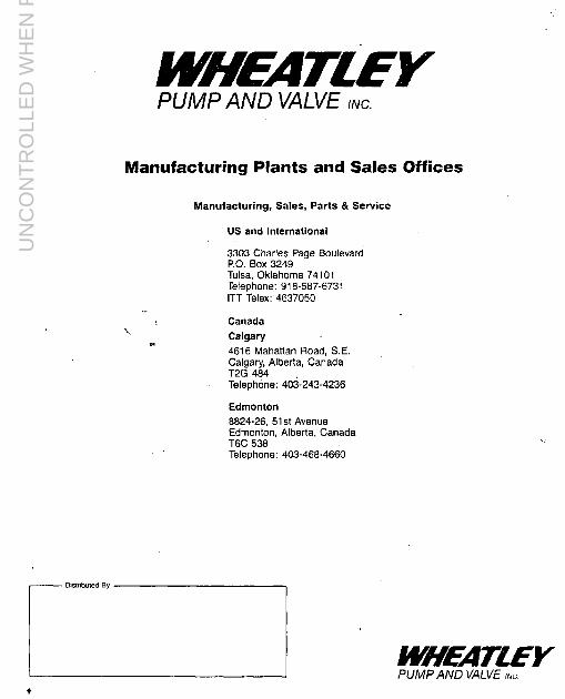
UN
CO
NT
RO
LLE
D W
HE
N P
RIN
TE
D

The Pennutit Company of Ausualia Pty. Limited
INSTALIATION- Q MAINTENANCE
SEEETS .
AsEAk- ELECTRICAL MOTORS
UN
CO
NT
RO
LLE
D W
HE
N P
RIN
TE
D

i E
Prmted In Sweden 1986-05 %lV&lra Aros 40000 7
-.. . . -._._,_.___
ASEA MOTORS lnstruktion 420g ,77 Yc: Instruction b
Installation and maintenance of induction motors -3
installation och skijtsel av asynkronmotorer
7
UN
CO
NT
RO
LLE
D W
HE
N P
RIN
TE
D

Installation The purchaser bears full responsibility for the loundation. It must be sulficlently rlgid to withstand any forces which may arise due IO short circuiting and so dimensioned as to avoid the occurrence of vibration due to resonance. The supporling surface for Ihe motor must be level and the necessary cable and air ducts must be arranged so as to facilitale connection of the cables. A concrete foundation is to be recommended. When a motor is lo be set up on a concrete foundation, use foundation studs or a base-plate. For a belt or rope drive the motor should be set up on slide-rails. Before commissioning the motor, remove any transportation clamps and check the resistance of the winding insulation. For further information see under heading “Wmdings”. Motors up lo and includrng frame size 355 can be installed in any position. If a totally- enclosed machine is to be installed in a position drffering from the standard position care must be taken lo see that drain holes are provided at the lowest points. If the existing drain holes are in such a position that waler may run into the motor they should be plugged.
Foundation studs The foundation studs are bolted to the feet of the machine, after the dowel pins have been inserted in the specially reamed holes. This mounting must be carried out from the marking on the studs and stator feet if the studs are to fit properly. Place the machine on the foundation and align the coupling. Check with a spirit level that the shalt lies horizontally. After the stator has been jacked up it should be supported by means of steel shims or adjusting bolts. After making certain that the alignment is periect. grout the lixing studs with concrete.
Uppsttillning Bestallaren ansvarar for utfdrandet av fundamentet. Delta skall vara tillr&kligt stabilt for att motsta eventuellt upptradande kortslutnlngskralter och sa dimensionerat. att risken for vibrationer p3 grund av resonans undviks. Underlaget for motorn skall vara plant och erforderliga kabel- och luftkanaler lordningsttillda for bekvlm lednings- anslutning. Ett gjutet fundament Ir att rekommendera. Vid fastslttning I betongen bar man anvanda llstklotsar eller bottenplat. Vid rem- eller repdrift bar man stllla upp motorn pa spannlinjaler. Fore ldrifttagning av motorn avlligsnas event. transportl%ningar och kontrolleras lindningarnas isolationsmotst8nd. Se harem under rubrik “Lindningar”. sida 9. Motorer t.o.m. typ storlek 355 kan placeras i alla Ilgen. Se till att helkapslade maskiner har draneringshal I de llgsta punkterna om de monteras pa annat sltt In det normala. Befintliga hal. som darvid far sadant llge att vatten kan rtnna in i motorn, maste igensattas.
FAstklotsar Flstklotsarna skruvas fast vld maskinens totter, sedan styrsflften satts In I de h&for brotschade halen. For att klotsarna skall passa meste denna monterlng utfdras efter marknlngen pa klotsarna och statorlotterna. Masklnen sltts pB lundamentet och koppllngen riktas upp. Kontrollera med vattenpass att axeln ligger horisontalt. Uppallningen av statorn utfors antingen med stlllskruvar eller med hjalp av mellanllggs- platar. Sedan man overtygat sig om att uppriktningen Ir fullgod gjuts IG.tklotsarna fast med betong.
Fitting coupling halves and belt pulleys A coupling half which is mounted on the shaft with a push fit and is then keyed on can be pushed on by hand along about hall the shaft extension. A special tool or a fully threaded bolt, a nut and a piece of flat iron can be used lo press the pulley against the collar of the shaft. See the illustration. If the shaft extension does not have any hole, the coupling half Is heeted to about 80 “C and then pushed on to the shaft extension. The coupling half can be locked with an end washer. If the coupling half is drilled for a tighter fit than a push III, It must be heated to about 150 “C. A puller is used for removing a coupling half. The remarks made about couplings halves a!so apply to belt pulleys.
Mounting marks When a belt pulley or coupling is being fitted and, unfortunately, also when bearings are being changed, It often happens that a hammer or tin sledge is used. This results in lndentalions in
L the bearing races. These relatively small
1 marks are enlarged during the rotallon 01 the bearing and will result eveniually
I in severe flaking. The danger of such I handling of bearings cannot be sufficiently
over-emphasised. Statistics show that ap- proximately 70 per cent of all defecls are due to bearing failures. and that a large proportion of these occur during the fitting
I of couplings or belt pulleys. To avoid such defects, proceed as staled in the previous paragraph.
PAsCittning av kopplingshalvor och remskivor En kopplingshalva som passas till axeln med sugpassning och sltts fast med kil kan skjutas pa for hand till ungeflr helften av tappllngden. For att pressa upp den mot axelns ansals anvander man etl papress- ningsdon eller en helglngad bult. en mutter och ett plattjtirn. Se bllden.
89315
Om axeltappen saknar hBI. vBrmer man upp koppllngshalvan Ill1 ca 80 “C och skjuter sedan pg den pg axellappen. Kopplingshalvan ken l&as med Indbrlcka. Ar kopplingshal- van borrad for h&dare passnlng en sug- passnlng. m&te den varmas till omkrlng 150 “C. Vid demontering av en kopplings- halva anvlnder man en avdragare. Vad som ovan sagts om koppllngshalvor gCIller &fen remsklvor.
Monteringsmgrken ’ Vld p&sattning av remskiva eller koppllng och tyvilrr liven vld byte av lager forekommer det ofta att man begagnar en tennslagga. Resultatet blir en intryckning i lagrets banor. Dessa relativt sma marken fdrstoras under rotatronen och sa smdningom framlrlder svara skalningar. Vadan av en sadan behandling kan inte nog betonas. Statistiken visar att ungefar 70 O/o av alla fel beror pB lagerfel, och en stor del av dessa uppster vid monlering av koppling eller remskiva. For att eliminera sadana fel skall man i stlllet forfara enligt ovan.
2 3
UN
CO
NT
RO
LLE
D W
HE
N P
RIN
TE
D

UN
CO
NT
RO
LLE
D W
HE
N P
RIN
TE
D

Slide-rails Spannlinjaler
When belt drive is employed, the lower belt part should be purling. Place the slide- rail nearest the belt so that the tensioning : screw lres belween the motor and the drlven machine. The tensioning screw for the other slide-rail must be in the opposite direction. See the adjacent iigure. Bolt the motor on to the slide-rails and set if up on the foundations and align so that the centre of the molor’s bell pulley IS exaclly opposite the centre of the corre- sponding pulley. The motor shalt must be parallel with the driven shalt. Then make certain that the upper surfaces of the slide-rails lie horizontally In the longitudinal direction. The positlon in the lateral direction determlnes the driven shaft, After the alignment has been completed, grout the foundation bolts and slide-rails with concrete. Do not tension the belt or rope harder than necessary. An excessive bell pressure will damage the bearings. In exlreme cases lhis can cause the shaft to break.
Vid remdrift bar den undre remparten vara dragande. Spdnnlinjalen nermast remmen placeras sb, att spinnskruven kommer mellan molorn och den drivna maskinen. Den andra splnnlinialen skall ha skruven at motsatt hall. Se flguren nedan. Motorn skruvas last pa spannlinjalerna och placeras pa fundamentel samt riktas sa att mltten pd molorns remskiva stlmmer Bverens med mitten pa motsklvan. Motoraxeln skall vara parallel1 med den drlvna axeln. Dlrefter ser man trll att splnnllnjalernas ijvre ytor ligger horisontellt i Iangdriktningen. LBget I tverriktningen bestammer den drivna axeln. Elter uppriktningen gjuts fundamentbultar och spannlinjaler fast med betong. Spann lnte remmen eller kllrepen hardare In nodvandlgt. For hogt remlryck skadar lagren. I svara fall kan axelbrott orsakas.
Observera: For storlek 200-355 skall tryckseg- men1 anvlndas. Dessa levereras til lsammans med splnnlrnjalerna.
Note, Srzes ZOO-355 are to be mounted with packing piece. These are supplied with the slide rails
Kilremsdrift med motor pA sptinnlinjaler (Remskyddet borttaget)
Belt drive with lhe motor set up on slide- rails. (The belt protection has been removed).
Belt drives For belt drives the shafts must be parallel and the pulleys must be exactly opposite each other.
Remdrift Vid remdrilt skall axlarna vara parallella och remskivorna sta mitt for varandra.
Correct
Incorrect
Incorrect
Vibrations
@==2 Fe’ L-I
Vibrationer Prior to delivery. the machines are balanced with a whole key in the shaft end and normally they have a maximum level of vibration ot:
Vibration level mm/s. rnis value
Motor size S 1800 rev/mm 1800-3600 rev/mm
80---132 1.8 la 160---225 2.6 2.6 250---355 2 8 4.5 If a machine vibrates even after it has been properly aligned on an amply sized foun- dation, this Is usually caused by incorrectly balanced belt pulley, coupling half or similar, fitted to the shaft. Such parts should be dynamically balanced (with keyway but without key) before fitting to the shaft, Magnetic vibratlons can arise as a result of an uneven air-gap, a break or shorl-circuit in the wmdmgs. If the voltage supply is interrupted the vibrations should cease II a fault of this type is present. Consult an Asea Service Centre
Vld leveransen ar maskinerna balanserade med he1 kll I axellappen, och har normalt nedanslaende max. vibrationsniv8. matf I mm/s ellekliwarde.
Vibrationsniva mm/s tioforslorlek s 1800 r/mm l&Z@-3600 r/mrri
ao---132 1.6 1.8 160---225 2.6 2.8 250---355 2.8 4.5 Om en maskin vibrerar sedan den blivil ordenlligt uppriktad och lastsatt vid ett valdrmensioneral fundament. beror det vanligen pB alt den lorsetls med en daligt balanserad remskiva. kopplingshalva eller dyllkt. SAdan de1 skall vara dynamiskl ut- balanserad (med kilspar men utan kil) fore pAsattnlngen. Som foljd av snelt luftgap. avbrotl eller kortslutnmg I lindningarna kan dock magne- tiska vibralioner uppstA. Om splnningen brytes skall vibralionerna upphora om sA- dant fel fdreltgger Anlrta Asea-Servicer
6
UN
CO
NT
RO
LLE
D W
HE
N P
RIN
TE
D

Cleaning Machines and apparatus should always be kept clean and free from dust, dirt. oil or other grime and they should, therefore. be installed in a sheltered place. In the case of slip-ring motors with the brushes in continuous contact with the sllp- rings, the brush- and slip-ring gear should be cleaned regularly by vacuum cleaning and wiping down, preferably once or twice a month.
Windings If Ihe windings have become damp the Insulation resistance should be measured. The following formula will serve to give a rough estimate:
where U= Voltage (V) P =Output (kW)
The formula applies at a 25 “C (77 OF) ambient temperature. If this value cannot be obtained the winding Is too damp and must then be dried in an oven. The oven temperature should be 90 “C (194 ‘F) for 12-16 hours, whereupon it should be raised to 105 ^C (221 “F) for a further 6-6 hours, If the winding has been drenched in salt-water re-winding IS usually Ihe only cure However, an attempt to remove the salt waler, by soaklng the winding In fresh water, may be made first. Detailed information can be acquired on reauest from Asea.
Renghing Masklner och apparater blur hallas rena och fria h&n damm, smuts, olja och andra fororenlngar. Man bar dftrf(lr redan vld lnstallatlonen placera molorer och apparater pB en skyddad plats. For sliipringade motorer med kontinuerligt anlfggande borstar glller dessutom att borst- och slapringsdonet dammsugs och avtorkas regelbundef heist en a tva ganger per m&tad.
Har llndningar bllvlt fuktlga bar isotationens
Lindningar
motstand mltas. Man kan dB anvlnda foljande tumregel:
R, 2 * w-4
dHr
U = Spanning (V) P= Effekt (kW)
Formeln geller vld 25 “C omgivnlngstemp. Skulle detta v&de inte erhallas, Ir genom- fuktnfngen for stor och lindnlngen behover dB torkas I ugn. Ugnstemperaturen bar vara 90 “C I 12-16 timmar och sedan 105 “C I 6-8 tlmmar. Har llndnlngen blivlt drflnkt I saltvatten brukar omllndnlng vara nodvtindlg, men en urfakning I farskvatten kan forsokas. N&mare anvisnlngar kan erh&las fren Asea.
I
Terminal diagrams, stator winding
If the flne Is connected to the stator terminals marked U, V and W and If the line phase sequence is 1, 2 and 3. the motor will have clockwise directlon of rotatlon as seen from the D-end whkh is normally the drive end. Should the opposite direction of rotation be desired. Interchange any two of the three leads connected to lhe starter or the motor.
Slngfe-8paad motor
Two-rpaed motor
Two separate wlndlngs
A-ccmeclion
Y-connactlon
High Speed
Low speed
One reconnectlble wlndlng
Constant torque ommecffon WIA
Oecresslng torque oonnectfon YYIY
8
UN
CO
NT
RO
LLE
D W
HE
N P
RIN
TE
D

10
Uttagsdiagram, statorlindning
O m n!#at ansluts till motorns statoruttag. som Ir m&k& U. V och W och ntitets fasfoljd 4r 1, 2. 3 far motorn medurs rotatlonsrlktnlng. sett mot D-lndan. den soda drir normalt axeltap- pen firms. O m motsatt rotationsriktning bnskas. vtixlas tva av de tre ledningama som Ir anslutna till startapparat eller motor.
Enhaallghetsmolor
Tvahaetfghetemotor
TV& skllda llndnlngar
a-koppling
Y-koppllng
H6ga hasllgheten
LBga hastlghelen
En omkoppllngsbar (Dahlanderkopplad) ltndnlng
Konstant moment koppllng YYIA
Fallande momenl koppllng YYlY
Uttagsdiagram f6r temperaturvakter och vtirmeelement
Terminal diagrams for temperature sensors and heating elements
Termlstorer/Thermlstors Vftrmeelementlfieatmg elements
r--------- A 1301
I\ 30;
0
Kllxon eller Mlcroterm/Kllxon or Mlcroterm r--------
A 130’ 19
3oq P,
‘-802------l
A = uttagslada A = termmal box /
M = motor M = motor
‘) ISg temperatur
‘) hog temperatur
‘) low temperature
‘) high temperature
.,. . _ -... __._ - -, ----.._-..,~--_ n- - . ._ ._.. ~ -- _ .-
UN
CO
NT
RO
LLE
D W
HE
N P
RIN
TE
D

T,-tider Far insllllning av vissa elektroniska motorskydd tordras uppgift om Is-lid. fl, tir definierat som den tid en motor tillats sfa fastbromsad med 6 g!mger mlrkstrbm i stator- lindningen). I tabellen anges T6 dels fZjr stator. dels for rotor i sekunder.
T,-times For the setting of certain electronic relays, T,-times are required. (l, Is by deflnitlon the permissible time for a motor with locked rotor lo have 6 times nominal current In the stator winding). The table gives T6 in seconds, as limited by the stator (s) and rotor(r) respectively.
TYP Type MBT 112M
132s 132SA 13258 132M 132MA 132MB 160MA 160M 160L 180M 180L 2ooLA 2OOL 2255 225M 250M
MBV 2805 280M
MBM 3155 315MA 315MB 355s 355MA 355MB 355MC
L
T,-tider i sekunder T.-times in seconds
2-oole I 4-o&e
24 30 40 13 25 43 12 23 9,” 50 14 35 14 45 12 40 13 40 12 24 12 41 12 26 12 35 12 24 12 40 10 31 11
:: 30
:: 27 7 9 - I - I -
6-wle I El-Dole
Connection, Starting and Stopping Squirrel-cage motors The mqtor. which normally has six terminals, should be connected to the line in accord- ance with the instruclions on the rating plate, or on the inside of the terminal-box cover. Check that the motor is connected for the line voltage. On motors designed for Y/A-starting remove all connecting links and connect the six terminals to the starter in accordance with the connection diagram. A-AKS type cable clamps, as listed in Asea-Skandia’s catalogue A500, list 11A and 20A, are recommended for connection of aluminium cables. The space required for these clamps may necessitate the use of LNPB cable glands, as listed in Asea Catalogue SK 17-l E, in the termi- nal box. When star-delta starting is used, first move the handle of the starter to the position Y (START) and keep it there until the motor has reached a constant speed. Then move the handle quickly over to the position A (RUN). The starting time should not generally exceed 5 to 10 seconds. If the motor has a contactor-type star-delta starter, the reconnection from star to delta takes place automatically. When stopping the motor, move the handle (or press the “OFF” pushbutton) Of the starter to the “STOP” position.
Inkoppling, igAngs2ittning och frAnslagning Kortslutna motorer Motorn, som normalt har sex uttag. ansluts till r&et enllgt anvlsningarna pa merkskylten eller i uttagsladans lock. Kontrollera att motorn Ir kopplad fer nslspfinningen. Vid motorer fbr Y/A -start tar man bar-l alla fbrbindnlngsbleck och ansluter de sex uttagen till startapparaten enligt koppllngs- schemat. F6r anslutning av alumlntumkabel rekommen- deras anvendnrng av anslutnrngsdon typ A-AKS enligt Asea-Skandtas katalog A 500. llsta 11 A och 20 A. Utrymmesbehovet fijr dessa kan krlva att uttagsledan fbrses med kabelmuff typ LNPB enligt katalog SK 17-l Om motom startas direkt, anvgnder man en motorbrytare. Vid Y/A-start sttiller man fbrst startkopplarens handtag i Iage Y (START) och belier det kvar d&h tills motorn uppnatt konstant hastighet. Handtaget llggs sedan snabbt her till lage A (DRIFT). Slartliden b8r I allmlnhet inte vara ltingre Bn 5-10 s. I en Y/A-kopplare med kontaktorer sker om- koppllngen fran Y till A automatiskt. Vid fr&nslag e)ppnar man brytaren eller sttiller startkopplsrens handtag I stoppllgef.
13
UN
CO
NT
RO
LLE
D W
HE
N P
RIN
TE
D

Slip-ring motors Skipringade motorer The motor has three or six stator terminals and three rotor terminals. If it has six stalor terminals check that it is connected for the line voltage Connect the stator terminals lo the d.o I. starter The rotor termmals can be connected to the slarter in any order. When the motor IS to be started, the handle of the starter must be in the “START” position. This also applies to the handle of lhe brush-lifting gear if used Close the switch and then move the handle of the starter sufficiently slowly towards the “RUN” position so that the molor has attained full speed when this position Is reached. Move the handle rapidly between Ihe notches so as to reduce the risk of burning of the conlacts. If the motor is fitted with a brush-lifting gear move the handle of the gear to the “RUN” position with a rapid and distinct movement when the starting operation is completed. When the motor is to be stopped, open the switch. Move the handle of the starter back lo the “START” positlon If it has not already returned automatically
Motorn har tre eller sex statoruttag och tre rotoruttag. Om den her sex statoruttag kontrollerar man att den Ir kopplad for ngtspdnningen. Statoruttagen ansluts till molorskyddsbrytaren. Rotoruttagen ansluts till padraget i godtycklig ordnlng. Vid igangsaltning skall padragets och. om motorn har borstlyftningsdon. dess handlag sta I startllget. Sla till strdmstlllaren och for sedan pbdragels handtag lagom lang- samt mot driftllget. sa att molorn har full hastighet, nlr detta lfige uppn8s. Flytta handtaget snabbt mellan stegen sa alt risken for brannskador pa kontakterna minskas. Om molorn har borstlyftningsdon skall handlaget pa detta med en snabb och bestamd rdrelse stallas i driftllge efter fullbordad start. Vld franslagning slar man ifran strdm- stallaren. Pddragets handtag fdrs tillbaka till start&get om det lnte har atergatt automatiskt.
Rheostahc starter tor- tare
Connection of a three-phase slip-ring motor.
lnkoppling av slapringad trefasmotor
14
Sliprings and brushes Motors with brushgear and slipnngs require more supervision than squirrel cage motors. It is impossible to prevent carbon dust from ac- cumulating on parts In the vicinity of the brushes and it is therefore essential that these parts be vacuum cleaned and wiped al regular intervals, normally once or twice per month At the same time. check the cable connections to lhe sliprings and the freedom of movement of fhe brushes in their holders. Lift the brushes by thefr pigtails to ensure that the latter are aHached satisfactorily. When the brushes have worn down to a length of approx. 18 mm, they should be replaced wtth new ones. Acceptable brush wear Is between 1 and 5 mm per 1000 hours of operation but this can vary consrderably depending on the load, the environment, vibrakons. etc. Irrespective of the typeof brush-holder used, Ihe distance between the lower edge of Ihe holders and the sliprings IS to be between 2 and 2.5 mm Toobtain the best co-ordrnation between the brushes and fhe sliprings, brush manufacturers specify acertain brush pressure for each given typeof brush material. For Industrial machines, the normal brush pressure is about 0.02 N/mm* (200 g/cm’). There are many reasons for abnormal brush wear. The most common are mentioned here below.
1. Type of load Excessive brush wear often occurs when a motor is run on low load. If the motor Is to run frequently on low load il may be necessary to select brushes which have a larger content of graphite.
2. 6NSh ffdefid By selecting the correct brush material, wear can be kept to a minimum. The seleclion of material Is very essential and in doubtful cases II is advisable to use the trial-and-error method and todlscuss the matter with your local supplier of brushes.
Skipringar och borstar Motorer med borst- och sllpnngsdon lordrar mer Bvervakning an sadana med kortslulen rolor Del Ilr ofrankomligt att borstdamm samlas pa alla delar omkring borsldonel. En noggrann rengonng maste darfor g&as genom dammsugning och avtorkning. I regel en lill Iv3 gdnger per mdnac Samlrdigt kontrolleras slapnngdonets kabelanslutningar och borstarnas rdrlighel i hallarna. Om borstarna darvid lyfts i anslulningssladden erhalls ocksa kontroll pa att denna inflslning ar intakt Ar borstarna nedslilna SB mycket all llngden minskat till ca 18 mm ers&Hs de med nya. Acceptabelt slitage pa elborstarna Br l-5 mm per 1000 drifttimmar. Stora variationer kan dock fdrekomma beroende pa belaslnlng, miljo. vibrationer etc. For alla borsthallartyper galler. all avstandel mellan borslhallarens underkanl och slapnngen skall vara 2-2.5 mm. For varje borslmaterial anger borslfabnkanten ett Iampligt borsttryck for att borsten skall fa del basta fdrhallandet till slaprlngen. Vanlrgtvis ar borstlrycket for industrimaskiner omknng 0.02 N/mm* (200 g/cm2) Onormal borslslitnrng kan ha flera orsaker. De vanligaste ar.
1. Belasfningens art Underbelastning medfor ofta hogI borslslitage. Om motorn ofta kdres med lag belastning kan det vara nodvandlgt alt valja etl mera grafit- halllgt borstmaterial.
2. 8ofstmaferial RaH borstmaterfal ger minst slitning. Materialvalet ar d&for av stor belydelse I tveksamma fall ar det lampligt att prova sig Ham, och radgora med den lokala leveran- t&en av borslar.
Correct distance between brush-holder and sllprlng.
Ratt avsland mellan borslhallare och slapring.
15
UN
CO
NT
RO
LLE
D W
HE
N P
RIN
TE
D

3. Low humidity The lower Ihe humtdily the grealer will be ?V brush wear. II has been eslablished lhat if the humidity of the air is below 3-4 g/m3 t?e brushes will wear down very quickly.
4. Resfncfed brush movement II the brushes are held ngidly In Ihe holcen or if lheir movement is reslricled. this will cause excessive wear.
5. Dust Abrasive dust such as that from concrete wrll increase wear while softer dust such as lhat from lextiles will seem lo have a lubricating lendency.
The conlacl surfaces of the brushes are lo be smooth and even during normal service. By studying lhe appearance of Ihe surface, faults con be delecled with a great deal of certainly. If, for example, Ihe surface is loo glossy, the cause can be too much frichon or excessive movement of the brush. which causes il to hammer against the slipring. The conlact surfaces should always have a semi-gloss appearance and have small pores. The surfaces of Ihe sliprlngs are to be smooth and free from slains and preferably have a brown coloured patina after a few hours of operatlon. Scored and scratched surfaces as well as the lack of patina may be Ihe resull of unsuitable brush grades. If small cavities have been formed due to sparfdng or if deep scores exist, the sliprlngs should be ground or machined. The surface tex- ture after machining should be Ra 1.5.
Ball and roller bearings Enclosed bearing housirtg In the majority of small machines where the grease supplied suffices for about 3 years of running, no openings are provlded for lubricallon. Before new grease is added, the bearing houslng must therefore be opened and cleaned of all old grease and traces of soap, which constitutes the broken-down products of grease. P-pole motors and motors installed in premises with an atmosphere containing vater or cor- rosive gases must be m-lubricated fn shorter Intervals than others.
16
3. FtJr /,lg fukighefsgrad JU IAgre fuktighetsgrad, desto stone slilage. Man har funnit aIt det flnns risk for snabb farslilnlng om vattenhalten per m3 luff #r mindre an 3-4 g.
4, K&wing av hNlama Om boonten silter fast eller klrvar i hallaren kan slrlagel bli mycket start.
5. Dam Sllpandedamm som belongdamm Bkar slltaget medan mjukaredamm, Lex. textildamm, kan verka smorjande.
Sorslamas konlaklyta skall vara slat och jamn vld normnl drift. Genom att studera ytans utseende knn man d&far med r&f stor sakemet konstalera ,,v. loI. Om ytan Lex. ar alltfor blank, brukar orsrrkon vara for stor friklion eller r&else hos Irorr~lon. J att den hamrar mot slaprfngen. Den Ilkt~qn ytsn ar alltld halvblank och smaporig. Slrlprlngsmas yIa skall vara jamn och flackfri, heist mod on brun patina efter en lids drift. GIsplg ocb repig yta samt avsaknad av patina kan lyda pn olampllg borslkvatilet. f-far kratrar upp stfitf p g a gnistbildnlng eller om storre repor finns eknlf ringama Slipas effer svarvas. Ytfinhelen ,rflor boarbelnlng skalf vara Ra 1,s.
Rullningslager I slutot lagerhus pfi do flosta sm$maskiner for vilka en fettp%yll- nlng rllcker for ~a 3 ars drift finns lnga ljppningar far gmOrjning. Vld behov av fettbyle meste fagomuset mpnas och rengijras fran gammalt fetI och h~fresler, som Br sonderdelnings- produkter av fettet, innan nytt fett far tillforas. 2.pollg9 motorer samt motorer. som stAri vi% olr@nlng med fratande gaser. maste forses mod nytt fett efter kortare drlfttider In ovriga.
With grease valves All machines provided with grease valves have a lubrication plate. which specifies the lubricating intervals. It is important thal these lnstructlons are carefully followed. The lubricating inlervals apply lo a machine set up in normal surroundings If the premises are particularly dusly or if the machlne is exposed to spraylng water, the intervals between lubrications should be reduced. The quantity of grease then required can be slightly less than for the normal lubricating inlervals. Lubricating nipples of Alemite type are being used on more recent motor deslgns. The corresponding grease gun is called Tecalemit. It is advisable to use the low- pressure grease gun, since this yields more grease per stroke. The lubricating nipple frtted at Asea should be used, since lhis has an opening sufficiently large to preserve the lubricating capacity of the grease during its passage through the nipple. Before lubricating a bearing, clean the nipple to prevent dirt from accompany- ing the grease into the bearing. Lubrication should be performed while Ihe motor is running. If this is not possible, e.g., because there are rotating parts In dangerous vicinity of the lubricating nipple, lubrication can be carried out while the machine is al a standstill. In this case only half the quantity of grease should be forced In, after which the motor is started and run for a few minutes al full speed. The remainlng quantity of grease can then be forced in when the machine has slopped. If the entire quantity of grease is forced in at the same lime while the machine is al a standstill, there is a risk that part of the grease will penetrate into the motor through the inner bearlng seal. When starting Ihe motor for the first lime and during subsequent lubrication. apply at least the specified quanllly of grease until it exudes from Ihe grease outlet. An extra lubrication of new bearlngs afler a few days’ running will give lhem a longer life.
Med ventiismijrjning Pa varJe maskin med fettvenliler firms en skylt. som anger smorjningsintervallerna och det Ir vlkligl all man lijljer dessa anvrsningar noggrant. Smdrjningsintervallerna Ir angivna med tanke pa en maskin som Br uppstalld i normal omgivning. Ar lokalen sarskill damm!L eller om maskinen ulsHtls for valten- begjutning bar tlden mellan smorjningarna minskas. Feltmangden kan da vara nagot mindre Hn vid normala intervaller. Smorjnipplar av lyp Alemite anvlnds for nyare motorlyper. Motsvarande smdrjsprulc har beteckningen Tecalemit. Llmpligast Ir lagtryckssprutan, som ger mera felt per slag Man bar anvtinda den nlppel som salts pa vrc fabriken, eftersom denna har en dppnlng som ar stor nog att bevara lettets smorj- formaga under passagen. lnnan man smorjer, bar man g&a nippeln ren for att hlndra fororenfngar fran att folja med lettet in I lagret. Smdrjning b6r ulfijras under drift. Om detta inte ar mojligl, t.ex. pa grund av ah det firms roterande delar i farlig niirhet av smdrj- nippeln, kan smdrjningen ulfbras vld stillestand. Da skalt man emellertid forst pressa in endast halva fettmlngden och sedan slarta molorn och k&a den nagon minut vid full1 varvtal. Aterstoden kan sedan pressas In nlr maskinen stannal. Sprutas hela feltmangden in pB en g&ng under stillestAnd, rlskerar man all en del av fettet IrAnger In i molorn genom den inre lager- tllningen. Smorl vid forsla starI och vrd efterfoljande smorlningar med alminslone angiven lelt- mangd. tills felt tranger ut genom fellutloppet. En extra smorjnlng efter nagra dagars inkdrning av nya lager ger dessa Likad IlvsNngd.
17
UN
CO
NT
RO
LLE
D W
HE
N P
RIN
TE
D

Suitable types and grades of grease are: Lsmpliga fettyper och kvaliteter 3r b1.a.: A. For normal versions of motors with insulatron class El and F‘) Complete filling of the housing for anti-frictton bearings worklng in dry or humid (not wet) surroundings. Grease for operating tem- peratures of -30°C to +llO”C.
8P. CdSfd. ESSO. SKF
Energrease LS 2. I Spheerol SW 2 Beacon 2 LGMT 2
6. For motors operating in high ambient tem- peratures and with insulatron class H. and for MT type motors. Heat resistant grease for anti- friction bearings Grease for operating temperatures of -20 “C to +145Yz.
Esso. MobI/ SKF
Unwev N 3 Mobrlgrease 532 GreaseLGHT 3
‘) Not appkcable lo MT type motors whrch have grease as per group B
N.B. When changing the grade and make of grease, ensure that all older grease Is replaced.
Intervals between lubrication Motors of sizes of 225-355 have vatve lubncatron as standard Motors in frame swes smaller than 225 can on request be htted wrth grease nipples The table shows the quantrhes of grease and the rntervals between lubri- catron for normal condrtions Refer- ence should also be made to the rating plafe on the motor. In excep- tionally dusty or humrd envrronments and III high ambrent temperatures, Ihe mtervals between lubncatron can be reduced accordmgly.
C. For motors with so-called wet bearings, which are occasronally splashed with water. EP grease for anti-friction bearings. Grease for operating temperatures of -30 “C to + 100°C. Nearest comparable grades:
BP. Casfrol. ESSO~ Mobd Opbmol. SKF
Energrease LS-EP 2 Spheerol SW 2 EP Beacon EP 2 Mobilux EP 2 Longtrme PLY 2 Grease LGEP 2
For other temperatures. consult Asea.
Intervals between lubrtcatron. in months. for motors operahng 24 Wday. For motors operating 6hIday. the intervals between lubncahon can be increased 3-fold. but they must not be longer than 12 months.
Motor sty of Interval between lubricatron frame grease at rev/mm size rn grams 3600 3000 1600 1500 1000 530 MT100 10 12 12 12 12 12 12 MBT112 IO 12 12 12 12 12 12 MBT 132 20 12 12 12 12 12 I2 MET 160 20 12 12 12 12 12 MET 160 20
: 12 12 12 12 12
MET200 20 6 6 12 12 12 12 MBT225 30 3 12 12 12 12 M 225 MBT250
:: :
12 12 12 12 6 I2 12 12 12
MBM250 60 1 MBV260 30 1
E 12 12 12 12 12 12
MBM260 60 l/2 1 6 12 12 12 MBM315 00 l/2 1 6 12 12 12
A. For motorer i normalutforande med isola- tionsklass B och F:) Helfyllnadslett for rullnings- lager vid torr eller fukttg (ej vAt) omgtvning. Fett for lagertemperatur -30°C till + 110 “C.
BP Castro/ Esso. SKF Nynds
Energrease LS 2-1 Spheerol SW 2 Beacon 2 LGMT 2 Alexol L 42
8. For motorer i hog omgrvnrngstemperatur och med isolationsklass H samt motorer typ MT. Varmebestandrgt fett for rullningslager. Fett for lagertemperatur -20 “C ttll + 145 “C.
Esso Mob!/ NynBs. SKF
Unrrex N3 Mobrlgrease 532 Alexol LK 62 Grease LGHT 3
‘) Galler ei molorer typ MT vrlka har fetl enkgt grupp B
Anm.: Vid byte av fettkvalrtet eller fabrikat. Se trll att allt fett blir utbytt.
Smiirjintewaller Motorer I stork9 225-355 har venhl- smorfnrng som standard. Motorer mindre an 225. kan pd begaran forses med venhlsmCir]nmg. Tabellen anger fettmdngd och sm5qintervaller vrd normala fCrh8llanden. Se Bven motorns markskyit. Vid mycket dammrg eller fuktig omgw nmg och vrd hog omgrvnrngstempera- tur mrnskas smdjrntewallen efter be- domnmg
C For motorer med s k veta lager, dar lagren temporart utsatts for overskollnrng av vatten. EP-felt for ruflnrngslager. Fett for lagertemperatur - 30 “C till 7 100 “C. Narmast famforbara kvalrteter
BP Energrease LS-EP 2 Gas/m/ Spheerol SW 2 EP &so. Beacon EP 2 Mobrf Mobrlux EP 2 Nyrws Alexol L 62 OK Oktosol Grease EP 2 Opfrmol Longhme PO 2 SKF Grease LGEP 2
Vid andra temperaturer bor Asea radfragas.
Smorfrnlervall I manader vrd 24.limmars dnft Vid 6kmmarsdnH kan i smdrfinlervallen forlangas 3 ganger. men den far ef Bvershga 12 mdnader
Motor slodek
Smojnrngsintervall Fettmangd vid r/min i gram 3600 3000 1600 1500 1000 500
MT 100 :: 12 12 12 12 12 12 MBTllP 12 12 12 12 12 12 MBT132 20 12 12 12 12 12 12 MBT 160 20 : 12 12 12 12 12 MBT 160 20 12 I2 12 12 12 : MBT200 20 6 6 12 12 12 12 MBT225 30 3 6 I2 2 I2 I2 M225 40 6 I2 12 I2 12 MBT250 30
: 6 12 12 12 I2
MBM250 60 1 2 6 12 12 12 MBV260 30 1 3 12 12 MBM260 60 l/2 1
: 12 12
:; ” )
MBM315 60 l/2 1 6 12 12 12 MBM355 60 l/2 1 1 MBM355 60 - - 4 4 -6 12
I MBM355 60 l/2 1 - MBM355 60 - - 4 4 6 12 .
18 19
UN
CO
NT
RO
LLE
D W
HE
N P
RIN
TE
D

Correct type and correct Rtitt typ och rtitt tillverknings- manuf. No. will give you the nummer ger Er ratt reservdel correct spare part When ordering spare parts the full type Vid best%lnlng av reservdelar skall designation of the motor must be stated. maskinens fullsttindiga typbeteckning anges. tf the machine is stamped with the manuf. Har maskinen tlllverkningsnummer ochletter No and/or Cat. No.. thus should also be stated. beslallningsnummer skall aven detta anges.
l@ASEA MOTORS r....,sv.s.~ “1
Bestellningsnummer Cat No.
-
Tlllverkningsnummer - Manuf. No.
We hope that the advice and instructions given in th)s booklet WIII be useful to those responsible for the installation and maintenance of electrical machines. Instructions on the maintenance of starters are given in the Asea brochure “The selection and maintenance of electrical appar- atus”. If problems avrse in connection of maintenance of electrical machines please contact Asea Service.
Vi hoppas att de rad och anvisningar som bar llmnats kommer att vara till god hjelp for Er. som svarar for montering och skotsel av elma- skiner. Anvisningar om skdtsel av stariapparater Iemnas i Asea-broschyren “Val och skotsel av elapparater”. Uppst& problem i samband med skbtseln eller vid Installation av elmaskiner, sa vand Er till Asea Service.
20
Argentina Finland Buenos Arres Helstnkl ASEASA ASEA OY 35-371 l/1260/ 90.591 11 64 14/4997/9467 Lappeenranla
ASEA OY AuStralia 953152 00 Melbwrne Oulu ASEA PTY LIMITED. LILYDALE ASEA OY (03) 735 03 88 981-22 37 00 Melbourne Tampwe ASEA PM LIMITED. MT WAVERLY ASEA OY (03) 544 21 44 Sydney ASEA PTY. LIMITED (02) 887 25 55 Brrsbane ASEA PTY. LIMITED (07) 263 31 33 Perth ASEA PTY LIMITED (09) 458 78 33 Dawn ASEA PTY LIMITED (089) 84 32 5 1 Adelarde ASEA PTY LIMITED (08) 297 33 55 * Launceston ASEA PT-f LIMITED (003) 31 99 88
Brarll S&J Pa010 ASEA ELSTRICA LTDA (011) 209 06 77 Belo Honzonte ASEA ELFTRICA LTDA (031) 223 6368 Aio de Janerro ASEA ELt?TRICA LTDA (021) 253 55 66 Recde ASEA EL&-RICA LTDA (061) 326 12 11
Canada Montreal ASEA INC. (514) 332 5.3 50 Calgary ASEA INC. (403) 269 29 69 Toronto ASEA INC. (416) 677 06 30 Vancouver ASEA INC. (604) 734 22 63
Denmark Aalborg Copenhagen Odense ASEA AIS g-14 7080
931-63 1206
Hong Kong Hongkong ASEA HAGGLUNDS (HK) Lid 3-723 0961
India Bombay ASEA LIMITED 264181 Calcutta ASGI LIMITED 473676 Nasrk ASEA LIMITED 30523/30524 New Delhr ASEA LIMITED 66 95 29166 95 31 Bangalore ASEA LIMITED 36 91 67 Peanya ASEA LIMITED 38417213851 81
lndoneala Jakarta P T. Scanteknik Elektro Indonesia 0t33729fEl03660
Ireland Dublin ASE4 Electnc 76 70 33 (Ireland) Ltd 76 47 36
Italy Mrlan ASEA S p.A. 02-675 077 67 60 21 Senago ASEA-CEI SERVICE S p.A 02-998 66 817753 Bologna ASEA Sp A 051.51 61 65
Genoa ASEASpA 01048 91 65/ 58 73 94 Padova ASEASpA 049.616611 Rome ASEASpA 06.474 30 73 474 31 85 Turm ASEA Sp A 01 l-544 8051 549 400
Japan Tokyo ASEA GADELIUS LTD (03) 436 62 21 Kobe ASEA GADELIUS LTD (078) 252 0861
Malaysia Kuala Lumpur ASEA Sdn Bhd 03-46 81 33 lpoh ASEA Sdn Bhd. 05.51 41 69 Johore Bahru ASEASdn Bhd 07-22 56 02 Kota Kmabalu ASEA Sdn. Bhd. 088-5 10 931 576 61 Penang ASEA Sdn. Bhd. 04.285 917 285 95
MtXlCO Ttalnepantla ASEA S A. 565 00 33/ 565 66 44 Guadalajara Jai. ASEA S.A. 13567OI 136864 Monterrey. N L ASEA S A. 44 43 057 44 54 58 Puebia. Pue ASEA S.A. 40 48 611 40 A? 37
21
UN
CO
NT
RO
LLE
D W
HE
N P
RIN
TE
D
,._ ___ ASEABV 055-77 53 21 Rotterdam ASEA SERVICE OtO-56 27 22
New Zealand welllngton 4SEA ELECTRIC (N Z.) Ltd 73 9369 Auckland ASEA ELECTRIC (N Z.) Ltd 54 5059 Chnstchurch ASEA ELECTRIC (N Z ) Lld 61085
Norwav Oslo - ASEA-PER KURE A/S 02-35 20 10 Slavanger ASEA-PER KURE A/S OJ-67 80 22
The Republic of the Philippines Manrla ASEA (PHILIPPINES) INC. 82i.40911 627 44 17 626 4565 Cebu A!jE,A (PHILIPPINES) INC. 63431.83667
Singapore Srngapore ASEA Smgapore Pte Ltd 265 26 77
South Ahica Johannesburg ASEA Electric SA. Lld (011 I 53 92 00 Durban ASEA Electnc S A Lld (031172 62 59 Prelona (012) i9 70 20
Sweden North LJ~slnct Lulea (Lennart Astrom) ASEA SERVICE A8 0920-104 50 Skellettea ASEA SERVICE AB 0910331 55 Umee ASEA SERVICE AB
, 22 090-l 1 65 35
, ,L_ -_ , .,_, -
0660-106 15 Sundsvall ASEA SERVICE AB 060-12 92 10 dstersund ASEA SERVICE AB 063-12 77 50 Central DNncf Vlisteras (Ryno Ragnerstam) 021-10 32 64 Storvik ASEA SERVICE A6 0290-ill 10 Borlange ASEA SERVICE AB 0243-124 50 Fagersla ASEA SERVICE AB 0223-140 40 v3steras ASEA SERVICE A6 021-126030 Spennarhyllan ASEA SERVICE AB 0223-231 35 drebro ASEA SERVICE Al3 019-10 10 50 Esktlstuna ASEA SERVICE AB 016-120060 Karlslad ASEA SERVICE AB 054-10 24 50 Slockholm ASEA SERVICE AB 08-19 01 90 Stockholm Legoeleklronlk 08-96 01 55 Linkbping ASEA SERVICE AB 013-11 10 70 Norrkdping ASEA SERVICE AB 011-129020 ‘Jsby ASEA SERVICE AB 0496.177 61 Sllte ASEA SERVICE AB 0498-205 67 Vaster& ASEA SERVICE AB 021-1047 69 South Bsfrrcl Gdleborg (Alf Fornell) ASEA SERVICE AB 031-23 51 50
,_ _, - _ I .,_,I_
0522-146 90 Jonkoping ASEA SERVICE AE 036-16 92 70 Oskarshamn ASEA SERVICE AB 0491-640 60 Helsmgborg ASEA SERVICE Al3 042-26 22 60. Malmd ASEA SERVICE AB 040-18 90 50 Ronneby ASEA SERVICE AB 0457-166 60
lhalland Bangkok ASEACo Ltd. 249 20 721 _ 1950/- 12967 -16567-2167
United Kingdom Manchester ASEA Limited 061 437 5290 London ASEA Lrmtted 01.93054 11 Bromborough Aulhonsed Servrce Workshop 051 334 6363
U.S.A. New York ASEA Roboltcs. Inc. (914) 426 6000 ASEA lndustrlal Systems Inc. (914) 969 1900 ASEA Hlgglunds. Inc. (914) 969 1900 ASEA STAL. Inc. (201) 391 6930 Milwaukee ASEA lndustnal Systems Inc. (414) 785 3200 ASEA Eleclnc. Inc. (414) 547 0121 Delrort ASEA ROBOTICS. Inc. (313) 526 3630 Seattle ASEA Induslrial Systems tnc (206) 451 6633 Bellevue Redmond (206) 683 7701 Houston ASEA Hegglunds. Inc. (71312924110 Los Angeles (714) 522 6550
# ,. Vienna Osterrerchrsche ASEA 02236-611 00
Belgium and Luremburg Brussels N.V. ASEA S A 02-721 20 31
France Persan ASEA S.A. (3) 470 92 00 Lyon ASEA !%A (7) 640 81 73 ET ASEA S.A. (6) 076 00 29 Marsetlle ASEA S.A (91) 02 36 39
German Federal Republic (GFR) FnedbergIHessen ASEA LEPPER GmbH 06031-651
Greece Athens ASEA SERVICE 01-573 96 067 573 9809 Pwaeus ASEA Marine 01.453 14 15
,.: Ltsbon ASEA Electrrca. Lda 256 1306 Port0 ASEA Electnca. Lda 995 25 76 995 26 73 995 29 53
Spain Barcelona ASEAICES. SA 93-710 36 04/ 71036547 7103600(Vx) Madrrd ASEA SERVICIO 91.67249 11 Brlbao ASEA SERVICIO 94-435 40 oil Las Palmas Representahve for ASEA SERVICIO Electroshrp Serwce S A 920-27 57 47
Switzerland Zunch ASEA AG 01-52 06 10 ARBOR AG 031-63 51 61
23
UN
CO
NT
RO
LLE
D W
HE
N P
RIN
TE
D

UN
CO
NT
RO
LLE
D W
HE
N P
RIN
TE
D

UN
CO
NT
RO
LLE
D W
HE
N P
RIN
TE
D

UN
CO
NT
RO
LLE
D W
HE
N P
RIN
TE
D

UN
CO
NT
RO
LLE
D W
HE
N P
RIN
TE
D

UN
CO
NT
RO
LLE
D W
HE
N P
RIN
TE
D

UN
CO
NT
RO
LLE
D W
HE
N P
RIN
TE
D

UN
CO
NT
RO
LLE
D W
HE
N P
RIN
TE
D

UN
CO
NT
RO
LLE
D W
HE
N P
RIN
TE
D

UN
CO
NT
RO
LLE
D W
HE
N P
RIN
TE
D

UN
CO
NT
RO
LLE
D W
HE
N P
RIN
TE
D

UN
CO
NT
RO
LLE
D W
HE
N P
RIN
TE
D

UN
CO
NT
RO
LLE
D W
HE
N P
RIN
TE
D

UN
CO
NT
RO
LLE
D W
HE
N P
RIN
TE
D

UN
CO
NT
RO
LLE
D W
HE
N P
RIN
TE
D

UN
CO
NT
RO
LLE
D W
HE
N P
RIN
TE
D

UN
CO
NT
RO
LLE
D W
HE
N P
RIN
TE
D

UN
CO
NT
RO
LLE
D W
HE
N P
RIN
TE
D

UN
CO
NT
RO
LLE
D W
HE
N P
RIN
TE
D
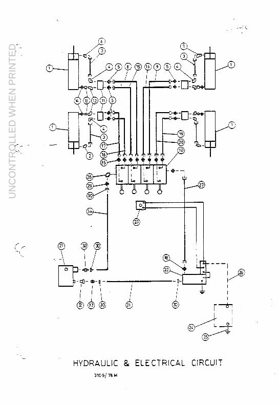
UN
CO
NT
RO
LLE
D W
HE
N P
RIN
TE
D

UN
CO
NT
RO
LLE
D W
HE
N P
RIN
TE
D

UN
CO
NT
RO
LLE
D W
HE
N P
RIN
TE
D

UN
CO
NT
RO
LLE
D W
HE
N P
RIN
TE
D

UN
CO
NT
RO
LLE
D W
HE
N P
RIN
TE
D

UN
CO
NT
RO
LLE
D W
HE
N P
RIN
TE
D

UN
CO
NT
RO
LLE
D W
HE
N P
RIN
TE
D

UN
CO
NT
RO
LLE
D W
HE
N P
RIN
TE
D

UN
CO
NT
RO
LLE
D W
HE
N P
RIN
TE
D

UN
CO
NT
RO
LLE
D W
HE
N P
RIN
TE
D

UN
CO
NT
RO
LLE
D W
HE
N P
RIN
TE
D

UN
CO
NT
RO
LLE
D W
HE
N P
RIN
TE
D

UN
CO
NT
RO
LLE
D W
HE
N P
RIN
TE
D

UN
CO
NT
RO
LLE
D W
HE
N P
RIN
TE
D

UN
CO
NT
RO
LLE
D W
HE
N P
RIN
TE
D

UN
CO
NT
RO
LLE
D W
HE
N P
RIN
TE
D

UN
CO
NT
RO
LLE
D W
HE
N P
RIN
TE
D

UN
CO
NT
RO
LLE
D W
HE
N P
RIN
TE
D

UN
CO
NT
RO
LLE
D W
HE
N P
RIN
TE
D

UN
CO
NT
RO
LLE
D W
HE
N P
RIN
TE
D

UN
CO
NT
RO
LLE
D W
HE
N P
RIN
TE
D

UN
CO
NT
RO
LLE
D W
HE
N P
RIN
TE
D

UN
CO
NT
RO
LLE
D W
HE
N P
RIN
TE
D

UN
CO
NT
RO
LLE
D W
HE
N P
RIN
TE
D

UN
CO
NT
RO
LLE
D W
HE
N P
RIN
TE
D

UN
CO
NT
RO
LLE
D W
HE
N P
RIN
TE
D

UN
CO
NT
RO
LLE
D W
HE
N P
RIN
TE
D

UN
CO
NT
RO
LLE
D W
HE
N P
RIN
TE
D

UN
CO
NT
RO
LLE
D W
HE
N P
RIN
TE
D

UN
CO
NT
RO
LLE
D W
HE
N P
RIN
TE
D

UN
CO
NT
RO
LLE
D W
HE
N P
RIN
TE
D
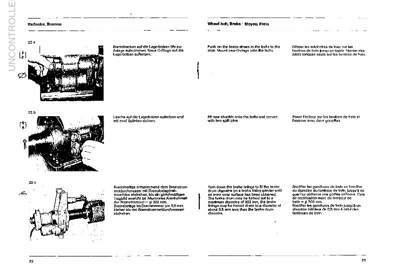
UN
CO
NT
RO
LLE
D W
HE
N P
RIN
TE
D

UN
CO
NT
RO
LLE
D W
HE
N P
RIN
TE
D

UN
CO
NT
RO
LLE
D W
HE
N P
RIN
TE
D

UN
CO
NT
RO
LLE
D W
HE
N P
RIN
TE
D

UN
CO
NT
RO
LLE
D W
HE
N P
RIN
TE
D
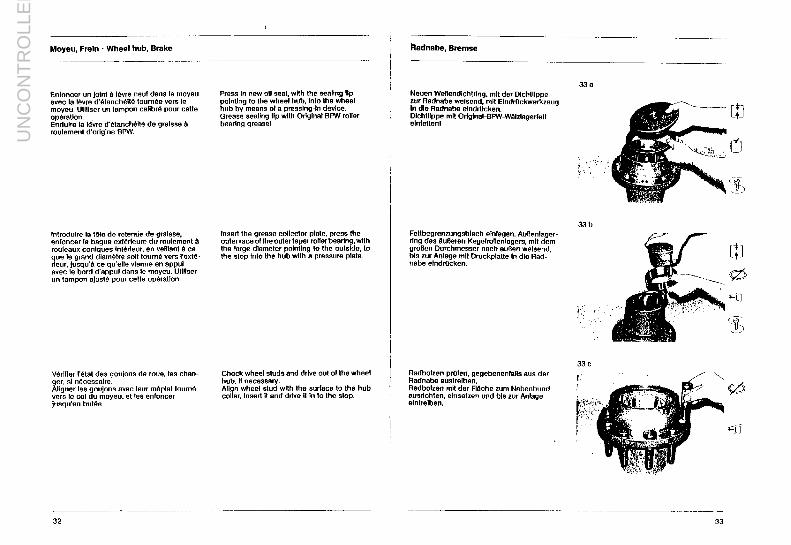
UN
CO
NT
RO
LLE
D W
HE
N P
RIN
TE
D

UN
CO
NT
RO
LLE
D W
HE
N P
RIN
TE
D

UN
CO
NT
RO
LLE
D W
HE
N P
RIN
TE
D

UN
CO
NT
RO
LLE
D W
HE
N P
RIN
TE
D

UN
CO
NT
RO
LLE
D W
HE
N P
RIN
TE
D

UN
CO
NT
RO
LLE
D W
HE
N P
RIN
TE
D

UN
CO
NT
RO
LLE
D W
HE
N P
RIN
TE
D
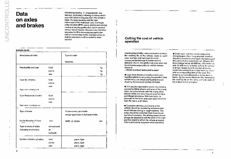
UN
CO
NT
RO
LLE
D W
HE
N P
RIN
TE
D

UN
CO
NT
RO
LLE
D W
HE
N P
RIN
TE
D

UN
CO
NT
RO
LLE
D W
HE
N P
RIN
TE
D

UN
CO
NT
RO
LLE
D W
HE
N P
RIN
TE
D

UN
CO
NT
RO
LLE
D W
HE
N P
RIN
TE
D

UN
CO
NT
RO
LLE
D W
HE
N P
RIN
TE
D

UN
CO
NT
RO
LLE
D W
HE
N P
RIN
TE
D

UN
CO
NT
RO
LLE
D W
HE
N P
RIN
TE
D

UN
CO
NT
RO
LLE
D W
HE
N P
RIN
TE
D

UN
CO
NT
RO
LLE
D W
HE
N P
RIN
TE
D

UN
CO
NT
RO
LLE
D W
HE
N P
RIN
TE
D

UN
CO
NT
RO
LLE
D W
HE
N P
RIN
TE
D

UN
CO
NT
RO
LLE
D W
HE
N P
RIN
TE
D

UN
CO
NT
RO
LLE
D W
HE
N P
RIN
TE
D

UN
CO
NT
RO
LLE
D W
HE
N P
RIN
TE
D

UN
CO
NT
RO
LLE
D W
HE
N P
RIN
TE
D

UN
CO
NT
RO
LLE
D W
HE
N P
RIN
TE
D
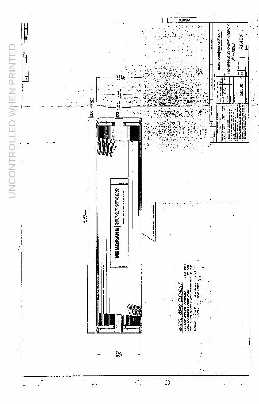
UN
CO
NT
RO
LLE
D W
HE
N P
RIN
TE
D

UN
CO
NT
RO
LLE
D W
HE
N P
RIN
TE
D

UN
CO
NT
RO
LLE
D W
HE
N P
RIN
TE
D

UN
CO
NT
RO
LLE
D W
HE
N P
RIN
TE
D

UN
CO
NT
RO
LLE
D W
HE
N P
RIN
TE
D

UN
CO
NT
RO
LLE
D W
HE
N P
RIN
TE
D

UN
CO
NT
RO
LLE
D W
HE
N P
RIN
TE
D

UN
CO
NT
RO
LLE
D W
HE
N P
RIN
TE
D

UN
CO
NT
RO
LLE
D W
HE
N P
RIN
TE
D

UN
CO
NT
RO
LLE
D W
HE
N P
RIN
TE
D

UN
CO
NT
RO
LLE
D W
HE
N P
RIN
TE
D

UN
CO
NT
RO
LLE
D W
HE
N P
RIN
TE
D

UN
CO
NT
RO
LLE
D W
HE
N P
RIN
TE
D

UN
CO
NT
RO
LLE
D W
HE
N P
RIN
TE
D

UN
CO
NT
RO
LLE
D W
HE
N P
RIN
TE
D

UN
CO
NT
RO
LLE
D W
HE
N P
RIN
TE
D

UN
CO
NT
RO
LLE
D W
HE
N P
RIN
TE
D

UN
CO
NT
RO
LLE
D W
HE
N P
RIN
TE
D

UN
CO
NT
RO
LLE
D W
HE
N P
RIN
TE
D

UN
CO
NT
RO
LLE
D W
HE
N P
RIN
TE
D

UN
CO
NT
RO
LLE
D W
HE
N P
RIN
TE
D

UN
CO
NT
RO
LLE
D W
HE
N P
RIN
TE
D

UN
CO
NT
RO
LLE
D W
HE
N P
RIN
TE
D

UN
CO
NT
RO
LLE
D W
HE
N P
RIN
TE
D

UN
CO
NT
RO
LLE
D W
HE
N P
RIN
TE
D

UN
CO
NT
RO
LLE
D W
HE
N P
RIN
TE
D

UN
CO
NT
RO
LLE
D W
HE
N P
RIN
TE
D

UN
CO
NT
RO
LLE
D W
HE
N P
RIN
TE
D

UN
CO
NT
RO
LLE
D W
HE
N P
RIN
TE
D

UN
CO
NT
RO
LLE
D W
HE
N P
RIN
TE
D

UN
CO
NT
RO
LLE
D W
HE
N P
RIN
TE
D

UN
CO
NT
RO
LLE
D W
HE
N P
RIN
TE
D

UN
CO
NT
RO
LLE
D W
HE
N P
RIN
TE
D

UN
CO
NT
RO
LLE
D W
HE
N P
RIN
TE
D

UN
CO
NT
RO
LLE
D W
HE
N P
RIN
TE
D

UN
CO
NT
RO
LLE
D W
HE
N P
RIN
TE
D

UN
CO
NT
RO
LLE
D W
HE
N P
RIN
TE
D

UN
CO
NT
RO
LLE
D W
HE
N P
RIN
TE
D

UN
CO
NT
RO
LLE
D W
HE
N P
RIN
TE
D

UN
CO
NT
RO
LLE
D W
HE
N P
RIN
TE
D

UN
CO
NT
RO
LLE
D W
HE
N P
RIN
TE
D

UN
CO
NT
RO
LLE
D W
HE
N P
RIN
TE
D

UN
CO
NT
RO
LLE
D W
HE
N P
RIN
TE
D

UN
CO
NT
RO
LLE
D W
HE
N P
RIN
TE
D

UN
CO
NT
RO
LLE
D W
HE
N P
RIN
TE
D

UN
CO
NT
RO
LLE
D W
HE
N P
RIN
TE
D

UN
CO
NT
RO
LLE
D W
HE
N P
RIN
TE
D

UN
CO
NT
RO
LLE
D W
HE
N P
RIN
TE
D

UN
CO
NT
RO
LLE
D W
HE
N P
RIN
TE
D

UN
CO
NT
RO
LLE
D W
HE
N P
RIN
TE
D

UN
CO
NT
RO
LLE
D W
HE
N P
RIN
TE
D

UN
CO
NT
RO
LLE
D W
HE
N P
RIN
TE
D

UN
CO
NT
RO
LLE
D W
HE
N P
RIN
TE
D

UN
CO
NT
RO
LLE
D W
HE
N P
RIN
TE
D

UN
CO
NT
RO
LLE
D W
HE
N P
RIN
TE
D

UN
CO
NT
RO
LLE
D W
HE
N P
RIN
TE
D

UN
CO
NT
RO
LLE
D W
HE
N P
RIN
TE
D

UN
CO
NT
RO
LLE
D W
HE
N P
RIN
TE
D

UN
CO
NT
RO
LLE
D W
HE
N P
RIN
TE
D

UN
CO
NT
RO
LLE
D W
HE
N P
RIN
TE
D

UN
CO
NT
RO
LLE
D W
HE
N P
RIN
TE
D

UN
CO
NT
RO
LLE
D W
HE
N P
RIN
TE
D

UN
CO
NT
RO
LLE
D W
HE
N P
RIN
TE
D

UN
CO
NT
RO
LLE
D W
HE
N P
RIN
TE
D

UN
CO
NT
RO
LLE
D W
HE
N P
RIN
TE
D

NOT TO SCALE — FOR REFERENCE ONLYU
NC
ON
TR
OLL
ED
WH
EN
PR
INT
ED

NOT TO SCALE — FOR REFERENCE ONLYU
NC
ON
TR
OLL
ED
WH
EN
PR
INT
ED