the european products catalogue 2016 - altergrupa
TRANSCRIPT

The
Euro
pean
Pro
duct
s Cat
alog
ue 2
016
www.johnsoncontrols.com
The European Products Catalogue2016
controls, hvac & refrigeration products

A more comfortable,safe and sustainable world


Company profileJohnson Controls has expanded remarkably since Professor Warren Johnson founded the company to manufacture his invention, the electric room thermostat. Since its start in 1885, Johnson Controls has grown into a global leader in automotive experience, building efficiency and power solutions.The company provides innovative automotive interiors that help make driving more comfortable, safe and enjoyable. For buildings, it offers products and services that optimize energy use and improve comfort and security. Johnson Controls also provides batteries for automobiles and hybrid electric vehicles, along with systems engineering and service expertise.
Our visionA more comfortable,safe and sustainable world.
Our valuesIntegrityHonesty, fairness, respect, and safety are of the utmost importance.
Customer SatisfactionOur future depends on us helping to make our customers successful. We are proactive and easy to do business with. We offer expert knowledge and practical solutions, and we deliver on our promises.
Employee EngagementWe foster a culture that promotes excellent performance, teamwork, inclusion, leadership and growth.
InnovationWe believe there is always a better way. We encourage change and seek the opportunity it brings.
SustainabilityThrough our products, services, operations and community involvement, we promote the efficient use of resources to benefit all people and the world.

The European Products Catalogue 2016
index
Manufacturer reserves the right to change specifications without prior notice
hvac control products
ValvesPAGE
Valves and Actuators Combinations 1
Terminal Unit ValvesDN10...20, PN16 V5000 2DN15...25, PN16 VG6000 4
Plant Valves
DN15...50, PN16VGS800 6VG7000 7
DN15...100, PN6 and PN10 VG9000 12DN15...150, PN16 VG8000N 15DN15...150, PN25 VG8000H 19DN40...150, PN16, Pressure Balanced VG8300N 23DN65...100, PN16 VG1000 Flanged 24DN15...50, PN40 VG1000 Threaded 27DN15...500, PN16 VFB Butterfly Valves 31
Pressure Independent ValvesDN15...32, PN25DN40...50, PN16 VP1000 39
DN50...150, PN16 VPA 45
The European Products Catalogue 2016
index
Manufacturer reserves the right to change specifications without prior notice
ActuatorsTerminal Unit Valve Actuators PAGE
Thermal ON/OFF Control VA-7070 47Thermal 0...10 V Control VA-7090 49Motorized Floating and Proportional Control VA-7480 50
Non Spring Return Plant Valve Actuators
Floating and Proportional Control
VA-7150 51VA-7200 52VA-7700 53VA7810 54VA1000 NSR 55FA-3000 56RA-3000 57
ON/OFF, Floating and Proportional Control Rotary Actuators for Ball Valves
4 Nm VA9104 588 Nm M9108-xxx-5 5910 Nm VA9310-HGA-1 60
ON/OFF, Floating and Proportional Control Rotary Actuators for Butterfly Valves 68 - 2430 Nm VA-9070 61
VAP Linear Actuators for VPA Pressure Independent Flanged Valves VAP1000 - VAP3000 64
Spring Return Plant Valve Actuators
Floating and Proportional Control
VA7820 - VA7830 65VA1000 SR 66FA-2000 67
ON/OFF, Floating and Proportional Control Rotary Actuators for Ball Valves
3 Nm VA9203 688 Nm VA9208 70
Non Spring Return Damper Actuators
ON/OFF, Floating and Proportional Control
2 and 4 Nm M9102 - M9104 724 Nm M9304 7310 Nm M9310-HGA-1 748, 16, 24 and 32 Nm M9108, M9116, M9124 and M9132 76
Spring Return Damper Actuators
ON/OFF, Floating and Proportional Control3 Nm M9203 798 Nm M9208 81
ON/OFF, Floating and Proportional Control 20 Nm M9220 82
Safety Damper ActuatorsON/OFF Control 8 Nm S9208 83
Pneumatic Valve ActuatorsMP8000 84PA-2000 85
Available Soon
Available Soon
The European Products Catalogue 2016
index
Manufacturer reserves the right to change specifications without prior notice
SensorsCarbon Dioxide PAGE
Wall Mount - CO2 and Temperature Transmitter CD-2xx-E00-00 86Wall Mount - CO2, Relative Humidity and Temperature Transmitter CD-3xx-E00-00 87Duct Mount CD-Pxx 88
Dew PointHX-9100 89
Differential PressureDP2500 - DP0250 90
Plant HumidityDuct Mount HT-1300 91
Plant TemperatureTS-6300 92
PressureLiquid or Air Pressure Transmitter PT-5217 95
Room HumidityWall Mount HT-1000 96
Room Temperature
Room Command Module
RS-1100 97TE-7000 98TM-1100 99TM-2100 100TM-3100 101
Network Room Command Module NS 102
Wireless Room SensorProprietary Wireless Protocol WRS 106ZigBee Wireless Protocol WRZ 107
The European Products Catalogue 2016
index
Manufacturer reserves the right to change specifications without prior notice
ThermostatsElectric Fan Coil Thermostat PAGE
Analog Fan Coil Thermostats T125-E 109LCD Digital Fan Coil Thermostats T5200-E 110Touch Screen Thermostats T8200 111
Programmable NetworkedRoom Thermostats TEC2000 112
Analog Room ControllerRoom Thermostats TC-8900 - PM-8900 115
Electronic Heating ControllerDigital Controller Hot Water and Air Units ER65-DRW 117
Pneumatic & TransducersElectro-Pneumatic Transducers PAGE
EP-1110 118EP-2000 119EP-8000 120
The European Products Catalogue 2016
index
Manufacturer reserves the right to change specifications without prior notice
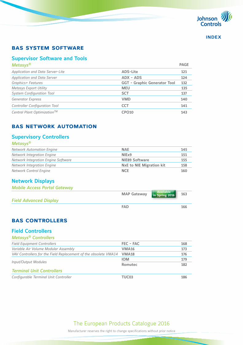
bas system software
Supervisor Software and ToolsMetasys® PAGE
Application and Data Server-Lite ADS-Lite 121Application and Data Server ADX - ADS 124Graphics+ Features GGT - Graphic Generator Tool 132Metasys Export Utility MEU 135System Configuration Tool SCT 137Generator Express VMD 140
Controller Configuration Tool CCT 141
Central Plant OptimizationTM CPO10 143
bas network automation
Supervisory ControllersMetasys®
Network Automation Engine NAE 145Network Integration Engine NIEx9 151Network Integration Engine Software NIE89 Software 155Network Integration Engine NxE to NIE Migration kit 158Network Control Engine NCE 160
Network DisplaysMobile Access Portal Gateway
MAP Gateway 163
Field Advanced DisplayFAD 166
bas controllers
Field ControllersMetasys® ControllersField Equipment Controllers FEC - FAC 168Variable Air Volume Modular Assembly VMA16 173VAV Controllers for the Field Replacement of the obsolete VMA14 VMA18 176
Input/Output ModulesIOM 179Romutec 182
Terminal Unit ControllersConfigurable Terminal Unit Controller TUC03 186
Available in Spring 2016
The European Products Catalogue 2016
index
Manufacturer reserves the right to change specifications without prior notice
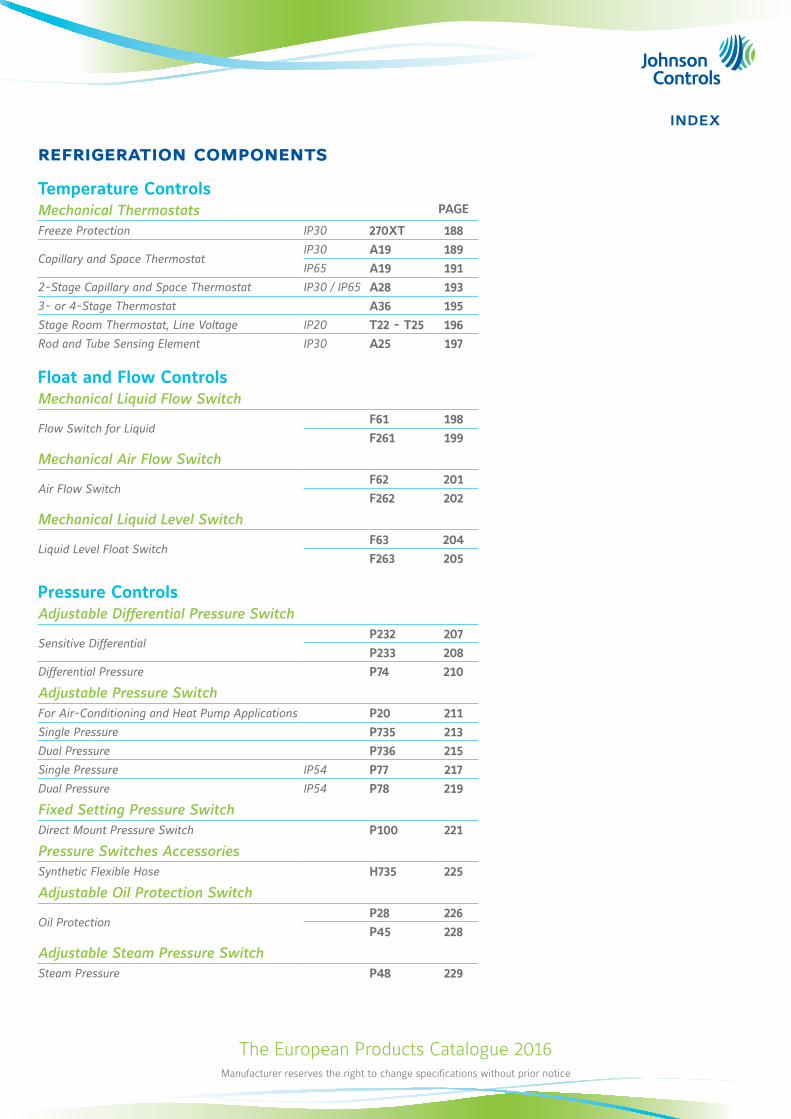
refrigeration components
Temperature ControlsMechanical Thermostats PAGE
Freeze Protection IP30 270XT 188
Capillary and Space ThermostatIP30 A19 189IP65 A19 191
2-Stage Capillary and Space Thermostat IP30 / IP65 A28 1933- or 4-Stage Thermostat A36 195Stage Room Thermostat, Line Voltage IP20 T22 - T25 196Rod and Tube Sensing Element IP30 A25 197
Float and Flow ControlsMechanical Liquid Flow Switch
Flow Switch for LiquidF61 198F261 199
Mechanical Air Flow Switch
Air Flow SwitchF62 201F262 202
Mechanical Liquid Level Switch
Liquid Level Float SwitchF63 204F263 205
Pressure ControlsAdjustable Differential Pressure Switch
Sensitive DifferentialP232 207P233 208
Differential Pressure P74 210
Adjustable Pressure SwitchFor Air-Conditioning and Heat Pump Applications P20 211Single Pressure P735 213Dual Pressure P736 215Single Pressure IP54 P77 217Dual Pressure IP54 P78 219
Fixed Setting Pressure SwitchDirect Mount Pressure Switch P100 221
Pressure Switches AccessoriesSynthetic Flexible Hose H735 225
Adjustable Oil Protection Switch
Oil ProtectionP28 226P45 228
Adjustable Steam Pressure SwitchSteam Pressure P48 229
The European Products Catalogue 2016
index
Manufacturer reserves the right to change specifications without prior notice
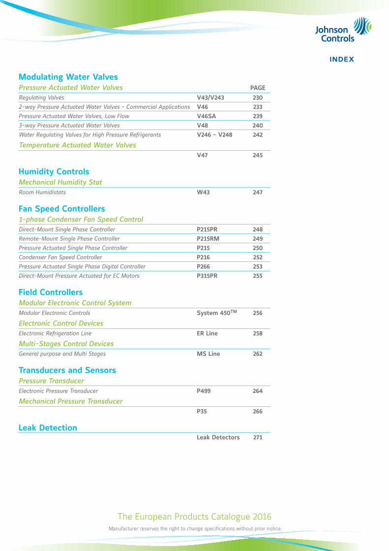
Modulating Water ValvesPressure Actuated Water Valves PAGE
Regulating Valves V43/V243 2302-way Pressure Actuated Water Valves - Commercial Applications V46 233Pressure Actuated Water Valves, Low Flow V46SA 2393-way Pressure Actuated Water Valves V48 240Water Regulating Valves for High Pressure Refrigerants V246 - V248 242
Temperature Actuated Water ValvesV47 245
Humidity ControlsMechanical Humidity StatRoom Humidistats W43 247
Fan Speed Controllers1-phase Condenser Fan Speed ControlDirect-Mount Single Phase Controller P215PR 248Remote-Mount Single Phase Controller P215RM 249Pressure Actuated Single Phase Controller P215 250Condenser Fan Speed Controller P216 252Pressure Actuated Single Phase Digital Controller P266 253Direct-Mount Pressure Actuated for EC Motors P315PR 255
Field ControllersModular Electronic Control SystemModular Electronic Controls System 450TM 256
Electronic Control DevicesElectronic Refrigeration Line ER Line 258
Multi-Stages Control DevicesGeneral purpose and Multi Stages MS Line 262
Transducers and SensorsPressure TransducerElectronic Pressure Transducer P499 264
Mechanical Pressure TransducerP35 266
Leak DetectionLeak Detectors 271
The European Products Catalogue 2016
index
Manufacturer reserves the right to change specifications without prior notice
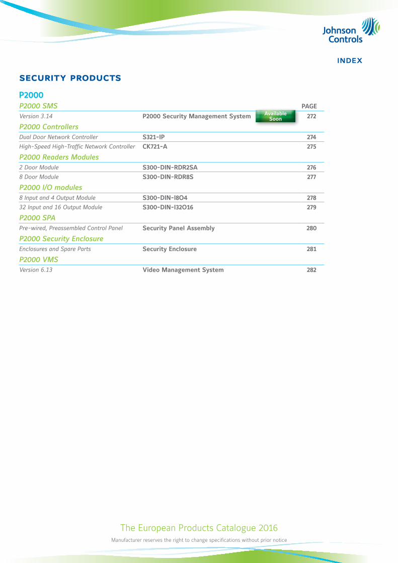
security products
P2000P2000 SMS PAGE
Version 3.14 P2000 Security Management System 272
P2000 ControllersDual Door Network Controller S321-IP 274High-Speed High-Traffic Network Controller CK721-A 275
P2000 Readers Modules2 Door Module S300-DIN-RDR2SA 2768 Door Module S300-DIN-RDR8S 277
P2000 I/O modules8 Input and 4 Output Module S300-DIN-I8O4 27832 Input and 16 Output Module S300-DIN-I32O16 279
P2000 SPAPre-wired, Preassembled Control Panel Security Panel Assembly 280
P2000 Security EnclosureEnclosures and Spare Parts Security Enclosure 281
P2000 VMSVersion 6.13 Video Management System 282
Available Soon
The European Products Catalogue 2016Manufacturer reserves the right to change specifications without prior notice
1
hvac control productsValves
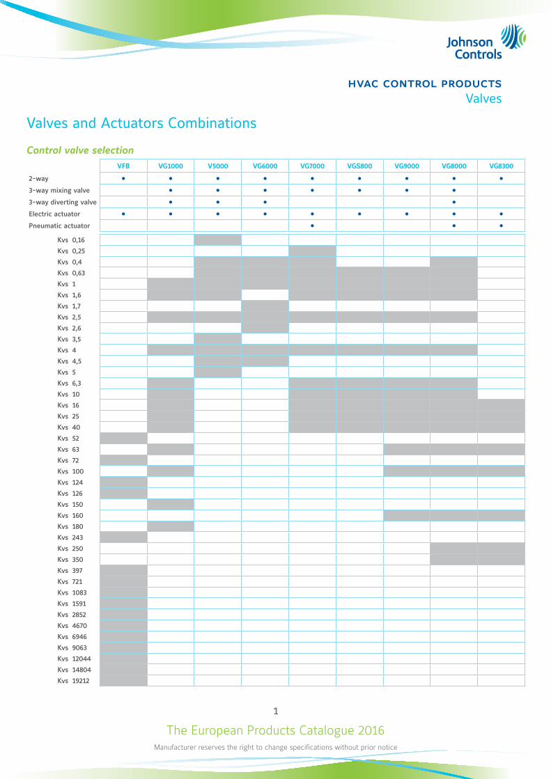
Valves and Actuators Combinations
Control valve selectionVFB VG1000 V5000 VG6000 VG7000 VGS800 VG9000 VG8000 VG8300
2-way 3-way mixing valve 3-way diverting valve Electric actuator Pneumatic actuator
Kvs 0,16
Kvs 0,25
Kvs 0,4
Kvs 0,63
Kvs 1
Kvs 1,6
Kvs 1,7
Kvs 2,5
Kvs 2,6
Kvs 3,5
Kvs 4
Kvs 4,5
Kvs 5
Kvs 6,3
Kvs 10
Kvs 16
Kvs 25
Kvs 40
Kvs 52
Kvs 63
Kvs 72
Kvs 100
Kvs 124
Kvs 126
Kvs 150
Kvs 160
Kvs 180
Kvs 243
Kvs 250
Kvs 350
Kvs 397
Kvs 721
Kvs 1083
Kvs 1591
Kvs 2852
Kvs 4670
Kvs 6946
Kvs 9063
Kvs 12044
Kvs 14804
Kvs 19212
The European Products Catalogue 2016Manufacturer reserves the right to change specifications without prior notice
2
hvac control productsValves
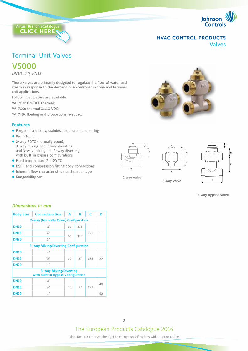
Terminal Unit Valves
V5000DN10...20, PN16
These valves are primarily designed to regulate the flow of water and steam in response to the demand of a controller in zone and terminal unit applications. Following actuators are available:VA-707x ON/OFF thermal;VA-709x thermal 0...10 VDC; VA-748x floating and proportional electric.
Features z Forged brass body, stainless steel stem and spring z KVS 0.16...5 z 2-way PDTC (normally open), 3-way mixing and 3-way diverting and 3-way mixing and 3-way diverting with built-in bypass configurations
z Fluid temperature 2...120 °C z BSPP and compression fitting body connections z Inherent flow characteristic: equal percentage z Rangeability 50:1
Dimensions in mm
Body Size Connection Size A B C D
2-way (Normally Open) Configuration
DN10 ½” 60 27.5
15.5 ---DN15 ¾”65 33.7
DN20 1”
3-way Mixing/Diverting Configuration
DN10 ½”
60 27 15.2 30DN15 ¾”
DN20 1”
3-way Mixing/Diverting with built-in bypass Configuration
DN10 ½”
60 27 15.240
DN15 ¾”
DN20 1” 50
A
B
C
A
D
B
C
A
D
B
C
2-way valve
3-way bypass valve
3-way valve
Virtual Branch eCatalogueclick here
The European Products Catalogue 2016Manufacturer reserves the right to change specifications without prior notice
3
hvac control productsValves
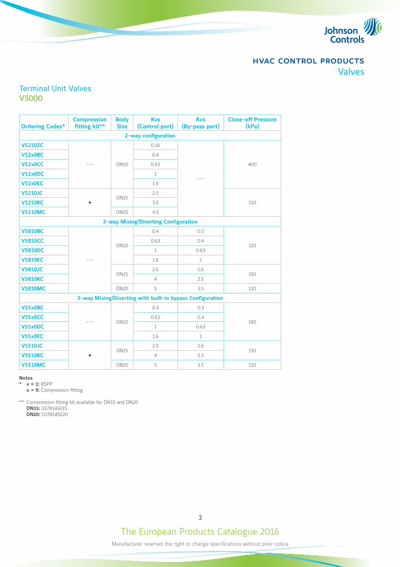
Terminal Unit ValvesV5000
Ordering Codes* Compression fitting kit**
Body Size
Kvs (Control port)
Kvs (By-pass port)
Close-off Pressure (kPa)
2-way configuration
V5210ZC
--- DN10
0.16
---
400
V52x0BC 0.4
V52x0CC 0.63
V52x0DC 1
V52x0EC 1.6
V5210JC
DN15
2.5
110V5210KC 3.5
V5210MC DN20 4.5
3-way Mixing/Diverting Configuration
V5810BC
---
DN10
0.4 0.3
120V5810CC 0.63 0.4
V5810DC 1 0.63
V5810EC 1.6 1
V5810JCDN15
2.5 1.6150
V5810KC 4 2.5
V5810MC DN20 5 3.5 110
3-way Mixing/Diverting with built-in bypass Configuration
V55x0BC
--- DN10
0.4 0.3
180V55x0CC 0.63 0.4
V55x0DC 1 0.63
V55x0EC 1.6 1
V5510JC
DN15
2.5 1.6150
V5510KC 4 2.5
V5510MC DN20 5 3.5 110
Notes* x = 1: BSPP x = 9: Compression fitting
** Compression fitting kit available for DN15 and DN20 DN15: 0378145015 DN20: 0378145020
The European Products Catalogue 2016Manufacturer reserves the right to change specifications without prior notice
4
hvac control productsValves
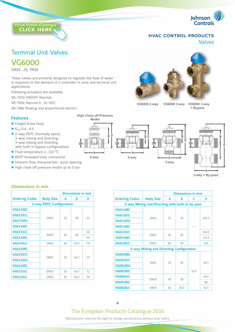
Terminal Unit Valves
VG6000DN15...25, PN16
These valves are primarily designed to regulate the flow of water in response to the demand of a controller in zone and terminal unit applications. Following actuators are available: VA-7070 ON/OFF thermal;VA-709x thermal 0...10 VDC;VA-748x floating and proportional electric.
Features z Forged brass body z KVS 0.4...4.5 z 2-way PDTC (normally open), 3-way mixing and diverting, 3-way mixing and diverting with built-in bypass configurations
z Fluid temperature 2...110 °C z BSPP threaded body connection z Inherent flow characteristic: quick opening z High close off pressure model up to 5 bar
DN
A
B
C
DN
A
B B
DN
A
DN
B
D
A
DDD
2-way3-way
3-way + By-pass
Dimensions in mm
Ordering Codes Body Size
Dimensions in mm
A B D
2-way PDTC Configuration
VG6210BC
DN15 52 29 51VG6210CC
VG6210DC
VG6210EC
VG6210JCDN20 56 28
56
VG6210KC 69
VG6210LC DN25 82 30.5 77.5
VG6310BC
DN15 52 44.7 70VG6310CC
VG6310DC
VG6310EC
VG6310JC DN20 56 43.7 72
VG6310LC DN25 82 46.2 78
VG6000 2-way VG6000 3-way VG6000 3-way + Bypass
Ordering Codes Body Size
Dimensions in mm
A B C D
3-way Mixing and Diverting with built-in by-pass
VG6510BC
DN15 52 29
---
102.5VG6510CC
VG6510DC
VG6510EC
VG6510JCDN20 56 28
104.5
VG6510KC 114.5
VG6510LC DN25 82 38 142
3-way Mixing and Diverting Configuration
VG6810BC
DN15 52 29
13.5
68.5VG6810CC
VG6810DC
VG6810EC
VG6810JCDN20 56 28
69.5
VG6810KC 86
VG6810LC DN25 82 30.5 92.5
2-way
High Close off Pressure Model
Virtual Branch eCatalogueclick here
The European Products Catalogue 2016Manufacturer reserves the right to change specifications without prior notice
5
hvac control productsValves
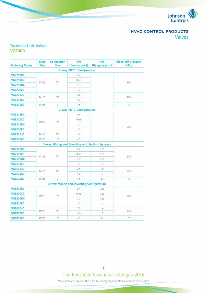
Terminal Unit Valves VG6000
Ordering CodesBody Size
Connection Size
Kvs (Control port)
Kvs (By-pass port)
Close-off pressure (kPa)
2-way PDTC Configuration
VG6210BC
DN15 ½”
0.4
---
250VG6210CC 0.63
VG6210DC 1.0
VG6210EC 1.7
VG6210JCDN20 ¾”
2.6150
VG6210KC 4.0
VG6210LC DN25 1” 4.5 70
2-way PDTC Configuration
VG6310BC
DN15 ½”
0.4
--- 500
VG6310CC 0.63
VG6310DC 1.0
VG6310EC 1.7
VG6310JC DN20 ¾” 2.6
VG6310LC DN25 1” 4.5
3-way Mixing and Diverting with built-in by-pass
VG6510BC
DN15 ½”
0.4 0.35
200VG6510CC 0.63 0.56
VG6510DC 1.0 0.86
VG6510EC 1.7 1.2
VG6510JCDN20 ¾”
2.5 1.6100
VG6510KC 4.0 1.7
VG6510LC DN25 1” 4.5 3.1 70
3-way Mixing and Diverting Configuration
VG6810BC
DN15 ½”
0.4 0.35
200VG6810CC 0.63 0.56
VG6810DC 1.0 0.86
VG6810EC 1.7 1.2
VG6810JCDN20 ¾”
2.5 1.6100
VG6810KC 4.0 1.7
VG6810LC DN25 1” 4.5 3.1 70
The European Products Catalogue 2016Manufacturer reserves the right to change specifications without prior notice
6
hvac control productsValves
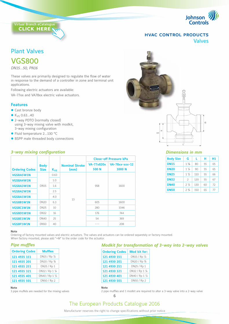
Plant Valves
VGS800DN15...50, PN16
These valves are primarily designed to regulate the flow of water in response to the demand of a controller in zone and terminal unit applications. Following electric actuators are available:VA-77xx and VA78xx electric valve actuators.
Features z Cast bronze body z KVS 0.63...40 z 2-way PDTO (normally closed) using 3-way mixing valve with modkit, 3-way mixing configuration
z Fluid temperature 2...130 °C z BSPP male threaded body connections
Dimensions in mmBody Size G L H H1
DN15 1 ⅛ 80 55 65
DN20 1 ¼ 90 55 65
DN25 1 ½ 110 55 66
DN32 2 120 55 67
DN40 2 ¼ 130 60 72
DN50 2 ¾ 150 65 77
3-way mixing configuration
Ordering CodesBody Size KVS
Nominal Stroke (mm)
Close-off Pressure kPa
VA-77x820x
500 N
VA-78xx-xxx-12
1000 N
VGS8A5W1N
DN15
0.63
13
958 1600
VGS8A4W1N 1.0
VGS8A3W1N 1.6
VGS8A2W1N 2.5
VGS8A1W1N 4.0
VGS8B1W1N DN20 6.3 605 1600
VGS8C1W1N DN25 10 280 1046
VGS8D1W1N DN32 16 176 744
VGS8E1W1N DN40 25 54 369
VGS8F1W1N DN50 40 --- 208
NoteOrdering of factory mounted valves and electric actuators. The valves and actuators can be ordered separetely or factory mounted. When factory mounted, please add “+M” to the order code for the actuator.
Pipe mufflesOrdering Codes Muffles
121 4935 151 DN15 / Rp ½
121 4935 201 DN20 / Rp ¾
121 4935 251 DN25 / Rp 1
121 4935 321 DN32 / Rp 1 ¼
121 4935 401 DN40 / Rp 1 ½
121 4935 501 DN50 / Rp 2
Note3 pipe muffels are needed for the mixing valves
Modkit for transformation of 3-way into 2-way valvesOrdering Codes Mod kit for:
121 4930 151 DN15 / Rp ½
121 4930 201 DN20 / Rp ¾
121 4930 251 DN25 / Rp 1
121 4930 321 DN32 / Rp 1 ¼
121 4930 401 DN40 / Rp 1 ½
121 4930 501 DN50 / Rp 2
Note 2 pipe muffles and 1 modkit are required to alter a 3-way valve into a 2-way valve
Virtual Branch eCatalogueclick here
The European Products Catalogue 2016Manufacturer reserves the right to change specifications without prior notice
7
hvac control productsValves
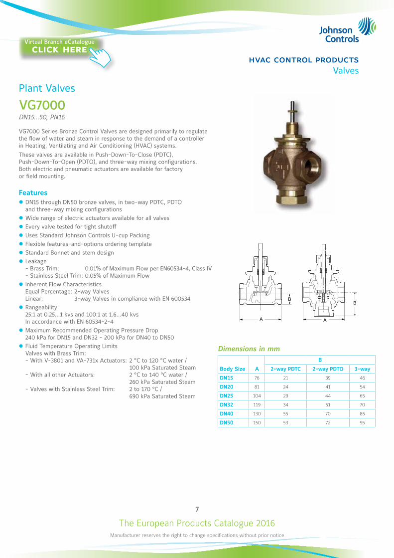
Plant Valves
VG7000DN15...50, PN16
VG7000 Series Bronze Control Valves are designed primarily to regulate the flow of water and steam in response to the demand of a controller in Heating, Ventilating and Air Conditioning (HVAC) systems.These valves are available in Push-Down-To-Close (PDTC), Push-Down-To-Open (PDTO), and three-way mixing configurations. Both electric and pneumatic actuators are available for factory or field mounting.
Features z DN15 through DN50 bronze valves, in two-way PDTC, PDTO and three-way mixing configurations
z Wide range of electric actuators available for all valves z Every valve tested for tight shutoff z Uses Standard Johnson Controls U-cup Packing z Flexible features-and-options ordering template z Standard Bonnet and stem design z Leakage - Brass Trim: 0.01% of Maximum Flow per EN60534-4, Class IV - Stainless Steel Trim: 0.05% of Maximum Flow
z Inherent Flow Characteristics Equal Percentage: 2-way Valves Linear: 3-way Valves in compliance with EN 600534
z Rangeability 25:1 at 0.25…1 kvs and 100:1 at 1.6…40 kvs In accordance with EN 60534-2-4
z Maximum Recommended Operating Pressure Drop 240 kPa for DN15 and DN32 - 200 kPa for DN40 to DN50
z Fluid Temperature Operating Limits Valves with Brass Trim: - With V-3801 and VA-731x Actuators: 2 °C to 120 °C water / 100 kPa Saturated Steam - With all other Actuators: 2 °C to 140 °C water / 260 kPa Saturated Steam - Valves with Stainless Steel Trim: 2 to 170 °C / 690 kPa Saturated Steam
B
A A
B
Dimensions in mm
Body Size A
B
2-way PDTC 2-way PDTO 3-way
DN15 76 21 39 46
DN20 81 24 41 54
DN25 104 29 44 65
DN32 119 34 51 70
DN40 130 55 70 85
DN50 150 53 72 95
Virtual Branch eCatalogueclick here
The European Products Catalogue 2016Manufacturer reserves the right to change specifications without prior notice
8
hvac control productsValves
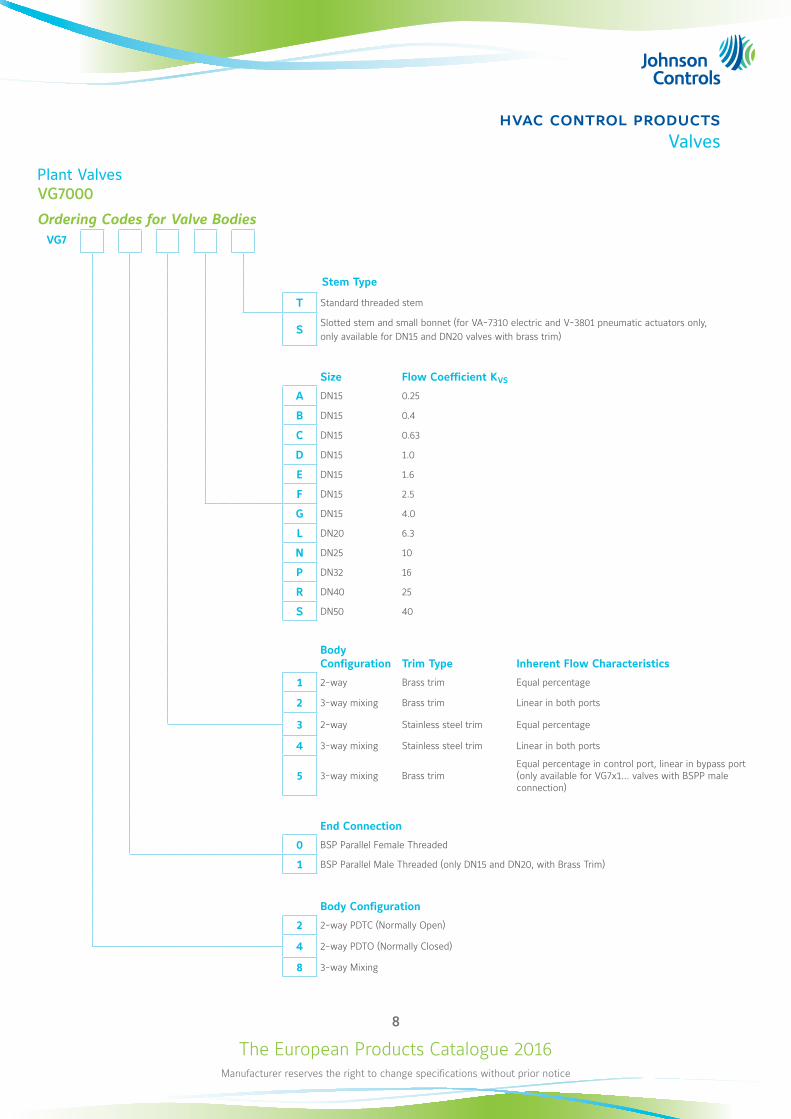
Plant ValvesVG7000
Ordering Codes for Valve BodiesVG7
Stem Type
T Standard threaded stem
S Slotted stem and small bonnet (for VA-7310 electric and V-3801 pneumatic actuators only,only available for DN15 and DN20 valves with brass trim)
Size Flow Coefficient KVS
A DN15 0.25
B DN15 0.4
C DN15 0.63
D DN15 1.0
E DN15 1.6
F DN15 2.5
G DN15 4.0
L DN20 6.3
N DN25 10
P DN32 16
R DN40 25
S DN50 40
Body Configuration Trim Type Inherent Flow Characteristics
1 2-way Brass trim Equal percentage
2 3-way mixing Brass trim Linear in both ports
3 2-way Stainless steel trim Equal percentage
4 3-way mixing Stainless steel trim Linear in both ports
5 3-way mixing Brass trimEqual percentage in control port, linear in bypass port (only available for VG7x1... valves with BSPP male connection)
End Connection
0 BSP Parallel Female Threaded
1 BSP Parallel Male Threaded (only DN15 and DN20, with Brass Trim)
Body Configuration
2 2-way PDTC (Normally Open)
4 2-way PDTO (Normally Closed)
8 3-way Mixing
The European Products Catalogue 2016Manufacturer reserves the right to change specifications without prior notice
9
hvac control productsValves
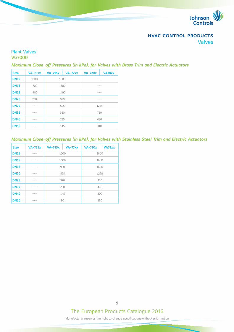
Plant ValvesVG7000
Maximum Close-off Pressures (in kPa), for Valves with Brass Trim and Electric Actuators
Size VA-731x VA-715x VA-77xx VA-720x VA78xx
DN15 1600 1600 ---
DN15 700 1600 ---
DN15 400 1490 ---
DN20 250 950 ---
DN25 --- 595 1235
DN32 --- 360 750
DN40 --- 235 480
DN50 --- 145 310
Maximum Close-off Pressures (in kPa), for Valves with Stainless Steel Trim and Electric Actuators
Size VA-731x VA-715x VA-77xx VA-720x VA78xx
DN15 --- 1600 1600
DN15 --- 1600 1600
DN15 --- 930 1600
DN20 --- 595 1220
DN25 --- 370 770
DN32 --- 230 470
DN40 --- 145 300
DN50 --- 90 190
The European Products Catalogue 2016Manufacturer reserves the right to change specifications without prior notice
10
hvac control productsValves
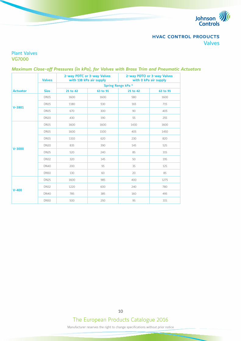
Plant ValvesVG7000
Maximum Close-off Pressures (in kPa), for Valves with Brass Trim and Pneumatic Actuators
Actuator
Valves2-way PDTC or 3-way Valves
with 138 kPa air supply2-way PDTO or 3-way Valves
with 0 kPa air supply
Size
Spring Range kPa *
21 to 42 63 to 91 21 to 42 63 to 91
V-3801
DN15 1600 1600 580 1600
DN15 1180 530 165 715
DN15 670 300 90 405
DN20 430 190 55 255
V-3000
DN15 1600 1600 1430 1600
DN15 1600 1100 405 1450
DN15 1310 620 230 820
DN20 835 390 145 525
DN25 520 240 85 315
DN32 320 145 50 195
DN40 200 95 35 125
DN50 130 60 20 85
V-400
DN25 1600 985 400 1275
DN32 1220 600 240 780
DN40 785 385 160 495
DN50 500 250 95 315
The European Products Catalogue 2016Manufacturer reserves the right to change specifications without prior notice
11
hvac control productsValves
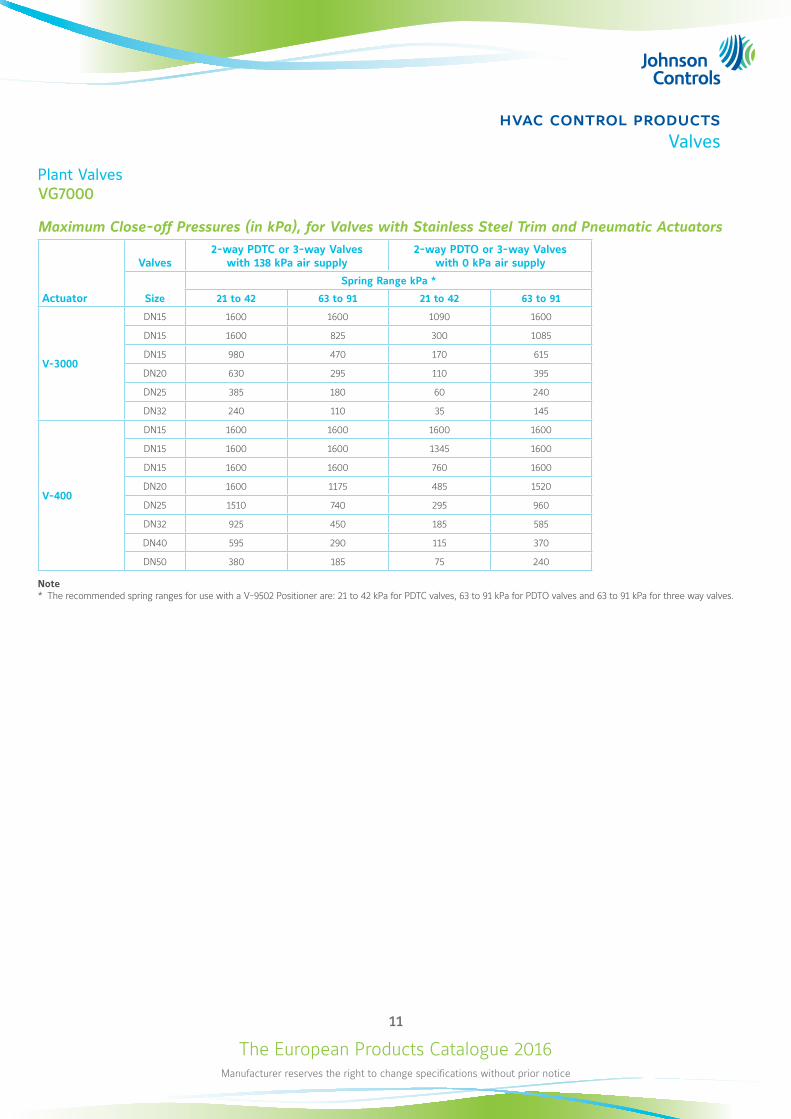
Plant ValvesVG7000
Maximum Close-off Pressures (in kPa), for Valves with Stainless Steel Trim and Pneumatic Actuators
Actuator
Valves2-way PDTC or 3-way Valves
with 138 kPa air supply2-way PDTO or 3-way Valves
with 0 kPa air supply
Size
Spring Range kPa *
21 to 42 63 to 91 21 to 42 63 to 91
V-3000
DN15 1600 1600 1090 1600
DN15 1600 825 300 1085
DN15 980 470 170 615
DN20 630 295 110 395
DN25 385 180 60 240
DN32 240 110 35 145
V-400
DN15 1600 1600 1600 1600
DN15 1600 1600 1345 1600
DN15 1600 1600 760 1600
DN20 1600 1175 485 1520
DN25 1510 740 295 960
DN32 925 450 185 585
DN40 595 290 115 370
DN50 380 185 75 240
Note * The recommended spring ranges for use with a V-9502 Positioner are: 21 to 42 kPa for PDTC valves, 63 to 91 kPa for PDTO valves and 63 to 91 kPa for three way valves.
The European Products Catalogue 2016Manufacturer reserves the right to change specifications without prior notice
12
hvac control productsValves
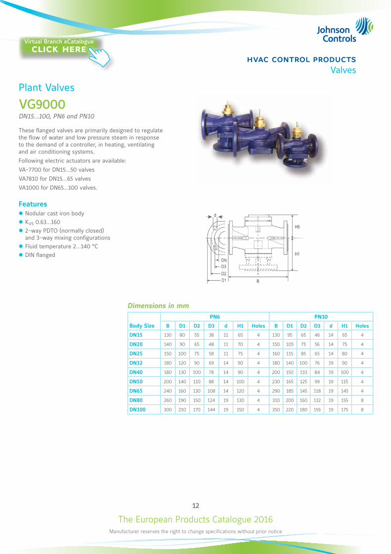
Dimensions in mm
Body Size
PN6 PN10
B D1 D2 D3 d H1 Holes B D1 D2 D3 d H1 Holes
DN15 130 80 55 38 11 65 4 130 95 65 46 14 65 4
DN20 140 90 65 48 11 70 4 150 105 75 56 14 75 4
DN25 150 100 75 58 11 75 4 160 115 85 65 14 80 4
DN32 180 120 90 69 14 90 4 180 140 100 76 19 90 4
DN40 180 130 100 78 14 90 4 200 150 110 84 19 100 4
DN50 200 140 110 88 14 100 4 230 165 125 99 19 115 4
DN65 240 160 130 108 14 120 4 290 185 145 118 19 145 4
DN80 260 190 150 124 19 130 4 310 200 160 132 19 155 8
DN100 300 210 170 144 19 150 4 350 220 180 156 19 175 8
Plant Valves
VG9000DN15...100, PN6 and PN10
These flanged valves are primarily designed to regulate the flow of water and low pressure steam in response to the demand of a controller, in heating, ventilating and air conditioning systems. Following electric actuators are available: VA-7700 for DN15...50 valvesVA7810 for DN15...65 valvesVA1000 for DN65...100 valves.
Features z Nodular cast iron body z KVS 0.63...160 z 2-way PDTO (normally closed) and 3-way mixing configurations
z Fluid temperature 2...140 °C z DIN flanged
Virtual Branch eCatalogueclick here
The European Products Catalogue 2016Manufacturer reserves the right to change specifications without prior notice
13
hvac control productsValves
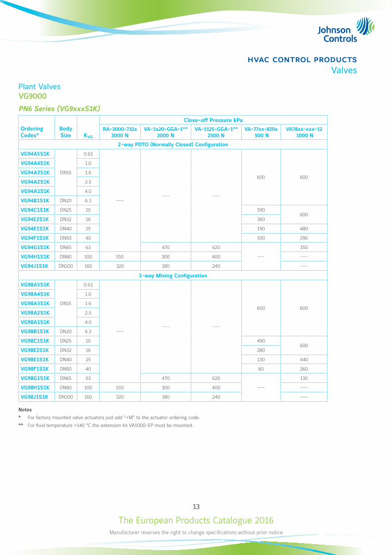
Plant ValvesVG9000
PN6 Series (VG9xxxS1K)
Ordering Codes*
Body Size KVS
Close-off Pressure kPa
RA-3000-732x3000 N
VA-1x20-GGA-1** 2000 N
VA-1125-GGA-1**2500 N
VA-77xx-820x 500 N
VA78xx-xxx-12 1000 N
2-way PDTO (Normally Closed) Configuration
VG94A5S1K
DN15
0.63
------ ---
600 600
VG94A4S1K 1.0
VG94A3S1K 1.6
VG94A2S1K 2.5
VG94A1S1K 4.0
VG94B1S1K DN20 6.3
VG94C1S1K DN25 10 590600
VG94E2S1K DN32 16 360
VG94E1S1K DN40 25 190 480
VG94F1S1K DN50 40 100 290
VG94G1S1K DN65 63 470 620
---
150
VG94H1S1K DN80 100 510 300 400 ---
VG94J1S1K DN100 160 320 180 240 ---
3-way Mixing Configuration
VG98A5S1K
DN15
0.63
------ ---
600 600
VG98A4S1K 1.0
VG98A3S1K 1.6
VG98A2S1K 2.5
VG98A1S1K 4.0
VG98B1S1K DN20 6.3
VG98C1S1K DN25 10 490600
VG98E2S1K DN32 16 280
VG98E1S1K DN40 25 130 440
VG98F1S1K DN50 40 60 260
VG98G1S1K DN65 63 470 620
---
130
VG98H1S1K DN80 100 510 300 400 ---
VG98J1S1K DN100 160 320 180 240 ---
Notes
* For factory mounted valve actuators just add “+M” to the actuator ordering code.
** For fluid temperature >140 °C the extension kit VA1000-EP must be mounted.
The European Products Catalogue 2016Manufacturer reserves the right to change specifications without prior notice
14
hvac control productsValves
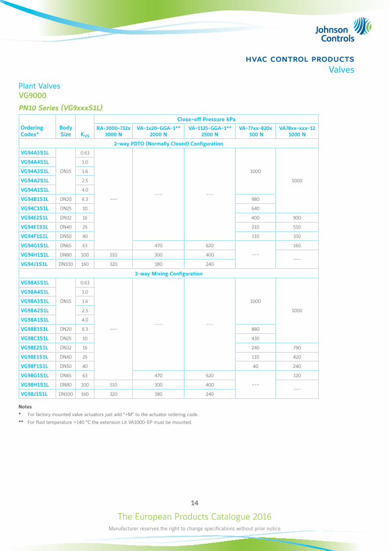
Plant ValvesVG9000
PN10 Series (VG9xxxS1L)
Ordering Codes*
Body Size KVS
Close-off Pressure kPa
RA-3000-732x3000 N
VA-1x20-GGA-1**2000 N
VA-1125-GGA-1**2500 N
VA-77xx-820x 500 N
VA78xx-xxx-121000 N
2-way PDTO (Normally Closed) Configuration
VG94A5S1L
DN15
0.63
------ ---
1000
1000
VG94A4S1L 1.0
VG94A3S1L 1.6
VG94A2S1L 2.5
VG94A1S1L 4.0
VG94B1S1L DN20 6.3 980
VG94C1S1L DN25 10 640
VG94E2S1L DN32 16 400 900
VG94E1S1L DN40 25 210 510
VG94F1S1L DN50 40 110 310
VG94G1S1L DN65 63 470 620
---
160
VG94H1S1L DN80 100 510 300 400---
VG94J1S1L DN100 160 320 180 240
3-way Mixing Configuration
VG98A5S1L
DN15
0.63
------ ---
1000
1000
VG98A4S1L 1.0
VG98A3S1L 1.6
VG98A2S1L 2.5
VG98A1S1L 4.0
VG98B1S1L DN20 6.3 880
VG98C1S1L DN25 10 430
VG98E2S1L DN32 16 240 790
VG98E1S1L DN40 25 110 420
VG98F1S1L DN50 40 40 240
VG98G1S1L DN65 63 470 620
---
120
VG98H1S1L DN80 100 510 300 400---
VG98J1S1L DN100 160 320 180 240
Notes
* For factory mounted valve actuators just add “+M” to the actuator ordering code.
** For fluid temperature >140 °C the extension Lit VA1000-EP must be mounted.
The European Products Catalogue 2016Manufacturer reserves the right to change specifications without prior notice
15
hvac control productsValves
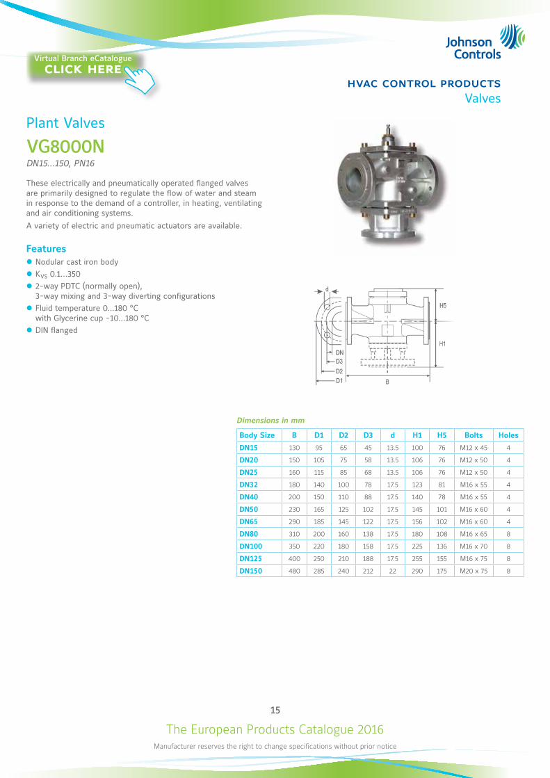
Plant Valves
VG8000NDN15...150, PN16
These electrically and pneumatically operated flanged valves are primarily designed to regulate the flow of water and steam in response to the demand of a controller, in heating, ventilating and air conditioning systems. A variety of electric and pneumatic actuators are available.
Features z Nodular cast iron body z KVS 0.1...350 z 2-way PDTC (normally open), 3-way mixing and 3-way diverting configurations
z Fluid temperature 0...180 °C with Glycerine cup -10...180 °C
z DIN flanged
Dimensions in mm
Body Size B D1 D2 D3 d H1 H5 Bolts Holes
DN15 130 95 65 45 13.5 100 76 M12 x 45 4
DN20 150 105 75 58 13.5 106 76 M12 x 50 4
DN25 160 115 85 68 13.5 106 76 M12 x 50 4
DN32 180 140 100 78 17.5 123 81 M16 x 55 4
DN40 200 150 110 88 17.5 140 78 M16 x 55 4
DN50 230 165 125 102 17.5 145 101 M16 x 60 4
DN65 290 185 145 122 17.5 156 102 M16 x 60 4
DN80 310 200 160 138 17.5 180 108 M16 x 65 8
DN100 350 220 180 158 17.5 225 136 M16 x 70 8
DN125 400 250 210 188 17.5 255 155 M16 x 75 8
DN150 480 285 240 212 22 290 175 M20 x 75 8
Virtual Branch eCatalogueclick here
The European Products Catalogue 2016Manufacturer reserves the right to change specifications without prior notice
16
hvac control productsValves
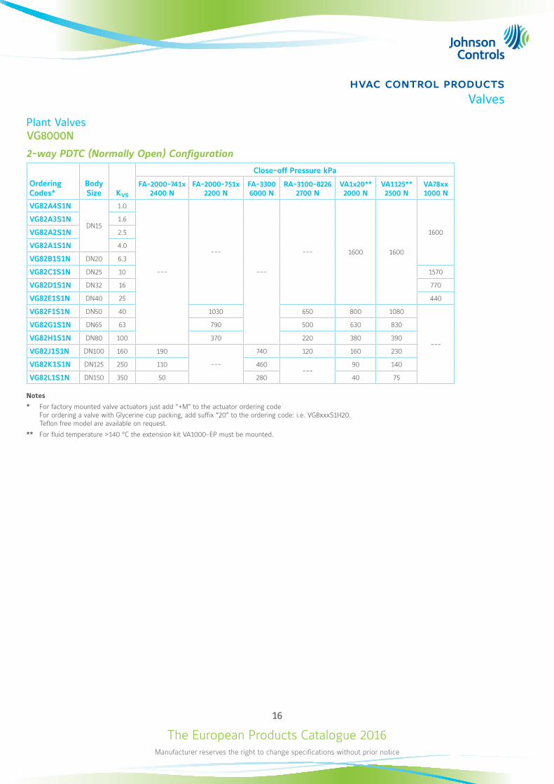
Plant ValvesVG8000N
2-way PDTC (Normally Open) Configuration
Ordering Codes*
Body Size KVS
Close-off Pressure kPa
FA-2000-741x2400 N
FA-2000-751x2200 N
FA-33006000 N
RA-3100-82262700 N
VA1x20**2000 N
VA1125** 2500 N
VA78xx 1000 N
VG82A4S1N
DN15
1.0
---
---
---
--- 1600 1600
1600
VG82A3S1N 1.6
VG82A2S1N 2.5
VG82A1S1N 4.0
VG82B1S1N DN20 6.3
VG82C1S1N DN25 10 1570
VG82D1S1N DN32 16 770
VG82E1S1N DN40 25 440
VG82F1S1N DN50 40 1030 650 800 1080
---
VG82G1S1N DN65 63 790 500 630 830
VG82H1S1N DN80 100 370 220 380 390
VG82J1S1N DN100 160 190
---
740 120 160 230
VG82K1S1N DN125 250 110 460---
90 140
VG82L1S1N DN150 350 50 280 40 75
Notes
* For factory mounted valve actuators just add “+M” to the actuator ordering code For ordering a valve with Glycerine cup packing, add suffix “20” to the ordering code: i.e. VG8xxxS1H20. Teflon free model are available on request.
** For fluid temperature >140 °C the extension kit VA1000-EP must be mounted.
The European Products Catalogue 2016Manufacturer reserves the right to change specifications without prior notice
17
hvac control productsValves
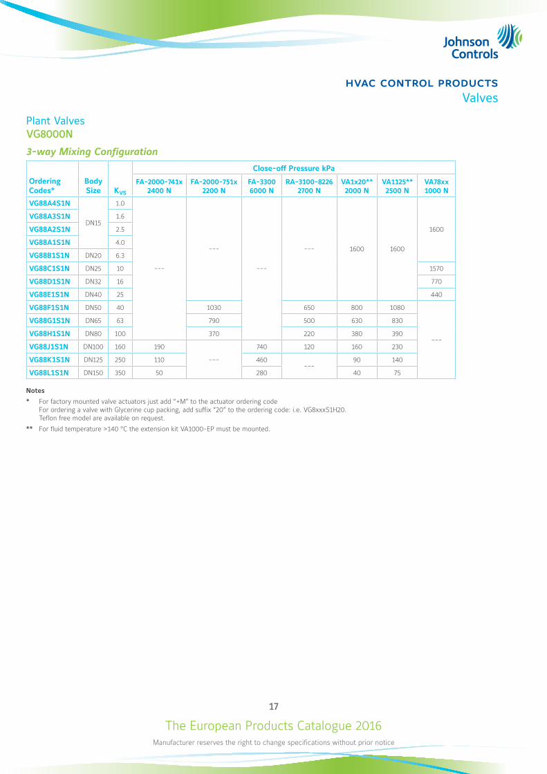
Plant ValvesVG8000N
3-way Mixing Configuration
Ordering Codes*
Body Size KVS
Close-off Pressure kPa
FA-2000-741x2400 N
FA-2000-751x2200 N
FA-33006000 N
RA-3100-82262700 N
VA1x20**2000 N
VA1125** 2500 N
VA78xx 1000 N
VG88A4S1N
DN15
1.0
---
---
---
--- 1600 1600
1600
VG88A3S1N 1.6
VG88A2S1N 2.5
VG88A1S1N 4.0
VG88B1S1N DN20 6.3
VG88C1S1N DN25 10 1570
VG88D1S1N DN32 16 770
VG88E1S1N DN40 25 440
VG88F1S1N DN50 40 1030 650 800 1080
---
VG88G1S1N DN65 63 790 500 630 830
VG88H1S1N DN80 100 370 220 380 390
VG88J1S1N DN100 160 190
---
740 120 160 230
VG88K1S1N DN125 250 110 460---
90 140
VG88L1S1N DN150 350 50 280 40 75
Notes
* For factory mounted valve actuators just add “+M” to the actuator ordering code For ordering a valve with Glycerine cup packing, add suffix “20” to the ordering code: i.e. VG8xxxS1H20. Teflon free model are available on request.
** For fluid temperature >140 °C the extension kit VA1000-EP must be mounted.
The European Products Catalogue 2016Manufacturer reserves the right to change specifications without prior notice
18
hvac control productsValves
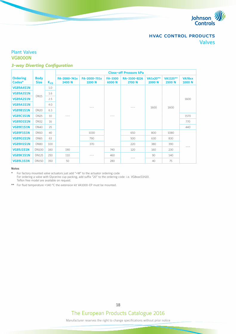
Plant ValvesVG8000N
3-way Diverting Configuration
Ordering Codes*
Body Size KVS
Close-off Pressure kPa
FA-2000-741x2400 N
FA-2000-751x2200 N
FA-33006000 N
RA-3100-82262700 N
VA1x20**2000 N
VA1125** 2500 N
VA78xx 1000 N
VG89A4S1N
DN15
1.0
---
---
---
--- 1600 1600
1600
VG89A3S1N 1.6
VG89A2S1N 2.5
VG89A1S1N 4.0
VG89B1S1N DN20 6.3
VG89C1S1N DN25 10 1570
VG89D1S1N DN32 16 770
VG89E1S1N DN40 25 440
VG89F1S1N DN50 40 1030 650 800 1080
---
VG89G1S1N DN65 63 790 500 630 830
VG89H1S1N DN80 100 370 220 380 390
VG89J1S1N DN100 160 190
---
740 120 160 230
VG89K1S1N DN125 250 110 460---
90 140
VG89L1S1N DN150 350 50 280 40 75
Notes
* For factory mounted valve actuators just add “+M” to the actuator ordering code For ordering a valve with Glycerine cup packing, add suffix “20” to the ordering code: i.e. VG8xxxS1H20. Teflon free model are available on request.
** For fluid temperature >140 °C the extension kit VA1000-EP must be mounted.
The European Products Catalogue 2016Manufacturer reserves the right to change specifications without prior notice
19
hvac control productsValves
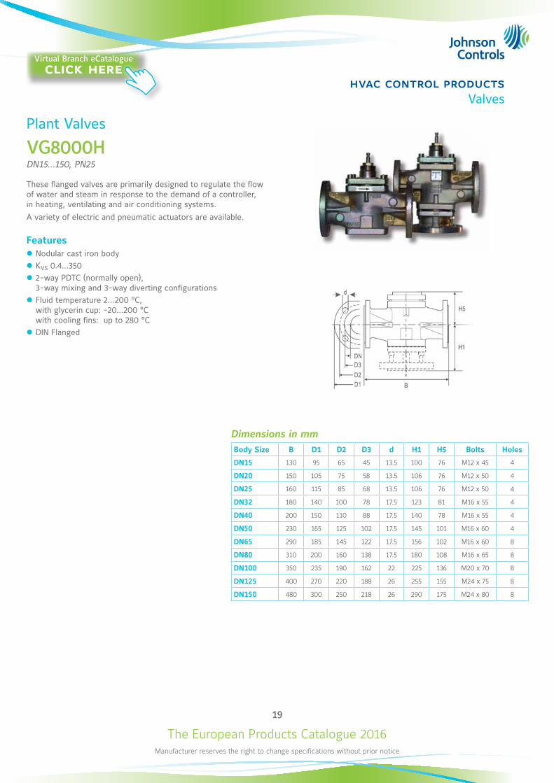
Plant Valves
VG8000HDN15...150, PN25
These flanged valves are primarily designed to regulate the flow of water and steam in response to the demand of a controller, in heating, ventilating and air conditioning systems. A variety of electric and pneumatic actuators are available.
Features z Nodular cast iron body z KVS 0.4...350 z 2-way PDTC (normally open), 3-way mixing and 3-way diverting configurations
z Fluid temperature 2...200 °C, with glycerin cup: -20...200 °C with cooling fins: up to 280 °C
z DIN Flanged
Dimensions in mmBody Size B D1 D2 D3 d H1 H5 Bolts Holes
DN15 130 95 65 45 13.5 100 76 M12 x 45 4
DN20 150 105 75 58 13.5 106 76 M12 x 50 4
DN25 160 115 85 68 13.5 106 76 M12 x 50 4
DN32 180 140 100 78 17.5 123 81 M16 x 55 4
DN40 200 150 110 88 17.5 140 78 M16 x 55 4
DN50 230 165 125 102 17.5 145 101 M16 x 60 4
DN65 290 185 145 122 17.5 156 102 M16 x 60 8
DN80 310 200 160 138 17.5 180 108 M16 x 65 8
DN100 350 235 190 162 22 225 136 M20 x 70 8
DN125 400 270 220 188 26 255 155 M24 x 75 8
DN150 480 300 250 218 26 290 175 M24 x 80 8
Virtual Branch eCatalogueclick here
The European Products Catalogue 2016Manufacturer reserves the right to change specifications without prior notice
20
hvac control productsValves
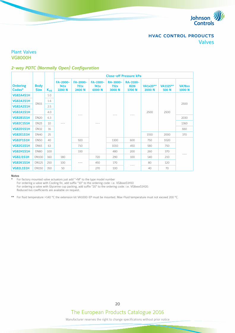
Plant ValvesVG8000H
2-way PDTC (Normally Open) Configuration
Ordering Codes*
Body Size KVS
Close-off Pressure kPa
FA-2000-741x
2200 N
FA-2000-751x
2400 N
FA-3300-741x
6000 N
RA-3000-732x
3000 N
RA-3100-8226
1700 NVA1x20**2000 N
VA1125**500 N
VA78xx1000 N
VG82A4S1H
DN15
1.0
---
---
---
--- ---2500 2500
2500VG82A3S1H 1.6
VG82A2S1H 2.5
VG82A1S1H 4.0
VG82B1S1H DN20 6.3 2030
VG82C1S1H DN25 10 1360
VG82D1S1H DN32 16 660
VG82E1S1H DN40 25 1550 2000 370
VG82F1S1H DN50 40 920 1300 600 750 1020
---
VG82G1S1H DN65 63 710 1010 450 580 750
VG82H1S1H DN80 100 330 480 200 260 370
VG82J1S1H DN100 160 180
---
720 290 100 140 210
VG82K1S1H DN125 250 100 450 170---
80 120
VG82L1S1H DN150 350 50 270 100 40 70
Notes* For factory mounted valve actuators just add “+M” to the type model number For ordering a valve with Cooling fin, add suffix “10” to the ordering code: i.e. VG8xxxS1H10 For ordering a valve with Glycerine cup packing, add suffix “20” to the ordering code: i.e. VG8xxxS1H20. Reduced kvs coefficients are available on request.
** For fluid temperature >140 °C the extension kit VA1000-EP must be mounted. Max-Fluid temperature must not exceed 200 °C.
The European Products Catalogue 2016Manufacturer reserves the right to change specifications without prior notice
21
hvac control productsValves
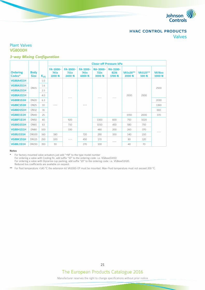
Plant ValvesVG8000H
3-way Mixing Configuration
Ordering Codes*
Body Size KVS
Close-off Pressure kPa
FA-2000-741x
2200 N
FA-2000-751x
2400 N
FA-3300-741x
6000 N
RA-3000-732x
3000 N
RA-3100-8226
1700 NVA1x20**2000 N
VA1125**500 N
VA78xx1000 N
VG88A4S1H
DN15
1.0
---
---
---
--- ---2500 2500
2500VG88A3S1H 1.6
VG88A2S1H 2.5
VG88A1S1H 4.0
VG88B1S1H DN20 6.3 2030
VG88C1S1H DN25 10 1360
VG88D1S1H DN32 16 660
VG88E1S1H DN40 25 1550 2000 370
VG88F1S1H DN50 40 920 1300 600 750 1020
---
VG88G1S1H DN65 63 710 1010 450 580 750
VG88H1S1H DN80 100 330 480 200 260 370
VG88J1S1H DN100 160 180
---
720 290 100 140 210
VG88K1S1H DN125 250 100 450 170---
80 120
VG88L1S1H DN150 350 50 270 100 40 70
Notes
* For factory mounted valve actuators just add “+M” to the type model number For ordering a valve with Cooling fin, add suffix “10” to the ordering code: i.e. VG8xxxS1H10 For ordering a valve with Glycerine cup packing, add suffix “20” to the ordering code: i.e. VG8xxxS1H20. Reduced kvs coefficients are available on request.
** For fluid temperature >140 °C the extension kit VA1000-EP must be mounted. Max-Fluid temperature must not exceed 200 °C.
The European Products Catalogue 2016Manufacturer reserves the right to change specifications without prior notice
22
hvac control productsValves
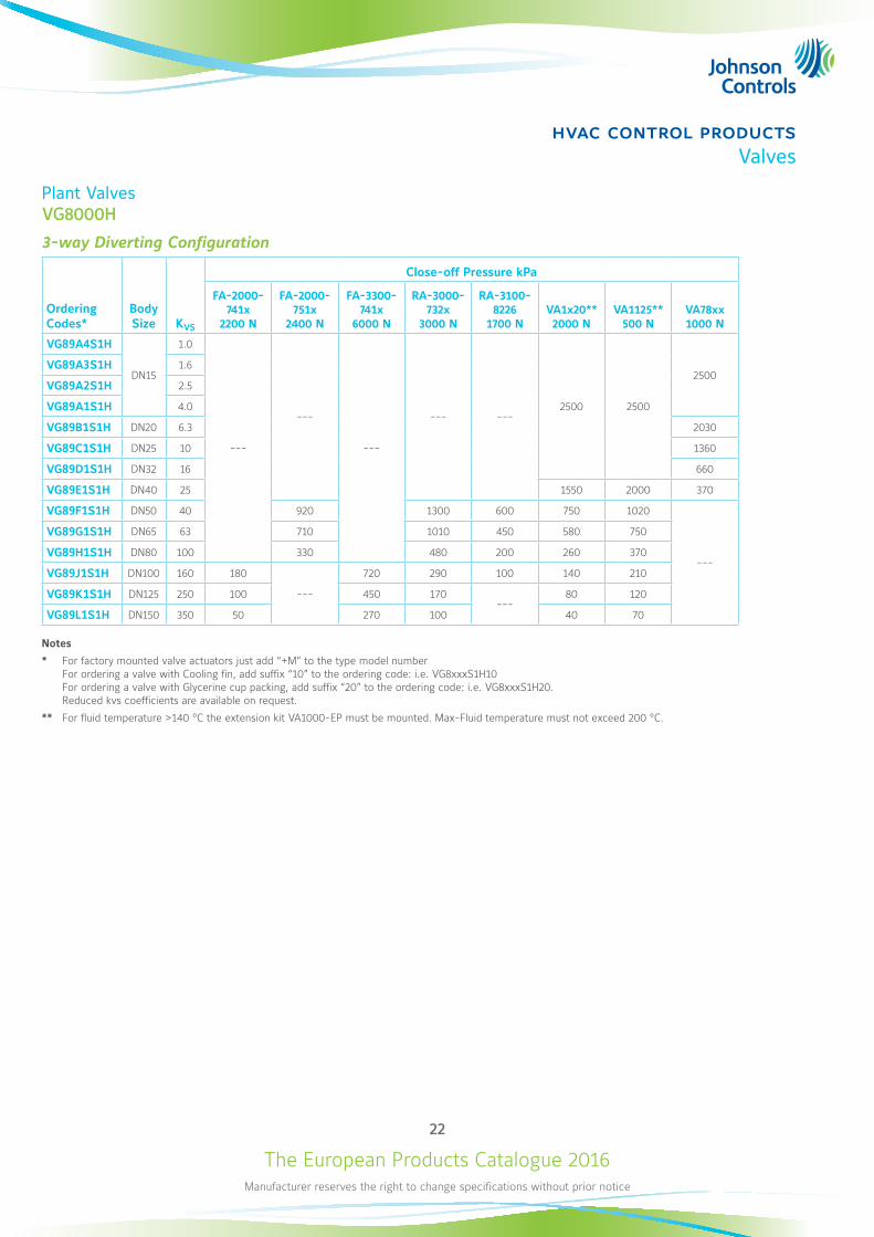
Plant ValvesVG8000H
3-way Diverting Configuration
Ordering Codes*
Body Size KVS
Close-off Pressure kPa
FA-2000-741x
2200 N
FA-2000-751x
2400 N
FA-3300-741x
6000 N
RA-3000-732x
3000 N
RA-3100-8226
1700 NVA1x20**2000 N
VA1125**500 N
VA78xx1000 N
VG89A4S1H
DN15
1.0
---
---
---
--- ---2500 2500
2500VG89A3S1H 1.6
VG89A2S1H 2.5
VG89A1S1H 4.0
VG89B1S1H DN20 6.3 2030
VG89C1S1H DN25 10 1360
VG89D1S1H DN32 16 660
VG89E1S1H DN40 25 1550 2000 370
VG89F1S1H DN50 40 920 1300 600 750 1020
---
VG89G1S1H DN65 63 710 1010 450 580 750
VG89H1S1H DN80 100 330 480 200 260 370
VG89J1S1H DN100 160 180
---
720 290 100 140 210
VG89K1S1H DN125 250 100 450 170---
80 120
VG89L1S1H DN150 350 50 270 100 40 70
Notes
* For factory mounted valve actuators just add “+M” to the type model number For ordering a valve with Cooling fin, add suffix “10” to the ordering code: i.e. VG8xxxS1H10 For ordering a valve with Glycerine cup packing, add suffix “20” to the ordering code: i.e. VG8xxxS1H20. Reduced kvs coefficients are available on request.
** For fluid temperature >140 °C the extension kit VA1000-EP must be mounted. Max-Fluid temperature must not exceed 200 °C.
The European Products Catalogue 2016Manufacturer reserves the right to change specifications without prior notice
23
hvac control productsValves
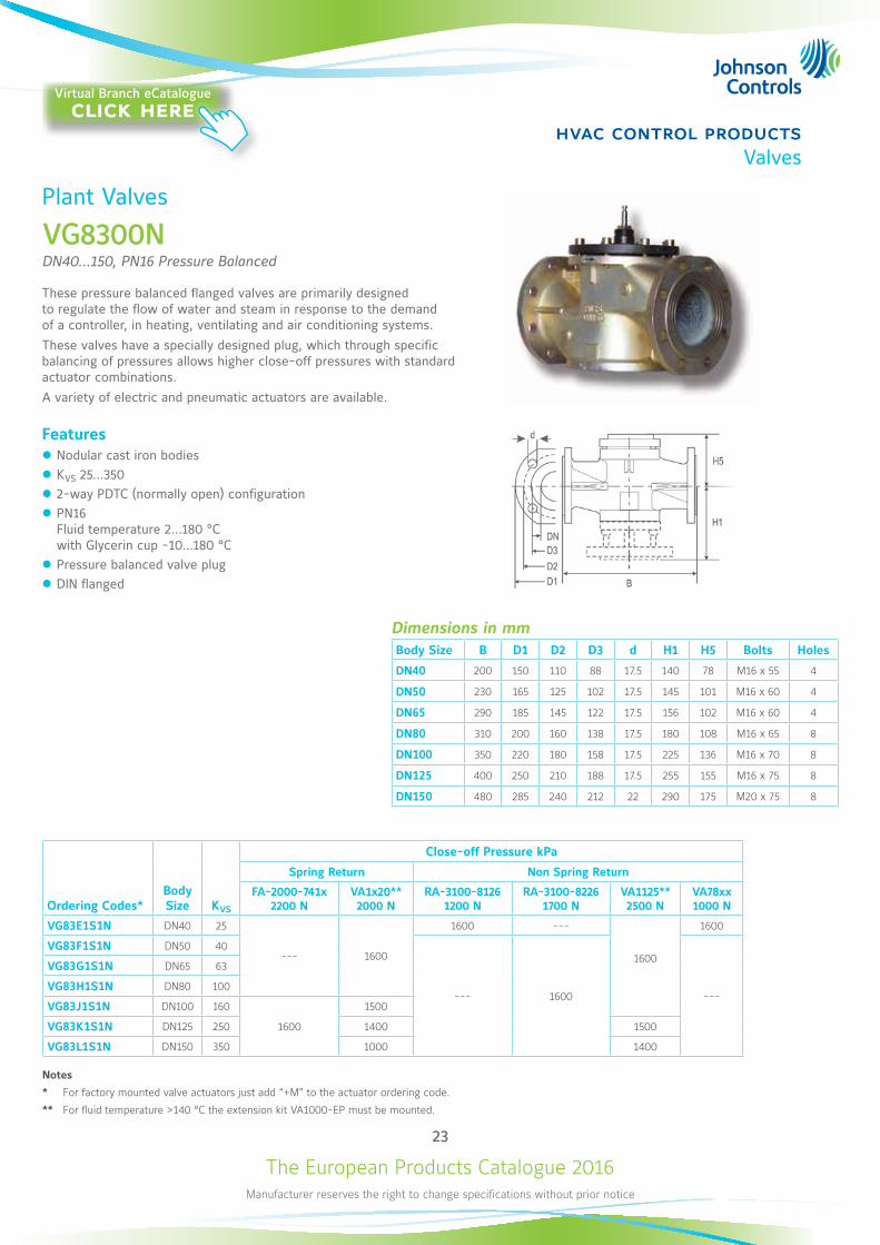
Plant Valves
VG8300NDN40...150, PN16 Pressure Balanced
These pressure balanced flanged valves are primarily designed to regulate the flow of water and steam in response to the demand of a controller, in heating, ventilating and air conditioning systems. These valves have a specially designed plug, which through specific balancing of pressures allows higher close-off pressures with standard actuator combinations. A variety of electric and pneumatic actuators are available.
Features z Nodular cast iron bodies z KVS 25...350 z 2-way PDTC (normally open) configuration z PN16 Fluid temperature 2...180 °C with Glycerin cup -10...180 °C
z Pressure balanced valve plug z DIN flanged
Dimensions in mmBody Size B D1 D2 D3 d H1 H5 Bolts Holes
DN40 200 150 110 88 17.5 140 78 M16 x 55 4
DN50 230 165 125 102 17.5 145 101 M16 x 60 4
DN65 290 185 145 122 17.5 156 102 M16 x 60 4
DN80 310 200 160 138 17.5 180 108 M16 x 65 8
DN100 350 220 180 158 17.5 225 136 M16 x 70 8
DN125 400 250 210 188 17.5 255 155 M16 x 75 8
DN150 480 285 240 212 22 290 175 M20 x 75 8
Ordering Codes*Body Size KVS
Close-off Pressure kPa
Spring Return Non Spring Return
FA-2000-741x2200 N
VA1x20**2000 N
RA-3100-81261200 N
RA-3100-82261700 N
VA1125**2500 N
VA78xx1000 N
VG83E1S1N DN40 25
--- 1600
1600 ---
1600
1600
VG83F1S1N DN50 40
--- 1600 ---
VG83G1S1N DN65 63
VG83H1S1N DN80 100
VG83J1S1N DN100 160
1600
1500
VG83K1S1N DN125 250 1400 1500
VG83L1S1N DN150 350 1000 1400
Notes
* For factory mounted valve actuators just add “+M” to the actuator ordering code.
** For fluid temperature >140 °C the extension kit VA1000-EP must be mounted.
Virtual Branch eCatalogueclick here
The European Products Catalogue 2016Manufacturer reserves the right to change specifications without prior notice
24
hvac control productsValves
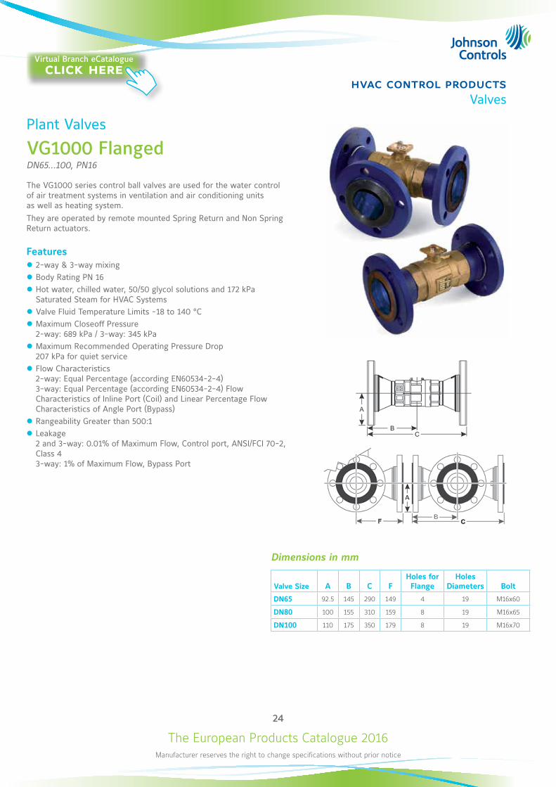
Plant Valves
VG1000 FlangedDN65...100, PN16
The VG1000 series control ball valves are used for the water control of air treatment systems in ventilation and air conditioning units as well as heating system.They are operated by remote mounted Spring Return and Non Spring Return actuators.
Features z 2-way & 3-way mixing z Body Rating PN 16 z Hot water, chilled water, 50/50 glycol solutions and 172 kPa Saturated Steam for HVAC Systems
z Valve Fluid Temperature Limits -18 to 140 °C z Maximum Closeoff Pressure 2-way: 689 kPa / 3-way: 345 kPa
z Maximum Recommended Operating Pressure Drop 207 kPa for quiet service
z Flow Characteristics 2-way: Equal Percentage (according EN60534-2-4) 3-way: Equal Percentage (according EN60534-2-4) Flow Characteristics of Inline Port (Coil) and Linear Percentage Flow Characteristics of Angle Port (Bypass)
z Rangeability Greater than 500:1 z Leakage 2 and 3-way: 0.01% of Maximum Flow, Control port, ANSI/FCI 70-2, Class 4 3-way: 1% of Maximum Flow, Bypass Port
Dimensions in mm
Valve Size A B C FHoles for Flange
Holes Diameters Bolt
DN65 92.5 145 290 149 4 19 M16x60
DN80 100 155 310 159 8 19 M16x65
DN100 110 175 350 179 8 19 M16x70
Virtual Branch eCatalogueclick here
The European Products Catalogue 2016Manufacturer reserves the right to change specifications without prior notice
25
hvac control productsValves
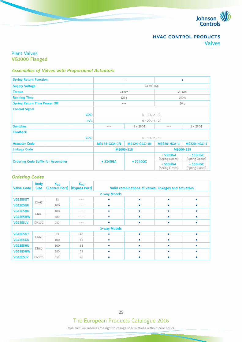
Plant ValvesVG1000 Flanged
Assemblies of Valves with Proportional Actuators
Spring Return Function --- Supply Voltage 24 VAC/DC
Torque 24 Nm 20 Nm
Running Time 125 s 150 s
Spring Return Time Power Off --- 26 s
Control Signal
VDC: 0 - 10 / 2 - 10
mA: 0 - 20 / 4 - 20
Switches --- 2 x SPDT --- 2 x SPDT
Feedback
VDC: 0 - 10 / 2 - 10
Actuator Code M9124-GGA-1N M9124-GGC-1N M9220-HGA-1 M9220-HGC-1
Linkage Code M9000-518 M9000-519
Ordering Code Suffix for Assemblies + 524GGA + 524GGC
+ 530HGA (Spring Opens)
+ 530HGC (Spring Opens)
+ 550HGA (Spring Closes)
+ 550HGC (Spring Closes)
Ordering Codes
Valve CodeBody Size
KVS (Control Port)
KVS (Bypass Port) Valid combinations of valves, linkages and actuators
2-way Models
VG12E5GTDN65
63 --- VG12E5GU 100 --- VG12E5HU
DN80100 ---
VG12E5HW 180 --- VG12E5JV DN100 150 ---
3-way Models
VG18E5GTDN65
63 40 VG18E5GU 100 63 VG18E5HU
DN80100 63
VG18E5HW 180 75 VG18E5JV DN100 150 75
The European Products Catalogue 2016Manufacturer reserves the right to change specifications without prior notice
26
hvac control productsValves
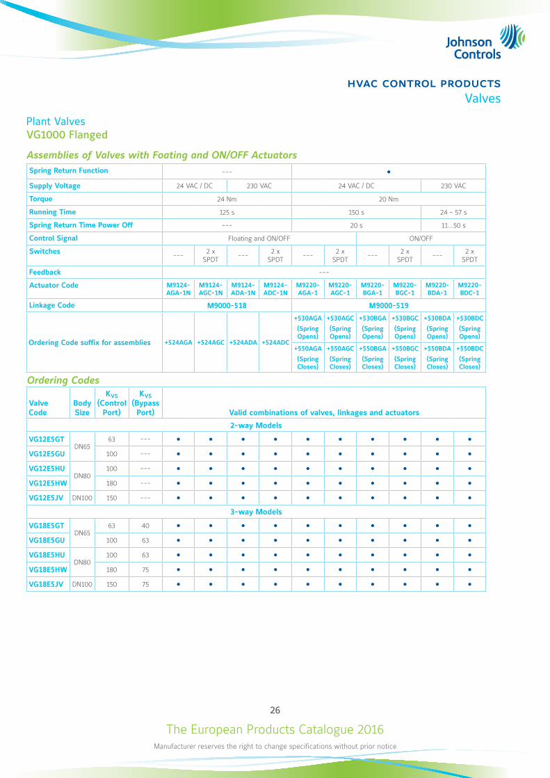
Plant ValvesVG1000 Flanged
Assemblies of Valves with Foating and ON/OFF ActuatorsSpring Return Function --- Supply Voltage 24 VAC / DC 230 VAC 24 VAC / DC 230 VAC
Torque 24 Nm 20 Nm
Running Time 125 s 150 s 24 - 57 s
Spring Return Time Power Off --- 20 s 11...50 s
Control Signal Floating and ON/OFF ON/OFF
Switches --- 2 x SPDT --- 2 x
SPDT --- 2 x SPDT --- 2 x
SPDT --- 2 x SPDT
Feedback ---
Actuator Code M9124-AGA-1N
M9124-AGC-1N
M9124-ADA-1N
M9124-ADC-1N
M9220-AGA-1
M9220-AGC-1
M9220-BGA-1
M9220-BGC-1
M9220-BDA-1
M9220-BDC-1
Linkage Code M9000-518 M9000-519
Ordering Code suffix for assemblies +524AGA +524AGC +524ADA +524ADC
+530AGA
(Spring Opens)
+530AGC
(Spring Opens)
+530BGA
(Spring Opens)
+530BGC
(Spring Opens)
+530BDA
(Spring Opens)
+530BDC
(Spring Opens)
+550AGA
(Spring Closes)
+550AGC
(Spring Closes)
+550BGA
(Spring Closes)
+550BGC
(Spring Closes)
+550BDA
(Spring Closes)
+550BDC
(Spring Closes)
Ordering Codes
Valve Code
Body Size
KVS (Control
Port)
KVS (Bypass Port) Valid combinations of valves, linkages and actuators
2-way Models
VG12E5GTDN65
63 --- VG12E5GU 100 --- VG12E5HU
DN80100 ---
VG12E5HW 180 --- VG12E5JV DN100 150 ---
3-way Models
VG18E5GTDN65
63 40 VG18E5GU 100 63 VG18E5HU
DN80100 63
VG18E5HW 180 75 VG18E5JV DN100 150 75
The European Products Catalogue 2016Manufacturer reserves the right to change specifications without prior notice
27
hvac control productsValves
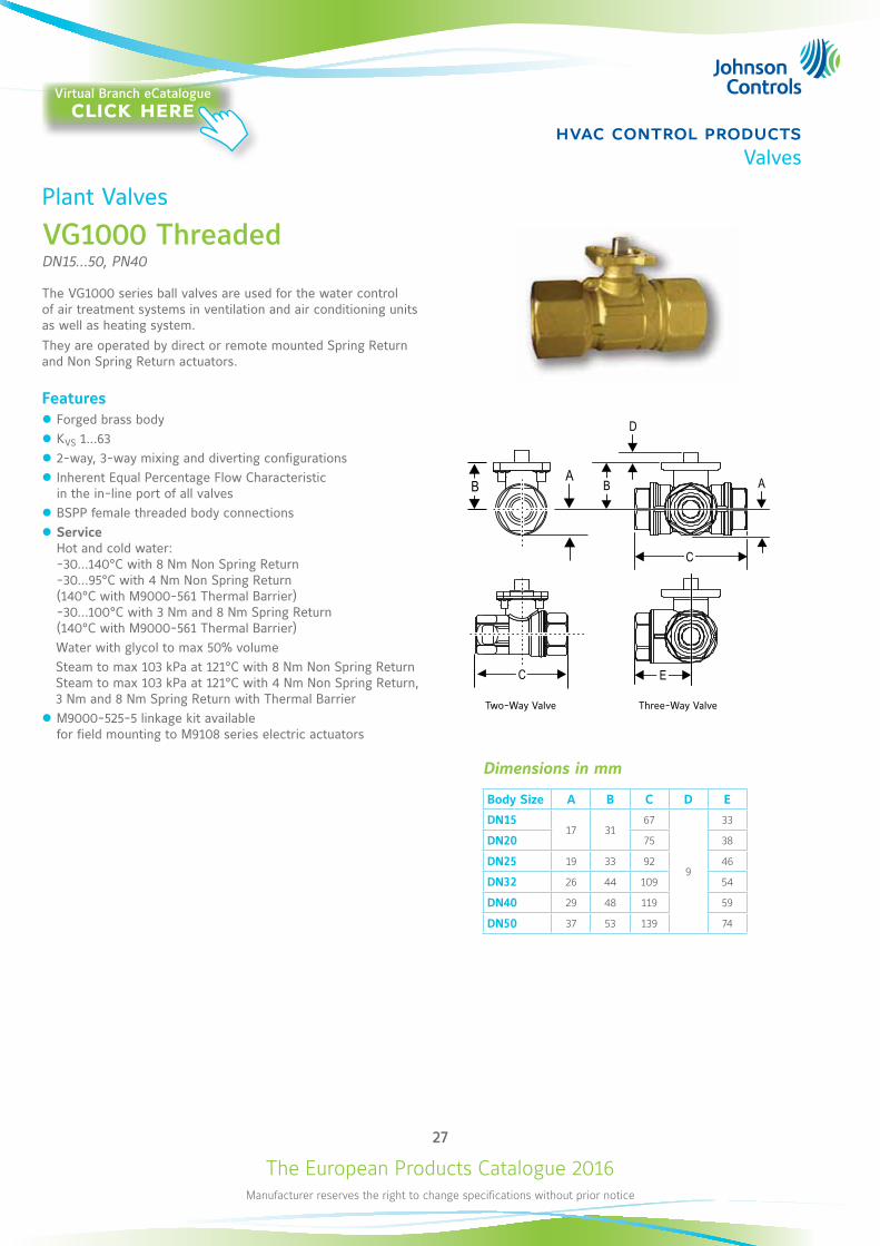
Plant Valves
VG1000 ThreadedDN15...50, PN40
The VG1000 series ball valves are used for the water control of air treatment systems in ventilation and air conditioning units as well as heating system.They are operated by direct or remote mounted Spring Return and Non Spring Return actuators.
Features z Forged brass body z KVS 1...63 z 2-way, 3-way mixing and diverting configurations z Inherent Equal Percentage Flow Characteristic in the in-line port of all valves
z BSPP female threaded body connections z Service Hot and cold water: -30...140°C with 8 Nm Non Spring Return -30...95°C with 4 Nm Non Spring Return (140°C with M9000-561 Thermal Barrier) -30...100°C with 3 Nm and 8 Nm Spring Return (140°C with M9000-561 Thermal Barrier)
Water with glycol to max 50% volume Steam to max 103 kPa at 121°C with 8 Nm Non Spring Return Steam to max 103 kPa at 121°C with 4 Nm Non Spring Return, 3 Nm and 8 Nm Spring Return with Thermal Barrier
z M9000-525-5 linkage kit available for field mounting to M9108 series electric actuators
Dimensions in mm
Body Size A B C D E
DN1517 31
67
9
33
DN20 75 38
DN25 19 33 92 46
DN32 26 44 109 54
DN40 29 48 119 59
DN50 37 53 139 74
Two-Way Valve Three-Way Valve
Virtual Branch eCatalogueclick here
The European Products Catalogue 2016Manufacturer reserves the right to change specifications without prior notice
28
hvac control productsValves
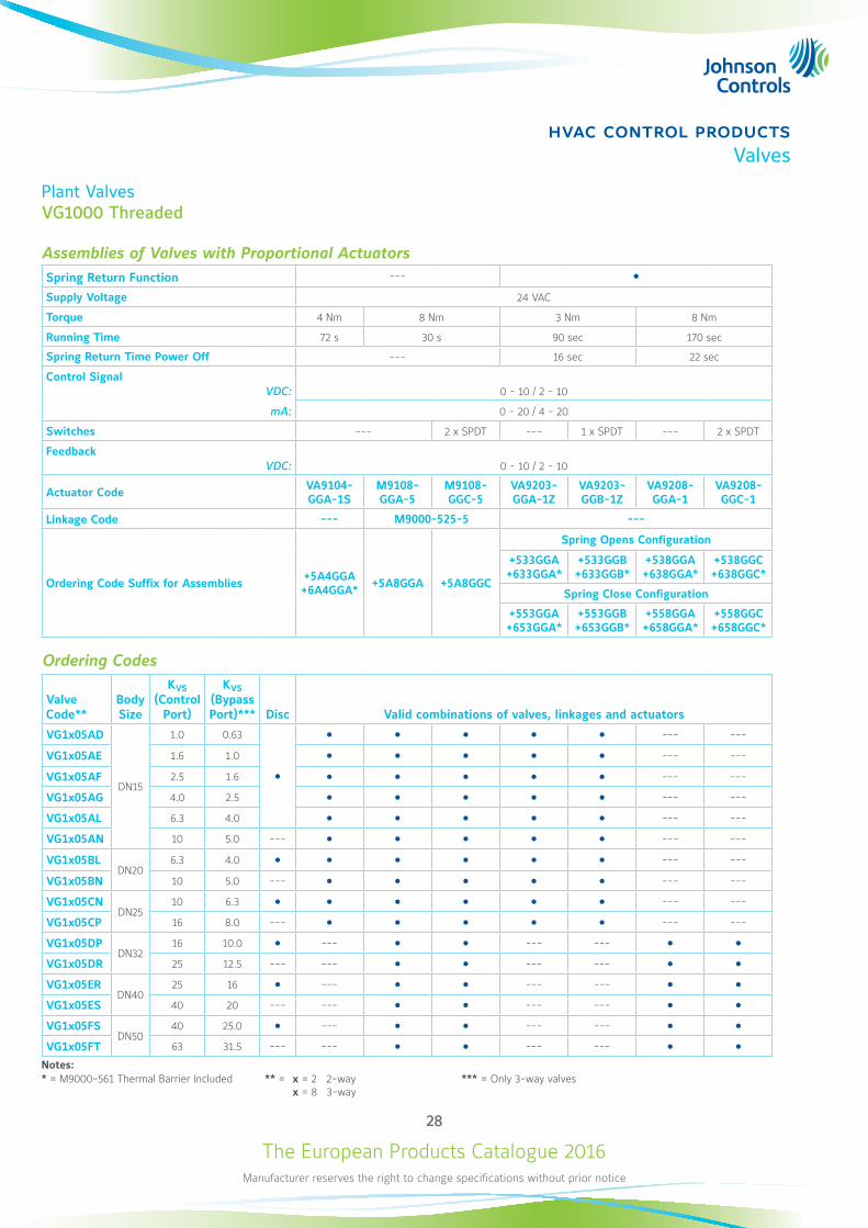
Plant ValvesVG1000 Threaded
Assemblies of Valves with Proportional ActuatorsSpring Return Function --- Supply Voltage 24 VAC
Torque 4 Nm 8 Nm 3 Nm 8 Nm
Running Time 72 s 30 s 90 sec 170 sec
Spring Return Time Power Off --- 16 sec 22 sec
Control SignalVDC: 0 - 10 / 2 - 10
mA: 0 - 20 / 4 - 20
Switches --- 2 x SPDT --- 1 x SPDT --- 2 x SPDT
FeedbackVDC: 0 - 10 / 2 - 10
Actuator Code VA9104- GGA-1S
M9108- GGA-5
M9108- GGC-5
VA9203- GGA-1Z
VA9203- GGB-1Z
VA9208-GGA-1
VA9208-GGC-1
Linkage Code --- M9000-525-5 ---
Ordering Code Suffix for Assemblies +5A4GGA +6A4GGA* +5A8GGA +5A8GGC
Spring Opens Configuration
+533GGA +633GGA*
+533GGB +633GGB*
+538GGA +638GGA*
+538GGC +638GGC*
Spring Close Configuration
+553GGA +653GGA*
+553GGB +653GGB*
+558GGA +658GGA*
+558GGC +658GGC*
Ordering Codes
Valve Code**
Body Size
KVS (Control
Port)
KVS (Bypass Port)*** Disc Valid combinations of valves, linkages and actuators
VG1x05AD
DN15
1.0 0.63
--- ---
VG1x05AE 1.6 1.0 --- ---
VG1x05AF 2.5 1.6 --- ---
VG1x05AG 4.0 2.5 --- ---
VG1x05AL 6.3 4.0 --- ---
VG1x05AN 10 5.0 --- --- ---
VG1x05BLDN20
6.3 4.0 --- ---
VG1x05BN 10 5.0 --- --- ---
VG1x05CNDN25
10 6.3 --- ---
VG1x05CP 16 8.0 --- --- ---
VG1x05DPDN32
16 10.0 --- --- --- VG1x05DR 25 12.5 --- --- --- --- VG1x05ER
DN4025 16 --- --- ---
VG1x05ES 40 20 --- --- --- --- VG1x05FS
DN5040 25.0 --- --- ---
VG1x05FT 63 31.5 --- --- --- --- Notes:* = M9000-561 Thermal Barrier Included ** = x = 2 2-way
x = 8 3-way*** = Only 3-way valves
The European Products Catalogue 2016Manufacturer reserves the right to change specifications without prior notice
29
hvac control productsValves
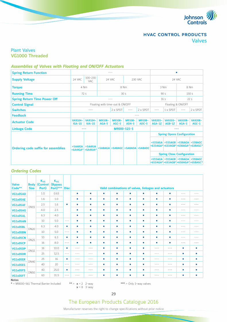
Plant ValvesVG1000 Threaded
Assemblies of Valves with Floating and ON/OFF ActuatorsSpring Return Function ---
Supply Voltage 24 VAC 100-230 VAC 24 VAC 230 VAC 24 VAC
Torque 4 Nm 8 Nm 3 Nm 8 Nm
Running Time 72 s 30 s 90 s 150 s
Spring Return Time Power Off --- 16 s 22 s
Control Signal Floating with time-out & ON/OFF Floating & ON/OFF
Switches --- 2 x SPDT --- 2 x SPDT --- 1 x SPDT --- 2 x SPDT
Feedback ---
Actuator Code VA9104- IGA-1S
VA9104-IUA-1S
M9108-AGA-5
M9108-AGC-5
M9108-ADA-5
M9108-ADC-5
VA9203- AGA-1Z
VA9203- AGB-1Z
VA9208-AGA-1
VA9208-AGC-1
Linkage Code --- M9000-525-5 ---
Ordering code suffix for assemblies +5A4IGA +6A4IGA*
+5A4IUA +6A4IUA* +5A8AGA +5A8AGC +5A8ADA +5A8ADC
Spring Opens Configuration
+533AGA +633AGA*
+533AGB +633AGB*
+538AGA +638AGA*
+538AGC +638AGC*
Spring Close Configuration
+553AGA +653AGA*
+553AGB +653AGB*
+558AGA +658AGA*
+558AGC +658AGC*
Ordering Codes
Valve Code**
Body Size
KVS (Control
Port)
KVS (Bypass Port)*** Disc Valid combinations of valves, linkages and actuators
VG1x05AD
DN15
1.0 0.63
--- ---
VG1x05AE 1.6 1.0 --- ---
VG1x05AF 2.5 1.6 --- ---
VG1x05AG 4.0 2.5 --- ---
VG1x05AL 6.3 4.0 --- ---
VG1x05AN 10 5.0 --- --- ---
VG1x05BLDN20
6.3 4.0 --- ---
VG1x05BN 10 5.0 --- --- ---
VG1x05CNDN25
10 6.3 --- ---
VG1x05CP 16 8.0 --- --- ---
VG1x05DPDN32
16 10.0 --- --- --- --- VG1x05DR 25 12.5 --- --- --- --- --- VG1x05ER
DN4025 16 --- --- --- ---
VG1x05ES 40 20 --- --- --- --- --- VG1x05FS
DN5040 25.0 --- --- --- ---
VG1x05FT 63 31.5 --- --- --- --- --- Notes* = M9000-561 Thermal Barrier Included ** = x = 2 2-way
x = 8 3-way*** = Only 3-way valves
The European Products Catalogue 2016Manufacturer reserves the right to change specifications without prior notice
30
hvac control productsValves
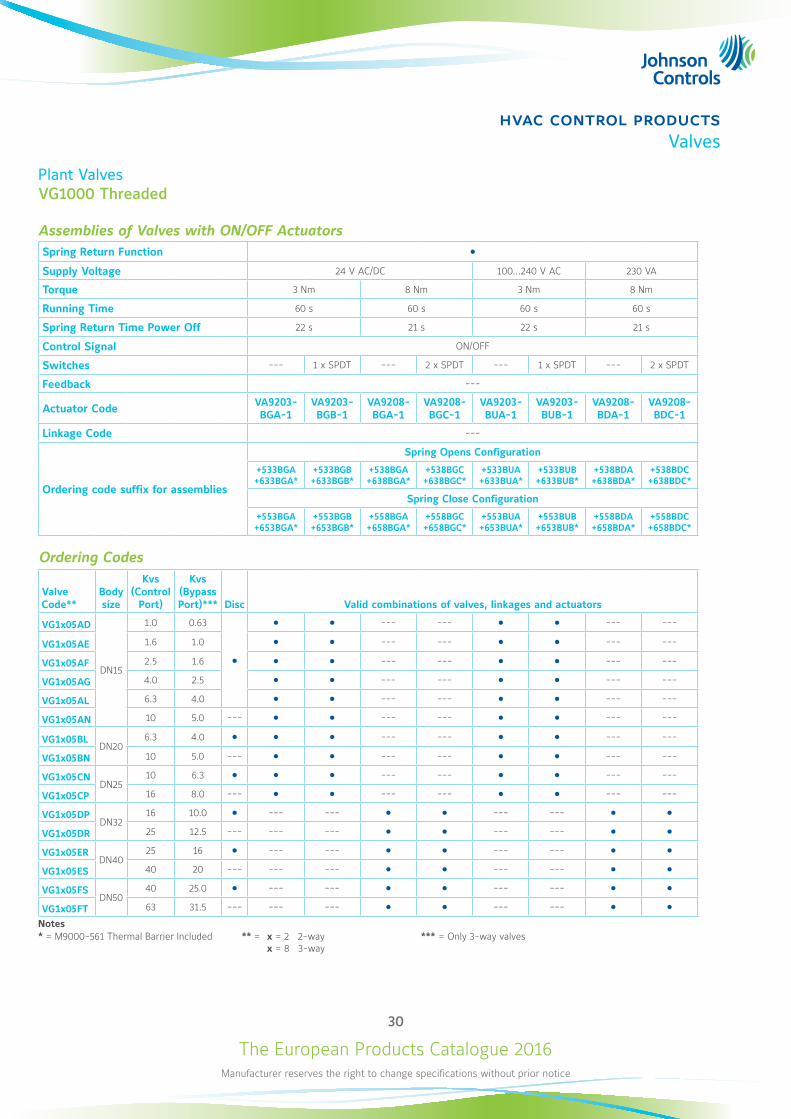
Plant ValvesVG1000 Threaded
Assemblies of Valves with ON/OFF ActuatorsSpring Return Function Supply Voltage 24 V AC/DC 100...240 V AC 230 VA
Torque 3 Nm 8 Nm 3 Nm 8 Nm
Running Time 60 s 60 s 60 s 60 s
Spring Return Time Power Off 22 s 21 s 22 s 21 s
Control Signal ON/OFF
Switches --- 1 x SPDT --- 2 x SPDT --- 1 x SPDT --- 2 x SPDT
Feedback ---
Actuator Code VA9203-BGA-1
VA9203-BGB-1
VA9208-BGA-1
VA9208-BGC-1
VA9203-BUA-1
VA9203-BUB-1
VA9208-BDA-1
VA9208-BDC-1
Linkage Code ---
Ordering code suffix for assemblies
Spring Opens Configuration
+533BGA +633BGA*
+533BGB +633BGB*
+538BGA +638BGA*
+538BGC +638BGC*
+533BUA +633BUA*
+533BUB +633BUB*
+538BDA +638BDA*
+538BDC +638BDC*
Spring Close Configuration
+553BGA +653BGA*
+553BGB +653BGB*
+558BGA +658BGA*
+558BGC +658BGC*
+553BUA +653BUA*
+553BUB +653BUB*
+558BDA +658BDA*
+558BDC +658BDC*
Ordering Codes
Valve Code**
Body size
Kvs (Control
Port)
Kvs (Bypass Port)*** Disc Valid combinations of valves, linkages and actuators
VG1x05AD
DN15
1.0 0.63
--- --- --- ---
VG1x05AE 1.6 1.0 --- --- --- ---
VG1x05AF 2.5 1.6 --- --- --- ---
VG1x05AG 4.0 2.5 --- --- --- ---
VG1x05AL 6.3 4.0 --- --- --- ---
VG1x05AN 10 5.0 --- --- --- --- ---
VG1x05BLDN20
6.3 4.0 --- --- --- ---
VG1x05BN 10 5.0 --- --- --- --- ---
VG1x05CNDN25
10 6.3 --- --- --- ---
VG1x05CP 16 8.0 --- --- --- --- ---
VG1x05DPDN32
16 10.0 --- --- --- --- VG1x05DR 25 12.5 --- --- --- --- --- VG1x05ER
DN4025 16 --- --- --- ---
VG1x05ES 40 20 --- --- --- --- --- VG1x05FS
DN5040 25.0 --- --- --- ---
VG1x05FT 63 31.5 --- --- --- --- --- Notes* = M9000-561 Thermal Barrier Included ** = x = 2 2-way
x = 8 3-way*** = Only 3-way valves
The European Products Catalogue 2016Manufacturer reserves the right to change specifications without prior notice
31
hvac control productsValves
Plant Valves
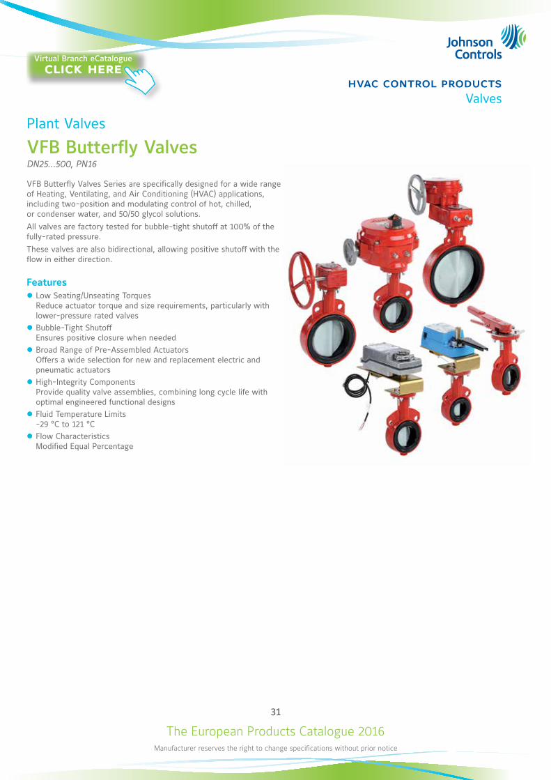
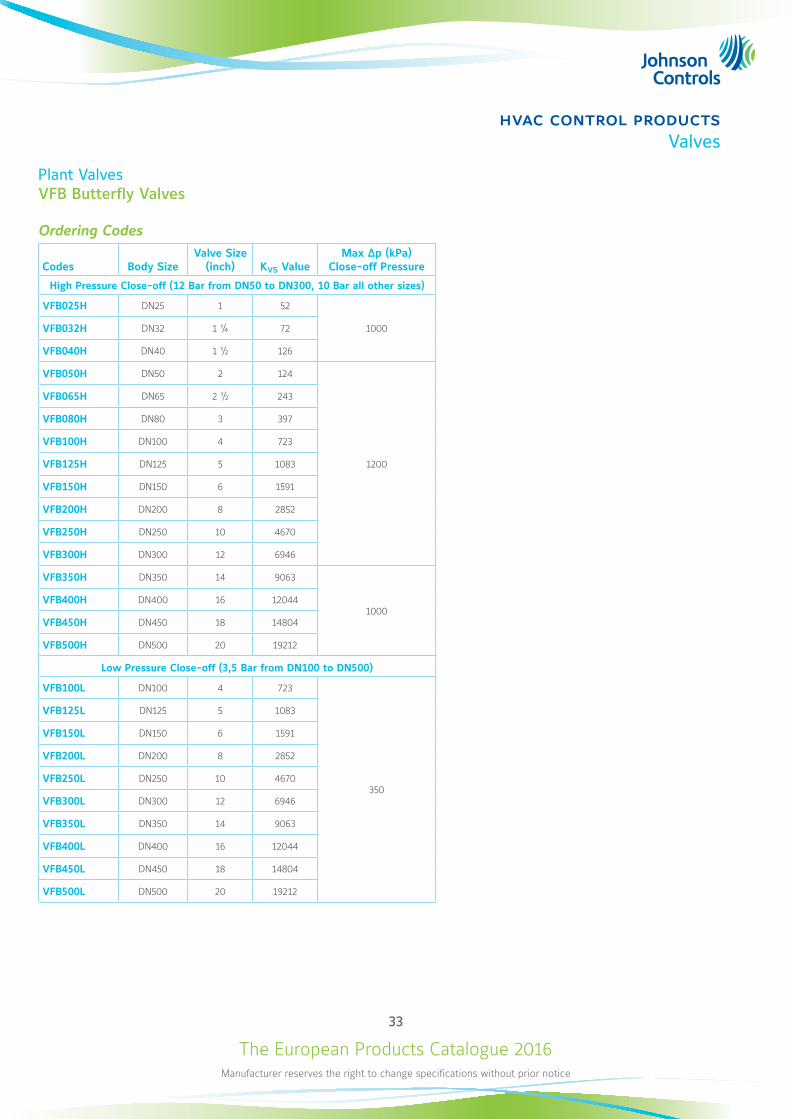
VFB Butterfly ValvesDN25...500, PN16
VFB Butterfly Valves Series are specifically designed for a wide range of Heating, Ventilating, and Air Conditioning (HVAC) applications, including two-position and modulating control of hot, chilled, or condenser water, and 50/50 glycol solutions.All valves are factory tested for bubble-tight shutoff at 100% of the fully-rated pressure. These valves are also bidirectional, allowing positive shutoff with the flow in either direction.
Features z Low Seating/Unseating Torques Reduce actuator torque and size requirements, particularly with lower-pressure rated valves
z Bubble-Tight Shutoff Ensures positive closure when needed
z Broad Range of Pre-Assembled Actuators Offers a wide selection for new and replacement electric and pneumatic actuators
z High-Integrity Components Provide quality valve assemblies, combining long cycle life with optimal engineered functional designs
z Fluid Temperature Limits -29 °C to 121 °C
z Flow Characteristics Modified Equal Percentage
Virtual Branch eCatalogueclick here
The European Products Catalogue 2016Manufacturer reserves the right to change specifications without prior notice
32
hvac control productsValves
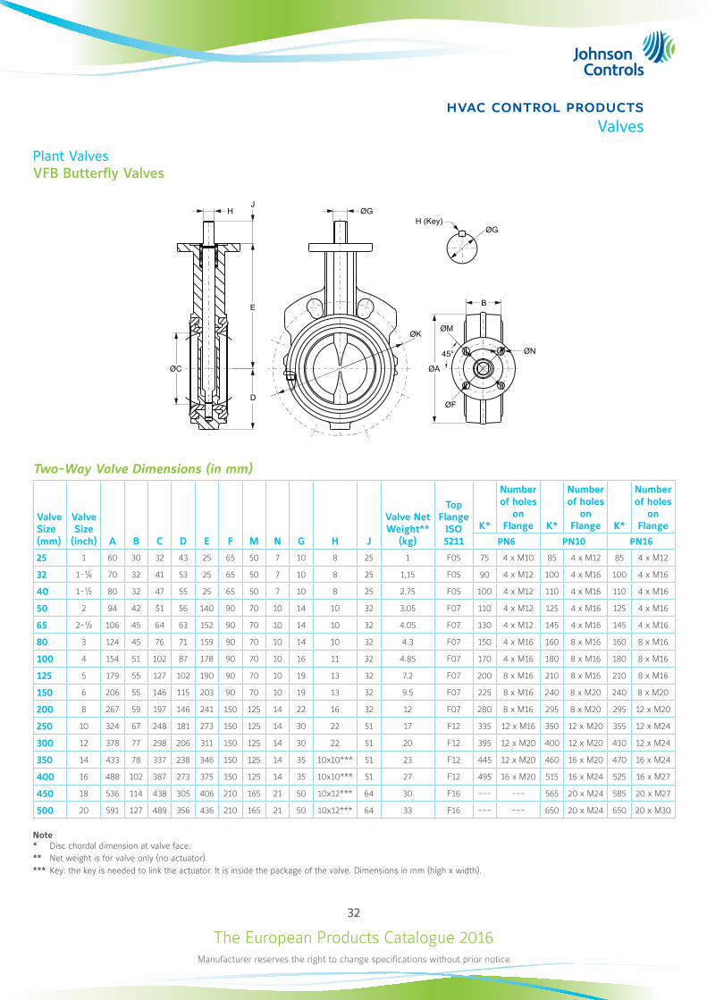
Plant ValvesVFB Butterfly Valves
HJ
E
D
ØC
ØK
ØG
ØGH (Key)
B
45°
ØM
ØN
ØA
ØF
Two-Way Valve Dimensions (in mm)
Valve Size (mm)
Valve Size
(inch) A B C D E F M N G H J
Valve Net Weight**
(kg)
Top Flange
ISO 5211
K*
Number of holes
on Flange K*
Number of holes
on Flange K*
Number of holes
on Flange
PN6 PN10 PN16
25 1 60 30 32 43 25 65 50 7 10 8 25 1 F05 75 4 x M10 85 4 x M12 85 4 x M12
32 1-¼ 70 32 41 53 25 65 50 7 10 8 25 1,15 F05 90 4 x M12 100 4 x M16 100 4 x M16
40 1-½ 80 32 47 55 25 65 50 7 10 8 25 2.75 F05 100 4 x M12 110 4 x M16 110 4 x M16
50 2 94 42 51 56 140 90 70 10 14 10 32 3.05 F07 110 4 x M12 125 4 x M16 125 4 x M16
65 2-½ 106 45 64 63 152 90 70 10 14 10 32 4.05 F07 130 4 x M12 145 4 x M16 145 4 x M16
80 3 124 45 76 71 159 90 70 10 14 10 32 4.3 F07 150 4 x M16 160 8 x M16 160 8 x M16
100 4 154 51 102 87 178 90 70 10 16 11 32 4.85 F07 170 4 x M16 180 8 x M16 180 8 x M16
125 5 179 55 127 102 190 90 70 10 19 13 32 7.2 F07 200 8 x M16 210 8 x M16 210 8 x M16
150 6 206 55 146 115 203 90 70 10 19 13 32 9.5 F07 225 8 x M16 240 8 x M20 240 8 x M20
200 8 267 59 197 146 241 150 125 14 22 16 32 12 F07 280 8 x M16 295 8 x M20 295 12 x M20
250 10 324 67 248 181 273 150 125 14 30 22 51 17 F12 335 12 x M16 350 12 x M20 355 12 x M24
300 12 378 77 298 206 311 150 125 14 30 22 51 20 F12 395 12 x M20 400 12 x M20 410 12 x M24
350 14 433 78 337 238 346 150 125 14 35 10x10*** 51 23 F12 445 12 x M20 460 16 x M20 470 16 x M24
400 16 488 102 387 273 375 150 125 14 35 10x10*** 51 27 F12 495 16 x M20 515 16 x M24 525 16 x M27
450 18 536 114 438 305 406 210 165 21 50 10x12*** 64 30 F16 --- --- 565 20 x M24 585 20 x M27
500 20 591 127 489 356 436 210 165 21 50 10x12*** 64 33 F16 --- --- 650 20 x M24 650 20 x M30
Note* Disc chordal dimension at valve face.** Net weight is for valve only (no actuator).*** Key: the key is needed to link the actuator. It is inside the package of the valve. Dimensions in mm (high x width).
The European Products Catalogue 2016Manufacturer reserves the right to change specifications without prior notice
33
hvac control productsValves
Plant ValvesVFB Butterfly Valves
Ordering Codes
Codes Body SizeValve Size
(inch) KVS ValueMax Δp (kPa)
Close-off Pressure
High Pressure Close-off (12 Bar from DN50 to DN300, 10 Bar all other sizes)
VFB025H DN25 1 52
1000 VFB032H DN32 1 ¼ 72
VFB040H DN40 1 ½ 126
VFB050H DN50 2 124
1200
VFB065H DN65 2 ½ 243
VFB080H DN80 3 397
VFB100H DN100 4 723
VFB125H DN125 5 1083
VFB150H DN150 6 1591
VFB200H DN200 8 2852
VFB250H DN250 10 4670
VFB300H DN300 12 6946
VFB350H DN350 14 9063
1000VFB400H DN400 16 12044
VFB450H DN450 18 14804
VFB500H DN500 20 19212
Low Pressure Close-off (3,5 Bar from DN100 to DN500)
VFB100L DN100 4 723
350
VFB125L DN125 5 1083
VFB150L DN150 6 1591
VFB200L DN200 8 2852
VFB250L DN250 10 4670
VFB300L DN300 12 6946
VFB350L DN350 14 9063
VFB400L DN400 16 12044
VFB450L DN450 18 14804
VFB500L DN500 20 19212
The European Products Catalogue 2016Manufacturer reserves the right to change specifications without prior notice
34
hvac control productsValves
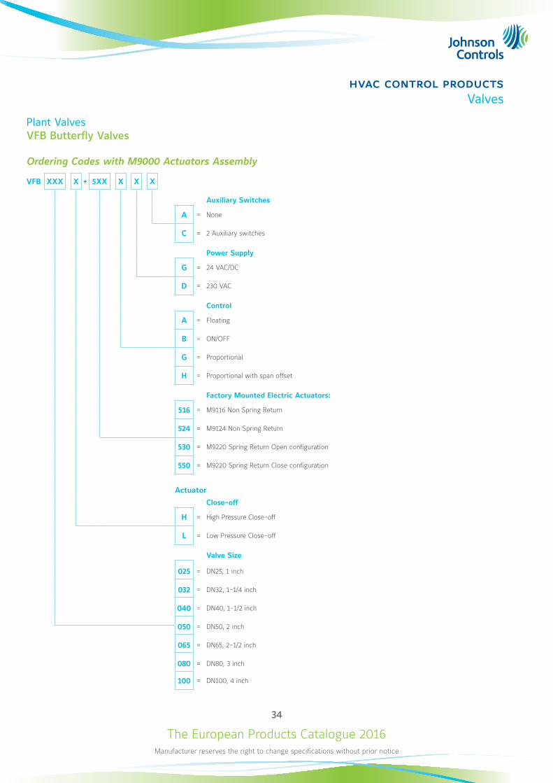
Plant ValvesVFB Butterfly Valves
Ordering Codes with M9000 Actuators Assembly
VFB XXX X + 5XX X X X
Auxiliary Switches
A = None
C = 2 Auxiliary switches
Power Supply
G = 24 VAC/DC
D = 230 VAC
Control
A = Floating
B = ON/OFF
G = Proportional
H = Proportional with span offset
Factory Mounted Electric Actuators:
516 = M9116 Non Spring Return
524 = M9124 Non Spring Return
530 = M9220 Spring Return Open configuration
550 = M9220 Spring Return Close configuration
Actuator
Close-off
H = High Pressure Close-off
L = Low Pressure Close-off
Valve Size
025 = DN25, 1 inch
032 = DN32, 1-1/4 inch
040 = DN40, 1-1/2 inch
050 = DN50, 2 inch
065 = DN65, 2-1/2 inch
080 = DN80, 3 inch
100 = DN100, 4 inch
The European Products Catalogue 2016Manufacturer reserves the right to change specifications without prior notice
35
hvac control productsValves
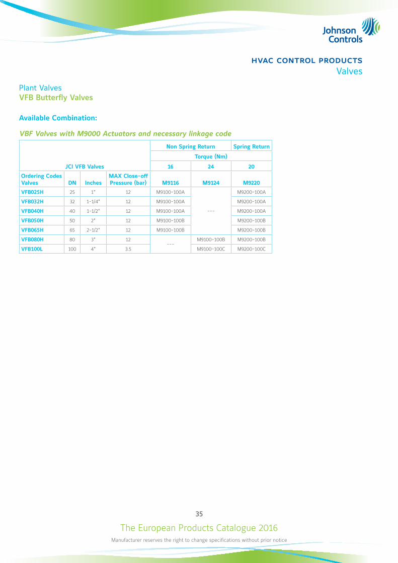
Plant ValvesVFB Butterfly Valves
Available Combination:
VBF Valves with M9000 Actuators and necessary linkage code
JCI VFB Valves
Non Spring Return Spring Return
Torque (Nm)
16 24 20
Ordering Codes Valves DN Inches
MAX Close-off Pressure (bar) M9116 M9124 M9220
VFB025H 25 1" 12 M9100-100A
---
M9200-100A
VFB032H 32 1-1/4" 12 M9100-100A M9200-100A
VFB040H 40 1-1/2" 12 M9100-100A M9200-100A
VFB050H 50 2" 12 M9100-100B M9200-100B
VFB065H 65 2-1/2" 12 M9100-100B M9200-100B
VFB080H 80 3" 12---
M9100-100B M9200-100B
VFB100L 100 4" 3.5 M9100-100C M9200-100C
The European Products Catalogue 2016Manufacturer reserves the right to change specifications without prior notice
36
hvac control productsValves
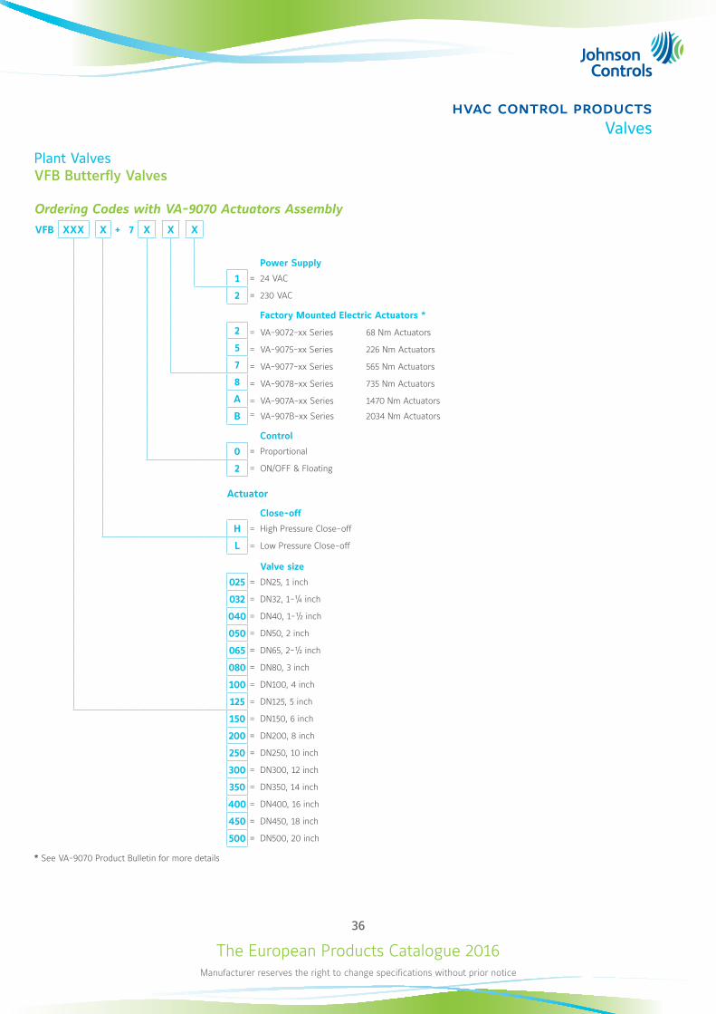
Plant ValvesVFB Butterfly Valves
Ordering Codes with VA-9070 Actuators Assembly VFB XXX X + 7 X X X
Power Supply
1 = 24 VAC
2 = 230 VAC
Factory Mounted Electric Actuators *
2 = VA-9072-xx Series 68 Nm Actuators
5 = VA-9075-xx Series 226 Nm Actuators
7 = VA-9077-xx Series 565 Nm Actuators
8 = VA-9078-xx Series 735 Nm Actuators
A = VA-907A-xx Series 1470 Nm Actuators
B = VA-907B-xx Series 2034 Nm Actuators
Control
0 = Proportional
2 = ON/OFF & Floating
Actuator
Close-off
H = High Pressure Close-off
L = Low Pressure Close-off
Valve size
025 = DN25, 1 inch
032 = DN32, 1-¼ inch
040 = DN40, 1-½ inch
050 = DN50, 2 inch
065 = DN65, 2-½ inch
080 = DN80, 3 inch
100 = DN100, 4 inch
125 = DN125, 5 inch
150 = DN150, 6 inch
200 = DN200, 8 inch
250 = DN250, 10 inch
300 = DN300, 12 inch
350 = DN350, 14 inch
400 = DN400, 16 inch
450 = DN450, 18 inch
500 = DN500, 20 inch
* See VA-9070 Product Bulletin for more details
The European Products Catalogue 2016Manufacturer reserves the right to change specifications without prior notice
37
hvac control productsValves
Plant ValvesVFB Butterfly Valves
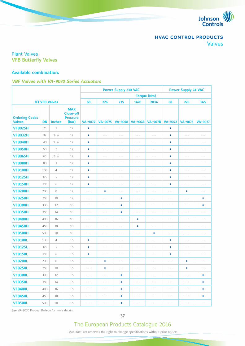
Available combination:
VBF Valves with VA-9070 Series Actuators
JCI VFB Valves
Power Supply 230 VAC Power Supply 24 VAC
Torque (Nm)
68 226 735 1470 2034 68 226 565
Ordering Codes Valves DN Inches
MAX Close-off Pressure
(bar) VA-9072 VA-9075 VA-9078 VA-907A VA-907B VA-9072 VA-9075 VA-9077
VFB025H 25 1 12 --- --- --- --- --- ---
VFB032H 32 1-¼ 12 --- --- --- --- --- ---
VFB040H 40 1-½ 12 --- --- --- --- --- ---
VFB050H 50 2 12 --- --- --- --- --- ---
VFB065H 65 2-½ 12 --- --- --- --- --- ---
VFB080H 80 3 12 --- --- --- --- --- ---
VFB100H 100 4 12 --- --- --- --- --- ---
VFB125H 125 5 12 --- --- --- --- --- ---
VFB150H 150 6 12 --- --- --- --- --- ---
VFB200H 200 8 12 --- --- --- --- --- ---
VFB250H 250 10 12 --- --- --- --- --- ---
VFB300H 300 12 10 --- --- --- --- --- ---
VFB350H 350 14 10 --- --- --- --- --- --- ---
VFB400H 400 16 10 --- --- --- --- --- --- ---
VFB450H 450 18 10 --- --- --- --- --- --- ---
VFB500H 500 20 10 --- --- --- --- --- --- ---
VFB100L 100 4 3.5 --- --- --- --- --- ---
VFB125L 125 5 3.5 --- --- --- --- --- ---
VFB150L 150 6 3.5 --- --- --- --- --- ---
VFB200L 200 8 3.5 --- --- --- --- --- ---
VFB250L 250 10 3.5 --- --- --- --- --- ---
VFB300L 300 12 3.5 --- --- --- --- --- ---
VFB350L 350 14 3.5 --- --- --- --- --- ---
VFB400L 400 16 3.5 --- --- --- --- --- ---
VFB450L 450 18 3.5 --- --- --- --- --- ---
VFB500L 500 20 3.5 --- --- --- --- --- --- ---
See VA-9070 Product Bulletin for more details.
The European Products Catalogue 2016Manufacturer reserves the right to change specifications without prior notice
38
hvac control productsValves
Plant ValvesVFB Butterfly Valves
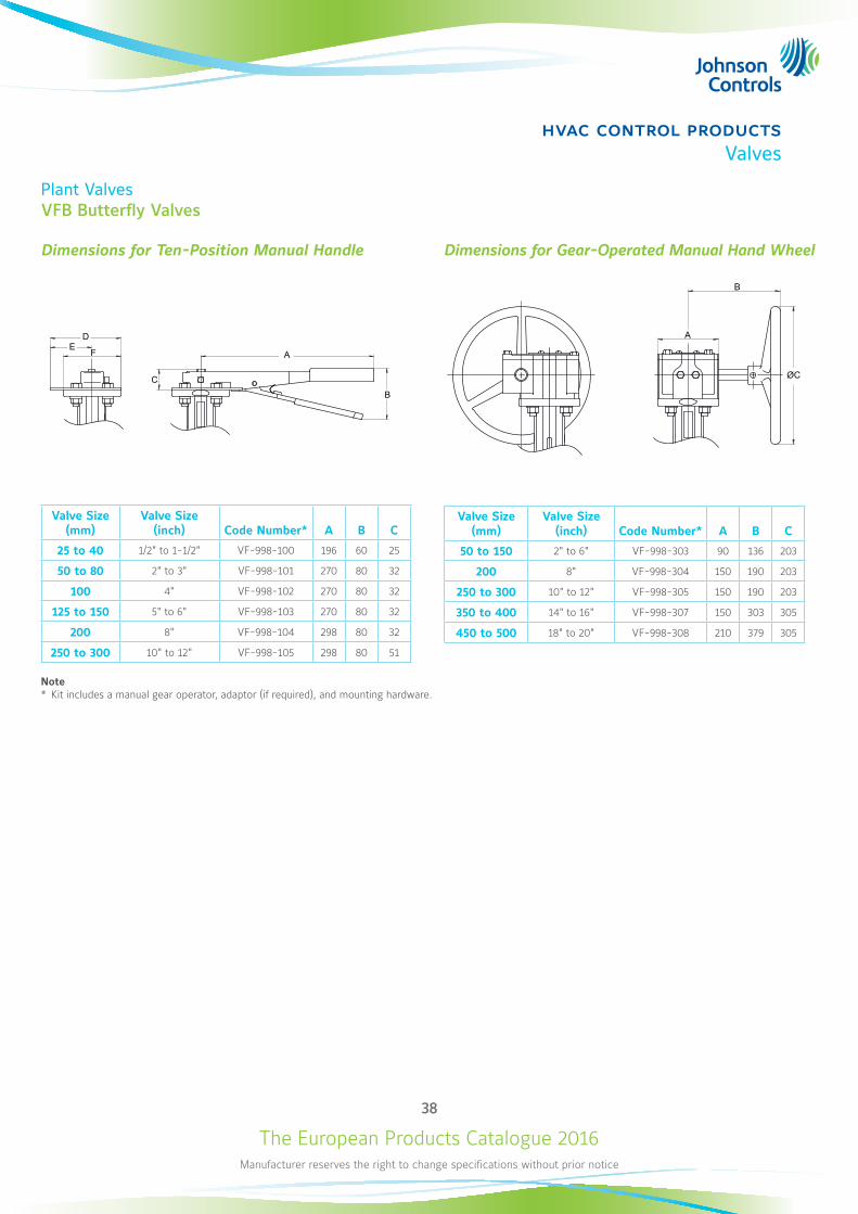
Dimensions for Ten-Position Manual Handle
C
FE
D
A
B
Valve Size (mm)
Valve Size (inch) Code Number* A B C
25 to 40 1/2" to 1-1/2" VF-998-100 196 60 25
50 to 80 2" to 3" VF-998-101 270 80 32
100 4" VF-998-102 270 80 32
125 to 150 5" to 6" VF-998-103 270 80 32
200 8" VF-998-104 298 80 32
250 to 300 10" to 12" VF-998-105 298 80 51
Dimensions for Gear-Operated Manual Hand Wheel
B
A
ØC
Valve Size (mm)
Valve Size (inch) Code Number* A B C
50 to 150 2" to 6" VF-998-303 90 136 203
200 8" VF-998-304 150 190 203
250 to 300 10" to 12" VF-998-305 150 190 203
350 to 400 14" to 16" VF-998-307 150 303 305
450 to 500 18" to 20" VF-998-308 210 379 305
Note* Kit includes a manual gear operator, adaptor (if required), and mounting hardware.
The European Products Catalogue 2016Manufacturer reserves the right to change specifications without prior notice
39
hvac control productsValves
Pressure Independent Valves
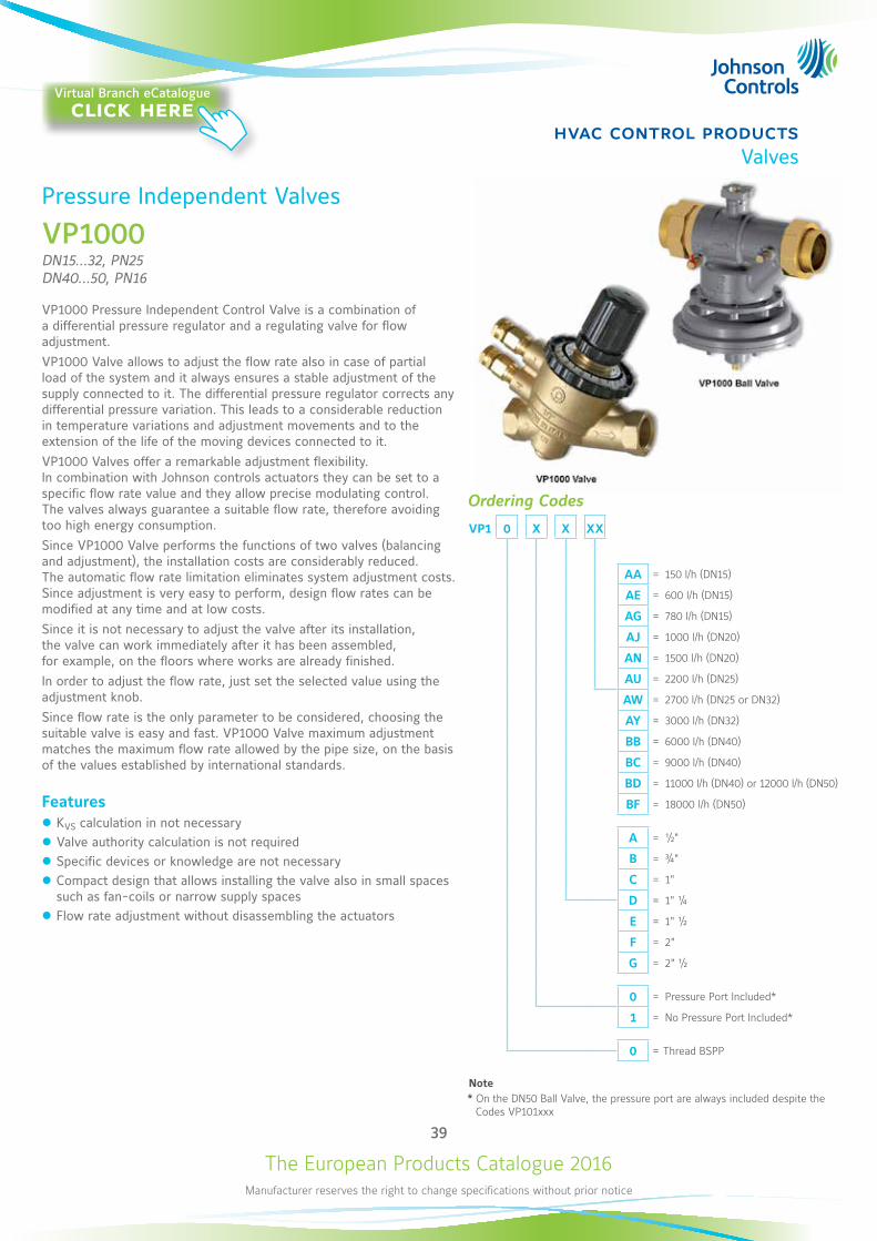
VP1000DN15...32, PN25 DN40...50, PN16
VP1000 Pressure Independent Control Valve is a combination of a differential pressure regulator and a regulating valve for flow adjustment. VP1000 Valve allows to adjust the flow rate also in case of partial load of the system and it always ensures a stable adjustment of the supply connected to it. The differential pressure regulator corrects any differential pressure variation. This leads to a considerable reduction in temperature variations and adjustment movements and to the extension of the life of the moving devices connected to it. VP1000 Valves offer a remarkable adjustment flexibility. In combination with Johnson controls actuators they can be set to a specific flow rate value and they allow precise modulating control. The valves always guarantee a suitable flow rate, therefore avoiding too high energy consumption. Since VP1000 Valve performs the functions of two valves (balancing and adjustment), the installation costs are considerably reduced. The automatic flow rate limitation eliminates system adjustment costs. Since adjustment is very easy to perform, design flow rates can be modified at any time and at low costs.Since it is not necessary to adjust the valve after its installation, the valve can work immediately after it has been assembled, for example, on the floors where works are already finished.In order to adjust the flow rate, just set the selected value using the adjustment knob.Since flow rate is the only parameter to be considered, choosing the suitable valve is easy and fast. VP1000 Valve maximum adjustment matches the maximum flow rate allowed by the pipe size, on the basis of the values established by international standards.
Features z KVS calculation in not necessary z Valve authority calculation is not required z Specific devices or knowledge are not necessary z Compact design that allows installing the valve also in small spaces such as fan-coils or narrow supply spaces
z Flow rate adjustment without disassembling the actuators
Ordering Codes
VP1 0 X X XX
AA = 150 l/h (DN15)
AE = 600 l/h (DN15)
AG = 780 l/h (DN15)
AJ = 1000 l/h (DN20)
AN = 1500 l/h (DN20)
AU = 2200 l/h (DN25)
AW = 2700 l/h (DN25 or DN32)
AY = 3000 l/h (DN32)
BB = 6000 l/h (DN40)
BC = 9000 l/h (DN40)
BD = 11000 l/h (DN40) or 12000 l/h (DN50)
BF = 18000 l/h (DN50)
A = ½"
B = ¾"
C = 1"
D = 1" ¼
E = 1" ½
F = 2"
G = 2" ½
0 = Pressure Port Included*
1 = No Pressure Port Included*
0 = Thread BSPP
Note* On the DN50 Ball Valve, the pressure port are always included despite the Codes VP101xxx
Virtual Branch eCatalogueclick here
The European Products Catalogue 2016Manufacturer reserves the right to change specifications without prior notice
40
hvac control productsValves
Pressure Independent Valves VP1000
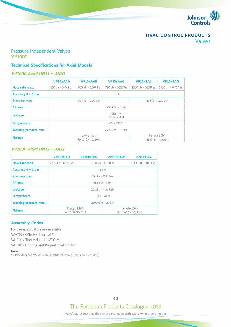
Technical Specifications for Axial Models
VP1000 Axial DN15 - DN20
VP10xAAA VP10xAAE VP10xAAG VP10xBAJ VP10xBAN
Flow rate max. 150 l/h - 0,042 l/s 600 l/h - 0,167 l/s 780 l/h - 0,217 l/s 1000 l/h - 0,278 l/s 1500 l/h - 0,417 l/s
Accuracy 0 ÷ 1 bar ± 5%
Start-up max. 20 kPa - 0,20 bar 25 kPa - 0,25 bar
ΔP max. 600 kPa - 6 bar
Leakage Class IV IEC 60534-4
Temperature -10 ÷ 120 °C
Working pressure max. 2500 kPa - 25 Bar
Fittings Female BSPP Rp ½" EN 10226-1
Female BSPPRp ¾" EN 10226-1
VP1000 Axial DN25 - DN32
VP100CAU VP100CAW VP100DAW VP100DAY
Flow rate max. 2200 l/h - 0,611 l/s 2700 l/h - 0,750 l/s 3000 l/h - 0,833 l/s
Accuracy 0 ÷ 1 bar ± 5%
Start-up max. 25 kPa - 0,25 bar
ΔP max. 600 kPa - 6 bar
Leakage 0,01% of Flow Rate
Temperature -10 ÷ 120 °C
Working pressure max. 2500 kPa - 25 Bar
Fittings Female BSPP Rc 1" EN 10226-1
Female BSPPRc 1 ¼" EN 10226-1
Assembly CodesFollowing actuators are availableVA-707x ON/OFF Thermal *;VA-709x Thermal 0...10 VDC *;VA-748x Floating and Proportional Electric.
Note * : (VA-707x and VA-709x are suitable for valves DN15 and DN20 only)
The European Products Catalogue 2016Manufacturer reserves the right to change specifications without prior notice
41
hvac control productsValves
Pressure Independent Valves VP1000
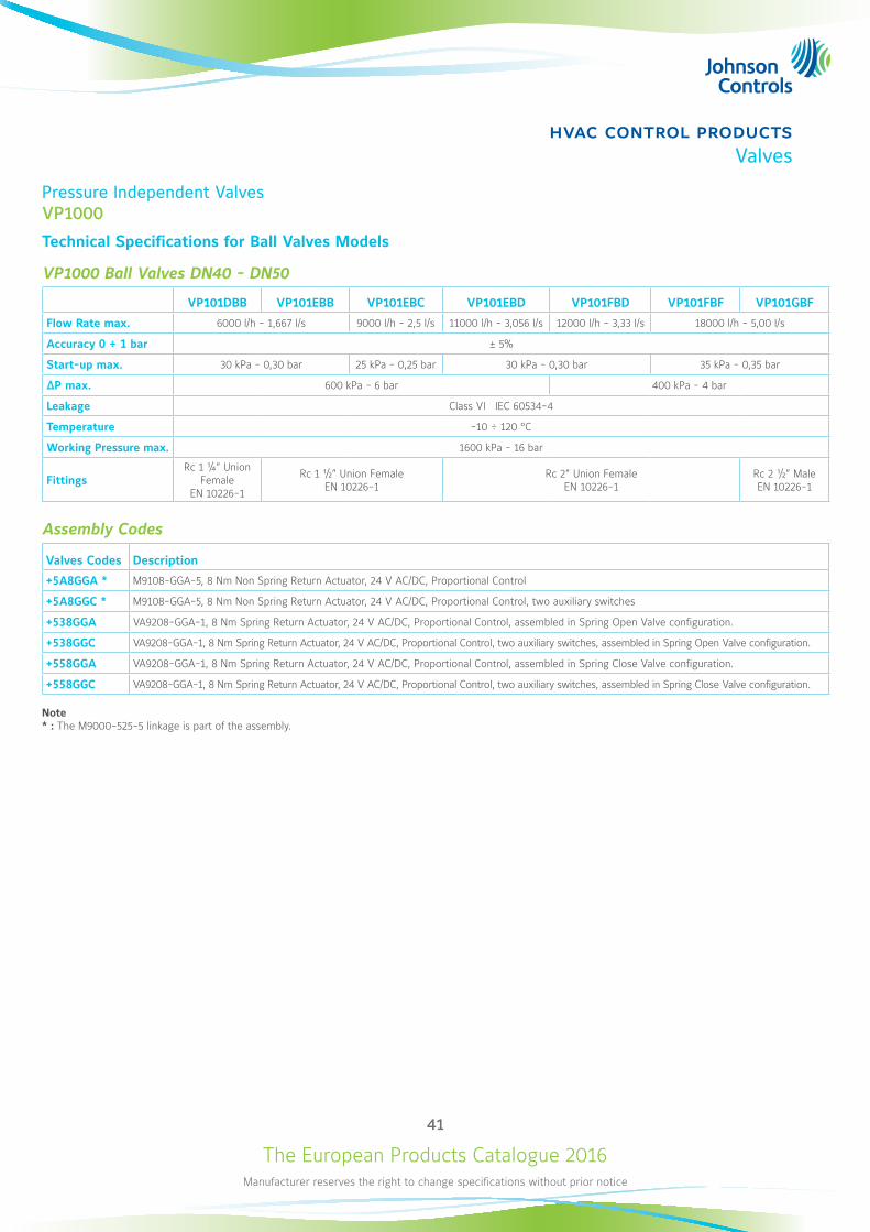
Technical Specifications for Ball Valves Models
VP1000 Ball Valves DN40 - DN50
VP101DBB VP101EBB VP101EBC VP101EBD VP101FBD VP101FBF VP101GBF
Flow Rate max. 6000 l/h - 1,667 l/s 9000 l/h - 2,5 l/s 11000 l/h - 3,056 l/s 12000 l/h - 3,33 l/s 18000 l/h - 5,00 l/s
Accuracy 0 ÷ 1 bar ± 5%
Start-up max. 30 kPa - 0,30 bar 25 kPa - 0,25 bar 30 kPa - 0,30 bar 35 kPa - 0,35 bar
ΔP max. 600 kPa - 6 bar 400 kPa - 4 bar
Leakage Class VI IEC 60534-4
Temperature -10 ÷ 120 °C
Working Pressure max. 1600 kPa - 16 bar
FittingsRc 1 ¼” Union
Female EN 10226-1
Rc 1 ½” Union Female EN 10226-1
Rc 2” Union Female EN 10226-1
Rc 2 ½” Male EN 10226-1
Assembly Codes
Valves Codes Description
+5A8GGA * M9108-GGA-5, 8 Nm Non Spring Return Actuator, 24 V AC/DC, Proportional Control
+5A8GGC * M9108-GGA-5, 8 Nm Non Spring Return Actuator, 24 V AC/DC, Proportional Control, two auxiliary switches
+538GGA VA9208-GGA-1, 8 Nm Spring Return Actuator, 24 V AC/DC, Proportional Control, assembled in Spring Open Valve configuration.
+538GGC VA9208-GGA-1, 8 Nm Spring Return Actuator, 24 V AC/DC, Proportional Control, two auxiliary switches, assembled in Spring Open Valve configuration.
+558GGA VA9208-GGA-1, 8 Nm Spring Return Actuator, 24 V AC/DC, Proportional Control, assembled in Spring Close Valve configuration.
+558GGC VA9208-GGA-1, 8 Nm Spring Return Actuator, 24 V AC/DC, Proportional Control, two auxiliary switches, assembled in Spring Close Valve configuration.
Note * : The M9000-525-5 linkage is part of the assembly.
The European Products Catalogue 2016Manufacturer reserves the right to change specifications without prior notice
42
hvac control productsValves
B
C
D
E
A
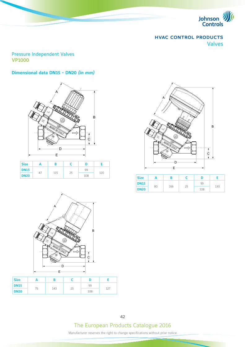
Size A B C D E
DN1580 166 25
99130
DN20 108
Pressure Independent Valves VP1000
Dimensional data DN15 - DN20 (in mm)
B
C
D
E
A
Size A B C D E
DN1547 115 25
99120
DN20 108
B
C
D
E
A
Size A B C D E
DN1575 143 25
99127
DN20 108
The European Products Catalogue 2016Manufacturer reserves the right to change specifications without prior notice
43
hvac control productsValves
B
C
D
A
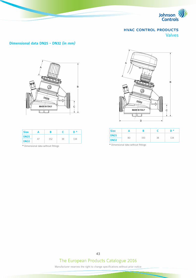
Size A B C D *
DN2580 193 38 134
DN32
* Dimensional data without fittings
Dimensional data DN25 - DN32 (in mm)
A
B
C
D
Size A B C D *
DN2547 152 38 134
DN32
* Dimensional data without fittings
The European Products Catalogue 2016Manufacturer reserves the right to change specifications without prior notice
44
hvac control productsValves
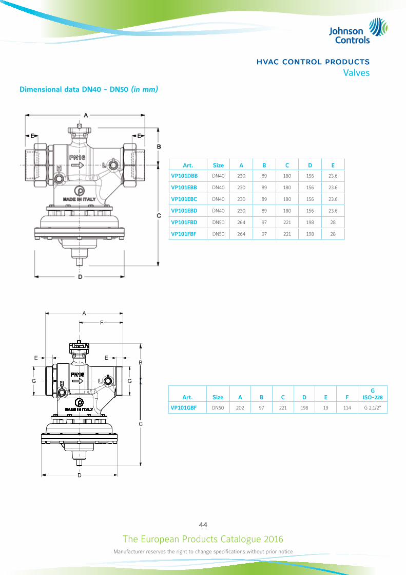
Dimensional data DN40 - DN50 (in mm)
D
C
A
E E B
F
G G
Art. Size A B C D E FG
ISO-228
VP101GBF DN50 202 97 221 198 19 114 G 2.1/2"
Art. Size A B C D E
VP101DBB DN40 230 89 180 156 23.6
VP101EBB DN40 230 89 180 156 23.6
VP101EBC DN40 230 89 180 156 23.6
VP101EBD DN40 230 89 180 156 23.6
VP101FBD DN50 264 97 221 198 28
VP101FBF DN50 264 97 221 198 28
The European Products Catalogue 2016Manufacturer reserves the right to change specifications without prior notice
45
hvac control productsValves
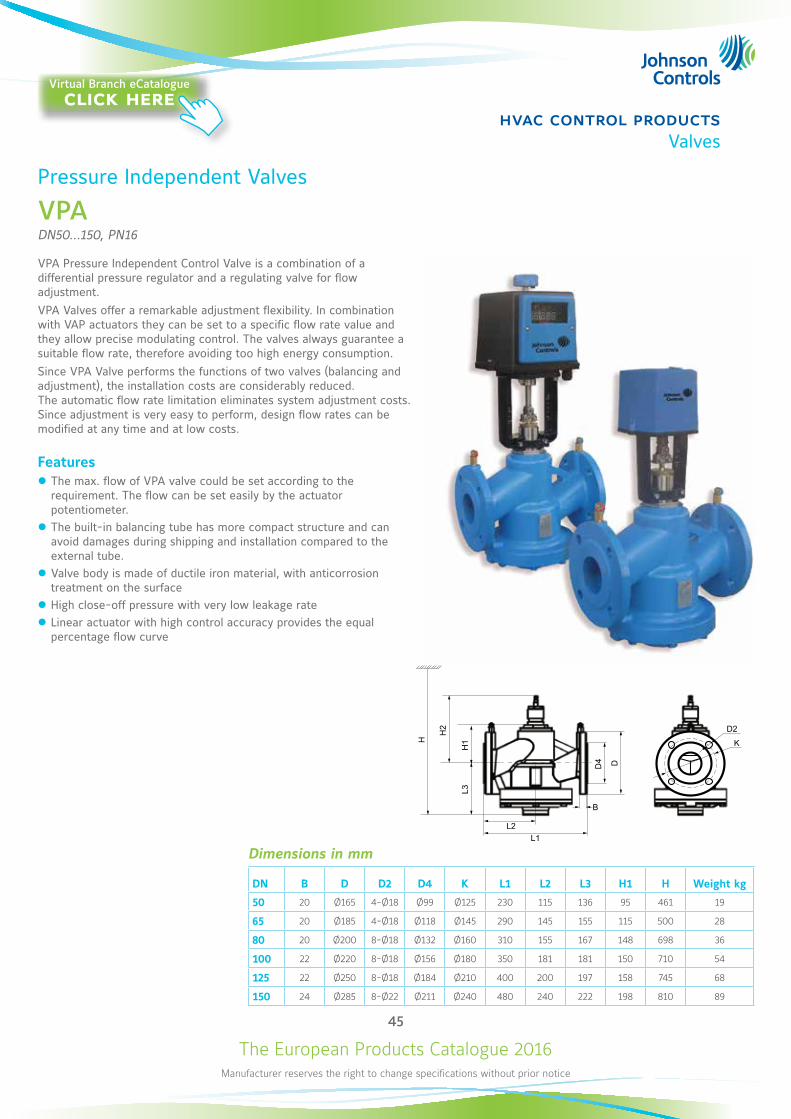
Pressure Independent Valves
VPADN50...150, PN16
VPA Pressure Independent Control Valve is a combination of a differential pressure regulator and a regulating valve for flow adjustment.VPA Valves offer a remarkable adjustment flexibility. In combination with VAP actuators they can be set to a specific flow rate value and they allow precise modulating control. The valves always guarantee a suitable flow rate, therefore avoiding too high energy consumption. Since VPA Valve performs the functions of two valves (balancing and adjustment), the installation costs are considerably reduced. The automatic flow rate limitation eliminates system adjustment costs. Since adjustment is very easy to perform, design flow rates can be modified at any time and at low costs.
Features z The max. flow of VPA valve could be set according to the requirement. The flow can be set easily by the actuator potentiometer.
z The built-in balancing tube has more compact structure and can avoid damages during shipping and installation compared to the external tube.
z Valve body is made of ductile iron material, with anticorrosion treatment on the surface
z High close-off pressure with very low leakage rate z Linear actuator with high control accuracy provides the equal percentage flow curve
L1
B
L2
L3
H
D4
H1
D
H2
K
D2
Dimensions in mm
DN B D D2 D4 K L1 L2 L3 H1 H Weight kg
50 20 Ø165 4-Ø18 Ø99 Ø125 230 115 136 95 461 19
65 20 Ø185 4-Ø18 Ø118 Ø145 290 145 155 115 500 28
80 20 Ø200 8-Ø18 Ø132 Ø160 310 155 167 148 698 36
100 22 Ø220 8-Ø18 Ø156 Ø180 350 181 181 150 710 54
125 22 Ø250 8-Ø18 Ø184 Ø210 400 200 197 158 745 68
150 24 Ø285 8-Ø22 Ø211 Ø240 480 240 222 198 810 89
Virtual Branch eCatalogueclick here
The European Products Catalogue 2016Manufacturer reserves the right to change specifications without prior notice
46
hvac control productsValves
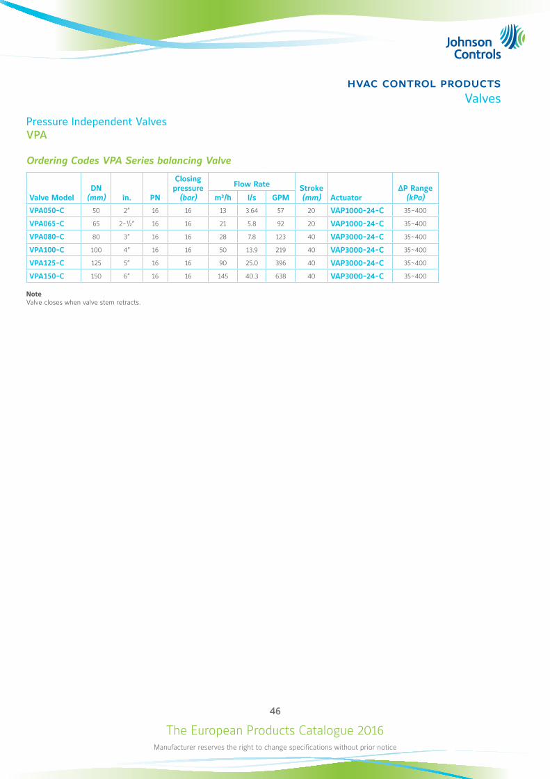
Pressure Independent Valves VPA
Ordering Codes VPA Series balancing Valve
Valve ModelDN
(mm) in. PN
Closing pressure
(bar)
Flow Rate Stroke (mm) Actuator
ΔP Range (kPa)m³/h l/s GPM
VPA050-C 50 2” 16 16 13 3.64 57 20 VAP1000-24-C 35~400
VPA065-C 65 2-½” 16 16 21 5.8 92 20 VAP1000-24-C 35~400
VPA080-C 80 3” 16 16 28 7.8 123 40 VAP3000-24-C 35~400
VPA100-C 100 4” 16 16 50 13.9 219 40 VAP3000-24-C 35~400
VPA125-C 125 5” 16 16 90 25.0 396 40 VAP3000-24-C 35~400
VPA150-C 150 6” 16 16 145 40.3 638 40 VAP3000-24-C 35~400
NoteValve closes when valve stem retracts.
The European Products Catalogue 2016Manufacturer reserves the right to change specifications without prior notice
47
hvac control productsActuators
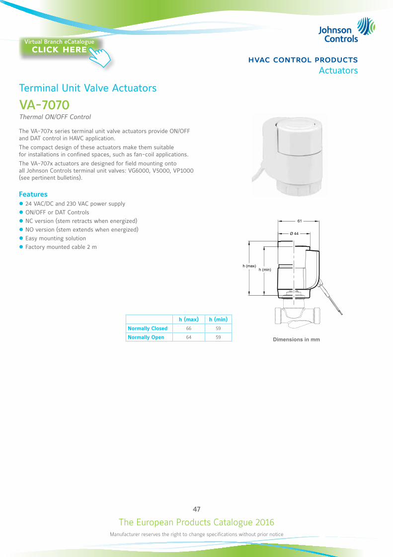
Terminal Unit Valve Actuators
VA-7070Thermal ON/OFF Control
The VA-707x series terminal unit valve actuators provide ON/OFF and DAT control in HAVC application.The compact design of these actuators make them suitable for installations in confined spaces, such as fan-coil applications.The VA-707x actuators are designed for field mounting onto all Johnson Controls terminal unit valves: VG6000, V5000, VP1000 (see pertinent bulletins).
Features z 24 VAC/DC and 230 VAC power supply z ON/OFF or DAT Controls z NC version (stem retracts when energized) z NO version (stem extends when energized) z Easy mounting solution z Factory mounted cable 2 m
61
Ø 44
h (min)h (max)
Dimensions in mm
h (max) h (min)
Normally Closed 66 59
Normally Open 64 59
Virtual Branch eCatalogueclick here
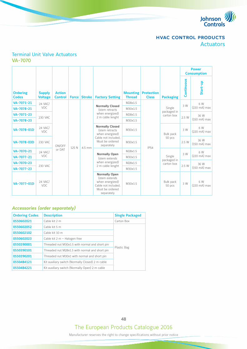
The European Products Catalogue 2016Manufacturer reserves the right to change specifications without prior notice
48
hvac control productsActuators
Terminal Unit Valve ActuatorsVA-7070
Ordering Codes
Supply Voltage
Action Control Force Stroke Factory Setting
Mounting Thread
Protection Class Packaging
Power Consumption
Con
tinu
ous
Sta
rt-u
p
VA-7071-21 24 VAC/VDC
ON/OFF or DAT 125 N 4.5 mm
Normally Closed (stem retracts
when energized) 2 m cable lenght
M28x1.5
IP54
Single packaged in carton box
3 W 6 W (220 mA) maxVA-7078-21 M30x1.5
VA-7071-23230 VAC
M28x1.52.5 W 36 W
(150 mA) maxVA-7078-23 M30x1.5
VA-7078-01D 24 VAC/VDC
Normally Closed (stem retracts
when energized) Cable not included. Must be ordered
separately
M30x1.5Bulk pack
50 pcs
3 W 6 W (220 mA) max
VA-7078-03D 230 VAC M30x1.5 2.5 W 36 W (150 mA) max
VA-7070-21 24 VAC/VDC Normally Open
(stem extends when energized) 2 m cable lenght
M28x1.5
Single packaged in carton box
3 W 6 W (220 mA) maxVA-7077-21 M30x1.5
VA-7070-23230 VAC
M28x1.52.5 W 36 W
(150 mA) maxVA-7077-23 M30x1.5
VA-7077-01D 24 VAC/VDC
Normally Open (stem extends
when energized) Cable not included. Must be ordered
separately
M30x1.5 Bulk pack 50 pcs 3 W 6 W
(220 mA) max
Accessories (order separately)Ordering Codes Description Single Packaged
0550602021 Cable kit 2 m Carton Box
0550602052 Cable kit 5 m
Plastic Bag
0550602102 Cable kit 10 m
0550602023 Cable kit 2 m – Halogen free
0550390001 Threaded nut M30x1.5 with normal and short pin
0550390101 Threaded nut M28x1.5 with normal and short pin
0550390201 Threaded nut M30x1 with normal and short pin
0550484121 Kit auxiliary switch (Normally Closed) 2 m cable
0550484221 Kit auxiliary switch (Normally Open) 2 m cable
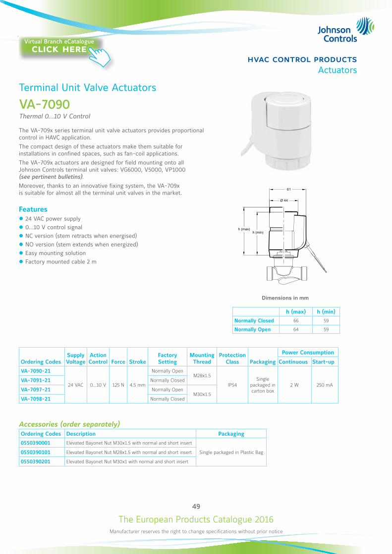
The European Products Catalogue 2016Manufacturer reserves the right to change specifications without prior notice
49
hvac control productsActuators
Terminal Unit Valve Actuators
VA-7090Thermal 0...10 V Control
The VA-709x series terminal unit valve actuators provides proportional control in HAVC application.The compact design of these actuators make them suitable for installations in confined spaces, such as fan-coil applications.The VA-709x actuators are designed for field mounting onto all Johnson Controls terminal unit valves: VG6000, V5000, VP1000 (see pertinent bulletins). Moreover, thanks to an innovative fixing system, the VA-709x is suitable for almost all the terminal unit valves in the market.
Features z 24 VAC power supply z 0...10 V control signal z NC version (stem retracts when energised) z NO version (stem extends when energized) z Easy mounting solution z Factory mounted cable 2 m
Ordering CodesSupply Voltage
Action Control Force Stroke
Factory Setting
Mounting Thread
Protection Class Packaging
Power Consumption
Continuous Start-up
VA-7090-21
24 VAC 0...10 V 125 N 4.5 mm
Normally OpenM28x1.5
IP54Single
packaged in carton box
2 W 250 mAVA-7091-21 Normally Closed
VA-7097-21 Normally OpenM30x1.5
VA-7098-21 Normally Closed
Accessories (order separately)Ordering Codes Description Packaging
0550390001 Elevated Bayonet Nut M30x1.5 with normal and short insert
Single packaged in Plastic Bag0550390101 Elevated Bayonet Nut M28x1.5 with normal and short insert
0550390201 Elevated Bayonet Nut M30x1 with normal and short insert
61
Ø 44
h (min)h (max)
Dimensions in mm
h (max) h (min)
Normally Closed 66 59
Normally Open 64 59
Virtual Branch eCatalogueclick here
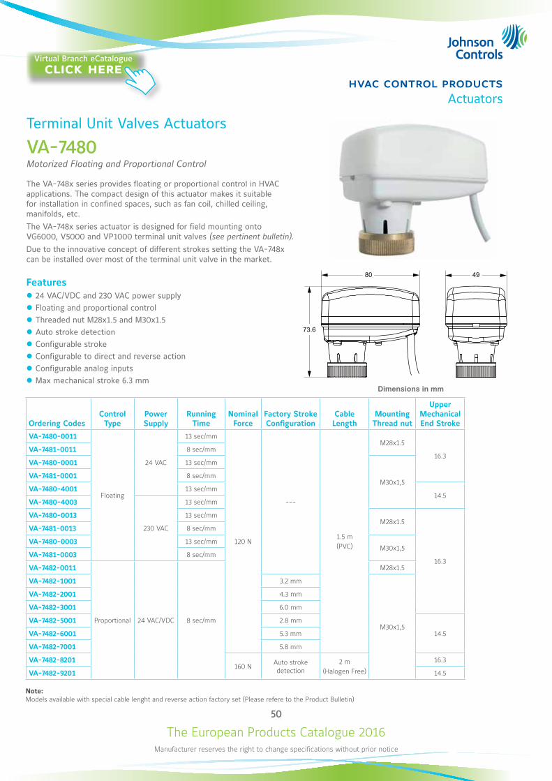
The European Products Catalogue 2016Manufacturer reserves the right to change specifications without prior notice
50
hvac control productsActuators
Terminal Unit Valves Actuators
VA-7480Motorized Floating and Proportional Control
The VA-748x series provides floating or proportional control in HVAC applications. The compact design of this actuator makes it suitable for installation in confined spaces, such as fan coil, chilled ceiling, manifolds, etc.The VA-748x series actuator is designed for field mounting onto VG6000, V5000 and VP1000 terminal unit valves (see pertinent bulletin).Due to the innovative concept of different strokes setting the VA-748x can be installed over most of the terminal unit valve in the market.
Features z 24 VAC/VDC and 230 VAC power supply z Floating and proportional control z Threaded nut M28x1.5 and M30x1.5 z Auto stroke detection z Configurable stroke z Configurable to direct and reverse action z Configurable analog inputs z Max mechanical stroke 6.3 mm
Dimensions in mm
73.6
4980
Ordering CodesControl Type
Power Supply
Running Time
Nominal Force
Factory Stroke Configuration
Cable Length
Mounting Thread nut
Upper Mechanical End Stroke
VA-7480-0011
Floating
24 VAC
13 sec/mm
120 N
---
1.5 m(PVC)
M28x1.5
16.3VA-7481-0011 8 sec/mm
VA-7480-0001 13 sec/mm
M30x1,5VA-7481-0001 8 sec/mm
VA-7480-4001 13 sec/mm14.5
VA-7480-4003
230 VAC
13 sec/mm
VA-7480-0013 13 sec/mmM28x1.5
16.3
VA-7481-0013 8 sec/mm
VA-7480-0003 13 sec/mmM30x1,5
VA-7481-0003 8 sec/mm
VA-7482-0011
Proportional 24 VAC/VDC 8 sec/mm
M28x1.5
VA-7482-1001 3.2 mm
M30x1,5
VA-7482-2001 4.3 mm
VA-7482-3001 6.0 mm
VA-7482-5001 2.8 mm
14.5VA-7482-6001 5.3 mm
VA-7482-7001 5.8 mm
VA-7482-8201160 N Auto stroke
detection2 m
(Halogen Free)
16.3
VA-7482-9201 14.5
Note:Models available with special cable lenght and reverse action factory set (Please refere to the Product Bulletin)
Virtual Branch eCatalogueclick here
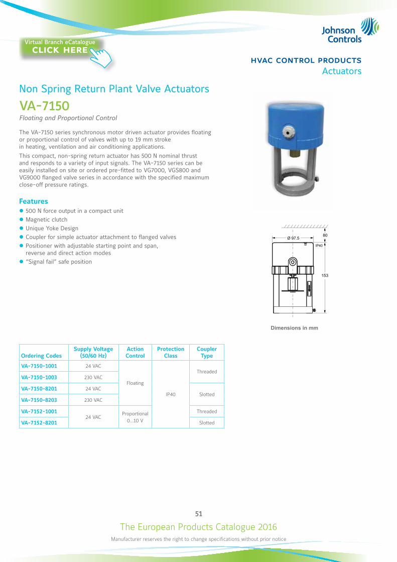
The European Products Catalogue 2016Manufacturer reserves the right to change specifications without prior notice
51
hvac control productsActuators
Non Spring Return Plant Valve Actuators
VA-7150Floating and Proportional Control
The VA-7150 series synchronous motor driven actuator provides floating or proportional control of valves with up to 19 mm stroke in heating, ventilation and air conditioning applications. This compact, non-spring return actuator has 500 N nominal thrust and responds to a variety of input signals. The VA-7150 series can be easily installed on site or ordered pre-fitted to VG7000, VGS800 and VG9000 flanged valve series in accordance with the specified maximum close-off pressure ratings.
Features z 500 N force output in a compact unit z Magnetic clutch z Unique Yoke Design z Coupler for simple actuator attachment to flanged valves z Positioner with adjustable starting point and span, reverse and direct action modes
z “Signal fail” safe position
Ordering CodesSupply Voltage
(50/60 Hz)Action Control
Protection Class
Coupler Type
VA-7150-1001 24 VAC
Floating
IP40
ThreadedVA-7150-1003 230 VAC
VA-7150-8201 24 VACSlotted
VA-7150-8203 230 VAC
VA-7152-100124 VAC
Proportional0...10 V
Threaded
VA-7152-8201 Slotted
Dimensions in mm
IP40
153
80 Ø 97.5
Virtual Branch eCatalogueclick here
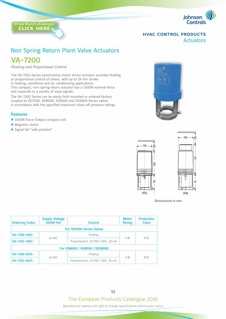
The European Products Catalogue 2016Manufacturer reserves the right to change specifications without prior notice
52
hvac control productsActuators
Non Spring Return Plant Valve Actuators
VA-7200Floating and Proportional Control
The VA-720x Series synchronous motor driven actuator provides floating or proportional control of valves, with up to 19 mm stroke in heating, ventilation and air conditioning applications. This compact, non-spring return actuator has a 1000N nominal force and responds to a variety of input signals. The VA-7200 Series can be easily field mounted or ordered factory coupled to VG7000, VG8000, VG9000 and VGS800 Series valves in accordance with the specified maximum close-off pressure ratings.
Features z 1000N Force Output compact unit z Magnetic clutch z Signal fail ”safe position”
Ordering CodesSupply Voltage
(50/60 Hz) ControlMotor Rating
Protection Class
For VG7000 Series Valves
VA-7200-100124 VAC
Floating 5 W IP42
VA-7202-1001 Proportional 0...10 VDC / 0(4)...20 mA
For VG8000 / VG9000 / VGS8000
VA-7200-820124 VAC
Floating 5 W IP42
VA-7202-8201 Proportional 0...10 VDC / 0(4)...20 mA
IP42 IP40
106 100
120
78
106 100
147
78
Dimensions in mm
Virtual Branch eCatalogueclick here
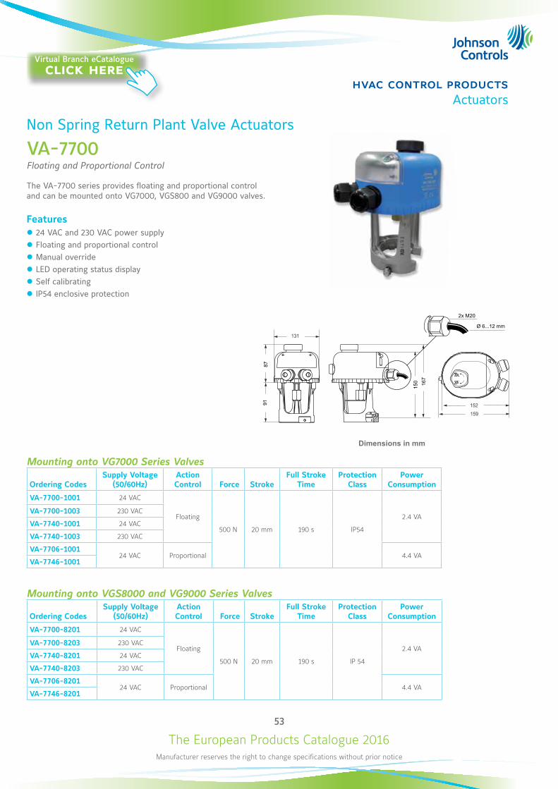
The European Products Catalogue 2016Manufacturer reserves the right to change specifications without prior notice
53
hvac control productsActuators
Non Spring Return Plant Valve Actuators
VA-7700Floating and Proportional Control
The VA-7700 series provides floating and proportional control and can be mounted onto VG7000, VGS800 and VG9000 valves.
Features z 24 VAC and 230 VAC power supply z Floating and proportional control z Manual override z LED operating status display z Self calibrating z IP54 enclosive protection
Mounting onto VG7000 Series Valves
Ordering CodesSupply Voltage
(50/60Hz)Action Control Force Stroke
Full Stroke Time
Protection Class
Power Consumption
VA-7700-1001 24 VAC
Floating
500 N 20 mm 190 s IP54
2.4 VAVA-7700-1003 230 VAC
VA-7740-1001 24 VAC
VA-7740-1003 230 VAC
VA-7706-100124 VAC Proportional 4.4 VA
VA-7746-1001
Mounting onto VGS8000 and VG9000 Series Valves
Ordering CodesSupply Voltage
(50/60Hz)Action Control Force Stroke
Full Stroke Time
Protection Class
Power Consumption
VA-7700-8201 24 VAC
Floating
500 N 20 mm 190 s IP 54
2.4 VAVA-7700-8203 230 VAC
VA-7740-8201 24 VAC
VA-7740-8203 230 VAC
VA-7706-820124 VAC Proportional 4.4 VA
VA-7746-8201
Dimensions in mm
Virtual Branch eCatalogueclick here
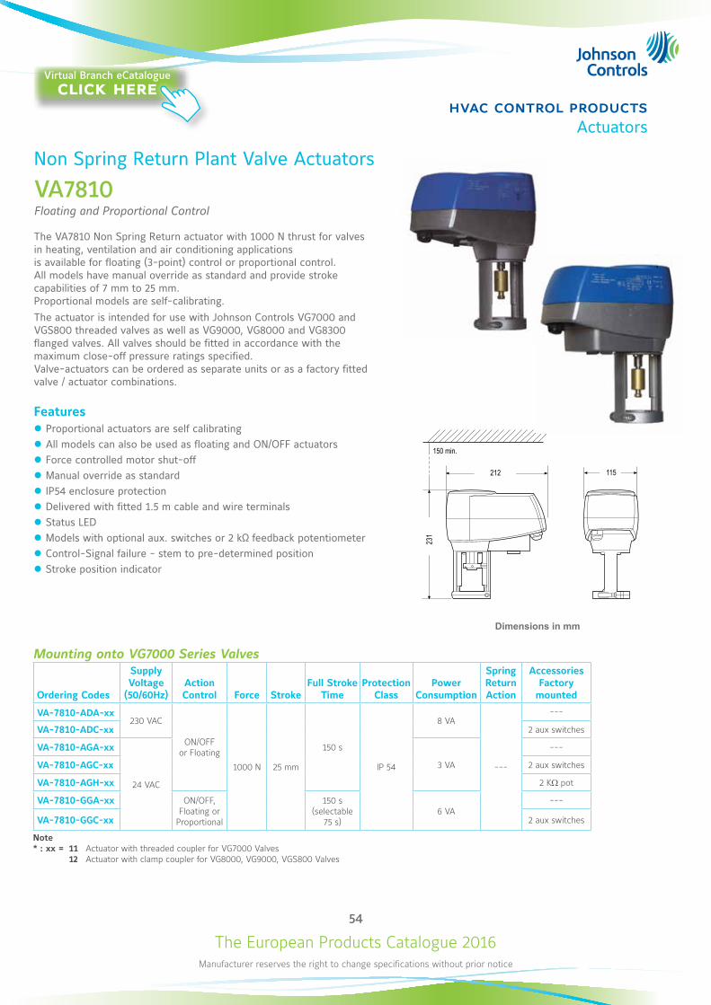
The European Products Catalogue 2016Manufacturer reserves the right to change specifications without prior notice
54
hvac control productsActuators
Non Spring Return Plant Valve Actuators
VA7810Floating and Proportional Control
The VA7810 Non Spring Return actuator with 1000 N thrust for valves in heating, ventilation and air conditioning applications is available for floating (3-point) control or proportional control. All models have manual override as standard and provide stroke capabilities of 7 mm to 25 mm. Proportional models are self-calibrating. The actuator is intended for use with Johnson Controls VG7000 and VGS800 threaded valves as well as VG9000, VG8000 and VG8300 flanged valves. All valves should be fitted in accordance with the maximum close-off pressure ratings specified. Valve-actuators can be ordered as separate units or as a factory fitted valve / actuator combinations.
Features z Proportional actuators are self calibrating z All models can also be used as floating and ON/OFF actuators z Force controlled motor shut-off z Manual override as standard z IP54 enclosure protection z Delivered with fitted 1.5 m cable and wire terminals z Status LED z Models with optional aux. switches or 2 kΩ feedback potentiometer z Control-Signal failure - stem to pre-determined position z Stroke position indicator
150 min.
212 115
231
Dimensions in mm
Mounting onto VG7000 Series Valves
Ordering Codes
Supply Voltage
(50/60Hz)Action Control Force Stroke
Full Stroke Time
Protection Class
Power Consumption
Spring Return Action
AccessoriesFactory
mounted
VA-7810-ADA-xx230 VAC
ON/OFF or Floating
1000 N 25 mm
150 s
IP 54
8 VA
---
---
VA-7810-ADC-xx 2 aux switches
VA-7810-AGA-xx
24 VAC
3 VA
---
VA-7810-AGC-xx 2 aux switches
VA-7810-AGH-xx 2 KW pot
VA-7810-GGA-xx ON/OFF, Floating or
Proportional
150 s (selectable
75 s)6 VA
---
VA-7810-GGC-xx 2 aux switches
Note* : xx = 11 Actuator with threaded coupler for VG7000 Valves 12 Actuator with clamp coupler for VG8000, VG9000, VGS800 Valves
Virtual Branch eCatalogueclick here
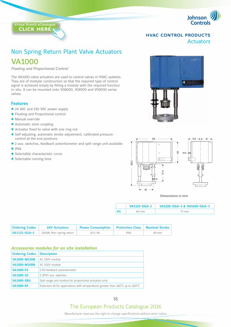
The European Products Catalogue 2016Manufacturer reserves the right to change specifications without prior notice
55
hvac control productsActuators
Non Spring Return Plant Valve Actuators
VA1000Floating and Proportional Control
The VA1000 valve actuators are used to control valves in HVAC systems. They are of modular construction so that the required type of control signal is achieved simply by fitting a module with the required function in-situ. It can be mounted onto VG8000, VG8300 and VG9000 series valves.
Features z 24 VAC and 230 VAC power supply z Floating and Proportional control z Manual override z Automatic stem coupling z Actuator fixed to valve with one ring nut z Self adjusting, automatic stroke adjustment, calibrated pressure control at the end positions
z 2 aux. switches, feedback potentiometer and split range unit available z IP66 z Selectable characteristic curve z Selectable running time
VA1125-GGA-1 VA1220-GGA-1 & VA1420-GGA-1
H1 60 mm 73 mm
Ordering Codes 24V Actuators Power Consumption Protection Class Nominal Stroke
VA1125-GGA-1 2500N; Non-spring return 20.5 VA IP66 49 mm
Accessories modules for on site installationOrdering Codes Description
VA1000-M230N AC 230V module
VA1000-M100N AC 100V module
VA1000-P2 2 KΩ feedback potentiometer
VA1000-S2 2 SPDT aux. switches
VA1000-SRU Split range unit module for proportional actuators only
VA1000-EP Extension kit for applications with temperatures greater than 140°C up to 200°C
262.5
90
230
111.4
14
18.5134
75.5 H1
Dimensions in mm
Virtual Branch eCatalogueclick here
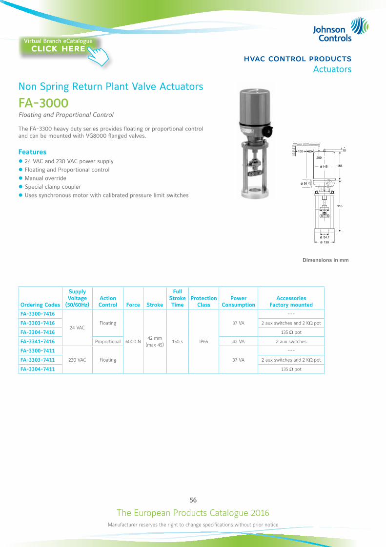
The European Products Catalogue 2016Manufacturer reserves the right to change specifications without prior notice
56
hvac control productsActuators
Non Spring Return Plant Valve Actuators
FA-3000Floating and Proportional Control
The FA-3300 heavy duty series provides floating or proportional control and can be mounted with VG8000 flanged valves.
Features z 24 VAC and 230 VAC power supply z Floating and Proportional control z Manual override z Special clamp coupler z Uses synchronous motor with calibrated pressure limit switches
Ordering Codes
Supply Voltage
(50/60Hz)Action Control Force Stroke
Full Stroke Time
Protection Class
Power Consumption
Accessories Factory mounted
FA-3300-7416
24 VACFloating
6000 N42 mm
(max 45)150 s IP65
37 VA
---
FA-3303-7416 2 aux switches and 2 KW pot
FA-3304-7416 135 W pot
FA-3341-7416 Proportional 42 VA 2 aux switches
FA-3300-7411
230 VAC Floating 37 VA
---
FA-3303-7411 2 aux switches and 2 KW pot
FA-3304-7411 135 W pot
ø 130ø 54.1
10
ø 54
200
100 60
ø145 156
316
Dimensions in mm
Virtual Branch eCatalogueclick here
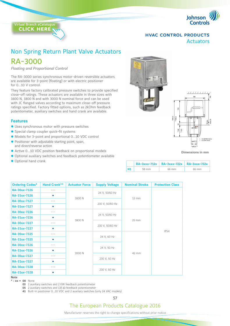
The European Products Catalogue 2016Manufacturer reserves the right to change specifications without prior notice
57
hvac control productsActuators
Non Spring Return Plant Valve Actuators
RA-3000Floating and Proportional Control
The RA-3000 series synchronous motor-driven reversible actuators are available for 3-point (floating) or with electric positioner for 0...10 V control. They feature factory calibrated pressure switches to provide specified close-off ratings. These actuators are available in three sizes with 1600 N, 1800 N and with 3000 N nominal force and can be used with JC flanged valves according to maximum close-off pressure ratings specified. Factory fitted options, such as 2kOhm feedback potentiometer, auxiliary switches and hand crank are available.
Features z Uses synchronous motor with pressure switches z Special clamp coupler quick-fit systems z Models for 3-point and proportional 0...10 VDC control z Positioner with adjustable starting point, span, and direct/reverse action
z Active 0...10 VDC position feedback on proportional models z Optional auxiliary switches and feedback potentiometer available z Optional hand crank
RA-3xxx-712x RA-3xxx-722x RA-3xxx-732x
H1 58 mm 66 mm 66 mm
Dimensions in mm
Ordering Codes* Hand Crank** Actuator Force Supply Voltage Nominal Stroke Protection Class
RA-30xx-7126 ---
1600 N
24 V, 50/60 Hz
13 mm
IP54
RA-31xx-7126 RA-30xx-7127 ---
230 V, 50/60 HzRA-31xx-7127 RA-30xx-7226 ---
1800 N
24 V, 50/60 Hz
25 mmRA-31xx-7226 RA-30xx-7227 ---
230 V, 50/60 HzRA-31xx-7227 RA-30xx-7325 ---
3000 N
24 V, 60 Hz
42 mm
RA-31xx-7325 RA-30xx-7326 ---
24 V, 50 HzRA-31xx-7326 RA-30xx-7327 ---
230 V, 50 HzRA-31xx-7327 RA-30xx-7328 ---
230 V, 60 HzRA-31xx-7328
Note* : xx = 00 None 03 2 auxiliary switches and 2 KW feedback potentiometer 05 2 auxiliary switches and 135 W feedback potentiometer 41 Built-in positioner 0...10 VDC and 2 auxiliary switches (only 24 VAC models)
Virtual Branch eCatalogueclick here
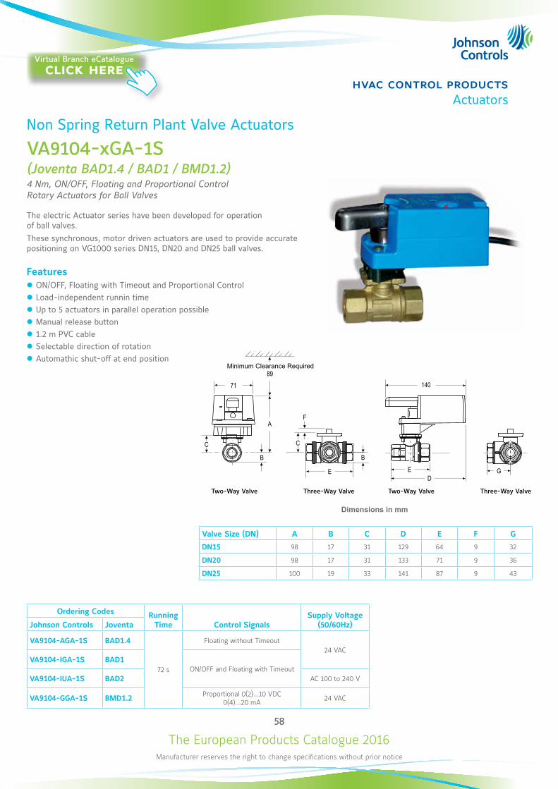
The European Products Catalogue 2016Manufacturer reserves the right to change specifications without prior notice
58
hvac control productsActuators
Non Spring Return Plant Valve Actuators
VA9104-xGA-1S(Joventa BAD1.4 / BAD1 / BMD1.2)4 Nm, ON/OFF, Floating and Proportional Control Rotary Actuators for Ball Valves
The electric Actuator series have been developed for operation of ball valves.These synchronous, motor driven actuators are used to provide accurate positioning on VG1000 series DN15, DN20 and DN25 ball valves.
Features z ON/OFF, Floating with Timeout and Proportional Control z Load-independent runnin time z Up to 5 actuators in parallel operation possible z Manual release button z 1.2 m PVC cable z Selectable direction of rotation z Automathic shut-off at end position
Ordering Codes Running Time Control Signals
Supply Voltage (50/60Hz)Johnson Controls Joventa
VA9104-AGA-1S BAD1.4
72 s
Floating without Timeout24 VAC
VA9104-IGA-1S BAD1ON/OFF and Floating with Timeout
VA9104-IUA-1S BAD2 AC 100 to 240 V
VA9104-GGA-1S BMD1.2 Proportional 0(2)...10 VDC 0(4)...20 mA 24 VAC
8971
C
B
A
E
F
B
C
140
ED
G
Dimensions in mm
Valve Size (DN) A B C D E F G
DN15 98 17 31 129 64 9 32
DN20 98 17 31 133 71 9 36
DN25 100 19 33 141 87 9 43
Two-Way Valve Three-Way Valve Two-Way Valve Three-Way Valve
Minimum Clearance Required
Virtual Branch eCatalogueclick here
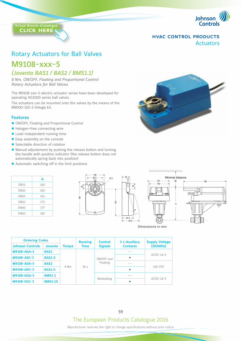
The European Products Catalogue 2016Manufacturer reserves the right to change specifications without prior notice
59
hvac control productsActuators
Rotary Actuators for Ball Valves
M9108-xxx-5(Joventa BAS1 / BAS2 / BMS1.1)8 Nm, ON/OFF, Floating and Proportional Control Rotary Actuators for Ball Valves
The M9108-xxx-5 electric actuator series have been developed for operating VG1000 series ball valves. The actuators can be mounted onto the valves by the means of the M9000-525-5 linkage kit.
Features z ON/OFF, Floating and Proportional Control z Halogen-free connecting wire z Load-independent running time z Easy assembly on the console z Selectable direction of rotation z Manual adjustement by pushing the release button and turning the handle with position indicator (the release button does not automatically spring back into position)
z Automatic switching off in the limit positions
Ordering Codes
TorqueRunning
TimeControl Signals
2 x Auxiliary Contacts
Supply Voltage (50/60Hz)Johnson Controls Joventa
M9108-AGA-5 BAS1
8 Nm 30 s
ON/OFF and Floating
---AC/DC 24 V
M9108-AGC-5 BAS1.S M9108-ADA-5 BAS2 ---
230 VDCM9108-ADC-5 BAS2.S M9108-GGA-5 BMS1.1
Modulating---
AC/DC 24 VM9108-GGC-5 BMS1.1S
A
DN15 160
DN20 160
DN25 162
DN32 173
DN40 177
DN50 182
482.5100
107100
45
35
180
140
67.582.5
20
89
A
199
Dimensions in mm
Minimal distance
Virtual Branch eCatalogueclick here
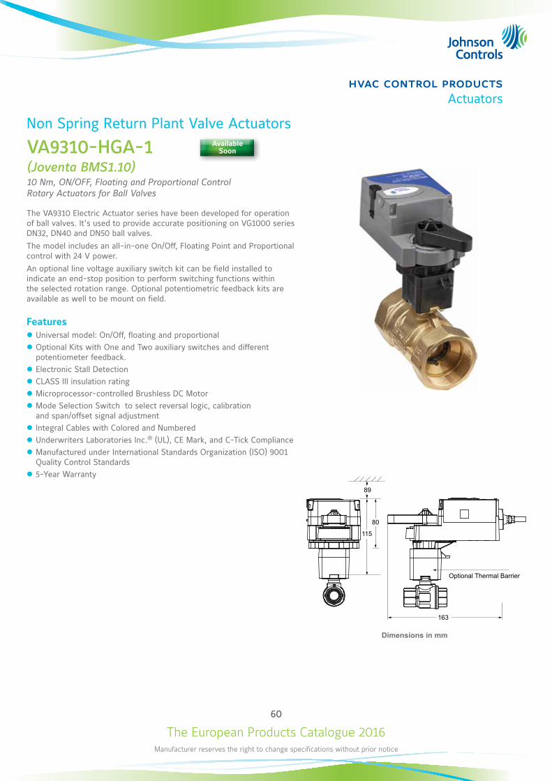
The European Products Catalogue 2016Manufacturer reserves the right to change specifications without prior notice
60
hvac control productsActuators
Non Spring Return Plant Valve Actuators
VA9310-HGA-1(Joventa BMS1.10)10 Nm, ON/OFF, Floating and Proportional Control Rotary Actuators for Ball Valves
The VA9310 Electric Actuator series have been developed for operation of ball valves. It’s used to provide accurate positioning on VG1000 series DN32, DN40 and DN50 ball valves.The model includes an all-in-one On/Off, Floating Point and Proportional control with 24 V power.An optional line voltage auxiliary switch kit can be field installed to indicate an end-stop position to perform switching functions within the selected rotation range. Optional potentiometric feedback kits are available as well to be mount on field.
Features z Universal model: On/Off, floating and proportional z Optional Kits with One and Two auxiliary switches and different potentiometer feedback.
z Electronic Stall Detection z CLASS III insulation rating z Microprocessor-controlled Brushless DC Motor z Mode Selection Switch to select reversal logic, calibration and span/offset signal adjustment
z Integral Cables with Colored and Numbered z Underwriters Laboratories Inc.® (UL), CE Mark, and C-Tick Compliance z Manufactured under International Standards Organization (ISO) 9001 Quality Control Standards
z 5-Year Warranty
163
89
115
80
Optional Thermal Barrier
Dimensions in mm
Available Soon
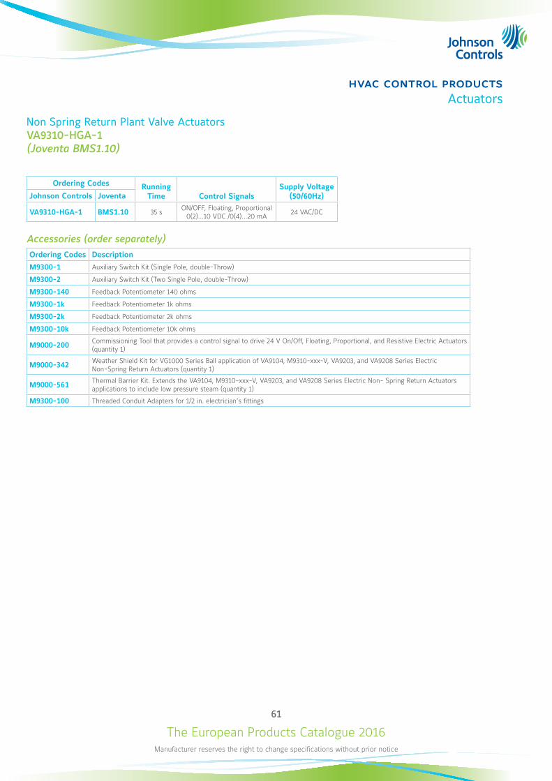
The European Products Catalogue 2016Manufacturer reserves the right to change specifications without prior notice
61
hvac control productsActuators
Non Spring Return Plant Valve Actuators VA9310-HGA-1(Joventa BMS1.10)
Ordering Codes Running Time Control Signals
Supply Voltage (50/60Hz) Johnson Controls Joventa
VA9310-HGA-1 BMS1.10 35 s ON/OFF, Floating, Proportional 0(2)...10 VDC /0(4)...20 mA 24 VAC/DC
Accessories (order separately)Ordering Codes Description
M9300-1 Auxiliary Switch Kit (Single Pole, double-Throw)
M9300-2 Auxiliary Switch Kit (Two Single Pole, double-Throw)
M9300-140 Feedback Potentiometer 140 ohms
M9300-1k Feedback Potentiometer 1k ohms
M9300-2k Feedback Potentiometer 2k ohms
M9300-10k Feedback Potentiometer 10k ohms
M9000-200 Commissioning Tool that provides a control signal to drive 24 V On/Off, Floating, Proportional, and Resistive Electric Actuators (quantity 1)
M9000-342 Weather Shield Kit for VG1000 Series Ball application of VA9104, M9310-xxx-V, VA9203, and VA9208 Series Electric Non-Spring Return Actuators (quantity 1)
M9000-561 Thermal Barrier Kit. Extends the VA9104, M9310-xxx-V, VA9203, and VA9208 Series Electric Non- Spring Return Actuators applications to include low pressure steam (quantity 1)
M9300-100 Threaded Conduit Adapters for 1/2 in. electrician’s fittings
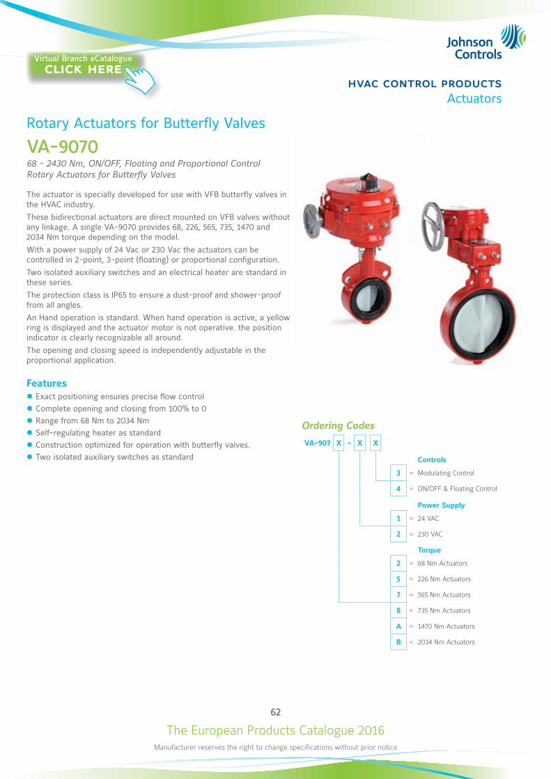
The European Products Catalogue 2016Manufacturer reserves the right to change specifications without prior notice
62
hvac control productsActuators
Rotary Actuators for Butterfly Valves
VA-907068 - 2430 Nm, ON/OFF, Floating and Proportional Control Rotary Actuators for Butterfly Valves
The actuator is specially developed for use with VFB butterfly valves in the HVAC industry. These bidirectional actuators are direct mounted on VFB valves without any linkage. A single VA-9070 provides 68, 226, 565, 735, 1470 and 2034 Nm torque depending on the model.With a power supply of 24 Vac or 230 Vac the actuators can be controlled in 2-point, 3-point (floating) or proportional configuration.Two isolated auxiliary switches and an electrical heater are standard in these series.The protection class is IP65 to ensure a dust-proof and shower-proof from all angles.An Hand operation is standard. When hand operation is active, a yellow ring is displayed and the actuator motor is not operative. the position indicator is clearly recognizable all around.The opening and closing speed is independently adjustable in the proportional application.
Features z Exact positioning ensures precise flow control z Complete opening and closing from 100% to 0 z Range from 68 Nm to 2034 Nm z Self-regulating heater as standard z Construction optimized for operation with butterfly valves. z Two isolated auxiliary switches as standard
Ordering Codes
VA-907 X - X X
Controls
3 = Modulating Control
4 = ON/OFF & Floating Control
Power Supply
1 = 24 VAC
2 = 230 VAC
Torque
2 = 68 Nm Actuators
5 = 226 Nm Actuators
7 = 565 Nm Actuators
8 = 735 Nm Actuators
A = 1470 Nm Actuators
B = 2034 Nm Actuators
Virtual Branch eCatalogueclick here
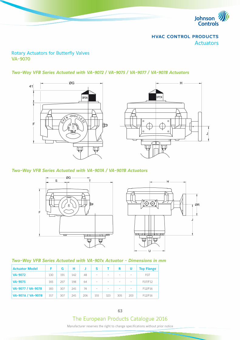
The European Products Catalogue 2016Manufacturer reserves the right to change specifications without prior notice
63
hvac control productsActuators
Rotary Actuators for Butterfly ValvesVA-9070
Two-Way VFB Series Actuated with VA-9072 / VA-9075 / VA-9077 / VA-9078 Actuators
ØG H
J
41
F
Two-Way VFB Series Actuated with VA-907A / VA-907B Actuators
Two-Way VFB Series Actuated with VA-907x Actuator - Dimensions in mm
Actuator Model F G H J S T R U Top Flange
VA-9072 130 191 142 48 - - - - F07
VA-9075 165 257 198 64 - - - - F07/F12
VA-9077 / VA-9078 183 307 241 74 - - - - F12/F16
VA-907A / VA-907B 317 307 241 206 155 323 305 203 F12/F16
ØGTS
F
ØR
J
U
H
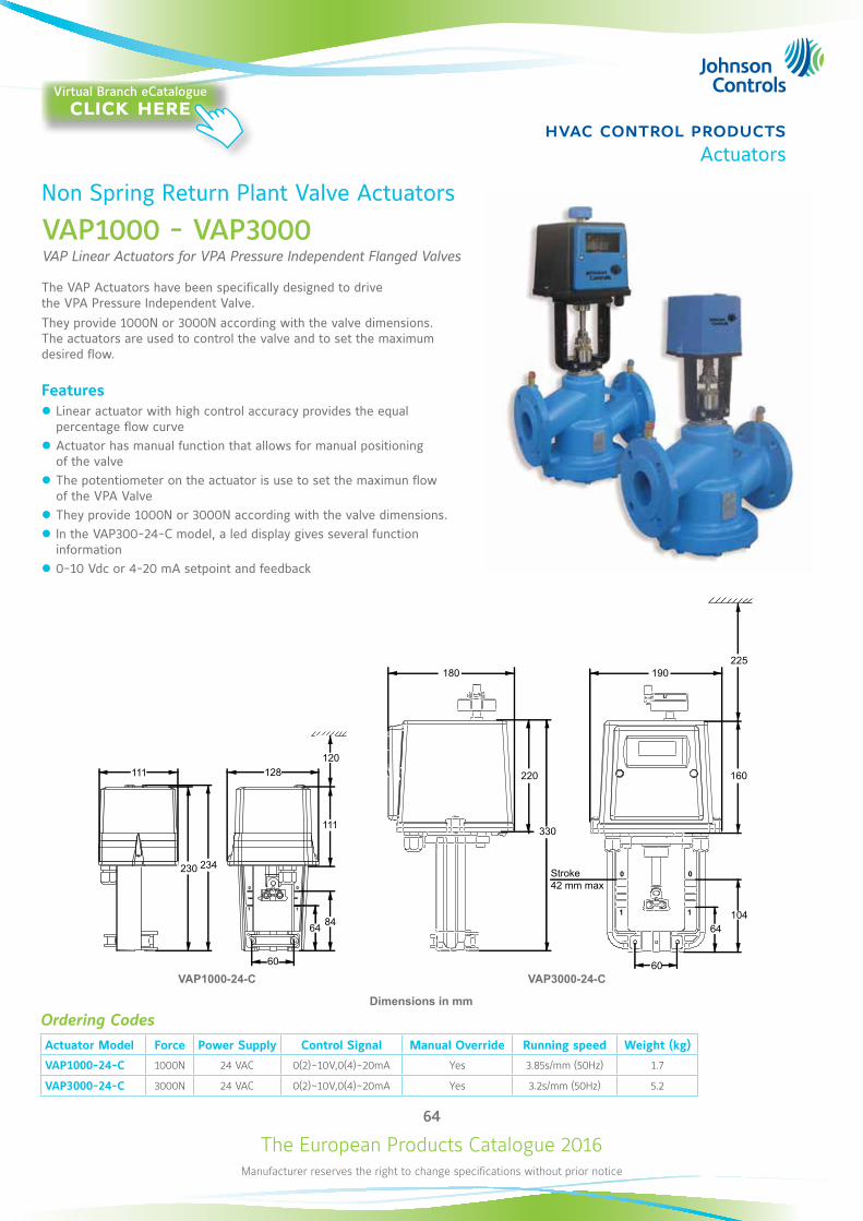
The European Products Catalogue 2016Manufacturer reserves the right to change specifications without prior notice
64
hvac control productsActuators
Non Spring Return Plant Valve Actuators
VAP1000 - VAP3000VAP Linear Actuators for VPA Pressure Independent Flanged Valves
The VAP Actuators have been specifically designed to drive the VPA Pressure Independent Valve. They provide 1000N or 3000N according with the valve dimensions. The actuators are used to control the valve and to set the maximum desired flow.
Features z Linear actuator with high control accuracy provides the equal percentage flow curve
z Actuator has manual function that allows for manual positioning of the valve
z The potentiometer on the actuator is use to set the maximun flow of the VPA Valve
z They provide 1000N or 3000N according with the valve dimensions. z In the VAP300-24-C model, a led display gives several function information
z 0-10 Vdc or 4-20 mA setpoint and feedback
Ordering CodesActuator Model Force Power Supply Control Signal Manual Override Running speed Weight (kg)
VAP1000-24-C 1000N 24 VAC 0(2)~10V,0(4)~20mA Yes 3.85s/mm (50Hz) 1.7
VAP3000-24-C 3000N 24 VAC 0(2)~10V,0(4)~20mA Yes 3.2s/mm (50Hz) 5.2
VAP1000-24-C VAP3000-24-C
Dimensions in mm
111
0 0
1 1
0
1
0
1
230 234
128
111
120
8464
60
180
220
330
60
64104
160
225190
Stroke42 mm max
Virtual Branch eCatalogueclick here
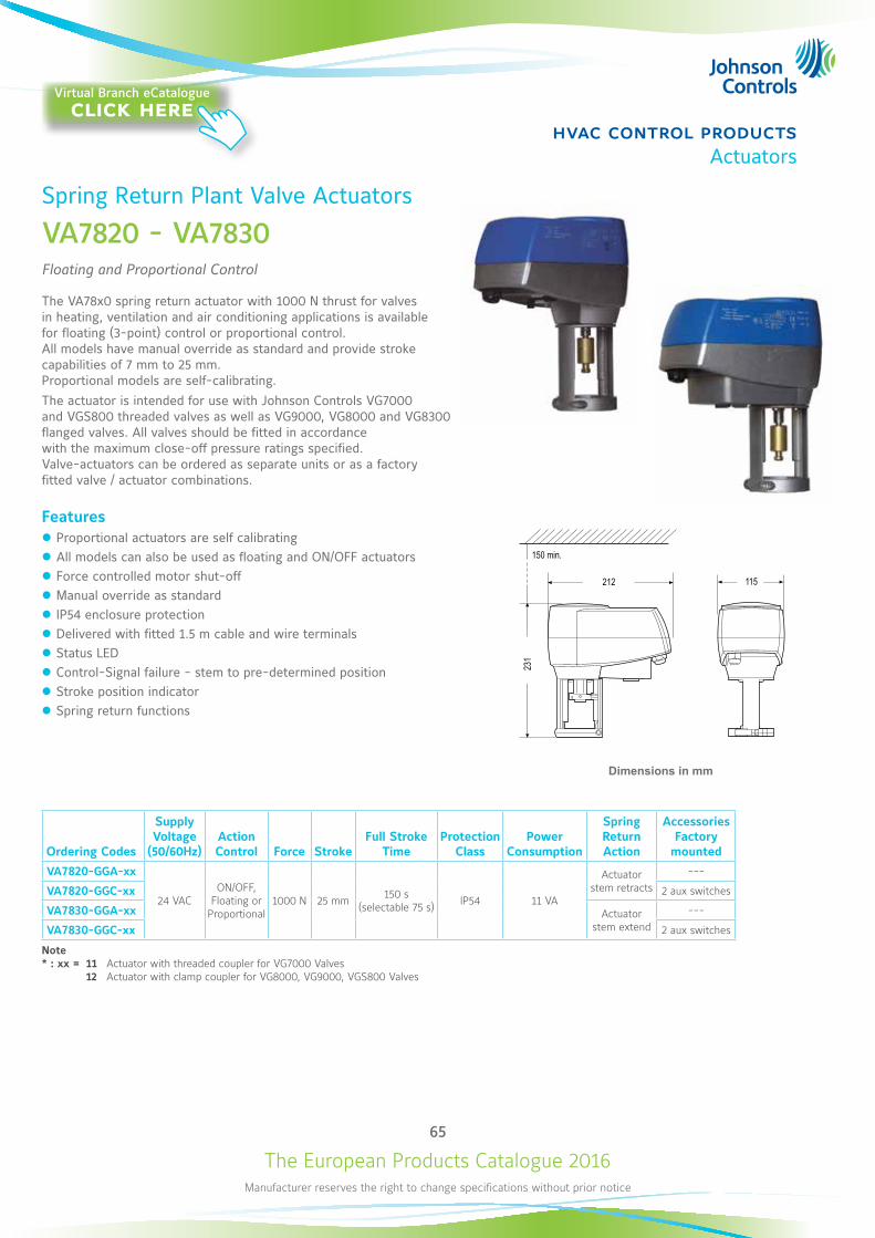
The European Products Catalogue 2016Manufacturer reserves the right to change specifications without prior notice
65
hvac control productsActuators
Spring Return Plant Valve Actuators
VA7820 - VA7830Floating and Proportional Control
The VA78x0 spring return actuator with 1000 N thrust for valves in heating, ventilation and air conditioning applications is available for floating (3-point) control or proportional control. All models have manual override as standard and provide stroke capabilities of 7 mm to 25 mm. Proportional models are self-calibrating.The actuator is intended for use with Johnson Controls VG7000 and VGS800 threaded valves as well as VG9000, VG8000 and VG8300 flanged valves. All valves should be fitted in accordance with the maximum close-off pressure ratings specified. Valve-actuators can be ordered as separate units or as a factory fitted valve / actuator combinations.
Features z Proportional actuators are self calibrating z All models can also be used as floating and ON/OFF actuators z Force controlled motor shut-off z Manual override as standard z IP54 enclosure protection z Delivered with fitted 1.5 m cable and wire terminals z Status LED z Control-Signal failure - stem to pre-determined position z Stroke position indicator z Spring return functions
Ordering Codes
Supply Voltage
(50/60Hz)Action Control Force Stroke
Full Stroke Time
Protection Class
Power Consumption
Spring Return Action
Accessories Factory
mounted
VA7820-GGA-xx
24 VACON/OFF,
Floating or Proportional
1000 N 25 mm 150 s (selectable 75 s) IP54 11 VA
Actuator stem retracts
---
VA7820-GGC-xx 2 aux switches
VA7830-GGA-xx Actuator stem extend
---
VA7830-GGC-xx 2 aux switches
Note* : xx = 11 Actuator with threaded coupler for VG7000 Valves 12 Actuator with clamp coupler for VG8000, VG9000, VGS800 Valves
150 min.
212 115
231
Dimensions in mm
Virtual Branch eCatalogueclick here
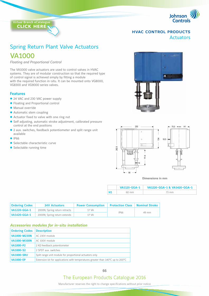
The European Products Catalogue 2016Manufacturer reserves the right to change specifications without prior notice
66
hvac control productsActuators
Spring Return Plant Valve Actuators
VA1000Floating and Proportional Control
The VA1000 valve actuators are used to control valves in HVAC systems. They are of modular construction so that the required type of control signal is achieved simply by fitting a module with the required function in-situ. It can be mounted onto VG8000, VG8300 and VG9000 series valves.
Features z 24 VAC and 230 VAC power supply z Floating and Proportional control z Manual override z Automatic stem coupling z Actuator fixed to valve with one ring nut z Self adjusting, automatic stroke adjustment, calibrated pressure control at the end positions
z 2 aux. switches, feedback potentiometer and split range unit available
z IP66 z Selectable characteristic curve z Selectable running time
VA1125-GGA-1 VA1220-GGA-1 & VA1420-GGA-1
H1 60 mm 73 mm
Ordering Codes 24V Actuators Power Consumption Protection Class Nominal Stroke
VA1220-GGA-1 2000N; Spring return retracts 17 VAIP66 49 mm
VA1420-GGA-1 2000N; Spring return extends 17 VA
Accessories modules for in-situ installationOrdering Codes Description
VA1000-M230N AC 230V module
VA1000-M100N AC 100V module
VA1000-P2 2 KΩ feedback potentiometer
VA1000-S2 2 SPDT aux. switches
VA1000-SRU Split range unit module for proportional actuators only
VA1000-EP Extension kit for applications with temperatures greater than 140°C up to 200°C
262.5
90
230
111.4
14
18.5134
75.5 H1
Dimensions in mm
Virtual Branch eCatalogueclick here
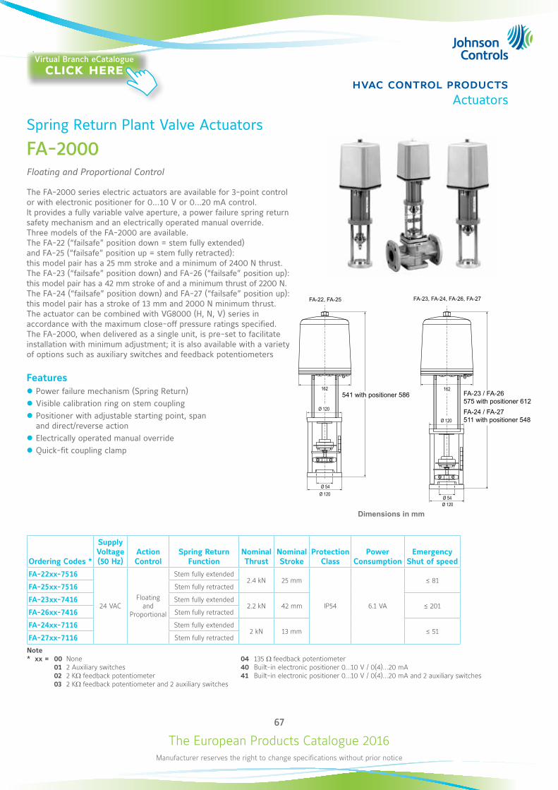
The European Products Catalogue 2016Manufacturer reserves the right to change specifications without prior notice
67
hvac control productsActuators
Spring Return Plant Valve Actuators
FA-2000Floating and Proportional Control
The FA-2000 series electric actuators are available for 3-point control or with electronic positioner for 0…10 V or 0…20 mA control. It provides a fully variable valve aperture, a power failure spring return safety mechanism and an electrically operated manual override. Three models of the FA-2000 are available. The FA-22 (“failsafe” position down = stem fully extended) and FA-25 (“failsafe” position up = stem fully retracted): this model pair has a 25 mm stroke and a minimum of 2400 N thrust. The FA-23 (“failsafe” position down) and FA-26 (“failsafe” position up): this model pair has a 42 mm stroke of and a minimum thrust of 2200 N. The FA-24 (“failsafe” position down) and FA-27 (“failsafe” position up): this model pair has a stroke of 13 mm and 2000 N minimum thrust. The actuator can be combined with VG8000 (H, N, V) series in accordance with the maximum close-off pressure ratings specified. The FA-2000, when delivered as a single unit, is pre-set to facilitate installation with minimum adjustment; it is also available with a variety of options such as auxiliary switches and feedback potentiometers
Features z Power failure mechanism (Spring Return) z Visible calibration ring on stem coupling z Positioner with adjustable starting point, span and direct/reverse action
z Electrically operated manual override z Quick-fit coupling clamp
Ordering Codes *
Supply Voltage (50 Hz)
Action Control
Spring Return Function
Nominal Thrust
Nominal Stroke
Protection Class
Power Consumption
Emergency Shut of speed
FA-22xx-7516
24 VACFloating
and Proportional
Stem fully extended2.4 kN 25 mm
IP54 6.1 VA
≤ 81FA-25xx-7516 Stem fully retracted
FA-23xx-7416 Stem fully extended2.2 kN 42 mm ≤ 201
FA-26xx-7416 Stem fully retracted
FA-24xx-7116 Stem fully extended2 kN 13 mm ≤ 51
FA-27xx-7116 Stem fully retracted
Note* xx = 00 None 04 135 W feedback potentiometer 01 2 Auxiliary switches 40 Built-in electronic positioner 0...10 V / 0(4)...20 mA 02 2 KW feedback potentiometer 41 Built-in electronic positioner 0...10 V / 0(4)...20 mA and 2 auxiliary switches 03 2 KW feedback potentiometer and 2 auxiliary switches
Dimensions in mm
FA-22, FA-25 FA-23, FA-24, FA-26, FA-27
162
Ø 120
Ø 54Ø 120
162
Ø 54Ø 120
Ø 120
541 with positioner 586 FA-23 / FA-26575 with positioner 612FA-24 / FA-27511 with positioner 548
Virtual Branch eCatalogueclick here
The European Products Catalogue 2016Manufacturer reserves the right to change specifications without prior notice
69
hvac control productsActuators
Rotary Actuators for Ball ValvesVA9203 (Joventa BxFx.03SZ)
Ordering Codes
Johnson Controls Joventa Description
VA9203-GGA-1Z BMF1.03Z 3 Nm Spring Return Actuator for Valves, Proportional, 24 V AC/DC
VA9203-GGB-1Z BMF1.03SZ 3 Nm Spring Return Actuator for Valves, Proportional, 24 V AC/DC, 1 Switch
VA9203-AGA-1Z BBF1.03Z 3 Nm Spring Return Actuator for Valves, Floating & ON/OFF, 24 V AC/DC
VA9203-AGB-1Z BBF1.03SZ 3 Nm Spring Return Actuator for Valves, Floating & ON/OFF, 24 V AC/DC, 1 Switch
VA9203-BGA-1 BAF1.03 3 Nm Spring Return Actuator for Valves, ON/OFF, 24 V AC/DC
VA9203-BGB-1 BAF1.03S 3 Nm Spring Return Actuator for Valves, ON/OFF, 24 V AC/DC, 1 Switch
VA9203-BUA-1 BAF2.03 3 Nm Spring Return Actuator for Valves, ON/OFF, 100 to 230 V AC
VA9203-BUB-1 BAF2.03S 3 Nm Spring Return Actuator for Valves, ON/OFF, 100 to 230 V AC, 1 Switch
Accessories (order separately)Ordering Codes Description
M9000-200 Commissioning Tool that Provides a Control Signal to Drive 24 V On/Off, Floating, Proportional and/or Resistive Electric Actuators
M9000-560 Ball Valve Linkage Kit for applying M9203 and M9208 Series Actuators to VG1000 Series Valves (quantity 1)
M9000-561 Thermal Barrier Extends M(VA)9104, M(VA)9203 and M(VA)9208 Series Electric Spring Return Actuator applications to include low pressure steam (quantity 1)
M9000-341 Weathershield Kit for VG1000 Series Ball Valve application of M(VA)9104, M(VA)9203 and M(VA)9208 Series Electric Spring Return Actuators (quantity 1)
M9000-607 Position Indicator for VG1000 Series Ball Valve Applications (Quantity 5)
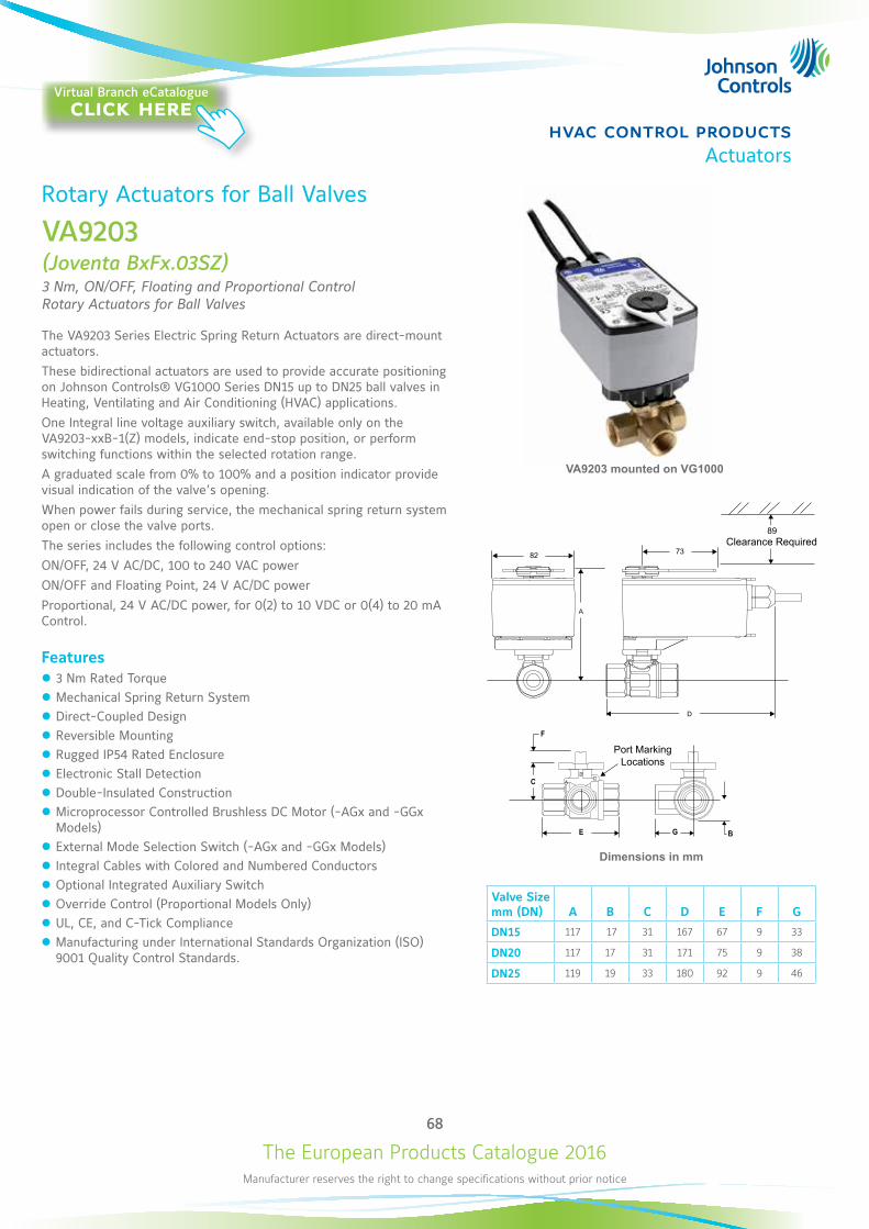
The European Products Catalogue 2016Manufacturer reserves the right to change specifications without prior notice
68
hvac control productsActuators
Rotary Actuators for Ball Valves
VA9203(Joventa BxFx.03SZ)3 Nm, ON/OFF, Floating and Proportional Control Rotary Actuators for Ball Valves
The VA9203 Series Electric Spring Return Actuators are direct-mount actuators.These bidirectional actuators are used to provide accurate positioning on Johnson Controls® VG1000 Series DN15 up to DN25 ball valves in Heating, Ventilating and Air Conditioning (HVAC) applications. One Integral line voltage auxiliary switch, available only on the VA9203-xxB-1(Z) models, indicate end-stop position, or perform switching functions within the selected rotation range.A graduated scale from 0% to 100% and a position indicator provide visual indication of the valve’s opening. When power fails during service, the mechanical spring return system open or close the valve ports.The series includes the following control options:ON/OFF, 24 V AC/DC, 100 to 240 VAC powerON/OFF and Floating Point, 24 V AC/DC powerProportional, 24 V AC/DC power, for 0(2) to 10 VDC or 0(4) to 20 mA Control.
Features z 3 Nm Rated Torque z Mechanical Spring Return System z Direct-Coupled Design z Reversible Mounting z Rugged IP54 Rated Enclosure z Electronic Stall Detection z Double-Insulated Construction z Microprocessor Controlled Brushless DC Motor (-AGx and -GGx Models)
z External Mode Selection Switch (-AGx and -GGx Models) z Integral Cables with Colored and Numbered Conductors z Optional Integrated Auxiliary Switch z Override Control (Proportional Models Only) z UL, CE, and C-Tick Compliance z Manufacturing under International Standards Organization (ISO) 9001 Quality Control Standards.
Dimensions in mm
82 73
Valve Size mm (DN) A B C D E F G
DN15 117 17 31 167 67 9 33
DN20 117 17 31 171 75 9 38
DN25 119 19 33 180 92 9 46
VA9203 mounted on VG1000
Clearance Required
Port Marking Locations
Virtual Branch eCatalogueclick here
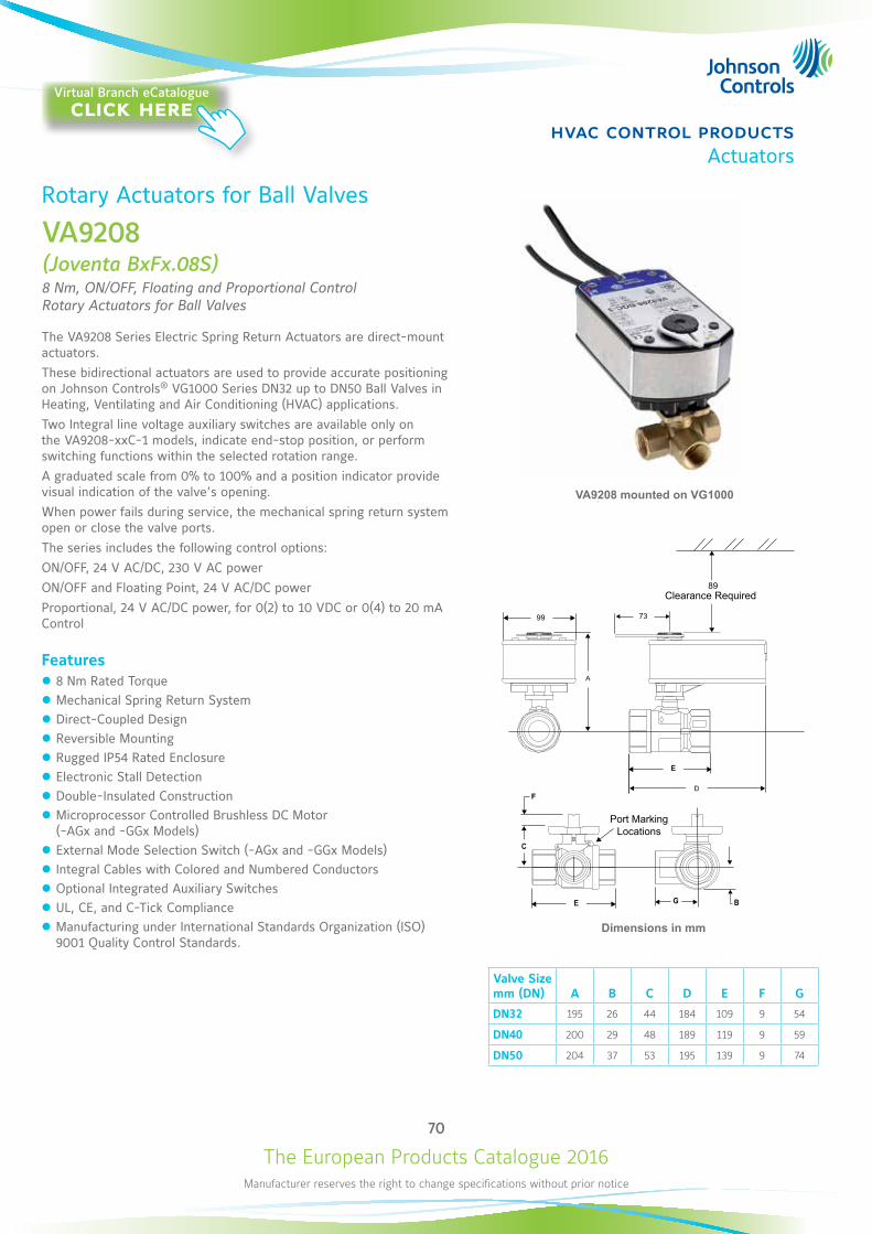
The European Products Catalogue 2016Manufacturer reserves the right to change specifications without prior notice
70
hvac control productsActuators
Rotary Actuators for Ball Valves
VA9208(Joventa BxFx.08S)8 Nm, ON/OFF, Floating and Proportional Control Rotary Actuators for Ball Valves
The VA9208 Series Electric Spring Return Actuators are direct-mount actuators.These bidirectional actuators are used to provide accurate positioning on Johnson Controls® VG1000 Series DN32 up to DN50 Ball Valves in Heating, Ventilating and Air Conditioning (HVAC) applications. Two Integral line voltage auxiliary switches are available only on the VA9208-xxC-1 models, indicate end-stop position, or perform switching functions within the selected rotation range.A graduated scale from 0% to 100% and a position indicator provide visual indication of the valve’s opening. When power fails during service, the mechanical spring return system open or close the valve ports.The series includes the following control options:ON/OFF, 24 V AC/DC, 230 V AC powerON/OFF and Floating Point, 24 V AC/DC powerProportional, 24 V AC/DC power, for 0(2) to 10 VDC or 0(4) to 20 mA Control
Features z 8 Nm Rated Torque z Mechanical Spring Return System z Direct-Coupled Design z Reversible Mounting z Rugged IP54 Rated Enclosure z Electronic Stall Detection z Double-Insulated Construction z Microprocessor Controlled Brushless DC Motor (-AGx and -GGx Models)
z External Mode Selection Switch (-AGx and -GGx Models) z Integral Cables with Colored and Numbered Conductors z Optional Integrated Auxiliary Switches z UL, CE, and C-Tick Compliance z Manufacturing under International Standards Organization (ISO) 9001 Quality Control Standards.
Valve Size mm (DN) A B C D E F G
DN32 195 26 44 184 109 9 54
DN40 200 29 48 189 119 9 59
DN50 204 37 53 195 139 9 74
VA9208 mounted on VG1000
99 73
F
Dimensions in mm
Clearance Required
Port MarkingLocations
Virtual Branch eCatalogueclick here
The European Products Catalogue 2016Manufacturer reserves the right to change specifications without prior notice
71
hvac control productsActuators
Rotary Actuators for Ball ValvesVA9208 (Joventa BxFx.08S)
Ordering Codes
Johnson Controls Joventa Description
VA9208-GGA-1 BMF1.08 8 Nm Spring Return Actuator for Valves, Proportional, 24 V AC/DC
VA9208-GGC-1 BMF1.08S 8 Nm Spring Return Actuator for Valves, Proportional, 24 V AC/DC, 2 Switch
VA9208-AGA-1 BBF1.08 8 Nm Spring Return Actuator for Valves, Floating & ON/OFF, 24 V AC/DC
VA9208-AGC-1 BBF1.08S 8 Nm Spring Return Actuator for Valves, Floating & ON/OFF, 24 V AC/DC, 2 Switch
VA9208-BGA-1 BAF1.08 8 Nm Spring Return Actuator for Valves, ON/OFF, 24 V AC/DC
VA9208-BGC-1 BAF1.08S 8 Nm Spring Return Actuator for Valves, ON/OFF, 24 V AC/DC, 2 Switch
VA9208-BDA-1 BAF2.08 8 Nm Spring Return Actuator for Valves, ON/OFF, 230 V AC
VA9208-BDC-1 BAF2.08S 8 Nm Spring Return Actuator for Valves, ON/OFF, 230 V AC, 2 Switch
Accessories (order separately)Ordering Codes Description
M9000-200 Commissioning Tool that Provides a Control Signal to Drive 24 V ON/OFF, Floating, Proportional and/or Resistive Electric Actuators
M9000-560 Ball Valve Linkage Kit for applying M9203 and M9208 Series Actuators to VG1000 Series Valves (quantity 1)
M9000-561 Thermal Barrier Extends M(VA)9104, M(VA)9203 and M(VA)9208 Series Electric Spring Return Actuator applications to include low pressure steam (quantity 1)
M9000-341 Weathershield Kit for VG1000 Series Ball Valve application of M(VA)9104, M(VA)9203 and M(VA)9208 Series Electric Spring Return Actuators (quantity 1)
M9000-607 Position Indicator for VG1000 Series Ball Valve Applications (quantity 5)
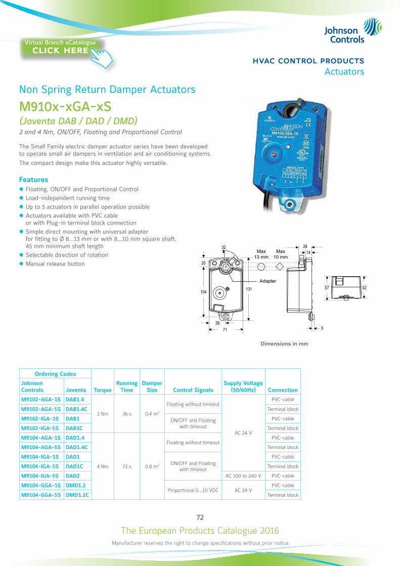
The European Products Catalogue 2016Manufacturer reserves the right to change specifications without prior notice
72
hvac control productsActuators
Non Spring Return Damper Actuators
M910x-xGA-xS (Joventa DAB / DAD / DMD)2 and 4 Nm, ON/OFF, Floating and Proportional Control
The Small Family electric damper actuator series have been developed to operate small air dampers in ventilation and air conditioning systems. The compact design make this actuator highly versatile.
Features z Floating, ON/OFF and Proportional Control z Load-independent running time z Up to 5 actuators in parallel operation possible z Actuators available with PVC cable or with Plug-in terminal block connection
z Simple direct mounting with universal adapter for fitting to Ø 8...13 mm or with 8...10 mm square shaft. 45 mm minimum shaft length
z Selectable direction of rotation z Manual release button
Ordering Codes
TorqueRunning
TimeDamper
Size Control SignalsSupply Voltage
(50/60Hz) ConnectionJohnson Controls Joventa
M9102-AGA-1S DAB1.4
2 Nm 36 s 0.4 m2
Floating without timeout
AC 24 V
PVC-cable
M9102-AGA-5S DAB1.4C Terminal block
M9102-IGA-1S DAB1 ON/OFF and Floating with timeout
PVC-cable
M9102-IGA-5S DAB1C Terminal block
M9104-AGA-1S DAD1.4
4 Nm 72 s 0.8 m2
Floating without timeoutPVC-cable
M9104-AGA-5S DAD1.4C Terminal block
M9104-IGA-1S DAD1ON/OFF and Floating
with timeout
PVC-cable
M9104-IGA-5S DAD1C Terminal block
M9104-IUA-5S DAD2 AC 100 to 240 V PVC-cable
M9104-GGA-1S DMD1.2Proportional 0...10 VDC AC 24 V
PVC-cable
M9104-GGA-5S DMD1.2C Terminal block
20
104
71
131
28 14
5
57 52
36
32
Dimensions in mm
Max13 mm
Max10 mm
Adapter
Virtual Branch eCatalogueclick here
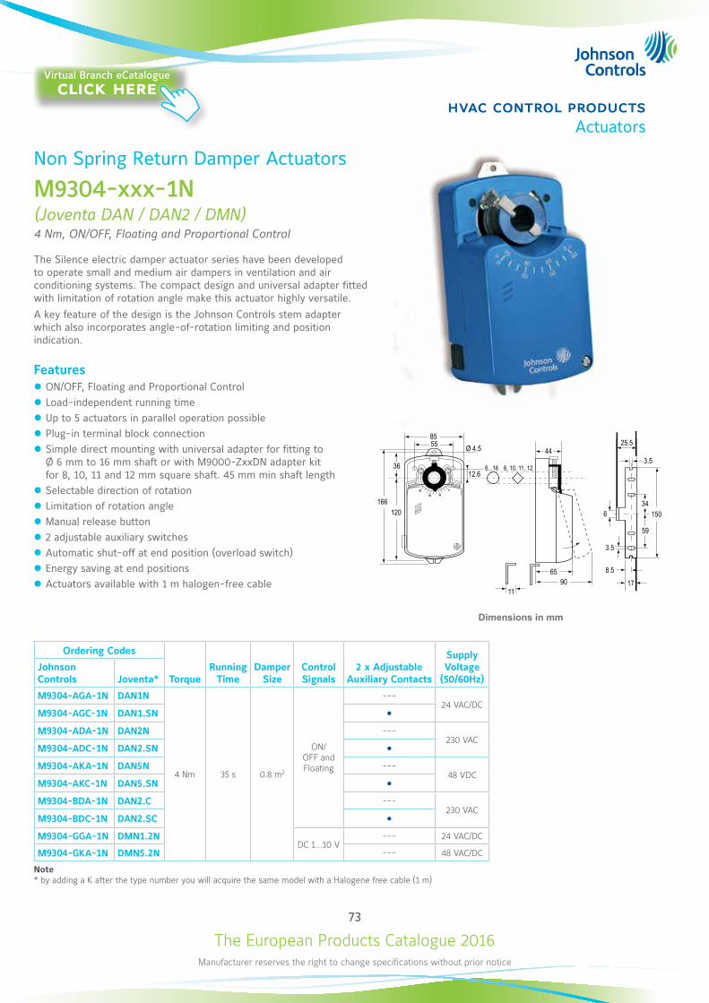
The European Products Catalogue 2016Manufacturer reserves the right to change specifications without prior notice
73
hvac control productsActuators
Non Spring Return Damper Actuators
M9304-xxx-1N(Joventa DAN / DAN2 / DMN)4 Nm, ON/OFF, Floating and Proportional Control
The Silence electric damper actuator series have been developed to operate small and medium air dampers in ventilation and air conditioning systems. The compact design and universal adapter fitted with limitation of rotation angle make this actuator highly versatile. A key feature of the design is the Johnson Controls stem adapter which also incorporates angle-of-rotation limiting and position indication.
Features z ON/OFF, Floating and Proportional Control z Load-independent running time z Up to 5 actuators in parallel operation possible z Plug-in terminal block connection z Simple direct mounting with universal adapter for fitting to Ø 6 mm to 16 mm shaft or with M9000-ZxxDN adapter kit for 8, 10, 11 and 12 mm square shaft. 45 mm min shaft length
z Selectable direction of rotation z Limitation of rotation angle z Manual release button z 2 adjustable auxiliary switches z Automatic shut-off at end position (overload switch) z Energy saving at end positions z Actuators available with 1 m halogen-free cable
Ordering Codes
TorqueRunning
TimeDamper
SizeControl Signals
2 x Adjustable Auxiliary Contacts
Supply Voltage
(50/60Hz)Johnson Controls Joventa*
M9304-AGA-1N DAN1N
4 Nm 35 s 0.8 m2
ON/OFF and Floating
---24 VAC/DC
M9304-AGC-1N DAN1.SN M9304-ADA-1N DAN2N ---
230 VACM9304-ADC-1N DAN2.SN M9304-AKA-1N DAN5N ---
48 VDCM9304-AKC-1N DAN5.SN M9304-BDA-1N DAN2.C ---
230 VACM9304-BDC-1N DAN2.SC M9304-GGA-1N DMN1.2N
DC 1...10 V--- 24 VAC/DC
M9304-GKA-1N DMN5.2N --- 48 VAC/DC
Note * by adding a K after the type number you will acquire the same model with a Halogene free cable (1 m)
90
60 30
0
Ø 4.5
12.66...16 8, 10, 11, 12
5585
120
36
4425.5
3.5
9011
65
150
59
346
3.5
8.5
17
166
Dimensions in mm
Virtual Branch eCatalogueclick here
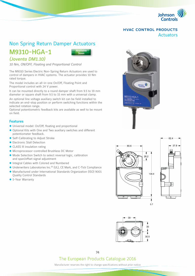
The European Products Catalogue 2016Manufacturer reserves the right to change specifications without prior notice
74
hvac control productsActuators
Non Spring Return Damper Actuators
M9310-HGA-1(Joventa DM1.10)10 Nm, ON/OFF, Floating and Proportional Control
The M9310 Series Electric Non-Spring Return Actuators are used to control of dampers in HVAC systems. The actuator provides 10 Nm rated torque.The model includes an all-in-one On/Off, Floating Point and Proportional control with 24 V power.It can be mounted directly to a round damper shaft from 9.5 to 19 mm diameter or square shaft from 9.5 to 15 mm with a universal clamp.An optional line voltage auxiliary switch kit can be field installed to indicate an end-stop position or perform switching functions within the selected rotation range. Optional potentiometric feedback kits are available as well to be mount on field.
Features z Universal model: On/Off, floating and proportional z Optional Kits with One and Two auxiliary switches and different potentiometer feedback.
z Self-Calibrating to Adjust Stroke z Electronic Stall Detection z CLASS III insulation rating z Microprocessor-controlled Brushless DC Motor z Mode Selection Switch to select reversal logic, calibration and span/offset signal adjustment
z Integral Cables with Colored and Numbered z Underwriters Laboratories Inc.® (UL), CE Mark, and C-Tick Compliance z Manufactured under International Standards Organization (ISO) 9001 Quality Control Standards
z 5-Year Warranty
136.9
28.2
5.7
80.6
62.4
37.8
30
30.5
39
Available Soon
The European Products Catalogue 2016Manufacturer reserves the right to change specifications without prior notice
75
hvac control productsActuators
Non Spring Return Damper Actuators M9310-HGA-1(Joventa DM1.10)
Ordering Codes
TorqueRunning
TimeDamper
Size Control SignalsSupply Voltage
(50/60Hz) Johnson Controls Joventa
M9310-HGA-1 DM1.10 10 Nm 35 s 2 m2 ON/OFF, Floating, Proportional 0(2)...10 VDC /0(4)...20 mA 24 VAC/DC
Accessories (order separately)Ordering Codes Description
M9300-140 Feedback Potentiometer 140 ohms
M9300-1k Feedback Potentiometer 1k ohms
M9300-2k Feedback Potentiometer 2k ohms
M9300-10k Feedback Potentiometer 10k ohms
M9000-200 Commissioning Tool that provides a control signal to drive 24 V On/Off, Floating, Proportional, and Resistive Electric Actuators (quantity 1)
M9000-322 NEMA 4x Weathershield Kit for Damper Application of M9104, M9310-xxx-D, M9203, and M9208 Series Electric Actuators (quantity 1)
M9000-342 Weather Shield Kit for VG1000 Series Ball application of VA9104, M9310-xxx-V, VA9203, and VA9208 Series Electric Non-Spring Return Actuators (quantity 1)
M9000-400 Jackshaft Linkage Adapter Kit (quantity 1)
M9310-500 Ball Valve Linkage Kit for applying M9310-xxx-D Series Electric Actuators to VG1000 Series Valves (quantity 1)
M9000-561 Thermal Barrier Kit. Extends the VA9104, M9310-xxx-V, VA9203, and VA9208 Series Electric Non- Spring Return Actuators applications to include low pressure steam (quantity 1)
M9000-604 Replacement Anti-Rotation Bracket Kit for M9310, M9203, M9208, M9210, and M9220 Series Electric Actuators
M9000-606 Position Indicator for Damper Applications (quantity 5) M9300-2 Auxiliary Contact Kit
M9300-100 Threaded Conduit Adapters for 1/2 in. electrician’s fittings
M9310-100 Remote Mounting Kit with Crankarm Kit (quantity 1)
M9310-600 Coupler
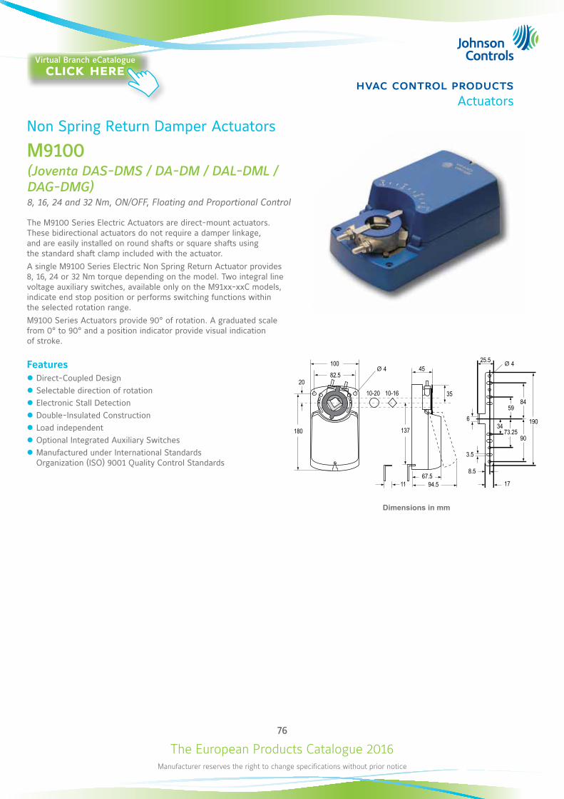
The European Products Catalogue 2016Manufacturer reserves the right to change specifications without prior notice
76
hvac control productsActuators
Non Spring Return Damper Actuators
M9100(Joventa DAS-DMS / DA-DM / DAL-DML / DAG-DMG)8, 16, 24 and 32 Nm, ON/OFF, Floating and Proportional Control
The M9100 Series Electric Actuators are direct-mount actuators. These bidirectional actuators do not require a damper linkage, and are easily installed on round shafts or square shafts using the standard shaft clamp included with the actuator.A single M9100 Series Electric Non Spring Return Actuator provides 8, 16, 24 or 32 Nm torque depending on the model. Two integral line voltage auxiliary switches, available only on the M91xx-xxC models, indicate end stop position or performs switching functions within the selected rotation range.M9100 Series Actuators provide 90° of rotation. A graduated scale from 0° to 90° and a position indicator provide visual indication of stroke.
Features z Direct-Coupled Design z Selectable direction of rotation z Electronic Stall Detection z Double-Insulated Construction z Load independent z Optional Integrated Auxiliary Switches z Manufactured under International Standards Organization (ISO) 9001 Quality Control Standards
10045
25.5
3510-20
44
6
3.5
8.5
17
10-16
180 137
67.594.5
19034
73.25
8459
90
11
2082.5
Dimensions in mm
Virtual Branch eCatalogueclick here
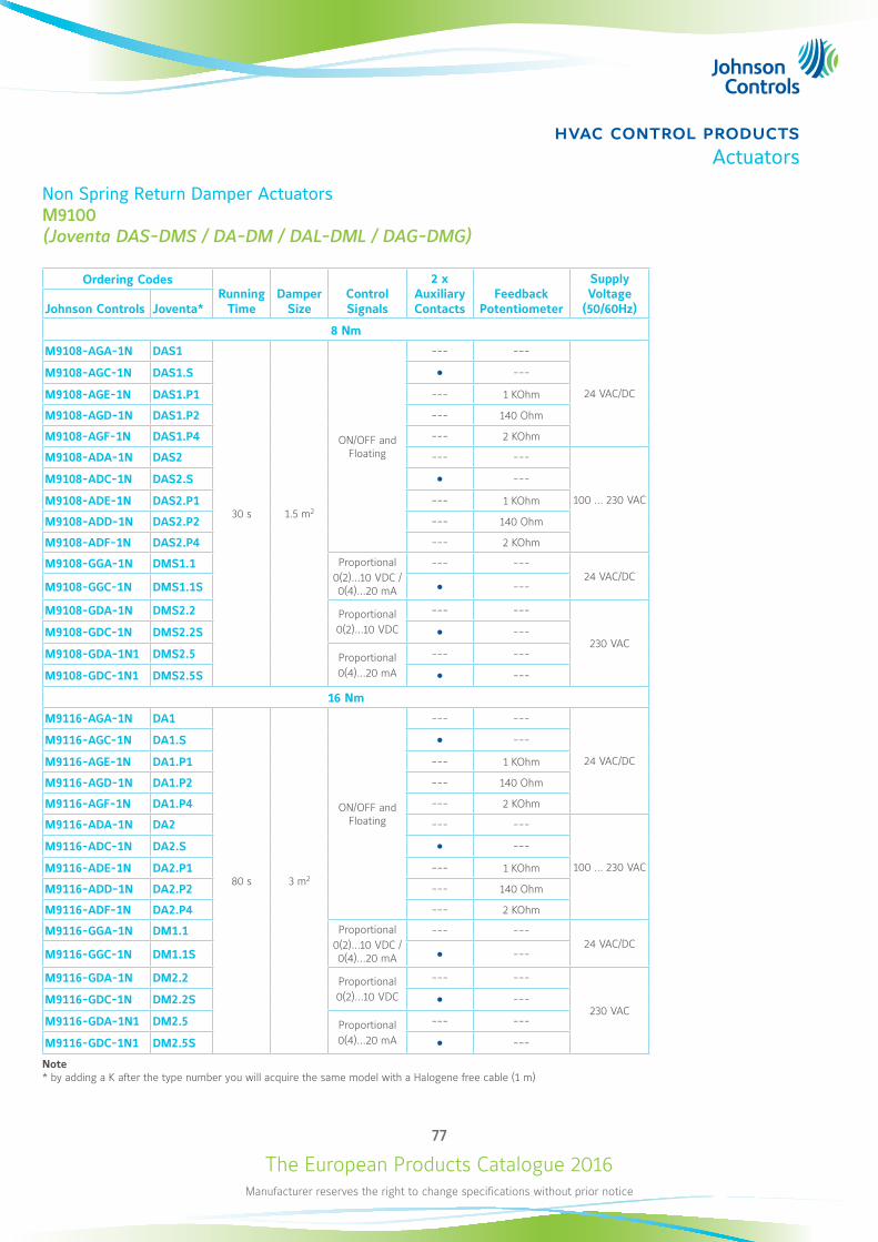
The European Products Catalogue 2016Manufacturer reserves the right to change specifications without prior notice
77
hvac control productsActuators
Non Spring Return Damper Actuators M9100 (Joventa DAS-DMS / DA-DM / DAL-DML / DAG-DMG)
Ordering Codes Running
TimeDamper
SizeControl Signals
2 x Auxiliary Contacts
Feedback Potentiometer
Supply Voltage
(50/60Hz)Johnson Controls Joventa*
8 Nm
M9108-AGA-1N DAS1
30 s 1.5 m2
ON/OFF and Floating
--- ---
24 VAC/DC
M9108-AGC-1N DAS1.S ---
M9108-AGE-1N DAS1.P1 --- 1 KOhm
M9108-AGD-1N DAS1.P2 --- 140 Ohm
M9108-AGF-1N DAS1.P4 --- 2 KOhm
M9108-ADA-1N DAS2 --- ---
100 ... 230 VAC
M9108-ADC-1N DAS2.S ---
M9108-ADE-1N DAS2.P1 --- 1 KOhm
M9108-ADD-1N DAS2.P2 --- 140 Ohm
M9108-ADF-1N DAS2.P4 --- 2 KOhm
M9108-GGA-1N DMS1.1 Proportional0(2)...10 VDC / 0(4)...20 mA
--- ---24 VAC/DC
M9108-GGC-1N DMS1.1S ---
M9108-GDA-1N DMS2.2 Proportional0(2)...10 VDC
--- ---
230 VACM9108-GDC-1N DMS2.2S ---
M9108-GDA-1N1 DMS2.5 Proportional0(4)...20 mA
--- ---
M9108-GDC-1N1 DMS2.5S ---
16 Nm
M9116-AGA-1N DA1
80 s 3 m2
ON/OFF and Floating
--- ---
24 VAC/DC
M9116-AGC-1N DA1.S ---
M9116-AGE-1N DA1.P1 --- 1 KOhm
M9116-AGD-1N DA1.P2 --- 140 Ohm
M9116-AGF-1N DA1.P4 --- 2 KOhm
M9116-ADA-1N DA2 --- ---
100 ... 230 VAC
M9116-ADC-1N DA2.S ---
M9116-ADE-1N DA2.P1 --- 1 KOhm
M9116-ADD-1N DA2.P2 --- 140 Ohm
M9116-ADF-1N DA2.P4 --- 2 KOhm
M9116-GGA-1N DM1.1 Proportional0(2)...10 VDC / 0(4)...20 mA
--- ---24 VAC/DC
M9116-GGC-1N DM1.1S ---
M9116-GDA-1N DM2.2 Proportional0(2)...10 VDC
--- ---
230 VACM9116-GDC-1N DM2.2S ---
M9116-GDA-1N1 DM2.5 Proportional0(4)...20 mA
--- ---
M9116-GDC-1N1 DM2.5S ---
Note * by adding a K after the type number you will acquire the same model with a Halogene free cable (1 m)
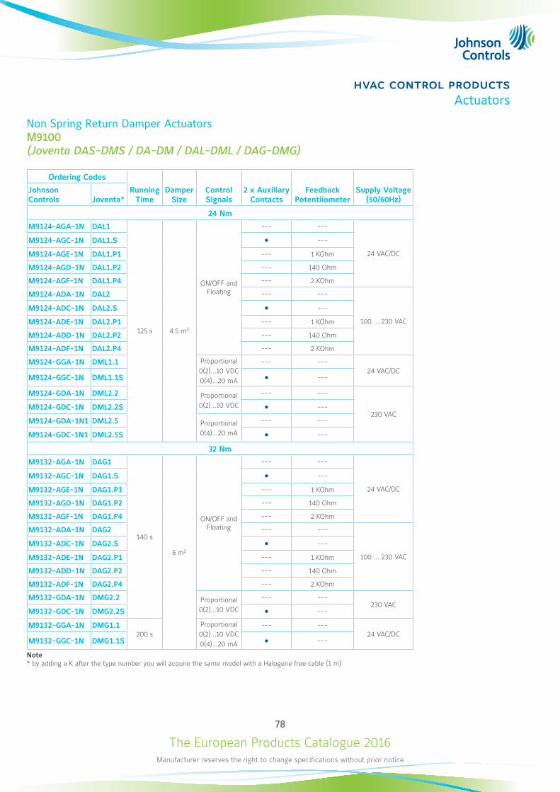
The European Products Catalogue 2016Manufacturer reserves the right to change specifications without prior notice
78
hvac control productsActuators
Non Spring Return Damper Actuators M9100 (Joventa DAS-DMS / DA-DM / DAL-DML / DAG-DMG)
Ordering Codes
Running Time
Damper Size
Control Signals
2 x Auxiliary Contacts
Feedback Potentiiometer
Supply Voltage (50/60Hz)
Johnson Controls Joventa*
24 Nm
M9124-AGA-1N DAL1
125 s 4.5 m2
ON/OFF and Floating
--- ---
24 VAC/DC
M9124-AGC-1N DAL1.S ---
M9124-AGE-1N DAL1.P1 --- 1 KOhm
M9124-AGD-1N DAL1.P2 --- 140 Ohm
M9124-AGF-1N DAL1.P4 --- 2 KOhm
M9124-ADA-1N DAL2 --- ---
100 ... 230 VAC
M9124-ADC-1N DAL2.S ---
M9124-ADE-1N DAL2.P1 --- 1 KOhm
M9124-ADD-1N DAL2.P2 --- 140 Ohm
M9124-ADF-1N DAL2.P4 --- 2 KOhm
M9124-GGA-1N DML1.1 Proportional0(2)...10 VDC0(4)...20 mA
--- ---24 VAC/DC
M9124-GGC-1N DML1.1S ---
M9124-GDA-1N DML2.2 Proportional0(2)...10 VDC
--- ---
230 VACM9124-GDC-1N DML2.2S ---
M9124-GDA-1N1 DML2.5 Proportional0(4)...20 mA
--- ---
M9124-GDC-1N1 DML2.5S ---
32 Nm
M9132-AGA-1N DAG1
140 s
6 m2
ON/OFF and Floating
--- ---
24 VAC/DC
M9132-AGC-1N DAG1.S ---
M9132-AGE-1N DAG1.P1 --- 1 KOhm
M9132-AGD-1N DAG1.P2 --- 140 Ohm
M9132-AGF-1N DAG1.P4 --- 2 KOhm
M9132-ADA-1N DAG2 --- ---
100 ... 230 VAC
M9132-ADC-1N DAG2.S ---
M9132-ADE-1N DAG2.P1 --- 1 KOhm
M9132-ADD-1N DAG2.P2 --- 140 Ohm
M9132-ADF-1N DAG2.P4 --- 2 KOhm
M9132-GDA-1N DMG2.2 Proportional0(2)...10 VDC
--- ---230 VAC
M9132-GDC-1N DMG2.2S ---
M9132-GGA-1N DMG1.1200 s
Proportional0(2)...10 VDC0(4)...20 mA
--- ---24 VAC/DC
M9132-GGC-1N DMG1.1S ---
Note * by adding a K after the type number you will acquire the same model with a Halogene free cable (1 m)

The European Products Catalogue 2016Manufacturer reserves the right to change specifications without prior notice
79
hvac control productsActuators
Spring Return Damper Actuators
M9203(Joventa DxF1.03S-Z)3 Nm, ON/OFF, Floating and Proportional Control
The M9203 Series Electric Spring Return Actuators are direct-mount actuators. These bidirectional actuators do not require a damper linkage, and are easily installed on round shafts or square shafts using the standard shaft clamp included with the actuator. A single M9203 Series Electric Spring Return Actuator provides 3 Nm running and spring return torque. An integral line voltage auxiliary switch, available only on the M9203-xxB-1(Z) models, indicates end stop position, or performs switching functions within the selected rotation range.M9203 Series Actuators provide 95° of rotation. A graduated scale from -5° to 90° and a position indicator provide visual indication of stroke. When power fails during service, the mechanical spring return system provides rated torque to the connected equipment, returning it to the home position.The series includes the following control options:ON/OFF, 24 V, 100 to 240 VAC powerON/OFF and Floating Point, 24 V powerProportional, 24 V power, for 0(2) to 10 VDC or 0(4) to 20 mA Control Signal.
Features z 3 Nm Rated Torque z Direct-Coupled Design z Reversible Mounting z Electronic Stall Detection z Double-Insulated Construction z Microprocessor-controlled Brushless DC Motor (-AGx and GGx types)
z External Mode Selection Switch (-AGx and -GGx types) z Integral Cables with Colored and Numbered Conductors z Optional Integrated Auxiliary Switch z Override Control (Proportional Models Only) z Manufactured under International Standards Organization (ISO) 9001 Quality Control Standards
6.5
8
107.5
20
123.6
152
826
57.518
28.7
39.2
18.7
Dimensions in mm
Virtual Branch eCatalogueclick here
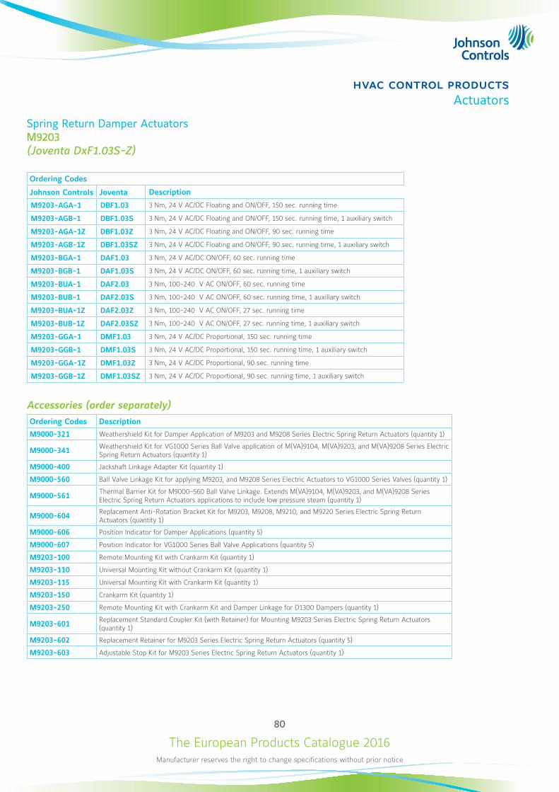
The European Products Catalogue 2016Manufacturer reserves the right to change specifications without prior notice
80
hvac control productsActuators
Spring Return Damper Actuators M9203 (Joventa DxF1.03S-Z)
Ordering Codes
Johnson Controls Joventa Description
M9203-AGA-1 DBF1.03 3 Nm, 24 V AC/DC Floating and ON/OFF, 150 sec. running time
M9203-AGB-1 DBF1.03S 3 Nm, 24 V AC/DC Floating and ON/OFF, 150 sec. running time, 1 auxiliary switch
M9203-AGA-1Z DBF1.03Z 3 Nm, 24 V AC/DC Floating and ON/OFF, 90 sec. running time
M9203-AGB-1Z DBF1.03SZ 3 Nm, 24 V AC/DC Floating and ON/OFF, 90 sec. running time, 1 auxiliary switch
M9203-BGA-1 DAF1.03 3 Nm, 24 V AC/DC ON/OFF, 60 sec. running time
M9203-BGB-1 DAF1.03S 3 Nm, 24 V AC/DC ON/OFF, 60 sec. running time, 1 auxiliary switch
M9203-BUA-1 DAF2.03 3 Nm, 100-240 V AC ON/OFF, 60 sec. running time
M9203-BUB-1 DAF2.03S 3 Nm, 100-240 V AC ON/OFF, 60 sec. running time, 1 auxiliary switch
M9203-BUA-1Z DAF2.03Z 3 Nm, 100-240 V AC ON/OFF, 27 sec. running time
M9203-BUB-1Z DAF2.03SZ 3 Nm, 100-240 V AC ON/OFF, 27 sec. running time, 1 auxiliary switch
M9203-GGA-1 DMF1.03 3 Nm, 24 V AC/DC Proportional, 150 sec. running time
M9203-GGB-1 DMF1.03S 3 Nm, 24 V AC/DC Proportional, 150 sec. running time, 1 auxiliary switch
M9203-GGA-1Z DMF1.03Z 3 Nm, 24 V AC/DC Proportional, 90 sec. running time
M9203-GGB-1Z DMF1.03SZ 3 Nm, 24 V AC/DC Proportional, 90 sec. running time, 1 auxiliary switch
Accessories (order separately)Ordering Codes Description
M9000-321 Weathershield Kit for Damper Application of M9203 and M9208 Series Electric Spring Return Actuators (quantity 1)
M9000-341 Weathershield Kit for VG1000 Series Ball Valve application of M(VA)9104, M(VA)9203, and M(VA)9208 Series Electric Spring Return Actuators (quantity 1)
M9000-400 Jackshaft Linkage Adapter Kit (quantity 1)
M9000-560 Ball Valve Linkage Kit for applying M9203, and M9208 Series Electric Actuators to VG1000 Series Valves (quantity 1)
M9000-561 Thermal Barrier Kit for M9000-560 Ball Valve Linkage. Extends M(VA)9104, M(VA)9203, and M(VA)9208 Series Electric Spring Return Actuators applications to include low pressure steam (quantity 1)
M9000-604 Replacement Anti-Rotation Bracket Kit for M9203, M9208, M9210, and M9220 Series Electric Spring Return Actuators (quantity 1)
M9000-606 Position Indicator for Damper Applications (quantity 5)
M9000-607 Position Indicator for VG1000 Series Ball Valve Applications (quantity 5)
M9203-100 Remote Mounting Kit with Crankarm Kit (quantity 1)
M9203-110 Universal Mounting Kit without Crankarm Kit (quantity 1)
M9203-115 Universal Mounting Kit with Crankarm Kit (quantity 1)
M9203-150 Crankarm Kit (quantity 1)
M9203-250 Remote Mounting Kit with Crankarm Kit and Damper Linkage for D1300 Dampers (quantity 1)
M9203-601 Replacement Standard Coupler Kit (with Retainer) for Mounting M9203 Series Electric Spring Return Actuators (quantity 1)
M9203-602 Replacement Retainer for M9203 Series Electric Spring Return Actuators (quantity 5)
M9203-603 Adjustable Stop Kit for M9203 Series Electric Spring Return Actuators (quantity 1)
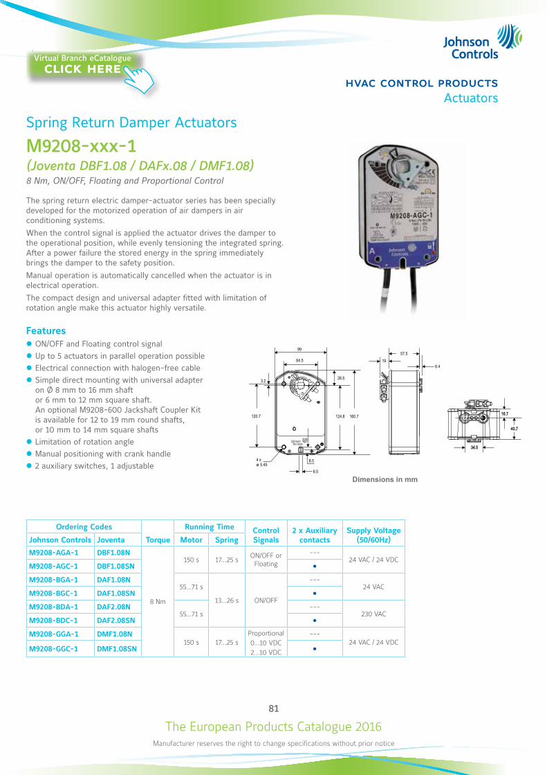
The European Products Catalogue 2016Manufacturer reserves the right to change specifications without prior notice
81
hvac control productsActuators
Spring Return Damper Actuators
M9208-xxx-1 (Joventa DBF1.08 / DAFx.08 / DMF1.08)8 Nm, ON/OFF, Floating and Proportional Control
The spring return electric damper-actuator series has been specially developed for the motorized operation of air dampers in air conditioning systems.When the control signal is applied the actuator drives the damper to the operational position, while evenly tensioning the integrated spring. After a power failure the stored energy in the spring immediately brings the damper to the safety position.Manual operation is automatically cancelled when the actuator is in electrical operation.The compact design and universal adapter fitted with limitation of rotation angle make this actuator highly versatile.
Features z ON/OFF and Floating control signal z Up to 5 actuators in parallel operation possible z Electrical connection with halogen-free cable z Simple direct mounting with universal adapter on Ø 8 mm to 16 mm shaft or 6 mm to 12 mm square shaft. An optional M9208-600 Jackshaft Coupler Kit is available for 12 to 19 mm round shafts, or 10 mm to 14 mm square shafts
z Limitation of rotation angle z Manual positioning with crank handle z 2 auxiliary switches, 1 adjustable
64.5
3.2
120.7
4 x5.45ø
28.5
99
124.8 160.7 16.7
40.7
34.5
6.4 19
57.5
Dimensions in mm
Ordering Codes
Torque
Running Time Control Signals
2 x Auxiliary contacts
Supply Voltage (50/60Hz)Johnson Controls Joventa Motor Spring
M9208-AGA-1 DBF1.08N
8 Nm
150 s 17...25 s ON/OFF or Floating
---24 VAC / 24 VDC
M9208-AGC-1 DBF1.08SN M9208-BGA-1 DAF1.08N
55...71 s
13...26 s ON/OFF
---24 VAC
M9208-BGC-1 DAF1.08SN M9208-BDA-1 DAF2.08N
55...71 s---
230 VAC M9208-BDC-1 DAF2.08SN M9208-GGA-1 DMF1.08N
150 s 17...25 sProportional0...10 VDC2...10 VDC
---24 VAC / 24 VDC
M9208-GGC-1 DMF1.08SN
Virtual Branch eCatalogueclick here
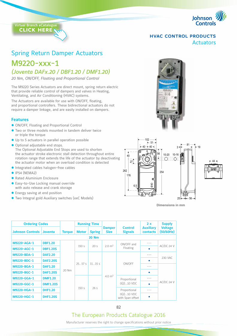
The European Products Catalogue 2016Manufacturer reserves the right to change specifications without prior notice
82
hvac control productsActuators
Spring Return Damper Actuators
M9220-xxx-1 (Joventa DAFx.20 / DBF1.20 / DMF1.20)20 Nm, ON/OFF, Floating and Proportional Control
The M9220 Series Actuators are direct mount, spring return electric that provide reliable control of dampers and valves in Heating, Ventilating, and Air Conditioning (HVAC) systems. The Actuators are available for use with ON/OFF, floating, and proportional controllers. These bidirectional actuators do not require a damper linkage, and are easily installed on dampers.
Features z ON/OFF, Floating and Proportional Control z Two or three models mounted in tandem deliver twice or triple the torque
z Up to 5 actuators in parallel operation possible z Optional adjustable end stops. The Optional Adjustable End Stops are used to shorten the actuator stroke electronic stall detection throughout entire rotation range that extends the life of the actuator by deactivating the actuator motor when an overload condition is detected
z Integrated cables halogen-free cables z IP54 (NEMA2) z Rated Aluminium Enclosure z Easy-to-Use Locking manual override with auto release and crank storage
z Energy saving at end position z Two Integral gold Auxiliary switches (xxC Models)
900
A
44
381
19
5625
254
56
27
10-20 10-16
10251
40
262
40
176
6.5
40
Dimensions in mm
Ordering Codes
Torque
Running TimeDamper
SizeControl Signals
2 x Auxiliary contacts
Supply Voltage
(50/60Hz)Johnson Controls Joventa Motor Spring
20 Nm
M9220-AGA-1 DBF1.20
20 Nm
150 s 20 s 2.0 m2 ON/OFF and Floating
---AC/DC 24 V
M9220-AGC-1 DBF1.20S M9220-BDA-1 DAF2.20
25...57 s 11...15 s
4.0 m2
ON/OFF
---230 VAC
M9220-BDC-1 DAF2.20S M9220-BGA-1 DAF1.20 ---
AC/DC 24 V
M9220-BGC-1 DAF1.20S M9220-GGA-1 DMF1.20
150 s 26 s
Proportional0(2)...10 VDC
---
M9220-GGC-1 DMF1.20S M9220-HGA-1 DHF1.20 Proportional
0(2)...10 VDC with Span offset
---
M9220-HGC-1 DHF1.20S
Virtual Branch eCatalogueclick here

The European Products Catalogue 2016Manufacturer reserves the right to change specifications without prior notice
83
hvac control productsActuators
Safety Damper Actuators
S9208-BxC-33x(Joventa SAFx.08Sx/12)8 Nm, ON/OFF Control
The S9208 Security Fire electric, Spring Return damper actuator series has been specially developed for the motorized operation of fire protection dampers.When the control signal is applied the actuator drives the damper to the operational position, while evenly tensioning the integrated spring.After a power failure the stored energy in the spring immediately brings the damper to the safety position. Manual operation is automatically cancelled when the actuator is in electrical operation.
Features z ON/OFF control signal z 12 mm square shaft and 10 mm, 8 mm adapter inside the package z Connection with halogen-free cable z ST1.72E temperature sensor. Switch point of temperature sensor ca. 72°C
z Actuator temperature sensor to monitor ambient sensor. z Low noise level z Manual positioning with crank handle z 2 fixed auxiliary switches (8° and 83°)
Dimensions in mm
Ordering Codes Supply Voltage (50-60Hz) DescriptionJohnson Controls Joventa
S9208-BGC-33 SAF1.08S/12
24 VAC / VDC
Without sensor
S9208-BGC-33A SAF1.08SA/12 With ambient thermosensor
S9208-BGC-33B SAF1.08SB/12 With duct sensor
S9208-BGC-33C SAF1.08SC/12 With duct and ambient sensors
S9208-BDC-33 SAF2.08S/12
230 VAC
Without sensor
S9208-BDC-33A SAF2.08SA/12 With ambient thermosensor
S9208-BDC-33B SAF2.08SB/12 With duct sensor
S9208-BDC-33C SAF2.08SC/12 With duct and ambient sensors
Virtual Branch eCatalogueclick here
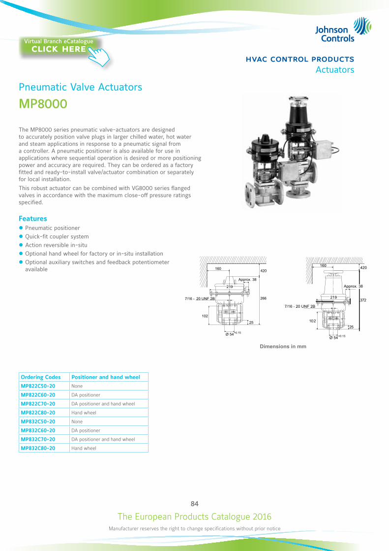
The European Products Catalogue 2016Manufacturer reserves the right to change specifications without prior notice
84
hvac control productsActuators
Pneumatic Valve Actuators
MP8000
The MP8000 series pneumatic valve-actuators are designed to accurately position valve plugs in larger chilled water, hot water and steam applications in response to a pneumatic signal from a controller. A pneumatic positioner is also available for use in applications where sequential operation is desired or more positioning power and accuracy are required. They can be ordered as a factory fitted and ready-to-install valve/actuator combination or separately for local installation. This robust actuator can be combined with VG8000 series flanged valves in accordance with the maximum close-off pressure ratings specified.
Features z Pneumatic positioner z Quick-fit coupler system z Action reversible in-situ z Optional hand wheel for factory or in-situ installation z Optional auxiliary switches and feedback potentiometer available
Ordering Codes Positioner and hand wheel
MP822C50-20 None
MP822C60-20 DA positioner
MP822C70-20 DA positioner and hand wheel
MP822C80-20 Hand wheel
MP832C50-20 None
MP832C60-20 DA positioner
MP832C70-20 DA positioner and hand wheel
MP832C80-20 Hand wheel
Approx. 38
7/16 - 20 UNF 2B
219
Ø 54+0.15
420
266
102
25
160
Dimensions in mm
160
Ø 54+0.15
7/16 - 20 UNF 2B273
20152
420
Approx. 38
219
Virtual Branch eCatalogueclick here
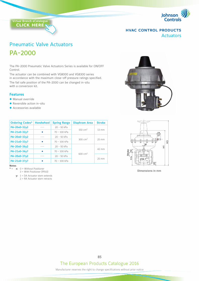
The European Products Catalogue 2016Manufacturer reserves the right to change specifications without prior notice
85
hvac control productsActuators
Pneumatic Valve Actuators
PA-2000
The PA-2000 Pneumatic Valve Actuators Series is available for ON/OFF Control.The actuator can be combined with VG8000 and VG8300 series in accordance with the maximum close-off pressure ratings specified.The fail safe position of the PA-2000 can be changed in-situ with a conversion kit.
Features z Manual override z Reversible action in-situ z Accessories available
Ordering Codes* Handwheel Spring Range Diaphram Area Stroke
PA-20x0-32y2 --- 20 - 50 kPa150 cm2 13 mm
PA-21x0-32y7 70 - 100 kPa
PA-20x0-33y2 --- 20 - 50 kPa300 cm2 25 mm
PA-21x0-33y7 70 - 100 kPa
PA-20x0-36y2 --- 20 - 50 kPa
600 cm2
42 mmPA-21x0-36y7 70 - 100 kPa
PA-20x0-37y2 --- 20 - 50 kPa25 mm
PA-21x0-37y7 70 - 100 kPa
Notes* = x: 0 = Without Positioner 3 = With Positioner (PR10)
y: 1 = DA Actuator stem extends 2 = RA Actuator stem retracts
Dimensions in mm
Virtual Branch eCatalogueclick here

The European Products Catalogue 2016Manufacturer reserves the right to change specifications without prior notice
hvac control productsSensors
86
Carbon Dioxide
CD-2xx-E00-00Wall Mount - CO2 and Temperature Transmitter
The CD-2xx-E00-00 series is a wall mount transmitter for measuring the CO2 levels and the relevant temperature within Heating, Ventilation and Air Conditioning (HAVC) applications. The CD-2xx Series incorporates a single beam dual wavelength NDIR CO2 sensor, which compensates for ageing effects, is highly insensitive to pollution and offers outstanding long term stability. A multiple point CO2 and T factory adjustment procedure leads to excellent CO2 measurement accuracy over the entire T working range.This compact wall-mounted device produces 0 to 10 V or 4 to 20 mA signals. It is designed to work:• in stand-alone mode • as part of any integrated Building Automation System (BAS)This new CO2 transmitter is easy to install, offers a full 3-year warranty, and requires no maintenance or field calibration.
Features z Power Supply 15...35 VDC / 24 VAC z 0…10 V or 4…20 mA CO2 and Temperature Output z Models with Display z Snap-on Enclosure z Outstanding long-term stability z CO2 Factory Calibration Certificate
85
26
100
Dimensions in mm
Ordering Code CO2 OutputCO2 Working
RangeTemperature
OutputTemperature
Working Range DisplayCalibration Certificate
CD-200-E00-000…10V
0...2000 ppm
0…10V
0...50 °C
---
CD-201-E00-00
CD-220-E00-004...20mA 4...20mA
---
CD-221-E00-00
Virtual Branch eCatalogueclick here

The European Products Catalogue 2016Manufacturer reserves the right to change specifications without prior notice
87
hvac control productsSensors
Carbon Dioxide
CD-3xx-E00-00Wall Mount - CO2 , Relative Humidity and Temperature Transmitter
The CD-3xx-E00-00 series is a wall mount transmitter for measuring the CO2 levels, the relevant humidity and the temperature within Heating, Ventilation and Air Conditioning (HAVC) applications.The CD-3xx Series incorporates a single beam dual wavelength NDIR CO2 sensor, which compensates for ageing effects, is highly insensitive to pollution and offers outstanding long term stability. A multiple point CO2 and T factory adjustment procedure leads to excellent CO2 measurement accuracy over the entire T working range.It is designed to work:• in stand-alone mode • as part of any integrated Building Automation System (BAS)This new CO2 transmitter is easy to install and requires no maintenance or field calibration.
Features z Power Supply 15...35 VDC / 24 VAC z 0…10 V CO2 and Relative Humidity Output z 0…10 V and Pt1000 Temperature Output on the same device z Models with Display z Snap-on Enclosure z Outstanding long-term stability z CO2 Factory Calibration Certificate
85
26
100
Dimensions in mm
Item CodeCO2
Output
CO2 Working Range RH% Output
RH% Working Range
Temperature Output
Temperature Working Range Display
Calibration Certificate
CD-310-E00-000…10V 0...2000 ppm 0...10V 10...90 % RH 0…10V
and Pt 10000...50 °C
(active model)
---
CD-311-E00-00
Virtual Branch eCatalogueclick here
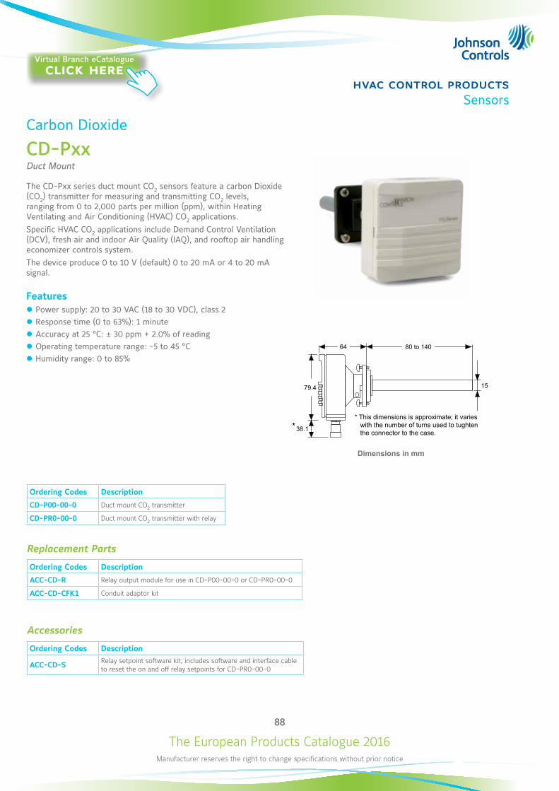
The European Products Catalogue 2016Manufacturer reserves the right to change specifications without prior notice
88
hvac control productsSensors
Carbon Dioxide
CD-PxxDuct Mount
The CD-Pxx series duct mount CO2 sensors feature a carbon Dioxide (CO2) transmitter for measuring and transmitting CO2 levels, ranging from 0 to 2,000 parts per million (ppm), within Heating Ventilating and Air Conditioning (HVAC) CO2 applications. Specific HVAC CO2 applications include Demand Control Ventilation (DCV), fresh air and indoor Air Quality (IAQ), and rooftop air handling economizer controls system. The device produce 0 to 10 V (default) 0 to 20 mA or 4 to 20 mA signal.
Features z Power supply: 20 to 30 VAC (18 to 30 VDC), class 2 z Response time (0 to 63%): 1 minute z Accuracy at 25 °C: ± 30 ppm + 2.0% of reading z Operating temperature range: -5 to 45 °C z Humidity range: 0 to 85%
79.4
38.1
15
*
80 to 14064
Dimensions in mm
Ordering Codes Description
CD-P00-00-0 Duct mount CO2 transmitter
CD-PR0-00-0 Duct mount CO2 transmitter with relay
Replacement Parts
Ordering Codes Description
ACC-CD-R Relay output module for use in CD-P00-00-0 or CD-PR0-00-0
ACC-CD-CFK1 Conduit adaptor kit
Accessories
Ordering Codes Description
ACC-CD-S Relay setpoint software kit; includes software and interface cable to reset the on and off relay setpoints for CD-PR0-00-0
* This dimensions is approximate; it varies with the number of turns used to tughten the connector to the case.
Virtual Branch eCatalogueclick here
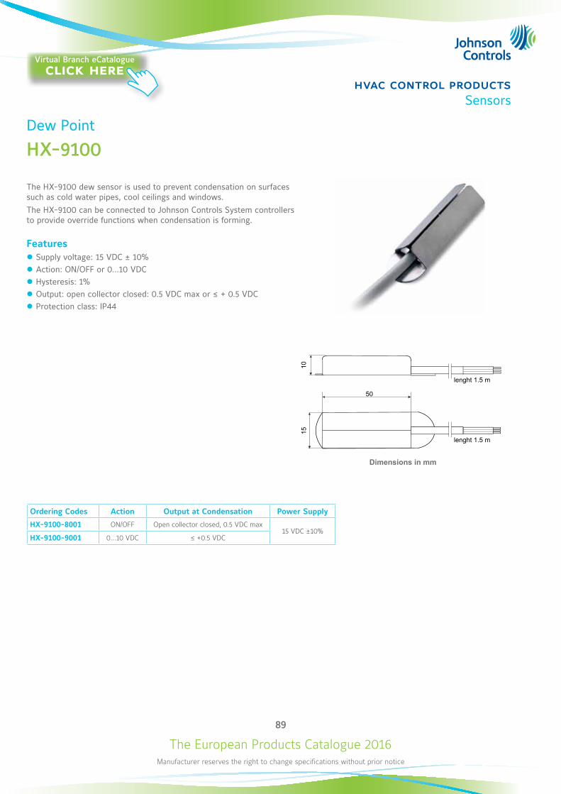
The European Products Catalogue 2016Manufacturer reserves the right to change specifications without prior notice
89
hvac control productsSensors
Dew Point
HX-9100
The HX-9100 dew sensor is used to prevent condensation on surfaces such as cold water pipes, cool ceilings and windows. The HX-9100 can be connected to Johnson Controls System controllers to provide override functions when condensation is forming.
Features z Supply voltage: 15 VDC ± 10% z Action: ON/OFF or 0...10 VDC z Hysteresis: 1% z Output: open collector closed: 0.5 VDC max or ≤ + 0.5 VDC z Protection class: IP44
Ordering Codes Action Output at Condensation Power Supply
HX-9100-8001 ON/OFF Open collector closed, 0.5 VDC max15 VDC ±10%
HX-9100-9001 0…10 VDC ≤ +0.5 VDC
50
1015
Dimensions in mm
lenght 1.5 m
lenght 1.5 m
Virtual Branch eCatalogueclick here
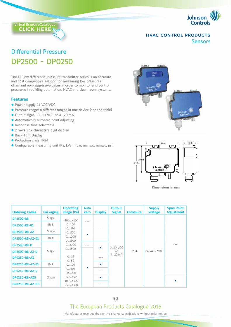
The European Products Catalogue 2016Manufacturer reserves the right to change specifications without prior notice
90
hvac control productsSensors
Differential Pressure
DP2500 - DP0250
The DP low differential pressure transmitter series is an accurate and cost competitive solution for measuring low pressures of air and non-aggressive gases in order to monitor and control pressures in building automation, HVAC and clean room systems.
Features z Power supply 24 VAC/VDC z Pressure range: 8 different ranges in one device (see the table) z Output signal: 0...10 VDC or 4...20 mA z Automatically autozero point adjusting z Response time selectable z 2 rows x 12 characters digit display z Back-light Display z Protection class: IP54 z Configurable measuring unit (Pa, kPa, mbar, inchwc, mmwc, psi)
Ordering Codes PackagingOperating Range (Pa)
Auto Zero Display
Output Signal Enclosure
Supply Voltage
Span Point Adjustment
DP2500-R8 Single-100...+100
0...1000...2500...5000...10000...15000...20000...2500
---
---
0...10 VDC or
4...20 mAIP54 24 VAC / VDC
---
DP2500-R8-01 Bulk
DP2500-R8-AZ Single
DP2500-R8-AZ-01 Bulk
DP2500-R8-D
Single
---
DP2500-R8-AZ-D
DP0250-R8-AZ 0...250...500...1000...250
-25...+25-50...+50
-100...+100-150...+150
---
DP0250-R8-AZ-01 Bulk
DP0250-R8-AZ-D
Single
---
DP0250-R8-AZS
DP0250-R8-AZ-DS ---
Dimensions in mm
90.0 36.0
95.071.5
Virtual Branch eCatalogueclick here
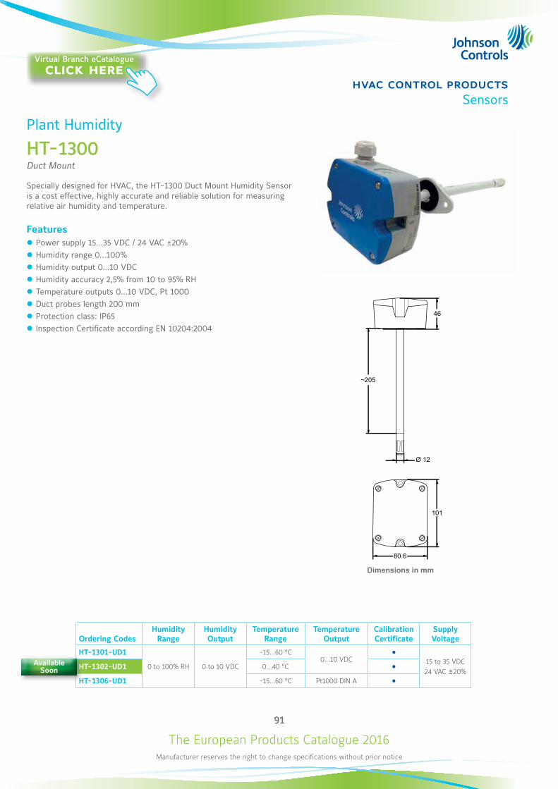
The European Products Catalogue 2016Manufacturer reserves the right to change specifications without prior notice
91
hvac control productsSensors
Plant Humidity
HT-1300 Duct Mount
Specially designed for HVAC, the HT-1300 Duct Mount Humidity Sensor is a cost effective, highly accurate and reliable solution for measuring relative air humidity and temperature.
Features z Power supply 15...35 VDC / 24 VAC ±20% z Humidity range 0...100% z Humidity output 0...10 VDC z Humidity accuracy 2,5% from 10 to 95% RH z Temperature outputs 0...10 VDC, Pt 1000 z Duct probes length 200 mm z Protection class: IP65 z Inspection Certificate according EN 10204:2004
Ordering CodesHumidity
RangeHumidity Output
Temperature Range
Temperature Output
Calibration Certificate
Supply Voltage
HT-1301-UD1
0 to 100% RH 0 to 10 VDC
-15…60 °C0…10 VDC
15 to 35 VDC 24 VAC ±20%
HT-1302-UD1 0…40 °C HT-1306-UD1 -15…60 °C Pt1000 DIN A
Dimensions in mm
101
80.6
46
Ø 12
~205
Available Soon
Virtual Branch eCatalogueclick here
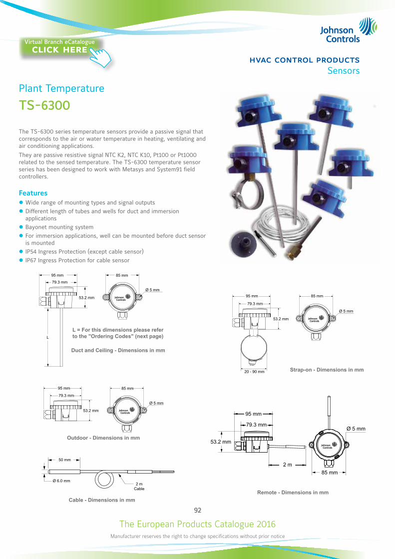
The European Products Catalogue 2016Manufacturer reserves the right to change specifications without prior notice
92
hvac control productsSensors
Plant Temperature
TS-6300
The TS-6300 series temperature sensors provide a passive signal that corresponds to the air or water temperature in heating, ventilating and air conditioning applications.They are passive resistive signal NTC K2, NTC K10, Pt100 or Pt1000 related to the sensed temperature. The TS-6300 temperature sensor series has been designed to work with Metasys and System91 field controllers.
Features z Wide range of mounting types and signal outputs z Different length of tubes and wells for duct and immersion applications
z Bayonet mounting system z For immersion applications, well can be mounted before duct sensor is mounted
z IP54 Ingress Protection (except cable sensor) z IP67 Ingress Protection for cable sensor
79.3 mm
53.2 mm
L
95 mm 85 mm
Ø 5 mm
79.3 mm
20 - 90 mm
53.2 mm
95 mm 85 mm
Ø 5 mm
79.3 mm
53.2 mm
95 mm 85 mm
Ø 5 mm
Ø 5 mm
85 mm
53.2 mm
79.3 mm
95 mm
2 m
Ø 6.0 mm
50 mm
2 mCable
Remote - Dimensions in mmCable - Dimensions in mm
Duct and Ceiling - Dimensions in mm
Outdoor - Dimensions in mm
Strap-on - Dimensions in mm
L = For this dimensions please refer to the "Ordering Codes" (next page)
Virtual Branch eCatalogueclick here
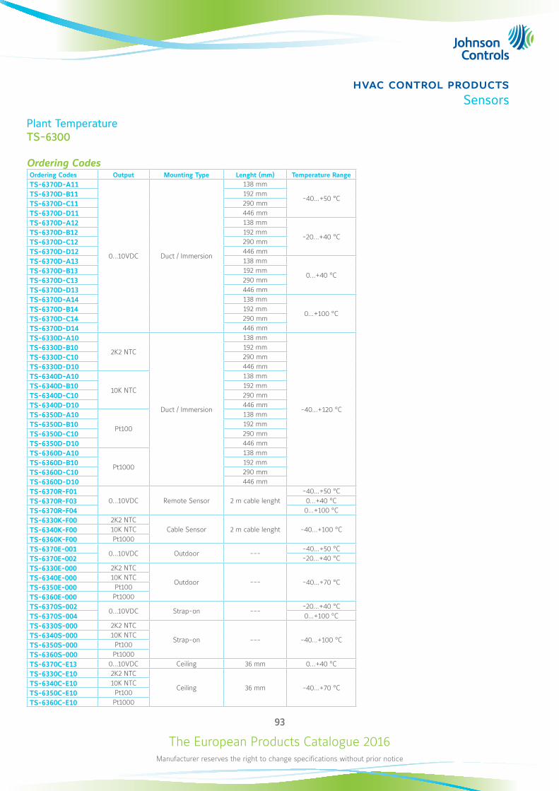
The European Products Catalogue 2016Manufacturer reserves the right to change specifications without prior notice
93
hvac control productsSensors
Plant TemperatureTS-6300
Ordering CodesOrdering Codes Output Mounting Type Lenght (mm) Temperature RangeTS-6370D-A11
0...10VDC Duct / Immersion
138 mm
-40...+50 °CTS-6370D-B11 192 mmTS-6370D-C11 290 mmTS-6370D-D11 446 mmTS-6370D-A12 138 mm
-20...+40 °CTS-6370D-B12 192 mmTS-6370D-C12 290 mmTS-6370D-D12 446 mmTS-6370D-A13 138 mm
0...+40 °CTS-6370D-B13 192 mmTS-6370D-C13 290 mmTS-6370D-D13 446 mmTS-6370D-A14 138 mm
0...+100 °CTS-6370D-B14 192 mmTS-6370D-C14 290 mmTS-6370D-D14 446 mmTS-6330D-A10
2K2 NTC
Duct / Immersion
138 mm
-40...+120 °C
TS-6330D-B10 192 mmTS-6330D-C10 290 mm TS-6330D-D10 446 mm TS-6340D-A10
10K NTC
138 mm TS-6340D-B10 192 mmTS-6340D-C10 290 mm TS-6340D-D10 446 mm TS-6350D-A10
Pt100
138 mm TS-6350D-B10 192 mmTS-6350D-C10 290 mm TS-6350D-D10 446 mm TS-6360D-A10
Pt1000
138 mm TS-6360D-B10 192 mmTS-6360D-C10 290 mm TS-6360D-D10 446 mm TS-6370R-F01
0...10VDC Remote Sensor 2 m cable lenght-40...+50 °C
TS-6370R-F03 0...+40 °CTS-6370R-F04 0...+100 °CTS-6330K-F00 2K2 NTC
Cable Sensor 2 m cable lenght -40...+100 °CTS-6340K-F00 10K NTCTS-6360K-F00 Pt1000TS-6370E-001 0...10VDC Outdoor ---
-40...+50 °CTS-6370E-002 -20...+40 °CTS-6330E-000 2K2 NTC
Outdoor --- -40...+70 °CTS-6340E-000 10K NTCTS-6350E-000 Pt100TS-6360E-000 Pt1000TS-6370S-002 0...10VDC Strap-on ---
-20...+40 °CTS-6370S-004 0...+100 °CTS-6330S-000 2K2 NTC
Strap-on --- -40...+100 °CTS-6340S-000 10K NTCTS-6350S-000 Pt100TS-6360S-000 Pt1000TS-6370C-E13 0...10VDC Ceiling 36 mm 0...+40 °CTS-6330C-E10 2K2 NTC
Ceiling 36 mm -40...+70 °CTS-6340C-E10 10K NTCTS-6350C-E10 Pt100TS-6360C-E10 Pt1000
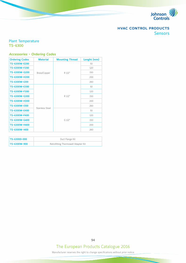
The European Products Catalogue 2016Manufacturer reserves the right to change specifications without prior notice
94
hvac control productsSensors
Plant TemperatureTS-6300
Accessories - Ordering CodesOrdering Codes Material Mounting Thread Lenght (mm)
TS-6300W-E200
Brass/Copper R 1/2"
50
TS-6300W-F200 120
TS-6300W-G200 150
TS-6300W-H200 200
TS-6300W-I200 260
TS-6300W-E300
Stainless Steel
R 1/2"
50
TS-6300W-F300 120
TS-6300W-G300 150
TS-6300W-H300 200
TS-6300W-I300 260
TS-6300W-E400
G 1/2"
50
TS-6300W-F400 120
TS-6300W-G400 150
TS-6300W-H400 200
TS-6300W-I400 260
TS-6300D-000 Duct Flange Kit
TS-6300W-900 Retrofitting Thermowell Adapter Kit
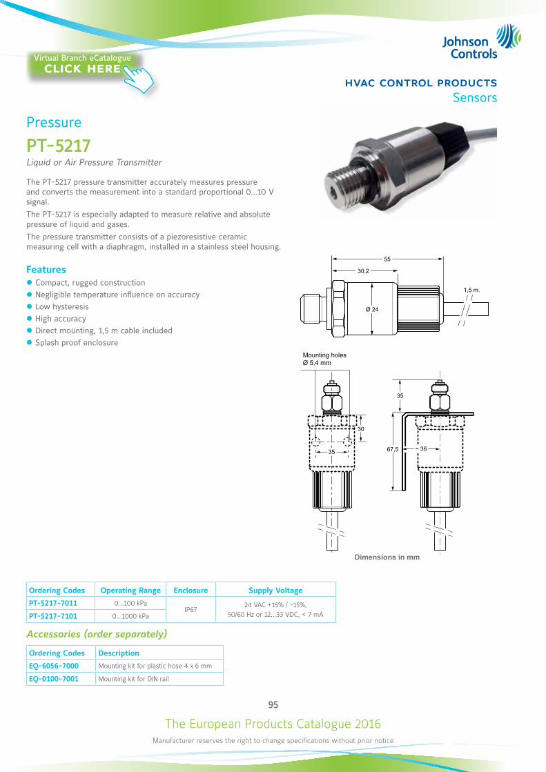
The European Products Catalogue 2016Manufacturer reserves the right to change specifications without prior notice
95
hvac control productsSensors
Pressure
PT-5217Liquid or Air Pressure Transmitter
The PT-5217 pressure transmitter accurately measures pressure and converts the measurement into a standard proportional 0...10 V signal. The PT-5217 is especially adapted to measure relative and absolute pressure of liquid and gases.The pressure transmitter consists of a piezoresistive ceramic measuring cell with a diaphragm, installed in a stainless steel housing.
Features z Compact, rugged construction z Negligible temperature influence on accuracy z Low hysteresis z High accuracy z Direct mounting, 1,5 m cable included z Splash proof enclosure
Ordering Codes Operating Range Enclosure Supply Voltage
PT-5217-7011 0…100 kPaIP67
24 VAC +15% / -15%, 50/60 Hz or 12…33 VDC, < 7 mAPT-5217-7101 0…1000 kPa
Accessories (order separately)
Ordering Codes Description
EQ-6056-7000 Mounting kit for plastic hose 4 x 6 mm
EQ-0100-7001 Mounting kit for DIN rail
1,5 m.
55
30,2
Ø 24
35 ~ 36
35
30
67,5
Dimensions in mm
Mounting holes Ø 5,4 mm
Virtual Branch eCatalogueclick here

The European Products Catalogue 2016Manufacturer reserves the right to change specifications without prior notice
96
hvac control productsSensors
Room Humidity
HT-1000Wall Mount
The HT-1000 series room humidity sensors provide active sensing of relative humidity and on specific models, also active/passive sensing of temperature in HVAC applications.It features a polymer capacitance humidity sensing element and provides within either ±2% or ±4% accuracy a voltage output signal proportional 0 to 100% relative humidity.The HT-1000 series room humidity sensors are designed for use with Johnson Controls System 91 and Facility Explorer controllers or for other systems having compatible input and output voltages.
Features z Supply voltage: 15 VAC / 24 VAC z Output RH%: 0...10 VDC z Output Temperature: 0...10 VDC, NTC K2, Pt1000 z Protection class: IP30
Ordering CodesHumidity
RangeHumidity Output
Humidity Accuracy
Temperature Range
Temperature Output
Supply Voltage
HT-1201-UR
0…100% RH 0…10 VDC
±2% 0...40°C 0…10 VDC
12 to 30 VDC 24 VAC ±15%
HT-1300-UR
±4%
--- ---
HT-1301-UR0...40°C
0…10 VDC
HT-1303-UR NTC K2
HT-1306-UR 0...60°C Pt1000
Dimensions in mm
Virtual Branch eCatalogueclick here
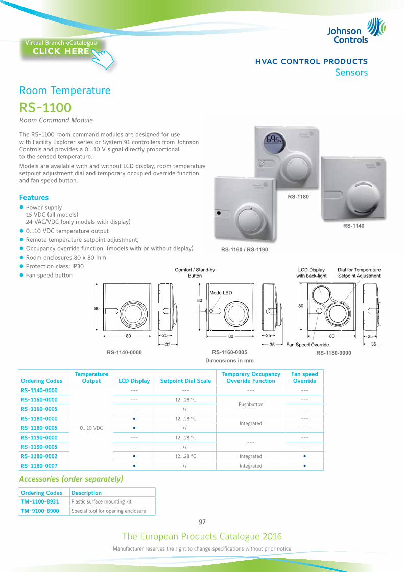
The European Products Catalogue 2016Manufacturer reserves the right to change specifications without prior notice
97
hvac control productsSensors
Room Temperature
RS-1100Room Command Module
The RS-1100 room command modules are designed for use with Facility Explorer series or System 91 controllers from Johnson Controls and provides a 0…10 V signal directly proportional to the sensed temperature. Models are available with and without LCD display, room temperature setpoint adjustment dial and temporary occupied override function and fan speed button.
Features z Power supply 15 VDC (all models) 24 VAC/VDC (only models with display)
z 0...10 VDC temperature output z Remote temperature setpoint adjustment, z Occupancy override function, (models with or without display) z Room enclosures 80 x 80 mm z Protection class: IP30 z Fan speed button
Ordering CodesTemperature
Output LCD Display Setpoint Dial ScaleTemporary Occupancy
Ovveride FunctionFan speed Override
RS-1140-0000
0...10 VDC
--- --- --- ---
RS-1160-0000 --- 12...28 °CPushbutton
---
RS-1160-0005 --- +/- ---
RS-1180-0000 12...28 °CIntegrated
---
RS-1180-0005 +/- ---
RS-1190-0000 --- 12...28 °C---
---
RS-1190-0005 --- +/- ---
RS-1180-0002 12...28 °C Integrated RS-1180-0007 +/- Integrated
Accessories (order separately)
Ordering Codes DescriptionTM-1100-8931 Plastic surface mounting kit
TM-9100-8900 Special tool for opening enclosure
RS-1180-0000 RS-1160-0005Dimensions in mm
RS-1140-0000
80
80 25
32
80
80 25
35
80
2580
35
RS-1180
RS-1140
RS-1160 / RS-1190
Comfort / Stand-by Button
LCD Display with back-light
Dial for Temperature Setpoint Adjustment
Mode LED
Fan Speed Override
Virtual Branch eCatalogueclick here
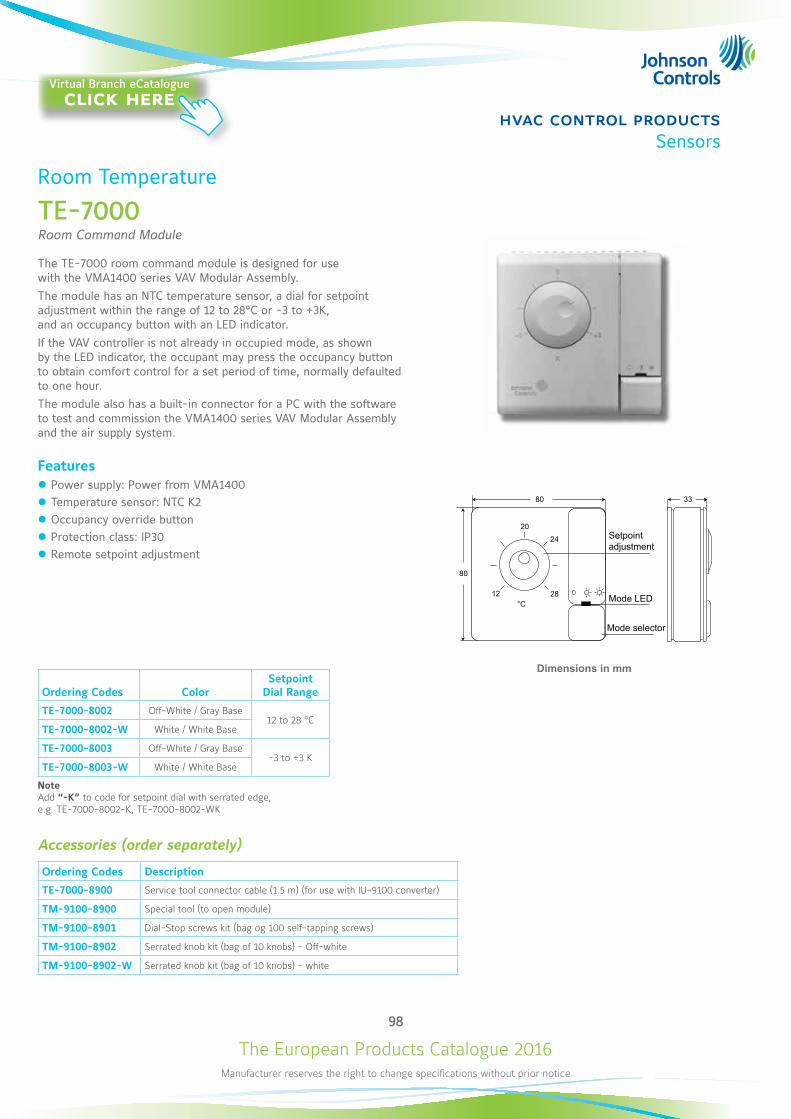
The European Products Catalogue 2016Manufacturer reserves the right to change specifications without prior notice
98
hvac control productsSensors
Dimensions in mm
80 33
20
12°C
28
24
80
Room Temperature
TE-7000Room Command Module
The TE-7000 room command module is designed for use with the VMA1400 series VAV Modular Assembly. The module has an NTC temperature sensor, a dial for setpoint adjustment within the range of 12 to 28°C or -3 to +3K, and an occupancy button with an LED indicator. If the VAV controller is not already in occupied mode, as shown by the LED indicator, the occupant may press the occupancy button to obtain comfort control for a set period of time, normally defaulted to one hour. The module also has a built-in connector for a PC with the software to test and commission the VMA1400 series VAV Modular Assembly and the air supply system.
Features z Power supply: Power from VMA1400 z Temperature sensor: NTC K2 z Occupancy override button z Protection class: IP30 z Remote setpoint adjustment
Ordering Codes ColorSetpoint
Dial Range
TE-7000-8002 Off-White / Gray Base12 to 28 °C
TE-7000-8002-W White / White Base
TE-7000-8003 Off-White / Gray Base-3 to +3 K
TE-7000-8003-W White / White Base
NoteAdd “-K” to code for setpoint dial with serrated edge, e.g. TE-7000-8002-K, TE-7000-8002-WK
Accessories (order separately)
Ordering Codes Description
TE-7000-8900 Service tool connector cable (1.5 m) (for use with IU-9100 converter)
TM-9100-8900 Special tool (to open module)
TM-9100-8901 Dial-Stop screws kit (bag og 100 self-tapping screws)
TM-9100-8902 Serrated knob kit (bag of 10 knobs) - Off-white
TM-9100-8902-W Serrated knob kit (bag of 10 knobs) - white
Setpointadjustment
Mode LED
Mode selector
Virtual Branch eCatalogueclick here
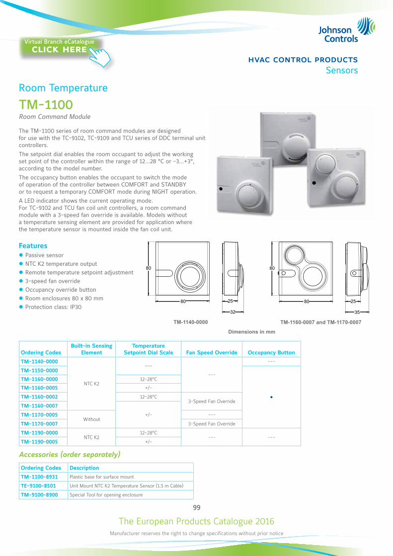
The European Products Catalogue 2016Manufacturer reserves the right to change specifications without prior notice
99
hvac control productsSensors
Room Temperature
TM-1100Room Command Module
The TM-1100 series of room command modules are designed for use with the TC-9102, TC-9109 and TCU series of DDC terminal unit controllers. The setpoint dial enables the room occupant to adjust the working set point of the controller within the range of 12…28 °C or -3...+3°, according to the model number. The occupancy button enables the occupant to switch the mode of operation of the controller between COMFORT and STANDBY or to request a temporary COMFORT mode during NIGHT operation. A LED indicator shows the current operating mode. For TC-9102 and TCU fan coil unit controllers, a room command module with a 3-speed fan override is available. Models without a temperature sensing element are provided for application where the temperature sensor is mounted inside the fan coil unit.
Features z Passive sensor z NTC K2 temperature output z Remote temperature setpoint adjustment z 3-speed fan override z Occupancy override button z Room enclosures 80 x 80 mm z Protection class: IP30
80
80
32
25 80
80
35
25
TM-1140-0000 TM-1160-0007 and TM-1170-0007
Ordering CodesBuilt-in Sensing
ElementTemperature
Setpoint Dial Scale Fan Speed Override Occupancy Button
TM-1140-0000
NTC K2
---
---
---
TM-1150-0000
TM-1160-0000 12-28°C
TM-1160-0005 +/-
TM-1160-0002 12-28°C3-Speed Fan Override
TM-1160-0007
+/-TM-1170-0005Without
---
TM-1170-0007 3-Speed Fan Override
TM-1190-0000NTC K2
12-28°C--- ---
TM-1190-0005 +/-
Accessories (order separately)
Ordering Codes Description
TM-1100-8931 Plastic base for surface mount
TE-9100-8501 Unit Mount NTC K2 Temperature Sensor (1.5 m Cable)
TM-9100-8900 Special Tool for opening enclosure
Dimensions in mm
Virtual Branch eCatalogueclick here
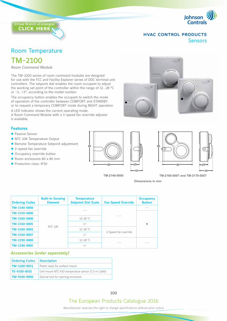
The European Products Catalogue 2016Manufacturer reserves the right to change specifications without prior notice
100
hvac control productsSensors
Room Temperature
TM-2100Room Command Module
The TM-2100 series of room command modules are designed for use with the FCC and Facility Explorer series of DDC terminal unit controllers. The setpoint dial enables the room occupant to adjust the working set point of the controller within the range of 12…28 °C or -3...+3°, according to the model number.The occupancy button enables the occupant to switch the mode of operation of the controller between COMFORT and STANDBY or to request a temporary COMFORT mode during NIGHT operation. A LED indicator shows the current operating mode. A Room Command Module with a 3-speed fan override adjuster is available.
Features z Passive Sensor z NTC 10K Temperature Output z Remote Temperature Setpoint adjustment z 3-speed fan override z Occupancy override button z Room enclosures 80 x 80 mm z Protection class: IP30
Ordering CodesBuilt-in Sensing
ElementTemperature
Setpoint Dial Scale Fan Speed OverrideOccupancy
Button
TM-2140-0000
NTC 10K
---
---
---
TM-2150-0000
TM-2160-0000 12-28 °C
TM-2160-0005 +/-
TM-2160-0002 12-28 °C3-Speed fan override
TM-2160-0007 +/-
TM-2190-0000 12-28 °C--- ---
TM-2190-0005 +/-
Accessories (order separately)
Ordering Codes Description
TM-1100-8931 Plastic base for surface mount
TE-9100-8502 Unit mount NTC K10 temperature sensor (1.5 m Cable)
TM-9100-8900 Special tool for opening enclosure
80
80
32
25 80
80
35
25
TM-2140-0000 TM-2160-0007 and TM-2170-0007
Dimensions in mm
Virtual Branch eCatalogueclick here
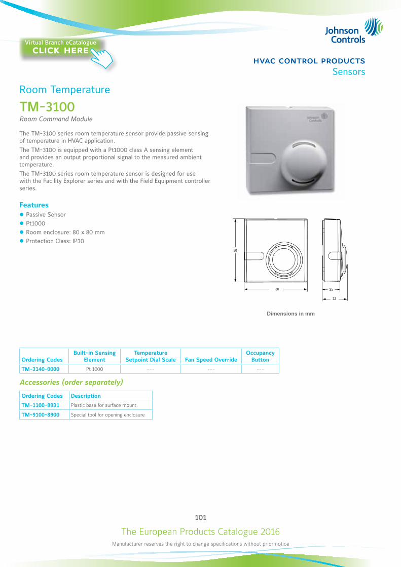
The European Products Catalogue 2016Manufacturer reserves the right to change specifications without prior notice
101
hvac control productsSensors
Room Temperature
TM-3100Room Command Module
The TM-3100 series room temperature sensor provide passive sensing of temperature in HVAC application.The TM-3100 is equipped with a Pt1000 class A sensing element and provides an output proportional signal to the measured ambient temperature.The TM-3100 series room temperature sensor is designed for use with the Facility Explorer series and with the Field Equipment controller series.
Features z Passive Sensor z Pt1000 z Room enclosure: 80 x 80 mm z Protection Class: IP30
Dimensions in mm
Ordering CodesBuilt-in Sensing
ElementTemperature
Setpoint Dial Scale Fan Speed OverrideOccupancy
Button
TM-3140-0000 Pt 1000 --- --- ---
Accessories (order separately)
Ordering Codes Description
TM-1100-8931 Plastic base for surface mount
TM-9100-8900 Special tool for opening enclosure
Virtual Branch eCatalogueclick here
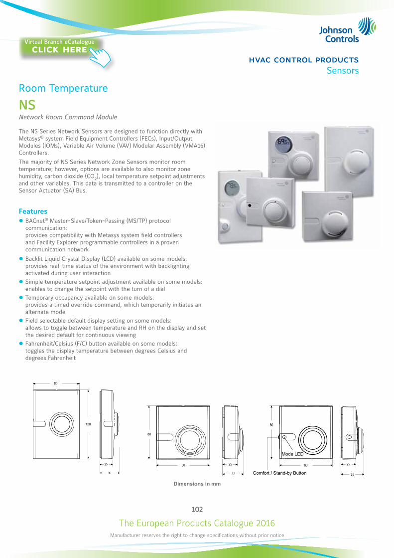
The European Products Catalogue 2016Manufacturer reserves the right to change specifications without prior notice
102
hvac control productsSensors
Room Temperature
NSNetwork Room Command Module
The NS Series Network Sensors are designed to function directly with Metasys® system Field Equipment Controllers (FECs), Input/Output Modules (IOMs), Variable Air Volume (VAV) Modular Assembly (VMA16) Controllers.The majority of NS Series Network Zone Sensors monitor room temperature; however, options are available to also monitor zone humidity, carbon dioxide (CO2), local temperature setpoint adjustments and other variables. This data is transmitted to a controller on the Sensor Actuator (SA) Bus.
Features z BACnet® Master-Slave/Token-Passing (MS/TP) protocol communication: provides compatibility with Metasys system field controllers and Facility Explorer programmable controllers in a proven communication network
z Backlit Liquid Crystal Display (LCD) available on some models: provides real-time status of the environment with backlighting activated during user interaction
z Simple temperature setpoint adjustment available on some models: enables to change the setpoint with the turn of a dial
z Temporary occupancy available on some models: provides a timed override command, which temporarily initiates an alternate mode
z Field selectable default display setting on some models: allows to toggle between temperature and RH on the display and set the desired default for continuous viewing
z Fahrenheit/Celsius (F/C) button available on some models: toggles the display temperature between degrees Celsius and degrees Fahrenheit
Dimensions in mm
80
120
Mode LED
Comfort / Stand-by Button
Virtual Branch eCatalogueclick here
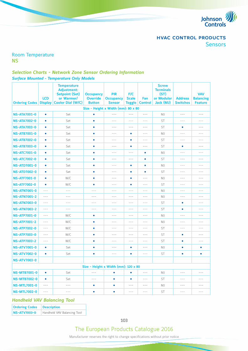
The European Products Catalogue 2016Manufacturer reserves the right to change specifications without prior notice
103
hvac control productsSensors
Room TemperatureNS
Selection Charts - Network Zone Sensor Ordering InformationSurface Mounted - Temperature Only Models
Ordering CodesLCD
Display
Temperature Adjustment:
Setpoint (Set) or Warmer/
Cooler Dial (W/C)
Occupancy Override Button
PIR Occupancy
Sensor
F/C Scale Toggle
Fan Control
Screw Terminals
(ST) or Modular Jack (MJ)
Address Switches
VAV Balancing Feature
Size - Height x Width (mm): 80 x 80
NS-ATA7001-0 Set --- --- --- MJ --- ---
NS-ATA7002-0 Set --- --- --- ST --- ---
NS-ATA7003-0 Set --- --- --- ST ---
NS-ATB7001-0 Set --- --- MJ --- ---
NS-ATB7002-0 Set --- --- ST --- ---
NS-ATB7003-0 Set --- --- ST ---
NS-ATC7001-0 Set --- --- MJ --- ---
NS-ATC7002-0 Set --- --- ST --- ---
NS-ATD7001-0 Set --- MJ --- ---
NS-ATD7002-0 Set --- ST --- ---
NS-ATF7001-0 W/C --- --- MJ --- ---
NS-ATF7002-0 W/C --- --- ST --- ---
NS-ATN7001-0 --- --- --- --- --- --- MJ --- ---
NS-ATN7001-2 --- --- --- --- --- --- MJ --- ---
NS-ATN7003-0 --- --- --- --- --- --- ST ---
NS-ATN7003-2 --- --- --- --- --- --- ST ---
NS-ATP7001-0 --- W/C --- --- --- MJ --- ---
NS-ATP7001-2 --- W/C --- --- --- MJ --- ---
NS-ATP7002-0 --- W/C --- --- --- ST --- ---
NS-ATP7003-0 --- W/C --- --- --- ST ---
NS-ATP7003-2 --- W/C --- --- --- ST ---
NS-ATV7001-0 Set --- --- MJ NS-ATV7002-0 Set --- --- ST NS-ATV7003-0
Size - Height x Width (mm): 120 x 80
NS-MTB7001-0 Set --- --- MJ --- ---
NS-MTB7002-0 Set --- --- ST --- ---
NS-MTL7001-0 --- --- --- --- MJ --- ---
NS-MTL7002-0 --- --- --- --- ST --- ---
Handheld VAV Balancing ToolOrdering Codes Description
NS-ATV7003-0 Handheld VAV Balancing Tool
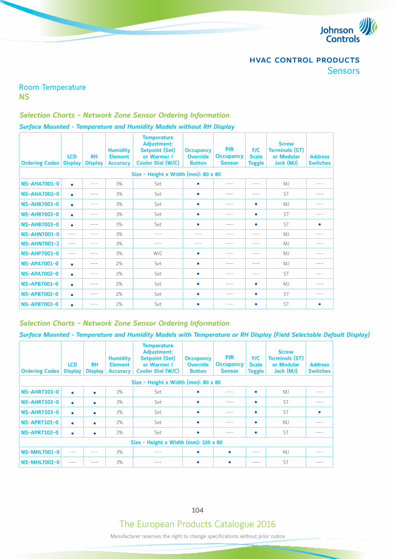
The European Products Catalogue 2016Manufacturer reserves the right to change specifications without prior notice
104
hvac control productsSensors
Room TemperatureNS
Selection Charts - Network Zone Sensor Ordering Information
Surface Mounted - Temperature and Humidity Models without RH Display
Ordering CodesLCD
DisplayRH
Display
Humidity Element Accuracy
Temperature Adjustment:
Setpoint (Set) or Warmer /
Cooler Dial (W/C)
Occupancy Override Button
PIR Occupancy
Sensor
F/C Scale Toggle
Screw Terminals (ST)
or Modular Jack (MJ)
Address Switches
Size - Height x Width (mm): 80 x 80
NS-AHA7001-0 --- 3% Set --- --- MJ ---
NS-AHA7002-0 --- 3% Set --- --- ST ---
NS-AHB7001-0 --- 3% Set --- MJ ---
NS-AHB7002-0 --- 3% Set --- ST ---
NS-AHB7003-0 --- 3% Set --- ST NS-AHN7001-0 --- --- 3% --- --- --- --- MJ ---
NS-AHN7001-2 --- --- 3% --- --- --- --- MJ ---
NS-AHP7001-0 --- --- 3% W/C --- --- MJ ---
NS-APA7001-0 --- 2% Set --- --- MJ ---
NS-APA7002-0 --- 2% Set --- --- ST ---
NS-APB7001-0 --- 2% Set --- MJ ---
NS-APB7002-0 --- 2% Set --- ST ---
NS-APB7003-0 --- 2% Set --- ST
Selection Charts - Network Zone Sensor Ordering Information
Surface Mounted - Temperature and Humidity Models with Temperature or RH Display (Field Selectable Default Display)
Ordering CodesLCD
DisplayRH
Display
Humidity Element Accuracy
Temperature Adjustment:
Setpoint (Set) or Warmer /
Cooler Dial (W/C)
Occupancy Override Button
PIR Occupancy
Sensor
F/C Scale Toggle
Screw Terminals (ST)
or Modular Jack (MJ)
Address Switches
Size - Height x Width (mm): 80 x 80
NS-AHR7101-0 3% Set --- MJ ---
NS-AHR7102-0 3% Set --- ST ---
NS-AHR7103-0 3% Set --- ST NS-APR7101-0 2% Set --- MJ ---
NS-APR7102-0 2% Set --- ST ---
Size - Height x Width (mm): 120 x 80
NS-MHL7001-0 --- --- 3% --- --- MJ ---
NS-MHL7002-0 --- --- 3% --- --- ST ---
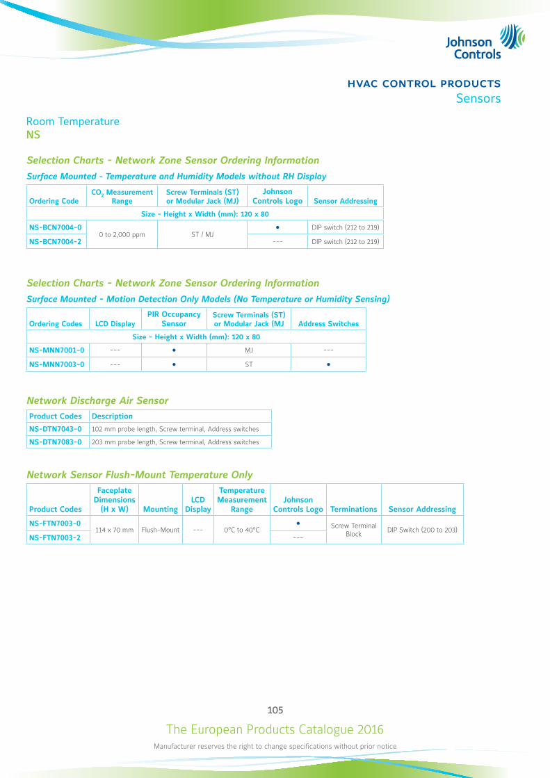
The European Products Catalogue 2016Manufacturer reserves the right to change specifications without prior notice
105
hvac control productsSensors
Room TemperatureNS
Selection Charts - Network Zone Sensor Ordering Information
Surface Mounted - Temperature and Humidity Models without RH Display
Ordering CodeCO2 Measurement
RangeScrew Terminals (ST) or Modular Jack (MJ)
Johnson Controls Logo Sensor Addressing
Size - Height x Width (mm): 120 x 80
NS-BCN7004-00 to 2,000 ppm ST / MJ
DIP switch (212 to 219)
NS-BCN7004-2 --- DIP switch (212 to 219)
Selection Charts - Network Zone Sensor Ordering Information
Surface Mounted - Motion Detection Only Models (No Temperature or Humidity Sensing)
Ordering Codes LCD DisplayPIR Occupancy
SensorScrew Terminals (ST) or Modular Jack (MJ Address Switches
Size - Height x Width (mm): 120 x 80
NS-MNN7001-0 --- MJ ---
NS-MNN7003-0 --- ST
Network Discharge Air SensorProduct Codes Description
NS-DTN7043-0 102 mm probe length, Screw terminal, Address switches
NS-DTN7083-0 203 mm probe length, Screw terminal, Address switches
Network Sensor Flush-Mount Temperature Only
Product Codes
Faceplate Dimensions
(H x W) MountingLCD
Display
Temperature Measurement
RangeJohnson
Controls Logo Terminations Sensor Addressing
NS-FTN7003-0114 x 70 mm Flush-Mount --- 0°C to 40°C
Screw Terminal Block DIP Switch (200 to 203)
NS-FTN7003-2 ---

The European Products Catalogue 2016Manufacturer reserves the right to change specifications without prior notice
106
hvac control productsSensors
Wireless Room Sensor
WRS Proprietary Wireless Protocol
The WRS Many-to-One and TE-7800 One-to-One wireless room temperature sensing system are designed to gather temperature and zone data from multiple wireless room temperature sensors, and distribute that data to multiple field controllers on a Metasys® network. A Many-to-One WRS system consists of multiple WRS-TTx series wireless room temperature sensors communicating with one or more WRS-RTN series receivers. The receivers collect wireless temperature, zone, and battery-condition data messages and route that data over Ethernet to a Network Automation Engine (NAE) or a Network Control Engine (NCE). The NAE or NCE distributes the temperature and zone data to supported BACnet®, N2 and LonWorks® controllers on Metasys networks.A simple One-to-One wireless sensing system consists of one WRS-TTx series wireless room temperature sensor communicating single-zone temperature data to an associated TE-7800 series receiver. Up to four sensors can report to a single receiver to provide enhanced zone control.
Features z Power supply: 24 VAC z RF band: 2.4 GHZ ISM Bands z Transmission range: 114 m max indoor line-of-sight 50 m practical average indoor
z Transmissions: every 60 seconds z Ambient operating temperature: 0 to 50 °C z Ambient operating humidity: 0 to 95% RH
Ordering Codes DescriptionTransmission
Power
WRS-RTN0000-1 Receiver for Many-to-One wireless room temperature sensing system, includes omnidirectional antenna
10 dBm (CE Mark)
TE-7820-1Receiver with Zone Bus Interface for One-to-One wireless room temperature sensing system, interfaces with VMA1400 series controllers (only). Includes 1.8 m Zone Bus Interface cable and omnidirectional antenna
TE-7830-1
Receiver with Analog Interface for One-to-One wireless room temperature sensing system, Interfaces with Specified Analog Digital controllers (Johnson Controls AS-AHU, AS-UNT, AS-VAV, DX-9100 or FXxx Series Controllers). Includes 1.8 m Analog Interface cable and omnidirectional antenna.
WRS-TTP0000-1 Wireless Room Temperature sensor, warmer/cooler (+/-) set point adjustment
WRS-TTR0000-1 Wireless Room Temperature sensor, no set point adjustment
WRS-TTS0000-1 Wireless Room Temperature sensor, set point adjustment scale: 13 to 29°C
80
120
Dimensions in mm
Virtual Branch eCatalogueclick here

The European Products Catalogue 2016Manufacturer reserves the right to change specifications without prior notice
107
hvac control productsSensors
Wireless Room Sensor
WRZ ZigBee Wireless Protocol
The WRZ Series Wireless Room Sensors are designed to sense room/zone temperature and transmit wireless temperature control data. Some models also sense and transmit relative humidity.In a ZFR1800 Series Wireless Field Bus System application, the sensors communicate with FEC16 Series, FEC26 Series and VMA16 Series Controllers by means of the ZFR1811 Router.In wired field bus applications, the sensors communicate with a WRZ-7860 Wireless Receiver. The WRZ-7860 Receiver transfers data to the controller by means of the Sensor Actuator (SA) communication bus. In a typical application, one WRZ Series Sensor reports to one WRZ-7860 Receiver, but up to five WRZ Series Sensors can be associated with a single WRZ-7860 Receiver for multi-sensor averaging or high/low temperature selection.WRZ Series sensor models are available with or without a Liquid Crystal Display (LCD). Depending on the sensor model, the WRZ Series Sensor can transmit sensed temperature, setpoint temperature, sensed humidity, occupancy status & PIR occupancy sensor and low battery conditions to an associated router or receiver. The WRZ Series Sensors are designed for indoor, intra-building applications only.The WRZ Sensors use direct-sequence, spread-spectrum RF technology, and operate on the 2.4 GHz Industrial, Scientific, and Medical (ISM) band. The receiver meets the IEEE 802.15.4 standard for low power, low duty cycle RF transmitting systems.Refer to the WRZ Series Wireless Room Sensors Product Bulletin (LIT-12011653) for important product application information.
Features z Wireless RF Design z Integral Wireless Signal Strength Testing Built into the Sensor z Easy Installation and Relocation z Easily-Applicable Data Types z Simple, Field Adjustable DIP Switches z Optional, Battery-Powered WRZ-SST-110 Wireless System Survey Tool z High Resistance to RF Interference from Other Radio Devices or RF Noise Sources
z User Selectable Default Display for Humidity Models z Display Models z Three Temperature Setpoint Range Options
120
80
120
2532
Dimensions in mm
Virtual Branch eCatalogueclick here
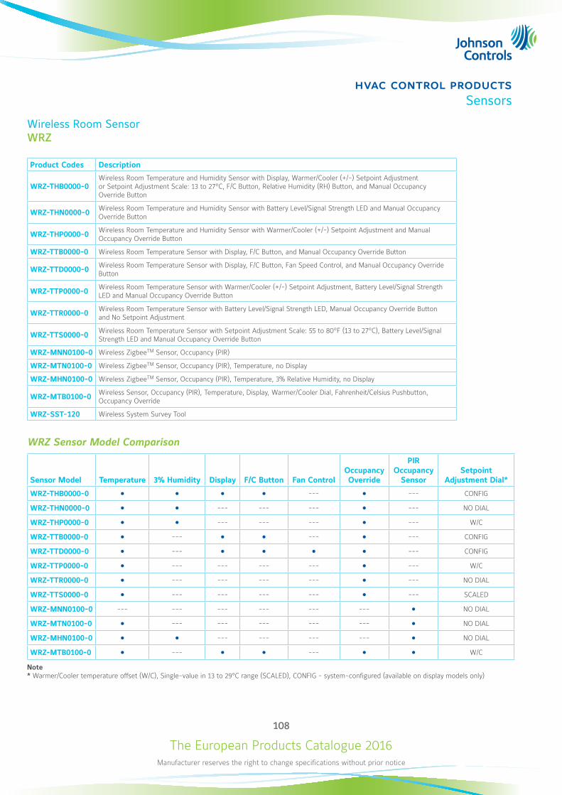
The European Products Catalogue 2016Manufacturer reserves the right to change specifications without prior notice
108
hvac control productsSensors
Wireless Room SensorWRZ
Product Codes Description
WRZ-THB0000-0 Wireless Room Temperature and Humidity Sensor with Display, Warmer/Cooler (+/-) Setpoint Adjustment or Setpoint Adjustment Scale: 13 to 27°C, F/C Button, Relative Humidity (RH) Button, and Manual Occupancy Override Button
WRZ-THN0000-0 Wireless Room Temperature and Humidity Sensor with Battery Level/Signal Strength LED and Manual Occupancy Override Button
WRZ-THP0000-0 Wireless Room Temperature and Humidity Sensor with Warmer/Cooler (+/-) Setpoint Adjustment and Manual Occupancy Override Button
WRZ-TTB0000-0 Wireless Room Temperature Sensor with Display, F/C Button, and Manual Occupancy Override Button
WRZ-TTD0000-0 Wireless Room Temperature Sensor with Display, F/C Button, Fan Speed Control, and Manual Occupancy Override Button
WRZ-TTP0000-0 Wireless Room Temperature Sensor with Warmer/Cooler (+/-) Setpoint Adjustment, Battery Level/Signal Strength LED and Manual Occupancy Override Button
WRZ-TTR0000-0 Wireless Room Temperature Sensor with Battery Level/Signal Strength LED, Manual Occupancy Override Button and No Setpoint Adjustment
WRZ-TTS0000-0 Wireless Room Temperature Sensor with Setpoint Adjustment Scale: 55 to 80°F (13 to 27°C), Battery Level/Signal Strength LED and Manual Occupancy Override Button
WRZ-MNN0100-0 Wireless ZigbeeTM Sensor, Occupancy (PIR)
WRZ-MTN0100-0 Wireless ZigbeeTM Sensor, Occupancy (PIR), Temperature, no Display
WRZ-MHN0100-0 Wireless ZigbeeTM Sensor, Occupancy (PIR), Temperature, 3% Relative Humidity, no Display
WRZ-MTB0100-0 Wireless Sensor, Occupancy (PIR), Temperature, Display, Warmer/Cooler Dial, Fahrenheit/Celsius Pushbutton, Occupancy Override
WRZ-SST-120 Wireless System Survey Tool
WRZ Sensor Model Comparison
Sensor Model Temperature 3% Humidity Display F/C Button Fan ControlOccupancy Override
PIR Occupancy
SensorSetpoint
Adjustment Dial*
WRZ-THB0000-0 --- --- CONFIG
WRZ-THN0000-0 --- --- --- --- NO DIAL
WRZ-THP0000-0 --- --- --- --- W/C
WRZ-TTB0000-0 --- --- --- CONFIG
WRZ-TTD0000-0 --- --- CONFIG
WRZ-TTP0000-0 --- --- --- --- --- W/C
WRZ-TTR0000-0 --- --- --- --- --- NO DIAL
WRZ-TTS0000-0 --- --- --- --- --- SCALED
WRZ-MNN0100-0 --- --- --- --- --- --- NO DIAL
WRZ-MTN0100-0 --- --- --- --- --- NO DIAL
WRZ-MHN0100-0 --- --- --- --- NO DIAL
WRZ-MTB0100-0 --- --- W/C
Note* Warmer/Cooler temperature offset (W/C), Single-value in 13 to 29°C range (SCALED), CONFIG - system-configured (available on display models only)

The European Products Catalogue 2016Manufacturer reserves the right to change specifications without prior notice
109
hvac control productsThermostats
Electric Fan Coil Thermostat
T125-EAnalog Fan Coil Thermostats
T125 Electric Fan Coil Thermostats are designed to control heating, cooling, or air conditioning unit in Commercial, Industrial and Residential Installation.Typical application includes the control of fan coil units, packaged terminal air conditioners and combination heating and cooling equipment. As part of the system that consists of a two-way or three-way valve and a multi-speed line voltage fan.
Features z 220 V power supply z Heating and Cooling mode z 2-4 pipes configuration z 3-speed fan override z 86 x 86 mm room enclosures z Temperature dial ranges 10...30 °C z Relay output max. 5A
Ordering Codes Built-in NTC Setpoint Range2 pipes
(Heating or Cooling)4 pipes
(Heating and Cooling)
Outputs
PAT On/Off
T125BAC-JS0-E 10…30 °C
--- T125FAC-JS0-E --- ---
86
86
27
35
60
30
42
8
R2
Dimensions in mm
Virtual Branch eCatalogueclick here

The European Products Catalogue 2016Manufacturer reserves the right to change specifications without prior notice
110
hvac control productsThermostats
Electric Fan Coil Thermostat
T5200-ELCD Digital Fan Coil Thermostats
T5200-E LCD Digital Fan Coil Thermostats are designed to control heating, cooling, or year round air conditioning unit in Commercial, Industrial and Residential Installation. Typical Application includes the control of fan coil units, packaged terminal airconditioners and combination heating and cooling equipment. As part of the system that consists of a two-way or three-way valve and a multi-speed line voltage fan. These aesthetic design thermostat features with Backlit Liquid Crystal Display (LCD); an attractive white color in a compact size complements any decor.The thermostat does not require any battery backup as setpoint and other parameters are stored in nonvolatile memory. The intuitive operation makes the thermostat very user-friendly.
Features z 85…260 VAC power supply z Heating and Cooling mode z 2-4 pipes configuration z 3-speed fan override z 88 x 88 mm room enclosures z Setpoint Temperature 10...30 °C z °C & °F Changeable z Relay output max. 5A z Occupancy Mode
Ordering Codes Built-in NTCOccupancy
ModeSetpoint Range
2 pipes(Heating or
Cooling)
4 pipes (Heating and
Cooling)
Outputs
PAT On/Off
T5200-TB-9JS0-E
10…30°C
--- T5200-TF-9JS0-E --- --- ---
Dimensions in mm
88
88
52.5
8
8
41
42
15
60
Virtual Branch eCatalogueclick here
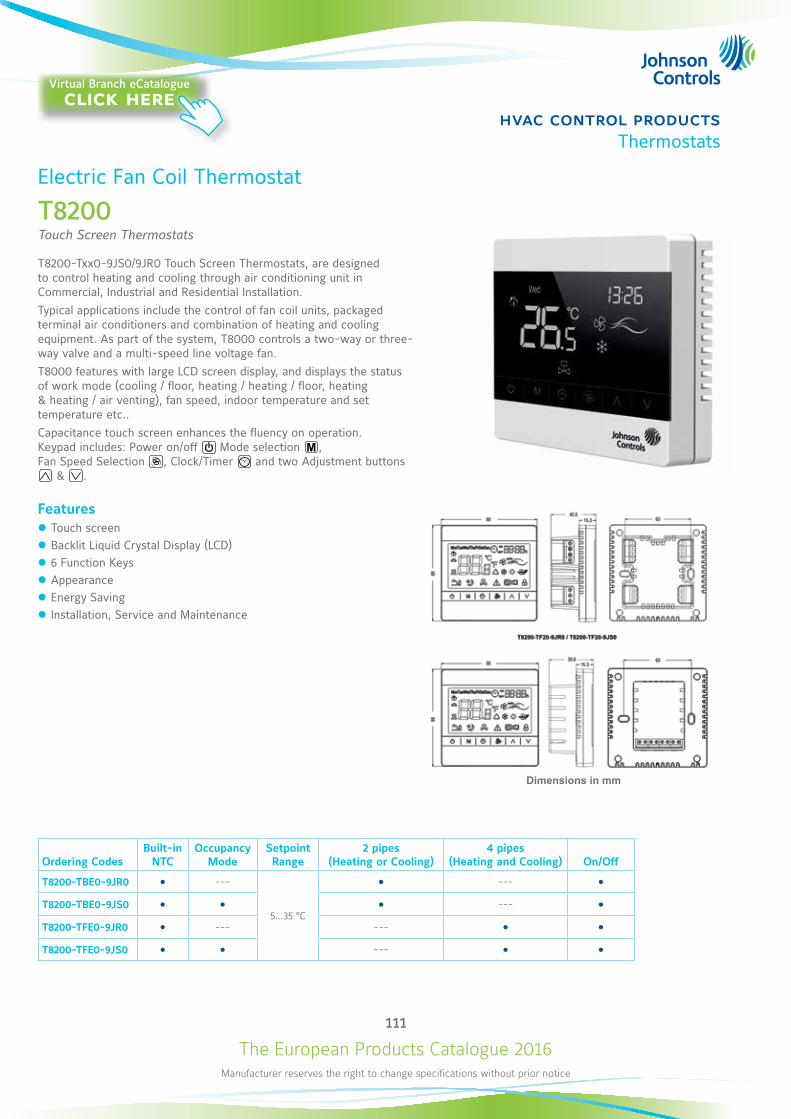
The European Products Catalogue 2016Manufacturer reserves the right to change specifications without prior notice
111
hvac control productsThermostats
Electric Fan Coil Thermostat
T8200Touch Screen Thermostats
T8200-Txx0-9JS0/9JR0 Touch Screen Thermostats, are designed to control heating and cooling through air conditioning unit in Commercial, Industrial and Residential Installation. Typical applications include the control of fan coil units, packaged terminal air conditioners and combination of heating and cooling equipment. As part of the system, T8000 controls a two-way or three-way valve and a multi-speed line voltage fan.T8000 features with large LCD screen display, and displays the status of work mode (cooling / floor, heating / heating / floor, heating & heating / air venting), fan speed, indoor temperature and set temperature etc.. Capacitance touch screen enhances the fluency on operation. Keypad includes: Power on/off Mode selection , Fan Speed Selection , Clock/Timer and two Adjustment buttons
& .
Features z Touch screen z Backlit Liquid Crystal Display (LCD) z 6 Function Keys z Appearance z Energy Saving z Installation, Service and Maintenance
Dimensions in mm
Ordering Codes Built-in
NTCOccupancy
ModeSetpoint Range
2 pipes(Heating or Cooling)
4 pipes (Heating and Cooling) On/Off
T8200-TBE0-9JR0 ---
5…35 °C
---
T8200-TBE0-9JS0 ---
T8200-TFE0-9JR0 --- ---
T8200-TFE0-9JS0 ---
Virtual Branch eCatalogueclick here

The European Products Catalogue 2016Manufacturer reserves the right to change specifications without prior notice
112
hvac control productsThermostats
Programmable Networked
TEC2000Room Thermostats
The TEC2000 series thermostat is a networked small equipment controller providing N2, BACnet® MS/TP and LonWorks® communicating options. It offers equipment control from a single product: thermostat, controller and temperature sensor.The TEC series staged controllers can be used with rooftop units (with and without economizers), heat pumps and single- and multi-stage heating/cooling equipment.The TEC2x45, TEC2xx6 and TEC2xx7 series controllers are available for commercial and hospitality applications, including cabinet unit heaters, perimeter heating/cooling, zoning and fan coil units. They provide control of various two- and four-pipe fan coil equipment, have options for one- to three-speeds of fan control and offer additional application flexibility by providing advanced control signals – proportional 0 to 10 VDC, ON/OFF, or floating.All TEC2000 models have two configurable binary inputs for advanced functions and features over 20 configurable parameters, which enable the thermostat to be customized for any application.The thermostats features a two-line, eight-character backlit LCD display with status texts in English. Models with display texts in other languages are available on special requests. For easy programming and commissioning, all controllers are pre-programmed and may be configured directly using the local display and keyboard eliminating the need for separate tools.
NOYES
21.5 °C
86
125
29
Room Temp
Dimensions in mm
Virtual Branch eCatalogueclick here
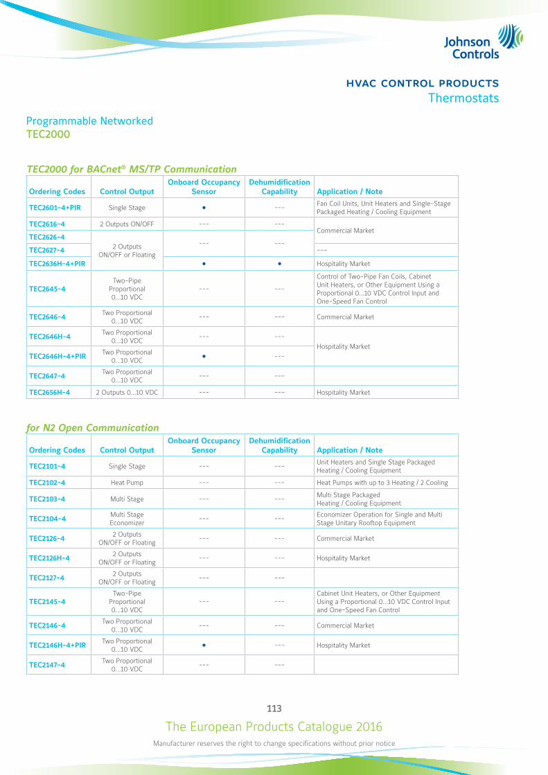
The European Products Catalogue 2016Manufacturer reserves the right to change specifications without prior notice
113
hvac control productsThermostats
Programmable NetworkedTEC2000
TEC2000 for BACnet® MS/TP Communication
Ordering Codes Control OutputOnboard Occupancy
SensorDehumidification
Capability Application / Note
TEC2601-4+PIR Single Stage --- Fan Coil Units, Unit Heaters and Single-Stage Packaged Heating / Cooling Equipment
TEC2616-4 2 Outputs ON/OFF --- ---Commercial Market
TEC2626-42 Outputs
ON/OFF or Floating
--- ---TEC2627-4 ---
TEC2636H-4+PIR Hospitality Market
TEC2645-4Two-Pipe
Proportional 0...10 VDC
--- ---
Control of Two-Pipe Fan Coils, Cabinet Unit Heaters, or Other Equipment Using a Proportional 0...10 VDC Control Input and One-Speed Fan Control
TEC2646-4 Two Proportional 0...10 VDC --- --- Commercial Market
TEC2646H-4 Two Proportional 0...10 VDC --- ---
Hospitality MarketTEC2646H-4+PIR Two Proportional
0...10 VDC ---
TEC2647-4 Two Proportional 0...10 VDC --- ---
TEC2656H-4 2 Outputs 0...10 VDC --- --- Hospitality Market
for N2 Open Communication
Ordering Codes Control OutputOnboard Occupancy
SensorDehumidification
Capability Application / Note
TEC2101-4 Single Stage --- --- Unit Heaters and Single Stage Packaged Heating / Cooling Equipment
TEC2102-4 Heat Pump --- --- Heat Pumps with up to 3 Heating / 2 Cooling
TEC2103-4 Multi Stage --- --- Multi Stage Packaged Heating / Cooling Equipment
TEC2104-4 Multi Stage Economizer --- --- Economizer Operation for Single and Multi
Stage Unitary Rooftop Equipment
TEC2126-4 2 Outputs ON/OFF or Floating --- --- Commercial Market
TEC2126H-4 2 Outputs ON/OFF or Floating --- --- Hospitality Market
TEC2127-4 2 Outputs ON/OFF or Floating --- ---
TEC2145-4Two-Pipe
Proportional 0...10 VDC
--- ---Cabinet Unit Heaters, or Other Equipment Using a Proportional 0...10 VDC Control Input and One-Speed Fan Control
TEC2146-4 Two Proportional 0...10 VDC --- --- Commercial Market
TEC2146H-4+PIR Two Proportional 0...10 VDC --- Hospitality Market
TEC2147-4 Two Proportional 0...10 VDC --- ---
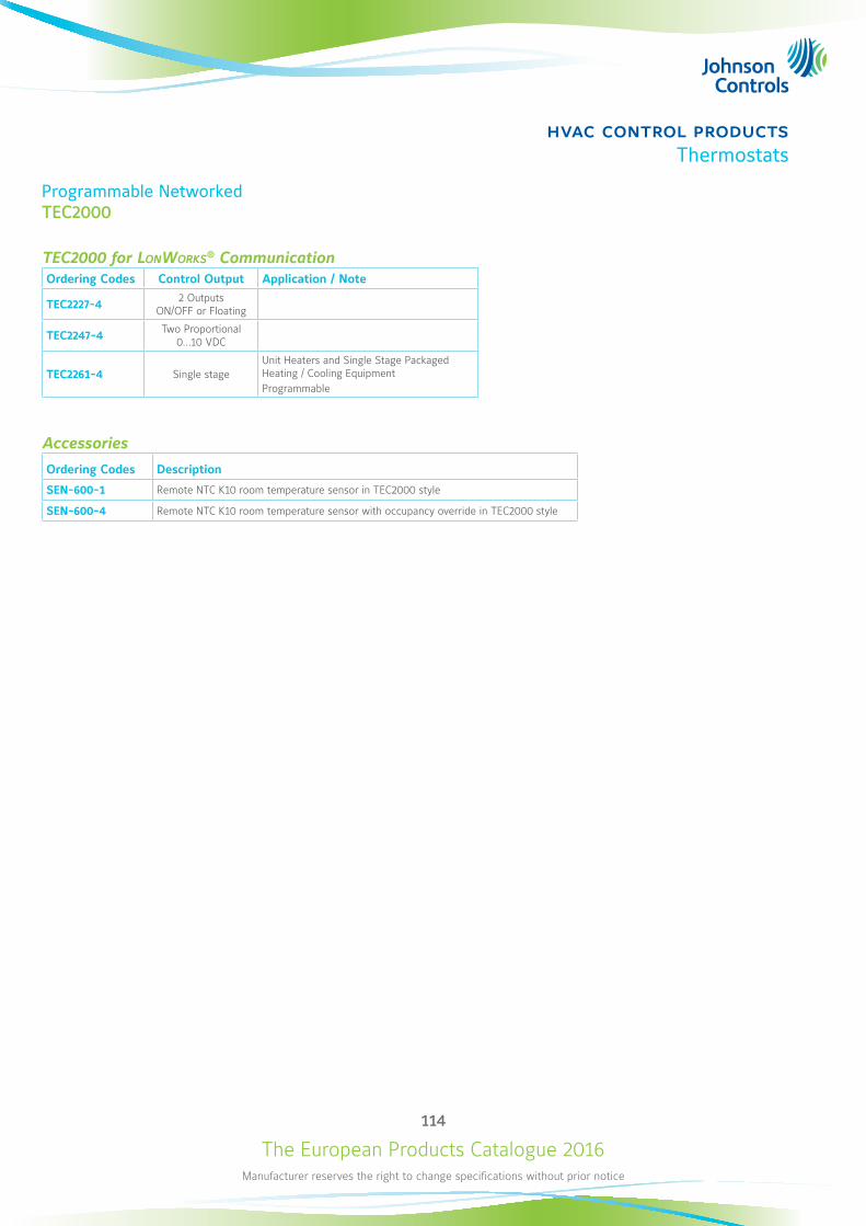
The European Products Catalogue 2016Manufacturer reserves the right to change specifications without prior notice
114
hvac control productsThermostats
Programmable NetworkedTEC2000
TEC2000 for LonWorks® CommunicationOrdering Codes Control Output Application / Note
TEC2227-4 2 Outputs ON/OFF or Floating
TEC2247-4 Two Proportional 0...10 VDC
TEC2261-4 Single stageUnit Heaters and Single Stage Packaged Heating / Cooling EquipmentProgrammable
Accessories
Ordering Codes Description
SEN-600-1 Remote NTC K10 room temperature sensor in TEC2000 style
SEN-600-4 Remote NTC K10 room temperature sensor with occupancy override in TEC2000 style
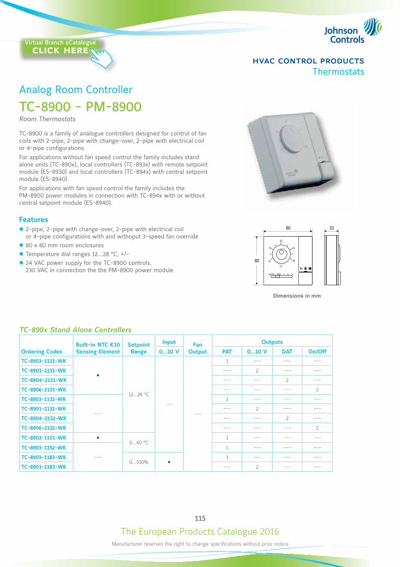
The European Products Catalogue 2016Manufacturer reserves the right to change specifications without prior notice
115
hvac control productsThermostats
Analog Room Controller
TC-8900 - PM-8900Room Thermostats
TC-8900 is a family of analogue controllers designed for control of fan coils with 2-pipe, 2-pipe with change-over, 2-pipe with electrical coil or 4-pipe configurations.For applications without fan speed control the family includes stand alone units (TC-890x), local controllers (TC-893x) with remote setpoint module (ES-8930) and local controllers (TC-894x) with central setpoint module (ES-8940). For applications with fan speed control the family includes the PM-8900 power modules in connection with TC-894x with or without central setpoint module (ES-8940).
Features z 2-pipe, 2-pipe with change-over, 2-pipe with electrical coil or 4-pipe configurations with and withoput 3-speed fan override
z 80 x 80 mm room enclosures z Temperature dial ranges 12...28 °C, +/- z 24 VAC power supply for the TC-8900 controls, 230 VAC in connection the the PM-8900 power module
°C
Dimensions in mm
TC-890x Stand Alone Controllers
Ordering CodesBuilt-in NTC K10 Sensing Element
Setpoint Range
Input Fan Output
Outputs
0...10 V PAT 0...10 V DAT On/Off
TC-8903-1131-WK
12…28 °C
---
---
1 --- --- ---
TC-8901-2131-WK --- 2 --- ---
TC-8904-2131-WK --- --- 2 ---
TC-8906-2131-WK --- --- --- 2
TC-8903-1132-WK
---
1 --- --- ---
TC-8901-2132-WK --- 2 --- ---
TC-8904-2132-WK --- --- 2 ---
TC-8906-2132-WK --- --- --- 2
TC-8903-1151-WK 0…40 °C
1 --- --- ---
TC-8903-1152-WK
---
1 --- --- ---
TC-8903-1183-WK0…100%
1 --- --- ---
TC-8901-2183-WK --- 2 --- ---
Virtual Branch eCatalogueclick here
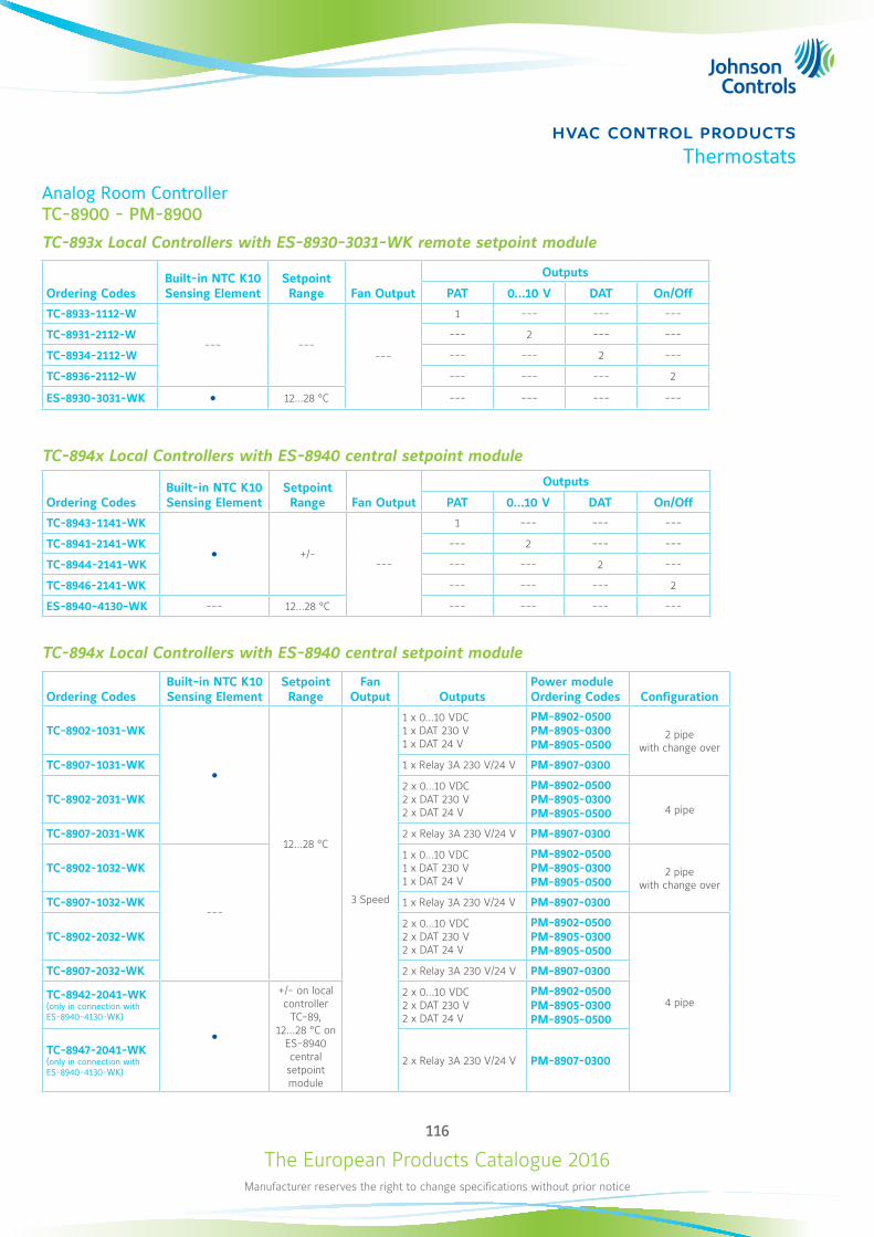
The European Products Catalogue 2016Manufacturer reserves the right to change specifications without prior notice
116
hvac control productsThermostats
Analog Room ControllerTC-8900 - PM-8900
TC-893x Local Controllers with ES-8930-3031-WK remote setpoint module
Ordering Codes Built-in NTC K10 Sensing Element
Setpoint Range Fan Output
Outputs
PAT 0...10 V DAT On/Off
TC-8933-1112-W
--- ------
1 --- --- ---
TC-8931-2112-W --- 2 --- ---
TC-8934-2112-W --- --- 2 ---
TC-8936-2112-W --- --- --- 2
ES-8930-3031-WK 12…28 °C --- --- --- ---
TC-894x Local Controllers with ES-8940 central setpoint module
Ordering Codes Built-in NTC K10 Sensing Element
Setpoint Range Fan Output
Outputs
PAT 0...10 V DAT On/Off
TC-8943-1141-WK
+/----
1 --- --- ---
TC-8941-2141-WK --- 2 --- ---
TC-8944-2141-WK --- --- 2 ---
TC-8946-2141-WK --- --- --- 2
ES-8940-4130-WK --- 12…28 °C --- --- --- ---
TC-894x Local Controllers with ES-8940 central setpoint module
Ordering Codes Built-in NTC K10 Sensing Element
Setpoint Range
Fan Output Outputs
Power module Ordering Codes Configuration
TC-8902-1031-WK
12...28 °C
3 Speed
1 x 0...10 VDC 1 x DAT 230 V 1 x DAT 24 V
PM-8902-0500 PM-8905-0300 PM-8905-0500
2 pipe with change over
TC-8907-1031-WK 1 x Relay 3A 230 V/24 V PM-8907-0300
TC-8902-2031-WK2 x 0...10 VDC 2 x DAT 230 V 2 x DAT 24 V
PM-8902-0500 PM-8905-0300 PM-8905-0500 4 pipe
TC-8907-2031-WK 2 x Relay 3A 230 V/24 V PM-8907-0300
TC-8902-1032-WK
---
1 x 0...10 VDC 1 x DAT 230 V 1 x DAT 24 V
PM-8902-0500 PM-8905-0300 PM-8905-0500
2 pipe with change over
TC-8907-1032-WK 1 x Relay 3A 230 V/24 V PM-8907-0300
TC-8902-2032-WK2 x 0...10 VDC 2 x DAT 230 V 2 x DAT 24 V
PM-8902-0500 PM-8905-0300 PM-8905-0500
4 pipe
TC-8907-2032-WK 2 x Relay 3A 230 V/24 V PM-8907-0300
TC-8942-2041-WK (only in connection with ES-8940-4130-WK)
+/- on local controller
TC-89, 12...28 °C on
ES-8940 central setpoint module
2 x 0...10 VDC 2 x DAT 230 V 2 x DAT 24 V
PM-8902-0500 PM-8905-0300 PM-8905-0500
TC-8947-2041-WK (only in connection with ES-8940-4130-WK)
2 x Relay 3A 230 V/24 V PM-8907-0300
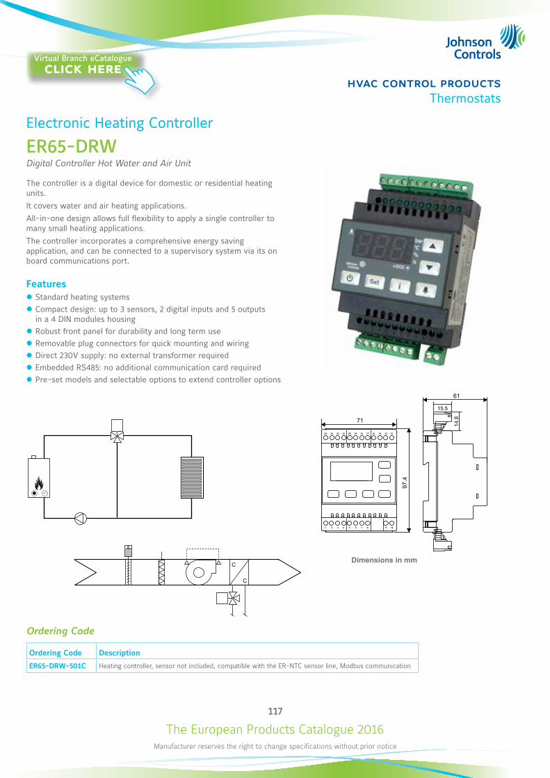
The European Products Catalogue 2016Manufacturer reserves the right to change specifications without prior notice
117
hvac control productsThermostats
Electronic Heating Controller
ER65-DRWDigital Controller Hot Water and Air Unit
The controller is a digital device for domestic or residential heating units.It covers water and air heating applications.All-in-one design allows full flexibility to apply a single controller to many small heating applications.The controller incorporates a comprehensive energy saving application, and can be connected to a supervisory system via its on board communications port.
Features z Standard heating systems z Compact design: up to 3 sensors, 2 digital inputs and 5 outputs in a 4 DIN modules housing
z Robust front panel for durability and long term use z Removable plug connectors for quick mounting and wiring z Direct 230V supply: no external transformer required z Embedded RS485: no additional communication card required z Pre-set models and selectable options to extend controller options
97.4
71
1 32 4 11865 7 12
24 2223 21 14171920 18 16 15 13
61
14.8
15.5
Dimensions in mmC
C
Ordering Code
Ordering Code Description
ER65-DRW-501C Heating controller, sensor not included, compatible with the ER-NTC sensor line, Modbus communication
Virtual Branch eCatalogueclick here
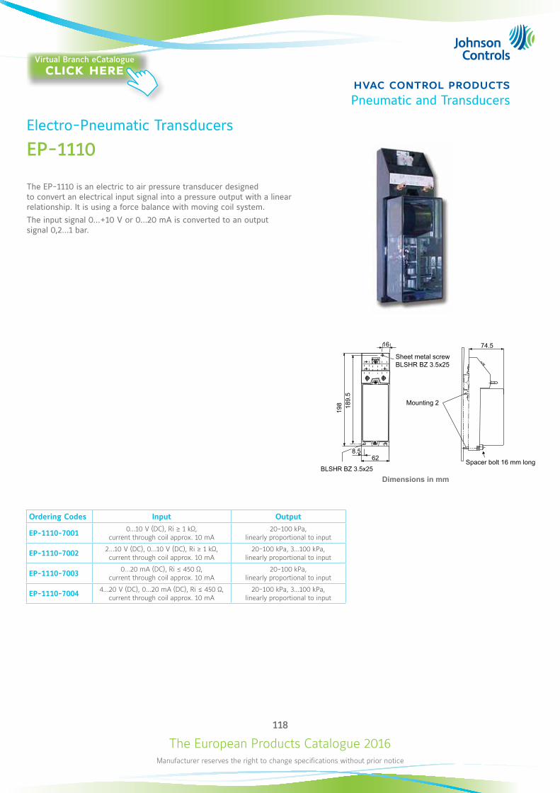
The European Products Catalogue 2016Manufacturer reserves the right to change specifications without prior notice
118
hvac control productsPneumatic and Transducers
198 18
9.5
8.562
BLSHR BZ 3.5x25
74.516
Ordering Codes Input Output
EP-1110-7001 0...10 V (DC), Ri ≥ 1 kΩ, current through coil approx. 10 mA
20-100 kPa, linearly proportional to input
EP-1110-7002 2...10 V (DC), 0...10 V (DC), Ri ≥ 1 kΩ, current through coil approx. 10 mA
20-100 kPa, 3...100 kPa, linearly proportional to input
EP-1110-7003 0...20 mA (DC), Ri ≤ 450 Ω, current through coil approx. 10 mA
20-100 kPa, linearly proportional to input
EP-1110-7004 4...20 V (DC), 0...20 mA (DC), Ri ≤ 450 Ω, current through coil approx. 10 mA
20-100 kPa, 3...100 kPa, linearly proportional to input
Dimensions in mm
Electro-Pneumatic Transducers
EP-1110
The EP-1110 is an electric to air pressure transducer designed to convert an electrical input signal into a pressure output with a linear relationship. It is using a force balance with moving coil system.The input signal 0...+10 V or 0...20 mA is converted to an output signal 0,2...1 bar.
Sheet metal screwBLSHR BZ 3.5x25
Mounting 2
Spacer bolt 16 mm long
Virtual Branch eCatalogueclick here
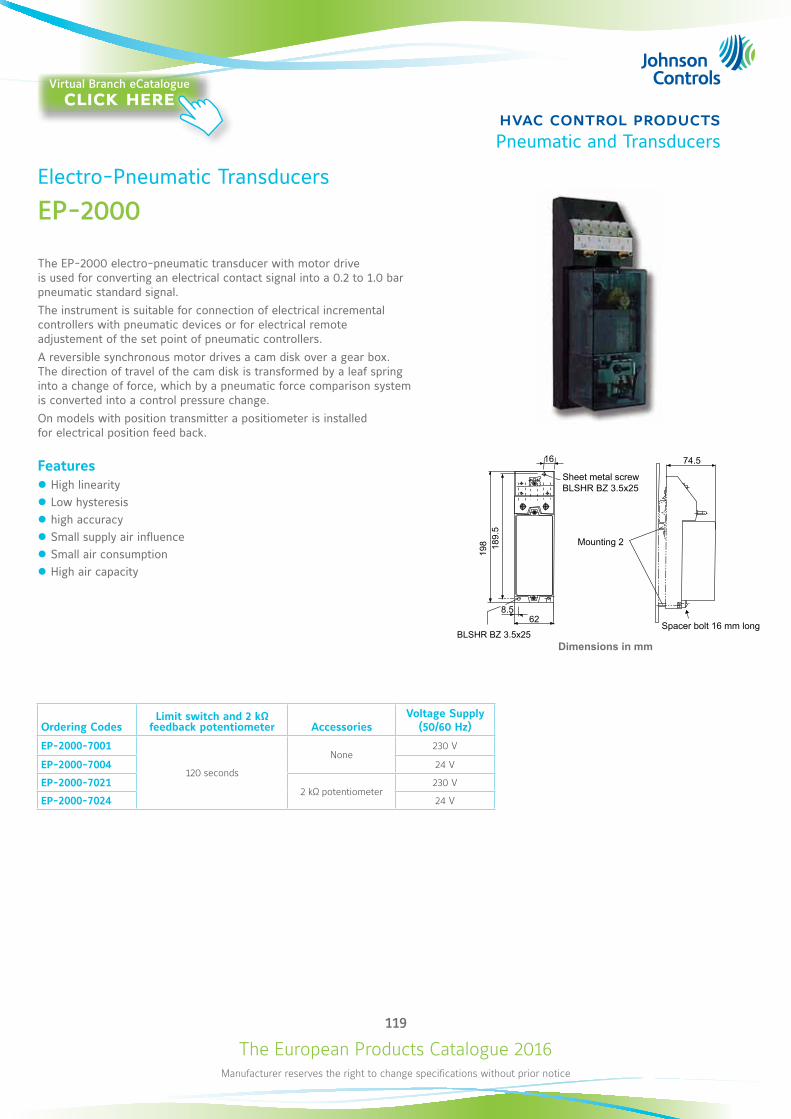
The European Products Catalogue 2016Manufacturer reserves the right to change specifications without prior notice
119
hvac control productsPneumatic and Transducers
198 18
9.5
8.562
BLSHR BZ 3.5x25
74.516
Dimensions in mm
Ordering CodesLimit switch and 2 kΩ
feedback potentiometer AccessoriesVoltage Supply
(50/60 Hz)
EP-2000-7001
120 seconds
None230 V
EP-2000-7004 24 V
EP-2000-70212 kΩ potentiometer
230 V
EP-2000-7024 24 V
Electro-Pneumatic Transducers
EP-2000
The EP-2000 electro-pneumatic transducer with motor drive is used for converting an electrical contact signal into a 0.2 to 1.0 bar pneumatic standard signal.The instrument is suitable for connection of electrical incremental controllers with pneumatic devices or for electrical remote adjustement of the set point of pneumatic controllers.A reversible synchronous motor drives a cam disk over a gear box. The direction of travel of the cam disk is transformed by a leaf spring into a change of force, which by a pneumatic force comparison system is converted into a control pressure change.On models with position transmitter a positiometer is installed for electrical position feed back.
Features z High linearity z Low hysteresis z high accuracy z Small supply air influence z Small air consumption z High air capacity
Sheet metal screwBLSHR BZ 3.5x25
Mounting 2
Spacer bolt 16 mm long
Virtual Branch eCatalogueclick here
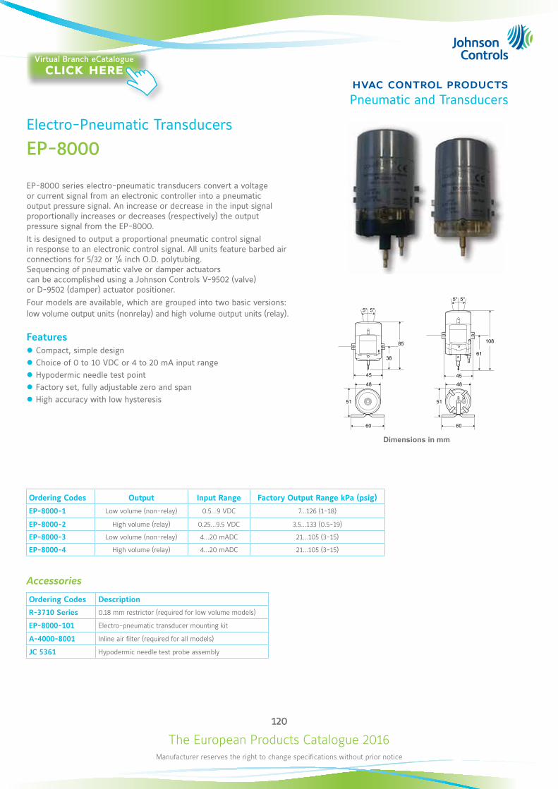
The European Products Catalogue 2016Manufacturer reserves the right to change specifications without prior notice
120
hvac control productsPneumatic and Transducers
Electro-Pneumatic Transducers
EP-8000
EP-8000 series electro-pneumatic transducers convert a voltage or current signal from an electronic controller into a pneumatic output pressure signal. An increase or decrease in the input signal proportionally increases or decreases (respectively) the output pressure signal from the EP-8000.It is designed to output a proportional pneumatic control signal in response to an electronic control signal. All units feature barbed air connections for 5/32 or ¼ inch O.D. polytubing. Sequencing of pneumatic valve or damper actuators can be accomplished using a Johnson Controls V-9502 (valve) or D-9502 (damper) actuator positioner.Four models are available, which are grouped into two basic versions: low volume output units (nonrelay) and high volume output units (relay).
Features z Compact, simple design z Choice of 0 to 10 VDC or 4 to 20 mA input range z Hypodermic needle test point z Factory set, fully adjustable zero and span z High accuracy with low hysteresis
5°5°
85
38
45
48
51
60
48
51
60
S O
5°5°
108
61
45
Dimensions in mm
Ordering Codes Output Input Range Factory Output Range kPa (psig)
EP-8000-1 Low volume (non-relay) 0.5...9 VDC 7...126 (1-18)
EP-8000-2 High volume (relay) 0.25...9.5 VDC 3.5...133 (0.5-19)
EP-8000-3 Low volume (non-relay) 4...20 mADC 21...105 (3-15)
EP-8000-4 High volume (relay) 4...20 mADC 21...105 (3-15)
Accessories
Ordering Codes Description
R-3710 Series 0.18 mm restrictor (required for low volume models)
EP-8000-101 Electro-pneumatic transducer mounting kit
A-4000-8001 Inline air filter (required for all models)
JC 5361 Hypodermic needle test probe assembly
Virtual Branch eCatalogueclick here
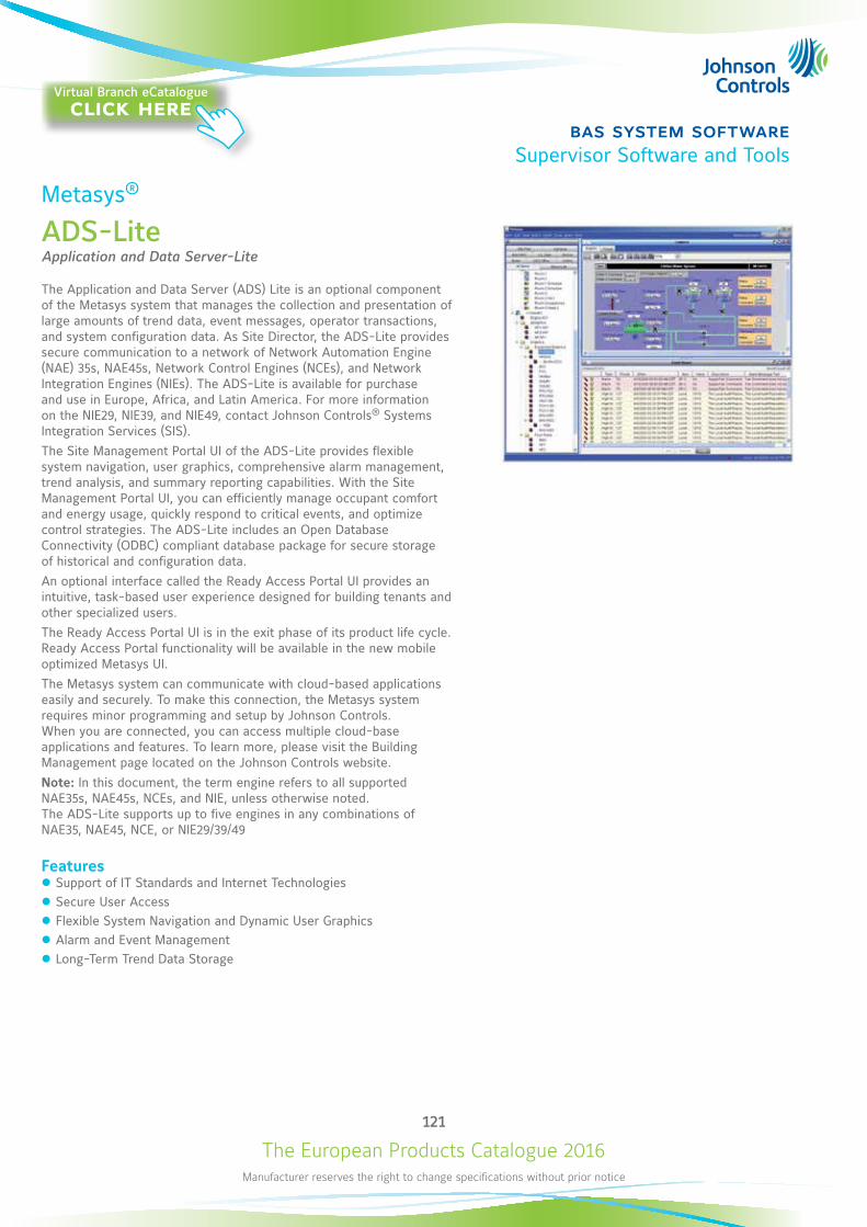
The European Products Catalogue 2016Manufacturer reserves the right to change specifications without prior notice
121
bas system softwareSupervisor Software and Tools
Metasys®
ADS-LiteApplication and Data Server-Lite
The Application and Data Server (ADS) Lite is an optional component of the Metasys system that manages the collection and presentation of large amounts of trend data, event messages, operator transactions, and system configuration data. As Site Director, the ADS-Lite provides secure communication to a network of Network Automation Engine (NAE) 35s, NAE45s, Network Control Engines (NCEs), and Network Integration Engines (NIEs). The ADS-Lite is available for purchase and use in Europe, Africa, and Latin America. For more information on the NIE29, NIE39, and NIE49, contact Johnson Controls® Systems Integration Services (SIS).The Site Management Portal UI of the ADS-Lite provides flexible system navigation, user graphics, comprehensive alarm management, trend analysis, and summary reporting capabilities. With the Site Management Portal UI, you can efficiently manage occupant comfort and energy usage, quickly respond to critical events, and optimize control strategies. The ADS-Lite includes an Open Database Connectivity (ODBC) compliant database package for secure storage of historical and configuration data.An optional interface called the Ready Access Portal UI provides an intuitive, task-based user experience designed for building tenants and other specialized users.The Ready Access Portal UI is in the exit phase of its product life cycle. Ready Access Portal functionality will be available in the new mobile optimized Metasys UI.The Metasys system can communicate with cloud-based applications easily and securely. To make this connection, the Metasys system requires minor programming and setup by Johnson Controls. When you are connected, you can access multiple cloud-base applications and features. To learn more, please visit the Building Management page located on the Johnson Controls website.Note: In this document, the term engine refers to all supported NAE35s, NAE45s, NCEs, and NIE, unless otherwise noted. The ADS-Lite supports up to five engines in any combinations of NAE35, NAE45, NCE, or NIE29/39/49
Features z Support of IT Standards and Internet Technologies z Secure User Access z Flexible System Navigation and Dynamic User Graphics z Alarm and Event Management z Long-Term Trend Data Storage
Virtual Branch eCatalogueclick here
The European Products Catalogue 2016Manufacturer reserves the right to change specifications without prior notice
122
bas system softwareSupervisor Software and Tools
Metasys®
ADS-Lite
Ordering InformationOrdering Codes * Description
MS-ADSLE5U-0 ADS-Lite New project software for up to on new up to 5 users
MS-ADSLE5U-6 ADS-Lite Upgrade project software: for up to 5 users, on site with a previous version of the Metasys software
MS-ADSLE5U-8 ADS-Lite to full ADS Migration project software: for up to 5 users, on site migrating from a previous major release of ADS-Lite, to the current release of full ADS
Note* Availability: The ADS-Lite is available for purchase and use in Europe, Africa and Latin America. For information on the NIE29, NIE39, and NIE49,
contact Johnson Controls® Systems Integration Services (SIS). Refer to ADS Lite Product Bulletin (LIT-12011690) for important product application information.
Technical SpecificationsThe following table lists by operating system the Microsoft® SQL Server® software editions that have been fully qualified by Johnson Controls for Release 7.0. You can select other combinations, but we recommend that you select from the following pairings.
Recommended Operating System and SQL Server Combinations
Operating System
Database SoftwareSQL Server 2014 Express (64-bit)
SQL Server 2012 Express SP2 (64-bit)
SQL Server 2008 Express R2 SP2 (64-bit)
SQL Server 2008 Express R2 SP2 (32-bit)
Windows® 8.1 Pro and Windows 8.1 Enterprise (64-bit) ---
Windows 8 Pro and Windows 8 Enterprise (64-bit) ---
Windows 7 Professional, Enterprise, and Ultimate Editions with SP1 (64-bit) ---
Windows 7 Professional, Enterprise, and Ultimate Editions with SP1 (32-bit)
--- --- ---
NoteTo use SQL Server 2014 with Metasys products, you must install Microsoft cumulative package 3 (KB2984923) for SQL Server 2014.To download the update package, visit http://support.microsoft.com/kb/2984923/.
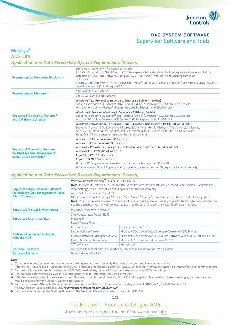
The European Products Catalogue 2016Manufacturer reserves the right to change specifications without prior notice
123
bas system softwareSupervisor Software and Tools
Metasys®
ADS-Lite Application and Data Server-Lite System Requirements (5 Users)
Recommended Computer Platform 1
Intel Core I7 processor, 4th generation or later 2 x 320 GB hard disk (RAID 1) 2 with 40 GB free space after installation of all prerequisite software and before installation of ADS-Lite software. Configure RAID 1 (mirroring) with disk write-caching turned on. DVD drive Graphics card (1 GB RAM, ATI® Technologies or NVIDIA® Corporation, 64-bit compatible [for 64-bit operating systems], Small Form Factor [SFF] if required) 3
Recommended Memory 44 GB RAM (32-bit systems)
8 to 16 GB RAM (64-bit systems)
Supported Operating Systems 5 and Database Software
Windows® 8.1 Pro and Windows 8.1 Enterprise Editions (64-bit) Supports Microsoft SQL Server® 2014 Express (64-bit) 6, Microsoft SQL Server 2012 Express with SP2 (64-bit), or Microsoft SQL Server 2008 R2 Express with SP2 (64-bit)
Windows 8 Pro and Windows 8 Enterprise Editions (64-bit) Supports Microsoft SQL Server® 2014 Express (64-bit) 5, Microsoft SQL Server 2012 Express with SP2 (64-bit), or Microsoft SQL Server 2008 R2 Express with SP2 (64-bit)
Windows 7 Professional, Enterprise, and Ultimate Editions with SP1 (32-bit or 64-bit) Supports Microsoft SQL Server 2014 Express (32-bit or 64-bit) 5, Microsoft SQL Server 2012 Express with SP2 (32-bit or 64-bit), or Microsoft SQL Server 2008 R2 Express with SP2 (32-bit or 64-bit) Note: The OS and software must both be 32-bit or 64-bit.
Supported Operating Systems for Metasys Site Management Portal Client Computer
Windows 8.1 Pro or Windows 8.1 Enterprise Windows 8 Pro or Windows 8 Enterprise Windows 7 Professional, Enterprise, or Ultimate Edition with SP1 (32-bit or 64-bit) Windows XP® Professional with SP3 Apple® OS X® 10.9 Mavericks Apple OS X 10.8 Mountain Lion Note: In OS X, you cannot view Graphics in the Site Management Portal UI. Note: Windows XP and Apple operating systems are supported for Metasys client computers only.
Application and Data Server-Lite System Requirements (5 Users)
Supported Web Browser Software for Metasys Site Management Portal Client Computers
Windows Internet Explorer® version 8, 9, 10, and 11 Note: In Internet Explorer 11, select the Use Microsoft compatibility lists option, found under Tools > Compatibility View Settings, to ensure that websites appear and function correctly. Apple Safari® version 6.0.5 and 7.0 Other browsers, such as Google® Chrome® and Mozilla® Firefox®, may also be used but are not fully supported.Note: You use the web browser to download the Launcher application. After you install the Launcher application, you use the Launcher, not the web browser, to log in to the Site Management Portal (SMP) user interface.
Supported Virtual Environments Microsoft Hyper-V™, VMware®
Supported User InterfacesSite Management Portal (SMP) Metasys UI Ready Access Portal
Additional Software Included with the ADS
CCT software Launcher softwareExport Utility software Microsoft SQL Server 2012 Express software with SP2 (64-bit)Metasys Database Manager software Microsoft SQL Server 2008 R2 Express software with SP2 (32-bit and 64-bit)Ready Access Portal software Microsoft .NET Framework Version 3.5 SP1SCT software Metasys UI6
Optional Hardware Any network or local printer supported by the qualified Windows operating system
Optional Software Graphic Generation Tool
Note1 Our computer platform and memory recommendations are not meant to imply that older or slower machines are not usable.
Refer to the Network and IT Guidance for the BAS Professional Technical Bulletin (LIT-12011279) for more information regarding computer/server recommendations.2 For best performance, use Serial Attached SCSI (SAS) hard drives, not small Computer System Interface (SCSI) hard drives.3 For improved performance only when ADS and Ready Access Portal share the same computer.4 Refer to the Network and IT Guidance for the BAS Professional Technical Bulletin (LIT-12011279) for specific Microsoft Windows operating system settings that
may be required for your Metasys system configuration.5 To use SQL Server 2014 with Metasys products, you must install Microsoft cumulative update package 3 (KB2984923) for SQL Server 2014.
To download the update package, visit http://support.microsoft.com/kb/2984923/.6 For more information on the Metasys UI, refer to the Metasys UI Installation Instructions (LIT-12011952)
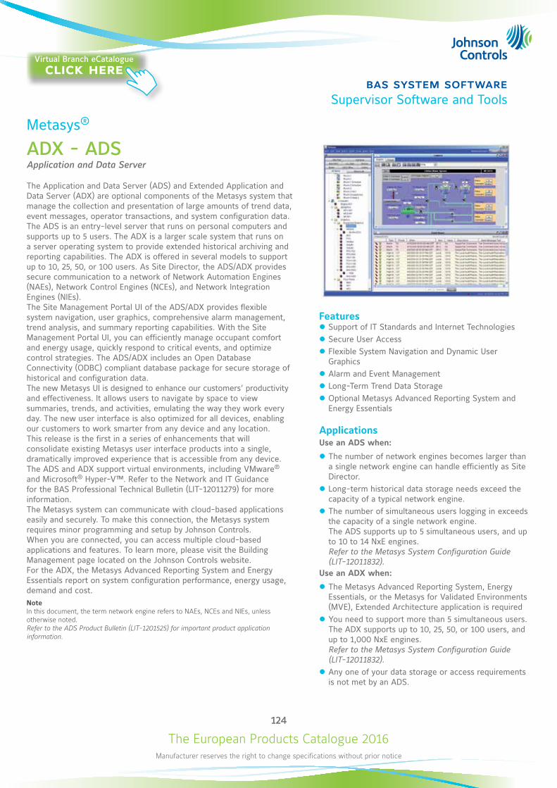
The European Products Catalogue 2016Manufacturer reserves the right to change specifications without prior notice
124
bas system softwareSupervisor Software and Tools
Metasys®
ADX - ADSApplication and Data Server
The Application and Data Server (ADS) and Extended Application and Data Server (ADX) are optional components of the Metasys system that manage the collection and presentation of large amounts of trend data, event messages, operator transactions, and system configuration data. The ADS is an entry-level server that runs on personal computers and supports up to 5 users. The ADX is a larger scale system that runs on a server operating system to provide extended historical archiving and reporting capabilities. The ADX is offered in several models to support up to 10, 25, 50, or 100 users. As Site Director, the ADS/ADX provides secure communication to a network of Network Automation Engines (NAEs), Network Control Engines (NCEs), and Network Integration Engines (NIEs).The Site Management Portal UI of the ADS/ADX provides flexible system navigation, user graphics, comprehensive alarm management, trend analysis, and summary reporting capabilities. With the Site Management Portal UI, you can efficiently manage occupant comfort and energy usage, quickly respond to critical events, and optimize control strategies. The ADS/ADX includes an Open Database Connectivity (ODBC) compliant database package for secure storage of historical and configuration data.The new Metasys UI is designed to enhance our customers’ productivity and effectiveness. It allows users to navigate by space to view summaries, trends, and activities, emulating the way they work every day. The new user interface is also optimized for all devices, enabling our customers to work smarter from any device and any location. This release is the first in a series of enhancements that will consolidate existing Metasys user interface products into a single, dramatically improved experience that is accessible from any device.The ADS and ADX support virtual environments, including VMware® and Microsoft® Hyper-V™. Refer to the Network and IT Guidance for the BAS Professional Technical Bulletin (LIT-12011279) for more information.The Metasys system can communicate with cloud-based applications easily and securely. To make this connection, the Metasys system requires minor programming and setup by Johnson Controls. When you are connected, you can access multiple cloud-based applications and features. To learn more, please visit the Building Management page located on the Johnson Controls website.For the ADX, the Metasys Advanced Reporting System and Energy Essentials report on system configuration performance, energy usage, demand and cost.NoteIn this document, the term network engine refers to NAEs, NCEs and NIEs, unless otherwise noted.Refer to the ADS Product Bulletin (LIT-1201525) for important product application information.
Features z Support of IT Standards and Internet Technologies z Secure User Access z Flexible System Navigation and Dynamic User Graphics
z Alarm and Event Management z Long-Term Trend Data Storage z Optional Metasys Advanced Reporting System and Energy Essentials
ApplicationsUse an ADS when:
z The number of network engines becomes larger than a single network engine can handle efficiently as Site Director.
z Long-term historical data storage needs exceed the capacity of a typical network engine.
z The number of simultaneous users logging in exceeds the capacity of a single network engine. The ADS supports up to 5 simultaneous users, and up to 10 to 14 NxE engines. Refer to the Metasys System Configuration Guide (LIT-12011832).
Use an ADX when:
z The Metasys Advanced Reporting System, Energy Essentials, or the Metasys for Validated Environments (MVE), Extended Architecture application is required
z You need to support more than 5 simultaneous users. The ADX supports up to 10, 25, 50, or 100 users, and up to 1,000 NxE engines. Refer to the Metasys System Configuration Guide (LIT-12011832).
z Any one of your data storage or access requirements is not met by an ADS.
Virtual Branch eCatalogueclick here
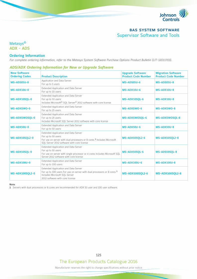
The European Products Catalogue 2016Manufacturer reserves the right to change specifications without prior notice
125
bas system softwareSupervisor Software and Tools
Metasys®
ADX - ADS
Ordering InformationFor complete ordering information, refer to the Metasys System Software Purchase Options Product Bulletin (LIT-12011703).
ADS/ADX Ordering Information for New or Upgrade SoftwareNew Software Ordering Codes Product Description
Upgrade Software Product Code Number
Migration Software Product Code Number
MS-ADS05U-0Application and Data Server For up to 5 users
MS-ADS05U-6 MS-ADS05U-8
MS-ADX10U-0Extended Application and Data Server For up to 10 users
MS-ADX10U-6 MS-ADX10U-8
MS-ADX10SQL-0Extended Application and Data Server For up to 10 users Includes Microsoft® SQL Server® 2012 software with core license
MS-ADX10SQL-6 MS-ADX10U-8
MS-ADXSWO-0Extended Application and Data Server For up to 25 users
MS-ADXSWO-6 MS-ADXSWO-8
MS-ADXSWOSQL-0Extended Application and Data Server For up to 25 users Includes Microsoft SQL Server 2012 software with core license
MS-ADXSWOSQL-6 MS-ADXSWOSQL-8
MS-ADX50U-0Extended Application and Data Server For up to 50 users
MS-ADX50U-6 MS-ADX50U-8
MS-ADX50SQL2-0
Extended Application and Data Server For up to 50 users For use on server with dual processors or 8 cores 1 Includes Microsoft SQL Server 2012 software with core license
MS-ADX50SQL2-6 MS-ADX50SQL2-8
MS-ADX50SQL-0
Extended Application and Data Server For up to 50 users For use on server with single processor or 4 cores Includes Microsoft SQL Server 2012 software with core license
MS-ADX50SQL-6 MS-ADS50SQL-8
MS-ADX100U-0Extended Application and Data Server For up to 100 users
MS-ADX100U-6 MS-ADX100U-8
MS-ADX100SQL2-0
Extended Application and Data Server For up to 100 users For use on server with dual processors or 8 cores 1 Includes Microsoft SQL Server2012 software with core license
MS-ADX100SQL2-6 MS-ADX100SQL2-8
Note1 Servers with dual processors or 8 cores are recommended for ADX 50 user and 100 user software.
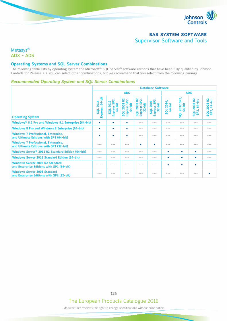
The European Products Catalogue 2016Manufacturer reserves the right to change specifications without prior notice
126
bas system softwareSupervisor Software and Tools
Metasys®
ADX - ADS
Operating Systems and SQL Server CombinationsThe following table lists by operating system the Microsoft® SQL Server® software editions that have been fully qualified by Johnson Controls for Release 7.0. You can select other combinations, but we recommend that you select from the following pairings.
Recommended Operating System and SQL Server Combinations
Operating System
Database SoftwareADS ADX
SQ
L 20
14
Expr
ess,
64-
bit
SQ
L 20
12
Expr
ess
SP2
, 64
-bit
SQ
L 20
08 R
2 Ex
pres
s SP2
, 64
-bit
SQ
L 20
08 R
2 Ex
pres
s SP2
, 32
-bit
SQ
L 20
08
Expr
ess
SP3
, 32
-bit
SQ
L 20
14,
64-b
it
SQ
L 20
12 S
P2,
64-b
it
SQ
L 20
08 R
2 SP2
, 64
-bit
SQ
L 20
08 R
2 SP2
, 32
-bit
Windows® 8.1 Pro and Windows 8.1 Enterprise (64-bit) --- --- --- --- --- ---
Windows 8 Pro and Windows 8 Enterprise (64-bit) --- --- --- --- --- ---
Windows 7 Professional, Enterprise, and Ultimate Editions with SP1 (64-bit) --- --- --- --- --- ---
Windows 7 Professional, Enterprise, and Ultimate Editions with SP1 (32-bit)
--- --- --- --- --- --- ---
Windows Server® 2012 R2 Standard Edition (64-bit) --- --- --- --- --- ---
Windows Server 2012 Standard Edition (64-bit) --- --- --- --- --- ---
Windows Server 2008 R2 Standard and Enterprise Editions with SP1 (64-bit)
--- --- --- --- --- ---
Windows Server 2008 Standard and Enterprise Editions with SP2 (32-bit)
--- --- --- --- --- --- --- ---
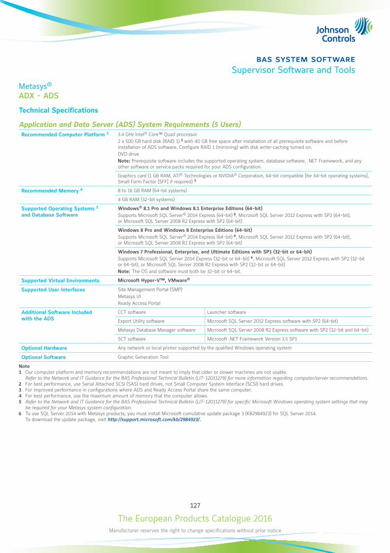
The European Products Catalogue 2016Manufacturer reserves the right to change specifications without prior notice
127
bas system softwareSupervisor Software and Tools
Metasys®
ADX - ADS
Technical Specifications
Application and Data Server (ADS) System Requirements (5 Users)Recommended Computer Platform 1 3.4 GHz Intel® Core™ Quad processor
2 x 500 GB hard disk (RAID 1) 2 with 40 GB free space after installation of all prerequisite software and before installation of ADS software. Configure RAID 1 (mirroring) with disk write-caching turned on. DVD drive Note: Prerequisite software includes the supported operating system, database software, .NET Framework, and any other software or service packs required for your ADS configuration.
Graphics card (1 GB RAM, ATI® Technologies or NVIDIA® Corporation, 64-bit compatible [for 64-bit operating systems], Small Form Factor [SFF] if required) 3
Recommended Memory 4 8 to 16 GB RAM (64-bit systems)
4 GB RAM (32-bit systems)
Supported Operating Systems 5 and Database Software
Windows® 8.1 Pro and Windows 8.1 Enterprise Editions (64-bit) Supports Microsoft SQL Server® 2014 Express (64-bit) 6, Microsoft SQL Server 2012 Express with SP2 (64-bit), or Microsoft SQL Server 2008 R2 Express with SP2 (64-bit)
Windows 8 Pro and Windows 8 Enterprise Editions (64-bit) Supports Microsoft SQL Server® 2014 Express (64-bit) 6, Microsoft SQL Server 2012 Express with SP2 (64-bit), or Microsoft SQL Server 2008 R2 Express with SP2 (64-bit)
Windows 7 Professional, Enterprise, and Ultimate Editions with SP1 (32-bit or 64-bit) Supports Microsoft SQL Server 2014 Express (32-bit or 64-bit) 6, Microsoft SQL Server 2012 Express with SP2 (32-bit or 64-bit), or Microsoft SQL Server 2008 R2 Express with SP2 (32-bit or 64-bit) Note: The OS and software must both be 32-bit or 64-bit.
Supported Virtual Environments Microsoft Hyper-V™, VMware®
Supported User Interfaces Site Management Portal (SMP) Metasys UI Ready Access Portal
Additional Software Included with the ADS
CCT software Launcher software
Export Utility software Microsoft SQL Server 2012 Express software with SP2 (64-bit)
Metasys Database Manager software Microsoft SQL Server 2008 R2 Express software with SP2 (32-bit and 64-bit)
SCT software Microsoft .NET Framework Version 3.5 SP1
Optional Hardware Any network or local printer supported by the qualified Windows operating system
Optional Software Graphic Generation Tool
Note1 Our computer platform and memory recommendations are not meant to imply that older or slower machines are not usable.
Refer to the Network and IT Guidance for the BAS Professional Technical Bulletin (LIT-12011279) for more information regarding computer/server recommendations.2 For best performance, use Serial Attached SCSI (SAS) hard drives, not Small Computer System Interface (SCSI) hard drives.3 For improved performance in configurations where ADS and Ready Access Portal share the same computer.4 For best performance, use the maximum amount of memory that the computer allows.5 Refer to the Network and IT Guidance for the BAS Professional Technical Bulletin (LIT-12011279) for specific Microsoft Windows operating system settings that may
be required for your Metasys system configuration.6 To use SQL Server 2014 with Metasys products, you must install Microsoft cumulative update package 3 (KB2984923) for SQL Server 2014.
To download the update package, visit http://support.microsoft.com/kb/2984923/.
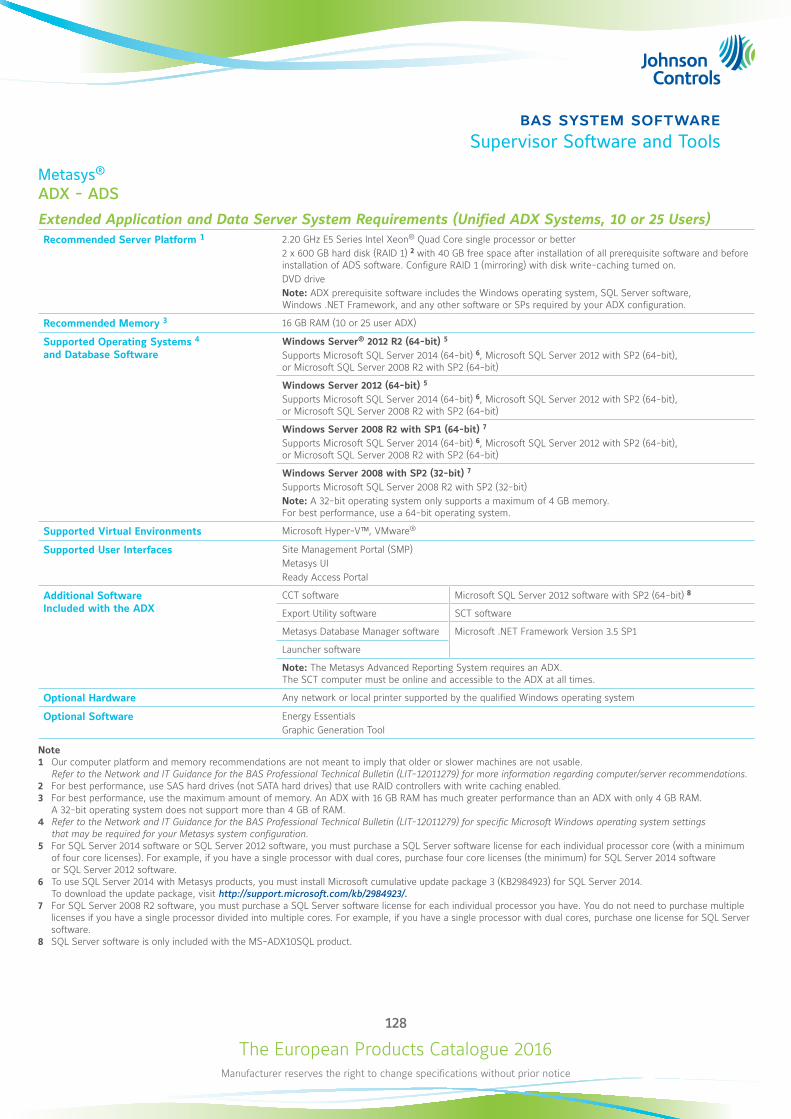
The European Products Catalogue 2016Manufacturer reserves the right to change specifications without prior notice
128
bas system softwareSupervisor Software and Tools
Metasys®
ADX - ADS
Extended Application and Data Server System Requirements (Unified ADX Systems, 10 or 25 Users)Recommended Server Platform 1 2.20 GHz E5 Series Intel Xeon® Quad Core single processor or better
2 x 600 GB hard disk (RAID 1) 2 with 40 GB free space after installation of all prerequisite software and before installation of ADS software. Configure RAID 1 (mirroring) with disk write-caching turned on. DVD drive Note: ADX prerequisite software includes the Windows operating system, SQL Server software, Windows .NET Framework, and any other software or SPs required by your ADX configuration.
Recommended Memory 3 16 GB RAM (10 or 25 user ADX)
Supported Operating Systems 4 and Database Software
Windows Server® 2012 R2 (64-bit) 5 Supports Microsoft SQL Server 2014 (64-bit) 6, Microsoft SQL Server 2012 with SP2 (64-bit), or Microsoft SQL Server 2008 R2 with SP2 (64-bit)
Windows Server 2012 (64-bit) 5 Supports Microsoft SQL Server 2014 (64-bit) 6, Microsoft SQL Server 2012 with SP2 (64-bit), or Microsoft SQL Server 2008 R2 with SP2 (64-bit)
Windows Server 2008 R2 with SP1 (64-bit) 7 Supports Microsoft SQL Server 2014 (64-bit) 6, Microsoft SQL Server 2012 with SP2 (64-bit), or Microsoft SQL Server 2008 R2 with SP2 (64-bit)
Windows Server 2008 with SP2 (32-bit) 7 Supports Microsoft SQL Server 2008 R2 with SP2 (32-bit) Note: A 32-bit operating system only supports a maximum of 4 GB memory. For best performance, use a 64-bit operating system.
Supported Virtual Environments Microsoft Hyper-V™, VMware®
Supported User Interfaces Site Management Portal (SMP) Metasys UI Ready Access Portal
Additional Software Included with the ADX
CCT software Microsoft SQL Server 2012 software with SP2 (64-bit) 8
Export Utility software SCT software
Metasys Database Manager software Microsoft .NET Framework Version 3.5 SP1
Launcher software
Note: The Metasys Advanced Reporting System requires an ADX. The SCT computer must be online and accessible to the ADX at all times.
Optional Hardware Any network or local printer supported by the qualified Windows operating system
Optional Software Energy Essentials Graphic Generation Tool
Note1 Our computer platform and memory recommendations are not meant to imply that older or slower machines are not usable.
Refer to the Network and IT Guidance for the BAS Professional Technical Bulletin (LIT-12011279) for more information regarding computer/server recommendations.2 For best performance, use SAS hard drives (not SATA hard drives) that use RAID controllers with write caching enabled.3 For best performance, use the maximum amount of memory. An ADX with 16 GB RAM has much greater performance than an ADX with only 4 GB RAM.
A 32-bit operating system does not support more than 4 GB of RAM.4 Refer to the Network and IT Guidance for the BAS Professional Technical Bulletin (LIT-12011279) for specific Microsoft Windows operating system settings
that may be required for your Metasys system configuration.5 For SQL Server 2014 software or SQL Server 2012 software, you must purchase a SQL Server software license for each individual processor core (with a minimum
of four core licenses). For example, if you have a single processor with dual cores, purchase four core licenses (the minimum) for SQL Server 2014 software or SQL Server 2012 software.
6 To use SQL Server 2014 with Metasys products, you must install Microsoft cumulative update package 3 (KB2984923) for SQL Server 2014. To download the update package, visit http://support.microsoft.com/kb/2984923/.
7 For SQL Server 2008 R2 software, you must purchase a SQL Server software license for each individual processor you have. You do not need to purchase multiple licenses if you have a single processor divided into multiple cores. For example, if you have a single processor with dual cores, purchase one license for SQL Server software.
8 SQL Server software is only included with the MS-ADX10SQL product.
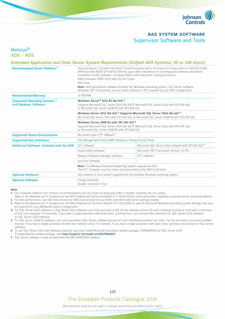
The European Products Catalogue 2016Manufacturer reserves the right to change specifications without prior notice
129
bas system softwareSupervisor Software and Tools
Metasys®
ADX - ADS
Extended Application and Data Server System Requirements (Unified ADX Systems, 50 or 100 Users)Recommended Server Platform 1 Two processors: 2.20 GHz Intel Xeon® Dual Processors with a minimum of 4 cores each 6 x 300 GB 15,000
RPM hard disk (RAID 5) 2 with 50 GB free space after installation of all prerequisite software and before installation of ADS software. Configure RAID 5 with disk write-caching turned on. RAID Controller-PERC H710 with 512 NV Cache DVD drive Note: ADX prerequisite software includes the Windows operating system, SQL Server software, Windows .NET Framework, and any other software or SPs required by your ADX configuration.
Recommended Memory 32 GB RAM
Supported Operating Systems 3 and Database Software
Windows Server® 2012 R2 (64-bit) 4 Supports Microsoft SQL Server 2014 (64-bit) 6, Microsoft SQL Server 2012 with SP2 (64-bit), or Microsoft SQL Server 2008 R2 with SP2 (64-bit)
Windows Server 2012 (64-bit) 4 Supports Microsoft SQL Server 2014 (64-bit) 6 Microsoft SQL Server 2012 with SP2 (64-bit), or Microsoft SQL Server 2008 R2 with SP2 (64-bit)
Windows Server 2008 R2 with SP1 (64-bit) 5 Supports Microsoft SQL Server 2014 (64-bit) 6, Microsoft SQL Server 2012 with SP2 (64-bit), or Microsoft SQL Server 2008 R2 with SP2 (64-bit)
Supported Virtual Environments Microsoft Hyper-V™, VMware®
Supported User Interfaces Site Management Portal (SMP) Metasys UI Ready Access Portal
Additional Software Included with the ADX CCT software Microsoft SQL Server 2012 software with SP2 (64-bit) 7
Export Utility software Microsoft .NET Framework Version 3.5 SP1
Metasys Database Manager software SCT software
Launcher software
Note: The Metasys Advanced Reporting System requires an ADX. The SCT computer must be online and accessible to the ADX at all times.
Optional Hardware Any network or local printer supported by the qualified Windows operating system
Optional Software Energy Essentials Graphic Generation Tool
Note1 Our computer platform and memory recommendations are not meant to imply that older or slower machines are not usable.
Refer to the Network and IT Guidance for the BAS Professional Technical Bulletin (LIT-12011279) for more information regarding computer/server recommendations.2 For best performance, use SAS hard drives (not SATA hard drives) that use RAID controllers with write caching enabled.3 Refer to the Network and IT Guidance for the BAS Professional Technical Bulletin (LIT-12011279) for specific Microsoft Windows operating system settings that may
be required for your Metasys® system configuration.4 For SQL Server 2014 software or SQL Server 2012 software, you must purchase a SQL Server software license for each individual processor core (with a minimum
of four core licenses). For example, if you have a single processor with dual cores, purchase four core licenses (the minimum) for SQL Server 2014 software or SQL Server 2012 software.
5 For SQL Server 2008 R2 software, you must purchase a SQL Server software license for each individual processor you have. You do not need to purchase multiple licenses if you have a single processor divided into multiple cores. For example, if you have a single processor with dual cores, purchase one license for SQL Server software.
6 To use SQL Server 2014 with Metasys products, you must install Microsoft cumulative update package 3 (KB2984923) for SQL Server 2014. To download the update package, visit http://support.microsoft.com/kb/2984923/.
7 SQL Server software is only included with the MS-ADX50SQL product.
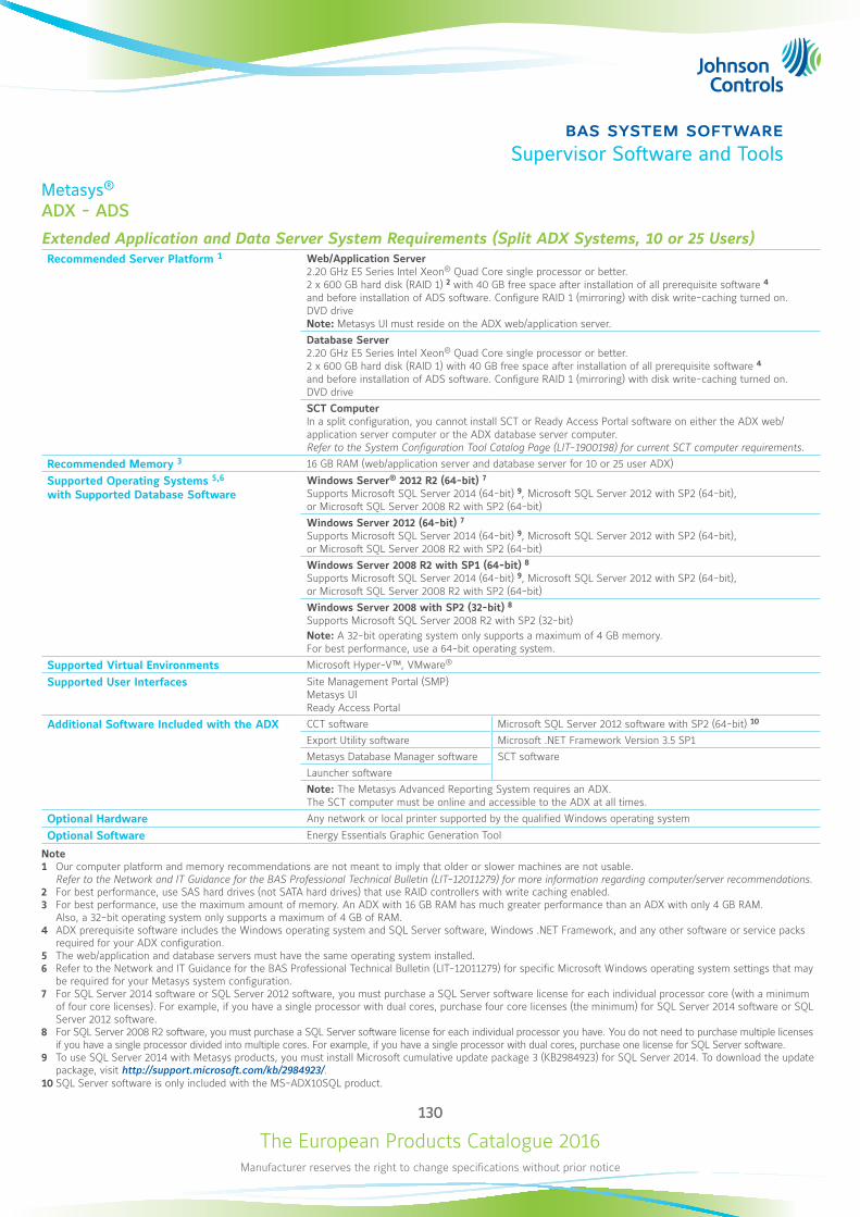
The European Products Catalogue 2016Manufacturer reserves the right to change specifications without prior notice
130
bas system softwareSupervisor Software and Tools
Metasys®
ADX - ADS
Extended Application and Data Server System Requirements (Split ADX Systems, 10 or 25 Users)Recommended Server Platform 1 Web/Application Server
2.20 GHz E5 Series Intel Xeon® Quad Core single processor or better. 2 x 600 GB hard disk (RAID 1) 2 with 40 GB free space after installation of all prerequisite software 4 and before installation of ADS software. Configure RAID 1 (mirroring) with disk write-caching turned on. DVD drive Note: Metasys UI must reside on the ADX web/application server.Database Server 2.20 GHz E5 Series Intel Xeon® Quad Core single processor or better. 2 x 600 GB hard disk (RAID 1) with 40 GB free space after installation of all prerequisite software 4 and before installation of ADS software. Configure RAID 1 (mirroring) with disk write-caching turned on. DVD driveSCT Computer In a split configuration, you cannot install SCT or Ready Access Portal software on either the ADX web/application server computer or the ADX database server computer. Refer to the System Configuration Tool Catalog Page (LIT-1900198) for current SCT computer requirements.
Recommended Memory 3 16 GB RAM (web/application server and database server for 10 or 25 user ADX)
Supported Operating Systems 5,6 with Supported Database Software
Windows Server® 2012 R2 (64-bit) 7 Supports Microsoft SQL Server 2014 (64-bit) 9, Microsoft SQL Server 2012 with SP2 (64-bit), or Microsoft SQL Server 2008 R2 with SP2 (64-bit)Windows Server 2012 (64-bit) 7 Supports Microsoft SQL Server 2014 (64-bit) 9, Microsoft SQL Server 2012 with SP2 (64-bit), or Microsoft SQL Server 2008 R2 with SP2 (64-bit)Windows Server 2008 R2 with SP1 (64-bit) 8 Supports Microsoft SQL Server 2014 (64-bit) 9, Microsoft SQL Server 2012 with SP2 (64-bit), or Microsoft SQL Server 2008 R2 with SP2 (64-bit)Windows Server 2008 with SP2 (32-bit) 8 Supports Microsoft SQL Server 2008 R2 with SP2 (32-bit) Note: A 32-bit operating system only supports a maximum of 4 GB memory. For best performance, use a 64-bit operating system.
Supported Virtual Environments Microsoft Hyper-V™, VMware®
Supported User Interfaces Site Management Portal (SMP) Metasys UI Ready Access Portal
Additional Software Included with the ADX CCT software Microsoft SQL Server 2012 software with SP2 (64-bit) 10
Export Utility software Microsoft .NET Framework Version 3.5 SP1Metasys Database Manager software SCT softwareLauncher softwareNote: The Metasys Advanced Reporting System requires an ADX. The SCT computer must be online and accessible to the ADX at all times.
Optional Hardware Any network or local printer supported by the qualified Windows operating system
Optional Software Energy Essentials Graphic Generation Tool
Note1 Our computer platform and memory recommendations are not meant to imply that older or slower machines are not usable.
Refer to the Network and IT Guidance for the BAS Professional Technical Bulletin (LIT-12011279) for more information regarding computer/server recommendations.2 For best performance, use SAS hard drives (not SATA hard drives) that use RAID controllers with write caching enabled.3 For best performance, use the maximum amount of memory. An ADX with 16 GB RAM has much greater performance than an ADX with only 4 GB RAM.
Also, a 32-bit operating system only supports a maximum of 4 GB of RAM.4 ADX prerequisite software includes the Windows operating system and SQL Server software, Windows .NET Framework, and any other software or service packs
required for your ADX configuration.5 The web/application and database servers must have the same operating system installed.6 Refer to the Network and IT Guidance for the BAS Professional Technical Bulletin (LIT-12011279) for specific Microsoft Windows operating system settings that may
be required for your Metasys system configuration.7 For SQL Server 2014 software or SQL Server 2012 software, you must purchase a SQL Server software license for each individual processor core (with a minimum
of four core licenses). For example, if you have a single processor with dual cores, purchase four core licenses (the minimum) for SQL Server 2014 software or SQL Server 2012 software.
8 For SQL Server 2008 R2 software, you must purchase a SQL Server software license for each individual processor you have. You do not need to purchase multiple licenses if you have a single processor divided into multiple cores. For example, if you have a single processor with dual cores, purchase one license for SQL Server software.
9 To use SQL Server 2014 with Metasys products, you must install Microsoft cumulative update package 3 (KB2984923) for SQL Server 2014. To download the update package, visit http://support.microsoft.com/kb/2984923/.
10 SQL Server software is only included with the MS-ADX10SQL product.
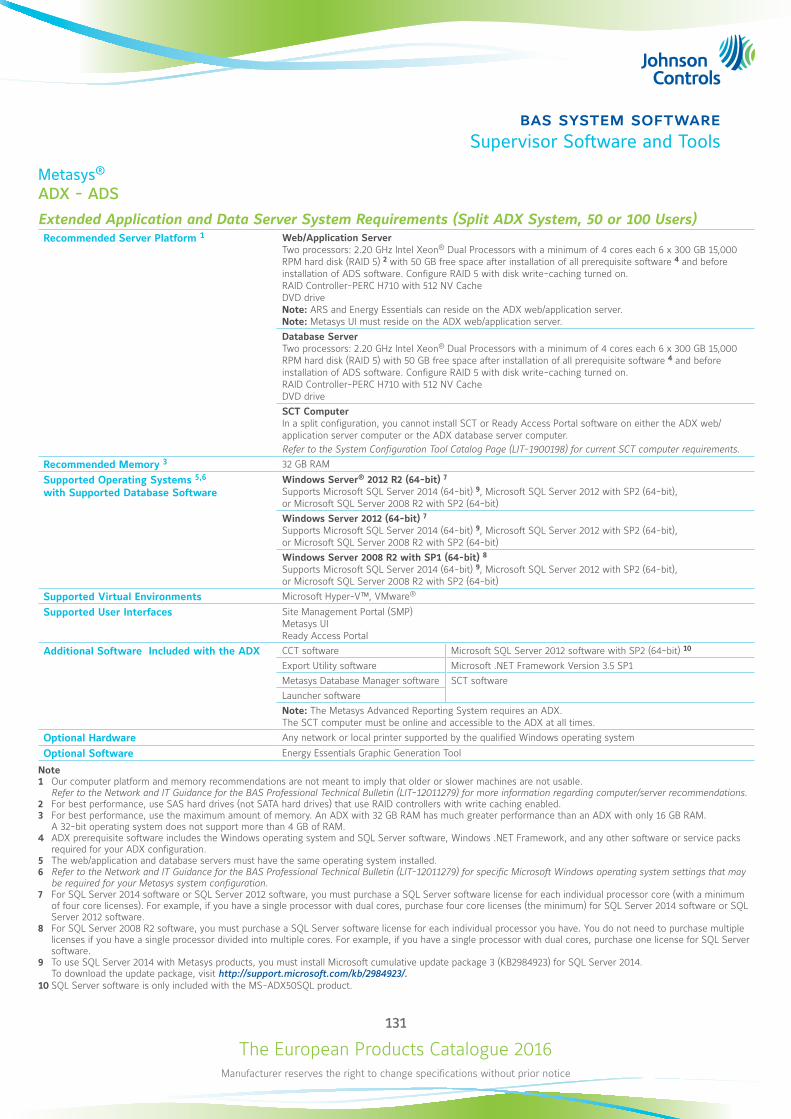
The European Products Catalogue 2016Manufacturer reserves the right to change specifications without prior notice
131
bas system softwareSupervisor Software and Tools
Metasys®
ADX - ADS
Extended Application and Data Server System Requirements (Split ADX System, 50 or 100 Users)Recommended Server Platform 1 Web/Application Server
Two processors: 2.20 GHz Intel Xeon® Dual Processors with a minimum of 4 cores each 6 x 300 GB 15,000 RPM hard disk (RAID 5) 2 with 50 GB free space after installation of all prerequisite software 4 and before installation of ADS software. Configure RAID 5 with disk write-caching turned on. RAID Controller-PERC H710 with 512 NV Cache DVD drive Note: ARS and Energy Essentials can reside on the ADX web/application server. Note: Metasys UI must reside on the ADX web/application server.Database Server Two processors: 2.20 GHz Intel Xeon® Dual Processors with a minimum of 4 cores each 6 x 300 GB 15,000 RPM hard disk (RAID 5) with 50 GB free space after installation of all prerequisite software 4 and before installation of ADS software. Configure RAID 5 with disk write-caching turned on. RAID Controller-PERC H710 with 512 NV Cache DVD driveSCT Computer In a split configuration, you cannot install SCT or Ready Access Portal software on either the ADX web/application server computer or the ADX database server computer. Refer to the System Configuration Tool Catalog Page (LIT-1900198) for current SCT computer requirements.
Recommended Memory 3 32 GB RAM
Supported Operating Systems 5,6 with Supported Database Software
Windows Server® 2012 R2 (64-bit) 7 Supports Microsoft SQL Server 2014 (64-bit) 9, Microsoft SQL Server 2012 with SP2 (64-bit), or Microsoft SQL Server 2008 R2 with SP2 (64-bit)Windows Server 2012 (64-bit) 7 Supports Microsoft SQL Server 2014 (64-bit) 9, Microsoft SQL Server 2012 with SP2 (64-bit), or Microsoft SQL Server 2008 R2 with SP2 (64-bit)Windows Server 2008 R2 with SP1 (64-bit) 8 Supports Microsoft SQL Server 2014 (64-bit) 9, Microsoft SQL Server 2012 with SP2 (64-bit), or Microsoft SQL Server 2008 R2 with SP2 (64-bit)
Supported Virtual Environments Microsoft Hyper-V™, VMware®
Supported User Interfaces Site Management Portal (SMP) Metasys UI Ready Access Portal
Additional Software Included with the ADX CCT software Microsoft SQL Server 2012 software with SP2 (64-bit) 10
Export Utility software Microsoft .NET Framework Version 3.5 SP1Metasys Database Manager software SCT softwareLauncher softwareNote: The Metasys Advanced Reporting System requires an ADX. The SCT computer must be online and accessible to the ADX at all times.
Optional Hardware Any network or local printer supported by the qualified Windows operating system
Optional Software Energy Essentials Graphic Generation Tool
Note1 Our computer platform and memory recommendations are not meant to imply that older or slower machines are not usable.
Refer to the Network and IT Guidance for the BAS Professional Technical Bulletin (LIT-12011279) for more information regarding computer/server recommendations.2 For best performance, use SAS hard drives (not SATA hard drives) that use RAID controllers with write caching enabled.3 For best performance, use the maximum amount of memory. An ADX with 32 GB RAM has much greater performance than an ADX with only 16 GB RAM.
A 32-bit operating system does not support more than 4 GB of RAM.4 ADX prerequisite software includes the Windows operating system and SQL Server software, Windows .NET Framework, and any other software or service packs
required for your ADX configuration.5 The web/application and database servers must have the same operating system installed.6 Refer to the Network and IT Guidance for the BAS Professional Technical Bulletin (LIT-12011279) for specific Microsoft Windows operating system settings that may
be required for your Metasys system configuration.7 For SQL Server 2014 software or SQL Server 2012 software, you must purchase a SQL Server software license for each individual processor core (with a minimum
of four core licenses). For example, if you have a single processor with dual cores, purchase four core licenses (the minimum) for SQL Server 2014 software or SQL Server 2012 software.
8 For SQL Server 2008 R2 software, you must purchase a SQL Server software license for each individual processor you have. You do not need to purchase multiple licenses if you have a single processor divided into multiple cores. For example, if you have a single processor with dual cores, purchase one license for SQL Server software.
9 To use SQL Server 2014 with Metasys products, you must install Microsoft cumulative update package 3 (KB2984923) for SQL Server 2014. To download the update package, visit http://support.microsoft.com/kb/2984923/.
10 SQL Server software is only included with the MS-ADX50SQL product.
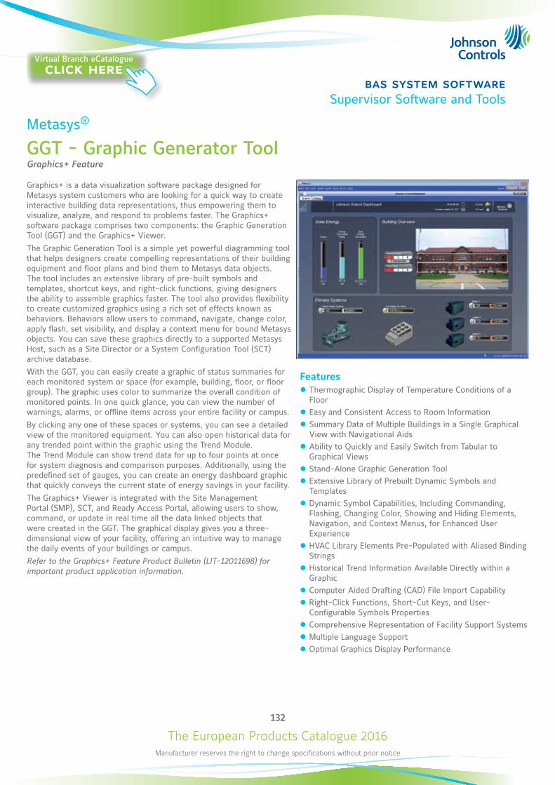
The European Products Catalogue 2016Manufacturer reserves the right to change specifications without prior notice
132
bas system softwareSupervisor Software and Tools
Metasys®
GGT - Graphic Generator ToolGraphics+ Feature
Graphics+ is a data visualization software package designed for Metasys system customers who are looking for a quick way to create interactive building data representations, thus empowering them to visualize, analyze, and respond to problems faster. The Graphics+ software package comprises two components: the Graphic Generation Tool (GGT) and the Graphics+ Viewer.The Graphic Generation Tool is a simple yet powerful diagramming tool that helps designers create compelling representations of their building equipment and floor plans and bind them to Metasys data objects. The tool includes an extensive library of pre-built symbols and templates, shortcut keys, and right-click functions, giving designers the ability to assemble graphics faster. The tool also provides flexibility to create customized graphics using a rich set of effects known as behaviors. Behaviors allow users to command, navigate, change color, apply flash, set visibility, and display a context menu for bound Metasys objects. You can save these graphics directly to a supported Metasys Host, such as a Site Director or a System Configuration Tool (SCT) archive database.With the GGT, you can easily create a graphic of status summaries for each monitored system or space (for example, building, floor, or floor group). The graphic uses color to summarize the overall condition of monitored points. In one quick glance, you can view the number of warnings, alarms, or offline items across your entire facility or campus.By clicking any one of these spaces or systems, you can see a detailed view of the monitored equipment. You can also open historical data for any trended point within the graphic using the Trend Module. The Trend Module can show trend data for up to four points at once for system diagnosis and comparison purposes. Additionally, using the predefined set of gauges, you can create an energy dashboard graphic that quickly conveys the current state of energy savings in your facility.The Graphics+ Viewer is integrated with the Site Management Portal (SMP), SCT, and Ready Access Portal, allowing users to show, command, or update in real time all the data linked objects that were created in the GGT. The graphical display gives you a three-dimensional view of your facility, offering an intuitive way to manage the daily events of your buildings or campus.Refer to the Graphics+ Feature Product Bulletin (LIT-12011698) for important product application information.
Features z Thermographic Display of Temperature Conditions of a Floor
z Easy and Consistent Access to Room Information z Summary Data of Multiple Buildings in a Single Graphical View with Navigational Aids
z Ability to Quickly and Easily Switch from Tabular to Graphical Views
z Stand-Alone Graphic Generation Tool z Extensive Library of Prebuilt Dynamic Symbols and Templates
z Dynamic Symbol Capabilities, Including Commanding, Flashing, Changing Color, Showing and Hiding Elements, Navigation, and Context Menus, for Enhanced User Experience
z HVAC Library Elements Pre-Populated with Aliased Binding Strings
z Historical Trend Information Available Directly within a Graphic
z Computer Aided Drafting (CAD) File Import Capability z Right-Click Functions, Short-Cut Keys, and User-Configurable Symbols Properties
z Comprehensive Representation of Facility Support Systems z Multiple Language Support z Optimal Graphics Display Performance
Virtual Branch eCatalogueclick here
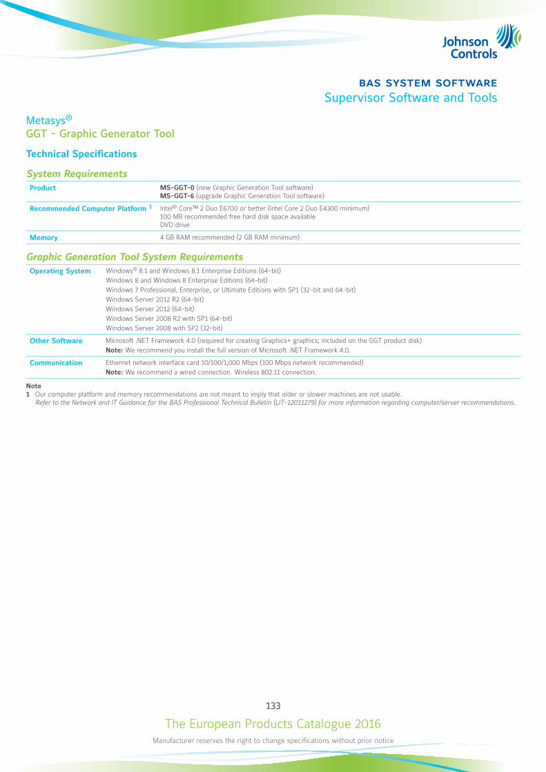
The European Products Catalogue 2016Manufacturer reserves the right to change specifications without prior notice
133
bas system softwareSupervisor Software and Tools
Metasys®
GGT - Graphic Generator Tool
Technical Specifications
System RequirementsProduct MS-GGT-0 (new Graphic Generation Tool software)
MS-GGT-6 (upgrade Graphic Generation Tool software)
Recommended Computer Platform 1 Intel® Core™ 2 Duo E6700 or better (Intel Core 2 Duo E4300 minimum) 100 MB recommended free hard disk space available DVD drive
Memory 4 GB RAM recommended (2 GB RAM minimum)
Graphic Generation Tool System RequirementsOperating System Windows® 8.1 and Windows 8.1 Enterprise Editions (64-bit)
Windows 8 and Windows 8 Enterprise Editions (64-bit) Windows 7 Professional, Enterprise, or Ultimate Editions with SP1 (32-bit and 64-bit) Windows Server 2012 R2 (64-bit)Windows Server 2012 (64-bit) Windows Server 2008 R2 with SP1 (64-bit) Windows Server 2008 with SP2 (32-bit)
Other Software Microsoft .NET Framework 4.0 (required for creating Graphics+ graphics; included on the GGT product disk) Note: We recommend you install the full version of Microsoft .NET Framework 4.0.
Communication Ethernet network interface card 10/100/1,000 Mbps (100 Mbps network recommended) Note: We recommend a wired connection. Wireless 802.11 connection.
Note1 Our computer platform and memory recommendations are not meant to imply that older or slower machines are not usable.
Refer to the Network and IT Guidance for the BAS Professional Technical Bulletin (LIT-12011279) for more information regarding computer/server recommendations.
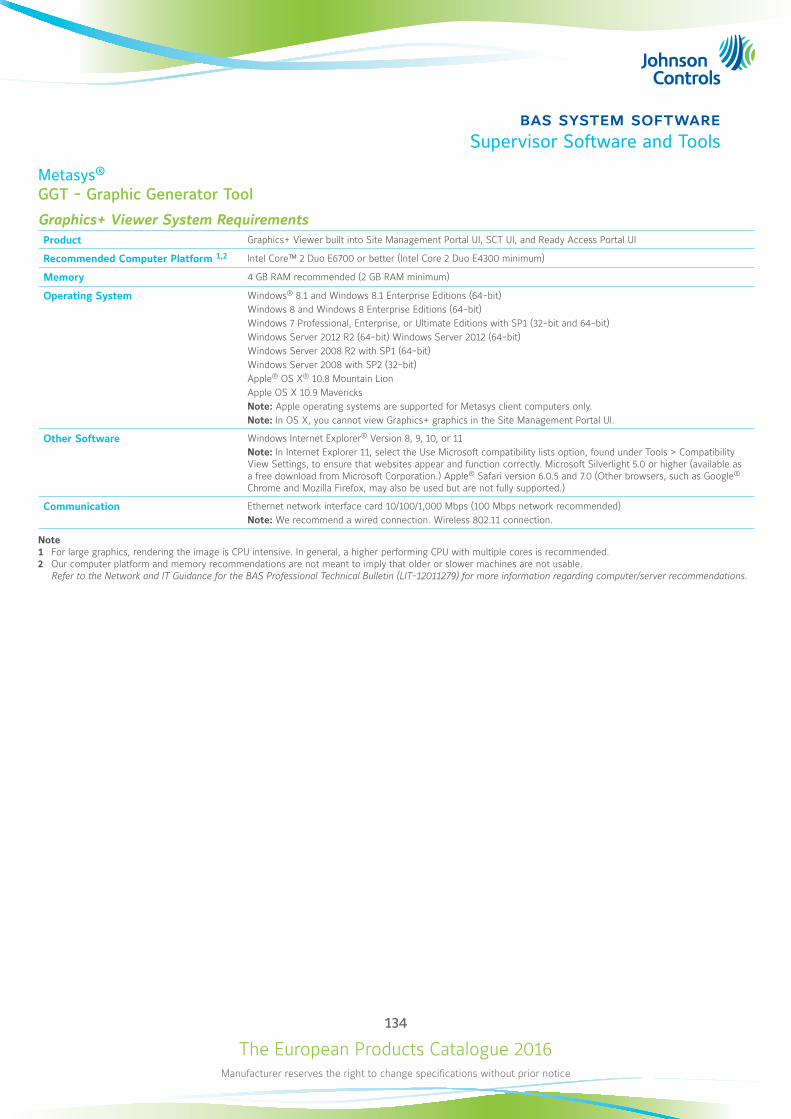
The European Products Catalogue 2016Manufacturer reserves the right to change specifications without prior notice
134
bas system softwareSupervisor Software and Tools
Metasys®
GGT - Graphic Generator Tool
Graphics+ Viewer System RequirementsProduct Graphics+ Viewer built into Site Management Portal UI, SCT UI, and Ready Access Portal UI
Recommended Computer Platform 1,2 Intel Core™ 2 Duo E6700 or better (Intel Core 2 Duo E4300 minimum)
Memory 4 GB RAM recommended (2 GB RAM minimum)
Operating System Windows® 8.1 and Windows 8.1 Enterprise Editions (64-bit) Windows 8 and Windows 8 Enterprise Editions (64-bit) Windows 7 Professional, Enterprise, or Ultimate Editions with SP1 (32-bit and 64-bit) Windows Server 2012 R2 (64-bit) Windows Server 2012 (64-bit) Windows Server 2008 R2 with SP1 (64-bit) Windows Server 2008 with SP2 (32-bit) Apple® OS X® 10.8 Mountain Lion Apple OS X 10.9 Mavericks Note: Apple operating systems are supported for Metasys client computers only. Note: In OS X, you cannot view Graphics+ graphics in the Site Management Portal UI.
Other Software Windows Internet Explorer® Version 8, 9, 10, or 11 Note: In Internet Explorer 11, select the Use Microsoft compatibility lists option, found under Tools > Compatibility View Settings, to ensure that websites appear and function correctly. Microsoft Silverlight 5.0 or higher (available as a free download from Microsoft Corporation.) Apple® Safari version 6.0.5 and 7.0 (Other browsers, such as Google® Chrome and Mozilla Firefox, may also be used but are not fully supported.)
Communication Ethernet network interface card 10/100/1,000 Mbps (100 Mbps network recommended) Note: We recommend a wired connection. Wireless 802.11 connection.
Note1 For large graphics, rendering the image is CPU intensive. In general, a higher performing CPU with multiple cores is recommended.2 Our computer platform and memory recommendations are not meant to imply that older or slower machines are not usable.
Refer to the Network and IT Guidance for the BAS Professional Technical Bulletin (LIT-12011279) for more information regarding computer/server recommendations.
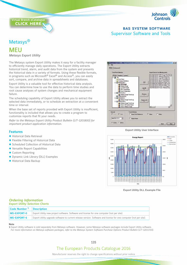
The European Products Catalogue 2016Manufacturer reserves the right to change specifications without prior notice
135
bas system softwareSupervisor Software and Tools
Metasys®
MEUMetasys Export Utility
The Metasys system Export Utility makes it easy for a facility manager to efficiently manage daily operations. The Export Utility extracts historical trend, alarm, and audit data from the system and presents the historical data in a variety of formats. Using these flexible formats, in programs such as Microsoft® Excel® and Access®, you can easily sort, compare, and archive data in spreadsheets and databases.Export Utility is a valuable tool for effective historical data analysis. You can determine how to use the data to perform time studies and root cause analyses of system changes and mechanical equipment failure.The scheduling capability of Export Utility allows you to extract the selected data immediately, or to schedule an extraction at a convenient time or interval.When the base set of reports provided with Export Utility is insufficient, functionality is included that allows you to create a program to customize reports that fit your needs.Refer to the Metasys Export Utility Product Bulletin (LIT-1201800) for important product application information.
Features z Historical Data Retrieval z Flexible Filtering of Historical Data z Scheduled Collection of Historical Data z Versatile Report Capabilities z Custom Reporting z Dynamic Link Library (DLL) Examples z Historical Data Backup
Export Utility DLL Example File
Export Utility User Interface
Ordering InformationExport Utility Selection Charts
Code Number 1 Description
MS-EXPORT-0 Export Utility new project software. Software and license for one computer (not per site).
MS-EXPORT-6 Export Utility upgrade software to current release version. Software and license for one computer (not per site).
Note1 Export Utility software is sold separately from Metasys software. However, some Metasys software packages include Export Utility software.
For more information on Metasys software packages, refer to the Metasys System Software Purchase Options Product Bulletin (LIT-12011703).
Virtual Branch eCatalogueclick here
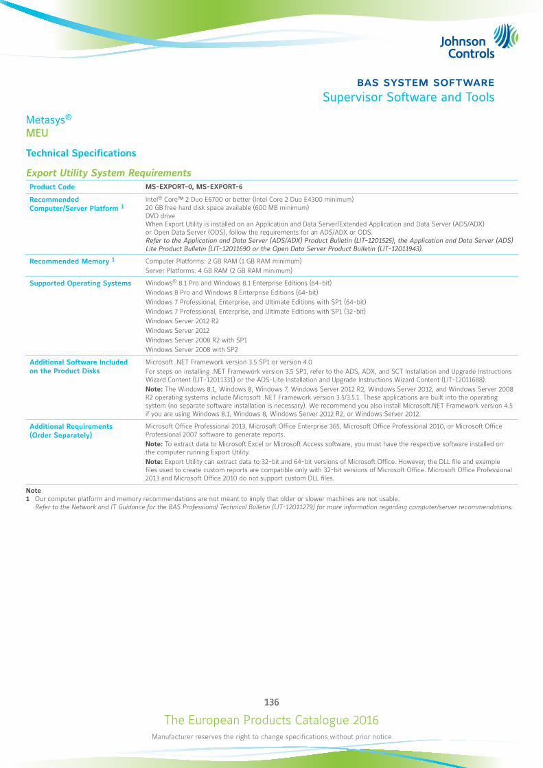
The European Products Catalogue 2016Manufacturer reserves the right to change specifications without prior notice
136
bas system softwareSupervisor Software and Tools
Metasys®
MEU
Technical Specifications
Export Utility System RequirementsProduct Code MS-EXPORT-0, MS-EXPORT-6
Recommended Computer/Server Platform 1
Intel® Core™ 2 Duo E6700 or better (Intel Core 2 Duo E4300 minimum) 20 GB free hard disk space available (600 MB minimum) DVD drive When Export Utility is installed on an Application and Data Server/Extended Application and Data Server (ADS/ADX) or Open Data Server (ODS), follow the requirements for an ADS/ADX or ODS. Refer to the Application and Data Server (ADS/ADX) Product Bulletin (LIT-1201525), the Application and Data Server (ADS) Lite Product Bulletin (LIT-12011690 or the Open Data Server Product Bulletin (LIT-12011943).
Recommended Memory 1 Computer Platforms: 2 GB RAM (1 GB RAM minimum) Server Platforms: 4 GB RAM (2 GB RAM minimum)
Supported Operating Systems Windows® 8.1 Pro and Windows 8.1 Enterprise Editions (64-bit) Windows 8 Pro and Windows 8 Enterprise Editions (64-bit) Windows 7 Professional, Enterprise, and Ultimate Editions with SP1 (64-bit) Windows 7 Professional, Enterprise, and Ultimate Editions with SP1 (32-bit) Windows Server 2012 R2 Windows Server 2012 Windows Server 2008 R2 with SP1 Windows Server 2008 with SP2
Additional Software Included on the Product Disks
Microsoft .NET Framework version 3.5 SP1 or version 4.0 For steps on installing .NET Framework version 3.5 SP1, refer to the ADS, ADX, and SCT Installation and Upgrade Instructions Wizard Content (LIT-12011331) or the ADS-Lite Installation and Upgrade Instructions Wizard Content (LIT-12011688). Note: The Windows 8.1, Windows 8, Windows 7, Windows Server 2012 R2, Windows Server 2012, and Windows Server 2008 R2 operating systems include Microsoft .NET Framework version 3.5/3.5.1. These applications are built into the operating system (no separate software installation is necessary). We recommend you also install Microsoft.NET Framework version 4.5 if you are using Windows 8.1, Windows 8, Windows Server 2012 R2, or Windows Server 2012.
Additional Requirements (Order Separately)
Microsoft Office Professional 2013, Microsoft Office Enterprise 365, Microsoft Office Professional 2010, or Microsoft Office Professional 2007 software to generate reports. Note: To extract data to Microsoft Excel or Microsoft Access software, you must have the respective software installed on the computer running Export Utility. Note: Export Utility can extract data to 32-bit and 64-bit versions of Microsoft Office. However, the DLL file and example files used to create custom reports are compatible only with 32-bit versions of Microsoft Office. Microsoft Office Professional 2013 and Microsoft Office 2010 do not support custom DLL files.
Note1 Our computer platform and memory recommendations are not meant to imply that older or slower machines are not usable.
Refer to the Network and IT Guidance for the BAS Professional Technical Bulletin (LIT-12011279) for more information regarding computer/server recommendations.
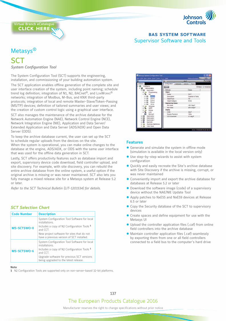
The European Products Catalogue 2016Manufacturer reserves the right to change specifications without prior notice
137
bas system softwareSupervisor Software and Tools
Metasys®
SCTSystem Configuration Tool
The System Configuration Tool (SCT) supports the engineering, installation, and commissioning of your building automation system.The SCT application enables offline generation of the complete site and user interface creation of the system, including point naming; schedule trend log definition; integration of N1, N2, BACnet®, and LonWorks® networks; integration of Modbus, M-Bus, and KNX third-party protocols; integration of local and remote Master-Slave/Token-Passing (MS/TP) devices; definition of tailored summaries and user views; and the creation of custom control logic using a graphical user interface.SCT also manages the maintenance of the archive database for the Network Automation Engine (NAE), Network Control Engine (NCE), Network Integration Engine (NIE), Application and Data Server/Extended Application and Data Server (ADS/ADX) and Open Data Server (ODS).To keep the archive database current, the user can set up the SCT to schedule regular uploads from the devices on the site. When the system is operational, you can make online changes to the database at the engine, ADS/ADX, or ODS with the same user interface that was used for the offline data generation in SCT.Lastly, SCT offers productivity features such as database import and export, supervisory device code download, field controller upload, and site discovery. For example, with site discovery, you can rebuild the entire archive database from the online system, a useful option if the original archive is missing or was never maintained. SCT also lets you fully manage a mixed release site for a Metasys system at Release 5.2 or later. Refer to the SCT Technical Bulletin (LIT-1201534) for details.
Features z Generate and simulate the system in offline mode (simulation is available in the local version only)
z Use step-by-step wizards to assist with system configuration
z Quickly and easily recreate the Site’s archive database with Site Discovery if the archive is missing, corrupt, or was never maintained
z Conveniently import and export the archive database for databases at Release 5.2 or later
z Download the software image (code) of a supervisory device without the NAE/NIE Update Tool
z Apply patches to NxE55 and NxE59 devices at Release 6.5 or later
z Copy the Security database of the SCT to supervisory devices
z Create spaces and define equipment for use with the Metasys UI
z Upload the controller application files (.caf) from online field controllers into the archive database
z Maintain controller application files (.caf) seamlessly by exporting them from one or all field controllers connected to a field bus to the computer’s hard drive
SCT Selection ChartCode Number Description
MS-SCTSWO-0
System Configuration Tool Software for local installations. Includes a copy of N2 Configuration Tools 1 and CCT. New project software for sites that do not have a previous version of SCT installed.
MS-SCTSWO-6
System Configuration Tool Software for local installations. Includes a copy of N2 Configuration Tools 1 and CCT. Upgrade software for previous SCT versions being upgraded to the latest release.
Note1 N2 Configuration Tools are supported only on non-server-based 32-bit platforms.
Virtual Branch eCatalogueclick here
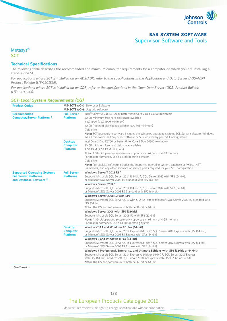
The European Products Catalogue 2016Manufacturer reserves the right to change specifications without prior notice
138
bas system softwareSupervisor Software and Tools
Metasys®
SCT
Technical SpecificationsThe following table describes the recommended and minimum computer requirements for a computer on which you are installing a stand-alone SCT.For applications where SCT is installed on an ADS/ADX, refer to the specifications in the Application and Data Server (ADS/ADX) Product Bulletin (LIT-1201525). For applications where SCT is installed on an ODS, refer to the specifications in the Open Data Server (ODS) Product Bulletin (LIT-12011943).
SCT-Local System Requirements (1/2)Product Codes MS-SCTSWO-0: New User Software
MS-SCTSWO-6: Upgrade software
Recommended Computer/Server Platform 2
Full Server Platform
Intel® Core™ 2 Duo E6700 or better (Intel Core 2 Duo E4300 minimum)20 GB minimum free hard disk space available4 GB RAM (2 GB RAM minimum)20 GB free hard disk space available (600 MB minimum)DVD driveNote: SCT prerequisite software includes the Windows operating system, SQL Server software, Windows .NET Framework, and any other software or SPs required by your SCT configuration.
Desktop Computer Platform
Intel Core 2 Duo E6700 or better (Intel Core 2 Duo E4300 minimum)20 GB minimum free hard disk space available2 GB RAM (1 GB RAM minimum)Note: A 32-bit operating system only supports a maximum of 4 GB memory. For best performance, use a 64-bit operating system.DVD driveNote: Prerequisite software includes the supported operating system, database software, .NET Framework, and any other software or service packs required for your SCT configuration.
Supported Operating Systems Full Server Platforms and Database Software 2
Full Server Platforms
Windows Server® 2012 R2 4
Supports Microsoft SQL Server 2014 (64-bit) 5, SQL Server 2012 with SP2 (64-bit), or Microsoft SQL Server 2008 R2 Standard with SP2 (64-bit) Windows Server 2012 4
Supports Microsoft SQL Server 2014 (64-bit) 5, SQL Server 2012 with SP2 (64-bit), or Microsoft SQL Server 2008 R2 Standard with SP2 (64-bit) Windows Server 2008 R2 with SP1Supports Microsoft SQL Server 2012 with SP2 (64-bit) or Microsoft SQL Server 2008 R2 Standard with SP2 (64-bit)Note: The OS and software must both be 32-bit or 64-bit.Windows Server 2008 with SP2 (32-bit)Supports Microsoft SQL Server 2008 R2 with SP2 (32-bit)Note: A 32-bit operating system only supports a maximum of 4 GB memory. For best performance, use a 64-bit operating system.
Desktop Computer Platform
Windows® 8.1 and Windows 8.1 Pro (64-bit)Supports Microsoft SQL Server 2014 Express (64-bit) 5, SQL Server 2012 Express with SP2 (64-bit), or Microsoft SQL Server 2008 R2 Express with SP2 (64-bit)Windows 8 and Windows 8 Pro (64-bit)Supports Microsoft SQL Server 2014 Express (64-bit) 5, SQL Server 2012 Express with SP2 (64-bit), or Microsoft SQL Server 2008 R2 Express with SP2 (64-bit)Windows 7 Professional, Enterprise, and Ultimate Editions with SP1 (32-bit or 64-bit)Supports Microsoft SQL Server 2014 Express (32-bit or 64-bit) 3, SQL Server 2012 Express with SP2 (64-bit), or Microsoft SQL Server 2008 R2 Express with SP2 (32-bit or 64-bit)Note: The OS and software must both be 32-bit or 64-bit.
...Continued...
The European Products Catalogue 2016Manufacturer reserves the right to change specifications without prior notice
139
bas system softwareSupervisor Software and Tools
Metasys®
SCT
SCT-Local System Requirements (2/2)Supported Operating Systems for Metasys System Configuration Tool Client Computer
Windows 8.1. or Windows 8.1 Pro (64-bit)Windows 8 or Windows 8 Pro (64-bit)Windows 7 Professional, Enterprise, or Ultimate Edition with SP1 (64-bit or 32-bit)Windows XP® Professional with SP3Apple® OS X® 10.9 MavericksApple OS X 10.8 Mountain LionNote: In OS X, you cannot view Graphics+ graphics in the Site Management Portal UI.Note: Windows XP and Apple operating systems are supported for Metasys client computers only.
Supported Web Browser Software for Metasys System Configuration Tool Client Computers
Windows Internet Explorer® version 8, 9, 10, and 11Note: In Internet Explorer 11, select the Use Microsoft compatibility lists option, found under Tools > Compatibility View Settings, to ensure that websites appear and function correctly.Apple Safari® version 6.0.5 and 7.0Other browsers, such as Google® Chrome® and Mozilla® Firefox®, may also be used but are not fully supported.Note: You use the web browser to download the Launcher application. After you install the Launcher application, you use the Launcher, not the web browser, to log in to SCT.
Network Communication for Metasys System Configuration Tool Client Computers
Ethernet network interface card 10/100/1000 Mbps (100 Mbps network or better recommended)Note: The computer hosting the SCT application supports only one network interface card.
Optional Software Packaging The ADS, ADX, ODS, and Ready Access Portal software include SCT software.
Note1 Our computer platform and memory recommendations are not meant to imply that older or slower machines are not usable.
Refer to the Network and IT Guidance for the BAS Professional Technical Bulletin (LIT-12011279) for more information regarding computer/server recommendations.2 Refer to the Network and IT Guidance for the BAS Professional Technical Bulletin (LIT-1201279) for specific Microsoft Windows OS settings that may be required for
your Metasys system configuration.3 Match the bit versions of the operating system and SQL Server software. For example, use the 32-bit version of the operating system with a 32-bit version
of SQL Server software, and a 64-bit version of operating system with a 64-bit version of SQL Server software.4 For SQL Server 2012 software, you must purchase a SQL Server software license for each individual processor core (with a minimum of four core licenses).
For example, if you have a single processor with dual cores, purchase four core licenses (the minimum) for SQL Server 2012 software.5 To use SQL Server 2014 with Metasys products, you must install Microsoft cumulative update package 3 (KB2984923) for SQL Server 2014.
To download theupdate package, visit http://support.microsoft.com/kb/2984923/.
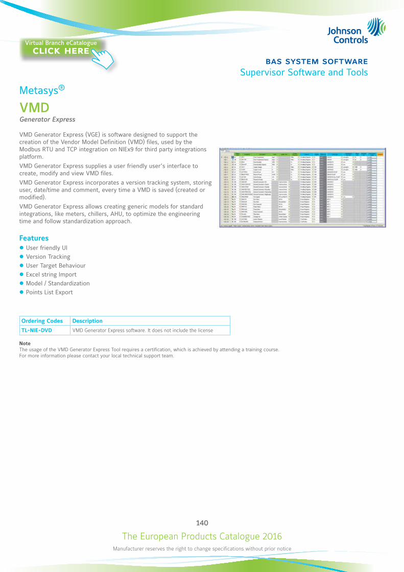
The European Products Catalogue 2016Manufacturer reserves the right to change specifications without prior notice
140
bas system softwareSupervisor Software and Tools
Metasys®
VMDGenerator Express
VMD Generator Express (VGE) is software designed to support the creation of the Vendor Model Definition (VMD) files, used by the Modbus RTU and TCP integration on NIEx9 for third party integrations platform.VMD Generator Express supplies a user friendly user’s interface to create, modify and view VMD files.VMD Generator Express incorporates a version tracking system, storing user, date/time and comment, every time a VMD is saved (created or modified).VMD Generator Express allows creating generic models for standard integrations, like meters, chillers, AHU, to optimize the engineering time and follow standardization approach.
Features z User friendly UI z Version Tracking z User Target Behaviour z Excel string Import z Model / Standardization z Points List Export
Ordering Codes Description
TL-NIE-DVD VMD Generator Express software. It does not include the license
Note The usage of the VMD Generator Express Tool requires a certification, which is achieved by attending a training course. For more information please contact your local technical support team.
Virtual Branch eCatalogueclick here
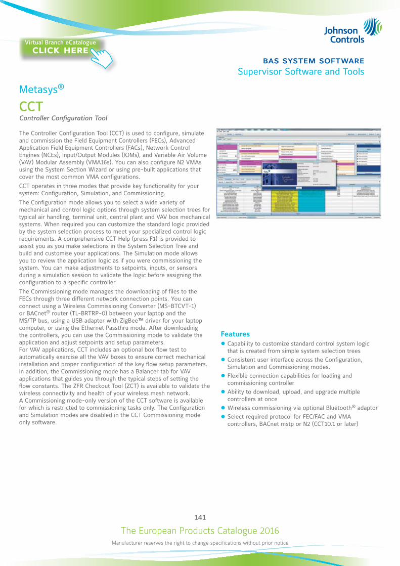
The European Products Catalogue 2016Manufacturer reserves the right to change specifications without prior notice
141
bas system softwareSupervisor Software and Tools
Metasys®
CCTController Configuration Tool
The Controller Configuration Tool (CCT) is used to configure, simulate and commission the Field Equipment Controllers (FECs), Advanced Application Field Equipment Controllers (FACs), Network Control Engines (NCEs), Input/Output Modules (IOMs), and Variable Air Volume (VAV) Modular Assembly (VMA16s). You can also configure N2 VMAs using the System Section Wizard or using pre-built applications that cover the most common VMA configurations.CCT operates in three modes that provide key functionality for your system: Configuration, Simulation, and Commissioning.The Configuration mode allows you to select a wide variety of mechanical and control logic options through system selection trees for typical air handling, terminal unit, central plant and VAV box mechanical systems. When required you can customize the standard logic provided by the system selection process to meet your specialized control logic requirements. A comprehensive CCT Help (press F1) is provided to assist you as you make selections in the System Selection Tree and build and customise your applications. The Simulation mode allows you to review the application logic as if you were commissioning the system. You can make adjustments to setpoints, inputs, or sensors during a simulation session to validate the logic before assigning the configuration to a specific controller.The Commissioning mode manages the downloading of files to the FECs through three different network connection points. You can connect using a Wireless Commissioning Converter (MS-BTCVT-1) or BACnet® router (TL-BRTRP-0) between your laptop and the MS/TP bus, using a USB adapter with ZigBee™ driver for your laptop computer, or using the Ethernet Passthru mode. After downloading the controllers, you can use the Commissioning mode to validate the application and adjust setpoints and setup parameters. For VAV applications, CCT includes an optional box flow test to automatically exercise all the VAV boxes to ensure correct mechanical installation and proper configuration of the key flow setup parameters. In addition, the Commissioning mode has a Balancer tab for VAV applications that guides you through the typical steps of setting the flow constants. The ZFR Checkout Tool (ZCT) is available to validate the wireless connectivity and health of your wireless mesh network. A Commissioning mode-only version of the CCT software is available for which is restricted to commissioning tasks only. The Configuration and Simulation modes are disabled in the CCT Commissioning mode only software.
Features z Capability to customize standard control system logic that is created from simple system selection trees
z Consistent user interface across the Configuration, Simulation and Commissioning modes.
z Flexible connection capabilities for loading and commissioning controller
z Ability to download, upload, and upgrade multiple controllers at once
z Wireless commissioning via optional Bluetooth® adaptor z Select required protocol for FEC/FAC and VMA controllers, BACnet mstp or N2 (CCT10.1 or later)
Virtual Branch eCatalogueclick here
The European Products Catalogue 2016Manufacturer reserves the right to change specifications without prior notice
142
bas system softwareSupervisor Software and Tools
Metasys®
CCT
CCT Ordering InformationOrdering Code Description
MS-CCT-0 CCT Media for the full and commissioning only versions
Technical SpecificationsProduct Code MS-CCT-0
Recommended Platform Intel® Core™ 2 Duo E6700 or better (Intel Core 2 Duo E4300 minimum) 20 GB free hard disk available (600 MB minimum) DVD drive
Recommended Memory Computer Platforms: 2 GB RAM recommended (1 GB RAM minimum) Server Platforms: 4 GB RAM recommended (2 GB RAM minimum)
Supported Operating Systems Full Server Platforms and Database Software
Windows® 8.1 Pro and Windows 8.1 Enterprise Editions (64-bit) Supports Microsoft® SQL Server® 2014 Express (64-bit) 1, Microsoft SQL Server 2012 Express with SP2 (64-bit), or Microsoft SQL Server 2008 R2 Express with SP2 (64-bit)
Windows 8 Pro and Windows 8 Enterprise Editions (32-bit or 64-bit) Supports Microsoft SQL Server 2014 Express (32-bit or 64-bit) 1, Microsoft SQL Server 2012 Express with SP2 (32-bit or 64-bit), or Microsoft SQL Server 2008 R2 Express with SP2 (32-bit or 64-bit) Note: A 32-bit operating system only supports a maximum of 4 GB memory. For best performance, use a 64-bit operating system. Note: The OS and software must both be 32-bit or 64-bit. Note: cTool applications (for example, HVACPro or GX) cannot be installed on 64-bit platforms. Note: We recommend Windows 8 for users that need cTools.
Windows 7 Professional, Enterprise, and Ultimate Editions with SP1 (32-bit or 64-bit) Supports Microsoft SQL Server 2014 Express (32-bit or 64-bit)1, Microsoft SQL Server 2012 Express with SP2 (32-bit or 64-bit), or Microsoft SQL Server 2008 R2 Express with SP2 (32-bit or 64-bit) Note: A 32-bit operating system only supports a maximum of 4 GB memory. For best performance, use a 64-bit operating system. Note: The OS and software must both be 32-bit or 64-bit. Note: cTool applications (for example, HVACPro or GX) cannot be installed on 64-bit platforms.
Required Web Browser Software for Metasys Client Computers
Windows Internet Explorer® version 8, 9, 10, and 11 Note: In Internet Explorer 11, select the Use Microsoft compatibility lists option, found under Tools > Compatibility View Settings, to ensure that websites appear and function correctly. Note: Web browser software is required if you want to view the Controller Tool Help (LIT-12011147) online. However, you can also access this help system as a PDF from the software.
Network Communication for Metasys CCT Client Computers
Ethernet network interface card 10/100/1000 Mbps (100 Mbps network or better recommended)
Software Optionally Installed During CCT Install
Microsoft .NET Framework version 3.5 with SP1 or 3.5.1 Microsoft SQL Server 2008 Express software with SP2
Optional Hardware Any network or local printer supported by the qualified Windows operating system
Note1 To use SQL Server 2014 with Metasys products, you must install Microsoft cumulative update package 3 (KB2984923) for SQL Server 2014. To download the update package, visit http://support.microsoft.com/kb/2984923/.
AccessoriesOrdering Codes Description
BT-CVTVT-1 Bluetooth® commissioning adaptor
TL-BRTRP-0 Portable BACnet/IP to MSTP Router, includes a 1.8M USB cable and a 1.5M Ethernet cable
ZFR-USBHA-0USB Dongle with ZigBee™ Driver provides a wireless connection through the CCT to allow wireless commissioning of the wirelessly enabled FEC and VMA16 field controllers. Also allows use of the ZCT in CCT.
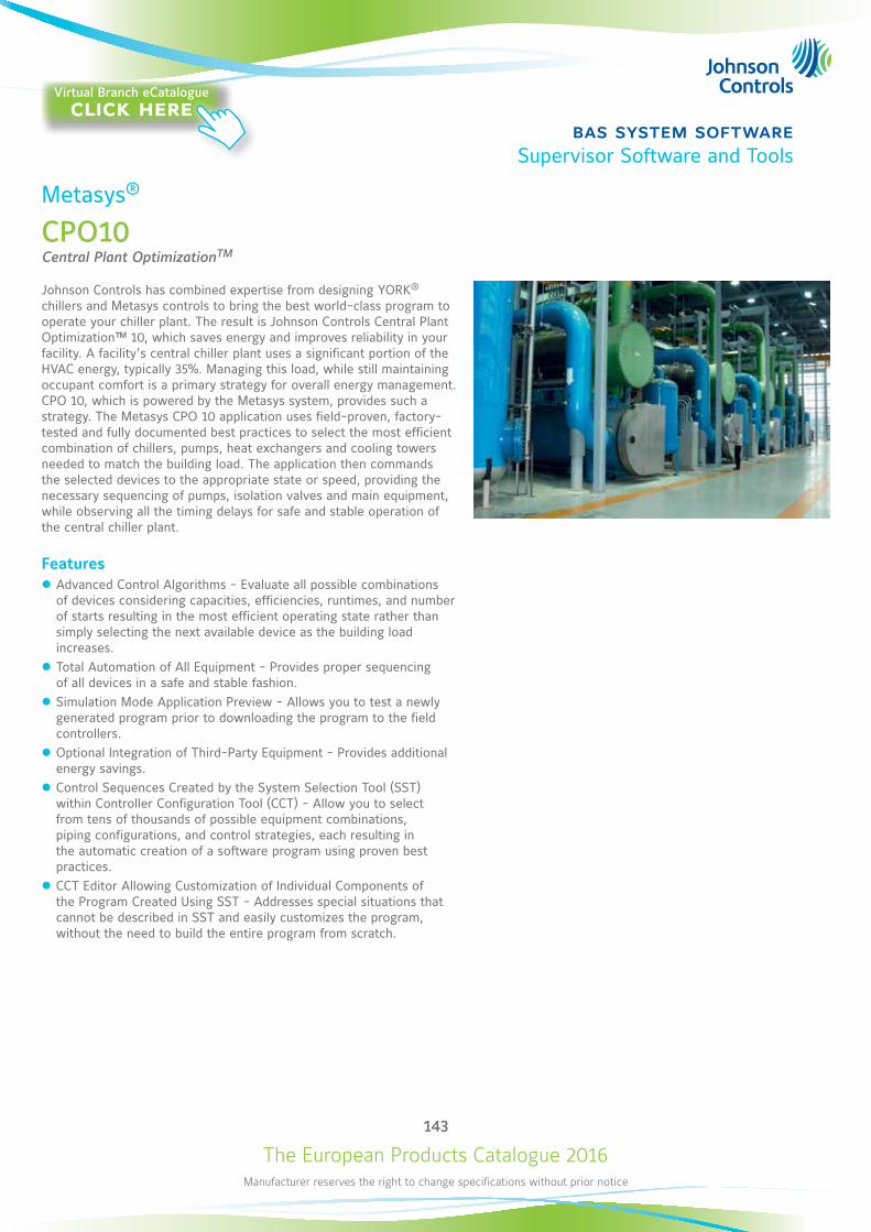
The European Products Catalogue 2016Manufacturer reserves the right to change specifications without prior notice
143
bas system softwareSupervisor Software and Tools
Metasys®
CPO10Central Plant OptimizationTM
Johnson Controls has combined expertise from designing YORK® chillers and Metasys controls to bring the best world-class program to operate your chiller plant. The result is Johnson Controls Central Plant Optimization™ 10, which saves energy and improves reliability in your facility. A facility’s central chiller plant uses a significant portion of the HVAC energy, typically 35%. Managing this load, while still maintaining occupant comfort is a primary strategy for overall energy management. CPO 10, which is powered by the Metasys system, provides such a strategy. The Metasys CPO 10 application uses field-proven, factory-tested and fully documented best practices to select the most efficient combination of chillers, pumps, heat exchangers and cooling towers needed to match the building load. The application then commands the selected devices to the appropriate state or speed, providing the necessary sequencing of pumps, isolation valves and main equipment, while observing all the timing delays for safe and stable operation of the central chiller plant.
Features z Advanced Control Algorithms - Evaluate all possible combinations of devices considering capacities, efficiencies, runtimes, and number of starts resulting in the most efficient operating state rather than simply selecting the next available device as the building load increases.
z Total Automation of All Equipment - Provides proper sequencing of all devices in a safe and stable fashion.
z Simulation Mode Application Preview - Allows you to test a newly generated program prior to downloading the program to the field controllers.
z Optional Integration of Third-Party Equipment - Provides additional energy savings.
z Control Sequences Created by the System Selection Tool (SST) within Controller Configuration Tool (CCT) - Allow you to select from tens of thousands of possible equipment combinations, piping configurations, and control strategies, each resulting in the automatic creation of a software program using proven best practices.
z CCT Editor Allowing Customization of Individual Components of the Program Created Using SST - Addresses special situations that cannot be described in SST and easily customizes the program, without the need to build the entire program from scratch.
Virtual Branch eCatalogueclick here
The European Products Catalogue 2016Manufacturer reserves the right to change specifications without prior notice
144
bas system softwareSupervisor Software and Tools
Metasys®
CPO10
The CPO10 Application Supports: Up to eight chillers, centrifugal (mix of constant or variable speed), screw, reciprocating or scroll compressor of mixed sizes,
piped in parallel
Up to eight primary chilled water pumps of mixed sizes, all dedicated or headered and all constant or variable speed
Up to eight secondary chilled water pumps that are mixed in size, are piped in parallel and are variable speed
Up to eight condenser water pumps that are mixed in size, all dedicated or headered and all constant or variable speed
Up to four heat exchangers of mixed sizes, piped in parallel
Up to eight cooling towers piped in common to the chillers, are single speed (with optional vernier control), multispeed or variable speed with a variety of tower/sump valve arrangements
A non-integrated waterside economizer able to control up to eight total devices (chillers and heat exchangers) piped in parallel
Air-cooled chillers
The CPO10 application offers a variety of primary control strategies including measuring building chilled-water flow and differential temperature, the chillers’ kW load and flow through a decoupler pipe in a primary/secondary system, or differential temperature only in a constant speed chilled water pump system. You can also select dozens of secondary strategies, such as open loop control of the cooling towers (as defined by the American Society of Heating, Refrigerating and Air-Conditioning Engineers [ASHRAE]) or closed loop control of condenser-water setpoint. The CPO10 application supports 24 sequences through any combination of the following chilled water systems and condenser water systems:
Chilled Water Systems Condenser Water Systems
z Variable Primary Headered z Variable Primary Dedicated z Primary Secondary Headered z Primary Secondary Dedicated z Constant Headered
z Constant Dedicated z Variable Headered z Variable Dedicated z Constant Headered
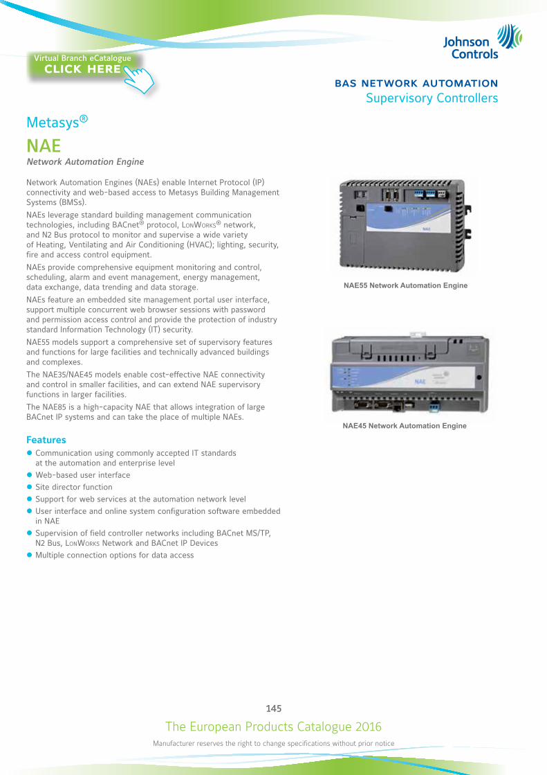
The European Products Catalogue 2016Manufacturer reserves the right to change specifications without prior notice
145
bas network automationSupervisory Controllers
Metasys®
NAENetwork Automation Engine
Network Automation Engines (NAEs) enable Internet Protocol (IP) connectivity and web-based access to Metasys Building Management Systems (BMSs). NAEs leverage standard building management communication technologies, including BACnet® protocol, LonWorks® network, and N2 Bus protocol to monitor and supervise a wide variety of Heating, Ventilating and Air Conditioning (HVAC); lighting, security, fire and access control equipment. NAEs provide comprehensive equipment monitoring and control, scheduling, alarm and event management, energy management, data exchange, data trending and data storage. NAEs feature an embedded site management portal user interface, support multiple concurrent web browser sessions with password and permission access control and provide the protection of industry standard Information Technology (IT) security. NAE55 models support a comprehensive set of supervisory features and functions for large facilities and technically advanced buildings and complexes. The NAE35/NAE45 models enable cost-effective NAE connectivity and control in smaller facilities, and can extend NAE supervisory functions in larger facilities. The NAE85 is a high-capacity NAE that allows integration of large BACnet IP systems and can take the place of multiple NAEs.
Features z Communication using commonly accepted IT standards at the automation and enterprise level
z Web-based user interface z Site director function z Support for web services at the automation network level z User interface and online system configuration software embedded in NAE
z Supervision of field controller networks including BACnet MS/TP, N2 Bus, LonWorks Network and BACnet IP Devices
z Multiple connection options for data access
NAE55 Network Automation Engine
NAE45 Network Automation Engine
Virtual Branch eCatalogueclick here
The European Products Catalogue 2016Manufacturer reserves the right to change specifications without prior notice
146
bas network automationSupervisory Controllers
Metasys®
NAE
NAE35Ordering Codes DescriptionMS-NAE35xx-xxx(Base Features of Each NAE35)
NAE35 Network Automation Engines: Requires a 24 VAC power supply. Each model includes one RS-232-C serial port, one USB serial port, one Ethernet port, and an MS-BAT1020-0 data protection battery.
MS-NAE3510-2 Supports one N2 or BACnet MS/TP (RS-485) trunk; includes an additional RS-232-C serial port for optional external modem; supports up to 50 devices on the N2 or BACnet MS/TP trunk.
MS-NAE3511-2 Supports one N2 or BACnet MS/TP (RS-485) trunk (RS-485 port); includes an internal modem; supports up to 50 devices on the N2 or BACnet MS/TP trunk.
MS-NAE3514-2 Supports one N2 or BACnet MS/TP (RS-485) trunk; features basic access support; includes an additional RS-232-C serial port for optional external modem; supports up to 50 devices on the N2 or BACnet MS/TP trunk.
MS-NAE3515-2 Supports one N2 or BACnet MS/TP (RS-485) trunk; features basic access support; includes an internal modem; supports up to 50 devices on the N2 or BACnet MS/TP trunk.
MS-NAE3520-2 Supports one LonWorks trunk, includes an additional RS-232-C serial port for optional external modem. Supports up to 64 devices on the LonWorks port.
MS-NAE3521-2 Supports one LonWorks trunk, includes an internal modem. Supports up to 64 devices on the LonWorks port.
MS-NAE3524-2 Supports one LonWorks trunk, features Basic Access support, and includes an additional RS-232-C serial port for optional external modem. Supports up to 64 devices on the LonWorks trunks.
MS-NAE3525-2 Supports one LonWorks trunk, features Basic Access support, and includes an internal modem. Supports up to 64 devices on the LonWorks trunks.
NAE45Ordering Codes Description
MS-NAE45xx-xxx (Base Features of Each NAE45)
NAE45 Network Automation Engines: Requires a 24 VAC power supply. Each model includes one RS-232-C serial port, one USB serial port, one Ethernet port, and an MS-BAT1020-0 data protection battery.
MS-NAE4510-2 Supports one N2 or BACnet MS/TP (RS-485) trunk; includes an additional RS-232-C serial port for optional external modem; supports up to 100 devices on the N2 or BACnet MS/TP trunk.
MS-NAE4511-2 Supports one N2 or BACnet MS/TP (RS-485) trunk; includes an internal modem; supports up to 100 devices on the N2 or BACnet MS/TP trunk.
MS-NAE4520-2 Supports one LonWorks trunk, includes an additional RS-232-C serial port for optional external modem; supports up to 127 devices on the LonWorks port.
MS-NAE4521-2 Supports one LonWorks trunk, includes an internal modem; supports up to 127 devices on the LonWorks port.
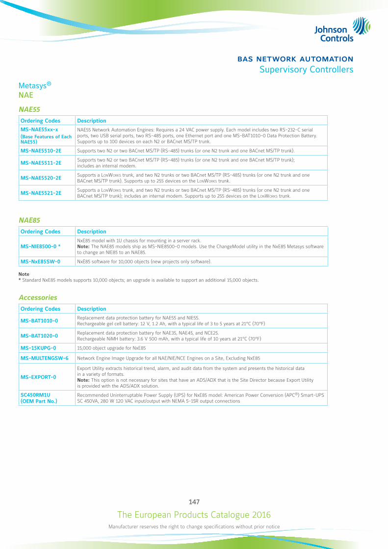
The European Products Catalogue 2016Manufacturer reserves the right to change specifications without prior notice
147
bas network automationSupervisory Controllers
Metasys®
NAE
NAE55Ordering Codes Description
MS-NAE55xx-x(Base Features of Each NAE55)
NAE55 Network Automation Engines: Requires a 24 VAC power supply. Each model includes two RS-232-C serial ports, two USB serial ports, two RS-485 ports, one Ethernet port and one MS-BAT1010-0 Data Protection Battery. Supports up to 100 devices on each N2 or BACnet MS/TP trunk.
MS-NAE5510-2E Supports two N2 or two BACnet MS/TP (RS-485) trunks (or one N2 trunk and one BACnet MS/TP trunk).
MS-NAE5511-2E Supports two N2 or two BACnet MS/TP (RS-485) trunks (or one N2 trunk and one BACnet MS/TP trunk); includes an internal modem.
MS-NAE5520-2E Supports a LonWorks trunk, and two N2 trunks or two BACnet MS/TP (RS-485) trunks (or one N2 trunk and one BACnet MS/TP trunk). Supports up to 255 devices on the LonWorks trunk.
MS-NAE5521-2E Supports a LonWorks trunk, and two N2 trunks or two BACnet MS/TP (RS-485) trunks (or one N2 trunk and one BACnet MS/TP trunk); includes an internal modem. Supports up to 255 devices on the LonWorks trunk.
NAE85Ordering Codes Description
MS-NIE8500-0 *NxE85 model with 1U chassis for mounting in a server rack. Note: The NAE85 models ship as MS-NIE8500-0 models. Use the ChangeModel utility in the NxE85 Metasys software to change an NIE85 to an NAE85.
MS-NxE85SW-0 NxE85 software for 10,000 objects (new projects only software).
Note* Standard NxE85 models supports 10,000 objects; an upgrade is available to support an additional 15,000 objects.
AccessoriesOrdering Codes Description
MS-BAT1010-0 Replacement data protection battery for NAE55 and NIE55. Rechargeable gel cell battery: 12 V, 1.2 Ah, with a typical life of 3 to 5 years at 21°C (70°F)
MS-BAT1020-0 Replacement data protection battery for NAE35, NAE45, and NCE25. Rechargeable NiMH battery: 3.6 V 500 mAh, with a typical life of 10 years at 21°C (70°F)
MS-15KUPG-0 15,000 object upgrade for NxE85
MS-MULTENGSW-6 Network Engine Image Upgrade for all NAE/NIE/NCE Engines on a Site, Excluding NxE85
MS-EXPORT-0
Export Utility extracts historical trend, alarm, and audit data from the system and presents the historical data in a variety of formats. Note: This option is not necessary for sites that have an ADS/ADX that is the Site Director because Export Utility is provided with the ADS/ADX solution.
SC450RM1U (OEM Part No.)
Recommended Uninterruptable Power Supply (UPS) for NxE85 model: American Power Conversion (APC®) Smart-UPS SC 450VA, 280 W 120 VAC input/output with NEMA 5-15R output connections
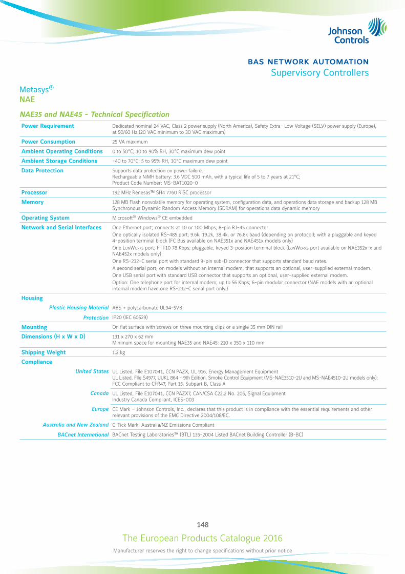
The European Products Catalogue 2016Manufacturer reserves the right to change specifications without prior notice
148
bas network automationSupervisory Controllers
Metasys®
NAE
NAE35 and NAE45 - Technical SpecificationPower Requirement Dedicated nominal 24 VAC, Class 2 power supply (North America), Safety Extra- Low Voltage (SELV) power supply (Europe),
at 50/60 Hz (20 VAC minimum to 30 VAC maximum)
Power Consumption 25 VA maximum
Ambient Operating Conditions 0 to 50°C; 10 to 90% RH, 30°C maximum dew point
Ambient Storage Conditions -40 to 70°C; 5 to 95% RH, 30°C maximum dew point
Data Protection Supports data protection on power failure. Rechargeable NiMH battery: 3.6 VDC 500 mAh, with a typical life of 5 to 7 years at 21°C; Product Code Number: MS-BAT1020-0
Processor 192 MHz Renesas™ SH4 7760 RISC processor
Memory 128 MB Flash nonvolatile memory for operating system, configuration data, and operations data storage and backup 128 MB Synchronous Dynamic Random Access Memory (SDRAM) for operations data dynamic memory
Operating System Microsoft® Windows® CE embedded
Network and Serial Interfaces One Ethernet port; connects at 10 or 100 Mbps; 8-pin RJ-45 connector One optically isolated RS-485 port; 9.6k, 19.2k, 38.4k, or 76.8k baud (depending on protocol); with a pluggable and keyed 4-position terminal block (FC Bus available on NAE351x and NAE451x models only) One LonWorks port; FTT10 78 Kbps; pluggable, keyed 3-position terminal block (LonWorks port available on NAE352x-x and NAE452x models only) One RS-232-C serial port with standard 9-pin sub-D connector that supports standard baud rates. A second serial port, on models without an internal modem, that supports an optional, user-supplied external modem. One USB serial port with standard USB connector that supports an optional, user-supplied external modem. Option: One telephone port for internal modem; up to 56 Kbps; 6-pin modular connector (NAE models with an optional internal modem have one RS-232-C serial port only.)
Housing
Plastic Housing Material ABS + polycarbonate UL94-5VB
Protection IP20 (IEC 60529)
Mounting On flat surface with screws on three mounting clips or a single 35 mm DIN rail
Dimensions (H x W x D) 131 x 270 x 62 mm Minimum space for mounting NAE35 and NAE45: 210 x 350 x 110 mm
Shipping Weight 1.2 kg
Compliance
United States UL Listed, File E107041, CCN PAZX, UL 916, Energy Management Equipment UL Listed, FIle S4977, UUKL 864 - 9th Edition, Smoke Control Equipment (MS-NAE3510-2U and MS-NAE4510-2U models only); FCC Compliant to CFR47, Part 15, Subpart B, Class A
Canada UL Listed, File E107041, CCN PAZX7, CAN/CSA C22.2 No. 205, Signal Equipment Industry Canada Compliant, ICES-003
Europe CE Mark – Johnson Controls, Inc., declares that this product is in compliance with the essential requirements and other relevant provisions of the EMC Directive 2004/108/EC.
Australia and New Zealand C-Tick Mark, Australia/NZ Emissions Compliant
BACnet International BACnet Testing Laboratories™ (BTL) 135-2004 Listed BACnet Building Controller (B-BC)
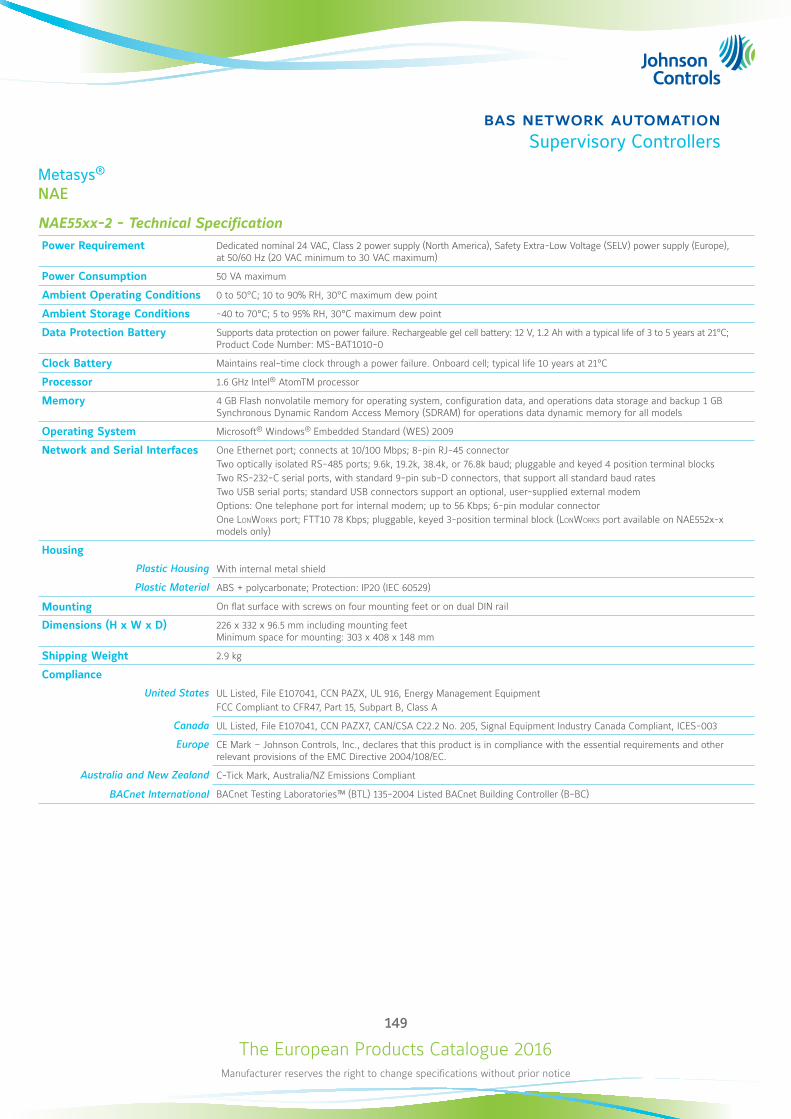
The European Products Catalogue 2016Manufacturer reserves the right to change specifications without prior notice
149
bas network automationSupervisory Controllers
Metasys®
NAE
NAE55xx-2 - Technical SpecificationPower Requirement Dedicated nominal 24 VAC, Class 2 power supply (North America), Safety Extra-Low Voltage (SELV) power supply (Europe),
at 50/60 Hz (20 VAC minimum to 30 VAC maximum)
Power Consumption 50 VA maximum
Ambient Operating Conditions 0 to 50°C; 10 to 90% RH, 30°C maximum dew point
Ambient Storage Conditions -40 to 70°C; 5 to 95% RH, 30°C maximum dew point
Data Protection Battery Supports data protection on power failure. Rechargeable gel cell battery: 12 V, 1.2 Ah with a typical life of 3 to 5 years at 21°C; Product Code Number: MS-BAT1010-0
Clock Battery Maintains real-time clock through a power failure. Onboard cell; typical life 10 years at 21°C
Processor 1.6 GHz Intel® AtomTM processor
Memory 4 GB Flash nonvolatile memory for operating system, configuration data, and operations data storage and backup 1 GB Synchronous Dynamic Random Access Memory (SDRAM) for operations data dynamic memory for all models
Operating System Microsoft® Windows® Embedded Standard (WES) 2009
Network and Serial Interfaces One Ethernet port; connects at 10/100 Mbps; 8-pin RJ-45 connector Two optically isolated RS-485 ports; 9.6k, 19.2k, 38.4k, or 76.8k baud; pluggable and keyed 4 position terminal blocks Two RS-232-C serial ports, with standard 9-pin sub-D connectors, that support all standard baud rates Two USB serial ports; standard USB connectors support an optional, user-supplied external modem Options: One telephone port for internal modem; up to 56 Kbps; 6-pin modular connector One LonWorks port; FTT10 78 Kbps; pluggable, keyed 3-position terminal block (LonWorks port available on NAE552x-x models only)
Housing
Plastic Housing With internal metal shield
Plastic Material ABS + polycarbonate; Protection: IP20 (IEC 60529)
Mounting On flat surface with screws on four mounting feet or on dual DIN rail
Dimensions (H x W x D) 226 x 332 x 96.5 mm including mounting feet Minimum space for mounting: 303 x 408 x 148 mm
Shipping Weight 2.9 kg
Compliance
United States UL Listed, File E107041, CCN PAZX, UL 916, Energy Management Equipment FCC Compliant to CFR47, Part 15, Subpart B, Class A
Canada UL Listed, File E107041, CCN PAZX7, CAN/CSA C22.2 No. 205, Signal Equipment Industry Canada Compliant, ICES-003
Europe CE Mark – Johnson Controls, Inc., declares that this product is in compliance with the essential requirements and other relevant provisions of the EMC Directive 2004/108/EC.
Australia and New Zealand C-Tick Mark, Australia/NZ Emissions Compliant
BACnet International BACnet Testing Laboratories™ (BTL) 135-2004 Listed BACnet Building Controller (B-BC)
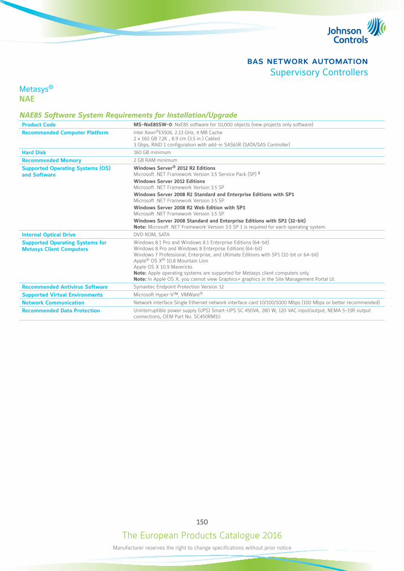
The European Products Catalogue 2016Manufacturer reserves the right to change specifications without prior notice
150
bas network automationSupervisory Controllers
Metasys®
NAE
NAE85 Software System Requirements for Installation/UpgradeProduct Code MS-NxE85SW-0: NxE85 software for 10,000 objects (new projects only software)
Recommended Computer Platform Intel Xeon®E5506, 2.13 GHz, 4 MB Cache 2 x 160 GB 7.2K , 8.9 cm (3.5 in.) Cabled 3 Gbps, RAID 1 configuration with add-in SAS6/iR (SATA/SAS Controller)
Hard Disk 160 GB minimum
Recommended Memory 2 GB RAM minimum
Supported Operating Systems (OS) and Software
Windows Server® 2012 R2 Editions Microsoft .NET Framework Version 3.5 Service Pack (SP) 1 Windows Server 2012 Editions Microsoft .NET Framework Version 3.5 SP Windows Server 2008 R2 Standard and Enterprise Editions with SP1 Microsoft .NET Framework Version 3.5 SP Windows Server 2008 R2 Web Edition with SP1 Microsoft .NET Framework Version 3.5 SP Windows Server 2008 Standard and Enterprise Editions with SP2 (32-bit) Note: Microsoft .NET Framework Version 3.5 SP 1 is required for each operating system.
Internal Optical Drive DVD ROM, SATA
Supported Operating Systems for Metasys Client Computers
Windows 8.1 Pro and Windows 8.1 Enterprise Editions (64-bit) Windows 8 Pro and Windows 8 Enterprise Editions (64-bit) Windows 7 Professional, Enterprise, and Ultimate Editions with SP1 (32-bit or 64-bit) Apple® OS X® 10.8 Mountain Lion Apple OS X 10.9 Mavericks Note: Apple operating systems are supported for Metasys client computers only. Note: In Apple OS X, you cannot view Graphics+ graphics in the Site Management Portal UI.
Recommended Antivirus Software Symantec Endpoint Protection Version 12
Supported Virtual Environments Microsoft Hyper-V™, VMWare®
Network Communication Network interface Single Ethernet network interface card 10/100/1000 Mbps (100 Mbps or better recommended)
Recommended Data Protection Uninterruptible power supply (UPS) Smart-UPS SC 450VA, 280 W, 120 VAC input/output, NEMA 5-15R output connections, OEM Part No. SC450RM1U
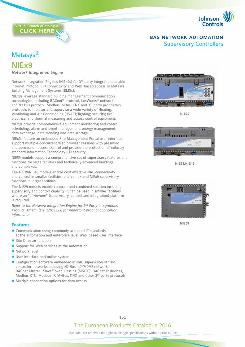
The European Products Catalogue 2016Manufacturer reserves the right to change specifications without prior notice
151
bas network automationSupervisory Controllers
Metasys®
NIEx9Network Integration Engine
Network Integration Engines (NIEx9s) for 3rd party integrations enable Internet Protocol (IP) connectivity and Web-based access to Metasys Building Management Systems (BMSs).NIEx9s leverage standard building management communication technologies, including BACnet® protocol, LonWorks® network and N2 Bus protocol, Modbus, MBus, KNX and 3rd party proprietary protocols to monitor and supervise a wide variety of Heating, Ventilating and Air Conditioning (HVAC); lighting; security; fire; electrical and thermal measuring and access control equipment.NIEx9s provide comprehensive equipment monitoring and control, scheduling, alarm and event management, energy management, data exchange, data trending and data storage.NIEx9s feature an embedded Site Management Portal user interface, support multiple concurrent Web browser sessions with password and permission access control and provide the protection of industry standard Information Technology (IT) security.NIE59 models support a comprehensive set of supervisory features and functions for large facilities and technically advanced buildings and complexes.The NIE39/NIE49 models enable cost effective NAE connectivity and control in smaller facilities, and can extend NIEx9 supervisory functions in larger facilities.The NIE29 models enable compact and combined solution including supervisory and control capacity. It can be used in smaller facilities where an “all-in-one” (supervisory, control and integration) platform is required.Refer to the Network Integration Engine for 3rd Party Integrations Product Bulletin (LIT-12011923) for important product application information.
Features z Communication using commonly accepted IT standards at the automation and enterprise level Web-based user interface
z Site Director function z Support for Web services at the automation z Network level z User interface and online system z Configuration software embedded in NAE supervision of field controller networks including N2 Bus, LonWorks network, BACnet Master- Slave/Token-Passing (MS/TP), BACnet IP devices, Modbus RTU, Modbus IP, M-Bus, KNX and other 3rd party protocols
z Multiple connection options for data access
NIE59
NIE39/NIE49
NIE29
Virtual Branch eCatalogueclick here
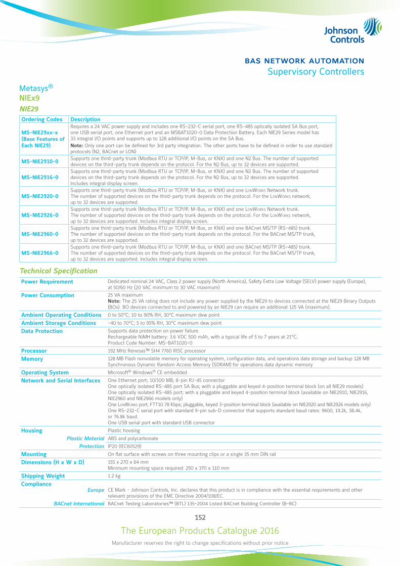
The European Products Catalogue 2016Manufacturer reserves the right to change specifications without prior notice
152
bas network automationSupervisory Controllers
Metasys®
NIEx9 NIE29Ordering Codes Description
MS-NIE29xx-x (Base Features of Each NIE29)
Requires a 24 VAC power supply and includes one RS-232-C serial port, one RS-485 optically isolated SA Bus port, one USB serial port, one Ethernet port and an MSBAT1020-0 Data Protection Battery. Each NIE29 Series model has 33 integral I/O points and supports up to 128 additional I/O points on the SA Bus. Note: Only one port can be defined for 3rd party integration. The other ports have to be defined in order to use standard protocols (N2, BACnet or LON)
MS-NIE2910-0 Supports one third-party trunk (Modbus RTU or TCP/IP, M-Bus, or KNX) and one N2 Bus. The number of supported devices on the third-party trunk depends on the protocol. For the N2 Bus, up to 32 devices are supported.
MS-NIE2916-0Supports one third-party trunk (Modbus RTU or TCP/IP, M-Bus, or KNX) and one N2 Bus. The number of supported devices on the third-party trunk depends on the protocol. For the N2 Bus, up to 32 devices are supported. Includes integral display screen.
MS-NIE2920-0Supports one third-party trunk (Modbus RTU or TCP/IP, M-Bus, or KNX) and one LonWorks Network trunk. The number of supported devices on the third-party trunk depends on the protocol. For the LonWorks network, up to 32 devices are supported.
MS-NIE2926-0 Supports one third-party trunk (Modbus RTU or TCP/IP, M-Bus, or KNX) and one LonWorks Network trunk. The number of supported devices on the third-party trunk depends on the protocol. For the LonWorks network, up to 32 devices are supported. Includes integral display screen.
MS-NIE2960-0 Supports one third-party trunk (Modbus RTU or TCP/IP, M-Bus, or KNX) and one BACnet MS/TP (RS-485) trunk. The number of supported devices on the third-party trunk depends on the protocol. For the BACnet MS/TP trunk, up to 32 devices are supported.
MS-NIE2966-0 Supports one third-party trunk (Modbus RTU or TCP/IP, M-Bus, or KNX) and one BACnet MS/TP (RS-485) trunk. The number of supported devices on the third-party trunk depends on the protocol. For the BACnet MS/TP trunk, up to 32 devices are supported. Includes integral display screen.
Technical SpecificationPower Requirement Dedicated nominal 24 VAC, Class 2 power supply (North America), Safety Extra Low Voltage (SELV) power supply (Europe),
at 50/60 Hz (20 VAC minimum to 30 VAC maximum)
Power Consumption 25 VA maximum Note: The 25 VA rating does not include any power supplied by the NIE29 to devices connected at the NIE29 Binary Outputs (BOs). BO devices connected to and powered by an NIE29 can require an additional 125 VA (maximum).
Ambient Operating Conditions 0 to 50°C; 10 to 90% RH, 30°C maximum dew point
Ambient Storage Conditions -40 to 70°C; 5 to 95% RH, 30°C maximum dew point
Data Protection Supports data protection on power failure. Rechargeable NiMH battery: 3.6 VDC 500 mAh, with a typical life of 5 to 7 years at 21°C; Product Code Number: MS-BAT1020-0
Processor 192 MHz Renesas™ SH4 7760 RISC processor
Memory 128 MB Flash nonvolatile memory for operating system, configuration data, and operations data storage and backup 128 MB Synchronous Dynamic Random Access Memory (SDRAM) for operations data dynamic memory
Operating System Microsoft® Windows® CE embedded
Network and Serial Interfaces One Ethernet port; 10/100 MB; 8-pin RJ-45 connector One optically isolated RS-485 port SA Bus; with a pluggable and keyed 4-position terminal block (on all NIE29 models) One optically isolated RS-485 port; with a pluggable and keyed 4-position terminal block (available on NIE2910, NIE2916, NIE2960 and NIE2966 models only) One LonWorks port; FTT10 78 Kbps; pluggable, keyed 3-position terminal block (available on NIE2920 and NIE2926 models only) One RS-232-C serial port with standard 9-pin sub-D connector that supports standard baud rates: 9600, 19.2k, 38.4k, or 76.8k baud. One USB serial port with standard USB connector
Housing Plastic housing
Plastic Material ABS and polycarbonate
Protection IP20 (IEC60529)
Mounting On flat surface with screws on three mounting clips or a single 35 mm DIN rail
Dimensions (H x W x D) 155 x 270 x 64 mm Minimum mounting space required: 250 x 370 x 110 mm
Shipping Weight 1.2 kg
Compliance Europe CE Mark - Johnson Controls, Inc. declares that this product is in compliance with the essential requirements and other
relevant provisions of the EMC Directive 2004/108/EC.
BACnet International BACnet Testing Laboratories™ (BTL) 135-2004 Listed BACnet Building Controller (B-BC)
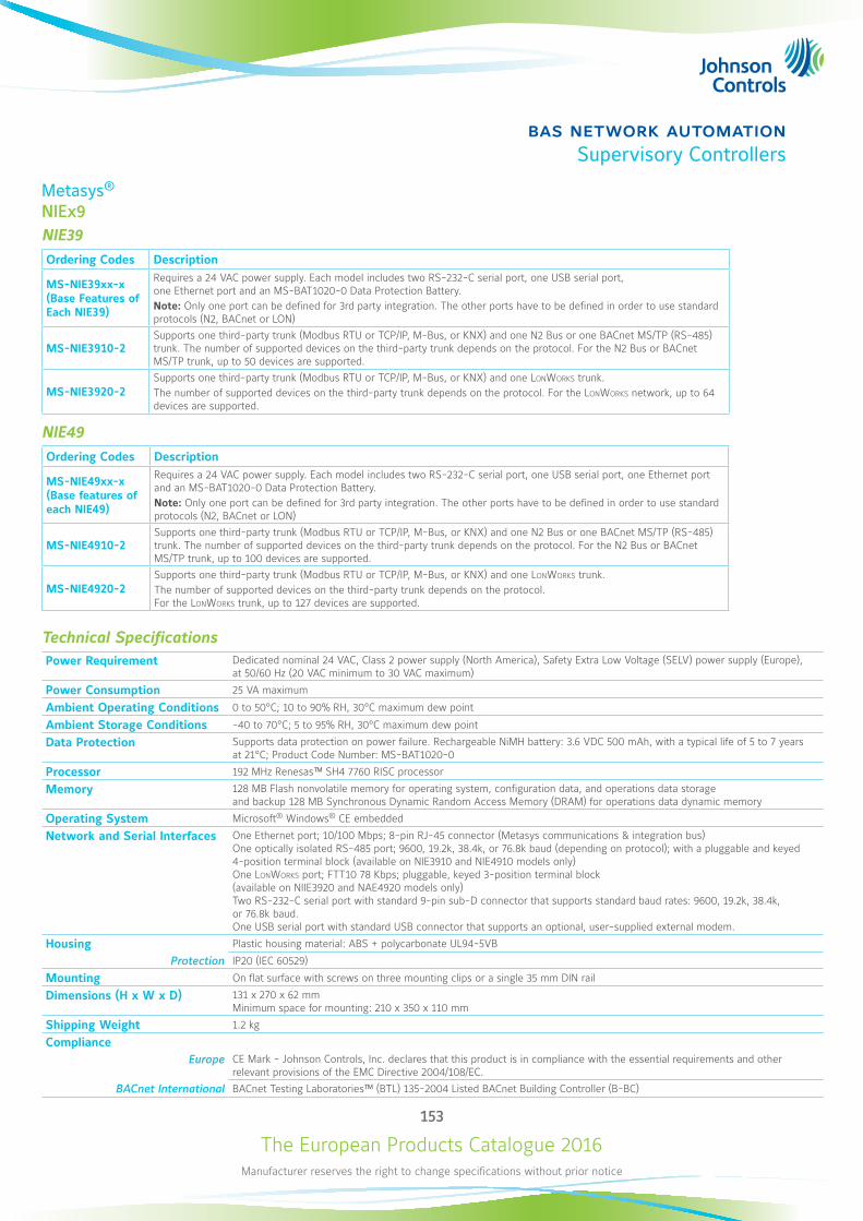
The European Products Catalogue 2016Manufacturer reserves the right to change specifications without prior notice
153
bas network automationSupervisory Controllers
Metasys®
NIEx9
NIE39Ordering Codes Description
MS-NIE39xx-x (Base Features of Each NIE39)
Requires a 24 VAC power supply. Each model includes two RS-232-C serial port, one USB serial port, one Ethernet port and an MS-BAT1020-0 Data Protection Battery. Note: Only one port can be defined for 3rd party integration. The other ports have to be defined in order to use standard protocols (N2, BACnet or LON)
MS-NIE3910-2 Supports one third-party trunk (Modbus RTU or TCP/IP, M-Bus, or KNX) and one N2 Bus or one BACnet MS/TP (RS-485) trunk. The number of supported devices on the third-party trunk depends on the protocol. For the N2 Bus or BACnet MS/TP trunk, up to 50 devices are supported.
MS-NIE3920-2 Supports one third-party trunk (Modbus RTU or TCP/IP, M-Bus, or KNX) and one LonWorks trunk.The number of supported devices on the third-party trunk depends on the protocol. For the LonWorks network, up to 64 devices are supported.
NIE49Ordering Codes Description
MS-NIE49xx-x (Base features of each NIE49)
Requires a 24 VAC power supply. Each model includes two RS-232-C serial port, one USB serial port, one Ethernet port and an MS-BAT1020-0 Data Protection Battery. Note: Only one port can be defined for 3rd party integration. The other ports have to be defined in order to use standard protocols (N2, BACnet or LON)
MS-NIE4910-2 Supports one third-party trunk (Modbus RTU or TCP/IP, M-Bus, or KNX) and one N2 Bus or one BACnet MS/TP (RS-485) trunk. The number of supported devices on the third-party trunk depends on the protocol. For the N2 Bus or BACnet MS/TP trunk, up to 100 devices are supported.
MS-NIE4920-2 Supports one third-party trunk (Modbus RTU or TCP/IP, M-Bus, or KNX) and one LonWorks trunk.The number of supported devices on the third-party trunk depends on the protocol. For the LonWorks trunk, up to 127 devices are supported.
Technical SpecificationsPower Requirement Dedicated nominal 24 VAC, Class 2 power supply (North America), Safety Extra Low Voltage (SELV) power supply (Europe),
at 50/60 Hz (20 VAC minimum to 30 VAC maximum)
Power Consumption 25 VA maximum
Ambient Operating Conditions 0 to 50°C; 10 to 90% RH, 30°C maximum dew point
Ambient Storage Conditions -40 to 70°C; 5 to 95% RH, 30°C maximum dew point
Data Protection Supports data protection on power failure. Rechargeable NiMH battery: 3.6 VDC 500 mAh, with a typical life of 5 to 7 years at 21°C; Product Code Number: MS-BAT1020-0
Processor 192 MHz Renesas™ SH4 7760 RISC processor
Memory 128 MB Flash nonvolatile memory for operating system, configuration data, and operations data storage and backup 128 MB Synchronous Dynamic Random Access Memory (DRAM) for operations data dynamic memory
Operating System Microsoft® Windows® CE embedded
Network and Serial Interfaces One Ethernet port; 10/100 Mbps; 8-pin RJ-45 connector (Metasys communications & integration bus) One optically isolated RS-485 port; 9600, 19.2k, 38.4k, or 76.8k baud (depending on protocol); with a pluggable and keyed 4-position terminal block (available on NIE3910 and NIE4910 models only) One LonWorks port; FTT10 78 Kbps; pluggable, keyed 3-position terminal block (available on NIIE3920 and NAE4920 models only) Two RS-232-C serial port with standard 9-pin sub-D connector that supports standard baud rates: 9600, 19.2k, 38.4k, or 76.8k baud. One USB serial port with standard USB connector that supports an optional, user-supplied external modem.
Housing Plastic housing material: ABS + polycarbonate UL94-5VB
Protection IP20 (IEC 60529)
Mounting On flat surface with screws on three mounting clips or a single 35 mm DIN rail
Dimensions (H x W x D) 131 x 270 x 62 mm Minimum space for mounting: 210 x 350 x 110 mm
Shipping Weight 1.2 kg
Compliance Europe CE Mark - Johnson Controls, Inc. declares that this product is in compliance with the essential requirements and other
relevant provisions of the EMC Directive 2004/108/EC.
BACnet International BACnet Testing Laboratories™ (BTL) 135-2004 Listed BACnet Building Controller (B-BC)
The European Products Catalogue 2016Manufacturer reserves the right to change specifications without prior notice
154
bas network automationSupervisory Controllers
Metasys®
NIEx9
NIE59Ordering Codes Description
MS-NIE59xx-x (Base features of each NIE59)
Requires a 24 VAC power supply. Each model includes two RS-232-C serial ports, two USB serial ports, two RS-485 ports, one Ethernet port and one MS-BAT1010-0 Data Protection Battery. Supports up to 100 devices on each N2 or BACnet MS/TP trunk. Note: Only one port can be defined for 3rd party integration. The other ports have to be defined in order to use standard protocols (N2, BACnet or LON)
MS-NIE5960-2 Supports one third-party trunk (Modbus RTU or TCP/IP, M-Bus, or KNX) and one N2 or BACnet MS/TP (RS-485) trunk. The number of supported devices depends on third-party protocol. For the N2 or BACnet MS/TP (RS-485) trunk, up to 100 devices are supported.
MS-NIE5920-2 Supports one third-party trunk (Modbus RTU or TCP/IP, M-Bus, or KNX) and one LonWorks Network trunk. The number of supported devices depends on protocol. For the LonWorks trunk, up to 255 devices are supported.
NIE59xx-2 - Technical SpecificationsPower Requirement Dedicated nominal 24 VAC, Class 2 power supply (North America), Safety Extra-Low Voltage (SELV) power supply (Europe),
at 50/60 Hz (20 VAC minimum to 30 VAC maximum)
Power Consumption 50 VA maximum
Ambient Operating Conditions 0 to 50°C; 10 to 90% RH, 30°C maximum dew point
Ambient Storage Conditions -40 to 70°C; 5 to 95% RH, 30°C maximum dew point
Data Protection Supports data protection on power failure. Rechargeable gel cell battery: 12 V, 1.2 Ah, with a typical life of 3 to 5 years at 21°C; Product Code Number: MS-BAT1010-0
Clock Battery Maintains real-time clock through a power failure. Onboard cell; typical life 10 years at 21°C
Processor 1.6 GHz Intel® Atom™ processor
Memory 4 GB Flash nonvolatile memory for operating system, configuration data, and operations data storage and backup 1 GB Synchronous Dynamic Random Access Memory (SDRAM) for operations data dynamic memory for all models
Operating System Microsoft® Windows® Embedded Standard (WES) 2009
Network and Serial Interfaces One Ethernet port; 10/100 Mb; 8-pin RJ-45 connector (Metasys® communications & integration bus) One optically isolated RS-485 ports; 9600, 19.2K, 38.4K or 76.8K baud; pluggable and keyed 4 position terminal blocks Two RS-232-C serial ports, with standard 9-pin sub-D connector, that support all standard baud rates One LonWorks port; FTT10 78 Kbps; pluggable, keyed 3-position terminal block (available on NIIE5920 model only) Two USB serial ports; standard USB connectors support an optional, user-supplied external modem
Housing Plastic housing with internal metal shield
Plastic material ABS + polycarbonate UL94-5VB Protection: IP20 (IEC 60529)
Mounting On flat surface with screws on four mounting feet or on dual DIN rail
Dimensions (H x W x D) 226 x 332 x 96.5 mm including mounting feet. Minimum space for mounting: 303 x 408 x 148 mm
Shipping Weight 2.9 kg
Compliance
Europe CE Mark - Johnson Controls, Inc. declares that this product is in compliance with the essential requirements and other relevant provisions of the EMC Directive 2004/108/EC.
BACnet International BACnet Testing Laboratories™ (BTL) 135-2004 Listed BACnet Building Controller (B-BC)
AccessoriesOrdering Codes Description
MS-BAT1010-0 Replacement data protection battery for NIE59. Rechargeable gel cell battery: 12 V, 1.2 Ah, with a typical life of 3 to 5 years at 21°C
MS-BAT1020-0 Replacement data protection battery for NIE29, NIE39, and NIE49. Rechargeable NiMH battery: 3.6 V 500 mAh, with a typical life of 10 years at 21°C
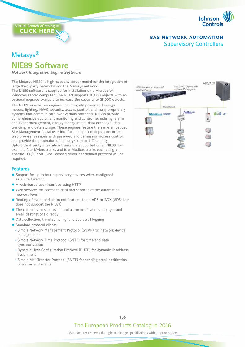
The European Products Catalogue 2016Manufacturer reserves the right to change specifications without prior notice
155
bas network automationSupervisory Controllers
Metasys®
NIE89 SoftwareNetwork Integration Engine Software
The Metasys NIE89 is high-capacity server model for the integration of large third-party networks into the Metasys network. The NIE89 software is supplied for installation on a Microsoft® Windows server computer. The NIE89 supports 10,000 objects with an optional upgrade available to increase the capacity to 25,000 objects.The NIE89 supervisory engines can integrate power and energy meters, lighting, HVAC, security, access control, and many proprietary systems that communicate over various protocols. NIEx9s provide comprehensive equipment monitoring and control, scheduling, alarm and event management, energy management, data exchange, data trending, and data storage. These engines feature the same embedded Site Management Portal user interface, support multiple concurrent web browser sessions with password and permission access control, and provide the protection of industry-standard IT security. Upto 8 third-party integration trunks are supported on an NIE89, for example four M-bus trunks and four Modbus trunks each using a specific TCP/IP port. One licensed driver per defined protocol will be required.
Features z Support for up to four supervisory devices when configured as a Site Director
z A web-based user interface using HTTP z Web services for access to data and services at the automation network level
z Routing of event and alarm notifications to an ADS or ADX (ADS-Lite does not support the NIE89)
z The capability to send event and alarm notifications to pager and email destinations directly
z Data collection, trend sampling, and audit trail logging z Standard protocol clients:• Simple Network Management Protocol (SNMP) for network device
management• Simple Network Time Protocol (SNTP) for time and date
synchronization• Dynamic Host Configuration Protocol (DHCP) for dynamic IP address
assignment• Simple Mail Transfer Protocol (SMTP) for sending email notification
of alarms and events
Virtual Branch eCatalogueclick here
The European Products Catalogue 2016Manufacturer reserves the right to change specifications without prior notice
156
bas network automationSupervisory Controllers
Metasys®
NIE89 Software
Ordering Code Description
MS-NIE89SW-0 Network Integration Engine software for installation on a Microsoft® Windows server computer: supports up to 8 third-party trunks (Modbus RTU or TCP/IP, M-Bus, or KNX) and a total of 10,000 objects
MS-NIE89SW-6 Upgrade NIE89 software; for existing NIE89s
MS-MODBUSN89-0 Modbus driver for NIE89
MS-MBUSN89-0 M-Bus driver for NIE89
MS-KNXN89-0 KNX driver for NIE89
MS-15KUPG-0 15,000 object expansion upgrade for NIE89 (one expansion only per NIE89)
Computer recommendations for NIE89 installationRecommended Computer Platform Intel® Quad-Core Processor
2.0 GHz minimum
Hard Disk 160 GB minimum
Recommended Memory 8 GB RAM minimum
Supported Operating Systems (OS) and Software
Windows Server® 2012 R2 Windows Server 2012 Windows Server 2008 R2 Standard with SP1 Windows Server 2008 R2 Web with SP1 Windows Server 2008 Standard with SP2 (32-bit) Note: Microsoft .NET Framework 3.5 Service Pack (SP) 1 is required for each operating system.
Internal Optical Drive DVD ROM, SATA
Supported Web Browser Software for Metasys Site Management Portal Cloud-based Client Computers
Windows Internet Explorer® version 8, 9, 10, and 11 Note: In Internet Explorer 11, select the Use Microsoft compatibility lists option, found under Tools > Compatibility View Settings, to ensure that websites appear and function correctly. Apple Safari® version 7.0 and 6.0.5 Other browsers, such as Google® Chrome® and Mozilla® Firefox®, may also be used but are not fully supported. Note: You use the web browser to download the Launcher application. After you install the Launcher application, you use the Launcher, not the web browser, to log in to the Site Management Portal UI.
Supported Virtual Environments Microsoft Hyper-V™, VMWare®
Network Communication Network interface Single Ethernet network interface card 10/100/1000 Mbps (100 Mbps or better recommended)
Recommended Data Protection Uninterruptible power supply (UPS) Smart-UPS SC 450VA, 280 W, 120 VAC input/output, NEMA 5-15R output connections, OEM Part No. SC450RM1U
Accessories (M-BUS)Ordering Code Description
SIS-MBUSNCLH-0E M-Bus level converter for up to 100 units loads, 230 VAC (TCP connected)
SIS-MBUSNCLL-0E M-Bus level converter for up to 100 units loads, 24 VAC/DC (TCP connected)
SIS-MBUSRPLH-0E M-Bus repeater for up to 100 units loads, 230 VAC
SIS-MBUSRPLL-0E M-Bus repeater for up to 100 units loads, 24 VAC/DC
SIS-MBUSSCLL-0E M-Bus level converter for up to 100 units loads, 24 VAC/DC (RS232 connection)
SIS-MBUSSCSL-0E M-Bus level converter for up to 6 units loads, 24 VAC/DC (RS232 connection)
INT-DX-KAB01 Optional connection cable SUB-D to RJ-12 for use with SIS-MBUSSCLL-0E
The European Products Catalogue 2016Manufacturer reserves the right to change specifications without prior notice
157
bas network automationSupervisory Controllers
Metasys®
NIE89 Software
NIE89 Accessories (KNX)Ordering Code Description Features
SIS-KNXNIXL-0E KNX IP Tunneler Module
Connects NIE to a single KNX line Max No. of NIE per Interface: 5 Max Group Addresses per NIE: 1000
Max KNX Networks per NIE89, NIE59, NIE49: 5 per NIE39, NIE29: 3
SIS-KNXNRXL-0E KNX IP Router Module
KNX Router acts as Area / Line Coupler over Ethernet NIE connects to a “KNX Network” Max Group Addresses per NIE: 1000
Max KNX Networks per NIE89, NIE59, NIE49: 5 per NIE39, NIE29: 3
NIE89 ToolsItem Description
VMD Generator Express Tool
The VMD Generator Express Tool is required to manage the creation of the 3rd party integrations on the NIE platform. The usage of the VMD Generator Express Tool requires a certification, which is achieved by attending a training course. For more information please contact your local technical support team.
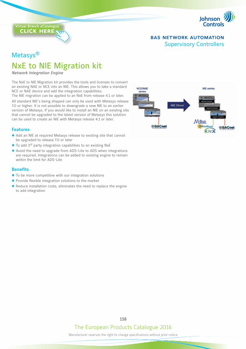
The European Products Catalogue 2016Manufacturer reserves the right to change specifications without prior notice
158
bas network automationSupervisory Controllers
Metasys®
NxE to NIE Migration kitNetwork Integration Engine
The NxE to NIE Migration kit provides the tools and licenses to convert an existing NAE or NCE into an NIE. This allows you to take a standard NCE or NAE device and add the integration capabilities. The NIE migration can be applied to an NxE from release 4.1 or later. All standard NIE’s being shipped can only be used with Metasys release 7.0 or higher. It is not possible to downgrade a new NIE to an earlier version of Metasys. If you would like to install an NIE on an existing site that cannot be upgraded to the latest version of Metasys this solution can be used to create an NIE with Metasys release 4.1 or later.
Features z Add an NIE at required Metasys release to existing site that cannot be upgraded to release 7.0 or later
z To add 3rd party integration capabilities to an existing NxE z Avoid the need to upgrade from ADS-Lite to ADS when integrations are required. Integrations can be added to existing engine to remain within the limit for ADS-Lite
Benefits z To be more competitive with our integration solutions z Provide flexible integration solutions to the market z Reduce installation costs, eliminates the need to replace the engine to add integration
Virtual Branch eCatalogueclick here
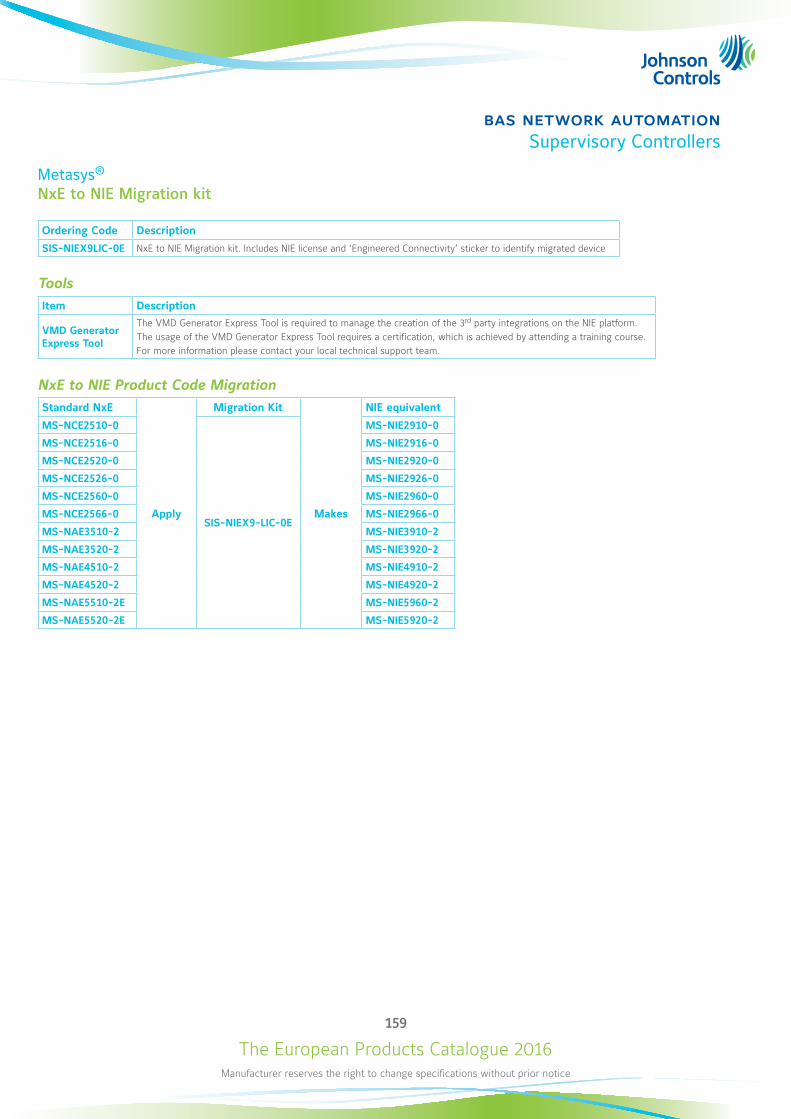
The European Products Catalogue 2016Manufacturer reserves the right to change specifications without prior notice
159
bas network automationSupervisory Controllers
Metasys®
NxE to NIE Migration kit
Ordering Code Description
SIS-NIEX9LIC-0E NxE to NIE Migration kit. Includes NIE license and ‘Engineered Connectivity’ sticker to identify migrated device
ToolsItem Description
VMD Generator Express Tool
The VMD Generator Express Tool is required to manage the creation of the 3rd party integrations on the NIE platform. The usage of the VMD Generator Express Tool requires a certification, which is achieved by attending a training course. For more information please contact your local technical support team.
NxE to NIE Product Code MigrationStandard NxE
Apply
Migration Kit
Makes
NIE equivalent
MS-NCE2510-0
SIS-NIEX9-LIC-0E
MS-NIE2910-0
MS-NCE2516-0 MS-NIE2916-0
MS-NCE2520-0 MS-NIE2920-0
MS-NCE2526-0 MS-NIE2926-0
MS-NCE2560-0 MS-NIE2960-0
MS-NCE2566-0 MS-NIE2966-0
MS-NAE3510-2 MS-NIE3910-2
MS-NAE3520-2 MS-NIE3920-2
MS-NAE4510-2 MS-NIE4910-2
MS-NAE4520-2 MS-NIE4920-2
MS-NAE5510-2E MS-NIE5960-2
MS-NAE5520-2E MS-NIE5920-2
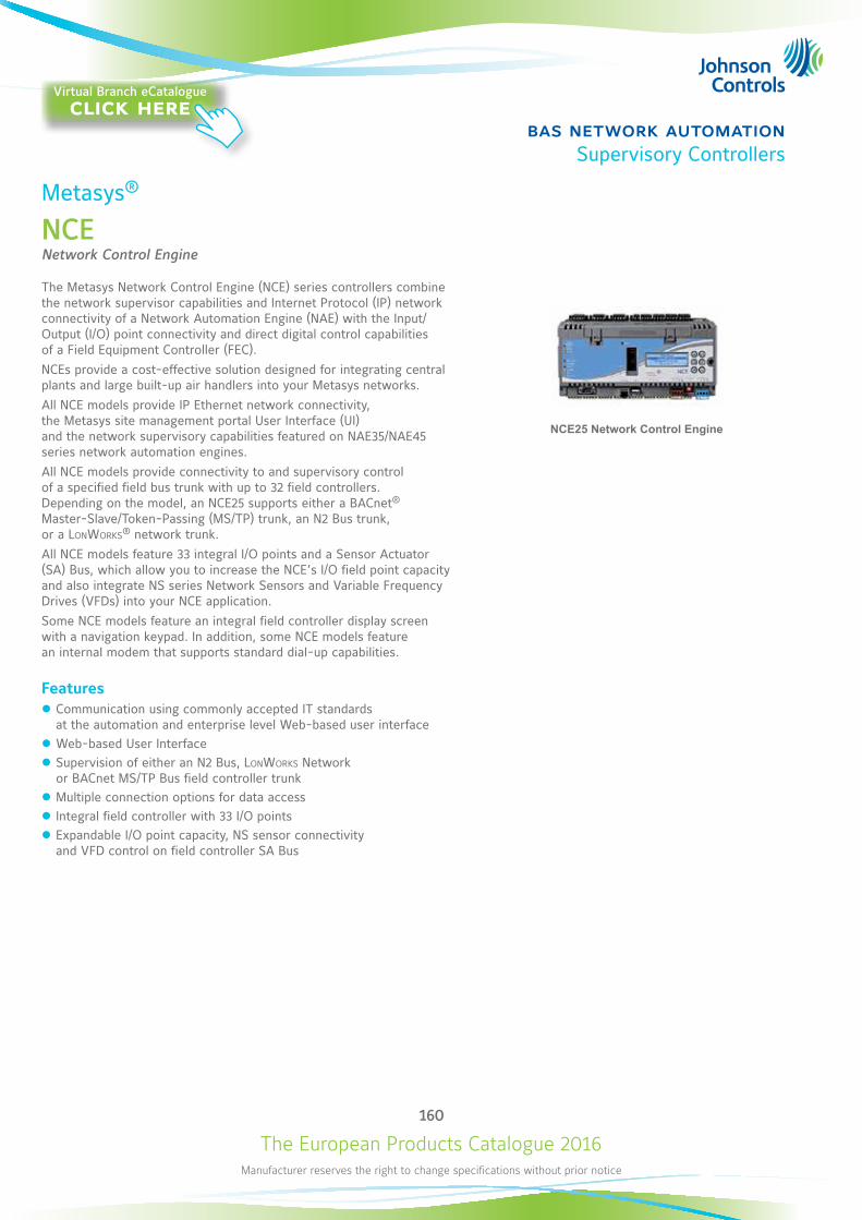
The European Products Catalogue 2016Manufacturer reserves the right to change specifications without prior notice
160
bas network automationSupervisory Controllers
Metasys®
NCENetwork Control Engine
The Metasys Network Control Engine (NCE) series controllers combine the network supervisor capabilities and Internet Protocol (IP) network connectivity of a Network Automation Engine (NAE) with the Input/Output (I/O) point connectivity and direct digital control capabilities of a Field Equipment Controller (FEC). NCEs provide a cost-effective solution designed for integrating central plants and large built-up air handlers into your Metasys networks. All NCE models provide IP Ethernet network connectivity, the Metasys site management portal User Interface (UI) and the network supervisory capabilities featured on NAE35/NAE45 series network automation engines. All NCE models provide connectivity to and supervisory control of a specified field bus trunk with up to 32 field controllers. Depending on the model, an NCE25 supports either a BACnet® Master-Slave/Token-Passing (MS/TP) trunk, an N2 Bus trunk, or a LonWorks® network trunk. All NCE models feature 33 integral I/O points and a Sensor Actuator (SA) Bus, which allow you to increase the NCE’s I/O field point capacity and also integrate NS series Network Sensors and Variable Frequency Drives (VFDs) into your NCE application. Some NCE models feature an integral field controller display screen with a navigation keypad. In addition, some NCE models feature an internal modem that supports standard dial-up capabilities.
Features z Communication using commonly accepted IT standards at the automation and enterprise level Web-based user interface
z Web-based User Interface z Supervision of either an N2 Bus, LonWorks Network or BACnet MS/TP Bus field controller trunk
z Multiple connection options for data access z Integral field controller with 33 I/O points z Expandable I/O point capacity, NS sensor connectivity and VFD control on field controller SA Bus
NCE25 Network Control Engine
Virtual Branch eCatalogueclick here
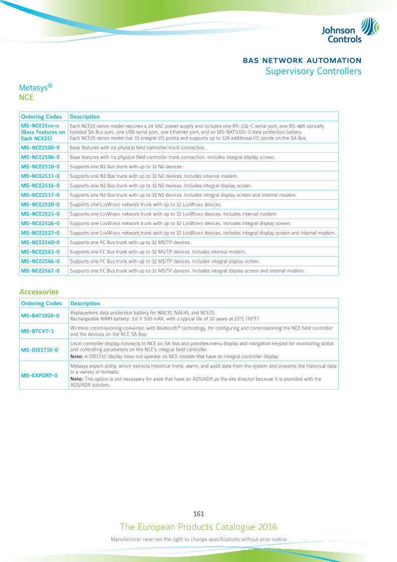
The European Products Catalogue 2016Manufacturer reserves the right to change specifications without prior notice
161
bas network automationSupervisory Controllers
Metasys®
NCE
Ordering Codes Description
MS-NCE25xx-x (Base Features on Each NCE25)
Each NCE25 series model requires a 24 VAC power supply and includes one RS-232-C serial port, one RS-485 optically isolated SA Bus port, one USB serial port, one Ethernet port, and an MS-BAT1020-0 data protection battery. Each NCE25 series model has 33 integral I/O points and supports up to 128 additional I/O points on the SA Bus.
MS-NCE2500-0 Base features with no physical field controller trunk connection.
MS-NCE2506-0 Base features with no physical field controller trunk connection. Includes integral display screen.
MS-NCE2510-0 Supports one N2 Bus trunk with up to 32 N2 devices.
MS-NCE2511-0 Supports one N2 Bus trunk with up to 32 N2 devices. Includes internal modem.
MS-NCE2516-0 Supports one N2 Bus trunk with up to 32 N2 devices. Includes integral display screen.
MS-NCE2517-0 Supports one N2 Bus trunk with up to 32 N2 devices. Includes integral display screen and internal modem.
MS-NCE2520-0 Supports one LonWorks network trunk with up to 32 LonWorks devices.
MS-NCE2521-0 Supports one LonWorks network trunk with up to 32 LonWorks devices. Includes internal modem.
MS-NCE2526-0 Supports one LonWorks network trunk with up to 32 LonWorks devices. Includes integral display screen.
MS-NCE2527-0 Supports one LonWorks network trunk with up to 32 LonWorks devices. Includes integral display screen and internal modem.
MS-NCE2560-0 Supports one FC Bus trunk with up to 32 MS/TP devices.
MS-NCE2561-0 Supports one FC Bus trunk with up to 32 MS/TP devices. Includes internal modem.
MS-NCE2566-0 Supports one FC Bus trunk with up to 32 MS/TP devices. Includes integral display screen.
MS-NCE2567-0 Supports one FC Bus trunk with up to 32 MS/TP devices. Includes integral display screen and internal modem.
AccessoriesOrdering Codes Description
MS-BAT1020-0 Replacement data protection battery for NAE35, NAE45, and NCE25. Rechargeable NiMH battery: 3.6 V 500 mAh, with a typical life of 10 years at 21°C (70°F)
MS-BTCVT-1 Wireless commissioning converter, with Bluetooth® technology, for configuring and commissioning the NCE field controller and the devices on the NCE SA Bus
MS-DIS1710-0Local controller display connects to NCE on SA Bus and provides menu display and navigation keypad for monitoring status and controlling parameters on the NCE’s integral field controller.Note: A DIS1710 display does not operate on NCE models that have an integral controller display.
MS-EXPORT-0
Metasys export utility, which extracts historical trend, alarm, and audit data from the system and presents the historical data in a variety of formats.Note: This option is not necessary for sites that have an ADS/ADX as the site director because it is provided with the ADS/ADX solution.
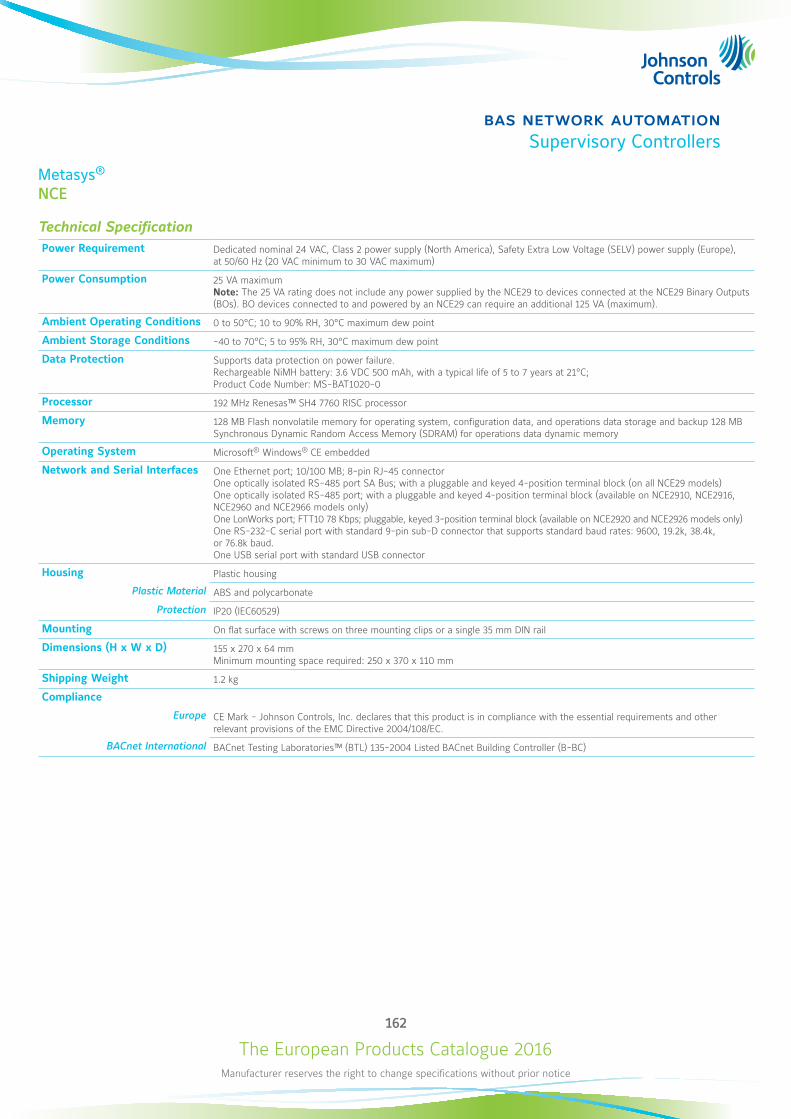
The European Products Catalogue 2016Manufacturer reserves the right to change specifications without prior notice
162
bas network automationSupervisory Controllers
Metasys®
NCE
Technical SpecificationPower Requirement Dedicated nominal 24 VAC, Class 2 power supply (North America), Safety Extra Low Voltage (SELV) power supply (Europe),
at 50/60 Hz (20 VAC minimum to 30 VAC maximum)
Power Consumption 25 VA maximum Note: The 25 VA rating does not include any power supplied by the NCE29 to devices connected at the NCE29 Binary Outputs (BOs). BO devices connected to and powered by an NCE29 can require an additional 125 VA (maximum).
Ambient Operating Conditions 0 to 50°C; 10 to 90% RH, 30°C maximum dew point
Ambient Storage Conditions -40 to 70°C; 5 to 95% RH, 30°C maximum dew point
Data Protection Supports data protection on power failure. Rechargeable NiMH battery: 3.6 VDC 500 mAh, with a typical life of 5 to 7 years at 21°C; Product Code Number: MS-BAT1020-0
Processor 192 MHz Renesas™ SH4 7760 RISC processor
Memory 128 MB Flash nonvolatile memory for operating system, configuration data, and operations data storage and backup 128 MB Synchronous Dynamic Random Access Memory (SDRAM) for operations data dynamic memory
Operating System Microsoft® Windows® CE embedded
Network and Serial Interfaces One Ethernet port; 10/100 MB; 8-pin RJ-45 connector One optically isolated RS-485 port SA Bus; with a pluggable and keyed 4-position terminal block (on all NCE29 models) One optically isolated RS-485 port; with a pluggable and keyed 4-position terminal block (available on NCE2910, NCE2916, NCE2960 and NCE2966 models only) One LonWorks port; FTT10 78 Kbps; pluggable, keyed 3-position terminal block (available on NCE2920 and NCE2926 models only) One RS-232-C serial port with standard 9-pin sub-D connector that supports standard baud rates: 9600, 19.2k, 38.4k, or 76.8k baud. One USB serial port with standard USB connector
Housing Plastic housing
Plastic Material ABS and polycarbonate
Protection IP20 (IEC60529)
Mounting On flat surface with screws on three mounting clips or a single 35 mm DIN rail
Dimensions (H x W x D) 155 x 270 x 64 mm Minimum mounting space required: 250 x 370 x 110 mm
Shipping Weight 1.2 kg
Compliance
Europe CE Mark - Johnson Controls, Inc. declares that this product is in compliance with the essential requirements and other relevant provisions of the EMC Directive 2004/108/EC.
BACnet International BACnet Testing Laboratories™ (BTL) 135-2004 Listed BACnet Building Controller (B-BC)
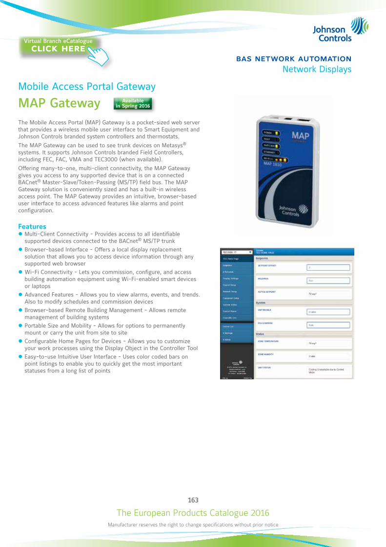
The European Products Catalogue 2016Manufacturer reserves the right to change specifications without prior notice
163
bas network automationNetwork Displays
Mobile Access Portal Gateway
MAP GatewayThe Mobile Access Portal (MAP) Gateway is a pocket-sized web server that provides a wireless mobile user interface to Smart Equipment and Johnson Controls branded system controllers and thermostats. The MAP Gateway can be used to see trunk devices on Metasys® systems. It supports Johnson Controls branded Field Controllers, including FEC, FAC, VMA and TEC3000 (when available). Offering many-to-one, multi-client connectivity, the MAP Gateway gives you access to any supported device that is on a connected BACnet® Master-Slave/Token-Passing (MS/TP) field bus. The MAP Gateway solution is conveniently sized and has a built-in wireless access point. The MAP Gateway provides an intuitive, browser-based user interface to access advanced features like alarms and point configuration.
Features z Multi-Client Connectivity - Provides access to all identifiable supported devices connected to the BACnet® MS/TP trunk
z Browser-based Interface - Offers a local display replacement solution that allows you to access device information through any supported web browser
z Wi-Fi Connectivity - Lets you commission, configure, and access building automation equipment using Wi-Fi-enabled smart devices or laptops
z Advanced Features - Allows you to view alarms, events, and trends. Also to modify schedules and commission devices
z Browser-based Remote Building Management - Allows remote management of building systems
z Portable Size and Mobility - Allows for options to permanently mount or carry the unit from site to site
z Configurable Home Pages for Devices - Allows you to customize your work processes using the Display Object in the Controller Tool
z Easy-to-use Intuitive User Interface - Uses color coded bars on point listings to enable you to quickly get the most important statuses from a long list of points
Available in Spring 2016
Virtual Branch eCatalogueclick here
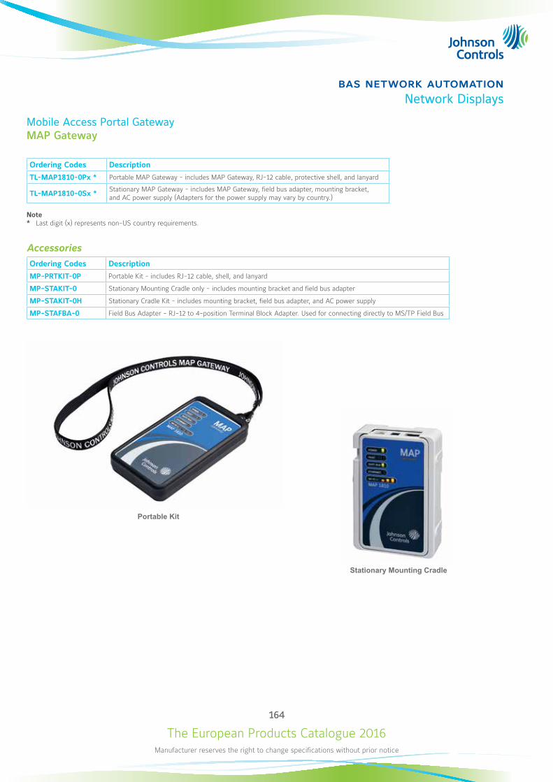
The European Products Catalogue 2016Manufacturer reserves the right to change specifications without prior notice
164
bas network automationNetwork Displays
Mobile Access Portal GatewayMAP Gateway
Ordering Codes Description
TL-MAP1810-0Px * Portable MAP Gateway - includes MAP Gateway, RJ-12 cable, protective shell, and lanyard
TL-MAP1810-0Sx * Stationary MAP Gateway - includes MAP Gateway, field bus adapter, mounting bracket, and AC power supply (Adapters for the power supply may vary by country.)
Note* Last digit (x) represents non-US country requirements.
AccessoriesOrdering Codes Description
MP-PRTKIT-0P Portable Kit - includes RJ-12 cable, shell, and lanyard
MP-STAKIT-0 Stationary Mounting Cradle only - includes mounting bracket and field bus adapter
MP-STAKIT-0H Stationary Cradle Kit - includes mounting bracket, field bus adapter, and AC power supply
MP-STAFBA-0 Field Bus Adapter - RJ-12 to 4-position Terminal Block Adapter. Used for connecting directly to MS/TP Field Bus
Portable Kit
Stationary Mounting Cradle
The European Products Catalogue 2016Manufacturer reserves the right to change specifications without prior notice
165
bas network automationNetwork Displays
Mobile Access Portal GatewayMAP Gateway
Technical SpecificationsProduct Codes TL-MAP1810-0Px: Portable MAP Gateway - includes MAP Gateway, RJ-12 cable, bumper guard, and lanyard.
TL-MAP1810-0Sx: Stationary MAP Gateway - includes MAP Gateway, field bus adapter, mounting bracket, and AC power supply. (Adapters for the power supply may vary by country.)
Power Consumption From SA/FC bus: 15 VDC at 2.7 VA maximum
Ambient Temperature Conditions
Operating 0 to 50°C
Operating Survival -30 to 60°C
Storage -40 to 70°C
Ambient Humidity Conditions
Storage -40 to 70°C; 5 to 95% RH 30°C maximum dew point conditions
Operating 0-50°C; 5 to 95% RH, 30°C maximum dew point conditions
Transmission Power (Typical) Wireless Local Area Network (WLAN) Transmission Power: +14.5 dBm, 54 Mbps +12.5 dBm, 65 Mbps
WLAN Receiver Sensitivity (Typical) -76 dBm, 10% packet error rate (PER ), 54 Mbps -73 dBm, 10% PER, 65 Mbps
Transmission Speeds
Wireless Communication 2.4 GHz ISM bands, 802.11 b/g/n, 11/22/54 Mbps
Serial Communication (SA/FC Bus) 9600, 19.2k, 38.4k, or 115.2k bps
Ethernet Communication 10, 100 Mbps
Transmission Range (Typical)
Wireless Communication 30 m line-of-sight indoors 90 m line-of-sight outdoors
WLAN Range Performance 0 – 15 m = Excellent 15 – 30 m = Good 30 – 90 m = Weakest, approaching out of range
Wireless Security WPA2-PSK TKIP (Wi-Fi Protected Access Pre-Shared Key mode Temporal Key Integrity Protocol)
Network and Serial Interfaces One SA/FC port (6-pin port; connects with 1.5 m RJ-12 field bus cable) One USB port (Micro-B port; 2.0; supports Open Host Controller Interface [Open HCI] specification)
Dimensions (H x W x D)
Unit alone 120 x 70 x 24.5 mm (when used vertically)
Unit in shell 128 x 75 x 29.5 mm (when used vertically)
Housing White Acrylonitrile butadiene styrene (ABS) bracket Black silicone shell
Weight
Unit alone 0.10 kg
Unit in shell 0.15 kg
Note: Weights do not include any peripheral components such as cables, lanyard, or an external power supply.
Web Browser Requirements for Computers and Handheld Devices
Computer Windows® Internet Explorer® 10 and Windows Internet Explorer 11, Apple® Safari® 6.1 and later, or Google® Chrome™
Handheld Device The handheld device must be running either Internet Explorer Mobile for Windows Mobile version 5 or version 6 operating system (OS); Apple® iPhone® and iPod touch® iOS version 7.0 or greater; or Android™ 4.0.3, 4.0.4, and 4.1+, or Google Chrome. Other web browsers may display the UI, but the functionality is not guaranteed.
Compliance
Europe CE Mark – Johnson Controls, Inc. declares that this product is in compliance with the essential requirements and other relevant provisions of the R&TTE Directive 1999/05/EC and EMC Directive 2004/108/EC. IC: RSS-210
CE Emission EN61000-6-3: 2007; Generic standards for residential, commercial, and light-industrial Environments. ETSI EN 301 489-1:2001-09, ETSI EN301 489-3:2001-11 (Class 2), IEC 60950-1/ EN 60950-1
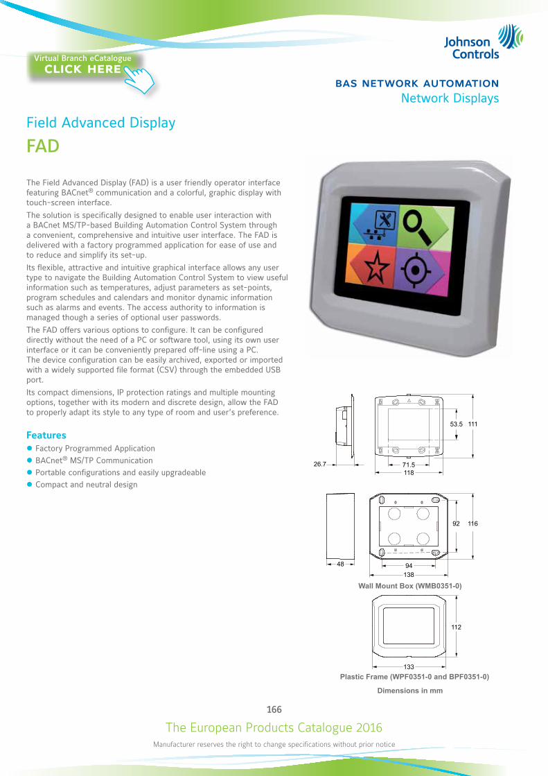
The European Products Catalogue 2016Manufacturer reserves the right to change specifications without prior notice
166
bas network automationNetwork Displays
Field Advanced Display
FAD
The Field Advanced Display (FAD) is a user friendly operator interface featuring BACnet® communication and a colorful, graphic display with touch-screen interface.The solution is specifically designed to enable user interaction with a BACnet MS/TP-based Building Automation Control System through a convenient, comprehensive and intuitive user interface. The FAD is delivered with a factory programmed application for ease of use and to reduce and simplify its set-up.Its flexible, attractive and intuitive graphical interface allows any user type to navigate the Building Automation Control System to view useful information such as temperatures, adjust parameters as set-points, program schedules and calendars and monitor dynamic information such as alarms and events. The access authority to information is managed though a series of optional user passwords. The FAD offers various options to configure. It can be configured directly without the need of a PC or software tool, using its own user interface or it can be conveniently prepared off-line using a PC. The device configuration can be easily archived, exported or imported with a widely supported file format (CSV) through the embedded USB port.Its compact dimensions, IP protection ratings and multiple mounting options, together with its modern and discrete design, allow the FAD to properly adapt its style to any type of room and user’s preference.
Features z Factory Programmed Application z BACnet® MS/TP Communication z Portable configurations and easily upgradeable z Compact and neutral design
92 116
48 94138
71.5118
26.7
53.5 111
133
112
Dimensions in mm
Wall Mount Box (WMB0351-0)
Plastic Frame (WPF0351-0 and BPF0351-0)
Virtual Branch eCatalogueclick here
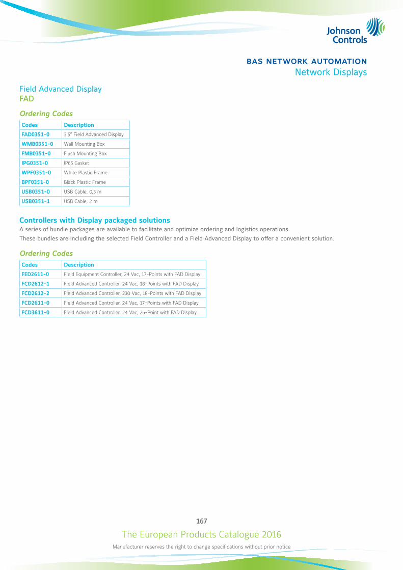
The European Products Catalogue 2016Manufacturer reserves the right to change specifications without prior notice
167
bas network automationNetwork Displays
Field Advanced DisplayFAD
Ordering CodesCodes Description
FAD0351-0 3.5” Field Advanced Display
WMB0351-0 Wall Mounting Box
FMB0351-0 Flush Mounting Box
IPG0351-0 IP65 Gasket
WPF0351-0 White Plastic Frame
BPF0351-0 Black Plastic Frame
USB0351-0 USB Cable, 0,5 m
USB0351-1 USB Cable, 2 m
Controllers with Display packaged solutionsA series of bundle packages are available to facilitate and optimize ordering and logistics operations.These bundles are including the selected Field Controller and a Field Advanced Display to offer a convenient solution.
Ordering CodesCodes Description
FED2611-0 Field Equipment Controller, 24 Vac, 17-Points with FAD Display
FCD2612-1 Field Advanced Controller, 24 Vac, 18-Points with FAD Display
FCD2612-2 Field Advanced Controller, 230 Vac, 18-Points with FAD Display
FCD2611-0 Field Advanced Controller, 24 Vac, 17-Points with FAD Display
FCD3611-0 Field Advanced Controller, 24 Vac, 26-Point with FAD Display
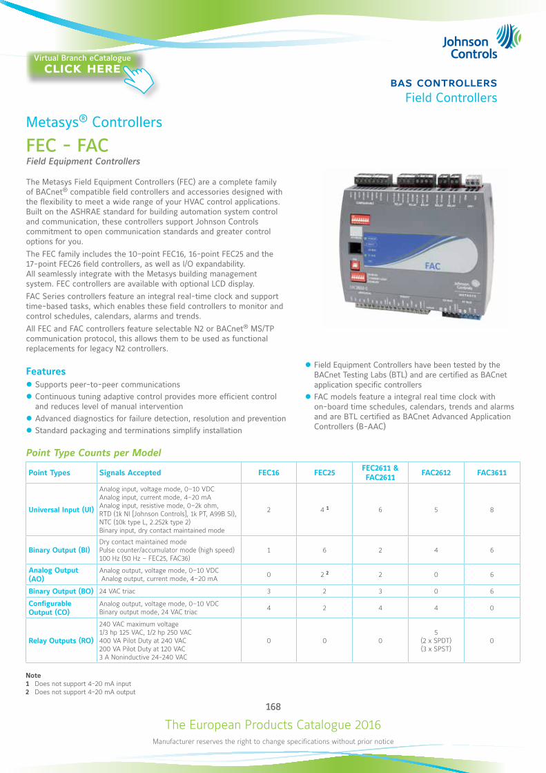
The European Products Catalogue 2016Manufacturer reserves the right to change specifications without prior notice
168
bas controllersField Controllers
Metasys® Controllers
FEC - FACField Equipment Controllers
The Metasys Field Equipment Controllers (FEC) are a complete family of BACnet® compatible field controllers and accessories designed with the flexibility to meet a wide range of your HVAC control applications. Built on the ASHRAE standard for building automation system control and communication, these controllers support Johnson Controls commitment to open communication standards and greater control options for you.The FEC family includes the 10-point FEC16, 16-point FEC25 and the 17-point FEC26 field controllers, as well as I/O expandability. All seamlessly integrate with the Metasys building management system. FEC controllers are available with optional LCD display.FAC Series controllers feature an integral real-time clock and support time-based tasks, which enables these field controllers to monitor and control schedules, calendars, alarms and trends.All FEC and FAC controllers feature selectable N2 or BACnet® MS/TP communication protocol, this allows them to be used as functional replacements for legacy N2 controllers.
Features z Supports peer-to-peer communications z Continuous tuning adaptive control provides more efficient control and reduces level of manual intervention
z Advanced diagnostics for failure detection, resolution and prevention z Standard packaging and terminations simplify installation
Point Type Counts per Model
Point Types Signals Accepted FEC16 FEC25 FEC2611 & FAC2611 FAC2612 FAC3611
Universal Input (UI)
Analog input, voltage mode, 0–10 VDC Analog input, current mode, 4–20 mA Analog input, resistive mode, 0–2k ohm, RTD (1k NI [Johnson Controls], 1k PT, A99B SI), NTC (10k type L, 2.252k type 2) Binary input, dry contact maintained mode
2 4 1 6 5 8
Binary Output (BI)Dry contact maintained mode Pulse counter/accumulator mode (high speed) 100 Hz (50 Hz – FEC25, FAC36)
1 6 2 4 6
Analog Output (AO)
Analog output, voltage mode, 0–10 VDC Analog output, current mode, 4–20 mA 0 2 2 2 0 6
Binary Output (BO) 24 VAC triac 3 2 3 0 6
Configurable Output (CO)
Analog output, voltage mode, 0–10 VDC Binary output mode, 24 VAC triac 4 2 4 4 0
Relay Outputs (RO)
240 VAC maximum voltage 1/3 hp 125 VAC, 1/2 hp 250 VAC 400 VA Pilot Duty at 240 VAC 200 VA Pilot Duty at 120 VAC 3 A Noninductive 24-240 VAC
0 0 05
(2 x SPDT) (3 x SPST)
0
Note1 Does not support 4-20 mA input2 Does not support 4-20 mA output
z Field Equipment Controllers have been tested by the BACnet Testing Labs (BTL) and are certified as BACnet application specific controllers
z FAC models feature a integral real time clock with on-board time schedules, calendars, trends and alarms and are BTL certified as BACnet Advanced Application Controllers (B-AAC)
Virtual Branch eCatalogueclick here
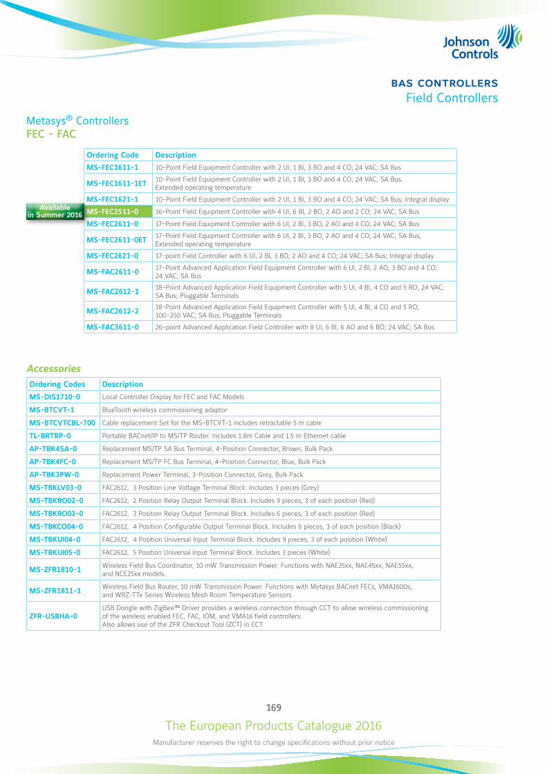
The European Products Catalogue 2016Manufacturer reserves the right to change specifications without prior notice
169
bas controllersField Controllers
Metasys® ControllersFEC - FAC
Ordering Code Description
MS-FEC1611-1 10-Point Field Equipment Controller with 2 UI, 1 BI, 3 BO and 4 CO; 24 VAC; SA Bus
MS-FEC1611-1ET 10-Point Field Equipment Controller with 2 UI, 1 BI, 3 BO and 4 CO; 24 VAC; SA Bus, Extended operating temperature
MS-FEC1621-1 10-Point Field Equipment Controller with 2 UI, 1 BI, 3 BO and 4 CO; 24 VAC; SA Bus; Integral display
MS-FEC2511-0 16-Point Field Equipment Controller with 4 UI, 6 BI, 2 BO, 2 AO and 2 CO; 24 VAC; SA Bus
MS-FEC2611-0 17-Point Field Equipment Controller with 6 UI, 2 BI, 3 BO, 2 AO and 4 CO; 24 VAC; SA Bus
MS-FEC2611-0ET 17-Point Field Equipment Controller with 6 UI, 2 BI, 3 BO, 2 AO and 4 CO; 24 VAC; SA Bus, Extended operating temperature
MS-FEC2621-0 17-point Field Controller with 6 UI, 2 BI, 3 BO, 2 AO and 4 CO; 24 VAC; SA Bus; Integral display
MS-FAC2611-0 17-Point Advanced Application Field Equipment Controller with 6 UI, 2 BI, 2 AO, 3 BO and 4 CO; 24 VAC; SA Bus
MS-FAC2612-1 18-Point Advanced Application Field Equipment Controller with 5 UI, 4 BI, 4 CO and 5 RO; 24 VAC; SA Bus; Pluggable Terminals
MS-FAC2612-2 18-Point Advanced Application Field Equipment Controller with 5 UI, 4 BI, 4 CO and 5 RO; 100-250 VAC; SA Bus; Pluggable Terminals
MS-FAC3611-0 26-point Advanced Application Field Controller with 8 UI, 6 BI, 6 AO and 6 BO; 24 VAC; SA Bus
AccessoriesOrdering Codes Description
MS-DIS1710-0 Local Controller Display for FEC and FAC Models
MS-BTCVT-1 BlueTooth wireless commissioning adaptor
MS-BTCVTCBL-700 Cable replacement Set for the MS-BTCVT-1 includes retractable 5 m cable
TL-BRTRP-0 Portable BACnet/IP to MS/TP Router. Includes 1.8m Cable and 1.5 m Ethernet cable
AP-TBK4SA-0 Replacement MS/TP SA Bus Terminal, 4-Position Connector, Brown, Bulk Pack
AP-TBK4FC-0 Replacement MS/TP FC Bus Terminal, 4-Position Connector, Blue, Bulk Pack
AP-TBK3PW-0 Replacement Power Terminal, 3-Position Connector, Grey, Bulk Pack
MS-TBKLV03-0 FAC2612, 3 Position Line Voltage Terminal Block. Includes 3 pieces (Grey)
MS-TBKRO02-0 FAC2612, 2 Position Relay Output Terminal Block. Includes 9 pieces, 3 of each position (Red)
MS-TBKRO03-0 FAC2612, 3 Position Relay Output Terminal Block. Includes 6 pieces, 3 of each position (Red)
MS-TBKCO04-0 FAC2612, 4 Position Configurable Output Terminal Block. Includes 6 pieces, 3 of each position (Black)
MS-TBKUI04-0 FAC2612, 4 Position Universal Input Terminal Block. Includes 9 pieces, 3 of each position (White)
MS-TBKUI05-0 FAC2612, 5 Position Universal Input Terminal Block. Includes 3 pieces (White)
MS-ZFR1810-1 Wireless Field Bus Coordinator, 10 mW Transmission Power. Functions with NAE35xx, NAE45xx, NAE55xx, and NCE25xx models.
MS-ZFR1811-1 Wireless Field Bus Router, 10 mW Transmission Power. Functions with Metasys BACnet FECs, VMA1600s, and WRZ-TTx Series Wireless Mesh Room Temperature Sensors.
ZFR-USBHA-0USB Dongle with ZigBee™ Driver provides a wireless connection through CCT to allow wireless commissioning of the wireless enabled FEC, FAC, IOM, and VMA16 field controllers. Also allows use of the ZFR Checkout Tool (ZCT) in CCT
Available in Summer 2016
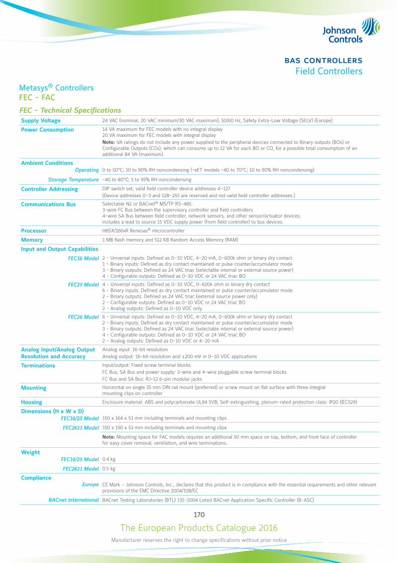
The European Products Catalogue 2016Manufacturer reserves the right to change specifications without prior notice
170
bas controllersField Controllers
Metasys® ControllersFEC - FAC
FEC - Technical SpecificationsSupply Voltage 24 VAC (nominal, 20 VAC minimum/30 VAC maximum), 50/60 Hz, Safety Extra-Low Voltage (SELV) (Europe)
Power Consumption 14 VA maximum for FEC models with no integral display 20 VA maximum for FEC models with integral displayNote: VA ratings do not include any power supplied to the peripheral devices connected to Binary outputs (BOs) or Configurable Outputs (COs), which can consume up to 12 VA for each BO or CO, for a possible total consumption of an additional 84 VA (maximum).
Ambient ConditionsOperating 0 to 50°C; 10 to 90% RH noncondensing (-xET models -40 to 70°C; 10 to 90% RH noncondensing)
Storage Temperature -40 to 80°C; 5 to 95% RH noncondensing
Controller Addressing DIP switch set; valid field controller device addresses 4–127(Device addresses 0–3 and 128–255 are reserved and not valid field controller addresses.)
Communications Bus Selectable N2 or BACnet® MS/TP RS-485: 3-wire FC Bus between the supervisory controller and field controllers 4-wire SA Bus between field controller, network sensors, and other sensor/actuator devices, includes a lead to source 15 VDC supply power (from field controller) to bus devices.
Processor H8SX/166xR Renesas® microcontroller
Memory 1 MB flash memory and 512 KB Random Access Memory (RAM)
Input and Output Capabilities
FEC16 Model 2 - Universal inputs: Defined as 0–10 VDC, 4–20 mA, 0–600k ohm or binary dry contact 1 - Binary inputs: Defined as dry contact maintained or pulse counter/accumulator mode 3 - Binary outputs: Defined as 24 VAC triac (selectable internal or external source power) 4 - Configurable outputs: Defined as 0–10 VDC or 24 VAC triac BO
FEC25 Model 4 - Universal inputs: Defined as 0–10 VDC, 0–600k ohm or binary dry contact 6 - Binary inputs: Defined as dry contact maintained or pulse counter/accumulator mode 2 - Binary outputs: Defined as 24 VAC triac (external source power only) 2 - Configurable outputs: Defined as 0–10 VDC or 24 VAC triac BO 2 - Analog outputs: Defined as 0–10 VDC only
FEC26 Model 6 - Universal inputs: Defined as 0–10 VDC, 4–20 mA, 0–600k ohm or binary dry contact 2 - Binary inputs: Defined as dry contact maintained or pulse counter/accumulator mode 3 - Binary outputs: Defined as 24 VAC triac (selectable internal or external source power) 4 - Configurable outputs: Defined as 0–10 VDC or 24 VAC triac BO 2 - Analog outputs: Defined as 0–10 VDC or 4–20 mA
Analog Input/Analog Output Resolution and Accuracy
Analog input: 16-bit resolutionAnalog output: 16-bit resolution and ±200 mV in 0–10 VDC applications
Terminations Input/output: Fixed screw terminal blocksFC Bus, SA Bus and power supply: 3-wire and 4-wire pluggable screw terminal blocksFC Bus and SA Bus: RJ-12 6-pin modular jacks
Mounting Horizontal on single 35 mm DIN rail mount (preferred) or screw mount on flat surface with three integral mounting clips on controller
Housing Enclosure material: ABS and polycarbonate UL94 5VB; Self-extinguishing, plenum-rated protection class: IP20 (IEC529)
Dimensions (H x W x D)FEC16/25 Model 150 x 164 x 53 mm including terminals and mounting clips
FEC2611 Model 150 x 190 x 53 mm including terminals and mounting clips
Note: Mounting space for FAC models requires an additional 50 mm space on top, bottom, and front face of controller for easy cover removal, ventilation, and wire terminations.
WeightFEC16/25 Model 0.4 kg
FEC2611 Model 0.5 kg
ComplianceEurope CE Mark – Johnson Controls, Inc., declares that this product is in compliance with the essential requirements and other relevant
provisions of the EMC Directive 2004/108/EC
BACnet International BACnet Testing Laboratories (BTL) 135-2004 Listed BACnet Application Specific Controller (B-ASC)
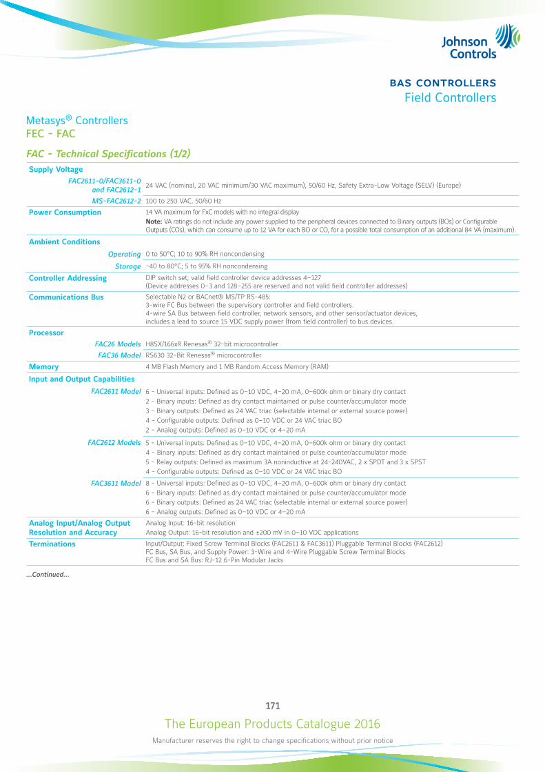
The European Products Catalogue 2016Manufacturer reserves the right to change specifications without prior notice
171
bas controllersField Controllers
Metasys® ControllersFEC - FAC
FAC - Technical Specifications (1/2) Supply Voltage
FAC2611-0/FAC3611-0 and FAC2612-1
24 VAC (nominal, 20 VAC minimum/30 VAC maximum), 50/60 Hz, Safety Extra-Low Voltage (SELV) (Europe)
MS-FAC2612-2 100 to 250 VAC, 50/60 Hz
Power Consumption 14 VA maximum for FxC models with no integral displayNote: VA ratings do not include any power supplied to the peripheral devices connected to Binary outputs (BOs) or Configurable Outputs (COs), which can consume up to 12 VA for each BO or CO, for a possible total consumption of an additional 84 VA (maximum).
Ambient Conditions
Operating 0 to 50°C; 10 to 90% RH noncondensing
Storage -40 to 80°C; 5 to 95% RH noncondensing
Controller Addressing DIP switch set; valid field controller device addresses 4–127 (Device addresses 0–3 and 128–255 are reserved and not valid field controller addresses)
Communications Bus Selectable N2 or BACnet® MS/TP RS-485: 3-wire FC Bus between the supervisory controller and field controllers. 4-wire SA Bus between field controller, network sensors, and other sensor/actuator devices, includes a lead to source 15 VDC supply power (from field controller) to bus devices.
ProcessorFAC26 Models H8SX/166xR Renesas® 32-bit microcontroller
FAC36 Model RS630 32-Bit Renesas® microcontroller
Memory 4 MB Flash Memory and 1 MB Random Access Memory (RAM)
Input and Output Capabilities
FAC2611 Model 6 - Universal inputs: Defined as 0–10 VDC, 4–20 mA, 0–600k ohm or binary dry contact2 - Binary inputs: Defined as dry contact maintained or pulse counter/accumulator mode3 - Binary outputs: Defined as 24 VAC triac (selectable internal or external source power)4 - Configurable outputs: Defined as 0–10 VDC or 24 VAC triac BO2 - Analog outputs: Defined as 0–10 VDC or 4–20 mA
FAC2612 Models 5 - Universal inputs: Defined as 0–10 VDC, 4–20 mA, 0–600k ohm or binary dry contact4 - Binary inputs: Defined as dry contact maintained or pulse counter/accumulator mode5 - Relay outputs: Defined as maximum 3A noninductive at 24-240VAC, 2 x SPDT and 3 x SPST4 - Configurable outputs: Defined as 0–10 VDC or 24 VAC triac BO
FAC3611 Model 8 - Universal inputs: Defined as 0–10 VDC, 4–20 mA, 0–600k ohm or binary dry contact6 - Binary inputs: Defined as dry contact maintained or pulse counter/accumulator mode6 - Binary outputs: Defined as 24 VAC triac (selectable internal or external source power)6 - Analog outputs: Defined as 0–10 VDC or 4–20 mA
Analog Input/Analog Output Resolution and Accuracy
Analog Input: 16-bit resolutionAnalog Output: 16-bit resolution and ±200 mV in 0–10 VDC applications
Terminations Input/Output: Fixed Screw Terminal Blocks (FAC2611 & FAC3611) Pluggable Terminal Blocks (FAC2612) FC Bus, SA Bus, and Supply Power: 3-Wire and 4-Wire Pluggable Screw Terminal Blocks FC Bus and SA Bus: RJ-12 6-Pin Modular Jacks
...Continued...
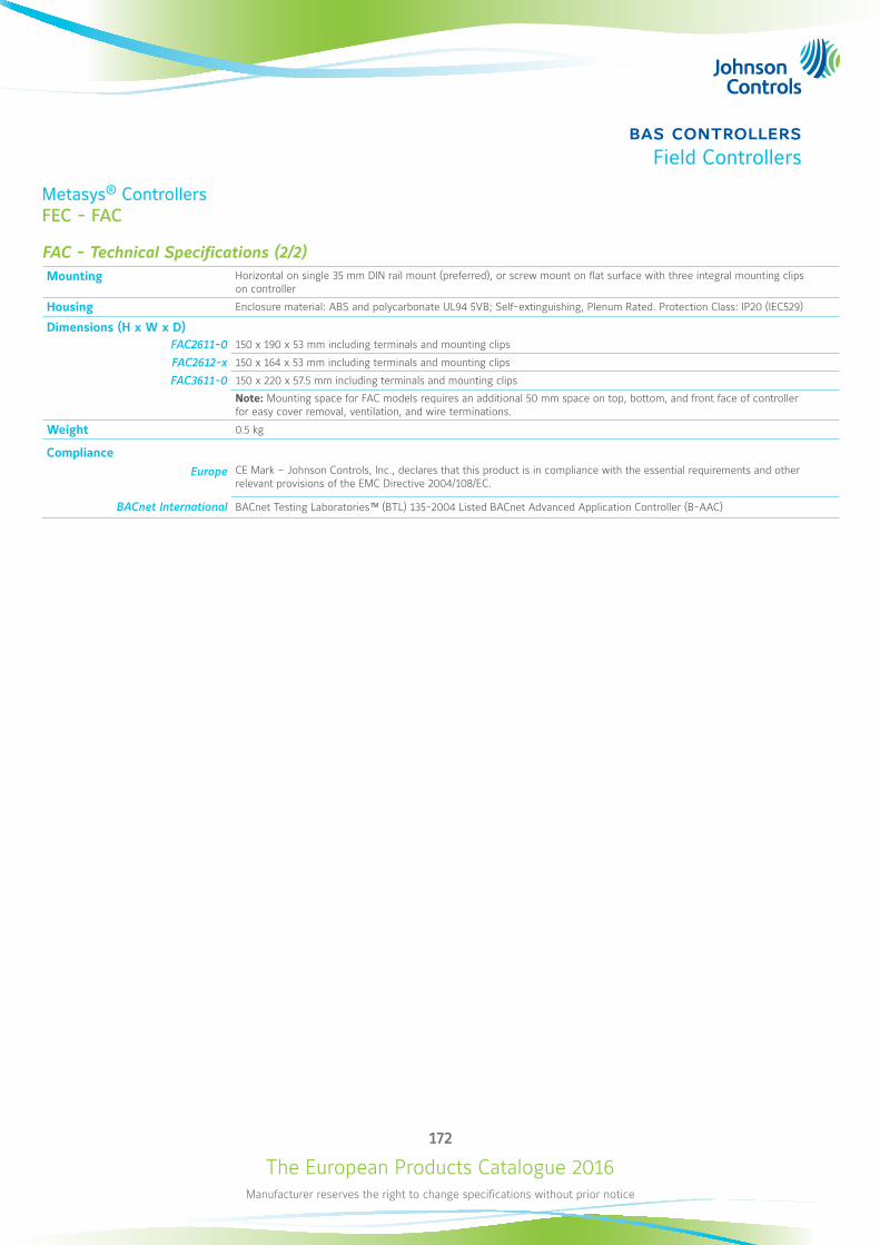
The European Products Catalogue 2016Manufacturer reserves the right to change specifications without prior notice
172
bas controllersField Controllers
Metasys® ControllersFEC - FAC
FAC - Technical Specifications (2/2)Mounting Horizontal on single 35 mm DIN rail mount (preferred), or screw mount on flat surface with three integral mounting clips
on controller
Housing Enclosure material: ABS and polycarbonate UL94 5VB; Self-extinguishing, Plenum Rated. Protection Class: IP20 (IEC529)
Dimensions (H x W x D)FAC2611-0 150 x 190 x 53 mm including terminals and mounting clips
FAC2612-x 150 x 164 x 53 mm including terminals and mounting clips
FAC3611-0 150 x 220 x 57.5 mm including terminals and mounting clips
Note: Mounting space for FAC models requires an additional 50 mm space on top, bottom, and front face of controller for easy cover removal, ventilation, and wire terminations.
Weight 0.5 kg
ComplianceEurope CE Mark – Johnson Controls, Inc., declares that this product is in compliance with the essential requirements and other
relevant provisions of the EMC Directive 2004/108/EC.
BACnet International BACnet Testing Laboratories™ (BTL) 135-2004 Listed BACnet Advanced Application Controller (B-AAC)
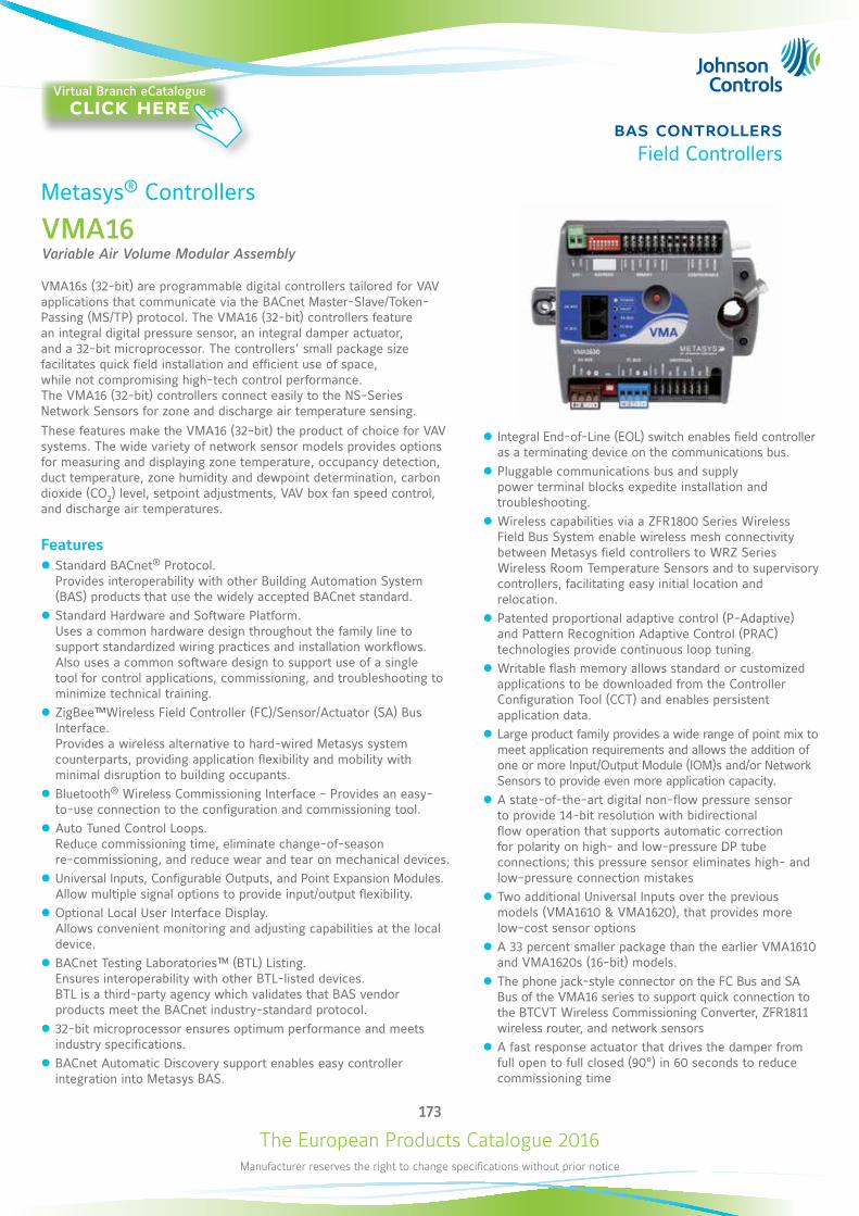
The European Products Catalogue 2016Manufacturer reserves the right to change specifications without prior notice
173
bas controllersField Controllers
Metasys® Controllers
VMA16Variable Air Volume Modular Assembly
VMA16s (32-bit) are programmable digital controllers tailored for VAV applications that communicate via the BACnet Master-Slave/Token-Passing (MS/TP) protocol. The VMA16 (32-bit) controllers feature an integral digital pressure sensor, an integral damper actuator, and a 32-bit microprocessor. The controllers’ small package size facilitates quick field installation and efficient use of space, while not compromising high-tech control performance. The VMA16 (32-bit) controllers connect easily to the NS-Series Network Sensors for zone and discharge air temperature sensing.These features make the VMA16 (32-bit) the product of choice for VAV systems. The wide variety of network sensor models provides options for measuring and displaying zone temperature, occupancy detection, duct temperature, zone humidity and dewpoint determination, carbon dioxide (CO2) level, setpoint adjustments, VAV box fan speed control, and discharge air temperatures.
Features z Standard BACnet® Protocol. Provides interoperability with other Building Automation System (BAS) products that use the widely accepted BACnet standard.
z Standard Hardware and Software Platform. Uses a common hardware design throughout the family line to support standardized wiring practices and installation workflows. Also uses a common software design to support use of a single tool for control applications, commissioning, and troubleshooting to minimize technical training.
z ZigBee™Wireless Field Controller (FC)/Sensor/Actuator (SA) Bus Interface. Provides a wireless alternative to hard-wired Metasys system counterparts, providing application flexibility and mobility with minimal disruption to building occupants.
z Bluetooth® Wireless Commissioning Interface - Provides an easy-to-use connection to the configuration and commissioning tool.
z Auto Tuned Control Loops. Reduce commissioning time, eliminate change-of-season re-commissioning, and reduce wear and tear on mechanical devices.
z Universal Inputs, Configurable Outputs, and Point Expansion Modules. Allow multiple signal options to provide input/output flexibility.
z Optional Local User Interface Display. Allows convenient monitoring and adjusting capabilities at the local device.
z BACnet Testing Laboratories™ (BTL) Listing. Ensures interoperability with other BTL-listed devices. BTL is a third-party agency which validates that BAS vendor products meet the BACnet industry-standard protocol.
z 32-bit microprocessor ensures optimum performance and meets industry specifications.
z BACnet Automatic Discovery support enables easy controller integration into Metasys BAS.
z Integral End-of-Line (EOL) switch enables field controller as a terminating device on the communications bus.
z Pluggable communications bus and supply power terminal blocks expedite installation and troubleshooting.
z Wireless capabilities via a ZFR1800 Series Wireless Field Bus System enable wireless mesh connectivity between Metasys field controllers to WRZ Series Wireless Room Temperature Sensors and to supervisory controllers, facilitating easy initial location and relocation.
z Patented proportional adaptive control (P-Adaptive) and Pattern Recognition Adaptive Control (PRAC) technologies provide continuous loop tuning.
z Writable flash memory allows standard or customized applications to be downloaded from the Controller Configuration Tool (CCT) and enables persistent application data.
z Large product family provides a wide range of point mix to meet application requirements and allows the addition of one or more Input/Output Module (IOM)s and/or Network Sensors to provide even more application capacity.
z A state-of-the-art digital non-flow pressure sensor to provide 14-bit resolution with bidirectional flow operation that supports automatic correction for polarity on high- and low-pressure DP tube connections; this pressure sensor eliminates high- and low-pressure connection mistakes
z Two additional Universal Inputs over the previous models (VMA1610 & VMA1620), that provides more low-cost sensor options
z A 33 percent smaller package than the earlier VMA1610 and VMA1620s (16-bit) models.
z The phone jack-style connector on the FC Bus and SA Bus of the VMA16 series to support quick connection to the BTCVT Wireless Commissioning Converter, ZFR1811 wireless router, and network sensors
z A fast response actuator that drives the damper from full open to full closed (90°) in 60 seconds to reduce commissioning time
Virtual Branch eCatalogueclick here
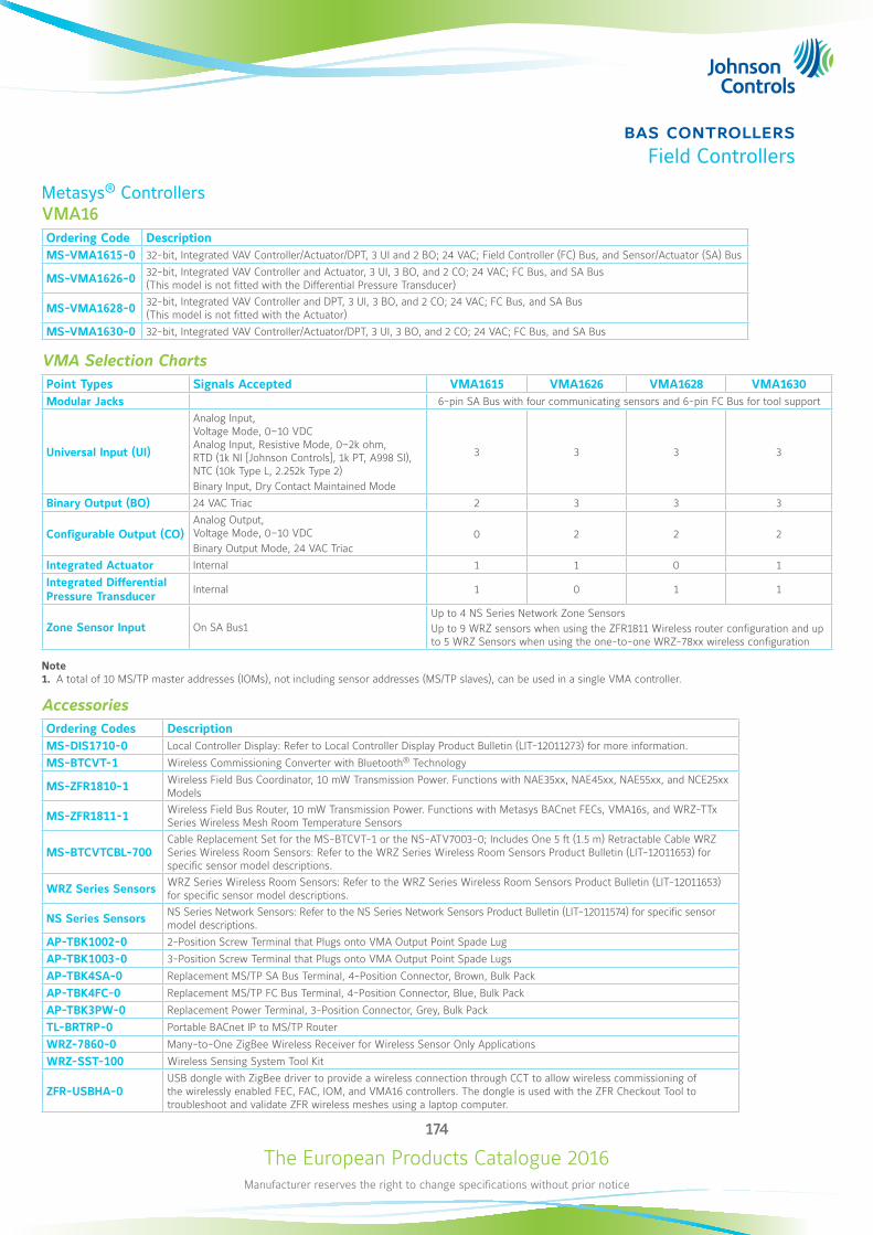
The European Products Catalogue 2016Manufacturer reserves the right to change specifications without prior notice
174
bas controllersField Controllers
Metasys® ControllersVMA16Ordering Code DescriptionMS-VMA1615-0 32-bit, Integrated VAV Controller/Actuator/DPT, 3 UI and 2 BO; 24 VAC; Field Controller (FC) Bus, and Sensor/Actuator (SA) Bus
MS-VMA1626-0 32-bit, Integrated VAV Controller and Actuator, 3 UI, 3 BO, and 2 CO; 24 VAC; FC Bus, and SA Bus (This model is not fitted with the Differential Pressure Transducer)
MS-VMA1628-0 32-bit, Integrated VAV Controller and DPT, 3 UI, 3 BO, and 2 CO; 24 VAC; FC Bus, and SA Bus (This model is not fitted with the Actuator)
MS-VMA1630-0 32-bit, Integrated VAV Controller/Actuator/DPT, 3 UI, 3 BO, and 2 CO; 24 VAC; FC Bus, and SA Bus
VMA Selection ChartsPoint Types Signals Accepted VMA1615 VMA1626 VMA1628 VMA1630Modular Jacks 6-pin SA Bus with four communicating sensors and 6-pin FC Bus for tool support
Universal Input (UI)
Analog Input, Voltage Mode, 0–10 VDC Analog Input, Resistive Mode, 0–2k ohm, RTD (1k NI [Johnson Controls], 1k PT, A998 SI), NTC (10k Type L, 2.252k Type 2) Binary Input, Dry Contact Maintained Mode
3 3 3 3
Binary Output (BO) 24 VAC Triac 2 3 3 3
Configurable Output (CO)Analog Output, Voltage Mode, 0–10 VDC Binary Output Mode, 24 VAC Triac
0 2 2 2
Integrated Actuator Internal 1 1 0 1
Integrated Differential Pressure Transducer
Internal 1 0 1 1
Zone Sensor Input On SA Bus1Up to 4 NS Series Network Zone Sensors Up to 9 WRZ sensors when using the ZFR1811 Wireless router configuration and up to 5 WRZ Sensors when using the one-to-one WRZ-78xx wireless configuration
Note1. A total of 10 MS/TP master addresses (IOMs), not including sensor addresses (MS/TP slaves), can be used in a single VMA controller.
AccessoriesOrdering Codes DescriptionMS-DIS1710-0 Local Controller Display: Refer to Local Controller Display Product Bulletin (LIT-12011273) for more information.
MS-BTCVT-1 Wireless Commissioning Converter with Bluetooth® Technology
MS-ZFR1810-1 Wireless Field Bus Coordinator, 10 mW Transmission Power. Functions with NAE35xx, NAE45xx, NAE55xx, and NCE25xx Models
MS-ZFR1811-1 Wireless Field Bus Router, 10 mW Transmission Power. Functions with Metasys BACnet FECs, VMA16s, and WRZ-TTx Series Wireless Mesh Room Temperature Sensors
MS-BTCVTCBL-700Cable Replacement Set for the MS-BTCVT-1 or the NS-ATV7003-0; Includes One 5 ft (1.5 m) Retractable Cable WRZ Series Wireless Room Sensors: Refer to the WRZ Series Wireless Room Sensors Product Bulletin (LIT-12011653) for specific sensor model descriptions.
WRZ Series Sensors WRZ Series Wireless Room Sensors: Refer to the WRZ Series Wireless Room Sensors Product Bulletin (LIT-12011653) for specific sensor model descriptions.
NS Series Sensors NS Series Network Sensors: Refer to the NS Series Network Sensors Product Bulletin (LIT-12011574) for specific sensor model descriptions.
AP-TBK1002-0 2-Position Screw Terminal that Plugs onto VMA Output Point Spade Lug
AP-TBK1003-0 3-Position Screw Terminal that Plugs onto VMA Output Point Spade Lugs
AP-TBK4SA-0 Replacement MS/TP SA Bus Terminal, 4-Position Connector, Brown, Bulk Pack
AP-TBK4FC-0 Replacement MS/TP FC Bus Terminal, 4-Position Connector, Blue, Bulk Pack
AP-TBK3PW-0 Replacement Power Terminal, 3-Position Connector, Grey, Bulk Pack
TL-BRTRP-0 Portable BACnet IP to MS/TP Router
WRZ-7860-0 Many-to-One ZigBee Wireless Receiver for Wireless Sensor Only Applications
WRZ-SST-100 Wireless Sensing System Tool Kit
ZFR-USBHA-0USB dongle with ZigBee driver to provide a wireless connection through CCT to allow wireless commissioning of the wirelessly enabled FEC, FAC, IOM, and VMA16 controllers. The dongle is used with the ZFR Checkout Tool to troubleshoot and validate ZFR wireless meshes using a laptop computer.
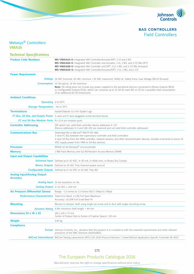
The European Products Catalogue 2016Manufacturer reserves the right to change specifications without prior notice
175
bas controllersField Controllers
Metasys® ControllersVMA16
Technical SpecificationsProduct Code Numbers MS-VMA1615-0: Integrated VAV Controller/Actuator/DPT, 3 UI and 2 BO
MS-VMA1626-0: Integrated VAV Controller and Actuator, 3 UI, 3 BO, and 2 CO (No DPT)MS-VMA1628-0: Integrated VAV Controller and DPT, 3 UI, 3 BO, and 2 CO (No Actuator)MS-VMA1630-0: Integrated VAV Controller/Actuator/DPT, 3 UI, 3 BO, and 2 CO
Power Requirement
Voltage 24 VAC (nominal, 20 VAC minimum / 30 VAC maximum), 50/60 Hz, Safety Extra-Low Voltage (SELV) (Europe)
Consumption 10 VA typical, 14 VA maximum Note: VA rating does not include any power supplied to the peripheral devices connected to Binary Outputs (BOs) or Configurable Outputs (COs), which can consume up to 12 VA for each BO or CO for a possible total consumption of an additional 60 VA (maximum).
Ambient Conditions
Operating 0 to 50°C
Storage Temperature -40 to 70°C
Terminations Inputs/Outputs: 6.3 mm Spade Lugs
FC Bus, SA Bus, and Supply Power 4-wire and 2-wire pluggable screw terminal blocks
FC and SA Bus Modular Ports RJ-12 6-pin modular jacks
Controller Addressing DIP switch set; valid field controller device addresses 4–127 (Device addresses 0–3 and 128–255 are reserved and not valid field controller addresses)
Communications Bus Selectable N2 or BACnet® MS/TP RS-485: 3-wire FC Bus between the supervisory controller and field controllers4-wire SA Bus from the VMA controller, network sensors, and other sensor/actuator devices, includes a terminal to source 15VDC supply power from VMA to SA Bus devices.
Processor RX630 32-bit Renesas® microcontroller
Memory 1 MB Flash Memory and 512 KB Random Access Memory (RAM)
Input and Output Capabilities
Universal Input Defined as 0–10 VDC, 4–20 mA, 0–600k ohm, or Binary Dry Contact
Binary Outputs Defined as 24 VAC Triac (internal power source)
Configurable Outputs Defined as 0–10 VDC or 24 VAC Triac BO
Analog Input/Analog OutputAccuracy
Analog Input 15-bit resolution on UIs
Analog Output 0–10 VDC ± 200 mV
Air Pressure Differential Sensor Range: -1.5 inches to 1.5 inches H20 (-374pa to 374pa)
Performance Characteristics Total Error Band: ±1.3% Full Span MaximumAccuracy: ±0.25% Full Scale Best Fit
Mounting Mounts to damper shaft using single set screw and to duct with single mounting screw.
Actuator Rating 4 Nm minimum shaft length = 44 mm
Dimensions (H x W x D) 165 x 125 x 73 mm Center of Output Hub to Center of Captive Spacer: 135 mm
Weight 0.65 kg
Compliance
Europe Johnson Controls, Inc., declares that this product is in compliance with the essential requirements and other relevant provisions of the EMC Directive 2004/108/EC.
BACnet International BACnet Testing Laboratories (BTL) 135-2010 Protocol Revision 7 Listed BACnet Application Specific Controller (B-ASC)
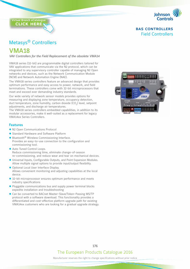
The European Products Catalogue 2016Manufacturer reserves the right to change specifications without prior notice
176
bas controllersField Controllers
Metasys® Controllers
VMA18VAV Controllers for the Field Replacement of the obsolete VMA14
VMA18 series (32-bit) are programmable digital controllers tailored for VAV applications that communicate via the N2 protocol, which can be integrated to any supervisory controller capable of managing N2 Open networks and devices, such as the Network Communication Module (NCM) and Network Automation Engine (NAE).The VMA18 series controllers feature an advanced design that provides optimum performance and easy access to power, network, and field terminations. These controllers come with 32-bit microprocessors that meet and exceed ever demanding industry standards.Our wide variety of network sensor models provides options for measuring and displaying zone temperature, occupancy detection, duct temperature, zone humidity, carbon dioxide (CO2) level, setpoint adjustments, and discharge air temperatures. The VMA18 series controllers embedded capabilities, in addition to its modular accessories, make it well-suited as a replacement for legacy VMA14xx Series Controllers.
Features z N2 Open Communications Protocol z Standard Hardware and Software Platform z Bluetooth® Wireless Commissioning Interface. Provides an easy-to-use connection to the configuration and commissioning tool.
z Auto Tuned Control Loops. Reduce commissioning time, eliminate change-of-season re-commissioning, and reduce wear and tear on mechanical devices.
z Universal Inputs, Configurable Outputs, and Point Expansion Modules. Allow multiple signal options to provide input/output flexibility.
z Optional Local User Interface Display. Allows convenient monitoring and adjusting capabilities at the local device.
z 32-bit microprocessor ensures optimum performance and meets industry specifications
z Pluggable communications bus and supply power terminal blocks expedite installation and troubleshooting
z Can be converted to BACnet Master-Slave/Token-Passing MS/TP protocol with a software download. This functionality provides a differentiated and cost-effective platform upgrade path for existing VMA14xx customers who are looking for a gradual upgrade strategy.
Virtual Branch eCatalogueclick here
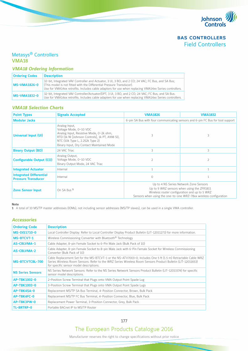
The European Products Catalogue 2016Manufacturer reserves the right to change specifications without prior notice
177
bas controllersField Controllers
Metasys® ControllersVMA18
VMA18 Ordering InformationOrdering Codes Description
MS-VMA1826-032-bit, Integrated VAV Controller and Actuator, 3 UI, 3 BO, and 2 CO; 24 VAC; FC Bus, and SA Bus; (This model is not fitted with the Differential Pressure Transducer). Use for VMA14xx retrofits. Includes cable adapters for use when replacing VMA14xx Series controllers.
MS-VMA1832-0 32-bit, Integrated VAV Controller/Actuator/DPT, 3 UI, 3 BO, and 2 CO; 24 VAC; FC Bus, and SA Bus. Use for VMA14xx retrofits. Includes cable adapters for use when replacing VMA14xx Series controllers.
VMA18 Selection ChartsPoint Types Signals Accepted VMA1826 VMA1832
Modular Jacks 6-pin SA Bus with four communicating sensors and 6-pin FC Bus for tool support
Universal Input (UI)
Analog Input, Voltage Mode, 0–10 VDC Analog Input, Resistive Mode, 0–2k ohm, RTD (1k NI [Johnson Controls], 1k PT, A998 SI), NTC (10k Type L, 2.252k Type 2) Binary Input, Dry Contact Maintained Mode
3 3
Binary Output (BO) 24 VAC Triac 3 3
Configurable Output (CO)Analog Output, Voltage Mode, 0–10 VDC Binary Output Mode, 24 VAC Triac
2 2
Integrated Actuator Internal 1 1
Integrated Differential Pressure Transducer
Internal 0 1
Zone Sensor Input On SA Bus 1
Up to 4 NS Series Network Zone Sensors Up to 9 WRZ sensors when using the ZFR1811 Wireless router configuration and up to 5 WRZ
Sensors when using the one-to-one WRZ-78xx wireless configuration
Note1 A total of 10 MS/TP master addresses (IOMs), not including sensor addresses (MS/TP slaves), can be used in a single VMA controller.
AccessoriesOrdering Code Description
MS-DIS1710-0 Local Controller Display: Refer to Local Controller Display Product Bulletin (LIT-12011273) for more information.
MS-BTCVT-1 Wireless Commissioning Converter with Bluetooth® Technology
AS-CBLVMA-1 Cable Adapter, 8-pin Female Socket to 6-Pin Male Jack (Bulk Pack of 10)
AS-CBLVMA-2 Cable Adapter, 8-pin Female Socket to 8-pin Male Jack with 6-Pin Female Socket for Wireless Commissioning Converter (Bulk Pack of 10)
MS-BTCVTCBL-700Cable Replacement Set for the MS-BTCVT-1 or the NS-ATV7003-0; Includes One 5 ft (1.5 m) Retractable Cable WRZ Series Wireless Room Sensors: Refer to the WRZ Series Wireless Room Sensors Product Bulletin (LIT-12011653) for specific sensor model descriptions.
NS Series Sensors NS Series Network Sensors: Refer to the NS Series Network Sensors Product Bulletin (LIT-12011574) for specific sensor model descriptions.
AP-TBK1002-0 2-Position Screw Terminal that Plugs onto VMA Output Point Spade Lug
AP-TBK1003-0 3-Position Screw Terminal that Plugs onto VMA Output Point Spade Lugs
AP-TBK4SA-0 Replacement MS/TP SA Bus Terminal, 4-Position Connector, Brown, Bulk Pack
AP-TBK4FC-0 Replacement MS/TP FC Bus Terminal, 4-Position Connector, Blue, Bulk Pack
AP-TBK3PW-0 Replacement Power Terminal, 3-Position Connector, Grey, Bulk Pack
TL-BRTRP-0 Portable BACnet IP to MS/TP Router
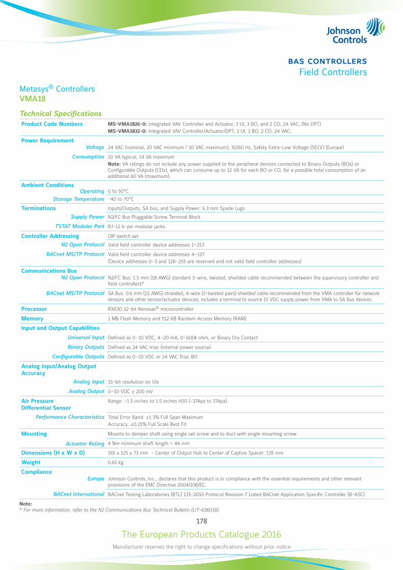
The European Products Catalogue 2016Manufacturer reserves the right to change specifications without prior notice
178
bas controllersField Controllers
Metasys® ControllersVMA18
Technical SpecificationsProduct Code Numbers MS-VMA1826-0: Integrated VAV Controller and Actuator, 3 UI, 3 BO, and 2 CO; 24 VAC; (No DPT)
MS-VMA1832-0: Integrated VAV Controller/Actuator/DPT, 3 UI, 3 BO, 2 CO; 24 VAC;
Power RequirementVoltage 24 VAC (nominal, 20 VAC minimum / 30 VAC maximum), 50/60 Hz, Safety Extra-Low Voltage (SELV) (Europe)
Consumption 10 VA typical, 14 VA maximum Note: VA ratings do not include any power supplied to the peripheral devices connected to Binary Outputs (BOs) or Configurable Outputs (COs), which can consume up to 12 VA for each BO or CO, for a possible total consumption of an additional 60 VA (maximum).
Ambient ConditionsOperating 0 to 50°C
Storage Temperature -40 to 70°C
Terminations Inputs/Outputs, SA bus, and Supply Power: 6.3 mm Spade Lugs
Supply Power N2/FC Bus Pluggable Screw Terminal Block
TSTAT Modular Port RJ-12 6-pin modular jacks
Controller Addressing DIP switch set
N2 Open Protocol Valid field controller device addresses 1–253
BACnet MS/TP Protocol Valid field controller device addresses 4–127(Device addresses 0–3 and 128–255 are reserved and not valid field controller addresses)
Communications BusN2 Open Protocol N2/FC Bus: 1.5 mm (18 AWG) standard 3-wire, twisted, shielded cable recommended between the supervisory controller and
field controllers*
BACnet MS/TP Protocol SA Bus: 0.6 mm (22 AWG) stranded, 4-wire (2-twisted pairs) shielded cable recommended from the VMA controller for network sensors and other sensor/actuator devices; includes a terminal to source 15 VDC supply power from VMA to SA Bus devices
Processor RX630 32-bit Renesas® microcontroller
Memory 1 MB Flash Memory and 512 KB Random Access Memory (RAM)
Input and Output Capabilities
Universal Input Defined as 0–10 VDC, 4–20 mA, 0–600k ohm, or Binary Dry Contact
Binary Outputs Defined as 24 VAC triac (internal power source)
Configurable Outputs Defined as 0–10 VDC or 24 VAC Triac BO
Analog Input/Analog OutputAccuracy
Analog Input 15-bit resolution on UIs
Analog Output 0–10 VDC ± 200 mV
Air Pressure Differential Sensor
Range: -1.5 inches to 1.5 inches H20 (-374pa to 374pa)
Performance Characteristics Total Error Band: ±1.3% Full Span MaximumAccuracy: ±0.25% Full Scale Best Fit
Mounting Mounts to damper shaft using single set screw and to duct with single mounting screw.
Actuator Rating 4 Nm minimum shaft length = 44 mm
Dimensions (H x W x D) 165 x 125 x 73 mm - Center of Output Hub to Center of Captive Spacer: 135 mm
Weight 0.65 kg
ComplianceEurope Johnson Controls, Inc., declares that this product is in compliance with the essential requirements and other relevant
provisions of the EMC Directive 2004/108/EC.
BACnet International BACnet Testing Laboratories (BTL) 135-2010 Protocol Revision 7 Listed BACnet Application Specific Controller (B-ASC)
Note:* For more information, refer to the N2 Communications Bus Technical Bulletin (LIT-636018).
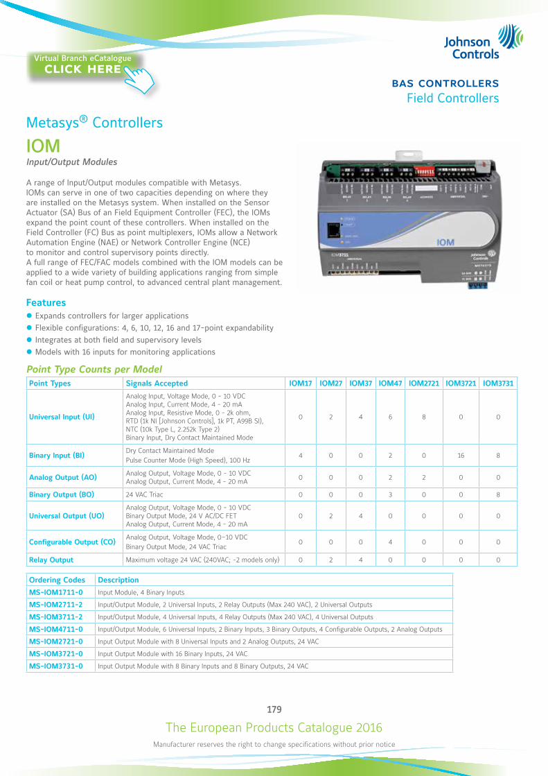
The European Products Catalogue 2016Manufacturer reserves the right to change specifications without prior notice
179
bas controllersField Controllers
Metasys® Controllers
IOMInput/Output Modules
A range of Input/Output modules compatible with Metasys. IOMs can serve in one of two capacities depending on where they are installed on the Metasys system. When installed on the Sensor Actuator (SA) Bus of an Field Equipment Controller (FEC), the IOMs expand the point count of these controllers. When installed on the Field Controller (FC) Bus as point multiplexers, IOMs allow a Network Automation Engine (NAE) or Network Controller Engine (NCE) to monitor and control supervisory points directly. A full range of FEC/FAC models combined with the IOM models can be applied to a wide variety of building applications ranging from simple fan coil or heat pump control, to advanced central plant management.
Features z Expands controllers for larger applications z Flexible configurations: 4, 6, 10, 12, 16 and 17-point expandability z Integrates at both field and supervisory levels z Models with 16 inputs for monitoring applications
Point Type Counts per ModelPoint Types Signals Accepted IOM17 IOM27 IOM37 IOM47 IOM2721 IOM3721 IOM3731
Universal Input (UI)
Analog Input, Voltage Mode, 0 - 10 VDCAnalog Input, Current Mode, 4 - 20 mAAnalog Input, Resistive Mode, 0 - 2k ohm, RTD (1k NI [Johnson Controls], 1k PT, A99B SI), NTC (10k Type L, 2.252k Type 2)Binary Input, Dry Contact Maintained Mode
0 2 4 6 8 0 0
Binary Input (BI)Dry Contact Maintained ModePulse Counter Mode (High Speed), 100 Hz
4 0 0 2 0 16 8
Analog Output (AO) Analog Output, Voltage Mode, 0 - 10 VDCAnalog Output, Current Mode, 4 - 20 mA 0 0 0 2 2 0 0
Binary Output (BO) 24 VAC Triac 0 0 0 3 0 0 8
Universal Output (UO)Analog Output, Voltage Mode, 0 - 10 VDCBinary Output Mode, 24 V AC/DC FETAnalog Output, Current Mode, 4 - 20 mA
0 2 4 0 0 0 0
Configurable Output (CO)Analog Output, Voltage Mode, 0–10 VDCBinary Output Mode, 24 VAC Triac
0 0 0 4 0 0 0
Relay Output Maximum voltage 24 VAC (240VAC; -2 models only) 0 2 4 0 0 0 0
Ordering Codes Description
MS-IOM1711-0 Input Module, 4 Binary Inputs
MS-IOM2711-2 Input/Output Module, 2 Universal Inputs, 2 Relay Outputs (Max 240 VAC), 2 Universal Outputs
MS-IOM3711-2 Input/Output Module, 4 Universal Inputs, 4 Relay Outputs (Max 240 VAC), 4 Universal Outputs
MS-IOM4711-0 Input/Output Module, 6 Universal Inputs, 2 Binary Inputs, 3 Binary Outputs, 4 Configurable Outputs, 2 Analog Outputs
MS-IOM2721-0 Input Output Module with 8 Universal Inputs and 2 Analog Outputs, 24 VAC
MS-IOM3721-0 Input Output Module with 16 Binary Inputs, 24 VAC
MS-IOM3731-0 Input Output Module with 8 Binary Inputs and 8 Binary Outputs, 24 VAC
Virtual Branch eCatalogueclick here
The European Products Catalogue 2016Manufacturer reserves the right to change specifications without prior notice
180
bas controllersField Controllers
Metasys® ControllersIOM
Technical Specifications (1/2)Supply Voltage 24 VAC (nominal, 20 VAC minimum/30 VAC maximum), 50/60 Hz, Safety Extra-Low Voltage (SELV) Europe
Power Consumption 14 VA maximumNote: VA rating does not include any power supplied to the peripheral devices connected to Binary Outputs (BOs) or Configurable Outputs (COs), which can consume up to 12 VA for each BO or CO; for a possible total consumption of an additional 84 VA (maximum).
Ambient Conditions
Operating 0 to 50°C; 10 to 90% RH noncondensing
Storage Temperature -40 to 80°C; 5 to 95% RH noncondensing
Controller Addressing DIP switch set; valid field controller device addresses 4–127(Device addresses 0–3 and 128–255 are reserved and not valid IOM addresses.)
Communications Bus BACnet® MS/TP, RS-485: 3-wire FC Bus between the supervisory controller and field devices 4-wire SA Bus between field controller, network sensors, and other sensor/actuator devices, includes a lead to source 15 VDC supply power (from field controller) to bus devices*.
Processor H8SX/166xR Renesas® 32-bit microcontroller
Memory 1 MB Flash Memory and 512 KB Random Access Memory (RAM)
IOM17, IOM27, and IOM37 Models 640 KB Flash Memory and 128 KB Random Access Memory (RAM)
IOM47 Models 1 MB Flash Memory and 512 KB RAM
Input and Output Capabilities Analog Input: 16-bit resolutionAnalog Output: 16-bit resolution and ±200 mV in 0–10 VDC applications
IOM1711 4 - Binary Inputs: Defined as Dry Contact Maintained or Pulse Counter/Accumulator Mode
IOM2711 2 - Universal Inputs: Defined as 0–10 VDC, 4–20 mA, 0–600k ohm, or Binary Dry Contact2 - Universal Outputs: Analog Output mode - 0-10 VDC, Binary Output Mode - 24 VAC/VDC Field-effect Transistor2 - Relay Outputs (Single-Pole, Double-Throw) Rate as: 24 VAC Maximum Voltage 3A Non-inductive 24 VAC 6(4)A 240 VAC Maximum Voltage; MS-IOM2711-2 Model only
IOM2721 8 - Universal Inputs: Defined as 0–10 VDC, 4–20 mA, 0–600k ohm, or Binary Dry Contact2 - Analog Outputs: Defined as 0–10 VDC or 4–20 mA
IOM3711 4 - Universal Inputs: Defined as 0–10 VDC, 4–20 mA, 0–600k ohm, or Binary Dry Contact4 - Universal Outputs: Analog Output mode - 0-10 VDC, Binary Output Mode - 24 VAC/VDC Field-effect Transistor4 - Relay Outputs (Single-Pole, Double-Throw) Rate as: 24 VAC Maximum Voltage 3A Non-inductive 24 VAC 6(4)A 240 VAC Maximum Voltage; MS-IOM3711-2 Model only
IOM3721 16 - Binary Inputs: Defined as Dry Contact Maintained or Pulse Counter/Accumulator Mode
IOM3731 8 - Binary Inputs: Defined as Dry Contact Maintained or Pulse Counter/Accumulator Mode8 - Binary Outputs: Defined as 24 VAC TriacNote: Binary Outputs (BOs) on MS-IOM3731 controllers do not supply power for the outputs; the BOs require external low-voltage (< 30 VAC) power sources.
IOM4711 6 - Universal Inputs: Defined as 0–VDC, 4–20 mA, 0–600k ohm, or Binary Dry Contact2 - Binary Inputs: Defined as Dry Contact Maintained or Pulse Counter/Accumulator Mode3 - Binary Outputs: Defined as 24 VAC Triac (selectable internal or external source power)4 - Configurable Outputs: Defined as 0–10 VDC or 24 VAC Triac BO2 - Analog Outputs: Defined as 0–10 VDC or 4–20 mA
...Continued...
The European Products Catalogue 2016Manufacturer reserves the right to change specifications without prior notice
181
bas controllersField Controllers
Metasys® ControllersIOM
Technical Specifications (2/2)Analog Input/Analog Output Resolution and Accuracy
Analog Input 16-bit resolution
Analog Output 16-bit resolution and ±200 mV in 0–10 VDC applications
Terminations Input/Output: Fixed Screw Terminal BlocksSA/FC Bus and Supply Power: 4-Wire and 3-Wire Pluggable Screw Terminal BlocksSA/FC Bus Port: RJ-12 6-Pin Modular Jacks
Mounting Horizontal on single 35 mm DIN rail mount (preferred), or screw mount on flat surface with three integral mounting clips on controller
Housing Enclosure material: ABS and polycarbonate UL94 5VB; Self-extinguishing, Plenum-rated Protection Class: IP20 (IEC529)
Dimensions (H x W x D)
IOM17xx and IOM271x Models 150 x 120 x 53 mm including terminals and mounting clips
IOM272x, IOM372x and IOM373x Models 150 x 164 x 53 mm including terminals and mounting clips
IOM37 and IOM47 Models 150 x 190 x 53 mm including terminals and mounting clips
Note: For all models, mounting space requires an additional 50 mm space on top, bottom, and front face of controller for easy removal, ventilation, and wire terminations.
Weight 0.5 Kg
Compliance
Europe CE Mark, EMC Directive 2004/108/EC, in accordance with EN 61000-6-3 (2007) Generic Emission Standard for Residential and Light Industrial and EN 61000-6-2 (2005) Generic Immunity Standard for Heavy Industrial EnvironmentNote: For IOM17/IOM27/IOM37, Low Voltage Directive 73/23/EEC in accordance with EN 60730-1:2000/A2:2008 Automatic electrical controls for household and similar use.Note: For IOM47 Models, Conducted RF Immunity within EN 61000-6-2 meets performance criteria B.
BACnet International BACnet Testing Laboratories (BTL) 135-2004 Listed BACnet Application Specific Controller (B-ASC)
AccessoriesOrdering Codes Description
AP-TBK4SA-0 Replacement MS/TP SA Bus Terminal, 4-Position Connector, Brown, Bulk Pack
AP-TBK4FC-0 Replacement MS/TP FC Bus Terminal, 4-Position Connector, Blue, Bulk Pack
AP-TBK3PW-0 Replacement Power Terminal, 3-Position Connector, Grey, Bulk Pack
MS-DIS1710-0 Local Controller Display for FEC and FAC Models
MS-BTCVT-1 Wireless Commissioning Converter, with Bluetooth® technology
MS-BTCVTCBL-700 Cable replacement Set for the MS-BTCVT-1 or the NS-ATV7003-0; includes one 5-foot retractable cable
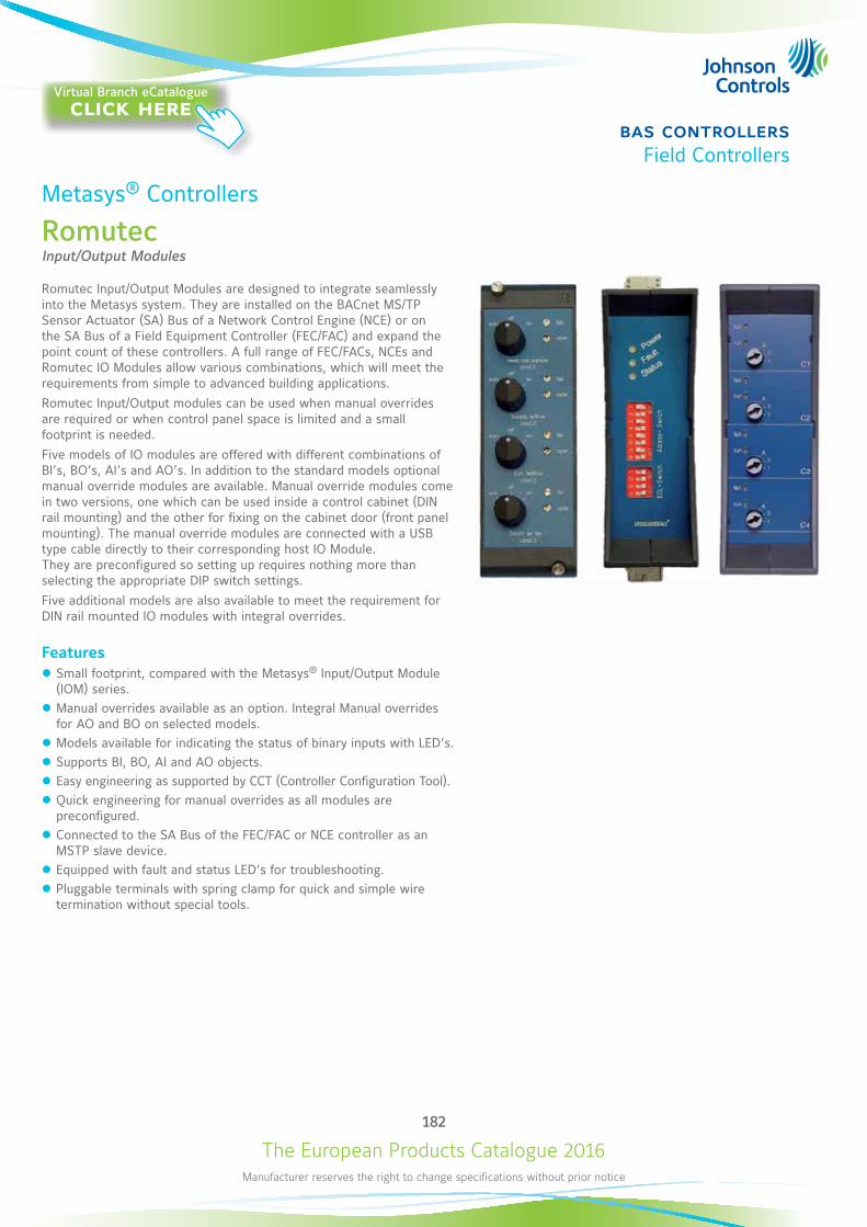
The European Products Catalogue 2016Manufacturer reserves the right to change specifications without prior notice
182
bas controllersField Controllers
Metasys® Controllers
RomutecInput/Output Modules
Romutec Input/Output Modules are designed to integrate seamlessly into the Metasys system. They are installed on the BACnet MS/TP Sensor Actuator (SA) Bus of a Network Control Engine (NCE) or on the SA Bus of a Field Equipment Controller (FEC/FAC) and expand the point count of these controllers. A full range of FEC/FACs, NCEs and Romutec IO Modules allow various combinations, which will meet the requirements from simple to advanced building applications.Romutec Input/Output modules can be used when manual overrides are required or when control panel space is limited and a small footprint is needed.Five models of IO modules are offered with different combinations of BI’s, BO’s, AI’s and AO’s. In addition to the standard models optional manual override modules are available. Manual override modules come in two versions, one which can be used inside a control cabinet (DIN rail mounting) and the other for fixing on the cabinet door (front panel mounting). The manual override modules are connected with a USB type cable directly to their corresponding host IO Module. They are preconfigured so setting up requires nothing more than selecting the appropriate DIP switch settings. Five additional models are also available to meet the requirement for DIN rail mounted IO modules with integral overrides.
Features z Small footprint, compared with the Metasys® Input/Output Module (IOM) series.
z Manual overrides available as an option. Integral Manual overrides for AO and BO on selected models.
z Models available for indicating the status of binary inputs with LED’s. z Supports BI, BO, AI and AO objects. z Easy engineering as supported by CCT (Controller Configuration Tool). z Quick engineering for manual overrides as all modules are preconfigured.
z Connected to the SA Bus of the FEC/FAC or NCE controller as an MSTP slave device.
z Equipped with fault and status LED’s for troubleshooting. z Pluggable terminals with spring clamp for quick and simple wire termination without special tools.
Virtual Branch eCatalogueclick here
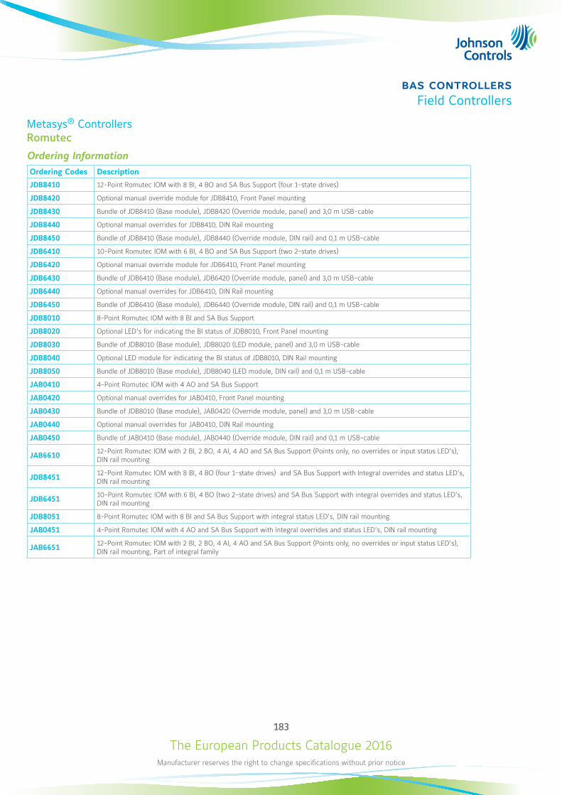
The European Products Catalogue 2016Manufacturer reserves the right to change specifications without prior notice
183
bas controllersField Controllers
Metasys® ControllersRomutec
Ordering InformationOrdering Codes Description
JDB8410 12-Point Romutec IOM with 8 BI, 4 BO and SA Bus Support (four 1-state drives)
JDB8420 Optional manual override module for JDB8410, Front Panel mounting
JDB8430 Bundle of JDB8410 (Base module), JDB8420 (Override module, panel) and 3,0 m USB-cable
JDB8440 Optional manual overrides for JDB8410, DIN Rail mounting
JDB8450 Bundle of JDB8410 (Base module), JDB8440 (Override module, DIN rail) and 0,1 m USB-cable
JDB6410 10-Point Romutec IOM with 6 BI, 4 BO and SA Bus Support (two 2-state drives)
JDB6420 Optional manual override module for JDB6410, Front Panel mounting
JDB6430 Bundle of JDB6410 (Base module), JDB6420 (Override module, panel) and 3,0 m USB-cable
JDB6440 Optional manual overrides for JDB6410, DIN Rail mounting
JDB6450 Bundle of JDB6410 (Base module), JDB6440 (Override module, DIN rail) and 0,1 m USB-cable
JDB8010 8-Point Romutec IOM with 8 BI and SA Bus Support
JDB8020 Optional LED’s for indicating the BI status of JDB8010, Front Panel mounting
JDB8030 Bundle of JDB8010 (Base module), JDB8020 (LED module, panel) and 3,0 m USB-cable
JDB8040 Optional LED module for indicating the BI status of JDB8010, DIN Rail mounting
JDB8050 Bundle of JDB8010 (Base module), JDB8040 (LED module, DIN rail) and 0,1 m USB-cable
JAB0410 4-Point Romutec IOM with 4 AO and SA Bus Support
JAB0420 Optional manual overrides for JAB0410, Front Panel mounting
JAB0430 Bundle of JDB8010 (Base module), JAB0420 (Override module, panel) and 3,0 m USB-cable
JAB0440 Optional manual overrides for JAB0410, DIN Rail mounting
JAB0450 Bundle of JAB0410 (Base module), JAB0440 (Override module, DIN rail) and 0,1 m USB-cable
JAB6610 12-Point Romutec IOM with 2 BI, 2 BO, 4 AI, 4 AO and SA Bus Support (Points only, no overrides or input status LED’s), DIN rail mounting
JDB8451 12-Point Romutec IOM with 8 BI, 4 BO (four 1-state drives) and SA Bus Support with Integral overrides and status LED’s, DIN rail mounting
JDB6451 10-Point Romutec IOM with 6 BI, 4 BO (two 2-state drives) and SA Bus Support with integral overrides and status LED’s, DIN rail mounting
JDB8051 8-Point Romutec IOM with 8 BI and SA Bus Support with integral status LED’s, DIN rail mounting
JAB0451 4-Point Romutec IOM with 4 AO and SA Bus Support with integral overrides and status LED’s, DIN rail mounting
JAB6651 12-Point Romutec IOM with 2 BI, 2 BO, 4 AI, 4 AO and SA Bus Support (Points only, no overrides or input status LED’s), DIN rail mounting, Part of integral family
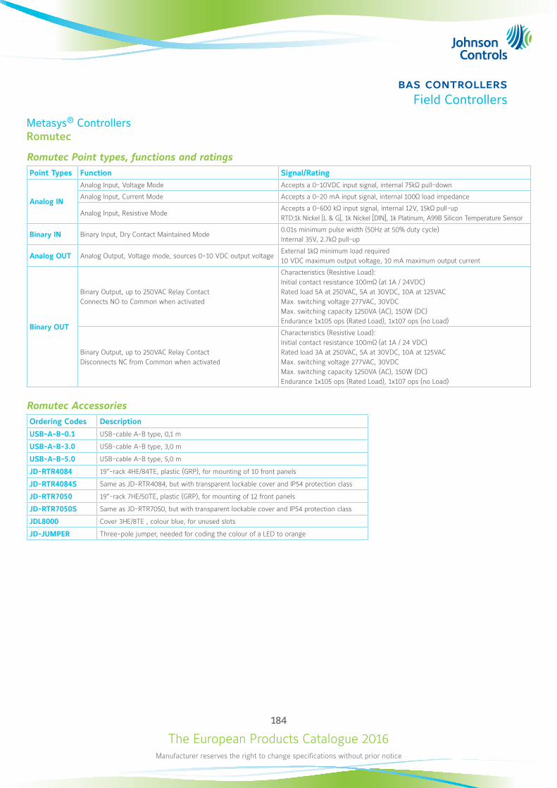
The European Products Catalogue 2016Manufacturer reserves the right to change specifications without prior notice
184
bas controllersField Controllers
Metasys® ControllersRomutec
Romutec Point types, functions and ratingsPoint Types Function Signal/Rating
Analog IN
Analog Input, Voltage Mode Accepts a 0-10VDC input signal, internal 75kΩ pull-down
Analog Input, Current Mode Accepts a 0-20 mA input signal, internal 100Ω load impedance
Analog Input, Resistive ModeAccepts a 0-600 kΩ input signal, internal 12V, 15kΩ pull-upRTD:1k Nickel [L & G], 1k Nickel [DIN], 1k Platinum, A99B Silicon Temperature Sensor
Binary IN Binary Input, Dry Contact Maintained Mode0.01s minimum pulse width (50Hz at 50% duty cycle)Internal 35V, 2.7kΩ pull-up
Analog OUT Analog Output, Voltage mode, sources 0-10 VDC output voltageExternal 1kΩ minimum load required10 VDC maximum output voltage, 10 mA maximum output current
Binary OUT
Binary Output, up to 250VAC Relay ContactConnects NO to Common when activated
Characteristics (Resistive Load):Initial contact resistance 100mΩ (at 1A / 24VDC)Rated load 5A at 250VAC, 5A at 30VDC, 10A at 125VACMax. switching voltage 277VAC, 30VDCMax. switching capacity 1250VA (AC), 150W (DC)Endurance 1x10⁵ ops (Rated Load), 1x10⁷ ops (no Load)
Binary Output, up to 250VAC Relay ContactDisconnects NC from Common when activated
Characteristics (Resistive Load):Initial contact resistance 100mΩ (at 1A / 24 VDC)Rated load 3A at 250VAC, 5A at 30VDC, 10A at 125VACMax. switching voltage 277VAC, 30VDCMax. switching capacity 1250VA (AC), 150W (DC)Endurance 1x10⁵ ops (Rated Load), 1x10⁷ ops (no Load)
Romutec AccessoriesOrdering Codes Description
USB-A-B-0.1 USB-cable A-B type, 0,1 m
USB-A-B-3.0 USB-cable A-B type, 3,0 m
USB-A-B-5.0 USB-cable A-B type, 5,0 m
JD-RTR4084 19”-rack 4HE/84TE, plastic (GRP), for mounting of 10 front panels
JD-RTR4084S Same as JD-RTR4084, but with transparent lockable cover and IP54 protection class
JD-RTR7050 19”-rack 7HE/50TE, plastic (GRP), for mounting of 12 front panels
JD-RTR7050S Same as JD-RTR7050, but with transparent lockable cover and IP54 protection class
JDL8000 Cover 3HE/8TE , colour blue, for unused slots
JD-JUMPER Three-pole jumper, needed for coding the colour of a LED to orange
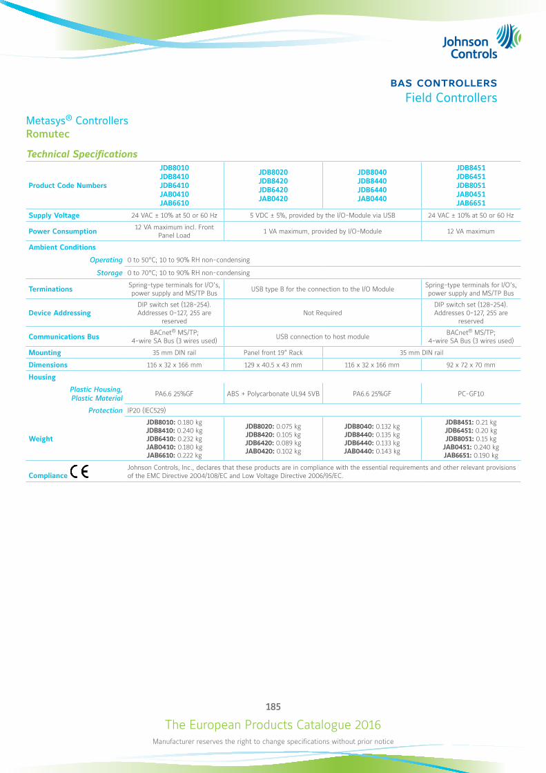
The European Products Catalogue 2016Manufacturer reserves the right to change specifications without prior notice
185
bas controllersField Controllers
Metasys® ControllersRomutec
Technical Specifications
Product Code Numbers
JDB8010 JDB8410 JDB6410 JAB0410 JAB6610
JDB8020 JDB8420 JDB6420 JAB0420
JDB8040 JDB8440 JDB6440 JAB0440
JDB8451 JDB6451 JDB8051 JAB0451 JAB6651
Supply Voltage 24 VAC ± 10% at 50 or 60 Hz 5 VDC ± 5%, provided by the I/O-Module via USB 24 VAC ± 10% at 50 or 60 Hz
Power Consumption 12 VA maximum incl. Front Panel Load 1 VA maximum, provided by I/O-Module 12 VA maximum
Ambient Conditions
Operating 0 to 50°C; 10 to 90% RH non-condensing
Storage 0 to 70°C; 10 to 90% RH non-condensing
Terminations Spring-type terminals for I/O’s, power supply and MS/TP Bus USB type B for the connection to the I/O Module Spring-type terminals for I/O’s,
power supply and MS/TP Bus
Device AddressingDIP switch set (128-254). Addresses 0-127, 255 are
reservedNot Required
DIP switch set (128-254). Addresses 0-127, 255 are
reserved
Communications Bus BACnet® MS/TP; 4-wire SA Bus (3 wires used) USB connection to host module BACnet® MS/TP;
4-wire SA Bus (3 wires used)
Mounting 35 mm DIN rail Panel front 19” Rack 35 mm DIN rail
Dimensions 116 x 32 x 166 mm 129 x 40.5 x 43 mm 116 x 32 x 166 mm 92 x 72 x 70 mm
Housing
Plastic Housing, Plastic Material
PA6.6 25%GF ABS + Polycarbonate UL94 5VB PA6.6 25%GF PC-GF10
Protection IP20 (IEC529)
Weight
JDB8010: 0.180 kg JDB8410: 0.240 kg JDB6410: 0.232 kg JAB0410: 0.180 kg JAB6610: 0.222 kg
JDB8020: 0.075 kg JDB8420: 0.105 kg JDB6420: 0.089 kg JAB0420: 0.102 kg
JDB8040: 0.132 kg JDB8440: 0.135 kg JDB6440: 0.133 kg JAB0440: 0.143 kg
JDB8451: 0.21 kg JDB6451: 0.20 kg JDB8051: 0.15 kg
JAB0451: 0.240 kg JAB6651: 0.190 kg
Compliance Johnson Controls, Inc., declares that these products are in compliance with the essential requirements and other relevant provisions of the EMC Directive 2004/108/EC and Low Voltage Directive 2006/95/EC.
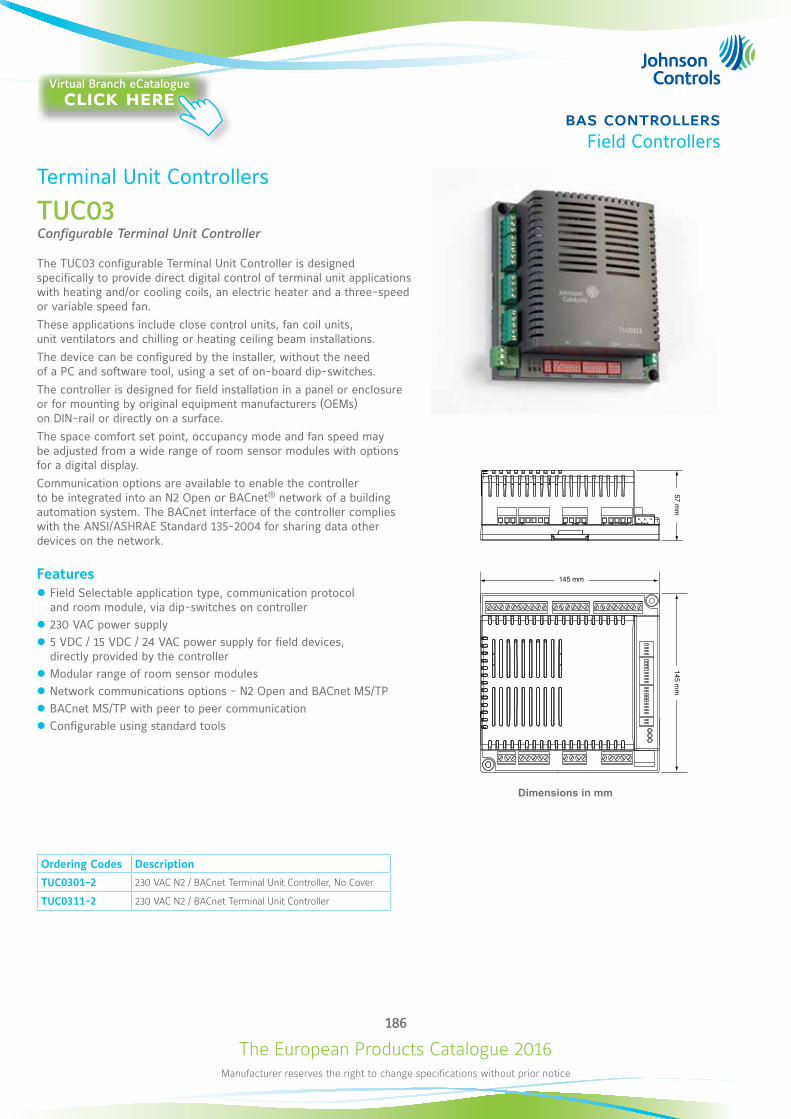
The European Products Catalogue 2016Manufacturer reserves the right to change specifications without prior notice
186
bas controllersField Controllers
Dimensions in mm
Ordering Codes Description
TUC0301-2 230 VAC N2 / BACnet Terminal Unit Controller, No Cover
TUC0311-2 230 VAC N2 / BACnet Terminal Unit Controller
Terminal Unit Controllers
TUC03Configurable Terminal Unit Controller
The TUC03 configurable Terminal Unit Controller is designed specifically to provide direct digital control of terminal unit applications with heating and/or cooling coils, an electric heater and a three-speed or variable speed fan. These applications include close control units, fan coil units, unit ventilators and chilling or heating ceiling beam installations.The device can be configured by the installer, without the need of a PC and software tool, using a set of on-board dip-switches.The controller is designed for field installation in a panel or enclosure or for mounting by original equipment manufacturers (OEMs) on DIN-rail or directly on a surface.The space comfort set point, occupancy mode and fan speed may be adjusted from a wide range of room sensor modules with options for a digital display.Communication options are available to enable the controller to be integrated into an N2 Open or BACnet® network of a building automation system. The BACnet interface of the controller complies with the ANSI/ASHRAE Standard 135-2004 for sharing data other devices on the network.
Features z Field Selectable application type, communication protocol and room module, via dip-switches on controller
z 230 VAC power supply z 5 VDC / 15 VDC / 24 VAC power supply for field devices, directly provided by the controller
z Modular range of room sensor modules z Network communications options - N2 Open and BACnet MS/TP z BACnet MS/TP with peer to peer communication z Configurable using standard tools
Virtual Branch eCatalogueclick here
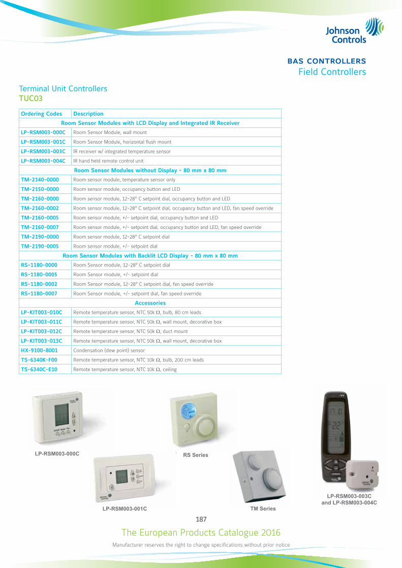
The European Products Catalogue 2016Manufacturer reserves the right to change specifications without prior notice
187
bas controllersField Controllers
Terminal Unit ControllersTUC03
Ordering Codes Description
Room Sensor Modules with LCD Display and Integrated IR Receiver
LP-RSM003-000C Room Sensor Module, wall mount
LP-RSM003-001C Room Sensor Module, horizontal flush mount
LP-RSM003-003C IR receiver w/ integrated temperature sensor
LP-RSM003-004C IR hand held remote control unit
Room Sensor Modules without Display - 80 mm x 80 mm
TM-2140-0000 Room sensor module, temperature sensor only
TM-2150-0000 Room sensor module, occupancy button and LED
TM-2160-0000 Room sensor module, 12-28° C setpoint dial, occupancy button and LED
TM-2160-0002 Room sensor module, 12-28° C setpoint dial, occupancy button and LED, fan speed override
TM-2160-0005 Room sensor module, +/- setpoint dial, occupancy button and LED
TM-2160-0007 Room sensor module, +/- setpoint dial, occupancy button and LED, fan speed override
TM-2190-0000 Room sensor module, 12-28° C setpoint dial
TM-2190-0005 Room sensor module, +/- setpoint dial
Room Sensor Modules with Backlit LCD Display - 80 mm x 80 mm
RS-1180-0000 Room Sensor module, 12-28° C setpoint dial
RS-1180-0005 Room Sensor module, +/- setpoint dial
RS-1180-0002 Room Sensor module, 12-28° C setpoint dial, fan speed override
RS-1180-0007 Room Sensor module, +/- setpoint dial, fan speed override
Accessories
LP-KIT003-010C Remote temperature sensor, NTC 50k W, bulb, 80 cm leads
LP-KIT003-011C Remote temperature sensor, NTC 50k W, wall mount, decorative box
LP-KIT003-012C Remote temperature sensor, NTC 50k W, duct mount
LP-KIT003-013C Remote temperature sensor, NTC 50k W, wall mount, decorative box
HX-9100-8001 Condensation (dew point) sensor
TS-6340K-F00 Remote temperature sensor, NTC 10k W, bulb, 200 cm leads
TS-6340C-E10 Remote temperature sensor, NTC 10k W, ceiling
LP-RSM003-001C
LP-RSM003-003C and LP-RSM003-004C
RS Series
TM Series
LP-RSM003-000C
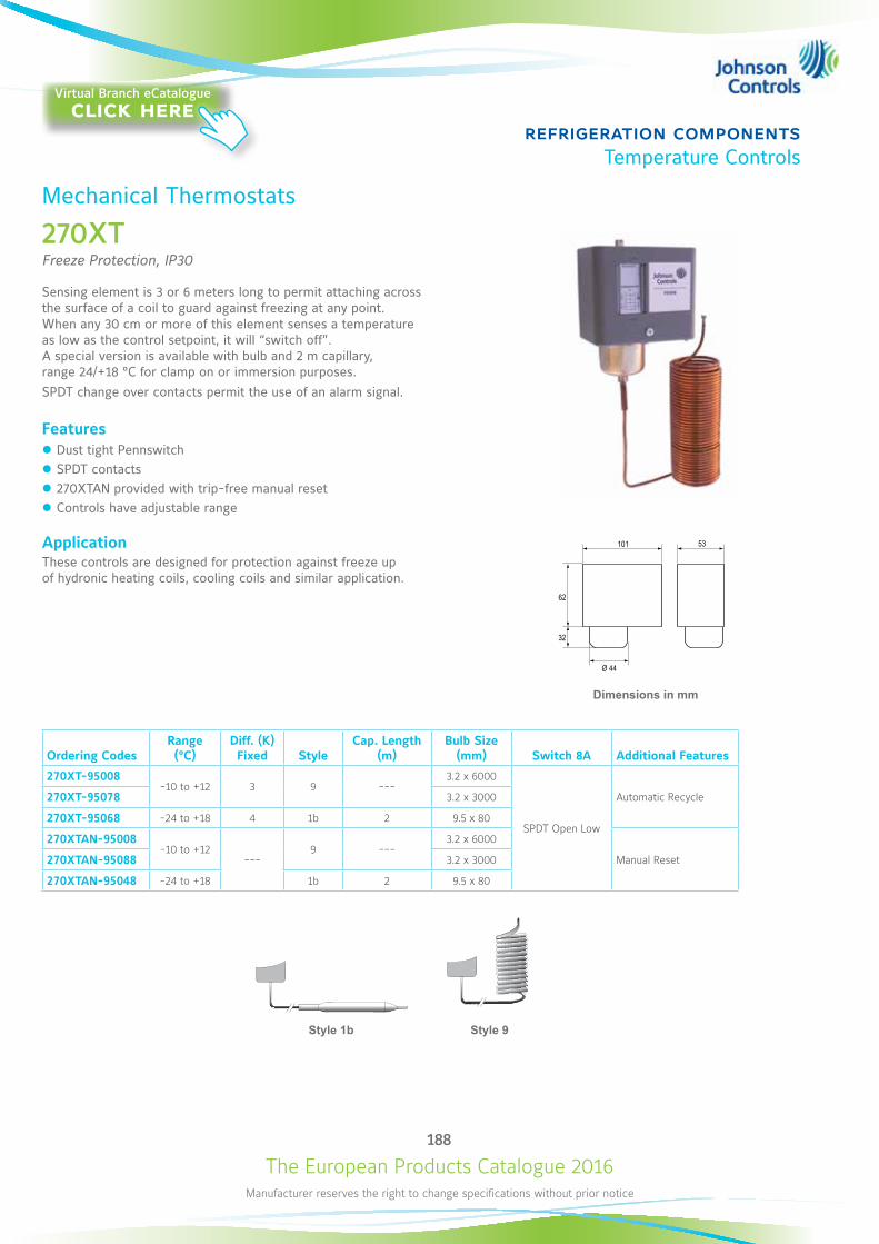
The European Products Catalogue 2016Manufacturer reserves the right to change specifications without prior notice
188
refrigeration componentsTemperature Controls
Ordering CodesRange (°C)
Diff. (K) Fixed Style
Cap. Length (m)
Bulb Size (mm) Switch 8A Additional Features
270XT-95008-10 to +12 3 9 ---
3.2 x 6000
SPDT Open Low
Automatic Recycle270XT-95078 3.2 x 3000
270XT-95068 -24 to +18 4 1b 2 9.5 x 80
270XTAN-95008-10 to +12
---9 ---
3.2 x 6000
Manual Reset270XTAN-95088 3.2 x 3000
270XTAN-95048 -24 to +18 1b 2 9.5 x 80
Dimensions in mm
2 3
1
»62
32
101 53
Ø 44
Mechanical Thermostats
270XT Freeze Protection, IP30
Sensing element is 3 or 6 meters long to permit attaching across the surface of a coil to guard against freezing at any point. When any 30 cm or more of this element senses a temperature as low as the control setpoint, it will “switch off”. A special version is available with bulb and 2 m capillary, range 24/+18 °C for clamp on or immersion purposes.SPDT change over contacts permit the use of an alarm signal.
Features z Dust tight Pennswitch z SPDT contacts z 270XTAN provided with trip-free manual reset z Controls have adjustable range
ApplicationThese controls are designed for protection against freeze up of hydronic heating coils, cooling coils and similar application.
Style 9Style 1b
Virtual Branch eCatalogueclick here
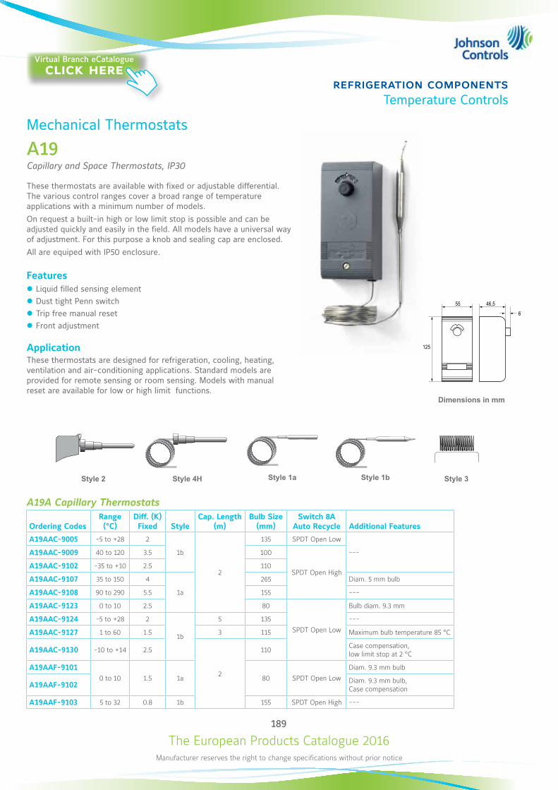
The European Products Catalogue 2016Manufacturer reserves the right to change specifications without prior notice
189
refrigeration componentsTemperature Controls
55
125
46,56
3 2
1
»
Dimensions in mm
Mechanical Thermostats
A19Capillary and Space Thermostats, IP30
These thermostats are available with fixed or adjustable differential. The various control ranges cover a broad range of temperature applications with a minimum number of models. On request a built-in high or low limit stop is possible and can be adjusted quickly and easily in the field. All models have a universal way of adjustment. For this purpose a knob and sealing cap are enclosed. All are equiped with IP50 enclosure.
Features z Liquid filled sensing element z Dust tight Penn switch z Trip free manual reset z Front adjustment
ApplicationThese thermostats are designed for refrigeration, cooling, heating, ventilation and air-conditioning applications. Standard models are provided for remote sensing or room sensing. Models with manual reset are available for low or high limit functions.
Style 2 Style 4H Style 1a Style 3
55(2.16)
125
(4.92)
46,5(1,83) 6
(0.24)3 2
1
Θ >
Style 1b
A19A Capillary Thermostats
Ordering CodesRange (°C)
Diff. (K) Fixed Style
Cap. Length (m)
Bulb Size (mm)
Switch 8A Auto Recycle Additional Features
A19AAC-9005 -5 to +28 2
1b
2
135 SPDT Open Low
---A19AAC-9009 40 to 120 3.5 100
SPDT Open HighA19AAC-9102 -35 to +10 2.5 110
A19AAC-9107 35 to 150 4
1a
265 Diam. 5 mm bulb
A19AAC-9108 90 to 290 5.5 155 ---
A19AAC-9123 0 to 10 2.5 80
SPDT Open Low
Bulb diam. 9.3 mm
A19AAC-9124 -5 to +28 2
1b
5 135 ---
A19AAC-9127 1 to 60 1.5 3 115 Maximum bulb temperature 85 °C
A19AAC-9130 -10 to +14 2.5
2
110 Case compensation, low limit stop at 2 °C
A19AAF-91010 to 10 1.5 1a 80 SPDT Open Low
Diam. 9.3 mm bulb
A19AAF-9102 Diam. 9.3 mm bulb, Case compensation
A19AAF-9103 5 to 32 0.8 1b 155 SPDT Open High ---
Virtual Branch eCatalogueclick here
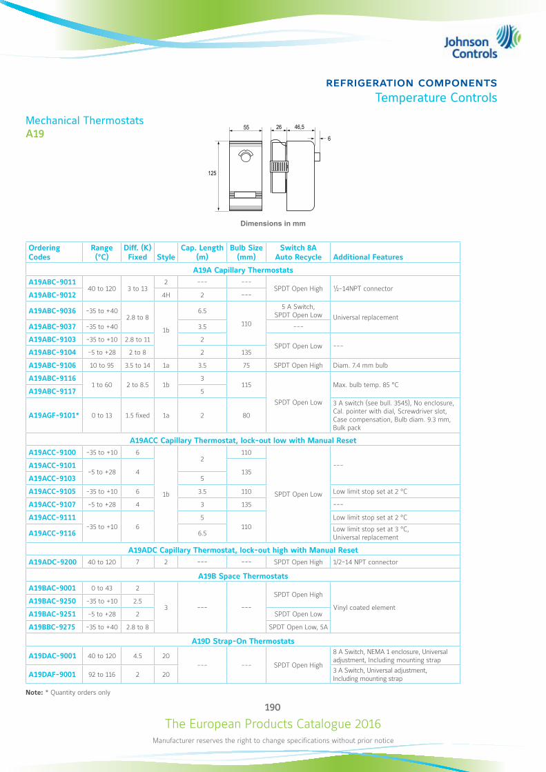
The European Products Catalogue 2016Manufacturer reserves the right to change specifications without prior notice
190
refrigeration componentsTemperature Controls
Mechanical Thermostats A19
Dimensions in mm
Ordering Codes
Range (°C)
Diff. (K) Fixed Style
Cap. Length (m)
Bulb Size (mm)
Switch 8A Auto Recycle Additional Features
A19A Capillary ThermostatsA19ABC-9011
40 to 120 3 to 132 --- ---
SPDT Open High ½-14NPT connector A19ABC-9012 4H 2 ---
A19ABC-9036 -35 to +402.8 to 8
1b
6.5
110
5 A Switch, SPDT Open Low Universal replacement
A19ABC-9037 -35 to +40 3.5 ---
A19ABC-9103 -35 to +10 2.8 to 11 2SPDT Open Low ---
A19ABC-9104 -5 to +28 2 to 8 2 135
A19ABC-9106 10 to 95 3.5 to 14 1a 3.5 75 SPDT Open High Diam. 7.4 mm bulb
A19ABC-91161 to 60 2 to 8.5 1b
3115
SPDT Open Low
Max. bulb temp. 85 °CA19ABC-9117 5
A19AGF-9101* 0 to 13 1.5 fixed 1a 2 80
3 A switch (see bull. 3545), No enclosure, Cal. pointer with dial, Screwdriver slot, Case compensation, Bulb diam. 9.3 mm, Bulk pack
A19ACC Capillary Thermostat, lock-out low with Manual ResetA19ACC-9100 -35 to +10 6
1b
2110
SPDT Open Low
---A19ACC-9101-5 to +28 4 135
A19ACC-9103 5
A19ACC-9105 -35 to +10 6 3.5 110 Low limit stop set at 2 °C
A19ACC-9107 -5 to +28 4 3 135 ---
A19ACC-9111-35 to +10 6
5110
Low limit stop set at 2 °C
A19ACC-9116 6.5 Low limit stop set at 3 °C, Universal replacement
A19ADC Capillary Thermostat, lock-out high with Manual ResetA19ADC-9200 40 to 120 7 2 --- --- SPDT Open High 1/2-14 NPT connector
A19B Space ThermostatsA19BAC-9001 0 to 43 2
3 --- ---
SPDT Open High
Vinyl coated elementA19BAC-9250 -35 to +10 2.5
A19BAC-9251 -5 to +28 2 SPDT Open Low
A19BBC-9275 -35 to +40 2.8 to 8 SPDT Open Low, 5A
A19D Strap-On Thermostats
A19DAC-9001 40 to 120 4.5 20--- --- SPDT Open High
8 A Switch, NEMA 1 enclosure, Universal adjustment, Including mounting strap
A19DAF-9001 92 to 116 2 20 3 A Switch, Universal adjustment, Including mounting strap
Note: * Quantity orders only
55
125
46,5
6
26

The European Products Catalogue 2016Manufacturer reserves the right to change specifications without prior notice
191
refrigeration componentsTemperature Controls
Dimensions in mm
A19A Capillary Thermostats
Ordering Codes
Range (°C)
Diff. (K) Adjust. Style
Cap. Length (m)
Bulb Size (mm)
Switch 8A Auto Recycle Additional Features
A19ARC-9100 -35 to +10 2.8 to 11 1b 2 110
SPDT Open Low
---A19ARC-9101 -5 to +28 2 to 8 1b 2 135
A19ARC-9104 -20 to +65 3.5 to 13 1a 3.5 75 Diam. 7.4 mm bulb
A19ARC-9105 5 to 50 2.5 to 11 1b 2 110Concealed scale, Screwdriver adjustment, Bulb and cap. rubber coated
A19ARC-9107 40 to 120 3.5 to 13.5 1a 2 100 ---
A19ARC-9109 1 to 60 2 to 8.5 1a 3 115 Maximum bulb temperature 85 °C
A19ARC-9110 -10 to +50 2.5 to 11 1b 2 110 Concealed scale, Screwdriver adjustment
A19ARC-9113 -35 to +40 2.8 to 11 1b 2 110 ---
2 3
1
»19125
115960
Mechanical Thermostats
A19Capillary and Space Thermostat, IP65
These thermostats are available with fixed or adjustable differential. The various control ranges cover a broad range of temperature applications with a minimum number of models. SPDT contacts are standard on all models.
Features z Liquid filled sensing element z Dust tight Penn switch z IP65 protection class z Front adjustment
ApplicationThese thermostats are designed for applications where a splash-proof and/or dust-tight enclosure is required. Four types are available:
z Types A19ARC are general purpose capillary thermostats. z Types A19BRC and A19BQC are space thermostats with coiled element to be used as farm control, outdoor thermostats or in cold storage rooms.
z Types A19AQF is specially designed for milkcool-tank applications. z Type A19AQC-9101 is specially designed for ice-bank application.
Style 1a Style 3
55(2.16)
125
(4.92)
46,5(1,83) 6
(0.24)3 2
1
Θ >
Style 1b
Virtual Branch eCatalogueclick here
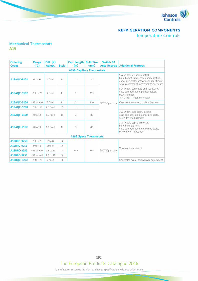
The European Products Catalogue 2016Manufacturer reserves the right to change specifications without prior notice
192
refrigeration componentsTemperature Controls
Mechanical Thermostats A19
Ordering Codes
Range (°C)
Diff. (K) Adjust. Style
Cap. Length (m)
Bulb Size (mm)
Switch 8A Auto Recycle Additional Features
A19A Capillary Thermostats
A19AQC-9101 -5 to +5 2 fixed 1a 2 80
SPDT Open Low
5 A switch, Ice bank control, bulb diam 9.3 mm, case compensation, concealed scale, screwdriver adjustment, scale calibrated at increasing temperature
A19AQC-9102 -5 to +28 2 fixed 1b 2 135
8 A switch, calibrated and set at 2 °C, case compensation, pointer adjust, PG16 connect., ½ - 14 NPT WELL connector
A19AQC-9104 -35 to +10 2 fixed 1b 2 110 Case compensation, knob adjustment
A19AQC-9200 -5 to +55 2.5 fixed 2 --- --- ---
A19AQF-9100 0 to 13 1.5 fixed 1a 2 803 A switch, bulb diam. 9.3 mm, case compensation, concealed scale, screwdriver adjustment
A19AQF-9102 0 to 13 1.5 fixed 1a 3 80
3 A switch, cap. thermostat, bulb diam. 9.3 mm, case compensation, concealed scale, screwdriver adjustment
A19B Space Thermostats
A19BRC-9250 -5 to +28 2 to 8 3
--- --- SPDT Open LowVinyl coated element
A19BRC-9251 0 to 43 2 to 8 3
A19BRC-9252 -35 to +10 2.8 to 11 3
A19BRC-9253 -35 to +40 2.8 to 11 3
A19BQC-9252 -5 to +25 2 fixed 3 Concealed scale, screwdriver adjustment
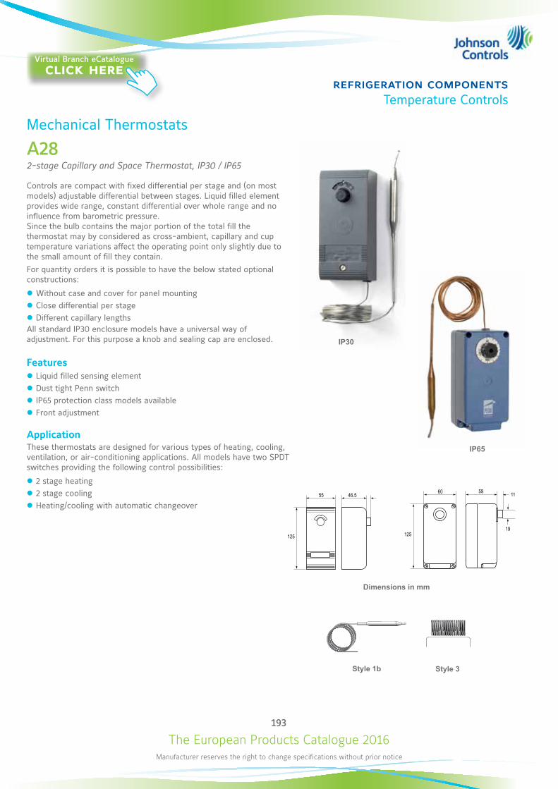
The European Products Catalogue 2016Manufacturer reserves the right to change specifications without prior notice
193
refrigeration componentsTemperature Controls
Dimensions in mm
55
125
46.56
3 2 2 3
1 1
HI LO
» 1» 2
1 2<» »
19125
115960
Mechanical Thermostats
A282-stage Capillary and Space Thermostat, IP30 / IP65
Controls are compact with fixed differential per stage and (on most models) adjustable differential between stages. Liquid filled element provides wide range, constant differential over whole range and no influence from barometric pressure. Since the bulb contains the major portion of the total fill the thermostat may by considered as cross-ambient, capillary and cup temperature variations affect the operating point only slightly due to the small amount of fill they contain.For quantity orders it is possible to have the below stated optional constructions:
z Without case and cover for panel mounting z Close differential per stage z Different capillary lengths
All standard IP30 enclosure models have a universal way of adjustment. For this purpose a knob and sealing cap are enclosed.
Features z Liquid filled sensing element z Dust tight Penn switch z IP65 protection class models available z Front adjustment
ApplicationThese thermostats are designed for various types of heating, cooling, ventilation, or air-conditioning applications. All models have two SPDT switches providing the following control possibilities:
z 2 stage heating z 2 stage cooling z Heating/cooling with automatic changeover
55
125
46.56
3 2 2 3
1 1
HI LO
» 1» 2
1 2<» »
19125
115960
Style 3
55(2.16)
125
(4.92)
46,5(1,83) 6
(0.24)3 2
1
Θ >
Style 1b
IP30
IP65
Virtual Branch eCatalogueclick here
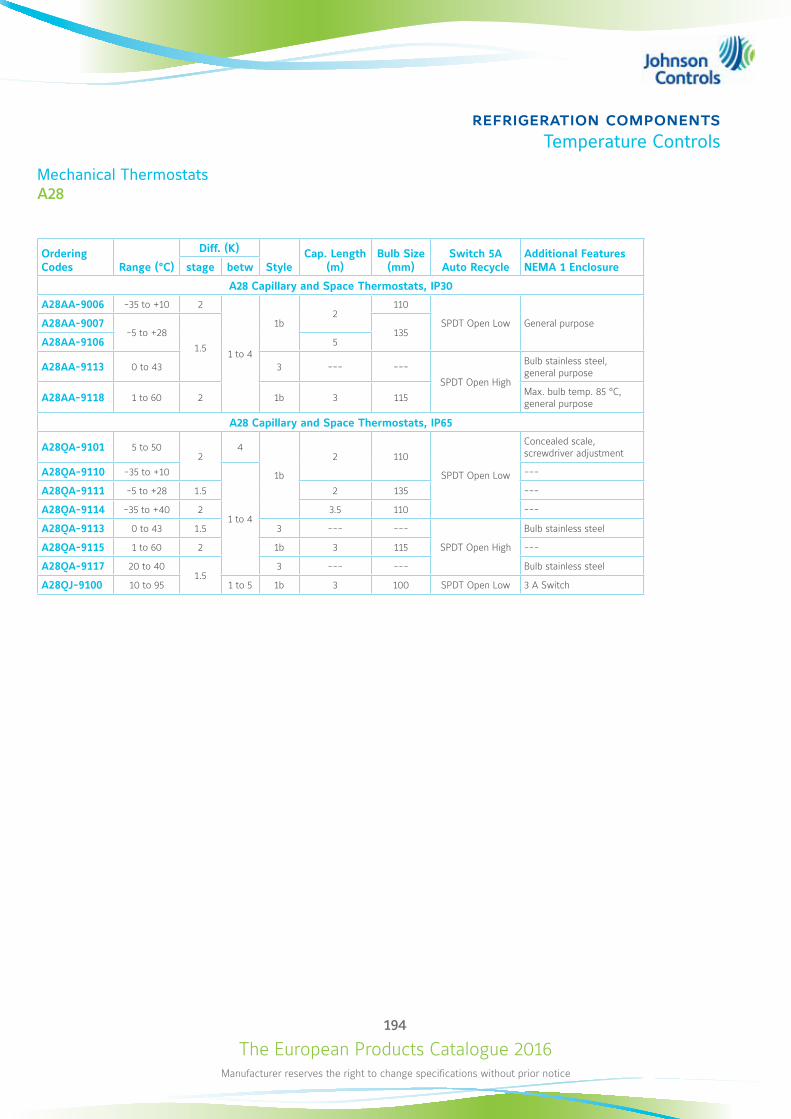
The European Products Catalogue 2016Manufacturer reserves the right to change specifications without prior notice
194
refrigeration componentsTemperature Controls
Mechanical ThermostatsA28
Ordering Codes Range (°C)
Diff. (K)
StyleCap. Length
(m)Bulb Size
(mm)Switch 5A
Auto RecycleAdditional Features NEMA 1 Enclosurestage betw
A28 Capillary and Space Thermostats, IP30
A28AA-9006 -35 to +10 2
1 to 4
1b2
110
SPDT Open Low General purposeA28AA-9007-5 to +28
1.5
135A28AA-9106 5
A28AA-9113 0 to 43 3 --- ---
SPDT Open High
Bulb stainless steel, general purpose
A28AA-9118 1 to 60 2 1b 3 115 Max. bulb temp. 85 °C, general purpose
A28 Capillary and Space Thermostats, IP65
A28QA-9101 5 to 502
4
1b
2 110
SPDT Open Low
Concealed scale, screwdriver adjustment
A28QA-9110 -35 to +10
1 to 4
---
A28QA-9111 -5 to +28 1.5 2 135 ---
A28QA-9114 -35 to +40 2 3.5 110 ---
A28QA-9113 0 to 43 1.5 3 --- ---
SPDT Open High
Bulb stainless steel
A28QA-9115 1 to 60 2 1b 3 115 ---
A28QA-9117 20 to 401.5
3 --- --- Bulb stainless steel
A28QJ-9100 10 to 95 1 to 5 1b 3 100 SPDT Open Low 3 A Switch
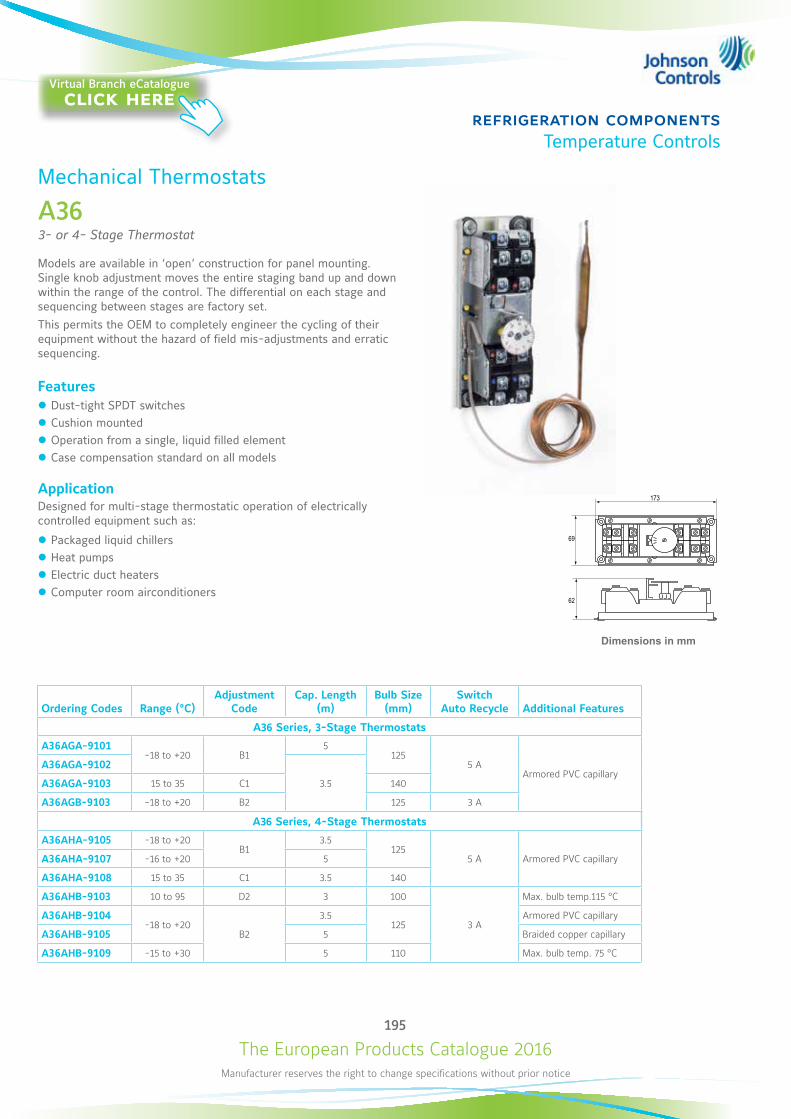
The European Products Catalogue 2016Manufacturer reserves the right to change specifications without prior notice
195
refrigeration componentsTemperature Controls
Mechanical Thermostats
A363- or 4- Stage Thermostat
Models are available in ‘open’ construction for panel mounting. Single knob adjustment moves the entire staging band up and down within the range of the control. The differential on each stage and sequencing between stages are factory set. This permits the OEM to completely engineer the cycling of their equipment without the hazard of field mis-adjustments and erratic sequencing.
Features z Dust-tight SPDT switches z Cushion mounted z Operation from a single, liquid filled element z Case compensation standard on all models
ApplicationDesigned for multi-stage thermostatic operation of electrically controlled equipment such as:
z Packaged liquid chillers z Heat pumps z Electric duct heaters z Computer room airconditioners
Dimensions in mm
1 1
» 1» 2 » 3 » 4
1 2<» » 3< » 4< »
Red Red Red Red
Blue BlueWhite BlueWhite BlueWhite White
69
62
173
Ordering Codes Range (°C)Adjustment
CodeCap. Length
(m)Bulb Size
(mm)Switch
Auto Recycle Additional Features
A36 Series, 3-Stage Thermostats
A36AGA-9101-18 to +20 B1
5125
5 AArmored PVC capillary
A36AGA-9102
3.5A36AGA-9103 15 to 35 C1 140
A36AGB-9103 -18 to +20 B2 125 3 A
A36 Series, 4-Stage Thermostats
A36AHA-9105 -18 to +20B1
3.5125
5 A Armored PVC capillaryA36AHA-9107 -16 to +20 5
A36AHA-9108 15 to 35 C1 3.5 140
A36AHB-9103 10 to 95 D2 3 100
3 A
Max. bulb temp.115 °C
A36AHB-9104-18 to +20
B2
3.5125
Armored PVC capillary
A36AHB-9105 5 Braided copper capillary
A36AHB-9109 -15 to +30 5 110 Max. bulb temp. 75 °C
Virtual Branch eCatalogueclick here
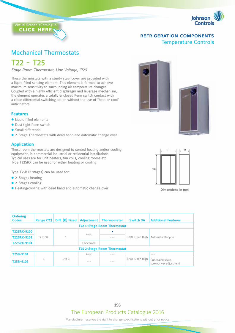
The European Products Catalogue 2016Manufacturer reserves the right to change specifications without prior notice
196
refrigeration componentsTemperature Controls
Mechanical Thermostats
T22 - T25Stage Room Thermostat, Line Voltage, IP20
These thermostats with a sturdy steel cover are provided with a liquid filled sensing element. This element is formed to achieve maximum sensitivity to surrounding air temperature changes. Coupled with a highly efficient diaphragm and leverage mechanism, the element operates a totally enclosed Penn switch contact with a close differential switching action without the use of “heat or cool” anticipators.
Features z Liquid filled elements z Dust tight Penn switch z Small differential z 2-Stage Thermostats with dead band and automatic change over
ApplicationThese room thermostats are designed to control heating and/or cooling equipment, in commercial industrial or residential installations. Typical uses are for unit heaters, fan coils, cooling rooms etc. Type T22SRX can be used for either heating or cooling.
Type T25B (2 stages) can be used for:
z 2-Stages heating z 2-Stages cooling z Heating/cooling with dead band and automatic change over
Ordering Codes Range (°C) Diff. (K) Fixed Adjustment Thermometer Switch 3A Additional Features
T22 1-Stage Room Thermostat
T22SRX-9100
5 to 32 1Knob
SPDT Open High Automatic RecycleT22SRX-9101 ---
T22SRX-9104 Concealed ---
T25 2-Stage Room Thermostat
T25B-91011 1 to 3
Knob ---
SPDT Open High
---
T25B-9102 --- --- Concealed scale, screwdriver adjustment
Dimensions in mm
133
71 49
2 3 2 3
1 1
HI LO
» 1» 2
3 2
1
»
1 2<» »
Virtual Branch eCatalogueclick here
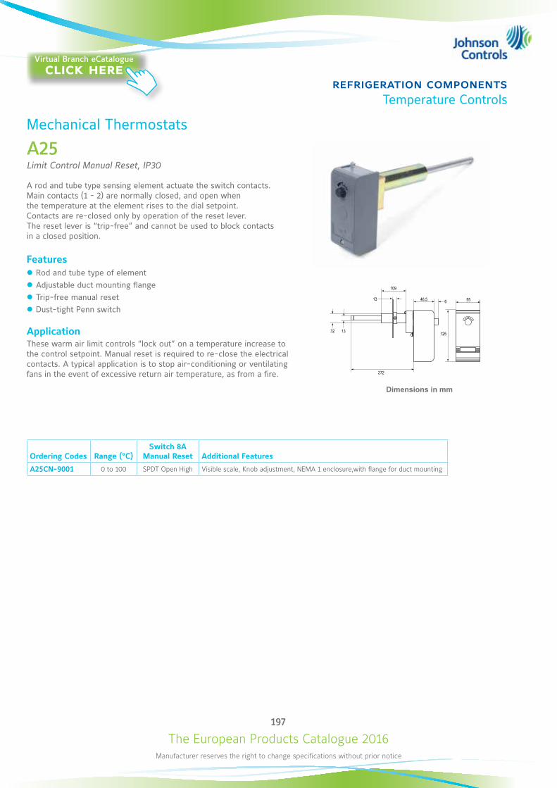
The European Products Catalogue 2016Manufacturer reserves the right to change specifications without prior notice
197
refrigeration componentsTemperature Controls
Ordering Codes Range (°C)Switch 8A
Manual Reset Additional Features
A25CN-9001 0 to 100 SPDT Open High Visible scale, Knob adjustment, NEMA 1 enclosure,with flange for duct mounting
Dimensions in mm
272
32 13
13 6
109
46.5 55
125
2 3
1
»
Mechanical Thermostats
A25Limit Control Manual Reset, IP30
A rod and tube type sensing element actuate the switch contacts. Main contacts (1 - 2) are normally closed, and open when the temperature at the element rises to the dial setpoint. Contacts are re-closed only by operation of the reset lever. The reset lever is “trip-free” and cannot be used to block contacts in a closed position.
Features z Rod and tube type of element z Adjustable duct mounting flange z Trip-free manual reset z Dust-tight Penn switch
ApplicationThese warm air limit controls “lock out” on a temperature increase to the control setpoint. Manual reset is required to re-close the electrical contacts. A typical application is to stop air-conditioning or ventilating fans in the event of excessive return air temperature, as from a fire.
Virtual Branch eCatalogueclick here
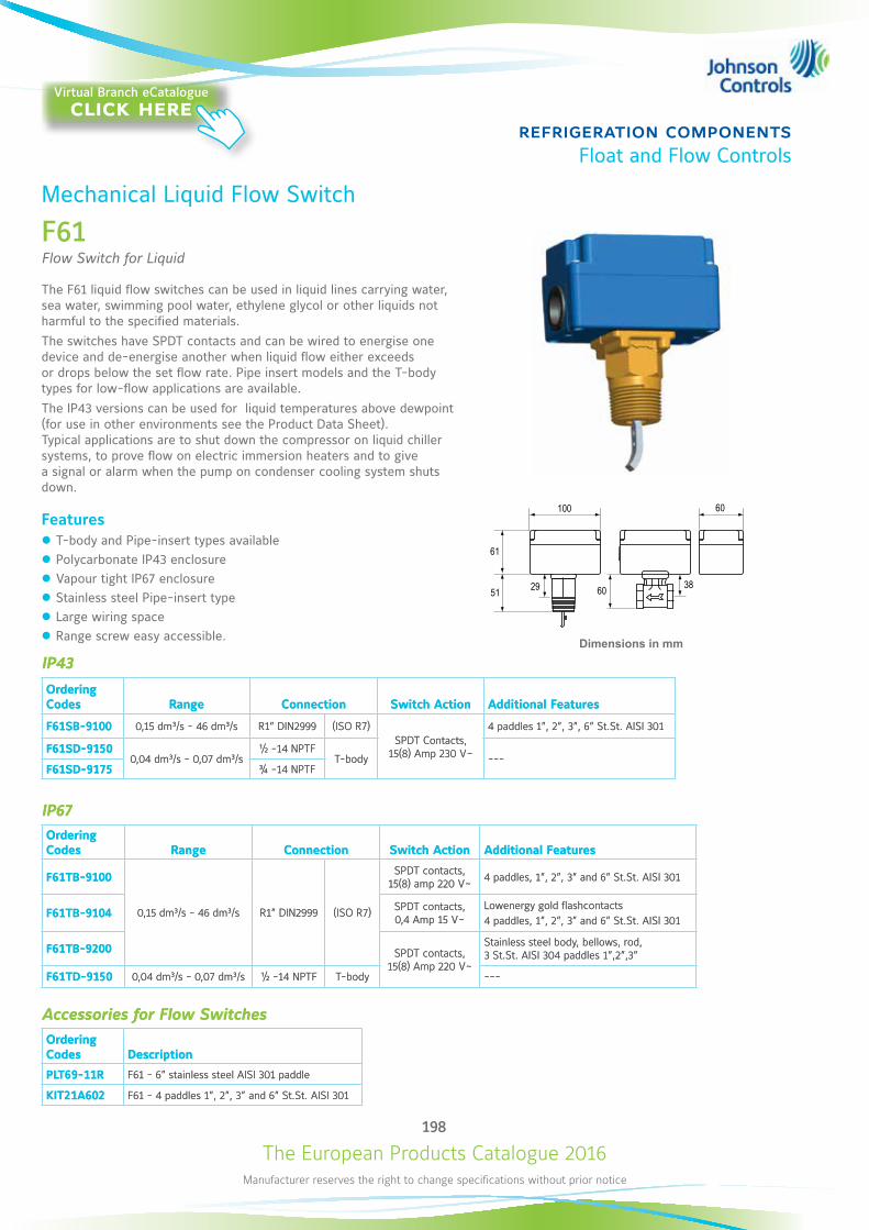
The European Products Catalogue 2016Manufacturer reserves the right to change specifications without prior notice
198
refrigeration componentsFloat and Flow Controls
Mechanical Liquid Flow Switch
F61Flow Switch for Liquid
The F61 liquid flow switches can be used in liquid lines carrying water, sea water, swimming pool water, ethylene glycol or other liquids not harmful to the specified materials. The switches have SPDT contacts and can be wired to energise one device and de-energise another when liquid flow either exceeds or drops below the set flow rate. Pipe insert models and the T-body types for low-flow applications are available. The IP43 versions can be used for liquid temperatures above dewpoint (for use in other environments see the Product Data Sheet). Typical applications are to shut down the compressor on liquid chiller systems, to prove flow on electric immersion heaters and to give a signal or alarm when the pump on condenser cooling system shuts down.
Features z T-body and Pipe-insert types available z Polycarbonate IP43 enclosure z Vapour tight IP67 enclosure z Stainless steel Pipe-insert type z Large wiring space z Range screw easy accessible.
IP43
Ordering Codes Range Connection Switch Action Additional Features
F61SB-9100 0,15 dm³/s - 46 dm³/s R1” DIN2999 (ISO R7)SPDT Contacts,
15(8) Amp 230 V~
4 paddles 1”, 2”, 3”, 6” St.St. AISI 301
F61SD-91500,04 dm³/s - 0,07 dm³/s
½ -14 NPTFT-body ---
F61SD-9175 ¾ -14 NPTF
IP67Ordering Codes Range Connection Switch Action Additional Features
F61TB-9100
0,15 dm³/s - 46 dm³/s R1” DIN2999 (ISO R7)
SPDT contacts, 15(8) amp 220 V~ 4 paddles, 1”, 2”, 3” and 6” St.St. AISI 301
F61TB-9104 SPDT contacts, 0,4 Amp 15 V~
Lowenergy gold flashcontacts4 paddles, 1”, 2”, 3” and 6” St.St. AISI 301
F61TB-9200 SPDT contacts, 15(8) Amp 220 V~
Stainless steel body, bellows, rod, 3 St.St. AISI 304 paddles 1”,2”,3”
F61TD-9150 0,04 dm³/s - 0,07 dm³/s ½ -14 NPTF T-body ---
Accessories for Flow SwitchesOrdering Codes Description
PLT69-11R F61 - 6” stainless steel AISI 301 paddle
KIT21A602 F61 - 4 paddles 1”, 2”, 3” and 6” St.St. AISI 301
Dimensions in mm
60 38
100 60
51
61
29
IP43
Ordering Codes Range Connection Switch Action Additional Features
F61SB-9100 0,15 dm³/s - 46 dm³/s R1” DIN2999 (ISO R7)SPDT Contacts,
15(8) Amp 230 V~
4 paddles 1”, 2”, 3”, 6” St.St. AISI 301
F61SD-91500,04 dm³/s - 0,07 dm³/s
½ -14 NPTFT-body ---
F61SD-9175 ¾ -14 NPTF
IP67Ordering Codes Range Connection Switch Action Additional Features
F61TB-9100
0,15 dm³/s - 46 dm³/s R1” DIN2999 (ISO R7)
SPDT contacts, 15(8) amp 220 V~ 4 paddles, 1”, 2”, 3” and 6” St.St. AISI 301
F61TB-9104 SPDT contacts, 0,4 Amp 15 V~
Lowenergy gold flashcontacts4 paddles, 1”, 2”, 3” and 6” St.St. AISI 301
F61TB-9200 SPDT contacts, 15(8) Amp 220 V~
Stainless steel body, bellows, rod, 3 St.St. AISI 304 paddles 1”,2”,3”
F61TD-9150 0,04 dm³/s - 0,07 dm³/s ½ -14 NPTF T-body ---
Accessories for Flow SwitchesOrdering Codes Description
PLT69-11R F61 - 6” stainless steel AISI 301 paddle
KIT21A602 F61 - 4 paddles 1”, 2”, 3” and 6” St.St. AISI 301
Virtual Branch eCatalogueclick here
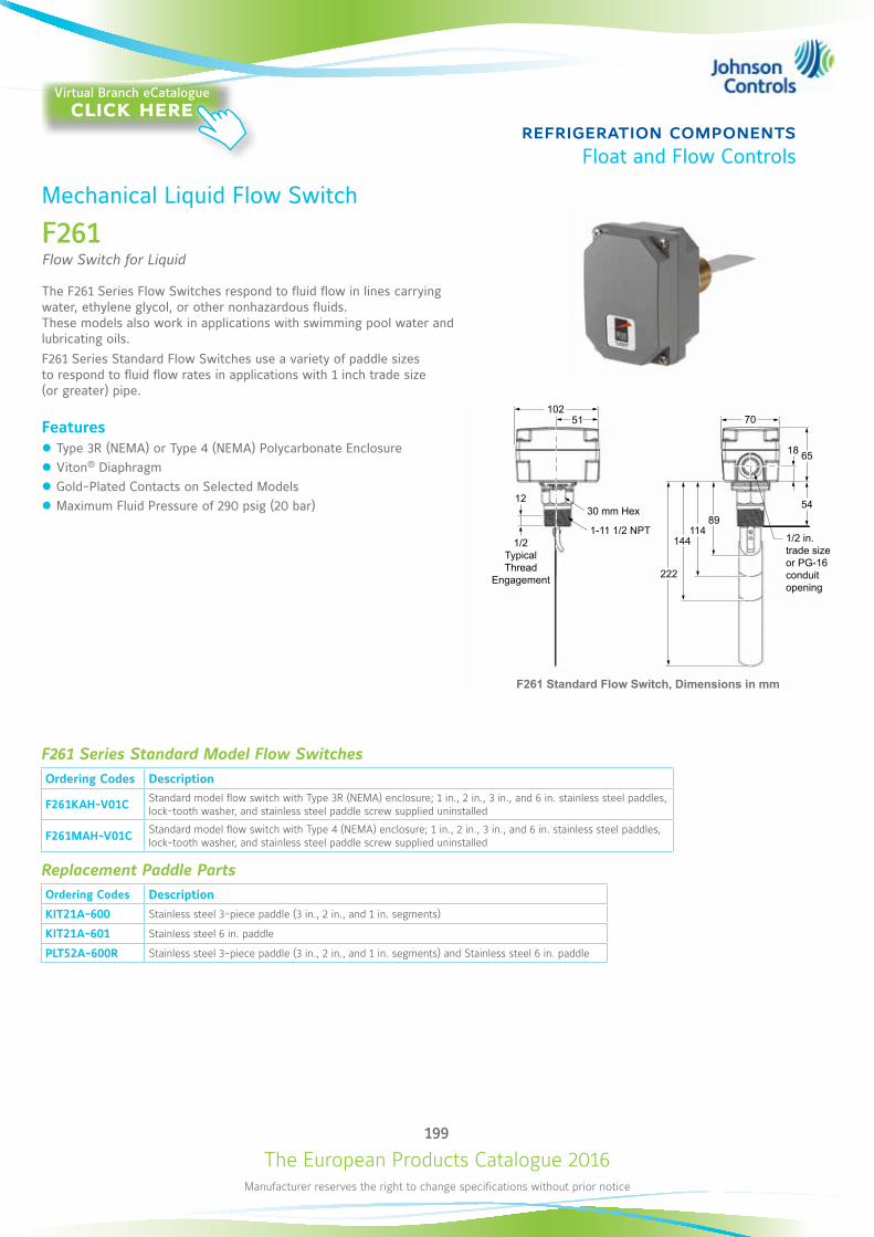
The European Products Catalogue 2016Manufacturer reserves the right to change specifications without prior notice
199
refrigeration componentsFloat and Flow Controls
Mechanical Liquid Flow Switch
F261Flow Switch for Liquid
The F261 Series Flow Switches respond to fluid flow in lines carrying water, ethylene glycol, or other nonhazardous fluids. These models also work in applications with swimming pool water and lubricating oils.F261 Series Standard Flow Switches use a variety of paddle sizes to respond to fluid flow rates in applications with 1 inch trade size (or greater) pipe.
Features z Type 3R (NEMA) or Type 4 (NEMA) Polycarbonate Enclosure z Viton® Diaphragm z Gold-Plated Contacts on Selected Models z Maximum Fluid Pressure of 290 psig (20 bar)
F261 Series Standard Model Flow SwitchesOrdering Codes Description
F261KAH-V01C Standard model flow switch with Type 3R (NEMA) enclosure; 1 in., 2 in., 3 in., and 6 in. stainless steel paddles, lock-tooth washer, and stainless steel paddle screw supplied uninstalled
F261MAH-V01C Standard model flow switch with Type 4 (NEMA) enclosure; 1 in., 2 in., 3 in., and 6 in. stainless steel paddles, lock-tooth washer, and stainless steel paddle screw supplied uninstalled
Replacement Paddle PartsOrdering Codes Description
KIT21A-600 Stainless steel 3-piece paddle (3 in., 2 in., and 1 in. segments)
KIT21A-601 Stainless steel 6 in. paddle
PLT52A-600R Stainless steel 3-piece paddle (3 in., 2 in., and 1 in. segments) and Stainless steel 6 in. paddle
51102
1230 mm Hex
1-11 1/2 NPT
70
18 65
54
222
144114
89
51102
5929 19
38
70
6518
39
F261 Standard Flow Switch, Dimensions in mm
1/2 in.trade sizeor PG-16 conduit opening
1/2TypicalThread
Engagement
Virtual Branch eCatalogueclick here
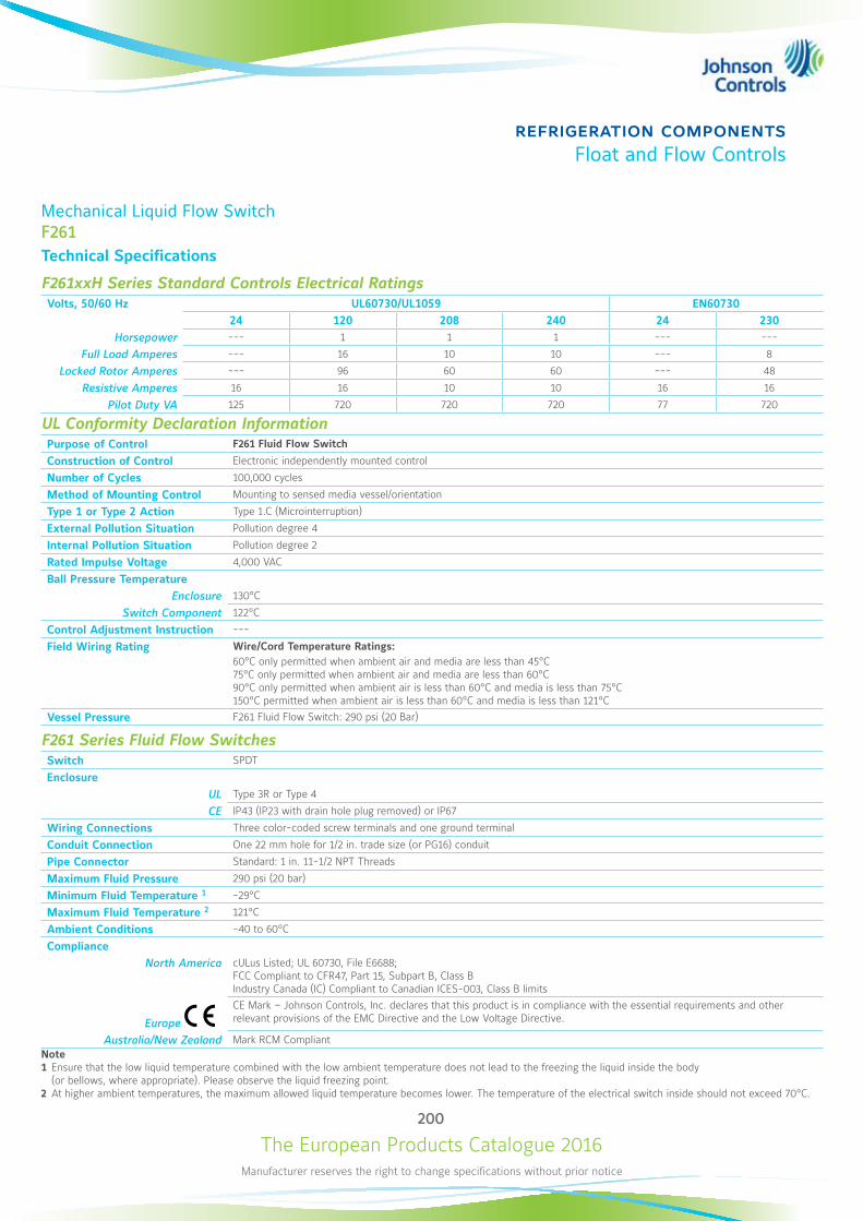
The European Products Catalogue 2016Manufacturer reserves the right to change specifications without prior notice
200
refrigeration componentsFloat and Flow Controls
Mechanical Liquid Flow SwitchF261Technical Specifications
F261xxH Series Standard Controls Electrical RatingsVolts, 50/60 Hz UL60730/UL1059 EN60730
24 120 208 240 24 230Horsepower --- 1 1 1 --- ---
Full Load Amperes --- 16 10 10 --- 8
Locked Rotor Amperes --- 96 60 60 --- 48
Resistive Amperes 16 16 10 10 16 16
Pilot Duty VA 125 720 720 720 77 720
UL Conformity Declaration InformationPurpose of Control F261 Fluid Flow Switch
Construction of Control Electronic independently mounted control
Number of Cycles 100,000 cycles
Method of Mounting Control Mounting to sensed media vessel/orientation
Type 1 or Type 2 Action Type 1.C (Microinterruption)
External Pollution Situation Pollution degree 4
Internal Pollution Situation Pollution degree 2
Rated Impulse Voltage 4,000 VAC
Ball Pressure Temperature Enclosure 130°C
Switch Component 122°C
Control Adjustment Instruction ---
Field Wiring Rating Wire/Cord Temperature Ratings: 60°C only permitted when ambient air and media are less than 45°C 75°C only permitted when ambient air and media are less than 60°C 90°C only permitted when ambient air is less than 60°C and media is less than 75°C 150°C permitted when ambient air is less than 60°C and media is less than 121°C
Vessel Pressure F261 Fluid Flow Switch: 290 psi (20 Bar)
F261 Series Fluid Flow SwitchesSwitch SPDT
Enclosure UL Type 3R or Type 4
CE IP43 (IP23 with drain hole plug removed) or IP67
Wiring Connections Three color-coded screw terminals and one ground terminal
Conduit Connection One 22 mm hole for 1/2 in. trade size (or PG16) conduit
Pipe Connector Standard: 1 in. 11-1/2 NPT Threads
Maximum Fluid Pressure 290 psi (20 bar)
Minimum Fluid Temperature 1 -29°C
Maximum Fluid Temperature 2 121°C
Ambient Conditions -40 to 60°C
ComplianceNorth America cULus Listed; UL 60730, File E6688;
FCC Compliant to CFR47, Part 15, Subpart B, Class B Industry Canada (IC) Compliant to Canadian ICES-003, Class B limits
Europe
CE Mark – Johnson Controls, Inc. declares that this product is in compliance with the essential requirements and other relevant provisions of the EMC Directive and the Low Voltage Directive.
Australia/New Zealand Mark RCM CompliantNote1 Ensure that the low liquid temperature combined with the low ambient temperature does not lead to the freezing the liquid inside the body (or bellows, where appropriate). Please observe the liquid freezing point.2 At higher ambient temperatures, the maximum allowed liquid temperature becomes lower. The temperature of the electrical switch inside should not exceed 70°C.
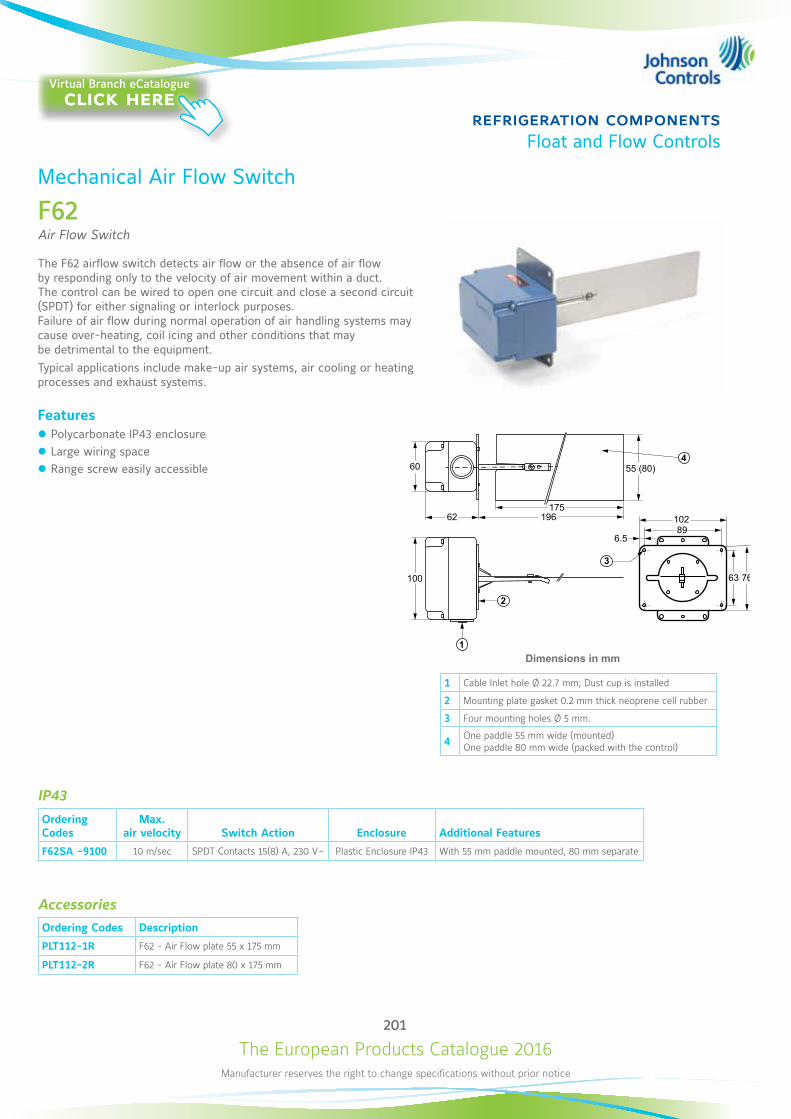
The European Products Catalogue 2016Manufacturer reserves the right to change specifications without prior notice
201
refrigeration componentsFloat and Flow Controls
IP43
Ordering Codes
Max. air velocity Switch Action Enclosure Additional Features
F62SA –9100 10 m/sec SPDT Contacts 15(8) A, 230 V~ Plastic Enclosure IP43 With 55 mm paddle mounted, 80 mm separate
AccessoriesOrdering Codes Description
PLT112-1R F62 - Air Flow plate 55 x 175 mm
PLT112-2R F62 - Air Flow plate 80 x 175 mm
Dimensions in mm
60
62175
196
2
55 (80)
6.5
10289
63 76100
1
3
4
Mechanical Air Flow Switch
F62Air Flow Switch
The F62 airflow switch detects air flow or the absence of air flow by responding only to the velocity of air movement within a duct. The control can be wired to open one circuit and close a second circuit (SPDT) for either signaling or interlock purposes. Failure of air flow during normal operation of air handling systems may cause over-heating, coil icing and other conditions that may be detrimental to the equipment.Typical applications include make-up air systems, air cooling or heating processes and exhaust systems.
Features z Polycarbonate IP43 enclosure z Large wiring space z Range screw easily accessible
1 Cable Inlet hole Ø 22.7 mm; Dust cup is installed
2 Mounting plate gasket 0.2 mm thick neoprene cell rubber
3 Four mounting holes Ø 5 mm.
4 One paddle 55 mm wide (mounted) One paddle 80 mm wide (packed with the control)
Virtual Branch eCatalogueclick here
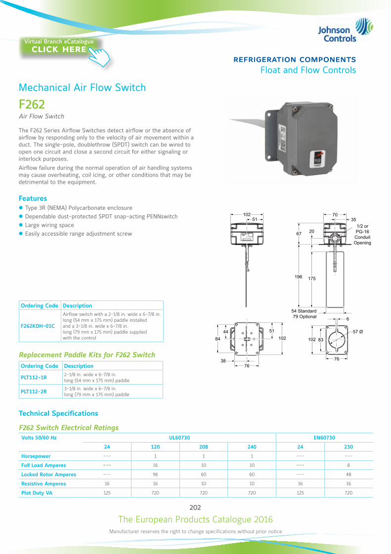
The European Products Catalogue 2016Manufacturer reserves the right to change specifications without prior notice
202
refrigeration componentsFloat and Flow Controls
Mechanical Air Flow Switch
F262Air Flow Switch
The F262 Series Airflow Switches detect airflow or the absence of airflow by responding only to the velocity of air movement within a duct. The single-pole, doublethrow (SPDT) switch can be wired to open one circuit and close a second circuit for either signaling or interlock purposes.Airflow failure during the normal operation of air handling systems may cause overheating, coil icing, or other conditions that may be detrimental to the equipment.
Features z Type 3R (NEMA) Polycarbonate enclosure z Dependable dust-protected SPDT snap-acting PENNswitch z Large wiring space z Easily accessible range adjustment screw
Ordering Code Description
F262KDH-01C
Airflow switch with a 2-1/8 in. wide x 6-7/8 in. long (54 mm x 175 mm) paddle installed and a 3-1/8 in. wide x 6-7/8 in. long (79 mm x 175 mm) paddle supplied with the control
Replacement Paddle Kits for F262 SwitchOrdering Code Description
PLT112-1R 2-1/8 in. wide x 6-7/8 in. long (54 mm x 175 mm) paddle
PLT112-2R 3-1/8 in. wide x 6-7/8 in. long (79 mm x 175 mm) paddle
Technical Specifications
F262 Switch Electrical RatingsVolts 50/60 Hz UL60730 EN60730
24 120 208 240 24 230
Horsepower –-- 1 1 1 –-- –--
Full Load Amperes –-- 16 10 10 –-- 8
Locked Rotor Amperes –-- 96 60 60 –-- 48
Resistive Amperes 16 16 10 10 16 16
Plot Duty VA 125 720 720 720 125 720
51102 70
35
67 20
196 175
6
76
8310210251
7638
8444 57 Ø
1/2 orPG-16ConduitOpening
54 Standard79 Optional
Virtual Branch eCatalogueclick here
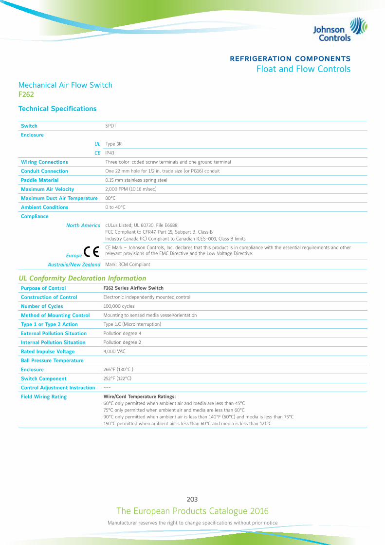
The European Products Catalogue 2016Manufacturer reserves the right to change specifications without prior notice
203
refrigeration componentsFloat and Flow Controls
Mechanical Air Flow SwitchF262
Technical Specifications
Switch SPDT
Enclosure
UL Type 3R
CE IP43
Wiring Connections Three color-coded screw terminals and one ground terminal
Conduit Connection One 22 mm hole for 1/2 in. trade size (or PG16) conduit
Paddle Material 0.15 mm stainless spring steel
Maximum Air Velocity 2,000 FPM (10.16 m/sec)
Maximum Duct Air Temperature 80°C
Ambient Conditions 0 to 40°C
Compliance
North America cULus Listed; UL 60730, File E6688; FCC Compliant to CFR47, Part 15, Subpart B, Class B Industry Canada (IC) Compliant to Canadian ICES-003, Class B limits
Europe
CE Mark – Johnson Controls, Inc. declares that this product is in compliance with the essential requirements and other relevant provisions of the EMC Directive and the Low Voltage Directive.
Australia/New Zealand Mark: RCM Compliant
UL Conformity Declaration InformationPurpose of Control F262 Series Airflow Switch
Construction of Control Electronic independently mounted control
Number of Cycles 100,000 cycles
Method of Mounting Control Mounting to sensed media vessel/orientation
Type 1 or Type 2 Action Type 1.C (Microinterruption)
External Pollution Situation Pollution degree 4
Internal Pollution Situation Pollution degree 2
Rated Impulse Voltage 4,000 VAC
Ball Pressure Temperature
Enclosure 266°F (130°C )
Switch Component 252°F (122°C)
Control Adjustment Instruction ---
Field Wiring Rating Wire/Cord Temperature Ratings: 60°C only permitted when ambient air and media are less than 45°C75°C only permitted when ambient air and media are less than 60°C90°C only permitted when ambient air is less than 140°F (60°C) and media is less than 75°C150°C permitted when ambient air is less than 60°C and media is less than 121°C
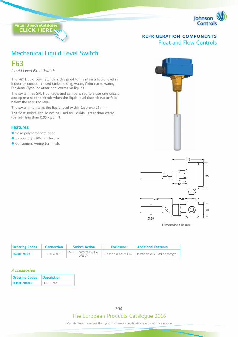
The European Products Catalogue 2016Manufacturer reserves the right to change specifications without prior notice
204
refrigeration componentsFloat and Flow Controls
Mechanical Liquid Level Switch
F63Liquid Level Float Switch
The F63 Liquid Level Switch is designed to maintain a liquid level in indoor or outdoor closed tanks holding water, Chlorinated water, Ethylene Glycol or other non-corrosive liquids.The switch has SPDT contacts and can be wired to close one circuit and open a second circuit when the liquid level rises above or falls below the required level. The switch maintains the liquid level within (approx.) 13 mm. The float switch should not be used for liquids lighter than water (density less than 0.95 kg/dm3).
Features z Solid polycarbonate float z Vapour tight IP67 enclosure z Convenient wiring terminals
Ordering Codes Connection Switch Action Enclosure Additional Features
F63BT-9102 1-11½ NPT SPDT Contacts 15(8) A, 230 V~ Plastic enclosure IP67 Plastic float, VITON diaphragm
Accessories
Ordering Codes Description
FLT001N001R F63 - Float
Dimensions in mm
115
55
100
60
29 17215
Ø 25
Virtual Branch eCatalogueclick here
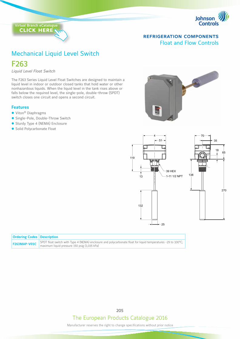
The European Products Catalogue 2016Manufacturer reserves the right to change specifications without prior notice
205
refrigeration componentsFloat and Flow Controls
Mechanical Liquid Level Switch
F263Liquid Level Float Switch
The F263 Series Liquid Level Float Switches are designed to maintain a liquid level in indoor or outdoor closed tanks that hold water or other nonhazardous liquids. When the liquid level in the tank rises above or falls below the required level, the single-pole, double-throw (SPDT) switch closes one circuit and opens a second circuit.
Features z Viton® Diaphragms z Single-Pole, Double-Throw Switch z Sturdy Type 4 (NEMA) Enclosure z Solid Polycarbonate Float
Ordering Codes Description
F263MAP-V01C SPDT float switch with Type 4 (NEMA) enclosure and polycarbonate float for liquid temperatures -29 to 100°C; maximum liquid pressure 150 psig (1,035 kPa)
13
39 HEX
1-11 1/2 NPT
25
132
119
51
4
138
270
6518
35
70
Virtual Branch eCatalogueclick here
The European Products Catalogue 2016Manufacturer reserves the right to change specifications without prior notice
206
refrigeration componentsFloat and Flow Controls
Mechanical Liquid Level SwitchF263
Technical Specifications
F263 Switch Electrical RatingsVolts 50/60 Hz UL60730 EN60730
24 120 208 240 24 230
Horsepower –-- 1 1 1 –-- –--
Full Load Amperes –-- 16 10 10 –-- 8
Locked Rotor Amperes –-- 96 60 60 –-- 48
Resistive Amperes 16 16 10 10 16 16
Plot Duty VA 125 720 720 720 125 720
Switch Single-Pole, Double-Throw (SPDT)
Enclosure
UL Type 4 (NEMA)
CE IP67
Wiring Connections Three color-coded screw terminals and one ground terminal
Conduit Connection One 22 mm hole for 1/2 in. trade size (or PG16) conduit
Pipe Connector 1 in. 11-1/2 NPT threads
Minimum Tank Diameter 229 mm
Maximum Liquid Pressure 150 psig (1,035 kPa)
Liquid Temperature Range
Minimum -29°C or liquid freezing point
Maximum 100°C
Ambient Conditions
Minimum -40°C
Maximum 60°C
Compliance
North America cULus Listed; UL 60730, File E6688; FCC Compliant to CFR47, Part 15, Subpart B, Class B Industry Canada (IC) Compliant to Canadian ICES-003, Class B limits
Europe
CE Mark – Johnson Controls, Inc. declares that this product is in compliance with the essential requirements and other relevant provisions of the EMC Directive and the Low Voltage Directive.
Australia/New Zealand Mark RCM Compliant
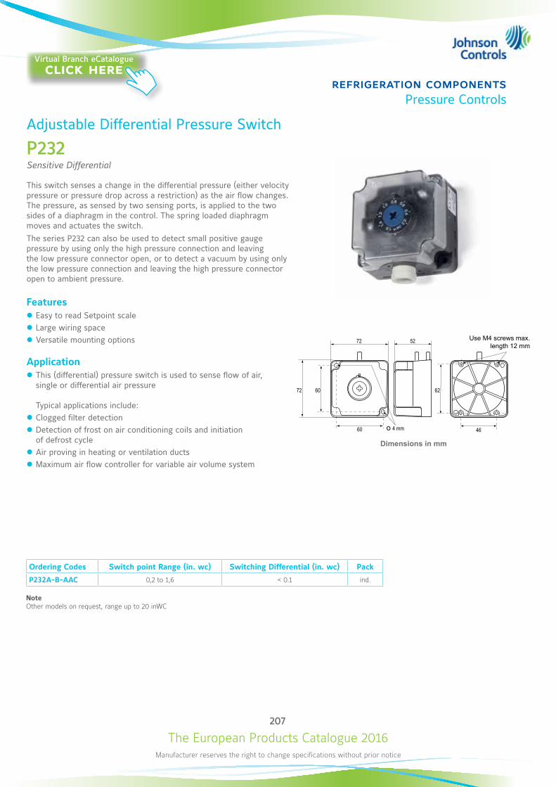
The European Products Catalogue 2016Manufacturer reserves the right to change specifications without prior notice
207
refrigeration componentsPressure Controls
Adjustable Differential Pressure Switch
P232Sensitive Differential
This switch senses a change in the differential pressure (either velocity pressure or pressure drop across a restriction) as the air flow changes. The pressure, as sensed by two sensing ports, is applied to the two sides of a diaphragm in the control. The spring loaded diaphragm moves and actuates the switch. The series P232 can also be used to detect small positive gauge pressure by using only the high pressure connection and leaving the low pressure connector open, or to detect a vacuum by using only the low pressure connection and leaving the high pressure connector open to ambient pressure.
Features z Easy to read Setpoint scale z Large wiring space z Versatile mounting options
Application z This (differential) pressure switch is used to sense flow of air, single or differential air pressure Typical applications include:
z Clogged filter detection z Detection of frost on air conditioning coils and initiation of defrost cycle
z Air proving in heating or ventilation ducts z Maximum air flow controller for variable air volume system
Dimensions in mm
72 60 62
60 46
5272
o 4 mm
Ordering Codes Switch point Range (in. wc) Switching Differential (in. wc) Pack
P232A-B-AAC 0,2 to 1,6 < 0.1 ind.
NoteOther models on request, range up to 20 inWC
Use M4 screws max.length 12 mm
Virtual Branch eCatalogueclick here
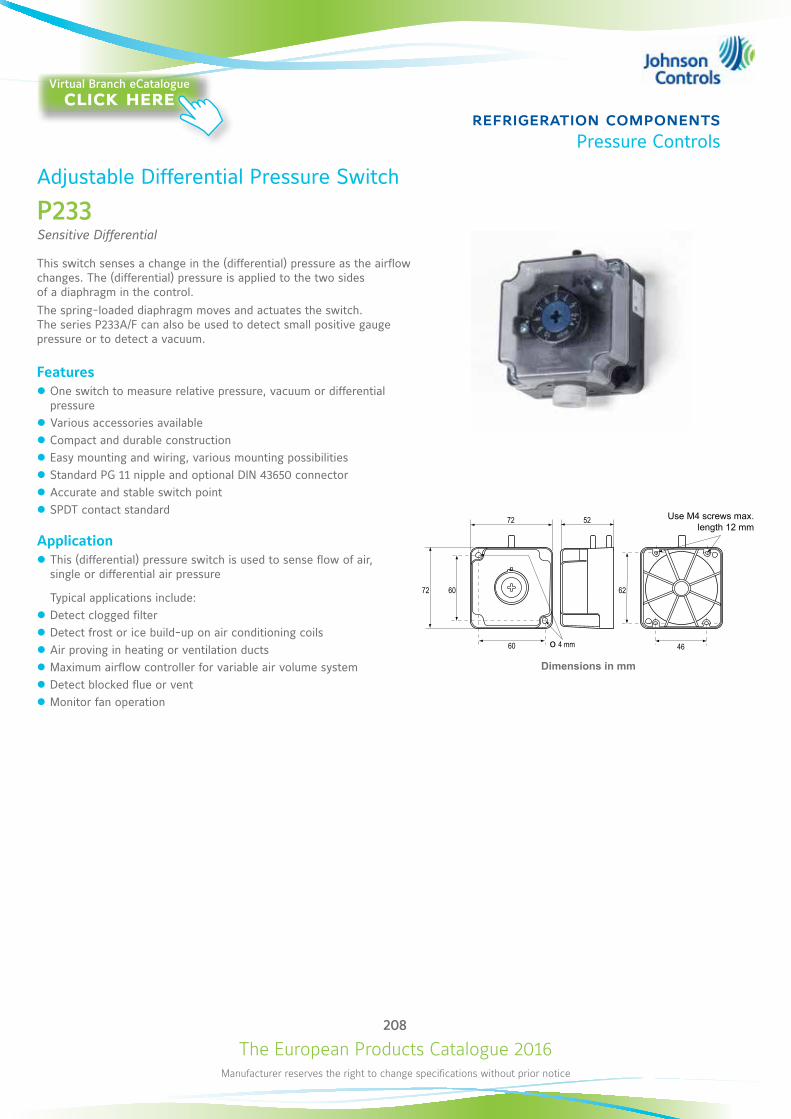
The European Products Catalogue 2016Manufacturer reserves the right to change specifications without prior notice
208
refrigeration componentsPressure Controls
Adjustable Differential Pressure Switch
P233Sensitive Differential
This switch senses a change in the (differential) pressure as the airflow changes. The (differential) pressure is applied to the two sides of a diaphragm in the control. The spring-loaded diaphragm moves and actuates the switch. The series P233A/F can also be used to detect small positive gauge pressure or to detect a vacuum.
Features z One switch to measure relative pressure, vacuum or differential pressure
z Various accessories available z Compact and durable construction z Easy mounting and wiring, various mounting possibilities z Standard PG 11 nipple and optional DIN 43650 connector z Accurate and stable switch point z SPDT contact standard
Application z This (differential) pressure switch is used to sense flow of air, single or differential air pressure Typical applications include:
z Detect clogged filter z Detect frost or ice build-up on air conditioning coils z Air proving in heating or ventilation ducts z Maximum airflow controller for variable air volume system z Detect blocked flue or vent z Monitor fan operation
Dimensions in mm
72 60 62
60 46
5272
o 4 mm
Use M4 screws max.length 12 mm
Virtual Branch eCatalogueclick here
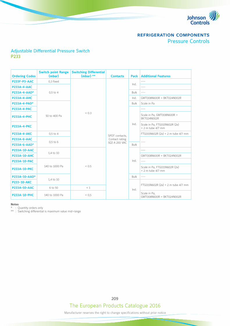
The European Products Catalogue 2016Manufacturer reserves the right to change specifications without prior notice
209
refrigeration componentsPressure Controls
Adjustable Differential Pressure SwitchP233
Ordering CodesSwitch point Range
(mbar)Switching Differential
(mbar) ** Contacts Pack Additional Features
P233F-P3-AAC 0,3 fixed
< 0.3
SPDT contacts, Contact rating 5(2) A 250 VAC
Ind.---
P233A-4-AAC
0,5 to 4
---
P233A-4-AAD* Bulk ---
P233A-4-AHC Ind. GMT008N600R + BKT024N002R
P233A-4-PAD*
50 to 400 Pa
Bulk Scale in Pa
P233A-4-PAC
Ind.
---
P233A-4-PHC Scale in Pa, GMT008N600R + BKT024N002R
P233A-4-PKC Scale in Pa, FTG015N602R (2x) + 2 m tube 4/7 mm
P233A-4-AKC 0,5 to 4 FTG015N602R (2x) + 2 m tube 4/7 mm
P233A-6-AAC0,5 to 6 ---
P233A-6-AAD* Bulk
P233A-10-AAC1,4 to 10
< 0.5
Ind.
---
P233A-10-AHC GMT008N600R + BKT024N002R
P233A-10-PAC
140 to 1000 Pa
---
P233A-10-PKC Scale in Pa, FTG015N602R (2x) + 2 m tube 4/7 mm
P233A-10-AAD*1,4 to 10
Bulk ---
P233-10-AKC
Ind.
FTG015N602R (2x) + 2 m tube 4/7 mmP233A-50-AAC 6 to 50 < 1
P233A-10-PHC 140 to 1000 Pa < 0,5 Scale in Pa, GMT008N600R + BKT024N002R
Notes * : Quantity orders only** : Switching differential is maximum value mid-range
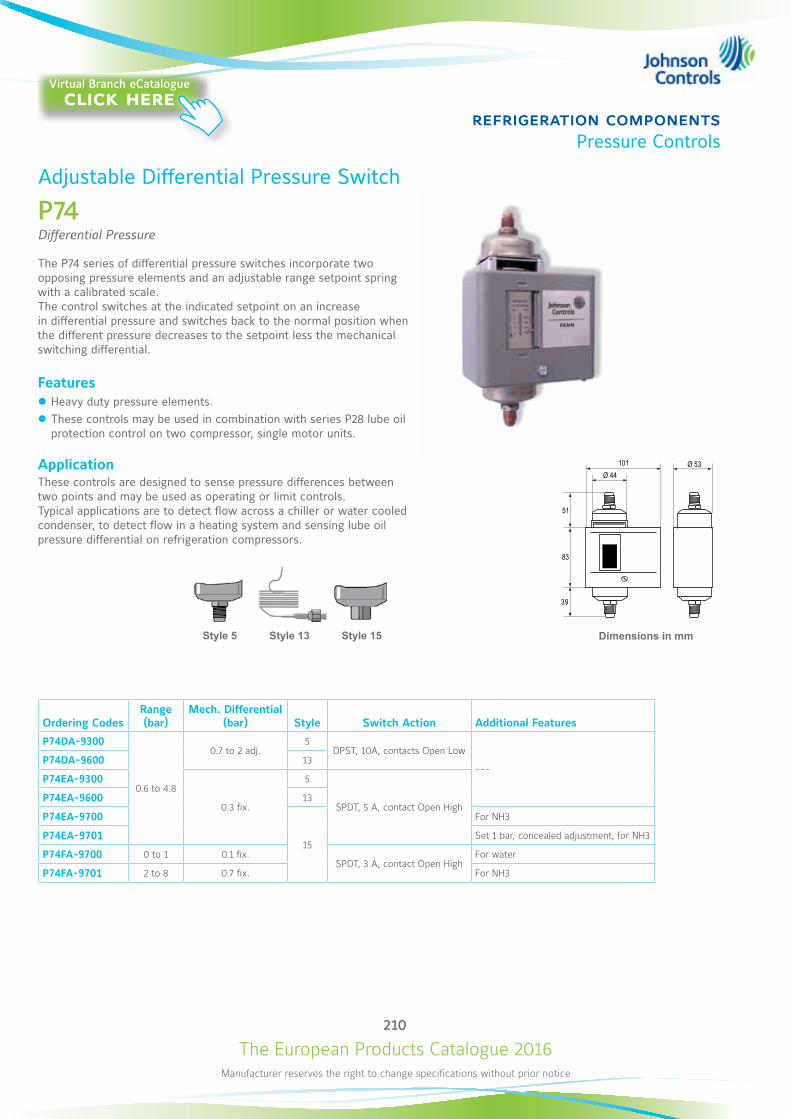
The European Products Catalogue 2016Manufacturer reserves the right to change specifications without prior notice
210
refrigeration componentsPressure Controls
Ordering CodesRange (bar)
Mech. Differential (bar) Style Switch Action Additional Features
P74DA-9300
0.6 to 4.8
0.7 to 2 adj.5
DPST, 10A, contacts Open Low
---P74DA-9600 13
P74EA-9300
0.3 fix.
5
SPDT, 5 A, contact Open HighP74EA-9600 13
P74EA-9700
15
For NH3
P74EA-9701 Set 1 bar, concealed adjustment, for NH3
P74FA-9700 0 to 1 0.1 fix.SPDT, 3 A, contact Open High
For water
P74FA-9701 2 to 8 0.7 fix. For NH3
Dimensions in mm
83
39
51
101 Ø 44
Ø 53
? Ò
3 2
1
? Ò
L2
M3
L1
M1
Adjustable Differential Pressure Switch
P74Differential Pressure
The P74 series of differential pressure switches incorporate two opposing pressure elements and an adjustable range setpoint spring with a calibrated scale. The control switches at the indicated setpoint on an increase in differential pressure and switches back to the normal position when the different pressure decreases to the setpoint less the mechanical switching differential.
Features z Heavy duty pressure elements. z These controls may be used in combination with series P28 lube oil protection control on two compressor, single motor units.
ApplicationThese controls are designed to sense pressure differences between two points and may be used as operating or limit controls. Typical applications are to detect flow across a chiller or water cooled condenser, to detect flow in a heating system and sensing lube oil pressure differential on refrigeration compressors.
Style 5 Style 15Style 13
Virtual Branch eCatalogueclick here

The European Products Catalogue 2016Manufacturer reserves the right to change specifications without prior notice
211
refrigeration componentsPressure Controls
Adjustable Pressure Switch
P20For Air-Conditioning and Heat Pump Applications
The P20 series high and low limit (cut-out) controls for all non-corrosive refrigerants are compact pressure controls ideally suited for commercial or residential packaged air conditioning units, heat pumps, small water chillers, ice cube machines and other applications where a semi fixed setting is acceptable or required and where mounting space is limited. The P20 series includes auto reset as well as manual reset models and is factory set. A special setting tool is available while also field (screwdriver) adjustable models can be chosen.
Features z Field proven reliability z Reset tab must be released before restart (Trip free manual reset)
z Compact design z Enclosed dust-tight switch z SPDT contact with special terminals z Test pressure 53 bar z Designed for at least 300000 cycles
Dimensions in mm
3 2
1
Ò
3 2
1
Ò
26 17.5
37
6719
85
56
Style 13 Style 45AStyle 34 Style 50Style 35
Virtual Branch eCatalogueclick here
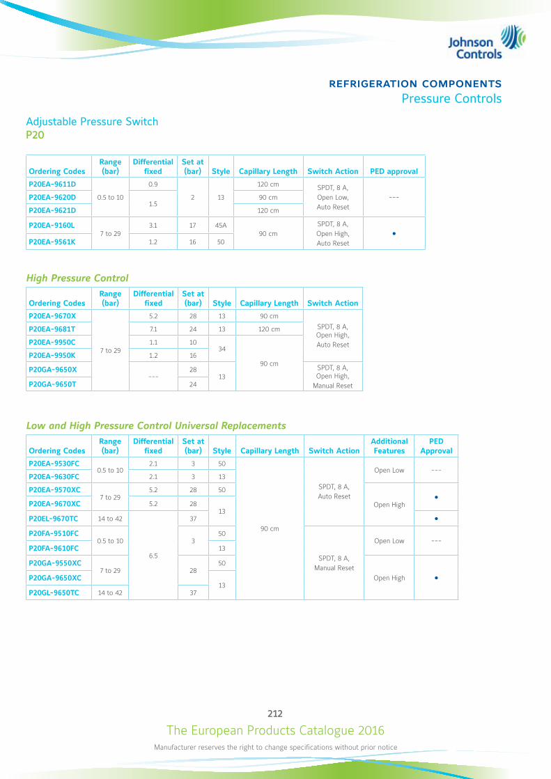
The European Products Catalogue 2016Manufacturer reserves the right to change specifications without prior notice
212
refrigeration componentsPressure Controls
Adjustable Pressure SwitchP20
Ordering CodesRange (bar)
Differential fixed
Set at (bar) Style Capillary Length Switch Action PED approval
P20EA-9611D
0.5 to 10
0.9
2 13
120 cm SPDT, 8 A,Open Low,Auto Reset
---P20EA-9620D1.5
90 cm
P20EA-9621D 120 cm
P20EA-9160L7 to 29
3.1 17 45A90 cm
SPDT, 8 A, Open High, Auto Reset
P20EA-9561K 1.2 16 50
High Pressure Control
Ordering CodesRange (bar)
Differential fixed
Set at (bar) Style Capillary Length Switch Action
P20EA-9670X
7 to 29
5.2 28 13 90 cm
SPDT, 8 A, Open High,Auto Reset
P20EA-9681T 7.1 24 13 120 cm
P20EA-9950C 1.1 1034
90 cmP20EA-9950K 1.2 16
P20GA-9650X---
2813
SPDT, 8 A, Open High,
Manual ResetP20GA-9650T 24
Low and High Pressure Control Universal Replacements
Ordering CodesRange (bar)
Differential fixed
Set at (bar) Style Capillary Length Switch Action
Additional Features
PED Approval
P20EA-9530FC0.5 to 10
2.1 3 50
90 cm
SPDT, 8 A, Auto Reset
Open Low ---P20EA-9630FC 2.1 3 13
P20EA-9570XC7 to 29
5.2 28 50
Open High
P20EA-9670XC 5.2 2813
P20EL-9670TC 14 to 42
6.5
37 P20FA-9510FC
0.5 to 10 350
SPDT, 8 A, Manual Reset
Open Low ---P20FA-9610FC 13
P20GA-9550XC7 to 29 28
50
Open High P20GA-9650XC13
P20GL-9650TC 14 to 42 37
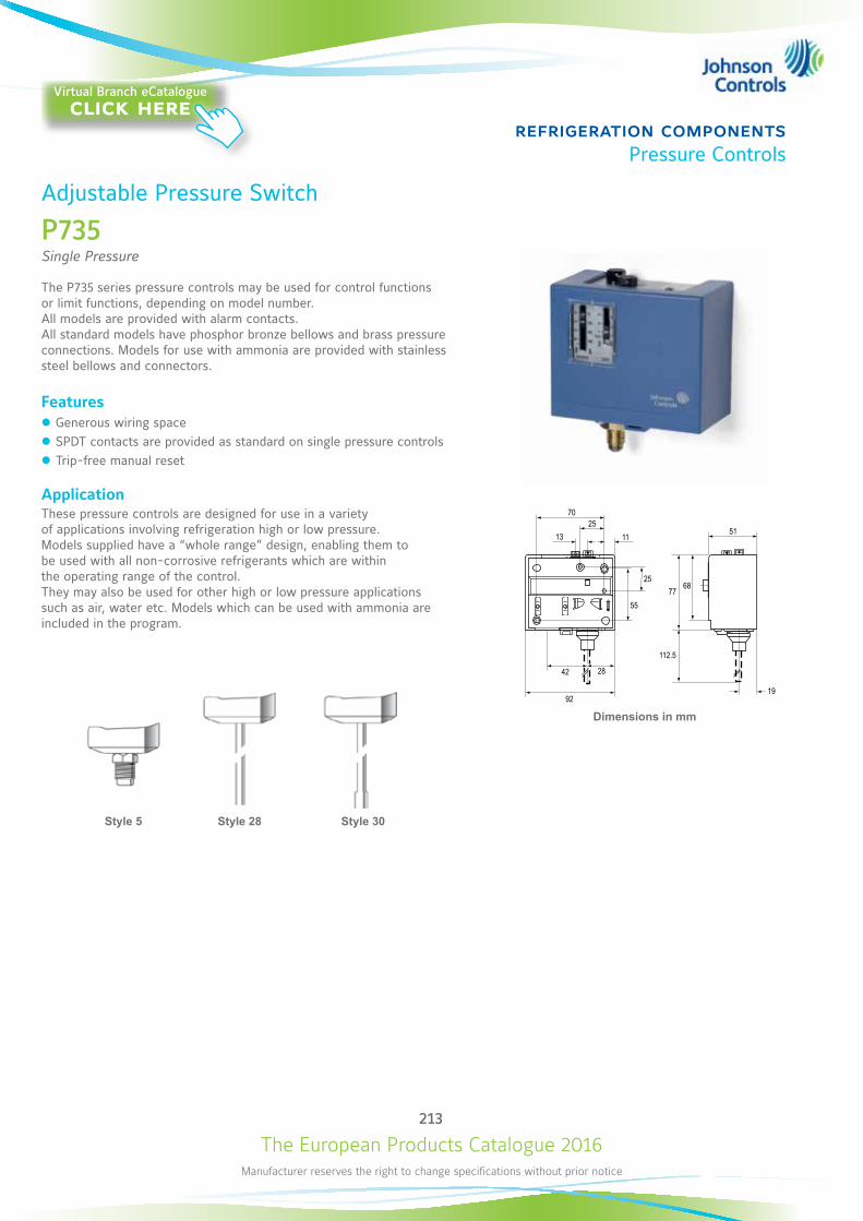
The European Products Catalogue 2016Manufacturer reserves the right to change specifications without prior notice
213
refrigeration componentsPressure Controls
Adjustable Pressure Switch
P735Single Pressure
The P735 series pressure controls may be used for control functions or limit functions, depending on model number. All models are provided with alarm contacts. All standard models have phosphor bronze bellows and brass pressure connections. Models for use with ammonia are provided with stainless steel bellows and connectors.
Features z Generous wiring space z SPDT contacts are provided as standard on single pressure controls z Trip-free manual reset
ApplicationThese pressure controls are designed for use in a variety of applications involving refrigeration high or low pressure. Models supplied have a “whole range” design, enabling them to be used with all non-corrosive refrigerants which are within the operating range of the control. They may also be used for other high or low pressure applications such as air, water etc. Models which can be used with ammonia are included in the program.
Dimensions in mm
70
13
92
42 28
19
2511
51
112.5
55
2568
77
BA
C
MLine~
max. 20 A
AB
CM
Line~max. 20 A
CA
B
MLine~
max. 20 A
Style 5 Style 30Style 28
Virtual Branch eCatalogueclick here
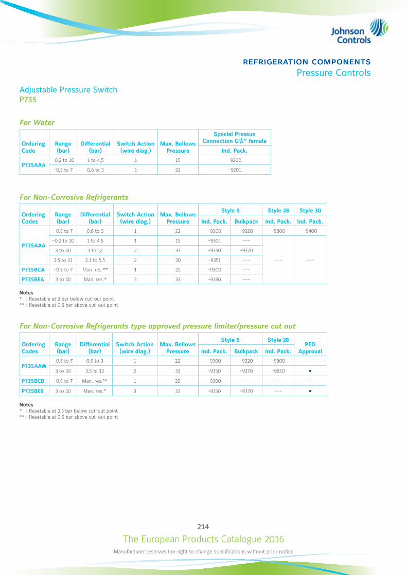
The European Products Catalogue 2016Manufacturer reserves the right to change specifications without prior notice
214
refrigeration componentsPressure Controls
Adjustable Pressure SwitchP735
For Water
Ordering Code
Range (bar)
Differential (bar)
Switch Action (wire diag.)
Max. Bellows Pressure
Special Pressue Connection G¼” female
Ind. Pack.
P735AAA-0,2 to 10 1 to 4,5 1 15 -9200
-0,5 to 7 0,6 to 3 1 22 -9201
For Non-Corrosive Refrigerants
Ordering Codes
Range (bar)
Differential (bar)
Switch Action (wire diag.)
Max. Bellows Pressure
Style 5 Style 28 Style 30
Ind. Pack. Bulkpack Ind. Pack. Ind. Pack.
P735AAA
-0.5 to 7 0.6 to 3 1 22 -9300 -9320 -9800 -9400
-0.2 to 10 1 to 4.5 1 15 -9301 ---
--- ---
3 to 30 3 to 12 2 33 -9350 -9370
3.5 to 21 2.1 to 5.5 2 30 -9351 ---
P735BCA -0.5 to 7 Man. res.** 1 22 -9300 ---
P735BEA 3 to 30 Man. res.* 3 33 -9350 ---
Notes * : Resetable at 3 bar below cut-out point ** : Resetable at 0.5 bar above cut-out point
For Non-Corrosive Refrigerants type approved pressure limiter/pressure cut out
Ordering Codes
Range (bar)
Differential (bar)
Switch Action (wire diag.)
Max. Bellows Pressure
Style 5 Style 28PED
ApprovalInd. Pack. Bulkpack Ind. Pack.
P735AAW-0.5 to 7 0.6 to 3 1 22 -9300 -9320 -9800 ---
3 to 30 3.5 to 12 2 33 -9350 -9370 -9850 P735BCB -0.5 to 7 Man. res.** 1 22 -9300 --- --- ---
P735BEB 3 to 30 Man. res.* 3 33 -9350 -9370 ---
Notes * : Resetable at 3.5 bar below cut-out point ** : Resetable at 0.5 bar above cut-out point

The European Products Catalogue 2016Manufacturer reserves the right to change specifications without prior notice
215
refrigeration componentsPressure Controls
Adjustable Pressure Switch
P736Dual Pressure
The P736 series pressure controls may be used for control functions or limit functions, depending on model number. All models are provided with alarm contacts (except P736ALA). All standard models have phosphor bronze bellows and brass pressure connections. Models for use with ammonia are provided with stainless steel bellows and connectors.
Features z Generous wiring space z Trip-free manual reset z Separate alarm contacts for both low pressure and high pressure cut-out (except P736ALA)
ApplicationThese dual pressure controls are designed for use in a variety of applications involving refrigeration high or low pressure. Models supplied have a “whole range” design, enabling them to be used all non-corrosive refrigerants which are within the operating range of the control. They may also be used for other high or low pressure applications such as air, water etc. Models which can be used with ammonia are included in the program.
Dimensions in mm
70
13
132
42 28
75
25
11
55
25
19
51
112.5
6877
C
B D
M
M1 M2
D
B
ALine~
max. 20 A
ALine~
max. 20 A
LP HP HPHP
Style 5 Style 30Style 28
Virtual Branch eCatalogueclick here
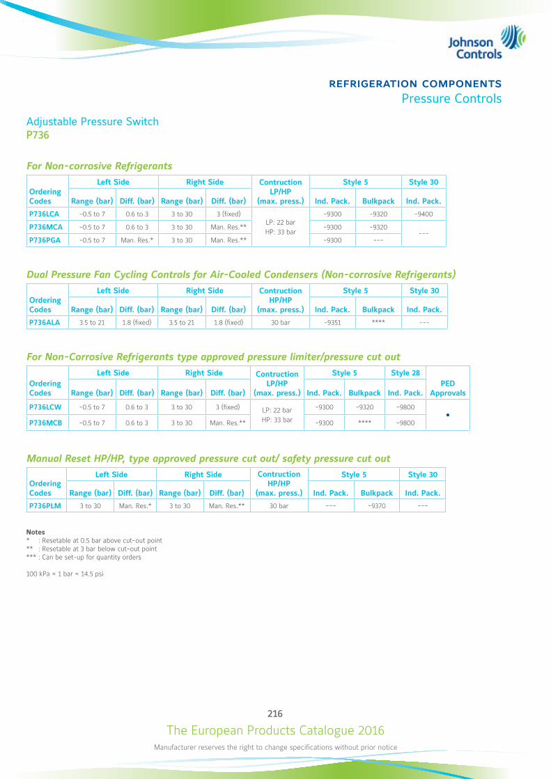
The European Products Catalogue 2016Manufacturer reserves the right to change specifications without prior notice
216
refrigeration componentsPressure Controls
Adjustable Pressure SwitchP736
For Non-corrosive Refrigerants
Ordering Codes
Left Side Right Side Contruction LP/HP
(max. press.)
Style 5 Style 30
Range (bar) Diff. (bar) Range (bar) Diff. (bar) Ind. Pack. Bulkpack Ind. Pack.
P736LCA -0.5 to 7 0.6 to 3 3 to 30 3 (fixed)LP: 22 bar HP: 33 bar
-9300 -9320 -9400
P736MCA -0.5 to 7 0.6 to 3 3 to 30 Man. Res.** -9300 -9320---
P736PGA -0.5 to 7 Man. Res.* 3 to 30 Man. Res.** -9300 ---
Dual Pressure Fan Cycling Controls for Air-Cooled Condensers (Non-corrosive Refrigerants)
Ordering Codes
Left Side Right Side Contruction HP/HP
(max. press.)
Style 5 Style 30
Range (bar) Diff. (bar) Range (bar) Diff. (bar) Ind. Pack. Bulkpack Ind. Pack.
P736ALA 3.5 to 21 1.8 (fixed) 3.5 to 21 1.8 (fixed) 30 bar -9351 **** ---
For Non-Corrosive Refrigerants type approved pressure limiter/pressure cut out
Ordering Codes
Left Side Right Side Contruction LP/HP
(max. press.)
Style 5 Style 28PED
ApprovalsRange (bar) Diff. (bar) Range (bar) Diff. (bar) Ind. Pack. Bulkpack Ind. Pack.
P736LCW -0.5 to 7 0.6 to 3 3 to 30 3 (fixed) LP: 22 bar HP: 33 bar
-9300 -9320 -9800
P736MCB -0.5 to 7 0.6 to 3 3 to 30 Man. Res.** -9300 **** -9800
Manual Reset HP/HP, type approved pressure cut out/ safety pressure cut out
Ordering Codes
Left Side Right Side Contruction HP/HP
(max. press.)
Style 5 Style 30
Range (bar) Diff. (bar) Range (bar) Diff. (bar) Ind. Pack. Bulkpack Ind. Pack.
P736PLM 3 to 30 Man. Res.* 3 to 30 Man. Res.** 30 bar --- -9370 ---
Notes* : Resetable at 0.5 bar above cut-out point ** : Resetable at 3 bar below cut-out point *** : Can be set-up for quantity orders
100 kPa = 1 bar ≈ 14.5 psi
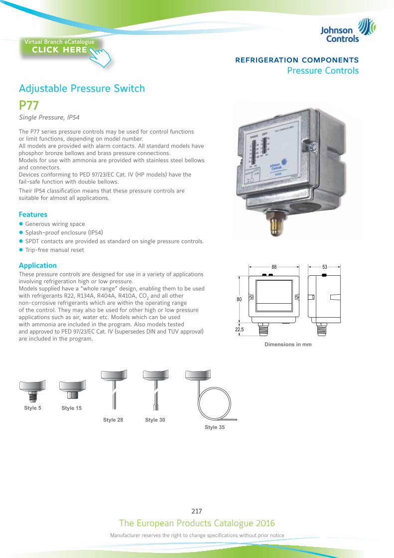
The European Products Catalogue 2016Manufacturer reserves the right to change specifications without prior notice
217
refrigeration componentsPressure Controls
Style 5 Style 15
Style 30Style 28
Dimensions in mm
22,5
80
88 53
Adjustable Pressure Switch
P77Single Pressure, IP54
The P77 series pressure controls may be used for control functions or limit functions, depending on model number. All models are provided with alarm contacts. All standard models have phosphor bronze bellows and brass pressure connections. Models for use with ammonia are provided with stainless steel bellows and connectors. Devices conforming to PED 97/23/EC Cat. IV (HP models) have the fail-safe function with double bellows.Their IP54 classification means that these pressure controls are suitable for almost all applications.
Features z Generous wiring space z Splash-proof enclosure (IP54) z SPDT contacts are provided as standard on single pressure controls. z Trip-free manual reset
ApplicationThese pressure controls are designed for use in a variety of applications involving refrigeration high or low pressure. Models supplied have a “whole range” design, enabling them to be used with refrigerants R22, R134A, R404A, R410A, CO2 and all other non-corrosive refrigerants which are within the operating range of the control. They may also be used for other high or low pressure applications such as air, water etc. Models which can be used with ammonia are included in the program. Also models tested and approved to PED 97/23/EC Cat. IV (supersedes DIN and TUV approval) are included in the program.
Style 35
Virtual Branch eCatalogueclick here
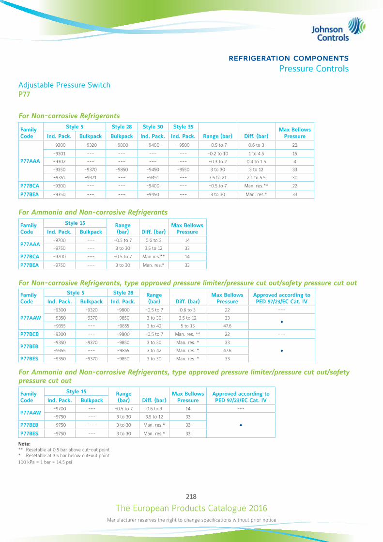
The European Products Catalogue 2016Manufacturer reserves the right to change specifications without prior notice
218
refrigeration componentsPressure Controls
Adjustable Pressure SwitchP77
For Non-corrosive Refrigerants
Family Code
Style 5 Style 28 Style 30 Style 35
Range (bar) Diff. (bar)Max Bellows
PressureInd. Pack. Bulkpack Bulkpack Ind. Pack. Ind. Pack.
P77AAA
-9300 -9320 -9800 -9400 -9500 -0.5 to 7 0.6 to 3 22
-9301 --- --- --- --- -0.2 to 10 1 to 4.5 15
-9302 --- --- --- --- -0.3 to 2 0.4 to 1.5 4
-9350 -9370 -9850 -9450 -9550 3 to 30 3 to 12 33
-9351 -9371 --- -9451 --- 3.5 to 21 2.1 to 5.5 30
P77BCA -9300 --- --- -9400 --- -0.5 to 7 Man. res.** 22
P77BEA -9350 --- --- -9450 --- 3 to 30 Man. res:* 33
For Ammonia and Non-corrosive Refrigerants
Family Code
Style 15 Range (bar) Diff. (bar)
Max Bellows PressureInd. Pack. Bulkpack
P77AAA -9700 --- -0.5 to 7 0.6 to 3 14
-9750 --- 3 to 30 3.5 to 12 33
P77BCA -9700 --- -0.5 to 7 Man res.** 14
P77BEA -9750 --- 3 to 30 Man. res.* 33
For Non-corrosive Refrigerants, type approved pressure limiter/pressure cut out/safety pressure cut out
Family Code
Style 5 Style 28 Range (bar) Diff. (bar)
Max Bellows Pressure
Approved according to PED 97/23/EC Cat. IVInd. Pack. Bulkpack Ind. Pack.
P77AAW
-9300 -9320 -9800 -0.5 to 7 0.6 to 3 22 ---
-9350 -9370 -9850 3 to 30 3.5 to 12 33
-9355 --- -9855 3 to 42 5 to 15 47.6
P77BCB -9300 --- -9800 -0.5 to 7 Man. res. ** 22 ---
P77BEB-9350 -9370 -9850 3 to 30 Man. res. * 33
-9355 --- -9855 3 to 42 Man. res. * 47.6
P77BES -9350 -9370 -9850 3 to 30 Man. res. * 33
For Ammonia and Non-corrosive Refrigerants, type approved pressure limiter/pressure cut out/safety pressure cut out
Family Code
Style 15 Range (bar) Diff. (bar)
Max Bellows Pressure
Approved according to PED 97/23/EC Cat. IVInd. Pack. Bulkpack
P77AAW-9700 --- -0.5 to 7 0.6 to 3 14 ---
-9750 --- 3 to 30 3.5 to 12 33
P77BEB -9750 --- 3 to 30 Man. res.* 33
P77BES -9750 --- 3 to 30 Man. res.* 33
Note: ** Resetable at 0.5 bar above cut-out point* Resetable at 3.5 bar below cut-out point100 kPa = 1 bar ≈ 14.5 psi
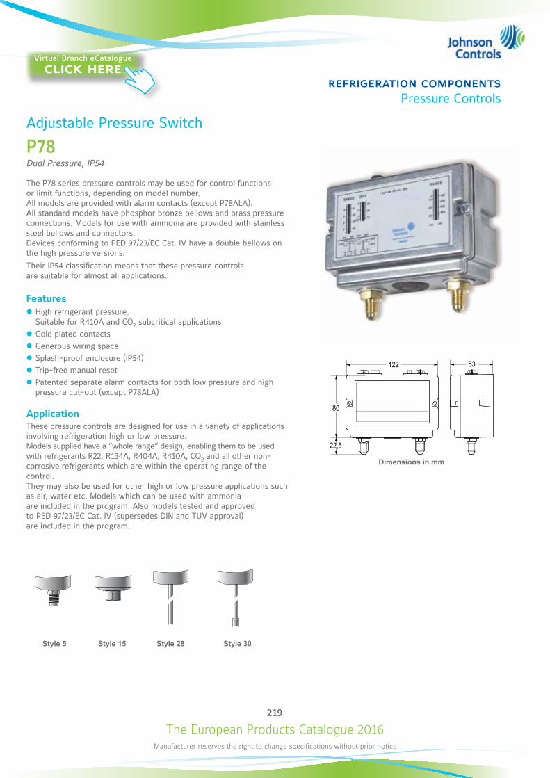
The European Products Catalogue 2016Manufacturer reserves the right to change specifications without prior notice
219
refrigeration componentsPressure Controls
122 53
80
22,5
Dimensions in mm
Adjustable Pressure Switch
P78Dual Pressure, IP54
The P78 series pressure controls may be used for control functions or limit functions, depending on model number. All models are provided with alarm contacts (except P78ALA). All standard models have phosphor bronze bellows and brass pressure connections. Models for use with ammonia are provided with stainless steel bellows and connectors. Devices conforming to PED 97/23/EC Cat. IV have a double bellows on the high pressure versions. Their IP54 classification means that these pressure controls are suitable for almost all applications.
Features z High refrigerant pressure. Suitable for R410A and CO2 subcritical applications
z Gold plated contacts z Generous wiring space z Splash-proof enclosure (IP54) z Trip-free manual reset z Patented separate alarm contacts for both low pressure and high pressure cut-out (except P78ALA)
ApplicationThese pressure controls are designed for use in a variety of applications involving refrigeration high or low pressure. Models supplied have a “whole range” design, enabling them to be used with refrigerants R22, R134A, R404A, R410A, CO2 and all other non-corrosive refrigerants which are within the operating range of the control. They may also be used for other high or low pressure applications such as air, water etc. Models which can be used with ammonia are included in the program. Also models tested and approved to PED 97/23/EC Cat. IV (supersedes DIN and TUV approval) are included in the program.
22,5
(0,89)
80(3.15)
122(4.80)
53(2.09)
A
B
C
D
M Line~
max. 20 A
C B D M
M1 M2
D
B
A Line~
max. 20 A
A Line~
max. 20 A
LP HP
HP HP
HP HP
Style 5 Style 15 Style 30Style 28
Virtual Branch eCatalogueclick here
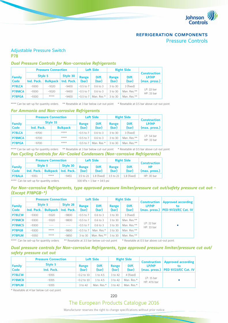
The European Products Catalogue 2016Manufacturer reserves the right to change specifications without prior notice
220
refrigeration componentsPressure Controls
Adjustable Pressure SwitchP78
Dual Pressure Controls for Non-corrosive Refrigerants
Family Code
Pressure Connection Left Side Right SideConstruction
LP/HP (max. press.)
Style 5 Style 30 Range (bar)
Diff. (bar)
Range (bar)
Diff. (bar)Ind. Pack. Bulkpack Ind. Pack.
P78LCA -9300 -9320 -9400 -0.5 to 7 0.6 to 3 3 to 30 3 (fixed)LP: 22 barHP: 33 bar
P78MCA -9300 -9320 -9400 -0.5 to 7 0.6 to 3 3 to 30 Man. Res.**
P78PGA -9300 **** -9400 -0.5 to 7 Man. Res * 3 to 30 Man. Res.**
**** Can be set-up for quantity orders ** Resetable at 3 bar below cut-out point * Resetable at 0.5 bar above cut-out point
For Ammonia and Non-corrosive Refrigerants
Family Code
Pressure Connection Left Side Right SideConstruction
LP/HP (max. press.)
Style 15 Range (bar)
Diff. (bar)
Range (bar)
Diff. (bar)Ind. Pack. Bulkpack
P78LCA -9700 **** -0.5 to 7 0.6 to 3 3 to 30 3 (fixed)LP: 14 barHP: 33 bar
P78MCA -9700 **** -0.5 to 7 0.6 to 3 3 to 30 Man. Res.**
P78PGA -9700 **** -0.5 to 7 Man. Res * 3 to 30 Man. Res.**
**** Can be set-up for quantity orders ** Resetable at 3 bar below cut-out point * Resetable at 0.5 bar above cut-out point
Fan Cycling Controls for Air-Cooled Condensers (Non-corrosive Refrigerants)
Family Code
Pressure Connection Left Side Right SideConstruction
HP (max. press.)
Style 5 Style 30 Range (bar)
Diff. (bar)
Range (bar)
Diff. (bar)Ind. Pack. Bulkpack Ind. Pack.
P78ALA -9351 **** -9451 3.5 to 21 1.8 (fixed) 3.5 to 21 1.8 (fixed) HP: 30 bar
**** Can be set-up for quantity orders 100 kPa = 1 bar ≈ 14.5 psi
For Non-corrosive Refrigerants, type approved pressure limiter/pressure cut out/safety pressure cut out - (Except P78PGB-*)
Family Code
Pressure Connection Left Side Right SideConstruction
LP/HP (max. press.)
Approved according to
PED 97/23/EC Cat. IV
Style 5 Style 28 Range (bar)
Diff. (bar)
Range (bar)
Diff. (bar)Ind. Pack. Bulkpack Ind. Pack.
P78LCW -9300 -9320 -9800 -0.5 to 7 0.6 to 3 3 to 30 3 (fixed)
LP: 22 barHP: 33 bar
P78MCB -9300 -9320 -9800 -0.5 to 7 0.6 to 3 3 to 30 Man. Res.**
P78MCS -9300 --- --- -0.5 to 7 0.6 to 3 3 to 30 Man. Res.**
P78PGB -9300 **** -9800 -0.5 to 7 Man. Res.* 3 to 30 Man. Res.**
P78PLM -9350 **** -9850 3 to 30 Man. Res.** 3 to 30 Man. Res.**
**** Can be set-up for quantity orders ** Resetable at 3.5 bar below cut-out point * Resetable at 0.5 bar above cut-out point
Dual pressure controls for Non-corrosive Refrigerants, type approved pressure limiter/pressure cut out/safety pressure cut out
Family Code
Pressure Connection Left Side Right SideConstruction
LP/HP (max. press.)
Approved according to
PED 97/23/EC Cat. IV
Style 5 Range (bar)
Diff. (bar)
Range (bar)
Diff. (bar)Ind. Pack.
P78LCW -9355 -0.2 to 10 1 to 4.5 3 to 42 4 (fixed)LP: 15 bar
HP: 47.6 bar P78MCB -9355 -0.2 to 10 1 to 4.5 3 to 42 Man. Res.*
P78PLM -9355 3 to 42 Man. Res.* 3 to 42 Man. Res.*
* Resetable at 4 bar below cut-out point
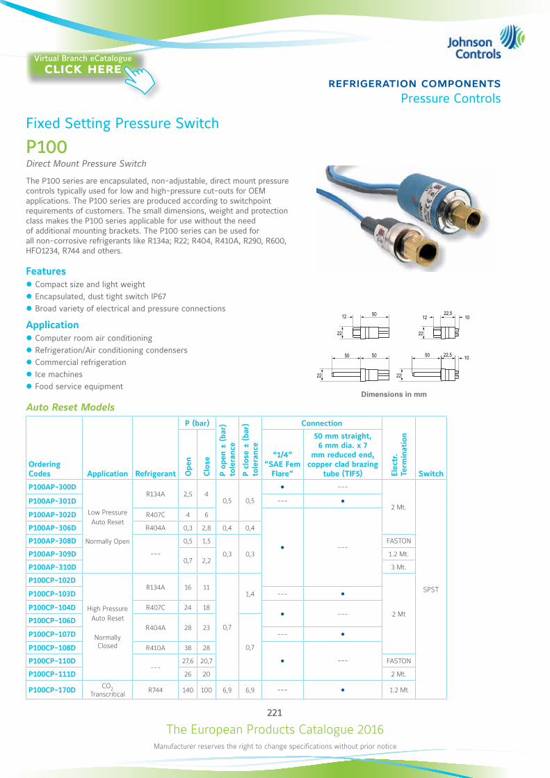
The European Products Catalogue 2016Manufacturer reserves the right to change specifications without prior notice
221
refrigeration componentsPressure Controls
Dimensions in mm
22,5
22
2222
22
10
10
1212
50 22,550 50
50 L
O
Ò
B
Fixed Setting Pressure Switch
P100Direct Mount Pressure Switch
The P100 series are encapsulated, non-adjustable, direct mount pressure controls typically used for low and high-pressure cut-outs for OEM applications. The P100 series are produced according to switchpoint requirements of customers. The small dimensions, weight and protection class makes the P100 series applicable for use without the need of additional mounting brackets. The P100 series can be used for all non-corrosive refrigerants like R134a; R22; R404, R410A, R290, R600, HFO1234, R744 and others.
Features z Compact size and light weight z Encapsulated, dust tight switch IP67 z Broad variety of electrical and pressure connections
Application z Computer room air conditioning z Refrigeration/Air conditioning condensers z Commercial refrigeration z Ice machines z Food service equipment
Auto Reset Models
Ordering Codes Application Refrigerant
P (bar)
P op
en ±
(ba
r)
tole
ranc
e
P cl
ose
± (b
ar)
tole
ranc
e
Connection
Elec
tr.
Term
inat
ion
SwitchOpe
n
Clo
se
“1/4” ”SAE Fem
Flare”
50 mm straight, 6 mm dia. x 7
mm reduced end, copper clad brazing
tube (TIF5)
P100AP-300D
Low Pressure Auto Reset
Normally Open
R134A 2,5 40,5 0,5
---
2 Mt.
SPST
P100AP-301D --- P100AP-302D R407C 4 6
---
P100AP-306D R404A 0,3 2,8 0,4 0,4
P100AP-308D
---
0,5 1,5
0,3 0,3
FASTON
P100AP-309D0,7 2,2
1.2 Mt.
P100AP-310D 3 Mt.
P100CP-102D
High Pressure Auto Reset
Normally Closed
R134A 16 11
0,7
1,4
2 Mt
P100CP-103D --- P100CP-104D R407C 24 18
---P100CP-106D
R404A 28 23
0,7
P100CP-107D --- P100CP-108D R410A 38 28
---P100CP-110D---
27,6 20,7 FASTON
P100CP-111D 26 20 2 Mt.
P100CP-170D CO2 Transcritical R744 140 100 6,9 6,9 --- 1.2 Mt
Virtual Branch eCatalogueclick here
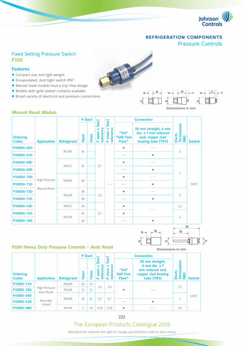
The European Products Catalogue 2016Manufacturer reserves the right to change specifications without prior notice
222
refrigeration componentsPressure Controls
Manual Reset Models
Ordering Codes Application Refrigerant
P (bar)
P op
en ±
(ba
r)
tole
ranc
e
P cl
ose
± (b
ar)
tole
ranc
e
Connection
Elec
tr.
Term
inat
ion
(Mt)
SwitchOpe
n
Clo
se
“1/4” ”SAE Fem
Flare”
50 mm straight, 6 mm dia. x 7 mm reduced
end, copper clad brazing tube (TIF5)
P100DA-66D
High Pressure
Manual Reset
R134A 16
0,7
---
---2
SPST
P100DA-67D ---
P100DA-68DR407C 26
---
3P100DA-69D ---
P100DA-70DR404A 28
---
P100DA-71D ---
P100DA-72DR410A
381,0
---2
P100DA-73D 38 ---
P100DA-74D R407C 26
0,7
---
1,2
P100DA-75DR410A
42 2
P100DA-76D 42 ---
P100 Heavy Duty Pressure Controls - Auto Reset
Ordering Codes Application Refrigerant
P (bar)
P op
en ±
(ba
r)
tole
ranc
e
P cl
ose
± (b
ar)
tole
ranc
e
Connection
Elec
tr.
Term
inat
ion
(Mt)
SwitchOpe
n
Clo
se
“1/4” SAE Fem
Flare”
50 mm straight, 6 mm dia. x 7
mm reduced end, copper clad brazing
tube (TIF5)
P100EE-17DHigh Pressure
Auto Reset
Normally closed
R404A 20 251,0 1,0
---1,5
SPDT
P100EE-18D R134A 15 11
P100EE-60DR404A 28 21 0,7 0,7 2
P100EE-61D --- P100EE-68D R134A 3 25 0,35 0,35 --- 1,8
Fixed Setting Pressure SwitchP100
Features z Compact size and light weight z Encapsulated, dust tight switch IP67 z Manual reset models have a trip-free design z Models with gold-plated contacts available z Broad variety of electrical and pressure connections
Dimensions in mm
24 29 24
16 16 50 211134
L
Ò
L
O O
Ò
MM
1116
Dimensions in mm
31 27
38 90
50
32
16
L
2
1
3
Ò
M
MP LP
L
O O
2
1
3
Ò
M
The European Products Catalogue 2016Manufacturer reserves the right to change specifications without prior notice
223
refrigeration componentsPressure Controls
Pressure Switches Accessories
Ordering Codes Description Minimum order qty.
BKT034N602R Mounting bracket + screws for P35AC transducer
1BKT275-1 Mounting bracket dual for P20
210-25R Mounting bracket for P20/P35 (single)
WRN12-1 Wrench P20/P21
210-604R Terminal cover P20/P21 50
BKT024N002R Mounting bracket for P233
1
FTG015N602R Duct mounting kit “staight”
FTG015N603R Duct mounting kit “bent”
GMT008N600R Duct kit for P233, self locking grommet and tubing
CNR003N001R Connector 6 mm for P77/P78, P735/P736
CNR003N002R Connector 8 mm for P77/P78, P735/P736
CNR012N001R Adapter R3/8 female to 1/4-18 NPT male for P48
CNR013N001R Adapter R 3/8 female to 1/4-18 NPT female for P48
KIT023N600 Locking kit for P48, P77/P78, P735/P736 - for field installation
KIT031N600 Valve depressors for conversion style 13 - style 45a 100 (1 box)
KIT031N601 Valve depressors for conversion style 51 - style 50
KIT034N600 Seal rings for style 50/51 250 (1 box)
271-51L Mounting bracket for P28, P45, P48, P74, P77/P78, P735/P736 50
The European Products Catalogue 2016Manufacturer reserves the right to change specifications without prior notice
224
refrigeration componentsPressure Controls
Pressure Switches Accessories
Capillary kitOrdering Codes Length Style Minimum order qty.
SEC002N600 90 cm 2x style 13100
SEC002N602 90 cm style 13 - style 45a
SEC002N606 200 cm style 13 - style 45a75
SEC002N607 200 cm 2x style 13
SEC002N617 100 cm style 13 - style 13
100SEC002N621 90 cm style 34 - style 34
SEC002N622 90 cm style 50 - style 50
SEC002N624 200 cm style 50 - style 50 75
SEC002N626 90 cm style 50 - style 51100
SEC002N627 200 cm style 50 - style 51
SEC002N628 300 cm style 50 - style 51 75
Replacement - Time relays P28 - P29
Ordering Codes Timing (s) Voltage Switch Action
RLY13A603R 90
120/240 Manual reset, dual voltage (AC)RLY13A620R 120
RLY13A998R 50
RLY13A626R 90 12 Manual reset, 12 VAC/DC
RLY13A627R 120
24 Manual reset, 24 VAC/DCRLY13A635R 90
RLY13A644R 50

The European Products Catalogue 2016Manufacturer reserves the right to change specifications without prior notice
225
refrigeration componentsPressure Controls
Ordering Codes Pressure Connection Fitting Connection Length (cm) Additional Features
H735AA-30C
Straight x 90° elbow 1/4” metal tube with 7/16”-20 UNF swivel nut connection suitable for 1/4” SAE male flare
30
All models bulk packed
H735AA-40C 40
H735AA-50C 50
H735AA-70C 70
H735AA-90D 90
H735AA-100C 100
H735AA-150C 150
H735AA-200C 200
NoteMinimum shipping quantity 100 pieces
Pressure Switches Accessories
H735Syntetic Flexible Hose
The synthetic hoses consist of a seamless PA compound inner layer reinforced with a braided layer of high performance synthetic fibre.This reinforcement is protected by an oil, weather and abrasion resistant Polyester Elastomer Compound. The standard assembly length is 0,9 meter with one straight and one elbow 90 degree hose fitting. The fitting connection is 1/4” metal tube with 7/16”-20 UNF swivel nut connection suitable for 1/4” SAE male flare. Other lengths and/or fitting connections configurations (Style 50, 51 straight or elbow) are available on request (quantity orders only).
Features z Very flexible z Low minimum bend radius (30 mm) z One straight and one 90° elbow pressure connection z Polyester Elastomer Compound construction z High pressure safety ratio z Low effusion
ApplicationThese synthetic hoses are designed for pressure measuring connections. They provide, for example, a very flexible connection between a refrigerant compressor and pressure controls. The hoses can be used for all non-corrosive refrigerants including R134a, R22, R404a, R407c and R410A with pressures within the maximum pressure range of the hose. Hoses are tested with common compressor oils in combination with above mentioned refrigerants.
Virtual Branch eCatalogueclick here

The European Products Catalogue 2016Manufacturer reserves the right to change specifications without prior notice
226
refrigeration componentsPressure Controls
Adjustable Oil Protection Switch
P28Oil Protection
These controls measure the pressure differential between the pressure generated by the oil pump and the refrigerant pressure at the crankcase. A built-in time delay switch allows for pressure-pick up on start and avoids nuisance shutdowns on pressure drops of short duration during the running cycle.When the compressor is started, the time delay switch is energised. If the net oil pressure does not build up within the required time limit, the time delay switch trips to stop the compressor. If the net oil pressure rises within the required time after the compressor starts, the time delay switch is automatically de-energised and the compressor continues to operate normally. If the net oil pressure should drop below setting (scale pointer) during the running cycle, the time delay switch is energised and, unless the net oil pressure returns to cut-in point within the time delay period, the compressor will be shut down, and have to be manual reset. The compressor can never run longer than the predetermined time on low oil pressure. Controls are available only for manual reset after cut-out.
Features z Heavy duty pressure elements z Safety lock-out with trip-free manual reset z Ambient compensated timing z Dust-tight Penn switch
ApplicationThese oil protection controls are designed to give protection against low net lube oil pressure on pressure lubricated refrigeration compressors. Dimensions in mm
Style 5 Style 15Style 13
Virtual Branch eCatalogueclick here
The European Products Catalogue 2016Manufacturer reserves the right to change specifications without prior notice
227
refrigeration componentsPressure Controls
Adjustable Oil Protection SwitchP28
Ordering Codes
Range (bar) Style
Time Delay (s) Voltage Switch Action Refrigerant Additional Features
P28DA-9341
0.6 to 4.8
5 50115/230
15(8) A, 230 VAC, Open Low,
Alarm and Safe Light Contacts
non-corr.
Incl 2 flare nuts 7/16”-20 UNF
P28DA-9660 13 90 ---
P28DJ-9360 5 90
230
IP66 enclosure
P28DJ-9861 15 90 NH3 IP66 enclosure, Incl. 2 connectors CNR003N001
P28DP-9300
5
---
non-corr.
Without time delay
P28DP-9340 50 ---
P28DP-9360 90 ---
P28DP-9380120
---
P28DP-9381 Concealed adjustment, set 0.65 bar
P28DP-9640
13
50 ---
P28DP-9660 90 ---
P28DP-9680 120 ---
P28DP-9840
15
50
NH3
---
P28DP-9860 90 --- ---
P28DN-9750 50 115/230 --- Concealed adjustment, set 1,5 bar
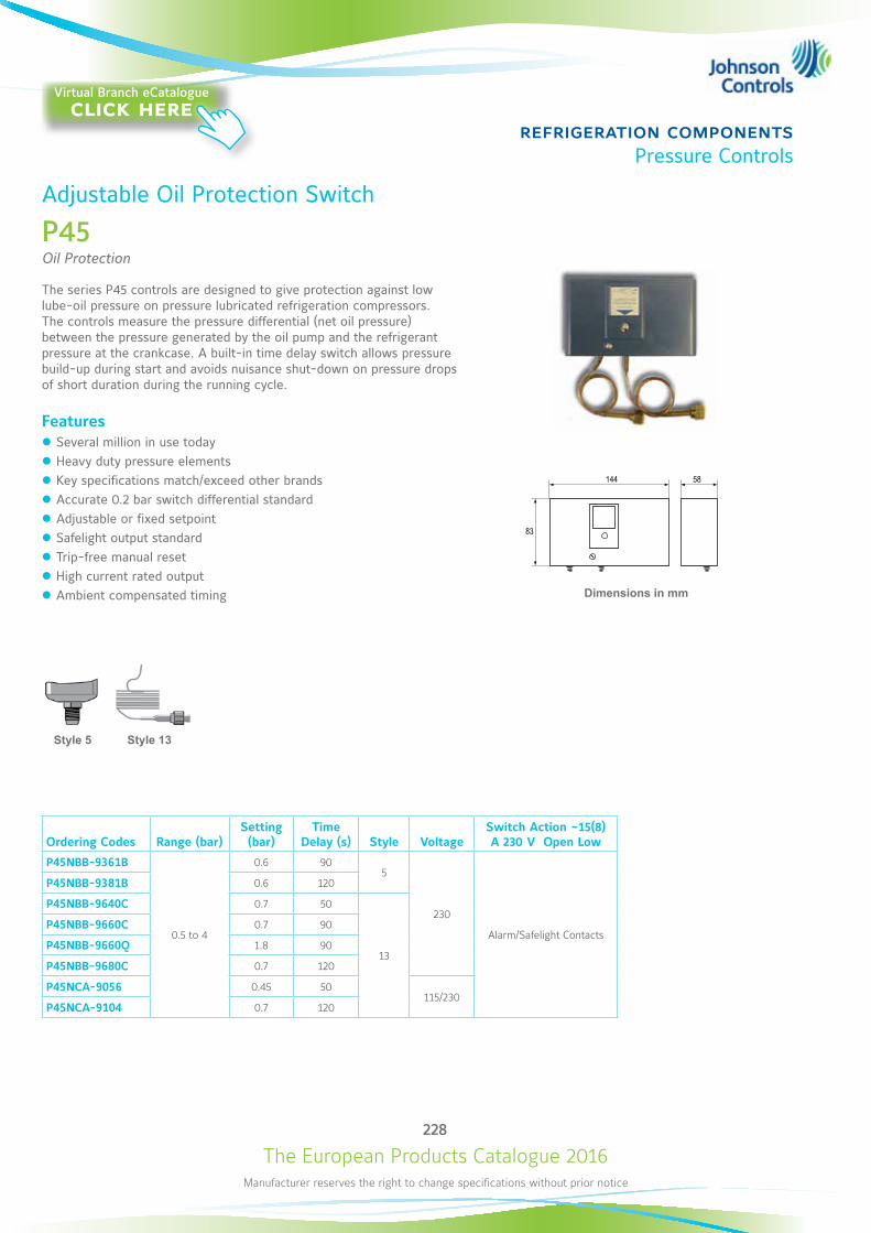
The European Products Catalogue 2016Manufacturer reserves the right to change specifications without prior notice
228
refrigeration componentsPressure Controls
Ordering Codes Range (bar)Setting (bar)
Time Delay (s) Style Voltage
Switch Action ~15(8)A 230 V Open Low
P45NBB-9361B
0.5 to 4
0.6 905
230
Alarm/Safelight Contacts
P45NBB-9381B 0.6 120
P45NBB-9640C 0.7 50
13
P45NBB-9660C 0.7 90
P45NBB-9660Q 1.8 90
P45NBB-9680C 0.7 120
P45NCA-9056 0.45 50115/230
P45NCA-9104 0.7 120
Adjustable Oil Protection Switch
P45Oil Protection
The series P45 controls are designed to give protection against low lube-oil pressure on pressure lubricated refrigeration compressors. The controls measure the pressure differential (net oil pressure) between the pressure generated by the oil pump and the refrigerant pressure at the crankcase. A built-in time delay switch allows pressure build-up during start and avoids nuisance shut-down on pressure drops of short duration during the running cycle.
Features z Several million in use today z Heavy duty pressure elements z Key specifications match/exceed other brands z Accurate 0.2 bar switch differential standard z Adjustable or fixed setpoint z Safelight output standard z Trip-free manual reset z High current rated output z Ambient compensated timing Dimensions in mm
Style 5 Style 13
Virtual Branch eCatalogueclick here
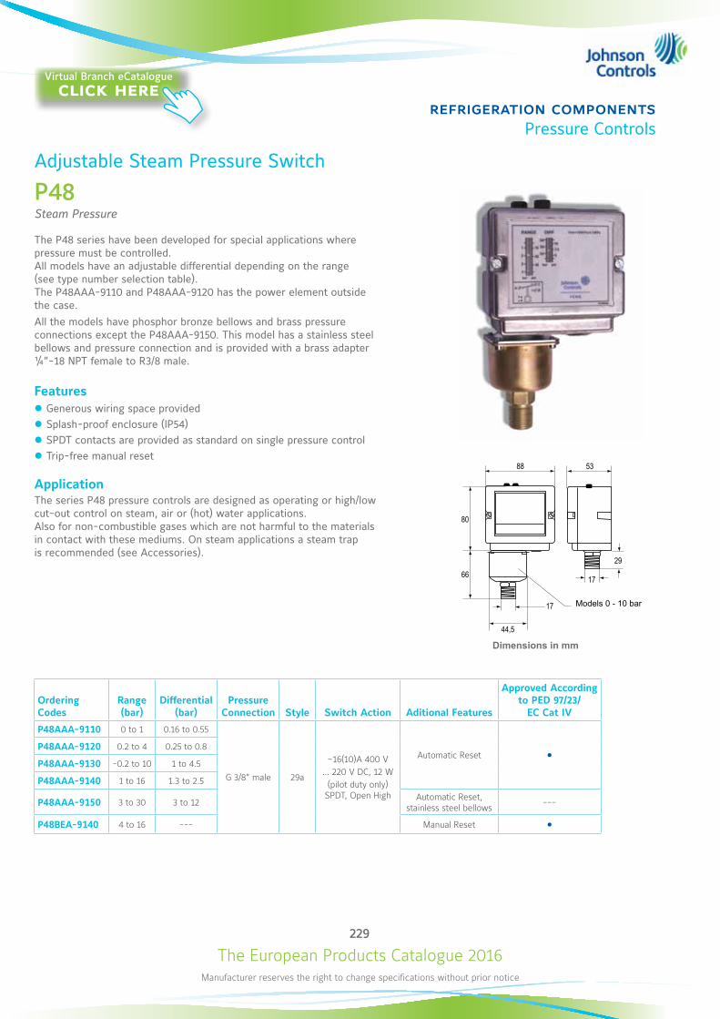
The European Products Catalogue 2016Manufacturer reserves the right to change specifications without prior notice
229
refrigeration componentsPressure Controls
Adjustable Steam Pressure Switch
P48Steam Pressure
The P48 series have been developed for special applications where pressure must be controlled. All models have an adjustable differential depending on the range (see type number selection table). The P48AAA-9110 and P48AAA-9120 has the power element outside the case.All the models have phosphor bronze bellows and brass pressure connections except the P48AAA-9150. This model has a stainless steel bellows and pressure connection and is provided with a brass adapter ¼”-18 NPT female to R3/8 male.
Features z Generous wiring space provided z Splash-proof enclosure (IP54) z SPDT contacts are provided as standard on single pressure control z Trip-free manual reset
ApplicationThe series P48 pressure controls are designed as operating or high/low cut-out control on steam, air or (hot) water applications. Also for non-combustible gases which are not harmful to the materials in contact with these mediums. On steam applications a steam trap is recommended (see Accessories).
Dimensions in mm
Ordering Codes
Range (bar)
Differential (bar)
Pressure Connection Style Switch Action Aditional Features
Approved According to PED 97/23/
EC Cat IV
P48AAA-9110 0 to 1 0.16 to 0.55
G 3/8” male 29a
~16(10)A 400 V… 220 V DC, 12 W
(pilot duty only) SPDT, Open High
Automatic Reset P48AAA-9120 0.2 to 4 0.25 to 0.8
P48AAA-9130 -0.2 to 10 1 to 4.5
P48AAA-9140 1 to 16 1.3 to 2.5
P48AAA-9150 3 to 30 3 to 12 Automatic Reset, stainless steel bellows ---
P48BEA-9140 4 to 16 --- Manual Reset
66
44,5
17
80
88 53
17
29
Models 0 - 10 bar
Virtual Branch eCatalogueclick here
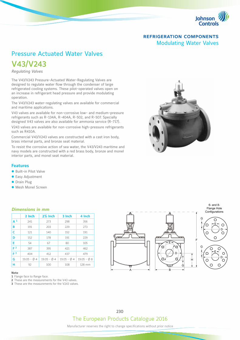
The European Products Catalogue 2016Manufacturer reserves the right to change specifications without prior notice
230
refrigeration componentsModulating Water Valves
Pressure Actuated Water Valves
V43/V243Regulating Valves
The V43/V243 Pressure-Actuated Water-Regulating Valves are designed to regulate water flow through the condenser of large refrigerated cooling systems. These pilot-operated valves open on an increase in refrigerant head pressure and provide modulating operation.The V43/V243 water-regulating valves are available for commercial and maritime applications. V43 valves are available for non-corrosive low- and medium-pressure refrigerants such as R-134A, R-404A, R-502, and R-507. Specially designed V43 valves are also available for ammonia service (R-717).V243 valves are available for non-corrosive high-pressure refrigerants such as R410A. Commercial V43/V243 valves are constructed with a cast iron body, brass internal parts, and bronze seat material.To resist the corrosive action of sea water, the V43/V243 maritime and navy models are constructed with a red brass body, bronze and monel interior parts, and monel seat material.
Features z Built-in Pilot Valve z Easy Adjustment z Drain Plug z Mesh Monel Screen
Dimensions in mm2 Inch 2½ Inch 3 Inch 4 Inch
A 1 241 273 298 356
B 191 203 229 273
C 121 140 152 191
D 152 178 191 229
E 54 67 80 105
F 2 387 395 421 462
F 3 404 412 437 479
G 19.05 - Ø 4 19.05 - Ø 4 19.05 - Ø 4 19.05 - Ø 8
H 92 100 108 128 mm
Note1 Flange face to flange face.2 These are the measurements for the V43 valves.3 These are the measurements for the V243 valves.
G
E
D
G
E
D
G
E
DC
BA
F
H
6- and 8-Flange Hole Configurations
The European Products Catalogue 2016Manufacturer reserves the right to change specifications without prior notice
231
refrigeration componentsModulating Water Valves
Adjustable Steam Pressure SwitchV43/V243
V43 Series Pressure Actuated Water Valves (except NAVSEA valves, see table below)
Ordering Codes Pipe Size (in.) Inlet and Outlet Opening Point Adjustment
Range psig (kPa)Ship Weight. Kg
Commercial Type – Non-Corrosive Refrigerants (R)
V43AT-2C 2 ½ 4 Hole ASME Flanged 140 to 260 (1,103 to 1,793) 29.48
V43AW-2C 4 8 Hole ASME Flanged 160 to 260 (1,103 to 1,793) 64.41
Maritime Type – Non-Corrosive Refrigerants (R)
V43BT-7C 2 ½4 Hole ASME Flanged 140 to 260 (1,103 to 1,793)
29.48
V43BV-7C 3 40.82
V43 Series Pressure Actuated Water Valves, Navy NAVSEA Certified
Ordering Codes Pipe Size (in.) Inlet and Outlet Pressure Connector Opening Point Adjustment
Range – psig (kPa)Ship Weight. Kg
Navy NAVSEA Certified – Non-Corrosive Refrigerants (R)
V43BW-7C4 8 Hole ASME Flange 1/4 in. Male Flared Conn.
70 to 150 (483 to 1,034)64.41
V43BW-2C 140 to 260 (1,103 to 1,793)
V243 Series Pressure Actuated Water Valves
Ordering Codes Pipe Size (in.) Inlet and Outlet Opening Point Adjustment
Range – psig (kPa)Ship Weight. Kg
Commercial Type – High Pressure Refrigerants
V243HW-1C 4 8 Hole ASME Flange 200 to 400 (1,379 to 2,758) 64.41
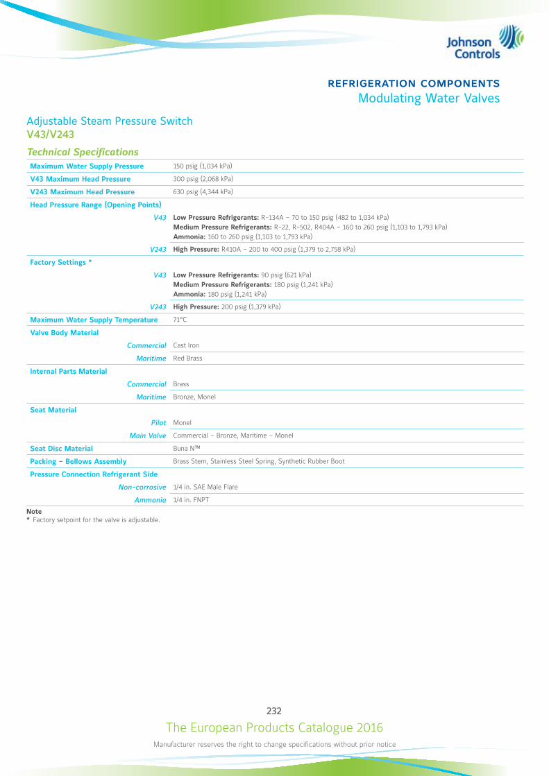
The European Products Catalogue 2016Manufacturer reserves the right to change specifications without prior notice
232
refrigeration componentsModulating Water Valves
Adjustable Steam Pressure SwitchV43/V243
Technical Specifications Maximum Water Supply Pressure 150 psig (1,034 kPa)
V43 Maximum Head Pressure 300 psig (2,068 kPa)
V243 Maximum Head Pressure 630 psig (4,344 kPa)
Head Pressure Range (Opening Points)
V43 Low Pressure Refrigerants: R-134A – 70 to 150 psig (482 to 1,034 kPa)Medium Pressure Refrigerants: R-22, R-502, R404A – 160 to 260 psig (1,103 to 1,793 kPa)Ammonia: 160 to 260 psig (1,103 to 1,793 kPa)
V243 High Pressure: R410A – 200 to 400 psig (1,379 to 2,758 kPa)
Factory Settings *
V43 Low Pressure Refrigerants: 90 psig (621 kPa)Medium Pressure Refrigerants: 180 psig (1,241 kPa)Ammonia: 180 psig (1,241 kPa)
V243 High Pressure: 200 psig (1,379 kPa)
Maximum Water Supply Temperature 71°C
Valve Body Material
Commercial Cast Iron
Maritime Red Brass
Internal Parts Material
Commercial Brass
Maritime Bronze, Monel
Seat Material
Pilot Monel
Main Valve Commercial – Bronze, Maritime – Monel
Seat Disc Material Buna N™
Packing – Bellows Assembly Brass Stem, Stainless Steel Spring, Synthetic Rubber Boot
Pressure Connection Refrigerant Side
Non-corrosive 1/4 in. SAE Male Flare
Ammonia 1/4 in. FNPT
Note* Factory setpoint for the valve is adjustable.
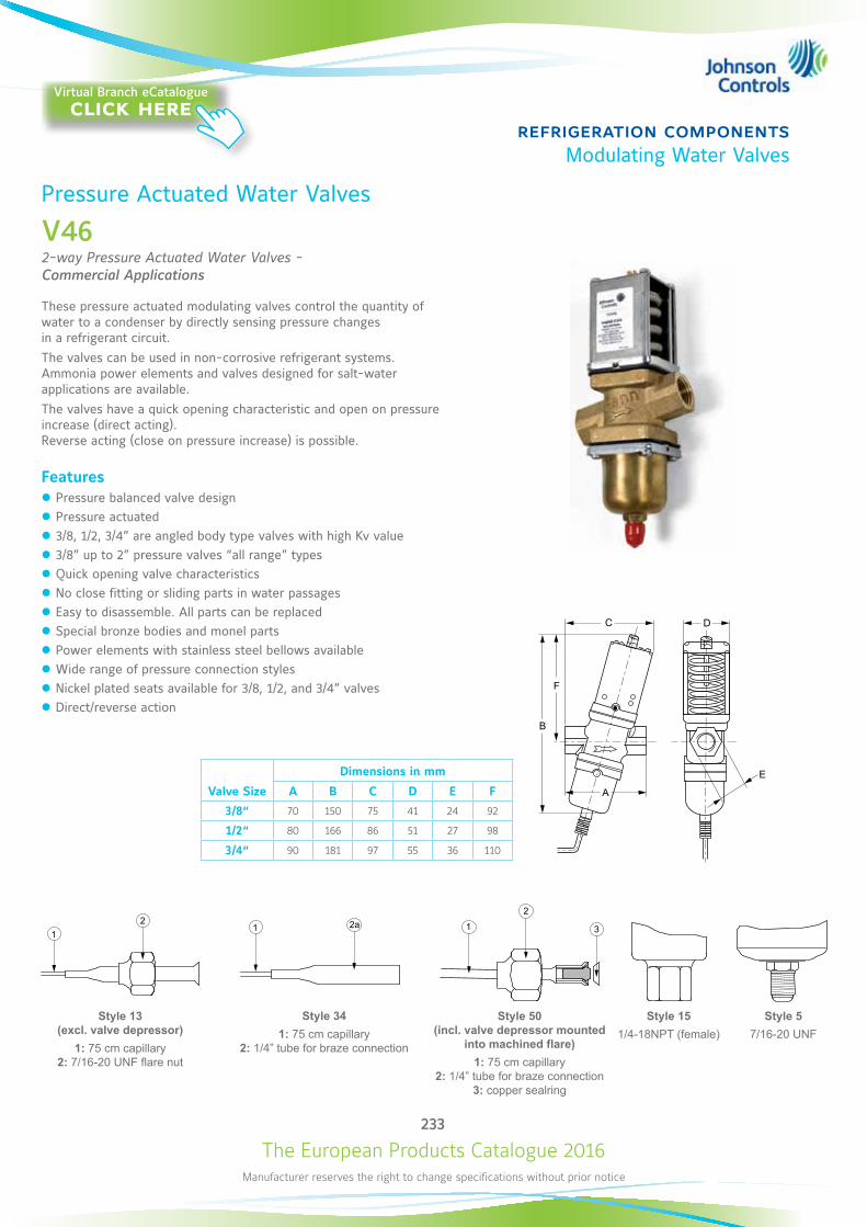
The European Products Catalogue 2016Manufacturer reserves the right to change specifications without prior notice
233
refrigeration componentsModulating Water Valves
Pressure Actuated Water Valves
V462-way Pressure Actuated Water Valves - Commercial Applications
These pressure actuated modulating valves control the quantity of water to a condenser by directly sensing pressure changes in a refrigerant circuit. The valves can be used in non-corrosive refrigerant systems. Ammonia power elements and valves designed for salt-water applications are available. The valves have a quick opening characteristic and open on pressure increase (direct acting). Reverse acting (close on pressure increase) is possible.
Features z Pressure balanced valve design z Pressure actuated z 3/8, 1/2, 3/4” are angled body type valves with high Kv value z 3/8” up to 2” pressure valves “all range” types z Quick opening valve characteristics z No close fitting or sliding parts in water passages z Easy to disassemble. All parts can be replaced z Special bronze bodies and monel parts z Power elements with stainless steel bellows available z Wide range of pressure connection styles z Nickel plated seats available for 3/8, 1/2, and 3/4” valves z Direct/reverse action
F
B
A
C D
E
Valve Size
Dimensions in mm
A B C D E F
3/8“ 70 150 75 41 24 92
1/2“ 80 166 86 51 27 98
3/4“ 90 181 97 55 36 110
12
Style 13 (excl. valve depressor)
1: 75 cm capillary 2: 7/16-20 UNF flare nut
1 2a
Style 341: 75 cm capillary
2: 1/4” tube for braze connection
1
2
3
Style 50 (incl. valve depressor mounted
into machined flare)1: 75 cm capillary
2: 1/4” tube for braze connection 3: copper sealring
Style 151/4-18NPT (female)
Style 57/16-20 UNF
Virtual Branch eCatalogueclick here
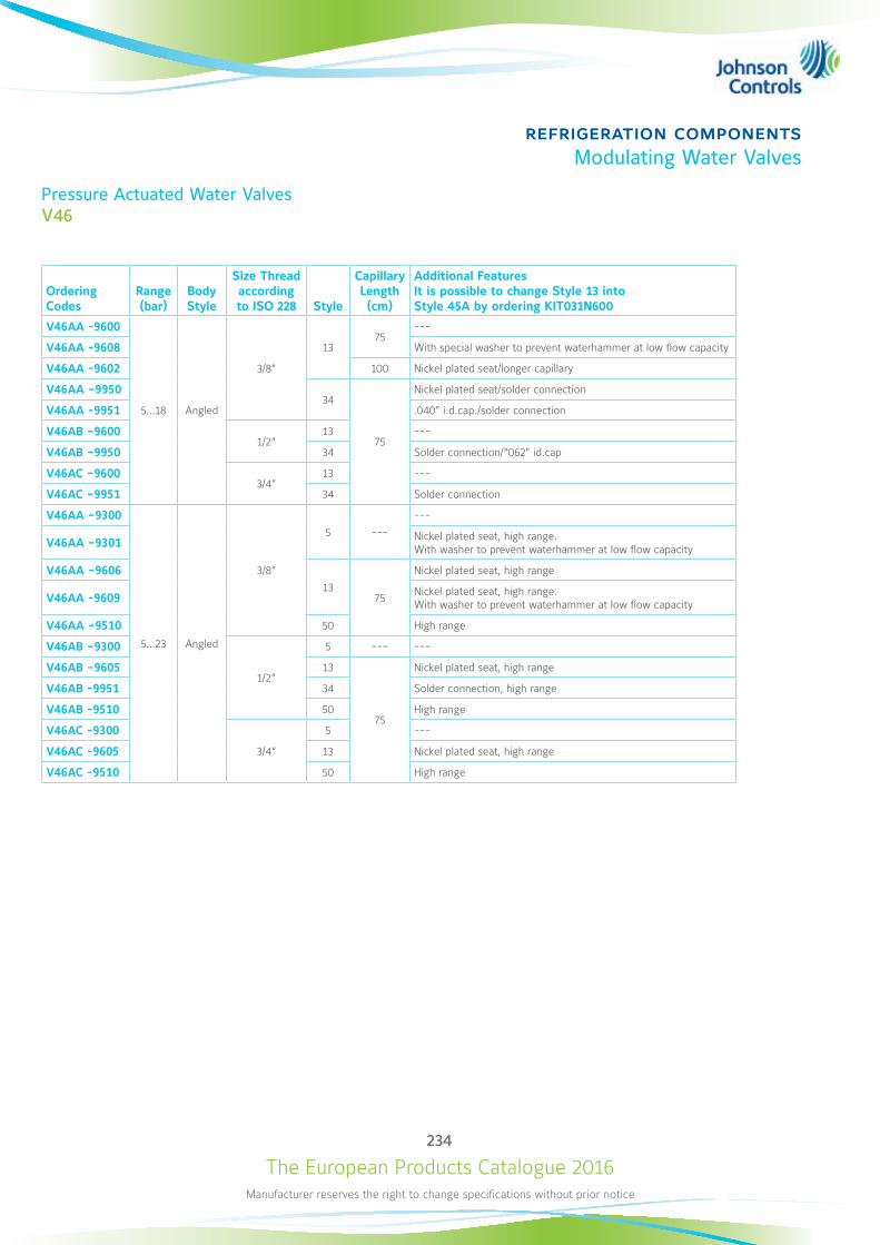
The European Products Catalogue 2016Manufacturer reserves the right to change specifications without prior notice
234
refrigeration componentsModulating Water Valves
Pressure Actuated Water ValvesV46
Ordering Codes
Range (bar)
Body Style
Size Thread according to ISO 228 Style
Capillary Length (cm)
Additional Features It is possible to change Style 13 into Style 45A by ordering KIT031N600
V46AA -9600
5…18 Angled
3/8“
1375
---
V46AA -9608 With special washer to prevent waterhammer at low flow capacity
V46AA -9602 100 Nickel plated seat/longer capillary
V46AA –995034
75
Nickel plated seat/solder connection
V46AA -9951 .040” i.d.cap./solder connection
V46AB –96001/2“
13 ---
V46AB –9950 34 Solder connection/“062” id.cap
V46AC –96003/4“
13 ---
V46AC –9951 34 Solder connection
V46AA –9300
5…23 Angled
3/8“
5 ---
---
V46AA –9301 Nickel plated seat, high range. With washer to prevent waterhammer at low flow capacity
V46AA –960613
75
Nickel plated seat, high range
V46AA -9609 Nickel plated seat, high range. With washer to prevent waterhammer at low flow capacity
V46AA –9510 50 High range
V46AB –9300
1/2“
5 --- ---
V46AB –9605 13
75
Nickel plated seat, high range
V46AB -9951 34 Solder connection, high range
V46AB -9510 50 High range
V46AC -9300
3/4“
5 ---
V46AC -9605 13 Nickel plated seat, high range
V46AC -9510 50 High range
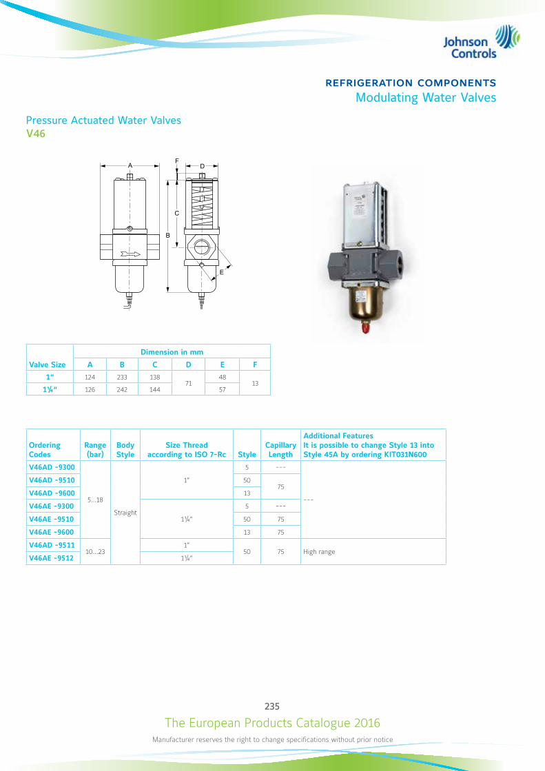
The European Products Catalogue 2016Manufacturer reserves the right to change specifications without prior notice
235
refrigeration componentsModulating Water Valves
Pressure Actuated Water ValvesV46
F
B
A
C
D
E
Valve Size
Dimension in mm
A B C D E F
1“ 124 233 13871
4813
1¼“ 126 242 144 57
Ordering Codes
Range (bar)
Body Style
Size Thread according to ISO 7-Rc Style
Capillary Length
Additional Features It is possible to change Style 13 into Style 45A by ordering KIT031N600
V46AD -9300
5…18
Straight
1”
5 ---
---
V46AD -9510 5075
V46AD -9600 13
V46AE -9300
1¼“
5 ---
V46AE -9510 50 75
V46AE -9600 13 75
V46AD -951110…23
1”50 75 High range
V46AE -9512 1¼“
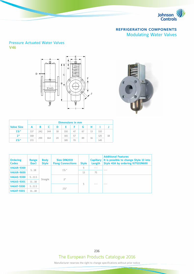
The European Products Catalogue 2016Manufacturer reserves the right to change specifications without prior notice
236
refrigeration componentsModulating Water Valves
Pressure Actuated Water ValvesV46
F
B
A
CD
E
I
J
H
G
Valve Size
Dimensions in mm
A B C D E F G H I J
1½“ 137 242 144 18 150 47 67 13 110
182“ 168299 164 20
165 5789 16
125
2½“ 172 185 70 145
Ordering Codes
Range (bar)
Body Style
Size DIN2533 Flang Connections Style
Capillary Length
Additional Features It is possible to change Style 13 into Style 45A by ordering KIT031N600
V46AR-93005…18
Straight
1½ “5 ---
---V46AR-9600 13 75
V46AS-9300 5…11.52“
5 --- ---V46AS-9301 11…18
V46AT-9300 5…11.52½“
V46AT-9301 11…18
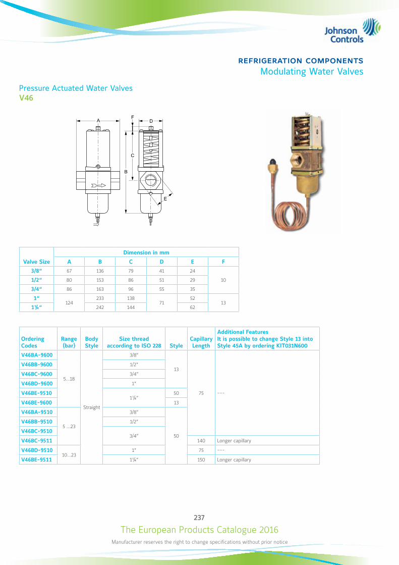
The European Products Catalogue 2016Manufacturer reserves the right to change specifications without prior notice
237
refrigeration componentsModulating Water Valves
Pressure Actuated Water ValvesV46
F
B
A
C
D
E
Valve Size
Dimension in mm
A B C D E F
3/8“ 67 136 79 41 24
101/2“ 80 153 86 51 29
3/4“ 86 163 96 55 35
1“124
233 13871
5213
1¼“ 242 144 62
Ordering Codes
Range (bar)
Body Style
Size thread according to ISO 228 Style
Capillary Length
Additional Features It is possible to change Style 13 into Style 45A by ordering KIT031N600
V46BA-9600
5…18
Straight
3/8“
13
75 ---
V46BB-9600 1/2“
V46BC-9600 3/4“
V46BD-9600 1“
V46BE-95101¼“
50
V46BE-9600 13
V46BA-9510
5 …23
3/8“
50
V46BB-9510 1/2“
V46BC-95103/4“
V46BC-9511 140 Longer capillary
V46BD-951010…23
1“ 75 ---
V46BE-9511 1¼“ 150 Longer capillary
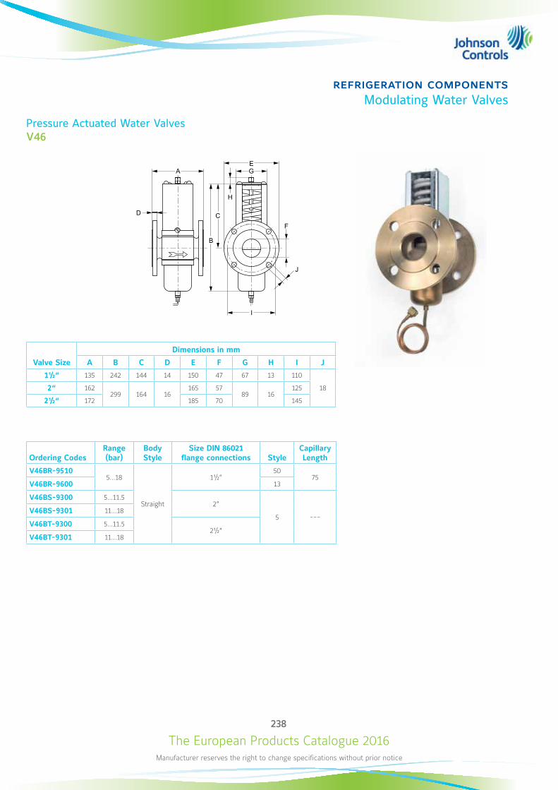
The European Products Catalogue 2016Manufacturer reserves the right to change specifications without prior notice
238
refrigeration componentsModulating Water Valves
Pressure Actuated Water ValvesV46
F
B
A
CD
E
I
J
H
G
Valve Size
Dimensions in mm
A B C D E F G H I J
1½“ 135 242 144 14 150 47 67 13 110
182“ 162299 164 16
165 5789 16
125
2½“ 172 185 70 145
Ordering CodesRange (bar)
Body Style
Size DIN 86021 flange connections Style
Capillary Length
V46BR-95105…18
Straight
1½“50
75V46BR-9600 13
V46BS-9300 5…11.52“
5 ---V46BS-9301 11…18
V46BT-9300 5…11.52½“
V46BT-9301 11…18
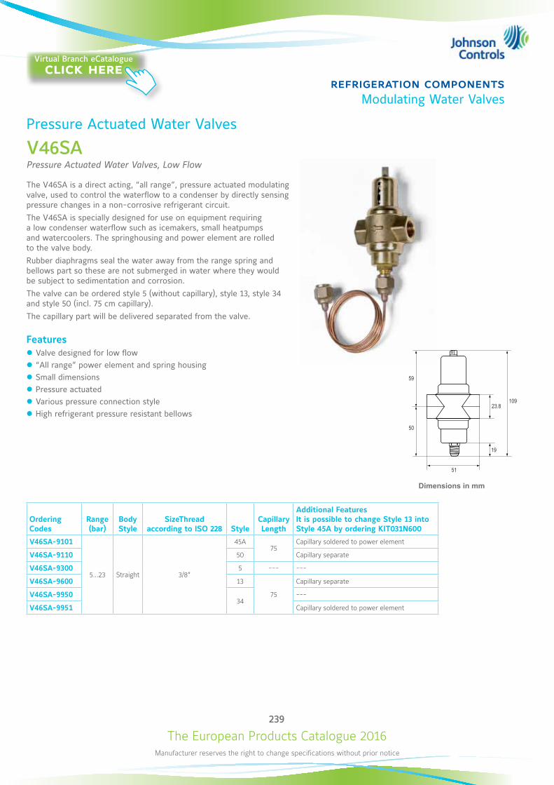
The European Products Catalogue 2016Manufacturer reserves the right to change specifications without prior notice
239
refrigeration componentsModulating Water Valves
Pressure Actuated Water Valves
V46SAPressure Actuated Water Valves, Low Flow
The V46SA is a direct acting, “all range”, pressure actuated modulating valve, used to control the waterflow to a condenser by directly sensing pressure changes in a non-corrosive refrigerant circuit. The V46SA is specially designed for use on equipment requiring a low condenser waterflow such as icemakers, small heatpumps and watercoolers. The springhousing and power element are rolled to the valve body.Rubber diaphragms seal the water away from the range spring and bellows part so these are not submerged in water where they would be subject to sedimentation and corrosion.The valve can be ordered style 5 (without capillary), style 13, style 34 and style 50 (incl. 75 cm capillary).The capillary part will be delivered separated from the valve.
Features z Valve designed for low flow z “All range” power element and spring housing z Small dimensions z Pressure actuated z Various pressure connection style z High refrigerant pressure resistant bellows
Ordering Codes
Range (bar)
Body Style
SizeThread according to ISO 228 Style
Capillary Length
Additional Features It is possible to change Style 13 into Style 45A by ordering KIT031N600
V46SA-9101
5…23 Straight 3/8“
45A75
Capillary soldered to power element
V46SA-9110 50 Capillary separate
V46SA-9300 5 --- ---
V46SA-9600 13
75
Capillary separate
V46SA-995034
---
V46SA-9951 Capillary soldered to power element
Dimensions in mm
23.8
59
50
109
51
19
Virtual Branch eCatalogueclick here
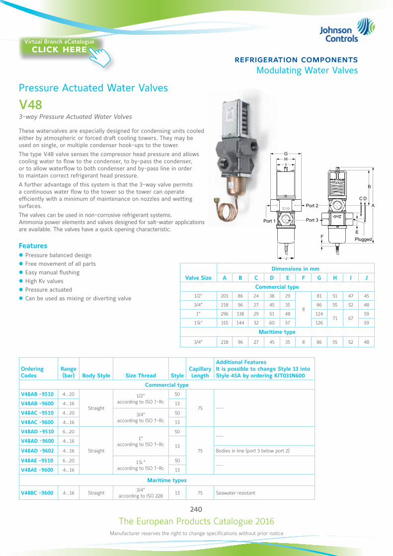
The European Products Catalogue 2016Manufacturer reserves the right to change specifications without prior notice
240
refrigeration componentsModulating Water Valves
Pressure Actuated Water Valves
V483-way Pressure Actuated Water Valves
These watervalves are especially designed for condensing units cooled either by atmospheric or forced draft cooling towers. They may be used on single, or multiple condenser hook-ups to the tower. The type V48 valve senses the compressor head pressure and allows cooling water to flow to the condenser, to by-pass the condenser, or to allow waterflow to both condenser and by-pass line in order to maintain correct refrigerant head pressure. A further advantage of this system is that the 3-way valve permits a continuous water flow to the tower so the tower can operate efficiently with a minimum of maintenance on nozzles and wetting surfaces. The valves can be used in non-corrosive refrigerant systems. Ammonia power elements and valves designed for salt-water applications are available. The valves have a quick opening characteristic.
Features z Pressure balanced design z Free movement of all parts z Easy manual flushing z High Kv values z Pressure actuated z Can be used as mixing or diverting valve
Valve Size
Dimensions in mm
A B C D E F G H I J
Commercial type
1/2“ 201 86 24 38 29
8
81 51 47 45
3/4“ 218 96 27 45 35 86 55 52 48
1“ 296 138 29 51 48 12471 67
59
1¼“ 315 144 32 60 57 126 59
Maritime type
3/4“ 218 96 27 45 35 8 86 55 52 48
Ordering Codes
Range (bar) Body Style Size Thread Style
Capillary Length
Additional Features It is possible to change Style 13 into Style 45A by ordering KIT031N600
Commercial type
V48AB -9510 4…20
Straight
1/2“ according to ISO 7-Rc
50
75 ---V48AB -9600 4…16 13
V48AC -9510 4…20 3/4“ according to ISO 7-Rc
50
V48AC -9600 4…16 13
V48AD -9510 6…20
Straight
1“ according to ISO 7-Rc
50
75
---V48AD -9600 4…16
13V48AD -9602 4…16 Bodies in line (port 3 below port 2)
V48AE -9510 6…20 1¼ “ according to ISO 7-Rc
50---
V48AE -9600 4…16 13
Maritime types
V48BC -9600 4…16 Straight 3/4“ according to ISO 228 13 75 Seawater resistant
G
IH
J
F
A
B
E
C D
Plugged
Port 1
Port 2
Port 3
Virtual Branch eCatalogueclick here
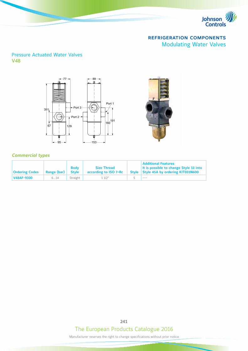
The European Products Catalogue 2016Manufacturer reserves the right to change specifications without prior notice
241
refrigeration componentsModulating Water Valves
Commercial types
Ordering Codes Range (bar)Body Style
Size Thread according to ISO 7-Rc Style
Additional Features It is possible to change Style 13 into Style 45A by ordering KIT031N600
V48AF-9300 6…14 Straight 1 1/2“ 5 ---
77
95 153
160191
89
12967
351
Pressure Actuated Water ValvesV48
Port 1
Port 2
Port 3
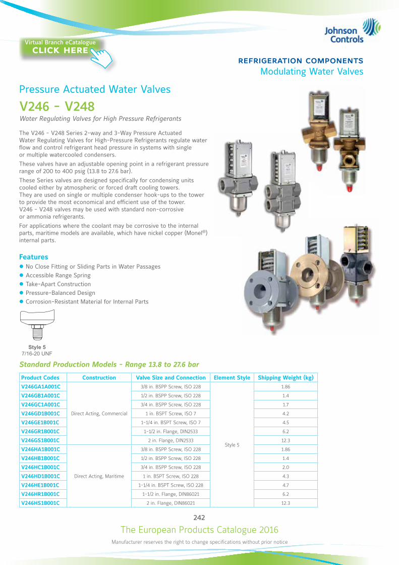
The European Products Catalogue 2016Manufacturer reserves the right to change specifications without prior notice
242
refrigeration componentsModulating Water Valves
Pressure Actuated Water Valves
V246 - V248 Water Regulating Valves for High Pressure Refrigerants
The V246 - V248 Series 2-way and 3-Way Pressure Actuated Water Regulating Valves for High-Pressure Refrigerants regulate water flow and control refrigerant head pressure in systems with single or multiple watercooled condensers. These valves have an adjustable opening point in a refrigerant pressure range of 200 to 400 psig (13.8 to 27.6 bar). These Series valves are designed specifically for condensing units cooled either by atmospheric or forced draft cooling towers. They are used on single or multiple condenser hook-ups to the tower to provide the most economical and efficient use of the tower. V246 - V248 valves may be used with standard non-corrosive or ammonia refrigerants. For applications where the coolant may be corrosive to the internal parts, maritime models are available, which have nickel copper (Monel®) internal parts.
Features z No Close Fitting or Sliding Parts in Water Passages z Accessible Range Spring z Take-Apart Construction z Pressure-Balanced Design z Corrosion-Resistant Material for Internal Parts
Standard Production Models - Range 13.8 to 27.6 bar
Product Codes Construction Valve Size and Connection Element Style Shipping Weight (kg)
V246GA1A001C
Direct Acting, Commercial
3/8 in. BSPP Screw, ISO 228
Style 5
1.86
V246GB1A001C 1/2 in. BSPP Screw, ISO 228 1.4
V246GC1A001C 3/4 in. BSPP Screw, ISO 228 1.7
V246GD1B001C 1 in. BSPT Screw, ISO 7 4.2
V246GE1B001C 1-1/4 in. BSPT Screw, ISO 7 4.5
V246GR1B001C 1-1/2 in. Flange, DIN2533 6.2
V246GS1B001C 2 in. Flange, DIN2533 12.3
V246HA1B001C
Direct Acting, Maritime
3/8 in. BSPP Screw, ISO 228 1.86
V246HB1B001C 1/2 in. BSPP Screw, ISO 228 1.4
V246HC1B001C 3/4 in. BSPP Screw, ISO 228 2.0
V246HD1B001C 1 in. BSPT Screw, ISO 228 4.3
V246HE1B001C 1-1/4 in. BSPT Screw, ISO 228 4.7
V246HR1B001C 1-1/2 in. Flange, DIN86021 6.2
V246HS1B001C 2 in. Flange, DIN86021 12.3
Style 5 7/16-20 UNF
Virtual Branch eCatalogueclick here
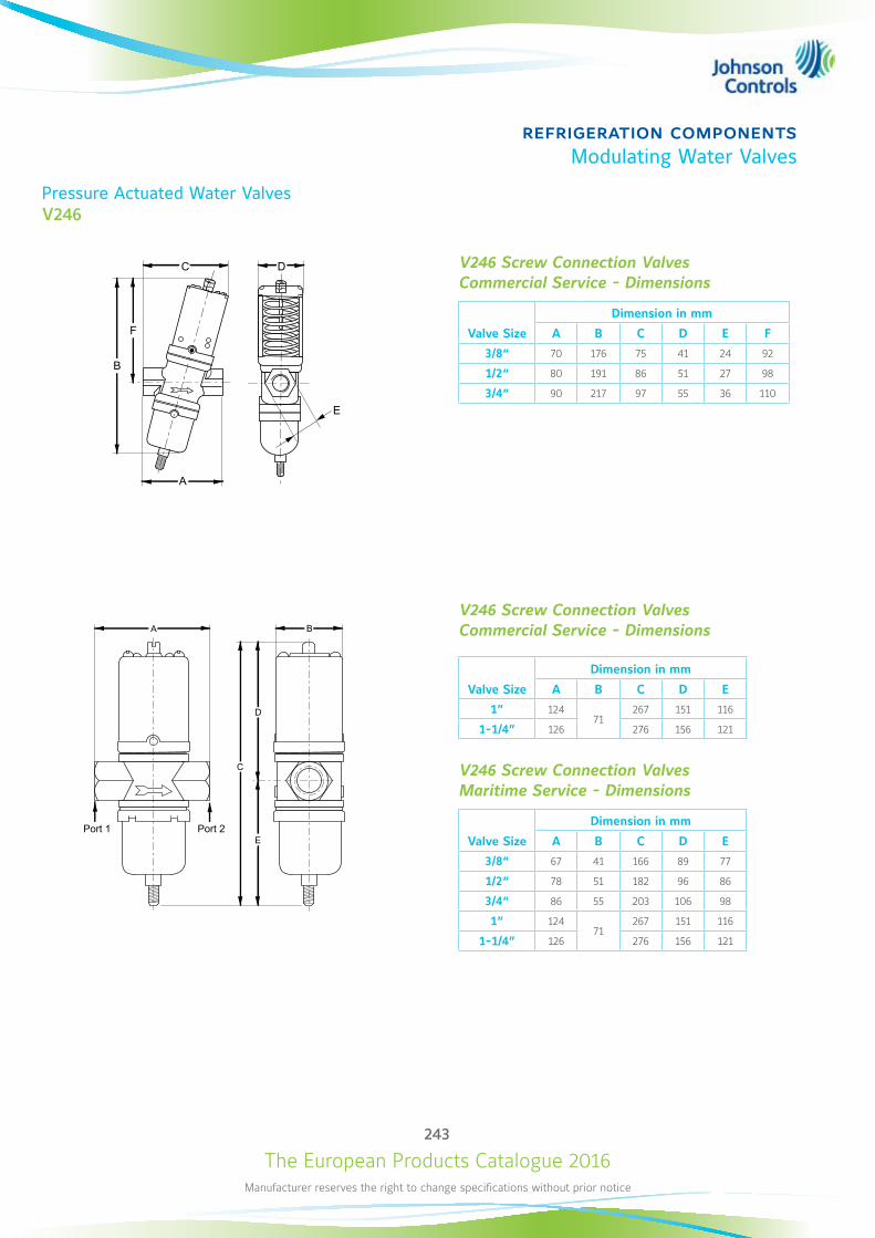
The European Products Catalogue 2016Manufacturer reserves the right to change specifications without prior notice
243
refrigeration componentsModulating Water Valves
Pressure Actuated Water ValvesV246
C
B
D
E
A
C
A
F
B
D
E
V246 Screw Connection Valves Commercial Service - Dimensions
Valve Size
Dimension in mm
A B C D E F
3/8“ 70 176 75 41 24 92
1/2“ 80 191 86 51 27 98
3/4“ 90 217 97 55 36 110
V246 Screw Connection Valves Commercial Service - Dimensions
Valve Size
Dimension in mm
A B C D E
1” 12471
267 151 116
1-1/4” 126 276 156 121
V246 Screw Connection Valves Maritime Service - Dimensions
Valve Size
Dimension in mm
A B C D E
3/8“ 67 41 166 89 77
1/2“ 78 51 182 96 86
3/4“ 86 55 203 106 98
1” 12471
267 151 116
1-1/4” 126 276 156 121
Port 1 Port 2
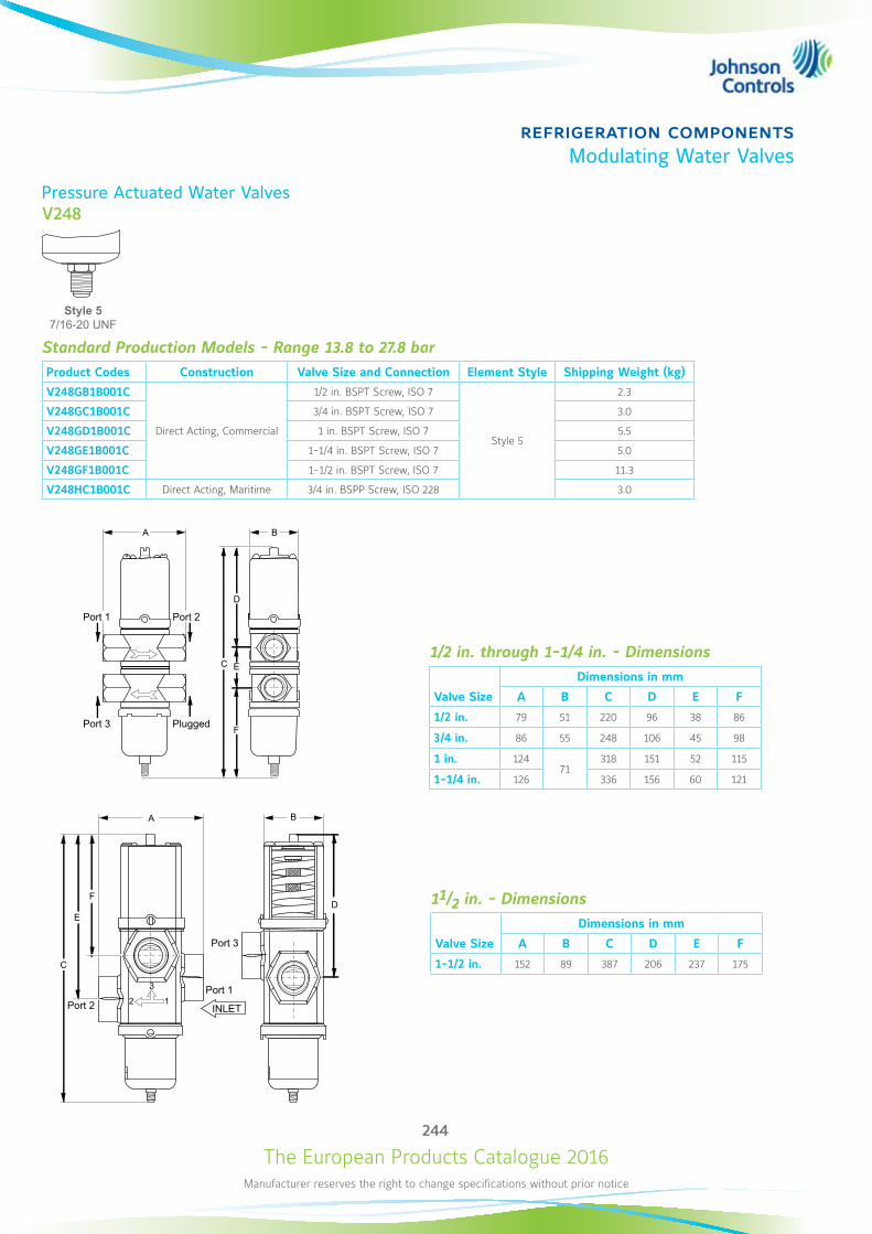
The European Products Catalogue 2016Manufacturer reserves the right to change specifications without prior notice
244
refrigeration componentsModulating Water Valves
Pressure Actuated Water ValvesV248
Standard Production Models - Range 13.8 to 27.8 barProduct Codes Construction Valve Size and Connection Element Style Shipping Weight (kg)
V248GB1B001C
Direct Acting, Commercial
1/2 in. BSPT Screw, ISO 7
Style 5
2.3
V248GC1B001C 3/4 in. BSPT Screw, ISO 7 3.0
V248GD1B001C 1 in. BSPT Screw, ISO 7 5.5
V248GE1B001C 1-1/4 in. BSPT Screw, ISO 7 5.0
V248GF1B001C 1-1/2 in. BSPT Screw, ISO 7 11.3
V248HC1B001C Direct Acting, Maritime 3/4 in. BSPP Screw, ISO 228 3.0
Style 5 7/16-20 UNF
A
C E
F
D
B
1/2 in. through 1-1/4 in. - Dimensions
Valve Size
Dimensions in mm
A B C D E F
1/2 in. 79 51 220 96 38 86
3/4 in. 86 55 248 106 45 98
1 in. 12471
318 151 52 115
1-1/4 in. 126 336 156 60 121
A
C
E
FD
B
3
2 1
11/2 in. - Dimensions
Valve Size
Dimensions in mm
A B C D E F
1-1/2 in. 152 89 387 206 237 175
Port 1 Port 2
Port 3 Plugged
Port 1Port 2
Port 3
INLET
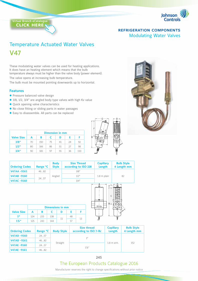
The European Products Catalogue 2016Manufacturer reserves the right to change specifications without prior notice
245
refrigeration componentsModulating Water Valves
Valve Size
Dimension in mm
A B C D E F
3/8“ 70 150 75 41 24 92
1/2“ 80 166 86 51 27 98
3/4“ 90 181 97 55 36 110
Ordering Codes Range °CBody Style
Size Thread according to ISO 228
Capillary Length
Bulb Style 4 Length mm
V47AA -9161 46…82
Angled
3/8“
1.8 m plain 82V47AB -916024…57
1/2“
V47AC -9160 3/4“
Valve Size
Dimensions in mm
A B C D E F
1“ 124 233 13872
4813
1¼“ 125 243 144 57
Ordering Codes Range °C Body StyleSize thread
according to ISO 7-RcCapillary Length
Bulb Style 4 Length mm
V47AD -9160 24…57
Straight
1“
1.8 m arm. 152V47AD -9161 46…82
V47AE -9160 24…571¼“
V47AE -9161 46…82
B
C
FA D
E
B
F
C D
A E
Temperature Actuated Water Valves
V47
These modulating water valves can be used for heating applications. It does have an heating element which means that the bulb temperature always must be higher than the valve body (power element). The valve opens at increasing bulb temperature. The bulb must be mounted pointing downwards up to horizontal.
Features z Pressure balanced valve design z 3/8, 1/2, 3/4” are angled body type valves with high Kv value z Quick opening valve characteristics z No close fitting or sliding parts in water passages z Easy to disassemble. All parts can be replaced
Virtual Branch eCatalogueclick here
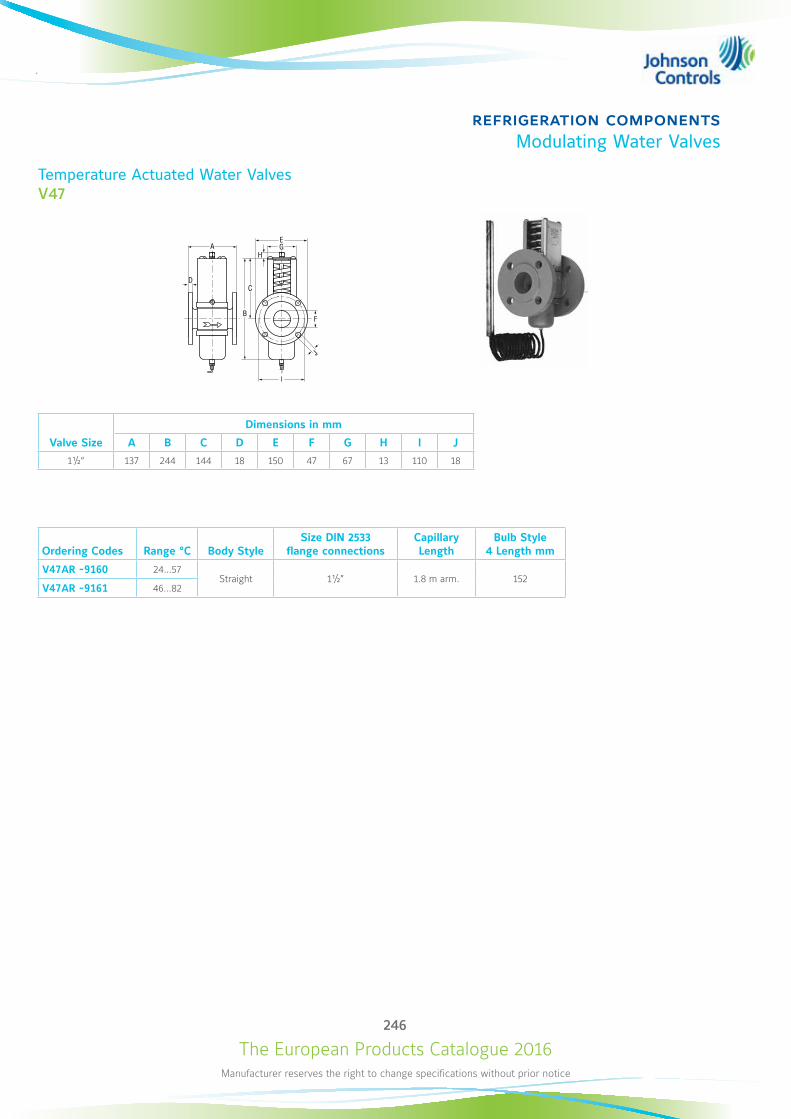
The European Products Catalogue 2016Manufacturer reserves the right to change specifications without prior notice
246
refrigeration componentsModulating Water Valves
Temperature Actuated Water Valves V47
A
B
CD
F
GH
J
I
E
Valve Size
Dimensions in mm
A B C D E F G H I J
1½“ 137 244 144 18 150 47 67 13 110 18
Ordering Codes Range °C Body StyleSize DIN 2533
flange connections Capillary Length
Bulb Style 4 Length mm
V47AR -9160 24…57Straight 1½” 1.8 m arm. 152
V47AR -9161 46…82
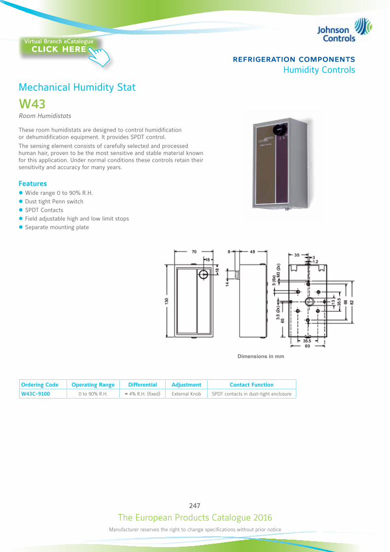
The European Products Catalogue 2016Manufacturer reserves the right to change specifications without prior notice
247
refrigeration componentsHumidity Controls
Mechanical Humidity Stat
W43Room Humidistats
These room humidistats are designed to control humidification or dehumidification equipment. It provides SPDT control.The sensing element consists of carefully selected and processed human hair, proven to be the most sensitive and stable material known for this application. Under normal conditions these controls retain their sensitivity and accuracy for many years.
Features z Wide range 0 to 90% R.H. z Dust tight Penn switch z SPDT Contacts z Field adjustable high and low limit stops z Separate mounting plate
Ordering Code Operating Range Differential Adjustment Contact Function
W43C-9100 0 to 90% R.H. ≈ 4% R.H. (fixed) External Knob SPDT contacts in dust-tight enclosure
Dimensions in mm
Virtual Branch eCatalogueclick here
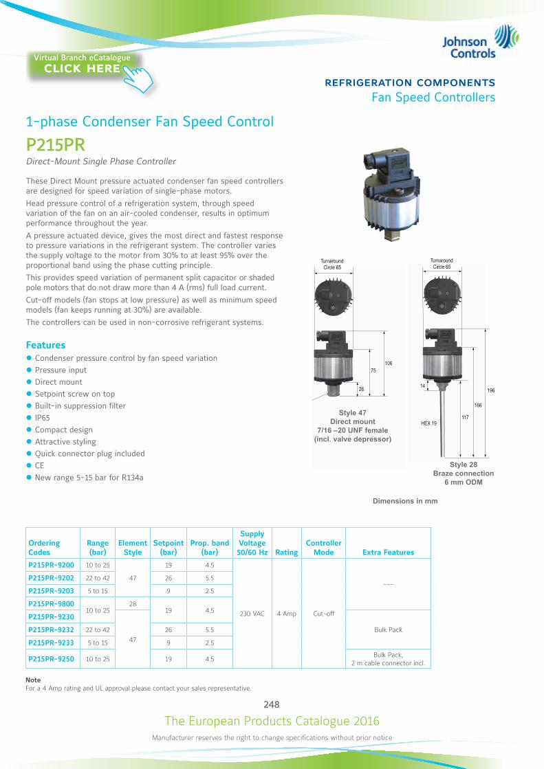
The European Products Catalogue 2016Manufacturer reserves the right to change specifications without prior notice
248
refrigeration componentsFan Speed Controllers
TurnaroundCircle 65
75
26 14
117
166
196
106
HEX 19
TurnaroundCircle 65
Style 47 Direct mount
7/16 –20 UNF female (incl. valve depressor)
Style 28 Braze connection
6 mm ODM
TurnaroundCircle 65
75
26 14
117
166
196
106
HEX 19
TurnaroundCircle 65
1-phase Condenser Fan Speed Control
P215PRDirect-Mount Single Phase Controller
These Direct Mount pressure actuated condenser fan speed controllers are designed for speed variation of single-phase motors.Head pressure control of a refrigeration system, through speed variation of the fan on an air-cooled condenser, results in optimum performance throughout the year.A pressure actuated device, gives the most direct and fastest response to pressure variations in the refrigerant system. The controller varies the supply voltage to the motor from 30% to at least 95% over the proportional band using the phase cutting principle.This provides speed variation of permanent split capacitor or shaded pole motors that do not draw more than 4 A (rms) full load current. Cut-off models (fan stops at low pressure) as well as minimum speed models (fan keeps running at 30%) are available. The controllers can be used in non-corrosive refrigerant systems.
Features z Condenser pressure control by fan speed variation z Pressure input z Direct mount z Setpoint screw on top z Built-in suppression filter z IP65 z Compact design z Attractive styling z Quick connector plug included z CE z New range 5-15 bar for R134a
Ordering Codes
Range (bar)
Element Style
Setpoint (bar)
Prop. band (bar)
Supply Voltage 50/60 Hz Rating
Controller Mode Extra Features
P215PR-9200 10 to 25
47
19 4.5
230 VAC 4 Amp Cut-off
---P215PR-9202 22 to 42 26 5.5
P215PR-9203 5 to 15 9 2.5
P215PR-980010 to 25
2819 4.5
P215PR-9230
47Bulk PackP215PR-9232 22 to 42 26 5.5
P215PR-9233 5 to 15 9 2.5
P215PR-9250 10 to 25 19 4.5 Bulk Pack, 2 m cable connector incl.
NoteFor a 4 Amp rating and UL approval please contact your sales representative.
Dimensions in mm
Virtual Branch eCatalogueclick here
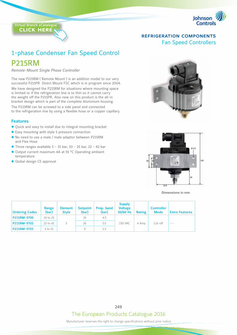
The European Products Catalogue 2016Manufacturer reserves the right to change specifications without prior notice
249
refrigeration componentsFan Speed Controllers
1-phase Condenser Fan Speed Control
P215RM Remote-Mount Single Phase Controller
The new P215RM ( Remote Mount ) is an addition model to our very successful P215PR Direct Mount FSC which is in program since 2004. We have designed the P215RM for situations where mounting space is limited or if the refrigeration line is to thin so it cannot carry the weight off the P215PR. Also new on this product is the all-in bracket design which is part of the complete Aluminium housing.The P215RM can be screwed to a side panel and connected to the refrigeration line by using a flexible hose or a copper capillary.
Features z Quick and easy to install due to integral mounting bracket z Easy mounting with style 5 pressure connection z No need to use a male / male adaptor between P215RM and Flex Hose
z Three ranges available 5 - 15 bar, 10 - 25 bar, 22 - 42 bar z Output current maximum 4A at 55 °C Operating ambient temperature
z Global design CE approval
Dimensions in mm
Ordering CodesRange (bar)
Element Style
Setpoint (bar)
Prop. band (bar)
Supply Voltage 50/60 Hz Rating
Controller Mode Extra Features
P215RM-9700 10 to 25
5
19 4.5
230 VAC 4 Amp Cut-off ---P215RM-9702 22 to 42 26 5.5
P215RM-9703 5 to 15 9 2.5
Virtual Branch eCatalogueclick here

The European Products Catalogue 2016Manufacturer reserves the right to change specifications without prior notice
250
refrigeration componentsFan Speed Controllers
1-phase Condenser Fan Speed Control
P215Pressure Actuated Single Phase Controller
These controllers are designed for speed variation of single phase motors, especially for fan speed control on air cooled condensers. Head pressure control of a refrigeration system, through speed variation of the fan on an air-cooled condenser, results in optimum performance throughout the year. Using a pressure transducer as the input device to the fan speed controller, gives the most direct and fastest response to pressure variations in the refrigerant system. The controller varies the supply voltage to the motor from 45% to at least 95% over the proportional band using the phase cutting principle. It is recommended to confirm with the electric motor manufacturer if a controller using the phase cutting principle for speed variation can be used. The controller used for dual pressure input varies the fan speed by directly sensing the pressure changes of two separate refrigerant circuits. The setpoint of each pressure transducer can be separately adjusted. The controller selects the input with the greatest cooling demand to control the fan speed. The transducers can be used in non-corrosive refrigerant systems.
Features z Condenser pressure control by fan speed variation z Pressure input z Transducers with proven reliability z Easy accessible setpoint screw z Adjustable minimum speed or cut-off selection z Heatpump input available (P215SH) z IP54 enclosure
P215SH/ST
Dimensions in mm
125100
94
140
130
Ordering Codes
Range (bar)
Prop. band (bar)
Setpoint (bar)
Pressure Connection
Supply Voltage 50/60 Hz Rating
Additional FeaturesNote: Style 50 is allowed on the Dutch market!
P215SH-9100 14 to 24 4 16
90 cm cap. st. 50
230 VAC
4 Amp
Single inputP215SH-9101 8 to 14 2.5 10
P215SH-9102 22 to 42 6 30 For use on R410A applications
P215SH-9800 14 to 24 4 16 Braze con. st. 28 Single input
P215ST-9100 14 to 24 4 1690 cm cap. st. 50
6 AmpSingle input P215ST-9101 8 to 14 2.5 10
P215ST-9600 14 to 24 4 16 90 cm cap. st. 51
P215ST-9102 22 to 42 6 30 90 cm cap. st. 50 For use on R410A applications
Virtual Branch eCatalogueclick here
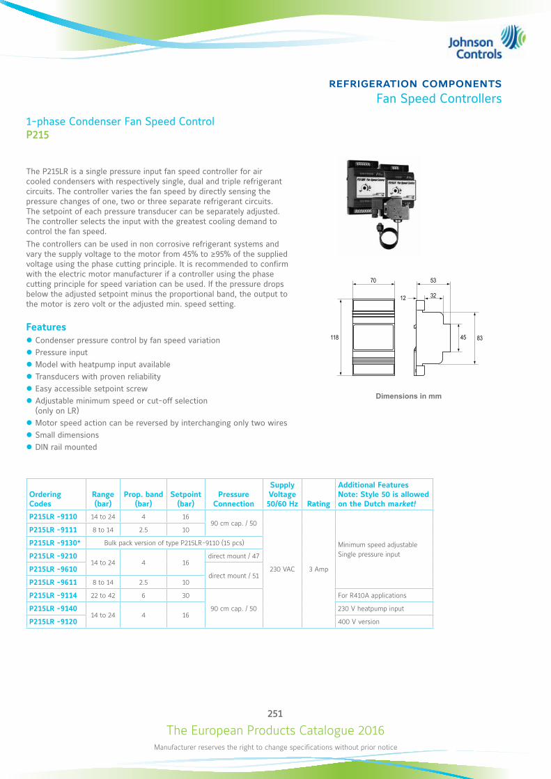
The European Products Catalogue 2016Manufacturer reserves the right to change specifications without prior notice
251
refrigeration componentsFan Speed Controllers
1-phase Condenser Fan Speed ControlP215
The P215LR is a single pressure input fan speed controller for air cooled condensers with respectively single, dual and triple refrigerant circuits. The controller varies the fan speed by directly sensing the pressure changes of one, two or three separate refrigerant circuits. The setpoint of each pressure transducer can be separately adjusted. The controller selects the input with the greatest cooling demand to control the fan speed. The controllers can be used in non corrosive refrigerant systems and vary the supply voltage to the motor from 45% to ≥95% of the supplied voltage using the phase cutting principle. It is recommended to confirm with the electric motor manufacturer if a controller using the phase cutting principle for speed variation can be used. If the pressure drops below the adjusted setpoint minus the proportional band, the output to the motor is zero volt or the adjusted min. speed setting.
Features z Condenser pressure control by fan speed variation z Pressure input z Model with heatpump input available z Transducers with proven reliability z Easy accessible setpoint screw z Adjustable minimum speed or cut-off selection (only on LR)
z Motor speed action can be reversed by interchanging only two wires z Small dimensions z DIN rail mounted
Dimensions in mm
HPA1A2A3
HPA1A2A3A1A2 A3
L1 L2 M1M2
(one earth pole)
(one earth pole)Heat
Pump Hp 1
Hp
slow
Hp2
P35AC1
1
>2 m2
2
3
3
P35AC
L
N
N
M1~M
1~
max 6 Amp
max 6 Ampslow
L2
L1
P35AC
1
2
3
P35AC
1
2
3
P35AC
1
2
3
P35AC
1
2
3
1
>2 m
2
3
P35AC
(one earthing pole)
6 Amp
N1
C1P215TR
L1N2 L2
C2B2B2A2 B3ABA2 C3
M1~
12
5370
32
45 83118
!
!Ordering Codes
Range (bar)
Prop. band (bar)
Setpoint (bar)
Pressure Connection
Supply Voltage 50/60 Hz Rating
Additional Features Note: Style 50 is allowed on the Dutch market!
P215LR -9110 14 to 24 4 1690 cm cap. / 50
230 VAC 3 Amp
Minimum speed adjustable Single pressure input
P215LR -9111 8 to 14 2.5 10
P215LR -9130* Bulk pack version of type P215LR-9110 (15 pcs)
P215LR -921014 to 24 4 16
direct mount / 47
P215LR -9610direct mount / 51
P215LR -9611 8 to 14 2.5 10
P215LR -9114 22 to 42 6 30
90 cm cap. / 50
For R410A applications
P215LR -914014 to 24 4 16
230 V heatpump input
P215LR -9120 400 V version

The European Products Catalogue 2016Manufacturer reserves the right to change specifications without prior notice
252
refrigeration componentsFan Speed Controllers
1-phase Condenser Fan Speed Control
P216Condenser Fan Speed Controller
These controllers are designed for speed variation of single phase motors, especially for fan speed control on air cooled condensers. Head pressure control of a refrigeration system, through speed variation of the fan on an air-cooled condenser, results in optimum performance throughout the year.Using a pressure transducer as the input device to the fan speed controller, gives the most direct and fastest response to pressure variations in the refrigerant system. The controller varies the supply voltage to the motor from 45% to at least 95% over the proportional band using the phase cutting principle.If the pressure drops below the adjusted setpoint minus the proportional band, the output to the motor is zero volt or the adjusted min. speed setting. This provides speed variation of permanent split capacitor or shaded pole motors which do not draw more than 12 A (rms) full load current.The controller used for dual pressure input varies the fan speed by directly sensing the pressure changes of two separate refrigerant circuits. The setpoint of each pressure transducer can be separately adjusted. The controller selects the input with the greatest cooling demand to control the fan speed.The transducers can be used in non-corrosive refrigerant systems.The motor manufacturer should have approved his product for this speed control principle. It is recommended to confirm with the electric motor manufacturer, that the motor can be used with a controller, using the phase cutting principle for speed variation.You can also provide a copy of this P216 product data sheet to the motor manufacturer/supplier for review.
Features z The new benchmark in standard FSC z Easy to Install and Easy to operate z Output Range: 0,5 to 12 Amp (1 phase) z Input 0-10 Vdc z Including 0-50 bar pressure transducer P499VCS-405C z Heatpump mode z Reverse operation mode z Master / Slave mode z Fixed pressure ranges for direct replacement (P215) z Setpoint and Min speed potmeters
165
178
76
66
Dimensions in mm
Ordering CodesProduct Codes Description
P216EEA-1K Wall Mount FSC P216EEA-100C + P499VCS-405C pressure transducer
P216EEA-100C Wall Mounted FSC
P499VCS-405C Pressure Transmitter with range 0-50 bar, Output 0-10V. 2 meter fixed cable. Pressure connection 7/16-20UNF female thread
Virtual Branch eCatalogueclick here

The European Products Catalogue 2016Manufacturer reserves the right to change specifications without prior notice
253
refrigeration componentsFan Speed Controllers
1-phase Condenser Fan Speed Control
P266Pressure Actuated Single Phase Digital Controller
The P266 Pressure Actuated Single Phase Digital Controller is a cost-effective, weather-resistant, durable motor speed control. The P266 control is designed for approved single-phase, Permanent Split-Capacitor (PSC) motors commonly used in a wide variety of refrigeration and air conditioning condenser fan applications.The P266 Series controls are designed to replace the Johnson Controls® P66 Series and P215 Series fan speed controls, providing additional features and flexibility, greater energy efficiency, and longer motor life in a compact, rugged, weather-resistant package.P266 models are available for 208 to 240 VAC and 440 to 575 VAC range applications. P266 controls have current ratings from 4 to 12 A depending on the voltage and model.Some P266 models provide optional control of up to three auxiliary (fixed-speed) fans or fan stages. Also, some models provide two additional high-voltage triacs, which allow you to split the source power to the main and auxiliary windings, and connect a low-speed capacitor to increase efficiency at low speed operation.
Features z Global design CE / UL / CSA / C-tick z Microprocessor based z Field Programmable, Digital setting z One or two Electronic Pressure Transducers (P266SNR) z Pressure range 0 - 35 bar or 0 - 52 bar z Patented design z Output 8 or 12 Amp at 60°C ambient temperature z Robust aluminium IP54 enclosure with integral heatsink z Multi triac control providing energy savings up to 25% z Optional auxiliary (vernier) control z Auto selection 50 / 60 Hz
Dimensions in mm
165
178
76
66
Virtual Branch eCatalogueclick here
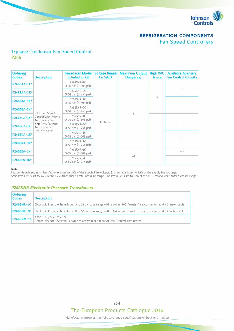
The European Products Catalogue 2016Manufacturer reserves the right to change specifications without prior notice
254
refrigeration componentsFan Speed Controllers
1-phase Condenser Fan Speed ControlP266
Ordering Codes Description
Transducer Model Included in Kit
Voltage Range (in VAC)
Maximum Output (Ampères)
High VAC Triacs
Available Auxiliary Fan Control Circuits
P266EAA-1K*
P266 Fan Speed Control with Internal Transformer and one P266 Pressure Transducer and one 2 m cable
P266SNR-1C 0-35 bar (0-508 psi)
208 to 240
8
3
---P266EAA-3K* P266SNR-2C
0-52 bar (0-754 psi)
P266EBA-1K* P266SNR-1C 0-35 bar (0-508 psi)
3P266EBA-3K* P266SNR-2C
0-52 bar (0-754 psi)
P266ECA-1K* P266SNR-1C 0-35 bar (0-508 psi)
1
---P266ECA-3K P266SNR-2C
0-52 bar (0-754 psi)
P266EDA-1K* P266SNR-1C 0-35 bar (0-508 psi)
3P266EDA-3K* P266SNR-2C
0-52 bar (0-754 psi)
P266EEA-1K* P266SNR-1C 0-35 bar (0-508 psi)
12---
P266EFA-3K* P266SNR-2C 0-52 bar (0-754 psi) 3
NoteFactory default settings: Start Voltage is set to 40% of the supply line-voltage. End Voltage is set to 95% of the supply line-voltage. Start Pressure is set to 44% of the P266 transducer’s total pressure range. End Pressure is set to 51% of the P266 transducer’s total pressure range.
P266SNR Electronic Pressure TransducersOrdering Codes Description
P266SNR-1C Electronic Pressure Transducer: 0 to 35 bar total range with a 1/4 in. SAE Female Flare connection and a 2 meter cable.
P266SNR-2C Electronic Pressure Transducer: 0 to 52 bar total range with a 1/4 in. SAE Female Flare connection and a 2 meter cable.
P266PRM-1K P266 Utility Com. Tool Kit. Communication Software Package to program and monitor P266 Control parameters.
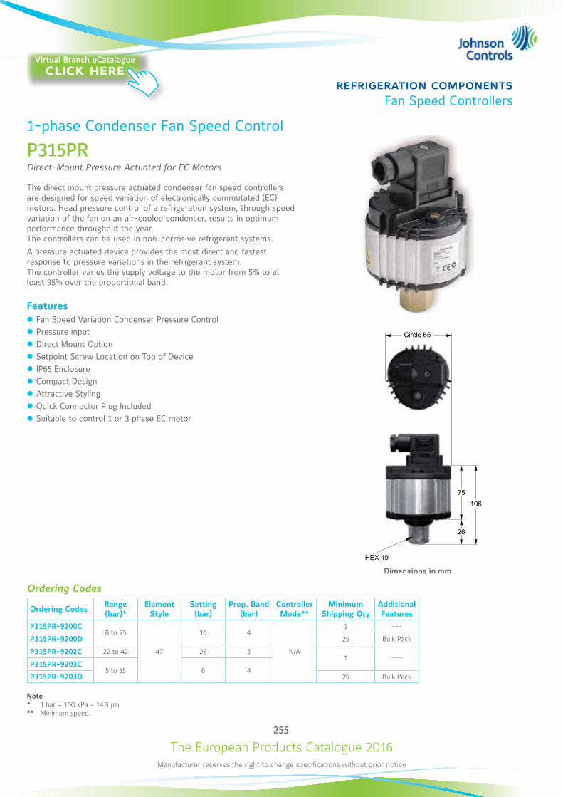
The European Products Catalogue 2016Manufacturer reserves the right to change specifications without prior notice
255
refrigeration componentsFan Speed Controllers
1-phase Condenser Fan Speed Control
P315PRDirect-Mount Pressure Actuated for EC Motors
The direct mount pressure actuated condenser fan speed controllers are designed for speed variation of electronically commutated (EC) motors. Head pressure control of a refrigeration system, through speed variation of the fan on an air-cooled condenser, results in optimum performance throughout the year. The controllers can be used in non-corrosive refrigerant systems.A pressure actuated device provides the most direct and fastest response to pressure variations in the refrigerant system. The controller varies the supply voltage to the motor from 5% to at least 95% over the proportional band.
Features z Fan Speed Variation Condenser Pressure Control z Pressure input z Direct Mount Option z Setpoint Screw Location on Top of Device z IP65 Enclosure z Compact Design z Attractive Styling z Quick Connector Plug Included z Suitable to control 1 or 3 phase EC motor
Ordering Codes
Ordering Codes Range (bar)*
Element Style
Setting (bar)
Prop. Band (bar)
Controller Mode**
Minimum Shipping Qty
Additional Features
P315PR-9200C8 to 25
47
16 4
N/A
1 ---
P315PR-9200D 25 Bulk Pack
P315PR-9202C 22 to 42 26 51 ---
P315PR-9203C5 to 15 6 4
P315PR-9203D 25 Bulk Pack
Note* 1 bar = 100 kPa ≈ 14.5 psi** Minimum speed.
TurnaroundCircle 65
HEX 19
26
75106
Dimensions in mm
Virtual Branch eCatalogueclick here
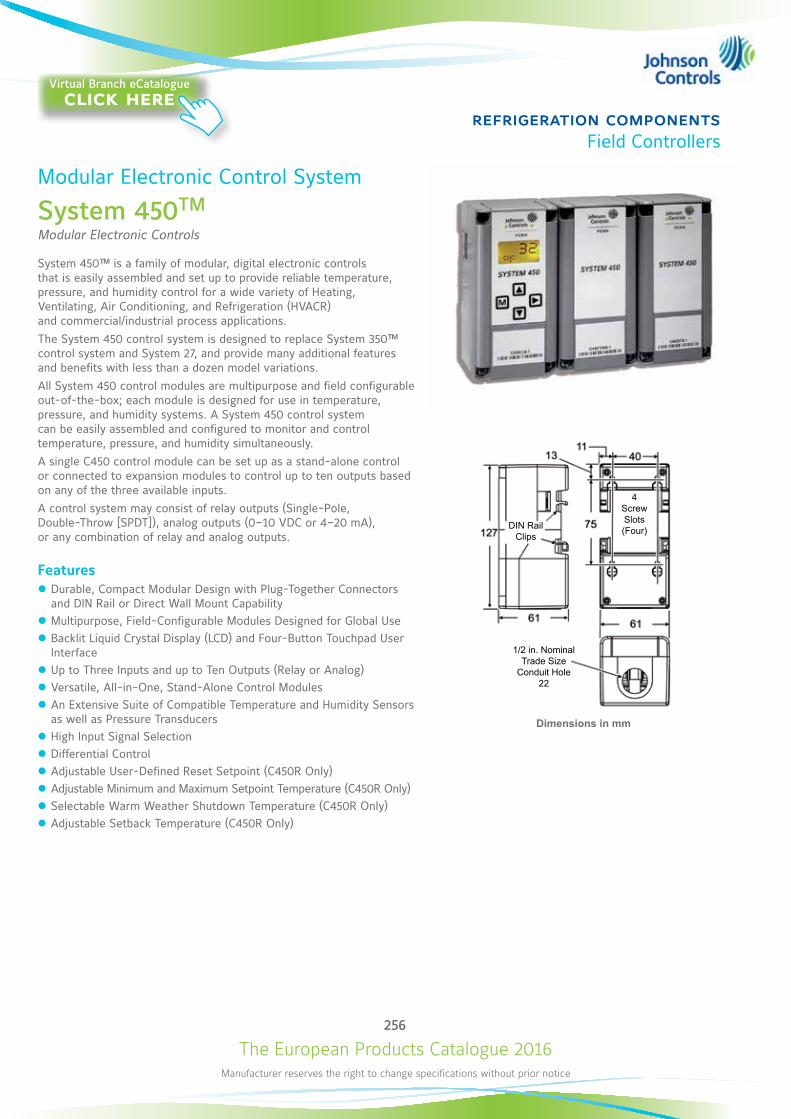
The European Products Catalogue 2016Manufacturer reserves the right to change specifications without prior notice
256
refrigeration componentsField Controllers
Modular Electronic Control System
System 450TM
Modular Electronic Controls
System 450™ is a family of modular, digital electronic controls that is easily assembled and set up to provide reliable temperature, pressure, and humidity control for a wide variety of Heating, Ventilating, Air Conditioning, and Refrigeration (HVACR) and commercial/industrial process applications.The System 450 control system is designed to replace System 350™ control system and System 27, and provide many additional features and benefits with less than a dozen model variations.All System 450 control modules are multipurpose and field configurable out-of-the-box; each module is designed for use in temperature, pressure, and humidity systems. A System 450 control system can be easily assembled and configured to monitor and control temperature, pressure, and humidity simultaneously.A single C450 control module can be set up as a stand-alone control or connected to expansion modules to control up to ten outputs based on any of the three available inputs.A control system may consist of relay outputs (Single-Pole, Double-Throw [SPDT]), analog outputs (0–10 VDC or 4–20 mA), or any combination of relay and analog outputs.
Features z Durable, Compact Modular Design with Plug-Together Connectors and DIN Rail or Direct Wall Mount Capability
z Multipurpose, Field-Configurable Modules Designed for Global Use z Backlit Liquid Crystal Display (LCD) and Four-Button Touchpad User Interface
z Up to Three Inputs and up to Ten Outputs (Relay or Analog) z Versatile, All-in-One, Stand-Alone Control Modules z An Extensive Suite of Compatible Temperature and Humidity Sensors as well as Pressure Transducers
z High Input Signal Selection z Differential Control z Adjustable User-Defined Reset Setpoint (C450R Only) z Adjustable Minimum and Maximum Setpoint Temperature (C450R Only) z Selectable Warm Weather Shutdown Temperature (C450R Only) z Adjustable Setback Temperature (C450R Only)
Dimensions in mm
4ScrewSlots(Four)DIN Rail
Clips
1/2 in. NominalTrade Size
Conduit Hole22
Virtual Branch eCatalogueclick here
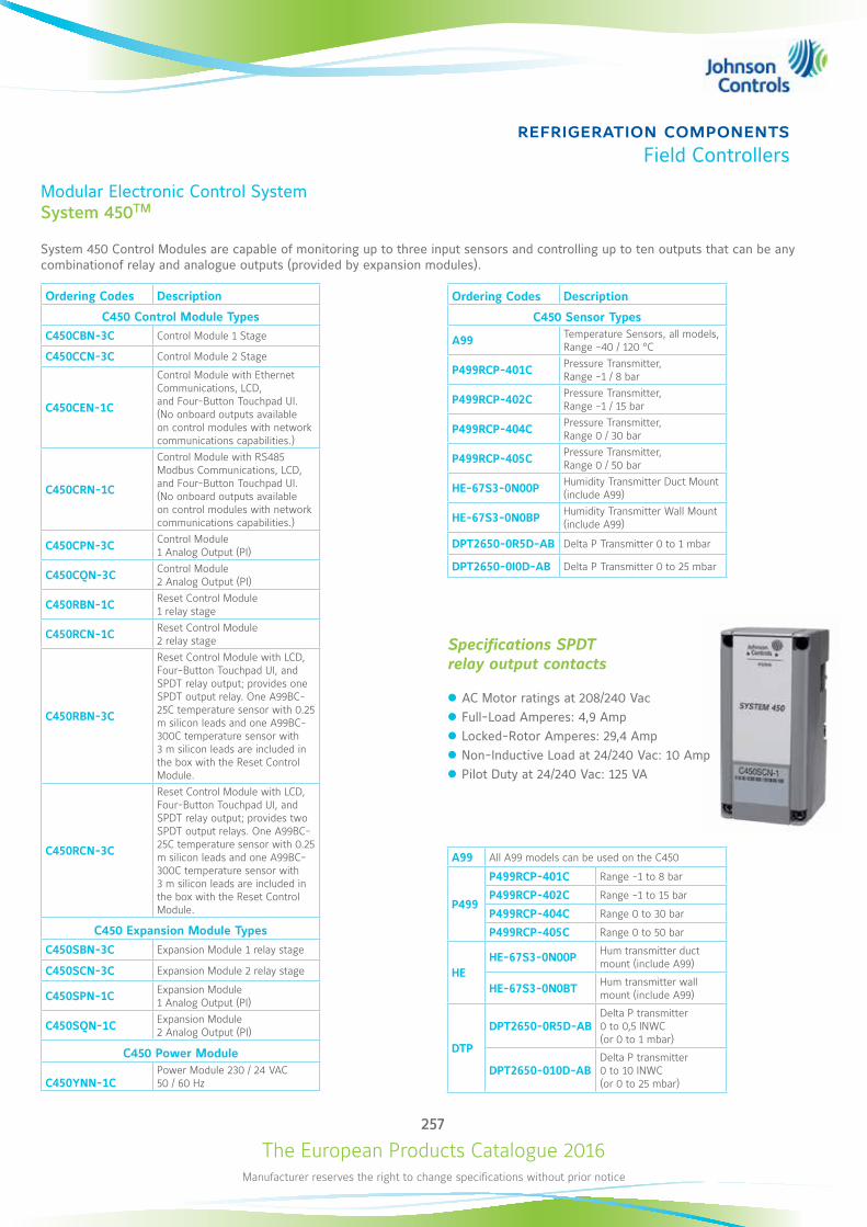
The European Products Catalogue 2016Manufacturer reserves the right to change specifications without prior notice
257
refrigeration componentsField Controllers
Modular Electronic Control SystemSystem 450TM
System 450 Control Modules are capable of monitoring up to three input sensors and controlling up to ten outputs that can be any combinationof relay and analogue outputs (provided by expansion modules).
Ordering Codes Description
C450 Control Module TypesC450CBN-3C Control Module 1 Stage
C450CCN-3C Control Module 2 Stage
C450CEN-1C
Control Module with Ethernet Communications, LCD, and Four-Button Touchpad UI. (No onboard outputs available on control modules with network communications capabilities.)
C450CRN-1C
Control Module with RS485 Modbus Communications, LCD, and Four-Button Touchpad UI. (No onboard outputs available on control modules with network communications capabilities.)
C450CPN-3C Control Module 1 Analog Output (PI)
C450CQN-3C Control Module 2 Analog Output (PI)
C450RBN-1C Reset Control Module 1 relay stage
C450RCN-1C Reset Control Module 2 relay stage
C450RBN-3C
Reset Control Module with LCD, Four-Button Touchpad UI, and SPDT relay output; provides one SPDT output relay. One A99BC-25C temperature sensor with 0.25 m silicon leads and one A99BC-300C temperature sensor with 3 m silicon leads are included in the box with the Reset Control Module.
C450RCN-3C
Reset Control Module with LCD, Four-Button Touchpad UI, and SPDT relay output; provides two SPDT output relays. One A99BC-25C temperature sensor with 0.25 m silicon leads and one A99BC-300C temperature sensor with 3 m silicon leads are included in the box with the Reset Control Module.
C450 Expansion Module Types
C450SBN-3C Expansion Module 1 relay stage
C450SCN-3C Expansion Module 2 relay stage
C450SPN-1C Expansion Module 1 Analog Output (PI)
C450SQN-1C Expansion Module 2 Analog Output (PI)
C450 Power Module
C450YNN-1CPower Module 230 / 24 VAC 50 / 60 Hz
Specifications SPDT relay output contacts
z AC Motor ratings at 208/240 Vac z Full-Load Amperes: 4,9 Amp z Locked-Rotor Amperes: 29,4 Amp z Non-Inductive Load at 24/240 Vac: 10 Amp z Pilot Duty at 24/240 Vac: 125 VA
A99 All A99 models can be used on the C450
P499
P499RCP-401C Range -1 to 8 bar
P499RCP-402C Range -1 to 15 bar
P499RCP-404C Range 0 to 30 bar
P499RCP-405C Range 0 to 50 bar
HEHE-67S3-0N00P Hum transmitter duct
mount (include A99)
HE-67S3-0N0BT Hum transmitter wall mount (include A99)
DTP
DPT2650-0R5D-ABDelta P transmitter 0 to 0,5 INWC (or 0 to 1 mbar)
DPT2650-010D-ABDelta P transmitter 0 to 10 INWC (or 0 to 25 mbar)
Ordering Codes Description
C450 Sensor Types
A99 Temperature Sensors, all models, Range -40 / 120 °C
P499RCP-401C Pressure Transmitter, Range -1 / 8 bar
P499RCP-402C Pressure Transmitter, Range -1 / 15 bar
P499RCP-404C Pressure Transmitter, Range 0 / 30 bar
P499RCP-405C Pressure Transmitter, Range 0 / 50 bar
HE-67S3-0N00P Humidity Transmitter Duct Mount (include A99)
HE-67S3-0N0BP Humidity Transmitter Wall Mount (include A99)
DPT2650-0R5D-AB Delta P Transmitter 0 to 1 mbar
DPT2650-0I0D-AB Delta P Transmitter 0 to 25 mbar

The European Products Catalogue 2016Manufacturer reserves the right to change specifications without prior notice
258
refrigeration componentsField Controllers
Electronic Control Devices
ER LineElectronic Refrigeration Line
Devices are designed to be incorporated in refrigerated display cases and cold storage rooms.ER Line proposes progressive offer from basic controls to advanced controls including real time clock, energy saving and network communication to be integrated with monitoring system. It also introduces specific products for supermarkets (e.g. compressor rack).
Hardware Features z Robust front panel for durability and long term usage z Direct 230V supply, no external transformer required z Up to 5 relays in a single package z NTC or PTC (A99) sensors z Removable plug connectors for quick mounting and wiring z Embedded real time clock, no additional clock card required z Embedded RS485 port, no additional communication card required
Application Features z Positive or negative temperature units with a single product z Minimum and maximum temperature monitoring z Comprehensive controls z Light and standby switching z Energy saving (2nd setpoint)
Product Type Mounting WiringCompressor
Relays Fan
RelaysDefrost Relays
Auxiliary Relays
Real Time Clock RS485
ER54 Evaporator Control Panel Removable plug
connectors
ER55-DR Cold Room Control Din Rail Removable plug
connectors (2 Relays)
ER55-SM Cold Room Control Split Fixed screw
connectors (2 Relays)
ER65 Rack Control Din Rail Removable plug connectors
(4 Relays)
Please refer to product bulletins for complete information
AccessoriesOrdering Codes Description Applied Products
ER-NTC-0C NTC sensor, cable 2 m, universal replacement All ER products
ER-COM-1C RS485 cable, 1.5 m, plug connector ER54, ER55-SM
ER-COM-2C RS485 cable, 1.5 m, RJ connector ER55-DR
P499Axx-xxxPressure transducer, 4-20 mA(See also P499 catalogue section)
ER65
Virtual Branch eCatalogueclick here
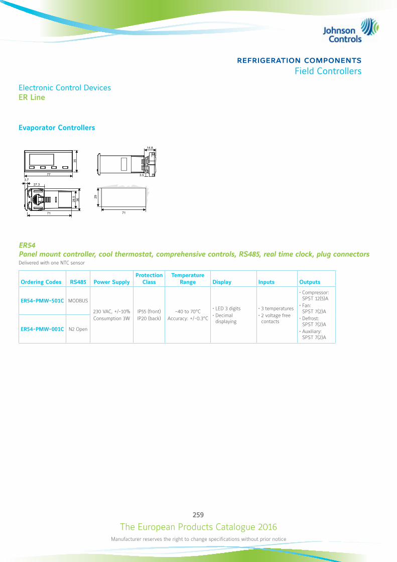
The European Products Catalogue 2016Manufacturer reserves the right to change specifications without prior notice
259
refrigeration componentsField Controllers
Electronic Control DevicesER Line
Evaporator Controllers
35
77
29
71
14.8
3.5
27.3
71
36
3.7
28.5
ER54 Panel mount controller, cool thermostat, comprehensive controls, RS485, real time clock, plug connectorsDelivered with one NTC sensor
Ordering Codes RS485 Power SupplyProtection
ClassTemperature
Range Display Inputs Outputs
ER54-PMW-501C MODBUS
230 VAC, +/-10%Consumption 3W
IP55 (front)IP20 (back)
-40 to 70°CAccuracy: +/-0.3°C
• LED 3 digits• Decimal displaying
• 3 temperatures• 2 voltage free contacts
• Compressor: SPST 12(5)A
• Fan: SPST 7(2)A
• Defrost: SPST 7(2)A
• Auxiliary: SPST 7(2)A
ER54-PMW-001C N2 Open
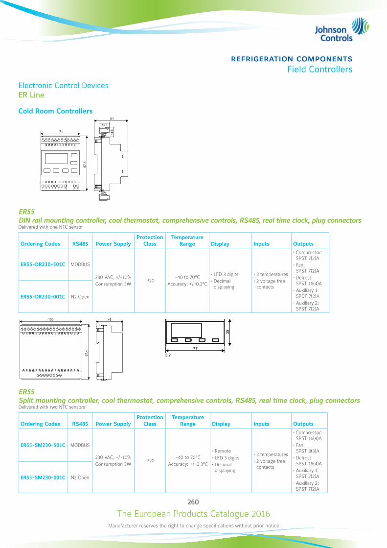
The European Products Catalogue 2016Manufacturer reserves the right to change specifications without prior notice
260
refrigeration componentsField Controllers
Electronic Control DevicesER Line
Cold Room Controllers
97.4
71
1 32 4 11865 7 12
24 2223 21 14171920 18 16 15 13
61
14.8
15.5
ER55 DIN rail mounting controller, cool thermostat, comprehensive controls, RS485, real time clock, plug connectorsDelivered with one NTC sensor
Ordering Codes RS485 Power SupplyProtection
ClassTemperature
Range Display Inputs Outputs
ER55-DR230-501C MODBUS
230 VAC, +/-10%Consumption 3W
IP20-40 to 70°C
Accuracy: +/-0.3°C
• LED 3 digits• Decimal displaying
• 3 temperatures• 2 voltage free contacts
• Compressor: SPST 7(2)A
• Fan: SPST 7(2)A
• Defrost: SPST 16(4)A
• Auxiliary 1: SPDT 7(2)A
• Auxiliary 2: SPST 7(2)A
ER55-DR230-001C N2 Open
97.4
105
13 1514 16 1817 191 32 4 11865 7 9 10 12
46
ER55 Split mounting controller, cool thermostat, comprehensive controls, RS485, real time clock, plug connectorsDelivered with two NTC sensors
Ordering Codes RS485 Power SupplyProtection
ClassTemperature
Range Display Inputs Outputs
ER55-SM230-501C MODBUS
230 VAC, +/-10%Consumption 3W
IP20-40 to 70°C
Accuracy: +/-0.3°C
• Remote• LED 3 digits• Decimal displaying
• 3 temperatures• 2 voltage free contacts
• Compressor: SPST 16(8)A
• Fan: SPST 8(3)A
• Defrost: SPST 16(4)A
• Auxiliary 1: SPST 7(2)A
• Auxiliary 2: SPST 7(2)A
ER55-SM230-001C N2 Open
35
77
29
71
14.8
3.5
27.3
71
36
3.7
28.5
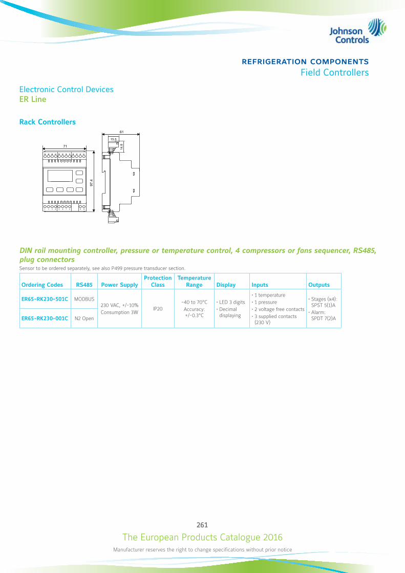
The European Products Catalogue 2016Manufacturer reserves the right to change specifications without prior notice
261
refrigeration componentsField Controllers
Electronic Control DevicesER Line
Rack Controllers
97.4
71
1 32 4 11865 7 12
24 2223 21 14171920 18 16 15 13
61
14.8
15.5
DIN rail mounting controller, pressure or temperature control, 4 compressors or fans sequencer, RS485, plug connectorsSensor to be ordered separately, see also P499 pressure transducer section.
Ordering Codes RS485 Power SupplyProtection
ClassTemperature
Range Display Inputs Outputs
ER65-RK230-501C MODBUS230 VAC, +/-10%Consumption 3W
IP20-40 to 70°CAccuracy: +/-0.3°C
• LED 3 digits• Decimal displaying
• 1 temperature• 1 pressure• 2 voltage free contacts• 3 supplied contacts (230 V)
• Stages (x4): SPST 5(1)A
• Alarm: SPDT 7(2)AER65-RK230-001C N2 Open
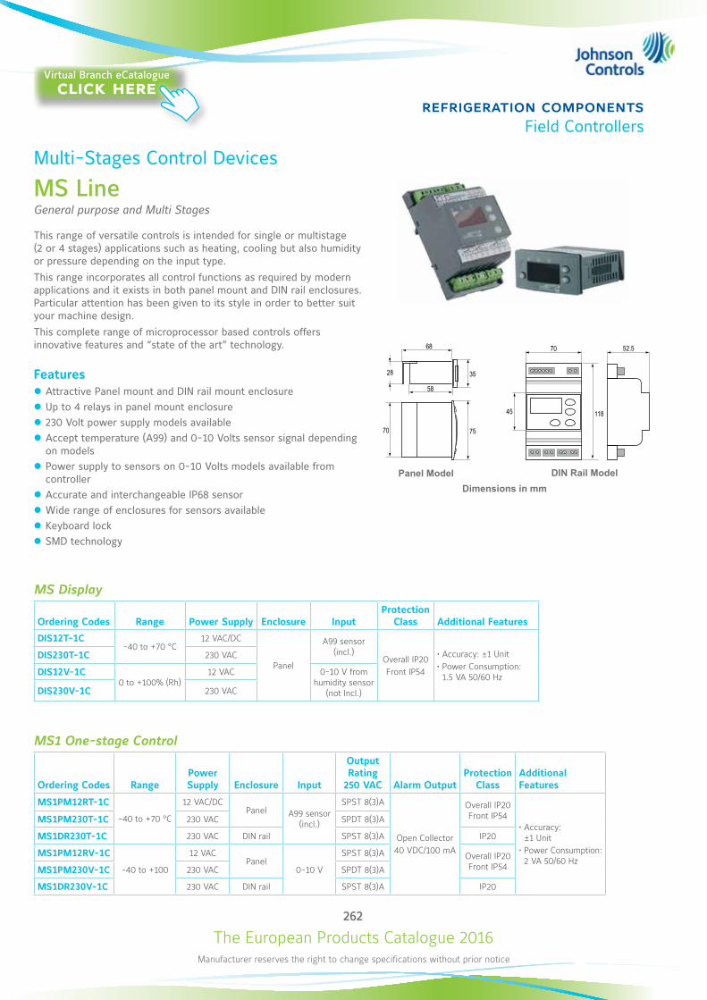
The European Products Catalogue 2016Manufacturer reserves the right to change specifications without prior notice
262
refrigeration componentsField Controllers
MS Display
Ordering Codes Range Power Supply Enclosure InputProtection
Class Additional Features
DIS12T-1C-40 to +70 °C
12 VAC/DC
Panel
A99 sensor (incl.)
Overall IP20 Front IP54
• Accuracy: ±1 Unit • Power Consumption: 1.5 VA 50/60 Hz
DIS230T-1C 230 VAC
DIS12V-1C0 to +100% (Rh)
12 VAC 0-10 V from humidity sensor
(not Incl.)DIS230V-1C 230 VAC
MS1 One-stage Control
Ordering Codes RangePower Supply Enclosure Input
Output Rating
250 VAC Alarm OutputProtection
ClassAdditional Features
MS1PM12RT-1C
-40 to +70 °C
12 VAC/DCPanel A99 sensor
(incl.)
SPST 8(3)A
Open Collector40 VDC/100 mA
Overall IP20 Front IP54
• Accuracy: ±1 Unit
• Power Consumption: 2 VA 50/60 Hz
MS1PM230T-1C 230 VAC SPDT 8(3)A
MS1DR230T-1C 230 VAC DIN rail SPST 8(3)A IP20
MS1PM12RV-1C
-40 to +100
12 VACPanel
0-10 V
SPST 8(3)A Overall IP20 Front IP54MS1PM230V-1C 230 VAC SPDT 8(3)A
MS1DR230V-1C 230 VAC DIN rail SPST 8(3)A IP20
DIN Rail Model
11845
52.570 68
28 35
58
70 75
Panel Model
11845
52.570 68
28 35
58
70 75
Multi-Stages Control Devices
MS LineGeneral purpose and Multi Stages
This range of versatile controls is intended for single or multistage (2 or 4 stages) applications such as heating, cooling but also humidity or pressure depending on the input type.This range incorporates all control functions as required by modern applications and it exists in both panel mount and DIN rail enclosures. Particular attention has been given to its style in order to better suit your machine design.This complete range of microprocessor based controls offers innovative features and “state of the art” technology.
Features z Attractive Panel mount and DIN rail mount enclosure z Up to 4 relays in panel mount enclosure z 230 Volt power supply models available z Accept temperature (A99) and 0-10 Volts sensor signal depending on models
z Power supply to sensors on 0-10 Volts models available from controller
z Accurate and interchangeable IP68 sensor z Wide range of enclosures for sensors available z Keyboard lock z SMD technology
Dimensions in mm
Virtual Branch eCatalogueclick here
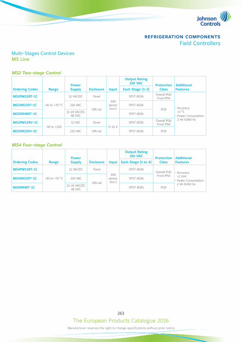
The European Products Catalogue 2016Manufacturer reserves the right to change specifications without prior notice
263
refrigeration componentsField Controllers
Multi-Stages Control Devices MS Line
MS2 Two-stage Control
Ordering Codes RangePower Supply Enclosure Input
Output Rating 250 VAC Protection
ClassAdditional FeaturesEach Stage (1-2)
MS2PM12RT-1C
-40 to +70 °C
12 VAC/DC Panel
A99 sensor (incl.)
SPST 8(3)A Overall IP20 Front IP54
• Accuracy: ±1 °C
• Power Consumption: 2 VA 50/60 Hz
MS2DR230T-1C 230 VACDIN rail
SPST 8(3)AIP20
MS2DR48DT-1C 12-24 VAC/DC 48 VDC SPDT 8(3)A
MS2PM12RV-1C -40 to +100
12 VAC Panel0-10 V
SPST 8(3)A Overall IP20 Front IP54
MS2DR230V-1C 230 VAC DIN rail SPST 8(3)A IP20
MS4 Four-stage Control
Ordering Codes RangePower Supply Enclosure Input
Output Rating 250 VAC Protection
ClassAdditional FeaturesEach Stage (1 to 4)
MS4PM12RT-1C
-40 to +70 °C
12 VAC/DC Panel
A99 sensor (incl.)
SPST 8(3)AOverall IP20 Front IP54
• Accuracy: ±1 Unit
• Power Consumption: 2 VA 50/60 Hz
MS4DR230T-1C 230 VACDIN rail
SPST 8(3)A
MS4DR48T-1C 12-24 VAC/DC 48 VDC SPDT 8(3)A IP20
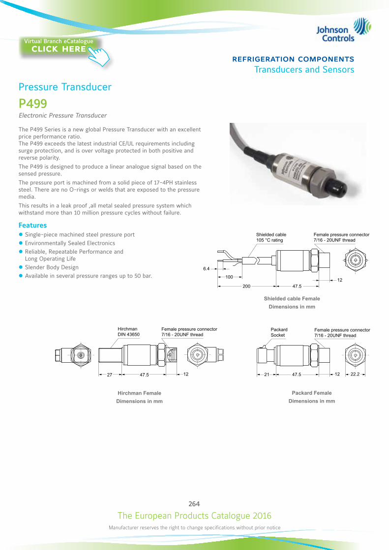
The European Products Catalogue 2016Manufacturer reserves the right to change specifications without prior notice
264
refrigeration componentsTransducers and Sensors
100
6.4
200 47.5
27 21
12
22.21247.547.5 12
Shielded cable FemaleDimensions in mm
Hirchman FemaleDimensions in mm
Packard FemaleDimensions in mm
Pressure Transducer
P499Electronic Pressure Transducer
The P499 Series is a new global Pressure Transducer with an excellent price performance ratio. The P499 exceeds the latest industrial CE/UL requirements including surge protection, and is over voltage protected in both positive and reverse polarity. The P499 is designed to produce a linear analogue signal based on the sensed pressure. The pressure port is machined from a solid piece of 17-4PH stainless steel. There are no O-rings or welds that are exposed to the pressure media. This results in a leak proof ,all metal sealed pressure system which withstand more than 10 million pressure cycles without failure.
Features z Single-piece machined steel pressure port z Environmentally Sealed Electronics z Reliable, Repeatable Performance and Long Operating Life
z Slender Body Design z Available in several pressure ranges up to 50 bar.
Shielded cable 105 °C rating
Female pressure connector7/16 - 20UNF thread
Hirchman DIN 43650
PackardSocket
Female pressure connector7/16 - 20UNF thread
Female pressure connector7/16 - 20UNF thread
Virtual Branch eCatalogueclick here
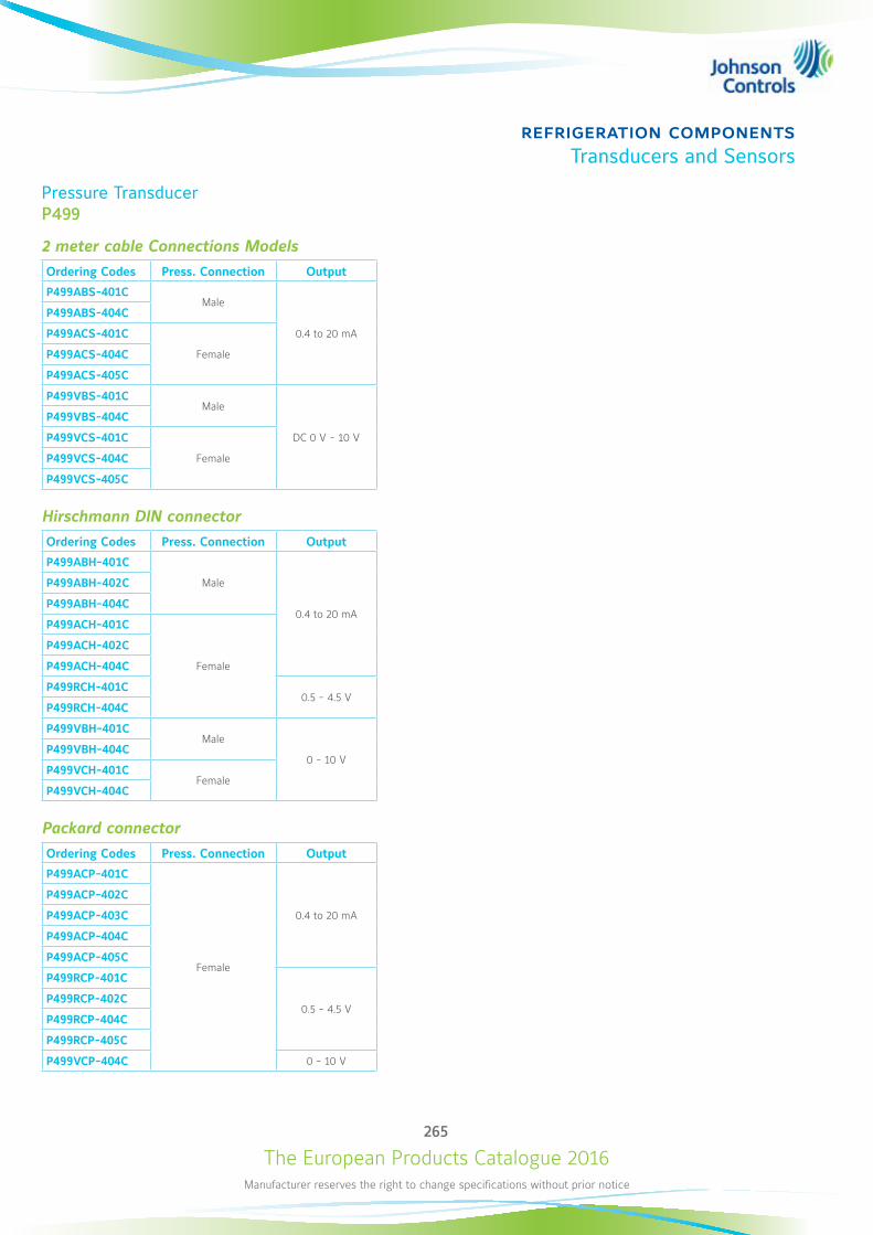
The European Products Catalogue 2016Manufacturer reserves the right to change specifications without prior notice
265
refrigeration componentsTransducers and Sensors
Pressure Transducer P499
2 meter cable Connections ModelsOrdering Codes Press. Connection Output
P499ABS-401CMale
0.4 to 20 mA
P499ABS-404C
P499ACS-401C
FemaleP499ACS-404C
P499ACS-405C
P499VBS-401CMale
DC 0 V - 10 V
P499VBS-404C
P499VCS-401C
FemaleP499VCS-404C
P499VCS-405C
Hirschmann DIN connectorOrdering Codes Press. Connection Output
P499ABH-401C
Male
0.4 to 20 mA
P499ABH-402C
P499ABH-404C
P499ACH-401C
Female
P499ACH-402C
P499ACH-404C
P499RCH-401C0.5 - 4.5 V
P499RCH-404C
P499VBH-401CMale
0 - 10 VP499VBH-404C
P499VCH-401CFemale
P499VCH-404C
Packard connectorOrdering Codes Press. Connection Output
P499ACP-401C
Female
0.4 to 20 mA
P499ACP-402C
P499ACP-403C
P499ACP-404C
P499ACP-405C
P499RCP-401C
0.5 - 4.5 VP499RCP-402C
P499RCP-404C
P499RCP-405C
P499VCP-404C 0 - 10 V
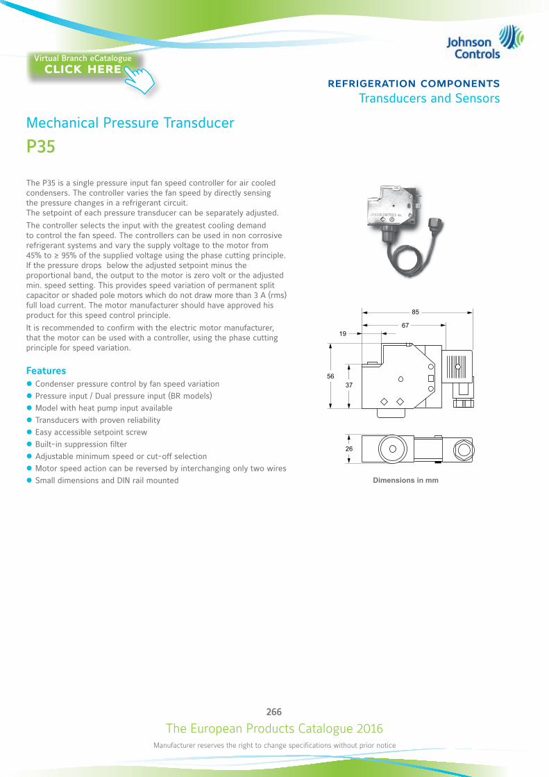
The European Products Catalogue 2016Manufacturer reserves the right to change specifications without prior notice
266
refrigeration componentsTransducers and Sensors
Dimensions in mm
19
85
67
3756
26
Mechanical Pressure Transducer
P35
The P35 is a single pressure input fan speed controller for air cooled condensers. The controller varies the fan speed by directly sensing the pressure changes in a refrigerant circuit. The setpoint of each pressure transducer can be separately adjusted. The controller selects the input with the greatest cooling demand to control the fan speed. The controllers can be used in non corrosive refrigerant systems and vary the supply voltage to the motor from 45% to ≥ 95% of the supplied voltage using the phase cutting principle. If the pressure drops below the adjusted setpoint minus the proportional band, the output to the motor is zero volt or the adjusted min. speed setting. This provides speed variation of permanent split capacitor or shaded pole motors which do not draw more than 3 A (rms) full load current. The motor manufacturer should have approved his product for this speed control principle. It is recommended to confirm with the electric motor manufacturer, that the motor can be used with a controller, using the phase cutting principle for speed variation.
Features z Condenser pressure control by fan speed variation z Pressure input / Dual pressure input (BR models) z Model with heat pump input available z Transducers with proven reliability z Easy accessible setpoint screw z Built-in suppression filter z Adjustable minimum speed or cut-off selection z Motor speed action can be reversed by interchanging only two wires z Small dimensions and DIN rail mounted
Virtual Branch eCatalogueclick here
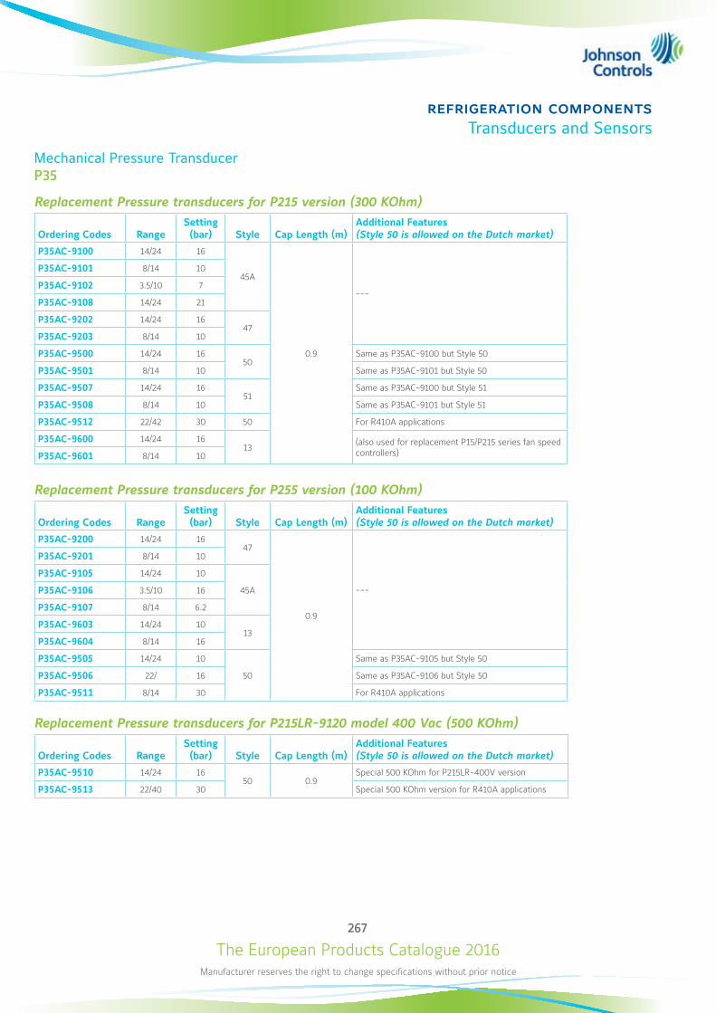
The European Products Catalogue 2016Manufacturer reserves the right to change specifications without prior notice
267
refrigeration componentsTransducers and Sensors
Mechanical Pressure Transducer P35
Replacement Pressure transducers for P215 version (300 KOhm)
Ordering Codes RangeSetting (bar) Style Cap Length (m)
Additional Features (Style 50 is allowed on the Dutch market)
P35AC-9100 14/24 16
45A
0.9
---
P35AC-9101 8/14 10
P35AC-9102 3.5/10 7
P35AC-9108 14/24 21
P35AC-9202 14/24 1647
P35AC-9203 8/14 10
P35AC-9500 14/24 1650
Same as P35AC-9100 but Style 50
P35AC-9501 8/14 10 Same as P35AC-9101 but Style 50
P35AC-9507 14/24 1651
Same as P35AC-9100 but Style 51
P35AC-9508 8/14 10 Same as P35AC-9101 but Style 51
P35AC-9512 22/42 30 50 For R410A applications
P35AC-9600 14/24 1613 (also used for replacement P15/P215 series fan speed
controllers)P35AC-9601 8/14 10
Replacement Pressure transducers for P255 version (100 KOhm)
Ordering Codes RangeSetting (bar) Style Cap Length (m)
Additional Features (Style 50 is allowed on the Dutch market)
P35AC-9200 14/24 1647
0.9
---
P35AC-9201 8/14 10
P35AC-9105 14/24 10
45AP35AC-9106 3.5/10 16
P35AC-9107 8/14 6.2
P35AC-9603 14/24 1013
P35AC-9604 8/14 16
P35AC-9505 14/24 10
50
Same as P35AC-9105 but Style 50
P35AC-9506 22/ 16 Same as P35AC-9106 but Style 50
P35AC-9511 8/14 30 For R410A applications
Replacement Pressure transducers for P215LR-9120 model 400 Vac (500 KOhm)
Ordering Codes RangeSetting (bar) Style Cap Length (m)
Additional Features (Style 50 is allowed on the Dutch market)
P35AC-9510 14/24 1650 0.9
Special 500 KOhm for P215LR-400V version
P35AC-9513 22/40 30 Special 500 KOhm version for R410A applications
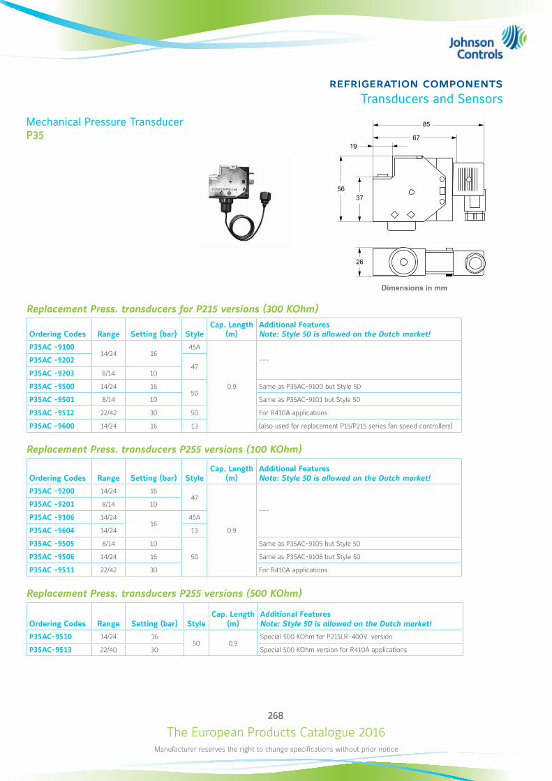
The European Products Catalogue 2016Manufacturer reserves the right to change specifications without prior notice
268
refrigeration componentsTransducers and Sensors
Mechanical Pressure Transducer P35
Replacement Press. transducers for P215 versions (300 KOhm)
Ordering Codes Range Setting (bar) StyleCap. Length
(m)Additional Features Note: Style 50 is allowed on the Dutch market!
P35AC -910014/24 16
45A
0.9
---P35AC -920247
P35AC -9203 8/14 10
P35AC -9500 14/24 1650
Same as P35AC-9100 but Style 50
P35AC -9501 8/14 10 Same as P35AC-9101 but Style 50
P35AC -9512 22/42 30 50 For R410A applications
P35AC -9600 14/24 16 13 (also used for replacement P15/P215 series fan speed controllers)
Replacement Press. transducers P255 versions (100 KOhm)
Ordering Codes Range Setting (bar) StyleCap. Length
(m)Additional Features Note: Style 50 is allowed on the Dutch market!
P35AC -9200 14/24 1647
0.9
--- P35AC -9201 8/14 10
P35AC -9106 14/2416
45A
P35AC -9604 14/24 13
P35AC -9505 8/14 10
50
Same as P35AC-9105 but Style 50
P35AC -9506 14/24 16 Same as P35AC-9106 but Style 50
P35AC -9511 22/42 30 For R410A applications
Replacement Press. transducers P255 versions (500 KOhm)
Ordering Codes Range Setting (bar) StyleCap. Length
(m)Additional Features Note: Style 50 is allowed on the Dutch market!
P35AC-9510 14/24 1650 0.9
Special 500 KOhm for P215LR-400V. version
P35AC-9513 22/40 30 Special 500 KOhm version for R410A applications
Dimensions in mm
19
85
67
3756
26
The European Products Catalogue 2016Manufacturer reserves the right to change specifications without prior notice
269
refrigeration componentsTransducers and Sensors
Mechanical Pressure Transducer P35
AccessoriesOrdering Codes Description
BKT034N602R Mounting bracket + screws for P35AC transducer
Replacement Parts
P38AA-9111 Replacement electronic module P215LR-230 V types
P38AA-9112 Replacement electronic module P215LR-230 V incl. heatpump input types
P38AA-9211 Replacement electronic module P215BR-230 V types
P38AA-9311 Replacement electronic module P215TR-230 V types
P38AD-9100 Replacement electronic module P255MM
P38AD-9101 Replacement electronic module P255ML
The European Products Catalogue 2016Manufacturer reserves the right to change specifications without prior notice
270
refrigeration componentsTransducers and Sensors
Accessories for Temperature Controls
Ordering Codes DescriptionPrimary Usage
Inner Ø x Tube Length Bulb well (mm)
Inside & Outside connector (NPT)
Material Connector Pocket
FTG13A-600R Closed tank connector Style 1b elements, Max. 10 bar, 120 °C, Min. -40 °C A19/28/36
--- --- ---
KIT012N600 Capillary brackets (6 pieces) 270XT
WEL003N602RBulb well, Max. pressure 70 bar, Temp. 370 °C
--- 9.8 x 125 1/2 - 14 Stainless steel
WEL11A601RBulb well, Max. pressure 20 bar, Temp. 120 °C, USA item
A19 7.3 x 60 1/2 - 14 Brass/Copper
WEL14A-600RBulb well, Max. pressure 69 bar, Temp. 370 °C, USA item
A19/28/36 11.2 x 120 1/2 - 14 Monel/Monel
WEL14A602RBulb well, Max. pressure 20 bar, Temp. 120 °C, USA item
A19/28/36 9.8 x 125 1/2 - 14 Brass/Copper
WEL14A603RBulb well, Max. pressure 20 bar, Temp. 120 °C, USA item
A19/28/36 9.8 x 147 1/2 - 14 Brass/Copper
WEL16A-601RBulb well, Max. pressure 20 bar, Temp. 120 °C, USA item
A19/28/36 9.5 x 71 1/2 - 14 Brass/Copper
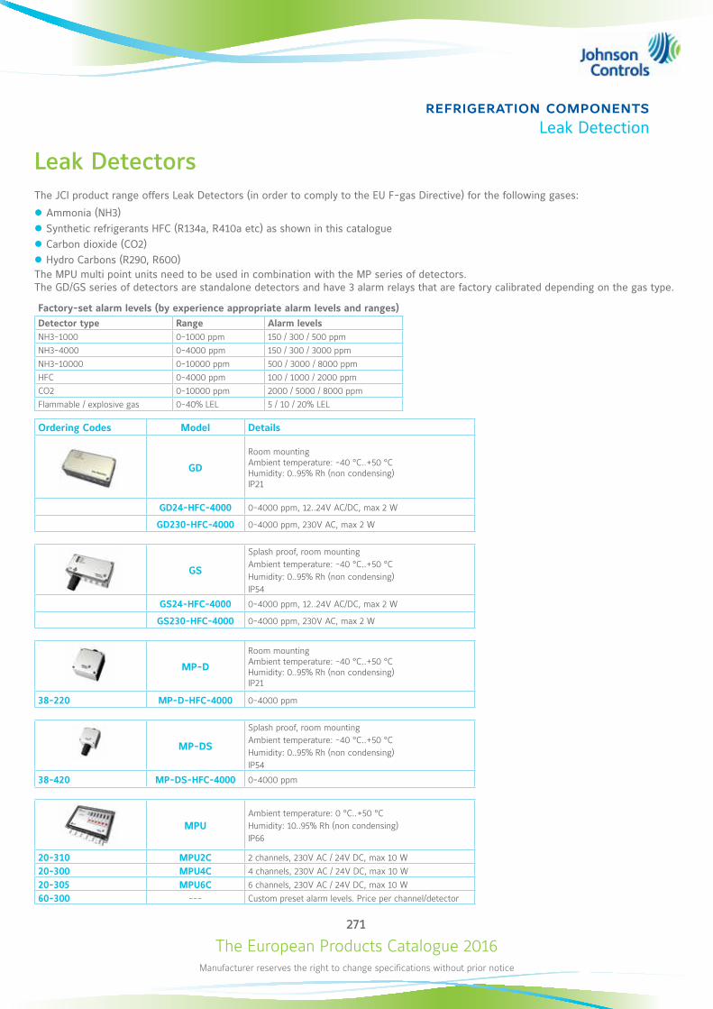
The European Products Catalogue 2016Manufacturer reserves the right to change specifications without prior notice
271
refrigeration componentsLeak Detection
Leak DetectorsThe JCI product range offers Leak Detectors (in order to comply to the EU F-gas Directive) for the following gases:
z Ammonia (NH3) z Synthetic refrigerants HFC (R134a, R410a etc) as shown in this catalogue z Carbon dioxide (CO2) z Hydro Carbons (R290, R600)
The MPU multi point units need to be used in combination with the MP series of detectors. The GD/GS series of detectors are standalone detectors and have 3 alarm relays that are factory calibrated depending on the gas type.
Factory-set alarm levels (by experience appropriate alarm levels and ranges)Detector type Range Alarm levelsNH3-1000 0-1000 ppm 150 / 300 / 500 ppmNH3-4000 0-4000 ppm 150 / 300 / 3000 ppmNH3-10000 0-10000 ppm 500 / 3000 / 8000 ppmHFC 0-4000 ppm 100 / 1000 / 2000 ppmCO2 0-10000 ppm 2000 / 5000 / 8000 ppmFlammable / explosive gas 0-40% LEL 5 / 10 / 20% LEL
Ordering Codes Model Details
GD
Room mounting Ambient temperature: -40 °C..+50 °C Humidity: 0..95% Rh (non condensing) IP21
GD24-HFC-4000 0-4000 ppm, 12..24V AC/DC, max 2 W
GD230-HFC-4000 0-4000 ppm, 230V AC, max 2 W
GS
Splash proof, room mountingAmbient temperature: -40 °C..+50 °CHumidity: 0..95% Rh (non condensing)IP54
GS24-HFC-4000 0-4000 ppm, 12..24V AC/DC, max 2 W
GS230-HFC-4000 0-4000 ppm, 230V AC, max 2 W
MP-D
Room mounting Ambient temperature: -40 °C..+50 °C Humidity: 0..95% Rh (non condensing) IP21
38-220 MP-D-HFC-4000 0-4000 ppm
MP-DS
Splash proof, room mountingAmbient temperature: -40 °C..+50 °CHumidity: 0..95% Rh (non condensing)IP54
38-420 MP-DS-HFC-4000 0-4000 ppm
MPUAmbient temperature: 0 °C..+50 °CHumidity: 10..95% Rh (non condensing)IP66
20-310 MPU2C 2 channels, 230V AC / 24V DC, max 10 W
20-300 MPU4C 4 channels, 230V AC / 24V DC, max 10 W
20-305 MPU6C 6 channels, 230V AC / 24V DC, max 10 W
60-300 --- Custom preset alarm levels. Price per channel/detector

The European Products Catalogue 2016Manufacturer reserves the right to change specifications without prior notice
272
security productsP2000
P2000 SMS
Version 3.14
The Johnson Controls® P2000 Security Management System (SMS) represents the latest technology in integrated security solutions. Using Microsoft® Windows® Operating Systems (OSs), users can easily configure and use the P2000 software. An underlying Microsoft SQL Server™ database engine offers high performance without high overhead. The enhanced graphical user interface (GUI) provides operators access to interactive real-time facility maps featuring dynamic icons, to monitor and control major facility systems and functions. Authorized operators can create cardholder records, define hardware components, and control access using badging, Closed Circuit Television (CCTV), Digital Video Recorders (DVR), area control, mustering, and elevator control to name a few, as well as monitor local and remote transactions and alarm activity in real time.The version 3.14 enables the advanced Web UI HTLM5 interface through: Geo location mapping, Case management, ONVIF Video viewer and Alarm management options. Scalable, the P2000 is available in three editions: Express, Professional and Corporate.
COMMON OPTIONS to all P2000 Editions
z Map for real time monitoring z Alarm management + response z Cardholder management z Web Visitor management z Cardholders DB sharing (MIS) z Security Threat levels z Area Control z Hour on site reporting z Evacuation control (Mustering) z Guard Tour z Elevators low level interface z Cabinet Control z BAS integration (METASYS) z P2000 VMS integration
EXPRESS EDITION main Feature and Integration options
z 1 Workstation, 32 doors and 10.000 Cardholders z P2000 VMS Integration z Other Video System Integration z Video Badging Station Option z HID® Edge EVO® / Assa Abloy® Aperio® Options z Intercom Option z Fire / Intrusion OPC Options z Server Virtualization (HA) Option z Advanced HTLM5 Web UI z Mobile Application for Apple iOS® and Android®
PROFESSIONAL EDITION adds to Express the following features
z Up to 5 Workstations, 128 doors z 25.000 Cardholders z DB Partitioning z Archive Report Server options z Elevators Option z Enterprise (WAN Participant)
CORPORATE EDITION adds to Professional the following features
z 5 Workstations upgradable to 40 z 25.000 Cardholders upgradable to 10 Millions z Up to 2.048 doors . z Enterprise (WAN Central site) z FDA Cfr 21 P11 Option for Pharmaceutical ind.
P2000 Security Management System Available Soon
Virtual Branch eCatalogueclick here
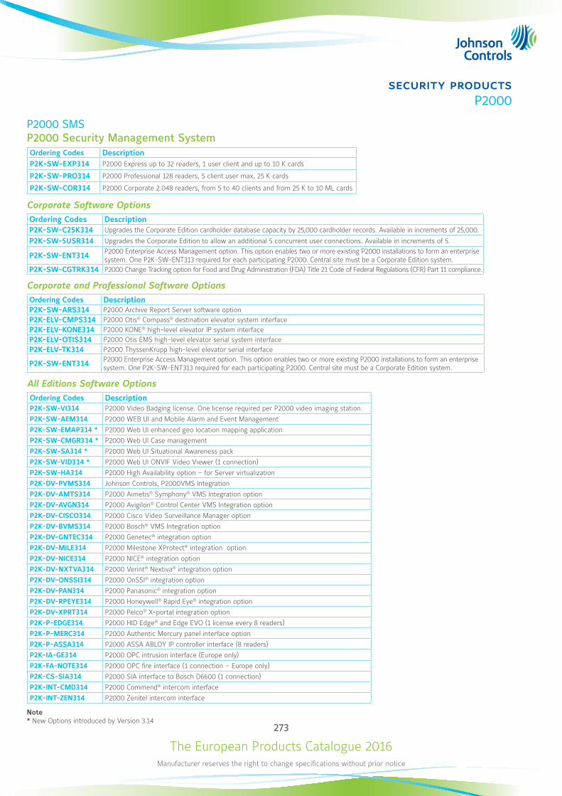
The European Products Catalogue 2016Manufacturer reserves the right to change specifications without prior notice
273
security productsP2000
P2000 SMS P2000 Security Management SystemOrdering Codes DescriptionP2K-SW-EXP314 P2000 Express up to 32 readers, 1 user client and up to 10 K cards
P2K-SW-PRO314 P2000 Professional 128 readers, 5 client user max, 25 K cards
P2K-SW-COR314 P2000 Corporate 2.048 readers, from 5 to 40 clients and from 25 K to 10 ML cards
Corporate Software OptionsOrdering Codes DescriptionP2K-SW-C25K314 Upgrades the Corporate Edition cardholder database capacity by 25,000 cardholder records. Available in increments of 25,000.
P2K-SW-5USR314 Upgrades the Corporate Edition to allow an additional 5 concurrent user connections. Available in increments of 5.
P2K-SW-ENT314 P2000 Enterprise Access Management option. This option enables two or more existing P2000 installations to form an enterprise system. One P2K-SW-ENT313 required for each participating P2000. Central site must be a Corporate Edition system.
P2K-SW-CGTRK314 P2000 Change Tracking option for Food and Drug Administration (FDA) Title 21 Code of Federal Regulations (CFR) Part 11 compliance.
Corporate and Professional Software OptionsOrdering Codes DescriptionP2K-SW-ARS314 P2000 Archive Report Server software optionP2K-ELV-CMPS314 P2000 Otis® Compass® destination elevator system interfaceP2K-ELV-KONE314 P2000 KONE® high-level elevator IP system interfaceP2K-ELV-OTIS314 P2000 Otis EMS high-level elevator serial system interfaceP2K-ELV-TK314 P2000 ThyssenKrupp high-level elevator serial interface
P2K-SW-ENT314 P2000 Enterprise Access Management option. This option enables two or more existing P2000 installations to form an enterprise system. One P2K-SW-ENT313 required for each participating P2000. Central site must be a Corporate Edition system.
All Editions Software OptionsOrdering Codes DescriptionP2K-SW-VI314 P2000 Video Badging license. One license required per P2000 video imaging station. P2K-SW-AEM314 P2000 WEB UI and Mobile Alarm and Event Management P2K-SW-EMAP314 * P2000 Web UI enhanced geo location mapping applicationP2K-SW-CMGR314 * P2000 Web UI Case managementP2K-SW-SA314 * P2000 Web UI Situational Awareness packP2K-SW-VID314 * P2000 Web UI ONVIF Video Viewer (1 connection)P2K-SW-HA314 P2000 High Availability option – for Server virtualization P2K-DV-PVMS314 Johnson Controls, P2000VMS Integration P2K-DV-AMTS314 P2000 Aimetis® Symphony® VMS Integration option P2K-DV-AVGN314 P2000 Avigilon® Control Center VMS Integration option P2K-DV-CISCO314 P2000 Cisco Video Surveillance Manager optionP2K-DV-BVMS314 P2000 Bosch® VMS Integration option P2K-DV-GNTEC314 P2000 Genetec® integration option P2K-DV-MILE314 P2000 Milestone XProtect® integration option P2K-DV-NICE314 P2000 NICE® integration option P2K-DV-NXTVA314 P2000 Verint® Nextiva® integration option P2K-DV-ONSSI314 P2000 OnSSI® integration option P2K-DV-PAN314 P2000 Panasonic® integration option P2K-DV-RPEYE314 P2000 Honeywell® Rapid Eye® integration option P2K-DV-XPRT314 P2000 Pelco® X-portal integration option P2K-P-EDGE314 P2000 HID Edge® and Edge EVO (1 license every 8 readers)P2K-P-MERC314 P2000 Authentic Mercury panel interface optionP2K-P-ASSA314 P2000 ASSA ABLOY IP controller interface (8 readers)P2K-IA-GE314 P2000 OPC intrusion interface (Europe only) P2K-FA-NOTE314 P2000 OPC fire interface (1 connection – Europe only) P2K-CS-SIA314 P2000 SIA interface to Bosch D6600 (1 connection)P2K-INT-CMD314 P2000 Commend® intercom interface P2K-INT-ZEN314 P2000 Zenitel intercom interface
Note* New Options introduced by Version 3.14

The European Products Catalogue 2016Manufacturer reserves the right to change specifications without prior notice
274
security productsP2000
P2000 Controllers
S321-IP Dual Door Network Controller
The S321-IP is an advanced, intelligent, network controller capable of monitoring and controlling one or two fully-configured doors for small-to-large security installations. The S321-IP can be used as a standalone device, with all cardholders and configuration data saved locally at the controller, or can be seamlessly integrated with the P2000. S321-IP host communications use a standard TCP/IP network protocol and are easily integrated into the P2000 Security Management System. The controller can be programmed either from its own user interface from any network-connected computer and standard browser, or through the P2000 interface.The S321-IP controller can store locally up to 5.000 Cardholders and manage 40 holidays and 64 time zones.
Features z Interfaces to one or two readers z 8 inputs, 4 outputs z Four-state (supervised) inputs and two-state (unsupervised) inputs z Up to 5,000 cardholder badges z 4 MB flash memory z 10/100Base-T network connection z Up to 128-bit badge numbers, 2 schedules per badge z RTC with 40 holidays and 64 schedules z Can be updated remotely using File Transfer Protocol (FTP) z Browser-based Graphical User Interface (GUI) z Expandable modular design z Input Voltage +12 to +24 VDC; 16 to 24 VAC z Mounting: DIN rail or Flat surface z Dimensions: 14.4cm x 15cm x 5.5cm
S321-IP
SPC1000-1A10Security Panel Assembly
SPC10000-1A10 Security control panel with S321-IP controller and power supply Features
z S321-IP pre-Assembled in a Security Panel z Power supply: 1 module 24V@5 Amp, nominal Input: 85/240 VAC
z Dimensions : 40,6 cm W x 40,6 cm H x 16,8 cm D z Battery brackets for 2 x S300-BAT (12V 7Ah) z Key lock and Tamper switch
Ordering Codes Description
S321-IP Dual Door Network Controller
SPC10000-1A10 Security Panel with S321 and Power Supply
Virtual Branch eCatalogueclick here

The European Products Catalogue 2016Manufacturer reserves the right to change specifications without prior notice
275
security productsP2000
P2000 Controllers
CK721-A High-Speed High-Traffic Network Controller
The CK721-A is an advanced, intelligent, network controller capable of handling high volume, high-speed traffic with host security management systems. The controller is able to perform manual and automatic control functions using add-on modules to connect readers, monitor 2- or 4-state inputs, and add output points. Communication between the CK721-A and modules is achieved via an RS485 connection. The Expandable modular design allows an unlimited number of CK721-A controllers to be connected via Ethernet. Each CK721-A can support up to 64 readers; for a total capacity of 2,048 readers in a network with the P2000 Security Management System.CK721-A host communications use a standard TCP/IP on a 10/100Base-T network and are easily integrated into the P2000 security management system. The controller can be programmed by using its own user interface or by using the Microsoft® Windows® based P2000 interface. Its easy integration with P2000 software allows the CK721-A to take advantage of all the P2000 software features, including alarm monitoring, history reporting, input/output linking, card and system activated events and local, central or shared operation; history and event transactions are uploaded to the host for storage and report generation. The CK721-A/P2000 server encrypted communications provides secure network communications between the CK721-A controller and the P2000 server using the Advanced Encryption Standard (AES256)
Features The CK721-A supports the following functional capacity:
z Embedded 32-bit processor z 128 MB flash memory z 10/100Base-T network connection, encrypted z DB9 port for configuration, commissioning, and service maintenance z Up to 64 readers per controller z Storage capacity for up to 200,000 cardholders z Supports OSDP Version 1.1 z Accepts up to 128-bit badge numbers z 12 facility codes per reader (768 per controller)
z 40 holidays z 64 time zones z 32 access group/time zone pairs per badge z Supports Wiegand® interface, proximity, magnetic stripe, smart card, most biometric readers and bar code card technologies. Custom Card engineered formats are also accepted.
z RS485 expansion Bus supports Reader module: S300-DIN-RDR2SA and S300-DIN-RDR8S and auxilliary I/O modules: S300-DIN-I8O4 and S300-DIN-I32O16
z Mounting DIN rail or Flat surface z Dimensions: 13.1 x 27.0 x 6.2 cm
Expansion modulesReaders and I/O boardsCommunication between the CK721-A and modules is achieved via an RS485 connection:
Ordering Codes Description
S300-DIN-RDR2SA The Two-door module RDR2SA provides two doors full control connecting Cards Readers through Wiegand ports or via OSDP in RS485.
S300-DIN-RDR8S The Eight-door module RDR8SA provides eight doors full control connecting Cards Readers through Wiegand ports or via a single RS485 multidrop ( OSDP).
S300-DIN-I8O4 The I8O4 module provides, on a limited footprint, up to 8 Supervised inputs, plus power fails and Tamper inputs, and 2 Relay plus 2 Open- Collector outputs.
S300-DIN-I32O16 The I32O16 module provides up to 16 supervised inputs, plus power fails and Tamper inputs, and 16 Relay plus 16 Open- Collector outputs.
Virtual Branch eCatalogueclick here
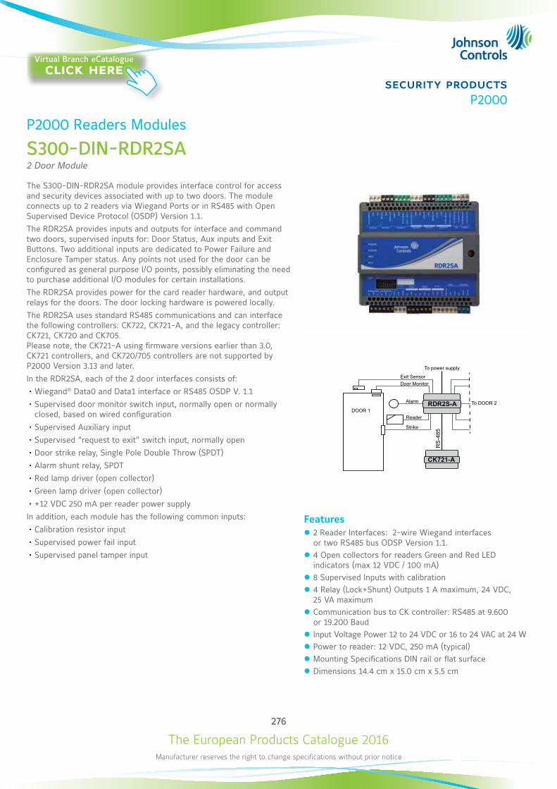
The European Products Catalogue 2016Manufacturer reserves the right to change specifications without prior notice
276
security productsP2000
P2000 Readers Modules
S300-DIN-RDR2SA 2 Door Module
The S300-DIN-RDR2SA module provides interface control for access and security devices associated with up to two doors. The module connects up to 2 readers via Wiegand Ports or in RS485 with Open Supervised Device Protocol (OSDP) Version 1.1.The RDR2SA provides inputs and outputs for interface and command two doors, supervised inputs for: Door Status, Aux inputs and Exit Buttons. Two additional inputs are dedicated to Power Failure and Enclosure Tamper status. Any points not used for the door can be configured as general purpose I/O points, possibly eliminating the need to purchase additional I/O modules for certain installations.The RDR2SA provides power for the card reader hardware, and output relays for the doors. The door locking hardware is powered locally.The RDR2SA uses standard RS485 communications and can interface the following controllers: CK722, CK721-A, and the legacy controller: CK721, CK720 and CK705. Please note, the CK721-A using firmware versions earlier than 3.0, CK721 controllers, and CK720/705 controllers are not supported by P2000 Version 3.13 and later.In the RDR2SA, each of the 2 door interfaces consists of:• Wiegand® Data0 and Data1 interface or RS485 OSDP V. 1.1• Supervised door monitor switch input, normally open or normally
closed, based on wired configuration• Supervised Auxiliary input • Supervised “request to exit” switch input, normally open• Door strike relay, Single Pole Double Throw (SPDT)• Alarm shunt relay, SPDT• Red lamp driver (open collector)• Green lamp driver (open collector) • +12 VDC 250 mA per reader power supply
In addition, each module has the following common inputs:• Calibration resistor input• Supervised power fail input• Supervised panel tamper input
RS
-485
CK721-A
RDR2S-A
To power supply
Exit SensorDoor Monitor
Alarm
Reader
Strike
To DOOR 2DOOR 1
Features z 2 Reader Interfaces: 2-wire Wiegand interfaces or two RS485 bus ODSP Version 1.1.
z 4 Open collectors for readers Green and Red LED indicators (max 12 VDC / 100 mA)
z 8 Supervised Inputs with calibration z 4 Relay (Lock+Shunt) Outputs 1 A maximum, 24 VDC, 25 VA maximum
z Communication bus to CK controller: RS485 at 9.600 or 19.200 Baud
z Input Voltage Power 12 to 24 VDC or 16 to 24 VAC at 24 W z Power to reader: 12 VDC, 250 mA (typical) z Mounting Specifications DIN rail or flat surface z Dimensions 14.4 cm x 15.0 cm x 5.5 cm
Virtual Branch eCatalogueclick here
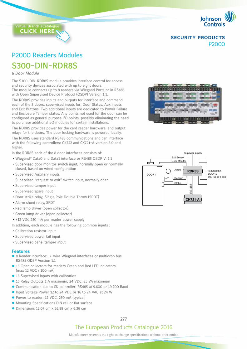
The European Products Catalogue 2016Manufacturer reserves the right to change specifications without prior notice
277
security productsP2000
P2000 Readers Modules
S300-DIN-RDR8S 8 Door Module
The S300-DIN-RDR8S module provides interface control for access and security devices associated with up to eight doors. The module connects up to 8 readers via Wiegand Ports or in RS485 with Open Supervised Device Protocol (OSDP) Version 1.1. The RDR8S provides inputs and outputs for interface and command each of the 8 doors, supervised inputs for: Door Status, Aux inputs and Exit Buttons. Two additional inputs are dedicated to Power Failure and Enclosure Tamper status. Any points not used for the door can be configured as general purpose I/O points, possibly eliminating the need to purchase additional I/O modules for certain installations. The RDR8S provides power for the card reader hardware, and output relays for the doors. The door locking hardware is powered locally.The RDR8S uses standard RS485 communications and can interface with the following controllers: CK722 and CK721-A version 3.0 and higher. In the RDR8S each of the 8 door interfaces consists of:• Wiegand® Data0 and Data1 interface or RS485 OSDP V. 1.1 • Supervised door monitor switch input, normally open or normally
closed, based on wired configuration• Supervised Auxiliary inputs • Supervised “request to exit” switch input, normally open• Supervised tamper input• Supervised spare input• Door strike relay, Single Pole Double Throw (SPDT)• Alarm shunt relay, SPDT• Red lamp driver (open collector)• Green lamp driver (open collector) • +12 VDC 250 mA per reader power supply
In addition, each module has the following common inputs :• Calibration resistor input• Supervised power fail input• Supervised panel tamper input
Features z 8 Reader Interface: 2-wire Wiegand interfaces or multidrop bus RS485 ODSP Version 1.1
z 16 Open collectors for readers Green and Red LED indicators (max 12 VDC / 100 mA)
z 16 Supervised Inputs with calibration z 16 Relay Outputs 1 A maximum, 24 VDC, 25 VA maximum z Communication bus to CK controller: RS485 at 9.600 or 19.200 Baud z Input Voltage Power 12 to 24 VDC or 16 to 24 VAC at 24 W z Power to reader: 12 VDC, 250 mA (typical) z Mounting Specifications DIN rail or flat surface z Dimensions 13.07 cm x 26.88 cm x 6.36 cm
RS
-485
CK721-A
RDR8S
To power supply
Exit SensorDoor Monitor
Alarm
Reader
Strike
To DOOR 2,DOOR 3,etc. (up to 8 doors)
DOOR 1
Virtual Branch eCatalogueclick here
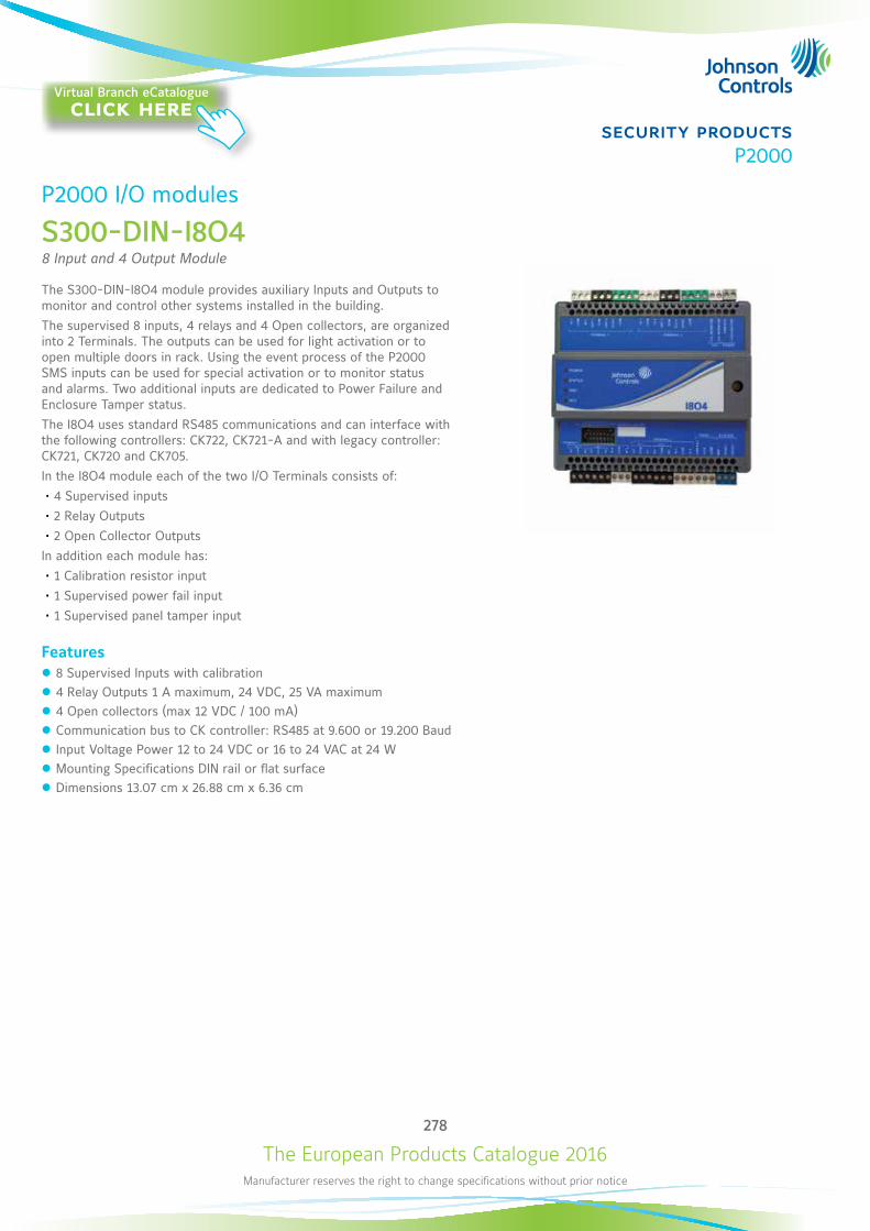
The European Products Catalogue 2016Manufacturer reserves the right to change specifications without prior notice
278
security productsP2000
P2000 I/O modules
S300-DIN-I8O4 8 Input and 4 Output Module
The S300-DIN-I8O4 module provides auxiliary Inputs and Outputs to monitor and control other systems installed in the building. The supervised 8 inputs, 4 relays and 4 Open collectors, are organized into 2 Terminals. The outputs can be used for light activation or to open multiple doors in rack. Using the event process of the P2000 SMS inputs can be used for special activation or to monitor status and alarms. Two additional inputs are dedicated to Power Failure and Enclosure Tamper status.The I8O4 uses standard RS485 communications and can interface with the following controllers: CK722, CK721-A and with legacy controller: CK721, CK720 and CK705. In the I8O4 module each of the two I/O Terminals consists of:• 4 Supervised inputs• 2 Relay Outputs • 2 Open Collector Outputs
In addition each module has:• 1 Calibration resistor input• 1 Supervised power fail input• 1 Supervised panel tamper input
Features z 8 Supervised Inputs with calibration z 4 Relay Outputs 1 A maximum, 24 VDC, 25 VA maximum z 4 Open collectors (max 12 VDC / 100 mA) z Communication bus to CK controller: RS485 at 9.600 or 19.200 Baud z Input Voltage Power 12 to 24 VDC or 16 to 24 VAC at 24 W z Mounting Specifications DIN rail or flat surface z Dimensions 13.07 cm x 26.88 cm x 6.36 cm
Virtual Branch eCatalogueclick here

The European Products Catalogue 2016Manufacturer reserves the right to change specifications without prior notice
279
security productsP2000
P2000 I/O modules
S300-DIN-I32O16 32 Input and 16 Output Module
The S300-DIN-I3204 module provides auxiliary Inputs and Outputs to interface difference services in the plants. The supervised 8 inputs, the 4 relay and the 4 Open collectors are organized into 8 Terminals. The outputs can be used for light activation or to open multiple doors in rack. Using the event process of the P2000 SMS inputs can be used for special activation or to monitor status and alarms. Other two inputs are dedicated to Power Failure and Enclosure Tamper status.The I32O16 uses standard RS485 communications and can interface with the following controllers: CK722, CK721-A and with legacy controller: CK721, CK720 and CK705. In the I32O4 module, each of the eight I/O Terminals consists of:• 4 Supervised inputs• 2 Relay Outputs • 2 Open Collector Outputs
In addition each module has:• 1 Calibration resistor input• 1 Supervised power fail input• 1 Supervised panel tamper input
Features z 8 Supervised Inputs with calibration z 4 Relay Outputs 1 A maximum, 24 VDC, 25 VA maximum z 4 Open collectors (max 12 VDC / 100 mA) z Communication bus to CK controller: RS485 at 9.600 or 19.200 Baud z Input Voltage Power 12 to 24 VDC or 16 to 24 VAC at 24 W z Mounting Specifications DIN rail or flat surface z Dimensions 13.07 cm x 26.88 cm x 6.36 cm
Virtual Branch eCatalogueclick here
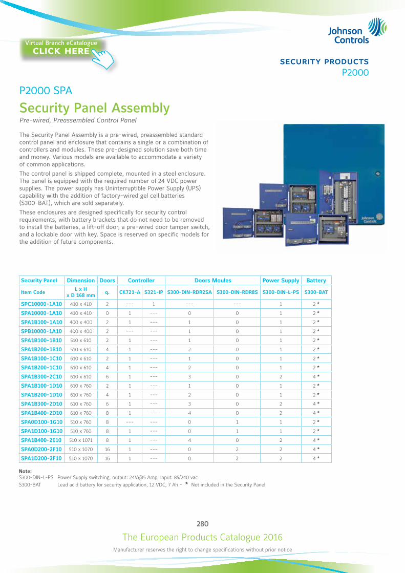
The European Products Catalogue 2016Manufacturer reserves the right to change specifications without prior notice
280
security productsP2000
P2000 SPA
Security Panel Assembly Pre-wired, Preassembled Control Panel
The Security Panel Assembly is a pre-wired, preassembled standard control panel and enclosure that contains a single or a combination of controllers and modules. These pre-designed solution save both time and money. Various models are available to accommodate a variety of common applications.The control panel is shipped complete, mounted in a steel enclosure. The panel is equipped with the required number of 24 VDC power supplies. The power supply has Uninterruptible Power Supply (UPS) capability with the addition of factory-wired gel cell batteries (S300-BAT), which are sold separately.These enclosures are designed specifically for security control requirements, with battery brackets that do not need to be removed to install the batteries, a lift-off door, a pre-wired door tamper switch, and a lockable door with key. Space is reserved on specific models for the addition of future components.
Security Panel Dimension Doors Controller Doors Moules Power Supply Battery
Item Code L x H x D 168 mm q. CK721-A S321-IP S300-DIN-RDR2SA S300-DIN-RDR8S S300-DIN-L-PS S300-BAT
SPC10000-1A10 410 x 410 2 --- 1 --- --- 1 2 *
SPA10000-1A10 410 x 410 0 1 --- 0 0 1 2 *
SPA1B100-1A10 400 x 400 2 1 --- 1 0 1 2 *
SPB10000-1A10 400 x 400 2 --- --- 1 0 1 2 *
SPA1B100-1B10 510 x 610 2 1 --- 1 0 1 2 *
SPA1B200-1B10 510 x 610 4 1 --- 2 0 1 2 *
SPA1B100-1C10 610 x 610 2 1 --- 1 0 1 2 *
SPA1B200-1C10 610 x 610 4 1 --- 2 0 1 2 *
SPA1B300-2C10 610 x 610 6 1 --- 3 0 2 4 *
SPA1B100-1D10 610 x 760 2 1 --- 1 0 1 2 *
SPA1B200-1D10 610 x 760 4 1 --- 2 0 1 2 *
SPA1B300-2D10 610 x 760 6 1 --- 3 0 2 4 *
SPA1B400-2D10 610 x 760 8 1 --- 4 0 2 4 *
SPA0D100-1G10 510 x 760 8 --- --- 0 1 1 2 *
SPA1D100-1G10 510 x 760 8 1 --- 0 1 1 2 *
SPA1B400-2E10 510 x 1071 8 1 --- 4 0 2 4 *
SPA0D200-2F10 510 x 1070 16 1 --- 0 2 2 4 *
SPA1D200-2F10 510 x 1070 16 1 --- 0 2 2 4 *
Note: S300-DIN-L-PS Power Supply switching, output: 24V@5 Amp, Input: 85/240 vacS300-BAT Lead acid battery for security application, 12 VDC, 7 Ah - * Not included in the Security Panel
Virtual Branch eCatalogueclick here
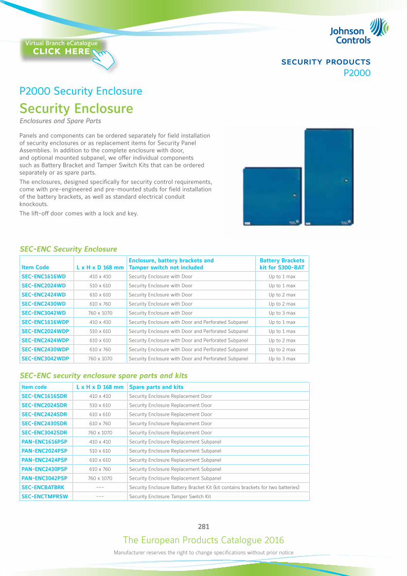
The European Products Catalogue 2016Manufacturer reserves the right to change specifications without prior notice
281
security productsP2000
P2000 Security Enclosure
Security Enclosure Enclosures and Spare Parts
Panels and components can be ordered separately for field installation of security enclosures or as replacement items for Security Panel Assemblies. In addition to the complete enclosure with door, and optional mounted subpanel, we offer individual components such as Battery Bracket and Tamper Switch Kits that can be ordered separately or as spare parts.The enclosures, designed specifically for security control requirements, come with pre-engineered and pre-mounted studs for field installation of the battery brackets, as well as standard electrical conduit knockouts. The lift-off door comes with a lock and key.
SEC-ENC Security Enclosure
Item Code L x H x D 168 mmEnclosure, battery brackets and Tamper switch not included
Battery Brackets kit for S300-BAT
SEC-ENC1616WD 410 x 410 Security Enclosure with Door Up to 1 max
SEC-ENC2024WD 510 x 610 Security Enclosure with Door Up to 1 max
SEC-ENC2424WD 610 x 610 Security Enclosure with Door Up to 2 max
SEC-ENC2430WD 610 x 760 Security Enclosure with Door Up to 2 max
SEC-ENC3042WD 760 x 1070 Security Enclosure with Door Up to 3 max
SEC-ENC1616WDP 410 x 410 Security Enclosure with Door and Perforated Subpanel Up to 1 max
SEC-ENC2024WDP 510 x 610 Security Enclosure with Door and Perforated Subpanel Up to 1 max
SEC-ENC2424WDP 610 x 610 Security Enclosure with Door and Perforated Subpanel Up to 2 max
SEC-ENC2430WDP 610 x 760 Security Enclosure with Door and Perforated Subpanel Up to 2 max
SEC-ENC3042WDP 760 x 1070 Security Enclosure with Door and Perforated Subpanel Up to 3 max
SEC-ENC security enclosure spare parts and kitsItem code L x H x D 168 mm Spare parts and kits
SEC-ENC1616SDR 410 x 410 Security Enclosure Replacement Door
SEC-ENC2024SDR 510 x 610 Security Enclosure Replacement Door
SEC-ENC2424SDR 610 x 610 Security Enclosure Replacement Door
SEC-ENC2430SDR 610 x 760 Security Enclosure Replacement Door
SEC-ENC3042SDR 760 x 1070 Security Enclosure Replacement Door
PAN-ENC1616PSP 410 x 410 Security Enclosure Replacement Subpanel
PAN-ENC2024PSP 510 x 610 Security Enclosure Replacement Subpanel
PAN-ENC2424PSP 610 x 610 Security Enclosure Replacement Subpanel
PAN-ENC2430PSP 610 x 760 Security Enclosure Replacement Subpanel
PAN-ENC3042PSP 760 x 1070 Security Enclosure Replacement Subpanel
SEC-ENCBATBRK --- Security Enclosure Battery Bracket Kit (kit contains brackets for two batteries)
SEC-ENCTMPRSW --- Security Enclosure Tamper Switch Kit
Virtual Branch eCatalogueclick here

The European Products Catalogue 2016Manufacturer reserves the right to change specifications without prior notice
282
security productsP2000
P2000 VMS
Video Management System Version 6.13
The Johnson Controls® P2000 Video Management System is an intelligent video security solution that offers a single, innovative, open IP video platform for video management, video analytics, system integration, and alarm management.P2000 VMS provides a feature-rich, easy-to-use interface that installs on standard commercial-off-the-shelf hardware and software platforms, that incorporates IT-friendly features to make administration simple. With support for hundreds of IP cameras and analog camera encoders, from several manufacturers, P2000 VMS makes it easy to find the right camera without compatibility worries.With three software Editions the P2000 VMS has a solution for every topology and size of installation. Licensing a camera has never been so simple. P2000 VMS allows you to add licenses one at a time, limited only by the server hardware. No additional charge for servers and clients or the P2000VMS.P2000VMS is natively integrated in the P2000 Security Management System. This allows operators to control all their security platforms from a single location, such as access control, intercom, intrusion detection, and video.
STANDARD EDITION Single site, single server recording system
z Multiple Web Clients z Low to Medium camera counts z Easy migration from DVN5000 or other DVR systems z Mobile Bridge to Android and iOS Apps Option z Video Analytics Options z P2000 SMS native integration
PROFESSIONAL EDITION Single or multisite, multiserver systemProfessional includes all Standard edition features and:
z Medium to high cameras counts z Highly scalable, advanced functionality z Active Directory Support z Alarm Management z Server Farms and Virtualization z Videowall management
ENTERPRISE EDITION Multiserver with Fail-Over back up Enterprise includes all Professional edition features and:
z Medium to very high cameras counts z Redundancy and Failover recording z Business Intelligence reports
Video Analytics included in all P2000 VMS editions are:
z Camera signal loss Detection z Camera covered, painted or moved z Motion Detection
LEGACY DVN5000When a DVN unit, with firmware version 2.10 or higher, is implemented in a P2000VMS system, the driver supports Pan, Tilt and Zoom (PTZ) and I/O operation. Images are recorded at P2000 VMS server at resolution max 4CIF and up to 30 FPS.
Virtual Branch eCatalogueclick here
The European Products Catalogue 2016Manufacturer reserves the right to change specifications without prior notice
283
security productsP2000
P2000 VMSVideo Management System
Optional Video AnalyticsThe following video analytic can be added at any camera, at any time and at any of the three P2000 VMS editions.
Area Alarms and Restricted Zones• Area alarms or restricted zones refers to the ability to highlight multiple zones in a field of view and alert on activity in any one of
them while ignoring activity in unselected areas.
Automatic License Plate Recognition• Available in four and eight camera pack, this analytic provides out-of-the-box Automatic License Plate Recognition (ALPR)
functionality. It can be used for parking applications. License plates and their corresponding images are stored and can be easily searched. Various alarm scenarios can be achieved by using white or black lists.
Automatic PTZ Tracking• The auto-PTZ tracking function will automatically control PTZ cameras when relevant activity or a rule- break is detected.
Dwell Time and Loitering• The loitering/dwell time function recognizes how long a particular target stays in a defined field of view. In security applications,
this analytic can help with identifying potential threat by detecting loitering people or vehicles. It support business intelligence.
Item Left Behind and Removed Detection• The left/removed item function alerts on background image changes due to new or removed objects in the field of view.
Motion Tracking• The motion tracking function compares relevant pixel changes between images and alerts on relevant foreground motion while
ignoring irrelevant motion.
Object Classification• The object classification functionality is able to segment objects between people, vehicles and unknown objects.
People and Vehicle Counting• The counting functionality counts objects entering and leaving a field of view or crossing a virtual fence. This analytic is great for
tracking attendance in large venues and counting vehicles in parking garages.
Virtual Fence and Tripwire• A virtual fence refers to an invisible digital fence or tripwire that can send an alert when an object crosses in one or both directions.
Especially useful in perimeter security.
Wrong Direction• The wrong direction function will alert on motion going against the specified flow of traffic.
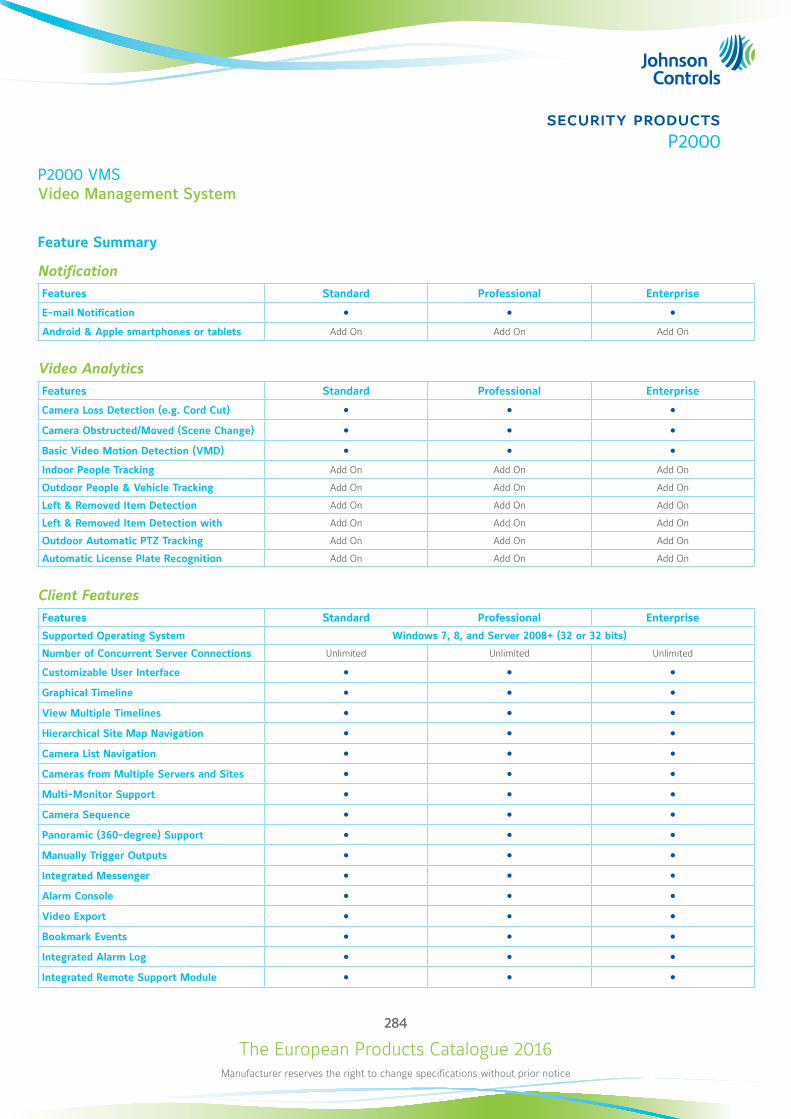
The European Products Catalogue 2016Manufacturer reserves the right to change specifications without prior notice
284
security productsP2000
P2000 VMSVideo Management System
Feature Summary
NotificationFeatures Standard Professional Enterprise
E-mail Notification Android & Apple smartphones or tablets Add On Add On Add On
Video AnalyticsFeatures Standard Professional Enterprise
Camera Loss Detection (e.g. Cord Cut) Camera Obstructed/Moved (Scene Change) Basic Video Motion Detection (VMD) Indoor People Tracking Add On Add On Add On
Outdoor People & Vehicle Tracking Add On Add On Add On
Left & Removed Item Detection Add On Add On Add On
Left & Removed Item Detection with Add On Add On Add On
Outdoor Automatic PTZ Tracking Add On Add On Add On
Automatic License Plate Recognition Add On Add On Add On
Client FeaturesFeatures Standard Professional Enterprise
Supported Operating System Windows 7, 8, and Server 2008+ (32 or 32 bits)
Number of Concurrent Server Connections Unlimited Unlimited Unlimited
Customizable User Interface Graphical Timeline View Multiple Timelines Hierarchical Site Map Navigation Camera List Navigation Cameras from Multiple Servers and Sites Multi-Monitor Support Camera Sequence Panoramic (360-degree) Support Manually Trigger Outputs Integrated Messenger Alarm Console Video Export Bookmark Events Integrated Alarm Log Integrated Remote Support Module
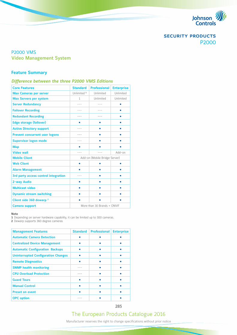
The European Products Catalogue 2016Manufacturer reserves the right to change specifications without prior notice
285
security productsP2000
P2000 VMSVideo Management System
Feature Summary
Difference between the three P2000 VMS EditionsCore Features Standard Professional Enterprise
Max Cameras per server Unlimited 1 Unlimited Unlimited
Max Servers per system 1 Unlimited Unlimited
Server Redundancy --- --- Failover Recording --- --- Redundant Recording --- --- Edge storage (failover) Active Directory support --- Prevent concurrent user logons --- Supervisor logon mode --- Map Video wall --- --- Add-on
Mobile Client Add-on (Mobile Bridge Server)
Web Client Alarm Management 3rd party access control integration --- 2-way Audio Multicast video Dynamic stream switching Client side 360 dewarp 2 Camera support More than 30 Brands + ONVIF
Note1 Depending on server hardware capability, it can be limited up to 300 cameras.2 Dewarp supports 360 degree cameras
Management Features Standard Professional Enterprise
Automatic Camera Detection Centralized Device Management Automatic Configuration Backups Uninterrupted Configuration Changes Remote Diagnostics SNMP health monitoring --- CPU Overload Protection --- Guard Tours Manual Control Preset on event OPC option ---
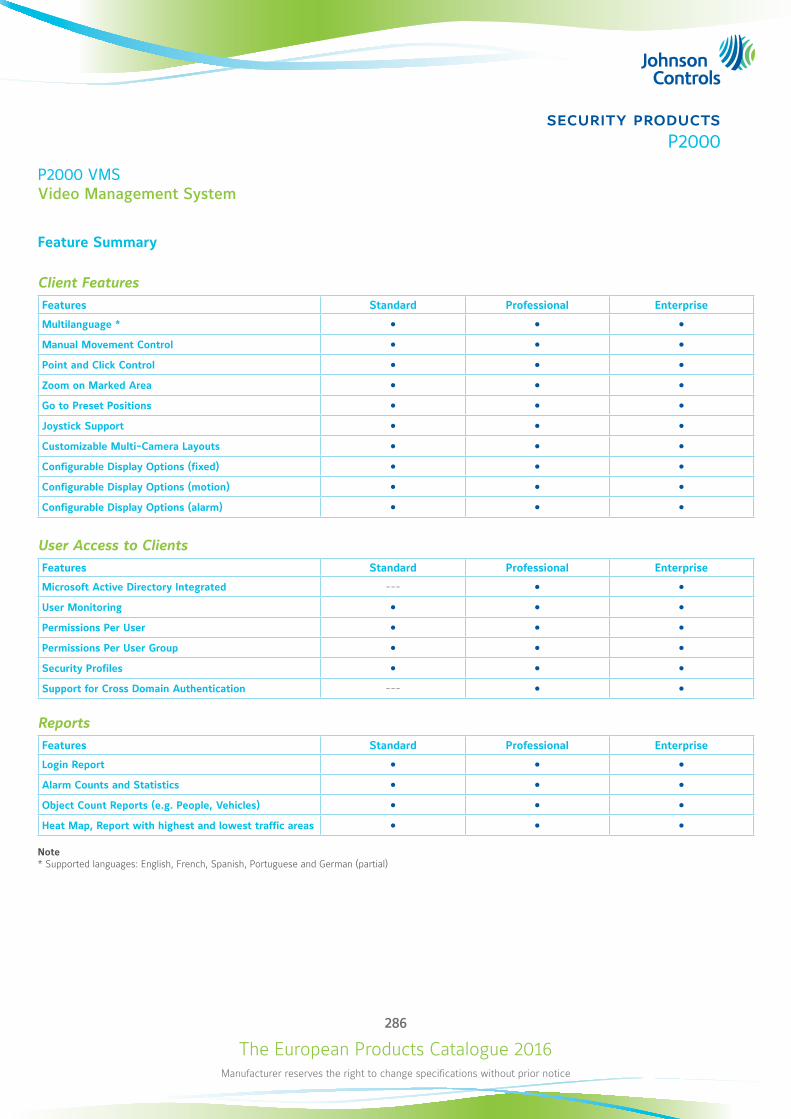
The European Products Catalogue 2016Manufacturer reserves the right to change specifications without prior notice
286
security productsP2000
P2000 VMSVideo Management System
Feature Summary
Client FeaturesFeatures Standard Professional Enterprise
Multilanguage * Manual Movement Control Point and Click Control Zoom on Marked Area Go to Preset Positions Joystick Support Customizable Multi-Camera Layouts Configurable Display Options (fixed) Configurable Display Options (motion) Configurable Display Options (alarm)
User Access to ClientsFeatures Standard Professional Enterprise
Microsoft Active Directory Integrated --- User Monitoring Permissions Per User Permissions Per User Group Security Profiles Support for Cross Domain Authentication ---
ReportsFeatures Standard Professional Enterprise
Login Report Alarm Counts and Statistics Object Count Reports (e.g. People, Vehicles) Heat Map, Report with highest and lowest traffic areas
Note* Supported languages: English, French, Spanish, Portuguese and German (partial)
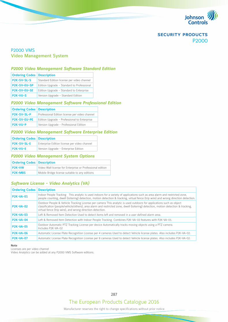
The European Products Catalogue 2016Manufacturer reserves the right to change specifications without prior notice
287
security productsP2000
P2000 VMSVideo Management System
P2000 Video Management Software Standard EditionOrdering Codes Description
P2K-SV-SL-S Standard Edition license per video channel
P2K-SV-EU-SP Edition Upgrade - Standard to Professional
P2K-SV-EU-SE Edition Upgrade - Standard to Enterprise
P2K-VU-S Version Upgrade - Standard Edition
P2000 Video Management Software Professional Edition
Ordering Codes Description
P2K-SV-SL-P Professional Edition license per video channel
P2K-SV-EU-PE Edition Upgrade - Professional to Enterprise
P2K-VU-P Version Upgrade - Professional Edition
P2000 Video Management Software Enterprise Edition
Ordering Codes Description
P2K-SV-SL-E Enterprise Edition license per video channel
P2K-VU-E Version Upgrade - Enterprise Edition
P2000 Video Management System OptionsOrdering Codes Description
P2K-VW Video Wall license for Enterprise or Professional edition
P2K-MBS Mobile Bridge license suitable to any editions
Software License - Video Analytics (VA)Ordering Codes Description
P2K-VA-01 Indoor People Tracking This analytic is used indoors for a variety of applications such as area alarm and restricted zone, people counting, dwell (loitering) detection, motion detection & tracking, virtual fence (trip wire) and wrong direction detection.
P2K-VA-02 Outdoor People & Vehicle Tracking License per camera This analytic is used outdoors for applications such as object classification (people/vehicle/others), area alarm and restricted zone, dwell (loitering) detection, motion detection & tracking, virtual fence (trip wire), and wrong direction detection.
P2K-VA-03 Left & Removed Item Detection Used to detect items left and removed in a user defined alarm area.
P2K-VA-04 Left & Removed Item Detection with Indoor People Tracking Combines P2K-VA-03 features with P2K-VA-01.
P2K-VA-05 Outdoor Automatic PTZ Tracking License per device Automatically tracks moving objects using a PTZ camera. Includes P2K-VA-02
P2K-VA-06 Automatic License Plate Recognition License per 4 cameras Used to detect Vehicle license plates. Also includes P2K-VA-02.
P2K-VA-07 Automatic License Plate Recognition License per 8 cameras Used to detect Vehicle license plates. Also includes P2K-VA-02.
NoteLicenses are per video channelVideo Analytics can be added at any P2000 VMS Software editions.

The
Euro
pean
Pro
duct
s Cat
alog
ue 2
016
PUBL
-657
6_11
201
5
www.johnsoncontrols.com