the design of a stoping scraper scoop - saimm
TRANSCRIPT

The design of a stoping scraper scoopby V. J. SOLOMON*. M.A.M.M.. M.W.S.A.. A.E.P. and
P. VAN NIEKERK*. Pr. Eng.. B.Sc. (Eng.). M.B.L. (Visitors)
SYNOPSISImprovements in the drilling and blasting techniques used in the stopes of narrow reefs have caused the clearing
of broken rock to become the major cause of delay in the achievement of a regular cyclic operation. This paperdiscusses the development of a scoop in accordance with a predetermined set of performance parameters.
The test results obtained to date have shown that the basic objectives have been achieved within tolerable limitsof variation.
SAMEVATTINGIn afbouplekke met 'n nou rifband het verbeterde afboutegnieke veroorsaak dat die verwydering van gebreekte
rots die belangrikste faktor geword wat verhinder dat 'n gereelde daaglikse siklus in die afbouproses behaal word.Hierdie artikel bespreek 'n metode wat gevolg is om 'n skraper te ontwikkel wat voldoen aan 'n stel voorafbepaaldeprestasieveranderlikes.
Die resultate tans beskikbaar toon dat die gedefineerde doelwitte binne aanvaarbare afwykings bereik is.
Introduction
This paper describes the design and development of ascraper scoop that could improve the stope-cleaningactivities in narrow reef stopes.
Improvements in drilling and blasting techniques,coupled with more effective blasting barricades and lesslabour-intensive support systems, have increased theaverage monthly stope-face advance by 80 per cent onStilfontein Gold Mining Company Limited. One of themajor factors inhibiting the attainment of a blast perpanel per day on a cyclic basis is the ability to clear thebroken rock in the time available. As the length of thestope strike gully becomes progressively greater than thelength of the panel, an imbalance in scraping capacitybegins to occur. Even though higher-capacity winchesare used for the strike gully, scraping capacity is stillthe major cause of delay. For this reason, the clearing ofbroken rock from the strike gully by increasing thescoop capacity formed the initial objective of the workdescribed in this paper. The aim was therefore to obtaina scraper scoop that, in balance with the availablewinch power and ancillary scraping equipment, wouldprovide optimum cleaning characteristics. Secondaryobjectives were to minimize any maintenance work, andto balance the economic life of the scoop with the life ofthe stope panel.
All the commercially available scraper scoops wereevaluated, and none was found to combine all therequired properties in one unit. Because of this, it wasdecided to start at the beginning by designing a scoopthat would embody the necessary characteristics.
The methodology described can be applied to variousother mining methods with different design parameters,and it is not suggested that the scraper scoop describedin the following pages is the ultimate design for allsituations.
Mining ConditionsThe following are the conditions under which the
scraper scoop was required to operate:
*Stilfontein Gold Mining Company Limite:l, Stilfontein,Transvaal.
Capacity of scraper winches 37 kW55 kW120m20m1,30 mQuartzitic85 t1,5 m wide by3,00 m high.
Maximum length of stope strike gullyAverage panel lengthAverage stope widthType of rockAverage tons per blastSize of stope strike gully
Approach Adopted
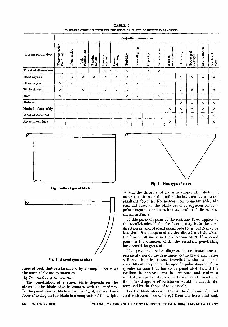
At the start of any project, it is necessary to design aset of preference conditions that should be achieved interms of clearly understood parameters. For this purpose,a set of objective parameters subdivided into Perform-ance, Engineering, and Economics parameters weredefined.
In addition, the following group of design parameterscould be manipulated to attain the desired results:Physical dimensions, Basic layout, Blade angle, Bladedesign, Mass, Material, Method of assembly, Wearattachments, and Attachment lugs.
A matrix was constructed from the two groups' ofparameters (Table I) so that the interrelationshipbetween the various factors could be evaluated.
The objective parameters are first discussed in detail,followed by a description of how the design parameterswere incorporated to meet the defined requirements.
Performance Parameters
(a) Fragmentation HandlingFragmentation handling is mostly affected by the
basic shape and blade design of a scoop. The commonconfigurations into which practically all scoops can beclassified are shown in Figs. 1 to 3.
Of these three basic designs, the shovel type wouldhandle broken rock best. Because of its totally exposedblade and the absence of any side plates, the shovel typeof scoop is not sensitive to the size of rock in its path.In contrast to this, the box type can be considered to bea compromise. With the correct blade design on ahoe type of scoop, its rock-handling capability couldclosely approach that of a shovel type of scoop. The
JOURNAL OF THE SOUTH AFRICAN INSTITUTE OF MINING AND METALLURGY OCTOBER 1978 65
Objective parameters- - - - - - - - - -- - - -
o§t>II
... iI) iI)
S diI)
... d ~~" doS °&J >. <e~~t>II ~0
"" "0
Design parameters '" >. t>II >. 0..'E~
...~ :;::e e t>II t>II ... :=I d~~oSd ;§§ ...t>II :::: ;.a
'g ~;.a ::3..." "... .!doS iI) i:I iI)::3 "'b() ..., ::3iI) §:j E'~ j iI)
" ~" i:I i:I "d...,ea ~"cl ::3°~
"0.. d 00 ~.se '~~f 0"" cl cl ~a
000E=<~ [;<;~
Oo~~e ::s
... 0[;<;~ Q"d 00 [;<; Q ooti ...."- - - - - - - - - - - - - -
Physical dimensIOns X X X X X X- - - - - - - - - - - - -
Basic layout X X X X X X X X X X X X X- - - - - - - - - - - - -
Blade angle X X X X X X X X- - - - - - - - - - - - -
Blade design X X X X X X X X X X- - - - - - - - - - - - -
Mass X X X X X X X- - - - - - - - - - - - -
Material X X X X- - - -- - - - - - - - - -
Method of assembly X X X X X- - - - - - -- - - - - - -
Wear attachment X X X X- - - - - - - - - - - - -
Atta.clunent lugs X X X X
INTERRELATIONSHIP BETWEEN THE DESIGN AND THE OBJECTIVE PARAMETERS
TABLE I
ro
Fig. I-Box type of blade
0
Fig. l-Shovel type of blade
mass of rock that can be moved by a scoop increases asthe ma~s of the scoop increases.(b) Pr,etration oJ Broken Rock
The penetration of a scoop blade depends on thestress on the blade edge in contact with the medium.In the parallel-sided blade shown in Fig. 4, the resultantforce R acting on the blade is a composite of the weight
66 OCTOBER 11178 JOURNAL OF THE SOUTH AFRICAN INSTITUTE OF MINING AND METALLURGY
0
Fig. 3-Hoe type of blade
Wand the thrust T of the winch rope. The blade willmove in a direction that offers the least resistance to theresultant force R. No matter how unmeasurable, theresistant force to the blade could be represented by apolar diagram to indicate its magnitude and direction asshown in Fig. 5.
If this polar diagram of the resistant force applies tothe parallel-sided blade, the force A may be in the samedirection as, and of equal magnitude to, R, but B may beless than R's component in the direction of B. Thus,the blade will move in the direction of B. If R couldpoint in the direction of B, the resultant penetratingforce would be greatest.
The predicted polar diagram is an instantaneousrepresentation of the resistance to the blade and varieswith each infinite distance travelled by the blade. It isvery difficult to predict the specific polar diagram for aspecific medium that has to be penetrated, but, if themedium is homogeneous in structure and resists asimilarly shaped obstacle equally well in all directions,the polar diagram of resistance would be mainly de-termined by the shape of the obstacle.
For the blade shown in Fig. 4, the direction of initialleast resistance would be (J/2 from the horizontal and,
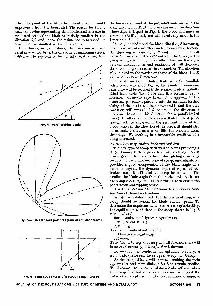
when the point of the blade had penetrated, it wouldapproach 8 from the horizontal. The reason for this isthat the vector representing the infinitesimal increase inprojected area of the blade is initially smallest in thedirection 812 and, once the point has penetrated, itwould be the smallest in the direction 8.
In a homogeneous medium, the direction of leastresistance would be in the direction of maximum stress,which can be represented by the ratio RIA, where R is
T
Fig. 4-Parallel-sided blade
Fig. 5-lnstantaneous polar diagram of resistant forces
L
.%:
8
Fig. 6-Schematic sketch of a scoop in equilibrium
the force vector and A the projected area vector in thesame direction as R. If the blade moves in the directionwhere RIA is largest in Fig. 4, the blade will move indirection 812 if £=812, and will eventually move in thedirection 8 if £=8.
If £< 812initially and the blade tilts (i.e., 8 increases),it will have an adverse effect on the penetration becausethe direction of maximum R and minimum A willmove further apart. If £ > 812initially, the tilting of theblade will have a favourable effect because the anglebetween maximum R and minimum A will decrease,thereby moving them closer to one another. The directionof A is fixed to the particular shape of the blade, but Rvaries as the force T increases.
Thus, it can be concluded that, with the parallel-sided blade shown in Fig. 4, the point of minimumresistance will be reached if the scraper blade is initiallytilted backwards (i.e., 8-+0) and tilts forward (i.e., 8increases) whenever rope thrust T is applied. If theblade has penetrated partially into the medium, furthertilting of the blade will be unfavourable and the bestcondition will prevail if R points in the direction 8(because LlA =0 in this direction for a parallel-sidedblade). In other words, this means that the best pene-tration will be achieved if the resultant force of theblade points in the direction of the blade. It should alsobe recognized that, as a scoop fills, the contents assistthe weight W, resulting in a favourable condition of £being increased.
(c) Retainment of Broken Rock and StabilityThe box type of scoop with its side plates providing a.
large running surface gives the best stability, but itdischarges much of its payload when gliding over largerocks in its path. The hoe type of scoop, once stabilized,provides a good compromise. If the blade angle of ascoop is beyond the dynamic angle of repose of thebroken rock, it will tend to dump its contents. Thesmaller the blade angle from the horizontal, the betterthe scoop can carry its load, but this in turn offsets thepenetration and tipping action.
It is thus necessary to determine the optimum com-bination of these two functions.
In (b) it was determined that the centre of mass of ascoop should lie behind the blade contact point. Todetermine the requirements to impose a scoop's stability,the equilibrium conditions of the scoop shown in Fig. 6were analysed.
For a condition of dynamic equilibrium,T=fLR and R=mg.
:.T=fLmg.Taking moments about point B,
Th=mgx or fLmgh=mgx.:.h=xlfL'
Therefore, if h > xl fL, the scoop will tilt forward and 8 willincrease. Conversely, if h < xlfL, 8 will decrease.
To achieve the condition for optimum stability, hshould always be smaller or equal to xl fL, i.e. h:(, xl fL.
As the scoop fills, fL will increase, making the ratioxlfL smaller and more difficult for h to remain smaller.The distance x to the centre of mass is also affected whenthe scoop fills, but could even increase to beyond thevalue of an empty scoop. The best solution to improve
.JOURNAL OF THE SOUTH AFRICAN INSTITUTE OF MINING AND METALLURGY OCTOBER 1978 67

stability is therefore to lower the bridle (making It,small).(c) Tipping Action
As mentioned above, the tipping action of a steeplyinclined blade will be superior to that of a shallow-a~gled blade. A blade angle close to the natural angle ofrepose of the rock was selected as a compromise. Thiswas assessed subjectively and set to 240 from thehorizontal.(d) Fouling Action
This requirement refers to the ability of the scoop toavoid 'hooking' onto any projecting edges of a gully. Ifan even action can be achieved, shedding of the load canbe avoided and a greater overall width can be achieved.The hoe type of scoop lends itself best to a rounded-contour design to eliminate all sharp edges, whereas, forthe box type of scoop, this requirement is very difficultand expensive to achieve.(e) Corner Digging
Broken rock in the gullies always forms a taperedtrench as it piles into the corners. This rock willinevitably be lost if a scoop cannot dig into the cornersto remove it. A scoop the same width as the gully wouldbe ideal, but in practice it would continuously foul ontothe sidewall. When a scoop is narrower than the gully,it always tends to drift to the middle.
Large rocks in the gully deflect a scoop towards thesidewall and consequently clean the gully edges. Themajor factor contributing to a high corner-diggingperformance lies with the design of the blade edge, aswill be described later.(f) Face Digging
The ability of a scoop to penetrate into the brokenrock pile as close as possible to the face where the returnsnatchblock is anchored can best be achieved with theshovel type of scoop, because the exposed blade withoutside plates enables it to penetrate more quickly into therock pile. The box type of scoop is very poor in thisregard; a hoe scoop with an extended blade couldclosely simulate the action of a shovel type of scoop.(g) Capacity
The amount of rock a scoop can move in a single rundepends on its size and retainment ability. This para-meter should be matched with the scraper winches inuse.
It was established that a capacity of Ii' to 2 tons forthe gully scoops would be the optimum range to matchthe scraper winches used. The winches used for thepurpose of this study are 22 kW on the face, 37 kW inthe gullies, and 37 or 55 kW in the centre gully. A22 kW winch can cope with 1 gully scoop, a 50 h.p.with 2 gully scoops, and a 55 kW winch can just copewith 3 gully scoops of the abovementioned size.(h) Power Requirements
The power requirements have already been discussed.
Engineering Parameters(a) Ease of Manufacture
Ease of manufacture is of vital interest to the personsconcerned with the manufacturing process. A scoop mustbe designed so that it can be manufactured with the
68 OCTOBER 1978 JOURNAL OF THE SOUTH AFRICAN INSTITUTE OF MINING AND METALLURGY
Fig. 1-Profile of broken rock lying in gullies
minimum of special facilities. The less sophisticated theequipment required, the greater the benefit. Because ofhigh labour costs, it is advisable to avoid labour-intensivedesigns. A design that utilizes only a few components isan objective worth striving for. The material used playsa very important role, especially when welding is to beused as an assembly technique. Very hard steels shouldbe carefully selected because they are more difficult toweld.
The box type of scoop has the most components, andthe shovel type probably has the least. Hinged blades asfound on certain box types of scoops should be avoided.(b) Durability
The economics parameters are closely interrelatedwith durability. The optimum life of a scoop depends onthe initial costs, the maintenance costs, and the prob-bility of re-use. A scoop that lasts longer than the life ofone panel has to be moved to a new panel for re-use ifoptimum advantage is to be gained from its durability.The probability that the equipment will not be re-usedto the full decreases the advantage obtained from a moredurable scoop. If a scoop could be designed with anexpected life expressed as a multiple of panel lives, itwould also limit the transporting activity on a gold mine.
The probability of re-use of a scoop affects theallowable cost of a more durable one. Factors werederived to determine, for different probabilities of re-use(p), the cost increases that could be allowed in themanufacture of a scoop with a longer life. Table IIindicates these factors for scoops that could outlast one,two, or three stope panels.
As shown in Table II, if the probability of re-use is60 per cent, a scoop that could outlast two panels shouldcost only 1,61 times as much as a scoop that lasts thelife of one panel.
The cost factor may not be the limiting constraint inthe manufacture of a more durable scoop; there may be
TABLE IIFACTORS BY WHICH SCOOP COST CAN BE INCREASED FOR A HIGHER
DURABILITY
Scoop life as a Probability of re-usemultiple of panel -
1
- - -- -- ---life 0,8 ~~~~~ 0,3-
1 1 1 1 1 1---------
2
3
1,79 1,41 1,321,72 1,61 1,52-------
2,55 2,252,87 1,98 1,75 1,55

.~.
>="d
bIJ0
>=";:
"bIJ
" " ';::O! >= ,S >= '" "'"
0 O! '5iJ~:>,
ca >=~5bIJ ";>'" g ~'"'"
:>, bIJ :>,
'B.s'""<::
"....~
i:1 " bIJ bIJ'"
.;:1~;§
'" '"
bIJ:::::
;.a~'",S
>= ;§§ '8 ~"'bIJ o'~'"
~,S
"~'" ~,,::a
" ~§:,~ :g "O! ">= >=O!"d 5 "
~,~
8,~ "0., 00 §
'"e e '~ >='" 00
>='"
>= 0 ~~O! O! ~O!00 O!O!~~~'~"
'"~s ~"'", ;S ;S8p., HoJ Q"d m ~Q moo ~..<::
- - - - - - - - - - - - - -
Box type Fair Poor Good Fair Poor Fair Good Poor Fair Poor Fair Fair Poor Poor Poor- - - - - -- - - - - - - - -
Hoe type Good Fair Fair Fair Fair Fair Fair Fair Fair Fair Fair Fair Fair Fair Fair- - - ~.- - - - - - - - - -
Fair-Shovel type Good Good Poor Good Poor Fair Poor Good Fair Fair Fair Fair Poor Fair Fair
other practical reasons. It should be borne in mind that apiece of equipment is only as durable as its least durablecomponent, which demands a good balance between thecomponents. The higher the objective durability, themore difficult it is to achieve this balance.
The most vulnerable component on a scoop is thecorner section of the blade. This is due to the taperedshape of the broken rock lying in the gullies, which isindicated in Fig. 7. This explains why most scoop bladeswear down in a curved shape, greatly reducing theoverall performance of the scoop.(c) Structural Strength
Many scoops have failed because of their inability toresist shocks and strains. A survey of scoops has indicatedthat this problem is mainly caused by sharp corners andedges. In order to overcome this problem, certaindesigns utilize reinforcing plates. This practice is notfavoured because the plates tend to be added as anafterthought and increase the manufacturing time andcost.
Scoops with hinged blades are particularly subject tobreakages. A design that was recently tested usedcomponent plates to build up the scoop body, but alsofailed as a result of fractures at the seams.
Economics Parameters
(a) MaintenanceMaintenance is very difficult to carry out on scoops in
the stopes because it is a very tedious task to transporttools and equipment to and from a stope, and themaintenance is often neglected. It is therefore recom-mended that a scoop should require as little maintenanceas possible. Certain designs incorporate bolts or lockingpins and wedges to hold the components together.These practices are not favoured because, if thesecomponents are not protected against wear, they can beremoved later only by use of a cutting torch. Welding-seams in particular should be well protected, because, ifthey wear down, premature fractures will result.
(b) Manufacturing CostsThe labour cost constitutes a large proportion of a
scoop's manufacturing cost. Scoop prices vary fromapproximately R280 to R850, the box types of scoopstending to be more expensive than the other types. Thereason is obvious if the number of separate components
is considered. A comparison of manufacturing costsshould be based on standard material and la1:;our costsfor all scoops.
Summary of Objective Parameters
Table III gives a summary of the preceding discussion,and indicates the advantages and disadvantages of thethree basic scoop designs.
Design and Development of a Scraper Scoop
Based on the evaluation of the interrelationshipsbetween the objective and design parameters in theforegoing discussions, an actual design was established.
Scoop SizeThe maximum width of the scoop is governed by the
width of the stope strike gully, which is 1,5 m. In fact,the final size was influenced by the dimensions of astandard mild-steel plate, taking into considerationminimum off-cut wastage.
Basic LayoutThe hoe type of scoop layout was selected because,
as shown in Table Ill, it has the potential to achievethe best balance between the requirements of theobjective parameters. The body of the ECOOp wasdesigned as shown in Figs. 8 and 9, and consists of thefollowing five components:(a) a body shell, which is pressed or rolled from a
profiled plate,(b) a bottom plate, also profiled to fit the bottom of the
body shell,(c) a bridle consisting of two rolled or pressed semi-order
flat bars welded to the body shell,(d) rope-attachment lugs welded onto the front and back,(e) the blade (which will be discussed later).
This design was selected because it has the followingadvantages.(a) The shape is totally rounded, which will prevent the
scoop from fouling onto sharp edges in the gully.(b) There are very few components, which will assist in
the manufacture of the scoop.(c) Because of the relatively few welding seams and
round shape, the structural strength of the scoopshould be approaching optimum.
The Bkule AngleThe three blade angles most commonly used at
COMPARISON OF THREE SCOOP DESIGNS
TABLE III
JOURNAL OF THE SOUTH AFRICAN INSTITUTE OF MINING AND METALLURGY OCTOBER 1978 69
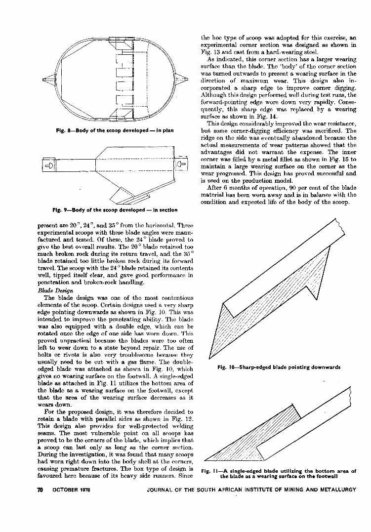
Fig. 8-Body of the scoop developed - in plan
cD
Fig. 9-Body of the scoop developed - in section
present are 200, 240, and 350 from the horizontal. Threeexperimental scoops with these blade angles were manu-factured and tested. Of these, the 240 blade proved togive the best overall results. The 200 blade retained toomuch broken rock during its return travel, and the 350blade retained too little broken rock during its forwardtravel. The scoop with the 240 blade retained its contentswell, tipped itself clear, and gave good performance inpenetration and broken-rock handling.
Blade DesignThe blade design was one of the most contentious
elements of the scoop. Certain designs used a very sharpedge pointing downwards as shown in Fig. 10. This wasintended to improve the penetrating ability. The bladewas also equipped with a double edge, which can berotated once the edge of one side has worn down. Thisproved unpractical because the blades were too oftenleft to wear down to a state beyond repair. The use ofbolts or rivets is also very troublesome because theyusually need to be cut with a gas flame. The double-edged blade was attached as shown in Fig. 10, whichgives no wearing surface on the footwall. A single-edgedblade as attached in Fig. 11 utilizes the bottom area ofthe blade as a wearing surface on the footwall, exceptthat the area of the wearing surface decreases as itwears down.
For the proposed design, it was therefore decided toretain a blade with parallel sides as shown in Fig. 12.This design also provides for well-protected weldingseams. The most vulnerable point on all scoops hasproved to be the corners of the blade, which implies thata scoop can last only as long as the corner section.During the investigation, it was found that many scoopshad worn right down into the body shell at the corners,causing premature fractures. The box type of design isfavoured here because of its heavy side runners. Since
70
the hoe type of scoop was adopted for this exercise, anexperimental corner section was designed as shown inFig. 13 and cast from a hard-wearing steel.
As indicated, this corner section has a larger wearingsurface than the blade. The 'body' of the corner sectionwas turned outwards to present a wearing surface in thedirection of maximum wear. This design also in-corporated a sharp edge to improve corner digging.Although this design performed well during test runs, theforward-pointing edge wore down very rapidly. Conse-quently, this sharp edge was replaced by a wearingsurface as shown in Fig. 14.
This design considerably improved the wear resistance,but some corner-digging efficiency was sacrificed. Theridge on the side was eventually abandoned because theactual measurements of wear patterns showed that theadvantages did not warrant the expense. The innercorner was filled by a metal fillet as shown in Fig. 15 tomaintain a large wearing surface on the corner as thewear progressed. This design has proved successful andis used on the production model.
After 6 months of operation, 90 per cent of the bladematerial has been worn away and is in balance with thecondition and expected life of the body of the scoop.
Fig. IO-Sharp-edged blade pointing downwards
Fig. II-A single-edged blade utilizing the bottom area ofthe blade as a wearing surface on the footwall
OCTOBER 1978 JOURNAL OF THE SOUTH AFRICAN INSTITUTE OF MINING AND METALLURGY
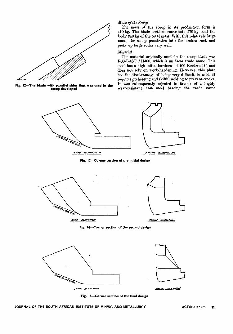
Fig. 12- The blade with parallel sides that was used In thescoop developed
~D. i!:/,,'-"VATION
Mass of the ScoopThe mass of the scoop in its production form is
410 kg. The blade sections contribute 170 kg, and thebody 240 kg of the total mass. With this relatively largemass, the scoop penetrates into the broken rock andpicks up large rocks very well.
MaterialThe material originally used for the scoop blade was
Roo-LAST AH400, which is an Iscor trade name. Thissteel has a high initial hardness of 400 Rockwell C, anddoes not rely on work-hardening. However, this platehas the disadvantage of being very difficult to weld. Itrequires preheating and skilful welding to prevent cracks.It was subsequently rejected in favour of a highlywear-resistant cast steel bearing the trade name
Fig. 13-Corner section of the Initial design
I"RoNT IlLI!!:VATION
S"IDI SEVAT,ON
Fig. I4-Corner section of the second design
'IiONT ~EVATION
SIDS ELEVATION
Fig. IS-Corner section of the final desl,n
FAON7 ~~EVATIO/.:
JOURNAL OF THE SOUTH AFRICAN INSTITUTE OF MINING AND METALLURGY OCTOBER 1978 71
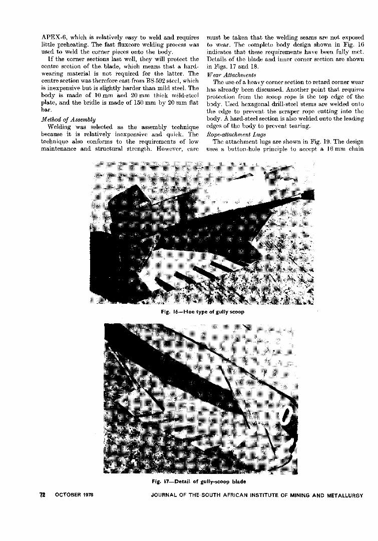
APEX-6, which is relatively easy to weld and requireslittle preheating. The fast fluxcore welding process wasused to weld the corner pieces onto the body.
If the corner sections last well, they will protect thecentre section of the blade, which means that a hard-wearing material is not required for the latter. Thecentre section was therefore cast from BS 592 steel, whichis inexpensive but is slightly harder than mild steel. Thebody is made of 10 mm and 20 mm thick mild-steelplate, and the bridle is made of 150 mm by 20 mm flatbar.
Method of AssemblyWelding was selected as the assembly technique
because it is relatively inexpensive and quick. Thetec4nique also conforms to the requirements of lowmaintenance and structural strength. However, care
must be taken that the welding seams are not exposedto wear. The complete body design shown in Fig. 16indicatcs that these requirements have been fully met.Details of the blade and inner corner section are shownin Figs. 17 and 18.
TVear AttachmentsThe use of a heavy corner section to retard corner wear
h'l.s already been discussed. Another point that requiresprotection from the scoop rope is the top edge of thebody. Used hexagonal drill-steel stems are welded ontothe edge to prevent the scraper rope cutting into thebody. A hard-steel section is also welded onto the leadingedges of the body to prevent tearing.
Rope-attachment LugsThe attachment lugs are shown in Fig. 19. The design
uses a button-hole principle to accept a 16 mm chain
Fig. 16-Hoe type of gully scoop
72 OCTOBER 1978
Fig. 17-Detail of gully-scoop blade
JOURNAL OF THE. SOUTH AFRICAN INSTITUTE OF MINING AND METALLURGY
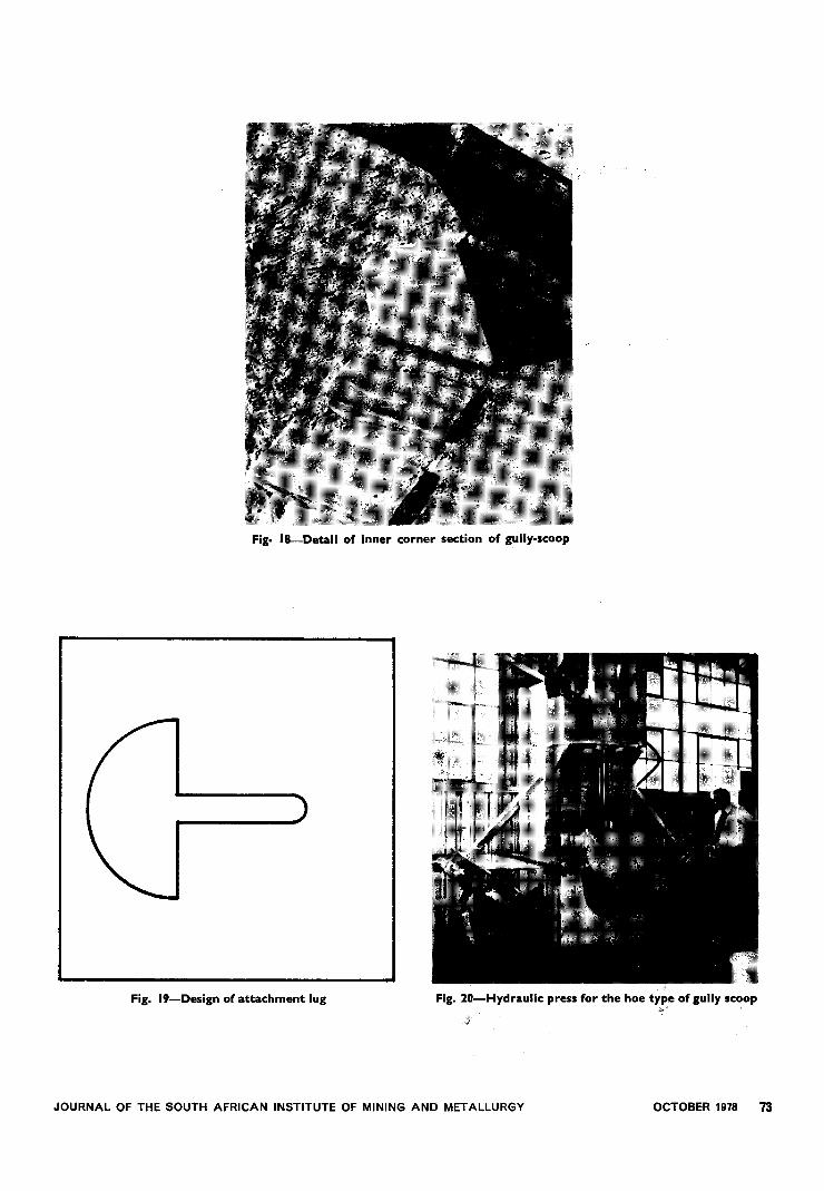
Fig. IS-Detail of Inner corner section of gully-scoop
Fig. I9-Deslgn of attachment lug Fig. 20-Hydraulic press for the hoe tYP,e of gully scoop
JOURNAL OF THE SOUTH AFRICAN INSTITUTE OF MINING AND METALLURGY OCTOBER 1978 73
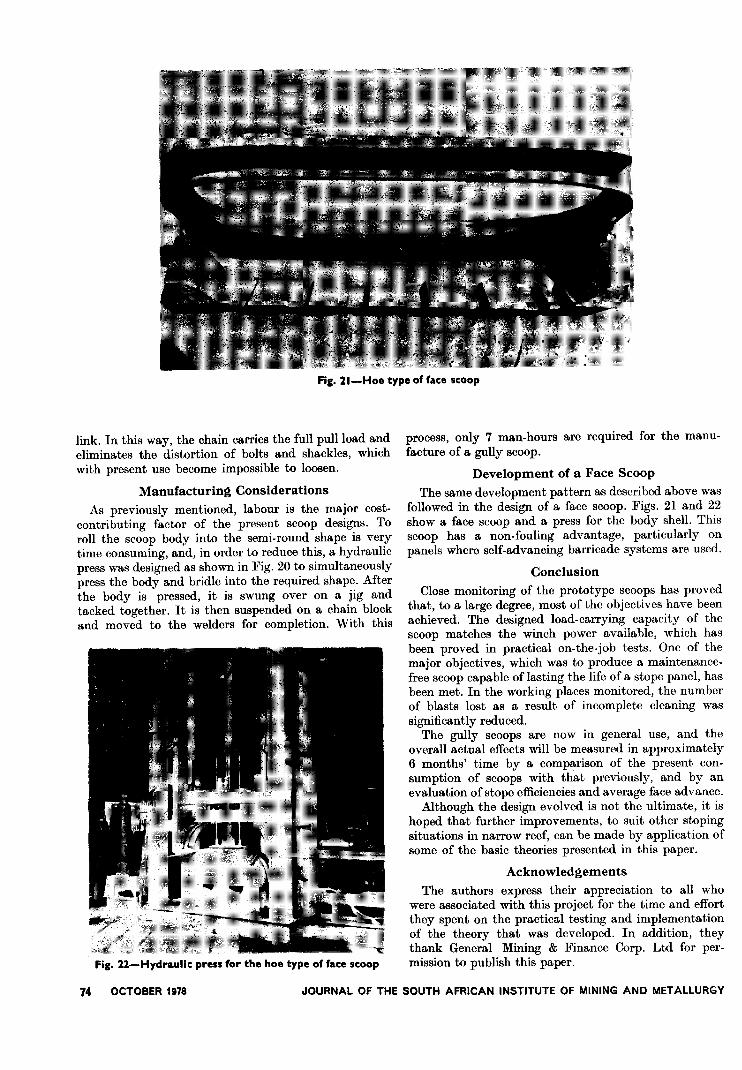
Fig. 21-Hoe type of face scoop
link. In this way, the chain carries the full pull load andeliminates the distortion of bolts and shackles, whichwith present use become impossible to loosen.
Manufacturing Considerations
As previously mentioned, labour is the major cost-contributing factor of the present scoop designs. Toroll the scoop body into the semi-round shape is verytime consuming, and, in order to reduce this, a hydraulicpress was designed as shown in Fig. 20 to simultaneouslypress the body and bridle into the required shape. Afterthe body is pressed, it is swung over on a jig andtacked together. It is then suspended on a chain blockand moved to the welders for completion. With this
Fig. 22-Hydraulic press for the hoe type of face scoop
process, only 7 man-hours are required for the manu-facture of a gully scoop.
Development of a Face Scoop
The same development pattern as described above wasfollowed in the design of a face scoop. Figs. 21 and 22show a face scoop and a press for the body shell. Thisscoop has a non-fouling advantage, particularly onpanels where self-advancing barricade systems are used.
Conclusion
Close monitoring of the prototype scoops has provedthat, to a large degree, most of the objectives have beenachieved. The designed load-carrying capacity of thescoop matches the winch power available, which hasbeen proved in practical on-the-job tests. One of themajor objectives, which was to produce a maintenance-free scoop capable of lasting the life of a stope panel, hasbeen met. In the working places monitored, the numberof blasts lost as a result of incomplete cleaning wassignificantly reduced.
The gully scoops are now in general use, and theoverall actual effects will be measured in approximately6 months' time by a comparison of the present con-sumption of scoops with that previously, and by anevaluation of stope efficiencies and average face advance.
Although the design evolved is not the ultimate, it ishoped that further improvements, to suit other stopingsituations in narrow reef, can be made by application ofsome of the basic theories presented in this paper.
Acknowledgements
The authors express their appreciation to all whowere associated with this project for the time and effortthey spent on the practical testing and implementationof the theory that was developed. In addition, theythank General Mining & Finance Corp. Ltd for per-mission to publish this paper.
74 OCTOBER 1978 JOURNAL OF THE SOUTH AFRICAN INSTITUTE OF MINING AND METALLURGY

NIM reportsThe following reports are available free of charge from
the National Institute for Metallurgy, Private BagX3015, Randburg, 2125 South Africa.
Report no. 1969
The interaction of silicon monoxide gas with carbona-ceous reducing agents. (30th May, 1978).
The rate of reaction between different carbonaceousreducing a.gents and silicon monoxide gas was studied bythe use of a technique developed in Norway by Tuset andRaaness. Argon carrier gas was used to pass a knownfixed concentration of silicon monoxide gas through anII cm3 sample of precalcined reducing agent at 1650cC.Silicon monoxide gas was generated by the heating of amixture of silica and silicon carbide, and the progress ofthe reaction was followed by monitoring the carbonmonoxide in the off-gas with an infrared spectrometer.
The reactivity of silicon monoxide gas towards anumber of carbonaceous reducing agents (charcoal, Iscorcoke, Lurgi char, and petroleum coke) was shown to besimilar to results obtained with the carbon dioxidereactivity test. The silicon monoxide reactivity test wasable also to indicate the extent to which fines weregenerated when the reducing agent was converted tosilicon monoxide. Of the reducing agents studied, Lurgichar appeared to be the most suitable for the productionof ferrosilicon because it has a high reactivity towardssilicon monoxide gas and high strength when convertedto silicon carbide.
So that industry could be given some indication of thesuitability of certain reducing agents for the productionof ferrosilicon and silicon metal, a reactivity scale similarto that of Tuset and Raaness was constructed that com-pares the volume of silicon monoxide gas required by areducing agent to reach a carbon monoxide content of 10per cent in the off-gas during the conversion of the re-ducing agent to silicon carbide. This scale assists in theselection of those reducing agents that require less siliconmonoxide gas for conversion to silicon carbide, and that
give savings in material and power costs because less sili-con monoxide gas need be generated in the furnace.
Report no. 1975
Reactions in the production of high-carbon ferromanganesefrom Mamatwan manganese ore. (18th Aug., 1978).
The influence of the reducing agents Iscor coke andDelmas coal on the reduction of Mamatwan manganeseore to ferromanganese was examined by use of a variationof the 'stationary charge in controlled environment'(SCICE) technique.
The charges of Mamatwan ore and the appropriatereducing agent were heated to temperatures between1300 and 1600 Cc and either cooled immediately therequired temperature had been reached or held at thatparticular temperature for periods of up to 4 hours. Theheating rate was 350 Cc per hour, the particle size of the
ore was between 2,83 and 12,7 mm, and the particlesize of the reducing agent was between 2,83 and 6,35 mm.
After being allowed to cool in air, the reacted chargeswere examined by optical microscopy, X-ray-diffractionanalysis, scanning electron microscopy, and electron-microprobe analysis. No significant difference was foundbetween the qualitative changes observed during thereduction of Mamatwan manganese ore by Iscor cokeand by Delmas coal. A tentative hypothesis is advancedto explain the mechanism of formation of theFe-Mn-C alloy.
Report no. 1985
The determination of boron in high-purity aluminiummetal by spark-source mass spectrometry. (15th Aug., 1978).
A method is described for the determination of boronin high-purity aluminium metal. Both isotopic boronlines (loB+ and llB+) are used for the analysis. As thereare no low-abundance isotopic lines for aluminium,measurements were made direct without reference toaluminium as an internal standard.
The boron concentration values of eight aluminiumsamples analysed by this method compared favourablywith results obtained from other techniques.
.JOURNAL OF THE SOUTH AFRICAN INSTITUTE OF MINING AND METALLURGY OCTOBER 1978 75
World copperWestern World consumption of refined copper is
expected just to tip the seven million mark for the firsttime this year, before turning down again slightly in1979. Buoyant fabricator activity in the U.S.A. andJapan in the first half of this year helped to maintain thedemand for copper at a remarkably brisk level, but amarked slowdown in the American economy next yearwill be reflected in a fall in copper consumption there.Meanwhile, little growth is expected in the Japaneseand European demand for copper.
This is the picture painted in CRU's latest quarterlyreview of the copper industry. However, CRU's outlookfor copper prices is not quite as gloomy as might beexpected, since a small decline in mine output this yearis pushing the industry into supply deficit, and theresultant rundown in metal stocks will have a firmingeffect on LME prices in the next few months. Thewirebar quote could pass the £800 mark by the end ofthe year.
76 OCTOBER 1978 JOURNAL OF THE SOUTH AFRICAN, INSTITUTE OF MINING AND METALLURGY
The tighter supply situation currently beingexperienced is the result mainly of the familiar problemof operational and transport difficulties in centralAfrica. Cost pressures and imports are continuing toaffect North American production, and labour problemsmay reduce shipments from Peru.
By the second quarter of next year, the slackening inworld demand for copper, combined with the reappear-ance of a supply surplus as new mines open in Mexico,Iran, and the Philippines, will once again hit prices, andCRU expects the LME wire bar quote by the summer of1979 to be only modestly up on the levels prevailing atpresent.
For further information contact Jarr..es Fry, Esq.,Commodities Research Unit Ltd, 26 Red Lion Square,London WCIR 4RL, England, or R. H. Lesemalln, Esq.,Consolidated Research Inc., 33 West 54th Street, NewYork, N.Y. 10019, U.S.A.