the analysis of the calculation process ... - sciendo
TRANSCRIPT
Int. J. of Applied Mechanics and Engineering, 2013, vol.18, No.4, pp.1057-1066 DOI: 10.2478/ijame-2013-0066
THE ANALYSIS OF THE CALCULATION PROCESS RELATED TO LABYRINTH SEALING WITH EXTRACTION
D. JOACHIMIAK*, M. JOACHIMIAK and P. KRZYŚLAK Poznan University of Technology, Chair of Thermal Engineering
ul. Piotrowo 3, 60-965 Poznań, POLAND E-mail: [email protected] [email protected]
The work presents a calculation process enabling one-dimensional numerical calculations of labyrinth sealing. A DSV program determines the thermodynamic parameters of gas in the sealing chambers with extraction. The influence of the sealing length upon the stability of a matrix solution of the system of equations with the use of Cond(C) parameter is analysed. Next, the operation of the software extended with a module that enables determination of the initial pressure p0, to which the assumed mass flow for a set geometry and sealing length would correspond is discussed. The work analyzes Cond(C) and initial pressure values for various sealing lengths with an assumed leak value. The work also compares the values of static pressures on the extraction plane, as obtained from the measurements, to theoretically calculated values. The calculations and comparisons were made for various heights of incomplete sealing fissures. Key words: labyrinth seals, turbomachines, fluid-flow machines, method of calculation labyrinth seals.
1. Introduction It is difficult to perform direct measurements of mass flow of steam flowing through steam and gas turbine stuffing boxes due to the design of the machines. Using calculation methods of Egli and Stodoli described by Trütnovsky (1964), Zalfa included in the work of Winowiecki (2009) or Hodkinson (Gamal, 2007) it is possible to determine the leak values in seals with a preset nominal geometry. The problem appears when it comes to the estimation of the leak values for the operating machine, for which the current geometry of seals is unknown (Anker, 2012). Krzyslak and Winowiecki (2006; 2008) and Winowiecki (2009) the theoretical assumptions of the diagnosing method involving a disruption of gas flow in the stuffing box are determined. The disruption was obtained by leading a small mass flow out of the stuffing box. In a high pressure steam turbine the front, i.e., the inter-body stuffing box is most responsible for the rotor tightness. The front sealing of turbines consists of several segments. It is characterized by a specific geometry and the number of teeth. The method of determination of the sealing geometry involves a disruption of flow in the first sealing segment (Joachimiak, 2013a). Timpton et al. (1985) describes tests on the distribution of pressure and enthalpy for total and static parameters along the seal length. The calculation model of labyrinth sealing without extraction is described by Joachimiak (2013b). So far, there have been no works on the calculation model of a labyrinth sealing segment with extraction. Subject of this work is a model segment of incomplete sealing with extraction, including n number of teeth.
* To whom correspondence should be addressed
1058 D.Joachimiak, M.Joachimiak and P.Krzyślak
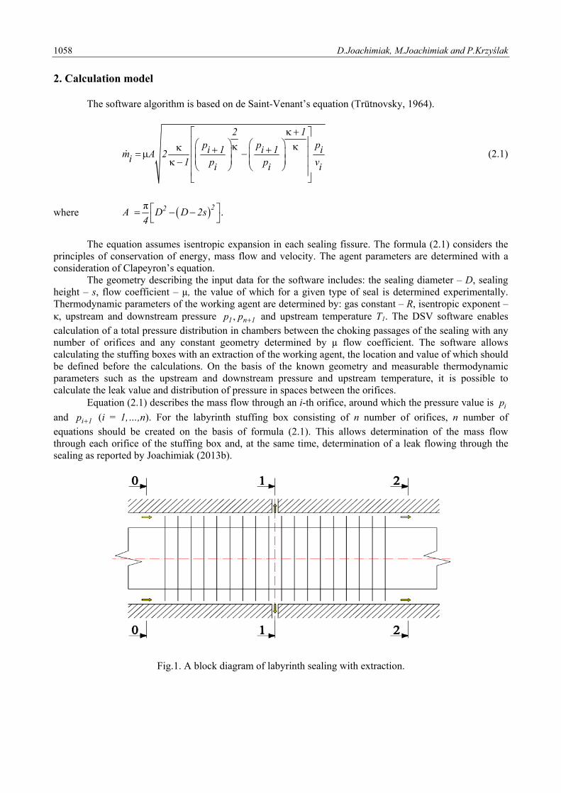
2. Calculation model The software algorithm is based on de Saint-Venant’s equation (Trütnovsky, 1964).
2 1p p pi 1 i 1 im A 2i 1 p p vi i i
(2.1)
where π.
22A D D 2s4
The equation assumes isentropic expansion in each sealing fissure. The formula (2.1) considers the principles of conservation of energy, mass flow and velocity. The agent parameters are determined with a consideration of Clapeyron’s equation. The geometry describing the input data for the software includes: the sealing diameter – D, sealing height – s, flow coefficient – µ, the value of which for a given type of seal is determined experimentally. Thermodynamic parameters of the working agent are determined by: gas constant – R, isentropic exponent – κ, upstream and downstream pressure ,1 n 1p p and upstream temperature T1. The DSV software enables calculation of a total pressure distribution in chambers between the choking passages of the sealing with any number of orifices and any constant geometry determined by µ flow coefficient. The software allows calculating the stuffing boxes with an extraction of the working agent, the location and value of which should be defined before the calculations. On the basis of the known geometry and measurable thermodynamic parameters such as the upstream and downstream pressure and upstream temperature, it is possible to calculate the leak value and distribution of pressure in spaces between the orifices. Equation (2.1) describes the mass flow through an i-th orifice, around which the pressure value is ip
and i 1p (i = 1,…,n). For the labyrinth stuffing box consisting of n number of orifices, n number of equations should be created on the basis of formula (2.1). This allows determination of the mass flow through each orifice of the stuffing box and, at the same time, determination of a leak flowing through the sealing as reported by Joachimiak (2013b).
Fig.1. A block diagram of labyrinth sealing with extraction.
The analysis of the calculation process related to labyrinth … 1059
For n number of choking passages, the mass flow through the sealing has to be stable, except for the extraction spot. As a result, the sealing is divided into two parts. The main mass 0 1m flows through the first
part. At the end of the first part there is an extraction spot, through which the gas stream 1m flows out of the
sealing. The remaining part 1 2m flows through the other part of the stuffing box. Therefore, we obtain the following equation on the basis of Fig.1 .0 1 1 1 2m m m (2.2) A change in the mass flow of gas flowing through the i-th choking passage may be determined as follows (Joachimiak, 2013b) depending on the change of pressure before pi choking passage pi+1
.i ii i i 1
i i 1
m mdm dp dp
p p
(2.3)
Partial derivatives on the basis of Eq.(2.1) are as follows
,2 2 1 1
i 0i ii 1 i 1 2 2 2 1 1
ii ii 1 i 1
12
m 1 T RA 2 2 1p p p p
p 2p p p p
(2.4)
.2 2 2 1 1
i 0i ii 1 i 1 2 2 2 1 1
i 1i ii 1 i 1
12g
m 1 T RA 2 1p p p p
p 2p p p p
(2.5)
The following difference vectors of mass flows were obtained on the basis of the formula (2.1) .i i i 1m m m (2.6) Comparing Eqs (2.4) and (2.5) for two adjacent orifices as referred to the finite increments and in consideration of Eq.(2.6) the following may be stated
,i i i 1 i 1i i i 1 i 2
i i 1 i 1 i 2
m m m mm p p p
p p p p
(2.7)
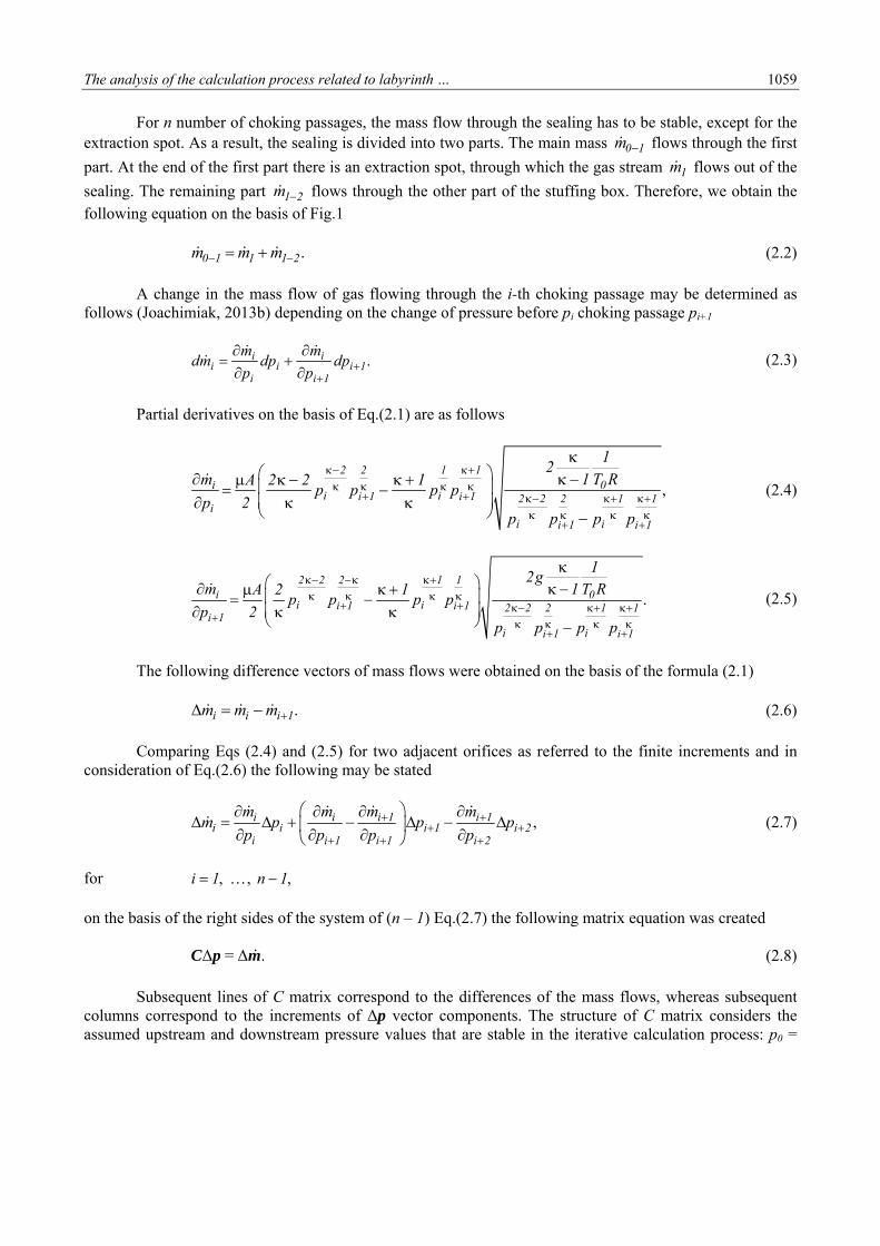
for , , ,i 1 n 1 on the basis of the right sides of the system of (n – 1) Eq.(2.7) the following matrix equation was created Δ = Δ .C p m (2.8) Subsequent lines of C matrix correspond to the differences of the mass flows, whereas subsequent columns correspond to the increments of Δp vector components. The structure of C matrix considers the assumed upstream and downstream pressure values that are stable in the iterative calculation process: p0 =
1060 D.Joachimiak, M.Joachimiak and P.Krzyślak
const, pn = const. Therefore, the upstream and downstream pressure values in relation to the sealing equal zero. Δp0 = Δpn+1 = 0. (2.9) Therefore, C matrix does not have the following components: , 1 1 n n 1m p m p
1 2 2
2 2 3
3 32 2
2 3 3 4
3 3 4 4
3 4 4 5
n 2 n 2 n 1
n 2 n 1 n 1
m m m0 0
p p p
m mm m0 0
p p p p
m m m m0 0 0
p p p p
0 0 0
0 0 0
0 0
m m m0 0
p p p
C
n 2
n 1
n 1 n 1 n
n 1 n n
m
p
m m m0 0 0 0 0 0
p p p
,
Δ ,T
1 2 n 1p p p p (2.10)
Δ .T
1 2 n 1m m m m (2.11)
The vector of mass flow differences i i i 1m m m for , , i 1 n 1 was determined on the basis of Eq.(2.1) for the assumed pressures of p0 and pn+1. During the analysis of the labyrinth sealing with extraction, an extraction should be taken into account by changing the values of elements of the vector of the mass flow differences m . Calculation of the sealing, from which an extraction with the value of 1m is determined before the i-th choking passage requires making the following change
Δ .T
1 2 i 1 i 1 i 1 n 1m m m m m m m m (2.12)
C matrix was presented as a product of 2-band lower triangular matrix with values equaling 1 at the main L diagonal and U 2-band upper triangular matrix. On the basis of Thomson’s algorithm and Gauss’s
method (Kosma, 2008) the matrix equation of Δ = ΔC p m was converted to Δ =U p w , where 1 w L m . Next, through a sequential solution of the linear system of equations, it was possible to obtain a solution that was a vector of ∆p pressure adjustments. The solution of Δ =U p w equations is the first approximation of pressure adjustments. Reiteration of the process allows obtaining another ∆p adjustments of p pressure distribution vector. This leads to an iterative process and finding of the sought distribution of pressures. The iterative calculations are completed, when the highest value of the element of the vector of mass flow differences is lower or equal to the assumed accuracy of calculations - ε. Therefore the completion of the calculations is conditional upon obtaining a stable mass flow of gas through the first and the second part of the sealing. Then the mass flow differences in both parts have to be close to zero. The matrix stability depends on whether the matrix contains very large or very small elements. Elements with very low values contained in C main matrix cause that in the reverse matrix there appear
The analysis of the calculation process related to labyrinth … 1061
elements of high values. Therefore, the high value of standards from C and C matrix may denote problems with numerical stability. The program performs operations on matrixes, the measurements of which depend on the number of orifices. During iterative calculations, the program checks Cond(C) values determined as follows (Maćkiewicz, 2002)
( ) .n n n n
1 2 2ij ij
i 1 j 1 i 1 j 1
1 1Cond c c
n n
C C C (2.13)
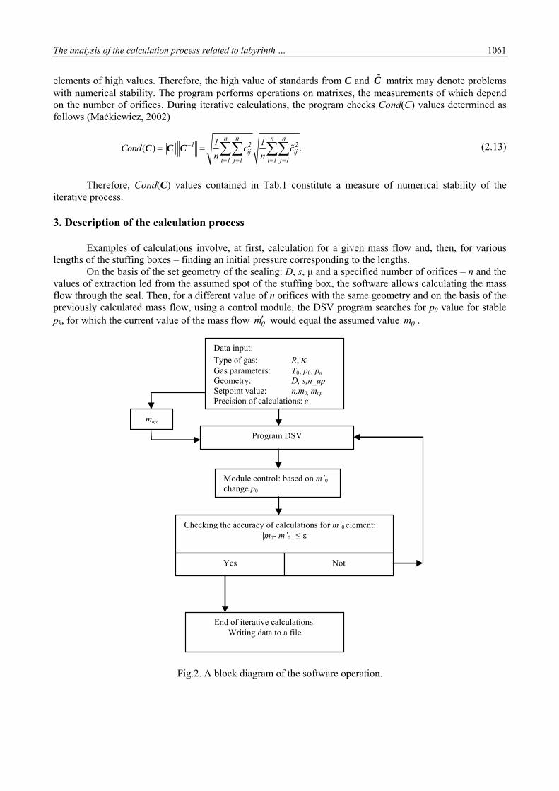
Therefore, Cond(C) values contained in Tab.1 constitute a measure of numerical stability of the iterative process. 3. Description of the calculation process Examples of calculations involve, at first, calculation for a given mass flow and, then, for various lengths of the stuffing boxes – finding an initial pressure corresponding to the lengths. On the basis of the set geometry of the sealing: D, s, μ and a specified number of orifices – n and the values of extraction led from the assumed spot of the stuffing box, the software allows calculating the mass flow through the seal. Then, for a different value of n orifices with the same geometry and on the basis of the previously calculated mass flow, using a control module, the DSV program searches for p0 value for stable pk, for which the current value of the mass flow 0m would equal the assumed value 0m .
Fig.2. A block diagram of the software operation.
Data input:
Type of gas: R, κ Gas parameters: T0, p0, pn Geometry: D, s,n_up Setpoint value: n,m0, mup Precision of calculations: ε
Checking the accuracy of calculations for m’0 element: |m0- m’0 | ≤ ε
Yes
End of iterative calculations. Writing data to a file
Module control: based on m’0 change p0
Not
Program DSV
mup
1062 D.Joachimiak, M.Joachimiak and P.Krzyślak
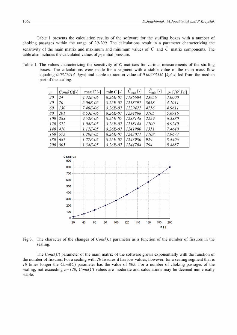
Table 1 presents the calculation results of the software for the stuffing boxes with a number of choking passages within the range of 20-200. The calculations result in a parameter characterizing the
sensitivity of the main matrix and maximum and minimum values of C and C matrix components. The table also includes the calculated values of p0 initial pressure. Table 1. The values characterizing the sensitivity of C matrixes for various measurements of the stuffing
boxes. The calculations were made for a segment with a stable value of the main mass flow equaling 0.0317014 [kg/s] and stable extraction value of 0.00233556 [kg/ s] led from the median part of the sealing.
n Cond(C)[-] max C [-] min C [-] maxC [-] minC [-] p0 [105 Pa] 20 24 4.32E-06 8.26E-07 1186604 23956 3.0000 40 70 6.06E-06 8.26E-07 1218597 8658 4.1011 60 130 7.40E-06 8.26E-07 1229421 4756 4.9611 80 201 8.53E-06 8.26E-07 1234868 3105 5.6916 100 283 9.52E-06 8.26E-07 1238148 2229 6.3380 120 372 1.04E-05 8.26E-07 1238148 1700 6.9240 140 470 1.12E-05 8.26E-07 1241900 1351 7.4640 160 575 1.20E-05 8.26E-07 1243071 1108 7.9673 180 687 1.27E-05 8.26E-07 1243980 929 8.4406 200 805 1.34E-05 8.26E-07 1244704 794 8.8887
Fig.3. The character of the changes of Cond(C) parameter as a function of the number of fissures in the
sealing. The Cond(C) parameter of the main matrix of the software grows exponentially with the function of the number of fissures. For a sealing with 20 fissures it has low values, however, for a sealing segment that is 10 times longer the Cond(C) parameter has the value of 805. For a number of choking passages of the sealing, not exceeding n=120, Cond(C) values are moderate and calculations may be deemed numerically stable.
The analysis of the calculation process related to labyrinth … 1063
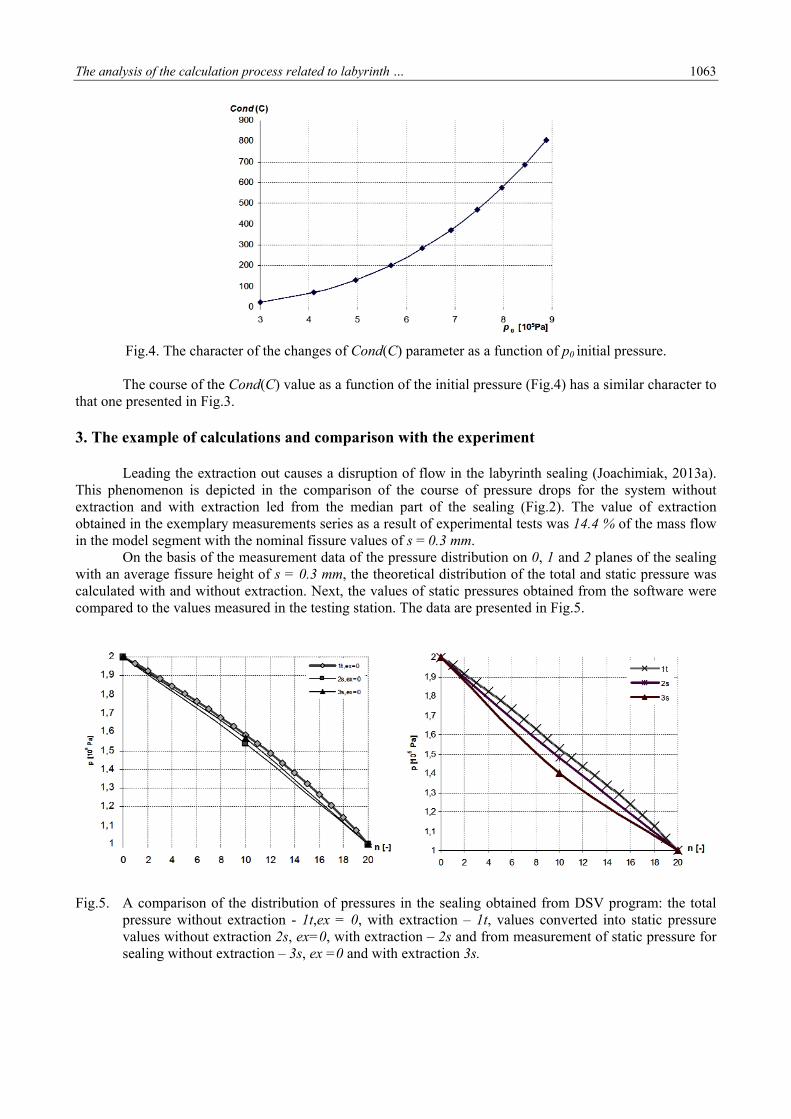
Fig.4. The character of the changes of Cond(C) parameter as a function of p0 initial pressure. The course of the Cond(C) value as a function of the initial pressure (Fig.4) has a similar character to that one presented in Fig.3. 3. The example of calculations and comparison with the experiment Leading the extraction out causes a disruption of flow in the labyrinth sealing (Joachimiak, 2013a). This phenomenon is depicted in the comparison of the course of pressure drops for the system without extraction and with extraction led from the median part of the sealing (Fig.2). The value of extraction obtained in the exemplary measurements series as a result of experimental tests was 14.4 % of the mass flow in the model segment with the nominal fissure values of s = 0.3 mm. On the basis of the measurement data of the pressure distribution on 0, 1 and 2 planes of the sealing with an average fissure height of s = 0.3 mm, the theoretical distribution of the total and static pressure was calculated with and without extraction. Next, the values of static pressures obtained from the software were compared to the values measured in the testing station. The data are presented in Fig.5.
Fig.5. A comparison of the distribution of pressures in the sealing obtained from DSV program: the total
pressure without extraction - 1t,ex = 0, with extraction – 1t, values converted into static pressure values without extraction 2s, ex=0, with extraction – 2s and from measurement of static pressure for sealing without extraction – 3s, ex =0 and with extraction 3s.
1064 D.Joachimiak, M.Joachimiak and P.Krzyślak
Figure 5 presents a relative difference of static pressure measured on the extraction plane and the one calculated theoretically. The relative difference of pressures is defined as follows
, ,
,
%.1 DSV 1 measurement1
1 measurement
p pp 100
p
The measurements and calculations were presented in Tab.2 for three segments of a smooth sealing with fissure heights of s = 0.3; 0.5; 0.7 mm. The working pressures for each measurement were p0 = 2·105 Pa, pn = 105 Pa. The values of the mass flow and extraction for individual variants are presented in the table below. Table 2. The pressure values in the plane of extraction obtained from the measurement and DSV calculation
program.
s [mm] 0m [kg/s] 1m [kg/s] p1,measurement [105 Pa]
p1, DSV [105 Pa]
δp1 [%]
0.3 0.01625 0.002336 1.3995 1.48156 5.8
0.5 0.03318 0.002543 1.458 1.50153 2.9
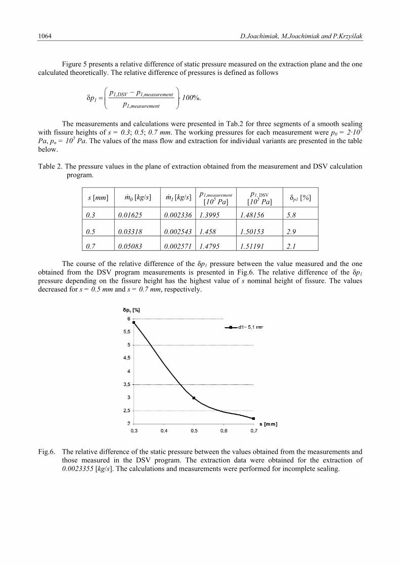
0.7 0.05083 0.002571 1.4795 1.51191 2.1 The course of the relative difference of the δp1 pressure between the value measured and the one obtained from the DSV program measurements is presented in Fig.6. The relative difference of the δp1 pressure depending on the fissure height has the highest value of s nominal height of fissure. The values decreased for s = 0.5 mm and s = 0.7 mm, respectively.
Fig.6. The relative difference of the static pressure between the values obtained from the measurements and
those measured in the DSV program. The extraction data were obtained for the extraction of 0.0023355 [kg/s]. The calculations and measurements were performed for incomplete sealing.
The analysis of the calculation process related to labyrinth … 1065
4. Conclusions The software uses a linear system of n equations based on de Saint-Venant-Wanzel’s formula. On the basis of iterative operations on the matrix equations, the software approximates a respective distribution of pressures in spaces between the orifices. The calculated distribution of pressures was used for determining the mass flow through the sealing. The software performs iterative calculations until the assumed accuracy of the calculations is obtained. The software structure allows calculation of additional gas parameters in the stuffing box, e.g., velocity and the Reynolds and Mach number. The proposed method of calculation leads to a stable iterative process. An extension of the software by a control module allowed searching for the p0
unknown initial pressure to which a specified mass flow through the sealing would correspond for the assumed geometry of the sealing. The extended software may be used for calculating steam leaks in segments of steam turbine stuffing boxes. A comparison of results of the calculations made in the DSV program with the measurement data indicates that for relatively high extraction and nominal values of fissures, the error of determination of pressure in the extraction plane may reach 5.8%. It decreases, however, for the worn segments. Nomenclature A – flow field in the orifice C – main matrix of DSV program Cond(C) – condition number of the main matrix D – sealing diameter d – extraction orifice diameter im – mass flow through i-th orifice
0 1m – mass flow in first part of labirynth seals
1m – mass flow of extraction
1 2m – mass flow in second part of labirynth seals
pi – pressure upstream of thei-th orifice pi+1 – pressure downstream of the i-th orifice R – gas constant s – fissure height vi – specific volume upstream of the i-th orifice
δp1 – relative difference of the static pressure between the values obtained from the measurements and DSV program
κ – isentropic exponent μ – flow contraction coefficient References Anker J.E., Mayer J.F. and Casey M.V. (2012): Impact of rotor labyrinth seal leakage flow on the loss generation in an
axial turbine engineering. – International Journal of Power and Energy Systems. – Procedings of the Institution of Mechanical Engineers, vol.219, Part A, pp.481-490.
Bjorck A. and Dahlquist G. (1987): Numerical Methods (in Polish). – Warsaw: PWN.
Gamal Eldin A.M. (2007): Leakage and rotordynamic effects of pocket damper seals and see-through labyrinth seals – Dissertation, Texas A&M University, USA, December.
Joachimiak D. (2013a): The Labyrinth Seals Research With Extraction (in Polish). – Dissertation, Poznan University of Technology.
Joachimiak D. and Krzyślak P. (2011): Calculation of labyrinth seals with extraction. – International Journal of Applied Mechanics and Engineering, vol.16, No.1, pp.5-14.
1066 D.Joachimiak, M.Joachimiak and P.Krzyślak
Joachimiak D., Joachimiak M. and Krzyślak P.(2013b): Description program Dlawnica used for calculations labyrinth seals (in Polish). – Journal of Mechanical and Transport Engineering, No.65, pp.25-35.
Kosma Z. (2008): Numerical Methods in Engineering Applications (in Polish). – Radom: University Press.
Krzyślak P. and Winowiecki M. (2008): A method of diagnosing labyrinth seals in fluid-flow machines. – Polish Maritime Research, No.3 (57), vol.15, pp.38-41, 10.2478/v10012-007-0081-2.
Krzyślak P. and Winowiecki M. (2006): RP Patent Office: P-379431 – Acknowledgement of patent submission. Flow seal in a fluid-flow machine and method of its diagnostics (in Polish), Warsaw.
Maćkiewicz A. (2002): Linear Algebra Algorithms, Direct Methods (in Polish). – Poznan University of Technology Press.
Tipton D.L., Scott T.E. and Vogel T.E. (1985): Analytical and Experimental Development of a Design Model for Labyrinth Seals. – Air Force Wright Aeronautical Laboratories, Allison Gas Turbine-Division of General Motors Corporation.
Trütnovsky K. (1964): Berührungsfreie Dichtungen, Grundlagen und Anwendungen der Strömung durch Spalte und Labyrinthe. – VDI-Verlag bh Düsseldorf, Verlag des Vereins Deutscher Ingenieure.
Winowiecki M. (2009): The Method of Diagnosing Labyrinth Seals On Machines (in Polish). – Dissertation, Poznan: University of Technology.
Received: July 10, 2013
Revised: August 29, 2013