test sets - radionerds
TRANSCRIPT
-/- il/13
"Hil
WAR DEPARTMENT TECHNICAL MANUAL
(•/
>F• tTEST SETS
I-56-C, -D, -H, -J_
DEPARTMENT MARCH 1944
Genera
ted o
n 2
01
5-1
0-1
3 1
8:3
2 G
MT /
htt
p:/
/hd
l.hand
le.n
et/
20
27
/uc1
.b3
24
54
41
Public
Dom
ain
, G
oog
le-d
igit
ized
/
htt
p:/
/ww
w.h
ath
itru
st.o
rg/a
ccess
_use
#pd-g
oogle
WAR DEPARTMENT TECHNICAL MANUALTM 11-303
FEST SETS
I-56-C, -D, -H, -J
WAR DEPARTMENT • 4 MARCH 1944
Uni(ed S(a(es Governmen( Prin(ing Office
H"asking(on : 1944
Genera
ted o
n 2
01
5-1
0-1
3 1
8:3
2 G
MT /
htt
p:/
/hd
l.hand
le.n
et/
20
27
/uc1
.b3
24
54
41
Public
Dom
ain
, G
oog
le-d
igit
ized
/
htt
p:/
/ww
w.h
ath
itru
st.o
rg/a
ccess
_use
#pd-g
oogle
WAR DEPARTMENT,WASHINGTON 25, D. C.• 4 MARCH 1944.
TM 11-303, Test Sets" I-56-C, M6-D, I-56-H, and I-56-J, is published
for the information and guidance of all concerned.
[A. G. 300.7 (6 DEC. 43).]
BY ORDER OF THE SECRETARY OF WAR:G. C. MARSHALL,
Chief of Staff
OFFICIAL:
J. A. ULIO,Major General,
The Adjutant General,
DISTRIBUTION:
R and H 1, 4, 7(2); IBn 11(2); 1C 2, 4, 5, 6, 7, 17, 18(2), 11(5).
(For explanation of symbols see FM 21-6.)
.CI . •'.
r\V\.
II
Genera
ted o
n 2
01
5-1
0-1
3 1
8:3
2 G
MT /
htt
p:/
/hd
l.hand
le.n
et/
20
27
/uc1
.b3
24
54
41
Public
Dom
ain
, G
oog
le-d
igit
ized
/
htt
p:/
/ww
w.h
ath
itru
st.o
rg/a
ccess
_use
#pd-g
oogle
,1TM \
OF CONTENTS
SECTION I. DescriptionPar. Page
Purpose 1 1
General 2 1
Model 104 Combination Tester, general. 3 1
Model 104 Combination Tester as a tube
checker 4 2
Model 104 Combination Tester as a volt-
ohm-milliammeter 5 3
Model 104 Combination Tester as a free-
point tester (socket analyzer) ... 6 4
Model 104 Combination Tester as used
for capacitance measurements ... 7 5
Model 104 Combination Tester as an
audio-frequency output meter ... 8 6
Model 1183-SC Combination Tester . . 9 6
Model 102 Volt-Ohm Tester .... 10 6
Model 666-SC Volt-Ohm Tester ... 11 7
Model 103 Output Meter 12 7
Model 650-SC Output Meter .... 13 8
Accessory equipment 14 8
Carrying case 15 8
Components, weights and dimensions .16 9
II. Operation
Preliminary instructions"
17 11
Model 104 Combination Tester as a tube
tester 18 11
Model 104 Combination Tester as a pilotlamp tester - . 19 14
III
Genera
ted o
n 2
01
5-1
0-1
3 1
8:3
2 G
MT /
htt
p:/
/hd
l.hand
le.n
et/
20
27
/uc1
.b3
24
54
41
Public
Dom
ain
, G
oog
le-d
igit
ized
/
htt
p:/
/ww
w.h
ath
itru
st.o
rg/a
ccess
_use
#pd-g
oogle
TABLE OF CONTENTS (continued)
Par. Page
Model 104 Combination Tester as an ohm-
meter 20 15
Model 104 Combination Tester as a volt
meter 21 15
Model 104 Combination Tester as a milli-
ammeter 22 16
Model 104 Combination Tester as an
audio-frequency output meter ... 23 16
Model 104 Combination Tester —prepara
tion for free-point (socket analyzing)
measurements 24 17
Model 104 Combination Tester —free-
point voltage measurements .... 25 17
Model 104 Combination Tester —free-
point current measurements ... 26 18
Model 104 Combination Tester — free-
point continuity and resistance
measurements 27 18
Model 104 Combination Tester—capaci
tance measurements 28 19
Model 1183-SC Combination Tester . . 29 21
Model 102 Volt-Ohm Tester as a D-CVoltmeter 30 22
Model 102 Volt-Ohm Tester as an ohm-
meter 31 23
Model 666-SC Volt-Ohm Tester ... 32 23
Model 103 Output Meter 33 23
Model 650-SC Output Meter .... 34 24
Servicing Radio Equipment with Test Set
I-56-(*) 35 24
III. Functioning of Parts
Model 104 Combination Tester ... 36 29
Model 1183-SC Combination Tester . . 37 33
Model 102 Volt-Ohm Tester .... 38 35
Model 666-SC Volt-Ohm Tester .... 39 35
Model 103 Output Meter 40 35
Model 650-SC Output Meter .... 41 35
IV
Genera
ted o
n 2
01
5-1
0-1
3 1
8:3
2 G
MT /
htt
p:/
/hd
l.hand
le.n
et/
20
27
/uc1
.b3
24
54
41
Public
Dom
ain
, G
oog
le-d
igit
ized
/
htt
p:/
/ww
w.h
ath
itru
st.o
rg/a
ccess
_use
#pd-g
oogle
TABLE OF CONTENTS (continued)
IV. MaintenancePar. Page
General 42 36
Combination Testers, Model 104 and
Model 1183-SC 43 36
Volt-Ohm Testers, Model 102 and Model
666-SC 44 38
Output Meters, Model 103 and Model650-SC \ . . 45 38
Moistureproofing and fungiproofinginstructions 46 49
V. Supplementary Data
Tube-base chart for Signal Corps and
commercial tubes 47 50
Commercial equivalents of Signal Corps
tubes 48 61
Signal Corps equivalents of commercial
tubes 49 64
Tube testing data 50 68
Resistor color-code chart 51 78
Capacitor color-code chart 52 79
Table of replaceable parts for Test Sets
I-56-C and I-56-J 53 80
Table of replaceable parts for Test Sets
I-56-D and I-56-H ..... 54 89
Genera
ted o
n 2
01
5-1
0-1
3 1
8:3
2 G
MT /
htt
p:/
/hd
l.hand
le.n
et/
20
27
/uc1
.b3
24
54
41
Public
Dom
ain
, G
oog
le-d
igit
ized
/
htt
p:/
/ww
w.h
ath
itru
st.o
rg/a
ccess
_use
#pd-g
oogle
LIST OF ILLUSTRATIONS
Pig. Title Page
1. Test Set I-?6-(*) with Cover Raised 2
2. Model 104 Combination Tester with Cover Raised .... 4
3. Test Set I-56-(*>, Adapter Plugs 5
4. Model 1183-SCU) Combination Tester .75. Model 102 Volt-Ohm Tester 8
6. Model 103 Output Meter 8
7. Combination Tester, Settings 10
8. Combination Tester, Testing an Acorn Tube 13
9. Combination Tester, Free-Point Current Measurements . . .1910. Combination Tester, Capacitance Test Graph 20
11. Model 1183-SC(J) Combination Tester, Measuring Capacitance 22
12. Model 104 Combination Tester, Simplified Tube Testing Circuit 28
13. Model 104 Combination Tester, Simplified Filament Continuityand "Short" Test Circuit 30
14. Model 104 Combination Tester, Simplified Glow Test Circuit 30
15. Model 104 Combination Tester, Simplified A-F and A-CVoltmeter Circuit . 32
16. Model 104 Combination Tester, Simplified D-C VoltmeterCircuit 32
17. Model 104 Combination Tester, Simplified D-C Milliammeter
Circuit 32
18. Model 104 Combination Tester, Simplified Capacitance
Measuring Circuit 33
19. Model 104 Combination Tester, Simplified Ohmmeter Circuit . 34
20. Model 104 Combination Tester, Simplified Free-Point Testing"
Circuit 34
21. Model 104 and Model 1183-SC Combination Tester, Battery
Replacement lanel 37
VI
Genera
ted o
n 2
01
5-1
0-1
3 1
8:3
3 G
MT /
htt
p:/
/hd
l.hand
le.n
et/
20
27
/uc1
.b3
24
54
41
Public
Dom
ain
, G
oog
le-d
igit
ized
/
htt
p:/
/ww
w.h
ath
itru
st.o
rg/a
ccess
_use
#pd-g
oogle
LIST OF ILLUSTRATIONS (continued]
Fig. Title Page
22. Model 104 Combination Tester, Schematic Diagram .... 39
23. Model 104 Combination Tester, Bottom View of Chassis . . 40
24. Model 104 Combination Tester, Resistor Board Diagram . . 40
25. "Model 1183-SC(C) Combination Tester, Schematic Diagram . 41
26. Model 1183-SC(C) Combination Tester, Resistor Board Diagram 42
27. Model 1183-SC(J) Combination Tester, Resistor Board Diagram 42
28. Model 1183-SC(J) Combination Tester, Schematic Diagram . 43
29. Model 102 and Model 666-SC Volt-Ohm Tester, Schematic
Diagram 44
30. Model 102 Volt-Ohm Tester, Resistor Board Diagram ... 45
31. Model 666-SC Volt-Ohm Tester, Location of Parts .... 45
32. Model 103 and Model 650-SC Output Meter, Schematic Diagram 46
33. Model 103 Output Meter, Resistor Board 47
34. Model 650-SC Output Meter, Location of Parts 47
35. Model 650-SC (C) Output Meter, Resistor Board 48
36. Model 650-SC(J) Output Meter, Resistor Board 48
37. Tube Base Diagrams 57-60
38. Resistor Color-Code Chart 78
39. Capacitor Color Code Chart 79
VII
Genera
ted o
n 2
01
5-1
0-1
3 1
8:3
3 G
MT /
htt
p:/
/hd
l.hand
le.n
et/
20
27
/uc1
.b3
24
54
41
Public
Dom
ain
, G
oog
le-d
igit
ized
/
htt
p:/
/ww
w.h
ath
itru
st.o
rg/a
ccess
_use
#pd-g
oogle

DESTRUCTION NOTICE
WHY — To prevent the enemy from using or salvaging this equipment
for his benefit. -
WHEN —When ordered by your commander.
HOW — 1. Smash—Use sledges, axes, handaxes, pickaxes, hammers,
crowbars, heavy tools.
2. Cu( —Use axes, handaxes, machetes.
3. Burn—Use gasoline, kerosene, oil, flame throwers, incendiary
grenades.
4. Explosives —Use firearms, grenades, TNT.5. Disposal—Bury in slit trenches, fox holes, other holes. Throw
in streams. Scatter.
USE ANYTHING IMMEDIATELY AVAILABLE FOR DESTRUCTION OF THIS EQUIPMENT.
WHAT— 1. Smash —Meters, controls, panels.
2. Cu(—Cables and all wiring.
3. Burn—Resistors, capacitors, all technical manuals, instruction
books, tube charts.
4. Bury or scat(er—Any or all of the above pieces after destroy
ing their usefulness.
DESTROY EVERYTHING
SAFETY NOTICE
WHEN THIS EQUIPMENT IS USED IN CONNECTION WITHHIGH VOLTAGES WHICH ARE DANGEROUS TO LIFE, OPERATING PERSONNEL MUST EXERCISE EXTREME CARE. SAFETYREGULATIONS AND CAUTION NOTICES WHICH APPEARTHROUGHOUT THIS MANUAL MUST BE OBSERVED AT ALLTIMES. MAKE TESTS EXACTLY AS DIRECTED. PERSONNELNOT FAMILIAR WITH THE SERVICING OF HIGH-VOLTAGECIRCUITS SHOULD NEVER MAKE TESTS INVOLVING SUCHCIRCUITS.
viii
Genera
ted o
n 2
01
5-1
0-1
3 1
8:3
3 G
MT /
htt
p:/
/hd
l.hand
le.n
et/
20
27
/uc1
.b3
24
54
41
Public
Dom
ain
, G
oog
le-d
igit
ized
/
htt
p:/
/ww
w.h
ath
itru
st.o
rg/a
ccess
_use
#pd-g
oogle
TM 11-303
Pars. 1-3
This manual supersedes War Department Training Circular 69,
19 May 1943
SECTION I
DESCRIPTION
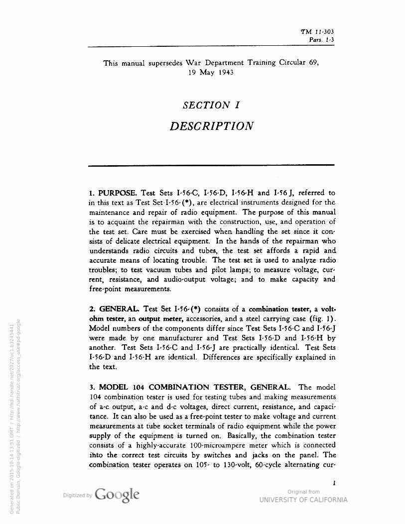
1. PURPOSE. Test Sets I-56-C, I-56-D, I-56-H and 1-56 J, referred to
in this text as Test Set 1-56- (*), are electrical instruments designed for the
maintenance and repair of radio equipment. The purpose of this manual
is to acquaint the repairman with the construction, use, and operation of
the test set. Care must be exercised when handling the set since it con
sists of delicate electrical equipment. In the hands of the repairman who
understands radio circuits and tubes, the test set affords a rapid and
accurate means of locating trouble. The test set is used to analyze radio
troubles; to test vacuum tubes and pilot lamps; to measure voltage, cur
rent, resistance, and audio-output voltage; and to make capacity and
free-point measurements.
2. GENERAL. Test Set 1-56- (*) consists of a combination tester, a volt-
ohm tester, an output meter, accessories, and a steel carrying case (fig. 1).Model numbers of the components differ since Test Sets I-56-C and I-56-Jwere made by one manufacturer and Test Sets I-56-D and I-56-H byanother. Test Sets I-56-C and I-56-J are practically identical. Test Sets
I-56-D and I-56-H are identical. Differences are specifically explained inthe text.
3. MODEL 104 COMBINATION TESTER, GENERAL. The model
104 combination tester is used for testing tubes and making measurements
of a-c output, a-c and d-c voltages, direct current, resistance, and capaci
tance. It can also be used as a free-point tester to make voltage and current
measurements at tube socket terminals of radio equipment while the power
supply of the equipment is turned on. Basically, the combination tester
consists of a highly-accurate 100-microampere meter which is connected
ihto the correct test circuits by switches and jacks on the panel. The
combination tester operates on 105- to 130-volt, 60-cycle alternating cur
1
Genera
ted o
n 2
01
5-1
0-1
4 1
3:5
1 G
MT /
htt
p:/
/hd
l.hand
le.n
et/
20
27
/uc1
.b3
24
54
41
Public
Dom
ain
, G
oog
le-d
igit
ized
/
htt
p:/
/ww
w.h
ath
itru
st.o
rg/a
ccess
_use
#pd-g
oogle

TM 11-303 Test Sets
Pars. 3-4, Fig. 1 I-56-C, I-56-D, I-56-H and I-56-J
FIG. 1. TEST SET M6-(*) WITH COVER RAISEDTL"7380
rent. A model is supplied for use with 105- to 130-volt, 25-cycle alternat
ing current. A vibrator power supply is available for supplying voltages
where there is no 105- to 130-volt source. Make sure that the power cord
and adapter cable are wound on the brackets in the cover and that all
the panel controls are in the off, or neutral positions (fig. 2) before closing
the cover of the tester.
4. MODEL 104 COMBINATION TESTER AS A TUBE CHECKER.The model 104 combination tester uses a standard RMA-approved emis
sion-type tube-checking circuit. Slide switches allow testing receiver tubes,
regardless of the positions of filament and cathode prongs. Individual
emission tests can be made for each plate in rectifier tubes and multiple-
function tubes.
a. Sockets on the tester panel serve for both Signal Corps and com
mercial vacuum tubes. The tester provides sockets for 4-prong, 5-prong,
6-prong, combination large and small 7-prong, 8-prong octal, 8-prong loctal,
5 -prong Bantam, Jr., 7-prong miniature and 7-prong midget tubes.
Pilot lamps can be tested in a special socket located in the center of the
7-prong socket. A special BN adapter for tests of acorn tubes and a lead
for testing tubes with top caps are provided in the test lead compartment.
b. A neon lamp, marked SHORT TEST, visible through a hole inthe panel just below the meter, indicates leakages or shorts between tube
electrodes.
Genera
ted o
n 2
01
5-1
0-1
4 1
3:5
1 G
MT /
htt
p:/
/hd
l.hand
le.n
et/
20
27
/uc1
.b3
24
54
41
Public
Dom
ain
, G
oog
le-d
igit
ized
/
htt
p:/
/ww
w.h
ath
itru
st.o
rg/a
ccess
_use
#pd-g
oogle
TM 11-303
Description Pars. 4-5
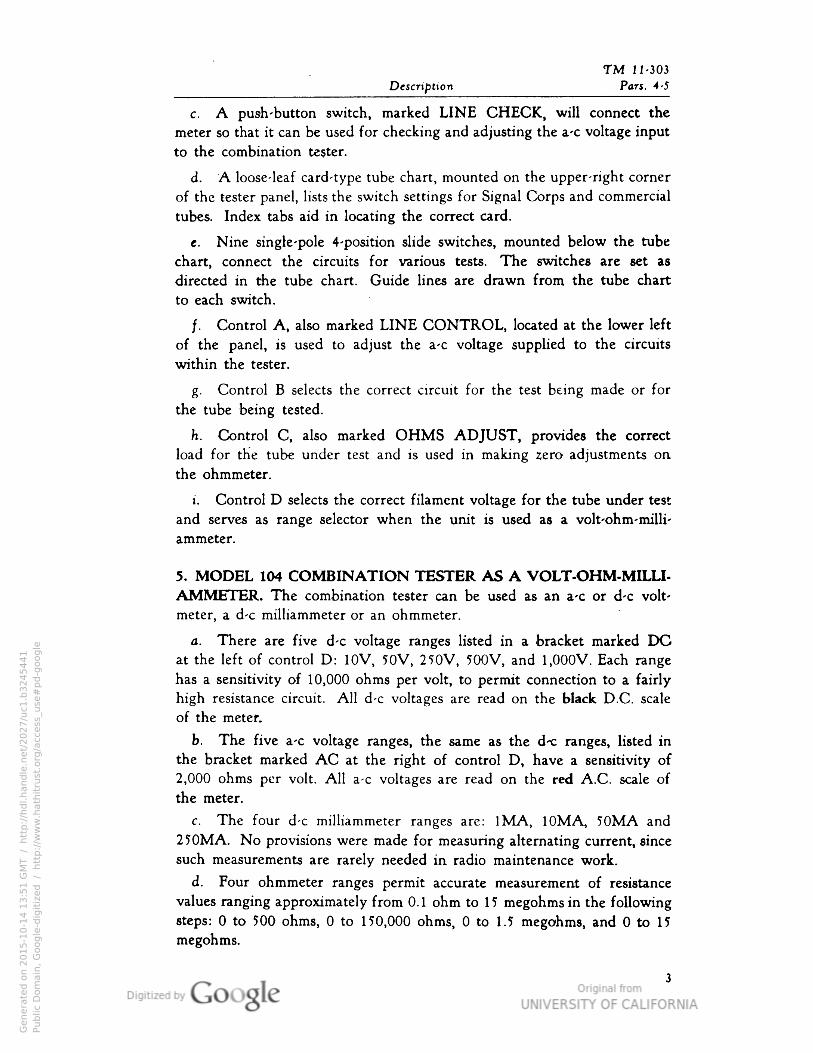
c. A push-button switch, marked LINE CHECK, will connect the
meter so that it can be used for checking and adjusting the a-c voltage input
to the combination tester.
d. A loose-leaf card-type tube chart, mounted on the upper-right corner
of the tester panel, lists the switch settings for Signal Corps and commercial
tubes. Index tabs aid in locating the correct card.
e. Nine single-pole 4-position slide switches, mounted below the tube
chart, connect the circuits for various tests. The switches are set as
directed in the tube chart. Guide lines are drawn from the tube chart
to each switch.
/. Control A, also marked LINE CONTROL, located at the lower left
of the panel, is used to adjust the a-c voltage supplied to the circuits
within the tester.
g. Control B selects the correct circuit for the test being made or for
the tube being tested.
h. Control C, also marked OHMS ADJUST, provides the correct
load for the tube under test and is used in making zero adjustments on
the ohmmeter.
i. Control D selects the correct filament voltage for the tube under test
and serves as range selector when the unit is used as a volt-ohm-milli-
ammeter.
5. MODEL 104 COMBINATION TESTER AS A VOLT-OHM-MILLI-AMMETER. The combination tester can be used as an a-c or d-c volt
meter, a d-c milliammeter or an ohmmeter.
a. There are five d-c voltage ranges listed in a bracket marked DCat the left of control D: 10V, 50V, 250V, 500V, and 1,000V. Each range
has a sensitivity of 10,000 ohms per volt, to permit connection to a fairlyhigh resistance circuit. All d-c voltages are read on the black D.C. scale
of the meter.
b. The five a-c voltage ranges, the same as the d< ranges, listed inthe bracket marked AC at the right of control D, have a sensitivity of2,000 ohms per volt. All a-c voltages are read on the red A.C. scale ofthe meter.
c. The four d-c milliammeter ranges are: IMA, 10MA, 50MA and
250MA. No provisions were made for measuring alternating current, since
such measurements are rarely needed in radio maintenance work.
d. Four ohmmeter ranges permit accurate measurement of resistance
values ranging approximately from 0.1 ohm to 15 megohms in the followingsteps: 0 to 500 ohms, 0 to 150,000 ohms, 0 to 1.5 megohms, and 0 to 15
megohms.
Genera
ted o
n 2
01
5-1
0-1
4 1
3:5
1 G
MT /
htt
p:/
/hd
l.hand
le.n
et/
20
27
/uc1
.b3
24
54
41
Public
Dom
ain
, G
oog
le-d
igit
ized
/
htt
p:/
/ww
w.h
ath
itru
st.o
rg/a
ccess
_use
#pd-g
oogle

TM 11-303 Test Sets
Pars. 5-6, Fig. 2 I-56-C, I-56-D, I-56-H and I-56-]
TL-7381
FIG. 2. MODEL 104 COMBINATION TESTER WITH COVER RAISED
e. The BAL position of control D may be used for continuity checks
of ballast tubes with the tube tester. No instructions are given for these
checks because actual ohmmeter measurements between ballast tube prongs
give more useful indications.
/. Capacitor leakage-resistance measurements can be made with the
highest ohmmeter range, 1?MEG. Any paper or mica capacitor having a
resistance of less than 10 megohms should be considered defective.
g. All ohmmeter ranges are operated by two self-contained batteries,
accessible through a small removable panel in the bottom of the tester.
6. MODEL 104 COMBINATION TESTER AS A FREE-POINTTESTER (SOCKET ANALYZER).
a. When all nine slide switches (E, F, G, H, I, J, K, L, and M) of
the combination tester are set in position 4, the tube sockets and the nine
Genera
ted o
n 2
01
5-1
0-1
4 1
3:5
1 G
MT /
htt
p:/
/hd
l.hand
le.n
et/
20
27
/uc1
.b3
24
54
41
Public
Dom
ain
, G
oog
le-d
igit
ized
/
htt
p:/
/ww
w.h
ath
itru
st.o
rg/a
ccess
_use
#pd-g
oogle

TM 11-303
Description Pars. 6-7, Fig. 3
TL-7382
FIG. 3. TEST SET I-56-(*), ADAPTER PLUGS
pairs of red and black jacks directly below the sockets are isolated from
the rest of the tester, converting it to a free-point tester, or a socket anal
yzer. A free-point tester makes circuits in radio equipment accessible
through the tube sockets, and eliminates the need of under-chassis socket-
voltage and resistance measurements. Current measurements may also
be taken without physically opening a circuit.
b. The free-point testing jacks are numbered according to the standard
RMA system for tubes. A connection to a particular tube socket terminal
can be made instantly by plugging a test probe into the jack with the
corresponding number.
c. The seven adapter plugs, which are furnished for free-point testing,
fit the following sockets: 4-prong, 5-prong, 6-prong, small 7-prong, large
7-prong, 8-prong octal and 8-prong loctal sockets. Adapter plugs forBantam, Jr., miniature and midget tubes are not furnished. The adapter
plugs are kept in the bottom of the test lead compartment as shown in
fig. 3.
7. MODEL 104 COMBINATION TESTER AS USED FOR CAPACITANCE MEASUREMENTS. Capacitance values of paper and mica capa
citors ranging in size from O.OOlMf to 1(W can be measured with the
Genera
ted o
n 2
01
5-1
0-1
4 1
3:5
1 G
MT /
htt
p:/
/hd
l.hand
le.n
et/
20
27
/uc1
.b3
24
54
41
Public
Dom
ain
, G
oog
le-d
igit
ized
/
htt
p:/
/ww
w.h
ath
itru
st.o
rg/a
ccess
_use
#pd-g
oogle
TM 11-303 Test Sets
Pars. 7-10 I-56-C, I-56-D• I-56-H and I-56-J
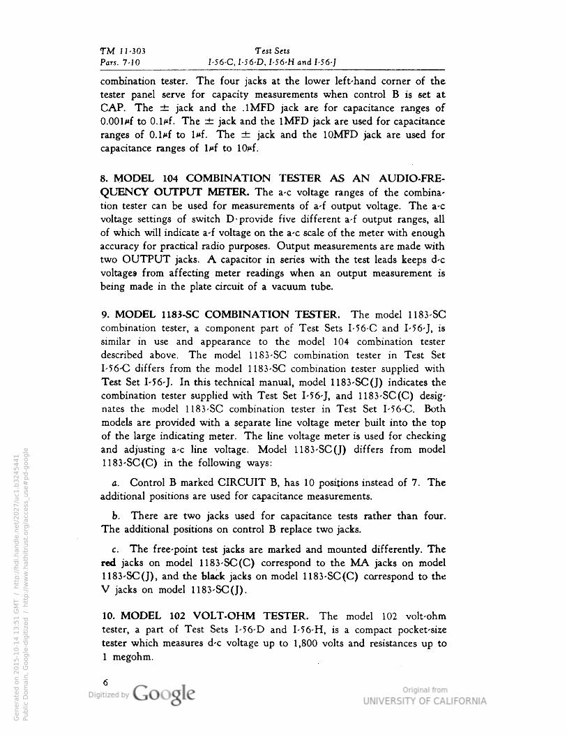
combination tester. The four jacks at the lower left-hand corner of the
tester panel serve for capacity measurements when control B is set at
CAP. The ± jack and the .1MFD jack are for capacitance ranges ofO.OOlMf to 0.1/*f. The ± jack and the 1MFD jack are used for capacitance
ranges of O.lMf to l<*f. The rt jack and the 10MFD jack are used for
capacitance ranges of l/*f to 10/*f.
8. MODEL 104 COMBINATION TESTER AS AN AUDIO-FRE
QUENCY OUTPUT METER. The a-c voltage ranges of the combina
tion tester can be used for measurements of a-f output voltage. The a-c
voltage settings of switch D- pro vide five different a-f output ranges, all
of which will indicate a-f voltage on the a-c scale of the meter with enough
accuracy for practical radio purposes. Output measurements are made withtwo OUTPUT jacks. A capacitor in series with the test leads keeps d-c
voltages from affecting meter readings when an output measurement is
being made in the plate circuit of a vacuum tube.
9. MODEL 1183-SC COMBINATION TESTER. The model 1183-SC
combination tester, a component part of Test Sets I-56-C and I-56-J, is
similar in use and appearance to the model 104 combination tester
described above. The model 1183-SC combination tester in Test Set
I-56-C differs from the model 1183-SC combination tester supplied with
Test Set I-56-J. In this technical manual, model 1183-SC(J) indicates the
combination tester supplied with Test Set I-56-J, and 1183-SC(C) desig
nates the model 1183-SC combination tester in Test Set I-56-C. Both
models are provided with a separate line voltage meter built into the top
of the large indicating meter. The line voltage meter is used for checking
and adjusting a-c line voltage. Model 1183-SC(J) differs from model
1183-SC(C) in the following ways:
a. Control B marked CIRCUIT B, has 10 positions instead of 7. The
additional positions are used for capacitance measurements.
b. There are two jacks used for capacitance tests rather than four.
The additional positions on control B replace two jacks.
c. The free-point test jacks are marked and mounted differently. The
red jacks on model 1183-SC(C) correspond to the MA jacks on model
1183-SC(J), and the black jacks on model 1183-SC(C) correspond to the
V jacks on model 1183-SC(J).
10. MODEL 102 VOLT-OHM TESTER. The model 102 volt-ohm
tester, a part of Test Sets I-56-D and I-56-H, is a compact pocket-size
tester which measures d-c voltage up to 1,800 volts and resistances up to
1 megohm.
Genera
ted o
n 2
01
5-1
0-1
4 1
3:5
1 G
MT /
htt
p:/
/hd
l.hand
le.n
et/
20
27
/uc1
.b3
24
54
41
Public
Dom
ain
, G
oog
le-d
igit
ized
/
htt
p:/
/ww
w.h
ath
itru
st.o
rg/a
ccess
_use
#pd-g
oogle

TM 11-303
Description Pars. 10-12, Fig. 4
TL-7497
FIG. 4. MODEL 1183-SC(J) COMBINATION TESTER
a. Five d-c voltage ranges, 3V, 30V, 300V, 600V and 1,800V, having
a sensitivity of 1,000 ohms per volt, are provided.
b. There are four ohmmeter ranges employing a series-type ohmmeter
circuit and a 4.5-volt internal battery. The ranges are: 0 to 1,000 ohms,
0 to 10,000 ohms, 0 to 100,000 ohms and 0 to 1,000,000 ohms (1 megohm).
c. Below the meter is a selector switch for changing ranges and under
this switch is a circuit-adjusting control for the ohmmeter. In addition,
there are three test lead jacks on the panel.
11. MODEL 666-SC VOLT-OHM TESTER. Model 666-SC volt-ohm
tester, a part of Test Sets I-56-C and 1-56- J, is similar in construction and
use to model 102 volt-ohm tester (par. 10) except that the highest d-c
voltage range measures up to 1,500 volts.
12. MODEL 103 OUTPUT METER. The model 103 output meter, a
component of Test Set I-56-D and I-56-H, is used mainly for checking
the a-f output voltage of a radio set during an alignment procedure using
a signal generator. A full-wave copper-oxide rectifier in the output meter
changes a-f current into a proportional direct current which moves the
meter. Below the meter (on the panel) is a selector switch which selects
Genera
ted o
n 2
01
5-1
0-1
4 1
3:5
1 G
MT /
htt
p:/
/hd
l.hand
le.n
et/
20
27
/uc1
.b3
24
54
41
Public
Dom
ain
, G
oog
le-d
igit
ized
/
htt
p:/
/ww
w.h
ath
itru
st.o
rg/a
ccess
_use
#pd-g
oogle

TM 11-303 Test Sets
Pars. 12-15, Figs. 5-6 I-56-C• I-56-D, I-56-H and I-56-J
-7383FIG. 5.
MODEL 102 VOLT-OHM TESTER
-7384
FIG. 6.
MODEL 103 OUTPUT METER
one of the five ranges for a-c and a-f voltage measurements; 1.5V, 6V,
15V, 60V and 150V. At the bottom of the panel are three jacks for
test leads.
13. MODEL 650-SC OUTPUT METER. Model 650-SC output meter,
a component of Test Sets I-56-C and I-56-J, is identical in design to
model 103 output meter (par. 12).
14. ACCESSORY EQUIPMENT.
a. Three pairs of test leads permit each of the units to be used indi
vidually while the other units are in use.
b. Slip-on alligator clips fasten the test prods into the circuit under test.
c. A special BN adapter is provided for testing acorn tubes. The
procedure is explained in paragraph 18i.
15. CARRYING CASE. The components of Test Set 1-56- (*) fit into a
steel carrying case which has four main compartments, one for each of
the three test instruments and one for the test leads and adapter plugs. Inaddition, a flat compartment in the cover of the steel case provides a
Genera
ted o
n 2
01
5-1
0-1
4 1
3:5
1 G
MT /
htt
p:/
/hd
l.hand
le.n
et/
20
27
/uc1
.b3
24
54
41
Public
Dom
ain
, G
oog
le-d
igit
ized
/
htt
p:/
/ww
w.h
ath
itru
st.o
rg/a
ccess
_use
#pd-g
oogle
TM 11-303
Description Pars. 15-16
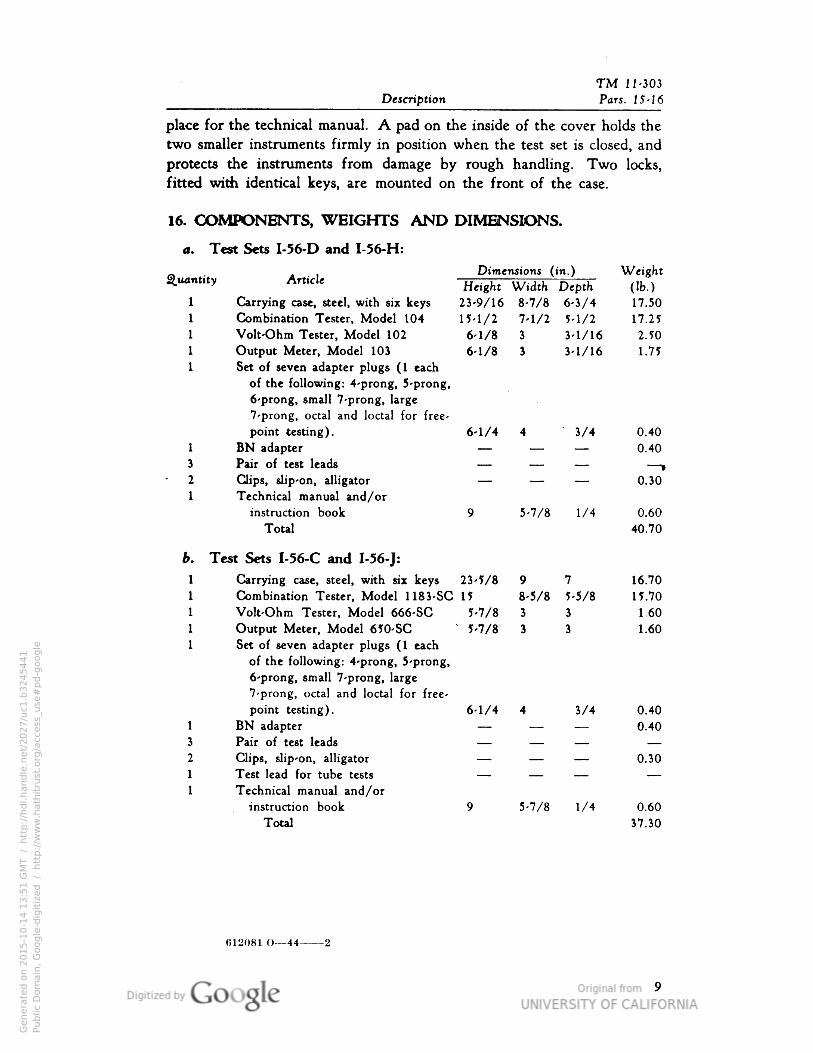
place for the technical manual. A pad on the inside of the cover holds the
two smaller instruments firmly in position when the test set is closed, and
protects the instruments from damage by rough handling. Two locks,
fitted with identical keys, are mounted on the front of the case.
16. COMPONENTS, WEIGHTS AND DIMENSIONS.
a. Test Sets I-56-D and I 56-H:
Dimensions (in.) WeightQuantity Article „ . , —.... , , — j^ r- ••• .^ 7 Height Width Depth (Ib.)
1 Carrying case, steel, with six keys 23-9/16 8-7/8 6-3/4 17.50
1 Combination Tester• Model 104 15-1/2 7-1/2 5-1/2 17.25
1 Volt-Ohm Tester, Model 102 6-1/8 3 3-1/16 2.50
1 Output Meter, Model 103 6-1/8 3 3-1/16 1.75
1 Set of seven adapter plugs (1 each
of the following: 4-prong, 5-prong,
6-prong, small 7-prong, large
7-prong, octal and loctal for free-
point testing). 6-1/4 4 3/4 0.40
1 BN adapter — — — 0.403 Pair of test leads — — — — ,
2 Clips, slip-on, alligator — — — 0.301 Technical manual and/or
instruction book 9 5-7/8 1/4 0.60
Total 40.70
b. Test Sets I-56-C and I-56-J:1 Carrying case, steel, with six keys 23-5/8 9 7 16.70
1 Combination Tester, Model 1183-SC 15 8-5/8 5-5/8 15.70
1 Volt-Ohm Tester, Model 666-SC 5-7/8 3 3 1.60
I Output Meter, Model 650-SC'
5-7/8 3 3 1.60
1 Set of seven adapter plugs (1 each
of the following: 4-prong, 5-prong,
6-prong, small 7-prong, large
7-prong, octal and loctal for free-
point testing). 6-1/4 4 3/4 0.401 BN adapter — — — 0.403 Pair of test leads — — — —2 Clips, slip-on, alligator — — — 0.30
1 Test lead for tube tests — — — —1 Technical manual and/or
instruction book 9 5-7/8 1/4 0.60
Total 37.30
612081 O—44-
Genera
ted o
n 2
01
5-1
0-1
4 1
3:5
1 G
MT /
htt
p:/
/hd
l.hand
le.n
et/
20
27
/uc1
.b3
24
54
41
Public
Dom
ain
, G
oog
le-d
igit
ized
/
htt
p:/
/ww
w.h
ath
itru
st.o
rg/a
ccess
_use
#pd-g
oogle
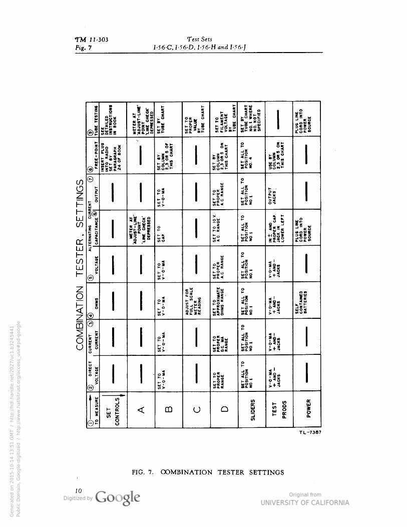
TM 11-303 Test Sets
Fig. 7 I-56-C• I-56-D• I-56-H and I-56-J
iD
OA
ILED
OS
OR
UC
OIO
•S
MO
ER
AO
-AD
JUS
O-L
OE-
PO
OO
"LO
EC
HEC
K"
DEPR
ES
0D
H I0
OO
OFI
LAM
E0
VO
LOA
EE
ne
TU
0E
CH
AR
O
0O
0Y
OU
0E
CH
AR
O•O
.
1
WH
ER
E•O
.•O
OS
PEC
IFIE
D
1
OK „ o^oE2
®su
0E
•
5
:o-
S IllsK 19 «->-
bic >ma.
_ o S£z32
^°5 °; °i10a o .,x
1 <ODcco **-
u
UsS3
ss"-^>-<n•
SS~^
©
?a. SS"-H
oU K
i ?a o«z d| *- •
*- 1
""o* HS *! Ho
uu 1
H> «£<uoo i?
I®
& ggo a. H
! i| o z jl
4 U-
*£*B
TER
•A
OI
CA
PA
CI
5|*
0<
*-w "^
-lit(3QU K
UJ u i- a:sS S£i 3§0|5 o
(ftU a.uo. <".i
O
g
u 1-<
19
S- ., i
51
z
fli
> . ou ^ uo 6 1 +•*
@u '
in * OTO.Z > ~*
o:" u o?* (o 1- p
(n o5"•o
g o * J2 < I
* uz »•• fc^*-X
^ j *-0
*-5 ""o .0
£i; o= u<ii.3 u J uoo t*5 VIU •
(5) V) P ino. z
°
s**-
°? 0*< do SoUJ J£ K 1
HW "^or E K oo: 5 uoo
>•*-*3 wwo.d.t (na•ZU
r- o0 K
II OX off si»o
I- 1 KS« *«"* 0<g>—O KOZ uoo
(N)W '
«0.tt MIL Z
1 U. f
Crt>
0
MEA
SU
R
ON
TR
OLS
M 1- «•> •e
1
C CO J Q B |
^ *~
UJcn
0
< (.
3
ena.
en
LJCO
crUJh-(/)LUI-
m
8
TL-7387
FIG. 7. COMBINATION TESTER SETTINGS
10
Genera
ted o
n 2
01
5-1
0-1
4 1
3:5
1 G
MT /
htt
p:/
/hd
l.hand
le.n
et/
20
27
/uc1
.b3
24
54
41
Public
Dom
ain
, G
oog
le-d
igit
ized
/
htt
p:/
/ww
w.h
ath
itru
st.o
rg/a
ccess
_use
#pd-g
oogle
TM 11-303
Pars. 17-18
SECTION IIOPERATION
NOTE: The d-c voltage readings taken with the combination tester
will often be higher than the readings given in technical manuals
because the combination tester has a higher resistance (10,000 ohms
per volt) than the average meter. The readings given in technical
manuals are usually based upon 1,000-ohm-per-Volt meters.
17. PRELIMINARY INSTRUCTIONS. Before handling any component
of Test Set 1-56- (*) read the instructions covering its use carefully. The
components are delicate electrical instruments and must be handled withcare. Pay particular attention to all cautions; they are inserted to guide
the user and to protect the equipment. For instructions on general testing
procedure see paragraph 35.
CAUTION: After completing one type of measurement, or after test
ing a tube, always reset all the controls to their off (or neutral)positions as indicated below. The practice of restoring the controls
to neutral positions safeguards against damaging the instrument
caused by using it before the controls have been properly set. Thecorrect off (neutral) positions for the various combination tester
controls are as follows (fig. 2) :
Control or switch TSfame J^eutral position
A LINE CONTROL OFFB Circuit switch Position 1
C OHMS ADJUST control OD Range selector switch OFF or D
E, F, G, H, I, J, K, L, M Slide switches Position 1
18. MODEL 104 COMBINATION TESTER AS A TUBE TESTER.To use the model 104 combination tester as a tube tester proceed as
follows:
M
Genera
ted o
n 2
01
5-1
0-1
4 1
3:5
2 G
MT /
htt
p:/
/hd
l.hand
le.n
et/
20
27
/uc1
.b3
24
54
41
Public
Dom
ain
, G
oog
le-d
igit
ized
/
htt
p:/
/ww
w.h
ath
itru
st.o
rg/a
ccess
_use
#pd-g
oogle
TM 11-303 Test Sets
Par. 18 I-56-C• I-56-D• I-56-H and I-56-J
a. Make sure that all controls are in their neutral positions (par. 17).
b. Plug the power cord of the tester into a suitable a-c power outlet
(105. to 125 volts).
c. Determine the type number of the tube to be tested by reference
to the card-type tube chart. The letters G, GT, or GT/G at the end of
a commercial tube number indicate the type and size of the glass envelope
used on the tube. These letters are to be disregarded when looking up a
tube on the tube chart. See paragraph 49 for additional tube testing data.
d. Set switch B at 1.
e. Set control C at the position specified in column C in the tube chart.
/. Set control D at the filament voltage specified in column D in the
tube chart.
g. Insert the tube in the correct socket on the tester panel. When in
serting or removing a loctal tube from a socket, handle the tube as gently
as possible. Tube prongs pass through the glass seals and excessive force
will crack the glass. A slight sidewise pressure applied to the tube willrelease the lock and permit easy removal of the tube from the socket.
h. If the tube has a top cap, insert the plug end of the tube-test lead
into the jack located between the meter and the 6-prong socket and attach
the rubber-covered clip to the top cap of the tube. The top cap can be
left in its jack and the clip end merely set aside while testing tubes without:
top caps. The lead must be removed and placed in the test lead com
partment before closing the cover of the tester.
i. When testing acorn tubes, plug the BN adapter into the octal socket.
Then place the acorn tube in the adapter and attach the top-cap clip ofthe tube-test lead to the clip on the side of the adapter. If the tube has a
top lead, push the adapter top-lead connector over it. The adapter top-
lead connector is attached to a lead coming out of the adapter (fig. 8).
j. Turn control A (LINE CONTROL) to the right, with the LINECHECK button depressed, until the pointer of the meter is directly over
the ADJUST LINE mark.
\. Referring to the tube chart, determine which is the first slide
switch (starting from E) designated with an asterisk (*), and set it at
the specified position. If the neon lamp glows, the filament of the tube
being tested has continuity. If the lamp does not light, the tube has an
open or burned-out filament.
1. All tubes marked with a dagger (f) must be tested for "shorts" as
described below. When these tubes are tested for short circuits using the
12
Genera
ted o
n 2
01
5-1
0-1
4 1
3:5
2 G
MT /
htt
p:/
/hd
l.hand
le.n
et/
20
27
/uc1
.b3
24
54
41
Public
Dom
ain
, G
oog
le-d
igit
ized
/
htt
p:/
/ww
w.h
ath
itru
st.o
rg/a
ccess
_use
#pd-g
oogle

TM 11-303
Operation Par. 18, Fig. 8
FIG. 8.
TL-7386
COMBINATION TESTER, TESTING AN ACORN TUBE
combination tester, the voltage applied between filament and grid pro-
duces an electrostatic field which in many cases is strong enough to cause
a short circuit in the tube. Remove the tube from the combination tester,
and check between the tube elements using the high resistance range ofthe volt-ohm tester. See the proper tube base diagram in paragraph 46
to determine the correct tube prongs for the elements being tested. If a
short circuit is present, the meter will deflect to full scale.
CAUTION: To avoid burning out the tube by placing 250 volts a-c
between the tube elements or 30 volts a-c across the filament terminals,
be sure to set all the controls for the emission test (subparagraphs o
and p below) before placing the tube into the tester socket.
m. For all tubes not marked with a dagger (t), set the remaining
asterisk-marked switches to the positions specified by the chart, leaving
13
Genera
ted o
n 2
01
5-1
0-1
4 1
3:5
2 G
MT /
htt
p:/
/hd
l.hand
le.n
et/
20
27
/uc1
.b3
24
54
41
Public
Dom
ain
, G
oog
le-d
igit
ized
/
htt
p:/
/ww
w.h
ath
itru
st.o
rg/a
ccess
_use
#pd-g
oogle
TM 11-303 Test Sets
Pars. 18-19 I-56-C. I-56-D• I-56-H and I-56-J
all others at position 1. If the tube has a heater-type cathode, the neon
lamp will indicate the amount of filament-cathode leakage. The brighter
the glow, the greater the leakage. No glow from the lamp indicates neg
ligible leakage.
CAUTION: Omit steps nt and n when testing 1.4-volt "peanut"
tubes with the combination tester in Test Set 1-56- (*). Follow the
procedure given in subparagraph 1 above for these tubes.
n. Without changing the positions of the slide switches already set,
move each of the remaining switches from position 1 to position 2 to
position 1, while tapping the tube lightly, and observing the neon lamp.
A bright glow when any slide switch is in position 2 indicates that the
tube has shorted electrodes, and should be discarded. A short momentary
flash, occurring as a slide switch is being moved between positions 1
and 2, is normal, and does not indicate a short, since it is due to the charg
ing of the capacitor in the lamp circuit.
o. If there are no shorted electrodes, proceed with the electron-emission
test. Set the remaining unset slide switches at the positions specified on
the tube chart. A dash (....) on the chart means that the slide switch
should be left at position 1, its neutral position.
p. Set control B at the position specified on the tube chart.
q. Readjust Control A (LINE CONTROL) with the LINE CHECKbutton depressed until the pointer of the meter is directly over the
ADJUST LINE mark.
r. Release the button and read the meter. If the meter registers inthe green sector, the tube is good; if in the red sector, the tube is defective
and should be discarded.
NOTE: Some tubes (with indirectly-heated cathodes) require heating
before they will give a correct reading. Allow these tubes at least 30
seconds to heat before reading.
s. If a second or third test is required, repeat the steps described insubparagraphs d, e, I, m, n, o, p, and q above for each additional test.
t. Remove the tube, and return all controls to neutral positions.
19. MODEL 104 COMBINATION TESTER AS A PILOT LAMPTESTER. To check a pilot lamp or other type of lamp with a miniature
base, set switch D to the correct voltage for the lamp. Hold the lamp in
the special socket located in the center of the 7-prong socket on the
tester panel.
14
Genera
ted o
n 2
01
5-1
0-1
4 1
3:5
2 G
MT /
htt
p:/
/hd
l.hand
le.n
et/
20
27
/uc1
.b3
24
54
41
Public
Dom
ain
, G
oog
le-d
igit
ized
/
htt
p:/
/ww
w.h
ath
itru
st.o
rg/a
ccess
_use
#pd-g
oogle
TM 11-303
Operation Pars. 20-21
20. MODEL 104 COMBINATION TESTER AS AN OHMMETER.To use model 104 combination tester as an ohmmeter proceed as follows:
a. Make sure that all controls are in their off, or neutral positions.
b. Set Control B at V-O-MA.
c. Set Control D at the resistance range required for the measurement
to be made. When in doubt, start with a higher range to prevent
damage to the meter.
d. Plug the short probe of a red test lead into the red V-O-MA jack
at the bottom of the tester panel, and plug the short probe of a black test
lead into the black V-O-MA jack.
CAUTION: Before making ohmmeter measurements, make sure that
no voltages exist in the circuit under test. External voltages will burn
out the meter.
e. If the lowest ohmmeter range (500 ohms) is used, adjust the con-
trol OHMS ADJUST (knob C) with the long-handled test probes apart,
until the meter pointer is exactly at 0 on the HI OHMS scale (at the
extreme right on the ohmmeter scale). Then, shorting the test probes by
bringing their metal ends together should bring the pointer down to 0
at the left of the LO OHMS scale.
CAUTION: Never leave Control D at the 500-ohm position any
longer than necessary to get a reading, as a heavy drain is put on the
battery, shortening its life.
/. If one of the higher ranges (150M, 1.5MEG or 15MEG) is used,
adjust the OHMS ADJUST, Control C, with the test probes shorted, until
the meter pointer is exactly at 0 on the HI OHMS scale.
g. Hold the long-handled test probes on the terminals at which the
measurement is to be made. For clip-on connections, push the alligator
clips over the ends of the test probes. If using the free-point tester, plug
the probes into the correct black free-point tester jacks.
h. Read the meter indication on the correct scale for the range being
used.
21. MODEL 104 COMBINATION TESTER AS A VOLTMETER.To use this instrument as a voltmeter proceed as follows:
a. Make sure that all controls are in their off, or neutral positions.
b. Set Control B at V-O-MA.
15
Genera
ted o
n 2
01
5-1
0-1
4 1
3:5
2 G
MT /
htt
p:/
/hd
l.hand
le.n
et/
20
27
/uc1
.b3
24
54
41
Public
Dom
ain
, G
oog
le-d
igit
ized
/
htt
p:/
/ww
w.h
ath
itru
st.o
rg/a
ccess
_use
#pd-g
oogle
TM 11-303 Test Sets
Pars. 21-23 I-56-C, I-56-D• I-56-H and I-56-]
CAUTION: When• in doubt as to voltage range to use, always start
with the highest range to prevent damage to the meter.
c. Be sure that Switch D is on the proper a-c or d-c range.
d. Plug the short probe of a red test lead into the red V-O-MA jack
on tester panel and plug the short probe of a black test lead into the black
V-O-MA jack.
e. When taking d-c readings, be sure to observe polarity. The red
probe must be connected to the positive terminal and the black probe
must be connected to the negative terminal of the circuit being tested.
CAUTION: Do not touch high-voltage terminals when making
measurements on radio equipment while the power is on. Any volt-
age over 300 volts (or less under certain conditions) is dangerous to
human life. Make connections only when the equipment is turned off.
/. Read the meter indication on the correct scale for the range being
used.
22. MODEL 104 COMBINATION TESTER AS A MILLIAMMETER.To use the tester as a milliammeter it is necessary to:
a. Make sure that all controls are in their off, or neutral positions.
b. Set Control B at V-O-MA.•
c. Set 'Control D to the proper current range. When in doubt, start
with the highest range to prevent damage to the meter.
d. Plug the short probe of a red test lead into the red V-O-MA jackon the tester panel and plug the short probe of a black lead into the black
V-O-MA jack.
e. Connect the probes to the circuit, being sure to observe polarity(par. 21e).
CAUTION: For milliammeter measurements, the tester must alwaysbe in series with the circuit. Never connect a milliammeter across a
voltage source or across a circuit, as any voltage over 100 milli voltswill burn out the meter.
/. Read the meter indication on the correct scale for the range beingused.
23. MODEL 104 COMBINATION TESTER AS AN AUDIO-FREQUENCY OUTPUT METER. To use the tester as an audio-frequency
output meter:
16
Genera
ted o
n 2
01
5-1
0-1
4 1
3:5
2 G
MT /
htt
p:/
/hd
l.hand
le.n
et/
20
27
/uc1
.b3
24
54
41
Public
Dom
ain
, G
oog
le-d
igit
ized
/
htt
p:/
/ww
w.h
ath
itru
st.o
rg/a
ccess
_use
#pd-g
oogle
TM 11-303
Operation Pars. 23-25
a. Make sure that all controls are in their neutral positions.
b. Set Control B at V-O-MA.
c. Set Control D at the 50V or 10V a-c voltage positions.
d. Plug a pair of test leads into the two OUTPUT jacks.
e. Connect the test leads to the radio set terminals at which the a-f
output is to be measured.
/. Turn on the radio set, and proceed with aligning adjustments whilewatching the meter pointer. Change Control D to lower or higher voltage
ranges as required.
g. Read the a-f value on the a-c scale exactly as a-c voltages would
be read.
24. MODEL 104 COMBINATION TESTER — PREPARATION FORFREE-POINT (SOCKET ANALYZING) MEASUREMENTS. To use
the tester for free-point measurements:
a. Make sure that all controls are in neutral positions.
b. Set the nine slide switches (E through M) at poskion 4.
c. Remove the tube from the radio set socket at which measurements
are to be made and insert the tube in a corresponding socket on the panel
of the tester. If the tube has a top cap, remove the tube-test lead from
the test lead compartment, plug the prong end into the jack located between
the meter and the 6-prong socket, and attach the rubber-covered clip to
the top cap of the tube.
d. Select the adapter plug that corresponds to the base of the tube and
carefully place this plug on the adapter handle. Aligning slots insure
getting the adapter plug in the proper position, and a locking catch holds
it in position. To release the catch, press the metal button on the side
of the adapter handle. The adapter plugs are fragile and must be
handled with care.
e. Insert the assembled adapter unit into the empty socket of the
radio set, and push the top-cap clip for this socket, if it has one, over the
button at the end of the wire coming out of the adapter handle.
/. Determine the proper tube base diagram for the tube being measured,
using the chart in paragraph 47.
25. MODEL 104 COMBINATION TESTER — FREE-POINT VOLTAGE MEASUREMENTS. Free-point voltage measurements of the tube
under test are made as follows:
17
Genera
ted o
n 2
01
5-1
0-1
4 1
4:0
9 G
MT /
htt
p:/
/hd
l.hand
le.n
et/
20
27
/uc1
.b3
24
54
41
Public
Dom
ain
, G
oog
le-d
igit
ized
/
htt
p:/
/ww
w.h
ath
itru
st.o
rg/a
ccess
_use
#pd-g
oogle
TM 11-303 Test Sets
Pars. 25-27 I-56-C• I-56-D• I-56-H and I-56-]
a. LINE CONTROL A must be in die OFF position.
b. Set Control B at V-O-MA.
c. Set Control C at 0.
d. Set Control D at the proper voltage range.
e. Set all slide switches at position 4.
/. Choose two long leads from the test lead compartment and insert
one into the red V-O-MA jack; the other into the black V-O-MA jack.
g. Insert the other ends of the leads into the correct black jacks. See
the tube base chart and the socket connection diagram in paragraph 47 to
determine the correct numbers and polarities for each measurement.
h. Read the meter indication on the correct scale for the range being
used.
i. For voltage to ground measurements, measure between one of the
black jacks and the chassis of the radio set, with the red (+) prod inserted
in the black jack for all plate, screen, and cathode measurements. The
black prod connects the chassis to the black V-O-MA jack.
26. MODEL 104 COMBINATION TESTER — FREE-POINT CURRENT MEASUREMENTS. The current flowing in an electrode of a
tube is measured as follows:
a. Set Control D to the proper milliampere range for the tests to be
made.
b. Using the red test lead, connect the red V-O-MA jack to the red
jack corresponding to the electrode being measured (fig. 9).
c. Connect the black V-O-MA jack to the black jack corresponding
to the tube base pin. Thus, if pin 5 of a particular tube is connected to
the plate, plate current would be measured by connnecting the red
V-O-MA jack to the red jack 5, and connecting the black V-O-MA jack
to the black jack 5. Insertion of the test prod in the red jack 5 auto
matically opens the circuit between the red jack and its corresponding
black jack, placing the meter in series with the circuit.
27. MODEL 104 COMBINATION TESTER — FREE-POINT CONTINUITY AND RESISTANCE MEASUREMENTS. Continuity and
resistance measurements between electrodes of a tube are made between
correspondingly numbered black jacks, the same as for voltage measure
ments (See figure 37 for socket connection diagram). The radio set must
be turned off during these measurements.
18
Genera
ted o
n 2
01
5-1
0-1
4 1
4:0
9 G
MT /
htt
p:/
/hd
l.hand
le.n
et/
20
27
/uc1
.b3
24
54
41
Public
Dom
ain
, G
oog
le-d
igit
ized
/
htt
p:/
/ww
w.h
ath
itru
st.o
rg/a
ccess
_use
#pd-g
oogle

TM 11-303
Operation Par. 28, Fig. 9
TL-7386
FIG. 9. COMBINATION TESTER, FREE-POINT CURRENTMEASUREMENTS
NOTE: Current is measured between red and black jacks of the same
number (fig. 9). Voltage or resistance is measured between black
jacks or a black jack and the chassis.
28. MODEL 104 COMBINATION TESTER — CAPACITANCEMEASUREMENTS. When using the tester for capacitance measure-
ments, the procedure is as follows:
a. Make sure that all controls are in neutral positions.
b. Plug the power cord of the tester into a suitable power outlet.
c. Set Control B at CAP.
d. Set Control D at any a-c voltage range.
e. Estimate the capacitance value of the capacitor being measured
and plug the test leads into the ± and either the .1MFD., 1MFD. or10MFD. jack.
19
Genera
ted o
n 2
01
5-1
0-1
4 1
4:0
9 G
MT /
htt
p:/
/hd
l.hand
le.n
et/
20
27
/uc1
.b3
24
54
41
Public
Dom
ain
, G
oog
le-d
igit
ized
/
htt
p:/
/ww
w.h
ath
itru
st.o
rg/a
ccess
_use
#pd-g
oogle

TM 11-303 Test Sets
Fig. 10 I-56-C• I-56-D, I-56-H and I-56-J
CAPACITANCE VALUE CHART (in microfarads)
Meter
reading 0.01 to .1/uf 0.1 to l>if 1 to 10/tfon0-10 range range range
A.C. scale
1 0.011
2 .022
3 .033
4 .045
5 .056
6 .065
7 .077
8 .087
9 .097
10
0.10 0.5
.21 1.1
.31 1.7
5
0
0
0
00
0
5
0
0
5 : — |j ;••:•• iiji:; jt
.41 2.3
.51 3.0
.61 3.8
.71 4.7
.81 5.7
.95 7.2
1.00 10.0
;;;ji!!;i•!;;;;;^*<||;;;;;;;;! - i :ii::l;
.l>lf-»0 .01 .02 .03 .04 .05 .06 .07 .08 .09 .1l>lf—0 .1 .2 .3 .4 .S .6 .7 .8 .9 1
IOHf-»0 23456.7 89 10
CAPACITANCE VALUE IN uf TL-7391
FIG. 10. COMBINATION TESTER• CAPACITANCE TEST GRAPH
20
Genera
ted o
n 2
01
5-1
0-1
4 1
4:0
9 G
MT /
htt
p:/
/hd
l.hand
le.n
et/
20
27
/uc1
.b3
24
54
41
Public
Dom
ain
, G
oog
le-d
igit
ized
/
htt
p:/
/ww
w.h
ath
itru
st.o
rg/a
ccess
_use
#pd-g
oogle
TM 11-303
Operation Pars. 28-29
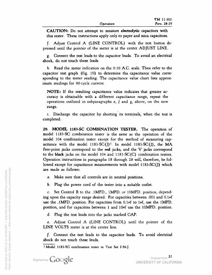
CAUTION: Do not attempt to measure electrolytic capacitors with
this tester. These instructions apply only to paper and mica capacitors.
/. Adjust Control A (LINE CONTROL) with the test button de
pressed until the .pointer of the meter is at the center ADJUST LINE.
g. Connect the test leads to the capacitor leads. To avoid an electrical
shock, do not touch these leads.
h. Read the meter indication on the 0-10 A.C. scale. Then refer to the
capacitor test graph (fig. 10) to determine the capacitance value corre
sponding to the meter reading. The capacitance value chart lists approx
imate readings for 60-cycle current.
NOTE: If the resulting capacitance value indicates that greater ac
curacy is obtainable with a different capacitance range, repeat the
operations outlined in subparagraphs e, f and g, above, on the new
range.
i. Discharge the capacitor by shorting its terminals, when the test is
completed.
29. MODEL 1183-SC COMBINATION TESTER. The operation ofmodel 1183-SC combination tester is the same as the operation of the
model 104 combination tester except for the method of measuring cap
acitance with the model 1183-SCO)1. In model 1183-SC(J), the MA.free-point jacks correspond to the red jacks, and the V jacks correspondto the black jacks on the model 104 and 1183-SC(C) combination testers.
Operation instructions in paragraphs 18 through 28 will, therefore, be followed except for capacitance measurements with model 1183-SC(J) whichare made as follows:
a. Make sure that all controls are in neutral positions.
b. Plug the power cord of the tester into a suitable outlet.
c. Set Control B to the .1MFD., 1MFD. or 10MFD. position, depend
ing upon the capacity range desired. For capacities between .001 and 0.1/*f
use the .1MFD. position. For capacities from 0.1/*f to l/*f, use the 1MFD.
position, and for capacities between 1 and lO^f use the 10MFD. position.
d. Plug the test leads into the jacks marked CAP.
e. Adjust Control A (LINE CONTROL) until the pointer of the
LINE VOLTS meter is at the center line.
/. Connect the test leads to the capacitor leads. To avoid electrical
shock do not touch these leads.
Model 1183-SC combination tester in Test Set I-56-J.
21
Genera
ted o
n 2
01
5-1
0-1
4 1
4:0
9 G
MT /
htt
p:/
/hd
l.hand
le.n
et/
20
27
/uc1
.b3
24
54
41
Public
Dom
ain
, G
oog
le-d
igit
ized
/
htt
p:/
/ww
w.h
ath
itru
st.o
rg/a
ccess
_use
#pd-g
oogle

TM 11-303 Test Sets
Pars. 29-30• Fig. 1 1 I-56-C I-56-D. I-56-H and I-56-J
FIG. 11. MODEL 1183-SC(J) COMBINATION TESTER,MEASURING CAPACITANCE
g. Read the meter on the 0-10 A.C. scale. Refer to the capacitor test
graph (fig. 10) to determine the capacitance value corresponding to the
meter reading.
h. Discharge the capacitor by shorting the terminals when the test
is completed.
30. MODEL 102 VOLT-OHM TESTER AS D-C VOLTMETER. Touse the volt-ohm tester as a d-c voltmeter perform the following operations:
a. Set the rotary selector switch to the required voltage range for the
measurement to be made. When in doubt about the voltage, always start
with the highest range.
b. Plug the short-handled probe of the red test lead into the jackmarked. V+O.
c. Plug the short-handled probe of the black test lead into the black
jack marked V— .
22
Genera
ted o
n 2
01
5-1
0-1
4 1
4:0
9 G
MT /
htt
p:/
/hd
l.hand
le.n
et/
20
27
/uc1
.b3
24
54
41
Public
Dom
ain
, G
oog
le-d
igit
ized
/
htt
p:/
/ww
w.h
ath
itru
st.o
rg/a
ccess
_use
#pd-g
oogle
TM 11-303
Operation "Pars. 30-33
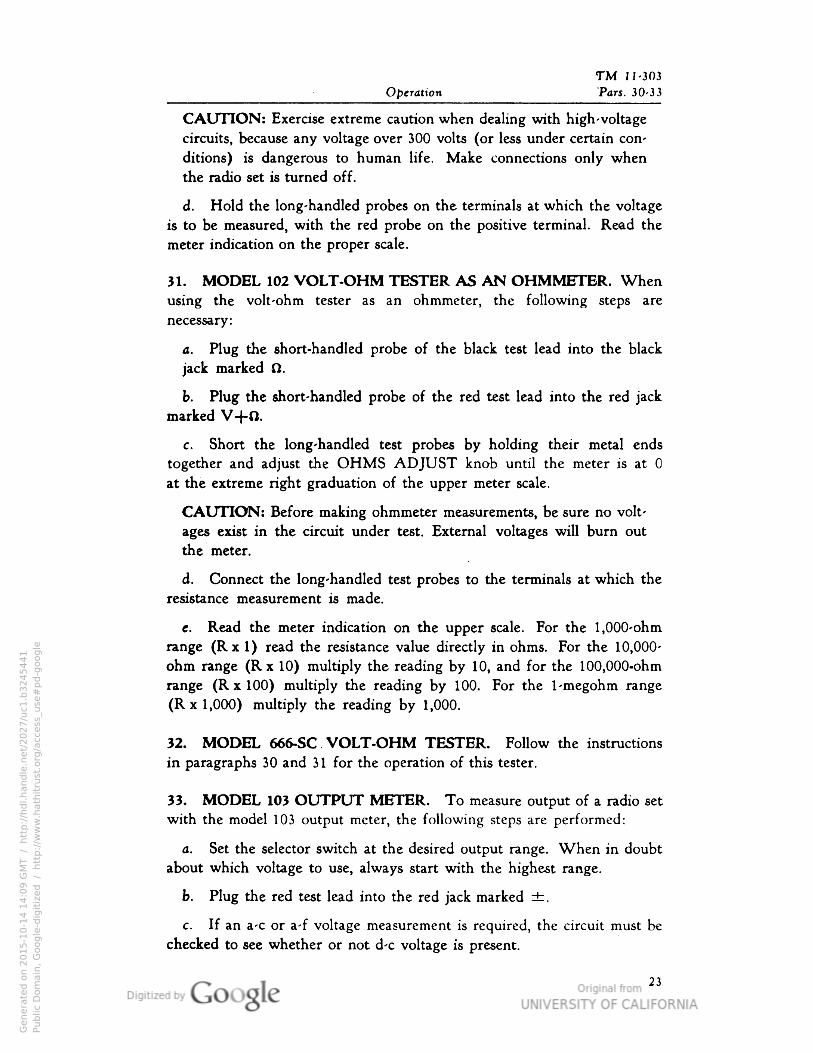
CAUTION: Exercise extreme caution when dealing with high-voltage
circuits, because any voltage over 300 volts (or less under certain con
ditions) is dangerous to human life. Make connections only when
the radio set is turned off.
d. Hold the long-handled probes on the terminals at which the voltage
is to be measured, with the red probe on the positive terminal. Read the
meter indication on the proper scale.
31. MODEL 102 VOLT-OHM TESTER AS AN OHMMETER. When
using the volt-ohm tester as an ohmmeter, the following steps are
necessary:
a. Plug the short-handled probe of the black test lead into the black
jack marked fl.
b. Plug the short-handled probe of the red test lead into the red jack
marked V+O.
c. Short the long-handled test probes by holding their metal ends
together and adjust the OHMS ADJUST knob until the meter is at 0
at the extreme right graduation of the upper meter scale.
CAUTION: Before making ohmmeter measurements, be sure no volt
ages exist in the circuit under test. External voltages will burn out
the meter.
d. Connect the long-handled test probes to the terminals at which the
resistance measurement is made.
e. Read the meter indication on the upper scale. For the 1,000-ohm
range (Rx 1) read the resistance value directly in ohms. For the 10,000-
ohm range (Rx 10) multiply the reading by 10, and for the 100,000-ohm
range (R x 100) multiply the reading by 100. For the 1 -megohm range
(Rx 1,000) multiply the reading by 1,000.
32. MODEL 666-SC VOLT-OHM TESTER. Follow the instructions
in paragraphs 30 and 31 for the operation of this tester.
33. MODEL 103 OUTPUT METER. To measure output of a radio set
with the model 103 output meter, the following steps are performed:
a. Set the selector switch at the desired output range. When in doubt
about which voltage to use, always start with the highest range.
b. Plug the red test lead into the red jack marked ±.
c. If an a-c or a-f voltage measurement is required, the circuit must be
checked to see whether or not d-c voltage is present.
23
Genera
ted o
n 2
01
5-1
0-1
4 1
4:0
9 G
MT /
htt
p:/
/hd
l.hand
le.n
et/
20
27
/uc1
.b3
24
54
41
Public
Dom
ain
, G
oog
le-d
igit
ized
/
htt
p:/
/ww
w.h
ath
itru
st.o
rg/a
ccess
_use
#pd-g
oogle
TM I! -303 Test Sets
Pars. 33-35 I-J6-C• I-56-D, I-56-H ancH-56-J
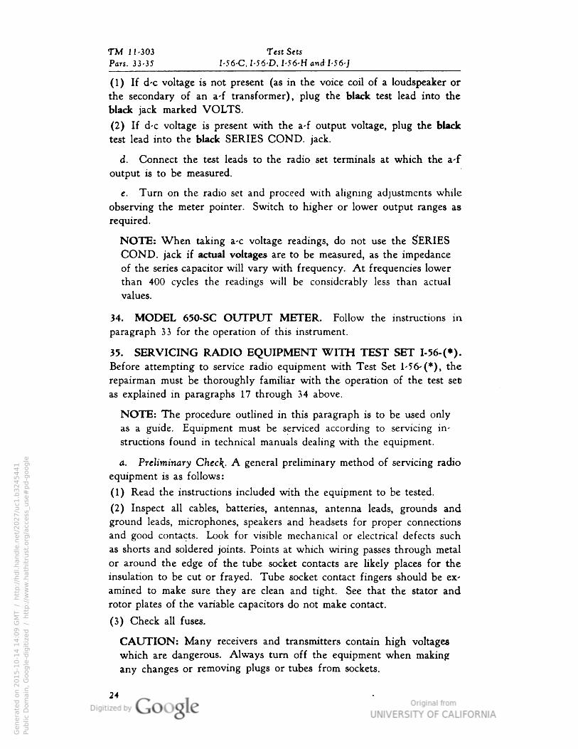
(1) If d-c voltage is not present (as in the voice coil of a loudspeaker or
the secondary of an a-f transformer), plug the black test lead into the
black jack marked VOLTS.
(2) If d-c voltage is present with the a-f output voltage, plug the black
test lead into the black SERIES COND. jack.
d. Connect the test leads to the radio set terminals at which the a-f
output is to be measured.
e. Turn on the radio set and proceed with aligning adjustments while
observing the meter pointer. Switch to higher or lower output ranges as
required.
NOTE: When taking a-c voltage readings, do not use the SERIESCOND. jack if actual voltages are to be measured, as the impedance
of the series capacitor will vary with frequency. At frequencies lower
than 400 cycles the readings will be considerably less than actual
values.
34. MODEL 650-SC OUTPUT METER. Follow the instructions inparagraph 33 for the operation of this instrument.
35. SERVICING RADIO EQUIPMENT WITH TEST SET I-56-(*).Before attempting to service radio equipment with Test Set 1-56- (*), the
repairman must be thoroughly familiar with the operation of the test set
as explained in paragraphs 17 through 34 above.
NOTE: The procedure outlined in this paragraph is to be used only
as a guide. Equipment must be serviced according to servicing in
structions found in technical manuals dealing with the equipment.
a. Preliminary Chec\. A general preliminary method of servicing radio
equipment is as follows:
(1) Read the instructions included with the equipment to be tested.
(2) Inspect all cables, batteries, antennas, antenna leads, grounds and
ground leads, microphones, speakers and headsets for proper connections
and good contacts. Look for visible mechanical or electrical defects such
as shorts and soldered joints. Points at which wiring passes through metal
or around the edge of the tube socket contacts are likely places for the
insulation to be cut or frayed. Tube socket contact fingers should be ex
amined to make sure they are clean and tight. See that the stator and
rotor plates of the variable capacitors do not make contact.
(3) Check all fuses.
CAUTION: Many receivers and transmitters contain high voltages
which are dangerous. Always turn off the equipment when making
any changes or removing plugs or tubes from sockets.
24
Genera
ted o
n 2
01
5-1
0-1
4 1
4:0
9 G
MT /
htt
p:/
/hd
l.hand
le.n
et/
20
27
/uc1
.b3
24
54
41
Public
Dom
ain
, G
oog
le-d
igit
ized
/
htt
p:/
/ww
w.h
ath
itru
st.o
rg/a
ccess
_use
#pd-g
oogle
TM 11-303
Operation Par. 35
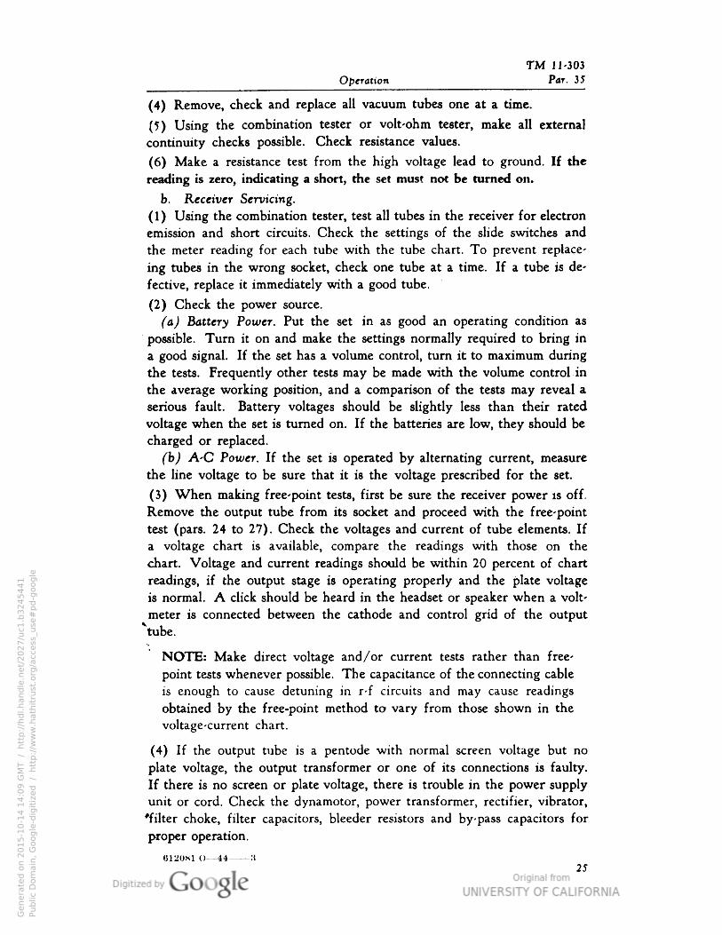
(4) Remove, check and replace all vacuum tubes one at a time.
(5) Using the combination tester or volt-ohm tester, make all external
continuity checks possible. Check resistance values.
(6) Make a resistance test from the high voltage lead to ground. If the
reading is zero, indicating a short, the set must not be turned on.
b. Receiver Servicing.
( 1 ) Using the combination tester, test all tubes in the receiver for electron
emission and short circuits. Check the settings of the slide switches and
the meter reading for each tube with the tube chart. To prevent replace-
ing tubes in the wrong socket, check one tube at a time. If a tube is de
fective, replace it immediately with a good tube.
(2) Check the power source.
(a) Battery Power. Put the set in as good an operating condition as
possible. Turn it on and make the settings normally required to bring in
a good signal. If the set has a volume control, turn it to maximum during
the tests. Frequently other tests may be made with the volume control in
the average working position, and a comparison of the tests may reveal a
serious fault. Battery voltages should be slightly less than their rated
voltage when the set is turned on. If the batteries are low, they should be
charged or replaced.
(b) A-C Power. If the set is operated by alternating current, measure
the line voltage to be sure that it is the voltage prescribed for the set.
(3) When making free-point tests, first be sure the receiver power is off.
Remove the output tube from its socket and proceed with the free-point
test (pars. 24 to 27). Check the voltages and current of tube elements. Ifa voltage chart is available, compare the readings with those on the
chart. Voltage and current readings should be within 20 percent of chart
readings, if the output stage is operating properly and the plate voltage
is normal. A click should be heard in the headset or speaker when a volt
meter is connected between the cathode and control grid of the output
vtube.•.
NOTE: Make direct voltage and /or current tests rather than free-
point tests whenever possible. The capacitance of the connecting cable
is enough to cause detuning in r-f circuits and may cause readings
obtained by the free-point method to vary from those shown in the
voltage-current chart.
(4) If the output tube is a pentode with normal screen voltage but no
plate voltage, the output transformer or one of its connections is faulty.
If there is no screen or plate voltage, there is trouble in the power supply
unit or cord. Check the dynamotor, power transformer, rectifier, vibrator,
'filter choke, filter capacitors, bleeder resistors and by- pass capacitors for
proper operation.
012081 O—44 3
25
Genera
ted o
n 2
01
5-1
0-1
4 1
4:0
9 G
MT /
htt
p:/
/hd
l.hand
le.n
et/
20
27
/uc1
.b3
24
54
41
Public
Dom
ain
, G
oog
le-d
igit
ized
/
htt
p:/
/ww
w.h
ath
itru
st.o
rg/a
ccess
_use
#pd-g
oogle
TM 11-303 Test Sets
Par. 35 I-56-C• I-56-D• I-56-H and I-56-J
(5) Using the a-c voltmeter section of the combination tester, check the
voltage at the input and secondary windings of the power transformers.
Check the d-C voltage output of the rectifier, and at each stage of the
filtering system, until the plate supply voltage to the output tube is
reached. When using the combination tester for any voltage check, be
sure that the proper scale is selected. The normal rated voltage of the
power supply must be within the maximum voltage rating of the instru
ment to prevent damage to the meter or any of its multiplier resistors.
(6) When the output stage is operating properly, turn off the set, remove
the analyzer plug from the output tube socket and return the tube to its
socket in the set. Then select the proper adapter and check the preceding
audio stage in a similar manner. Compare the readings with the voltage
chart of the set. If any of the voltage readings are not normal, check each
circuit element of the audio stage, and resistors and capacitors immediately
connected with it.
(7) Return the audio tube to its socket and connect the analyzer plug
to the detector socket. If the detector is a triode or pentode, voltage checks
may be made in the same manner as the audio stage. If the detector is a
diode, only filament voltage measurements can be made.
(8) A rough check of the detector may be made by switching the meter
of the combination tester to a resistance range and touching two test leads
to the plate and cathode of the diode. Be sure that all controls in the audio
circuit are turned to maximum volume. If the audio portion of the detector
circuit is operating, a loud click should be heard in phones or speakerwhen the connection is made.
(9) Return the detector tube to its socket. Select the proper adapter and
check the voltages of each intermediate frequency stage, starting with the
last and proceeding forward. When using the combination tester for
voltage and current checks on intermediate frequency stages, the r-f oscil-
lator stage, the mixer stage and the r-f amplifier stage, static voltages and
current only can be measured because the capacity of the analyzer cable
will detune the circuit to which it is connected.
(10) In some cases, capacity in the connecting cable may stop the oscil
lator from operating. Various measurements of the oscillator made under
static conditions may be different from the dynamic or operating conditions.
Therefore, after the i-f stages have been checked, a static or non-operating
check of the oscillator and r-f stages should be made in a similar manner.
(11) If the source of trouble has not been located, check the operation ofoscillator by measuring the grid current. Unsolder the grounded end of the
oscillator grid leak. Using the combination tester as a milliammeter, con
nect it between the unsoldered wire and ground, with the positive side ofthe meter connected to ground. Turn the set on and read the grid current
on the meter, selecting the scale that gives the highest reading on the meter
26
Genera
ted o
n 2
01
5-1
0-1
4 1
4:1
0 G
MT /
htt
p:/
/hd
l.hand
le.n
et/
20
27
/uc1
.b3
24
54
41
Public
Dom
ain
, G
oog
le-d
igit
ized
/
htt
p:/
/ww
w.h
ath
itru
st.o
rg/a
ccess
_use
#pd-g
oogle
TM 11-303
Operation Par. 35
scale. On most receivers, this current is never over one milliampere. Ifthere is no grid current or only a slight indication on the meter, the tube
is not oscillating. All of the component parts of the oscillator should be
checked for open or short circuits. Examine the oscillator coil for open
circuits or shorted turns. Replace the defective element.
(12) With the oscillator operating properly, check the parts of each
circuit of the receiver, such as the automatic volume control circuit. Allresistors and capacitors connected with it should be checked for open and
short circuits and for the correct values. Starting with the last i-f stage,
any continuity checks possible should be made on the i-f and r-f stages
to determine whether the coil, accompanying by-pass capacitors and r-f
filter resistors are shorted or open or have changed value.
NOTE: If the receiver is out of. alignment, the automatic volume
control circuit will not function properly.
(13) If a signal generator is available, an alignment check should be made
following instructions given for the receiver under test, using the output
meter as an output indicator.
NOTE: The volt-ohm tester has a higher d-c voltage range than the
combination tester. Use the volt-ohm tester instead of the combination
tester to make d-c voltage measurements which are within its ranges.
c. Transmitter Servicing.
(1) Read the technical manual or servicing instructions on the transmitters.
(2) Check all external parts directly connected with the transmitter, such
as cables and connecting plugs.
(3) Check the power supply. Be sure that the voltages are within the
range of the meter used.
(4) Measure the grid current, as outlined in subparagraph b(ll) above,
to see that the oscillator is operating. The grid current will be obtained
only when the tuning circuit oscillator is resonant with the crystal fre-
quency, and will be higher than normal. If the oscillator is crystal-con
trolled, either check the crystal in another unit or replace it with one
known to be good. Test the oscillator tube and all parts associated with
the oscillator unit.
(5) Using the combination tester, test all tubes possible for emission and
short circuits. If the tubes cannot be checked, replace them with good
tubes of the same type.
(6) Following the instructions for the particular unit, start with the oscil
lator unit and check each successive r-f stage for voltages and continuity.
Be sure that the voltages to be measured are within the range of the meter
used or the instrument will be burned out.
27
Genera
ted o
n 2
01
5-1
0-1
4 1
4:1
0 G
MT /
htt
p:/
/hd
l.hand
le.n
et/
20
27
/uc1
.b3
24
54
41
Public
Dom
ain
, G
oog
le-d
igit
ized
/
htt
p:/
/ww
w.h
ath
itru
st.o
rg/a
ccess
_use
#pd-g
oogle

TM 11-303 Test Sets
Par. 35, Fig. 12 I-56-C• I-S6-D, I-56-H and I-56-J
TO CORRESPONDINGLYNUMBERED TERMINALS
ON OTHER SOCKETS
TOP CAP CONNECTION
SLIDE SWITCHES(S-3)
FIG. 12. MODEL 104 COMBINATION TESTER, SIMPLIFIEDTUBE-TESTING CIRCUIT
(7) To test the modulator section of the transmitter, start with the audio
output or modulator tube. If the voltage range of the combination tester
permits, and the adapters are available for the tubes used, use the free-
point tester and check voltage and current of the modulator tube. If there
are no voltages, or the voltages are low, check all of the parts associated
with the modulator stage and the connection to the power supply.
(8) Make the same check of each preceding stage of the modulator ampli
fier. Check all values of current or voltage at the available meter jacks
or the built-in meters.
Genera
ted o
n 2
01
5-1
0-1
4 1
4:1
0 G
MT /
htt
p:/
/hd
l.hand
le.n
et/
20
27
/uc1
.b3
24
54
41
Public
Dom
ain
, G
oog
le-d
igit
ized
/
htt
p:/
/ww
w.h
ath
itru
st.o
rg/a
ccess
_use
#pd-g
oogle
Par. 36
TM 11-303
SECTION IIIFUNCTIONING OF PARTS
36. MODEL 104 COMBINATION TESTER. Parts of the model 104
combination tester are described below as they function in the various
circuits.
CAUTION: Wiring diagrams in this section are included for a better
understanding of this equipment. They must not be used for un
authorized repairs.
a. Combination Tester as Tube Checker (fig. 12). Control A (LINECONTROL) is a 164-ohm rheostat (R-29) which adjusts transformer
(T-l) for changes in line voltage. Control B (S-5) is a 10-position 4-wafer
switch used to select the proper circuit for tube tests. Control C (R-30) is
a 200-ohm potentiometer which provides the proper load for the tube
being tested. Control D (S-6), a 20-position 4-wafer switch, sets the
proper filament voltage for the tube under test. Slide switches (S-3) are
single-pole 4-position switches used to connect the tube terminals to the
test circuits. Tube socket terminal 1 connects to the arm of switch E,
terminal 2 to the arm of switch F, etc. The arm of switch M is con
nected to the top-cap clip. In position 1, the slide switch arms connect
Control B and the proper load resistor to a 30-volt winding on transformer
(T-l), providing the correct plate voltage for the tube being tested. In.
position 2, the slide switch arms connect the common leads of the two sec
ondary windings on transformer (T-l), to the cathode of the tube being
tested. In position 3, the slide switch arms connect the filament taps on
the transformer (T-l) to the tube filament through control D. The emis
sion of the tube is shown on the indicating meter. In position 4, the
slide switch arms are out of the tube testing circuit. When the LINECHECK button is pressed, a secondary winding of transformer (T-l) is
connected to. the type-H rectifier (RE-2), which changes the a-c to d-c•
voltage. The d-c voltage is then read on the indicating meter. The fila-
29
Genera
ted o
n 2
01
5-1
0-1
4 1
4:1
0 G
MT /
htt
p:/
/hd
l.hand
le.n
et/
20
27
/uc1
.b3
24
54
41
Public
Dom
ain
, G
oog
le-d
igit
ized
/
htt
p:/
/ww
w.h
ath
itru
st.o
rg/a
ccess
_use
#pd-g
oogle
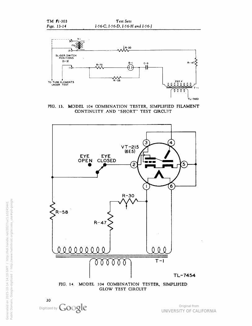
TM #1-303 Test Sets
Figs. 13-14 I-56-C• I-56-D• I-56-H and I-56-]
SLIDER SWITCHPOSITIONS
(S-3)
TO TUBE ELEMENTSUNDER TEST
|R-3<^vwv
B-l C-3
pnmn
FIG. 13. MODEL 104 COMBINATION TESTER, SIMPLIFIED FILAMENTCONTINUITY AND "SHORT" TEST CIRCUIT
EYE EYEOPEN CLOSED
VT-215(6E5)
R-30
R-58
R-47
UMMMJUUnnmnnn
UMJT-l
TL-7454
FIG. 14. MODEL 104 COMBINATION TESTER, SIMPLIFIEDGLOW TEST CIRCUIT
30
Genera
ted o
n 2
01
5-1
0-1
4 1
4:1
0 G
MT /
htt
p:/
/hd
l.hand
le.n
et/
20
27
/uc1
.b3
24
54
41
Public
Dom
ain
, G
oog
le-d
igit
ized
/
htt
p:/
/ww
w.h
ath
itru
st.o
rg/a
ccess
_use
#pd-g
oogle
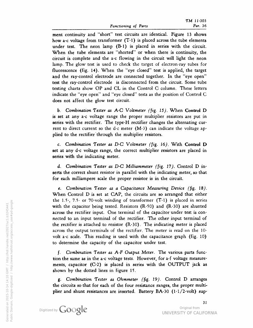
TM 11-303
Functioning of Parts Par. 36
ment continuity and "short" test circuits are identical. Figure 13 shows
how a-c voltage from transformer (T-l) is placed across the tube elements
under test. The neon lamp (B-l) is placed in series with the circuit.
When the tube elements are "shorted" or when there is continuity, the
circuit is complete and the a-c flowing in the circuit will light the neon
lamp. The glow test is used to check the target of electron-ray tubes for
fluorescence (fig. 14). When the "eye closed" test is applied, the target
and the ray-control electrode are connected together. In the "eye open"
test the ray-control electrode is disconnected from the circuit. Some tube
testing charts show OP and CL in the Control C column. These letters
indicate the "eye open" and "eye closed" tests as the position of Control Cdoes not affect the glow test circuit.
b. Combination Tester as A-C Voltmeter (fig. 15). When Control Dis set at any a-c voltage range the proper multiplier resistors are put in
series with the rectifier. The type-H rectifier changes the alternating cur
rent to direct current so the d-c meter (M-3) can indicate the voltage ap
plied to the rectifier through the multiplier resistors.
c. Combination Tester as D-C Voltmeter (jig. 16). With Control Dset at any d-c voltage range, the correct multiplier resistors are placed in
series with the indicating meter.
d. Combination Tester as D-C Milliammeter (fig. 17). Control D in
serts the correct shunt resistor in parallel with the indicating meter, so that
for each milliampere scale the proper resistor is in the circuit.
e. Combination Tester as a Capacitance Measuring Device (fig. 18).When Control D is set at CAP, the circuits are so arranged that either
the 1.5-, 7.5- or 70-volt winding of transformer (T-l) is placed in series
with the capacitor being tested. Resistors (R-50) and (R-30) are shunted
across the rectifier input. One terminal of the capacitor under test is con
nected to an input terminal of the rectifier. The other input terminal of
the rectifier is attached to resistor (R-30). The indicating meter is placed
across the output terminals of the rectifier. The meter is read on the 10-
volt a-c scale. This reading is used with the capacitance graph (fig. 10)
to determine the capacity of the capacitor under test.
/. Combination Tester as A-F Output Meter. The various parts func
tion the same as in the a-c voltage tests. However, for a-f voltage measure
ments, capacitor (C-2) is placed in series with the OUTPUT jack as
shown by the dotted lines in figure 15.
g. Combination Tester as Ohmmeter (fig. 19). Control D arranges
the circuits so that for each of the four resistance ranges, the proper multi
plier and shunt resistances are inserted. Battery BA-30 (1-1/2-volt) sup
31
Genera
ted o
n 2
01
5-1
0-1
4 1
4:1
0 G
MT /
htt
p:/
/hd
l.hand
le.n
et/
20
27
/uc1
.b3
24
54
41
Public
Dom
ain
, G
oog
le-d
igit
ized
/
htt
p:/
/ww
w.h
ath
itru
st.o
rg/a
ccess
_use
#pd-g
oogle
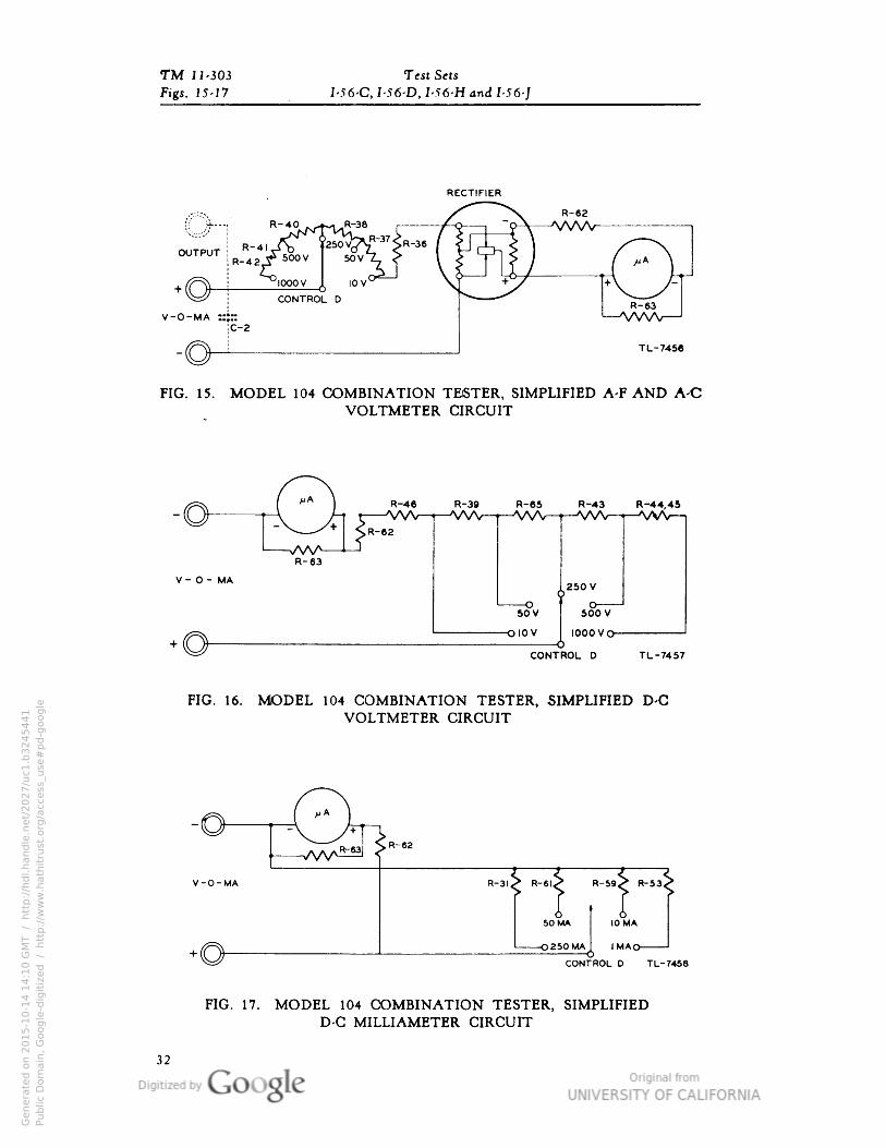
TM 11-303 Test Sets
Figs. 15-17 I-56-C, I-56-D• I-56-H and I-56-J
RECTIFIER
TL-7456
FIG. 15. MODEL 104 COMBINATION TESTER, SIMPLIFIED A-F AND A-CVOLTMETER CIRCUIT
R-44•45
V - O - MA
CONTROL D TL-7457
FIG. 16. MODEL 104 COMBINATION TESTER, SIMPLIFIED D-CVOLTMETER CIRCUIT
R-6I<> R-59X R-53
SO MA I 10MA
-O250MAJ IMAo-
CONTROL D TL-7458
FIG. 17. MODEL 104 COMBINATION TESTER, SIMPLIFIEDD-C MILLIAMETER CIRCUIT
Genera
ted o
n 2
01
5-1
0-1
4 1
4:1
0 G
MT /
htt
p:/
/hd
l.hand
le.n
et/
20
27
/uc1
.b3
24
54
41
Public
Dom
ain
, G
oog
le-d
igit
ized
/
htt
p:/
/ww
w.h
ath
itru
st.o
rg/a
ccess
_use
#pd-g
oogle
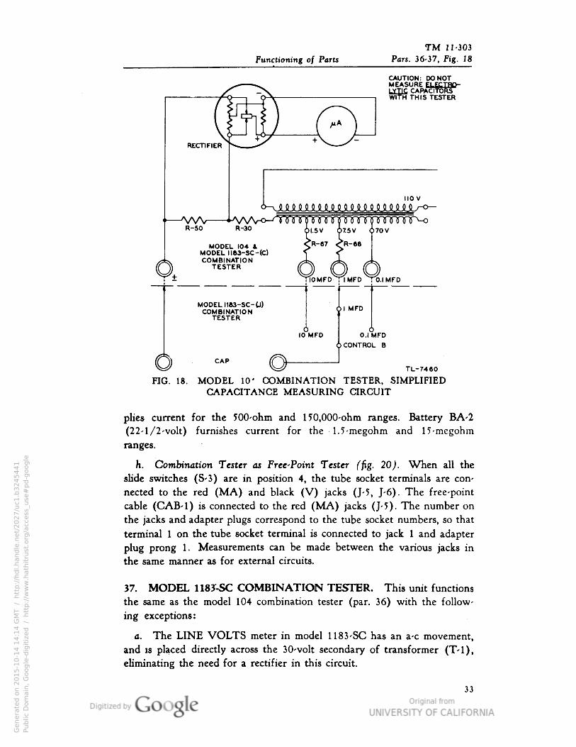
TM 11-303
Functioning of Parts Pars. 36-37, Fig. 18
CAUTION: DO NOTMEASURE ELECTROLYTIC CAPACITORSWITH THIS TESTER
MODEL 104MODEL 1183-SC-lC)COMBINATION
TESTER
!- 10MFD Tl MFD O.I MFD
MODEL 1163-SC-U)COMBINATION
TESTERil MFD4
10 MFD o.,< lireI
\ CAP ff5^
) CONTROL B
f̂=? V^ TL-7460
FIG. 18. MODEL 10' COMBINATION TESTER, SIMPLIFIEDCAPACITANCE MEASURING CIRCUIT
plies current for the 500-ohm and 150,000-ohm ranges. Battery BA-2
(22-1/2-volt) furnishes current for the 1.5-megohm and 15-megohm
ranges.
h. Combination Tester as Free-Point Tester (fig. 20). When all the
slide switches (S-3) are in position 4, the tube socket terminals are con
nected to the red (MA) and black (V) jacks (J-5, J-6). The free-point
cable (CAB-1) is connected to the red (MA) jacks (J-5). The number on
the jacks and adapter plugs correspond to the tube socket numbers, so that
terminal 1 on the tube socket terminal is connected to jack 1 and adapter
plug prong 1. Measurements can be made between the various jacks inthe same manner as for external circuits.
37. MODEL 1183-SC COMBINATION TESTER. This unit functions
the same as the model 104 combination tester (par. 36) with the follow
ing exceptions:
a. The LINE VOLTS meter in model 1183-SC has an a-c movement,
and is placed directly across the 30-volt secondary of transformer (T-l),eliminating the need for a rectifier in this circuit.
33
Genera
ted o
n 2
01
5-1
0-1
4 1
4:1
4 G
MT /
htt
p:/
/hd
l.hand
le.n
et/
20
27
/uc1
.b3
24
54
41
Public
Dom
ain
, G
oog
le-d
igit
ized
/
htt
p:/
/ww
w.h
ath
itru
st.o
rg/a
ccess
_use
#pd-g
oogle
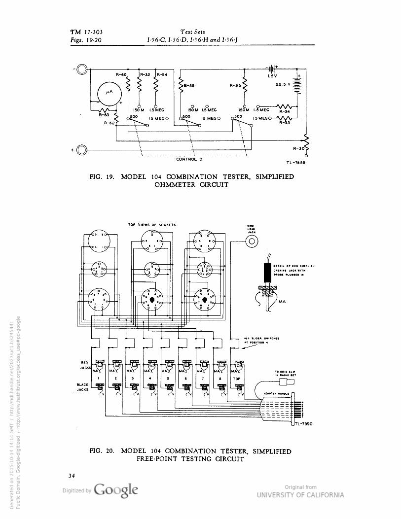
TM 11-303 Test Sets
Figs. 19-20 I-56-C, I-56-D• I-56-H and I-56-J
FIG. 19. MODEL 104 COMBINATION TESTER, SIMPLIFIEDOHMMETER CIRCUIT
BLACK mamJACKS «^
. TL-7390
FIG. 20. MODEL 104 COMBINATION TESTER, SIMPLIFIEDFREE-POINT TESTING CIRCUIT
34
Genera
ted o
n 2
01
5-1
0-1
4 1
4:1
4 G
MT /
htt
p:/
/hd
l.hand
le.n
et/
20
27
/uc1
.b3
24
54
41
Public
Dom
ain
, G
oog
le-d
igit
ized
/
htt
p:/
/ww
w.h
ath
itru
st.o
rg/a
ccess
_use
#pd-g
oogle
TM 11-303
Functioning of Parts Pars. 37-41
b. Model 1183-SC(J) has three additional positions on Control B for
capacitance measurements which eliminate three capacitance jacks (J-7).
38. MODEL 102 VOLT-OHM TESTER. Selector switch (S-l) places
the correct shunt and multiplier resistors for the resistance or voltage range
being used (fig. 29). The OHMS ADJ. control (R-l) adjusts the current
flowing through meter (M-l) so the pointer can be "zeroed" at the full
scale reading on the OHMS scale. Battery BA-31 (4. 5 -volt) furnishes
current for the resistance measurements.
39. MODEL 666-SC VOLT-OHM TESTER. The model 666-SC volt-
ohm tester functions the same as the model 102 volt-ohm tester (par. 38).
40. MODEL 103 OUTPUT METER. Selector switch (S-2) connects
the various shunt and multiplier resistors for the range being used (fig. 32).The rectifier (RE- 1 ) converts a-c voltage into the d-c voltage which moves
the meter pointer. The SERIES COND. jack places capacitor (C-l) in
series with the circuit to keep high d-c voltage out of the rectifier and
meter.
41. MODEL 650-SC OUTPUT METER. This meter functions the
same as the model 103 output meter (par. 40).
Genera
ted o
n 2
01
5-1
0-1
4 1
4:1
4 G
MT /
htt
p:/
/hd
l.hand
le.n
et/
20
27
/uc1
.b3
24
54
41
Public
Dom
ain
, G
oog
le-d
igit
ized
/
htt
p:/
/ww
w.h
ath
itru
st.o
rg/a
ccess
_use
#pd-g
oogle
TM 11-303
Pars. 42-43
SECTION IVMAINTENANCE
UNSATISFACTORY PERFORMANCE OF THIS EQUIPMENTWILL BE REPORTED IMMEDIATELY ON W. D., A. G. O. FORMNO. 468. IF THIS IS NOT AVAILABLE, SEE TM 38-250.
42. GENERAL. Combination testers, model 104 and model 1183-SC,
and volt-ohm testers, model 102 and model 666- SC, are equipped with
self-contained batteries and type-H plug-in rectifiers which may require
replacement. This section covers only necessary tube chart, battery and
rectifier replacements.
CAUTION: Test set panels must be opened only to make necessary
battery and rectifier replacements. No other service work should be
done on these instruments at any time, except by authorized Signal
Corps repair shops or by the manufacturer.
43. COMBINATION TESTERS, MODEL 104 AND MODEL 1183-SC.
a. General. Batteries and type-H plug-in rectifiers which require re
placement in these instruments can be reached by removing a small panel
fastened to the bottom of the case with four screws.
b. Battery Replacement. Instructions for replacing batteries are printed
on the panel (fig. 21). As the batteries drop in potential because of use
or age, the OHMS ADJUST• control must be turned closer to 100 for a
zero adjustment. When the meter pointer cannot be brought to 0 on the
upper scale of the ohmmeter with the test leads shorted together (on any
one of the ohmmeter ranges), the battery serving that range should be re
placed. Do not replace batteries until the battery clips have been inspected.
A poor battery connection may give the same indication as a bad battery.
Batteries are replaced as follows:
36
Genera
ted o
n 2
01
5-1
0-1
4 1
4:1
4 G
MT /
htt
p:/
/hd
l.hand
le.n
et/
20
27
/uc1
.b3
24
54
41
Public
Dom
ain
, G
oog
le-d
igit
ized
/
htt
p:/
/ww
w.h
ath
itru
st.o
rg/a
ccess
_use
#pd-g
oogle
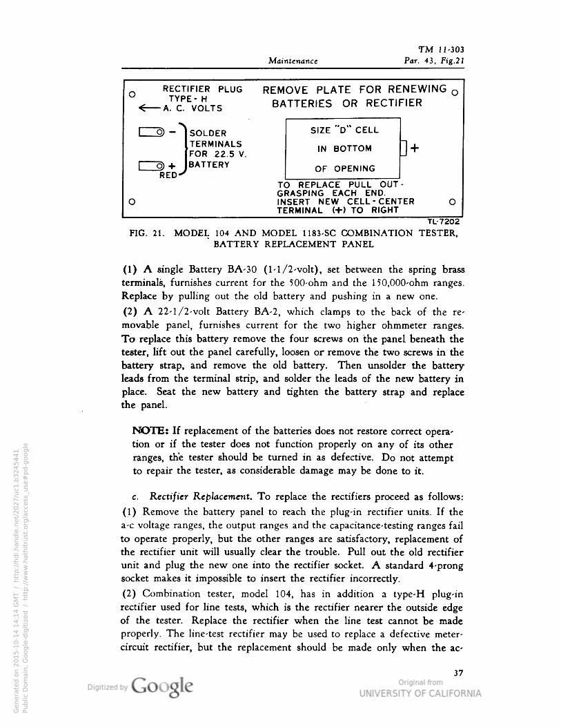
TM 11-303
Maintenance Par. 43• Fig.21
RECTIFIER PLUG REM0 TYPE-H R.< A. C. VOLTS DM
OVE PLATE FOR RENEWING oTTERIES OR RECTIFIER
1 0) - SOLDERTERMINALSFOR 22.5 V.
[" cj)
+ BATTERYRED-7
T(Gl
O INTE
^ SIZE "D" CELL
IN BOTTOM ] +
OF OPENING
D REPLACE PULL OUT -
GASPING EACH END.SERT NEW CELL -CENTERIRMINAL H-) TO RIGHT
0
TL-7202
FIG. 21. MODEL 104 AND MODEL 1183-SC COMBINATION TESTER,'BATTERY REPLACEMENT PANEL
(1) A single Battery BA-30 (1-1/2-volt), set between the spring brass
terminals, furnishes current for the 500-ohm and the 150,000-ohm ranges.
Replace by pulling out the old battery and pushing in a new one.
(2) A 22-1/2-volt Battery BA-2, which clamps to the back of the re
movable panel, furnishes current for the two higher ohmmeter ranges.
To replace this battery remove the four screws on the panel beneath the
tester, lift out the panel carefully, loosen or remove the two screws in the
battery strap, and remove the old battery. Then unsolder the battery
leads from the terminal strip, and solder the leads of the new battery in
place. Seat the new battery and tighten the battery strap and replace
the panel.
NOTE: If replacement of the batteries does not restore correct operation or if the tester does not function properly on any of its other
ranges, the tester should be turned in as defective. Do not attempt
to repair the tester, as considerable damage may be done to it.
c. Rectifier Replacement. To replace the rectifiers proceed as follows:
(1) Remove the battery panel to reach the plug-in rectifier units. If the
a-c voltage ranges, the output ranges and the capacitance-testing ranges fail
to operate properly, but the other ranges are satisfactory, replacement ofthe rectifier unit will usually clear the trouble. Pull out the old rectifierunit and plug the new one into the rectifier socket. A standard 4-prongsocket makes it impossible to insert the rectifier incorrectly.
(2) Combination tester, model 104, has in addition a type-H plug-in
rectifier used for line tests, which is the rectifier nearer the outside edge
of the tester. Replace the rectifier when the line test cannot be made
properly. The line-test rectifier may be used to replace a defective meter-
circuit rectifier, but the replacement should be made only when the ac-
J7
Genera
ted o
n 2
01
5-1
0-1
4 1
4:1
4 G
MT /
htt
p:/
/hd
l.hand
le.n
et/
20
27
/uc1
.b3
24
54
41
Public
Dom
ain
, G
oog
le-d
igit
ized
/
htt
p:/
/ww
w.h
ath
itru
st.o
rg/a
ccess
_use
#pd-g
oogle
TM 11-303 Test Sets
Par. 43-45 I-56-C• I-.T6-D• I-56-H and I-56-J
curacy of the tube testing function of the combination tester is unimportant
compared to its use as a general purpose a-c meter.
d. Tube Chart Replacement. Tube chart cards on the combination
tester in Test Sets I-56-C, I-56-D and I-56-H may be replaced by opening
the binding rings. Before removing or replacing cards, on the combina-
tion tester in Test Set I-56-J, one screw in the upright bracket must be
removed, and the bracket swung back.
44. VOLT-OHM TESTERS, MODEL 102 AND MODEL 666-SC.
Each volt-ohm tester contains a 4.5-volt Battery BA-31 which supplies cur
rent for the ohmmeter ranges. As the battery drops in potential due to use
or age, the fi ADJUST control must be turned more to the right each
time the instrument is used. When the meter pointer cannot be brought
to 0 on the ohmmeter scale by adjusting the Cl ADJUST control, the bat
tery should be replaced. Replace batteries as follows:
a. Remove the screws at the four corners of the instrument panel.
(Two of these screws pass through the upper corners of the meter hous
ing.) Then lift the entire instrument panel and battery out of the plastic
case.
b. Disconnect the old battery from the circuit by removing the knurled
terminal nuts on the battery studs, or unsolder the connections if necessary.
Remove the battery from the holding clamps and place a new battery into
position. Connect the new battery. The red lead must go to the positive
(+) terminal, and the black lead must be connected to the negative ( — )terminal. Replace the panel assembly in the case, making sure that the
name plate is at the jack end of the panel, before replacing the panel
screws.
NOTE: If replacement of the battery does not restore normal opera
tion, or if the tester does not function properly, the test set must be
turned in as defective.
45. OUTPUT METERS, MODEL 103 AND MODEL 650-SC. The
output meters do not contain batteries or fuses, and should be opened only
at an authorized Signal Corps repair shop. If the instrument does not func
tion properly, it must be turned in as defective. Diagrams and drawings inthe text are for use only by authorized repair personnel. These test instru
ments are very delicate and require special repair equipment. Replacement
of parts will affect the calibration of the meters.
NOTE: The glass in some of the meters is so thick that it often binds
the pointer. Authorized repair personnel must check to see that glass
replacements do not interfere with the movement of the meter pointer.
38
Genera
ted o
n 2
01
5-1
0-1
4 1
4:1
4 G
MT /
htt
p:/
/hd
l.hand
le.n
et/
20
27
/uc1
.b3
24
54
41
Public
Dom
ain
, G
oog
le-d
igit
ized
/
htt
p:/
/ww
w.h
ath
itru
st.o
rg/a
ccess
_use
#pd-g
oogle
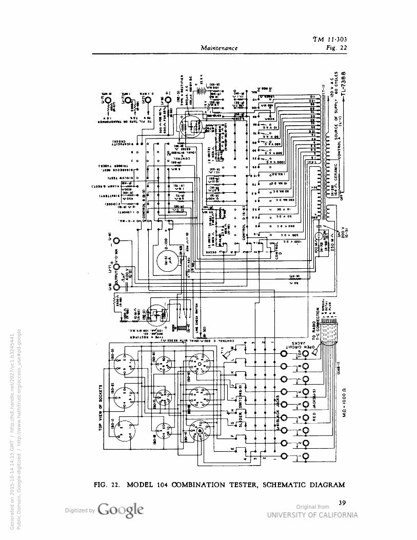
TM J 1-303
Maintenance Fig. 22
FIG. 22. MODEL 104 COMBINATION TESTER, SCHEMATIC DIAGRAM
39
Genera
ted o
n 2
01
5-1
0-1
4 1
4:1
5 G
MT /
htt
p:/
/hd
l.hand
le.n
et/
20
27
/uc1
.b3
24
54
41
Public
Dom
ain
, G
oog
le-d
igit
ized
/
htt
p:/
/ww
w.h
ath
itru
st.o
rg/a
ccess
_use
#pd-g
oogle

TM 11-303 Test Sets
Figs. 23-24 I-56-C• I-56-D• I-56-H and I-56-]
CONTROL RESISTOR BOARDS(SEE DRAWINGS)
-2 -RE-3 TL-752O
HG. 23. MODEL 104 COMBINATION TESTER,BOTTOM VIEW OF CHASSIS
-BOARD NEAREST\ FRONT PANELX I m Tg
°— t R-52
°— I R-55
°— I R60 ]-°
°— T R-32 r-°
°—i R-54 n-o
<»H R-81
_H>
°H R59
°H RC3
NOTE: R70 MOUNTED ON BASE OF NEON LAMRR72 MOUNTED ON CONTROL B (S-5).
TL-7W9
FIG. 24. MODEL 104 COMBINATION TESTER,RESISTOR BOARD DIAGRAM
40
Genera
ted o
n 2
01
5-1
0-1
4 1
4:1
5 G
MT /
htt
p:/
/hd
l.hand
le.n
et/
20
27
/uc1
.b3
24
54
41
Public
Dom
ain
, G
oog
le-d
igit
ized
/
htt
p:/
/ww
w.h
ath
itru
st.o
rg/a
ccess
_use
#pd-g
oogle
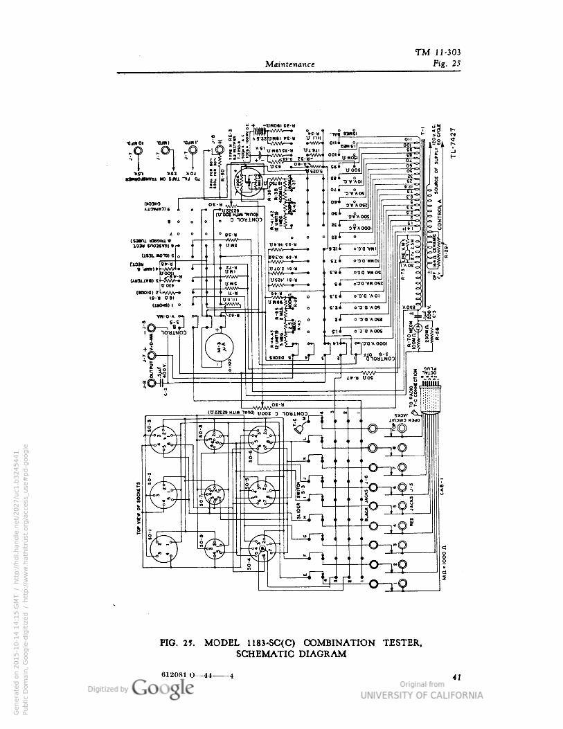
TM 11-303
Maintenance Fig. 25
FIG. 25. MODEL 1183-SC(C) COMBINATION TESTER,SCHEMATIC DIAGRAM
612081 O— 44 4
Genera
ted o
n 2
01
5-1
0-1
4 1
4:1
5 G
MT /
htt
p:/
/hd
l.hand
le.n
et/
20
27
/uc1
.b3
24
54
41
Public
Dom
ain
, G
oog
le-d
igit
ized
/
htt
p:/
/ww
w.h
ath
itru
st.o
rg/a
ccess
_use
#pd-g
oogle
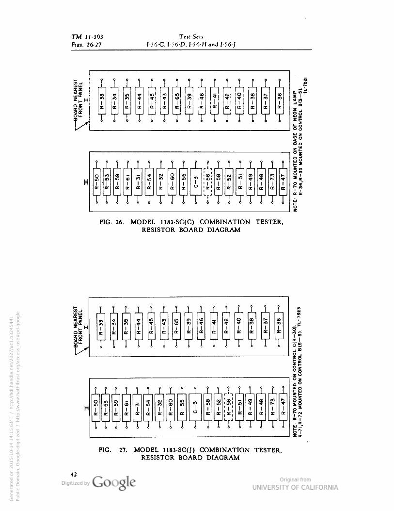
TW 11-303 TettSeu
Pint. 26-27 /-56-C, I 56-D• I-56-H and I-56-J
IJLJLJLXJLJLJLJLJLJLJLJL
YYYYYYYYY II*§
JL_L_L_LJL_L±JLiJ_.LJ_J_J_J_J_±±to
m 10« OJ
10 10f>
IO'1
o>m
CM m en ? ^m 10
1
m1
in1
r^1 1 1 i 1 1 1 1 1 1 1
1 1 1 1 1 i« 4 cc CE CE CE CE CE CE]CE[
CE CE ce CE CE CE CE
T TTYY T T TYYTYYY TTTT
FIG. 26. MODEL 1183-SC(C) COMBINATION TESTER,RESISTOR BOARD DIAGRAM
Bd
I!-
ozCEC
1 T r i L 4_ 1 1 JL, JL^^ i JL j_
^ ^ « m IO K> (0 <M
§ne r_ U)
Cf fO 10 Tf <b
"«f ^ * rO
1 1 i I 1 I i 1 l 1 i i 1 1
oc cc ce CE tt K CE ck tt CE ac K ce K CE
T T T Y T T T T T Y T Y T Y TI fc I
J_JL ? T T T LJL_L_L__L_L_L_LJ__LJ__L
R ffi s g o m 10 9i) Si -
? ? IO £<0 rO U) m
1 \ 1 ; 1 1 i 1 1 1 1i i I 1 I 1
I 1 1
CE CECE * oc ce oe CE or ce ce
hr CE CE CE CE ce
VYYYYY YY T VYYYYYYYPIG. 27. MODEL 1183-SC(J) COMBINATION TESTER,
RESISTOR BOARD DIAGRAM
Genera
ted o
n 2
01
5-1
0-1
4 1
4:1
5 G
MT /
htt
p:/
/hd
l.hand
le.n
et/
20
27
/uc1
.b3
24
54
41
Public
Dom
ain
, G
oog
le-d
igit
ized
/
htt
p:/
/ww
w.h
ath
itru
st.o
rg/a
ccess
_use
#pd-g
oogle

TM 11-303
Maintenance Fig. 28
FIG. 28. MODEL 1183-SC(J) COMBINATION TESTER,SCHEMATIC DIAGRAM
Genera
ted o
n 2
01
5-1
0-1
4 1
4:1
5 G
MT /
htt
p:/
/hd
l.hand
le.n
et/
20
27
/uc1
.b3
24
54
41
Public
Dom
ain
, G
oog
le-d
igit
ized
/
htt
p:/
/ww
w.h
ath
itru
st.o
rg/a
ccess
_use
#pd-g
oogle
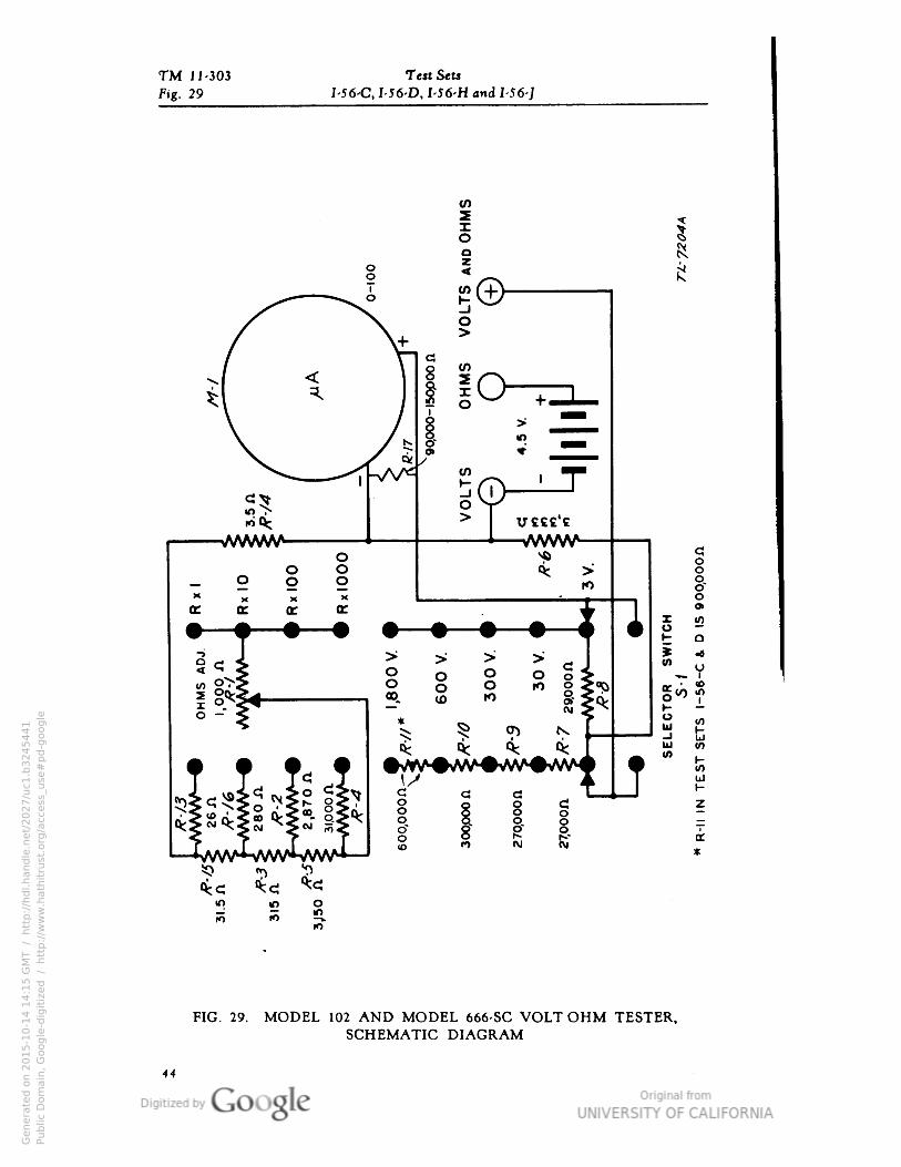
TM 11-303 Test Sets
Fig. 29 I-56-C• I-56-D• I-56-H and 1-56-]
FIG. 29. MODEL 102 AND MODEL 666-SC VOLT OHM TESTER,SCHEMATIC DIAGRAM
44
Genera
ted o
n 2
01
5-1
0-1
4 1
4:1
5 G
MT /
htt
p:/
/hd
l.hand
le.n
et/
20
27
/uc1
.b3
24
54
41
Public
Dom
ain
, G
oog
le-d
igit
ized
/
htt
p:/
/ww
w.h
ath
itru
st.o
rg/a
ccess
_use
#pd-g
oogle

TM 11-303
Maintenance Figs. 30-31
r~i 1 ±XB *aL« •_!—> •_•!_.
"•9
I 1a:
I I
1-I I
LrJ
Li.J~liJ X JPIG. 30. MODEL 102 VOLT-OHM TESTER, RESISTOR BOARD DIAGRAM
FIG. 31. MODEL 666-SC VOLT-OHM TESTER, LOCATION OF PARTS
45
Genera
ted o
n 2
01
5-1
0-1
4 1
4:1
5 G
MT /
htt
p:/
/hd
l.hand
le.n
et/
20
27
/uc1
.b3
24
54
41
Public
Dom
ain
, G
oog
le-d
igit
ized
/
htt
p:/
/ww
w.h
ath
itru
st.o
rg/a
ccess
_use
#pd-g
oogle
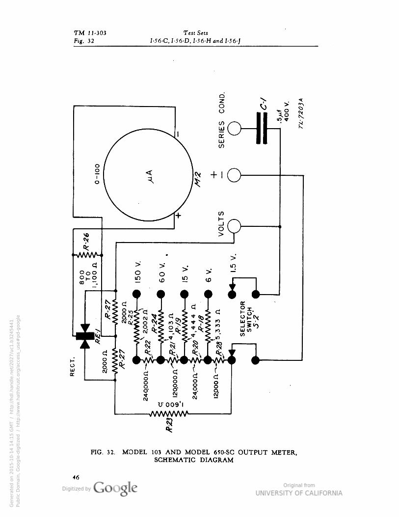
TM 11-303 Test Sets
Pig. 32 I-56-C, I-56-D, I-56-H and I-56-]
[ I: -.U009 I
-VWWWVNA
d c;0 oO o
« §
FIG. 32. MODEL 103 AND MODEL 650-SC OUTPUT METER,SCHEMATIC DIAGRAM
Genera
ted o
n 2
01
5-1
0-1
4 1
4:1
5 G
MT /
htt
p:/
/hd
l.hand
le.n
et/
20
27
/uc1
.b3
24
54
41
Public
Dom
ain
, G
oog
le-d
igit
ized
/
htt
p:/
/ww
w.h
ath
itru
st.o
rg/a
ccess
_use
#pd-g
oogle

TM 11-303
Maintenance Figs. 33-34
FIG. 33. MODJEL 103 OUTPUT METER• RESISTOR BOARD
M-l
c-i
J-2
TL-7525
FIG. 34. MODEL 650-SC OUTPUT METER, LOCATION OF PARTS
47
Genera
ted o
n 2
01
5-1
0-1
4 1
4:2
7 G
MT /
htt
p:/
/hd
l.hand
le.n
et/
20
27
/uc1
.b3
24
54
41
Public
Dom
ain
, G
oog
le-d
igit
ized
/
htt
p:/
/ww
w.h
ath
itru
st.o
rg/a
ccess
_use
#pd-g
oogle

TM 11-303 Test Sets
Figs. 35-36 I-56-C• I-56-D• I-56-H and I-56-J
R-22-28-
R-23
C-l
TL-7526
FIG. 35. MODEL 650-SC(C) OUTPUT METER• RESISTOR BOARD
R-27
C-l
J-2TL-7527
R-18
R-19
FIG. 36. MODEL 650-SC(J) OUTPUT METER, RESISTOR BOARD
Genera
ted o
n 2
01
5-1
0-1
4 1
4:2
7 G
MT /
htt
p:/
/hd
l.hand
le.n
et/
20
27
/uc1
.b3
24
54
41
Public
Dom
ain
, G
oog
le-d
igit
ized
/
htt
p:/
/ww
w.h
ath
itru
st.o
rg/a
ccess
_use
#pd-g
oogle
TM 11-303
Maintenance Par. 46
46. MOISTUREPROOFING 8C FUNGIPROOFING INSTRUCTIONS.
a. General. The moistureproofing and fungiproofing instructions for
components of Test Set 1-56- (*) given below supplement general instruc-
tions supplied with moistureproofing and fungiproofing equipment.
b. Preliminary steps. Before any components of Test Set 1-56- (*) can
be moistureproofed and fungiproofed, the instrument must be checked for
proper operation. Defective equipment must be repaired by authorized
personnel before proceeding. Then prepare the instruments as follows:
(1) COMBINATION TESTERS, MODEL 104 AND MODEL 1183-SC.
Loosen the four screws on the bottom of the panel and remove the panel,
batteries, and rectifier unit. Carefully disconnect the leads from the meter
terminals, and, after taking out the four screws holding the meter remove
the meter from the panel.
(2) VOLT-OHM TESTERS, MODEL 102 AND MODEL 666-SC, ANDOUTPUT METERS, MODEL 103 AND MODEL 650-SC. Loosen the
four screws holding the meter panel and remove the unit from the case.
Take out the battery and disconnect the leads attached to the meter contacts.
Lift up the terminal board carefully so that no -leads are broken. Loosen
the screws holding the meter and remove the meter from the panel.
c. Procedure.
(1) Moistureproof and fungiproof the equipment as follows: Place the
panel and attached parts in the baking oven. DO NOT EXCEED 160° F.
If there are indications of melting wax, reduce the temperature. The total
baking time must be increased one hour for each 10° F. drop in
temperature.
(2) When the baking is finished, remove the unit from the oven and brush
varnish on all exposed surfaces except the rotary-switch contacts.
CAUTION: Protect switch contacts from the varnish.
(3) After the varnish has dried properly, mount the meter on the panel.
(4) Brush varnish around the inside of the case and panel. Do not allow
any varnish to touch the rotary-switch contacts.
(5) When the varnish has dried, reassemble the parts.
(6) Check the equipment to see that it operates properly.
49
Genera
ted o
n 2
01
5-1
0-1
4 1
4:2
7 G
MT /
htt
p:/
/hd
l.hand
le.n
et/
20
27
/uc1
.b3
24
54
41
Public
Dom
ain
, G
oog
le-d
igit
ized
/
htt
p:/
/ww
w.h
ath
itru
st.o
rg/a
ccess
_use
#pd-g
oogle
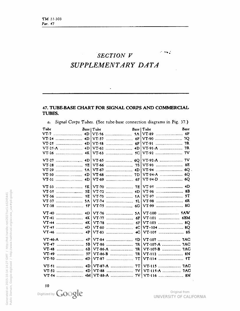
TM 11-303
Par. 47
SECTION V
SUPPLEMENTARY DATA
47. TUBE-BASE CHART FOR SIGNAL CORPS AND COMMERCIALTUBES.
a. Signal Corps Tubes. (See tube-base connection diagrams in Fig. 37.)
Tube Base
VT-7 4D
VT-24 4D
VT-2? 4D
VT-25-A 4D
VT-26 4K
VT-27 4D
VT-28 5E
VT-29 5AVT-30 4D
VT-31 4D
VT-33 5K
VT-35 5E
VT-36 JEVT-37 5A
VT-38 5F
VT-40 4D
VT-41 4KVT-44 4KVT-4J 4D
VT-46 4P
VT-46-A 4P
VT-47 5B
VT-48 6B
VT-49 5F
VT-5O 4D
VT-?l 4D
VT-52 4D
VT-J4 4M
Tube BOM
VT-56 5A
VT-57 6F
VT-58 6F
VT-62 4D
VT-63 1C
VT-65 6QVT-66 7S
VT-67 4D
VT-68 7D
VT-69 6F
VT-70 7E
VT-72 4D
VT-73 ?AVT-74 ?LVT-75 6G
VT-76 5AVT-77 6FVT-78 6F
VT-80 4C
VT-83 4C
VT-84 IDVT-86 7R
VT-86-A 7R
VT-86-B 7R
VT-87 7T
VT-87-A 7TVT-88 7VVT-88-A 7V
Tube Bate
VT-89 6F
VT-90 7QVT-91 7R
VT-91-A 7R
VT-92 7V
VT-92-A 7VVT-93 8E
VT-94 6Q .
VT-94-A 6QVT-94-D 6Q
VT-91 4D
VT-96 8B
VT-97 .. 5TVT-98 6R
VT-99 8G
VT-100 „ 5AWVT-101 6BMVT-103 8QVT-104 8QVT-105 8S
VT-107 7ACVT-107-A 7ACVT-107-B 7ACVT-112 8NVT-114 IT
VT-115 7ACVT-H5-A 7ACVT-116 8N
50
Genera
ted o
n 2
01
5-1
0-1
4 1
4:2
7 G
MT /
htt
p:/
/hd
l.hand
le.n
et/
20
27
/uc1
.b3
24
54
41
Public
Dom
ain
, G
oog
le-d
igit
ized
/
htt
p:/
/ww
w.h
ath
itru
st.o
rg/a
ccess
_use
#pd-g
oogle
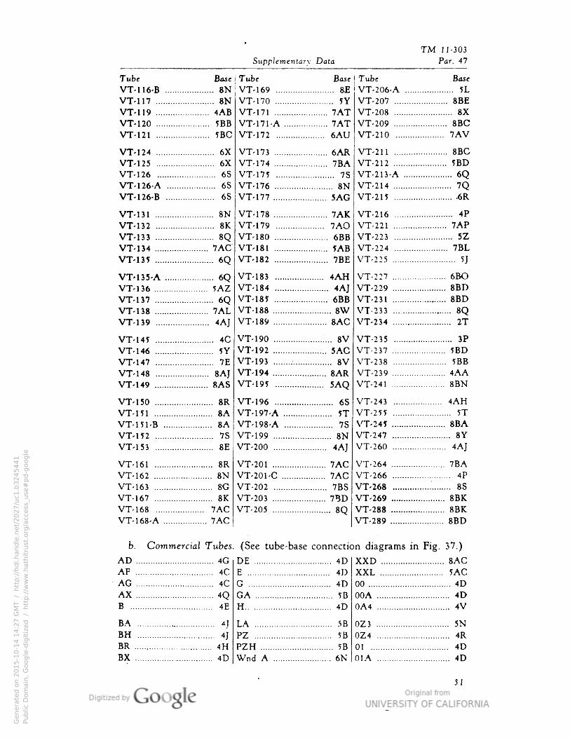
TM 11-303
Supplementary Data Par. 47
Tube Base
VT-116-B 8NVT-117 8N
VT-119 4ABVT-120 5BB
VT-121 5BC
VT-124 6X
VT-125 6X
VT-126 6S
VT-126-A 6S
VT-126-B 6S
VT-131 8N
VT-132 8K
VT-133 8QVT-134 7ACVT-135 6Q
VT>135-A 6QVT-136 5AZVT-137 6QVT-138 7ALVT-139 4AJ
VT-14J 4C
VT-146 5YVT-147 7E
VT-148 8AJVT-149 8AS
VT-150 8R
VT-151 8AVT-151-B 8AVT-H2 7S
VT-153 8E
VT-161 8R
VT-162 8N
VT-163 8G
VT-167 8K
VT-168 7ACVT-168-A 7AC
Tube Base I Tube Base
VT-169 8E VT-206-A 5L
VT-170 5YVT-171 7ATVT-171-A 7ATVT-172 6AU
VT-173 6ARVT-174 7BAVT-171 7S
VT-176 8NVT-177 5AG
VT-178 7AKVT-179 7AOVT-180 6BBVT-181 JABVT-182 7BE
VT-183 4AHVT-184 4AJVT-185 6BBVT-188 8WVT-189 8AG
VT-190 8VVT-192 5ACVT-193 8VVT-194 8ARVT-195 5AQ
VT-196 6S
VT-197-A 5TVT-198-A 7S
VT-199 8NVT-200 ".... 4AJ
VT-201 7ACVT-201-C 7ACVT-202 7BS
VT-203 7BD
VT-205 ..:
8Q
VT-207 8BE
VT-208 8XVT-209 8BCVT-210 7AV
VT-211 8BCVT-212 5BD
VT-213-A 6QVT-214 7QVT-215 6R
VT-216 4PVT-221 7APVT-223 5Z
VT-224 7BLVT-225 5
J
VT-227 6BOVT-229 8BDVT-231 8BD
VT-233 8QVT-234 2T
VT-235 3P
VT-237 5BD
VT-238 5BB
VT-239 4AAVT-241 8BN
VT-243 4AHVT-255 5TVT-247 8BAVT-247 8YVT-260 4AJ
VT-264 7BAVT-266 4PVT-268 ."
.
8S
VT-269 8BKVT-288 8BKVT-289 8BD
b. Commercial Tubes. (See tube-base connection diagrams in Fig. 37.)
AD 4G DE 4D XXD 8ACAF 4C E 41) XXL . 5AGAG 4C G 4D 00 4D
AX 4Q GA 5B 00A 4D
B 4E H 4D 0A4 4V
BA . . 4] LA SB 0Z3 5N
BH 4T PZ 5B 0Z4 4RBR 4H PZH 5B 01 4D
BX 4D Wnd A 6N 01A 4D
51
Genera
ted o
n 2
01
5-1
0-1
4 1
4:2
7 G
MT /
htt
p:/
/hd
l.hand
le.n
et/
20
27
/uc1
.b3
24
54
41
Public
Dom
ain
, G
oog
le-d
igit
ized
/
htt
p:/
/ww
w.h
ath
itru
st.o
rg/a
ccess
_use
#pd-g
oogle
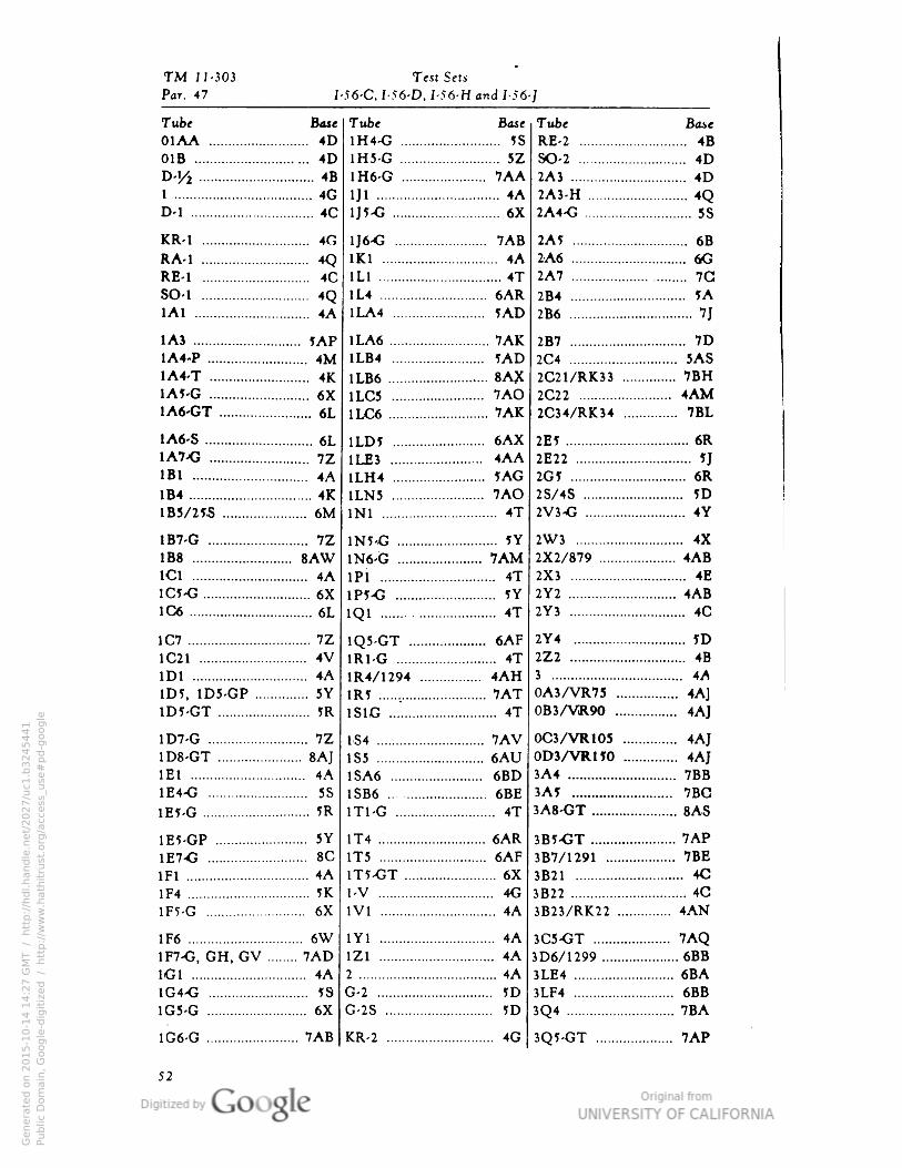
TM 11-303 Test Sets
Par. 47 I-56-C• I-56-D• I-56-H and I-56-]
Tube
01AABase
4D
Tube
1H4-G
Base Tube
RE-2 .
Bane
4B.. .. 5S
01B 4D 1H5-G 5Z SO-2 4D
D-'/i 4B 1H6-G ... 7AA 2A3 . . 4D1 40 HI . 4A 2A3-H 4OD-l 4C ll?-C .. «x 2A4-G 5S
KR-1 4G 1J6-O 7AB 2A5 6B
RA-1 4O 1K1 4A 2A6 6G
RE-1 4C 1L1 4T 2A7 7G
SO-1 4O 1L4 ... 6AR 2B4 ?A1A1 4A 1LA4 5AD 2B6 71
1A3 5AP 1LA6 7AK 2B7 7D1A4-P 4M 1LB4 . . 5AD 2C4 5AS1A4-T 4K 1LB6 . 8AX 2C21/RK33 7BHIA5-G 6X 1LC5 . 7AO 2C22 4AM1A6-GT 6L 1LC6 7AK 2C34/RK34 . 7BL
1A6-S 6L 1LD5 . 6AX 2E1 6R1A7<5 7Z 1LE3 4AA 2E22 11
1B1 4A ILH4 5AG IG1 6R1B4 . . 4K 1LN5 7AO 2S/4S ID1B3/25S 6M INI 4T 2V3-G 4Y
1B7-G 7Z 1N5-G 5Y 2W3 4X
IB8 8AW 1N6-G .. 7AM 2X2/879 4AB1C1 4A iPi 4T 2X3 4E
1C5-G 6X 1P5-G 5Y 2Y2 4AB1C6 6L 1O1 4T 2Y3 4C
1C7 7Z 1Q5-GT 6AF 2Y4 5D
1C21 4V 1R1-G 4T 2Z2 4B
1D1 4A 1R4/1294 4AH 3 4A
1D5 1D5-GP 5Y 1R5 7AT 0A3/VR75 ... .. 4A1
1D5-GT ?R 1S1G 4T 0B3/VR90 4AJ
1D7-G 7Z 184 7AV OC3/VR105 .. 4AT
1D8-GT 8A] 185 6AU OD3/VR.1IO 4AJ1E1 4A 1SA6 6BD 3A4 7BB
1E4-G 5S 1SB6 6BE 3A5 7BG
1E5-G 5R IT1-G 4T 3A8-GT 8AS
1EVGP 5Y 1T4 6AR 3B5-GT 7AP
1E7<J 8C IT5 6AF 3B7/1291 . 7BE
1F1 . .. 4A 1T5-GT .. . 6X 3B21 4C
1F4 5K 1/V 4G 3B22 4C
1F5-G 6X 1V1 4A 3B23/RK22 . . 4AN
1F6 6W 1Y1 4A 3C5-GT 7AO1F7-G GH GV 7AD 1Z1 .„.. 4A 3D6/1299 6BB
1G1 . 4A 2 .. 4A 3LE4 . . 6BA1G4-G 19 G-2 5D 3LF4 6BB
1G5-G 6X G-2S 5D 3O4 7BA
1G6-G ... 7AB KR-2 4G 3O5-GT 7AP
52
Genera
ted o
n 2
01
5-1
0-1
4 1
4:2
7 G
MT /
htt
p:/
/hd
l.hand
le.n
et/
20
27
/uc1
.b3
24
54
41
Public
Dom
ain
, G
oog
le-d
igit
ized
/
htt
p:/
/ww
w.h
ath
itru
st.o
rg/a
ccess
_use
#pd-g
oogle
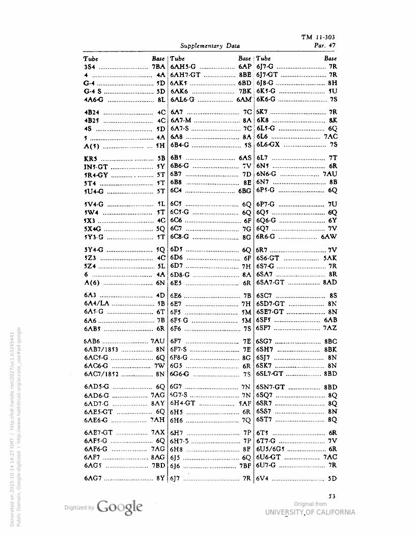
TM 11-303
Supplementary Data Par. 47
Tube
3S4 .
4
G-4..
Base
7BA.. 4A... ID
G-4 S 5D
4A6-G 8L
4B24 4C
4B25 4C
4S ?D
1 4A
A(5) 5H
KR5 5B
IW-GT 5T
5R4-GY 5T5T4 IT5U4-G 5T
1V4-G 5L
9W4 5THC3 4C
5X4G 5Q5Y3 G 5T
5Y4-G 5QJZ3 4C
5Z4 5L
6 4A
A(6) 6N
6A3 4D
6A4/LA 5B
6A5-G 6T
6A6 7B
6AB? 6R
6AB6 7AU6AB7/1853 8N6AC5-G 6Q6AC6-G 7W6AC7/1852 8N
6AD5-G 6Q6AD6-G 7AG6AD7-G 8AY6AE5-CT 6Q6AE6-G 7AH
6AE7-GT 7AX6AF5-G 6Q6AF6-G 7AG6AF7 8AG6AG5 7BD
6AG7 8Y
Tube Base
6AH5-G .................... 6AP6AH7-GT .................. 8BE
6AK5 .......................... 6BD6AK6 ........................ 7BK6AL6-G .................... 6AM
6A7 .............................. 7C
6A7-M .......................... 8A6A7-S ............................ 7C
6A8 .............................. 8A6B4-G ............................ JS
6B5 ............................ 6AS6B6-G .......................... 7V6B7 .............................. 7D6B8 .............................. 8E6C4 ........................ ..... 6BG
6C5 .............................. 6Q6CI-G .......................... 6Q6C6 ................ 6F6C7 .............................. 7G6C8-G .......................... 8G
6D5 .............................. 6Q6D6 .............................. 6F6D7 .............................. 7H6D8-G .......................... 8A6E5 .............................. 6R
6E6
6E7
6F5
6F5 G
6F6
7B
7H5M5M
7S
6F7 .............................. 7E
6F7-S ............................ 7E
6F8-G ............................ 8G6G5 .............................. 6R6G6-G .......................... 7S
6G7 .............................. 7N
6G7-S ............................ 7N6H4-GT .................... 5AF6H5 .............................. 6R
6H6 .............................. 7Q
6H7 .............................. 7P
6H7-S ............................ 7P
6H8 .............................. 8E
6J5 ................ 6Q
6J6 .............................. 7BF
6J7 7R
Tube Base
6J7-G 7R
6J7-GT 7R
6J8-G 8H6K5-G JU6K6-G 7S
UK7 7R
6K8 8JC
6L5-G 6Q6L6 7AC6L6-GX 7S
6L7 7T6W 6R6N6-G 7AU6N7 8B6P5-G 6Q
6P7-G 7U
6Q5 6Q6Q6-G 6Y
6Q7 7V6R6-G 6AW
6R7 7V6S6-GT 5AK6S7-G 7R
6SA7 8R
6SA7-GT 8AD
6SC7 8S
6SD7-GT 8K6SE7-GT 8N6SF5 6AB6SF7 7AZ
6SG7 8BC6SH7 8BK
6SJ7 8N6SK7 8N6SL7-GT 8BD
6SN7-GT 8BD
6SQ7 8Q6SR7 8Q6SS7 8N"
6ST7 8Q
6T? 6R
6T7-G 7V6U5/6G5 6R6U6>GT 7AC6U7-G 7R
6V4 5D
Genera
ted o
n 2
01
5-1
0-1
4 1
4:2
7 G
MT /
htt
p:/
/hd
l.hand
le.n
et/
20
27
/uc1
.b3
24
54
41
Public
Dom
ain
, G
oog
le-d
igit
ized
/
htt
p:/
/ww
w.h
ath
itru
st.o
rg/a
ccess
_use
#pd-g
oogle
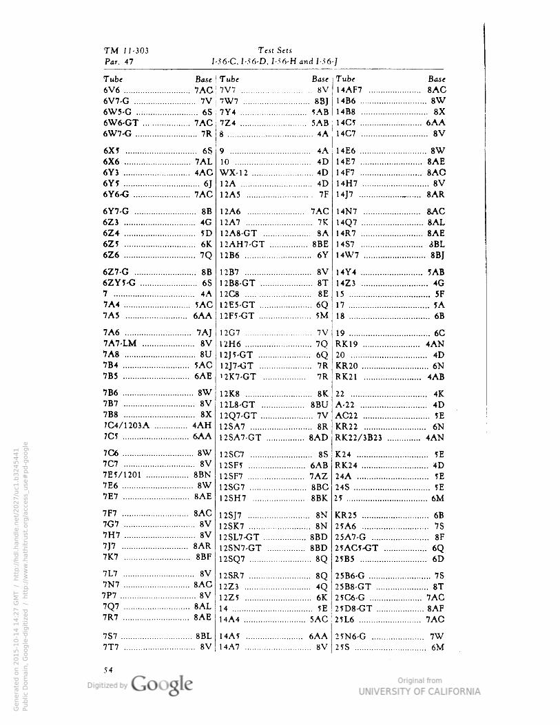
TM 11-303 SetsTest
Par. 47 I-56-C. I-56-D, I 56-H and I-56-]
Tube
6V6
Bast
7ACTube Base
8VTube
14AF7
Base
7V7 8AC6V7-G 7V 7W7 8B] I486 8W6W5-G ..; .... 6S 7Y4 5AB 1488 8X6W6-GT 7AC 7Z4 5AB 14C5 6AA6W7-G 7R g 4A 14C7 8V
6X5 6S 9 4A 14E6 8W6X6 7AL 10 4D 14E7 8AE6YJ 4AC WX-12 .. . 4D 14F7 8AO6Y? 6J 12A 4D 14H7 8V6Y6-G .... 7AC 12A5 7F 1417 8AR
6Y7-G 8B 12A6 7AC 14N7 8AC6Z3 4G 12A7 7K 14Q7 8AL6Z4 5D 12A8-GT
12AH7-GT8A
.... 8BE
14R7 8AE6Z? 6K 14S7 3BL6Z6 7O 12B6 6Y 14W7 . 8BI
6Z7-G 8B 12B7 8V 14Y4 5AB
6ZY5-G . .. 6S 1 2B8-GT 8T 14Z3 4G7 4A 12C8 8E 15 5F7A4 5AC 12E5-GT . .. 6Q 17 . 1A7A5 6AA 12F5-GT . . . 5M 18 6B
7A6 7A] 12G7 7V 19 6C7A7-LM 8V 12H6 7Q RK19 4AN7A8 8U 12J5-GT 6O 20 4D7B4 5AC 12J7-GT 7R KR20 6N7B5 6AE '2K7-GT 7R RK21 4AB
7B6 8W 12K8 8K 22 4K7B7 8V 12L8-GT 8BU A-22 4D7B8 8X 12Q7-GT 7V AC22 5E
7C4/1203A 4AH 12SA7 8R KR22 6N7C5 6AA 12SA7-GT 8AD RK22/3B23 4AN
7C6 8W 12SC7 8S K24 5E7C7 8V 12SF5 6AB RK24 4D7EJ/1201 8BN 12SF7 7AZ 24A IE7E6 8W 12SG7 8BC 24S 5E7E7 8AE 12SH7 8BK 25 6M
7F7 8AC 12SJ7 8N KR25 6B7G7 8V 12SK7 8N 25A6 757H7 8V 12SL7-GT 8BD 25A7-G 8F7J7 8AR 12SN7-GT 8BD 25AC5-GT °V
6D6O
7K7 8BF 12SQ7 8O 25B5
7L7 8V 12SR7 8O 25B6-G 7S7N7 8AC 12Z3 4O •>5B8-GT 8T7P7 8V 12Z5 6K 25C6-G 7AC7Q7 8AL 14 5E 25D8-GT 8AF7R7 8AE HA 4 5AC 25L6 7AC
7S7 8BL 14A5 6AA 25N6-G 7W7T7 8V 14A7 8V 25S 6M
Genera
ted o
n 2
01
5-1
0-1
4 1
4:2
7 G
MT /
htt
p:/
/hd
l.hand
le.n
et/
20
27
/uc1
.b3
24
54
41
Public
Dom
ain
, G
oog
le-d
igit
ized
/
htt
p:/
/ww
w.h
ath
itru
st.o
rg/a
ccess
_use
#pd-g
oogle
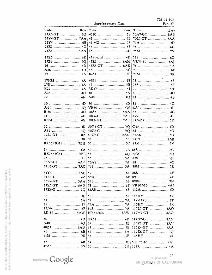
TM J 1-303
Supplementary Data Par. 47
25Y4-GT ..„ 5AA 43 6B i 701.7-fJT 6\A25Y5 6E 43-MG 7S 71A 4D25Z3 4G 44 5F 75 6G25Z4 5AA 45 4D 75M 7V
25Z5 6E 4D 75S 6G25Z6 . 7Q 45Z3 5AM VR75-30 4AI26 4D 45Z5-GT 6AD 76 5\A26 . 4D 46 5C 77 6F27 5A 46A1 2S 77M 7R
27HM 5A 46B1 2S 78 6F27S . . 5A 47 . . 5B 78S 6FK27 5A RK47 5J 79 . 6HA28 4D 48 6A 80 4C29 6N A48 4O 81 4B
30 4D 50 . . 4D 82 . 4GA-30 4O VR50 4W S2V 4LR-30 4D 50A5 6AA 83 4C31 4D 50C6-G . 7AC 83V .... 4LKR31 . 4G 50L6-GT 7AC 84/6Z4 5D
32 .. .. 4K 50Y6-GT 7O G-84 5DA32 4Q 50Z6-G 7Q 85 6G32L7-GT 8Z 50Z7-G 8AN 85AS 6G33 5K 51 5E 85L7 8ABRK33/2C21 7BH 52 . 5C 85M .... 7V
34 .. .. 4M 53 7B 85S .. 6GRK34/2C34 ...... 7BL 55 6Q 86M . 6O35 5E 56 5A 87S 6F35A5-LT . 6A* 56AS . 5A 88 4C35L6-GT 7AC 56S 5A 88M 7R
35Y4 5AL 57 6F 88S 6F
3-5Z3-LT 4Z 57AS . . 6F 89 6F35Z4-GT . 5AA 57S 6F 89RS 7N
35Z5-GT 6AD 58 6F VR105-30 4AJ35Z6-G 7O 58AS . 6F 112A 4D
36 5E 58S 6F 113HY 5K•
37 5A 59 ... 7A HY-114B 2T38 .. . 5F 59A 7A 115HY . 5K39/44 If 5VS 7A 117L7-GT 8AORK-39 . . 5AW HY61/807 5AW 117M7-GT 8AO
40 4D RK62 4D 117N7-GT . 8AVA40 4Q 64 5E 117P7-GT 3AV40Z5 6AD 65 5E 117Z4-GT 5AA41 6B 67 5A 117Z6-GT 7O41M 7S 68 . 5E 125HY 5K
42 6B 69 5E VRl 50-30 4AI42A2 3S 70 6N 165R 4A
Genera
ted o
n 2
01
5-1
0-1
4 1
4:2
7 G
MT /
htt
p:/
/hd
l.hand
le.n
et/
20
27
/uc1
.b3
24
54
41
Public
Dom
ain
, G
oog
le-d
igit
ized
/
htt
p:/
/ww
w.h
ath
itru
st.o
rg/a
ccess
_use
#pd-g
oogle
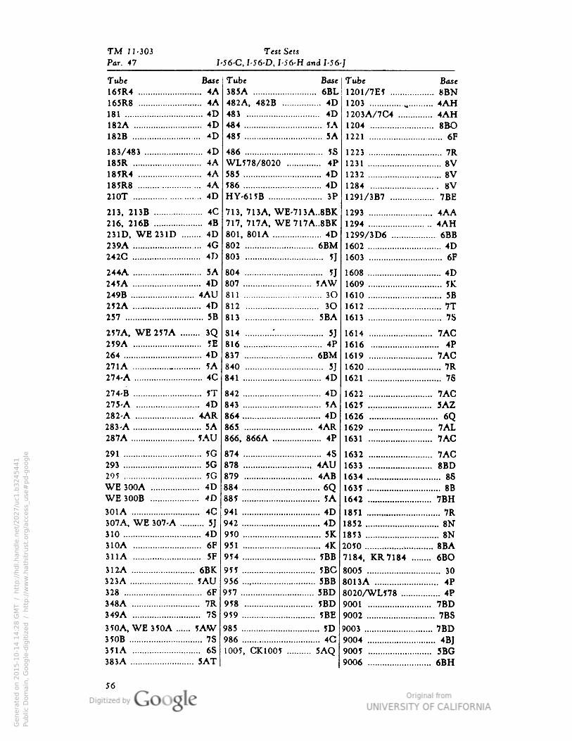
TM J 1-303 Test Sets
Par. 47 I-56-C, I-56-D, I-56-H and I-56-J
Tube Base
165R4 4A165R8 4A181 4D
182A 4D
182B *D
183/483 4D
185R 4A185R4 4A185R8 4A210T 4D
213, 21JB 4C
216, 216B 4B
231D• WE231D 4D
239A 4G
242C 4D
244A 5A
245A 4D
249B 4AU252A 4D
257 5B
257A, WE 257A 3Q259A IE264 4D
271A _ 5A
274-A 4C
274-B 5T275-A 4D
282-A 4AR283-A 5A287A 5AU
291 5G
293 5G
295 1G
WE 300A 4D
WE300B 4D
301A 4C307A, WE 307-A 5J310 4D
310A 6F
31 1A 5F
312A 6BK323A 5AU328 6F
348A 7R
349A 7S
350A, WE350A 5AW350B 7S35IA 6S
383A 5AT
Tube
385A
Bate
6BLTube
1201/7E5
Base
8BN482A, 482B .... 4D 1203 4AH483 4D 1203A/7C4 4AH484 1A 1204 8BO485 5A 1221 6F
486 5S 1223 7R
WL578/8020 .. 4P 1231 8V585 4D 1232 8V586 4D 1284 8VHY-615B 3P 1291/3B7 7BE
713, 713A, WE 713A..8BK 1293 i .. 4AA717, 717A, WE 717A..8BK 1294 4AH801, 801A 4D 1299/3 D6 6BB802 6BM 1602 4D803 5J 1603 6F
804 .... yj 1608 4D807 5AW 1609 . .. 5K811 .. 3O 1610 5B
812 3O 1612 7T813 5BA 1613 . . . 7S
814 r. 5J 1614 . 7AC816 4P 1616 4P
837 6BM 1619 7AC840 5J 1620 7R
841 4D 1621 . . 76
842 4D 1622 . . 7AC843 5A 1625 . 5AZ864 4D 1626 6O865 4AR 1629 7AL866, 866A 4P 1631 . 7AC
874 4S 1632 7AC878 4AU 1633 8BD879 4AB 1634 . 88
884 • ... 6Q 1635 8B
885 5A 1642 7BH
941 4D 1851 7R942 4D 1852 8N950 5K 1853 8N951 4K 2050 8BA954 5BB 7184 KR7184 6BO
955 5BC 8005 . 30
956 5BB 801 3A 4P957 5BD 8020/WL578 4P958 5BD 9001 7BD959 5BE 9002 7BS
985 JD 9003 . 7BD986 4G 9004 461
1005, CK1005 .. 5AO 9005 5BG9006 ... 6BH
56
Genera
ted o
n 2
01
5-1
0-1
4 1
4:2
8 G
MT /
htt
p:/
/hd
l.hand
le.n
et/
20
27
/uc1
.b3
24
54
41
Public
Dom
ain
, G
oog
le-d
igit
ized
/
htt
p:/
/ww
w.h
ath
itru
st.o
rg/a
ccess
_use
#pd-g
oogle
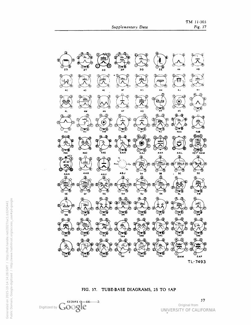
TM 11-303
Supplementary Data Fig. 37
2T JO
S 1
3Q O3S" 44 46
4J
4M 4N 40 4R
4X 4Y 4AA 4AB
4AC 4AD 4AG 4AH 4AJ «AK
..KEY4AL KEY'AAI
. 5C 50
5U 5M
5P 50 5R 55 5U 5W
5Y 5Z SAC 5AD
5AF JIG 5AH 5» SAK SAL 5AM 5AP
TL-7493
FIG. 37. TUBE-BASE DIAGRAMS, 2S TO 5AP
612081 O— 44 5 57
Genera
ted o
n 2
01
5-1
0-1
4 1
4:2
8 G
MT /
htt
p:/
/hd
l.hand
le.n
et/
20
27
/uc1
.b3
24
54
41
Public
Dom
ain
, G
oog
le-d
igit
ized
/
htt
p:/
/ww
w.h
ath
itru
st.o
rg/a
ccess
_use
#pd-g
oogle
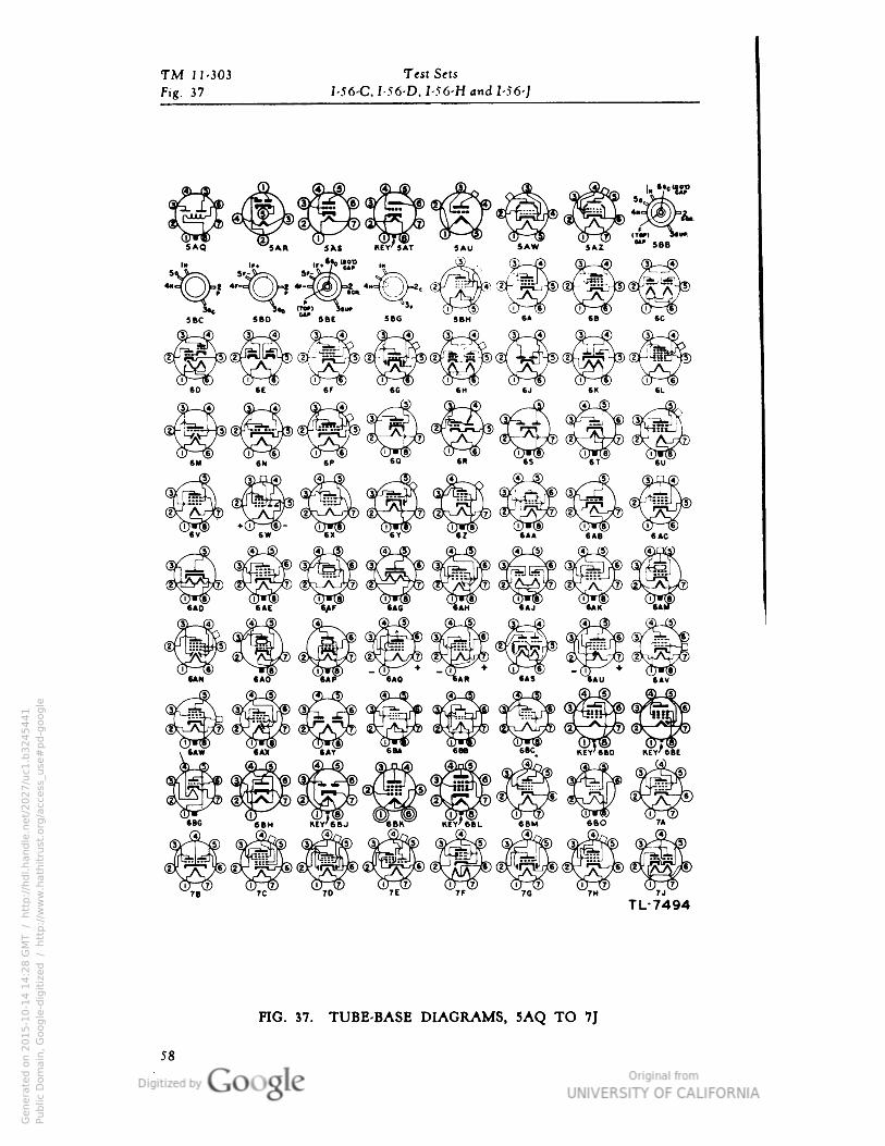
TM 11-303 Test Sets
Fig. 37 I-56-C• I-56-D• I-56-H and 1-56-J
5AR 5*S MY'SAT 5AU SAW SAZ
FIG. 37. TUBE-BASE DIAGRAMS, 5AQ TO 7J
58
Genera
ted o
n 2
01
5-1
0-1
4 1
4:2
8 G
MT /
htt
p:/
/hd
l.hand
le.n
et/
20
27
/uc1
.b3
24
54
41
Public
Dom
ain
, G
oog
le-d
igit
ized
/
htt
p:/
/ww
w.h
ath
itru
st.o
rg/a
ccess
_use
#pd-g
oogle
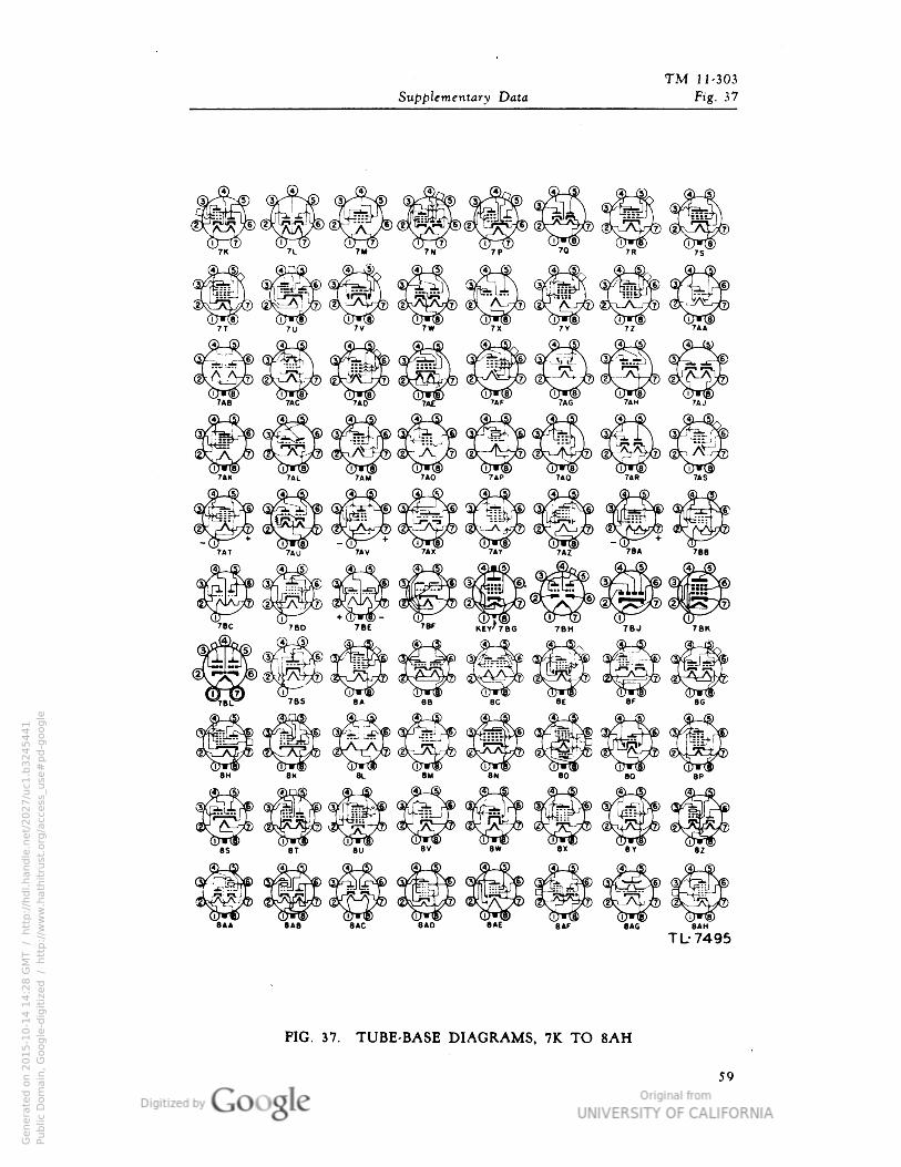
TM 11-303
Supplementary Data Fig. 37
845 808 BAC 840 B4E e«F 8«G BAH
TL-7495
FIG. 37. TUBE-BASE DIAGRAMS, 7K TO 8AH
59
Genera
ted o
n 2
01
5-1
0-1
4 1
4:2
8 G
MT /
htt
p:/
/hd
l.hand
le.n
et/
20
27
/uc1
.b3
24
54
41
Public
Dom
ain
, G
oog
le-d
igit
ized
/
htt
p:/
/ww
w.h
ath
itru
st.o
rg/a
ccess
_use
#pd-g
oogle
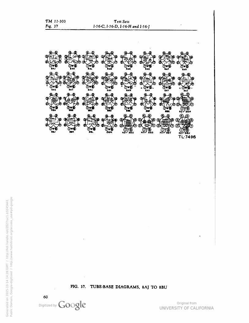
TM 11-303 Test Sew
Fig. 37 I-56-C• I-56-D• I-56-H and I-56-]
e»J SAK BAL eaM BAN BAD SIP
8AS BAT 8AU .„ gAW 8AX~ ~8AY~*
"sAZ
88L SBN
TL-7496
FIG. 37. TUBE-BASE DIAGRAMS• 8AJ TO 8BU
60
Genera
ted o
n 2
01
5-1
0-1
4 1
4:2
8 G
MT /
htt
p:/
/hd
l.hand
le.n
et/
20
27
/uc1
.b3
24
54
41
Public
Dom
ain
, G
oog
le-d
igit
ized
/
htt
p:/
/ww
w.h
ath
itru
st.o
rg/a
ccess
_use
#pd-g
oogle
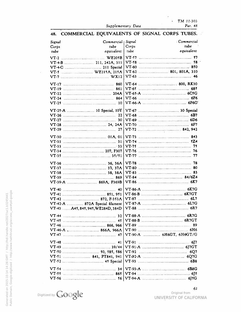
TM 11-303
Supplementary Data Par. 48
48. COMMERCIAL EQUIVALENTS OF SIGNAL CORPS TUBES.
Signal Commercial
Corps tube
tube equivalent
VT-2 WE205BVT-4-B 211, 242A, 311
VT-4-C 211 Special
VT-5 WE215A, 215A
VT-7 WX12
VT-17 860
VT-19 861
VT-22 204A
VT-24 864
VT-25 10
VT-25-A 10 Special, 10Y
VT-26 22
VT-27 ...; 30
VT-28 24, 24A
VT-29 27
VT-30 01A, 01
VT-31 : 31
VT-33 33
VT-34 207, F307
VT-35 35/51
VT-36 36, 36A
VT-37 37, 37A
VT-38 ". 38, 38A
VT-39 869
VT-39-A 869A, F369B
VT-40 : 40
VT-41 851, 951
VT-42 872, F-353AVT-42-A 872A Special filament
VT-43 A45,845,945,WE284D, 384D
VT-44 32
VT-45 45
VT-46 866, 966
VT-46-A , 866A, 966AVT-47 47
VT-48 41
VT-49 39/44VT-50 50, 585, 586
VT-51 841, PT841, 941
VT-52 45 Special
VT-54 34
VT-55 865
VT-56 56
Signal Commercial
Corps tube
tube equivalent
VT-57 57
VT-58 : 58
VT-60 850
VT-62 801, 801A, 310
VT-63 46
VT-64 800, RK30VT-65 685
VT-65-A 6C5G
VT-66 6F6
VT-66-A 6F6G*
VT-67 30 Special
VT-68 6B7
VT-69 6D6
VT-70 6F7
VT-72 842,942
VT-73 843
VT-74 5Z4
VT-75 : 75
VT-76 76
VT-77 77
VT-78 ; 78
VT-80 80
VT-83 83
VT-84 84/6Z4VT-86 6K7
VT-86-A 6K7GVT-86-B 6K7GTVT-87 6L7
VT-87-A 6L7GVT-88 ....: 6R7
VT-88-A 6R7G
VT-88-B 6R7GTVT-89 89
VT-90 6H6VT-90-A 6H6GT, 6H6GT/G
VT-91 6J7VT-91-A , 6J7GTVT-92 6Q7VT-52-A 6Q7GVT-93 6B8
VT-93-A 6B8G
VT-94 6J5VT-94-A 6J5G
61
Genera
ted o
n 2
01
5-1
0-1
4 1
4:2
8 G
MT /
htt
p:/
/hd
l.hand
le.n
et/
20
27
/uc1
.b3
24
54
41
Public
Dom
ain
, G
oog
le-d
igit
ized
/
htt
p:/
/ww
w.h
ath
itru
st.o
rg/a
ccess
_use
#pd-g
oogle
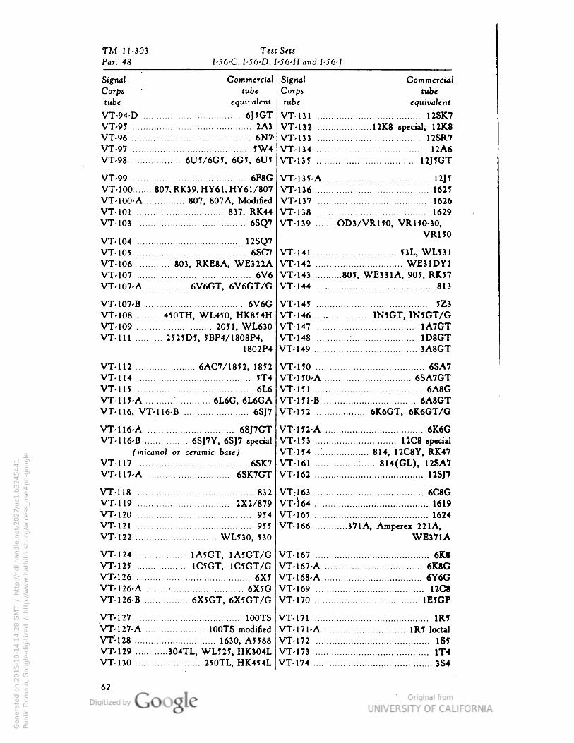
TM 11-303 Test Sets
Par. 48 I-56-C• I-56-D• I-56-H and 1-56-J
Signal Commercial
Corps"
tube
tube equivalent
VT-94-D 6J5GTVT-95 2A3
VT-96 6N7-
VT-97 ..." 5W4
VT-98 6U5/6G5, 6G5, 6U5
VT-99 6F8G
VT-100 807,RK39.HY61•HY61/807VT-100-A 807, 807A, Modified
VT-101 837, RK44VT-103 6SQ7
VT-104 12SQ7VT-105 6SC7
VT-106 803, RKE8A, WE322AVT-107 6V6VT-107-A 6V6GT, 6V6GT/G
VT-107-B 6V6GVT-108 .450TH, WL450, HK854HVT-109 2051, WL630VT-111 2525D5, 5BP4/1808P4,
1802P4
VT-112 6AC7/1852, 1812
VT-114 5T4
VT-115 6L6
VT-115-A 6L6G, 6L6GAVM16, VT-116-B 6SJ7
VT-116-A 6SJ7GTVT-116-B 6SJ7Y, 6SJ7 special
fmicanol or ceramic base^
VT-117 6SK7VT-117-A 6SK7GT
VT-118 832
VT-119 2X2/879VT-120 914
VT-121 955
VT-122 WL530, 530
VT-124 1A5GT, 1A5GT/GVT-125 1C5GT, 1C5GT/GVT-126 6X5VT-126-A 6X5GVT-126-B 6X5GT, 6X5GT/G
VT-127 : 100TS
VT-127-A 100TS modified
VT-128 1630• A5588VT-129 304TL, WL525, HK304LVT-130 250TL.HK454L
Signal Commercial
Corps tube
tube equivalent
VT-131 12SK7
VT-132 12K8 special, 12K8
VT-133 12SR7
VT-134 12A6
VT-131 12J5GT
VT-135-A 12J5VT-136 1625
VT-137 1626
VT-138 1629
VT-139 OD3/VR150, VR150-J0,VR150
VT-141 53L, WL531VT-142 WE31DY1VT-143 805, WE331A, 905, RK57VT-144 813
VT-145 5Z3
VT-146 IN5GT, IN5GT/GVT-147 1A7GTVT-148 : 1D8GTVT-149 3A8GT
VT-150 6SA7
VT-150-A 6SA7GTVT-151 6A8GVT-I51-B 6A8GTVT-152 6K6GT, 6K6GT/G
VT-152-A 6K6GVT-153 12C8 special
VT-154 ..:
814, 12C8Y, RK47
VT-161 : 814(GL), 12SA7
VT-162 12SJ7
VT-163 6C8G
VT-164 1619
VT-165 1624
VT-166 371A, Amperex 221A,
WE371A
VT-167 6K8
VT-167-A 6K8GVT-168-A 6Y6GVT-169 12C8
VT-170 1E5GP
VT-171 : 1R5
VT-171-A 1R5 localVT-172 1SJVT-173 ". 1T4VT-174 3S4
Genera
ted o
n 2
01
5-1
0-1
4 1
4:2
8 G
MT /
htt
p:/
/hd
l.hand
le.n
et/
20
27
/uc1
.b3
24
54
41
Public
Dom
ain
, G
oog
le-d
igit
ized
/
htt
p:/
/ww
w.h
ath
itru
st.o
rg/a
ccess
_use
#pd-g
oogle
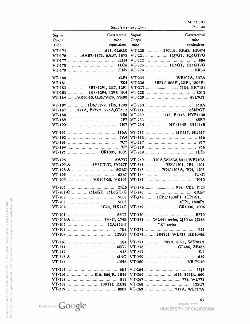
TM 11-303
Supplementary Data Par. 48
Signal Commercial
Corps tube
tube equivalent
VT-175 1613, 6L6GXVT-176 6AB7/1853, 6AB7, 1853
VT-177 1LH4
VT-178 1LC6
VT-179 1LW
VT-180 3LF4
VT-181 7Z4
VT-182 3B7/1291, 3B7, 1291
VT-183 1R4/1294, 1294, 1R4
VT-184 VR90-30, OB3/VR90,VR90
VM8? 3D6/1299, 3D6, 1299
VT-187 575A, F375A, 975A,GL512
VT-188 7E6
VT-189 7F7
VT-190 7H7
VT-191 316A
VT-192 7A4VT-193 .. 7C7
VT-194 7J7VT-19J CK1005, 1005
VT-196 6W5CVT-197-A 5Y3GT/G, JY3GTVT-198-A 6G6G
VT-199 ! 6SS7
VT-200 VRlO?-30, VR105
VT-201 2JL6VT-201-C 25L6GT, 25L6GT/GVT-202 9002
VT-203 9003
VT-204 3C24, HK24G
VT-205 6ST7
VT-206-A JV4G, 274B
VT-207 12AH7GTVT-208 7B8
VT-209 12SG7
VT-210 1S4
VT-211 6SG7
VT-212 958
VT-213-A 6L?GVT-214 12H6
VT-215 6E1
VT-216 816, 866JR, 2B26VT-217 811
VT-218 100TH, RK38VT-219 8007
Signal Commercial
Corpj tube
tube equivalent
VT-220 250TH, RK63, HK454VT-221 3Q5GT, 3Q5GT/GVT-222 884
VT-223 1H5GT• 1H7GT/GV.T-224 RK34
VT-225 WE307A, 307A
VT-226 3EP1/1806P1,3EP1.1806P1VT-227 7184, KR7184
VT-228 8012
VT-229 6SL7GT
VT-230 35OA
VT-231 6SN7GTVT-232 1148, E1148, HYE1148VT-233 6SR7
VT-234 HY/114B• NU114B
VT-235 HY615, NU6HVT-236 836
VT-237 9J7VT-238 ". 956
VT-239 1LE3
VT-240 710A,WL538,8011,WE710AVT-241 7EI/1201, 7E5, 1201
VT-243 7C4/1203A, 7C4, 1203
VT-244 JU4GVT-245 20JO
VT-246 918, CE1, PJ23VT-247 6AG7VT-248 3CP1/1808P1, 3CP1-S1,
3CP1, 1808P1
VT-249 CK1006, 1006
VT-250 EF5O
VT-2H WL441 teiies, 2J30 to 2J34S"K" series
VT-252 923
VT-254 304TH, WL535, HK304M
VT-25fi 70JA, 8021, WE705AVT-256 GL486, ZP486
VT-2557 K-7
VT-259 829
VT-260 VR-7MO
VT-264 3Q4VT-266 1616, 866JR, 660
VT-267 J78, WL578VT-268 12SC7
VT-269 717A, WE717A
Genera
ted o
n 2
01
5-1
0-1
4 1
4:2
8 G
MT /
htt
p:/
/hd
l.hand
le.n
et/
20
27
/uc1
.b3
24
54
41
Public
Dom
ain
, G
oog
le-d
igit
ized
/
htt
p:/
/ww
w.h
ath
itru
st.o
rg/a
ccess
_use
#pd-g
oogle
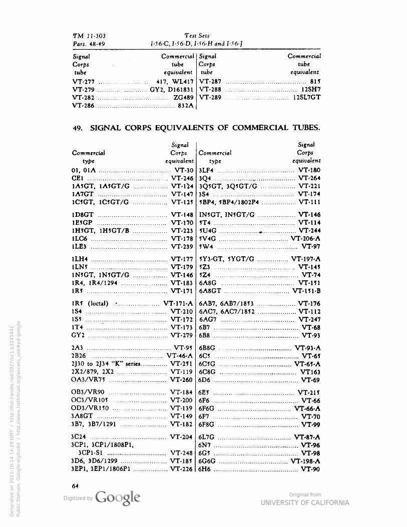
TM 11-303 Test Sets
Pars. 48-49 I-56-C, I-56-D• I-Sfi-H and 1-56-J
Signal Commercial
Corps tube
tube equivalent
VT-277 417, WL417VT-279 GY2, D161831
VT-282 ZG489
VT-286 832A
Signal Commercial
Corpj tube
tube equivalent
VT-287 81?
VT-288 .- 12SH7
VT-289 .... 12SL7GT
49. SIGNAL CORPS EQUIVALENTS OF COMMERCIAL TUBES.
Signal
Commercial Corps
type equivalent
01, 01A VT-30CE1 : VT-2461A5GT, 1A5GT/G VT-1241A7GT VT-1471C5GT, 1C5GT/G VT-125
1D8GT VT-1481E5GP VT-1701H?GT, 1H5GT/B VT-2231LC6 VT-1781LE3 VT-239
1LH4 VT-1771LN? VT-1791N5GT, 1N5GT/G VT-1461R4, 1R4/1294 VT-183iR? : VT-171
1R? (loctal) .• VT-171-A184 , VT-210IS? VT-1721T4
"VT-173
GY2 VT-279
2A3 VT-952B26 VT-46-A
2J30 to 2J34 "K" series VT-2512X2/879, 2X2 VT-119OA3/VR7? VT-260
OB3/VR90 VT-184OC3/VR105 VT-200OD3/VR150 VT-1393A8GT VT-1493B7, 3B7/1291 VT-182
3C24 VT-2043CP1, 3CP1/1808P1,
3CP1-S1 VT-2483D6, JD6/1299 VT-1853EP1, 3EP1/1806P1 VT-226
Signal
Commercial Corps
type equivalent
3LF4 VT-180
3Q4 VT-2643Q5GT, 3Q5GT/G VT-2213S4 VT-1745BP4, 5BP4/1802P4 VT-111
IN?GT, IN5GT/G VT-146?T4 VT-114?U4G » VT-244W4G VT-206-A?W4 VT-97
5Y3-GT, JYGT/G VT-197-A5Z3 VT-14J?Z4 VT-746A8G VT-l5l6A8GT VT-Ul-B
6AB7, 6AB7/1853 VT-1766AC7, 6AC7/1852 VT-1126AG7 VT-2476B7 VT-686B8 VT-93
6B8G VT-93-A6C? VT-6?6C5G VT-65-A6C8G VT1636D6 VT-69
6E5 VT-21J6F6 VT-666F6G VT-66-A6F7 VT-706F8G VT-99
6L7G VT-87-A6N7 VT-966G5 VT-986G6G VT-198-A6H6 VT-90
Genera
ted o
n 2
01
5-1
0-1
4 1
4:2
9 G
MT /
htt
p:/
/hd
l.hand
le.n
et/
20
27
/uc1
.b3
24
54
41
Public
Dom
ain
, G
oog
le-d
igit
ized
/
htt
p:/
/ww
w.h
ath
itru
st.o
rg/a
ccess
_use
#pd-g
oogle
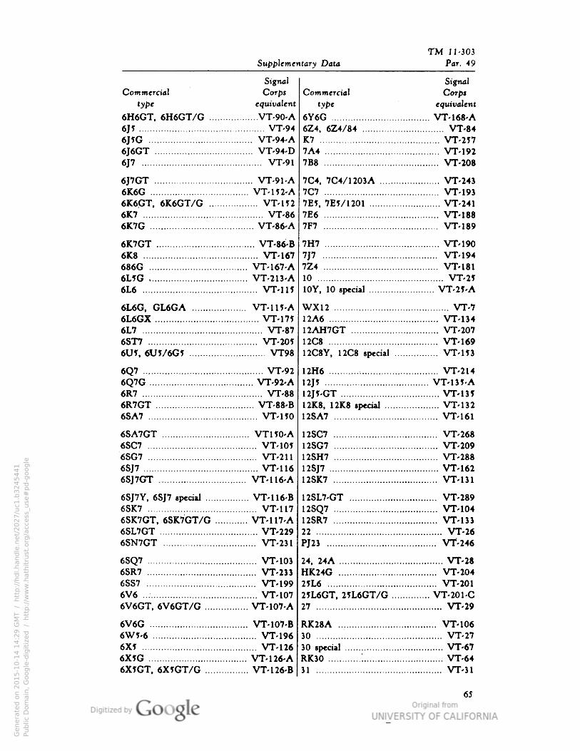
TM 11-303
Supplementary Data Par. 49
SignalCommercial Corps
type equivalent
6H6GT, 6H6GT/G VT-90-A
6J? VT-94
6J?G VT-94-A
6J6GT VT-94-D
6J7 VT-91
6J7GT VT-91-A6K6G VT-m-A6K6.GT, 6K6GT/G VT-1526K7 VT-866K7G VT-86-A
6K7GT VT-M-B6K8 VT-167686G VT-167-A6L1G VT-213-A6L6 VT-115
6L6G, GL6GA VT-1H-A6L6GX VT-m6L7 VT-876ST7 VT-20J6U5, 6U1/6G1 VT98
6Q7 VT-92
6Q7G VT-92-A6R7 VT-886R7GT VT-88-B6SA7 VT-HO
6SA7GT VT150-A6SC7 VT-1056SG7 VT-211
6SJ7 VT-116
6SJ7GT VT-116-A
6SJ7Y, 6SJ7 special VT-116-B6SK7 VT-1176SK7GT, 6SK7GT/G ....: VT-117-A6SL7GT VT-2296SN7GT VT-231
6SQ7 VT-10J6SR7 VT-23J6SS7 VT-1996V6 VT-1076V6GT, 6V6GT/G VT-107-A
6V6G VT-107-B6WI-6 VT-1966X5 VT-1266XJG VT-126-A6X5GT, 6X5GT/G VT-126-B
SignalCommercial Corps
type equivalent
6Y6G VT-168-A6Z4, 6Z4/84 VT-84K7 VT-2577A4 VT-1927B8 VT-208
7C4, 7C4/1203A VT-2437C7 VT-193Wl, 7E5/1201 VT-2417E6 VT-1887F7 VT-189
7H7 VT-190
7J7 VT-1947Z4 VT-18110 VT-2510Y, 10 special VT-25-A
WX12 VT-712A6 VT-13412AH7GT VT-20712C8 VT-16912C8Y, 12C8 special VT-153
12H6 VT-214
\l]1 VT-135-A
12J?-GT VT-13I12K8, 12K8 special VT-13212SA7 \rr-i6i
12SC7 VT-26812SG7 VT-20912SH7 VT-288
12SJ7 VT-16212SK7 VT-131
12SL7-GT VT-289
12SQ7 VT-10412SR7 VT-13322 VT-26
PJ23 Vt-246
24, 24A VT-28HK24G VT-2042JL6 VT-20125L6GT, 2IL6GT/G VT-201-C27 VT-29
RK28A VT-10630 ". VT-2730 special VT-67RK30 : VT-6431 VT-31
65
Genera
ted o
n 2
01
5-1
0-1
4 1
4:2
9 G
MT /
htt
p:/
/hd
l.hand
le.n
et/
20
27
/uc1
.b3
24
54
41
Public
Dom
ain
, G
oog
le-d
igit
ized
/
htt
p:/
/ww
w.h
ath
itru
st.o
rg/a
ccess
_use
#pd-g
oogle
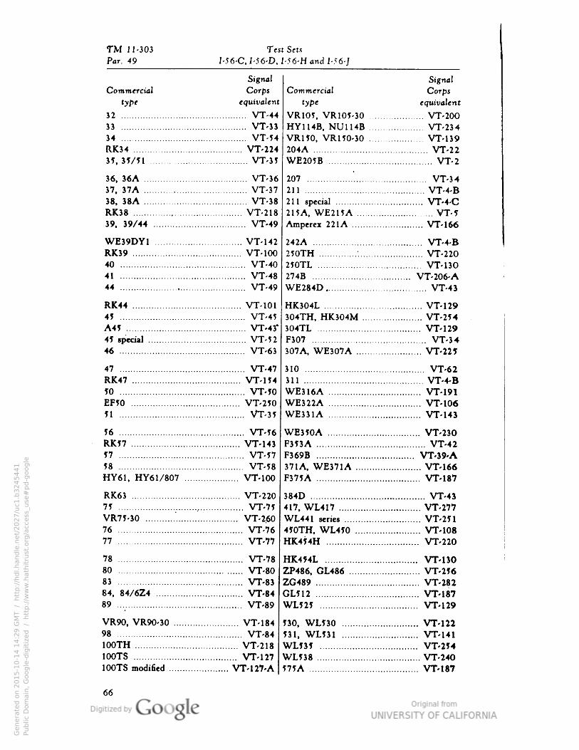
TM 11-303 Test Sets
Par. 49 I-56-C• I-56-D• I-56-H and I-56-J
Signal
Commercial Corps
type equivalent
32 VT-4433 VT-3334 VT-54RK34 VT-22435, 35/51 VT-35
36, 36A VT-3637, 37A VT-3738, 38A VT-38RK38 VT-21839, 39/44 : VT-49
WE39DY1 VT-142RK39 VT-10040 VT-4041 ."
. VT-4844 VT-49
RK44 VT-101
45 VT-45A45 VT-43"41 special VT-5246 VT-63
47 VT-47RK47 VT-15410 VT-50EF50 VT-25051 VT-35
56 VT-56RK57 VT-14357 VT-5758 VT-58HY61, HY61/807 VT-100
RK63 VT-22075 VT-75VR75-30 ". VT-2.6076 VT-7677 VT-77
78 VT-7880 VT-8083 VT-8384, 84/6Z4 VT-8489 VT-89
VR90, VR90-30 VT-18498 VT-84100TH VT-218100TS VT-127100TS modified VT-127-A
SignalCommercial Corps
type equivalent
VR105• VR105-30 VT-200HY114B, NU114B VT-234VR150, VR150-30 VT-139204A VT-22WE205B VT-2
207 ". VT-34211 VT-4-B211 special VT-4-C215A, WE215A VT-5Amperex 22IA VT-166
242A VT-4-B250TH : VT-220250TL VT-130274B VT-206-AWE284D VT-43
HK304L VT-129304TH, HK304M VT-254304TL VT-129F307 VT-34307A, WE307A VT-225
310 VT-62311 VT-4-BWE316A VT-191WE322A VT-106WE331A VT-143
WE350A VT-230F353A VT-42F369B VT-39-A371A, WE371A VT-166F375A VT-187
384D VT-43417, WL417 VT-277WL441 series ". VT-251450TH, WL450 VT-108HK454H VT-220
HK4J4L VT-130ZP486, GL486 VT-256ZG489 VT-282
L512 VT-187WL525 VT-129
530, WL530 VT-122531, WL531 VT-141WL535 VT-254WL538 VT-240575A VT-187
66
Genera
ted o
n 2
01
5-1
0-1
4 1
4:2
9 G
MT /
htt
p:/
/hd
l.hand
le.n
et/
20
27
/uc1
.b3
24
54
41
Public
Dom
ain
, G
oog
le-d
igit
ized
/
htt
p:/
/ww
w.h
ath
itru
st.o
rg/a
ccess
_use
#pd-g
oogle
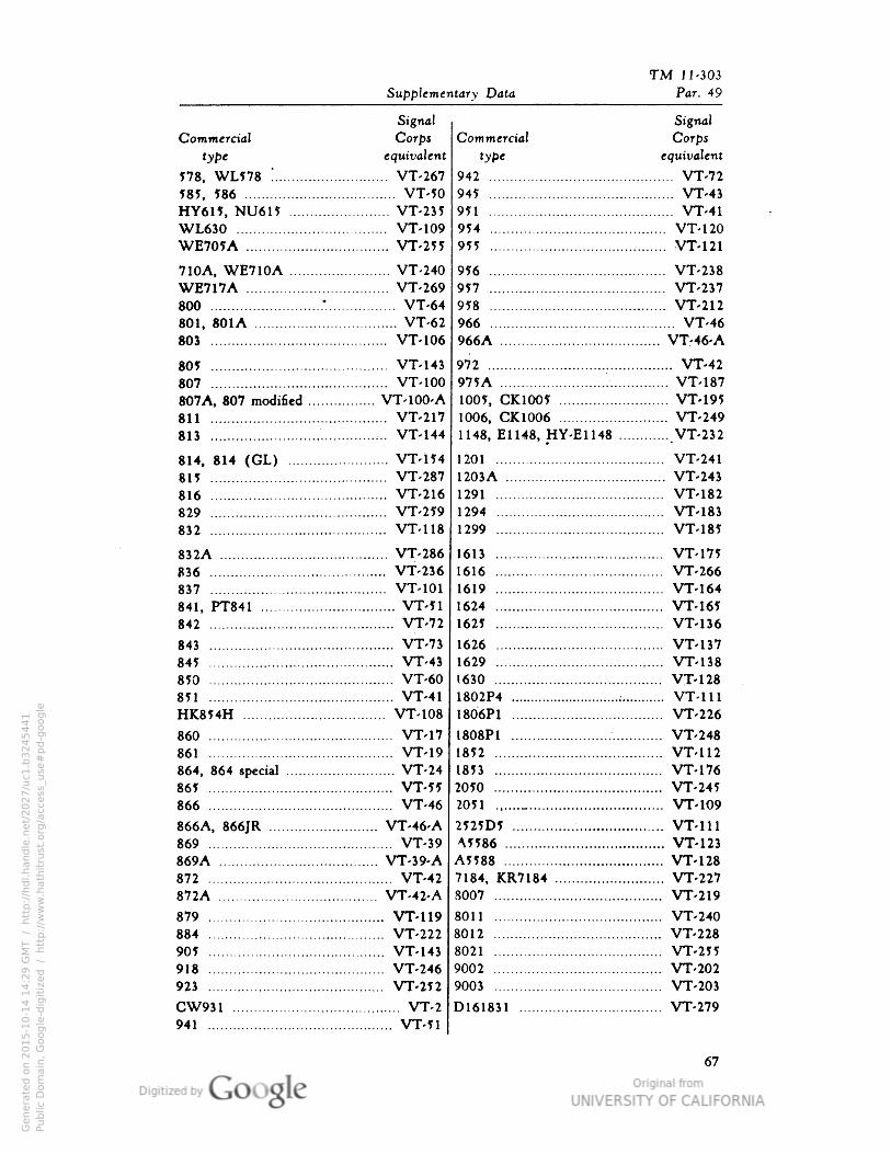
TM J 1-303
Supplementary Data Par. 49
Signal
Commercial Corps
type equivalent
578, WL578 ! VT-267585, 586 VT-50HY615, NU615 . VT-235WL630 VT-109WE705A VT-255
710A, WE710A VT-240WE717A VT-269800 .-
. VT-64801, 801A VT-62803 VT-106
805 VT-143807 VT-100807A, 807 modified VT-100-A811 VT-21781J ..• VT-144
814, 814 (GL) VT-154815 VT-287816 VT-216829 VT-259832 VT-118
832A VT-286836 VT-236837 VT-101
841, PT841 VT-51842 VT-72
843 VT-73845 VT-43850 VT-60851 VT-41HK854H VT-108
860 VT-17861 VT-19864, 864 special VT-24865 VT-55866 VT-46
866A, 866JR VT-46-A869 VT-39869A VT-39-A872 VT-42872A VT-42-A
879 VT-119884 VT-222905 VT-143918 VT-246923 VT-252
CW931 VT-2941 VT-51
Signal
Commercial Corps
type equivalent
942 VT-72945 VT-43951 VT-41954 VT-120955 -VT-121
956 VT-238957 VT-237958 VT-212966 VT-46966A VT-46-A
972 VT-42975A VT-1871005, CK1005 VT-1951006, CK1006 VT-2491148, E1148, HY-E1148 VT-232
1201 VT-241
1203A VT-2431291 VT-1821294 VT-1831299 VT-185
1613 VT-1751616 VT-2661619 VT-1641624 VT-1651625 VT-136
1626 VT-1371629 VT-1381630 VT-1281802P4 : VT-1111806P1 VT-226
1808P1 VT-2481852 . VT-1121853 VT-1762050 VT-2452051 _ VT-109
2525D5 VT-111A5586 VT-123A5588 VT-1287184, KR7184 VT-2278007 VT-219
8011 VT-2408012 VT-2288021 VT-2559002 VT-2029003 VT-203
D161831 VT-279
67
Genera
ted o
n 2
01
5-1
0-1
4 1
4:2
9 G
MT /
htt
p:/
/hd
l.hand
le.n
et/
20
27
/uc1
.b3
24
54
41
Public
Dom
ain
, G
oog
le-d
igit
ized
/
htt
p:/
/ww
w.h
ath
itru
st.o
rg/a
ccess
_use
#pd-g
oogle
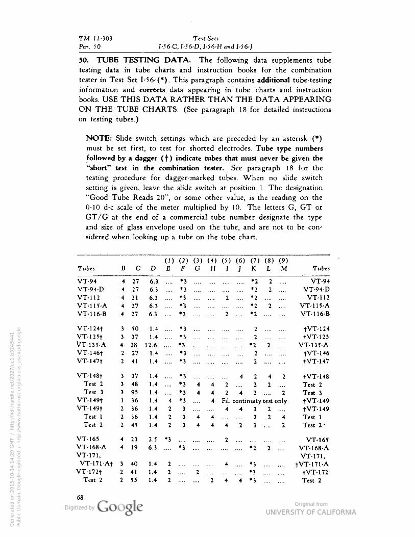
TM 11-303 Text Sets
Par. 50 I-56-C, I-56-D• I-56-H and I-56-J
50. TUBE TESTING DATA. The following data supplements tube
testing data in tube charts and instruction books for the combination
tester in Test Set 1-56- (*). This paragraph contains additional tube-testing
information and corrects data appearing in tube charts and instruction
books. USE THIS DATA RATHER THAN THE DATA APPEARINGON THE TUBE CHARTS. (See paragraph 18 for detailed instructions
on testing tubes.)
NOTE: Slide switch settings which are preceded by an asterisk (*)must be set first, to test for shorted electrodes. Tube type numbers
followed by a dagger ( f ) indicate tubes that must never be given the
"short" test in the combination tester. See paragraph 18 for the
testing procedure for dagger-marked tubes. When no slide switch
setting is given, leave the slide switch at position 1. The designation
"Good Tube Reads 20", or some other value, is the reading on the
0-10 d-c scale of the meter multiplied by 10. The letters G, GT or
GT/G at the end of a commercial tube number designate the type
and size of glass envelope used on the tube, and are not to be con
sidered when looking up a tube on the tube chart.
Tubes(1) (2) (3) (4) (5) (6) (7) (8) (9)DEFGHIJKLM Tubes
VT-94 4 27 6.3 .... *3 *2 2 .... VT-94VT-94-D 4 27 6.3 .... *3 *2 2 .... VT-94-DVT-112 4 21 6.3 .... *3 2 .... *2 VT 112
VT-m-A 4 27 6.3 .... *^ *2 2 .... VT-115-AVT-116-B 4 27 6.3 .... *3 2 .... *2 VT-116-B
VT-124t 3 50 1.4 .... *3 2 tVT 124
VT-mt 3 37 1.4 .... *3 2 tVT- 125
VT-m-A 4 28 12.6 .... *3 *2 2 .... VT-135-AVT-146t 2 27 .4 .... *3 2 tVT- 146
VT-147t 2 41 .4 *3 2 tVT- 147
VT-148t 3 37 .4 .... *3 4242 tVT- 148
Test 2 3 48 .4 .... *3 442 .... 2 2 .... Test 2
Test 3 3 95 .4 .... *3 442 4 2 .... 2 Test 3
VT-149t 1 36 .4 4 *3 .... 4 Fil. continuity test only tVT- 149
VT-149t 2 36 .423 4 4 3 2 .... tVT- 149
Test 1 2 36 .423 4 4 .... .... 3 2 4 Test 1
Test 2 2 45 .423 444 2 3 .... 2 Test 2-
VT-165 4 23 2.5 *3 ... .... 2 VT- 165
VT-168-A 4 19 6.3 .... *3 *2 2 .... VT-168-AVT-171, VT-171,VT-171-At 3 40 1 .4 2 4 .... *3 .... .... tVT-171-A
VT-172t 2 41 1 .4 2 .... 2 .".
*3 tVT- 172
Test 2 2 55 1 .4 2 .... 2 4 4 *3 Test 2
68
Genera
ted o
n 2
01
5-1
0-1
4 1
4:2
9 G
MT /
htt
p:/
/hd
l.hand
le.n
et/
20
27
/uc1
.b3
24
54
41
Public
Dom
ain
, G
oog
le-d
igit
ized
/
htt
p:/
/ww
w.h
ath
itru
st.o
rg/a
ccess
_use
#pd-g
oogle
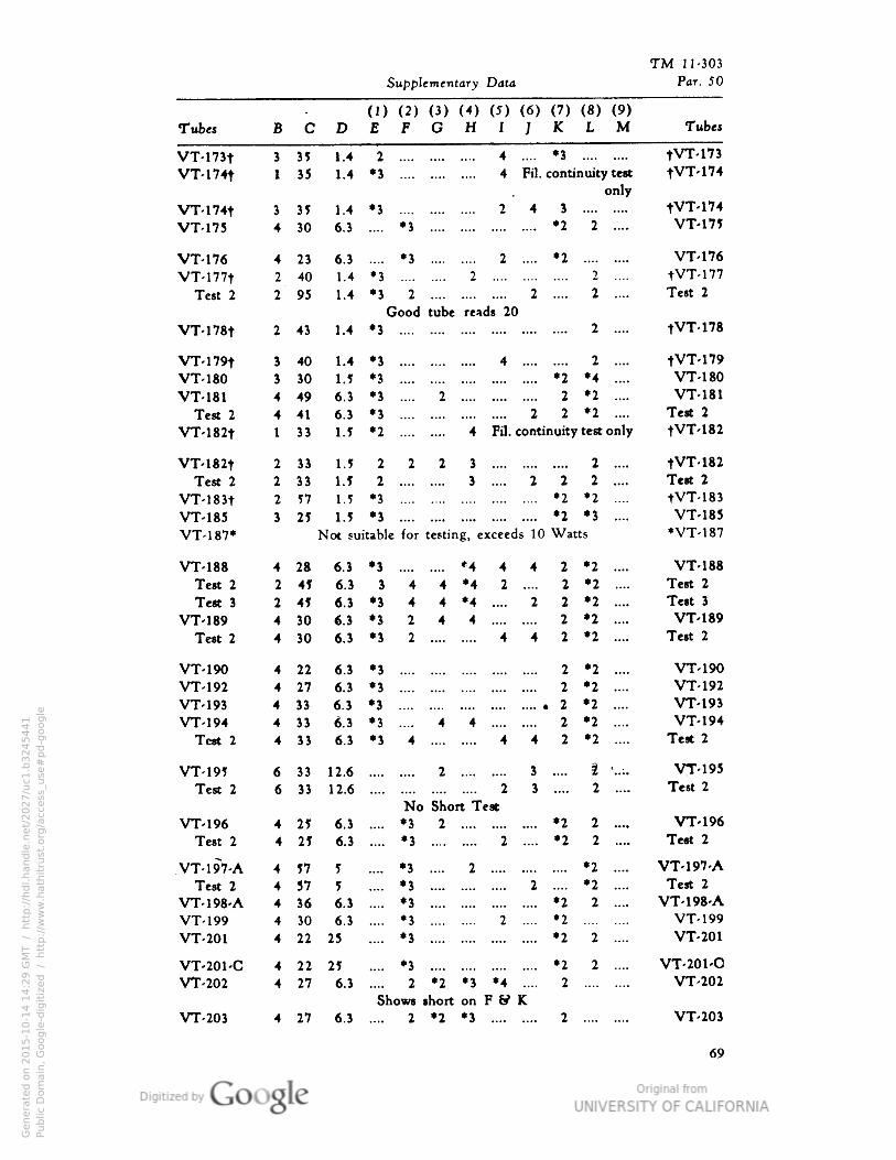
TM 11-303
Supplementary Data Par. 50
(D (2) (3) (4) (5) (6) (7) (8) (9)Tubes B C D £ F G H I J K L M Tubes
VT-173t 3 35 1.4 2 .... 4 .... *3 tVT-173
vr-mt 1 35 1.4 *3 4 Fil. continuity test
onlytVT-174
VT-174t 3 39 1.4 •3 2 4 S tVT-174VT-175 4 30 6.3 •3 *2 2 .... VT-17J
VT-176 4 23 6.3 •3 2 .... *2 VT-176
VT-177t 2 40 1.4 •3 .... 2 2 .... tVT-177Test 2 2 95 1.4 •3 2 2 .... 2 .... Test 2
Good tube reads 20
VT-l78t 2 43 1.4 •3 2 .... tVT-178
VT-179t i 40 1.4 •3 4 2 .... tVT-179VT-180 » 30 1.5 *3 *2 *4 .... VT-180
VT-181 4 49 6.3 •3 2 2 *2 .... VT-181
Test 2 4 41 6.3 •3 2 2 *2 .... Test 2
VT-182t 1 33 1.5 •2 4 Fil. continuity test only tVT-182
VT-182t 2 31 1.5 2 2 2 3 2 .... tVT-182Test 2 2 33 1.5 2 .... 3 .... 2 2 2 .... Test 2
VT-183t 2 57 1.5 *3 *2 *2 .... tVT-183VT-185 3 25 1.5 *3 *2 *3 .... VT-185
VT-187* Not suitable for testing, exceeds 10 Watts *VT-187
VT-188 4 2ft 6.3 •3 .... *4 4 4 2 •2 .... VT-188Test 2 2 49 6.3 3 4 4 *4 2 .... 2 *2 .... Test 2
Test 3 2 49 6.3 *> 4 4 *4 .... 2 2 *2 .... Test 3
VT-189 4 30 6.3 •3 2 4 4 2 *2 .... VT-189
Test 2 4 30 6.3 •3 2 442 •2 .... Test 2
VT-190 4 22 6.3 •3 2 •2 .... VT-190VT-192 4 27 6.3 •3 2 *2 .... VT-192
VT-193 4 33 6.3 •3 2 •2 .... VT-193VT-194 4 33 673 •3 4 4 2 *2 .... VT-194
Test 2 4 33 6.3 •3 4 442 *2 .... Test 2
VT-195 « 33 12.6 2 3 .... 2 '..:. VT-195
Test 2 6 33 12.6
No Short Test
2 3 .... 2 .... Test 2
VT-196 4 29 6.3 .... •3 2 *2 2 .... VT-196
Test 2 4 25 6.3 •S 2 .... *2 2 .... Tert 2
VT-197-A 4 57 5 •3 .... 2 *2 .... VT-197-A
Test 2 4 37 5 •3 2 .... *2 .... Test 2
VT-198-A 4 36 6.3 •s *2 2 .... VT-198-AVT-199 4 30 6.3 •3 2 .... *2 VT-199
VT-201 4 22 25 •3 *2 2 .... VT-201
VT-201-C 4 22 25 •3 *2 2 .... VT-201-OVT-202 4 27 6.3 *•-• 2 *2 *3 *4 .... 2 VT-202
Shows short on F & KVT-203 4 27 6.3 .... 2 *2 *3 2 VT-203
69
Genera
ted o
n 2
01
5-1
0-1
4 1
4:2
9 G
MT /
htt
p:/
/hd
l.hand
le.n
et/
20
27
/uc1
.b3
24
54
41
Public
Dom
ain
, G
oog
le-d
igit
ized
/
htt
p:/
/ww
w.h
ath
itru
st.o
rg/a
ccess
_use
#pd-g
oogle
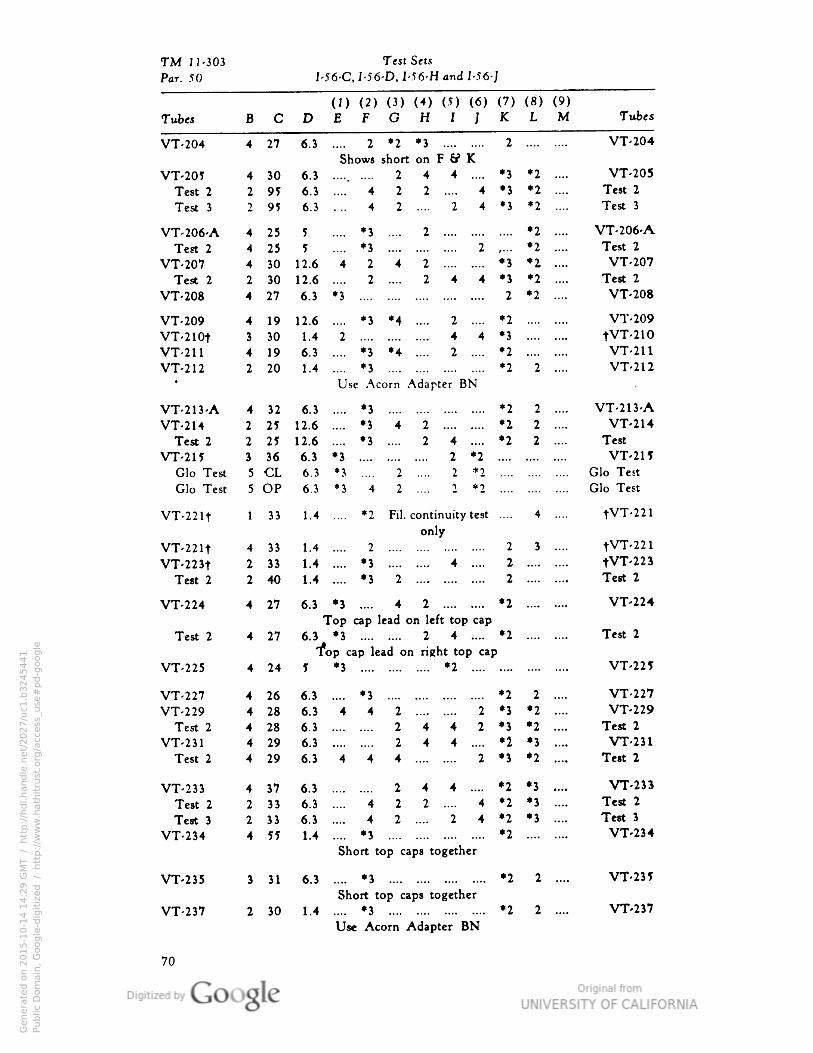
TM 11-303 Test Sets
Par. 50 I-56-C, I-56-D, 1-56-H and I-56-;
Tubes BCDEFGHIJKLM Tubes
VT-204 4 27 6.3 .... 2 *2 *3 2 VT-204
Shows short on F (f K
VT-205 4 30 6.3 ..... .... 244 .... *3 *2 .... VT-205
Test 2 2 95 6.3 .... 422 .... 4 *3 *2 .... Test 2
Test 3 2 95 6.3 .... 4 2 .... 2 4 *3 *2 .... Test 3
VT-206-A 4 25 5 .... *3 .... 2 *2 .... VT-206-A
Test 2 4 25 5 .... *3 2 ,... *2 .... Test 2
VT-207 4 30 12.6 4 2 4 2 *3 *2 .... VT-207
Test 2 2 30 12.6 .... 2 .... 2 4 4 *3 *2 .... Test 2
VT-208 4 27 6.3 *3 2 *2 .... VT-208
VT-209 4 19 12.6 .... *3 *4 .... 2 .... *2 VT-209
VT-210t 3 30 1.4 2 4 4 *3 tVT-210VT-211 4 19 6.3 .... *3 *4 .... 2 .... *2 VT-211
VT-212 2 20 1.4 .... *3 *2 2 .... VT-212* Use Acorn Adapter BN
VT-213-A 4 32 6.3 .... *3 *2 2 .... VT-213-A
VT-214 2 25 12.6 .... *3 4 2 *2 2 .... VT-214Test 2 2 25 12.6 .... *3 .... 2 4 .... *2 2 .... Test
VT-215 3 36 6.3 *3 2 *2 VT-215Glo Test 5 CL 6.3 *3 .... 2 .... 2 *2 Glo Test
Glo Test 5 OP 6.3 *3 4 2 .... 2 *2 Glo Test
VT-221t 1 33 1.4 .... *2 Fil. continuity test .... 4 .... tVT-221only
VT-221t 4 33 1.4 .... 2 -.. 2 3 .... tVT-221
VT-223t 2 33 1.4 .... *3 4 .... 2 tVT-223Test 2 2 40 1.4 .... *3 2 2 Test 2
VT-224 4 27 6.3 *3 .... 4 2 *2 VT-224
Top cap lead on left top cap
Test 2 4 27 6.3 *3 2 4 .... *2 Test 2
Top cap lead on right top cap
VT-225 4 24 5 *3 *2 VT-225
VT-227 4 26 6.3 .... *3 *2 2 .... VT-227
VT-229 4 28 6.3 4 4 2 2 *3 *2 .... VT-229Test 2 4 28 6.3 2 4 4 2 *3 *2 .... Test 2
VT-231 4 29 6.3 244 .... *2 *3 .... VT-231Test 2 4 29 6.3 4 4 4 2 *3 *2 .... Test 2
VT-233 4 37 6.3 244 .... *2 *3 .... VT-233
Test 2 2 33 6.3 .... 422 .... 4 *2 *3 .... Test 2
Test 3 2 33 6.3 .... 4 2 .... 2 4 *2 *3 .... Test 3
VT-234 4 55 1.4 .... *3 *2 VT-234
Short top caps together
VT-235 3 31 6.3 .... *3 *2 2 .... VT-235
Short top caps together
VT-237 2 30 1.4 .... *3 *2 2 .... VT-237
Use Acorn Adapter BN
70
Genera
ted o
n 2
01
5-1
0-1
4 1
4:2
9 G
MT /
htt
p:/
/hd
l.hand
le.n
et/
20
27
/uc1
.b3
24
54
41
Public
Dom
ain
, G
oog
le-d
igit
ized
/
htt
p:/
/ww
w.h
ath
itru
st.o
rg/a
ccess
_use
#pd-g
oogle
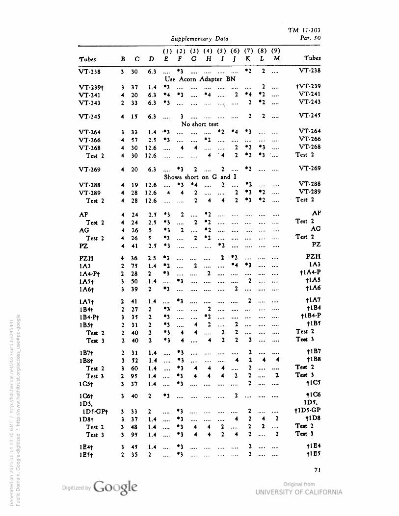
TM 11-303
Supplementary Data Par. 5O
(J) (2) (3) (4) (5) (6) (7) (8) (9)Tubes B C D E F G H I I K L M Tubes
VT-238 3 30 6.3 .... •3 .... •2 2 .... VT-238
Use Acorn Adapter BN
VT-239t 3 37 1 .4 *3 2 .... tVT-239VT-241 4 20 6 .3 •4 *3 .... *4 .... 2 *4 *2 .... VT-241
VT-243 2 33 6 .3 •3 2 *2 .... VT-243
VT-245 4 I? 6 .8 3 .... 2 2 .... VT-245
VT-264 3 33 1 .4 -•3
No short test
.... *2 •4 *3 VT-264
VT-266 4 57 2.5 •3 *2 .... VT-266
VT-268 4 30 12 .6 4 4 2 *2 *3 .... VT-268
Test 2 4 30 12 .6 4 4 2 *2 *3 .... Test 2
VT-269 4 20 6 .3 •3 2 .... 2 *2 VT-269
Shows short on G and IVT-288 4 19 12.6 *3 *4 2 *2 VT-288
VT-289 4 28 12 .6 4 4 2 2 *3 *2 .... VT-289
Test 2 4 28 12 .6 .... 2 4 4 2 *3 *2 .... Test 2
AF 4 24 2 .5 •3 2 .... *2 .... AFTest 2 4 24 2.5 *3 2 *2 .... Test 2
AG 4 26 3 •3 2 .... *2 .... AGTest 2 4 26 5 •3 .... 2 *2 .... Test 2
PZ 4 41 2.5 •3 .... *2 PZ
PZH 4 36 2.3 •3 .... 2 •2 PZH1A3 2 7? 1 .4 •2 .... 2 •4 *3 1A3
lA4-Pt 2 28 2 •3 2 .... tlA4-PlA?t 3 5O 1 .4 •3 .... 2 tlA5lA6t 3 39 2 •3 2 tlA6
lA7t 2 41 1 .4 *3 .... 2 tlA7lB4t 2 27 2 •3 2 .... tlB4
lB4-Pt 3 35 2 •3 *2 .... tlB4-PlB5t 2 31 2 •3 4 2 2 tlB5
Test 2 2 40 2 •3 4 4 2 2 Test 2
Test 3 2 40 2 •3 4 .... 4 2 2 2 Te«t 3
lB7t 2 31 1 .4 •3 .... 2 tlB7lB8t 3 n 1.4 .... •3 .... 4 244 tlB8
Test 2 3 60 1 .4 *3 4 4 4 2 Test 2
Test 3 2 95 1 .4 *3 4 4 4 2 2 .... 2 Test 3
lC5t 3 37 1 .4 *3 .... 2 tlC5
lC6t ) 40 2 •3 2 tlC6ID5, 1D5.
lD5-GPt 3 33 2 •3 .... 2 tlD5-GPlD8t 3 37 1 .4 *3 .... 4 242 tlD8
Test 2 3 48 1 .4 •3 4 4 2 .... 2 2 .... Test 2
Test 3 3 95 1 .4 •3 4 4 2 4 2 .... 2 Test J
lE4t 3 45 1 .4 •J .... 2 tlE4lE?t 2 33 2 *3 .... 2 tlE?
71
Genera
ted o
n 2
01
5-1
0-1
4 1
4:3
0 G
MT /
htt
p:/
/hd
l.hand
le.n
et/
20
27
/uc1
.b3
24
54
41
Public
Dom
ain
, G
oog
le-d
igit
ized
/
htt
p:/
/ww
w.h
ath
itru
st.o
rg/a
ccess
_use
#pd-g
oogle
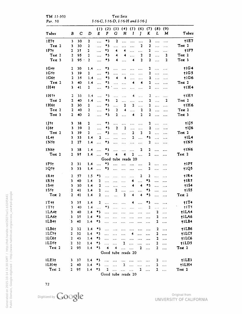
TM 11 Test Sets-303
I. :• I-56-D• I-56-H and 1-56 -JPar. 5(> 56-(
) (2) (3) (4) (5) (6) (7) (8) (9)(1
Tubes B C I> 2 F C H I ] K L M Tubes
lE7t 3 30 2 •3 2 2 tlE7Test 2 3 30 2 •3 2 2 Test 2
lF7t 2 35 2 *3 4 4 2 tlF7Test 2 2 95 2 •344 .... 2 2 .... 2 Test 2
Test 3 2 95 - 2 *3 4 .... 4 2 2 .... 2 Test 3
lG4t 2 30 1 .4 *3 2 tlG4iG5t 3 39 2 *3 2 tlG5lG6t 2 35 1 .4 *3 4 4 2 tlG6
Test 2 3 40 1 .4 *3 4 4 2 Test 2
lH4t 3 41 2 •3"
2 tlH4
inn 2 33 1 .4 *3 4 .... 2 tlH5Test 2 2 40 1 .4 *3 2 2 .... 2 Test 2
lH6t 2 30 2 •*•• *3 .... 2 2 .... 2 tlH6Test 2 2 40 2 *3 2 4 .... 2 2 Test 2
Test 3 2 40 2 _.. •3 2 .... 4 2 2 Test 3
IJJt 3 38 2 •3 2 tU?U6t 3 39 2 •322 2 tlJ6
Test 2 3 39 2 *3 2 2 2 Test 2
lL4t 3 33 1 .4 2 2 .... *3 tlL4lN5t 2 27 1 .4 *3 2 tlN?
lN6t 3 38 1 •4 •3 2 2 tlN6Test 2 2 95 1 •4
Good tube reads 20
*3 4 4 2 .... 2 Test 2
lP5t 2 31 1.•4 •3 2 tlP5lQ*t 3 3) 1..4 *3 2 tlQ5
lR4t 2 57 1 .5 •3 2 2 tlR4lR5t 3 40 1. 4 2 4 .... *3 tlR5lS4t 3 30 1 •4 2 4 4 *3 tlS4lS5t 2 41 1..4 2 .... 2 *3 tiss
Test 2 2 41 1.•4 2 244 *3 Test 2
lT4t 3 35 1..4 2 4 .... •3 tlT4mt 3 40 1 .4 *3 2 tlT5lLA4t 3 40 1.4 •3 .... 2 .... tlLA4lLA6t 3 35 1•4 •3 .... 2 .... tlLA6lLB4t "3 40 1. 4 •3 .... 2 .... tlLB4
lLB6t 2 32 1..4 •3 .... 2 .... tlLB6ILG?t 2 32 1. 4 *3 4 .... .... 2 .... tlLC5lLC6t 2 43 1. 4 *3 .... 2 .... tlLC6ILD5t 2 32 1. 4 •3 2 2 .... tlLD5
Test 2 2 95 1. 4 •3 4 4 2 .... 2 .... Test 2
Good tube reads 20i
lLE3t 3 37 1. 4 •3 .... 2 .... tlLE3lLH4t 2 40 1. 4 *3 2 .... 2 .... tlLH4
Test 2 2 95 1.4 •3 2 2 .... 2 .... Test 2
72
Genera
ted o
n 2
01
5-1
0-1
4 1
4:3
0 G
MT /
htt
p:/
/hd
l.hand
le.n
et/
20
27
/uc1
.b3
24
54
41
Public
Dom
ain
, G
oog
le-d
igit
ized
/
htt
p:/
/ww
w.h
ath
itru
st.o
rg/a
ccess
_use
#pd-g
oogle
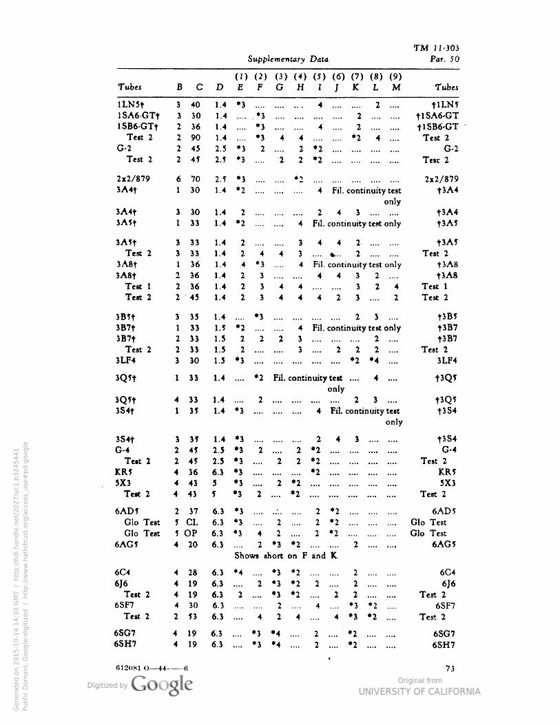
TM N-303
Supplementary Data Par. 50
(D (2) (3) (,») (5) (6) (7) (8) (9)Tubes B C D £ f G H I i *^ L M Tubes
ILN5t 3 40 1.4 •3 4 2 .... tlLN5lSA6-GTt 3 30 1.4 .*3 .... 2 tlSA6-GTlSB6-GTt
Test 2
2 36 1.4 •3 4 . 2 tlSB6-GT2 90 1.4 •3 4 4 .... *2 4 .... Test 2
G-2 2 45 2.5 •3 2 2 •2 G-2Test 2 "2 45 2.5 •3 2 2 •2 Test 2
2x2/879 6 70 2.5 •3 •2 2x2/8793A4t 1 30 1.4 •2 4 Fil. continuity test
onlyt3A4
3A4t 3 30 1.4 2 2 4 3 t3A43^k5y 1 33 1.4 •2 .... 4 F3. continuity test only t'A5
3 ,A ) y 3 33 1.4 2 3 4 4 2 t3A?Test 2 3 33 1.4 2 4 4 3 «... 2 Test 2
3A8t 1 36 1.4 4 •3 4 Fa. continuity test only t3A83A8t 2 36 1.4 2 3 4 4 3 2 .... t3A8
Test 1 2 36 1.4 2 3 4 4 .... 3 2 4 Test 1
Test 2 2 45 1.4 2 3 4 4 4 2 3 2 Test 2
3B5t 3 35 1.4 *3 2 3 .... t3B5
3B7t 1 33 1.5 •2 4 Fa. continuity test only t3B73B7t 2 33 1.5 2 2 2 3 2 .... t3B7
Test 2 2 33 1.5 2 3 2 2 2 .... Test 2
3LF4 3 30 1.5 •3 *2 •4 .... 3LF4
3Q?t 1 13 1.4 •-•• •2 Fil. continuity test ....
only
4 .... tJQ*
3Q?t 4 33 1.4 2 2 3 .... tJQ53S4t 1 35 1.4 •3 4 Fil. continuity test
onlytJS4
SS4t 3 35 1.4 •3 2 4 3 .... .... t3S4G-4 2 45 2.5 •J 2 •••• 2 •2 G-4
Test 2 2 45 2.5 •3 •••• 2 2 •2 Test 2
KR5 4 36 6.3 •3 •2 KR55X3 4 43 5 •3 •••• 2 •2 5X3
Test 2 4 43 5 •3 2 .... •2 Test 2
6AD5 2 37 6.3 •3 - 2 *2 6AD 5
Glo Test 5 CL 6.3 *3 2 2 *2 Glo Test
Glo Test 5 OP 6.3 *3 4 2 2 •2 Glo Test
6AC5 4 20 6.3 2 •3 •2 - --• 2 .... .... 6AGJShows short on F and K
6C4 4 28 6.3 •4 •3 *2 .... 2 6C4
6J6 4 19 4.3 •..• 2 •3 *2 2 .... 2 6J6Test 2 4 19 6.3 2 *\ *2 2 2 Test 2
6SF7 4 30 6.3 2 4 .... *3 *2 .... 6SF7Test 2 2 53 6.3 .... 4 2 4 4 *3 *2 .... Test 2
6SG7 4 19 6.3 .... •3 *4 2 .... *2 6SG76SH7 4 19 6.3 .... •3 •4 2 .... *2 *--- 6SH7
612081 O—44- 73
Genera
ted o
n 2
01
5-1
0-1
4 1
4:3
0 G
MT /
htt
p:/
/hd
l.hand
le.n
et/
20
27
/uc1
.b3
24
54
41
Public
Dom
ain
, G
oog
le-d
igit
ized
/
htt
p:/
/ww
w.h
ath
itru
st.o
rg/a
ccess
_use
#pd-g
oogle
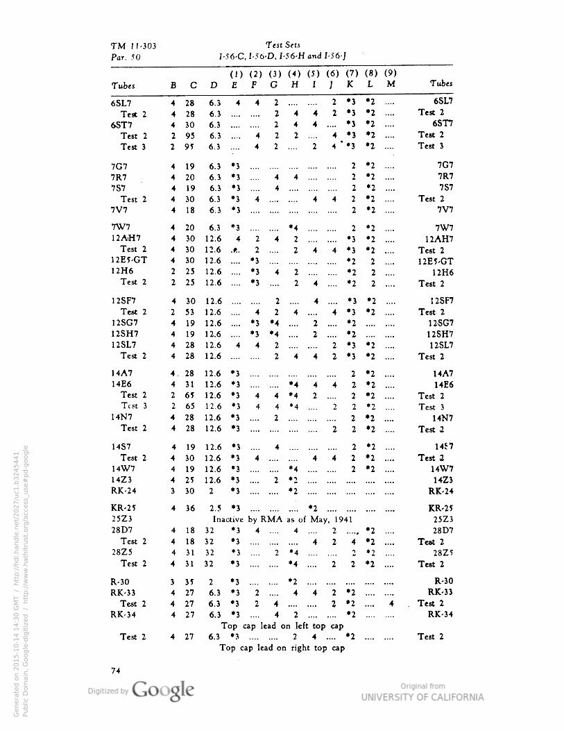
TM 11-303 SetsTest
Par. 50 I- 56-C, 1-56- D, I 56-H and I-56-J
(I) (2) (3) (<)H
(J)I
(6) (7)
J K(8) (9)L MTubes B c D E r o Tubes
6SL7
Test 2
6ST7Test 2
Test 3
4
44
2
2
28
28
30
95
95
6.3
6.3
6.3
6.3
6.3
4 4 1 2 *3
2 *3
.... *3
4 *3
4 "*3
*2 ....
*2 ....
•2 ....
•2 ....
*2 ....
6SL7
Test 2
6ST7
Test 2
Test 3
4
4
2
2
2
2
4
4
2
4
4
7G77R7
7S7
Test 2
7V7
4
4
44
4
19
20
19
30
18
6.3
6.3
6.3
6.3
6.3
•3
•3
•3
•3
•3
2
2 *2 ....
*2 ....
*2 ....
*2 ....
*2 ....
7G7
7R7
7S7
Test 2
7V7
4 4 2
4 2
4 4 4 2
2
7W7
12AH7Test 2
12E5-GT
12H6
Test 2
4
44
4
2
2
20
30
30
6.3
12.6
12.6
12.6
12.6
12.6
*3 •4 2
.... *3
4 *3
.... *2
*2 ....
*2 ....
•2 ....
2 ....
2 ....
2 ....
7W7
12AH7
Test 2
12E5-GT
12H6
Test 2
4.f .
2
2
•3
•3
•3
4 2
30
25
25
2 4
4
7
2 .... *2
.... *2
12SF7
Test 2
12SG7
12SH7
USL7Test 2
4
2
3053
19
19
28
28
12.6
12.6
12.6
12.6
12.6
12.6
2 4
4 .... *3 *2 ....
•2 ....
12SF7
Test 2
12SG7
12SH7
12SL7
Test 2
4
4
4
4
4
•3
2
*4•4
4
4
2
2
4 *3
.... *2
.... *2
2 *3
2 *3
•3
4 4 2
2 4
•2 ....
*2 ....
14A7
14E6
Test 2
Test 3
14N7
Test 2
4. 28
31
65
65
28
28
12.6
12.6
12.6
12.6
12.6
12.6
*3 2 *2 ....
*2 ....
*2 ....
*2 ....
•2 ....
•2 ....
14A7
14E6
Test 2
Test 3
14N7
Test 2
4
2
•3
•3
*3
•3
4
4
44
2
•4
•4
4
2
4 2
2
2 *4 2 2
24
4 •3 2 2
214S7
Test 2
14W7
14Z3
RK-24
4
4
4
4
19
30
19
25
30
12.6
12.6
12.6
12.6
2
*3
*3
•3
•3
•3
4.
4
2
•4
•2
•2
4 4 2
.... 2
*2 ....
*2 ....
*2 ....
14S7
Test 2
14W7
14Z3
RK-24
KR-2?25Z3
28D7
Test 2
28Z5
Test 2
4 36 2.5 *3 KR-25
25Z3
28D7
Test 2
28Z?
Test 2
4
4
4
4
18
18
31
31
Ina
32
32
32
32
ctive
*3
•3
•3
•3
by RMA4 ....
as of
4
Ma y• 1941
2
2 4
*2 ....
*2 ....
*2 ....
*2 ....
R-30
RK-33
Test 2
RK-34
3 35
27
27
27
2
6.3
6.3
•3
•3
•3
2 *4
•4
4
2 2
R-30
RK-33
. Test 2
RK-34
4
4
4
2 4
2
4 2 *2
2 *2
.... *26.3 •3
2 4
4
4
Top cap lead on left top cap
Test 2 4 27 6.3 *3 2 4 .... *2
Top cap lead on right top cap
Test 2
Genera
ted o
n 2
01
5-1
0-1
4 1
4:3
0 G
MT /
htt
p:/
/hd
l.hand
le.n
et/
20
27
/uc1
.b3
24
54
41
Public
Dom
ain
, G
oog
le-d
igit
ized
/
htt
p:/
/ww
w.h
ath
itru
st.o
rg/a
ccess
_use
#pd-g
oogle
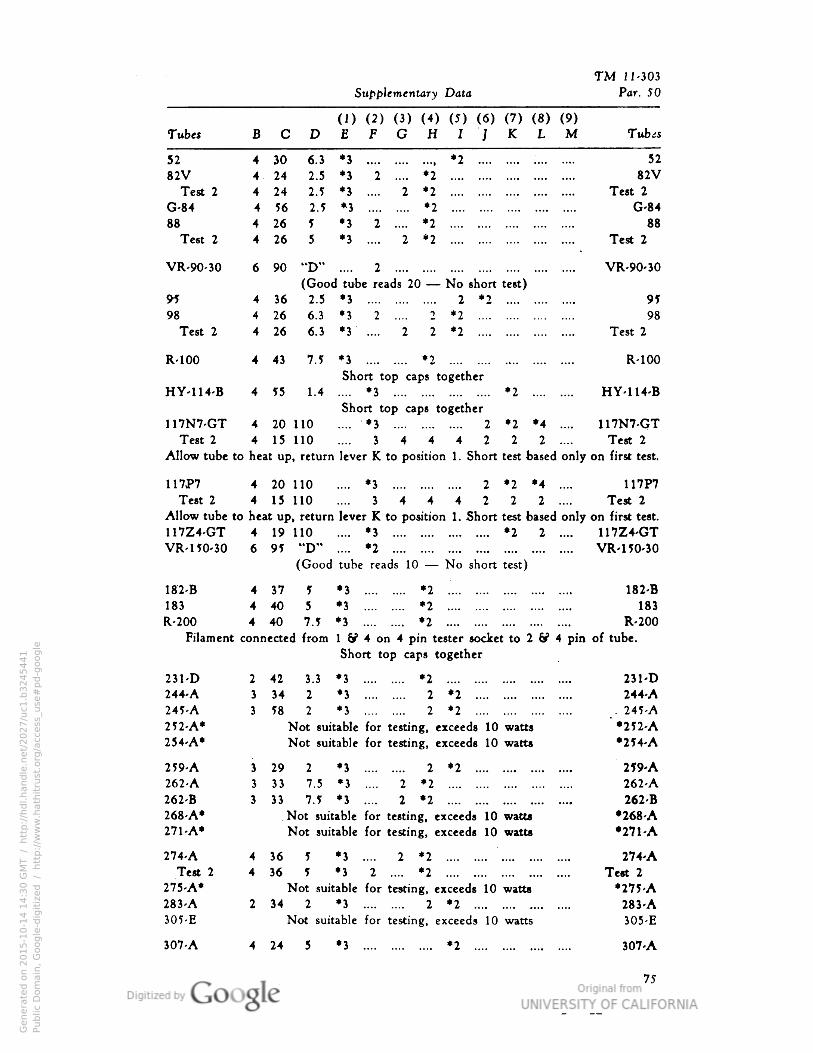
TM 11-303
Supplementary Data Par. 50
(D (2) (3) (4) (5) (6) (7) (8) (9)Tubes BCDEFGH1JKLM Tubts
52 4 30 6.3 *3 *2 52
82V 4 24 2.5 *3 2 .... *2 82VTest 2 4 24 2.5 *3 .... 2 *2 Test 2
G-84 4 56 2.5 *3 *2 G-84
88 4 26 5 *3 2 .... *2 88
Test 2 4 26 5 *3 .... 2 *2 Test 2
VR-90-30 6 90 "D" .... 2 VR-90-30
(Good tube reads 20 — No short test)
91 4 36 2.5 *3 2 *2 91
98 4 26 6.3 *3 2 .... 2 *2 98
Test 2 4 26 6.3 *3 .... 2 2 *2 Test 2
R-100 4 43 7.5 *3 *2 R-100
Short top caps together
HY-114-B 4 55 1.4 .... *3 *2 HY-114-BShort top caps together
117N7-GT 4 20 110 .... *3 2 *2 *4 .... 117N7-GTTest 2 4 15 110 .... 3444222 .... Test 2
Allow tube to heat up, return lever K to position 1. Short test based only on first test.
117P7 4 20 110 .... *3 2 *2 *4 .... 117P7
Test 2 4 15 110 .... 3444222 .... Test 2
Allow tube to heat up, return lever K to position 1. Short test based only on first test.
117Z4-GT 4 19 110 .... *3 *2 2 .... 117Z4-GT
VR-1 50-30 6 95 "D" .... *2 VR-1 50-30
(Good tube reads 10 — No short test)
182-B 4 37 5 *3 *2 182-B
183 4 40 5 *3 *2 183
R-200 4 40 7.5 *3 *2 R-200
Filament connected from 1 & 4 on 4 pin tester socket to 2 & 4 pin of tube.
Short top caps together
231-D 2
244-A 3
245-A 3
252-A*
254-A*
2 59-A 3
262-A )262-B 3
268-A*
271-A*
274-A 4
Test 2 4
275-A*
283-A 2
305-E
42 3.3 *3 *234 2 *3 2 *2
58 2 *3 2 *2
Not suitable for testing, exceeds 10 watts
Not suitable for testing, exceed* 10 watts
29 2 *3 2 *2
33 7.5 *3 .... 2 *2
33 7.5 *3 .... 2 *2
Not suitable for testing, exceeds 10 watts
Not suitable for testing• exceeds 10 watts
36 5 *3 .... 2 *2
36 5 *3 2 .... *2Not suitable for testing, exceeds 10 watts
34 2 *3 2 *2
Not suitable for testing, exceeds 10 watts
231-D
244-A. 245-A
"•252-A•254-A
259-A
262-A
262-B
*268-A•271-A
274-A
Test 2
•275-A
283-A
307-A 4 24
305-E
307-A
75
Genera
ted o
n 2
01
5-1
0-1
4 1
4:3
0 G
MT /
htt
p:/
/hd
l.hand
le.n
et/
20
27
/uc1
.b3
24
54
41
Public
Dom
ain
, G
oog
le-d
igit
ized
/
htt
p:/
/ww
w.h
ath
itru
st.o
rg/a
ccess
_use
#pd-g
oogle
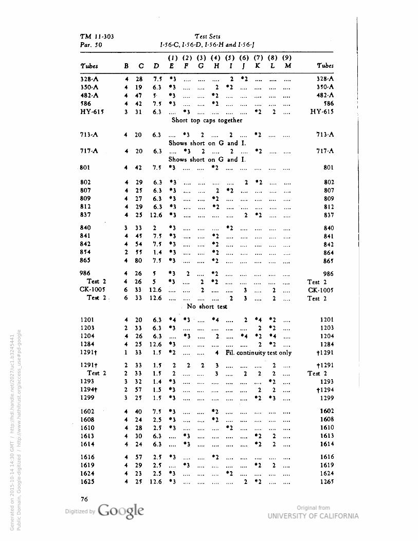
TM J 1-303 Test Sets
Par. 50 I-56-C, I-56-D• I-56-H and I-56-J
(J) (2) (3) H) (5) (6) (7) (8) (9)Tubes B C D E F G H I / K L M Tubes
328-A 4 28 7.5 *3 .... 2 *2 328-A
350-A 4 19 6.3 •3 2 *2 .... 350-A
482-A 4 47 5- •3 *2 482-A
586 4 42 1.1 •3 *2 586
HY-615 3 31 6.3 .... *3 .... •2 2 HY-615Short top caps together
713-A 4 20 6.3 .... *3 2 2 .... *2 713-A
Shows short on G and I.717-A 4 20 6.3 .... *3 2 2 .... *2 717-A
Shows short on G and I.•01 4 42 7.5 *3 *2 801
802 4 29 6.3 *3 2 *2 802
807 4 25 6.3 *3 2 *2 .... 807
809 4 27 6.) *3 *2 809
812 4 29 6.3 *3 •2 .... .... 812
837 4 25 12.6 *3 2 *2 837
840 3 33 2 •3 .... *2 .... 840
•41 4 45 1.1 *3 *2 841
842 4 54 1.1 •3 *2 842
854 2 11 1.4 *3 •2 864
865 4 80 7.5 *3 *2 865
986 4 26 5 *3 2 .... •2 986
Test 2 4 26 5 •3 .... 2 *2 .... .... Test 2
CK-1005 6 33 12.6 2 3 2 .... CK-1005Test 2 . 6 33 12.6
No short test
.... 2 3 2 .... Test 2
1201 4 20 6.3 *4 *3 .... *4 .... 2 *4 *2 .... 1201
1203 2 33 6.3 *3 2 *2 .... 1203
1204 4 26 6.3 .... *3 .... 2 .... *4 *2 *4 .... 1204
1284 4 23 12.6 *3 2 *2 .... 1284
1291t 1 33 1.5 •2 4 Fil. continuity test only tl291
1291t 2 33 I.5 222 3 .... 2 .... tl291Test 2 2 33 I.5 2 3 .... 2 2 2 .... Test 2
1293 3 32 1.4 *3 .... *2 .... 1293
1294t 2 57 1.5 *3 2 2 .... tl2941299 > 25 I.5 *3 *2 *3 .... 1299
1602 4 40 7.1 *3 *2 1602
1608 4 24 2.5 *j *2 1608
1610 4 28 2.5 *3 .... *2 .... 1610
1613 4 30 6.3 .... *3 .... *2 2 .... 1613
1614 4 24 6.3 .... *3 .... *2 2 .... 1614
1616 4 37 2.1 *3 *2 1616
1619 4 29 2.1 .... *3 .... *2 2 .... 1619
1624 4 23 2.5 *3 .... *2 .... 1624
1625 4 21 12.6 •3 2 *2 1245
76
Genera
ted o
n 2
01
5-1
0-1
4 1
4:3
0 G
MT /
htt
p:/
/hd
l.hand
le.n
et/
20
27
/uc1
.b3
24
54
41
Public
Dom
ain
, G
oog
le-d
igit
ized
/
htt
p:/
/ww
w.h
ath
itru
st.o
rg/a
ccess
_use
#pd-g
oogle
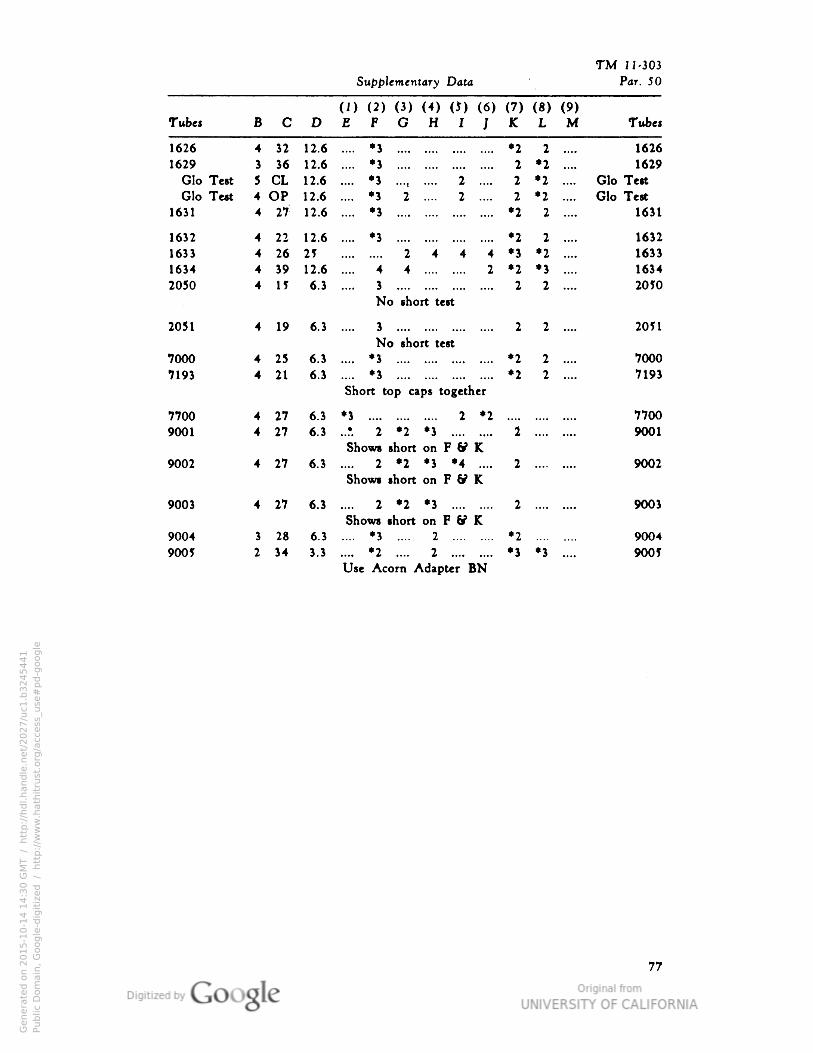
TM 11-303
Supplementary Data Par. 50
(I) (2) (3) (4) (J) (6)E F G H 1 ]
(7) (8) (9)Tubes B C D K L M Tube*
1626
1629
Glo TeGlo Te
1631
4
S
32
36
CLOP
12.6
12.6
12.6
12.6
12.6
.... *3
.... *3
.... *J 2 ....
.... *3 2 .... 2 ....
.... *3
•2 2 ....
2 *2 ....
2 *2 .... G
2 *2 .... G
•2 2 ....
1626
1629
Ho Test
lo Test
1631
st 5
it 4
4 27
1632 4 22 12.6 .... *3 *2 2 .... 1632
1633 4 26 25 2444 •3 *2 .... 1633
1634 4 39 12.6 .... 4 4 2 *2 *3 .... 1634
2050 4 I5 6.3 .... 3 2 2 .... 20 50
No short te*t
2051 4 19 6.3 .... 3 2 2 .... 2051
No short test
7000 4 25 6.) .... *3 •2 2 .... 7000
7193 4 21 6.) .... *3 *2 2 .... 7193
Short top caps together
7700 4 27 «.S *3 2 *2 7700
9001 4 27 6.3 ..?. 2 *2 *3 2 9001
Shows short on F & K9002 4 27 6.3 .... 2 *2 *3 *4 .... 2 9002
Shows short on F ff K
9003 4 27 6.3 .... 2 *2 *3 2 9003
Shows short on F ff K.
9004 1 28 6.3 .... *3 .... 2 *2 9004
9005 2 34 3.3 .... *2 .... 2 •3 *3 .... 900 5
Use Acorn Adapter BN
77
Genera
ted o
n 2
01
5-1
0-1
4 1
4:3
0 G
MT /
htt
p:/
/hd
l.hand
le.n
et/
20
27
/uc1
.b3
24
54
41
Public
Dom
ain
, G
oog
le-d
igit
ized
/
htt
p:/
/ww
w.h
ath
itru
st.o
rg/a
ccess
_use
#pd-g
oogle
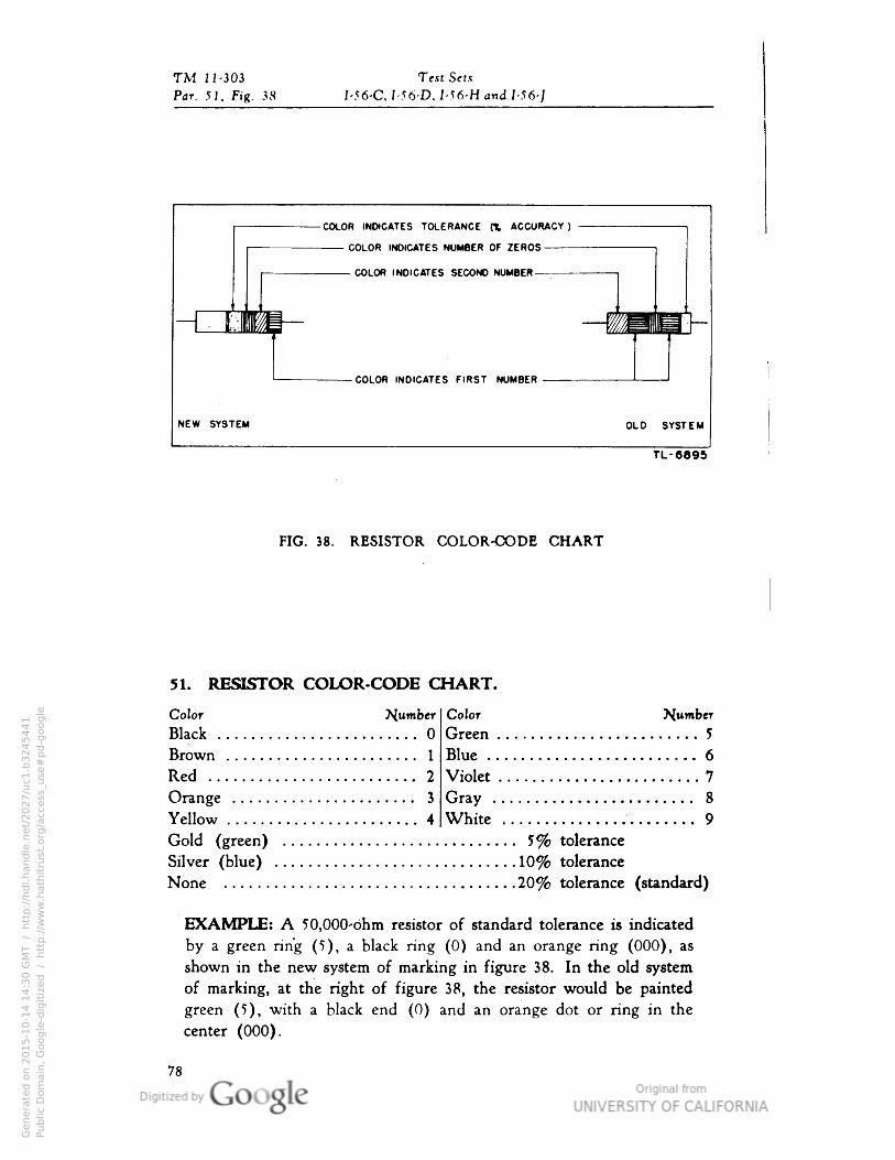
TM J 1-3 03 Test Sets
Par. 51• Fig. 38 I-56-C, I-56-D. I-56-H and I-56-]
COLOR INDICATES TOLERANCE a ACCURACY )
COLOR INDICATES NUMBER OF ZEROS
COLOR INDICATES SECOND NUMBER
-L_E
COLOR INDICATES FIRST NUMBER
NEW SYSTEM OLD SYSTEM
TL-6695
FIG. 38. RESISTOR COLOR-CODE CHART
Dumber Color
Green . .
Dumber
5o
n 1 Blue 6
2 Violet . . . 7
76 . - . . • . . . . . 3 Gray ... 8
M 4 White ... 9
(green) 5% tolerance
51. RESISTOR COLOR-CODE CHART.
Color
Black
Brown
Red
Orange
Yellow
Gold (,
Silver (blue) 10% tolerance
None 20% tolerance (standard)
EXAMPLE: A 50,000-bhm resistor of standard tolerance is indicated
by a green ring (5), a black ring (0) and an orange ring (000), as
shown in the new system of marking in figure 38. In the old system
of marking, at the right of figure 38, the resistor would be painted
green (5), with a black end (0) and an orange dot or ring in the
center (000).
78
Genera
ted o
n 2
01
5-1
0-1
4 1
4:3
0 G
MT /
htt
p:/
/hd
l.hand
le.n
et/
20
27
/uc1
.b3
24
54
41
Public
Dom
ain
, G
oog
le-d
igit
ized
/
htt
p:/
/ww
w.h
ath
itru
st.o
rg/a
ccess
_use
#pd-g
oogle

TM 11-303
Supplementary Data Par. 52, Fig. 39
COLOR DENOTES VOLTAGE RATICOIjOR DENOTES TOLERANCE
COLOR FOR FIRST NUMBER
COLOR FOR SECOND NUMBERCOLOR FOR THIRD NUMBER
COLOR FOR NUMBER OF ZEROS
COLOR FOR FIRST NUMBER
COLOR FOR SECOND NUMBER
COLOR FOR NUMBER OF ZEROS
TL-6896
FIG. 39. CAPACITOR COLOR-CODE CHART
52. CAPACITOR COLOR-CODE CHART.Voltage
RatingColor Dumber
Black 0 —
Brown 1 100
Red 2 200
Orange 3 300
Yellow 4 400
Green 5 500
Blue 6 600
Violet 7 700
Gray 8 800
White 9 900
Gold 5% tolerance 1,000
Silver 10% tolerance 2,000
None 20% tolerance —
EXAMPLE: A 5,600wf. (0.0563/*f.) capacitor of 10% tolerance and a
TOO- volt rating is indicated by a green dot (5), a blue dot (6)and an orange dot (3), on the top row; a red dot (00), a silver dot
(10% tolerance) and a green dot (500 volts) on the bottom row,
arranged in the order shown in figure 39. All capacitance values are
given in micromicrofarads (w*f). Small capacitors often use a 3-dot
code, shown in figure 39.
79
Genera
ted o
n 2
01
5-1
0-1
4 1
4:3
0 G
MT /
htt
p:/
/hd
l.hand
le.n
et/
20
27
/uc1
.b3
24
54
41
Public
Dom
ain
, G
oog
le-d
igit
ized
/
htt
p:/
/ww
w.h
ath
itru
st.o
rg/a
ccess
_use
#pd-g
oogle
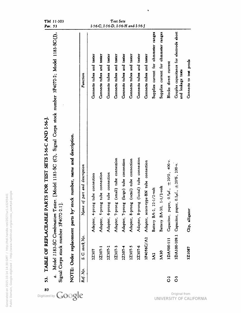
TM 11-303 Test Sets
Par. 53 I-56-C• 1-56 D, I-56-H and 1-56-]
1SSBit tM 60B BM «
Ssr irt V
i i 1OO8 S 4>•—<
H S Q "v»—«
|V V W 4> V V V
"w i i 1 1 8 8 2 -s -§ 4* J -5J -o
•»-» *J
•ou. b
i 8 83 SB B B B *s *s 0.
M « (4 3 B „
11
wB s c J J J i3 2
J G BV (U
u a «
If§ 3 •§ 2 2 3 S i 1«
uC
*J cu bo
5
C••ect
s
C••ect
s
C••ect
s
C••ect
s
C••ect
s
C••ect
s
C••ect
s
C••ect
s
•> 00
C••ect
s
O "3• "E•o• a.s s
eo co
•3 ll
~ &
c
jo
5
** *£.
EH ^ 1
•ect
i•
lect
io•
nect
i•
i•ect
i•
H i a e
ect
io• |
i
0
8M oo
S.
Bo
B B0 0 8 § 1 8
c
*U 0
H ~
Ibe
c••ect
ii
6 6 a 1 1
o o-o w u
B B
G B
£
r*S
*^ U -H
S 1
c
a 8 8
J5 J! 1 1
1
I 1
+1
V) i— i
•|
XX => 3 3 "W ^« v o
£ 15 _,
-**- ^^
1
•r ^ o60 61 60 bo bo bo bo
PLA
CEA
BLE
PA
Com
bin
ati
on
Test
imb
er
3F4
07
2-2
.1] C
s
V co
B B0 0 § S 1 1
e . o"4> 4>
1 8
0•rt Ou
iji o. p. 0. o. o. O. C.
51
If »0 i- r- 00 00 MuTO
i-T
O
bo
1
0•
TJ0. S
. K a.
&
2. rt
o.
Sw -o -o
< < < <
•3
M «
«3
I
09 M
}
Oh
| 8 g
1
»D
A1
00
-10
'«i i 1^1 •ff - M -> -«- V, « I
S Si^0 r*
^ — , CO CJ O o o o o O O O i 8
a "i ^
u N N N N N N N N
o
H — ui
d
S
?r
Z
Vr^ *o
tr> to a;
80
Genera
ted o
n 2
01
5-1
0-1
4 1
4:3
0 G
MT /
htt
p:/
/hd
l.hand
le.n
et/
20
27
/uc1
.b3
24
54
41
Public
Dom
ain
, G
oog
le-d
igit
ized
/
htt
p:/
/ww
w.h
ath
itru
st.o
rg/a
ccess
_use
#pd-g
oogle
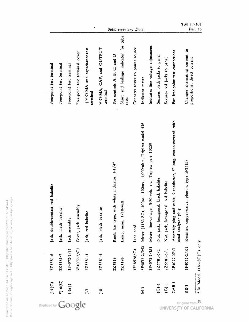
TM 11-303>
Supplementary Data
14*
Par. 53
XV
H MO
eS
iV Me
term
i•al
cove
1
cap
aci
ta•ce
't
ft.H o 1*
test
con•ect
iol
iti•
gcu
rre•t
-ect
curr
e•t
O
3
•oc 1 -5"
Bl., rt o
term
i•al
term
i•al
term
inal
O•o
M -3p. rt
cf
c
a•u a
P.
B
«" o a
•3
J3
O
it u Jw
§
fcf &• > rt D
£ ^
1
**
S !BM
MV
4> nj 4*MV4J
O c
«-< V •a GV
g
"I
H
| ed •o -3 1*-> *j
|j•o 4>
e
"S
c
"o
B ll ait"
C••ect
s
I•d
icato
r
I•d
icate
s
V 8|
"p- "o e
oo
10
eg
Bk O. Di4>
Sp
bO "
i 1
VV 9 S
> s 1 | « u
£
IIH< tu A co o s.
1
S
9-c
onduct
or•
5'
l•"
cott
•-c
ove
10*n•
15.
H
r"iO
t
at
6 a.
§
PQ
.co
ys•
i-To
H w P<o
0)
*4>
tdO Ioo
(J
rt j 4>
*4>
Jj
•3 e
•a
"£
Obo
JS ? u3"
.** r -(-, K "S.•o "I
/10
-watt 1
O25
S
er-
oxid
"
i
JK
U
uso
"34>
U 1 1
as
eo
bo
e
o cnj 2
8 J "3 &
nj aa.>• M Ji (4 ^^ V "o X
V
M
VboJ3 .^
«
H -8
•
•e•• 00 V
-C
(4
a.
g
S o
02 -a
Jt
"E8
B3O m 4> _rt^ TJ u rt o "(3 b
(Vt> cti ^
ja
o. 5 i i
crt
^
S j ^ .M"u g e CJ
if B 9 fl
u
$rdU
IV M
c
2
4*fitf
S. Q
« § ^ M M >x 2
« >*-.
*? *? ^ lr>OO
—r* <o >0 r! r-i
00 00CS 0* 00 OB
00 S fS r* <j
00 00 r-r*
«^ IrsV)
V) 00 00t*) I
IT" 0V) JNcs
N fc (£4 Nts
N N N u- N N (Li(S r*
Oto
6 e--- \o o o WK
81
Genera
ted o
n 2
01
5-1
0-1
4 1
4:3
1 G
MT /
htt
p:/
/hd
l.hand
le.n
et/
20
27
/uc1
.b3
24
54
41
Public
Dom
ain
, G
oog
le-d
igit
ized
/
htt
p:/
/ww
w.h
ath
itru
st.o
rg/a
ccess
_use
#pd-g
oogle
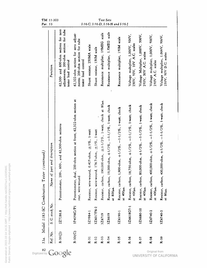
TM 11-303 Test Sets
Par. 53
S "1
I-56-C. I-56-D, I-56-H and I-56-J
!J 1 1 8 1- !3
" —
f-§B B O
*"* DJ W "°0 0 .
ti tt% $
*- u. O*>5^ ^ ^O^ ^ ^>B "3 C K P p V P n ~• 8 S " *^ o"°o § S< . ".
'
-0 °-5 ®" °- Se e *2.9
. . 1 i J -S .« 1- < u- 2 "- 1 §B ^
111SS§
.2 « 2 S 2 .5- °- 0- .S > -!i rj .S 8 " •
Funct
ion
i j1 1 1 n i t2 1< f§ P!Sl el
-S ° •S i 1 u « « e>S>Iue>
6 6 -4> ™ O C1>^
J
4^
Ort-BB B w^y^w-^w1^"~"
*j *.• J! II rt bo^bo.bo bo.O to u s § § 1 -3 1 |> |> |> |>
S £ 5 & £ £ >§ >S >S >Sif! . c
r J VNO £
-
a .
g O M j^ .j u u00 U ••- O o 4> **
u *^ JS w ^3 ^ V U
4> "u 4> V .^1 .*j
(A
. -8 « u. B a « S
0 Jj u °
e1 x i s s g
* ?
u r gf
^ v ^ ^
c m
•"•"^S ^ S ^ ^ M
**" * *O* " " ^? ^
rJ.u so
3 ? ^H *\ *N "^ \ .-H r-rs .p
a
e —' ^H ^ ^H % ^^ ^-1 1 Io
*B" o ^ ' 7 ' ' ...S^^s-x. ' - ">9 v?e
o6
imse
ctio
nat
ft
7,
7, I * * * * « *
o 0ro +
1
+i
+| ^ ^ ^ S - -
T3 u
S.
riso
8"
E" . + 7 + ++ +-§-§j_- + -- -- E E
§ £
S
"* Brt *i li 0 8 r-
" 6 6 U= J=
1 1
^sO
S^.rjs E j: j= o oS;S§? -5 9 9 6 66~8g ? g § § §
6
8
t !
0" « o o o r* o /—r f~\
•tf i 2 S §. » 1 8 8o rt
D 3 ^^ ww -i -Jo 4-93 OO"- - - - * «
£ jj C
uT 3w O
a>^c c c c c c??So o o o o o££"u-n -0 -° -13 -° -°
B j< 2 ig u. i- u u L.
1
* t; w S "S'SE^rt rt rt rt rt rt?!»u u (J u W y
43
1
B E u
2 2 s sl sl sl s-l s"l |iO .2 •-
^c
i! u"s (o * S2^ * 2 .£O .«O "*^ <AO
i-S B "35 "« 55
35
oo "K ^" E ^" S ^ '« ^" "« °0
I K «2
S! OiOi^OilJOitjOiSBiSoSrtOili
0 d
r i J^T*"* ^ T
(/) -tt- oo S•r £ 2 § 1 2 2r«i ° SO ^ "^-f^•O^O^ O °0 O O O
OQ *•* 00
1
00 ~* ^ _i O\ *-• 00 t1 i^-
^ CJ t~
ONOr-xO ^^ ^ ^ *"* t1*
NNNN N N N N NN"i) ^ C*> **> «*)t-nmrO *** tn »*1 *n **)
-oO
l< 0 ;2; 0^ ^j"
. O o^ •—'**• *r* \o r*- OO &*
'.-I ai
•n rO **> tO «*> t*i ro r-o t*> CO *n
a: 0! H fltf fl£
06 C^ fl^ o£ (^ 0^
_J82
Genera
ted o
n 2
01
5-1
0-1
4 1
4:3
1 G
MT /
htt
p:/
/hd
l.hand
le.n
et/
20
27
/uc1
.b3
24
54
41
Public
Dom
ain
, G
oog
le-d
igit
ized
/
htt
p:/
/ww
w.h
ath
itru
st.o
rg/a
ccess
_use
#pd-g
oogle
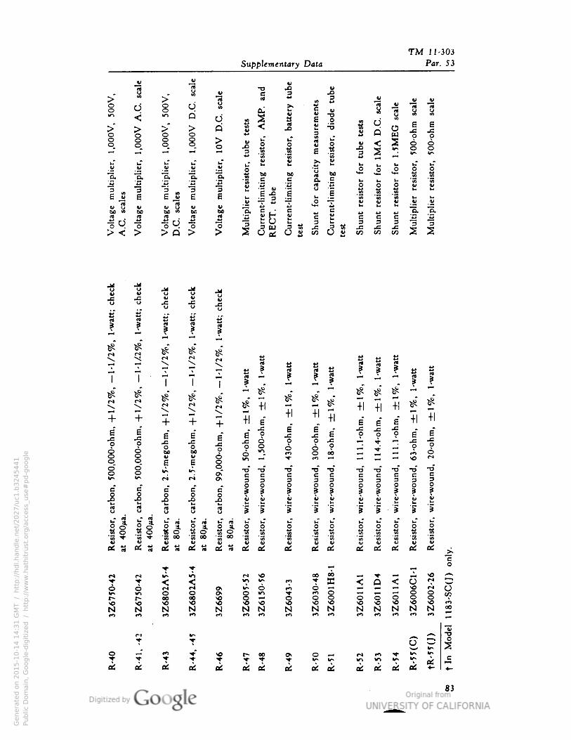
TM 11-303
v
1
Supplementary Data Par. 53
1 v •O J3JS• „
•ge
CL)oo q 8 q u
rt IB
2JU "3 1
iQ
oqQ
DM
1
hi
measu
rem
e
w
s m
1"
5 <o
•5<«i
5
o e a
p S Q u JS
8 8 i wja3 1 |
o o
o o
B f I
I u"O
O
i
ap
aci
ty
0
3
i" i*
w a* b
W
|M uO
hi
o
1
.-0• bo
*-O
V- *s "3-a O -a •s o o v V3
E J 1 Ij 3 3 II J o
1 1
hi
4>™"flj
8 B hi u1-
h<V
bo ">4>
toV
O B • G c (X cu60 bo *l>
£• rt *c
*j C"^ K
M V 4_1 ^ .J*^ *j3rt (4 e B c e"3
23 5 > Q"o * 1 oS ai
3
JSCO ai
3.CCO
3JCCO
3 p
H •a j.
JM
in
V U U
a S
7 7
X
7 ^
« I a
1
a1
1 | I S| f7
* *
M—
$" *"
S
^" S S i 5 *" ir* r*
+1
+1 41
+ +NH
+ 7 -H a*
" ""
-H
8* 8" -H +
1
+ 6
8*
•f
•0
00
-ohm
• 8*
8*
s"
JS
43
0-o
hm
e
6*
•f JS
0 1
63
-ohm
• 8*
8" o JS JS-c ja
o JS JS 8 o oQ
§
o o o
8 6
Vbo 6 00
8
8 8 «^ Vs
9>*•rf •a t> •o -o -o -o -o
c^^ ^^ f"4 ri C> B c B B B c B B c
33 3 3 3 g 3 3 3 3
O
| J |
O o O p O O e
BO |
B
O
S S
v
•s
•e V 4>
S! u u V £! a
3 5 1 i u
"5
u i • "1 "Iu
1 |i
rtU S 8 "5 "5 "i "5
esi
stor
4nn«: o I II S J
ll esi
stor•
esi
stor• o 0
esi
stor.
esi
stor•
esi
stor•
esi
stor•
esi
stor•
esi
stor
« o
3 -* •1 « 1 J(2 S
8 B V« t; t£ al Oi M .* * o! B ci B B B jj.
o
M ^ ^ M „ X> 00 00 ^^ ^. — J^ SO A«^ ^> ^ ^* 10 f"i ^ 3
3
4^ Q ^ U (^ ^po o ^ M O^ 1^• O f*I O ^H ^.i ^4 I r'* or-
Cn 0 O
1 0SO i i § i o 0 §
CO*o
N N N N N N N N N N N N N N N oo(n •"• •n f^ •n ro •" « rt tn ro s
TJri WK ^ ^»
•§t T O ^ 1
0 . ~ " ? •f
^ ^ ? ON o •n •T
e
«A B oi
«: oi B oi B oi
<i B oi oi at 7- Z
83
Genera
ted o
n 2
01
5-1
0-1
4 1
4:3
1 G
MT /
htt
p:/
/hd
l.hand
le.n
et/
20
27
/uc1
.b3
24
54
41
Public
Dom
ain
, G
oog
le-d
igit
ized
/
htt
p:/
/ww
w.h
ath
itru
st.o
rg/a
ccess
_use
#pd-g
oogle
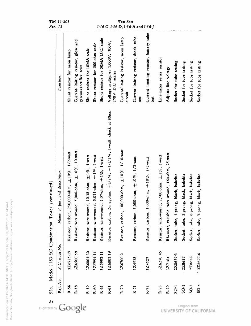
TM 11-303 Test Sets
Par. 53 I-56-C• I -56-D• I -56-H and I-J6-J
|•O
Oi,
O
5 JK y ^*
""""B
»J * >.
e 11 - 1 j o: I |
•g I.9•S
§ i I*
{
u" *r oo S M M M M
*> .2 »-8
2S u "3 •« -3 -a
; §| u ^ M S » » "»2X • w M— bo u
O "*3 *•**
uM •• -
-3 «•g ? J5 J! J! ^o•—
(J C " 3 3 P 3
•I 1 1 .1 « i i • -3 -3
1g5 5 £
O 1 "i u B b V. u i.3 ;= ^* v is o o o o
It. " g 3 tt M K ff •^ g ** £ cu
Id! 111^ •S cj
B
1
S 8 - S tiii
1 a S
^ .5 1 1 1 V 1 S S
x.. " ^ I -_«
0
2 ±i
* " 1
o
\*^ - 1 s s s s•a
. +1
^_^ f II II o o - .2 jd ja jrf JiSO "^ "w w "v
"S
-o
1 1
1 1
^ Jl 6* +
• II II g a a « a
onti
nu
0 O J3 JS §3 "o *u "(5
"u
S JS JS JS JS•oi « ^ °
e o 6
1atn r« r- ^ J3
O
1
u I 2 ^>
-o" -o -a" 6
4*
8 § -o" S c c c e
Ss
b-
c c c -• c oooo
3 «f •*>•«*o => 3 3 D Mo — p
. o. p. o.
|
G iJ I
O O O e"
p j 1
| * 3 "w "S "a "» rt u 3 (4Uu j 6 c 3 a
££a
•u*
0 0 o o o o oI* ^- rt ....
S .2 •- .2 M •KV -I
1
o
n fo •I II ft M U)_j S u u u u u V
U ci
at t£ A et ai p^ 0d C/5 t/3 W3 U3
g
2 £ 2 S - S 2 rt 5
o
3Z
67
00
00
3Z
45
2Joo H
r- in SO* O* 00lr> v*) SO
r*O vO so
Irt-* so r- oo ao oo oo
N N N N N N
1
00N N N N N N N
0
3 **-.-o oo °* S "^ ** o p « p s r
6 6 6'•o V
ok £ ok
ok
flk
ok ek
cktt (t! Di fid C/3 CO C/3 t/3
Genera
ted o
n 2
01
5-1
0-1
4 1
4:3
1 G
MT /
htt
p:/
/hd
l.hand
le.n
et/
20
27
/uc1
.b3
24
54
41
Public
Dom
ain
, G
oog
le-d
igit
ized
/
htt
p:/
/ww
w.h
ath
itru
st.o
rg/a
ccess
_use
#pd-g
oogle
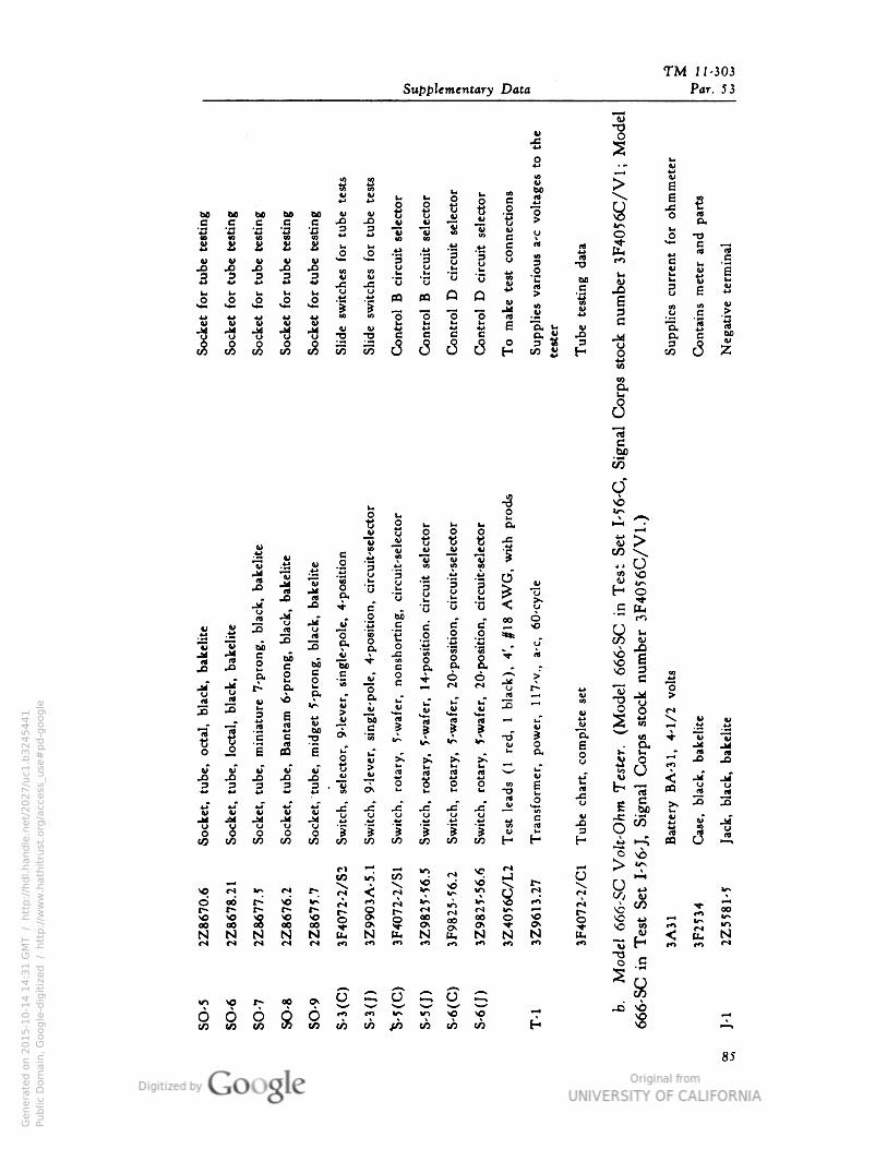
TM 11- 303
Supplementary Data
4>
1
Par . 53
-S
S
ohm
mete
r<oVbo
1
neo
neo ^
ctio
•s a O3
oboO
bo bo
B
ti
uw 6 rt
e B e •f -0ftr< &
2 •g § § 5 «-> 44 Si w • % B 0 O 0 •o
£>O i
£J>
S
Co•tr
ol
B
circ
uit
C•tr
ol
B
circ
uit 8
Sup
plie
svari
ous
a
test
er
Tub
ete
stin
gd
ata S
Sup
plie
scu
rre•t
1
C•ta
i•s
mete
ra•
Neg
ati
ve
term
inal
1 | 3
CO W c
O-a IH
V
U U
(-.O
-C -G
Q JQo e e
1 1 "o
1
J3 9
ne
i 1 I 1
OJi i&
g
1 55 t/3eH
1
siti
••
circ
uit
'sele
ctor
uo S
*r~•V-H
r3
F40
56
C/V
1.)
i••
circ
uit
-sele
ctor
o••
circ
uit
-sele
ctor
G•
1 BO
1 V
i 8
*s .K
0
H.§
o"
<
w"u
V
1 Cb Hjf *0 o c
nju «
r c OO Sw u 2"Q
c
bo3 CU a
o
Q v
I 1 §
bi
M
B
O
wbeB
"
-g
o. -CO "§a
o
-a I6
V rt
>* i §
0• I ?•
^4-
M Jj i> O. b "p »* cs ^ U I*- j_*
•8
"3
£ uT a.
C
& &
Ufti
|2 3 g V u 2 - •*r*
u "&bU
V.
1
wbo i tt 4-J
•g
1
!> ^c f f ?
V -_- 5*} c 3
ex SO
"§ "i c OO*
£
Q.- B
"
O
.|
i_T X
z?
>. O a
»
J? Ji*
1
v b i~rX3
Vo i
rt aS
V
£2 3
0u- Cn
g rt 03•o -C rttt o ** s
g**-> "g «r *-« *j JJ f- jS jg jg jg y
-2P
g^
3 ^i Jj S{ U . u u w O y c y -C V
1
u u
5 1 J5
1 1
2
X o C/3o 0
^ H3
H^0CO to CO t/3
^ r* p;
riCO •ri CO
9
rj•0
|
r*
•t
\ g
I-H
o oor*
i
r-i r)p^
GOr-<ooo
r*
S
r-oo § i
rj i i i00 sS £ £
00 CO ooo 0N
±-> i—i
N N N N N N N NrO
u."v H <
••> r*") •n r*>
-3o •1-Hw_
o o oC/D CO CO
S 6 B 6 Q S
m ro v> IT) >O ^IO </) {/> CO IT) O)
- K 2
< £ N
85
Genera
ted o
n 2
01
5-1
0-1
4 1
4:3
1 G
MT /
htt
p:/
/hd
l.hand
le.n
et/
20
27
/uc1
.b3
24
54
41
Public
Dom
ain
, G
oog
le-d
igit
ized
/
htt
p:/
/ww
w.h
ath
itru
st.o
rg/a
ccess
_use
#pd-g
oogle
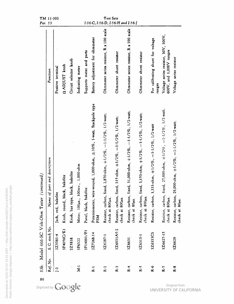
TM J 1-303 Test Sets
Par. 53 I-56-C, I-56-D, I-56-H and I-56-J
w V
1
§1 Ine§ *>
bo
g M |e _j 5 >"
nej=
u u l« o Sa uT C p o b£(4 O
"I .§i& J .2
^si o >- o
0 •o
23 s g 3
.C
1 8 ^
cb § V
ne 8 i1
I • "ifc S s? -§ -^ £ ^T •4>.3 So e « w G
O jj H 4> B ij? u u u b 3 S -n vC * V W
•2
1 I* i 1 a•§ §•
t
Ohm
met
V
Ohm
met
1 I " 1^ 1
> S >
bo . bo
1 < 3
8 JS
£ G 0 M 10m
(0 O
V .
a |"o ai 8 ^ f>
r*\
^ d | »* S | ^ 1
1
-- (S \ \ ^
^
fS) "•x riV. r) ^
•* ^ •
^"
7
^r 7 —'
$" '- ?
o 7 l"V
l \ ;js. *7*
7j ^
«
' • #
"^
$ 4. \ 1r* t> ^ l
e • \ C<4 1 ^J ~f" w^T_o E i ^^ "I i >o ^r. B O . + a . S e
" \
"g J3 o C
"?
£ ^^ "S^H
^
?
0_J=o a
•f
JC
^ + 6 '
8 o-o "O
§
ii TJ
O t^» *A 1 6 8 6
r-" -&u
1 "* M O
.£ •fcJ • o rO ' 1
e --° JJ > TJ
4>•o
1 •-V
(j
S !^ 3M M M M
**1 "*" M**-•
2 J* •r **. ***O
"3 3 j j1 II0 S 0
00 O 00
J 1 18
§ a § -
-s o -e 3.
1
vj< ---"•-Q. i ^
- hTu Ii1 3 i * §y
(4w 8
a 0
s i s S
g K J!
3 B"* 3 g s « "-" rt1,1
0 «
0 00
| | « o" «
£ O
"
2
-« * -O -fi 4> -y 2 *•> -— -ij
" "ij
• 2 "ij
•— *i5 .g .« "^ -2 "«j
O 0 c B tJ c § oo « u 2 « $ u S w § S u S u
-S i% M M 2 d. a( & c2 u 0^ u cd o cd u e£ cS -g oi -g
"oS^ d
5 *M
o
2 i oo
PH 2 <
tt 2
op o
o- - O
*o S oo £ on r* § S 00 r*1) m — CO S *""
£ b 5 1 N
S 2 5 N N N N N N N"S CO <-» *•> w m CO r• **> "** m m-oo
s o;zr
«•> £ ^ i 2 s 2 I S 2 s 2
86
Genera
ted o
n 2
01
5-1
0-1
4 1
4:3
1 G
MT /
htt
p:/
/hd
l.hand
le.n
et/
20
27
/uc1
.b3
24
54
41
Public
Dom
ain
, G
oog
le-d
igit
ized
/
htt
p:/
/ww
w.h
ath
itru
st.o
rg/a
ccess
_use
#pd-g
oogle
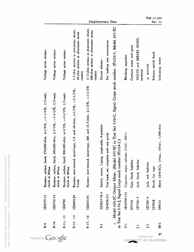
TM 11- 303
Supplementary Data
8
Par . 53
ohm
mete
rsh
unt;
ohm
mete
rse
ries
s
ohm
mete
rsh
u•t;
ohm
mete
rse
ries 0
Dnnect
ions I
0
28
I iuO
M(X CO
- .2c* M
Q
-« •H • 2 u ^
u. e rS cV a
seri
es
re
sect
io•
sect
i•
it
i sect
i•
sect
i•
o»
1
A w JM
I
|M
i ro
S
CO
1ii S
*nb**•
(X v •ocbrp
e
rt "tiVu
<3
8 C
1) II
SI 31
.5-o
hm
28
0-o
hm
I 3
num
ber
Blo
cki•
g
(o
±te
rmi
Sele
ctor
:
B1
60 60
resi
stor
resi
stor
rt c
5 a
e 'rt
-5
Q J > s c
>A *>A5^ ^
1 1 1 a
s * S
o<o
^5 "X
^M
•o
•f + + e
a" B"
B irkus j= rn
i p o
i o V
oef
1 1o o g "3•"* tn o> i
•rf •^ •o*
4> wM
V •rfM*^
M B4M *** 3
IIc" •
§ a
wir
e-w
oO J -Son o sgU 00
js 0 * u" "o ™ o
ti Jd"g"s
.i ti
cS-l"a « *« (4
W)aJ-g 4»ed
M e «j*. A o rj(•* rO 0
5 r-« 3
N N N N
a•
00
wound
Z6
0
p.
-so 9
— « C
| I n
.£ % 6
<o tr-•- 2 o
BC u
H|IIICO
00OSN
en•ortV
IZ4
05
6/L
-C6
Uc.9C.
o JS JS
C-
cj
O
°? 6
Ir-MJ
DA
50
0- oo
52 >^
"" 6A M
s s s""* 00 C*j
N N £
(N f^ m
o 2
c
o H _
.S 6
87
Genera
ted o
n 2
01
5-1
0-1
4 1
4:3
1 G
MT /
htt
p:/
/hd
l.hand
le.n
et/
20
27
/uc1
.b3
24
54
41
Public
Dom
ain
, G
oog
le-d
igit
ized
/
htt
p:/
/ww
w.h
ath
itru
st.o
rg/a
ccess
_use
#pd-g
oogle
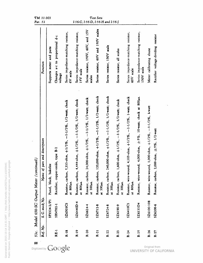
TM 11-303 Test Sets
Par. 53 I-56-C, I-56-D• I-56-H and I-56-J
^ C
1u"O
m1 i o
« 1u i TJ
1*TJ
S i c£ S |
S «c bo ,• «—<
1&0 aa
|p
rop
ort
io
ce-m
atc
hi•
ce-m
atc
hi•
3 |
e
ce-m
atc
hin
bo
8 .cu j e
|
rt
^S
•o• E •So U H VS c ij
•8v
u c
'unct
ion I
c
-esi
stor.
i-T u"
c rt
"3U0.
•3
.I|
rt
d• v-O4> V .O
rtG u
B- v
8 e"3 "»oMM E & S §
|> i!•"• M)
t-
o
II 8 B
1
*o (O K^4>^"u O
11
v0.
1§• w 8
4>CO
VCO otf10
•a
41
•fi
"2 .1o•a V
•a
uB •
8 "S M
•6 "6
|
a £ "v jj a
{
I r* I i j u
#
* ** 1
<~j « Irl r* \7 7
T JJ, I 1 i j^ "".
>8 f
7 1
I
j£ ^
i * ^ S vj
•a ^ ^" S V. ^ ^ Ti
4- >s
| O —<
j
4- •M
»•0
00
-ohm
•
•0
00
-ohm
•
• ^
i
ffl 4-
e* e
a-f
i\
| I 6•f 4
rnO Jl
I tf"H
I
0
J m 4 o^r § -o" •o •o 1
ico
pper-
o
•V
I
wir
e-w
our
c g
u
4 4 4
wir
e-w
ou
3
11 jj
3 .
MO
J3
u S 3 3
(C
2S- sl §1 1 1 ll il 1 1 sl I 1 1
1S» g
c S •s «
B
*n
B
"S «*• si •*• •s °°
-g "s
(2
V 4>
(2 a
(U
o
05 IS o: is 05 a 05 3 05 IS 05 M 05 05 05
;zr £ ^ 00**)
i ^
+
op A i
•*J- oSo
2
«o"
O op
g
0 6o 8oo
Wl So p-SO
C X NVO So
NSo
N N N N N N N NvO ** " tn " M m "" CO *n
0*M 00 Os O M fS CO * ^ ^ p.
tr M ^* ^" ff CS M r* r« r* r* dai 05 K * at O5 at «! at o5 «: e6
88
Genera
ted o
n 2
01
5-1
0-1
4 1
4:3
1 G
MT /
htt
p:/
/hd
l.hand
le.n
et/
20
27
/uc1
.b3
24
54
41
Public
Dom
ain
, G
oog
le-d
igit
ized
/
htt
p:/
/ww
w.h
ath
itru
st.o
rg/a
ccess
_use
#pd-g
oogle
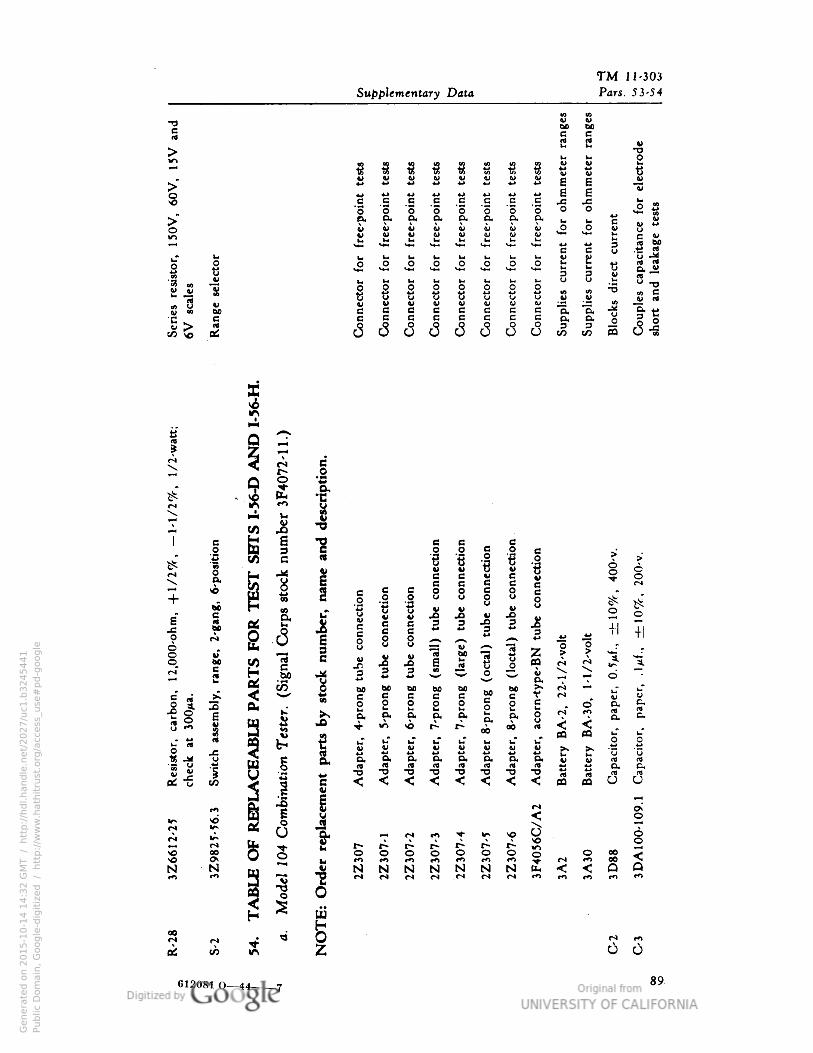
TM 11-303
Supplementary Data Pars. 53-54
1
S
i t &s> s£5 «!
e 1 « 31 | i
V«
•Si! i! i! w V V V
6 Eg
G e e a c c e Bs
j= u ^s 3
0.o&
0 a o o 5o.
o o ^so.
va o. o.
s2 ^e
o**
a So
vJ! S s 2! K V
t*u
Ke c
f:
u •s-32. 2
»_O
V-i U. u i~.O
u.aO 0 O o o o tjP D
UV (40 T3
s Bft) M
k« I h« IMs 2
u I oc
•a •3ts
«
C c c e
Jec •
Bj e (X 0. O• uC j J j BQO
u JlJ o. o.3 _o3
(O cn
! Q CT
X ^
k
num
ber
3F4
07
2- O
* 1
V
1t—'1
losi
ti•
nect
i•
nect
io•
ect
i•
nect
i• i I^ P tT: V £ c e c e
*o
1§
pro
•g
tube
c••ect
i•
-pro
•g
tube
c••ect
i•
•pro
•g
tube
co••ect
i•
8
0 I oo
c
bo |
u
£Z
8 o
6•f
e
§ 1
S if
+iBO
i 1
** J«T "rt be
Q00
1
e1
rt BQ rs *r*
Oe.M)
k
1
o k ^r
i bo^-*
^* C1^
§ JIfX a
o co i
V r*ef
V3 B
18 X L«0 <
?"
(fl ^
1
s * **o. a. ?*
« <
*j «~ r* !»• 00 00
. « « uTu." M
mb
inati
on
T f1
V I w a
tt
0o.2 -%
1
1
S.
•3
B, S.
S
™ tl
b utt
raTJ
tt
<
rtTJ
ttTJ i o.
*j
< < c3ei
« ? 2 u V ^^ ^ •« ^ ^ -o ^5
r*
S S * o r*O
r-o O O O i ~ o 00\o
00^
J{
Om 00
N N m
^
N N N N N N N a- < <; o
•«* 'H ti (•* C*l ".*^ r^ r* m »** **i *«
1
2 o2 2
§i
m
I »s m
U O
612081 O— i 89
Genera
ted o
n 2
01
5-1
0-1
4 1
4:3
2 G
MT /
htt
p:/
/hd
l.hand
le.n
et/
20
27
/uc1
.b3
24
54
41
Public
Dom
ain
, G
oog
le-d
igit
ized
/
htt
p:/
/ww
w.h
ath
itru
st.o
rg/a
ccess
_use
#pd-g
oogle
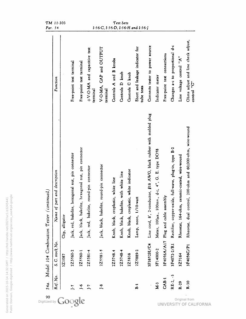
TM i1-303 Test Sets
Par. 54 I-S6-C• I 56-D, I-56-H and I-56-]
t« H o
VS
u"5*
:erm
i•al
cap
aci
tive
tV ^J *•• 3•o
(X
1
S
c••ect
io•s
pro
port
io•al
ntr
ol
"A"
u
"<3c O •
§
in
1
«Jfiy
J3
o v•o & •
S
wc« « u> x 4>
M o
2 8 c
• « « "c ^
"° B°
•a
1
l-w
bv «o V rt *^ J4
JU v
v &u 0= 5
J < Q 0
*3
U
I "S S
(4 03
1 a 6"« "5 "3
WWW * u., *-l
t!
v
« bO
c
ST.! "o "o g
e rtobO ->B u l!•V s > "e o 'i
S > S J J J 0
J>
«« 2 J •3
1 a ai! £ + eu-
BO
»—i
- d.
•0V -o
"o c
e
|
? \o 00„
S
u.O
g *§
CQ j=oe g
^4 & 3v co j< 8
s uid (9 0• • s o
8 1 1 1
X
M"T1 Ji g
K e V u 2 O•^ E
. « c c .S " "Q- cc• c §u 8
»>~
:s O •o"
«
rt
E 3 B u ^
Eo
e 1 co "2•
c — •« .£
.a t S
oo 5 o
? VT3 "S.--"V r~t c •o .r' "S i? -1. u o
1 § 1
a T)X B
^ 3
e *
1
* •* 5 "e
o
3 0j». . 2
ri
M
VJ3 O
o cj1 "
(S4_l
1 5
-C
1 i « «" i
/10
-wat
s
-oeo
O
"1 -O o "o
"3• "3 "o•0 i 1 iU 0 "3
2 -a s
o
8
s i
Ti rt ^
JMV «A U
u o•* A 35
D- «(4- o «
j
if 00 4 3
8
"̂"^" rt ••" Jd ^f s a * o 0 u o *-« T3bO
»13 M ~O 3 3 3
*> oV i-~ VJJ b 3
e b0 e• 1 i I
1
ft
JcfUflt
.a" .0 J3 c£ V 60 c S
"
^5
3vu U (J
nj rt0 O 0 c
13
CJ
c
9 ft) c c cM M M
rti-J E oi
-S -S 2
Jj !••]
o"S i^T <; OS
O ^v-
2Z
55
60
-2
2Z
55
60
-1
2Z
55
81
-4
2Z
55
81
-5
* T
oo ob
oo^ *•- m
O
3F3
85
2H
/
3F1
40
00
-2
3F4
07
6A
/
3F4
07
2-2
/
3Z
71
64
3F4
05
6C
/
^—* o
3Z
10
87
00
2 cj
r- r- oo 00
OvN N N N
r*Oo0
l< o T
<*•—
fs" o, oCO
5 2" x VO t~ 00
S 3 S w "^
m
oi
90
Genera
ted o
n 2
01
5-1
0-1
4 1
4:3
2 G
MT /
htt
p:/
/hd
l.hand
le.n
et/
20
27
/uc1
.b3
24
54
41
Public
Dom
ain
, G
oog
le-d
igit
ized
/
htt
p:/
/ww
w.h
ath
itru
st.o
rg/a
ccess
_use
#pd-g
oogle
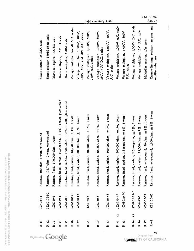
TM 11-303
SuWle, notary Data
41
Par. 54
T3* PH "rt BV
1 > »
1 1O I>"
K
1V
Uu
"3V 8 -a
d Vrt
1ITN O.
1S i
o 1v- O IT" V^
1 id B
2•o | I, > Q
o
M
6w "Ji
o. 1 V |o O o. a M
g 3S m . JJ •S^
ouT
1-1 rt
C u"
45 8>/^ u
(V u
J^
b ^ u
r* J i-~ c _j
S" ca S IP
1"o« "S. | B _«
ai_r
.5- o< -iQ 'A "C
•|3
s" 3 3 " "3 "3 « 3 V
"3 •§ 3 3 8 6 ^ 6 ^ Sn8 8 6 jw a ai*
£ JD3 i~
||w e
i8
§
8 « u <• <D^bo .
_w
_a
14-1 i a
M .« >
BO*S bo wrt 3 rt
O .
rtjg
mB3 "3 "o ° o 3
CO M o O O > !> "^^ M "^ ^ E
•8 •prt
-sg
3S
s
|-5.•a „ g a a | a tt „
1
! f 1 ! |J 5
rt
1 ! i1 Ti 5
^"
5^
TI 5r*r*
+1+1 +1
a"-o e -Hr~ g
!a" aO 8*
o
ire-w
oui
|
8*
a"
a" •
•g
s•g
8
8*
1a"
50
-ohm
• 0
0o
JS 80bow
o
I6 i 4>
1
9 a" o. I
a" oT 00 o- 1
g 8
§•o
|
o€0 ri ri c
3 g
e*
4 |B
*
3Or ^fO j 1 I I | 1
Q
B* a
"
S? TI
§
•e i-
-C
B
(DO 8 rt
3 8 8 (4 rt
*s 5o O y
o r> •o T> •o •o T» •o •rf -D T3 -u TJ -o •o
r~ M M a M _M M M H
"M X
o
8 | o P
§ | O | Ow
Q O
O
O O^
QO
o iI 1/0 i i
-a"3 "3
8 g 8 8 8 si
v w*3
V C V
S, <a
oSV
a: * fitf oiOS OS ai OS cA OS BS
« ». U-"m
— £ --< ^ •n tJ. ^
u-l „ u-j V* jj 5 — £
^ NHO" ^ o 00 6 A Q ^ O ^j
(sj
(-^
^ 6
00O>
r—0s 00 v* o o
1
V)O
>O 5> i <o \O <J
>o00 00
HO § >oN N N N N N N N N N N N N N N<•*) CO •n m *n (n «« ««> **> •n m •n •n '"
r* 5
»H O •n ^• v* ^ P. 00 OS o ^£ f" y 2 o. opm CO *n r*) •*> r*"> tn r-O ^ ^ ^ ^ ^ ^i ct oS ti
l
BS oS as ai oS QS oS oi OS o! oS oS
Genera
ted o
n 2
01
5-1
0-1
4 1
4:3
2 G
MT /
htt
p:/
/hd
l.hand
le.n
et/
20
27
/uc1
.b3
24
54
41
Public
Dom
ain
, G
oog
le-d
igit
ized
/
htt
p:/
/ww
w.h
ath
itru
st.o
rg/a
ccess
_use
#pd-g
oogle
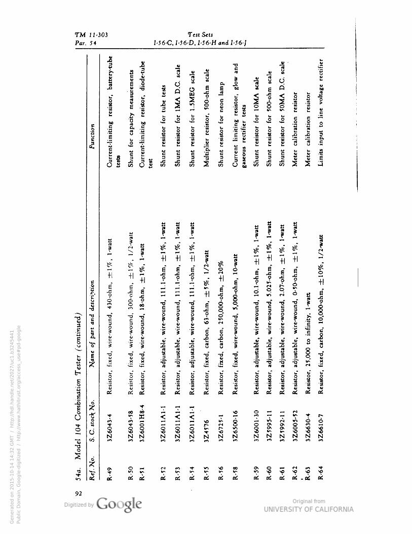
TM 11-303 Test S«tj
Par. 54 I-56-C, I-56-D• I-56-H and I-56-J
t if 1 -S -3s
-Ss
1
be T. I* JH Jl rt 0 h M n E
.14 Sxoji""5'1 2Bci Mi- » " H "1 •* tf <-SI" 11 i i i i ! liiiilil"3
£* S fc)eSi!-***kJtaS
• 60
oOu
B2 '-'[-; to O O >- ts 6 g .1 .S .g ^2 ^2 2
C jj:= SSg.S8""s8SS"«g.c3 ~•N B y 4> ^ ^
.i
^i
"2 "f-* V ? £ - £ • j-; w y .**
£-" *H< B 2 L > (_• (oV
sfc 3 3 3"3 3 ^§3^^«j«jSt H
as COUS^ ^ ^ ^ ^ O3)W3W5W322>J
<4 rt rt tt • M •s r r f 2?[*£
^ ^^-ji• ^»^™^( jj
8 3 . ^" . *"* r*• \|^S^S ^"^^"^ «^
* ^"
o r rf rf c 2 J P . ^
_i_i Ti 5 js j: ji ~ ** —• S-jsS^ o
desc
ripti
on P "- "• n £ j J - « «
^ s "*"'
I
-1 | H = H +1
4 1
2 S S 6
g J0o
O 00 Tj" "O" Tj" e" O O T> T> T>" "5 ? A« J2
ccc^o,,,- cccc^,o3 3 3 -g °. 333OO
"0 Hu 5
13B "c "c
"
1 f f S "i | ? ? ? -? °"
s O
u M 1 -B 1 g 8 1 1 * * "* 1 J«w r .r .f *£ *C e ••••0L> O S"i 2S2Su"l 3333"*
. . 222... 22222.-o-o »5»-o-o-o gS3So"2I 1
T3
to xTX
<ur
1 1 i§§ii§ 1 1 1 1 1 i
.[,
uotj
mii
O
s s s "5 s "8 8 "8 "8 s s '2 8 SU
.Q 0
£ x. &. ai et t£ ai ai ai lit m m $ m m
f _o .^ co o
b » M « •>o o -1 — M ^.°
2
ir* h^ ^^ ^^ ^* ^^ ^^ *" "^ >"* >^* * t*rO ~- ^J -^ — v^j »
A
O CSmOO^ P i-« ^^ *-H r* (^ O O ^ ^ O **) **
2 cj
No o o p o ^** ^ m o ^ c^ o so vo
NN NNNNNN H^NySN-oo^ o
a 2 «
£ oi
a:
92
Genera
ted o
n 2
01
5-1
0-1
4 1
4:3
2 G
MT /
htt
p:/
/hd
l.hand
le.n
et/
20
27
/uc1
.b3
24
54
41
Public
Dom
ain
, G
oog
le-d
igit
ized
/
htt
p:/
/ww
w.h
ath
itru
st.o
rg/a
ccess
_use
#pd-g
oogle
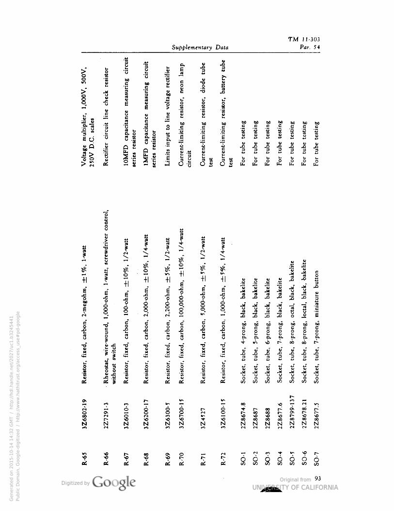
TM 11-303
nee
measu
ri•g
circ
uit
cem
easu
ri•g
circ
uit
Supplementary Data
o. H
resi
stor•
batt
ery
tub
e
Par. 54
o (4) 3oO
i
1-8 ee •o
i-
O4> •3
u bow rt u"
|
c
•S
1
o
41
4> 10c
B
4>
J3 4>
circ
uit § bo BO BO bo W) bC BO
Bcm bo
c c
|1
e d
B • c
•3B B c c
« V• O L. -c
1
| 5S
tis tft
S I 1« s || a. "J J ty U V
JoQ
u-a u
8ut£ o a 6
- M J3 .£> JO -Q3 3 i •
§
Q--
S
B B
2 3 3
II ne
£
(LI
11I!
[r• CO | Is»iJ w
2? o-5 d s (fa £ [L. [j^ £ [LI [LI
O00<eN
-o * » V.. »
?
1
r* •x. »vu
>*^-i* » * • o
>S tfa
Oo
Tl Ti 5
+1
v^
•* .^j
a*
8*
m
+1
1•0
00
-ohm
• S9oo
-C
£
oo
5•0
00
-ohm
8
o
|
o
" rf
8
8 ocs oo
B*
B*
O j1 1 56
3
O
-e
u aQ 9 3
rtu
4>
"f
•o T3V
•rf -ou
•D T3VV v
1
« M X M * y.
rf* «c *+•
|
1-"O
u"0
1
0 o
« So*• •S Q
|
V JS -g "S
fltf i * V OJ 4> uc£oi at at
6 1 i 6o 6 SOK
§
r*
r* s -o If 5
N N N N N N
eo
oi
ON
oi
o
oi
£
«J
VV B.. V „ 4> 1
rt-P
O
*jjS
V (U •5 j^ •M ja
J JM urt
Urtja
rt Vb3
u urt
jd"u
rt §O
"3tJ
mi•
ial
JBIJ3 J3
BO BO BO BO BO bo BOB B B B B B B
5 O O O O o O
Ou p. C. D. O• o. p.
* ** s6 *" 00 ob """•
-3 2
J33
Jo .Q33 3 p
V V V V V V U^4
U UU U UO O
CA J O OCO Jto
rOr^00 "*£> •*00*
V~l•-J- r- 00 r~.". o r*
00 00"0NO
00 0000 00 00 00N
ooN N N N N NCH r* r I r 1
ir i „ ^ ^ r*
6 S O O 0 OCO CO CO CO CO
93
Genera
ted o
n 2
01
5-1
0-1
4 1
4:3
2 G
MT /
htt
p:/
/hd
l.hand
le.n
et/
20
27
/uc1
.b3
24
54
41
Public
Dom
ain
, G
oog
le-d
igit
ized
/
htt
p:/
/ww
w.h
ath
itru
st.o
rg/a
ccess
_use
#pd-g
oogle
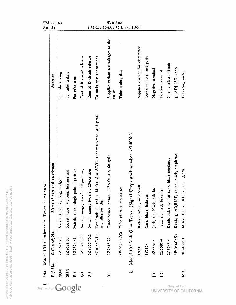
TM 11-303 Test Sets
Par. 54 I-56-C• I-56-D• I-56-H and I-56-J
uo O c
1 | _O
"5*B V• ™ C
^> .tt C00 BO
"§3u 82 e e
o1 "3 i •o ci .«l
ti S* v O S
10
i y
| |1
2 |C B e
B. a eH
I1
1-03to
j* OO £r• TJ c
o eo
-a
eo3
<"5 rt 00<*5
| 8U tJ boe
oc.
mi-O 9
O* ex
T3"-o bo
•4
-
6
r(lv c T3 «v o JM
UV) 1 -C o"
(4
'conti
n
«-j
1
_ro•"
"o w. uT 2bo B. v
^
OJ
i ^wrt
•-—• "ob t*O pi c o>
>»•w
E
«0 CK •wbo
_r "73
JS B
b0 "^ o^) z JO -o Ae«u 3 3 J" rt
b- 1 .5?*1 x: ^
= -cu
U S
JK
4>.M
O rto u u J i I J |-gs o
to co H «
.c
.o
o
$ ro0
rJ r 1
I-)Jt-u
o O*l 4 0»s t5u r* r>
S
<fl00
*o
o"~C00
000
000\
00 §0 0to
Nw
Nn Nt*>
N N N•n•.^ rt fO"^
1S d*
^
-•i- i 00 O***> Cr*
CO<0o S«-> CO CO CO
•f
riou
we"
i i" u JS*• T!
•8
c
JM
co3
II -i
I "I I I -S G
Sup
pl
M
I
V
>s
stock
num
ber
•
bla
ck•
cropla
stici (U
i . &
u
ort r*
"3-H
? tr £> • g -6
^ 1 a
e
^ „ i 3
O ^
"jj
V
1 J EooV
5
u *3
11
0. M it
g J3o 03 u
"K
B
i
u
7
"x QV tf V <
(4 A U •oa. c
<-2 <j g -^ JD *Q •a
*m
«
1
t- j v
A 1
IC o oert U u . c
H HIt
5
o—
t- 2 ^ 2; Tr*
^
oa 0000
rj A
S o o **i w~IT) J; 0 *
N t. "*< U- N N N u- UH
co « H c3 ^ Posi
O G £
•oo
Genera
ted o
n 2
01
5-1
0-1
4 1
4:3
2 G
MT /
htt
p:/
/hd
l.hand
le.n
et/
20
27
/uc1
.b3
24
54
41
Public
Dom
ain
, G
oog
le-d
igit
ized
/
htt
p:/
/ww
w.h
ath
itru
st.o
rg/a
ccess
_use
#pd-g
oogle
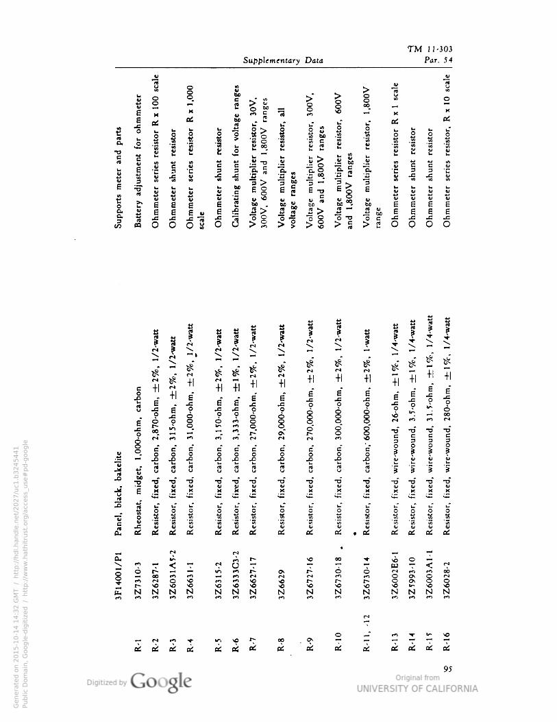
TM 11- 303
Supplementary Data Par . 54
"rt1
O
2
§ :
rang
es
1
n
i > s. 1" |
10
M8 M O M
2
•0
00
as6 • Oi 50 » ^ Oi|
.cO
i 1
s
(do >
esi
stor o g O o
I"§
1
1
l*
.15 o
3 o •i 2 .1 0 o
"3
oJ -i •3 u °°• U (4 V *
"3
a ft) i! £ 3 v."™
u u
b pi
Sup
port
sm
ete
rai
Ohm
mete
rse
ries
Ohm
mete
rsh
u•t
Ohm
mete
rse
ries
scale
Ohm
mete
rsh
u•t e g
*6
.u
IS!i
"E.
Ohm
mete
rse
ries
Ohm
mete
rsh
u•t
Ohm
mete
rsh
u•t
Ohm
mete
rse
ries
3
•5"
.e ^ v
P "-1 "3
8rt
b
boB O
3
6 § S -o
| u ^ ejV V
!">
i>
°
00boJ « -
"o -o
bo
1 3
.g j_- P*a u
^J bo0 C"o o
J> B > 2
0-o
hm
•±
2%
•1
/2-w
att |
00
-ohm
•±
2%
•1
/2-w
att
1 |
1?
00
0-o
hm
•±
2%
•1
-watt
a
4-1
1
ri •*^4̂
•v
ri >sV.
*+*
8*
S
r) g+
1
r)
?|B
"
Ti
-H
r) -H +1
8* 6
*
1 5 8
+1
8* a
* 8*
3 8* -f
8*
B*
J •s o o -c
O-C0
o J3O
.c 0
1
vo 00
6- 6 c i
-C *•
2 0. o o* | •rf •rf -o •oo 00
n- •0 m a 0m B E
3e c
1
3 3 3
J J J
G e*
o4BOi B
| 1
c e*
o
J£
p
V •e-w
o O
V
o o O4*
V
£ g M
8 M rtO o 8 s (t a
*| "i | "5
-2 60 -o •o TJ •o
u
T3* ^«•o TJV
•o T3w
(M
•o*lM
•o •o -o
•a "e
V w
1
4>M
4> V VM
w 4 4>MX -- X X x • M M K
2 ^**"*
**^
"^
**"
**^ *** **" **"* **• ^""
**^
**^
S
uT uT uT u."
bO
«
o o 0 O
1
O 0 O.*
o O 0_«o
O O
"C o 1 •J
« .? «
c V
S 2 ^ 2
£
.c V V U V V v V V V Vcd Qtf ^ eC •* a; Oi • &. * OS
S
r-* r*00
-O
-**> *^ «4* "f r) G *J« T •* ^« M ^ r
r? 6 r- «M —i in I--. £J^ x~-. o 6 r l CO r^i 00
8 00O
•0tn s>
n fSSO t*-
m •0 § 0 1 O*f^ «O sO <e ^p sO SO -0 SO *o •o
Jt ( N M N N N N N N N N N N N Nt0 •0 •n •n •0 m •** •0
t^ o^e
—-
u-—" « r*) •-f m VO o
p -* IM «-« ^^ •* •*
ok pi
oi
oi & (i oi
tf! 01 OS Oi oi
ok oi
a:
95
Genera
ted o
n 2
01
5-1
0-1
4 1
4:3
2 G
MT /
htt
p:/
/hd
l.hand
le.n
et/
20
27
/uc1
.b3
24
54
41
Public
Dom
ain
, G
oog
le-d
igit
ized
/
htt
p:/
/ww
w.h
ath
itru
st.o
rg/a
ccess
_use
#pd-g
oogle
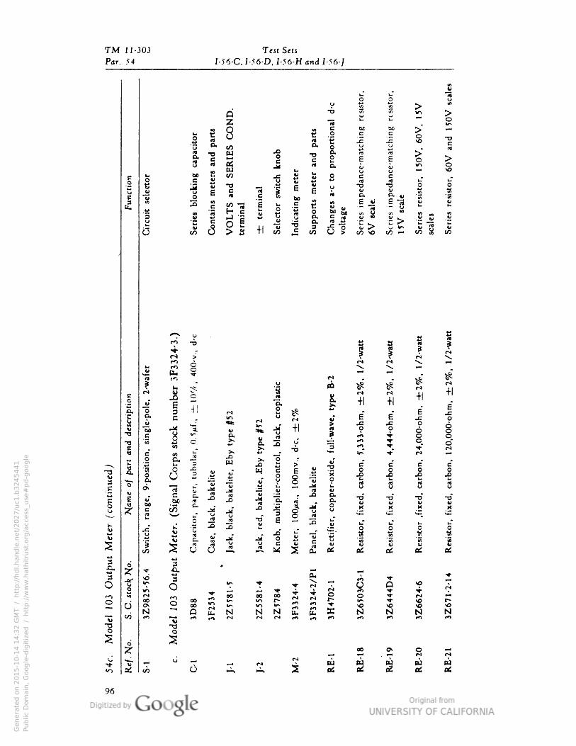
TM 11-303 Test Sets
Par. 54 I 56-C• I 56-D• I-56-H and I -56-/
8uT
1oo 0
0 •61
w m
iu
io
1 t S
port
i•:
bo boc B
-oc
" -nCO jQ
0..c -n
u
G. ^
w O
B S E E
w3 S i Mc
5% otu S
rt u(J 0
^ *- CA .c ** J* o c c mO S
1 S
•OB(d
•3 | e
V u •o(•
o. w | it} JM c £ rt 0. •72 S
-+:
term
i
Sele
ctor
Ind
icati
•{
Sup
port
s IfE jij E "3•— y
U
.*
VO
LTS
term
i•al
"""(3
Ct
u
1 1
/ u M _
i0
S 4> S
'
in O SI u? — eo S
UCO
r^«u
tJ *j-o
! |
M 5
cs ^
S V
CO^ ^
5
rl
£ rO 0 •• .
^"
1E K
A r*«"»
it
rl o r*
-rl -H
w
Ti S
. -H +1
6*"o
S,
e a e
xu
g
1 i ^ |
.c o
"Soe
*t .c O 6§4t 0 6
§-a "• i o
5.
a• 3 V 3rn
V ^OC"4
e
o 0 -3 x 1 • .rrJ ^^
—. b
1 1
w a B*
B*
^" 3 -a a •j W c g v
pO 1
O
|O ". ° o
2 i 2
C
3 **-( &^ ^
s
1
ri rt"rt
If! .
copper
O o u
•o
O
II C 0 •rf•T £ T3
B0c/5 X M
VM 1e
c
(1
o J2 to "g 8 S rtb • • •
H
1
G - -°" s" "w 1"
Resi
stoi
Resi
stoi
Resi
sto: o
atf1
S.
S J/ua
Jd 0 ^
1
fi
fltf
3 o
CO
3
u c3
« ^ "5^O" ^* ^6
^* 5^ -rj- A. —- ^^
3 £• ^ P-.
en ,j. ^
o t u-O T ri
-H
« Q *o ISCn^f
•-- •*• .J- riro **
•!
i oo 00 oo ^ *^ O o •<r rJ ^
2 o o °o r2 v> r""
N N £
r^
U-
Ms * r*
Noo {
Q
Q BU £
*O MS *ON N N N
"jj *O ••> *?* *«^ »** (~* r* to *n **) **> ••* rO
"a •20 O
**5 ^
*2^
rC«0 Ch O P4
£ S
^ M ,—1 — 04
< ^
3 *?" ^ a
w UCO
«e£ at
96
Genera
ted o
n 2
01
5-1
0-1
4 1
4:3
2 G
MT /
htt
p:/
/hd
l.hand
le.n
et/
20
27
/uc1
.b3
24
54
41
Public
Dom
ain
, G
oog
le-d
igit
ized
/
htt
p:/
/ww
w.h
ath
itru
st.o
rg/a
ccess
_use
#pd-g
oogle
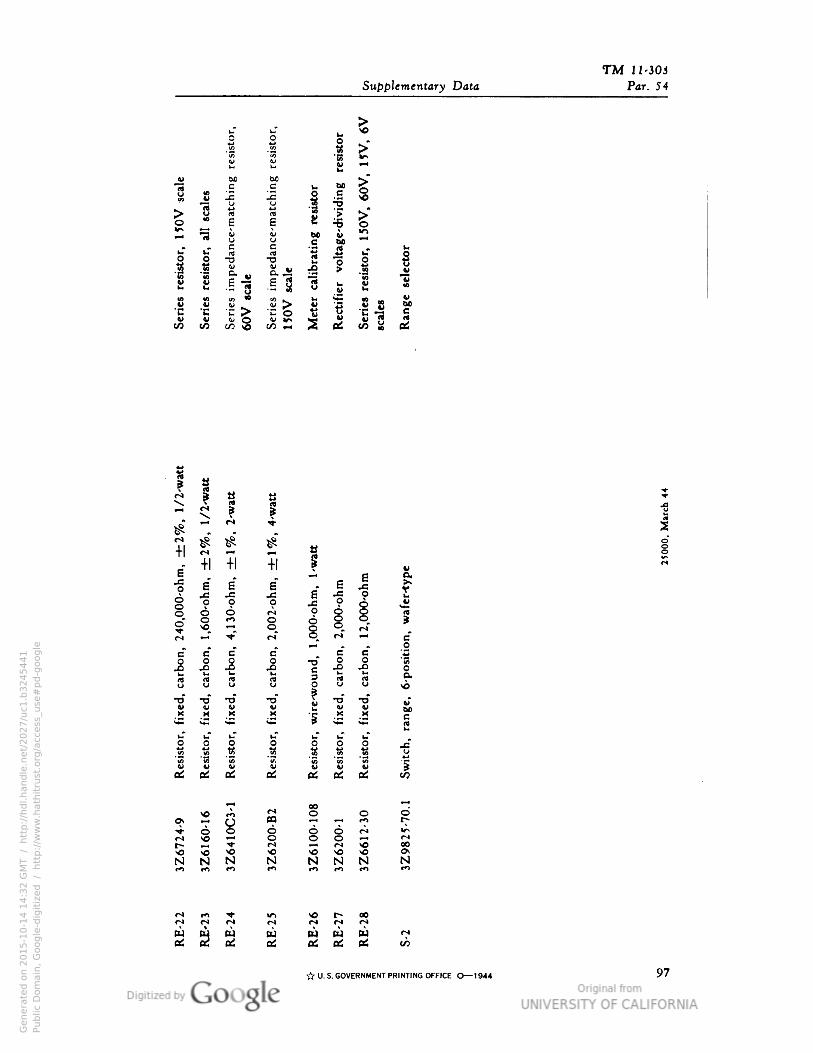
TMSupplementary Data Par. 54
esi
stor•
esi
stor• ne
o |i-5
ne u £
**
ne
i•1
c c
u i
BO
J8 -C .Crt u -i •3
s (4
e £o E 8 =5** «M V &> KJJ 4> >ouc<»
-o
u
1
i-TO
c
i i1
(4 i
•DV
-o
8
V
E 8 .5 *3 •- 8 o u.V 2 •
-? 8
4>U
1
"6
BO"C O
u
C -3 e
uCO
eu QJ O U >r* wK u g rt
«t/3 .-,
f
01
f 1
#
^
r'*
s *
+1
•1
30
-ohm
•rf
c
« «
»0
•0
00
-ohm
•
•6
00
-ohm
•± •H
e1
•
wafe
r-ty
pe
E" g
ooo
0rf rf
m •—. •*}- ri o^ ~* c
j-"1
e* e* ^H — ^ _o
J c•o"
B 6
^ 1 ^ £ "§
H 22 c
dl0 3 (4 ItU u U u p O O <cs
•o T3 TJ •o \ •o •o .rAl4> •i c
M
52•M =
M eS
O
» 1 1 §
o O i i •g
(O 2 *s "S3 -i ti
0 V o V v V 3
05 etf * as fltf ai
^4 00_
y-J C*1 ^* O o 6
<*
I 8 °?oo I 6o £
M r* SO 00^o y»J -0 VO SO OSN N N N N N N N
tn *" «
M w ^ w •» o. oe
M ^ ta . U M w W «eC K z OS K OS as CO
I
-fr U.S. GOVERNMENTPRINTINGOFFICE O— 1944 97
Genera
ted o
n 2
01
5-1
0-1
4 1
4:3
2 G
MT /
htt
p:/
/hd
l.hand
le.n
et/
20
27
/uc1
.b3
24
54
41
Public
Dom
ain
, G
oog
le-d
igit
ized
/
htt
p:/
/ww
w.h
ath
itru
st.o
rg/a
ccess
_use
#pd-g
oogle

Genera
ted o
n 2
01
5-1
0-1
4 1
4:3
3 G
MT /
htt
p:/
/hd
l.hand
le.n
et/
20
27
/uc1
.b3
24
54
41
Public
Dom
ain
, G
oog
le-d
igit
ized
/
htt
p:/
/ww
w.h
ath
itru
st.o
rg/a
ccess
_use
#pd-g
oogle