tender-document.pdf - state law office
TRANSCRIPT

REPUBLICOFKENYA
MINISTRY OF TRANSPORT, INFRASTRUCTURE,
PUBLIC WORKS, HOUSING AND URBAN
DEVELOPMENT
STATE DEPARTMENT FOR PUBLIC WORKS
PROPOSED OFFICE PARTITIONING AND REFURBISHMENT TO
ASSETS RECOVERY AGENCY OFFICES AT U.A.P TOWERS 21ST
FLOOR
WP ITEM NO D120 NB/NB/ 2001 JOB NO. 10855A
TENDERDOCUMENTS PROJECT MANAGER WORKS SECRETARY
M.L.H.U.D (STATE DEPARTMENT OF PUBLIC WORKS)
P.O. BOX 30743-00100 NAIROBI
ARCHITECT QUANTITY SURVEYOR
CHIEF ARCHITECT CHIEF Q UANTITY SURVEYO R
M.T.I.H.U.D M.T.I.H.U.D
P.O . BO X 30743-00100 P.O . BO X 30743-00100
NAIRO BI NAIRO BI
ELECTRICAL ENGINEER (B.S) STRUCTURAL ENGINEER CHIEF ENGINEER ELECTRICAL (BS) CHIEF ENGINEER (STRUCTURAL)
M.T.I.H.U.D M.T.I.H.U.D
P.O . BO X 30743-00100 P.O . BO X 30743-00100
NAIRO BI NAIRO BI
MECHANICAL ENGINEER (B.S) CHIEF MECHANICAL ENGINEER (BS)
M.T.I.H.U.D
P.O . BO X 30743-00100 NAIRO BI
JANUARY 2021
REPUBLIC OF KENYA
MINISTRY OF TRANSPORT, INFRASTRUCTURE,
PUBLIC WORKS HOUSING AND URBAN DEVELOPMENT STATE DEPARTMENT FOR PUBLICWORKS
PROPOSED OFFICE PARTITIONING AND REFURBISHMENT TO ASSETS
RECOVERY AGENCY OFFICES AT U.A.P TOWERS 21ST FLOOR
WP ITEM NO D120 NB/NB/ 2001 JOB NO. 10855A
CONTENTS
A Contents page 1
B Signature and Special notes page (i to ii)
C Standard Tender Documents for Procurement Of Works:
SECTION I: Invitation to Tenderer 3
SECTION II: Instructions to tenderers 4 - 17
SECTION III: Conditions of Contract 18 - 43
SECTION IV: Appendix to conditions of contract 44 - 54
SECTION V: Drawings 55
SECTION VI: Standard Forms 56 – 75
D Particular Preliminaries PP/1 to PP/9
E General Preliminaries GP/1 to GP/13
F Preambles and Pricing Notes PN/1 to PN/3
G Builder’s work P8/1 to P8/9
H MECHANICAL WORKS---Preliminaries MW/1 to MW/9
I ELECTRICAL WORKS….Electrical Installation Works. Vol. 2 of 6
…..CCTV, ACESS CONTROL &
Structured Cabling Vol. 3 of 6
J Prime Costs and Provisional Sums PC/1
K Grand Summary GS/1
(i)
REPUBLIC OF KENYA
MINISTRY OF TRANSPORT, INFRASTRUCTURE, PUBLIC WORKS HOUSING
AND URBAN DEVELOPMENT
STATE DEPARTMENT FOR PUBLIC WORKS
Supplied as part of the Contract No;.
WP ITEM NO D120 NB/NB/ 2001 JOB NO. 10855A
PROPOSED OFFICE PARTITIONING AND REFURBISHMENT TO ASSETS
RECOVERY AGENCY OFFICES AT U.A.P TOWERS 21ST FLOOR
Issued by:-
Quantities and Contracts Department.
State Department of Public Works
P O Box 30743-00100
NAIROBI
The contract for the above mentioned works entered into this ….. day of
…………………. 2015.. by the undersigned refers to these Bills of Quantities
and the Ministry of Roads and Public Works General Specification dated March,
1976 (together with any amendments issued thereto) shall be read and
construed as part of the said contract.
……………………………… ………………………………………
C O N T R A C T O R DIRECTOR A.R.A
Date: ……………………………… Date: ……………………………
Name of Witness …………………………… of ………………………….
Address……………………………………..
In the presence
Signature ………………………………….. ……………………………………
Date ……………………………………….. Date: …………………………….

SPECIAL NOTES
The Contractor is required to check the numbers of the pages of these Bills of
Quantities and should he find any missing or in duplicate or figures indistinct
he must inform the Permanent Secretary from Ministry of Transport,
Infrastructure, Housing and Urban Development. Head Office, Ngong Road,
Nairobi at once and have the same rectified.
Should the Contractor be in doubt about the precise meaning of any item or
figure for any reason whatsoever, he must inform the Permanent Secretary,
Ministry of Transport, Infrastructure, Housing and urban development, Head
Office in order that the correct meaning may be decided before the date for
submission of tenders.
No liability will be admitted nor claim allowed in respect of errors in the
Contractor’s Tender due to mistakes in the Specifications which should have
been rectified in the manner described above.
SIGNATURE PAGE AND NOTEi

1
REPUBLIC OF KENYA
STANDARD TENDER DOCUMENT
FOR
PROCUREMENT OF WORKS
(BUILDING AND ASSOCIATED
CIVIL ENGINEERING WORKS)
ASSETS RECOVERY AGENCY UAP TOWER,22ND FLOOR
P.O. BOX 52410 - 00100 NAIROBI.
2
TABLE OF CONTENTS
PAGE
SECTION I: INVITATION TO TENDER …………………………………… 3
SECTION II: INSTRUCTIONS TO TENDERERS ……………….. 4 - 16
APPENDIX TO INSTRUCTIONS TO TENDERERS………..17
SECTION III: CONDITIONS OF CONTRACT …………………….. 18 - 40
SECTION IV: APPENDIX TO CONDITIONS OF
CONTRACT …………………………………………… 41 - 43
SECTION V: DRAWINGS …………………………………………………… 44
SECTION VI: STANDARD FORMS ………………………………… 45 - 63
3
SECTION I INVITATION FOR TENDERS
Tender reference No. (as per tender document)
Tender Name (as per tender document)
1.1 The Assets Recovery Agency invites sealed tenders for the
partitioning and refurbishment of offices including all
services, Electrical, Mechanical at U.A.P building Nairobi
1.2 Interested eligible candidates may obtain further information and
inspect tender documents at ARA offices in Nairobi during
normal working hours.
1.3 A complete set of tender documents may be obtained by
interested candidates upon payment of a non-refundable fees of
Kshs.1,000 in cash or Bankers Cheque payable to Director
A.R.A through Kenya Commercial Bank A/C No.
1210028794.
1.4 Prices quoted should be net inclusive of all taxes, must be in
Kenya shillings and shall remain valid for (120) days from the
closing date of tender.
1.5 Completed tender documents are to be enclosed in plain sealed
envelopes marked with Tender name and reference number and
deposited in the Tender Box at (UAP Towers, 22ND Floor) or to
be addressed to (Asses Recovery Agency, P.O Box 52420-
00100, Nairobi) so as to be received on or before (1100 hrs).
1.6 Tenders will be opened immediately thereafter in the presence of
the candidates or their representatives who choose to attend at
(Assets Recovery Agency Board Room.)
NB: Tenderers who choose to attend the opening session
MUST fully comply to all COVID 19 prevention protocols as
prescribed by the Ministry of Health and set by the Agency.
The Management therefore, refers the right of admission to
own compliance.
________________________________
4
For (Accounting Officer/Procuring Entity)
SECTION II
INSTRUCTIONS TO TENDERERS
TABLE OF CONTENTS PAGE
CLAUSE PAGE
1. General …………………………………………………. 5
2. Tender Documents ………………………………… 7 - 8
3. Preparation of Tenders ………………………………… 9 - 10
4. Submission of Tenders ………………………………… 11 - 13
5. Tender Opening and Evaluation ……………………… 13 - 15
6. Award of Contract ………………………………………… 15 - 16

5
INSTRUCTIONS TO TENDERERS.
1. 1. General/Eligibility/Qualifications/Joint venture/Cost of
tendering
1.1 The Employer as defined in the Appendix to Conditions of Contract
invites tenders for Works Contract as described in the tender
documents. The successful tenderer will be expected to complete
the Works by the Intended Completion Date specified in the
tender documents.
1.2 All tenderers shall provide the Qualification Information, a
statement that the tenderer (including all members of a joint
venture and subcontractors) is not associated, or has not been
associated in the past, directly or indirectly, with the Consultant
or any other entity that has prepared the design, specifications,
and other documents for the project or being proposed as Project
Manager for the Contract. A firm that has been engaged by the
Employer to provide consulting services for the preparation or
supervision of the Works, and any of its affiliates, shall not be
eligible to tender.
1.3 All tenderers shall provide in the Form of Tender and Qualification
Information, a preliminary description of the proposed work
method and schedule, including drawings and charts, as
necessary.
1.4 In the event that pre-qualification of potential tenderers has been
undertaken, only tenders from pre-qualified tenderers will be
considered for award of Contract. These qualified tenderers
should submit with their tenders any information updating their
original pre-qualification applications or, alternatively, confirm in
their tenders that the originally submitted pre-qualification
information remains essentially correct as of the date of tender
submission.
1.5 Where no pre-qualification of potential tenderers has been done, all
tenderers shall include the following information and documents
with their tenders, unless otherwise stated:
(a) copies of original documents defining the constitution or legal
status, place of registration, and principal place of
business; written power of attorney of the signatory of the
tender to commit the tenderer:
(b) total monetary value of construction work performed for each
of the last five years:
6
(c) experience in works of a similar nature and size for each of
the last five years, and details of work under way or
contractually committed; and names and addresses of
clients who may be contacted for further information on
these contracts;
(d) major items of construction equipment proposed to carry out
the Contract and an undertaking that they will be available
for the Contract.
(e) qualifications and experience of key site management and
technical personnel proposed for the Contract and an
undertaking that they shall be available for the Contract.
(f) reports on the financial standing of the tenderer, such as
profit and loss statements and auditor’s reports for the
past five years;
(g) evidence of adequacy of working capital for this Contract
(access to line(s) of credit and availability of other financial
resources);
(h) authority to seek references from the tenderer’s bankers;
(i) information regarding any litigation, current or during the
last five years, in which the tenderer is involved, the
parties concerned and disputed amount; and
(j) proposals for subcontracting components of the Works
amounting to more than 10 percent of the Contract Price.
1.6 Tenders submitted by a joint venture of two or more firms as
partners shall comply with the following requirements, unless
otherwise stated:
(a) the tender shall include all the information listed in clause
1.5 above for each joint venture partner;
(b) the tender shall be signed so as to be legally binding on all
partners;
(c) all partners shall be jointly and severally liable for the
execution of the Contract in accordance with the Contract
terms;
(d) one of the partners will be nominated as being in charge,
authorised to incur liabilities, and receive instructions for
and on behalf of all partners of the joint venture; and

7
(e) the execution of the entire Contract, including payment, shall
be done exclusively with the partner in charge.
1.7 To qualify for award of the Contract, tenderers shall meet the
following minimum qualifying criteria;
(a) annual volume of construction work of at least 1.5 times the
estimated annual cashflow for the Contract;
(b) experience as main contractor in the construction of at least
two works of a nature and complexity equivalent to the Works
over the last 10 years (to comply with this requirement, works
cited should be at least 70 percent complete);
(c) proposals for the timely acquisition (own, lease, hire, etc.) of
the essential equipment listed as required for the Works;
(d) a Contract manager with at least five years’ experience in
works of an equivalent nature and volume, including no less
than three years as Manager; and
(e) liquid assets and/or credit facilities, net of other contractual
commitments and exclusive of any advance payments which
may be made under the Contract, of no less than 4 months of
the estimated payment flow under this Contract.
1.8 The figures for each of the partners of a joint venture shall be
added together to determine the tenderer’s compliance with the
minimum qualifying criteria of clause 1.7 (a) and (e); however, for
a joint venture to qualify, each of its partners must meet at least
25 percent of minimum criteria 1.7 (a), (b) and (e) for an
individual tenderer, and the partner in charge at least 40 percent
of those minimum criteria. Failure to comply with this
requirement will result in rejection of the joint venture’s tender.
Subcontractors’ experience and resources will not be taken into
account in determining the tenderer’s compliance with the
qualifying criteria, unless otherwise stated.
1.9 Each tenderer shall submit only one tender, either individually or
as a partner in a joint venture. A tenderer who submits or
participates in more than one tender (other than as a
subcontractor or in cases of alternatives that have been
permitted or requested) will cause all the proposals with the
tenderer’s participation to be disqualified.
1.10 The tenderer shall bear all costs associated with the preparation
and submission of his tender, and the Employer will in no case
be responsible or liable for those costs.
8
1.11 The tenderer, at the tenderer’s own responsibility and risk, is
encouraged to visit and examine the Site of the Works and its
surroundings, and obtain all information that may be necessary
for preparing the tender and entering into a contract for
construction of the Works. The costs of visiting the Site shall be
at the tenderer’s own expense.
1.12 The procuring entity’s employees, committee members, board
members and their relative (spouse and children) are not eligible
to participate in the tender.
1.13 The price to be changed for the tender document shall not exceed
Kshs. 1,000/=
1.14 The procuring entity shall allow the tenderer to review the tender
document free of charge before purchase.
2. Tender Documents
2.1 The complete set of tender documents comprises the documents
listed below and any addenda issued in accordance with Clause
2.4.
(a) These Instructions to Tenderers (b) Form of Tender and Qualification
Information (c) Conditions of Contract
(d) Appendix to Conditions of Contract
(e) Specifications (f) Drawings
(g) Bills of Quantities (h) Forms of Securities
2.2 The tenderer shall examine all Instructions, Forms to be filled and
Specifications in the tender documents. Failure to furnish all
information required by the tender documents, or submission of
a tender not substantially responsive to the tendering documents
in every respect will be at the tenderer’s risk and may result in
rejection of his tender.
2.3 A prospective tenderer making an inquiry relating to the tender
documents may notify the Employer in writing or by cable, telex
or facsimile at the address indicated in the letter of invitation to
tender. The Employer will only respond to requests for
clarification received earlier than seven days prior to the deadline
for submission of tenders. Copies of the Employer’s response will
be forwarded to all persons issued with tendering documents,
including a description of the inquiry, but without identifying its
source.

9
2.4 Before the deadline for submission of tenders, the Employer may
modify the tendering documents by issuing addenda. Any
addendum thus issued shall be part of the tendering documents
and shall be communicated in writing or by cable, telex or
facsimile to all tenderers. Prospective tenderers shall
acknowledge receipt of each addendum in writing to the
Employer.
7
2.5 To give prospective tenderers reasonable time in which to take an
addendum into account in preparing their tenders, the Employer
shall extend, as necessary, the deadline for submission of
tenders, in accordance with Clause 4.2 here below.
3. Preparation of Tenders
3.1 All documents relating to the tender and any correspondence shall
be in English language.
3.2 Thetender submitted by the tenderer shall
comprise the following:
(a) These Instructions to Tenderers, Form of Tender, Conditions
of Contract, Appendix to Conditions of Contract and
Specifications;
(b) Tender Security;
(c) Priced Bill of Quantities;
(d) Qualification Information Form and Documents;
(e) Alternative offers where invited; and
(f) Any other materials required to be completed and submitted
by the tenderers.
3.3 The tenderer shall fill in rates and prices for all items of the Works
described in the Bill of Quantities. Items for which no rate or
price is entered by the tenderer will not be paid for when
executed and shall be deemed covered by the other rates and
prices in the Bill of Quantities. All duties, taxes, and other levies
payable by the Contractor under the Contract, or for any other
cause relevant to the Contract, as of 30 days prior to the
deadline for submission of tenders, shall be included in the
tender price submitted by the tenderer.
3.4 The rates and prices quoted by the tenderer shall only be subject to
adjustment during the performance of the Contract if provided
10
for in the Appendix to Conditions of Contract and provisions
made in the Conditions of Contract.
3.5 The unit rates and prices shall be in Kenya Shillings.
3.6 Tenders shall remain valid for a period of one hundred and twenty
(120) days from the date of submission. However, in exceptional
circumstances, the Employer may request that the tenderers
extend the period of validity for a specified additional period. The
request and the tenderers’ responses shall be made in writing. A
tenderer may refuse the request without forfeiting the Tender
Security. A tenderer agreeing to the request will not be required
or permitted to otherwise modify the tender, but will be required
to extend the validity of Tender Security for the period of the
extension, and in compliance with Clause 3.7 - 3.11 in all
respects.
3.7 The tenderer shall furnish, as part of the tender, a Tender Security
in the amount and form specified in the appendix to invitation to
tenderers. This shall be in the amount not exceeding 2 percent of
the tender price
3.8 The format of the Tender Security should be in accordance with the
form of Tender Security included in Section G - Standard forms
or any other form acceptable to the Employer . Tender Security
shall be valid for 30 days beyond the validity of the tender.
3.9 Any tender not accompanied by an acceptable Tender Security shall
be rejected. The Tender Security of a joint venture must define as
“Tenderer” all joint venture partners and list them in the
following manner: a joint venture consisting
of”…………”,”…………”,and “…………”.
3.10 The Tender Securities of unsuccessful tenderers will be returned
within 28 days of the end of the tender validity period specified in
Clause 3.6.
3.11 The Tender Security of the successful tenderer will be discharged
when the tenderer has signed the Contract Agreement and
furnished the required Performance Security.
3.12 The Tender Security may be forfeited
(a) if the tenderer withdraws the tender after tender opening
during the period of tender validity;
(b) if the tenderer does not accept the correction of the tender
price, pursuant to Clause 5.7;
11
(c) in the case of a successful tenderer, if the tenderer fails
within the specified time limit to (i) sign the Agreement, or
(ii) furnish the required Performance Security.
3.13 Tenderers shall submit offers that comply with the requirements
of the tendering documents, including the basic technical design
as indicated in the Drawings and Specifications. Alternatives will
not be considered, unless specifically allowed in the invitation to
tender. If so allowed, tenderers wishing to offer technical
alternatives to the requirements of the tendering documents
must also submit a tender that complies with the requirements
of the tendering documents, including the basic technical design
as indicated in the Drawings and Specifications. In addition to
submitting the basic tender, the tenderer shall provide all
information necessary for a complete evaluation of the
alternative, including design calculations, technical
specifications, breakdown of prices, proposed construction
methods and other relevant details. Only the technical
alternatives, if any, of
the lowest evaluated tender conforming to the basic technical
requirements shall be considered.
3.14 The tenderer shall prepare one original of the documents
comprising the tender documents as described in Clause 3.2 of
these Instructions to Tenderers, bound with the volume
containing the Form of Tender,
and clearly marked “ORIGINAL”. In addition, the tenderer shall
submit copies of the tender, in the number specified in the
invitation to tender, and clearly marked as “COPIES”. In the
event of discrepancy between them, the original shall prevail.
3.15 The original and all copies of the tender shall be typed or written
in indelible ink and shall be signed by a person or persons duly
authorised to sign on behalf of the tenderer, pursuant to Clause
1.5 (a) or 1.6 (b), as the case may be. All pages of the tender
where alterations or additions have been made shall be initialled
by the person or persons signing the tender.
3.16 Clarification of tenders shall be requested by the tenderer to be
received by the procuring entity not later than 7 days prior to the
deadline for submission of tenders.
3.17 The procuring entity shall reply to any clarifications sought by
the tenderer within 3 days of receiving the request to enable the
tenderer to make timely submission of its tender.
12
3.18 The tender security shall be in the amount of 0.5 – 2 per cent of
the tender price.
4. Submission of Tenders
4.1 The tenderer shall seal the original and all copy of the tender in two
inner envelopes and one outer envelope, duly marking the inner
envelopes as “ORIGINAL” and “COPY” as appropriate. The inner
and outer envelopes shall:
(a) be addressed to the Employer at the address provided in
the invitation to tender;
(b) bear the name and identification number of the Contract as
defined in the invitation to tender; and
(c) provide a warning not to open before the specified time and
date for tender opening.
4.2 Tenders shall be delivered to the Employer at the address specified
above not later than the time and date specified in the invitation
to tender. However, the Employer may extend the deadline for
submission of tenders by issuing an amendment in accordance
with Sub-Clause 2.5 in which case all rights and obligations of
the Employer and the tenderers previously subject to the original
deadline will then be subject to the new deadline.
4.3 Any tender received after the deadline prescribed in clause 4.2 will
be returned to the tenderer un-opened.
4.4 Tenderers may modify or withdraw their tenders by giving notice in
writing before the deadline prescribed in clause 4.2. Each
tenderer’s modification or withdrawal notice shall be prepared,
sealed, marked,
and delivered in accordance with clause 3.13 and 4.1, with the
outer and inner envelopes additionally marked
“MODIFICATION”and “WITHDRAWAL”, as appropriate. No
tender may be modified after the deadline for submission of
tenders.
4.5 Withdrawal of a tender between the deadline for submission of
tenders and the expiration of the period of tender validity
specified in the invitation to tender or as extended pursuant to
Clause 3.6 may result in the forfeiture of the Tender Security
pursuant to Clause 3.11.
4.6 Tenderers may only offer discounts to, or otherwise modify the
prices of their tenders by submitting tender modifications in
accordance with Clause 4.4 or be included in the original tender
submission.
13
5. Tender Opening and Evaluation
5.1 The tenders will be opened by the Employer, including
modifications made pursuant to Clause 4.4, in the presence of
the tenderers’ representatives who choose to attend at the time
and in the place specified in the invitation to tender. Envelopes
marked “WITHDRAWAL” shall be opened and read out first.
Tenderers’ and Employer’s representatives who are present
during the opening shall sign a register evidencing their
attendance.
5.2 The tenderers’ names, the tender prices, the total amount of each
tender and of any alternative tender (if alternatives have been
requested or permitted), any discounts, tender modifications and
withdrawals, the presence or absence of Tender Security, and
such other details as may be considered appropriate, will be
announced by the Employer at the opening. Minutes of the
tender opening, including the information disclosed to those
present will be prepared by the Employer.
5.3 Information relating to the examination, clarification, evaluation,
and comparison of tenders and recommendations for the award
of Contract shall not be disclosed to tenderers or any other
persons not officially concerned with such process until the
award to the successful tenderer has been announced. Any effort
by a tenderer to influence the Employer’s officials, processing of
tenders or award decisions may result in the rejection of his
tender.
5.4 To assist in the examination, evaluation, and comparison of
tenders, the Employer at his discretion, may ask any tenderer for
clarification of the tender, including breakdowns of unit rates.
The request for clarification and the response shall be in writing
or by cable, telex or facsimile but no change in the price or
substance of the tender shall be sought, offered, or permitted
except as required to confirm the correction of arithmetic errors
discovered in the evaluation of the tenders in accordance with
Clause 5.7.
5.5 Prior to the detailed evaluation of tenders, the Employer will
determine whether each tender (a) meets the eligibility criteria
defined
in Clause 1.7;(b) has been properly signed; (c) is accompanied by
the required securities; and (d) is substantially responsive to the
requirements of the tendering documents. A substantially
responsive tender is one which conforms to all the terms,
conditions and specifications of the tendering documents,
without material deviation or reservation. A material deviation or
reservation is one (a) which
14
affects in any substantial way the scope, quality, or performance
of the works; (b) which limits in any substantial way,
inconsistent with the tendering documents, the Employer’s
rights or the tenderer’s obligations under the Contract; or (c)
whose rectification would affect unfairly the competitive position
of other tenderers presenting substantially responsive tenders.
5.6 If a tender is not substantially responsive, it will be rejected, and
may not subsequently be made responsive by correction or
withdrawal of the nonconforming deviation or reservation.
5.7 Tenders determined to be substantially responsive will be checked
for any arithmetic errors. Errors will be corrected as follows:
(a) where there is a discrepancy between the amount in figures
and the amount in words, the amount in words
will prevail; and
(b) where there is a discrepancy between the unit rate and the
line item total resulting from multiplying the unit rate by
the quantity, the unit rate as quoted will prevail, unless in
the opinion of the Employer, there is an obvious
typographical error, in which case the adjustment will be
made to the entry containing that error.
(c) In the event of a discrepancy between the tender amount as
stated in the Form of Tender and the corrected tender
figure in the main summary of the Bill of Quantities, the
amount as stated in the Form of Tender shall prevail.
(d) The Error Correction Factor shall be computed by expressing
the difference between the tender amount and the
corrected tender sum as a percentage of the corrected
Builder’s Work (i.e. Corrected tender sum less P.C. and
Provisional Sums)
(e) The Error Correction Factor shall be applied to all Builder’s
Work (as a rebate or addition as the case may be) for the
purposes of valuations for Interim Certificates and
valuation of variations.
(f) the amount stated in the tender will be adjusted in
accordance with the above procedure for the correction of
errors and, with
concurrence of the tenderer, shall be considered as binding
upon the tenderer. If the tenderer does not accept the
corrected amount, the tender may be rejected and the
Tender Security may be forfeited in accordance with clause
3.11.
15
5.8 The Employer will evaluate and compare only the tenders
determined to be substantially responsive in accordance with
Clause 5.5
5.9 In evaluating the tenders, the Employer will determine for each
tender the evaluated tender price by adjusting the tender price as
follows:
(a) making any correction for errors pursuant to clause 5.7;
(b) excluding provisional sums and the provision, if any, for
contingencies in the Bill of Quantities, but including
Dayworks where priced competitively.
(c) making an appropriate adjustment for any other acceptable
variations, deviations, or alternative offers submitted in
accordance with clause 3.12; and
(d) making appropriate adjustments to reflect discounts or other
price modifications offered in accordance with clause 4.6
5.10 The Employer reserves the right to accept or reject any variation,
deviation, or alternative offer. Variations, deviations, and
alternative offers and other factors which are in excess of the
requirements of the tender documents or otherwise result in
unsolicited benefits for the Employer will not be taken into
account in tender evaluation.
5.11 The tenderer shall not influence the Employer on any matter
relating to his tender from the time of the tender opening to the
time the Contract is awarded. Any effort by the Tenderer to
influence the Employer or his employees in his decision on
tender evaluation, tender comparison or Contract award may
result in the rejection of the tender.
5.12 Firms incorporated in Kenya where indigenous Kenyans own
51% or more of the share capital shall be allowed a 10%
preferential bias provided that they do not sub-contract work
valued at more than 50% of the Contract Price excluding
Provisional Sums to an non-indigenous sub-contractor.
6. Award of Contract
6.1 Subject to Clause 6.2, the award of the Contract will be made to
the tenderer whose tender has been determined to be
substantially
responsive to the tendering documents and who has offered the
lowest evaluated tender price, provided that such tenderer has
been determined to be (a) eligible in accordance with the
16
provision of Clauses 1.2, and (b) qualified in accordance with the
provisions of clause 1.7 and 1.8.
6.2 Notwithstanding clause 6.1 above, the Employer reserves the
right to
accept or reject any tender, and to cancel the tendering process
and reject all tenders, at any time prior to the award of Contract,
without thereby incurring any liability to the affected tenderer or
tenderers or any obligation to inform the affected tenderer or
tenderers of the grounds for the action.
6.3 The tenderer whose tender has been accepted will be notified of the
award prior to expiration of the tender validity period in writing
or by cable, telex or facsimile. This notification (hereinafter and
in all Contract documents called the “Letter of Acceptance”) will
state the sum (hereinafter and in all Contract documents called
the “Contract Price”) that the Employer will pay the Contractor in
consideration of the execution, completion, and maintenance of
the Works by the Contractor as prescribed by the Contract. At
the same time the other tenderers shall be informed that their
tenders have not been successful.
The contract shall be formed on the parties signing the contract.
6.4 The Agreement will incorporate all agreements between the
Employer and the successful tenderer. Within 14 days of receipt
the successful tenderer will sign the Agreement and return it to
the Employer.
6.5 Within 21 days after receipt of the Letter of Acceptance, the
successful tenderer shall deliver to the Employer a Performance
Security in the amount stipulated in the Appendix to Conditions
of Contract and in the form stipulated in the Tender documents.
The Performance Security shall be in the amount and specified
form
6.6 Failure of the successful tenderer to comply with the requirements
of clause 6.5 shall constitute sufficient grounds for cancellation
of the award and forfeiture of the Tender Security.
6.7 Upon the furnishing by the successful tenderer of the Performance
Security, the Employer will promptly notify the other tenderers
that their tenders have been unsuccessful.
6.8 Preference where allowed in the evaluation of tenders shall not be
allowed for contracts not exceeding one year (12 months)
17
6.9 The tender evaluation committee shall evaluate the tender within
30 days of the validity period from the date of opening the tender.
6.10 The parties to the contract shall have it signed within 30 days
from the date of notification of contract award unless there is an
administrative review request.
6.11 Contract price variations shall not be allowed for contracts not
exceeding one year (12 months)
6.12 Where contract price variation is allowed, the variation shall not
exceed 15% of the original contract price.
6.13 Price variation request shall be processed by the procuring entity
within 30 days of receiving the request.
6.14 The procuring entity may at any time terminate procurement
proceedings before contract award and shall not be liable to any
person for the termination.
6.15 The procuring entity shall give prompt notice of the termination to
the tenderers and on request give its reasons for termination
within 14 days of receiving the request from any tenderer.
6.16 A tenderer who gives false information in the tender document
about its qualification or who refuses to enter into a contract
after notification of contract award shall be considered for
debarment from participating in future public procurement.
7. Corrupt and Fraudulent practices
7.1 The procuring entity requires that tenderers observe the highest
standards of ethics during procurement process and execution of
contracts. A tenderer shall sign a declaration that he has not and
will not be involved in corrupt and fraudulent practices.
18
APPENDIX TO INSTRUCTIONS TO TENDERERS
The following clauses shall be amended as follows;
Clause 1.4: Delete the entire clause
Clause 1.5: a) Delete the entire subclause and substitute with the words “a
copy of the current registration certificate with the Relevant
Statutory body and NCA under the relevant category’’.
d) Delete the word ‘Major’ and substitute with the word
‘Relevant’
Clause 1.7: d) Delete the words ‘contract manager’ and ‘manager’ at the
beginning and end of the sub clause and substitute with the
words ‘general foreman’ and ‘foreman’ respectively
e) Delete the figure ‘4’ and substitute with figure ‘2’
Clause 3.6: Amend the first sentence to read as follows: ‘Tenders shall
remain valid for a period of 120 days from the date of submission’
Clause 3.14: Delete the entire clause and substitute with the following;
The tenderer shall prepare one original of the volume of tender
documents comprising the documents as described in clause
3.2 of these instructions and clearly marked ‘ORIGINAL’
Clause 3.15: Delete the words ‘original and all copies’ and insert the word
‘original’ after the word ‘the’
Clause 4.1: Delete the first paragraph and insert the words ‘The tenderer
shall seal the original of the tender documents in one envelop
duly marked original’
Clause 6.12: Delete 15% and substitute with 25%
19
APPENDIX TO INSTRUCTIONS TO TENDERERS
Change Instruction 1.5: To read “This invitation to tender is “open to all
eligible tenderers as per the tender invitation notice”
Add to Instruction 3.3: The rates and prices set down by the tenderer against
the items in the Bills of Quantities are to be the full
inclusive value of the finished work described
thereunder and are to include for profits, taxes and
all obligations and liabilities of every kind which
under the contract are to be borne by the
Contractor. The tenderer’s attention is particularly
drawn to the Preliminaries section, where provision
is made for the pricing of the contractor’s general
obligations. Any item not priced either in this section
or elsewhere in the Bills of Quantities will be deemed
to have been allowed for the prices inserted against
other items in the Bills of Quantities.
The pricing should be inclusive of VAT; the
contractor shall include his/her allowance for VAT
in the all-in rates for individual items. The VAT
should not be added as a separate item on the GRAND SUMMARY page.
Add to Instruction 6.5: The amount of Performance Security shall be five
percent (5%) of the contract price and shall be in
form of a Bank Guarantee
Modify instruction 5.8 & 5.9: The Tender Evaluation Criteria shall be as
follows: -
20
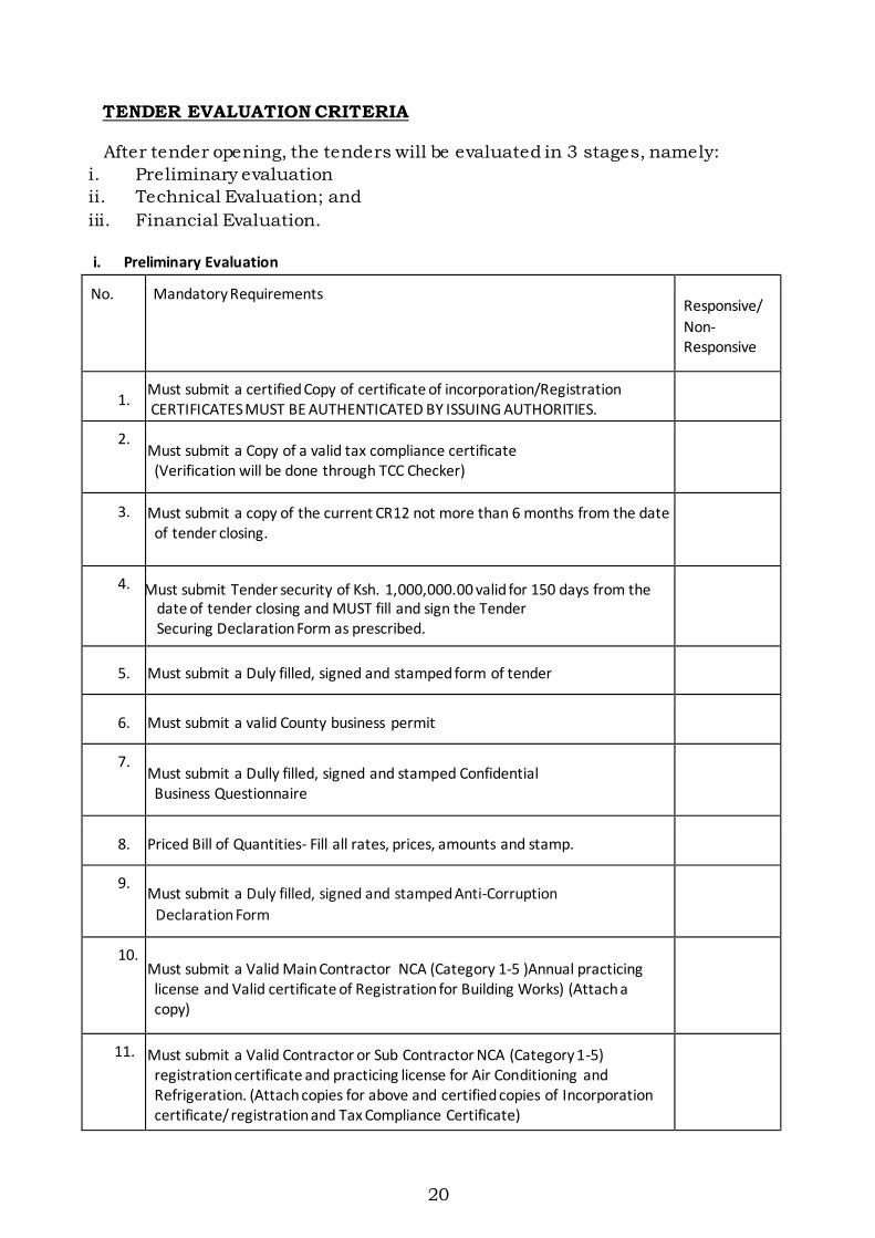
TENDER EVALUATION CRITERIA
After tender opening, the tenders will be evaluated in 3 stages, namely:
i. Preliminary evaluation
ii. Technical Evaluation; and
iii. Financial Evaluation.
i. Preliminary Evaluation
No. Mandatory Requirements Responsive/
Non- Responsive
1. Must submit a certified Copy of certificate of incorporation/Registration CERTIFICATES MUST BE AUTHENTICATED BY ISSUING AUTHORITIES.
2. Must submit a Copy of a valid tax compliance certificate
(Verification will be done through TCC Checker)
3. Must submit a copy of the current CR12 not more than 6 months from the date of tender closing.
4. Must submit Tender security of Ksh. 1,000,000.00 valid for 150 days from the date of tender closing and MUST fill and sign the Tender Securing Declaration Form as prescribed.
5. Must submit a Duly filled, signed and stamped form of tender
6. Must submit a valid County business permit
7. Must submit a Dully filled, signed and stamped Confidential
Business Questionnaire
8. Priced Bill of Quantities- Fill all rates, prices, amounts and stamp.
9. Must submit a Duly filled, signed and stamped Anti-Corruption
Declaration Form
10. Must submit a Valid Main Contractor NCA (Category 1-5 )Annual practicing
license and Valid certificate of Registration for Building Works) (Attach a copy)
11. Must submit a Valid Contractor or Sub Contractor NCA (Category 1-5) registration certificate and practicing license for Air Conditioning and Refrigeration. (Attach copies for above and certified copies of Incorporation certificate/ registration and Tax Compliance Certificate)
21
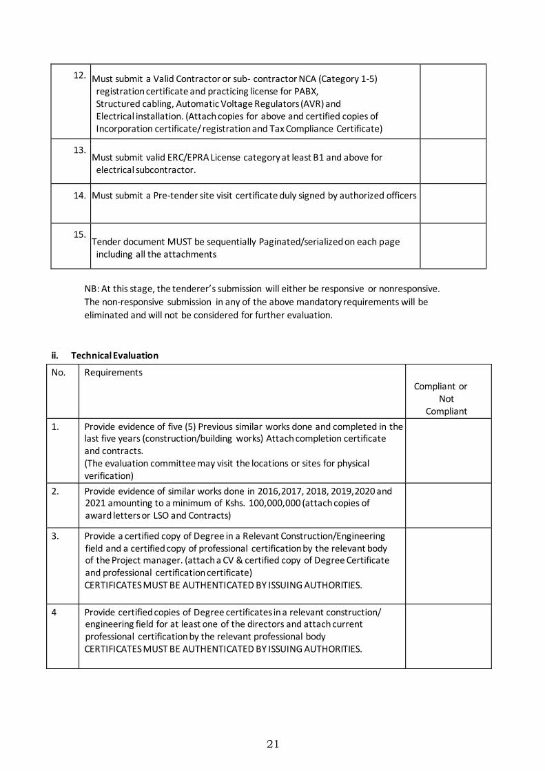
12. Must submit a Valid Contractor or sub- contractor NCA (Category 1-5) registration certificate and practicing license for PABX, Structured cabling, Automatic Voltage Regulators (AVR) and Electrical installation. (Attach copies for above and certified copies of Incorporation certificate/ registration and Tax Compliance Certificate)
13. Must submit valid ERC/EPRA License category at least B1 and above for
electrical subcontractor.
14. Must submit a Pre-tender site visit certificate duly signed by authorized officers
15. Tender document MUST be sequentially Paginated/serialized on each page
including all the attachments
NB: At this stage, the tenderer’s submission will either be responsive or nonresponsive.
The non-responsive submission in any of the above mandatory requirements will be
eliminated and will not be considered for further evaluation.
ii. Technical Evaluation
No. Requirements
Compliant or Not
Compliant
1. Provide evidence of five (5) Previous similar works done and completed in the last five years (construction/building works) Attach completion certificate and contracts. (The evaluation committee may visit the locations or sites for physical verification)
2. Provide evidence of similar works done in 2016,2017, 2018, 2019,2020 and 2021 amounting to a minimum of Kshs. 100,000,000 (attach copies of award letters or LSO and Contracts)
3. Provide a certified copy of Degree in a Relevant Construction/Engineering field and a certified copy of professional certification by the relevant body of the Project manager. (attach a CV & certified copy of Degree Certificate and professional certification certificate) CERTIFICATES MUST BE AUTHENTICATED BY ISSUING AUTHORITIES.
4 Provide certified copies of Degree certificates in a relevant construction/ engineering field for at least one of the directors and attach current professional certification by the relevant professional body CERTIFICATES MUST BE AUTHENTICATED BY ISSUING AUTHORITIES.
22
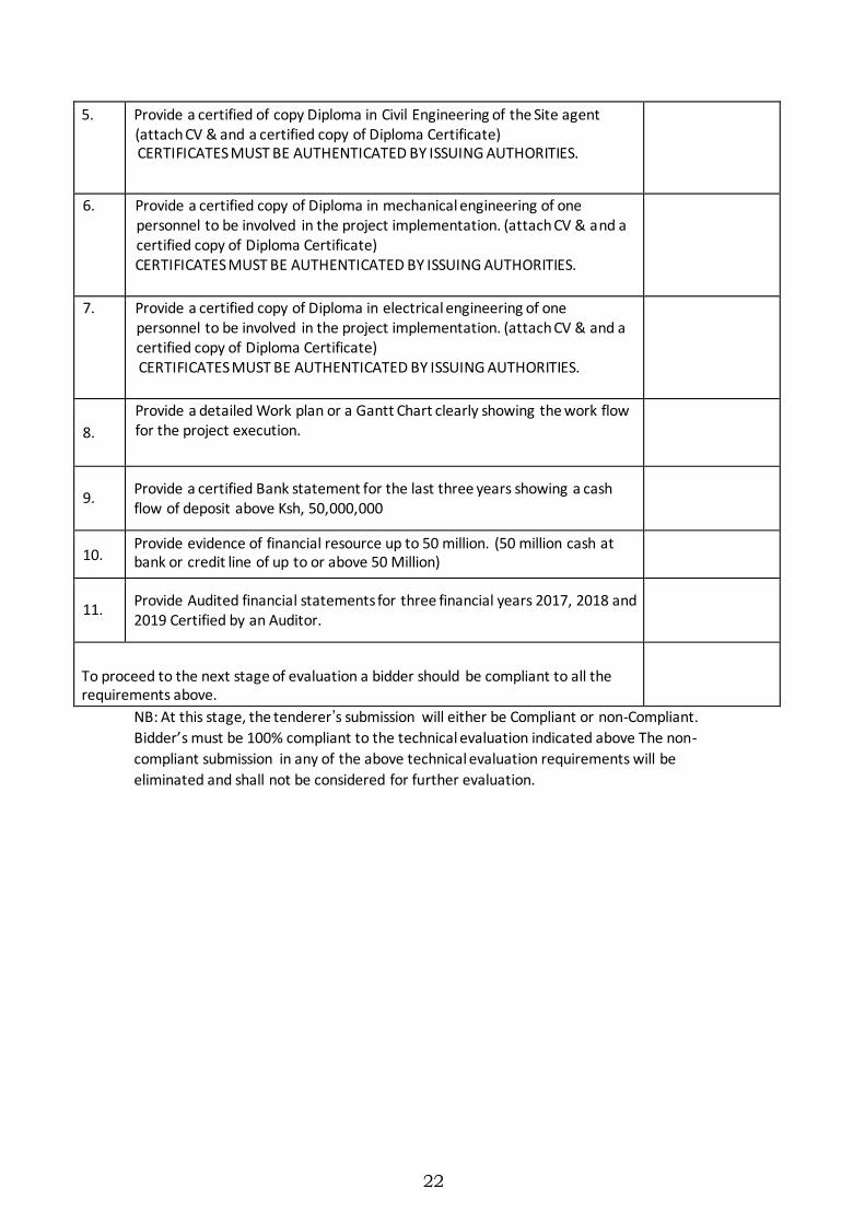
5. Provide a certified of copy Diploma in Civil Engineering of the Site agent (attach CV & and a certified copy of Diploma Certificate) CERTIFICATES MUST BE AUTHENTICATED BY ISSUING AUTHORITIES.
6. Provide a certified copy of Diploma in mechanical engineering of one personnel to be involved in the project implementation. (attach CV & and a certified copy of Diploma Certificate) CERTIFICATES MUST BE AUTHENTICATED BY ISSUING AUTHORITIES.
7. Provide a certified copy of Diploma in electrical engineering of one personnel to be involved in the project implementation. (attach CV & and a certified copy of Diploma Certificate) CERTIFICATES MUST BE AUTHENTICATED BY ISSUING AUTHORITIES.
8.
Provide a detailed Work plan or a Gantt Chart clearly showing the work flow for the project execution.
9. Provide a certified Bank statement for the last three years showing a cash flow of deposit above Ksh, 50,000,000
10. Provide evidence of financial resource up to 50 million. (50 million cash at bank or credit line of up to or above 50 Million)
11. Provide Audited financial statements for three financial years 2017, 2018 and 2019 Certified by an Auditor.
To proceed to the next stage of evaluation a bidder should be compliant to all the requirements above.
NB: At this stage, the tenderer’s submission will either be Compliant or non-Compliant.
Bidder’s must be 100% compliant to the technical evaluation indicated above The non-
compliant submission in any of the above technical evaluation requirements will be
eliminated and shall not be considered for further evaluation.
23
iii. FINANCIAL EVALUATION
Bids that pass the Technical Evaluation shall be subjected to the Financial
Evaluation in three stages, as follows: -
(1) Tender Sum Comparison
(2) Consistency of Rates within the Priced Bill of Quantities.
(3) Comparison of Rates in view of Value for Money and a realistic
representative of the prevailing market rates
Tender Rates
Evaluation of the tender rates will constitute examination of (i) pricing
consistency (same rates for similar items, price distribution amongst
sections, etc); (ii) reasonableness of pricing (comparison with prevailing
market levels, inclusion of taxes [VAT, etc] in the rates)
1.
Award Criteria
The Contract will be awarded to the successful tenderer whose tender has been determined to be substantially responsive and has been
determined to be the lowest responsive evaluated tender
Due Diligence
The Agency shall conduct due diligence to the successful tenderer before
contract signing.
24
SECTION III CONDITIONS OF CONTRACT
Table of Contents
1 Definitions ………………………………………………… 20
2 Interpretation……………………………………………… 22
3 Language and Law ………………………………………… 22
4 Project Manager’s Decisions……………………………… 22
5 Delegation………………………………………………… 23
6 Communications ………………………………………… 23
7 Sub Contracting ………………………………………… 23
8 Other Contractors ……………………………………… 23
9 Personnel ………………………………………………… 23
10 Works……………………………………………………… 24
11 Safety and temporary works ………………………………24
12 Discoveries ………………………………………………… 24
13 Work Programme ………………………………………… 24 -25
14 Possession of site ………………………………………… 26
15 Access to site …………………………………………… 26
16 Instructions ……………………………………………… 26
17 Extension or Acceleration of completion date …………26
18 Management Meetings ………………………………… 27
19 Early Warning …………………………………………… 27
20 Defects ……………………………………………………27 - 28
21 Bills of Quantities ………………………………………… 28
22 Variations ………………………………………………… 28- 29
23 Payment certificates, currency of payments and
Advance Payments ……………………………………… 30
24 Compensation events …………………………………… 31 - 32
25 Price Adjustment ………………………………………… 32 - 33
26 Retention ………………………………………………… 33
27 Liquidated Damages……………………………………… 33
28 Securities ………………………………………………… 33
29 Day Works ……………………………………………… 34 - 35

25
30 Liability and Insurance …………………………………… 35 - 36 31
Completion and taking over ……………………………… 36
32 Final Account …………………………………………… 36
33 Termination ……………………………………………… 36 - 37
34 Payment upon termination ………………………………… 37 - 38
35 Release from performance ………………………………… 38
36 Corrupt gifts and payments of commission ………………38 - 39
37 Settlement of Disputes ……………………………………… 39 - 40
26
CONDITIONS OF CONTRACT
1. Definitions
1.1 In this Contract, except where context otherwise requires, the
following terms shall be interpreted as indicated;
“Bill of Quantities” means the priced and completed Bill of
Quantities forming part of the tender.
“Compensation Events” are those defined in
Clause 24 hereunder.
“The Completion Date” means the date of completion of the
Works as certified by the Project Manager, in accordance with
Clause 31.
“The Contract” means the agreement entered into between the
Employer and the Contractor as recorded in the Agreement Form
and signed by the parties including all attachments and
appendices thereto and all documents incorporated by reference
therein to execute, complete, and maintain the Works,
“The Contractor” refers to the person or corporate body whose
tender to carry out the Works has been accepted by the
Employer.
“The Contractor’s Tender”is the completed tendering document
submitted by the Contractor to the Employer.
“The Contract Price” is the price stated in the Letter of
Acceptance and thereafter as adjusted in accordance with the
provisions of the Contract.
“Days” are calendar days; “Months” are calendar months.
“A Defect” is any part of the Works not completed in accordance
with the Contract.
“The Defects Liability Certificate” is the certificate issued by
Project Manager upon correction of defects by the Contractor.
“The Defects Liability Period” is the period named in the
Contract Data and calculated from the Completion Date.

27
“Drawings” include calculations and other information provided
or approved by the Project Manager for the execution of the
Contract.
“Dayworks” are Work inputs subject to payment on a time basis
for labour and the associated materials and plant.
“Employer”, or the “Procuring entity” as defined in the Public
Procurement Regulations (i.e. Central or Local Government
administration, Universities, Public Institutions and
Corporations, etc) is the party who employs the Contractor to
carry out the Works.
“Equipment” is the Contractor’s machinery and vehicles
brought temporarily to the Site for the execution of the Works.
“The Intended Completion Date” is the date on which it is
intended that the Contractor shall complete the Works. The
Intended Completion Date may be revised only by the Project
Manager by issuing an extension of time or an acceleration
order.
“Materials” are all supplies, including consumables, used by the
Contractor for incorporation in the Works.
“Plant” is any integral part of the Works that shall have a
mechanical, electrical, chemical, or biological function.
“Project Manager” is the person named in the Appendix to
Conditions of Contract (or any other competent person appointed
by the Employer and notified to the Contractor, to act in
replacement of the Project Manager) who is responsible for
supervising the execution of the Works and administering the
Contract and shall be an “Architect” or a “Quantity Surveyor”
registered under the Architects and Quantity Surveyors Act Cap
525 or an “Engineer” registered under Engineers Registration Act
Cap 530.
“Site” is the area defined as such in the Appendix to Condition
of Contract.
“Site Investigation Reports” are those reports that may be
included in the tendering documents which are factual and
interpretative about the surface and subsurface conditions at the
Site.
28
“Specifications” means the Specifications of the Works included
in the Contract and any modification or addition made or
approved by the Project Manager.
“Start Date” is the latest date when the Contractor shall
commence execution of the Works. It does not necessarily
coincide with the Site possession date(s).
“A Subcontractor” is a person or corporate body who has a
Contract with the Contractor to carry out a part of the Work in
the Contract, which includes Work on the Site.
“Temporary works” are works designed, constructed, installed,
and removed by the Contractor which are needed for
construction or installation of the Works.
“A Variation” is an instruction given by the Project Manager which
varies the Works.
“The Works” are what the Contract requires the Contractor to
construct, install, and turnover to the Employer, as defined in the
Appendix to Conditions of Contract.
2. Interpretation
2.1 In interpreting these Conditions of Contract, singular also means
plural, male also means female or neuter, and the other way
around. Headings have no significance. Words have their normal
meaning in English Language unless specifically defined. The
Project Manager will provide instructions clarifying queries about
these Conditions of Contract.
2.2 If sectional completion is specified in the Appendix to Conditions of
Contract, reference in the Conditions of Contract to the Works,
the Completion Date and the Intended Completion Date apply to
any section of the Works (other than references to the Intended
Completion Date for the whole of the Works).
2.3 The following documents shall constitute the Contract documents
and shall be interpreted in the following order of
priority;
(1) Agreement,
(2) Letter of Acceptance,
(3) Contractor’s Tender,

29
(4) Appendix to Conditions of Contract,
(5) Conditions of Contract,
(6) Specifications,
(7) Drawings,
(8) Bill of Quantities,
(9) Any other documents listed in the Appendix to Conditions of
Contract as forming part of the Contract.
Immediately after the execution of the Contract, the Project
Manager shall furnish both the Employer and the Contractor with two
copies each of all the Contract documents. Further, as and
when
necessary the Project Manager shall furnish the Contractor [always with a
copy to the Employer] with three [3] copies of such further drawings
or details or descriptive schedules as are reasonably necessary
either to explain or amplify the Contract drawings or to enable the
Contractor to carry out and complete the Works in accordance with
these Conditions.
3. Language and Law
3.1 Language of the Contract and the law governing the Contract
shall be English language and the Laws of Kenya respectively
unless
otherwise stated.
4 Project Manager’s Decisions
4.1 Except where otherwise specifically stated, the Project Manager will
decide contractual matters between the Employer and the
Contractor in the role representing the Employer.
5 Delegation
5.1 The Project Manager may delegate any of his duties and
responsibilities to others after notifying the Contractor.
6 Communications
6.1 Communication between parties shall be effective only when in
writing. A notice shall be effective only when it is delivered.

30
7 Subcontracting
7.1 The Contractor may subcontract with the approval of the Project
Manager, but may not assign the Contract without the approval
of the Employer in writing. Subcontracting shall not alter the
Contractor’s obligations.
8 Other Contractors
8.1 The Contractor shall cooperate and share the Site with other
contractors, public authorities, utilities etc. as listed in the
Appendix to Conditions of Contract and also with the Employer,
as per the directions of the Project Manager. The Contractor shall
also provide facilities and services for them. The Employer may
modify the said List of Other Contractors etc., and shall notify
the Contractor of any such modification.
9 Personnel
9.1 The Contractor shall employ the key personnel named in the
Qualification Information, to carry out the functions stated in the
said Information or other personnel approved by the Project
Manager. The Project Manager will approve any proposed
replacement of key personnel only if their relevant qualifications
and abilities are substantially equal to or better than those of the
personnel listed in the Qualification Information. If the Project
Manager asks the Contractor to remove a person who is a
member of the Contractor’s staff or work force, stating the
reasons, the Contractor shall ensure that the person leaves the
Site within seven days and has no further connection with the
Work in the Contract.
10 Works
10.1 The Contractor shall construct and install the Works in
accordance with the Specifications and Drawings. The Works
may commence on the Start Date and shall be carried out in
accordance with the Program submitted by the Contractor, as
updated with the approval of the Project Manager, and complete
them by the Intended Completion Date.
11 Safety and Temporary Works
11.1 The Contractor shall be responsible for the design of temporary
works. However before erecting the same, he shall submit his
designs including specifications and drawings to the Project
Manager and to any other relevant third parties for their

31
approval. No erection of temporary works shall be done until
such approvals are obtained.
11.2 The Project Manager’s approval shall not alter the Contractor’s
responsibility for design of the Temporary works and all drawings
prepared by the Contractor for the execution of the temporary or
permanent Works, shall be subject to prior approval by the
Project Manager before they can be used.
11.3 The Contractor shall be responsible for the safety of all activities
on the Site.
12. Discoveries
12.1 Anything of historical or other interest or of significant value
unexpectedly discovered on Site shall be the property of the
Employer. The Contractor shall notify the Project Manager of
such discoveries and carry out the Project Manager’s instructions
for dealing with them.
13. Work Program
13.1 Within the time stated in the Appendix to Conditions of Contract,
the Contractor shall submit to the Project Manager for approval a
program showing the general methods, arrangements, order, and
timing for all the activities in the Works. An update of the
program shall be a program showing the actual progress achieved
on each activity and the effect of the progress achieved on the
timing of the remaining Work, including any changes to the
sequence of the activities.
The Contractor shall submit to the Project Manager for approval
an updated program at intervals no longer than the period stated
in the Appendix to Conditions of Contract. If the Contractor does
not submit an updated program within this period, the Project
Manager
may withhold the amount stated in the said Appendix from the
next payment certificate and continue to withhold this amount
until the next payment after the date on which the overdue
program has been submitted. The Project Manager’s approval of
the program shall not alter the Contractor’s obligations. The
Contractor may revise the program and submit it to the Project
Manager again at any time. A revised program shall show the
effect of Variations and Compensation Events.
32
14. Possession of Site
14.1 The Employer shall give possession of all parts of the Site to the
Contractor. If possession of a part is not given by the date stated
in the Appendix to Conditions of Contract, the Employer will be
deemed to have delayed the start of the relevant activities, and
this will be a Compensation Event.
15. Access to Site
15.1 The Contractor shall allow the Project Manager and any other
person authorised by the Project Manager, access to the Site and
to any place where work in connection with the Contract is being
carried out or is intended to be carried out.
16. Instructions
16.1 The Contractor shall carry out all instructions of the Project
Manager which are in accordance with the Contract.
17. Extension or Acceleration of Completion Date
17.1 The Project Manager shall extend the Intended Completion Date if
a Compensation Event occurs or a variation is issued which
makes it impossible for completion to be achieved by the
Intended Completion Date without the Contractor taking steps to
accelerate the remaining Work, which would cause the
Contractor to incur additional cost. The Project Manager shall
decide whether and by how much to extend the Intended
Completion Date within 21 days of the Contractor asking the
Project Manager in writing for a decision upon the effect of a
Compensation Event or variation and submitting full supporting
information. If the Contractor has failed to give early warning of a
delay or has failed to cooperate in dealing with a delay, the delay
caused by such failure shall not be considered in assessing the
new (extended) Completion Date.
17.2 No bonus for early completion of the Works shall be paid to the
Contractor by the Employer.
18. Management Meetings
18.1 A Contract management meeting shall be held monthly and
attended by the Project Manager and the Contractor. Its business
shall be to review the plans for the remaining Work and to deal
with matters raised in accordance with the early warning
procedure. The Project Manager shall record the minutes of
management meetings and provide copies of the same to those
attending the meeting and the Employer. The responsibility of
33
the parties for actions to be taken shall be decided by the Project
Manager either at the management meeting or after the
management meeting and stated in writing to all who attended the meeting.
19. Early Warning
19.1 The Contractor shall warn the Project Manager at the earliest
opportunity of specific likely future events or circumstances that
may adversely affect the quality of the Work, increase the
Contract Price or delay the execution of the Works. The Project
Manager may require the Contractor to provide an estimate of
the expected effect of the future event or circumstance on the
Contract Price and Completion Date. The estimate shall be
provided by the Contractor as soon as reasonably possible.
19.2 The Contractor shall cooperate with the Project Manager in
making and considering proposals on how the effect of such an
event or circumstance can be avoided or reduced by anyone
involved in the Work and in carrying out any resulting
instructions of the Project Manager.
20. Defects
20.1 The Project Manager shall inspect the Contractor’s work and
notify the Contractor of any defects that are found. Such
inspection shall not affect the Contractor’s responsibilities. The
Project Manager may instruct the Contractor to search for a
defect and to uncover and test any Work that the Project
Manager considers may have a defect. Should the defect be
found, the cost of uncovering and making good shall be borne by
the Contractor, However, if there is no defect found, the cost of
uncovering and making good shall be treated as a variation and
added to the Contract Price.
20.2 The Project Manager shall give notice to the Contractor of any
defects
before the end of the Defects Liability Period, which begins at
Completion, and is defined in the Appendix to Conditions of
Contract. The Defects Liability Period shall be extended for as
long as defects remain to be corrected.
20.3 Every time notice of a defect is given, the Contractor shall correct
the notified defect within the length of time specified by the
Project Manager’s notice. If the Contractor has not corrected a
defect within the time specified in the Project Manager’s notice,
the Project Manager will assess the cost of having the defect

34
corrected by other parties and such cost shall be treated as a
variation and be deducted from the Contract Price.
21. Bills Of Quantities
21.1 The Bills of Quantities shall contain items for the construction,
installation, testing and commissioning of the Work to be done
by the Contractor. The Contractor will be paid for the quantity
of the Work done at the rate in the Bills of Quantities for each
item.
21.2 If the final quantity of the Work done differs from the quantity in
the Bills of Quantities for the particular item by more than 25
percent and provided the change exceeds 1 percent of the Initial
Contract price, the Project Manager shall adjust the rate to allow
for the change.
21.3 If requested by the Project Manager, the Contractor shall provide
the Project Manager with a detailed cost breakdown of any rate
in the Bills of Quantities.
22. Variations
22.1 All variations shall be included in updated programs produced by
the Contractor.
22.2 The Contractor shall provide the Project Manager with a quotation
for carrying out the variations when requested to do so. The
Project Manager shall assess the quotation, which shall be given
within seven days of the request or within any longer period as
may be stated by the Project Manager and before the Variation is
ordered.
22.3 If the work in the variation corresponds with an item description
in the Bills of Quantities and if in the opinion of the Project
Manager, the quantity of work is not above the limit stated in
Clause 21.2 or the timing of its execution does not cause the
cost per unit of quantity to change, the rate in the Bills of
Quantities shall be used to calculate the value of the variation. If
the cost per unit of quantity changes, or
if the nature or timing of the work in the variation does not
correspond with items in the Bills of Quantities, the quotation by
the Contractor shall be in the form of new rates for the relevant
items of Work.
22.4 If the Contractor’s quotation is unreasonable, the Project Manager
may order the variation and make a change to the Contract price,
35
which shall be based on the Project Manager’s own forecast of the effects of the variation on the Contractor’s costs.
22.5 If the Project Manager decides that the urgency of varying the
Work would prevent a quotation being given and considered
without delaying the Work, no quotation shall be given and the
variation shall be treated as a Compensation Event.
22.6 The Contractor shall not be entitled to additional payment for
costs that could have been avoided by giving early warning.
22.7 When the Program is updated, the Contractor shall provide the
Project Manager with an updated cash flow forecast.
23. Payment Certificates, Currency of Payments and Advance Payments
23.1 The Contractor shall submit to the Project Manager monthly
applications for payment giving sufficient details of the Work
done and materials on Site and the amounts which the
Contractor considers himself to be entitled to. The Project
Manager shall check the monthly application and certify the
amount to be paid to the Contractor within 14 days. The value of
Work executed and payable shall be determined by the Project
Manager.
23.2 The value of Work executed shall comprise the value of the
quantities of the items in the Bills of Quantities completed,
materials delivered on Site, variations and compensation events.
Such materials shall become the property of the Employer once
the Employer has paid the Contractor for their value. Thereafter,
they shall not be removed from Site without the Project
Manager’s instructions except for use upon the Works.
23.3 Payments shall be adjusted for deductions for retention. The
Employer shall pay the Contractor the amounts certified by the
Project Manager within 30 days of the date of issue of each
certificate. If the Employer makes a late payment, the Contractor
shall be paid simple interest on the late payment in the next
payment. Interest shall be calculated on the basis of number of
days delayed at a rate three percentage points above the Central
Bank of Kenya’s average rate for base lending prevailing as of the
first day the payment becomes overdue.
23.4 If an amount certified is increased in a later certificate or as a
result of an award by an Arbitrator, the Contractor shall be paid
interest upon the delayed payment as set out in this clause.
Interest shall be calculated from the date upon which the

36
increased amount would have been certified in the absence of
dispute.
23.5 Items of the Works for which no rate or price has been entered in
will not be paid for by the Employer and shall be deemed covered
by other rates and prices in the Contract.
23.6 The Contract Price shall be stated in Kenya Shillings. All
payments to the Contractor shall be made in Kenya Shillings and
foreign currency in the proportion indicated in the tender, or
agreed prior to the execution of the Contract Agreement and
indicated therein. The rate of exchange for the calculation of the
amount of foreign currency payment shall be the rate of
exchange indicated in the Appendix to Conditions of Contract. If
the Contractor indicated foreign currencies for payment other
than the currencies of the countries of origin of related goods and
services the Employer reserves the right to pay the equivalent at
the time of payment in the currencies of the countries of such
goods and services. The Employer and the Project Manager shall
be notified promptly by the Contractor of an changes in the
expected foreign currency requirements of the Contractor during
the execution of the Works as indicated in the Schedule of
Foreign Currency Requirements and the foreign and local
currency portions of the balance of the Contract Price shall then
be amended by agreement between Employer and the
Contractor in order to reflect appropriately such changes.
23.7 In the event that an advance payment is granted, the following
shall apply:-
a) On signature of the Contract, the Contractor shall at his
request, and without furnishing proof of expenditure, be
entitled to an advance of 10% (ten percent) of the original
amount of the Contract. The advance shall not be subject
to retention money.
b) No advance payment may be made before the Contractor has
submitted proof of the establishment of deposit or a
directly
liable guarantee satisfactory to the Employer in the
amount of the advance payment. The guarantee shall be in
the same currency as the advance.
c) Reimbursement of the lump sum advance shall be made by
deductions from the Interim payments and where
applicable from the balance owing to the Contractor.
Reimbursement shall begin when the amount of the sums
due under the Contract reaches 20% of the original
37
amount of the Contract. It shall have been completed by
the time 80% of this amount is reached.
The amount to be repaid by way of successive deductions shall be calculated by means of the formula:
R
Where:
= A(x1 – x11) 80 – 20
R = the amount to be reimbursed
granted
A = the amount of the advance which has been
X1 = the amount of proposed cumulative payments as a percentage of the original amount of the
Contract. This figure will exceed 20% but not
exceed 80%.
X11 = the amount of the previous cumulative
payments as a percentage of the original amount of the Contract. This figure will be
below 80%but not less than 20%.
d) with each reimbursement the counterpart of the directly
liable guarantee may be reduced accordingly. 24. Compensation Events
24.1 The following issues shall constitute Compensation Events:
(a) The Employer does not give access to a part of the Site by the
Site Possession Date stated in the Appendix to
Conditions of Contract.
(b) The Employer modifies the List of Other Contractors, etc., in
a way that affects the Work of the Contractor under the
Contract.
(c) The Project Manager orders a delay or does not issue
drawings, specifications or instructions required for
execution of the Works on time.
(d) The Project Manager instructs the Contractor to uncover or to
carry out additional tests upon the Work, which is then
found to have no defects.
(e) The Project Manager unreasonably does not approve a
subcontract to be let.
38
(f) Ground conditions are substantially more adverse than could
reasonably have been assumed before issuance of the
Letter of Acceptance from the information issued to
tenderers (including the Site investigation reports), from
information available publicly and from a visual inspection
of the Site.
(g) The Project Manager gives an instruction for dealing with an
unforeseen condition, caused by the Employer or
additional work required for safety or other reasons.
(h) Other contractors, public authorities, utilities, or the
Employer does not work within the dates and other
constraints stated in the Contract, and they cause delay or
extra cost to the Contractor.
(i) The effects on the Contractor of any of the Employer’s risks.
(j) The Project Manager unreasonably delays issuing a
Certificate of Completion.
(k) Other compensation events described in the Contract or
determined by the Project Manager shall apply.
24.2 If a compensation event would cause additional cost or would
prevent the Work being completed before the Intended
Completion Date, the Contract Price shall be increased and/or
the Intended Completion Date shall be extended. The Project
Manager shall decide whether and by how much the Contract
Price shall be increased and whether and by how much the
Intended Completion Date shall be extended.
24.3 As soon as information demonstrating the effect of each
compensation event upon the Contractor’s forecast cost has been
provided by the Contractor, it shall be assessed by the Project
Manager, and the Contract Price shall be adjusted accordingly. If
the Contractor’s forecast is deemed unreasonable, the Project
Manager shall adjust the Contract Price based on the Project
Manager’s own forecast. The
Project Manager will assume that the Contractor will react
competently and promptly to the event.
24.4 The Contractor shall not be entitled to compensation to the
extent that the Employer’s interests are adversely affected by the
Contractor not having given early warning or not having
cooperated with the Project Manager.
39
24.5 Prices shall be adjusted for fluctuations in the cost of inputs only
if provided for in the Appendix to Conditions of Contract.
24.6 The Contractor shall give written notice to the Project Manager of
his intention to make a claim within thirty days after the event
giving rise to the claim has first arisen. The claim shall be
submitted within thirty days thereafter.
Provided always that should the event giving rise to the claim of
continuing effect, the Contractor shall submit an interim claim
within the said thirty days and a final claim within thirty days of
the end of the event giving rise to the claim.
25. Price Adjustment
25.1 The Project Manager shall adjust the Contract Price if taxes,
duties and other levies are changed between the date 30 days
before the submission of tenders for the Contract and the date of
Completion. The adjustment shall be the change in the amount
of tax payable by the Contractor.
25.2 The Contract Price shall be deemed to be based on exchange rates
current at the date of tender submission in calculating the cost
to the Contractor of materials to be specifically imported (by
express provisions in the Contract Bills of Quantities or
Specifications) for permanent incorporation in the Works.
Unless otherwise stated in the Contract, if at any time during the
period of the Contract exchange rates shall be varied and this
shall affect the cost to the Contractor of such materials, then the
Project Manager shall assess the net difference in the cost of
such materials. Any amount from time to time so assessed shall
be added to or deducted from the Contract Price, as the case
may be.
25.3 Unless otherwise stated in the Contract, the Contract Price shall
be deemed to have been calculated in the manner set out below
and in sub-clauses 25.4 and 25.5 and shall be subject to
adjustment in the events specified thereunder;
(i) The prices contained in the Contract Bills of Quantities shall
be deemed to be based upon the rates of wages and other
emoluments and expenses as determined by the Joint
Building Council of Kenya (J.B.C.) and set out in the
schedule of basic rates issued 30 days before the date for
submission of tenders.A copy of the schedule used by the
Contractor in his pricing shall be attached in the Appendix
to Conditions of Contract.
40
(ii) Upon J.B.C. determining that any of the said rates of wages
or other emoluments and expenses are increased or
decreased, then the Contract Price shall be increased or
decreased by the amount assessed by the Project Manager
based upon the difference, expressed as a percentage, between the rate set out
in the schedule of basic rates issued 30 days before the
date for submission of tenders and the rate published by
the J.B.C. and applied to the quantum of labour
incorporated within the amount of Work remaining to be
executed at the date of publication of such increase or
decrease.
(iii) No adjustment shall be made in respect of changes in the
rates of wages and other emoluments and expenses which
occur after the date of Completion except during such
other period as may be granted as an extension of time
under clause 17.0 of these Conditions.
25.4 The prices contained in the Contract Bills of Quantities shall be
deemed to be based upon the basic prices of materials to be
permanently incorporated in the Works as determined by the
J.B.C. and set out in the schedule of basic rates issued 30 days
before the date for submission of tenders. A copy of the schedule
used by the Contractor in his pricing shall be attached in the
Appendix to Conditions of Contract.
25.5 Upon the J.B.C. determining that any of the said basic prices are
increased or decreased then the Contract Price shall be increased
or decreased by the amount to be assessed by the Project
Manager based upon the difference between the price set out in
the schedule of basic rates issued 30 days before the date for
submission of tenders and the rate published by the J.B.C. and
applied to the quantum of the relevant materials which have not
been taken into account in arriving at the amount of any interim
certificate under clause 23 of these Conditions issued before the
date of publication of such increase or decrease.
25.6 No adjustment shall be made in respect of changes in basic
prices of materials which occur after the date for Completion
except during such other period as may be granted as an
extension of time under clause 17.0 of these Conditions.
25.7 The provisions of sub-clause 25.1 to 25.2 herein shall not apply
in respect of any materials included in the schedule of basic
rates.
41
26. Retention
26.1 The Employer shall retain from each payment due to the
Contractor the proportion stated in the Appendix to Conditions of
Contract until Completion of the whole of the Works. On
Completion of the whole of the Works, half the total amount
retained shall be repaid to the Contractor and the remaining half
when the Defects Liability Period has passed and the Project
Manager has certified that all defects notified to the Contractor
before the end of this period have been corrected.
27. Liquidated Damages
27.1 The Contractor shall pay liquidated damages to the Employer at
the rate stated in the Appendix to Conditions of Contract for each
day that the actual Completion Date is later than the Intended
Completion Date. The Employer may deduct liquidated damages
from payments due to the Contractor. Payment of liquidated
damages shall not alter the Contractor’s liabilities.
27.2 If the Intended Completion Date is extended after liquidated
damages have been paid, the Project Manager shall correct any
overpayment of liquidated damages by the Contractor by
adjusting the next payment certificate. The Contractor shall be
paid interest on the overpayment, calculated from the date of
payment to the date of repayment, at the rate specified in Clause
23.30
28. Securities
28.1 The Performance Security shall be provided to the Employer no
later than the date specified in the Letter of Acceptance and shall
be issued in an amount and form and by a reputable bank
acceptable to the Employer, and denominated in Kenya Shillings.
The Performance Security shall be valid until a date 30 days
beyond the date of issue of the Certificate of Completion.
29. Day works
29.1 If applicable, the Day works rates in the Contractor’s tender shall
be used for small additional amounts of Work only when the
Project Manager has given written instructions in advance for
additional work to be paid for in that way.
29.2 All work to be paid for as Day works shall be recorded by the
Contractor on Forms approved by the Project Manager. Each
completed form shall be verified and signed by the Project
Manager within two days of the Work being done.
42
29.3 The Contractor shall be paid for Day works subject to obtaining
signed Day works forms.
30. Liability and Insurance
30.1 From the Start Date until the Defects Correction Certificate has
been issued, the following are the Employer’s risks:
(a) The risk of personal injury, death or loss of or damage to
property (excluding the Works, Plant, Materials and
Equipment), which are due to;
(i) use or occupation of the Site by the Works or for the
purpose of the Works, which is the unavoidable
result of the Works, or
(ii) negligence, breach of statutory duty or interference
with any legal right by the Employer or by any
person employed by or contracted to him except the
Contractor.
(b) The risk of damage to the Works, Plant, Materials, and
Equipment to the extent that it is due to a fault of the
Employer or in Employer’s design, or due to war or
radioactive contamination directly affecting the place
where the Works are being executed.
30.2 From the Completion Date until the Defects Correction Certificate
has been issued, the risk of loss of or damage to the Works,
Plant, and Materials is the Employer’s risk except loss or damage
due to;
(a) a defect which existed on or before the Completion Date.
(b) an event occurring before the Completion Date, which was
not itself the Employer’s risk
(c) the activities of the Contractor on the Site after the
Completion Date.
30.3 From the Start Date until the Defects Correction Certificate has
been issued, the risks of personal injury, death and loss of or
damage to property (including, without limitation, the Works,
Plant, Materials, and Equipment) which are not Employer’s risk
are Contractor’s risks.
43
The Contractor shall provide, in the joint names of the Employer
and the Contractor, insurance cover from the Start Date to the
end of the Defects Liability Period, in the amounts stated in the Appendix to Conditions of Contract for the following events;
(a) loss of or damage to the Works, Plant, and Materials;
(b) loss of or damage to Equipment;
(c) loss of or damage to property (except the Works, Plant,
Materials, and Equipment) in connection with the
Contract, and
(d) personal injury or death.
30.4 Policies and certificates for insurance shall be delivered by the
Contractor to the Project Manager for the Project Manager’s
approval before the Start Date. All such insurance shall provide
for compensation required to rectify the loss or damage incurred.
30.5 If the Contractor does not provide any of the policies and
certificates required, the Employer may effect the insurance
which the Contractor should have provided and recover the
premiums from payments otherwise due to the Contractor or, if
no payment is due, the payment of the premiums shall be a debt
due.
30.6 Alterations to the terms of an insurance shall not be made
without the approval of the Project Manager. Both parties shall
comply with any conditions of insurance policies.
31. Completion and taking over
31.1 Upon deciding that the Works are complete, the Contractor shall
issue a written request to the Project Manager to issue a
Certificate of Completion of the Works. The Employer shall take
over the Site and the Works within seven [7] days of the Project
Manager’s issuing a Certificate of Completion.
32. Final Account
32.1 The Contractor shall issue the Project Manager with a de tailed
account of the total amount that the Contractor considers
payable to him by the Employer under the Contract before the
end of the Defects Liability Period. The Project Manager shall
issue a Defects Liability Certificate and certify any final payment
that is due to the Contractor within 30 days of receiving the
Contractor’s account if it is correct and complete. If it is not, the
Project Manager shall issue within 30 days a schedule that states
the scope of the corrections or additions that are necessary. If
the final account is still unsatisfactory after it has been
resubmitted, the Project Manager shall decide on the amount
44
payable to the Contractor and issue a Payment Certificate. The
Employer shall pay the Contractor the amount due in the Final
Certificate within 60 days.
33. Termination
33.1 The Employer or the Contractor may terminate the Contract if the
other party causes a fundamental breach of the Contract. These
fundamental breaches of Contract shall include, but shall not be
limited to, the following;
(a) the Contractor stops work for 30 days when no stoppage of
work is shown on the current program and the stoppage
has not been authorised by the Project Manager;
(b) the Project Manager instructs the Contractor to delay the
progress of the Works, and the instruction is not
withdrawn within 30 days;
(c) the Contractor is declared bankrupt or goes into liquidation
other than for a reconstruction or
amalgamation;
(d) a payment certified by the Project Manager is not paid by the
Employer to the Contractor within 30 days (for Interim
Certificate) or 60 days (for Final Certificate)of issue.
(e) the Project Manager gives notice that failure to correct a
particular defect is a fundamental breach of Contract and
the Contractor fails to correct it within a reasonable period
of time determined by the Project Manager;
(f) the Contractor does not maintain a security,
whichis required.
33.2 When either party to the Contract gives notice of a breach of
Contract to the Project Manager for a cause other than those
listed under Clause 33.1 above, the Project Manager shall decide
whether the breach is fundamental or not.
33.3 Notwithstanding the above, the Employer may terminate the
Contract for convenience.
33.4 If the Contract is terminated, the Contractor shall stop work
immediately, make the Site safe and secure, and leave the Site as
soon as reasonably possible. The Project Manager shall
immediately thereafter arrange for a meeting for the purpose of
45
taking record of the Works executed and materials , goods, equipment and temporary buildings on Site .
34. Payment Upon Termination
34.1 If the Contract is terminated because of a fundamental breach of
Contract by the Contractor, the Project Manager shall issue a
certificate for the value of the Work done and materials ordered
and delivered to Site up to the date of the issue of the certificate.
Additional liquidated damages shall not apply. If the total
amount due to the Employer exceeds any payment due to the
Contractor, the difference shall be a debt payable by the
Contractor.
34.2 If the Contract is terminated for the Employer’s convenience or
because of a fundamental breach of Contract by the Employer,
the Project Manager shall issue a certificate for the value of the
Work done, materials ordered, the reasonable cost of removal of
equipment, repatriation of the Contractor’s personnel employed
solely on the
Works, and the Contractor’s costs of protecting and securing the
Works.
34.3 The Employer may employ and pay other persons to carry out and
complete the Works and to rectify any defects and may enter
upon the Works and use all materials on the Site, plant,
equipment and temporary works.
34.4 The Contractor shall, during the execution or after the completion
of the Works under this clause remove from the Site as and when
required, within such reasonable time as the Project Manager
may in writing specify, any temporary buildings, plant,
machinery, appliances, goods or materials belonging to or hired
by him, and in default the Employer may (without being
responsible for any loss or damage) remove and sell any such
property of the Contractor, holding the proceeds less all costs
incurred to the credit of the Contractor.
Until after completion of the Works under this clause the
Employer shall not be bound by any other provision of this
Contract to make any payment to the Contractor, but upon such
completion as aforesaid and the verification within a reasonable
time of the accounts therefore the Project Manager shall certify
the amount of expenses properly incurred by the Employer and,
if such amount added to the money paid to the Contractor before
such determination exceeds the total amount which would have
been payable on due completion in accordance with this
Contract the difference shall be a debt payable to the Employer
46
by the Contractor; and if the said amount added to the said
money be less than the said total amount, the difference shall be
a debt payable by the Employer to the Contractor.
35. Release from Performance
35.1 If the Contract is frustrated by the outbreak of war or by any
other event entirely outside the control of either the Employer or
the Contractor, the Project Manager shall certify that the
Contract has been frustrated. The Contractor shall make the Site
safe and stop Work as quickly as possible after receiving this
certificate and shall be paid for all Work carried out before
receiving it.
36. Corrupt gifts and payments of commission
The Contractor shall not;
(a) Offer or give or agree to give to any person in the service of the
Employer any gift or consideration of any kind as an induceme nt
or reward for doing or forbearing to do or for having done or
forborne to do any act in relation to the obtaining or execution of
this or any other Contract for the Employer or for showing or
forbearing to show favour
or disfavour to any person in relation to this or any other
contract for the Employer.
(b) Enter into this or any other contract with the Employer in
connection with which commission has been paid or agreed to be
paid by him or on his behalf or to his knowledge, unless before
the Contract is made particulars of any such commission and of
the terms and conditions of any agreement for the payment
thereof have been disclosed in writing to the Employer.
Any breach of this Condition by the Contractor or by anyone
employed by him or acting on his behalf (whether with or without
the knowledge of the Contractor) shall be an offence under the
provisions of the Public Procurement Regulations issued under
The Exchequer and Audit Act Cap 412 of the Laws of Kenya.
37. Settlement Of Disputes
37.1 In case any dispute or difference shall arise between the Employer
or the Project Manager on his behalf and the
Contractor, either during the progress or after the completion or
termination of the Works, such dispute shall be notified in
writing by either party to the other with a request to submit it to

47
arbitration and to concur in the appointment of an Arbitrator
within thirty days of the notice. The dispute shall be referred to
the arbitration and final decision of a person to be agreed
between the parties. Failing agreement to concur in the
appointment of an Arbitrator, the Arbitrator shall be appointed
by the Chairman or Vice Chairman of any of the following
professional institutions;
(i) Architectural Association of Kenya
(ii) Institute of Quantity Surveyors of Kenya
(iii) Association of Consulting Engineers of Kenya
(iv) Chartered Institute of Arbitrators (Kenya Branch)
(v) Institution of Engineers of Kenya
On the request of the applying party. The institution written to
first by the aggrieved party shall take precedence over all other
institutions.
37.2 The arbitration may be on the construction of this Contract or on
any matter or thing of whatsoever nature arising thereunder or
in connection therewith, including any matter or thing left by
this Contract to the discretion of the Project Manager, or the
withholding by the Project Manager of any certificate to which
the Contractor may claim to be entitled to or the measurement
and valuation referred to in clause 23.0 of these conditions, or
the rights and liabilities of the parties subsequent to the
termination of Contract.
37.3 Provided that no arbitration proceedings shall be commenced on
any dispute or difference where notice of a dispute or difference
has not been given by the applying party within ninety days of
the occurrence or discovery of the matter or issue giving rise to
the dispute.
37.4 Notwithstanding the issue of a notice as stated above, the
arbitration of such a dispute or difference shall not commence
unless an attempt has in the first instance been made by the
parties to settle such dispute or difference amicably with or
without the assistance of third parties. Proof of such attempt
shall be required.
37.5 Notwithstanding anything stated herein the following matters
may be referred to arbitration before the practical completion of
48
the Works or abandonment of the Works or termination of the
Contract by either party:
37.5.1.1 The appointment of a replacement
Project Manager upon the said person ceasing to
act.
37.5.1.2 Whether or not the issue of an instruction by the
Project Manager is empowered by
these Conditions.
37.5.1.3 Whether or not a certificate has been improperly
withheld or is not in accordance with these
Conditions.
37.5.1.4 Any dispute or difference arising in respect of war
risks or war damage.
37.6 All other matters shall only be referred to arbitration after the
completion or alleged completion of the Works or termination or
alleged termination of the Contract, unless the Employer and the
Contractor agree otherwise in writing.
37.7 The Arbitrator shall, without prejudice to the generality of his
powers, have powers to direct such measurements,
computations, tests or valuations as may in his opinion be
desirable in order to determine the rights of the parties and
assess and award any sums which ought to have been the
subject of or included in any certificate.
37.8 The Arbitrator shall, without prejudice to the generality of his
powers,
have powers to open up, review and revise any certificate,
opinion, decision, requirement or notice and to determine all
matters in dispute which shall be submitted to him in the same
manner as if no such certificate, opinion, decision requirement
or notice had been given.
37.9 The award of such Arbitrator shall be final and binding upon the
parties.

49
SECTION IV – APPENDIX TO CONDITIONS OF CONTRACT
THE EMPLOYER IS Name: ASSET RECOVERY AGENCY
Address: U.A.P Building
U.A.P Old Mutual Tower 22nd FLOOR Upperhill
P.O. BOX 52420-00100, NAIROBI.
Tel: (020) 2020282
Email: info.assetsrecoveryagency.go.ke
Name of Authorised Representative: Director of Assets Recovery Agency
Address P.O. BOX 52420-00100, NAIROBI. Tel: (020) 2020282
Email: info.assetsrecoveryagency.go.ke
The Project Manager is;
Name: WORKS SECRETARY,
STATE DEPARTMENT OF PUBLIC WORKS
Address: P.O. BOX 30743-00100 NAIROBI
Telephone: 2723101
Email: www.publicworks.go.ke
The name (and identification number) of the Contract is : PROPOSED
PARTITIONING AND REFURBISHMENT OF OFFICE AT 21ST FLOOR UAP
TOWERS FOR A.R.A
The Works consist of: Office Partitioning and Refurbishment
Electrical works include electrical wiring, fittings and, Mechanical works are sanitary fittings,
The Start Date shall be AGREED WITH THE PROJECT MANAGER
The Intended Completion Date for the whole of the Works shall be
16 WEEKS FROM DATE OF POSSESSION
The following documents also form part of the Contract:
50
AS LISTED IN CLAUSE 2.3 OF CONDITIONS OF CONTRACT
The Contractor shall submit a revised program for the Works within SEVEN
(7) days of delivery of the Letter of Acceptance.
The Site Possession Date shall be AGREED WITHTHE PROJECT MANAGER
The Site is Located at U.A.P Old Mutual Tower 21st Floor
The Defects Liability period is SIX MONTHS from date of completion.
Other Contractors, utilities etc., to be engaged by the Employer on the Site
Include those for the execution of;
1. PLUMBING AND DRAINAGE WORKS 2. ELECTRICAL WORKS
3. STRUCTURAL CABLING WORKS
_____________________________________________
The minimum insurance covers shall be;
2. The minimum cover for insurance of the Works and of Plant and
Materials in respect of the Contractor’s faulty design is; N/A
3. The minimum cover for loss or damage to Equipment is; ------NIL----
4. The minimum for insurance of other property is; Kshs 500,000.00
5. The minimum cover for personal injury or death insurance
• For the Contractor’s employees is; Kshs 1,000,000.00
• And for other people is; Kshs 1,000,000.00
The following events shall also be Compensation Events:
NONE (ONLY AS LISTED IN CLAUSE 24 OF THE CONDITIONS OF
CONTRACT
The period between Program updates is 30 days.
The amount to be withheld for late submission of an updated Program is;
FULL CERTIFICATE
The proportion of payments retained is 10% percent.

51
The Price Adjustment Clause SHALL apply
Advance Payment ______________shall___Not____________ be granted
The liquidated damages for the whole of the Works is Kshs. 20,000/=(per
week)
The Performance Security shall be 5 percent (%) of the Contract Price.
The Completion Period for the Works is 16 WEEKS.
The rate of exchange for calculation of foreign currency payments is not
applicable

52
SECTION V - DRAWINGS
1. Architectural drawings (see Appendix B)
2. Electrical and mechanical drawings
53
SECTION VI – STANDARD FORMS
(i) Form of Invitation for Tenders
(ii) Form of Tender
(iii) Letter of Acceptance
(iv) Form of Agreement
(v) Form of Tender Security
(vi) Performance Bank Guarantee
(vii) Bank Guarantee for Advance Payment
(viii) Qualification Information
(ix) Tender Questionnaire
(xi) Confidential Business Questionnaire
(x) Statement of Foreign Currency Requirement
(xi) Details of Sub-Contractors

54
FORM OF INVITATION FOR TENDERS
_______________________[date]
To: _____________________________________ [name of Contractor]
_____________________________________[address]
_____________________________________
_____________________________________
Dear Sirs:
Reference:______________________________________________[Contract Name]
You have been prequalified to tender for the above project.
We hereby invite you and other prequalified tenderers to submit a tender for
the execution and completion of the above Contract.
A complete set of tender documents may be purchased by you from ____
________________________________________________________________________
[mailing address, cable/telex/facsimile numbers].
Upon payment of a non-refundable fee of Kshs __________________________
All tenders must be accompanied by ________________number of copies of the
same and a security in the form and amount specified in the tendering
documents, and must be delivered to
________________________________________________________________________
[address and location]
at or before _______________________(time and date). Tenders will be opened
immediately thereafter, in the presence of tenderers’ representatives who
choose to attend.
Please confirm receipt of this letter immediately in writing by cable/facsimile
or telex.
Yours faithfully,
_____________________________________ Authorised Signature
_____________________________________ Name and Title

55
FORM OF TENDER
TO: …………………………………………………………………………………………..
…………………………………… ……………………………………..
Dear Sir,
1. In accordance with the Conditions of Contract,
Specifications,
Drawings and Bills of Quantities for the execution of the above named
Works, we, the undersigned offer to construct, install and complete
such Works and remedy any defects therein for the sum of KENYA
SHILLINGS ………………………………………………………………..........
…………………………………………………………………………………………
……………………………………..(kshs……………………….)
2. We undertake, if our tender is accepted, to commence the Works as soon
as is reasonably possible after the receipt of the Project Manager’s notice
to commence, and to complete the whole of the Works comprised in the
Contract within the time stated in the Appendix to Conditions of
Contract.
3. We agree to abide by this tender until ___________________ [Insert date],
and it shall remain binding upon us and may be accepted at any time
before that date.
4. Unless and until a formal Agreement is prepared and executed this
tender together with your written acceptance thereof, shall constitute a
binding Contract between us.
5. We understand that you are not bound to accept the lowest or any tender
you may receive.
Dated this ____________________ day of _______20________________
Signature __________________in the capacity of___________________
duly authorized to sign tenders for and on behalf of
_____________________________________________[Name of Employer]
of___________________________________________[Address of Employer]
Witness; Name______________________________________
Address_____________________________________
Signature___________________________________
Date_______________________________________

56
LETTER OF ACCEPTANCE [letterhead paper of the Employer]
_______________________[date]
To: _______________________
[name of the Contractor]
_____________________
[address of the Contractor]
Dear Sir,
This is to notify you that your Tender dated ___________________________
for the execution of ________________________________________________
[name of the Contract and identification number,as given in the Tender
documents] for the Contract Price of Kshs. __________________________
[amount in figures][Kenya Shillings______________________________ (amount in
words) ] in accordance with the Instructions to Tenderers is hereby accepted.
You are hereby instructed to proceed with the execution of the said Works in
accordance with the Contract documents.
Authorized Signature …………………………………………………………………
Name and Title of Signatory …………………………………………………………
Attachment : Agreement
FORM OF AGREEMENT
THIS AGREEMENT, made the _________________ day of ________ 20 ______
between________________________________________________of[or whose
registered office is situated at]__________________________________________
(hereinafter called “the Employer”) of the one part AND
________________________________________________________of[or whose
registered office is situated at]_________________________________________
(hereinafter called “the Contractor”) of the other part.
WHEREAS THE Employer is desirous that the Contractor executes
________________________________________________________________________
(name and identification number of Contract ) (hereinafter called “the Works”)
located at______________________________[Place/location of the Works]and the
Employer has accepted the tender submitted by the Contractor for the
execution and completion of such Works and the remedying of any defects

57
therein for the Contract Price of Kshs___________________________[Amount in
figures],Kenya
Shillings_____________________________________________[Amount in words].
NOW THIS AGREEMENT WITNESSETH as follows:
1. In this Agreement, words and expressions shall have the same
meanings as are respectively assigned to them in the Conditions of
Contract hereinafter referred to.
2. The following documents shall be deemed to form and shall be read and
construed as part of this Agreement i.e.
(i) Letter of Acceptance
(ii) Form of Tender
(iii) Conditions of Contract Part I
(iv) Conditions of Contract Part II and Appendix to Conditions of
Contract
(v) Specifications
(vi) Drawings
(vii) Priced Bills of Quantities
3. In consideration of the payments to be made by the Employer to the
Contractor as hereinafter mentioned, the Contractor hereby
covenants with the Employer to execute and complete the Works and
remedy any defects therein in conformity in all respects with the
provisions of the Contract.
4. The Employer hereby covenants to pay the Contractor in consideration
of the execution and completion of the Works and the remedying of
defects therein, the Contract Price or such other sum as may become
payable under the provisions of the Contract at the times and in the
manner prescribed by the Contract.
IN WITNESS whereof the parties thereto have caused this Agreement to be
executed the day and year first before written.
The common Seal of _________________________________________________
Was hereunto affixed in the presence of ________________________________
Signed Sealed, and Delivered by the said ______________________________
58
Binding Signature of Employer ________________________________________
Binding Signature of Contractor _______________________________________
In the presence of (i) Name_______________________________________
Address_____________________________________
Signature___________________________________
[ii] Name _______________________________________
Address_____________________________________
Signature____________________________________
FORM OF TENDER SECURITY
WHEREAS ……………………………………….. (hereinafter called “the Tenderer”)
has submitted his tender dated ………………………… for the construction of ………………………………………………………………………
…………………… (Name of Contract)
KNOW ALL PEOPLE by these presents that WE ……………………… having our
registered office at ………………(hereinafter called “the Bank”), are bound
unto ……………………………(hereinafter called “the Employer”) in the sum of
Kshs.……………………… for which payment well and truly to be made to the
said Employer, the Bank binds itself, its successors and assigns by these
presents sealed with the Common Seal of the said Bank this ……………. Day
of ………20…………
THE CONDITIONS of this obligation are:
1. If after tender opening the tenderer withdraws his tender during the
period of tender validity specified in the instructions to tenderers Or
2. If the tenderer, having been notified of the acceptance of his tender by the
Employer during the period of tender validity:
(a) fails or refuses to execute the form of Agreement in accordance with
the Instructions to Tenderers, if required; or
(b) fails or refuses to furnish the Performance
Security, in
accordance with the Instructions to Tenderers;
We undertake to pay to the Employer up to the above amount upon
receipt of his first written demand, without the Employer having to
substantiate his demand, provided that in his demand the Employer
59
will note that the amount claimed by him is due to him, owing to the
occurrence of one or both of the two conditions, specifying the occurred
condition or conditions.
This guarantee will remain in force up to and including thirty (30) days
after the period of tender validity, and any demand in respect thereof
should reach the Bank not later than the said date.
___________________________ ______________________________
[Date [ [signature of the Bank]
___________________________ ______________________________
[Witness] [Seal]
PERFORMANCE BANK GUARANTEE
To: _________________________(Name of Employer) ___________(Date)
__________________________(Address of Employer)
Dear Sir,
WHEREAS ______________________(hereinafter called “the Contractor”) has
undertaken, in pursuance of Contract No. _____________ dated _________ to
execute _______________ (hereinafter called “the Works”);
AND WHEREAS it has been stipulated by you in the said Contract that the
Contractor shall furnish you with a Bank Guarantee by a recognised bank
for the sum specified therein as security for compliance with his obligations
in accordance with the Contract;
AND WHEREAS we have agreed to give the Contractor
such a Bank Guarantee:
NOW THEREFORE we hereby affirm that we are the Guarantor and
responsible to you, on behalf of the Contractor, up to a total of Kshs.
________________ (amount of Guarantee in figures) Kenya
Shillings__________________________________________ (amount of Guarantee in
words), and we undertake to pay you, upon your first written demand and
without cavil or argument, any sum or sums within the limits of Kenya
Shillings _________________________ (amount of Guarantee in words) as
aforesaid without your needing to prove or to show grounds or reasons for
your demand for the sum specified therein.
We hereby waive the necessity of your demanding the said debt from the
Contractor before presenting us with the demand.
We further agree that no change, addition or other modification of the terms
of the Contract or of the Works to be performed thereunder or of any of the
Contract documents which may be made between you and the Contractor
60
shall in any way release us from any liability under this Guarantee, and we
hereby waive notice of any change, addition, or modification.
This guarantee shall be valid until the date of issue of the Certificate of
Completion.
SIGNATURE AND SEAL OF THE GUARANTOR ___________________
Name of Bank ____________________________________________
Address ________________________________________________
Date _____________________________________________________
BANK GUARANTEE FOR ADVANCE PAYMENT
To: ________________________ [name of Employer] ___________(Date)
________________________[address of Employer]
Gentlemen,
Ref: _______________________________________________[name of Contract]
In accordance with the provisions of the Conditions of Contract of the
abovementioned Contract, We,_______________________________________[name
and Address of Contractor] (hereinafter called “the Contractor”) shall deposit
with _______________________________[name of Employer] a bank guarantee to
guarantee his proper and faithful performance under the said Contract in an
amount of Kshs._____________[amount of Guarantee in figurers] Kenya
Shillings_____________________________________[amount of Guarantee in
words].
We, ________________[bank or financial institution], as instructed by the
Contractor, agree unconditionally and irrevocably to guarantee as primary
obligator and not as Surety merely, the payment to
___________________________[name of Employer] on his first demand without
whatsoever right of objection on our part and without his first claim to the Contractor, in the amount not exceeding
Kshs________________________[amount of Guarantee in figures] Kenya
Shillings
_____________________________________________________________[amount of
Guarantee in words], such amount to be reduced
periodically by the amounts recovered by you from the proceeds of the
Contract.

61
We further agree that no change or addition to or other modification of the
terms of the Contract or of the Works to be performed thereunder or of any of
the Contract documents which may be made between
________________________[name of Employer] and the Contractor, shall in any
way release us from any liability under this guarantee, and we hereby waive
notice of any such change, addition or modification.
No drawing may be made by you under this guarantee until we have received
notice in writing from you that an advance payment of the amount listed
above has been paid to the Contractor pursuant to the Contract.
This guarantee shall remain valid and in full effect from the date of the
advance payment under the Contract until
______________________________________________(name of Employer) receives
full payment of the same amount from the Contract.
Yours faithfully,
Signature and Seal __________________________________________________
Name of the Bank or financial institution ______________________________
Address ______________________________________________________________
Date _________________________________________________________________
Witness: Name: ____________________________________________________
Address: __________________________________________________
Signature: ________________________________________________
Date: _____________________________________________________

62
QUALIFICATION INFORMATION
1. Individual Tenderers or Individual Members of Joint Ventures
1.1 Constitution or legal status of tenderer (attach copy or
Incorporation Certificate);
Place of registration: ____________________________
Principal place of business _____________________________
Power of attorney of signatory of tender ____________________
1.2 Total annual volume of construction work performed in the last five years
Year Volume
Currency Value
1.3 Work performed as Main Contractor on works of a similar nature
and volume over the last five years. Also list details of work
under way or committed, including expected completion date.
Project name Name of client Type of work Value of
and contact performed and Contract
person year of
completion
_________ ___________ __________ ________ _________
___________ __________ ________
________ __________ __________ _______
1.4 Major items of Contractor’s Equipment proposed for carrying out
the Works. List all information requested below.
Item of
Equipment
Description,
Make and age (years)
Condition(new,
good, poor) and number
available
Owned, leased
(from whom?), or to be
purchased
(from whom?)
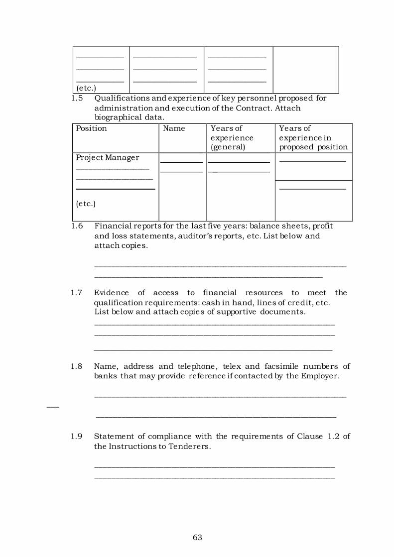
63
_________
_________
_________
(etc.)
____________
____________
____________
___________
___________
___________
1.5 Qualifications and experience of key personnel proposed for
administration and execution of the Contract. Attach biographical data.
Position Name Years of
experience (general)
Years of
experience in proposed position
Project Manager __________________
___________________
(etc.)
1.6 Financial reports for the last five years: balance sheets, profit
and loss statements, auditor’s reports, etc. List below and
attach copies.
_______________________________________________________________
_________________________________________________________
1.7 Evidence of access to financial resources to meet the
qualification requirements: cash in hand, lines of credit, etc. List below and attach copies of supportive documents.
____________________________________________________________
____________________________________________________________
_____________________________________________
1.8 Name, address and telephone, telex and facsimile numbers of
banks that may provide reference if contacted by the Employer.
_______________________________________________________________
___
____________________________________________________________
1.9 Statement of compliance with the requirements of Clause 1.2 of
the Instructions to Tenderers.
____________________________________________________________
____________________________________________________________

64
_____________________________________________
1.10 Proposed program (work method and schedule) for the whole of
the Works.
2 Joint Ventures
2.4 The information listed in 1.1 – 1.10 above shall be provided for
each partner of the joint venture.
2.5 The information required in 1.11 above shall be provided for the
joint venture.
2.6 Attach the power of attorney of the signatory(ies) of the tender
authorizing signature of the tender on behalf of the joint venture
2.7 Attach the Agreement among all partners of the joint venture ( and
which is legally binding on all partners), which shows that:
a) all partners shall be jointly and severally liable for the
execution of the Contract in accordance with the Contract
terms;
b) one of the partners will be nominated as being in charge,
authorized to incur liabilities and receive instructions
for and on behalf of any and all partners of the joint
venture; and
c) the execution of the entire Contract, including payment, shall
be done exclusively with the partner in charge.
TENDER QUESTIONNAIRE
Please fill in block letters.
1. Full names of tenderer
………………………………………………………………………………………
2. Full address of tenderer to which tender correspondence is to be sent
(unless an agent has been appointed below)
………………………………………………………………………………………
3. Telephone number (s) of tenderer
………………………………………………………………………………………
65
4. Telex address of tenderer
………………………………………………………………………………………
5. Name of tenderer’s representative to be contacted on matters of the
tender during the tender period
………………………………………………………………………………………
6. Details of tenderer’s nominated agent (if any) to receive tender notices.
This is essential if the tenderer does not have his registered address in
Kenya (name, address, telephone, telex)
………………………………………………………………………………………
………………………………………………………………………………………
_______________________
Signature of Tenderer
Make copy and deliver to:_____________________(Name of Employer)

66
CONFIDENTIAL BUSINESS QUESTIONNAIRE
You are requested to give the particulars indicated in Part 1 and either Part 2
(a), 2 (b) or 2 (c) and 2 (d) whichever applies to your type of business.
You are advised that it is a serious offence to give false information on this
Form.
Part 1 – General
Business Name ………………………………………………………………………
Location of business premises; Country/Town……………………….
Plot No……………………………………… Street/Road …………………………
Postal Address……………………………… Tel No………………………………..
Nature of Business…………………………………………………………………..
Current County Business Permit No…………………… Expiring
date…………………
Maximum value of business whichyou can handle at
any time: K. pound………………………..
Name of your bankers………………………………………………………………
Branch…………………………………………………………………………………
Part 2 (a) – Sole Proprietor
Your name in full…………………………………… Age…………………………
Nationality………………………………… Country of Origin…………………
*Citizenship details …………………………………………………………………
Part 2 (b) – Partnership
Give details of partners as follows:
Name in full Nationality Citizenship Details Shares
1……………………………………………………………………………………
67
2……………………………………………………………………………………
3……………………………………………………………………………………
Part 2(c) – Registered Company: Private or public……………………………………………………………
State the nominal and issued capital of the Company-
Nominal Kshs…………………………………………………………………
Issued Kshs……………………………………………………………………
Give details of all directors as follows:
Name in full. Nationality. Citizenship Details*. Shares.
1.
………………………………………………………………………………………
2.
………………………………………………………………………………………
3.
………………………………………………………………………………………
4.
………………………………………………………………………………………
Part 2(d) – Interest in the Firm:
Is there any person / persons in …………… ………(Name of Employer)
who has interest in this firm? Yes/No………………………(Delete as
necessary)
I certify that the information given above is correct.
……………………… ……………………… ………………… (Title) (Signature) (Date)
Attach proof of citizenship
68
STATEMENT OF FOREIGN CURRENCY REQUIREMENTS
(See Clause 23] of the Conditions of Contract)
In the event of our Tender for the execution of____________________
__________________________(name of Contract) being accepted, we would
require in accordance with Clause 21 of the Conditions of Contract,
which is attached hereto, the following percentage:
(Figures)………………………… (Words)…………………………………
of the Contract Sum, (Less Fluctuations) to be paid in foreign currency.
Currency in which foreign exchange element is required:
………………………………………………………………………………………
Date: The ………… Day of …………….. 20…………….
Enter 0% (zero percent) if no payment will be made in foreign currency.
Maximum foreign currency requirement shall be _____________(percent) of the Contract Sum, less Fluctuations.
_____________________
(Signature of Tenderer)
DETAILS OF SUB-CONTRACTORS
If the Tenderer wishes to sublet any portions of the Works under any
heading, he must give below details of the sub-contractors he intends
to employ for each portion.
Failure to comply with this requirement may invalidate the tender.
(1) Portion of Works to be sublet: [i)
Full name of Sub-
contractor
………………………………
and address of head office:
(ii) Sub-contractor’s experience
of similar works carried out in the last 3 years with
………………………………
………………………………
69
Contract value: ………………………………
………………………………
………………………………
(2) Portion of Works to sublet:
(i) Full name of sub-contractor
………………………………
and address of head office:
(ii) Sub-contractor’s experience of similar works carried out
in the last 3 years with
………………………………
………………………………
………………………………
contract value: ……………………………
……………………………
____________________ _______________________ [Signature of Tenderer) Date
LETTER OF NOTIFICATION OF AWARD
Address of Procuring Entity
_____________________
_____________________
To:
This is to notify that the contract/s stated below under the above mentioned
tender have been awarded to you.
1. Please acknowledge receipt of this letter of notification signifying your
acceptance.
RE: Tender No.
Tender Name
70
2. The contract/contracts shall be signed by the parties within 30 days of
the date of this letter but not earlier than 14 days from the date of the
letter.
3. You may contact the officer(s) whose particulars appear below on the
subject matter of this letter of notification of award.
(FULL PARTICULARS)
SIGNED FOR ACCOUNTING OFFICER FORM RB 1
REPUBLIC OF KENYA
PUBLIC PROCUREMENT ADMINISTRATIVE REVIEW BOARD
APPLICATION NO……………………………….OF………………20………….
BETWEEN
………………………………………………………………………APPLICANT
AND
……………………………………………………RESPONDENT (procuring entity)
Request for review of the decision of the
……………………………………………………… (Name of procuring entitity)
of…………………………dated the ……………….20………..in the matter of
tender no. …………….of …………..20…………
REQUEST FOR REVIEW
I/We …………………………………, the above named Applicant(s), of address:
Physical address……………………Fax No……………tel.
No………..Email……………, hereby request the Public
Procurement Administrative Review Board to review the
whole/part of the above mentioned decision on the following
grounds, namely:1.
2.
3.

71
Etc.
By this memorandum, the applicant requests the Board for order/orders that:1.
2.
Etc
Signed…………………………………(Applicant)
Dated on………………………………day of ………………/20……..
FOR OFFICIAL USE ONLY
Lodged with the secretary public procurement administrative review board
on………………….day of ……….20…………..
Signed
Board secretary


PN/1
PREAMBLES AND PRICING NOTES
A. GENERALLY
All work to be carried out in accordance with the Ministry of Public Works
General Specifications for Building Works issued in 1976 or as qualified or amended below.
B. MANUFACTURERS’ NAMES
Where manufacturers’ names and catalogue references are given for guidance
to quality and standard only. Alternative manufacturer of equal quality will be accepted at the discretion of the Project Manager.
C. WALLING
All precast concrete blocks shall be manufactured by the methods and to the
sizes specified in the Ministry of Public Works “Specification for Metric Sized Concrete Blocks for Building (1972)”
Walling of 100 mm thickness or under shall be reinforced with hoop iron every alternate course.
Prices for walling must allow for all costs in preparing, packing and sending sample blocks for testing as and when required by the Project Manager.
D. CARPENTRY
The grading rules for cypress shall be the same for podocarpus and all timber used for structural work shall be select (second grade).
All structural timber must conform to the minimum requirements for moisture
content and preservative treatment and timber prices must allow for preparing, packing and sending samples for testing when required.
Prices must also include for all nails and fasteners.

PN/2
A. JOINERY
Cypress for joinery shall be second grade in accordance with the latest grading rules of the Kenya Government.
Where Mahogany is specified, this refers to prime grade only. The Contractor
may with the approval of the Project Manager; use either Msharagi or Mvuli
in lieu of Mahogany but such approval will be given only in the case of shortages of the hardwoods specified.
Plugging shall be carried out by drilling walling or concrete with masonry
drill and filling with propriety plugs of the correct sizes. Cutting with hammer and chisel will not be allowed.
Prices for joinery must include for pencil rounded arises, protection against damage, nails, screws, framing and bedding in cement mortar as required.
Sizes given for joinery items are nominal sizes and exact dimensions of doors, etc, must be ascertained on site.
B. IRONMONGERY
Ironmongery shall be specified in the Bills of Quantities or equal and approved.
Prices must include for removing and re-fixing during and after painting,
labeling all keys, and for fixing to hardwood, softwood, concrete or blockwork.
Catalogue references given for ironmongery are for purposes of indicating
quality and size of item(s). Should the Contractor wish to substitute the
specified item(s) with others of equal manufacture, he must inform the Project Manager and obtain approval in writing.
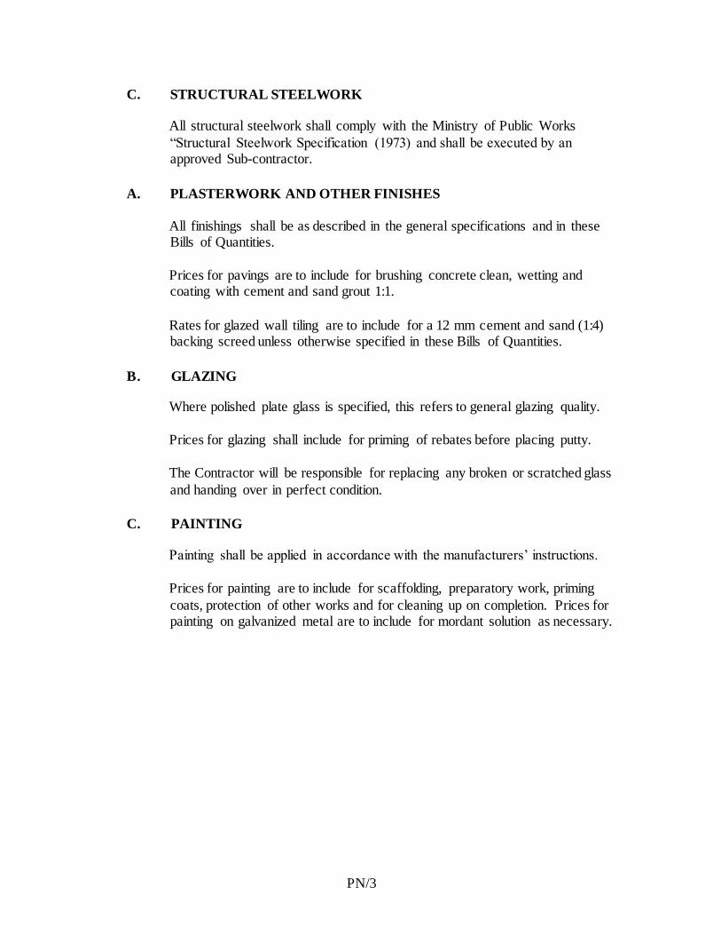
PN/3
C. STRUCTURAL STEELWORK
All structural steelwork shall comply with the Ministry of Public Works
“Structural Steelwork Specification (1973) and shall be executed by an approved Sub-contractor.
A. PLASTERWORK AND OTHER FINISHES
All finishings shall be as described in the general specifications and in these Bills of Quantities.
Prices for pavings are to include for brushing concrete clean, wetting and coating with cement and sand grout 1:1.
Rates for glazed wall tiling are to include for a 12 mm cement and sand (1:4) backing screed unless otherwise specified in these Bills of Quantities.
B. GLAZING
Where polished plate glass is specified, this refers to general glazing quality.
Prices for glazing shall include for priming of rebates before placing putty.
The Contractor will be responsible for replacing any broken or scratched glass
and handing over in perfect condition.
C. PAINTING
Painting shall be applied in accordance with the manufacturers’ instructions.
Prices for painting are to include for scaffolding, preparatory work, priming
coats, protection of other works and for cleaning up on completion. Prices for painting on galvanized metal are to include for mordant solution as necessary.


PROPOSED OFFICE PARTITIONING AND REFURBISHMENT TO ASSETS RECOVERY AGENCY OFFICES AT UAP BUILD ING 21ST FLOOR,
NAIROBI
PP/2
PARTICULAR PRELIMINARIES
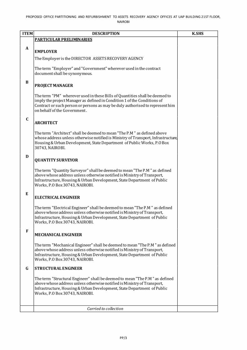
PROPOSED OFFICE PARTITIONING AND REFURBISHMENT TO ASSETS RECOVERY AGENCY OFFICES AT UAP BUILDING 21ST FLOOR,
NAIROBI
PP/3
ITEM DESCRIPTION K.SHS
PARTICULAR PRELIMINARIES
A EMPLOYER
The Employer is the DIRECTOR ASSETS RECOVERY AGENCY
The term "Employer" and "Government" wherever used in the contract document shall be synonymous.
B PROJECT MANAGER
The term "PM" wherever used in these Bills of Quantities shall be deemed to imply the project Manager as defined in Condition 1 of the Conditions of Contract or such person or persons as may be duly authorised to represent him on behalf of the Government .
C ARCHITECT
The term "Architect" shall be deemed to mean "The P.M " as defined above whose address unless otherwise notified is Ministry of Transport, Infrastructure, Housing & Urban Development, State Department of Public Works, P.O Box 30743, NAIROBI.
D QUANTITY SURVEYOR
The term "Quantity Surveyor" shall be deemed to mean "The P.M " as defined above whose address unless otherwise notified is Ministry of Transport, Infrastructure, Housing & Urban Development, State Department of Public Works, P.O Box 30743, NAIROBI.
E ELECTRICAL ENGINEER
The term "Electrical Engineer" shall be deemed to mean "The P.M " as defined above whose address unless otherwise notified is Ministry of Transport, Infrastructure, Housing & Urban Development, State Department of Public Works, P.O Box 30743, NAIROBI.
F MECHANICAL ENGINEER
The term "Mechanical Engineer" shall be deemed to mean "The P.M " as defined above whose address unless otherwise notified is Ministry of Transport, Infrastructure, Housing & Urban Development, State Department of Public Works, P.O Box 30743, NAIROBI.
G STRUCTURAL ENGINEER
The term "Structural Engineer" shall be deemed to mean "The P.M " as defined above whose address unless otherwise notified is Ministry of Transport, Infrastructure, Housing & Urban Development, State Department of Public Works, P.O Box 30743, NAIROBI.
Carried to collection
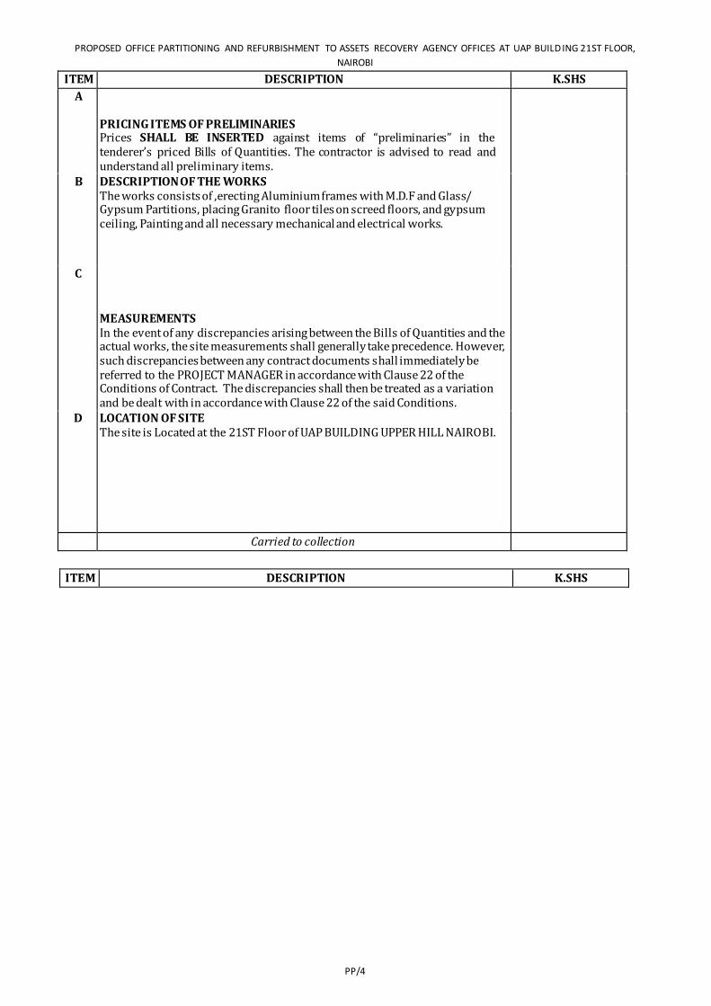
PROPOSED OFFICE PARTITIONING AND REFURBISHMENT TO ASSETS RECOVERY AGENCY OFFICES AT UAP BUILD ING 21ST FLOOR,
NAIROBI
PP/4
ITEM DESCRIPTION K.SHS
A
PRICING ITEMS OF PRELIMINARIES Prices SHALL BE INSERTED against items of “preliminaries” in the tenderer’s priced Bills of Quantities. The contractor is advised to read and understand all preliminary items.
B DESCRIPTION OF THE WORKS The works consists of ,erecting Aluminium frames with M.D.F and Glass/ Gypsum Partitions, placing Granito floor tiles on screed floors, and gypsum ceiling, Painting and all necessary mechanical and electrical works.
C
MEASUREMENTS In the event of any discrepancies arising between the Bills of Quantities and the actual works, the site measurements shall generally take precedence. However, such discrepancies between any contract documents shall immediately be referred to the PROJECT MANAGER in accordance with Clause 22 of the Conditions of Contract. The discrepancies shall then be treated as a variation and be dealt with in accordance with Clause 22 of the said Conditions.
D LOCATION OF SITE The site is Located at the 21ST Floor of UAP BUILDING UPPER HILL NAIROBI.
Carried to collection
ITEM DESCRIPTION K.SHS
PROPOSED OFFICE PARTITIONING AND REFURBISHMENT TO ASSETS RECOVERY AGENCY OFFICES AT UAP BUILDING 21ST FLOOR,
NAIROBI
PP/5
A
DEMOLITIONS AND ALTERATIONS
The Contractor is to allow for all temporary protection required during the works including ordinary and special dust screens, hoardings, barriers, warning signs, etc as directed by the Project Manager and as necessary for the adequate propping and protection of existing property, finishes, workmen employed on the site, employer's agents and the public. Any damage or loss incurred due to the insufficiency of such protection must be made good by the Contractor. All protective devices are to be removed on completion of the works and any necessary making good consequent upon this is to be executed to the satisfaction of the Project Manager
The works shall be propped, strutted and supported as necessary before any alteration or demolition work commences. Prices shall include for all cleaning and preparatory work to structure and finishes and for making good to all finishes on completion whether or not specifically described.
Unless described as set aside for re-use all arising debris and surplus materials shall be carefully removed from building and carted away from site.
The Contractor shall be entirely responsible for any breakage or damage which may occur to materials required for re-use during their removal unless it is certified by the Project Manager that such damage or breakage was inevitable as a result of the condition of the item concerned
B CLEARING AWAY
The Contractor shall remove all temporary works, rubbish, debris and surplus materials from the site as they accumulate and upon completion of the works, remove and clear away all plant, equipment, rubbish, unused materials and stains and leave in a clean and tidy state to the reasonable satisfaction of the Project Manager.
The whole of the works shall be delivered up clean, complete and in perfect condition in every respect to the satisfaction of the Project Manager.
C
CLAIMS It shall be a condition of this contract that upon it becoming reasonably apparent to the Contractor that he has incurred losses and / or expenses due to any of the contract conditions, or by any other reason whatsoever, he shall present such a claim or intent to claim notice to the PROJECT MANAGER within the contract period. No claim shall be entertained upon the expiry of the said contact period.
Carried to collection -
PROPOSED OFFICE PARTITIONING AND REFURBISHMENT TO ASSETS RECOVERY AGENCY OFFICES AT UAP BUILD ING 21ST FLOOR,
NAIROBI
PP/6
ITEM DESCRIPTION K.SHS
A PAYMENTS The tenderer’s attention is drawn to the fact that the GOVERNMENT DOES NOT MAKE ADVANCE PAYMENTS but pays for work done and materials delivered to sit: all in accordance with Clause 23 of the Conditions of Contract Agreement. In order to facilitate this, a list of the general component elements for the works is given at the summary page of these specifications and the tenderer is requested to break down his tender sum commensurate to the said elements
B
PREVENTION OF ACCIDENT, DAMAGE OR LOSS
The Contractor is notified that these works are to be carried out on a restricted site where the client is going on with other nomal activities. The Contractor is thus instructed to take reasonable care in the execution of the works as to prevent accidents, damage or loss and disruoption of activities beeing carried out by the Client. The Contractor shall allow in his rates any expense he deemed necessary by taking such care within the site.
C
WORKING CONDITIONS
The Contractor shall allow in his rates for any interferance that he may encounter in the course of the works for the Client may in some cases ask the Contractor not to proceed with the works until some activities within the site are completed, as the facility will be operating as usual during the course of the contract.
D SIGNBOARD
Allow for providing, erecting, maintaining throughout the course of the Contract and afterwards clearing away a signboard as designed, specified and approved by the Project Manager.
E LABOUR CAMPS
The Contractor shall not be allowed to house labour on site. Allow for transporting workers to and from the site during the tenure of the contract.
F MATERIALS FROM DEMOLITIONS
Any materials arising from demolitions and not re-used shall become the property of the client. The Contractor shall allow in his rates the cost of disposing the demolished materials as directed.
50,000.00
PROPOSED OFFICE PARTITIONING AND REFURBISHMENT TO ASSETS RECOVERY AGENCY OFFICES AT UAP BUILDING 21ST FLOOR,
NAIROBI
PP/7
Carried to collection 50,000.00
ITEM DESCRIPTION K.SHS
A PRICING RATES The tenderer shall include for all costs in executing the whole of the works, including transport, replacing damaged items, fixing, all to comply with the said Conditions of Contract.
B SECURITY
The Contractor shall allow for providing adequate security for the works and the workers in the course of execution of this contract. No claim will be entertained from the Contractor for not maintaining adequate security for both the works and workers.
150,000.00
C URGENCY OF THE WORKS
The Contractor is notified that these “ works are urgent” and should be completed within the period stated in these Particular Preliminaries.
The Contractor shall allow in his rates for any costs he/ she deems that he/she may incur by having to complete these works within the stipulated contract period.
D PAYMENT FOR MATERIALS ON SITE All materials for incorporation in the works must be stored on site before payment is effected, unless specifically exempted by the Project Manager. This is to include materials of the Contractor, nominated sub-Contractors and nominated suppliers.
E EXISTING SERVICES Prior to the commencement of any work, the Contractor is to ascertain from the relevant authority the exact position, depth and level of all existing services in the area and he/she shall make whatever provisions may be required by the authorities concerned for the support, maintenance and protection of such services.
F CONTRACT COMPLETION PERIOD The contract completion period in accordance with condition 31 of the
Conditions of contract must be adhered to.
The ‘PROJECT MANAGER’ shall strictly monitor the Contractors progress in relation to the progress chart and should it be found necessary the ‘PROJECT MANAGER’ shall inform the Contractor in writing that his actual performance on site is not satisfactory .In all such cases the Contractor shall accelerate his rate of performance production and progress by all means such as additional labour,plant, e.t.c and working overtime all at his cost.
PROPOSED OFFICE PARTITIONING AND REFURBISHMENT TO ASSETS RECOVERY AGENCY OFFICES AT UAP BUILD ING 21ST FLOOR,
NAIROBI
PP/8
Carried to collection 150,000.00
ITEM DESCRIPTION K.SHS
A PERFORMANCE BOND
A bond of 5% of the contract sum will be required in accordance with clause 6.00 (as amended) on award of contract of the Instructions to Tenderer’s. No payment on account for the works executed will be made to the contractor until he has submitted the Performance Bond to the Project Manager duly signed, sealed and stamped from an approved Bank.
112,500.00
B
TENDER DOCUMENTS
Tender documents are as listed in Clause 2.1 of the Instruction to Tenderer’s Page STD/9
C DELIVERY OF TENDER
Tenders and all documents in connection therewith, as specified above must be delivered in the addressed envelope which should be properly sealed and deposited at the offices as specified in the letter accompanying these documents or as indicated in the advertisement.
Tenders will be opened at the time specified in the letter accompanying these Tender Documents or as indicated in the advertisement. Tenders delivered/received later than the above time will not be opened.
PROPOSED OFFICE PARTITIONING AND REFURBISHMENT TO ASSETS RECOVERY AGENCY OFFICES AT UAP BUILDING 21ST FLOOR,
NAIROBI
PP/9
D VALUE ADDED TAX
The Contractor’s attention is drawn to the Legal Notice in the Finance Act part 3
Section 21(b) operative from 1st September, 1993 which requires payment of VAT on all contracts. The Contractor should therefore include allowance in his rates and prices for prices for VAT and any other Government taxes currently in force.
The tenderer is advised that in accordance with Government public notice No.
35 & 36 Dated 11th September 2003 operational from 1st October 2003, VAT will be deducted against the contract sum at the prevailing rate by the Employer and remitted directly to the Commissioner of VAT through all interim certificates. It should however be noted that this is not additional tax but a new mode of payment for VAT, any excess payment will be refundable once the Contractor has submitted monthly returns to the Commissioner of VAT who will do the refunds when satisfied that the VAT regulations have been complied with.
NB: The Contractor should therefore include the tax within the rates.
Carried to collection 112,500.00
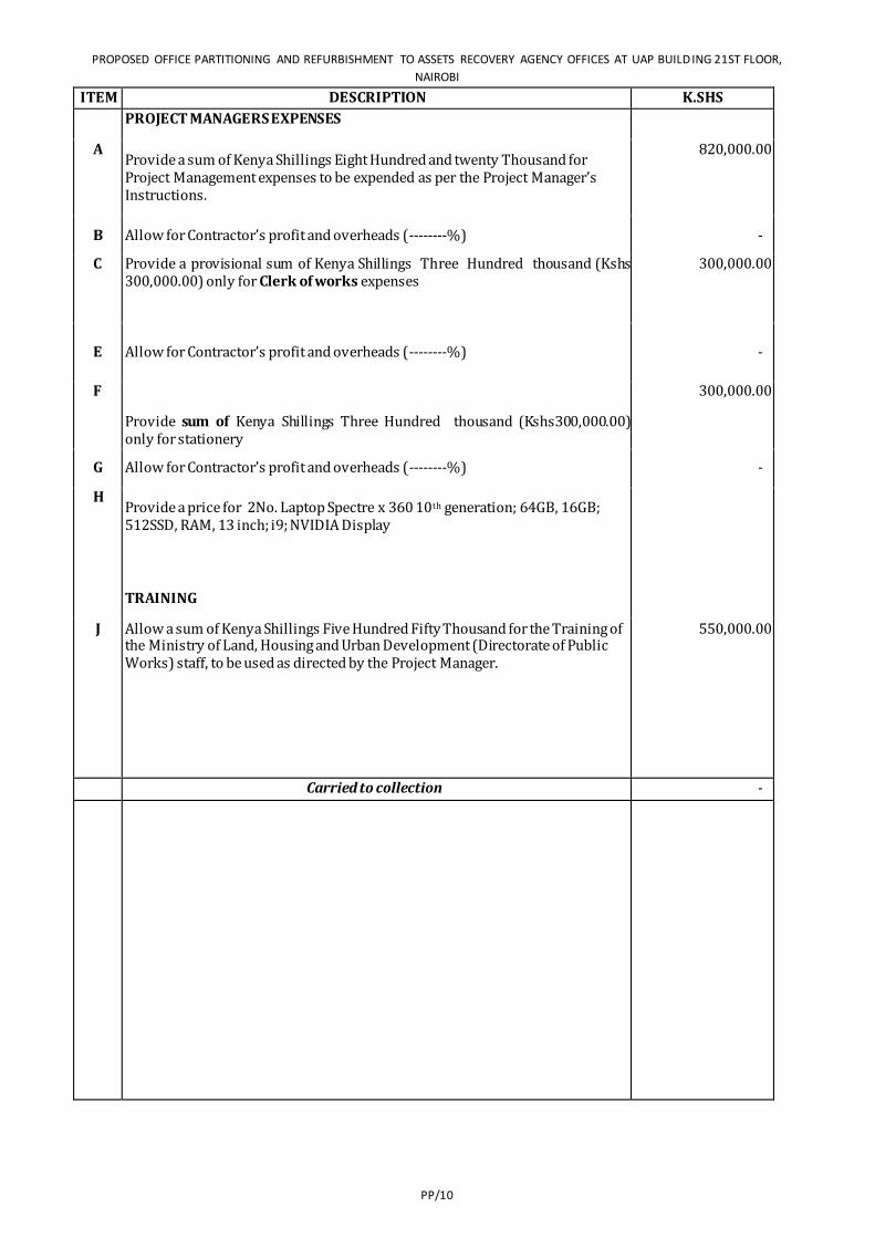
PROPOSED OFFICE PARTITIONING AND REFURBISHMENT TO ASSETS RECOVERY AGENCY OFFICES AT UAP BUILD ING 21ST FLOOR,
NAIROBI
PP/10
ITEM DESCRIPTION K.SHS
PROJECT MANAGERS EXPENSES
A Provide a sum of Kenya Shillings Eight Hundred and twenty Thousand for Project Management expenses to be expended as per the Project Manager’s Instructions.
820,000.00
B Allow for Contractor’s profit and overheads (--------%) -
C Provide a provisional sum of Kenya Shillings Three Hundred thousand (Kshs 300,000.00) only for Clerk of works expenses
300,000.00
E Allow for Contractor’s profit and overheads (--------%) -
F
Provide sum of Kenya Shillings Three Hundred thousand (Kshs300,000.00) only for stationery
300,000.00
G Allow for Contractor’s profit and overheads (--------%) -
H Provide a price for 2No. Laptop Spectre x 360 10th generation; 64GB, 16GB; 512SSD, RAM, 13 inch; i9; NVIDIA Display
TRAINING
J Allow a sum of Kenya Shillings Five Hundred Fifty Thousand for the Training of the Ministry of Land, Housing and Urban Development (Directorate of Public Works) staff, to be used as directed by the Project Manager.
550,000.00
Carried to collection -
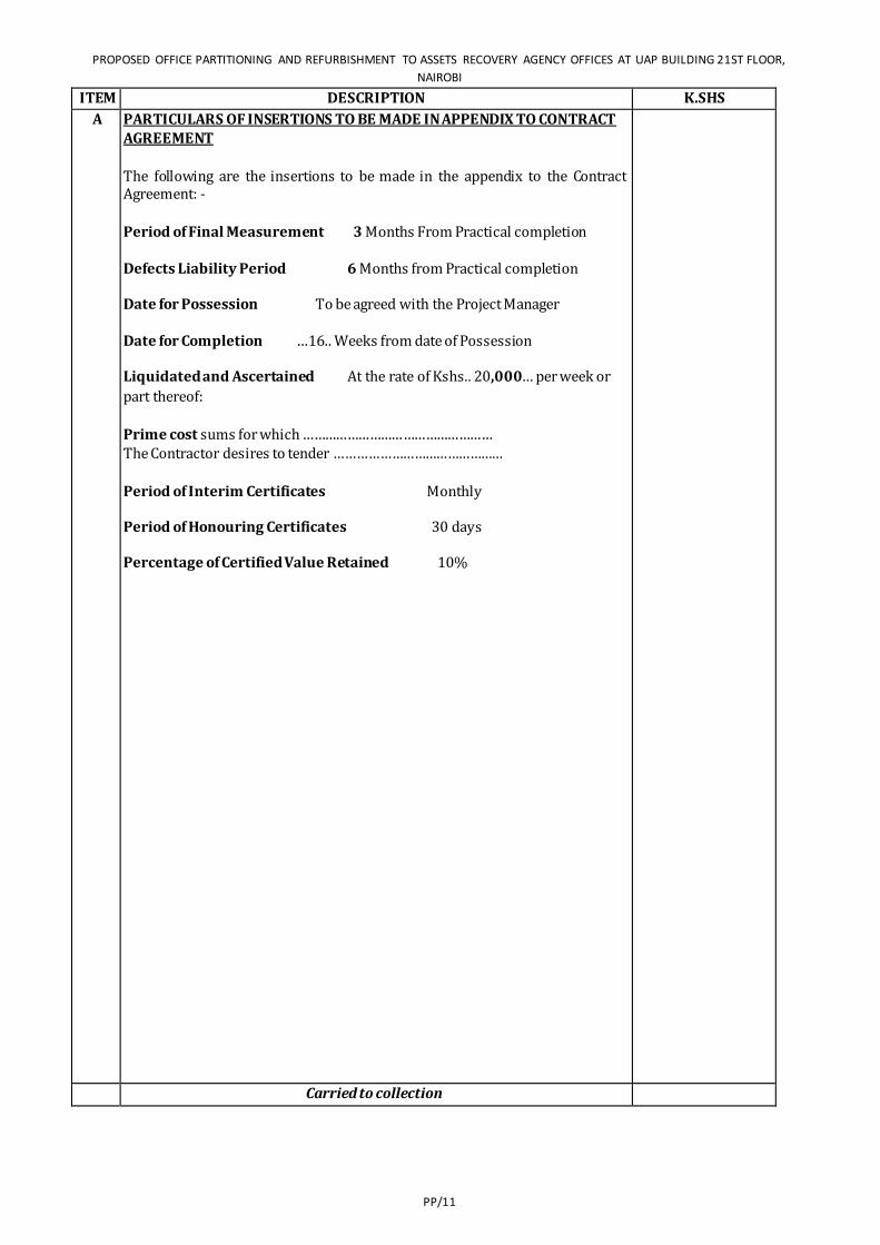
PROPOSED OFFICE PARTITIONING AND REFURBISHMENT TO ASSETS RECOVERY AGENCY OFFICES AT UAP BUILDING 21ST FLOOR,
NAIROBI
PP/11
ITEM DESCRIPTION K.SHS
A PARTICULARS OF INSERTIONS TO BE MADE IN APPENDIX TO CONTRACT AGREEMENT
The following are the insertions to be made in the appendix to the Contract Agreement: -
Period of Final Measurement 3 Months From Practical completion
Defects Liability Period 6 Months from Practical completion
Date for Possession To be agreed with the Project Manager
Date for Completion …16.. Weeks from date of Possession
Liquidated and Ascertained At the rate of Kshs.. 20,000… per week or
part thereof: Prime cost sums for which …………………………………………… The Contractor desires to tender ………………………………………
Period of Interim Certificates Monthly
Period of Honouring Certificates 30 days
Percentage of Certified Value Retained 10%
Carried to collection
PROPOSED OFFICE PARTITIONING AND REFURBISHMENT TO ASSETS RECOVERY AGENCY OFFICES AT UAP BUILD ING 21ST FLOOR,
NAIROBI
PP/12
ITEM DESCRIPTION K.SHS
COLLECTION
Brought forward from page PP/1
Brought forward from page PP/2 -
Brought forward from page PP/3 -
Brought forward from page PP/4 50,000.00
Brought forward from page PP/5 150,000.00
Brought forward from page PP/6 112,500.00
Brought forward from page PP/7 -
Brought forward from page PP/8 -
TOTAL FOR PARTICULAR PRELIMINARIES CARRIED TO GRAND SUMMARY 312,500.00


PROPOSED OFFICE PARTITIONING AND REFURBISHMENT TO ASSETS RECOVERY AGENCY OFFICES AT UAP BUILDING 21ST FLOOR,
NAIROBI
GP/14
GENERAL PRELIMINARIES
PROPOSED OFFICE PARTITIONING AND REFURBISHMENT TO ASSETS RECOVERY AGENCY OFFICES AT UAP BUILDING 21ST FLOOR,
NAIROBI
GP/15
ITEM DESCRIPTION KSHS.
GENERAL PRELIMINARIES
A. PRICING OF ITEMS OF PRELIMINARIES AND PREAMBLES
Prices will be inserted against items of Preliminaries in the Contractor's priced Bills of Quantities and Specification.
The Contractor shall be deemed to have included in his prices or rates for the various items in the Bills of Quantities or Specification for all costs involved in complying with all the requirements for the proper execution of the whole of the works in the Contract.
B.
ABBREVIATIONS
Throughout these Bills, units of measurement and terms are abbreviated and shall be interpreted as follows:-
C.M. Shall mean cubic metre
S.M. Shall mean square metre
L.M. Shall mean linear metre
MM Shall mean Millimetre
Kg. Shall mean Kilogramme
No. Shall mean Number
Prs. Shall mean Pairs
B.S. Shall mean the British Standard Specification Published by the British Standards Institution, 2 Park Street, London W.I., England.
Ditto Shall mean the whole of the preceding description except as qualified in the description in which it occurs.
m.s. Shall mean measured separately.
a.b.d Shall mean as before described.
Carried to collection
ITEM DESCRIPTION KSHS.

PROPOSED OFFICE PARTITIONING AND REFURBISHMENT TO ASSETS RECOVERY AGENCY OFFICES AT UAP BUILDING 21ST FLOOR,
NAIROBI
GP/16
A. EXCEPTION TO THE STANDARD METHOD OF MEASUREMENT
Attendance ; Clause B19(a) of the Standard Method of Measurement is deleted and the following clause is substituted:-
Attendance on nominated Sub-Contractors shall be given as an item in each case shall be deemed to include: allowing use of standing scaffolding, mess rooms, sanitary accommodation and welfare facilities; provision of special scaffolding where necessary; providing space for office accommodation and for storage of plant and materials; providing light and water for their work: clearing away rubbish; unloading checking and hoisting: providing electric power and removing and replacing duct covers, pipe casings and the like necessary for the execution and testing of Sub- Contractors' work and being responsible for the accuracy of the same.
Fix Only:-
"Fix Only" shall mean take delivery at nearest railway station (Unless otherwise stated), pay all demurrage charges, load and transport to site where necessary, unload, store, unpack, assemble as necessary, distribute to position, hoist and fix only.
Carried to collection

PROPOSED OFFICE PARTITIONING AND REFURBISHMENT TO ASSETS RECOVERY AGENCY OFFICES AT UAP BUILDING 21ST FLOOR,
NAIROBI
GP/17
ITEM DESCRIPTION KSHS.
A FORM OF CONTRACT
The Form of Contract shall be as stipulated in the Republic of Kenya's Standard Tender Document for Procurement of Building Works (2006 Edition) included herein
The Conditions of Contract are also included herein
Conditions of Contract
These are numbered from 1 to 37 as set out in pages 18 to 37 of these tender documents.
Particulars of insertions to be made in the Appendix to the Contract Agreement will be found in the Particular Preliminaries part of these Bills of Quantities
Carried to collection
PROPOSED OFFICE PARTITIONING AND REFURBISHMENT TO ASSETS RECOVERY AGENCY OFFICES AT UAP BUILDING 21ST FLOOR,
NAIROBI
GP/18
ITEM DESCRIPTION KSHS.
A. PLANT, TOOLS AND VEHICLES
Allow for providing all scaffolding, plant, tools and vehicles required for the works except in so far as may be stated otherwise herein and except for such items specifically and only required for the use of nominated Sub-Contractors as described herein. No timber used for scaffolding, formwork or temporary works of any kind shall be used afterwards in the permanent work.
100,000.00 B.
TRANSPORT.
Allow for transport of workmen, materials, etc., to and from the site at such hours and by such routes as may be permitted by the competent authorities.
C. MATERIALS AND WORKMANSHIP.
All materials and workmanship used in the execution of the work shall be of the best quality and description unless otherwise stated. The Contractor shall order all materials to be obtained from overseas immediately after the Contract is signed and shall also order materials to be obtained from local sources as early as necessary to ensure that they are onsite when required for use in the works. The Bills of Quantities shall not be used for the purpose of ordering materials.
D. SIGN FOR MATERIALS SUPPLIED.
The Contractor will be required to sign a receipt for all articles and materials supplied by the PROJECT MANAGER at the time of taking deliver thereof, as having received them in good order and condition, and will thereafter be responsible for any loss or damage and for replacements of any such loss or damage with articles and/or materials which will be supplied by the PROJECT MANAGER at the current market prices including Customs Duty and V.A.T., all at the Contractor’s own cost and expense, to the satisfaction of the PROJECT MANAGER
E. STORAGE OF MATERIALS
The Contractor shall provide at his own risk and cost where directed on the site weather proof lock-up sheds and make good damaged or disturbed surfaces upon completion to the satisfaction of the PROJECT MANAGER Nominated Sub-Contractors are to be made liable for the cost of any storage accommodation provided especially for their use.
50,000.00
Carried to collection 150,000.00

PROPOSED OFFICE PARTITIONING AND REFURBISHMENT TO ASSETS RECOVERY AGENCY OFFICES AT UAP BUILDING 21ST FLOOR,
NAIROBI
GP/19
ITEM DESCRIPTION KSHS.
A. SAMPLES The Contractor shall furnish at his own cost any samples of materials or workmanship including concrete test cubes required for the works that may be called for by the PROJECT MANAGER for his approval until such samples are approved by the PROJECT MANAGER and the PROJECT MANAGER, may reject any materials or workmanship not in his opinion to be up to approved samples. The PROJECT MANAGER shall arrange for the testing of such materials as he may at his discretion deem desirable, but the testing shall be made at the expense of the Contractor and not at the expense of the PROJECT MANAGER. The Contractor shall pay for the testing in accordance with the current scale of testing charges laid down by the Ministry of Public Works.
The procedure for submitting samples of materials for testing and the method of marking for identification shall be as laid down by the PROJECT MANAGER The Contractor shall allow in his tender for such samples and tests except those in connection with nominated sub-contractors’ work.
25,000.00 B.
GOVERNMENT ACTS REGARDING WORK, PEOPLE ETC.
Allow for complying with all Government Acts, Orders and Regulations in connection with the employment of Labour and other matters related to the execution of the works. In particular the Contractor’s attention is drawn to the provisions of the Factory Act 1950 and his tender must include for all costs arising or resulting from compliance with any Act, Order or Regulation relating to Insurances, pensions and holidays for workpeople or so the safety, health and welfare of the workpeople.
The Contractor must make himself fully acquainted with current Acts and Regulations, including Police Regulations regarding the movement, housing, security and control of labour, labour camps , passes for transport, etc. It is most important that the Contractor, before tendering, shall obtain from the relevant Authority the fullest information regarding all such regulations and/or restrictions which may affect the rganization of the works, supply and control of labour, etc., and allow accordingly in his tender. No claim in respect of want of knowledge in this connection will be entertained.
C. SECURITY OF WORKS ETC. The Contractor shall be entirely responsible for the security of all the works stores, materials, plant, personnel, etc., both his own and sub-contractors’ and must provide all necessary watching, lighting and other precautions as necessary to ensure security against theft, loss or damage and the protection of the public.
Carried to collection
25,000.00
PROPOSED OFFICE PARTITIONING AND REFURBISHMENT TO ASSETS RECOVERY AGENCY OFFICES AT UAP BUILDING 21ST FLOOR,
NAIROBI
GP/20
ITEM DESCRIPTION KSHS.
A. PUBLIC AND PRIVATE ROADS.
Maintain as required throughout the execution of the works and make good any damage to public or private roads arising from or consequent upon the execution of the works to the satisfaction of the local and other competent authority and the PROJECT MANAGER
B. EXISTING PROPERTY.
The Contractor shall take every precaution to avoid damage to all existing property including roads, cables, drains and other services and he will be held responsible for and shall make good all such damage arising from the execution of this contract at his own expense to the satisfaction of the PROJECT MANAGER
100,000.00 C.
VISIT SITE AND EXAMINE DRAWINGS.
The Contractor is recommended to examine the drawings and visit the site the location of which is described in the Particular Preliminaries hereof. He shall be deemed to have acquainted himself therewith as to its nature, position, means of access or any other matter which, may affect his tender. No claim arising from his failure to comply with this recommendation will be considered.
D. ACCESS TO SITE AND TEMPORARY ROADS.
Means of access to the Site shall be agreed with the PROJECT MANAGER prior to commencement of the work and Contractor must allow for building any necessary temporary access roads (approximately 70 metres long) for the transport of the materials, plant and workmen as may be required for the complete execution of the works including the provision of temporary culverts, crossings, bridges, or any other means of gaining access to the Site. Upon completion of the works, the Contractor shall remove such temporary access roads; temporary culverts, bridges, etc., and make good and reinstate all works and surfaces disturbed to the satisfaction of the PROJECT MANAGER
E. AREA TO BE OCCUPIED BY THE CONTRACTOR
The area of the site which may be occupied by the Contractor for use of storage and for the purpose of erecting workshops, etc., shall be defined on site by the PROJECT MANAGER

PROPOSED OFFICE PARTITIONING AND REFURBISHMENT TO ASSETS RECOVERY AGENCY OFFICES AT UAP BUILDING 21ST FLOOR,
NAIROBI
GP/21
Carried to collection 100,000.00
ITEM DESCRIPTION KSHS.
A. OFFICE ETC. FOR THE PROJECT MANAGER
The Contractor shall provide, erect and maintain where directed on site a properly ventilated lockable office for the consultants, having a minimum floor area of 40 Square Metres complete with furniture (Tables, chairs e.t.c). Provision shall be made for artificial lighting and cleaning facilities for the duration of the works. Upon clompletion the Contractor shall dismantle and clear away the office. He shall also provide a strong metal trunk complete with strong hasp and staple fastening and two keys. He shall provide, erect and maintain a lock-up type water or bucket closet for the sole use of the PROJECT MANAGER including making temporary connections to the drain where applicable to the satisfaction of Government and Medical Officer of Health and shall provide services of cleaner and pay all conservancy charges and keep both office and closet in a clean and sanitary condition from commencement to the completion of the works and dismantle and make good disturbed surfaces. The office and closet shall be completed before the Contractor is permitted to commence the works. The Contractor shall make available on the Site as and when required by the “PROJECT MANAGER” a modern and accurate level together with levelling staff, ranging rods and 50 metre metallic or linen tape.
100,000.00 B.
WATER AND ELECTRICITY SUPPLY FOR THE WORKS
The Contractor shall provide at his own risk and cost all necessary water, electric light and power required for use in the works. The Contractor must make his own arrangements for connection to the nearest suitable water main and for metering the water used. He must also provide temporary tanks and meters as required at his own cost and clear away when no longer required and make good on completion to the entire satisfaction of the PROJECT MANAGER . The Contractor shall pay all charges in connection herewith. No guarantee is given or implied that sufficient water will be available from mains and the Contractor must make his own arrangements for augmenting this supply at his own cost. Nominated Sub—contractors are to be made liable for the cost of any water or electric current used and for any installation provided especially for their own use.
120,000.00 C.
SANITATION OF THE WORKS
The Sanitation of the works shall be arranged and maintained by the Contractor to the satisfaction of the Government and/or Local Authorities, Labour Department and the PROJECT MANAGER
90,000.00
PROPOSED OFFICE PARTITIONING AND REFURBISHMENT TO ASSETS RECOVERY AGENCY OFFICES AT UAP BUILDING 21ST FLOOR,
NAIROBI
GP/22
D. SUPERVISION AND WORKING HOURS
The works shall be executed under the direction and to the entire satisfaction in all respects of the PROJECT MANAGER who shall at all times during normal working hours have access to the works and to the yards and workshops of the Contractor and sub-Contractors or other places where work is being prepared for the contract.
Carried to collection 310,000.00
ITEM DESCRIPTION KSHS.
A
B
PROVISIONAL SUMS.
The term “Provisional Sum” wherever used in these Bills of Quantities shall have the meaning stated in Section A item A7(i) of the Standard Method of Measurement mentioned in Condition No. 16 of the conditions of Contract. Such sums are net and no addition shall be made to them for profit.
PRIME COST (OR P.C.) SUMS.
The term “Prime Cost Sum” or "P.C. Sum" wherever used in these Bills of Quantities shall have the meaning stated in Section A item A7 (ii) of the Standard Method of Measurement mentioned in Condition No. 16 of the conditions of Contract. Persons or firms nominated by the PROJECT MANAGER to execute work or to provide and fix materials or goods as stated in Condition No. 20 of the Conditions of Contract are described herein as Nominated Sub-Contractors.
Persons or firms so nominated to supply goods or materials are described herein as Nominated Suppliers.
C PROGRESS CHART.
The Contractor shall provide within two weeks of Possession of Site and in agreement with the PROJECT MANAGER a Progress Chart for the whole of the works including the works of Nominated Sub-Contractors ; one copy to be handed to the PROJECT MANAGER and a further copy to be retained on Site. Progress to be recorded and chart to be amended as necessary as the work proceeds.
15,000.00
PROPOSED OFFICE PARTITIONING AND REFURBISHMENT TO ASSETS RECOVERY AGENCY OFFICES AT UAP BUILDING 21ST FLOOR,
NAIROBI
GP/23
D ADJUSTMENT OF P.C. SUMS.
In the final account all P.C. Sums shall be deducted and the amount properly expended upon the PROJECT MANAGER'S order in respect of each of them added to the Contract sum. The Contractor shall produce to the PROJECT MANAGER such quotations, invoices or bills, properly receipted, as may be necessary to show the actual details of the sums paid by the Contractor. Items of profit upon P.C. Sums shall be adjusted in the final account pro-rata to the amount paid. Items of "attendance" (as previously described) following P.C. Sums shall be adjusted pro-rata to the physical extent of the work executed (not pro-rata to the amount paid) and this shall apply even though the Contractor's priced Bill shows a percentage in the rate column in respect of them.
Should the Contractor be permitted to tender and his tender be accepted of any work for which a P.C. Sum is included in these Bill of Quantities profit and attendance will be allowed at the same rate as it would be if the work were executed by a Nominated Sub-Contractor.
Carried to collection
15,000.00
ITEM DESCRIPTION KSHS. A. ADJUSTMENT OF PROVISIONAL SUMS.
In the final account all Provisional Sums shall be deducted and the value of the work properly executed in respect of them upon the PROJECT MANAGER's order added to the Contract Sum. Such work shall be valued as described for Variations in Conditions No. 13of the Conditions of Contract, but should any part of the work be executed by a Nominated Sub-Contractor, the value of such work or articles for the work to be supplied by a Nominated Supplier, the value of such work or articles shall be treated as a P.C. Sum and profit and attendance comparable to that contained in the priced Bills of Quantities for similar items added.
PROPOSED OFFICE PARTITIONING AND REFURBISHMENT TO ASSETS RECOVERY AGENCY OFFICES AT UAP BUILDING 21ST FLOOR,
NAIROBI
GP/24
B. NOMINATED SUB-CONTRACTORS
When any work is ordered by the PROJECT MANAGER to be executed by nominated sub-contractors, the Contractor shall enter into sub-contracts as described in Condition No. 20 of the Conditions of Contract and shall thereafter be responsible for such sub-contractors in every respect. Unless otherwise described the Contractor is to provide for such Sub-Contractors any or all of the facilities described in these Preliminaries. The Contractor should price for these with the nominated Sub-contract Contractor's work concerned in the P.C. Sums under the description "add for Attendance".
C. DIRECT CONTRACTS
Notwithstanding the foregoing conditions, the Government reserves the right to place a "Direct Contract" for any goods or services required in the works which are covered by a P.C. Sum in the Bills of Quantities and to pay for the same direct. In any such instances, profit relative to the P.C. Sum the priced Bills of Quantities will be adjusted as described for P.C. Sums and allowed.
D. ATTENDANCE UPON OTHER TRADESMEN, ETC.
The Contractor shall allow for the attendance of trade upon trade and shall afford any tradesmen or other persons employed for the execution of any work not included in this Contract every facility for carrying out their work and also for use of his ordinary scaffolding. The Contractor, however, shall not be required to erect any special scaffolding for them. The Contractor shall perform such cutting away for and making good after the work of such tradesmen or persons as may be ordered by the PROJECT MANAGER and the work will be measured and paid for to the extent executed at rates provided in these Bills.
Carried to collection
ITEM DESCRIPTION KSHS.
A. INSURANCE
The Contractor shall insure as required in Conditions No 30 of the Conditions of Contract. No payment on account of the work executed will be made to the Contractor until he has satisfied the PROJECT MANAGER either by production of an Insurance Policy or and Insurance Certificate that the provision of the foregoing Insurance Clauses have been complied with in all respects. Thereafter the PROJECT MANAGER shall from time to time ascertain that premiums are duly paid up by the Contractor who shall if called upon to do so, produce the receipted premium renewals for the PROJECT MANAGER's inspection. 300,000.00
PROPOSED OFFICE PARTITIONING AND REFURBISHMENT TO ASSETS RECOVERY AGENCY OFFICES AT UAP BUILDING 21ST FLOOR,
NAIROBI
GP/25
B. PROVISIONAL WORK
All work described as "Provisional" in these Bills of Quantities is subject to remeasurement in order to ascertain the actual quantity executed for which payment will be made. All "Provisional" and other work liable to adjustment under this Contract shall left uncovered for a reasonable time to allow all measurements needed for such adjustment to be taken by the PROJECT MANAGER
Immediately the work is ready for measuring, the Contractor shall give notice to the PROJECT MANAGER. If the Contractor makes default in these respects he shall if the PROJECT MANAGER so directs uncover the work to enable all measurements to be taken and afterwards reinstate at his own expense.
C. ALTERATIONS TO BILLS, PRICING, ETC.
Any unauthorised alteration or qualification made to the text of the Bills of Quantities may cause the Tender to be disqualified and will in any case be ignored. The Contractor shall be deemed to have made allowance in his prices generally to cover any items against which no price has been inserted in the priced Bills of Quantities. All items of measured work shall be priced in detail and the Tenders containing Lump Sums to cover trades or groups of work must be broken down to show the price of each item before they will be accepted.
D. BLASTING OPERATIONS
Blasting will only be allowed with the express permission of the PROJECT MANAGER in writing. All blasting operations shall be carried out at the Contractor's sole risk and cost in accordance with any Government regulations in force for the time being, and any special regulations laid down by the PROJECT MANAGER governing the use and storage of explosives.
Carried to collection
300,000.00
ITEM DESCRIPTION KSHS.
A. MATERIALS ARISING FROM EXCAVATIONS
Materials of any kind obtained from the excavations shall be the property of the Government. Unless the PROJECT MANAGER directs otherwise such materials shall be dealt with as provided in the Contract. Such materials shall only be used in the works, in substitution of materials which the Contractor would otherwise have had to supply with the written permission of the PROJECT MANAGER Should such permission be given, the Contractor shall make due allowance for the value of the materials so used at a price to be agreed.
B. PROTECTION OF THE WORKS.
Provide protection of the whole of the works contained in the Bills of Quantities, including casing , casing up, covering or such other means as may be necessary to avoid damage to the satisfaction of the PROJECT MANAGER and remove such protection when no longer required and make good any damage which may nevertheless have been done at completion free of cost to the Government.
PROPOSED OFFICE PARTITIONING AND REFURBISHMENT TO ASSETS RECOVERY AGENCY OFFICES AT UAP BUILDING 21ST FLOOR,
NAIROBI
GP/26
C. WORKS TO BE DELIVERED UP CLEAN
Clean and flush all gutters, rainwater and waste pipes, manholes and drains, wash (except where such treatment might cause damage) and clean all floors, sanitary fittings, glass inside and outside and any other parts of the works and remove all marks, blemishes, stains and defects from joinery, fittings and decorated surfaces generally, polish door furniture and bright parts of metalwork and leave the whole of the buildings watertight, clean, perfect and fit for occupation to the approval of the PROJECT MANAGER
Carried to collection
ITEM DESCRIPTION KSHS.
A. GENERAL SPECIFICATION.
For the full description of materials and workmanship, method of execution of the work and notes for pricing, the Contractor is referred to the Ministry of Roads and Public Works and Housing General Specification dated 1976 or any subsequent revision thereof which is issued as a separate document, and which shall be allowed in all respects unless it conflicts with the General Preliminaries, Trade Preambles or other items in these Bills of Quantities.
B TRAINING LEVY The Contractor's attention is drawn to the legal notice which requires payment by the Contractor of a Training Levy at the rate of 1/4 % of the Contract sum on all contracts of more than KShs. 1,000,000.00 in value.
150,000.00 C.
MATERIALS ON SITE
All materials for incorporation in the works must be stored on or adjacent to the site before payment is effected unless specifically exempted by the PROJECT MANAGER. This includes the materials of the Main Contractor, Nominated Sub-Contractors and Nominated Suppliers.
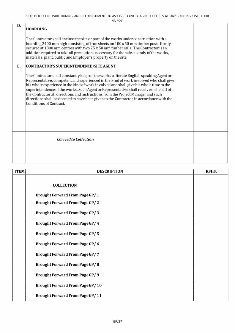
PROPOSED OFFICE PARTITIONING AND REFURBISHMENT TO ASSETS RECOVERY AGENCY OFFICES AT UAP BUILDING 21ST FLOOR,
NAIROBI
GP/27
D. HOARDING
The Contractor shall enclose the site or part of the works under construction with a hoarding 2400 mm high consisting of iron sheets on 100 x 50 mm timber posts firmly secured at 1800 mm centres with two 75 x 50 mm timber rails. The Contractor is in addition required to take all precautions necessary for the safe custody of the works, materials, plant, public and Employer's property on the site.
E. CONTRACTOR'S SUPERINTENDENCE/SITE AGENT
The Contractor shall constantly keep on the works a literate English speaking Agent or Representative, competent and experienced in the kind of work involved who shall give his whole experience in the kind of work involved and shall give his whole time to the superintendence of the works. Such Agent or Representative shall receive on behalf of the Contractor all directions and instructions from the Project Manager and such directions shall be deemed to have been given to the Contractor in accordance with the Conditions of Contract.
Carried to Collection 150,000.00
ITEM DESCRIPTION KSHS.
COLLECTION
Brought Forward From Page GP/ 1 -
Brought Forward From Page GP/ 2 -
Brought Forward From Page GP/ 3 -
Brought Forward From Page GP/ 4 150,000.00
Brought Forward From Page GP/ 5 150,000.00
Brought Forward From Page GP/ 6 100,000.00
Brought Forward From Page GP/ 7 310,000.00
Brought Forward From Page GP/ 8 15,000.00
Brought Forward From Page GP/ 9 -
Brought Forward From Page GP/ 10 300,000.00
Brought Forward From Page GP/ 11 -

PROPOSED OFFICE PARTITIONING AND REFURBISHMENT TO ASSETS RECOVERY AGENCY OFFICES AT UAP BUILDING 21ST FLOOR,
NAIROBI
GP/28
Brought Forward From Page GP/ 12 150,000.00
TOTAL FOR GENERAL PRELIMINARIES
CARRIED TO GRAND SUMMARY 1,175,000.00

PROPOSED OFFICE PARTITIONING AND REFURBISHMENT TO ASSETS RECOVERY AGENCY OFFICES AT UAP BUILDING 21ST
FLOOR, NAIROBI
P8/30
BUILDER’S WORKS
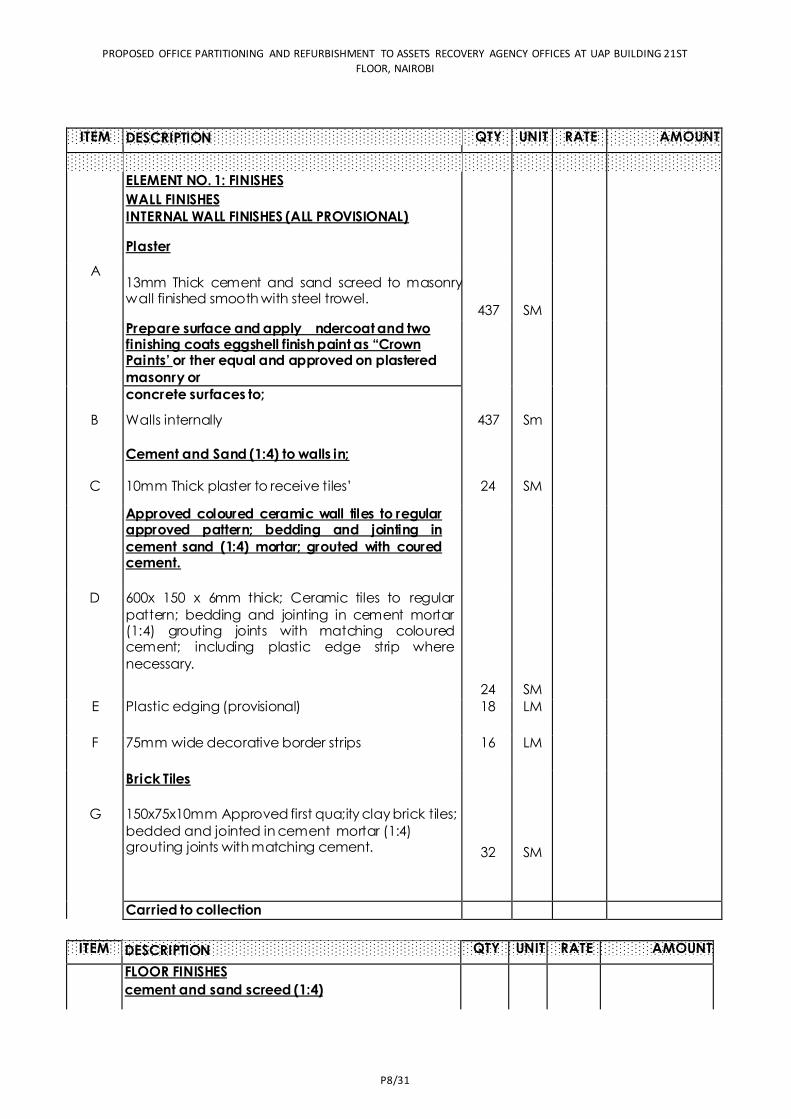
PROPOSED OFFICE PARTITIONING AND REFURBISHMENT TO ASSETS RECOVERY AGENCY OFFICES AT UAP BUILDING 21ST
FLOOR, NAIROBI
P8/31
ITEM
QTY UNIT RATE AMOUNT
ELEMENT NO. 1: FINISHES
WALL FINISHES INTERNAL WALL FINISHES (ALL PROVISIONAL)
Plaster
A 13mm Thick cement and sand screed to masonry wall finished smooth with steel trowel.
437 SM 400 174,800.00 -
Prepare surface and apply ndercoat and two finishing coats eggshell finish paint as “Crown Paints’ or ther equal and approved on plastered
masonry or
- -
concrete surfaces to;
B Walls internally 437 Sm 400 174,800.00 -
Cement and Sand (1:4) to walls in; - -
C 10mm Thick plaster to receive tiles’ 24 SM 350 8,400.00
Approved coloured ceramic wall tiles to regular approved pattern; bedding and jointing in
cement sand (1:4) mortar; grouted with coured cement.
- -
D 600x 150 x 6mm thick; Ceramic tiles to regular
pattern; bedding and jointing in cement mortar (1:4) grouting joints with matching coloured cement; including plastic edge strip where
necessary.
24 SM 1800 43,200.00 -
E Plastic edging (provisional) 18 LM 60 1,080.00 -
F 75mm wide decorative border strips 16 LM 350 5,600.00 -
Brick Tiles - -
G 150x75x10mm Approved first qua;ity clay brick tiles;
bedded and jointed in cement mortar (1:4) grouting joints with matching cement. 32 SM 2400 76,800.00
Carried to collection 484,680.00
ITEM
QTY UNIT RATE AMOUNT
FLOOR FINISHES cement and sand screed (1:4)
DESCRIPTION
DESCRIPTION
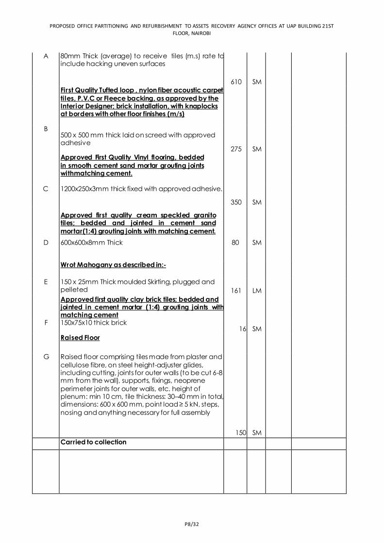
PROPOSED OFFICE PARTITIONING AND REFURBISHMENT TO ASSETS RECOVERY AGENCY OFFICES AT UAP BUILDING 21ST
FLOOR, NAIROBI
P8/32
A 80mm Thick (average) to receive tiles (m.s) rate to include hacking uneven surfaces
610 SM 800 488,000.00 -
First Quality Tufted loop , nylon fiber acoustic carpet
tiles, P.V.C or Fleece backing, as approved by the Interior Designer; brick installation, with knaplocks at borders with other floor finishes (m/s)
- B
500 x 500 mm thick laid on screed with approved adhesive
275 SM 6750 1,856,250.00 -
Approved First Quality Vinyl flooring, bedded
in smooth cement sand mortar grouting joints withmatching cement.
- -
C 1200x250x3mm thick fixed with approved adhesive.
350 SM 4500 1,575,000.00
Approved first quality cream speckled granito tiles; bedded and jointed in cement sand
mortar(1:4) grouting joints with matching cement.
- D 600x600x8mm Thick 80 SM 3524
281,920.00 -
Wrot Mahogany as described in:- - -
E 150 x 25mm Thick moulded Skirting, plugged and pelleted 161 LM 540 86,940.00
Approved first quality clay brick tiles; bedded and jointed in cement mortar (1:4) grouting joints with matching cement
- F 150x75x10 thick brick
16 SM 2500 40,000.00 Raised Floor
- -
G Raised floor comprising tiles made from plaster and
cellulose fibre, on steel height-adjuster glides, including cutting, joints for outer walls (to be cut 6-8 mm from the wall), supports, fixings, neoprene
perimeter joints for outer walls, etc. height of plenum: min 10 cm, tile thickness: 30–40 mm in total, dimensions: 600 x 600 mm, point load ≥ 5 kN, steps,
nosing and anything necessary for full assembly
150 SM 3400 510,000.00
Carried to collection 4,838,110.00
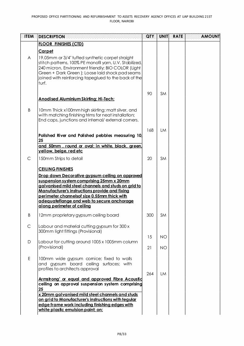
PROPOSED OFFICE PARTITIONING AND REFURBISHMENT TO ASSETS RECOVERY AGENCY OFFICES AT UAP BUILDING 21ST
FLOOR, NAIROBI
P8/33
ITEM
QTY UNIT RATE AMOUNT
FLOOR FINISHES (CTD)
Carpet
A 19.05mm or 3/4" tufted synthetic carpet straight stitch patterns, 100% PE monofil yarn, U.V. Stabilized,
240 micron, Environment friendly; BIO COLOR (Light Green + Dark Green ); Loose laid shock pad seams joined with reinforcing tapeglued to the back of the
turf.
90 SM 4500 405,000.00 -
Anodised Aluminium Skirting; Hi-Tech; - -
B 10mm Thick x100mm high skirting; matt silver, and with matching finishing trims for neat installation; End caps, junctions and internal/ external corners.
168 LM 450 75,600.00 -
Polished River and Polished pebbles measuring 10, 25
- -
and 50mm , round or oval; in white, black, green, yellow, beige, red etc
C 150mm Strips to detail 20 SM 9000 180,000.00 -
CEILING FINISHES -
Drop down Decorative gypsum ceiling on approved
suspension system comprising 25mm x 20mm galvanised mild steel channels and studs on grid to Manufacturer's instructions provide and fixing
perimeter channelsof size 0.55mm thick with adequateflange and web to secure anchorage along perimeter of ceiling
- -
B 12mm proprietary gypsum ceiling board 300 SM 8000 2,400,000.00 -
C Labour and material cutting gypsum for 300 x 300mm light fittings (Provisional)
15 NO 1000 15,000.00 -
D Labour for cutting around 1005 x 1005mm column
(Provisional) 21 NO 1000 21,000.00 -
E 100mm wide gypsum cornice; fixed to walls
and gypsum board ceiling surfaces; with profiles to architects approval
264 LM 450 118,800.00 -
Armstrong' or equal and approved Fibre Acoustic ceiling on approval suspension system comprising
25
-
x 20mm galvanised mild steel channels and studs on grid to Manufacturer's instructions with tegular
edge frame work including finishing edges with white plastic emulsion paint; on;
DESCRIPTION
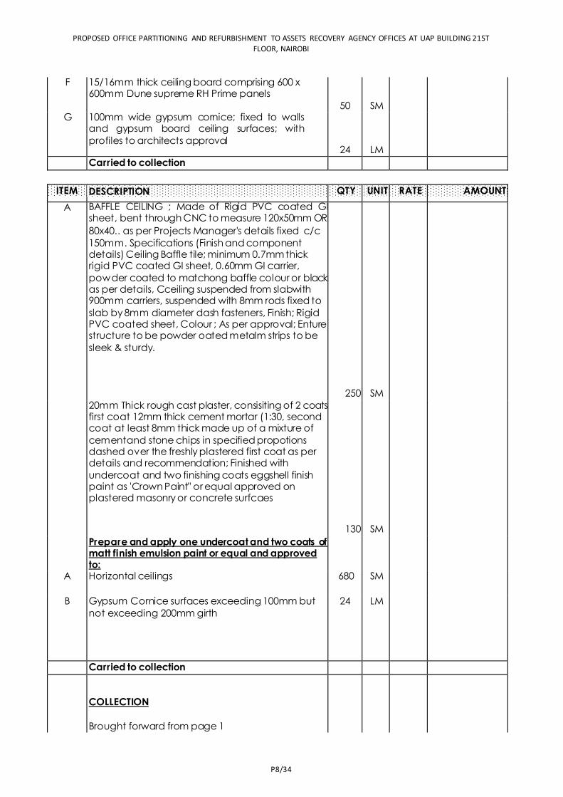
PROPOSED OFFICE PARTITIONING AND REFURBISHMENT TO ASSETS RECOVERY AGENCY OFFICES AT UAP BUILDING 21ST
FLOOR, NAIROBI
P8/34
F 15/16mm thick ceiling board comprising 600 x 600mm Dune supreme RH Prime panels
50 SM 2400
120,000.00
- G 100mm wide gypsum cornice; fixed to walls
and gypsum board ceiling surfaces; with
profiles to architects approval 24 LM 450 10,800.00
Carried to collection 3,346,200.00
ITEM
QTY UNIT RATE AMOUNT
A BAFFLE CEILING ; Made of Rigid PVC coated GI sheet, bent through CNC to measure 120x50mm OR 80x40.. as per Projects Manager's details fixed c/c
150mm. Specifications (Finish and component details) Ceiling Baffle tile; minimum 0.7mm thick rigid PVC coated GI sheet, 0.60mm GI carrier,
powder coated to matchong baffle colour or black as per details, Cceiling suspended from slabwith 900mm carriers, suspended with 8mm rods fixed to
slab by 8mm diameter dash fasteners, Finish; Rigid PVC coated sheet, Colour ; As per approval; Enture structure to be powder oated metalm strips to be
sleek & sturdy.
250 SM 8000 2,000,000.00 -
20mm Thick rough cast plaster, consisiting of 2 coats first coat 12mm thick cement mortar (1:30, second coat at least 8mm thick made up of a mixture of
cementand stone chips in specified propotions dashed over the freshly plastered first coat as per details and recommendation; Finished with
undercoat and two finishing coats eggshell finish paint as 'Crown Paint" or equal approved on plastered masonry or concrete surfcaes
130 SM 600 78,000.00 -
Prepare and apply one undercoat and two coats of matt finish emulsion paint or equal and approved to:
- A Horizontal ceilings 680 SM 400 272,000.00
-
B Gypsum Cornice surfaces exceeding 100mm but
not exceeding 200mm girth 24 LM 40 960.00
Carried to collection 2,350,960.00
COLLECTION
Brought forward from page 1
484,680.00
DESCRIPTION
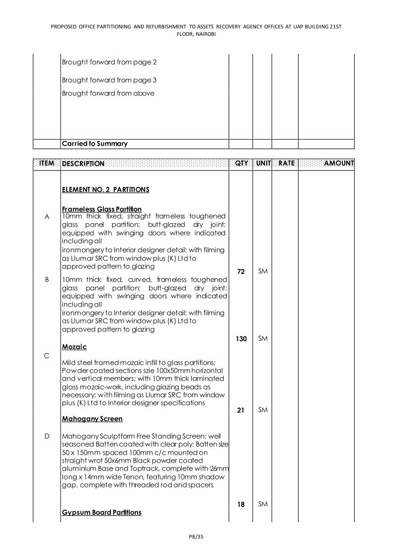
PROPOSED OFFICE PARTITIONING AND REFURBISHMENT TO ASSETS RECOVERY AGENCY OFFICES AT UAP BUILDING 21ST
FLOOR, NAIROBI
P8/35
Brought forward from page 2
4,838,110.00
Brought forward from page 3
3,346,200.00
Brought forward from above 2,350,960.00
Carried to Summary 11,019,950.00
ITEM
QTY UNIT RATE AMOUNT
ELEMENT NO. 2 PARTITIONS
Frameless Glass Partition
A 10mm thick fixed, straight frameless toughened
glass panel partition: butt-glazed dry joint:
equipped with swinging doors where indicated including all ironmongery to Interior designer detail: with filming
as Llumar SRC from window plus (K) Ltd to approved pattern to glazing
72 SM 7500 540,000.00 B 10mm thick fixed, curved, frameless toughened
glass panel partition: butt-glazed dry joint: equipped with swinging doors where indicated
including all ironmongery to Interior designer detail: with filming as Llumar SRC from window plus (K) Ltd to
approved pattern to glazing
130 SM 15000 1,950,000.00 -
Mozaic -
C Mild steel framed mozaic infill to glass partitions; Powder coated sections szie 100x50mm horizontal and vertical members; with 10mm thick laminated
glass mozaic-work, including glazing beads as necessary; with filming as Llumar SRC from window plus (K) Ltd to Interior designer specifications
21 SM 65000 1,365,000.00 Mahogany Screen -
-
D Mahogany Sculptform Free Standing Screen: well seasoned Batten coated with clear poly: Batten size
50 x 150mm spaced 100mm c/c mounted on straight wrot 50x6mm Black powder coated aluminium Base and Toptrack, complete with 26mm
long x 14mm wide Tenon, featuring 10mm shadow gap, complete with threaded rod and spacers
18 SM 12000 216,000.00 -
Gypsum Board Partitions -
DESCRIPTION
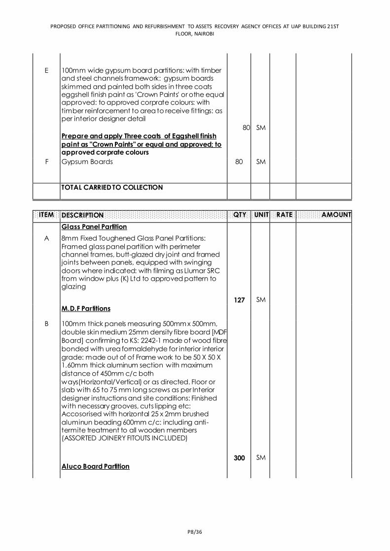
PROPOSED OFFICE PARTITIONING AND REFURBISHMENT TO ASSETS RECOVERY AGENCY OFFICES AT UAP BUILDING 21ST
FLOOR, NAIROBI
P8/36
-
E 100mm wide gypsum board partitions: with timber and steel channels framework: gypsum boards
skimmed and painted both sides in three coats eggshell finish paint as 'Crown Paints' or othe equal approved: to approved corprate colours: with
timber reinforcement to area to receive fittings: as per interior designer detail
80 SM 2400
192,000.00
- Prepare and apply Three coats of Eggshell finish
paint as "Crown Paints" or equal and approved; to approved corprate colours
-- F Gypsum Boards 80 SM 400 32,000.00
- -
TOTAL CARRIED TO COLLECTION 4,295,000.00
ITEM
QTY UNIT RATE AMOUNT
Glass Panel Partition
A 8mm Fixed Toughened Glass Panel Partitions:
Framed glass panel partition with perimeter channel frames, butt-glazed dry joint and framed joints between panels, equipped with swinging
doors where indicated: with filming as Llumar SRC from window plus (K) Ltd to approved pattern to glazing
127 SM 5900 749,300.00 -
M.D.F Partitions --
B 100mm thick panels measuring 500mm x 500mm,
double skin medium 25mm density fibre board [MDF
Board] confirming to KS: 2242-1 made of wood fibre
bonded with urea formaldehyde for interior interior
grade: made out of of Frame work to be 50 X 50 X 1.60mm thick aluminum section with maximum
distance of 450mm c/c both ways(Horizontal/Vertical) or as directed. Floor or slab with 65 to 75 mm long screws as per Interior
designer instructions and site conditions: Finished with necessary grooves, cuts lipping etc: Accosorised with horizontal 25 x 2mm brushed
aluminun beading 600mm c/c: including anti-termite treatment to all wooden members (ASSORTED JOINERY FITOUTS INCLUDED)
300 SM 9700 2,910,000.00 -
Aluco Board Partition - -
DESCRIPTION
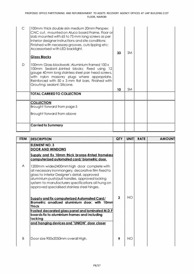
PROPOSED OFFICE PARTITIONING AND REFURBISHMENT TO ASSETS RECOVERY AGENCY OFFICES AT UAP BUILDING 21ST
FLOOR, NAIROBI
P8/37
C 100mm thick double skin medium 20mm Perspex:
CNC cut, mounted on Aluco board Frame, Floor or slab mounted with 65 to 75 mm long screws as per
Interior designer instructions and site conditions: Finished with necessary grooves, cuts lipping etc: Accessorised with LED backlight.
33 SM 14950
493,350.00
- Glass Blocks -
- D 100mm Glass-blockwork: Aluminium framed 100 x
100mm Sealant-Jointed blocks: Fixed using 12 gauge 40 mm long stainless steel pan head screws,
with nylon masonry plugs where appropriate, Reinforced with 50 x 3 mm flat bars, Finished with Grouting: sealant: Silicone.
10 SM 60750 607,500.00
- TOTAL CARRIED TO COLLECTION
4,760,150.00
COLLECTION Brought forward from page 5
4,295,000.00 Brought forward from above
4,760,150.00
Carried to Summary 9,055,150.00
ITEM
QTY UNIT RATE AMOUNT
ELEMENT NO. 3 DOOR AND WINDOWS
Supply and fix 10mm thick bronze-tinted frameless
computerized automated card/ biometric door.
A 1200mm widex2400mm high door complete with
all necessary ironmongery, decorative film fixed to
glass to interior Designer's detail, approved aluminium push/pull handles, approved locking
system to manufacturers specifications all hung on
approved specialised stainless steel hinges.
Supply and fix computerized Automated Card/ Biometric anodized aluminium door; with 10mm Thick
2 NO 120000 240,000.00
frosted decorated glass panel and laminated M.D.F boards fix to aluminium frames and including locking and hanging devices and "UNION" door closer
B Door size 900x2050mm overall High. 9 NO 105000 945,000.00 -
DESCRIPTION
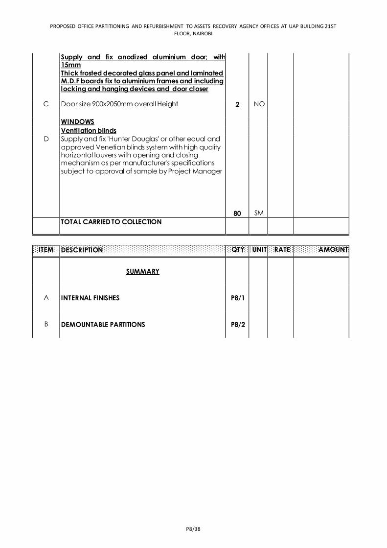
PROPOSED OFFICE PARTITIONING AND REFURBISHMENT TO ASSETS RECOVERY AGENCY OFFICES AT UAP BUILDING 21ST
FLOOR, NAIROBI
P8/38
Supply and fix anodized aluminium door; with 15mm Thick frosted decorated glass panel and laminated M.D.F boards fix to aluminium frames and including locking and hanging devices and door closer
- -
C Door size 900x2050mm overall Height 2 NO 23060 46,120.00 -
WINDOWS -
Ventilation blinds - D Supply and fix 'Hunter Douglas' or other equal and
approved Venetian blinds system with high quality horizontal louvers with opening and closing mechanism as per manufacturer's specifications
subject to approval of sample by Project Manager
80 SM 1200 96,000.00 TOTAL CARRIED TO COLLECTION
1,087,120.00
ITEM
QTY UNIT RATE AMOUNT
SUMMARY
A INTERNAL FINISHES P8/1
11,019,950.00
B DEMOUNTABLE PARTITIONS P8/2
9,055,150.00
DESCRIPTION
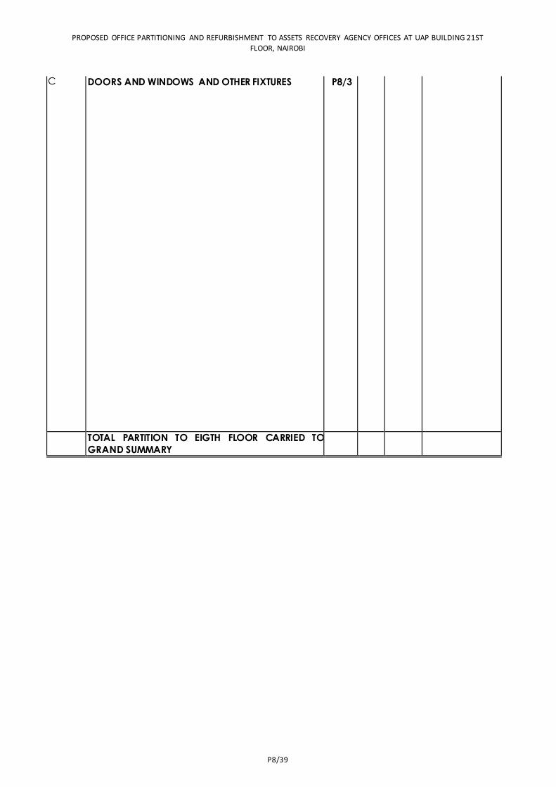
PROPOSED OFFICE PARTITIONING AND REFURBISHMENT TO ASSETS RECOVERY AGENCY OFFICES AT UAP BUILDING 21ST
FLOOR, NAIROBI
P8/39
C DOORS AND WINDOWS AND OTHER FIXTURES P8/3 87,120.00
TOTAL PARTITION TO EIGTH FLOOR CARRIED TO
GRAND SUMMARY
21,162,220.00


MECHANICAL WORKS
MW/41
MECHANICAL WORKS

MECHANICAL WORKS
MW/42
PROPOSED OFFICE PARTITIONING AND REFURBISHMENT TO ASETS RECOVERY AGENCY OFFICES AT UAP TOWERS - 21ST FLOOR WP ITEM NO. D120 NB/NB/200/JOB NO. 10855A MECHANICAL WORKS SANITARY FITTINGS,PLUMBING AND DRAINAGE,FIRE FIGHTING AND AIR CONDITIONING
Item Description Qty Unit Rate (Kshs) Amount (Kshs)
A Mothers room sink Sinlge bow l single drainer stainless steel sink of size 1000 x 500mm as manufactured by ASL or equal and approved. The bow l size to be 430 x 420 x 150mm deep complete w ith
chrome plated 40mm w aste fittings, plugs, chain stays, overflow, 1No. chrome plated sink Mixer as ideal standard, Cobra model, heavy duty plastic bottle trap w ith 75mm deep seal and chain w aste f itting.
1 No
B Flexible Tubing 15mm diameter x 300mm long f lexible connectors complete w ith integral chrome plated angle valve for connecting the sanitary f itting to water supply. To be as Cobra or equal and approved.
2 No
C Undersink water heater : 10 Litres glass lined(enamelled) steel heater vessel complete w ith 2.2 kW element, external rhermostat adjustable up to 650 .Such as "Heatre Saidia" HOTFLO 10 or approved equivalent
1 No.
D Soap Dispenser Wall mounted soap dispenser with a capacity of about one litre having a press action soap release mechanism complete w ith f ixing screws. Allow for initial soap supply. To be as Starmix or approved equivalent. 1 No.
E Paper dispenser Paper dispenser for dispensing interfolded paper tissue. The
dispenser shall include a casing having a narrow dispensing
slot in the bottom surface. The dispenser should have a
proper mechanism to prevent excessive quantities of tissue. The paper dispenser shall be in approved colour.
1 No.
F Hand Driers Automatic hand drier in w hite colour, operating on an infrared automatic sensing system w ith heating element
safety cut-out complete with a 30 seconds safety timer, plastic raw l plugs and f ixing screws. The hand drier to have a heating capacity of 2.1kw and performance flow rate of 135cfm (3.82m3/min) and to be of size 270x264x143mm deep It shall have a noise level below 72.5 dBA at 1.5m. It
shall be as Medclinic or approved equivalent.
1 No.
G Robe Hook Chrome plated robe hook mounted w ith concealed screws. To be as Ideal Standard or equal and approved.
1 No.
Total carried forward to collection page
Item Description Qty Unit Rate (Kshs) Amount (Kshs)
Internal Plumbing and Drainage Works PP-R pipes
A 20mm diameter pipew ork 5 Lm B 25mm diameter pipew ork 10 Lm C 20mm diameter bend 4 No. D 25mm diameter bend 4 No.
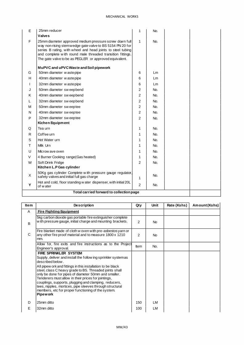
MECHANICAL WORKS
MW/43
E 25mm reducer Valves
1 No.
F 25mm diameter approved medium pressure screw down full
way non-rising stem wedge gate valve to BS 5154 PN 20 for
series B rating, with wheel and head joints to steel tubing
and complete w ith round male threaded transition f ittings.
The gate valve to be as PEGLER or approved equivalent.
MuPVC and uPVC Waste and Soil pipework
1 No.
G 50mm diameter w aste pipe 6 Lm H 40mm diameter w aste pipe 6 Lm I 32mm diameter w aste pipe 6 Lm J 50mm diameter sw eep bend 2 No. K 40mm diameter sw eep bend 2 No. L 32mm diameter sw eep bend 2 No. M 50mm diameter sw eep tee 2 No. N 40mm diameter sw eep tee 2 No. P 32mm diameter sw eep tee
Kichen Equipment 2 No.
Q Tea urn 1 No. R Coffee urn 1 No. S Hot Water urn 1 No. T Milk Urn 1 No. U Microw ave oven 1 No. V 4 Burner Cooking range(Gas heated) 1 No. W Soft Drink Fridge
Kitchen L.P Gas cylinder 2 No.
X 50Kg gas cylinder Complete w ith pressure gauge regulator, safety valves and initial full gas charge
1
No.
Y Hot and cold, f loor standing w ater dispenser, with initial 20L of w ater 2 No.
Total carried forward to collection page
Item Description Qty Unit Rate (Kshs) Amount (Kshs)
A
B
C
Fire Fighting Equipment 5kg carbon dioxide gas portable f ire extinguisher complete w ith pressure gauge, initial charge and mounting brackets. 2 No
Fire blanket made of cloth w oven with pre-asbestos yarn or any other f ire proof material and to measure 1800 x 1210 mm.
2 No
Allow for, f ire exits and f ire instructions as to the Project
Engineer's approval. Item No.
FIRE SPRINKLER SYSTEM Supply, deliver and install the follow ing sprinkler system as
described below . All pipew ork and f ittings in this installation to be black steel, class C heavy grade to BS. Threaded joints shall only be done for pipes of diameter 50mm and smaller. Tenderers must allow in their prices for jointings,
couplings, supports, plugging and clamping, reducers, tees, nipples, mortices, pipe sleeves through structural members, etc for proper functioning of the system. Pipework
D 25mm ditto 150 LM E 32mm ditto 100 LM
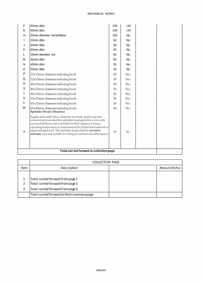
MECHANICAL WORKS
MW/44
F 40mm ditto 100 LM G 65mm ditto 100 LM H 25mm diameter bend/elbow 100 No. I 32mm ditto 50 No. J 40mm ditto 30 No. K 65mm ditto 20 No. L 25mm diameter tee 50 No. M 32mm ditto 50 No. N 40mm ditto 30 No. O 65mm ditto 10 No. P 25x15mm diameter reducing bush 50 No. Q 32x15mm diameter reducing bush 30 No. R 40x15mm diameter reducing bush 20 No. S 40x25mm diameter reducing bush 20 No. T 40x32mm diameter reducing bush 20 No. U 32x25mm diameter reducing bush 20 No. V 65x32mm diameter reducing bush 20 No. W 65x40mm diameter reducing bush
Sprinkler Heads (Nozzles) 20 No.
X
Supply and install 15mm diameter automatic quick response commercial concealed fire sprinkler head and white cover with
universal deflector and red bulb for 68oC (degrees Celsius)
operating temperature as manufactured by Firekil International or equal and approved. The sprinkler heads shall be corrosive
resistant type and suitable for fixing in commercial office spaces. 50 No.
Total carried forward to collection page
COLLECTION PAGE
Item Description Amount (Kshs)
1 Total carried forward from page 1
2 Total carried forward from page 2
3 Total carried forward from page 3
Total carried forward to Main summary page
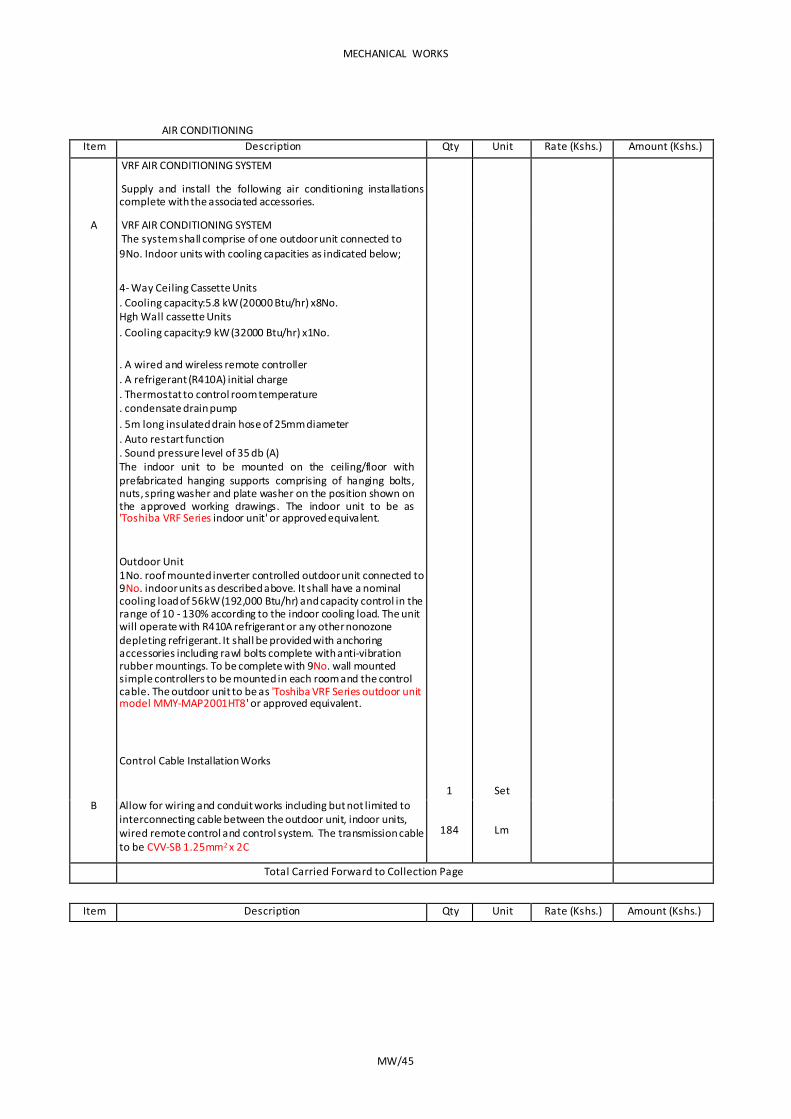
MECHANICAL WORKS
MW/45
AIR CONDITIONING Item Description Qty Unit Rate (Kshs.) Amount (Kshs.)
VRF AIR CONDITIONING SYSTEM
Supply and install the following air conditioning installations complete with the associated accessories.
A VRF AIR CONDITIONING SYSTEM The system shall comprise of one outdoor unit connected to 9No. Indoor units with cooling capacities as indicated below;
4- Way Ceiling Cassette Units . Cooling capacity:5.8 kW (20000 Btu/hr) x8No. Hgh Wall cassette Units . Cooling capacity:9 kW (32000 Btu/hr) x1No.
. A wired and wireless remote controller
. A refrigerant (R410A) initial charge
. Thermostat to control room temperature
. condensate drain pump
. 5m long insulated drain hose of 25mm diameter
. Auto restart function
. Sound pressure level of 35 db (A) The indoor unit to be mounted on the ceiling/floor with prefabricated hanging supports comprising of hanging bolts, nuts, spring washer and plate washer on the position shown on the approved working drawings. The indoor unit to be as 'Toshiba VRF Series indoor unit' or approved equivalent.
Outdoor Unit 1No. roof mounted inverter controlled outdoor unit connected to 9No. indoor units as described above. It shall have a nominal cooling load of 56kW (192,000 Btu/hr) and capacity control in the range of 10 - 130% according to the indoor cooling load. The unit will operate with R410A refrigerant or any other nonozone depleting refrigerant. It shall be provided with anchoring accessories including rawl bolts complete with anti-vibration rubber mountings. To be complete with 9No. wall mounted simple controllers to be mounted in each room and the control cable. The outdoor unit to be as 'Toshiba VRF Series outdoor unit model MMY-MAP2001HT8' or approved equivalent.
Control Cable Installation Works
1 Set
B Allow for wiring and conduit works including but not limited to interconnecting cable between the outdoor unit, indoor units, wired remote control and control system. The transmission cable to be CVV-SB 1.25mm2 x 2C
184 Lm
Total Carried Forward to Collection Page
Item Description Qty Unit Rate (Kshs.) Amount (Kshs.)
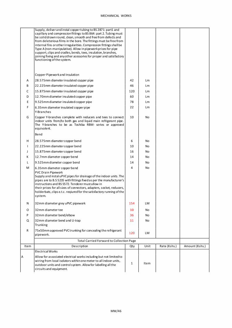
MECHANICAL WORKS
MW/46
Supply, deliver and instal copper tubing to BS 2871: part1 and capillary and compression fittings to BS 864: part 2. Tubing must be solid drawn round, clean, smooth and free from defects and from deleterious films in the bore. The fittings must be free from internal fins or other irregularities. Compression fittings shall be Type A (non-manipulative). Allow in pipework prices for pipe support, clips and cradles, bends, tees, insulation, branches, joining fixing and any other acessories for proper and satisfactory functioning of the system.
Copper Pipework and Insulation
A 28.575mm diameter insulated copper pipe 42 Lm B 22.225mm diameter insulated copper pipe 46 Lm C 15.875mm diameter insulated copper pipe 120 Lm D 12.70mm diameter insulated copper pipe 60 Lm E 9.525mm diameter insulated copper pipe 78 Lm F 6.35mm diameter insulated copper pipe
Y-Branches 22 Lm
G Copper Y-branches complete with reducers and tees to connect indoor units from/to both gas and liquid main refrigerant pipe. The Y-branches to be as Toshiba RBM- series or approved equivalent.
Bend
10 No
H 28.575mm diameter copper bend 6 No I 22.225mm diameter copper bend 10 No J 15.875mm diameter copper bend 16 No K 12.7mm diameter copper bend 14 No L 9.525mm diameter copper bend 14 No M 6.35mm diameter copper bend
PVC Drain Pipework Supply and instal uPVC pipes for drainage of the indoor units. The pipes are to B.S 5235 with fittings fixed as per the manufacturer's instructions and BS 5572. Tenderer must allow in their prices for all sizes of connectors, adapters, socket, reducers, holderbats, clips e.t.c. reqiured for the satisfactory running of the system.
4 No
N 32mm diameter grey uPVC pipework 154 LM
O 32mm diameter tee 10 No P 32mm diameter bend/elbow 36 No Q 32mm diameter bend and U-trap
Trunking 11 No
R 75x50mm approved PVC trunking for concealing the refrigerant pipework. 120 LM
Total Carried Forward to Collection Page Item Description Qty Unit Rate (Kshs.) Amount (Kshs.)
Electrical Works A Allow for associated electrical works including but not limited to
wiring from local isolators within one meter to all indoor units, outdoor units and control system. Allow for labelling all the circuits and equipment.
1 Item
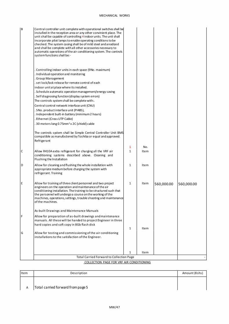
MECHANICAL WORKS
MW/47
B Central controller unit complete with operational switches shall be installed in the reception area or any other convinient place. The unit shall be capable of controlling 4 indoor units. The unit shall incorporate pilot lamps to enable operating conditions to be checked. The system casing shall be of mild steel and anodized and shall be complete with all other accessories necessary to automatic operations of the air conditioning system. The controls system functions shall be:-
. Controlling indoor units in each space (9No. maximum)
. Individual operation and monitoring
. Group Management
. set lock/lock release for remote control of each
indoor unit at place where its installed. . Schedule automatic operation management/energy saving . Self diagnosing function (display system errors) The controls system shall be complete with:.
Central control network interface unit (CNU) . 5No. product interface unit (PI485), . Independent built-in battery (minimum 2 hours) . Ethernet (Cross UTP Cable) . 30 meters long 0.75mm2 x 2C (shield) cable
The controls system shall be Simple Central Controller Unit BMS compatible as manufactered by Toshiba or equal and approved. Refrigerant
1 No.
C Allow R410A extra refrigerant for charging all the VRF air conditioning systems described above. Cleaning and Flushing the Installation
1 Item
D Allow for cleaning and flushing the whole installation with appropriate medium before charging the system with refrigerant. Training
1 Item
E Allow for training of three client personnel and two project engineers on the operation and maintenance of the air conditioning installation. The training to be structured such that the personnel will undergo a course on the working of the machines, operations, settings, trouble shooting and maintenance of the machines.
As-built Drawings and Maintenance Manuals
1 Item 560,000.00
560,000.00
F Allow for preparation of as-built drawings and maintenance manuals. All these will be handed to project Engineer in three
hard copies and soft copy in 8Gb flash disk 1 Item
G Allow for testing and commissioning of the air conditioning installations to the satisfaction of the Engineer.
1 Item
Total Carried Forward to Collection Page - COLLECTION PAGE FOR VRF AIR CONDITIONING
Item Description Amount (Kshs)
A Total carried forward from page 5

MECHANICAL WORKS
MW/48
B Total carried forward from page 6
C Total carried forward from page 7
Total Carried Forward to Airconditioning Summary Page
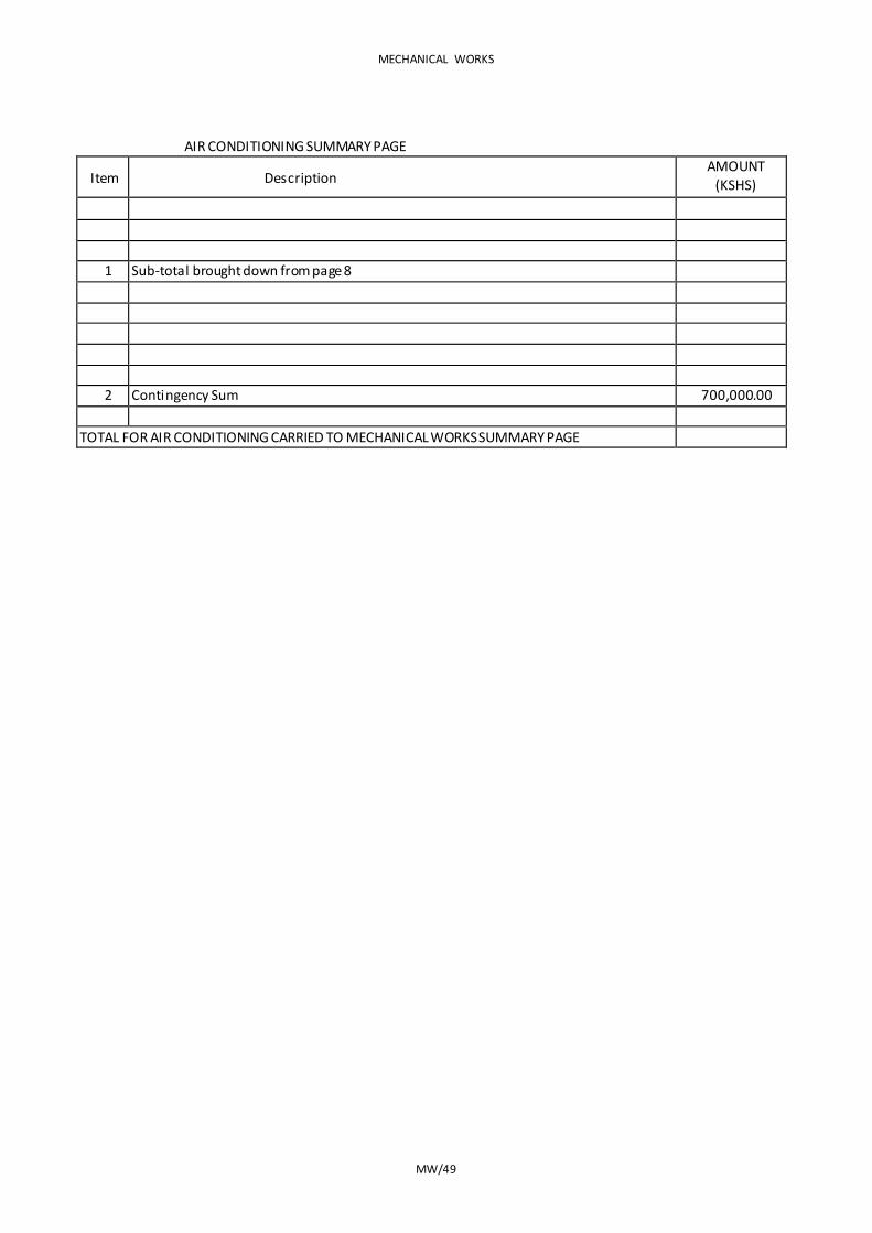
MECHANICAL WORKS
MW/49
AIR CONDITIONING SUMMARY PAGE
Item Description AMOUNT
(KSHS)
1 Sub-total brought down from page 8
2 Contingency Sum 700,000.00
TOTAL FOR AIR CONDITIONING CARRIED TO MECHANICAL WORKS SUMMARY PAGE
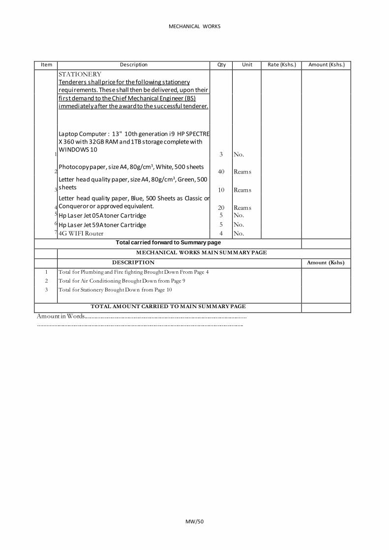
MECHANICAL WORKS
MW/50
Item Description Qty Unit Rate (Kshs.) Amount (Kshs.)
STATIONERY Tenderers shall price for the following stationery requirements. These shall then be delivered, upon their
first demand to the Chief Mechanical Engineer (BS) immediately after the award to the successful tenderer.
1
Laptop Computer : 13" 10th generation i9 HP SPECTRE X 360 with 32GB RAM and 1TB storage complete with WINDOWS 10
3 No.
2 Photocopy paper, size A4, 80g/cm3, White, 500 sheets
40 Reams
3
Letter head quality paper, size A4, 80g/cm3, Green, 500 sheets 10 Reams
4 Letter head quality paper, Blue, 500 Sheets as Classic or Conqueror or approved equivalent. 20 Reams
5 Hp Laser Jet 05A toner Cartridge 5 No. 6 Hp Laser Jet 59A toner Cartridge 5 No. 7 4G WIFI Router 4 No.
Total carried forward to Summary page
MECHANICAL WORKS MAIN SUMMARY PAGE
DESCRIPTION Amount (Kshs)
1 Total for Plumbing and Fire fighting Brought Down From Page 4 2 Total for Air Conditioning Brought Down from Page 9 3 Total for Stationery Brought Down from Page 10
TOTAL AMOUNT CARRIED TO MAIN SUMMARY PAGE Amount in Words.................................................................................................................
...............................................................................................................................................


PROVISIONAL SUMS
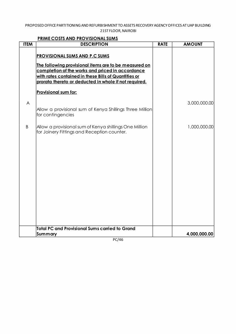
PROPOSED OFFICE PARTITIONING AND REFURBISHMENT TO ASSETS RECOVERY AGENCY OFFICES AT UAP BUILDING
21ST FLOOR, NAIROBI
PRIME COSTS AND PROVISIONAL SUMS
ITEM DESCRIPTION RATE AMOUNT
PROVISIONAL SUMS AND P.C SUMS
The following provisional items are to be measured on
completion of the works and priced in accordance
with rates contained in these Bills of Quantities or
prorata thereto or deducted in whole if not required.
Provisional sum for:
A
Allow a provisional sum of Kenya Shillings Three Million
for contingencies
3,000,000.00
B Allow a provisional sum of Kenya shillings One Million for Joinery Fittings and Reception counter.
1,000,000.00
Total PC and Provisional Sums carried to Grand Summary
4,000,000.00 PC/46
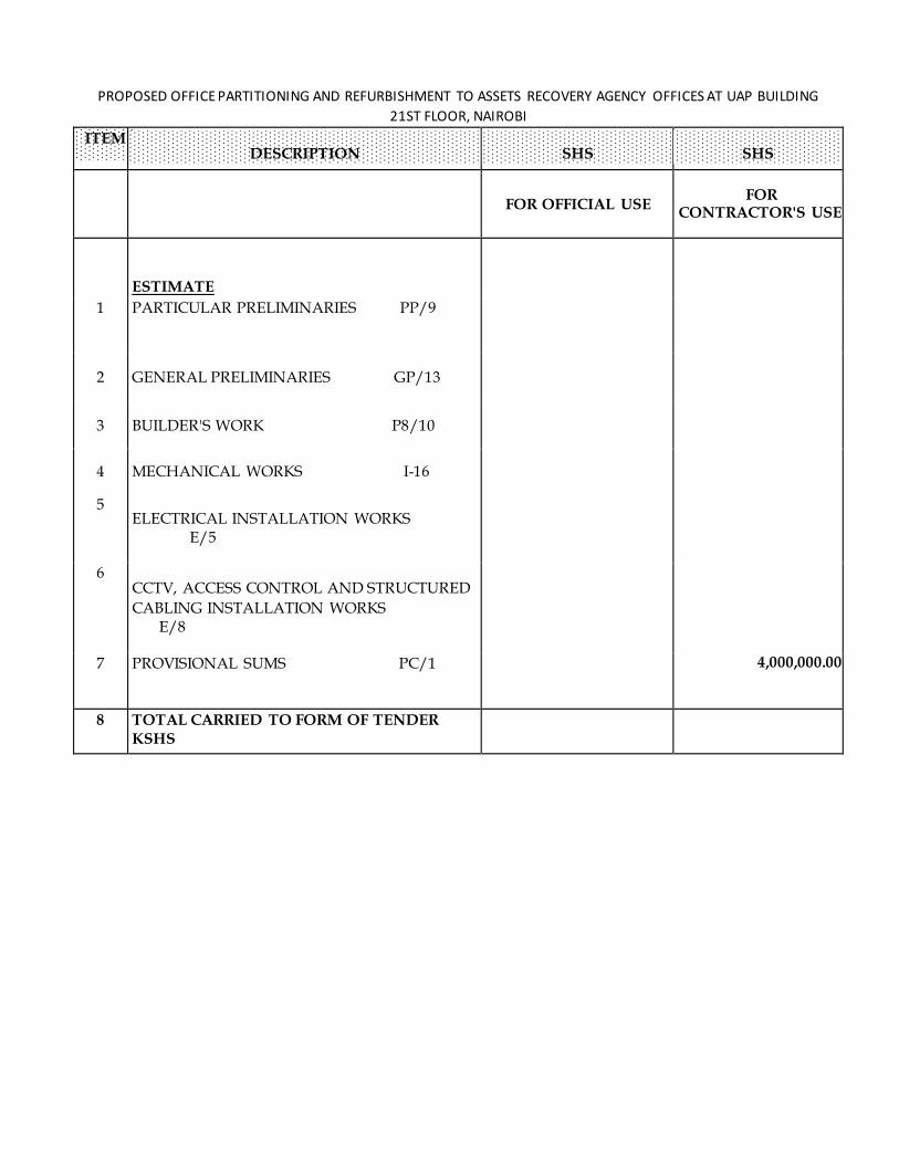
PROPOSED OFFICE PARTITIONING AND REFURBISHMENT TO ASSETS RECOVERY AGENCY OFFICES AT UAP BUILDING
21ST FLOOR, NAIROBI
ITEM
FOR OFFICIAL USE FOR
CONTRACTOR'S USE
ESTIMATE
1 PARTICULAR PRELIMINARIES PP/9
312,500.00
2 GENERAL PRELIMINARIES GP/13 1,175,000.00
3 BUILDER'S WORK P8/10 21,162,220.00
4 MECHANICAL WORKS I-16 11,190,006.00
5 ELECTRICAL INSTALLATION WORKS E/5
3,114,850.00
6 CCTV, ACCESS CONTROL AND STRUCTURED CABLING INSTALLATION WORKS E/8
11,248,750.00
7 PROVISIONAL SUMS PC/1 4,000,000.00 4,000,000.00
8 TOTAL CARRIED TO FORM OF TENDER KSHS 52,203,326.00
SHS SHS DESCRIPTION
AMOUNT OF TENDER IN WORDS;..............................................................................
.........................................................................................................................................................
TENDERER'S SIGNATURE AND STAMP;........................................................................................
ADDRESS;......................................................................................
DATE;........................................
WITNESS NAME AND SIGNATURE;...................................................................................
ADDRESS;......................................................................................
DATE;........................................
GS GS/1

REPUBLIC OF KENYA
PROPOSED OFFICE PARTITIONING AND REFURBISHMENT TO ASSETS
RECOVERY AGENCY OFFICES AT UAP TOWERS 21ST
FLOOR –
NAIROBI
W.P. ITEM NO. D120 NB/NB/200 – JOB NO. 10855A
TENDER SPECIFICATIONS AND BILL OF QUANTITIES
FOR
ELECTRICAL INSTALLATION WORKS
CLIENT
THE DIRECTOR ASSETS RECOVERY AGENCY P.O BOX 52420 – 00100 NAIROBI
PROJECT MANAGER ELECTRICAL ENGINER WORKS SECRETARY CHIEF ENGINEER (ELECTRICAL) MINISTRY OF TRANSPORT, INFRASTRUCTURE, PUBLIC MINISTRY OF TRANSPORT, INFRASTRUCTURE, PUBLIC WORKS, HOUSING & URBAN DEVELOPMENT WORKS, HOUSING & URBAN DEVELOPMENT STATE DEPARTMENT FOR PUBLIC WORKS, STATE DEPARTMENT FOR PUBLIC WORKS, P.O BOX 30743 – 00100, P.O BOX 41191 – 00100, NAIROBI
NAIROBI
ARCHITECT STRUCTURAL ENGINEER CHIEF ARCHITECT CHIEF ENGINEER (STRUCTURAL) MINISTRY OF TRANSPORT, INFRASTRUCTURE, PUBLIC MINISTRY OF TRANSPORT, INFRASTRUCTURE, PUBLIC WORKS, WORHOUSING & URBAN DEVELOPMENT WORKS, HOUSING & URBAN DEVELOPMENT
STATE DEPARTMENT FOR PUBLIC WORKS, STATE DEPARTMENT FOR PUBLIC WORKS, P.O
BOX 30743 – 00100, P.O BOX 30743 – 00100, NAIROBI
NAIROBI
QUANTITY SURVYOR MECHANICAL ENGINEER CHIEF QUANTITY SURVEYOR CHIEF ENGINEER (MECHANICAL (BS)) MINISTRY OF TRANSPORT, INFRASTRUCTURE, PUBLIC MINISTRY OF TRANSPORT, INFRASTRUCTURE, PUBLIC WORKS, HOUSING & URBAN DEVELOPMENT WORKS, HOUSING & URBAN DEVELOPMENT STATE DEPARTMENT FOR PUBLIC WORKS, STATE DEPARTMENT FOR PUBLIC WORKS, P.O BOX 30743 – 00100, P.O BOX 41191 – 00100, NAIROBI NAIROBI
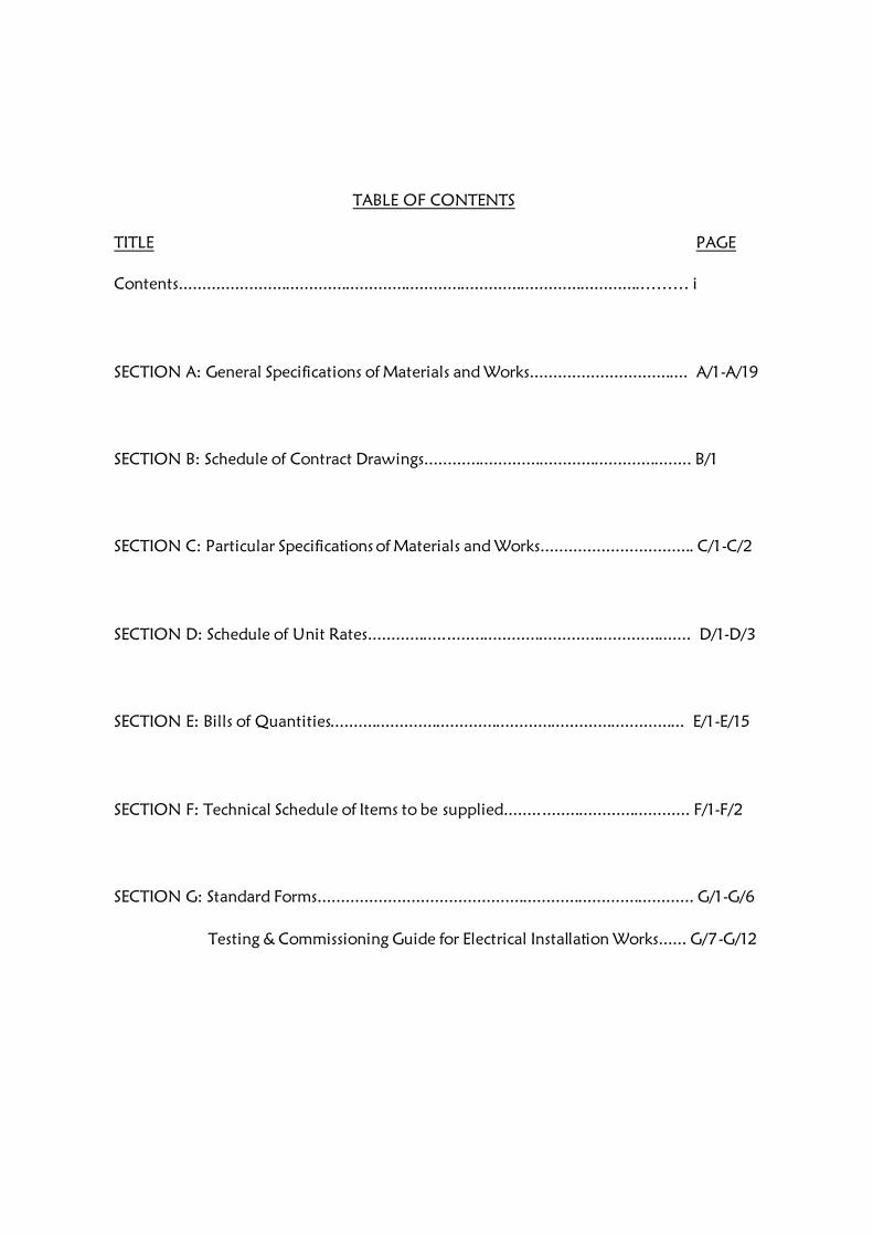
TABLE OF CONTENTS
TITLE PAGE
Contents....................................................................................................……… i
SECTION A: General Specifications of Materials and Works.................................. A/1-A/19
SECTION B: Schedule of Contract Drawings.......................................................... B/1
SECTION C: Particular Specifications of Materials and Works................................. C/1-C/2
SECTION D: Schedule of Unit Rates...................................................................... D/1-D/3
SECTION E: Bills of Quantities............................................................................. E/1-E/15
SECTION F: Technical Schedule of Items to be supplied........................................ F/1-F/2
SECTION G: Standard Forms................................................................................. G/1-G/6
Testing & Commissioning Guide for Electrical Installation Works...... G/7-G/12
i
SECTION A
GENERAL SPECIFICATIONS
OF
MATERIALS AND WORKS

GENERAL SPECIFICATIONS OF MATERIALS AND WORKS
1. General
2. Standard of Materials
3. Workmanship
4. Procurement of Materials
5. Shop Drawings
6. Record Drawings
7. Regulations and Standards
8. Setting out Works
9. Position of Electrical Plant and Apparatus
10. M.C.B Distribution Panels and Consumer Units
11. Fused Switchgear and Isolators
12. Conduits and Conduit Runs
13. Conduit Boxes and Accessories
14. Labels
15. Earthing
16. Cables and Flexible Cords
17. Armoured PVC Insulated and Sheathed Cables
18. Cable Supports; Markers and Tiles
19. PVC Insulated Cables
20. Heat Resisting Cables
21. Flexible Cords
22. Cable Ends and phase Colours
23. Cable Insulation Colours

24. Sub-circuit Wiring
25. Space Factor
26. Insulation
27. Lighting Switches
28. Sockets and Switched sockets
29. Fused Spur Boxes
30. Cooker Outlets
31. Connectors
32. Lampholders
33. Lamps
34. lighting Fittings Street lighting Lanterns
35. Position of Points and Switches
36. Street/Security Lighting Columns
37. Timing Control Switch
38. Wiring System for Street Lighting
39. Metal control Pillar
40. Current Operated Earth leakage circuit breaker
41. MV Switchboard
42. Steel Conduits and Steel Trunking
43. Testing on Site

1. GENERAL
This specification is to be read in conjunction with the drawings which are issued with it.
Bills of quantities shall be the basis of all additions and omissions during the progres s of
the works.
2. STANDARD OF MATERIALS
Where the material and equipment are specifically described and named in the
Specification followed by approved equal, they are so named or described for the
purpose of establishing a standard to which the sub-contractor shall adhere.
Should the Sub-contractor install any material not specified herein before receiving
approval from the proper authorities, the Engineer shall direct the Sub-contractor to
remove the material in question immediately. The fact that this material has been
installed shall have no bearing or influence on the decision by the Engineer.
All materials condemned by the Engineer as not approved for use, are to be removed
from the premises and suitable materials delivered and installed in their place at the
expense of the Sub-contractor. All materials required for the works shall be new and the
best of the respective kind and shall be of a uniform pattern.
3. WORKMANSHIP
The workmanship and method of installation shall conform to the best standard practice.
All work shall be performed by a skilled tradesman and to the satisfaction of the
Engineer. Helpers shall have qualified supervision.
Any work that does not in the opinion of the Engineer conform to the best standard
practice will be removed and reinstated at the Sub-contractors expense.
Permits, Certificates or Licenses must be held by all tradesmen for the type of work; in
which they are involved where such permits, certificates or licenses exist under
Government legislation.
4. PROCUREMENT OF MATERIALS
The sub-contractor is advised that no assistance can be given in the procurement or
allotment of any materials or products to be used in and necessary for the construction
and completion of the work.
Sub-contractors are warned that they must make their own arrangements for the supply
of materials and/or products specified or required.
5. SHOP DRAWINGS

Before manufacture or Fabrication is commenced the sub-contractor shall submit Two
copies of detailed drawings of all control pillars, meter cubicles, medium voltage
switchboards including their components showing all pertinent information including
sizes, capacities, construction details, etc, as may be required to determine the suitability
of the equipment for the approval of the Engineer. Approval of the detailed drawings
shall not relieve the sub-contractor of the full responsibility of errors or the necessity of
checking the drawings himself or of furnishing the materials and equipment and
performing the work required by the plans and specifications.
6. RECORD DRAWINGS
These diagrams and drawings shall show the completed installation including sizes, runs
and arrangements of the installation. The drawings shall be to scale not less than 1:50
and shall include plan views and section.
The drawings shall include all the details which may be useful in the operation,
maintenance or subsequent modifications or extensions to the installation.
Three sets of diagrams and drawings shall be provided, all to the approval of the
Engineer.
One coloured set of line diagrams relating to operating and maintenance instructions shall
be framed and, mounted in a suitable location.
7. REGULATIONS AND STANDARDS
All work executed by the Sub-contractor shall comply with the current edition of the
“Regulations” for the Electrical Equipment of Buildings, issued by the Institution of
Electrical Engineers, and with the Regulations of the Local Electricity Authority.
Where the two sets of regulations appear to conflict, they shall be clarified with the
Engineers. All materials used shall comply with relevant Kenya Bureau of Standards
Specification.
8. SETTING OUT WORK
The sub-contractor at his own expenses; is to set out works and take all measurements
and dimensions required for the erection of his materials on site; making any
modifications in details as may be found necessary during the progress of the works,
submitting any such modifications or alterations in detail to the Engineer before
proceeding and must allow in his Tender for all such modifications and for the provision
of any such sketches or drawings related thereto.
9. POSITIONS OF ELECTRICAL PLANT AND APPARATUS
The routes of cables and approximate positions of switchboards etc, as shown on the
drawings shall be assumed to be correct for purpose of Tendering, but exact positions of
all electrical Equipment and routes of cables must be agreed on site with the Engineer
before any work is carried out.
10. MCB DISTRIBUTION PANELS AND CONSUMER UNITS
All cases of MCB Panels and consumer units shall be constructed in heavy gauge sheet
with hinged covers.
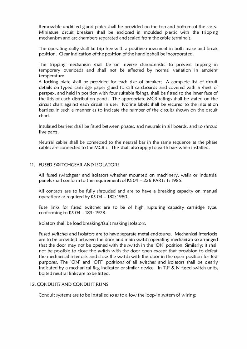
Removable undrilled gland plates shall be provided on the top and bottom of the cases.
Miniature circuit breakers shall be enclosed in moulded plastic with the tripping
mechanism and arc chambers separated and sealed from the cable terminals.
The operating dolly shall be trip-free with a positive movement in both make and break
position. Clear indication of the position of the handle shall be incorporated.
The tripping mechanism shall be on inverse characteristic to prevent tripping in
temporary overloads and shall not be affected by normal variation in ambient
temperature.
A locking plate shall be provided for each size of breaker; A complete list of circuit
details on typed cartridge paper glued to stiff cardboards and covered with a sheet of
perspex, and held in position with four suitable fixings, shall be fitted to the inner face of
the lids of each distribution panel. The appropriate MCB ratings shall be stated on the
circuit chart against each circuit in use: Ivorine labels shall be secured to the insulation
barriers in such a manner as to indicate the number of the circuits shown on the circuit
chart.
Insulated barriers shall be fitted between phases, and neutrals in all boards, and to shroud
live parts.
Neutral cables shall be connected to the neutral bar in the same sequence as the phase
cables are connected to the MCB’s. This shall also apply to earth bars when installed.
11. FUSED SWITCHGEAR AND ISOLATORS
All fused switchgear and isolators whether mounted on machinery, walls or industrial
panels shall conform to the requirements of KS 04 – 226 PART: 1: 1985.
All contacts are to be fully shrouded and are to have a breaking capacity on manual
operations as required by KS 04 – 182: 1980.
Fuse links for fused switches are to be of high rupturing capacity cartridge type,
conforming to KS 04 – 183: 1978.
Isolators shall be load breaking/fault making isolators.
Fused switches and isolators are to have separate metal enclosures. Mechanical interlocks
are to be provided between the door and main switch operating mechanism so arranged
that the door may not be opened with the switch in the ‘ON’ position. Similarly; it shall
not be possible to close the switch with the door open except that provision to defeat
the mechanical interlock and close the switch with the door in the open position for test
purposes. The ‘ON’ and ‘OFF’ positions of all switches and isolators shall be clearly
indicated by a mechanical flag indicator or similar device. In T.P & N fused switch units,
bolted neutral links are to be fitted.
12. CONDUITS AND CONDUIT RUNS
Conduit systems are to be installed so as to allow the loop-in system of wiring:

All conduits shall be black rigid super high impact heavy gauge class ‘A’ PVC in
accordance with KS 04 – 179: 1988 and IEE Regulations. No conduit less than 20mm in
diameter shall be used anywhere in this installation.
Conduit shall be installed buried in plaster work and floor screed except when run on
wooden or metal surface when they will be installed surface supported with saddles
every 600mm. Conduit run in chases shall be firmly held in position by means of
substantial pipe hooks driven into wooden plugs.
The Sub-contractors attention is drawn to the necessity of keeping all conduits entirely
separate from other piping services such as water and no circuit connections will be
permitted between conduits and such pipes.
All conduits systems shall be arranged wherever possible to be self-draining to switch
boxes and conduit outlet points for fittings:
The systems, when installed and before wiring shall be kept plugged with well -fitting
plugs and when short conduit pieces are used as plugs, they shall be doubled over and
tied firmly together with steel wire; before wiring all conduit systems shall be carried out
until the particular section of the conduit installation is complete in every respect.
The sets and bends in conduit runs are to be formed on site using appropriate size
bending springs and all radii of bends must not be less than 2.5 times the outside
diameter of the conduit. No solid or inspection bends, tees or elbows will be used.
Conduit connections shall either be by a demountable (screwed up) assembly or adhesive
fixed and water tight by solution. The tube and fittings must be clean and free of all
grease before applying the adhesive. When connections are made between the conduit
and switch boxes, circular or non-screwed boxes, and care shall be taken that no rough
edges of conduit stick out into the boxes.
Runs between draw in boxes are not to have more than two right angle bends or their
equivalent. The sub-contractor may be required to demonstrate to the Engineers that
wiring in any particular run is easily withdrawable and the sub-contractor may, at no
extra cost to the contract; be required to install additional draw-in boxes required. If
conduit is installed in straight runs in excess of 6000mm, expansion couplings as
manufactured by Egatube shall be used at intervals of 6000mm.
Where conduit runs are to be concealed in pillars and beams, the approval of the
Structural Engineer, shall be obtained. The sub-contractor shall be responsible for
marking the accurate position of all holes chases etc, on site, or if the Engineer so directs,
shall provide the Main Contractor with dimensional drawings to enable him to mark out
and form all holes and chases. Should the sub-contractor fail to inform the main
contractor of any inaccuracies in this respect they shall be rectified at the sub-contractors
expense.
It will be the Sub-contractors responsibility to ascertain from site, the details of reinforced
concrete or structural steelwork and check from the builder’s drawings the positions of
walls, structural concrete and finishes. No reinforced concrete or steelwork may be
drilled without first obtaining the written permission of the Structural Engineer.
The drawings provided with these specifications indicate the appropriate positions only
of points and switches, and it shall be the Sub-Contractors responsibility to mark out and
centre on site the accurate positions where necessary in consultation with the Architect
and the Engineer. The sub-contractor alone shall be responsible for the accuracy of the
final position.
13. CONDUIT BOXES AND ACCESSORIES
All conduit outlets and junction boxes are to be either malleable iron and of standard
circular pattern of the appropriate type to suit saddles being used or super high impact
PVC manufactured to KS 04 – 179 : 1983.
Small circular pattern boxes are to be used with conduits up to and including 25mm
outside diameter. Rectangular pattern adaptable boxes are to be used for conduits of
32mm outside diameter and larger. For drawing in of cables in exposed runs of conduit,
standard pattern through boxes are to be used:
Boxes are to be not less than 50mm deep and of such dimensions as will enable the
largest appropriate number of cables for the conduit sizes to be drawn in without
excessive bending.
Outlet boxes for lighting fittings are to be of the loop-in type where conduit installation is
concealed and the sub-contractor shall allow one such box per fitting, except where
fluorescent fittings are specified when two such boxes per fitting shall be fitted flush with
ceiling and if necessary fitted with break joint rings. Pattresses shall be fitted where
required to outlets on surface conduit runs.
Adaptable boxes are of PVC or mild steel (of not less than 12swg) and black enamelled or
galvanised finish according to location. They shall be of square or oblong shape location.
They shall be of square or oblong shape complete with lids secured by four 2 BA brass
roundhead screws; No adaptable box shall be less than 75mm x 75mm x 50mm or larger
than 300mm x 300mm x 75mm and shall be adequate in depth in relation to the size of
conduit entering it. Conduits shall only enter boxes by means of conduit bushes.
14. LABELS
Labels fitted to switches and fuse boards;-
(i) Shall be Ivorine engraved black on white.
(ii) Shall be secured by R.H brass screws of same manufacturing throughout.
(iii) Shall be indicated on switches:-
a) Reference number of switch
b) Special current rating
c) Item of equipment controlled
(iv) Shall indicate on MCB panels
d) Reference number
e) Type of board, i.e.; lighting, sockets, etc.,
f) Size of cable supplying panel
g) where to isolate feeder cable
(v) Shall be generally not less than 75mm x 50mm.
15. EARTHING
The earthing of the installation shall comply with the following requirements;-
(i) It shall be carried out in accordance with the appropriate sections of the current
edition of the Regulations, for the Electrical Equipment of Buildings issued by
Institute of Electrical Engineers of Great Britain.
(ii) At all main distribution panels and main service positions a 25mm x 3mm
minimum cross sectional area Copper tape shall be provided and all
equipment including the lead sheath and armouring of cables, distribution
boards and metal frames shall be bonded thereto.
(iii) The earth tape in Sub-clause (ii) shall be connected by means of a copper tape
or cable of suitable cross sectional area to an earth electrode which shall be a
copper earth rod (see later sub-clause).
(iv) All tapes to be soft high conductivity copper, untinned except where
otherwise specified and where run underground on or through walls, floors,
etc., it shall be served with corrosion resisting tape or coated with corrosion
compound and braided
(v) Where the earth electrode is located outside the building a removable test link
shall be provided inside the building as near as possible to the point of entry
to the tape, for isolating the earth electrode for testing purposes.
(vi) Earthing of sub-main equipment shall be deemed to be satisfactory where the
sub-main cables are M.I.C.S. or conduit with separate earth wire, and
installation is carried out in accordance with the figures stated in the current
edition of the I.E.E Regulations.
(vii) Where an earth rod is specified (see Sub-clause (iii) it shall be proprietary
manufacture, solid hand drawn copper of 15mm diameter driven into the
ground to a minimum depth of 3.6M. It shall be made up to 1.2m sections
with internal screw and socket joints and fitted with hardened steel tip and
driving cap.
(viii) Earth plates will not be permitted
(ix) Where an earth rod is used the earth resistance shall be tested in the manner
described in the current edition of the IEE Regulations, by the Sub-Contractor
in the presence of the Engineer and the Sub-Contractor shall be responsible
for the supply of all test equipment.
(x) Where copper tape is fixed to the building structure it shall be by means of
purpose made non-ferrous saddles which space the conductor away from the
structure a minimum distance of 20mm. Fixings, shall be made using purpose
made plugs; No fixings requiring holes to be drilled through the tape will be
accepted.
(xi) Joints in copper tape shall be tinned before assembly riveted with a minimum
of two copper rivets and seated solid.
(xii) Where holes are drilled in the earth tape for connection to items of
equipment the effective cross sectional area must not be less than required to
comply with the IEE regulations.
(xiii) Bolts, nuts and washers for any fixing to the earth tape must be of non-
ferrous material.
(xiv) Attention is drawn to the need for the earthing metal parts of lighting fittings
and for bonding ball joint suspension in lighting fittings.
16. CABLES AND FLEXIBLE CORDS
All cables used in this Sub-Contract shall be manufactured in accordance with the current
appropriate Kenya standard Specification which are as follows:-
P.V.C. Insulated Cables and Flexible Cords --- Ks 04-192:1988
P.V.C Insulated Armoured Cables --- Ks 04-194:1990
Armouring of Electric cables --- Ks 04-290:1987
The successful Sub-Contractor will, at the Engineers discretion be required to submit
samples of cables for the Engineers approval; the Engineer reserves the right to call for
the cables of an alternative manufacture without any extra cost being incurred.
P.V.C. insulated cables shall be 500/1000 volt grade. No cables smaller than 1.5mm² shall
be used unless otherwise specified. The installation and the finish of cables shall be as
detailed in later clauses. The colour of cables shall conform to the details stated in the
“Cable Braid and insulation Colours” Clause.
17. ARMOURED P.V.C. INSULATED AND SHEATHED CABLES:
Shall be 600/1000 volt grade manufactured to Ks 04-194:1988 and Ks 04-187/188 with
copper stranded conductors.
The wire armour of the cable shall be used wholly as an earth continuity conductor and
the resistance of the wire armour shall have a resistance not more than twice of the
largest current carrying conductor of the cable.
P.V.C./S.W.A./P.V.C. cables shall be terminated using “Telecom” “B” type or approved
equal or approved equal glands and a P.V.C. tapered sleeve shall be provided to shroud
each gland.
18. CABLE SUPPORTS, MARKERS AND TILES
All PVC/SWA/PVC cables run inside the building shall be fixed in rising ducts or on
ceilings by means of die cast cable hooks or clamps, of appropriate size to suit cables,
fixed by studs and back nuts to their channel sections.

Alternatively, fixing shall be by BICC claw type cleating system with die-cast cleats and
galvanised mild steel back straps or similar approved equal method. For one or two
cables run together the cleats shall be fixed a special channel section supports or
backstraps described above which shall in turn be secured to walls or ceilings of ducts by
rawbolts.
In excessively damp or corrosive atmospheric conditions special finishes may be required
and the Sub-contractor shall apply to the Engineer for further instructions before ordering
cleats and channels for such areas.
The above type of hooks and clamps and channels or cleats and blackstraps shall also be
used for securing cables in vertical ducts.
Cables supports shall be fixed at 600mm maximum intervals, the supports being supplied
and erected under this Sub-contract. Saddles shall not be used for supporting cables nor
any other type of fixing other than one of the two methods described above or other
system which has received prior approval of the Engineer;
Cables are to be kept clear of all pipe work and the Sub-contractor shall work in close
liaison with other services Sub-contractors.
The Sub-Contractor shall include for the provision of fixing of approved type coloured
slip on cables end markers to indicate permanently the correct phase and neutral colours
on all ends.
Provision shall be made for supplying and fixing approved non-corrosive metal cable
markers to be attached to the outside of all PVC/SWA/PVC cables at 15mm intervals
indicating cable size and distinction.
Where PVC/SWA/PVC cables are outside the building they shall be laid underground
750mm deep with protecting concrete interlocking cover tiles laid over which shall be
provided and laid under this Sub-contract.
All necessary excavations and reinstatement of ground including sanding or trenches will
be carried out by the Sub-Contractor, unless otherwise stated.
19. PVC INSULATED CABLES
Shall be of non-braided type as CMA reference 6491 x 600/1000/1000 volt grade cables,
or equal approved.
PVC cables shall conform to the details of the “Cables and Flexible cords” and “Cable
Braid and Insulation Colours” clauses.
20. HEAT RESISTING CABLES
Final connections to cookers, water heaters, etc., shall be made using butyl rubber
insulated cable as CMA reference 610 butyl (Single core 600/1000 Volt).
This type of cable shall be used in all instances where a temperature exceeding 100°F, but
not exceeding 150°F is likely to be experienced. Final connections to all lighting fittings
(and other equipment where a temperature in excess of 150°c likely to be experienced)
shall be made using silicon rubber insulated cable or equal and approved.
21. FLEXIBLE CORDS
Shall be in accordance with the “Cable and Flexible Cords” clause. No cord shall be less
than 24/0.2mm in size unless otherwise specified.
Circular white twin TRS flex shall be used for plain pendant fittings up to 100 watts. For
all other types of lighting fittings the flexible cable shall be silicone rubber insulated.
No polythene insulated flexible cable shall be used in any lighting fitting or other
appliance (see “Heat Resisting Cables” Clause 30).
22. CABLE ENDS AND PHASE COLOURS
All cable ends connected up in switchgear, MCB panels etc;, shall have the insulation
carefully cut back and the ends sealed with Hellerman rubber slip on cable end markers.
The markers shall be of appropriate phase colour for switch and all other live feeds to the
details of the “Cable Insulation Colours” clause. Black cable with black end markers shal l
only be used for neutral cables.
23. CABLE INSULATION COLOURS
Unless otherwise stated in later clauses the insulation colours shall be in accordance with
the following table.
Where other systems are installed the cable colours shall be in accordance with the details
stated in the appropriate clause.
SYSTEM INSULATION COLOUR CABLE END
MARKER 1) Main and Sub-Main
a) Phase Red Red
b) Neutral Black Black
2) Sub-Circuits Single Phase
a) Phase Red Red
b) Neutral Black Black
24. SUB-CIRCUIT WIRING
For all lighting and sockets wiring shall be carried out in the “looping in” system and
there shall be no joints whatsoever. No lighting circuits shall comprise more than 20
points when protected by 10A MCB. Cables with different cross-section area of copper
shall not be used in combination.
Lighting circuits P.V.C. cable.
(i) 1.5mm² for all lighting circuits indicated on the drawing.
Power circuits P.V.C cable (minimum sizes).
(ii) 2.5mm² for one, two or three 5Amp sockets wired in parallel.
(iii) 2.5mm² for one 15Amp socket.
(iv) 2.5mm² for maximum of ten switched 13 Amp sockets wired from 30 Amp
MCB.
The wiring sizes for lighting circuits and sockets are shown on the drawings. In such cases,
the sizes shown on the drawings shall prevail over the sizes specified.
Wiring sizes for other appliances shall be shown on the drawing or specified in later
clauses of this specification.
25. SPACE FACTOR
The maximum number of cables that may be accommodated in a given size of conduit or
trunking or duct is not to exceed the number in Tables B.5 and B.6 or as stated in
Regulation B.91, B.117 and B.118 of the I.E.E Regulations whichever is appropriate.
26. INSULATION
The insulation resistance to earth and between poles of the whole wiring system, fittings
and lumps, shall not be less than the requirements of the latest edition of the I.E.E
Regulations. Complete tests shall be made on all circuits by the Sub-contractor before the
installations are handed over.
A report of all tests shall be furnished by the Sub-Contractor to the Engineer. The
Engineer will then check test with his own instruments if necessary.
27. LIGHTING SWITCHES
These shall be mounted flush with the walls, shall be contained in steel or alloy boxes and
shall be of the gangs’ ratings and type shown in the drawings. They shall be as
manufactured by M.K. Electrical Ltd., or other equal and approved to KS 04 – 247: 1988
28. SOCKETS AND SWITCHED SOCKETS
These shall be flush pattern in steel/pvc box and shall be of the gangs and type specified
in the drawings.
They shall be 13- Amp, 3-pin, shuttered, switched and as manufactured by “M.K.
Electrical Co. Ltd.”, or other approved equal to KS 04 – 246: 1987
29. FUSED SPUR BOXES
These shall be flush, D.P switched as in steel/pvc box and of type and make specified in
the drawings complete with pilot light and as manufactured by “M. K. Electrical
Company Ltd”, or other approved equal. KS 04 – 247: 1988

30. COOKER OUTLETS
These shall be flush mounted with 13-A switched socket outlet and neon indicator Lamps.
The cooker control units shall be as manufactured by “M.K. Electrical Company Ltd”, or
other approved equal KS 04 – 247: 1988
31. CONNECTORS
Shall be specified in the drawings and appropriate rating. These shall be fitted at all
conduit box lighting point outlets for jointing of looped P.V.C cables with flexible cables
of specified quality.
32. LAMPHOLDERS
Shall be of extra heavy H.O skirted and shall be provided for every specified lighting
fitting and shall be B.C; E.S;, or G.E.S as required. All E.S. and G.E.S. holders shall be
heavy brass type (except for plain pendants where the reinforced bakelite type shall be
used). The screwed cap of the E.S and G.E.S. holders shall be connected to the neutral.
Where lampholders are supported by flexible cable, the holders shall have “cord grip”
arrangements and in the case of metal shades earthing screws shall be provided on each
of the holders.
The Sub-Contractor must order the appropriate type of holder when ordering lighting
fittings, to ensure that the correct types of holders are provided irrespective of the type
normally supplied by the manufacturers.
33. LAMPS
All lamps shall be suitable for normal stated supply voltage and the number and sizes of
lamps detailed on the drawings shall be supplied and fixed. The Sub-Contractor must
verify the actual supply voltage with the supply authority before ordering the lamps.
Tungsten filament lamps shall be manufactured in accordance with KS 04 – 112:1978 for
general service lamps and KS 04 – 307:1985 for lamps other than general services.
Tubular fluorescent lamps shall comply with KS 04 – 464:1982
Pearl lamps shall be used in all fittings unless otherwise specified.
34. LIGHTING FITTINGS AND STREET LIGHTING LANTERNS
This Sub-Contract shall include for the provision, handling charges, taking the delivery,
safe storage, wiring (including internal wiring) assembling and erecting of all lighting
fittings shown on the drawings.
All fittings and pendants shall be fixed to the conduit boxes with brass R/H screws. These
to be in line with metal finish of fittings. The lighting fittings are detailed for the purpose
of establishing a high standard of finish and under no circumstances will substitute fittings
be permitted.
In case of rectangular shaped ceiling fittings, the extreme ends of the fittings shall be
secured to suitable support in addition to the central conduit box fittings. Supports shall
be provided and fixed by the Sub-Contractor.
The whole of the metal work of each lighting fittings shall be effectively bonded to earth.
In the case of ball and/or knuckle joints short lengths of flexible cable shall be provided,
bonded to the metal work on either side of the joints. If the above provisions are not
made by the manufacturers -, the Sub-contractor shall include cost of additional work
necessary in his tender. See “Flexible Cords” clause for details of internal wiring of
lighting fittings.
Minimum size of internal wiring shall be 20/0.20mm (23/0067). Each lighting fitting
shall be provided with number type and size of lamps as detailed on the drawings. It is
to be noted that some fittings are suspended as shown on the drawings.
Where two or more points are shown adjacent to each other on the drawings, e.g socket
outlet and telephone outlet, they shall be lined up vertically or horizontally on the centre
lines of the units concerned.
Normally, the units shall be lined up on vertical centre lines, but where it is necessary to
mount units at low level they shall be lined up horizontally.
35. POSITIONS OF POINTS AND SWITCHES
Although the approximate positions of all points are shown on the drawings, enquiry
shall be made as to the exact positions of all M.C.B panels, lighting points, socket outlets
etc, before work is actually commenced. The Sub-contractor must approach the Architect
with regard to the final layout of all lights on the ceiling and walls.
The Sub-contractor must consult with the Engineer in liaison with the Clerk of Works, or
the General Foreman on site regarding the positions of all points before fixing any
conduit etc. The Sub-Contractor shall be responsible for all alterations made necessary by
the noncompliance with the clause.
36. STREET/SECURITY OUTDOOR LIGHTING COLUMNS:
The column shall be at a minimum of 225mm in the ground on 75mm thick concrete
foundations and the pole upto 150mm shall be surrounded with concrete. The top
bracket and plain section of the columns shall be common to and interchangeable with
all brackets with maximum mismatching tolerance of 3mm between any pole and
bracket. After manufacture and before erection the columns shall be treated with an
approved mordant solution which shall be washed off and the whole allowed to dry.
Thereafter, the columns shall be painted with one undercoat and two coats of gloss paint
to an approved colour. All columns shall be complete with fused cut-outs.
37. TIMING CONTROL SWITCH
These shall be installed where shown on the drawings. Photocell timing control circuits
which will operate ‘on’ with a specified level of darkness and ‘off’ with a given level of
light. The initial adjustment will be done with approval of the Electrical Engineer.
38. WIRING SYSTEM FOR STREET LIGHTING
Cables shall be as indicated on the drawings, and shall be laid in a cable trench 450mm
deep along the road sides and 600mm deep across the roads and 900mm away from the
road kerb or 1500mm away from the edges of the road. ‘Loop-in’ and ‘Loop-out’

arrangement shall be used at every pole. Wiring to the lanterns on each pole shall be
with 1.5mm² PVC twin insulated and sheathed cable with earth wire shall be laid at least
600mm below the finished road level on a compact bed of murram at least 50mm thick
and covered with a concrete surrounded 150mm thick.
39. METAL CONTROL PILLAR
These shall be metal clad and fabricated as per contract drawings and specification. The
Sub-Contractor shall supply, install, test and commission control pillars including
supplying, fixing connecting switchgears as detailed on the appropriate drawings.
40. CURRENT OPERATED EARTH LEAKAGE CIRCUIT BREAKER
Current operated earth leakage circuit breaker shall conform to B.S.S. 4293:68 rated at
240 volts D.P. 50 cycles A.C. Mains.
The breaker shall be provided with test switch and fitted in weather proof enclosure for
surface mounting. The rated load current and earth fault operating current shall be as
specified in the drawings. These shall be as manufactured by Crabtree, Siemens or other
equal and approved.
41. M.V. SWITCHBOARD AND SWITCHGEAR
The switchboard shall be manufactured in accordance with KS04-226 which co-ordinates
the requirements for electrical power switchgear and associated apparatus. It is not
intended that this K.S. should cover the requirements for specified apparatus for which
separate Kenyan Standard exist. All equipment and material used in the switchboard shall
be in accordance with the appropriate Kenya Standard.
The switchboard shall comprise the equipment shown on the drawings together with all
current transformers, auxiliary fuses, labels, small wiring and interconnections necessary
for the satisfactory operation of the switchboard.
The Switchboard shall be of the flush fronted, enclosed, metal clad type with full front or
rear access as called for in the particular specifications, suitable for indoor use,
sectionalized as necessary to facilitate transport and erection. The maximum height of
the switchboard is to be approximately 2.0 metres. A suitable connection chamber
containing all field terminals shall be provided at the top or bottom of the switchboard
as appropriate.
Before manufacture, the Sub-Contractor shall submit to the consulting Engineer for
approval of detailed drawings showing the layout, construction and connection of the
switchboard.
All bus-bars and bus-bar connections shall consist of high conductivity copper and be
provided in accordance with KS 04-226: 1985. The bus-bars shall be clearly marked with
the appropriate phase and neutral colours which should be red, yellow, blue for the
phases and black for neutral. The bus-bars shall be so arranged in the switchboard that
the extensions to the left and right may be made in the future with ease should the need
arise.
Small wiring, which will be neatly arranged and cleated, shall be executed in accordance
with B.S. 158 and the insulation of the wiring shall be coloured according to the phase or
neutral connection.
Switches and fuse switches, shall be in strict accordance with KS04-183:1978 Class 2
switches. Means of locking the switch in the “OFF” position shall be provided.
All fuse switches shall comply with KS04-183:1978, PARTS 2 and 3 a fault rating at least
equal to the fault rating of the switchboard in which they are installed. Cartridge fuse
links to KS 04-183:1978 category A.C. 46, class Q1 and fusing factor not exceeding 1.5
shall be supplied with each fused switch.
Mounting arrangements shall be such that individual complete fuse switches may be
disconnected and withdrawn when necessary without extensive dismantling work.
When switches are arranged in their formation all necessary horizontal and vertical
barriers shall be provided to ensure segregation from adjacent units. Means of locking the
switch in the “OFF” position shall be provided.
42. STEEL CONDUITS AND STEEL TRUNKING
Conduits shall be of heavy gauge class “B” welded to Standard specification KS
04180:1985. In no case will conduit smaller than 20mm diameter be used on the works.
Conduits installed within buildings shall be black enamelled finish except where specified
otherwise. Where installed externally or in damp conditions they shall be galvanised.
Conduit fittings, accessories or equipment used in conjunction with galvanised conduits
shall also be galvanised or otherwise as approved by the service engineer.
Metal trunking shall be fabricated from mild steel of not less than 18 swg. All sections of
trunking shall be rigidly fixed together and attached to the framework or fabric or the
building at intervals of not less than 1.2m. Joint trunking shall not overhang fixing points
by more than 0.5m.
All trunking shall be made electrically continuous by means of 25 x 3mm copper links
across each joint and where the trunking is galvanized, the links shall be made by
galvanized flat iron strips.
All trunking fittings (i.e. Bends, tees, etc.) shall leave the main through completely clear
of obstructions and continuously open except through walls and floors at which points
suitable fire resisting barriers shall be provided as may be necessary. The inner edge of
bends and tees shall be chamfered where cables larger than 35mm² are employed.
Where trunking passes through ceilings and walls the cover shall be solidly fixed to
150mm either side of ceilings and floors and 50mm either side of walls.
Screws and bolts securing covers to trunking or sections of covers together shall be
arranged so that damage to cables cannot occur either when fixing covers or when
installing cables in the trough.
Where trunking is used to connect switchgear of fuseboards, such connections shall be
made by trunking fittings manufactured for this purpose and not by multiple conduit
couplings.
Where vertical sections of trunking are used which exceed 4.5m in length, staggered tie
off points shall be provided at 4.5m intervals to support the weight of cables.
Unless otherwise stated, all trunking systems shall be painted as for conduit.
Where a wiring system incorporates galvanized conduit and trunking, the trunking shall
be deemed to be galvanized unless specified otherwise.
The number of cables to be installed in trunking shall be such as to permit easy drawing in
without damage to the cables, and shall in no circumstances be such that a space factor of
45% is exceeded.
Conduit and trunking shall be mechanically and electrically continuous. Conduit shall be
tightly screwed between the various lengths so that they butt at the socketed joints. The
internal edges of conduit and all fittings shall be smooth, free from burrs and other
defects.
Oil and any other insulating substance shall be removed from the screw threads; where
conduits terminate in fuse-gear, distribution boards, adaptable boxes, non-spouted
switchboxes, etc., they shall, unless otherwise stated, be connected thereto by means of
smooth bore male brass bushes, compression washers and sockets. All exposed threads
and abrasions shall be painted using an oil paint for black enameled tubing and
galvanizing paint for galvanized tubing immediately after the conduits are erected. All
bends and sets shall be made cold without altering the section of the conduit.
The inner radius of the bed shall not be less than four (4) times the outside diameter of
the conduit. Not more than two right angle bends will be permitted without the inter-
position of a draw-in-box. Where straight runs of conduit are installed, draw-in-boxes
shall be provided at distances not exceeding 15mm. No tees, elbows, sleeves, either of
inspection or solid type, will be permitted.
Conduit shall be swabbed out prior to drawing in cables, and they shall be laid so as to
drain of all condensed moisture without injury to end connections.
Conduits and trunking shall be run at least 150mm clear of hot water and steam pipes,
and at least 75mm clear of cold water and other services unless otherwise approved by
the services engineer.
All boxes shall conform to KS 04 – 668: 1986, to be of malleable iron, and black
enamelled or galvanised according to the type of conduit specified. All accessory boxes
shall have threaded brass inserts.
Box lids where required shall be heavy gauge metal, secured by means of zinc plated or
cadmium plated steel screws.
All adaptable boxes and lids of the same size shall be interchangeable.
Boxes used on surface work are to be tapped or drilled to line up with the conduit fixed
in distance type saddles allowing clearance between the conduit and wall without the
need for setting the conduit.

Where used in conjunction with mineral insulated copper sheathed cable, galvanized
boxes shall be used and painted after erection.
Draw-in boxes in the floors are generally to be avoided but where they are essential they
must be grouped in positions approved by the services engineer and covered and by the
suitable floor traps, with non-ferrous trays and covers.
The floor trap covers are to be recessed and filled in with a material to match the floor
surface.
The Sub-contractor must take full responsibility for the filling in of all covers, but the
filling in material will be supplied and the filling carried out by the main building
contractor.
Where buried in the ground outside the building the whole of the buried conduit is to be
painted with two coats of approved bitumastic composition before covering up.
Where run on the surface, unpainted fittings and joints shall be painted with two coats of
oil bound enamel applied to rust and grease free metalwork.
43. TESTING ON SITE
The Sub-contractor shall conduct during and at the completion of the installation and, if
required, again at the expiration of the maintenance period, tests in accordance with the
relevant section of the current edition of the Regulations for the electrical equipment of
buildings issued by the I.E.E of Great Britain, the Government Electrical Specification and
the Electric Supply Company’s By-Laws.
(a) Tests shall be carried out to prove that all single pole switches are installed in the
‘live’ conductor.
(b) Tests shall be carried out to prove that all socket outlets and switched socket
outlets are connected to the ‘live’ conductor in the terminal marked as such, and
that each earth pin is effectively bonded to the earth continuity system. Tests
shall be carried out to verify the continuity of all conductors of each ‘ring’ circuit.
(c) Phase tests shall be carried out on completion of the installation to ensure that
correct phase sequence is maintained throughout the installation. Triplicate copies
of the results of the above tests shall be provided within 14 days of the witnessed
tests and the Sub-contractor will be required to issue to the service engineer the
requisite certificate upon completion as required by the regulations referred to
above.
(d) Any faults, defects or omissions or faulty workmanship, incorrectly positioned or
installed parts of the installation made apparently by such inspections or tests shall
be rectified by the Sub-contractor at his own expense.
(e) The Sub-contractor shall provide accurate instruments and apparatus and all
labour required to carry out the above tests. The instruments and apparatus shall
be made available to the services engineer to enable him to carry out such tests as
he may require.
(f) The Sub-contractor shall generally attend on other contractors employed on the
project and carry out such electrical tests as may be necessary.
(g) The Sub-contractor shall test to the services engineer’s approval and as specified
elsewhere in this specification or in standards and regulations already referred to,
all equipment, plant and apparatus forming part of the works and before
connecting to any power or other supply and setting to work.
(h) Where such equipment, etc., forms part of or is connected to a system whether
primarily or of an electrical nature or otherwise (e.g. air conditioning system) the
Sub-contractor shall attend on and assist in balancing, regulating testing and
commissioning, or if primarily an electrical or other system forming part of works,
shall balance, regulate, test and commission the system to the service engineer’s
approval.
APPENDIX TO GENERAL SPECIFICATIONS OF MATERIALS AND WORKS
The electrical sub-contractor shall comply with the following:-
1. Government Electrical Specifications No. 1 and No. 2.
2. All requirements of Kenya Power Company Limited, and Communications Authority
of Kenya (CA).

SECTION B
SCHEDULE OF CONTRACT DRAWINGS
SCHEDULE OF CONTRACT DRAWINGS
DRAWING NO.
DRAWING TITLE
As shall be issued by the Engineer
NOTE: Tenderers are advised to inspect the electrical drawings at the office of the Chief Engineer
(Electrical) – State Department for Public Works, at Chief Engineer’s (Electrical) office, 5th
Floor Hill Plaza Building, Community area, Nairobi along Ngong road, during normal
working hours.
The drawings shall however be availed, on award of the tender, to the contractor.

SECTION C
PARTICULAR SPECIFICATIONS
OF
MATERIALS AND WORKS

PARTICULAR SPECIFICATIONS
1.00 SITE LOCATION
The site of the proposed works is at UAP Towers, Nairobi County
2.00 SCOPE OF WORKS
The works to be carried out under this sub-contract comprise supply, installation,
testing and commissioning of the following: -
(a) Electrical Works
This shall include Trunking, Conduit Works, Cabling, Isolators, LV Sub-
boards, Internal Lighting, Power fittings, Internal Power Distribution, Area
Lighting, Fire Alarm & Detection System and related accessories among other
works.
3.00 MATERIALS FOR THE WORKS
Materials shall be as specified in Section A and in the Bills of Quantities of this
document which shall be read in conjunction with contract drawings. Alternative
materials shall be accepted only after approval by the Project Manager.
4.00 BROCHURES FOR FIRE ALARM PANEL & ANY ELECTRICAL EQUIPMENT AND
FITTINGS
For consideration and qualification tenderers shall, at their own cost, provide coloured
manufacturer’s brochures detailing technical literature and specifications where
applicable.
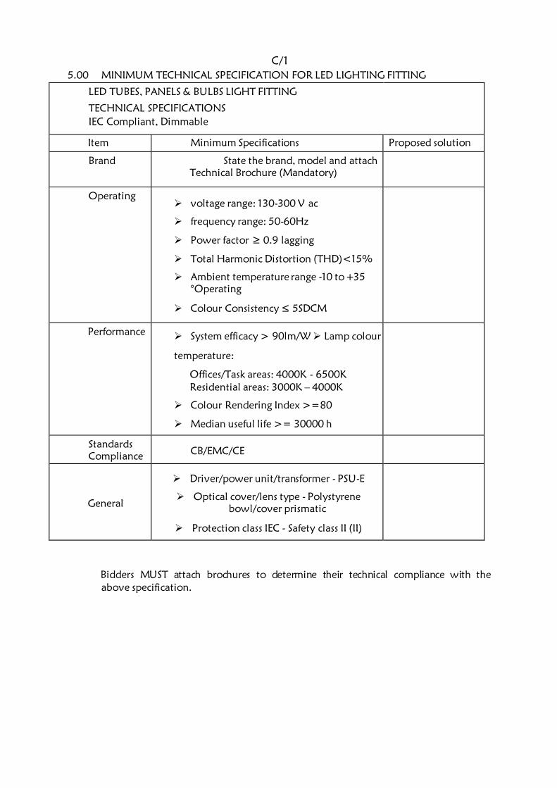
C/1
5.00 MINIMUM TECHNICAL SPECIFICATION FOR LED LIGHTING FITTING
LED TUBES, PANELS & BULBS LIGHT FITTING
TECHNICAL SPECIFICATIONS
IEC Compliant, Dimmable
Item Minimum Specifications Proposed solution
Brand State the brand, model and attach Technical Brochure (Mandatory)
Operating voltage range: 130-300 V ac
frequency range: 50-60Hz
Power factor ≥ 0.9 lagging
Total Harmonic Distortion (THD)<15%
Ambient temperature range -10 to +35
°Operating
Colour Consistency ≤ 5SDCM
Performance System efficacy > 90lm/W Lamp colour
temperature:
Offices/Task areas: 4000K - 6500K Residential areas: 3000K – 4000K
Colour Rendering Index >=80
Median useful life >= 30000 h
Standards
Compliance CB/EMC/CE
General
Driver/power unit/transformer - PSU-E
Optical cover/lens type - Polystyrene
bowl/cover prismatic
Protection class IEC - Safety class II (II)
Bidders MUST attach brochures to determine their technical compliance with the
above specification.
C/2
SECTION D
SCHEDULE OF UNIT RATES
D/1
SCHEDULE OF UNIT RATES
1. The tenderer shall insert unit rates against the items in the following schedules and
may add such other items as he considers appropriate.
2. The unit rates shall include for supply, transport, insurance, delivery to site, storage as
necessary, assembling, cleaning, installing, connecting, profit and maintenance in
defects liability and any other obligation under this contract.
3. The unit rates will be used to assess the value of additions or omissions arising from
authorised variations to the contract works.
4. Where trade names or manufacturer’s catalogue numbers are mentioned in the
specification, the reference is intended as a guide to the type of article or quality
of material required. Alternative brands of equal and approved quality will be
accepted.
5. The prices quoted shall be deemed to include for all obligations under the subcontract
including but not limited to supply of materials, labour, delivery to site, storage
on site, installation, testing, commissioning and all taxes (including V.A.T,
Withholding tax and all other taxes applicable at the time of tender). 6. Any bid returned with unfilled Schedule of Unit Rates shall be considered technically
non- responsive, and the bidder shall automatically be disqualified.

D/2
SCHEDULE OF UNIT RATES (To be completed by the Tenderer)
NO
DESCRIPTION
QTY
UNIT
UNIT RATE
(KSHS) (CTS)
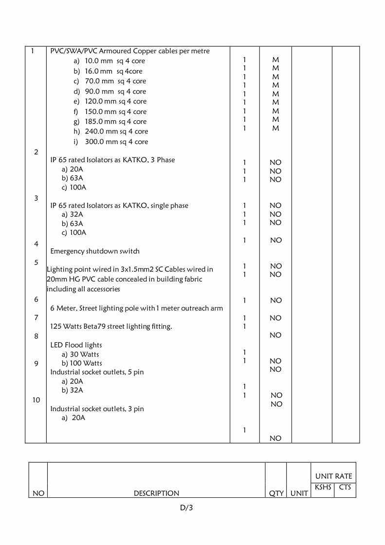
D/3
1
2
3
4
5
6
7
8
9
10
PVC/SWA/PVC Armoured Copper cables per metre
a) 10.0 mm sq 4 core
b) 16.0 mm sq 4core
c) 70.0 mm sq 4 core
d) 90.0 mm sq 4 core
e) 120.0 mm sq 4 core
f) 150.0 mm sq 4 core
g) 185.0 mm sq 4 core
h) 240.0 mm sq 4 core
i) 300.0 mm sq 4 core
IP 65 rated Isolators as KATKO, 3 Phase
a) 20A b) 63A
c) 100A
IP 65 rated Isolators as KATKO, single phase a) 32A
b) 63A c) 100A
Emergency shutdown switch
Lighting point wired in 3x1.5mm2 SC Cables wired in
20mm HG PVC cable concealed in building fabric
including all accessories
6 Meter, Street lighting pole with 1 meter outreach arm
125 Watts Beta79 street lighting fitting.
LED Flood lights
a) 30 Watts b) 100 Watts
Industrial socket outlets, 5 pin
a) 20A b) 32A
Industrial socket outlets, 3 pin a) 20A
1 1 1 1 1 1 1 1 1
1 1 1
1 1 1
1
1 1
1
1 1
1 1
1 1
1
M M M M M M M M M
NO NO NO
NO NO NO
NO
NO NO
NO
NO
NO
NO NO
NO
NO NO
NO
DESCRIPTION
QTY
UNIT
UNIT RATE
KSHS CTS
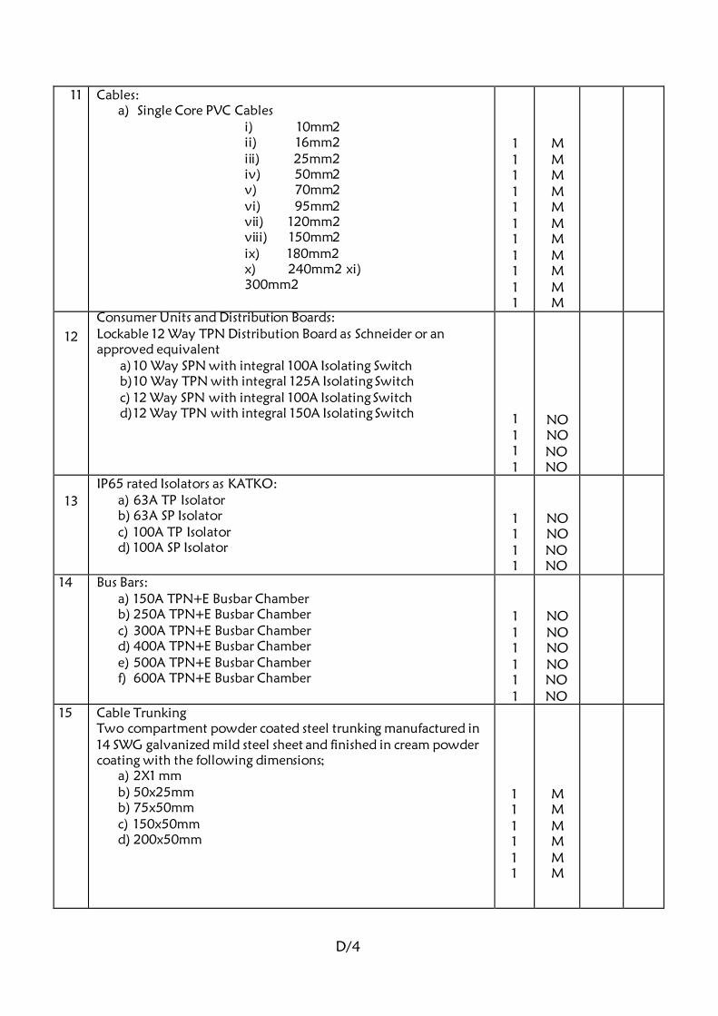
D/4
11 Cables: a) Single Core PVC Cables
i) 10mm2
ii) 16mm2
iii) 25mm2
iv) 50mm2
v) 70mm2
vi) 95mm2
vii) 120mm2
viii) 150mm2
ix) 180mm2 x) 240mm2 xi)
300mm2
1 1 1 1 1 1 1 1 1 1 1
M M M M M M M M M M M
12
Consumer Units and Distribution Boards: Lockable 12 Way TPN Distribution Board as Schneider or an
approved equivalent a) 10 Way SPN with integral 100A Isolating Switch b) 10 Way TPN with integral 125A Isolating Switch c) 12 Way SPN with integral 100A Isolating Switch d) 12 Way TPN with integral 150A Isolating Switch
1 1 1 1
NO NO NO
NO
13
IP65 rated Isolators as KATKO: a) 63A TP Isolator b) 63A SP Isolator c) 100A TP Isolator d) 100A SP Isolator
1 1 1 1
NO NO NO
NO
14 Bus Bars: a) 150A TPN+E Busbar Chamber b) 250A TPN+E Busbar Chamber c) 300A TPN+E Busbar Chamber d) 400A TPN+E Busbar Chamber e) 500A TPN+E Busbar Chamber f) 600A TPN+E Busbar Chamber
1 1 1 1 1 1
NO NO NO NO NO
NO
15 Cable Trunking Two compartment powder coated steel trunking manufactured in
14 SWG galvanized mild steel sheet and finished in cream powder
coating with the following dimensions; a) 2X1 mm b) 50x25mm b) 75x50mm c) 150x50mm d) 200x50mm
1 1 1 1 1 1
M M M M M M

D/5
16
Cable Trunking Two compartment powder coated HG PVC trunking manufactured
in heavy gauge material and finished in cream powder coating with
the following dimensions; a) 250x50mm b) 200x50mm
1 1
M M


G/1
SECTION E
BILLS OF QUANTITIES

G/2
BILLS OF QUANTITIES
A) PRICING OF PRELIMINARIES ITEMS
Prices will be inserted against item of preliminaries in the Contractor’s Bills of Quantities and
specification. These Bills are designated as Bill No.1 in this Section. Where the Contractor fails
to insert his price in any item he shall be deemed to have made adequate provision for this on
various items in the Bills of Quantities. The preliminaries form part of this contract and
together with other Bills of Quantities covers for the costs involved in complying with all the
requirements for the proper execution of the whole of the works in the contract.
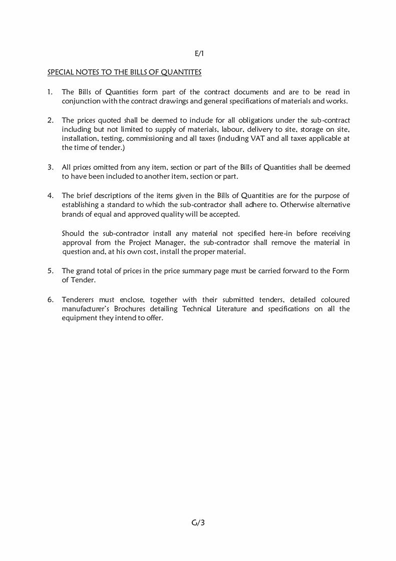
G/3
E/1
SPECIAL NOTES TO THE BILLS OF QUANTITES
1. The Bills of Quantities form part of the contract documents and are to be read in
conjunction with the contract drawings and general specifications of materials and works.
2. The prices quoted shall be deemed to include for all obligations under the sub-contract
including but not limited to supply of materials, labour, delivery to site, storage on site,
installation, testing, commissioning and all taxes (including VAT and all taxes applicable at
the time of tender.)
3. All prices omitted from any item, section or part of the Bills of Quantities shall be deemed
to have been included to another item, section or part.
4. The brief descriptions of the items given in the Bills of Quantities are for the purpose of
establishing a standard to which the sub-contractor shall adhere to. Otherwise alternative
brands of equal and approved quality will be accepted.
Should the sub-contractor install any material not specified here-in before receiving
approval from the Project Manager, the sub-contractor shall remove the material in
question and, at his own cost, install the proper material.
5. The grand total of prices in the price summary page must be carried forward to the Form
of Tender.
6. Tenderers must enclose, together with their submitted tenders, detailed coloured
manufacturer’s Brochures detailing Technical Literature and specifications on all the
equipment they intend to offer.
G/4
E/2
SECTION F
TECHNICAL SCHEDULE
OF
ITEMS TO BE SUPPLIED
G/5
TECHNICAL SCHEDULE
1. The technical schedule shall be submitted by tenderers to facilitate and enable the
Project Manager to evaluate the tenders, especially where the tenderer intends to
supply or has based his tender sum on equipment which differs in manufacture,
type or performance from the specifications indicated by the Project Manager.
2. The filling of this schedule forms part of Technical Evaluation of the tenders, and
bidders shall therefore be required to indicate the type/make and country of origin
of all the materials and equipment they intend to offer to the employer in this
schedule.
3. This schedule shall form part of the technical evaluation criterion, and tenderers are
therefore advised to complete the schedule as they shall be considered responsive.
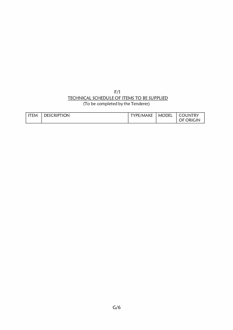
G/6
F/1
TECHNICAL SCHEDULE OF ITEMS TO BE SUPPLIED
(To be completed by the Tenderer)
ITEM
DESCRIPTION TYPE/MAKE MODEL COUNTRY
OF ORIGIN
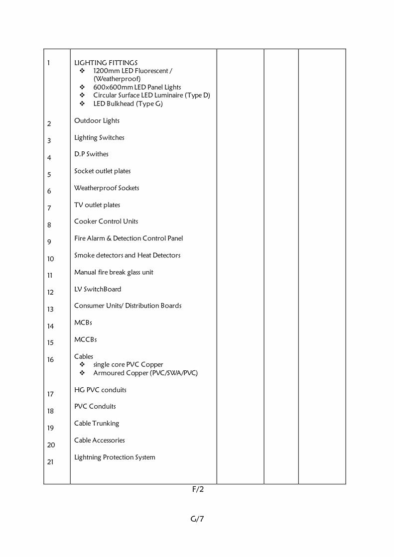
G/7
1 2 3 4 5 6 7 8 9 10 11 12 13 14 15 16 17 18 19 20 21
LIGHTING FITTINGS 1200mm LED Fluorescent /
(Weatherproof) 600x600mm LED Panel Lights Circular Surface LED Luminaire (Type D) LED Bulkhead (Type G)
Outdoor Lights Lighting Switches D.P Swithes Socket outlet plates Weatherproof Sockets TV outlet plates Cooker Control Units Fire Alarm & Detection Control Panel Smoke detectors and Heat Detectors Manual fire break glass unit LV SwitchBoard Consumer Units/ Distribution Boards MCBs MCCBs Cables single core PVC Copper Armoured Copper (PVC/SWA/PVC)
HG PVC conduits PVC Conduits Cable Trunking Cable Accessories Lightning Protection System
F/2

G/8
Code: E/CG/01
REPUBLIC OF KENYA
MINISTRY OF TRANSPORT, INFRASTRUCTUTRE,
HOUSING, URBAN DEVELOPMENT PUBLIC WORKS
STATE DEPARTMENT FOR PUBLIC WORKS
(ELECTRICAL DEPARTMENT)
TESTING & COMMISSIONING GUIDE FOR
ELECTRICAL INSTALLATION WORKS ON SITE
Issued by:
The Chief Engineer (Electrical),
Ministry of Transport, Infrastructure, Public Works, Housing
& Urban Development, State Department of Public
Works, P. O.BOX 41191 – 00100 GPO, NAIROBI.
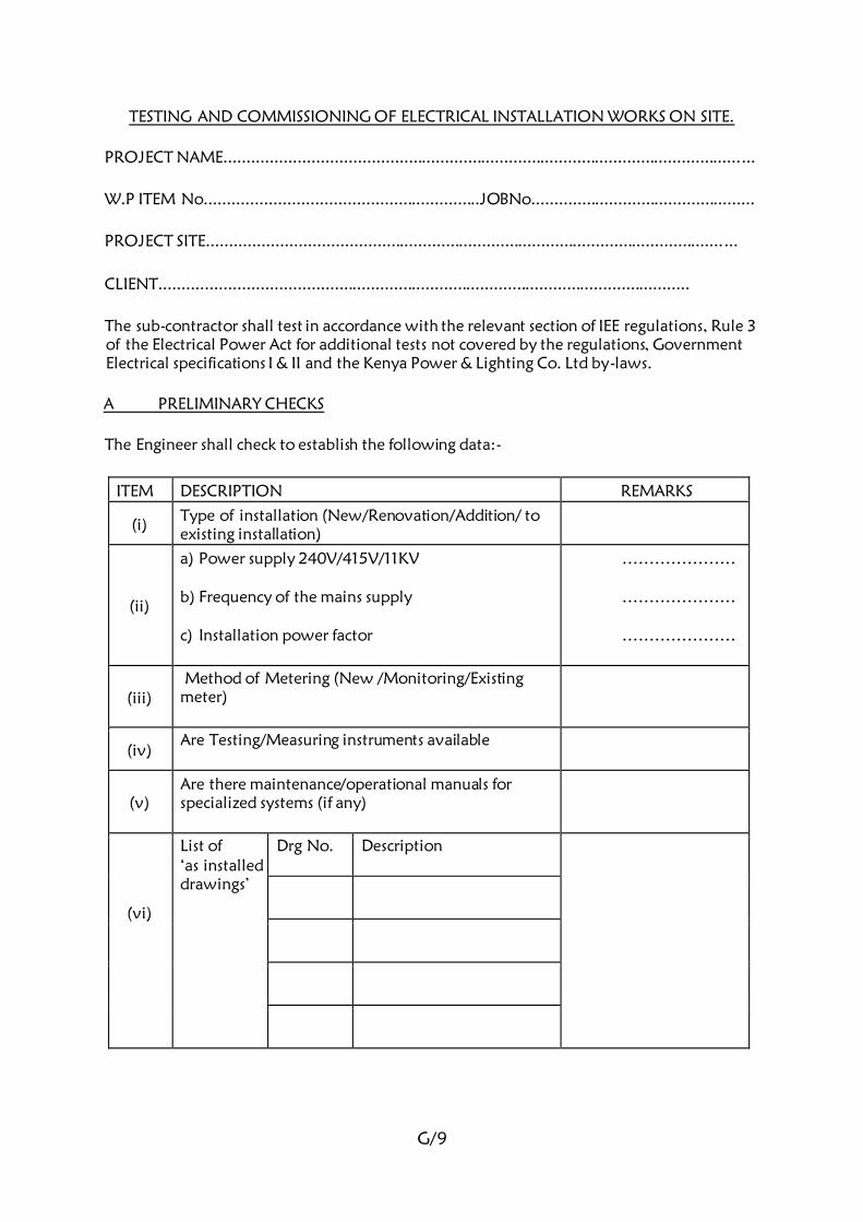
G/9
TESTING AND COMMISSIONING OF ELECTRICAL INSTALLATION WORKS ON SITE.
PROJECT NAME....................................................................................................................
W.P ITEM No............................................................JOBNo.................................................
PROJECT SITE....................................................................................................................
CLIENT....................................................................................................................
The sub-contractor shall test in accordance with the relevant section of IEE regulations, Rule 3
of the Electrical Power Act for additional tests not covered by the regulations, Government
Electrical specifications I & II and the Kenya Power & Lighting Co. Ltd by-laws.
A PRELIMINARY CHECKS
The Engineer shall check to establish the following data:-
ITEM DESCRIPTION REMARKS
(i) Type of installation (New/Renovation/Addition/ to
existing installation)
(ii)
a) Power supply 240V/415V/11KV
b) Frequency of the mains supply
c) Installation power factor
…………………
…………………
…………………
(iii) Method of Metering (New /Monitoring/Existing
meter)
(iv) Are Testing/Measuring instruments available
(v) Are there maintenance/operational manuals for
specialized systems (if any)
(vi)
List of ‘as installed drawings’
Drg No.
Description
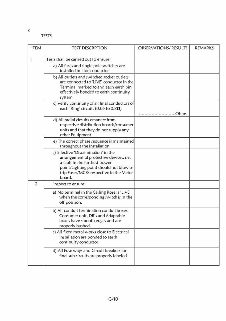
B
G/10
TESTS
ITEM TEST DESCRPTION OBSERVATIONS/ RESULTS REMARKS
1 Tests shall be carried out to ensure:
a) All fuses and single pole switches are
installed in live conductor
b) All outlets and switched socket outlets
are connected to ‘LIVE’ conductor in the
Terminal marked so and each earth pin
effectively bonded to earth continuity
system
c) Verify continuity of all final conductors of
each ‘Ring’ circuit. (0.05 to 0.8Ω)
……………………..Ohms
d) All radial circuits emanate from
respective distribution boards/consumer
units and that they do not supply any
other Equipment
e) The correct phase sequence is maintained
throughout the installation
f) Effective ‘Discrimination’ in the
arrangement of protective devices. i.e.
a fault in the furthest power
point/Lighting point should not blow or
trip Fuses/MCBs respective in the Meter
board.
2 Inspect to ensure:
a) No terminal in the Ceiling Rose is ‘LIVE’
when the corresponding switch is in the
off position.
b) All conduit termination conduit boxes,
Consumer unit, DB’s and Adaptable
boxes have smooth edges and are
properly bushed.
c) All fixed metal works close to Electrical
installation are bonded to earth
continuity conductor.
d) All Fuse ways and Circuit breakers for
final sub circuits are properly labeled
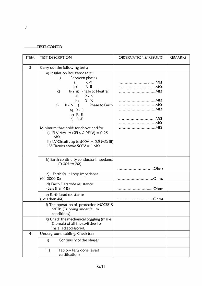
B
G/11
TESTS CONT’D
ITEM TEST DESCRPTION OBSERVATIONS/ RESULTS REMARKS
3
Carry out the following tests:
a) Insulation Resistance tests
i) Between phases a) R -Y b) R -B
c) B-Y ii) Phase to Neutral
a) R - N b) R - N
c) B - N iii) Phase to Earth
a) R - E b) R -E c) B -E
Minimum thresholds for above and for:
i) ELV circuits (SELV & PELV) = 0.25 MΩ
ii) LV Circuits up to 500V = 0.5 MΩ iii)
LV Circuits above 500V = 1 MΩ
………………….. ……MΩ ………………………..MΩ ………………………..MΩ
………………………..MΩ ………………….…….MΩ ………………….…….MΩ
………………………..MΩ ………………….…….MΩ ………………….…….MΩ
b) Earth continuity conductor impedance (0.005 to 2Ω)
………………………..Ohms
c) Earth fault Loop impedance
(0 - 2000 Ω)
……………………….Ohms
d) Earth Electrode resistance
(Less than 4Ω)
…………………….....Ohms
e) Earth Lead resistance
(Less than 4Ω)
……………………….Ohms
f) The operation of protection MCCBS &
MCBS (Tripping under faulty
conditions)
g) Check the mechanical toggling (make
& break) of all the switches to
installed accessories.
4 Underground cabling, Check for:
i) Continuity of the phases
ii) Factory tests done (avail
certification)
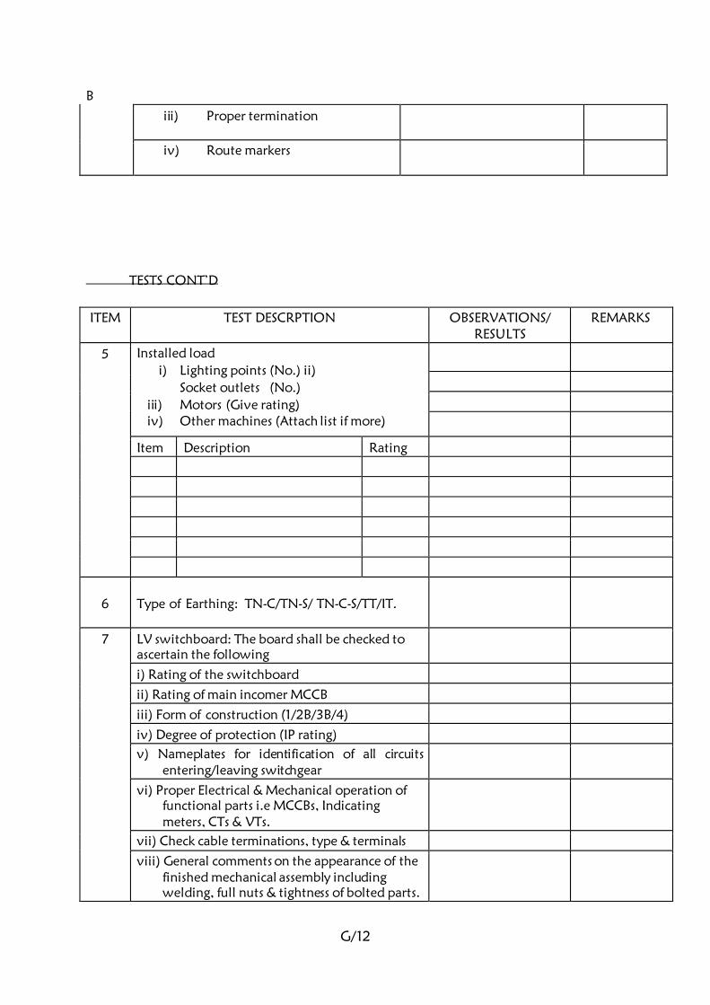
B
G/12
iii) Proper termination
iv) Route markers
TESTS CONT’D
ITEM TEST DESCRPTION OBSERVATIONS/
RESULTS REMARKS
5 Installed load
i) Lighting points (No.) ii)
Socket outlets (No.)
iii) Motors (Give rating) iv) Other machines (Attach list if more)
Item Description Rating
6
Type of Earthing: TN-C/TN-S/ TN-C-S/TT/IT.
7 LV switchboard: The board shall be checked to
ascertain the following
i) Rating of the switchboard
ii) Rating of main incomer MCCB
iii) Form of construction (1/2B/3B/4)
iv) Degree of protection (IP rating)
v) Nameplates for identification of all circuits
entering/leaving switchgear
vi) Proper Electrical & Mechanical operation of
functional parts i.e MCCBs, Indicating
meters, CTs & VTs.
vii) Check cable terminations, type & terminals
viii) General comments on the appearance of the
finished mechanical assembly including
welding, full nuts & tightness of bolted parts.
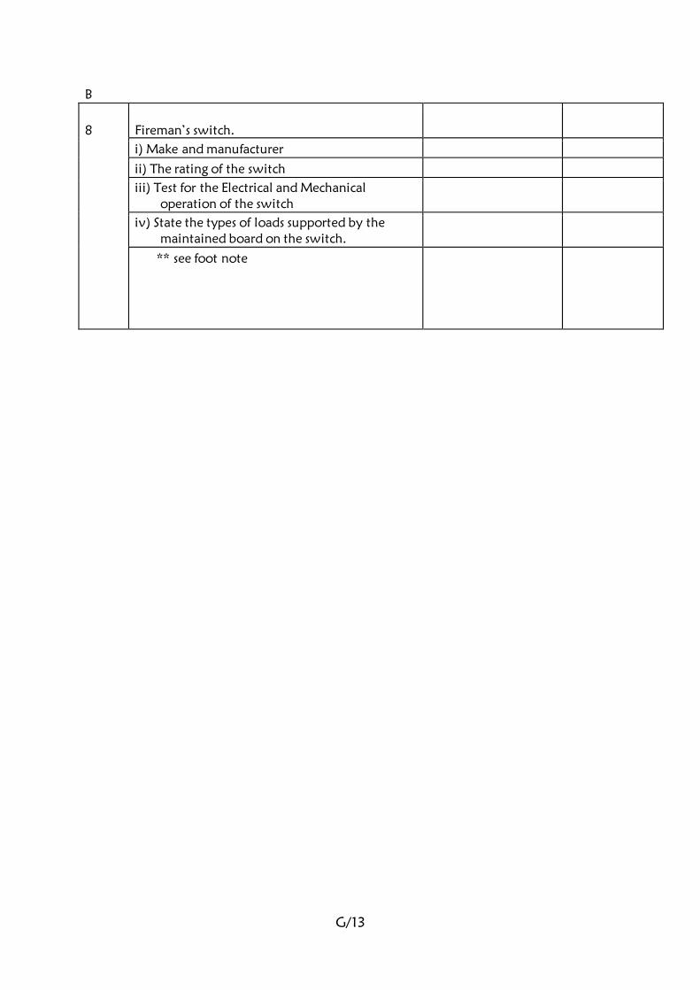
B
G/13
8
Fireman’s switch.
i) Make and manufacturer
ii) The rating of the switch
iii) Test for the Electrical and Mechanical
operation of the switch
iv) State the types of loads supported by the
maintained board on the switch.
** see foot note

G/14
General comments on the Electrical installation:-
Testing and Commissioning witnessed by:
S.D.P.W REPRESENTATIVE/ PROJECT ENGINEER:-
Name ………………….....................Designation……………………............
Sign………………………………… Date……………….…..……………….
CONTRACTOR’S REPRESENTATIVE:-
Name ………………….....................Designation……………………............

G/15
Sign………………………………… Date……………….…..…………….....
**If there are other defects noted, list them on a separate sheet and attach.

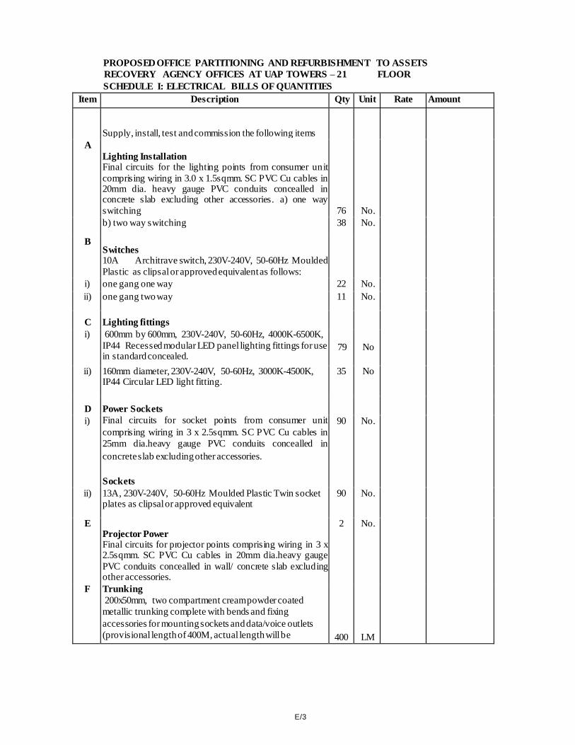
E/3
PROPOSED OFFICE PARTITIONING AND REFURBISHMENT TO ASSETS
RECOVERY AGENCY OFFICES AT UAP TOWERS – 21 FLOOR SCHEDULE I: ELECTRICAL BILLS OF QUANTITIES
Item Description Qty Unit Rate Amount
Supply, install, test and commission the following items
A Lighting Installation Final circuits for the lighting points from consumer unit
comprising wiring in 3.0 x 1.5sqmm. SC PVC Cu cables in 20mm dia. heavy gauge PVC conduits concealled in concrete slab excluding other accessories. a) one way
switching 76 No. 1,300 98,800 b) two way switching 38 No. 1,400 53,200
B Switches 10A Architrave switch, 230V-240V, 50-60Hz Moulded Plastic as clipsal or approved equivalent as follows:
i) one gang one way 22 No. 750 16,500 ii) one gang two way 11 No. 900 9,900
C Lighting fittings
i) 600mm by 600mm, 230V-240V, 50-60Hz, 4000K-6500K,
IP44 Recessed modular LED panel lighting fittings for use in standard concealed.
79 No 7,500 592,500
ii) 160mm diameter, 230V-240V, 50-60Hz, 3000K-4500K, IP44 Circular LED light fitting.
35 No 2,500 87,500
D Power Sockets
i) Final circuits for socket points from consumer unit
comprising wiring in 3 x 2.5sqmm. SC PVC Cu cables in
25mm dia.heavy gauge PVC conduits concealled in
concrete slab excluding other accessories.
Sockets
90 No. 2,500 225,000
ii) 13A, 230V-240V, 50-60Hz Moulded Plastic Twin socket plates as clipsal or approved equivalent
90 No. 950 85,500
E Projector Power Final circuits for projector points comprising wiring in 3 x 2.5sqmm. SC PVC Cu cables in 20mm dia.heavy gauge
PVC conduits concealled in wall/ concrete slab excluding other accessories.
2 No. 2,500 5,000
F Trunking 200x50mm, two compartment cream powder coated
metallic trunking complete with bends and fixing
accessories for mounting sockets and data/voice outlets (provisional length of 400M, actual length will be 400 LM 2,900
1,160,000
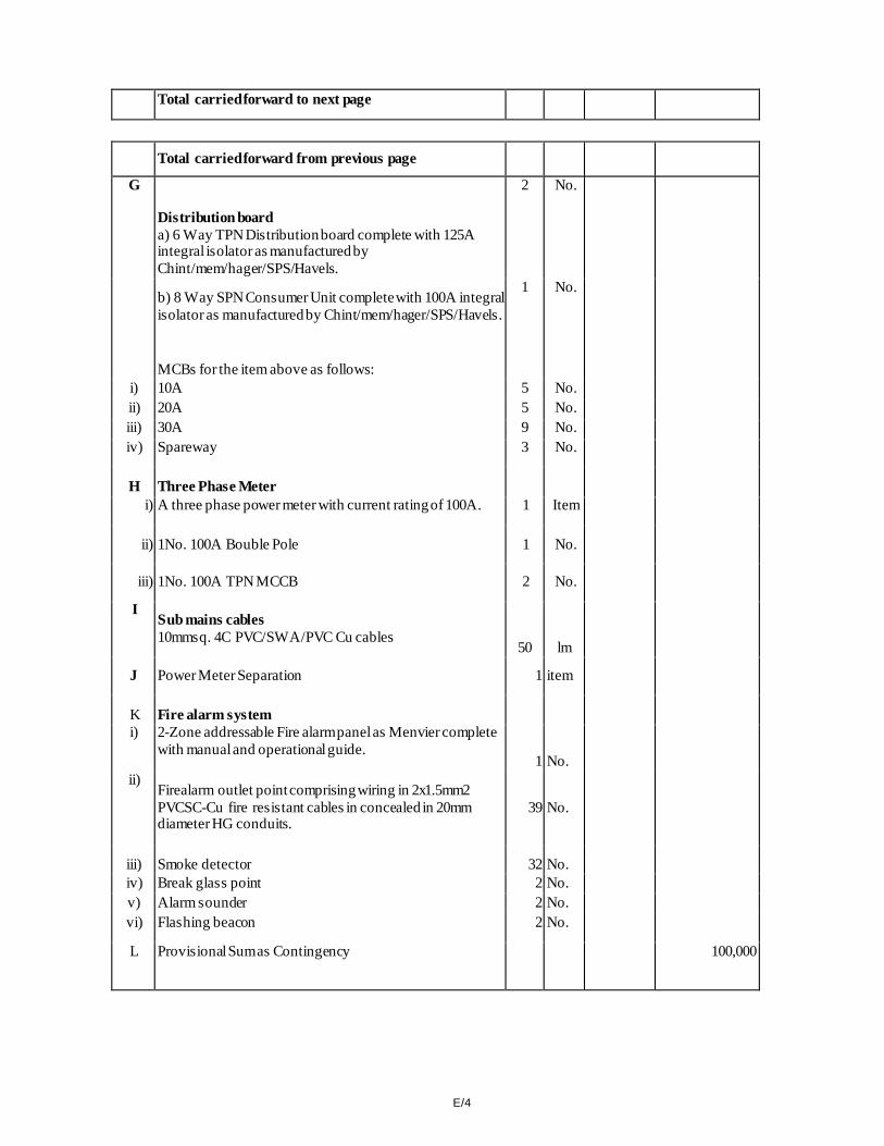
E/4
Total carried forward to next page 2,333,900
Total carried forward from previous page 2,333,900
G
Distribution board a) 6 Way TPN Distribution board complete with 125A integral isolator as manufactured by
Chint/mem/hager/SPS/Havels.
2 No. 26,500 53,000
b) 8 Way SPN Consumer Unit complete with 100A integral
isolator as manufactured by Chint/mem/hager/SPS/Havels.
MCBs for the item above as follows:
1 No. 8,500 8,500
i) 10A 5 No. 650 3,250 ii) 20A 5 No. 650 3,250 iii) 30A 9 No. 650 5,850 iv) Spareway 3 No. 250 750
H Three Phase Meter
i) A three phase power meter with current rating of 100A. 1 Item 11,500 11,500
ii) 1No. 100A Bouble Pole 1 No. 3,500 3,500
iii) 1No. 100A TPN MCCB 2 No. 10,500 21,000
I Sub mains cables 10mmsq. 4C PVC/SWA/PVC Cu cables
50 lm 1,945 97,250
J Power Meter Separation 1 item 30,000 30,000
K Fire alarm system
i) 2-Zone addressable Fire alarm panel as Menvier complete
with manual and operational guide. 1 No. 150,000
150,000
ii) Firealarm outlet point comprising wiring in 2x1.5mm2
PVCSC-Cu fire resistant cables in concealed in 20mm diameter HG conduits.
39 No. 1,900
74,100
iii) Smoke detector 32 No. 5,500 176,000 iv) Break glass point 2 No. 7,500 15,000 v) Alarm sounder 2 No. 7,000 14,000 vi) Flashing beacon 2 No. 7,000 14,000
L Provisional Sum as Contingency 100,000

E/5
Total for Electrical Works taken to Summary Page
3,114,850
ELECTRICAL SUMMARY PAGE
Item Description Amount
a) Schedule I: Electrical Works 3,114,850.00
Total for Electrical Taken to Main Summary Page 3,114,850.00
AMOUNT IN WORDS
Kenya shillings …………………………………………………………………………..
…………………………………………………………………………………………….
.
……………………………………………………………………………………………
…………………………………………………………………………………………….
Bidder's Official Stamp …………………………………………………………
Signature …………………………………………………………………….
P.O. Box …………………………...……………………… PIN
…………………………………………… VAT ………………………………..
Witness ………………………………………….Address ………………………….
Signature ……………………………………….. Date ……………………………….

REPUBLIC OF KENYA
PROPOSED OFFICE PARTITIONING AND REFURBISHMENT TO ASSETS
RECOVERY AGENCY OFFICES AT UAP TOWERS 21ST
FLOOR –
NAIROBI
TENDER SPECIFICATIONS AND BILL OF QUANTITIES
FOR
CCTV, ACCESS CONTROL AND STRUCTURED CABLING
INSTALLATION WORKS
CLIENT
THE CHIEF EXECUTIVE OFFICER ASSETS RECOVERY AGENCY P.O BOX 52420 – 00100 NAIROBI
PROJECT MANAGER ELECTRICAL ENGINER WORKS SECRETARY CHIEF ENGINEER (ELECTRICAL) MINISTRY OF TRANSPORT, INFRASTRUCTURE, PUBLIC MINISTRY OF TRANSPORT, INFRASTRUCTURE, PUBLIC WORKS, HOUSING & URBAN DEVELOPMENT WORKS, HOUSING & URBAN DEVELOPMENT STATE DEPARTMENT FOR PUBLIC WORKS, STATE DEPARTMENT FOR PUBLIC WORKS, P.O BOX 30743 – 00100, P.O BOX 41191 – 00100, NAIROBI
NAIROBI
ARCHITECT STRUCTURAL ENGINEER CHIEF ARCHITECT CHIEF ENGINEER (STRUCTURAL) MINISTRY OF TRANSPORT, INFRASTRUCTURE, PUBLIC MINISTRY OF TRANSPORT, INFRASTRUCTURE, PUBLIC WORKS, WORHOUSING & URBAN DEVELOPMENT WORKS, HOUSING & URBAN DEVELOPMENT
STATE DEPARTMENT FOR PUBLIC WORKS, STATE DEPARTMENT FOR PUBLIC WORKS, P.O
BOX 30743 – 00100, P.O BOX 30743 – 00100, NAIROBI
NAIROBI
QUANTITY SURVYOR MECHANICAL ENGINEER CHIEF QUANTITY SURVEYOR CHIEF ENGINEER (MECHANICAL (BS)) MINISTRY OF TRANSPORT, INFRASTRUCTURE, PUBLIC MINISTRY OF TRANSPORT, INFRASTRUCTURE, PUBLIC WORKS, HOUSING & URBAN DEVELOPMENT WORKS, HOUSING & URBAN DEVELOPMENT STATE DEPARTMENT FOR PUBLIC WORKS, STATE DEPARTMENT FOR PUBLIC WORKS, P.O BOX 30743 – 00100, P.O BOX 41191 – 00100, NAIROBI NAIROBI
TABLE OF CONTENTS
TITLE PAGE
Contents....................................................................................................……… i
SECTION A: General Specifications of Materials and Works.................................. A/1-A/3
SECTION B: Schedule of Contract Drawings.......................................................... B/1
SECTION C: Particular Specifications of Materials and Works................................. C/1-C/19
SECTION D: Schedule of Unit Rates...................................................................... D/1-D/2
SECTION E: Bills of Quantities............................................................................. E/1-E/9
SECTION F: Technical Schedule of Items to be supplied........................................ F/1-F/2
SECTION G: Standard Forms................................................................................. G/1-G/6
i
SECTION A
GENERAL SPECIFICATIONS
OF
MATERIALS AND WORKS
A/1
GENERAL SPECIFICATIONS OF MATERIALS AND WORKS
1. General
2. Standard of Materials
3. Workmanship
4. Procurement of Materials
5. Record Drawings
6. Regulations and Standards
7. Setting out Works
8. Testing on Site
1. GENERAL
This specification is to be read in conjunction with the drawings which are issued with it.
Bills of quantities shall be the basis of all additions and omissions during the progress of
the works.
2. STANDARD OF MATERIALS
Where the material and equipment are specifically described and named in the
Specification followed by approved equal, they are so named or described for the
purpose of establishing a standard to which the sub-contractor shall adhere.
Should the Sub-contractor install any material not specified herein before receiving
approval from the proper authorities, the Engineer shall direct the Sub-contractor to
remove the material in question immediately. The fact that this material has been
installed shall have no bearing or influence on the decision by the Engineer.

A/2
All materials condemned by the Engineer as not approved for use, are to be removed
from the premises and suitable materials delivered and installed in their place at the
expense of the Sub-contractor. All materials required for the works shall be new and the
best of the respective kind and shall be of a uniform pattern.
3. WORKMANSHIP
The workmanship and method of installation shall conform to the best standard practice.
All work shall be performed by a skilled tradesman and to the satisfaction of the
Engineer. Helpers shall have qualified supervision.
Any work that does not in the opinion of the Engineer conform to the best standard
practice will be removed and reinstated at the Sub-contractors expense.
Permits, Certificates or Licenses must be held by all tradesmen for the type of work; in
which they are involved where such permits, certificates or licenses exist under
Government legislation.
4. PROCUREMENT OF MATERIALS
The sub-contractor is advised that no assistance can be given in the procurement or
allotment of any materials or products to be used in and necessary for the construction
and completion of the work.
Sub-contractors are warned that they must make their own arrangements for the supply
of materials and/or products specified or required.
5. RECORD DRAWINGS
These diagrams and drawings shall show the completed installation including sizes, runs
and arrangements of the installation. The drawings shall be to scale not less than 1:50
and shall include plan views and section.
The drawings shall include all the details which may be useful in the operation,
maintenance or subsequent modifications or extensions to the installation.
Three sets of diagrams and drawings shall be provided, all to the approval of the
Engineer.
One coloured set of line diagrams relating to operating and maintenance instructions
shall be framed and, mounted in a suitable location.
6. REGULATIONS AND STANDARDS
All work executed by the contractor shall comply with the current edition of the
“Regulations” for the Electrical Equipment of Buildings, issued by the Institution of
Electrical Engineers, Electric Power Act, Kenya Bureau of Standards (KEBS), Institution of
Electrical Engineers (I.E.E) Wiring Regulations, Current recommendation of CCITT and
CCIR, and with the Regulations of the Local Electricity Authority and the
Communications Authority of Kenya (CA)
A/3
Where the two sets of regulations appear to conflict, they shall be clarified with the
Engineers. All materials used shall comply with relevant Kenya Bureau of Standards
Specification.
7. SETTING OUT WORK
The sub-contractor at his own expenses; is to set out works and take all measurements
and dimensions required for the erection of his materials on site; making any
modifications in details as may be found necessary during the progress of the works,
submitting any such modifications or alterations in detail to the Engineer before
proceeding and must allow in his Tender for all such modifications and for the provision
of any such sketches or drawings related thereto.
8. TESTING ON SITE
The Sub-contractor shall conduct during and at the completion of the installation and, if
required, again at the expiration of the maintenance period, tests in accordance with the
relevant section of the current edition of the Regulations for the electrical equipment of
buildings issued by the I.E.E of Great Britain, the Government Electrical Specification
No.1 and No. 2, the Electric Supply Company’s By-Laws, Communications Authority of
Kenya (CA) requirements or any other supplementary Regulations as may be produced
by the engineer
(a) Any faults, defects or omissions or faulty workmanship, incorrectly positioned or
installed parts of the installation made apparently by such inspections or tests shall
be rectified by the Sub-contractor at his own expense.
SECTION B
SCHEDULE OF CONTRACT DRAWINGS
SCHEDULE OF CONTRACT DRAWINGS
DRAWING NO.
DRAWING TITLE
As shall be issued by the Engineer
NOTE: Tenderers are advised to inspect the electrical drawings at the office of the Chief Engineer
(Electrical) – State Department for Public Works, at Chief Engineer’s (Electrical) office, 5th
Floor Hill Plaza Building, Community area, Nairobi along Ngong road, during normal
working hours.
The drawings shall however be availed, on award of the tender, to the contractor.
B/1
C/1
SECTION C
PARTICULAR SPECIFICATIONS
OF
MATERIALS AND WORKS
PARTICULAR SPECIFICATIONS
1.00 SITE LOCATION

C/2
The site of the proposed works is at UAP Towers, Nairobi County.
2.00 SCOPE OF WORKS
The works to be carried out under this sub-contract comprise supply, installation,
testing and commissioning of the following:
• CCTV System
• Structured Cabling
• Access Control System
• Office Telephone
3.00 REGULATION AND STANDARD
The works shall comply with the provisions of the following as necessary and
relevant:
• Electric Power Act
• Kenya Bureau of Standards (KBS)
• I.E.T Wiring Regulations
• Current recommendation of CCITT and CC1R
4.00 ELECTRICAL REQUIREMENTS
The equipment to be supplied shall be capable of being operated from 240V AC
50Hz power supply.
5.00 MANDATORY REQUIREMENTS
A. All equipment and materials used shall be standard components that are
regularly manufactured and used in the manufacturer’s system.
B. All systems and components shall have been thoroughly tested and proven in
actual use.
C. All systems and components shall be provided with the availability of a, 24hour
technical assistance program (TAP) from the manufacturer. The TAP shall
allow for immediate technical assistance for either the dealer/installer or the
end user at no charge.
D. All systems and components shall be provided with a one-day turn around
repair express and 24-hour parts replacement. The repair and parts express
shall be guaranteed by the manufacturer on warranty and non-warranty items.
E. The supplier shall be the manufacturer, or the manufacturer appointed agent
(proof to be submitted).
F. The Offered system has been installed and commissioned by the supplier in
G. other locations.

C/3
PRELIMINARY & TECHNICAL EVALUATION CRITERIA
TENDER EVALUATION CRITERIA
After tender opening, the tenders will be evaluated in 2 stages, namely:
1. Preliminary Evaluation;
2. Technical Evaluation;
STAGE 1: PRELIMINARY EVALUATION
This stage of evaluation shall involve examination of the mandatory requirements as
set out in the Tender Advertisement Notice or Letter of Invitation to Tender and any
other conditions stated in the bid document.
These conditions shall include the following:
i) Company Certificate of incorporation/registration;
ii) Current certificate of Registration with National Construction Authority (As
Prescribed) in CCTV/Security Surveillance and Telecommunication and
Structured Cabling Installations;
iii) Current Annual NCA contractor’s Practicing license; iv) Valid Tax
Compliance Certificate;
v) Compliance with Technical Specifications;
The bids will then be analyzed, using the information in the technical brochures, to determine
compliance with technical specifications for the works/items as indicated in the tender
document. Bidders not complying with any of the technical specifications shall be adjudged
technically non-responsive while those meeting all technical specifications shall be considered
technically responsive.
The tenderer shall also fill in the Technical Schedule as specified in the tender document for
Equipment and Items indicating the Country of Origin, Model/Make/Manufacturer and
catalogue numbers of the Items/Equipment they propose to supply.
The tenderers who do not satisfy any of the above mandatory requirements shall be
considered Non- Responsive and their tenders will not be evaluated further.
STAGE 2: TECHNICAL EVALUATION
In order to be compliant, the Tenderers shall be required;
a) To fill the Standard Forms provided in the bid document for the purposes of
providing the required information. The tenderers may also attach the required
information if they so desire;
The award of points considered in this section shall be as shown below:
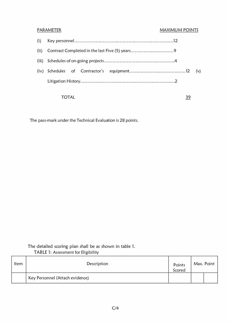
C/4
PARAMETER MAXIMUM POINTS
(i) Key personnel…………………………………………………………….12
(ii) Contract Completed in the last Five (5) years…………………………9
(iii) Schedules of on-going projects……………………………………….….4
(iv) Schedules of Contractor’s equipment…………………….……………12 (v)
Litigation History………………………………………………………….2
TOTAL 39
The pass-mark under the Technical Evaluation is 28 points.
The detailed scoring plan shall be as shown in table 1.
TABLE 1: Assessment for Eligibility
Item
Description
Points Scored
Max. Point
Key Personnel (Attach evidence)
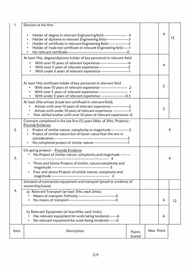
C/5
1. Director of the firm
• Holder of degree in relevant Engineering field----------------------- 4 • Holder of diploma in relevant Engineering field----------------------3 • Holder of certificate in relevant Engineering field--------------------2 • Holder of trade test certificate in relevant Engineering field------1 • No relevant certificate---------------------------------------------------------0
4
12
At least 1No. degree/diploma holder of key personnel in relevant field
• With over 10 years of relevant experience----------------------------4 • With over 5 years of relevant experience-----------------------------2 • With under 5 years of relevant experience ---------------------------1
4
At least 1No certificate holder of key personnel in relevant field • With over 10 years of relevant experience--------------------------- 2 • With over 5 years of relevant experience ---------------------------- 1 • With under 5 years of relevant experience ------------------------0.5
2
At least 2No artisan (trade test certificate in relevant field) • Artisan with over 10 years of relevant experience------------------2 • Artisan with under 10 years of relevant experience ----------------1 • Non skilled worker with over 10 years of relevant experience--0
2
2.
Contracts completed in the last five (5) years (Max of 3No. Projects) -
Provide Evidence
• Project of similar nature, complexity or magnitude------------------3 • Project of similar nature but of lower value than the one in
consideration----------------------------------------------------------------------2 • No completed project of similar nature----------------------------------1
9
3.
On-going projects – Provide Evidence • No Project of similar nature, complexity and magnitude ----------
---------------------------------------------------------------------- 4
• Three and below Projects of similar, nature complexity and magnitude –------------------------------------------------------3
• Four and above Projects of similar nature, complexity and magnitude ------------------------------------------------------- 2
4
4.
Schedule of contractors equipment and transport (proof or evidence of
ownership/Lease)
a) Relevant Transport (at least 3No. each 2mks) • Means of transport (Vehicle)-------------------------------------6 • No means of transport---------------------------------------------0
6
12
b) Relevant Equipment (at least 6No. each 1mks)
• Has relevant equipment for work being tendered--------6 • No relevant equipment for work being tendered--------0
6
Item
Description
Points Scored
Max. Point

C/6
5.
Litigation History
• Duly Filled --------------------------------------------------------2 • Not filled ----------------------------------------------------------0
2
TOTAL
39
Any bidder who scores 28 Points and above shall be considered for further
evaluation.

C/7
6.00 IP CCTV SURVEILLANCE SYSTEM:
a) IP Video System Overview:
• Transmit and Receive H.265, H.264 and MPEG-4 Video and bi-directional
Audio.
• Video and alarm management software under one single front end and should
be on open platform with support to renowned IP camera brands (like Axis,
Pelco, Samsung,Hanwa, Honeywell, Panasonic, Sony etc.)
• Support for multi user and multi user group environment in addition to user
hierarchy
• System should allow to be used as a distributed or central architecture with
support to any number of cameras and any number of clients that may be
added in future.
• System Guarantees Bandwidth & Frame rate control.
• Provides Activity Controlled Frame rate, which in turn reduces the Bandwidth
and the Storage requirements.
• Provides Broadcast Quality Video across IP network including Internet.
• Provides multiple failover and network resilience.
• Provides real time recording at 25fps with no frame loss.
• Provides PTZ Camera Controls & Binary INPUT/OUTPUT controls.
• Supports Multiple IP Video Streams.
• Secured recording for evidence purposes and user authentication to protect data
integrity.
• Video Stream bit rate selectable from 32 to 4096kbps. or better
• All the IP cameras shall have SD card slot for recording in SD card when
network is down/fail
b) Network Video Recorder
16 Channel Standard Network Video Recorder – The NVR should currently be
supported by the Manufacturer and not less than 5 year to end of life. Proposal
Solution
• 16 Channel up to 12MP Resolution
• H.265, MPEG4 and Motion JPEG, Recording Bandwidth Max 320 Mbps (Raid
200Mbps).
• Network interface: Dual 1 Gigabit Ethernet
• Monitor Output: 1 No. HDMI Ports and DVI w/VGA adapter RCA Spot
monitor output
• 4 SATA HDDs that supports upto 6TB each. Support no limitations on the kind
of storage to be used (RAID, NAS, etc).
• Automatic camera registration, any Recording Device ONVIF and Major Camera
Brands Support
• Network management/viewer software inbuilt
• In built intelligent video analysis capabilities ( Face Detection, Number plate
Recognition, Heat map Generation, Counting )
• System should be in Linux/Windows

C/8
c) CCTV CAMERAS
i. TYPE A CAMERA - The Camera should currently be supported by the
Manufacturer and not less than 5 year to end of life.
Tender Specifications for Outdoor > or = 4MP varifocal Lens IR Dome
Camera Proposed Solution
The camera should be of >or= 4 MP Dome type
The camera should have 3.9 ~ 9.4mm(2.4x) motorized varifocal lens with
maximum aperture ratio of F1.6
The lens mount should be Board type
The image sensor used in the camera should >1/1.5" 6M CMOS Progressive Scan,
The Electronic shutter time of the camera should be Minimum / Maximum /
Anti flicker (2 ~ 1/12,000sec)
The minimum illumination(B/W) provided should be 0 Lux with IR LED on
The minimum illumination Color : 0.07Lux (F1.3, 1/30sec)
Adaptive IR >45m ; auto ON in night mode, or off
The camera should have the property of IR cut filter with auto switch
The camera should have SNR of >50 dB
The camera should have the property of WDR (Wide Dynamic Range) of
>100dB
The camera should provide 3D DNR (Digital Noise Reduction) SSNRV
(2D+3D noise filter) (Off / On)
Compression Standards
The video compression of the camera should be H.264/H.265 COMPLIANT /MJPEG
The Bit Rate Control Method of the camera should be H.264/H.265: CBR
or VBR, MJPEG : VBR
The camera should be capable of providing more than 3 streams
Image
The Maximum Image Resolution of the Camera should be 2560 x 1920 @
30fps
The camera should have configurable frame rate up to 30 frames
The Camera should have GOP ration should be from 1-100
The cameras should have image settings like Rotate mode, Saturation,
Brightness, Contrast adjustable by client software or web browser
The cameras should have Motion detection, View Tampering alarm, Trip
wire, Line Crossing, Directional Motion, Zone intrusion, Object Intrusion
etc.
The Camera should have support of ROI, BLC, Digital Zoom and Edge
Recording, smart stream(Max. 3 windows)Function support
Alerts
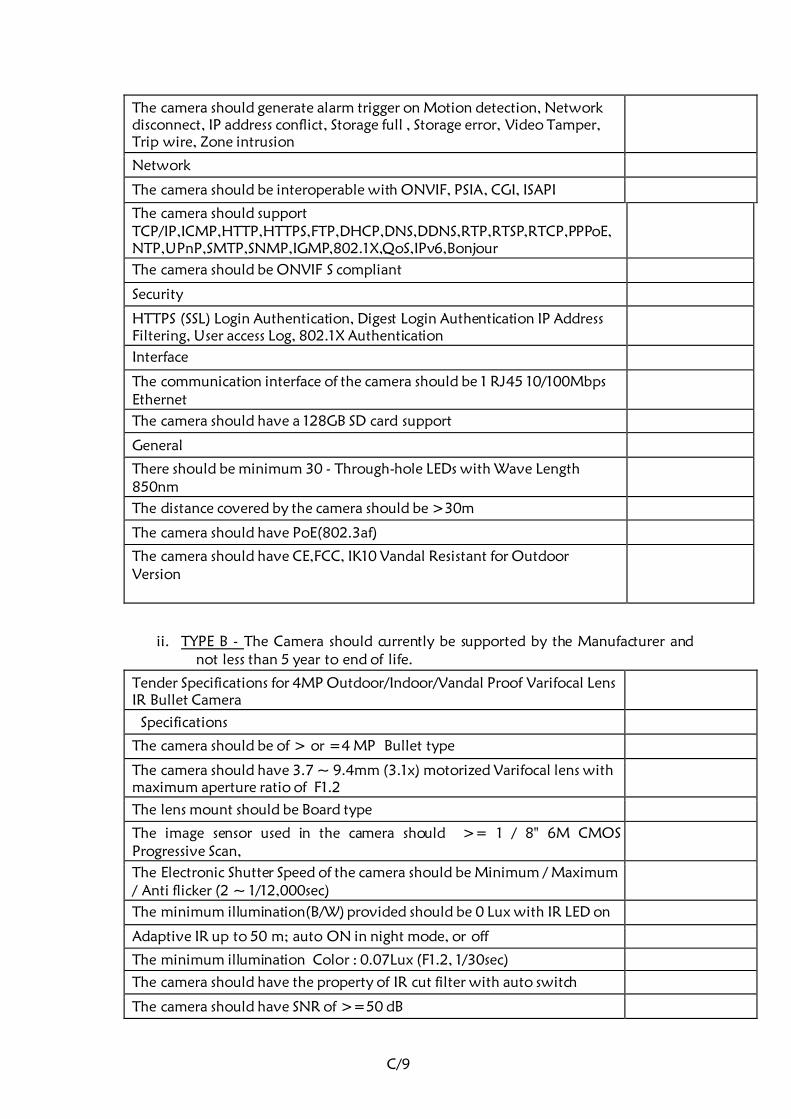
C/9
The camera should generate alarm trigger on Motion detection, Network
disconnect, IP address conflict, Storage full , Storage error, Video Tamper,
Trip wire, Zone intrusion
Network
The camera should be interoperable with ONVIF, PSIA, CGI, ISAPI
The camera should support TCP/IP,ICMP,HTTP,HTTPS,FTP,DHCP,DNS,DDNS,RTP,RTSP,RTCP,PPPoE,
NTP,UPnP,SMTP,SNMP,IGMP,802.1X,QoS,IPv6,Bonjour
The camera should be ONVIF S compliant
Security
HTTPS (SSL) Login Authentication, Digest Login Authentication IP Address
Filtering, User access Log, 802.1X Authentication
Interface
The communication interface of the camera should be 1 RJ45 10/100Mbps
Ethernet
The camera should have a 128GB SD card support
General
There should be minimum 30 - Through-hole LEDs with Wave Length
850nm
The distance covered by the camera should be >30m
The camera should have PoE(802.3af)
The camera should have CE,FCC, IK10 Vandal Resistant for Outdoor
Version
ii. TYPE B - The Camera should currently be supported by the Manufacturer and
not less than 5 year to end of life.
Tender Specifications for 4MP Outdoor/Indoor/Vandal Proof Varifocal Lens
IR Bullet Camera
Specifications
The camera should be of > or =4 MP Bullet type
The camera should have 3.7 ~ 9.4mm (3.1x) motorized Varifocal lens with
maximum aperture ratio of F1.2
The lens mount should be Board type
The image sensor used in the camera should >= 1 / 8" 6M CMOS
Progressive Scan,
The Electronic Shutter Speed of the camera should be Minimum / Maximum
/ Anti flicker (2 ~ 1/12,000sec)
The minimum illumination(B/W) provided should be 0 Lux with IR LED on
Adaptive IR up to 50 m; auto ON in night mode, or off
The minimum illumination Color : 0.07Lux (F1.2, 1/30sec)
The camera should have the property of IR cut filter with auto switch
The camera should have SNR of >=50 dB

C/1
0
The camera should have the property of (Wide Dynamic Range), WDR of
>=120dB
The camera should provide 3 DNR (Digital Noise Reduction) of SSNRV
(2D+3D noise filter) (Off / On)
Compression Standards
The video compression of the camera should be H.265/MJPEG compliant
The bit rate of the camera should be 512 Kbps ~ 4 Mbps
The camera should be capable of providing minimum of 4 streams
Image
The Maximum Image Resolution of the Camera should not less than 2560 x
1920@ 30fps
Frame rate H.265: Max. 30fps at all resolutions, MJPEG : Max. 30fps
The Camera should have GOP ration should be from 1-100
The cameras should have image settings like Rotate mode, Saturation,
Brightness, Contrast adjustable by client software or web browser
The cameras should have Motion detection, View Tampering alarm, Trip
wire, Line Crossing, Directional Motion, Zone intrusion, Object Intrusion.
The Camera should have support of ROI, BLC, Digital Zoom and Edge
Recording, smart stream(Max. 3 windows)Function support
Alerts
The camera should generate alarm trigger on Motion detection, Network
disconnect, IP address conflict, Storage full , Storage error, Video Tamper,
Trip wire, Zone intrusion
Network
The camera should be interoperable with ONVIF, PSIA, CGI, ISAPI
The camera should support TCP/IP,ICMP,HTTP,HTTPS,FTP,DHCP,DNS,DDNS,RTP,RTSP,RTCP,PPPoE,
NTP,UPnP,SMTP,SNMP,IGMP,802.1X,QoS,IPv6,Bonjour
The camera should be ONVIF S compliant
Security
HTTPS (SSL) Login Authentication, Digest Login Authentication IP Address
Filtering, User access Log, 802.1X Authentication
Interface
The communication interface of the camera should be 1 RJ45 10/100Mbps
Ethernet
The camera should have a 128GB or more SD card support
General
The camera should have PoE(802.3af)
The camera should have IP67, IP66, NEMA 4X / IK10 Vandal Resistant for
outdoor usage
iii. TYPE C - The Camera should currently be supported by the Manufacturer and
not less than 5 year to end of life.
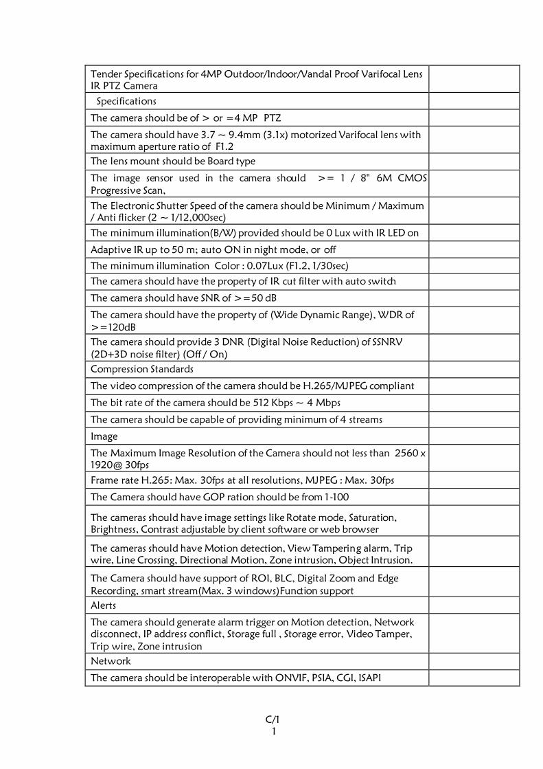
C/1
1
Tender Specifications for 4MP Outdoor/Indoor/Vandal Proof Varifocal Lens
IR PTZ Camera
Specifications
The camera should be of > or =4 MP PTZ
The camera should have 3.7 ~ 9.4mm (3.1x) motorized Varifocal lens with
maximum aperture ratio of F1.2
The lens mount should be Board type
The image sensor used in the camera should >= 1 / 8" 6M CMOS
Progressive Scan,
The Electronic Shutter Speed of the camera should be Minimum / Maximum
/ Anti flicker (2 ~ 1/12,000sec)
The minimum illumination(B/W) provided should be 0 Lux with IR LED on
Adaptive IR up to 50 m; auto ON in night mode, or off
The minimum illumination Color : 0.07Lux (F1.2, 1/30sec)
The camera should have the property of IR cut filter with auto switch
The camera should have SNR of >=50 dB
The camera should have the property of (Wide Dynamic Range), WDR of
>=120dB
The camera should provide 3 DNR (Digital Noise Reduction) of SSNRV
(2D+3D noise filter) (Off / On)
Compression Standards
The video compression of the camera should be H.265/MJPEG compliant
The bit rate of the camera should be 512 Kbps ~ 4 Mbps
The camera should be capable of providing minimum of 4 streams
Image
The Maximum Image Resolution of the Camera should not less than 2560 x
1920@ 30fps
Frame rate H.265: Max. 30fps at all resolutions, MJPEG : Max. 30fps
The Camera should have GOP ration should be from 1-100
The cameras should have image settings like Rotate mode, Saturation,
Brightness, Contrast adjustable by client software or web browser
The cameras should have Motion detection, View Tampering alarm, Trip
wire, Line Crossing, Directional Motion, Zone intrusion, Object Intrusion.
The Camera should have support of ROI, BLC, Digital Zoom and Edge
Recording, smart stream(Max. 3 windows)Function support
Alerts
The camera should generate alarm trigger on Motion detection, Network
disconnect, IP address conflict, Storage full , Storage error, Video Tamper,
Trip wire, Zone intrusion
Network
The camera should be interoperable with ONVIF, PSIA, CGI, ISAPI
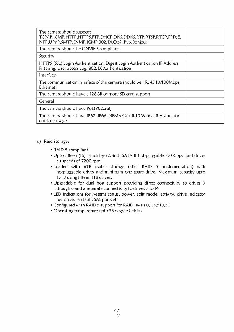
C/1
2
The camera should support TCP/IP,ICMP,HTTP,HTTPS,FTP,DHCP,DNS,DDNS,RTP,RTSP,RTCP,PPPoE,
NTP,UPnP,SMTP,SNMP,IGMP,802.1X,QoS,IPv6,Bonjour
The camera should be ONVIF S compliant
Security
HTTPS (SSL) Login Authentication, Digest Login Authentication IP Address
Filtering, User access Log, 802.1X Authentication
Interface
The communication interface of the camera should be 1 RJ45 10/100Mbps
Ethernet
The camera should have a 128GB or more SD card support
General
The camera should have PoE(802.3af)
The camera should have IP67, IP66, NEMA 4X / IK10 Vandal Resistant for
outdoor usage
d) Raid Storage:
• RAID-5 compliant
• Upto fifteen (15) 1-inch-by-3.5-inch SATA II hot-pluggable 3.0 Gbps hard drives
a t speeds of 7200 rpm
• Loaded with 6TB usable storage (after RAID 5 implementation) with
hotpluggable drives and minimum one spare drive. Maximum capacity upto
15TB using fifteen 1TB drives.
• Upgradable for dual host support providing direct connectivity to drives 0
though 6 and a separate connectivity to drives 7 to 14
• LED indications for systems status, power, split mode, activity, drive indicator
per drive, fan fault, SAS ports etc.
• Configured with RAID 5 support for RAID levels 0,1,5,510,50
• Operating temperature upto 35 degree Celsius
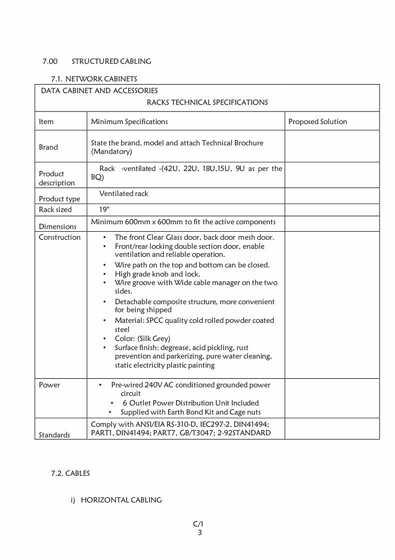
C/1
3
7.00 STRUCTURED CABLING
7.1. NETWORK CABINETS
DATA CABINET AND ACCESSORIES
RACKS TECHNICAL SPECIFICATIONS
Item Minimum Specifications Proposed Solution
Brand State the brand, model and attach Technical Brochure
(Mandatory)
Product
description
Rack -ventilated -(42U, 22U, 18U,15U, 9U as per the
BQ)
Product type Ventilated rack
Rack sized 19"
Dimensions Minimum 600mm x 600mm to fit the active components
Construction
• The front Clear Glass door, back door mesh door. • Front/rear locking double section door, enable
ventilation and reliable operation.
• Wire path on the top and bottom can be closed. • High grade knob and lock. • Wire groove with Wide cable manager on the two
sides.
• Detachable composite structure, more convenient
for being shipped
• Material: SPCC quality cold rolled powder coated steel
• Color: (Silk Grey) • Surface finish: degrease, acid pickling, rust
prevention and parkerizing, pure water cleaning,
static electricity plastic painting
Power
• Pre-wired 240V AC conditioned grounded power circuit
• 6 Outlet Power Distribution Unit Included • Supplied with Earth Bond Kit and Cage nuts
Standards
Comply with ANSI/EIA RS-310-D, IEC297-2, DIN41494;
PART1, DIN41494; PART7, GB/T3047; 2-92STANDARD
7.2. CABLES
i) HORIZONTAL CABLING
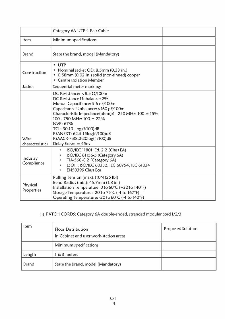
C/1
4
Category 6A UTP 4-Pair Cable
Item Minimum specifications
Brand State the brand, model (Mandatory)
Construction
• UTP • Nominal jacket OD: 8.5mm (0.33 in.) • 0.58mm (0.02 in.) solid (non-tinned) copper • Centre Isolation Member
Jacket Sequential meter markings
Wire characteristics
DC Resistance: <8.5 O/100m DC Resistance Unbalance: 2% Mutual Capacitance: 5.6 nF/100m Capacitance Unbalance:<160 pF/100m Characteristic Impedance(ohms):1 - 250 MHz: 100 ± 15% 100 - 750 MHz: 100 ± 22% NVP: 67% TCL: 30-10 log (f/100)dB PSANEXT: 62.5-15log(f /100)dB PSAACR-F:38.2-20log(f /100)dB Delay Skew: = 45ns
Industry Compliance
• ISO/IEC 11801 Ed. 2.2 (Class EA) • ISO/IEC 61156-5 (Category 6A) • TIA-568-C.2 (Category 6A) • LSOH: ISO/IEC 60332, IEC 60754, IEC 61034 • EN50399 Class Eca
Physical
Properties
Pulling Tension (max):110N (25 lbf) Bend Radius (min): 45.7mm (1.8 in.) Installation Temperature: 0 to 60°C (+32 to 140°F) Storage Temperature: -20 to 75°C (-4 to 167°F) Operating Temperature: -20 to 60°C (-4 to 140°F)
ii) PATCH CORDS: Category 6A double-ended, stranded modular cord 1/2/3
Item
Floor Distribution
In Cabinet and user work-station areas
Proposed Solution
Minimum specifications
Length 1 & 3 meters
Brand State the brand, model (Mandatory)
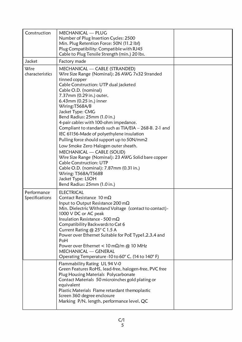
C/1
5
Construction MECHANICAL — PLUG Number of Plug Insertion Cycles: 2500 Min. Plug Retention Force: 50N (11.2 lbf) Plug Compatibility: Compatible with RJ45 Cable to Plug Tensile Strength (min.) 20 lbs.
Jacket Factory made
Wire characteristics
MECHANICAL — CABLE (STRANDED) Wire Size Range (Nominal): 26 AWG 7x32 Stranded
tinned copper Cable Construction: UTP dual jacketed Cable O.D. (nominal) 7.37mm (0.29 in.) outer, 6.43mm (0.25 in.) inner Wiring:T568A/B Jacket Type: CMG Bend Radius: 25mm (1.0 in.) 4-pair cables with 100-ohm impedance. Compliant to standards such as TIA/EIA – 268-B. 2-1 and
IEC 61156-Made of polyethylene insulation
Pulling force should support up to 50N/mm2
Low Smoke Zero Halogen outer sheath.
MECHANICAL — CABLE (SOLID) Wire Size Range (Nominal): 23 AWG Solid bare copper Cable Construction: UTP Cable O.D. (nominal): 7.87mm (0.31 in.) Wiring: T568A/T568B Jacket Type: LSOH Bend Radius: 25mm (1.0 in.)
Performance
Specifications ELECTRICAL Contact Resistance 10 mΩ Input to Output Resistance 200 mΩ Min. Dielectric Withstand Voltage (contact to contact)-
1000 V DC or AC peak Insulation Resistance - 500 mΩ Compatibility Backwards to Cat 6 Current Rating @ 25° C 1.5 A Power over Ethernet Suitable for PoE Type1,2,3,4 and PoH Power over Ethernet < 10 mΩ/m @ 10 MHz MECHANICAL — GENERAL Operating Temperature -10 to 60° C, (14 to 140° F)
Flammability Rating UL 94 V-0 Green Features RoHS, lead-free, halogen-free, PVC free Plug Housing Materials Polycarbonate Contact Materials 50 microinches gold plating or
equivalent Plastic Materials Flame retardant themoplastic Screen 360 degree enclosure Marking P/N, length, performance level, QC
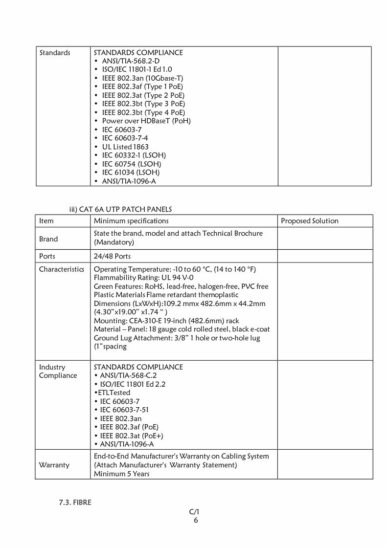
C/1
6
Standards STANDARDS COMPLIANCE • ANSI/TIA-568.2-D • ISO/IEC 11801-1 Ed 1.0 • IEEE 802.3an (10Gbase-T) • IEEE 802.3af (Type 1 PoE) • IEEE 802.3at (Type 2 PoE) • IEEE 802.3bt (Type 3 PoE) • IEEE 802.3bt (Type 4 PoE) • Power over HDBaseT (PoH) • IEC 60603-7 • IEC 60603-7-4 • UL Listed 1863 • IEC 60332-1 (LSOH) • IEC 60754 (LSOH) • IEC 61034 (LSOH) • ANSI/TIA-1096-A
iii) CAT 6A UTP PATCH PANELS
Item Minimum specifications Proposed Solution
Brand State the brand, model and attach Technical Brochure
(Mandatory)
Ports 24/48 Ports
Characteristics Operating Temperature: -10 to 60 °C, (14 to 140 °F) Flammability Rating: UL 94 V-0 Green Features: RoHS, lead-free, halogen-free, PVC free Plastic Materials Flame retardant themoplastic Dimensions (LxWxH):109.2 mmx 482.6mm x 44.2mm (4.30”x19.00” x1.74 “ ) Mounting: CEA-310-E 19-inch (482.6mm) rack Material – Panel: 18 gauge cold rolled steel, black e-coat Ground Lug Attachment: 3/8” 1 hole or two-hole lug
(1”spacing
Industry Compliance
STANDARDS COMPLIANCE • ANSI/TIA-568-C.2 • ISO/IEC 11801 Ed 2.2 •ETLTested • IEC 60603-7 • IEC 60603-7-51 • IEEE 802.3an • IEEE 802.3af (PoE) • IEEE 802.3at (PoE+) • ANSI/TIA-1096-A
Warranty End-to-End Manufacturer's Warranty on Cabling System (Attach Manufacturer's Warranty Statement) Minimum 5 Years
7.3. FIBRE
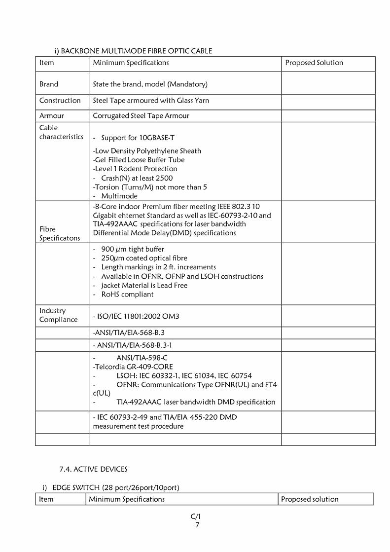
C/1
7
i) BACKBONE MULTIMODE FIBRE OPTIC CABLE
Item Minimum Specifications Proposed Solution
Brand State the brand, model (Mandatory)
Construction Steel Tape armoured with Glass Yarn
Armour Corrugated Steel Tape Armour
Cable
characteristics
- Support for 10GBASE-T
-Low Density Polyethylene Sheath -Gel Filled Loose Buffer Tube -Level 1 Rodent Protection
- Crash(N) at least 2500 -Torsion (Turns/M) not more than 5 - Multimode
Fibre Specificatons
-8-Core indoor Premium fiber meeting IEEE 802.3 10 Gigabit ehternet Standard as well as IEC-60793-2-10 and TIA-492AAAC specifications for laser bandwidth Differential Mode Delay(DMD) specifications
- 900 µm tight buffer - 250µm coated optical fibre - Length markings in 2 ft. increaments
- Available in OFNR, OFNP and LSOH constructions - jacket Material is Lead Free - RoHS compliant
Industry Compliance - ISO/IEC 11801:2002 OM3
-ANSI/TIA/EIA-568-B.3
- ANSI/TIA/EIA-568-B.3-1
- ANSI/TIA-598-C -Telcordia GR-409-CORE - LSOH: IEC 60332-1, IEC 61034, IEC 60754 - OFNR: Communications Type OFNR(UL) and FT4
c(UL) - TIA-492AAAC laser bandwidth DMD specification
- IEC 60793-2-49 and TIA/EIA 455-220 DMD
measurement test procedure
7.4. ACTIVE DEVICES
i) EDGE SWITCH (28 port/26port/10port)
Item Minimum Specifications Proposed solution
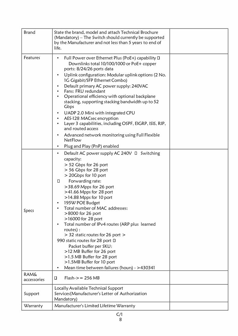
C/1
8
Brand
State the brand, model and attach Technical Brochure
(Mandatory) – The Switch should currently be supported
by the Manufacturer and not less than 5 years to end of
life.
Features • Full Power over Ethernet Plus (PoE+) capability
Downlinks total 10/100/1000 or PoE+ copper
ports: 8/24/26 ports data
• Uplink configuration: Modular uplink options (2 No. 1G Gigabit/SFP Ethernet Combo)
• Default primary AC power supply: 240VAC • Fans: FRU redundant • Operational efficiency with optional backplane
stacking, supporting stacking bandwidth up to 52
Gbps
• UADP 2.0 Mini with integrated CPU • AES-128 MACsec encryption • Layer 3 capabilities, including OSPF, EIGRP, ISIS, RIP,
and routed access
• Advanced network monitoring using Full Flexible
NetFlow
• Plug and Play (PnP) enabled
Specs
• Default AC power supply AC 240V Switching
capacity:
> 52 Gbps for 26 port > 56 Gbps for 28 port > 20Gbps for 10 port
Forwarding rate:
>38.69 Mpps for 26 port >41.66 Mpps for 28 port >14.88 Mpps for 10 port
• 195W POE Budget • Total number of MAC addresses:
>8000 for 26 port >16000 for 28 port
• Total number of IPv4 routes (ARP plus learned
routes) : > 32 static routes for 26 port >
990 static routes for 28 port
Packet buffer per SKU: >12 MB Buffer for 26 port >1.5 MB Buffer for 28 port >1.5MB Buffer for 10 port
• Mean time between failures (hours) - >430341
RAM& accessories Flash->= 256 MB
Support Locally Available Technical Support Services(Manufacturer's Letter of Authorization
Mandatory)
Warranty Manufacturer's Limited Lifetime Warranty
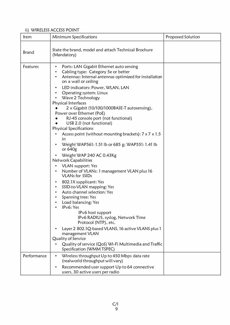
C/1
9
ii) WIRELESS ACCESS POINT
Item Minimum Specifications Proposed Solution
Brand State the brand, model and attach Technical Brochure
(Mandatory)
Features • Ports: LAN Gigabit Ethernet auto sensing • Cabling type: Category 5e or better • Antennas: Internal antennas optimized for installation
on a wall or ceiling
• LED indicators: Power, WLAN, LAN • Operating system: Linux • Wave 2 Technology
Physical Interfaces 2 x Gigabit (10/100/1000BASE-T autosensing),
Power over Ethernet (PoE) RJ-45 console port (not functional) USB 2.0 (not functional)
Physical Specifications
• Access point (without mounting brackets): 7 x 7 x 1.5 in
• Weight WAP561: 1.51 lb or 685 g; WAP551: 1.41 lb
or 640g
• Weight WAP 240 AC 0.43Kg Network Capabilities
• VLAN support: Yes • Number of VLANs: 1 management VLAN plus 16
VLANs for SSIDs
• 802.1X supplicant: Yes • SSID-to-VLAN mapping: Yes • Auto channel selection: Yes • Spanning tree: Yes • Load balancing: Yes • IPv6: Yes
IPv6 host support IPv6 RADIUS, syslog, Network Time
Protocol (NTP), etc.
• Layer 2 802.1Q-based VLANS, 16 active VLANS plus 1
management VLAN Quality of Service
• Quality of service (QoS) Wi-Fi Multimedia and Traffic
Specification (WMM TSPEC)
Performance • Wireless throughput Up to 450 Mbps data rate
(realworld throughput will vary)
• Recommended user support Up to 64 connective
users, 30 active users per radio
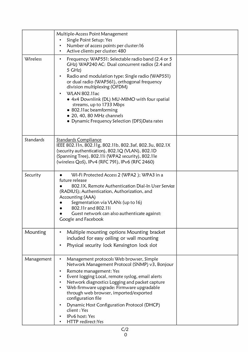
C/2
0
Multiple-Access Point Management
• Single Point Setup: Yes • Number of access points per cluster:16 • Active clients per cluster: 480
Wireless
• Frequency: WAP551: Selectable radio band (2.4 or 5
GHz) WAP240 AC: Dual concurrent radios (2.4 and
5 GHz)
• Radio and modulation type: Single radio (WAP551)
or dual radio (WAP561), orthogonal frequency
division multiplexing (OFDM)
• WLAN 802.11ac 4x4 Downlink (DL) MU-MIMO with four spatial
streams, up to 1733 Mbps 802.11ac beamforming 20, 40, 80 MHz channels Dynamic Frequency Selection (DFS)Data rates
Standards Standards Compliance IEEE 802.11n, 802.11g, 802.11b, 802.3af, 802.3u, 802.1X (security authentication), 802.1Q (VLAN), 802.1D (Spanning Tree), 802.11i (WPA2 security), 802.11e (wireless QoS), IPv4 (RFC 791), IPv6 (RFC 2460)
Security
Wi-Fi Protected Access 2 (WPA2 ); WPA3 in a
future release 802.1X, Remote Authentication Dial-In User Service (RADIUS); Authentication, Authorization, and Accounting (AAA) Segmentation via VLANs (up to 16) 802.11r and 802.11i Guest network can also authenticate against:
Google and Facebook
Mounting • Multiple mounting options Mounting bracket
included for easy ceiling or wall mounting
• Physical security lock Kensington lock slot
Management
• Management protocols Web browser, Simple
Network Management Protocol (SNMP) v3, Bonjour
• Remote management: Yes • Event logging Local, remote syslog, email alerts • Network diagnostics Logging and packet capture • Web firmware upgrade: Firmware upgradable
through web browser, imported/exported
configuration file
• Dynamic Host Configuration Protocol (DHCP) client : Yes
• IPv6 host: Yes • HTTP redirect:Yes

C/2
1
Support Locally Available Technical Support Services
(Manufacturer's Letter of Authorization Mandatory)
Warranty Manufacturer's Limited Lifetime Warranty
iii) Uninterruptible Power Supply
RACK MOUNT UPS
Item Minimum Specifications Proposed solution
Brand
State the brand, model and attach Technical Brochure
(Mandatory)
Features Output
Nominal Output Voltage: 240V
Output Voltage Distortion: Less than 5%
Output Frequency (sync to mains): 50 Hz Line Interactive
Waveform Type: Sine wave Output Connections: (1) IEC 320 C19 (Battery
Backup) , (2) IEC Jumpers (Battery Backup) , (8)
IEC
Input 320 C13 (Battery Backup)
Nominal Input Voltage: 240V
Input Frequency: 50/60 Hz +/- 3 Hz (auto sensing)
Input Connections: IEC-320 C20
Input voltage range for main operations 180 - 287
V
Batteries &: Runtime
Battery Type: Maintenance-free sealed Lead-Acid
battery with suspended electrolyte : leakproof
Typical recharge time: 3 hour(s)
Replacement Battery: YES RBC Quantity: 1
Surge Protection and Filtering
Surge energy rating: 300 Joules Filtering: Full time multi-pole noise filtering :
0.3% IEEE surge let-through : zero clamping response time : meets UL 1449
Management Interface Port(s): USB Control panel: Multi-function LCD status and
control console
Audible Alarm: Alarm when on battery : distinctive low battery alarm : configurable delays
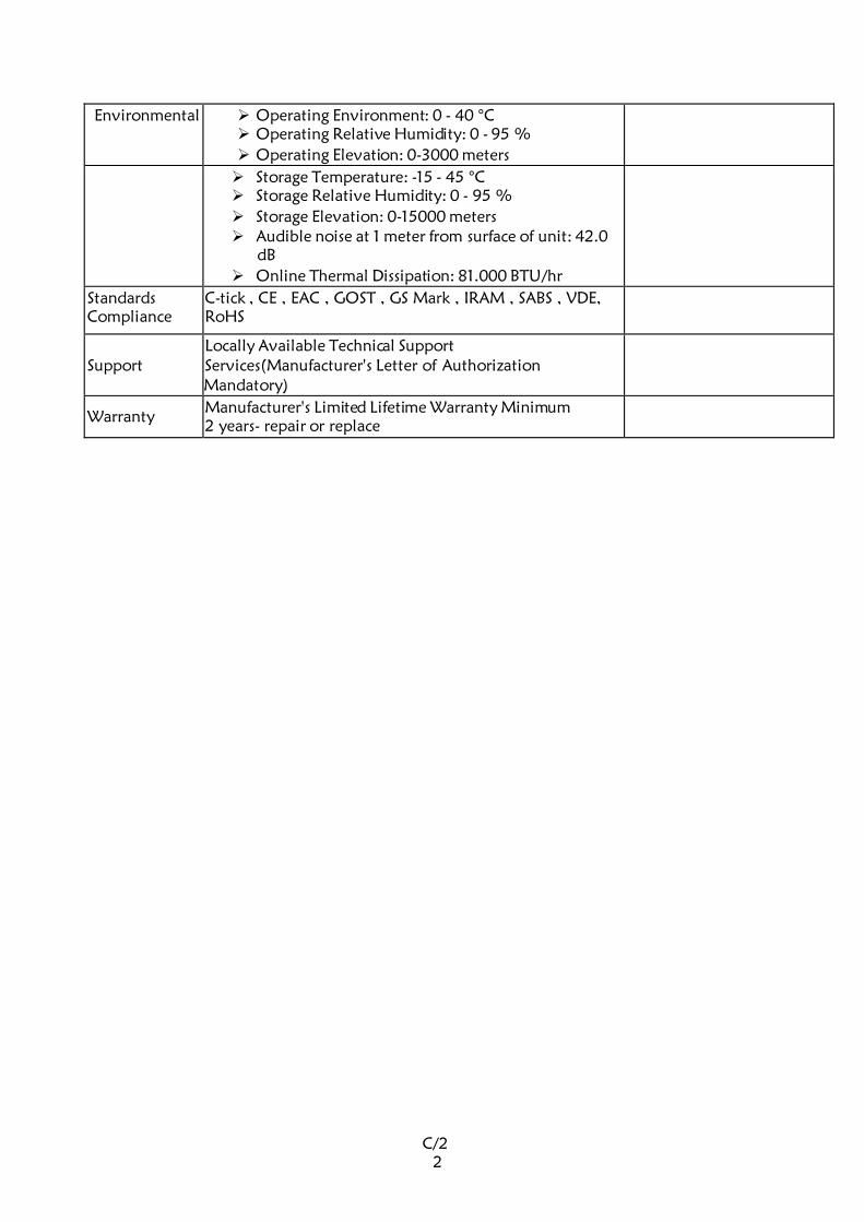
C/2
2
Environmental Operating Environment: 0 - 40 °C Operating Relative Humidity: 0 - 95 %
Operating Elevation: 0-3000 meters
Storage Temperature: -15 - 45 °C Storage Relative Humidity: 0 - 95 %
Storage Elevation: 0-15000 meters Audible noise at 1 meter from surface of unit: 42.0
dB
Online Thermal Dissipation: 81.000 BTU/hr
Standards
Compliance C-tick , CE , EAC , GOST , GS Mark , IRAM , SABS , VDE,
RoHS
Support Locally Available Technical Support Services(Manufacturer's Letter of Authorization
Mandatory)
Warranty Manufacturer's Limited Lifetime Warranty Minimum
2 years- repair or replace
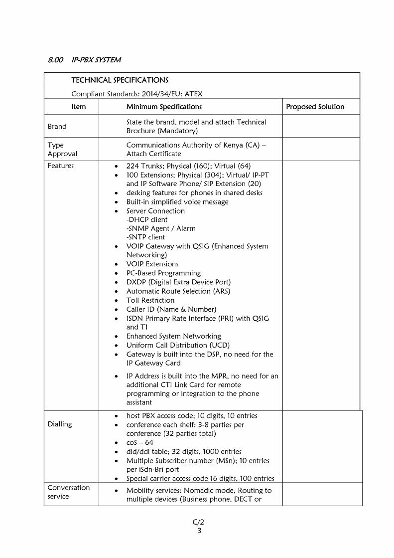
C/2
3
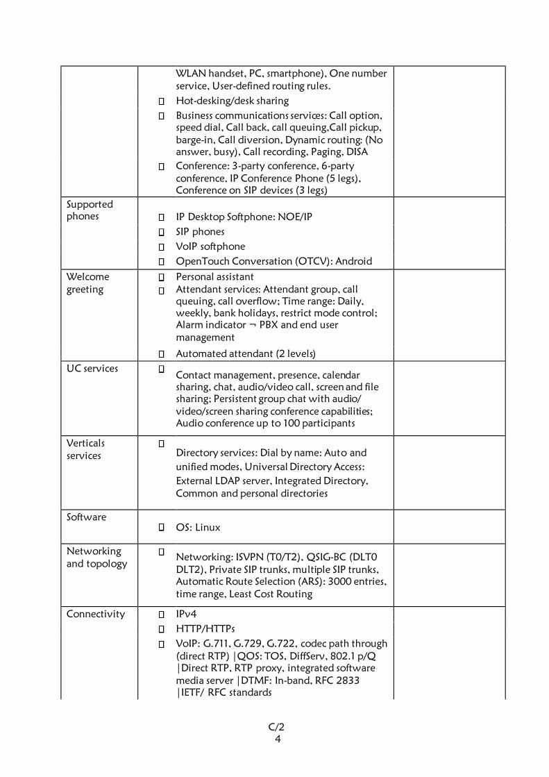
C/2
4
WLAN handset, PC, smartphone), One number
service, User-defined routing rules.
Hot-desking/desk sharing
Business communications services: Call option,
speed dial, Call back, call queuing,Call pickup,
barge-in, Call diversion, Dynamic routing: (No
answer, busy), Call recording, Paging, DISA
Conference: 3-party conference, 6-party
conference, IP Conference Phone (5 legs),
Conference on SIP devices (3 legs)
Supported
phones
IP Desktop Softphone: NOE/IP
SIP phones
VoIP softphone
OpenTouch Conversation (OTCV): Android
Welcome greeting
Personal assistant Attendant services: Attendant group, call
queuing, call overflow; Time range: Daily,
weekly, bank holidays, restrict mode control; Alarm indicator ¬ PBX and end user
management
Automated attendant (2 levels)
UC services Contact management, presence, calendar
sharing, chat, audio/video call, screen and file
sharing; Persistent group chat with audio/
video/screen sharing conference capabilities; Audio conference up to 100 participants
Verticals
services
Directory services: Dial by name: Auto and
unified modes, Universal Directory Access:
External LDAP server, Integrated Directory, Common and personal directories
Software OS: Linux
Networking
and topology
Networking: ISVPN (T0/T2), QSIG-BC (DLT0
DLT2), Private SIP trunks, multiple SIP trunks,
Automatic Route Selection (ARS): 3000 entries,
time range, Least Cost Routing
Connectivity IPv4
HTTP/HTTPs
VoIP: G.711, G.729, G.722, codec path through (direct RTP) |QOS: TOS, DiffServ, 802.1 p/Q
|Direct RTP, RTP proxy, integrated software
media server |DTMF: In-band, RFC 2833 |IETF/ RFC standards

C/2
5
WebRTC VOIP services over the Internet |Firewall friendly port forwarding and VPN less |Encrypted media, STUN/TURN
Management: Remote Access | Integrated VPN IPsec |ISDN (1 or 2B), call back
SIP: Public SIP trunk | Private SIP trunk | SIP
endpoints (local users)
WLAN
Security User Authentication: Password 6 digits |Access
locked after repeated authentication errors,
notification |Normal/restricted modes |User
right to services |Pin for remote access (DISA)
Certificate: Server self-signed, Import for public
authority
WAN access: HTTP proxy compliant
SIP Authentication: RFC2617
Traffic filtering: ARP spoofing protection| SIP
perimeter defense: Quarantine, blacklist,
automated blacklist |Connection tracking
Encryption: SSLv3 for secure HTTP |HTTPS
Hardware CPU
Board Power CPU EE (PowerPC e300): Chassis:
Compact |16 VoIP DSP channel (embedded)
|VoIP 64 optional daughter board: 76 VoIP
channels |Memory Storage daughter board (MSDB): 8GB (eMMC)
Warranty Comprehensive Manufacturer’s Warranty
(Attach Manufacturer's Warranty Statement)
minimum of 2 years.
8.1. IP EXECUTIVE PHONE
TECHNICAL SPECIFICATIONS
Compliant Standards: TIA/EIA 810-B
Item Minimum Specifications Proposed Solution
Brand State the brand, model and attach Technical Brochure
(Mandatory)
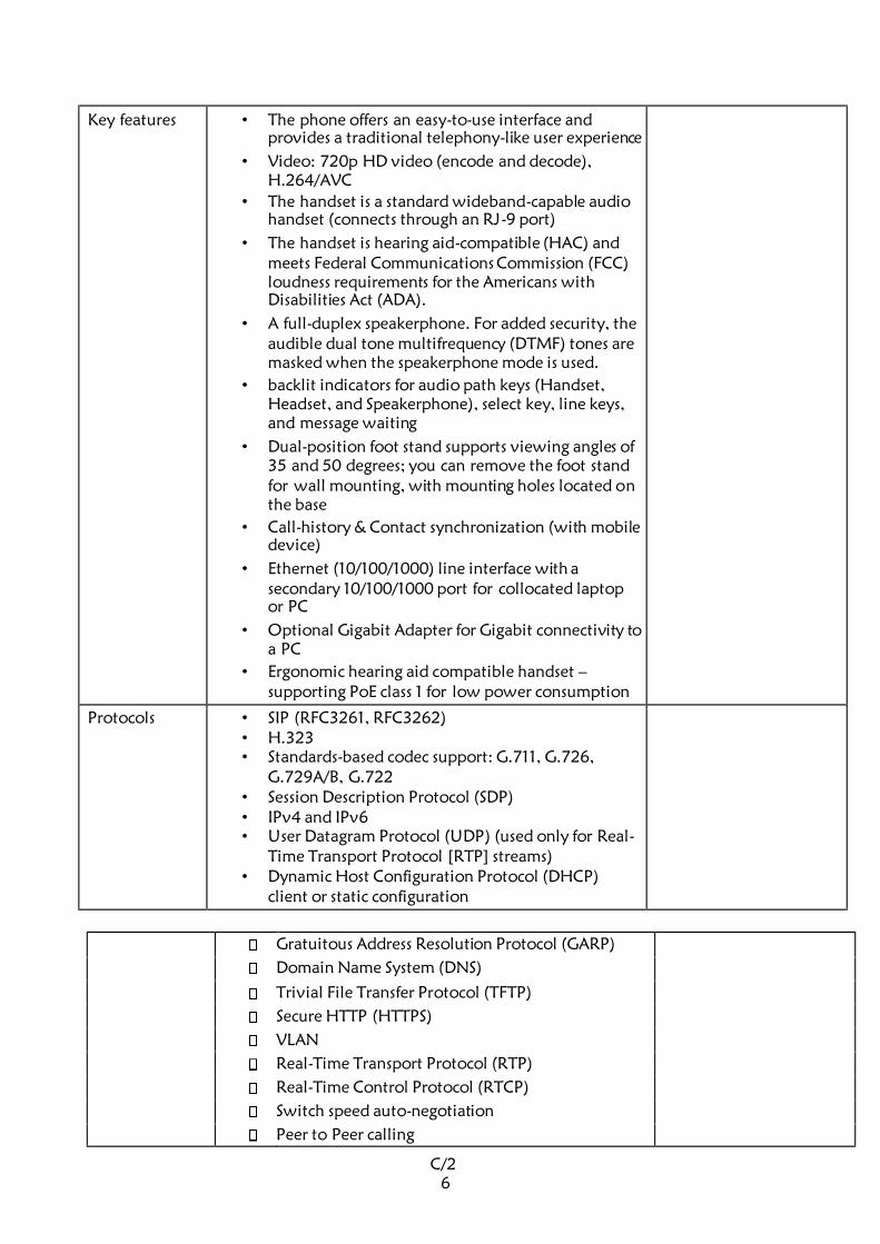
C/2
6
Key features • The phone offers an easy-to-use interface and
provides a traditional telephony-like user experience
• Video: 720p HD video (encode and decode), H.264/AVC
• The handset is a standard wideband-capable audio
handset (connects through an RJ-9 port)
• The handset is hearing aid-compatible (HAC) and
meets Federal Communications Commission (FCC)
loudness requirements for the Americans with
Disabilities Act (ADA).
• A full-duplex speakerphone. For added security, the
audible dual tone multifrequency (DTMF) tones are
masked when the speakerphone mode is used.
• backlit indicators for audio path keys (Handset,
Headset, and Speakerphone), select key, line keys,
and message waiting
• Dual-position foot stand supports viewing angles of
35 and 50 degrees; you can remove the foot stand
for wall mounting, with mounting holes located on
the base
• Call-history & Contact synchronization (with mobile
device)
• Ethernet (10/100/1000) line interface with a
secondary 10/100/1000 port for collocated laptop
or PC
• Optional Gigabit Adapter for Gigabit connectivity to
a PC
• Ergonomic hearing aid compatible handset –
supporting PoE class 1 for low power consumption
Protocols • SIP (RFC3261, RFC3262) • H.323 • Standards-based codec support: G.711, G.726,
G.729A/B, G.722 • Session Description Protocol (SDP) • IPv4 and IPv6 • User Datagram Protocol (UDP) (used only for Real-
Time Transport Protocol [RTP] streams) • Dynamic Host Configuration Protocol (DHCP)
client or static configuration
Gratuitous Address Resolution Protocol (GARP)
Domain Name System (DNS)
Trivial File Transfer Protocol (TFTP)
Secure HTTP (HTTPS)
VLAN
Real-Time Transport Protocol (RTP)
Real-Time Control Protocol (RTCP)
Switch speed auto-negotiation
Peer to Peer calling
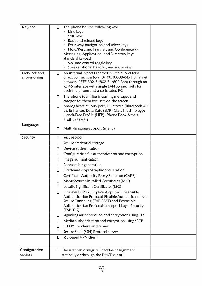
C/2
7
Key-pad The phone has the following keys: Line keys Soft keys Back and release keys Four-way navigation and select keys Hold/Resume, Transfer, and Conference k Messaging, Application, and Directory key Standard keypad Volume-control toggle key Speakerphone, headset, and mute keys
Network and
provisioning An internal 2-port Ethernet switch allows for a
direct connection to a 10/100/1000BASE-T Ethernet
network (IEEE 802.3i/802.3u/802.3ab) through an
RJ-45 interface with single LAN connectivity for both the phone and a co-located PC
The phone identifies incoming messages and
categorizes them for users on the screen.
Analog headset, Aux port, Bluetooth (Bluetooth 4.1 LE, Enhanced Data Rate (EDR) Class 1 technology; Hands-Free Profile (HFP); Phone Book Access
Profile (PBAP))
Languages Multi-language support (menu)
Security Secure boot
Secure credential storage
Device authentication
Configuration file authentication and encryption
Image authentication
Random bit generation
Hardware cryptographic acceleration
Certificate Authority Proxy Function (CAPF)
Manufacturer-Installed Certificates (MIC)
Locally Significant Certificates (LSC)
Ethernet 802.1x supplicant options: Extensible Authentication Protocol-Flexible Authentication via Secure Tunneling (EAP-FAST) and Extensible Authentication Protocol-Transport Layer Security
(EAP-TLS)
Signaling authentication and encryption using TLS
Media authentication and encryption using SRTP
HTTPS for client and server
Secure Shell (SSH) Protocol server
SSL-based VPN client
Configuration
options The user can configure IP address assignment
statically or through the DHCP client.
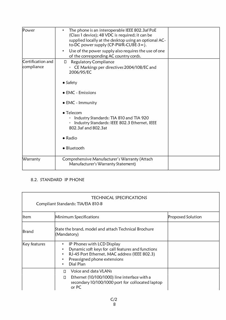
C/2
8
Power • The phone is an interoperable IEEE 802.3af PoE
(Class 1 device); 48 VDC is required; it can be
supplied locally at the desktop using an optional AC-
to-DC power supply (CP-PWR-CUBE-3=).
• Use of the power supply also requires the use of one
of the corresponding AC country cords.
Certification and
compliance Regulatory Compliance
CE Markings per directives 2004/108/EC and 2006/95/EC
Safety
EMC - Emissions
EMC - Immunity
Telecom Industry Standards: TIA 810 and TIA 920 Industry Standards: IEEE 802.3 Ethernet, IEEE 802.3af and 802.3at
Radio
Bluetooth
Warranty Comprehensive Manufacturer’s Warranty (Attach
Manufacturer's Warranty Statement)
8.2. STANDARD IP PHONE
TECHNICAL SPECIFICATIONS
Compliant Standards: TIA/EIA 810-B
Item Minimum Specifications Proposed Solution
Brand State the brand, model and attach Technical Brochure
(Mandatory)
Key features • IP Phones with LCD Display • Dynamic soft keys for call features and functions • RJ-45 Port Ethernet, MAC address (IEEE 802.3) • Preassigned phone extensions • Dial Plan
Voice and data VLANs
Ethernet (10/100/1000) line interface with a
secondary 10/100/1000 port for collocated laptop
or PC
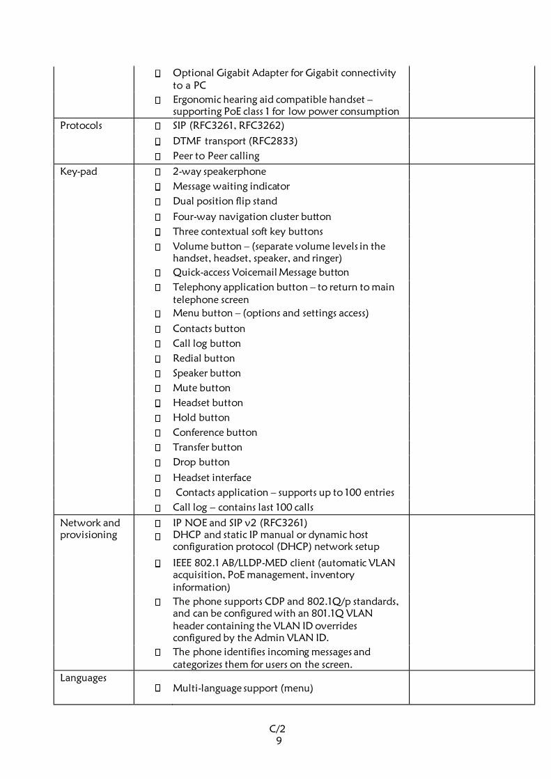
C/2
9
Optional Gigabit Adapter for Gigabit connectivity
to a PC
Ergonomic hearing aid compatible handset –
supporting PoE class 1 for low power consumption
Protocols SIP (RFC3261, RFC3262)
DTMF transport (RFC2833)
Peer to Peer calling
Key-pad 2-way speakerphone
Message waiting indicator
Dual position flip stand
Four-way navigation cluster button
Three contextual soft key buttons
Volume button – (separate volume levels in the
handset, headset, speaker, and ringer)
Quick-access Voicemail Message button
Telephony application button – to return to main
telephone screen
Menu button – (options and settings access)
Contacts button
Call log button
Redial button
Speaker button
Mute button
Headset button
Hold button
Conference button
Transfer button
Drop button
Headset interface
Contacts application – supports up to 100 entries
Call log – contains last 100 calls
Network and
provisioning
IP NOE and SIP v2 (RFC3261) DHCP and static IP manual or dynamic host
configuration protocol (DHCP) network setup
IEEE 802.1 AB/LLDP-MED client (automatic VLAN
acquisition, PoE management, inventory
information)
The phone supports CDP and 802.1Q/p standards,
and can be configured with an 801.1Q VLAN
header containing the VLAN ID overrides
configured by the Admin VLAN ID.
The phone identifies incoming messages and
categorizes them for users on the screen.
Languages Multi-language support (menu)
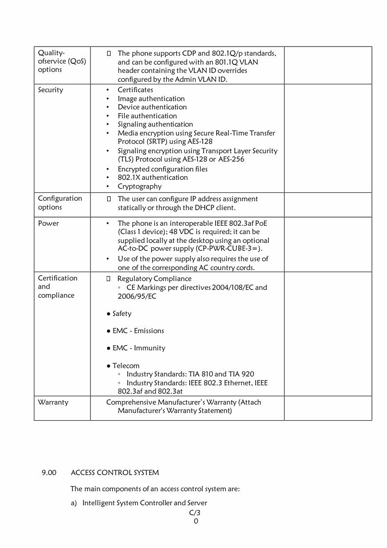
C/3
0
Quality-
ofservice (QoS)
options
The phone supports CDP and 802.1Q/p standards,
and can be configured with an 801.1Q VLAN
header containing the VLAN ID overrides
configured by the Admin VLAN ID.
Security • Certificates • Image authentication • Device authentication • File authentication • Signaling authentication • Media encryption using Secure Real-Time Transfer
Protocol (SRTP) using AES-128
• Signaling encryption using Transport Layer Security
(TLS) Protocol using AES-128 or AES-256
• Encrypted configuration files • 802.1X authentication • Cryptography
Configuration
options The user can configure IP address assignment
statically or through the DHCP client.
Power • The phone is an interoperable IEEE 802.3af PoE
(Class 1 device); 48 VDC is required; it can be
supplied locally at the desktop using an optional
AC-to-DC power supply (CP-PWR-CUBE-3=).
• Use of the power supply also requires the use of
one of the corresponding AC country cords.
Certification
and
compliance
Regulatory Compliance CE Markings per directives 2004/108/EC and 2006/95/EC
Safety
EMC - Emissions
EMC - Immunity
Telecom Industry Standards: TIA 810 and TIA 920 Industry Standards: IEEE 802.3 Ethernet, IEEE
802.3af and 802.3at
Warranty Comprehensive Manufacturer’s Warranty (Attach
Manufacturer's Warranty Statement)
9.00 ACCESS CONTROL SYSTEM
The main components of an access control system are:
a) Intelligent System Controller and Server
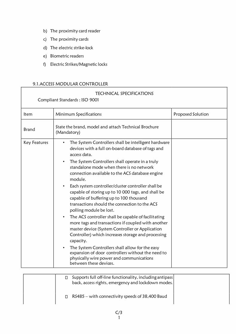
C/3
1
b) The proximity card reader
c) The proximity cards
d) The electric strike-lock
e) Biometric readers
f) Electric Strikes/Magnetic locks
9.1. ACCESS MODULAR CONTROLLER
TECHNICAL SPECIFICATIONS
Compliant Standards : ISO 9001
Item Minimum Specifications Proposed Solution
Brand State the brand, model and attach Technical Brochure
(Mandatory)
Key Features • The System Controllers shall be intelligent hardware
devices with a full on-board database of tags and
access data.
• The System Controllers shall operate in a truly
standalone mode when there is no network
connection available to the ACS database engine
module.
• Each system controller/cluster controller shall be
capable of storing up to 10 000 tags, and shall be
capable of buffering up to 100 thousand
transactions should the connection to the ACS
polling module be lost.
• The ACS controller shall be capable of facilitating
more tags and transactions if coupled with another
master device (System Controller or Application
Controller) which increases storage and processing
capacity.
• The System Controllers shall allow for the easy
expansion of door controllers without the need to
physically wire power and communications
between these devices.
Supports full off-line functionality, including antipass
back, access rights, emergency and lockdown modes.
RS485 – with connectivity speeds of 38,400 Baud
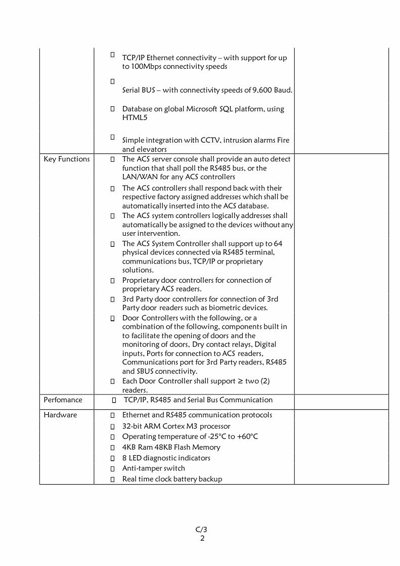
C/3
2
TCP/IP Ethernet connectivity – with support for up
to 100Mbps connectivity speeds
Serial BUS – with connectivity speeds of 9,600 Baud.
Database on global Microsoft SQL platform, using HTML5
Simple integration with CCTV, intrusion alarms Fire
and elevators
Key Functions The ACS server console shall provide an auto detect
function that shall poll the RS485 bus, or the
LAN/WAN for any ACS controllers
The ACS controllers shall respond back with their
respective factory assigned addresses which shall be
automatically inserted into the ACS database.
The ACS system controllers logically addresses shall
automatically be assigned to the devices without any
user intervention.
The ACS System Controller shall support up to 64
physical devices connected via RS485 terminal,
communications bus, TCP/IP or proprietary
solutions.
Proprietary door controllers for connection of
proprietary ACS readers.
3rd Party door controllers for connection of 3rd
Party door readers such as biometric devices.
Door Controllers with the following, or a
combination of the following, components built in
to facilitate the opening of doors and the
monitoring of doors, Dry contact relays, Digital
inputs, Ports for connection to ACS readers,
Communications port for 3rd Party readers, RS485
and SBUS connectivity.
Each Door Controller shall support ≥ two (2)
readers.
Perfomance TCP/IP, RS485 and Serial Bus Communication
Hardware Ethernet and RS485 communication protocols
32-bit ARM Cortex M3 processor
Operating temperature of -25°C to +60°C
4KB Ram 48KB Flash Memory
8 LED diagnostic indicators
Anti-tamper switch
Real time clock battery backup
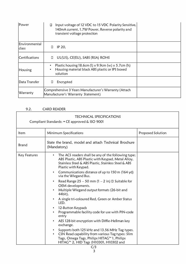
C/3
3
Power Input voltage of 12 VDC to 15 VDC Polarity Sensitive,
140mA current, 1.7W Power, Reverse polarity and
transient voltage protection
Environmental class IP 20,
Certifications UL(US), CE(EU), SABS (RSA) ROHS
Housing
• Plastic housing 18.6cm (l) x 9.9cm (w) x 5.7cm (h) • Housing material black ABS plastic or IPS boxed
solution
Data Transfer Encrypted
Warranty Comprehensive 3 Years Manufacturer’s Warranty (Attach
Manufacturer's Warranty Statement)
9.2. CARD READER
TECHNICAL SPECIFICATIONS
Compliant Standards: • CE approved & ISO 9001
Item Minimum Specifications Proposed Solution
Brand State the brand, model and attach Technical Brochure
(Mandatory)
Key Features • The ACS readers shall be any of the following type;
ABS Plastic, ABS Plastic with Keypad, Metal Alloy,
Stainless Steel & ABS Plastic, Stainless Steel & ABS
Plastic with Keypad.
• Communications distance of up to 150 m (164 yd)
via the Wiegand Bus.
• Read Range 25 – 50 mm (1 – 2 in) Suitable for
OEM developments. • Multiple Wiegand output formats (26-bit and
44bit).
• A single tri-coloured Red, Green or Amber Status
LED.
• 12-Button Keypads • Programmable facility code for use with PIN-code
entry
• AES 128-bit encryption with Diffie-Hellman key
exchange.
• Supports both 125 kHz and 13.56 MHz Tag types. • CSN Read capability from various Tag types: Slim
Tags, Omega Tags, Philips HITAG™ 1, Philips HITAG™ 2, HID Tags (H10301, H10302 and
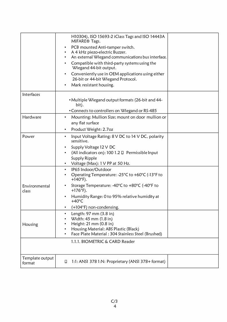
C/3
4
H10304), ISO 15693-2 iClass Tags and ISO 14443A
MIFARE® Tags.
• PCB mounted Anti-tamper switch. • A 4 kHz piezo-electric Buzzer. • An external Wiegand communications bus interface.
• Compatible with third-party systems using the
Wiegand 44-bit output.
• Conveniently use in OEM applications using either
26-bit or 44-bit Wiegand Protocol.
• Mark resistant housing.
Interfaces
• Multiple Wiegand output formats (26-bit and 44-
bit).
• Connects to controllers on Wiegand or RS-485
Hardware • Mounting: Mullion Size; mount on door mullion or
any flat surface
• Product Weight: 2.7oz
Power • Input Voltage Rating: 8 V DC to 14 V DC, polarity
sensitive.
• Supply Voltage 12 V DC
• (All indicators on): 100 1.2 Permissible Input
Supply Ripple • Voltage (Max): 1 V PP at 50 Hz.
Environmental class
• IP65 Indoor/Outdoor • Operating Temperature: -25°C to +60°C (-13°F to
+140°F).
• Storage Temperature: -40°C to +80°C (-40°F to
+176°F).
• Humidity Range: 0 to 95% relative humidity at
+40°C
• (+104°F) non-condensing.
Housing
• Length: 97 mm (3.8 in) • Width: 45 mm (1.8 in) • Height: 21 mm (0.8 in) • Housing Material: ABS Plastic (Black) • Face Plate Material : 304 Stainless Steel (Brushed)
1.1.1. BIOMETRIC & CARD Reader
Template output
format 1:1: ANSI 378 1:N: Proprietary (ANSI 378+ format)
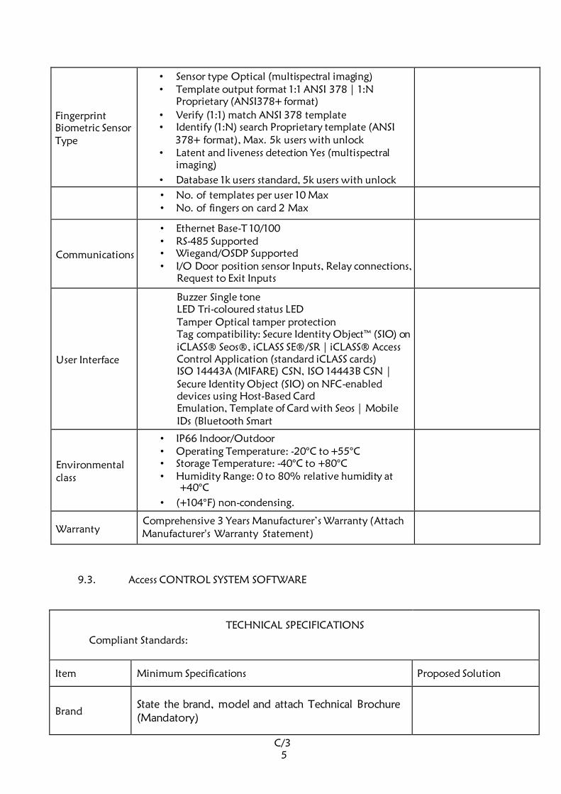
C/3
5
Fingerprint Biometric Sensor Type
• Sensor type Optical (multispectral imaging) • Template output format 1:1 ANSI 378 | 1:N
Proprietary (ANSI378+ format)
• Verify (1:1) match ANSI 378 template • Identify (1:N) search Proprietary template (ANSI
378+ format), Max. 5k users with unlock • Latent and liveness detection Yes (multispectral
imaging)
• Database 1k users standard, 5k users with unlock
• No. of templates per user 10 Max • No. of fingers on card 2 Max
Communications
• Ethernet Base-T 10/100 • RS-485 Supported • Wiegand/OSDP Supported • I/O Door position sensor Inputs, Relay connections,
Request to Exit Inputs
User Interface
Buzzer Single tone LED Tri-coloured status LED Tamper Optical tamper protection Tag compatibility: Secure Identity Object™ (SIO) on
iCLASS® Seos®, iCLASS SE®/SR | iCLASS® Access
Control Application (standard iCLASS cards) ISO 14443A (MIFARE) CSN, ISO 14443B CSN |
Secure Identity Object (SIO) on NFC-enabled
devices using Host-Based Card Emulation, Template of Card with Seos | Mobile
IDs (Bluetooth Smart
Environmental class
• IP66 Indoor/Outdoor • Operating Temperature: -20°C to +55°C • Storage Temperature: -40°C to +80°C • Humidity Range: 0 to 80% relative humidity at
+40°C
• (+104°F) non-condensing.
Warranty Comprehensive 3 Years Manufacturer’s Warranty (Attach
Manufacturer's Warranty Statement)
9.3. Access CONTROL SYSTEM SOFTWARE
TECHNICAL SPECIFICATIONS
Compliant Standards:
Item Minimum Specifications Proposed Solution
Brand State the brand, model and attach Technical Brochure
(Mandatory)
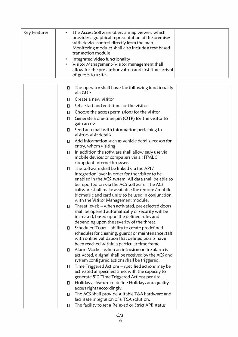
C/3
6
Key Features • The Access Software offers a map viewer, which
provides a graphical representation of the premises
with device control directly from the map. Monitoring modules shall also include a text based
transaction module
• integrated video functionality • Visitor Management- Visitor management shall
allow for the pre-authorization and first time arrival
of guests to a site.
The operator shall have the following functionality
via GUI:
Create a new visitor
Set a start and end time for the visitor
Choose the access permissions for the visitor
Generate a one-time pin (OTP) for the visitor to
gain access
Send an email with information pertaining to
visitors visit details
Add information such as vehicle details, reason for
entry, whom visiting
In addition the software shall allow easy use via
mobile devices or computers via a HTML 5
compliant internet browser.
The software shall be linked via the API /
integration layer in order for the visitor to be
enabled in the ACS system. All data shall be able to
be reported on via the ACS software. The ACS
software shall make available the remote / mobile
biometric and card units to be used in conjunction
with the Visitor Management module.
Threat levels – when activated, pre-selected doors
shall be opened automatically or security will be
increased, based upon the defined rules and
depending upon the severity of the threat.
Scheduled Tours – ability to create predefined
schedules for cleaning, guards or maintenance staff
with online validation that defined points have
been reached within a particular time frame.
Alarm Mode – when an intrusion or fire alarm is
activated, a signal shall be received by the ACS and
system configured actions shall be triggered.
Time Triggered Actions – specified actions may be
activated at specified times with the capacity to
generate 512 Time Triggered Actions per site.
Holidays - feature to define Holidays and qualify
access rights accordingly.
The ACS shall provide suitable T&A hardware and
facilitate integration of a T&A solution.
The facility to set a Relaxed or Strict APB status
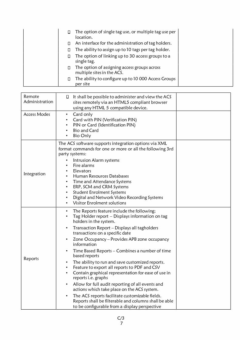
C/3
7
The option of single tag use, or multiple tag use per
location.
An interface for the administration of tag holders.
The ability to assign up to 10 tags per tag holder.
The option of linking up to 30 access groups to a
single tag.
The option of assigning access groups across
multiple sites in the ACS.
The ability to configure up to 10 000 Access Groups
per site
Remote Administration
It shall be possible to administer and view the ACS
sites remotely via an HTML5 compliant browser
using any HTML 5 compatible device.
Access Modes • Card only • Card with PIN (Verification PIN) • PIN or Card (Identification PIN) • Bio and Card • Bio Only
Integration
The ACS software supports integration options via XML
format commands for one or more or all the following 3rd
party systems:
• Intrusion Alarm systems • Fire alarms • Elevators • Human Resources Databases • Time and Attendance Systems • ERP, SCM and CRM Systems • Student Enrolment Systems • Digital and Network Video Recording Systems • Visitor Enrolment solutions
Reports
• The Reports feature include the following; • Tag Holder report – Displays information on tag
holders in the system.
• Transaction Report – Displays all tagholders
transactions on a specific date
• Zone Occupancy – Provides APB zone occupancy
information
• Time Based Reports – Combines a number of time
based reports
• The ability to run and save customized reports. • Feature to export all reports to PDF and CSV • Contain graphical representation for ease of use in
reports i.e. graphs
• Allow for full audit reporting of all events and
actions which take place on the ACS system.
• The ACS reports facilitate customizable fields.
Reports shall be filterable and columns shall be able
to be configurable from a display perspective

C/3
8
Max. number of access
authorizations
groups
10,00 per site
Card
enrollment USB enrollment devices AMC connected readers
Operator Security
• The ACS software shall include an Operator Security
module that will enable the System Administrator to
define operator groups for users who will operate
the various modules.
• The Operator Security module shall facilitate the
creation of users and passwords, as well as user
groups.
• The System Administrator shall be able to set up
application security as well as granular security
settings within each application.
• The Operator Security module shall facilitate the
assignment of tag holder access groups to selected
operator groups.
• The ACS must provide configurable security options
to limit system users’ activity within it. Such
operator security must be configurable on a per user
group basis.
System Health Check Reporting
The ACS system shall have a health checking or
selfdiagnostic capability. The Health check shall
inform an administrator/system integrator of any
faults or issues as well as explain any user initiated
elements that are at variance with the rules of
implementation. This process must be an automated
process
Minimum Software Specification
Windows operating system: • Windows 2016
Standard Server (64 bit) • Windows 2012 R2 Server • Windows 10 x 64 Professional • Windows
Database: Microsoft SQL Server2014
License Comprehensive Manufacturer’s license
9.4. POWER SUPPLY MODULE
TECHNICAL SPECIFICATIONS
Compliant Standards:
Item Minimum Specifications Proposed Solution
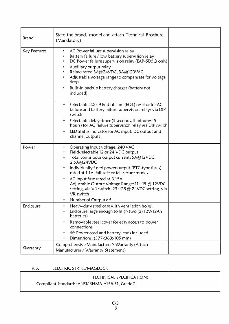
C/3
9
Brand State the brand, model and attach Technical Brochure
(Mandatory)
Key Features • AC Power failure supervision relay • Battery failure / low battery supervision relay • DC Power failure supervision relay (EAP-5D5Q only)
• Auxiliary output relay • Relays rated 3A@24VDC, 3A@120VAC • Adjustable voltage range to compensate for voltage
drop
• Built-in backup battery charger (battery not
included)
• Selectable 2.2k 9 End-of-Line (EOL) resistor for AC
failure and battery failure supervision relays via DIP
switch
• Selectable delay timer (5 seconds, 5 minutes, 5
hours) for AC failure supervision relay via DIP switch
• LED Status indicator for AC input, DC output and
channel outputs
Power • Operating Input voltage: 240 VAC • Field-selectable 12 or 24 VDC output • Total continuous output current: 5A@12VDC,
2.5A@24VDC
• Individually fused power output (PTC-type fuses)
rated at 1.1A, fail-safe or fail-secure modes.
• AC Input fuse rated at 3.15A Adjustable Output Voltage Range: 11~15 @ 12VDC
setting, via VR switch, 23~28 @ 24VDC setting, via
VR switch
• Number of Outputs: 5
Enclosure • Heavy-duty steel case with ventilation holes • Enclosure large enough to fit (>two (2) 12V/12Ah
batteries)
• Removable steel cover for easy access to power
connections
• 6ft Power cord and battery leads included • Dimensions: (377x363x105 mm)
Warranty Comprehensive Manufacturer’s Warranty (Attach
Manufacturer's Warranty Statement)
9.5. ELECTRIC STRIKE/MAGLOCK
TECHNICAL SPECIFICATIONS
Compliant Standards: ANSI/ BHMA A156.31, Grade 2
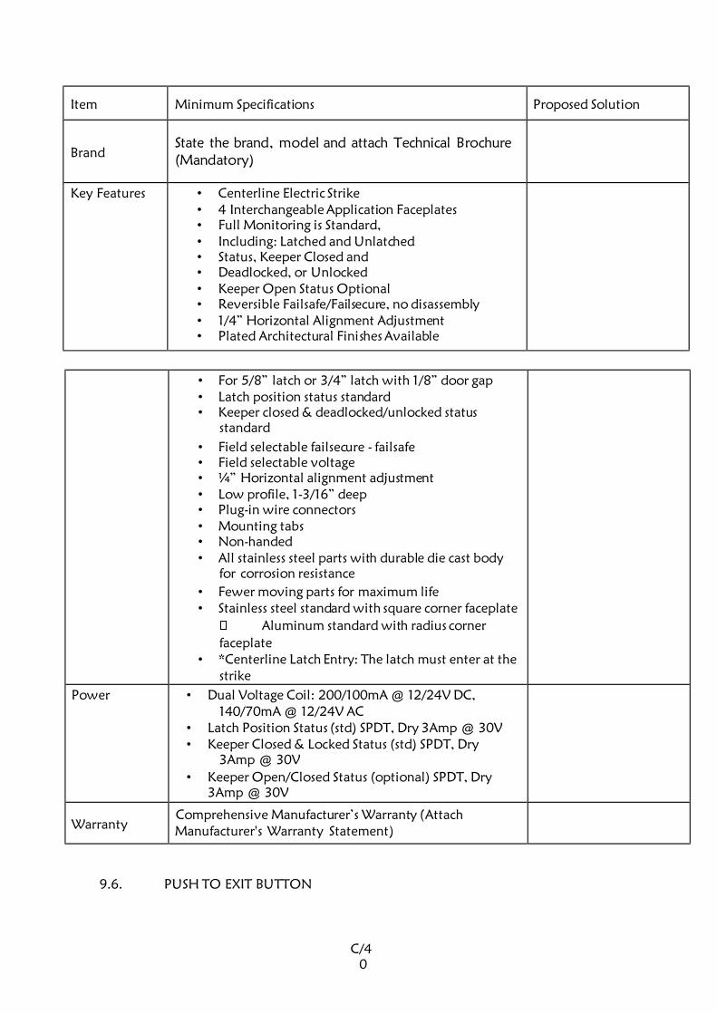
C/4
0
Item Minimum Specifications Proposed Solution
Brand State the brand, model and attach Technical Brochure
(Mandatory)
Key Features • Centerline Electric Strike • 4 Interchangeable Application Faceplates • Full Monitoring is Standard, • Including: Latched and Unlatched • Status, Keeper Closed and • Deadlocked, or Unlocked • Keeper Open Status Optional • Reversible Failsafe/Failsecure, no disassembly • 1/4” Horizontal Alignment Adjustment • Plated Architectural Finishes Available
• For 5/8” latch or 3/4” latch with 1/8” door gap • Latch position status standard • Keeper closed & deadlocked/unlocked status
standard
• Field selectable failsecure - failsafe • Field selectable voltage • ¼” Horizontal alignment adjustment • Low profile, 1-3/16” deep • Plug-in wire connectors • Mounting tabs • Non-handed • All stainless steel parts with durable die cast body
for corrosion resistance
• Fewer moving parts for maximum life • Stainless steel standard with square corner faceplate
Aluminum standard with radius corner
faceplate • *Centerline Latch Entry: The latch must enter at the
strike
Power • Dual Voltage Coil: 200/100mA @ 12/24V DC, 140/70mA @ 12/24V AC
• Latch Position Status (std) SPDT, Dry 3Amp @ 30V • Keeper Closed & Locked Status (std) SPDT, Dry
3Amp @ 30V
• Keeper Open/Closed Status (optional) SPDT, Dry
3Amp @ 30V
Warranty Comprehensive Manufacturer’s Warranty (Attach
Manufacturer's Warranty Statement)
9.6. PUSH TO EXIT BUTTON
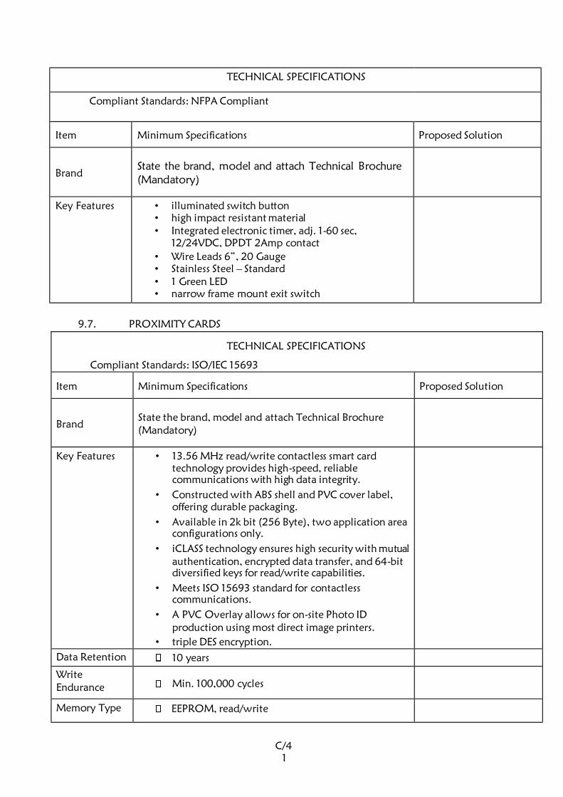
C/4
1
TECHNICAL SPECIFICATIONS
Compliant Standards: NFPA Compliant
Item Minimum Specifications Proposed Solution
Brand State the brand, model and attach Technical Brochure
(Mandatory)
Key Features • illuminated switch button • high impact resistant material • Integrated electronic timer, adj. 1-60 sec,
12/24VDC, DPDT 2Amp contact
• Wire Leads 6”, 20 Gauge • Stainless Steel – Standard • 1 Green LED • narrow frame mount exit switch
9.7. PROXIMITY CARDS
TECHNICAL SPECIFICATIONS
Compliant Standards: ISO/IEC 15693
Item Minimum Specifications Proposed Solution
Brand State the brand, model and attach Technical Brochure
(Mandatory)
Key Features • 13.56 MHz read/write contactless smart card
technology provides high-speed, reliable
communications with high data integrity.
• Constructed with ABS shell and PVC cover label,
offering durable packaging.
• Available in 2k bit (256 Byte), two application area
configurations only.
• iCLASS technology ensures high security with mutual
authentication, encrypted data transfer, and 64-bit
diversified keys for read/write capabilities.
• Meets ISO 15693 standard for contactless
communications.
• A PVC Overlay allows for on-site Photo ID
production using most direct image printers.
• triple DES encryption.
Data Retention 10 years
Write Endurance Min. 100,000 cycles
Memory Type EEPROM, read/write
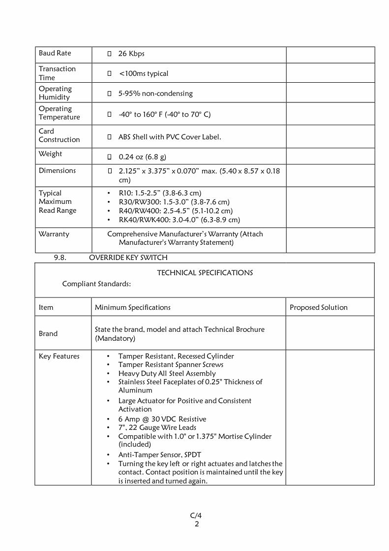
C/4
2
Baud Rate 26 Kbps
Transaction
Time <100ms typical
Operating
Humidity 5-95% non-condensing
Operating
Temperature -40° to 160° F (-40° to 70° C)
Card Construction ABS Shell with PVC Cover Label.
Weight 0.24 oz (6.8 g)
Dimensions 2.125” x 3.375” x 0.070” max. (5.40 x 8.57 x 0.18
cm)
Typical Maximum Read Range
• R10: 1.5-2.5” (3.8-6.3 cm) • R30/RW300: 1.5-3.0” (3.8-7.6 cm) • R40/RW400: 2.5-4.5” (5.1-10.2 cm) • RK40/RWK400: 3.0-4.0” (6.3-8.9 cm)
Warranty Comprehensive Manufacturer’s Warranty (Attach
Manufacturer's Warranty Statement)
9.8. OVERRIDE KEY SWITCH
TECHNICAL SPECIFICATIONS
Compliant Standards:
Item Minimum Specifications Proposed Solution
Brand State the brand, model and attach Technical Brochure
(Mandatory)
Key Features • Tamper Resistant, Recessed Cylinder • Tamper Resistant Spanner Screws • Heavy Duty All Steel Assembly • Stainless Steel Faceplates of 0.25" Thickness of
Aluminum
• Large Actuator for Positive and Consistent
Activation
• 6 Amp @ 30 VDC Resistive • 7", 22 Gauge Wire Leads • Compatible with 1.0" or 1.375" Mortise Cylinder
(included)
• Anti-Tamper Sensor, SPDT • Turning the key left or right actuates and latches the
contact. Contact position is maintained until the key
is inserted and turned again.
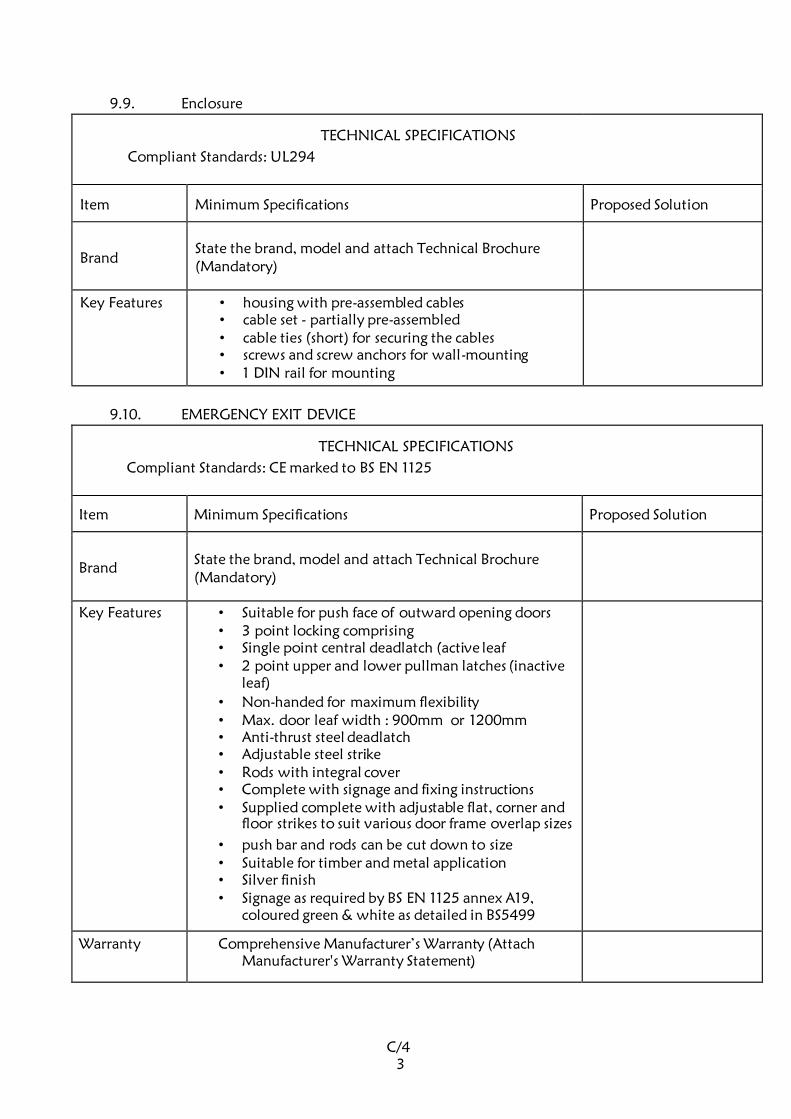
C/4
3
9.9. Enclosure
TECHNICAL SPECIFICATIONS
Compliant Standards: UL294
Item Minimum Specifications Proposed Solution
Brand State the brand, model and attach Technical Brochure
(Mandatory)
Key Features • housing with pre-assembled cables • cable set - partially pre-assembled • cable ties (short) for securing the cables • screws and screw anchors for wall-mounting • 1 DIN rail for mounting
9.10. EMERGENCY EXIT DEVICE
TECHNICAL SPECIFICATIONS
Compliant Standards: CE marked to BS EN 1125
Item Minimum Specifications Proposed Solution
Brand State the brand, model and attach Technical Brochure
(Mandatory)
Key Features • Suitable for push face of outward opening doors • 3 point locking comprising • Single point central deadlatch (active leaf • 2 point upper and lower pullman latches (inactive
leaf)
• Non-handed for maximum flexibility • Max. door leaf width : 900mm or 1200mm • Anti-thrust steel deadlatch • Adjustable steel strike • Rods with integral cover • Complete with signage and fixing instructions • Supplied complete with adjustable flat, corner and
floor strikes to suit various door frame overlap sizes
• push bar and rods can be cut down to size • Suitable for timber and metal application • Silver finish • Signage as required by BS EN 1125 annex A19,
coloured green & white as detailed in BS5499
Warranty Comprehensive Manufacturer’s Warranty (Attach
Manufacturer's Warranty Statement)
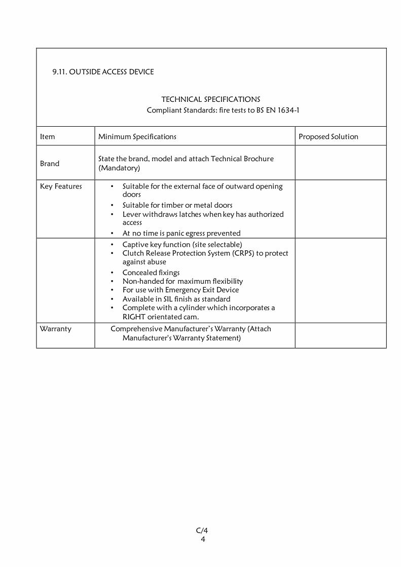
C/4
4
9.11. OUTSIDE ACCESS DEVICE
TECHNICAL SPECIFICATIONS
Compliant Standards: fire tests to BS EN 1634-1
Item Minimum Specifications Proposed Solution
Brand State the brand, model and attach Technical Brochure
(Mandatory)
Key Features • Suitable for the external face of outward opening
doors
• Suitable for timber or metal doors • Lever withdraws latches when key has authorized
access
• At no time is panic egress prevented
• Captive key function (site selectable) • Clutch Release Protection System (CRPS) to protect
against abuse
• Concealed fixings • Non-handed for maximum flexibility • For use with Emergency Exit Device • Available in SIL finish as standard • Complete with a cylinder which incorporates a
RIGHT orientated cam.
Warranty Comprehensive Manufacturer’s Warranty (Attach
Manufacturer's Warranty Statement)

C/4
5
10.00 BROCHURES AND TECHNICAL LITERATURE
Tenderers must enclose together with their submitted bids brochures detailing technical
Literature and specifications of the active components of the access control system. The
brochures shall be used to evaluate the suitability of these components.
Any bid submitted without the brochures shall be considered technically non-responsive, and
may subsequently be disqualified.

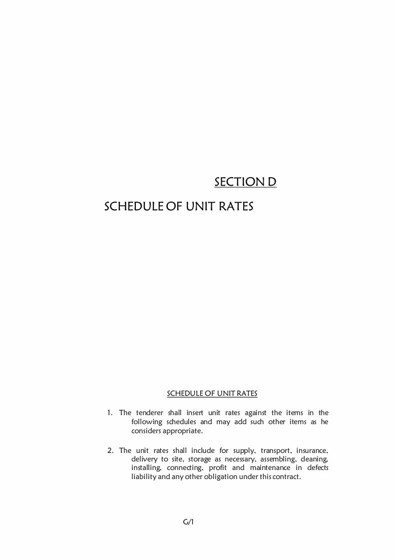
G/1
SECTION D
SCHEDULE OF UNIT RATES
SCHEDULE OF UNIT RATES
1. The tenderer shall insert unit rates against the items in the
following schedules and may add such other items as he
considers appropriate.
2. The unit rates shall include for supply, transport, insurance,
delivery to site, storage as necessary, assembling, cleaning,
installing, connecting, profit and maintenance in defects
liability and any other obligation under this contract.
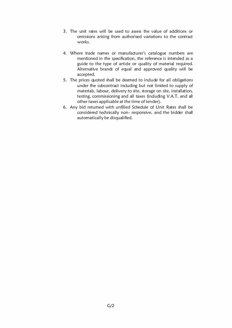
G/2
3. The unit rates will be used to assess the value of additions or
omissions arising from authorised variations to the contract
works.
4. Where trade names or manufacturer’s catalogue numbers are
mentioned in the specification, the reference is intended as a
guide to the type of article or quality of material required.
Alternative brands of equal and approved quality will be
accepted.
5. The prices quoted shall be deemed to include for all obligations
under the subcontract including but not limited to supply of
materials, labour, delivery to site, storage on site, installation,
testing, commissioning and all taxes (including V.A.T, and all
other taxes applicable at the time of tender). 6. Any bid returned with unfilled Schedule of Unit Rates shall be
considered technically non- responsive, and the bidder shall
automatically be disqualified.
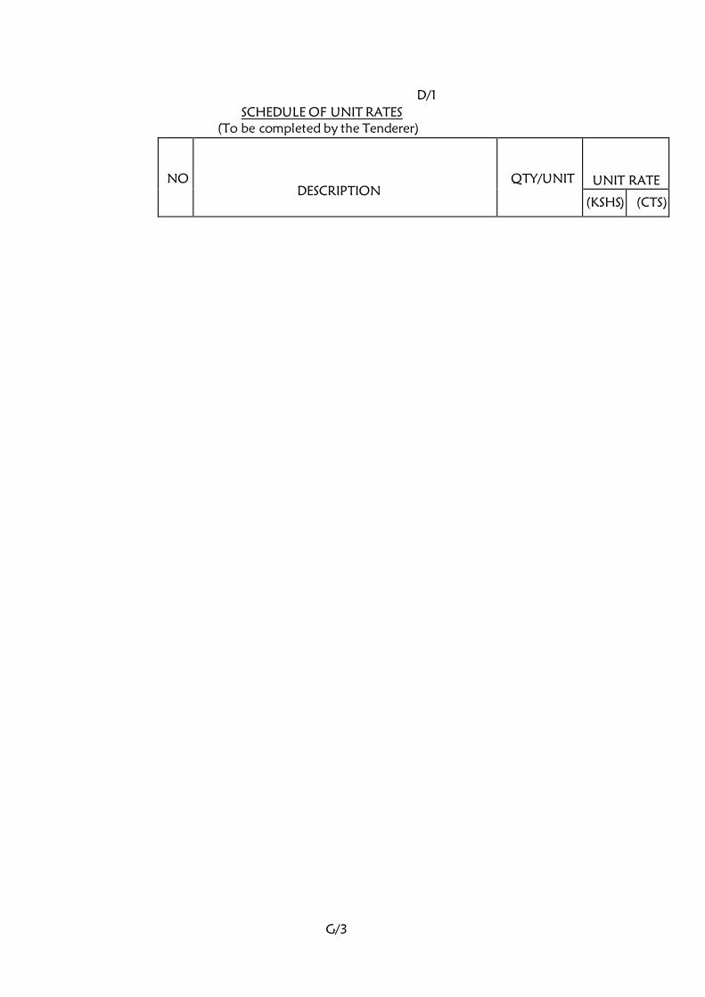
G/3
D/1
SCHEDULE OF UNIT RATES (To be completed by the Tenderer)
NO
DESCRIPTION
QTY/UNIT
UNIT RATE
(KSHS) (CTS)
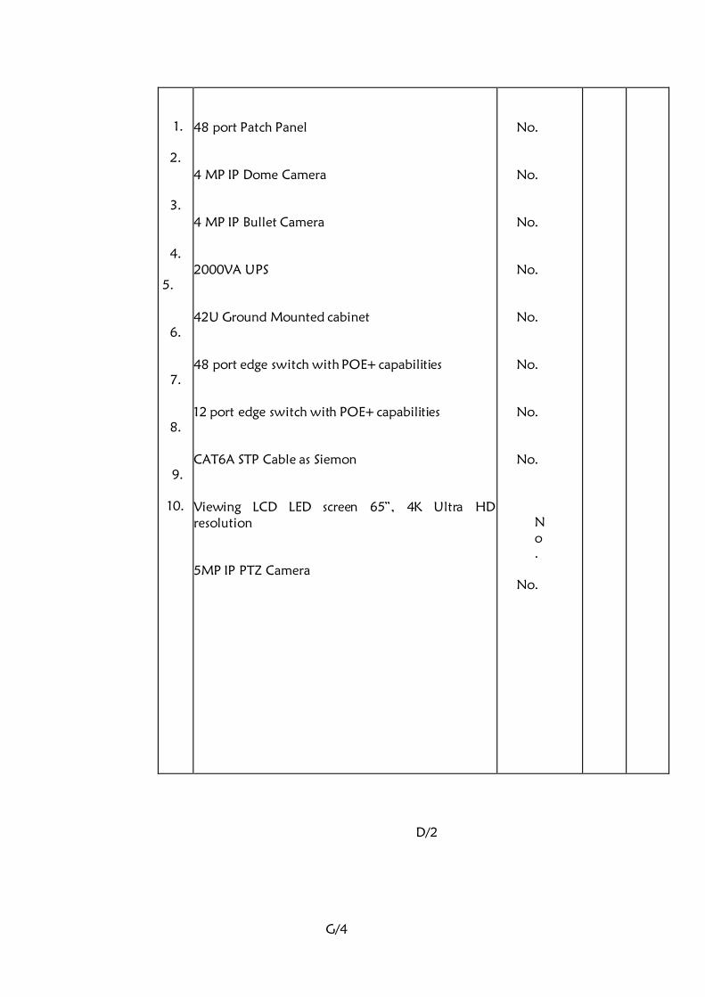
G/4
1.
2.
3.
4.
5.
6.
7.
8.
9.
10.
48 port Patch Panel
4 MP IP Dome Camera
4 MP IP Bullet Camera
2000VA UPS
42U Ground Mounted cabinet
48 port edge switch with POE+ capabilities
12 port edge switch with POE+ capabilities
CAT6A STP Cable as Siemon
Viewing LCD LED screen 65”, 4K Ultra HD
resolution
5MP IP PTZ Camera
No.
No.
No.
No.
No.
No.
No.
No.
N
o
.
No.
D/2

G/5
SECTION E
BILLS OF QUANTITIES

G/6
BILLS OF QUANTITIES
PRICING OF PRELIMINARIES ITEMS
Prices will be inserted against item of preliminaries in the Contractor’s
Bills of Quantities and specification. These Bills are designated as Bill
No.1 in this Section. Where the Contractor fails to insert his price in any
item he shall be deemed to have made adequate provision for this on
various items in the Bills of Quantities. The preliminaries form part of
this contract and together with other Bills of Quantities covers for the
costs involved in complying with all the requirements for the proper
execution of the whole of the works in the contract.
SPECIAL NOTES TO THE BILLS OF QUANTITES
1. The Bills of Quantities form part of the contract documents and are
to be read in conjunction with the contract drawings and general
specifications of materials and works.
2. The prices quoted shall be deemed to include for all obligations
under the sub-contract including but not limited to supply of
materials, labour, delivery to site, storage on site, installation,
testing, commissioning and all taxes (including VAT and all taxes
applicable at the time of tender.)
All prices omitted from any item, section or part of the Bills of
Quantities shall be deemed to have been included to another item,
section or part.
3. The brief descriptions of the items given in the Bills of Quantities are
for the purpose of establishing a standard to which the sub-
contractor shall adhere to. Otherwise alternative brands of equal
and approved quality will be accepted.
Should the sub-contractor install any material not specified here-in
before receiving approval from the Project Manager, the sub-
contractor shall remove the material in question and, at his own
cost, install the proper material.
4. The grand total of prices in the price summary page must be carried
forward to the Form of Tender.
5. Tenderers must enclose, together with their submitted tenders,
detailed coloured manufacturer’s Brochures detailing Technical
Literature and specifications on all the equipment they intend to
offer.
G/7
E/1
1. Statement of Compliance
a) I confirm compliance of all clauses of the General
Conditions, General Specifications and Particular
Specifications in this tender.
b) I confirm I have not made and will not make any
payment to any person, who can be perceived as an
inducement to win this tender.
Signed: …………………………………….for and on behalf of the
Tenderer
Date: ……………………..
Official Rubber Stamp:
……………………………………………………………
G/8
E/2
SECTION F
TECHNICAL SCHEDULE
OF
ITEMS TO BE SUPPLIED

G/9
TECHNICAL SCHEDULE
1. The technical schedule shall be submitted by tenderers to
facilitate and enable the Project Manager to evaluate the
tenders, especially where the tenderer intends to supply or
has based his tender sum on equipment which differs in
manufacture, type or performance from the specifications
indicated by the Project Manager.
2. The filling of this schedule forms part of Technical Evaluation of
the tenders, and bidders shall therefore be required to
indicate the type/make and country of origin of all the
materials and equipment they intend to offer to the
employer in this schedule.
3. This schedule shall form part of the technical evaluation criterion,
and tenderers are therefore advised to complete the schedule
as they shall be considered responsive.
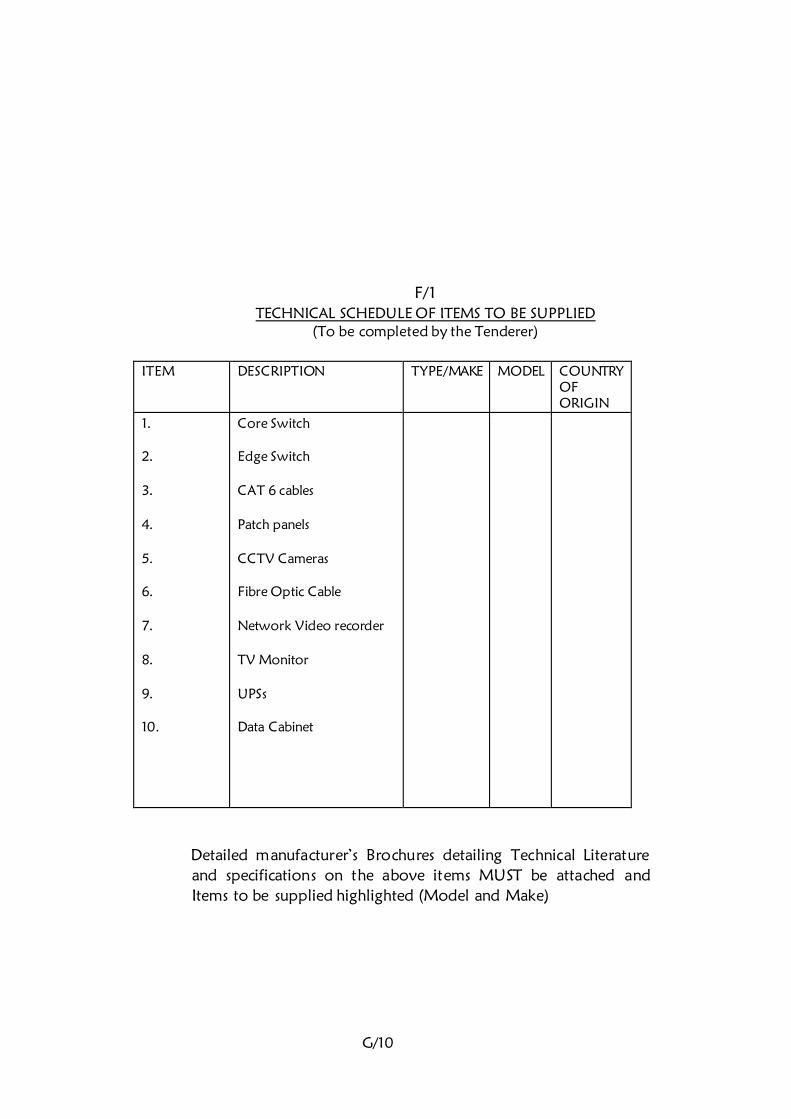
G/10
F/1
TECHNICAL SCHEDULE OF ITEMS TO BE SUPPLIED (To be completed by the Tenderer)
ITEM
DESCRIPTION TYPE/MAKE MODEL COUNTRY
OF
ORIGIN
1. 2. 3. 4. 5. 6. 7. 8. 9. 10.
Core Switch Edge Switch CAT 6 cables Patch panels CCTV Cameras Fibre Optic Cable Network Video recorder TV Monitor UPSs Data Cabinet
Detailed manufacturer’s Brochures detailing Technical Literature
and specifications on the above items MUST be attached and
Items to be supplied highlighted (Model and Make)
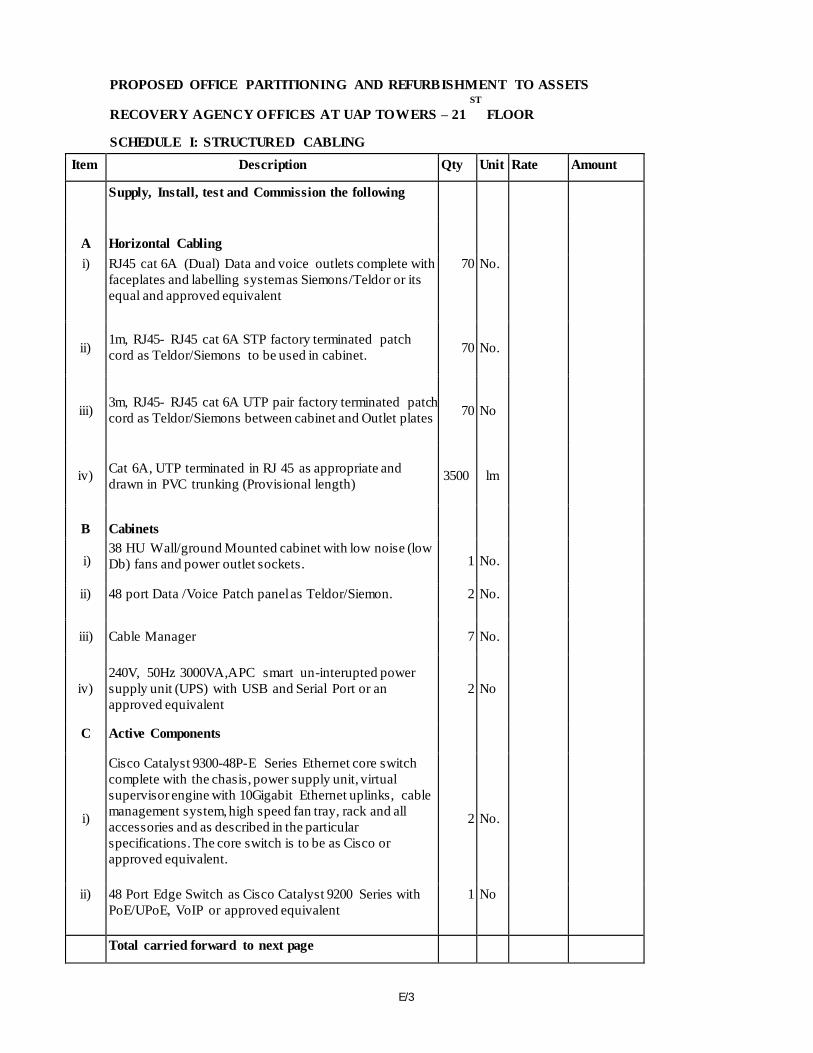
E/3
PROPOSED OFFICE PARTITIONING AND REFURBISHMENT TO ASSETS ST
RECOVERY AGENCY OFFICES AT UAP TOWERS – 21 FLOOR
SCHEDULE I: STRUCTURED CABLING
Item Description Qty Unit Rate Amount
Supply, Install, test and Commission the following
A Horizontal Cabling
i) RJ45 cat 6A (Dual) Data and voice outlets complete with
faceplates and labelling system as Siemons/Teldor or its
equal and approved equivalent
70 No. 850 59,500
ii) 1m, RJ45- RJ45 cat 6A STP factory terminated patch
cord as Teldor/Siemons to be used in cabinet. 70 No. 250 17,500
iii) 3m, RJ45- RJ45 cat 6A UTP pair factory terminated patch
cord as Teldor/Siemons between cabinet and Outlet plates 70 No 550 38,500
iv) Cat 6A, UTP terminated in RJ 45 as appropriate and
drawn in PVC trunking (Provisional length) 3500 lm 120 420,000
B Cabinets
i) 38 HU Wall/ground Mounted cabinet with low noise (low
Db) fans and power outlet sockets. 1 No. 75,000 75,000
ii) 48 port Data /Voice Patch panel as Teldor/Siemon. 2 No. 32,000 64,000
iii) Cable Manager 7 No. 3,500 24,500
iv) 240V, 50Hz 3000VA,APC smart un-interupted power
supply unit (UPS) with USB and Serial Port or an
approved equivalent 2 No 120,000 240,000
C Active Components
i)
Cisco Catalyst 9300-48P-E Series Ethernet core switch
complete with the chasis, power supply unit, virtual
supervisor engine with 10Gigabit Ethernet uplinks, cable
management system, high speed fan tray, rack and all
accessories and as described in the particular
specifications. The core switch is to be as Cisco or
approved equivalent.
2 No. 870,000 1,740,000
ii) 48 Port Edge Switch as Cisco Catalyst 9200 Series with PoE/UPoE, VoIP or approved equivalent
1 No 370,000 370,000
Total carried forward to next page 3,049,000
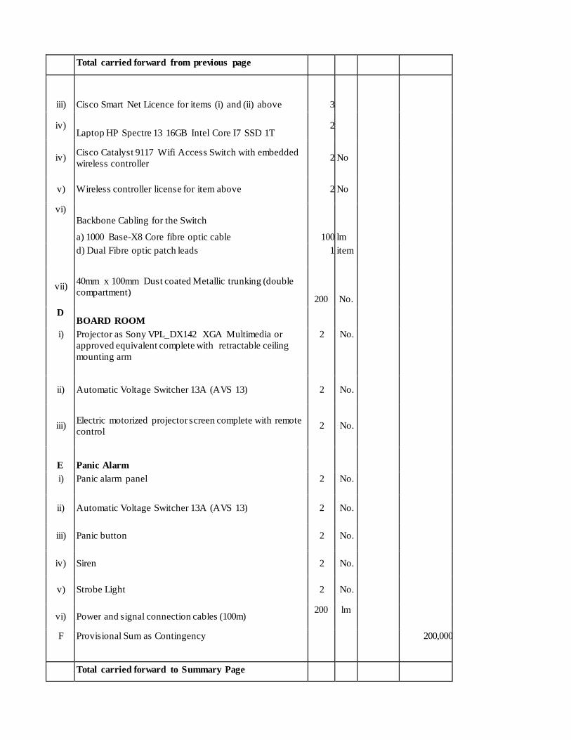
Total carried forward from previous page 3,049,000
iii) Cisco Smart Net Licence for items (i) and (ii) above 3
120,000 360,000
iv) Laptop HP Spectre 13 16GB Intel Core I7 SSD 1T
2
180,000 360,000
iv) Cisco Catalyst 9117 Wifi Access Switch with embedded
wireless controller 2 No 350,000 700,000
v) Wireless controller license for item above 2 No 120,000 240,000
vi) Backbone Cabling for the Switch
a) 1000 Base-X8 Core fibre optic cable 100 lm 80 8,000
d) Dual Fibre optic patch leads 1 item 2,200 2,200
vii) 40mm x 100mm Dust coated Metallic trunking (double
compartment) 200 No. 1,900
380,000
D BOARD ROOM
i) Projector as Sony VPL_DX142 XGA Multimedia or
approved equivalent complete with retractable ceiling
mounting arm
2 No. 75,000 150,000
ii) Automatic Voltage Switcher 13A (AVS 13) 2 No. 7,600 15,200
iii) Electric motorized projector screen complete with remote
control 2 No. 25,000 50,000
E Panic Alarm
i) Panic alarm panel 2 No. 25,000 50,000
ii) Automatic Voltage Switcher 13A (AVS 13) 2 No. 7,600 15,200
iii) Panic button 2 No. 5,500 11,000
iv) Siren 2 No. 5,500 11,000
v) Strobe Light 2 No. 5,500 11,000
vi) Power and signal connection cables (100m) 200 lm
750 150,000
F Provisional Sum as Contingency 200,000
Total carried forward to Summary Page 1,293,600
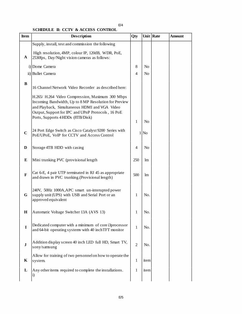
E/5
E/4 SCHEDULE II: CCTV & ACCESS CONTROL
Item Description Qty Unit Rate Amount
Supply, install, test and commission the following
A High resolution, 4MP, colour IP, 120dB, WDR, PoE,
2530fps, Day/Night vision cameras as follows:
i) Dome Camera 8 No 43,000 344,000
ii) Bullet Camera 4 No 43,000 172,000
B 16 Channel Network Video Recorder as described here:
H.265/ H.264 Video Compression, Maximum 300 Mbps
Incoming Bandwidth, Up to 8 MP Resolution for Preview
and Playback, Simultaneous HDMI and VGA Video
Output, Support for IPC and UPnP Protocols , 16 PoE Ports, Supports 4 HDDs (8TB/Disk)
1 No 85,000 85,000
C 24 Port Edge Switch as Cisco Catalyst 9200 Series with PoE/UPoE, VoIP for CCTV and Access Control 1 No 350,000 350,000
D Storage 4TB HDD with casing 4 No 27,000 108,000
E Mini trunking PVC (provisional length 250 lm 350 87,500
F Cat 6-E, 4 pair UTP terminated in RJ 45 as appropriate
and drawn in PVC trunking.(Provisional length) 500 lm 120 60,000
G 240V, 50Hz 1000A,APC smart un-interupted power
supply unit (UPS) with USB and Serial Port or an
approved equivalent 1 No. 54,000 54,000
H Automatic Voltage Switcher 13A (AVS 13) 1 No. 7,600 7,600
I Dedicated computer with a minimum of core i3processor
and 64-bit operating systemv with 40 inchTFT monitor 1 No. 123,000 123,000
J Addition display screen 40 inch LED full HD, Smart TV,
sony/samsung 2 No. 57,000 114,000
K Allow for training of two personnel on how to operate the
system. 1 item 10,000 10,000
L Any other items required to complete the installations.
i) 1 item 50000 50,000
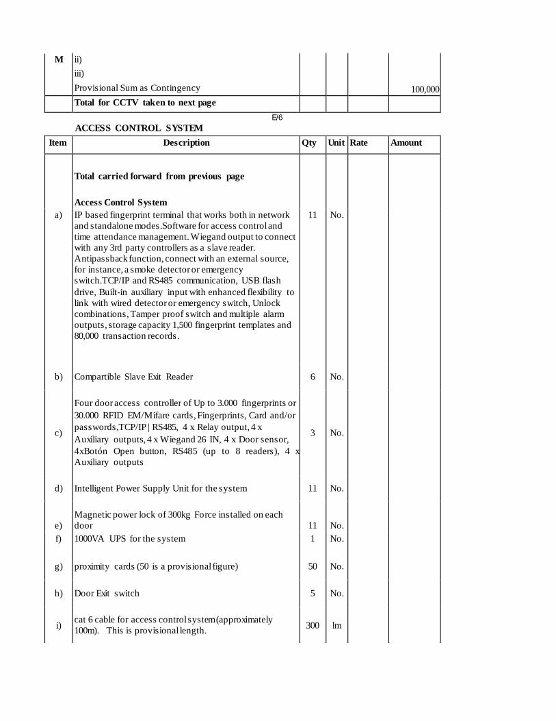
M ii)
iii)
Provisional Sum as Contingency
100,000
Total for CCTV taken to next page 1,665,100
E/6 ACCESS CONTROL SYSTEM
Item Description Qty Unit Rate Amount
Total carried forward from previous page
Access Control System
1,665,100
a) IP based fingerprint terminal that works both in network
and standalone modes.Software for access control and
time attendance management. Wiegand output to connect
with any 3rd party controllers as a slave reader.
Antipassback function, connect with an external source,
for instance, a smoke detector or emergency
switch.TCP/IP and RS485 communication, USB flash
drive, Built-in auxiliary input with enhanced flexibility to
link with wired detector or emergency switch, Unlock
combinations, Tamper proof switch and multiple alarm
outputs, storage capacity 1,500 fingerprint templates and
80,000 transaction records.
11 No. 26,500 291,500
b) Compartible Slave Exit Reader 6 No. 26,500 159,000
c)
Four door access controller of Up to 3.000 fingerprints or
30.000 RFID EM/Mifare cards, Fingerprints, Card and/or
passwords,TCP/IP | RS485, 4 x Relay output, 4 x
Auxiliary outputs, 4 x Wiegand 26 IN, 4 x Door sensor, 4xBotón Open button, RS485 (up to 8 readers), 4 x
Auxiliary outputs
3 No. 89,000 267,000
d) Intelligent Power Supply Unit for the system 11 No. 14,000 154,000
e) Magnetic power lock of 300kg Force installed on each
door 11 No. 22,000
242,000
f) 1000VA UPS for the system 1 No. 70,000 70,000
g) proximity cards (50 is a provisional figure) 50 No. 500 25,000
h) Door Exit switch 5 No. 2,800 14,000
i) cat 6 cable for access control system (approximately
100m). This is provisional length. 300 lm 75
22,500

E/7
j) Alarm cable (approximately 100m). This is a provisional
length. 200 lm 55 11,000
k) Power point wired in 3.0 x 2.5sqmm. SC PVC Cu cables
in 40 by 25 mm metalic mini trunking (provisional length) 300 lm 145 43,500
Total carried forward to next page 2,964,600
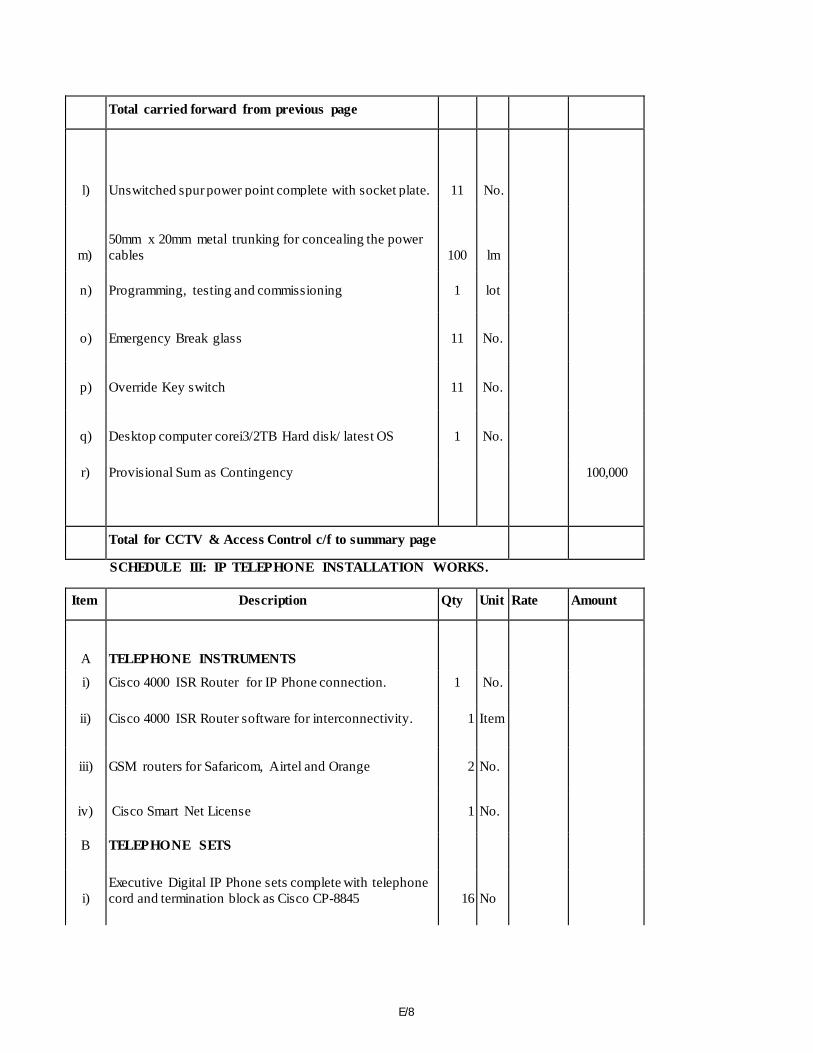
E/8
Total carried forward from previous page 2,964,600
l) Unswitched spur power point complete with socket plate. 11 No. 950
10,450
m) 50mm x 20mm metal trunking for concealing the power
cables 100 lm 125
12,500
n) Programming, testing and commissioning 1 lot 10,000 10,000
o) Emergency Break glass 11 No. 4,800 52,800
p) Override Key switch 11 No. 4,800 52,800
q) Desktop computer corei3/2TB Hard disk/ latest OS 1 No. 170,000 170,000
r) Provisional Sum as Contingency 100,000
Total for CCTV & Access Control c/f to summary page 3,373,150
SCHEDULE III: IP TELEPHONE INSTALLATION WORKS.
Item Description Qty Unit Rate Amount
A TELEPHONE INSTRUMENTS
i) Cisco 4000 ISR Router for IP Phone connection. 1 No. 550,000 550,000
ii) Cisco 4000 ISR Router software for interconnectivity. 1 Item 250,000 250,000
iii) GSM routers for Safaricom, Airtel and Orange 2 No. 8,500 17,000
iv) Cisco Smart Net License 1 No. 120,000 120,000
B TELEPHONE SETS
i) Executive Digital IP Phone sets complete with telephone
cord and termination block as Cisco CP-8845 16 No 73,500 1,176,000
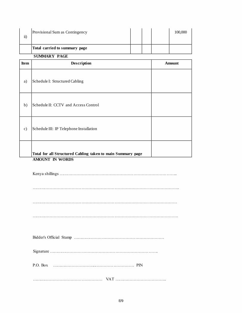
E/9
ii) Provisional Sum as Contingency 100,000
Total carried to summary page 2,213,000
SUMMARY PAGE
Item Description Amount
a) Schedule I: Structured Cabling 1,293,600.00
b) Schedule II: CCTV and Access Control 3,373,150.00
c) Schedule III: IP Telephone Installation 2,213,000.00
Total for all Structured Cabling taken to main Summary page 6,879,750.00
AMOUNT IN WORDS
Kenya shillings …………………………………………………………………………..
……………………………………………………………………………………………..
……………………………………………………………………………………………
…………………………………………………………………………………………….
Bidder's Official Stamp …………………………………………………………
Signature …………………………………………………………………….
P.O. Box …………………………...……………………… PIN
…………………………………………… VAT ………………………………..

E/10
Witness ………………………………………….Address ………………………….
Signature ……………………………………….. Date ……………………………….