technology for cleaning of molten steel in tundish - j-stage
TRANSCRIPT
ISIJ International, Vol. 34 (1 994), No. 11, pp. 868-875
Technology for Cleaning of Molten Steel in Tundish
Hiroyuki TANAKA.Ryoji NISHIHARA.Ryusuke MIURA.1) Ryoji TSUJINO.Takeshi KIMURA.1)Takashi NISH11)and Tatuo IMOTO1)
YawataR&DLaboratories, Nippon Steel Corporation, Tobihata, Tobata-ku, Kitakyushu. Fukuoka-ken, 804 Japan.1)YawataWorks, Nippon Steel Corporation. Tobihata. Tobata-ku. Kitakyushu, Fukuoka-ken. 804 Japan.
(Received on June 30. l994 accepted in final form on September l6. 1994)
Sheet and coated steel have been demandedto meet quality requirements of ever increasing severity in
recent years. Reduction in nonmetallic inclusions is an important challenge in this respect.Protection on the moiten steel in the tundish against contamination is of special importance in not only
improving steel product quality, but also avoiding immersion nozzle clogging and increasing the numberof sequence-cast heats. To supply molten stee] with high cleanliness in a stable manner, the cleaningbehavior of the molten steel in the tundish was investigated and mechanismwhereby the molten steel is
kept clean in the tundish wasquantified. Basedon the results achieved, technology wasstudied for keepingthe molten steel clean in the tundish.
KEYWORDS:continuous casting; steelmaking; casting; inclusion; clean steel; air oxidation.
1. Introduction
Ensuring the cleanliness of molten steel in the tundishis very important in not only producing clean steel
products, but also preventing immersion nozzle blockage.The tundish has the functions of distributing the moltensteel to multiple strands and cleaning the molten steel
by facilitating the flotation and removal of nonmetallicinclusions.1 ~4) The tundish is also knownto cause thecontamination of the molten steel, however.5~9)Technology for improving the fiotation and removal ofinclusions in the tundishl0-13) and technology forpreventing the contamination of molten steel in thetundishl4-21) have been traditionally studied as pre-requisites for the manufacture of clean steel products.
To produce clean steel stably by making the most of theinclusion fiotation and removal function of the tundish,it is essential identify factors responsible in combinationfor the contamination of the molten steel in the tundish,to determine the contribution of the specific factors, andto take appropriate measures for preventing the con-tamination of the molten steel in the tundish.
This study investigated inclusions in the molten steel
in the tundish of an actual continuous caster andclarified
the causes of contamination of molten steel in the tun-dish. Based on the findings thus obtained, technologyfor preventing the air oxidation of molten steel andtechnology for using harmless ladle well-packing strands
were investigated for their effectiveness in cleaning themolten steel in the tundish.
2. Results of Analysis of Behavior of Inclusions in
Tundish
Three heats of aluminum-killed steel with analuminum
C 1994 ISIJ 868
content of about 0.05 o/o were cast on No. I continuouscasting machine(with two strands and a 60-ton tundish)at No. 3steelmaking plant. YawataWorks, Nippon Steel
Corporation. Samplesof molten steel in the tlmdish weretaken with a rapid cooling sampler at the long nozzleposition (tundish inlet) and the immersion nozzle position(tundish outlet). The samples were examinedby opticalmicroscopy to count 10 ,lm or larger inclusions by shape(cluster, Iump or globular) and size. The compositionsof the inclusions were investigated by 'an electron-probemicroanalyzer (EPMA). '
Before casting the first test heat, the sliding nozzle ofthe ladle was opened above a slag pot outside of thetundish and the ladle well-packing sand wasdischargedoutside of the tundish. At the end of the first heat, about20 tons of molten steel was left in the ladle to preventthe carryover of the ladle slag into the tundish by theladle-to-tundish pouring stream. The second and thirdheats were sequencecast as normally done.
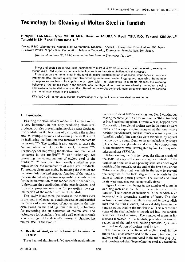
Figure I shows the change in the numberof aluminaand slag inclusions counted in the molten steel in thetundish. The numberof inclusions in the tundish inlet
increased with increasing number of heats. The slaginclusion count almost similarly changed in the tundishinlet and the tundish outlet, but wasslightly lower in thetundish outlet than in the tundish inlet. This meansthat
someof the slag inclusions introduced into the tundish
were floated and removed. The numberof alumina in-
clusions increased in the tundish, probably because ofreduction of the ladle well-packing material by alumi-
numand oxidation of molten steel by air.
The theoretical cleanliness of molten steel in thetundish outlet as determined on the assumption that themolten steel is not contaminated in the tundish [Eq. (1)]
andthe observedcleanliness of molten steel as determined
ISIJ International, Vol. 34 (1 994), No. 11
c!)
~~~:;~",
* *D ~*1'*
'e.~.S~~ 12 tlst, heat 2ntL heat~~lO t '
th ,~
s~o~ 8 ~\ ' \ 1'~~(\~;~ 6o- V'~S,oF:*,
4~~~~~ 2o~p~~ Oo
40 80
Time
Fig.
3r~L heat~,
,~/ \•*~4f
120 160 200 O 40 80
(min) Time (min)l. Changein inclusion density (> lOum) in tundish.
~lh+e 5~o_,e ~~*oQ "4\1
~,d
\J3~c,)
Ist. hea,t 2n(L heat,t 3r(L heat
,a t
lI lI
O_C;+' .~ 2 ~ I
Lcec,,
~~l ,IFt
oF::A~'- O ~o 120 160 200
(xl0-6)25
20
I~. 15
~'~1
"' lO~
5
o
!Ist. heat r: 2nd,heatl Observed value+,~\~~\\ /_:F~kl
.L
h:k~+*L
t la
+ '
+\~l~il t~i
+ 3*d' h**t,,+Jj+'~~~:~~" ~~l'~""ti"I
~~!{~:N~~~~\~+
+_
'(l+~':\+:\~F
~ +~~\
O 80 120 160 20040
Time (min)Fig. 2. Experimental analysis of steel cleanliness in tundish
during the casting.
~~v~O~:!
~f:j
O,e~~
~ee
*~O
100
80
60
40
20
o
Ist'heat 2nd'heat} t, 3rd' heat ~Air oxidation
i : """"'\'~"
l;::;f\lT~'lA11f
SlagCOntamI nat lon
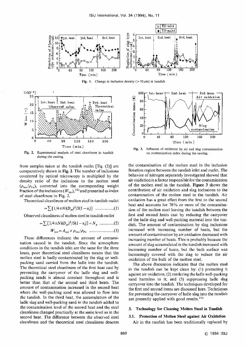
from samples taken at the tundish outlet [Eq. (2)] arecomparatively shownin Fig. 2. Thenumberof inclusions
countered by optical microscopy is multiplied by thedensity ratio of the inclusions to the molten steel
(pi*c/pFe)' converted into the corresponding weightfraction of the inclusions (Wi..), 22) andpresented as indexof steel cleanliness in Fig. 2.
Theoretical cleanliness of molten steel in tundish outlet
=~[1/4l~Ni(Dpi)2/S(1-
oci)] ..,..............(1)
Observedcleanliness of molten steel in tundish outlet
=~[1/4 ILNi(Dpi)2/S(1-
oci)] +Np .............(2)
Wi*.=A~**xp. /p ..........(3)
These differences indicate the amount of contami-nation caused in the tundish. Since the atmosphereconditions in the tundish inlet are the samefor the threeheats, poor theoretical steel cleanliness meansthat the
molten steel is badly contaminated by the slag or well-
packing sand carried from the ladle into the tundish.
The theoretical steel cleanliness of the first heat cast bypreventing the carryover of the ladle slag and well-
packing sands is almost constant throughout and is
better than that of the second and third heats. Theamountof contamination increased in the second heatwhere the well-packing sand was allowed to flow into
the tundish. In the third heat, the accumulation of theladle slag and well-packing sand in the tundish addedtothe contarnination level of the second heat and the steel
cleanliness changedpractically at the samelevel as in thesecond heat. The difference between the observed steel
cleanliness and the theoretical steel cleanliness denotes
O 40 80 120 160 200
Time (min )Fig. 3. Influence of oxidation by air and slag contamination
on contamination index during the casting.
the contamination of the molten steel. in the inclusionflotation region betweenthe tundish inlet andoutlet. Thebehavior of nitrogen separately investigated showedthatair oxidation is a factor responsible for the contaminationof the molten steel in the tundish. Figure 3shows the
contributio~ of air oxidation and slag inclusions to the
contamination of the molten steel in the tundish. Airoxidation has a great effect from the first to the secondheat and accounts for 70 o/o or moreof the contamina-tion of the molten steel leaving the tundish between thefirst and second heats cast by reducing the carryoverof the ladle slag and well-packing material into the tun-dish. The amountof contamination by slag inclusions
increased with increasing nuinber of heats, but the
amountof contamination by air oxidation decreasedwithincreasing numberof heats. This is probably becausethe
amountof slag accumulated in the tundish increased withincreasing numberof heats, but the bath surface wasincreasingly covered with the slag to reduce the air
oxidation of the bulk of the molten steel.
The above discussion indicates that the molten steel
in the tundish can be kept clean by: (1) protecting it
against air oxidation; (2) rendering the ladle well-packingsand harmless to it; and (3) suppressing ladle slag
carryover into the tundish. Thetechniques developed for
the first and second items are discussed here. Techniquesfor preventing the carryover of ladle slag into the tundish
are presently applied with good results.23)
3. Technology for Cleaning Molten Steel in Tundish
3.1. Protection of Molten Steel against Air Oxidation
Air in the tundish has been traditionally replaced by
869 C 1994 ISIJ
ISIJ International, Vol.
Table l. Composition offluxes used for sealing molten steel
surface.
Flux
2345
Composition ("/o)
50Ca0-50Al20347.5Ca0~~7.5Al203-5Si0245CaO~}5Al203-10Si0240Ca0~~OAl203-20Si02100MgO(conventional heat insulating material)
argon to protect the molten steel in the tundish againstair oxidation. This technique has not been perfect dueto the difficulty of completely shrouding the tundish anddistortion of the tundish cover. The results discussed in
the preceding chapter indicate that the air oxidation ofthe molten steel can be increasingly prevented by in-
creasing the amount of slag accumulated on the bathsurface in the tundish. Covering the bath surface with alow-melting fusible fiux was investigated as one methodfor protecting the molten steel in the tundish against air
oxidation.
3.1.1. Methodsof Laboratory ExperimentThe optimum composition of fiux to seal the bath
surface in the tundish was studied by laboratoryexperiment, Using a 100-kg high frequency meltingfurnace, 70kg of steel was melted and adjusted toaluminum-killed steel composition (0.038 o/o C, 0.012 o/o
Si, 0.18 o/o Mn, and 0.042 o/o Al) with the mouthof thefurnace sealed with argon. Then, 2.5 kg of fiux wasaddedto the bath surface, the argon seal was stopped, andaluminum was added to achieve the aim aluminumcontent of about 0.05 o/o. Themolten steel wassampledfor 16min at 2-min intervals and analyzed. The com-positions of fluxes used in the laboratory experimentare given in Table I .
First, the bath surface wascoveredwith each flux to investigate its effect in protecting themolten steel against air oxidation. Second, to investigatethe effect on moiten steel oxidation of silica (Si02) withsmaller affinity for oxygen than aluminumhas, the silica
content of each flux waschanged. Third, a conventional98 o/o MgOmaterial was used to thermally insulate the
molten steel in the tundish.
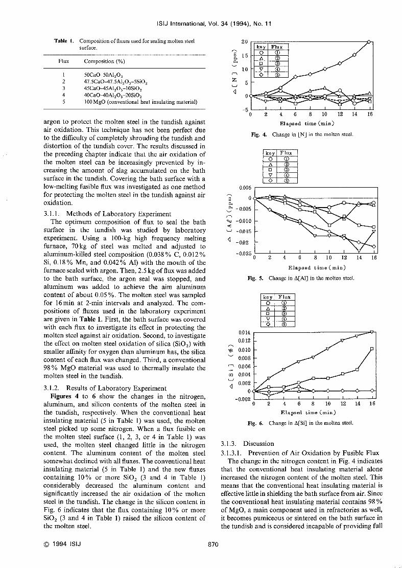
3. I .2. Results of Laboratory ExperimentFigures 4 to 6 show the changes in the nitrogen,
aluminum, and silicon contents of the molten steel in
the tundish, respectively. Whenthe conventional heatinsulating material (5 in Table l) wasused, the moltensteel picked up somenitrogen. Whena flux fusible onthe molten steel surface (1, 2, 3, or 4 in Table l) wasused, the molten steel changed little in the nitrogencontent. The aluminum content of the molten steel
somewhatdeclined with all fluxes. Theconventional heatinsulating, material (5 in Table l) and the new fluxes
containing 100/0 or more Si02 (3 and 4 in Table l)
considerably decreased the aluminum content andsignificantly increased the air oxidation of the moltensteel in the tundish. Thechange in the silicon content in
Fig. 6 indicates that the flux containing 100/0 or moreSi02 (3 and 4 in Table l) raised the silicon content ofthe molten steel.
C 1994 ISIJ 870
34 (1994), No.
~O'~
r~~~
LJ~
~~:+
~r~c~,
~l
~
~~~
nCQ
LJ~
20
15
lO
5
O
-5
11
key FluxO lA 2D 3V 4
5
"v" :•
O 2 4 6 8 10 12 14 16
Elapsed time (min)
Fig. 4. Changein [N] in the molten steel,
o.oo 5
- O005
-0.010
-OO15
- OD2-0.025
key FIux
o lA 2O 3v 4~ 5
5o5
o5
o
Fig. 5.
On14
0.0 12
0.010
O.008
O~06O~04
0.002
O-0.002
o
Fig.
2 6 8 10 12 14 164Elapsed time (min)
Changein A[Al] in the molten steel.
key FluxOACl
V~ 5
.~~.
2 4 6 8 10 12 14 16Elapsed time (min)
6. Changein A[Si] in the molten steel.
3.1.3. Discussion3,1.3.1. Prevention of Air Oxidation by Fusible Flux
Thechangein the nitrogen content in Fig. 4indicates
that the conventional heat insulating material aloneincreased the nitrogen content of the molten steel. This
meansthat the conventional heat insulating material is
effective little in shielding the bath surface from air. Sincethe conventional heat insulating material contains 98 olo
of MgO,a main componentused in refractories as well,
it becomespumiceousor sintered on the bath surface in
the tundish and is considered incapable of providing full
ISIJ International, Vol.
protection against air infiltration.
The nitrogen pickup can be stably prevented bycovering the bath surface with a flux fusible at the
temperature of the molten steel. A Iiquid flux layer
formed between the molten steel and the outside air is
believed to reduce the speed at which the oxygen in theair enters the molten steel.
3.1.3.2. Effect of Si02 on Oxidation of Molten Steel
According to the change in the aluminum contentshownin Fig. 5, the air oxidation of the molten steel canbe controlled by a fusible fiux, but the aluminumcontentof the molten steel is reduced if the flux contains 10'/~
or more Si02 (3 and 4 in Table 1). The change in thesilicon content in Fig. 6indicates that whenit containslO "/• or moreSi02, the flux raises 'the silicon content ofthe molten steel. According to these results, a fusible fiux
can protect the molten steel against air oxidation, butwhen it contains Si02 and other oxides with smalleraffinity for oxygenthan the aluminumin the molten steel,
the Si02 in the flux reacts with the aluminum in the
molten steel to oxidize the molten steel. The flux doesnot cause the oxidation of the molten steel whenits Si02contents is up to 5o/o (2 in Table 1). Whenthe fiux
contains lO'/, or more Si02 (3 and 4 in Table l), the
oxidation of the molten steel increases with increasing
Si02 content. The probable reason for this situation is
the difference in the rate of reaction due to the difference
in the activity of Si02' The above results indicate that
the air oxidation of the molten steel and the secondaryoxidation of the molten steel by the flux can be preventedby using such a flux that is fusible at the temperature ofthe molten steel and contains no or negligible amountsof componentshaving smaller affinity for oxygen than
Weir
LadIen07,zle
Lad I e
mlet
Sampling position
oc\]
Dam
outlet
950nwn
SubmergednozzIe
Frg. 7. Schematicdrawing ofYawataWorksNo. I slab castertundish.
l~~~~fLOU~I
10
864
2O
type
34 (1 994). No. 11
the aluminum in the molten steel does.
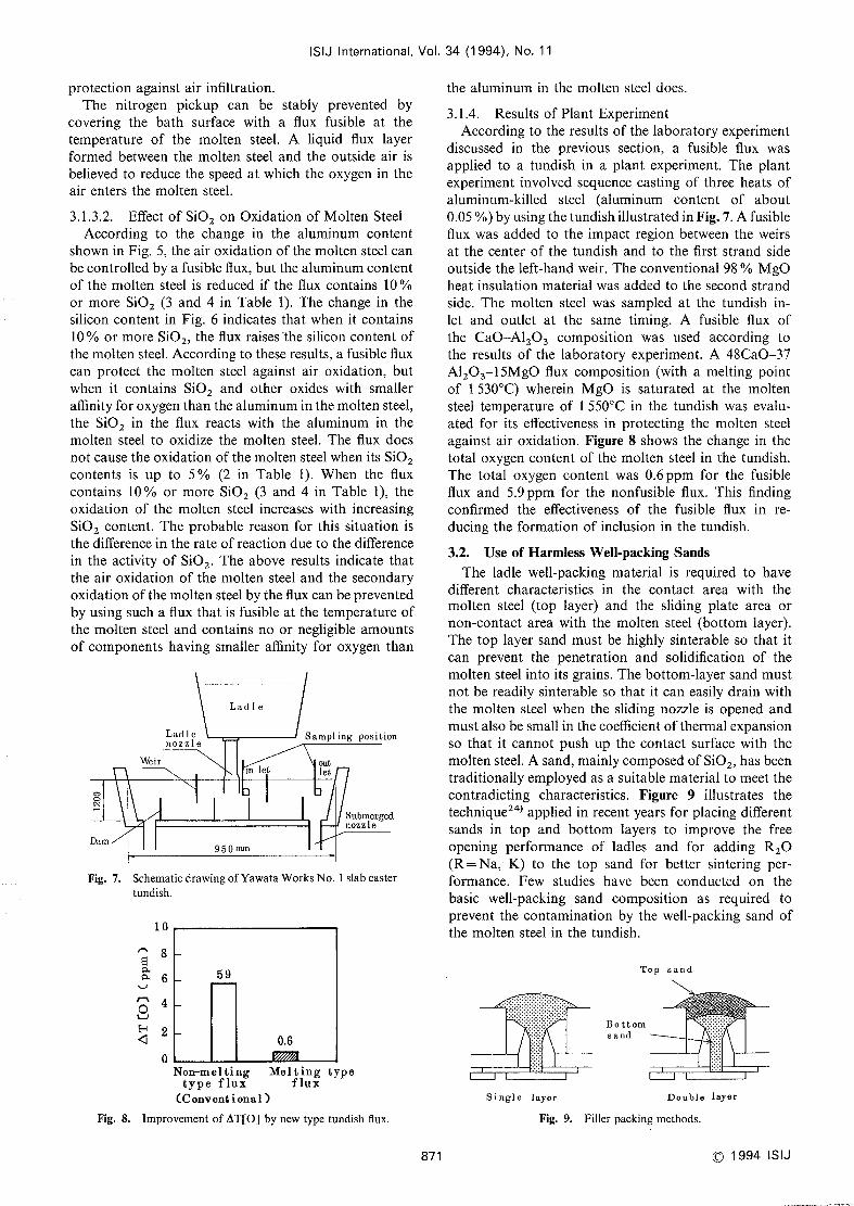
3.1.4. Results of Plant ExperimentAccording to the results of the laboratory experiment
discussed in the previous section, a fusible flux wasapplied to a tundish in a plant experiment. The plantexperiment involved sequencecasting of three heats ofaluminum-killed steel (aluminum content of about0.05 o/o) by using the tundish illustrated in Fig. 7. Afusible
flux was added to the impact region between the weirs
at the center of the tundish and to the first strand side
outside the left-hand weir. Theconventional 98 olo MgOheat insulation material wasadded to the second strandside. The molten steel was sampled at the tundish in-
let and outlet at the same timing. A fusible fiux ofthe CaO-Al203 composition was used according tothe results of the laboratory experirnent. A 48Ca0-37Al203-15MgOflux composition (with a melting pointof 1530'C) wherein MgOis saturated at the moltensteel temperature of 1550'C in the tundish was evalu-
ated for its effectiveness in protecting the molten steel
against air oxidation. Figure 8shows the change in thetotal oxygen content of the molten steel in the tundish.
The total oxygen content was 0.6ppm for the fusible
flux and 5.9ppm for the nonfusible fiux. This finding
confirmed the effectiveness of the fusible flux in re-
ducing the formation of inclusion in the tundish.
3.2. Useof Harmless Well-packing Sands
The ladle well-packing material is required to havedifferent characteristics in the contact area with themolten steel (top layer) and the sliding plate area ornon-contact area with the molten steel (bottom layer).
The top layer sand must be highly sinterable so that it
can prevent the penetration and solidification of the
molten steel into its grains. Thebottom-1ayer sand mustnot be readily sinterable so that it can easily drain withthe molten steel whenthe sliding nozzle is openedandmustalso be small in the coefficient of thermal expansion
so that it cannot push up the contact surface with the
molten steel. Asand, mainly composedof Si02, has beentraditionally employedas a suitable material to meet thecontradicting characteristics. Figure 9 illustrates thetechnique24) applied in recent years for placing different
sands in top and bottom layers to improve the free
opening performance of ladles and for adding R20(R=Na, K) to the top sand for better sintering per-formance. Few studies have been conducted on thebasic well-packing sand composition as required to
prevent the contamination by the well-packing sand ofthe molten steel in the tundish.
Top sand
Bottoms a nd
Fig. 8. Improvementof AT[O] by newtype tundish flux.
871
Single layer Double layer
Fig. 9. Filler packing methods.
C 1994 ISIJ
ISIJ International, Vol. 34 (1994), No. 11
Nozzle filler Table 3. Chemical composition and grain size ofthe nozzlefiller.
SampleNo. I 2 3 4 5
Material Lowpure Pure MgO Spinel A1203Si02 Si02
TChemical composition (olo)
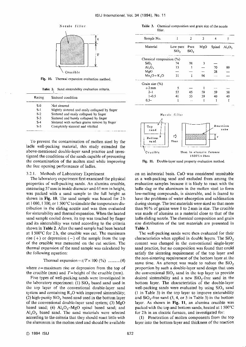
Cruc ib IeFig. 10. Thermai expansion evaluation method.
Si02 74Al203 13
MgOMa20+K20 11
98 370 9928
l 96
Table 2. Sandsinterability evaluation criteria.
Rating Sintered condition
Grain size (o/o)
+2mm21l~).5
0.5-
55341
l
l45 59 59 5055 39 40 49
l I lS-OS- lS-2S-3
S-4S-5
Not sintered
Slightly sintered and easily coiiapsed by finger
Sintered and easily collapsed by finger
Sintered and barely collapsed by finger
Sintered with surface grains removeby finger
Completely sintered and vitrified
To prevent the contamination of molten steel by theladle well-packing material, this study extended theabove-mentioned double-layer sand practice and inves-tigated the conditions of the sands capable of preventingthe contamination of the molten steel while improvingthe free opening performance of ladles.
3.2.1. Methodsof Laboratory ExperimentThe laboratory experiment first examinedthe physical
properties of well-packing sands. Analumina crucible,
measuring57mmin inside diameter and65mmin height,
was packed with a sand sample to the full height asshownin Fig. 10. The sand sample was heated for 2hat I OOO,1300, or 1500'C to simulate the temperature dis-
tribution in the sliding nozzle and was then evaluatedfor sinterability and thermal expansion. Whenthe heatedsand samplecooled down, its top was touched by finger
and its sinterability was rated according to the criteria
shownin Table 2. After the sand samplehadbeenheatedat 1500'C for 2h, the crucible was cut. The maximumrise (+) or depression (-) of the sanrple from the topof the crucible was measuredon the cut section. Thethermal expansion of the sand samplewascalculated bythe following equation:
Thermal expansion = t/Tx 100 (o/o) ...........(4)
where t=maximumrise or depression from the top ofthe crucible (mm)and T=height of the crucible (mm).
Five types of well-packing sands were investigated in
the laboratory experiment: (1) Si02 based sand used in
the top layer of the conventional double-1ayer sandsystem and containing R20with improved sinterability;
(2) high-purity Si02 basedsand used in the bottom layerof the conventional double-1ayer sand system; (3) MgObased sand; (4) Al203-MgOspinel based sand; andA1203 based sand. The sand materials were selected
according to the criteria that they should react little withthe aluminumin the molten steel and should be available
Nozzlc filler
C~>
Heat
Reactionzone
r
Crucible Heat in electric furnace15001Cx2hrs
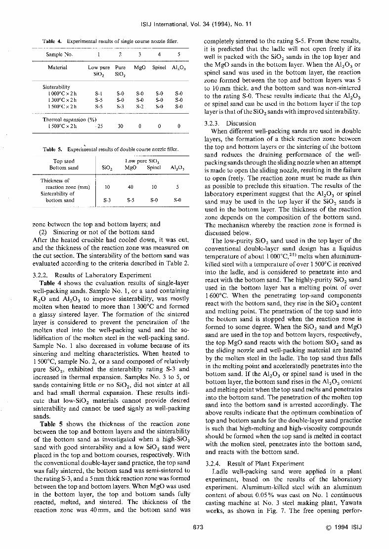
Fig. Il. Double-layer sand property evaluation method.
on an industrial basi.s. CaOwas considered unsuitable
as a well-packing sand and excluded from amongthe
evaluation samples because it is likely to react with theladle slag or the aluminum in the molten steel to formlow-melting compounds,is sinterable, and is feared tohave the problems of water absorption and sublimationduring storage. Thetest materials weresized so that morethan 90 "/o of grains were I to 2mmin size. Thecrucible
wasmadeof alumina as a material close to that of theladle sliding nozzle. Thechemical composition and grainsize distribution of the test materials are presented in
Table 3.
The well-packing sands were then evaluated for their
characteristics whenapplied in double layers. The Si02content was changed in the conventional single-1ayer
sand practice, but no composition wasfound that couldsatisfy the sintering requirement of the top layer andthe non-sintering requirement of the bottom layer at the
sametime. An attempt was madeto reduce the Si02proportion by such a double-layer sand design that usesthe conventional Si02 sand in the top layer to providedesired sinterability and a new Si02-free sand in the
bottom layer. The characteristics of the double-1ayerwell-packing sands were evaluated by using Si02 sand(1 in Table 3) in the top layer to improve sinterability
and Si02-free sand (3, 4, or 5in Table 3) in the bottomlayer. As shown in Fig. 11, an alumina crucible waspackedwith the top andbottom sands, heated at 1500'Cfor 2h in an electric furnace, and investigated for:
(1) Penetration of molten componentsfrom the toplayer into the bottom layer and thickness of the reaction
C 1994 ISIJ 872
ISIJ International, Vol. 34 (1 994). No. 11
Table 4. Experimental results of single course nozzle filler.
SampleNo. l 2 3 4 5
Material Lowpure Pure MgO Spinel Al203Si02 Si02
Sinterability
1OOO"Cx 2hl 300'C x 2hl 500'C x 2h
S- I S-O S-O S-O S-OS-5 S-O S-O S-O S-O
S-5 S-3 S-2 S-O S-O
Thermal expansion ("/.)
l 500'C x 2h 25 30 o o o
Table 5. Experimental results ofdouble course nozzle filler.
Top sand Lowpure Si02Bottom sand Si02 MgO Spinel Al203
Thickness ofreaction zone (mm) lO 40 lO 5
Sinterability ofbottom sand S-3 S-5 s-o S-o
zone between the top and bottom layers; and(2) Sintering or not of the bottom sand
After the heated crucible had cooled down, it was cut,
and the thickness of the reaction zone wasmeasuredonthe cut section. Thesinterability of the bottom sand wasevaluated according to the criteria described in Table 2.
3.2.2. Results of Laboratory ExperimentTable 4 shows the evaluation results of single-layer
well-packing sands. SampleNo. l, or a sand containing
R20and Al203 to improve sinterability, was mostlymolten whenheated to more than 1300'C and formed
a glassy sintered layer. The formation of the sintered
layer is considered to prevent the penetration of the
molten steel into the well-packing sand and the so-lidification of the molten steel in the well-packing sand.
SampleNo. I also decreased in volume because of its
sintering and melting characteristics. Whenheated to
l 500'C, sampleNo. 2, or a sand composedof relatively
pure Si02, exhibited the sinterability rating S-3 andincreased in thermal expansion. SamplesNo, 3to 5, orsands containing little or no Si02, did not sinter at all
and had small thermal expansion. These results indi-
cate that low-Si02 materials cannot provide desiredsinterability and cannot be used signly as well-packingsands.
Table 5 shows the thickness of the reaction zonebetween the top and bottom layers and the sinterability
of the bottom sand as investigated whena high-Si02sand with good sinterability and a low Si02 sand wereplaced in the top and bottom courses, respectively. Withthe conventional double-layer sandpractice, the top sand
was fully sintered, the bottom sand wassemi-sintered to
the rating S-3, anda5mmthick reaction zonewasformedbetweenthe top andbottom layers. WhenMgOwasusedin the bottom layer, the top and bottom sands fully
reacted, melted, and sintered. The thickness of the
reaction zone was 40mm,and the bottom sand was
873
completely sintered to the rating S-5. Fromthese results,
it is predicted that the ladle will not open freely if its
well is packed with the Si02 sands in the top layer andthe MgOsands in the bottom layer. Whenthe A1203orspinel sand was used in the bottom layer, the reaction
zone formed between the top and bottom layers was5to 10mmthick, and the bottom sand wasnon-sintered
to the rating S-O. These results indicate that the A1203or spinel sand can be used in the bottom layer if the toplayer is that of the Si02 sandswith improved sinterability.
3.2.3. Discussion
Whendifferent well-packing sands are used in doublelayers, the formation of a thick reaction zone betweenthe top and bottom layers or the sintering of the bottomsand reduces the draining performance of the well-
packing sands through the sliding nozzle whenanattemptis madeto open the sliding nozzle, resulting in the failure
to open freely. The reaction zone must be madeas thin
as possible to preclude this situation. The results of the
laboratory experiment suggest that the Al203 or spinel
sand maybe used in the top layer if the Si02 sands is
used in the bottom layer. The thickness of the reaction
zone dependson the composition of the bottom sand.
Themechanismwhereby the reaction zone is formed is
discussed below.The low-purity Si02 Sandused in the top layer of the
conventional double-layer sand design has a liquidus
temperature of about I OOO'C,25)melts whenaluminum-killed steel with a temperature of over 1500'C is received
into the ladle, and is considered to penetrate into andreact with the bottom sand. Thehighly-purity Si02 sandused in the bottom layer has a melting point of overl 600'C. Whenthe penetrating top-sand componentsreact with the bottom sand, they rise in the Si02 contentand melting point. Thepenetration of the top sand into
the bottom sand is stopped when the reaction zone is
formed to somedegree. Whenthe Si02 sand and MgOsand are used in the top and bottom layers, iespectively,
the top MgOsand reacts with the bottom Si02 sand asthe sliding nozzle and well-packing material are heatedby the molten steel in the ladle. The top sand thus falls
in the melting point and acceleratedly penetrates into the
bottom sand. If the Al203 or spinel sand is used in the
bottom layer, the bottom sand rises in the Al203 contentandmelting point whenthe top sandmelts andpenetratesinto the bottom sand. Thepenetration of the molten topsand into the bottom sand is arrested accordingly. Theabove results indicate that the optimumcombination of
top and bottom sands for the double-layer sand practiceis such that high-melting and high-viscosity compoundsshould be formed whenthe top sand is melted in contactwith the molten steel, penetrates into the bottom sand,
and reacts with the bottom sand.
3.2.4. Result of Plant ExperimentLadle well-packing sand were applied in a plant
experiment, based on the results of the laboratoryexperiment. Aluminum-killed steel with an aluminumcontent of about 0.05 ~/* was cast on No. I continuouscasting machine at No. 3 steel making plant, Yawataworks, as shown in Fig. 7. The free opening perfor-
C 1994 ISIJ
100
99
98
ISIJ International, Vol. 34 (1994), No. 11
~~
~o~Ft
f~
~
97
96
95Jun. Aug. Sep Oct.Nov' Dec.
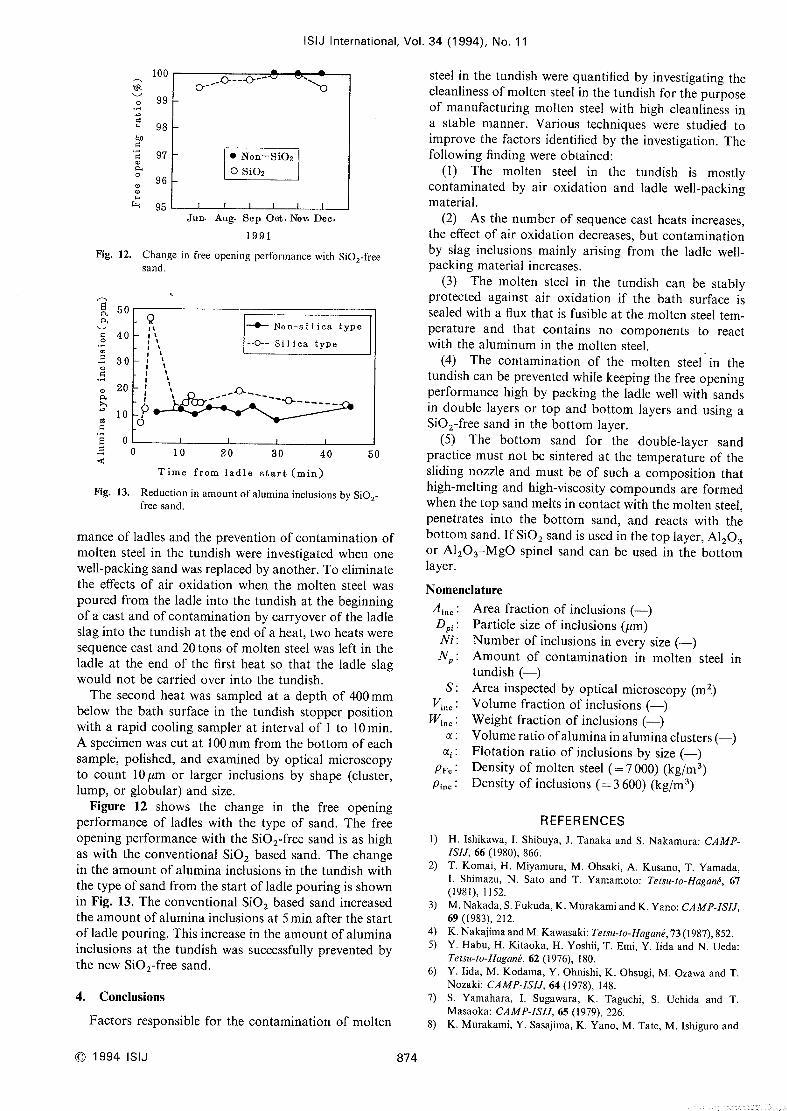
1991Fig. 12. Changein free opening performance with Si02-free
sand.
8 50~~~~ 9
It -~ Non-si~ ica type~ 40 Il
: t--o-- Silica type
::~ 30 IoF:
q> 20 j __JO--_c~ I --*~---
10 ~h1's 6~1
~ O:s lOO 20 30~ 40 50
Time from ladle start (min)
Fig. 13. Reduction in amountof alumina inclusions by Si02-free sand.
manceof ladles and the prevention of contamination ofmolten steel in the tundish were investigated whenonewell-packing sand wasreplaced by another. Toeliminatethe effects of air oxidation whenthe molten steel waspoured from the ladle into the tundish at the beginningof a cast and of contamination by carryover of the ladleslag into the tundish at the end of a heat, two heats weresequencecast and 20 tons of molten steel was left in theladle at the end of the first heat so that the ladle slag
would not be carried over into the tundish.
The second heat was sampled at a depth of 400mmbelow the bath surface in the tundish stopper positionwith a rapid cooling sampler at interval of I to 10 min.
Aspecimenwascut at 100mmfrom the bottom of eachsample, polished, and examined by optical microscopyto count lO,xm or larger inclusions by shape (cluster,
lump, or globular) and size.
Figure 12 shows the change in the free openingperformance of ladles with the type of sand. The free
opening performance with the Si02-free sand is as highas with the conventional Si02 based sand. The changein the amountof alumina inclusions in the tundish withthe type of sand from the start of ladle pouring is shownin Fig. 13. Theconventional Si02 based sand increasedthe amountof alumina inclusions at 5min after the startof ladle pouring. This increase in the amountof aluminainclusions at the tundish was successfully prevented bythe newSi02-free sand.
4. Conclusions
Factors responsible for the contamination of molten
C 1994 ISIJ 874
steel in the tundish were quantified by investigating thecleanliness of molten steel in the tundish for the purposeof manufacturing molten steel with high cleanliness in
a stable manner. Various techniques were studied toimprove the factors identified by the investigation. Thefollowing finding were obtained:
(1) The molten steel in the tundish is mostlycontaminated by air oxidation and ladle well-packingmaterial.
(2) As the numberof sequencecast heats increases,the effect of air oxidation decreases, but contaminationby slag inclusions mainly arising from the ladle well-packing material increases.
(3) The molten stee] in the tundish can be stablyprotected against air oxidation if the bath surface is
sealed with a flux that is fusible at the molten steel tem-perature and that contains no components to reactwith the aluminum in the molten steel.
(4) The contamination of the molten steel in thetundish can be prevented while keeping the free openingperformance high by packing the ladle well with sandsin double layers or top and bottom layers and using aSi02-free sand in the bottom layer.
(5) The bottom sand for the double-layer sandpractice must not be sintered at the temperature of thesliding nozzle and must be of such a composition thathigh-melting and high-viscosity compoundsare formedwhenthe top sand melts in contact with the molten steel,
penetrates into the bottom sand, and reacts with thebottom sand. If Si02 sand is used in the top layer, Al203or Al203MgOspinel sand can be used in the bottomlayer.
NomenclatureAi.. : Area fraction of inclusions (-)DFi : Particle size of inclusions (,Im)
Ni : Numberof inclusions in every size (L)Np: Amountof contamination in molten steel in
tundish (-)S: Area inspected by optical microscopy (m2.)
V~~*: Volumefraction of inclusions (-)Wi.. : Weight fraction of inclusions (-)
c( : Volumeratio ofalumina in aluminaclusters (-)oci : Flotation ratio of inclusions by size (-)
pp. : Density of molten steel (=7OOO)(kg/m3)Pi.. : Density of inclusions (=3600) (kg/m3)
l)
2)
3)
4)
5)
6)
7)
8)
REFERENCESH, Ishikawa. I. Shibuya, J. Tanakaand S. Nakamura:CAMP-ISIJ, 66 (1980), 866.T. Komai, H. Miyamura, M. Ohsaki, A. Kusano. T. Yamada,I. Shimazu, N. Sato and T. Yamamoto:Telsu-to-Hagan~. 67(1981), I152.
M. Nakada,S. Fukuda, K. MurakamiandK. Yano: CAMP-ISIJ,69 (1983), 212.
K, NakajimaandM. Kawasaki: Tetsu-to-Ifaganb, 73(1987), 852.Y. Habu, H. Kitaoka, H. Yoshii, T. Emi, Y. Iida and N. Ueda:Tetsu-to-Haganb, 62 (1976), 180.
Y. Iida, M. Kodama,Y. Ohnishi, K. Ohsugi, M. Ozawaand T.Nozaki: CAMP-ISIJ. 64 (1978), 148.S. Yamahara, I. Sugawara, K. Taguchi, S. Uchida and T.Masaoka: CAMP-ISIJ, 65 (1979), 226.K. Murakami, Y. Sasajima, K. Yano, M. Tate, M. Ishiguro and
9)
lO)
1l)
12)
13)
l4)
l5)
16)
17)
ISIJ International, Vol. 34
Y. Ogura: CAMP-ISIJ, 66 (1980), 865.
O. Naka, N. Katsuyama,M. Waki, T. Komiya, H. Misumi and 18)
S. Iguchi: CAMP-ISIJ, 68 (1982), 1006.
H. Tomono,T. Ura, H. Sakamotoand K. Iwata: CAMP-ISIJ, 19)
69 (1983), 210,
K. Yamanaka,S. Terashima, K. Nakada,T. Koshikawa, N. Ueda 20)
and H. Yoshii: CAMP-ISIJ, 69 (1983), 213.S. Imamura, A. Imamura, H. Ikezaki. A. Kusamo,H. Kuwatori 21)
and H. Miyamura: CAMP-ISIJ, 73 (1987), 281.
K. NakajimaandM.Kawasaki: Tetsu-to-Hagan~, 73 (1987), 860. 22)
M. Yoshida. S. Ishitobi, J. Wakidaand S. Mizoguchi: CAMP-ISIJ, 66 (1980), 863. 23)J. Wakida, S. Mizoguchi, Y. Yoshida and S. Ishitobi: CAMP-ISIJ, 66 (1980), 864.
M. Ohnishi. Y. Iwamoto, S. Hiwasa, Y. Kato and H. Daizu: 24)
CAMP-ISIJ, 69 (1983), 21 I. 25)
T. Ito. T. Koshikywa. A. Takahashi and T. Imai: CAMP-ISIJ,
(1 994). No. 11
67 (1981), 847.S. Miyahara, I. Sugawara, K. Taguchi. S, Uchida and T.Masaoka:CAMP-ISIJ, 65 (1979), 228.
H. Tomono, K. Ozaki, T. Ura, K. Iwata and T. Suzuki:CAMP-ISIJ, 69 (1983), 914.
N. Morioka, K. Washio, K. Hamaguchi,S. Ogura, H, Nishikawaand R. Asaho: CAMP-ISIJ, 73 (1987), 280.
N. Kasai. O. Miyazaki, H. Yamazoe,M. Yoshii andT. Shinozuka:CAMP-ISIJ,7(1994), 325.
H. Tanaka, Y. Nishihara. I. Kitagawa and R. Tsujino: ISIJ Int.,
33 (1993), 1238.
H. Tanaka. R. Tsujino, R. Nishihara, I. Kitamura. H. Nomoto,R. Miura, Y. Takasaki andT. Imoto: Tetsu-to-Hagan~, 78 (1992),
T201.
T. Suruga: Refractories, 39 (1987), 298.
Handbookof Physico~ChemicalProperties at High Temperature,ed. by ISIJ. Tokyo.
875 C 1994 ISIJ