technical mistakes during the acquisition of the electrocardiogram
TRANSCRIPT

REVIEW
Technical Mistakes during the Acquisitionof the Electrocardiogram
Javier Garcıa-Niebla, R.N.,∗ Pablo Llontop-Garcıa, M.D.,∗Juan Ignacio Valle-Racero, R.N.,† Guillem Serra-Autonell, M.D.,‡Velislav N. Batchvarov, M.D., PH.D.,§ and Antonio Bayes de Luna, M.D., PH.D.,¶From the ∗Servicios Sanitarios del Area de Salud de El Hierro, Valle del Golfo Health Center, Islas Canarias,Spain; †Servicio de Cardiologıa, Hospitales Universitarios Virgen del Rocıo, Sevilla, Espana; ‡Gem-Med S.L.Barcelona, Spain; §Division of Cardiac and Vascular Sciences, St George’s University of London, London, UK;and ¶Institut Catala d’Ciencies Cardiovasculars, Hospital Santa Creu i Sant Pau, Barcelona, Spain
In addition to knowledge of normal and pathological patterns, the correct interpretation of electro-cardiographic (ECG) recordings requires the use of acquisition procedures according to approvedstandards. Most manuals on standard electrocardiography devote little attention to inadequate ECGrecordings. In this article, we present the most frequent ECG patterns resulting from errors in limband precordial lead placement, artifacts in 12-lead ECG as well as inadequate filter application; wealso review alternative systems to the standard ECG, which may help minimize errors.
Ann Noninvasive Electrocardiol 2009;14(4):389–403
electrocardiogram; artifacts; electrode misplacement; filters; leads
In addition to knowledge of normal and patho-logical patterns, the correct interpretation of elec-trocardiographic recordings requires the use ofacquisition procedures according to approved stan-dards.1 Many electrocardiograms (ECGs) obtainedin routine daily practice present inadequate leadplacement. Heden et al.,2 using automated ECGanalysis software, showed that 2% of more than11,000 ECGs analyzed presented lead placementinterchange. To these errors, others must surelybe added—those frequently presenting due to highprecordial lead displacement and, less frequently,those produced when limb leads are placed on thechest.
The presence of artifacts in ECG recordings mayinduce important diagnostic errors leading to un-necessary therapeutic interventions,3 such as an-tiarrhythmic treatment or the implantation of pace-makers or defibrillators. In this respect, Knightet al.4 showed that 38% of nearly 500 electrophys-
Address for reprints: Javier Garcıa-Niebla, C/Las Lapas 45, 38911 Frontera-El Hierro, Islas Canarias, Espana. E-mail: [email protected]
iologists participating in their study diagnosed asventricular tachycardia what was in fact an artifact.
Most manuals on standard electrocardiographydevote little attention to inadequate ECG record-ings. In this article, we present the most frequentECG patterns resulting from errors in limb andprecordial lead placement, artifacts or inadequatefilter application; we also review alternative sys-tems to the standard ECG that may help minimizeerrors.
INCORRECT PLACEMENTOF LIMB LEADS
Upward Displacement
Proximal or distal placement of leads on thelimbs produces different ECG tracings and shouldtherefore be correctly performed, although greatprecision is not required. Positioning of the limb
C©2009, Copyright the AuthorsJournal compilation C©2009, Wiley Periodicals, Inc.
389

390 � A.N.E. � October 2009 � Vol. 14, No. 4 � Garcıa-Niebla, et al. � Technical Mistakes during Acquisition of ECG
Figure 1. (A) Electrocardiogram of a patient with acute coronary syndrome (ACS) due to coronary descending arteryocclusion, obtained with standard electrode placement. (B) Electrocardiogram of the same patient obtained withMason-Likar system, showing markedly reduced R voltage in lead I and aVL, and increased in lead III and aVF.The reciprocal changes in inferior leads due to coronary descending artery occlusion are further accentuated ondisplacement of the limb electrodes to the torso.
lead electrodes on the chest according to theMason-Likar system5 causes a rightward shift ofthe QRS axis, thus diminishing R voltage in lead Iand aVL and increasing it in leads II, III, and aVF(Fig. 1).6–8 Long ago, Einthoven obtained his firstrecordings using distal limbs submerged in bucketsof salt water. Later authors9–10 recommended plac-ing electrodes on arms and legs far from the shoul-ders and hips, but not necessarily on the wrists andankles.
The introduction of single-use adhesive elec-trodes, easily applied to any part of the limbs oreven the chest, has significantly reduced ECG arti-facts caused by movement and allowed more proxi-mal limb lead placement.11 Although advantageousin terms of speed and easy application,12 the useof such electrodes with upward displacement pro-vides ECGs that cannot be considered equivalentto standard ECGs. Any modification of the po-sition of the limb electrodes should be recorded

A.N.E. � October 2009 � Vol. 14, No. 4 � Garcıa-Niebla, et al. � Technical Mistakes during Acquisition of ECG � 391
Figure 2. (A) The most frequent interchanges without ground electrode dis-placement to upper limbs. (B) The presence of an isoelectric line in Einthovenleads identifies electrode interchange when involving only two electrodes.
and taken into consideration when the ECG isinterpreted.
Electrode Placement Interchange
In general, the ECG patterns recorded with limblead interchange depend on the patient’s basal ECG(Fig. 2A). However, there are well-defined patternsresulting from incorrect lead placement, regardlessof the basal ECG. For example, tracings with a prac-tically isoelectric line in leads I, II, or III are due tomisplacement of the ground lead13–14 to an upperlimb (Fig. 2B).
Contralateral Interchange
Interchange between Right and Left Arm Electrodes.This combination is one of the easiest errors toidentify in routine clinical practice ECGs. Gener-ally, the usual lead I tracing is inverted in sinusrhythm and P, QRS, and T are negative. Lead II isin fact lead III, and aVR is aVL and vice versa. Withthe left leg electrode correctly placed, aVF remainsunaltered. The negative P wave recorded in lead Iand positive in aVR, as can be observed in ectopicrhythms, is exceptional during sinus rhythm.15 Inthe vertical heart, this interchange produces lead Imorphology showing qR or QR and aVR showingQS complex (Fig. 3). In patients with dextrocardia,

392 � A.N.E. � October 2009 � Vol. 14, No. 4 � Garcıa-Niebla, et al. � Technical Mistakes during Acquisition of ECG
Figure 3. (A) Frontal plane leads in a healthy patient with left shift of the QRS electrical axis. (B) on interchanging leftarm and right arm electrodes, the ECG shows the classical pattern of P, QRS, and T as negative waves in lead DI andpositive in aVR. However, in the vertical heart (C) the most striking finding may be (D) a QR or qR complex in lead DIwith negative P wave or negative/positive in aVR.
we may record morphologies similar to those ob-tained with right-left arm interchange but we donot observe the usual progression of the R wave inthe precordial leads. In atrial fibrillation, this tech-nical error can be distinguished from dextrocardiaby the discordance between the QRS complex inlead I, which is predominantly negative, and V6,which is positive.16
Interchange between the Right and Left Leg Electrodes.Interchange between the right and left leg elec-trodes may be overlooked in the ECG, since thepotentials of the two legs are practically the sameand the recording does not differ from that obtainedwith standard electrode placement.
Homolateral Interchange
Interchange between Right Arm and Right Leg Elec-trodes. The artifact generated by interchangebetween right arm and right leg electrodes iseasily identified; it manifests as a practically iso-electric line in lead II, because there is practi-cally no difference between the potentials of theright arm electrode (now on the right leg) andthe left leg13 (Fig. 2B). However, the differencein potential increases notably if the electrodes areelevated to the iliac crests.17 In addition, lead Iis inverted lead III while lead III is unaffected.Leads aVR and aVF are identical since the voltagerecorded from the left and right legs is practicallythe same. Precordial lead voltages are only slightlyaffected.

A.N.E. � October 2009 � Vol. 14, No. 4 � Garcıa-Niebla, et al. � Technical Mistakes during Acquisition of ECG � 393
Figure 4. (A) Electrocardiogram recorded with left leg–left arm electrode interchange. In this case, the P axis has a leftshift with a P wave in lead I and aVL amplitude greater than in lead II. In lead III, a negative P wave is recorded followedby a QRS complex with dominant R. (B) Electrocardiogram of the same patient with correctly placed electrodes withP axis at 60◦. (C) Left leg–left arm electrode interchange in a patient with atrial flutter: the ECG shows the typical sawtooth morphology in lead III and aVF but not in II. (D) Electrocardiogram of the same patient with correctly placedelectrodes.
Interchange between Left Arm and Left Leg Electrodes.Although changes are produced in all frontal planeleads except aVR, this placement error is difficultto detect. In general, the electrical axis of the Pwave is more leftward than normal (30–70◦ in 90%of normal cases)18 with a larger P wave in lead Ithan in lead II, while in lead III we occasionally ob-serve a biphasic (−/+) P wave such as one that canbe recorded in ectopic rhythms19 (Fig. 4). Hedenproposed an automated system that can detect in-terchange between left arm and left leg electrodeswith a sensitivity of 57% and specificity of practi-cally 100%.2 In the presence of atrial flutter, this er-ror is easily detected by the characteristic sawtoothmorphology recorded in lead III and aVF but not inlead II.19 If this error occurs in an acute coronarysyndrome patient with ST elevation in the inferior
leads due to right coronary artery occlusion, theECG shows ST elevation in lead I and aVL and STdepression in lead III and aVF, which in principleindicates that the defective artery is not the rightcoronary.20 The same occurs in chronic phase in-ferior myocardial infarction with Q waves in leadII, III, and aVF where this interchange “displaces”the necrosis toward lead I and aVL.21
Cross-Over Electrode Interchange
Interchange between Right Arm and Left Leg Elec-trodes. This error produces generalized inversionof the basal ECG in all the frontal plane leads exceptaVL. In most cases, the recording simulates that ofa chronic phase inferior myocardial infarction andnonsinus rhythm22 with greater inversion of the P

394 � A.N.E. � October 2009 � Vol. 14, No. 4 � Garcıa-Niebla, et al. � Technical Mistakes during Acquisition of ECG
Figure 5. (A) Frontal plane leads in a 60-year-old malepatient showing inferior myocardial infarction in chronicphase. (B) The same patient with right arm-left leg elec-trode interchange. In this case, aVF resembles the usualaVR lead and II is inverted. The Q wave in lead II disap-pears and its depth in aVF is reduced, thus simulatingless extension of the necrosis. (C) A 30-year-old womanwithout cardiopathy with correctly placed electrodes.(D) Tracing of the same patient with clockwise electroderotation without ground electrode displacement, show-ing negative QS and P wave complexes similar to thoseobtained with right arm-left leg electrode interchangeobtained in a patient without previous inferior infarction.
and T waves in the rS or QS complexes. The QRSis usually positive in aVR and negative in lead I,as commonly observed when the left and right armelectrodes are interchanged. In patients with pre-vious inferior myocardial infarction, this electrodeinterchange can cause the Q wave in lead II to dis-appear, giving the impression of a less extensiveinfarction (Fig. 5).
Interchange between Left Arm and Right Leg Elec-trodes. The most striking aspect in this case is thepresence of a practically isoelectric line in lead III(Fig. 2B) due to practically no difference in poten-tial between the right leg electrode (negative pole)
and the incorrectly placed left leg electrode (posi-tive pole).23 In this case, leads I and II are identical.This type of error also affects the potential of theprecordial leads.
Clockwise and Anticlockwise Interchange withoutMisplacement of the Ground Lead
Ho and Ho24 described these two unusual ECGpatterns resulting from the misplacement of threeelectrodes.
Clockwise rotation generates a pattern similar tothat obtained from interchanging right arm and leftleg leads, with negative P waves and QRS com-plexes in inferior leads. Anticlockwise rotation gen-erates a P axis with a marked right shift, with Ppositive in aVR and negative in lead II. Lead I andaVL are replaced by—II and aVR, respectively.
INCORRECT PLACEMENTOF PRECORDIAL LEADS
The misplacement of precordial lead electrodesis perhaps the most frequent error found when 12-lead ECGs are performed. The degree of inexac-titude in the placement of precordial electrodes isclosely related with the level of technical training ofthe professional performing the technique.25 Thistechnical error may be due to
(1) Vertical displacement of electrodes, usuallytoward the head.
(2) Horizontal displacement of electrodes.(3) Interchange of electrodes with respect to their
assigned places.
The first and second cases are more difficult todetect than the third where abnormal R wave pro-gression reveals the technical error.
Vertical Displacement of Electrodes
The method of correct placement of the precor-dial leads was described long ago26–28 and has re-cently been updated.1 The precise identificationof the intercostal spaces (IS) is necessary for suchplacement.29 Of vital importance is the localizationof the Sternal Angle or Angle of Louis (Fig. 6) toidentify the 2nd IS and thereafter the 3rd and 4thIS. On occasions, there may be difficulty in locat-ing the anatomical reference points, for examplein obese individuals without a prominent sternal

A.N.E. � October 2009 � Vol. 14, No. 4 � Garcıa-Niebla, et al. � Technical Mistakes during Acquisition of ECG � 395
Figure 6. (A) From the sternal notch, the 2nd and 3rdfingers are slid down the sternum to the angle of Louis.(B) Sliding the fingers to the left or right, the 2nd inter-costal is located, then downward to locate the 3rd and4th intercostal spaces.
angle. A typical error when trying to locate the 1stIS is to confuse it with the costoclavicular space.
Another frequent error is high IS placement of V1and V2.30,31 This produces important ECG changes,especially in the P, R, and T waves.32 Zema et al.33
showed 1 mm reduction of the R wave for ev-ery IS involved. Certain morphological patterns areproduced, and knowing them helps identify highplacement of these electrodes (Fig. 7A).34,35
(1) The recording of the negative component of Pwave in V2 indicates high placement. This Pmorphology can be recorded as from the 3rd IS
and is usually accompanied by an isodiphasicP wave in V1 or with a predominantly negativecomponent.
(2) Exclusively negative P wave in V1. In ECGsobtained from healthy subjects, the P wavein V1 is positive or diphasic type +/− withgreater positive component and a slight slope.High placement of this electrode suggeststhat V1 is recording the tail of the result-ing vector instead of the head due to atrialdepolarization.
(3) The classic rSr′ pattern with a negative P waveis exclusively indicative of V1 placement inthe 2nd IS; this placement error presents in17% of healthy individuals′ ECGs. In this case,the high placement of V1 results in recordingof the third vector due to basal ventriculardepolarization (r’ o R’).
The V4–V6 electrodes are sometimes placedlower and too far to the left than their correct posi-tion,30 and furthermore, V5 and V6 are erroneouslyplaced attempting to follow the costal curvature ofthe 5th IS. This is probably due to the fact thatmany ECG textbooks mention this anatomical ref-erence point instead of the correct one, which is thesame horizontal level as V4 at the intersection of theanterior and midaxillary line.16 New guidelines forthe standardization and interpretation of ECGs rec-ommend placing V5 on the midline between V4–V6when the anterior axillary line is not well defined.1
However, V1 and V2 recordings with high IS elec-trode placement may be useful for increasing sen-sitivity to detect Brugada syndrome.36,37
In women, V1 and V2 electrode placement is usu-ally not affected by the breast size, whereas theplacement of the other precordial leads, especiallyV4 may be complicated by large breasts. Much de-bate has centered on the possible voltage attenua-tion of the ECG waves by placing electrodes on theleft breast. Colaco38 compared R wave amplitudewith electrodes placed on the breast or below it.He showed significantly reduced V3 voltage withbreast placement, but no significant differences forV4. However, V5 and V6 voltage was greater withelectrodes placed on the left breast compared withplacement below it.
Rautaharju et al.39 reported that the effect ofbreast placement on ECG wave amplitude wasinsignificant and therefore recommended breastplacement of precordial lead electrodes to facil-itate more precise positioning. However, current
396 � A.N.E. � October 2009 � Vol. 14, No. 4 � Garcıa-Niebla, et al. � Technical Mistakes during Acquisition of ECG
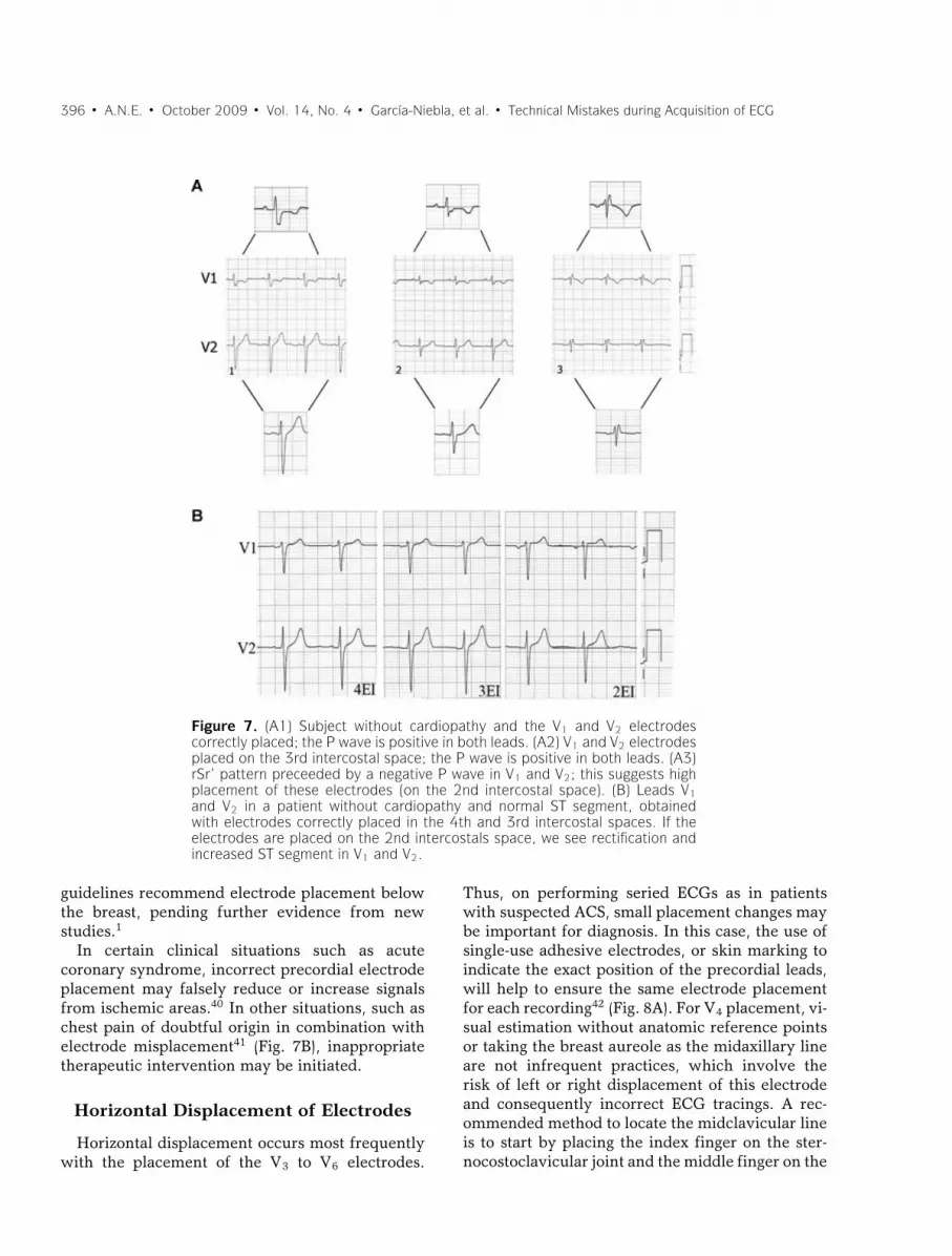
Figure 7. (A1) Subject without cardiopathy and the V1 and V2 electrodescorrectly placed; the P wave is positive in both leads. (A2) V1 and V2 electrodesplaced on the 3rd intercostal space; the P wave is positive in both leads. (A3)rSr’ pattern preceeded by a negative P wave in V1 and V2; this suggests highplacement of these electrodes (on the 2nd intercostal space). (B) Leads V1and V2 in a patient without cardiopathy and normal ST segment, obtainedwith electrodes correctly placed in the 4th and 3rd intercostal spaces. If theelectrodes are placed on the 2nd intercostals space, we see rectification andincreased ST segment in V1 and V2.
guidelines recommend electrode placement belowthe breast, pending further evidence from newstudies.1
In certain clinical situations such as acutecoronary syndrome, incorrect precordial electrodeplacement may falsely reduce or increase signalsfrom ischemic areas.40 In other situations, such aschest pain of doubtful origin in combination withelectrode misplacement41 (Fig. 7B), inappropriatetherapeutic intervention may be initiated.
Horizontal Displacement of Electrodes
Horizontal displacement occurs most frequentlywith the placement of the V3 to V6 electrodes.
Thus, on performing seried ECGs as in patientswith suspected ACS, small placement changes maybe important for diagnosis. In this case, the use ofsingle-use adhesive electrodes, or skin marking toindicate the exact position of the precordial leads,will help to ensure the same electrode placementfor each recording42 (Fig. 8A). For V4 placement, vi-sual estimation without anatomic reference pointsor taking the breast aureole as the midaxillary lineare not infrequent practices, which involve therisk of left or right displacement of this electrodeand consequently incorrect ECG tracings. A rec-ommended method to locate the midclavicular lineis to start by placing the index finger on the ster-nocostoclavicular joint and the middle finger on the

A.N.E. � October 2009 � Vol. 14, No. 4 � Garcıa-Niebla, et al. � Technical Mistakes during Acquisition of ECG � 397
Figure 8. (A) Patient with acute myocardial infarction at subacute stage with V1–V6 Qwaves and correctly placed precordial leads (A.1). Small changes of leftward misplacementof V3–V6 electrodes (A.2) cause significantly modified QRS morphology with qR in V6.According to classical nomenclature, the first ECG (A.1.1) would be interpreted as necrosisspreading to low lateral wall, and the second ECG (A.1.2) as no recorded spreading. A.2:Patient with inferolateral infarction (R ≥ S1 in V1) and QR in V6 (A2.1). After slightrightward displacement of the precordial leads, the QR pattern in V6 disappears. B.1:ECG of a healthy 45-year-old man with V6 > V5 voltage, which obliges us to reviewthe placement of these two electrodes. B.2: Interchange between the two black coloredelectrodes, V5 and the ground lead (IEC), which imitates interchange between V6 and V5.In this case, we can observe the loss of S in V5 that is present in V4 and V6.
acromioclavicular joint, then join them toward themiddle of the clavicle.
Interchange of Precordial Electrodes
This error is easily identified by the alterationit produces in the normal pattern of the R wavein precordial leads.43 When the R wave is higherin lead V6 than in lead V5, interchange of theseelectrodes must be suspected, since this finding isnot observed in normal ECGs44 but can be foundin left ventricular hypertrophy45 (Fig. 8B).
INTERCHANGE BETWEEN LIMBAND PRECORDIAL ELECTRODES
This interchange generates important changes inboth planes of a standard ECG, altering Wilson’s
Central Terminal17 except if the interchange af-fects the ground electrode (Fig. 8B). The fact thatthe electrodes recording both planes are the samecolor46 together with operator inexperience,47 fa-vors this type of error. There are two different sys-tems of color coding and cable labeling (Fig. 9),one recommended by the American Heart Asso-ciation (AHA) and the other by the InternationalElectrotechnical Commission (IEC).
ARTIFACTS THAT SIMULATEARRHYTHMIAS
IN THE 12-LEAD ECG
The literature contains numerous cases ofartifacts simulating cardiac arrythmia.48–50 In gen-eral, most artifacts are directly attributable to

398 � A.N.E. � October 2009 � Vol. 14, No. 4 � Garcıa-Niebla, et al. � Technical Mistakes during Acquisition of ECG
Figure 9. Electrode color coding and labeling system for electrocardiogramsrecommended by the American Heart Association and the International Elec-trotechnical Commission.
patient factors such as tremor or voluntary move-ments during ECG recording; however, they arealso caused by deficient electrode-skin contact.
Confusing an artifact with an important diagnos-tic entity may lead to inappropriate clinical inter-vention. Serious error may occur when an artifactresults in diagnosis of ventricular tachycardia, forexample, and unnecessary diagnostic and therapeu-tic procedures for the patient.2 In this case, the ar-tifact may easily be identified if any of the 12 leadspresents basal rhythm of the patient. In other cases,it is necessary to perform a detailed examinationof the basal complexes underlying the artifactualtracing appearing as a spike (R wave) or a notch51
(Fig. 10A). For this, a useful procedure is to identifythe basal rhythm with a pair of compasses.
It is important to know that certain artifacts maysometimes simulate atrial waves. These artifactsmay be produced by diaphragmatic contractions(singultus or hiccups) and also recording problemsarising from involuntary patient movement such
as tremor (Parkinson’s disease). In the latter case,the artifact is usually more evident in the frontalplane leads, and the basal rhythm of the patientmay be present in the precordial leads (Fig. 10B).The problem may disappear on placing the limbelectrodes as proximal as possible,52 bearing inmind the need to record the modifications madein electrode placement. Davidenko and Snyder53
showed that on numerous occasions baseline arti-facts lead to misdiagnosis of atrial fibrillation bymedical staff, especially when there was irregularventricular rhythm and low P wave amplitude.
IMPROPER FILTER APPLICATION
Improper filter application is relatively frequentin ECGs performed in daily clinical practice, asshown by Kligfield and Okin.54 In the great major-ity of the ECGs they studied, filters were appliedthat did not conform to the standards establishedby AHA in 1975. The most prevalent deviation

A.N.E. � October 2009 � Vol. 14, No. 4 � Garcıa-Niebla, et al. � Technical Mistakes during Acquisition of ECG � 399
Figure 10. (A) Healthy 35-year-old patient, with palpitations. Holter recordingshows rapid bursts with wide complexes and morphology similar to that ofventricular flutter. Detailed examination of the recording allows identificationof the basal rhythm (arrows) hidden among the wide artifactual complexes.(B) Patient with Parkinson’s disease whose ECG simulates atrial flutter in DIIIwhile V4 clearly shows P waves.
from standard was reduced high-frequency cutoff,which was present in 96% of tracings with nonstan-dard bandwidth (most commonly 40 Hz). Increasedlow-frequency cutoff was present in 62% of ECGsin which it was documented.
The objective of filtering 12-lead ECG record-ings is to reduce unwanted signals, noise and inter-ference, and thus provide an ECG of maximumquality. Among the most important signals thatmay provoke artifacts are those produced by theelectrical power line and electromiographic signalsproduced by normal or abnormal muscular activity(Parkinson’s disease and others) (Fig. 11A). How-ever, acquiring ECGs with clean amplification andhigh gain is no easy task; filtering should only min-imally distort or modify the original unfiltered car-diac signals.
The filters habitually applied in electrocardiog-raphy are as follows:
(1) Alternating current filtering.
Alternating current frequency varies from 50 Hz(e.g., in Spain) to 60 Hz (e.g., in USA). ModernECG recorders incorporate a notch filter that selec-tively attenuates the frequency of the interferenceproduced by the electrical power line with a verynarrow range of frequency so as not to significantlyaffect cardiac signals.55 This filter cannot normallybe deactivated from the keyboard, although somerecorders allow this.
(2) Low-frequency high-pass filter.
Low frequency interference presents as baselinewander in the ECG. The low-frequency high-passfilter is important to attenuate this, which occurswith patient movement and breathing. CurrentAHA guidelines1 establish a low-frequency filter

400 � A.N.E. � October 2009 � Vol. 14, No. 4 � Garcıa-Niebla, et al. � Technical Mistakes during Acquisition of ECG
Figure 11. (A) Examples of artifacts caused by differentcircumstances. (B) Effect on the ST segment on manuallyapplying three different low-frequency filters to precor-dial lead signals, in a healthy patient with early repo-larization. A striking elevation of the ST segment is ob-served in V1 and V2 on applying the 0.5 Hz filter, butnot when the standard recommended filter (0.05 Hz) isapplied. (C) Lead V5 in a healthy 23-year-old man withearly repolarization. The J wave is visible on applying thelow-pass filter at 150 Hz (arrow), but this disappears onreducing the frequency to 40 Hz.
cutoff of 0.05 Hz, which may be up to 0.67 Hz iflinear filters are used with zero distortion phase.56
Using this filter to eliminate baseline sway or wan-der without distorting the ST segment may provedifficult on occasions (Fig. 11B). The use of con-ventional analogue filters with a frequency cutoffof 0.5 Hz may produce significant alterations of theST segment.57–59 This situation is particularly im-portant in nonlinear phases, when the frequencyand wave amplitude change suddenly, as occursat the end of the QRS complex and the beginningof the ST segment.60 To avoid potentially impor-tant distortion from the clinical point of view, it
is necessary to use a linear phase filter or a low-frequency filter set at 0.05 Hz.
Bidirectional linear phase filters are most com-monly used; they apply the same high-pass filter inthe forward direction and then again in the reverse-time direction. This type of filter presents two im-portant features: (1) They double the filtering order(while only doubling the filtering computationalcost instead of multiplying it by a factor of four)and (2) they do not produce signal delay, whichmay be prolonged when dealing with high-orderlinear filters. Biderectional filters require storageof the signal in the computer memory for reverse-time filtering. From a practical point of view, thismeans that reverse-time filtering cannot be carriedout when performing the ECG in real time (manualmode)54 Alternative linear methods can be appliedin real time, although there may be some signaldelay.
1. High-frequency low-pass filters.
High-frequency filters should be at least 150 Hzfor adolescents and adults and up to 250 Hz forchildren.1 It must be remembered that a high-frequency filter set too low, at 40 Hz for instance,eliminates most of the noise but also eliminateshigh-frequency signals that may be important froma clinical point of view (Fig. 11C) for examplepacemaker peaks, R wave voltage, QRS notches,etc.61
ALTERNATIVES TO STANDARDECG RECORDING
The different problems arising from incorrectelectrode placement described above are directlyrelated to the fact that standard 12-lead electro-cardiography requires the correct placement of 10electrodes. This number of electrodes may consti-tute a source of error. Much debate has thereforecentered on the idea of developing more simplifiedrecording systems.
In certain clinical settings, alternative ECGrecording with simplified electrode placement isperformed. Although any change in standard elec-trode positioning causes ECG wave alterations, thishas little effect in continuous cardiac monitoringwhere the objective is to detect gross alterationsin cardiac rhythm. Precisely in this setting, differ-ent more simplified systems of electrode placement

A.N.E. � October 2009 � Vol. 14, No. 4 � Garcıa-Niebla, et al. � Technical Mistakes during Acquisition of ECG � 401
have been used;62 however, these present impor-tant limitations for ECG analysis.
The following two alternative systems developedin recent years are widely used:
(1) Mason-Likar system.
In 1966, Mason and Likar5 introduced a modi-fication of standard electrode placement to over-come signal distortion due to muscle activation inexercise ECG, placing standard limb electrodes onthe torso. The right arm electrode in the Mason-Likar modification is assigned to a point in the infr-aclavicular fossa medial to the border of the deltoidmuscle. The left arm electrode is located similarlyon the left side. The left leg electrode is placedon the anterior axillary line half way between thecostal ridge and the left iliac crest (this position isnot critical) and finally, the right leg electrode is ha-bitually placed in the region of the right iliac fossabut can be placed elsewhere.
The rapid and easy applicability of this modi-fication11,12 together with elimination of artifactscaused by limb movement has promoted its usein resting ECG recording. However, significantvariations are observed between standard and theMason-Likar ECG,6–8 as mentioned previously.The Wilson Central Terminal is notably affected,with reduced R wave amplitude in precordial leadsand right shift of the axis in the frontal plane(Fig. 1).
Although the Mason-Likar electrode positionshave been suggested for use in routine 12-leadECG,63 an appropriate system for convertingrecording data obtained from standard positioningto the alternative is necessary,64 primarily for thelimb lead measurements62 or, although more com-plicated, the creation of new diagnostic standardsadapted to this system.
(2) EASI system.
Dower et al.65 introduced a simplified configu-ration with four electrodes being placed on thepatient torso (and one ground electrode, usuallyplaced anywhere below these positions). CalledEASI, this system places electrodes on E (sternumat the level of 5th intercostal space), A (midaxil-lary line at the level of V6), S (sternum below thesternal notch) and I (midaxillary line at the levelof V6R). From these four electrodes, three essen-
tially orthogonal leads are recorded and from thema full 12-lead ECG is derived. This system has beenthe subject of many studies seeking to determineits comparability with standard ECG in differentclinical settings, such as the diagnosis of multi-ple cardiac abnormalities66 and the classificationof acute myocardial ischemia and old myocardialinfarction,67 where the tracings obtained with EASIwere comparable to those obtained with the stan-dard ECG system.
More recently, various studies have been pub-lished on the EASI system used to monitor high-risk coronary unit patients68 and to detect acutecoronary syndrome in hospitalized patients.69
Sejersten et al.31 compared the managementof patients referred to hospital with chest painwho had undergone three types of ECG beforehospitalization (Standard ECG, EASI, and Mason-Likar electrode configuration). They sought possi-ble differences in clinical decisions based on theECGs obtained. Although acknowledging the obvi-ous limitation of a small sample size, the authorsrecommended using either alternative system forpatient monitoring but emphatically not for diag-nostic purposes.
Two important aspects must be considered whenusing alternative systems.
(1) It is not possible to compare seried ECGsobtained using different systems. This hasbasic clinical implications, the same patientmay have ECG recordings performed at differ-ent stages (prehospital setting, emergency de-partment, coronary unit, hospital ward, etc.).Clearly, comparisons between ECGs obtainedby different systems may lead to erroneousdiagnosis and inappropriate decisions.
(2) Any of the systems proposed as simplified al-ternatives to the conventional 12-lead ECGmust consistently demonstrate accuracy andreliability in the clinical context, especially ifour aim is to generalize their use as a routinetechnique.
CONCLUSION
Undoubtedly, many factors and technical prob-lems may alter the interpretation of ECGs. Theymay induce erroneous diagnoses and inappropri-ate therapeutic interventions, putting patients atrisk, and harming the credibility of the medical

402 � A.N.E. � October 2009 � Vol. 14, No. 4 � Garcıa-Niebla, et al. � Technical Mistakes during Acquisition of ECG
professional. Therefore, they are of significant clin-ical importance.
Training programs should include correct elec-trode placement and the differences betweennormal and pathological patterns, with specialattention given to the ability to recognize ECGpatterns derived from electrode misplacement, ar-tifacts, and other technical problems inducing er-roneous interpretation.
With specific training, the quality of ECG record-ing may be substantially improved and we could beassured that interpretation is based on artifact-freeECGs reflecting the real clinical situation of thepatient.
Acknowledgment: We would like to thank Prof. Barbara Drewfor her ongoing support and advice in development of some aspectsof this article.
REFERENCES1. Kligfield P, Gettes LS, Bailey JJ, et al. Recommendations for
the standardization and interpretation of the electrocardio-gram: Part I: The electrocardiogram and its technology: Ascientific statement from the American Heart Association,Electrocardiography and Arrthymias Committee, Councilon Clinical Cardiology; the American College of CardiologyFoundation; and the Heart Rhythm Society endorsed by theInternational Society for Computerized Electrocardiology.J Am Coll Cardiol 2007;49:1109–1127.
2. Heden B, Ohlsson M, Edenbrandt L, et al. Artificial neuralnetworks for recognition of electrocardiographic lead rever-sal. Am J Cardiol 1995;75:929–933.
3. Knight BP, Pelosi F, Michaud GF, et al. Clinical conse-quences of electrocardiographic artifact mimicking ventric-ular tachycardia. N Eng J Med 1999;341:1270–1274.
4. Knight BP, Pelosi F, Michaud GF, et al. Physician interpreta-tion of electrocardiographic artifact that mimics ventriculartachycardia. Am J Med 2001;110:335–338.
5. Mason RE, Likar I. A new system of multiple-lead exerciseelectrocardiography. Am Heart J 1966;71:196–205.
6. Pahlm O, Haisty WK Jr, Edenbrandt L, et al. Evaluation ofchanges in standard electrocardiographic QRS waveformsrecorded from activity-compatible proximal limb lead posi-tions. Am J Cardiol 1992;69:253–257.
7. Papouchado M, Walker PR, James MA, et al. Fundamen-tal differences between the standard 12-lead electrocardio-graph and the modified (Mason-Likar) exercise lead system.Eur Heart J 1987;8:725–733.
8. Sevilla DC, Dohrmann MD, Somelofski CA, et al. Invalida-tion of the resting electrocardiogram obtained via exerciseelectrode sites as a standard 12-lead recording. Am J Cardiol1989;63:35–39.
9. Pipberger HV, Arzbaecher RC, Berson AS. Recommenda-tions for standardization of leads and of specifications for in-struments in electrocardiography and vectorcardiography.Circulation 1967;35:583–602.
10. Pipberger HV, Arzbaecher RC, Berson AS, et al. Recommen-dations for standardization of leads and of specificationsfor instruments in electrocardiography and vectorcardiog-raphy: Report of the Committee on Electrocardiography.Circulation 1975;52:11–31.
11. Hoffman I. Einthoven’s left foot: A plea for disciplined elec-trode placement. J Electrocardiol 2008;41:197–201.
12. Takuma K, Hori S, Sasaki J, et al. An alternative limb leadsystem for electrocardiography in emergency patients. Am JEmerg Med 1995;13:514–517.
13. Hoffman I. A flatline electrocardiogram in lead II is amarker for right arm/right leg electrode switch. J Electro-cardiol 2007;40:226.
14. Hoffman I. A flatline lead I results from bilateral arm-to-legelectrode exchange. J Electrocardiol 2008;41:388–390.
15. Zielinski J. Negative P wave in lead I due to right atrialenlargement and displacement of the heart in the chest.Lung 1976;153:197–201.
16. Macfarlane PW, Coleman EN. Resting 12-Lead ECGelectrode placement and associated problems. Availableat: (http://www.scst.org.uk/coleman/resting.htm, accessedMarch 22, 2008).
17. Batchvarov VN, Malik M, Camm AJ. Incorrect electrodecable connection during electrocardiographic recording. Eu-ropace 2007;9:1081–1090.
18. Bayes de Luna A. Basic Electrocardiography: Normal y Ab-normal Patterns. Boston, MA, Blackwell, 2007.
19. Abdollah H, Milliken JA. Recognition of electrocar-diographic left-arm/left-leg lead-reversal. Am J Cardiol1997;80:1247–1249.
20. Akel R, Saeed M, Ware DL, et al. Unusual evolution ofST elevation acute myocardial infarction. Ann NoninvasiveElectrocardiol 2004;9:410–414.
21. Harrigan R, Chan T, Brady W. Diagnosis: Limb ElectrodeReversal. Emerg Med News 2004;26:18–20.
22. Peberdy MA, Ornato JP. Recognition of electrocardio-graphic lead misplacements. Am J Emerg Med 1993;11:403–405.
23. Bennett FT, Bennett KR, Markov AK. Einthoven’s triangle:Lead errors and an algorithm for solution. Am J Med Sci2005;329:71–77.
24. Ho KK, Ho SK. Use of the sinus P wave in diagnosing elec-trocardiographic limb lead misplacement not involving theright leg (ground) lead. J Electrocardiol 2001;34:161–167.
25. Rajaganeshan R, Ludlam CL, Francis DP, et al. Accuracyin ECG lead placement among technicians, nurses, generalphysicians and cardiologists. Int J Clin Pract 2008;62:65–70.
26. Joint Recommendations of the American Heart Associationand the Cardiac Society of Great Britain and Ireland. Stan-dardization of precordial leads. Am Heart J 1938;15:107–108.
27. Committee of the American Heart Association for the Stan-dardization of Precordial Leads. Supplementary report. AmHeart J 1938;15:235–239.
28. Committee of the American Heart Association for the Stan-dardization of Precordial Leads. Second supplementary re-port. J Am Med Assoc 1943;121:1349–1351.
29. Pelter MM. Electrocardiography: normal electrocardio-gram. In: Moser DK, Riegel B., Eds. Cardiac nursing: acompanion to Braunwald’s heart disease. Philadelphia, PA:Elsevier Saunders 2008: 597–611.
30. Wenger W, Kligfield P. Variability of precordial electrodeplacement during routine electrocardiography. J Electrocar-diol 1996;29:179–184.
31. Sejersten M, Pahlm O, Pettersson J, et al. Comparison ofEASI-derived 12-lead electrocardiograms versus paramedic-acquired 12-lead electrocardiograms using Mason-Likarlimb lead configuration in patients with chest pain. J Elec-trocardiol 2006;39:13–21.
32. Garcıa Niebla J. Imagenes electrocardiograficas derivadasde una incorrecta colocacion de V1-V2. Enferm Cardiol2004;11:38–44.
33. Zema MJ, Kligfield P. ECG poor R-wave progression: Re-view and synthesis. Arch Intern Med 1982;142:1145–1148.
34. Garcıa Niebla J. Morfologıas que indican colocacion inade-cuada de V1-V2. Rev Esp Cardiol 2008;61:1109–1110.

A.N.E. � October 2009 � Vol. 14, No. 4 � Garcıa-Niebla, et al. � Technical Mistakes during Acquisition of ECG � 403
35. Garcıa-Niebla J. Comparison of P-wave patterns derivedfrom correct and incorrect placement of V1-V2 electrodes.J Cardiovasc Nurs 2009;24:156–161.
36. Shimizu W, Matsuo K, Takagi M, et al. Body surface dis-tribution and response to drugs of ST segment elevationin Brugada syndrome: Clinical implication of eighty-seven-lead body surface potential mapping and its application totwelve-lead electrocardiograms. J Cardiovasc Electrophys-iol 2000;11:396–404.
37. Cabezon Ruiz S, Errazquin Saenz de Tejada F, PedroteMartınez A, et al. El electrocardiograma convencional nor-mal con test de provocacion farmacologico negativo nodescarta el sındrome de Brugada. Rev Esp Cardiol 2003;56:107–110.
38. Colaco R, Reay P, Beckett C, et al. False positive ECG re-ports of anterior myocardial infarction in women. J Electro-cardiol 2000;33(Suppl):239–244.
39. Rautaharju PM, Park L, Rautaharju FS, et al. A standardizedprocedure for locating and documenting ECG chest elec-trode positions: Consideration of the effect of breast tissueon ECG amplitudes in women. J Electrocardiol 1998;31:17–29.
40. Drew BJ. Pseudo myocardial injury patterns because of non-standard electrocardiogram electrode placement. J Electro-cardiol 2008;41:202–204.
41. Bayes de Luna A. Electrocardiografıa Clınica. Barcelona,Espaxs, 1999.
42. Bayes de Luna A, Fiol-Sala M. Electrocardiography in Is-chemic Heart Disease: Clinical and Imaging Correlationsand Prognostic Implications. Boston, MA, Blackwell, 2007.
43. Hurst JW. “Switched” precordial leads. Circulation 2000;101:2870–2871.
44. Macfarlane PW, Veitch Lawrie TDV. eds. ComprehensiveElectrocardiology: Theory and Practice in Health and Dis-ease, Vol 3. New York, Pergamon Press, 1989.
45. Rodrıguez Padial L, Navarro Lima A, Sanchez DominguezJ. RV6:RV5 voltage ratio in systemic hypertension. Am JCardiol 1990;66:869–871.
46. Garcıa-Niebla J, Llontop-Garcıa P. An unusual case of elec-trode misplacement: Left arm and V2 electrode reversal.J Electrocardiol 2008;41:380–381.
47. Pastor JA, Castellanos A, Myerburg RJ, et al. Apparent mis-placement of chest electrode on left leg: A unique exampleof electrodal confusion. Am J Cardiol 2001;88:829–830.
48. Barriales Villa R, Catalan Adivinacion F, Moller BustinzaI, et al. El bosque no te deja ver el arbol. Rev Esp Cardiol2001;54:790.
49. Srikureja W, Darbar D, Reeder GS. Tremor-induced ECGartifact mimicking ventricular tachycardia. Circulation2000;102:1337–1338.
50. Llinas R, Henderson GV. Tremor as a cause of pseudo-ventricular tachycardia. N Engl J Med 1999;341:1275.
51. Huang CY, Shan DE, Lai CH, et al. An accurate electrocar-diographic algorithm for differentiation of tremor-inducedpseudo-tachycardia and true ventricular tachycardia. Int JCardiol 2006;111:163–165.
52. Bayes de Luna A. Electrocardiografıa Clınica. Barcelona,Espaxs, 1999.
53. Davidenko JM, Snyder LS. Causes of errors in the electro-cardiographic diagnosis of atrial fibrillation by physicians.J Electrocardiol 2007;40:450–456.
54. Kligfield P, Okin PM. Prevalence and clinical implicationsof improper filter settings in routine electrocardiography.Am J Cardiol 2007;99:711–713.
55. Gregg RE, Zhou SH, Lindauer JM, et al. What is inside theelectrocardiograph? J Electrocardiol 2008;41:8–14.
56. Bailey JJ, Berson AS, Garson A Jr, et al. Recommenda-tions for standardization and specifications in automatedelectrocardiography: Bandwidth and digital signal process-ing: A report for health professionals by an ad hoc writinggroup of the Committee on Electrocardiography and Car-diac Electrophysiology of the Council on Clinical Cardiol-ogy, American Heart Association. Circulation 1990;81:730–739.
57. Berson AS, Pipberger HV. The low-frequency response ofelectrocardiographs, a frequent source of recording errors.Am Heart J 1966;71:779–789.
58. Burri H, Shah D, Sunthorn H. Simulation of anteroseptalmyocardial infarction by electrocardiographic filters. J Elec-trocardiol 2006;39:253–258.
59. Tagan D, Feihl F. ST segment artifact mimicking coronaryischemic syndrome. J Emerg Med 2003;25:108–109.
60. Bailey J. The triangular wave test for electrocardio-graphic devices: A historical perspective. J Electrocardiol2004;37:71–73.
61. Drew BJ. Pitfalls and artifacts in electrocardiography. Car-diol Clin 2006;24:309–315.
62. Drew BJ, Califf RM, Funk M, et al. Practice standards forelectrocardiographic monitoring in hospital settings. Circu-lation 2004;110:2721–2746.
63. Macfarlane PW. The future of electrocardiography. AnatolJ Cardiol 2007;7(Suppl):1–4.
64. Man SC, Man AC, Kim E, et al. Reconstruction of stan-dard 12-lead electrocardiograms from 12-lead electrocardio-grams recorded with the Mason-Likar electrode configura-tion. J Electrocardiol 2007;41:211–219.
65. Dower GE, Yakush A, Nazzal SB, et al. Deriving the 12-leadelectrocardiogram from four (EASI) electrodes. J Electrocar-diol 1988;21(Suppl):S182–S187.
66. Drew BJ, Pelter MM, Wung SF, et al. Accuracy of the EASI12-lead electrocardiogram compared to the standard 12-leadelectrocardiogram for diagnosing multiple cardiac abnor-malities. J Electrocardiol 1999;32(Suppl):38–47.
67. Rautaharju PM, Zhou SH, Hancock EW, et al. Compara-bility of 12-lead ECGs derived from EASI leads with stan-dard 12-lead ECGs in the classification of acute myocar-dial ischemia and old myocardial infarction. J Electrocardiol2002;35(Suppl):35–39.
68. Chantad D, Krittayaphong R, Komoltri C. Derived 12-leadelectrocardiogram in the assessment of ST-segment devia-tion and cardiac rhythm. J Electrocardiol 2006;39:7–12.
69. Wehr G, Peters RJ, Khalife K, et al. A vector-based,5-electrode, 12-lead monitoring ECG (EASI) is equiv-alent to conventional 12-lead ECG for diagnosis ofacute coronary syndromes. J Electrocardiol 2006;39:22–28.