t645 15” tft lcd treadmill - owner's manual - sportsart
TRANSCRIPT

T645 15” TFT LCD TreadmillOwner’s Manual
Sports Art Industrial Co., Ltd. ISO 9001/14001 Certified 2014.08No. 11, Gong Huan Rd. Tainan City, Taiwan R.O.C. www.gosportsart.com

T645-15 OWNER’S MANUAL CONTENTS1. INTRODUCTION ................................................................................ 2
2. SAFETY PRECAUTIONS .................................................................. 3
3. LIST OF PARTS ................................................................................. 7
4. ASSEMBLE THE PRODUCT ............................................................. 9STEP 0 Preparation: Inspect the Walk Belt Placement ......................... 10STEP 1 Install the Pedestals and Handlebar Assembly ........................ 11STEP 2 Install the Display ..................................................................... 18STEP 3 Move the Treadmill into Place for Use ...................................... 22STEP 4 Level the Treadmill ................................................................... 23STEP 5 Align the Walk Belt ................................................................... 24STEP 6 Adjust the Walk Belt Tension .................................................... 25STEP 7 Install the Power Cord .............................................................. 26STEP 8 TV Terminal and Network ......................................................... 27STEP 9 Install the TV Cable .................................................................. 28
5. UNDERSTAND THE T645-15 DISPLAY ............................................ 29DISPLAY Overview ................................................................................ 29DISPLAY Safety Key ............................................................................. 29DISPLAY Keys ...................................................................................... 30DISPLAY Windows ................................................................................ 30DISPLAY Home Page ........................................................................... 31
6. OPERATE THE T645-15 TREADMILL .............................................. 32OPERATION Quick Start ....................................................................... 32OPERATION Program Selection ........................................................... 34OPERATION Workout Programs ........................................................... 34OPERATION Heart Rate Programs ....................................................... 38OPERATION Fit Test Programs ............................................................. 41
OPERATION Media Selection ............................................................... 45OPERATION User Profile ..................................................................... 46OPERATION Default Setting ................................................................. 47OPERATION Switching Program .......................................................... 48OPERATION Idle Mode ........................................................................ 48OPERATION Energy Smart Function ................................................... 48OPERATION Error Messages ................................................................ 49
7. ABOUT HEART RATE DETECTION .................................................. 50HEART RATE Telemetry ........................................................................ 50HEART RATE Contact ........................................................................... 50
8. GUIDELINES FOR EXERCISE ......................................................... 51
9. ACCESSORIES .............................................................................. 52 ACCESSORIES Entertainment Cap .................................................... 53
10. MAINTENANCE .............................................................................. 54MAINTENANCE How to Replace a Fuse .............................................. 54MAINTENANCE Lubrication System ..................................................... 55MAINTENANCE Schedule ..................................................................... 58MAINTENANCE Task List ..................................................................... 59MAINTENANCE One-Year Maintenance Log ........................................ 60MAINTENANCE Electronics Block Diagram .......................................... 61

2
1. INTRODUCTIONCongratulations on the purchase of a high quality SportsArt product, the T645 15” touch screen treadmill. Constructed of high quality materials and designed for years of reliable performance, this product was made for full commercial use.
Before this product is assembled or operated, we recommend that you familiarize yourself with this manual. Understanding the correct assembly and operation of this product will help ensure that exercisers obtain their fitness goals safely and successfully.

3
2. SAfETy PRECAUTIONS This product was designed and built for optimum safety. However certain precau-tions apply during the use of this product. Please note the following safety precautions:
• Please read the entire manual before assembly and operation. Make sure the product is installed and operated as instructed in this manual.• Assemble and operate the product on a solid, level surface. Do not use outdoors or near water, including pools and saunas.• Check the product before every use. Make sure all parts are assem-bled, and all fasteners are tightened. Do not use the product if it is disas-sembled in any way.• Wear proper workout clothing. Do not wear loose clothing. Do not wear shoes with leather soles or high heels. Tie all long hair back. Do not go barefoot on this product.• Keep away from moving parts. Moving parts may or may not stop imme-diately if an object becomes caught or impedes normal motion.• Use this product only for its intended purpose as described in this manual.• Be careful when mounting and dismounting the unit.• Never operate this product if it has been damaged in any way. If it is not working properly, or has been dropped or damaged, contact a service technician for repairs.• Do not use accessories that are not specifically recommended by the manufacturer. Such parts might cause injuries or cause the unit to fail.• Keep all air ventilation areas free of blockage. Never drop or insert any object into any opening.• Do not operate where aerosol (spray) products are being used or where oxygen is being administered.• This product is not intended for use by persons (including children) with reduced physical, sensory, or mental capabilities, or by people who are otherwise deficient in product knowledge or experience. If such people use this product, they should be given training and be supervised at all times by someone responsible for their safety. • Children should be supervised to ensure that they do not play on or near the product. • Treadmills should be positioned away from walls to avoid injury due to falls. Be sure that the back of the treadmill has at least six to seven feet of clearance from a ledge, wall or window. The power supply and wiring should be located away from walking paths or taped to prevent tripping when step-ping on or off of the running belt.• The user weight limit for this product is 205 kg, 450 lb. At maximum speed, this product meets standards for users up to 150 kg, 330 lb.

4
2. SAfETy PRECAUTIONS (CONTINUED)CAUTION: If you feel any pain or any abnormal sensations, STOP YOUR WORKOUT and consult your physician immediately. Work within your recommended exercise level. DO NOT work to exhaustion. Before beginning any exercise program, you should consult with your doctor. It is recommended that you undergo a complete physical examination.
WARNING! Heart rate monitoring systems may be inaccurate. Too much exercise may result in serious injury or death. If you feel faint, stop exercising immediately.
Note: This equipment has been tested and found to comply with the limits for a Class B digital device, pursuant to part 15 of the FCC Rules. These limits are designed to provide reasonable protection against harmful interference in a residential instal-lation. This equipment generates, uses and can radiate radio frequency energy and, if not installed and used in accordance with the instructions, may cause harmful interference to radio communications. However, there is no guarantee that inter-ference will not occur in a particular installation. If the user desires to correct the interference, it is at the user’s own expense.
WARNING! Only qualified technicians should be allowed to contact electrical components such as circuit boards. Some components carry an electrical charge even after use has been discontinued or the product has been unplugged. For products with power cords, turn off unit power, wait five minutes, then disconnect the power cord from the power socket. For products without power cords, let the unit sit without use for five minutes. Only after taking such precautions should covers be removed and electrical components are accessed.
• Do not attempt to drag or carry this unit by the power cord. Keep the power cord away from heated surfaces.• Improper grounding can increase the risk of electric shock. Check with a qualified electrician if you are in doubt as to whether the power outlet is properly grounded.• Do not attempt to modify the plug provided with this product. Proper pow-er supply must be provided. If the plug does not fit an outlet, contact a quali-fied electrician to inspect or modify power in the facility.• Do not stand on the walk belt when starting the treadmill. Straddle the belt with your feet on the right and left landing strips.• Always use the safety key when operating the treadmill.French speakers, please note the following:• Please place the sticker (provided in the owner’s manual) on the product as shown.

5
2. CONSIGNES DE SÉCURITÉ IMPORTANTESVotre tapis de course SportsArt a été conçu et fabriqué afin d’assurer une sécurité optimale. Cependant certaines précautions s’appliquent chaque fois que vous uti-lisez votre tapis de course. • Lisez entièrement le manuel avant l’assemblage et l’utilisation. Veuillez aussi noter les consignes de sécurité suivantes:• Veuillez lire attentivement les instructions et installer le tapis de course selon les instructions.• Assemblez et faites fonctionner l’elliptique sur une surface solide et plane; NE PAS l’utiliser à l’extérieur ou près de l’eau.• En aucun cas, ne laissez des enfants à proximité ou sur le tapis de course. • Vérifiez le tapis de course avant chaque utilisation. Assurez-vous que toutes les pièces sont assemblées et que tous les éléments de fixation sont serrés. NE PAS utiliser le tapis de course si l’appareil est démonté de quelque façon.• Gardez vos mains loin des pièces mobiles.• Portez des vêtements d’entraînement appropriés; NE PORTEZ PAS de vête-ments amples. NE PORTEZ PAS de chaussures à semelles en cuir ou à talons hauts. Attachez les cheveux longs. Ne marchez pas pieds nus sur l’appareil.• Soyez prudent lors du montage et démontage de l’appareil.• Le tapis de marche ne s’arrêtera pas immédiatement si un objet est pris dans les courroies ou les rouleaux.• NE PAS utiliser d’accessoire non spécifiquement recommandé par le fabri-cant. Car cela pourraient provoquer des blessures ou entraîner une panne de l’appareil. • Débranchez l’appareil de la prise avant l’entretien ou la suppression de toute pièce.• Une surveillance étroite est nécessaire quand ce tapis de course est utilisé par ou à proximité d’enfants, de malades ou de personnes handicapées.• Utilisez ce tapis de course uniquement pour l’usage prévu dans ce manuel.• N’utilisez jamais ce tapis de course s’il a été endommagé de quelque façon que ce soit. S’il ne fonctionne pas correctement, ou s’il est tombé ou endom-magé, contactez votre vendeur.• NE PAS transporter ce tapis de course par le cordon d’alimentation et n’utilisez pas le cordon comme poignée.• Maintenez le cordon éloigné de toute surface chaude.• Veillez à ce qu’aucun orifice de ventilation ne soit obstrué.• Ne faites jamais tomber ou n’insérez jamais d’objet dans les orifices.• NE PAS l’utiliser là où des produits aérosols (vaporisés) sont utilisés ou lorsque de l’oxygène est administré.• La limite de poids de l’utilisateur pour ce tapis de course est de 205 kg, 450 lb. Remarquez que la vitesse de 12 mph (20 km/h) convient jusqu’à 150 kg, 330 lb.• Les performances du produit dépendent d’une alimentation adéquate.• Ce tapis de course n’est pas destiné à être utilisé par des personnes (y com-pris des enfants) dont les capacités physiques, sensorielles ou mentales sont réduites ou qui ne disposent pas de l’expérience ou du savoir nécessaires, sauf si celles-ci ont au préalable été formées eu égard à l’utilisation de ce tapis de course par une personne responsable de leur sécurité.• Les enfants doivent être encadrés afin d’empêcher qu’ils ne jouent avec le tapis de course.• Les tapis de course doivent de préférence être situés loin des murs, pour éviter de se blesser en cas de chute. Vérifiez si l’extrémité arrière du tapis est au moins à 2 mètres d’un rebord, d’un mur ou d’une fenêtre. Veillez également à positionner le cordon d’alimentation loin de tout passage ou à le protéger avec du ruban adhésif pour ne pas s’y prendre les pieds en montant et descendant du tapis.• Utilisez toujours le clip de sûreté pendant le fonctionnement du tapis de course. • NE PAS rester sur le tapis de marche lors du démarrage du tapis de course. Enjambez le tapis et placez vos pieds sur les bandes de repos droite et gauche.

6
• Pour éviter de vous blesser, restez sur les bandes de repos (barres latérales) avant de démarrer le tapis de course. • Ce tapis de course n’est pas destiné à être utilisé par des personnes (y com-pris des enfants) dont les capacités physiques, sensorielles ou mentales sont réduites ou qui ne disposent pas de l’expérience ou du savoir nécessaires, sauf si celles-ci ont au préalable été formées eu égard à l’utilisation de ce tapis de course par une personne responsable de leur sécurité.• Les enfants doivent être encadrés afin d’empêcher qu’ils ne jouent avec le tapis de course.• Utilisez toujours le clip de sûreté pendant le fonctionnement du tapis de course.• NE PAS rester sur le tapis de marche lors du démarrage du tapis de course. Enjambez le tapis et placez vos pieds sur les bandes de repos droite et gauche.• Pour éviter de vous blesser, restez sur les bandes de repos (barres latérales) avant de démarrer le tapis de course.
ATTENTIONSi vous ressentez une douleur ou si vous avez une sensation anormale, AR-RÊTEZ VOTRE ENTRAÎNEMENT et consultez immédiatement votre médecin. Entraînez-vous à votre niveau d’exercice recommandé. NE PAS s’entraîner jusqu’à l’épuisement.• Avant de commencer un programme d’exercice, vous devriez consulter votre médecin. Il est recommandé de faire un examen physique complet.• NE PAS monter sur l’étape plus haute. En maintenant sur les supports de stabilité, monter sur l’ étape plus bas. • Pour diminuer le risque de choc électrique, débranchez toujours ce tapis de course de la prise de courant, immédiatement après utilisation et avant le nettoy-age.• Un branchement incorrect du connecteur de mise à la terre de l'équipement risque d'entraîner un choc électrique. En cas de doute sur la mise à la terre cor-recte de l’elliptique, faites appel à un technicien ou un électricien qualifié. NE PAS modifier la fiche fournie avec l’elliptique, si elle ne correspond pas à la prise, faites installer une prise adéquate par un technicien qualifié.
Remarque: Ce matériel a été testé et déclaré conforme aux normes des appareils digitaux de Classe B, conformément à la partie 15 du Règlement de la FCC. Ces limites sont conçues pour offrir une protection raisonnable contre les interférences nuisibles dans une installation résidentielle. Cet appareil génère, utilise, et peut dif-fuser des signaux radioélectriques, et, s’il n’est pas installé et utilisé conformément aux instructions, peut provoquer des interférences nuisibles aux communications radio. Cependant, il n’y a aucune garantie que des interférences ne se produiront pas dans une installation particulière. Si l'utilisateur désire corriger les interférenc-es, ces corrections seront à la charge de l’utilisateur
Dans ce manuel, les mots “gauche” et “droit” sont utilisés en référence aux pièces et au produit. Comme tels, les mots “gauche” et “droit” font respectivement ré-férence aux côtés gauche et droit de l’exerciseur. De même pour plus de conci-sion, le mot «vis» est utilisé dans certains cas où des rondelles, des vis et autres matériels sont associés.
2. CONSIGNES DE SÉCURITÉ (SUITE)

7
3. LIST Of PARTS
Assembly Parts
No. Name Qty. No. Name Qty.A1 Display 1 A6a Motor right cover 1A2 Handlebar assembly 1 A6b Motor left cover 1A3 Right pedestal 1 A7 Left pedestal 1
A4 Feeder cord 2 A8 Owner’s manual 1
A5 Waterproof ring 2 A9 Hardware kit 1
A6 Main frame 1 A10 Power cord 1

8
Components in the Hardware Kit
No. Name Qty. Specification Notes
30 NTSC To PAL Adapter 1
31 Screw cover (curved) 2
32 Screw cover (flat) 2
33 Mushroom top self tapping screw 6 M4*L16
Screw socket 4
Spring clip 4Fuse (Europe, etc.) 1 10A-200V-220VFuse (N. America) 1 15A-100V-110VL-shaped Allen wrench 1 M4L-shaped Allen wrench 1 M5L-shaped Allen wrench 1 M6T-shaped Allen wrench 1 M6Double open-end wrench 1 22*24Cable wrench 1Screwdriver handle 1 greenScrewdriver shank 1 Phillips and flat
Components on the Product
No. Name Specification Notes
41Inner hex screw M8*L20Spring washer M8Serrated washer D18*d8.5*t2
42Mushroom top inner hex screw M8*L20Serrated washer (curved) D18*d8.5*t2
43Mushroom top inner hex screw M8*L20Serrated washer D18*d8.5*t2
44 Mushroom top inner hex screw M5*L1245 Phillips screw M4*L8

9
4. ASSEMBLE THE PRODUCTFollow instructions below to assemble this product. Note that in this manual the words “left” and “right” are used to refer to the product and its parts. As such, these designations correspond to the “left” and “right” sides of a person in position to exercise on this product. Also, for brevity, the word “screws” is used where screws, washers, and other hardware may be involved. And, for clarity, names of keys are capitalized.
STEP 0 Preparation: Separate product from the PackageFollow the A, B, C sequence and lay the main frame flat on the cardboard.(a) Remove treadmill parts. Set them aside in a safe place. Cut the corners of the box and flatten the cardboard.(b) Starting from the rear end, raise the main frame and remove the rear and middle section Styrofoam. (c) Then move to the front end, raise the main frame and remove the front section Styrofoam.

10
STEP 0 Preparation: Inspect Walk Belt PlacementInspect the position of the walk belt in relation to the guide rollers. The walk belt should be in the groove of the guide rollers (image √). Make sure that the walk belt is not outside of the groove of the guide rollers (image X).
If the walk belt is in the wrong position, press the walk belt into the groove of the guide rollers. After making sure the walk belt is in the correct position, adjust walk belt tension as shown in step 6.

11
STEP 1 Install the Pedestals and Handlebar assemblyFollow instructions below to install the pedestals and handlebar assembly. The illustration below provides an overview of this step.
(a) First, remove screws (41) from pedestal mounts.(b) Next, inspect the spring clip (A) and screw socket (B) to see if they are in place still. If not, get them from the hardware kit and inset them in place.

12
STEP 1 Install the Pedestals and Handlebar Assy (Cont.)Follow instructions (a through d) below to thread the data cable through the right pedestal. Before assembly, make sure the left & right pedestals are align with left and right sides on the main frame.(a) Pull the cable from the right side of pedestal mount. Cut the zip tie on the data cable, and pull the cable straight and away from the pedestal mount as shown. Note: make sure the cable is fully pull out of the oval opening from the pedestal mount.(b) Place the right pedestal (A3) on the floor as shown, with the bottom end facing the data cable. Detach the feeder cord (A4) from the base of the ped-estal. Then tie the low end of the feeder cord onto the top of the data cable. (c) Disconnect the feeder cord (A4) at the top of the right pedestal (A3). From the top of the pedestal, pull the feeder cord (A4), thus threading the data cable through the right pedestal (A3).(d) Once the data cable has been threaded through the pedestal, untie the feeder cord (A4) from the data cable.
(c)
(d)
(b)
(a)

13
STEP 1 Install the Pedestals and Handlebar Assy (Cont.)Follow instructions (a through d) below to thread the data cable through the left pedestal. Before assembly, make sure the left & right pedestals are align with left and right sides on the main frame.(a) Pull the cable from the left side of pedestal mount. Cut the zip tie on the data cable, and pull the cable straight and away from the pedestal mount as shown. Note: make sure the cable is fully pull out of the oval opening from the pedestal mount.(b) Place the left pedestal (A7) on the floor as shown, with the bottom end facing the data cable. Detach the feeder cord (A4) from the base of the ped-estal. Then tie the low end of the feeder cord onto the top of the data cable. (Note: there are 4 data cables inside.)(c) Disconnect the feeder cord (A4) at the top of the left pedestal (A7). From the top of the pedestal, pull the feeder cord (A4), thus threading the data cable through the left pedestal (A7).(d) Once the data cable has been threaded through the pedestal, untie the feeder cord (A4) from the data cable.
(c)
(d)
(b)
(a)

14
STEP 1 Install the Pedestals and Handlebar Assy (Cont.)While holding the data cable to prevent it from slipping into the pedestal, lift the top of the right pedestal (A3). Then insert the pedestal base onto its mount. Use screws (41) to loosely secure the right pedestal (A3) into place. Repeat the process for the left pedestal assembly. Do not fully secure ped-estal screws yet; the pedestals should be wobbling a bit. Avoid pinching or crimping the data cable, and prevent it from falling into the pedestal. To make motor cover assembly easy, slide the water guard upward, above the motor cover.

15
STEP 1 Install the Pedestals and Handlebar Assy (Cont.)Follow the instructions (a through f) to finish install handlebar assembly.(a) Remove screws (42, 43) from the mounting plates on the bottom of the handlebar assembly (A2).(b) Securely connect the left and right cables from the handlebar assembly (A2) to the left and right pedestals (A3, A7) cables. (It is better to have 2 per-sons doing the installation.) Note: Follow the label instruction when connect the cable in the B area; CATV to CATV; DTV to DTV and cover the cables with the black tube. Connect the male plug of Ethernet cable to the female one.(c) Place the right side of handlebar assembly (A2) into right pedestal (A3), then place the left side into left pedestal (A7). Make sure the cable is not shown or pinched.

16
STEP 1 Install the Pedestals and Handlebar Assy (Cont.)(d) Put the previously removed screws (42, 43) back into the pedestals. Tighten the screws (42) at the B area first, then tighten the screws (43) at the C area next. (e) Finally, press the screw covers (31, 32) into the screw heads to cover them up.

17
STEP 1 Install the Pedestals and Handlebar Assy (Cont.)After securing the handlebar assembly, secure screws onto the base of left and right pedestals (area A). Put motor right and left side covers (A6a, A6b) into place, and secure them with screws (33) and then slide the water guard (A5) downward into place against the motor cover.

18
STEP 2 Install the DisplayFollow instructions below to install the display onto the cowling. The illustra-tion below provides an overview of this step.

19
STEP 2 Install the Display (Continued)Please follow steps (a through f) to install the display.(a) First, remove screws (44) from the display mount on the handlebar as-sembly (A2).(b) Place the display (A1) onto the handlebar assembly (A2) Note: make sure the display is aligning with its guiding pieces to avoid damaging the control board.(c) Push the display (A1) slightly upward, then insert the display mounting bottom into the opening on the handlebar assembly. Make sure the display is place securely.

20
STEP 2 Install the Display (Continued)(d) Connect cables in areas A, B and D. Pull the cables from handlebar as-sembly to close to display mounting plate in the area C, then connect the cables and data cables correctly and securely. Note: follow the label instruc-tions to connect the cables correctly, CATV to CATV; DTV to DTV and cover the cables with the black tube. Connect the male plug of Ethernet cable to the female one.
C
(d) A
B
D

21
STEP 2 Install the Display (Continued)(e) After securing cable connections, arrange all the cables nicely, After-wards push the display (A1) slightly upward, aligning it correctly, then press it into place on the handlebar assembly. Note: make sure the cables are not pinched. Also make sure the display is resting outside of the handlebar as-sembly.(f) Hold the display (A1) forward slightly as shown and then press downward when securing screws (44). Secure screws (44) on the top of display first and then screws (44) on the bottom of display.
(e)
D
(f)

22
STEP 3 Move the Treadmill into Place for UsePut the hands underneath the read end of treadmill shown in area A; grasp the treadmill then lift it up, and roll the treadmill into the desired place.

23
STEP 4 Level the TreadmillPress downward on the rear part of the treadmill as shown. Inspect whether the treadmill rests flat on the floor. If the treadmill wobbles, adjust treadmill levelers as follows:(a) Loosen the leveler nut.(b) Rotate the leveler foot downward, touching the floor.(c) Rotate the leveler nut upward, against the frame of the product, to secure this position.

24
STEP 5 Align the Walk Belt(a) First, make sure the treadmill is on a leveled surface and the incline is at 0%.(b) Start the speed at a lower rate of 3kph/2.5mph to check if the walk belt is aligned and there is an equal amount of space between walk belt and side-rails on both sides. Turn the rear roller adjustment screw to adjust the walk belt if there is a misalignment.(c) Adjust the speed higher to 15kph/10mph or above to ensure the belt is aligned.(d) Adjust the rear roller screw if necessary to make sure the belt fall in the middle of 2 green labels in the front of the deck and the distance between deck and rear roller on both sides of walk belt is tolerable. (e) Let the treadmill run for 2 minutes or more to see if the walk belt moved. If so, repeat the procedure (d).(f) Finish adjustment and walk belt is aligned.*Make adjustments as needed, but avoid turning rear roller screws more than one quarter rotation at a time.

25
STEP 6 Adjust Walk Belt TensionWalk belt tension is important to treadmill performance. As your foot hits the walk belt, does the walk belt stop sluggishly before regaining traction? Or, if you stomp your feet, bracing against the direction of rotation, does the walk belt not pause whatsoever? When either of these two conditions occurs, walk belt tension should be adjusted. To further examine walk belt tension, lift both sides of the walk belt at the center of its length (Shown in figure A & B). The walk belt should rise 30 mm (about 1 1/8th inch). A hanging gauge, should measure the weight at 3 kg or 6.6 lb.
Adjust the tension if it differs from this specification. If the walk belt is too loose, use a hex wrench to turn rear roller screws clockwise one quarter rotation at a time. If the walk belt is too tight, use a hex wrench to turn rear roller screws counterclockwise one half rotation at a time. Test walk belt ten-sion after each adjustment and repeat the process until the tension is right. Do not turn the screw more than 2 turns. Note: The gap between the finger pinch guard and the rear roller should be 2mm. If it is larger than 6mm, then remove the step rail and loosen the finger pinch guard to adjust its position (Shown in figure C).

26
STEP 7 Install the Power CordFirst remove screws (45) from the power cord socket on the product.Insert the power cord into place on the product. Secure the power cord (A10) connector screws (45). And insert the other end of the power cord into the power socket on the wall.
27
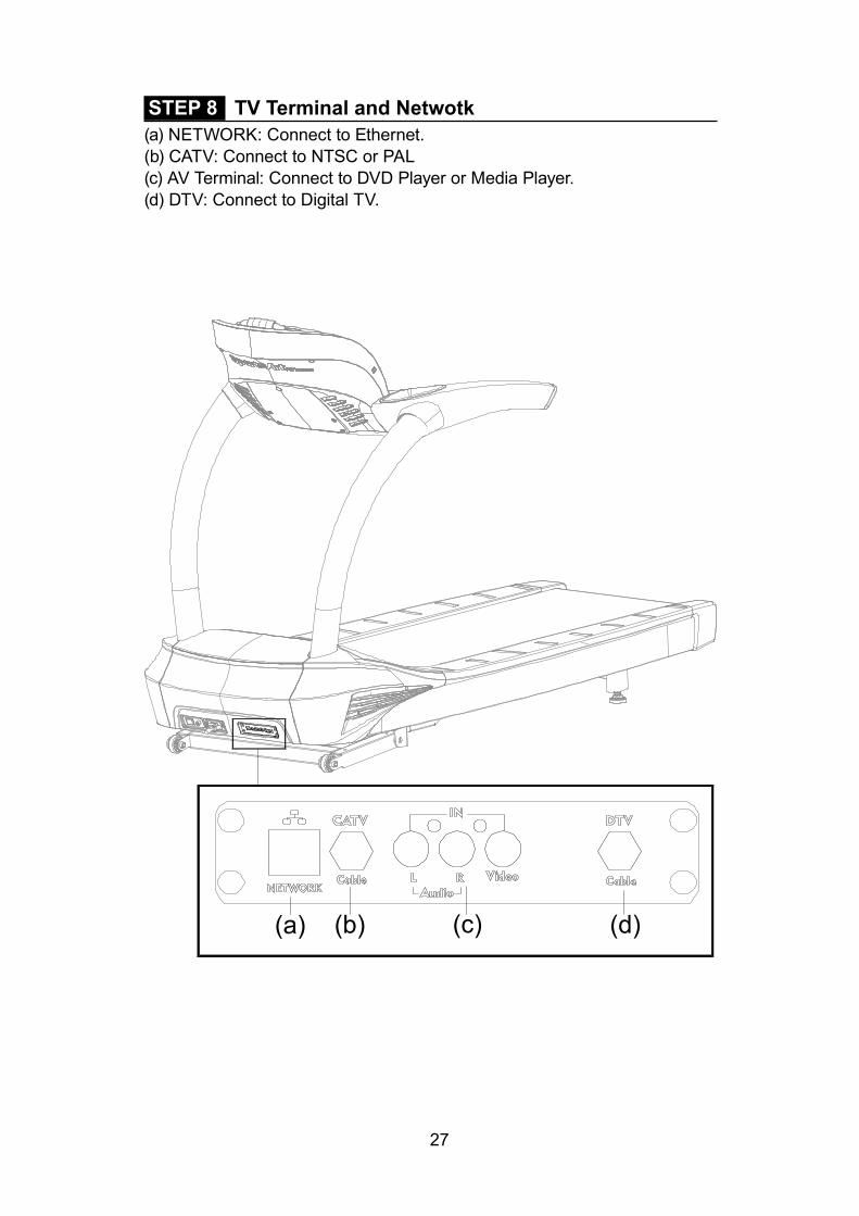
STEP 8 TV Terminal and Netwotk(a) NETWORK: Connect to Ethernet.(b) CATV: Connect to NTSC or PAL(c) AV Terminal: Connect to DVD Player or Media Player.(d) DTV: Connect to Digital TV.
(d)(c)(b)(a)

28
STEP 9 Install the TV cableNTSC system: Directly connect your local area connector as shown.PAL system: Insert NTSC To PAL Adapter (30) as shown and conect to your local area connector.

29
5. UNDERSTAND THE T645-15 DISPLAy DISPLAy OverviewThe T645-15 display was designed to help people obtain their fitness goals simply and conveniently. Please familiarize yourself with the features of this display and thereby get optimum benefit and enjoyment from this product.
DISPLAy Safety KeyGeneral information about Safety Key:The safety key is meant to stop walk belt rotation if the exerciser stumbles or falls. Always attach the clip to your clothes and set the magnet in place on the console. When the magnet is not in place, “SAFETY KEY” will appear on the message window. At this point, the safety key must be put into place on the console to resume normal operation.
Safety Key & Home page display sequence:

30
DISPLAy WindowsSPEED (forward rotation): 0.2 to 20.0 kph; 0.1 to 12.0 mphINCLINE: 0% to 15%, in intervals of 0.5%TIME: 0:00 to 600:00DISTANCE: 0.00 to 9999 kilometers or milesCALORIES: Range 0 to 9999 kcalCAL/HR: 0 to 9999 kcal METS: Metabolic equivalent of task: 0.0 to 99.0PACE: 1 / SPEEDPROGRAM: WORKOUT PROGRAM, TRACK, GLUTE, HILL (HILL1, HILL2, HILL3), RANDOM, INTERVAL (1:1, 1:2, 2:2), FIT TEST (BRUCE, GERKIN, WFI, ARMY, MARINES, NAVY, AIR FORCE, PEB, British Fireman, Norway Fireman, Sweden Fireman), HEART RATE PROGRAM (TARGET HEART RATE 65%, TARGET HEART RATE 80%, CUSTOM HEART RATE, HEART RATE HILL, HEART RATE INTERVAL)
DISPLAy Keys
1. Energy Smart wake up button2. Headphone Jacks3. Stop/Reset button4. Speed Up/Down keys5. Incline Up/Down keys

31
DISPLAy Home Page
1. QUICK START key: to start Quick Start program2. PROGRAM SELECTION key: to enter various program categories3. MEDIA SELECTION key: to enter various media options4. USER PROFILE key: to set up user’s profile5. DEFAULT SETTINGS key: to enter engineering settings6. HELP key: to find out information and/or instruction for each function7. GO GREEN key: to learn more about SportsArt Fitness’ Green Mission

32
6. OPERATE THE T645-15 TREADMILLThere are two ways to start operating this product: (1) Press the QUICK START key, or (2) press the PROGRAM SELECTION key to enter a preset program. Using the QUICK START key allows you to begin exercising im-mediately, without first entering user information. OPERATION Quick Start1. In QUICK START mode, the program will bypass the user age and weight setting and start the motor right away. It will count down from 3 seconds, and the walk belt will rotate at 0.2 kph/0.1 mph. 2. The program time is default at 60 minutes. If the program time limit is ac-tivated in the engineering mode and the limit is less than 60 minutes, then program time limit will take precedence. 3. Quick Start program will use default age of 35 year and weight of 165lb/75kg for exercise expenditure calculation.4. Quick Start display:
1. Cardio Advisor window: it displays actual heart rate, WT loss HR (65% of max HR) and Cardio HR (80% of max HR) (Max HR = 220 - age).2. Workout data pull down menu: select the desired data to customize the feedback display.3. Lap counter and speed display4. Goal completion progress bar5. Media selection button: select or change the media source during exercis-ing, such as iPod, USB music player, TV...6. View selection button: switch program display from default to track, profile, entertaining or heart rate display.7. Program selection button: switch current program to a different program during exercising.

33
OPERATION Quick Start (Continued)8. Left-handed or right-handed buttons: press either hand to put the Quick keys (10) on the left side of the screen or right side. 9. Home button and Back button: when these buttons are light up, press home button to go back to home page or press Back button to go back to previous page.10. Quick keys: press this arrow key, the quick key menu will pull up as be-low.
11. Speed quick keys: press these button to bring the treadmill speed to the selected speed right away.12. Speed adjusting keys: press +, - to adjust the speed by 0.1mph/kph incre-ment. Or press numeric window and the numeric key pads (shown on the left) will pop up for entry.13. Incline adjusting keys: press +, - to adjust the incline by 0.5% increment. Or press numeric window and the numeric key pads (shown on the left) will pop up for entry.14. Fan speed adjusting key: press this key to adjust the speed of the fan.15. Volume control keys16. Cool Down key: press this key during program to end the program and enter cool down mode. It is default for 2 minutes. The speed will gradually reduce to 0 and incline will return to 0 right away. When the time reaches 0, it will end cool down and go into Workout summary review.17. Pause: press this key to pause the treadmill and display. Speed will re-turn to 0 and incline will stay at the current setting. Pause button to switch to “Resume”. Press resume to return exercising.18. STOP button: press this key to end the program and review workout summary (See next page). Speed and incline will reset to 0, press EXIT to go back to home page.

34
OPERATION Quick Start (Continued)Workout summary:
OPERATION Program SelectionThe program mode provides user-specific caloric expenditure and target heart rate values, along with accumulated time, total distance, and total ca-loric expenditure values for individual users.
WORKOUT PROGRAMS: Preset workout programs include: Track, Glute, Hill (Hill 1, Hill 2, Hill 3), Ran-dom, Interval (1:1, 1:2, 2:2) programs.
TRACKThe running distance is preset at 1/4 mile (400m) per track. Once Track pro-gram is selected, it will enter user profile setting page.(1) Age: enter user’s age. The age setting range is 10 to 99 years old, with a default setting of 35 years old. (2) Weight: enter user’s weight. The max weight setting is 205 kg. LB next to the weight setting means English units vs. KG is for Metric units. Press LB/KG to switch the units setting.(3) Select Goal: there are three goal settings: Time/Calories/Distance. Press the key to switch it.(4) Time/Distance/Calories: set program goal.(5) Speed: set the starting speed; the treadmill will adjust the speed to this setting when it starts.
The display after program begins is the same as Quick Start program, please refer to Quick Start program page for details.

35
OPERATION Program Selection (Continued)HILLHill is a preset incline profile program; there are 3 profiles to select from. Once Hill program is selected, it will enter user profile setting page. The pro-gram setting is the same as Track program setting, please refer to previous page for details.
Display during exercise is as shown below. The human icon indicates the current progress; the finished portion is showing in Grey; current position is flashing orange and white and the future portion is showing in white. The progress bar is showing below to indicate user progress. Other operation during exercise is the same as Quick Start program, refer to Quick Start page for details.
INTERVAL (1:1, 1:2, 2:2)There are two segments, a rest segment and a work segment, each of which can have a different speed and incline setting. There are three interval pro-grams: 1:1, 1:2, and 2:2. Numbers in these programs represent time. For instance, in the 1:2- interval workout, one indicates a segment of one-minute in duration, followed by a second segment of two minutes in duration.
Interval segment settings can be changed during a workout. To do so, while exercising, simply press incline or speed keys to change the setting in the current segment. The new settings will apply to that segment thereafter.
Once an Interval program is selected, it will enter user profile setting page. Age, weight, program time as well as Rest and Work segment setting. User can set both incline and speed for Rest and Work segments to customize the Interval program. When the program begins, the treadmill will adjust the speed/incline to the setting.

36
OPERATION Program Selection (Continued)
Display during exercise is the same as Hill program, refer to Hill program page for details.
GLUTEThe Glute Program exercises the gluteus muscle group of the body. There are 2 different exercise illustrations built into this program: 30 minute and 45 minute programs. Once Glute program is selected, it will enter user profile setting page: Age, weight and speed. After setting, press START to begin the program.
Display during exercise is the same as Hill program, refer to Hill program page for details.

37
OPERATION Program Selection (Continued)RANDOMEach time the RANDOM key is pressed a different randomly generated workout illustration will appear. There is an almost infinite number of ran-domly generated workouts. Once Random program is selected, it will enter user profile setting page: Age, weight, goal and speed. After setting, press START to begin the program.
Display during exercise is the same as Hill program, refer to Hill program page for details.
5K & 10KThe 5K workout automatically has a goal of 5 kilometers and 10K workout automatically has a goal of 10 kilometers. Once 5K or 10K program is se-lected, it will enter user profile setting page: Age, weight and speed. After setting, press START to begin the program.

38
OPERATION Program Selection (Continued)Display during exercise is shown below. The red flag is the start position as well as the end position. The tear drop shape represents the current position and it runs in a clockwise direction.
HEART RATE PROGRAM A heart rate program is a goal program based on the target heart rate. In heart rate control programs, speed or incline values automatically adjust to keep the exerciser’s pulse at the optimum rate to obtain his or her fitness goals. There are 5 heart rate programs to select from: TARGET HEART RATE 65%, TARGET HEART RATE 80%, CUSTOM HEAR RATE, HEART RATE HILL and HEART RATE INTERVAL.

39
OPERATION Program Selection (Continued)(1) Target Heart Rate 65% & 80%The target heart rate is calculated at the 65% or 80% of the max heart rate with the max heart rate equals (220 - age). Once one of these program is selected, it will enter user profile setting page: Age, weight, time, priority and max speed. Note: Priority is for user to select either Speed or Incline as the control method for the program. If the speed is selected as the control meth-od, the max speed box will light up for entry. User may set the max speed for the program. Target Heart Rate box is calculated autonomically based on the age entered. After setting, press START to begin the program.
Display during exercise is as shown below. The number above the Heart icon represents the current heart rate. The progress bar is showing below to indicate user progress. The graph in the middle represents the heart rate progressing graph.

40
OPERATION Program Selection (Continued)(2) Custom Heart RateIn Custom heart rate program, user gets to set his/her own heart rate target. Once Custom heart rate program is selected, it will enter user profile setting page: Age, weight, time, target heart rate, priority and max speed. When the Incline is as the control method, user may adjust the speed during program. After setting, press START to begin he program.
Display during exercise is the same as Target hear rate 65% & 80%, refer to previous pages for details.
(3) Heart Rate HillThis program is designed to alternate between 65% & 80% max heart rate targets. Once this program is selected, it will enter user profile setting page: Age, weight, time, priority and max speed. The program setting and display during exercise is the same as pervious heart rate programs.
(4) Heart Rate Interval This program is designed to alternate between Work & Rest heart rate tar-gets. User gets to set his/her own Work and Rest heart rate targets. Once this program is selected, it will enter user profile setting page: Age, weight, time, work heart rate, rest heart rate, priority and max speed. After setting, press START to begin the program.
Display during exercise is the same as pervious heart rate programs; refer to previous pages for details.

41
OPERATION Program Selection (Continued)fIT TEST PROGRAMSThe FIT TEST program includes 11 preset types of physical fitness assess-ments: Bruce, Gerkin, WFI (the Wellness Fitness Initiative), Army, Marines, Navy, Air Force, and PEB (Physical Efficiency Battery), British Fireman, Nor-way Fireman, Sweden Fireman as well as a Custom Fit Test program. User may build his/her custom fit test program in the Default setting section. Once a Fit Test program is selected, it will enter user profile setting page: Age, weight, height, gender. Target heart rate and BMI boxes are calculated and filled based on the information user entered; it can not be changed.
Display during exercise is the same as Hill program; refer to that page for details.

42
OPERATION Program Selection (Continued)(1) BruceThis program is designed based on Bruce Protocol for examining one’s car-diac function. Health care professional often uses this test along with elec-trocardiogram to assess one’s cardio health. When using this program, user may stop the test at anytime according to his/her condition.
(2) GerkinThe fitness test will end if any one of the following conditions occurs:
● The STOP key is pressed ● The test is completed ● The exerciser’s heart rate exceeds (220-AGE) x 0.8 for 15 seconds
At the end of the fitness test, “END OF FIT TEST” “YOUR SCORE- xxx” will appear, where xxx represents a score of from 0 to 100 points.
(3) WfI (Wellness fitness Initiative)This is a fitness test recommended by IAFF/IAFC for assessing a firefighter’s aerobic fitness in North America.
At the beginning of this fitness test, the message “WEAR HR STRAP” will appear on the display. If no heart rate signal is received, the message “NO HR SIGNAL, TEST REQUIRES HR” will appear, followed by the startup banner screen. If the heart rate signal is received, a prompt for the height setting will appear. The height setting range is 40 - 90 inches (100 - 230 cm) with default of 70 inch/180 cm. Once the height is entered, the Target heart rate and BMI will be displayed. After setting, press START to begin the test. This fitness test will end if any one of the following conditions occurs:
● The STOP key is pressed ● The test is completed ● The exerciser’s heart rate exceeds (220-AGE) x 0.85 for 15 seconds ● No heart rate signal is received for 30 seconds
At the end of this fitness test, “TEST END – xx MIN” will appear, where xx represents the exercise time, and “SCORE - xxx” will appear, where xxx rep-resents VO2 MAX. Then a three-minute cool down period will begin. Speed will decrease to three mph and incline will decrease to zero percent.
(4) Army, Marine & NavyWhen these fitness tests begin, the program first inspects whether the exer-ciser’s age is within the test’s age range. Army: 17 to 42 years old. Marines: 17 to 90 years old. Navy: 17 to 34 years old. If the exerciser’s age is not within the specified range, “AGE xx-xx” will appear on the message window, then return to the home screen. If the exerciser’s age is within the specified range, the gender setting protocol begins.

43
OPERATION Program Selection (Continued)The ARMY and MARINES tests will begin after the gender setting. But the Navy test offers more options from which to choose. The NAVY test includes five different physical fitness assessments: 1-IFA (Individual Fitness Assess-ment), 2-SEAL (Sea Air Land), 3-SBO (Swift Boat Operator), 4-EOD (Ex-plosive Ordnance Disposal), 5-ARS (Air Rescue Swimmers). Press numeric keys (1 to 5) to choose one of the five fitness tests, or press the ENTER key to directly select the IFA test.
If your time is less than or equals the test needed time , “PASS” will appear on the message window. If not, “SORRY, TRY AGAIN” will appear. At this point, after Army and Navy tests, the home screen will appear. After the Marine test, a cool down period will begin. During the test, if you press the STOP key before the time elapses, “SORRY, TRY AGAIN” will appear, then return to the home screen.
(5) Air forceFor this fitness test, the exerciser’s age must fall within the range of 20 to 50 years old. If the age is not within this range, “AGE xx-xx” will appear, followed by the home screen. If age is within the range, the gender selection protocol will begin. After setting, press START to begin the test .
After program starts, “WEAR HR STRAP” will appear on the message screen. This test requires a heart rate signal. If there is no heart rate signal within 20 seconds, “NO HR SIGNAL, TEST REQUIRES HR” will appear then return to the home screen.
When the test ends or the STOP key is pressed, “YOUR SCORE-xxx” will appear, where xxx represents a score with from 0 to 100 points. If the dis-tance was covered within the time limit, “PASS” will appear. If not, “SORRY, TRY AGAIN” will appear. Then a cool down period will begin.
(6) PEB (Physical Efficiency Battery)The PEB test requires a gender designation. After gendre setting, press START to begin test. When the test ends or the user presses the STOP key, “YOUR SCORE- xxx” will appear, where xxx represents a score with 0 to 100 points. Then return to the home screen.
(7) British firemanThis fitness test will end if any one of the following conditions occurs:
● The STOP key is pressed, “TEST FAIL” will appear and return to home screen in 5 seconds.
● The test is completed ● The exerciser’s heart rate exceeds (220-AGE) x 0.85 for 15 seconds ● No heart rate signal is received for 30 seconds. “TEST FAIL” will appear
and return to home screen in 5 seconds

44
OPERATION Program Selection (Continued)(8) Norway fireman If the test is completed, “TEST FINISH” will appear. It will return to home screen in 2 minute if no other activities occurred. If the test is interrupted and not finished, “TEST FAIL” will appear. It will return to home screen in 2 minutes if no other activities occurred.
(9) Sweden firemanFirst, select from one of six Brandmanna tests to begin the test. If the test is completed, “TEST FINISH” will appear. It will return to home screen in 2 min-ute if no other activities occurred. If the test is interrupted and not finished, “TEST FAIL” will appear. It will return to home screen in 2 minutes if no other activities occurred.
(10) Custom fit TestUser may design and set up his/her own fitness test program. To custom your own fitness test program, access it through the Default setting section during home screen.

45
OPERATION Media Selection There are several media input options built in this console; such as TV(TV, DTV, A/V), YouTube, Hulu, Netflix, iPod/iPhone, USB(Music/Video), Face-book, Twitter social medias.
There is a built in remote control for changing the channels and volume con-trol. Channel changing is compatible with TV & DTV only.
Music media will be displayed with a play list as shown below.1. Music play time2. Play, Next, Previous, Continuously, Shuffle3. Volume +, - keys4. Song’s name5. Song scrolling
iPod/iPhone selection includes iPod/iPhone music and video.USB selection includes USB music and video.

46
OPERATION User Profile User profile is designed for more accurate workout calculation and control during program. It is encouraged to enter and save the user profile before each program for future convenience and more accurate workout tracking.
User may build his/her own program by press Custom Program button and define all the segments. Afterwards, if an USB flash disk is inserted, the user information including Custom Program can be saved into the disk by press-ing SAVE button. The user profile can be shared with an optional SA WELL+ member workout tracking system.

47
OPERATION Default Setting User may change the default setting by visit Default setting section and mod-ify the settings.
(1) Language Setting: user may select a different language by choosing an associated country.
(2) Engineering Setting: this section is designed for service provider or equipment manager to access the product’s record as well reviewing the his-tory of this product. Manager can change the setting to better fit the facility needs. There is a password required to enter the settings. (The password is “2013” and it not changeable)
(3) Bluetooth Setting: this is for Bluetooth device pairing.

48
OPERATION Error MessagesError messages can appear on this treadmill as a troubleshooting aid. Error messages appear in the following format: “ERROR _X_Y”. X represents the category of the error. Y represents the specific issue.
In the position of the X placeholder, the following numbers can appear to represent the category of the malfunction:
Code Explanation1 Servo motor abnormality2 IGBT abnormality3 Incline motor abnormality4 Power switch abnormality8 Communication abnormality
Error code explanations follow:ERROR_1_1_ : Servo motor encoder abnormality. Restart the unit to re-cover normal functions.ERROR_1_2_: Servo motor excessive heat warning. The treadmill will oper-ate at half speed.ERROR_1_3_: Servo motor overload abnormality. Restart the unit to re-cover normal functions.ERROR_2_1_: IGBT excessive current. Restart the unit to recover normal functions.ERROR_2_2_: IGBT excessive heat. The treadmill will operate at half speed.ERROR_2_3_: Current sensor value is too high. Wait until current returns to normal before restarting the unit.ERROR_3_1_: Incline motor calibration abnormality.ERROR_4_2_: Power supply voltage is too low. Wait until voltage returns to normal before restarting the unit.ERROR_4_3_: Power supply voltage is too high. Wait until voltage returns to normal before restarting the unit.ERROR_8_1_: Startup communication abnormality. Resume operation when communication is normal.ERROR_8_2_: Communication abnormality. Resume operation when com-munication is normal.

49
OPERATION Switching Program User may switch to a different program during exercising by pressing the Program Selection button on the bottom of the screen. If this occurs, the program goal will remain the same as previous program and data accumula-tion (Time, Distance, Calories) will continue counting from previous program as well. However there are exceptions listed below:
(1) While using HILL, INTERVAL, RANDOM, TRACK programs, it is not al-lowed to switch to FIT TEST programs.(2) It is not allowed to do the program switching while using GLUTE or FIT TEST program.
OPERATION Idle ModeWhen the treadmill is stop running and no other activity for 2 minutes, the console will enter Idle mode and the display will go back to Idle page and display SportsArt logo. Press any key during idle mode to enter Home page.
OPERATION Energy Smart functionThis treadmill is built in with energy smart feature which is an energy conser-vation function for when the treadmill is not in use. This feature can be acti-vated in the Engineering setting and a timer can be set. When this feature is activated, the power will be shut off to run any control boards and electronic components in this treadmill. This will reduce the energy consumption to the minimal. There will be only an LED next to WAKE UP button light up on the console to indicate that the treadmill is in the energy smart mode. Press the WAKE UP button to turn the power on and return to idle mode. If the timer is setting less than 5 minutes, the timer will be de-activated and the console will not get into energy smart mode at all.

50
7. ABOUT HEART RATE DETECTIONHeart rate detection functions are selected at the time of purchase. Not every product includes every type of heart rate detection device. The following explains factors that influence the performance of two of the most common types of heart rate detection devices.
HEART RATE TelemetryThe words “telemetry heart rate” refer to the detection of heart rate via a device worn on the exerciser and transmitted over the air to a circuit board built into the product. Telemetry heart rate devices are commonly worn on the exerciser’s chest, where the pulse is strongest and relatively easy to detect.
The following explains conditions that affect the performance of the telemetry heart rate detection in all fitness products.
● The telemetry heart rate transmitter emits a wireless 5 kHz signal that is harmless to the human body. Inside the transmitter is a 3-volt battery (CR2032). If the battery voltage is too low, either the reception distance shortens or there will be no reception whatsoever.
● Secure the telemetry heart rate transmitter on your chest so that it stays in place without making you feel uncomfortable. Moisten the skin for better contact.
● Because the telemetry heart rate signal varies in strength from 20 Hz to 20 KHz, environmental interference can block signal reception. Physical vibration and electronic devices, including stereos, TVs, and even fluores-cent lights, can interfere with signal reception. For best results, install fitness products in an area free from such interference.
● Space fitness products apart by at least 39 inches (100 cm) to avoid hav-ing the heart rate value from one exerciser appear on a neighboring fitness product.
HEART RATE ContactThe words “contact heart rate” refer to the detection of the heart rate via sensors on the fitness product. By holding the sensors, the exerciser can view his or her heart rate on the product display. Like telemetry heart rate, contact heart rate can be influenced by several factors. The following list includes some of these factors.
● A weak pulse makes it difficult to detect heart rate.
● Low systolic blood pressure makes it difficult to detect heart rate.
● Dry, course palms impede heart rate detection. For best results, moisten your palms. But do not apply hand lotion immediately prior to your workout, because hand lotion can gum up the contact pads.
Heart rate detection devices used on fitness products are not medical de-vices. Heart rate values are for reference only. Do not use them for medical diagnostic or treatment work.

51
HE
CAUTION: Heart rate detection and transmission devices have been known to interfere with the operation of pacemakers, possibly endangering human life. If you have a pacemaker, exercise under your doctor’s supervision; take a test to ensure your safety during the simultaneous use of the pacemaker and heart rate detection devices. The use of such devices must be undertaken at your own risk.
Note that in dry areas in particular, static electricity can interfere with unit operation and shock people. To discharge static electricity from your body, touch something else before touching metal on the fitness product.
8 GUIDELINES fOR EXERCISEHOW HARD SHOULD I EXERCISE?
Studies show that to benefit from aerobic exercise you need to maintain a certain heart rate during your workout. Your heart rate training zone depends on your age and fitness level.
The darkened area in the chart to the right represents the recommended heart rate training zone for people of various ages. It was calculated by taking 220 minus age in years, multiplied by 65% and 80%. The area between those values is the heart rate training zone.
CAUTION: Heart rate training zones are generalizations and may not suit every person. Always check with your physician to understand what heart rate goal would be appropriate for you.
HOW LONG SHOULD I EXERCISE?
The duration of your workout must depend on your fitness level. In general, it is recommended that you maintain a heart rate within your training zone for at least 15 to 20 minutes to experience the benefits of aerobic exercise. Beginners should always start out slowly and gradually increase the duration and intensity of their workouts. As your fitness level improves, you will be able to maintain a heart rate within the training zone for longer periods of time.
When you begin your workout, use the first several minutes to warm up. Then slowly increase the intensity of your workout to bring your heart rate into your training zone. At the end of your workout, gradually decrease your workload. Then exercise lightly to cool down.
HOW OfTEN SHOULD I EXERCISE?
Research indicates that to achieve the greatest benefit, people should exercise three to five times per week. It is important to allow sufficient time, at least 24 hours, for your body to recover after exercise.

52
9. ACCESSORIESThere are accessories attached to this console; some are standard and some are optional. The following explains the details of each accessory and its function.
USB CHARGER (Standard)The USB charger will provide 5V 500mA voltage for the smart phone or other devices charging. However it is not compatible with tablet PC, such asiPad. Check the device for charging details.
USB MEDIA PLAyER (Standard)When an USB disk contains MP3/MP4 format music or video files is plugged into the Media player USB port, the media player will be activated and the play list will be shown. Follow the play list menu to control the player func-tions. (Note: this function does not support Android smart phone music play-er due to upkeep of their software.)
CSAfE PORT (Standard)Compatible with CSAFE (Communications Specification for Fitness Equip-ment) Protocol. It works with optional Netpulse Personal Entertainment Sys-tem as well as ECOFIT System.
SA WELL+ Member System (Option)This is a system designed specially by SportsArt to assist user managing his/her workout history. There are three ways to get connected with the member site:1. Use Bluetooth in the smart phone and SA WELL+ App. The App is available for downloading in the App stores.2. Use USB Flash Drive to store the workout data.3. Use member card to access user profile and workout tracking.
Visit SA WELL+ website for more information about this feature.

53
9. ACCESSORIES (CONTINUED)Entertainment Cap (a) RFID member card slot: work with both optional SA WELL+ and ECOFIT member cards.(b) Bluetooth connection button: press this button to unpair the smart phone SA WELL+ App.(c) USB port: this port is used for device charging as well as optional data transferring. (d) USB port: this port is used for device charging as well as media playing such as MP3/MP4.(Note: USB port is not used for tablet PC charging, such as iPad.)

54
10. MAINTENANCEThis section covers maintenance topics, including instructions on replacing a fuse and lubricating the walk belt, along with the presentation of a main-tenance schedule, maintenance task list, one-year maintenance log, and electronics block diagram.
MAINTENANCE How to Replace a fuseIf electrical current becomes too high, the fuse breaks. This protects the product. To replace a fuse, follow instructions (a) through (g) below.(a) Press the fuse cap inward. using a tool.(b) Turn the fuse cap counterclockwise.(c) The fuse cap springs out.(d) Remove the burnt fuse.(e) Insert a new fuse into the fuse cap.(f) Insert the fuse into the fuse holder.(g) Use a tool to rotate the fuse cap clockwise and secure it into place.Fuse specifications: 110 V = 15 Amp, A(F); 220V = 10 Amp, A(F)

55
MAINTENANCE Lubrication System Lubrication System flowchart
Power On
RESET
Total ExerciseDistance Display (mile)ex:
Walks Belt Total
Running Time
Speed Version Displayex:T655
Up
Total ExerciseDistance Display (km)ex:
Total ExerciseDistance Display (km)ex:
Total ExerciseDistance Display (km)
ex:
Model No. Display ex: T655 5 seconds
Beeper On &LED Flashes【CH oil】
Display:
ReplaceLubricant
Bottle
Auto Lubricate40 Times
(1000km/time)
Lubricant Change ProcedureNote: Pay extra attention during the lubricant changing procedure to avoid electric shock; especially operating it while the power is on.
Press KeyDisplay:
Press & hold RESETKey for 3 seconds
Display:
Completed【【【【done】】】】Display:
Total ExerciseDistance Display
ex:
Turn power off & Remove motor
cover
ReplaceLubricant
Bottle
Turn Power on
Auto lubricate twice【detect】
Display:
※ Press RESET Key twice to replace the bottle.
Press RESET KeyPress RESET Key
Turn power off & Assemble motor
cover back
※※※※Press Key to choose Yes or No

56
MAINTENANCE Lubrication System (Continued)To replace the lubricant bottle, follow instructions (a) through (d) below.(a) Loosen the screws on the bezel and push the bezel up.(b) Take the old lubricant bottle out.
(c) Unscrew the nozzle from the old lubricant bottle and screw it onto new bottle.(d) Place the new lubricant bottle into the lubrication system; push the bezel down and tighten it with screws. (Note: Before place the new bottle in place, press the pump a couple of times to ensure the lubricant floats through the hose nicely. Pay attention to the lubricant hose direction when place the bottle into the system.)
Also note the following:1. Even if the “Lubricant bottle exchange” warning is not displaying, it is still OK to perform the “Lubri-cant change procedure”.
2. After replacing the lu-bricant, the total lubrica-tion timer will reset to 0 and start counting again.
3. After the “Lubricant bottle exchange” warning displayed, the lubrication system will stop lubricating automatically. The lubrica-tion system will continue lubricating every 1000km (621.4miles) after the warning is cleared.
4. The lubrication system will pump twice automatically once the lubri-cant exchanging procedure is completed to ensure the new bottle is working properly.

57
MAINTENANCE Lubrication System (Continued)Error Messages:There are 2 error messages with this system.Error 1: It indicates that the system memory failing and it will not be able to perform any auto lubrication.
Error 2: It indicates motor is failing or system will not be able to perform any function.
If any of these messages showing, contact your local dealer for servicing.
Protective Message:Indication Buzzer
occurredBuzzer sound
frequency Action Protective message
Replace lubricant bottle
If an abnormal-ity occurs during the operating, the buzzer will sound for 30 seconds.
The buzzer will sound for 0.5 sec-onds and stop for 0.5 seconds.The buzzer will stop working after 30 seconds.
Replace lubricant bottle. Press & hold RESET Key for 3 seconds and then choose Yes.
CH Oil
Lubrication VR motor damaged
If an abnormal-ity occurs during the operating, the buzzer will sound for 30 seconds..
The buzzer will sound for 2 sec-onds and stop for 2 seconds.The buzzer will stop working after 30 seconds.
Replace lubrica-tion VR motor.
ERR.02
EEPROM damaged
If an abnormal-ity occurs during the operating, the buzzer will sound for 30 seconds.
The buzzer will sound for 2 sec-onds and stop for 2 seconds.The buzzer will stop working after 30 seconds.
Replace new lubrication system.
ERR.01
Lubrication system cannot accumulate mileage
If an abnormality occurs, the buzz-er will sound for 60 seconds after the unit is turned on for 20 times.
The buzzer will sound for 1 sec-ond and stop for 1 second.The buzzer will stop working after 60 seconds.
Wipe dust off the sensor if neces-sary. Replace the sen-sor if damaged.
ERR.03
Lubrication system cannot accumulate mileage
If an abnormality occurs, the buzz-er will sound for 60 seconds after 480 hours.
The buzzer will sound for 1 sec-ond and stop for 3 second.The buzzer will stop working after 60 seconds.
Wipe dust off the sensor if neces-sary. Replace the sen-sor if damaged.
ERR.04

58
Area Day Week Month Quarter Year Notes
1 Exterior Clean.
2 Screws Inspect and secure loose parts.
3 Treadmill test Ensure the treadmill operates properly.
4 Walk belt Inspect alignment (centering) and look for wear.
5 Walk deck Inspect for wear.
6 Belt guides Inspect for normal rotation.
7 Front roller Inspect for normal rotation.
8 Rear roller Inspect for normal rotation.
9 Motor compartment Remove dust and debris.
10 Drive belt Replace once every three years.
11 Lubricant bottle Replace once every 40000km /25000mi
MAINTENANCE Schedule

59
MAINTENANCE Task ListLike cars, fitness products require maintenance. Regular maintenance ex-tends product life, and failure to maintain products can void the manufac-turer’s warranty. Copy the maintenance log sheet, and record maintenance work for each fitness product.
Daily tasks1. Use a clean, lint-free towel, dampened with a mixture of Simple Green® all-purpose cleaner and water, to thoroughly clean the product exterior.2. Inspect all screws. Secure if necessary.3. Run a treadmill test everyday to make sure it is operating properly.
Monthly tasks1. Inspect walk belt alignment. Align the walk belt if necessary. Inspect for wear.
Quarterly1. Inspect the walk deck for wear. Flip the walk deck if necessary.2. Inspect the walk belt guides for normal rotation.3. Inspect the front roller for normal rotation.4. Inspect the rear roller for normal rotation.5. Remove dust and debris from the motor compartment.
yearly1. Replace the drive belt once every three years. 2. Replace the lubricant bottle every 40,000km/25,000mile.
Caution ● Please follow standard safety precautions when servicing on this product.
● Electronic components can carry an electrical charge even after the prod-uct has been turned off. For safety, turn off unit power. Wait five minutes to allow capacitors to discharge. Then disconnect the power cord from the wall socket (if applicable.) Only after such steps have been completed should covers be removed and electronic components accessed.
● Do NOT use cleaners with alcohol, ammonia, or other damaging chemi-cals. The use of such chemicals can damage the product and void the war-ranty. Never spray or pour any liquid directly onto the product. Doing so can damage electronic components and void the warranty.
● This product has moving parts that can be hazardous. Exercise caution when maintaining, operating, or moving this product.

60
Daily Tasks Weeks 1-7 Weeks 8-14 Weeks 15-21 Week 22-28Completed
Daily Tasks Week 29-35 Week 36-42 Week 43-49 Week 50-52Completed
Weekly Tasks Weeks 1-7 Weeks 8-14 Weeks 15-21 Weeks 22-28Completed
Weekly Tasks Weeks 29-35 Weeks 35-42 Weeks 43-49 Weeks 50-52Completed
Monthly tasks 1 2 3 4 5 6 7 8 9 10 11 12Completed
Quarterly Tasks Quarter 1 Quarter 2 Quarter 3 Quarter 4Completed
yearly Tasks year 1Completed
Notes: __________________________________________________________
________________________________________________________________
________________________________________________________________
________________________________________________________________
MAINTENANCE One-year Maintenance Log
Facility:_______________________ Supervisor:____________________
Product model number:__________ Serial number:_________________
Start date: ____________________ End date:_____________________

61
MAINTENANCE Electronics Block Diagram
:Connector:Converge
◇A
◇E
◇F◇D◇B
◇G
◇C
SAC3 Board
DSP Board POWER
Board
Drive board internal connection:
Fan
Contact HTR plates
HRC Board
Fan Board
Safety key Board Bridge Board
Speed/Incline Key Board
Incline Control Motor Incline Sensor
AC Servo motor
Automatic Oil Lubrication System
Inductor ※ 220V products only
110V not necessary
SwitchFuseAC Jack
◇A
◇B ◇C ◇D◇E
◇F
◇G
Oil Lubrication
Drive Board
[Option]
15" LCD Screen
CATV
DTV
AV Board
HTR Board
IPOD Board
Head Phone Board
CSAFE Board
EUP Key Board
Control BoardDisplay Board
USB Board
◇B ◇D ◇F
◇A
◇E
◇G
◇C
EAC Board
DSP Board
POWER Board
Only U.S.A
EUP Board
Filter