switched-mode power supply module with ac and dc supply
TRANSCRIPT
*26862557_1220*Drive Technology \ Drive Automation \ System Integration \ Services
Operating Instructions
Power and Energy SolutionsSwitched-Mode Power Supply Module with AC and DCSupply
Edition 12/2020 26862557/EN
SEW-EURODRIVE—Driving the world
Table of contents
Operating Instructions – Switched-Mode Power Supply Module with AC and DC Supply 3
Table of contents1 General information.................................................................................................................. 6
1.1 About this documentation ............................................................................................... 61.2 Structure of the safety notes ........................................................................................... 6
1.2.1 Meaning of signal words ................................................................................ 61.2.2 Structure of section-related safety notes........................................................ 71.2.3 Structure of embedded safety notes .............................................................. 7
1.3 Rights to claim under limited warranty ............................................................................ 71.4 Other applicable documentation ..................................................................................... 81.5 Product names and trademarks...................................................................................... 81.6 Copyright notice .............................................................................................................. 8
2 Safety notes .............................................................................................................................. 92.1 Preliminary information ................................................................................................... 92.2 Duties of the user............................................................................................................ 92.3 Target group ................................................................................................................. 102.4 Designated use ............................................................................................................. 11
2.4.1 Hoist applications ......................................................................................... 112.4.2 Restrictions under the European WEEE Directive 2012/19/EU ................... 11
2.5 Functional safety technology ........................................................................................ 112.6 Transport....................................................................................................................... 122.7 Installation/assembly..................................................................................................... 122.8 Electrical installation ..................................................................................................... 13
2.8.1 Required preventive measure ...................................................................... 132.8.2 Stationary application................................................................................... 13
2.9 Protective separation .................................................................................................... 132.10 Startup/operation .......................................................................................................... 14
3 Device structure ..................................................................................................................... 153.1 Nameplate..................................................................................................................... 15
3.1.1 Switched-mode power supply module with AC and DC supply MDS90A .... 153.2 MOVIDRIVE® modular Power and Energy Solutions type code .................................. 163.3 Device structure of switched-mode power supply module with AC and DC supply
MDS90A-0054-5E3-X-000 ............................................................................................ 17
4 Installation............................................................................................................................... 184.1 Installation accessories................................................................................................. 18
4.1.1 Standard accessories – mechanical accessories ........................................ 184.1.2 Electrical accessories................................................................................... 18
4.2 Permitted tightening torques ......................................................................................... 194.3 Requirements when combining switched-mode power supply modules in a network .. 20
4.3.1 Examples ..................................................................................................... 214.4 Mechanical installation.................................................................................................. 22
4.4.1 Mounting grid ............................................................................................... 224.5 Electrical installation ..................................................................................................... 23
4.5.1 General information...................................................................................... 244.5.2 Permitted voltage systems ........................................................................... 244.5.3 Line fuses, fuse types .................................................................................. 25
2686
2557
/EN
– 1
2/20
20
Table of contents
Operating Instructions – Switched-Mode Power Supply Module with AC and DC Supply4
4.5.4 DC connection via line connection ............................................................... 264.5.5 Line filter....................................................................................................... 284.5.6 Use in IT systems......................................................................................... 284.5.7 AC contactor control..................................................................................... 294.5.8 Parallel connection of 2 switched-mode power supply modules.................. 314.5.9 Parallel connection of 3 to 6 switched-mode power supply modules........... 324.5.10 Connection of an axis system ...................................................................... 344.5.11 Inputs/outputs............................................................................................... 354.5.12 Installing touch guards and closing covers .................................................. 35
4.6 Terminal assignment..................................................................................................... 374.6.1 Switched-mode power supply module with AC and DC supply ................... 37
4.7 Wiring diagrams ............................................................................................................ 384.7.1 Connection of switched-mode power supply module via DC link and line
connection.................................................................................................... 384.7.2 Connection of switched-mode power supply module via MDP92A or MDE90A
394.7.3 Connection of switched-mode power supply module and power supply module
with separate line connection....................................................................... 404.7.4 Connection of switched-mode power supply module via DC source and DC
link................................................................................................................ 414.7.5 Electronics connection of switched-mode power supply module ................. 42
5 Startup ..................................................................................................................................... 435.1 Settings on the selector switches.................................................................................. 43
5.1.1 Output voltage.............................................................................................. 435.1.2 Start delay .................................................................................................... 435.1.3 Starting voltage threshold ............................................................................ 43
6 Operation................................................................................................................................. 456.1 LED displays ................................................................................................................. 45
6.1.1 Operating displays – LED displays .............................................................. 456.2 Monitor signals.............................................................................................................. 46
6.2.1 24 V monitor ................................................................................................. 466.2.2 DC link monitor............................................................................................. 466.2.3 Output OK .................................................................................................... 476.2.4 DC available................................................................................................. 476.2.5 AC available ................................................................................................. 486.2.6 Enable .......................................................................................................... 486.2.7 Auxiliary voltage output 12 V out.................................................................. 48
6.3 External voltage ............................................................................................................ 48
7 Service..................................................................................................................................... 497.1 Electronics Service by SEW‑EURODRIVE................................................................... 497.2 Extended storage.......................................................................................................... 49
7.2.1 Storage conditions ....................................................................................... 497.3 Waste disposal.............................................................................................................. 50
8 Technical data......................................................................................................................... 518.1 Markings ....................................................................................................................... 51
2686
2557
/EN
– 1
2/20
20
Table of contents
Operating Instructions – Switched-Mode Power Supply Module with AC and DC Supply 5
8.1.1 Basic device ................................................................................................. 518.1.2 Accessories.................................................................................................. 52
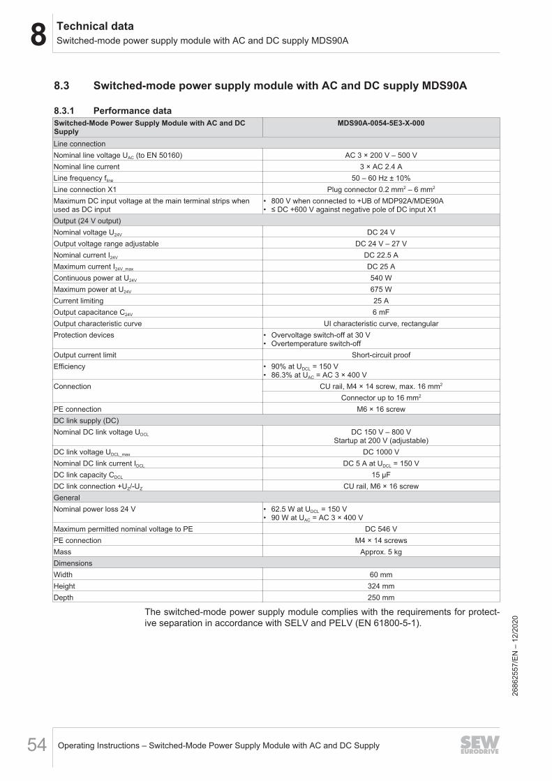
8.2 General technical data .................................................................................................. 538.3 Switched-mode power supply module with AC and DC supply MDS90A..................... 54
8.3.1 Performance data......................................................................................... 548.3.2 Electronics data – signal terminals............................................................... 558.3.3 Dimension sheet .......................................................................................... 56
8.4 Technical data of accessories....................................................................................... 578.4.1 Line filter....................................................................................................... 57
Index ........................................................................................................................................ 58
9 Address list ............................................................................................................................. 60
2686
2557
/EN
– 1
2/20
20
1 General informationAbout this documentation
Operating Instructions – Switched-Mode Power Supply Module with AC and DC Supply6
1 General information1.1 About this documentation
The documentation at hand is the original.This documentation is an integral part of the product. The documentation is intendedfor all employees who perform work on the product.Make sure this documentation is accessible and legible. Ensure that persons respon-sible for the systems and their operation as well as persons who work on the productindependently have read through the documentation carefully and understood it. If youare unclear about any of the information in this documentation or if you require furtherinformation, contact SEW‑EURODRIVE.
1.2 Structure of the safety notes1.2.1 Meaning of signal words
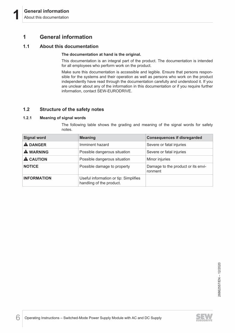
The following table shows the grading and meaning of the signal words for safetynotes.
Signal word Meaning Consequences if disregarded
DANGER Imminent hazard Severe or fatal injuries
WARNING Possible dangerous situation Severe or fatal injuries
CAUTION Possible dangerous situation Minor injuries
NOTICE Possible damage to property Damage to the product or its envi-ronment
INFORMATION Useful information or tip: Simplifieshandling of the product.
2686
2557
/EN
– 1
2/20
20
1General informationRights to claim under limited warranty
Operating Instructions – Switched-Mode Power Supply Module with AC and DC Supply 7
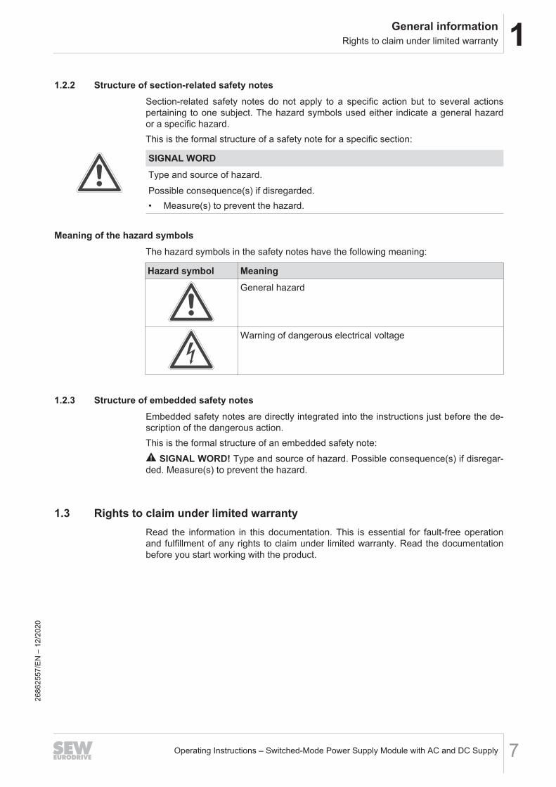
1.2.2 Structure of section-related safety notesSection-related safety notes do not apply to a specific action but to several actionspertaining to one subject. The hazard symbols used either indicate a general hazardor a specific hazard.This is the formal structure of a safety note for a specific section:
SIGNAL WORDType and source of hazard.Possible consequence(s) if disregarded.• Measure(s) to prevent the hazard.
Meaning of the hazard symbolsThe hazard symbols in the safety notes have the following meaning:
Hazard symbol MeaningGeneral hazard
Warning of dangerous electrical voltage
1.2.3 Structure of embedded safety notesEmbedded safety notes are directly integrated into the instructions just before the de-scription of the dangerous action.This is the formal structure of an embedded safety note:
SIGNAL WORD! Type and source of hazard. Possible consequence(s) if disregar-ded. Measure(s) to prevent the hazard.
1.3 Rights to claim under limited warrantyRead the information in this documentation. This is essential for fault-free operationand fulfillment of any rights to claim under limited warranty. Read the documentationbefore you start working with the product.
2686
2557
/EN
– 1
2/20
20
1 General informationOther applicable documentation
Operating Instructions – Switched-Mode Power Supply Module with AC and DC Supply8
1.4 Other applicable documentationUse this addendum only together with the following documentation:• "Power and Energy Solutions – Energy Supply for Multi-Axis Systems with Storage
Technology" operating instructions• "Power and Energy Solutions – Energy Supply for Multi-Axis Systems with Storage
Technology" product manual
1.5 Product names and trademarks
The brands and product names in this documentation are trademarks or registeredtrademarks of their respective titleholders.
1.6 Copyright notice
© 2020 SEW‑EURODRIVE. All rights reserved. Unauthorized reproduction, modifica-tion, distribution or any other use of the whole or any part of this documentation isstrictly prohibited.
2686
2557
/EN
– 1
2/20
20
2Safety notesPreliminary information
Operating Instructions – Switched-Mode Power Supply Module with AC and DC Supply 9
2 Safety notes2.1 Preliminary information
The following general safety notes serve the purpose of preventing injury to personsand damage to property. They primarily apply to the use of products described in thisdocumentation. If you use additional components, also observe the relevant warningand safety notes.
2.2 Duties of the userAs the user, you must ensure that the basic safety notes are observed and compliedwith. Make sure that persons responsible for the machinery and its operation as wellas persons who work on the device independently have read through the documenta-tion carefully and understood it.As the user, you must ensure that all of the work listed in the following may be carriedout only by qualified specialists:• Setup and installation• Installation and connection• Startup• Maintenance and repairs• Shutdown• DisassemblyEnsure that the persons who work on the product pay attention to the following regula-tions, conditions, documentation, and information:• National and regional safety and accident prevention regulations• Warning and safety signs on the product• All other relevant project planning documents, installation and startup instructions,
and wiring diagrams• Do not assemble, install or operate damaged products• All system-specific specifications and conditionsEnsure that systems in which the product is installed are equipped with additionalmonitoring and protection devices. Observe the applicable safety regulations and leg-islation governing technical work equipment and accident prevention regulations.
2686
2557
/EN
– 1
2/20
20
2 Safety notesTarget group
Operating Instructions – Switched-Mode Power Supply Module with AC and DC Supply10
2.3 Target group
Specialist for me-chanical work
Any mechanical work may be performed only by adequately qualified specialists. Spe-cialists in the context of this documentation are persons who are familiar with thedesign, mechanical installation, troubleshooting, and maintenance of the product whopossess the following qualifications:• Qualifications in the field of mechanics in accordance with the national regulations• Familiarity with this documentation
Specialist for elec-trotechnical work
Any electrotechnical work may be performed only by electrically skilled persons with asuitable education. Electrically skilled persons in the context of this documentation arepersons who are familiar with electrical installation, startup, troubleshooting, and main-tenance of the product who possess the following qualifications:• Qualifications in the field of electrical engineering in accordance with the national
regulations• Familiarity with this documentation
Additional qualific-ations
In addition to that, these persons must be familiar with the valid safety regulations andlaws, as well as with the requirements of the standards, directives, and laws specifiedin this documentation.The persons must have the express authorization of the company to operate, pro-gram, parameterize, label, and ground devices, systems, and circuits in accordancewith the standards of safety technology.
Instructed persons All work in the areas of transportation, storage, operation and waste disposal must becarried out by persons who are trained appropriately. The purpose of the training is togive persons the ability to perform the required tasks and work steps in a safe and cor-rect manner.
2686
2557
/EN
– 1
2/20
20
2Safety notesDesignated use
Operating Instructions – Switched-Mode Power Supply Module with AC and DC Supply 11
2.4 Designated use
The product is intended for control cabinet installation in electrical plants or machines.In case of installation in electrical systems or machines, startup of the product is pro-hibited until it is determined that the machine meets the requirements stipulated in thelocal laws and directives. For Europe, Machinery Directive 2006/42/EC as well as theEMC Directive 2014/30/EU apply. Observe EN 60204-1 (Safety of machinery - elec-trical equipment of machines). The product meets the requirements stipulated in theLow Voltage Directive 2014/35/EU.The standards given in the declaration of conformity apply to the product.The systems can be mobile or stationary.Do not connect any other loads to the product. Never connect capacitive loads to theproduct.Technical data and information on the connection conditions are provided on thenameplate and in chapter "Technical data" in the documentation. Always comply withthe data and conditions.Unintended or improper use of the product may result in severe injury to persons anddamage to property.
2.4.1 Hoist applicationsTo avoid danger of fatal injury due to falling hoists, observe the following points whenusing the product in lifting applications:• Use mechanical protection devices.
2.4.2 Restrictions under the European WEEE Directive 2012/19/EUYou may use options and accessories from SEW-EURODRIVE exclusively in connec-tion with products from SEW-EURODRIVE.
2.5 Functional safety technologyThe product must not perform any safety functions without a higher-level safety sys-tem unless explicitly allowed by the documentation.
2686
2557
/EN
– 1
2/20
20
2 Safety notesTransport
Operating Instructions – Switched-Mode Power Supply Module with AC and DC Supply12
2.6 Transport
Inspect the shipment for damage as soon as you receive the delivery. Inform the ship-ping company immediately about any damage. If the product is damaged, it must notbe assembled, installed or started up.Observe the following notes when transporting the device:• Ensure that the product is not subject to mechanical impact.• Before transportation, cover the connections with the supplied protection caps.• Only place the product on the cooling fins or on the side without connectors during
transportation.• Always use all attachment points if available. The attachment points are designed
to carry only the mass of the product. Severe or fatal injuries. Do not apply any ad-ditional loads.
If necessary, use suitable, sufficiently dimensioned handling equipment.Observe the information on climatic conditions in chapter Technical data of the docu-mentation.
2.7 Installation/assembly
Ensure that the product is installed and cooled in accordance with the regulations inthe documentation.Protect the product from excessive mechanical strain. The product and its mountedcomponents must not protrude into the path of persons or vehicles. Ensure that nocomponents are deformed or no insulation spaces are modified, particularly duringtransportation. Electrical components must not be mechanically damaged or de-stroyed.Observe the notes in chapter Mechanical installation in the documentation.
2686
2557
/EN
– 1
2/20
20
2Safety notesElectrical installation
Operating Instructions – Switched-Mode Power Supply Module with AC and DC Supply 13
2.8 Electrical installation
Ensure that all of the required covers are correctly attached after carrying out the elec-trical installation.Make sure that preventive measures and protection devices comply with the applica-ble regulations (e.g. EN 60204-1 or EN 61800-5-1).
2.8.1 Required preventive measureMake sure that the product is correctly attached to the ground connection.
2.8.2 Stationary applicationNecessary preventive measure for the product is:
Type of energy transfer Preventive measureDirect power supply • Ground connection
2.9 Protective separationThe product meets all requirements for protective separation of power and electronicsconnections in accordance with EN 61800-5-1. The connected signal circuits mustmeet requirements according to SELV (Safety Extra Low Voltage) or PELV (ProtectiveExtra Low Voltage) to ensure protective separation. The installation must meet the re-quirements for protective separation.
2686
2557
/EN
– 1
2/20
20
2 Safety notesStartup/operation
Operating Instructions – Switched-Mode Power Supply Module with AC and DC Supply14
2.10 Startup/operation
Observe the safety notes in chapters Startup and Operation in this documentation.Make sure the connection boxes are closed and screwed before connecting the sup-ply voltage.Depending on the degree of protection, products may have live, uninsulated, andsometimes moving or rotating parts as well as hot surfaces during operation.When the device is switched on, dangerous voltages are present at all power connec-tions as well as at any connected cables and terminals. This also applies even whenthe product is inhibited and the motor is at standstill.Risk of burns due to arcing: Do not disconnect power connections during operation.Do not connect power connections during operation.If you disconnect the product from the voltage supply, do not touch any live compo-nents or power connections because capacitors might still be charged. Observe thefollowing minimum switch-off time:10 minutes.Observe the corresponding information signs on the product.The fact that the operation LED and other display elements are no longer illuminateddoes not indicate that the product has been disconnected from the supply system andno longer carries any voltage.Mechanical blocking or internal protective functions of the product can cause a motorstandstill. Eliminating the cause of the problem or performing a reset may result in thedrive restarting automatically. If, for safety reasons, this is not permitted for the drive-controlled machine, first disconnect the product from the supply system and then starttroubleshooting.Risk of burns: The surface temperature of the product can exceed 60 °C during opera-tion. Do not touch the product during operation. Let the product cool down beforetouching it.
2686
2557
/EN
– 1
2/20
20
3Device structureNameplate
Operating Instructions – Switched-Mode Power Supply Module with AC and DC Supply 15
3 Device structure3.1 Nameplate
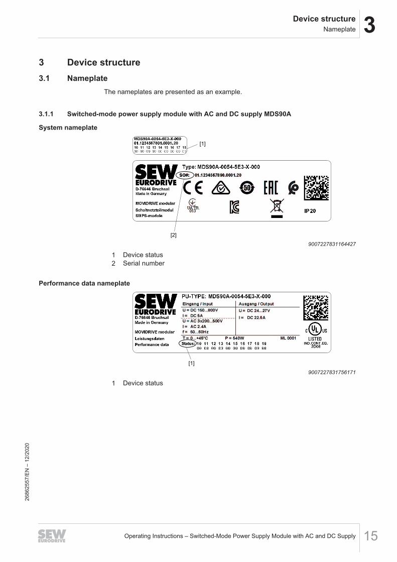
The nameplates are presented as an example.
3.1.1 Switched-mode power supply module with AC and DC supply MDS90A
System nameplate
[1]
[2]
20
9007227831164427
1 Device status2 Serial number
Performance data nameplate
[1]
9007227831756171
1 Device status
2686
2557
/EN
– 1
2/20
20
3 Device structureMOVIDRIVE® modular Power and Energy Solutions type code
Operating Instructions – Switched-Mode Power Supply Module with AC and DC Supply16
3.2 MOVIDRIVE® modular Power and Energy Solutions type codeMOVIDRIVE® modularPower andEnergySolutionstype code
Example: MDP92A-0250-503-4-S00
Product name MD • MD = MOVIDRIVE®
Device type P • C = Capacitor module• E = DC/DC converter module• P = Power supply module• S = Switched-mode power supply module with AC and DC supply
Series 92 • 90 = Standard design• 92 = With controlled DC link voltage
Version A • A = Version status A
Performance class 0250 • MDC: Capacitance – e.g. 0120 = 12 mF• MDE: Nominal output current – e.g. 0750 = 75 A• MDP: Nominal power – e.g. 0250 = 25 kW• MDS: Nominal power – e.g. 0054 = 540 W
Connection voltage 5 • MDP92A, MDS90A: 5 = AC 200 – 500 V• MDC90A, MDE90A: 5 = DC 0 – 800 V
EMC variant 0 • 0 = Basic interference suppression integrated• E = EMC filter limit value category C2 in accordance with EN 61800-3
Connection type 3 • X = Not relevant• 0 = DC connection• 3 = 3-phase connection type
Operating mode 4 • X = Not relevant• 4 = With brake chopper
Variants S • 0 = Not relevant• S = MOVI-C® CONTROLLER control
Designs 00 • 00 = Standard design
Options • /L = Variant with coated printed circuit boards26
8625
57/E
N –
12/
2020
3Device structureDevice structure of switched-mode power supply module with AC and DC supply MDS90A-0054-5E3-X-000
Operating Instructions – Switched-Mode Power Supply Module with AC and DC Supply 17
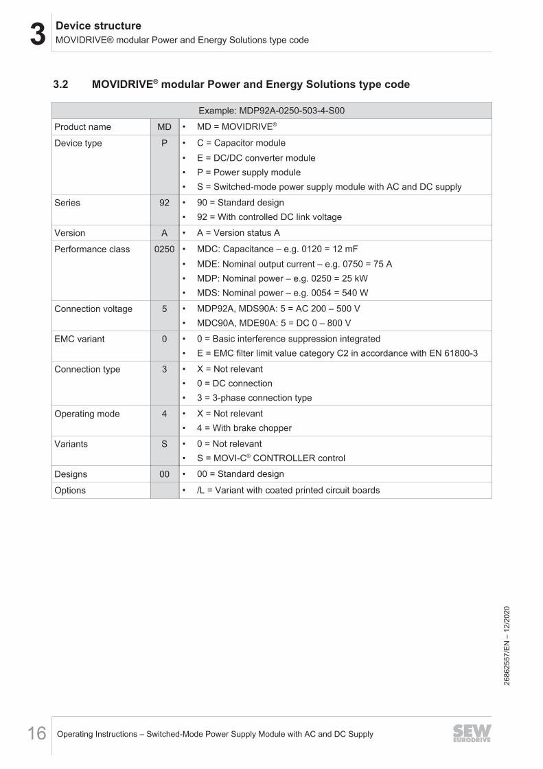
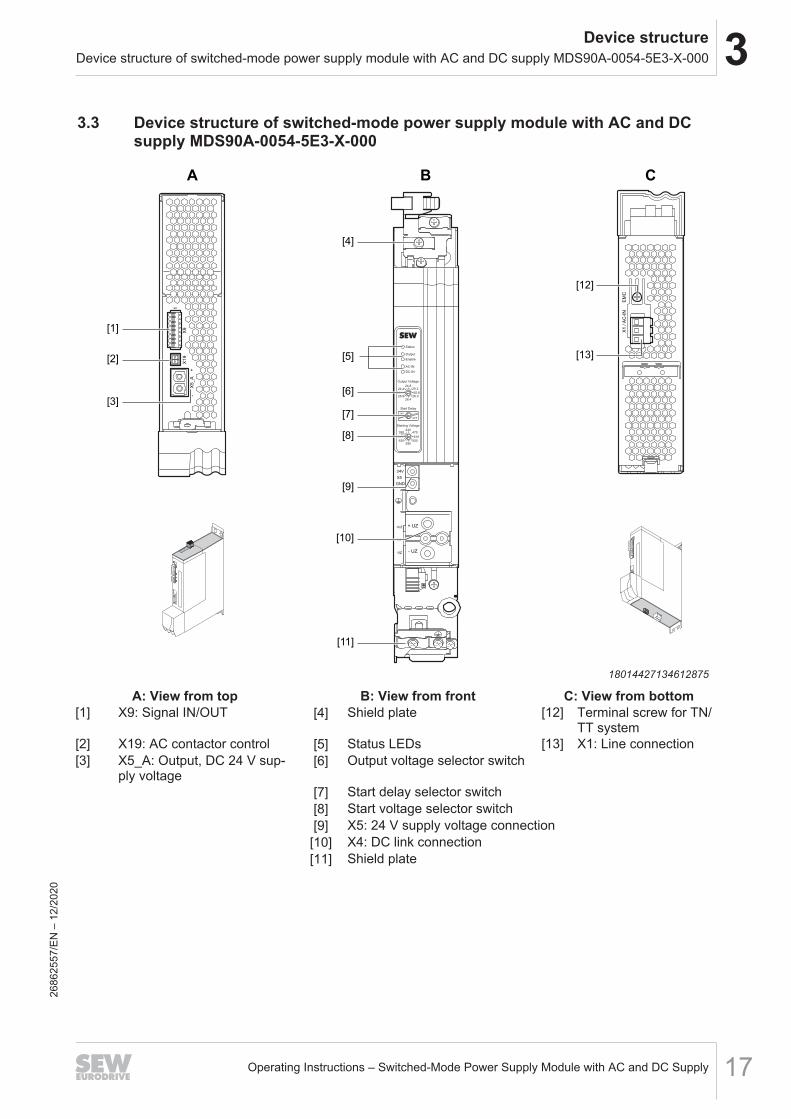
3.3 Device structure of switched-mode power supply module with AC and DCsupply MDS90A-0054-5E3-X-000
24V
X5
GND
+UZ
X4
-UZ
+ UZ
- UZ
Status
Output
Enable
AC-IN
DC-IN
Output Voltage
24.825.2
25.626.0
26.4
OFF
ON
26.824.0
24.4
430470
510
550590
630
200
390370
Start Delay
Starting Voltage
EM
CX
1 / A
C-I
N
- X
5_A
+
X9
X19
1A B C
[3]
[1]
[2]
[4]
[5]
[6]
[7]
[8]
[9]
[10]
[11]
[12]
[13]
18014427134612875
A: View from top B: View from front C: View from bottom[1] X9: Signal IN/OUT [4] Shield plate [12] Terminal screw for TN/
TT system[2] X19: AC contactor control [5] Status LEDs [13] X1: Line connection[3] X5_A: Output, DC 24 V sup-
ply voltage[6] Output voltage selector switch
[7] Start delay selector switch[8] Start voltage selector switch[9] X5: 24 V supply voltage connection
[10] X4: DC link connection[11] Shield plate
2686
2557
/EN
– 1
2/20
20
4 InstallationInstallation accessories
Operating Instructions – Switched-Mode Power Supply Module with AC and DC Supply18
4 Installation4.1 Installation accessories
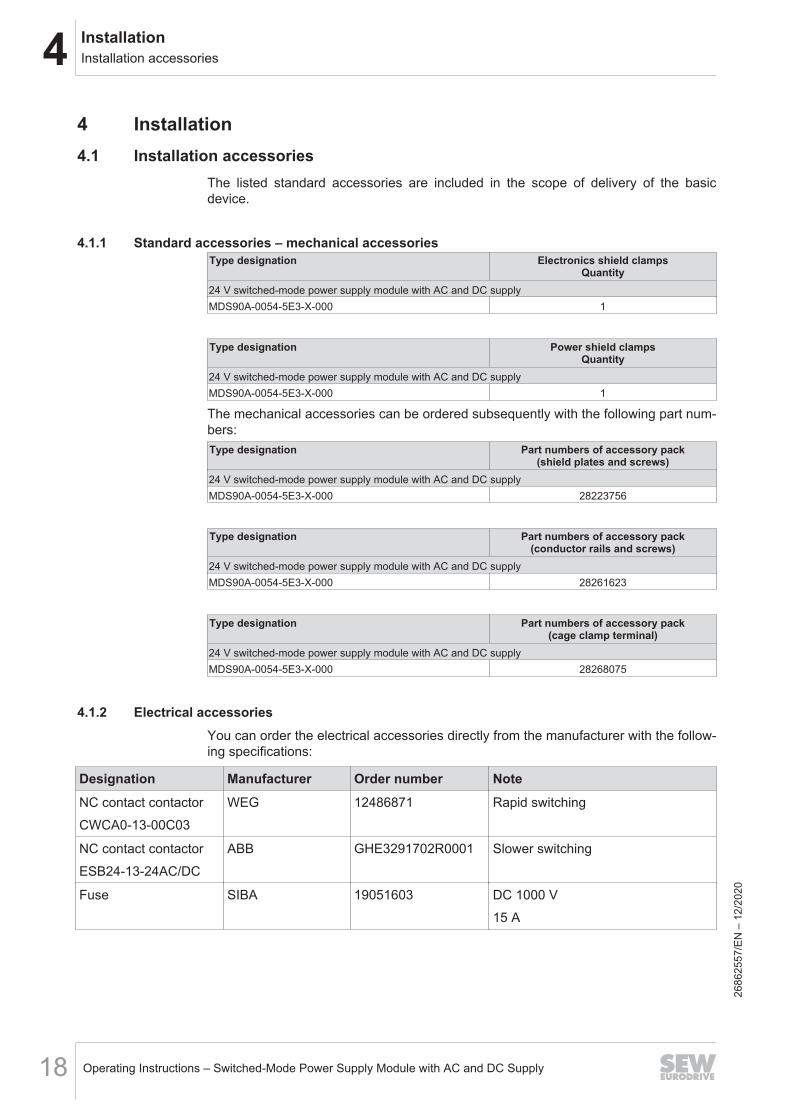
The listed standard accessories are included in the scope of delivery of the basicdevice.
4.1.1 Standard accessories – mechanical accessoriesType designation Electronics shield clamps
Quantity24 V switched-mode power supply module with AC and DC supplyMDS90A-0054-5E3-X-000 1
Type designation Power shield clampsQuantity
24 V switched-mode power supply module with AC and DC supplyMDS90A-0054-5E3-X-000 1
The mechanical accessories can be ordered subsequently with the following part num-bers:Type designation Part numbers of accessory pack
(shield plates and screws)24 V switched-mode power supply module with AC and DC supplyMDS90A-0054-5E3-X-000 28223756
Type designation Part numbers of accessory pack(conductor rails and screws)
24 V switched-mode power supply module with AC and DC supplyMDS90A-0054-5E3-X-000 28261623
Type designation Part numbers of accessory pack(cage clamp terminal)
24 V switched-mode power supply module with AC and DC supplyMDS90A-0054-5E3-X-000 28268075
4.1.2 Electrical accessoriesYou can order the electrical accessories directly from the manufacturer with the follow-ing specifications:
Designation Manufacturer Order number NoteNC contact contactorCWCA0-13-00C03
WEG 12486871 Rapid switching
NC contact contactorESB24-13-24AC/DC
ABB GHE3291702R0001 Slower switching
Fuse SIBA 19051603 DC 1000 V15 A
2686
2557
/EN
– 1
2/20
20
4InstallationPermitted tightening torques
Operating Instructions – Switched-Mode Power Supply Module with AC and DC Supply 19
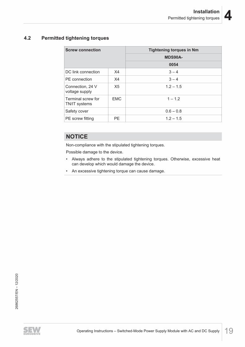
4.2 Permitted tightening torques
Screw connection Tightening torques in NmMDS90A-
0054DC link connection X4 3 – 4
PE connection X4 3 – 4
Connection, 24 Vvoltage supply
X5 1.2 – 1.5
Terminal screw forTN/IT systems
EMC 1 – 1.2
Safety cover 0.6 – 0.8
PE screw fitting PE 1.2 – 1.5
NOTICENon-compliance with the stipulated tightening torques.Possible damage to the device.• Always adhere to the stipulated tightening torques. Otherwise, excessive heat
can develop which would damage the device.• An excessive tightening torque can cause damage.
2686
2557
/EN
– 1
2/20
20
4 InstallationRequirements when combining switched-mode power supply modules in a network
Operating Instructions – Switched-Mode Power Supply Module with AC and DC Supply20
4.3 Requirements when combining switched-mode power supply modules in anetwork
In this chapter, you can find conditions for the use of the switched-mode power supplymodules and sample combinations. The examples show how the individual devicesare arranged in the network. The structure of a network of devices consisting of powersupply module and axis modules is described in the documentation "MOVIDRIVE®
modular application inverter".Structure of a device network• A maximum of 16 devices with module bus connection can be combined in a net-
work. Devices with module bus connection are power supply modules and axismodules.
• Axis modules MDA90A/MDD9.A must be installed to the right of the MDP92Apower supply module, the DC/DC converter module or the MDC90A capacitormodule.
• Switched-mode power supply modules must be attached to the left of the MDP92Apower supply module or to the right of the final axis module MDA90A/MDD9.A.You can use a maximum of 6 switched-mode power supply modules in a network;only 2 of them may be connected directly to the 24 V supply connection.
• MDC90A capacitor modules must be installed to the right of the MDP92A powersupply module or the DC/DC converter module MDE90A. An MDC90A capacitormodule can only be used in combination with an MDP92A power supply module ora DC/DC converter module MDE90A. A maximum of 4 capacitor modules can beused in a network of devices.
• If a DC/DC converter module MDE90A is used in combination with an MDP92A/MDP90A power supply module, the MDE90A must be mounted to the left of thepower supply module.
2686
2557
/EN
– 1
2/20
20
4InstallationRequirements when combining switched-mode power supply modules in a network
Operating Instructions – Switched-Mode Power Supply Module with AC and DC Supply 21
4.3.1 Examples
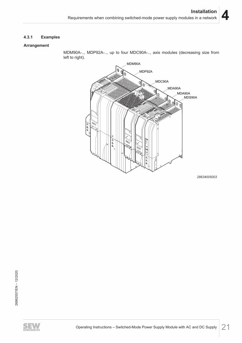
ArrangementMDM90A-.., MDP92A-.., up to four MDC90A-.., axis modules (decreasing size fromleft to right).
MDM90A
MDP92A
MDC90A
MDA90A
MDA90A
MDS90A
28634005003
2686
2557
/EN
– 1
2/20
20
4 InstallationMechanical installation
Operating Instructions – Switched-Mode Power Supply Module with AC and DC Supply22
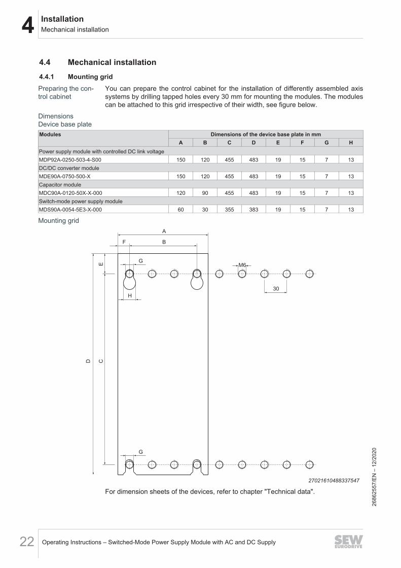
4.4 Mechanical installation4.4.1 Mounting gridPreparing the con-trol cabinet
You can prepare the control cabinet for the installation of differently assembled axissystems by drilling tapped holes every 30 mm for mounting the modules. The modulescan be attached to this grid irrespective of their width, see figure below.
DimensionsDevice base plateModules Dimensions of the device base plate in mm
A B C D E F G HPower supply module with controlled DC link voltageMDP92A-0250-503-4-S00 150 120 455 483 19 15 7 13DC/DC converter moduleMDE90A-0750-500-X 150 120 455 483 19 15 7 13Capacitor moduleMDC90A-0120-50X-X-000 120 90 455 483 19 15 7 13Switch-mode power supply moduleMDS90A-0054-5E3-X-000 60 30 355 383 19 15 7 13
Mounting gridA
D C
30
E M6
BF
G
H
G
27021610488337547
For dimension sheets of the devices, refer to chapter "Technical data".
2686
2557
/EN
– 1
2/20
20
4InstallationElectrical installation
Operating Instructions – Switched-Mode Power Supply Module with AC and DC Supply 23
4.5 Electrical installation
DANGERThere might be dangerous voltages inside the devices and at the terminal stripsafter the complete axis system has been disconnected from the power supply.Severe or fatal injuries from electric shock.To prevent electric shocks:• Observe the labels on the devices and the waiting times until discharge of the en-
ergy storage units before you start working on the power connections.• If you discharge the energy storage units with the discharge unit, observe the in-
formation in chapter Discharging the energy storage units using the dischargeunit.
• After maintenance work, do not operate the axis system unless you have re-mounted the safety covers, because the device has only a IP00 degree of protec-tion with the safety cover removed.
DANGERA leakage current > 3.5 mA can occur during operation of the device.Severe or fatal injuries from electric shock.To avoid shock currents according to EN 61800-5-1, observe the following:• Supply system cable < 10 mm2:
– Route a second PE conductor with the cable cross-section of the supply sys-tem cable in parallel to the protective earth via separate terminals or use acopper PE conductor with a cable cross-section of 10 mm2.
• Supply system cable 10 mm2 – 16 mm2:– Route a copper PE conductor with the cable cross-section of the supply sys-
tem cable.• Supply system cable 16 mm2 – 35 mm2:
– Route a copper protective earth conductor with a cable cross-section of16 mm2.
• Supply system cable > 35 mm2:– Route a copper protective earth conductor with half the cross-section of the
supply system cable.• If an earth leakage circuit breaker is used for protection against direct and indir-
ect contact in isolated cases, it must be universal current-sensitive (RCD type B).
WARNINGWith the MDP92A on the AC grid, voltage is present between PE and DC link evenin deactivated state.Severe or fatal injuries from electric shock.All work on the DC link may only be carried out after complete disconnection fromthe grid.
2686
2557
/EN
– 1
2/20
20
4 InstallationElectrical installation
Operating Instructions – Switched-Mode Power Supply Module with AC and DC Supply24
NOTICEInterchanging the poles when connecting a DC source/sink.The devices are damaged if you interchange poles while connecting an external DCsource/sink to an MDP92A, MDE90A and/or MDC90A.
INFORMATIONInstallation with protective separation.The device meets all requirements for protective separation of power and electronicsconnections in accordance with EN 61800‑5‑1. The connected signal circuits and theDC 24 V voltage supply must meet the requirements according to SELV (Safety ExtraLow Voltage) or PELV (Protective Extra Low Voltage) to ensure protective separa-tion. The installation must meet the requirements for protective separation.
4.5.1 General information• SEW‑EURODRIVE recommends using closed cable lugs for connection to the
screws in order to prevent litz strands from escaping.• SEW‑EURODRIVE recommends using 10 mm-long conductor end sleeves when
connecting to plug connectors.
4.5.2 Permitted voltage systems
Information on voltage systems Information on permissibilityDC voltage grids Maximum voltage to ground = 546
V.
Information on voltage systems Information on permissibilityTN and TT systems – voltage systems with dir-ectly grounded star point.
Participants: Use is possible withoutrestrictions.TT: Use for UL-certified equipmentnot permitted.
IT systems – voltage systems with non-groun-ded star point.
Use is only permitted adhering tospecific measures. For measures,refer to chapter "Use in IT sys-tems" (→ 2 28).
Voltage systems with grounded outer con-ductor.
Not permitted.
2686
2557
/EN
– 1
2/20
20
4InstallationElectrical installation
Operating Instructions – Switched-Mode Power Supply Module with AC and DC Supply 25
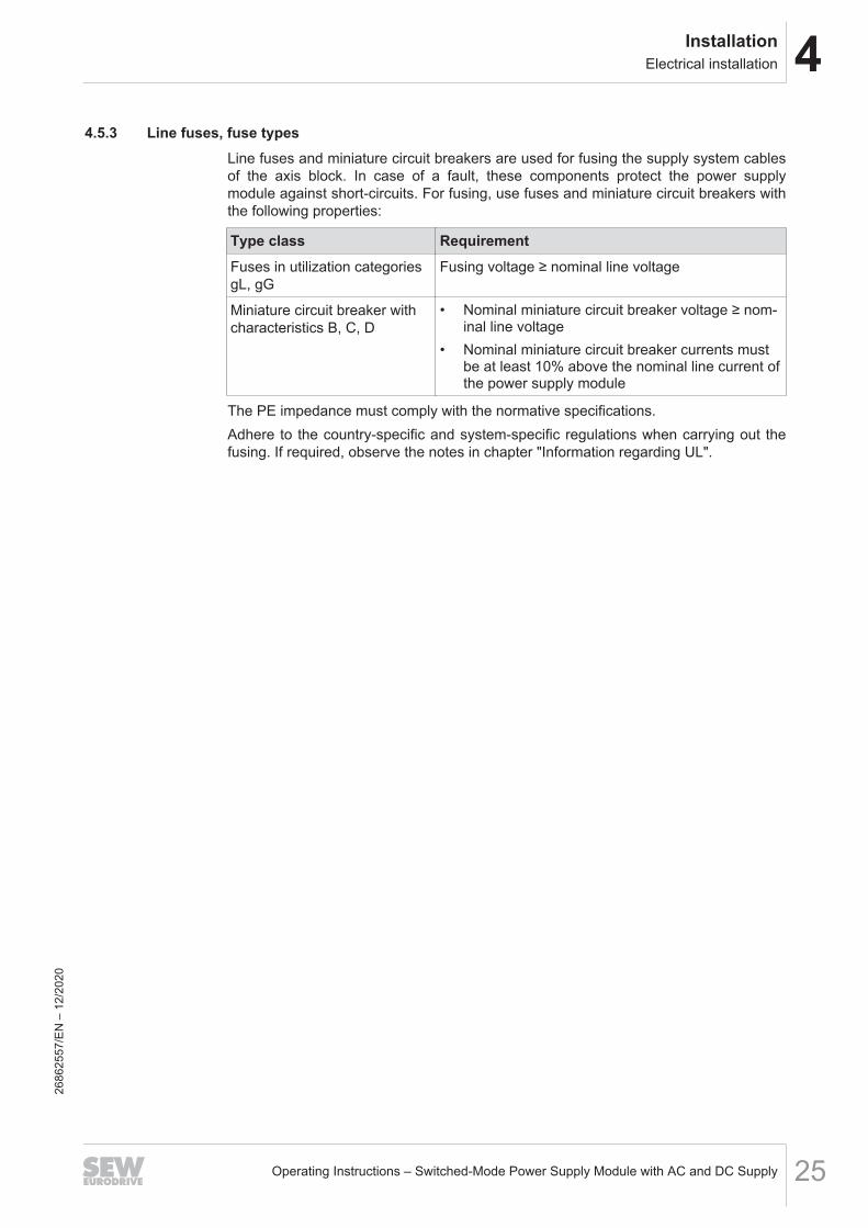
4.5.3 Line fuses, fuse typesLine fuses and miniature circuit breakers are used for fusing the supply system cablesof the axis block. In case of a fault, these components protect the power supplymodule against short-circuits. For fusing, use fuses and miniature circuit breakers withthe following properties:
Type class RequirementFuses in utilization categoriesgL, gG
Fusing voltage ≥ nominal line voltage
Miniature circuit breaker withcharacteristics B, C, D
• Nominal miniature circuit breaker voltage ≥ nom-inal line voltage
• Nominal miniature circuit breaker currents mustbe at least 10% above the nominal line current ofthe power supply module
The PE impedance must comply with the normative specifications.Adhere to the country-specific and system-specific regulations when carrying out thefusing. If required, observe the notes in chapter "Information regarding UL".
2686
2557
/EN
– 1
2/20
20
4 InstallationElectrical installation
Operating Instructions – Switched-Mode Power Supply Module with AC and DC Supply26
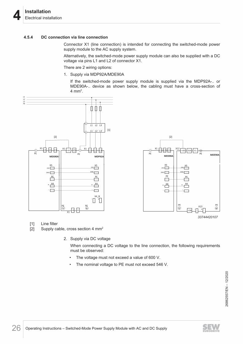
4.5.4 DC connection via line connectionConnector X1 (line connection) is intended for connecting the switched-mode powersupply module to the AC supply system.Alternatively, the switched-mode power supply module can also be supplied with a DCvoltage via pins L1 and L2 of connector X1.There are 2 wiring options:1. Supply via MDP92A/MDE90A
If the switched-mode power supply module is supplied via the MDP92A-.. orMDE90A-.. device as shown below, the cabling must have a cross-section of4 mm2.
L1
L2
L3
PE
X1
PE
PE
X1-R
L1 L2 L3
MDP92A
PE
+UBX1
PE
MDS90A
X1L1 L2 L3 -ES
-+ X4
-
+ X4
PEPE
X4_B
- +
X5X5
GND
24V
GND
24V
L1 L2 L3
L1 ´ L2 ´ L3 ´
+R
PE
X1
-
+ X4
PE
X5
GND
24V
MDS90A
L1 L2 L3
MDE90A-
+ X4
PE
X5
GND
24V
PEX13
- +
PE
-ESB
+UZB+UB ICL-ESA
PE
X12
33744420107
[1] Line filter[2] Supply cable, cross section 4 mm2
2. Supply via DC voltageWhen connecting a DC voltage to the line connection, the following requirementsmust be observed:• The voltage must not exceed a value of 600 V.• The nominal voltage to PE must not exceed 546 V.
2686
2557
/EN
– 1
2/20
20
4InstallationElectrical installation
Operating Instructions – Switched-Mode Power Supply Module with AC and DC Supply 27
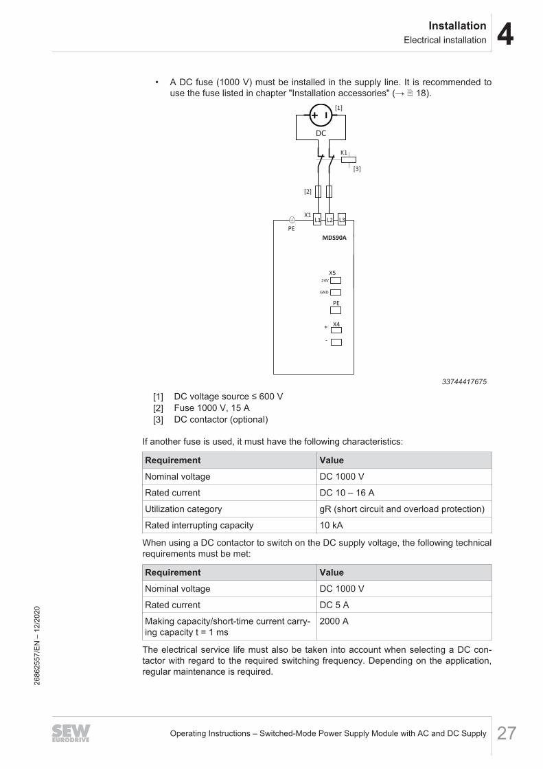
• A DC fuse (1000 V) must be installed in the supply line. It is recommended touse the fuse listed in chapter "Installation accessories" (→ 2 18).
PE
MDS90A
X1L1 L2 L3
-
+ X4
PE
X5
GND
24V
DC
[2]
K1
[3]
[1]
33744417675
[1] DC voltage source ≤ 600 V[2] Fuse 1000 V, 15 A[3] DC contactor (optional)
If another fuse is used, it must have the following characteristics:
Requirement ValueNominal voltage DC 1000 V
Rated current DC 10 – 16 A
Utilization category gR (short circuit and overload protection)
Rated interrupting capacity 10 kA
When using a DC contactor to switch on the DC supply voltage, the following technicalrequirements must be met:
Requirement ValueNominal voltage DC 1000 V
Rated current DC 5 A
Making capacity/short-time current carry-ing capacity t = 1 ms
2000 A
The electrical service life must also be taken into account when selecting a DC con-tactor with regard to the required switching frequency. Depending on the application,regular maintenance is required.
2686
2557
/EN
– 1
2/20
20
4 InstallationElectrical installation
Operating Instructions – Switched-Mode Power Supply Module with AC and DC Supply28
4.5.5 Line filterIf the switched-mode power supply module is operated in conjunction with an MD-P90A-..,MDR91A-.. or MDR90/91B, the MDS90A-.. requires a separate line filter.Several switched-mode power supply modules can be connected to one line filter:• Up to 2 MDS90A to NF0055-503• Up to 5 MDS90A to NF0120-503• Up to 9 MDS90A to NF0220-503For further information on line filters, refer to chapter "Line filter" (→ 2 57).
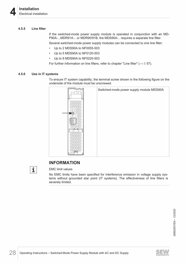
4.5.6 Use in IT systemsTo ensure IT system capability, the terminal screw shown in the following figure on theunderside of the module must be unscrewed.
EM
CX
1 / A
C-I
N
Switched-mode power supply module MDS90A
INFORMATIONEMC limit valuesNo EMC limits have been specified for interference emission in voltage supply sys-tems without grounded star point (IT systems). The effectiveness of line filters isseverely limited.
2686
2557
/EN
– 1
2/20
20
4InstallationElectrical installation
Operating Instructions – Switched-Mode Power Supply Module with AC and DC Supply 29
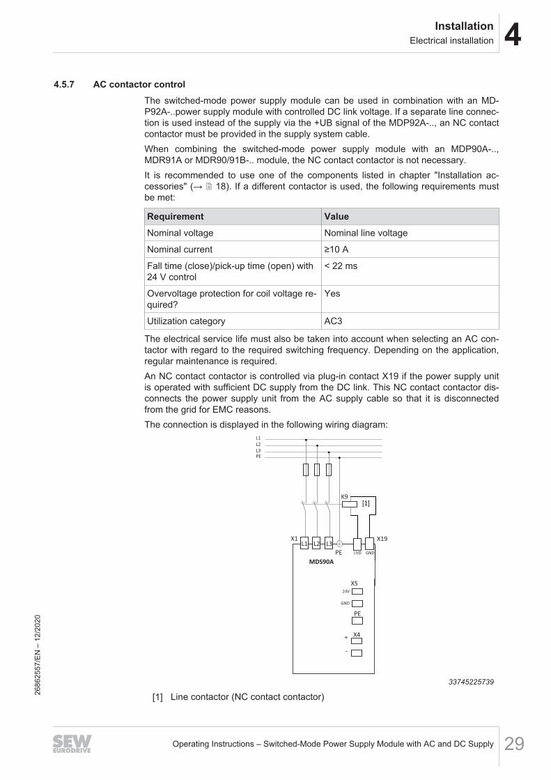
4.5.7 AC contactor controlThe switched-mode power supply module can be used in combination with an MD-P92A-..power supply module with controlled DC link voltage. If a separate line connec-tion is used instead of the supply via the +UB signal of the MDP92A-.., an NC contactcontactor must be provided in the supply system cable.When combining the switched-mode power supply module with an MDP90A-..,MDR91A or MDR90/91B-.. module, the NC contact contactor is not necessary.It is recommended to use one of the components listed in chapter "Installation ac-cessories" (→ 2 18). If a different contactor is used, the following requirements mustbe met:
Requirement ValueNominal voltage Nominal line voltage
Nominal current ≥10 A
Fall time (close)/pick-up time (open) with24 V control
< 22 ms
Overvoltage protection for coil voltage re-quired?
Yes
Utilization category AC3
The electrical service life must also be taken into account when selecting an AC con-tactor with regard to the required switching frequency. Depending on the application,regular maintenance is required.An NC contact contactor is controlled via plug-in contact X19 if the power supply unitis operated with sufficient DC supply from the DC link. This NC contact contactor dis-connects the power supply unit from the AC supply cable so that it is disconnectedfrom the grid for EMC reasons.The connection is displayed in the following wiring diagram:
L1
L2
L3
PE
PE
MDS90A
X1L1 L2 L3
-
+ X4
K9
PE
X5
GND
24V
X19
LVD GND
33745225739
[1] Line contactor (NC contact contactor)2686
2557
/EN
– 1
2/20
20
4 InstallationElectrical installation
Operating Instructions – Switched-Mode Power Supply Module with AC and DC Supply30
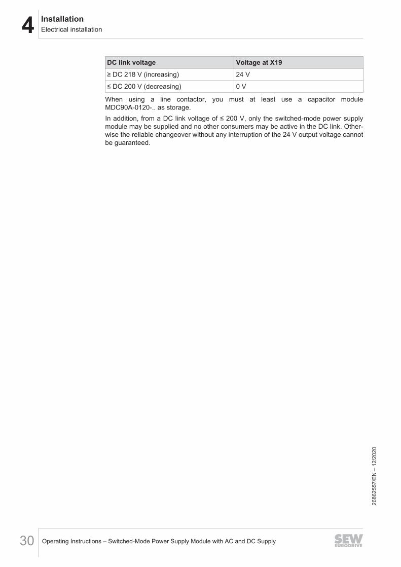
DC link voltage Voltage at X19≥ DC 218 V (increasing) 24 V
≤ DC 200 V (decreasing) 0 V
When using a line contactor, you must at least use a capacitor moduleMDC90A-0120-.. as storage.In addition, from a DC link voltage of ≤ 200 V, only the switched-mode power supplymodule may be supplied and no other consumers may be active in the DC link. Other-wise the reliable changeover without any interruption of the 24 V output voltage cannotbe guaranteed.
2686
2557
/EN
– 1
2/20
20
4InstallationElectrical installation
Operating Instructions – Switched-Mode Power Supply Module with AC and DC Supply 31
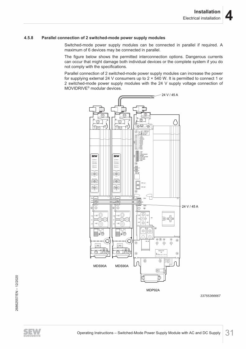
4.5.8 Parallel connection of 2 switched-mode power supply modulesSwitched-mode power supply modules can be connected in parallel if required. Amaximum of 6 devices may be connected in parallel.The figure below shows the permitted interconnection options. Dangerous currentscan occur that might damage both individual devices or the complete system if you donot comply with the specifications.Parallel connection of 2 switched-mode power supply modules can increase the powerfor supplying external 24 V consumers up to 2 × 540 W. It is permitted to connect 1 or2 switched-mode power supply modules with the 24 V supply voltage connection ofMOVIDRIVE® modular devices.
MDS90A
24V
X5
GND
+UZ
X4
-UZ
+ UZ
- UZ
Status
Output
Enable
AC-IN
DC-IN
Output Voltage
24.825.2
25.626.0
26.4
OFF
ON
26.824.0
24.4
430470
510
550590
630
200
390370
Start Delay
Starting Voltage
24 V / 45 A
24 V / 45 A
MDS90A
24V
X5
GND
+UZ
X4
-UZ
+ UZ
- UZ
Status
Output
Enable
AC-IN
DC-IN
Output Voltage
24.825.2
25.626.0
26.4
OFF
ON
26.824.0
24.4
430470
510
550590
630
200
390370
Start Delay
Starting Voltage
MDP92A
X31_A
RUN
S1
EC ID
(x10)
S2 (x1)
ERR
X31_B
24V
X5
GND
X4
+UZ +UZ
-UZ -UZ
X4_B
- +
topofunit
X30 OUTX30 IN
X7 1 + TEMP R /NC1 - TEMP R /NC
bottom of unit
X1
1
UZB
+
1
ES
-
1
R+
1
R-
1
L1
1
L2
1
L3
X33
X20
33755366667
2686
2557
/EN
– 1
2/20
20
4 InstallationElectrical installation
Operating Instructions – Switched-Mode Power Supply Module with AC and DC Supply32
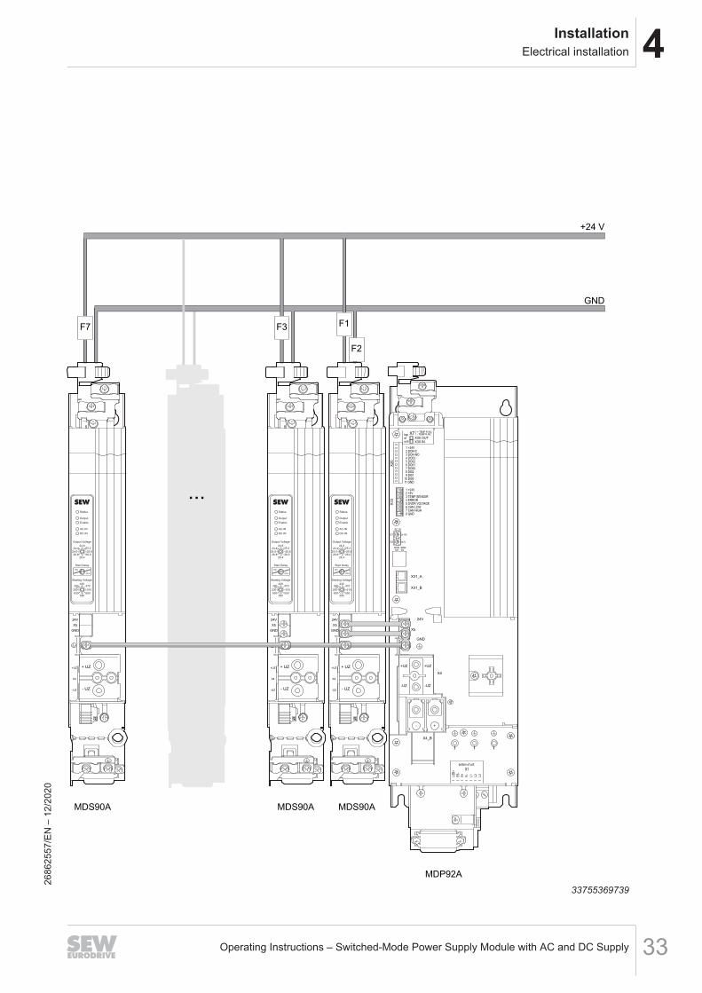
4.5.9 Parallel connection of 3 to 6 switched-mode power supply modulesParallel connection of 3 to 6 switched-mode power supply modules can increase thepower for supplying external 24 V consumers up to 6 × 540 W. It is permitted to con-nect 1 switched-mode power supply module with the 24 V supply voltage connectionof MOVIDRIVE® modular devices.
2686
2557
/EN
– 1
2/20
20
4InstallationElectrical installation
Operating Instructions – Switched-Mode Power Supply Module with AC and DC Supply 33
MDS90A MDS90A
24V
X5
GND
+UZ
X4
-UZ
+ UZ
- UZ
Status
Output
Enable
AC-IN
DC-IN
Output Voltage
24.825.2
25.626.0
26.4
OFF
ON
26.824.0
24.4
430470
510
550590
630
200
390370
Start Delay
Starting Voltage
24V
X5
GND
+UZ
X4
-UZ
+ UZ
- UZ
Status
Output
Enable
AC-IN
DC-IN
Output Voltage
24.825.2
25.626.0
26.4
OFF
ON
26.824.0
24.4
430470
510
550590
630
200
390370
Start Delay
Starting Voltage
...
MDS90A
24V
X5
GND
+UZ
X4
-UZ
+ UZ
- UZ
Status
Output
Enable
AC-IN
DC-IN
Output Voltage
24.825.2
25.626.0
26.4
OFF
ON
26.824.0
24.4
430470
510
550590
630
200
390370
Start Delay
Starting Voltage
MDP92A
X31_A
RUN
S1
EC ID
(x10)
S2 (x1)
ERR
X31_B
24V
X5
GND
X4
+UZ +UZ
-UZ -UZ
X4_B
- +
topofunit
X30 OUTX30 IN
X7 1 + TEMP R /NC1 - TEMP R /NC
bottom of unit
X1
1
UZB
+
1
ES
-
1
R+
1
R-
1
L1
1
L2
1
L3
X33
X20
F7 F3 F1
+24 V
GND
F2
33755369739
2686
2557
/EN
– 1
2/20
20
4 InstallationElectrical installation
Operating Instructions – Switched-Mode Power Supply Module with AC and DC Supply34
The cabling of connector X5_A must have a cross-section of at least 4 mm2 when 3 - 6switched-mode power supply modules are connected in parallel. The F1 - F7 fusesshown above must meet the following requirements:• Nominal voltage: ≥ 30 V• Rated current: 25 AThe fuses protect the switched-mode power supply modules against overcurrent anddestruction. External consumers are not protected against overcurrent by this type offusing.When 3 - 6 switched-mode power supply modules are connected in parallel, only thefirst switched-mode power supply module next to the power supply module may beconnected to the axis system via the 24 V connection. This device must have a fuse inthe GND signal of connector X5_A at the 24 V output X5_A in addition to the fuse inthe +24 V signal.
4.5.10 Connection of an axis systemFor information on this topic, refer to the "MOVIDRIVE® modular Application Inverters"operating instructions.
2686
2557
/EN
– 1
2/20
20
4InstallationElectrical installation
Operating Instructions – Switched-Mode Power Supply Module with AC and DC Supply 35
4.5.11 Inputs/outputs
NOTICEDamage to the digital inputs and digital outputs.The digital inputs and digital outputs are not electrically isolated. Incorrectly appliedvoltages can damage the digital inputs and digital outputs.• Do not apply external voltages to the digital outputs.• The digital inputs and outputs are dimensioned according to IEC 61131‑2.
• The cable length must not exceed 30 m.• Cables outside the control cabinet must be shielded.
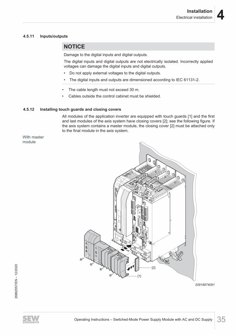
4.5.12 Installing touch guards and closing coversAll modules of the application inverter are equipped with touch guards [1] and the firstand last modules of the axis system have closing covers [2]; see the following figure. Ifthe axis system contains a master module, the closing cover [2] must be attached onlyto the final module in the axis system.
With mastermodule
[2]
54
321
54
321
[1]
20918974091
2686
2557
/EN
– 1
2/20
20
4 InstallationElectrical installation
Operating Instructions – Switched-Mode Power Supply Module with AC and DC Supply36
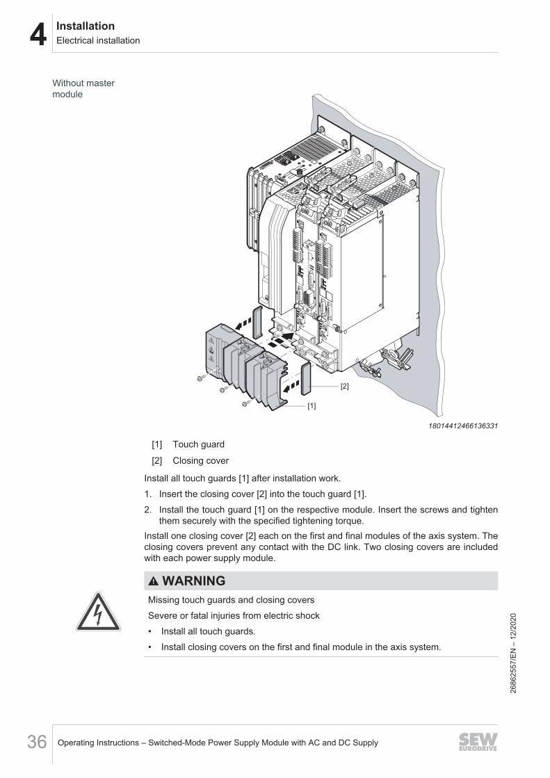
Without mastermodule
[1]
[2]
54
321
54
321
18014412466136331
[1] Touch guard
[2] Closing cover
Install all touch guards [1] after installation work.1. Insert the closing cover [2] into the touch guard [1].2. Install the touch guard [1] on the respective module. Insert the screws and tighten
them securely with the specified tightening torque.Install one closing cover [2] each on the first and final modules of the axis system. Theclosing covers prevent any contact with the DC link. Two closing covers are includedwith each power supply module.
WARNINGMissing touch guards and closing coversSevere or fatal injuries from electric shock• Install all touch guards.• Install closing covers on the first and final module in the axis system.
2686
2557
/EN
– 1
2/20
20
4InstallationTerminal assignment
Operating Instructions – Switched-Mode Power Supply Module with AC and DC Supply 37
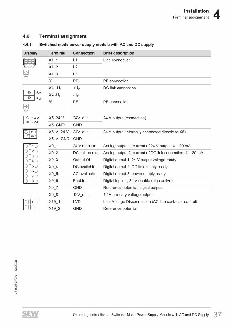
4.6 Terminal assignment4.6.1 Switched-mode power supply module with AC and DC supply
Display Terminal Connection Brief descriptionX1_1 L1 Line connection
X1_2 L2
X1_3 L3
PE PE connection
-U
+UZ
Z
X4:+UZ +UZ DC link connection
X4:-UZ -UZ
PE PE connection
24 V
GND
X5: 24 V 24V_out 24 V output (connection)
X5: GND GND
X5_A: 24 V 24V_out 24 V output (internally connected directly to X5)
X5_A: GND GND
1
2
3
4
5
6
7
8
X9_1 24 V monitor Analog output 1, current of 24 V output: 4 – 20 mA
X9_2 DC link monitor Analog output 2, current of DC link connection: 4 – 20 mA
X9_3 Output OK Digital output 1, 24 V output voltage ready
X9_4 DC available Digital output 2, DC link supply ready
X9_5 AC available Digital output 3, power supply ready
X9_6 Enable Digital input 1, 24 V enable (high active)
X9_7 GND Reference potential, digital outputs
X9_8 12V_out 12 V auxiliary voltage output
1
2
X19_1 LVD Line Voltage Disconnection (AC line contactor control)
X19_2 GND Reference potential
2686
2557
/EN
– 1
2/20
20
4 InstallationWiring diagrams
Operating Instructions – Switched-Mode Power Supply Module with AC and DC Supply38
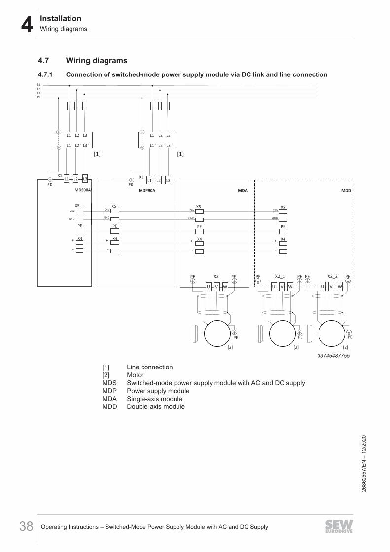
4.7 Wiring diagrams4.7.1 Connection of switched-mode power supply module via DC link and line connection
PE
MDS90A
X1L1 L2 L3
-
+ X4
PE
X5
GND
24V
MDP90A
-
+ X4
PE
X5
GND
24V
PE
X2PE
U V W
X2_1PE
U V W
X2_2PE
U V W
[2] [2] [2]
PE PE PE
PE PE PE
-
+
-
+X4 X4
PE PE
X5 X5
GND
24V
GND
24V
MDA MDD
X1L1 L2 L3
L1 L2 L3
L1 ´ L2 ´ L3 ´
L1
L2
L3
PE
[1]
L1 L2 L3
L1 ´ L2 ´ L3 ´
[1]
33745487755
[1] Line connection[2] MotorMDS Switched-mode power supply module with AC and DC supplyMDP Power supply moduleMDA Single-axis moduleMDD Double-axis module
2686
2557
/EN
– 1
2/20
20
4InstallationWiring diagrams
Operating Instructions – Switched-Mode Power Supply Module with AC and DC Supply 39
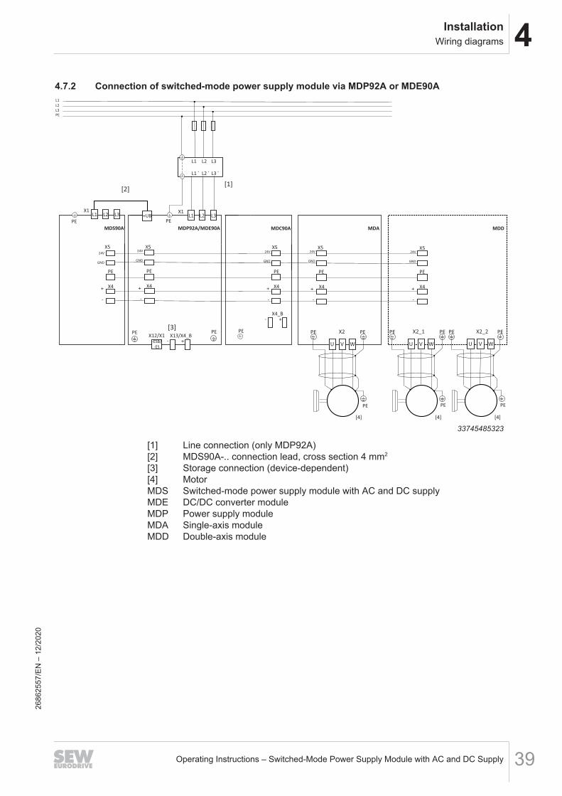
4.7.2 Connection of switched-mode power supply module via MDP92A or MDE90A
X2PE
U V W
X2_1PE
U V W
X2_2PE
U V W
[4] [4] [4]
PE PE PE
PE PE PE
MDC90A
PE
MDS90A
X1L1 L2 L3
-
+
-
+X4 X4
-
+ X4
-
+ X4
PE PEPEPE
X4_B
- +
X5 X5X5X5
GND
24V
GND
24V
GND
24V
GND
24V
MDA MDD
PE
MDP92A/MDE90A
-
+ X4
PE
X5
GND
24V
PE
PE
X13/X4_B
- +
PE
-ESB/
-ES
[3]
X1L1 L2 L3
L1 L2 L3
L1 ´ L2 ´ L3 ´
L1
L2
L3
PE
[1]
X12/X1
+UB
[2]
33745485323
[1] Line connection (only MDP92A)[2] MDS90A-.. connection lead, cross section 4 mm2
[3] Storage connection (device-dependent)[4] MotorMDS Switched-mode power supply module with AC and DC supplyMDE DC/DC converter moduleMDP Power supply moduleMDA Single-axis moduleMDD Double-axis module
2686
2557
/EN
– 1
2/20
20
4 InstallationWiring diagrams
Operating Instructions – Switched-Mode Power Supply Module with AC and DC Supply40
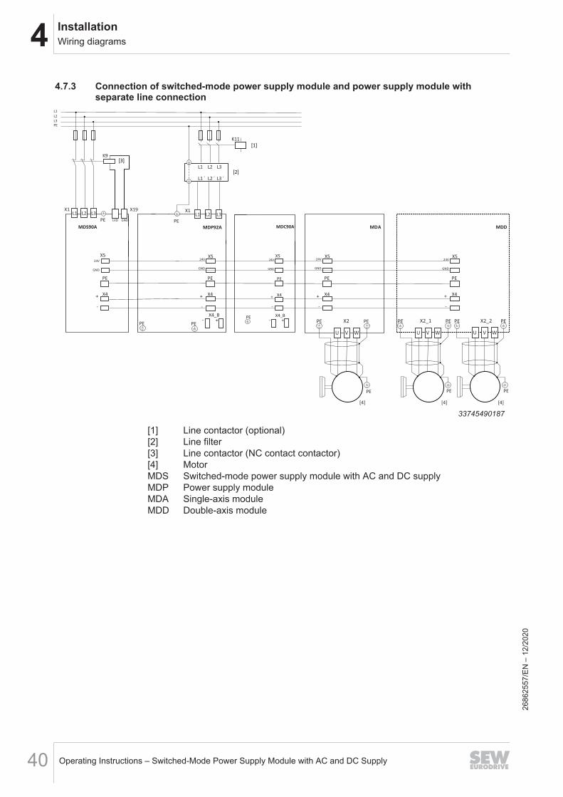
4.7.3 Connection of switched-mode power supply module and power supply module withseparate line connection
L1 L2 L3
L1 ´ L2 ´ L3 ´
L1
L2
L3
PE
X1
PEX2PE
U V W
X2_1PE
U V W
X2_2PE
U V W
PE
L1 L2 L3
MDP92A MDA
[4] [4] [4]
MDD
PE PE PE
PE PE PE
-
+
-
+
-
+ X4 X4X4
-
+ X4
PE PEPEPE
PE
X4_B
- +
X5 X5X5X5
GND
24V
GND
24V
GND
24V
GND
24V
K11
PE
MDS90A
X1L1 L2 L3
K9
X19
LVD GND
MDC90A
-
+ X4
PE
X4_B
- +
X5
GND
24V
PE
33745490187
[1] Line contactor (optional)[2] Line filter[3] Line contactor (NC contact contactor)[4] MotorMDS Switched-mode power supply module with AC and DC supplyMDP Power supply moduleMDA Single-axis moduleMDD Double-axis module
2686
2557
/EN
– 1
2/20
20
4InstallationWiring diagrams
Operating Instructions – Switched-Mode Power Supply Module with AC and DC Supply 41
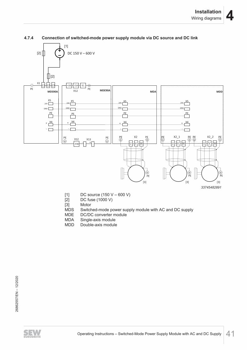
4.7.4 Connection of switched-mode power supply module via DC source and DC link
X2PE
U V W
X2_1PE
U V W
X2_2PE
U V W
[3] [3] [3]
PE PE PE
PE PE PE
PE
X1
-
+
-
+X4 X4
-
+ X4
PE PEPE
X5 X5X5
GND
24V
GND
24V
GND
24V
MDS90A MDA MDD
L1 L2 L3
MDE90A
-
+ X4
PE
X5
GND
24V
PEX13
- +
PE
-ESB
+UZB+UB ICL-ESA
PE
X12
X12
DC 150 V – 600 V
[1]
[2]
[2]
33745482891
[1] DC source (150 V – 600 V)[2] DC fuse (1000 V)[3] MotorMDS Switched-mode power supply module with AC and DC supplyMDE DC/DC converter moduleMDA Single-axis moduleMDD Double-axis module
2686
2557
/EN
– 1
2/20
20
4 InstallationWiring diagrams
Operating Instructions – Switched-Mode Power Supply Module with AC and DC Supply42
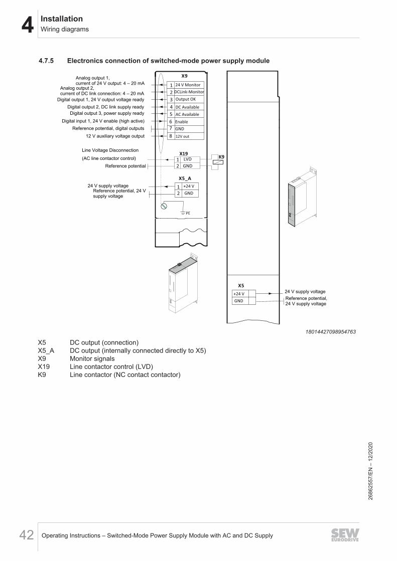
4.7.5 Electronics connection of switched-mode power supply module
X9
X5
+24 V
GND
2
1
3
4
PE
X5_A
+24 V
GND
5
6
7
8
24 V Monitor
DCLink-Monitor
Output OK
DC Available
12V out
AC Available
Enable
GND
GND
LVDX19
K9
2
1
2
1
Analog output 1,current of 24 V output: 4 – 20 mA
Analog output 2, current of DC link connection: 4 – 20 mA
Digital output 1, 24 V output voltage readyDigital output 2, DC link supply readyDigital output 3, power supply ready
Digital input 1, 24 V enable (high active)Reference potential, digital outputs
12 V auxiliary voltage output
24 V supply voltageReference potential, 24 Vsupply voltage
Reference potential,24 V supply voltage
24 V supply voltage
Line Voltage Disconnection (AC line contactor control)
Reference potential
18014427098954763
X5 DC output (connection)X5_A DC output (internally connected directly to X5)X9 Monitor signalsX19 Line contactor control (LVD)K9 Line contactor (NC contact contactor)
2686
2557
/EN
– 1
2/20
20
5StartupSettings on the selector switches
Operating Instructions – Switched-Mode Power Supply Module with AC and DC Supply 43
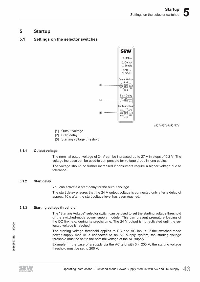
5 Startup5.1 Settings on the selector switches
Status
Output
Output Voltage
24.825.2
25.626.0
26.4
OFF
ON
26.824.0
24.4
430470
510
550590
630
200
390370
Start Delay
Starting Voltage
Enable
AC-IN
DC-IN
[1]
[2]
[3]
18014427184501771
[1] Output voltage[2] Start delay[3] Starting voltage threshold
5.1.1 Output voltageThe nominal output voltage of 24 V can be increased up to 27 V in steps of 0.2 V. Thevoltage increase can be used to compensate for voltage drops in long cables.The voltage should be further increased if consumers require a higher voltage due totolerance.
5.1.2 Start delayYou can activate a start delay for the output voltage.The start delay ensures that the 24 V output voltage is connected only after a delay ofapprox. 10 s after the start voltage level has been reached.
5.1.3 Starting voltage thresholdThe "Starting Voltage" selector switch can be used to set the starting voltage thresholdof the switched-mode power supply module. This can prevent premature loading ofthe DC link, e.g. during its precharging. The 24 V output is not activated until the se-lected voltage is reached.The starting voltage threshold applies to DC and AC inputs. If the switched-modepower supply module is connected to an AC supply system, the starting voltagethreshold must be set to the nominal voltage of the AC supply.Example: In the case of a supply via the AC grid with 3 × 200 V, the starting voltagethreshold must be set to 200 V.26
8625
57/E
N –
12/
2020
5 StartupSettings on the selector switches
Operating Instructions – Switched-Mode Power Supply Module with AC and DC Supply44
The starting voltage threshold has no influence on the supply of the switched-modepower supply module. This is guaranteed at a voltage of 200 V or higher. Due to thebuilt-in hysteresis, the switched-mode power supply module remains active until avoltage of 150 V is reached before the supply is interrupted. The starting voltagethreshold only controls the activation of the 24 V output.
2686
2557
/EN
– 1
2/20
20
6OperationLED displays
Operating Instructions – Switched-Mode Power Supply Module with AC and DC Supply 45
6 Operation6.1 LED displays6.1.1 Operating displays – LED displays
24V
X5
GND
+UZ
X4
+ UZ
Status
OutputEnable
AC-INDC-IN
Output Voltage
24.825.2
25.626.0
26.4
OFF
ON
26.824.0
24.4
430470
510
550590
630
200
390370
Start Delay
Starting Voltage
9007227871218699
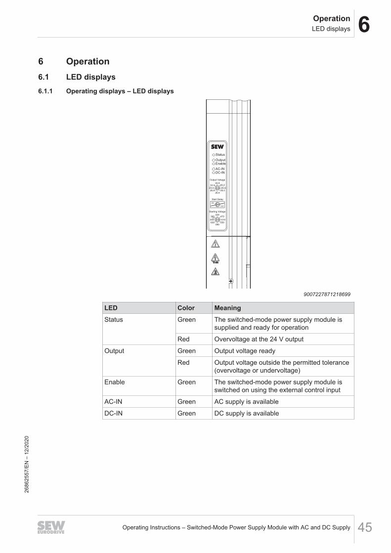
LED Color MeaningStatus Green The switched-mode power supply module is
supplied and ready for operation
Red Overvoltage at the 24 V output
Output Green Output voltage ready
Red Output voltage outside the permitted tolerance(overvoltage or undervoltage)
Enable Green The switched-mode power supply module isswitched on using the external control input
AC-IN Green AC supply is available
DC-IN Green DC supply is available
2686
2557
/EN
– 1
2/20
20
6 OperationMonitor signals
Operating Instructions – Switched-Mode Power Supply Module with AC and DC Supply46
6.2 Monitor signalsVarious control signals can be queried or set via terminal X9 on the top of theswitched-mode power supply module. Reference potential for these signals is alwaysthe reference potential of the digital outputs GND.
NOTICEDestruction of the switched-mode power supply moduleThe GND connection at X9 and X19 is only used as reference ground for control sig-nals and must not be used to supply 24 V loads.
Refer to chapter "Terminal assignment" (→ 2 37) for the pin assignment of the X9 ter-minal.
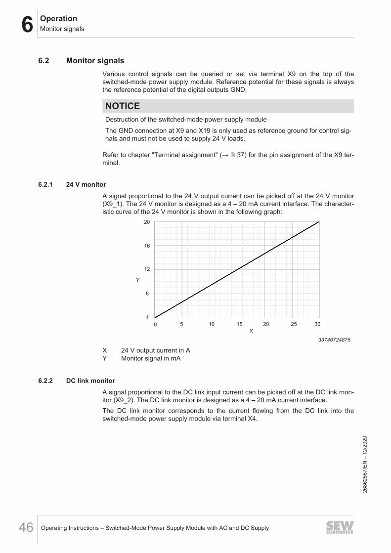
6.2.1 24 V monitorA signal proportional to the 24 V output current can be picked off at the 24 V monitor(X9_1). The 24 V monitor is designed as a 4 – 20 mA current interface. The character-istic curve of the 24 V monitor is shown in the following graph:
0
4
8
12
16
20
5 10 15 20 25 30
X
Y
33746724875
X 24 V output current in AY Monitor signal in mA
6.2.2 DC link monitorA signal proportional to the DC link input current can be picked off at the DC link mon-itor (X9_2). The DC link monitor is designed as a 4 – 20 mA current interface.The DC link monitor corresponds to the current flowing from the DC link into theswitched-mode power supply module via terminal X4.
2686
2557
/EN
– 1
2/20
20

6OperationMonitor signals
Operating Instructions – Switched-Mode Power Supply Module with AC and DC Supply 47
The characteristic curve of the output is shown in the following graph:
0
4
8
12
16
20
2.5 5 7.5 10 12.5
Y
X
33746727307
X DC link current in AY DC link monitor in mA
6.2.3 Output OKThe status of the 24 V output voltage can be queried via the "Output OK" signal. "Out-put OK" supplies 24 V if the 24 V output voltage is within a permitted tolerance win-dow. If the output voltage is too low (e.g. due to overload) or too high (e.g. due to re-generative power supply from small drives), "Output OK" changes to 0 V.Definition of tolerance window:• Overvoltage: from 30.4 V upwards (Output OK = 0 V)
Reset of overvoltage from 29 V downwards (Output OK = 24 V)• Undervoltage from 21.9 V downwards (Output OK = 0 V)
Reset of undervoltage from 22 V upwards (Output OK = 24 V)
INFORMATION"Output OK" reports the state of the 24 V output voltage only if the switched-modepower supply module is activated via "Enable".
6.2.4 DC availableThe status of the DC link voltage can be queried via "DC Available". "DC Available"supplies 24 V when the DC link voltage has reached a value that is sufficiently high tosupply the switched-mode power supply module.The necessary level of the DC link voltage can be set via the "Starting Voltage" controlknob. For more information, refer to chapter "Settings on the selectorswitches" (→ 2 43).
INFORMATION"DC Available" reports the state of the 24 V output voltage only if the switched-modepower supply module is activated via "Enable".
2686
2557
/EN
– 1
2/20
20
6 OperationExternal voltage
Operating Instructions – Switched-Mode Power Supply Module with AC and DC Supply48
6.2.5 AC availableThe status of the line voltage can be queried via "AC Available". "AC Available" sup-plies 24 V if the line voltage is available at a sufficient level to supply the switched-mode power supply module.The necessary level of the line voltage can be set via the "Starting Voltage" controlknob. For more information, refer to chapter "Settings on the selectorswitches" (→ 2 43).
INFORMATIONOnly the availability of the line voltage is output. No conclusions can be drawn as towhether the power supply unit is supplied from DC or AC.
INFORMATIONThe signal is only present when the switched-mode power supply module activelycontrols the 24 V output. If the 24 V output voltage is deactivated, the "AC Available"signal also has no significance.
6.2.6 EnableThe 24 V output of the switched-mode power supply module can be activated via "En-able".The 24 V output is activated when a voltage of DC 12 V to DC 24 V is applied to "En-able". The 12 V auxiliary voltage output can be used for voltage supply.If an external source is used to control "Enable", the GNDs of the source and of termi-nal X9 must be connected to one another.If the "Enable" input is not controlled, the 24 V output of the switched-mode powersupply module is permanently switched off.
6.2.7 Auxiliary voltage output 12 V outThis output is used to control the "Enable" input. The auxiliary voltage output is protec-ted against short circuit.
6.3 External voltageLoads such as motors and inductors (e.g. contactors, long cable lengths) can cause aregenerative voltage at the 24 V output of the switched-mode power supply module.The power supply unit is resistant to this type of overvoltage and reacts to it with a redindication of the status LED.The maximum permitted voltage at the 24 V output is 34 V. The maximum possibleabsorbable energy can be calculated taking into account the installed output capacit-ance of 6 mF.
2686
2557
/EN
– 1
2/20
20
7ServiceElectronics Service by SEW‑EURODRIVE
Operating Instructions – Switched-Mode Power Supply Module with AC and DC Supply 49
7 Service7.1 Electronics Service by SEW‑EURODRIVE
If you are unable to rectify a fault, contact SEW‑EURODRIVE Service. For the ad-dresses, refer to www.sew-eurodrive.com.When contacting SEW‑EURODRIVE Service, always specify the following informationso that our service personnel can assist you more effectively:• Information on the device type on the nameplate (e.g. type designation, serial
number, part number, product key, purchase order number)• Brief description of the application• Fault message on the status display• Nature of the fault• Accompanying circumstances• Any unusual events preceding the problem
7.2 Extended storage
7.2.1 Storage conditionsFor the switched-mode power supply module, the defined storage temperature isbetween -25 °C and +70 °C.If one of the following conditions applies, measures must be taken prior to startup:• The storage period exceeds 2 years• The storage temperature is constantly higher than 35 °CConnect the switched-mode power supply module to the AC line voltage for at leastone hour without loading the 24 V output.
2686
2557
/EN
– 1
2/20
20
7 ServiceWaste disposal
Operating Instructions – Switched-Mode Power Supply Module with AC and DC Supply50
7.3 Waste disposalDispose of the product and all parts separately in accordance with their material struc-ture and the national regulations. Put the product through a recycling process or con-tact a specialist waste disposal company. If possible, divide the product into the follow-ing categories:• Iron, steel or cast iron• Stainless steel• Magnets• Aluminum• Copper• Electronic parts• PlasticsThe following materials are hazardous to health and the environment. These materialsmust be collected and disposed of separately.• Oil and grease
Collect used oil and grease separately according to type. Ensure that the used oilis not mixed with solvent. Dispose of used oil and grease correctly.
• Screens• Capacitors
Waste disposal according to WEEE Directive 2012/19/EUThis product and its accessories may fall within the scope of the country-specific appli-cation of the WEEE Directive. Dispose of the product and its accessories according tothe national regulations of your country.For further information, contact the responsible SEW‑EURODRIVE branch or an au-thorized partner of SEW‑EURODRIVE.
2686
2557
/EN
– 1
2/20
20
8Technical dataMarkings
Operating Instructions – Switched-Mode Power Supply Module with AC and DC Supply 51
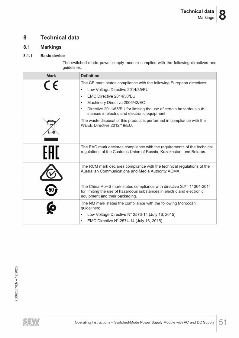
8 Technical data8.1 Markings8.1.1 Basic device
The switched-mode power supply module complies with the following directives andguidelines:
Mark DefinitionThe CE mark states compliance with the following European directives:• Low Voltage Directive 2014/35/EU• EMC Directive 2014/30/EU• Machinery Directive 2006/42/EC• Directive 2011/65/EU for limiting the use of certain hazardous sub-
stances in electric and electronic equipment
The waste disposal of this product is performed in compliance with theWEEE Directive 2012/19/EU.
The EAC mark declares compliance with the requirements of the technicalregulations of the Customs Union of Russia, Kazakhstan, and Belarus.
The RCM mark declares compliance with the technical regulations of theAustralian Communications and Media Authority ACMA.
The China RoHS mark states compliance with directive SJ/T 11364-2014for limiting the use of hazardous substances in electric and electronicequipment and their packaging.
The NM mark states the compliance with the following Moroccanguidelines:• Low Voltage Directive N° 2573-14 (July 16, 2015)• EMC Directive N° 2574-14 (July 16, 2015)
2686
2557
/EN
– 1
2/20
20
8 Technical dataMarkings
Operating Instructions – Switched-Mode Power Supply Module with AC and DC Supply52
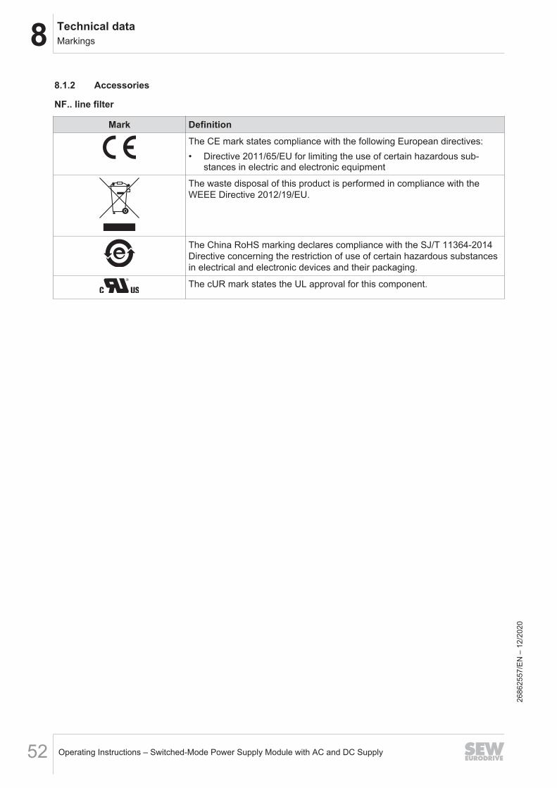
8.1.2 Accessories
NF.. line filter
Mark DefinitionThe CE mark states compliance with the following European directives:• Directive 2011/65/EU for limiting the use of certain hazardous sub-
stances in electric and electronic equipment
The waste disposal of this product is performed in compliance with theWEEE Directive 2012/19/EU.
The China RoHS marking declares compliance with the SJ/T 11364-2014Directive concerning the restriction of use of certain hazardous substancesin electrical and electronic devices and their packaging.
The cUR mark states the UL approval for this component.
2686
2557
/EN
– 1
2/20
20
8Technical dataGeneral technical data
Operating Instructions – Switched-Mode Power Supply Module with AC and DC Supply 53
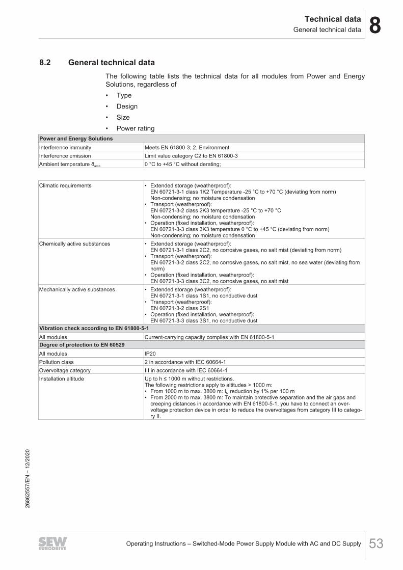
8.2 General technical dataThe following table lists the technical data for all modules from Power and EnergySolutions, regardless of• Type• Design• Size• Power rating
Power and Energy SolutionsInterference immunity Meets EN 61800-3; 2. EnvironmentInterference emission Limit value category C2 to EN 61800‑3Ambient temperature ϑamb 0 °C to +45 °C without derating;
Climatic requirements • Extended storage (weatherproof):EN 60721-3-1 class 1K2 Temperature -25 °C to +70 °C (deviating from norm)Non-condensing; no moisture condensation
• Transport (weatherproof):EN 60721-3-2 class 2K3 temperature -25 °C to +70 °CNon-condensing; no moisture condensation
• Operation (fixed installation, weatherproof):EN 60721-3-3 class 3K3 temperature 0 °C to +45 °C (deviating from norm)Non-condensing; no moisture condensation
Chemically active substances • Extended storage (weatherproof):EN 60721-3-1 class 2C2, no corrosive gases, no salt mist (deviating from norm)
• Transport (weatherproof):EN 60721-3-2 class 2C2, no corrosive gases, no salt mist, no sea water (deviating fromnorm)
• Operation (fixed installation, weatherproof):EN 60721-3-3 class 3C2, no corrosive gases, no salt mist
Mechanically active substances • Extended storage (weatherproof):EN 60721-3-1 class 1S1, no conductive dust
• Transport (weatherproof):EN 60721-3-2 class 2S1
• Operation (fixed installation, weatherproof):EN 60721-3-3 class 3S1, no conductive dust
Vibration check according to EN 61800-5-1All modules Current-carrying capacity complies with EN 61800-5-1Degree of protection to EN 60529All modules IP20Pollution class 2 in accordance with IEC 60664-1Overvoltage category III in accordance with IEC 60664-1Installation altitude Up to h ≤ 1000 m without restrictions.
The following restrictions apply to altitudes > 1000 m:• From 1000 m to max. 3800 m: IN reduction by 1% per 100 m• From 2000 m to max. 3800 m: To maintain protective separation and the air gaps and
creeping distances in accordance with EN 61800‑5‑1, you have to connect an over-voltage protection device in order to reduce the overvoltages from category III to catego-ry II.
2686
2557
/EN
– 1
2/20
20
8 Technical dataSwitched-mode power supply module with AC and DC supply MDS90A
Operating Instructions – Switched-Mode Power Supply Module with AC and DC Supply54
8.3 Switched-mode power supply module with AC and DC supply MDS90A
8.3.1 Performance dataSwitched-Mode Power Supply Module with AC and DCSupply
MDS90A-0054-5E3-X-000
Line connectionNominal line voltage UAC (to EN 50160) AC 3 × 200 V – 500 VNominal line current 3 × AC 2.4 ALine frequency fline 50 – 60 Hz ± 10%Line connection X1 Plug connector 0.2 mm2 – 6 mm2
Maximum DC input voltage at the main terminal strips whenused as DC input
• 800 V when connected to +UB of MDP92A/MDE90A• ≤ DC +600 V against negative pole of DC input X1
Output (24 V output)Nominal voltage U24V DC 24 VOutput voltage range adjustable DC 24 V – 27 VNominal current I24V DC 22.5 AMaximum current I24V_max DC 25 AContinuous power at U24V 540 WMaximum power at U24V 675 WCurrent limiting 25 AOutput capacitance C24V 6 mFOutput characteristic curve UI characteristic curve, rectangularProtection devices • Overvoltage switch-off at 30 V
• Overtemperature switch-offOutput current limit Short-circuit proofEfficiency • 90% at UDCL = 150 V
• 86.3% at UAC = AC 3 × 400 VConnection CU rail, M4 × 14 screw, max. 16 mm2
Connector up to 16 mm2
PE connection M6 × 16 screwDC link supply (DC)Nominal DC link voltage UDCL DC 150 V – 800 V
Startup at 200 V (adjustable)DC link voltage UDCL_max DC 1000 VNominal DC link current IDCL DC 5 A at UDCL = 150 VDC link capacity CDCL 15 μFDC link connection +UZ/-UZ CU rail, M6 × 16 screwGeneralNominal power loss 24 V • 62.5 W at UDCL = 150 V
• 90 W at UAC = AC 3 × 400 VMaximum permitted nominal voltage to PE DC 546 VPE connection M4 × 14 screwsMass Approx. 5 kgDimensionsWidth 60 mmHeight 324 mmDepth 250 mm
The switched-mode power supply module complies with the requirements for protect-ive separation in accordance with SELV and PELV (EN 61800-5-1).
2686
2557
/EN
– 1
2/20
20
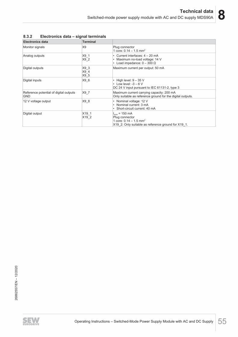
8Technical dataSwitched-mode power supply module with AC and DC supply MDS90A
Operating Instructions – Switched-Mode Power Supply Module with AC and DC Supply 55
8.3.2 Electronics data – signal terminalsElectronics data TerminalMonitor signals X9 Plug connector
1 core: 0.14 – 1.5 mm2
Analog outputs X9_1X9_2
• Current interfaces: 4 – 20 mA• Maximum no-load voltage: 14 V• Load impedance: 0 – 300 Ω
Digital outputs X9_3X9_4X9_5
Maximum current per output: 50 mA
Digital inputs X9_6 • High level: 9 – 35 V• Low level: -3 – 6 VDC 24 V input pursuant to IEC 61131-2, type 3
Reference potential of digital outputsGND
X9_7 Maximum current carrying capacity: 200 mAOnly suitable as reference ground for the digital outputs.
12 V voltage output X9_8 • Nominal voltage: 12 V• Nominal current: 3 mA• Short-circuit current: 40 mA
Digital output X19_1X19_2
Inom = 150 mAPlug connector1 core: 0.14 – 1.5 mm2
X19_2: Only suitable as reference ground for X19_1.
2686
2557
/EN
– 1
2/20
20
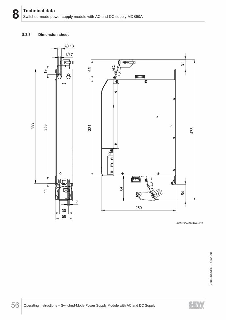
8 Technical dataSwitched-mode power supply module with AC and DC supply MDS90A
Operating Instructions – Switched-Mode Power Supply Module with AC and DC Supply56
8.3.3 Dimension sheet
31
54
473
65
324
250
84
7
1319
353
383
11
7
30
59
9007227802454923
2686
2557
/EN
– 1
2/20
20
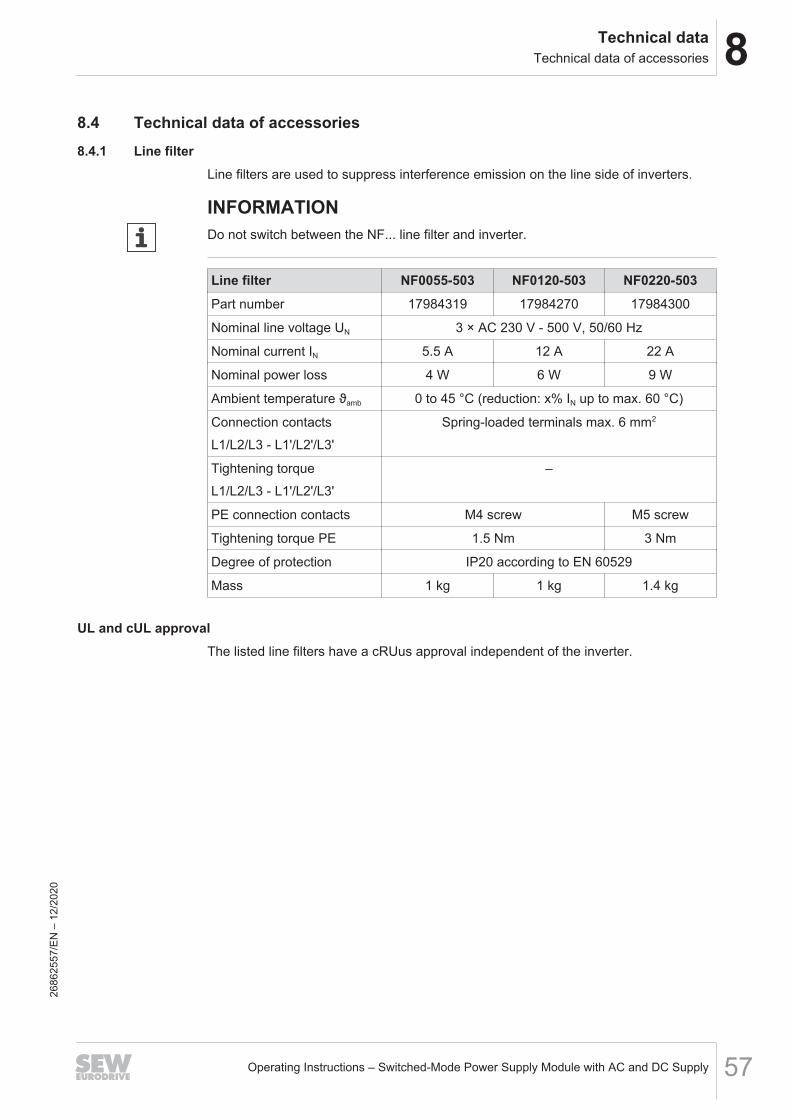
8Technical dataTechnical data of accessories
Operating Instructions – Switched-Mode Power Supply Module with AC and DC Supply 57
8.4 Technical data of accessories8.4.1 Line filter
Line filters are used to suppress interference emission on the line side of inverters.
INFORMATIONDo not switch between the NF... line filter and inverter.
Line filter NF0055-503 NF0120-503 NF0220-503Part number 17984319 17984270 17984300
Nominal line voltage UN 3 × AC 230 V - 500 V, 50/60 Hz
Nominal current IN 5.5 A 12 A 22 A
Nominal power loss 4 W 6 W 9 W
Ambient temperature ϑamb 0 to 45 °C (reduction: x% IN up to max. 60 °C)
Connection contactsL1/L2/L3 - L1'/L2'/L3'
Spring-loaded terminals max. 6 mm2
Tightening torqueL1/L2/L3 - L1'/L2'/L3'
–
PE connection contacts M4 screw M5 screw
Tightening torque PE 1.5 Nm 3 Nm
Degree of protection IP20 according to EN 60529
Mass 1 kg 1 kg 1.4 kg
UL and cUL approvalThe listed line filters have a cRUus approval independent of the inverter.
2686
2557
/EN
– 1
2/20
20
Index
IndexA
AssemblySafety notes ................................................... 12
C
Closing covers and touch guards ........................ 35Combination of the devices ................................. 20Copyright notice .................................................... 8
D
Designated use ................................................... 11Device structure
MDS90A ......................................................... 17Type code....................................................... 16
Dimension drawingsSwitch-mode power supply module MDS90A 56
E
Electrical installation............................................ 13Fuse types, line fuses..................................... 25General information........................................ 24Inputs/outputs................................................. 35Line fuses, fuse types..................................... 25Safety notes ................................................... 13Touch guards and closing covers................... 35Use in IT systems........................................... 28
Electronics Service.............................................. 49Embedded safety notes......................................... 7Extended storage ................................................ 49
F
Functional safety technologySafety note ..................................................... 11
Fuse types, line fuses.......................................... 25
H
Hazard symbolsMeaning............................................................ 7
I
Inputs/outputs...................................................... 35Installation
Combining devices ......................................... 20Connection of an axis system ........................ 34Mounting grid.................................................. 22
Permitted tightening torques .......................... 19IT systems ........................................................... 28
L
Lifting applications............................................... 11Line fuses, fuse types.......................................... 25
M
MDS90A storage conditions................................ 49Mechanical accessories ...................................... 18Mounting grid....................................................... 22
N
NotesDesignation in the documentation .................... 6Meaning of the hazard symbols ....................... 7
O
OperationOperating displays MDS90A .......................... 45Safety notes ................................................... 14
P
Permitted tightening torques ............................... 19Product names ...................................................... 8Project planning
Parallel connection of switched-mode powersupply modules .............................................. 31Selector switch of output voltage MDS90A .... 43Settings on the selector switches ................... 43
Protective separation........................................... 13
R
Repair .................................................................. 49Rights to claim under limited warranty .................. 7
S
Safety functions................................................... 11Safety notes
Assembly........................................................ 12Designation in the documentation .................... 6Installation ...................................................... 12Meaning of the hazard symbols ....................... 7Preliminary information..................................... 9Structure of embedded..................................... 7Structure of section-related .............................. 7
2686
2557
/EN
– 1
2/20
Operating Instructions – Switched-Mode Power Supply Module with AC and DC Supply58
Index
Section-related safety notes.................................. 7Selector switch of output voltage MDS90A ......... 43Separation, protective ......................................... 13Signal words in safety notes.................................. 6Standard accessories
Mechanical accessories ................................. 18Startup
Safety notes ................................................... 14
T
Target group........................................................ 10Technical data
General technical data ................................... 53
Switched-mode power supply module MDS90A....................................................................... 54
Terminal assignmentMDS90A ......................................................... 37
Tightening torques............................................... 19Touch guards and closing covers........................ 35Trademarks ........................................................... 8Transport ............................................................. 12Type code............................................................ 16
U
Use in IT systems................................................ 28
W
Waste disposal .................................................... 50
2686
2557
/EN
– 1
2/20
Operating Instructions – Switched-Mode Power Supply Module with AC and DC Supply 59
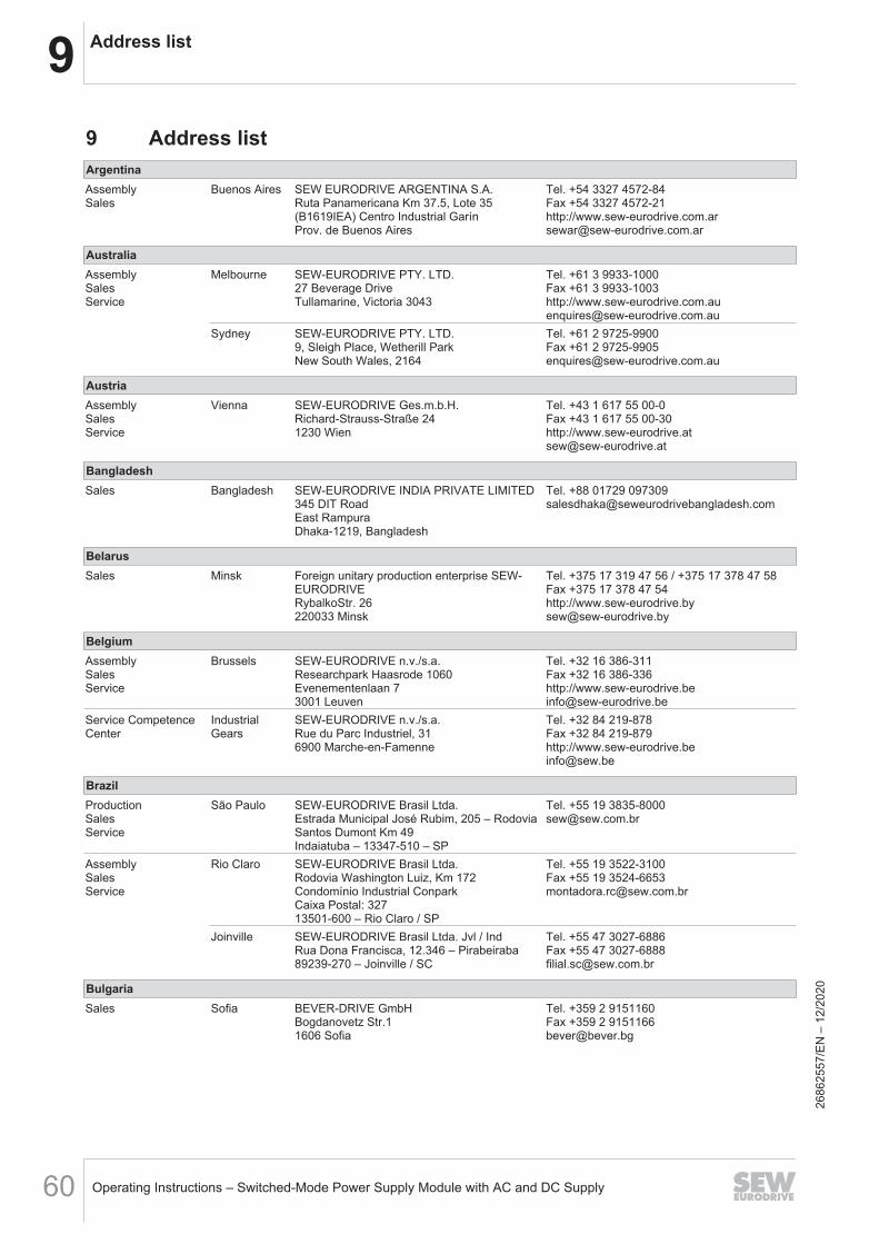
9 Address list
Operating Instructions – Switched-Mode Power Supply Module with AC and DC Supply60
9 Address listArgentinaAssemblySales
Buenos Aires SEW EURODRIVE ARGENTINA S.A.Ruta Panamericana Km 37.5, Lote 35(B1619IEA) Centro Industrial GarínProv. de Buenos Aires
Tel. +54 3327 4572-84Fax +54 3327 4572-21http://[email protected]
AustraliaAssemblySalesService
Melbourne SEW-EURODRIVE PTY. LTD.27 Beverage DriveTullamarine, Victoria 3043
Tel. +61 3 9933-1000Fax +61 3 9933-1003http://[email protected]
Sydney SEW-EURODRIVE PTY. LTD.9, Sleigh Place, Wetherill ParkNew South Wales, 2164
Tel. +61 2 9725-9900Fax +61 2 [email protected]
AustriaAssemblySalesService
Vienna SEW-EURODRIVE Ges.m.b.H.Richard-Strauss-Straße 241230 Wien
Tel. +43 1 617 55 00-0Fax +43 1 617 55 00-30http://[email protected]
BangladeshSales Bangladesh SEW-EURODRIVE INDIA PRIVATE LIMITED
345 DIT RoadEast RampuraDhaka-1219, Bangladesh
Tel. +88 01729 [email protected]
BelarusSales Minsk Foreign unitary production enterprise SEW-
EURODRIVERybalkoStr. 26220033 Minsk
Tel. +375 17 319 47 56 / +375 17 378 47 58Fax +375 17 378 47 54http://[email protected]
BelgiumAssemblySalesService
Brussels SEW-EURODRIVE n.v./s.a.Researchpark Haasrode 1060Evenementenlaan 73001 Leuven
Tel. +32 16 386-311Fax +32 16 386-336http://[email protected]
Service CompetenceCenter
IndustrialGears
SEW-EURODRIVE n.v./s.a.Rue du Parc Industriel, 316900 Marche-en-Famenne
Tel. +32 84 219-878Fax +32 84 219-879http://[email protected]
BrazilProductionSalesService
São Paulo SEW-EURODRIVE Brasil Ltda.Estrada Municipal José Rubim, 205 – RodoviaSantos Dumont Km 49Indaiatuba – 13347-510 – SP
Tel. +55 19 [email protected]
AssemblySalesService
Rio Claro SEW-EURODRIVE Brasil Ltda.Rodovia Washington Luiz, Km 172Condomínio Industrial ConparkCaixa Postal: 32713501-600 – Rio Claro / SP
Tel. +55 19 3522-3100Fax +55 19 [email protected]
Joinville SEW-EURODRIVE Brasil Ltda. Jvl / IndRua Dona Francisca, 12.346 – Pirabeiraba89239-270 – Joinville / SC
Tel. +55 47 3027-6886Fax +55 47 [email protected]
BulgariaSales Sofia BEVER-DRIVE GmbH
Bogdanovetz Str.11606 Sofia
Tel. +359 2 9151160Fax +359 2 [email protected]
2686
2557
/EN
– 1
2/20
20
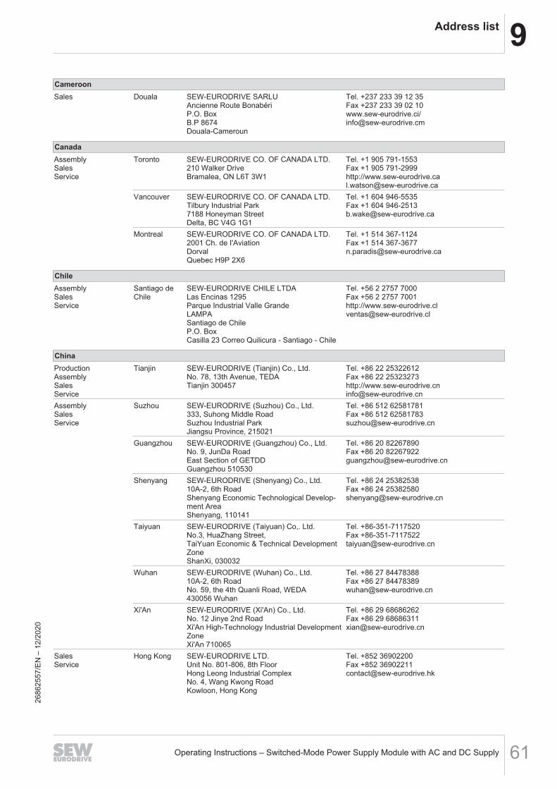
9Address list
Operating Instructions – Switched-Mode Power Supply Module with AC and DC Supply 61
CameroonSales Douala SEW-EURODRIVE SARLU
Ancienne Route BonabériP.O. BoxB.P 8674Douala-Cameroun
Tel. +237 233 39 12 35Fax +237 233 39 02 10www.sew-eurodrive.ci/[email protected]
CanadaAssemblySalesService
Toronto SEW-EURODRIVE CO. OF CANADA LTD.210 Walker DriveBramalea, ON L6T 3W1
Tel. +1 905 791-1553Fax +1 905 791-2999http://[email protected]
Vancouver SEW-EURODRIVE CO. OF CANADA LTD.Tilbury Industrial Park7188 Honeyman StreetDelta, BC V4G 1G1
Tel. +1 604 946-5535Fax +1 604 [email protected]
Montreal SEW-EURODRIVE CO. OF CANADA LTD.2001 Ch. de I'AviationDorvalQuebec H9P 2X6
Tel. +1 514 367-1124Fax +1 514 [email protected]
ChileAssemblySalesService
Santiago deChile
SEW-EURODRIVE CHILE LTDALas Encinas 1295Parque Industrial Valle GrandeLAMPASantiago de ChileP.O. BoxCasilla 23 Correo Quilicura - Santiago - Chile
Tel. +56 2 2757 7000Fax +56 2 2757 7001http://[email protected]
ChinaProductionAssemblySalesService
Tianjin SEW-EURODRIVE (Tianjin) Co., Ltd.No. 78, 13th Avenue, TEDATianjin 300457
Tel. +86 22 25322612Fax +86 22 25323273http://[email protected]
AssemblySalesService
Suzhou SEW-EURODRIVE (Suzhou) Co., Ltd.333, Suhong Middle RoadSuzhou Industrial ParkJiangsu Province, 215021
Tel. +86 512 62581781Fax +86 512 [email protected]
Guangzhou SEW-EURODRIVE (Guangzhou) Co., Ltd.No. 9, JunDa RoadEast Section of GETDDGuangzhou 510530
Tel. +86 20 82267890Fax +86 20 [email protected]
Shenyang SEW-EURODRIVE (Shenyang) Co., Ltd.10A-2, 6th RoadShenyang Economic Technological Develop-ment AreaShenyang, 110141
Tel. +86 24 25382538Fax +86 24 [email protected]
Taiyuan SEW-EURODRIVE (Taiyuan) Co,. Ltd.No.3, HuaZhang Street,TaiYuan Economic & Technical DevelopmentZoneShanXi, 030032
Tel. +86-351-7117520Fax [email protected]
Wuhan SEW-EURODRIVE (Wuhan) Co., Ltd.10A-2, 6th RoadNo. 59, the 4th Quanli Road, WEDA430056 Wuhan
Tel. +86 27 84478388Fax +86 27 [email protected]
Xi'An SEW-EURODRIVE (Xi'An) Co., Ltd.No. 12 Jinye 2nd RoadXi'An High-Technology Industrial DevelopmentZoneXi'An 710065
Tel. +86 29 68686262Fax +86 29 [email protected]
SalesService
Hong Kong SEW-EURODRIVE LTD.Unit No. 801-806, 8th FloorHong Leong Industrial ComplexNo. 4, Wang Kwong RoadKowloon, Hong Kong
Tel. +852 36902200Fax +852 [email protected]
2686
2557
/EN
– 1
2/20
20
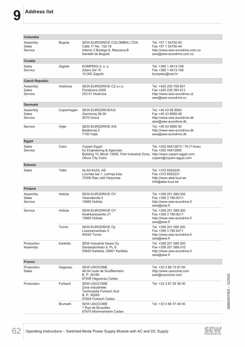
9 Address list
Operating Instructions – Switched-Mode Power Supply Module with AC and DC Supply62
ColombiaAssemblySalesService
Bogota SEW-EURODRIVE COLOMBIA LTDA.Calle 17 No. 132-18Interior 2 Bodega 6, Manzana BSantafé de Bogotá
Tel. +57 1 54750-50Fax +57 1 54750-44http://[email protected]
CroatiaSalesService
Zagreb KOMPEKS d. o. o.Zeleni dol 1010 000 Zagreb
Tel. +385 1 4613-158Fax +385 1 [email protected]
Czech RepublicAssemblySalesService
Hostivice SEW-EURODRIVE CZ s.r.o.Floriánova 2459253 01 Hostivice
Tel. +420 255 709 601Fax +420 235 350 613http://[email protected]
DenmarkAssemblySalesService
Copenhagen SEW-EURODRIVEA/SGeminivej 28-302670 Greve
Tel. +45 43 95 8500Fax +45 43 9585-09http://[email protected]
Service Vejle SEW-EURODRIVE A/SBødkervej 27100 Vejle
Tel. +45 43 9585 00http://[email protected]
EgyptSalesService
Cairo Copam Egyptfor Engineering & AgenciesBuilding 10, Block 13005, First Industrial Zone,Obour City Cairo
Tel. +202 44812673 / 79 (7 lines)Fax +202 44812685http://[email protected]
EstoniaSales Tallin ALAS-KUUL AS
Loomäe tee 1, Lehmja küla75306 Rae vald Harjumaa
Tel. +372 6593230Fax +372 6593231http://[email protected]
FinlandAssemblySalesService
Hollola SEW-EURODRIVE OYVesimäentie 415860 Hollola
Tel. +358 201 589-300Fax +358 3 780-6211http://[email protected]
Service Hollola SEW-EURODRIVE OYKeskikankaantie 2115860 Hollola
Tel. +358 201 589-300Fax +358 3 780-6211http://[email protected]
Tornio SEW-EURODRIVE OyLossirannankatu 595420 Tornio
Tel. +358 201 589 300Fax +358 3 780 6211http://[email protected]
ProductionAssembly
Karkkila SEW Industrial Gears OySantasalonkatu 6, PL 803620 Karkkila, 03601 Karkkila
Tel. +358 201 589-300Fax +358 201 589-310http://[email protected]
FranceProductionSales
Hagenau SEW USOCOME48-54 route de SoufflenheimB. P. 2018567506 Haguenau Cedex
Tel. +33 3 88 73 67 00http://[email protected]
Production Forbach SEW USOCOMEZone industrielleTechnopôle Forbach SudB. P. 3026957604 Forbach Cedex
Tel. +33 3 87 29 38 00
Brumath SEW USOCOME1 Rue de Bruxelles67670 Mommenheim Cedex
Tel. +33 3 88 37 48 00
2686
2557
/EN
– 1
2/20
20
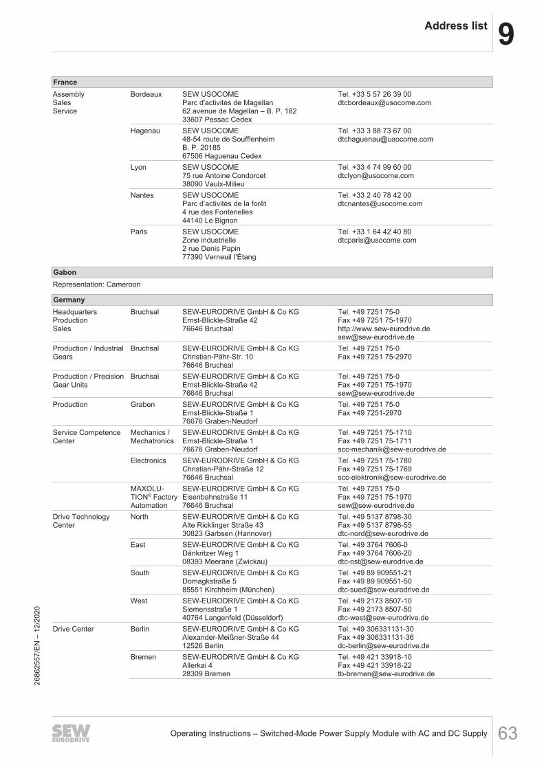
9Address list
Operating Instructions – Switched-Mode Power Supply Module with AC and DC Supply 63
FranceAssemblySalesService
Bordeaux SEW USOCOMEParc d'activités de Magellan62 avenue de Magellan – B. P. 18233607 Pessac Cedex
Tel. +33 5 57 26 39 [email protected]
Hagenau SEW USOCOME48-54 route de SoufflenheimB. P. 2018567506 Haguenau Cedex
Tel. +33 3 88 73 67 [email protected]
Lyon SEW USOCOME75 rue Antoine Condorcet38090 Vaulx-Milieu
Tel. +33 4 74 99 60 [email protected]
Nantes SEW USOCOMEParc d’activités de la forêt4 rue des Fontenelles44140 Le Bignon
Tel. +33 2 40 78 42 [email protected]
Paris SEW USOCOMEZone industrielle2 rue Denis Papin77390 Verneuil I'Étang
Tel. +33 1 64 42 40 [email protected]
GabonRepresentation: Cameroon
GermanyHeadquartersProductionSales
Bruchsal SEW-EURODRIVE GmbH & Co KGErnst-Blickle-Straße 4276646 Bruchsal
Tel. +49 7251 75-0Fax +49 7251 75-1970http://[email protected]
Production / IndustrialGears
Bruchsal SEW-EURODRIVE GmbH & Co KGChristian-Pähr-Str. 1076646 Bruchsal
Tel. +49 7251 75-0Fax +49 7251 75-2970
Production / PrecisionGear Units
Bruchsal SEW-EURODRIVE GmbH & Co KGErnst-Blickle-Straße 4276646 Bruchsal
Tel. +49 7251 75-0Fax +49 7251 [email protected]
Production Graben SEW-EURODRIVE GmbH & Co KGErnst-Blickle-Straße 176676 Graben-Neudorf
Tel. +49 7251 75-0Fax +49 7251-2970
Service CompetenceCenter
Mechanics /Mechatronics
SEW-EURODRIVE GmbH & Co KGErnst-Blickle-Straße 176676 Graben-Neudorf
Tel. +49 7251 75-1710Fax +49 7251 [email protected]
Electronics SEW-EURODRIVE GmbH & Co KGChristian-Pähr-Straße 1276646 Bruchsal
Tel. +49 7251 75-1780Fax +49 7251 [email protected]
MAXOLU-TION® FactoryAutomation
SEW-EURODRIVE GmbH & Co KGEisenbahnstraße 1176646 Bruchsal
Tel. +49 7251 75-0Fax +49 7251 [email protected]
Drive TechnologyCenter
North SEW-EURODRIVE GmbH & Co KGAlte Ricklinger Straße 4330823 Garbsen (Hannover)
Tel. +49 5137 8798-30Fax +49 5137 [email protected]
East SEW-EURODRIVE GmbH & Co KGDänkritzer Weg 108393 Meerane (Zwickau)
Tel. +49 3764 7606-0Fax +49 3764 [email protected]
South SEW-EURODRIVE GmbH & Co KGDomagkstraße 585551 Kirchheim (München)
Tel. +49 89 909551-21Fax +49 89 [email protected]
West SEW-EURODRIVE GmbH & Co KGSiemensstraße 140764 Langenfeld (Düsseldorf)
Tel. +49 2173 8507-10Fax +49 2173 [email protected]
Drive Center Berlin SEW-EURODRIVE GmbH & Co KGAlexander-Meißner-Straße 4412526 Berlin
Tel. +49 306331131-30Fax +49 [email protected]
Bremen SEW-EURODRIVE GmbH & Co KGAllerkai 428309 Bremen
Tel. +49 421 33918-10Fax +49 421 [email protected]
2686
2557
/EN
– 1
2/20
20
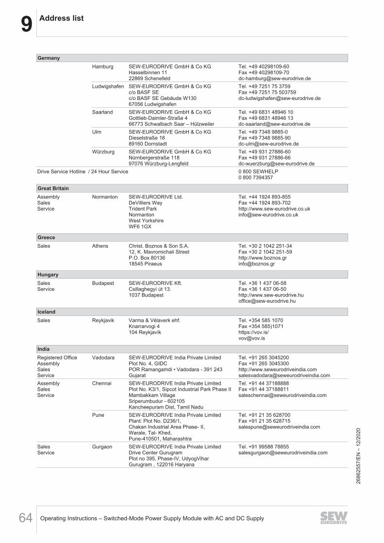
9 Address list
Operating Instructions – Switched-Mode Power Supply Module with AC and DC Supply64
GermanyHamburg SEW-EURODRIVE GmbH & Co KG
Hasselbinnen 1122869 Schenefeld
Tel. +49 40298109-60Fax +49 [email protected]
Ludwigshafen SEW-EURODRIVE GmbH & Co KGc/o BASF SEc/o BASF SE Gebäude W13067056 Ludwigshafen
Tel. +49 7251 75 3759Fax +49 7251 75 [email protected]
Saarland SEW-EURODRIVE GmbH & Co KGGottlieb-Daimler-Straße 466773 Schwalbach Saar – Hülzweiler
Tel. +49 6831 48946 10Fax +49 6831 48946 [email protected]
Ulm SEW-EURODRIVE GmbH & Co KGDieselstraße 1889160 Dornstadt
Tel. +49 7348 9885-0Fax +49 7348 [email protected]
Würzburg SEW-EURODRIVE GmbH & Co KGNürnbergerstraße 11897076 Würzburg-Lengfeld
Tel. +49 931 27886-60Fax +49 931 [email protected]
Drive Service Hotline / 24 Hour Service 0 800 SEWHELP0 800 7394357
Great BritainAssemblySalesService
Normanton SEW-EURODRIVE Ltd.DeVilliers WayTrident ParkNormantonWest YorkshireWF6 1GX
Tel. +44 1924 893-855Fax +44 1924 893-702http://[email protected]
GreeceSales Athens Christ. Boznos & Son S.A.
12, K. Mavromichali StreetP.O. Box 8013618545 Piraeus
Tel. +30 2 1042 251-34Fax +30 2 1042 251-59http://[email protected]
HungarySalesService
Budapest SEW-EURODRIVE Kft.Csillaghegyí út 13.1037 Budapest
Tel. +36 1 437 06-58Fax +36 1 437 06-50http://[email protected]
IcelandSales Reykjavik Varma & Vélaverk ehf.
Knarrarvogi 4104 Reykjavík
Tel. +354 585 1070Fax +354 585)1071https://vov.is/[email protected]
IndiaRegistered OfficeAssemblySalesService
Vadodara SEW-EURODRIVE India Private LimitedPlot No. 4, GIDCPOR Ramangamdi • Vadodara - 391 243Gujarat
Tel. +91 265 3045200Fax +91 265 3045300http://[email protected]
AssemblySalesService
Chennai SEW-EURODRIVE India Private LimitedPlot No. K3/1, Sipcot Industrial Park Phase IIMambakkam VillageSriperumbudur - 602105Kancheepuram Dist, Tamil Nadu
Tel. +91 44 37188888Fax +91 44 [email protected]
Pune SEW-EURODRIVE India Private LimitedPlant: Plot No. D236/1,Chakan Industrial Area Phase- II,Warale, Tal- Khed,Pune-410501, Maharashtra
Tel. +91 21 35 628700Fax +91 21 35 [email protected]
SalesService
Gurgaon SEW-EURODRIVE India Private LimitedDrive Center GurugramPlot no 395, Phase-IV, UdyogViharGurugram , 122016 Haryana
Tel. +91 99588 [email protected]
2686
2557
/EN
– 1
2/20
20
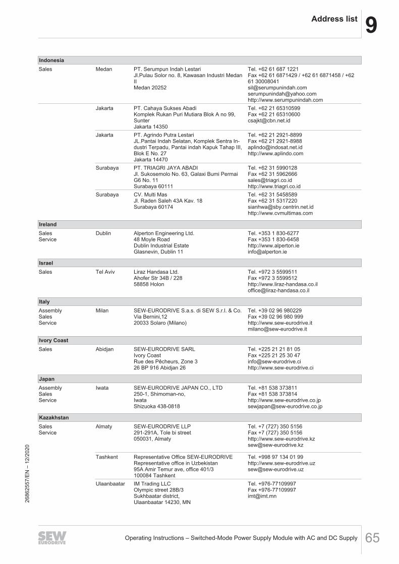
9Address list
Operating Instructions – Switched-Mode Power Supply Module with AC and DC Supply 65
IndonesiaSales Medan PT. Serumpun Indah Lestari
Jl.Pulau Solor no. 8, Kawasan Industri MedanIIMedan 20252
Tel. +62 61 687 1221Fax +62 61 6871429 / +62 61 6871458 / +6261 [email protected]@yahoo.comhttp://www.serumpunindah.com
Jakarta PT. Cahaya Sukses AbadiKomplek Rukan Puri Mutiara Blok A no 99,SunterJakarta 14350
Tel. +62 21 65310599Fax +62 21 [email protected]
Jakarta PT. Agrindo Putra LestariJL.Pantai Indah Selatan, Komplek Sentra In-dustri Terpadu, Pantai indah Kapuk Tahap III,Blok E No. 27Jakarta 14470
Tel. +62 21 2921-8899Fax +62 21 [email protected]://www.aplindo.com
Surabaya PT. TRIAGRI JAYA ABADIJl. Sukosemolo No. 63, Galaxi Bumi PermaiG6 No. 11Surabaya 60111
Tel. +62 31 5990128Fax +62 31 [email protected]://www.triagri.co.id
Surabaya CV. Multi MasJl. Raden Saleh 43A Kav. 18Surabaya 60174
Tel. +62 31 5458589Fax +62 31 [email protected]://www.cvmultimas.com
IrelandSalesService
Dublin Alperton Engineering Ltd.48 Moyle RoadDublin Industrial EstateGlasnevin, Dublin 11
Tel. +353 1 830-6277Fax +353 1 830-6458http://[email protected]
IsraelSales Tel Aviv Liraz Handasa Ltd.
Ahofer Str 34B / 22858858 Holon
Tel. +972 3 5599511Fax +972 3 5599512http://[email protected]
ItalyAssemblySalesService
Milan SEW-EURODRIVE S.a.s. di SEW S.r.l. & Co.Via Bernini,1220033 Solaro (Milano)
Tel. +39 02 96 980229Fax +39 02 96 980 999http://[email protected]
Ivory CoastSales Abidjan SEW-EURODRIVE SARL
Ivory CoastRue des Pêcheurs, Zone 326 BP 916 Abidjan 26
Tel. +225 21 21 81 05Fax +225 21 25 30 [email protected]://www.sew-eurodrive.ci
JapanAssemblySalesService
Iwata SEW-EURODRIVE JAPAN CO., LTD250-1, Shimoman-no,IwataShizuoka 438-0818
Tel. +81 538 373811Fax +81 538 373814http://[email protected]
KazakhstanSalesService
Almaty SEW-EURODRIVE LLP291-291A, Tole bi street050031, Almaty
Tel. +7 (727) 350 5156Fax +7 (727) 350 5156http://[email protected]
Tashkent Representative Office SEW-EURODRIVERepresentative office in Uzbekistan95A Amir Temur ave, office 401/3100084 Tashkent
Tel. +998 97 134 01 99http://[email protected]
Ulaanbaatar IM Trading LLCOlympic street 28B/3Sukhbaatar district,Ulaanbaatar 14230, MN
Tel. +976-77109997Fax [email protected]
2686
2557
/EN
– 1
2/20
20
9 Address list
Operating Instructions – Switched-Mode Power Supply Module with AC and DC Supply66
LatviaSales Riga SIA Alas-Kuul
Katlakalna 11C1073 Riga
Tel. +371 6 7139253Fax +371 6 7139386http://[email protected]
LebanonSales (Lebanon) Beirut Gabriel Acar & Fils sarl
B. P. 80484Bourj Hammoud, Beirut
Tel. +961 1 510 532Fax +961 1 494 [email protected]
Sales (Jordan, Kuwait ,Saudi Arabia, Syria)
Beirut Middle East Drives S.A.L. (offshore)Sin El Fil.B. P. 55-378Beirut
Tel. +961 1 494 786Fax +961 1 494 971http://[email protected]
LithuaniaSales Alytus UAB Irseva
Statybininku 106C63431 Alytus
Tel. +370 315 79204Fax +370 315 56175http://[email protected]
LuxembourgRepresentation: Belgium
MacedoniaSales Skopje Boznos DOOEL
Dime Anicin 2A/7A1000 Skopje
Tel. +389 23256553Fax +389 23256554http://www.boznos.mk
MalaysiaAssemblySalesService
Johor SEW-EURODRIVE SDN BHDNo. 95, Jalan Seroja 39, Taman Johor Jaya81000 Johor Bahru, JohorWest Malaysia
Tel. +60 7 3549409Fax +60 7 [email protected]
MexicoAssemblySalesService
Quéretaro SEW-EURODRIVE MEXICO S.A. de C.V.SEM-981118-M93Tequisquiapan No. 102Parque Industrial QuéretaroC.P. 76220Querétaro, México
Tel. +52 442 1030-300Fax +52 442 1030-301http://[email protected]
SalesService
Puebla SEW-EURODRIVE MEXICO S.A. de C.V.Calzada Zavaleta No. 3922 Piso 2 Local 6Col. Santa Cruz BuenavistaC.P. 72154Puebla, México
Tel. +52 (222) 221 248http://[email protected]
MongoliaTechnical Office Ulaanbaatar IM Trading LLC
Olympic street 28B/3Sukhbaatar district,Ulaanbaatar 14230, MN
Tel. +976-77109997Tel. +976-99070395Fax +976-77109997http://imt.mn/[email protected]
MoroccoSalesServiceAssembly
Bouskoura SEW-EURODRIVE Morocco SARLParc Industriel CFCIM, Lot. 55/5927182 BouskouraGrand Casablanca
Tel. +212 522 88 85 00Fax +212 522 88 84 50http://[email protected]
NamibiaSales Swakopmund DB MINING & INDUSTRIAL SUPPLIES CC
Einstein StreetStrauss Industrial ParkUnit1Swakopmund
Tel. +264 64 462 738Fax +264 64 462 [email protected]
2686
2557
/EN
– 1
2/20
20
9Address list
Operating Instructions – Switched-Mode Power Supply Module with AC and DC Supply 67
NetherlandsAssemblySalesService
Rotterdam SEW-EURODRIVE B.V.Industrieweg 1753044 AS RotterdamPostbus 100853004 AB Rotterdam
Tel. +31 10 4463-700Fax +31 10 4155-552Service: 0800-SEWHELPhttp://[email protected]
New ZealandAssemblySalesService
Auckland SEW-EURODRIVE NEW ZEALAND LTD.P.O. Box 58-42882 Greenmount driveEast Tamaki Auckland
Tel. +64 9 2745627Fax +64 9 2740165http://[email protected]
Christchurch SEW-EURODRIVE NEW ZEALAND LTD.30 Lodestar Avenue, WigramChristchurch
Tel. +64 3 384-6251Fax +64 3 [email protected]
NigeriaSales Lagos Greenpeg Nig. Ltd
Plot 296A, Adeyemo Akapo Str. Omole GRAIkeja Lagos-Nigeria
Tel. +234-701-821-9200-1http://[email protected]
NorwayAssemblySalesService
Moss SEW-EURODRIVE A/SSolgaard skog 711599 Moss
Tel. +47 69 24 10 20Fax +47 69 24 10 40http://[email protected]
PakistanSales Karachi Industrial Power Drives
Al-Fatah Chamber A/3, 1st Floor Central Com-mercial Area,Sultan Ahmed Shah Road, Block 7/8,Karachi
Tel. +92 21 452 9369Fax +92-21-454 [email protected]
ParaguaySales Fernando de la
MoraSEW-EURODRIVE PARAGUAY S.R.LDe la Victoria 112, Esquina nueva AsunciónDepartamento CentralFernando de la Mora, Barrio Bernardino
Tel. +595 991 519695Fax +595 21 [email protected]
PeruAssemblySalesService
Lima SEW EURODRIVE DEL PERU S.A.C.Los Calderos, 120-124Urbanizacion Industrial Vulcano, ATE, Lima
Tel. +51 1 3495280Fax +51 1 3493002http://[email protected]
PhilippinesSales Makati P.T. Cerna Corporation
4137 Ponte St., Brgy. Sta. CruzMakati City 1205
Tel. +63 2 519 6214Fax +63 2 890 [email protected]://www.ptcerna.com
PolandAssemblySalesService
Łódź SEW-EURODRIVE Polska Sp.z.o.o.ul. Techniczna 592-518 Łódź
Tel. +48 42 293 00 00Fax +48 42 293 00 49http://[email protected]
Service Tel. +48 42 293 0030Fax +48 42 293 0043
24 Hour ServiceTel. +48 602 739 739 (+48 602 SEW SEW)[email protected]
PortugalAssemblySalesService
Coimbra SEW-EURODRIVE, LDA.Av. da Fonte Nova, n.º 863050-379 Mealhada
Tel. +351 231 20 9670Fax +351 231 20 3685http://[email protected]
2686
2557
/EN
– 1
2/20
20
9 Address list
Operating Instructions – Switched-Mode Power Supply Module with AC and DC Supply68
RomaniaSalesService
Bucharest Sialco Trading SRLstr. Brazilia nr. 36011783 Bucuresti
Tel. +40 21 230-1328Fax +40 21 230-7170http://[email protected]
RussiaAssemblySalesService
St. Petersburg ЗАО «СЕВ-ЕВРОДРАЙФ»188660, Russia, Leningrad Region, Vse-volozhsky District, Korabselki, AleksandraNevskogo str.building 4, block 1P.O. Box 36195220 St. Petersburg
Tel. +7 812 3332522 / +7 812 5357142Fax +7 812 3332523http://[email protected]
SenegalSales Dakar SENEMECA
Mécanique GénéraleKm 8, Route de RufisqueB.P. 3251, Dakar
Tel. +221 338 494 770Fax +221 338 494 771http://[email protected]
SerbiaSales Belgrade DIPAR d.o.o.
Ustanicka 128aPC Košum, IV floor11000 Beograd
Tel. +381 11 347 3244 / +381 11 288 0393Fax +381 11 347 [email protected]
SingaporeAssemblySalesService
Singapore SEW-EURODRIVE PTE. LTD.No 9, Tuas Drive 2Jurong Industrial EstateSingapore 638644
Tel. +65 68621701Fax +65 68612827http://[email protected]
SlovakiaSales Bernolákovo SEW-Eurodrive SK s.r.o.
Priemyselná ulica 6267/7900 27 Bernolákovo
Tel.+421 2 48 212 800http://[email protected]
SloveniaSalesService
Celje Pakman - Pogonska Tehnika d.o.o.UI. XIV. divizije 143000 Celje
Tel. +386 3 490 83-20Fax +386 3 490 [email protected]
South AfricaAssemblySalesService
Johannesburg SEW-EURODRIVE (PROPRIETARY) LIMITEDEurodrive HouseCnr. Adcock Ingram and Aerodrome RoadsAeroton Ext. 2Johannesburg 2013P.O.Box 90004Bertsham 2013
Tel. +27 11 248-7000Fax +27 11 248-7289http://[email protected]
Cape Town SEW-EURODRIVE (PROPRIETARY) LIMITEDRainbow ParkCnr. Racecourse & Omuramba RoadMontague GardensCape TownP.O.Box 36556Chempet 7442
Tel. +27 21 552-9820Fax +27 21 552-9830Telex 576 [email protected]
Durban SEW-EURODRIVE (PROPRIETARY) LIMITED48 Prospecton RoadIsipingoDurbanP.O. Box 10433, Ashwood 3605
Tel. +27 31 902 3815Fax +27 31 902 [email protected]
Nelspruit SEW-EURODRIVE (PROPRIETARY) LIMITED7 Christie CrescentVintoniaP.O.Box 1942Nelspruit 1200
Tel. +27 13 752-8007Fax +27 13 [email protected]
2686
2557
/EN
– 1
2/20
20
9Address list
Operating Instructions – Switched-Mode Power Supply Module with AC and DC Supply 69
South KoreaAssemblySalesService
Ansan SEW-EURODRIVE Korea Co., Ltd.7, Dangjaengi-ro,Danwon-gu,Ansan-si, Gyeonggi-do, Zip 425-839
Tel. +82 31 492-8051Fax +82 31 492-8056http://[email protected]
Busan SEW-EURODRIVE Korea Co., Ltd.28, Noksansandan 262-ro 50beon-gil,Gangseo-gu,Busan, Zip 618-820
Tel. +82 51 832-0204Fax +82 51 832-0230
AssemblyService
Siheung SEW-EURODRIVE Korea Co., Ltd.35, Emtibeui 26-ro 58beon-gil,Siheung-si, Gyeonggi-do
http://www.sew-eurodrive.kr
SpainAssemblySalesService
Bilbao SEW-EURODRIVE ESPAÑA, S.L.Parque Tecnológico, Edificio, 30248170 Zamudio (Vizcaya)
Tel. +34 94 43184-70http://[email protected]
Sri LankaSales Colombo SM International (Pte) Ltd
254, Galle RaodColombo 4, Sri Lanka
Tel. +94 1 2584887Fax +94 1 2582981
SwazilandSales Manzini C G Trading Co. (Pty) Ltd
Simunye streetMatsapha, Manzini
Tel. +268 7602 0790Fax +268 2 518 [email protected]
SwedenAssemblySalesService
Jönköping SEW-EURODRIVE ABGnejsvägen 6-8553 03 JönköpingBox 3100 S-550 03 Jönköping
Tel. +46 36 34 42 00Fax +46 36 34 42 80http://[email protected]
SwitzerlandAssemblySalesService
Basel Alfred lmhof A.G.Jurastrasse 104142 Münchenstein bei Basel
Tel. +41 61 417 1717Fax +41 61 417 1700http://[email protected]
TaiwanSales Taipei Ting Shou Trading Co., Ltd.
6F-3, No. 267, Sec. 2Tung Huw S. RoadTaipei
Tel. +886 2 27383535Fax +886 2 27368268Telex 27 [email protected]://www.tingshou.com.tw
Nan Tou Ting Shou Trading Co., Ltd.No. 55 Kung Yeh N. RoadIndustrial DistrictNan Tou 540
Tel. +886 49 255353Fax +886 49 [email protected]://www.tingshou.com.tw
TanzaniaSales Daressalam SEW-EURODRIVE PTY LIMITED TANZANIA
Plot 52, Regent EstatePO Box 106274Dar Es Salaam
Tel. +255 0 22 277 5780Fax +255 0 22 277 5788http://[email protected]
ThailandAssemblySalesService
Chonburi SEW-EURODRIVE (Thailand) Ltd.700/456, Moo.7, DonhuarohMuangChonburi 20000
Tel. +66 38 454281Fax +66 38 [email protected]
TunisiaSales Tunis T. M.S. Technic Marketing Service
Zone Industrielle Mghira 2Lot No. 392082 Fouchana
Tel. +216 79 40 88 77Fax +216 79 40 88 66http://[email protected]
8625
57/E
N –
12/
2020
9 Address list
Operating Instructions – Switched-Mode Power Supply Module with AC and DC Supply70
TurkeyAssemblySalesService
Kocaeli-Gebze SEW-EURODRIVE Ana MerkezGebze Organize Sanayi Böl. 400 Sok No. 40141480 Gebze Kocaeli
Tel. +90 262 9991000 04Fax +90 262 9991009http://[email protected]
UkraineAssemblySalesService
Dnipropetrovsk SEW-EURODRIVE, LLCRobochya str., bld. 23-B, office 40949008 Dnipro
Tel. +380 56 370 3211Fax +380 56 372 2078http://[email protected]
United Arab EmiratesDrive TechnologyCenter
Dubai SEW-EURODRIVE FZEPO Box 263835Jebel Ali Free Zone – South,P.O. BoxDubai, United Arab Emirates
Tel. +971 (0)4 8806461Fax +971 (0)4 [email protected]
UruguayAssemblySales
Montevideo SEW-EURODRIVE Uruguay, S. A.Jose Serrato 3569 Esqina CorumbeCP 12000 Montevideo
Tel. +598 2 21181-89Fax +598 2 [email protected]
USAProductionAssemblySalesService
SoutheastRegion
SEW-EURODRIVE INC.1295 Old Spartanburg HighwayP.O. Box 518Lyman, S.C. 29365
Tel. +1 864 439-7537Fax Sales +1 864 439-7830Fax Production +1 864 439-9948Fax Assembly +1 864 439-0566Fax Confidential/HR +1 864 949-5557http://[email protected]
AssemblySalesService
NortheastRegion
SEW-EURODRIVE INC.Pureland Ind. Complex2107 High Hill Road, P.O. Box 481Bridgeport, New Jersey 08014
Tel. +1 856 467-2277Fax +1 856 [email protected]
MidwestRegion
SEW-EURODRIVE INC.2001 West Main StreetTroy, Ohio 45373
Tel. +1 937 335-0036Fax +1 937 [email protected]
SouthwestRegion
SEW-EURODRIVE INC.3950 Platinum WayDallas, Texas 75237
Tel. +1 214 330-4824Fax +1 214 [email protected]
WesternRegion
SEW-EURODRIVE INC.30599 San Antonio St.Hayward, CA 94544
Tel. +1 510 487-3560Fax +1 510 [email protected]
Wellford SEW-EURODRIVE INC.148/150 Finch Rd.Wellford, S.C. 29385
Tel. +1 864 439-7537Fax +1 864 661 [email protected]
Additional addresses for service provided on request!
VietnamSales Ho Chi Minh
CitySEW-EURODRIVE PTE. LTD. RO at Hochim-inh CityFloor 8, KV I, Loyal building, 151-151 Bis VoThi Sau street, ward 6, District 3, Ho Chi MinhCity, Vietnam
Tel. +84 937 299 700
Hanoi MICO LTDQuảng Trị - North Vietnam / All sectors except Construction Materials8th Floor, Ocean Park Building, 01 Dao DuyAnh St, Ha Noi, Viet Nam
Tel. +84 4 39386666Fax +84 4 3938 [email protected]://www.micogroup.com.vn
ZambiaRepresentation: South Africa
2686
2557
/EN
– 1
2/20
20


SEW-EURODRIVE—Driving the world
SEW-EURODRIVE GmbH & Co KGErnst-Blickle-Str. 4276646 BRUCHSALGERMANYTel. +49 7251 75-0Fax +49 7251 [email protected]