sustainable earth walls to meet the building regulations
TRANSCRIPT
www.elsevier.com/locate/enbuild
Energy and Buildings 37 (2005) 451–459
Sustainable earth walls to meet the building regulations
Steven Goodhewa, Richard Griffithsb,*
aSchool of Civil Engineering, University of Plymouth, Reynolds Building, Drake Circus, Plymouth PL4 8AA, UKbSchool of Architecture and Design, University of Plymouth, Hoe Centre, Notte Street, Plymouth PL1 2AR, Devon, UK
Received 25 May 2004; received in revised form 24 July 2004; accepted 10 August 2004
Abstract
The thermal conductivity and diffusivity of un-fired clay bricks, a straw clay mixture and straw bales have been measured using a thermal
probe technique, with an iterative method for data analysis. The steady-state air-to-air thermal transmittance, or U-value, and the time-
dependent thermal properties of some proposed sustainable earth wall constructions are presented. Sustainable cavity walls of un-fired clay
bricks with paper, straw or wool cavity insulation have thermal transmittances less than 0.35 W/m2 K, and therefore meet the current United
Kingdom Building Regulations. A review of possible methods for thermally up-grading existing earth walls, by adding an internal insulated
timber frame construction, again demonstrates possible compliance with the current UK thermal regulations.
# 2004 Elsevier B.V. All rights reserved.
Keywords: Sustainable walls; Earth construction; Thermal transmittance; Building regulations
1. Introduction
Sustainable earth walls can be designed to meet modern
building standards. Vernacular earth walls built in the South
West of England are known as cob walls. These walls are
constructed using a mixture of earth and straw placed in
layers on a stone plinth. Earth walls constructed in the past
were engineered to be structurally sufficient. The builders of
these walls knew nothing of the current Building Regula-
tions, ‘‘Conservation of Fuel and Power. Approved
document L1 Conservation of fuel and power in dwellings’’
[1], nor worried about fuel efficiency or embodied energy.
Today there is a need to minimise the use of energy and the
production of carbon dioxide. To this end sustainable
building materials are sought, materials that will provide a
thermally efficient wall, while at the same time walls that
will not require large amounts of energy in the construction
or deconstruction processes. The assessment of the energy
involved in the life-cycling of materials is a complex
problem [2], which will not be considered here. Given that
earth walls represent a possible and sustainable solution, two
* Corresponding author. Tel.: +44 1752 233605; fax: +44 1752 233634.
E-mail address: [email protected] (R. Griffiths).
0378-7788/$ – see front matter # 2004 Elsevier B.V. All rights reserved.
doi:10.1016/j.enbuild.2004.08.005
factors must be considered so that these walls are acceptable.
Firstly, the thermal data of earth walls must be known and
secondly, these earth walls must have a thermal performance
that can be demonstrated to meet the modern building
standards. There are two aspects of earth walling that need to
be addressed: (a) new buildings of earth and (b) the
upgrading and repair of existing walls. In the design
proposal for a new building, the steady-state air-to-air
thermal transmittance, or U-value, of the walls must be
considered, and compared with the building standards to
seek compliance. Currently, the United Kingdom regula-
tions require that the wall should have a U-value of 0.35 W/
m2 K. The historic earth walls in Devon with thickness in the
region of 600 mm have U-values far larger than the modern
requirement. The cob cottage in Devon had the reputation of
being cosy in winter and cool in the summer. The
explanation for this may lie in the time-dependent behaviour
of the walls not just in the steady-state case where the U-
values are relevant. The large thermal mass [3] allows the
external temperature cycling to be smoothed so that
relatively small internal temperature fluctuations are
observed. The second application of earth is in the repair
and conservation of our heritage buildings. English Heritage
[4] reminds us that the changes in the UK Building
S. Goodhew, R. Griffiths / Energy and Buildings 37 (2005) 451–459452
Regulations [1], part ‘‘L’’, arise partly due to the need to
reduce the carbon dioxide emissions (Kyoto Protocol).
English Heritage must be able to demonstrate that their
buildings are sustainable. Often this is difficult since the
thermal properties of the buildings are unknown, and repairs
are made with traditional materials often of unknown
thermal properties. Moreover, the National Physical
Laboratory identifies further goals in their work, ‘‘Standards
for heat transfer through structures’’ [5]. Firstly, there is the
need to develop materials and products with improved
thermal performance and secondly, there is the need to
develop the dynamic thermal modelling of buildings. The
current UK Building Regulations employ steady-state
thermal models, U-values for heat transfer, while clearly
a real building is rarely in a steady-state. Improved
modelling of the thermal performance of buildings with
real thermal properties of the constituent materials is
therefore an important goal.
United Kingdom built environment professionals use the
CIBSE Environmental Design Guide A 1999 [6] for
guidance on the thermal properties of different construc-
tions. However, in the section on walls, CIBSE 1999 [6],
pages 3–59 to 3–60, there are only three entries describing
constructions with U-values less that 0.35 W/m2 K.
2. Aims
This paper will present thermal data on some sustainable
earth based materials, suitable for walls. The thermal
properties of these materials have been obtained using a
novel thermal probe technique involving an iterative method
of data analysis for determining simultaneously the thermal
conductivity and diffusivity [7]. It is important to stress that
the time-dependent thermal properties of built constructions
are a function of the material volumetric heat capacity,
which is the ratio of thermal conductivity to diffusivity. For
the steady-state properties, only the thermal conductivity is
required. Here, in this paper, calculations and discussion will
compare both the steady-state and time-dependent thermal
properties of some proposed earth wall constructions with
wall construction given in the CIBSE Guide [6]. Moreover,
the possibility of modifying existing earth walls to meet the
current regulations will be discussed.
Three aims can be identified:
(1) T
o report the thermal properties of three sustainablebuilding materials measured using the thermal probe
technique with iterative data analysis.
(2) T
o determine the thermal properties of some proposedsustainable walls and to compare their thermal
performance with that of less sustainable wall con-
structions.
(3) T
o demonstrate how the thermal properties of existingearth walls might be upgraded to meet the current
United Kingdom Building Regulations.
3. Probe technique
The Hukseflux [8] thermal probe, type TP02, was used
for these studies. This probe is 150 mm long and 1.5 mm in
diameter. The external sheath of the probe is stainless steel
and contains two internal thermojunctions, and the 100 mm
long hairpin heater. At the base is a platinum-resistance
thermometer to determine the ambient temperature. The two
internal thermojunctions are used to measure the rise in
probe temperature as a function of time, when a constant
heater current is maintained. A recipe has been developed to
identify the appropriate time window when the rise in probe
temperature as a function of the natural logarithm of the
elapsed heating time should be analysed. Microsoft Excel
Solver routines are used to find iterative solutions for the
sample thermal conductivity and volumetric heat capacity.
Full details are given by Goodhew and Griffiths [7].
4. Materials
The thermal probe technique has been used to measure
the thermal properties of three sustainable materials. Both
the thermal conductivity and the diffusivity have been
measured, and the volumetric heat capacity calculated.
The three materials studied were: (1) unfired clay bricks,
(2) straw bales and (3) straw–clay. The bricks and straw–
clay are examples of structural building materials, while the
straw bale was to be an in-fill insulator.
4.1. Bricks
The bricks were Claytec unfired clay bricks, type 7002DF,
Construction Resources [9], with a composition of clay–silt–
sand mixed with straw and wood chippings. The ratio of the
clay–silt–sand mixture to straw was between 1:2 and 1:3,
according to Dewar [10]. The manufacturer does not give any
more information about the composition of these bricks. The
bricks are nominally 240 mm by 115 mm by 113 mm and the
density is given as 700 kg/m3. The supplier provides a light
clay mortar for constructing clay brick walls. Holes 150 mm
long and 1.5 mm diameter were carefully drilled in the
bricks. Toothpaste was used to ensure good thermal contact
between the thermal probe and the brick material.
4.2. Straw bale
The straw bale samples were measured as produced by an
agricultural bailer. The bales were 360 mm by 615 mm by
610 mm with a density of 60 kg/m3, and were supplied by a
local farmer.
4.3. Straw–clay mixture
This material was a relatively dense mixture of straw with
clay made in the shape of a cylinder 300 mm in diameter and
S. Goodhew, R. Griffiths / Energy and Buildings 37 (2005) 451–459 453
350 mm high. The material had a density of 440 kg/m3. This
material was supplied by Lysana Robinson from a sample of
a material being used for a light clay wall.
4.4. Pads
Data on the thermal conductivity and diffusivity of the
pads were reported earlier [7] and this material will also
be used as an insulator. The pads were made from straw
with a little clay, and were produced as part of the
Department of Trade and Industry ‘‘Partners in Innova-
tion’’ programme to investigate the potential of ‘‘Light
Earth Construction’’ for the UK [11]. The straw–clay
pads were approximately 150 mm cubes and consisted of
cut lengths of straw in layers to the depth of 150 mm. The
straw was then fixed by allowing a semifluid clay water
mixture, a slip, to drain through the pads. When dry the
clay held the straw together to produce a reasonably firm
cube.
Having described the materials for this study, the next
section will outline the method for calculating the thermal
properties of some constructions.
5. Calculation of the time-dependent properties
of walls
The steady-state thermal transmittance and the time-
dependent thermal properties of the various walls were
calculated using Hevacomp Ltd. software [12], program
MAT version 16.00. All the MAT calculations presented
here were performed with normal weather exposure,
although other exposure settings can be selected from
within the software.
The internal and external surface resistances were taken
as 0.120 and 0.060 m2 K/W respectively. The solid layers
were defined in terms of thickness and their thermal
conductivity, density and specific heat capacity. Air cavity
data was stored within the Mat software and was simply
selected.
Following the timber frame technique, it is proposed that
an external leaf of claytec bricks or earth walling like cob be
used in place of the more common brick, block or stone
work. Problems of moisture penetration, structural stability
and buildability would need to be considered carefully. Here
only the thermal properties will be discussed.
6. Results and discussion
Following the aims stated earlier, the results of the
experimental work will be presented first. This will be
followed by the presentation of the thermal properties of the
existing cob walls, the thermal design of new build walls
and, finally, the thermal upgrading of existing cob walls will
be considered.
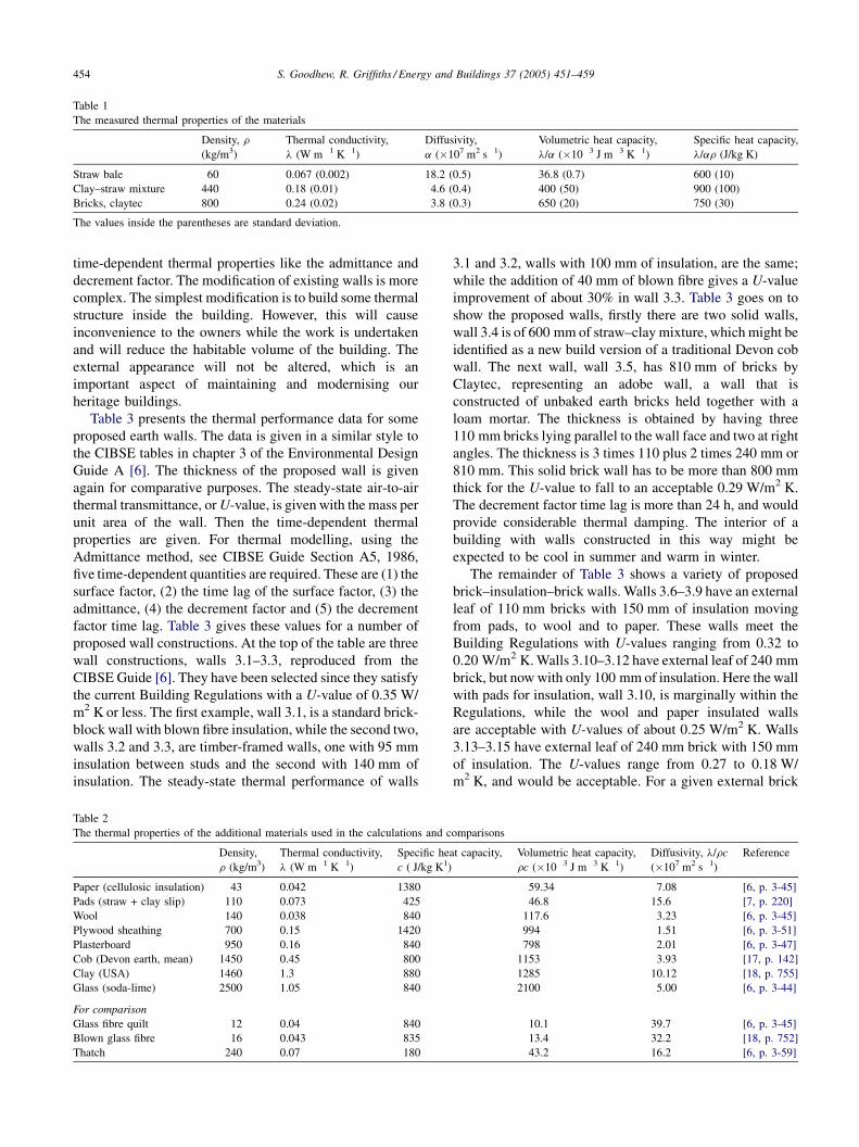
6.1. Thermal properties of materials studied in this work
Table 1 shows the measured values of the thermal
conductivity and thermal diffusivity of the three building
materials studied in this work. The probe technique with an
iterative method of data analysis gives these two parameters,
and with knowledge of the density of the materials the
specific heat capacity is calculated. As expected the
behaviour of the straw bale was similar to that of thatch,
see Table 2 for comparison. There is some confusion in the
literature concerning the value of the specific heat capacity
of thatch. The CIBSE guide [6] gives the specific heat as
180 J/kg K, while Szokolay [13], page 248, quotes the
specific heat capacity of thatch as 1420 J/kg K. The straw–
clay mixture can be used in any thickness, and traditional
cob walls can be designed using this material. The Claytec
bricks can be used in a variety of ways, for example as an
adobe wall construction [14].
6.2. Thermal properties of materials required for the
proposed wall constructions
Table 2 shows the thermal properties of the other
materials used in the design of the sustainable walls. It is
proposed to use only sustainable insulation materials, like
Warmcel [15], manufactured from recycled newsprint
treated to enable its use as a cavity filling for wall
constructions; or wool as Thermafleece [16]. Both these
materials have low embodied energies, although transport
energy would need to be considered in a full life-cycle
analysis. The pads, formed from a layer of straw loosely held
together with a little clay, are again to be used as a building
insulator. The plywood sheathing and plasterborad are used
in a timber frame construction, similar to that used in brick
or stone exterior timber framed buildings here in the UK. In
order to explore a range of possible earth walls the measured
thermal data on some Devon cob walls is included, along
with data on clay from the USA. The data published in the
Terra 2000 conference [17] has been used to give a mean
value for Devon cob walls. In Table 2 the difference between
the thermal conductivity for clay (USA) and cob (Devon
earth) lies in the different compositions and possible
moisture content of the real walls represented by the cob
value. Data on soda-lime window glass is given for the
modelling of possible cladding of earth buildings. Finally,
for comparison with the novel materials presented here, the
data for glass fibre quilt, blown glass fibre and thatch are
included in Table 2.
6.3. Thermal properties of proposed sustainable
earth walls
We will consider some new build options and the possible
upgrading of traditional cob walls to modern thermal
standards. New build is relatively straightforward, the wall
can be designed and the U-value calculated along with the
S. Goodhew, R. Griffiths / Energy and Buildings 37 (2005) 451–459454
Table 1
The measured thermal properties of the materials
Density, r
(kg/m3)
Thermal conductivity,
l (W m�1 K�1)
Diffusivity,
a (�107 m2 s�1)
Volumetric heat capacity,
l/a (�10�3 J m�3 K�1)
Specific heat capacity,
l/ar (J/kg K)
Straw bale 60 0.067 (0.002) 18.2 (0.5) 36.8 (0.7) 600 (10)
Clay–straw mixture 440 0.18 (0.01) 4.6 (0.4) 400 (50) 900 (100)
Bricks, claytec 800 0.24 (0.02) 3.8 (0.3) 650 (20) 750 (30)
The values inside the parentheses are standard deviation.
time-dependent thermal properties like the admittance and
decrement factor. The modification of existing walls is more
complex. The simplest modification is to build some thermal
structure inside the building. However, this will cause
inconvenience to the owners while the work is undertaken
and will reduce the habitable volume of the building. The
external appearance will not be altered, which is an
important aspect of maintaining and modernising our
heritage buildings.
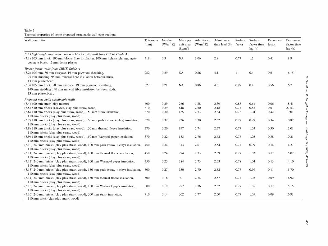
Table 3 presents the thermal performance data for some
proposed earth walls. The data is given in a similar style to
the CIBSE tables in chapter 3 of the Environmental Design
Guide A [6]. The thickness of the proposed wall is given
again for comparative purposes. The steady-state air-to-air
thermal transmittance, or U-value, is given with the mass per
unit area of the wall. Then the time-dependent thermal
properties are given. For thermal modelling, using the
Admittance method, see CIBSE Guide Section A5, 1986,
five time-dependent quantities are required. These are (1) the
surface factor, (2) the time lag of the surface factor, (3) the
admittance, (4) the decrement factor and (5) the decrement
factor time lag. Table 3 gives these values for a number of
proposed wall constructions. At the top of the table are three
wall constructions, walls 3.1–3.3, reproduced from the
CIBSE Guide [6]. They have been selected since they satisfy
the current Building Regulations with a U-value of 0.35 W/
m2 K or less. The first example, wall 3.1, is a standard brick-
block wall with blown fibre insulation, while the second two,
walls 3.2 and 3.3, are timber-framed walls, one with 95 mm
insulation between studs and the second with 140 mm of
insulation. The steady-state thermal performance of walls
Table 2
The thermal properties of the additional materials used in the calculations and c
Density,
r (kg/m3)
Thermal conductivity,
l (W m�1 K�1)
Specific he
c ( J/kg K1)
Paper (cellulosic insulation) 43 0.042 1380
Pads (straw + clay slip) 110 0.073 425
Wool 140 0.038 840
Plywood sheathing 700 0.15 1420
Plasterboard 950 0.16 840
Cob (Devon earth, mean) 1450 0.45 800
Clay (USA) 1460 1.3 880
Glass (soda-lime) 2500 1.05 840
For comparison
Glass fibre quilt 12 0.04 840
Blown glass fibre 16 0.043 835
Thatch 240 0.07 180
3.1 and 3.2, walls with 100 mm of insulation, are the same;
while the addition of 40 mm of blown fibre gives a U-value
improvement of about 30% in wall 3.3. Table 3 goes on to
show the proposed walls, firstly there are two solid walls,
wall 3.4 is of 600 mm of straw–clay mixture, which might be
identified as a new build version of a traditional Devon cob
wall. The next wall, wall 3.5, has 810 mm of bricks by
Claytec, representing an adobe wall, a wall that is
constructed of unbaked earth bricks held together with a
loam mortar. The thickness is obtained by having three
110 mm bricks lying parallel to the wall face and two at right
angles. The thickness is 3 times 110 plus 2 times 240 mm or
810 mm. This solid brick wall has to be more than 800 mm
thick for the U-value to fall to an acceptable 0.29 W/m2 K.
The decrement factor time lag is more than 24 h, and would
provide considerable thermal damping. The interior of a
building with walls constructed in this way might be
expected to be cool in summer and warm in winter.
The remainder of Table 3 shows a variety of proposed
brick–insulation–brick walls. Walls 3.6–3.9 have an external
leaf of 110 mm bricks with 150 mm of insulation moving
from pads, to wool and to paper. These walls meet the
Building Regulations with U-values ranging from 0.32 to
0.20 W/m2 K. Walls 3.10–3.12 have external leaf of 240 mm
brick, but now with only 100 mm of insulation. Here the wall
with pads for insulation, wall 3.10, is marginally within the
Regulations, while the wool and paper insulated walls
are acceptable with U-values of about 0.25 W/m2 K. Walls
3.13–3.15 have external leaf of 240 mm brick with 150 mm
of insulation. The U-values range from 0.27 to 0.18 W/
m2 K, and would be acceptable. For a given external brick
omparisons
at capacity, Volumetric heat capacity,
rc (�10�3 J m�3 K�1)
Diffusivity, l/rc
(�107 m2 s�1)
Reference
59.34 7.08 [6, p. 3-45]
46.8 15.6 [7, p. 220]
117.6 3.23 [6, p. 3-45]
994 1.51 [6, p. 3-51]
798 2.01 [6, p. 3-47]
1153 3.93 [17, p. 142]
1285 10.12 [18, p. 755]
2100 5.00 [6, p. 3-44]
10.1 39.7 [6, p. 3-45]
13.4 32.2 [18, p. 752]
43.2 16.2 [6, p. 3-59]
S.
Go
od
hew
,R
.G
riffith
s/E
nerg
ya
nd
Bu
ildin
gs
37
(20
05
)4
51
–4
59
45
5
Table 3
Thermal properties of some proposed sustainable wall constructions
Wall description Thickness
(mm)
U-value
(W/m2 K)
Mass per
unit area
(kg/m2)
Admittance
(W/m2 K)
Admittance
time lead (h)
Surface
factor
Surface
factor time
lag (h)
Decrement
factor
Decrement
factor time
lag (h)
Brick/lightweight aggregate concrete block cavity wall from CIBSE Guide A
(3.1) 105 mm brick, 100 mm blown fibre insulation, 100 mm lightweight aggregate
concrete block, 13 mm dense plaster
318 0.3 NA 3.06 2.8 0.77 1.2 0.41 8.9
Timber frame walls from CIBSE Guide A
(3.2) 105 mm, 50 mm airspace, 19 mm plywood sheathing,
95 mm studding, 95 mm mineral fibre insulation between studs,
13 mm plasterboard
282 0.29 NA 0.86 4.1 1 0.4 0.6 6.15
(3.3) 105 mm brick, 50 mm airspace, 19 mm plywood sheathing,
140 mm studding 140 mm mineral fibre insulation between studs,
13 mm plasterboard
327 0.21 NA 0.86 4.5 0.97 0.4 0.56 6.7
Proposed new build sustainable walls
(3.4) 600 mm straw–clay mixture 600 0.29 266 1.88 2.39 0.83 0.61 0.06 18.41
(3.5) 810 mm bricks (Claytec, clay plus straw, wood) 810 0.29 648 2.50 2.18 0.77 0.82 0.01 27.53
(3.6) 110 mm bricks (clay plus straw, wood), 150 mm straw insulation,
110 mm bricks (clay plus straw, wood)
370 0.30 185 2.73 2.64 0.78 1.04 0.42 9.01
(3.7) 110 mm bricks (clay plus straw, wood), 150 mm pads (straw + clay) insulation,
110 mm bricks (clay plus straw, wood)
370 0.32 226 2.70 2.52 0.77 0.99 0.34 10.82
(3.8) 110 mm bricks (clay plus straw, wood), 150 mm thermal fleece insulation,
110 mm bricks (clay plus straw, wood)
370 0.20 197 2.74 2.57 0.77 1.03 0.30 12.01
(3.9) 110 mm bricks (clay plus straw, wood), 150 mm Warmcel paper insulation,
110 mm bricks (clay plus straw, wood)
370 0.22 183 2.76 2.62 0.77 1.05 0.38 10.21
(3.10) 240 mm bricks (clay plus straw, wood), 100 mm pads (straw + clay) insulation,
110 mm bricks (clay plus straw, wood)
450 0.34 313 2.67 2.54 0.77 0.99 0.14 14.27
(3.11) 240 mm bricks (clay plus straw, wood), 100 mm thermal fleece insulation,
110 mm bricks (clay plus straw, wood)
450 0.24 294 2.73 2.59 0.77 1.03 0.12 15.07
(3.12) 240 mm bricks (clay plus straw, wood), 100 mm Warmcel paper insulation,
110 mm bricks (clay plus straw, wood)
450 0.25 284 2.73 2.63 0.78 1.04 0.13 14.10
(3.13) 240 mm bricks (clay plus straw, wood), 150 mm pads (straw + clay) insulation,
110 mm bricks (clay plus straw, wood)
500 0.27 330 2.70 2.52 0.77 0.99 0.11 15.70
(3.14) 240 mm bricks (clay plus straw, wood), 150 mm thermal fleece insulation,
110 mm bricks (clay plus straw, wood)
500 0.18 301 2.74 2.57 0.77 1.03 0.09 16.92
(3.15) 240 mm bricks (clay plus straw, wood), 150 mm Warmcel paper insulation,
110 mm bricks (clay plus straw, wood)
500 0.19 287 2.76 2.62 0.77 1.05 0.12 15.15
(3.16) 240 mm bricks (clay plus straw, wood), 360 mm straw insulation,
110 mm brick (clay plus straw, wood)
710 0.14 302 2.77 2.60 0.77 1.05 0.09 16.91
S. Goodhew, R. Griffiths / Energy and Buildings 37 (2005) 451–459456
Tab
le4
Ther
mal
pro
per
ties
of
som
epro
pose
dsu
stai
nab
lew
all
const
ruct
ions
Wal
ld
escr
ipti
on
Th
ick
nes
s
(mm
)
U-v
alu
e
(W/m
2K
)
Mas
sp
eru
nit
area
(kg
/m2)
Ad
mit
tan
ce
(W/m
2K
)
Ad
mit
tan
ce
tim
ele
ad(h
)
Su
rfac
e
fact
or
Su
rfac
efa
cto
r
tim
ela
g(h
)
Dec
rem
ent
fact
or
Dec
rem
ent
fact
or
tim
ela
g(h
)
(4.1
)C
ob
(Dev
on
eart
h,
mea
n)
40
00
.94
58
03
.83
1.7
40
.62
1.2
60
.13
13
.84
(4.2
)C
ob
(Dev
on
eart
h,
mea
n)
60
00
.66
87
03
.83
1.7
40
.62
1.2
60
.03
21
.23
(4.3
)C
ob
(Dev
on
eart
h,
mea
n)
80
00
.51
11
60
3.8
31
.74
0.6
21
.26
0.0
12
8.6
3
(4.4
)C
lay
(US
A)
40
02
.05
58
45
.15
1.2
80
.46
1.7
30
.30
9.0
6
(4.5
)C
lay
(US
A)
60
01
.56
87
65
.13
1.2
80
.47
1.7
20
.12
13
.64
(4.6
)C
lay
(US
A)
80
01
.26
11
68
5.1
31
.28
0.4
71
.72
0.0
41
8.2
2
Up
gra
de
cod
by
ad
din
gex
tern
al
gla
zin
g
(4.7
)6
mm
exte
rnal
gla
ss,
50
mm
ven
tila
ted
air
cav
ity,
40
0m
mD
evo
nea
rth
45
60
.80
59
53
.83
1.7
40
.62
1.2
60
.09
15
.06
(4.8
)6
mm
exte
rnal
gla
ss,
50
mm
ven
tila
ted
air
cav
ity,
60
0m
mD
evo
nea
rth
65
60
.59
88
53
.83
1.7
40
.62
1.2
60
.02
22
.46
(4.9
)6
mm
exte
rnal
gla
ss,
50
mm
ven
tila
ted
air
cav
ity,
80
0m
mD
evo
nea
rth
85
60
.47
11
75
3.8
31
.74
0.6
21
.26
0.0
02
7.8
5
(4.1
0)
12
mm
exte
rnal
gla
ss,
50
mm
ven
tila
ted
air
cav
ity,
40
0m
mD
evo
nea
rth
46
20
.79
61
03
.83
1.7
40
.62
1.2
60
.08
15
.27
(4.1
1)
12
mm
exte
rnal
gla
ss,
50
mm
ven
tila
ted
air
cav
ity,
60
0m
mD
evo
nea
rth
66
20
.59
90
03
.83
1.7
40
.62
1.2
60
.02
22
.67
(4.1
2)
12
mm
exte
rnal
gla
ss,
50
mm
ven
tila
ted
air
cav
ity,
80
0m
mD
evo
nea
rth
86
20
.47
11
90
3.8
31
.74
0.6
21
.26
0.0
03
0.0
6
thickness the insulation materials may be arranged as pads,
straw, paper and wool in order of decreasing U-value and
therefore increasing thermal efficiency. The wool walls have
the longer decrement time lags. In each case there is little to
choose between paper and wool. Moreover, both paper and
wool are commercially available. Focussing on the walls
3.10–3.15, the walls with external leaf of 240 mm of adobe
construction bricks, walls 3.10–3.12 with 100 mm of
insulation, walls 3.13–3.15 with 150 mm of insulation,
the following may be seen in Table 3. Increasing the
thickness of the insulation decreases the U-value, while the
admittance remains the same, the surface factor remains
constant as is to be expected, the decrement factor decreases
as the time lag increases. Again, as the mass of the insulation
increases through paper, pads and wool the decrement factor
decreases while the time lag increases.
Finally, at the bottom of Table 3 is a proposed brick wall,
wall 3.16, with a straw bale 360 mm thick providing the
insulation between 240 mm external brick leaf and 110 mm
internal brick leaf. Wall 3.16 has the lowest U-value at
0.14 W/m2 K. This wall would be acceptable as an
alternative to an existing cob wall in terms of thermal
behaviour and thickness, and would meet the current
Building Regulations.
As mentioned above there are two aspects in this work,
new build and upgrading. Firstly, there is the issue of new
building with proposed wall designs using sustainable
materials to meet the Building Regulations. Secondly, there
is the upgrading and repair of existing earth walls to meet
current standards. The possibility of sustainable walls for
new buildings to meet current standards has been discussed
above. Before addressing the upgrading and repairing of
existing cob walls, it is important to note that in one parish in
Devon, Sandford for example, there are over a hundred listed
earth structures, including dwellings in use [19]. For the
upgrading of existing earth walls, there are two simple
strategies that can be explored, one external and one internal.
The first would use an external glass wall or screen to
provide a ventilated air cavity between the external glass and
the cob wall. Problems of aesthetics, structural stability and
safety, moisture movement and building ventilation would
need to be addressed. The second strategy would be to erect
an insulated timber frame inside the cob wall. This would
have a large impact on the internal spaces of some of the
smaller cottages and dwellings. Again issues of aesthetics,
moisture movement and vermin attack would need to be
addressed. Otto [20] reminds us that sustainability has three
interwoven strands. The three are: (a) the social aspects,
about people, (b) the environmental aspects, about the planet
and (c) the economic aspects, about the profit. Clearly, the
upgrading of our heritage buildings will depend strongly on
the people or social aspects of the proposed modifications.
The method of upgrading the thermal performance of
heritage buildings will have to be socially acceptable, as
well as efficient and economic. The present work will only
review the thermal properties, with the main aim being to
S.
Go
od
hew
,R
.G
riffith
s/E
nerg
ya
nd
Bu
ildin
gs
37
(20
05
)4
51
–4
59
45
7
Table 5
Thermal properties of some proposed upgraded cob wall constructions to satisfy the Building Regulations
Thermally upgraded cob wall with added internal timber frame and insulation Thickness
(mm)
U-value
(W/m2 K)
Mass per
unit area
(kg/m2)
Admittance
(W/m2 K)
Admittance
time
lead (h)
Surface
factor
Surface
factor time
lag (h)
Decrement
factor
Decrement
factor time
lag (h)
(5.1) 400 mm cob wall, 50 mm ventilated air cavity, 19 mm plywood sheathing,
100 mm paper insulation (100 mm studding), 13 mm plasterboard
582 0.26 610 0.94 3.97 0.95 0.39 0.03 18.20
(5.2) 600 mm cob wall, 50 mm ventilated air cavity, 19 mm plywood sheathing,
100 mm paper insulation (100 mm studding), 13 mm plasterboard
782 0.23 900 0.94 3.97 0.95 0.39 0.01 25.60
(5.3) 800 mm cob wall, 50 mm ventilated air cavity, 19 mm plywood sheathing,
100 mm paper insulation (100 mm studding), 13 mm plasterboard
982 0.21 1190 0.94 3.97 0.95 0.39 0.00 33.00
(5.4) 400 mm cob wall, 50 mm ventilated air cavity, 19 mm plywood sheathing,
100 mm wool insulation (100 mm studding), 13 mm plasterboard
582 0.25 620 1.05 4.01 0.94 0.44 0.03 19.19
(5.5) 600 mm cob wall, 50 mm ventilated air cavity, 19 mm plywood sheathing,
100 mm wool insulation (100 mm studding), 13 mm plasterboard
782 0.22 910 1.05 4.01 0.94 0.04 0.01 26.59
(5.6) 800 mm cob wall, 50 mm ventilated air cavity, 19 mm plywood sheathing,
100 mm wool insulation (100 mm studding), 13 mm plasterboard
982 0.20 1200 1.05 4.01 0.94 0.44 0.00 34.00
(5.7) 400 mm cob wall, 50 mm ventilated air cavity, 19 mm plywood sheathing,
150 mm paper insulation (150 mm studding), 13 mm plasterboard
632 0.20 612 0.97 4.30 0.96 0.42 0.03 19.19
(5.8) 600 mm cob wall, 50 mm ventilated air cavity, 19 mm plywood sheathing,
150 mm paper insulation (150 mm studding), 13 mm plasterboard
832 0.18 902 0.97 4.30 0.96 0.42 0.01 26.59
(5.9) 800 mm cob wall, 50 mm ventilated air cavity, 19 mm plywood sheathing,
150 mm paper insulation (150 mm studding), 13 mm plasterboard
1032 0.17 1192 0.97 4.30 0.96 0.42 0.00 33.98
(5.10) 400 mm cob wall, 50 mm ventilated air cavity, 19 mm plywood sheathing,
150 mm wool insulation (150 mm studding), 13 mm plasterboard
632 0.19 627 1.10 4.14 0.95 0.47 0.02 21.02
(5.11) 600 mm cob wall, 50 mm ventilated air cavity, 19 mm plywood sheathing,
150 mm wool insulation (150 mm studding), 13 mm plasterboard
832 0.17 917 1.10 4.14 0.95 0.47 0.00 28.42
(5.12) 800 mm cob wall, 50 mm ventilated air cavity, 19 mm plywood sheathing,
150 mm wool insulation (150 mm studding), 13 mm plasterboard
1032 0.16 1207 1.10 4.14 0.95 0.47 0.00 35.81
S. Goodhew, R. Griffiths / Energy and Buildings 37 (2005) 451–459458
produce a U-value of 0.35 W/m2 K or less, and to produce
the necessary input information for time-dependent thermal
studies of some modelled cob buildings.
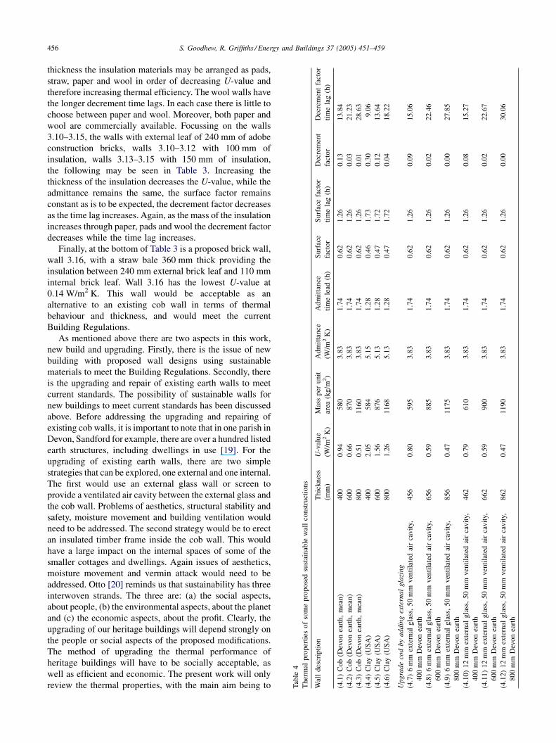
6.4. Thermal properties of upgraded earth walls with
external glazing
To illustrate the problem of upgrading earth walls Table 4
starts with three cob walls, walls 4.1–4.3, and three clay
(USA) walls, walls 4.4–4.6. The thicknesses have been
chosen to represent the walls found here in Devon. The
thickness of Devon cob walls ranges from 400 to 750 mm
[21]. The thickness of the cob walls, reported by Keefe in his
individual case studies of cob wall failures, have been
analysed and show that the average wall thickness is
570 mm, with a standard deviation of 90 mm. A further
simplification is applied to the cob walls in this work.
Typically real cob walls are protected externally by a lime
wash and are finished internally with a lime render. In the
following calculations on the thermal properties of cob walls
it will be assumed that there are no surface treatments. The
thermal properties of Devon cob walls are determined
assuming walls of thickness 400, 600, and 800 mm. This
will provide a range of properties to reflect those likely to be
found in the real buildings and these dimensions will be used
throughout the upgrading studies. Clearly, the Devon cob
walls 4.1–4.3 and the clay (USA) walls 4.4–4.6 fail the
current standard requirements. The steady-state thermal
transmittances, U-values, range from 0.5 to 0.9 W/m2 K for
cob and 1.3–2.1 W/m2 K for clay (USA), and are therefore
all well above the 0.35 W/m2 K standard. The Devon cob
walls have the lower U-values, while the clay (USA) the
shorter decrement time lags.
To upgrade these cob walls it is proposed to erect an
external glass screen, or envelope, around the cob walls to
improve the wall to an acceptable thermal standard. Walls
4.7–4.9 have an external leaf of glass 6 mm thick providing a
ventilated air cavity before the cob material. The U-values
range from 0.47 to 0.8 W/m2 K, and are unacceptably high.
Walls 4.10–4.12 have a 12 mm external glass leaf with
ventilated air cavity, and these are also unacceptable with U-
values of 0.47–0.79 W/m2 K. Even when a double glazed
external glass screen and ventilated air cavity is added to
600 mm of cob the U-value only falls to 0.49 W/m2 K. This
proposal of adding a glass screen will not provide sufficient
thermal improvement to meet current Building Regulations.
It may be questioned why Table 4 was included, since it
only shows wall constructions that are thermally unaccep-
table in terms of the current Building Regulations. Walls
4.1–4.6 forcefully demonstrate the thermal problem arising
with traditional cob walls. Walls 4.7–4.12 show that simply
enclosing the cob building in a glass screen, although this is
an inexpensive and simple measure, the improvement in U-
value falls short, this solution does not provide the thermal
insulation required.
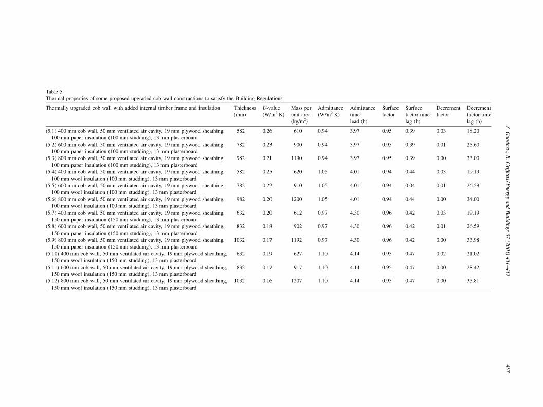
6.5. Thermal properties of upgraded earth walls with
internal insulated timber frame
Table 5 has a layout similar to Table 4, and gives details of
the possible upgrading of existing cob walls by the addition
of an internal timber frame with various types and
thicknesses of insulation. To gain an overview of the
upgrading of earth walls the three earth thicknesses 400, 600
and 800 mm have again been used together with two
differing insulation thicknesses, 100 and 150 mm, each in
turn using the two insulating materials paper or wool. There
are therefore 12 combinations, and the thermal properties of
these 12 upgraded cob walls are given in Table 5. Walls 5.1–
5.3 show the three thicknesses of cob, 400, 600 and 800 mm,
with 100 mm of paper insulation. All three walls meet the
current Building Regulations with U-values 0.26–0.21 W/
m2 K. Walls 5.4–5.6 are as 5.1–5.3 except that the insulation
has been changed to wool. Here the U-values are about 4%
smaller, and represent no significant advantage over paper.
Walls 5.7–5.9 are again like walls 5.1–5.3, but now the paper
insulation layer is 150 mm. The increase in insulation
thickness has resulted in a reduction of the U-value by about
15%. Again the wool insulation used in walls 5.10–5.12
shows an improved U-value. All these walls have low
decrement factors, indicating that even with sol–air driven
thermal input to the external wall surface, then negligible
temperature differences would appear at the internal wall
surface. The time lags are in the region of 18–36 h
suggesting that any very small daily temperature fluctuations
will disappear.
7. Conclusions
At the start of this work three aims where identified. To
meet aim 1 of this work, the thermal properties of some
straw based building materials have been measured using the
thermal probe technique to give both the thermal
conductivity and the diffusivity. Using some earlier data,
theoretical predictions of Devon cob walls with thickness
600 mm shows that the U-value is about twice the acceptable
value. Erecting an external glass screen of single or double
glazing does not provide sufficient thermal insulation to
reduce the cob wall air-to-air thermal transmittance to an
acceptable value. Two further conclusions can be drawn
from this work to satisfy aims 2 and 3. Firstly, it is possible to
design new earth walls that can satisfy current United
Kingdom Building Regulations, Part L. Both traditional cob
structures and adobe constructions can be designed to meet
the thermal requirements. Secondly, the upgrading of
existing cob walls to meet the UK Building Regulations
is possible by adding an insulated timber frame to the
internal wall surface.
Future work will measure the air-to-air thermal trans-
mittance of Devon cob walls following the recipe reported
by the Building Research Establishment [22]. At the same
S. Goodhew, R. Griffiths / Energy and Buildings 37 (2005) 451–459 459
time the thermal properties of the materials in the walls will
be determined using the probe technique. Then it will be
possible to compare designed thermal transmittances with
real built values, the values determined for walls in real
buildings with real internal and external environmental
conditions.
Finally, the time-dependent thermal properties of the
sustainable walls proposed here will be used to model the
time-dependent behaviour of some proposed dwellings, with
standard dwelling designs and occupancy schedules
provided by Allen and Pinney [23]. The Hevacomp software
‘‘Gain’’ uses the admittance method to give hourly building
heating and cooling loads along with indoor temperatures,
and will therefore allow a preliminary view of the time-
dependent behaviour of the modelled buildings. More
sophisticated time-dependent studies will be carried out
using the Environmental Design Solutions ‘‘Thermal
Analysis Software’’.
References
[1] The Building Regulations 2000, Conservation of Fuel and Power,
Approved document L1 Conservation of fuel and power in dwellings,
Effective from 1 April 2002, 2002 Edition, DTLR, The Stationery
Office, London. http://www.safety.odem.gov.uk/bregs/brpub/ad/ad-11/
index01.htm (accessed 14 November 2002).
[2] PRe Consultants bv http://www.pre.nl and http://www.pre.nl/eco-
indicator99/ei99-reports.htm (accessed 25 February 2004).
[3] Greenhouse, ‘‘Thermal Mass’’simple design guide to sustainable design
for dwellings. http://www.greenhouse.gov.au/yourhome/technical/fs17.
htm (accessed 17 February 2004).
[4] English Heritage, State of the Historic Environment 2002 Report,
Chapter 2, The Economic Dimension (PDF), English Heritage, London,
p. 40. http://www.heritagecounts.org.uk/ (accessed 20 February 2004).
[5] National Physical Laboratory, Standards for heat transfer through
structures (thermal transmittance). http://www.npl.co.uk/thermal/
projects/project4-2.html (accessed 20 February 2004).
[6] Environmental Design CIBSE Guide A, CIBSE, The Yale Press Ltd.,
London, 1999.
[7] S. Goodhew, R. Griffiths, Analysis of thermal-probe measurements
using an iterative method to give sample conductivity and diffusivity
data, Applied Energy 77 (2004) 205–223.
[8] Hukseflux Thermal Sensors, Delft, The Netherlands. www.hukseflux.
com.
[9] Construction Resources, Claytec unfired claybrick 700, 2DF. http://
www.constructionresources.com/products/Building envelope/lightclay.
htm (accessed 17 February 2004).
[10] L. Dewar, Details of Claytec unfired clay brick 700, 2DF. www.
ecoconstruct.com. Private communication, 1 April 2003.
[11] C. Morgan, Light earth constructions, in: Research Focus, issue 50,
Department of Trade and Industry, London, 2002, p. 4. Also see http://
www.lightearth.co.uk/characteristics.htm (accessed 17 February 2004).
[12] Hevacomp Ltd. http://www.hevacomp.com/freedownloads/literatur-
e.pdf (accessed 1 March 2004).
[13] S.V. Szokolay, Introduction to architectural science: the basis of
sustainable design, in: Data Sheet 1.1 Thermal Properties of Materials,
Architectural Press/Elsevier, Oxford, UK, 2004.
[14] Adobe, Mud Brick (Adobe) construction, For details see: http://
www.greenhouse.gov.au/yourhome/technical/pdf/fs34d.pdf (accessed
17 February 2004).
[15] Warmcel, Recycled newsprint for building insulation, For details see:
http://www.warmcel.com/excel/techdata.html (accessed 1 March
2004).
[16] Thermafleece, Wool for insulating walls, floors and roofs, For details
see: http://www.secondnatureuk.com/sppec.htm (accessed 1 March
2004).
[17] S. Goodhew, R. Griffiths, D. Short, L. Watson, Some preliminary
studies of the thermal properties of Devon cob walls, in: Proceedings
of the Eighth International Conference on the Study and Conservation
of Earthen Architecture (Terra 2000), English Heritage, James and
James, London, 2000, pp. 139–143.
[18] F.P. Incropera, D.P. DeWitt, Introduction to Heat Transfer, 3rd ed.
Wiley, New York, 1996.
[19] M. Ford, R. Griffiths, L. Watson, The Sandford inventory of earth
buildings: a conservator’s tool, Journal of Architectural of Conserva-
tion, in press.
[20] B.K.Otto, About: sustainability, Design Council, UK. http/www.
designcouncil.org.uk/webdav/servlet/XRM?Page/@id=6004&Session/
@id=D_wK2jr8zM7zumlQsB2NDz&Section/@id=1317 (accessed
10 March 2004).
[21] L. Keefe, An investigation into the causes of structural failure in
traditional cob buildings, MPhil Thesis, University of Plymouth, 1998,
unpublished.
[22] Building Research Establishment (BRE) Client Report Number
78132, Field investigations of the thermal performance of construction
elements as built, BRE Ltd., Watford, UK, 2000.
[23] E.A. Allen, A.A. Pinney, Standard dwellings for modelling: details of
dimensions, construction and occupancy schedules, in: Building
Environmental Performance Analysis Club (BEPAC) Technical note
90/2, Building Research Establishment, Watford, UK, 1990.