suggestion of safety certification standards and performance
TRANSCRIPT
�����������������
Citation: Kim, H.; Lim, J.; Won, J.-H.;
Kwon, J.-H.; Kim, S. Suggestion of
Safety Certification Standards and
Performance Evaluation Methods for
Fabricated Mobile Scaffold in South
Korea. Int. J. Environ. Res. Public
Health 2022, 19, 133. https://
doi.org/10.3390/ijerph19010133
Academic Editor: Paul B.
Tchounwou
Received: 2 November 2021
Accepted: 20 December 2021
Published: 23 December 2021
Publisher’s Note: MDPI stays neutral
with regard to jurisdictional claims in
published maps and institutional affil-
iations.
Copyright: © 2021 by the authors.
Licensee MDPI, Basel, Switzerland.
This article is an open access article
distributed under the terms and
conditions of the Creative Commons
Attribution (CC BY) license (https://
creativecommons.org/licenses/by/
4.0/).
International Journal of
Environmental Research
and Public Health
Article
Suggestion of Safety Certification Standards and PerformanceEvaluation Methods for Fabricated Mobile Scaffold inSouth Korea
Heesoo Kim 1 , Jeonghyeon Lim 1 , Jeong-Hun Won 2, Jun-Hyuk Kwon 3 and Seungjun Kim 1,*
1 School of Civil, Environmental and Architectural Engineering, Korea University, Seoul 02841, Korea;[email protected] (H.K.); [email protected] (J.L.)
2 Department of Safety Engineering, Chungbuk National University, Cheongju 28644, Korea;[email protected]
3 Temporary Equipment Certification Department, Occupational Safety & Health Certification Institute,Ulsan 44429, Korea; [email protected]
* Correspondence: [email protected]; Tel.: +82-(2)-32904868
Abstract: At construction sites, various types of temporary equipment and structures are used forsafety and work efficiency. However, various temporary equipment-related accidents frequentlyoccur for many reasons, including inappropriate installation, usage, and material and structuralimperfections. A mobile scaffold is one of the most commonly used indoor temporary equipmentfor work in high places. In general, the main structural members of the mobile scaffold, such as themainframes, horizontal members, braces, caster wheels, outriggers, and handrails, are installed onthe construction site for this purpose. This means that the load-carrying capacity of the equipmentcan vary depending on the assembly details. In Korea, there are safety certification standardsapplied for frequently used temporary equipment, such as scaffolds and shoring. However, thestandards concern the strength criteria for the member itself, rather than the global load-carryingcapacity. Therefore, it is difficult to review whether the fabricated mobile scaffold has sufficient load-carrying capacity, or to confirm the structural safety considering the various uncertainties affecting thestructural performance. In this study, rational safety certification standards and evaluation methodsare suggested for fabricated mobile scaffolds. The suggested safety certification standards presentstructure-level criteria for checking the load-carrying capacity, horizontal stiffness of the structure,and overturning risk. It is expected that the structural performance for safety can be directly checkedbased on the suggested safety certification standards and performance evaluation methods duringthe safety certification stage.
Keywords: construction safety; fabricated mobile scaffold; load-carrying capacity; safety certificationstandard; temporary equipment
1. Introduction
Temporary structures are facilities installed for the construction of buildings or struc-tures in construction work; when construction is completed, they are dismantled anddemolished. In general, “temporary structures” denotes scaffolds, casts, sheathing tim-bering, etc. Temporary structures may have reduced strength and/or structural defects.Therefore, the materials and structural shapes of the members used, connection conditions,and assembly method should be carefully considered, particularly to the risk of seriousdisasters owing to collapse or overturning.
When a structural defect exists in a temporary structure, a collapse accident may occur,greatly threatening the safety of workers. Therefore, it is important to ensure product safety.Accordingly, many countries have suggested materials, structural standards, and structuralperformance standards for temporary structures, and manufacturers have been required todesign and manufacture products that comply with them.
Int. J. Environ. Res. Public Health 2022, 19, 133. https://doi.org/10.3390/ijerph19010133 https://www.mdpi.com/journal/ijerph
Int. J. Environ. Res. Public Health 2022, 19, 133 2 of 24
According to the United States Bureau of Labor Statistics (BLS) [1], scaffold-relatedaccidents result in approximately 60 deaths and 4500 injuries every year. Approximately25% of the falls from scaffolds (for all working surfaces) are fatal. According to a recentBLS study, 72% of scaffold accidents are attributable to one of the following three causes:scaffold support or planking problems owing to defective equipment or improper assembly,slipping or tripping while on a scaffold owing to factors such as slippery surfaces or a lackof handrails, and falling objects hitting either a worker standing on a scaffold or workersbelow. The remaining 28% of accidents are caused by electrocution resulting from scaffoldsand equipment being too close to power or utility lines, environmental conditions suchas wind, rain, and the presence of hazardous substances, inadequate fall protection, andcollapses of scaffolds owing to overloading.
Table 1 shows an analysis of the industrial accidents in Korea from 2013 to 2017 [2].Among the factors in industrial accidents in the construction industry, fatal accidents owingto temporary objects account for a significant proportion (approximately 22.8%). It wellshows that a high probability of fatal accidents exists in construction site because varioustemporary equipment and structures are frequently used [3].
Table 1. Fatalities related to scaffold work in Korea for 5 years (2013–2017).
Division Construction Industry Scaffold Work
Total 2134 488Share 100% 22.8%
In addition, considering the accident status by type of scaffold shown in Table 2 [2], ifaccidents caused by mobile scaffolds are combined with accidents from using a ladder in awork environment requiring the use of the mobile scaffold, it accounts for a more significantproportion, i.e., 29%. As scaffolds are a temporary structure used in most constructionsites, the safety accidents thereon have continued to directly contribute to the deaths andinjuries of workers. As shown in Table 3 [2], the status of scaffolding accidents by typeof occurrence, the most frequent fall occurred, followed by unbalanced motion, crushing,electric shock, collapse, and hit. As a result of analyzing the accident cases, it was causedby defects in the main member, the defect in the connecting member, and the bucklingof the assembly. Therefore, it was identified that performance evaluation of the bucklingbehavior and load-bearing capacity of the assembly unit as well as the performance of themember was also necessary.
Table 2. Accident status by type of scaffold.
Total Steel PipeScaffold Ladder Hanging
ScaffoldMobileScaffold
GangForm
StepLadder
SystemScaffold
Steel PipeSupport
PrefabricatedScaffold Other
488(100%) 213 (43.7%) 97 (19.9%) 63 (12.9%) 45 (9.2%) 37 (7.6%) 17 (3.5%) 9 (1.8%) 3 (0.6%) 2 (0.4%) 2 (0.4%)
Table 3. Accident status by type of occurrence.
Total Falling UnbalancedMotion Underlay Electric
Shock Collapse Hit Bump Jammed Overturning Other
488(100%)
417(85.5%) 21 (4.3%) 13 (2.7%) 9 (1.8%) 8 (1.7%) 7 (1.4%) 6 (1.2%) 4 (0.8%) 1 (0.2%) 2 (0.4%)
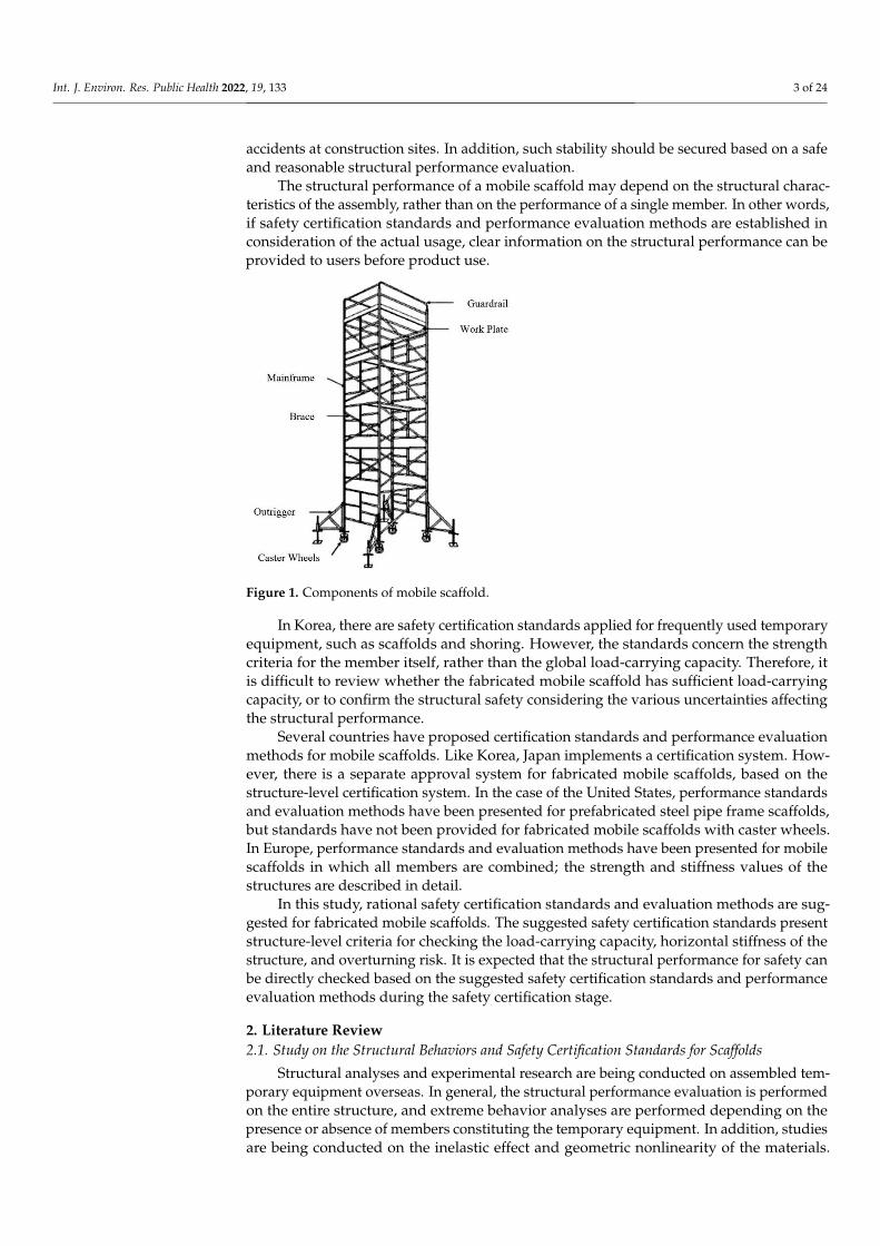
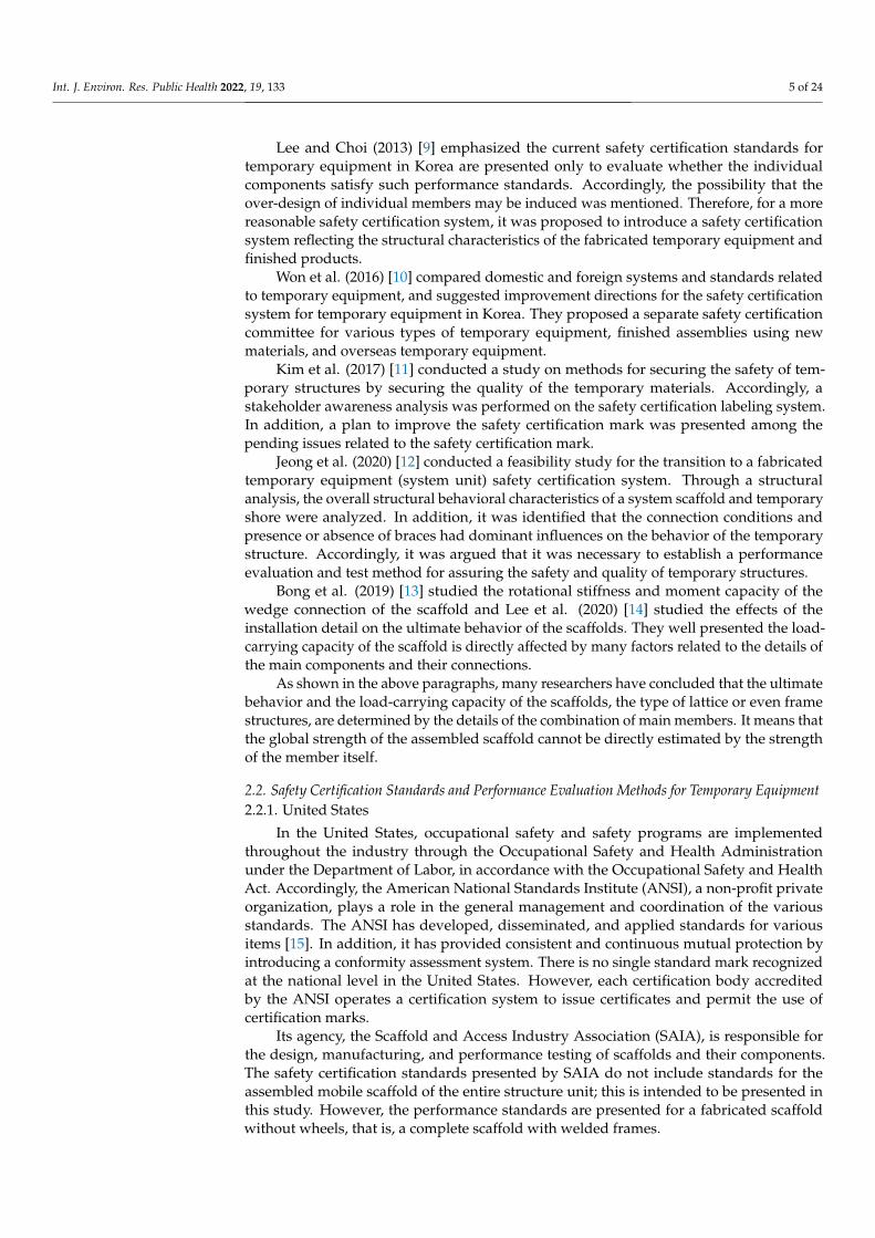
The mobile scaffold in Figure 1 is a scaffolding structure in which a work plate andsafety handrail are installed on the top floor of a frame structure fabricated in the form ofa tower, and in which caster wheels are attached to the bottom of each vertical member.These mobile scaffolds can not only be easily changed in height but can also be movedusing the caster wheels. This type of scaffold is mainly used for finishing work, such as forinterior ceilings and walls. Securing the stability of temporary structures for high-heightwork such as on scaffolds is the most important measure for preventing the frequent fall
Int. J. Environ. Res. Public Health 2022, 19, 133 3 of 24
accidents at construction sites. In addition, such stability should be secured based on a safeand reasonable structural performance evaluation.
The structural performance of a mobile scaffold may depend on the structural charac-teristics of the assembly, rather than on the performance of a single member. In other words,if safety certification standards and performance evaluation methods are established inconsideration of the actual usage, clear information on the structural performance can beprovided to users before product use.
Int. J. Environ. Res. Public Health 2022, 19, x FOR PEER REVIEW 3 of 24
for interior ceilings and walls. Securing the stability of temporary structures for high-
height work such as on scaffolds is the most important measure for preventing the fre-
quent fall accidents at construction sites. In addition, such stability should be secured
based on a safe and reasonable structural performance evaluation.
The structural performance of a mobile scaffold may depend on the structural char-
acteristics of the assembly, rather than on the performance of a single member. In other
words, if safety certification standards and performance evaluation methods are estab-
lished in consideration of the actual usage, clear information on the structural perfor-
mance can be provided to users before product use.
Figure 1. Components of mobile scaffold.
In Korea, there are safety certification standards applied for frequently used tempo-
rary equipment, such as scaffolds and shoring. However, the standards concern the
strength criteria for the member itself, rather than the global load-carrying capacity.
Therefore, it is difficult to review whether the fabricated mobile scaffold has sufficient
load-carrying capacity, or to confirm the structural safety considering the various uncer-
tainties affecting the structural performance.
Several countries have proposed certification standards and performance evaluation
methods for mobile scaffolds. Like Korea, Japan implements a certification system. How-
ever, there is a separate approval system for fabricated mobile scaffolds, based on the
structure-level certification system. In the case of the United States, performance stand-
ards and evaluation methods have been presented for prefabricated steel pipe frame scaf-
folds, but standards have not been provided for fabricated mobile scaffolds with caster
wheels. In Europe, performance standards and evaluation methods have been presented
for mobile scaffolds in which all members are combined; the strength and stiffness values
of the structures are described in detail.
In this study, rational safety certification standards and evaluation methods are sug-
gested for fabricated mobile scaffolds. The suggested safety certification standards pre-
sent structure-level criteria for checking the load-carrying capacity, horizontal stiffness of
the structure, and overturning risk. It is expected that the structural performance for safety
can be directly checked based on the suggested safety certification standards and perfor-
mance evaluation methods during the safety certification stage.
2. Literature Review
2.1. Study on the Structural Behaviors and Safety Certification Standards for Scaffolds
Structural analyses and experimental research are being conducted on assembled
temporary equipment overseas. In general, the structural performance evaluation is
Figure 1. Components of mobile scaffold.
In Korea, there are safety certification standards applied for frequently used temporaryequipment, such as scaffolds and shoring. However, the standards concern the strengthcriteria for the member itself, rather than the global load-carrying capacity. Therefore, itis difficult to review whether the fabricated mobile scaffold has sufficient load-carryingcapacity, or to confirm the structural safety considering the various uncertainties affectingthe structural performance.
Several countries have proposed certification standards and performance evaluationmethods for mobile scaffolds. Like Korea, Japan implements a certification system. How-ever, there is a separate approval system for fabricated mobile scaffolds, based on thestructure-level certification system. In the case of the United States, performance standardsand evaluation methods have been presented for prefabricated steel pipe frame scaffolds,but standards have not been provided for fabricated mobile scaffolds with caster wheels.In Europe, performance standards and evaluation methods have been presented for mobilescaffolds in which all members are combined; the strength and stiffness values of thestructures are described in detail.
In this study, rational safety certification standards and evaluation methods are sug-gested for fabricated mobile scaffolds. The suggested safety certification standards presentstructure-level criteria for checking the load-carrying capacity, horizontal stiffness of thestructure, and overturning risk. It is expected that the structural performance for safety canbe directly checked based on the suggested safety certification standards and performanceevaluation methods during the safety certification stage.
2. Literature Review2.1. Study on the Structural Behaviors and Safety Certification Standards for Scaffolds
Structural analyses and experimental research are being conducted on assembled tem-porary equipment overseas. In general, the structural performance evaluation is performedon the entire structure, and extreme behavior analyses are performed depending on thepresence or absence of members constituting the temporary equipment. In addition, studiesare being conducted on the inelastic effect and geometric nonlinearity of the materials.
Int. J. Environ. Res. Public Health 2022, 19, 133 4 of 24
However, few studies have been conducted on fabricated mobile scaffolds. Unlike othertemporary equipment, specific safety certification standards and performance evaluationmethods for mobile scaffolds with caster wheels have not been specifically presented exceptin Europe, and studies on the extreme behavior characteristics of such structures have notbeen conducted.
Chandrangsu (2009) [4] studied a rational structural modeling technique for evaluatingthe overall structural performance of the system unit of a scaffold. It was conducted basedon the definition of appropriate finite elements and boundary conditions for simulation ofthe major structural members, connection conditions between members, and analysis units.The ultimate behavior analysis technique for structures was proposed through a nonlinearinelastic structural analysis considering both the material inelastic effect of steel and thegeometrical nonlinear effect of the structure as a whole (or of individual member).
Peng et al. (2007) [5] analyzed the effects of the structural geometry and gradual loadon the overall buckling strength of a fabricated scaffold. The overall buckling analysis wasperformed by directly implementing the horizontal and sloped members and end supportconditions directly affecting the buckling strength of the compression and compressionmembers (the main members of the scaffold) on the structural analysis model. As an analy-sis model, a three-story system scaffold was studied, and a nonlinear inelastic structuralanalysis was performed to consider the geometric nonlinear effect owing to the inelasticeffect of steel and beam-column effect of the member.
Liu et al. (2010) [6] studied the structural stability of a steel pipe assembly type scaffoldwithout braces. In general, for frame structures without braces, the main buckling mode isaccompanied by a pronounced overall lateral deformation of the frame when compressiveforces act on the vertical members. Therefore, the effective buckling length was long,and the buckling strength was also evaluated as very low. This structural behavior wasanalyzed through structural analyses and experiments.
Kim et al. (2021) [7] identified the structural behavioral characteristics of structures inunits of finished products by conducting actual experiments and structural analysis studieson assembled mobile scaffolds distributed in Korea. The extreme behavior characteristicsand load capacity of each structure were analyzed by conducting an experiment andstructural analysis comprising loading a vertical load while using the material and heightof the fabricated mobile scaffold with the caster wheels as the parameters. Thus, it wasunderstood that the load capacity that the structure could withstand may vary dependingon the height of the mobile scaffold and whether the caster wheels were attached, evenif the performance standards of the members satisfied the safety certification standardsfor temporary equipment. Therefore, it was argued that it was necessary to establishreasonable safety certification standards and performance evaluation methods for the entirestructural unit.
From analyzing the existing studies on the safety certification systems and perfor-mance evaluation methods for temporary equipment in Korea, it can be concluded that theexisting safety performance standards for evaluating member units are difficult to use toclearly evaluate the structural behavior characteristics of an entire structure. To evaluatethe structural performance of the assembled temporary equipment, it is suggested thatnot only the performance of the members, but also the connection conditions between themembers, flexural stiffness ratio, load conditions, and presence or absence of installationof braces should be considered. Although studies on temporary equipment assembled inKorea are being actively conducted on system scaffolds and temporary shores, research onmobile scaffolds remains insufficient.
Bae and Lee (2002) [8] indicated that the distribution of untested products or productsthat have failed to pass performance tests was the cause of the continuous occurrence ofindustrial accidents, despite the implementation of the performance test system basedon the Industrial Safety and Health Act of Korea. Therefore, they suggested the needfor the consistent establishment of temporary equipment management standards andinstitutional improvements.
Int. J. Environ. Res. Public Health 2022, 19, 133 5 of 24
Lee and Choi (2013) [9] emphasized the current safety certification standards fortemporary equipment in Korea are presented only to evaluate whether the individualcomponents satisfy such performance standards. Accordingly, the possibility that theover-design of individual members may be induced was mentioned. Therefore, for a morereasonable safety certification system, it was proposed to introduce a safety certificationsystem reflecting the structural characteristics of the fabricated temporary equipment andfinished products.
Won et al. (2016) [10] compared domestic and foreign systems and standards relatedto temporary equipment, and suggested improvement directions for the safety certificationsystem for temporary equipment in Korea. They proposed a separate safety certificationcommittee for various types of temporary equipment, finished assemblies using newmaterials, and overseas temporary equipment.
Kim et al. (2017) [11] conducted a study on methods for securing the safety of tem-porary structures by securing the quality of the temporary materials. Accordingly, astakeholder awareness analysis was performed on the safety certification labeling system.In addition, a plan to improve the safety certification mark was presented among thepending issues related to the safety certification mark.
Jeong et al. (2020) [12] conducted a feasibility study for the transition to a fabricatedtemporary equipment (system unit) safety certification system. Through a structuralanalysis, the overall structural behavioral characteristics of a system scaffold and temporaryshore were analyzed. In addition, it was identified that the connection conditions andpresence or absence of braces had dominant influences on the behavior of the temporarystructure. Accordingly, it was argued that it was necessary to establish a performanceevaluation and test method for assuring the safety and quality of temporary structures.
Bong et al. (2019) [13] studied the rotational stiffness and moment capacity of thewedge connection of the scaffold and Lee et al. (2020) [14] studied the effects of theinstallation detail on the ultimate behavior of the scaffolds. They well presented the load-carrying capacity of the scaffold is directly affected by many factors related to the details ofthe main components and their connections.
As shown in the above paragraphs, many researchers have concluded that the ultimatebehavior and the load-carrying capacity of the scaffolds, the type of lattice or even framestructures, are determined by the details of the combination of main members. It means thatthe global strength of the assembled scaffold cannot be directly estimated by the strengthof the member itself.
2.2. Safety Certification Standards and Performance Evaluation Methods for Temporary Equipment2.2.1. United States
In the United States, occupational safety and safety programs are implementedthroughout the industry through the Occupational Safety and Health Administrationunder the Department of Labor, in accordance with the Occupational Safety and HealthAct. Accordingly, the American National Standards Institute (ANSI), a non-profit privateorganization, plays a role in the general management and coordination of the variousstandards. The ANSI has developed, disseminated, and applied standards for variousitems [15]. In addition, it has provided consistent and continuous mutual protection byintroducing a conformity assessment system. There is no single standard mark recognizedat the national level in the United States. However, each certification body accreditedby the ANSI operates a certification system to issue certificates and permit the use ofcertification marks.
Its agency, the Scaffold and Access Industry Association (SAIA), is responsible forthe design, manufacturing, and performance testing of scaffolds and their components.The safety certification standards presented by SAIA do not include standards for theassembled mobile scaffold of the entire structure unit; this is intended to be presented inthis study. However, the performance standards are presented for a fabricated scaffoldwithout wheels, that is, a complete scaffold with welded frames.
Int. J. Environ. Res. Public Health 2022, 19, 133 6 of 24
In the vertical load loading test of a scaffold, a strength test is performed by applyinga load to four vertical members [15]. Test A presents a test method for a single-bay scaffoldconsisting of three stories, and Test B presents a test method performed in a multi-bay, thatis, two or more scaffolds connected in the horizontal direction.
In addition, the performance standards and test method for the caster wheel arepresented as a single-member test method [15]. The test methods for the torque test inthe radial direction, torque test for the swivel brake, torque test for the wheel brake, andvertical load test are presented. However, as mentioned above, a test method for the entirestructural unit, including the caster wheels, is not presented.
2.2.2. Europe
Europe has proposed European standards for unifying the levels of standards amongEuropean Union countries. In Europe, the British Standards Institution, German Institutefor Standardization, and French National Standards Agency are preparing regulationsand detailed standards for scaffold installation, constituent members, materials, safetyperformance requirements, test methods, etc.
In the standard for mobile access and working towers made of prefabricated elements(EN 1004-1) [16], the materials, dimensions, design loads, safety, and performance require-ments of the fabricated mobile scaffolds are presented. The European safety certificationstandards and performance evaluation methods for fabricated mobile scaffolds can be seenas the only standards presented for finished products (i.e., including caster wheels).
The European mobile scaffold design standards suggest a height limit for the structureaccording to the stiffness of the fabricated mobile scaffold [16]. These methods were usedas a reference to prepare the safety certification standards and performance evaluationmethod for the fabricated mobile scaffold in this study.
2.2.3. Japan
In Japan, the Japanese Temporary Industry Association manages a certification systemfor temporary equipment. The system for temporary equipment is divided into a certifica-tion system, approval system, single product approval system, and applied factory system.Among these systems, the certification system can be seen to have content similar to that ofKorea’s temporary equipment certification system. The accreditation inspection system isoperated under the legal basis of the Occupational Safety and Health Act (Articles 42 and119 of the Act, Article 13 of the Enforcement Decree) [17]. The performance test items areclassified into 49 standard products, 19 legally regulated items, and 30 performance testenforcement agencies’ standard items. The performance is checked using a sampling test.
As mentioned above, the Japan Temporary Industry Association operates an approvalsystem separately from the certification system. This system is not subject to the certificationsystem for temporary equipment and is a system for confirming the safety of temporarystructures as assembled with an entire structure. In other words, the performance cer-tification system for temporary structures in Japan is based on the safety certificationstandards for single-member units, as in Korea. Accordingly, the structural performance ofthe temporary structure of the entire system unit is not subject to certification. Therefore,an approval system is being used to evaluate the structural performances of new materialsand newly assembled temporary structures. In other words, it is an approval procedurethat incorporates assembly and usage methods by conducting a system-level strength test.
This approach is similar to the safety certification standards for the fabricated mobilescaffold of the entire product unit, as proposed in this study. However, Japan’s approvalsystem for temporary structures is not mandatory owing to legal force. However, in re-sponse to a request for a structural performance evaluation of an assembled temporarystructure, the manufacturer can obtain voluntary approval. Therefore, there is no perfor-mance standard for approval, and the Japan Temporary Industry Association’s test methodis being used for performance evaluations.
Int. J. Environ. Res. Public Health 2022, 19, 133 7 of 24
2.2.4. Korea
Korea examines manufacturers’ technical capabilities, production systems, and prod-uct performance for temporary equipment classified according to Article 34 of the Occupa-tional Safety and Health Act (an act on safety certification), and Article 36 of the IndustrialSafety and Health Act (an Act on voluntary safety verification and reporting). In addition,a safety certification mark can be used if it meets the safety certification standards.
As shown in Table 4, temporary structures and equipment are divided into 12 typesand 33 items subject to mandatory safety certification, and eight types subject to voluntarysafety reports. Among them, mobile scaffold members are classified as subject to mandatorysafety certification, and performance standards and test methods for each member ofthe mobile scaffold are specified in accordance with the mandatory safety certificationnotice for protective devices. As described above, the safety certification standards formobile scaffolds in Korea exist only for each member, and not for the entire structure.A performance evaluation method is also suggested for conducting tests, but only onthe single members of the system scaffold, temporary shore, prefabricated scaffold, andmobile scaffold.
Table 4. Subjects for safety certification and autonomous safety verification.
Mandatory Safety Certification Target Voluntary Safety Report Target
1. A member for pipe support and support 1. Shelf Post2. Prefabricated scaffold members 2. Steel pipe for single pipe scaffold
3. Mobile scaffold member 3. Fixed support hardware4. Support hardware (except fixed type) 4. Hanging scaffold and absence
5. Fastener 5. Protective shelf6. Prefab safety railing 6. Handrails for elevator openings
7. Fall or fall protection nets 7. Bracket for side wall8. Sub-materials like or in combination with
the provisions of items 1 to 7, etc.
The Ministry of Employment and Labor Notice No. 2018-54, on the procedures forsafety certifications and autonomous safety confirmation reports, presents performancestandards and test methods for mobile scaffold members [18]. The members constitutingthe mobile scaffold are divided into the mainframe, caster wheel, handrail, and outrigger.Accordingly, material standards are suggested for each member, but it is also suggestedthat general structural steel pipes be used for the materials of most members, except forthe caster wheels. The structural and material standards for each member are shown inTables 5 and 6, and the test performance standards for the mainframe are shown in Table 7.
Table 5. Material performance standards for mobile scaffold.
Member Material Performance Standards for Mobile Scaffold
Mainframe
(1) The material of the pillar member, lateral member and reinforcing member must be STK400 of KS D 3566(carbon steel pipe for general structural use) or have mechanical properties equivalent to or higher than that ofKS D 3566.(2) Each part of the mainframe must be free from significant damage, deformation, corrosion, or wear.
Caster wheel(1) Main shaft and axle: SS400 of KS D 3503 (rolled steel for general structure)(2) Tire: KS B 6415 (industrial wheel) type 1 (limited to those specified in 6.2).It should be used with mechanical properties equivalent to or higher than this.
Handrail
(1) Footrest plate, post material, handrail material, brace material: STK400 specified in KS D 3566 (carbon steelpipe for general structure)(2) Bolts, nuts, pins, etc. among hardware for installation: SS330 specified in KS D 3503 (rolled steel for generalstructure)(3) Other parts of the installation hardware: SPHC specified in KS D 3501 (Hot-rolled mild steel plate and steelstrip) must have mechanical properties equivalent to or higher than that of SPHC.
Outrigger (1) Items for outriggers are in accordance with the standards set by the Korean Industrial Standard (KS F 8011).
Int. J. Environ. Res. Public Health 2022, 19, 133 8 of 24
Table 6. Structural performance standards for mobile scaffold.
Member Structural Performance Standards for Mobile Scaffold
Mainframe
(1) The length between the centers of both vertical members should be 1200 mm or more and 1600 mm or less(2) The length of the vertical member must be 2000 mm or less.(3) The outer diameter of the vertical and horizontal member must be 42.4 mm or more.(4) In case of having an insertion tube at the upper end of the vertical member, the length of the part where thevertical member is inserted must be 95 mm or more, and it must have a structure that does not come off.(5) If there is no insertion tube at the upper end of the vertical member, it shall have a structure that does notbreak off by inserting a connecting joint that meets the provisions of Nos. 18 through 20(6) The length of the horizontal reinforcing member used as a stepping platform and the part of the horizontalmember shall be 300 mm or more, and the center distance between the horizontal stiffeners shall be 400 mmor less.
Caster wheel
(1) Among the main shafts, the length of the part inserted into the vertical member of the mainframe shall beat least 200 mm (95 mm in the case of the main axis having a separation prevention function).(2) The outer diameter of the wheel tire must be at least 125 mm.(3) The axle should be able to rotate around the main shaft.
Handrail
(1) The outer diameter of the posts, handrails and braces must be at least 21.4 mm.(2) When the handrail frame is installed on the mainframe, the height of the handrail frame must be at least900 mm from the top of the workbench to the top of the upper handrail.(3) Intermediate handrails or braces must be installed in the middle of the handrail frame, and the intermediatehandrail must be in the middle between the top of the workbench and the top of the upper handrail.(4) Installation hardware must have a strong structure that does not fall off easily during use.(5) The vertical member of the handrail must be of a structure that is inserted into the post of the handrail orthat is connected by a connecting pin.
Outrigger (1) Items for outriggers are in accordance with the standards set by the Korean Industrial Standard (KS F 8011).
Table 7. Test performance standard for mobile scaffold mainframe.
Items Test Performance Standards
Compressive strength 44,000 N or moreVertical deflection 10.0 mm or less
Similar to the Japanese certification system, the safety certification system for tempo-rary equipment in Korea proposes to conduct verification for each member unit. However,the US and Europe are proposing safety certification standards for temporary structures infinished products, and are proposing broader and more flexible standards for materialsand structural shapes. Insofar as Europe is concerned, design standards, safety certificationstandards, and performance evaluation methods for mobile scaffolds fabricated with casterwheels have been presented.
2.3. Design Standards for Mobile Scaffolds in Korea
In Korea, a mobile scaffold is manufactured according to the design standards forscaffolds and safety facilities. The design standards are divided into general matters,materials, and designs. In the general section, the scopes of the scaffold, design load, andstructural design are presented, and in the materials section, material standards for eachscaffold are presented. In the design section, standards for the applied safety factors andconsiderations are presented for the design of scaffolds and safety facilities.
The safety certification standards and performance evaluation methods for the fabri-cated mobile scaffold presented in this study were prepared based on the design standardsfor scaffold and safety facilities in Korea. The main contents of the cited items are as follows.
2.3.1. Vertical Load
The vertical loads of a scaffold include dead loads and the working loads of thescaffold and work plate. Among them, the weight of the working platform, a dead load
Int. J. Environ. Res. Public Health 2022, 19, 133 9 of 24
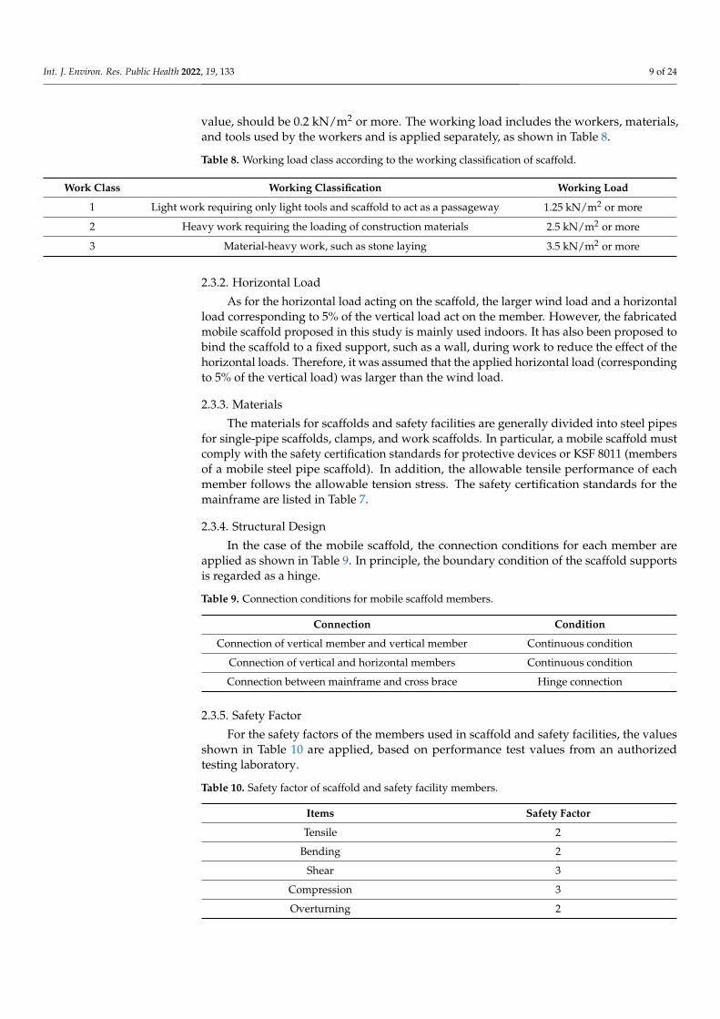
value, should be 0.2 kN/m2 or more. The working load includes the workers, materials,and tools used by the workers and is applied separately, as shown in Table 8.
Table 8. Working load class according to the working classification of scaffold.
Work Class Working Classification Working Load
1 Light work requiring only light tools and scaffold to act as a passageway 1.25 kN/m2 or more
2 Heavy work requiring the loading of construction materials 2.5 kN/m2 or more
3 Material-heavy work, such as stone laying 3.5 kN/m2 or more
2.3.2. Horizontal Load
As for the horizontal load acting on the scaffold, the larger wind load and a horizontalload corresponding to 5% of the vertical load act on the member. However, the fabricatedmobile scaffold proposed in this study is mainly used indoors. It has also been proposed tobind the scaffold to a fixed support, such as a wall, during work to reduce the effect of thehorizontal loads. Therefore, it was assumed that the applied horizontal load (correspondingto 5% of the vertical load) was larger than the wind load.
2.3.3. Materials
The materials for scaffolds and safety facilities are generally divided into steel pipesfor single-pipe scaffolds, clamps, and work scaffolds. In particular, a mobile scaffold mustcomply with the safety certification standards for protective devices or KSF 8011 (membersof a mobile steel pipe scaffold). In addition, the allowable tensile performance of eachmember follows the allowable tension stress. The safety certification standards for themainframe are listed in Table 7.
2.3.4. Structural Design
In the case of the mobile scaffold, the connection conditions for each member areapplied as shown in Table 9. In principle, the boundary condition of the scaffold supportsis regarded as a hinge.
Table 9. Connection conditions for mobile scaffold members.
Connection Condition
Connection of vertical member and vertical member Continuous condition
Connection of vertical and horizontal members Continuous condition
Connection between mainframe and cross brace Hinge connection
2.3.5. Safety Factor
For the safety factors of the members used in scaffold and safety facilities, the valuesshown in Table 10 are applied, based on performance test values from an authorizedtesting laboratory.
Table 10. Safety factor of scaffold and safety facility members.
Items Safety Factor
Tensile 2
Bending 2
Shear 3
Compression 3
Overturning 2
Int. J. Environ. Res. Public Health 2022, 19, 133 10 of 24
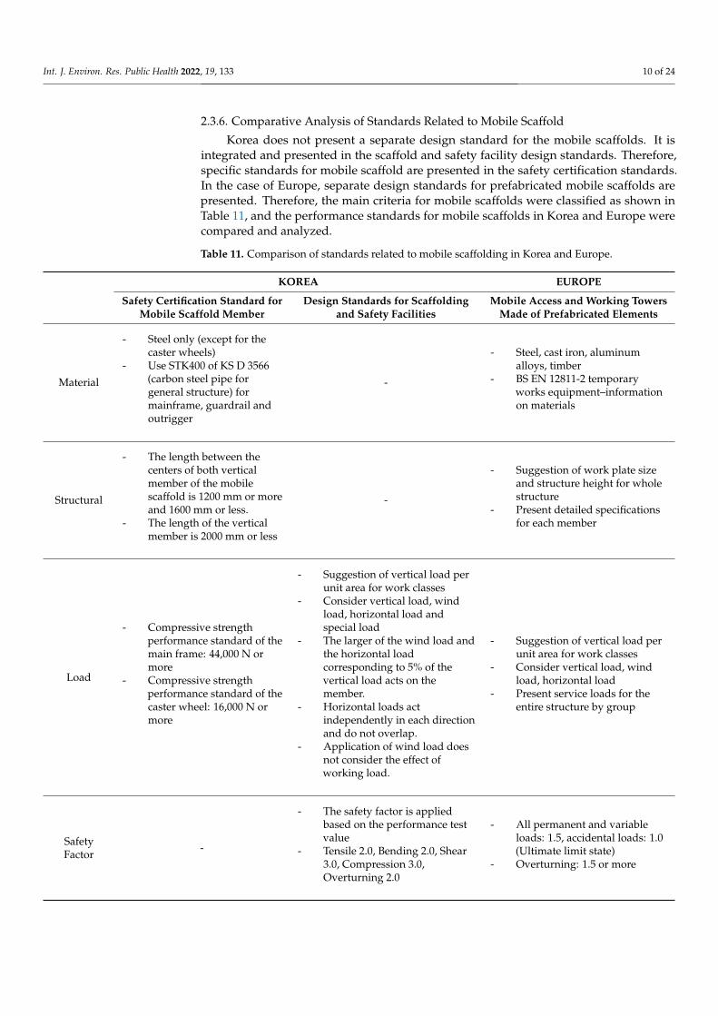
2.3.6. Comparative Analysis of Standards Related to Mobile Scaffold
Korea does not present a separate design standard for the mobile scaffolds. It isintegrated and presented in the scaffold and safety facility design standards. Therefore,specific standards for mobile scaffold are presented in the safety certification standards.In the case of Europe, separate design standards for prefabricated mobile scaffolds arepresented. Therefore, the main criteria for mobile scaffolds were classified as shown inTable 11, and the performance standards for mobile scaffolds in Korea and Europe werecompared and analyzed.
Table 11. Comparison of standards related to mobile scaffolding in Korea and Europe.
KOREA EUROPE
Safety Certification Standard forMobile Scaffold Member
Design Standards for Scaffoldingand Safety Facilities
Mobile Access and Working TowersMade of Prefabricated Elements
Material
- Steel only (except for thecaster wheels)
- Use STK400 of KS D 3566(carbon steel pipe forgeneral structure) formainframe, guardrail andoutrigger
-
- Steel, cast iron, aluminumalloys, timber
- BS EN 12811-2 temporaryworks equipment–informationon materials
Structural
- The length between thecenters of both verticalmember of the mobilescaffold is 1200 mm or moreand 1600 mm or less.
- The length of the verticalmember is 2000 mm or less
-
- Suggestion of work plate sizeand structure height for wholestructure
- Present detailed specificationsfor each member
Load
- Compressive strengthperformance standard of themain frame: 44,000 N ormore
- Compressive strengthperformance standard of thecaster wheel: 16,000 N ormore
- Suggestion of vertical load perunit area for work classes
- Consider vertical load, windload, horizontal load andspecial load
- The larger of the wind load andthe horizontal loadcorresponding to 5% of thevertical load acts on themember.
- Horizontal loads actindependently in each directionand do not overlap.
- Application of wind load doesnot consider the effect ofworking load.
- Suggestion of vertical load perunit area for work classes
- Consider vertical load, windload, horizontal load
- Present service loads for theentire structure by group
SafetyFactor -
- The safety factor is appliedbased on the performance testvalue
- Tensile 2.0, Bending 2.0, Shear3.0, Compression 3.0,Overturning 2.0
- All permanent and variableloads: 1.5, accidental loads: 1.0(Ultimate limit state)
- Overturning: 1.5 or more
Int. J. Environ. Res. Public Health 2022, 19, 133 11 of 24
Table 11. Cont.
KOREA EUROPE
Safety Certification Standard forMobile Scaffold Member
Design Standards for Scaffoldingand Safety Facilities
Mobile Access and Working TowersMade of Prefabricated Elements
PerformanceTest
- In relation to Article 36 ofthe Act, the performancestandards and test methods
- Suggested standards formain frame, caster wheel,guardrail, and outrigger
- Suggestion of performanceevaluation method of eachmember
- Absence of safetycertification standards andperformance evaluationmethods for mobile scaffoldin assembly
-
- Stiffness test on complete towerstructure
- Horizontal load 500 N: structureheight 6 m, horizontaldisplacement 200 mm
- The linear formula is notprecisely correct but over therange of towers that thisdocument covers.
3. Study on Rationality of the Current Safety Certification Standards for AssembledMobile Scaffolding through Structural Analysis3.1. Performance Evaluation Method for the Mainframe of Mobile Scaffold
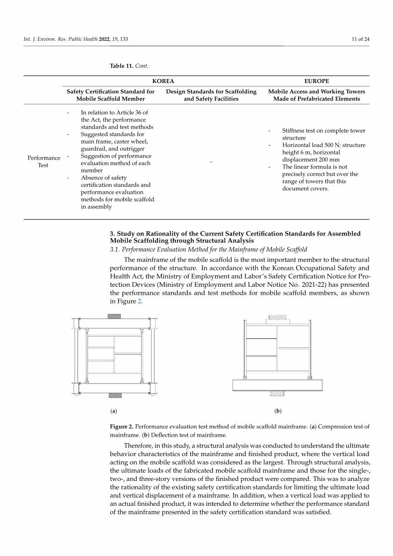
The mainframe of the mobile scaffold is the most important member to the structuralperformance of the structure. In accordance with the Korean Occupational Safety andHealth Act, the Ministry of Employment and Labor’s Safety Certification Notice for Pro-tection Devices (Ministry of Employment and Labor Notice No. 2021-22) has presentedthe performance standards and test methods for mobile scaffold members, as shownin Figure 2.
Int. J. Environ. Res. Public Health 2022, 19, x FOR PEER REVIEW 11 of 24
Safety Factor -
- The safety factor is applied based on
the performance test value
- Tensile 2.0, Bending 2.0, Shear 3.0,
Compression 3.0, Overturning 2.0
- All permanent and variable
loads: 1.5, accidental loads: 1.0
(Ultimate limit state)
- Overturning: 1.5 or more
Performance
Test
- In relation to Article 36 of the Act,
the performance standards and
test methods
- Suggested standards for main
frame, caster wheel, guardrail,
and outrigger
- Suggestion of performance
evaluation method of each
member
- Absence of safety certification
standards and performance
evaluation methods for mobile
scaffold in assembly
-
- Stiffness test on complete tower
structure
- Horizontal load 500 N: structure
height 6 m, horizontal
displacement 200 mm
- The linear formula is not
precisely correct but over the
range of towers that this
document covers.
3. Study on Rationality of the Current Safety Certification Standards for Assembled
Mobile Scaffolding Through Structural Analysis
3.1. Performance Evaluation Method for the Mainframe of Mobile Scaffold
The mainframe of the mobile scaffold is the most important member to the structural
performance of the structure. In accordance with the Korean Occupational Safety and
Health Act, the Ministry of Employment and Labor’s Safety Certification Notice for Pro-
tection Devices (Ministry of Employment and Labor Notice No. 2021-22) has presented
the performance standards and test methods for mobile scaffold members, as shown in
Figure 2.
(a) (b)
Figure 2. Performance evaluation test method of mobile scaffold mainframe. (a) Compression test
of mainframe. (b) Deflection test of mainframe.
Therefore, in this study, a structural analysis was conducted to understand the ulti-
mate behavior characteristics of the mainframe and finished product, where the vertical
load acting on the mobile scaffold was considered as the largest. Through structural anal-
ysis, the ultimate loads of the fabricated mobile scaffold mainframe and those for the sin-
gle-, two-, and three-story versions of the finished product were compared. This was to
analyze the rationality of the existing safety certification standards for limiting the ulti-
mate load and vertical displacement of a mainframe. In addition, when a vertical load was
applied to an actual finished product, it was intended to determine whether the perfor-
mance standard of the mainframe presented in the safety certification standard was satis-
fied.
Figure 2. Performance evaluation test method of mobile scaffold mainframe. (a) Compression test ofmainframe. (b) Deflection test of mainframe.
Therefore, in this study, a structural analysis was conducted to understand the ultimatebehavior characteristics of the mainframe and finished product, where the vertical loadacting on the mobile scaffold was considered as the largest. Through structural analysis,the ultimate loads of the fabricated mobile scaffold mainframe and those for the single-,two-, and three-story versions of the finished product were compared. This was to analyzethe rationality of the existing safety certification standards for limiting the ultimate loadand vertical displacement of a mainframe. In addition, when a vertical load was applied toan actual finished product, it was intended to determine whether the performance standardof the mainframe presented in the safety certification standard was satisfied.
Int. J. Environ. Res. Public Health 2022, 19, 133 12 of 24
3.2. Specifications and Structural Analysis Method
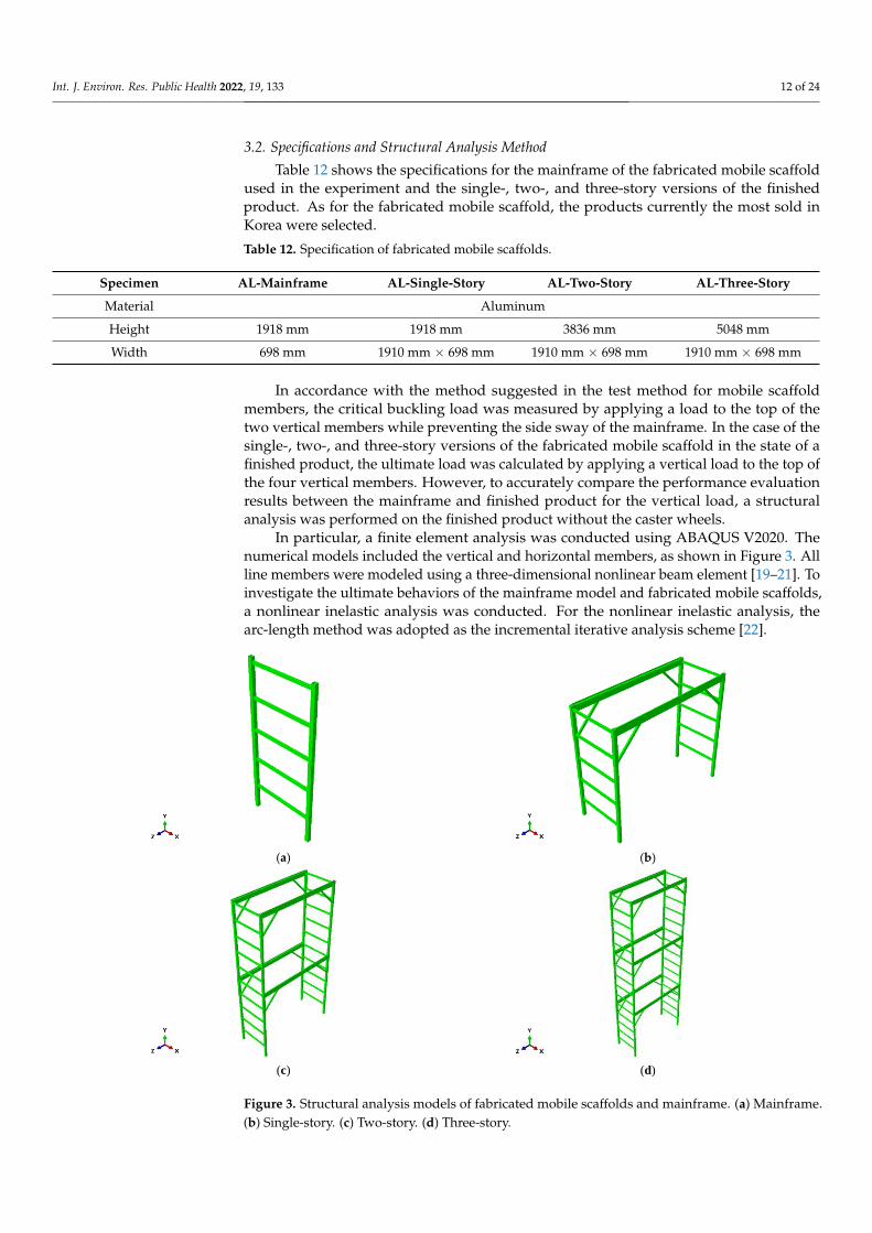
Table 12 shows the specifications for the mainframe of the fabricated mobile scaffoldused in the experiment and the single-, two-, and three-story versions of the finishedproduct. As for the fabricated mobile scaffold, the products currently the most sold inKorea were selected.
Table 12. Specification of fabricated mobile scaffolds.
Specimen AL-Mainframe AL-Single-Story AL-Two-Story AL-Three-Story
Material Aluminum
Height 1918 mm 1918 mm 3836 mm 5048 mm
Width 698 mm 1910 mm × 698 mm 1910 mm × 698 mm 1910 mm × 698 mm
In accordance with the method suggested in the test method for mobile scaffoldmembers, the critical buckling load was measured by applying a load to the top of thetwo vertical members while preventing the side sway of the mainframe. In the case of thesingle-, two-, and three-story versions of the fabricated mobile scaffold in the state of afinished product, the ultimate load was calculated by applying a vertical load to the top ofthe four vertical members. However, to accurately compare the performance evaluationresults between the mainframe and finished product for the vertical load, a structuralanalysis was performed on the finished product without the caster wheels.
In particular, a finite element analysis was conducted using ABAQUS V2020. Thenumerical models included the vertical and horizontal members, as shown in Figure 3. Allline members were modeled using a three-dimensional nonlinear beam element [19–21]. Toinvestigate the ultimate behaviors of the mainframe model and fabricated mobile scaffolds,a nonlinear inelastic analysis was conducted. For the nonlinear inelastic analysis, thearc-length method was adopted as the incremental iterative analysis scheme [22].
Int. J. Environ. Res. Public Health 2022, 19, x FOR PEER REVIEW 12 of 24
3.2. Specifications and Structural Analysis Method
Table 12 shows the specifications for the mainframe of the fabricated mobile scaffold
used in the experiment and the single-, two-, and three-story versions of the finished prod-
uct. As for the fabricated mobile scaffold, the products currently the most sold in Korea
were selected.
Table 12. Specification of fabricated mobile scaffolds.
Specimen AL-Mainframe AL-Single-Story AL-Two-Story AL-Three-Story
Material Aluminum
Height 1918 mm 1918 mm 3836 mm 5048 mm
Width 698 mm 1910 mm × 698 mm 1910 mm × 698 mm 1910 mm × 698 mm
In accordance with the method suggested in the test method for mobile scaffold
members, the critical buckling load was measured by applying a load to the top of the two
vertical members while preventing the side sway of the mainframe. In the case of the sin-
gle-, two-, and three-story versions of the fabricated mobile scaffold in the state of a fin-
ished product, the ultimate load was calculated by applying a vertical load to the top of
the four vertical members. However, to accurately compare the performance evaluation
results between the mainframe and finished product for the vertical load, a structural
analysis was performed on the finished product without the caster wheels.
In particular, a finite element analysis was conducted using ABAQUS V2020. The
numerical models included the vertical and horizontal members, as shown in Figure 3.
All line members were modeled using a three-dimensional nonlinear beam element [19–
21]. To investigate the ultimate behaviors of the mainframe model and fabricated mobile
scaffolds, a nonlinear inelastic analysis was conducted. For the nonlinear inelastic analy-
sis, the arc-length method was adopted as the incremental iterative analysis scheme [22].
(a) (b)
(c) (d)
Figure 3. Structural analysis models of fabricated mobile scaffolds and mainframe. (a) Mainframe.
(b) Single-story. (c) Two-story. (d) Three-story. Figure 3. Structural analysis models of fabricated mobile scaffolds and mainframe. (a) Mainframe.(b) Single-story. (c) Two-story. (d) Three-story.
Int. J. Environ. Res. Public Health 2022, 19, 133 13 of 24
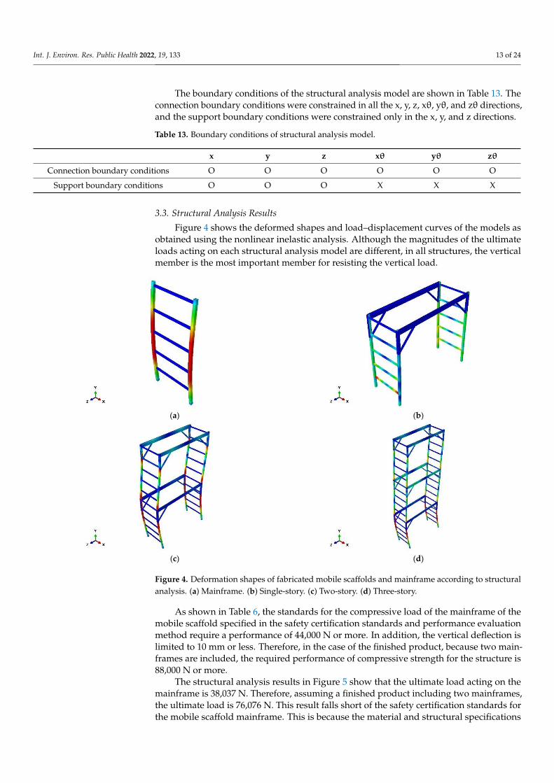
The boundary conditions of the structural analysis model are shown in Table 13. Theconnection boundary conditions were constrained in all the x, y, z, xθ, yθ, and zθ directions,and the support boundary conditions were constrained only in the x, y, and z directions.
Table 13. Boundary conditions of structural analysis model.
x y z xθ yθ zθ
Connection boundary conditions O O O O O O
Support boundary conditions O O O X X X
3.3. Structural Analysis Results
Figure 4 shows the deformed shapes and load–displacement curves of the models asobtained using the nonlinear inelastic analysis. Although the magnitudes of the ultimateloads acting on each structural analysis model are different, in all structures, the verticalmember is the most important member for resisting the vertical load.
Int. J. Environ. Res. Public Health 2022, 19, x FOR PEER REVIEW 13 of 24
The boundary conditions of the structural analysis model are shown in Table 13. The
connection boundary conditions were constrained in all the x, y, z, xθ, yθ, and zθ direc-
tions, and the support boundary conditions were constrained only in the x, y, and z direc-
tions.
Table 13. Boundary conditions of structural analysis model.
x y z xθ yθ zθ
Connection boundary conditions O O O O O O
Support boundary conditions O O O X X X
3.3. Structural Analysis Results
Figure 4 shows the deformed shapes and load–displacement curves of the models as
obtained using the nonlinear inelastic analysis. Although the magnitudes of the ultimate
loads acting on each structural analysis model are different, in all structures, the vertical
member is the most important member for resisting the vertical load.
(a) (b)
(c) (d)
Figure 4. Deformation shapes of fabricated mobile scaffolds and mainframe according to structural
analysis. (a) Mainframe. (b) Single-story. (c) Two-story. (d) Three-story.
As shown in Table 6, the standards for the compressive load of the mainframe of the
mobile scaffold specified in the safety certification standards and performance evaluation
method require a performance of 44,000 N or more. In addition, the vertical deflection is
limited to 10 mm or less. Therefore, in the case of the finished product, because two main-
frames are included, the required performance of compressive strength for the structure
is 88,000 N or more.
The structural analysis results in Figure 5 show that the ultimate load acting on the
mainframe is 38,037 N. Therefore, assuming a finished product including two main-
frames, the ultimate load is 76,076 N. This result falls short of the safety certification stand-
ards for the mobile scaffold mainframe. This is because the material and structural speci-
fications of the fabricated mobile scaffold mainframe do not meet the scaffold design
Figure 4. Deformation shapes of fabricated mobile scaffolds and mainframe according to structuralanalysis. (a) Mainframe. (b) Single-story. (c) Two-story. (d) Three-story.
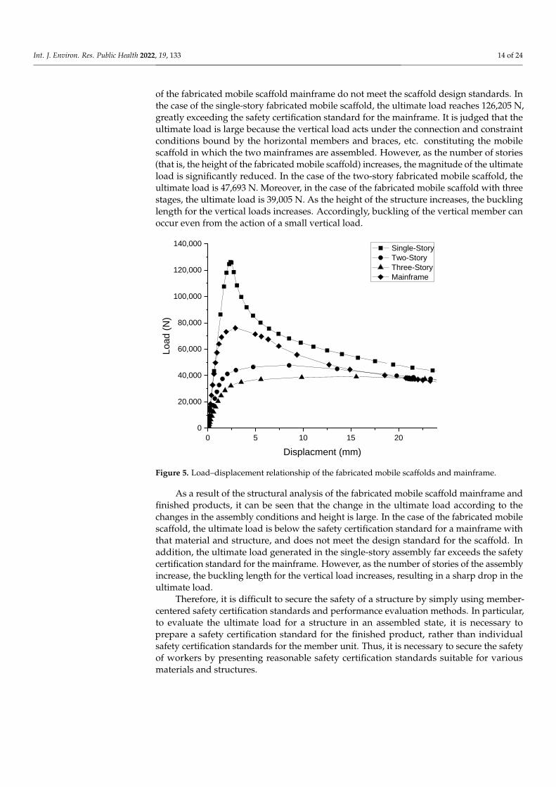
As shown in Table 6, the standards for the compressive load of the mainframe of themobile scaffold specified in the safety certification standards and performance evaluationmethod require a performance of 44,000 N or more. In addition, the vertical deflection islimited to 10 mm or less. Therefore, in the case of the finished product, because two main-frames are included, the required performance of compressive strength for the structure is88,000 N or more.
The structural analysis results in Figure 5 show that the ultimate load acting on themainframe is 38,037 N. Therefore, assuming a finished product including two mainframes,the ultimate load is 76,076 N. This result falls short of the safety certification standards forthe mobile scaffold mainframe. This is because the material and structural specifications
Int. J. Environ. Res. Public Health 2022, 19, 133 14 of 24
of the fabricated mobile scaffold mainframe do not meet the scaffold design standards. Inthe case of the single-story fabricated mobile scaffold, the ultimate load reaches 126,205 N,greatly exceeding the safety certification standard for the mainframe. It is judged that theultimate load is large because the vertical load acts under the connection and constraintconditions bound by the horizontal members and braces, etc. constituting the mobilescaffold in which the two mainframes are assembled. However, as the number of stories(that is, the height of the fabricated mobile scaffold) increases, the magnitude of the ultimateload is significantly reduced. In the case of the two-story fabricated mobile scaffold, theultimate load is 47,693 N. Moreover, in the case of the fabricated mobile scaffold with threestages, the ultimate load is 39,005 N. As the height of the structure increases, the bucklinglength for the vertical loads increases. Accordingly, buckling of the vertical member canoccur even from the action of a small vertical load.
Int. J. Environ. Res. Public Health 2022, 19, x FOR PEER REVIEW 14 of 24
standards. In the case of the single-story fabricated mobile scaffold, the ultimate load
reaches 126,205 N, greatly exceeding the safety certification standard for the mainframe.
It is judged that the ultimate load is large because the vertical load acts under the connec-
tion and constraint conditions bound by the horizontal members and braces, etc. consti-
tuting the mobile scaffold in which the two mainframes are assembled. However, as the
number of stories (that is, the height of the fabricated mobile scaffold) increases, the mag-
nitude of the ultimate load is significantly reduced. In the case of the two-story fabricated
mobile scaffold, the ultimate load is 47,693 N. Moreover, in the case of the fabricated mo-
bile scaffold with three stages, the ultimate load is 39,005 N. As the height of the structure
increases, the buckling length for the vertical loads increases. Accordingly, buckling of the
vertical member can occur even from the action of a small vertical load.
0 5 10 15 20
0
20,000
40,000
60,000
80,000
100,000
120,000
140,000
Load (
N)
Displacment (mm)
Single-Story
Two-Story
Three-Story
Mainframe
Figure 5. Load–displacement relationship of the fabricated mobile scaffolds and mainframe.
As a result of the structural analysis of the fabricated mobile scaffold mainframe and
finished products, it can be seen that the change in the ultimate load according to the
changes in the assembly conditions and height is large. In the case of the fabricated mobile
scaffold, the ultimate load is below the safety certification standard for a mainframe with
that material and structure, and does not meet the design standard for the scaffold. In
addition, the ultimate load generated in the single-story assembly far exceeds the safety
certification standard for the mainframe. However, as the number of stories of the assem-
bly increase, the buckling length for the vertical load increases, resulting in a sharp drop
in the ultimate load.
Therefore, it is difficult to secure the safety of a structure by simply using member-
centered safety certification standards and performance evaluation methods. In particu-
lar, to evaluate the ultimate load for a structure in an assembled state, it is necessary to
prepare a safety certification standard for the finished product, rather than individual
safety certification standards for the member unit. Thus, it is necessary to secure the safety
of workers by presenting reasonable safety certification standards suitable for various ma-
terials and structures.
4. Suggestion of Safety Certification Standards for Fabricated Mobile Scaffolds
Figure 5. Load–displacement relationship of the fabricated mobile scaffolds and mainframe.
As a result of the structural analysis of the fabricated mobile scaffold mainframe andfinished products, it can be seen that the change in the ultimate load according to thechanges in the assembly conditions and height is large. In the case of the fabricated mobilescaffold, the ultimate load is below the safety certification standard for a mainframe withthat material and structure, and does not meet the design standard for the scaffold. Inaddition, the ultimate load generated in the single-story assembly far exceeds the safetycertification standard for the mainframe. However, as the number of stories of the assemblyincrease, the buckling length for the vertical load increases, resulting in a sharp drop in theultimate load.
Therefore, it is difficult to secure the safety of a structure by simply using member-centered safety certification standards and performance evaluation methods. In particular,to evaluate the ultimate load for a structure in an assembled state, it is necessary toprepare a safety certification standard for the finished product, rather than individualsafety certification standards for the member unit. Thus, it is necessary to secure the safetyof workers by presenting reasonable safety certification standards suitable for variousmaterials and structures.
Int. J. Environ. Res. Public Health 2022, 19, 133 15 of 24
4. Suggestion of Safety Certification Standards for Fabricated Mobile Scaffolds
The safety certification standards for fabricated mobile scaffolds must comply withthe following principles. First, in a fully assembled state, it must be possible to intuitivelycheck and verify the structural performance, and the unfavorable constraints from theexisting safety certification standards must be deleted. In addition, increased efficiency canbe pursued by simplifying the authentication process for each member unit, i.e., for theentire structure unit authentication process.
In a general certification standard, the contents of the material and structural standardsare presented. In addition, performance standards and evaluation methods are presentedfor the vertical load, horizontal load, and overturning safety. The method of calculatingthe load according to the load class, or the method of determining the horizontal load,should not deviate from the framework of Korea’s design standards for scaffold and safetyfacilities. Therefore, in this study, updated standards were derived, such as those for thevertical load, horizontal load, and safety factors suggested in the design certification.
4.1. General Safety Certification Standards for Materials and Structures
The scope of application for the safety certification standards for fabricated mobilescaffolds was set as certification standards for materials and structural types different fromthose comprising the general mobile scaffolds manufactured in units of members in Korea.The manufacture was required to follow the assembly or installation method providedby the manufacturer. As shown in Table 14, the material was made to include a squaretube and aluminum tube in addition to the steel tube, i.e., the main material of the generalmobile scaffold.
Table 14. Material standards for fabricated mobile scaffold.
Members of Scaffold Component Material
Mainframe Or VerticalMember
Steel Column, lateral, and reinforcingmember Equivalent to STK 400 specified in KS D 3566
Aluminum Column, lateral, and reinforcingmember Equivalent to A 6063S specified in KS D 6759
Caster Wheel
Spindle and axle Equivalent to SS400 specified in KS D 3503
Fork Equivalent to SPHC specified in KS D 3501
Tire Rubber material for products specified in KS BISO 22877
Guard Rail
Jam band Equivalent to SS 330 specified in KS D 3503
Steel Post, handrail, and bracemember Equivalent to STK 400 specified in KS D 3566
Aluminum Post, handrail, and bracemember Equivalent to A 6063S specified in KS D 6759
Ironware for installation Equivalent to SPHC specified in KS D 3501 orSS 330 specified in KS D 3503
Outrigger
SteelVertical, horizontal, diagonal,
reinforcing member, andinsertion tube
Equivalent to STK 400 specified in KS D 3566
AluminumVertical, horizontal, diagonal,
reinforcing member, andinsertion tube
Equivalent to A 6063S specified in KS D 6759
Ironware for attachment Equivalent to SPHC specified in KS D 3501 orEquivalent to SS 330 specified in KS D 3503
Int. J. Environ. Res. Public Health 2022, 19, 133 16 of 24
Table 14. Cont.
Members of Scaffold Component Material
Work Plate
Steel
Flooring member Equivalent to SPHC specified in KS D 3501 orXS 42 specified in KS D 3601
Horizontal and beam member Equivalent to SPHC specified in KS D 3501
Hanging hook Single plate Equivalent to SS400 specified in KS D 3503
Box Equivalent to SPHC specified in KS D 3501
Aluminum
Flooring, horizontal, and beammember Equivalent to A 6063S specified in KS D 6759
Hanging hook
Single plate Equivalent to A 5052P specified in KS D 6701 orA 6063S specified in KS D 6759
Box Equivalent to A 5052P specified in KS D 6701 orA 6063S specified in KS D 6759
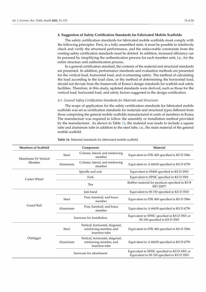
The width of the structure was suggested to have a value greater than or equal tothe minimum size of the working scaffold according to the Korean working scaffold andpassage design standards. In addition, the height of the structure was based on the heightlimit of the scaffold specified in the guidelines for the use of mobile scaffolds manufacturedby the Korea Occupational Safety and Health Agency [23]. As shown in Figure 6 andEquation (1), a height limit was suggested for the mobile scaffold, and a height for afabricated mobile scaffold was also suggested according to this guideline.
Int. J. Environ. Res. Public Health 2022, 19, x FOR PEER REVIEW 16 of 24
Horizontal and beam
member Equivalent to SPHC specified in KS D 3501
Hanging
hook
Single plate Equivalent to SS400 specified in KS D 3503
Box Equivalent to SPHC specified in KS D 3501
Aluminum
Flooring, horizontal,
and beam member Equivalent to A 6063S specified in KS D 6759
Hanging
hook
Single plate Equivalent to A 5052P specified in KS D 6701 or A
6063S specified in KS D 6759
Box Equivalent to A 5052P specified in KS D 6701 or A
6063S specified in KS D 6759
The width of the structure was suggested to have a value greater than or equal to the
minimum size of the working scaffold according to the Korean working scaffold and pas-
sage design standards. In addition, the height of the structure was based on the height
limit of the scaffold specified in the guidelines for the use of mobile scaffolds manufac-
tured by the Korea Occupational Safety and Health Agency [23]. As shown in Figure 6
and Equation (1), a height limit was suggested for the mobile scaffold, and a height for a
fabricated mobile scaffold was also suggested according to this guideline.
(a) (b)
Figure 6. Height limitation of fabricated mobile scaffold. (a) Method A. (b) Method B.
𝐻 ≤ 7.7𝐿 − 5.0 (1)
Here, 𝐻: height from the bottom of the caster wheel to the work plate (m); and 𝐿:
spacing of the main axis (short side) of the caster wheels (m).
4.2. Safety Certification Standards for Strength Safety of the Fabricated Mobile Scaffolds
Equation (2) is suggested for the vertical load that dominates the strength of the struc-
ture. 𝑤1 is the vertical load per unit area for each work class presented in the design
standards for scaffold and safety facilities in Korea. The work classes are divided into
three classes: light work, heavy work, and heavy material work. The unit weights for each
class are shown in Table 7.
𝑃𝑣 = 3 × (𝑤1 + 𝑤2) × 𝐴 × 𝑛 (2)
In the above, 𝑃: maximum load for each story of work plate (kN); 𝑤1: vertical load
per unit area by work grade (kN/m2); 𝑤2: unit load of work plate (kN/m2); 𝐴: work plate
area (m2); 𝑛: number of story of work plate; and a compression safety factor of 3 is ap-
plied.
W2 is the unit weight of the work plates, and was obtained by reference to Korean
work plates and passage design standards.
The height of the first stage of the assembled mobile scaffold was approximately 2 m,
and most instances of the fabricated mobile scaffold comprised single-, two-, and three-
story examples. That is, the maximum height of the fabricated mobile scaffold was limited
Figure 6. Height limitation of fabricated mobile scaffold. (a) Method A. (b) Method B.
H ≤ 7.7L − 5.0 (1)
Here, H: height from the bottom of the caster wheel to the work plate (m); and L:spacing of the main axis (short side) of the caster wheels (m).
4.2. Safety Certification Standards for Strength Safety of the Fabricated Mobile Scaffolds
Equation (2) is suggested for the vertical load that dominates the strength of thestructure. w1 is the vertical load per unit area for each work class presented in the designstandards for scaffold and safety facilities in Korea. The work classes are divided into threeclasses: light work, heavy work, and heavy material work. The unit weights for each classare shown in Table 7.
Pv = 3 × (w1 + w2)× A × n (2)
In the above, P: maximum load for each story of work plate (kN); w1: vertical loadper unit area by work grade (kN/m2); w2: unit load of work plate (kN/m2); A: work platearea (m2); n: number of story of work plate; and a compression safety factor of 3 is applied.
W2 is the unit weight of the work plates, and was obtained by reference to Koreanwork plates and passage design standards.
Int. J. Environ. Res. Public Health 2022, 19, 133 17 of 24
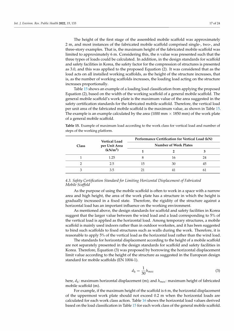
The height of the first stage of the assembled mobile scaffold was approximately2 m, and most instances of the fabricated mobile scaffold comprised single-, two-, andthree-story examples. That is, the maximum height of the fabricated mobile scaffold waslimited to approximately 6 m. Considering this, the n value was presented such that thethree types of loads could be calculated. In addition, in the design standards for scaffoldand safety facilities in Korea, the safety factor for the compression of structures is presentedas 3.0, and this was applied to the proposed Equation (2). It was considered that as theload acts on all installed working scaffolds, as the height of the structure increases, thatis, as the number of working scaffolds increases, the loading load acting on the structureincreases proportionally.
Table 15 shows an example of a loading load classification from applying the proposedEquation (2), based on the width of the working scaffold of a general mobile scaffold. Thegeneral mobile scaffold’s work plate is the maximum value of the area suggested in thesafety certification standards for the fabricated mobile scaffold. Therefore, the vertical loadper unit area of the fabricated mobile scaffold is the maximum value, as shown in Table 15.The example is an example calculated by the area (1000 mm × 1850 mm) of the work plateof a general mobile scaffold.
Table 15. Example of maximum load according to the work class for vertical load and number ofsteps of the working platform.
ClassVertical Loadper Unit Area
(kN/m2)
Performance Certification for Vertical Load (kN)
Number of Work Plates
1 2 3
1 1.25 8 16 24
2 2.5 15 30 45
3 3.5 21 41 61
4.3. Safety Certification Standard for Limiting Horizontal Displacement of FabricatedMobile Scaffold
As the purpose of using the mobile scaffold is often to work in a space with a narrowarea and high height, the area of the work plate has a structure in which the height isgradually increased in a fixed state. Therefore, the rigidity of the structure against ahorizontal load has an important influence on the working environment.
As mentioned above, the design standards for scaffold and safety facilities in Koreasuggest that the larger value between the wind load and a load corresponding to 5% ofthe vertical load is applied as the horizontal load. Among temporary structures, a mobilescaffold is mainly used indoors rather than in outdoor worksites, and it has been suggestedto bind such scaffolds to fixed structures such as walls during the work. Therefore, it isreasonable to apply 5% of the vertical load as the horizontal load rather than the wind load.
The standards for horizontal displacement according to the height of a mobile scaffoldare not separately presented in the design standards for scaffold and safety facilities inKorea. Therefore, Equation (3) was proposed by borrowing the horizontal displacementlimit value according to the height of the structure as suggested in the European designstandard for mobile scaffolds (EN 1004-1).
dh =1
30hmax (3)
here, dh: maximum horizontal displacement (m); and hmax: maximum height of fabricatedmobile scaffold (m).
For example, if the maximum height of the scaffold is 6 m, the horizontal displacementof the uppermost work plate should not exceed 0.2 m when the horizontal loads arecalculated for each work class action. Table 16 shows the horizontal load values derivedbased on the load classification in Table 15 for each work class of the general mobile scaffold.
Int. J. Environ. Res. Public Health 2022, 19, 133 18 of 24
Table 16. Example of safety certification standards for horizontal loads acting on the fabricatedmobile scaffold for limiting horizontal displacement.
ClassNumber of Work Plate
1 2 3
1 0.4 0.8 1.2
2 0.75 1.5 2.25
3 1.1 2.1 3.1
4.4. Safety Certification Criteria for Overturning Safety of Fabricated Mobile Scaffold
The safety certification standards regarding the overturning safety limit the lifting ofthe feet attached to the bottom of the fabricated mobile scaffold when an eccentric loadis applied, e.g., from a worker’s movement or from loading on the top work plate ofthe scaffold.
In Equation (4), 0.9 is the overturning moment that one worker can generate at the topof the fabricated mobile scaffold. This value considers the weight of the worker (100 kg)and the location of the worker who may be the most vulnerable to overturning. Thisequation considers the overturning safety factor of 3.0 suggested in the design standardsfor scaffold and safety facilities in Korea.
Ph =0.9
hmax× 3 (4)
In the above, Ph: horizontal load for overturning safety (kN); hmax: maximum heightof fabricated mobile scaffold (m); and an overturning safety factor of 3 is applied.
For example, if the height of the fabricated mobile scaffold is 6 m, the maximumhorizontal load to secure overturning safety is 0.45 kN. Therefore, when this horizontalload acts on the structure, there should be no lifting of the caster wheels.
5. Performance Evaluation Method for Fabricated Mobile Scaffolds5.1. Performance Evaluation Method for Strength Safety of the Fabricated Mobile Scaffold
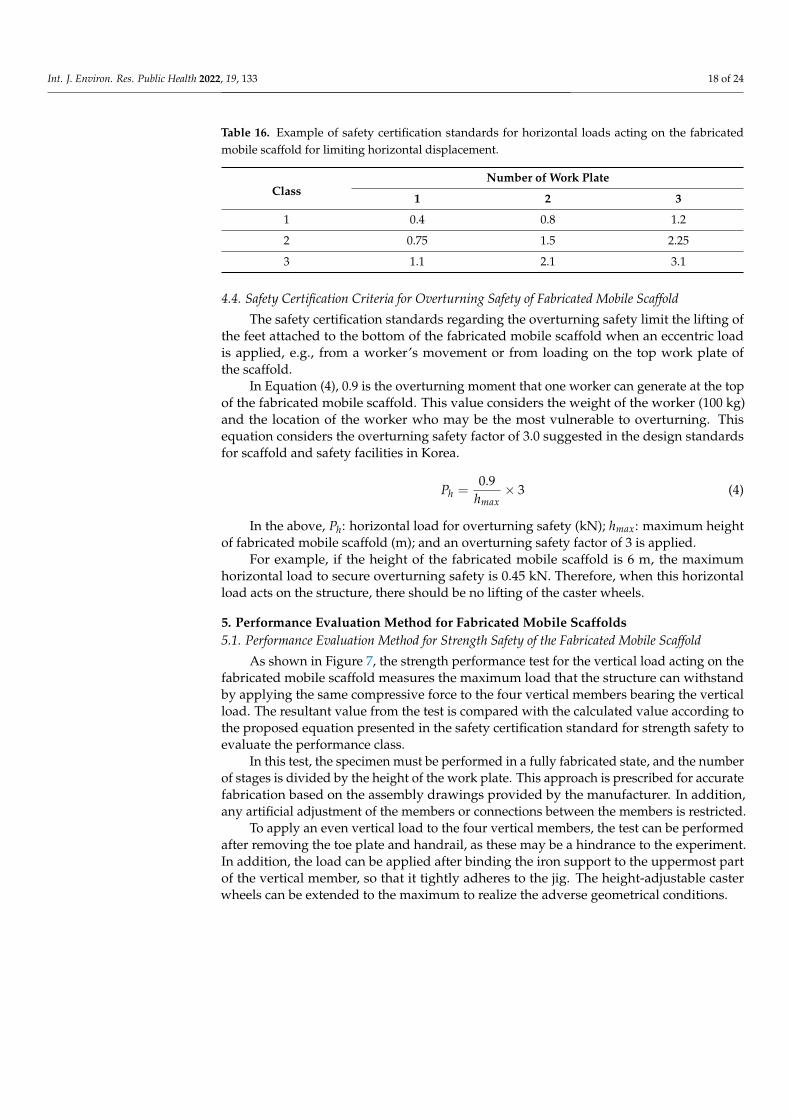
As shown in Figure 7, the strength performance test for the vertical load acting on thefabricated mobile scaffold measures the maximum load that the structure can withstandby applying the same compressive force to the four vertical members bearing the verticalload. The resultant value from the test is compared with the calculated value according tothe proposed equation presented in the safety certification standard for strength safety toevaluate the performance class.
In this test, the specimen must be performed in a fully fabricated state, and the numberof stages is divided by the height of the work plate. This approach is prescribed for accuratefabrication based on the assembly drawings provided by the manufacturer. In addition,any artificial adjustment of the members or connections between the members is restricted.
To apply an even vertical load to the four vertical members, the test can be performedafter removing the toe plate and handrail, as these may be a hindrance to the experiment.In addition, the load can be applied after binding the iron support to the uppermost partof the vertical member, so that it tightly adheres to the jig. The height-adjustable casterwheels can be extended to the maximum to realize the adverse geometrical conditions.
Int. J. Environ. Res. Public Health 2022, 19, 133 19 of 24Int. J. Environ. Res. Public Health 2022, 19, x FOR PEER REVIEW 19 of 24
Figure 7. Vertical load test method.
In this test, the specimen must be performed in a fully fabricated state, and the num-
ber of stages is divided by the height of the work plate. This approach is prescribed for
accurate fabrication based on the assembly drawings provided by the manufacturer. In
addition, any artificial adjustment of the members or connections between the members
is restricted.
To apply an even vertical load to the four vertical members, the test can be performed
after removing the toe plate and handrail, as these may be a hindrance to the experiment.
In addition, the load can be applied after binding the iron support to the uppermost part
of the vertical member, so that it tightly adheres to the jig. The height-adjustable caster
wheels can be extended to the maximum to realize the adverse geometrical conditions.
5.2. Performance Evaluation Method for Limiting Horizontal Displacement of Fabricated Mobile
Scaffold
The stiffness test of the fabricated mobile scaffold measures the horizontal displace-
ment generated by applying an equal horizontal load to two vertical members located on
one side of the uppermost part of the structure. During the test, a sufficient ballast can be
installed at the bottom to prevent the structure from overturning. In addition, the caster
wheel located on the surface not undergoing a horizontal load can be fixed so that it does
not move.
As shown in Figure 8, the test load in this study comprised two horizontal loads ap-
plied perpendicular to the outer surface of the scaffold. Therefore, it was suggested that
the test be repeated at 90° to the first side after applying a horizontal load on one side.
Figure 7. Vertical load test method.
5.2. Performance Evaluation Method for Limiting Horizontal Displacement of FabricatedMobile Scaffold
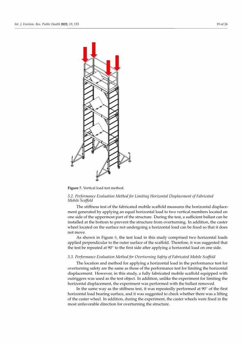
The stiffness test of the fabricated mobile scaffold measures the horizontal displace-ment generated by applying an equal horizontal load to two vertical members located onone side of the uppermost part of the structure. During the test, a sufficient ballast can beinstalled at the bottom to prevent the structure from overturning. In addition, the casterwheel located on the surface not undergoing a horizontal load can be fixed so that it doesnot move.
As shown in Figure 8, the test load in this study comprised two horizontal loadsapplied perpendicular to the outer surface of the scaffold. Therefore, it was suggested thatthe test be repeated at 90◦ to the first side after applying a horizontal load on one side.
5.3. Performance Evaluation Method for Overturning Safety of Fabricated Mobile Scaffold
The location and method for applying a horizontal load in the performance test foroverturning safety are the same as those of the performance test for limiting the horizontaldisplacement. However, in this study, a fully fabricated mobile scaffold equipped withoutriggers was used as the test object. In addition, unlike the experiment for limiting thehorizontal displacement, the experiment was performed with the ballast removed.
In the same way as the stiffness test, it was repeatedly performed at 90◦ of the firsthorizontal load bearing surface, and it was suggested to check whether there was a liftingof the caster wheel. In addition, during the experiment, the caster wheels were fixed in themost unfavorable direction for overturning the structure.
Int. J. Environ. Res. Public Health 2022, 19, 133 20 of 24Int. J. Environ. Res. Public Health 2022, 19, x FOR PEER REVIEW 20 of 24
Figure 8. Horizontal load test method.
5.3. Performance Evaluation Method for Overturning Safety of Fabricated Mobile Scaffold
The location and method for applying a horizontal load in the performance test for
overturning safety are the same as those of the performance test for limiting the horizontal
displacement. However, in this study, a fully fabricated mobile scaffold equipped with
outriggers was used as the test object. In addition, unlike the experiment for limiting the
horizontal displacement, the experiment was performed with the ballast removed.
In the same way as the stiffness test, it was repeatedly performed at 90° of the first
horizontal load bearing surface, and it was suggested to check whether there was a lifting
of the caster wheel. In addition, during the experiment, the caster wheels were fixed in the
most unfavorable direction for overturning the structure.
6. Application Example of the Suggested Safety Certification Standards and
Experimental Evaluation for the Fabricated Mobile Scaffold
Based on the safety certification standards for strength safety presented in this study,
the work classes were classified for the three products for which the vertical load tests
were performed. As shown in Table 17, two 1-story and one 3-story fabricated mobile
scaffolds were examined. Also, one of the 1-story specimens was fabricated with alumi-
num and the other was fabricated with steel. Details of the experiments were presented
in a previous study (Kim et al., 2021) [7]. Figure 9 shows the load–displacement curves for
the vertical load applied to the three specimens. As can be seen from the experimental
results, the experimental results for the single-story specimens show results similar to
those of the steel and aluminum specimens. However, the loading capacity sharply de-
creases in the experimental results of the three-story specimen with a high height. Accord-
ing to the research, the governing factor on the ultimate behavior of the 3-story specimen
was buckling of the vertical members rather than a failure of the caster wheel. Addition-
ally, in the case of the single-story specimens, the destruction of the caster wheel occurs
before the buckling of the vertical member. The experimental study clearly shows that the
Figure 8. Horizontal load test method.
6. Application Example of the Suggested Safety Certification Standards andExperimental Evaluation for the Fabricated Mobile Scaffold
Based on the safety certification standards for strength safety presented in this study,the work classes were classified for the three products for which the vertical load testswere performed. As shown in Table 17, two 1-story and one 3-story fabricated mobilescaffolds were examined. Also, one of the 1-story specimens was fabricated with aluminumand the other was fabricated with steel. Details of the experiments were presented in aprevious study (Kim et al., 2021) [7]. Figure 9 shows the load–displacement curves forthe vertical load applied to the three specimens. As can be seen from the experimentalresults, the experimental results for the single-story specimens show results similar to thoseof the steel and aluminum specimens. However, the loading capacity sharply decreasesin the experimental results of the three-story specimen with a high height. According tothe research, the governing factor on the ultimate behavior of the 3-story specimen wasbuckling of the vertical members rather than a failure of the caster wheel. Additionally, inthe case of the single-story specimens, the destruction of the caster wheel occurs beforethe buckling of the vertical member. The experimental study clearly shows that the load-carrying capacity of the fabricated mobile scaffolds cannot be easily estimated by themember strength because the ultimate modes and the governing factor on the globalstrength are determined by the details of the combination of the main components as wellas the material strength. Therefore, it is reasonable to judge a fabricated mobile scaffoldingbased on safety certification criteria for the overall shape of the structure, rather than usingindividual member performance-based safety certification criteria.
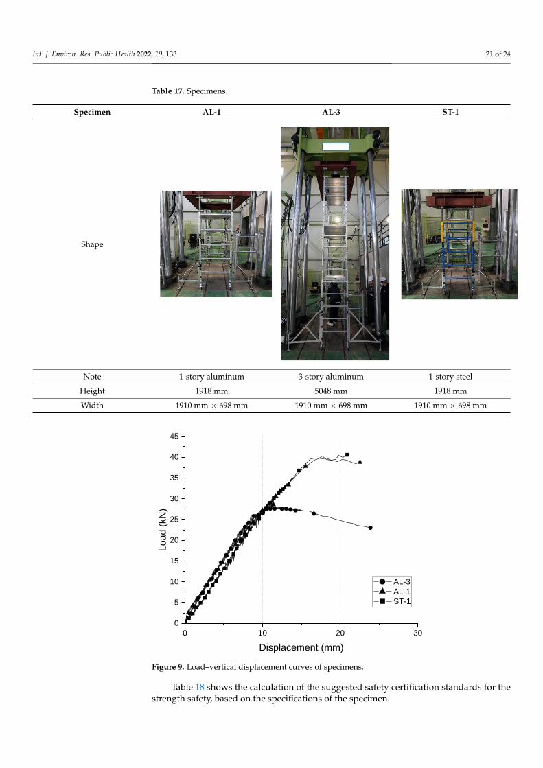
Int. J. Environ. Res. Public Health 2022, 19, 133 21 of 24
Table 17. Specimens.
Specimen AL-1 AL-3 ST-1
Shape
Int. J. Environ. Res. Public Health 2022, 19, x FOR PEER REVIEW 21 of 25
load-carrying capacity of the fabricated mobile scaffolds cannot be easily estimated by the member strength because the ultimate modes and the governing factor on the global strength are determined by the details of the combination of the main components as well as the material strength. Therefore, it is reasonable to judge a fabricated mobile scaffolding based on safety certification criteria for the overall shape of the structure, rather than using individual member performance-based safety certification criteria.
Table 17. Specimens.
Specimen AL-1 AL-3 ST-1
Shape
Note 1-story aluminum 3-story aluminum 1-story steel Height 1918 mm 5048 mm 1918 mm Width 1910 mm × 698 mm 1910 mm × 698 mm 1910 mm × 698 mm
Note 1-story aluminum 3-story aluminum 1-story steel
Height 1918 mm 5048 mm 1918 mm
Width 1910 mm × 698 mm 1910 mm × 698 mm 1910 mm × 698 mm
Int. J. Environ. Res. Public Health 2022, 19, x FOR PEER REVIEW 21 of 24
load-carrying capacity of the fabricated mobile scaffolds cannot be easily estimated by the
member strength because the ultimate modes and the governing factor on the global
strength are determined by the details of the combination of the main components as well
as the material strength. Therefore, it is reasonable to judge a fabricated mobile scaffolding
based on safety certification criteria for the overall shape of the structure, rather than using
individual member performance-based safety certification criteria.
Table 17. Specimens.
Specimen AL-1 AL-3 ST-1
Shape
Note 1-story aluminum 3-story aluminum 1-story steel
Height 1918 mm 5048 mm 1918 mm
Width 1910 mm × 698 mm 1910 mm × 698 mm 1910 mm × 698 mm
0 10 20 30
0
5
10
15
20
25
30
35
40
45
Load (
kN
)
Displacement (mm)
AL-3
AL-1
ST-1
Figure 9. Load–vertical displacement curves of specimens.
Table 18 shows the calculation of the suggested safety certification standards for thestrength safety, based on the specifications of the specimen.
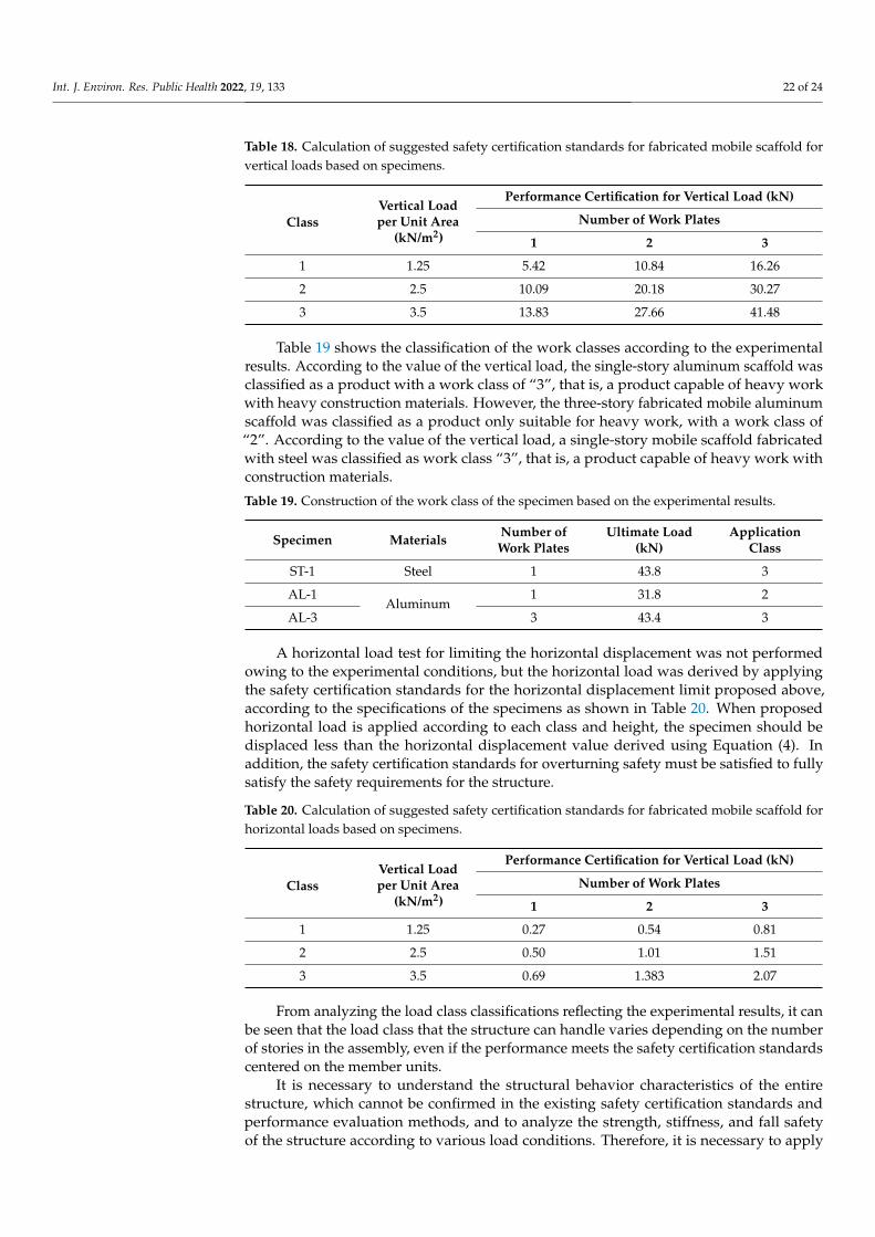
Int. J. Environ. Res. Public Health 2022, 19, 133 22 of 24
Table 18. Calculation of suggested safety certification standards for fabricated mobile scaffold forvertical loads based on specimens.
ClassVertical Loadper Unit Area
(kN/m2)
Performance Certification for Vertical Load (kN)
Number of Work Plates
1 2 3
1 1.25 5.42 10.84 16.26
2 2.5 10.09 20.18 30.27
3 3.5 13.83 27.66 41.48
Table 19 shows the classification of the work classes according to the experimentalresults. According to the value of the vertical load, the single-story aluminum scaffold wasclassified as a product with a work class of “3”, that is, a product capable of heavy workwith heavy construction materials. However, the three-story fabricated mobile aluminumscaffold was classified as a product only suitable for heavy work, with a work class of“2”. According to the value of the vertical load, a single-story mobile scaffold fabricatedwith steel was classified as work class “3”, that is, a product capable of heavy work withconstruction materials.
Table 19. Construction of the work class of the specimen based on the experimental results.
Specimen Materials Number ofWork Plates
Ultimate Load(kN)
ApplicationClass
ST-1 Steel 1 43.8 3
AL-1Aluminum
1 31.8 2
AL-3 3 43.4 3
A horizontal load test for limiting the horizontal displacement was not performedowing to the experimental conditions, but the horizontal load was derived by applyingthe safety certification standards for the horizontal displacement limit proposed above,according to the specifications of the specimens as shown in Table 20. When proposedhorizontal load is applied according to each class and height, the specimen should bedisplaced less than the horizontal displacement value derived using Equation (4). Inaddition, the safety certification standards for overturning safety must be satisfied to fullysatisfy the safety requirements for the structure.
Table 20. Calculation of suggested safety certification standards for fabricated mobile scaffold forhorizontal loads based on specimens.
ClassVertical Loadper Unit Area
(kN/m2)
Performance Certification for Vertical Load (kN)
Number of Work Plates
1 2 3
1 1.25 0.27 0.54 0.81
2 2.5 0.50 1.01 1.51
3 3.5 0.69 1.383 2.07
From analyzing the load class classifications reflecting the experimental results, it canbe seen that the load class that the structure can handle varies depending on the numberof stories in the assembly, even if the performance meets the safety certification standardscentered on the member units.
It is necessary to understand the structural behavior characteristics of the entirestructure, which cannot be confirmed in the existing safety certification standards andperformance evaluation methods, and to analyze the strength, stiffness, and fall safetyof the structure according to various load conditions. Therefore, it is necessary to apply
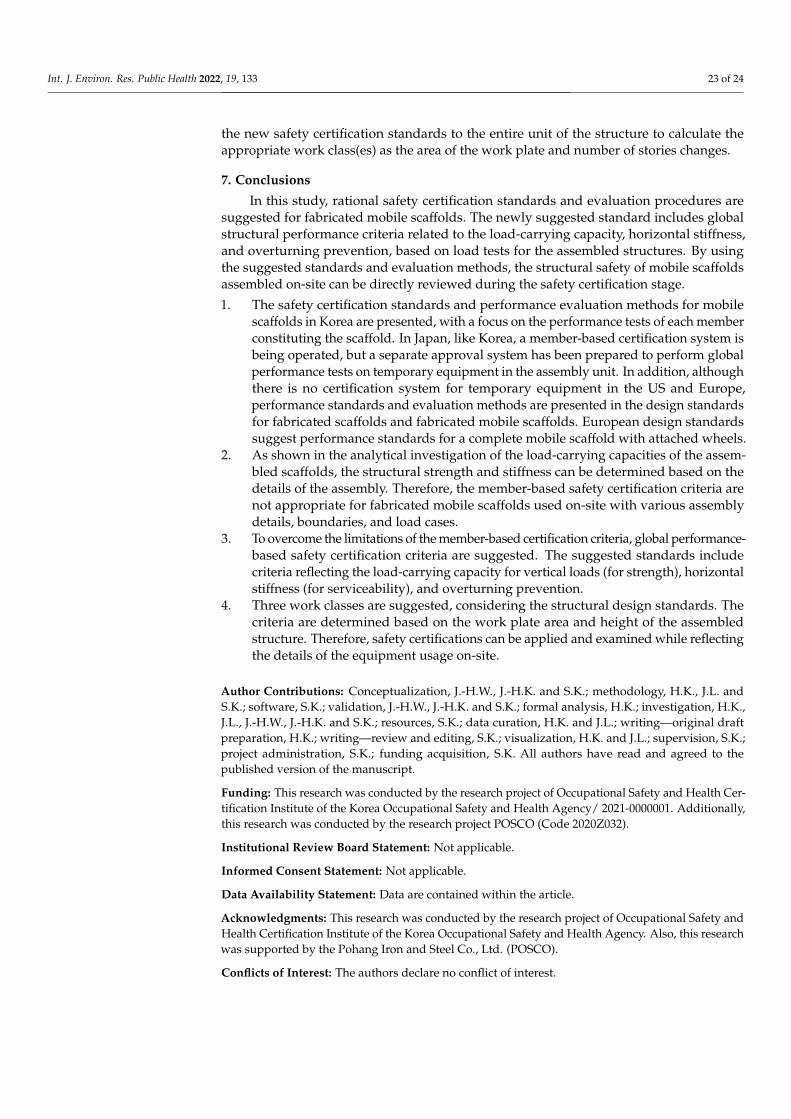
Int. J. Environ. Res. Public Health 2022, 19, 133 23 of 24
the new safety certification standards to the entire unit of the structure to calculate theappropriate work class(es) as the area of the work plate and number of stories changes.
7. Conclusions
In this study, rational safety certification standards and evaluation procedures aresuggested for fabricated mobile scaffolds. The newly suggested standard includes globalstructural performance criteria related to the load-carrying capacity, horizontal stiffness,and overturning prevention, based on load tests for the assembled structures. By usingthe suggested standards and evaluation methods, the structural safety of mobile scaffoldsassembled on-site can be directly reviewed during the safety certification stage.
1. The safety certification standards and performance evaluation methods for mobilescaffolds in Korea are presented, with a focus on the performance tests of each memberconstituting the scaffold. In Japan, like Korea, a member-based certification system isbeing operated, but a separate approval system has been prepared to perform globalperformance tests on temporary equipment in the assembly unit. In addition, althoughthere is no certification system for temporary equipment in the US and Europe,performance standards and evaluation methods are presented in the design standardsfor fabricated scaffolds and fabricated mobile scaffolds. European design standardssuggest performance standards for a complete mobile scaffold with attached wheels.
2. As shown in the analytical investigation of the load-carrying capacities of the assem-bled scaffolds, the structural strength and stiffness can be determined based on thedetails of the assembly. Therefore, the member-based safety certification criteria arenot appropriate for fabricated mobile scaffolds used on-site with various assemblydetails, boundaries, and load cases.
3. To overcome the limitations of the member-based certification criteria, global performance-based safety certification criteria are suggested. The suggested standards includecriteria reflecting the load-carrying capacity for vertical loads (for strength), horizontalstiffness (for serviceability), and overturning prevention.
4. Three work classes are suggested, considering the structural design standards. Thecriteria are determined based on the work plate area and height of the assembledstructure. Therefore, safety certifications can be applied and examined while reflectingthe details of the equipment usage on-site.
Author Contributions: Conceptualization, J.-H.W., J.-H.K. and S.K.; methodology, H.K., J.L. andS.K.; software, S.K.; validation, J.-H.W., J.-H.K. and S.K.; formal analysis, H.K.; investigation, H.K.,J.L., J.-H.W., J.-H.K. and S.K.; resources, S.K.; data curation, H.K. and J.L.; writing—original draftpreparation, H.K.; writing—review and editing, S.K.; visualization, H.K. and J.L.; supervision, S.K.;project administration, S.K.; funding acquisition, S.K. All authors have read and agreed to thepublished version of the manuscript.
Funding: This research was conducted by the research project of Occupational Safety and Health Cer-tification Institute of the Korea Occupational Safety and Health Agency/ 2021-0000001. Additionally,this research was conducted by the research project POSCO (Code 2020Z032).
Institutional Review Board Statement: Not applicable.
Informed Consent Statement: Not applicable.
Data Availability Statement: Data are contained within the article.
Acknowledgments: This research was conducted by the research project of Occupational Safety andHealth Certification Institute of the Korea Occupational Safety and Health Agency. Also, this researchwas supported by the Pohang Iron and Steel Co., Ltd. (POSCO).
Conflicts of Interest: The authors declare no conflict of interest.
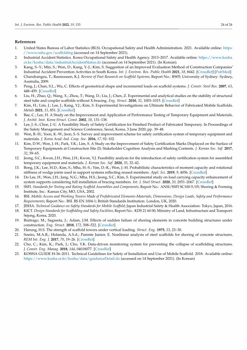
Int. J. Environ. Res. Public Health 2022, 19, 133 24 of 24
References1. United States Bureau of Labor Statistics (BLS). Occupational Safety and Health Administration. 2021. Available online: https:
//www.osha.gov/scaffolding (accessed on 14 September 2021).2. Industrial Accident Statistics. Korea Occupational Safety and Health Agency. 2013–2017. Available online: https://www.kosha.
or.kr/kosha/data/industrialAccidentStatus.do (accessed on 14 September 2021). (In Korean).3. Kang, S.-Y.; Min, S.; Won, D.; Kang, Y.-J.; Kim, S. Suggestion of an Improved Evaluation Method of Construction Companies’
Industrial Accident Prevention Activities in South Korea. Int. J. Environ. Res. Public Health 2021, 18, 8442. [CrossRef] [PubMed]4. Chandrangsu, T.; Rasmussen, K.J. Review of Past Research on Scaffold Systems; Report No.: R905; University of Sydney: Sydney,
Australia, 2009.5. Peng, J.; Chan, S.L.; Wu, C. Effects of geometrical shape and incremental loads on scaffold systems. J. Constr. Steel Res. 2007, 63,
448–459. [CrossRef]6. Liu, H.; Zhao, Q.; Wang, X.; Zhou, T.; Wang, D.; Liu, J.; Chen, Z. Experimental and analytical studies on the stability of structural
steel tube and coupler scaffolds without X-bracing. Eng. Struct. 2010, 32, 1003–1015. [CrossRef]7. Kim, H.; Lim, J.; Lee, J.; Kang, Y.J.; Kim, S. Experimental Investigations on Ultimate Behavior of Fabricated Mobile Scaffolds.
Metals 2021, 11, 851. [CrossRef]8. Bae, C.; Lee, H. A Study on the Improvement and Application of Performance Testing of Temporary Equipment and Materials.
J. Archit. Inst. Korea Struct. Const. 2002, 18, 131–138.9. Lee, J.-S.; Choe, J.-U. A Feasibility Study of Safety Certification for Finished Product of Fabricated Temporary. In Proceedings of
the Safety Management and Science Conference, Seoul, Korea, 3 June 2020; pp. 39–48.10. Won, B.-H.; Yoon, K.-W.; Jeon, S.-S. Survey and improvement scheme for safety certification system of temporary equipment and
materials. J. Korea Acad.-Ind. Coop. Soc. 2016, 17, 92–102.11. Kim, D.W.; Won, J.-H.; Park, Y.K.; Lim, S. A Study on the Improvement of Safety Certification Marks Displayed on the Surface of
Temporary Equipments at Construction Site (I): Stakeholder Cognition Analysis and Marking Contents. J. Korean Soc. Saf. 2017,32, 59–65.
12. Jeong, S.C.; Kwon, J.H.; Won, J.H.; Kwon, Y.J. Feasibility analysis for the introduction of safety certification system for assembledtemporary equipment and materials. J. Korean Soc. Saf. 2020, 35, 32–42.
13. Bong, J.K.; Lee, H.D.; Kim, S.; Mha, H.-S.; Yim, D.-K.; Won, J.-H. Probabilistic characteristics of moment capacity and rotationalstiffness of wedge joints used in support systems reflecting reused members. Appl. Sci. 2019, 9, 4056. [CrossRef]
14. Do Lee, H.; Won, J.H.; Jang, N.G.; Mha, H.S.; Jeong, S.C.; Kim, S. Experimental study on load carrying capacity enhancement ofsystem supports considering full installation of bracing members. Int. J. Steel Struct. 2020, 20, 2051–2067. [CrossRef]
15. SSFI. Standards for Testing and Rating Scaffold Assemblies and Components; Report No.: ANSI/SSFI SC100-5/05; Shoring & FormingInstitute, Inc.: Kansas City, MO, USA, 2002.
16. BSI. Mobile Access and Working Towers Made of Prefabricated Elements-Materials, Dimensions, Design Loads, Safety and PerformanceRequirements; Report No.: BSI. BS EN 1004-1; British Standards Institution: London, UK, 2020.
17. JISHA. Technical Guidance on Safety Standards for Mobile Scaffold; Japan Industrial Safety & Health Association: Tokyo, Japan, 2016.18. KICT. Design Standards for Scaffolding and Safety Facilities; Report No.: KDS 21 60 00; Ministry of Land, Infrastructure and Transport:
Sejong, Korea, 2020.19. Buitrago, M.; Sagaseta, J.; Adam, J.M. Effects of sudden failure of shoring elements in concrete building structures under
construction. Eng. Struct. 2018, 172, 508–522. [CrossRef]20. Harung, H.S. The strength of scaffold towers under vertical loading. Struct. Eng. 1975, 53, 23–30.21. Soeiro, M.A.R.; Holanda, A.S.d.; Parente Junior, E. Nonlinear analysis of steel scaffolds for shoring of concrete structures.
REM Int. Eng. J. 2017, 70, 19–26. [CrossRef]22. Cho, C.; Kim, K.; Park, J.; Cho, Y.K. Data-driven monitoring system for preventing the collapse of scaffolding structures.
J. Constr. Eng. Manag. 2018, 144, 04018077. [CrossRef]23. KOSHA GUIDE H-36–2011. Technical Guidelines for Safety of Installation and Use of Mobile Scaffold. 2018. Available online:
https://www.kosha.or.kr/kosha/data/guidanceDetail.do (accessed on 14 September 2021). (In Korean)