subpixel motion computing architecture
TRANSCRIPT

Subpixel motion computing architecture
J. Dıaz, E. Ros, S. Mota, F. Pelayo and E.M. Ortigosa
Abstract: A pipelined optical-flow processing system that works as a virtual motion sensor hasbeen described. It is based on a field programmable gate array (FPGA) device enabling the easychange of configuring parameters to adapt the sensor to different speeds, light conditions andother environmental factors. It is referred to as a ‘virtual sensor’ because it consists of a conven-tional camera as front-end supported by an FPGA processing device, which embeds the framegrabber, optical-flow algorithm implementation, output module and some configuration andstorage circuitry. This is the first fully stand-alone working optical-flow processing system toinclude both accuracy and speed of measurement of the platform performance. The customisabilityof the system for different hardware resources and platforms has also been discussed, showing theresources and performance for a stand-alone board and a PCI co-processing board.
1 Introduction
Optical flow computation consists in extracting a densevelocity field from an image sequence assuming that inten-sity is conserved during displacement. This result may thenbe used for other applications such as 3-D reconstruction,time interpolation of image sequences, video compression,segmentation from motion, tracking, robot navigation,time-to-collision estimation and so on. The technicalproblem with estimating the motion of objects in 3-D isthat, in the image formation process, because of the perspec-tive projection of the 3-D world onto the 2-D image plane,some of the information is lost. There are several ways ofrecovering the 3-D information from 2-D images usingvarious cues. These cues are motion, binocular stereopsis,texture, shading and contour. In this paper, we will describethe implementation of a real-time motion flow system,leaving the potential applications for future studies.
Optical-flow algorithms have been widely described inthe literature. Some authors have addressed a comparativestudy of the accuracy of different approaches with syntheticsequences [1]. Their evaluation using real-life sequences isdifficult to address because the real optical flow of suchsequences is unknown. We have focused on a classicalgradient model based on Lucas and Kanade’s (L & K)approach [1, 2]. Several authors have emphasised the satis-factory trade-off between accuracy and efficiency in thismodel, which is an important factor when deciding whichmodel is most suitable to use as a real-time processingsystem. For a comparative study [1], the L & K algorithmprovides very accurate results, added to which, otherauthors specifically evaluating the efficiency against accu-racy trade-off of different optical-flow approaches [3] alsoregard the L&K model as being quite efficient. Finally,
# The Institution of Engineering and Technology 2006
IEE Proceedings online no. 20050207
doi:10.1049/ip-vis:20050207
Paper first received 19th July 2005 and in revised form 23rd June 2006
J. Dıaz, E. Ros, F. Pelayo and E.M. Ortigosa are with the Department ofComputer Architecture and Technology, University of Granada, Spain
S. Mota is with the Department of Computer Science and Numerical Analysis,University of Cordoba, Spain
E-mail: [email protected]
IEE Proc.-Vis. Image Signal Process., Vol. 153, No. 6, December 2006
McCane et al. [4] also give L & K a good score and con-clude that the computational power required by thisapproach is affordable. This has prompted later researchersto focus on the L&K algorithm [5].
We describe here a hardware implementation of the L&Kalgorithm. Other authors have recently described the hard-ware implementation of optical-flow algorithms [6–10],but most of them provide no results to evaluate the perform-ance of the system, that is the accuracy and the computationspeed.
The hardware implementation of an algorithm requires adetailed study of the model. After this preliminary stage,simplification strategies are adopted. Finally, it is necessaryto evaluate how the adopted simplifications affect the results(Section 5).
We define our system with a high-level hardware descrip-tion language such as Handel-C [11]. This high-levellanguage enables the easy parameterisation of the design,thus we present a system that can be customised to accom-plish different requirements for diverse applications.
2 Optical-flow model
Although the original algorithm was proposed as a methodto estimate the disparity map in stereo-pair images [2], wehave applied Barron’s description of the L&K algorithmto optical-flow computation [1]. We have also addedseveral modifications to improve the feasibility of its hard-ware implementation, we have used IIR temporal filters asdescribed by Fleet and Langley [12] and we have includedbias estimations in the detection of maximum gradient whenaperture problem appears [13].
In the following equations, we describe briefly the com-putations upon which the L&K approach is based. Adetailed description of the model is provided in previousstudies [1, 2].
The algorithm belongs to gradient-based techniquescharacterised by a gradient search performed on extractedspatial and temporal derivatives. Upon the assumption ofconstant luminance values through time, the first-ordergradient constraint equation (1) is obtained as
rxy Iðx; y; tÞ � ðvx; vyÞ þ I tðx; y; tÞ ¼ 0 ð1Þ
869

This equation only allows us to estimate velocity in thedirection of maximum gradient, that is in the normal direc-tion of moving surfaces. To overcome this limitation, theL&K method constructs a flow estimation based on thefirst-order derivatives of the image. By least-squarefitting, the model extracts an estimation of motion on thebasis of the hypothesis of similarity of velocity values inthe neighbourhood of a central pixel. This is describedmathematically in (2)
minXx[V
W2ðxÞ½rxyIðx; y; tÞ � ðvx; vyÞ þ I tðx; y; tÞ�
2ð2Þ
where W(x) weights the constraints with values near thecentre of the spatial neighbourhood V.
The known solution to this problem is expressed in (3)and (4).
~v ¼ ½ATW 2A��1ATW 2~b ð3Þ
where
ATW 2A ¼
Px[V
W2I
2x þ a
Px[V
W2IxIy
Px[V
W 2IxIy
Px[V
W 2I2y þ a
264
375
ATW
2~b ¼
�P
x[V
W 2IxI t
�P
x[V
W2IyI t
264
375 ð4Þ
An inherent limitation to these models appears in blankwall or aperture problem situations. In these cases, theproblem has no solution (matrix ATW2A is not invertible)and the model cannot provide any estimation of motion.To overcome this, we have added a small constant, a, tothe matrix diagonal, as suggested by Simoncelli et al.[13], which allows us to estimate the normal velocity fieldin situations where 2-D velocity cannot be extractedbecause of the lack of contrast information. In summary,we have to compute the 2 � 2 matrix of (4-left), itsinverse and the 2 � 1 matrix indicated in (4-right).
Before computing the image derivatives in the matrixelements of (4) they are pre-processed by Gaussian smooth-ing, which reduces image noise and generates a highercorrelation between adjacent pixels. Typically, Gaussianspace-time filters of 2 pixels variance plus a temporalderivative of 5 pixels are used. All the temporal operationsrequire storage of 15 images for the entire process. Thisis hardly affordable in embedded hardware systems.Therefore as indicated in the work of Fleet and Langley[12], a more efficient tactic can be implemented by usingIIR temporal recursive smoothing and derivative filters. Inthis way, the temporal storage requirement is reduced tothree frames and the computation time improved at a costof only slightly reduced accuracy. The temporal filter canbe computed as follows.
Let us consider a separable space-time smoothing filter.After the spatial filtering operation, we can use a causaltemporal filter based on a truncated exponential.
EðtÞ ¼expð�t=tÞ=t t � 0
0 t , 0
�ð5Þ
where t is the time constant of the filter. The temporalderivative of the images can be calculated using this filter.
870
The digital filter equations [12] are
wðtÞ ¼ IðtÞ � 2rwðt � 1Þ � r2wðt � 2Þ
R2ðtÞ ¼ q2wðtÞ þ 2q2wðt � 1Þ þ qwðt � 2Þ
yðtÞ ¼ R2ðtÞ � ryðt � 1Þ
ð6Þ
where we store and update: w(t 2 1), w(t 2 2), y(t 2 1). Theparameters q and r are calculated from t according to (7)
q ¼1
1þ 2tr ¼
1� 2t
1þ 2tð7Þ
Finally, the smoothed temporal image and its derivative arecomputed with (8)
I smoothðtÞ ¼ qyðtÞ þ qyðt � 1Þ
I tðtÞ ¼ðI2ðtÞ � I smoothÞ
t
ð8Þ
3 Hardware implementation
Nowadays real-time computation of simple optical-flowalgorithms for small images is possible by softwarebecause of the outstanding computational power of PCs.The drawback is that it is difficult to adapt these systemsto use as embedded solutions, for instance, in robotics appli-cations. Optical-flow can provide to robots navigation infor-mation, time-to-contact or tracking capabilities. Currentrobots incorporate simple motion information extractionschemes [14] that limit unnecessarily the potential appli-cations of the system. In interactive robotic tasks, hightemporal resolution is crucial, and this requires highpower computation to extract reliable motion informationin real-time. The presented approach fulfils this require-ment, as the processing is done at conventional framerates with different spatial resolutions.
For recovering 3-D structure from motion [15], largeimages, dense information and high accuracy is needed.The huge computational power required for this taskmakes this application difficult to address with conventionalcomputing platforms.
Encoding standards also use motion information. Theactual implementations typically use block-matchingmethods and try to minimise the total coding error (oftenmeasured as signal-to-noise ratio). However, this does nottake into account the subjective appearance of the codingartefacts, which can significantly affect the video quality.High-quality motion estimation methods [16, 17] lead tohigher quality pictures compared with the use of a simple‘best match’ motion estimator.
As it can be seen from earlier discussions, diverse poten-tial applications can benefit from the development of a cus-tomisable optical flow system of high computational powerand high quality. The customisation feasibility is the key-factor to address several applications with the same technol-ogy. The possibilities of working for a specific-applicationwhile managing design trade-offs (such as different frame-rate against spatial resolution and customised flow-accuracyagainst system cost) are very advantageous. The solution wepropose is based on the use of programmable logic circuits(FPGAs), where the motion computation chip can beregarded as part of a smart sensor. These circuits allow usto design a customised DSP circuit in a single chip ofhigh computational power based on an intensive use oftheir intrinsic parallelism and pipeline resources. As wewill show in later sections, the solution described hereuses this technology to implement a real-time hardware
IEE Proc.-Vis. Image Signal Process., Vol. 153, No. 6, December 2006

device capable of working as a PC co-processor or as asmart sensor in embedded applications.
3.1 Hardware development
For our design, we have used two platforms: the first one isthe RC1000-PP board from Celoxica [18]. This is a PCI busboard connected to the PC and can be used as a hardwareaccelerator board or as a prototype board. It contains aVirtex 2000E-6 Xilinx FPGA and four 2 MB SRAMmemory banks accessible in parallel. This platform uses aclient–server scheme. A host program written in C/Cþþsends image data to the FPGA through the PCI bus andthen receives data processed by the FPGA. Because weare interested in stand-alone hardware devices, all the com-putations have been made with the FPGA, but this platformis also flexible and capable of working within more complexco-design schemes. The second platform is the stand-aloneRC203 board from Celoxica [18]. This board includescamera input, video/VGA output, two 2 MB SSRAMmemory banks and a XC2V3000-4 FPGA. It is a very suit-able test system for embedded applications.
We have used Handel-C [11] as hardware specificationlanguage to generate the Edif input to the Xilinx ISEenvironment. This high-level hardware language allows usto describe register transfer level (RTL) circuits in a veryalgorithmic-like way. This is relevant because of the algo-rithmic nature of the proposed method that makes an RTLapproach more difficult to adopt. The drawback is the costin terms of number of gates, but the design time isreduced significantly. Finally, the Xilinx tool generatesthe programming file for the FPGA.
3.2 System implementation overview
The processing schemes of the PCI co-processing board andthe stand-alone platform are illustrated in Figs. 1a and b.The efficient implementation of the algorithm with anFPGA device requires the intensive exploitation of theintrinsic processing parallelism of this kind of device. Weuse segmented architecture, as shown in Fig. 1c.
IEE Proc.-Vis. Image Signal Process., Vol. 153, No. 6, December 2006
The basic computational stages in Fig. 1c can be summar-ised as follows.
† S0. The frame-grabber receives the pixels from thecamera and stores them in one of the memory banks,using a double-buffer technique to avoid temporisationproblems.† S1. Spatial-Gaussian-filter smoothing stage.† S2. The IIR temporal filter computes temporal derivativeand space-time smoothed images.† S3. Spatial derivatives stage.† S4. Construction of least-square matrices of (4).† S5. Custom floating-point unit. Final velocity estimationrequires the computation of a matrix inversion, whichincludes a division operation. At this stage, the resolutionof the incoming data bits is significant and expensive arith-metic operations are required. Thus fixed-point arithmeticbecomes too expensive, prompting us to design a custo-mised floating-point unit.
The computation bit-width increases throughout thepipeline structure. For example, for a high-precisionsystem with low accuracy degradation, we use 8 bits inthe first two stages, 12 bits in the third and fourth stages,24 in the construction of the least-square matrices and 25for the floating-point unit. The computation of theleast-square matrices (S4) is the most expensive stage interms of computational resources. Different parallelismstrategies can be adopted at this point. We have in facttested a less expensive approach in terms of hardwarewith good qualitative results.
The basic parameters of the pipeline structure are latency(L) and the maximum number of cycles (MNC) requiredduring the longest stage, which is the limiting factor ofthe computing speed. The pipeline circuit scheme providesa computing speed (data throughput) in pixels per second(pps) that depends on the MNC and the frequency clockaccording to the expression pps ¼ fclk/MNC.
3.2.1 Bit-width estimation: The bit-width at each stageis a very important parameter because it significantly
Fig. 1 Boards schemes and FPGA pipeline architecture
a PCI-board schemeb Stand-alone board schemec Coarse pipeline processing architecture for optical flow computation
871

affects system quality and hardware requirements. Severaldecisions have to be arrived at:
1. The data bit-width for data registers.2. Arithmetic data representation: integer, fixed point orfloating point.3. Rescaling data or data range compression after operations:by truncation, wrapping or nonlinear range compressionsuch as saturation or logarithmic data range compression.
All the design decisions summarised above have beentaken after several trials to obtain a balanced design inwhich the degradation of the results along the data-path isminimised and hardware resources are kept to affordablelevels. The following considerations have been taken intoaccount.
1. Convolution operations can be implemented efficientlywith integer or fixed-point arithmetic.2. Operations such as division or multiplication with highbit-widths are more efficiently implemented with floating-point arithmetic. This is necessary to process data withreasonable bit-width precision during some stages.3. Nonlinear range compression such as logarithmic datarange compression (for rescaling data after arithmetic oper-ations) is not well suited to FPGA devices because of itscomplex implementation, unless lookup tables are used.The effects on system quality have not been studied yet,so we use truncation and wrapping techniques. A statisticalstudy can be made to evaluate how this operation affects thequality of the results.
3.3 Critical stages
There are two main critical stages: S4 and S5. The construc-tion of least-square matrices is done in S4 where the trade-off between efficiency and cost can vary widely. Equation(4) requires the computation of five products: Ix
2, Iy2, IxIy,
IxIt, IyIt. Thus we make a weighted sum in a window (V)over a neighbourhood of size wx � wy. Owing to memorylimitations, we save the Ix, Iy and It values instead of thefive crossed products. Therefore the operations made are:
† computation of the products for all the elements withina neighbourhood. We need to calculate five wx � wy
multiplications;† row-convolution operation. We compute five multiply bywy convolutions;† column-convolution operation, requiring the compu-tation of five convolutions.
This is an important stage where we can bias the trade-offbetween efficiency and hardware cost. For example, if weuse a 3 � 3 neighbourhood, we need between 1 to 45 mul-tipliers, 1 to 15 row-convolution units and 1 to 5 column-convolution units. This choice allows us to compute theweighted sum values in one clock cycle with a highlyparallel hardware unit or to compute it sequentially.
This has been schematically represented in Fig. 2 forthree implementations with different levels of parallelismand with an integration area of 3 � 3 for the least-squaresneighbourhood. Fig. 2a represents a very parallel datapaththat we call high-speed (HS) version and which achievesMNC ¼ 10 cycles. A slower version was implementedwith less parallelism (reducing the number of parallel mul-tipliers and row/column convolution units) as shown inFig. 2b, thus resulting in a medium speed (MS) version.This configuration leads to a limiting data throughput
872
stage with MNC ¼ 26. Finally, we implemented a low-speed (LS) version represented in Fig. 2c with just onecolumn and one row convolution unit and MNC ¼ 42.
The second critical stage is the computation of final vel-ocities using a custom floating point unit. At this stage, (3) iscomputed. Until now, the arithmetic operations have beendone using integer or fixed-point arithmetic with truncationoperations. Convolution operations work well with this rep-resentation but when bit-width is too large, a floating-pointrepresentation of the data is better suited for hardwareimplementation. This is done with a customised superscalarfloating-point unit. As during the previous stage (S4), a highbit-width (24 bits) is used to preserve computational accu-racy, the current stage (S5) becomes very expensive interms of hardware resources. Therefore the design of S5 iscritical as it exerts an important influence on the accuracyagainst processing speed trade-off.
The calculations in this stage involve the following basicarithmetical operations: subtraction, multiplication anddivision. When arithmetical operations are made withhigh bit-width, the signal delays associated with carrylines degrade overall performance, decreasing themaximum system frequency. To avoid this, pipeline arith-metic operators or sequential iterative operators can beused. The first approach allows us to make the computationin 1 or 2 clock cycles, after a given latency at a high cost interms of hardware resources. The second option takesseveral clock cycles therefore degrading the MNC of thesystem, but allows us to use the same hardware for each iter-ation. We define a system that uses one-cycle floating-pointhardware circuits, because this works at the desiredmaximum clock frequency (without becoming the limitingstage) for all the operations except the division. We haveused a hardware sequential divisor instead of a pipelineddivisor that needs 21 cycles to compute the division of 25bits of floating numbers. But in this case, the MNC is toohigh and imposes a considerable limit on pipeline perform-ance. To counter this, we use up to three-way division unitsand, depending on the performance required, we can syn-thesise more or less ways. Each floating-point unit needs:
1. one to five fixed-point to floating-point converter units;2. one to six 25-bit floating point multipliers;3. one to three subtractors;4. one or two divisor units. If an n-ways divisor scheme ischosen, we use n to 2n divisor units.
The hardware consumption resources using different con-figurations are represented in Fig. 3. More concretely, inFig. 3a, we consider a high parallel implementation withseveral multipliers, adders, division units as well as fixedto floating point converters (all these are used in the HSversion). Fig. 3b represents an implementation with lessparallelism used for MS and LS versions. The high MNCvalues of MS and LS versions (using a limited parallelismlevel) allow a high degree of resources sharing.
4 Hardware performance and resourcesconsumption study
The system is designed in modules, so that parallelism andbit accuracy at different stages can be easily modified.Owing to the high level of abstraction that Handel-Cprovides [11], it is easy to manage the parallelism of thecomputing circuits and the bit-width at the different stages.
One important aspect is that of the various possibilitiesfor configuring the system. We have evaluated several con-figurations to explore different trade-offs between accuracy,
IEE Proc.-Vis. Image Signal Process., Vol. 153, No. 6, December 2006

Fig. 2 Stage S4 architecture, parallelism levels of the different versions are schematically shown
a Architecture of the HS version (S4).Note the large number of parallel scalar units and multipliers that are usedb Architecture for the MS version (S4).Row convolution units are shared for each derivative product and only one group of multipliers is usedc Architecture for the LS version (S4)Only one group of multipliers, one row and one column of convolution units are used for this version
hardware cost and computing speed. In all these configur-ations, we have used the same basic architecture but withdifferent levels of parallelism as shown in Figs. 2 and 3.Table 1 summarises the main properties of the different con-figurations. The one using a 5 � 5 average window for the
IEE Proc.-Vis. Image Signal Process., Vol. 153, No. 6, December 2006
least-square-matrix neighbourhood is the one we havecalled high-quality (HQ) approach, and the ones using a3 � 3 window, medium quality (MQ). Other modifiableparameters are the smoothing and spatial derivative filtersizes. HQ and MQ approaches include 5-pixel derivative
873

Fig. 3 Architecture description of stage S5, different numbers of scalar units are used depending on the target parallelism level
a HS version with a larger number of parallel scalar unitsb MS and LS versionsMNC value of the previous stage S4 allows sharing most of the processing units used at this stage as well as the fixed point to floating point con-verters, multipliers adders or the division unit which only requires one way
filters and 9-pixel Gaussians. In a more economical way, thelow cost (LQ) version uses 3-pixel Gaussian and derivativesfilters.
If we fix the optical-flow quality of the system, anotherfactor to take into account is the performance against hard-ware cost trade-off. As commented in Section 3.3, we havedesigned datapaths with different levels of parallelism andwhich lead to different performances (i.e. diverse MNCvalues). Table 1 summarises the performance of thesystems and hardware costs.
It is important to note that in our experiments datatransmission of the images to the prototyping boardthrough the 33 MHz PCI bus takes about 30–40% of thetotal processing time and therefore higher frame ratesmight be expected using a direct connection between thecamera and the FPGA. Furthermore, as explained inSection 1, the data-throughput of the HSHQ is 2.700 Kppsat 27 MHz of clock frequency (in Table 1 this is limitedto 1776 by the PCI bandwidth). This topic is discussed inthe work of Benitez [19].
874
We have tested the design using the stand-aloneprototyping platform RC203 from Celoxica [18] to avoidthe PCI bus bottleneck. This platform includes anXC2V3000-4 FPGA with embedded multipliers. In thisapproach, we have implemented the whole optical flowsystem plus Video input, VGA and a memory arbitrationcontroller. A LUT for visual colour representation of thevelocities vector for the VGA output has also been includedin the FPGA. The optical flow system implemented is basedon the HSHQ version but uses the embedded multipliers andseveral clock domains. Table 2 shows the hardware costsand the system performance.
The computing speed measured with fclk ¼ 41 MHz was4100 kpps (53 fps of 340 � 280 images, MNC ¼ 10). Nowthe system is faster due to the improved technology of theVirtex II. The use of a customisable approach with a high-level description language facilitates the implementation ofthis system on different platforms. In fact, the optical flowprocessing algorithm only consumes 80% of the numberof slices while the rest is occupied by the I/O controllers.
Table 1: Performance and hardware cost of different configurations on a Virtex 2000-EFPGA (2 million gates, 43 200 logical cells (LC) and 640 Kbits of embedded memory)
Version % device
occupation
% on-chip
memory
Kpps Image
resolution
Fps,
fclk ¼ 27 MHz
Maximum fclk,
MHz
HSHQ 99 17 1776 160 � 120 95 35
31 320 � 240 24
HSMQ 65 16 1776 160 � 120 97 35
31 320 � 240 24
MSMQ 43 16 625 160 � 120 33 35
LSLQ 36 8 400 120 � 90 38 35
K, �1000; Kpps, kilopixels per second; Fps, frames per second
IEE Proc.-Vis. Image Signal Process., Vol. 153, No. 6, December 2006

Table 2: Performance and hardware costs of a stand-alone system with camera input and VGA output on a Virtex IIXC2V3000-4 FPGA (3 million gates and 1728 Kbits of embedded memory)
Version % device
occupation
% on-chip
memory
% embedded
multipliers
Kpps Image
resolution
Fps Maximum fclk,
MHz
Stand-alone RC203 board 99 29 41 4100 340 � 280 53 41
The use of the embedded multipliers saves 1324 LCs (aboutthe 4.6% of the resources of the device).
A critical design issue is the internal and externalmemory management of our system. The communicationbandwidth shall be high enough not to degrade the comput-ing performance. Internal memory [called embeddedmemory blocks (EMBs)] can be arranged with a highdegree of flexibility, allowing a high-communication band-width but only with very small capacity (640 Kbits for thedevice used in the PCI board). Owing to this fact, wehave only used this resource for the internal convolutionunits designed in our system and synchronisation buffers.For a 320 � 240 image resolution, 44 EMBs are requiredin the HS version, 32 in the MS approach and 24 in theLS implementation. Increasing the image resolutionmeans obtaining longer rows. For example, a VGA imageresolution requires multiplying by two the number ofEMBs, but this is not a problem because we have plentyof EMBs available.
The real bottleneck may be the external memory access.In our system, the PCI board version includes four parallelmemory banks with 4-byte memory words each. We havedesigned an efficient memory management unit with anMNC ¼ 1 that allows reading or writing these 4 bytes injust one clock cycle. This produces a memory bandwidthof 16 bytes per clock cycle, which completely fulfils ourrequirements (we require ten accesses in ten cycles).Furthermore, this efficient management of the externalmemory resources is a key factor that allows using justthe only two memory blocks available in the stand-alonesystem or replicating the number of processing cores iffurther performance is required.
We have shown the system’s flexibility and the trade-offbetween the number of gates and performance. Anotherimportant subject is that of scalability at the level of func-tional units. All our results work on the assumption thatonly one computational unit is used. A local image proces-sing algorithm can take advantage of the possibility of split-ting the FPGA. We can synthesise some computationalunits in the same FPGA or in several of them andcompute larger images in real-time. If a memory buffer isused, it is straightforward to assign a small area to eachcomputational unit and run it in parallel. The computationalpower is then increased by a factor close to the number ofcomputational units running in parallel. See a more detailedexample in Section 6.
4.1 Comparison with other approaches
The implementation of the optical-flow algorithm withFPGA has only been addressed by some authors in veryrecent years. Table 3 summarises the results from differentapproaches. On the basis of iterative algorithm of Horn andSchunk (H&S) [20], Martin et al. [10] makes a systemimplementation that fits quite well the specification of anoptical flow system but just simulation results are presented.The main disadvantage of this approach is that performanceof H&S model is poor compared with other alternatives [1].For example, the evaluation of the Yosemite sequence with
IEE Proc.-Vis. Image Signal Process., Vol. 153, No. 6, December 2006
the L&K method leads to results with 4.288 of averageerrors (density 35.1%), whereas with the Barron improvedversion of H&S, taking more than 100 iterations, theaverage error is 5.598 (density 32.9). This represents a rela-tive error 23% higher than the L&K algorithm adopted inthe approach presented here considering that the density issimilar. This is also the case in Cobos and Monasterio[21], which uses the same algorithm but addressing animplementation with less resources and therefore withworse performance. Using the block-matching approach,the implementation described by Niitsuma and Maruyama[6] achieves 30 fps of image size 640 � 480 but with highhardware cost (90% slices of a XC2V6000 FPGA) andwithout sub-pixel accuracy. Another study has been pub-lished recently [8], in which the hardware requirementsare lower but no information about the system performanceis provided.
On the basis of the L&K approach, Correia and Campilho[9] recently presented a real-time implementation of thesystem using a MaxVideo200 pipeline image processor.With this accelerator board, the performance and accuracyare similar to our results (we obtained a maximum perform-ance of 1776 Kpps with our PCI board system, 4100 Kppswith the stand-alone, whereas they obtained 1692 Kpps).However, the use of an acceleration processor makes it dif-ficult to be transferred to embedded applications. Finally,the model described here, running in software on anAMD 1800þMHz, can compute 1666 Kpps (for instancearranged in 25 fps of 160 � 120 pixels) and this could beoptimised using MMX and SSE instructions. The problemis that in this case it consumes all the computing resourcesof the machine.
5 System accuracy evaluation
As commented in the introduction, the accuracy of thecomputation of the optical flow in real-life sequences isdifficult to assess because the real flow of these sequencesis unknown. Therefore to evaluate the accuracy of ourdesign, which depends on the bit-width of the differentstages, we have adopted two different evaluation
Table 3: Comparison with prior approaches
Implementation Throughput,
Kpixels/s
Image size,
pixels
Image rate,
frames/s
L&K stand-alone board
(described here)
4100 320 � 240 53
L&K PCI-board ([22]
and described here)
1776 320 � 240 30
H&S [10] 3932 256 � 256 60
Block-matching [6] 9216 640 � 480 30
L&K [9] 1692 256 � 256 26
H&S [21] 47 50 � 50 19
Our data has been obtained using the maximum availablesystem clock frequency
875

methods. First, in Section 5.1, we use the test scheme and asynthetic sequence from the comparative study made byBarron et al. [1], with the error measurement proposedby Fleet and Jepson [23]. This error measurement hasbeen widely used in the literature, being therefore appro-priate to compare our results with previous works. Thismeasurement can be used with high- and low-velocitymodules with the same estimators but with some bias. Amore detailed explanation about this issue can be foundin Barron et al. [1]. Secondly, Section 5.2 shows somequalitative results that illustrate the accuracy of our system.
5.1 Synthetic sequences with known optical flow
In the hardware implementation some simplifications aremade to the original model. Table 4 shows the accuracyof the model after the modification of several parameters.Unthresholded results (100% density) are included toenable an easy comparison between the hardware and soft-ware versions. The second row in Table 4 includes theevaluation results with reliable estimations as indicatedin Barron et al. [1].
The fourth and fifth rows include results of theimplementation of the algorithm with IIR filters computedwith fixed point arithmetic using 12 bit-width. In the sixthrow of Table 4, the accuracy of the L&K algorithm (withhardware-system parameters) is computed by a standardPC using double precision variables and unthresholdedresults. Finally, the seventh row includes the performanceachieved with our hardware implementation. It can beseen that accuracy is reasonably high, bearing in mindthat fixed-point variables and restricted bit-widths areused in this approach. It can be seen that the performanceof the hardware is only slightly worse (2.488 increasein error) than the software version with a data precisionof 64 bits. Furthermore, the results of the hardwareimplementation described here are comparable with othersoftware approaches evaluated by Barron et al. [1].
We have also compared the performance of the softwareand the hardware implementations using sinusoidal gratingsequences. We used different stimulus frequencies ( f0 ¼0.02 and f0 ¼ 0.05) and velocities (V ¼ 0.25 ppf andV ¼ 1 ppf). With these tests, the hardware achievedresults very similar to those of the software (less than 5%error in the speed of calculation).
876
5.2 Real sequences: qualitative opticalflow results
Only qualitative differences were estimated with both thehardware and software optical-flow approaches using realsequences (as the real flow is unknown). In this section,we include some real-image sequences for a qualitativeevaluation.
Fig. 4 contains the image of an overtaking-car sequence,together with the results of software (LK IIR version) andhardware optical-flow estimations. This is a good exampleof how optical flow can be used for certain real-life appli-cations in a very straightforward way. In the example, thegoal is the segmentation of the overtaking car, which caneasily be done relying on optical flow, as the motionpattern of the overtaking car (moving rightward in theimages) contrasts sharply with the landmarks, movingleftwards due to the egomotion of the host car.
As shown in Figs. 4b and c, the software results aresmoother than those produced by the hardware. This isdue to the Bit-width restriction of the hardware approach.Nevertheless, the results are quite similar and the accuracyof the hardware seems to be enough to obtain good qualitat-ive results.
Fig. 5 shows illustrative results using the different versionqualities (HQ, MQ and LQ) also in the framework of therear-view mirror (refer to Section 6 for a numerical dataevaluation with synthetic data). Note that there is no signifi-cant quality degradation for MQ with respect to HQ thoughthe latter produces smoother results. Software results arealso quite similar to the hardware ones, which also validateour bit-width decisions. LQ version leads to larger errors butrequires only very moderate computing resources.
6 System cost evaluation: accuracy againstperformance trade-off
The comparison of the different system versions requiresdefining some homogeneous resources utilisation metricthat takes into account logic and embedded memory. Wewill focus on the PCI board version because only resultsfor the HSHQ are presented for the stand-alone system.Table 1 provides detailed information about the resourcesconsumption for the different approaches using percentageof occupation of LC and embedded memory. This infor-mation can be easily converted to system gates as in thework of Ortigosa et al. [24]. Each LC is equivalent to 12
Table 4: Yosemite sequence results using the angle error measurement of Fleet and Jepson [23]
Model Average
error,
degree
Standard
deviation,
degree
Density,
%
Parameters
LK FIR 11.29 17.72 100 lmin ¼ 0, a ¼ 0, sxyt ¼ 1.5
LK FIR 4.54 11.31 33.3 lmin ¼ 0.75, a ¼ 0, sxyt ¼ 1.5
LK IIR 11.97 16.027 100 lmin ¼ 0, sxy ¼ 1.5, t ¼ 2, a ¼ 0
LK IIR (with hardwarised filters) 11.47 15.34 100 lmin ¼ 0, sxy ¼ 1.5, t ¼ 2, a ¼ 0
LK IIR (with hardwarised filters) 13.71 15.99 100 lmin ¼ 0, sxy ¼ 1.5, t ¼ 2, a ¼ 1/16
LK IIR (version implemented in
hardware)
15.918 11.58 100 lmin ¼ 0, sxy ¼ 0.8, t ¼ 2, a ¼ 1
Hardware system 18.308 15.88 100 lmin ¼ 0, sxy ¼ 0.8, t ¼ 2, a ¼ 1
Comparison between software models (including FIR and IIR filters, and computed with double precisionvariables) with different parameters [1, 12]. Final row also includes the hardware system accuracy. The fourth,fifth and sixth rows use the simplifications adopted in the hardware implementation (these simplifications aredescribed in Section 3.)
IEE Proc.-Vis. Image Signal Process., Vol. 153, No. 6, December 2006

Fig. 4 Optical flow for the overtaking car, software against hardware estimations
a Original image extracted from the sequenceb Software resultc Hardware resultLeft-hand images use arrows to represent velocity vectorsIn the right-hand images, for the sake of clarity, only leftwards (light shades) due to the landscape and rightwards (dark shades) due to the overtaking-car are used to indicate the motionFrom this information the car segmentation is straight-forward
system gates and each memory bit to four system gates. Thisallows translating the resources consumption into systemgates [24]. This facilitates the analysis of the different ver-sions and the generalisation of the results. The system gatesestimated for the different versions of Table 1 are presentedin Table 5. This metric allows us to define the performancecost (Pc) and accuracy cost (Ac) as described by (9) and(10), respectively.
Pc ¼system gates
Data throughputð9Þ
Ac ¼ b �system gates
1=ðangular errorÞð10Þ
where b is normalisation constant to scale the Ac to the samerange as Pc to facilitate results comparison (we have usedb ¼ 175 for our data).
IEE Proc.-Vis. Image Signal Process., Vol. 153, No. 6, December 2006
We have used these parameters to compare the differentsystem alternatives. The results regarding performanceand accuracy costs are plotted in Fig. 6. Fig. 6a illustratesthat the approach with better trade-off between resourcesand performance is the HSMQ. This is so because it isvery parallel but with a reduced least-squares neighbour-hood of 3 � 3 pixels. Fig. 6b shows that the best approachin terms of accuracy cost is the MSMQ version, with similarcost for the HSMQ and LSLQ.
We can also combine these two performance parametersand define the system cost (Sc) as described in (11).
Sc ¼ a � Pc þ ð1� aÞ � Ac ð11Þ
where a is a parameter between 0 and 1 that weights thedifferent cost contributions. Depending on our target appli-cation, we can use different values for this parameter as rep-resented in Fig. 7. We shall take into account that our goal isto minimise the required system gates and maximise
877
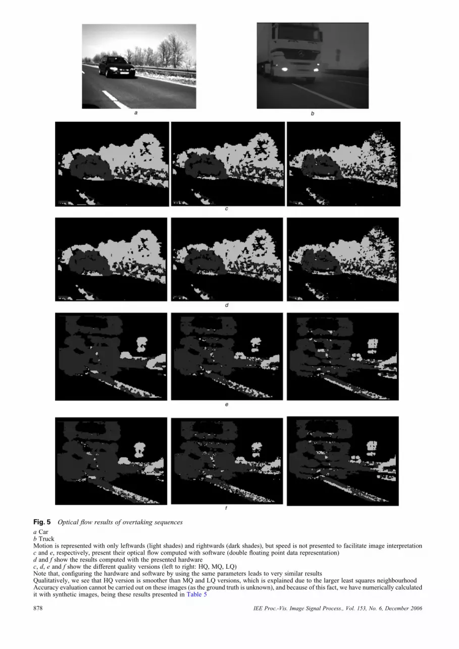
Fig. 5 Optical flow results of overtaking sequences
a Carb TruckMotion is represented with only leftwards (light shades) and rightwards (dark shades), but speed is not presented to facilitate image interpretationc and e, respectively, present their optical flow computed with software (double floating point data representation)d and f show the results computed with the presented hardwarec, d, e and f show the different quality versions (left to right: HQ, MQ, LQ)Note that, configuring the hardware and software by using the same parameters leads to very similar resultsQualitatively, we see that HQ version is smoother than MQ and LQ versions, which is explained due to the larger least squares neighbourhoodAccuracy evaluation cannot be carried out on these images (as the ground truth is unknown), and because of this fact, we have numerically calculatedit with synthetic images, being these results presented in Table 5
IEE Proc.-Vis. Image Signal Process., Vol. 153, No. 6, December 2006878

Table 5: Analysis of the performance cost Pc and accuracy cost Ac of the different systemversions described in Sections 3.2 and 3.3
System gates,
Kgates
Performance,
Kpps
Performance
cost, gates/pps
Mean error,
degree
Accuracy cost,
gates . degree
HSHQ 1234 1776 0.69 15.149 1.79
HSMQ 861 1776 0.48 16.17 1.33
MSMQ 747 625 1.2 16.17 1.16
LSLQ 580 400 1.45 23.33 1.3
System gates count the FPGA logic dedicated to processing operations and the embedded memoryutilisation. The accuracy of the different system versions is also shown in this table considering anoptical flow density of the hardware version of 91%. Note that in terms of accuracy there are nosignificant differences between HQ and MQ versions, but the error value significantly increases inthe LQ approach
Fig. 6 Performance and accuracy costs of different system gates
a Performance costb Accuracy costFrom these figures, HSMQ and MSMQ are respectively highlighted as the approaches with best accuracy against performance trade-off
performance and accuracy. Fig. 7 shows that the minimumis obtained in most cases for the HSMQ version, which rep-resents the best trade-off between resources consumption,accuracy and performance. The HSHQ approach demandshigh resources consumption, and therefore is not the bestchoice for a low-cost device. In contrast, LSLQ produceslow accuracy therefore not being a good choice for highprecision systems. Finally, MSMQ is the best option if wefocus on reducing the accuracy cost.
Though the previous analysis presents the HSMQ versionas the best trade-off version, the final decision relies on thetarget accuracy and on the available resources.
After this comparison, we can evaluate the requiredresources for a real-time VGA computing performanceusing the HSMQ version. A simple core replication tech-nique can be used to increase the computing performanceas discussed in Section 4. A real-time VGA resolutionversion requires computing 640 � 480 � 25 ¼ 7680 Kpps.Our PCI system is able to process up to 1776 Kpps andtherefore it is necessary to increase the resources by afactor of 4.3 in order to achieve the target performance.This is a significant increment, which makes this approachhardly affordable, but the main limitation is imposed bythe PCI data transmission that consumes about the 35% ofthe processing time. Current PCI transmission rates (usingPCI-Express or PCI-X) are more than four times fasterthan the used PCI version and allow increasing the perform-ance in a factor of 27%. This can be combined with increas-ing the system clock frequency. Our design implemented inthe Virtex II FPGA family is 17% faster than Virtex-E (as
IEE Proc.-Vis. Image Signal Process., Vol. 153, No. 6, December 2006
shown in the maximum clock rates included in Tables 1and 2). These modifications increase the global performance43% and thus, we only need to replicate the processing corethree times.
The stand-alone version does not suffer from the datatransmission limitation. Its performance is 41 000 Kpps
Fig. 7 System cost representation for the different systemalternatives
Each line represents different values of a which weights the perform-ance and accuracy costsExtreme cases are a ¼ 1 (optimises only performance cost) and a ¼ 0(focusing only on accuracy cost)Most of the cases show that the minimum is achieved by the HSMQversion, and therefore this should be pointed out as the version withthe best performance against accuracy cost trade-off
879

and allows achieving real-time VGA resolution at 26 fpswith just two cores. This is affordable and fits in currentFPGA devices such as the XC2V6000 Virtex II, whereasby being a stand-alone approach it can be used for mobileapplications such as robotics or embedded sensors too.
7 Conclusions and future work
Reconfigurable computing is a very active research field,which architectures and design methods evolve fast [25].The system described here shows how an optical-flow esti-mation circuit can be implemented as a customised DSPsystem using this technology. The paper describes a scal-able architecture that can work with large image data at aconventional video-frame rate (30 fps). System perform-ance, customisation feasibility and scalability, due to theFPGA technology and design strategy, allow the use ofthe system in diverse application fields as explained in pre-vious sections.
The accuracy of the estimated flow is essential for someof the possible applications outlined in this paper. Theresults of the hardware implementation are in the rangeof other software approaches considered in the study ofBarron et al. [1]. Therefore the performance of the hardwareis of reasonable quality provided that it computes in real-time (at a speed of 1776 Kpps with our PCI board systemat 27 MHz, 4100 Kpps with the stand-alone platform).These results outperform in accuracy and computing pre-vious power approaches.
The described computing platform can be fullyimplemented on a single chip (as a System-on-Chip),requiring only external memory support for temporalpartial results. This has been implemented on an FPGAdevice efficiently exploiting its inherent computing paralle-lism and pipeline resources. Furthermore, the modularity ofthe system enables the easy alteration of the computingscheme to target different computing speed against hard-ware cost trade-offs.
We have studied how the restricted bit-width of thedifferent computations affects the quality of the extractedoptic flow and compared the results obtained with softwareimplementations of the algorithm computed with doubleprecision.
In the future, we plan to apply the described approach indifferent applications such as tracking systems, robot navi-gation, video compression and so on. We will evaluate thesystem requirements for these applications. We will alsoexplore the implementation of multiscale approaches toobtain more reliable flow for different velocity scales.Finally, we also plan to further extend the parallelismlevel, decreasing the MNC values by adopting a fine-grainpipeline design strategy to increase the computing perform-ance. This will make feasible the utilisation of this kind ofspecific purpose computing circuits with high frame-ratecameras to increase the optical flow accuracy.
8 Acknowledgments
This work has been supported by the V EU research frame-work funds through the European Projects DRIVSCO(IST-016276-2), SENSOPAC (IST-028056) and theNational Spanish Grant DEPROVI (DPI2004-07032).
880
9 References
1 Barron, J.L., Fleet, D.J., and Beauchemin, S.: ‘Performance ofoptical-flow techniques’, Int. J. Comput. Vis., 1994, 12, (1)pp. 43–77
2 Lucas, B.D., and Kanade, T.: ‘An iterative image registration techniquewith an application to stereo vision’. Proc. DARPA Image UnderstandingWorkshop, April 1984, pp. 121–130
3 Liu, H.C., Hong, T.S., Herman, M., Camus, T., and Chellappa, R.:‘Accuracy vs efficiency trade-offs in optical flow algorithms’,Comput. Vis. Image Underst., 1998, 72, (3), pp. 271–286
4 McCane, B., Novins, K., Crannitch, D., and Galvin, B.: ‘Onbenchmarking optical flow’, Comput. Vis. Image Underst., 2001, 84,pp. 126–143
5 Baker, S., and Matthews, I.: ‘Lucas–Kanade 20 Years on: a unifyingframework’, Int. J. Comput. Vis., 2004, 56, (3), pp. 221–255
6 Niitsuma, H., and Maruyama, T.: ‘Real-time detection of movingobjects’, Lect. Notes Comput. Sci., 2004, 3203, pp. 1153–1157
7 Cobos, P., and Monasterio, F.: ‘FPGA implementation of Camuscorrelation optical flow algorithm for real time images’. Proc. and14th Int. Conf. on Vision Interface (VI2001), 2001, pp. 32–38
8 Maya-Rueda, S., and Arias-Estrada, M.: ‘FPGA processor for real-timeoptical flow computation’, Lect. Notes Comput. Sci., 2003, 2778,pp. 1103–1016
9 Correia, M.V., and Campilho, A.C.: ‘Real-time implementation of anoptical flow algorithm’. Int. Conf. on Pattern Recognition(ICPR2002), 2002, pp. 247–250
10 Martin, J.L., Zuloaga, A., Cuadrado, C., Lazaro, J., and Bidarte, U.:‘Hardware implementation of optical flow constraint equation usingFPGAs’. CVIU(98), June 2005, vol. 3, pp. 462–490
11 Celoxica Limited.: ‘Handel-C language reference manual’ (dk2.0Edn, 2003), RM-1003-4.0
12 Fleet, D.J., and Langley, K.: ‘Recursive filters for optical flow’, IEEETrans. Pattern Anal. Mach. Intell., 1995, 17, (1), pp. 61–67
13 Simoncelli, E.P., and Adelson, E.H., and Heeger, D.J.:‘Probability distributions of optical flow’. IEEE Conf. on ComputerVision and Pattern Recognition, Mauii, Hawaii, June 1991,pp. 310–315
14 Yamada, H., Tominaga, T., and Ichikawa, M.: ‘An autonomous flyingobject navigated by real-time optical flow and visual target detection’.Proc. IEEE Int. Conf. on Field-Programmable Technology, 2003,pp. 222–227
15 Jebara, T., Azarbayejani, A., and Pentland, A.: ‘3D structure from 2Dmotion’, IEEE Signal Process. Mag., 1999, 16, (3), pp. 66–84
16 Thomas, G.A., and Dancer, S.J.: ‘Improved motion estimation forMPEG coding within the RACE ‘COUGAR’ project’. IEE Int.Broadcasting Convention, IBC 95, September 1995, vol. 413,pp. 238–243
17 Tabatabai, A.J., Jasinschi, R.S., and Naveen, T.: ‘Motion estimationmethods for video compression. A review’, J. Franklin Inst., 1998,335B, (8), pp. 1411–1441
18 www.celoxica.com19 Benitez, D.: ‘Performance of reconfigurable architectures for
image-processing applications’, J. Syst. Archit., Euromicro J., 2003,49, (4–6), pp. 193–210
20 Horn, B.K.P., and Schunck, B.G.: ‘Determining optical flow’, Artif.Intell., 1981, 17, pp. 185–204
21 Cobos, P., and Monasterio, F.: ‘FPGA implementation of the Horn &Shunk optical flow algorithm for motion detection in real timeimages’. Proc. XIII Design of Circuits and Integrated SystemsConf., Madrid, Espana, November 1998, pp. 616–621
22 Diaz, J., Ros, E., Mota, S., Carrillo, R., and Agis, R.: ‘Real timeoptical flow processing system’, Lect. Notes Comput. Sci., 2004,3203, pp. 617–626
23 Fleet, D.J., and Jepson, A.D.: ‘Computation of component imagevelocity from local phase information’, Int. J. Comput. Vis., 1990,5, (1), pp. 77–104
24 Ortigosa, E.M., Canas, A., Ros, E., Ortigosa, P.M., Mota, S., andDıaz, J.: ‘Hardware description of multi-layer perceptrons with 3different abstraction levels’, Microprocess. Microsyst., 2006, 30, (7),pp. 435–444
25 Todman, T.J., Constantinides, G.A., Wilton, S.J.E., Mencer, O.,Luk, W., and Cheung, P.Y.K.: ‘Reconfigurable computing:architectures and design methods’, IEE Proc., Comput. Digit. Tech.,2005, 152, (2), pp. 193–207
IEE Proc.-Vis. Image Signal Process., Vol. 153, No. 6, December 2006