study of cyclic strain localization and fatigue crack initiation using fib technique
TRANSCRIPT

International Journal of Fatigue 39 (2012) 44–53
Contents lists available at ScienceDirect
International Journal of Fatigue
journal homepage: www.elsevier .com/locate / i j fa t igue
Study of cyclic strain localization and fatigue crack initiation using FIB technique
J. Man a,⇑, T. Vystavel b, A. Weidner c, I. Kubena a,d, M. Petrenec a, T. Kruml a, J. Polák a
a Institute of Physics of Materials ASCR, Zizkova 22, 616 62 Brno, Czech Republicb FEI, Podnikatelská 6, 612 00 Brno, Czech Republicc Institute of Materials Engineering, TU Bergakademie Freiberg, Gustav-Zeuner-Str. 5, 09596 Freiberg, Germanyd Institute of Materials Science and Engineering, Brno University of Technology, Technická 2, 616 69 Brno, Czech Republic
a r t i c l e i n f o
Article history:Received 20 January 2011Accepted 2 May 2011Available online 6 May 2011
Keywords:Fatigue crack initiationPersistent slip band (PSB)ExtrusionIntrusionNickelAustenitic steelFocused ion beam (FIB)
0142-1123/$ - see front matter � 2011 Elsevier Ltd. Adoi:10.1016/j.ijfatigue.2011.05.002
⇑ Corresponding author.E-mail address: [email protected] (J. Man).
a b s t r a c t
Focused ion beam (FIB) technique together with other advanced microscopic techniques was applied tostudy the early microstructural changes leading to fatigue crack initiation in cyclically strained polycrys-tals (nickel, 316L steel). Dislocation structures of persistent slip bands (PSBs) and surrounding matrixwere investigated in detail using electron channeling contrast imaging (ECCI) technique (concurrentlyin the FIB cross-section and on the specimen surface) and simultaneously with the surface relief topog-raphy using transmission electron microscopy (TEM) of thin surface foils prepared by in situ lift-out tech-nique. True shape of extrusions and intrusions and the path of initiated fatigue cracks were assessed inthree dimensions by FIB micro-tomography. The role of twin boundary in cyclic strain localization andfatigue crack initiation is discussed. Principal advantages and some limitations of FIB technique in fatiguecrack initiation studies in polycrystals are highlighted.
� 2011 Elsevier Ltd. All rights reserved.
1. Introduction
Focused ion beam (FIB) technique represents a modern toolwhich, in conjunction with other high resolution microscopic tech-niques, has been fruitfully used in various areas of materials re-search for studying and/or modifying materials systems at themicro and nanometer levels (for a review see e.g. [1,2]). The adop-tion of this technique in the studies of material fatigue has beenpursued, generally, at two different size-scales. Small-size-scale(micrometer and submicrometer) applications are mainly devotedto study the size effects in fatigue behavior and damage mecha-nisms of thin films/foils [3,4], degradation of coatings [5] or prep-aration of micro-sized bending beams of different geometries [6–10] (for a review on fatigue at small-size scales see also [11]).
Second size-scale which can be termed ‘normal-size-scale’ rep-resents the application of FIB to bulk polycrystalline materials with‘normal’ grain size and to specimens of traditional geometry andsize. Such studies can be thus considered as a continuation of‘classical’ fatigue damage investigations in which, however, FIBtechnique represents a novel tool capable to bring new originalexperimental data and a new insight into the damage mechanismsin cyclically strained polycrystals. In this context the FIB was firstlyutilized by Wang et al. [12] for documentation of environment-assisted
ll rights reserved.
fatigue crack profiles in a pipeline steel cyclically loaded in asimulated dilute groundwater solution. Marx et al. [13,14] usedthe FIB for the controlled artificial initiation of short fatigue cracksin individual grains of nickel-based superalloy to study their inter-action with selected interfaces (e.g. grain boundaries, precipitates).The three-dimensional (3D) reconstruction of the short crack pathusing the FIB tomography showed that the sub-surface orientationof grain boundaries is an important factor for interpreting crackgrowth rate at the surface [14]. The creation of very small sharpnotches of various well-defined geometries into testing specimensby the FIB has been adopted also by other authors to facilitate thesubsequent study of short fatigue crack growth [15–17]. Earlystages of crack propagation and subsurface short crack path in fer-ritic–martensitic dual phase steel was investigated with the FIBtomography by Motoyashiki et al. [18,19]. Subsurface observationsand crystallographic analyses using electron backscattering dif-fraction (EBSD) showed that fatigue cracks initiated and grew pref-erentially within ferrite grains as a result of single slip systemoperation. Cracks initiated at grain or phase boundaries close tothe surface were found to propagate in the bulk preferably in fer-rite grains by a shear mode. Weidner et al. [20] and Höppel et al.[21] used the FIB technique to document the specific surface andsubsurface features of fatigue damage in polycrystalline copperand aluminum alloys cycled below classical fatigue limit underconditions of so-called ultra-high-cycle fatigue (UHCF). Quiterecently, Takahashi et al. [22] combined a novel specimen

Nomenclature
EBSD electron backscattering diffractionECCI electron channeling contrast imagingFIB focused ion beamGB grain boundaryPSB persistent slip bandPSM persistent slip marking
SEM–FEG scanning electron microscopy equipped with fieldemission gun electron source
STEM scanning transmission electron microscopyTEM transmission electron microscopyTB twin boundary3D three-dimensional
J. Man et al. / International Journal of Fatigue 39 (2012) 44–53 45
preparation method based on FIB and high-voltage electronmicroscopy (HVEM) to reveal dislocation structures around a tipof a long fatigue crack originally located inside a bulk body ofFe–3.2 wt.% Si alloy.
In comparison with the above papers the present work is direc-ted primarily to the study of earlier stages of damage producedduring cyclic straining, namely to study the localization of cyclicplastic strain leading to surface relief formation and fatigue crackinitiation. Numerous experimental studies (for a review see e.g.[23–26]) proved the dominant role of cyclic strain localization inthe process of early fatigue damage. It is accompanied by changesin dislocation microstructure resulting in persistent slip band (PSB)formation. As a direct consequence of the persistent irreversibleslip activity localized within PSBs thin persistent slip markings(PSMs) are formed. PSMs consist of extrusions and intrusionswhich represent incipient fatigue crack sites. Various microscopictechniques have been adopted for the examination of surface reliefevolution and fatigue crack initiation [26]. Study of surface profilesof PSMs in individual cross-sections [27] and cumulative evolutionof PSMs on two perpendicular surfaces [28,29] using the FIB tech-nique were performed recently.
In the present study, the interest is again focused to the adop-tion of the FIB technique to study the early fatigue damage. Severalalternative examples of application of FIB technique accompaniedby other advanced microscopic techniques are demonstrated fortwo cyclically strained polycrystals – pure nickel and 316L austen-itic stainless steel. Results on dislocation structure of PSBs revealedboth by electron channeling contrast imaging (ECCI) technique andtransmission electron microscopy (TEM) are reported. True shapeof PSMs and the path of initiated fatigue cracks are documentedby TEM in surface foils produced by FIB and in the three dimen-sions by high resolution scanning electron microscopy equippedwith field emission gun electron source (SEM–FEG) using the serialFIB cross-sectioning (FIB micro-tomography). Experimental dataobtained are used for a discussion on the role of twin boundaries(TBs) in the initiation and early growth of fatigue cracks. The po-tential and the limitations related to the specific experimentaltechniques and further possible utilization of FIB to study the earlydamage in fatigued polycrystals are highlighted.
2. Experimental
2.1. Material, specimens and fatigue tests
Two polycrystalline face centered cubic (fcc) materials wereused in the present study. Flat specimens of commercially purenickel (99.9%) with a square cross-section of 5 � 5 mm2 and a
Table 1Chemical composition (in wt.%) of 316L austenitic stainless steel.
C Si Mn P S Cr Ni Mo Fe
0.018 0.42 1.68 0.015 0.001 17.6 13.8 2.6 Rest
gauge length of 8 mm were prepared from a cold rolled plate byspark erosion. Recrystallization of nickel specimens during a heattreatment at 850 �C for 1.5 h followed by furnace cooling resultedin the structure with almost random orientation distribution andaverage grain size of 80 lm (found by the linear intercept method).
316L austenitic stainless steel was supplied by Uddeholm (Swe-den) in the form of a 25 mm thick plate with the chemical compo-sition given in Table 1. The heat treatment, consisting of solutionannealing at 1080 �C and water quenching, resulted in an averagegrain size of 39 lm measured by the linear intercept method with-out counting TBs. Cylindrical specimens with threaded ends had agauge diameter and length of 8 and 12 mm, respectively. To facil-itate observations of surface relief evolution and fatigue crack ini-tiation a shallow notch in the form of a concave facet havingapproximately an elliptical shape was produced in the center ofthe specimen. Finished specimens were finally annealed at 600 �Cfor 1 h in vacuum.
All specimens were cycled at room temperature in air in sym-metrical push–pull cycle under strain control with constant plasticstrain amplitude to various stages of fatigue life (see below). Cen-tral parts of both specimen geometries were mechanically andelectrochemically polished before fatigue tests. Further detailsconcerning the materials and their cyclic stress–strain responsecan be found elsewhere [29,30].
2.2. Microscopic observations and FIB techniques
Study of dislocation structures corresponding to the areas oflocalized cyclic slip using the FIB technique were performed forboth materials but in a different manner. In polycrystalline nickel(specimen IV used in our recent study [30]) a FIB instrument ZeissCrossBeam 1540 XB was adopted for creation of craters in somegrains of interest. In order to reduce contingent artefacts and ob-tain fine surface on FIB cross-section plane, the surfaces for FIB sec-tioning were protected by a thin platinum layer and, in addition,the last FIB milling steps were always carried out with the lowestpossible current beam. Dislocation structures were then studied byECCI technique in high-resolution SEM–FEG (Zeiss Ultra 55 FESEM)directly in the specimen. In the case of 316L steel thin lamellaeacross PSMs within individual grains were prepared by in situlift-out technique [31,32] in a FEI Quanta 3D FEG (detail descrip-tion of this technique is given in the next section). These lamellaewere then examined either in a scanning TEM mode (STEM) withthe same instrument at lower accelerating voltage of 30 kV orusing a conventional TEM (Philips CM-12) operating at 120 kV.
For the serial cross-sectioning (FIB micro-tomography) of PSMsin 316L steel a combined SEM/FIB system FEI Dual Beam HeliosNanolab was used. A thin protective platinum layer was depositedon a small area of interest across PSMs before ion milling. U-shaped trench with one high quality cross-sectional surface per-pendicular to PSMs and to the specimen surface were producedby FIB. Subsequently series of surface relief profiles were obtainedby periodical removing the material within U-shaped craterparallel with the high quality cross-sectional surface by FIB using

46 J. Man et al. / International Journal of Fatigue 39 (2012) 44–53
automated software FEI Slice and View. In total, 975 sections weremilled and documented in four steps with different slice thick-nesses. The first step comprised 300 sections with slice thicknessof 20 nm, the second one 200 sections with finer milling step of12 nm, the third one 275 sections with 10 nm thickness followedby the last step comprising 200 sections with slice thickness of15 nm.
Fig. 2. In-lens SE (a) and BSE (b) micrographs of the FIB cut across GB1 (see Fig. 1) inpolycrystalline nickel fatigued for 32,000 cycles with eap = 5 � 10�4. Traces of GB1and TB1 both in the interior and on the specimen surface are indicated.
3. Results
3.1. Dislocation structure and the depth of PSBs in surface grains
Recent study of the cyclic plastic strain within PSBs in nickelpolycrystals revealed the broad spectrum of local strain amplitudeswith the average value around 1.5% [30]. Among factors which caninfluence both the local plastic shear in PSBs and the magnitude ofappertaining PSMs, the depth of PSBs and their dislocationarrangement beneath the specimen surface are of a great impor-tance. Another important factor, mainly in fatigued fcc metals, rep-resent TBs with their specific role in initiation and propagation ofshort fatigue cracks (see below).
Fig. 1a shows a grain of polycrystalline nickel cycled with theplastic strain amplitude eap = 5 � 10�4 for 30,000 cycles (60% Nf).PSMs belonging to two activated slip systems are apparent in thisgrain. The EBSD measurements [30,33] showed that this grain isdemarcated by TB1, TB2 and TB3 and a high angle grain boundaryGB1, as indicated in Fig. 1a and schematically shown in Fig. 1b. Thecalculation of trace angles for the TBs and PSMs both on the spec-imen surface and in the interior resulted in the construction of atentative subsurface profile of this grain and the evaluation ofthe PSB depth – see Fig. 1b.
To reveal the unknown trace of GB1 and the dislocation struc-ture below the specimen surface a combined FIB/ECCI technique
Fig. 1. (a) Surface relief in a grain of polycrystalline nickel fatigued for 30,000 cycleswith eap = 5 � 10�4, ECCI. (b) Schema of a virtual cut through the grain shown inFig. 1a. Traces of grain boundaries (GBs) and twin boundaries (TBs) found by EBSDand the position of FIB crater are indicated.
was adopted. After finishing the half-cycle experiments [30] addi-tional 2000 cycles with the same eap were applied to specimen IVfollowed by a regular FIB cross-sectioning across GB1 (see Fig. 1).Fig. 2a shows an in-lens SE micrograph of a part of FIB-cut. As itis apparent from this figure the grain boundaries GB1 and TB2can be clearly distinguished using the secondary electron image.Applying the BSE (backscattered electron) contrast the differentgrains become much more visible due to the grain orientation con-trast – see Fig. 2b.
In addition to the grain orientation contrast some other contrastappears, reminiscent of the dislocation arrangement contrast ob-tained by ECCI technique. The results obtained by ECCI techniqueare shown in Fig. 3a which documents dislocation arrangementboth on the specimen surface and on the FIB-cut obtained inSEM–FEG. To improve the quality of ECCI micrographs and to re-move some artefacts produced during FIB milling (see white orblack lines running vertically across FIB-cut plane in Fig. 2a andb, respectively) the specimen was shortly electropolished. This re-sulted in the slight rounding of FIB-cut edges (cf. Figs. 3a and 2a)and the removal of a thin surface layer (�4 lm). Detail of disloca-tion structure from the central area on the FIB cross-section planeshows Fig. 3b. A PSB lamella with ladder structure lying parallel toTB1 is clearly seen. This finding perfectly agrees with the surfacerelief observation of the PSM going along the intersection of TB1with the specimen surface (cf. Figs. 1 and 3b).
Another interesting feature apparent from Fig. 3b and moreclearly from Fig. 2b is the presence of grain boundary displace-ments in the direction of the Burgers vector in the place wherethe PSB meets GB1. Similar grain boundary displacements due tothe adjoining PSBs (nonparallel with twins) has been reported forbulk grains of fatigued copper [34,35] and nickel [36]. The
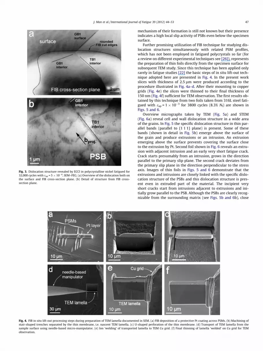
Fig. 3. Dislocation structure revealed by ECCI in polycrystalline nickel fatigued for32,000 cycles with eap = 5 � 10�4, SEM–FEG. (a) Overview of the dislocation both onthe surface and FIB cross-section plane. (b) Detail of structure from FIB cross-section plane.
Fig. 4. FIB in situ lift-out processing steps during preparation of TEM lamella documentestair-shaped trenches separated by the thin membrane, i.e. nascent TEM lamella. (c) Usample surface using needle-based micro-manipulator. (e) Ion ‘welding’ of transportedobservation.
J. Man et al. / International Journal of Fatigue 39 (2012) 44–53 47
mechanism of their formation is still not known but their presenceindicates a high local slip activity of PSBs even below the specimensurface.
Further promising utilization of FIB technique for studying dis-location structures simultaneously with related PSM profiles,which has not been employed in fatigued polycrystals so far (fora review on different experimental techniques see [26]), representsthe preparation of thin foils directly from the specimen surface forsubsequent TEM study. Since this technique has been applied onlyrarely in fatigue studies [22] the basic steps of in situ lift-out tech-nique adopted here are presented in Fig. 4. In the present workslices with thickness of 2.5 lm were produced according to theprocedure illustrated in Fig. 4a–d. After their mounting to coppergrids (Fig. 4e) the slices were thinned to their final thickness of150 nm (Fig. 4f) sufficient for TEM observation. The first results ob-tained by this technique from two foils taken from 316L steel fati-gued with eap = 1 � 10�3 for 3800 cycles (8.3% Nf) are shown inFigs. 5 and 6.
Overview micrographs taken by TEM (Fig. 5a) and STEM(Fig. 6a) reveal cell and wall dislocation structure in a wide areaof the grains. In Fig. 5 the specific dislocation structure in thin par-allel bands (parallel to {1 1 1} plane) is present. Some of thesebands (shown in detail in Fig. 5b) emerge above the surface ofthe grain and produce extrusions or an intrusion. An extrusionemerging above the surface prevents covering the surface closeto the extrusion by Pt. Second foil shown in Fig. 6 reveals an extru-sion with adjacent intrusion and an early very short fatigue crack.Crack starts presumably from an intrusion, grows in the directionparallel to the primary slip plane. The second crack deviates fromthe primary slip plane in the direction perpendicular to the stressaxis. Images of thin foils in Figs. 5 and 6 demonstrate that theextrusions and intrusions are closely linked with the specific dislo-cation structure of the PSBs and this dislocation structure is pres-ent even in extruded part of the material. The incipient veryshort cracks start from intrusions adjacent to extrusions and ini-tially grow parallel to the PSB. Although the PSBs are clearly recog-nizable from the surrounding matrix (see Figs. 5b and 6b), close
d in SEM. (a) FIB deposition of a protective Pt coating across PSMs. (b) Machining of-shaped perforation of the thin membrane. (d) Transport of TEM lamella from thelamella to TEM Cu grid. (f) Final thinning of lamella ‘welded’ on Cu grid for TEM
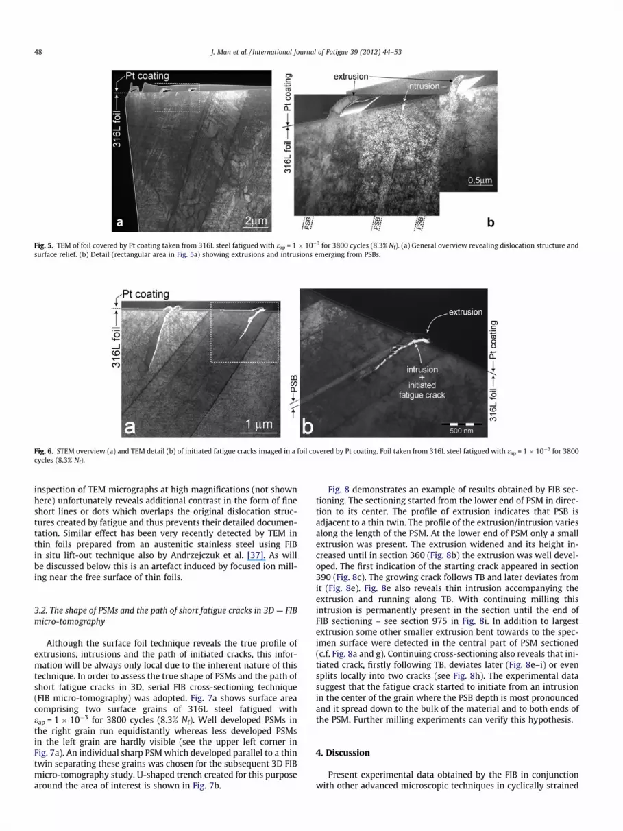
Fig. 5. TEM of foil covered by Pt coating taken from 316L steel fatigued with eap = 1 � 10�3 for 3800 cycles (8.3% Nf). (a) General overview revealing dislocation structure andsurface relief. (b) Detail (rectangular area in Fig. 5a) showing extrusions and intrusions emerging from PSBs.
Fig. 6. STEM overview (a) and TEM detail (b) of initiated fatigue cracks imaged in a foil covered by Pt coating. Foil taken from 316L steel fatigued with eap = 1 � 10�3 for 3800cycles (8.3% Nf).
48 J. Man et al. / International Journal of Fatigue 39 (2012) 44–53
inspection of TEM micrographs at high magnifications (not shownhere) unfortunately reveals additional contrast in the form of fineshort lines or dots which overlaps the original dislocation struc-tures created by fatigue and thus prevents their detailed documen-tation. Similar effect has been very recently detected by TEM inthin foils prepared from an austenitic stainless steel using FIBin situ lift-out technique also by Andrzejczuk et al. [37]. As willbe discussed below this is an artefact induced by focused ion mill-ing near the free surface of thin foils.
3.2. The shape of PSMs and the path of short fatigue cracks in 3D — FIBmicro-tomography
Although the surface foil technique reveals the true profile ofextrusions, intrusions and the path of initiated cracks, this infor-mation will be always only local due to the inherent nature of thistechnique. In order to assess the true shape of PSMs and the path ofshort fatigue cracks in 3D, serial FIB cross-sectioning technique(FIB micro-tomography) was adopted. Fig. 7a shows surface areacomprising two surface grains of 316L steel fatigued witheap = 1 � 10�3 for 3800 cycles (8.3% Nf). Well developed PSMs inthe right grain run equidistantly whereas less developed PSMsin the left grain are hardly visible (see the upper left corner inFig. 7a). An individual sharp PSM which developed parallel to a thintwin separating these grains was chosen for the subsequent 3D FIBmicro-tomography study. U-shaped trench created for this purposearound the area of interest is shown in Fig. 7b.
Fig. 8 demonstrates an example of results obtained by FIB sec-tioning. The sectioning started from the lower end of PSM in direc-tion to its center. The profile of extrusion indicates that PSB isadjacent to a thin twin. The profile of the extrusion/intrusion variesalong the length of the PSM. At the lower end of PSM only a smallextrusion was present. The extrusion widened and its height in-creased until in section 360 (Fig. 8b) the extrusion was well devel-oped. The first indication of the starting crack appeared in section390 (Fig. 8c). The growing crack follows TB and later deviates fromit (Fig. 8e). Fig. 8e also reveals thin intrusion accompanying theextrusion and running along TB. With continuing milling thisintrusion is permanently present in the section until the end ofFIB sectioning – see section 975 in Fig. 8i. In addition to largestextrusion some other smaller extrusion bent towards to the spec-imen surface were detected in the central part of PSM sectioned(c.f. Fig. 8a and g). Continuing cross-sectioning also reveals that ini-tiated crack, firstly following TB, deviates later (Fig. 8e–i) or evensplits locally into two cracks (see Fig. 8h). The experimental datasuggest that the fatigue crack started to initiate from an intrusionin the center of the grain where the PSB depth is most pronouncedand it spread down to the bulk of the material and to both ends ofthe PSM. Further milling experiments can verify this hypothesis.
4. Discussion
Present experimental data obtained by the FIB in conjunctionwith other advanced microscopic techniques in cyclically strained

Fig. 7. SEM image of 316L steel fatigued for 3800 cycles (8.3% Nf) with eap = 1 � 10�3 before (a) and after the creation of U-shaped FIB trench (b). Both images were taken withthe 52� specimen tilting. Small black arrow indicates the same position on both micrographs.
Fig. 8. (a) Detail of PSM in 316L steel sectioned by FIB tomography (see Fig. 7a). (b–i) Profiles of PSM and initiated fatigue crack in sections indicated in Fig. 8a. All SEM–FEGmicrographs were corrected for a 52� sample tilt. The scale of micrographs in Fig. 8b–i is identical.
J. Man et al. / International Journal of Fatigue 39 (2012) 44–53 49
polycrystalline nickel and 316L steel allow discussing some funda-mental aspects and mechanisms of initiation and early growth offatigue cracks. Applicability and some limitations of FIB in the earlyfatigue damage studies are advocated in the next section.
4.1. Cyclic strain localization and fatigue crack initiation
Cyclic loading of two fcc polycrystalline metals (pure nickel andaustenitic 316L steel) with constant plastic strain amplitude atambient temperature resulted in the localization of cyclic slip intoPSBs and the formation of prominent PSMs on the originally flatsurface. PSBs with the specific structure different form the matrixwere revealed on cross-sections of surface grains. Generally, they
were detected within grains but as will be discussed in more detailin the next section, PSBs and PSMs parallel to TBs are also present.
Our recent systematic study of the evolution of surface relieftopography in fatigued 316L steel [27] showed that PSMs start todevelop very early as surface extrusions. Static extrusions devel-oped quickly during the initial 1000 cycles. Their growth continuesand at the same time thin intrusions start to appear and deepenalong them. Experimental data on the surface relief topography,obtained in the present work by FIB cross-sectioning of PSMs(FIB micro-tomography and surface foils), are consistent with thisscenario [27]. TEM study of surface foils evidenced that extrusionsin later stages grow over the whole width of PSB lamellae followingthe trace of active slip plane (see Figs. 5 and 6). Well-developedribbon-like extrusions can be locally bent and thus hiding parallel
50 J. Man et al. / International Journal of Fatigue 39 (2012) 44–53
intrusions. It is clear from Fig. 5 that even tilting of the specimenwithin SEM chamber with electron beam parallel to the active slipplane need not yield in all cases the full information on PSM geom-etry. This fact should be also kept in mind in models based on theevolution of PSM morphology (PSM width and spacing) inferredonly from the surface observations [38].
The finding that not all extrusions were found to be accompa-nied by intrusions (cf. Figs. 5 and 6) is not in contradiction to theabove scenario since a great variability in PSM morphology is pres-ent (an intrusion can develop even between two parallel extru-sions – see Fig. 6a) and furthermore, intrusions along extrusionscan evolve only locally [27]. Unequivocal evidence on the intrusionoccurrence can be obtained by either atomic force microscopy(AFM) or SEM–FEG of inverse copy of specimen surface using plas-tic replicas [27,39] and/or FIB micro-tomography (see Fig. 8). Con-cerning the sign of extrusion–intrusion pairs and crack initiationsites [26,27], the present results show that intrusions accompany-ing extrusions have been developed at side B of the extrusionwhere the emerging active slip plane is inclined to the surface atan acute angle [27] (see Figs. 5, 6 and 8). These results are, how-ever, still very restricted and more systematic FIB observationsare needed to obtain a comprehensive view on true PSMsmorphology.
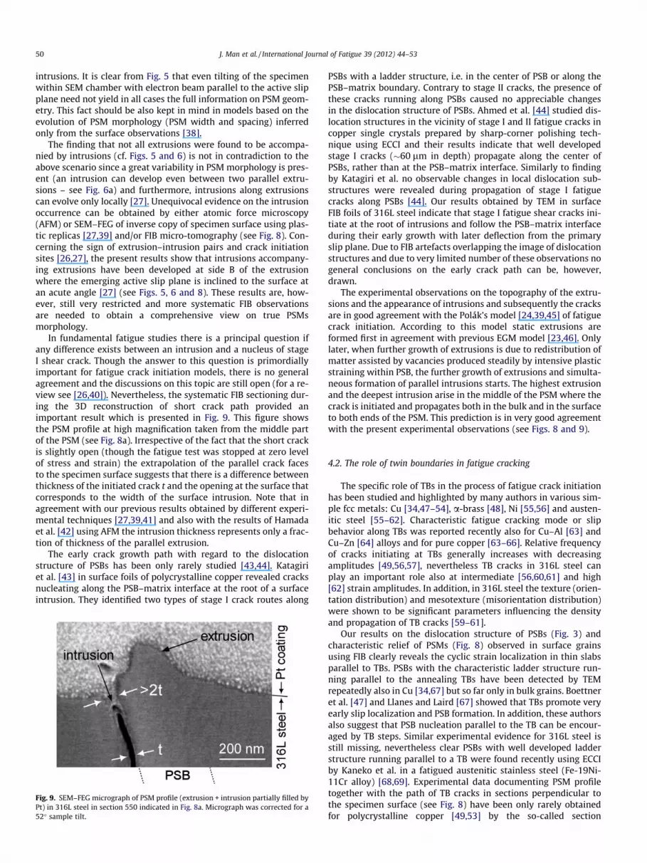
In fundamental fatigue studies there is a principal question ifany difference exists between an intrusion and a nucleus of stageI shear crack. Though the answer to this question is primordiallyimportant for fatigue crack initiation models, there is no generalagreement and the discussions on this topic are still open (for a re-view see [26,40]). Nevertheless, the systematic FIB sectioning dur-ing the 3D reconstruction of short crack path provided animportant result which is presented in Fig. 9. This figure showsthe PSM profile at high magnification taken from the middle partof the PSM (see Fig. 8a). Irrespective of the fact that the short crackis slightly open (though the fatigue test was stopped at zero levelof stress and strain) the extrapolation of the parallel crack facesto the specimen surface suggests that there is a difference betweenthickness of the initiated crack t and the opening at the surface thatcorresponds to the width of the surface intrusion. Note that inagreement with our previous results obtained by different experi-mental techniques [27,39,41] and also with the results of Hamadaet al. [42] using AFM the intrusion thickness represents only a frac-tion of thickness of the parallel extrusion.
The early crack growth path with regard to the dislocationstructure of PSBs has been only rarely studied [43,44]. Katagiriet al. [43] in surface foils of polycrystalline copper revealed cracksnucleating along the PSB–matrix interface at the root of a surfaceintrusion. They identified two types of stage I crack routes along
Fig. 9. SEM–FEG micrograph of PSM profile (extrusion + intrusion partially filled byPt) in 316L steel in section 550 indicated in Fig. 8a. Micrograph was corrected for a52� sample tilt.
PSBs with a ladder structure, i.e. in the center of PSB or along thePSB–matrix boundary. Contrary to stage II cracks, the presence ofthese cracks running along PSBs caused no appreciable changesin the dislocation structure of PSBs. Ahmed et al. [44] studied dis-location structures in the vicinity of stage I and II fatigue cracks incopper single crystals prepared by sharp-corner polishing tech-nique using ECCI and their results indicate that well developedstage I cracks (�60 lm in depth) propagate along the center ofPSBs, rather than at the PSB–matrix interface. Similarly to findingby Katagiri et al. no observable changes in local dislocation sub-structures were revealed during propagation of stage I fatiguecracks along PSBs [44]. Our results obtained by TEM in surfaceFIB foils of 316L steel indicate that stage I fatigue shear cracks ini-tiate at the root of intrusions and follow the PSB–matrix interfaceduring their early growth with later deflection from the primaryslip plane. Due to FIB artefacts overlapping the image of dislocationstructures and due to very limited number of these observations nogeneral conclusions on the early crack path can be, however,drawn.
The experimental observations on the topography of the extru-sions and the appearance of intrusions and subsequently the cracksare in good agreement with the Polák’s model [24,39,45] of fatiguecrack initiation. According to this model static extrusions areformed first in agreement with previous EGM model [23,46]. Onlylater, when further growth of extrusions is due to redistribution ofmatter assisted by vacancies produced steadily by intensive plasticstraining within PSB, the further growth of extrusions and simulta-neous formation of parallel intrusions starts. The highest extrusionand the deepest intrusion arise in the middle of the PSM where thecrack is initiated and propagates both in the bulk and in the surfaceto both ends of the PSM. This prediction is in very good agreementwith the present experimental observations (see Figs. 8 and 9).
4.2. The role of twin boundaries in fatigue cracking
The specific role of TBs in the process of fatigue crack initiationhas been studied and highlighted by many authors in various sim-ple fcc metals: Cu [34,47–54], a-brass [48], Ni [55,56] and austen-itic steel [55–62]. Characteristic fatigue cracking mode or slipbehavior along TBs was reported recently also for Cu–Al [63] andCu–Zn [64] alloys and for pure copper [63–66]. Relative frequencyof cracks initiating at TBs generally increases with decreasingamplitudes [49,56,57], nevertheless TB cracks in 316L steel canplay an important role also at intermediate [56,60,61] and high[62] strain amplitudes. In addition, in 316L steel the texture (orien-tation distribution) and mesotexture (misorientation distribution)were shown to be significant parameters influencing the densityand propagation of TB cracks [59–61].
Our results on the dislocation structure of PSBs (Fig. 3) andcharacteristic relief of PSMs (Fig. 8) observed in surface grainsusing FIB clearly reveals the cyclic strain localization in thin slabsparallel to TBs. PSBs with the characteristic ladder structure run-ning parallel to the annealing TBs have been detected by TEMrepeatedly also in Cu [34,67] but so far only in bulk grains. Boettneret al. [47] and Llanes and Laird [67] showed that TBs promote veryearly slip localization and PSB formation. In addition, these authorsalso suggest that PSB nucleation parallel to the TB can be encour-aged by TB steps. Similar experimental evidence for 316L steel isstill missing, nevertheless clear PSBs with well developed ladderstructure running parallel to a TB were found recently using ECCIby Kaneko et al. in a fatigued austenitic stainless steel (Fe-19Ni-11Cr alloy) [68,69]. Experimental data documenting PSM profiletogether with the path of TB cracks in sections perpendicular tothe specimen surface (see Fig. 8) have been only rarely obtainedfor polycrystalline copper [49,53] by the so-called section

J. Man et al. / International Journal of Fatigue 39 (2012) 44–53 51
micromilling technique developed by Hunsche and Neumann [70](see also [26]).
Numerous theories have been suggested to explain the TBs aspreferential sites for fatigue crack nucleation (see e.g. [71]). Themodels relevant here are those developed by Neumann and co-workers [49,53,57] and Blochwitz and co-workers [55,56,60,61].Our results on the cyclic strain localization and fatigue crack initi-ation are consistent with both of them. Neumann et al. [49,53,57]calculated the stress concentration near the emerging TB takinginto account the elastic incompatibility of the twin pair. Due toadditional shear stresses at the surface the local plasticity withinthe TBs will be triggered and since TBs in fcc metals run alongthe same planes as slip planes ({1 1 1} slip planes) it results instronger strain localization, i.e. the formation of PSBs, PSMs andcrack nuclei is triggered. Blochwitz et al. [55,56,60] taking into ac-count plastic strains in the observed slip systems modified slightlythis model for medium and higher strain amplitudes where plasticincompatibilities between grains cannot be neglected. The domi-nance of the TBs cracks can be also explained by additional surfacestresses [55,56,60]. According to both models, the strain localiza-tion zones once formed (in dependence of inclination of TB with re-spect to the stress axis) lead to TB crack initiation and propagationin the same manner as described above for PSBs.
Deflected path of the short crack in the vicinity of a thin twinreported here is in agreement with the results obtained recentlyby Blochwitz et al. [60,61] in textured 316L steel. Using periodicalstep-by-step removal of the surface and adoption of EBSD they re-vealed that the crack starting on the surface along the TB followslow-indexed crystallographic planes, mainly the {1 0 0} plane.
4.3. Applicability and limitations of FIB technique in the early fatiguedamage studies
In addition to utilization of FIB in short fatigue crack path stud-ies [12–14,18,19] the present work has demonstrated that the FIBtechnique in conjunction with other advanced (SEM–FEG, ECCI,EBSD) or ‘classical’ (TEM, STEM) high-resolution techniques repre-sents an effective but to date rather rarely employed tool for sys-tematic studies of the details of the mechanisms relevant to theearly fatigue damage in individual grains of cyclically strainedpolycrystals at sub-micrometer level. Besides observations of sur-face profiles of PSMs in individual cross-sections [20,21,27] andcumulative evolution of PSMs on two mutually perpendicular sur-faces [28,29] published recently, the present study shows that de-tailed data on the 3D form of PSMs and the initiation of fatiguecracks can be obtained using the FIB micro-tomography.
Dislocation structures corresponding to the surface PSMs can beidentified and the depth of PSBs (i.e. their length in the active slipdirection beneath the specimen surface) can be evaluated in thesections perpendicular to the specimen surface both using ECCIin individual FIB craters and TEM (STEM) in thin foils preparedby in situ lift-out technique. In addition, the ECCI technique willfacilitate such study in 3D and thus enable to reconstruct a spatialdislocation arrangement. In both cases, however, the interpretationof data on dislocation structures can be complicated by the addi-tional artefacts coming from the FIB milling process [37,72]. Sev-eral possible ways for a reduction of the damage introduced bythe Ga+ ion bombardment has been discussed in detail by Kieneret al. [72]. The relevant effective ways during the FIB preparationof thin foils by in situ lift-out technique are the substantial reduc-tion of ion energies (acceleration voltage) during the final thinningof both sides of the TEM lamellae and the use of a low incidenceangle of the impinging Ga+ ions. Such procedure during the finalthinning of TEM lamellae has not been, unfortunately, performedin the present work and thus some additional contrast due to theFIB artefacts ‘overlapping’ dislocation structures induced by
fatiguing was detected during the detail observations of surfacefoils by TEM at high magnification. Nevertheless, the related workson the final thinning of TEM lamellae with a low ion energies(�5 keV) are in progress.
In addition to the ways mentioned above the present workshowed that there is another reliable way to avoid the FIB artefacts– an additional slight electropolishing. This relatively simple meth-od is, unfortunately, applicable only in the case of ECCI observationof dislocation structures in craters produced by FIB directly in thespecimen surface (see Fig. 3). This will, however, result in a slightrounding of the FIB-edges and removal of a thin layer with a pos-sible partial modification of PSMs (both extrusions and intrusions)contours.
In spite of the above mentioned possible artefacts arising duringthe FIB milling process the most promising use of this technique inthe studies of early fatigue damage of polycrystalline materialsrepresents the preparation of thin foils directly from specimen sur-face by in situ lift out technique for subsequent TEM analysis. Thefirst attempt has been done in the present work (see Figs. 5 and 6).Generally, such results are still very rare and up to date they couldbe obtained only by the demanding technique of surface foil afterelectrodeposition [43,73,74] or combining the sharp-corner polish-ing technique with ECCI [44]. In comparison with these methods,suitable primarily for single crystals, surface FIB foil technique willenable systematic study of the fatigue crack initiation via simulta-neous visualization of PSM profiles and dislocation structures ofappertaining PSBs and surrounding matrix in preselected individ-ual grains. The path of initiated cracks can be identified and atthe same time related to the respective dislocation arrangementand crystallographic orientation of a grain.
All these data will be invaluable for checking the validity andfurther advancement of theoretical models of surface relief forma-tion leading to fatigue crack initiation. It should be however, keptin mind that the surface FIB foil technique will always give only lo-cal information. PSMs exhibit appreciable variability of surfacemorphology even within one grain and this variability can changewith continuing cycling [27]. This indicates the importance of sta-tistical approach in the study of the early fatigue damage.
5. Summary and conclusions
Adoption of the FIB technique to the experimental study of cyc-lic strain localization and surface relief formation leading to fatiguecrack initiation in cyclically strained polycrystals allows drawingthe following conclusions:
(1) FIB coupled with other advanced microscopic techniques(SEM–FEG, ECCI, EBSD, TEM) represent an effective tool forsystematic studies of the early fatigue damage in individualgrains of cyclically strained polycrystals.
(2) Detailed data on the 3D topography of PSMs and the initia-tion of fatigue cracks can be obtained and the subsurfacepath of initiated short fatigue cracks can be reconstructed.
(3) Dislocation structure of PSBs appertaining to surface PSMs(with their possible 3D reconstruction) can be identifiedusing ECCI. The most promising use of FIB is the preparationof thin surface foils for TEM enabling simultaneous visuali-zation of PSM profiles and corresponding dislocationsubstructures.
(4) The depth of PSBs (i.e. PSB length in the active slip direction)below the specimen surface can be evaluated.
The results of the early fatigue damage study of polycrystallinenickel and 316L austenitic stainless steel cyclically strained withconstant plastic strain amplitude to early stages of fatigue lifeusing the FIB can be summarized as follows:

52 J. Man et al. / International Journal of Fatigue 39 (2012) 44–53
(1) Cyclic strain localization into PSBs with specific dislocationstructure followed by the formation of distinctive surfacePSMs can occur both within grains and parallel to twinboundaries suitably oriented with respect to the stress axis.
(2) Extrusions growing in later stages over the whole width ofPSBs are accompanied (somewhere only locally) by thin par-allel intrusions.
(3) Detection of intrusions can be in some cases difficult due tothe local bending of well-developed mature extrusions.
(4) Surface cracks start locally from subtle deep surface intru-sions, follow initially the PSB/matrix interface and later candeflect from the primary slip plane.
(5) Limited experimental data suggests that there is a differencebetween intrusions and initiated fatigue cracks.
(6) Experimental data on the form and growth of extrusionsand intrusions and early crack nucleation support vacancymodels of surface relief formation and crack initiation inwhich redistribution of matter between PSBs and matrixis considered.
Acknowledgements
Support of this work by the research project No. AV0Z20410507 of ASCR and by the Grants P108/10/2371 of Czech Sci-ence Foundation (GACR) and Sk 21/24-2 of German Research Foun-dation (DFG) is gratefully acknowledged.
References
[1] Phaneuf MW. Applications of focused ion beam microscopy to materialsscience specimens. Micron 1999;30:277–88.
[2] Munroe PR. The application of focused ion beam microscopy in the materialsciences. Mater Charact 2009;60:2–13.
[3] Schwaiger R, Kraft O. Size effects in the fatigue behavior of thin Ag films. ActaMater 2003;51:195–206.
[4] Schwaiger R, Dehm G, Kraft O. Cyclic deformation of polycrystalline Cu films.Philos Mag 2003;83:693–710.
[5] Cairney JM, Tsukano R, Hoffman MJ, Yang M. Degradation of TiN coatingsunder cyclic loading. Acta Mater 2004;52:3229–37.
[6] Takashima K, Higo Y, Sugiura S, Shimojo M. Fatigue crack growth behavior ofmicro-sized specimens prepared from an electroless plated Ni–P amorphousalloy thin film. Mater Trans JIM 2001;42:68–73.
[7] Zhang GP, Takashima K, Shimojo M, Higo Y. Fatigue behavior of microsizedaustenitic stainless steel specimens. Mater Lett 2003;57:1555–60.
[8] Motz C, Schöberl T, Pippan R. Mechanical properties of micro-sized copperbending beams machined by the focused ion beam technique. Acta Mater2005;53:4269–79.
[9] Yang Y, Yao N, Imasogie B, Soboyejo WO. Nanoscale and submicron fatiguecrack growth in nickel microbeams. Acta Mater 2007;55:4305–15.
[10] Kiener D, Motz C, Grosinger W, Weygand D, Pippan R. Cyclic response ofcopper single crystal micro-beams. Scripta Mater 2010;63:500–3.
[11] Connolley T, McHugh PE, Bruzzi M. A review of deformation and fatigue ofmetals at small size scales. Fatigue Fract Eng Mater Struct 2005;28:1119–52.
[12] Wang Y-Z, Revie RW, Phaneuf MW, Li J. Application of focused ion beam (FIB)microscopy to the study of crack profiles. Fatigue Fract Eng Mater Sruct1999;22:251–6.
[13] Marx M, Schäf W, Vehoff H, Holzapfel C. Interaction of microcracks withselected interfaces: focused ion beam for a systematic crack initiation. MaterSci Eng A 2006;435–436:595–601.
[14] Holzapfel C, Schäf W, Marx M, Vehoff H, Mücklich F. Interaction of cracks withprecipitates and grain boundaries: understanding crack growth mechanismsthrough focused ion beam tomography. Scripta Mater 2007;56:697–700.
[15] Ferrié E, Buffière J-Y, Ludwig W, Gravouil A, Edwards L. Fatigue crackpropagation: in situ visualization using X-ray microtomography and 3Dsimulation using the extended finite element method. Acta Mater2006;54:1111–22.
[16] Tesch A, Pippan R, Trautmann K-H, Döker H. Short cracks initiated in Al 6013–T6 with the focused ion beam (FIB)-technology. Int J Fatigue2007;29:1803–11.
[17] Kotecky O, Degallaix S, Polák J. Growth of short fatigue cracks emanating fromnotches in an austenitic-ferritic stainless steel. Key Eng Mater 2007;348–349:117–20.
[18] Motoyashiki Y, Brückner-Foit A, Sugeta A. Investigation of small crackbehaviour under cyclic loading in a dual phase steel with an FIB tomographytechnique. Fatigue Fract Eng Mater Struct 2007;30:556–64.
[19] Motoyashiki Y, Brückner-Foit A, Sugeta A. Microstructural influence on smallfatigue cracks in a ferritic-martensitic steel. Eng Fract Mech 2008;75:768–78.
[20] Weidner A, Amberger D, Pyczak F, Schönbauer B, Stanzl-Tschegg S, MughrabiH. Fatigue damage in copper polycrystals subjected to ultrahigh-cycle fatiguebelow the PSB threshold. Int J Fatigue 2010;32:872–8.
[21] Höppel HW, Prell M, May L, Göken M. Influence of grain size and precipitateson the fatigue lives and deformation mechanisms in the VHCF-regime. ProcEng 2010;2:1025–34.
[22] Takahashi Y, Tanaka M, Higashida K, Noguchi H. High-voltage electron-microscopic observation of cyclic slip behavior around a fatigue crack tip in aniron alloy. Scripta Mater 2009;60:717–20.
[23] Mughrabi H. Dislocations in fatigue. In: Dislocations and properties ofreal materials, book no. 323. London: The Institute of Metals; 1985. p.244–62.
[24] Polák J. Cyclic deformation, crack initiation, and low-cycle fatigue. In: Milne I,Ritchie RO, Karihaloo B, editors. Comprehensive structural integrity, vol.4. Amsterdam: Elsevier; 2003. p. 1–39.
[25] Mughrabi H. Cyclic slip irreversibilities and the evolution of fatigue damage.Metall Mater Trans A 2009;40:1257–79.
[26] Man J, Obrtlík K, Polák J. Extrusions and intrusions in fatigued metals. Part 1.State of the art and history. Philos Mag 2009;89:1295–336.
[27] Man J, Klapetek P, Man O, Weidner A, Obrtlík K, Polák J. Extrusions andintrusions in fatigued metals. Part 2. AFM and EBSD study of the early growthof extrusions and intrusions in 316L steel fatigued at room temperature. PhilosMag 2009;89:1337–72.
[28] Polák J, Man J, Vystavel T, Zouhar L. Fatigue crack initiation in crystallinematerials–experimental evidence and models. Key Eng Mater 2007;345–346:379–82.
[29] Polák J, Man J, Vystavel T, Petrenec M. The shape of extrusions and intru-sions and initiation of stage I fatigue cracks. Mater Sci Eng A 2009;517:204–11.
[30] Weidner A, Man J, Tirschler W, Klapetek P, Blochwitz C, Polák J, et al. Half-cycleslip activity of persistent slip bands at different stages of fatigue life ofpolycrystalline nickel. Mater Sci Eng A 2008;492:118–27.
[31] Ohnishi T, Koike H, Ishitani T, Tomimatsu S, Umemura K, Kamino T. Anew focused-ion-beam microsampling technique for TEM observation ofsite-specific areas. In: Proc 25th international symposium for testing andfailure analysis (ISTFA ’99). Materials Park, Ohio: ASM International; 1999.p. 449–53.
[32] Langford RM, Clinton C. In situ lift-out technique using a FIB-SEM system.Micron 2004;35:607–11.
[33] Weidner A, Beyer R, Blochwitz C, Holste C, Schwab A, Tirschler W. Slip activityof persistent slip bands in polycrystalline nickel. Mater Sci Eng A 2006;435–436:540–6.
[34] Winter AT, Pedersen OB, Rasmussen KV. Dislocation microstructures infatigued copper polycrystals. Acta Metall 1981;29:735–48.
[35] Huang HL, Ho NJ. The study of fatigue in polycrystalline copper under variousstrain amplitude at stage I: crack initiation and propagation. Mater Sci Eng A2000;293:7–14.
[36] Weidner A, Skrotzki W. Cyclic slip activity of PSBs in bulk and surface grains.Int J Fatigue 2010;32:851–5.
[37] Andrzejczuk M, Płocinski T, Zielinski W, Kurzydłowski KJ. TEMcharacterization of the artefacts induced by FIB in austenitic stainless steel. JMicrosc Oxford 2010;237:439–42.
[38] Chan KS, Tian JW, Yang B, Liaw PK. Evolution of slip morphology and fatiguecrack initiation in surface grains of Ni200. Metall Mater Trans A2009;40:2545–56.
[39] Polák J, Man J, Obrtlík K. AFM evidence of surface relief formation and modelsof fatigue crack nucleation. Int J Fatigue 2003;25:1027–36.
[40] Mughrabi H. Fatigue, an everlasting materials problem – still en vogue. ProcEng 2010;2:3–26.
[41] Polák J, Man J, Obrtlík K, Kruml T. The shape of extrusions and intrusionsproduced by cyclic straining. Z Metallkd 2003;94:1327–30.
[42] Hamada AS, Karjalainen LP, Puustinen J. Fatigue behavior of high-Mn TWIPsteels. Mater Sci Eng A 2009;517:68–77.
[43] Katagiri K, Omura A, Koyanagi K, Awatani J, Shiraishi T, Kaneshiro H. Earlystage crack tip dislocation morphology in fatigued copper. Metall Trans A1977;8:1769–73.
[44] Ahmed J, Wilkinson AJ, Roberts SG. Electron channelling contrast imagingcharacterization of dislocation structures associated with extrusion andintrusion systems and fatigue cracks in copper single crystals. Philos Mag A2001;81:1473–88.
[45] Polák J. On the role of point defects in fatigue crack initiation. Mater Sci Eng1987;92:71–80.
[46] Essmann U, Gösele U, Mughrabi H. A model of extrusions and intrusions infatigued metals. I. Poin-defect production and the growth of extrusions. PhilosMag A 1981;44:405–26.
[47] Boettner RC, McEvily AJ, Liu YC. On the formation of fatigue cracks at twinboundaries. Philos Mag 1964;10:95–106.
[48] Thompson AW. The influence of grain and twin boundaries in fatigue cracking.Acta Metall 1972;20:1085–94.
[49] Neumann P, Tönnessen A. Cyclic deformation and crack initiation. In: RitchieRO, Starke EA Jr, editors. Proc third int conf on fatigue and fatigue thresholds(FATIGUE ’87), vol. I. West Midlands, UK: EMAS; 1987. p. 3–22.
[50] Polák J, Liškutín P. Nucleation and short cracks growth in fatiguedpolycrystalline copper. Fatigue Fract Eng Mater Struct 1990;13:119–33.
[51] Lim LC, Tay YK, Fong HS. Fatigue damage and crack nucleation mechanisms atintermediate strain amplitudes. Acta Metall Mater 1990;38:595–601.

J. Man et al. / International Journal of Fatigue 39 (2012) 44–53 53
[52] Bayerlein M, Mughrabi H. Fatigue crack initiation and early cracks growth incopper polycrystals – effects of temperature and environment. In: Miller KJ, delos Rios ER, editors. Short fatigue cracks, ESIS 13. London: MechanicalEngineering Publications; 1992. p. 55–82.
[53] Neumann P. Analytical solution for the incompatibility stresses at twinboundaries in cubic crystals. In: Wu X-R, Wang Z-G, editors. Proc of theseventh international fatigue congress (FATIGUE ’99), vol. 1/4. Beijing/WestMidlands, UK: Higher Education Press/EMAS; 1999. p. 107–14.
[54] Sumigawa T, Kitamura T, Ohishi K. Slip behaviour near a grain boundary inhigh-cycle fatigue of poly-crystal copper. Fatigue Fract Eng Mater Struct2004;27:495–503.
[55] Blochwitz C, Richter R, Tirschler W, Obrtlík K. The effect of local textures onmicrocrack propagation in fatigued f.c.c. metals. Mater Sci Eng A 1997;234–236:563–6.
[56] Blochwitz C, Richter R. Plastic strain amplitude dependent surface path ofmicrostructurally short fatigue cracks in face-centered cubic metals. Mater SciEng A 1999;267:120–9.
[57] Heinz A, Neumann P. Crack initiation during high cycle fatigue of an austeniticsteel. Acta Metall Mater 1990;38:1933–40.
[58] Rolim Lopes LC, Thomson CB, Randle V. Correlation between grain boundarystructure and cyclic plastic strain below yield stress. In: Rie K-T, Portella PD,editors. Low cycle fatigue and elasto-plastic behaviour ofmaterials. Oxford: Elsevier Science; 1998. p. 327–32.
[59] Mineur M, Villechaise P, Mendez J. Influence of the crystalline texture on thefatigue behavior of a 316L austenitic stainless steel. Mater Sci Eng A2000;286:257–68.
[60] Blochwitz C, Tirschler W. Influence of texture on twin boundary cracks infatigued austenitic stainless steel. Mater Sci Eng A 2003;339:318–27.
[61] Blochwitz C, Jacob S, Tirschler W. Grain orientation effects on the growth ofshort fatigue cracks in austenitic stainless steel. Mater Sci Eng A2008;496:59–66.
[62] Kamaya M. Influence of bulk damage on crack initiation in low-cycle fatigue of316 stainless steel. Fatigue Fract Eng Mater Struct 2009;33:94–104.
[63] Qu S, Zhang P, Wu SD, Zang QS, Zhang ZF. Twin boundaries: strong or weak?Scripta Mater 2008;59:1131–4.
[64] Zhang P, Duan QQ, Li SX, Zhang ZF. Cyclic deformation and fatigue crackingbehaviour of polycrystalline Cu, Cu–10 wt% Zn and Cu–32 wt% Zn. Philos Mag2008;88:2487–503.
[65] Ma J. Nanoscale study of cyclic deformation behaviour and mechanism ofannealing twin. Mater Sci Eng A 2006;427:282–8.
[66] Ma J. AFM study of the morphology and micro-strain of slip bands in twinunder cyclic deformation. Mater Sci Eng A 2007;457:63–8.
[67] Llanes L, Laird C. The role of annealing twin boundaries in the cyclicdeformation of f.c.c. materials. Mater Sci Eng A 1992;157:21–7.
[68] Kaneko Y, Hashimoto S. Observation of dislocation structures of fatiguedmetallic materials by scanning electron microscopy. JEOL News 2003;38:20–3.
[69] Taniguchi T, Kaneko Y, Hashimoto S. Fatigue lives of a ferritic stainless steelcontaining deformation twins. Key Eng Mater 2007;353–358:283–6.
[70] Hunsche A, Neumann P. Quantitative measurement of persistent slip bandprofiles and crack initiation. Acta Metall 1986;34:207–17.
[71] Sangid MD, Maier HJ, Sehitoglu H. The role of grain boundaries on fatigue crackinitiation – An energy approach. Int J Plast 2011;27:801–21.
[72] Kiener D, Motz C, Rester M, Jenko M, Dehm G. FIB damage of Cu and possibleconsequences for miniaturized mechanical tests. Mater Sci Eng A2007;459:262–72.
[73] Lukáš P, Klesnil M, Krejcí J. Dislocations and persistent slip bands in coppersingle crystals fatigued at low stress amplitude. Phys Status Solidi1968;27:545–58.
[74] Lukáš P, Klesnil M. Dislocation structures in fatigued Cu–Zn single crystals.Phys Status Solidi 1970;37:833–42.