state of new york (nys) pre-filed evidentiary hearing exhibit
TRANSCRIPT
UNITED STATESNUCLEAR REGULATORY COMMISSION
ATOMIC SAFETY AND LICENSING BOARD
-----------------------------------------------------------}{In re:
License. Renewal Application Submitted by
Entergy Nuclear Indian Point 2, LLC,Entergy Nuclear Indian Point 3, LLC, andEntergy Nuclear Operations, Inc.
-----------------------------------------------------------}{
Docket Nos. 50-247-LR; 50-286-LR
ASLBP No. 07-858-03-LR-BD01
DPR-26, DPR-64
December 12, 2011
REPORT OF
DR.ROBERTC.DEGENEFF
IN SUPPORT OF
CONTENTION NYS-8
TABLE OF CONTENTS
Page
Summary of Findings l
1. Introduction 1
2. NRC Regulations 4
3. Comparison of Transformers to Included Components 6
Electric Cables 6
Pipes 7
Heat Exchanger 7
Steam Generator 7
Reactor Vessel & Containment 8
4. Comparison of Transformers to Excluded Components 8
Batteries 13
Power inverters 13
Power supply 13
5. Age related degradation in transformers to notreadily monitored and management of age relateddegradation requires a comprehensive inspection program 14
6. Consequences of Inadequate Management of Transformers 17
7. Entergy's Argument 22
7.1 Declaration of Dr. Dobbs 24
7.2 Declaration of R. Rucker 27
7.3 Declaration of J.W. Craig 28
1
TABLE OF CONTENTS
Page
7.4 Documents Produced by Entergy 31
8. Conclusion 32
References 33
11
Report of Dr. Robert C. DegeneffSubmitted with Pre-Filed Testimony
Contention NYS-8
Summary of Findings
The uncontroversial consensus of the technical community is that transformers are:static components, which do not experience changes in configuration or state duringtheir operation; components in which age related degradation is not readilymonitored; and components whose useful life may exceed 60 years and for whichperiodic replacement is not generally scheduled. After reviewing 10 C.F.R. §54.21(a), I can also conclude that transformers are components that are moresimilar to components for which aging management review is required than tocomponents for which aging management review is not required.
In refusing to conduct an aging management review of transformers, Entergyconflates the properties of the transformer with the properties of the electricityflowing through the transformer. Furthermore, Entergy's arguments in thislicensing proceeding about the ease of monitoring age related degradation are beliedby their own maintenance records, which show that age related degradation intransformers is a common phenomena, detection of which requires invasiveinspections of the sort that Entergy requires are not necessary.
1. Introduction
"The almost universal use of t~e alternating-current system for the transmissionand distribution of electrical energy is largely due to the fact that circuits ofdifferent voltages can be linked by a simple, convenient, and reliable device - thestatic transformer... " L.F. Blume, Chapter 1, page 1 of Transformer Engineering,Copyright 1938,1951 General Electric Company. The transformer may be assumedto be an essentially perfect device for the transformation of electrical power, e.g., theinput volt-amperes will equal the output volt-amperes. The turns ratio (ratio of theturns contained in the input winding divided by the turns in the output winding)may be taken as the voltage transformation ratio between the input and outputwinding and the inverse of the current transformation ratio.
Transformers typically contain two insulated wires that are wrapped or coiledaround a form called a "core" that is frequently made of iron or metal alloys.Transformers contain a primary winding (a winding supplying the energy to thecircuit) and one or more secondary windings (the windings through which the powerflows out of the transformer). In its most basic form, a transformer need not evencontain a physical core: two coils of wire adjacent to one another will act as atransformer. Two wires or cables in proximity will also act as a transformer in thatvarying current in one wire or conductor will induce voltages and currents in theadjacent wire or conductor.
1
Report of Dr. Robert C. DegeneffSubmitted with Pre-Filed Testimony
Contention NYS-8
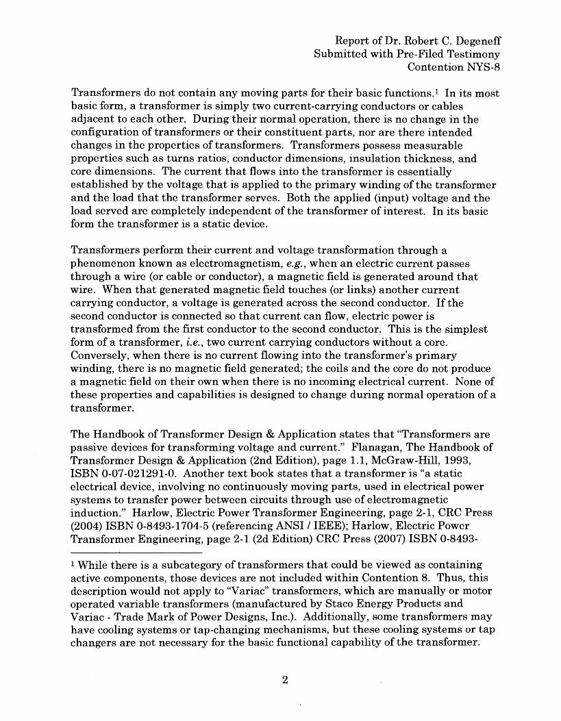
Transformers do not contain any moving parts for their basic functions. 1 In its mostbasic form, a transformer is simply two current-carrying conductors or cablesadjacent to each other. During their normal operation, there is no change in theconfiguration of transformers or their constituent parts, nor are there intendedchanges in the properties of transformers. Transformers possess measurableproperties such as turns ratios, conductor dimensions, insulation thickness, andcore dimensions. The current that flows into the transformer is essentiallyestablished by the voltage that is applied to the primary winding of the transformerand the load that the transformer serves. Both the applied (input) voltage and theload served are completely independent of the transformer of interest. In its basicform the transformer is a static device.
Transformers perform their current and voltage transformation through aphenomenon known as electromagnetism, e.g., when an electric current passesthrough a wire (or cable or conductor), a magnetic field is generated around thatwire. When that generated magnetic field touches (or links) another currentcarrying conductor, a voltage is generat~dacross the second conductor. If thesecond conductor is connected so that current can flow, electric power istransformed from the first conductor to the second conductor. This is the simplestform of a transformer, i.e., two current carrying conductors without a core.Conversely, when there is no current flowing into the transformer's primarywinding, there is no magnetic field generated; the coils and the co~e do not producea magnetic field on their own when there is no incoming electrical current. None ofthese properties and capabilities is designed to change during normal operation of atransformer.
The Handbook of Transformer Design & Application states that "Transformers arepassive devices for transforming voltage and current." Flanagan, The Handbook ofTransformer Design & Application (2nd Edition), page 1.1, McGraw-Hill, 1993,ISBN 0-07-021291-0. Another text book states that a transformer is "a staticelectrical device, involving no continuously moving parts, used in electrical powersystems to transfer power between circuits through use of electromagneticinduction." Harlow, Electric Power Transformer Engineering, page 2-1, CRC Press(2004) ISBN 0-8493-1704-5 (referencing ANSI I IEEE); Harlow, Electric PowerTransformer Engineering, page 2-1 (2d Edition) CRC Press (2007) ISBN 0-8493-
1 While there is a subcategory of transformers that could be viewed as containingactive components, those devices are not included within Contention 8. Thus, thisdescription would not apply to "Variac" transformers, which are manually or motoroperated variable transformers (manufactured by Staco Energy Products andVariac - Trade Mark of Power Designs, Inc.). Additionally, some transformers mayhave cooling systems or tap-changing mechanisms, but these cooling systems or tapchangers are not necessary for the basic functional capability of the transformer.
2
Report of Dr. Robert C. DegeneffSubmitted with Pre-Filed Testimony
Contention NYS-8
9186-5. The sixth edition of the IEEE Standard Dictionary of Electrical andElectronic Terms includes the following definition of transformer: "A static electricaldevice consisting of a winding, or two or more coupled windings, with or without amagnetic core, for introducing mutual coupling between electrical circuits." IEEEStandard Dictionary of Electrical and Electronic Terms, IEEE Std 100-1996 (6th
Edition), page 1131, ISBN 1-55937-833-6 (1996). This same definition is repeatedin IEEE Standard Terminology for Power and Distribution Transformers, IEEE StdC57.12.80TM-2010. NRC has acknowledged that "transformers perform theirprimary function without the use of moving parts." NlJREG/CR-5753, at 50.
Transformers are built with certain properties, which depend on the intendedfunction of the transformer. These properties, including the turns ratio, conductorsize, insulation type and thickness, and cooling capability, among others, remainconstant during the lifetime of a given transformer. These properties ensure thateven if differing levels of power may be sent through the transformer during itslifetime, each level of power will be transformed in a uniform manner, dependent onthe design properties of the transformer. In this way, the power will be transformedin a uniform manner that can be predicted based on the design properties of thetransformer.
Transformers play important roles in the operation of a nuclear power plant.Transformers can come in a variety of sizes. By way of example, some largetransformers used at power reactors likely would include Station AuxiliaryTransformers, Station Service Transformers, Station Black Out (SBO) transformer,15 KVA GRD Transformer for the gas turbines, instrumentation transformers, andlighting transform'ers. Some smaller transformers in use at power reactors wouldinclude those used in control circuits. A review of various publicly availableelectrical one-line diagrams for IP2 and IP3 reflects that there are numerouselectrical transformers ranging from 345 KV to 120 volts located throughout theIndian Point facilities that perform a function described in §§ 54.4(a)(1)/(2) and (3).The role of some of the transformers in providing for safety functions is described inChapter 8 (Electrical Systems) of the lJFSAR for each Unit on pp. 1167-68, 1333-43of the UFSAR for IP3 and on pp. 1039-50 of the UFSAR for IP2. The lJFSAR forIP2 includes a one-line diagram for the electrical plan for IP2; that diagramidentifies some of the transformers at IP2 and the central role that they play in theelectrical system of the plant. IP2 UFSAR, figure 8.2-1, 8.2-2, ElectricalDistribution & Transmission System, DWG. NO. A250907-21. A diagram for IP3'selectrical system identifies transformers and the central role that they play at thatplant. Indian Point No.3 Nuclear Power Plant, Electrical Distribution &Transmission System, DWG NO 9321-F-33853, REV 17.
3
Report of Dr. Robert C. DegeneffSubmitted with Pre-Filed Testimony
Contention NYS-8
A transformer can be represented by the following electrical engineering symbol:
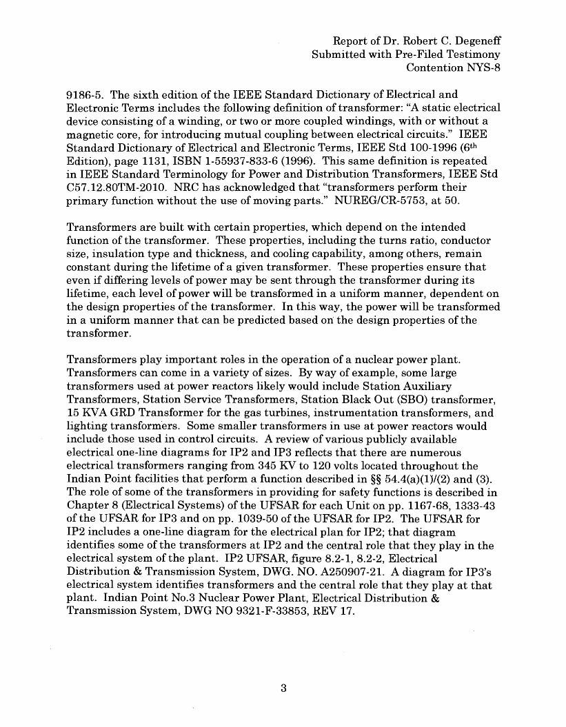
Drawings of electrical systems for the Indian Point facilities use the followingsymbol to denote a transformer in the electrical systems:
See, e.g.: IP2 Updated Final Safety Analysis Report (UFSAR), Revision 20, DrawingA250907-21, Title: Electrical Distribution and Transmission System - UFSAR Fig.No. 8.2-1 and 8.2-2 (PDF frame 1069 of 1698); see also Indian Point No.3 NuclearPower Plant, Electrical Distribution & Transmission System, DWG NO 9321-F33853, REV 17 (ML090400895).
2. NRC Regulations
In preparing this declaration, I reviewed 10 C.F.R. § 54.21. Specifically, §54.21(a)(I) provides:
Structures and components subject to an aging managementreview shall encompass those structures and components-
(i) That perform an intended function, as described in § 54.4,without moving parts or without a change in configuration orproperties. These structures and components include, but arenot limited to, the reactor vessel, the reactor coolant systempressure boundary, steam generators, the pressurizer, piping,pump casings, valve bodies, the core shroud, componentsupports, pressure retaining boundaries, heat exchangers,ventilation ducts, the containment, the containment liner,electrical and mechanical penetrations, equipment hatches,
4
Report of Dr. Robert C. DegeneffSubmitted with Pre-Filed Testimony
Contention NYS-8
seismic Category I structures, electrical cables and connections,cable trays, and electrical cabinets, excluding, but not limited to,pumps '(except casing), valves (except body), motors, dieselgenerators, air compressors, snubbers, the control rod drive,ventilation dampers, pressure transmitters, pressure indicators,water level indicators, switchgears, cooling fans, transistors,batteries, breakers, relays, switches, power inverters, circuitboards, battery chargers, and power supplies; and
(ii) That are not subject to replacement based on a qualifiedlife or specified time period.
10 C.F.R. § 54.21(a)(I)(i), (ii).
Based on my review of 10 C.F.R. § 54.21(a)(I), it is my understanding that NRCregulations provide that structures or components without moving parts or withouta change in configuration or properties are included within the scope of the rule.The regulation contains a non-exhaustive list of such structures and components.My understanding of the regulation is that those structures and components are tobe included in an aging management review. The regulation also provides anothernon-exhaustive list of structures and components that are not within the scope ofthe rule. The NRC has elected to exclude this second category of structures andcomponents from aging management review. 10 C.F.R. § 54.21(a)(I)(i).
The text of § 54.21(a)(I)(i) expressly includes the following components as withinthe first category and therefore within the scope of the regulation: the reactorvessel, the reactor coolant system pressure boundary, steam generators, thepressurizer, piping, pump casings, valve bodies, the core shroud, componentsupports, pressure retaining boundaries, heat exchangers, ventilation ducts, thecontainment, the containment liner, electrical and mechanical penetrations,equipment hatches, seismic Category I structures, electrical cables and connections,cable trays, and electrical cabinets. Because these components are expresslyincluded in the first category, they are subject to aging management review. 10C.F.R. § 54.21(a)(I)(i).
On the other hand, pumps (except casing), valves (except body), motors, dieselgenerators, air compressors, snubbers, the control rod drive, ventilation dampers,pressure transmitters, pressure indicators, water level indicators, switchgears,cooling fans, transistors, batteries, breakers, relays, switches, power inverters,circuit boards, battery chargers, and power supplies are included in the secondcategory and therefore are not subject to aging management review. 10 C.F.R. §54.21(a)(I)(i).
5
Report of Dr. Robert C. DegeneffSubmitted with Pre-Filed Testimony
Contention NYS-8
3. Comparison of Transformers to Included Components
In preparing this report, I also reviewed the Atomic Safety and Licensing Board'sJuly 31,2008 decision concerning the admission of various contentions includingthe admission of New York State Contention No.8, which concerns transformers.The Board further stated: "In addressing this contention, the Board will require,inter alia, representations from the parties to help us determine whethertransformers are more similar to the included, or to the excluded, componentexamples." July 31,2008 ASLB Memorandum and Order at 45.
I have reviewed a table previously submitted by the State in this proceeding thatcompares the included and excluded structures and components expressly listed in10 C.F.R. § 54.21(a)(I) to transformers. This table entitled, "Comparison of VariousStructures and Components," demonstrates that transformers are similar to thecategory of structures and components that are expressly listed as included in 10C.F.R. § 54.21(a)(I) in that transformers, like the included structures andcomponents, contain no moving parts, do not change properties or configuration,and do not undergo any change of state. The table summarizes whether a structureor component contains moving parts, experiences a change in configuration orproperties, experiences a change in state, is active or passive, and is specificallylisted in § 54.21(a)(I).2
To be sure, many of these "included" structures and components do change the"properties" of the fluids, electric power, or fuel that travel through or are containedwithin those structures and components; however, the "properties" of the includedstructures and components themselves do not change during their intended use.Likewise, a transformer may increase or decrease the voltage of the electrical powerthat passes through that transformer; however, the properties of the transformer,itself, do not change during its intended use.
Electric Cables. Electric cables do not have moving parts. The purpose of theelectric cable is to transmit electric power from one point to another. When ACcurrent passes through a cable, a varying magnetic field is generated around thecable. The magnitude and phase of the currents through the cable and voltages
2 In my review of 10 C.F.R. § 54.21(a)(I)(i), I observed that the provision does notcontain the terms "active," "passive," or a "change in state." I am also aware thatthe Commissioners have stated "Further the Commission has concluded that 'achange in configuration or properties' should be interpreted to include 'a change instate,' which is a term sometimes found in the literature relating to 'passive.'" 60Fed. Reg. at 22,477.
6
Report of Dr. Robert C. DegeneffSubmitted with Pre-Filed Testimony
Contention NYS-8
across the electric cable may change, but the physical properties of the cable (e.g.,conductor shape, material composition of the cable, cable insulation and theresultant resistance, capacitance per unit length) are not designed to change.Cables are included as within the scope of § 54.21(a)(I). The physical laws thatdescribe how the magnetic field is developed around a cable are exactly the samephysical laws that describe how a magnetic field is developed in a transformer.
In many applications cables are contained in parallel raceways. In the simplestconfigurations, two cables are laid parallel to each other in a raceway. Theequations that describe the electrical performance of these cables are exactly thesame equations that describe the performance of a two winding transformer with noiron core. For both cables and transformers, the properties of the device, itself, donot change during its intended use.
Pipes. The properties of fluids contained within a pipe may change. The propertiesof such fluids include temperature, pressure, velocity, specific volume, specificweight, viscosity, density, etc. The phase of the fluid in a pipe may even change.Yet, a pipe is a component which is included within the scope of § 54.21(a)(I). Apipe's diameter may narrow at a particular location or the pipe may contain arestriction (e.g., "elbow," or "tee") that may change the velocity and/or pressure ofthe fluid contained in the pipe; however, the properties of the pipe itself have notchanged. Stated differently, the properties of the contents of the pipe (a fluid) maychange, but not the conduit,(pipe). The pipe itself is not designed to change its ownproperties. In fact, if the pipe's properties changed it would present significantengineering design problems. These comparisons demonstrate that transformersare analogous to the category of structures and components that are expressly listedas included in 10 C.F.R. § 54.21(a)(I). Like pipes, transformers contain no movingparts, do not change properties or configuration, and do not undergo any change ofstate.
Heat Exchanger. The temperature properties of the fluids contained within a heatexchanger may change, as can a fluid's flow rates. The properties of the fluid in aheat exchanger change in a manner similar to the change in voltage and currentthat takes place in a transformer when electrical power is passing through it. Theheat exchanger (another component which is included within the scope of §54.21(a)(I», like the transformer, is not designed to change its own properties.
.Steam Generator. The properties and the state of the fluids in a steam generatormay both change. The fluid's temperature may increase and the fluid's state maychange from liquid to steam. However, the steam generator itself (anothercomponent which is included within the scope of § 54.21(a)(I) is not designed tochange its own properties during its normal use.
7
Report of Dr. Robert C. DegeneffSubmitted with Pre-Filed Testimony
Contention NYS-8
Reactor Vessel & Containment. Further, various nuclear processes do occurwithin the reactor vessel, the containment liner, or the containment, but thosecomponents are included in § 54.21(a)(1). Those processes cause some wear onthose components, and that wear is the subject of aging management.
Turning to transformers, transformers do not have moving parts. The magnitude ofthe currents and voltages in and out of a transformer may change, but theproperties and configuration of the transformer and its capabilities (ability totransform electric power from one voltage to another) are not designed to changeduring normal operation. Furthermore, transformers themselves do not experiencea "change of state" as that term is commonly used.
4. Comparison of Transformers to Excluded Components
Because Entergy focuses so heavily on the similarity of transformers to transistors,I will describe at some length the distinctions between the two components, andthen more briefly contrast transformers with other electrical components that are"excluded" from aging management review.
Unlike the abovementioned components, the properties of a transistor, itself, dochange during its normal intended use. Transistors are commonly three wire solidstate devices initially made from germanium (Ge) and silicon (Si) semiconductormaterial. A semiconductor is a material whose resistivity can be changed byapplying an electric current to the material; a semiconductor's electrical resistancecan be made to vary between that of a conductor (full flow or very low resistance)and that of an insulator (very low flow or very high resistance). An externalelectrical field or voltage changes a semiconductor's resistivity - which is a propertyof the semiconductor device itself. A transistor clearly, measurably, undergoes achange in its properties and, in some cases, a change in state (from conductor toinsulator).
The change in resistivity that occurs in the semiconductor device can be thought ofas a valve whose position may be changed through an external electric stimulus. Asmall change in the voltage input to a basic transistor gate drive changes theproperties (resistance and/or conductance) of the semiconductor's main conductingpath. Nothing of this nature is present in a transformer. As a result of this appliedcontrol voltage, the semiconductor changes its properties and, depending upon thegate control input, will act as an insulator, or a conductor, or variable resistorcontrolling large currents in its main conducting path. These variable devicecharacteristics are the direct result of a change in properties of the semiconductor.Many transistors such as silicon controlled rectifiers undergo a "change of state"from a conductor to an insulator depending on the applied voltage and the polarityof the applied voltage. In contrast, a transformer's physical characteristics are
8
Report of Dr. Robert C. DegeneffSubmitted with Pre-Filed Testimony
Contention NYS-8
completely independent of the applied voltage and the polarity of the appliedvoltage. The turns ratio, which determines how the power is transformed, is notdependent on what kind of power is fed to the tran'sformer. The turns ratio isdesigned and built into the transformer when it is assembled and that turns ratiobecomes one of its properties. Once a turns ratio has been built into thetransformer, the turns ratio does not change. 3 If a transformer were like atransistor, the ratio between the voltages of input and output power would dependon the amount of power and the size of the load. This does not occur, however,because unlike a transistor, the transformer does not change its properties inoperation.
An examination of how the current flowing through a transformer changes providesanother illustration of the distinction between the properties of the transformer andthe properties of the electricity flowing through it. When 100 volts are applied tothe primary winding of a two winding isolation transformer where the transformerhas a one to one turns ratio and the secondary winding of the transformer isconnected to a 50 ohm load, the current flowing through the transformer is 2amperes. If the voltage is increased to 150 volts the current increases to 3 amperes,while if the voltage is reduced to 50 volts the current reduces to 1 ampere. Theconnecting conductors, transformer and load have not changed. Only the currentflowing in the system as a function of the applied voltage has changed, according toa fixed ratio, which ratio is an unchanging property of the transformer.
The example of a cable illustrates the difference between transformers andtransistors. If 100 volts are applied to two cables connected to a 50 ohm load, thecurrent in the cables will be 2 amperes. If the voltage is increased to 150 volts, thecurrent increases to 3 amperes, while if the voltage is reduced to 50 volts thecurrent reduces to 1 ampere. In other words, both the transformer and the cablefunction in the same way. To suggest that the properties or state of the transformerchange is incorrect. If one were to observe only the properties of the electricityflowing through either a one to one transformer or through two cables, theperformance of the two devices would be indistinguishable.
A transistor relies on external power to operate (like a transformer) but also (unlikea transformer) requires an external source of energy to control or determine itselectrical conducting properties.4 Because of this intended ability to vary its
3 Some transformers have mechanical devices to change the turns ratio. See note 1,supra.
4 I understand that when the Commissioners modified the license renewalregulations they said "'a change in configuration or properties' should be interpretedto include 'a change in state,' which is a term sometimes found in the literaturerelating to passive. For example a transistor can 'change its state' and therefore
9
Report of Dr. Robert C. DegeneffSubmitted with Pre-Filed .Testimony
Contention NYS-8
resistivity, it is possible to continuously control the operation of a transistor and itsvalve-like function by changing its state (its resistivity). Accordingly, a transistorand most other solid state devices are considered active devices whose propertiescontinuously change through external control.
An analogy may be helpful to understand the active nature of a transistor. Onemight imagine a simple garden hose that has properties such as internal andexternal diameters, length, stiffness, and materials of construction. It may alsohave design capacities such as maximum flow rate and temperature limitations. Iwould suggest that a hose is a passive device similar to a pipe or electrical cable.When water flows through a hose, the properties of the hose do not change.Increasing or decreasing the flow does not change the properties of the hose.However, if some external force is applied to the hose such as squeezing or crimpingthe hose with one's hand or foot in a controlled manner, the properties of the hoseare changed as a result of changing the effective internal diameter of the hose.Turning back to electrical components, a resistor is an electrical component thatrestricts the flow of electrical current, but it does so at a fixed rate much like asection of hose or pipe. In much the same way that a person might squeeze a hose,the invention of the transistor made it possible for a small control voltage from anexternal source to change the electrical properties of a fixed resistance previouslyprovided by a resistor. Thus, the name "transistor." The semiconductor in thetransistor changes state in much the same way that the diameter of the hose isdecreased when someone squeezes the hose. The resistivity properties of atransistor can be changed on an ongoing manner through the application of anexternal electrical stimulus. This is not true of a transformer; whereas a transistorresponds to changes in external forces like a hose that is squeezed, the properties ofa transformer do not change at all in normal operation, just as the properties of apipe, e.g., its diameter, will not change unless the pipe is squeezed to its failingpoint.
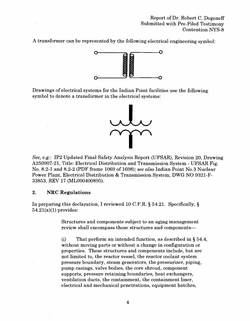
I have also prepared two drawings to assist the court and the parties anddemonstrate the differences between transformers and· transistors.
would not be screened in under this description." Final Rule, Nuclear Power PlantLicense Renewal; Revisions, 60 Fed. Reg. 22,461, 22,477 (May 8, 1995).
10
Report of Dr. Robert C. DegeneffSubmitted with Pre-Filed Testimony
Contention NYS-8
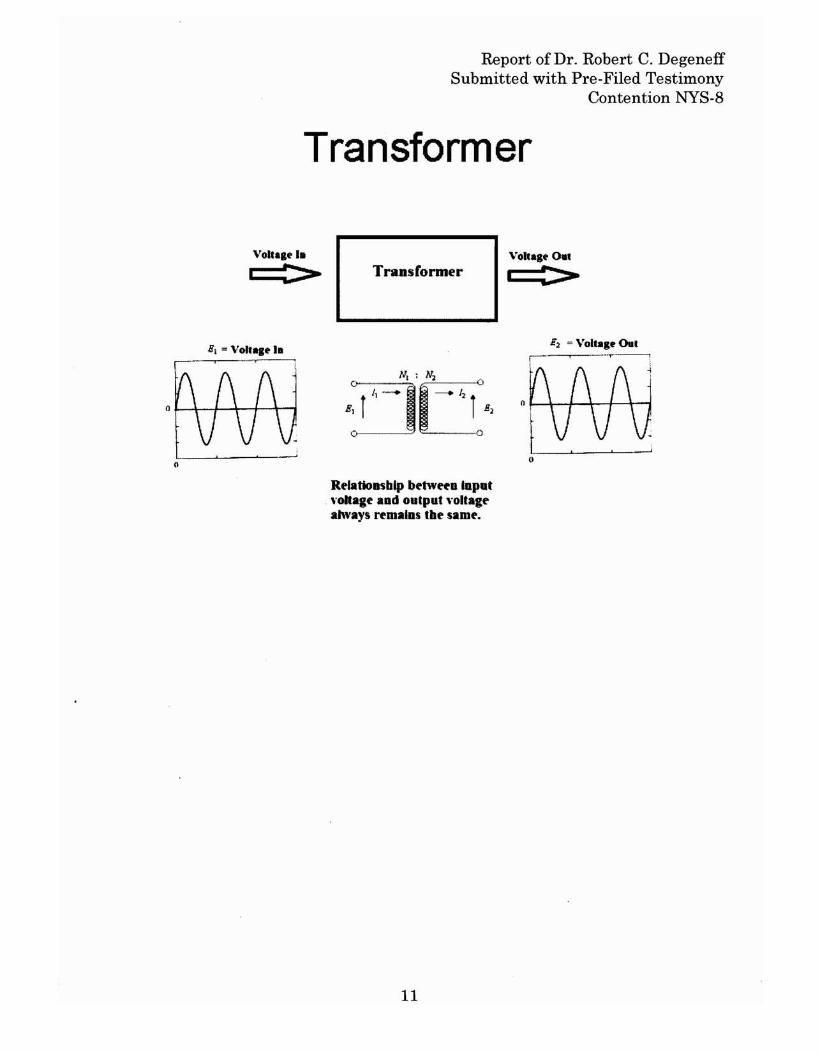
Transformer
Voha.C'I.
:> TransCormer
Relationsblp be-mefa laput\'ohage aad output "ollagealways rfmalns tbe samf.
11
VollagC' 0 ••
I :>
E~ = Voltal. Oul
,0---<-----'-----'
Report of Dr. Robert C. DegeneffSubmitted with Pre-Filed Testimony
Contention NYS-8
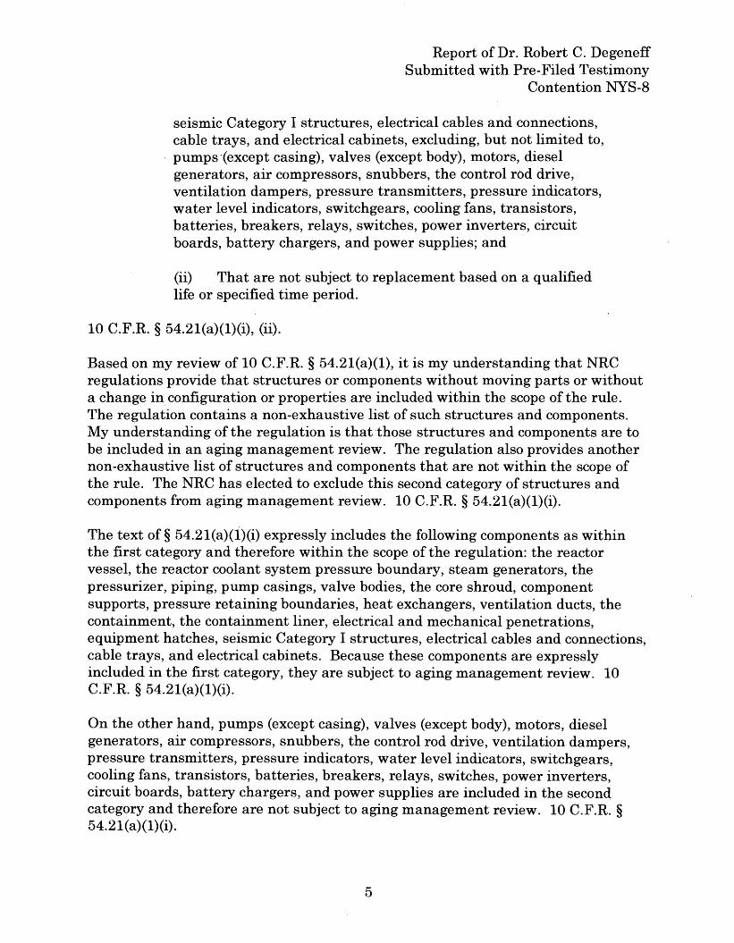
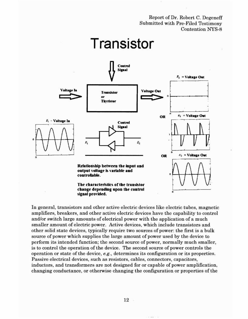
Transistor.n CODCro'V·.....
Tra.slslororn,.-';'tor
o
Relatlonsblp between tbe Input andoutput ,-oItage Is uriable andcontrollable.
TbE' cbaractertSiks or tbe transistorcbange depf'ndlng upon the controlsigDaI pro\idtd.
OR
OR
Ii~ = VO'C.I~ o.c
In general, transistors and other active electric devices like electric tubes, magneticamplifiers, breakers, and other active electric devices have the capability to controland/or switch large amounts of electrical power with the application of a muchsmaller amount of electric power. Active devices, which include transistors andother solid state devices, typically require two sources of power: the first is a bulksource of power which supplies the large amount of power used by the device toperform its intended function; the second source of power, normally much smaller,is to control the operation of the device. The second source of power controls theoperation or state of the device, e.g., determines its configuration or its properties.Passive electrical devices, such as resistors, cables, connectors, capacitors,inductors, and transformers are not designed for or capable of power amplification,changing conductance, or otherwise changing the configuration or properties of the
12
Report of Dr. Robert C. DegeneffSubmitted with Pre-Filed Testimony
Contention NYS-8
device based upon an external control signal. 5 A more detailed description ofseveral of the "excluded" components illustrates their active nature:
Batteries. A battery produces electrical energy through a chemical reaction. Theelectrolytic properties of the chemicals, which constitute the battery change as thebattery discharges. In contrast, only the properties of the power flowing through atransformer change. The key properties of a battery that has been discharged willbe different from a full battery, but the key properties of a transformer that has hadpower flow through it will not be different from the properties of a transformerwhich has not been used.
Power inverters. Like a transistor, the inverter requires an external control inorder to perform its intended function. An inverter takes direct current power andconverts it into alternating current power. Inverters accomplish this powerconversion by controlling the magnitude, frequency and wave shape of the outputpower. The external control allows the power inverter to vary the relationshipbetween the input and output power, e.g., to decrease or increase the magnitude,frequency, and wave shape of the power, which is wholly unlike the transformer, inwhich the relationship between the input and output power is fixed and determinedby the characteristics of the power fed into it and the load supplied by it. Moreover,the transformer will not change the magnitude, frequency or wave shape of thepower flowing through it.
Power supply. A power supply takes alternating current power and converts itinto direct current power. Like the transistor and the inverter, the power supplyrequires an external control to perform its intended function. Power suppliesrequire voltage regulation, which regulation is controlled by an electric controlcircuit, apart from the main circuit, which converts the bulk power. The externalcontrol will adjust the properties of the power supply to deliver the desired voltageand current to the load that is being supplied. The voltage and current supplied bythe transformer, on the other hand, depend on the properties of the load, itself, andnot on the properties of the transformer, which only controls the turns ratio. Thepower supply, decides, so to speak, what kind of power to supply to the load,whereas the transformer can only supply the power that the load requires.
5 Unlike transformers, electrical breakers, relays and switches all changeconfiguration in performing their intended function. I do not treat them in detail,because it is undisputed that transformers do not change their configuration inperforming their intended function.
13
Report of Dr. Robert C. DegeneffSubmitted with Pre-Filed Testimony
Contention NYS-8
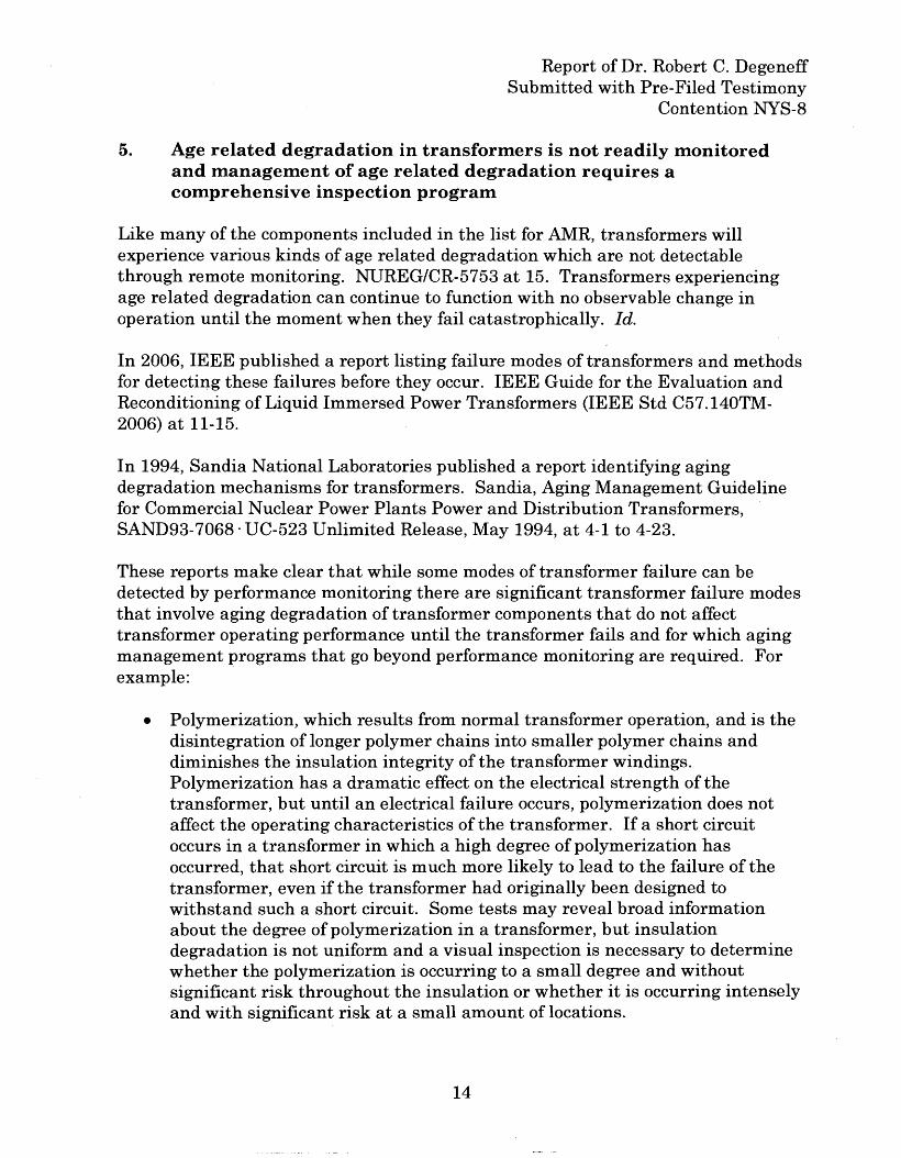
5. Age related degradation in transformers is not readily monitoredand management of age related degradation requires acomprehensive inspection program
Like many of the components included in the list for AMR, transformers willexperience various kinds of age related degradation which are not detectablethrough remote monitoring. NlJREG/CR-5753 at 15. Transformers experiencingage related degradation can continue to function with no observable change inoperation until the moment when they fail catastrophically. Id.
In 2006, IEEE published a report listing failure modes of transformers and methodsfor detecting these failures before they occur. IEEE Guide for the Evaluation andReconditioning of Liquid Immersed Power Transformers (IEEE Std C57.140TM2006) at 11-15.
In 1994, Sandia National Laboratories published a report identifying agingdegradation mechanisms for transformers. Sandia, Aging Management Guidelinefor Commercial Nuclear Power Plants Power and Distribution Transformers,SAND93-7068· UC-523 Unlimited Release, May 1994, at 4-1 to 4-23.
These reports make clear that while some modes of transformer failure can bedetected by performance monitoring there are significant transformer failure modesthat involve aging degradation of transformer components that do not affecttransformer operating performance until the transformer fails and for which agingmanagement programs that go beyond performance monitoring are required. Forexample:
• Polymerization, which results from normal transformer operation, and is thedisintegration of longer polymer chains into smaller polymer chains anddiminishes the insulation integrity of the transformer windings.Polymerization has a dramatic effect on the electrical strength of thetransformer, but until an electrical failure occurs, polymerization does notaffect the operating characteristics of the transformer. If a short circuitoccurs in a transformer in which a high degree of polymerization hasoccurred, that short circuit is much more likely to lead to the failure of thetransformer, even if the transformer had originally been designed towithstand such a short circuit. Some tests may reveal broad informationabout the degree of polymerization in a transformer, but insulationdegradation is not uniform and a visual inspection is necessary to determinewhether the polymerization is occurring to a small degree and withoutsignificant risk throughout the insulation or whether it is occurring intenselyand with significant risk at a small amount of locations.
14
Report of Dr. Robert C. DegeneffSubmitted with Pre-Filed Testimony
Contention NYS-8
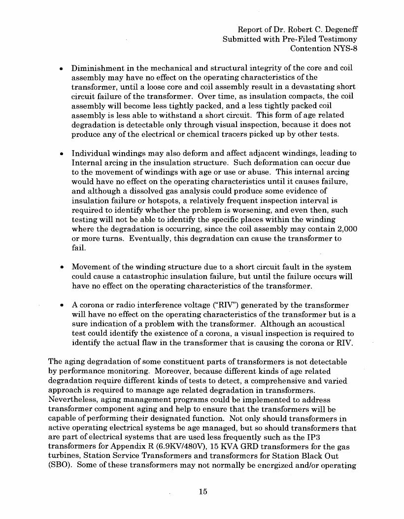
• Diminishment in the mechanical and structural integrity of the core and coilassembly may have no effect on the operating characteristics of thetransformer, until a loose core and coil assembly result in a devastating shortcircuit failure of the transformer. Over time, as insulation compacts, the coilassembly will become less tightly packed, and a less tightly packed coilassembly is less able to withstand a short circuit. This form of age relateddegradation is detectable only through visual inspection, because it does notproduce any of the electrical or chemical tracers picked up by other tests.
• Individual windings may also deform and affect adjacent windings, leading toInternal arcing in the insulation structure. Such deformation can occur dueto the movement of windings with age or use or abuse. This internal arcingwould have no effect on the operating characteristics until it causes failure,and although a dissolved gas analysis could produce some evidence ofinsulation failure or hotspots, a relatively frequent inspection interval isrequired to identify whether the problem is worsening, and even then, suchtesting will not be able to identify the specific places within the windingwhere the degradation is occurring, since the coil assembly may contain 2,000or more turns. Eventually, this degradation can cause the transformer tofail.
• Movement of the winding st~ucture due to a short circuit fault in the systemcould cause a catastrophic insulation failure, but until the failure occurs willhave no effect on the operating characteristics of the transformer.
• A corona or radio interference voltage ("RIV') generated by the transformerwill have no effect on the operating characteristics of the transformer but is asure indication of a problem with the transformer. Although an acousticaltest could identify the existence of a corona, a visual inspection is required toidentify the actual flaw in the transformer that is causing the corona or RIV.
The aging degradation of some constituent parts of transformers is not detectableby performance monitoring. Moreover, because different kinds of age relateddegradation require different kinds of tests to detect, a comprehensive and variedapproach is required to manage age related degradation in transformers.Nevertheless, aging management programs could be implemented to addresstransformer component aging and help to ensure that the transformers will becapable of performing their designated function. Not only should transformers inactive operating electrical systems be age managed, but so should transformers thatare part of electrical systems that are used less frequently such as the IP3transformers for Appendix R (6.9KV/480V), 15 KVA GRD transformers for the gasturbines, Station Service Transformers and transformers for Station Black Out(SBO). Some of these transformers may not normally be energized and/or operating
15
Report of Dr. Robert C. DegeneffSubmitted with Pre-Filed Testimony
Contention NYS-8
under full load conditions.
NRC's Information Notice 2009-10 (ML090540218), EPRI' s 2003 report entitledLarge Transformer End-of-Expected-Life Considerations and the Need for Planning[1013566], IEEE's 2007 report entitled IEEE Guide for the Evaluation andReconditioning of Liquid Immersed Power Transformers [C57.140TM-2006],NUREG/CR-5753, and Nuclear Energy Agency, Operating Experience Report:Recent Failures of Large Oil-Filled Transformers, NEAlCRNAlR(2011)6 (Mar. 14,2011) all indicate that current monitoring procedures for detecting the performanceof transformers, such as those in use at Indian Point, are not adequate to detect, inadvance of failure, all of the aging defects and degradation phenomena intransformers. Indeed, the NEA report concluded that "weakness in the'maintenance and monitoring programmes" is the root cause for many transformerfailures. NEA at 11
Moreover, simply monitoring the performance of transformers can not ensure thatcritical transformer components are not degrading to the point of component failure- now or during the period oflieense extension. As discussed in the 1994 SandiaReport, the 2003 EPRI report, the 2006 EPRI report, and the 2007 IEEE report,monitoring procedures such as component performance monitoring, personneltraining, and quality assurance audits are not adequate. Such monitoringprocedures do not provide the level of aging management sufficient to demonstratethat the various transformers will perform their intended functions during theperiod of extended operation including a potential design basis accident or incident.Additional aging management programs could be implemented to detect agingdegradation of transformers and their component parts in advance of failure. See,e.g., EPRI 2003 Report, at 7-2 & sec. 7.1.2. Aging management programs for agerelated degradation of transformers may include physical inspections, power factortesting, analysis of insulation resistance, oil leakage, gas- in-oil, comparison withoriginal factory test reports, vibration (humming), and impedance versus frequencyanalysis. By way of example, the 2003 EPRI Report identifies additional testing,surveillance, and inspection techniques that could support a meaningful agingmanagement program. See, e.g., EPRI 2003 Report, at 6-1 to 6-16.
NRC has acknowledged that a comprehensive and continual surveillance program isrequired to manage the effects of aging in transformers:
A continual program of inspection, surveillance, monitoring, andmaintenance will help ensure transformer reliability. Such aprogram will detect and reduce stressors that shortentransformer life, prevent stressors before they causedegradation, and detect degradation in the early stages so thatpreventive and corrective action can be taken prior to
16
Report of Dr. Robert C. DegeneffSubmitted with Pre-Filed Testimony
Contention NYS-8
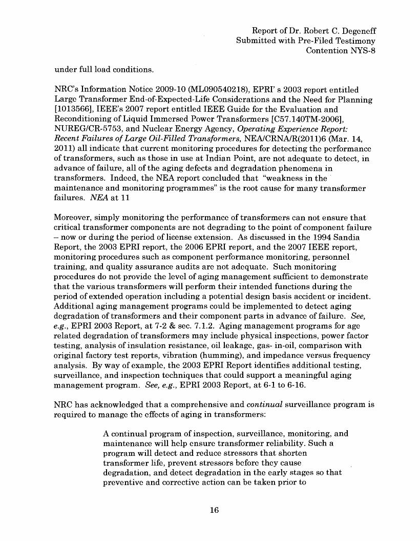
transformer failure to reduce the rate of aging. An effectiveprogram of inspection, surveillance, monitoring, andmaintenance consists of periodic cleaning and inspections;testing of dielectric strength; and testing of oil in liquid-filledtransformers; testing to verify that electrical characteristicssuch as winding resistance, insulation resistance, turns ratio,excitation current, and resistance to ground are maintained.Regular measurement of temperature is an important elementof a transformer monitoring program.
NUREG/CR-5753 at 50-51.
6. Consequences of Inadequate Management of Transformers
As noted in the State of New York's petition, the failure to properly manage aging ofElectrical Transformers at Indian Point may compromise:
a. The integrity of the reactor coolant pressure boundary;
b. The capability to shut down the reactor and maintain it in safeshutdown condition; or
c. The capability to prevent or mitigate the consequences of accidentswhich could result in potential offsite exposures comparable to thosereferred to in §§ 50.34(a)(1), 50.67(b)(2), or § 100.11 of this chapter, asapplicable. 10 C.F.R. §§ 54.4(a)(1)(2) and (3).
The consequence of failures of Electrical Transformers may result in accidentsbeyond the Design Basis Accidents resulting in exposures to the public exceeding 10C.F.R. § 100 limits if a station blackout occurs and the reactor core and spent fuelpools are not able to be properly cooled.
Failure to properly manage aging of electrical transformers could result in loss ofemergency power to the 480 volt safety equipment and 6.9kV busses includingstation blackout loads, in that a failed transformer can prevent power fromemergency generators or other backup sources from reaching the safety relatedbusses.
Recently, there have been a number of transformer failures at power reactors.Although NRC staff generally believes that transformers do not need to be subjectto aging management programs, these transformer failures underscore the need forthe proper maintenance and aging management of transformers.
17
Report of Dr. Robert C. DegeneffSubmitted with Pre-Filed Testimony
Contention NYS-8
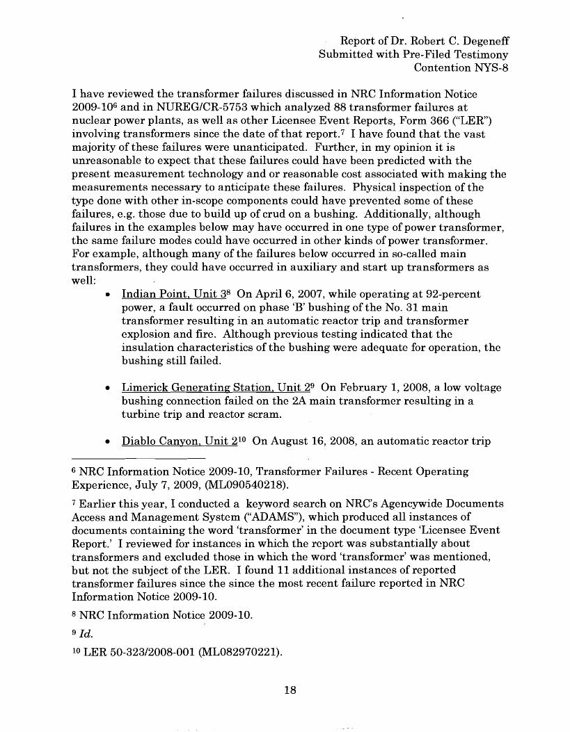
I have reviewed the transformer failures discussed in NRC Information Notice2009-106 and in NUREG/CR-5753 which analyzed 88 transformer failures atnuclear power plants, as well as other Licensee Event Reports, Form 366 ("LER")involving transformers since the date of that report. 7 I have found that the vastmajority of these failures were unanticipated. Further, in my opinion it isunreasonable to expect that these failures could have been predicted with thepresent measurement technology and or reasonable cost associated with making themeasurements necessary to anticipate these failures. Physical inspection of thetype done with other in-scope components could have prevented some of thesefailures, e.g. those due to build up of crud on a bushing. Additionally, althoughfailures in the examples below may have occurred in one type of power transformer,the same failure modes could have occurred in other kinds of power transformer.For example, although many of the failures below occurred in so-called maintransformers, they could have occurred in auxiliary and start up transformers aswell:
• Indian Point. Unit 38 On April 6, 2007, while operating at 92-percentpower, a fault occurred on phase 'B' bushing of the No. 31 maintransformer resulting in an automatic reactor trip and transformerexplosion and fire. Although previous testing indicated that theinsulation characteristics of the bushing were adequate for operation, thebushing still failed.
• Limerick Generating Station. Unit 29 On February 1, 2008, a low voltagebushing connection failed on the 2A main transformer resulting in aturbine trip and reactor scram.
• Diablo Canyon. Unit 210 On August 16, 2008, an automatic reactor trip
6 NRC Information Notice 2009-10, Transformer Failures - Recent OperatingExperience, July 7,2009, (ML090540218).
7 Earlier this year, I conducted a keyword search on NRC's Agencywide DocumentsAccess and Management System ("ADAMS"), which produced all instances ofdocuments containing the word 'transformer' in the document type 'Licensee EventReport.' I reviewed for instances in which the report was substantially abouttransformers and excluded those in which the word 'transformer' was mentioned,but not the subject of the LER. I found 11 additional instances of reportedtransformer failures since the since the most recent failure reported in NRCInformation Notice 2009-10.
8 NRC Information Notice 2009-10.
9 Id.
10 LER 50-323/2008-001 (ML082970221).
18
Report of Dr. Robert C. DegeneffSubmitted with Pre-Filed Testimony
Contention NYS-8
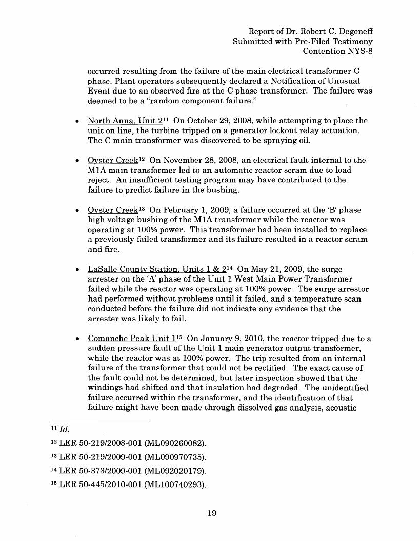
occurred resulting from the failure of the main electrical transformer Cphase. Plant operators subsequently declared a Notification of UnusualEvent due to an observed fire at the C phase transformer. The failure wasdeemed to be a "random component failure."
• North Anna, Unit 211 On October 29,2008, while attempting to place theunit on line, the turbine tripped on a generator lockout relay actuation.The C main transformer was discovered to be spraying oil.
• Oyster Creek12 On November 28,2008, an electrical fault internal to theMIA main transformer led to an automatic reactor scram due to loadreject. An insufficient testing program may have contributed to thefailure to predict failure in the bushing.
• Oyster Creek13 On February 1, 2009; a failure occurred at the 'B' phasehigh voltage bushing of the MIA transformer while the reactor wasoperating at 100% power. This transformer had been installed to replacea previously failed transformer and its failure resulted in a reactor scramand fire.
• LaSalle County Station, Units 1 & 214 On May 21, 2009, the surgearrester on the 'A' phase of the Unit 1 West Main Power Transformerfailed while the reactor was operating at 100% power. The surge arrestorhad performed without problems until it failed, and a temperature scanconducted before the failure did not indicate any evidence that thearrester was likely to fail.
• Comanche Peak Unit 115 On January 9,2010, the reactor tripped due to asudden pressure fault of the Unit 1 main generator output transformer,while the reactor was at 100% power. The trip resulted from an internalfailure of the transformer that could not be rectified. The exact cause ofthe fault could not be determined, but later inspection showed that thewindings had shifted and that insulation had degraded. The unidentifiedfailure occurred within the transformer, and the identification of thatfailure might have been made through dissolved gas analysis, acoustic
11 Id.
12 LER 50-219/2008-001 (ML090260082).
13 LER 50-219/2009-001 (ML090970735).
14 LER 50-373/2009-001 (ML092020179).
15 LER 50-445/2010-001 (MLI00740293).
19
Report of Dr. Robert C. DegeneffSubmitted with Pre-Filed Testimony
Contention NYS-8
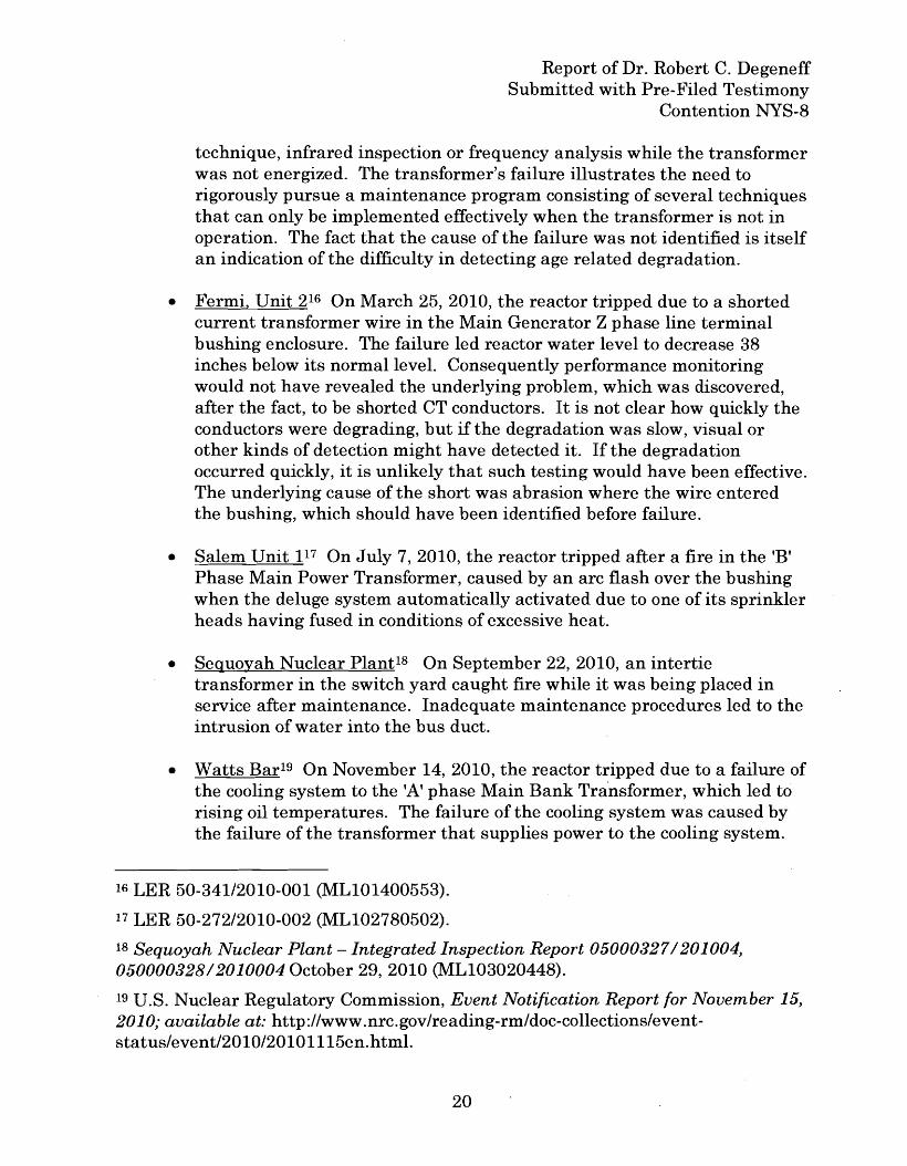
technique, infrared inspection or frequency analysis while the transformerwas not energized. The transformer's failure illustrates the need torigorously pursue a maintenance program consisting of several techniquesthat can only be implemented effectively when the transformer is not inoperation. The fact that the cause of the failure was not identified is itselfan indication of the difficulty in detecting age related degradation.
• Fermi, Unit 216 On March 25,2010, the reactor tripped due to a shortedcurrent transformer wire in the Main Generator Z phase line terminalbushing enclosure. The failure led reactor water level to decrease 38inches below its normal level. Consequently performance monitoringwould not have revealed the underlying problem, which was discovered,after the fact, to be shorted CT conductors. It is not clear how quickly theconductors were degrading, but if the degradation was slow, visual orother kinds of detection might have detected it. If the degradationoccurred quickly, it is unlikely that such testing would have been effective.The underlying cause of the short was abrasion where the wire enteredthe bushing, which should have been identified before failure.
• Salem Unit 117 On July 7,2010, the reactor tripped after a fire in the 'B'Phase Main Power Transformer, caused by an arc flash over the bushingwhen the deluge system automatically activated due to one of its sprinklerheads having fused in conditions of excessive heat.
• Seguoyah Nuclear Plant18 On September 22, 2010, an intertietransformer in the switch yard caught fire while it was being placed inservice after maintenance. Inadequate maintenance procedures led to theintrusion of water into the bus duct.
• Watts Bar19 On November 14, 2010, the reactor tripped due to a failure ofthe cooling system to the 'A' phase Main Bank Tra'nsformer, which led torising oil temperatures. The failure of the cooling system was caused bythe failure of the transformer that supplies power to the cooling system.
16 LER 50-341/2010-001 (ML101400553).
17 LER 50-272/2010-002 (ML102780502).
18 Sequoyah Nuclear Plant - Integrated Inspection Report 050003271201004,05000032812010004 October 29,2010 (ML103020448).
19 U.S. Nuclear Regulatory Commission, Event Notification Report for November 15,2010; available at: http://www.nrc.gov/reading-rm/doc-collections/eventstatus/event/2010/20101115en.html.
20
Report of Dr. Robert C. DegeneffSubmitted with Pre-Filed Testimony
Contention NYS-8
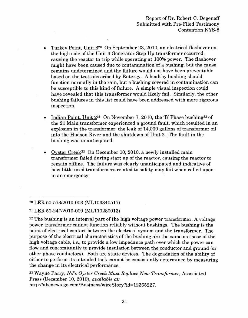
• Turkey Point, Unit 320 On September 23,2010, an electrical flashover onthe high side of the Unit 3 Generator Step Up transformer occurred,causing the reactor to trip while operating at 100% power. The flashovermight have been caused due to contamination of a bushing, but the causeremains undetermined and the failure would not have been preventablebased on the tests described by Entergy. A healthy bushing shouldfunction normally in the rain, but a bushing covered in contamination canbe susceptible to this kind of failure. A simple visual inspection couldhave revealed that this transformer would likely fail. Similarly, the otherbushing failures in this list could have been addressed with more rigorousinspection.
• Indian Point, Unit 221 On November 7,2010, the 'B' Phase bushing22 ofthe 21 Main transformer experienced a ground fault, which resulted in anexplosion in the transformer, the leak of 14,000 gallons of transformer oilinto the Hudson River and the shutdown of Unit 2. The fault in thebushing was unanticipated.
• Oyster Creek23 On December 10, 2010, a newly installed maintransformer failed during start up of the reactor, causing the reactor toremain offline. The failure was clearly unanticipated and indicative ofhow little used transformers related to safety may fail when called uponIn an emergency.
20 LER 50-573/2010-003 (ML103340517)
21 LER 50-247/2010-009 (ML110280013)
22 The bushing is an integral part of the high voltage power transformer. A voltagepower transformer cannot function reliably without bushings. The bushing is thepoint of electrical contact between the electrical system and the transformer. Thepurpose of the electrical characteristics of the bushing are the same as those of thehigh voltage cable, i.e., to provide a low impedance path over which the power canflow and concomitantly to provide insulation between the conductor and ground (orother phase conductors). Both are static devices. The degradation of the ability ofeither to perform its intended task cannot be consistently determined by measuringthe change in its electrical performance.
23 Wayne Parry, NJ's Oyster Creek Must Replace tvew Transformer, AssociatedPress (December 10, 2010), available at:http://abcnews.go.com/Business/wireStory?id=12365227.
21
Report of Dr. Robert C. DegeneffSubmitted with Pre-Filed Testimony
Contention NYS-8
• LaSalle County Station, Unit 124 On February 11, 2011 an externalbushing flashover on the C-phase of the 1W Main Power Transformercaused the reactor to trip while operating at 100% power. Ice build upand contamination with salt and dirt contributed to the flashover.Testing would not have predicted a flashover.
• Perry Nuclear Power Plant25 On October 2, 2011, an internal fault in theUnit 1 startup transformer caused the transformer to fail and cracked thetransformer's cooling fluid reservoir.
• Monticello Nuclear Generating Plant26 On October 28,2011, the auxiliarypower transformer failed, which caused the reactor to scram. Coincidentwith the failure of the transformer, the emergency diesel generators andnon-safety related busses experienced difficulties.
In 2003, EPRI published a report that identified a growing problem with failures inlarge transformers and a wide range of maintenance programs that it recommendedbe implemented by nuclear utilities to address these problems including theproblem of aging degradation of transformers. EPRI Life Cycle ManagementPlanning Sourcebooks, Volume 4, Large Power Transformers, [1007422], March2003, at 4-1 to 4-6, 4-17 and 6-2 to 6-13.
Moreover, as I describe below in Section 7.4, it appears that Entergy's own staffacknowledges in Entergy documents that detailed and comprehensive inspectionroutines performed at a regular interval are required to detect the effects of aging.
7. Entergy's Argument
I have reviewed Entergy's submissions in this proceeding, including the August 12,2009 declarations of Dr. Dobbs, Mr. Craig and Mr. Rucker. Supported by itsexperts' declarations, Entergy reaches three main conclusions about transformers.In my opinion and as I detail below, Entergy's conclusions and the statements of itsexperts are technically inaccurate and contrary to Entergy's own internal recordsregarding transformer maintenance.
Applicant's Motion for Summary Disposition of New York State Contention 8(Electrical Transformers) ("Entergy Summary Disposition Motion"), page 2 containsthe following assertion:
24 LER 11-013/2011-001 (MLII0890949)
25 PNO-III-II-012A (MLI1292AI19)
26 PNO-III-II-015A (ML11301A217
22
Report of Dr. Robert C. DegeneffSubmitted with Pre-Filed Testimony
Contention NYS-8
It is uncontroverted, as a technical matter, that all transformersperform their.intended functions through changes in theirvoltage and current properties, i.e., '0 change in state. "Therefore, because transformers perform their intended functionthrough a change in state, they are properly excluded from theAMR requirements in Part 54, and no AMP is required.
This assertion is the heart of Entergy's argument and is, quite simply, contrary tothe consensus of the technical community. As the technical community recognizes,the transformer performs its intended task without changing its configuration(mechanical or electrical), its material characteristics, or its state, and so is a staticdevice. Power merely passes through a transformer and the unchanging physicalproperties of the transformer cause that power to change voltage at a ratiodetermined by the transformer's unchanging design properties. Different amountsof power may be applied to a transformer, but the voltage will always change at thesame ratio, because the unchanging properties of the transformer dictate only oneratio. This is exactly the same situation one has when a fluid passes through a pipewith a constriction; when the amount of fluid that passes through the pipe isconstant, the pressure of the fluid will change at the constriction, but the piperemains invariant, its properties and characteristics unchanged.
Page 30 of Entergy's Summary Disposition Motion contains the following assertion:
All transformers are active components because they performtheir intended function through a change in configuration orproperties, which the Commission has explicitly stated should beinterpreted to include '0 change in state." They are not passiveand long-lived structures or components and, therefore, are notsubject to AMR under C.F.R. Part 54. '
In my opinion, Entergy's argument is technically inaccurate. The transformer is astatic device as defined by the IEEE and its Transformers Committee. See p. 30,supra. A transformer does not change its configuration or its properties when it isperforming its intended operation. Neither the physical and electrical configurationnor physical and electrical properties of a transformer change while it is operating.The transformer certainly does not change "state" when it is operating. Each of atransformer's key properties demonstrates that it is a passive device, which is longlived if properly maintained and monitored. See, e.g., NUREG/CR-5753 at 50.
23
Report of Dr. Robert C. DegeneffSubmitted with Pre-Filed Testimony
Contention NYS-8
Page 7 of Entergy's Summary Disposition Motion contains the following assertion:
Thus, potential degradation of the ability of a transformer toperform its intended function is monitorable by changes in theelectrical performance of the transformer and / or its associatedcircuits.
If this statement were true, no transformer would ever fail without warning whilein service. Entergy's assertion misapprehends the physical reality of transformerperformance in that many failure modes cannot be predicted by way of monitoringchanges in the transformers electrical performance. I have already described atlength several failure modes in transformers that cannot be predicted fromperformance monitoring, but, by way of example: the aging of the transformer'sinsulation structure cannot be determined by monitoring the transformer'selectrical performance; the tightness of the core and coils can not be determined bymonitoring the transformer's electrical performance; nor can the distortion ofwindings; arcing within the windings, core and clamps, moisture in the oil orwindings, generation of combustible gasses, or turn-to-turn failures be determinedby monitoring the transformer's electrical performance. These failure modes andothers can not be determined by simply monitoring the electrical performance of thetransformer. Entergy and its experts are incorrect to assert otherwise.
7.1 Declaration of Dr. Dobbs
In paragraph 31 of his declaration dated August 12, 2009, Dr. Dobbs makes thefollowing statement:
... [V]oltage, current, and heat signature are all properties of atransformer. When the transformer changes from an idle state toan active state, the voltage and current change. Also, thecurrents and heat signature will change with a variation in load.Because transformers perform their intended function with achange in properties, they are excluded from an AMR accordingto the defining statement in § 54.21(a)(1)(i).
Voltage and current are not properties of the transformer, but rather are propertiesof the source of power being supplied to the transformer and of the load beingserved. The transformer's characteristics or properties (turns ratio, conductor size,insulation type and thickness, cooling capability, etc.) are the same whether thetransformer is carrying power or not. If we applied Dr. Dobbs' logic to a pipe, whichis conceptually similar to a transformer, he is suggesting that a pipe's propertiesdepend on whether it is carrying fluid. This is incorrect. The properties of the pipewill not change depending upon the amount of fluid flowing through the pipe. In
24
Report of Dr. Robert C. DegeneffSubmitted with Pre-Filed Testimony
Contention NYS-8
the same manner, the properties of the transformer do not change depending uponthe power passing through the transformer. The properties of a transformer, listedabove, limit the characteristics of the power to which the transformer can besubjected before it fails, e.g., the voltage that can be applied or current carried by aspecific transformer design or the amount of pressure and temperature of the fluidcarried in a specific pipe, but its properties remain constant.
In paragraph 20 of his declaration, Dr. Dobbs presents a position that transformerschange "properties" in that:
The table above (paragraph 19) demonstrates that the voltageand current properties of a transformer change depending on theload condition of the transformer.
While I agree with the recognition that the "properties" of the current and voltageinputs to and outputs from are changed when they pass through a transformer, Idisagree with Dr. Dobbs' implication that the properties of the transformer change.The transformer does not change its configuration or properties during its intendeduse; the conductors or cables used to construct the windings do not change in size ornumber or location, nor does the size, weight, and material used to construct thetransformer's core. The electric power passing through a transformer is a functionof the voltage applied to that transformer's primary winding and the load that thetransformers services from its output winding. Both the input voltage and the loadserved are completely independent of the design and characteristics of thetransformer. Input and output voltages are not "properties" of the transformeritself. The turns ratio is a property of the transformer and it does not change innormal use. The insulation type and dimensions of the turns in the transformer areproperties of the transformer and do not change in normal use. If we assume thetransformer has a turns ratio of 10 to 1, e.g., a step down transformer, then an inputvoltage of 1,000 volts would be transformed to an output voltage of 100 volts; if theinput voltage were 500 volts, the output voltage would be 50 volts. The input andoutput voltages are different in each example, but the ratio between input andoutput voltages remains constant, because the ratio is a non-changing property ofthe transformer.
In paragraph 22, Dr. Dobbs states that in a transformer "[a]ll of the voltages andcurrents must vary in time. The voltages and currents also vary whenever loadconditions change." Dr. Dobbs is correct to acknowledge that a change in theproperties of the load will cause the voltage and current to change, but a change inthe load does not imply any variability in the transformer's properties. Neitherdoes the fact that voltage, current and magnetic flux vary over time imply anychange in a transformer's properties. As Dr. Dobbs states in paragraph 17 of hisdeclaration, the changes in the properties of the power flowing through a
25
Report of Dr. Robert C. DegeneffSubmitted with Pre-Filed Testimony
Contention NYS-8
transformer are a consequence of the power's being an alternating current. But thedetermination of whether current is alternating or direct does not come from theproperties of the transformer through which it flows, but from the source of thepower. It is true that transformers are designed to take advantage of the propertiesof alternating current, but it is not true that the properties of a transformer changewhen a certain kind of current is passed through it. A transformer may not operatecorrectly if it is connected to direct current, but to suggest that a transformer is onlya transformer so long as alternating current flows through the transformer is likesaying that a hot water pipe's properties have changed because it is hooked up to acold water source.
In paragraph 15 of his declaration, Dr. Dobbs describes the relationship betweenthe primary and secondary winding's voltage and current as a function of thetransformer's turns ratio. In paragraph 16, Dr. Dobbs goes on to state that"Therefore, voltage and current are integral properties of a transformer." It is myopinion that this statement is incorrect in the same way it would be incorrect to saythat the fluid passing through a pipe is a property of that pipe or that power flowingthrough a cable is an integral component or characteristic of that cable. It is myopinion that Dr. Dobbs has conflated the device (in this case the transformer) whichis a static device and the element that is flowing through it (in this case electricpower which is variable depending upon the driving voltage and the load beingserved).
In paragraph 25, Dr. Dobbs states that "Voltage, current, and the winding turnsratio are all properties of a transformer. These properties are easily monitoredwhile the transformer is performing its intended function and provide an indicationas to the operational health of the transformer." Voltage and current are no moreproperties of the transformer than water pressure is a property of a pipe that iscarrying the liquid. The turns ratio of a transformer is a property of thetransformer. But, to measure it accurately while the transformer is operating is nota simple or routine task, as Dr. Dobbs claims. Power transformers have thousandsof turns and the ability to measure within the accuracy of one turn would berequired to assess the health of the transformer. This is physically impractical withthe transformer energized and even difficult when the transformer is off-line.
In paragraphs 32 and 33 of his declaration, Dr. Dobbs argues that it is proper toexclude the transformer from the list of components that require an AMR becausethe ability of the _transformer to perform its intended function can be determined bydirect measurement of performance. In these two paragraphs, Dr. Dobbs comparesthe pipe and the transformer. The statement is made that it is not possible todetermine the suitability of the pipe to carry out its function by direct measurementof its function, but it is possible to determine the ability of a transformer to conductis desired function by direct measurement. This position is not only inaccurate, but
26
Report of Dr. Robert C. DegeneffSubmitted with Pre-Filed Testimony
Contention NYS-8
it suggests an operational policy that is dangerous to the facility and the personneland staff in that facility, as I have already described.
7.2 Declaration ofR. Rucker
In paragraph 16 of his declaration, dated August 12, 2009, Mr. Rucker points outthat Entergy identified two passive electrical and I&C commodity groups asmeeting Section 54.21(a)(1)(i) criteria, i.e., components that perform an intendedfunction without moving parts or without change in configuration. These groupsare subject to AMR. In paragraph 17, Mr. Rucker, on behalf of Entergy, thenexcludes everything that is not included in paragraph 16. As such, transformers areassumed to be active devices not subject to AMR. As I described in my statementsregarding Dr. Dobbs' declaration, the classification of a transformer as an activedevice is incorrect, and so transformers should be subject to AMR.
In paragraph 19, Mr. Rucker makes the following statement:
As explained above, transformers are not subject to AMR and,therefore, no AMP is required under 10 C.F.R. Part 54.Nonetheless, degradation of the ability of a transformer toperform its intended function is monitorable by changes in theelectrical performance of the transformer and / or its associatedcircuits. Moreover" certain IP2 and IP3 transformers, includingthose necessary for compliance with 10 C.F.R. § 50.48 and 50.63,are subject to direct, ongoing, surveillance, monitoring,maintenance, and inspection. These CLB programs andactivities would continue during the period of extendedoperation, in accordance with 10 C.F.R. § 54.33(d). They areintended to ensure that any degradation or failure of thetransformers, as active components, is detected and corrected,and that the transformers continue to perform their intendedfunctions.
I disagree with Mr. Rucker's declaration that the degradation of the ability of atransformer to perform its intended function can be determined simply bymeasuring the changes in the electrical performance of the transformer and/or itsassociated circuits. If this were a consistently valid statement, the number oftransformer failures would be drastically reduced. This is simply not the case.Additionally, I have already listed at pp. 14-15 five common transformer failuremodes that cannot be identified by measuring the performance of the transformer.
In paragraph 20, Mr. Rucker represents that large power transformers areequipped with instrumentation to detect degrading conditions and that personnel
27
Report of Dr. Robert C. DegeneffSubmitted with Pre-Filed Testimony
Contention NYS-8
are trained to take appropriate action. I disagree with this statement; the vastmajority of degradation to a transformer cannot be observed based on changes inelectrical performance. For example, the insulation integrity of a transformer'swinding structure can not be determined by monitoring a change in the electricalperformance. One must look at the insulation capability of the oil and paperstructure. Routine monitoring will not provide this data. Another example wouldbe the ability of the transformer to withstand a short circuit, which can not bedetermined with routine monitoring, but, rather, requires internal inspection or animpedance versus frequency scan of the winding structure. Any assertion that thehealth of the transformer is determinable by measuring changes in it electricalperformance simply ignores ample evidence of failure modes that are not detectablefrpm performance degradation.
The declaration of Mr. Rucker makes general reference" (at paragraphs 19-21) tomonitoring programs that seem to be focused on the performance of thetransformers, but not on the condition of the transformer components themselves.Mr. Rucker's declaration contains only generalities about performance monitoring.It also contains many qualifiers that make it difficult to understand the depth orthe extent of such monitoring. While it makes reference to "transformers" or"certain" transformers, it does not demonstrate that the licensee will monitor theperformance of all transformers that would be within the scope of Part 54, nor doesit explain how the licensee monitors transformers that may not normally beenergized and/or operating under full load conditions.
7.3 Declaration of J.W. Craig
In paragraphs 7(a), 7(b) and 7(c) of his declaration, dated August 12, 2009, Mr.Craig repeats Dr. Dobbs' assertions that transformers should be excluded fromAMR because they undergo continuous changes in their electrical and magneticproperties during operation, because a transformer's ability to perform its intendedfunction is readily monitorable, and because transformers are similar tocomponents listed in 10 C.F.R. § 54.21(a)(I)(i) that are excluded from the AMRrequirements of Part 54. Each of these assertions is incorrect, as I have alreadydescribed.
In paragraph 7(d), Mr. Craig points out that
"Both the NRC and industry license renewal guidance documentsproperly conclude that electrical transfor.mers are not subject toAMR under part 54 because effects of aging will be effectivelymanaged during the license renewal term through existinglicensee maintenance activities. "
28
Report of Dr. Robert C. DegeneffSubmitted with Pre-Filed Testimony
Contention NYS-8
I disagree with this statement for two reasons. First, the "health" or ability of atransformer to do its assigned task can not be determined with any degree ofcertainty by measuring its operating performance. In this document, at pp. 14-15,supra, I have listed 5 conditions that can not be evaluated by measuring operatingperformance. Second, the failure rate of these transformers has shown that theexisting maintenance activity conducted by the licensee needs to be improved. Theinstances of unanticipated failures described at pp. 18-22, supra demonstrate thatthe health of a transformer cannot be accurately determined from externalmeasurements.
In paragraph 22, Mr. Craig provides an example of a two winding step downtransformer transforming 6.9kV to 480 volts. He makes the statement that
"The voltage in the secondary coil is a result of a continuouschange of the magnetic properties or magnetic field in thetransformer while in service. Thus, while the transformers donot have moving parts, each of these components of thetransformer undergoes changes in electric properties or statewhen energized much like components in a transistor, inverter, orpower supply. When connected to an electrical load or circuit,each of these components must change properties in order toperform its intended function. "
This statement is incorrect for two reasons. First, the voltage in the secondarywinding is a result of the rate of change of the magnetic flux created by flowingcurrent in the primary winding, not the magnetic properties of the transformer.The magnetic properties of the transformer are invariant; to represent theproperties as variable is technically inaccurate. The magnetic field generatedwithin the transformer is a product of the current flowing through it; thetransformer is designed with certain characteristics, i.e., the turns ratio, to ensurethat the magnetic field behaves in a certain fashion, but the magnetic fieldgenerated by the flow of current will behave in a uniform manner, according to thenon-changing properties of the transformer. If the input power changes, the outputpower will also change, but the change in output power is wholly caused by thechange in input power and not by any change in the properties of the transformer.For example, if water is poured through a pipe at a constant rate, the water willcome out of that pipe at a constant rate. Only if the rate of water being poured intothe pipe changes will the rate at which water comes out of the pipe change. Thatchange will not at all be caused by any change in the property of the pipe. Second,the statement that each of these components of the transformer undergoes changesin electric properties or state when energized much like components in a transistor,inverter, or power supply is incorrect. A transistor changes state (or impedance) asa function of a specific input control signal, making it an active device. An inverter
29
Report of Dr. Robert C. DegeneffSubmitted with Pre-Filed Testimony
Contention NYS-8
changes direct current into alternating current and its function (state) is veryprecisely controlled, making it an active device. A power supply takes alternatingcurrent power and converts it into direct current power. The input power's voltagecan vary over a very broad range and the output voltage will be constant due toactive control in the power supply. The transformer, on the other hand, is a staticdevice, having no moving parts, no control mechanism, and with the relationshipbetween the input and output being fixed by the turns ratio of the windings. Itstransformation characteristic is fixed. The transformer, on the other hand,performs precisely the same degree of change to whatever amount of power passedthrough it. Thus, if the "transformation ratio" is 2 to 1, then the ratio of input tooutput voltage will always be 2 to 1, and the ratio of input to output current will be1 to 2 with the input power equaling the output power. See pp. 9-10, supra.
In paragraph 26, Mr. Craig, explains his understanding of the technical andregulatory basis for excluding transformers from AMR under 10 C.F.R.:
Transformers perform their intended function through a changein state by stepping down voltage from a higher to a lower value,stepping up voltage to a higher value, or providing isolation to aload. Transformers perform their intended function through achange in state similar to switchgear, power supplies, batterychargers, and power inverters, which have been excluded in §54.21(a)(l)(i) from an aging management review. Anydegradation of the transformer's ability to perform its intendedfunction is readily monitorable by a change in the electricalperformance of the transformer and the associated circuits.Trending electrical parameters measured during transformersurveillance and maintenance such as Doble test results, andadvanced monitoring methods such as infrared thermography,and electrical circuit characterization and diagnosis provide adirect indication of the performance of the transformer.Therefore, transformers are not subject to an aging managementreVLew.
Characterizing stepping up voltage, or stepping down voltage, or providingelectrical isolation with a transformer as a change in state is technically inaccurate.The transformer does not change state while it is performing its assigned activityany more than a pipe carrying a fluid changes state as the fluid flows through it.Secondly, to compare the operation of a transformer to that of a power supply,circuit breaker, inverter, or battery charger is incorrect. Each of these devices has amechanism to dynamically control the relationship between the input and outputand as such e'ach of these are truly active devices. A transformer is a passivedevice, and the relationship between the input and output is fixed. Thirdly, to
30
Report of Dr. Robert C. DegeneffSubmitted with Pre-Filed Testimony
Contention NYS-8
represent that the health and operational capability of a transformer can beconsistently and reliably determined by "Trending electrical parameters measuredduring transformer surveillance and maintenance such as Doble test results, andadvanced monitoring methods such as infrared thermography, and electrical circuitcharacterization and diagnosis" simply does not agree with the actual failure rate ofthese transformers. As I have outlined, there are numerous conditions of thetransformer that can not be accurately determine by surveillance and on linemaintenance or trending. Mr. Craig's conclusion at the end of the quoted paragraphis based on incorrect information and, in my opinion, is wrong.
In general, Mr. Craig conflates properties of the transformer and properties of thepower being transformed (voltage and current) by the transformer. Contrary to Mr.Craig's assertion, the properties of the transformer are fixed, e.g., the geometricaland physical characteristics of the transformers core and coil. The power passingthrough the transformer may change, but its characteristics are established by thevoltage applied to the primary and the load being supplied with power on thesecondary. Both the applied voltage and the load being supplied are completelyseparate from the transformer.
In paragraph 37, Mr. Craig points out that since 1997 the NRC has taken theposition that the transformer are not subject to AMR. This position has beensubsequently repeated on numerous occasions since. I would suggest that repeatinga mistake does not tend to make that mistake any less erroneous.
7.4 Documents Produced by Entergy
I have reviewed various documents, which Entergy has produced in this proceedingand that are related to its maintenance program for transformers. These reportsshow that contrary to what it has asserted in its pleadings that Entergy'smaintenance routines cannot evaluate the effects of every type of age relateddegradation in transformers.
For example, several Entergy owned transformers employ the GE DynaCompclamp; the clamp holds the internal winding in place, and severe degradation of theclamp could lead to fault conditions that end in catastrophic failure. See June 26,2007 Email String re Status of Regions Single Point Vulnerable Transformers(IPEC00071760). In order to predict failure, Entergy must perform internalinspection, because the other techniques that Entergy includes in its monitoringprogram will not be able to predict whether the clamp fails. Internal inspections,however, were not part of the regularly scheduled maintenance and were only donewhen the transformer had already been drained for another reason. Id. Evendiscovering which transformers contained this susceptible clamp requires internalinspection. Id. In another instance, Entergy Staff concluded that "dissolved gas
31
Report of Dr. Robert C. DegeneffSubmitte"d with Pre-Filed Testimony
Contention NYS-8
analysis and other PM maintenance tasks are not sufficient to identify all nonrandom degradation mechanisms internal to the transformer since no indication ofthis degradation mechanism was observable with existing maintenance." Id. Theseexamples are illustrative of the fact that, as I describe above, age relateddegradation in transformers is not readily monitorable, but instead requiresinvasive, expensive and time consuming procedures.
8. Conclusion
Entergy's argument is technically inaccurate. The transformer is a static device asdefined by the IEEE and its Transformers Committee. A transformer does notchange its configuration nor its properties when it is performing its intendedoperation. Neither the physical and electrical configuration nor physical andelectrical properties of a transformer change while it is operating. Because thetransformer is a static device, age related degradation in the transformer is notreadily monitorable. Rather detection of age related degradation in transformersrequires a continual surveillance program comprise of various techniques conductedboth while the transformer is operating and while it is offline. These facts about thetransformer, as well as the similarity of the transformer to components for whichthe NRC requires an aging management program, indicate that the transformer isprecisely the kind of component which would benefit from a rigorous agingmanagement program.
December 9,2011
Watervliet, New York
Robert C. Dege70 Cohoes RoadWatervliet, New York 12189
32
Report of Dr. Robert C. DegeneffSubmitted with Pre-Filed Testimony
Contention NYS-8
References
Blume, Transformer Engineering, Chapter 1, page 1, General Electric Co., 1938 (1st
Edition), 1951 (2d Edition)
Flanagan, The Handbook of Transformer Design & Application (2d Edition) page1.1, McGraw-Hill 1993, ISBN 0-07-021291-0
Harlow, Electric Power Transformer Engineering, page 2-1, CRC Press (2004) ISBN0-8493-1704-5
Harlow, Electric Power Transformer Engineering, page 2-1 (2d Edition) CRC Press(2007) ISBN 0-8493-9186-5
IEEE Standard Dictionary of Electrical and Electronic Terms, IEEE Std 100-1996(6th Edition), page 1131, ISBN 1-55937-833-6 (1996)
Indian Point UFSAR, Indian Point Unit 2, Chapter 8, Electrical Systems (submittedwith license renewal application) (2007)
Indian Point UFSAR, Indian Point Unit 2, figure 8.2-1, 8.2-2 (electrical systemdrawing) (2007)
Indian Point UFSAR, Indian Point Unit 3, Chapter 8, Electrical Systems (submittedwith license renewal application) (2007)
Indian Point No.3 Nuclear Power Plant, Electrical Distribution & TransmissionSystem, DWG NO 9321-F-33853, REV 17 (electrical system drawing) (dated:2/29/2008) ADAMS ML090400895
NRC Information Notice 2009-10, Transformer Failures - Recent OperatingExperience, July 7, 2009, ADAMS ML090540218
EPRI report, EPRI Life Cycle Management Planning Sourcebooks, Volume 4, LargePower Transformers, [1007422], March 2003
EPRI report, Plant Support Engineering: Large Transformer End-of-Expected-LifeConsiderations and the Need for Planning [1013566], December 2006
IEEE report, IEEE Guide for the Evaluation and Reconditioning of LiquidImmersed Power Transformers [C57.140TM-2006], April, 2007
33
Report of Dr. Robert C. DegeneffSubmitted with Pre-Filed Testimony
Contention NYS-8
Sandia National Laboratories report, Aging Management Guideline for CommercialNuclear Power Plants Power and Distribution Transformers, SAND93-7068· UC523, Unlimited Release, May 1994
NUREG/CR-5753, Aging of Safety Class Transformers in Safety Systems of NuclearPower Plants (Feb. 1996)
Nuclear Power Plant License Renewal; Revisions, 60 Fed. Reg. 22,461 (May 8, 1995)
Preliminary Notification of Event or Unusual Occurrence (PNO-III-11-012A), PerryNuclear Power Plant, Docket No. 50-440, License No. NPF-58, Perry UnplannedShutdown Greater than 72 Hours (Update) (Oct. 19, 2011) (MLl1292Al19)
Preliminary Notification of Event or Unusual Occurrence (PNO-III-11-015A),Monticello Nuclear Generating Plant, Unplanned Shutdown Greater Than 72 HoursDue to a Loss of the Auxiliary Power Transformer (Update) (Oct. 28,2011)(MLl1301A217)
Pacific Gas and Electric Company (PG&E Letter DCL-08-089), Licensee EventReport 2-2008-001-00, Reactor Trip Due to Main Electrical Transformer Failure,Diablo Canyon Unit 2, Docket No. 50-323, OL-DPR-82 (Oct. 15, 2008)(ML082970221)
Exelon Nuclear (RA-09-008), Oyster Creek Nuclear Generating Station, FacilityOperating License No. DPR-16, NRC Docket No, 50-219, Licensee Event Report2008-001-00, Automatic Reactor Shutdown Caused by Main Transformer Failure(Jan. 21, 2009) (ML090260082)
Exelon Nuclear (RA-09-026), Licensee Event Report 2009-001-00, AutomaticReactor Shutdown Caused by Main Transformer Failure, Oyster Creek NuclearGenerating Station, Facility Operating License No. DPR-16, NRC Docket No. 50219 (Mar. 31, 2009) (ML090970735)
Exelon Nuclear, Licensee Event Report 09-001-00, Automatic Reactor Scram Due toFailure of Main Power Transformer Surge Arrestor, LaSalle County Station Unit 1,Facility Operating License No. 11, NRC Docket No. 50-373 (Jul. 20,2009)(ML092020179)
Luminant Power (CP-201000074, Log# TXX-10010), Licensee Event Report 445/10001-00, Trip Due, to Pressure Relay Actuation on Main Transformer 01, ComanchePeak Nuclear Power Plant Unit 1, Docket No. 50-445 (Mar. 3, 2010) (ML100740293)
34
Report of Dr. Robert C. DegeneffSubmitted with Pre-Filed Testimony
Contention NYS-8
DTE Energy (NRC-IO-0043), Licensee Event Report 2010-001, Automatic ReactorShutdown Due to Generator Current Transformer Wiring Failure, Fermi 2, NRCLicense No. NPF-43, NRC Docket No. 50-341 (May 19, 2010) (MLI01400553)
PSEG Nuclear LLC (LR-NI0-0320), Licensee Event Report 272/2010-002,Automatic Reactor Trip Due to Main Power Transformer Bushing Failure, SalemNuclear Generating Station Unit 1, Facility Operating License No. DPR-70, NRCDocket No. 50-272 (Sept. 2, 2010) (MLI02780502)
Event Notification Report, Watts Bar Unit 1, Manual Reactor Trip Due to Loss ofCooling to the "A" Phase Main Bank Transformer, Event Number: 46418,Notification Date: 11/14/2010
FPL (L-2010-272), Licensee Event Report 2010-003-00, Reactor Trip Due to Faulton 230kV Side of Generator Step-Up Transformer, Turkey Point Unit 3, NRCDocket No. 50-250 (Nov. 19, 2010)(MLI03340517)
Entergy (NL-II-005), Licensee Event Report 2010-009-00, Automatic Reactor TripDue to a Turbine Generator Trip Caused by a Fault of the 21 Main TransformerPhase B High Voltage Bushing, Indian Point Unit No.2, NRC Docket No. 50-247,DPR-26 (Jan. 18, 2011) (MLII0280013)
Exelon Nuclear (RAII-013), Licensee Event Report 2011-001-00, Automatic ReactorScram Due to Main Power Transformer "C" Phase Electrical Fault, LaSalle CountyStation Unit 1, Facility Operating License No. NPF-ll, NRC Docket No. 50-373(Mar. 25, 2011) (MLII0890949)
Email String; June 26, 2007 8:24 AM; Subject: Status of Regions Single PointVulnerable Transformers; From: R.R. Davis; To: D.P. Wiles, M.A. Krupa, C.Reasoner, and K.D. Nichols; CC: K.A. Jelks, M.A. Wood, G.S. Matharu, R.T.Giguere, S. Saunders; June 26,2007 3:12 PM; Subject: FW: Status of Regions SinglePoint Vulnerable Transformers; Attachments: SPF Transformer writeup.doc, ENGSU Evaluation FINAL 6-25-2007.doc; From: R.R. Davis; To: R.A. Penny(IPEC00071760)
EN Large Power Transformer Status (IPEC00071765)
Nuclear Energy Agency, Operating Experience Report: Recent Failures of Large OilFilled Transformers, NEAlCRNAlR(2011)6 (Mar. 14,2011)
35
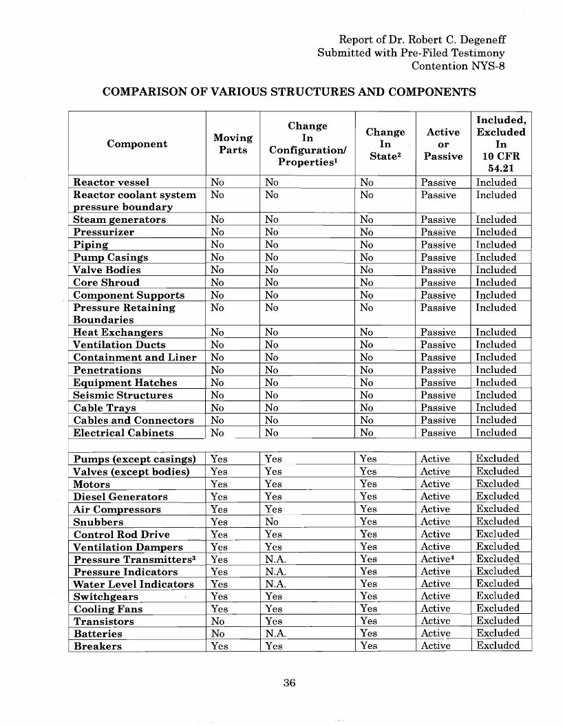
Report of Dr. Robert C. DegeneffSubmitted with Pre-Filed Testimony
Contention NYS-8
COMPARISON OF VARIOUS STRUCTURES AND COMPONENTS
Change Included,
Moving In Change Active ExcludedComponent
Parts Configuration!In or In
Properties! State2 Passive 10CFR54.21
Reactor vessel No No No Passive IncludedReactor coolant system No No No Passive Includedpressure boundarySteam g:enerators No No No Passive IncludedPressurizer No No No Passive IncludedPiping: No No No Passive IncludedPump Casings No No No Passive IncludedValve Bodies No No No Passive IncludedCore Shroud No No No Passive IncludedComponent Supports No No No Passive IncludedPressure Retaining No No No Passive IncludedBoundariesHeat Exchan~ers No No No Passive IncludedVentilation Ducts No No No Passive IncludedContainment and Liner No No No Passive IncludedPenetrations No No No Passive IncludedEquipment Hatches No No No Passive IncludedSeismic Structures No No No Passive IncludedCable Trays No No No Passive IncludedCables and Connectors No No No Passive IncludedElectrical Cabinets No No No Passive Included
Pumps (except casing:s) Yes Yes Yes Active ExcludedValves (except bodies) Yes Yes Yes Active ExcludedMotors Yes Yes Yes Active ExcludedDiesel Generators Yes Yes Yes Active ExcludedAir Compressors Yes Yes Yes Active ExcludedSnubbers Yes No Yes Active ExcludedControl Rod Drive Yes Yes Yes Active ExcludedVentilation Dampers Yes Yes Yes Active ExcludedPressure Transmitters3 Yes N.A. Yes Active4 ExcludedPressure Indicators Yes N.A. Yes Active ExcludedWater Level Indicators Yes N.A. Yes Active ExcludedSwitch~ears Yes Yes Yes Active ExcludedCoolin~Fans Yes Yes Yes Active ExcludedTransistors No Yes Yes Active ExcludedBatteries No N.A. Yes Active ExcludedBreakers Yes Yes Yes Active Excluded
36
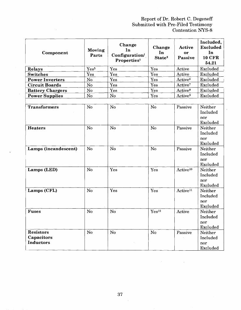
Report of Dr. Robert C. DegeneffSubmitted with Pre-Filed Testimony
Contention NYS-8
ChangeIncluded,
Change Active ExcludedComponent
Moving In In InParts Configuration/.
orState2 Passive 10 CFR
Properties1
54.21
Relays Yes5 Yes Yes Active ExcludedI
Switches Yes Yes Yes Active ExcludedPower Inverters No Yes Yes Active6 ExcludedCircuit Boards No Yes Yes Active7 ExcludedBattery Chargers No Yes Yes Active8 ExcludedPower Supplies No No Yes Active9 Excluded
Transformers No No No Passive NeitherIncludednorExcluded
Heaters No No No Passive NeitherIncludednorExcluded
Lamps (incandescent) No No No Passive NeitherIncludednorExcluded
Lamps (LED) No Yes Yes Active10 NeitherIncludednorExcluded
Lamps (CFL) No Yes Yes Active 11 NeitherIncludednorExcluded
Fuses No No Yes12 Active NeitherIncludednorExcluded
Resistors No No No Passive NeitherCapacitors IncludedInductors nor
Excluded
37
Report of Dr. Robert C. DegeneffSubmitted with Pre-Filed Testimony
Contention NYS-8
Table Endnotes:
1 Change in configuration occurs only with an external energy source applied.
2 Final Rule, Nuclear Power Plant License Renewal; Revisions, 60 Fed. Reg. 22,461, 22,477 (May 8,1995): "Further, the Commission has concluded that 'a change in configuration or properties,' should beinterpreted to include 'a change in state,' which is a term sometimes found in the literature relating to'passive.'"
3 Pressure and level transmitters mayor may not contain moving parts. Solid state indicators (LEOs orplasma) contain no moving parts; however, they do contain solid state devices such as transistors.
4 Most process transmitters and indicators (level, flow, pressure) contain either moving parts ortransistors (solid state devices) and are considered "active."
5 Solid state relays and switches do not contain moving parts; however, they are considered active basedupon the Commission's SOC related to transistors.
6 Power inverters employ solid state and other active devices to convert DC power to AC power. Poweroutput may be controlled by external inputs.
7 Circuit boards are assumed for the purpose of this discussion to contain active components such astransistors and other solid state devices.
8 Battery chargers convert AC voltages and currents to DC using solid state active devices such astransistors and rectifiers. Power output may be controlled by external inputs.
9 Power supplies convert AC voltages and currents to DC regulated voltages using solid state activedevices such as transistors and rectifiers.
10 Light Emitting Diodes (LEOs) change state (conductance) when a voltage is applied. State isdetermined by the polarity of the applied voltage.
II Compact Fluorescent Lights (CFL) lamps contain active devices such as diodes and transistors andmay also contain passive devices including transformers.
12 In order to perform their intended function, fuses undergo a change of state (conductance).
38