standalone pumped storage component of
TRANSCRIPT
________________________________________________________________________________
STANDALONE PUMPED STORAGE COMPONENT OF SAUNDATTI INTEGRATED RENEWABLE ENERGY PROJECT (IREP)
(4 X 252 MW + 2 X 126 MW)
FEASIBILITY REPORT
GREENKO SOLAR ENERGY PRIVATE LIMITED SEPTEMBER 2019
________________________________________________________________________________
TABLE OF CONTENTS
Sl. No. Description Page No.
Chapter - 1 Executive Summary 1
Chapter - 2 Salient Features of The Project 9
Chapter - 3 Project Area 16
Chapter - 4 Power Scenario 21
Chapter - 5 Survey and Geotechnical Investigations 23
Chapter - 6 Hydrology & Power Potential Studies 31
Chapter - 7 Design Features of Major Components 37
Chapter - 8 Electro-Mechanical Equipment’s 41
Chapter - 9 Environmental Aspects 64
Chapter – 10 Construction Programme Schedule 74
Chapter – 11 Cost Estimate 77
DRAWINGS
Drawing -1 General Layout Plan on Topo Sheet Saundatti-PSP-001
Drawing - 2 General Layout – Plan on Contour Saundatti-PSP-002
Drawing - 3 General Arrangement Plan Saundatti-PSP-003
Drawing - 4 General Arrangement – L - Section Saundatti-PSP-004
________________________________________________________________________________
_____________________________________________________________________ Feasibility Report-Standalone Component of Saundatti IREP Rev - R0
Page 1
CHAPTER – 1 EXECUTIVE SUMMARY
1.1 Introduction
Proposed Saundatti Integrated Renewable Energy Project (IREP) is located in Belagavi Distt of Karnataka. Saundatti IREP is a 4 GW project i.e. 2 GW of Solar Project and 2 GW of wind project with storage capacity of 1260MW/13734 MWH. This entire project is a self-identified project and is a first of its kind in the country which will supply firm dispatchable renewable power to the Discom /Grid for 24 Hrs i.e. round the clock (RTC). All three components of Saundatti IREP are in closed vicinity therefore power from all three components will be pooled in a common pooling station and will be connected to PGCIL sub-station at Dharwad.
Storage component of Saundatti IREP is a pumped storage project of 1260MW/13734 MWH storage capacity, located in Belagavi district of Karnataka. Saundatti IREP will comprise of two reservoirs i.e. Renuka Sagar Reservoir (already existing) and Saundatti IREP Reservoir (to be constructed newly). This project is a one of its kind because the proposed reservoir is not located on any river course and the existing Renuka Sagar reservoir is located across river Malaprabha. The proposed Saundatti IREP reservoir is far away from any river course.
The Saundatti IREP is located in Belagavi district of Karnataka. It envisages creation of reservoir near village Somapura under Tallur Grama Panchayat, Saundatti Taluk about 80 Kms from Belagavi. The Saundatti IREP is proposed in between two reservoirs i.e. Saundatti IREP Reservoir as Upper reservoir (to be constructed newly) and the existing Renuka Sagar (Malaprabha) Reservoir as Lower reservoir. This scheme envisages non-consumptive re-utilization of 1 TMC of water of the Renuka Sagar reservoir by recirculation. The water in the Renuka Sagar reservoir (existing lower reservoir) will be pumped up and stored in the proposed Saundatti IREP reservoir (Upper Reservoir) and will be utilized for power generation. The Geographical co - ordinates of the proposed Saundatti IREP reservoir are at longitude 75° 00' 19.50" East and latitude is 15° 51' 21.84" North and that of Renuka Sagar reservoir (existing) are15° 49' 17.15" N and 75° 05' 48.23" E. Proposed Rating of the Saundatti IREP Pump storage project is 1260 MW.
This project was conceived to provide Round The Clock renewables. Later on during discussions with DISCOMs and other buyers it was observed that preferred requirement is for lower number of hours i.e, 6-7 hours. In view of above final configuration of machines may change to fulfill the PPA requirements as same is presently under process. Since this is pumped storage
________________________________________________________________________________
_____________________________________________________________________ Feasibility Report-Standalone Component of Saundatti IREP Rev - R0
Page 2
project it will be ensured that even with revised configurations of machines total MWh of the project i.e, 13734 MWh will remain same as with present configuration of machines.
1.2 Scope of Report
The proposed Saundatti IREP is a self-identified project and this Pre-feasibility Report has been prepared to study, evaluate and establish the technical feasibility and economic viability of the proposed Saundatti IREP.
1.3 Scope of Works
The Saundatti IREP envisages construction of Upper reservoir (proposed) located in Saundatti Taluk of Belagavi District. The Renuka Sagar reservoir (Existing) is under operation with a live storage capacity of 29.34 TMC and utilized as Saundatti IREP Lower reservoir and is proposed for the live storage capacity of 1.00 TMC.
Two alternative layouts for this scheme were studied.
Alternative – 1: Upper reservoir is located on moderately flat land on top of hill and this scheme comprises of Intake Structure, Penstock / Pressure Shaft, Power House, Tail Race Outlet and Tail Race Channel
Alternative -2: Upper reservoir is located on the natural depression and this scheme comprises of Intake Structure, Head Race Tunnel, Surge Shaft, Penstock / Pressure Shaft, Power House, Tail Race Outlet and Tail Race Channel
Alternative-1
In Alternative -1, the Upper reservoir is proposed to be located on the flat / gradually sloping land wherein on one side a small hillock portion is existing which has to be excavated up to the desired level. Considering this location, the area capacity calculation has been carried out and found that the location is suitable for creating the gross storage capacity of 1.03 TMC in which live storage capacity is 1 TMC and dead storage capacity is 0.03 TMC by keeping FRL and MDDL at EL 855.00m & EL 825.00m respectively. For creating this storage, it is proposed to construct rockfill embankment with maximum height of 38 for the length of 5177m. This layout of the scheme comprises the following components:
Intake Structure
Penstock / Pressure Shaft
Power House
________________________________________________________________________________
_____________________________________________________________________ Feasibility Report-Standalone Component of Saundatti IREP Rev - R0
Page 3
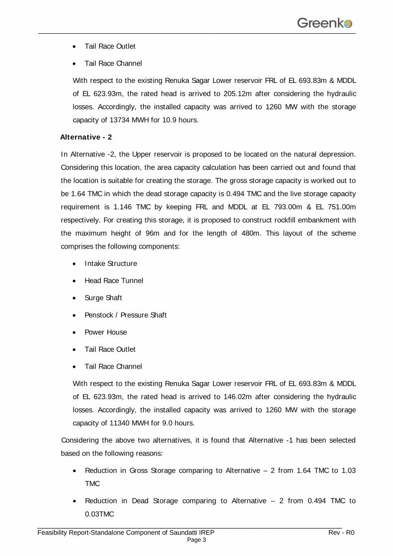
Tail Race Outlet
Tail Race Channel
With respect to the existing Renuka Sagar Lower reservoir FRL of EL 693.83m & MDDL of EL 623.93m, the rated head is arrived to 205.12m after considering the hydraulic losses. Accordingly, the installed capacity was arrived to 1260 MW with the storage capacity of 13734 MWH for 10.9 hours.
Alternative - 2
In Alternative -2, the Upper reservoir is proposed to be located on the natural depression. Considering this location, the area capacity calculation has been carried out and found that the location is suitable for creating the storage. The gross storage capacity is worked out to be 1.64 TMC in which the dead storage capacity is 0.494 TMC and the live storage capacity requirement is 1.146 TMC by keeping FRL and MDDL at EL 793.00m & EL 751.00m respectively. For creating this storage, it is proposed to construct rockfill embankment with the maximum height of 96m and for the length of 480m. This layout of the scheme comprises the following components:
Intake Structure
Head Race Tunnel
Surge Shaft
Penstock / Pressure Shaft
Power House
Tail Race Outlet
Tail Race Channel
With respect to the existing Renuka Sagar Lower reservoir FRL of EL 693.83m & MDDL of EL 623.93m, the rated head is arrived to 146.02m after considering the hydraulic losses. Accordingly, the installed capacity was arrived to 1260 MW with the storage capacity of 11340 MWH for 9.0 hours.
Considering the above two alternatives, it is found that Alternative -1 has been selected based on the following reasons:
Reduction in Gross Storage comparing to Alternative – 2 from 1.64 TMC to 1.03 TMC
Reduction in Dead Storage comparing to Alternative – 2 from 0.494 TMC to
0.03TMC
________________________________________________________________________________
_____________________________________________________________________ Feasibility Report-Standalone Component of Saundatti IREP Rev - R0
Page 4
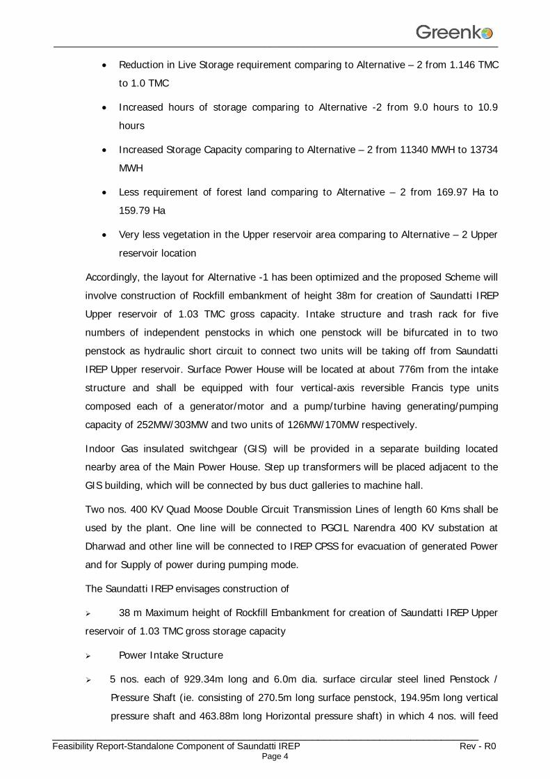
Reduction in Live Storage requirement comparing to Alternative – 2 from 1.146 TMC to 1.0 TMC
Increased hours of storage comparing to Alternative -2 from 9.0 hours to 10.9 hours
Increased Storage Capacity comparing to Alternative – 2 from 11340 MWH to 13734 MWH
Less requirement of forest land comparing to Alternative – 2 from 169.97 Ha to 159.79 Ha
Very less vegetation in the Upper reservoir area comparing to Alternative – 2 Upper
reservoir location
Accordingly, the layout for Alternative -1 has been optimized and the proposed Scheme will involve construction of Rockfill embankment of height 38m for creation of Saundatti IREP Upper reservoir of 1.03 TMC gross capacity. Intake structure and trash rack for five numbers of independent penstocks in which one penstock will be bifurcated in to two penstock as hydraulic short circuit to connect two units will be taking off from Saundatti IREP Upper reservoir. Surface Power House will be located at about 776m from the intake structure and shall be equipped with four vertical-axis reversible Francis type units composed each of a generator/motor and a pump/turbine having generating/pumping capacity of 252MW/303MW and two units of 126MW/170MW respectively.
Indoor Gas insulated switchgear (GIS) will be provided in a separate building located nearby area of the Main Power House. Step up transformers will be placed adjacent to the GIS building, which will be connected by bus duct galleries to machine hall.
Two nos. 400 KV Quad Moose Double Circuit Transmission Lines of length 60 Kms shall be used by the plant. One line will be connected to PGCIL Narendra 400 KV substation at Dharwad and other line will be connected to IREP CPSS for evacuation of generated Power and for Supply of power during pumping mode.
The Saundatti IREP envisages construction of
38 m Maximum height of Rockfill Embankment for creation of Saundatti IREP Upper reservoir of 1.03 TMC gross storage capacity
Power Intake Structure
5 nos. each of 929.34m long and 6.0m dia. surface circular steel lined Penstock / Pressure Shaft (ie. consisting of 270.5m long surface penstock, 194.95m long vertical pressure shaft and 463.88m long Horizontal pressure shaft) in which 4 nos. will feed
________________________________________________________________________________
_____________________________________________________________________ Feasibility Report-Standalone Component of Saundatti IREP Rev - R0
Page 5
4 units each of 252 MW and 1 no. will get bifurcated in to two near to power house to feed 2 units each of 126 MW.
A surface Power house having an installation of four nos. reversible Francis turbine each of 252 MW capacity (all are variable speed turbines) and two nos. reversible Francis turbine each of 1265 MW capacity (Both are variable speed turbines) operating under a rated head of 205.12 m in generating mode and 218.12 m in pumping mode.
Tailrace Outlet Structure
70m wide and FSD of 5.1m Tail race channel 1688 m long connecting to the Existing Renuka Sagar reservoir.
1.4 Hydrology
The total catchment area of the Renuka Sagar Reservoir is 2176 Sq. Km and the design flood discharge is 5239 cumec. The gross storage capacity of the Renuka sagar reservoir is 1067.27 Mcum (37.69 TMC) and the live storage is 830.81 Mcum (29.34 TMC). Operational pattern of Saundatti IREP has been kept in such a way that 1.0 TMC of water will be utilized for the proposed Saundatti IREP without affecting the existing commitments at existing Renuka sagar Reservoir. The project is a pumped storage scheme and hence, no consumptive utilization of water is required for its operation. The Saundatti IREP on Upper reservoir is proposed with a live storage of 1.00 TMC to facilitate the pumping operations.
1.5 Installed Capacity
The Saundatti IREP is proposed with a Storage Capacity of 13734 MWH with Rating of 1260 MW. This project is comprising of 4 units of 252 MW each and 2 units of 126 MW each. The installed capacity of a pumped storage scheme is influenced by the requirements of daily peaking power requirements, flexibility in efficient operation of units, storage available in the reservoirs and the area capacity characteristics. The Project in present scheme envisaged will generate 1260 MW by utilizing a design discharge of 711.56 Cumec and rated head of 205.12 m.
This project was conceived to provide Round The Clock renewables. Later on during discussions with DISCOMs and other buyers it was observed that preferred requirement is for lower number of hours i.e, 6-7 hours. In view of above final configuration of machines may change to fulfill the PPA requirements as same is presently under process. Since this is pumped storage project it will be ensured that even with revised configurations of machines total MWh of the project i.e, 13734 MWh will remain same as with present
________________________________________________________________________________
_____________________________________________________________________ Feasibility Report-Standalone Component of Saundatti IREP Rev - R0
Page 6
configuration of machines.
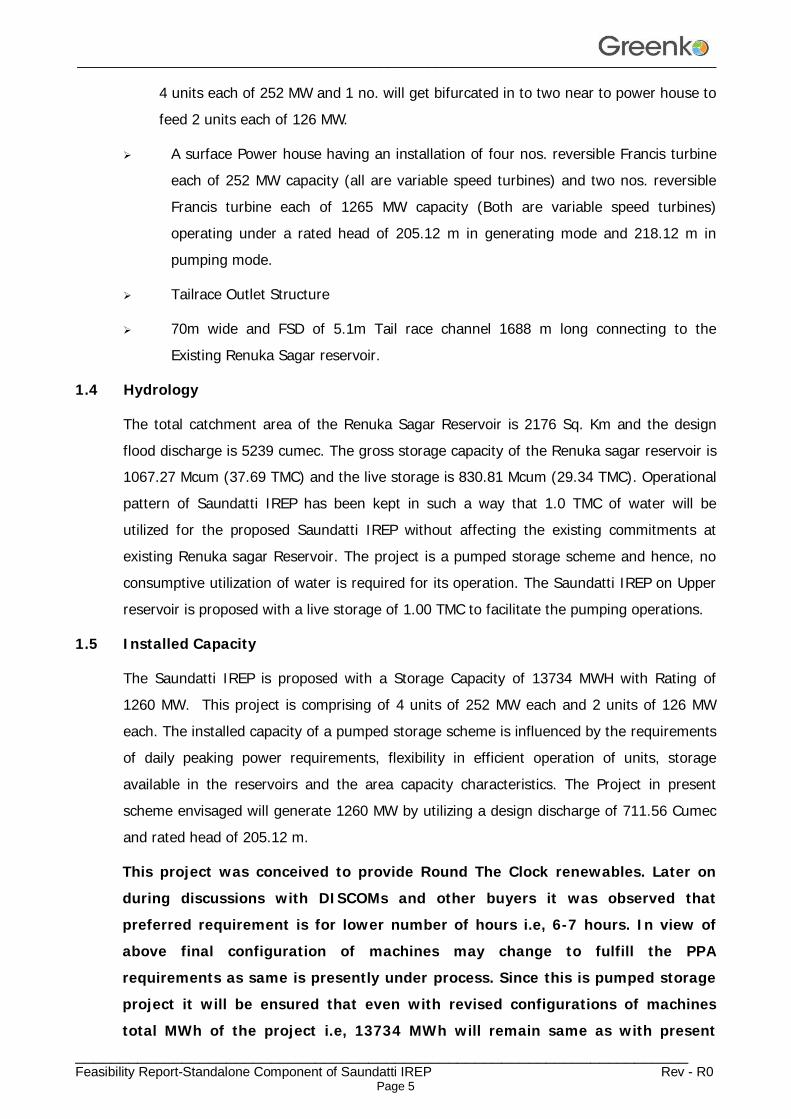
The Key parameters of Saundatti IREP Operation are as follows:
Sl. No. Parameter Unit Value
1 Storage Capacity MWH 13734
2 Rating MW 1260
3 No. of Units Nos. 6 4 Rated Head in Turbine mode m 205.12
5 Total Design Discharge Cumec 711.56
6 Design Discharge per unit of 252 MW Cumec 142.31 7 Design Discharge per unit of 126 MW Cumec 71.16
8 Generation Duration Hrs 10.9
9 Turbine Capacity – 4 Units MW 252
10 Turbine Capacity – 2 Units MW 126
11 Annual Energy Generation MU 4830
12 Pump Capacity – 4 Units MW 303
13 Pump Capacity – 2 Units MW 170 14 Rated Head in Pump mode m 218.12
15 Pumping Duration Hrs. 11.20
16 Annual Energy consumption Mu 6027
17 Cycle Efficiency % 80.13 The volume of water required for turbine mode of operation is equated to the pumped mode. In present scheme configuration annual energy generation by Saundatti IREP in Turbine mode is 4830 MU and annual energy consumption by Saundatti IREP in Pump mode is 6027 MU and the Cycle efficiency is 80.13%.
1.6 Power Evacuation
Two nos. 400 KV Quad Moose Double Circuit Transmission Lines of length 60 Kms shall be used by the plant. One line will be connected to PGCIL Narendra 400 KV substation at Dharwad and other line will be connected to IREP CPSS for evacuation of generated Power and for Supply of power during pumping mode.
1.7 Environmental Aspects
Upper and lower reservoir for Saundatti IREP will consist of proposed Saundatti IREP Upper reservoir (to be constructed newly) and the existing Renuka Sagar reservoir. There will be an additional land required for the proposed Saundatti IREP Upper reservoir for the pumped storage project. Also, the land required is for the construction of power house
________________________________________________________________________________
_____________________________________________________________________ Feasibility Report-Standalone Component of Saundatti IREP Rev - R0
Page 7
complex and its apparent works Viz., Intake structure, Penstocks, Powerhouse, Tail Race Outlet and Tail Race Channel etc. Total land required for the construction of various components is about 213.09 Ha. The project area is in Kagehala forest under Savadati Range. Tail race channel falls totally in private land area. Based on assessment of environmental impacts, management plans must be formulated for Catchment Area Treatment, compensatory afforestation and other environmental issues like rehabilitation & resettlement. These issues would be addressed during the investigations for DPR.
1.8 Construction Planning & Schedule
It is proposed to construct the project within a period of 3 years including infrastructure development which is proposed to be completed within 6 months.
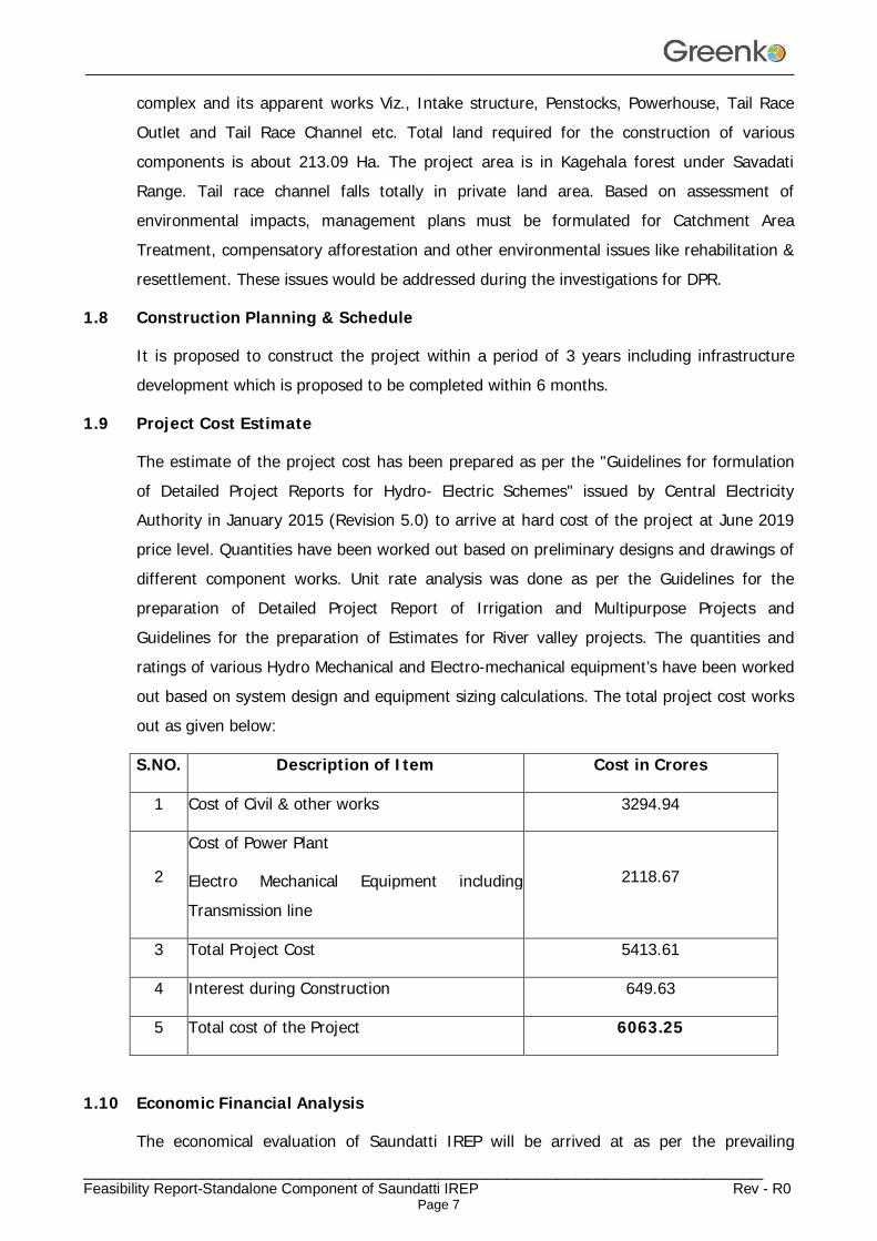
1.9 Project Cost Estimate
The estimate of the project cost has been prepared as per the "Guidelines for formulation of Detailed Project Reports for Hydro- Electric Schemes" issued by Central Electricity Authority in January 2015 (Revision 5.0) to arrive at hard cost of the project at June 2019 price level. Quantities have been worked out based on preliminary designs and drawings of different component works. Unit rate analysis was done as per the Guidelines for the preparation of Detailed Project Report of Irrigation and Multipurpose Projects and Guidelines for the preparation of Estimates for River valley projects. The quantities and ratings of various Hydro Mechanical and Electro-mechanical equipment’s have been worked out based on system design and equipment sizing calculations. The total project cost works out as given below:
S.NO. Description of Item Cost in Crores
1 Cost of Civil & other works 3294.94
2
Cost of Power Plant
Electro Mechanical Equipment including Transmission line
2118.67
3 Total Project Cost 5413.61
4 Interest during Construction 649.63
5 Total cost of the Project 6063.25
1.10 Economic Financial Analysis
The economical evaluation of Saundatti IREP will be arrived at as per the prevailing

________________________________________________________________________________
_____________________________________________________________________ Feasibility Report-Standalone Component of Saundatti IREP Rev - R0
Page 8
guidelines of PSP.
1.11 Conclusions
The Saundatti IREP is envisaged to be completed in a period of 3 years. The project cost works out to Rs. 6063.25 Crores. The project would generate designed energy of 4830 MU. Other benefit of this storage project can be in the form of spinning reserve with almost instantaneous start-up from zero to full power supply, supply of reactive energy, primary frequency regulation, voltage regulation, etc.
________________________________________________________________________________
_____________________________________________________________________ Feasibility Report-Standalone Component of Saundatti IREP Rev - R0
Page 9
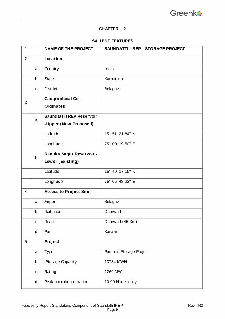
CHAPTER – 2 SALIENT FEATURES
1 NAME OF THE PROJECT SAUNDATTI IREP - STORAGE PROJECT
2 Location
a Country India
b State Karnataka
c District Belagavi
3 Geographical Co-Ordinates
a Saundatti IREP Reservoir -Upper (Now Proposed)
Latitude 15° 51' 21.84" N
Longitude 75° 00' 19.50" E
b Renuka Sagar Reservoir -Lower (Existing)
Latitude 15° 49' 17.15" N
Longitude 75° 05' 48.23" E
4 Access to Project Site
a Airport Belagavi
b Rail head Dharwad
c Road Dharwad (45 Km)
d Port Karwar
5 Project
a Type Pumped Storage Project
b Storage Capacity 13734 MWH
c Rating 1260 MW
d Peak operation duration 10.90 Hours daily
________________________________________________________________________________
_____________________________________________________________________ Feasibility Report-Standalone Component of Saundatti IREP Rev - R0
Page 10
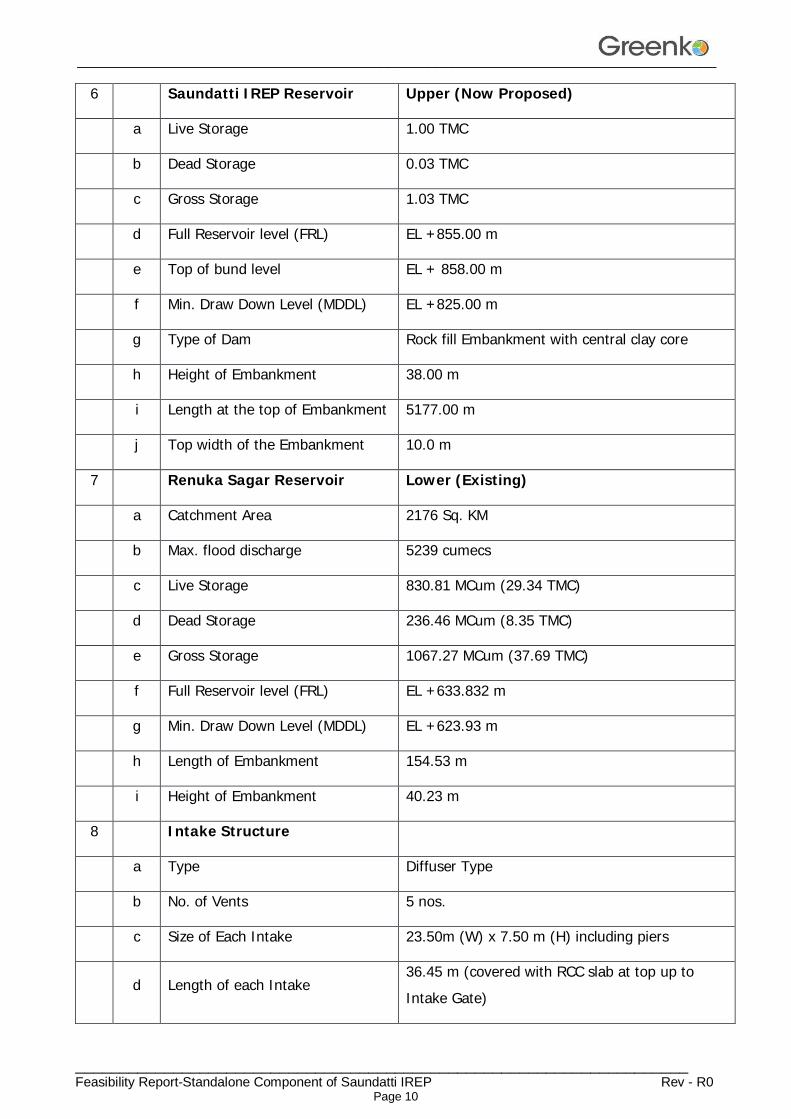
6 Saundatti IREP Reservoir Upper (Now Proposed)
a Live Storage 1.00 TMC
b Dead Storage 0.03 TMC
c Gross Storage 1.03 TMC
d Full Reservoir level (FRL) EL +855.00 m
e Top of bund level EL + 858.00 m
f Min. Draw Down Level (MDDL) EL +825.00 m
g Type of Dam Rock fill Embankment with central clay core
h Height of Embankment 38.00 m
i Length at the top of Embankment 5177.00 m
j Top width of the Embankment 10.0 m
7 Renuka Sagar Reservoir Lower (Existing)
a Catchment Area 2176 Sq. KM
b Max. flood discharge 5239 cumecs
c Live Storage 830.81 MCum (29.34 TMC)
d Dead Storage 236.46 MCum (8.35 TMC)
e Gross Storage 1067.27 MCum (37.69 TMC)
f Full Reservoir level (FRL) EL +633.832 m
g Min. Draw Down Level (MDDL) EL +623.93 m
h Length of Embankment 154.53 m
i Height of Embankment 40.23 m
8 Intake Structure
a Type Diffuser Type
b No. of Vents 5 nos.
c Size of Each Intake 23.50m (W) x 7.50 m (H) including piers
d Length of each Intake 36.45 m (covered with RCC slab at top up to Intake Gate)
________________________________________________________________________________
_____________________________________________________________________ Feasibility Report-Standalone Component of Saundatti IREP Rev - R0
Page 11
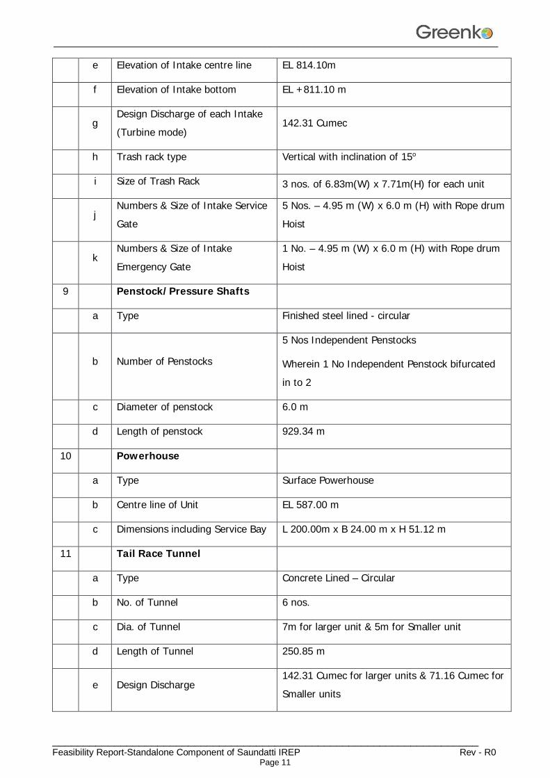
e Elevation of Intake centre line EL 814.10m
f Elevation of Intake bottom EL +811.10 m
g Design Discharge of each Intake (Turbine mode)
142.31 Cumec
h Trash rack type Vertical with inclination of 15o
i Size of Trash Rack 3 nos. of 6.83m(W) x 7.71m(H) for each unit
j Numbers & Size of Intake Service Gate
5 Nos. – 4.95 m (W) x 6.0 m (H) with Rope drum Hoist
k Numbers & Size of Intake Emergency Gate
1 No. – 4.95 m (W) x 6.0 m (H) with Rope drum Hoist
9 Penstock/Pressure Shafts
a Type Finished steel lined - circular
b Number of Penstocks
5 Nos Independent Penstocks
Wherein 1 No Independent Penstock bifurcated in to 2
c Diameter of penstock 6.0 m
d Length of penstock 929.34 m
10 Powerhouse
a Type Surface Powerhouse
b Centre line of Unit EL 587.00 m
c Dimensions including Service Bay L 200.00m x B 24.00 m x H 51.12 m
11 Tail Race Tunnel
a Type Concrete Lined – Circular
b No. of Tunnel 6 nos.
c Dia. of Tunnel 7m for larger unit & 5m for Smaller unit
d Length of Tunnel 250.85 m
e Design Discharge 142.31 Cumec for larger units & 71.16 Cumec for Smaller units
________________________________________________________________________________
_____________________________________________________________________ Feasibility Report-Standalone Component of Saundatti IREP Rev - R0
Page 12
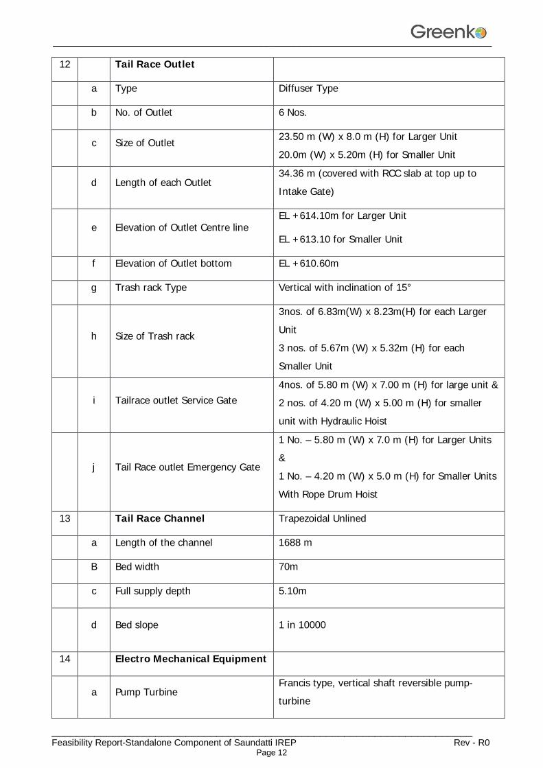
12 Tail Race Outlet
a Type Diffuser Type
b No. of Outlet 6 Nos.
c Size of Outlet 23.50 m (W) x 8.0 m (H) for Larger Unit 20.0m (W) x 5.20m (H) for Smaller Unit
d Length of each Outlet 34.36 m (covered with RCC slab at top up to Intake Gate)
e Elevation of Outlet Centre line EL +614.10m for Larger Unit
EL +613.10 for Smaller Unit
f Elevation of Outlet bottom EL +610.60m
g Trash rack Type Vertical with inclination of 15°
h Size of Trash rack
3nos. of 6.83m(W) x 8.23m(H) for each Larger Unit 3 nos. of 5.67m (W) x 5.32m (H) for each Smaller Unit
i Tailrace outlet Service Gate 4nos. of 5.80 m (W) x 7.00 m (H) for large unit & 2 nos. of 4.20 m (W) x 5.00 m (H) for smaller unit with Hydraulic Hoist
j Tail Race outlet Emergency Gate
1 No. – 5.80 m (W) x 7.0 m (H) for Larger Units &
1 No. – 4.20 m (W) x 5.0 m (H) for Smaller Units
With Rope Drum Hoist
13 Tail Race Channel Trapezoidal Unlined
a Length of the channel 1688 m
B Bed width 70m
c Full supply depth 5.10m
d Bed slope 1 in 10000
14 Electro Mechanical Equipment
a Pump Turbine Francis type, vertical shaft reversible pump-turbine
________________________________________________________________________________
_____________________________________________________________________ Feasibility Report-Standalone Component of Saundatti IREP Rev - R0
Page 13
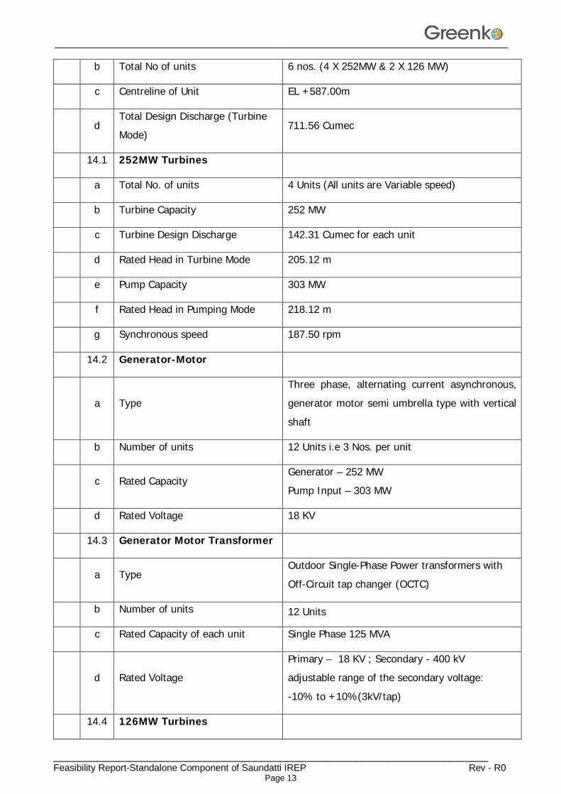
b Total No of units 6 nos. (4 X 252MW & 2 X 126 MW)
c Centreline of Unit EL +587.00m
d Total Design Discharge (Turbine Mode)
711.56 Cumec
14.1 252MW Turbines
a Total No. of units 4 Units (All units are Variable speed)
b Turbine Capacity 252 MW
c Turbine Design Discharge 142.31 Cumec for each unit
d Rated Head in Turbine Mode 205.12 m
e Pump Capacity 303 MW
f Rated Head in Pumping Mode 218.12 m
g Synchronous speed 187.50 rpm
14.2 Generator-Motor
a Type Three phase, alternating current asynchronous, generator motor semi umbrella type with vertical shaft
b Number of units 12 Units i.e 3 Nos. per unit
c Rated Capacity Generator – 252 MW
Pump Input – 303 MW
d Rated Voltage 18 KV
14.3 Generator Motor Transformer
a Type Outdoor Single-Phase Power transformers with Off-Circuit tap changer (OCTC)
b Number of units 12 Units
c Rated Capacity of each unit Single Phase 125 MVA
d Rated Voltage Primary – 18 KV ; Secondary - 400 kV adjustable range of the secondary voltage: -10% to +10%(3kV/tap)
14.4 126MW Turbines
________________________________________________________________________________
_____________________________________________________________________ Feasibility Report-Standalone Component of Saundatti IREP Rev - R0
Page 14
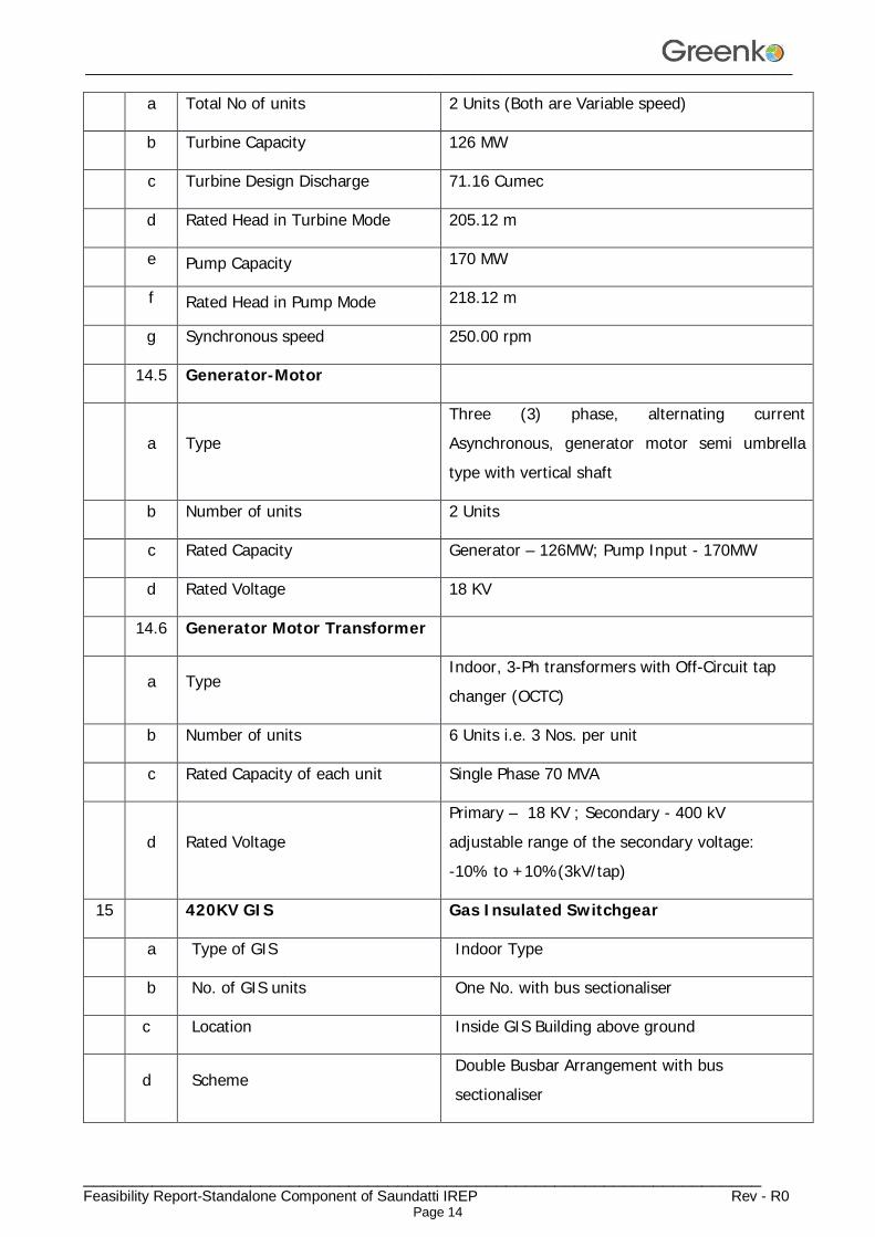
a Total No of units 2 Units (Both are Variable speed)
b Turbine Capacity 126 MW
c Turbine Design Discharge 71.16 Cumec
d Rated Head in Turbine Mode 205.12 m
e Pump Capacity 170 MW
f Rated Head in Pump Mode 218.12 m
g Synchronous speed 250.00 rpm
14.5 Generator-Motor
a Type Three (3) phase, alternating current Asynchronous, generator motor semi umbrella type with vertical shaft
b Number of units 2 Units
c Rated Capacity Generator – 126MW; Pump Input - 170MW
d Rated Voltage 18 KV
14.6 Generator Motor Transformer
a Type Indoor, 3-Ph transformers with Off-Circuit tap changer (OCTC)
b Number of units 6 Units i.e. 3 Nos. per unit
c Rated Capacity of each unit Single Phase 70 MVA
d Rated Voltage Primary – 18 KV ; Secondary - 400 kV adjustable range of the secondary voltage: -10% to +10%(3kV/tap)
15 420KV GIS Gas Insulated Switchgear
a Type of GIS Indoor Type
b No. of GIS units One No. with bus sectionaliser
c Location Inside GIS Building above ground
d Scheme Double Busbar Arrangement with bus sectionaliser
________________________________________________________________________________
_____________________________________________________________________ Feasibility Report-Standalone Component of Saundatti IREP Rev - R0
Page 15
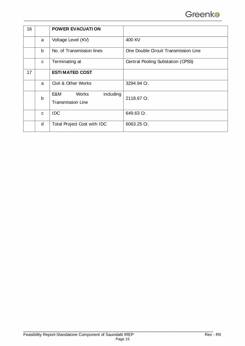
16 POWER EVACUATION
a Voltage Level (KV) 400 KV
b No. of Transmission lines One Double Circuit Transmission Line
c Terminating at Central Pooling Substation (CPSS)
17 ESTIMATED COST
a Civil & Other Works 3294.94 Cr.
b E&M Works including Transmission Line
2118.67 Cr.
c IDC 649.63 Cr.
d Total Project Cost with IDC 6063.25 Cr.

________________________________________________________________________________
_____________________________________________________________________ Feasibility Report-Standalone Component of Saundatti IREP Rev - R0
Page 16
CHAPTER – 3 PROJECT AREA
3.1 General
Saundatti IREP is located in Belagavi district of Karnataka. It envisages creation of Upper reservoir which is located away from all existing natural water systems and have no/negligible catchment area. The project is about 80 km from District headquarters Belagavi via Yeragatti. Nearest railhead and Airport are located at Dharwad and Belagavi respectively. The nearest Village to project is Somapura about 3 Km, which comes under Tallur Grama Panchayat, Saundatti Taluk. The Storage Capacity of the Project is proposed as 13734 MWH.
Karnataka is one of the 29 states of India, situated on the country's southwestern coast. The state is the seventh largest state covering an area of 1,91,976 km2 (74122 sq. mi). As per 2011 census of India, the state is the eighth largest by population with 6,11,30,704 inhabitants.
The state borders Kerala in the south, Maharashtra in the northwest, Karnataka in the northeast, Arabian sea in the west, Tamil Nadu in the south east. Karnataka is divided into 30 districts and 4 administrative divisions. The state is geographically consisting of 4 principal regions, the coastal region of Karavali, the hilly Malenadu region comprising the Western Ghats, Malnadu region of Kolar, Bengaluru and Tumakuru and the Bayaluseeme region comprising the plains of the Deccan plateau. Geographically, the two main river systems of the state are the Krishna and its tributaries, the Bhima, Ghataprabha, Vedavathi, Malaprabha, and Tungabhadra, in the north, and the Kaveri and its tributaries, the Hemavati, Shimsha, Arkavati, Lakshmana Thirtha and Kabini, in the south. Most of these rivers flow out of Karnataka eastward, reaching the sea at the Bay of Bengal.
The total forest cover of the state after the bifurcation is left with an area of 22,862 km2. The forest in the state can be broadly divided into four major biotic provinces. They are Deccan Plateau, Central Plateau, Eastern Highland, East Coastal Plains. Though several etymologies have been suggested for the name Karnataka, the generally accepted one is that Karnataka is derived from the Kannada words karu and nādu, meaning "elevated land". Karu nadu may also be read as karu, meaning "black", and nadu, meaning "region", as a reference to the black cotton soil found in the Bayalu Seeme region of the state. The British used the word Carnatic, sometimes Karnatak, to describe both sides of peninsular India, south of the Krishna.

________________________________________________________________________________
_____________________________________________________________________ Feasibility Report-Standalone Component of Saundatti IREP Rev - R0
Page 17
Karnataka has a rich diversity of flora and fauna. It has a recorded forest area of 38,720 km2 (14,950 sq. mile) which constitutes 20.19% of the total geographical area of the state. These forests support 25% of the elephant and 10% of the tiger population of India. Many regions of Karnataka are yet unexplored, so new species of flora and fauna are found periodically. The Western Ghats, a biodiversity hotspot, includes the western region of Karnataka. Two sub-clusters in the Western Ghats, viz. Talacauvery and Kudremukh, both in Karnataka, are on the tentative list of World Heritage Sites of UNESCO. The Bandipur and Nagarahole National Parks, which fall outside these sub clusters, were included in the Nilgiri Biosphere Reserve in 1986, a UNESCO designation. The Indian roller and the Indian elephant are recognised as the state bird and animal while sandalwood and the lotus are recognised as the state tree and flower respectively. Karnataka has five national parks: Anshi, Bandipur, Bannerghatta, Kudremukh and Nagarhole. It also has 27 wildlife sanctuaries of which seven are bird sanctuaries.
Wild animals that are found in Karnataka include the elephant, the tiger, the leopard, the gaur, the sambar deer, the chital or spotted deer, the muntjac, the bonnet macaque, the slender loris, the common palm civet, the small Indian civet, the sloth bear, the dhole, the striped hyena and the golden jackal. Some of the birds found here are the great hornbill, the Malabar pied hornbill, the Ceylon frogmouth, herons, ducks, kites, eagles, falcons, quails, partridges, lapwings, sandpipers, pigeons, doves, parakeets, cuckoos, owls, nightjars, swifts, kingfishers, bee-eaters and munias. Some species of trees found in Karnataka are Callophyllum tomentosa, Callophyllum wightianum, Garcina cambogia, Garcina morealla, Alstonia scholaris, Flacourtia montana, Artocarpus hirsutus, Artocarpus lacoocha, Cinnamomum zeylanicum, Grewia tilaefolia, Santalum album, Shorea talura, Emblica officinalis, Vitex altissima and Wrightia tinctoria. Wildlife in Karnataka is threatened by poaching, habitat destruction, human-wildlife conflict and pollution.
3.2 Malaprabha River
The Malaprabha river flows through Karnataka state. The Malaprabha river originates from Chorla ghats, which is a part of Western Ghats. It is a tributary to the Krishna river and it flows through the Dharwad district. The Malaprabha river is an important river in north Karnataka. The ancient temple of Shri Mauli Devi, which is located at the origin of the Malaprabha river, is a well-known pilgrimage centre in India. Badami, Pattadakal and Aihole temples, which are situated on the bank of Malaprabha river are famous in India. Some historical places are located on the bank of the Malaprabha river as well as in the vicinity of the river.

________________________________________________________________________________
_____________________________________________________________________ Feasibility Report-Standalone Component of Saundatti IREP Rev - R0
Page 18
The Malaprabha river originates in the Western Ghats, in the Kanakumbi village of Belagavi district at an altitude of 792 meters above the sea level. The Kanakumbi village is 16 km west of Jamboti village, Khanapur Taluka, Belagavi District in Karnataka state. The Malaprabha river flows first in east direction and then north-west, for almost 300 km and then it merges with Krishna river, at Kudala Sangama in Bagalkot district, Karnataka state. Merging of these two rivers is done at height of 488 meters from sea level.
The Bennihalla, Tuparihalla and Hirehalla are the tributaries of the river. Including its tributaries, the Malaprabha river covers 11,549 Sq. km area. The catchment area of the river lies between 15° 00' and 16° 12’ North latitude and 74° 14' and 76° 05' East longitude, in Karnataka state. The Malaprabha river flows from Kanakumbi, then Khanakpur-Soundatti-Nargund-Kudal Sangam, before it merges with the Krishna river at Kudal Sangama. The confluence of the Malaprabha river with the Krishna river is almost 304 km away from the origin of the Malaprabha river in Western Ghats.
The Bennihalla, Tuparihalla and Hirehalla are the main tributaries of the Malaprabha river. All these rivers originate in district Dharwad. The Bennihalla, Tuparihalla and Hirehalla, all are small streams. The Bennihalla originates at an elevation of 548 meters from sea level.
3.3 Climate
Climate of Karnataka presents an exceptional diversity. While the hilly and plateau regions demonstrate a different climatic behaviour, the plain presents comparatively a warmer atmosphere. Due to this diversity in climate and weather of Karnataka, it has been divided into 3 major parts:
Coastal Karnataka, which includes: Dakshina Kannada and Uttara Kannada districts.
North Interior Karnataka, which includes: Belagavi, Bidar, Bijapur, Dharwad, Gulbarga and Raichur districts.
South Interior Karnataka, which includes: the remaining districts of Bengaluru Rural, Bengaluru, Bellary, Chikmagalur, Chitradurga, Kodagu, Hassan, Kolar, Mysuru, Mandya, Shimoga and Tumkur districts.
The most famous city of Karnataka is Bengaluru which is best known for its awesome weather and panoramic views. Bengaluru is also known as ‘air-conditioned city’. During most of the time in year Bengaluru’s atmosphere remains pleasant, it’s douched with a nice shower, which dissolves a unique jolliness in the air during summers and winters. The coastal regions and highly elevated places reveal uniformity in day and night temperature. Till now the highest recorded temperature is 45.60° C at Raichur in 1928 while the lowest temperature of an individual station was recorded 2.80° C on December 16, 1918 in Bidar.
________________________________________________________________________________
_____________________________________________________________________ Feasibility Report-Standalone Component of Saundatti IREP Rev - R0
Page 19
3.3.1 Summers
The average weather of Karnataka is dry and warm over different regions and summers start from the month of April which last till the month of May. These months are the hottest months in Karnataka, somewhere the humidity percentage is comparatively low but as the month of June starts; pervaded humidity in the air could make you uncomfortable as the monsoon is reaching the state soon. The average temperature remains around 34°C with 75% humidity.
3.3.2 Monsoon
Monsoon season starts from June and lasts till September, as prominent downfalls in temperature are noted but at this time the percentage of humidity gets a little higher in atmosphere. The Tropical Monsoon climate covers the entire coastal belt and adjoining areas. This area experiences heavy rainfall 3456 mm annually while the North interior Karnataka and its adjoining areas; Bijapur, Bagalkot, Belagavi, Haveri, Gadag, Dharwad, Gulbarga, Bellary, Koppal and Raichur districts experience mediocre rainfall of 731mm per annum. On the other side, the South interior Karnataka receives a blissful shower of monsoon annually.
3.4 Mineral Resources
The state of Karnataka is abundant in mineral resources. It is said to be one of the most mineral rich states of India. The mineral belt covers an area of 1.92 lakh sq.km including 30 districts of the state. Karnataka is also endowed with the green stone belt with valuable mineral resources such as gold, silver, copper, iron-ore, manganese, limestone, dolomite, asbestos, bauxite, chromite, kaolin and granite rock.
3.4.1 Other Minerals in Karnataka
Other minerals found scattered across the state are Chromite, Dolomite, and Bauxite. Chromite is found in altered ultrabasic rocks in the districts of Chikmagalur, Chitradurga, Hassan, Mysuru and Shimoga. Dolomite’s presence has been recorded at a number of places. There is a possibility of a reserve of 1112 million tonnes of Dolomite deposits in the regions of Belagavi and Bijapur districts. Bauxite is found in the Chikmagalore district.
Karnataka is among the very few Indian states to formulate a progressive mineral policy as early as the year 2000. Features such as transparency in granting mineral concessions, adoption of modern techniques in mining and emphasis on value addition and sustainability make this policy so progressive.
________________________________________________________________________________
_____________________________________________________________________ Feasibility Report-Standalone Component of Saundatti IREP Rev - R0
Page 20
3.5 Education
The average literacy rate of Karnataka is 75.36 percent. Male literacy rate in Karnataka is 82.47 percent. Female literacy rate in Karnataka is 68.08 percent. Total literates in Karnataka are 40,647,322 people. Male literates in Karnataka are 22,508,471. Female literates in Karnataka are 18,138,851.
3.6 General Features of the Project
Saundatti IREP is located in Belagavi district of Karnataka. It envisages creation of Upper reservoir which is located away from all existing natural water systems and have no/negligible catchment area. There is no consumptive use of water as the same water is used for both pumping and generation. The project envisages construction of a rock fill embankment to form reservoir, an Intake Structure, Penstock / Pressure Shaft and a surface Power House. Storage Capacity of the Project is proposed as 13734 MWH. There are no monuments of archaeological or national importance which would be affected by project activities directly or indirectly.
________________________________________________________________________________
_____________________________________________________________________ Feasibility Report-Standalone Component of Saundatti IREP Rev - R0
Page 21
CHAPTER – 4
POWER SCENARIO
4.1. Karnataka State Power Position
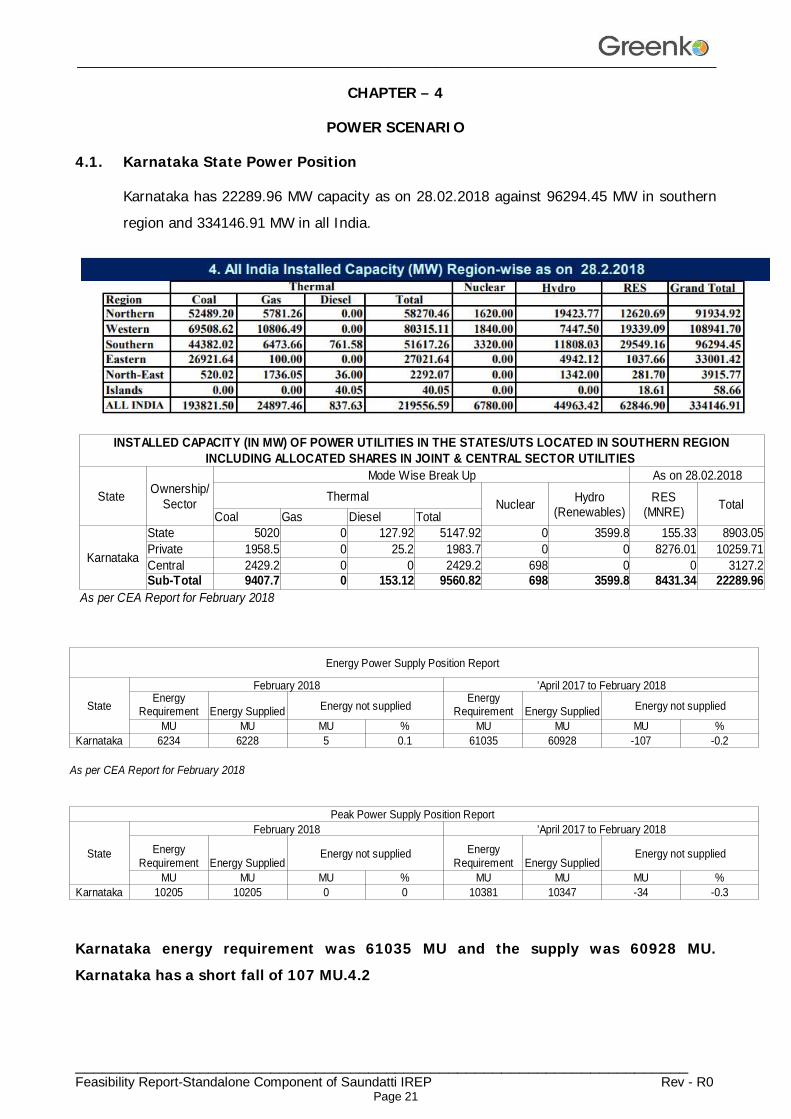
Karnataka has 22289.96 MW capacity as on 28.02.2018 against 96294.45 MW in southern region and 334146.91 MW in all India.
Karnataka energy requirement was 61035 MU and the supply was 60928 MU. Karnataka has a short fall of 107 MU.4.2
State Mode Wise Break Up As on 28.02.2018
Thermal Nuclear TotalCoal Gas Diesel Total
Karnataka
State 5020 0 127.92 5147.92 0 3599.8 155.33 8903.05Private 1958.5 0 25.2 1983.7 0 0 8276.01 10259.71Central 2429.2 0 0 2429.2 698 0 0 3127.2Sub-Total 9407.7 0 153.12 9560.82 698 3599.8 8431.34 22289.96
As per CEA Report for February 2018
INSTALLED CAPACITY (IN MW) OF POWER UTILITIES IN THE STATES/UTS LOCATED IN SOUTHERN REGION INCLUDING ALLOCATED SHARES IN JOINT & CENTRAL SECTOR UTILITIES
Ownership/ Sector Hydro
(Renewables)RES
(MNRE)
Energy Power Supply Position Report
State
February 2018 'April 2017 to February 2018
Energy Supplied Energy not supplied Energy Supplied Energy not supplied
MU MU MU % MU MU MU %Karnataka 6234 6228 5 0.1 61035 60928 -107 -0.2
As per CEA Report for February 2018
Peak Power Supply Position Report
State
February 2018 'April 2017 to February 2018
Energy SuppliedEnergy not supplied
Energy SuppliedEnergy not supplied
MU MU MU % MU MU MU %Karnataka 10205 10205 0 0 10381 10347 -34 -0.3
Energy Requirement
Energy Requirement
Energy Requirement
Energy Requirement
________________________________________________________________________________
_____________________________________________________________________ Feasibility Report-Standalone Component of Saundatti IREP Rev - R0
Page 22
Necessity of Hydro Power Development
The demand and supply position in Karnataka, discussed above, clearly brings out the immediate need for taking up new generation schemes in the state to bridge the gap between supply and demand. Karnataka has the largest hydro power potential among all the states of the Southern region. The need for implementing new hydroelectric schemes in the region for providing peak power besides energy at competitive rates therefore needs no further emphasis. In this power shortage scenario, the option available is to bridge the gap (to a great extent) between demand and supply adopting energy conservation measures optimally utilizing the existing generation capacity by improving Plant Load Factor (PLF) at the supply side and by adopting various energy efficiency measures at the demand side.
In addition of above the most reliable option for energy storage is development of Pumped storage schemes, which is the most widely used form of bulk-energy storage, which uses the simple combination of water and gravity to capture off-peak power and releases it at times of high demand. Along with energy management, pumped storage systems are also helpful in controlling electrical network frequency and provide reserve generation. Thermal plants are much less able to respond to sudden changes in electrical demand, potentially causing frequency and voltage instability. Pumped storage plants, like other hydroelectric plants, can respond to load changes within seconds.
In view of the power scenario described above, the Saundatti IREP envisaged with Storage Capacity of 13734 MWH with present scheme of Rating of 1260 MW and will help a long way in meeting the projected power demand.
________________________________________________________________________________
_____________________________________________________________________ Feasibility Report-Standalone Component of Saundatti IREP Rev - R0
Page 23
CHAPTER – 5
SURVEY & GEOTECHNICAL INVESTIGATIONS
5.1 General
The following investigations shall be carried out specifically for the proposed project and are briefly discussed in this Chapter:
Topographical survey
Geology & Geotechnical investigations
Construction material investigations
Hydrological & Meteorological investigations
5.2 Topographical Survey
Topographical maps (D43D1 and D43C13) of Survey of India were referred for preliminary investigation, reconnaissance and for finalizing the proposed project layout.
5.3 Reconnaissance Survey
The main aim of the project is to utilize the existing Renuka Sagar reservoir and proposed Saundatti IREP reservoir to act as lower and Upper reservoirs respectively for the proposed Saundatti IREP.
A reconnaissance survey is made for the river, existing reservoirs, possible intake and exit locations, penstock tunnels, power house area and TRC. All salient features of the area are noted during the reconnaissance survey.
5.4 Geological Survey & Investigation
5.4.1 Physiography
The Belagavi district is divided into three physiographical divisions.
Malenaadu Tract (Western Ghat Region)
Gadinaadu Tract (Border area Region)
Bayalunaadu Tract (Plain Land Region)
The “Malenaadu” tract is the Western Ghat area, with lush green forests, sharply undulating topography, and heavy rainfall. Many 1st order streams traverse this area. There are many natural springs in this tract. The “Gadinaadu” (intermediary) tract shows medium range flat to gently rising hills, with shrubby greenery, receiving an average rainfall. The streams are of 3rd & 4th order. The “Bayalunaadu” tract shows vast, flat terrain, with flat topped barren hills. The rainfall received is less than 650 mm.
________________________________________________________________________________
_____________________________________________________________________ Feasibility Report-Standalone Component of Saundatti IREP Rev - R0
Page 24
5.4.2 Soil
Soil is an index of the bedrock. Most of the soil is a bi-product of weathering of the bedrock. The Basalt area is covered by black cotton soil where the rock is directly subjected to weathering. Wherever the Zeolitic beds are exposed the soil is brownish with specks of amygdaloids, chalcedony, quartz and calcite, etc. The Sandstone and Quartzite formation are covered by brown, or deep gray, sandy soil. The Lime stone and Dolomite are covered by calcareous dark grey soil. The Schist covered by yellow and purple shale shows yellow and purple soils. The BHQ bands are not altered sufficiently and in many areas the bands are exposed at surface. Broken BHQ pieces and deep brown soil is observed around these deposits. Phyllite having limited weathering shows dark gray coloured soil covering. The Granite and Gneissic Granite, show light brown to deep brown and deep gray soils often mixed with sand and feldspar. The dykes are surrounded by black cotton soil.
5.4.3 Regional Geology
The complex geological formations can be observed in the Belagavi district. The Schist and Banded Ferruginous Quartzite, the peninsular gneiss by Granite and Gneissic Granites, the Kaladgi formations, Sandstone, Quartzite, Shale and Limestone and Dolomite, Basalt (Deccan Trap) and the Laterite formations are observed in the district. The Geological Succession of Belagavi District as follows:
Laterite, Sand deposits - Recent.
Deccan Basalt - Tertiary,
Sand Stone, Dolomite, Limestone - Kaladagi series,
Schist, Gneiss, Granite - Archean.
The Archaen Schist is an extension of the Dharawar schist belt. The formation is overlaid by thick cover of shale, the thickness varying from 15 to 25m as observed in many villages of Khanapur and Bailhongal, Belagavi talukas. In few places like, Marihal in Belagavi taluka, Shivanur, Nichanaki villages of Bailhongal taluka, the shale cover extends up to 100 m. The Schist encountered below shale cover is greyish in colour, exhibit well developed platy structures. Individual plates can be easily separated. It is usually weathered up to 25-30 m. It shows a general trend of NW 10-SW 10SE dipping due east. The Schist formation is observed in Bailhongal, Khanapur, Belagavi and Saundatti talukas.
Phyllite is a hard formation, resembling schist by its grey colour, having trend, dip etc similar and occurring adjoining the schist. Joints and platy structures are poorly
________________________________________________________________________________
_____________________________________________________________________ Feasibility Report-Standalone Component of Saundatti IREP Rev - R0
Page 25
developed. It is massive in nature, breaking in to irregular, angular fragments or irregular massive boulders. It shows a trend of NNW-SSE, and occurs parallel to schist. Such formation occupies limited extent in the Central part of Bailhongal taluka and Western parts of Saundatti shallow weathering, and non-porous nature, seepage of water is limited to shallow depth and hence regularly proved to be a poor aquifer.
The BHQ exposures occur parallel to the schist formation. The quartz and hematite impart a mixed brownish colour to the rock. Well-developed banded structures can be clearly observed. Exposures of BHQ are observed in the Bailhongal taluka. This is characterized by compact platy structure of hematite and quartz bands. Both Schist and BHQ show a general trend of NNW-SSE direction, dipping due East.
The Sandstone, Quartzite and Limestone, Shaly Limestone represent the Kaladagis. The Sandstones are horizontally bedded, fine to coarse grained, exhibiting white, buff, pink, yellow colours. Many structural features, like parallel bedding current bedding, ripple marks, folds, faults, brecciation, conglomeration etc. can be observed. Usually in the lower contours, the rock is weathered up to 25-45 m. Flat topped hill ranges can be seen in Hukkeri, Ramadurga, Saundatti and Bailhongal Talukas. This is the second largest formation observed in the district.
The huge quartzite exposures are available in Saundatti and Ramadurga talukas. The Limestone occurrence restricted to the eastern part of Gokak taluka and NE part of Ramadurga and South, western part of Khanapur taluka. This is greyish coloured, compact, and often thickly bedded. Ca% varies from 42-48%, Mg 14 %-17%. Si02 in Yadwad area ranges up to 7% Limestone of Belagavi district is massive in nature and occurs as massive deposits. This is being used for preparation of Lime, and Cement.
Dolomite is observed to occur in Limestone areas of Yadwad in Gokak taluka. A large deposit if Dolomite is observed near Yaragatti, Yarzarvi villages in Saundatti taluka. Sahley limestone is noticed around sidnal, Godachi village in Ramadurga taluka, being used as paving stone. Mg % is up to 21-27% with Ca % up to 29 - 30%. This is massive in nature, very brittle and often stands as hard, non-weathered stretch. In Talaewadi-Krishnapur range of Khanapur taluka there are at least 7-8 huge caves in limestone and dolomite are in area.
The Deccan Basalt, generally known as “Trap” of Deccan Trap” occupy a large extent in the Northern part, thinning out towards South. The origin of Trap is resultant of volcanic eruptions in the Pune region of Maharashtra State and surface flows in to Karnataka. At least 3-4 volcanic flows can be seen above ground levels, (640m) and 3-4 flows, below surface levels. Individual trap flow is marked by inter-trepan bed, usually
________________________________________________________________________________
_____________________________________________________________________ Feasibility Report-Standalone Component of Saundatti IREP Rev - R0
Page 26
filled with Zeolites, Amygdaloids, Quartz, jasper, Calcite etc as cavity filling deposits. Well-developed onion of exfoliation type weathering, vertical and columnar joints can be noticed.
Flat-topped hill ranges can be seen in Belagavi, Khanapur, Hukkeri, Chikkodi, Athani and Raibag talukas. This formation being the younger, it is observed to be over lying sandstone, schist, gneisses, limestone etc. At surface the rock is weathered up to 8-15m at various places. In many parts of Athani taluka, central parts of Chikkodi and Raibag taluka, the inter-trepan beds are exposed in the form of reddish, deep brownish soil, often mixed with the amygdaloids, jaspers, zeolites etc.
Laterite of this district is an altered product of Deccan trap. In a cross section, one can observe laterite at top followed by leached out alumina clay, grading down in to weathered of massive trap. It is exposed as covering over the trap bedrock. Because of its porous nature, laterite behaves as good receptor of water, allowing percolation up to the depth bedrock. This being followed by Deccan trap the water start to spread horizontally and at many places appear in the form of contact springs as observed in Khanapur and Belagavi talukas. Hence there are more than 15 villages having the water springs and using as their water supply sources.
Following table shows taluka wise distribution of geological formations in the district Belagavi.
Taluka Geological formation
Athani Daccan Trap
Belagavi Schist, Laterite, Basalt, sandstone, Gneiss
Chikkodi Daccan Trap
Gokak Granite, Gneiss, sandstone, Basalt, Limestone, Dolomite.
Hukkeri Basalt, sandstone Quartzite
Khanapura Schist, Granite, Gneiss, Basalt, Limestone, Bauxite, Manganese, Iron ore, Limestone, Dolomite, Dyke, Clays.
Raibag Daccan Trap
Ramadurga Shale, Basalt, Quartzite, Sandstone, Gneiss, Limestone, Shaley Lime Stone
________________________________________________________________________________
_____________________________________________________________________ Feasibility Report-Standalone Component of Saundatti IREP Rev - R0
Page 27
Saundatti Sandstones and Quartzite, Granite, Basic Intrusive
Bailahongal Phyllite and Deccan trap, BHQ
5.4.4 General Geology of Proposed Reservoir Area
The proposed project is comprising with an embankment dam of rock fill material, Surface and underground Penstock and Pit Power House.
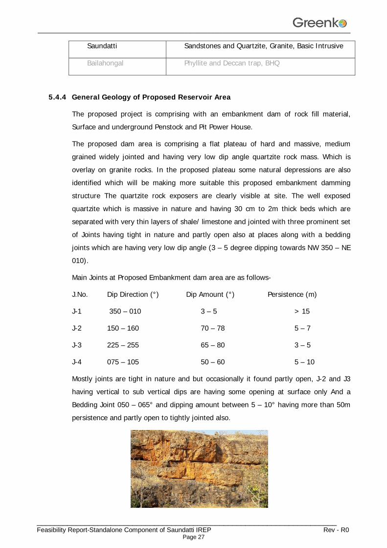
The proposed dam area is comprising a flat plateau of hard and massive, medium grained widely jointed and having very low dip angle quartzite rock mass. Which is overlay on granite rocks. In the proposed plateau some natural depressions are also identified which will be making more suitable this proposed embankment damming structure The quartzite rock exposers are clearly visible at site. The well exposed quartzite which is massive in nature and having 30 cm to 2m thick beds which are separated with very thin layers of shale/ limestone and jointed with three prominent set of Joints having tight in nature and partly open also at places along with a bedding joints which are having very low dip angle (3 – 5 degree dipping towards NW 350 – NE 010).
Main Joints at Proposed Embankment dam area are as follows-
J.No. Dip Direction (°) Dip Amount (°) Persistence (m)
J-1 350 – 010 3 – 5 > 15
J-2 150 – 160 70 – 78 5 – 7
J-3 225 – 255 65 – 80 3 – 5
J-4 075 – 105 50 – 60 5 – 10
Mostly joints are tight in nature and but occasionally it found partly open, J-2 and J3 having vertical to sub vertical dips are having some opening at surface only And a Bedding Joint 050 – 065° and dipping amount between 5 – 10° having more than 50m persistence and partly open to tightly jointed also.
________________________________________________________________________________
_____________________________________________________________________ Feasibility Report-Standalone Component of Saundatti IREP Rev - R0
Page 28
Photograph-1 Showing width of Quartzite bed and Vertical – sub vertical Joints and opening in bedding joints
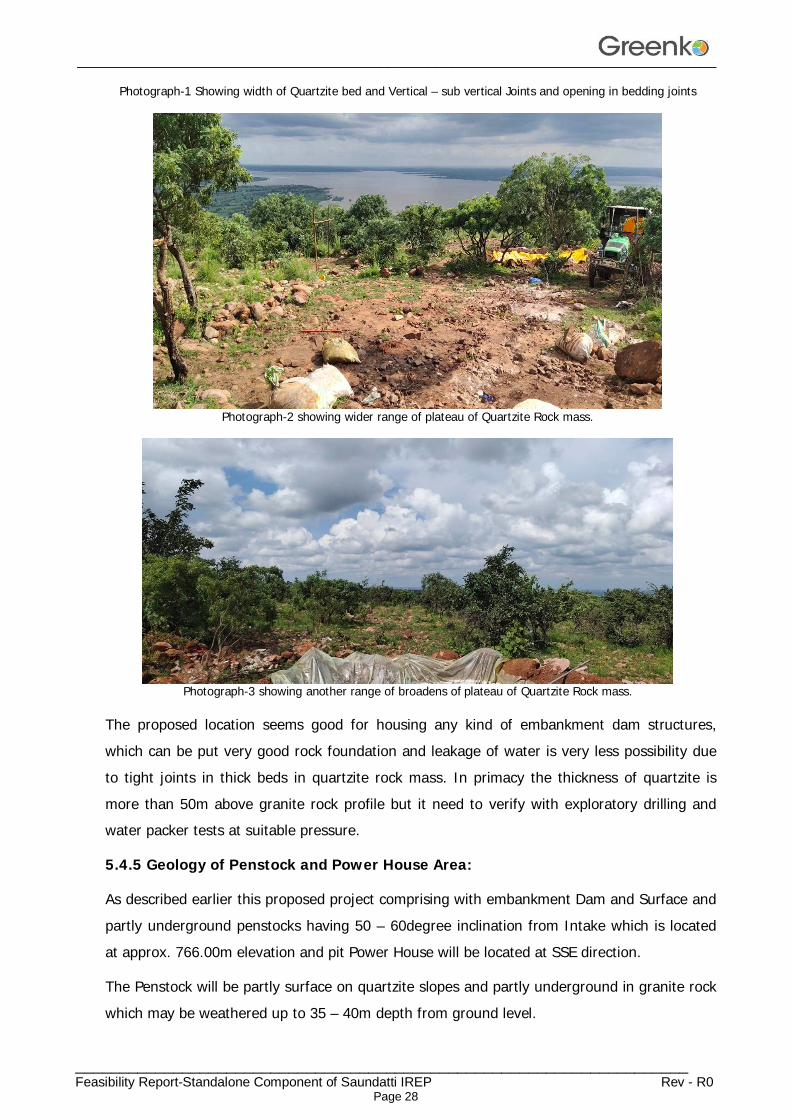
Photograph-2 showing wider range of plateau of Quartzite Rock mass.
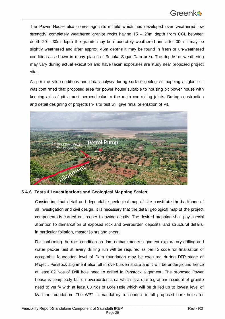
Photograph-3 showing another range of broadens of plateau of Quartzite Rock mass.
The proposed location seems good for housing any kind of embankment dam structures, which can be put very good rock foundation and leakage of water is very less possibility due to tight joints in thick beds in quartzite rock mass. In primacy the thickness of quartzite is more than 50m above granite rock profile but it need to verify with exploratory drilling and water packer tests at suitable pressure.
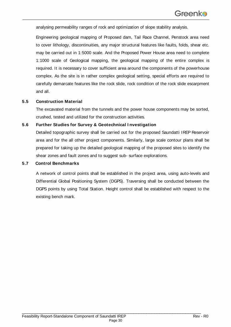
5.4.5 Geology of Penstock and Power House Area:
As described earlier this proposed project comprising with embankment Dam and Surface and partly underground penstocks having 50 – 60degree inclination from Intake which is located at approx. 766.00m elevation and pit Power House will be located at SSE direction.
The Penstock will be partly surface on quartzite slopes and partly underground in granite rock which may be weathered up to 35 – 40m depth from ground level.
________________________________________________________________________________
_____________________________________________________________________ Feasibility Report-Standalone Component of Saundatti IREP Rev - R0
Page 29
The Power House also comes agriculture field which has developed over weathered low strength/ completely weathered granite rocks having 15 – 20m depth from OGL between depth 20 – 30m depth the granite may be moderately weathered and after 30m it may be slightly weathered and after approx. 45m depths it may be found in fresh or un-weathered conditions as shown in many places of Renuka Sagar Dam area. The depths of weathering may vary during actual execution and have taken exposures are study near proposed project site.
As per the site conditions and data analysis during surface geological mapping at glance it was confirmed that proposed area for power house suitable to housing pit power house with keeping axis of pit almost perpendicular to the main controlling joints. During construction and detail designing of projects In- situ test will give finial orientation of Pit.
5.4.6 Tests & Investigations and Geological Mapping Scales
Considering that detail and dependable geological map of site constitute the backbone of all investigation and civil design, it is necessary that the detail geological map of the project components is carried out as per following details. The desired mapping shall pay special attention to demarcation of exposed rock and overburden deposits, and structural details, in particular foliation, master joints and shear.
For confirming the rock condition on dam embankments alignment exploratory drilling and water packer test at every drilling run will be required as per IS code for finalization of acceptable foundation level of Dam foundation may be executed during DPR stage of Project. Penstock alignment also fall in overburden strata and it will be underground hence at least 02 Nos of Drill hole need to drilled in Penstock alignment. The proposed Power house is completely fall on overburden area which is a disintegration/ residual of granite need to verify with at least 03 Nos of Bore Hole which will be drilled up to lowest level of Machine foundation. The WPT is mandatory to conduct in all proposed bore holes for
________________________________________________________________________________
_____________________________________________________________________ Feasibility Report-Standalone Component of Saundatti IREP Rev - R0
Page 30
analysing permeability ranges of rock and optimization of slope stability analysis.
Engineering geological mapping of Proposed dam, Tail Race Channel, Penstock area need to cover lithology, discontinuities, any major structural features like faults, folds, shear etc. may be carried out in 1:5000 scale. And the Proposed Power House area need to complete 1:1000 scale of Geological mapping, the geological mapping of the entire complex is required. It is necessary to cover sufficient area around the components of the powerhouse complex. As the site is in rather complex geological setting, special efforts are required to carefully demarcate features like the rock slide, rock condition of the rock slide escarpment and all.
5.5 Construction Material The excavated material from the tunnels and the power house components may be sorted, crushed, tested and utilized for the construction activities.
5.6 Further Studies for Survey & Geotechnical Investigation
Detailed topographic survey shall be carried out for the proposed Saundatti IREP Reservoir area and for the all other project components. Similarly, large scale contour plans shall be prepared for taking up the detailed geological mapping of the proposed sites to identify the shear zones and fault zones and to suggest sub- surface explorations.
5.7 Control Benchmarks
A network of control points shall be established in the project area, using auto-levels and Differential Global Positioning System (DGPS). Traversing shall be conducted between the DGPS points by using Total Station. Height control shall be established with respect to the existing bench mark.
________________________________________________________________________________
_____________________________________________________________________ Feasibility Report-Standalone Component of Saundatti IREP Rev - R0
Page 31
CHAPTER – 6 HYDROLOGY & POWER POTENTIAL STUDIES
6.0 Introduction
Determination of Power Potential is the primary step in planning a Hydro Power Plant. The power potential of the project shall be dependent on the project layout, operating water levels, data on long term flow availability, selected turbo generating equipment type and its parameters etc.
This storage project is being planned on the allocated water of 1TMC for utilization by recirculation from existing Renuka Sagar reservoir. Secondly the proposed Upper Saundatti IREP reservoir is not located across any stream and the existing Renuka Sagar reservoir is located across river Malaprabha. Therefore, no Specific hydrological studies are required to be carried out and similarly power potential studies are also required to be carried out for the power potential possibility to be generated by recirculation of inflows in between these reservoirs.
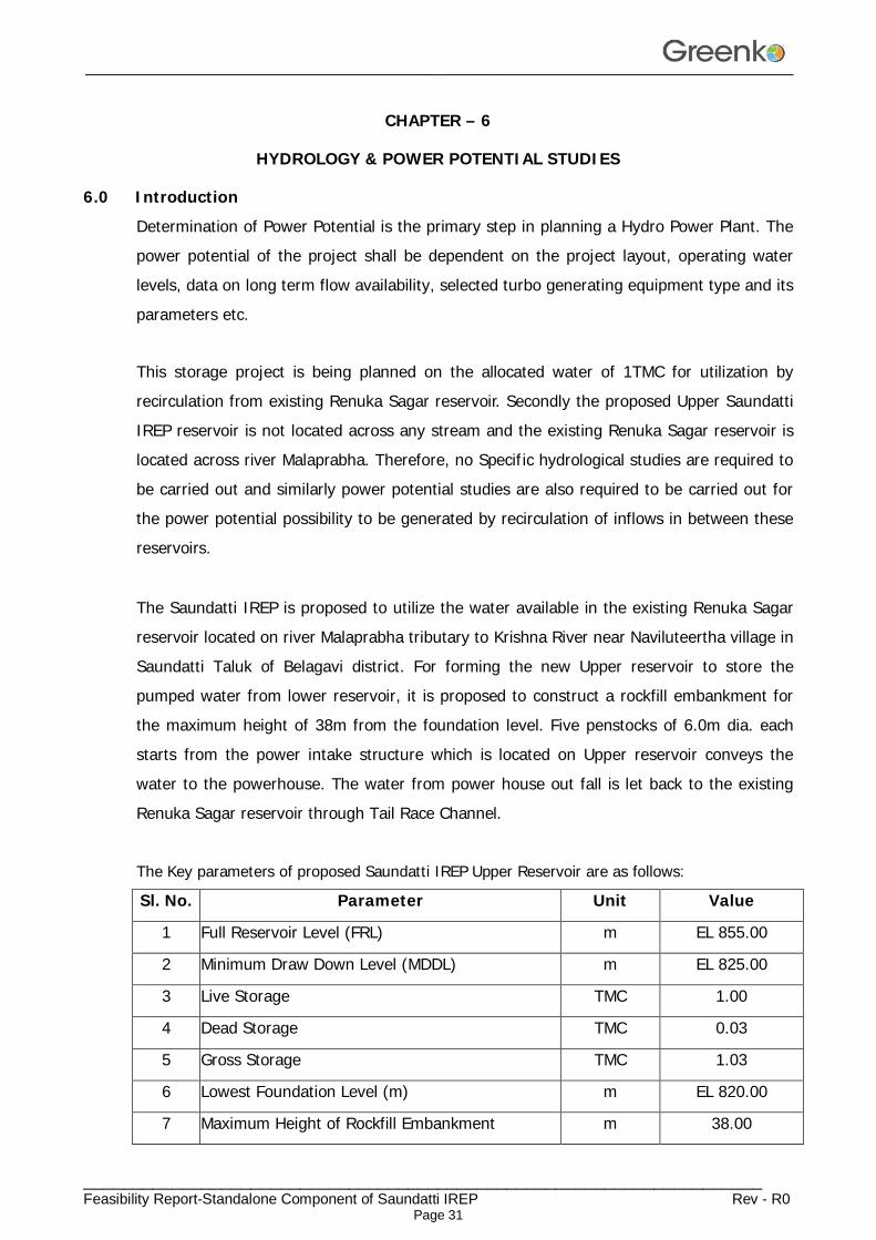
The Saundatti IREP is proposed to utilize the water available in the existing Renuka Sagar reservoir located on river Malaprabha tributary to Krishna River near Naviluteertha village in Saundatti Taluk of Belagavi district. For forming the new Upper reservoir to store the pumped water from lower reservoir, it is proposed to construct a rockfill embankment for the maximum height of 38m from the foundation level. Five penstocks of 6.0m dia. each starts from the power intake structure which is located on Upper reservoir conveys the water to the powerhouse. The water from power house out fall is let back to the existing Renuka Sagar reservoir through Tail Race Channel. The Key parameters of proposed Saundatti IREP Upper Reservoir are as follows:
Sl. No. Parameter Unit Value
1 Full Reservoir Level (FRL) m EL 855.00
2 Minimum Draw Down Level (MDDL) m EL 825.00
3 Live Storage TMC 1.00
4 Dead Storage TMC 0.03
5 Gross Storage TMC 1.03
6 Lowest Foundation Level (m) m EL 820.00
7 Maximum Height of Rockfill Embankment m 38.00
________________________________________________________________________________
_____________________________________________________________________ Feasibility Report-Standalone Component of Saundatti IREP Rev - R0
Page 32
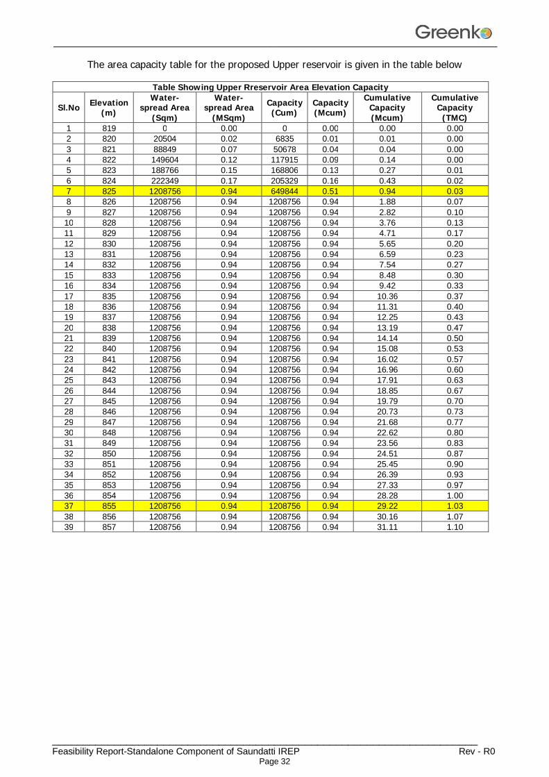
The area capacity table for the proposed Upper reservoir is given in the table below
Table Showing Upper Rreservoir Area Elevation Capacity
Sl.No Elevation (m)
Water-spread Area
(Sqm)
Water-spread Area
(MSqm) Capacity (Cum)
Capacity (Mcum)
Cumulative Capacity (Mcum)
Cumulative Capacity
(TMC) 1 819 0 0.00 0 0.00 0.00 0.00 2 820 20504 0.02 6835 0.01 0.01 0.00 3 821 88849 0.07 50678 0.04 0.04 0.00 4 822 149604 0.12 117915 0.09 0.14 0.00 5 823 188766 0.15 168806 0.13 0.27 0.01 6 824 222349 0.17 205329 0.16 0.43 0.02 7 825 1208756 0.94 649844 0.51 0.94 0.03 8 826 1208756 0.94 1208756 0.94 1.88 0.07 9 827 1208756 0.94 1208756 0.94 2.82 0.10 10 828 1208756 0.94 1208756 0.94 3.76 0.13 11 829 1208756 0.94 1208756 0.94 4.71 0.17 12 830 1208756 0.94 1208756 0.94 5.65 0.20 13 831 1208756 0.94 1208756 0.94 6.59 0.23 14 832 1208756 0.94 1208756 0.94 7.54 0.27 15 833 1208756 0.94 1208756 0.94 8.48 0.30 16 834 1208756 0.94 1208756 0.94 9.42 0.33 17 835 1208756 0.94 1208756 0.94 10.36 0.37 18 836 1208756 0.94 1208756 0.94 11.31 0.40 19 837 1208756 0.94 1208756 0.94 12.25 0.43 20 838 1208756 0.94 1208756 0.94 13.19 0.47 21 839 1208756 0.94 1208756 0.94 14.14 0.50 22 840 1208756 0.94 1208756 0.94 15.08 0.53 23 841 1208756 0.94 1208756 0.94 16.02 0.57 24 842 1208756 0.94 1208756 0.94 16.96 0.60 25 843 1208756 0.94 1208756 0.94 17.91 0.63 26 844 1208756 0.94 1208756 0.94 18.85 0.67 27 845 1208756 0.94 1208756 0.94 19.79 0.70 28 846 1208756 0.94 1208756 0.94 20.73 0.73 29 847 1208756 0.94 1208756 0.94 21.68 0.77 30 848 1208756 0.94 1208756 0.94 22.62 0.80 31 849 1208756 0.94 1208756 0.94 23.56 0.83 32 850 1208756 0.94 1208756 0.94 24.51 0.87 33 851 1208756 0.94 1208756 0.94 25.45 0.90 34 852 1208756 0.94 1208756 0.94 26.39 0.93 35 853 1208756 0.94 1208756 0.94 27.33 0.97 36 854 1208756 0.94 1208756 0.94 28.28 1.00 37 855 1208756 0.94 1208756 0.94 29.22 1.03 38 856 1208756 0.94 1208756 0.94 30.16 1.07 39 857 1208756 0.94 1208756 0.94 31.11 1.10
________________________________________________________________________________
_____________________________________________________________________ Feasibility Report-Standalone Component of Saundatti IREP Rev - R0
Page 33
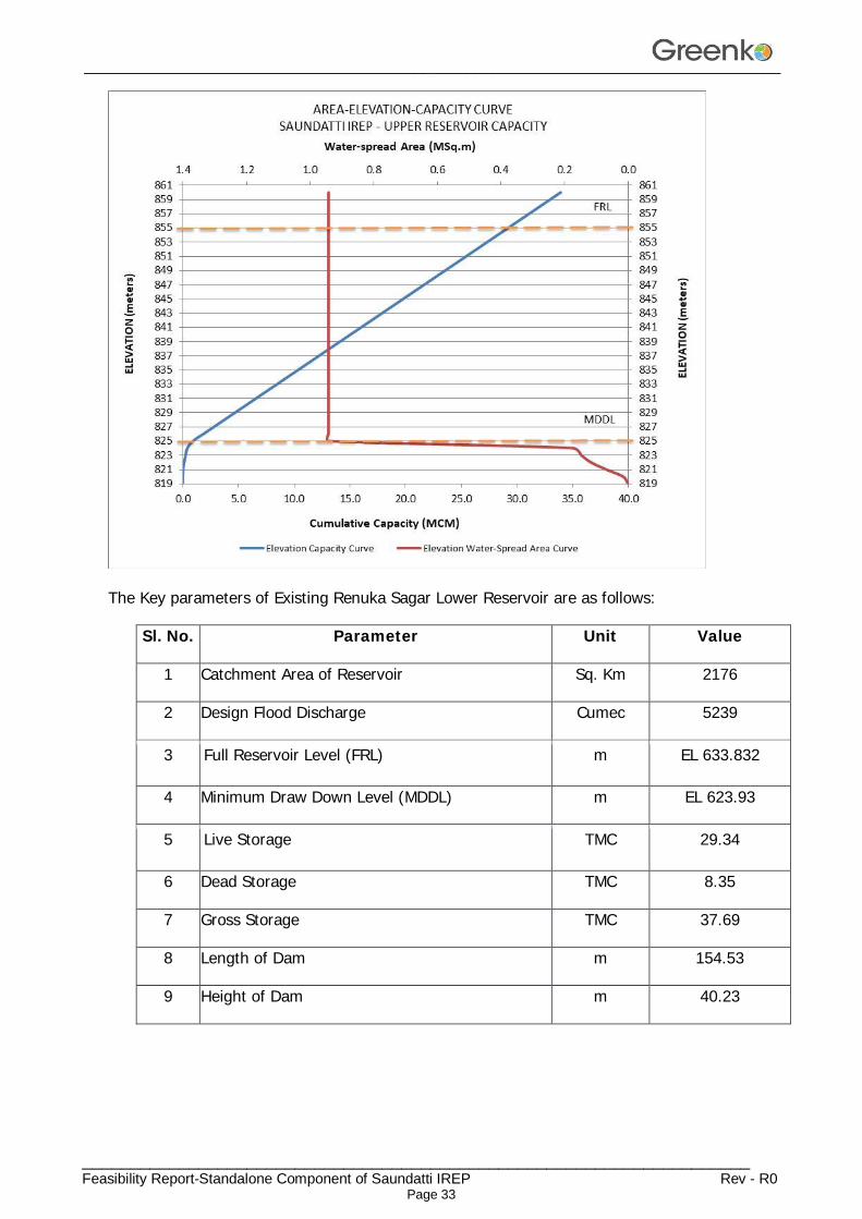
The Key parameters of Existing Renuka Sagar Lower Reservoir are as follows:
Sl. No. Parameter Unit Value
1 Catchment Area of Reservoir Sq. Km 2176
2 Design Flood Discharge Cumec 5239
3 Full Reservoir Level (FRL) m EL 633.832
4 Minimum Draw Down Level (MDDL) m EL 623.93
5 Live Storage TMC 29.34
6 Dead Storage TMC 8.35
7 Gross Storage TMC 37.69
8 Length of Dam m 154.53
9 Height of Dam m 40.23
________________________________________________________________________________
_____________________________________________________________________ Feasibility Report-Standalone Component of Saundatti IREP Rev - R0
Page 34
6.1 Malaprabha River
The Malaprabha river flows through Karnataka state. The Malaprabha river originates from Chorla ghats, which is a part of Western Ghats. It is a tributary river to the Krishna river and it flows through the Dharwad district. The Malaprabha river originates in the Western Ghats, in the Kanakumbi village of Belagavi district at an altitude of 792 meters above the sea level. The Kanakumbi village is 16 km west of Jamboti village, Khanapur Taluka, Belagavi District in Karnataka state. The Malaprabha river flows first in east direction and then north-west, for almost 300 km and then it merges with Krishna river, at Kudala Sangama in Bagalkot district, Karnataka state. Merging of these two rivers is done at height of 488 meters from sea level. The Bennihalla, Tuparihalla and Hirehalla are the tributaries of the river. Including its tributaries, the Malaprabha river covers 11,549 Sq. km area. The confluence of the Malaprabha river with the Krishna river is almost 304 km away from the origin of the Malaprabha river in Western Ghats.
6.2 Discharge Series
Based on the inflow data and the storage capacity of the existing reservoir, power potential study was carried out to assess the installed capacity. The Saundatti IREP is envisaged to utilize 1.0 TMC of water to be pumped from the existing Renuka Sagar reservoir to the proposed Upper Saundatti IREP reservoir in 11.20 hours. The project is a pumped storage scheme and hence, no consumptive utilization of water is required for its operation.
6.3 Renuka Sagar Reservoir (Existing)
The existing Renuka Sagar reservoir will be utilised as a lower reservoir to enable Saundatti IREP to operate as a peak station. The FRL & MDDL of existing Renuka Sagar reservoir is at EL 633.832m & EL 623.93 m respectively. The live storage capacity of existing reservoir is 29.34 TMC. Water will be pumped to the proposed Upper reservoir through TRC.
The proposed Upper Saundatti IREP reservoir is located at EL 820.00m and the FRL and MDDL of this reservoir is at EL 855.00m & 825.00m respectively. The live storage of the proposed reservoir is kept for 1.00 TMC. A tail race channel of approx. 1688 m will discharge the flows in to existing Renuka Sagar reservoir after power generation.
________________________________________________________________________________
_____________________________________________________________________ Feasibility Report-Standalone Component of Saundatti IREP Rev - R0
Page 35
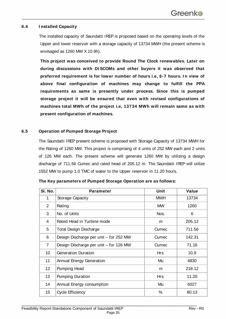
6.4 Installed Capacity
The installed capacity of Saundatti IREP is proposed based on the operating levels of the Upper and lower reservoir with a storage capacity of 13734 MWH (the present scheme is envisaged as 1260 MW X 10.9h).
This project was conceived to provide Round The Clock renewables. Later on during discussions with DISCOMs and other buyers it was observed that preferred requirement is for lower number of hours i.e, 6-7 hours. In view of above final configuration of machines may change to fulfill the PPA requirements as same is presently under process. Since this is pumped storage project it will be ensured that even with revised configurations of machines total MWh of the project i.e, 13734 MWh will remain same as with present configuration of machines.
6.5 Operation of Pumped Storage Project
The Saundatti IREP present scheme is proposed with Storage Capacity of 13734 MWH for the Rating of 1260 MW. This project is comprising of 4 units of 252 MW each and 2 units of 126 MW each. The present scheme will generate 1260 MW by utilizing a design discharge of 711.56 Cumec and rated head of 205.12 m. The Saundatti IREP will utilize 1552 MW to pump 1.0 TMC of water to the Upper reservoir in 11.20 hours.
The Key parameters of Pumped Storage Operation are as follows:
Sl. No. Parameter Unit Value 1 Storage Capacity MWH 13734
2 Rating MW 1260
3 No. of Units Nos. 6 4 Rated Head in Turbine mode m 205.12
5 Total Design Discharge Cumec 711.56
6 Design Discharge per unit – for 252 MW Cumec 142.31
7 Design Discharge per unit – for 126 MW Cumec 71.16
10 Generation Duration Hrs. 10.9
11 Annual Energy Generation Mu 4830
12 Pumping Head m 218.12
13 Pumping Duration Hrs. 11.20
14 Annual Energy consumption Mu 6027
15 Cycle Efficiency % 80.13
________________________________________________________________________________
_____________________________________________________________________ Feasibility Report-Standalone Component of Saundatti IREP Rev - R0
Page 36
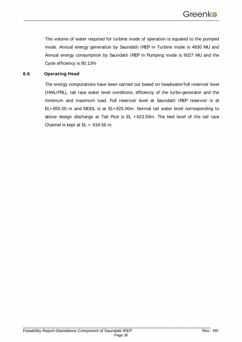
The volume of water required for turbine mode of operation is equated to the pumped mode. Annual energy generation by Saundatti IREP in Turbine mode is 4830 MU and Annual energy consumption by Saundatti IREP in Pumping mode is 6027 MU and the Cycle efficiency is 80.13%
6.6 Operating Head
The energy computations have been carried out based on headwater/full reservoir level (HWL/FRL), tail race water level conditions, efficiency of the turbo-generator and the minimum and maximum load. Full reservoir level at Saundatti IREP reservoir is at EL+855.00 m and MDDL is at EL+825.00m. Normal tail water level corresponding to above design discharge at Tail Pool is EL +623.93m. The bed level of the tail race Channel is kept at EL + 618.56 m.
________________________________________________________________________________
_____________________________________________________________________ Feasibility Report-Standalone Component of Saundatti IREP Rev - R0
Page 37
CHAPTER – 7 DESIGN FEATURES OF MAJOR COMPONENTS
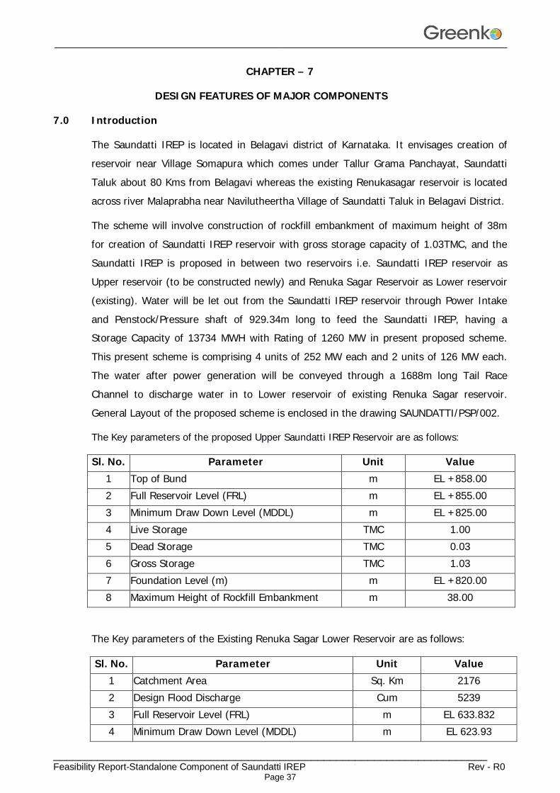
7.0 Introduction
The Saundatti IREP is located in Belagavi district of Karnataka. It envisages creation of reservoir near Village Somapura which comes under Tallur Grama Panchayat, Saundatti Taluk about 80 Kms from Belagavi whereas the existing Renukasagar reservoir is located across river Malaprabha near Navilutheertha Village of Saundatti Taluk in Belagavi District.
The scheme will involve construction of rockfill embankment of maximum height of 38m for creation of Saundatti IREP reservoir with gross storage capacity of 1.03TMC, and the Saundatti IREP is proposed in between two reservoirs i.e. Saundatti IREP reservoir as Upper reservoir (to be constructed newly) and Renuka Sagar Reservoir as Lower reservoir (existing). Water will be let out from the Saundatti IREP reservoir through Power Intake and Penstock/Pressure shaft of 929.34m long to feed the Saundatti IREP, having a Storage Capacity of 13734 MWH with Rating of 1260 MW in present proposed scheme. This present scheme is comprising 4 units of 252 MW each and 2 units of 126 MW each. The water after power generation will be conveyed through a 1688m long Tail Race Channel to discharge water in to Lower reservoir of existing Renuka Sagar reservoir. General Layout of the proposed scheme is enclosed in the drawing SAUNDATTI/PSP/002.
The Key parameters of the proposed Upper Saundatti IREP Reservoir are as follows:
Sl. No. Parameter Unit Value 1 Top of Bund m EL +858.00 2 Full Reservoir Level (FRL) m EL +855.00 3 Minimum Draw Down Level (MDDL) m EL +825.00 4 Live Storage TMC 1.00 5 Dead Storage TMC 0.03 6 Gross Storage TMC 1.03 7 Foundation Level (m) m EL +820.00 8 Maximum Height of Rockfill Embankment m 38.00
The Key parameters of the Existing Renuka Sagar Lower Reservoir are as follows:
Sl. No. Parameter Unit Value 1 Catchment Area Sq. Km 2176 2 Design Flood Discharge Cum 5239 3 Full Reservoir Level (FRL) m EL 633.832 4 Minimum Draw Down Level (MDDL) m EL 623.93
________________________________________________________________________________
_____________________________________________________________________ Feasibility Report-Standalone Component of Saundatti IREP Rev - R0
Page 38
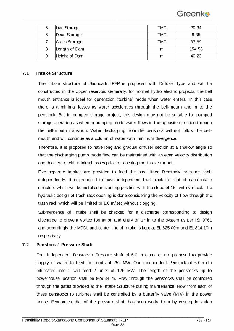
5 Live Storage TMC 29.34 6 Dead Storage TMC 8.35 7 Gross Storage TMC 37.69 8 Length of Dam m 154.53 9 Height of Dam m 40.23
7.1 Intake Structure
The intake structure of Saundatti IREP is proposed with Diffuser type and will be constructed in the Upper reservoir. Generally, for normal hydro electric projects, the bell mouth entrance is ideal for generation (turbine) mode when water enters. In this case there is a minimal losses as water accelerates through the bell-mouth and in to the penstock. But in pumped storage project, this design may not be suitable for pumped storage operation as when in pumping mode water flows in the opposite direction through the bell-mouth transition. Water discharging from the penstock will not follow the bell-mouth and will continue as a column of water with minimum divergence.
Therefore, it is proposed to have long and gradual diffuser section at a shallow angle so that the discharging pump mode flow can be maintained with an even velocity distribution and decelerate with minimal losses prior to reaching the Intake tunnel.
Five separate intakes are provided to feed the steel lined Penstock/ pressure shaft independently. It is proposed to have independent trash rack in front of each intake structure which will be installed in slanting position with the slope of 15° with vertical. The hydraulic design of trash rack opening is done considering the velocity of flow through the trash rack which will be limited to 1.0 m/sec without clogging.
Submergence of Intake shall be checked for a discharge corresponding to design discharge to prevent vortex formation and entry of air in to the system as per IS: 9761 and accordingly the MDDL and center line of intake is kept at EL 825.00m and EL 814.10m respectively.
7.2 Penstock / Pressure Shaft
Four independent Penstock / Pressure shaft of 6.0 m diameter are proposed to provide supply of water to feed four units of 252 MW. One independent Penstock of 6.0m dia bifurcated into 2 will feed 2 units of 126 MW. The length of the penstocks up to powerhouse location shall be 929.34 m. Flow through the penstocks shall be controlled through the gates provided at the Intake Structure during maintenance. Flow from each of these penstocks to turbines shall be controlled by a butterfly valve (MIV) in the power house. Economical dia. of the pressure shaft has been worked out by cost optimization
________________________________________________________________________________
_____________________________________________________________________ Feasibility Report-Standalone Component of Saundatti IREP Rev - R0
Page 39
studies for various diameters. Accordingly, a diameter of 6.00m has been adopted to carry the design discharge of 142.31 Cumec for each unit.
7.3 Power House
It has been proposed to have surface power house and all associated components under the ground. As the proposed power house involves little deeper excavation, intricate supporting arrangements for the cut slopes involving anchors etc., are provided. The control room is proposed on the downstream of machine hall above the Draft tubes.
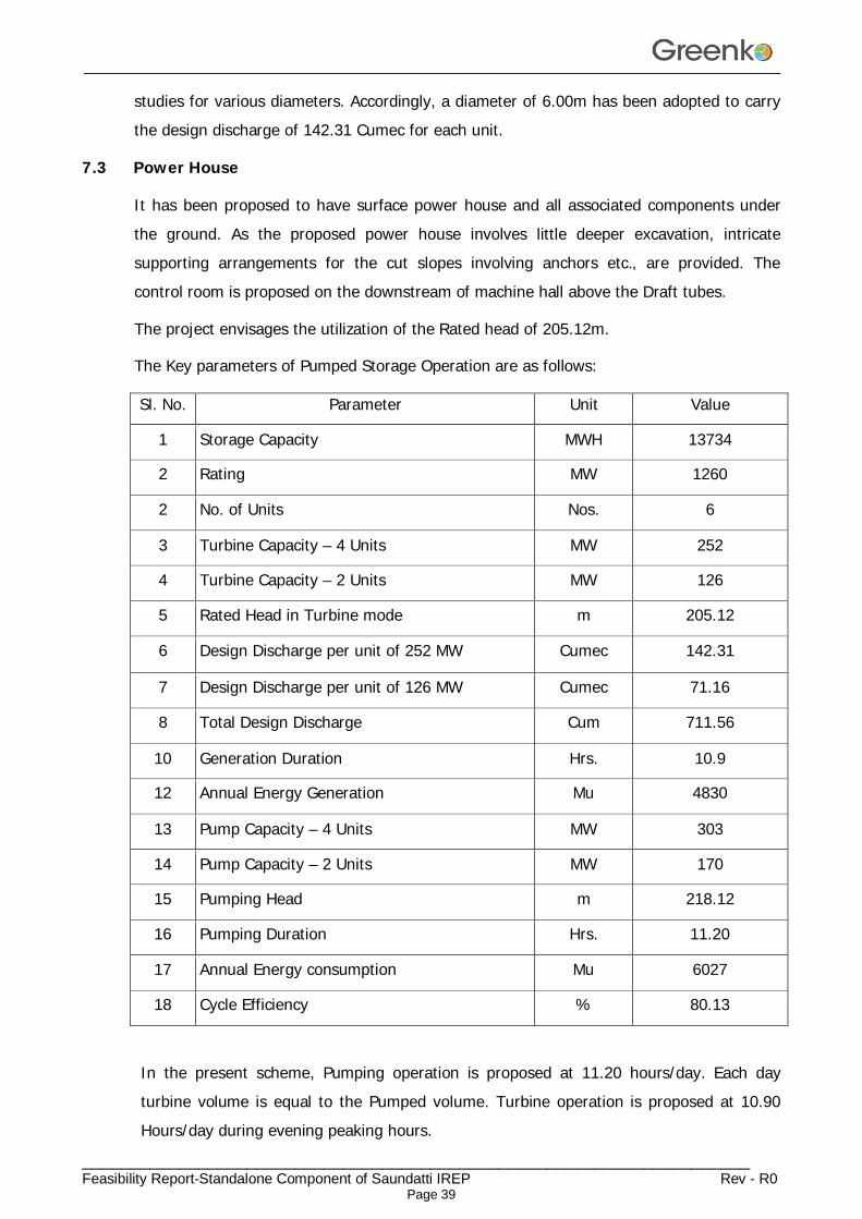
The project envisages the utilization of the Rated head of 205.12m.
The Key parameters of Pumped Storage Operation are as follows:
Sl. No. Parameter Unit Value
1 Storage Capacity MWH 13734
2 Rating MW 1260
2 No. of Units Nos. 6
3 Turbine Capacity – 4 Units MW 252
4 Turbine Capacity – 2 Units MW 126
5 Rated Head in Turbine mode m 205.12
6 Design Discharge per unit of 252 MW Cumec 142.31
7 Design Discharge per unit of 126 MW Cumec 71.16
8 Total Design Discharge Cum 711.56
10 Generation Duration Hrs. 10.9
12 Annual Energy Generation Mu 4830
13 Pump Capacity – 4 Units MW 303
14 Pump Capacity – 2 Units MW 170
15 Pumping Head m 218.12
16 Pumping Duration Hrs. 11.20
17 Annual Energy consumption Mu 6027
18 Cycle Efficiency % 80.13
In the present scheme, Pumping operation is proposed at 11.20 hours/day. Each day turbine volume is equal to the Pumped volume. Turbine operation is proposed at 10.90 Hours/day during evening peaking hours.
________________________________________________________________________________
_____________________________________________________________________ Feasibility Report-Standalone Component of Saundatti IREP Rev - R0
Page 40
7.4 Machine Hall
The internal dimensions of power house have been proposed with length 200m and width 24.00m including service bay. The units have been kept at about 26.00m spacing while the erection bay have been proposed as 40m long. For housing control room and various auxiliaries/offices, 4 nos. floor have been proposed on the D/s side of Power house over the draft tube. The main inlet valve is proposed to be housed in power house just u/s of turbine. 2 Nos. of EOT crane of suitable capacity shall be installed in erection bay and unit bay to facilitate erection and repair of heavy equipment including main inlet valves. The machine floor is designed to carry load of machines, live load and thrust transferred through turbines, generators and other machinery. The machine floor is designed as an RCC raft with adequate openings as required for equipment foundations and cable trenches etc.
7.5 Tail Race Outlet and Tail Race Channel
The tail water from the machines is led back to the lower reservoir through a tailrace Tunnel / Tail Race Channel. Water from each turbine will enter in to Tail Race tunnel constructed with steel liners and gate is provided at the end of TRT outlet. Water from TRT will enter in to tail race pool at outlet structure which is constructed with RCC walls on three sides. The tail pool is connected to a tail race Channel that conveys the water into the Lower Reservoir.
________________________________________________________________________________
_____________________________________________________________________ Feasibility Report-Standalone Component of Saundatti IREP Rev - R0
Page 41
CHAPTER – 8
ELECTRO - MECHANICAL EQUIPMENTS
8.1 ELECTRO-MECHANICAL EQUIPMENTS: The Electro-Mechanical equipment required for the proposed pumping scheme comprises of the following:
(1) Butterfly Valve for each Turbine.
(2) Reversible Pump Turbine and it’s auxiliaries like HP/LP air compressor system, water depression system, lubricating oil system, Governor and it’s oil pressure unit and Cooling water system etc.
(3) Generator/Motor (DFIM) and its auxiliaries like AC Excitation (VSI) for variable speed machines, & Automatic Voltage Regulation system, Cooling system, Brakes, PLC and Automation arrangement etc.,
(4) Generator circuit breakers for variable speed machines with Phase reversal device and it’s accessories.
(5) Control, Protection, metering, measurement and annunciation panels for Turbine, asynchronous generator-motor and 400KV feeders.
(6) Bus duct (IPBD) shall be provided for connecting generator to the generating transformer, SAT, LAVT (for variable speed machines this is part of Generator circuit breaker), NGT etc., for trouble free reliable operation.
(7) Single phase 18KV/400 KV Generator Transformers with OFF Load tap changer along with control and protective gear and breakers , with On Line dissolved gas analyzer system etc.
(8) 400 KV Gas Insulated switch-gear (GIS) for secondary side of the transformers.
(9) Auxiliary Power supply system consisting of unit auxiliary transformers, station auxiliary transformer, D.G Set for alternative emergency supply and station/ unit auxiliary boards for station auxiliaries, unit auxiliaries.
(10) Control supply system consisting of station battery, charger and its distribution system.
(11) The station auxiliaries like EOT crane, D.T crane, Air Compressor system, Dewatering and Drainage system, firefighting equipment, Air conditioning, Ventilation system and illumination system.
(12) Power evacuation system consists of transmission line, protection/ metering
________________________________________________________________________________
_____________________________________________________________________ Feasibility Report-Standalone Component of Saundatti IREP Rev - R0
Page 42
equipment, CT's, PT's, LA's along with its supporting structures and Receiving end equipment including bay extension at the other end.
(13) SCADA and Instrumentation system with necessary panels and workstations for GIS and for power plant operation from Local and Remote.
8.2 MECHANICAL EQUIPMENT: The Mechanical equipment consists of Turbine, Main Inlet Valve, Governor, instrumentation & control system, HP/LP Air Compressor system, oil pumping system, cooling water system, Drainage, Dewatering system, crane etc.
8.2.1 BUTTER Fly Valve: Each Turbine is provided with a Butterfly valve to act as a main inlet valve to achieve quick closing to cut off the water supply for the Turbine in the event of any machine tripping on a lock out fault. The Butter fly valve shall be normally opened and closed by hydraulic system and also have backup closing system with counter weight for closing during emergency. Hydraulic operated Bypass valve is provided across the Butterfly valve for smooth operation with pressure balance condition.
i) Size and Body:
The Size of the Butter fly valve proposed is 5000mm for 252MW unit and 3200mm for 126 MW units for present scheme configuration. It shall be fabricated from steel plates and provided with PTFE/Grease lubricated bronze bushes for bearings and cup seals for trunnions and stainless-steel sealing ring for the main seal.
ii) Door:
It shall have plane door fabricated from steel plates. The valve door shall have peripheral sealing ring of solid rubber.
iii) Sealing Device:
The valve will be provided with adequately reinforced rubber sealing held in position by means of removable sealing ring fixed by rust less screws against stainless steel ring secured to the valve body.
iv) Dismantling Joint:
The Joint shall be of Telescopic type and located on downstream of valve facilitating dismantling of valve during maintenance.
v) Lever:
A lever will be provided to the trunnion and a dead weight will be mounted on other
________________________________________________________________________________
_____________________________________________________________________ Feasibility Report-Standalone Component of Saundatti IREP Rev - R0
Page 43
end.
vi) Servo Motor:
Servo Motor of double acting type comprising of fabricated steel cylinder with covers, piston and pressure oil system will be provided in a complete shape.
8.2.2 Turbine/Pump: The type of turbine will be reversible vertical shaft Francis type directly coupled to the vertical asynchronous generator-motor. The turbine will have adjustable guide vanes for control of the flow. In hours of low demand electricity gets consumed and water gets pumped into the higher reservoir. When the peak hours arrive, and the demand is high, water gets turbine and generates therefore Electricity. The final design of the Turbine components would be carried out by means of Model Test results of Turbine.
The machines have four running modes namely
"generate"
"spin generate"
"spin pump"
"pump"
Involving two directions of rotations and power flow. The shutdown condition can be treated as a further mode. The diversity of the control requirements is therefore much greater. In the first two modes of operation, a machine rotates in the turbines (as opposed to pump) direction, that is clockwise when viewed from above. It can generate at any load (generate) or having been started in the "generate mode" can have its load reduced and water level in the pump/turbine runner chamber and the draft tube lowered by compressed air, thus leaving the machine spinning as a synchronous compensator with its runner in air.
In the second operation (two modes), the direction of rotation is reversed. The set is run as a motor with a SFC controller, the water level in the pump turbine having lowered. When the machine is synchronizing it can remain running as a synchronous compensator (spin pump) or water can be admitted to the pump/turbine and pumping carried out at a fixed guide vane setting (pump).
Final Design:
The final design of the Turbine components would be carried out by means of Model Test results of Turbine.
________________________________________________________________________________
_____________________________________________________________________ Feasibility Report-Standalone Component of Saundatti IREP Rev - R0
Page 44
8.2.3 Materials and Construction Features of Turbine:
Runner:
The turbine runner will be integrally cast / welded in stainless steel material having 13% chromium and 4% nickel and properly stress relieved. The runner will have suitable no. Of vanes polished and ground smooth and will be mounted on the turbine shaft. Adequate number of relief holes will be provided in the runner for the water past runner crown seal.
Guide Vanes:
Guide vanes will be of cast stainless steel material conforming to 13% chromium and 4% nickel and finished smooth. Guide vane operating mechanism will be of forged or fabricated steel. Each guide vane will be supported in grease or self-lubricated bearings. Synthetic rubber seals will be provided to prevent leakage of water. The guide vanes will be operated by guide vane servomotor for which the pressurized oil will be supplied from the pressure oil system. The control of guide vane opening will be through the governor.
Guide Vane Operating Mechanism:
Guide vane operating mechanism will consist of levers, friction coupling / shear pins, links, servomotor connecting rods, guide vane, regulating ring etc. The mechanism will be designed and constructed to withstand stresses due to servomotor and wear and tear.
Turbine/pump Shaft:
A turbine/pump shaft will be provided for mounting the turbine runner. The material of turbine/pump shaft will be of carbon steel forging conforming to BS 29 or ASTM A 668 Class D.
The shaft will have adequate diameter to operate safely in combination with generator. The turbine shaft will be connected directly to the generator shaft by means of a suitable coupling.
Shaft Sleeves:
The shaft will be provided with renewable stainless-steel sleeve. The sleeve will be of split construction and securely fastened to the turbine shaft.
Shaft Seal:
The shaft seal will be provided to prevent leakage of water through the gap between the shaft and turbine cover. The shaft seal will be of carbon & Resin seals in layers.
Thrust and Guide Bearing:
________________________________________________________________________________
_____________________________________________________________________ Feasibility Report-Standalone Component of Saundatti IREP Rev - R0
Page 45
The Thrust and Guide Bearing will be of the self-contained, oil lubricated pedestal type, water cooled. The bearing assembly will consist of Vertical tilting pad thrust and journal bearing. The journal pads will be lined with tin base white metal. The bearing accommodates the thrust pads below the thrust collar to carry thrust load. As the bearing is self-lubricated / oil bath type, no external lubrication system required.
Stay Ring Assembly:
The stay ring assembly will be made of fabricated steel plate conforming to IS - 2062 Gr. ‘B’. The stay ring assembly will have set of streamlined stay vanes to guide the water flow.
Spiral Casing:
Spiral casing will be of welded construction fabricated from steel plates conforming to IS -2062 Gr. ‘B’ designed to withstand the maximum operating pressure including water hammer. The stay ring assembly will be welded to the spiral casing. The spiral casing will be anchored in concrete. The upstream flanged end of spiral casing will be bolted to the dismantling joint of turbine inlet BF valve.
Draft Tube:
The draft tube will be made of fabricated steel plates conforming to IS – 2062 Gr. - ‘B’. Draft tube will be fabricated in 2 or 3 parts namely draft tube cone and draft tube liner etc. and will be heavily reinforced by ribs and anchored in the concrete.
Oil Pumping Unit:
The oil pumping unit will be provided for supply of pressurized oil for the following:
a) Guide vane Servomotor
b) Turbine inlet butterfly valve
For regulation of flow through guide vanes, the pressurized oil will be supplied through servo valve, which will receive an electronic signal from governor. The oil-pumping unit will be provided with two pumps (one main and one standby) with auto-changeover facility along with other required accessories. For ensuring availability of stored pressurized oil, adequate capacity of nitrogen bladder type accumulators will be provided which is a modern practice and this will avoid compressed air system with air receiver, pressure oil receiver etc., for the governor pressure oil system. The pressure oil system will be provided with necessary instrumentation and control system for the safe and reliable operation of the units.
OPU system for the inlet valve and for Governing system shall be separate and of adequate capacity. i.e, two complete operations could be carried out with absence of power supply.
________________________________________________________________________________
_____________________________________________________________________ Feasibility Report-Standalone Component of Saundatti IREP Rev - R0
Page 46
Two electrical pumps shall be operated in Main and standby pump will operate at level – 2 pressure drop.
8.3 GOVERNING SYSTEM: The turbine will be controlled by an electronic governor. The Governor in general shall be designed in accordance to IEC 61362.The guide vanes will be actuated by guide vane servomotor through the governor. The system will be so designed that the main functions of speed control, power control are handled as a separate program parts and shall be programmed to suit Francis turbine having adjustable guide vanes. Governor shall also support RGMO/FGMO mode of operation, Electrical Inertia as per the Indian Electricity Grid Code.
8.4 AUXILIARY SYSTEMS:
i) Cooling Water System:
Water required for cooling and shaft sealing of the machine will be taken from the Tail race and supplied to various coolers such as turbine bearing coolers, generator bearing oil coolers, governor oil cooler, stator air coolers and turbine shaft seal etc. through booster pumps and suitable duplex strainers as required. The cooling water system will be provided with necessary instrumentation such as flow switches, differential pressure switches across the strainers and pressure switches etc., for safe and reliable operation of the units.
Considering site ambient condition option for Chilled water to be considered during detailed engineering for cooling water system.
ii) Air Conditioning System:
Chiller units of adequate capacity shall be provided for air-conditioning of the important areas of the plant. Chiller units are to be placed in transformer cavern. Detailed design of same shall be done at DPR stage.
iii) Ventilation System:
Adequate ventilation tunnels have been proposed in this project, consists of Transformer cavern, Power house and other areas. Air Handling units are to be placed in transformer cavern. Detailed design of same shall be done at DPR stage.
8.5 Crane and Hoists:
Two nos EOT cranes of 400/60 Tons capacity each will be installed in the power house building for handling equipment during erection and maintenance. For handling of intake
________________________________________________________________________________
_____________________________________________________________________ Feasibility Report-Standalone Component of Saundatti IREP Rev - R0
Page 47
and draft tube gates suitable electrically operated hoisting mechanism will be provided individually. Tandem operation of two EOT cranes shall be provided.
8.6 Dewatering and Drainage System:
For Dewatering of turbine casing water up to the Tail race gate, Six (6) numbers of submersible pumps each of capacity 500 m3/hr. will be provided. The Dewatering sump will be located in the station floor and a pipe from the Tail race will be embedded and connected to the Dewatering sump. An isolation valve will be provided in this pipe which will be opened during Dewatering. The discharge from the pumps will be taken above the maximum flood level. The discharge line will be provided with necessary isolation valves and piping. Necessary level switches will be provided in the Dewatering sump to facilitate auto start / stop of the pumps.
To remove drain water collected in the drainage sump located in the BF valve pit / Station floor, Six (6) numbers of sump pumps each of capacity 400 m3/hr. will be installed with necessary piping and valves. The discharge from the pumps will be taken above the maximum flood level. The discharge line will be provided with necessary isolation valves and piping. Necessary level switches will be provided in the drainage sump to facilitate auto start/stop of the pumps.
V) Fire Protection System:
The proposed fire protection system shall be designed to provide adequate safety measures in the area susceptible to fire in the power station. TAC classifies hydelpower generating stations as “Light hazard Occupancy” and hence the system shall be designed accordingly. This system is designed as per applicable requirements of NFPA 71.
VI) Air Compressor System
Suitable Tank mounted HP and LP air compressor system to meet the station requirements such as for brakes, cleaning, Blowdown system etc. are considered.
8.7 ELECTRICAL EQUIPMENT: The Electrical scheme showing the major system, such as the Generator and its connections to 400 KV Switch Yard for Power evacuation, 11KV Switchgear and 415V Auxiliary Power distribution.
8.7.1 ASYNCHRONOUS MOTOR: The Asynchronous generator/Motor envisaged for present scheme will be 252/303 MW (4 Nos.), & 126/170 MW (2No’s), 18 KV, 3 phase with 0.95 PF (lag), 50 Hz with AC Excitation (VSI) for variable speed machines, suitable for parallel operation with the grid.
________________________________________________________________________________
_____________________________________________________________________ Feasibility Report-Standalone Component of Saundatti IREP Rev - R0
Page 48
The generator neutral (star point) will be grounded through suitably rated grounding/ distribution Transformer with loading resistor connected to secondary side to restrict earth fault current to a safe limit. Six terminals of the generator, 3 on the phase side and 3 on the neutral side will be brought out for external connection. The short circuit ratio of the generator shall be greater than 1 (for Fixed Speed machine) for better stability on faults.
Generator Stator:
The stator frame makes up part of the stator segments and is assembled together with the core and coil. The stator winding is insulated with epoxy resin.
Generator Rotor:
The rotor comprises of a welded steel rotor center (outside serves as a yoke) and magnetic poles bolted on the periphery.
8.7.2 Voltage source converter (ac excitation) and control system (for variable speed machines): The excitation system shall enable the operation of the generator motor units in frequency regulation, voltage regulation modes within the capability diagram of the units. The excitation system shall manage the DFIM operating point parameters such as active power, reactive power or stator voltage, shaft or runner speed according to desired P, Q set points (given by operator through SCADA system) and optimizing rules.
The excitation system shall include two types of controls:
A guide vane regulation controlling the guide vane opening and thus the mechanical torque on shaft.
A rotor current regulation controlling the electromagnetic torque in air gap and the magnetizing current of the DFIM.
The excitation system shall be designed to perform the following functions: Ensure the rotation of shaft line and voltage ramp up of DFIM stator. Bring the DFIM to synchronizing conditions Keep the unit at a desired set point within the capability curve of the primary mover and
the DFIM. Contribute to grid support through primary and secondary frequency control and primary
voltage control. Keep the unit within stability limits whether hydraulic, or electrical and within thermal limits
________________________________________________________________________________
_____________________________________________________________________ Feasibility Report-Standalone Component of Saundatti IREP Rev - R0
Page 49
Ensure safe state return in case of unit shut down whether normal shut down or trip whatever the cause.
Ensure that all requirements arising from grid connection specification are met Perform the specific tasks required by generator/turbine mode, motor/pump mode, condenser mode (in Motor rotation direction), STATCOM mode, electric braking, black start, line charging and islanded network operation. The excitation system shall be connected to SCADA system.
The harmonic content injected into the neighboring power grids must comply with IEC 61000-2-4 class 3 and IEC 61000- 3-6 standard.
The excitation system shall include two control strategies which can switched from one to the other (a) Active and reactive loads are controlled by the voltage source inverter (VSI) while the speed of shaft line is controlled by turbine governor. (b) Speed and reactive load are controlled by the VSI while the active load is controlled by turbine governor.
8.7.3 Brakes:
Generator will be provided with air-operated brakes to bring the rotor parts of the generator and turbine to stop from about 30% of rated speed during normal operation. The brakes will also be suitable for application at higher speed during emergency shutdown of the unit, in order to bring the rotor to rest at faster rate. The brakes will operate automatically/ manually from local control panel/ unit control board.
As these are large size machines and to reduce the mode change timings Dynamic breaking system is also envisaged.
8.7.4 Neutral grounding cubicle
To limit the fault current to 10 amps Neutral grounding cubicle which consists of current transformers for protection, 3 phase star formation, Grounding transformer with resistor connected to the secondary of transformer, earth isolation switch with pad lock arrangement is envisaged.
8.7.5 18 KV LAVT Cubicle:
The power generated will be fed to 18 KV side of the each transformer through respective Lightning Protection Voltage Transformer (LAVT) cubicle and neutral terminals are connected to Neutral grounding cubicle by means of Bus Duct. The auxiliary loads of the respective Units will be fed from Unit Auxiliary Transformers. These transformers shall be
________________________________________________________________________________
_____________________________________________________________________ Feasibility Report-Standalone Component of Saundatti IREP Rev - R0
Page 50
connected to the 18 KV LAVT Cubicle.
The main electrical parameters of the switchgear will be:
a) Rated voltage - 18 KV
b) Rated short circuit current - 150kArms & 75kArms for 3 sec
(app.)
c) Rated current of bus bars - 10,000 A & 5000 A (tentative)
LAVT Cubicle will consist of Lightning Protection equipment and voltage transformers. The Lightning Protection equipment would comprise of lightning arresters with suitable discharge characteristics to suit the Generator insulation level in parallel with suitably rated capacitor for smoothening the rate of rise of impulse voltage.
The LAVT cubicle will be connected by means of Bus Duct to Generator and to the Generator transformer. The Voltage transformer will be single phase, star connected, dry type units with draw out features. Current transformers for protection metering on line side of the Generator were provided in this cubicle.
8.7.6 STEP-UP TRANSFORMERS:
Power generated at 18 KV will be stepped up to 400KV by means of 12 nos of 1-Ph 125 MVA & 6 Nos 1-Ph 175 MVA 18/400KV oil filled transformers. These Step-up transformers will be installed in Transformer Cavern. Capacity of the transformers arrived based on the Power Factor 0.9, Derating factor.
The main electrical parameters of each transformer will be:
(a) Voltage ratio - 18 KV/400KV, 1 phase, 50 Hz
(b) Rating - 125 MVA and 70 MVA
(c) Cooling Method - OFWF (Oil Forced and Water Forced)
(d) 18KV connection - Delta
(e) 400KV connection - Delta/Star with neutral solidly earthed.
(f) ON load tap changer - In the range of +/-10.0% in step of 2.5%
as per IS 10028 (part – I)
The 18 KV terminals (Primary) will be suitable for Bus Duct connection and 400KV terminals for connection to GIS.
8.7.7 400 KV GIS:
________________________________________________________________________________
_____________________________________________________________________ Feasibility Report-Standalone Component of Saundatti IREP Rev - R0
Page 51
Indoor metal-enclosed phase segregated type SF6 gas insulated switchgear system rated for 400 kV, 3 phases, 50 Hz, 63 KA, 3150 amps SF6 gas insulated metal enclosed bus bars complete with Generator transformer, Line, Bus coupler, SAT bays.
Standards
The system and equipment shall be designed to the latest revisions of the following applicable standards. In the event of other standards being applicable they will be compared for specific requirement and specifically approved during detailed engineering for the purpose:
Sl. No.
Standards Description
1 IEC 62271(All Parts) “High voltage switchgear and control gear”,
2 IEEE C37.122-1993 IEEE Standard for Gas-Insulated Substations (GIS)
3 IEEE C37.123-1996 IEEE Guide to specifications for Gas- Insulated, Electric Power Substation Equipment
4 IEC 60694 1996 Edition Common Clauses for high-voltage switchgear and control gear standards
5 IEC 60376 – 2005 Edition Specification of technical grade sulphur hexafluoride (SF6) for use in electrical equipment
Arrangement and assembly:
The arrangement shall be single-phase enclosed. The assembly shall consist of completely separate pressurized sections designed to minimize the risk of damage to personnel or adjacent sections in the event of a failure occurring within the equipment. Rupture diaphragms shall be provided to prevent the enclosures from uncontrolled bursting and suitable deflectors provide protection for the operating personnel. In order to achieve maximum operating reliability, no internal relief devices shall be installed because adjacent compartments would be affected. Modular design, complete segregation, arc-proof bushings and “plug-in” connection pieces shall allow ready removal of any section.
Local control cubicle
The Local control cubicle shall contain all the equipment required for controlling and monitoring the bay.
________________________________________________________________________________
_____________________________________________________________________ Feasibility Report-Standalone Component of Saundatti IREP Rev - R0
Page 52
8.7.8 400 KV POTHEAD YARD:
The 400 KV pothead yard will consist of two Outgoing line bays with isolator, CT, CVT, WT & LA and take off tower. The isolators will be of Horizontal double break type with motor operated mechanism.
8.7.9 Station & unit auxiliary power supply arrangement:
a) Reactor Transformers
2No’s of 80MVA, 400kV reactor transformer to compensate the reactive power requirement when running the units in pumping mode will be installed in the transformer cavern. Based on the manufacturer design, this may change to unit wise in 18kV level. Requirement of reactor transformers may be finalized during detailed engineering.
b) Station Transformers
HT station power will be derived by providing 2 nos of 20/25.0 MVA, 400/11 KV Station Transformers. These transformers will be connected to their respective 11 KV bus through necessary switchgear.
c) Unit Auxiliary Transformers
415V station power will be derived by providing 9 nos 2.5 MVA, 11 KV/415V Station Transformers. These transformers will be connected to the 11 kV HT bus of 2 station transformers separately through necessary switchgear. The output at 415V is fed to the Station Board through incomer breakers. The Station Board feeds the auxiliary loads of the power plant which includes startup loads of units through Unit auxiliary boards, Dewatering pumps, drainage pumps, crane, air conditioning, ventilation, lighting load etc.
(a) Voltage ratio - 11 KV/415V, 3 phase, 50 Hz
(b) Rating - 9 Nos. of 2.5 MVA
(c) Type - Dry Type (CRT)
(d) Primary connection - Delta
(e) Secondary connection - Star with neutral solidly earthed.
(f) Off circuit Tap Changer (OCTC) - +/- 5% in step of 2.5%
d) 415V Switchgear:
Station Auxiliary Board (SAB)
Station Auxiliary transformers will be connected to a separate bus section of 415V
________________________________________________________________________________
_____________________________________________________________________ Feasibility Report-Standalone Component of Saundatti IREP Rev - R0
Page 53
auxiliary switchgear. The 415V auxiliary switchgear will feed the entire unit and station loads. The switchgear will be equipped with the following.
(a) Two nos ACB controlled incomer feeders from Station auxiliary transformers.
(b) ACB controlled Outgoing feeders to Unit auxiliary boards
(c) Outgoing feeders to battery chargers / lighting panels with MCCB.
(d) Motor feeders fitted with MPCB, DOL / Star- Delta Starter, thermal overload relays etc., are of draw out type
(e) The switchgear will be provided with the necessary current transformers, indicating instruments, relays, lamps, push buttons etc.
The main electrical parameters of the switchgear will be:
a) Rated Voltage – 415V
b) Rated short circuit breaking current 50kA for One Second
c) Rated bus bar current – 2500A
e) Power Station Auxiliary Services:
The various services in the power plant will be supplied at the following nominal voltages depending upon their ratings and function:
a) Motors - 415V, 3 phase AC supply
b) Lighting and space heaters - 230V, 1 phase AC supply
c) Power receptacles - 415V, 3 phase AC supply
d) Control circuits
110V, 1 phase grounded AC supply for control circuits
220V ungrounded DC supply for control, indication and Instrumentation & Control system
8.7.10 EMERGENCY POWER SYSTEM:
Diesel Generator Set:
One Number of 1.0 MVA, 415V, 3 phase Diesel Generator set will be provided to meet the requirement of power supply during construction. This DG set will meet the requirement of power supply for emergency lighting and maintenance purposes during AC power failure like operation of crane, operation of drainage and Dewatering pumps, ventilation system etc. The DG set will consist of a Diesel engine with engine mounted accessories, an Alternator rated for
________________________________________________________________________________
_____________________________________________________________________ Feasibility Report-Standalone Component of Saundatti IREP Rev - R0
Page 54
1.0 MVA, 415V, 3 phase, 50 Hz with exhaust system, fuel oil system, filters, piping, valves and fittings, etc.
Direct Current Supply System:
The DC system is the most reliable source of supply in the power station and will be used for the control and protection of power plant equipment. The DC system will be used for the following:
(a) Electrical control of equipment and indications / annunciations on the control panel.
(b) Emergency D.C lighting in case of total AC power failure
(c) The station battery will be sized to cater to the following type of loads:
i) Momentary load for 1 minute.
ii) Emergency load for 2 hours.
iii) Continuous load for 10 hours.
Two sets of 220 V, 500 AH (tentative) battery bank with two nos. float and float cum boost charger and DC distribution board will meet the DC loads. The batteries will be Lead Acid type only either Tubular or plante type, complete with racks, porcelain insulators, inter cell and inter-tier connectors. The chargers will be of silicon rectifier type with automatic voltage control and load limiting features. Under normal conditions, the battery will be on float charge. The float charger is connected to a distribution board and meets the requirements of DC load. In case of additional demand of load or AC supply failure, the battery will meet the requirements of DC loads. The boost charger will be designed to charge the fully discharged battery in 10 hours before putting it back on float charge.
8.8 CONTROL, INSTRUMENTATION & PROTECTION SYSTEMS: There shall be one control panel each for the Turbine governing, unit & its auxiliaries, station and its auxiliaries, GIS & its auxiliaries. It should be able to synchronize the units either manually through these control boards or through SCADA system located in control room. Protection panel for turbine, units, generator transformer, GIS, auxiliary transformers, line protections etc. The protection system adopted should be state of art type with latest practices in compliance with CEA requirements.
a) Turbine-Generator/Pump-Motor Control Board:
There shall be one control panel each for the Turbine and the Generator fabricated out of 2 mm thick mild steel. It shall be freestanding type with single front design. The control panel shall be mounted on anti-vibration pads. The panel shall be applied with synthetic
________________________________________________________________________________
_____________________________________________________________________ Feasibility Report-Standalone Component of Saundatti IREP Rev - R0
Page 55
enamel paint on antirust primer after sand blasting and acid picking.
Each Turbine-Generator control cubicle shall contain the following:
Measuring & Indicating instruments comprising of the following:
MDM Meters (On HV and LV side) - 2 Nos.
Voltmeter with selector switch - 1 No.
Ammeter with selector switch - 1 No.
Megawatt meter - 1 No.
Megavar meter - 1 No.
Power factor - 1 No.
Frequency meter - 1 No.
Speed indicator - 1 No.
Temperature recorder of paper less type-60 points - 1 No.
Energy meter – 0.2s class - 1 Set
(One main and check meters on the HT side of the GT, One meter on the LT side of the GT One meter on the 11 KV tap off of the generator bus, One main and check meters on the HT side of the ST. One main and check meters on the 400KV feeder.)
Indicating lamps for ON/OFF/ Trip - 1 set
Controls comprising of the following:
Start control switch with relays - 1 set
Stop control switch with relay - 1 set
Alarm annunciator - I set
Master protection relays -1 set
Synchronizing scheme with auto synchronizer - 1 set
Acknowledge, reset and test push button - 1 Set
Programmable logic controller (PLC) - 1 set
The control system shall be with manual controls with interlocks to facilitate the operation of Unit in case of failure of Automation system with programmable logic controller.
8.9 PROGRAMMABLE LOGIC CONTROLLER (PLC) SYSTEM:
________________________________________________________________________________
_____________________________________________________________________ Feasibility Report-Standalone Component of Saundatti IREP Rev - R0
Page 56
It is proposed to provide a programmable logic controller for the following functions:
a) Start/Stop of the turbine and generator/pump in sequence control.
b) Monitoring, recording & trending of the temperature inputs from RTD's
c) Monitoring of the alarm inputs from the turbine and generator/pump protection system.
d) Monitoring, recording & trending of all electrical and analog parameters through suitable transducers
e) Man Machine interface unit
The system shall be provided with redundant CPU and POWER SUPPLY and adequate memory.
The system shall have self-checking and self-diagnostic features for all internal faults and shall be capable of isolating the defective sub-system.
The system should be suitable for continuously operating without air conditioner in the power plant environment with temperature upto 45°C and high humidity.
Local Instrumentation:
The following instruments shall be mounted locally:
(1) Flow transmitters to check flow of cooling and sealing water to the bearings, Shaft Seal & Generator as required.
(2) DTT ‘s & RTD’s for Turbine & Generator bearing temperature.
(3) Oil pressure gauge, Pressure transmitter, pressure switches of the Oil pressure unit, Level transmitters, gauges, and switches of bearing sumps, drainage and dewatering pits etc.,
All necessary instruments required for safe and auto operation of the turbine-Generator are provided.
8.10 COMMUNICATION SYSTEM:
a) Internal Telephone System: An Electronic telephone exchange is to be provided in the powerhouse control room for Communication system between different vulnerable locations of the project. It is also proposed to install a 10-line exchange with subscribers at various important locations of the project for quick communication of the information and instructions etc. Some of the typical locations may be as follows:
a) Control room
________________________________________________________________________________
_____________________________________________________________________ Feasibility Report-Standalone Component of Saundatti IREP Rev - R0
Page 57
b) Switchgear room
c) Turbine pit
d) Machine hall
e) Unloading/erection bay
f) Drainage/ dewatering motor starter panel
g) Transformer Cavern
h) Outdoor yard
i) Staff quarters
j) Pump house
k) Security gates
b) External Communication: One Telephone connection shall be provided in the power station from the local Department of Telecommunication network for external communication.
c) Power Line Carrier Communication (PLCC)/FOTE:
1No PLCC set at PSP power house and 1 No PLCC at receiving end are proposed. Power-line communications systems operate by adding a modulated carrier signal to the wiring system. Different types of power-line communications use different frequency bands. Since the power distribution system was originally intended for transmission of AC power at typical frequencies of 50Hz, power wire circuits have only a limited ability to carry higher frequencies. The propagation problem is a limiting factor for each type of power-line communications. PLCC panels shall be provided with protection couplers for carrier inter tripping. FOTE system will be adopted as an alternative to PLCC as per the Grid connectivity requirement.
Data rates and distance limits vary widely over many power-line communication standards. Low-frequency (about 100–200 kHz) carriers impressed on high-voltage transmission lines may carry one or two analog voice circuits, or telemetry and control circuits with an equivalent data rate of a few hundred bits per second; however, these circuits may be many miles long. Higher data rates generally imply shorter ranges; a local area network operating at millions of bits per second may only cover one floor of an office building, but eliminates the need for installation of dedicated network cabling.
RTU panel shall be provided for Data and speech communication with the state Load Dispatch center. In addition with Data and Speech communications separate dedicated
________________________________________________________________________________
_____________________________________________________________________ Feasibility Report-Standalone Component of Saundatti IREP Rev - R0
Page 58
channels shall be provided for protection along with protection couplers.
GPS time synchronization equipments are provided for all the relays, governors, SCADA systems. For this purpose dual redundant gps antenna, dual redundant gps receiver / master clock with comparator, slave clock, slave distribution amplifier, signal conditioners, signal receiver, power supply unit equipments are used.
Features:
1 Continuous UTC reference, +5.30 hours offset (IST)
2 IRIG B Time Code output
3 RS 232 & 485 serial port interface
4 SNTP & NTP Ethernet Output
5 Pulse Output
6 BCD Output
7 DCF77 Output
8 Large size Time display
9 All weather water proof antenna
10 Synchronization software for Server /PC
11 Hot Redundant GPS / Master clock with comparator
12 Redundant power supply with Diode O-ring
13 Signal conditioner for various outputs
8.11 GENERATOR, TURBINE, AUXILIARY TRANSFORMER, GENERATOR TRANSFORMER, 400KV LINE PROTECTION RELAY EQUIPMENTS:
Integrated Numerical protection relays will be provided in redundant for each Generator and Generator transformer.
a) Generator protection
Redundant Generator numerical protection relays shall be of different make as per the latest protection philosophy. Relays shall be IEC61850 complaint and shall have GPS time synchronization provision in addition with Disturbance Reporting and Event logging provisions.
The following protections will be provided for the generators:
1. Backup Impedance (21)
________________________________________________________________________________
_____________________________________________________________________ Feasibility Report-Standalone Component of Saundatti IREP Rev - R0
Page 59
2. Over Excitation (24)
3. Under Voltage/ Over Voltage (27/59)
4. Reverse power (32)
5. Under Power (37)
6. Loss of Field/ excitation (40)
7. Negative phase sequence (46)
8. Thermal Over Loading (49)
9. Breaker Failure (50BF)
10. Voltage Restrained Over current (51V)
11. PT fuse failure (60FL)
12. 100% Stator earth fault (64G)
13. Under/ Over frequency (81O/U)
14. Generator Differential (87G)
15. Annunciator (30)
16. Rotor Earth Fault (64F)
17. Master Trip relay (86G)
18. Trip Circuit Supervision (95)
19. Split phase based inter turn protection
20. Overall differential protection with 3 winding inputs (Generator, GT HV, and Generator Tap off).
b) Turbine Protections
The following protections will be provided:
1. Under/ Over Speed (12/14)
2. Governor Failure Relay (33/63)
3. Bearing Temperature (38T)
4. Oil pressure Failure (96.2 OPU)
5. Oil levels
6. Shear pin
________________________________________________________________________________
_____________________________________________________________________ Feasibility Report-Standalone Component of Saundatti IREP Rev - R0
Page 60
7. vibrations etc
c) Auxiliary Transformer Protections
The following protections will be provided:
1. Under Voltage (27)
2. Instantaneous O/C & E/F (50/50N)
3. IDMTO/C & E/F (51/51N)
4. Master Trip (86)
d) Step-Up Generator Transformer Protections:
The following protections will be provided for step-up transformer:
1. Transformer Over Fluxing (49)
2. Instantaneous O/C & E/F (50/50N)
3. IDMT O/C & E/F (51/51N)
4. Transformer Differential (87GT)
5. Restricted earth fault (64Ref)
6. Annunciator (30)
7. Oil temperature, Alarm/Trip Aux (49OA/OT)
8. Winding temperature, Alarm/Trip Aux (49 WA/WT)
9. Buchholz/ Alarm/Trip Aux (63 A/T)
10. High Speed Tripping (Master) (86T)
11. Trip Circuit Supervision (95)
12. Low Oil Level Alarm (LOLA)
13. Oil Surge Trip (OSR-T)
14. Pressure Relief Device Trip Aux. (PRD-T)
15. Apparatus thermal device (26)
16. Liquid Switch (71)
e) 400KV Line protections:
400KV feeder protection shall be redundant with numerical protection relays and shall be of different make as per the latest protection philosophy. Relays shall be compatible to IEC
________________________________________________________________________________
_____________________________________________________________________ Feasibility Report-Standalone Component of Saundatti IREP Rev - R0
Page 61
61850 Protocol. Disturbance Recorder evaluation cum event logger units shall be included.
The following protections will be provided for the lines:
Impedance (21)
Over/ under voltage (27/59)
AC Directional over current (67/67N)
Frequency (81)
Master Trip (86)
Trip Circuit Supervision (95)
AC Reclosing Relay / Auto Reclose (79)
Instantaneous Overcurrent Relay (50)
Phase Angle Measuring or Out-of-Step Protective Relay (78)
Bus Differential (87B)
Overvoltage Relay (59)
400KV reactor protection
400KV bus bar protection
400KV cables protection
Bus coupler protection
8.12 SAFETY EARTHING & LIGHTING PROTECTION SYSTEM:
Separate earthing grids will be provided for powerhouse and switchyard area and they will be interconnected. The buried portion of the earth conductor will be of mild steel and exposed earth conductors will be of galvanized steel. Required number of earthing pits will be provided. The earthing grid will be designed to have a system resistance below 1 ohm. Detailed Design and drawings enclosed.
A lightning protection system will be provided as per IS - 2309 and Indian Electricity Rules. The protections will consist of roof conductors, air terminals and down conductors and will be provided for outdoor Switch Yard.
8.13 LIGHTING SYSTEM
The power station lighting system will comprise the following:
a) Normal 230V AC Lighting System:
________________________________________________________________________________
_____________________________________________________________________ Feasibility Report-Standalone Component of Saundatti IREP Rev - R0
Page 62
The lighting circuit in the normal 230V AC lighting system would be fed through 11/0.415KV, 3-phase, 4 wire transformers connected to 415V distribution system.
b) Direct Current Emergency Lighting system:
Direct current emergency lights would be provided at strategic points in the power station, viz. Near entrances, staircases, the main control room, Turbine area, switchyard area etc.
These would be fed from the station 220V DC system and would be off when the normal AC power supply is available. These would be automatically switched on when the normal AC supply fails.
The proposed illumination levels for various areas are given below: -
AREA Illumination Level
Control Room 300 lux
Switchgear/MCC room 250-300 lux
TG building 260lux
Outlying areas 30-40 lux
Switch yard 25-35 lux
stores 100-150 lux
Battery Room 100 lux
Administration building and Office rooms 300 lux
Roads 20 lux
8.14 POWER, CONTROL AND INSTRUMENTATION CABLING:
All cables will be selected to carry the full load current under site conditions, with permissible voltage drop/dip. In addition, these cables will be rated for short circuit capacity wherever required. The following types of cables will be used:
- For 11KV power cables – 11 (UE) grade, stranded aluminum conductor, XLPE insulated, extruded PVC Inner sheathed, armored, extruded FRLS-PVC (Flame retardant and low smoke – poly vinyl chloride) outer sheathed cables conforming to IS-7098.
- For low voltage power cables – 1100 V grade, stranded aluminum conductor, extruded PVC insulated, extruded PVC inner sheathed, armored, extruded FRLSPVC outer sheathed cables conforming to IS-1554.

________________________________________________________________________________
_____________________________________________________________________ Feasibility Report-Standalone Component of Saundatti IREP Rev - R0
Page 63
- Control and protection cables – 1100 V grade, annealed high conductivity copper conductor, extruded PVC insulated, extruded PVC inner sheathed, armored, and extruded FRLS-PVC outer sheathed.
- Signal and supervisory cables – Annealed tinned copper conductor in stranded circular construction, extruded PVC insulated, extruded PVC inner sheathed, armored, and extruded FRLS – PVC outer sheathed, in twisted pairs and screened.
- Cables will be laid in ladder type galvanized steel cable trays or in trenches.
8.15 Power Evacuation & Transmission Lines:
Two nos 400 KV Double circuit Transmission Lines with Moose conductor of length 60 Kms shall be used by the plant. One line will be connected to PGCIL Narendra 400 KV substation at Dharwad and other line will be connected to IREP CPSS for evacuation of generated Power and for Supply of power during pumping mode. The Power required for pumping operation of the plant shall also be drawn from the same circuit.
________________________________________________________________________________
_____________________________________________________________________ Feasibility Report-Standalone Component of Saundatti IREP Rev - R0
Page 64
CHAPTER – 9
ENVIRONMENTAL ASPECTS
9.0 Introduction
The Project is envisaged as a Pumped Storage Project being developed near existing Renuka Sagar Reservoir. The Standalone Pumped Storage Component of Saundatti IREP is located in Belagavi district of Karnataka. It envisages creation of a reservoir in karlakatti forest area near Karlakatti village, Yekkundi Gram Panchayat of Saundatti Taluk about 80 Kms from Belagavi. This chapter broadly covers the impacts likely to occur during construction and operation of the project.
9.1 Description of the Environment
9.1.1 Upper & Lower Reservoirs
The Standalong Pumped Storage Component of Saundatti IREP is proposed in between two reservoirs i.e. Saundatti IREP Reservoir as Upper reservoir (to be constructed newly) and the existing Renuka Sagar (Malaprabha) Reservoir as Lower reservoir. This scheme envisages non-consumptive re-utilization of 1 TMC of water of the Renuka Sagar reservoir by recirculation. The water in the Renuka Sagar reservoir (lower reservoir) will be pumped up and stored in the proposed Saundatti IREP reservoir (Upper Reservoir) and will be utilized for power generation. The Geographical co - ordinates of the proposed Saundatti IREP reservoir are at longitude 75° 00' 19.50" East and latitude is 15° 51' 21.84" North and that of Renuka Sagar reservoir (existing) are 15° 49' 17.15" N and 75° 05' 48.23" E.
9.1.2 Climate
Climate of Karnataka presents an exceptional diversity. While the hilly and plateau regions demonstrate a different climatic behaviour, the plain presents comparatively a warmer atmosphere. Due to this diversity in climate and weather of Karnataka, it has been divided into 3 major parts:
Coastal Karnataka, which includes: Dakshina Kannada and Uttara Kannada districts.
North Interior Karnataka, which includes: Belagavi, Bidar, Bijapur, Dharwad, Gulbarga and Raichur districts.
South Interior Karnataka, which includes: the remaining districts of Bengaluru Rural, Bengaluru, Bellary, Chikmagalur, Chitradurga, Kodagu, Hassan, Kolar, Mysuru, Mandya, Shimoga and Tumkur districts.
The most famous city of Karnataka is Bengaluru which is best known for its awesome weather and panoramic views. Bengaluru is also known as ‘air-conditioned city’. During
________________________________________________________________________________
_____________________________________________________________________ Feasibility Report-Standalone Component of Saundatti IREP Rev - R0
Page 65
most of the time in year Bengaluru’s atmosphere remains pleasant, it’s douched with a nice shower, which dissolves a unique jolliness in the air during summers and winters. The coastal regions and highly elevated places reveal uniformity in day and night temperature. Till now the highest recorded temperature is 45.60° C at Raichur in 1928 while the lowest temperature of an individual station was recorded 2.80° C on December 16, 1918 in Bidar.
9.1.3 River System
The Malaprabha River is a tributary of the Krishna River and flows through the state of Karnataka in India. It rises in the Western Ghats at an altitude of 792.4 m (2,600 ft) in the state's Belgaum district. The river joins Krishna River at Kudalasangama in Bagalkot district. Malaprabha River originates in the Sahyadri mountains at an altitude of 792.4 metres (2,600 ft) at Kanakumbi village 16 km (9.9 mi) west of Jamboti village, Khanapur taluka, Belgaum District, Karnataka. Malaprabha flows a distance of 304 km (189 mi) from Kanakumbi-Khanapur-Soundatti (Malaprabha Dam)-Nargund-Pattadkal-Kudalasangam before joining river Krishna at an altitude of 488 metres (1,601 ft) at Kudala Sangama in Bagalkot district.
9.1.4 REGIONAL GEOLOGY OF STUDY AREA
The complex geological formations can be observed in the Belagavi district. The Schist and Banded Ferruginous Quartzite, the peninsular gneiss by Granite and Gneissic Granites, the Kaladgi formations, Sandstone, Quartzite, Shale and Limestone and Dolomite, Basalt (Deccan Trap) and the Laterite formations are observed in the district. The Geological Succession of Belagavi District as follows:
Laterite, Sand deposits - Recent.
Deccan Basalt - Tertiary,
Sand Stone, Dolomite, Limestone - Kaladagi series,
Schist, Gneiss, Granite - Archean.
The Archaen Schist is an extension of the Dharawar schist belt. The formation is overlaid by thick cover of shale, the thickness varying from 15 to 25m as observed in many villages of Khanapur and Bailhongal, Belagavi talukas. In few places like, Marihal in Belagavi taluka, Shivanur, Nichanaki villages of Bailhongal taluka, the shale cover extends up to 100 m. The Schist encountered below shale cover is greyish in colour, exhibit well developed platy structures. Individual plates can be easily separated. It is usually weathered up to 25-30 m. It shows a general trend of NW 10-SW 10SE dipping due east. The Schist formation is observed in Bailhongal, Khanapur, Belagavi and Saundatti talukas.
________________________________________________________________________________
_____________________________________________________________________ Feasibility Report-Standalone Component of Saundatti IREP Rev - R0
Page 66
Phyllite is a hard formation, resembling schist by its grey colour, having trend, dip etc similar and occurring adjoining the schist. Joints and platy structures are poorly developed. It is massive in nature, breaking in to irregular, angular fragments or irregular massive boulders. It shows a trend of NNW-SSE, and occurs parallel to schist. Such formation occupies limited extent in the Central part of Bailhongal taluka and Western parts of Saundatti shallow weathering, and non-porous nature, seepage of water is limited to shallow depth and hence regularly proved to be a poor aquifer. 16 villages of Bailhongal taluka and western part of Saundatti taluka, which are traversed by these formations acute shortage of water.
9.1.5 Seismicity
The project area is located in Belagavi district of Karnataka. As per Seismic Zonation Map of India, the project area lies in Seismic Zone III.
9.1.6 Flora
Depending on phenological conditions and other ecological factors, the forests of Belagavi in Uttara Kannada are broadly divided into two types namely Moist and Dry types. The moist type may be sub-divided into evergreen, semi-evergreen and moist deciduous. The dry type can be divided into dry deciduous and thorny forest. Species flora as Acacia arabica, Albizzia amara, Albizzia lebbek, Albizzia odartissima, Artocarpus integrafolia, Azadirachta indica, Arundianaeca Dowga, Cassia fistula, Carissa caranda, Ficus species, Hardiwickia binate, Inga dulce, Imperata cylindrica, Elephant grass, Holoptelia integrifolia, Pongania pinnata, Prosopis juliflora, Randia dometorum, Syzigium specieas, Shorea talura, Streblus asper,Terminalia arjuna, Zizyphus species, etc. whereas ground cover is dominated by shrubs and weeds.
9.1.7 Fauna
The project area entails acquisition of forest land. The population density is quite low in the area and density of forests is quite good. In such areas, mainly faunal species are reported. Based on the review of secondary data and as per available records, faunal species reported in the district area include Spotted Deer, Bison, Jackal, Wild dog, Hyaena, Langur, Barking etc. The commonly observed birds in the district area and its surroundings include Jungle Bush, Quail, Teal Sparrow, etc.
Wild animals that are found in Karnataka include the elephant, the tiger, the leopard, the gaur, the sambar deer, the chital or spotted deer, the muntjac, the bonnet macaque, the slender loris, the common palm civet, the small Indian civet, the sloth bear, the dhole, the striped hyena and the golden jackal. Some of the birds found here are the great hornbill,
________________________________________________________________________________
_____________________________________________________________________ Feasibility Report-Standalone Component of Saundatti IREP Rev - R0
Page 67
the Malabar pied hornbill, the Ceylon frogmouth, herons, ducks, kites, eagles, falcons, quails, partridges, lapwings, sandpipers, pigeons, doves, parakeets, cuckoos, owls, nightjars, swifts, kingfishers, bee-eaters and munias.
9.2 Prediction of Impacts The environmental impacts of the proposed Saundatti IREP have been predicted and are being forecast in light of the activities that would be undertaken during the construction of various project appurtenances, e.g. Dam, drilling and blasting during tunneling for tunnel, adits, roads, construction of permanent and temporary housing and labour colonies, quarrying for construction material and dumping of muck generated from various project activities. The likely impacts have been considered for various aspects of environment, including physico-chemical, ecological and socio-economic aspects are briefly detailed as below
9.3 Impacts on Land Environment 9.3.1 Construction Phase
Only very few impacts of construction phase are permanent. Majority of the environmental impacts attributed to construction works are temporary in nature, lasting mainly during the construction phase and often little beyond the construction period. However, if these issues are not properly addressed, the impacts can continue even after the construction phase for longer duration. The time required for construction of the project has been assumed as about 3 years.
Tunnelling and foundation works will involve land excavation, filling and concrete works effecting environment by noise and dust pollution. Structural, deployment of machinery, approach roads construction and erection work will also result in dust, noise pollution and vehicular traffic. Material handling and transportation may significantly increase noise pollution.
The labour for various activities during the construction phase shall be engaged from the surrounding villages. Some essential services are also required to be provided. This will have an impact on drinking water supply and sanitary facilities. Economy of the nearby area will be improved due to increased job opportunities with corresponding increase in income. Other associated business activities like transport, hotels, consumer goods etc., will also be benefited. The major environmental parameters likely to be effected during construction phase are noise, dust pollution and sanitation. Water spraying during high dust will minimize the dust level to some extent. A proper temporary housing with water supply and sanitation for workers should be planned. The effect due to construction phase
________________________________________________________________________________
_____________________________________________________________________ Feasibility Report-Standalone Component of Saundatti IREP Rev - R0
Page 68
is however, of temporary in nature and has no permanent effect on environment.
9.3.1.1 Environmental degradation due to immigration of labour population
At the time of peak construction work in the project, around 1900 persons may be engaged, Out of 1900 the majority of about 800 nos will be from the local population/surrounding Villages and balance persons about 1100 will be migrate from other area. All the local persons will up/down from their home only. Only the migratory manpower will stay at site camp only.
Separate accommodation and related facilities for workers, service providers and technical staff are to be arranged. The volume of labour force is most likely will create problems of sewage disposal, solid waste management and requirement of fuel etc.
9.3.1.2 Quarrying Operations
The Coarse aggregate requirement and construction materials for formation of various roads and buildings of 118.77 lakh Cum will be extracted from the excavated muck from Upper reservoir area, Adit Tunnels, Intake, Penstock/Pressure Shaft and Power House. As such no separate quarry is required for production of construction materials.
9.3.1.3 Operation of construction equipment
During construction phase of the project, various types of construction equipment will be brought to the site. These include crushers, batching plant, drillers, earth movers, rock bolters, etc. The siting of these construction equipment’s would require significant amount of space. Land required will be temporarily acquired, i.e. for the duration of project construction for storage of the material before crushing, crushed material, cement, rubble, etc. Efforts shall be made to select the site for locating the construction equipment in such a way that the adverse impacts on environment are minimal. there are no major habitations in the project area. Thus, no significant impacts are anticipated on this account.
9.3.1.4 Soil Erosion
The runoff from various construction sites, will have a natural tendency to flow towards along with the natural drainage. Thus, the disposal of drainage effluent with such high turbidity levels is bound to affect the water quality, especially in the lean season. The drains/nallahs close to various construction sites are seasonal in nature. However, for the present project proposal no significant drains/nullahs are present. Hence, the increase in turbidity levels are not envisaged to be significant in nature.
________________________________________________________________________________
_____________________________________________________________________ Feasibility Report-Standalone Component of Saundatti IREP Rev - R0
Page 69
9.3.1.5 Muck Disposal
About 124.25 Lakh cum of muck is expected to be generated as a result of construction of Power house and other appurtenant works. The project proposes to utilize 118.77 Lakh cum of the muck to be generated as construction material in various project structures.
Therefore, 7.67 Lakh Cum muck is proposed to be dumped at pre-identified dumping sites, which are proposed to be rehabilitated subsequently in an environmentally sound manner. Retaining walls will be constructed. After the filling is done, rehabilitation of this site will be done. Plantation, wherever possible, will also be done on these sites so that these get stabilized over a period of time and do not pose any environmental problem.
9.3.2 Impact identification during operational phase
There would be little environmental and ecological changes during the operational phase. Since, only a small number of O&M staff will reside in the area in a well-designed colony with sewage treatment plant and other infrastructure facilities, problems of water pollution due to disposal of sewage are not anticipated.
9.4 Impacts on Air Environment
Considerable amount of air pollution will be caused during different stages of construction of tunnels, roads and other operations such as excavation, drilling, blasting, loading and transportation of material. Suspended Particulate Matter (SPM) is the main pollutant during construction. Most of the dust arises from drilling, blasting, excavation, crushing and transportation operations. Large quantities of dust become wind borne and are carried away from overburden dumps. The fugitive dust released during the construction activities may cause immediate effect on the construction workers who are directly exposed to the fugitive dust. Vegetation will also be adversely affected as deposition of dust on the leaves will choke the photosynthesis activity, which, in turn, will have adverse effect on the health of the plants. The other sources of air pollution is Pollution due to fuel combustion in various equipment. The operation of various construction equipment requires combustion of fuel. Normally, diesel is used in such equipment. The major pollutant which gets emitted as a result of combustion of diesel is SO2. The SPM emissions are minimal due to low ash content in diesel. The short-term increase in SO2, even assuming that all the equipment are operating at a common point, is quite low. Hence, no major impact is anticipated on this account on ambient air quality.
________________________________________________________________________________
_____________________________________________________________________ Feasibility Report-Standalone Component of Saundatti IREP Rev - R0
Page 70
9.5 Impacts on Noise Environment
The noise will be generated at the time of construction of powerhouse, tunnelling, drilling machines, dumpers, etc. Continuous exposure of workers to high level of noise may result in annoyance, fatigue, and may cause temporary shift of threshold limit of hearing and even permanent loss of hearing. During operational phase, noise level will be increased due trouncing machinery and vehicular movement in the area. However, these impacts are only
localized.
9.6 Impacts on Water Quality
The project construction is likely to last for a period of 3 years. As mentioned earlier around 1900 persons may be engaged, out of 1900 the majority of about 800 nos will be from the local population/surrounding Villages and balance persons about 1100 will be migrate from other area. Most of the workers during construction phase are likely to be employed from outside the project area. But, the construction phase, also leads to mushrooming of various allied activities to meet the demand of immigrant labour population in the project area. It is recommended to establish units for treatment of
sewage generated from labour camps prior to disposal.
During construction phase, one crusher will be commissioned at the muck dumping areas. It is proposed only crushed material would be brought at construction site. Water is required to wash the boulders and to lower the temperature of the crushing edge. About 0.1 m3 of water is required per ton of material crushed. The effluent from the crusher would contain high-suspended solids. The effluent from crushers will be treated by
providing settling tank prior to disposal.
9.7 Impacts on Flora and Fauna
There is no vegetation worth its name or any wild life, hence, there will not be any adverse impact. There is no Wild Life Sanctuary or National Park in the Project area. During the detailed study at DPR stage, it is recommended that detailed studies to be conducted to ascertain the ownership status of the lands, i.e. whether the land belongs Forest Department or is it a non-forest government land. Even barren land, could be categorized as forest land, if it is under the jurisdiction of forest department. In such a scenario, compensatory afforestation as per the norms of Forest Conservation Act will have to be done in lieu of entire forest land as per ownership, irrespective of its vegetal status to be acquired for the project. The ownership category of land required for various project appurtenances can be ascertained, once project layout is finalized as a part of DPR preparation. Based on the type of land being acquired for the project, suitable compensatory measures if any can be suggested as a part of Forest conservation act,
________________________________________________________________________________
_____________________________________________________________________ Feasibility Report-Standalone Component of Saundatti IREP Rev - R0
Page 71
1980.
9.8 R&R Aspects
The existing Renukasagar reservoir will be used as a lower reservoir for the project. The Upper reservoir at Saundatti shall be constructed new. No dwellings, houses or hamlets will be submerged with the proposed Upper reservoir. So, there is no displacement and resettlement is involved. However, for construction of civil structures and other components acquisition of forest land in forest block and private land in various settlements are required. A detailed socioeconomic survey has been conducted to ascertain the actual number of families losing land, as a result of acquisition of land for various project features including reservoir submergence as a part of Social Impact Assessment (SIA) under Land Acquisition, Rehabilitation and Resettlement Act, 2013 based on which, if required suitable Resettlement & Rehabilitation Plan can be formulated.
9.9 Environmental Management Plan
Environmental Management Plan (EMP) aims at the preservation of ecological system by considering certain mitigating measures at the proposed site. The mitigation measures are used to minimize or prevent adverse impacts on environment due to the proposed development activity. Some of the major criteria governing the environmental measures has be adopted, and the same is described below
9.10 Environmental Management
It is expected that the project area shall not be affected much with the proposed activity and likely to get new economic fillip due to power generation, not only for the study area but also for the region as a whole. The majority of the environmental impact pertains to the construction phase. It is planned to take corrective measures to ensure that these effects are kept to bare minimum.
9.10.1 Environmental Management during Construction
Dust emission and solid waste will be generated during initial site preparation activity and there will be slight increase in the noise levels around the site. The environmental impacts during the clearing or clearing for site preparation will be temporary, localised and negligible. Water sprays at appropriate location will be provided for dust suppression, hence reducing the impacts. Solid waste will be disposed off along with the muck at the designated sites.
9.10.2 Air Environment
The construction activities will generate large quantities of dust during drilling, blasting,
________________________________________________________________________________
_____________________________________________________________________ Feasibility Report-Standalone Component of Saundatti IREP Rev - R0
Page 72
loading and transportation operations. The following measures are required be taken to mitigate the dust from different operations.
To avoid the dust generation from the drilling operations, wet-drilling methods will be adopted.
Ceasing dust -generating activities during high winds
Covering of vehicles carrying solid waste (muck).
Watering of haul roads and other roads at regular intervals
Plantation near muck disposal places and dumping yards.
9.10.3 Noise environment
The major noise generating sources from the proposed activity are working machinery, blasting and movement of vehicles. The following control measures are to be undertaken to bring down the noise levels.
Traffic (vehicular movement) to be managed to produce a smooth flow instead of a noisier stop -and start flow.
Ensuring timely preventive maintenance of the equipment involved. Since a well maintained equipment is generally quieter than poorly maintained equipment.
Ensuring usage of personal protective devices i.e., earmuffs and earplugs by workers, working in high noise activity canters.
Plantation in the vicinity of the construction area will further reduce the noise levels.
9.10.4 Water environment
During construction phase the wastewater (sewage) coming from temporary Arrangements like offices, labour camp sheds, canteens etc., and impact due to soil erosion during monsoon period may cause surface water pollution. Some of the control measures adopted for controlling water pollution are as follows:
Establishing septic tanks followed by soak pits to treat the domestic waste water generated from the offices, canteens, labour camp sheds.
9.10.5 Compensatory Afforestation
The loss of vegetal cover can be compensated by compensatory afforestation. The Indian Forest Conservation Act (1980) stipulates:
if non-forest land is not available, compensatory forest plantations are to be established on degraded forest lands, which must be twice the forest area affected or lost, and if
________________________________________________________________________________
_____________________________________________________________________ Feasibility Report-Standalone Component of Saundatti IREP Rev - R0
Page 73
non-forest land is available, compensatory forest are to be raised over an area equivalent to the forest area affected or lost.
As per the applicable forest laws in vogue, the cost of compensatory afforestation, the NPV for environment loss as well as cost of trees are also payable as per the applicable norms.
9.10.6 Greenbelt Development
The forest loss due to various project appurtenances has been compensated as a part of compensatory afforestation. However, in addition to compensatory afforestation, it is proposed to develop greenbelt around the perimeter of various project appurtenances, selected stretches along the periphery of water spread area, roads, etc.
________________________________________________________________________________
_____________________________________________________________________ Feasibility Report-Standalone Component of Saundatti IREP Rev - R0
Page 74
CHAPTER – 10 CONSTRUCTION PROGRAMME AND SCHEDULE
10.1 General
Construction of Saundatti IREP including erection of six generating units is planned to be completed in a period of three (3) years including Pre-constructions works, creation of infrastructure facilities viz. additional investigations, improvement of road network and colonies.
10.2 Main Components of the Project
10.2.1 Main Structure/ Components
The Construction schedule has been detailed for major items of the following main structures/ components.
Civil Works
Rock fill Embankment
Power Intake
Penstock / Pressure Shaft
Surface Power House
Tailrace Outlet
Tailrace channel
Electrical Works
E.O.T cranes
Supply and erection of T.G sets 6 nos.
400 KV G.I.S. equipment
Main Power Transformers
Other auxiliary electro-mechanical equipment
Hydraulic equipment
Intake gates
Intake trash rack
Steel liner Penstock
Tailrace Outlet gates
________________________________________________________________________________
_____________________________________________________________________ Feasibility Report-Standalone Component of Saundatti IREP Rev - R0
Page 75
Outlet Trash rack
10.2.2 Target Schedule
The Total Construction period is scheduled as follows.
Preconstruction Period : 6 months
Construction Period (Main Works) : 2.5 Years
Total Construction Period : 3 Years
10.3 Infrastructure Facilities
The Saundatti IREP, however creation of additional infrastructure facilities or Renovation of existing infrastructure facilities will be taken up in the first year. Construction/improvement of project roads and improvements/ upgrading of access roads will be taken up and completed on priority basis. The construction of office and residential buildings will be started and completed in the 1st year. The facilities for workshop and store etc. are also included.
10.3.1 Rock fill Embankment
Construction of rockfill embankment will be started from the 3rd month of year 1 and will be completed by 12th month of year 2.
10.3.2 Power Intake
Excavation of intake structure may start from 5th month of year 1and will be completed by 4th month of year 2. The concreting of intake may take place from 7th month of year 2 and will be completed by 6th month of year 3.
10.3.3 Penstock / Pressure Shaft
Adit to Vertical Pressure shaft bottom and Horizontal Pressure shaft bottom near to Power house will be started in the 7th month of year 1 and will be completed by 2nd month of year 2. Excavation for penstock will be taken up in the 7th month of year 1 and will be completed by the end of 9th month of the 2nd year. The Lining & erection of steel liners will start from 10th month of year 2 and will be completed by the end of 5th month of year 3.
10.3.4 Powerhouse
Excavation of the power house will be taken up in the 6th month of the 1st year and will be completed by 2nd month of year 2. The concreting will be taken up in the 3rd month of the year 2 and will take 8 months for completion along with the trash rack structure.

________________________________________________________________________________
_____________________________________________________________________ Feasibility Report-Standalone Component of Saundatti IREP Rev - R0
Page 76
10.3.5 Electro-Mechanical Works
Action for procurement of EOT cranes is proposed to be initiated in the 1st year itself. The entire process of inviting the tender, placing orders, manufacture, supply, erection and testing is planned to be carried out in the 1st year to end of the 3rd year.
Pre-manufacture activities such as preparation of specifications, inviting and evaluation of tender etc. can be completed within the 1st year so that the supply orders are placed by the end of the 1st year. The model tests and approval to the supplier’s drawings will require nine more months. Installation period for each pump/turbine and generator/motor has been considered as 12 months.
________________________________________________________________________________
_____________________________________________________________________ Feasibility Report-Standalone Component of Saundatti IREP Rev - R0
Page 77
CHAPTER - 11
COST ESTIMATE
11.0 General Description Of The Project
The Saundatti IREP envisages utilization of water of the existing Renuka Sagar reservoir. Upper and lower reservoir for Saundatti IREP will be made up respectively by the proposed Saundatti IREP reservoir and the existing Renuka Sagar reservoir.
11.1 Cost Estimates
The Civil Cost Estimates of the project has been prepared as per "Guidelines for preparation of estimates for the river valley projects" issued by CWC and Indian Standard IS: 4877 "Guide for Preparation of Estimate for River Valley Projects".
Rates of major items of works have been prepared based on SSR of Karnataka & local prevailing rates are adopted for the items not covered by the SSR wherever quantification has not been possible at the present stage of design, lumpsum provisions have been made based on judgement / experience of other projects.
The estimates of the Hydro Electric Scheme has been divided under the following account heads:
A. Direct Cost
I. Works
A - Preliminary
B - Land
C - Works
J - Power Plant Civil Works
K - Buildings
M - Plantation
O - Miscellaneous
P - Maintenance during construction
Q - Special T&P R - Communications
S - Power Plant and Electro-Mechanical system
X - Environment and Ecology
Y - Losses on stock
________________________________________________________________________________
_____________________________________________________________________ Feasibility Report-Standalone Component of Saundatti IREP Rev - R0
Page 78
Total I-Works
Establishment
Tools and Plants
Suspense
Receipt and Recoveries
Total (A) - Direct Cost
B. Indirect Cost
Capitalization of Abatement of Land Revenue
Audit and Account Charges
Consultancy Charges
Upfront fee for loan
Total (B) - Indirect Cost
Total Cost (A+B)
11.2 Preparation Of Estimates
The capital cost of the project includes all costs associated with investigations, design, construction and maintenance during construction period of the project.
For preparation of cost estimates of civil works, the unit costs of labour, materials and equipment necessary to perform the work designated in the various pay-items for the proposed construction are determined based on Schedule of Rates for the year 2017-18 of Karnataka Irrigation and Command Area Development and for items for which the rates are not available, the accepted schedule of rates of similar ongoing/recently executed projects adopted. The rates of major items have been worked out by rate analysis.
The quantities of Civil Works are estimated based on designs and drawings prepared for various components of the project. The Daily wage rates have been taken as per Karnataka I&CAD Schedule of Rates for the year 2017 - 18.
Provision for contingencies are considered at 3% of the works cost and are provided in the detailed works estimates prepared on the heads of item rates and quantities of works to be executed. These percentage provisions are not considered on lump-sum items.
________________________________________________________________________________
_____________________________________________________________________ Feasibility Report-Standalone Component of Saundatti IREP Rev - R0
Page 79
PREPARATION OF DETAILED ESTIMATES OF COST (I-WORKS)
11.2.1 A - Preliminary
The provision under this head covers the works relating to various Investigations, Surveys, Model tests, Ecological studies etc. Provision for preliminary expenses is provided not to exceed 2% of total cost of I-Works.
11.2.2 B – Land
The provision under this head covers Acquisition of Land, Rehabilitation & Resettlement including compensation for property, Interest charges, Solatium charges, demarcation & measurement charges, etc. have been made as per actuals.
11.2.3 C - Works
The provisions under this head covers the costs of Rockfill Embankment, Intake structure, Penstock / Pressure Shaft, Power House, Tail Race Outlet and Tail Race Channel.
Important items considered under this head are
11.2.4 J - Power plant civil works
Important items to be considered under this head are
Intake Structure
Excavation
Foundation treatment
Cement concrete for foundation, piers and abutments
Masonry/concrete for guide walls of approach channel
Concrete for trash racks including raking arrangement
Gates with auxiliary equipment’s
Reinforcement Steel
Instrumentation etc.,
Penstock
Excavation
Cement concrete for Bed
Anchor blocks
Intermediate supports
________________________________________________________________________________
_____________________________________________________________________ Feasibility Report-Standalone Component of Saundatti IREP Rev - R0
Page 80
Stiffener, Reducers, Bends, Penstock valves, Instrumentation
Power House
Excavation
Concrete for foundation, sub-structure, super-structure and supports for turbines and generators.
Masonry/concrete for super-structure and other necessary items for building work.
Scroll casing / Generator barrel
Draft tube
Bulkhead gates, crane and hoisting equipment
Power-house crane
Miscellaneous items such as anchor bolts, grouting etc.
Instrumentation
Tail Race Tunnel / Tail Race channel
Excavation
Lining with cement concrete in bed and sides with drainage pipes and valves
Pucca works
Cross Drainage(s)
Instrumentation
11.3 K – Buildings
The provisions under this head covers the Residential / Non-residential buildings, office buildings, Stores, Testing laboratories, Workshops, Other Service Buildings, Community Centre etc. A provision of 2% of C- Works and J-Power plant civil works is made under this head.
11.4 M – Plantation
The provisions under this head covers the plantation program including Gardens etc. required for beautification which is considered necessary at downstream of Weir and around Power House and other important structures. A provision of Rs. 125.80 Lakhs is made under this head.
11.5 O – Miscellaneous
________________________________________________________________________________
_____________________________________________________________________ Feasibility Report-Standalone Component of Saundatti IREP Rev - R0
Page 81
The provision under this head covers the capital cost & maintenance of Electrification, Water supply, Sewage disposal and drainage works, Recreation, Medical, Firefighting equipments, Inspection vehicles, School bus, Pay van, visit of dignitaries, welfare works etc. A provision of around 2% of C- Works & J-Power plant civil works is made under this head.
11.6 P - Maintenance during Construction
The provision under this head covers the cost of maintenance of all works during the construction period. A provision of around 1% of C-Works & J-Power plant civil works is made under this head.
11.7 Q - Special Tools & Plants
The provisions under this head covers the Drilling & Grouting equipment’s, Transport, Compaction, Electrical equipment’s, Construction Plant & Earth Moving equipment’s and other Miscellaneous equipment’s. A provision of Rs.251.60 lakhs has been made under this head. As the project works have been planned for construction through contractors, and it is expected that the contractors will procure their own equipment’s for work.
The project estimates therefore do not provide for purchase of heavy earth moving equipment and concreting equipment by the department.
11.8 R – Communication
The provisions under this head covers the construction of main approach roads, quarry roads, temporary or permanent river crossing, railways, bridges and connecting roads.
11.9 S - Power plant and Electro - Mechanical System
The provision under this head cover the Electro-Mechanical equipment for the power plant and associated substation. The cost of the Electro-Mechanical equipment is arrived at based on the preliminary size and compared with recent projects. Cost of transmission line is also included in the project cost.
11.10 X - Environment and Ecology
Under this head provisions for items like, compensatory afforestation, catchment area treatment, establishment of fuel depot, salvage / rehabilitation of any rare or endangered species of flora and fauna, control of aquatic weeds, public health measures to control water or soil borne diseases, Restoration of land, seismological measures etc., are considered as per their requirements. A provision of around 2% of C-Works & J-Power plant civil works is made under this head.
11.11 Y - Losses on Stock
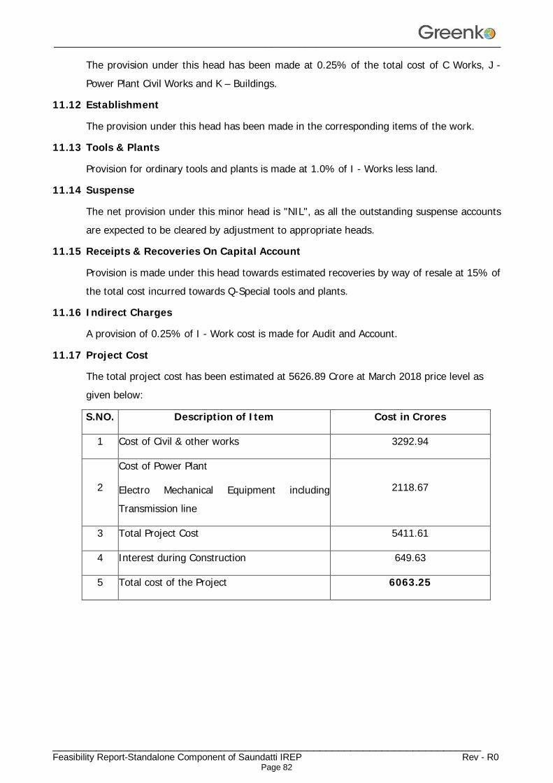
________________________________________________________________________________
_____________________________________________________________________ Feasibility Report-Standalone Component of Saundatti IREP Rev - R0
Page 82
The provision under this head has been made at 0.25% of the total cost of C Works, J - Power Plant Civil Works and K – Buildings.
11.12 Establishment
The provision under this head has been made in the corresponding items of the work.
11.13 Tools & Plants
Provision for ordinary tools and plants is made at 1.0% of I - Works less land.
11.14 Suspense
The net provision under this minor head is "NIL", as all the outstanding suspense accounts are expected to be cleared by adjustment to appropriate heads.
11.15 Receipts & Recoveries On Capital Account
Provision is made under this head towards estimated recoveries by way of resale at 15% of the total cost incurred towards Q-Special tools and plants.
11.16 Indirect Charges
A provision of 0.25% of I - Work cost is made for Audit and Account.
11.17 Project Cost
The total project cost has been estimated at 5626.89 Crore at March 2018 price level as given below:
S.NO. Description of Item Cost in Crores
1 Cost of Civil & other works 3292.94
2
Cost of Power Plant
Electro Mechanical Equipment including Transmission line
2118.67
3 Total Project Cost 5411.61
4 Interest during Construction 649.63
5 Total cost of the Project 6063.25

DRAWINGS
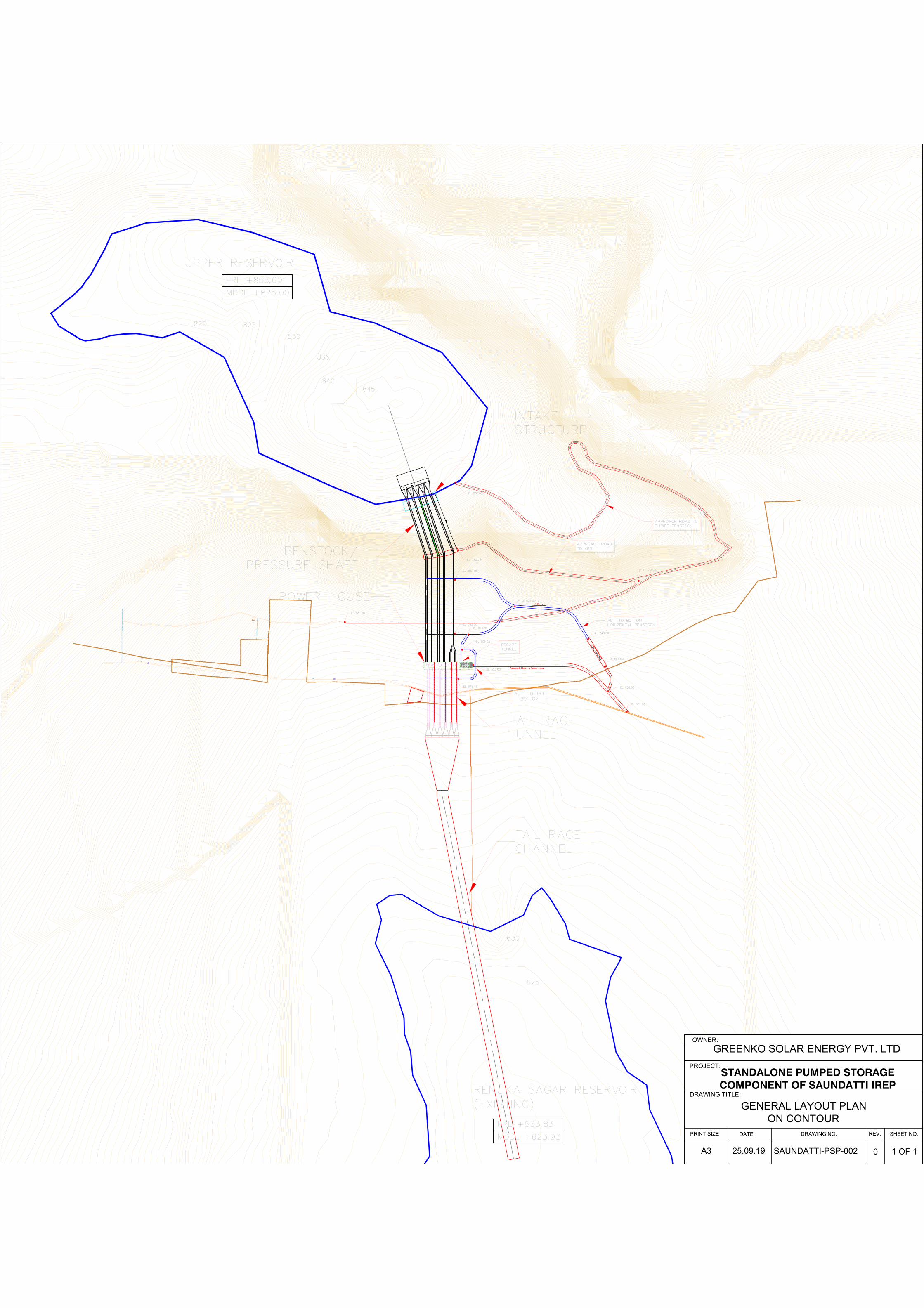
A
p
p
r
o
a
c
h
R
a
m
p
1 IN
12
Approach Road to Powerhouse
STANDALONE PUMPED STORAGECOMPONENT OF SAUNDATTI IREP
PROJECT:
DRAWING TITLE:
PRINT SIZEDATE SHEET NO.
REV.
0 1 OF 1
OWNER:
GREENKO SOLAR ENERGY PVT. LTD
SAUNDATTI-PSP-00225.09.19
GENERAL LAYOUT PLAN
ON CONTOUR
A3
DRAWING NO.
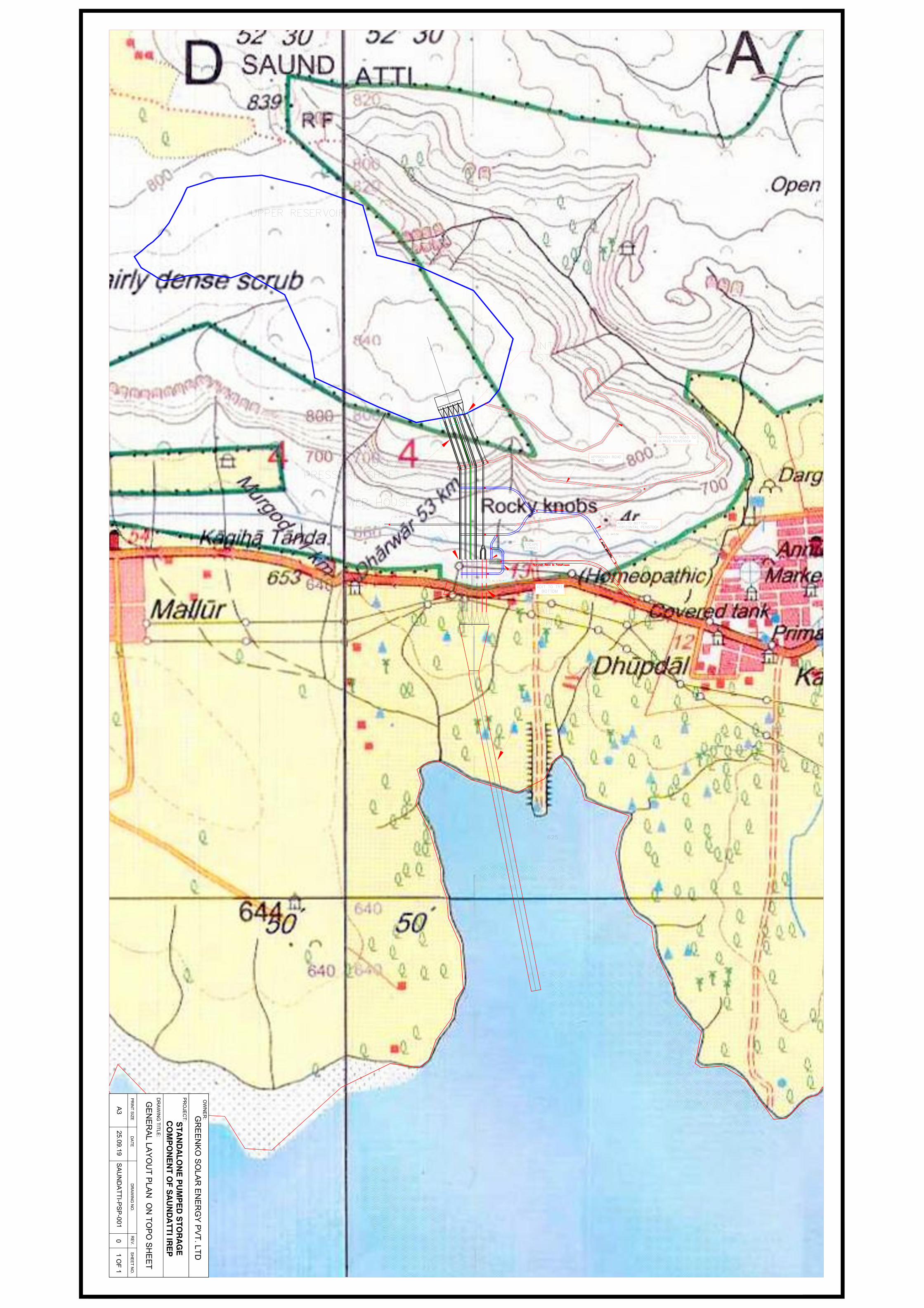
1 IN
12
STA
ND
ALO
NE
PU
MP
ED
STO
RA
GE
CO
MP
ON
EN
T OF S
AU
ND
ATTI IR
EP
PR
OJE
CT
:
DR
AW
IN
G T
IT
LE
:
PR
IN
T S
IZ
ED
AT
ES
HE
ET
N
O.
RE
V.
01 O
F 1
OW
NE
R:
GR
EE
NK
O S
OLA
R E
NE
RG
Y P
VT
. LT
D
SA
UN
DA
TT
I-P
SP
-001
25.09.19
GE
NE
RA
L L
AY
OU
T P
LA
N O
N T
OP
O S
HE
ET
A3
DR
AW
IN
G N
O.

PROJECT:
DRAWING TITLE:
PRINT SIZEDATE SHEET NO.
REV.
0 1 OF 1A3
DRAWING NO.
OWNER:
GREENKO SOLAR ENERGY PVT. LTD
SAUNDATTI-PSP-00325.09.19
GENERAL ARRANGEMENT PLAN
STANDALONE PUMPED STORAGE
COMPONENT OF SAUNDATTI IREP
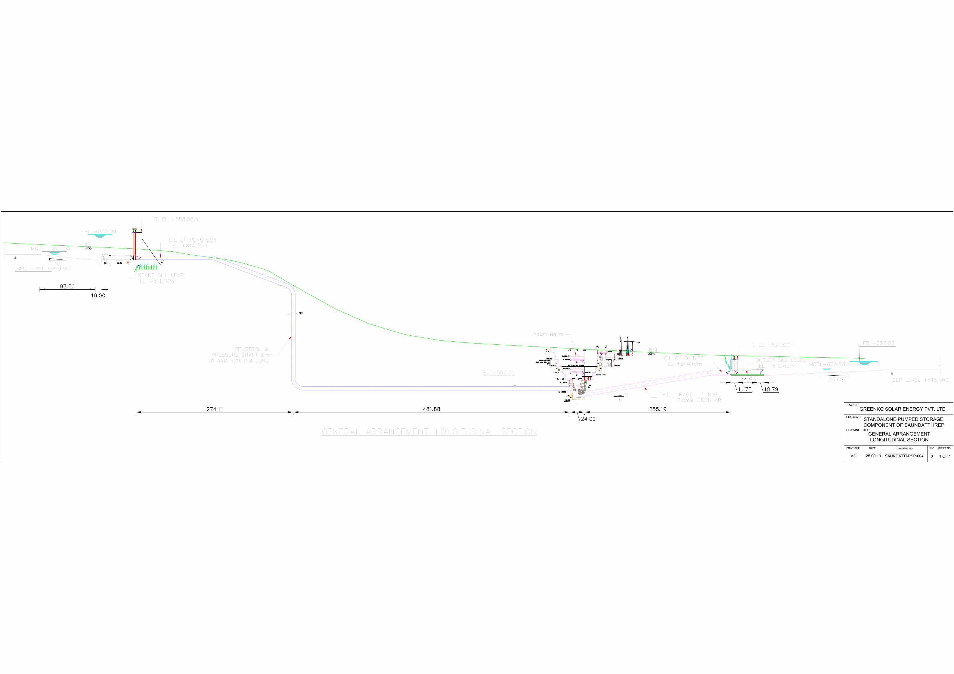
PROJECT:
DRAWING TITLE:
PRINT SIZEDATE SHEET NO.
REV.
0 1 OF 1A3
DRAWING NO.
OWNER:
GREENKO SOLAR ENERGY PVT. LTD
SAUNDATTI-PSP-00425.09.19
GENERAL ARRANGEMENT
LONGITUDINAL SECTION
STANDALONE PUMPED STORAGE
COMPONENT OF SAUNDATTI IREP