speed controller and control motors - spg usa
TRANSCRIPT
113
SPEED CONTROLLER AND CONTROL MOTORS
INDEX
CHARACTERISTICS OF SPEED CONTORL MOTORS 114
UNIT(CONNECTOR) TYPE CONTROL MOTOR
ANALOGUE TYPE SPEED CONTROLLER 118
DIGITAL TYPE SPEED CONTROLLER 121
UNIT TYPE SPEED CONTROL MOTOR 127
PACK TYPE CONTROLLER AND CONTROL MOTOR
SR TYPE SPEED CONTROLLER 140
SS TYPE SPEED CONTROLLER 147
SS 표준 TYPE SPEED CONTROLLER 150SH TYPE SPEED CONTROLLER 160
PACK TYPE SPEED CONTROL MOTORS 170
SPEED CONTROL INDUCTION MOTOR 171SPEED CONTROL REVERSIBLE MOTOR 191SPEED CONTROL ELECTROMAGNETIC BRAKE MOTOR(E·S MOTOR) 205
114 SPEED CONTROLLER AND CONTROL MOTORS
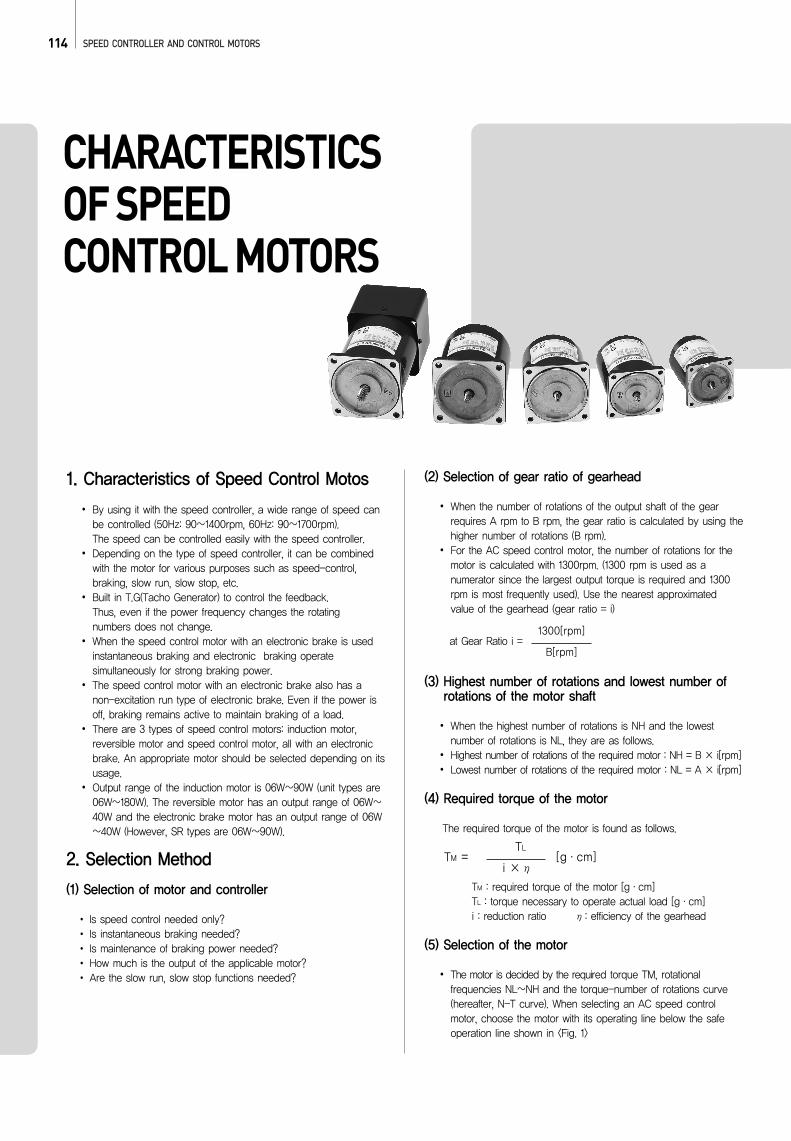
CHARACTERISTICS OF SPEED CONTROL MOTORS
1. Characteristics of Speed Control Motos
By using it with the speed controller, a wide range of speed canbe controlled (50Hz: 90∼1400rpm, 60Hz: 90∼1700rpm). The speed can be controlled easily with the speed controller.Depending on the type of speed controller, it can be combinedwith the motor for various purposes such as speed-control,braking, slow run, slow stop, etc.Built in T.G(Tacho Generator) to control the feedback.Thus, even if the power frequency changes the rotatingnumbers does not change.When the speed control motor with an electronic brake is usedinstantaneous braking and electronic braking operatesimultaneously for strong braking power.The speed control motor with an electronic brake also has anon-excitation run type of electronic brake. Even if the power isoff, braking remains active to maintain braking of a load.There are 3 types of speed control motors: induction motor,reversible motor and speed control motor, all with an electronicbrake. An appropriate motor should be selected depending on itsusage.Output range of the induction motor is 06W∼90W (unit types are06W∼180W). The reversible motor has an output range of 06W∼40W and the electronic brake motor has an output range of 06W∼40W (However, SR types are 06W∼90W).
2. Selection Method
(1) Selection of motor and controller
Is speed control needed only?Is instantaneous braking needed?Is maintenance of braking power needed?How much is the output of the applicable motor?Are the slow run, slow stop functions needed?
(2) Selection of gear ratio of gearhead
When the number of rotations of the output shaft of the gearrequires A rpm to B rpm, the gear ratio is calculated by using thehigher number of rotations (B rpm).For the AC speed control motor, the number of rotations for themotor is calculated with 1300rpm. (1300 rpm is used as anumerator since the largest output torque is required and 1300rpm is most frequently used). Use the nearest approximatedvalue of the gearhead (gear ratio = i)
(3) Highest number of rotations and lowest number ofrotations of the motor shaft
When the highest number of rotations is NH and the lowestnumber of rotations is NL, they are as follows.Highest number of rotations of the required motor : NH = B × i[rpm]Lowest number of rotations of the required motor : NL = A × i[rpm]
(4) Required torque of the motor
The required torque of the motor is found as follows.
TM : required torque of the motor [g·cm]TL : torque necessary to operate actual load [g·cm]i : reduction ratio η: efficiency of the gearhead
(5) Selection of the motor
The motor is decided by the required torque TM, rotationalfrequencies NL∼NH and the torque-number of rotations curve(hereafter, N-T curve). When selecting an AC speed controlmotor, choose the motor with its operating line below the safeoperation line shown in <Fig. 1>
at Gear Ratio i =1300[rpm]
B[rpm]
TM = [g·cm]TL
i × η
115
(Even in the area above the limit curve, the motor can be usedwithout any problems as long as the surface temperature remainsbelow 90°C.
(6) Selection of gearhead
After the motor is selected, the gearhead should be decided withconsideration of the torque size of the load. Confirm that thetorque of the load is within the torque allowed by the gearhead.
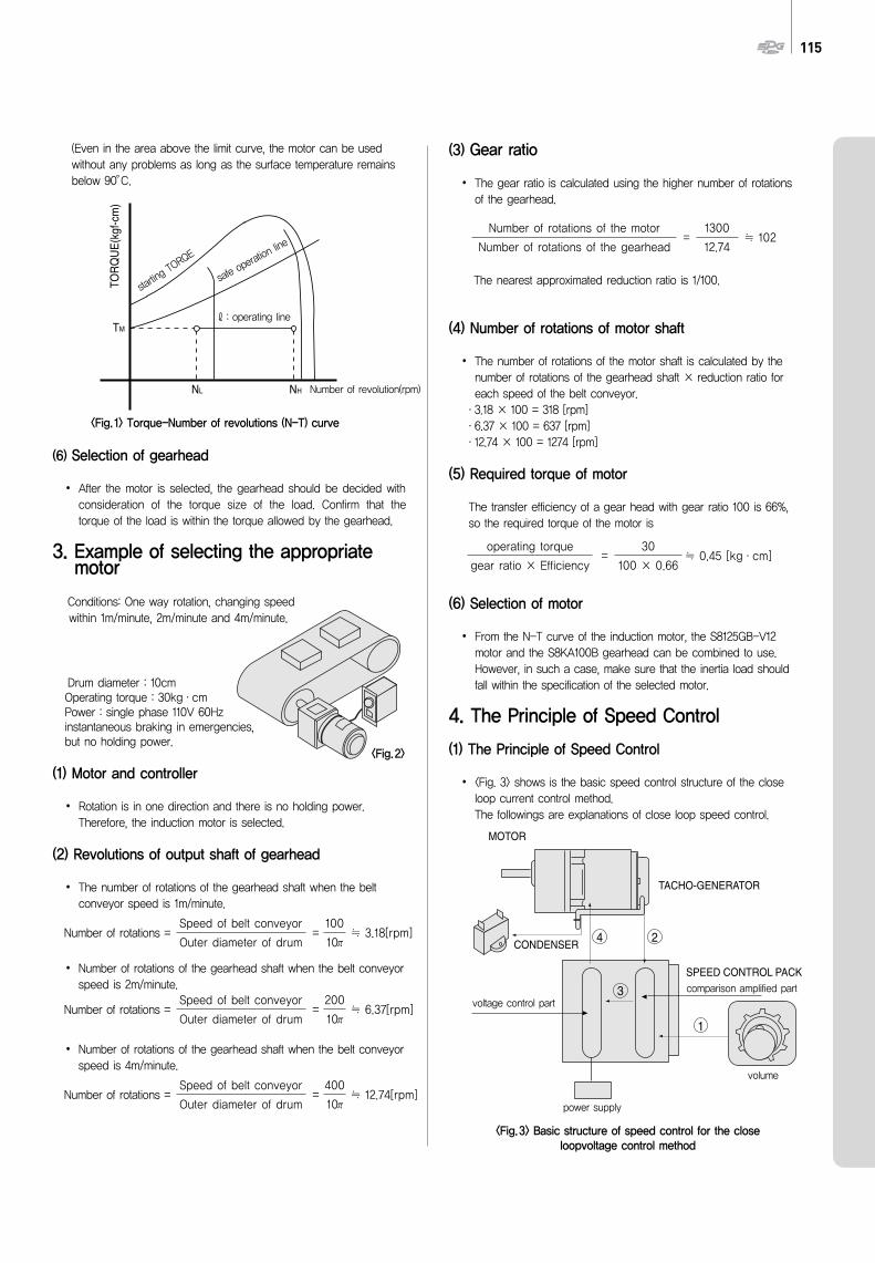
3. Example of selecting the appropriatemotor
Conditions: One way rotation, changing speed within 1m/minute, 2m/minute and 4m/minute.
Drum diameter : 10cmOperating torque : 30kg·cmPower : single phase 110V 60Hzinstantaneous braking in emergencies,but no holding power.
(1) Motor and controller
Rotation is in one direction and there is no holding power.Therefore, the induction motor is selected.
(2) Revolutions of output shaft of gearhead
The number of rotations of the gearhead shaft when the beltconveyor speed is 1m/minute.
Number of rotations of the gearhead shaft when the belt conveyorspeed is 2m/minute.
Number of rotations of the gearhead shaft when the belt conveyorspeed is 4m/minute.
(3) Gear ratio
The gear ratio is calculated using the higher number of rotationsof the gearhead.
The nearest approximated reduction ratio is 1/100.
(4) Number of rotations of motor shaft
The number of rotations of the motor shaft is calculated by thenumber of rotations of the gearhead shaft × reduction ratio foreach speed of the belt conveyor.
·3.18 × 100 = 318 [rpm]·6.37 × 100 = 637 [rpm]·12.74 × 100 = 1274 [rpm]
(5) Required torque of motor
The transfer efficiency of a gear head with gear ratio 100 is 66%,so the required torque of the motor is
(6) Selection of motor
From the N-T curve of the induction motor, the S8125GB-V12motor and the S8KA100B gearhead can be combined to use.However, in such a case, make sure that the inertia load shouldfall within the specification of the selected motor.
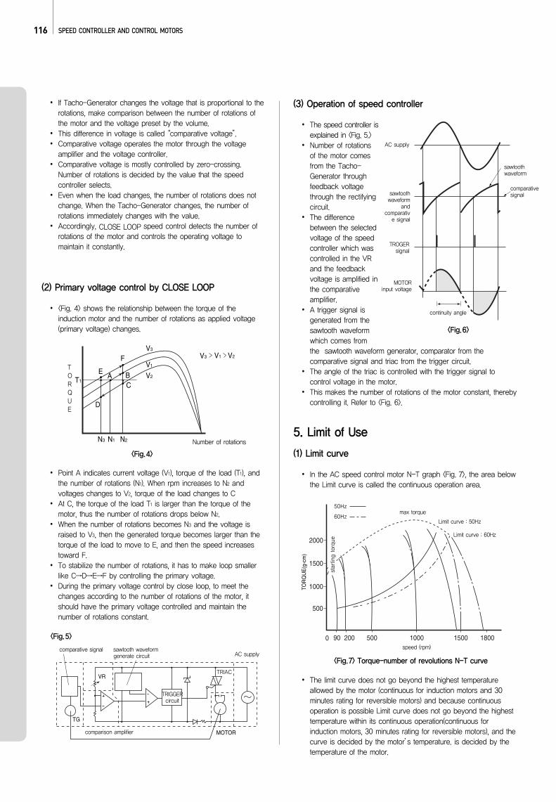
4. The Principle of Speed Control
(1) The Principle of Speed Control
<Fig. 3> shows is the basic speed control structure of the closeloop current control method.The followings are explanations of close loop speed control.
= ≒ 3.18[rpm]Number of rotations =Speed of belt conveyor
Outer diameter of drum
100
10π
= ≒ 102Number of rotations of the motor
Number of rotations of the gearhead
1300
12.74
= ≒ 0.45 [kg·cm]operating torque
gear ratio × Efficiency
30
100 × 0.66
= ≒ 6.37[rpm]Number of rotations =Speed of belt conveyor
Outer diameter of drum
200
10π
= ≒ 12.74[rpm]Number of rotations =Speed of belt conveyor
Outer diameter of drum
400
10π
<Fig.3> Basic structure of speed control for the closeloopvoltage control method
<Fig.2>
<Fig.1> Torque-Number of revolutions (N-T) curve
MOTOR
CONDENSER
TACHO-GENERATOR
SPEED CONTROL PACK
1
3
4 2
voltage control part comparison amplified part
power supply
volume
starting T
ORQE
safe op
eration
line
ℓ: operating line
Number of revolution(rpm)
116 SPEED CONTROLLER AND CONTROL MOTORS
If Tacho-Generator changes the voltage that is proportional to therotations, make comparison between the number of rotations ofthe motor and the voltage preset by the volume. This difference in voltage is called “comparative voltage”.Comparative voltage operates the motor through the voltageamplifier and the voltage controller.Comparative voltage is mostly controlled by zero-crossing.Number of rotations is decided by the value that the speedcontroller selects.Even when the load changes, the number of rotations does notchange. When the Tacho-Generator changes, the number ofrotations immediately changes with the value.Accordingly, CLOSE LOOP speed control detects the number ofrotations of the motor and controls the operating voltage tomaintain it constantly.
(2) Primary voltage control by CLOSE LOOP
<Fig. 4> shows the relationship between the torque of theinduction motor and the number of rotations as applied voltage(primary voltage) changes.
Point A indicates current voltage (V1), torque of the load (T1), andthe number of rotations (N1). When rpm increases to N2 andvoltages changes to V2, torque of the load changes to CAt C, the torque of the load T1 is larger than the torque of themotor, thus the number of rotations drops below N2.When the number of rotations becomes N3 and the voltage israised to V3, then the generated torque becomes larger than thetorque of the load to move to E, and then the speed increasestoward F.To stabilize the number of rotations, it has to make loop smallerlike C→D→E→F by controlling the primary voltage.During the primary voltage control by close loop, to meet thechanges according to the number of rotations of the motor, itshould have the primary voltage controlled and maintain thenumber of rotations constant.
(3) Operation of speed controller
The speed controller isexplained in <Fig. 5.>Number of rotationsof the motor comesfrom the Tacho-Generator throughfeedback voltagethrough the rectifyingcircuit.The differencebetween the selectedvoltage of the speedcontroller which wascontrolled in the VRand the feedbackvoltage is amplified inthe comparativeamplifier.A trigger signal isgenerated from thesawtooth waveformwhich comes fromthe sawtooth waveform generator, comparator from thecomparative signal and triac from the trigger circuit.The angle of the triac is controlled with the trigger signal tocontrol voltage in the motor.This makes the number of rotations of the motor constant, therebycontrolling it. Refer to <Fig. 6>.
5. Limit of Use
(1) Limit curve
In the AC speed control motor N-T graph <Fig. 7>, the area belowthe Limit curve is called the continuous operation area.
The limit curve does not go beyond the highest temperatureallowed by the motor (continuous for induction motors and 30minutes rating for reversible motors) and because continuousoperation is possible Limit curve does not go beyond the highesttemperature within its continuous operation(continuous forinduction motors, 30 minutes rating for reversible motors), and thecurve is decided by the motor’s temperature. is decided by thetemperature of the motor.
T1V2
V2
V1
V1
V3
V3
E
F
C
D
BA
N3 N1 N2
<Fig.4>
Number of rotations
TORQUE
TG
VR
MOTOR
TOR
QU
E(g
-cm
)
1000
500
0 90 200 500 1000 18001500
1500
2000
<Fig.5>
comparative signal sawtooth waveform generate circuit
TRIGGERcircuit
comparison amplifier
AC supply
TRIAC
<Fig.6>
<Fig.7> Torque-number of revolutions N-T curve
sawtoothwaveform
continuity angle
AC supply
sawtoothwaveform
andcomparativ
e signal
TROGERsignal
MOTOR input voltage
comparativesignal
50Hz
60Hzmax torque
speed (rpm)
Limit curve : 50Hz
Limit curve : 60Hz
starting torque
117
Our speed control motor has a class E insulation and thepermitted temperature of the winding section is 120.Therefore, if the temperature of the winding section is less than120, continuous operation is possible, But since measuring thetemperature of the winding section is difficult, continuousoperation is generally possible when the surface temperature ofthe motor housing is less than 90. The temperature differencebetween the winding section and the housing surface isgenerally around 10°C to 20°C, but may vary depending on thetype of the motor.
(2) Surface temperature of 90°C or less
The highest part of the motor's rising temperature is the windingsection. Thus, the highest allowable temperature is decided bythe insulation level of the winding section.(SPG’s small AC motors have a class E insulation and thehighest allowable temperature is 120.)The difference between the temperature of the surface ofthe motor and the winding section is about 10°C~20°C.(A motor with a cooling fan has about 30°C difference becausethe cooling fan cools the surface of the motor.)When the temperature of the winding section is 120, the surfacetemperature is about 100. Therefore 90 is the sufficient value.
118 SPEED CONTROLLER AND CONTROL MOTORS
ANALOGUE TYPE SPEED CONTROLLER
1. How to use
(1) Operation
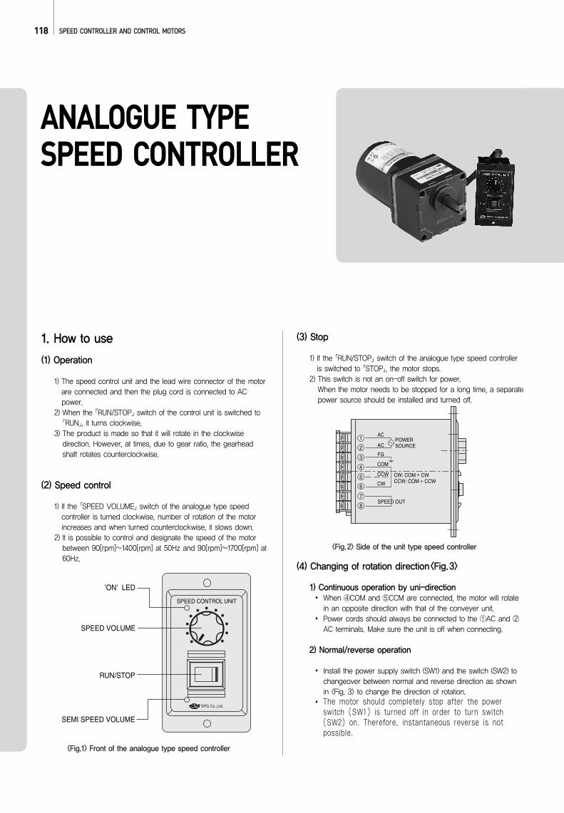
1) The speed control unit and the lead wire connector of the motorare connected and then the plug cord is connected to ACpower.
2) When the 「RUN/STOP」switch of the control unit is switched to「RUN」, it turns clockwise.
3) The product is made so that it will rotate in the clockwisedirection. However, at times, due to gear ratio, the gearheadshaft rotates counterclockwise.
(2) Speed control
1) If the 「SPEED VOLUME」switch of the analogue type speedcontroller is turned clockwise, number of rotation of the motorincreases and when turned counterclockwise, it slows down.
2) It is possible to control and designate the speed of the motorbetween 90[rpm]∼1400[rpm] at 50Hz and 90[rpm]∼1700[rpm] at60Hz.
(3) Stop
1) If the 「RUN/STOP」switch of the analogue type speed controlleris switched to 「STOP」, the motor stops.
2) This switch is not an on-off switch for power.When the motor needs to be stopped for a long time, a separatepower source should be installed and turned off.
(4) Changing of rotation direction<Fig.3>
1) Continuous operation by uni-directionWhen ④COM and ⑤CCM are connected, the motor will rotatein an opposite direction with that of the conveyer unit.Power cords should always be connected to the ①AC and ②AC terminals. Make sure the unit is off when connecting.
2) Normal/reverse operation
Install the power supply switch (SW1) and the switch (SW2) tochangeover between normal and reverse direction as shownin <Fig. 3> to change the direction of rotation.The motor should completely stop after the powerswitch (SW1) is turned off in order to turn switch(SW2) on. Therefore, instantaneous reverse is notpossible.
SPEED CONTROL UNIT
’ON’ LED
SPEED VOLUME
SEMI SPEED VOLUME
RUN/STOP
ACPOWERSOURCE
CW: COM CWCCW: COM CCW
AC
FG
COM
CCW
CW
SPEED OUT
1
2
3
4
5
6
7
8
<Fig.1> Front of the analogue type speed controller
<Fig.2> Side of the unit type speed controller
119
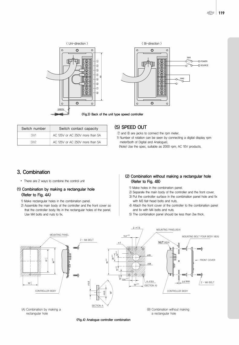
(5) SPEED OUT⑦ and ⑧ are jacks to connect the rpm meter.1) Number of rotation can be seen by connecting a digital display rpmmeter(both of Digital and Analogue).(Note) Use the spec, suitable as 2000 rpm, AC 10V products.
3. Combination
There are 2 ways to combine the control unit
(1) Combination by making a rectangular hole<Refer to Fig. 4A>1) Make rectangular holes in the combination panel.2) Assemble the main body of the controller and the front cover sothat the controller body fits in the rectangular holes of the panel.Use M4 bolts and nuts to fix.
(2) Combination without making a rectangular hole<Refer to Fig. 4B>1) Make holes in the combination panel.2) Separate the main body of the controller and the front cover.3) Put the controller surface in the combination panel hole and fixwith M3 flat-head bolts and nuts.
4) Attach the front cover of the controller to the combination paneland fix with M4 bolts and nuts.
5) The combination panel should be less than 2 thick.
SW1
POWER
SOURCE
SW2
80
GREEN
1
2
3
4
5
6
7
8
< Uni-direction > < Bi-direction >
<Fig.3> Back of the unit type speed controller
<Fig.4> Analogue controller combination
Switch number
SW1
SW2
Switch contact capacity
AC 125V or AC 250V more than 5A
AC 125V or AC 250V more than 5A
(A) Combination by making arectangular hole
(B) Combination without makinga rectangular hole
53+1 0
90+0
.2
81+1 0
CONTROLLER
PANEL
2 - M4
CONTROLLER
PANEL
COVER
NUT
2 - M4
90
3.5 4 -
7.5 2 -
2.0
7
50+0.2
6.5
3.5
90+0
.2 26+0
.2 15+0
.2
13.2 +0.2
15+0
.2
23
28
15+0
.2
13.6 +0.2
SECTION A
(SECTION A)
본체
(4EA)
MOUNTING PANEL
MOUNTING PANEL(4EA)
MOUNTING BOLT FOUR BODY (4EA)
FRONT COVER
2 - M4 BOLT
CONTROLLER BODY
2 - M4 BOLT
CONTROLLER BODY
less
120 SPEED CONTROLLER AND CONTROL MOTORS
DIMENSIONS
SPEED CONTROLLER
60(98.5)
76
3.5
1.5
(8)
90
100
51.5
80
ACPOWERSOURCE
CW: COM CWCCW: COM CCW
AC
FG
COM
CCW
CW
SPEED OUT
1
2
3
4
5
6
7
8
SPEED CONTROL UNIT
LOW HIGH
STOP RUN
GREEN YELLOW
4. SPECIFICATIONS
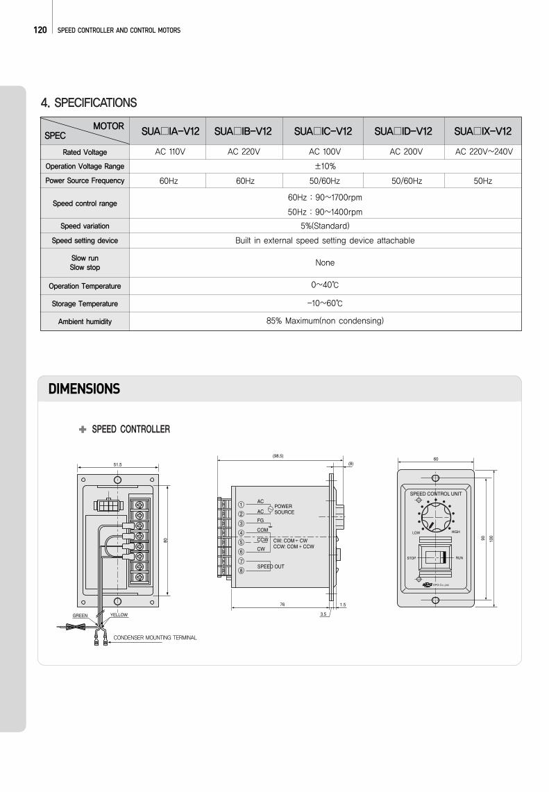
SPECMOTOR SUA IA-V12 SUA IB-V12 SUA IC-V12 SUA ID-V12 SUA IX-V12
AC 110V AC 220V AC 100V AC 200V AC 220V~240V
±10%
60Hz : 90~1700rpm
50Hz : 90~1400rpm
5%(Standard)
Built in external speed setting device attachable
None
0~40
-10~60
85% Maximum(non condensing)
60Hz 60Hz 50/60Hz 50/60Hz 50Hz
Rated Voltage
Operation Voltage Range
Power Source Frequency
Speed control range
Speed variation
Speed setting device
Slow run Slow stop
Operation Temperature
Storage Temperature
Ambient humidity
CONDENSER MOUNTING TERMINAL
121
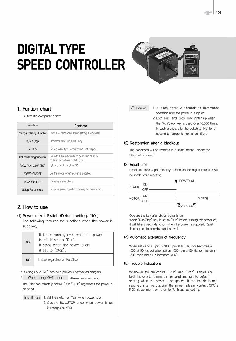
DIGITAL TYPE SPEED CONTROLLER
2. How to use
(1) Power on/off Switch (Default setting: ‘NO’)The following features the functions when the power issupplied.
Setting up to “NO”can help prevent unexpected dangers.
The user can remotely control “RUN/STOP”regardless the power is
on or off.
1. Set the switch to ‘YES’when power is on
2. Operate RUN/STOP once when power is on
(It recognizes YES)
1. It takes about 2 seconds to commence
operation after the power is supplied.
2. Both “Run”and “Stop”may lighten up when
the “Run/Stop”key is used over 10,000 times.
In such a case, alter the switch to “No”for a
second to restore its normal condition.
(2) Restoration after a blackout
The conditions will be restored in a same manner before the
blackout occurred.
(3) Reset timeReset time takes approximately 2 seconds. No digital indication will
be made while resetting.
Operate the key after digital signal is on.When “Run/Stop”key is set to “Run”before turning the power off,it will take 2 seconds to run when the power is supplied. Resettime applies to post-blackout as well.
(4) Automatic alteration of frequency
When set as 1400 rpm ~ 1800 rpm at 60 Hz, rpm becomes at1500 at 50 Hz, but when set as 1500 rpm at 50 Hz, rpm remains1500 even when Hz increases to 60.
(5) Trouble Indications
Whenever trouble occurs, “Run”and “Stop”signals areboth indicated. It may be restored and set to defaultsetting when the power is resupplied. If the trouble is notresolved after resupplying the power, please contact SPG’sR&D department or refer to 7. Troubleshooting.
It keeps running even when the power is off, if set to “Run”.It stops when the power is off, if set to “Stop”.
It stops regardless of “Run/Stop”.
Function
Change rotating direction
Run / Stop
Set RPM
Set mark magnification
SLOW RUN SLOW STOP
POWER-ON/OFF
LOCK Function
Setup Parameters
CW/CCW termianls(Default setting: Clockwise)
Operated with RUN/STOP Key
Set digital(multiple magnification unit, 10rpm)
Set with Gear ratio(refer to gear ratio chat) &multiple magnification(Unit 0.005)
0.1 sec. ~ 30 sec.(Unit 0.1)
Set the mode when power is supplied
Prevents malfunctions
Setup for powering off and saving the parameters
Contents
Installation
Caution
POWER
POWER ON
MOTOR
ON
OFF
ON
OFFrunning
about 2 sec.
YES
NO
1. Funtion chartAutomatic computer control
When using“YES" mode (Please use in set mode)
122 SPEED CONTROLLER AND CONTROL MOTORS
(6) Thermal protector
A thermal protector (TP) is installed in a motor to prevent the motorfrom overheating. When the motor overheats, the TP activates tostop the motor. It automatically deactivates when the motor coolsdown and start the motor again.
(7) Test for withstand voltage & Impulse voltage
Need to disconnect of two power codes from outer motor wire inthe case of withstand voltage testing with line earth, impulsevoltage testing and testing of heat transfer resistance.
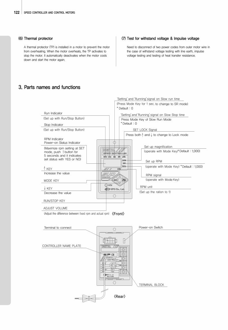
3. Parts names and functions
123
SW1
POWER
SOURCE
SW2
80
GREEN
52
1
2
3
4
5
6
<Uni-direction> <Bi-direction>
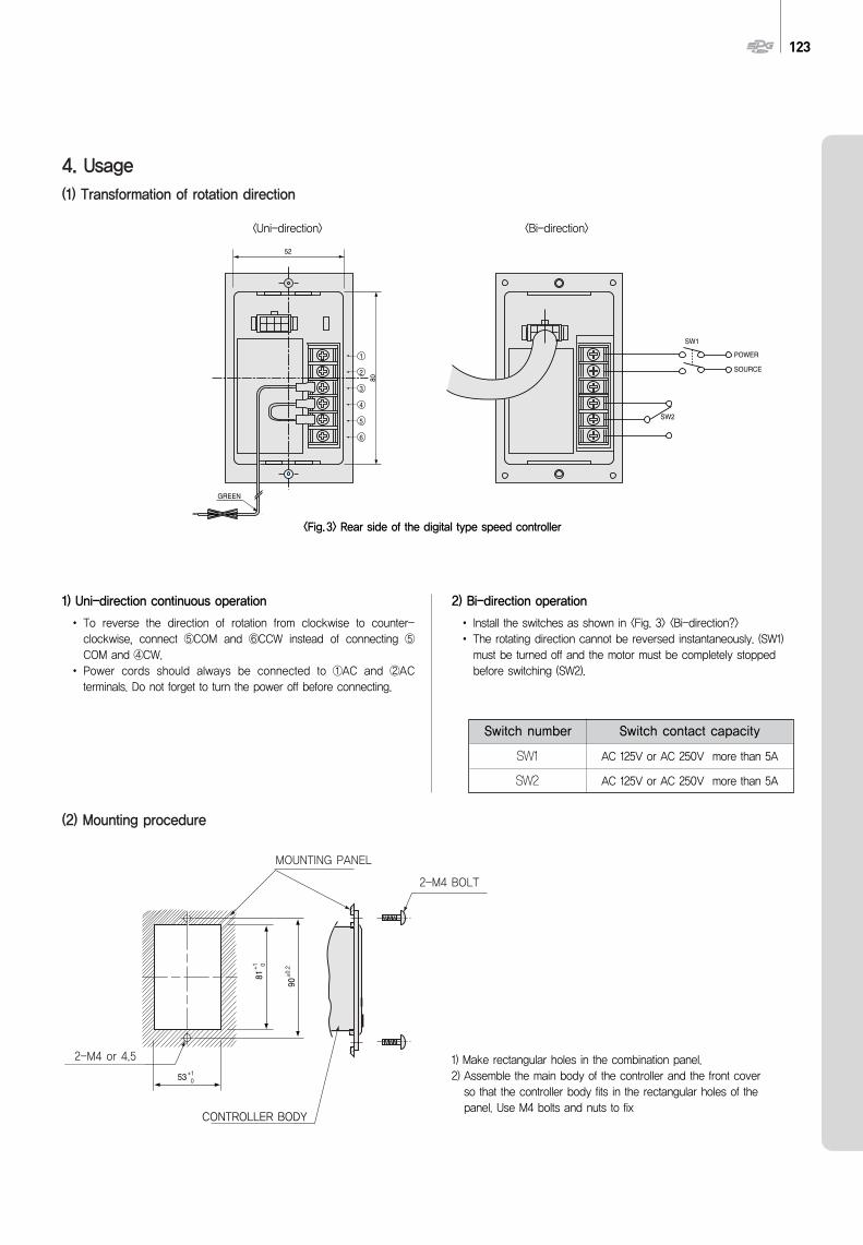
<Fig.3> Rear side of the digital type speed controller
1) Uni-direction continuous operation
To reverse the direction of rotation from clockwise to counter-clockwise, connect ⑤COM and ⑥CCW instead of connecting ⑤COM and ④CW.Power cords should always be connected to ①AC and ②ACterminals. Do not forget to turn the power off before connecting.
2) Bi-direction operation
Install the switches as shown in <Fig. 3> <Bi-direction?>The rotating direction cannot be reversed instantaneously. (SW1)must be turned off and the motor must be completely stoppedbefore switching (SW2).
53+1 0
90+0
.2
81+1 0
CONTROLLER
PANEL
2 - M4
2 - M4 4.5
MOUNTING PANEL
2-M4 BOLT
2-M4 or 4.5
(2) Mounting procedure
4. Usage(1) Transformation of rotation direction
Switch number
SW1
SW2
Switch contact capacity
AC 125V or AC 250V more than 5A
AC 125V or AC 250V more than 5A
1) Make rectangular holes in the combination panel.2) Assemble the main body of the controller and the front coverso that the controller body fits in the rectangular holes of thepanel. Use M4 bolts and nuts to fix
CONTROLLER BODY
124 SPEED CONTROLLER AND CONTROL MOTORS
(1) RATIO MODE
Ratio mode indicates the actual speed of gearhead output RPMand conveyor speed by multiplying rpm with magnification.
1) Gear Ratio (for indication conforming to gearheadoutput rpm)<“SET" or“REAL" value = Motor rpm÷Gearratio>Example) The Gear Ratio chart is listed. Select the required valuewith↑,↓ button 1.000 ↔ 3 ↔ ... ↔ 100 ... ↔ 202 ... ↔ 1000 ... ↔2515 [Refer to P14. Gear ratio]
2) Multiple magnification value (for indicationconforming to the transfer speed of conveyor belt)<“SET”or“REAL”value =Motor rpm X Multiple magnification value >Example) The Multiple magnifications are listed from 0.005 thru0.995. Select the required value with ↑,↓ button 1.000 ↔ 0.995↔... ↔ 0.015 ↔ 0.010 ↔ 0.005 (0.005 per tick)
(2) SET MODE
Set mode is used to setup RPM using ↑,↓ button
Term Value is 10 rpmExample) Frequency 50Hz : 90 ↔ 100 ↔ 110 ↔ ... ↔ 1400 ↔
1500rpmFrequency 60Hz : 90 ↔ 100 ↔ 110 ↔ ... ↔ 1400 ↔ ... ↔1700 ↔ 1800rpm
Rpm can be set in connection with the Multiple Magnification valueset on Ratio Mode.Example) Gear ratio value = 3
Base Unit, 10÷3rpm. The value is rounded to nearesttenth.Frequency 50Hz : 29.9 ↔ 33.3 ↔ 36.6 ↔ ... ↔ 466.6 ↔500.0rpmFrequency 60Hz : 29.9 ↔ 33.3 ↔ 36.6 ↔ ... ↔ 466.6 ↔... ↔ 566.6 ↔ 600.0rpm
Example) Multiple magnifications value =0.500Base Unit, 10X0.500. The value is rounded to nearesttenth.Frequency 50Hz : 45.0 ↔ 50.0 ↔ 55.0 ↔ ... ↔ 700.0 ↔750.0rpmFrequency 60Hz : 45.0 ↔ 50.0 ↔ 55.0 ↔ ... ↔ 700.0 ↔... ↔ 850.0 ↔ 900.0rpm
(3) REAL MODE
Real mode indicates the actual speed of a motor by multiplyingwith magnification.
「If the indicated magnification is 1.000」Term Value is 5 rpmExample) 0 ↔ 5 ↔ 10 ↔ ... ↔ 90 ↔ 95 ↔ 100 ↔ ... ↔ 1400 ↔ ... ↔
1700rpm
「If the indicated magnification is not 1.000」Operate on “Ratio”Mode by follows magnification and Gear ratio value
Example) Gear ratio value = 3Base Unit, 5÷3rpm. The value is rounded to nearest tenth.0 ↔ 1.6 ↔ ... ↔ 29.9 ↔ 31.6 ↔ 33.3 ↔ ... ↔ 466.6 ↔ ... ↔566.6rpm
Example) Multiple magnification value=0.500Base Unit, 5X0.500. The value is rounded to nearest tenth.
Example) 0 ↔ 1.6 ↔ ... ↔ 29.9 ↔ 31.6 ↔ 33.3 ↔ ... ↔ 466.6 ↔ ... ↔566.6rpm
(4) S/R MODES/R mode sets up the Slow Run time using ↑,↓ button. 0.1 secper tick, up to 30 seconds0 ↔ 0.1 ↔ ... ↔ 0.2 ↔ 0.3 ↔ 0.4 ↔ ... ↔ 29.9 ↔ 30.0sec.
(5) S/S MODES/S mode sets up the Slow Stop time using ↑,↓button. 0.1 sec per tick, up to 30 seconds0 ↔ 0.1 ↔ ... ↔ 0.2 ↔ 0.3 ↔ 0.4 ↔ ... ↔ 29.9 ↔ 30.0sec.
(6) Power-On Status Setup Mode
Power-On Status Setup mode enables selections of operationwhen the power is supplied.
1) Indicating “YES”When the power is resupplied, it recovers its previous operatingconditions.
5. Mode Descriptions
If the indicated magnification is 1.000
If the indicated magnification is not 1.000
NOTE
NOTE
NOTE
10s× = 5s750rpm
1500rpm
Nothing will be indicated if the magnification is under1.000
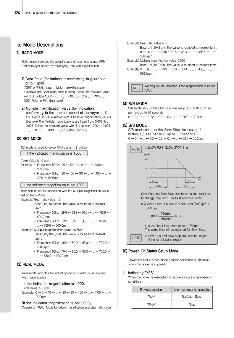
1. SLOW RUN·SLOW STOP time
Slow Run and Slow Stop time refers to time requiredto change rpm from 0 to 1500 and vice versa.
(ex) When Slow Run time is 10sec. And “Set”rpm is750rpm
It takes about 5sec from 0rpm to 750rpm. The same time will be required for Slow Stop.
2. Slow Run and Slow Stop time can be longer if lnertia of load is bigger
Previous condition
“RUN” Run(after 2Sec.)
Stop“STOP”
After the power is resupplied
125
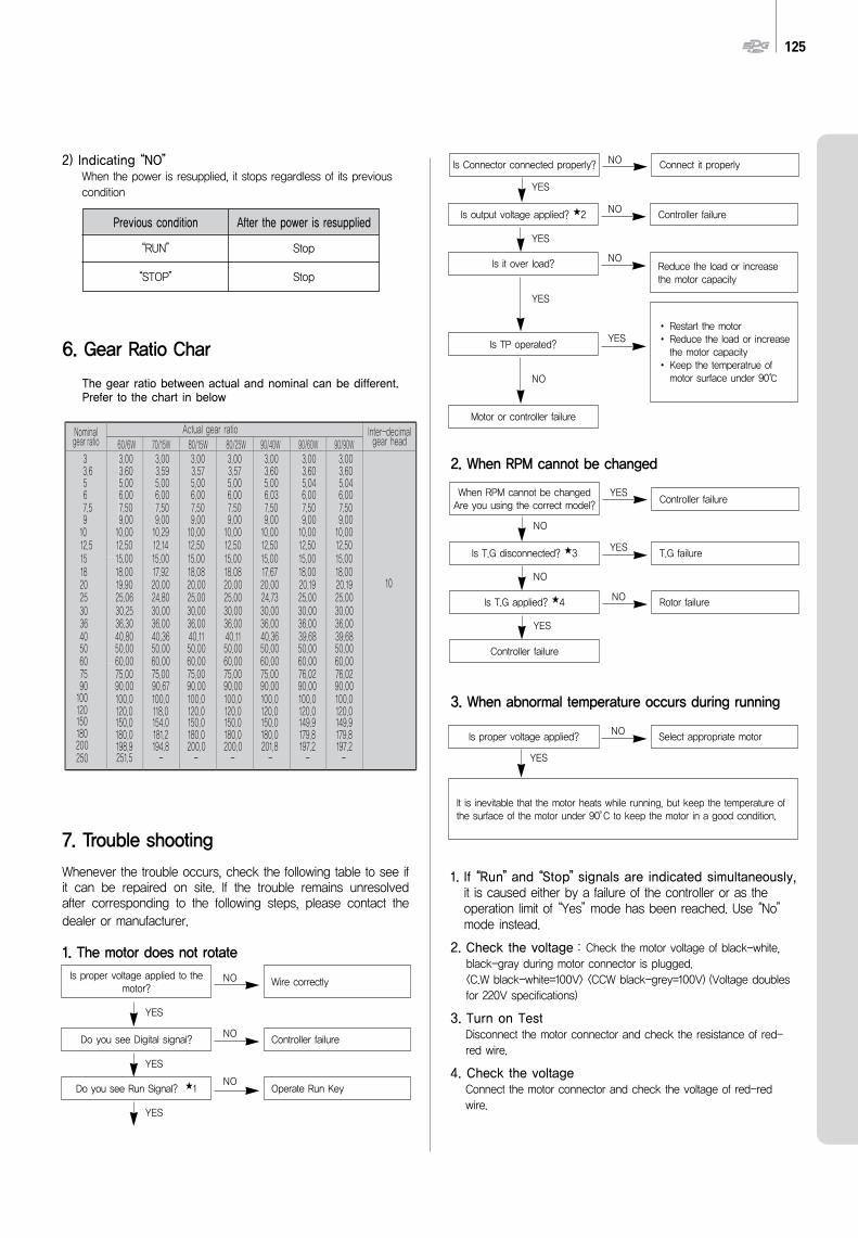
2) Indicating “NO”When the power is resupplied, it stops regardless of its previouscondition
6. Gear Ratio Char
The gear ratio between actual and nominal can be different.Prefer to the chart in below
7. Trouble shooting
Whenever the trouble occurs, check the following table to see ifit can be repaired on site. If the trouble remains unresolvedafter corresponding to the following steps, please contact thedealer or manufacturer.
1. The motor does not rotate
2. When RPM cannot be changed
3. When abnormal temperature occurs during running
1. If “Run”and “Stop”signals are indicated simultaneously,it is caused either by a failure of the controller or as theoperation limit of “Yes”mode has been reached. Use “No”mode instead.
2. Check the voltage : Check the motor voltage of black-white,black-gray during motor connector is plugged. <C.W black-white=100V> <CCW black-grey=100V) (Voltage doublesfor 220V specifications)
3. Turn on TestDisconnect the motor connector and check the resistance of red-red wire.
4. Check the voltageConnect the motor connector and check the voltage of red-redwire.
Previous condition
“RUN” Stop
Stop“STOP”
After the power is resupplied
Is proper voltage applied to themotor?
Wire correctlyNO
NO
NO
YES
YES
YES
Do you see Digital signal? Controller failure
Do you see Run Signal? 1 Operate Run Key
Is Connector connected properly? Connect it properlyNO
NO
NO
YES
YES
YES
YES
NO
Is output voltage applied? 2 Controller failure
Is it over load? Reduce the load or increasethe motor capacity
Is TP operated?
Motor or controller failure
Restart the motorReduce the load or increasethe motor capacityKeep the temperatrue ofmotor surface under 90
When RPM cannot be changedAre you using the correct model? Controller failure
YES
NO
Is T.G disconnected? 3 T.G failureYES
Is T.G applied? 4
Controller failure
Rotor failureNO
NO
YES
Is proper voltage applied?
It is inevitable that the motor heats while running, but keep the temperature ofthe surface of the motor under 90°C to keep the motor in a good condition.
Select appropriate motorNO
YES
126 SPEED CONTROLLER AND CONTROL MOTORS
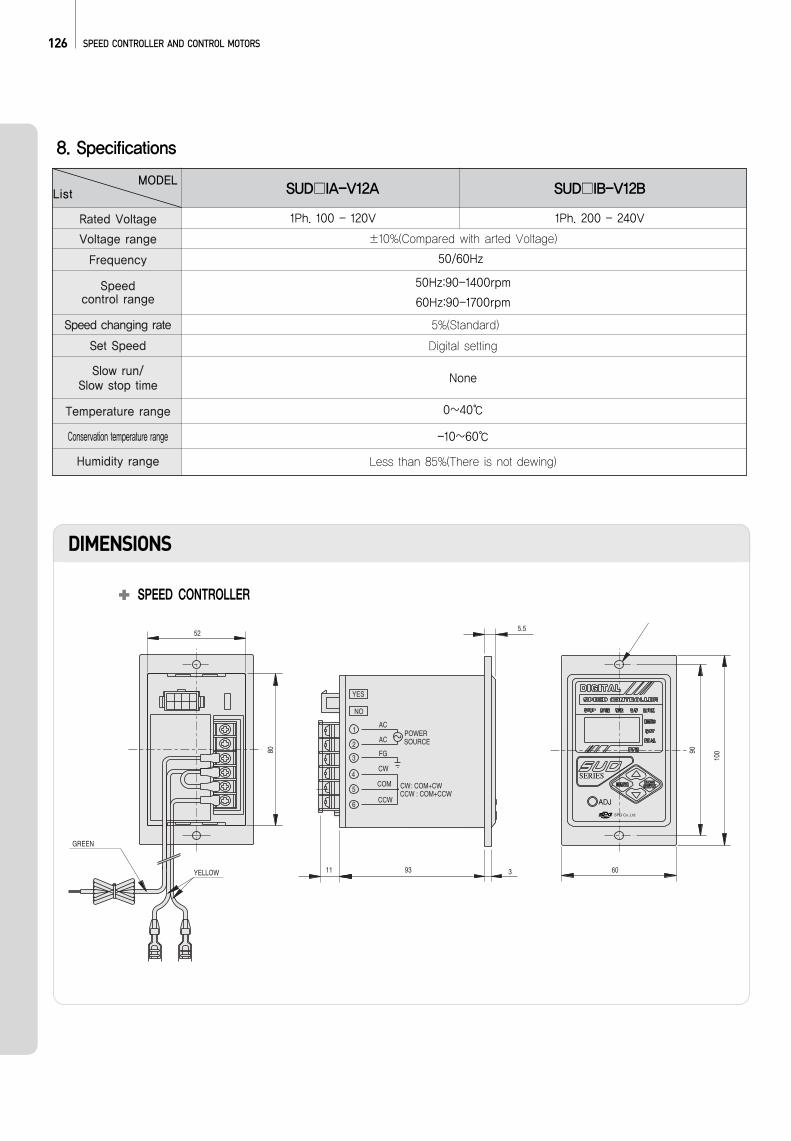
8. Specifications
ListMODEL
SUD IA-V12A SUD IB-V12B
±10%(Compared with arted Voltage)
50Hz:90-1400rpm
60Hz:90-1700rpm
5%(Standard)
Digital setting
None
0~40
-10~60
Less than 85%(There is not dewing)
50/60Hz
1Ph. 100 - 120V 1Ph. 200 - 240V
DIMENSIONS
SPEED CONTROLLER
80
GREEN
90
60
100
YELLOW
52
NO
YES
311 93
CW4
5
6CCW
COM
3 FG
CCW : COM+CCW: COM+CWCW
2AC
AC
SOURCEPOWER1
5.5
SERIES
ADJ
Rated Voltage
Voltage range
Frequency
Speedcontrol range
Speed changing rate
Set Speed
Slow run/Slow stop time
Temperature range
Conservation temperature range
Humidity range
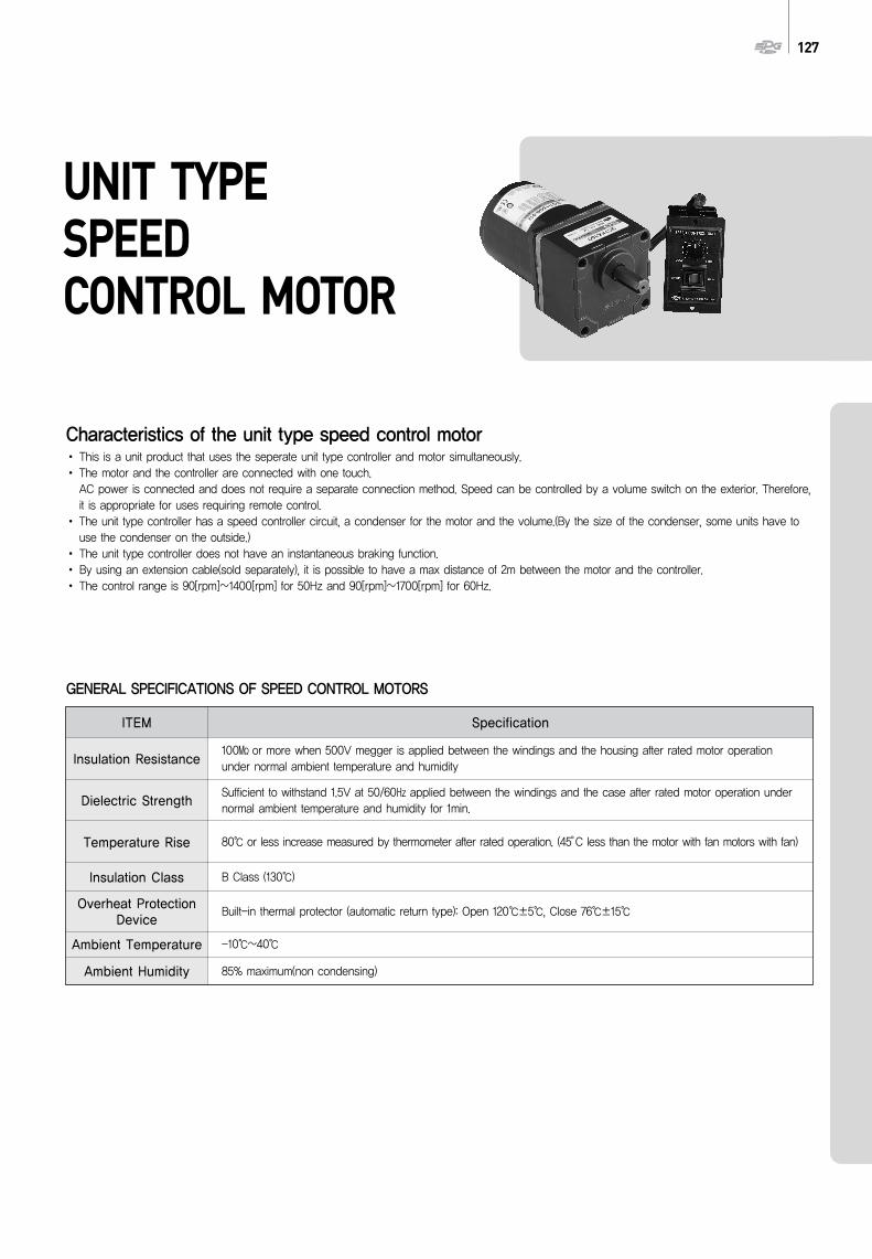
127
UNIT TYPE SPEEDCONTROL MOTOR
Characteristics of the unit type speed control motorThis is a unit product that uses the seperate unit type controller and motor simultaneously.The motor and the controller are connected with one touch. AC power is connected and does not require a separate connection method. Speed can be controlled by a volume switch on the exterior. Therefore,it is appropriate for uses requiring remote control.The unit type controller has a speed controller circuit, a condenser for the motor and the volume.(By the size of the condenser, some units have touse the condenser on the outside.)The unit type controller does not have an instantaneous braking function.By using an extension cable(sold separately), it is possible to have a max distance of 2m between the motor and the controller. The control range is 90[rpm]∼1400[rpm] for 50Hz and 90[rpm]∼1700[rpm] for 60Hz.
GENERAL SPECIFICATIONS OF SPEED CONTROL MOTORS
100 or more when 500V megger is applied between the windings and the housing after rated motor operationunder normal ambient temperature and humidity
Sufficient to withstand 1.5V at 50/60 applied between the windings and the case after rated motor operation undernormal ambient temperature and humidity for 1min.
B Class (130)
-10~40
85% maximum(non condensing)
Built-in thermal protector (automatic return type): Open 120±5, Close 76±15
ITEM Specification
Insulation Resistance
Dielectric Strength
Temperature Rise
Insulation Class
Overheat ProtectionDevice
Ambient Temperature
Ambient Humidity
80 or less increase measured by thermometer after rated operation. (45°C less than the motor with fan motors with fan)
(Hz)Phase (V)
Freq.
(A)
Currentat 1200 r/min at 90 r/min
Permissible Torque
(kgf·cm) (mN·m) (kgf·cm) (mN·m) (kgf·cm) (mN·m)
Degree ofProtection
InsulationClassification
ProtectedType
Starting Torque
()
CapacitorVoltageDuty
(r/min)
SpeedRangePolesMotor
ModelControllerModel
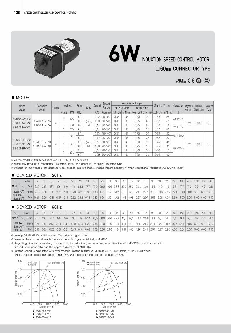
SG6I06GA-V12 SG6I06DA-V12 SG6I06SA-V12
SG6I06GB-V12 SG6I06DB-V12 SG6I06SB-V12
50606060506050605060
0.22 90-1400 0.45 45 0.30 30 0.58 580.20 90-1700 0.35 35 0.25 25 0.58 580.19 90-1700 0.35 35 0.25 25 0.50 500.19 90-1700 0.35 35 0.25 25 0.50 500.10 90-1400 0.45 45 0.30 30 0.52 520.10 90-1700 0.35 35 0.25 25 0.52 520.12 90-1400 0.45 45 0.30 30 0.45 450.09 90-1700 0.35 35 0.25 25 0.45 450.12 90-1400 0.45 45 0.30 30 0.52 520.09 90-1700 0.35 35 0.25 25 0.52 52
128 SPEED CONTROLLER AND CONTROL MOTORS
..All the model of SG series received UL, TUV, CCC certificate.output 6W product is Impedance Protected, 15~90W product is Thermally Protected type. Depend on the voltage, the capacitors are divided into two model. Please inquire separately when operational voltage is AC 100V or 200V.
Among GEAR HEAD model names, is reduction gear ratio.Value of the chart is allowable torque of reduction gear of GEARED MOTOR.Regarding direction of rotation, in case of , its reduction gear ratio has same direction with MOTOR's and in case of , its reduction gear ratio has the opposite direction of MOTOR's.rotation speed is calculated with synchronous rotation number of MOTOR(50Hz : 1500 r/min, 60Hz : 1800 r/min).Actual rotation speed can be less than (2~20%) depend on the size of the load 2~20%.
SG6I06GA-V12SG6I06DA-V12SG6I06SA-V12
SG6I06GB-V12SG6I06DB-V12SG6I06SB-V12
SUA06IA-V12ASUD06IA-V12A
SUA06IB-V12BSUD06IB-V12B
41 100
1 1101 115
1 200
1 220
1 230
3.5 (250V)
2.5 (250V)
0.8 (450V)
0.6 (450V)4
Cont.S1
Cont.S1
IP23
IP23
B(130)
B(130)
Z.P.
Z.P.
Ratio
r/minModel
SG6KASG6DASG6SA
kgf.cm
N.m
5 6 7.5 9 10 12.5 15 18 20 25 30 36 40 50 60 75 90 100 120 150
280 233 187 156 140 112 93.3 77.7 70.0 56.0 46.6 38.8 35.0 28.0 23.3 18.6 15.5 14.0 11.6 9.3
2.10 2.50 3.11 3.73 4.14 5.20 6.21 7.50 8.30 10.4 11.9 14.2 15.8 19.8 23.7 29.7 35.6 39.6 47.5 55.9
0.21 0.25 0.31 0.37 0.41 0.52 0.62 0.75 0.83 1.04 1.19 1.42 1.58 1.98 2.37 2.97 3.56 3.96 4.75 5.59
180 200 250 300 360
7.7 7.0 5.6 4.6 3.8
60.0 60.0 60.0 60.0 60.0
6.00 6.00 6.00 6.00 6.00
Ratio
r/min
kgf.cm
N.m
5 6 7.5 9 10 12.5 15 18 20 25 30 36 40 50 60 75 90 100 120 150
340 283 227 189 170 136 113 94.4 85.0 68.0 56.6 47.2 42.5 34.0 28.3 22.6 18.8 17.0 14.1 11.3
1.71 2.10 2.60 3.10 3.42 4.30 5.13 6.20 6.84 8.60 9.80 11.8 13.1 16.3 19.6 24.5 29.4 32.7 39.2 46.2
0.17 0.21 0.26 0.31 0.34 0.43 0.51 0.62 0.68 0.86 0.98 1.18 1.31 1.63 1.96 2.45 2.94 3.27 3.92 4.62
180 200 250 300 360
9.4 8.5 6.8 5.6 4.7
55.4 60.0 60.0 60.0 60.0
5.54 6.00 6.00 6.00 6.00
SG6KASG6DASG6SA
6W60 CONNECTOR TYPE
INDUCTION SPEED CONTROL MOTOR
Model
MOTOR
GEARED MOTOR - 60Hz
GEARED MOTOR - 50Hz
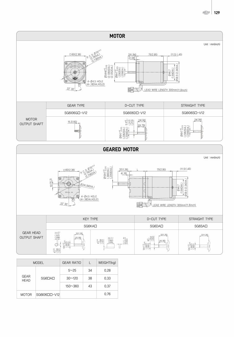
5~25 34 0.28
30~120 38 0.33
150~360 43 0.37
0.76
129
KEY TYPE
SG6KA SG6DA
D-CUT TYPE
SG6SA
STRAIGHT TYPE
MODEL
GEAR HEAD
SG6 A
MOTOR SG6I06 -V12
GEAR RATIO L WEIGHT(kg)
STRAIGHT TYPE
SG6I06S -V12SG6I06D -V12SG6I06G -V12
MOTOROUTPUT SHAFT
GEARED MOTOR
MOTOR
GEAR TYPE D-CUT TYPE
GEAR HEADOUTPUT SHAFT
Unit : mm(inch)
Unit : mm(inch)

(Hz)Phase (V)
Freq.
(A)
Currentat 1200 r/min at 90 r/min
Permissible Torque
(kgf·cm) (mN·m) (kgf·cm) (mN·m) (kgf·cm) (mN·m)
Degree ofProtection
InsulationClassification
ProtectedType
Starting Torque
()
CapacitorVoltageDuty
(r/min)
SpeedRangePolesMotor
ModelControllerModel
130 SPEED CONTROLLER AND CONTROL MOTORS
..All the model of SG series received UL, TUV, CCC certificate.output 6W product is Impedance Protected, 15~90W product is Thermally Protected type. Depend on the voltage, the capacitors are divided into two model. Please inquire separately when operational voltage is AC 100V or 200V.
Ratio
r/min
SG7KASG7DASG7SA
kgf.cm
N.m
GEARED MOTOR - 50Hz
Among GEAR HEAD model names, is reduction gear ratio.Value of the chart is allowable torque of reduction gear of GEARED MOTOR.Regarding direction of rotation, in case of , its reduction gear ratio has same direction with MOTOR's and in case of , its reduction gear ratio has the opposite direction of MOTOR's.rotation speed is calculated with synchronous rotation number of MOTOR(50Hz : 1500 r/min, 60Hz : 1800 r/min).Actual rotation speed can be less than (2~20%) depend on the size of the load 2~20%.
5 6 7.5 9 10 12.5 15 18 20 25 30 36 40 50 60 75 90 100 120 150
280 233 187 156 140 112 93.3 77.7 70.0 56.0 46.6 38.8 35.0 28.0 23.3 18.6 15.5 14.0 11.6 9.3
5.20 6.21 7.80 9.32 10.4 12.9 15.5 18.6 20.7 25.9 29.7 35.6 39.6 49.5 59.3 74.2 89.0 98.9 100 100
0.52 0.62 0.78 0.93 1.04 1.29 1.55 1.86 2.07 2.59 2.97 3.56 3.96 4.95 5.93 7.42 8.90 9.89 10.0 10.0
180 200 250 300 360
7.7 7.0 5.6 4.6 3.8
100 100 100 100 100
10.0 10.0 10.0 10.0 10.0
Ratio
r/min
kgf.cm
N.m
GEARED MOTOR - 60Hz5 6 7.5 9 10 12.5 15 18 20 25 30 36 40 50 60 75 90 100 120 150
340 283 227 189 170 136 113 94.4 85.0 68.0 56.6 47.2 42.5 34.0 28.3 22.6 18.8 17.0 14.1 11.3
4.20 5.02 6.30 7.53 8.40 10.5 12.6 15.1 16.7 20.9 24.0 28.8 32.0 40.0 48.0 60.0 72.0 80.0 96.0 100
0.42 0.50 0.63 0.75 0.84 1.05 1.26 1.51 1.67 2.09 2.40 2.88 3.20 4.00 4.80 6.00 7.20 8.00 9.60 10.0
180 200 250 300 360
9.4 8.5 6.8 5.6 4.7
100 100 100 100 100
10.0 10.0 10.0 10.0 10.0
SG7KASG7DASG7SA
Model
Model
MOTOR
15W70 CONNECTOR TYPE
INDUCTION SPEED CONTROL MOTOR
50606060506050605060
0.37 90-1400 1.10 110 0.60 60 0.80 800.32 90-1700 0.90 90 0.50 50 0.80 800.32 90-1700 0.90 90 0.50 50 0.70 700.32 90-1700 0.90 90 0.50 50 0.80 800.18 90-1400 1.20 120 0.60 60 1.00 1000.19 90-1700 0.90 90 0.50 50 1.00 1000.18 90-1400 1.10 110 0.60 60 0.70 700.15 90-1700 0.90 90 0.50 50 0.70 700.18 90-1400 1.10 110 0.60 60 0.80 800.15 90-1700 0.90 90 0.50 50 0.80 80
SG7I15GA-V12SG7I15DA-V12SG7I15SA-V12
SG7I15GB-V12SG7I15DB-V12SG7I15SB-V12
SUA715IA-V12ASUD715IA-V12A
SUA715IB-V12BSUD715IB-V12B
41 100
1 1101 115
1 200
1 220
1 230
5.5 (250V)
4.5 (250V)
1.5 (450V)
1.0 (450V)4
Cont.S1
Cont.S1
IP23
IP23
B(130)
B(130)
T.P.
T.P.
SG7I15GA-V12 SG7I15DA-V12 SG7I15SA-V12
SG7I15GB-V12 SG7I15DB-V12 SG7I15SB-V12
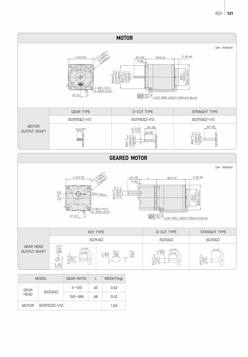
131
KEY TYPE D-CUT TYPE STRAIGHT TYPE
MODEL
GEAR HEAD
SG7 A
MOTOR SG7I15 -V12
GEAR RATIO L WEIGHT(kg)
5~120 43 0.42
150~360 48 0.52
1.04
STRAIGHT TYPE
MOTOROUTPUT SHAFT
GEARED MOTOR
MOTOR
GEAR TYPE D-CUT TYPE
GEAR HEADOUTPUT SHAFT
SG7I15G -V12 SG7I15D -V12 SG7I15S -V12
SG7KA SG7DA SG7SA
Unit : mm(inch)
Unit : mm(inch)
(Hz)Phase (V)
Freq.
(A)
Currentat 1200 r/min at 90 r/min
Permissible Torque
(kgf·cm) (mN·m) (kgf·cm) (mN·m) (kgf·cm) (mN·m)
Degree ofProtection
InsulationClassification
ProtectedType
Starting Torque
()
CapacitorVoltageDuty
(r/min)
SpeedRangePolesMotor
ModelControllerModel
132 SPEED CONTROLLER AND CONTROL MOTORS
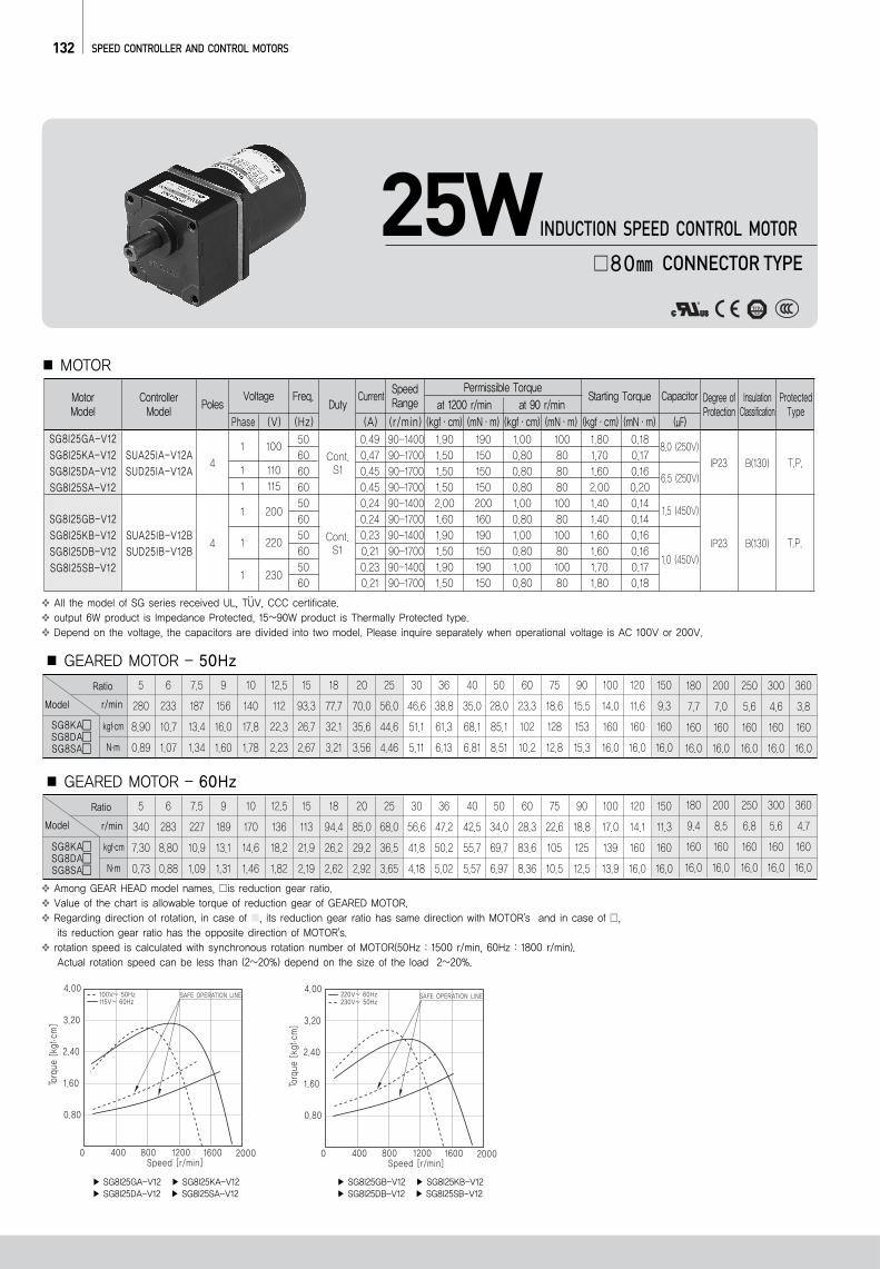
Among GEAR HEAD model names, is reduction gear ratio.Value of the chart is allowable torque of reduction gear of GEARED MOTOR.Regarding direction of rotation, in case of , its reduction gear ratio has same direction with MOTOR's and in case of , its reduction gear ratio has the opposite direction of MOTOR's.rotation speed is calculated with synchronous rotation number of MOTOR(50Hz : 1500 r/min, 60Hz : 1800 r/min).Actual rotation speed can be less than (2~20%) depend on the size of the load 2~20%.
Ratio
r/min
SG8KASG8DASG8SA
kgf.cm
N.m
GEARED MOTOR - 50Hz5 6 7.5 9 10 12.5 15 18 20 25 30 36 40 50 60 75 90 100 120 150
280 233 187 156 140 112 93.3 77.7 70.0 56.0 46.6 38.8 35.0 28.0 23.3 18.6 15.5 14.0 11.6 9.3
8.90 10.7 13.4 16.0 17.8 22.3 26.7 32.1 35.6 44.6 51.1 61.3 68.1 85.1 102 128 153 160 160 160
0.89 1.07 1.34 1.60 1.78 2.23 2.67 3.21 3.56 4.46 5.11 6.13 6.81 8.51 10.2 12.8 15.3 16.0 16.0 16.0
180 200 250 300 360
7.7 7.0 5.6 4.6 3.8
160 160 160 160 160
16.0 16.0 16.0 16.0 16.0
Ratio
r/min
kgf.cm
N.m
GEARED MOTOR - 60Hz5 6 7.5 9 10 12.5 15 18 20 25 30 36 40 50 60 75 90 100 120 150
340 283 227 189 170 136 113 94.4 85.0 68.0 56.6 47.2 42.5 34.0 28.3 22.6 18.8 17.0 14.1 11.3
7.30 8.80 10.9 13.1 14.6 18.2 21.9 26.2 29.2 36.5 41.8 50.2 55.7 69.7 83.6 105 125 139 160 160
0.73 0.88 1.09 1.31 1.46 1.82 2.19 2.62 2.92 3.65 4.18 5.02 5.57 6.97 8.36 10.5 12.5 13.9 16.0 16.0
180 200 250 300 360
9.4 8.5 6.8 5.6 4.7
160 160 160 160 160
16.0 16.0 16.0 16.0 16.0
SG8KASG8DASG8SA
Model
Model
..All the model of SG series received UL, TUV, CCC certificate.output 6W product is Impedance Protected, 15~90W product is Thermally Protected type. Depend on the voltage, the capacitors are divided into two model. Please inquire separately when operational voltage is AC 100V or 200V.
MOTOR
25W80 CONNECTOR TYPE
INDUCTION SPEED CONTROL MOTOR
50606060506050605060
0.49 90-1400 1.90 190 1.00 100 1.80 0.180.47 90-1700 1.50 150 0.80 80 1.70 0.170.45 90-1700 1.50 150 0.80 80 1.60 0.160.45 90-1700 1.50 150 0.80 80 2.00 0.200.24 90-1400 2.00 200 1.00 100 1.40 0.140.24 90-1700 1.60 160 0.80 80 1.40 0.140.23 90-1400 1.90 190 1.00 100 1.60 0.160.21 90-1700 1.50 150 0.80 80 1.60 0.160.23 90-1400 1.90 190 1.00 100 1.70 0.170.21 90-1700 1.50 150 0.80 80 1.80 0.18
SG8I25GA-V12SG8I25KA-V12SG8I25DA-V12SG8I25SA-V12
SG8I25GB-V12SG8I25KB-V12SG8I25DB-V12SG8I25SB-V12
SUA25IA-V12ASUD25IA-V12A
SUA25IB-V12BSUD25IB-V12B
41 100
1 1101 115
1 200
1 220
1 230
8.0 (250V)
6.5 (250V)
1.5 (450V)
1.0 (450V)4
Cont.S1
Cont.S1
IP23
IP23
B(130)
B(130)
T.P.
T.P.
SG8I25GA-V12 SG8I25KA-V12 SG8I25DA-V12 SG8I25SA-V12
SG8I25GB-V12 SG8I25KB-V12 SG8I25DB-V12 SG8I25SB-V12
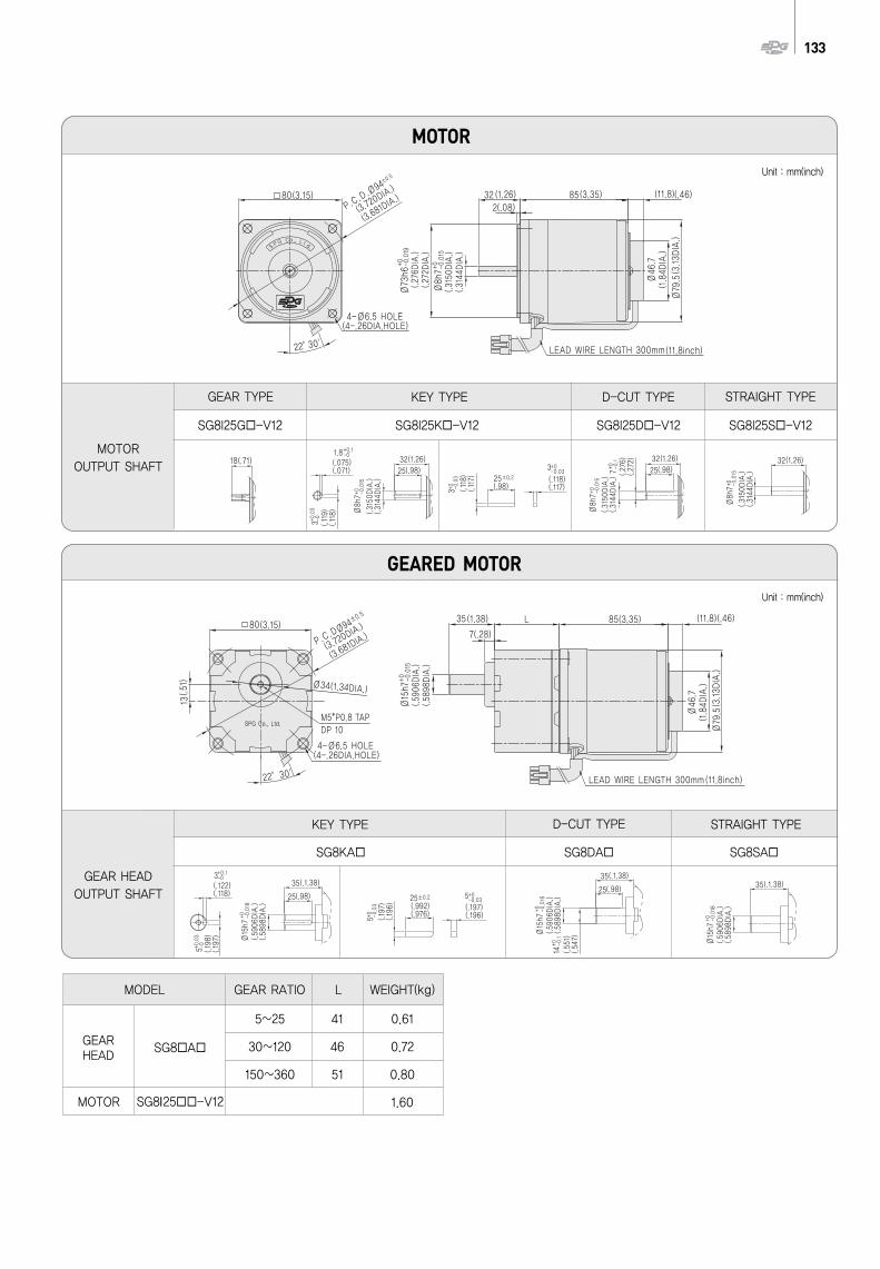
133
KEY TYPE D-CUT TYPE STRAIGHT TYPE
MODEL
GEAR HEAD
SG8 A
MOTOR SG8I25 -V12
GEAR RATIO L WEIGHT(kg)
5~25 41 0.61
30~120 46 0.72
150~360 51 0.80
1.60
GEARED MOTOR
MOTOR
GEAR HEADOUTPUT SHAFT
SG8KA SG8DA SG8SA
STRAIGHT TYPE
MOTOROUTPUT SHAFT
GEAR TYPE D-CUT TYPEKEY TYPE
SG8I25G -V12 SG8I25K -V12 SG8I25D -V12 SG8I25S -V12
Unit : mm(inch)
Unit : mm(inch)
(Hz)Phase (V)
Freq.
(A)
Currentat 1200 r/min at 90 r/min
Permissible Torque
(kgf·cm) (mN·m) (kgf·cm) (mN·m) (kgf·cm) (mN·m)
Degree ofProtection
InsulationClassification
ProtectedType
Starting Torque
()
CapacitorVoltageDuty
(r/min)
SpeedRangePolesMotor
ModelControllerModel
134 SPEED CONTROLLER AND CONTROL MOTORS
Among GEAR HEAD model names, is reduction gear ratio.Value of the chart is allowable torque of reduction gear of GEARED MOTOR.Regarding direction of rotation, in case of , its reduction gear ratio has same direction with MOTOR's and in case of , its reduction gear ratio has the opposite direction of MOTOR's.rotation speed is calculated with synchronous rotation number of MOTOR(50Hz : 1500 r/min, 60Hz : 1800 r/min).Actual rotation speed can be less than (2~20%) depend on the size of the load 2~20%.
..All the model of SG series received UL, TUV, CCC certificate.output 6W product is Impedance Protected, 15~90W product is Thermally Protected type. Depend on the voltage, the capacitors are divided into two model. Please inquire separately when operational voltage is AC 100V or 200V.
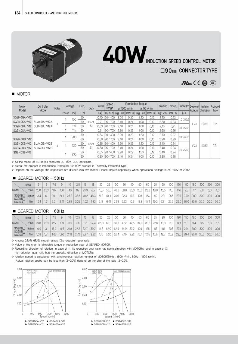
Ratio
r/minModel
SG9KBSG9DBSG9SB
kgf.cm
N.m
GEARED MOTOR - 50Hz5 6 7.5 9 10 12.5 15 18 20 25 30 36 40 50 60 75 90 100 120 150
280 233 187 156 140 112 93.3 77.7 70.0 56.0 46.6 38.8 35.0 28.0 23.3 18.6 15.5 14.0 11.6 9.3
13.4 16.1 20.1 24.1 26.8 33.5 40.2 48.3 51.3 64.1 76.9 92.3 103 128 154 192 231 256 290 300
1.34 1.61 2.01 2.41 2.68 3.35 4.02 4.83 5.13 6.41 7.69 9.23 10.3 12.8 15.4 19.2 23.1 25.6 29.0 30.0
180 200 250 300
7.7 7.0 5.6 4.6
300 300 300 300
30.0 30.0 30.0 30.0
Ratio
r/minModel
SG9KBSG9DBSG9SB
kgf.cm
N.m
5 6 7.5 9 10 12.5 15 18 20 25 30 36 40 50 60 75 90 100 120 150
340 283 227 189 170 136 113 94.4 85.0 68.0 56.6 47.2 42.5 34.0 28.3 22.6 18.8 17.0 14.1 11.3
10.9 13.1 16.3 19.6 21.8 27.2 32.7 39.2 41.6 52.0 62.4 74.9 83.2 104 125 156 187 208 235 294
1.09 1.31 1.63 1.96 2.18 2.72 3.27 3.92 4.16 5.20 6.24 7.49 8.32 10.4 12.5 15.6 18.7 20.8 23.5 29.4
180 200 250 300
9.4 8.5 6.8 5.6
300 300 300 300
30.0 30.0 30.0 30.0
GEARED MOTOR - 60Hz
MOTOR
40W90 CONNECTOR TYPE
INDUCTION SPEED CONTROL MOTOR
50606060506050605060
0.70 90-1400 3.00 0.30 1.20 0.12 2.20 0.220.71 90-1700 2.40 0.24 1.00 0.10 2.30 0.230.63 90-1700 2.40 0.24 1.00 0.10 2.10 0.210.61 90-1700 2.30 0.23 1.00 0.10 2.60 0.260.34 90-1400 2.90 0.29 1.20 0.12 2.70 0.270.38 90-1700 2.40 0.24 1.00 0.10 2.90 0.290.35 90-1400 2.90 0.29 1.20 0.12 2.40 0.240.30 90-1700 2.40 0.24 1.00 0.10 2.40 0.240.35 90-1400 2.90 0.29 1.20 0.12 2.40 0.240.30 90-1700 2.40 0.24 1.00 0.10 2.80 0.28
SG9I40GA-V12SG9I40KA-V12SG9I40DA-V12SG9I40SA-V12
SG9I40GB-V12SG9I40KB-V12SG9I40DB-V12SG9I40SB-V12
SUA40IA-V12ASUD40IA-V12A
SUA40IB-V12BSUD40IB-V12B
41 100
1 1101 115
1 200
1 220
1 230
11.0 (250V)
9.0 (250V)
3.0 (450V)
2.3 (450V)4
Cont.S1
Cont.S1
IP23
IP23
B(130)
B(130)
T.P.
T.P.
SG9I40GA-V12 SG9I40KA-V12 SG9I40DA-V12 SG9I40SA-V12
SG9I40GB-V12 SG9I40KB-V12 SG9I40DB-V12 SG9I40SB-V12
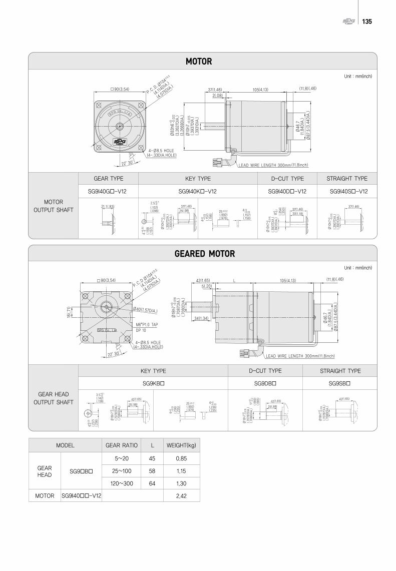
135
KEY TYPE D-CUT TYPE STRAIGHT TYPE
MODEL
GEAR HEAD
SG9 B
MOTOR SG9I40 -V12
GEAR RATIO L WEIGHT(kg)
5~20 45 0.85
25~100 58 1.15
120~300 64 1.30
2.42
STRAIGHT TYPE
MOTOROUTPUT SHAFT
GEARED MOTOR
MOTOR
GEAR TYPE D-CUT TYPEKEY TYPE
GEAR HEADOUTPUT SHAFT
SG9I40G -V12 SG9I40K -V12 SG9I40D -V12 SG9I40S -V12
SG9KB SG9DB SG9SB
Unit : mm(inch)
Unit : mm(inch)
(Hz)Phase (V)
Freq.
(A)
Currentat 1200 r/min at 90 r/min
Permissible Torque
(kgf·cm) (mN·m) (kgf·cm) (mN·m) (kgf·cm) (mN·m)
Degree ofProtection
InsulationClassification
ProtectedType
Starting Torque
()
CapacitorVoltageDuty
(r/min)
SpeedRangePolesMotor
ModelControllerModel
136 SPEED CONTROLLER AND CONTROL MOTORS
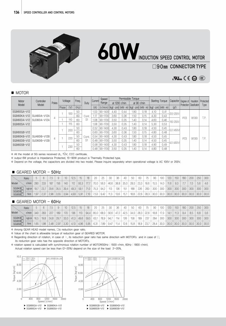
Among GEAR HEAD model names, is reduction gear ratio.Value of the chart is allowable torque of reduction gear of GEARED MOTOR.Regarding direction of rotation, in case of , its reduction gear ratio has same direction with MOTOR's and in case of , its reduction gear ratio has the opposite direction of MOTOR's.rotation speed is calculated with synchronous rotation number of MOTOR(50Hz : 1500 r/min, 60Hz : 1800 r/min).Actual rotation speed can be less than (2~20%) depend on the size of the load 2~20%.
..All the model of SG series received UL, TUV, CCC certificate.output 6W product is Impedance Protected, 15~90W product is Thermally Protected type. Depend on the voltage, the capacitors are divided into two model. Please inquire separately when operational voltage is AC 100V or 200V.
Ratio
r/minModel
SG9KBSG9DBSG9SB
kgf.cm
N.m
GEARED MOTOR - 50Hz5 6 7.5 9 10 12.5 15 18 20 25 30 36 40 50 60 75 90 100 120 150
280 233 187 156 140 112 93.3 77.7 70.0 56.0 46.6 38.8 35.0 28.0 23.3 18.6 15.5 14.0 11.6 9.3
19.7 23.7 29.6 35.5 39.4 49.3 59.1 71.0 75.3 94.2 113 136 151 188 226 283 300 300 300 300
1.97 2.37 2.96 3.55 3.94 4.93 5.91 7.10 7.53 9.42 11.3 13.6 15.1 18.8 22.6 28.3 30.0 30.0 30.0 30.0
180 200 250 300
7.7 7.0 5.6 4.6
300 300 300 300
30.0 30.0 30.0 30.0
Ratio
r/minModel
SG9KBSG9DBSG9SB
kgf.cm
N.m
5 6 7.5 9 10 12.5 15 18 20 25 30 36 40 50 60 75 90 100 120 150
340 283 227 189 170 136 113 94.4 85.0 68.0 56.6 47.2 42.5 34.0 28.3 22.6 18.8 17.0 14.1 11.3
16.5 19.8 24.8 29.7 33.0 41.3 49.6 59.5 63.1 78.9 94.7 114 126 158 189 237 284 300 300 300
1.65 1.98 2.48 2.97 3.30 4.13 4.96 5.95 6.31 7.89 9.47 11.4 12.6 15.8 18.9 23.7 28.4 30.0 30.0 30.0
180 200 250 300
9.4 8.5 6.8 5.6
300 300 300 300
30.0 30.0 30.0 30.0
GEARED MOTOR - 60Hz
MOTOR
60W90 CONNECTOR TYPE
INDUCTION SPEED CONTROL MOTOR
50606060506050605060
1.03 90-1400 4.40 0.44 1.80 0.18 4.10 0.411.17 90-1700 3.60 0.36 1.50 0.15 4.30 0.431.08 90-1700 3.50 0.35 1.40 0.14 4.60 0.461.08 90-1700 3.50 0.35 1.40 0.14 5.30 0.530.52 90-1400 4.30 0.43 1.80 0.18 4.50 0.450.60 90-1700 3.60 0.36 1.50 0.15 4.80 0.480.54 90-1400 4.30 0.43 1.80 0.18 4.50 0.450.48 90-1700 3.50 0.35 1.40 0.14 4.50 0.450.58 90-1400 4.30 0.43 1.80 0.18 4.90 0.490.48 90-1700 3.50 0.35 1.40 0.14 4.80 0.48
SG9I60GA-V12SG9I60KA-V12SG9I60DA-V12SG9I60SA-V12
SG9I60GB-V12SG9I60KB-V12SG9I60DB-V12SG9I60SB-V12
SUA60IA-V12ASUD60IA-V12A
SUA60IB-V12BSUD60IB-V12B
41 100
1 1101 115
1 200
1 220
1 230
20.0 (250V)
18.0 (250V)
5.0 (450V)
4.0 (450V)4
Cont.S1
Cont.S1
IP23
IP23
B(130)
B(130)
T.P.
T.P.
SG9I90GA-V12 SG9I90KA-V12 SG9I90DA-V12 SG9I90SA-V12
SG9I90GB-V12 SG9I90KB-V12 SG9I90DB-V12 SG9I90SB-V12
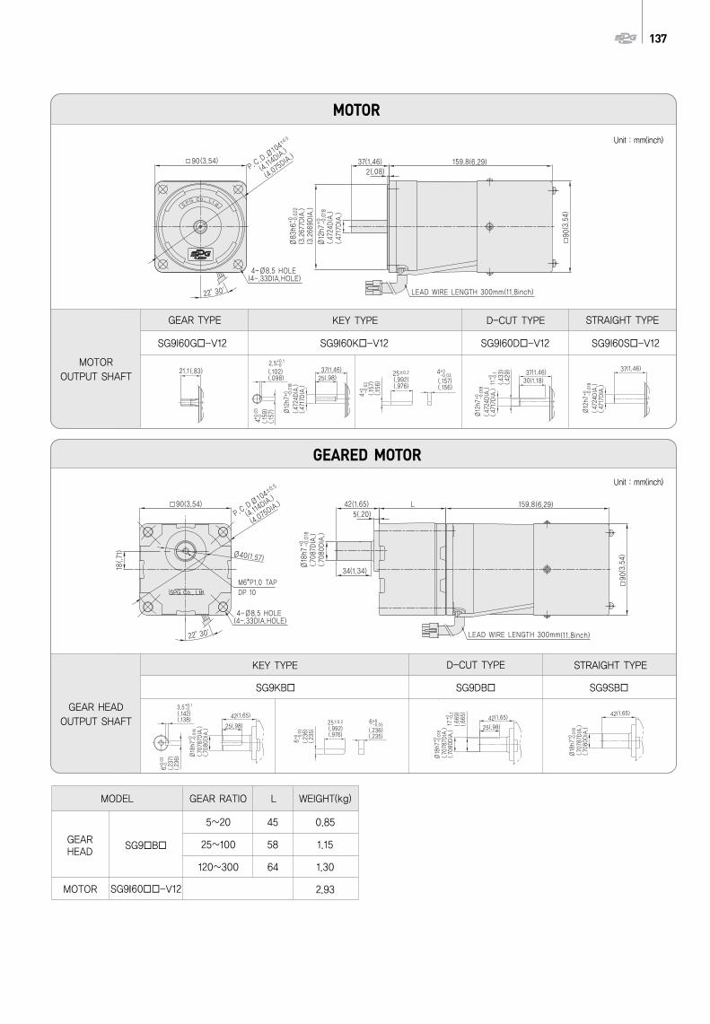
137
KEY TYPE D-CUT TYPE STRAIGHT TYPE
MODEL
GEAR HEAD
SG9 B
MOTOR SG9I60 -V12
GEAR RATIO L WEIGHT(kg)
5~20 45 0.85
25~100 58 1.15
120~300 64 1.30
2.93
STRAIGHT TYPE
MOTOROUTPUT SHAFT
GEARED MOTOR
MOTOR
GEAR TYPE D-CUT TYPEKEY TYPE
GEAR HEADOUTPUT SHAFT
SG9I60G -V12 SG9I60K -V12 SG9I60D -V12 SG9I60S -V12
SG9KB SG9DB SG9SB
Unit : mm(inch)
Unit : mm(inch)
(Hz)Phase (V)
Freq.
(A)
Currentat 1200 r/min at 90 r/min
Permissible Torque
(kgf·cm) (mN·m) (kgf·cm) (mN·m) (kgf·cm) (mN·m)
Degree ofProtection
InsulationClassification
ProtectedType
Starting Torque
()
CapacitorVoltageDuty
(r/min)
SpeedRangePolesMotor
ModelControllerModel
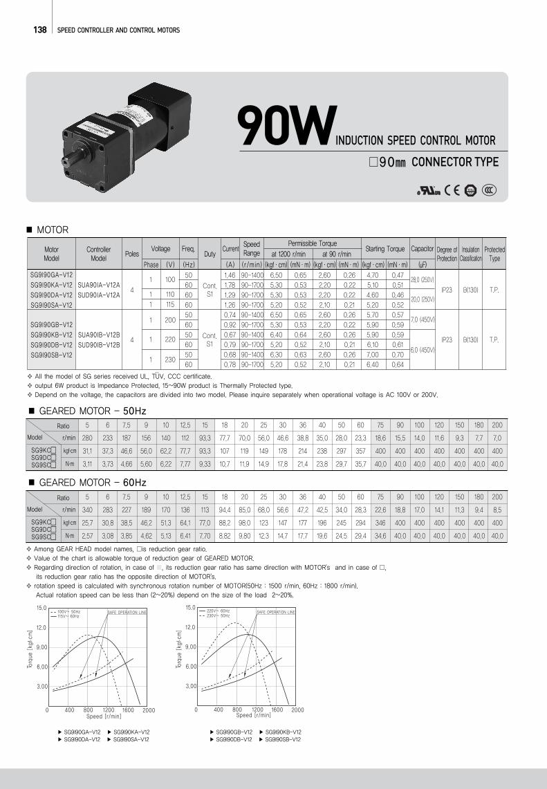
138 SPEED CONTROLLER AND CONTROL MOTORS
Ratio
r/minModel
SG9KCSG9DCSG9SC
kgf.cm
N.m
GEARED MOTOR - 50Hz5 6 7.5 9 10 12.5 15 18 20 25 30 36 40 50 60 75 90 100 120 150
280 233 187 156 140 112 93.3 77.7 70.0 56.0 46.6 38.8 35.0 28.0 23.3 18.6 15.5 14.0 11.6 9.3
31.1 37.3 46.6 56.0 62.2 77.7 93.3 107 119 149 178 214 238 297 357 400 400 400 400 400
3.11 3.73 4.66 5.60 6.22 7.77 9.33 10.7 11.9 14.9 17.8 21.4 23.8 29.7 35.7 40.0 40.0 40.0 40.0 40.0
180 200
7.7 7.0
400 400
40.0 40.0
Ratio
r/minModel
SG9KCSG9DCSG9SC
kgf.cm
N.m
5 6 7.5 9 10 12.5 15 18 20 25 30 36 40 50 60 75 90 100 120 150
340 283 227 189 170 136 113 94.4 85.0 68.0 56.6 47.2 42.5 34.0 28.3 22.6 18.8 17.0 14.1 11.3
25.7 30.8 38.5 46.2 51.3 64.1 77.0 88.2 98.0 123 147 177 196 245 294 346 400 400 400 400
2.57 3.08 3.85 4.62 5.13 6.41 7.70 8.82 9.80 12.3 14.7 17.7 19.6 24.5 29.4 34.6 40.0 40.0 40.0 40.0
180 200
9.4 8.5
400 400
40.0 40.0
GEARED MOTOR - 60Hz
Among GEAR HEAD model names, is reduction gear ratio.Value of the chart is allowable torque of reduction gear of GEARED MOTOR.Regarding direction of rotation, in case of , its reduction gear ratio has same direction with MOTOR's and in case of , its reduction gear ratio has the opposite direction of MOTOR's.rotation speed is calculated with synchronous rotation number of MOTOR(50Hz : 1500 r/min, 60Hz : 1800 r/min).Actual rotation speed can be less than (2~20%) depend on the size of the load 2~20%.
..All the model of SG series received UL, TUV, CCC certificate.output 6W product is Impedance Protected, 15~90W product is Thermally Protected type. Depend on the voltage, the capacitors are divided into two model. Please inquire separately when operational voltage is AC 100V or 200V.
MOTOR
90W90 CONNECTOR TYPE
INDUCTION SPEED CONTROL MOTOR
50606060506050605060
1.46 90-1400 6.50 0.65 2.60 0.26 4.70 0.471.78 90-1700 5.30 0.53 2.20 0.22 5.10 0.511.29 90-1700 5.30 0.53 2.20 0.22 4.60 0.461.26 90-1700 5.20 0.52 2.10 0.21 5.20 0.520.74 90-1400 6.50 0.65 2.60 0.26 5.70 0.570.92 90-1700 5.30 0.53 2.20 0.22 5.90 0.590.67 90-1400 6.40 0.64 2.60 0.26 5.90 0.590.79 90-1700 5.20 0.52 2.10 0.21 6.10 0.610.68 90-1400 6.30 0.63 2.60 0.26 7.00 0.700.78 90-1700 5.20 0.52 2.10 0.21 6.40 0.64
SG9I90GA-V12SG9I90KA-V12SG9I90DA-V12SG9I90SA-V12
SG9I90GB-V12SG9I90KB-V12SG9I90DB-V12SG9I90SB-V12
SUA90IA-V12ASUD90IA-V12A
SUA90IB-V12BSUD90IB-V12B
41 100
1 1101 115
1 200
1 220
1 230
28.0 (250V)
20.0 (250V)
7.0 (450V)
6.0 (450V)4
Cont.S1
Cont.S1
IP23
IP23
B(130)
B(130)
T.P.
T.P.
SG9I90GA-V12 SG9I90KA-V12 SG9I90DA-V12 SG9I90SA-V12
SG9I90GB-V12 SG9I90KB-V12 SG9I90DB-V12 SG9I90SB-V12
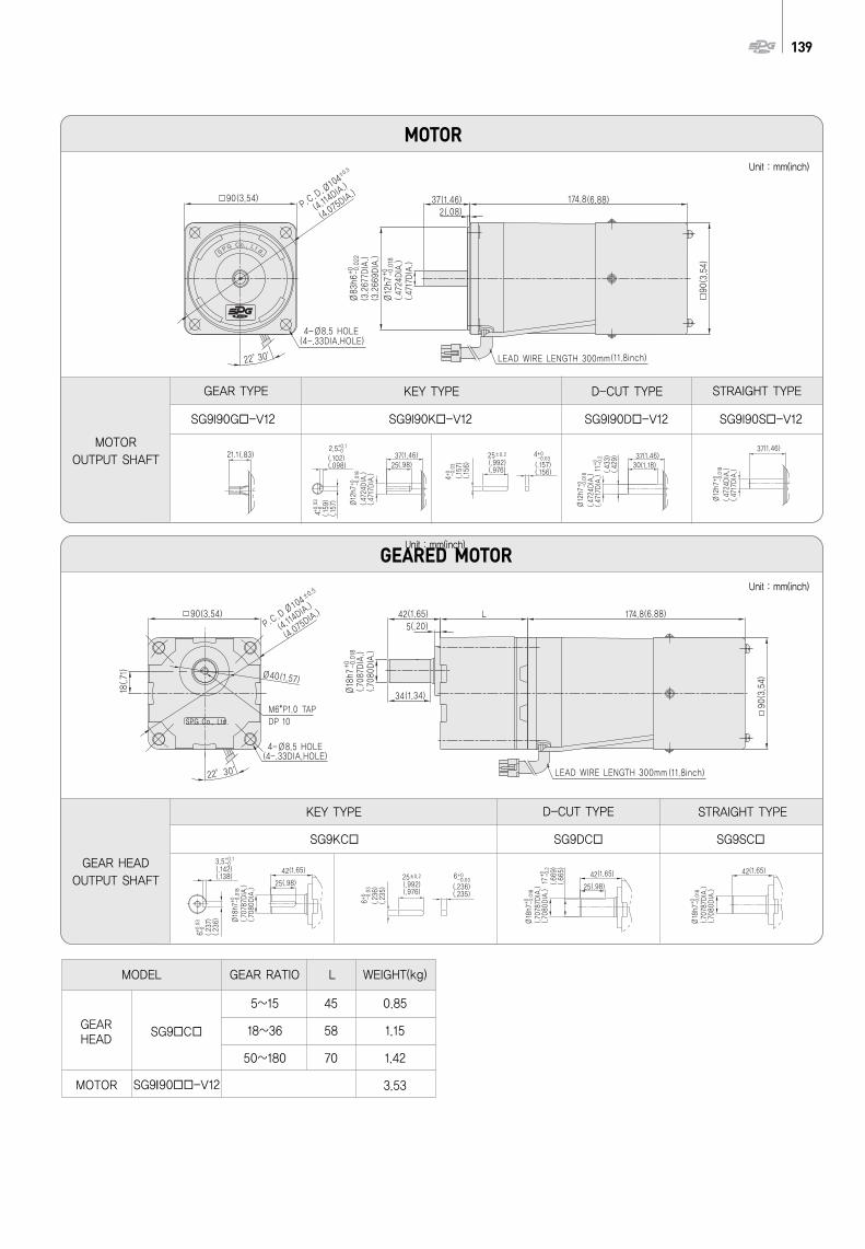
139
KEY TYPE D-CUT TYPE STRAIGHT TYPE
MODEL
GEAR HEAD
SG9 C
MOTOR SG9I90 -V12
GEAR RATIO L WEIGHT(kg)
5~15 45 0.85
18~36 58 1.15
50~180 70 1.42
3.53
STRAIGHT TYPE
MOTOROUTPUT SHAFT
GEARED MOTOR
MOTOR
GEAR TYPE D-CUT TYPEKEY TYPE
GEAR HEADOUTPUT SHAFT
SG9I90G -V12 SG9I90K -V12 SG9I90D -V12 SG9I90S -V12
SG9KC SG9DC SG9SC
Unit : mm(inch)
Unit : mm(inch)
Unit : mm(inch)
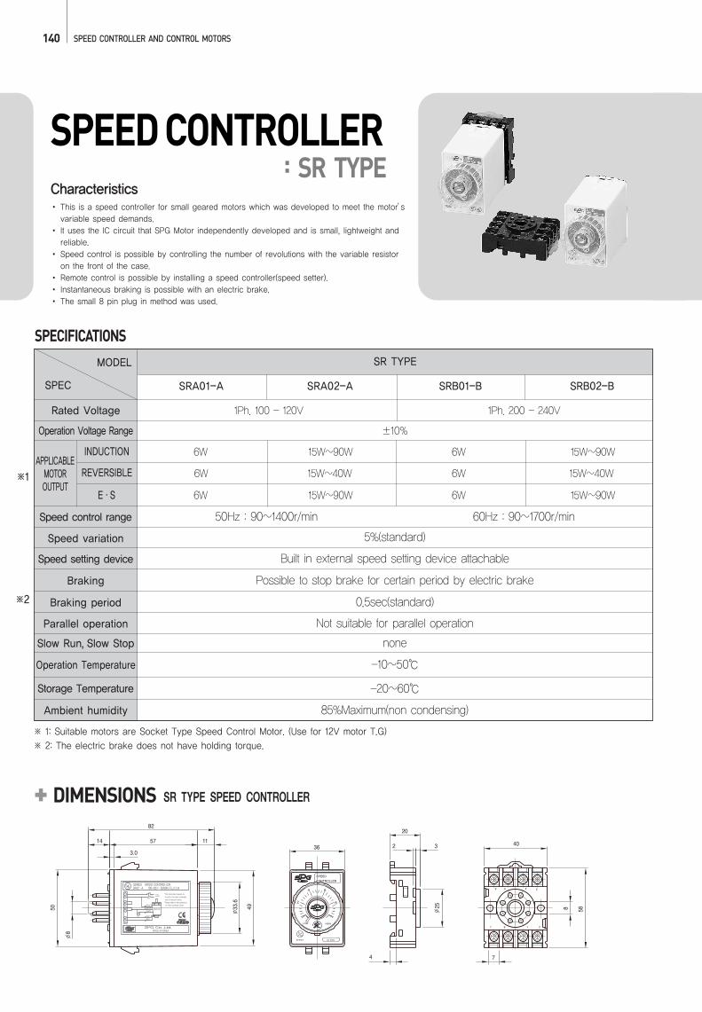
140 SPEED CONTROLLER AND CONTROL MOTORS
SPEED CONTROLLER: SR TYPE
SR TYPE SPEED CONTROLLERDIMENSIONS
CharacteristicsThis is a speed controller for small geared motors which was developed to meet the motor’svariable speed demands.It uses the IC circuit that SPG Motor independently developed and is small, lightweight andreliable.Speed control is possible by controlling the number of revolutions with the variable resistoron the front of the case.Remote control is possible by installing a speed controller(speed setter).Instantaneous braking is possible with an electric brake.The small 8 pin plug in method was used.
SPECIFICATIONSSR TYPE
SRA01-A SRA02-A SRB01-B SRB02-B
1Ph. 100 - 120V
6W 15W~90W
15W~90W
15W~40W
15W~90W
15W~90W
15W~40W6W
6W
6W
6W
6W
1Ph. 200 - 240V
±10%
5%(standard)
Built in external speed setting device attachable
Possible to stop brake for certain period by electric brake
0.5sec(standard)
Not suitable for parallel operation
none
-10~50
-20~60
85%Maximum(non condensing)
50Hz : 90~1400r/min 60Hz : 90~1700r/min
※ 1: Suitable motors are Socket Type Speed Control Motor. (Use for 12V motor T.G)※ 2: The electric brake does not have holding torque.
※1
※2
MODEL
SPEC
APPLICABLE MOTOR OUTPUT
INDUCTION
REVERSIBLE
E·S
Rated Voltage
Speed control range
Speed variation
Speed setting device
Braking
Braking period
Parallel operation
Slow Run, Slow Stop
Operation Temperature
Storage Temperature
Ambient humidity
Operation Voltage Range
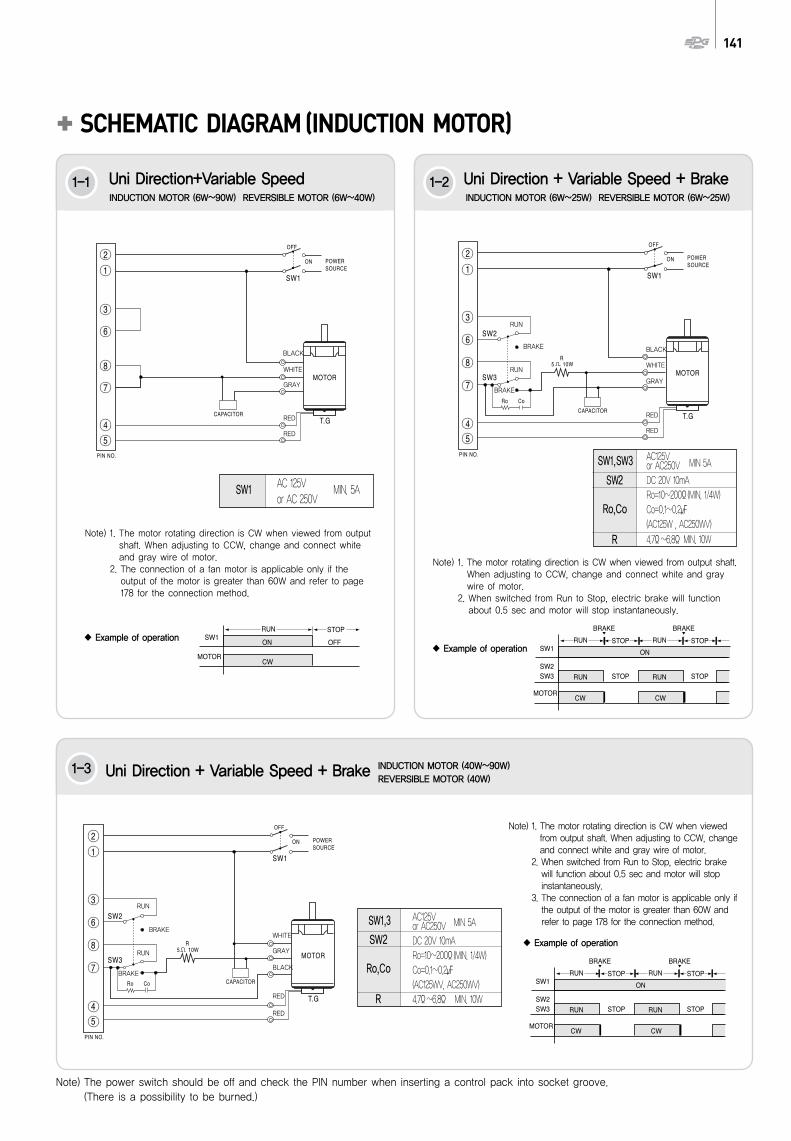
141
SCHEMATIC DIAGRAM (INDUCTION MOTOR)
SW1
Example of operation Example of operation
Example of operation
BLACK
WHITE
GRAY
RED
RED
AC 125Vor AC 250V
Note) 1. The motor rotating direction is CW when viewed from outputshaft. When adjusting to CCW, change and connect whiteand gray wire of motor.
2. The connection of a fan motor is applicable only if theoutput of the motor is greater than 60W and refer to page178 for the connection method.
SW2
Ro,Co
R
AC125Vor AC250VDC 20V 10mARo=10~200Ω(MIN. 1/4W)Co=0.1~0.2(AC125W , AC250WV)4.7Ω~6.8ΩMIN. 10W
SW1,SW3 MIN 5A
Note) 1. The motor rotating direction is CW when viewed from output shaft.When adjusting to CCW, change and connect white and graywire of motor.
2. When switched from Run to Stop, electric brake will functionabout 0.5 sec and motor will stop instantaneously.
MIN. 5A
Note) The power switch should be off and check the PIN number when inserting a control pack into socket groove.(There is a possibility to be burned.)
Note) 1. The motor rotating direction is CW when viewedfrom output shaft. When adjusting to CCW, changeand connect white and gray wire of motor.
2. When switched from Run to Stop, electric brakewill function about 0.5 sec and motor will stopinstantaneously.
3. The connection of a fan motor is applicable only ifthe output of the motor is greater than 60W andrefer to page 178 for the connection method.
SW2
Ro,Co
R
AC125Vor AC250VDC 20V 10mARo=10~200Ω(MIN. 1/4W)Co=0.1~0.2(AC125WV, AC250WV)4.7Ω~6.8Ω MIN. 10W
SW1,3 MIN 5A
1-1
1-3
1-2
RUN
RUN
RUN
BRAKE
BRAKE
RUN
BRAKE
BRAKE
BLACK
WHITE
GRAY
RED
RED
WHITE
GRAY
BLACK
RED
RED
INDUCTION MOTOR (6W~90W) REVERSIBLE MOTOR (6W~40W) INDUCTION MOTOR (6W~25W) REVERSIBLE MOTOR (6W~25W)
Uni Direction+Variable Speed
INDUCTION MOTOR (40W~90W)REVERSIBLE MOTOR (40W)
Uni Direction + Variable Speed + Brake
Uni Direction + Variable Speed + Brake
142 SPEED CONTROLLER AND CONTROL MOTORS
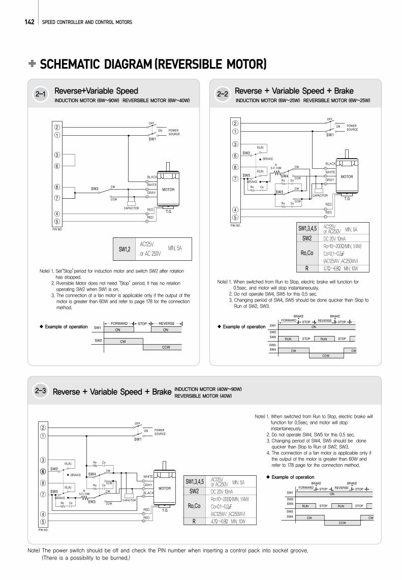
SCHEMATIC DIAGRAM (REVERSIBLE MOTOR)
SW1,2AC125V
or AC 250VMIN. 5A
Note) 1. Set“Stop”period for induction motor and switch SW2 after rotationhas stopped.
2. Rversible Motor does not need “Stop”period. It has no relationoperating SW2 when SW1 is on.
3. The connection of a fan motor is applicable only if the output of themotor is greater than 60W and refer to page 178 for the connectionmethod.
Note) 1. When switched from Run to Stop, electric brake will function for0.5sec. and motor will stop instantaneously.
2. Do not operate SW4, SW5 for this 0.5 sec. 3. Changing period of SW4, SW5 should be done quicker than Stop toRun of SW2, SW3.
SW2
Ro,Co
R
AC125Vor AC250VDC 20V 10mARo=10~200Ω(MIN. 1/4W)Co=0.1~0.2(AC125WV ,AC250WV)4.7Ω~6.8Ω MIN. 10W
SW1,3,4,5 MIN. 5A
Note) 1. When switched from Run to Stop, electric brake willfunction for 0.5sec. and motor will stopinstantaneously.
2. Do not operate SW4, SW5 for this 0.5 sec. 3. Changing period of SW4, SW5 should be donequicker than Stop to Run of SW2, SW3.
4. The connection of a fan motor is applicable only ifthe output of the motor is greater than 60W andrefer to 178 page for the connection method.
Note) The power switch should be off and check the PIN number when inserting a control pack into socket groove.(There is a possibility to be burned.)
SW2
Ro,Co
R
AC125Vor AC250VDC 20V 10mARo=10~200Ω(MIN. 1/4W)Co=0.1~0.2(AC125WV ,AC250WV)4.7Ω~6.8Ω MIN. 10W
SW1,3,4,5 MIN. 5A
2-1
2-3
2-2
RUN
RUN
BRAKE
BRAKE
RUN
RUN
BRAKE
BRAKE
BLACK
WHITE
GRAY
RED
RED
BLACK
WHITE
GRAY
RED
RED
WHITE
GRAY
BLACK
RED
RED
Example of operation Example of operation
Example of operation
INDUCTION MOTOR (6W~90W) REVERSIBLE MOTOR (6W~40W) INDUCTION MOTOR (6W~25W) REVERSIBLE MOTOR (6W~25W)
Reverse+Variable Speed
INDUCTION MOTOR (40W~90W)REVERSIBLE MOTOR (40W)
Reverse + Variable Speed + Brake
Reverse + Variable Speed + Brake
143
Note) The power switch should be off and check the PIN number when inserting a control pack into socket groove.(There is a possibility to be burned.)
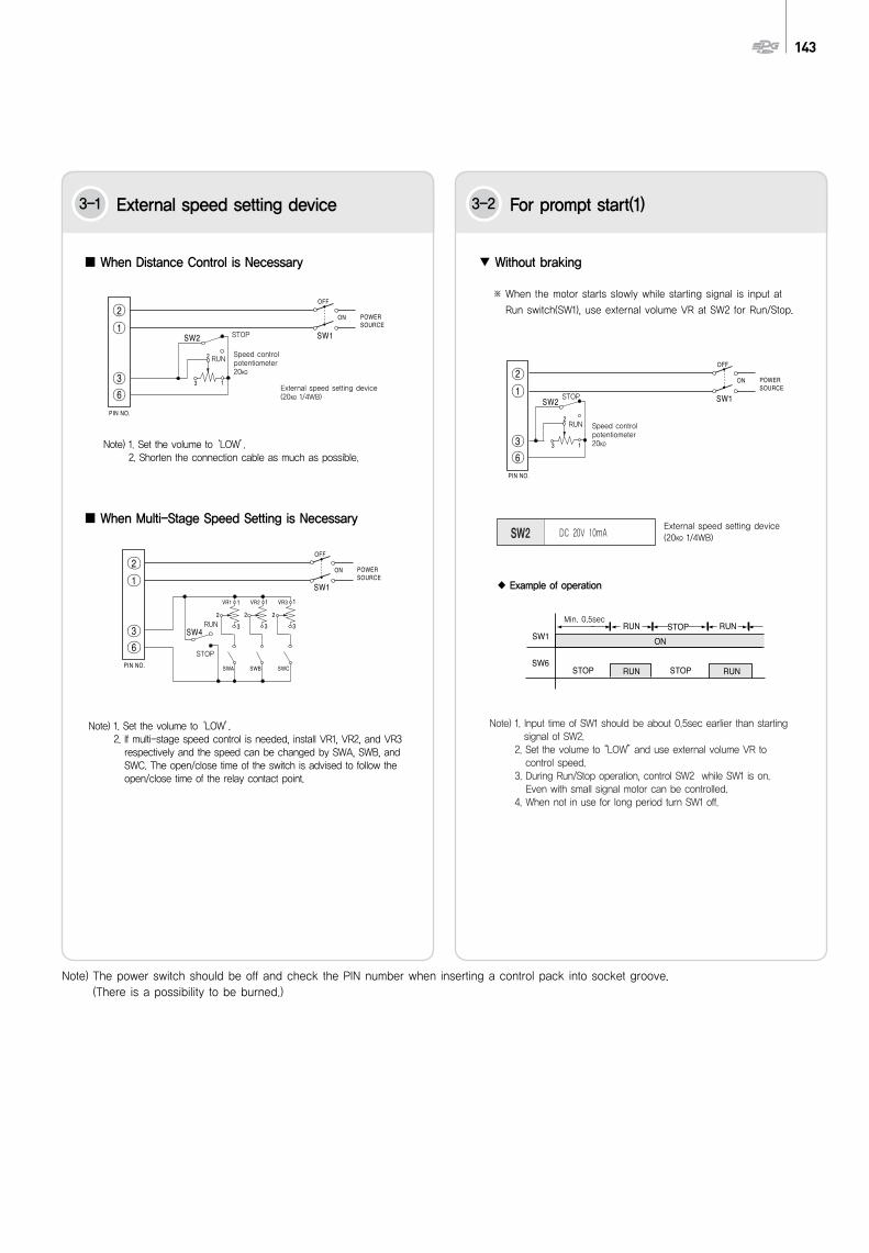
When Distance Control is Necessary
When Multi-Stage Speed Setting is Necessary
Note) 1. Set the volume to ‘LOW’.2. Shorten the connection cable as much as possible.
Speed controlpotentiometer20
Speed controlpotentiometer20
Note) 1. Set the volume to ‘LOW’.2. If multi-stage speed control is needed, install VR1, VR2, and VR3respectively and the speed can be changed by SWA, SWB, andSWC. The open/close time of the switch is advised to follow theopen/close time of the relay contact point.
※ When the motor starts slowly while starting signal is input at
Run switch(SW1), use external volume VR at SW2 for Run/Stop.
Without braking
DC 20V 10mASW2
Note) 1. Input time of SW1 should be about 0.5sec earlier than startingsignal of SW2.
2. Set the volume to “LOW”and use external volume VR tocontrol speed.
3. During Run/Stop operation, control SW2 while SW1 is on. Even with small signal motor can be controlled.
4. When not in use for long period turn SW1 off.
3-1 External speed setting device 3-2 For prompt start(1)
RUN
RUN
RUN
STOP
STOP
STOPExternal speed setting device (20 1/4WB)
External speed setting device (20 1/4WB)
Min. 0.5sec
Example of operation
144 SPEED CONTROLLER AND CONTROL MOTORS
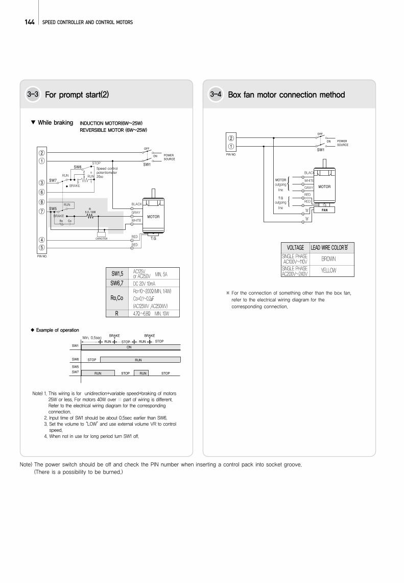
INDUCTION MOTOR(6W~25W) REVERSIBLE MOTOR (6W~25W)
SW6,7
Ro,Co
R
AC125Vor AC250VDC 20V 10mARo=10~200Ω(MIN. 1/4W)Co=0.1~0.2(AC125WV ,AC250WV)4.7Ω~6.8Ω MIN. 10W
SW1,5 MIN. 5A
While braking
Note) 1. This wiring is for unidirection+variable speed+braking of motors25W or less. For motors 40W over part of wiring is different.Refer to the electrical wiring diagram for the correspondingconnection.
2. Input time of SW1 should be about 0.5sec earlier than SW6.3. Set the volume to “LOW”and use external volume VR to controlspeed.
4. When not in use for long period turn SW1 off.
Note) The power switch should be off and check the PIN number when inserting a control pack into socket groove.(There is a possibility to be burned.)
※ For the connection of something other than the box fan,refer to the electrical wiring diagram for thecorresponding connection.
SINGLE PHASEAC100V~110V SINGLE PHASE AC200V~240V
BROWN
YELLOW
VOLTAGE LEAD WIRE COLOR‘B’
RUN RUN
RUN
BRAKE
STOP
BRAKE
BLACK
WHITE
GRAY
RED
RED
‘B’
‘B’
outgoingline
outgoingline
BLACK
WHITE
GRAY
RED
RED
3-3 For prompt start(2) 3-4 Box fan motor connection method
Speed control potentiometer20
Example of operation
Min. 0.5sec
145
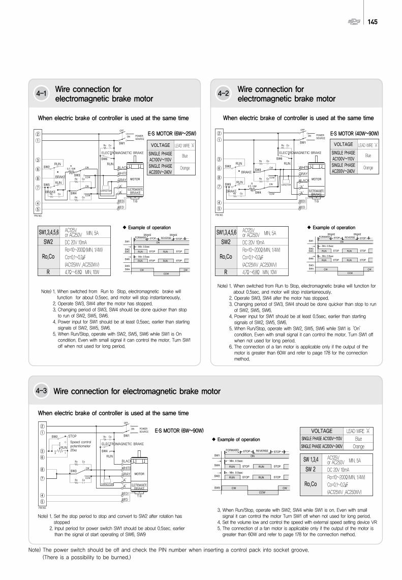
E.S MOTOR (6W~25W)
E.S MOTOR (6W~90W)
E.S MOTOR (40W~90W)
SW2
Ro,Co
R
AC125Vor AC250VDC 20V 10mARo=10~200Ω(MIN. 1/4W)Co=0.1~0.2(AC125WV ,AC250WV)4.7Ω~6.8Ω MIN. 10W
SW1,3,4,5,6 MIN. 5A
SW2
Ro,Co
R
AC125Vor AC250VDC 20V 10mARo=10~200Ω(MIN. 1/4W)Co=0.1~0.2(AC125WV ,AC250WV)4.7Ω~6.8Ω MIN. 10W
SW1,3,4,5,6 MIN. 5A
SW 2
Ro,Co
AC125Vor AC250VDC 20V 10mARo=10~200Ω(MIN. 1/4W)Co=0.1~0.2(AC125WV ,AC250WV)
SW 1,3,4 MIN. 5A
When electric brake of controller is used at the same time When electric brake of controller is used at the same time
Note) 1. When switched from Run to Stop, electromagnetic brake willfunction for about 0.5sec. and motor will stop instantaneously.
2. Operate SW3, SW4 after the motor has stopped.3. Changing period of SW3, SW4 should be done quicker than stopto run of SW2, SW5, SW6.
4. Power input for SW1 should be at least 0.5sec. earlier than startingsignals of SW2, SW5, SW6.
5. When Run/Stop, operate with SW2, SW5, SW6 while SW1 is Oncondition. Even with small signal it can control the motor. Turn SW1off when not used for long period.
Note) 1. When switched from Run to Stop, electromagnetic brake will function forabout 0.5sec. and motor will stop instantaneously.
2. Operate SW3, SW4 after the motor has stopped.3. Changing period of SW3, SW4 should be done quicker than stop to runof SW2, SW5, SW6.
4. Power input for SW1 should be at least 0.5sec. earlier than startingsignals of SW2, SW5, SW6.
5. When Run/Stop, operate with SW2, SW5, SW6 while SW1 is ‘On’condition. Even with small signal it can control the motor. Turn SW1 offwhen not used for long period.
6. The connection of a fan motor is applicable only if the output of themotor is greater than 60W and refer to page 178 for the connectionmethod.
Note) 1. Set the stop period to stop and convert to SW2 after rotation hasstopped
2. Input period for power switch SW1 should be about 0.5sec. earlierthan the signal of start operating of SW6, SW9
3. When Run/Stop, operate with SW2, SW4 while SW1 is on. Even with smallsignal it can control the motor Turn SW1 off when not used for long period.
4. Set the volume low and control the speed with external speed setting device VR5. The connection of a fan motor is applicable only if the output of the motor isgreater than 60W and refer to page 178 for the connection method.
When electric brake of controller is used at the same time
Note) The power switch should be off and check the PIN number when inserting a control pack into socket groove.(There is a possibility to be burned.)
LEAD WIRE ‘A’
Blue
Orange
LEAD WIRE ‘A’
Blue
Orange
LEAD WIRE ‘A’Blue
Orange
VOLTAGESINGLE PHASE AC100V~110V
SINGLE PHASE AC200V~240VRUN
RUN
STOP
RUN RUN
ELECTROMAGNETIC BRAKE
ELECTROMAGNETIC BRAKE
RUN
BRAKE
BRAKE
RUN RUN
ELECTROMAGNETIC BRAKE
RUN
BRAKE
BRAKE
BLACK
WHITE
GRAY
RED
‘A’
‘A’
RED
BLACK
WHITE
GRAY
RED
‘A’
‘A’
RED
BLACK
WHITE
GRAY
RED
‘A’
‘A’
RED
ELECTROMAGNETICBRAKE
ELECTROMAGNETICBRAKE
ELECTROMAGNETICBRAKE
4-1 Wire connection for electromagnetic brake motor
4-3 Wire connection for electromagnetic brake motor
4-2 Wire connection for electromagnetic brake motor
Speed control potentiometer20
Example of operation Example of operation
Example of operation
VOLTAGE
SINGLE PHASEAC100V~110VSINGLE PHASEAC200V~240V
VOLTAGE
SINGLE PHASEAC100V~110VSINGLE PHASEAC200V~240V