spatial signatures of retrograde spanwise vortices in wall turbulence
TRANSCRIPT

J. Fluid Mech. (2007), vol. 574, pp. 155–167. c© 2007 Cambridge University Press
doi:10.1017/S0022112006003788 Printed in the United Kingdom
155
Spatial signatures of retrograde spanwisevortices in wall turbulence
V. K. NATRAJAN, Y. WU AND K. T. CHRISTENSEN†Department of Mechanical Science and Engineering, University of Illinois, Urbana, IL 61801, USA
(Received 20 April 2006 and in revised form 10 October 2006)
The spatial signatures of retrograde spanwise vortices in wall turbulence are assessedfrom particle-image velocimetry measurements in the streamwise–wall-normal planeof a zero-pressure-gradient turbulent boundary layer at Reτ ≡ u∗δ/ν = 2350. Thepresent results suggest that a proportion of retrograde spanwise vortices have a well-defined spatial relationship with neighbouring prograde vortices. Two-point cross-correlations and conditionally averaged velocity fields given a retrograde vortexreveal that such structures are typically oriented either upstream of and below ordownstream of and above a prograde core. While these pairings are consistent withthe typical-eddy patterns reported by Falco and co-workers, we offer an alternativeinterpretation for a proportion of these retrograde/prograde pairs. In particular, thearrangement of a retrograde spanwise vortex upstream of and below a progradecore is also consistent with the spatial signature revealed if an omega-shaped hairpinstructure were sliced through its shoulder region by a fixed streamwise–wall-normalmeasurement plane.
1. IntroductionMany studies support the existence of hairpin-like structures in wall-bounded
turbulent flows (Theodorsen 1952; Head & Bandyopadhyay 1981; Smith et al.1991; Zhou et al. 1999; Adrian, Meinhart & Tomkins 2000; Ganapathisubramani,Longmire & Marusic 2003, among many others). The last four efforts also reveal thatthese vortices streamwise-align to form larger-scale structures termed vortex packetsthat are characterized by an inclined interface formed by the heads of the structuresas well as a region of large-scale streamwise momentum deficit beneath the interfacedue to the collective induction of the vortices. When sliced in the streamwise–wall-normal plane, the heads of the individual hairpins appear as spanwise vortex coreswith ωz < 0, where ωz is the fluctuating spanwise vorticity, and strong ejections oflow-speed fluid are observed upstream of and below each head due to the collectiveinduction of the hairpin’s head and leg(s). Spanwise vortices for which ωz < 0 aretermed prograde spanwise vortices herein since their rotation is in the same sense asthe mean shear. Recent work by Wu & Christensen (2006) shows that the largestpopulations of prograde spanwise vortices, most of which bear spatial signaturesconsistent with hairpin heads, occur in the region y < 0.3δ.
Retrograde spanwise vortices, positive ωz cores, have also been observed in wallturbulence. Falco (1977, 1983, 1991) present evidence of ‘typical eddies’ in the outerregion which have spatial characteristics consistent with ring-like structures. The flow
† Author to whom correspondence should be addressed: [email protected].

156 V. K. Natrajan, Y. Wu and K. T. Christensen
visualizations and an idealized schematic of these structures in Falco (1977) show thattypical eddies appear as spatially coincident prograde and retrograde spanwise vorticeswhen sliced in the streamwise–wall-normal plane. Falco (1977, 1983, 1991) offer littlediscussion regarding a preferred orientation for typical eddies except to state thatthe idealized schematic in Falco (1977) (which portrays the prograde core above andslightly downstream of the retrograde core) represents the “commonly-observed view”of such a structure in the streamwise–wall-normal plane. More recently, Klewicki &Hirschi (2004) observed that near-wall shear layers often occur in close proximity toclusters of prograde structures as well as adjacent regions of opposing-sign ωz, withthe retrograde event either above or below the prograde event.
The generation of such ring-like structures may be related to the pinch-off andreconnection of the legs of existing hairpin structures as observed by Moin, Leonard& Kim (1986), Smith et al. (1991) and Bake, Meyer & Rist (2002). Alternatively,Tomkins & Adrian (2003) proposed the generation of isolated retrograde structuresvia the spanwise merger of hairpin structures. Another possibility is that somefraction of retrograde structures occur in tandem with an adjacent prograde structurevia a single streamwise-aligned vortex structure, possibly a hairpin. Hambleton,Hutchins & Marusic (2006) computed a linear stochastic estimate of the conditionallyaveraged fluctuating velocity field given a retrograde spanwise vortex at y = 0.4δ in thestreamwise–wall-normal plane and observed a prograde spanwise vortex positioneddownstream of (by 0.5δ) and above (at y ≈ δ) the retrograde core. They conjecturedthis pattern to be the imprint of a slice through a large-scale vortex ring or omega-shaped vortex loop. Hambleton et al. (2006) also noted that estimates of similarfields for retrograde vortices closer to the wall did not yield spatially coincidentprograde cores. Regardless of their origin, Wu & Christensen (2006) report thatretrograde spanwise vortices occur most frequently in the region 0.15δ < y < 0.25δ,although prograde spanwise vortices are still found to outnumber retrograde cores byapproximately 2:1 in this wall-normal region. In addition, few retrograde structureswere identified at the inner boundary of the log layer. Finally, that work revealsan increase in the fraction of retrograde structures relative to prograde vortices inthe outer layer with Reynolds number (Re), indicating that such structures mayplay an increasingly important role at higher Re. The present effort documents thespatial signatures of retrograde spanwise vortices and explores their relationship withneighbouring prograde cores.
2. ExperimentThe experimental data utilized herein is a subset of measurements reported by
Wu & Christensen (2006). Two-thousand five-hundred instantaneous velocity (u, v)fields were acquired by particle-image velocimetry (PIV) over a δ×δ field of view in thestreamwise–wall-normal (x,y) plane of a zero-pressure-gradient turbulent boundarylayer at Reτ ≡ u∗δ/ν =2350. The wind-tunnel facility utilized for these measurementshas a documented turbulence intensity of 0.16% in the free stream and the boundarylayer develops over a 6.1 m long hydraulically smooth flat plate (Meinhart 1994). Thefriction velocity, u∗ =
√τw/ρ, and the viscous length scale, y∗ = ν/u∗, were determined
using the Clauser chart method. The PIV images were interrogated using two-frame cross-correlation methods which yielded nearly 35 000 vectors per instantaneousvelocity field with vector grid spacings in inner units of �x+ = �y+ = 12.3. Table 1summarizes the relevant flow parameters and the reader is directed to Wu &Christensen (2006) for further experimental details.
Spatial signatures of retrograde spanwise vortices in wall turbulence 157
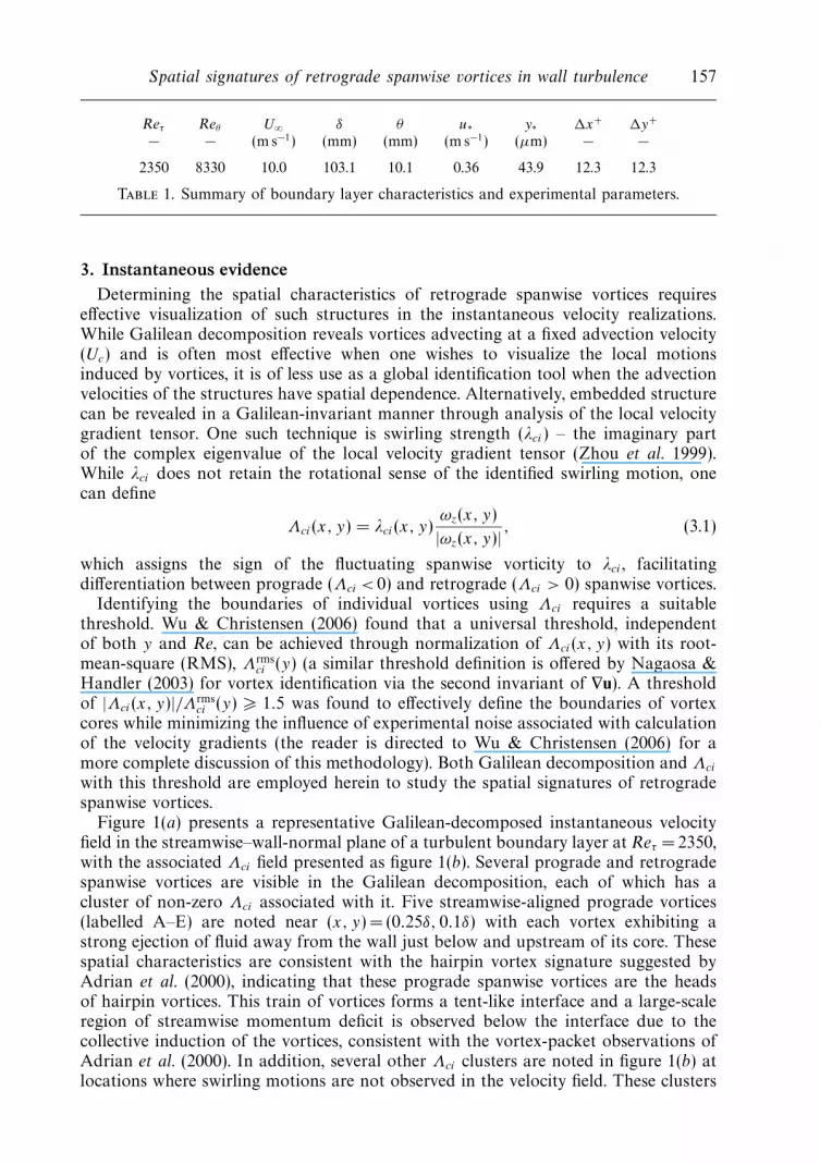
Reτ Reθ U∞ δ θ u∗ y∗ �x+ �y+
− − (m s−1) (mm) (mm) (m s−1) (µm) − −
2350 8330 10.0 103.1 10.1 0.36 43.9 12.3 12.3
Table 1. Summary of boundary layer characteristics and experimental parameters.
3. Instantaneous evidenceDetermining the spatial characteristics of retrograde spanwise vortices requires
effective visualization of such structures in the instantaneous velocity realizations.While Galilean decomposition reveals vortices advecting at a fixed advection velocity(Uc) and is often most effective when one wishes to visualize the local motionsinduced by vortices, it is of less use as a global identification tool when the advectionvelocities of the structures have spatial dependence. Alternatively, embedded structurecan be revealed in a Galilean-invariant manner through analysis of the local velocitygradient tensor. One such technique is swirling strength (λci) – the imaginary partof the complex eigenvalue of the local velocity gradient tensor (Zhou et al. 1999).While λci does not retain the rotational sense of the identified swirling motion, onecan define
Λci(x, y) = λci(x, y)ωz(x, y)
|ωz(x, y)| , (3.1)
which assigns the sign of the fluctuating spanwise vorticity to λci , facilitatingdifferentiation between prograde (Λci < 0) and retrograde (Λci > 0) spanwise vortices.
Identifying the boundaries of individual vortices using Λci requires a suitablethreshold. Wu & Christensen (2006) found that a universal threshold, independentof both y and Re, can be achieved through normalization of Λci(x, y) with its root-mean-square (RMS), Λrms
ci (y) (a similar threshold definition is offered by Nagaosa &Handler (2003) for vortex identification via the second invariant of ∇u). A thresholdof |Λci(x, y)|/Λrms
ci (y) � 1.5 was found to effectively define the boundaries of vortexcores while minimizing the influence of experimental noise associated with calculationof the velocity gradients (the reader is directed to Wu & Christensen (2006) for amore complete discussion of this methodology). Both Galilean decomposition and Λci
with this threshold are employed herein to study the spatial signatures of retrogradespanwise vortices.
Figure 1(a) presents a representative Galilean-decomposed instantaneous velocityfield in the streamwise–wall-normal plane of a turbulent boundary layer at Reτ = 2350,with the associated Λci field presented as figure 1(b). Several prograde and retrogradespanwise vortices are visible in the Galilean decomposition, each of which has acluster of non-zero Λci associated with it. Five streamwise-aligned prograde vortices(labelled A–E) are noted near (x, y) = (0.25δ, 0.1δ) with each vortex exhibiting astrong ejection of fluid away from the wall just below and upstream of its core. Thesespatial characteristics are consistent with the hairpin vortex signature suggested byAdrian et al. (2000), indicating that these prograde spanwise vortices are the headsof hairpin vortices. This train of vortices forms a tent-like interface and a large-scaleregion of streamwise momentum deficit is observed below the interface due to thecollective induction of the vortices, consistent with the vortex-packet observations ofAdrian et al. (2000). In addition, several other Λci clusters are noted in figure 1(b) atlocations where swirling motions are not observed in the velocity field. These clusters

158 V. K. Natrajan, Y. Wu and K. T. Christensen
0.2 0.4 0.60
0.1
0.2
0
0.1
x/δ
y–δ
y–δ
(a)
(b)
AB
C
DE
0.40 0.450.10
0.15
0.60 0.65
FG
0.1
Figure 1. (a) Galilean-decomposed velocity field in the streamwise–wall-normal plane atReτ = 2350 with Uc = 0.81U∞. (b) Retrograde (red) and prograde (blue) Λci calculated fromthe velocity field in (a). The dashed line highlights the tent-like interface of the visualizedpacket.
represent spanwise vortices that are not moving with the advection velocity chosenfor the Galilean decomposition.
Two retrograde vortices are also revealed in figure 1 (labelled F and G). The insetsof figure 1(a) present enlarged views of the local velocity fields around these tworetrograde vortices, with each retrograde structure appearing in close proximity to aprograde vortex just above and downstream of its core. Further, while a few isolatedretrograde structures are apparent in the Λci field, a majority of them appear inclose proximity to prograde cores in various orientations. Several possible pairingsare highlighted in figure 1(b) using dashed-line bounding boxes, with the orientationof a retrograde core upstream of and below a prograde core occurring most often inthis realization. In contrast, many of the prograde vortices occur in isolation ratherthan in tandem with retrograde structures.
4. Statistical evidence4.1. Two-point correlations
Two-point spatial correlations between the swirling strengths of prograde andretrograde vortices are calculated to further explore the spatial characteristics ofretrograde cores, particularly their relationship with neighbouring prograde vortices.

Spatial signatures of retrograde spanwise vortices in wall turbulence 159
–0.05 0 0.05
0.15
0.20
0.25
–150 0–75 75 150
375
450
525
600
–0.058
–0.009
ρΛrΛp
rx/δ
y–δ
rx+
y+
dA
θA
dB
θB
A
B
Figure 2. Two-point cross-correlation coefficient between Λrci and Λ
pci , ρΛrΛp , at yref = 0.2δ.
Each instantaneous Λci field is divided into a prograde field as
Λpci(x, y) =
{Λci(x, y) if Λci(x, y) � −1.5Λrms
ci (y),
0 otherwise,(4.1)
and a retrograde field as
Λrci(x, y) =
{Λci(x, y) if Λci(x, y) � +1.5Λrms
ci (y),
0 otherwise,(4.2)
using the aforementioned threshold, which yields efficient separation of progradeand retrograde cores and facilitates calculation of the two-point cross-correlationcoefficient
ρΛrΛp (rx, y) =
⟨Λr
ci(x, yref )Λpci(x + rx, y)
⟩σΛr (yref )σΛp (y)
, (4.3)
where σΛr and σΛp are the RMS of Λrci and Λ
pci , respectively.
Given that the largest populations of retrograde vortices occur in the range 0.15δ <
y < 0.25δ (Wu & Christensen 2006), figure 2 presents ρΛrΛp at yref = 0.2δ. The cross-correlation coefficient is zero at the event location and negative elsewhere, as expected,since we are cross-correlating retrograde swirl with prograde swirl. The cross-correlation coefficient also displays two definitive, yet broad, regions of enhancedcorrelation which represent preferred orientations of prograde structures relative toretrograde cores. The first region occurs in quadrant one of this plot, downstreamof and above the event location (rx, y) = (0, yref ), and its position of maximumcorrelation is denoted ‘A’ in figure 2. The second region of enhanced correlation(labelled ‘B’) is weaker than the first and occurs in quadrant three – upstream ofand below the event location. One can approximate these orientations by a ‘mean’

160 V. K. Natrajan, Y. Wu and K. T. Christensen
radial distance from the event location, d , and a ‘mean’ angle relative to horizontal,θ , yielding d+
A = 135 (dA = 0.058δ) and θA = 65◦ for peak location A and d+B = 103.5
(dB = 0.044δ) and θB = 230◦ for peak location B. However, it should be noted that bothregions of correlation span regions that are broad in both angle (30◦ < θA < 90◦ and210◦ <θB < 290◦) and distance relative to the reference location, indicating that therelative angle and spacing between correlated instantaneous retrograde and progradestructures can fluctuate.
While the magnitude of ρΛrΛp is small at A and B in figure 2 compared to the limitingcase of perfect correlation between spatially correlated instantaneous prograde andretrograde structures in these orientations (ρΛrΛp ≈ −0.5), this limiting case wouldonly be possible if the angle and spacing between the structures were identical forall instantaneous pairs and there were no uncorrelated prograde and/or retrogradestructures in the vicinity to generate de-correlation. Clearly such an ideal case shouldnot be expected in a flow that is marked by strong turbulent fluctuations. As such,fluctuations in the angle and spacing between spatially correlated instantaneousprograde and retrograde structures should be expected and probably account for therelatively low values of ρΛrΛp observed in figure 2. This hypothesis is validated byconsidering a model problem in which a large ensemble of artificial Λr
ci and Λpci fields is
generated wherein only spatially correlated retrograde and prograde spanwise vorticesare present and oriented at angles and distances equal to the positions of peaks A andB in figure 2 (50% at each orientation for simplicity). Slight random fluctuations of±7.5◦ about θA and θB and ±0.015δ about dA and dB are then imposed for each vortexpair and the two-point correlation coefficient is computed. While idealized, this modelproblem yields values and spatial extents of ρΛrΛp consistent with those presented infigure 2 (ρΛrΛp = −0.098 for the model problem compared to ρΛrΛp = −0.06 for peakA in figure 2, for example). This consistency substantiates the interpretation of peaksA and B as mean preferred orientations of prograde spanwise vortices relative toretrograde cores about which slight fluctuations in angle and spacing are observed.
4.2. Spatial orientations of neighbouring retrograde and prograde vortices
Given the preferred spatial orientations of prograde vortices relative to retrogradecores observed in ρΛrΛp , this relationship is explored further by consideringhistograms of the spacing (d) and angular orientation (θ) of instantaneous, spatiallycoincident retrograde and prograde vortices. Each retrograde vortex at y =0.2δ in theinstantaneous Λci fields is identified, its closest prograde neighbour is determined, andthe spacing and angular orientation of the prograde core relative to the retrogradevortex are then assessed. Figures 3(a) and 3(b) present histograms of d and θ ,respectively, at y = 0.2δ. Distances in the range 50 < d+ < 200 (0.021 < d/δ < 0.085)are observed with a peak near d+ =100 (d = 0.042δ), while broad peaks in theangle histogram occur at approximately θ =70◦ and 260◦. These characteristics areconsistent with the character of ρΛrΛp .
4.3. Conditionally averaged velocity fields
Conditionally averaged velocity fields given the presence of a retrograde vortex arealso computed to uncover its average velocity signature. These averages are accom-plished by centring a bounding box of width and height 0.2δ around each identifiedretrograde vortex at y =0.2δ and the local velocity field contained within this box isextracted. The instantaneous advection velocity of each identified retrograde vortex isremoved, yielding the local velocity field in the reference frame of the retrograde core.Since figures 2 and 3(b) reveal clear orientation preferences between retrograde andprograde structures, the identified retrograde vortices are sorted into four ensembles

Spatial signatures of retrograde spanwise vortices in wall turbulence 161
d+H
isto
gram
, d
0 200 400 600 800
0
0.05
0.10
0.15
d/δ0.1 0.2 0.3
θ (deg.)
His
togr
am, θ
0 60 120 180 240 300 3600
0.05
0.10
(a) (b)
Figure 3. Histograms of (a) spacing, d , and (b) angular orientation, θ , between identifiedretrograde spanwise vortices at y =0.2δ and their closest prograde neighbours.
based upon the angular orientation of their closest prograde neighbour: 0◦ � θ < 90◦,90◦ � θ < 180◦, 180◦ � θ < 270◦ and 270◦ � θ < 360◦ (hereafter referred to as quadrantsone to four, respectively). Conditional averages are then computed for each orientationsubset.
Figure 4(a–d) presents conditionally averaged velocity fields for retrograde vorticescentred at y = 0.2δ computed for each of the quadrants given above. We first considerthe conditionally averaged velocity field for a retrograde spanwise vortex whose closestprograde neighbour resides in quadrant one. This subset constitutes approximately26% of the total number of identified retrograde vortices at y =0.2δ (1401 retrogradevortices in total) and the corresponding conditionally averaged velocity field presentedin figure 4(a) reveals a well-defined prograde vortex oriented downstream of and abovethe retrograde core at an angle of approximately 47◦ and spacing of 103y∗ (= 0.044δ).This orientation is consistent with the preferences noted in ρΛrΛp and the histogramsof spacing and angular orientation. In addition, this spatial velocity signature is quitesimilar to that observed for the retrograde structures identified in figure 1(a). As such,a clear preference exists for some retrograde vortices at y = 0.2δ to be oriented belowand upstream of neighbouring prograde cores.
The conditionally averaged velocity field for the quadrant-three orientation, forwhich both ρΛrΛp and the histograms of spacing and orientation reveal a preference,is presented in figure 4(c). The retrograde samples included in this average compriseroughly 26% of the retrograde vortices at y = 0.2δ and the conditional averagereveals a well-defined prograde vortex below and upstream of the retrograde corewith a relative spacing of 0.046δ (=108y∗) at an angle of 220◦. Finally, the quadrant-two (figure 4b) and quadrant-four (figure 4d) ensembles, which account for 25% and23% of the retrograde vortices at y = 0.2δ, respectively, reveal average velocity fieldsdevoid of prograde vortices.
While the velocity fields in figure 4 indicate that retrograde vortices are oftenrelated to neighbouring prograde vortices oriented in quadrants one and three witha spacing of approximately 100y∗, it is not clear whether the opposite is true. Thatis, do a majority of prograde vortices occur in tandem with neighbouring retrogradestructures? While most of the instantaneous prograde spanwise vortices observed infigure 1 appear to occur in isolation, conditional averages are computed to furtherexplore this possibility. Figures 5(a) and 5(b) present conditionally averaged velocityfields given a prograde vortex at y = 0.2δ oriented in quadrants one and three,

162 V. K. Natrajan, Y. Wu and K. T. Christensen
y+
x/δx/δ
–0.05 0 0.05
0.15
0.20
0.25
375
450
525
600
–150 –75 75 1500x+
y–δ
y–δ
(a) (b)
(c) (d)
–0.05 0 0.05
0.15
0.20
0.25
375
450
525
600
–150 –75 75 1500x+
y+
–0.05 0 0.05
0.15
0.20
0.25
375
450
525
600
–150 –75 75 1500
–0.05 0 0.05
0.15
0.20
0.25
375
450
525
600
–150 –75 75 1500
Figure 4. Conditionally averaged velocity fields given a retrograde vortex at y = 0.2δ forwhich its closest prograde vortex is oriented in quadrants (a) one, (b) two, (c) three and(d) four relative to the retrograde core.
respectively, relative to their closest retrograde neighbours. (Given the patterns notedin figure 4, only quadrant one and three orientations are presented. The quadrant twoand four subsets yield similar patterns.) Each of these conditionally averaged progradestructures displays a closed streamline pattern with clockwise rotation and a strongejection of low-speed fluid away from the wall, consistent with the hairpin vortexsignature offered by Adrian et al. (2000); however, each field is devoid of retrogradestructures.
However, when these prograde conditional averages are further restricted to onlyinclude those prograde vortices that are within 150y∗ of their closest retrogradeneighbour, based on the results in figures 2–4, a different pattern emerges. Figure 5(c)presents this conditional average for the quadrant-one orientation and reveals aretrograde vortex oriented at approximately 240◦ relative to the prograde vortex core(or equivalently a prograde structure oriented at approximately 60◦ relative to theretrograde core). This velocity signature is nearly identical to that observed in theconditionally averaged velocity field given a retrograde vortex with its closest progradeneighbour in quadrant one (figure 4a). In contrast, the conditionally averaged fieldfor a prograde vortex oriented in quadrant three relative to its closest retrograde

Spatial signatures of retrograde spanwise vortices in wall turbulence 163
y+
x/δx/δ
–0.05 0 0.05
0.15
0.20
0.25
375
450
525
600
–150 –75 75 1500x+
y–δ
y–δ
(a) (b)
(c) (d)
–0.05 0 0.05
0.15
0.20
0.25
375
450
525
600
–150 –75 75 1500x+
y+
–0.05 0 0.05
0.15
0.20
0.25
375
450
525
600
–150 –75 75 1500
–0.05 0 0.05
0.15
0.20
0.25
375
450
525
600
–150 –75 75 1500
Figure 5. (a,b) Conditionally averaged velocity fields given a prograde vortex at y = 0.2δoriented in quadrants one and three, respectively, relative to its closest retrograde neighbour.(c,d) Same as (a,b) except averages are also restricted to prograde/retrograde neighboursspaced within 150y∗.
neighbour (figure 5d) is devoid of a retrograde core and simply resembles thehairpin-vortex signature of Adrian et al. (2000). As such, while most prograde vorticesin the quadrant-one orientation and within 150y∗ of their closest retrograde neigh-bours show a clear orientation preference, most prograde vortices in the quadrant-three orientation are randomly oriented relative to their closest retrograde neighbours.
5. Discussion and conclusionsInstantaneous evidence is presented supporting a spatial relationship between
retrograde and prograde spanwise vortices near the outer edge of the log layerwhere the retrograde populations are largest (Wu & Christensen 2006). The presentresults suggest that many retrograde vortices occur in tandem with neighbouringprograde cores with angular orientations 40◦ <θ < 90◦ and 220◦ < θ < 290◦ (relativeto the retrograde cores) and a mean spacing of approximately (100–150)y∗. Thesecharacteristics are observed in spatial cross-correlations of retrograde and progradeswirling strength, histograms of the spacing and angular orientation between identifiedretrograde vortex cores and their closest prograde neighbour and conditional averages

164 V. K. Natrajan, Y. Wu and K. T. Christensen
z
y
x
(a) (b)
x
y
Retrograde vortexωz > 0
Prograde vortexωz < 0
Omega-shapedhairpin
Figure 6. (a) Three-dimensional visualization of a hairpin vortex packet, adapted fromZhou et al. (1999), illustrating the existence of omega-shaped hairpin structures. (b) Spatialsignature revealed if the structure in (a) were sliced through one of its shoulders by astreamwise–wall-normal measurement plane.
of the local velocity fields around identified retrograde vortices. Further, the preferredalignment of retrograde vortices either above or below prograde cores is consistentwith the orientations of adjacent regions of opposing-sign ωz observed in the vicinityof near-wall shear layers by Klewicki & Hirschi (2004). In contrast, most progradespanwise vortices occur in isolation, except for a small subset of prograde cores thatappear related to retrograde structures oriented upstream of and below and spacedat approximately (100–150)y∗ from these prograde cores.
The spatial relationships between retrograde and prograde spanwise vortices repor-ted herein are not inconsistent with the flow-visualization observations of spatiallycoincident prograde and retrograde cores by Falco and co-workers. As noted earlier,Falco (1977, 1983, 1991) present many flow visualizations and schematics of spatiallycoincident prograde and retrograde vortex cores in the streamwise–wall-normal plane,nearly always with the prograde core oriented above and downstream of the retrogradecore. This arrangement is consistent with one of the preferred orientations presentedherein. However, an alternative argument for this orientation preference can be madeby supposing that some fraction of these spatially coincident prograde and retrogradecores are related to one another through a single streamwise-aligned, omega-shaped hairpin structure. Evidence supporting the existence of omega-shaped hairpinstructures has been presented previously in the literature (Zhou et al. 1999; Bakeet al. 2002, for example).
Figure 6(a) presents a three-dimensional visualization of a vortex packet originallyreported in Zhou et al. (1999, figure 3c) that illustrates the possible developmentof hairpin structures with distinct omega shapes around their shoulders and heads.Similar omega-shaped structures are also presented in Bake et al. (2002). If thehairpin in figure 6(a) were sliced in the streamwise–wall-normal plane through itsspanwise centre, a single prograde spanwise vortex associated with the head of thehairpin would be observed. If, however, this structure were sliced through either of itsshoulders, two spanwise vortices would be revealed as illustrated in figure 6(b): onewith clockwise rotation (a prograde structure) above and downstream of a secondvortex core with counterclockwise rotation (a retrograde vortex). While this spatialsignature is consistent with the patterns presented in the insets of figure 1(a) and theconditionally averaged velocity field of figure 4(a), the probability that this orientation

Spatial signatures of retrograde spanwise vortices in wall turbulence 165
is indeed associated with the shoulder of an omega-shaped hairpin is strengthenedby the velocity pattern observed in the conditionally averaged field given a progradevortex oriented in quadrant one relative to its closest retrograde neighbour witha spacing of 150y∗ or less (figure 5c). Indeed, the prospect of slicing through theshoulder of an omega-shaped hairpin on occasion in a fixed streamwise–wall-normalflow visualization or PIV measurement is certainly a reasonable one given that apreferred spanwise alignment of such structures relative to a fixed measurementplane cannot be expected. In addition, this alternative explanation is not inconsistentwith the observations of Falco and co-workers since significant evidence exists thathairpins can, under certain conditions, pinch off at their legs and reconnect to formring-like structures (Moin et al. 1986; Smith et al. 1991; Bake et al. 2002). Finally,the recent paper by Hambleton et al. (2006) includes a similar interpretation ofcoincident retrograde and prograde spanwise vortices observed in the estimate of theconditionally averaged velocity field given a retrograde core at y =0.4δ as a slicethrough either a large-scale vortex ring or an omega-shaped vortex loop, but forstructures well outside the log layer and of size O(δ).
With regard to the observations of retrograde vortices above and downstream ofprograde cores – the second preferred, albeit weaker, orientation observed herein(figure 4c) – there are several potential explanations. The first, and simplest, is thatthis pattern is the imprint of detached ring-like structures that preferentially alignthemselves into this particular orientation (possibly due to interactions with thesurrounding turbulence and/or the wall). On the other hand, it is also possible thatretrograde/prograde pairs in the quadrant-three orientation are not related via asingle vortex but rather represent the imprint of two different, yet spatially correlated,vortical structures. In the context of the hairpin-packet paradigm, this pattern couldrepresent the imprint of a hairpin vortex streamwise-aligned behind (upstream of) andslightly below an omega-shaped hairpin structure in a coherent vortex packet. In thisscenario, the prograde vortex in quadrant three (figure 4c) would represent the head ofthe upstream hairpin while the retrograde vortex would appear as part of the signatureof the downstream omega-shaped structure. However, given the packet inclinationangle observations of 12◦–20◦ by Adrian et al. (2000), estimates of streamwise spacingsof vortices in packets of approximately (0.15–0.2)δ by Christensen et al. (2004) at asimilar Re, and the observed spacing and angle of prograde/retrograde pairs in thequadrant-one orientation, this scenario would yield a quadrant-three orientation witha much larger spacing ((250–300)y∗) and a shallower angle (180◦–200◦) between thevortices compared to that reported herein.
Alternatively, the pinch-off and reconnection of omega-shaped hairpin structuresinto ring-like vortices also provides a consistent explanation for the quadrant-threeorientation. Bake et al. (2002) report that as omega-shaped hairpin structures ina transitional boundary layer advect downstream, the head and shoulders of thesehairpins can, on occasion, pinch off at their legs, eventually leading to detachment oftheir omega portions. When such a process occurs, the detached omega portions arethen observed to reconnect and form ring-like structures. Simultaneously, spanwise-oriented vortical ‘bridges’ appear to form between the remaining legs (figure 11 inBake et al. 2002). If one were to slice through this pattern with a streamwise–wall-normal measurement plane, one would observe a signature similar to that highlightedin figure 7 (an instantaneous velocity realization from the present PIV ensemble): aretrograde spanwise vortex (B) bounded by prograde cores both below (A) and above(C). In such a scenario, the prograde core above the retrograde structure wouldbe associated with the detached ring-like structure while the prograde core below

166 V. K. Natrajan, Y. Wu and K. T. Christensen
0.3 0.4 0.5 0.6 0.7 0.8 0.9
0.5 0.6
0.15
0.20
y–δ
x/δ
x/δ
A
B
C
Figure 7. Example of a prograde hairpin vortex head (labelled A) oriented at approximately255◦ relative to a neighbouring retrograde vortex (labelled B), as visualized by Galileandecomposition of an instantaneous velocity realization with Uc = 0.79U∞.
would represent the imprint of the spanwise vortical ‘bridge’ that forms between theremaining legs of the original hairpin. Further analysis, preferably with time-resolvedthree-dimensional data at moderate Re, would shed additional light on the preferredorientations observed herein.
This work was performed with funding from the Air Force Office of ScientificResearch under Grants FA9550-05-1-0043 and FA9550-05-1-0246 (Dr. JohnSchmisseur, Program Manager) and the University of Illinois.
REFERENCES
Adrian, R. J., Meinhart, C. D. & Tomkins, C. D. 2000 Vortex organization in the outer region ofthe turbulent boundary layer. J. Fluid Mech. 422, 1–54.
Bake, S., Meyer, G. W. & Rist, U. 2002 Turbulence mechanism in Klebanoff transition: Aquantitative comparison of experiment and direct numerical simulation. J. Fluid Mech. 459,217–243.
Christensen, K. T., Wu, Y., Adrian, R. J. & Lai, W. 2004 Statistical imprints of structure in wallturbulence. AIAA Paper 2004-1116.
Falco, R. E. 1977 Coherent motions in the outer region of turbulent boundary layers. Phys. Fluids20 (10), S124–S132.
Falco, R. E. 1983 New results, a review and synthesis of the mechanism of turbulence productionin boundary layers and its modification. AIAA Paper 83-0377.
Falco, R. E. 1991 A coherent structure model of the turbulent boundary layer and its ability topredict Reynolds number dependence. Phil. Trans. R. Soc. Lond. A 336, 103–129.
Ganapathisubramani, B., Longmire, E. K. & Marusic, I. 2003 Characteristics of vortex packetsin turbulent boundary layers. J. Fluid Mech. 478, 35–46.
Hambleton, W. T., Hutchins, N. & Marusic, I. 2006 Simultaneous orthogonal-plane particleimage velocimetry measurements in a turbulent boundary layer. J. Fluid Mech. 560, 53–64.
Head, M. R. & Bandyopadhyay, P. 1981 New aspects of turbulent boundary-layer structure.J. Fluid Mech. 107, 297–338.
Klewicki, J. C. & Hirschi, C. R. 2004 Flow field properties local to near-wall shear layers in alow Reynolds number turbulent boundary layer. Phys. Fluids 16, 4163–4176.

Spatial signatures of retrograde spanwise vortices in wall turbulence 167
Meinhart, C. D. 1994 Investigation of turbulent boundary-layer structure using particle-imagevelocimetry. PhD thesis, Department of Theoretical and Applied Mechanics, University ofIllinois at Urbana-Champaign.
Moin, P., Leonard, A. & Kim, J. 1986 Evolution of a curved vortex filament into a vortex ring.Phys. Fluids 29, 955–963.
Nagaosa, R. & Handler, R. A. 2003 Statistical analysis of coherent vortices near a free surface ina fully developed turbulence. Phys. Fluids 15, 375–394.
Smith, C. R., Walker, J. D. A., Haidari, A. H. & Sobrun, U. 1991 On the dynamics of near-wallturbulence. Phil. Trans. R. Soc. Lond A 336, 131–175.
Theodorsen, T. 1952 Mechanism of turbulence. In Proc. 2nd Midwestern Conference on FluidMechanics , pp. 1–19. Ohio State University, Columbus, Ohio.
Tomkins, C. D. & Adrian, R. J. 2003 Spanwise structure and scale growth in turbulent boundarylayers. J. Fluid Mech. 490, 37–74.
Wu, Y. & Christensen, K. T. 2006 Population trends of spanwise vortices in wall turbulence.J. Fluid Mech. 568, 55–76.
Zhou, J., Adrian, R. J., Balachandar, S. & Kendall, T. M. 1999 Mechanisms for generatingcoherent packets of hairpin vortices in channel flow. J. Fluid Mech. 387, 353–396.