southwest power pool, inc. (spp)
TRANSCRIPT
MITSUBISHI ELECTRIC POWER PRODUCTS, INC. POWER SYSTEMS ENGINEERING DIVISION 530 KEYSTONE DRIVE WARRENDALE, PA 15086, U.S.A. Phone: (724) 778-5111 Fax: (724) 778-5149 Home Page: www.meppi.com
Mitsubishi Electric Power Systems Engineering Power Products, Inc (MEPPI) Division (PSED)
______________________________________________
______________________________________________
Southwest Power Pool, Inc. (SPP) ______________________________________________
Limited Operation Impact Study
for GEN-2016-153 (Flat Ridge Wind 4)
Draft Report For Review
REP-1227 Revision #00
December 2021
Submitted By: Mitsubishi Electric Power Products, Inc. (MEPPI)
Power Systems Engineering Division Warrendale, PA
MITSUBISHI ELECTRIC POWER PRODUCTS, INC. POWER SYSTEMS ENGINEERING DIVISION 530 KEYSTONE DRIVE WARRENDALE, PA 15086, U.S.A. Phone: (724) 778-5111 Fax: (724) 778-5149 Home Page: www.meppi.com
Mitsubishi Electric Power Systems Engineering Power Products, Inc (MEPPI) Division (PSED)
Report Revision Table
Revision Report Revision Table Date
0 Issue Draft Report for review for LOIS-2016-153 12/6/2021
1
2
3
4
LOIS GEN-2016-153 Technical Report REP-1227
Title: Limited Operation Impact Study for GEN-2016-153 (Flat Ridge Wind 4): Draft Report REP-1227 for
Review Date: November 2021 Author: Rujuta Barve; Engineer I, Power Systems Engineering Division Rujuta Barve
Alex Fabian; Engineer I, Power Systems Engineering Division Alex Fabian
Reviewer: Nicholas Tenza; Managing Principal Consultant, Power Systems Engineering Division Nicholas Tenza
Mitsubishi Electric iii Power Systems Engineering Power Products, Inc (MEPPI) Division (PSED)
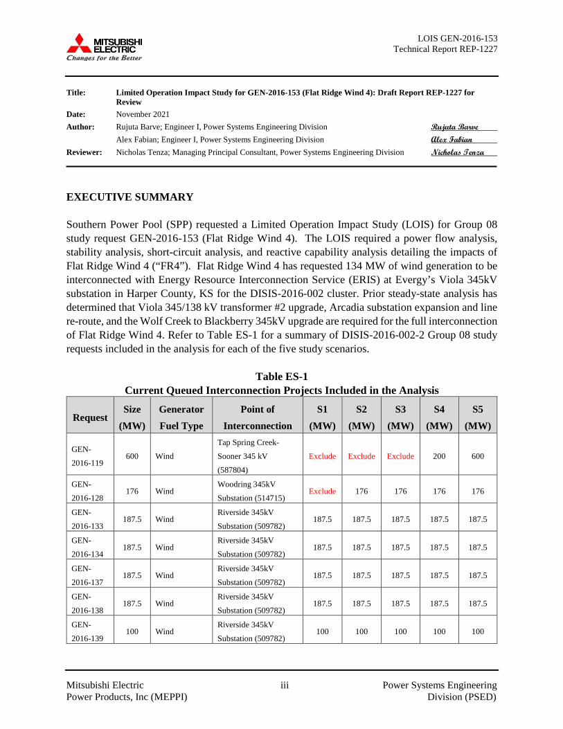
EXECUTIVE SUMMARY Southern Power Pool (SPP) requested a Limited Operation Impact Study (LOIS) for Group 08 study request GEN-2016-153 (Flat Ridge Wind 4). The LOIS required a power flow analysis, stability analysis, short-circuit analysis, and reactive capability analysis detailing the impacts of Flat Ridge Wind 4 (“FR4”). Flat Ridge Wind 4 has requested 134 MW of wind generation to be interconnected with Energy Resource Interconnection Service (ERIS) at Evergy’s Viola 345kV substation in Harper County, KS for the DISIS-2016-002 cluster. Prior steady-state analysis has determined that Viola 345/138 kV transformer #2 upgrade, Arcadia substation expansion and line re-route, and the Wolf Creek to Blackberry 345kV upgrade are required for the full interconnection of Flat Ridge Wind 4. Refer to Table ES-1 for a summary of DISIS-2016-002-2 Group 08 study requests included in the analysis for each of the five study scenarios.
Table ES-1
Current Queued Interconnection Projects Included in the Analysis
Request Size
(MW) Generator Fuel Type
Point of Interconnection
S1 (MW)
S2 (MW)
S3 (MW)
S4 (MW)
S5 (MW)
GEN-
2016-119 600 Wind
Tap Spring Creek-
Sooner 345 kV
(587804)
Exclude Exclude Exclude 200 600
GEN-
2016-128 176 Wind
Woodring 345kV
Substation (514715) Exclude 176 176 176 176
GEN-
2016-133 187.5 Wind
Riverside 345kV
Substation (509782) 187.5 187.5 187.5 187.5 187.5
GEN-
2016-134 187.5 Wind
Riverside 345kV
Substation (509782) 187.5 187.5 187.5 187.5 187.5
GEN-
2016-137 187.5 Wind
Riverside 345kV
Substation (509782) 187.5 187.5 187.5 187.5 187.5
GEN-
2016-138 187.5 Wind
Riverside 345kV
Substation (509782) 187.5 187.5 187.5 187.5 187.5
GEN-
2016-139 100 Wind
Riverside 345kV
Substation (509782) 100 100 100 100 100
LOIS GEN-2016-153 Technical Report REP-1227
Mitsubishi Electric iv Power Systems Engineering Power Products, Inc (MEPPI) Division (PSED)
Request Size
(MW) Generator Fuel Type
Point of Interconnection
S1 (MW)
S2 (MW)
S3 (MW)
S4 (MW)
S5 (MW)
GEN-
2016-141 350 Wind
Riverside 345kV
Substation (509782) 350 350 350 350 350
GEN-
2016-142 350 Wind
Riverside 345kV
Substation (509782) 350 350 350 350 350
GEN-
2016-145 175 Wind
Riverside 345kV
Substation (509782) 175 175 175 175 175
GEN-
2016-146 175 Wind
Riverside 345kV
Substation (509782) 175 175 175 175 175
GEN-
2016-153 134 Wind Viola 345kV (588364) 134 134 134 134 134
GEN-
2016-162 252
Wind Benton 345kV
(532791) Exclude Exclude 252 252 252
GEN-
2016-163 252
Wind Benton 345kV
(532791) Exclude Exclude 252 252 252
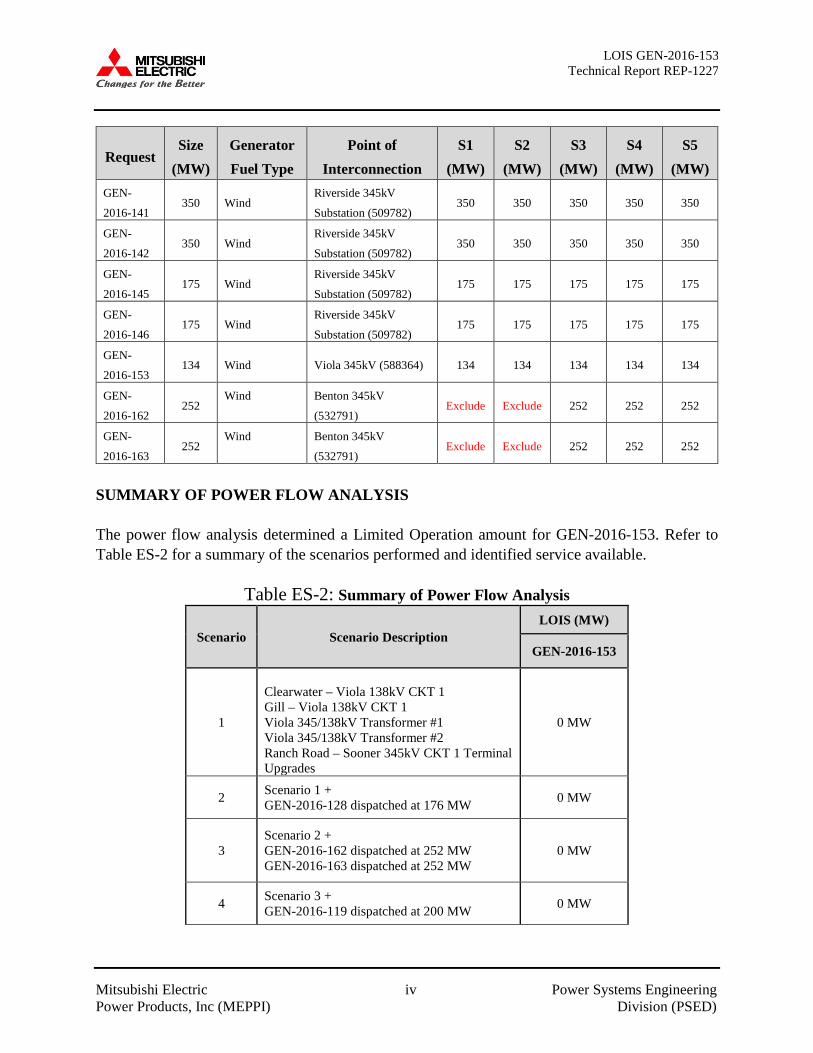
SUMMARY OF POWER FLOW ANALYSIS The power flow analysis determined a Limited Operation amount for GEN-2016-153. Refer to Table ES-2 for a summary of the scenarios performed and identified service available.
Table ES-2: Summary of Power Flow Analysis
Scenario Scenario Description LOIS (MW)
GEN-2016-153
1
Clearwater – Viola 138kV CKT 1 Gill – Viola 138kV CKT 1 Viola 345/138kV Transformer #1 Viola 345/138kV Transformer #2 Ranch Road – Sooner 345kV CKT 1 Terminal Upgrades
0 MW
2 Scenario 1 + GEN-2016-128 dispatched at 176 MW 0 MW
3 Scenario 2 + GEN-2016-162 dispatched at 252 MW GEN-2016-163 dispatched at 252 MW
0 MW
4 Scenario 3 + GEN-2016-119 dispatched at 200 MW 0 MW
LOIS GEN-2016-153 Technical Report REP-1227
Mitsubishi Electric v Power Systems Engineering Power Products, Inc (MEPPI) Division (PSED)
5 Scenario 4 + GEN-2016-119 dispatched at 600 MW GEN-2016-100/101 Tap-Arcadia 345kV
0 MW
6* Scenario 5 + Reduced dispatch of JEC 134 MW
These values reflect the gross generating facility capacity prior to losses associated with the interconnection facilities. It was determined that the dispatch of the Jeffrey Energy Center (“JEC”) Unit 2 and Unit 3 have an impact on GEN-2016-153’s LOIS amount when the Arcadia substation expansion and Wolf Creek to Blackberry 345 kV line are in-service. When JEC is dispatched at full output, a thermal constraint exists on the Hoyt to JEC 345 kV line and therefore, GEN-2016-153 is limited to 0 MW. When JEC Unit 2 and Unit 3 are at a reduced output, GEN-2016-153 is able to have full interconnection service (134 MW). The following seasons require reduced dispatch of JEC Unit 2 and Unit 3:
• 2020 Summer Peak: 1,370 MW gross (87% of nameplate) • 2024 Summer Peak: 1,419 MW gross (90% of nameplate) • 2029 Summer Peak: 1,554 MW gross (99% of nameplate)
SUMMARY OF STABILITY ANALYSIS The Stability Analysis was performed with the NERC MOD-026 and MOD-027 model validation updates implemented for the Wolf Creek Nuclear Facility (“Wolf Creek”) and determined several NERC Category P6 events that included a prior outage of a transmission line out of Wolf Creek 345kV followed by a fault on a circuit connected to either Waverly or Wolf Creek 345kV substations resulted in undamped rotor angle oscillations, voltages below the acceptable recovery voltage, voltage collapse, and generation instability when GEN-2016-153 was connected at 100% output. It is worth noting that this instability is a pre-existing system condition and therefore cannot be directly attributed to connection of GEN-2016-153 to its point of interconnection (“POI”). The following transmission upgrade options were observed to mitigate the system instability observed for all contingencies:
• Wolf Creek to Blackberry 345kV circuit (previously and current assigned mitigation in DISIS-2016-001-5)
This analysis identified the potential requirement of generation curtailment at Wolf Creek to maintain system stability for certain prior outage conditions including:
• Prior outage of Wolf Creek to Waverly 345kV circuit #1 • Prior outage of Wolf Creek to Benton 345 kV circuit #1

LOIS GEN-2016-153 Technical Report REP-1227
Mitsubishi Electric vi Power Systems Engineering Power Products, Inc (MEPPI) Division (PSED)
• Prior outage of Wolf Creek to Rose Hill 345 kV circuit #1 • Prior outage of Waverly to LaCygne 345kV circuit #1 • Prior outage of Wolf Creek to Blackberry 345kV circuit #1
System instability is observed with Wolf Creek dispatched at full output and prior to GEN-2016-153’s in-service date for the above prior outage conditions followed by a fault at Wolf Creek 345 kV or Waverly 345 kV. System stability is maintained for the prior outage events above when the Wolf Creek output does not exceed 900 MW gross output with or without GEN-2016-153 in-service. It should be noted that while this Limited Operation study analyzed many of the most probable contingencies, it is not an all-inclusive list that can account for every operation situation. Additionally, the study requests may not be able to inject any power onto the Transmission System due to constraints that fall below the threshold of mitigation for a Generator Interconnection request. Because of this, it is likely that the Customers may be required to reduce their generation output to 0 MW under certain system conditions to allow system operators to maintain the reliability of the transmission network.
LOIS GEN-2016-153 Technical Report REP-1227
Mitsubishi Electric vii Power Systems Engineering Power Products, Inc (MEPPI) Division (PSED)
Table of Contents Executive Summary ....................................................................................................................... iii Table of Contents ...................................................................................................................... vii Section 1: Objectives ......................................................................................................................1 Section 2: Background ....................................................................................................................1 Section 3: Power Flow Analysis .....................................................................................................9
3.1 Approach ..............................................................................................................................9
3.2 Steady-State Thermal and Voltage Analysis Results...........................................................9 Section 4: Stability Analysis .........................................................................................................11
4.1 Approach ............................................................................................................................11
4.2 Stability Analysis Results ..................................................................................................23 4.3 Reactive Compensation analysis........................................................................................23
Section 5: Short Circuit Analysis ..................................................................................................60 Section 6: Conclusions ..................................................................................................................60 Appendix A: Steady-State and Dynamic Model Data ................................................................ A-1 Appendix B: Plots for 2019 Winter Peak Conditions ..................................................................B-1 Appendix C: Plots for 2021 Summer Peak Conditions ...............................................................C-1 Appendix D: Plots for 2028 Summer Peak Conditions .............................................................. D-1 Appendix E: Plots for 2021 Light Load Conditions .................................................................... E-1
List of Tables Table 2-1: Current Study Project Interconnection Data ..................................................................2 Table 2-2: Group 8 Queued Interconnection Projects Included in Stability Analysis .....................2 Table 2-3: Interconnection Projects Not Included in the Stability Analysis ...................................3 Table 2-4: Previously Queued Nearby Interconnection Projects Included ......................................4 Table 3-1: Summary of Power Flow Analysis ...............................................................................10 Table 4-1: Fault List with Contingency Description .....................................................................12 Table 4-2: Stability Analysis Summary of Results for 2019 Winter, 2021 Summer, 2028 Summer
Peak, and 2021 Light Load Conditions for Scenario 1 ..............................................24 Table 4-3: Stability Analysis Summary of Results for 2019 Winter, 2021 Summer, 2028 Summer
Peak, and 2021 Light Load Conditions for Scenario 2 ..............................................29 Table 4-4: Stability Analysis Summary of Results for 2019 Winter, 2021 Summer, 2028 Summer
Peak, and 2021 Light Load Conditions for Scenario 3 ..............................................34 Table 4-5: Stability Analysis Summary of Results for 2019 Winter, 2021 Summer, 2028 Summer
Peak, and 2021 Light Load Conditions for Scenario 4 ..............................................39 Table 4-6: Stability Analysis Summary of Results for 2019 Winter, 2021 Summer, 2028 Summer
Peak, and 2021 Light Load Conditions for Scenario 5 ..............................................44 Table 4-7: Reactor Size Identified for 2028 Summer Peak Conditions .........................................55 Table 5-1: Short-Circuit Currents for 2028 Summer Peak Conditions..........................................56
LOIS GEN-2016-153 Technical Report REP-1227
Mitsubishi Electric viii Power Systems Engineering Power Products, Inc (MEPPI) Division (PSED)
Table 6-1: Summary of the Power Flow Analysis .........................................................................60
List of Figures Figure 4-1: Representative plot of voltages near Viola 345 kV for 2019 Winter Peak Scenario 5
conditions for contingency FLT130-3PH. ..................................................................50 Figure 4-2: Representative plot of real and reactive powers from machines near Viola 345 kV for
2019 Winter Peak Scenario 5 conditions for contingency FLT130-3PH. ..................50 Figure 4-3: Representative plot of Wolf Creek rotor angle for 2019 Winter Peak Scenario 5
conditions with and without the Wolf Creek curtailment. .........................................52 Figure 4-4: Representative plot of Wolf Creek real and reactive power for 2019 Winter Peak
Scenario 5 conditions with and without the Wolf Creek curtailment. .......................52 Figure 4-5: Representative plot of Wolf Creek rotor angle for 2019 Winter Peak Scenario 5
conditions with Wolf Creek to Blackberry 345 kV circuit #1 in-service. ..................53 Figure 4-6: Representative plot of real and reactive power for 2019 Winter Peak Scenario 5
conditions with Wolf Creek to Blackberry 345 kV circuit #1 in-service. ..................54 Figure 4-7: Representative plot of voltages near Wolf Creek for 2019 Winter Peak Scenario 5
conditions with Wolf Creek to Blackberry 345 kV circuit #1 in-service. ..................54
LOIS GEN-2016-153 Technical Report REP-1227
Mitsubishi Electric 1 Power Systems Engineering Power Products, Inc (MEPPI) Division (PSED)
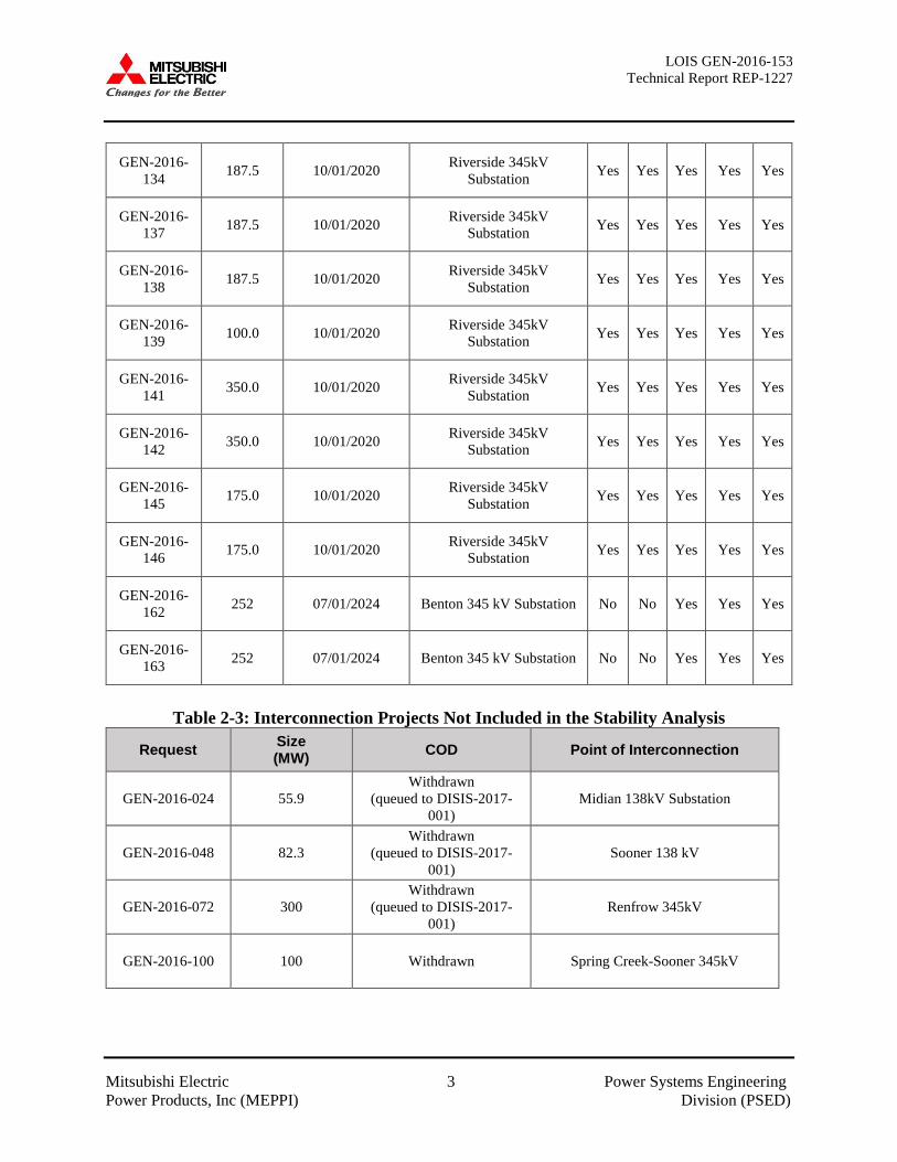
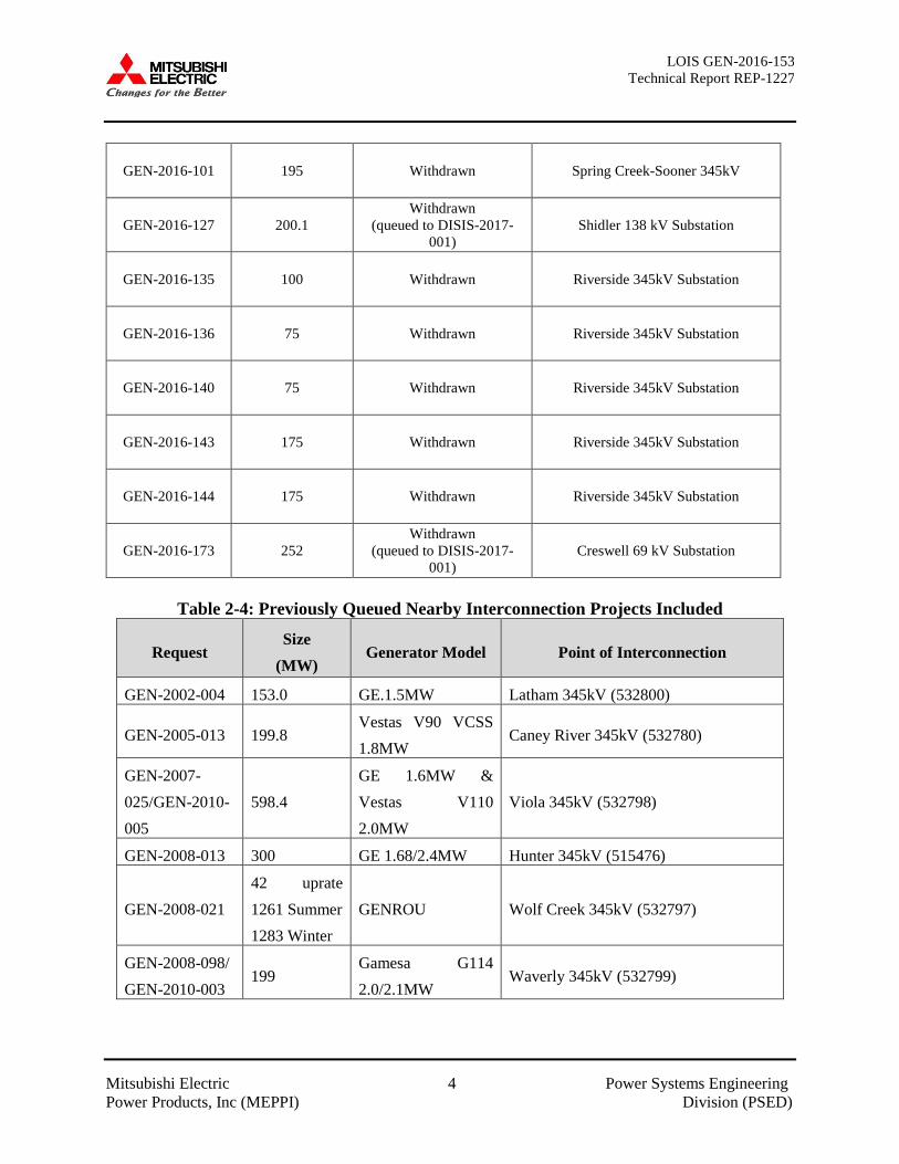
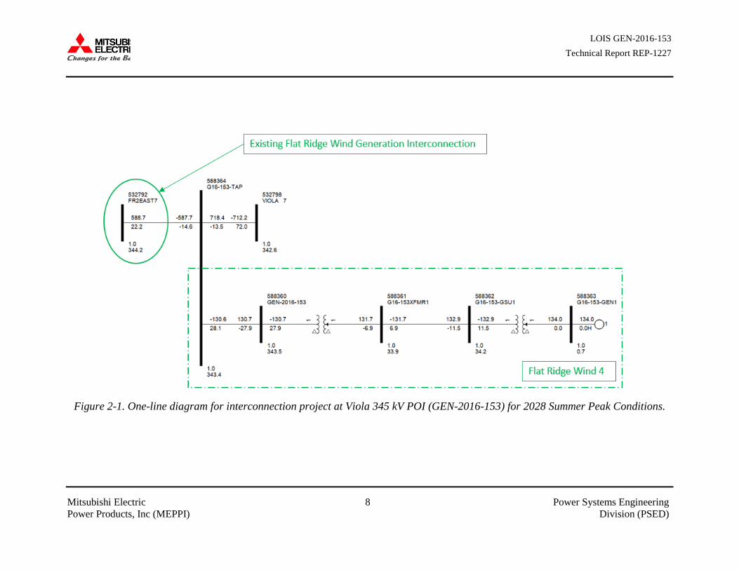
SECTION 1: OBJECTIVES The objective of this report is to provide Southern Power Pool (SPP) with the deliverables for the “Limited Operation Impact Study (LOIS) for GEN-2016-153 (Flat Ridge Wind 4).” SPP requested a Limited Operation Impact Study for one (1) generation interconnection request which requires a power flow analysis, stability analysis, short-circuit analysis, and reactive capability analysis with results in an Impact Study Report SECTION 2: BACKGROUND The Siemens Power Technologies International PSS/E power system simulation program Version 33.12.2 was used for this study. The DISIS-2017-001 power flow and stability cases under normal dispatch conditions were provided by SPP and updated accordingly to represent study conditions at the time of GEN-2016-153’s in-service date (“ISD”). The power flow cases include the Group 08 ERIS study models. Refer to the DISIS power flow report accompanying this report for details of changes made to the cases provided. The stability models provided included the 2019 Winter Peak, 2021 Summer Peak, 2028 Summer Peak, and 2021 Light Load cases. The study request listed in Table 2-1 was included in the analysis. Table 2-2 lists each of the five scenarios studied in this analysis and indicates the status of the Group 08 queued projects. The study cases were updated to reflect these study assumptions for each of the five scenarios. The study requests with estimated ISD after GEN-2016-153 or that have been withdrawn are shown in Table 2-3 and were removed from the study models to reflect current system configurations. Refer to Section 3.1 for the changes made to the base cases to reflect the removal of previously assigned Network Upgrades and study requests. Refer to Table 2-4 for a list of previously queued projects included in the analysis. A power flow one-line diagram for GEN-2016-153 is shown in Figure 2-1 and represents 2028 Summer Peak conditions. The Stability Analysis determined the impacts of the new interconnecting project on the stability and voltage recovery of the nearby system and the ability of the interconnecting projects to meet FERC Order 661A. If problems with stability or voltage recovery are identified, the need for reactive compensation or system upgrades were investigated. Three-phase faults and single line-to-ground faults were examined prior to any mitigation or curtailment implemented. With exception of transformers and prior outage faults, the typical sequence of events for a three-phase fault is as follows (refer to Section 4 for a list and description of fault events analyzed):
• Apply fault at particular station • Continue fault for five (5) cycles, clear the fault by tripping the faulted facility • After an additional twenty (20) cycles, re-close the previous facility back into the fault

LOIS GEN-2016-153 Technical Report REP-1227
Mitsubishi Electric 2 Power Systems Engineering Power Products, Inc (MEPPI) Division (PSED)
• Continue fault for five (5) additional cycles • Trip the faulted facility and remove the fault
Refer to Appendix A for the steady-state and dynamic model data for the study project.
Table 2-1: Current Study Project Interconnection Data
Request Size (MW) Estimated COD Point of Interconnection
GEN-2016-153 134 11/01/2023 Viola 345kV Substation
Table 2-2: Group 8 Queued Interconnection Projects Included in Stability Analysis
Request Size (MW) Estimate COD Point of Interconnection S1 S2 S3 S4 S5
GEN-2016-022 151.8 11/01/2022
Rose Hill (Open Sky)-Sooner (Ranch Road)
345kV Yes Yes Yes Yes Yes
GEN-2016-031 1.5 05/29/2018
Rose Hill (Open Sky)-Sooner (Ranch Road)
345kV Yes Yes Yes Yes Yes
GEN-2016-032 200.0 12/31/2023 Crescent Substation 138
kV Yes Yes Yes Yes Yes
GEN-2016-061 250.7 11/21/2020 Sooner-Woodring 345 kV
line Yes Yes Yes Yes Yes
GEN-2016-068 250 12/15/2020 Woodring 345kV Yes Yes Yes Yes Yes
GEN-2016-071 200.1 11/30/2021 Middleton Tap 138kV
Substation Yes Yes Yes Yes Yes
GEN-2016-073 220.0 10/30/2022 Thistle-Wichita Dbl Ckt
(Buffalo Flats) 345kV Yes Yes Yes Yes Yes
GEN-2016-119 600 12/31/2025 Spring Creek-Sooner
345kV No No No Yes (200 MW)
Yes
GEN-2016-128 176 12/31/2023 Woodring 345kV No Yes Yes Yes Yes
GEN-2016-133 187.5 10/01/2020 Riverside 345kV
Substation Yes Yes Yes Yes Yes
LOIS GEN-2016-153 Technical Report REP-1227
Mitsubishi Electric 3 Power Systems Engineering Power Products, Inc (MEPPI) Division (PSED)
GEN-2016-134 187.5 10/01/2020 Riverside 345kV
Substation Yes Yes Yes Yes Yes
GEN-2016-137 187.5 10/01/2020 Riverside 345kV
Substation Yes Yes Yes Yes Yes
GEN-2016-138 187.5 10/01/2020 Riverside 345kV
Substation Yes Yes Yes Yes Yes
GEN-2016-139 100.0 10/01/2020 Riverside 345kV
Substation Yes Yes Yes Yes Yes
GEN-2016-141 350.0 10/01/2020 Riverside 345kV
Substation Yes Yes Yes Yes Yes
GEN-2016-142 350.0 10/01/2020 Riverside 345kV
Substation Yes Yes Yes Yes Yes
GEN-2016-145 175.0 10/01/2020 Riverside 345kV
Substation Yes Yes Yes Yes Yes
GEN-2016-146 175.0 10/01/2020 Riverside 345kV
Substation Yes Yes Yes Yes Yes
GEN-2016-162 252 07/01/2024 Benton 345 kV Substation No No Yes Yes Yes
GEN-2016-163 252 07/01/2024 Benton 345 kV Substation No No Yes Yes Yes
Table 2-3: Interconnection Projects Not Included in the Stability Analysis
Request Size (MW) COD Point of Interconnection
GEN-2016-024 55.9 Withdrawn
(queued to DISIS-2017-001)
Midian 138kV Substation
GEN-2016-048 82.3 Withdrawn
(queued to DISIS-2017-001)
Sooner 138 kV
GEN-2016-072 300 Withdrawn
(queued to DISIS-2017-001)
Renfrow 345kV
GEN-2016-100 100 Withdrawn Spring Creek-Sooner 345kV
LOIS GEN-2016-153 Technical Report REP-1227
Mitsubishi Electric 4 Power Systems Engineering Power Products, Inc (MEPPI) Division (PSED)
GEN-2016-101 195 Withdrawn Spring Creek-Sooner 345kV
GEN-2016-127 200.1 Withdrawn
(queued to DISIS-2017-001)
Shidler 138 kV Substation
GEN-2016-135 100 Withdrawn Riverside 345kV Substation
GEN-2016-136 75 Withdrawn Riverside 345kV Substation
GEN-2016-140 75 Withdrawn Riverside 345kV Substation
GEN-2016-143 175 Withdrawn Riverside 345kV Substation
GEN-2016-144 175 Withdrawn Riverside 345kV Substation
GEN-2016-173 252 Withdrawn
(queued to DISIS-2017-001)
Creswell 69 kV Substation
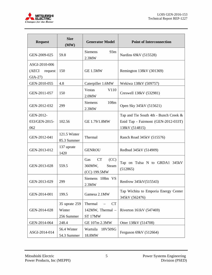
Table 2-4: Previously Queued Nearby Interconnection Projects Included
Request Size
(MW) Generator Model Point of Interconnection
GEN-2002-004 153.0 GE.1.5MW Latham 345kV (532800)
GEN-2005-013 199.8 Vestas V90 VCSS 1.8MW
Caney River 345kV (532780)
GEN-2007-025/GEN-2010-005
598.4 GE 1.6MW & Vestas V110 2.0MW
Viola 345kV (532798)
GEN-2008-013 300 GE 1.68/2.4MW Hunter 345kV (515476)
GEN-2008-021 42 uprate 1261 Summer 1283 Winter
GENROU Wolf Creek 345kV (532797)
GEN-2008-098/ GEN-2010-003
199 Gamesa G114 2.0/2.1MW
Waverly 345kV (532799)
LOIS GEN-2016-153 Technical Report REP-1227
Mitsubishi Electric 5 Power Systems Engineering Power Products, Inc (MEPPI) Division (PSED)
Request Size
(MW) Generator Model Point of Interconnection
GEN-2009-025 59.8 Siemens 93m 2.3MW
Nardins 69kV (515528)
ASGI-2010-006 (AECI request GIA-27)
150 GE 1.5MW Remington 138kV (301369)
GEN-2010-055 4.8 Caterpiller 1.6MW Wekiwa 138kV (509757)
GEN-2011-057 150 Vestas V110 2.0MW
Creswell 138kV (532981)
GEN-2012-032 299 Siemens 108m 2.3MW
Open Sky 345kV (515621)
GEN-2012-033/GEN-2015-062
102.56 GE 1.79/1.8MW Tap and Tie South 4th - Bunch Creek & Enid Tap - Fairmont (GEN-2012-033T) 138kV (514815)
GEN-2012-041 121.5 Winter 85.3 Summer
Thermal Ranch Road 345kV (515576)
GEN-2013-012 137 uprate 1420
GENROU Redbud 345kV (514909)
GEN-2013-028 559.5 Gas CT (CC) 360MW, Steam (CC) 199.5MW
Tap on Tulsa N to GRDA1 345kV (512865)
GEN-2013-029 299 Siemens 108m VS 2.3MW
Renfrow 345kV(515543)
GEN-2014-001 199.5 Gamesa 2.1MW Tap Wichita to Emporia Energy Center 345kV (562476)
GEN-2014-028 35 uprate 259 Winter 256 Summer
Thermal – CT 142MW, Thermal – ST 17MW
Riverton 161kV (547469)
GEN-2014-064 248.4 GE 107m 2.3MW Otter 138kV (514708)
ASGI-2014-014 56.4 Winter 54.3 Summer
Wartsila 18V50SG 18.8MW
Ferguson 69kV (512664)

LOIS GEN-2016-153 Technical Report REP-1227
Mitsubishi Electric 6 Power Systems Engineering Power Products, Inc (MEPPI) Division (PSED)
Request Size
(MW) Generator Model Point of Interconnection
GEN-2015-001/GEN-2016-031
201.3 Vestas V126 GridStreamer 3.3MW
Ranch Road 345kV (515576)
GEN-2015-015 154.6 Siemens 108m 2.415MW
Tap Medford Tap – Coyote 138kV (560031)
GEN-2015-016 200 Vestas V110 2.0MW
Tap Marmaton - Centerville 161kV (560029)
GEN-2015-024 217.8 GE 116m 1.8MW Tap Thistle - Wichita 345kV Dbl CKT (560033)
GEN-2015-025 215.95 GE 1.79/1.8MW Tap Thistle - Wichita 345kV Dbl CKT (560033)
ASGI-2015-004
54.300 Summer 56.364 Winter
Wartsila 18V50SG 18.788MW
Coffeyville Municipal Light & Power Northern Industrial Park Substation 69kV (512735)
GEN-2015-034 200 Vestas V136 GridStreamer 3.45MW
Ranch Road 345kV (515576)
GEN-2015-047 297.8 GE 2.3/2.5MW Sooner 345kV (514803)
GEN-2015-052 300 Vestas V110 VCSS 2.0MW
Tap on Opensky (515621) to RoseHill (532794) 345kV (560053)
GEN-2015-063 299.25 Acciona 125m 3.15MW
Tap on Woodring (514715) to Matthewson (515497) 345kV (560055)
GEN-2015-066 248.4 GE 2.3MW Tap on Cleveland (512694) to Sooner (514803) 345 kV (560056)
GEN-2015-069 300 Vestas V110 VCSS 2.0MW
Union Ridge 230kV (532874)
GEN-2015-073 200.1 Vestas V126 GridStreamer 3.45MW
Emporia Energy Center 345kV (532768)

LOIS GEN-2016-153 Technical Report REP-1227
Mitsubishi Electric 7 Power Systems Engineering Power Products, Inc (MEPPI) Division (PSED)
Request Size
(MW) Generator Model Point of Interconnection
GEN-2015-090 220 G.E. 2.0MW Wichita (532796)-Thistle (539801) 345kV Tap (GEN-2015-024 (560033) 345kV)
GEN-2016-009 29 Allen Bradley 14.5MW
Osage 69kV (514742)
GEN-2016-022 151.8 Vestas V126 GridStreamer 3.45MW
Ranch Road 345kV (515576)
GEN-2016-032 200 Vestas V110 VCSS 2.0MW
Tap Marshall (514733)- Cottonwood Creek (514827) 138kV, (G16-032-TAP, 560077)
GEN-2016-061 250.7 GE 2.3MW Tap Woodring (514715) – Sooner (514803) 345kV (G16-061-TAP, 560084)
GEN-2016-068 250 GE 2.0MW Woodring 345kV (514715)
GEN-2016-071 200.1 GE 2.3MW Chilocco 138kV (521198)
GEN-2016-073 220 GE 2.0MW Tap on Thistle (539801) to Wichita (532796) 345kV, ckt1&2 (Buffalo Flats 345kV; 560033)
LOIS GEN-2016-153 Technical Report REP-1227
Mitsubishi Electric 8 Power Systems Engineering Power Products, Inc (MEPPI) Division (PSED)
Figure 2-1. One-line diagram for interconnection project at Viola 345 kV POI (GEN-2016-153) for 2028 Summer Peak Conditions.
LOIS GEN-2016-153 Technical Report REP-1227
Mitsubishi Electric 9 Power System Engineering Power Products, Inc (MEPPI) Division (PSED)
SECTION 3: POWER FLOW ANALYSIS The objective of the power flow analysis was to determine the impacts of the generator interconnection on the steady-state thermal and voltage constraints on the SPP transmission system. The analysis evaluated if GEN-2016-153 can interconnect 134 MW of wind generation with Energy Resource Interconnection Service (ERIS). 3.1 Approach
MEPPI utilized the seven (7) following Before Transfer (“BC”) DISIS-2017-001-1 Group 08 power flow cases for this analysis:
• Steady-State Analysis o 2019 Winter Peak o 2020 Spring o 2020 Summer Peak o 2024 Light Load o 2024 Summer Peak o 2024 Winter Peak o 2029 Summer Peak
The power flow cases were dispatched in accordance with DISIS Manual, Table 1: Generation Dispatch in the Power Flow Models, and Business Practices 7250 to develop the ERIS cases. Seven (7) BC cases were created by including the study request but dispatched at 0 MW for ER. Seven (7) Transfer cases (“TC”) were created by including the study request and dispatched at full output for ER. Refer to the power flow report attachment for the status of other equally queued requests, previously assigned upgrades, and higher queued requests. 3.2 Steady-State Thermal and Voltage Analysis Results
The power flow analysis observed system constraints with identified Limited Operation capacity for GEN-2016-153 as shown in Table 3-1.
• Scenario 1: Includes the Clearwater – Viola 138kV CKT 1, Gill – Viola 138kV CKT 1, Viola 345/138kV Transformer #1, Viola 345/138kV Transformer #2, and Ranch Road – Sooner 345kV CKT 1 Terminal Upgrades.
• Scenario 2: Includes Scenario 1 topology plus GEN-2016-128 dispatched at 176 MW. • Scenario 3: Includes Scenario 2 plus GEN-2016-162 dispatched at 252 MW, and GEN-
2016-163 dispatched at 252 MW. • Scenario 4: Includes Scenario 3 plus GEN-2016-119 dispatched at 200 MW. • Scenario 5: Includes Scenario 4 plus GEN-2016-119 dispatched at 600 MW, GEN-2016-
100/101 Tap-Arcadia 345kV.
LOIS GEN-2016-153 Technical Report REP-1227
Mitsubishi Electric 10 Power System Engineering Power Products, Inc (MEPPI) Division (PSED)
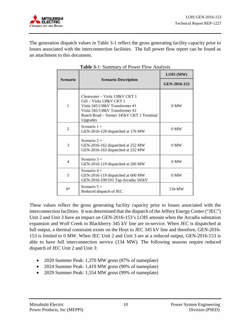
The generation dispatch values in Table 3-1 reflect the gross generating facility capacity prior to losses associated with the interconnection facilities. The full power flow report can be found as an attachment to this document.
Table 3-1: Summary of Power Flow Analysis
Scenario Scenario Description LOIS (MW)
GEN-2016-153
1
Clearwater – Viola 138kV CKT 1 Gill – Viola 138kV CKT 1 Viola 345/138kV Transformer #1 Viola 345/138kV Transformer #2 Ranch Road – Sooner 345kV CKT 1 Terminal Upgrades
0 MW
2 Scenario 1 + GEN-2016-128 dispatched at 176 MW 0 MW
3 Scenario 2 + GEN-2016-162 dispatched at 252 MW GEN-2016-163 dispatched at 252 MW
0 MW
4 Scenario 3 + GEN-2016-119 dispatched at 200 MW 0 MW
5 Scenario 4 + GEN-2016-119 dispatched at 600 MW GEN-2016-100/101 Tap-Arcadia 345kV
0 MW
6* Scenario 5 + Reduced dispatch of JEC 134 MW
These values reflect the gross generating facility capacity prior to losses associated with the interconnection facilities. It was determined that the dispatch of the Jeffrey Energy Center (“JEC”) Unit 2 and Unit 3 have an impact on GEN-2016-153’s LOIS amount when the Arcadia substation expansion and Wolf Creek to Blackberry 345 kV line are in-service. When JEC is dispatched at full output, a thermal constraint exists on the Hoyt to JEC 345 kV line and therefore, GEN-2016-153 is limited to 0 MW. When JEC Unit 2 and Unit 3 are at a reduced output, GEN-2016-153 is able to have full interconnection service (134 MW). The following seasons require reduced dispatch of JEC Unit 2 and Unit 3:
• 2020 Summer Peak: 1,370 MW gross (87% of nameplate) • 2024 Summer Peak: 1,419 MW gross (90% of nameplate) • 2029 Summer Peak: 1,554 MW gross (99% of nameplate)
LOIS GEN-2016-153 Technical Report REP-1227
Mitsubishi Electric 11 Power System Engineering Power Products, Inc (MEPPI) Division (PSED)
SECTION 4: STABILITY ANALYSIS The objective of the stability analysis was to determine the impacts of GEN-2016-153 generator interconnection study request on the stability and voltage recovery on the SPP transmission system. If problems with stability or voltage recovery were identified, limited operation amounts were investigated for GEN-2016-153. 4.1 Approach
MEPPI utilized the following four (4) DISIS-2017-001 power flow dynamic databases:
• MDWG18-19W_DIS1701_G08 • MDWG18-21S_DIS1701_G08 • MDWG18-28S_DIS1701_G08 • MDWG18-21L_DIS1701_G08
Each case was examined prior to the stability analysis to ensure the case contained the proposed study project and equally queued projects listed in Tables 2-1 and 2-2 respectively. The study cases were updated by removing study requests queued to DISIS-2017-001 and were uniformly offset to maintain generation and load balance by thermal generation in the SPP footprint. The analysis did not include Network Upgrades that were expected to be in-service after the Commercial Operation Date of GEN-2016-153 except for the Viola 345/138kV transformer #2. The following Network Upgrades were not included in the analysis:
• Arcadia Substation expansion • Wolf Creek to Blackberry 345kV circuit #1 • GEN-2016-133_146 – Sapulpa Road circuit #1
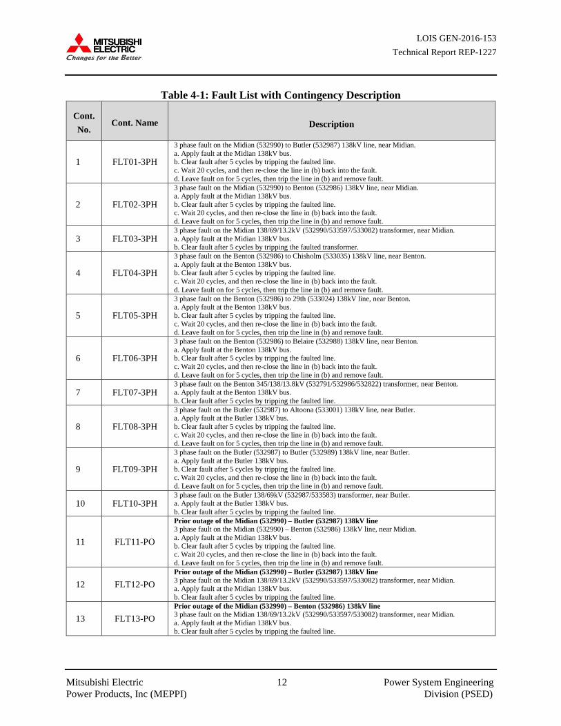
Each case was examined prior to the Stability Analysis to ensure the case contained Flat Ridge Wind 4 and any equally queued projects and previously queued projects listed in Tables 2-2 and 2-4, respectively. There was no suspect power flow data in the study area. The dynamic datasets were also verified and stable initial system conditions (i.e., “flat lines”) were achieved. Three-phase and single phase-to-ground faults listed in Table 4-1 were examined. The SCMU function internal to PSS/E was utilized to apply single phase-to-ground faults.
LOIS GEN-2016-153 Technical Report REP-1227
Mitsubishi Electric 12 Power System Engineering Power Products, Inc (MEPPI) Division (PSED)
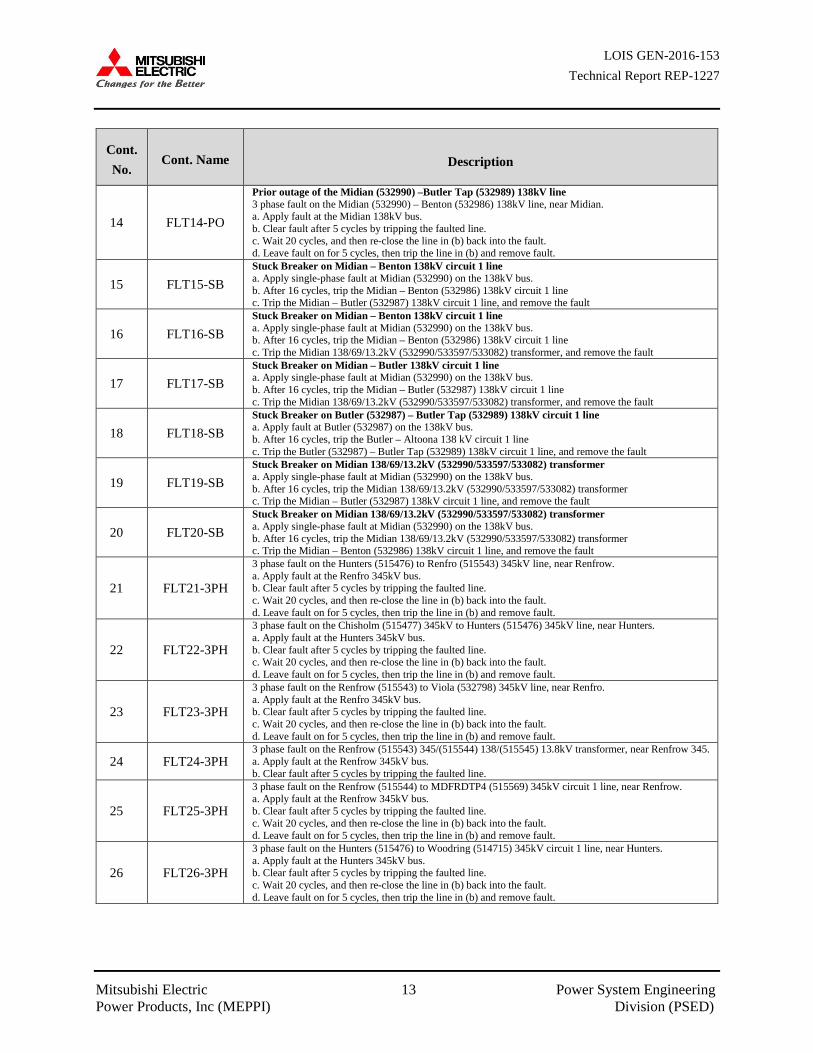
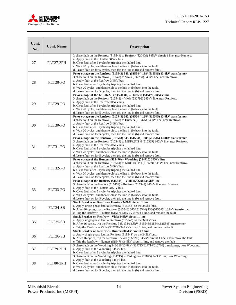
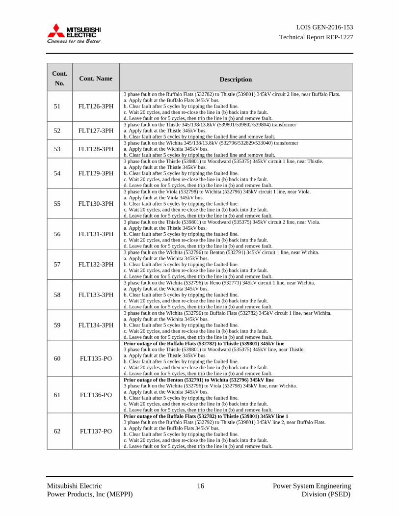
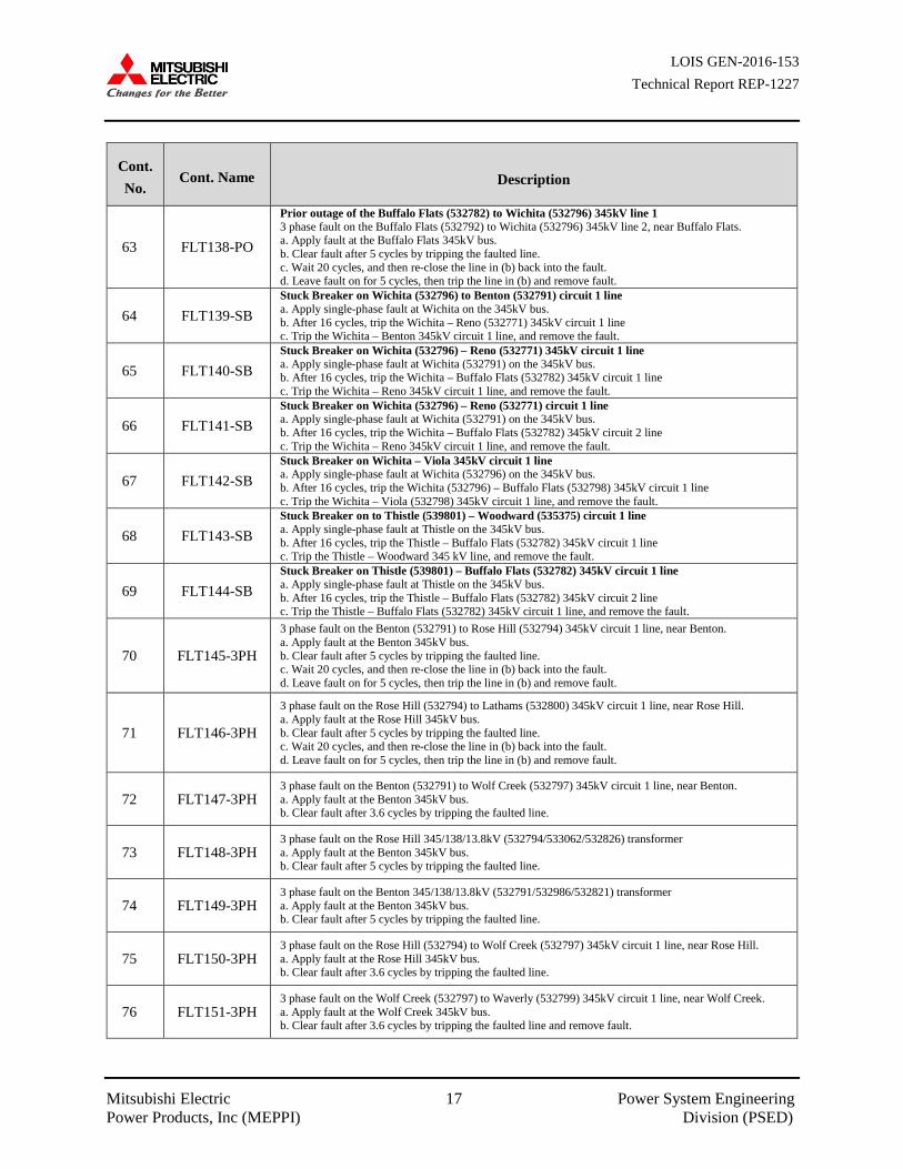
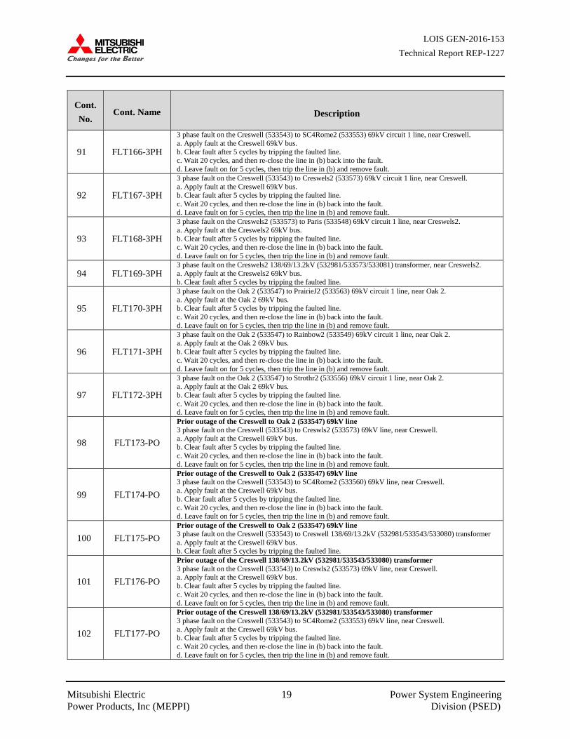
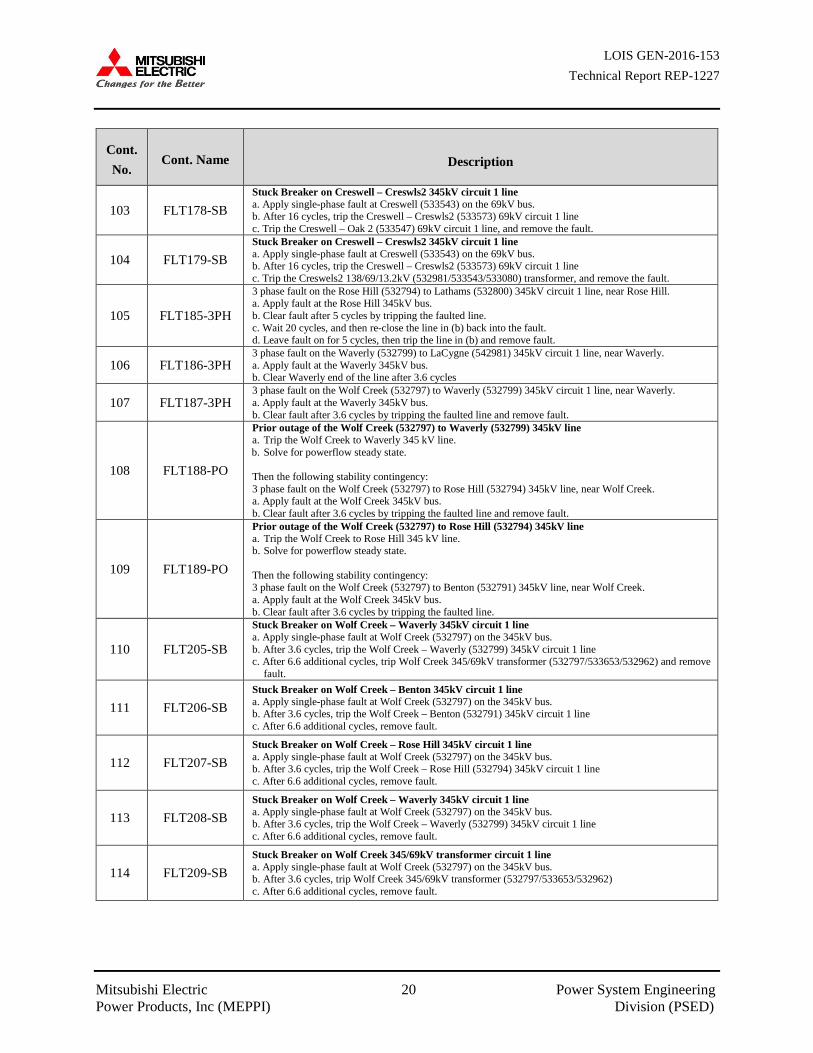
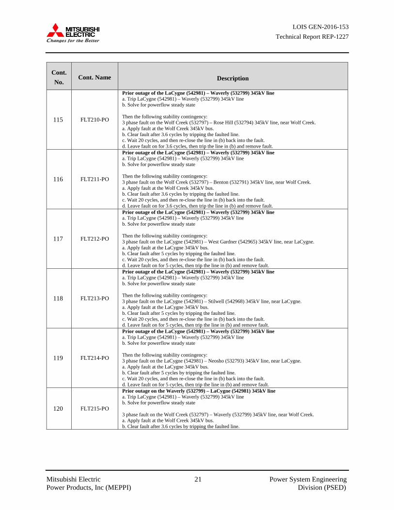
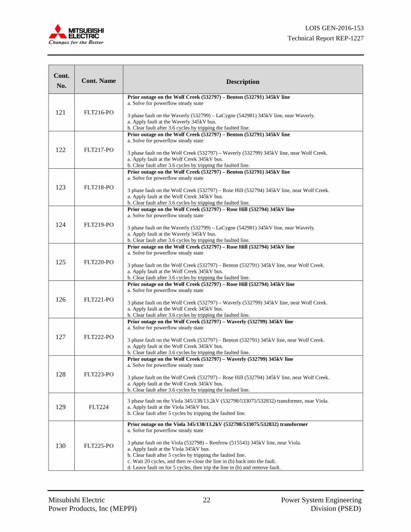
Table 4-1: Fault List with Contingency Description
Cont. No.
Cont. Name Description
1 FLT01-3PH
3 phase fault on the Midian (532990) to Butler (532987) 138kV line, near Midian. a. Apply fault at the Midian 138kV bus. b. Clear fault after 5 cycles by tripping the faulted line. c. Wait 20 cycles, and then re-close the line in (b) back into the fault. d. Leave fault on for 5 cycles, then trip the line in (b) and remove fault.
2 FLT02-3PH
3 phase fault on the Midian (532990) to Benton (532986) 138kV line, near Midian. a. Apply fault at the Midian 138kV bus. b. Clear fault after 5 cycles by tripping the faulted line. c. Wait 20 cycles, and then re-close the line in (b) back into the fault. d. Leave fault on for 5 cycles, then trip the line in (b) and remove fault.
3 FLT03-3PH 3 phase fault on the Midian 138/69/13.2kV (532990/533597/533082) transformer, near Midian. a. Apply fault at the Midian 138kV bus. b. Clear fault after 5 cycles by tripping the faulted transformer.
4 FLT04-3PH
3 phase fault on the Benton (532986) to Chisholm (533035) 138kV line, near Benton. a. Apply fault at the Benton 138kV bus. b. Clear fault after 5 cycles by tripping the faulted line. c. Wait 20 cycles, and then re-close the line in (b) back into the fault. d. Leave fault on for 5 cycles, then trip the line in (b) and remove fault.
5 FLT05-3PH
3 phase fault on the Benton (532986) to 29th (533024) 138kV line, near Benton. a. Apply fault at the Benton 138kV bus. b. Clear fault after 5 cycles by tripping the faulted line. c. Wait 20 cycles, and then re-close the line in (b) back into the fault. d. Leave fault on for 5 cycles, then trip the line in (b) and remove fault.
6 FLT06-3PH
3 phase fault on the Benton (532986) to Belaire (532988) 138kV line, near Benton. a. Apply fault at the Benton 138kV bus. b. Clear fault after 5 cycles by tripping the faulted line. c. Wait 20 cycles, and then re-close the line in (b) back into the fault. d. Leave fault on for 5 cycles, then trip the line in (b) and remove fault.
7 FLT07-3PH 3 phase fault on the Benton 345/138/13.8kV (532791/532986/532822) transformer, near Benton. a. Apply fault at the Benton 138kV bus. b. Clear fault after 5 cycles by tripping the faulted line.
8 FLT08-3PH
3 phase fault on the Butler (532987) to Altoona (533001) 138kV line, near Butler. a. Apply fault at the Butler 138kV bus. b. Clear fault after 5 cycles by tripping the faulted line. c. Wait 20 cycles, and then re-close the line in (b) back into the fault. d. Leave fault on for 5 cycles, then trip the line in (b) and remove fault.
9 FLT09-3PH
3 phase fault on the Butler (532987) to Butler (532989) 138kV line, near Butler. a. Apply fault at the Butler 138kV bus. b. Clear fault after 5 cycles by tripping the faulted line. c. Wait 20 cycles, and then re-close the line in (b) back into the fault. d. Leave fault on for 5 cycles, then trip the line in (b) and remove fault.
10 FLT10-3PH 3 phase fault on the Butler 138/69kV (532987/533583) transformer, near Butler. a. Apply fault at the Butler 138kV bus. b. Clear fault after 5 cycles by tripping the faulted line.
11 FLT11-PO
Prior outage of the Midian (532990) – Butler (532987) 138kV line 3 phase fault on the Midian (532990) – Benton (532986) 138kV line, near Midian. a. Apply fault at the Midian 138kV bus. b. Clear fault after 5 cycles by tripping the faulted line. c. Wait 20 cycles, and then re-close the line in (b) back into the fault. d. Leave fault on for 5 cycles, then trip the line in (b) and remove fault.
12 FLT12-PO Prior outage of the Midian (532990) – Butler (532987) 138kV line 3 phase fault on the Midian 138/69/13.2kV (532990/533597/533082) transformer, near Midian. a. Apply fault at the Midian 138kV bus. b. Clear fault after 5 cycles by tripping the faulted line.
13 FLT13-PO Prior outage of the Midian (532990) – Benton (532986) 138kV line 3 phase fault on the Midian 138/69/13.2kV (532990/533597/533082) transformer, near Midian. a. Apply fault at the Midian 138kV bus. b. Clear fault after 5 cycles by tripping the faulted line.
LOIS GEN-2016-153 Technical Report REP-1227
Mitsubishi Electric 13 Power System Engineering Power Products, Inc (MEPPI) Division (PSED)
Cont. No.
Cont. Name Description
14 FLT14-PO
Prior outage of the Midian (532990) –Butler Tap (532989) 138kV line 3 phase fault on the Midian (532990) – Benton (532986) 138kV line, near Midian. a. Apply fault at the Midian 138kV bus. b. Clear fault after 5 cycles by tripping the faulted line. c. Wait 20 cycles, and then re-close the line in (b) back into the fault. d. Leave fault on for 5 cycles, then trip the line in (b) and remove fault.
15 FLT15-SB Stuck Breaker on Midian – Benton 138kV circuit 1 line a. Apply single-phase fault at Midian (532990) on the 138kV bus. b. After 16 cycles, trip the Midian – Benton (532986) 138kV circuit 1 line c. Trip the Midian – Butler (532987) 138kV circuit 1 line, and remove the fault
16 FLT16-SB Stuck Breaker on Midian – Benton 138kV circuit 1 line a. Apply single-phase fault at Midian (532990) on the 138kV bus. b. After 16 cycles, trip the Midian – Benton (532986) 138kV circuit 1 line c. Trip the Midian 138/69/13.2kV (532990/533597/533082) transformer, and remove the fault
17 FLT17-SB Stuck Breaker on Midian – Butler 138kV circuit 1 line a. Apply single-phase fault at Midian (532990) on the 138kV bus. b. After 16 cycles, trip the Midian – Butler (532987) 138kV circuit 1 line c. Trip the Midian 138/69/13.2kV (532990/533597/533082) transformer, and remove the fault
18 FLT18-SB Stuck Breaker on Butler (532987) – Butler Tap (532989) 138kV circuit 1 line a. Apply fault at Butler (532987) on the 138kV bus. b. After 16 cycles, trip the Butler – Altoona 138 kV circuit 1 line c. Trip the Butler (532987) – Butler Tap (532989) 138kV circuit 1 line, and remove the fault
19 FLT19-SB Stuck Breaker on Midian 138/69/13.2kV (532990/533597/533082) transformer a. Apply single-phase fault at Midian (532990) on the 138kV bus. b. After 16 cycles, trip the Midian 138/69/13.2kV (532990/533597/533082) transformer c. Trip the Midian – Butler (532987) 138kV circuit 1 line, and remove the fault
20 FLT20-SB Stuck Breaker on Midian 138/69/13.2kV (532990/533597/533082) transformer a. Apply single-phase fault at Midian (532990) on the 138kV bus. b. After 16 cycles, trip the Midian 138/69/13.2kV (532990/533597/533082) transformer c. Trip the Midian – Benton (532986) 138kV circuit 1 line, and remove the fault
21 FLT21-3PH
3 phase fault on the Hunters (515476) to Renfro (515543) 345kV line, near Renfrow. a. Apply fault at the Renfro 345kV bus. b. Clear fault after 5 cycles by tripping the faulted line. c. Wait 20 cycles, and then re-close the line in (b) back into the fault. d. Leave fault on for 5 cycles, then trip the line in (b) and remove fault.
22 FLT22-3PH
3 phase fault on the Chisholm (515477) 345kV to Hunters (515476) 345kV line, near Hunters. a. Apply fault at the Hunters 345kV bus. b. Clear fault after 5 cycles by tripping the faulted line. c. Wait 20 cycles, and then re-close the line in (b) back into the fault. d. Leave fault on for 5 cycles, then trip the line in (b) and remove fault.
23 FLT23-3PH
3 phase fault on the Renfrow (515543) to Viola (532798) 345kV line, near Renfro. a. Apply fault at the Renfro 345kV bus. b. Clear fault after 5 cycles by tripping the faulted line. c. Wait 20 cycles, and then re-close the line in (b) back into the fault. d. Leave fault on for 5 cycles, then trip the line in (b) and remove fault.
24 FLT24-3PH 3 phase fault on the Renfrow (515543) 345/(515544) 138/(515545) 13.8kV transformer, near Renfrow 345. a. Apply fault at the Renfrow 345kV bus. b. Clear fault after 5 cycles by tripping the faulted line.
25 FLT25-3PH
3 phase fault on the Renfrow (515544) to MDFRDTP4 (515569) 345kV circuit 1 line, near Renfrow. a. Apply fault at the Renfrow 345kV bus. b. Clear fault after 5 cycles by tripping the faulted line. c. Wait 20 cycles, and then re-close the line in (b) back into the fault. d. Leave fault on for 5 cycles, then trip the line in (b) and remove fault.
26 FLT26-3PH
3 phase fault on the Hunters (515476) to Woodring (514715) 345kV circuit 1 line, near Hunters. a. Apply fault at the Hunters 345kV bus. b. Clear fault after 5 cycles by tripping the faulted line. c. Wait 20 cycles, and then re-close the line in (b) back into the fault. d. Leave fault on for 5 cycles, then trip the line in (b) and remove fault.
LOIS GEN-2016-153 Technical Report REP-1227
Mitsubishi Electric 14 Power System Engineering Power Products, Inc (MEPPI) Division (PSED)
Cont. No.
Cont. Name Description
27 FLT27-3PH
3 phase fault on the Renfrow (515544) to Renfrow (520409) 345kV circuit 1 line, near Hunters. a. Apply fault at the Hunters 345kV bus. b. Clear fault after 5 cycles by tripping the faulted line. c. Wait 20 cycles, and then re-close the line in (b) back into the fault. d. Leave fault on for 5 cycles, then trip the line in (b) and remove fault.
28 FLT28-PO
Prior outage on the Renfrow (515543) 345/ (515544) 138/ (515545) 13.8kV transformer 3 phase fault on the Renfrow (515543) to Viola (532798) 345kV line, near Renfrow. a. Apply fault at the Renfrow 345kV bus. b. Clear fault after 5 cycles by tripping the faulted line. c. Wait 20 cycles, and then re-close the line in (b) back into the fault. d. Leave fault on for 5 cycles, then trip the line in (b) and remove fault.
29 FLT29-PO
Prior outage of the G16-072-Tap (560086) – Hunters (515476) 345kV line 3 phase fault on the Renfrow (515543) – Viola (532798) 345kV line, near Renfrow. a. Apply fault at the Renfrow 345kV bus. b. Clear fault after 5 cycles by tripping the faulted line. c. Wait 20 cycles, and then re-close the line in (b) back into the fault. d. Leave fault on for 5 cycles, then trip the line in (b) and remove fault.
30 FLT30-PO
Prior outage on the Renfrow (515543) 345/ (515544) 138/ (515545) 13.8kV transformer 3 phase fault on the Renfrow (515543) to Hunters (515476) 345kV line, near Renfrow. a. Apply fault at the Renfrow 345kV bus. b. Clear fault after 5 cycles by tripping the faulted line. c. Wait 20 cycles, and then re-close the line in (b) back into the fault. d. Leave fault on for 5 cycles, then trip the line in (b) and remove fault.
31 FLT31-PO
Prior outage on the Renfrow (515543) 345/ (515544) 138/ (515545) 13.8kV transformer 3 phase fault on the Renfrow (515544) to MDFRDTPH (515569) 345kV line, near Renfrow. a. Apply fault at the Renfrow 345kV bus. b. Clear fault after 5 cycles by tripping the faulted line. c. Wait 20 cycles, and then re-close the line in (b) back into the fault. d. Leave fault on for 5 cycles, then trip the line in (b) and remove fault.
32 FLT32-PO
Prior outage of the Hunters (515476) – Woodring (514715) 345kV line 3 phase fault on the Renfrow (515544) to MDFRDTPH (515569) 345kV line, near Renfrow. a. Apply fault at the Renfrow 345kV bus. b. Clear fault after 5 cycles by tripping the faulted line. c. Wait 20 cycles, and then re-close the line in (b) back into the fault. d. Leave fault on for 5 cycles, then trip the line in (b) and remove fault.
33 FLT33-PO
Prior outage of the Renfrow (515543) – Viola (532798) 345kV line 3 phase fault on the Hunters (515476) – Renfrow (515543) 345kV line, near Hunters. a. Apply fault at the Hunters 345kV bus. b. Clear fault after 5 cycles by tripping the faulted line. c. Wait 20 cycles, and then re-close the line in (b) back into the fault. d. Leave fault on for 5 cycles, then trip the line in (b) and remove fault.
34 FLT34-SB Stuck Breaker on Renfrow– Hunters 345kV circuit 1 line a. Apply single-phase fault at Renfrow (515543) on the 345kV bus. b. After 16 cycles, trip the Renfrow (515543) 345/(515544) 138/(515545) 13.8kV transformer c. Trip the Renfrow – Hunters (515476) 345 kV circuit 1 line, and remove the fault
35 FLT35-SB Stuck Breaker on Renfrow – Viola 345kV circuit 1 line a. Apply single-phase fault at Renfrow (515543) on the 345kV bus. b. After 16 cycles, trip the Renfrow 345/138/13.8kV (515543/515544/515545) transformer c. Trip the Renfrow – Viola (532798) 345 kV circuit 1 line, and remove the fault
36 FLT36-SB Stuck Breaker on Renfrow – Hunters 345kV circuit 1 line a. Apply single-phase fault at Renfrow (515543) on the 345kV bus. b. After 16 cycles, trip the Renfrow – Viola (532798) 345 kV circuit 1 line, and remove the fault c. Trip the Renfrow – Hunters (515476) 345kV circuit 1 line, and remove the fault
37 FLT79-3PH 3 phase fault on the Woodring 345/138/13.8kV (514715/514714/515770) transformer, near Woodring. a. Apply fault at the Woodring 345kV bus. b. Clear fault after 5 cycles by tripping the faulted line.
38 FLT80-3PH
3 phase fault on the Woodring (514715) to Redington (515875) 345kV line, near Woodring. a. Apply fault at the Woodring 345kV bus. b. Clear fault after 5 cycles by tripping the faulted line. c. Wait 20 cycles, and then re-close the line in (b) back into the fault. d. Leave fault on for 5 cycles, then trip the line in (b) and remove fault.

LOIS GEN-2016-153 Technical Report REP-1227
Mitsubishi Electric 15 Power System Engineering Power Products, Inc (MEPPI) Division (PSED)
Cont. No.
Cont. Name Description
39 FLT81-3PH
3 phase fault on the Woodring (514715) to G16-061-Tap (560084) 345kV line, near Woodring. a. Apply fault at the Woodring 345kV bus. b. Clear fault after 5 cycles by tripping the faulted line. c. Wait 20 cycles, and then re-close the line in (b) back into the fault. d. Leave fault on for 5 cycles, then trip the line in (b) and remove fault.
40 FLT84-3PH
3 phase fault on the Woodring (514714) to Otter (514708) 345kV line, near Woodring. a. Apply fault at the Woodring 345kV bus. b. Clear fault after 5 cycles by tripping the faulted line. c. Wait 20 cycles, and then re-close the line in (b) back into the fault. d. Leave fault on for 5 cycles, then trip the line in (b) and remove fault.
41 FLT85-PO Prior outage of the Woodring (514715) – Redington (515875) 345kV line 3 phase fault on the Woodring 345/138/13.8kV (514715/514714/515770) transformer, near Woodring. a. Apply fault at the Woodring 345kV bus. b. Clear fault after 5 cycles by tripping the faulted line.
42 FLT86-PO
Prior outage of the Woodring (514715) – Hunters (514476) 345kV line 3 phase fault on the Woodring (514715) to Redington (515875) 345kV line, near Woodring. a. Apply fault at the Woodring 345kV bus. b. Clear fault after 5 cycles by tripping the faulted line. c. Wait 20 cycles, and then re-close the line in (b) back into the fault. d. Leave fault on for 5 cycles, then trip the line in (b) and remove fault.
43 FLT87-PO
Prior outage of the Woodring (514715) – Hunters (514476) 345kV line 3 phase fault on the G16-061-Tap (560084) to Sooner (514803) 345kV line, near Sooner. a. Apply fault at the Sooner 345kV bus. b. Clear fault after 5 cycles by tripping the faulted line. c. Wait 20 cycles, and then re-close the line in (b) back into the fault. d. Leave fault on for 5 cycles, then trip the line in (b) and remove fault.
44 FLT88-PO
Prior outage of the Woodring 345/138/13.8kV (514715/514714/515770) transformer 3 phase fault on the Woodring (514715) to Redington (515875) 345kV line, near Woodring. a. Apply fault at the Woodring 345kV bus. b. Clear fault after 5 cycles by tripping the faulted line. c. Wait 20 cycles, and then re-close the line in (b) back into the fault. d. Leave fault on for 5 cycles, then trip the line in (b) and remove fault.
45 FLT89-PO
Prior outage of the Woodring 345/138/13.8kV (514715/514714/515770) transformer 3 phase fault on the Woodring (514715) to Hunters (515476) 345kV line, near Woodring. a. Apply fault at the Woodring 345kV bus. b. Clear fault after 5 cycles by tripping the faulted line. c. Wait 20 cycles, and then re-close the line in (b) back into the fault. d. Leave fault on for 5 cycles, then trip the line in (b) and remove fault.
46 FLT90-SB Stuck Breaker on Woodring – Hunters 345kV circuit 1 line a. Apply single-phase fault at Woodring (514715) on the 345kV bus. b. After 16 cycles, trip the Woodring – Hunters (515476) 345kV circuit 1 line c. Trip the Woodring – Redington (515875) 345kV circuit 1 line, and remove the fault
47 FLT92-SB Stuck Breaker on Woodring – Hunters 345kV circuit 1 line a. Apply single-phase fault at Woodring (514715) on the 345kV bus. b. After 16 cycles, trip the Woodring – Hunters (515476) 345kV circuit 1 line c. Trip the Woodring 345/138/13.8kV (514715/514714/515770) transformer, and remove the fault
48 FLT93-SB Stuck Breaker on Woodring – Redington 345kV circuit 1 line a. Apply single-phase fault at Woodring (514715) on the 345kV bus. b. After 16 cycles, trip the Woodring – Redington (515875) 345kV circuit 1 line c. Trip the Woodring 345/138/13.8kV (514715/514714/515770) transformer, and remove the fault
49 FLT94-SB Stuck Breaker on Woodring – Redington 345kV circuit 1 line a. Apply single-phase fault at Woodring (514715) on the 345kV bus. b. After 16 cycles, trip the Woodring – Redington (515875) 345kV circuit 1 line c. Trip the Woodring – G16-061-Tap (560084) 345kV circuit 1 line, and remove the fault
50 FLT125-3PH
3 phase fault on the Buffalo Flats (532782) to Thistle (539801) 345kV circuit 1 line, near Buffalo Flats. a. Apply fault at the Buffalo Flats 345kV bus. b. Clear fault after 5 cycles by tripping the faulted line. c. Wait 20 cycles, and then re-close the line in (b) back into the fault. d. Leave fault on for 5 cycles, then trip the line in (b) and remove fault.
LOIS GEN-2016-153 Technical Report REP-1227
Mitsubishi Electric 16 Power System Engineering Power Products, Inc (MEPPI) Division (PSED)
Cont. No.
Cont. Name Description
51 FLT126-3PH
3 phase fault on the Buffalo Flats (532782) to Thistle (539801) 345kV circuit 2 line, near Buffalo Flats. a. Apply fault at the Buffalo Flats 345kV bus. b. Clear fault after 5 cycles by tripping the faulted line. c. Wait 20 cycles, and then re-close the line in (b) back into the fault. d. Leave fault on for 5 cycles, then trip the line in (b) and remove fault.
52 FLT127-3PH 3 phase fault on the Thistle 345/138/13.8kV (539801/539802/539804) transformer a. Apply fault at the Thistle 345kV bus. b. Clear fault after 5 cycles by tripping the faulted line and remove fault.
53 FLT128-3PH 3 phase fault on the Wichita 345/138/13.8kV (532796/532829/533040) transformer a. Apply fault at the Wichita 345kV bus. b. Clear fault after 5 cycles by tripping the faulted line and remove fault.
54 FLT129-3PH
3 phase fault on the Thistle (539801) to Woodward (535375) 345kV circuit 1 line, near Thistle. a. Apply fault at the Thistle 345kV bus. b. Clear fault after 5 cycles by tripping the faulted line. c. Wait 20 cycles, and then re-close the line in (b) back into the fault. d. Leave fault on for 5 cycles, then trip the line in (b) and remove fault.
55 FLT130-3PH
3 phase fault on the Viola (532798) to Wichita (532796) 345kV circuit 1 line, near Viola. a. Apply fault at the Viola 345kV bus. b. Clear fault after 5 cycles by tripping the faulted line. c. Wait 20 cycles, and then re-close the line in (b) back into the fault. d. Leave fault on for 5 cycles, then trip the line in (b) and remove fault.
56 FLT131-3PH
3 phase fault on the Thistle (539801) to Woodward (535375) 345kV circuit 2 line, near Viola. a. Apply fault at the Thistle 345kV bus. b. Clear fault after 5 cycles by tripping the faulted line. c. Wait 20 cycles, and then re-close the line in (b) back into the fault. d. Leave fault on for 5 cycles, then trip the line in (b) and remove fault.
57 FLT132-3PH
3 phase fault on the Wichita (532796) to Benton (532791) 345kV circuit 1 line, near Wichita. a. Apply fault at the Wichita 345kV bus. b. Clear fault after 5 cycles by tripping the faulted line. c. Wait 20 cycles, and then re-close the line in (b) back into the fault. d. Leave fault on for 5 cycles, then trip the line in (b) and remove fault.
58 FLT133-3PH
3 phase fault on the Wichita (532796) to Reno (532771) 345kV circuit 1 line, near Wichita. a. Apply fault at the Wichita 345kV bus. b. Clear fault after 5 cycles by tripping the faulted line. c. Wait 20 cycles, and then re-close the line in (b) back into the fault. d. Leave fault on for 5 cycles, then trip the line in (b) and remove fault.
59 FLT134-3PH
3 phase fault on the Wichita (532796) to Buffalo Flats (532782) 345kV circuit 1 line, near Wichita. a. Apply fault at the Wichita 345kV bus. b. Clear fault after 5 cycles by tripping the faulted line. c. Wait 20 cycles, and then re-close the line in (b) back into the fault. d. Leave fault on for 5 cycles, then trip the line in (b) and remove fault.
60 FLT135-PO
Prior outage of the Buffalo Flats (532782) to Thistle (539801) 345kV line 3 phase fault on the Thistle (539801) to Woodward (535375) 345kV line, near Thistle. a. Apply fault at the Thistle 345kV bus. b. Clear fault after 5 cycles by tripping the faulted line. c. Wait 20 cycles, and then re-close the line in (b) back into the fault. d. Leave fault on for 5 cycles, then trip the line in (b) and remove fault.
61 FLT136-PO
Prior outage of the Benton (532791) to Wichita (532796) 345kV line 3 phase fault on the Wichita (532796) to Viola (532798) 345kV line, near Wichita. a. Apply fault at the Wichita 345kV bus. b. Clear fault after 5 cycles by tripping the faulted line. c. Wait 20 cycles, and then re-close the line in (b) back into the fault. d. Leave fault on for 5 cycles, then trip the line in (b) and remove fault.
62 FLT137-PO
Prior outage of the Buffalo Flats (532782) to Thistle (539801) 345kV line 1 3 phase fault on the Buffalo Flats (532792) to Thistle (539801) 345kV line 2, near Buffalo Flats. a. Apply fault at the Buffalo Flats 345kV bus. b. Clear fault after 5 cycles by tripping the faulted line. c. Wait 20 cycles, and then re-close the line in (b) back into the fault. d. Leave fault on for 5 cycles, then trip the line in (b) and remove fault.
LOIS GEN-2016-153 Technical Report REP-1227
Mitsubishi Electric 17 Power System Engineering Power Products, Inc (MEPPI) Division (PSED)
Cont. No.
Cont. Name Description
63 FLT138-PO
Prior outage of the Buffalo Flats (532782) to Wichita (532796) 345kV line 1 3 phase fault on the Buffalo Flats (532792) to Wichita (532796) 345kV line 2, near Buffalo Flats. a. Apply fault at the Buffalo Flats 345kV bus. b. Clear fault after 5 cycles by tripping the faulted line. c. Wait 20 cycles, and then re-close the line in (b) back into the fault. d. Leave fault on for 5 cycles, then trip the line in (b) and remove fault.
64 FLT139-SB Stuck Breaker on Wichita (532796) to Benton (532791) circuit 1 line a. Apply single-phase fault at Wichita on the 345kV bus. b. After 16 cycles, trip the Wichita – Reno (532771) 345kV circuit 1 line c. Trip the Wichita – Benton 345kV circuit 1 line, and remove the fault.
65 FLT140-SB Stuck Breaker on Wichita (532796) – Reno (532771) 345kV circuit 1 line a. Apply single-phase fault at Wichita (532791) on the 345kV bus. b. After 16 cycles, trip the Wichita – Buffalo Flats (532782) 345kV circuit 1 line c. Trip the Wichita – Reno 345kV circuit 1 line, and remove the fault.
66 FLT141-SB Stuck Breaker on Wichita (532796) – Reno (532771) circuit 1 line a. Apply single-phase fault at Wichita (532791) on the 345kV bus. b. After 16 cycles, trip the Wichita – Buffalo Flats (532782) 345kV circuit 2 line c. Trip the Wichita – Reno 345kV circuit 1 line, and remove the fault.
67 FLT142-SB Stuck Breaker on Wichita – Viola 345kV circuit 1 line a. Apply single-phase fault at Wichita (532796) on the 345kV bus. b. After 16 cycles, trip the Wichita (532796) – Buffalo Flats (532798) 345kV circuit 1 line c. Trip the Wichita – Viola (532798) 345kV circuit 1 line, and remove the fault.
68 FLT143-SB Stuck Breaker on to Thistle (539801) – Woodward (535375) circuit 1 line a. Apply single-phase fault at Thistle on the 345kV bus. b. After 16 cycles, trip the Thistle – Buffalo Flats (532782) 345kV circuit 1 line c. Trip the Thistle – Woodward 345 kV line, and remove the fault.
69 FLT144-SB Stuck Breaker on Thistle (539801) – Buffalo Flats (532782) 345kV circuit 1 line a. Apply single-phase fault at Thistle on the 345kV bus. b. After 16 cycles, trip the Thistle – Buffalo Flats (532782) 345kV circuit 2 line c. Trip the Thistle – Buffalo Flats (532782) 345kV circuit 1 line, and remove the fault.
70 FLT145-3PH
3 phase fault on the Benton (532791) to Rose Hill (532794) 345kV circuit 1 line, near Benton. a. Apply fault at the Benton 345kV bus. b. Clear fault after 5 cycles by tripping the faulted line. c. Wait 20 cycles, and then re-close the line in (b) back into the fault. d. Leave fault on for 5 cycles, then trip the line in (b) and remove fault.
71 FLT146-3PH
3 phase fault on the Rose Hill (532794) to Lathams (532800) 345kV circuit 1 line, near Rose Hill. a. Apply fault at the Rose Hill 345kV bus. b. Clear fault after 5 cycles by tripping the faulted line. c. Wait 20 cycles, and then re-close the line in (b) back into the fault. d. Leave fault on for 5 cycles, then trip the line in (b) and remove fault.
72 FLT147-3PH 3 phase fault on the Benton (532791) to Wolf Creek (532797) 345kV circuit 1 line, near Benton. a. Apply fault at the Benton 345kV bus. b. Clear fault after 3.6 cycles by tripping the faulted line.
73 FLT148-3PH 3 phase fault on the Rose Hill 345/138/13.8kV (532794/533062/532826) transformer a. Apply fault at the Benton 345kV bus. b. Clear fault after 5 cycles by tripping the faulted line.
74 FLT149-3PH 3 phase fault on the Benton 345/138/13.8kV (532791/532986/532821) transformer a. Apply fault at the Benton 345kV bus. b. Clear fault after 5 cycles by tripping the faulted line.
75 FLT150-3PH 3 phase fault on the Rose Hill (532794) to Wolf Creek (532797) 345kV circuit 1 line, near Rose Hill. a. Apply fault at the Rose Hill 345kV bus. b. Clear fault after 3.6 cycles by tripping the faulted line.
76 FLT151-3PH 3 phase fault on the Wolf Creek (532797) to Waverly (532799) 345kV circuit 1 line, near Wolf Creek. a. Apply fault at the Wolf Creek 345kV bus. b. Clear fault after 3.6 cycles by tripping the faulted line and remove fault.

LOIS GEN-2016-153 Technical Report REP-1227
Mitsubishi Electric 18 Power System Engineering Power Products, Inc (MEPPI) Division (PSED)
Cont. No.
Cont. Name Description
77 FLT152-3PH 3 phase fault on the Wolf Creek 345/69/17 (532797/532962/533653) transformer. a. Apply fault at the Wolf Creek 345kV bus. b. Clear fault after 3.6 cycles by tripping the faulted line.
78 FLT153-3PH 3 phase fault on the Rosehill 345/138/13.8 kV (532794/533062/532831) transformer. a. Apply fault at the Rosehill 345kV bus. b. Clear fault after 5 cycles by tripping the faulted line.
79 FLT154-PO
Prior outage of the Benton to Rosehill (532794) 345kV line 3 phase fault on the Benton (532791) to Wichita (532796) 345kV line, near Benton. a. Apply fault at the Benton 345kV bus. b. Clear fault after 5 cycles by tripping the faulted line. c. Wait 20 cycles, and then re-close the line in (b) back into the fault. d. Leave fault on for 5 cycles, then trip the line in (b) and remove fault.
80 FLT155-PO Prior outage of the Wolf Creek (532797) to Benton (532791) 345kV line 3 phase fault on the Benton (532791) to Rosehill (532794) 345kV line, near Benton. a. Apply fault at the Benton 345kV bus. b. Clear fault after 3.6 cycles by tripping the faulted line.
81 FLT156-PO Prior outage of the Benton to Rosehill (532794) 345kV line 3 phase fault on the Benton 345/138/13.8kV (532791/532986/532822) transformer a. Apply fault at the Benton 345kV bus. b. Clear fault after 5 cycles by tripping the faulted line.
82 FLT157-PO Prior outage of the Benton 345/138/13.8kV (532791/532986/532821) transformer 3 phase fault on the Benton (532791) to Wolf Creek (532797) 345kV line, near Benton. a. Apply fault at the Benton 345kV bus. b. Clear fault after 3.6 cycles by tripping the faulted line.
83 FLT158-PO Prior outage of the Benton 345/138/13.8kV (532791/532986/532821) transformer 3 phase fault on the Benton 345/138/13.8kV (532791/532986/532822) transformer a. Apply fault at the Benton 345kV bus. b. Clear fault after 5 cycles by tripping the faulted line.
84 FLT159-SB Stuck Breaker on Benton – Rosehill 345kV circuit 1 line a. Apply single-phase fault at Benton (532791) on the 345kV bus. b. After 16 cycles, trip the Benton – Rosehill (532794) 345kV circuit 1 line c. Trip the Benton – Wolf Creek (532797) 345kV circuit 1 line, and remove the fault.
85 FLT160-SB Stuck Breaker on Benton – Rosehill 345kV circuit 1 line a. Apply single-phase fault at Benton (532791) on the 345kV bus. b. After 16 cycles, trip the Benton – Rosehill (532794) 345kV circuit 1 line c. Trip the Benton 345/138/13.8kV (532791/532986/532822) transformer
86 FLT161-SB Stuck Breaker on Benton 345/138/13.8kV (532791/532986/532821) transformer a. Apply single-phase fault at Benton (532791) on the 345kV bus. b. After 16 cycles, trip the Benton 345/138/13.8kV (532791/532986/532821) transformer c. Trip the Benton 345/138/13.8kV (532791/532986/532822) transformer
87 FLT162-SB Stuck Breaker on Benton 345/138/13.8kV (532791/532986/532821) transformer a. Apply single-phase fault at Benton (532791) on the 345kV bus. b. After 16 cycles, trip the Benton 345/138/13.8kV (532791/532986/532821) transformer c. Trip the Benton – Wolf Creek (532797) 345kV circuit 1 line, and remove the fault.
88 FLT163-3PH 3 phase fault on the Creswell 138/69/13.2kV (532981/533543/533080) transformer, near Creswell. a. Apply fault at the Creswell 69kV bus. b. Clear fault after 5 cycles by tripping the faulted transformer and remove fault.
89 FLT164-3PH
3 phase fault on the Creswell (533543) to Oak2 (533547) 69kV circuit 1 line, near Creswell. a. Apply fault at the Creswell 69kV bus. b. Clear fault after 5 cycles by tripping the faulted line. c. Wait 20 cycles, and then re-close the line in (b) back into the fault. d. Leave fault on for 5 cycles, then trip the line in (b) and remove fault.
90 FLT165-3PH
3 phase fault on the Creswell (533543) to SC7Cres2 (533555) 69kV circuit 1 line, near Creswell. a. Apply fault at the Creswell 69kV bus. b. Clear fault after 5 cycles by tripping the faulted line. c. Wait 20 cycles, and then re-close the line in (b) back into the fault. d. Leave fault on for 5 cycles, then trip the line in (b) and remove fault.
LOIS GEN-2016-153 Technical Report REP-1227
Mitsubishi Electric 19 Power System Engineering Power Products, Inc (MEPPI) Division (PSED)
Cont. No.
Cont. Name Description
91 FLT166-3PH
3 phase fault on the Creswell (533543) to SC4Rome2 (533553) 69kV circuit 1 line, near Creswell. a. Apply fault at the Creswell 69kV bus. b. Clear fault after 5 cycles by tripping the faulted line. c. Wait 20 cycles, and then re-close the line in (b) back into the fault. d. Leave fault on for 5 cycles, then trip the line in (b) and remove fault.
92 FLT167-3PH
3 phase fault on the Creswell (533543) to Creswels2 (533573) 69kV circuit 1 line, near Creswell. a. Apply fault at the Creswell 69kV bus. b. Clear fault after 5 cycles by tripping the faulted line. c. Wait 20 cycles, and then re-close the line in (b) back into the fault. d. Leave fault on for 5 cycles, then trip the line in (b) and remove fault.
93 FLT168-3PH
3 phase fault on the Creswels2 (533573) to Paris (533548) 69kV circuit 1 line, near Creswels2. a. Apply fault at the Creswels2 69kV bus. b. Clear fault after 5 cycles by tripping the faulted line. c. Wait 20 cycles, and then re-close the line in (b) back into the fault. d. Leave fault on for 5 cycles, then trip the line in (b) and remove fault.
94 FLT169-3PH 3 phase fault on the Creswels2 138/69/13.2kV (532981/533573/533081) transformer, near Creswels2. a. Apply fault at the Creswels2 69kV bus. b. Clear fault after 5 cycles by tripping the faulted line.
95 FLT170-3PH
3 phase fault on the Oak 2 (533547) to PrairieJ2 (533563) 69kV circuit 1 line, near Oak 2. a. Apply fault at the Oak 2 69kV bus. b. Clear fault after 5 cycles by tripping the faulted line. c. Wait 20 cycles, and then re-close the line in (b) back into the fault. d. Leave fault on for 5 cycles, then trip the line in (b) and remove fault.
96 FLT171-3PH
3 phase fault on the Oak 2 (533547) to Rainbow2 (533549) 69kV circuit 1 line, near Oak 2. a. Apply fault at the Oak 2 69kV bus. b. Clear fault after 5 cycles by tripping the faulted line. c. Wait 20 cycles, and then re-close the line in (b) back into the fault. d. Leave fault on for 5 cycles, then trip the line in (b) and remove fault.
97 FLT172-3PH
3 phase fault on the Oak 2 (533547) to Strothr2 (533556) 69kV circuit 1 line, near Oak 2. a. Apply fault at the Oak 2 69kV bus. b. Clear fault after 5 cycles by tripping the faulted line. c. Wait 20 cycles, and then re-close the line in (b) back into the fault. d. Leave fault on for 5 cycles, then trip the line in (b) and remove fault.
98 FLT173-PO
Prior outage of the Creswell to Oak 2 (533547) 69kV line 3 phase fault on the Creswell (533543) to Creswls2 (533573) 69kV line, near Creswell. a. Apply fault at the Creswell 69kV bus. b. Clear fault after 5 cycles by tripping the faulted line. c. Wait 20 cycles, and then re-close the line in (b) back into the fault. d. Leave fault on for 5 cycles, then trip the line in (b) and remove fault.
99 FLT174-PO
Prior outage of the Creswell to Oak 2 (533547) 69kV line 3 phase fault on the Creswell (533543) to SC4Rome2 (533560) 69kV line, near Creswell. a. Apply fault at the Creswell 69kV bus. b. Clear fault after 5 cycles by tripping the faulted line. c. Wait 20 cycles, and then re-close the line in (b) back into the fault. d. Leave fault on for 5 cycles, then trip the line in (b) and remove fault.
100 FLT175-PO Prior outage of the Creswell to Oak 2 (533547) 69kV line 3 phase fault on the Creswell (533543) to Creswell 138/69/13.2kV (532981/533543/533080) transformer a. Apply fault at the Creswell 69kV bus. b. Clear fault after 5 cycles by tripping the faulted line.
101 FLT176-PO
Prior outage of the Creswell 138/69/13.2kV (532981/533543/533080) transformer 3 phase fault on the Creswell (533543) to Creswls2 (533573) 69kV line, near Creswell. a. Apply fault at the Creswell 69kV bus. b. Clear fault after 5 cycles by tripping the faulted line. c. Wait 20 cycles, and then re-close the line in (b) back into the fault. d. Leave fault on for 5 cycles, then trip the line in (b) and remove fault.
102 FLT177-PO
Prior outage of the Creswell 138/69/13.2kV (532981/533543/533080) transformer 3 phase fault on the Creswell (533543) to SC4Rome2 (533553) 69kV line, near Creswell. a. Apply fault at the Creswell 69kV bus. b. Clear fault after 5 cycles by tripping the faulted line. c. Wait 20 cycles, and then re-close the line in (b) back into the fault. d. Leave fault on for 5 cycles, then trip the line in (b) and remove fault.
LOIS GEN-2016-153 Technical Report REP-1227
Mitsubishi Electric 20 Power System Engineering Power Products, Inc (MEPPI) Division (PSED)
Cont. No.
Cont. Name Description
103 FLT178-SB Stuck Breaker on Creswell – Creswls2 345kV circuit 1 line a. Apply single-phase fault at Creswell (533543) on the 69kV bus. b. After 16 cycles, trip the Creswell – Creswls2 (533573) 69kV circuit 1 line c. Trip the Creswell – Oak 2 (533547) 69kV circuit 1 line, and remove the fault.
104 FLT179-SB Stuck Breaker on Creswell – Creswls2 345kV circuit 1 line a. Apply single-phase fault at Creswell (533543) on the 69kV bus. b. After 16 cycles, trip the Creswell – Creswls2 (533573) 69kV circuit 1 line c. Trip the Creswels2 138/69/13.2kV (532981/533543/533080) transformer, and remove the fault.
105 FLT185-3PH
3 phase fault on the Rose Hill (532794) to Lathams (532800) 345kV circuit 1 line, near Rose Hill. a. Apply fault at the Rose Hill 345kV bus. b. Clear fault after 5 cycles by tripping the faulted line. c. Wait 20 cycles, and then re-close the line in (b) back into the fault. d. Leave fault on for 5 cycles, then trip the line in (b) and remove fault.
106 FLT186-3PH 3 phase fault on the Waverly (532799) to LaCygne (542981) 345kV circuit 1 line, near Waverly. a. Apply fault at the Waverly 345kV bus. b. Clear Waverly end of the line after 3.6 cycles
107 FLT187-3PH 3 phase fault on the Wolf Creek (532797) to Waverly (532799) 345kV circuit 1 line, near Waverly. a. Apply fault at the Waverly 345kV bus. b. Clear fault after 3.6 cycles by tripping the faulted line and remove fault.
108 FLT188-PO
Prior outage of the Wolf Creek (532797) to Waverly (532799) 345kV line a. Trip the Wolf Creek to Waverly 345 kV line. b. Solve for powerflow steady state. Then the following stability contingency: 3 phase fault on the Wolf Creek (532797) to Rose Hill (532794) 345kV line, near Wolf Creek. a. Apply fault at the Wolf Creek 345kV bus. b. Clear fault after 3.6 cycles by tripping the faulted line and remove fault.
109 FLT189-PO
Prior outage of the Wolf Creek (532797) to Rose Hill (532794) 345kV line a. Trip the Wolf Creek to Rose Hill 345 kV line. b. Solve for powerflow steady state. Then the following stability contingency: 3 phase fault on the Wolf Creek (532797) to Benton (532791) 345kV line, near Wolf Creek. a. Apply fault at the Wolf Creek 345kV bus. b. Clear fault after 3.6 cycles by tripping the faulted line.
110 FLT205-SB
Stuck Breaker on Wolf Creek – Waverly 345kV circuit 1 line a. Apply single-phase fault at Wolf Creek (532797) on the 345kV bus. b. After 3.6 cycles, trip the Wolf Creek – Waverly (532799) 345kV circuit 1 line c. After 6.6 additional cycles, trip Wolf Creek 345/69kV transformer (532797/533653/532962) and remove
fault.
111 FLT206-SB Stuck Breaker on Wolf Creek – Benton 345kV circuit 1 line a. Apply single-phase fault at Wolf Creek (532797) on the 345kV bus. b. After 3.6 cycles, trip the Wolf Creek – Benton (532791) 345kV circuit 1 line c. After 6.6 additional cycles, remove fault.
112 FLT207-SB Stuck Breaker on Wolf Creek – Rose Hill 345kV circuit 1 line a. Apply single-phase fault at Wolf Creek (532797) on the 345kV bus. b. After 3.6 cycles, trip the Wolf Creek – Rose Hill (532794) 345kV circuit 1 line c. After 6.6 additional cycles, remove fault.
113 FLT208-SB Stuck Breaker on Wolf Creek – Waverly 345kV circuit 1 line a. Apply single-phase fault at Wolf Creek (532797) on the 345kV bus. b. After 3.6 cycles, trip the Wolf Creek – Waverly (532799) 345kV circuit 1 line c. After 6.6 additional cycles, remove fault.
114 FLT209-SB Stuck Breaker on Wolf Creek 345/69kV transformer circuit 1 line a. Apply single-phase fault at Wolf Creek (532797) on the 345kV bus. b. After 3.6 cycles, trip Wolf Creek 345/69kV transformer (532797/533653/532962) c. After 6.6 additional cycles, remove fault.
LOIS GEN-2016-153 Technical Report REP-1227
Mitsubishi Electric 21 Power System Engineering Power Products, Inc (MEPPI) Division (PSED)
Cont. No.
Cont. Name Description
115 FLT210-PO
Prior outage of the LaCygne (542981) – Waverly (532799) 345kV line a. Trip LaCygne (542981) – Waverly (532799) 345kV line b. Solve for powerflow steady state Then the following stability contingency: 3 phase fault on the Wolf Creek (532797) – Rose Hill (532794) 345kV line, near Wolf Creek. a. Apply fault at the Wolf Creek 345kV bus. b. Clear fault after 3.6 cycles by tripping the faulted line. c. Wait 20 cycles, and then re-close the line in (b) back into the fault. d. Leave fault on for 3.6 cycles, then trip the line in (b) and remove fault.
116 FLT211-PO
Prior outage of the LaCygne (542981) – Waverly (532799) 345kV line a. Trip LaCygne (542981) – Waverly (532799) 345kV line b. Solve for powerflow steady state Then the following stability contingency: 3 phase fault on the Wolf Creek (532797) – Benton (532791) 345kV line, near Wolf Creek. a. Apply fault at the Wolf Creek 345kV bus. b. Clear fault after 3.6 cycles by tripping the faulted line. c. Wait 20 cycles, and then re-close the line in (b) back into the fault. d. Leave fault on for 3.6 cycles, then trip the line in (b) and remove fault.
117 FLT212-PO
Prior outage of the LaCygne (542981) – Waverly (532799) 345kV line a. Trip LaCygne (542981) – Waverly (532799) 345kV line b. Solve for powerflow steady state Then the following stability contingency: 3 phase fault on the LaCygne (542981) – West Gardner (542965) 345kV line, near LaCygne. a. Apply fault at the LaCygne 345kV bus. b. Clear fault after 5 cycles by tripping the faulted line. c. Wait 20 cycles, and then re-close the line in (b) back into the fault. d. Leave fault on for 5 cycles, then trip the line in (b) and remove fault.
118 FLT213-PO
Prior outage of the LaCygne (542981) – Waverly (532799) 345kV line a. Trip LaCygne (542981) – Waverly (532799) 345kV line b. Solve for powerflow steady state Then the following stability contingency: 3 phase fault on the LaCygne (542981) – Stilwell (542968) 345kV line, near LaCygne. a. Apply fault at the LaCygne 345kV bus. b. Clear fault after 5 cycles by tripping the faulted line. c. Wait 20 cycles, and then re-close the line in (b) back into the fault. d. Leave fault on for 5 cycles, then trip the line in (b) and remove fault.
119 FLT214-PO
Prior outage of the LaCygne (542981) – Waverly (532799) 345kV line a. Trip LaCygne (542981) – Waverly (532799) 345kV line b. Solve for powerflow steady state Then the following stability contingency: 3 phase fault on the LaCygne (542981) – Neosho (532793) 345kV line, near LaCygne. a. Apply fault at the LaCygne 345kV bus. b. Clear fault after 5 cycles by tripping the faulted line. c. Wait 20 cycles, and then re-close the line in (b) back into the fault. d. Leave fault on for 5 cycles, then trip the line in (b) and remove fault.
120 FLT215-PO
Prior outage on the Waverly (532799) – LaCygne (542981) 345kV line a. Trip LaCygne (542981) – Waverly (532799) 345kV line b. Solve for powerflow steady state 3 phase fault on the Wolf Creek (532797) – Waverly (532799) 345kV line, near Wolf Creek. a. Apply fault at the Wolf Creek 345kV bus. b. Clear fault after 3.6 cycles by tripping the faulted line.
LOIS GEN-2016-153 Technical Report REP-1227
Mitsubishi Electric 22 Power System Engineering Power Products, Inc (MEPPI) Division (PSED)
Cont. No.
Cont. Name Description
121 FLT216-PO
Prior outage on the Wolf Creek (532797) – Benton (532791) 345kV line a. Solve for powerflow steady state 3 phase fault on the Waverly (532799) – LaCygne (542981) 345kV line, near Waverly. a. Apply fault at the Waverly 345kV bus. b. Clear fault after 3.6 cycles by tripping the faulted line.
122 FLT217-PO
Prior outage on the Wolf Creek (532797) – Benton (532791) 345kV line a. Solve for powerflow steady state 3 phase fault on the Wolf Creek (532797) – Waverly (532799) 345kV line, near Wolf Creek. a. Apply fault at the Wolf Creek 345kV bus. b. Clear fault after 3.6 cycles by tripping the faulted line.
123 FLT218-PO
Prior outage on the Wolf Creek (532797) – Benton (532791) 345kV line a. Solve for powerflow steady state 3 phase fault on the Wolf Creek (532797) – Rose Hill (532794) 345kV line, near Wolf Creek. a. Apply fault at the Wolf Creek 345kV bus. b. Clear fault after 3.6 cycles by tripping the faulted line.
124 FLT219-PO
Prior outage on the Wolf Creek (532797) – Rose Hill (532794) 345kV line a. Solve for powerflow steady state 3 phase fault on the Waverly (532799) – LaCygne (542981) 345kV line, near Waverly. a. Apply fault at the Waverly 345kV bus. b. Clear fault after 3.6 cycles by tripping the faulted line.
125 FLT220-PO
Prior outage on the Wolf Creek (532797) – Rose Hill (532794) 345kV line a. Solve for powerflow steady state 3 phase fault on the Wolf Creek (532797) – Benton (532791) 345kV line, near Wolf Creek. a. Apply fault at the Wolf Creek 345kV bus. b. Clear fault after 3.6 cycles by tripping the faulted line.
126 FLT221-PO
Prior outage on the Wolf Creek (532797) – Rose Hill (532794) 345kV line a. Solve for powerflow steady state 3 phase fault on the Wolf Creek (532797) – Waverly (532799) 345kV line, near Wolf Creek. a. Apply fault at the Wolf Creek 345kV bus. b. Clear fault after 3.6 cycles by tripping the faulted line.
127 FLT222-PO
Prior outage on the Wolf Creek (532797) – Waverly (532799) 345kV line a. Solve for powerflow steady state 3 phase fault on the Wolf Creek (532797) – Benton (532791) 345kV line, near Wolf Creek. a. Apply fault at the Wolf Creek 345kV bus. b. Clear fault after 3.6 cycles by tripping the faulted line.
128 FLT223-PO
Prior outage on the Wolf Creek (532797) – Waverly (532799) 345kV line a. Solve for powerflow steady state 3 phase fault on the Wolf Creek (532797) – Rose Hill (532794) 345kV line, near Wolf Creek. a. Apply fault at the Wolf Creek 345kV bus. b. Clear fault after 3.6 cycles by tripping the faulted line.
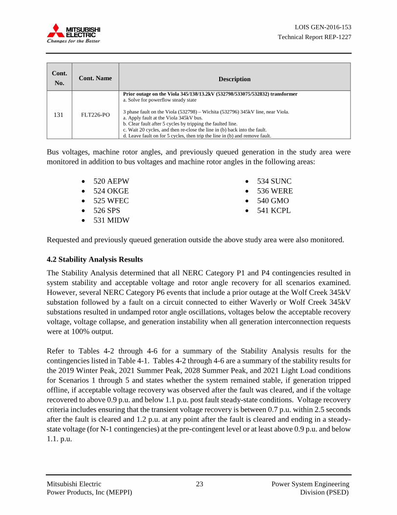
129 FLT224 3 phase fault on the Viola 345/138/13.2kV (532798/533075/532832) transformer, near Viola. a. Apply fault at the Viola 345kV bus. b. Clear fault after 5 cycles by tripping the faulted line.
130 FLT225-PO
Prior outage on the Viola 345/138/13.2kV (532798/533075/532832) transformer a. Solve for powerflow steady state 3 phase fault on the Viola (532798) – Renfrow (515543) 345kV line, near Viola. a. Apply fault at the Viola 345kV bus. b. Clear fault after 5 cycles by tripping the faulted line. c. Wait 20 cycles, and then re-close the line in (b) back into the fault. d. Leave fault on for 5 cycles, then trip the line in (b) and remove fault.
LOIS GEN-2016-153 Technical Report REP-1227
Mitsubishi Electric 23 Power System Engineering Power Products, Inc (MEPPI) Division (PSED)
Cont. No.
Cont. Name Description
131 FLT226-PO
Prior outage on the Viola 345/138/13.2kV (532798/533075/532832) transformer a. Solve for powerflow steady state 3 phase fault on the Viola (532798) – Wichita (532796) 345kV line, near Viola. a. Apply fault at the Viola 345kV bus. b. Clear fault after 5 cycles by tripping the faulted line. c. Wait 20 cycles, and then re-close the line in (b) back into the fault. d. Leave fault on for 5 cycles, then trip the line in (b) and remove fault.
Bus voltages, machine rotor angles, and previously queued generation in the study area were monitored in addition to bus voltages and machine rotor angles in the following areas:
• 520 AEPW • 524 OKGE • 525 WFEC • 526 SPS • 531 MIDW
• 534 SUNC • 536 WERE • 540 GMO • 541 KCPL
Requested and previously queued generation outside the above study area were also monitored. 4.2 Stability Analysis Results
The Stability Analysis determined that all NERC Category P1 and P4 contingencies resulted in system stability and acceptable voltage and rotor angle recovery for all scenarios examined. However, several NERC Category P6 events that include a prior outage at the Wolf Creek 345kV substation followed by a fault on a circuit connected to either Waverly or Wolf Creek 345kV substations resulted in undamped rotor angle oscillations, voltages below the acceptable recovery voltage, voltage collapse, and generation instability when all generation interconnection requests were at 100% output. Refer to Tables 4-2 through 4-6 for a summary of the Stability Analysis results for the contingencies listed in Table 4-1. Tables 4-2 through 4-6 are a summary of the stability results for the 2019 Winter Peak, 2021 Summer Peak, 2028 Summer Peak, and 2021 Light Load conditions for Scenarios 1 through 5 and states whether the system remained stable, if generation tripped offline, if acceptable voltage recovery was observed after the fault was cleared, and if the voltage recovered to above 0.9 p.u. and below 1.1 p.u. post fault steady-state conditions. Voltage recovery criteria includes ensuring that the transient voltage recovery is between 0.7 p.u. within 2.5 seconds after the fault is cleared and 1.2 p.u. at any point after the fault is cleared and ending in a steady-state voltage (for N-1 contingencies) at the pre-contingent level or at least above 0.9 p.u. and below 1.1. p.u.

LOIS GEN-2016-153 Technical Report REP-1227
Mitsubishi Electric 24 Power System Engineering Power Products, Inc (MEPPI) Division (PSED)
Table 4-2: Stability Analysis Summary of Results for 2019 Winter, 2021 Summer, 2028 Summer Peak, and 2021 Light Load Conditions for Scenario 1
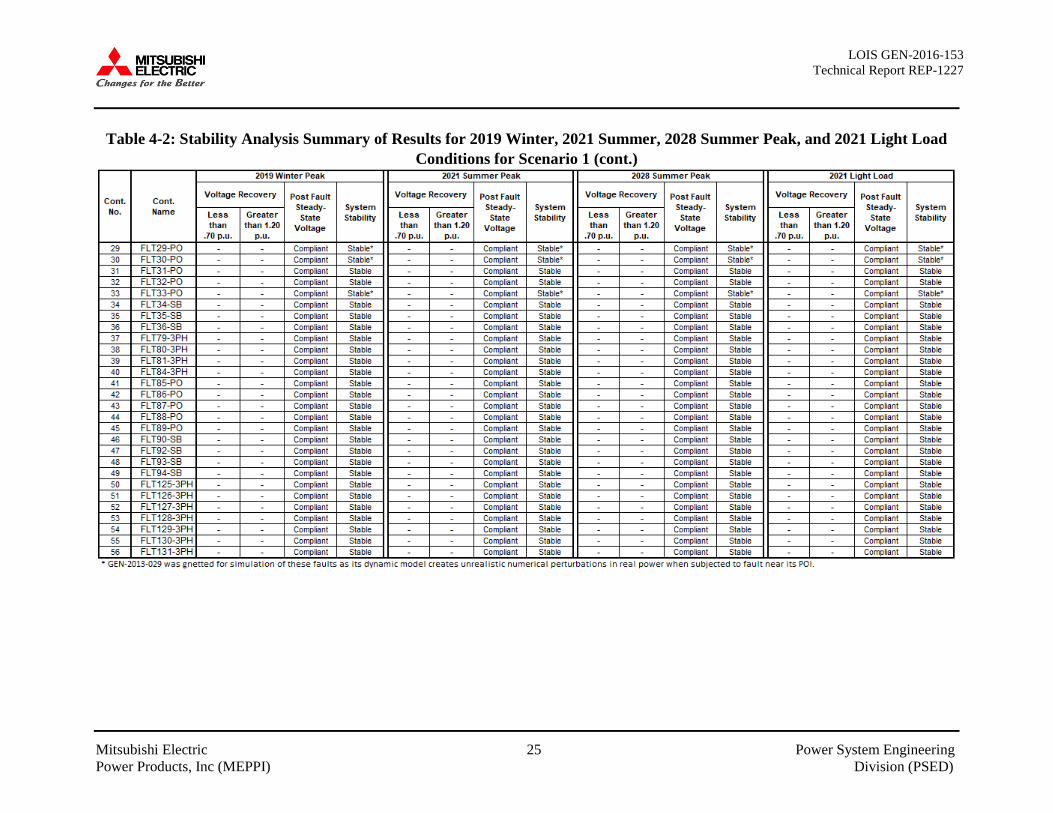
LOIS GEN-2016-153 Technical Report REP-1227
Mitsubishi Electric 25 Power System Engineering Power Products, Inc (MEPPI) Division (PSED)
Table 4-2: Stability Analysis Summary of Results for 2019 Winter, 2021 Summer, 2028 Summer Peak, and 2021 Light Load Conditions for Scenario 1 (cont.)
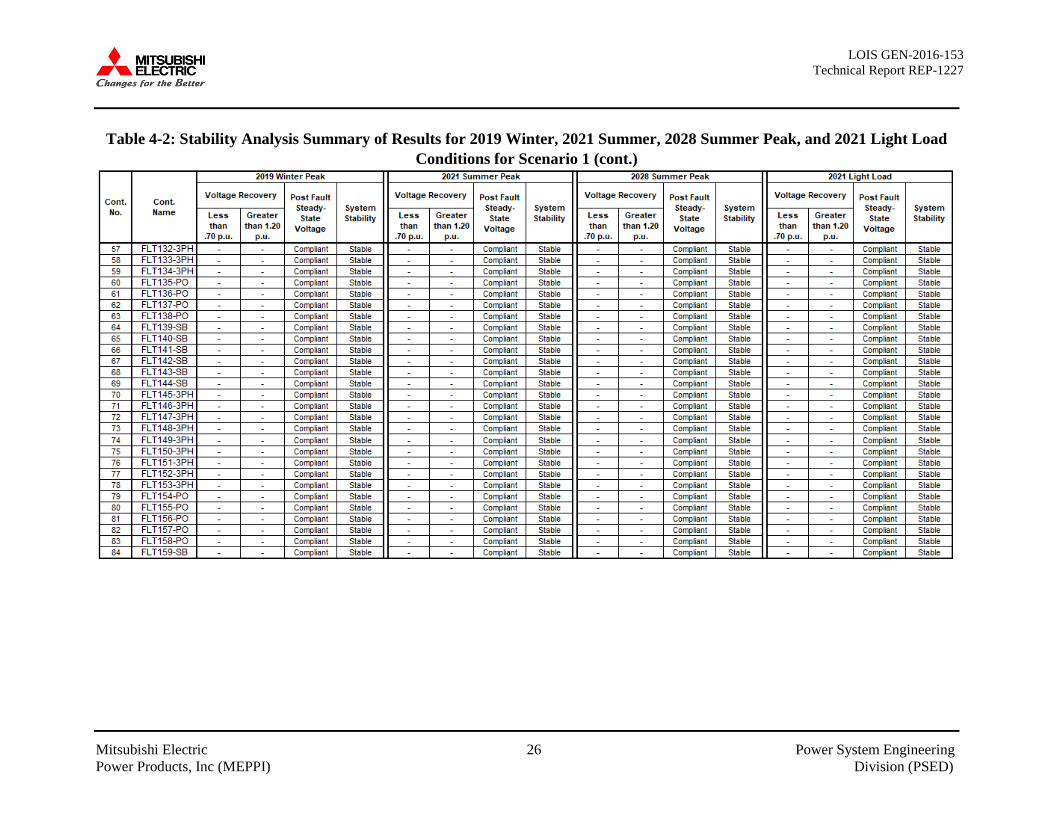
LOIS GEN-2016-153 Technical Report REP-1227
Mitsubishi Electric 26 Power System Engineering Power Products, Inc (MEPPI) Division (PSED)
Table 4-2: Stability Analysis Summary of Results for 2019 Winter, 2021 Summer, 2028 Summer Peak, and 2021 Light Load Conditions for Scenario 1 (cont.)

LOIS GEN-2016-153 Technical Report REP-1227
Mitsubishi Electric 27 Power System Engineering Power Products, Inc (MEPPI) Division (PSED)
Table 4-2: Stability Analysis Summary of Results for 2019 Winter, 2021 Summer, 2028 Summer Peak, and 2021 Light Load Conditions for Scenario 1 (cont.)
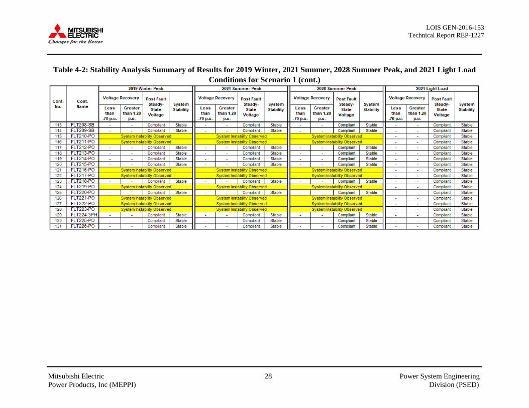
LOIS GEN-2016-153 Technical Report REP-1227
Mitsubishi Electric 28 Power System Engineering Power Products, Inc (MEPPI) Division (PSED)
Table 4-2: Stability Analysis Summary of Results for 2019 Winter, 2021 Summer, 2028 Summer Peak, and 2021 Light Load Conditions for Scenario 1 (cont.)
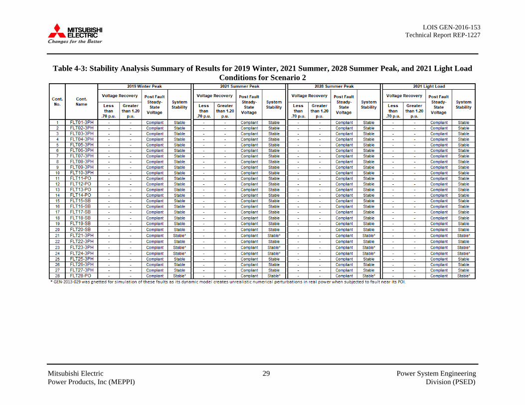
LOIS GEN-2016-153 Technical Report REP-1227
Mitsubishi Electric 29 Power System Engineering Power Products, Inc (MEPPI) Division (PSED)
Table 4-3: Stability Analysis Summary of Results for 2019 Winter, 2021 Summer, 2028 Summer Peak, and 2021 Light Load Conditions for Scenario 2
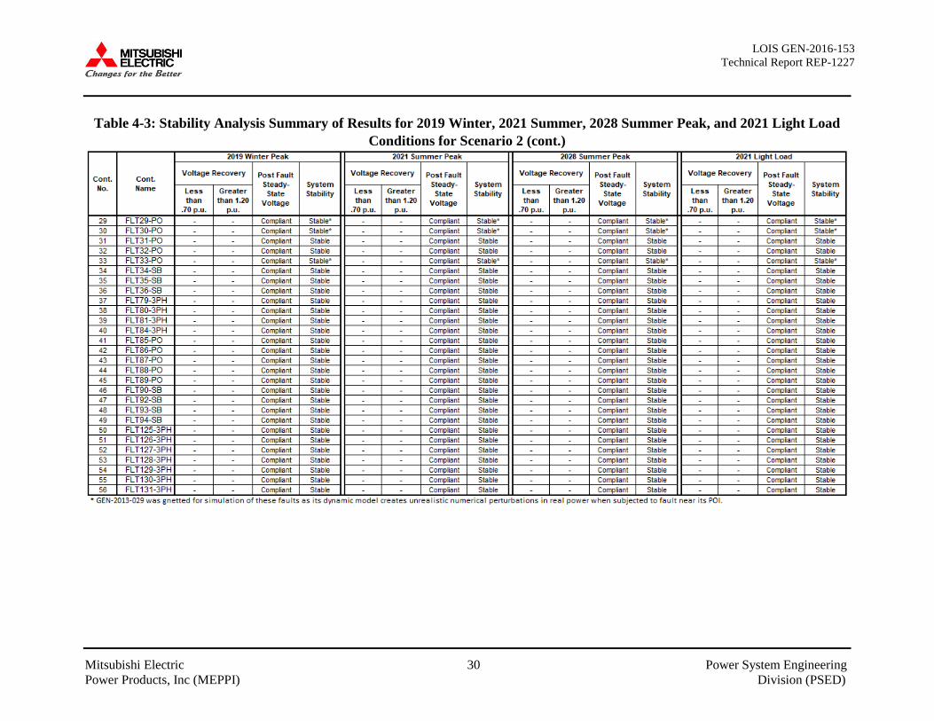
LOIS GEN-2016-153 Technical Report REP-1227
Mitsubishi Electric 30 Power System Engineering Power Products, Inc (MEPPI) Division (PSED)
Table 4-3: Stability Analysis Summary of Results for 2019 Winter, 2021 Summer, 2028 Summer Peak, and 2021 Light Load Conditions for Scenario 2 (cont.)
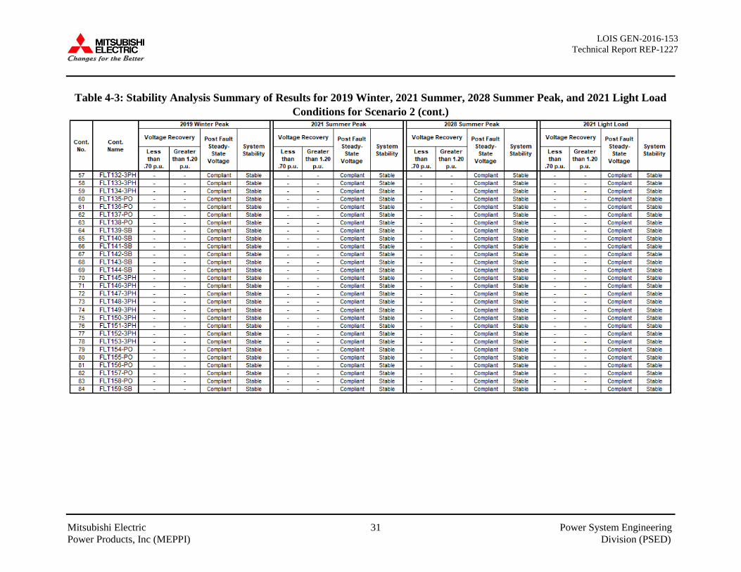
LOIS GEN-2016-153 Technical Report REP-1227
Mitsubishi Electric 31 Power System Engineering Power Products, Inc (MEPPI) Division (PSED)
Table 4-3: Stability Analysis Summary of Results for 2019 Winter, 2021 Summer, 2028 Summer Peak, and 2021 Light Load Conditions for Scenario 2 (cont.)
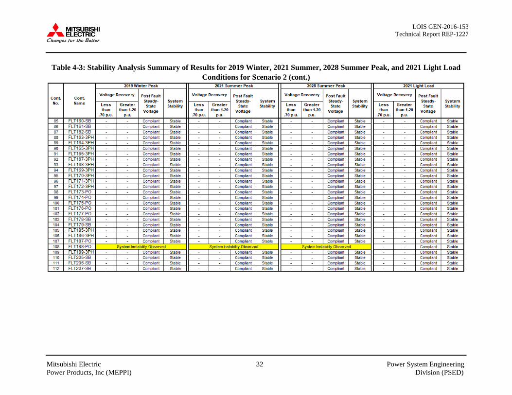
LOIS GEN-2016-153 Technical Report REP-1227
Mitsubishi Electric 32 Power System Engineering Power Products, Inc (MEPPI) Division (PSED)
Table 4-3: Stability Analysis Summary of Results for 2019 Winter, 2021 Summer, 2028 Summer Peak, and 2021 Light Load Conditions for Scenario 2 (cont.)

LOIS GEN-2016-153 Technical Report REP-1227
Mitsubishi Electric 33 Power System Engineering Power Products, Inc (MEPPI) Division (PSED)
Table 4-3: Stability Analysis Summary of Results for 2019 Winter, 2021 Summer, 2028 Summer Peak, and 2021 Light Load Conditions for Scenario 2 (cont.)

LOIS GEN-2016-153 Technical Report REP-1227
Mitsubishi Electric 34 Power System Engineering Power Products, Inc (MEPPI) Division (PSED)
Table 4-4: Stability Analysis Summary of Results for 2019 Winter, 2021 Summer, 2028 Summer Peak, and 2021 Light Load Conditions for Scenario 3
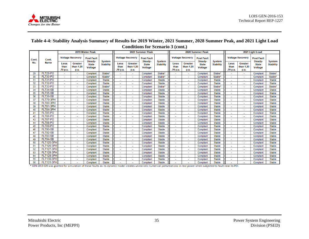
LOIS GEN-2016-153 Technical Report REP-1227
Mitsubishi Electric 35 Power System Engineering Power Products, Inc (MEPPI) Division (PSED)
Table 4-4: Stability Analysis Summary of Results for 2019 Winter, 2021 Summer, 2028 Summer Peak, and 2021 Light Load Conditions for Scenario 3 (cont.)

LOIS GEN-2016-153 Technical Report REP-1227
Mitsubishi Electric 36 Power System Engineering Power Products, Inc (MEPPI) Division (PSED)
Table 4-4: Stability Analysis Summary of Results for 2019 Winter, 2021 Summer, 2028 Summer Peak, and 2021 Light Load Conditions for Scenario 3 (cont.)

LOIS GEN-2016-153 Technical Report REP-1227
Mitsubishi Electric 37 Power System Engineering Power Products, Inc (MEPPI) Division (PSED)
Table 4-4: Stability Analysis Summary of Results for 2019 Winter, 2021 Summer, 2028 Summer Peak, and 2021 Light Load Conditions for Scenario 3 (cont.)

LOIS GEN-2016-153 Technical Report REP-1227
Mitsubishi Electric 38 Power System Engineering Power Products, Inc (MEPPI) Division (PSED)
Table 4-4: Stability Analysis Summary of Results for 2019 Winter, 2021 Summer, 2028 Summer Peak, and 2021 Light Load Conditions for Scenario 3 (cont.)
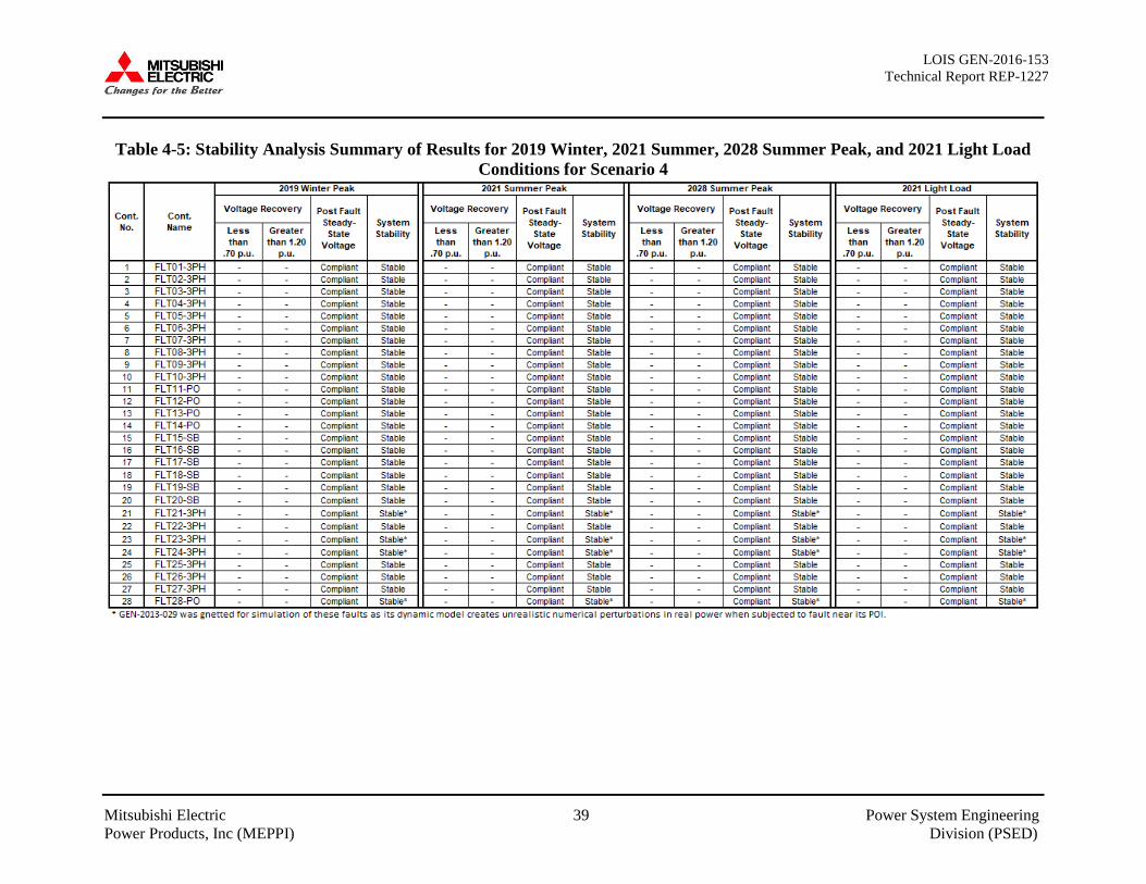
LOIS GEN-2016-153 Technical Report REP-1227
Mitsubishi Electric 39 Power System Engineering Power Products, Inc (MEPPI) Division (PSED)
Table 4-5: Stability Analysis Summary of Results for 2019 Winter, 2021 Summer, 2028 Summer Peak, and 2021 Light Load Conditions for Scenario 4
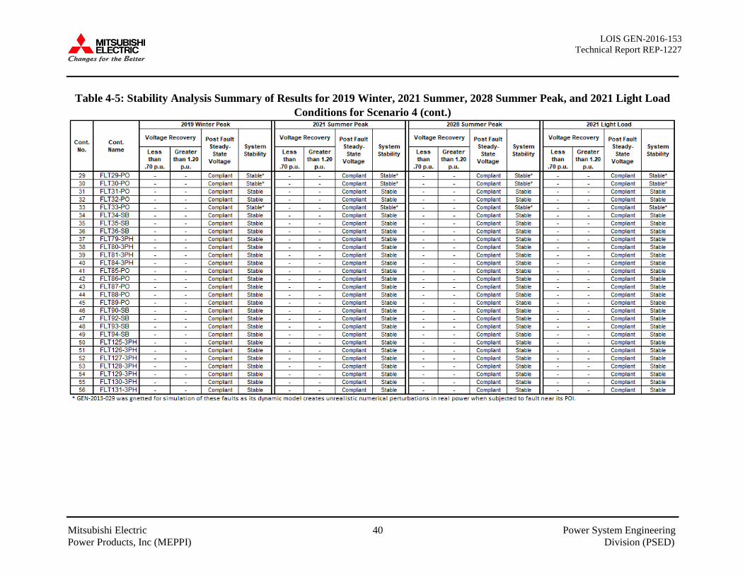
LOIS GEN-2016-153 Technical Report REP-1227
Mitsubishi Electric 40 Power System Engineering Power Products, Inc (MEPPI) Division (PSED)
Table 4-5: Stability Analysis Summary of Results for 2019 Winter, 2021 Summer, 2028 Summer Peak, and 2021 Light Load Conditions for Scenario 4 (cont.)

LOIS GEN-2016-153 Technical Report REP-1227
Mitsubishi Electric 41 Power System Engineering Power Products, Inc (MEPPI) Division (PSED)
Table 4-5: Stability Analysis Summary of Results for 2019 Winter, 2021 Summer, 2028 Summer Peak, and 2021 Light Load Conditions for Scenario 4 (cont.)
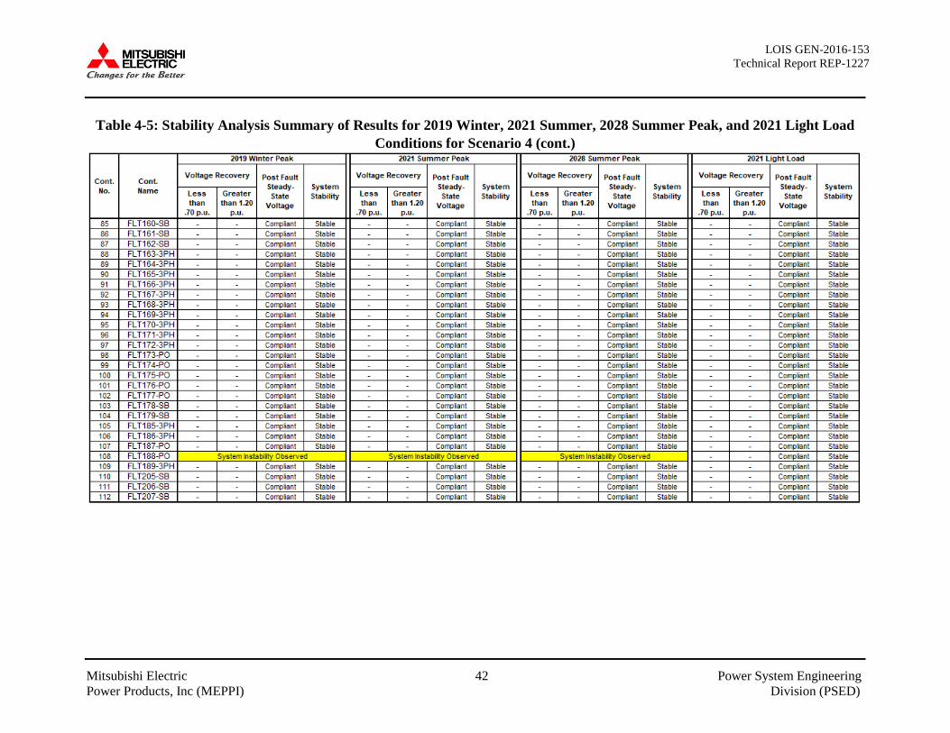
LOIS GEN-2016-153 Technical Report REP-1227
Mitsubishi Electric 42 Power System Engineering Power Products, Inc (MEPPI) Division (PSED)
Table 4-5: Stability Analysis Summary of Results for 2019 Winter, 2021 Summer, 2028 Summer Peak, and 2021 Light Load Conditions for Scenario 4 (cont.)
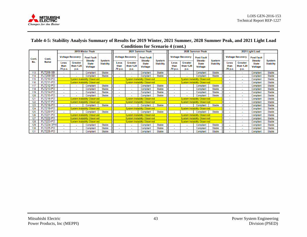
LOIS GEN-2016-153 Technical Report REP-1227
Mitsubishi Electric 43 Power System Engineering Power Products, Inc (MEPPI) Division (PSED)
Table 4-5: Stability Analysis Summary of Results for 2019 Winter, 2021 Summer, 2028 Summer Peak, and 2021 Light Load Conditions for Scenario 4 (cont.)
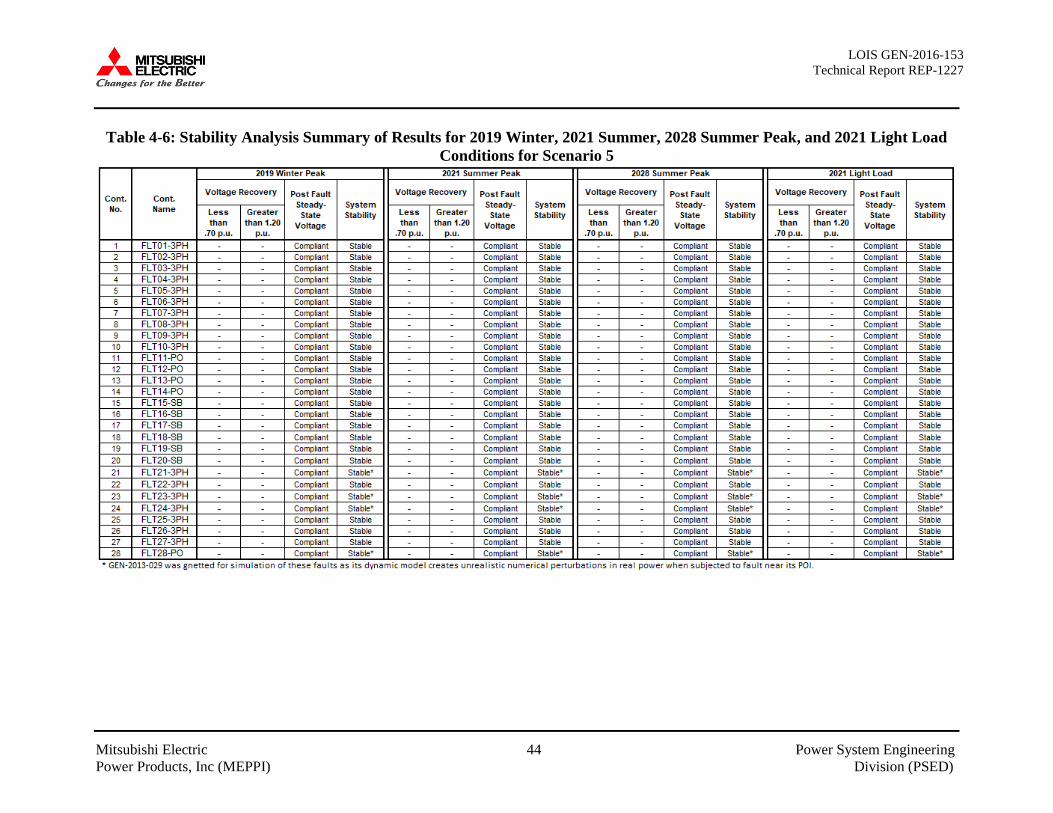
LOIS GEN-2016-153 Technical Report REP-1227
Mitsubishi Electric 44 Power System Engineering Power Products, Inc (MEPPI) Division (PSED)
Table 4-6: Stability Analysis Summary of Results for 2019 Winter, 2021 Summer, 2028 Summer Peak, and 2021 Light Load Conditions for Scenario 5

LOIS GEN-2016-153 Technical Report REP-1227
Mitsubishi Electric 45 Power System Engineering Power Products, Inc (MEPPI) Division (PSED)
Table 4-6: Stability Analysis Summary of Results for 2019 Winter, 2021 Summer, 2028 Summer Peak, and 2021 Light Load Conditions for Scenario 5 (cont.)
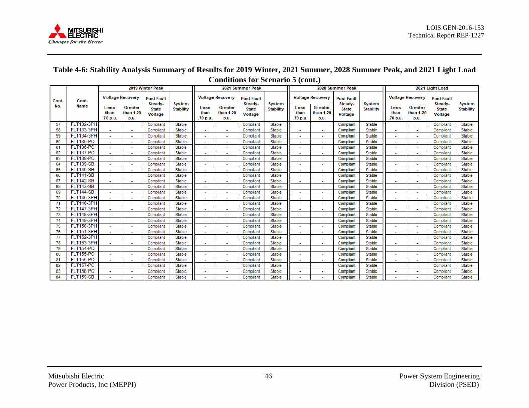
LOIS GEN-2016-153 Technical Report REP-1227
Mitsubishi Electric 46 Power System Engineering Power Products, Inc (MEPPI) Division (PSED)
Table 4-6: Stability Analysis Summary of Results for 2019 Winter, 2021 Summer, 2028 Summer Peak, and 2021 Light Load Conditions for Scenario 5 (cont.)
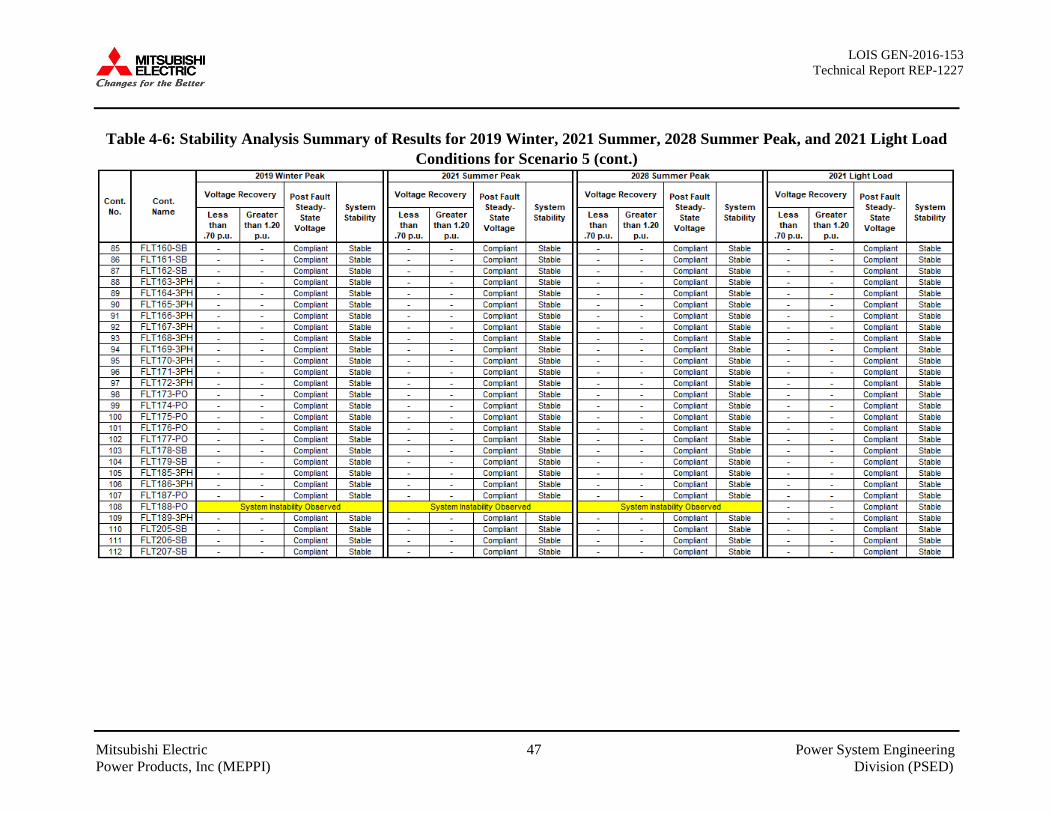
LOIS GEN-2016-153 Technical Report REP-1227
Mitsubishi Electric 47 Power System Engineering Power Products, Inc (MEPPI) Division (PSED)
Table 4-6: Stability Analysis Summary of Results for 2019 Winter, 2021 Summer, 2028 Summer Peak, and 2021 Light Load Conditions for Scenario 5 (cont.)

LOIS GEN-2016-153 Technical Report REP-1227
Mitsubishi Electric 48 Power System Engineering Power Products, Inc (MEPPI) Division (PSED)
Table 4-6: Stability Analysis Summary of Results for 2019 Winter, 2021 Summer, 2028 Summer Peak, and 2021 Light Load Conditions for Scenario 5 (cont.)
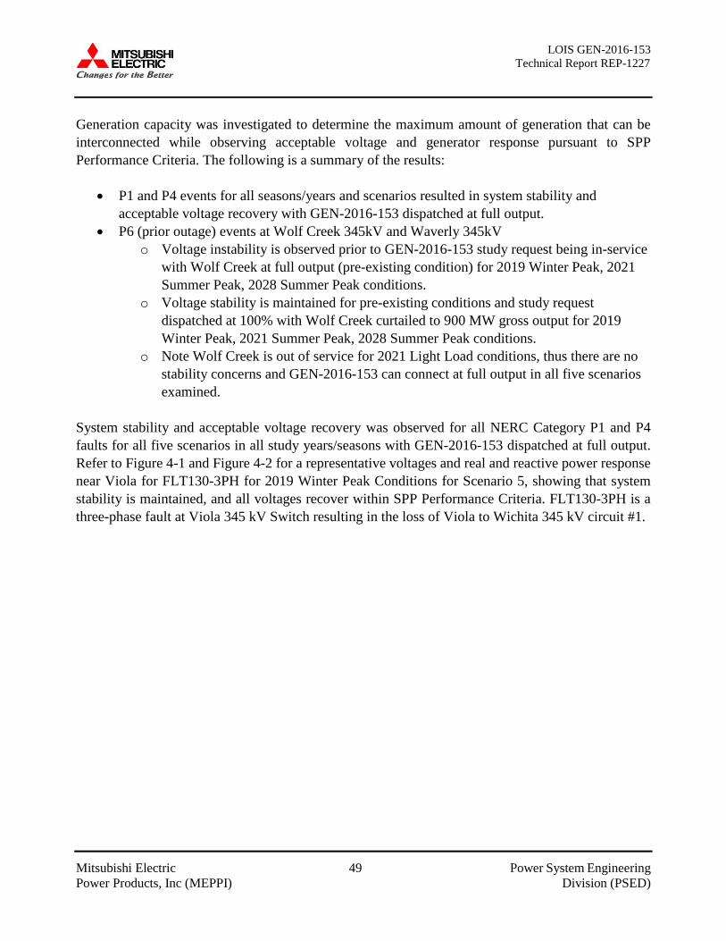
LOIS GEN-2016-153 Technical Report REP-1227
Mitsubishi Electric 49 Power System Engineering Power Products, Inc (MEPPI) Division (PSED)
Generation capacity was investigated to determine the maximum amount of generation that can be interconnected while observing acceptable voltage and generator response pursuant to SPP Performance Criteria. The following is a summary of the results:
• P1 and P4 events for all seasons/years and scenarios resulted in system stability and acceptable voltage recovery with GEN-2016-153 dispatched at full output.
• P6 (prior outage) events at Wolf Creek 345kV and Waverly 345kV o Voltage instability is observed prior to GEN-2016-153 study request being in-service
with Wolf Creek at full output (pre-existing condition) for 2019 Winter Peak, 2021 Summer Peak, 2028 Summer Peak conditions.
o Voltage stability is maintained for pre-existing conditions and study request dispatched at 100% with Wolf Creek curtailed to 900 MW gross output for 2019 Winter Peak, 2021 Summer Peak, 2028 Summer Peak conditions.
o Note Wolf Creek is out of service for 2021 Light Load conditions, thus there are no stability concerns and GEN-2016-153 can connect at full output in all five scenarios examined.
System stability and acceptable voltage recovery was observed for all NERC Category P1 and P4 faults for all five scenarios in all study years/seasons with GEN-2016-153 dispatched at full output. Refer to Figure 4-1 and Figure 4-2 for a representative voltages and real and reactive power response near Viola for FLT130-3PH for 2019 Winter Peak Conditions for Scenario 5, showing that system stability is maintained, and all voltages recover within SPP Performance Criteria. FLT130-3PH is a three-phase fault at Viola 345 kV Switch resulting in the loss of Viola to Wichita 345 kV circuit #1.
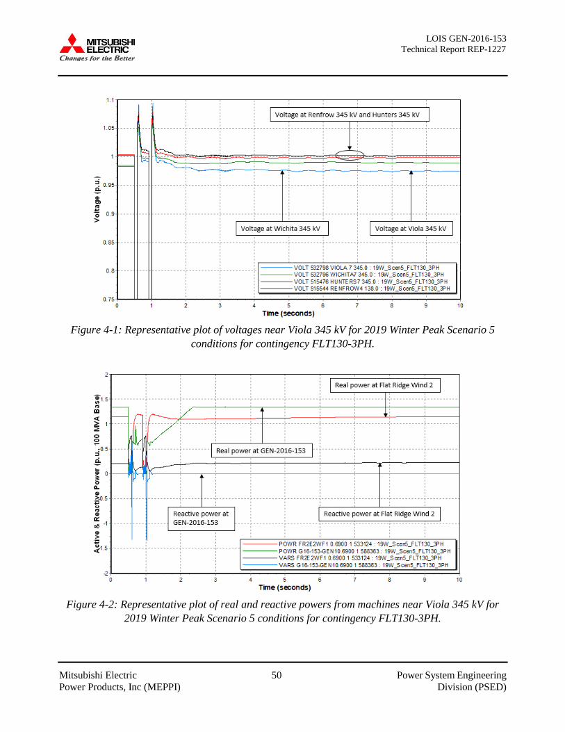
LOIS GEN-2016-153 Technical Report REP-1227
Mitsubishi Electric 50 Power System Engineering Power Products, Inc (MEPPI) Division (PSED)
Figure 4-1: Representative plot of voltages near Viola 345 kV for 2019 Winter Peak Scenario 5
conditions for contingency FLT130-3PH.
Figure 4-2: Representative plot of real and reactive powers from machines near Viola 345 kV for
2019 Winter Peak Scenario 5 conditions for contingency FLT130-3PH.
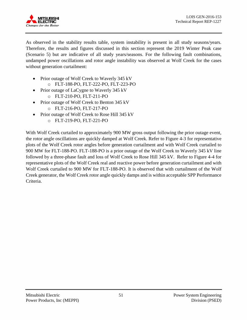
LOIS GEN-2016-153 Technical Report REP-1227
Mitsubishi Electric 51 Power System Engineering Power Products, Inc (MEPPI) Division (PSED)
As observed in the stability results table, system instability is present in all study seasons/years. Therefore, the results and figures discussed in this section represent the 2019 Winter Peak case (Scenario 5) but are indicative of all study years/seasons. For the following fault combinations, undamped power oscillations and rotor angle instability was observed at Wolf Creek for the cases without generation curtailment:
• Prior outage of Wolf Creek to Waverly 345 kV o FLT-188-PO, FLT-222-PO, FLT-223-PO
• Prior outage of LaCygne to Waverly 345 kV o FLT-210-PO, FLT-211-PO
• Prior outage of Wolf Creek to Benton 345 kV o FLT-216-PO, FLT-217-PO
• Prior outage of Wolf Creek to Rose Hill 345 kV o FLT-219-PO, FLT-221-PO
With Wolf Creek curtailed to approximately 900 MW gross output following the prior outage event, the rotor angle oscillations are quickly damped at Wolf Creek. Refer to Figure 4-3 for representative plots of the Wolf Creek rotor angles before generation curtailment and with Wolf Creek curtailed to 900 MW for FLT-188-PO. FLT-188-PO is a prior outage of the Wolf Creek to Waverly 345 kV line followed by a three-phase fault and loss of Wolf Creek to Rose Hill 345 kV. Refer to Figure 4-4 for representative plots of the Wolf Creek real and reactive power before generation curtailment and with Wolf Creek curtailed to 900 MW for FLT-188-PO. It is observed that with curtailment of the Wolf Creek generator, the Wolf Creek rotor angle quickly damps and is within acceptable SPP Performance Criteria.
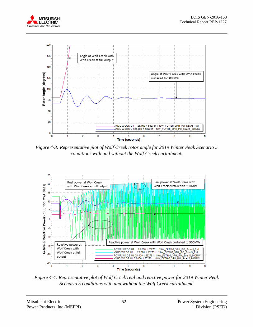
LOIS GEN-2016-153 Technical Report REP-1227
Mitsubishi Electric 52 Power System Engineering Power Products, Inc (MEPPI) Division (PSED)
Figure 4-3: Representative plot of Wolf Creek rotor angle for 2019 Winter Peak Scenario 5
conditions with and without the Wolf Creek curtailment.
Figure 4-4: Representative plot of Wolf Creek real and reactive power for 2019 Winter Peak
Scenario 5 conditions with and without the Wolf Creek curtailment.
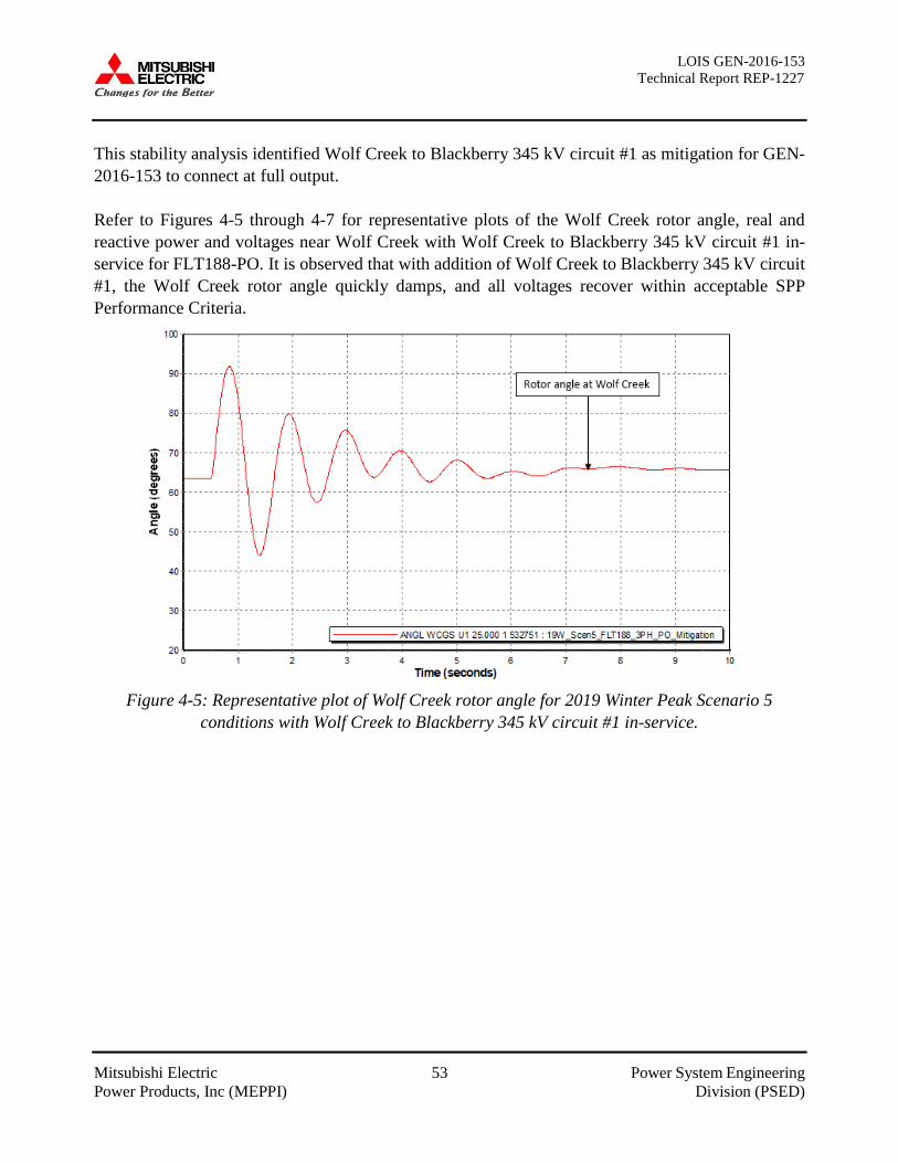
LOIS GEN-2016-153 Technical Report REP-1227
Mitsubishi Electric 53 Power System Engineering Power Products, Inc (MEPPI) Division (PSED)
This stability analysis identified Wolf Creek to Blackberry 345 kV circuit #1 as mitigation for GEN-2016-153 to connect at full output. Refer to Figures 4-5 through 4-7 for representative plots of the Wolf Creek rotor angle, real and reactive power and voltages near Wolf Creek with Wolf Creek to Blackberry 345 kV circuit #1 in-service for FLT188-PO. It is observed that with addition of Wolf Creek to Blackberry 345 kV circuit #1, the Wolf Creek rotor angle quickly damps, and all voltages recover within acceptable SPP Performance Criteria.
Figure 4-5: Representative plot of Wolf Creek rotor angle for 2019 Winter Peak Scenario 5
conditions with Wolf Creek to Blackberry 345 kV circuit #1 in-service.
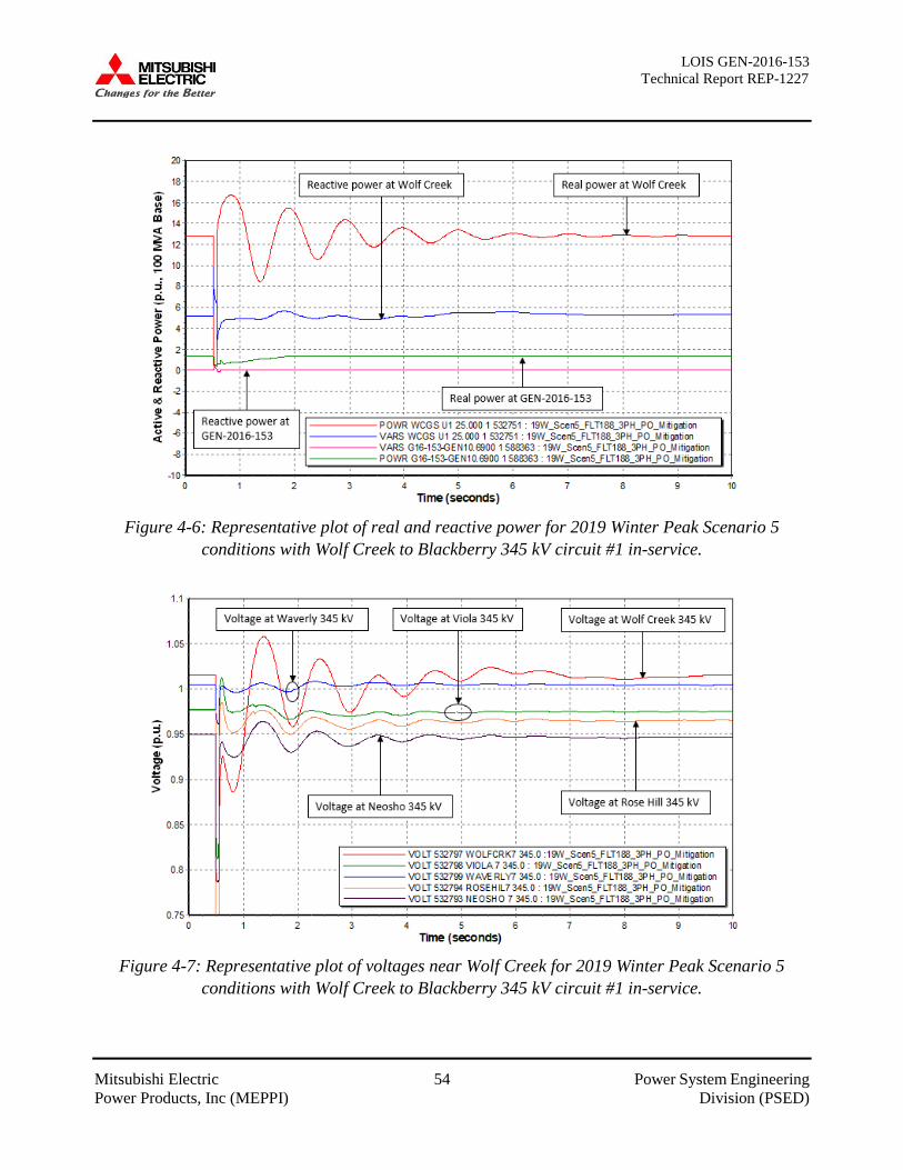
LOIS GEN-2016-153 Technical Report REP-1227
Mitsubishi Electric 54 Power System Engineering Power Products, Inc (MEPPI) Division (PSED)
Figure 4-6: Representative plot of real and reactive power for 2019 Winter Peak Scenario 5
conditions with Wolf Creek to Blackberry 345 kV circuit #1 in-service.
Figure 4-7: Representative plot of voltages near Wolf Creek for 2019 Winter Peak Scenario 5
conditions with Wolf Creek to Blackberry 345 kV circuit #1 in-service.

LOIS GEN-2016-153 Technical Report REP-1227
Mitsubishi Electric 55 Power System Engineering Power Products, Inc (MEPPI) Division (PSED)
4.3 Reactive Compensation Analysis Results
A reactive compensation analysis was performed on the 2028 Summer Peak case for all scenarios to determine the amount of charging current added by the interconnection facilities of GEN-2016-153 and the amount of shunt reactive compensation, located at the low-voltage side of the collector substation bus(es) that will be required to offset the charging current of the request’s interconnection facilities. The reactor size is generally equal to the sum of the B values of the collector system and generator lead line to the POI. Additional locations and appropriate bifurcation may be required for atypical facility designs. Table 4-7 lists the reactor size identified during this analysis.
Table 4-7: Reactor Size Identified for 2028 Summer Peak Conditions
SECTION 5: SHORT-CIRCUIT ANALYSIS The Short-Circuit Analysis was performed on the 2028 Summer Peak case to determine the increase in the maximum fault current from requests that the protective equipment on the SPP transmission system may need to be rated to interrupt. Each Transmission Owner will need to further evaluate, within the Facilities Study, whether their existing or planned facilities are adequately rated or will require replacement. This analysis assessed breaker adequacy and fault duties at GEN-2016-153’s POI and for each bus up-to and including five buses away from POI. No outages were assumed to find maximum short-circuit current that flows through the breaker. This analysis was conducted by using PSS\E’s Automatic Sequence Fault Calculation (ASCC) function. Table 5-1 summarize results of this short circuit analysis.
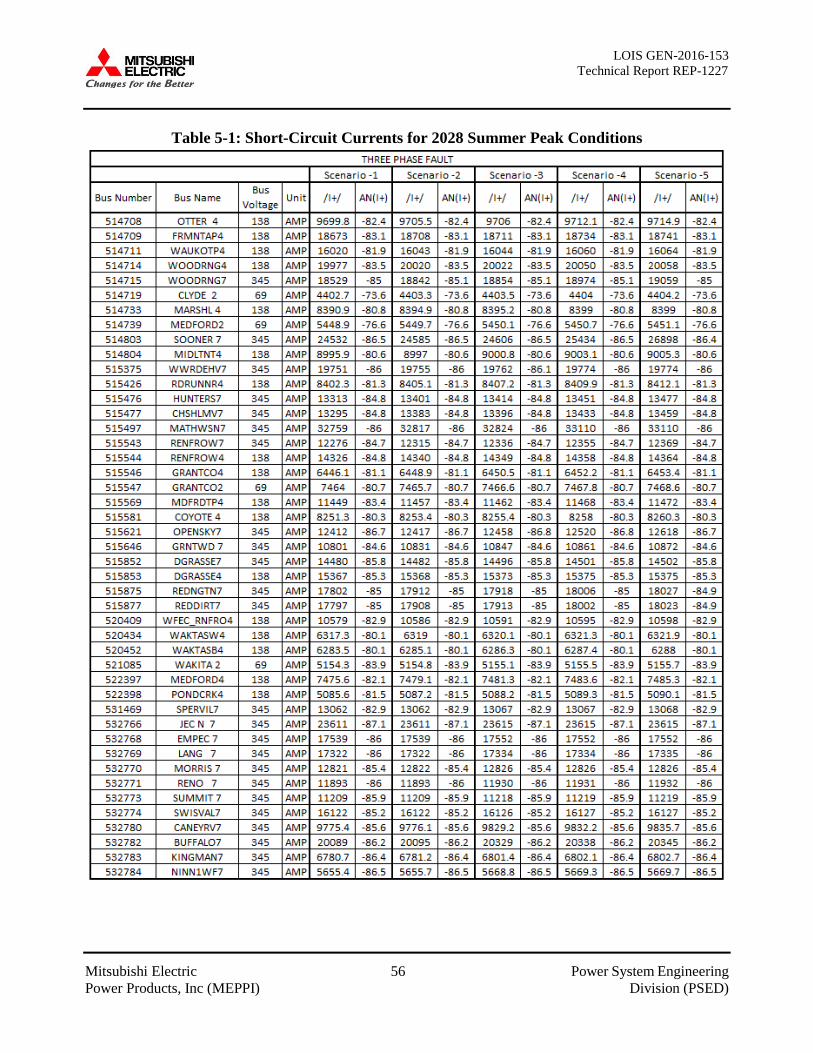
LOIS GEN-2016-153 Technical Report REP-1227
Mitsubishi Electric 56 Power System Engineering Power Products, Inc (MEPPI) Division (PSED)
Table 5-1: Short-Circuit Currents for 2028 Summer Peak Conditions
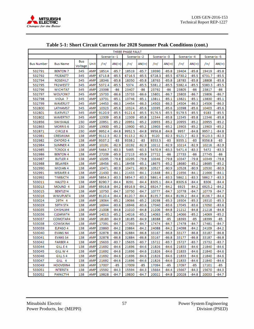
LOIS GEN-2016-153 Technical Report REP-1227
Mitsubishi Electric 57 Power System Engineering Power Products, Inc (MEPPI) Division (PSED)
Table 5-1: Short Circuit Currents for 2028 Summer Peak Conditions (cont.)
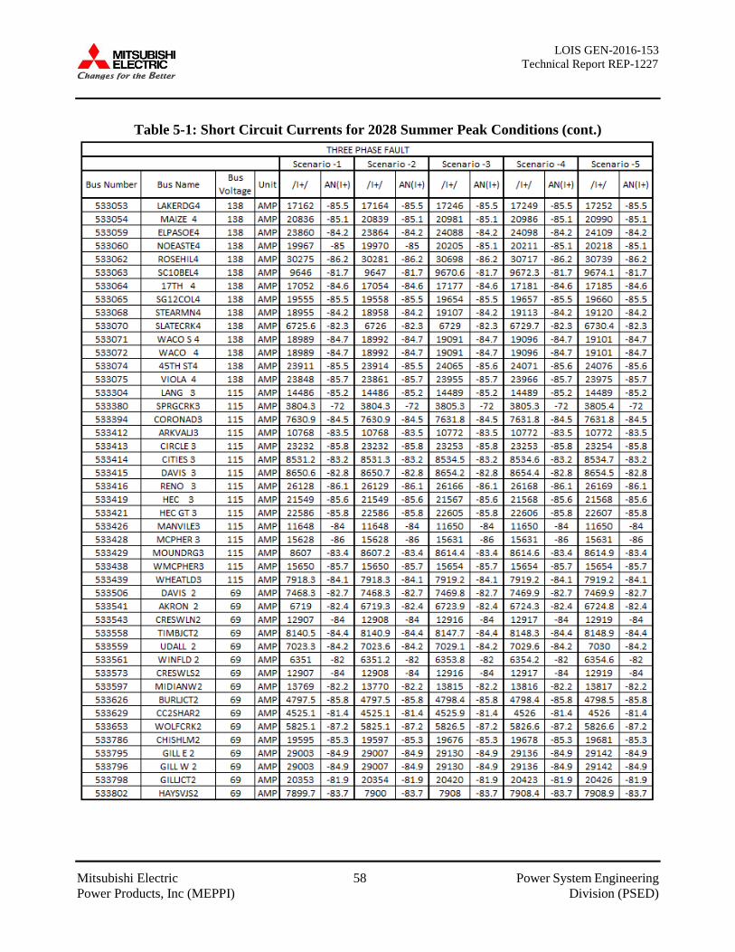
LOIS GEN-2016-153 Technical Report REP-1227
Mitsubishi Electric 58 Power System Engineering Power Products, Inc (MEPPI) Division (PSED)
Table 5-1: Short Circuit Currents for 2028 Summer Peak Conditions (cont.)

LOIS GEN-2016-153 Technical Report REP-1227
Mitsubishi Electric 59 Power System Engineering Power Products, Inc (MEPPI) Division (PSED)
Table 5-1: Short Circuit Currents for 2028 Summer Peak Conditions (cont.)
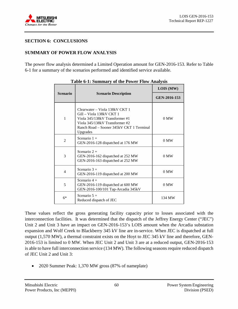
LOIS GEN-2016-153 Technical Report REP-1227
Mitsubishi Electric 60 Power System Engineering Power Products, Inc (MEPPI) Division (PSED)
SECTION 6: CONCLUSIONS SUMMARY OF POWER FLOW ANALYSIS The power flow analysis determined a Limited Operation amount for GEN-2016-153. Refer to Table 6-1 for a summary of the scenarios performed and identified service available.
Table 6-1: Summary of the Power Flow Analysis
Scenario Scenario Description LOIS (MW)
GEN-2016-153
1
Clearwater – Viola 138kV CKT 1 Gill – Viola 138kV CKT 1 Viola 345/138kV Transformer #1 Viola 345/138kV Transformer #2 Ranch Road – Sooner 345kV CKT 1 Terminal Upgrades
0 MW
2 Scenario 1 + GEN-2016-128 dispatched at 176 MW 0 MW
3 Scenario 2 + GEN-2016-162 dispatched at 252 MW GEN-2016-163 dispatched at 252 MW
0 MW
4 Scenario 3 + GEN-2016-119 dispatched at 200 MW 0 MW
5 Scenario 4 + GEN-2016-119 dispatched at 600 MW GEN-2016-100/101 Tap-Arcadia 345kV
0 MW
6* Scenario 5 + Reduced dispatch of JEC 134 MW
These values reflect the gross generating facility capacity prior to losses associated with the interconnection facilities. It was determined that the dispatch of the Jeffrey Energy Center (“JEC”) Unit 2 and Unit 3 have an impact on GEN-2016-153’s LOIS amount when the Arcadia substation expansion and Wolf Creek to Blackberry 345 kV line are in-service. When JEC is dispatched at full output (1,570 MW), a thermal constraint exists on the Hoyt to JEC 345 kV line and therefore, GEN-2016-153 is limited to 0 MW. When JEC Unit 2 and Unit 3 are at a reduced output, GEN-2016-153 is able to have full interconnection service (134 MW). The following seasons require reduced dispatch of JEC Unit 2 and Unit 3:
• 2020 Summer Peak: 1,370 MW gross (87% of nameplate)

LOIS GEN-2016-153 Technical Report REP-1227
Mitsubishi Electric 61 Power System Engineering Power Products, Inc (MEPPI) Division (PSED)
• 2024 Summer Peak: 1,419 MW gross (90% of nameplate) • 2029 Summer Peak: 1,554 MW gross (99% of nameplate)
SUMMARY OF STABILITY ANALYSIS The Stability Analysis determined that with the Wolf Creek NERC MOD-026 and MOD-027 model validation updates several P6 events that include a fault on a circuit connected to either Waverly or Wolf Creek 345kV substations resulted in undamped rotor angle oscillations, voltages below the acceptable recovery voltage, voltage collapse, and generation instability when GEN-2016-153 was connected at 100% output. It is worth noting that this instability is a pre-existing system condition and cannot be directly attributed to interconnection of GEN-2016-153 to its POI. This analysis identified the potential requirement of generation curtailment at Wolf Creek for certain prior outage conditions including:
• Wolf Creek to Blackberry 345kV circuit #1 • Wolf Creek to Waverly 345kV circuit #1 • Wolf Creek to Benton 345 kV circuit #1 • Wolf Creek to Rose Hill 345 kV circuit #1 • Waverly to LaCygne 345kV circuit #1
The Transmission Owner is advised to update the existing Wolf Creek Operating Guide accordingly. Also, it is observed that connecting Wolf Creek to Blackberry 345 kV circuit #1 mitigates this instability and allows for GEN-2016-153 to connect at full output. With addition of Wolf Creek to Blackberry 345 kV circuit #1, the Wolf Creek rotor angle quickly damps, and all voltages recover within acceptable SPP Performance Criteria. It should be noted that while this Limited Operation study analyzed many of the most probable contingencies, it is not an all-inclusive list that can account for every operation situation. Additionally, the study requests may not be able to inject any power onto the Transmission System due to constraints that fall below the threshold of mitigation for a Generator Interconnection request. Because of this, it is likely that the Customers may be required to reduce their generation output to 0 MW under certain system conditions to allow system operators to maintain the reliability of the transmission network.
LOIS GEN-2016-153 Technical Report REP-1227
Mitsubishi Electric A-1 Power System Engineering Power Products, Inc (MEPPI) Division (PSED)
APPENDIX A: STEADY-STATE AND DYNAMIC MODEL DATA
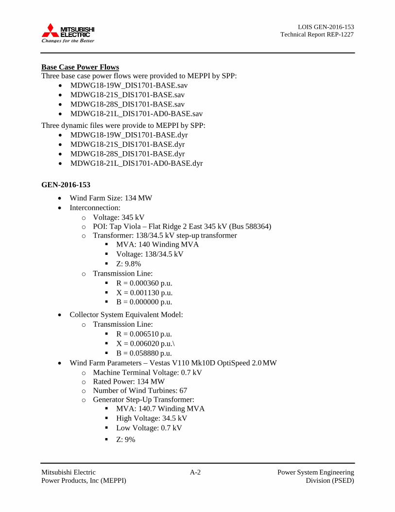
LOIS GEN-2016-153 Technical Report REP-1227
Mitsubishi Electric A-2 Power System Engineering Power Products, Inc (MEPPI) Division (PSED)
Base Case Power Flows Three base case power flows were provided to MEPPI by SPP:
• MDWG18-19W_DIS1701-BASE.sav • MDWG18-21S_DIS1701-BASE.sav • MDWG18-28S_DIS1701-BASE.sav • MDWG18-21L_DIS1701-AD0-BASE.sav
Three dynamic files were provide to MEPPI by SPP: • MDWG18-19W_DIS1701-BASE.dyr • MDWG18-21S_DIS1701-BASE.dyr • MDWG18-28S_DIS1701-BASE.dyr • MDWG18-21L_DIS1701-AD0-BASE.dyr
GEN-2016-153
• Wind Farm Size: 134 MW • Interconnection:
o Voltage: 345 kV o POI: Tap Viola – Flat Ridge 2 East 345 kV (Bus 588364) o Transformer: 138/34.5 kV step-up transformer
MVA: 140 Winding MVA Voltage: 138/34.5 kV Z: 9.8%
o Transmission Line: R = 0.000360 p.u. X = 0.001130 p.u. B = 0.000000 p.u.
• Collector System Equivalent Model: o Transmission Line:
R = 0.006510 p.u. X = 0.006020 p.u.\ B = 0.058880 p.u.
• Wind Farm Parameters – Vestas V110 Mk10D OptiSpeed 2.0 MW o Machine Terminal Voltage: 0.7 kV o Rated Power: 134 MW o Number of Wind Turbines: 67 o Generator Step-Up Transformer:
MVA: 140.7 Winding MVA High Voltage: 34.5 kV Low Voltage: 0.7 kV Z: 9%
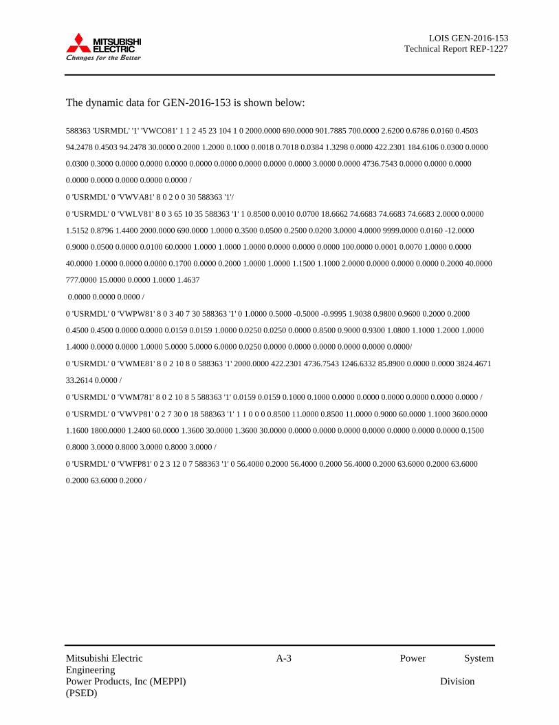
LOIS GEN-2016-153 Technical Report REP-1227
Mitsubishi Electric A-3 Power System Engineering Power Products, Inc (MEPPI) Division (PSED)
The dynamic data for GEN-2016-153 is shown below:
588363 'USRMDL' '1' 'VWCO81' 1 1 2 45 23 104 1 0 2000.0000 690.0000 901.7885 700.0000 2.6200 0.6786 0.0160 0.4503
94.2478 0.4503 94.2478 30.0000 0.2000 1.2000 0.1000 0.0018 0.7018 0.0384 1.3298 0.0000 422.2301 184.6106 0.0300 0.0000
0.0300 0.3000 0.0000 0.0000 0.0000 0.0000 0.0000 0.0000 0.0000 0.0000 3.0000 0.0000 4736.7543 0.0000 0.0000 0.0000
0.0000 0.0000 0.0000 0.0000 0.0000 /
0 'USRMDL' 0 'VWVA81' 8 0 2 0 0 30 588363 '1'/
0 'USRMDL' 0 'VWLV81' 8 0 3 65 10 35 588363 '1' 1 0.8500 0.0010 0.0700 18.6662 74.6683 74.6683 74.6683 2.0000 0.0000
1.5152 0.8796 1.4400 2000.0000 690.0000 1.0000 0.3500 0.0500 0.2500 0.0200 3.0000 4.0000 9999.0000 0.0160 -12.0000
0.9000 0.0500 0.0000 0.0100 60.0000 1.0000 1.0000 1.0000 0.0000 0.0000 0.0000 100.0000 0.0001 0.0070 1.0000 0.0000
40.0000 1.0000 0.0000 0.0000 0.1700 0.0000 0.2000 1.0000 1.0000 1.1500 1.1000 2.0000 0.0000 0.0000 0.0000 0.2000 40.0000
777.0000 15.0000 0.0000 1.0000 1.4637
0.0000 0.0000 0.0000 /
0 'USRMDL' 0 'VWPW81' 8 0 3 40 7 30 588363 '1' 0 1.0000 0.5000 -0.5000 -0.9995 1.9038 0.9800 0.9600 0.2000 0.2000
0.4500 0.4500 0.0000 0.0000 0.0159 0.0159 1.0000 0.0250 0.0250 0.0000 0.8500 0.9000 0.9300 1.0800 1.1000 1.2000 1.0000
1.4000 0.0000 0.0000 1.0000 5.0000 5.0000 6.0000 0.0250 0.0000 0.0000 0.0000 0.0000 0.0000 0.0000/
0 'USRMDL' 0 'VWME81' 8 0 2 10 8 0 588363 '1' 2000.0000 422.2301 4736.7543 1246.6332 85.8900 0.0000 0.0000 3824.4671
33.2614 0.0000 /
0 'USRMDL' 0 'VWM781' 8 0 2 10 8 5 588363 '1' 0.0159 0.0159 0.1000 0.1000 0.0000 0.0000 0.0000 0.0000 0.0000 0.0000 /
0 'USRMDL' 0 'VWVP81' 0 2 7 30 0 18 588363 '1' 1 1 0 0 0 0.8500 11.0000 0.8500 11.0000 0.9000 60.0000 1.1000 3600.0000
1.1600 1800.0000 1.2400 60.0000 1.3600 30.0000 1.3600 30.0000 0.0000 0.0000 0.0000 0.0000 0.0000 0.0000 0.0000 0.1500
0.8000 3.0000 0.8000 3.0000 0.8000 3.0000 /
0 'USRMDL' 0 'VWFP81' 0 2 3 12 0 7 588363 '1' 0 56.4000 0.2000 56.4000 0.2000 56.4000 0.2000 63.6000 0.2000 63.6000
0.2000 63.6000 0.2000 /

LOIS GEN-2016-153 Technical Report REP-1227
Mitsubishi Electric B-1 Power System Engineering Power Products, Inc (MEPPI) Division (PSED)
APPENDIX B: PLOTS FOR 2019 WINTER PEAK CONDITIONS
*Plots available upon request*

LOIS GEN-2016-153 Technical Report REP-1227
Mitsubishi Electric C-1 Power System Engineering Power Products, Inc (MEPPI) Division (PSED)
APPENDIX C: PLOTS FOR 2021 SUMMER PEAK CONDITIONS
*Plots available upon request*

LOIS GEN-2016-153 Technical Report REP-1227
Mitsubishi Electric D-1 Power System Engineering Power Products, Inc (MEPPI) Division (PSED)
APPENDIX D: PLOTS FOR 2028 SUMMER PEAK CONDITIONS
*Plots available upon request*

LOIS GEN-2016-153 Technical Report REP-1227
Mitsubishi Electric E-1 Power System Engineering Power Products, Inc (MEPPI) Division (PSED)
APPENDIX E: PLOTS FOR 2021 LIGHT LOAD CONDITIONS
*Plots available upon request*