sol–gel synthesis of 3-(triethoxysilyl)propylsuccinicanhydride containing fluorinated silane for...
TRANSCRIPT
ORIGINAL PAPER
Sol–gel synthesis of 3-(triethoxysilyl)propylsuccinicanhydridecontaining fluorinated silane for hydrophobic surface applications
Nadir Kiraz • Esin Burunkaya • Omer Kesmez •
Meltem Asilturk • H. Erdem Camurlu •
Ertugrul Arpac
Received: 9 April 2010 / Accepted: 13 July 2010 / Published online: 21 July 2010
� Springer Science+Business Media, LLC 2010
Abstract In this paper, novel fluorinated silane compound
was prepared by adding hydroxyl terminated Fluoro-
link D10H oligomer to 3-(triethoxysilyl)propylsuccinican-
hydride. The obtained silane system was independently
composed with 3-Aminopropyltrimethoxysilane, 3-Glyci-
dyloxypropyltrimethoxysilane and 3-Glycidyloxypropyl-
triethoxysilane and, then the prepared coating solutions
were applied to glass surface by spin-coating method. The
chemical bonding between groups in system was investi-
gated by Fourier Transform Infrared Spectroscopy analyses.
The elemental composition of coatings was determined
using Energy Dispersive X-ray Spectroscopy analyses. Its
structure and surface properties were analyzed by scanning
electron microscopy, atomic force microscopy, contact
angle measurement and Ultraviolet–visible Absorption
Spectroscopy. The amounts of fluorine on the coatings
prepared with GF20-D10H-AMMO, GF20-D10H-GLYEO
and GF20-D10H-GLYMO are 31, 32 and 34% at, respec-
tively. Transparent coatings with smooth surface and
uniform thickness were observed. The coatings had nano-
scale roughness. The contact angles of coatings for water
ranged from 88 to 107o, and that of n-hexadecane ranged
from 53 to 60o.
Keywords Fluorinated silane � Sol–gel �Hydrophobicity � Oleophobicity � Transparent coatings
1 Introduction
In recent years, various functional coatings have been
developed instead of bulk materials. Utilizing these func-
tional coatings, various additional functions, such as:
hydrophobic, hydrophilic, antibacterial or photocatalytic,
etc., can be gained to the substrate material. Silanes are the
most common compounds used in functional surface
coatings. They form a siloxane network by hydrolysis of
the alkoxysilanes tightly bound to the material surface in
which silane coupling agents react with surface hydroxyl
[1]. If an organic group with a certain function is intro-
duced in silane coupling agent molecules, the function of
the group can be fixed on the material surface. For exam-
ple, when a fluoroalkyl group is introduced, the surface
becomes water and oil repellent [2–11, 15–19]. Fluorinated
compounds are those unique compounds which possess
many excellent properties including high lubricativity,
noncombustibility, and chemical inactivity, in addition to
water repellency and oil repellency. Consequently, fluori-
nated compounds have been used as highly functional and
performable materials because of its superb characteristics.
When fluorinated compounds are applied to any surface,
fluoromethyl (-CF3) groups are uniformly arranged on
surface and the surface energy is effectively reduced to as
low as 8 mJ/m2 [12, 13]. Only a very small quantity of
N. Kiraz � E. Burunkaya � O. Kesmez � E. Arpac
Department of Chemistry, Akdeniz University, 07102 Antalya,
Turkey
M. Asilturk (&)
Prof.Dr.Hikmet Sayılkan Research and Development Laboratory
for Advanced Materials, _Inonu University, 44280 Malatya,
Turkey
e-mail: [email protected]
H. Erdem Camurlu
Department of Mechanical Engineering, Akdeniz University,
07058 Antalya, Turkey
N. Kiraz � E. Burunkaya � O. Kesmez � E. Arpac
NANOen R&D Ltd, Antalya Technopolis, Akdeniz University
Campus, 07102 Antalya, Turkey
123
J Sol-Gel Sci Technol (2010) 56:157–166
DOI 10.1007/s10971-010-2289-3
fluorinated compound is need to obtain hydrophobic sur-
face. The fluorinated compounds have the tendency to
migrate towards the air/film interface and minimize the
interfacial energy [14]. Because, the driving force for
surface segregation of the fluorine is the difference
between surface energies of the groups with fluorine and
the groups without fluorine.
Fluoroalkylsilanes (FAS), such as: heptadecafluorodecyl-
triclorosilane, perfluoro-octyltriclorosilane, heptadecafluoro-
decyltrimethoxysilane, perfluorododecyltrimethoxysilane.
are the most important fluorinated compounds used in
hydrophobic surface researches [7–11]. The surfaces applied
to fluoroalkylsilane have some advantages, such as: flexibil-
ity, heat resistant, stability due to the unique molecular
structure of silicone and fluorine groups in structure. How-
ever, the using of fluoroalkylsilanes is limited in industrial
applications due to high cost. Fluorinated silanes are alter-
native compounds to fluoroalkylsilanes and they are widely
used for hydrophobic surface applications [15–19]. In this
study, we synthesized fluorinated silane compound and
demonstrated that the glass surfaces can be coated with this
compound. We found that contact angles of water and hexane
on the coated surfaces were higher than those on the uncoated
surface.
The aim of this study was to prepare novel fluorinated
silane system that had good properties, such as: lower
prices, stronger water and oil repellency. For this purpose,
we used 3-(triethoxysilyl)propylsuccinicanhydride as link-
ing silane compound and hydroxyl terminated Fluorolink
D10H oligomer as fluorine source. Fluorolink D10H is a
commercial oligomer which has OH functional group and
contains CF3 and CF2 groups. Weight of fluorine in Flu-
orolink D10H is 61%. We investigated applicability of new
fluorinated silane compound with three different silane
compounds for hydrophobic surface applications.
2 Experimental section
2.1 Chemicals
3-(triethoxysilyl)propylsuccinicanhydride (commercial
name: GF20, 94%, ABCR) as linking silane compound,
hydroxyl terminated oligomer (commercial name: Fluoro-
link D10H, Solvay Solexis) as fluorine source, and Alu-
minium chloride (AlCl3, % 99.9, Aldrich) as catalyst were
used to prepare fluorinated silane compounds. 3-Glycidy-
loxypropyltrimethoxy-silane (GLYMO, Degussa), 3-Gly-
cidyloxypropyltri-ethoxysilane (GLYEO, Degussa) and
3-Aminopropyltrimethoxysilane (AMMO, % 97, Aldrich),
2-isopropoxyethanol (IPE, 99%, Aldrich), 2-butoxyethanol
(BG, 99%, Alfa Aesar), 0.1 M nitric acid (HNO3, 65%,
Merck) and deionized water were used to prepare the coating
solutions. The contact angles of films were measured against
water and n-hexadecane (Merck).
2.2 Fluorination of 3-(triethoxysilyl)propyl-
succinicanhydride
Fluorinated silane compound was prepared as in the fol-
lowing steps: 4.534 g GF20 and 9.905 g Fluorolink D10H
were stirred at room temperature. The mol ratio between
GF20 and D10H was 1. After 0.005 g AlCl3 (AlCl3/
GF20 = 0.001) directly was added to this mixture. Then,
they were stirred during 24 h at room temperature. The
prepared fluorinated silane compound was fluid, homoge-
neous and colorless. It was used as is in the coating
solutions.
2.3 Preparation of coating solutions
Three different silane systems were used in this study. The
first chemical system consisted of fluorinated GF20 com-
pound (GF20-D10H) and AMMO. The coating solution
containing this chemical system was prepared by mixing
GF20-D10H, AMMO, and 2-isopropoxyethanol and reac-
ted with water and acidic conditions at room temperature.
The mixture of GF20-D10H and AMMO was prepared and
then diluted with alcohol at room temperature under stir-
ring for 1 h. To hydrolyze of alkoxide groups, 0.1 M nitric
acid solution immediately was added to the solution. All
coating solutions were prepared with molar ratio of GF20-
D10H:AMMO (GLYEO and GLYMO) equal to 1:1.
The second and third chemical systems consisted of
GF20-D10H-GLYEO and GF20-D10H-GLYMO, respec-
tively. The coating solutions of these systems were pre-
pared with the same procedure which described above. The
compositions of all coating solutions used in this study are
summarized in Table 1. As it can be seen in Table 1, the
weight percentages of chemical systems in coating solu-
tions are 10 and 20.
2.4 Coated of glass surface
Before the coating process, for abrading and cleaning,
surface of glass substrates (plate, 10 cm W 9 10 cm
L 9 0.3 cm T) was polished with CeO2 (Technical grade,
Calıskanlar Chem., Turkey) and rinsed with water. After
this process, they treated with 30% (w/w) aqueous NaOH
solution in an ultrasonic bath at 80 �C for 30 min, and then
they were again cleaned with distilled water and placed in
aqueous HNO3 (10%, w/w) solution. For neutralization of
surfaces, they were held in this acidic medium about
30 min. The substrates were cleaned with distilled water
and placed in aqueous HNO3 (10%, w/w) solution and
finally held in this medium about 10 min for neutralization.
158 J Sol-Gel Sci Technol (2010) 56:157–166
123
The substrates were washed again with distilled water with
rubbing until pH of the wash water was neutral as con-
trolled by measuring the pH, kept at 110 �C for 2 h in
drying oven, and then cooled to room temperature.
The cleaned glass surface was coated by spin coating
method at 500, 750, 1,000 and 1,250 rpm for 10 s with the
different coating solutions. The coated glasses were firstly
delayed for 1 h at room temperature, and then they were
heated to 170 �C and cured for 2 h at this temperature in an
oven.
2.5 Characterization
Fourier transform infrared spectrophotometer (ATR-FTIR;
Varian 1,000 model) was used to attend the formed
chemical bonds between GF20 with D10H and the other
silane compounds which used coating solution.
Glass surfaces were coated with coating solution using
hand made spin coater. The curing of coatings samples was
made by (Thermo Electron Corporation, Heraeus model)
oven.
The elemental composition of films on glass surface was
investigated by electron dispersive analyses of X-rays
(EDX). The optical properties of films were measured using
a Varian Carry 5,000 model UV–Vis–NIR spectrophotom-
eter combined with DRA apparatus. The microstructure of
films was observed by scanning electron microscopy (SEM,
Leo Evo 40 model). The surface morphology of films was
examined using atomic force microscopy (AFM) (PSIA Inc.,
XE-100E). Root-mean-square (rms) surface roughness was
evaluated from the AFM line profile data by XEI software.
Film thicknesses were determined by Filmetrics F20-HC
thin film measurement system. Static contact angles of films
were measured by NRL C.A. Goniometer (RAME-HART,
Inc. Model no.100-00). Water or hexadecane droplets were
placed onto surfaces using a microsyringe and contact angle
of the droplets was read by goniometer. Average of the
contact angles obtained from three different drops was used,
and difference of the three contact angels was within 1�.
3 Result and discussion
3.1 Reaction mechanism
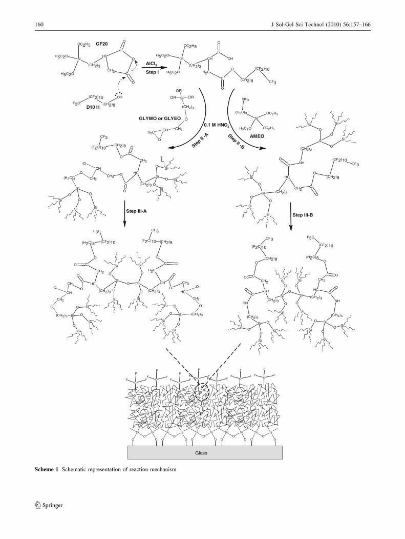
GF20 is a silane compound which has three ethoxy groups and
one succinic anhydride ring. Fluorination reaction of GF20 is
a chemical bonding occurring between succinic anhydride
rings and hydroxyl group of D10H. In Scheme 1, the sche-
matic reaction mechanism of GF20-D10H, GF20-D10H-
AMMO, GF20-D10H-GLYMO and GF20-D10H-GLYEO
systems was presented. As shown in step 1, succinic anhy-
dride ring of GF20 was opened by the attack of unsaturated
electrons above oxygen atom of D10H to the carbon atom of
the carbonyl group of the succinic anhydride ring. AlCl3 as
catalyst was used to provide this reaction. Thus, fluorinated
silane compound (GF20-D10H) which had terminal carbox-
ylic acid group was acquired by sol–gel reaction.
Step II indicated the reactions between GF20-D10H with
the other silane compound. Here, the epoxy modified alk-
oxysilanes (GLMYO and GLYEO) and the amine modified
alkoxysilanes (AMMO) were used to form organic–inor-
ganic polymer network in coatings. As shown in step II-A,
reactions of GF20-D10H with GLYMO or GLYEO, which
is an epoxy ring opening reaction, occur between carboxylic
acid group of GF20-D10H with epoxy ring of GLYMO or
GLYEO. In GF20-D10H-AMMO system, the peptide bond
forms due to the reaction between amine groups of AMMO
with carboxylic acid group of GF20-D10H which was
indicated in step II-B. 0.1 M HNO3 was used for hydrolysis
and polycondensation reaction alkoxide groups of silanes in
all systems. As shown in step III-A and III-B, the polymeric
network was ensured by further condensation reactions. As a
final step, terminal F groups containing organic and inor-
ganic polymeric network was transferred to glass surface.
Table 1 Compositions of coating solutions
Coating solution: GF20-D10H-AMMO GF20-D10H-GLYEO GF20-D10H-GLYMO
Weight ratio: 10 wt% 20 wt% 10 wt% 20 wt% 10 wt% 20 wt%
Amount (g)
GF20-D10H 1.500 2.117 1.500 1.855 1.500 1.786
AMMO 0.267 0.378 – – – –
GLYEO – – 0.415 0.513 – –
GLYMO – – – – 0.352 0.420
IPE 17.352 10.892 18.684 10.270 18.117 9.592
0.1 M HNO3 0.161 0.228 0.161 0.199 0.161 0.192
J Sol-Gel Sci Technol (2010) 56:157–166 159
123
H5C2O
H5C2O
OC2H5
Si
(CH2)3
O
O
O
C
C
CH
CH2
OH
F3C
(CF2)10
(CH2)8
.. ..
H5C2O
H5C2O
OC2H5
Si
(CH2)3
O
O
OH
C
C
CH
CH2O
CF3
(CF2)10
(CH2)8
(CH2)3
CH2CH2
CH
O
O
OR
OR
OR Si NH2
(H2C)3
H5C2O OC2H5
OC2H5Si
Si
SiSi
Si
Si
Si
O
OO
OO
O
Si (CH2)3
O
O
C
C
CH
CH2
O
CF3(CF2)10
(CH2)8
NH
(CH2)3
Si
O
Si Si
Si O
OO
Si
Si
Si
O
O
O
Si
(CH2)3
O
O
C
C
CH
CH2O
CF3
(F2C)10(CH2)8
(H2C)3 CH2CH2
CH-O
O
Si
O
O
Si
Si
Si
O
O
O
Si
Si
O
O
Si
(CH2)3
O
O-
C
C
CH
CH2
O
CF3
(F2C)10 (CH2)8
(CH2)3
CH2
CH2
CH
O-
O
Si
O
Si
Si
Si
O
O
O
Si
Si
O
O
Si
(CH2)3
O
O-
C
C
CH
CH2
O
F3C
(CF2)10(H2C)8
(CH2)3
CH2
CH2
CH-O
O
Si
SiSi
Si
Si
Si
O
OO
O
O
O
Si (CH2)3
O
O
C
C
CH
CH2
O
F3C
(CF2)10
(H2C)8
NH
(CH2)3
Si
SiSi
Si
Si
Si
O
OO
O
O
Si(CH2)3
O
O
C
C
CH
CH2
O
CF3
(F2C)10
(CH2)8
NH
(CH2)3
Si
D10 H
GF20
GLYMO or GLYEO
AMEO
Step I
Step II
-A Step II -B
Step III-AStep III-B
AlCl3
0.1 M HNO3
..........
.
O
.
SiO
O
.
O
SiO
O
.
OO
.O
O
.
O
.
O
O.
O
Si
O
.
O
.
Si Si Si Si Si
O
.
SiO
.
O
Si
.
F
F
FC
.
F
F
FC
.
F
F
FC
.
F
F
FC
.
F
F
FC
.
F
F
FC
.
F
F
FC
Glass
Scheme 1 Schematic representation of reaction mechanism
160 J Sol-Gel Sci Technol (2010) 56:157–166
123
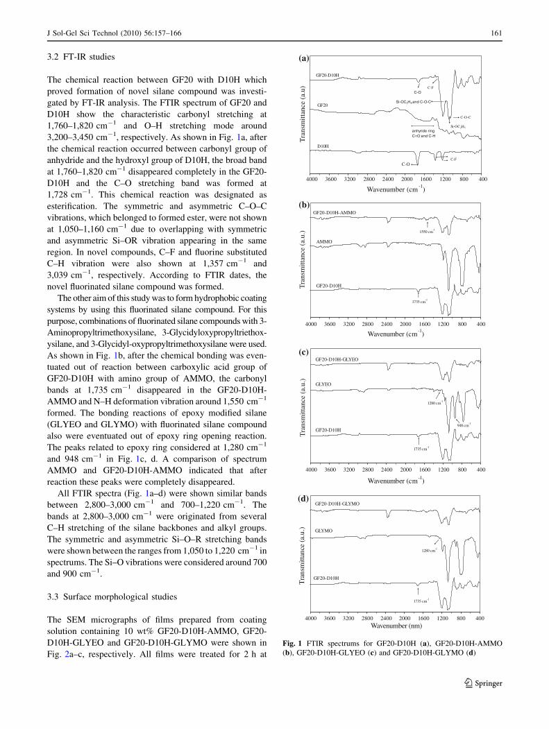
3.2 FT-IR studies
The chemical reaction between GF20 with D10H which
proved formation of novel silane compound was investi-
gated by FT-IR analysis. The FTIR spectrum of GF20 and
D10H show the characteristic carbonyl stretching at
1,760–1,820 cm-1 and O–H stretching mode around
3,200–3,450 cm-1, respectively. As shown in Fig. 1a, after
the chemical reaction occurred between carbonyl group of
anhydride and the hydroxyl group of D10H, the broad band
at 1,760–1,820 cm-1 disappeared completely in the GF20-
D10H and the C–O stretching band was formed at
1,728 cm-1. This chemical reaction was designated as
esterification. The symmetric and asymmetric C–O–C
vibrations, which belonged to formed ester, were not shown
at 1,050–1,160 cm-1 due to overlapping with symmetric
and asymmetric Si–OR vibration appearing in the same
region. In novel compounds, C–F and fluorine substituted
C–H vibration were also shown at 1,357 cm-1 and
3,039 cm-1, respectively. According to FTIR dates, the
novel fluorinated silane compound was formed.
The other aim of this study was to form hydrophobic coating
systems by using this fluorinated silane compound. For this
purpose, combinations of fluorinated silane compounds with 3-
Aminopropyltrimethoxysilane, 3-Glycidyloxypropyltriethox-
ysilane, and 3-Glycidyl-oxypropyltrimethoxysilane were used.
As shown in Fig. 1b, after the chemical bonding was even-
tuated out of reaction between carboxylic acid group of
GF20-D10H with amino group of AMMO, the carbonyl
bands at 1,735 cm-1 disappeared in the GF20-D10H-
AMMO and N–H deformation vibration around 1,550 cm-1
formed. The bonding reactions of epoxy modified silane
(GLYEO and GLYMO) with fluorinated silane compound
also were eventuated out of epoxy ring opening reaction.
The peaks related to epoxy ring considered at 1,280 cm-1
and 948 cm-1 in Fig. 1c, d. A comparison of spectrum
AMMO and GF20-D10H-AMMO indicated that after
reaction these peaks were completely disappeared.
All FTIR spectra (Fig. 1a–d) were shown similar bands
between 2,800–3,000 cm-1 and 700–1,220 cm-1. The
bands at 2,800–3,000 cm-1 were originated from several
C–H stretching of the silane backbones and alkyl groups.
The symmetric and asymmetric Si–O–R stretching bands
were shown between the ranges from 1,050 to 1,220 cm-1 in
spectrums. The Si–O vibrations were considered around 700
and 900 cm-1.
3.3 Surface morphological studies
The SEM micrographs of films prepared from coating
solution containing 10 wt% GF20-D10H-AMMO, GF20-
D10H-GLYEO and GF20-D10H-GLYMO were shown in
Fig. 2a–c, respectively. All films were treated for 2 h at
40080012001600200024002800320036004000
Wavenumber (cm-1
)
Tra
nsm
ittan
ce (
a.u)
D10H
GF20
GF20-D10H
C-O
anhyride ringC=O and C-H
Si-OC2H5 and C-O-C
C-F
C-O-C
Si-OC2H5
C-OC-F
(a)
40080012001600200024002800320036004000
Wavenumber (cm-1)
Tra
nsm
ittan
ce (
a.u.
)
GF20-D10H-AMMO
AMMO
GF20-D10H
1735 cm-1
1550 cm-1
(b)
40080012001600200024002800320036004000
Wavenumber (cm-1)
Tra
nsm
ittan
ce (
a.u.
)
GF20-D10H
GLYEO
GF20-D10H-GLYEO
1735 cm-1
948 cm-1
1280 cm-1
(c)
(d)
40080012001600200024002800320036004000Wavenumber (nm)
Tra
nsm
ittan
ce (
a.u.
)
GF20-D10H
GLYMO
GF20-D10H-GLYMO
1735 cm-1
1280 cm-1
Fig. 1 FTIR spectrums for GF20-D10H (a), GF20-D10H-AMMO
(b), GF20-D10H-GLYEO (c) and GF20-D10H-GLYMO (d)
J Sol-Gel Sci Technol (2010) 56:157–166 161
123
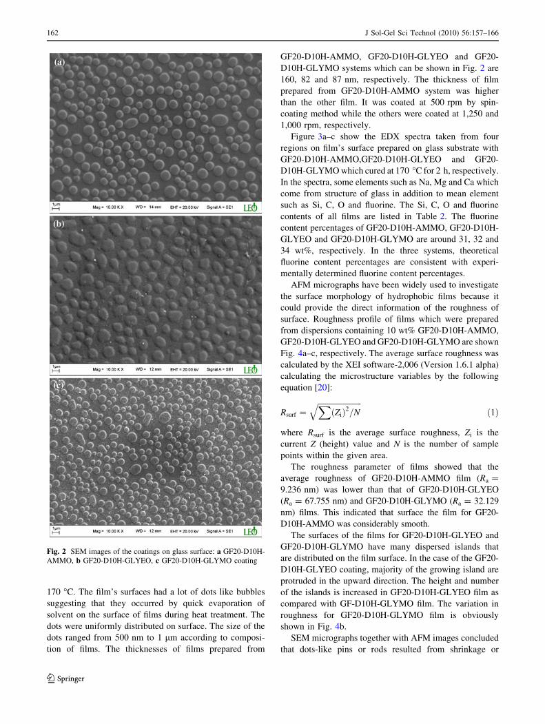
170 �C. The film’s surfaces had a lot of dots like bubbles
suggesting that they occurred by quick evaporation of
solvent on the surface of films during heat treatment. The
dots were uniformly distributed on surface. The size of the
dots ranged from 500 nm to 1 lm according to composi-
tion of films. The thicknesses of films prepared from
GF20-D10H-AMMO, GF20-D10H-GLYEO and GF20-
D10H-GLYMO systems which can be shown in Fig. 2 are
160, 82 and 87 nm, respectively. The thickness of film
prepared from GF20-D10H-AMMO system was higher
than the other film. It was coated at 500 rpm by spin-
coating method while the others were coated at 1,250 and
1,000 rpm, respectively.
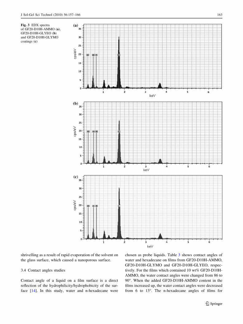
Figure 3a–c show the EDX spectra taken from four
regions on film’s surface prepared on glass substrate with
GF20-D10H-AMMO,GF20-D10H-GLYEO and GF20-
D10H-GLYMO which cured at 170 �C for 2 h, respectively.
In the spectra, some elements such as Na, Mg and Ca which
come from structure of glass in addition to mean element
such as Si, C, O and fluorine. The Si, C, O and fluorine
contents of all films are listed in Table 2. The fluorine
content percentages of GF20-D10H-AMMO, GF20-D10H-
GLYEO and GF20-D10H-GLYMO are around 31, 32 and
34 wt%, respectively. In the three systems, theoretical
fluorine content percentages are consistent with experi-
mentally determined fluorine content percentages.
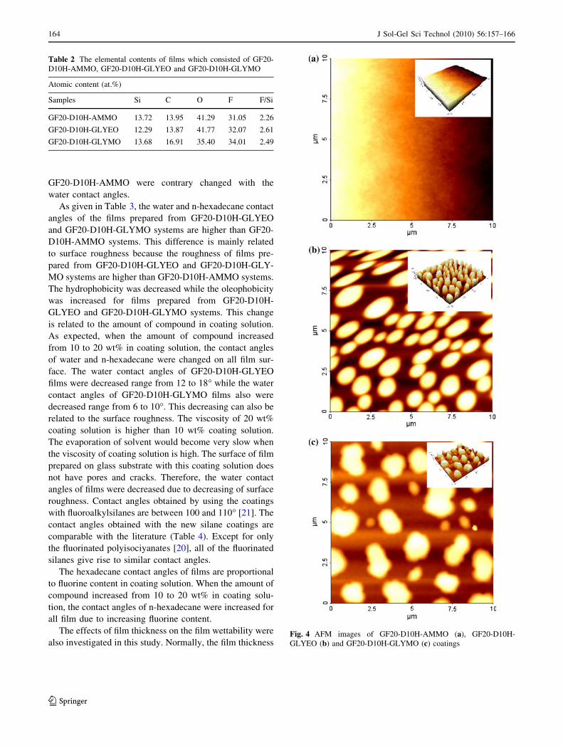
AFM micrographs have been widely used to investigate
the surface morphology of hydrophobic films because it
could provide the direct information of the roughness of
surface. Roughness profile of films which were prepared
from dispersions containing 10 wt% GF20-D10H-AMMO,
GF20-D10H-GLYEO and GF20-D10H-GLYMO are shown
Fig. 4a–c, respectively. The average surface roughness was
calculated by the XEI software-2,006 (Version 1.6.1 alpha)
calculating the microstructure variables by the following
equation [20]:
Rsurf ¼ffiffiffiffiffiffiffiffiffiffiffiffiffiffiffiffiffiffiffiffiffiffiffi
X
Zið Þ2=Nq
ð1Þ
where Rsurf is the average surface roughness, Zi is the
current Z (height) value and N is the number of sample
points within the given area.
The roughness parameter of films showed that the
average roughness of GF20-D10H-AMMO film (Ra =
9.236 nm) was lower than that of GF20-D10H-GLYEO
(Ra = 67.755 nm) and GF20-D10H-GLYMO (Ra = 32.129
nm) films. This indicated that surface the film for GF20-
D10H-AMMO was considerably smooth.
The surfaces of the films for GF20-D10H-GLYEO and
GF20-D10H-GLYMO have many dispersed islands that
are distributed on the film surface. In the case of the GF20-
D10H-GLYEO coating, majority of the growing island are
protruded in the upward direction. The height and number
of the islands is increased in GF20-D10H-GLYEO film as
compared with GF-D10H-GLYMO film. The variation in
roughness for GF20-D10H-GLYMO film is obviously
shown in Fig. 4b.
SEM micrographs together with AFM images concluded
that dots-like pins or rods resulted from shrinkage or
Fig. 2 SEM images of the coatings on glass surface: a GF20-D10H-
AMMO, b GF20-D10H-GLYEO, c GF20-D10H-GLYMO coating
162 J Sol-Gel Sci Technol (2010) 56:157–166
123
shrivelling as a result of rapid evaporation of the solvent on
the glass surface, which caused a nanoporous surface.
3.4 Contact angles studies
Contact angle of a liquid on a film surface is a direct
reflection of the hydrophilicity/hydrophobicity of the sur-
face [14]. In this study, water and n-hexadecane were
chosen as probe liquids. Table 3 shows contact angles of
water and hexadecane on films from GF20-D10H-AMMO,
GF20-D10H-GLYMO and GF20-D10H-GLYEO, respec-
tively. For the films which contained 10 wt% GF20-D10H-
AMMO, the water contact angles were changed from 86 to
90�. When the added GF20-D10H-AMMO content in the
films increased up, the water contact angles were decreased
from 6 to 13�. The n-hexadecane angles of films for
Fig. 3 EDX spectra
of GF20-D10H-AMMO (a),
GF20-D10H-GLYEO (b)
and GF20-D10H-GLYMO
coatings (c)
J Sol-Gel Sci Technol (2010) 56:157–166 163
123
GF20-D10H-AMMO were contrary changed with the
water contact angles.
As given in Table 3, the water and n-hexadecane contact
angles of the films prepared from GF20-D10H-GLYEO
and GF20-D10H-GLYMO systems are higher than GF20-
D10H-AMMO systems. This difference is mainly related
to surface roughness because the roughness of films pre-
pared from GF20-D10H-GLYEO and GF20-D10H-GLY-
MO systems are higher than GF20-D10H-AMMO systems.
The hydrophobicity was decreased while the oleophobicity
was increased for films prepared from GF20-D10H-
GLYEO and GF20-D10H-GLYMO systems. This change
is related to the amount of compound in coating solution.
As expected, when the amount of compound increased
from 10 to 20 wt% in coating solution, the contact angles
of water and n-hexadecane were changed on all film sur-
face. The water contact angles of GF20-D10H-GLYEO
films were decreased range from 12 to 18� while the water
contact angles of GF20-D10H-GLYMO films also were
decreased range from 6 to 10�. This decreasing can also be
related to the surface roughness. The viscosity of 20 wt%
coating solution is higher than 10 wt% coating solution.
The evaporation of solvent would become very slow when
the viscosity of coating solution is high. The surface of film
prepared on glass substrate with this coating solution does
not have pores and cracks. Therefore, the water contact
angles of films were decreased due to decreasing of surface
roughness. Contact angles obtained by using the coatings
with fluoroalkylsilanes are between 100 and 110� [21]. The
contact angles obtained with the new silane coatings are
comparable with the literature (Table 4). Except for only
the fluorinated polyisociyanates [20], all of the fluorinated
silanes give rise to similar contact angles.
The hexadecane contact angles of films are proportional
to fluorine content in coating solution. When the amount of
compound increased from 10 to 20 wt% in coating solu-
tion, the contact angles of n-hexadecane were increased for
all film due to increasing fluorine content.
The effects of film thickness on the film wettability were
also investigated in this study. Normally, the film thickness
Table 2 The elemental contents of films which consisted of GF20-
D10H-AMMO, GF20-D10H-GLYEO and GF20-D10H-GLYMO
Atomic content (at.%)
Samples Si C O F F/Si
GF20-D10H-AMMO 13.72 13.95 41.29 31.05 2.26
GF20-D10H-GLYEO 12.29 13.87 41.77 32.07 2.61
GF20-D10H-GLYMO 13.68 16.91 35.40 34.01 2.49
Fig. 4 AFM images of GF20-D10H-AMMO (a), GF20-D10H-
GLYEO (b) and GF20-D10H-GLYMO (c) coatings
164 J Sol-Gel Sci Technol (2010) 56:157–166
123
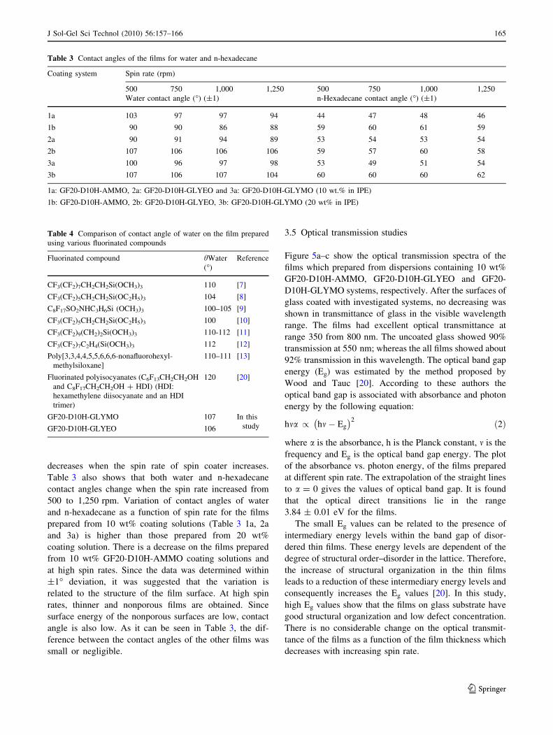
decreases when the spin rate of spin coater increases.
Table 3 also shows that both water and n-hexadecane
contact angles change when the spin rate increased from
500 to 1,250 rpm. Variation of contact angles of water
and n-hexadecane as a function of spin rate for the films
prepared from 10 wt% coating solutions (Table 3 1a, 2a
and 3a) is higher than those prepared from 20 wt%
coating solution. There is a decrease on the films prepared
from 10 wt% GF20-D10H-AMMO coating solutions and
at high spin rates. Since the data was determined within
±1� deviation, it was suggested that the variation is
related to the structure of the film surface. At high spin
rates, thinner and nonporous films are obtained. Since
surface energy of the nonporous surfaces are low, contact
angle is also low. As it can be seen in Table 3, the dif-
ference between the contact angles of the other films was
small or negligible.
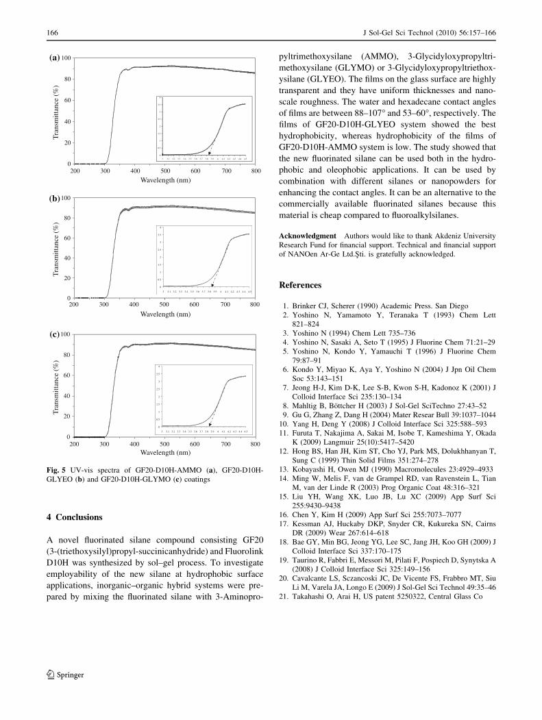
3.5 Optical transmission studies
Figure 5a–c show the optical transmission spectra of the
films which prepared from dispersions containing 10 wt%
GF20-D10H-AMMO, GF20-D10H-GLYEO and GF20-
D10H-GLYMO systems, respectively. After the surfaces of
glass coated with investigated systems, no decreasing was
shown in transmittance of glass in the visible wavelength
range. The films had excellent optical transmittance at
range 350 from 800 nm. The uncoated glass showed 90%
transmission at 550 nm; whereas the all films showed about
92% transmission in this wavelength. The optical band gap
energy (Eg) was estimated by the method proposed by
Wood and Tauc [20]. According to these authors the
optical band gap is associated with absorbance and photon
energy by the following equation:
hma / hm� Eg
� �2 ð2Þ
where a is the absorbance, h is the Planck constant, m is the
frequency and Eg is the optical band gap energy. The plot
of the absorbance vs. photon energy, of the films prepared
at different spin rate. The extrapolation of the straight lines
to a = 0 gives the values of optical band gap. It is found
that the optical direct transitions lie in the range
3.84 ± 0.01 eV for the films.
The small Eg values can be related to the presence of
intermediary energy levels within the band gap of disor-
dered thin films. These energy levels are dependent of the
degree of structural order–disorder in the lattice. Therefore,
the increase of structural organization in the thin films
leads to a reduction of these intermediary energy levels and
consequently increases the Eg values [20]. In this study,
high Eg values show that the films on glass substrate have
good structural organization and low defect concentration.
There is no considerable change on the optical transmit-
tance of the films as a function of the film thickness which
decreases with increasing spin rate.
Table 3 Contact angles of the films for water and n-hexadecane
Coating system Spin rate (rpm)
500 750 1,000 1,250 500 750 1,000 1,250
Water contact angle (�) (±1) n-Hexadecane contact angle (�) (±1)
1a 103 97 97 94 44 47 48 46
1b 90 90 86 88 59 60 61 59
2a 90 91 94 89 53 54 53 54
2b 107 106 106 106 59 57 60 58
3a 100 96 97 98 53 49 51 54
3b 107 106 107 104 60 60 60 62
1a: GF20-D10H-AMMO, 2a: GF20-D10H-GLYEO and 3a: GF20-D10H-GLYMO (10 wt.% in IPE)
1b: GF20-D10H-AMMO, 2b: GF20-D10H-GLYEO, 3b: GF20-D10H-GLYMO (20 wt% in IPE)
Table 4 Comparison of contact angle of water on the film prepared
using various fluorinated compounds
Fluorinated compound hWater
(�)
Reference
CF3(CF2)7CH2CH2Si(OCH3)3 110 [7]
CF3(CF2)5CH2CH2Si(OC2H5)3 104 [8]
C8F17SO2NHC3H6Si (OCH3)3 100–105 [9]
CF3(CF2)5CH2CH2Si(OC2H5)3 100 [10]
CF3(CF2)9(CH2)2Si(OCH3)3 110-112 [11]
CF3(CF2)7C2H4(Si(OCH3)3 112 [12]
Poly[3,3,4,4,5,5,6,6,6-nonafluorohexyl-
methylsiloxane]
110–111 [13]
Fluorinated polyisocyanates (C6F13CH2CH2OH
and C8F17CH2CH2OH ? HDI) (HDI:
hexamethylene diisocyanate and an HDI
trimer)
120 [20]
GF20-D10H-GLYMO 107 In this
studyGF20-D10H-GLYEO 106
J Sol-Gel Sci Technol (2010) 56:157–166 165
123
4 Conclusions
A novel fluorinated silane compound consisting GF20
(3-(triethoxysilyl)propyl-succinicanhydride) and Fluorolink
D10H was synthesized by sol–gel process. To investigate
employability of the new silane at hydrophobic surface
applications, inorganic–organic hybrid systems were pre-
pared by mixing the fluorinated silane with 3-Aminopro-
pyltrimethoxysilane (AMMO), 3-Glycidyloxypropyltri-
methoxysilane (GLYMO) or 3-Glycidyloxypropyltriethox-
ysilane (GLYEO). The films on the glass surface are highly
transparent and they have uniform thicknesses and nano-
scale roughness. The water and hexadecane contact angles
of films are between 88–107� and 53–60�, respectively. The
films of GF20-D10H-GLYEO system showed the best
hydrophobicity, whereas hydrophobicity of the films of
GF20-D10H-AMMO system is low. The study showed that
the new fluorinated silane can be used both in the hydro-
phobic and oleophobic applications. It can be used by
combination with different silanes or nanopowders for
enhancing the contact angles. It can be an alternative to the
commercially available fluorinated silanes because this
material is cheap compared to fluoroalkylsilanes.
Acknowledgment Authors would like to thank Akdeniz University
Research Fund for financial support. Technical and financial support
of NANOen Ar-Ge Ltd.Sti. is gratefully acknowledged.
References
1. Brinker CJ, Scherer (1990) Academic Press. San Diego
2. Yoshino N, Yamamoto Y, Teranaka T (1993) Chem Lett
821–824
3. Yoshino N (1994) Chem Lett 735–736
4. Yoshino N, Sasaki A, Seto T (1995) J Fluorine Chem 71:21–29
5. Yoshino N, Kondo Y, Yamauchi T (1996) J Fluorine Chem
79:87–91
6. Kondo Y, Miyao K, Aya Y, Yoshino N (2004) J Jpn Oil Chem
Soc 53:143–151
7. Jeong H-J, Kim D-K, Lee S-B, Kwon S-H, Kadonoz K (2001) J
Colloid Interface Sci 235:130–134
8. Mahltig B, Bottcher H (2003) J Sol-Gel SciTechno 27:43–52
9. Gu G, Zhang Z, Dang H (2004) Mater Resear Bull 39:1037–1044
10. Yang H, Deng Y (2008) J Colloid Interface Sci 325:588–593
11. Furuta T, Nakajima A, Sakai M, Isobe T, Kameshima Y, Okada
K (2009) Langmuir 25(10):5417–5420
12. Hong BS, Han JH, Kim ST, Cho YJ, Park MS, Dolukhhanyan T,
Sung C (1999) Thin Solid Films 351:274–278
13. Kobayashi H, Owen MJ (1990) Macromolecules 23:4929–4933
14. Ming W, Melis F, van de Grampel RD, van Ravenstein L, Tian
M, van der Linde R (2003) Prog Organic Coat 48:316–321
15. Liu YH, Wang XK, Luo JB, Lu XC (2009) App Surf Sci
255:9430–9438
16. Chen Y, Kim H (2009) App Surf Sci 255:7073–7077
17. Kessman AJ, Huckaby DKP, Snyder CR, Kukureka SN, Cairns
DR (2009) Wear 267:614–618
18. Bae GY, Min BG, Jeong YG, Lee SC, Jang JH, Koo GH (2009) J
Colloid Interface Sci 337:170–175
19. Taurino R, Fabbri E, Messori M, Pilati F, Pospiech D, Synytska A
(2008) J Colloid Interface Sci 325:149–156
20. Cavalcante LS, Sczancoski JC, De Vicente FS, Frabbro MT, Siu
Li M, Varela JA, Longo E (2009) J Sol-Gel Sci Technol 49:35–46
21. Takahashi O, Arai H, US patent 5250322, Central Glass Co
0
20
40
60
80
100
200 300 400 500 600 700
Wavelength (nm)
Tra
nsm
ittan
ce (
%)
(a)
0
20
40
60
80
100
Wavelength (nm)
Tra
nsm
ittan
ce (
%)
(b)
0
0.5
1
1.5
2
2.5
3
3.5
4
3 3.1 3.2 3.3 3.4 3.5 3.6 3.7 3.8 3.9 4 4.1 4.2 4.3 4.4 4.5
0
0.5
1
1.5
2
2.5
3
3.5
4
3 3.1 3.2 3.3 3.4 3.5 3.6 3.7 3.8 3.9 4 4.1 4.2 4.3 4.4 4.5
0
20
40
60
80
100
Wavelength (nm)
Tra
nsm
ittan
ce (
%)
(c)
0
0.5
1
1.5
2
2.5
3
3.5
4
3 3.1 3.2 3.3 3.4 3.5 3.6 3.7 3.8 3.9 4 4.1 4.2 4.3 4.4 4.5
800
200 300 400 500 600 700 800
200 300 400 500 600 700 800
Fig. 5 UV-vis spectra of GF20-D10H-AMMO (a), GF20-D10H-
GLYEO (b) and GF20-D10H-GLYMO (c) coatings
166 J Sol-Gel Sci Technol (2010) 56:157–166
123