slide air solutions -medium ssr 45-75 kw product overview
TRANSCRIPT
Slide # 1
Air Solutions - Medium
SSR 45-75 kW
Product Overview
Slide # 2
Air Solutions - Medium
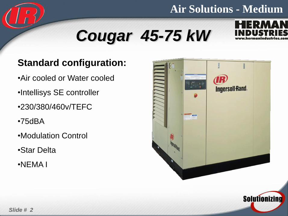
Standard configuration:
•Air cooled or Water cooled
•Intellisys SE controller
•230/380/460v/TEFC
•75dBA
•Modulation Control
•Star Delta
•NEMA I
Cougar 45-75 kW

Slide # 3
Air Solutions - Medium
SSR Cougar Fixed-Speed, Contact Cooled Rotary Screw
Air Compressors 45-75kW / 60-100 hp
Nominal Motor
PowerRated Pressure Sound Range
kW / HP m3/min cfm Bar (g) / psi (g) dB (A)
45 kW
ML45 45 / 60 7.4 260 7.5 / 109 78 +/-3
MM45 45 / 60 7.1 250 8.5 / 123 78 +/-3
MH45 45 / 60 6.5 230 10 / 145 78 +/-3
55 kW
ML55 55 / 75 10.1 357 7.5 / 109 78 +/-3
MM55 55 / 75 9.1 325 8.5 / 123 78 +/-3
MH55 55 / 75 8.3 293 10 / 145 78 +/-3
MJ55 55 / 75 7.6 268 11.4 / 165
75 kW
ML75 75 / 100 13 459 7.5 / 109 78 +/-3
MM75 75 / 100 12.1 427 8.5 / 123 78 +/-3
MH75 75 / 100 11 389 10 / 145 78 +/-3
MJ75 75 / 100 10.2 360 11.4 / 165 78 +/-3
CapacityModel Designation
Slide # 4
Air Solutions - Medium
Slide # 5
Air Solutions - Medium
OBJECTIVES
• Component Review
• Control System
• Adjustments
• Installation
• Maintenance
• Parts

Slide # 6
Air Solutions - Medium
AIR FILTER
• 3 micron system
– Improved separator element
life
– Change every 4000 hours
• Multi-Stage High Dust
Filter Optional
– Extended Life
• Pre-cleaner
• Primary element
• Secondary element
Slide # 7
Air Solutions - Medium
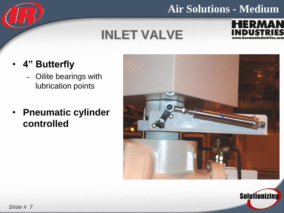
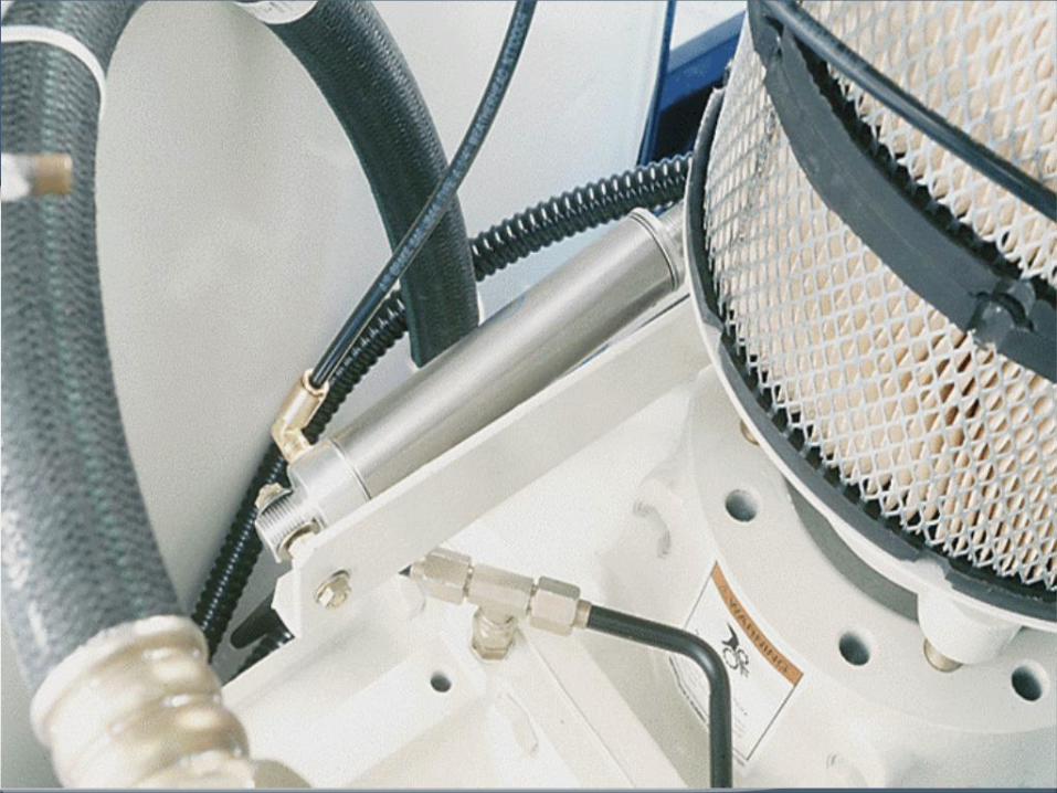
INLET VALVE
• 4” Butterfly
– Oilite bearings with
lubrication points
• Pneumatic cylinder
controlled
Slide # 8
Air Solutions - Medium

Slide # 9
Air Solutions - Medium
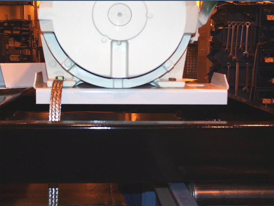
AIRENDS
• 45 kW - 127.5mm
• 55 & 75 kW -
178.5mm
• Shock mounts
– 3- point system
• Cantilevered motor
support
Slide # 10
Air Solutions - Medium

Slide # 11
Air Solutions - Medium
• Types of Profiles
–Symmetric or Asymmetric
–Male: 4 lobes, Female: 6 lobes
–Male: 3 lobes, Female: 5 lobes
–Male: 5 lobes, Female: 6 lobes
1
3
2 1 2
3
4 4
5
6
AIRENDS
Slide # 12
Air Solutions - Medium
Why does an airend have
bearings?
– Positions the rotor in the center of
airend housing
– Prevents movement of rotor due to
thrust
Bearings
Slide # 13
Air Solutions - Medium
• Bearing Types
–Angular Contact Ball
Bearings
–Cylindrical roller bearing
–Tapered roller bearing
• Duplex or triplex
configuration
Bearings

Slide # 14
Air Solutions - Medium
Angular Contact Ball
Bearings Tapered Roller Bearings
Bearings

Slide # 15
Air Solutions - Medium
Duplex Tapered Roller
Bearings
Triplex Tapered Roller
Bearings
Bearings
Slide # 17
Air Solutions - Medium
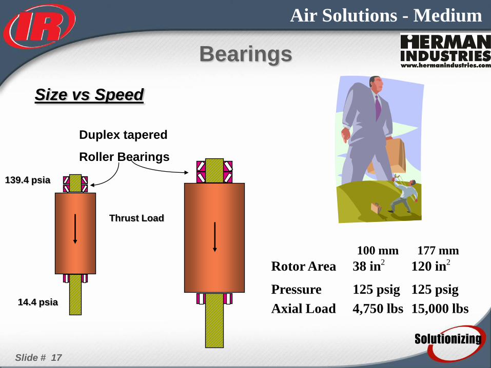
Size vs Speed
Thrust Load
Duplex tapered
Roller Bearings
14.4 psia
139.4 psia
100 mm 177 mm Rotor Area 38 in 2 120 in 2
Pressure 125 psig 125 psig
Axial Load 4,750 lbs 15,000 lbs
Bearings
Slide # 18
Air Solutions - Medium
• Size vs Speed – Increasing the load by two, reduces the estimated bearing
life 10 times
• 2 X Load (-10) x Life
– Increasing the speed (RPM) by two, reduces the estimated
bearing life by one half.
• 2 x RPM 1/2 x Life
Applying Bearings
Slide # 19
Air Solutions - Medium
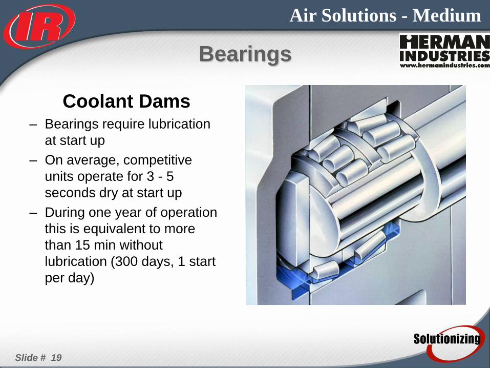
Coolant Dams – Bearings require lubrication
at start up
– On average, competitive
units operate for 3 - 5
seconds dry at start up
– During one year of operation
this is equivalent to more
than 15 min without
lubrication (300 days, 1 start
per day)
Bearings

Slide # 20
Air Solutions - Medium
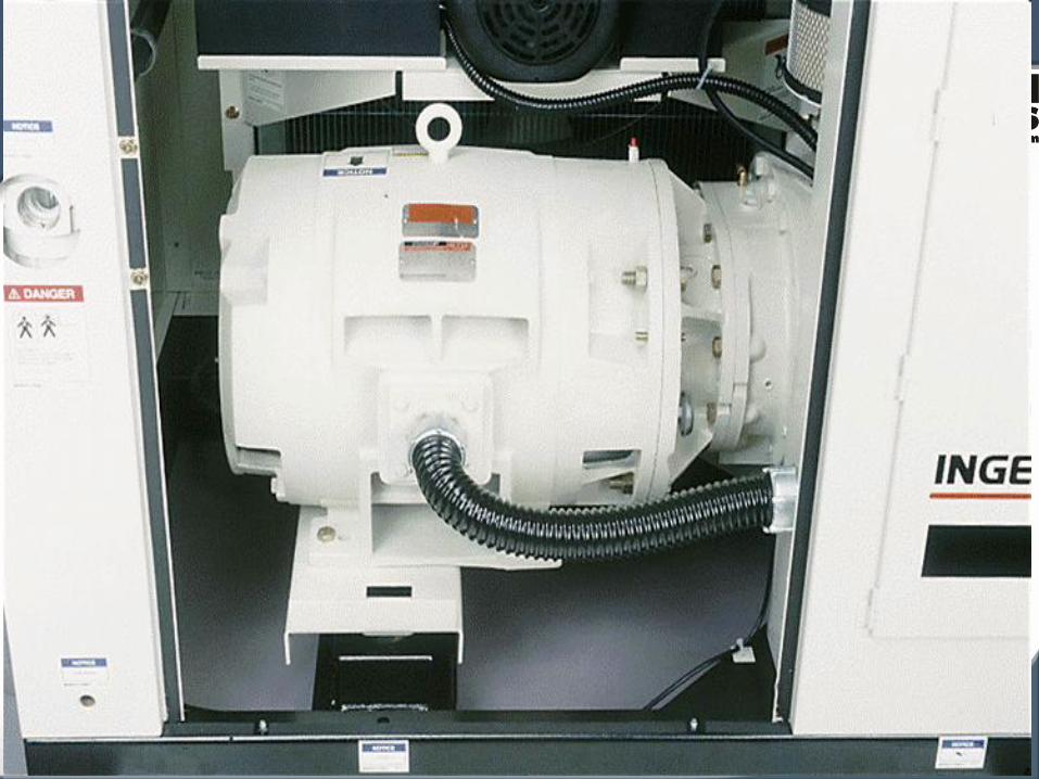
DRIVE MOTOR
• Standard TEFC
• Integral gear drive
Slide # 21
Air Solutions - Medium

Slide # 22
Air Solutions - Medium
DISCHARGE CHECK VALVE
• Disc and Spring type

Slide # 23
Air Solutions - Medium
DISCHARGE HOSE
• Connect airend to separator tank
• Isolates airend from separator tank
• Proper installation is critical
• Maintenance item
– Replace every 2 years

Slide # 24
Air Solutions - Medium
Slide # 25
Air Solutions - Medium
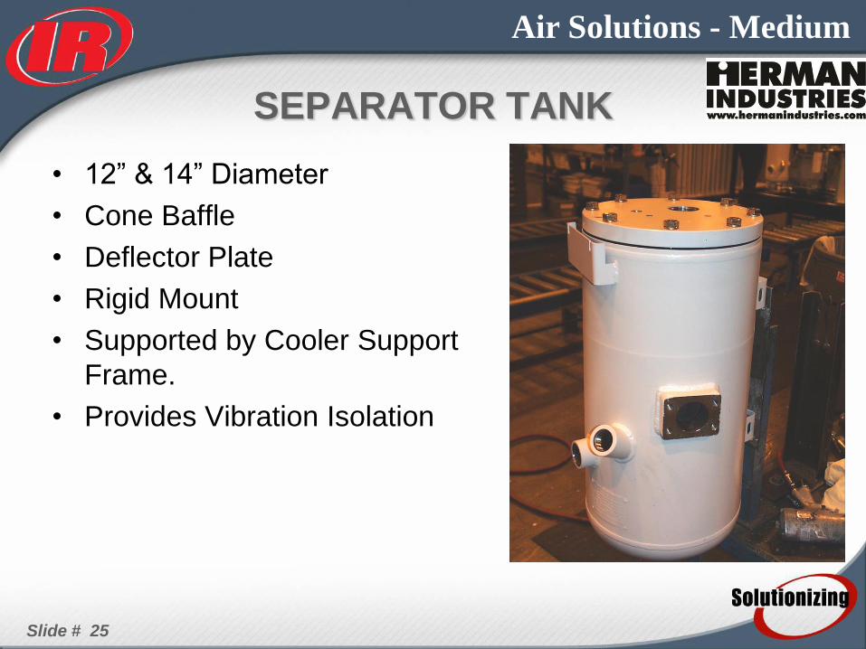
SEPARATOR TANK
• 12” & 14” Diameter
• Cone Baffle
• Deflector Plate
• Rigid Mount
• Supported by Cooler Support
Frame.
• Provides Vibration Isolation
Slide # 26
Air Solutions - Medium
Slide # 27
Air Solutions - Medium
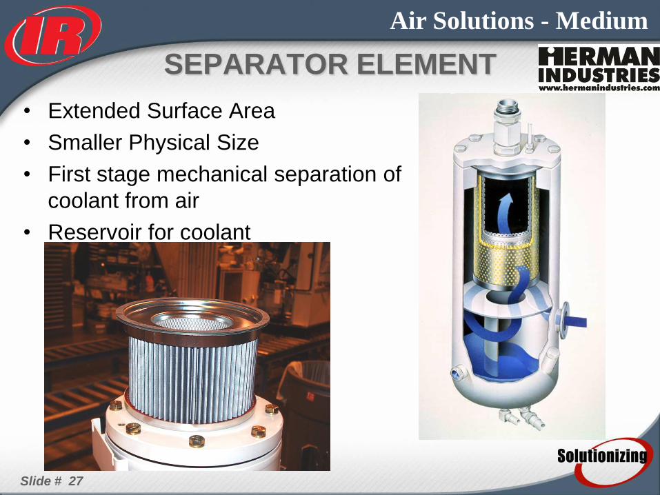
SEPARATOR ELEMENT
• Extended Surface Area
• Smaller Physical Size
• First stage mechanical separation of
coolant from air
• Reservoir for coolant
Slide # 28
Air Solutions - Medium
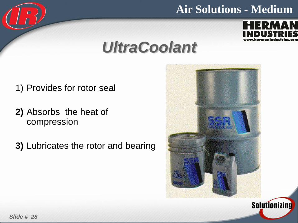
UltraCoolant
1) Provides for rotor seal
2) Absorbs the heat of compression
3) Lubricates the rotor and bearing
Slide # 29
Air Solutions - Medium
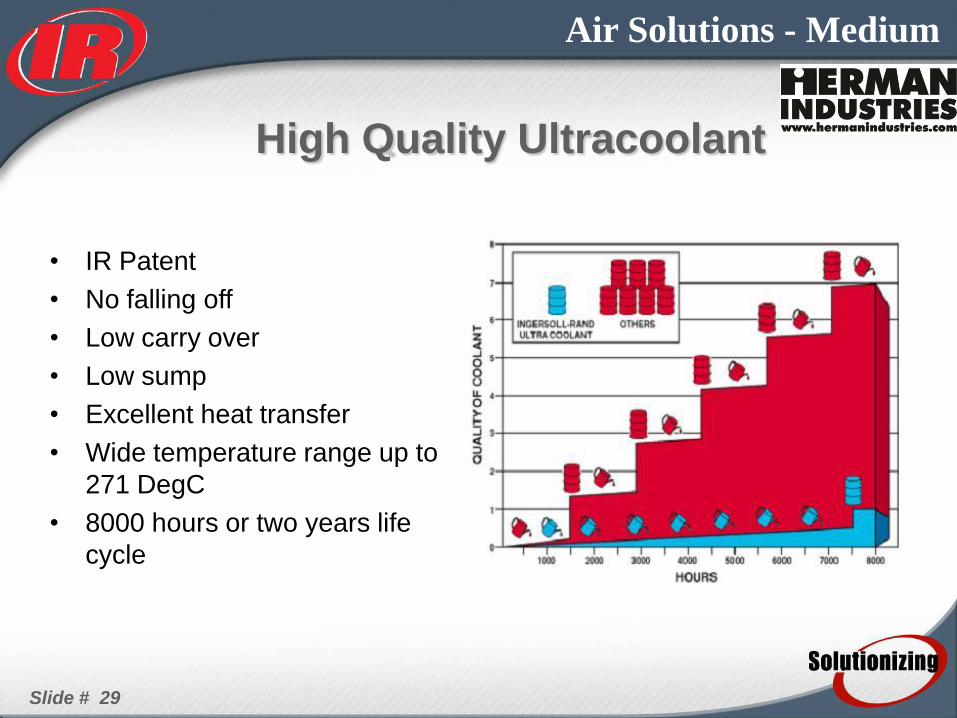
• IR Patent
• No falling off
• Low carry over
• Low sump
• Excellent heat transfer
• Wide temperature range up to
271 DegC
• 8000 hours or two years life
cycle
High Quality Ultracoolant

Slide # 30
Air Solutions - Medium
• SAE “O”-Rings
– Leak-Free
– Reduces cleaning
costs
– Saves lubricant
– Reduces EPA
contamination
concerns
Package- Piping
Slide # 31
Air Solutions - Medium
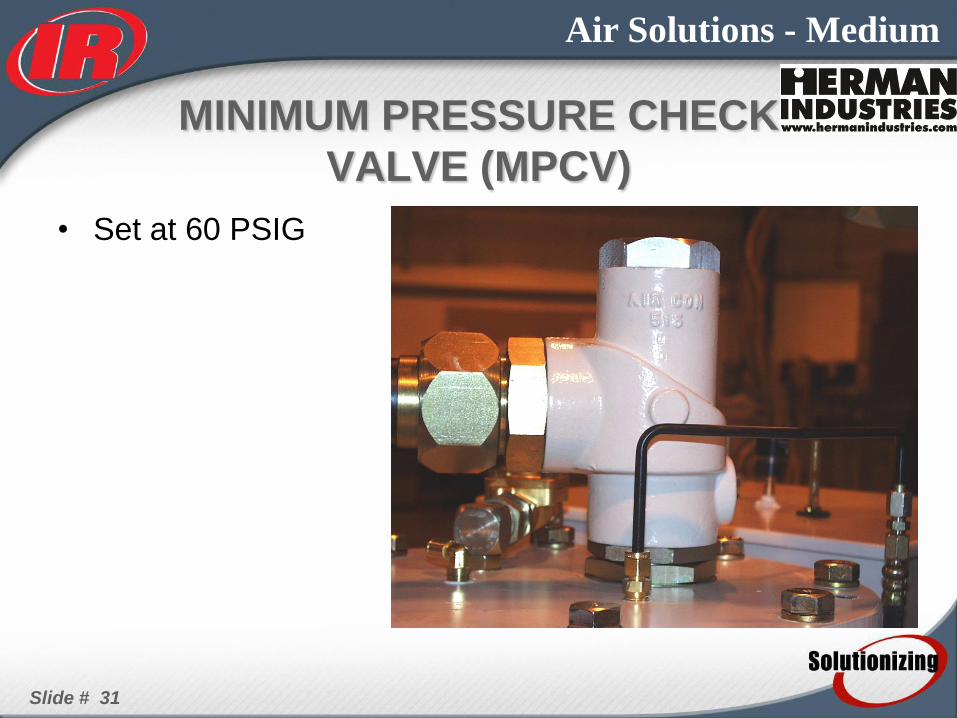
MINIMUM PRESSURE CHECK
VALVE (MPCV)
• Set at 60 PSIG

Slide # 32
Air Solutions - Medium
AFTERCOOLER
• Combination oilcooler &
aftercooler
– Aftercooler 15° CTD 40%
RH
• pressure drop 1 PSI
– Oilcooler 100°F ETD
• pressure drop 5 PSI
• Hinged for easy access
for cleaning

Slide # 33
Air Solutions - Medium
Slide # 34
Air Solutions - Medium
• Operating temperature
• 115 °F/46 °C Design Temperature – Prevents nuisance shutdowns for high
temperature
– Allows an increased time between maintenance intervals of coolers in cooler climates
– The equipment operates cooler at lower temperatures and lubricant doesn’t break down as quickly
SSR Coolers
Slide # 35
Air Solutions - Medium
Cooling System • 46DegC ambient means
– Decreased burden on the cooler
– Lower temp in the airend
– Lengthen the airend life
– Easy installation (Ventilation and environment)

Slide # 36
Air Solutions - Medium
MOISTURE SEPARATOR
• Cyclone Type
• Aluminum Construction

Slide # 37
Air Solutions - Medium
THERMAL VALVE
• Ingersoll Rand Body
• Caltherm Element set at
160°F
• Built in Pressure Relief to
Assist in Cold Start Oil
Flow. (approximately 50
psig)

Slide # 38
Air Solutions - Medium
CONTROL
• Standard SE Intellisys
• SE Star Delta Control Scheme
• Solenoids, 1SV, 2SV, 3SV, 6SV, 10SV
• Modulation is an Option
– Uses Special Modulation Regulator with different orifices and
response than SE Modulation Regulator
Slide # 39
Air Solutions - Medium
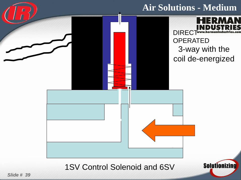
3-way with the
coil de-energized
DIRECT
OPERATED
1SV Control Solenoid and 6SV
Slide # 40
Air Solutions - Medium
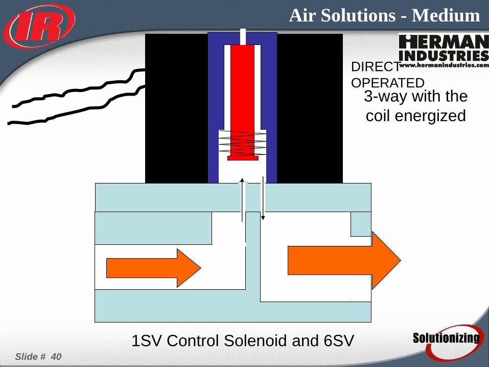
3-way with the
coil energized
DIRECT
OPERATED
1SV Control Solenoid and 6SV
Slide # 41
Air Solutions - Medium
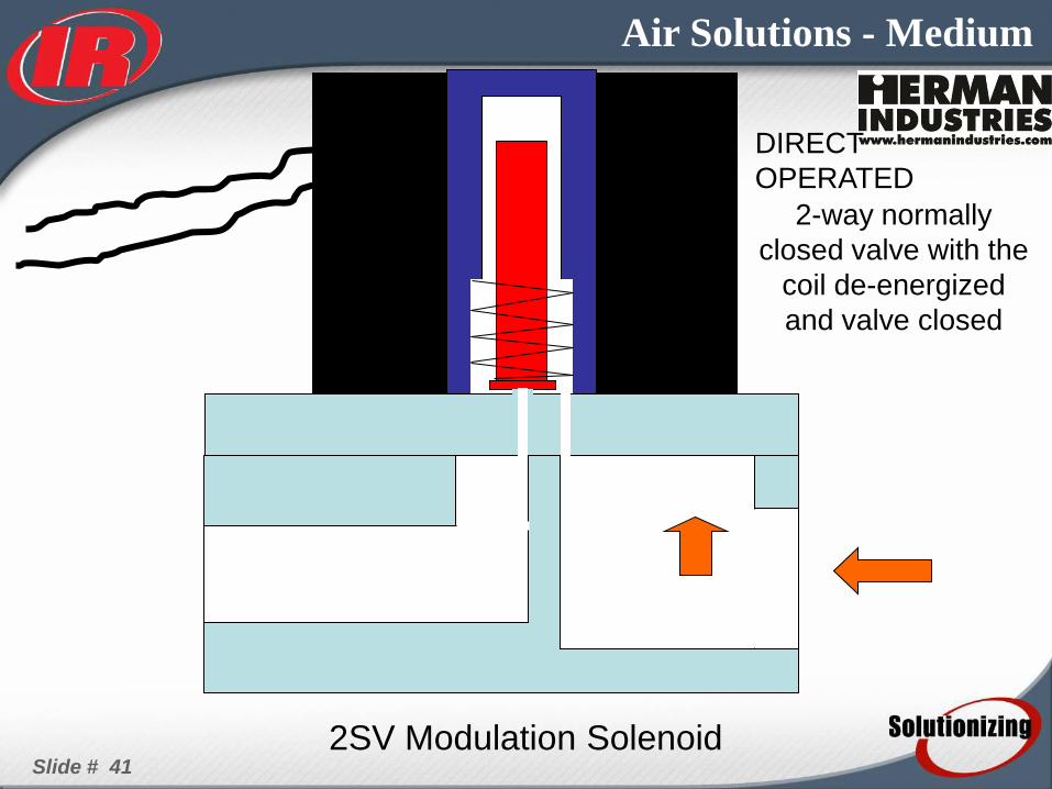
2-way normally
closed valve with the
coil de-energized
and valve closed
2SV Modulation Solenoid
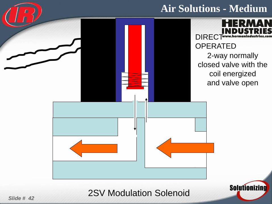
DIRECT
OPERATED
Slide # 42
Air Solutions - Medium
2-way normally
closed valve with the
coil energized
and valve open
2SV Modulation Solenoid
DIRECT
OPERATED
Slide # 43
Air Solutions - Medium
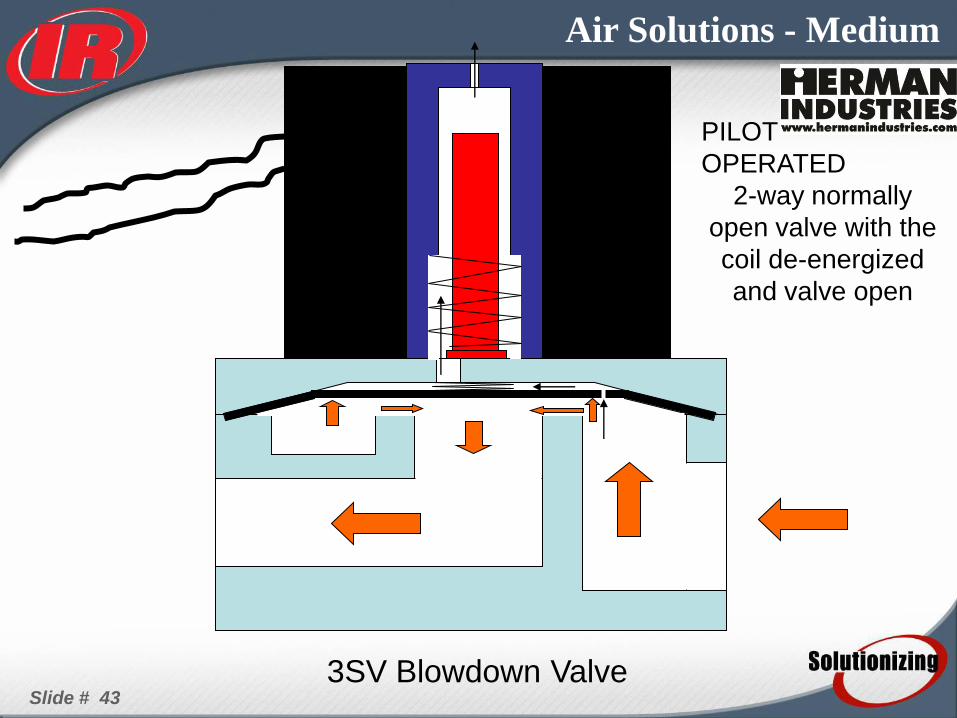
2-way normally
open valve with the
coil de-energized
and valve open
PILOT
OPERATED
3SV Blowdown Valve

Slide # 44
Air Solutions - Medium
2-way normally
open valve with the
coil energized
and valve closed
3SV Blowdown Valve
PILOT
OPERATED

Slide # 45
Air Solutions - Medium
2-way normally
closed valve with the
coil de-energized
and valve closed
5SV Coolant Stop Valve
PILOT
OPERATED
Slide # 46
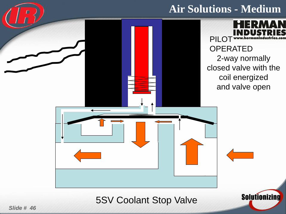
Air Solutions - Medium
2-way normally
closed valve with the
coil energized
and valve open
5SV Coolant Stop Valve
PILOT
OPERATED
Slide # 47
Air Solutions - Medium

Slide # 48
Air Solutions - Medium
INSTRUMENTATION
• Airend Discharge Temperature 2ATT
• Airend Discharge Temperature 1ATS
• Package Discharge Pressure 3APT
• Sump Pressure 3APT (10SV)

Slide # 49
Air Solutions - Medium
1ATS
CLR
CF
AFTER CLR
STATUS: UNIT STOPPED
NO POWER
TCV C
B
A
MOISTURE
SEPARATOR
AND TRAP
A/E SE
2ATT
RELIEF
VALVE
SO
MPCV
5SV
DISC CHECK
VALVE
SEPARATOR
TANK
Inlet Valve
1SV
N.C. 6SV
N.O.
2SV
N.C.
3SV
N.O.
10SV
3APT
MV
1ATS
AF
CYL

Slide # 50
Air Solutions - Medium
1ATS
CLR
CF
AFTER CLR
STATUS: UNIT UNLOADED
TCV C
B
A
MOISTURE
SEPARATOR
AND TRAP
A/E SE
2ATT
RELIEF
VALVE
SO
MPCV
5SV
DISC CHECK
VALVE
SEPARATOR
TANK
Inlet Valve
1SV
N.C. 6SV
N.O.
2SV
N.C.
3SV
N.O.
10SV
3APT
MV
1ATS
AF
CYL

Slide # 51
Air Solutions - Medium
1ATS
CLR
CF
AFTER CLR
STATUS: UNIT LOADED
TCV C
B
A
MOISTURE
SEPARATOR
AND TRAP
A/E SE
2ATT
RELIEF
VALVE
SO
MPCV
5SV
DISC CHECK
VALVE
SEPARATOR
TANK
Inlet Valve
1SV
N.C. 6SV
N.O.
2SV
N.C.
3SV
N.O.
10SV
3APT
MV
1ATS
AF
CYL

Slide # 52
Air Solutions - Medium
1ATS
CLR
CF
AFTER CLR
STATUS: UNIT LOADED
and MODULATING
TCV C
B
A
MOISTURE
SEPARATOR
AND TRAP
A/E SE
2ATT
RELIEF
VALVE
SO
MPCV
5SV
DISC CHECK
VALVE
SEPARATOR
TANK
Inlet Valve
1SV
N.C. 6SV
N.O.
2SV
N.C.
3SV
N.O.
10SV
3APT
MV
1ATS
AF
CYL
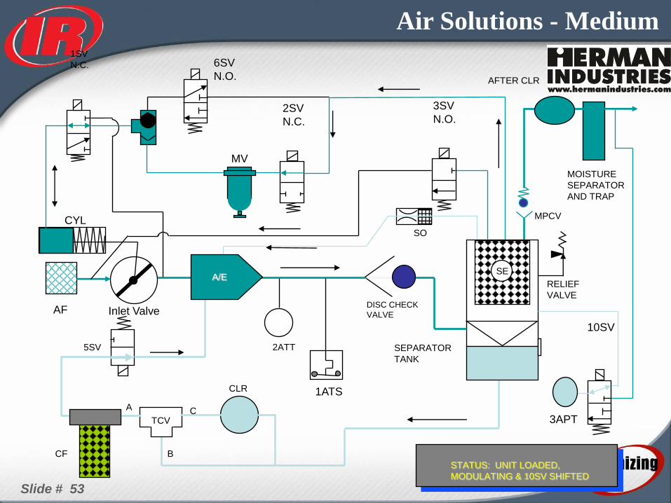
Slide # 53
Air Solutions - Medium
1ATS
CLR
CF
AFTER CLR
STATUS: UNIT LOADED,
MODULATING & 10SV SHIFTED
TCV C
B
A
MOISTURE
SEPARATOR
AND TRAP
A/E SE
2ATT
RELIEF
VALVE
SO
MPCV
5SV
DISC CHECK
VALVE
SEPARATOR
TANK
Inlet Valve
1SV
N.C. 6SV
N.O.
2SV
N.C.
3SV
N.O.
10SV
3APT
MV
1ATS
AF
CYL
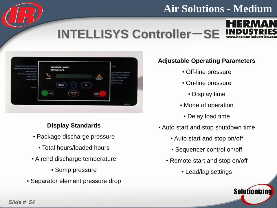
Slide # 54
Air Solutions - Medium
INTELLISYS Controller-SE
Adjustable Operating Parameters
• Off-line pressure
• On-line pressure
• Display time
• Mode of operation
• Delay load time
• Auto start and stop shutdown time
• Auto start and stop on/off
• Sequencer control on/off
• Remote start and stop on/off
• Lead/lag settings
Display Standards
• Package discharge pressure
• Total hours/loaded hours
• Airend discharge temperature
• Sump pressure
• Separator element pressure drop

Slide # 55
Air Solutions - Medium
Fault Shutdowns
• High airend discharge tempera-ture
• Low unloaded sump pressure
• Calibration failure
• Emergency stop
• Starter failure
• Main/fan motor overload
• Reverse rotation
• Sensor failure
• Control power loss
• High sump pressure
Fault Warnings
• High airend discharge tempera-ture
• Change separator element
Protective Controls
• Air pressure relief
• Minimum pressure/check valve
• High temperature shutdown
• Main/fan overloads
INTELLISYS Controller-SE
Slide # 56
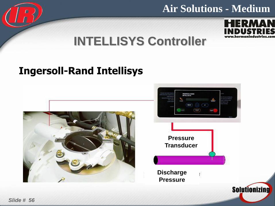
Air Solutions - Medium
Ingersoll-Rand Intellisys
INTELLISYS Controller
Pressure
Transducer
Discharge
Pressure

Slide # 57
Air Solutions - Medium
INTELLISYS Controller
• On/Off Line
–Recommended for
operation at loads less than 60% of
compressor capacity
–Energy Saving
• Modulation
–Effective from 60 to 100% of compressor
capacity
–Constant Pressure
–Less Airend wear
• ACS
–Integrated On-Line/ Off-Line with Upper
Range Modulation
–Decides the best mode of operation
depending on the load conditions
Slide # 58
Air Solutions - Medium
ADJUSTMENTS
• Sump pressure
– adjusted by moving end of hydraulic cylinder
• Online/Offline, ETC...
– adjusted on SE controller
• Modulation
– adjusted using regulator valve.
Slide # 59
Air Solutions - Medium
INSTALLATION
CONSIDERATIONS
• Standard ambient 35°F - 115°F
• Adequate Ventilation
• Away from chemicals and dust
• Protect from weather
• Service access around unit (minimum 42”)
• Do not reduce size of piping
Slide # 60
Air Solutions - Medium
CUSTOMER CONNECTIONS
• Air Discharge
– Location - Back Left Corner
• Condensate
– Location - Back Left Corner
• Power
– Location - Left Side at Top of Starter Enclosure

Slide # 61
Air Solutions - Medium
ROUTINE MAINTENANCE
• Air Filter
– change every 4000 hours
• Coolant Filter
– Initial change after 150 hours
– subsequent changes every 2000 or when coolant is changed
• Coolant
– every 8000 hours or 2 years, whichever comes 1st

Slide # 62
Air Solutions - Medium
• Separator Element
– every 8000 hours or when differential pressure is => 12 PSID
• Clean Coolers
• Grease Motor
– 1000 hours for TEFC
– 2000 hours for ODP
• Clean scavenge orifice
– At every oil filter change
ROUTINE MAINTENANCE
Drive Seal
–every 2 years
Replace Hoses
–Every 2 years
Slide # 63
Air Solutions - Medium
PARTS TO STOCK
• Air Filter
• Coolant Filter
• Coolant
• MPCV Kit
• Blowdown Valve Kit
• Thermal Valve Element
• Separator Element
• 3APT Pressure Sensor
• Thermistor
• HATS
• Inlet Cylinder
• Modulation Regulator
• Shaft Seal and Sleeve
• Fuses
• Auxiliary contacts