single-packet ip traceback
TRANSCRIPT
SNOERENET AL.: SINGLE-PACKET IP TRACEBACK 1
Single-Packet IP TracebackAlex C. Snoeren,Student Member, IEEE, Craig Partridge,Fellow, IEEE,
Luis A. Sanchez, Christine E. Jones, Fabrice Tchakountio,Member, IEEE, Beverly Schwartz,Stephen T. Kent, and W. Timothy Strayer,Senior Member, IEEE
Abstract— The design of the IP protocol makes it difficult to reliablyidentify the originator of an IP packet. Even in the absence of any delib-erate attempt to disguise a packet’s origin, wide-spread packet forwardingtechniques such as NAT and encapsulation may obscure the packet’s truesource. Techniques have been developed to determine the source of largepacket flows, but, to date, no system has been presented to track individualpackets in an efficient, scalable fashion. We present a hash-based techniquefor IP traceback that generates audit trails for traffic within the network,and can trace the origin of a single IP packet delivered by the network inthe recent past. We demonstrate that the system is effective, space-efficient(requiring approximately 0.5% of the link capacity per unit time in stor-age), and implementable in current or next-generation routing hardware.We present both analytic and simulation results showing the system’s effec-tiveness.
I. I NTRODUCTION
TODAY’S Internet infrastructure is extremely vulnerable tomotivated and well-equipped attackers. Tools are readily
available, from covertly exchanged exploit programs to publiclyreleased vulnerability assessment software, to degrade perfor-mance or even disable vital network services. The consequencesare serious and, increasingly, financially disastrous. While dis-tributed denial-of-service attacks, typically conducted by flood-ing network links with large amounts of traffic, are the mostwidely reported, there are other forms of network attacks, manyof which require significantly smaller packet flows. In fact, thereare a number of widely-deployed operating systems and routersthat can be disabled by a single well-targeted packet (e.g., theTeardrop attack crashes versions of Microsoft Windows withone packet [1]). To institute accountability for these attacks,the source of individual packets must be identified.
Unfortunately, the anonymous nature of the IP protocolmakes it difficult to accurately identify the true source of an IPdatagram if the source wishes to conceal it. The network rout-ing infrastructure is stateless and based largely on destinationaddresses; no entity in an IP network is officially responsible forensuring the source address is correct. Many routers employ atechnique calledingress filtering [2] to limit source addresses ofIP datagrams from a stub network to addresses belonging to thatnetwork, but not all routers have the resources necessary to ex-amine the source address of each incoming packet, and ingressfiltering provides no protection on transit networks. Further-
This work was sponsored by the Defense Advanced Research Projects Agency(DARPA) under contract No. N66001-00-C-8038. Views and conclusions con-tained in this document are those of the authors and should not be interpreted asrepresenting official policies, either expressed or implied.
A. C. Snoeren is with the MIT Laboratory for Computer Science, Cambridge,MA 02139 USA and with BBN Technologies, Cambridge, MA 02138 USA(e-mail: [email protected]). L. Sanchez is with Megisto Systems, Inc. (e-mail: [email protected]). The remaining authors are with BBN Technolo-gies, Cambridge, MA 02138 USA (e-mail:{craig, cej, ftchakou, bschwart, kent,strayer}@bbn.com).
A preliminary version of this paper was presented at ACM SIGCOMM ’01 inSan Diego, CA, August 2001.
more, spoofed source addresses are legitimately used by net-work address translators (NATs), Mobile IP, and various unidi-rectional link technologies such as hybrid satellite architectures.
Accordingly, a well-placed attacker can generate offending IPpackets that appear to have originated from almost anywhere.While techniques such as ingress filtering, which suppressespackets arriving from a given network with source addresses thatdo not properly belong to that network, increase the difficulty ofmounting an attack, transit networks are dependent upon theirpeers to perform the appropriate filtering. This interdependenceis clearly unacceptable from a liability perspective; each moti-vated network must be able to secure itself independently.
Systems that can reliably trace individual packets back to theirsources are a first and important step in making attackers (or, atleast, the systems they use) accountable. There are a number ofsignificant challenges in the construction of such a tracing sys-tem including determining which packets to trace, maintainingprivacy (a tracing system should not adversely impact the pri-vacy of legitimate users), and minimizing cost (both in routertime spent tracking rather than forwarding packets, and in stor-age used to keep information).
We have developed aSource Path Isolation Engine (SPIE) toenable IPtraceback, the ability to identify the source of a partic-ular IP packet given a copy of the packet to be traced, its desti-nation, and an approximate time of receipt. Historically, tracingindividual packets has required prohibitive amounts of memory;one of SPIE’s key innovations is to reduce the memory require-ment (down to 0.5% of link bandwidth per unit time) through theuse of Bloom filters [3]. By storing only packet digests, and notthe packets themselves, SPIE also does not increase a network’svulnerability to eavesdropping. SPIE therefore allows routers toefficiently determine if they forwarded a particular packet withina specified time interval while maintaining the privacy of unre-lated traffic.
The rest of this paper examines SPIE in detail. We begin bydefining the problem of IP traceback in section II, and articulatethe desired features of a traceback system. We survey previ-ous work in section III, relating their feature sets against ourrequirements. Section IV describes the digesting process in de-tail. Section V presents an overview of the SPIE architecture,while section VI offers a practical implementation of the con-cepts. Section VII provides both analytic and simulation resultsevaluating SPIE’s traceback success rates. We discuss the issuesinvolved in deploying SPIE in section VIII before concluding insection IX with a brief look at future work.
II. IP TRACEBACK
The concept of IP traceback is not yet well defined. In an at-tempt to clarify the context in which SPIE was developed, this

SNOERENET AL.: SINGLE-PACKET IP TRACEBACK 2
section presents a detailed and formal definition of traceback.We hope that presenting a strawman definition of tracebackwill also help the community better evaluate different tracebackschemes.
In order to remain consistent with the terminology in the liter-ature, we will consider a packet of interest to be nefarious, andterm it anattack packet; similarly, the destination of the packetis a victim. We note, however, that there are many reasons totrace the source of a packet; many packets of interest are sentwith no ill intent whatsoever.
A. Assumptions
There are several important assumptions that a traceback sys-tem should make about a network and the traffic it carries:
• Packets may be addressed to more than one physical host• Duplicate packets may exist in the network• Routers may be subverted, but not often• Attackers are aware they are being traced• The routing behavior of the network may be unstable• The packet size should not grow as a result of tracing• End hosts may be resource constrained• Traceback is an infrequent operation
The first two assumptions are simply characteristics of the In-ternet Protocol. IP packets may contain a multicast or broadcastaddress as their destination, causing the routing infrastructure toduplicate them internally. An attacker can also inject multipleidentical packets itself, possibly at multiple locations. A tracingsystem must be prepared for a situation where there are multi-ple sources of the same (identical) packet, or a single source ofmultiple (also typically identical) packets.
The next two assumptions speak to the capabilities of the at-tacker(s). An attacker may gain access to routers along (or adja-cent to) the path from attacker to victim by a variety of means.Further, a sophisticated attacker is aware of the characteristicsof the network, including the possibility that the network is ca-pable of tracing an attack. The traceback system must not beconfounded by a motivated attacker who subverts a router withthe intent to subvert the tracing system.
The instability of Internet routing is well known [4] and itsimplications for tracing are important. Two packets sent by thesame host to the same destination may traverse wildly differentpaths. As a result, any system that seeks to determine origins us-ing multi-packet analysis techniques must be prepared to makesense of divergent path information.
The assumption that the packet size should not grow is prob-ably the most controversial. There are a number of protocols to-day that cause the packet size to grow, for example technologiesthat rely on packet encapsulation, such as IPsec and mobile IP.However, increasing the packet size causes MTU problems andincreases overhead sharply (each byte of additional overhead re-duces system bandwidth by about 1%, given the average packetsize of about 128 bytes). A recent study by the CooperativeAssociation for Internet Data Analysis (CAIDA) [5] found thatpacket encapsulation (and the resulting growth in packet size) isthe single largest cause of fragmentation on the Internet. It fol-lows that an efficient traceback system should not cause packetsize to grow.
We assume that an end host, and in particular the victim of anattack, may be resource-poor and unable to maintain substan-tial additional administrative state regarding the routing state orthe packets it has previously received. This assumption comesfrom the observed rise in special purpose devices such as mi-croscopes, cameras, and printers that are attached to the Internetyet have few internal resources other than those devoted to per-forming their primary task.
The final assumption that traceback queries are infrequent hasimportant design implications. It implies queries can be han-dled by a router’s control path, and need not be dealt with onthe forwarding path at line speed. While there may be audit-ing tasks associated with packet forwarding to support tracebackthat must be executed while forwarding, the processing of theaudit trails is infrequent with respect to their generation.
B. The goal
Ideally, a traceback system should be able to identify thesource of any piece of data sent across the network. In an IPframework, the packet is the smallest atomic unit of data. Anysmaller division of data (a byte, for instance) is contained withina unique packet. Hence an optimal IP traceback system wouldprecisely identify the source of an arbitrary IP packet. Anylarger data unit or stream can be isolated by searching for anyparticular packet containing data within the stream.1
As with any auditing system, a traceback system can only beeffective in networks in which it has been deployed. Hence weconsider the source of a packet to be one of:• The ingress point to the traceback-enabled network• The actual host or network of origin• One or more compromised routers within the enabled network
If one assumes that any router along the path may be co-optedto assist in concealing a packet’s source, it becomes obvious thatone must attempt to discern not only the packet’s source, butits entire path through the network. Because subverted routerscan fabricate trace information, the path can only be guaranteedto be accurate on the portion from the victim to the a sourceor subverted router, whichever comes first. While subvertedrouters may attempt to conceal their identity by appending ad-ditional sources further up-stream, the subverted routers them-selves must still appear as a node in the trace. We consider sub-verted routers that attempt to conceal the true source of a packetas co-conspirator, and therefore attack sources themselves.
Hence, we are interested in constructing anattack path, wherethe path consists of each router traversed by the packet on itsjourney from source to the victim. Each node in an attackpath either forwarded the packet or lies upstream of a subvertedrouter that did. Further, since multiple, indistinguishable pack-ets may be injected into the network from different sources inthe general case, a traceback system should construct anattackgraph composed of the attack paths for every instance of theattack packet that arrived at the victim.
If routers are subverted, they may provide mis-information tothe traceback system, causing the attack graph to contain false
1Indeed, we would argue that it is desirable to trace the individual packetswithin a stream because the individual packets may have originated at differentsites (meeting only at the victim) and are likely to have followed different pathsthrough the network.
SNOERENET AL.: SINGLE-PACKET IP TRACEBACK 3
positives; that is, the attack graph may implicate sources thatdid not actually emit the packet. We argue these false positivesare unavoidable consequence of admitting the possibility of sub-verted routers. An ideal traceback system, however, produces nofalsenegatives while attempting to minimize false positives; itmust never exonerate an attacker by not including the attackerin the attack graph.
Further, when a traceback system is deployed, it must notreduce the privacy of IP communications. In particular, enti-ties not involved in the generation, forwarding, or receipt of theoriginal packet should not be able to gain access to packet con-tents by either utilizing or as part of participating in the IP trace-back system. An ideal IP traceback system must not expand theeavesdropping capabilities of a malicious party.
C. Transformations
It is important to note that packets may be modified duringthe forwarding process. In addition to the standard decrement-ing of the time to live (TTL) field and checksum recomputation,IP packets may be further transformed by intermediate routers.Packettransformation may be the result of valid processing,router error, or malicious intent. A traceback system need notconcern itself with packet transformations resulting from erroror malicious behavior. Packets resulting from such transforma-tions only need be traced to the point of transformation, as thetransforming node either needs to be fixed or can be considereda co-conspirator (source). A complete traceback system shouldtrace packets through valid transformations back to the sourceof the original packet.
Valid packet transformations are defined as a change of packetstate that allows for or enhances network data delivery. Trans-formations occur due to such reasons as hardware needs, net-work management, protocol requirements, and source request.Based on the transform produced, packet transformations arecategorized as follows:
1. Packet Encapsulation: A new packet is generated in whichthe original packet is encapsulated as the payload (e.g., IPsec).The new packet is forwarded to an intermediate destination forde-encapsulation. Also known astunneling.2. Packet Generation: One or more packets are generated as adirect result of an action by the router on the original packet(e.g., an ICMP Echo Reply sent in response to an ICMP EchoRequest, or packet duplication in IP Multicast). The new packetsare forwarded and processed independent of the original packet.(A large number ofreflector attacks utilize such transforms tohide their source [6].)
Common packet transformations include those performed byRFC 1812-compliant routers [7] such as packet fragmentation,IP option processing, ICMP processing, and packet duplication.Network address translation (NAT) and both IP-in-IP and IPsectunneling are also notable forms of packet transformation. Manyof these transformations result in a loss of the original packetstate due to the stateless nature of IP networks.
A recent CAIDA study of wide-area traffic patterns found thatless than 3% of IP traffic underwent common transformation andIP tunneling [8]. While this study did not encompass all formsof transformation (NAT processing being a notable omission),
it seems safe to assume that packet transformations account fora relatively small fraction of the overall IP traffic traversing theInternet today. However, attackers may transmit packets engi-neered to experience transformation. The ability to trace packetsthat undergo transformation is, therefore, an essential feature ofany viable traceback system.
III. R ELATED WORK
There are two approaches to the problem of determining theroute of a packet flow: one can audit the flow as it traverses thenetwork, or one can attempt to infer the route based upon itsimpact on the state of the network. Both approaches become in-creasingly difficult as the size of the flow decreases, but the latterbecomes infeasible when flow sizes approach a single packet be-cause small flows generally have no measurable impact on thenetwork state.
Route inference was pioneered by Burch and Cheswick [9]who considered the problem of large packet flows and proposeda novel technique that systematically floods candidate networklinks. By watching for variations in the received packet flowdue to the restricted link bandwidth, they are able to infer theflow’s route. This technique requires considerable knowledge ofnetwork topology and the ability to generate large packet floodson arbitrary network links.
One can categorize auditing techniques into two classes ac-cording to the way in which they balance resource requirementsacross the network components. Some techniques require re-sources at both the end host and the routing infrastructure, othersrequire resources only within the network itself. Of those thatrequire only infrastructure support, some add packet processingto the forwarding engine of the routers while others offload thecomputation to the control path of the routers.
A. End-host storage
Some auditing approaches attempt to distribute the burden bystoring state and performing computation at the end hosts ratherthan in the network. Routers notify the packet destination oftheir presence on the route. Because IP packets cannot growarbitrarily large, schemes have been developed to reduce theamount of space required to send such information. Recentlyproposed techniques by Savageet al. [10] and Bellovin [11] ex-plore in-band and out-of-band signaling, respectively.
Because of the high overhead involved, neither Savage norBellovin attempt to provide audit information for every packet.Instead, each employs probabilistic methods that allow suffi-ciently large packet flows to be traced. By providing partialinformation on a subset of packets in a flow, auditing routersenable an end host to reconstruct the entire path traversed bythe packet flow after receiving a sufficient number of packetsbelonging to the flow.
The two schemes diverge in the methods used to communi-cate the information to the end host. Savageet al. employ apacket marking scheme that encodes the information in rarely-used fields within the IP header itself. This approach has beenextended by Song and Perrig to improve the reconstruction ofpaths and authenticate the encodings [12]. In order to avoid thebackwards compatibility issues and increased computation re-
SNOERENET AL.: SINGLE-PACKET IP TRACEBACK 4
quired by the sophisticated encoding schemes employed in thepacket marking schemes, Bellovin’s scheme (and later “inten-tional” extension [13]) simply sends the audit information in anICMP message.
B. Infrastructure approaches
End-host schemes require the end hosts to log meta data incase an incoming packet proves to be offensive. Alternatively,the network itself can be charged with maintaining the audittrails.
The obvious approach to auditing packet flow is simply to logpackets at various points throughout the network and then useappropriate extraction techniques to discover the packet’s paththrough the network. Logging requires no computation on therouter’s fast path and, thus, can be implemented efficiently intoday’s router architecture. Sager suggests such a monitoringapproach [14]. However, the effectiveness of the logs is limitedby the amount of space available to store them. Given today’slink speeds, packet logs quickly grow to intractable sizes, evenover relatively short time frames. An OC-192 link is capableof transferring 1.25GB per second. If one allows 60 seconds toconduct a query, a router with 16 links would require 1.2TB ofhigh-speed storage.
These requirements can be reduced by sampling techniquessimilar to those of the end-host schemes, but down-samplingreduces the probability of detecting small flows and does not al-leviate the security issues raised by storing complete packets inthe router. The ability of an attacker to break into a router andcapture terrabytes of actual traffic has severe privacy implica-tions.
Alternatively, routers can be tasked to perform more sophis-ticated auditing in real time, extracting a smaller amount ofinformation as packets are forwarded. Many currently avail-able routers supportinput debugging, a feature that identifieson which incoming port a particular outgoing packet (or set ofpackets) of interest arrived. Since no history is stored, however,this process must be activated before an attack packet passes by.Furthermore, due to the high overhead of this operation on manypopular router architectures, activating it may have adverse ef-fects on the traffic currently being serviced by the router.
C. Specialized routing
One of the main problems with the link testing or loggingmethods above is the large amount of repetition required. Atrace is conducted in a hop-by-hop fashion, querying each routeralong the way. Once the incoming link or links have been iden-tified, the process must be repeated at the upstream router.
Several techniques have been developed to streamline and au-tomate this process. Some ISPs have developed their own adhoc mechanisms for automatically conducting input debuggingacross their networks. Schnackenberget al. [15] propose a moregeneral Intruder Detection and Isolation Protocol (IDIP) to facil-itate interaction between routers involved in a traceback effort.IDIP does not specify how participating entities should trackpacket traffic; it simply requires that they be able to determinewhether or not they have seen a component of an attack match-ing a certain description. Even with automated tools, however,
each router in the ISP must support input debugging or loggingwhich are not common in today’s high-speed routers for reasonsdiscussed above.
In order to avoid this requirement, Stone [16] suggests con-structing an overlay network connecting all the edge routers ofan ISP. By using a deliberately simple topology of specializedrouters, suspicious flows can be dynamically rerouted across thespecial tracking network for analysis. This approach has twomajor shortcomings. First, the attack must be sufficiently long-lived to allow the ISP to effect the rerouting before the relevantflow terminates. Second, the routing change is perceptible bythe attacker, and an especially motivated attacker may be able toescape detection by taking appropriate action. While techniquesexist to hide precisely what changed about the route, changes inlayer-three topology are hard to mask.
IV. PACKET DIGESTING
SPIE, the Source Path Isolation Engine, uses auditing tech-niques to support the traceback of individual packets while re-ducing the storage requirements by several orders of magnitudeover current log-based techniques [14]. Traffic auditing is ac-complished by computing and storing packet digests rather thanstoring the packets themselves. In addition to reducing stor-age requirements, storing packet digests instead of the actualpacket contents preserves traffic confidentiality by preventingSPIE from being used as a tool for eavesdropping.
A. Digest input
The packet content used as input to the digesting functionmust uniquely represent an IP packet and enable the identifi-cation of the packet across hops in the forwarding path. At thesame time, it is desirable to limit the size of the digest input bothfor performance and for reasons discussed below (c.f. section V-C). Duffield and Grossglauser encountered similar requirementswhile sampling a subset of forwarded packets in an attempt tomeasure traffic flows [17]. We use a similar approach, maskingvariant packet content and selecting an appropriate-length pre-fix of the packet to use as input to the digesting function. Ourchoice of invariant fields and prefix length is slightly different,however.2
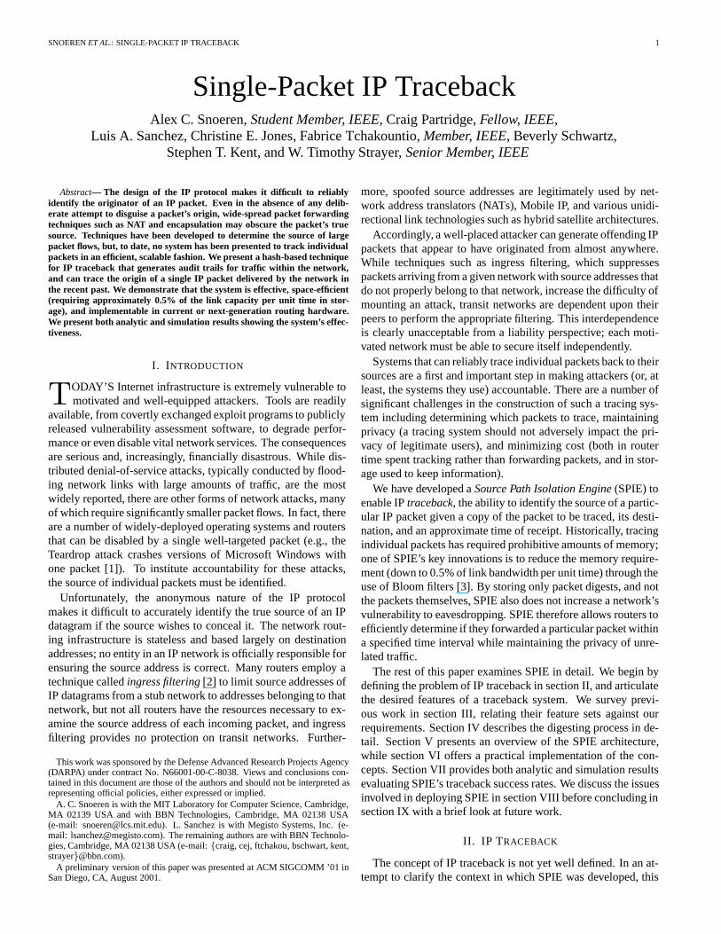
Figure 1 shows an IP packet and the fields included by theSPIE digesting function. SPIE computes digests over the invari-ant portion of the IP header and the first 8 bytes of the payload.Frequently modified header fields are masked prior to digesting.Note that beyond the obvious fields (TTL, TOS, and checksum),certain IP options cause routers to rewrite the option field at var-ious intervals. To ensure a packet appears identical at all stepsalong its route, SPIE masks or compensates for these fields whencomputing the packet digests. It is important to note that the in-variant IP fields used for SPIE digesting may occasionally bemodified by a packet transform (c.f. section V-C).
Our research indicates that the first 24invariant bytes of apacket (20-byte IP header with 4 bytes masked out plus the first8 bytes of payload) are sufficient to differentiate almost all non-
2Because we sample a smaller portion of the packet (28 vs. 40 bytes), weinclude fields like header length and protocol that Duffield and Grossglausereschewed due to their lower entropy.
SNOERENET AL.: SINGLE-PACKET IP TRACEBACK 5
Payload
Options
Destination Address
Source Address
TTL Protocol Checksum
Identification DF
MF Fragment Offset
Version HeaderLength Type of Service Total Length
Fig. 1. The fields of an IP packet. Fields in gray are masked out before digest-ing, including the Type of Service, Time to Live (TTL), IP checksum, and IPoptions fields.
1e-06
1e-05
0.0001
0.001
0.01
0.1
1
20 22 24 26 28 30 32 34 36 38 40
Fra
ctio
n of
Col
lided
Pac
kets
Prefix Length (in bytes)
WANLAN
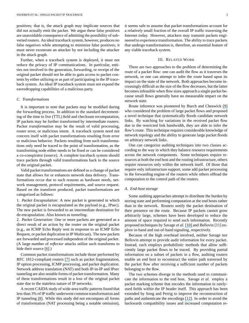
Fig. 2. The fraction of packets that collide (with ToS, TTL, and checksum fieldsmasked out) as a function of prefix length. The WAN trace represents 985,150packets (with 5,801 duplicates removed) between 6,031 host pairs collected onJuly 20, 2000 at the University of Florida OC-3 gateway. The LAN trace con-sists of one million packets (317 duplicates removed) between 2,879 host pairsobserved on an Ethernet segment at the MIT Lab for Computer Science.
identical packets. Figure 2 presents the rate of packet collisionsfor an increasing prefix length for two representative traces: aWAN trace from an OC-3 gateway router, and a LAN tracefrom an active 100Mb Ethernet segment. (Results were sim-ilar for traces across a number of sites.) Two unique packetswhich are identical up to the specified prefix length are termeda collision. A 28-byte prefix (only 24 non-masked bytes) resultsin a collision rate of approximately 0.00092% in the wide areaand 0.139% on the LAN.
Unlike similar results reported by Duffield and Gross-glauser [17, fig. 4], our results include only unique packets;exact duplicates were removed from the packet trace. Close in-spection of packets in the wide area with identical prefixes in-dicates that packets with matching prefix lengths of 22 and 23bytes are ICMP Time Exceeded error packets with the IP iden-tification field set to zero. Similarly, packets with matching pre-fixes between 24 and 31 bytes in length are TCP packets with IPidentifications also set to zero which are first differentiated by
H1(P)
H2(P)
H3(P)
.
.
.
Hk(P)
n bits
1
1
1
1
2n
bits
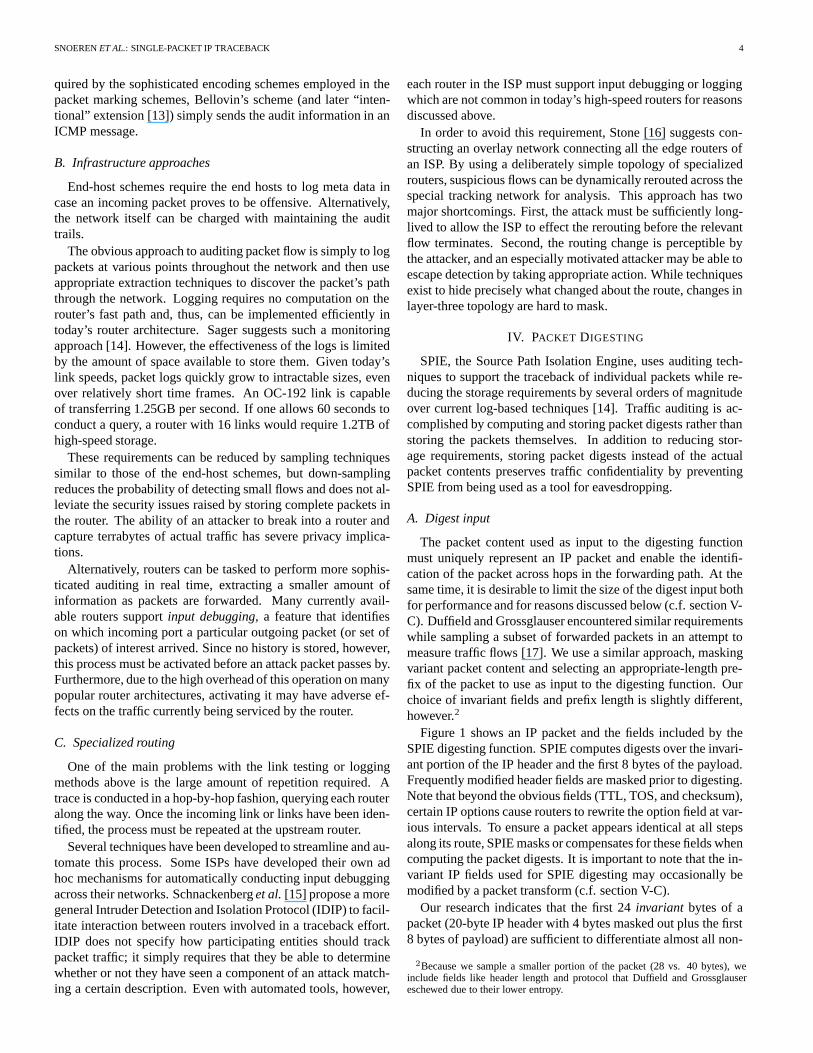
Fig. 3. For each packet received, SPIE computesk independentn-bit digests,and sets the corresponding bits in the2n-bit digest table.
the TCP sequence number or acknowledgment fields.3
The markedly higher collision rate in the local area is dueto the lack of address and traffic diversity. This expected re-sult does not significantly impact SPIE’s performance, how-ever. LANs are likely to exist at only two points in an attackgraph: immediately surrounding the victim and the attacker(s).False positives on the victim’s local network can be easily elimi-nated from the attack graph—they likely share the same gatewayrouter in any event. False positives at the source are unlikely ifthe attacker is using spoofed source addresses, as this providesthe missing diversity in attack traffic, and remain in the imme-diate vicinity of the true attacker by definition. Hence, for thepurposes of SPIE, IP packets are effectively distinguished by thefirst 24 invariant bytes of the packet.
B. Bloom filters
Constructing a digest table containing packet digests corre-sponding to the traffic forwarded by a router for a given timeinterval is a challenging task. A naive technique that simplystored the digests themselves would require massive amounts ofstorage. Instead, SPIE implements digest tables using space-efficient data structures known as Bloom filters [3]. A Bloomfilter computesk distinct packet digests for each packet usingindependent uniform hash functions, and uses then-bit resultsto index into a2n-sized bit array. The array is initialized to allzeros, and bits are set to one as packets are received. Figure 3depicts a Bloom filter withk hash functions.
Membership tests can be conducted simply by computing thek digests on the packet in question and checking the indicatedbit positions. If any one of them is zero, the packet was notstored in the table. If, however, all the bits are one, it is highlylikely the packet was stored. It is possible that some set of otherinsertions caused all the bits to be set, creating afalse positive,but the rate of such false positives can be controlled by onlyallowing an individual Bloom filter to store a limited numberof digests [18]. Saturated filters can be swapped out for a new,empty filter, and archived for later querying.
3Further investigation indicates a number of current operating systems, in-cluding recent versions of Linux, frequently set the IP ID to zero.
SNOERENET AL.: SINGLE-PACKET IP TRACEBACK 6
C. Hash functions
SPIE places three major restrictions on the family of hashfunctions,F , used as digesting functions in its Bloom filters.First, each member function must distribute a highly correlatedset of input values (IP packet prefixes),P , as uniformly as pos-sible over the hash’s result value space. That is, for a hash func-tion H : P → 2m in F , and distinct packetsx �= y ∈ P ,Pr[H(x) = H(y)] = 2−m. This is a standard property of goodhash functions.
SPIE further requires that the event that two packets collidein one hash function (H(x) = H(y) for someH) be inde-pendent of collision events in any other functions (H ′(x) =H ′(y), H ′ �= H). Intuitively, this implies false positives at onerouter are independent of false positives at neighboring routers.Formally, for any functionH ∈ F chosen at random indepen-dently of the input packetsx andy, Pr[H(x) = H(y)] = 2−m
with high probability. Such hash families, calleduniversal hashfamilies, were first defined by Carter and Wegman [19] and canbe implemented in a variety of fashions [20], [21], [22].
Finally, member functions must be straightforward to com-pute at high link speeds. This requirement is not impracticalbecause SPIE hash functions do not require any cryptographic“hardness” properties. That is, it does not have to be difficult togenerate a valid input packet given a particular hash value. Be-ing able to create a packet with a particular hash value enablesthree classes of attacks, each of which is fairly benign. Oneattack would ensure that all attack packets have the same finger-print in the Bloom filter at some router (which is very difficultsince there are multiple, independent hashes at each router), butthis achievement is of little use, as the packet fingerprints wouldbe distinct at neighboring routers (due to the independent hashfunctions at each router). Another attack is to ensure all attackpackets have different fingerprints, but that is the common casealready. The third, and most difficult attack, is to create an attackpacket with the same fingerprint as another, non-attack packet.In general, this attack simply adds one additional false-positivenode (where the two packets are indistinguishable) to the attackgraph of both packets.
V. SOURCE PATH ISOLATION ENGINE
SPIE-enhanced routers maintain a cache of packet digests forrecently forwarded traffic. If a packet is determined to be offen-sive by some intrusion detection system (or judged interestingby some other metric), a query is dispatched to SPIE which inturn queries routers for packet digests of the relevant time peri-ods. The results of this query are used in a simulated reverse-path flooding algorithm to build an attack graph that indicatesthe packet’s source(s).
A. Architecture
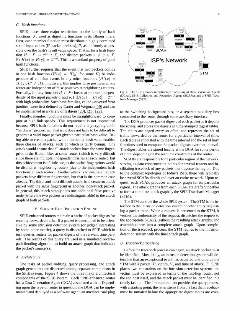
The tasks of packet auditing, query processing, and attackgraph generation are dispersed among separate components inthe SPIE system. Figure 4 shows the three major architecturalcomponents of the SPIE system. Each SPIE-enhanced routerhas a Data Generation Agent (DGA) associated with it. Depend-ing upon the type of router in question, the DGA can be imple-mented and deployed as a software agent, an interface card plug
Router
Router
DGA
RouterRouter
Router
DGA
SCARRouter
Router
Router
DGA
STM
ISP's Network
Fig. 4. The SPIE network infrastructure, consisting of Data Generation Agents(DGAs), SPIE Collection and Reduction Agents (SCARs), and a SPIE Trace-back Manager (STM).
to the switching background bus, or a separate auxiliary boxconnected to the router through some auxiliary interface.
The DGA produces packet digests of each packet as it departsthe router, and stores the digests in time-stamped digest tables.The tables are paged every so often, and represent the set oftraffic forwarded by the router for a particular interval of time.Each table is annotated with the time interval and the set of hashfunctions used to compute the packet digests over that interval.The digest tables are stored locally at the DGA for some periodof time, depending on the resource constraints of the router.
SCARs are responsible for a particular region of the network,serving as data concentration points for several routers and fa-cilitating traceback of any packets that traverse the region. Dueto the complex topologies of today’s ISPs, there will typicallybe several SCARs distributed over an entire network. Upon re-quest, each SCAR produces an attack graph for its particularregion. The attack graphs from each SCAR are grafted togetherto form a complete attack graph by the SPIE Traceback Manager(STM).
The STM controls the whole SPIE system. The STM is the in-terface to the intrusion detection system or other entity request-ing a packet trace. When a request is presented to the STM, itverifies the authenticity of the request, dispatches the request tothe appropriate SCARs, gathers the resulting attack graphs, andassembles them into a complete attack graph. Upon comple-tion of the traceback process, the STM replies to the intrusiondetection system with the final attack graph.
B. Traceback processing
Before the traceback process can begin, an attack packet mustbe identified. Most likely, an intrusion detection system will de-termine that an exceptional event has occurred and provide theSTM with a packet,P , victim, V , and time of attack,T . SPIEplaces two constraints on the intrusion detection system: thevictim must be expressed in terms of the last-hop router, notthe end host itself, and the attack packet must be identified in atimely fashion. The first requirement provides the query processwith a starting point; the latter stems from the fact that tracebackmust be initiated before the appropriate digest tables are over-
SNOERENET AL.: SINGLE-PACKET IP TRACEBACK 7
written by the DGAs. This time constraint is directly related tothe amount of resources dedicated to the storage of traffic di-gests. (We discuss timing and resource tradeoffs in section VII).
Upon receipt of traceback request, the STM cryptographicallyverifies its authenticity and integrity. Any entity wishing to em-ploy SPIE to perform a traceback operation must be properlyauthorized in order to prevent denial-of-service attacks. Uponsuccessful verification, the STM dispatches the query to the rele-vant SCARs for processing. Beginning at the SCAR responsiblefor the victim’s region of the network, the STM sends a querymessage containingP , V , andT as provided by the intrusiondetection system. The SCAR polls its DGAs and responds witha partial attack graph, the timeT ′ the packet entered the region,and the entering packet itselfP ′ (it may have been transformed,possibly multiple times, within the region).
The attack graph either terminates within the region managedby the SCAR, in which case a source has been identified, or itcontains nodes at the edge of the SCAR’s network region. Inthe latter case the STM sends a new query for the transformedpacketP ′ to the SCAR for the abutting network region. Thisquery uses the border router between the two network regionsas its victim,V ′, andT ′ as the time of attack. This processcontinues until all branches of the attack graph terminate, eitherat a source within the network, or at the edge of the SPIE sys-tem. The STM then constructs a composite attack graph whichit returns to the intrusion detection system.
C. Transformation processing
IP packets may undergo valid transformation while traversingthe network, and SPIE must be capable of tracing through suchtransformations. In particular, SPIE must be able to reconstructthe original packet from the transformed packet. Unfortunately,many transformations are not invertible without additional infor-mation due to the stateless nature of IP networks. Consequently,SPIE must record sufficient packet data at the time of transfor-mation to allow the original packet to be reconstructed.
The packet data chosen as input to the digesting function de-termines the set of packet transformations SPIE must handle—SPIE need only consider transformations that modify fields usedas input to the digest function. SPIE computes digests overthe IP header and the first eight bytes of the packet payloadbut masks out (or omits in the case of IP options) several fre-quently updated fields before digesting, as shown in figure 1of section IV. Masking hides most hop-by-hop transformationsfrom the digesting function, but forces SPIE to explicitly handleeach of the following transformations: fragmentation, networkaddress translation (NAT), ICMP messages, IP-in-IP tunneling,and IP security (IPsec).
Recording the information necessary to reconstruct the orig-inal packet from a transformed packet requires additional re-sources. Fortunately for SPIE, the circumstances that causea packet to undergo a transformation will generally take thatpacket off of the fast path of the router and put it onto the con-trol path, relaxing the timing requirements. The router’s mem-ory constraints remain unchanged, however; hence, transforma-tion information must be stored in a scalable and space-efficientmanner.
Digest Type I Packet Data
29 bits 3 bits 32 bits
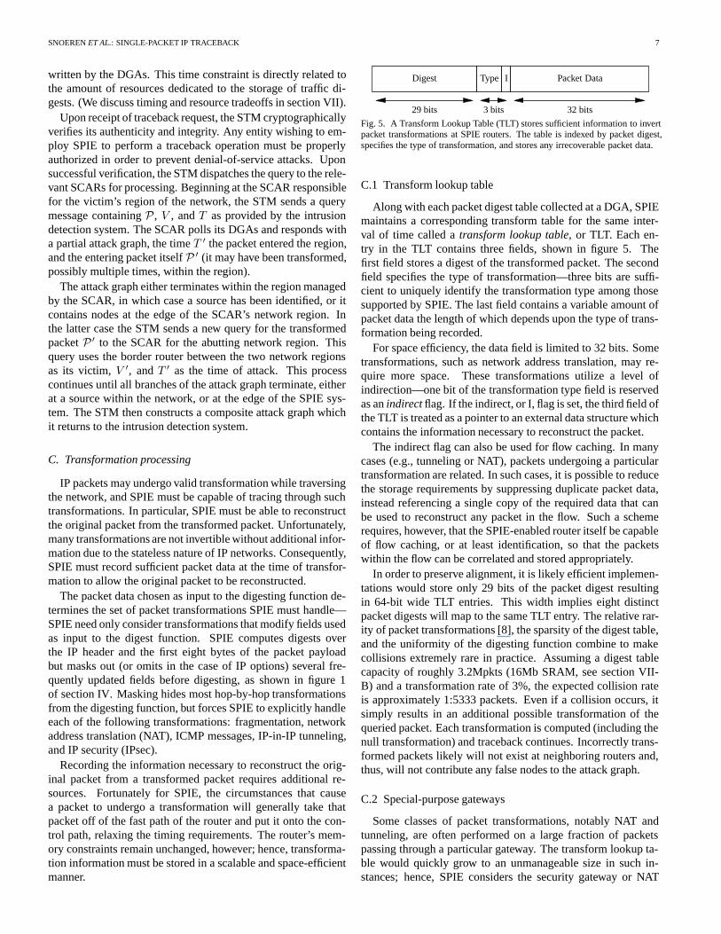
Fig. 5. A Transform Lookup Table (TLT) stores sufficient information to invertpacket transformations at SPIE routers. The table is indexed by packet digest,specifies the type of transformation, and stores any irrecoverable packet data.
C.1 Transform lookup table
Along with each packet digest table collected at a DGA, SPIEmaintains a corresponding transform table for the same inter-val of time called atransform lookup table, or TLT. Each en-try in the TLT contains three fields, shown in figure 5. Thefirst field stores a digest of the transformed packet. The secondfield specifies the type of transformation—three bits are suffi-cient to uniquely identify the transformation type among thosesupported by SPIE. The last field contains a variable amount ofpacket data the length of which depends upon the type of trans-formation being recorded.
For space efficiency, the data field is limited to 32 bits. Sometransformations, such as network address translation, may re-quire more space. These transformations utilize a level ofindirection—one bit of the transformation type field is reservedas anindirect flag. If the indirect, or I, flag is set, the third field ofthe TLT is treated as a pointer to an external data structure whichcontains the information necessary to reconstruct the packet.
The indirect flag can also be used for flow caching. In manycases (e.g., tunneling or NAT), packets undergoing a particulartransformation are related. In such cases, it is possible to reducethe storage requirements by suppressing duplicate packet data,instead referencing a single copy of the required data that canbe used to reconstruct any packet in the flow. Such a schemerequires, however, that the SPIE-enabled router itself be capableof flow caching, or at least identification, so that the packetswithin the flow can be correlated and stored appropriately.
In order to preserve alignment, it is likely efficient implemen-tations would store only 29 bits of the packet digest resultingin 64-bit wide TLT entries. This width implies eight distinctpacket digests will map to the same TLT entry. The relative rar-ity of packet transformations [8], the sparsity of the digest table,and the uniformity of the digesting function combine to makecollisions extremely rare in practice. Assuming a digest tablecapacity of roughly 3.2Mpkts (16Mb SRAM, see section VII-B) and a transformation rate of 3%, the expected collision rateis approximately 1:5333 packets. Even if a collision occurs, itsimply results in an additional possible transformation of thequeried packet. Each transformation is computed (including thenull transformation) and traceback continues. Incorrectly trans-formed packets likely will not exist at neighboring routers and,thus, will not contribute any false nodes to the attack graph.
C.2 Special-purpose gateways
Some classes of packet transformations, notably NAT andtunneling, are often performed on a large fraction of packetspassing through a particular gateway. The transform lookup ta-ble would quickly grow to an unmanageable size in such in-stances; hence, SPIE considers the security gateway or NAT
SNOERENET AL.: SINGLE-PACKET IP TRACEBACK 8
functionality of routers as a separate entity. Standard routingtransformations are handled as above, but special purpose gate-way transformations require a different approach to transforma-tion handling. Transformations in these types of gateways aregenerally computed in a stateful way (usually based on a staticrule set); hence, they can be inverted in a similar fashion. Whilethe details are implementation-specific, inverting such transfor-mations is straightforward; we do not consider it here.
C.3 Sample transformations
A good example of transformation is packet fragmentation.To avoid needing to store any of the packet payload, SPIE sup-ports inversion of only the first packet fragment, i.e., only thefirst fragment may be traced back beyond the point of fragmen-tation. The remaining fragments may be traced to the pointof fragmentation, but no further. Note that for most fragment-based attacks [1], the attacker inserts fragments directly into thenetwork (i.e., the attacker is the point of fragmentation) so thetraceback is complete. (If only a subset of the fragments is re-ceived by the victim the packet cannot be reassembled; hence,the only viable attack is a denial-of-service attack on the victim’sreassembly engine. But, if the fragmentation occurs within thenetwork itself, an attacker cannot control which fragments arereceived by the victim so the victim will eventually receive afirst fragment to use in traceback.) Packet data to be recordedincludes the total length, fragment offset, and more fragments(MF) field. Since properly-behaving IP routers cannot createfragments with less than 8 bytes of payload information [23],when given the first fragment, SPIE is always able to invert frag-mentation and reconstruct the header and at least 64 bits of pay-load of the pre-fragmented packet which is sufficient to continuetraceback.
Observe that SPIE never needs to record any packet payloadinformation. ICMP transformations can be inverted becauseICMP error messages always include at least the first 64 bitsof the offending packet [24]. Careful readers may be concernedthat encapsulation cannot be inverted if the encapsulated packetis subsequently fragmented and the fragments containing the en-capsulated IP header and first 64 bits of payload are not avail-able. While this is strictly true, such transformations need to beinverted only in extreme cases as it takes a very sophisticatedattacker to cause a packet to be first encapsulated, then frag-mented, and then ensure fragment loss. If all the fragments arereceived, the original header can be extracted from the reassem-bled payload. It seems quite difficult for an attacker to ensurethat packet fragments are lost. It can cause packet loss by flood-ing the link, but to do so requires sending such a large numberof packets that it is very likely that all the fragments for at leastone packet will be successfully received by the de-encapsulatorfor use in traceback.
D. Graph construction
Each SCAR constructs a subgraph using topology informa-tion about its particular region of the network. After queryingeach of the DGAs in its region, a SCAR simulates reverse-pathflooding by examining the results in the order they would bequeried if an actual reverse path flood was conducted on the
V
R6
R8 R9
R7
R1S1
S3S2
R4
A S4
R3R2
R5S5
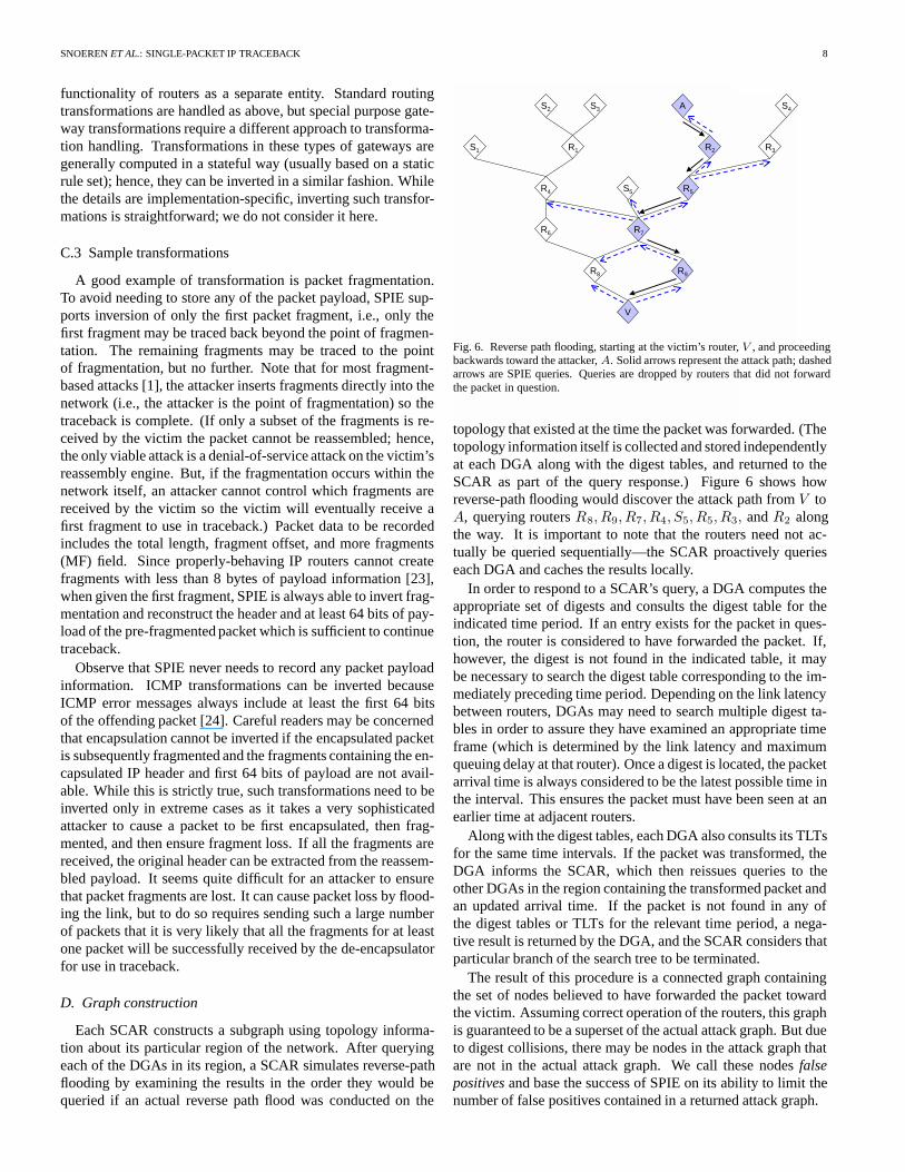
Fig. 6. Reverse path flooding, starting at the victim’s router,V , and proceedingbackwards toward the attacker,A. Solid arrows represent the attack path; dashedarrows are SPIE queries. Queries are dropped by routers that did not forwardthe packet in question.
topology that existed at the time the packet was forwarded. (Thetopology information itself is collected and stored independentlyat each DGA along with the digest tables, and returned to theSCAR as part of the query response.) Figure 6 shows howreverse-path flooding would discover the attack path fromV toA, querying routersR8, R9, R7, R4, S5, R5, R3, andR2 alongthe way. It is important to note that the routers need not ac-tually be queried sequentially—the SCAR proactively querieseach DGA and caches the results locally.
In order to respond to a SCAR’s query, a DGA computes theappropriate set of digests and consults the digest table for theindicated time period. If an entry exists for the packet in ques-tion, the router is considered to have forwarded the packet. If,however, the digest is not found in the indicated table, it maybe necessary to search the digest table corresponding to the im-mediately preceding time period. Depending on the link latencybetween routers, DGAs may need to search multiple digest ta-bles in order to assure they have examined an appropriate timeframe (which is determined by the link latency and maximumqueuing delay at that router). Once a digest is located, the packetarrival time is always considered to be the latest possible time inthe interval. This ensures the packet must have been seen at anearlier time at adjacent routers.
Along with the digest tables, each DGA also consults its TLTsfor the same time intervals. If the packet was transformed, theDGA informs the SCAR, which then reissues queries to theother DGAs in the region containing the transformed packet andan updated arrival time. If the packet is not found in any ofthe digest tables or TLTs for the relevant time period, a nega-tive result is returned by the DGA, and the SCAR considers thatparticular branch of the search tree to be terminated.
The result of this procedure is a connected graph containingthe set of nodes believed to have forwarded the packet towardthe victim. Assuming correct operation of the routers, this graphis guaranteed to be a superset of the actual attack graph. But dueto digest collisions, there may be nodes in the attack graph thatare not in the actual attack graph. We call these nodesfalsepositives and base the success of SPIE on its ability to limit thenumber of false positives contained in a returned attack graph.
SNOERENET AL.: SINGLE-PACKET IP TRACEBACK 9
...
S32
S32
S32
S32
S32
Sk
2k-bit RAMt
t-P s
+
FIFO RAM MUX
Readout by
Control Processor
......
Ring Buffer DRAM
Time=t
readout every R ms
Signature Taps Signature Aggregation History Memory
Line Cards SPIE Card (or Box)
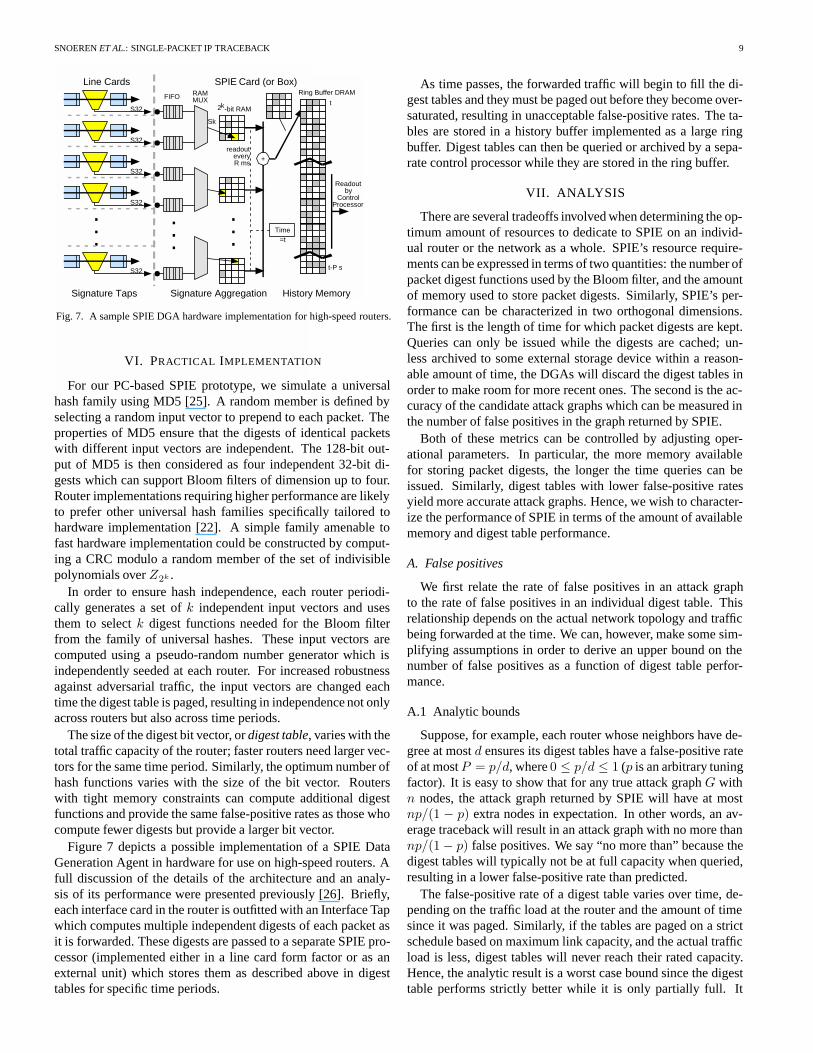
Fig. 7. A sample SPIE DGA hardware implementation for high-speed routers.
VI. PRACTICAL IMPLEMENTATION
For our PC-based SPIE prototype, we simulate a universalhash family using MD5 [25]. A random member is defined byselecting a random input vector to prepend to each packet. Theproperties of MD5 ensure that the digests of identical packetswith different input vectors are independent. The 128-bit out-put of MD5 is then considered as four independent 32-bit di-gests which can support Bloom filters of dimension up to four.Router implementations requiring higher performance are likelyto prefer other universal hash families specifically tailored tohardware implementation [22]. A simple family amenable tofast hardware implementation could be constructed by comput-ing a CRC modulo a random member of the set of indivisiblepolynomials overZ2k .
In order to ensure hash independence, each router periodi-cally generates a set ofk independent input vectors and usesthem to selectk digest functions needed for the Bloom filterfrom the family of universal hashes. These input vectors arecomputed using a pseudo-random number generator which isindependently seeded at each router. For increased robustnessagainst adversarial traffic, the input vectors are changed eachtime the digest table is paged, resulting in independence not onlyacross routers but also across time periods.
The size of the digest bit vector, ordigest table, varies with thetotal traffic capacity of the router; faster routers need larger vec-tors for the same time period. Similarly, the optimum number ofhash functions varies with the size of the bit vector. Routerswith tight memory constraints can compute additional digestfunctions and provide the same false-positive rates as those whocompute fewer digests but provide a larger bit vector.
Figure 7 depicts a possible implementation of a SPIE DataGeneration Agent in hardware for use on high-speed routers. Afull discussion of the details of the architecture and an analy-sis of its performance were presented previously [26]. Briefly,each interface card in the router is outfitted with an Interface Tapwhich computes multiple independent digests of each packet asit is forwarded. These digests are passed to a separate SPIE pro-cessor (implemented either in a line card form factor or as anexternal unit) which stores them as described above in digesttables for specific time periods.
As time passes, the forwarded traffic will begin to fill the di-gest tables and they must be paged out before they become over-saturated, resulting in unacceptable false-positive rates. The ta-bles are stored in a history buffer implemented as a large ringbuffer. Digest tables can then be queried or archived by a sepa-rate control processor while they are stored in the ring buffer.
VII. ANALYSIS
There are several tradeoffs involved when determining the op-timum amount of resources to dedicate to SPIE on an individ-ual router or the network as a whole. SPIE’s resource require-ments can be expressed in terms of two quantities: the number ofpacket digest functions used by the Bloom filter, and the amountof memory used to store packet digests. Similarly, SPIE’s per-formance can be characterized in two orthogonal dimensions.The first is the length of time for which packet digests are kept.Queries can only be issued while the digests are cached; un-less archived to some external storage device within a reason-able amount of time, the DGAs will discard the digest tables inorder to make room for more recent ones. The second is the ac-curacy of the candidate attack graphs which can be measured inthe number of false positives in the graph returned by SPIE.
Both of these metrics can be controlled by adjusting oper-ational parameters. In particular, the more memory availablefor storing packet digests, the longer the time queries can beissued. Similarly, digest tables with lower false-positive ratesyield more accurate attack graphs. Hence, we wish to character-ize the performance of SPIE in terms of the amount of availablememory and digest table performance.
A. False positives
We first relate the rate of false positives in an attack graphto the rate of false positives in an individual digest table. Thisrelationship depends on the actual network topology and trafficbeing forwarded at the time. We can, however, make some sim-plifying assumptions in order to derive an upper bound on thenumber of false positives as a function of digest table perfor-mance.
A.1 Analytic bounds
Suppose, for example, each router whose neighbors have de-gree at mostd ensures its digest tables have a false-positive rateof at mostP = p/d, where0 ≤ p/d ≤ 1 (p is an arbitrary tuningfactor). It is easy to show that for any true attack graphG withn nodes, the attack graph returned by SPIE will have at mostnp/(1 − p) extra nodes in expectation. In other words, an av-erage traceback will result in an attack graph with no more thannp/(1 − p) false positives. We say “no more than” because thedigest tables will typically not be at full capacity when queried,resulting in a lower false-positive rate than predicted.
The false-positive rate of a digest table varies over time, de-pending on the traffic load at the router and the amount of timesince it was paged. Similarly, if the tables are paged on a strictschedule based on maximum link capacity, and the actual trafficload is less, digest tables will never reach their rated capacity.Hence, the analytic result is a worst case bound since the digesttable performs strictly better while it is only partially full. It
SNOERENET AL.: SINGLE-PACKET IP TRACEBACK 10
represents the expected number of false positives returned if thequery was conducted at the worst possible moment, i.e., whenall digest tables were at maximum capacity. Furthermore, ouranalysis assumes the set of neighbors at each node is disjointwhich is not true in real networks. It seems reasonable to ex-pect, therefore, that the false-positive rate over real topologieswith actual utilization rates would be substantially lower.
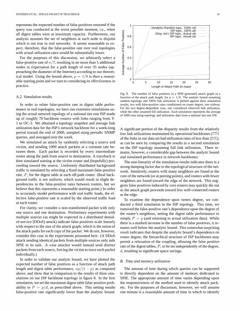
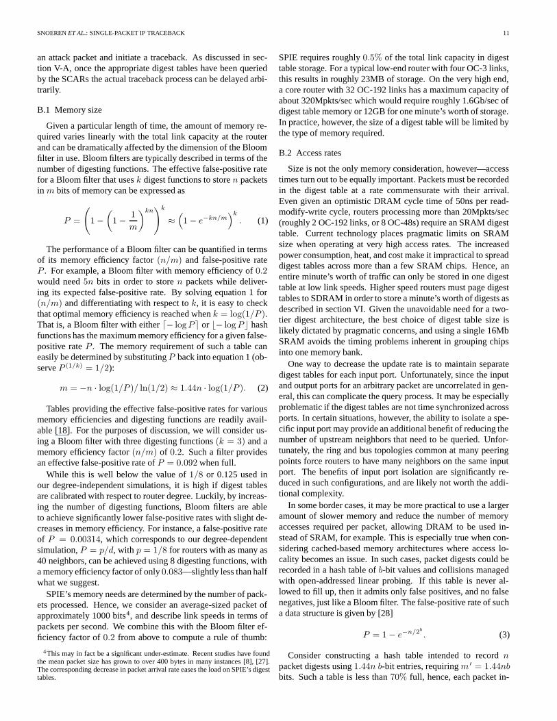
For the purposes of this discussion, we arbitrarily select afalse-positive rate ofn/7, resulting in no more than 5 additionalnodes in expectation for a path length of over 35 nodes (ap-proaching the diameter of the Internet) according to our theoret-ical model. Using the bound above,p = 1/8 is then a reason-able starting point and we turn to considering its effectiveness inpractice.
A.2 Simulation results
In order to relate false-positive rate to digest table perfor-mance in real topologies, we have run extensive simulations us-ing the actual network topology of a national tier-one ISP madeup of roughly 70 backbone routers with links ranging from T-1 to OC-3. We obtained a topology snapshot and average linkutilization data for the ISP’s network backbone for a week-longperiod toward the end of 2000, sampled using periodic SNMPqueries, and averaged over the week.
We simulated an attack by randomly selecting a source andvictim, and sending 1000 attack packets at a constant rate be-tween them. Each packet is recorded by every intermediaterouter along the path from source to destination. A traceback isthen simulated starting at the victim router and (hopefully) pro-ceeding toward the source. Uniformly distributed backgroundtraffic is simulated by selecting a fixed maximum false-positiverate,P , for the digest table at each off-path router. (Real back-ground traffic is not uniform, which would result in slight de-pendencies in the false-positive rates between routers, but webelieve that this represents a reasonable starting point.) In orderto accurately model performance with real traffic loads, the ef-fective false-positive rate is scaled by the observed traffic loadat each router.
For clarity, we consider a non-transformed packet with onlyone source and one destination. Preliminary experiments withmultiple sources (as might be expected in a distributed denial-of-service (DDoS) attack) indicate false positives scale linearlywith respect to the size of the attack graph, which is the union ofthe attack paths for each copy of the packet. We do not, however,consider this case in the experiments presented here. (A DDoSattack sending identical packets from multiple sources only aidsSPIE in its task. A wise attacker would instead senddistinctpackets from each source, forcing the victim to trace each packetindividually.)
In order to validate our analytic bound, we have plotted theexpected number of false positives as a function of attack pathlength and digest table performance,np/(1 − p) as computedabove, and show that in comparison to the results of three sim-ulations on our ISP backbone topology in figure 8. In the firstsimulation, we set the maximum digest table false-positive prob-ability to P = p/d, as prescribed above. This setting resultsfalse-positive rate significantly lower than the analytic bound.
0
0.2
0.4
0.6
0.8
1
0 5 10 15 20 25 30
Ave
rage
Num
ber
of F
alse
Pos
itive
s
Length of Attack Path (in hops)
(Analytic) Random topo., 100% util.ISP topo., 100% util.
(Deg. Ind.) ISP topo., Actual util.ISP topo., Actual util.
Fig. 8. The number of false positives in a SPIE-generated attack graph as afunction of the attack path length, forp = 1/8. The analytic bound assumingrandom topology and 100% link utilization is plotted against three simulationresults, two with false-positive rates conditioned on router degree, one without.For the two degree-dependent runs, one considered observed link utilization,while the other assumed full utilization. Each simulation represents the averageof 5000 runs using topology and utilization data from a national tier-one ISP.
A significant portion of the disparity results from the relativelylow link utilizations maintained by operational backbones (77%of the links in our data set had utilization rates of less than25%),as can be seen by comparing the results to a second simulationon the ISP topology assuming full link utilization. There re-mains, however, a considerable gap between the analytic boundand simulated performance in network backbones.
The non-linearity of the simulation results indicates there is astrong damping factor due to the topological structure of the net-work. Intuitively, routers with many neighbors are found at thecore of the network (or at peering points), and routers with fewerneighbors are found toward the edge of the network. This sug-gests false positives induced by core routers may quickly die outas the attack graph proceeds toward less well-connected routersat the edge.
To examine the dependence upon vertex degree, we con-ducted a third simulation in the ISP topology. This time, weremoved the false-positive rate’s dependence upon the degree ofthe router’s neighbors, setting the digest table performance tosimply P = p (and returning to actual utilization data). Whilethere is a marked increase in the number of false positives, it re-mains well below the analytic bound. This somewhat surprisingresult indicates that despite the analytic bound’s dependence onrouter degree, the hierarchical structure of ISP backbones maypermit a relaxation of the coupling, allowing the false positiverate of the digest tables,P , to be set independently of the degree,d, resulting in significant space savings.
B. Time and memory utilization
The amount of time during which queries can be supportedis directly dependent on the amount of memory dedicated toSPIE. The appropriate amount of time varies depending uponthe responsiveness of the method used to identify attack pack-ets. For the purposes of discussion, however, we will assumeone minute is a reasonable amount of time in which to identify
SNOERENET AL.: SINGLE-PACKET IP TRACEBACK 11
an attack packet and initiate a traceback. As discussed in sec-tion V-A, once the appropriate digest tables have been queriedby the SCARs the actual traceback process can be delayed arbi-trarily.
B.1 Memory size
Given a particular length of time, the amount of memory re-quired varies linearly with the total link capacity at the routerand can be dramatically affected by the dimension of the Bloomfilter in use. Bloom filters are typically described in terms of thenumber of digesting functions. The effective false-positive ratefor a Bloom filter that usesk digest functions to storen packetsin m bits of memory can be expressed as
P =
(1 −
(1 − 1
m
)kn)k
≈(1 − e−kn/m
)k
. (1)
The performance of a Bloom filter can be quantified in termsof its memory efficiency factor(n/m) and false-positive rateP . For example, a Bloom filter with memory efficiency of0.2would need5n bits in order to storen packets while deliver-ing its expected false-positive rate. By solving equation 1 for(n/m) and differentiating with respect tok, it is easy to checkthat optimal memory efficiency is reached whenk = log(1/P ).That is, a Bloom filter with either− logP or �− logP � hashfunctions has the maximum memory efficiency for a given false-positive rateP . The memory requirement of such a table caneasily be determined by substitutingP back into equation 1 (ob-serveP (1/k) = 1/2):
m = −n · log(1/P )/ ln(1/2) ≈ 1.44n · log(1/P ). (2)
Tables providing the effective false-positive rates for variousmemory efficiencies and digesting functions are readily avail-able [18]. For the purposes of discussion, we will consider us-ing a Bloom filter with three digesting functions(k = 3) and amemory efficiency factor(n/m) of 0.2. Such a filter providesan effective false-positive rate ofP = 0.092 when full.
While this is well below the value of1/8 or 0.125 used inour degree-independent simulations, it is high if digest tablesare calibrated with respect to router degree. Luckily, by increas-ing the number of digesting functions, Bloom filters are ableto achieve significantly lower false-positive rates with slight de-creases in memory efficiency. For instance, a false-positive rateof P = 0.00314, which corresponds to our degree-dependentsimulation,P = p/d, with p = 1/8 for routers with as many as40 neighbors, can be achieved using 8 digesting functions, witha memory efficiency factor of only0.083—slightly less than halfwhat we suggest.
SPIE’s memory needs are determined by the number of pack-ets processed. Hence, we consider an average-sized packet ofapproximately 1000 bits4, and describe link speeds in terms ofpackets per second. We combine this with the Bloom filter ef-ficiency factor of0.2 from above to compute a rule of thumb:
4This may in fact be a significant under-estimate. Recent studies have foundthe mean packet size has grown to over 400 bytes in many instances [8], [27].The corresponding decrease in packet arrival rate eases the load on SPIE’s digesttables.
SPIE requires roughly0.5% of the total link capacity in digesttable storage. For a typical low-end router with four OC-3 links,this results in roughly 23MB of storage. On the very high end,a core router with 32 OC-192 links has a maximum capacity ofabout 320Mpkts/sec which would require roughly 1.6Gb/sec ofdigest table memory or 12GB for one minute’s worth of storage.In practice, however, the size of a digest table will be limited bythe type of memory required.
B.2 Access rates
Size is not the only memory consideration, however—accesstimes turn out to be equally important. Packets must be recordedin the digest table at a rate commensurate with their arrival.Even given an optimistic DRAM cycle time of 50ns per read-modify-write cycle, routers processing more than 20Mpkts/sec(roughly 2 OC-192 links, or 8 OC-48s) require an SRAM digesttable. Current technology places pragmatic limits on SRAMsize when operating at very high access rates. The increasedpower consumption, heat, and cost make it impractical to spreaddigest tables across more than a few SRAM chips. Hence, anentire minute’s worth of traffic can only be stored in one digesttable at low link speeds. Higher speed routers must page digesttables to SDRAM in order to store a minute’s worth of digests asdescribed in section VI. Given the unavoidable need for a two-tier digest architecture, the best choice of digest table size islikely dictated by pragmatic concerns, and using a single 16MbSRAM avoids the timing problems inherent in grouping chipsinto one memory bank.
One way to decrease the update rate is to maintain separatedigest tables for each input port. Unfortunately, since the inputand output ports for an arbitrary packet are uncorrelated in gen-eral, this can complicate the query process. It may be especiallyproblematic if the digest tables are not time synchronized acrossports. In certain situations, however, the ability to isolate a spe-cific input port may provide an additional benefit of reducing thenumber of upstream neighbors that need to be queried. Unfor-tunately, the ring and bus topologies common at many peeringpoints force routers to have many neighbors on the same inputport. The benefits of input port isolation are significantly re-duced in such configurations, and are likely not worth the addi-tional complexity.
In some border cases, it may be more practical to use a largeramount of slower memory and reduce the number of memoryaccesses required per packet, allowing DRAM to be used in-stead of SRAM, for example. This is especially true when con-sidering cached-based memory architectures where access lo-cality becomes an issue. In such cases, packet digests could berecorded in a hash table ofb-bit values and collisions managedwith open-addressed linear probing. If this table is never al-lowed to fill up, then it admits only false positives, and no falsenegatives, just like a Bloom filter. The false-positive rate of sucha data structure is given by [28]
P = 1 − e−n/2b
. (3)
Consider constructing a hash table intended to recordnpacket digests using1.44n b-bit entries, requiringm ′ = 1.44nbbits. Such a table is less than70% full, hence, each packet in-
SNOERENET AL.: SINGLE-PACKET IP TRACEBACK 12
sertion takes only∼2 memory accesses in expectation [28, sec.6.4, table 4]. Solving equation 3 forb, and substituting intothe above equation, we see the memory required for a particularfalse-positive rateP while storingn packets is given by
m′ = 1.44n · log(−n/ ln(1 − P )).
WhenP is much smaller than 1,ln(1 − P ) is approximated by−P . Hence,
m′ = 1.44n · log(n/P ). (4)
Combining equations 2 and 4, the additional cost of using ahash table instead of a Bloom filter, in terms of increased mem-ory consumption, is a factor of (for small values ofP )
m′/m = 1 + log n/ log(1/P ) = 1 + log1/P (n). (5)
For slower routers with many neighbors (and therefore smallP ), the decrease in number and improved locality of memoryaccesses may outweigh the additional storage requirements of ahash table.
C. Timing uncertainties
For routers with a single OC-192 link, a 16Mb SRAM wouldhold roughly 10ms of traffic data; hence, the history bufferwould store 6,000 individual digest tables. This observationgives rise to another important issue: imperfect timing maycause SPIE to need to examine multiple packet digests at a par-ticular router. The more digests that must be considered, thegreater the chance of false positives, so it is advantageous tomake the digest tables as large as possible (within practical hard-ware limits). For reasonable link speeds, the memory accesstime becomes slow enough that SDRAM can be used which, us-ing current technology, would allow 256Mb digest tables, witha capacity of roughly 50Mpkts.
It may be the case that the approximate packet service timecannot be confined to an interval covered by one digest table.In that case, we expect the false-positive rate to increase lin-early with the number of digest tables examined. For high-speedrouters, it is especially important to maintain precise timing syn-chronization between adjacent routers. We have not yet exam-ined the impact of typical NTP clock skew on SPIE’s perfor-mance, but believe synchronization can be maintained to withina small number of digesting intervals, not significantly impact-ing our false-positive rate.
VIII. D ISCUSSION
We believe there are three main areas that affect the practical-ity of SPIE. We examine several issues relating to deployment,vulnerability, and transform handling below.
A. Deployment
SPIE’s usefulness increases greatly with widespread deploy-ment because SPIE can only construct an attack graph for thatportion of the packet’s path within the SPIE domain. Within aparticular ISP, however, it is likely that DGAs need not be de-ployed at every router. If a particular region of the network canbe identified as transit-only, meaning no traffic originates within
the region, and further, that no transforms are computed in theregion, then the region need only be instrumented at the edges.Since all packets leaving the region are guaranteed to have en-tered the region, a traceback can consider the entire region as asingle router without any loss of precision or reliability. Whenconsidering the network topology, the SCAR could simply col-lapse all the region’s edge routers into one virtual router, andconsider the virtual router’s neighbors to be the set of all routersbordering the region.
Between ISPs, however, the situation is significantly morecomplicated. It is likely that independent ISPs may lack suf-ficient levels of technical or political cooperation to unite theirSPIE infrastructures. Hence, regardless of the degree of deploy-ment within adjacent ISPs, many ISPs will prefer to have theirown STM responsible for all queries within their network. Insuch a case, one ISP’s STM must be granted the authority toissue queries to adjacent ISPs’ STMs in order to complete thetraceback.
B. Vulnerabilities
SPIE’s vulnerabilities can be divided into three distinctclasses; we discuss each separately below.
B.1 Denial of service
Traceback operations will often be requested when the net-work is unstable (likely due to the attack that triggered the trace-back); SPIE communications must succeed in a timely fash-ion even in the face of network congestion and instability. IfSPIE traffic is not properly insulated from normal network traf-fic, SPIE may be unable to complete a traceback during periodsof network congestion or routing failures. The best solution isto provide SPIE with an out-of-band channel, possibly througheither physically or logically separate (e.g., ATM VCs) links.Even without private channels, it is still possible to ensure suc-cessful transmission by granting sufficient priority and config-uring static routes for SPIE traffic.
B.2 Flow amplification
SPIE is designed to trace any distinct IP packet to itssource(s). It does not, however, concern itself with the mul-tiplicity of any particular packet. It is possible to exploit thisfact to launch an “amplification” denial-of-service attack thatSPIE alone is not able to isolate. Specifically, a router or hostcannot surreptitiously insert a new, distinct packet into a SPIE-enabled network. It may, however, duplicate packets already inthe network without detection, effectively amplifying the size ofa traffic flow. In particular, a routerR on the path between twohostsA andB may duplicate all packets going fromA to B inan attempt to overwhelm downstream resources, including anyrouters and network links on the path fromR to B, and evenBitself.
The usefulness of such an attack is limited by the requirementthatR lie on the path betweenA andB. Furthermore, duplicatepackets are only undetectable if they fall within the same di-gest table page. Duplicate packets inserted significantly afterthe original packet will likely fall into a later digest table pageon some downstream router, and therefore be detected as a dis-
SNOERENET AL.: SINGLE-PACKET IP TRACEBACK 13
tinct, later packet. Similarly, large numbers of duplicate packetswould become apparent even to extremely simplistic networkmonitoring tools. Hence, an attacker likely can only increasethe size of an individual flow by a small factor.
A naive attacker might attempt to increase the attack’s effec-tiveness by amplifying a large number of flows destined to thesame destination. This serves only to help isolate the attacker’slocation, however. If packets from several of the amplified flowsare traced using SPIE, and their attack paths compared, the at-tacker must lie on the shared portion of the paths. As the num-ber of flows amplified by the attacker grows, the portion of thepath shared by all attack paths will converge to the path betweenthe attacker and the destination, effectively identifying the roguesourceR.
B.3 Information leakage
In the normal course of operation, SPIE requires a query-ing intrusion detection system to submit the packet it wishes totrace. This obviously provides information to the entity admin-istering SPIE about traffic a particular party finds interesting. Insome rare cases, a querying party may not wish to leak such in-formation by exposing the content of the packet, yet still wishto employ SPIE. In such a case, it might be possible to supportcall-backs from SCARs which would provide the querying in-trusion detection system with the applicable digesting functionand transformation information and ask it to do actual digesting.This is an expensive operation, but the existence of such a caseimplies the querying intrusion detection system has grave causefor concern in the first place and is likely willing to dedicate agreat deal of resources to the traceback.
C. Transformations
Finally, transformations raise several additional issues, somerelated to performance, others to policy. In particular, assum-ing that packet transformations represent a small percentage ofthe overall IP traffic traversing a router, an efficient SPIE imple-mentation can easily handle the resource requirements of log-ging transformation information. Attackers, though, may viewpacket transformations as a method of denial-of-service attackon SPIE. The number of transformations that are recorded dur-ing a given time interval is bounded by the rate at which therouter is able to process the packet transformations. Therefore,SPIE aims to handle packet transformations at a rate equal orgreater than the router. As a result, the router rather than SPIEis the bottleneck in processing packet transformations. This taskis made easier when one realizes that the vast majority of trans-formations occur only at low-to-medium speed routers. Sophis-ticated transformations such as tunneling, NAT, and the like aretypically done at customer premises equipment. Further, manyISPs turn off standard transformation handing, often even ICMPprocessing, at their core routers.
IX. CONCLUSION & FUTURE WORK
Developing a traceback system that can trace a single packethas long been viewed as impractical due to the tremendous stor-age requirements of saving packet data and the increased eaves-dropping risks the packet logs posed. We believe that SPIE’s
key contribution is to demonstrate that single packet tracing isfeasible. SPIE has low storage requirements and does not aid ineavesdropping. Furthermore, SPIE is a complete, practical sys-tem. It deals with the complex problem of transformations andcan be implemented in high-speed routers (often a problem forproposed tracing schemes).
The most pressing challenges for SPIE are increasing the win-dow of time in which a packet may be successfully traced and re-ducing the amount of information that must be stored for trans-formation handling. One possible way to extend the length oftime queries can be conducted without linearly increasing thememory requirements is by relaxing the set of packets that canbe traced. In particular, SPIE can support traceback of largepacket flows for longer periods of time in a fashion similar toprobabilistic marking schemes—rather than discard packet di-gests as they expire, discard them probabilistically as they age.For large packet flows, odds are quite high some constituentpacket will remain traceable for longer periods of time.
ACKNOWLEDGEMENTS
Geva Patz assisted with the UNIX DGA prototype, and AlexColvin helped design the SPIE messaging protocols. ChuckBlake pointed out the advantages of linear probing at highspeeds. SPIE’s vulnerability to traffic amplification was firstnoted by Dina Katabi. We thank Hari Balakrishnan and theanonymous reviewers for helpful feedback on earlier drafts.
REFERENCES
[1] Microsoft Corporation, “Stop 0A in tcpip.sys when receiving out of band(OOB) data,”http://support.microsoft.com/support/kb/articles/Q143/4/78.asp.
[2] Paul Ferguson and Daniel Senie, “Network ingress filtering: Defeat-ing denial of service attacks which employ IP source address spoofing,”RFC 2267, IETF, Jan. 1998.
[3] Burton H. Bloom, “Space/time trade-offs in hash coding with allowableerrors,” Communications of ACM, vol. 13, no. 7, pp. 422–426, July 1970.
[4] Vern Paxson, “End-to-end Internet path dynamics,”ACM Trans. on Net-working, vol. 7, no. 3, pp. 277–292, 1999.
[5] Colleen Shannon, David Moore, and K. Claffy, “Characteristics of frag-mented IP traffic on Internet links,” inRIPE Workshop on Passive andActive Measurements, Apr. 2001.
[6] Vern Paxson, “An analysis of using reflectors for distributed denial-of-service attacks,”ACM Comp. Comm. Review, vol. 31, no. 3, 2001.
[7] Fred Baker, “Requirements for IP version 4 routers,” RFC 1812, IETF,June 1995.
[8] Sean McCreary and K. Claffy, “Trends in wide area IP traffic patterns:A view from Ames Internet exchange,” inITC Specialist Seminar on IPTraffic Modeling, Measurement and Management, 2000.
[9] Hal Burch and Bill Cheswick, “Tracing anonymous packets to their ap-proximate source,” inProc. USENIX LISA ’00, Dec. 2000.
[10] Stefan Savage, David Wetherall, Anna Karlin, and Tom Anderson, “Net-work support for IP traceback,”ACM/IEEE Trans. on Networking, vol. 9,no. 3, pp. 226–239, June 2001.
[11] Steven M. Bellovin, Marcus Leech, and Tom Taylor, “ICMP tracebackmessages,” Internet Draft, IETF, Oct. 2001,draft-ietf-itrace-01.txt (work in progress).
[12] Dawn Xiaodong Song and Adrian Perrig, “Advanced and authenticatedmarking schemes for IP traceback,” inProc. IEEE Infocom ’01, Apr. 2001.
[13] Allison Mankin, Dan Massey, Chien-Long Wu, S. Felix Wu, and LixiaZhang, “On design and evaluation of “intention-driven” ICMP traceback,”in Proc. IEEE International Conference on Computer Communicationsand Networks, Oct. 2001.
[14] Glenn Sager, “Security fun with OCxmon and cflowd,” Internet 2 WorkingGroup Meeting, Nov. 1998,http://www.caida.org/projects/NGI/content/security/1198.
[15] Dan Schnackenberg, Kelly Djahandari, and Dan Sterne, “Infrastructurefor intrusion detection and response,” inProc. First DARPA InformationSurvivability Conference and Exposition, Jan. 2000.

SNOERENET AL.: SINGLE-PACKET IP TRACEBACK 14
[16] Robert Stone, “CenterTrack: An IP overlay network for tracking DoSfloods,” inProc. USENIX Security Symposium ’00, Aug. 2000.
[17] N. G. Duffield and M. Grossglauser, “Trajectory sampling for direct trafficobservation,” inProc. ACM SIGCOMM ’00, Aug. 2000, pp. 271–282.
[18] Li Fan, Pei Cao, Jussara Almeida, and Andrei Z. Broder, “Summary cache:a scalable wide-area web cache sharing protocol,”ACM/IEEE Trans. onNetworking, vol. 8, no. 3, pp. 281–293, 2000.
[19] L. Carter and M. Wegman, “Universal classes of hash functions,”Journalof Computer and System Sciences, pp. 143–154, 1979.
[20] J. Black, S. Halevi, J. Krawczyk, T. Krovetz, and P. Rogaway, “UMAC:fast and secure message authentication,” inProc. Advances in Cryptology— CRYPTO ’99, Aug. 1999, pp. 216–233.
[21] S. Halevi and H. Krawczyk, “MMH: Software message authentication inthe Gbit/second rates,” inProc. 4th Workshop on Fast Software Encryp-tion, 1997, pp. 172–189.
[22] H. Krawczyk, “LFSR-Based hashing and authentication,” inProc. Ad-vances in Cryptology — CRYPTO ’94, Aug. 1994, pp. 129–139.
[23] John Postel, “Internet Protocol,” RFC 791, IETF, Sept. 1981.[24] John Postel, “Internet Control Message Protocol,” RFC 792, IETF, Sept.
1981.[25] Ron Rivest, “The MD5 message-digest algorithm,” RFC 1321, IETF, Apr.
1992.[26] Luis A. Sanchez, Walter C. Milliken, Alex C. Snoeren, Fabrice Tchakoun-
tio, Christine E. Jones, Stephen T. Kent, Craig Partridge, and W. TimothyStrayer, “Hardware support for a hash-based IP traceback,” inProc. Sec-ond DARPA Information Survivability Conference and Exposition, June2001, vol. 2, pp. 146–152.
[27] Chuck Fraleigh, Christophe Diot, Bryan Lyles, Sue Moon, PhilippeOwezarski, Dina Papagiannaki, and Fouad Tobagi, “Design and deploy-ment of a passive monitoring infrastructure,” inRIPE Workshop on Passiveand Active Measurements, Apr. 2001.
[28] Donald E. Knuth, The Art of Computer Programming, vol. 3, Addison-Wesley, Reading, Massachusetts, 2nd edition, 1998.
Alex C. Snoeren(S’00/ACM S’99) received the B.S.degrees in computer science and applied mathemat-ics from the Georgia Institute of Technology, Atlanta,GA, in 1996 and 1997, respectively, and the M.S. de-gree in computer science in 1997. He is currentlypursuing the Ph.D. degree in computer science at theMassachusetts Institute of Technology, Cambridge,MA. He is also a Scientist with the Internetwork-ing Research Department, BBN Technologies, Cam-bridge, MA. His research interests include network-ing, distributed systems, and mobile computing.
Craig Partridge (M’88—SM’91—F’99/ACM) re-ceived the A.B., S.M., and Ph.D. degrees from Har-vard University, Cambridge, MA. He is a Chief Scien-tist with BBN Technologies, Cambridge, MA, wherehe does research on various aspects of internetwork-ing. He is chair of ACM SIGCOMM and the formereditor in chief ofIEEE NETWORK MAGAZINE andACM Computer Communication Review. He is co-consulting editor of the Addison-Wesley ProfessionalComputing Series.
Luis A. Sanchezreceived the B.S. degree in electri-cal engineering from the University of Puerto Rico,Mayaguez campus, in 1989 and the M.S. degreein electrical engineering from Boston University in1994. He was the lead architect of Site Patrol v3.0,BBN Planet’s first managed VPN service, before mov-ing from BBN Planet to BBN Technologies. He leftBBN in 2001 to join Megisto Systems as their Direc-tor of Security and Policy architecture. He co-chairsthe IPsec Policy Working Group of the Internet Engi-neering Task Force.
Christine E. Jonesreceived the B.S. degree in com-puter science from Whitworth College, Spokane, WAin 1998, and the M.S. degree in computer science fromWashington State University, Pullman, WA in 2000.She joined BBN Technologies, Cambridge, MA in2000 as a Scientist in the Internetworking ResearchDepartment. Her research interests include networksecurity and wireless networks.
Fabrice Tchakountio (M’00) received the B.S degreein computer science from the Swiss Federal Instituteof Technology, Lausanne, Switzerland in 1997 and theM.S degree in computer science from Eurecom Insti-tute, Sophia Antipolis, France in 1998. He is a Sci-entist at BBN Technologies, Cambridge, MA, wherehe has been involved in the design and implementa-tion of clustering algorithms for very large networksand predictive techniques for highly mobile networksystems.
Beverly Schwartz (ACM’00) received the B.S. de-gree in electrical engineering from Tufts University,Somerville, MA, in 1985, and the S.M. degree in com-puter science from Harvard University, Cambridge,MA, in 1989. She is a Scientist at BBN Technologies,Cambridge, MA, in the Internetworking Research De-partment where she works on software solutions forIP traceback.
Stephen T. Kent (ACM) received the B.S. degree inmathematics from Loyola University, New Orleans,and the S.M., E.E., and Ph.D. degrees in computer sci-ence from the Massachusetts Institute of Technology.An ACM Fellow, he is the Chief Scientist for Infor-mation Security for BBN Technologies, Cambridge,MA, where he has engaged in information securityR&D for over 20 years. His most recent work focuseson public-key certification infrastructures for govern-ment and commercial applications, security for Inter-net routing, and high assurance cryptographic mod-
ules. He has served on the Internet Architecture Board and chaired the Privacyand Security Research Group of the IRTF, both for over a decade. He currentlyco-chairs the Public Key Infrastructure Working Group of the IETF and is amember of the editorial board of theJournal of Computer Security.
W. Timothy Strayer (S’88—M’91—SM’98/ACM’88)received the B.S. degree in mathematics and com-puter science from Emory University, Atlanta, GA, in1985 and the M.S. and Ph.D. degrees in computer sci-ence from the University of Virginia, Charlottesville,VA, in 1988 and 1992, respectively. He joined BBNTechnologies, Cambridge, MA, in 1997, where he isa Division Scientist in the Internetworking ResearchDepartment. His research interests include transportprotocols, active networks, satellite packet switching,virtual private networks, and routing systems. He is
an author ofVirtual Private Networks: Technologies and Solutions (Addison-Wesley).