sierpinski triangle based data center architecture in cloud computing
TRANSCRIPT

J SupercomputDOI 10.1007/s11227-014-1187-9
Sierpinski triangle based data center architecturein cloud computing
Han Qi · Muhammad Shiraz · Abdullah Gani ·Md Whaiduzzaman · Suleman Khan
© Springer Science+Business Media New York 2014
Abstract Computational clouds are increasingly becoming popular for the provision-ing of computing resources and service on demand basis. As a backbone in computa-tional clouds, a set of applications are configured over virtual machines running on alarge number of server machines in data center networks (DCNs). Currently, DCNs usetree-based architecture which inherits the problems of limited bandwidth capacity andlower server utilization. This requires a new design of scalable and inexpensive DCNinfrastructure which enables high-speed interconnection for exponentially increasingnumber of client devices and provides fault-tolerant and high network capacity. In thispaper, we propose a novel architecture for DCN which uses Sierpinski triangle fractalto mitigate throughput bottleneck in aggregate layers as accumulated in tree-basedstructure. Sierpinski Triangle Based (STB) is a fault-tolerant architecture which pro-vides at least two parallel paths for each pair of servers. The proposed architectureis evaluated in NS2 simulation. The performance of STB-based architecture is thenvalidated by comparing the results with DCell and BCube DCN architecture. Theo-retical analysis and simulation results verify that the proportion of switches to servers
H. Qi (B) · M. Shiraz · A. Gani · M. Whaiduzzaman · S. KhanMobile Cloud Computing Research Lab, Faculty of Computer Science and Information Technology,University of Malaya, 50603 Kuala Lumpur, Malaysiae-mail: [email protected]
M. Shiraze-mail: [email protected]
A. Ganie-mail: [email protected]
M. Whaiduzzamane-mail: [email protected]
S. Khane-mail: [email protected]
123

H. Qi et al.
is 0.167 in STB, lower than BCube (3.67); the average shortest path length is limitedbetween 5.0 and 6.7, whenever node failure proportion remains between 0.02 and0.2, shorter than DCell and BCube in a four-level architecture. Network throughput isalso increased in STB, which spends 87 s to transfer data than DCell and BCube in agiven condition. The simulation results validate the significance of STB based DCNarchitecture for datacenter in computational clouds.
Keywords Data center network · Cloud computing · Architecture ·Network topology
1 Introduction
In 2006, Google proposed the 101 plan which evenly introduced the concept of cloud[1]. Contrasted by the traditional personal-centric local computing, cloud comput-ing is internet-centric and provides safe, reliable, fast, convenient, transparent high-performance computing, mass data storage, and other internet-based services to clientsby data centers. The cloud data centers consist of high-potential computing servers andlower-cost network equipment. Such computing model has emerged from DistributedComputing, Parallel Computing and Grid Computing. Mobile Cloud Computing, asan extension of cloud computing, provides more suitable conditions for mobile deviceusers to fully enjoy the benefits and convenience of cloud computing via wireless net-works [2,3]. Cloud computing takes many changes to data center network (DCN), suchas higher bandwidth and lower end-to-end delay, increased scale of virtual machine(VM), communication management among VMs, VM motion (vMotion) betweendifferent DCNs, cloud-oriented data structure optimization, platform management,resource scheduling, etc. All of the above changes and technologies are achieved,directly or indirectly, through DCN.
DCN is the basic infrastructure and backbone which plays an increasingly importantrole in services providing whether it is cloud computing or mobile cloud computing.One of the most widely used architecture is the Tree-based hierarchical structure.However, the tree-based structure in data center involves the following limitations.(a) A number of applications and operations need higher bandwidth and networkthroughput in cloud computing [4]. The well-known Google search engine, for exam-ple, is deployed based on Google File System (GFS) [5] and MapReduce model [6],which will consume a higher bandwidth due to mass file replications in GFS and theall-to-all communication model in MapReduce. However, the network bandwidth isoften a scarce resource in the traditional tree-based DCN, especially in the high level,which causes the region segmentation of servers. (b) The number of servers in datacenter is growing at an exponential rate, and more and more online applications aredeployed on DCN, such as search service, community network, and web 2.0 [5–7].The traditional IP subnetting in data center wastes resource. For example, the loadbalancing equipment are the servers in a same subnet, and over-provision of servershappens due to the inaccurate subnetting. (c) The larger Internet companies have theirown data centers, such as IBM, Google, eBay, Yahoo!, Facebook and Amazon [8,9].Therefore, a novel fault-tolerant, scalable and higher network capacity DCN architec-
123

Data center architecture in cloud computing
ture is necessary in cloud computing for minimizing the operational errors causing bycomplicated configurations [10,11]. Finally, in the DCN of Google and Amazon, forexample, nodes and link failure cost millions of dollars in the initial hours.
In this paper, a novel data center network architecture, called Sierpinski TriangleBased (STB), is proposed, which creates network based on the principle of well-knownclassic deterministic fractal, Sierpinski Triangle (Gasket) [12]. In the STB networkinterconnection, three or more common servers connect to a lower-cost switch to createa basic STB architecture S0, and the high-level STB architecture Sn is establishedrecursively from the low levels in this way. STB is fault-tolerant by providing multipleparallel short paths between each pair of nodes to avoid network performance decreasedue to single point or link failure. STB uses a two-tuple [L , D] to replace the traditionalIP address which indicates the location of server, whereas L shows level and D isdegree of node in the architecture, which effectively points out the position of nodeand saves the trouble of manual configuring in assigning IP addresses to hosts.
The main contribution of this work is our proposed STB network architecture whichprovides the above goals of large-scale data center network design, especially for cloudcomputing. By comparing with DCell and BCube architectures in simulation, the STBhas a better performance in proportion of switches to servers, average shortest pathlength, and network throughput as well, and the results have been verified by thetheoretical analysis and simulations.
The rest of the paper is organized as follows: Section 2 discusses background andbasic features of DCN, and gives a review of current architectures. Section 3 describesthe STB network architecture, properties and its routing mechanism as well. Section 4presents simulation and experiments to evaluate the proposed architecture, and Sect. 5concludes the paper.
2 Data center networking
2.1 Switch-centric structure
Switch-centric structure means all servers in DCN are connected by switches. Alldata packets are forwarded by switches, whereas the servers are concerned with dataprocessing and storage. At present, a tree-based structure has emerged as a mainstreamin switch-centric structure in data center.
2.1.1 Tree-based structure
Tree-based structure simulates a hierarchical tree structure with a set of linked nodes(server and switch). This structure is divided into three layers: Access (Edge) layer,Aggregation layer, and Core layer. As shown in Fig. 1, a rack server (20–80 serversnormally) is connected to a Top-of-Rack switch (ToR) and establishes an Ethernet byconnecting with some End-of-row switches to create the infrastructure of access layer.The switches in access layer connect with aggregation layers switches for bandwidthbinding and load balancing. At last, those aggregation switches connect with core
123

H. Qi et al.
Si Si SiSi
Fig. 1 Three-layer tree-based structure
switch or router in core layer to provide route for client accessing servers from theInternet.
To increase the Ethernet scale, save the bandwidth, and improve data forwardingin cloud computing data center, normally the deployment of any security or optimizeequipment in the aggregation layer is “omitted”. Therefore, most of DCN in cloudcomputing has only two layers with 10 Gigabit Ethernet and Terabit backbone network.
The tree-based structure is simple and can be easily deployed and extended byincreasing the rack and related switches. However, there are still many problems inthis structure that are stated as follows:
Limited capacity of bandwidth The bandwidth requirement is more important atcore layer as compared to the lower layers as the bandwidth aggregation. Advancedswitches are required with higher bandwidth and data forwarding performance in thecore layer. The core switch or router is still unable to meet the bandwidth requirementsfrom lower links when the throughput is higher. In this case, though some idle serversexist in the access layer, they may still be assigned any task due to the insufficientbandwidth.
Low server utilization As the nodes IP and topology are closely related in thistree-based structure, it is inconvenient to reconfigure the IP address for all devices forgrowing network. Therefore, normally a number of standby servers and IP resourcesare reserved to ensure the well running of DCN in case of node or link failure happens.
Serious waste of resources in switch Redundancy is a common approach to improvethe reliability and availability of a system. In traditional tree-based structure, we use1:1 equipment redundancy on the switches in upper layers. However, to ensure theperformance of DCN when switch failure happens, a range of bandwidth is reservedfor the redundancy switches and routers.
2.1.2 Improved tree-based structure
For the above bottleneck performance in aggregation layer and resource wasted in thetraditional tree-based structure, researchers have proposed several improved structuresfor DCNs.
123

Data center architecture in cloud computing
Based on the tree structure, Al-Fares et al. [13] introduced Fat-Tree data centernetwork architecture that fully connects switches between core and edge (access)layers using the aggregation layer switches. The switches in fat-tree structure aredivided into three types: the core switch, aggregation switch, and edge switch. Upperhalf part of ports in aggregation switch connects with core switch and the rest connectwith edge switch. Commonly, switches with K ports support K 3
4 hosts in fat-tree basedDCN. For example 27, 648 servers are supported in a fat-tree network which consistsof 2, 880 switches with 48 ports. In Fat-tree, a certain unit of switches and severs areconsidered as a Pod, so there are K pods in a K -ports switches established fat-treestructure. Each pod has K /2 edge switches, and those switches are interconnected withK2 servers directly using half number of ports. Thus, the number of supported server
is K 3
4 . Similarly, the number of switches involved establishing a fat-tree structure is
calculated as 5K 2
4 .Fat-tree improves the cost-effectiveness by deploying a large number of low-cost
switches with complex connections to replace the expensive and high layer switches inDCN. Thus, the fat-tree can overcome the “root bottleneck” problem in data forward-ing as each layer has same connections, and the maximum flow of server is almostsame with the maximum throughput in core layer. Meanwhile, fat-tree uses two routingtables to achieve a two-layer routing algorithm, and a fault-tolerance mechanism usingredundant paths between any pair of servers. However, the scalability of Fat-tree isrestricted due to the limited number of ports in core switch. In addition, those complexinterconnections among switches and servers bring additional overhead of installationand maintenance. Greenberg points out in [14] that the fat-tree structure is sensitiveabout the low-level switch failure that impacts the data forwarding performance ofDCN. This is because the fat-tree is still a Tree-based structure and has the lack of treeessentially.
Virtual Layer 2 Networking (VL2) [15] is introduced to address the bandwidthbottleneck of mass data forwarding in core layer. VL2 modifies the traditional tree-based structure to a Clos [16] network by fully connecting switches between coreand aggregation layers. Meanwhile, it uses a novel scheme creating two differentIP-address families for server names: Location-specific IP addresses (LAs) for thelocation of servers and switches in DCN, and Application-specific IP addresses (AAs)for applications and server names. In VL2, however, the fault-tolerant is weak due tothe only two 10 Gbps links for each ToR upper connecting with aggregation layer.For the high bandwidth using applications, the throughput of LV2 network is still abottleneck with the increasing of ToR.
2.2 Server-centric structure
In server-centric structure, multiple network adapters are installed on the servers whichare employed for the interconnection of server nodes. Each server node stores andprocesses data and serves the role of switch by transferring data packet.
CamCube is a server-centric structure [17,18], which replaces the traditional switch-centric structure network with a 3D torus topology. Each server is directly connectedwith two neighbor servers in 3D directions. CamCube assigns an (x , y, z) coordinates
123

H. Qi et al.
to indicate the position for each server in the topology and provides functionalityto send or receive packets to and from one-hop neighbors. Meanwhile, CamCubeprovides a platform for developers to create their own efficient routing algorithmfor applications to achieve specific application-level characteristics and decreases theadditional network performance overhead.
CamCube has a simple structure and connection, as well as a high link redundancy.There is no bandwidth bottleneck in specific node. However, the servers act a roleof switch to forward data, which consumes part of the server’s computing resourcesand reduces the computing efficiency of servers. In addition, the number of networkadapter installed in each server is limited (two adapters for each server commonly),which means the size of CamCube network is also restricted.
2.3 Hybrid structure
Hybrid structure consists of both switch-centric and server-centric structures: someroot or higher level servers participate in the data forwarding like switches. In thisstructure, low-cost switches and servers are employed with multiple network adaptersto establish a mass data center network, which achieves the efficient interconnection.At present, the compound graph-based and hierarchical hybrid structure are becomingthe main stream in data center networks [19].
2.3.1 DCell
A compound-based DCN structure, called DCell, is proposed in [10], which is ahierarchical and recursive network structure in which higher level DCell network iscombined by multi lower level DCells. If the level-K DCell (DCellk) is assumed as avirtual node, all nodes in this level are fully connected with others. In DCell network,DCell0 (the building block and the lowest level to construct larger DCells) consistsof n servers and a mini-switch, and (n + 1)DCell0 construct a DCell1 network, andthe construction for a level-2 and higher DCellk is in the same way. A DCellk withn nodes has total n(n+1)!
(n−1)! nodes in level-1. When k = 3, n = 6, DCell is able to sup-port 3, 263, 442 servers. Based on the DCell0 structure (one mini-switch connects tosix servers), the number of 6-ports mini-switch is 543, 907. DCell uses a distributedrouting algorithm called DCellRouting for data forwarding. According to the desti-nation node and the relationship of server and virtual nodes, data packet is forwardedto next hop automatically without routing table searching in server. The mass redun-dancy links in DCell make a higher bandwidth than in tree-based structure and have abetter performance at one-to-all and all-to-all communication model in data-intensivecomputing.
DCell uses local reroute, local link-state, and jump-up mechanism to address nodefailures, so data packet can also be delivered to destination node through fault- tolerantpath. As the routing algorithm is running between layer 2 and layer 3, the existingTCP/IP protocol and based applications are deployed in the structure seamlessly andeffectively. However, there are still some disadvantages in DCell: first of all, the com-pound graph-based connection bring huge overhead, large scale of real link, and incon-
123

Data center architecture in cloud computing
venient connection and maintenance as well. Second, traffic flow is distributed. Evenin different levels, and the majority of traffic is processed in level-0, which impactsthe throughput of the network. Third, network latency is increased due to server par-ticipates routing, and its routing protocol is not suitable to find the shortest path whena link failure.
2.3.2 BCube
BCube is a module version of DCell [20]. Similar to the recursive defined characterof DCell structure, BCube0 is constructed by n servers connecting to an n − portswitch, and BCube1 is constructed from nBCube0 connecting to n switches. Moregenerically, a BCubek is constructed from n BCubek−1 connecting to nk n − portswitches. Each host has k +1 parallel paths with different lengths. It is easy to see thata k-level BCube structure, BCubek has nk+1 servers and nk(k + 1) mini-switches.BCube improves the address naming scheme based on the DCell structure and deploysBCube Source Routing (BSR, an adaptive routing protocol) for routing and reliabledata delivery.
BCube is a hypercube-related structure with the features of shipping-containerbased modular data center (MDC). It is constructed by thousands of servers, networkdevices, and a variety of infrastructure in a closed space, which requires a high utiliza-tion for space and a better network performance for physical connections. The resultsshow [13] that in a given condition (2,048 servers), BCube has a better performance innetwork throughput and fault-tolerance comparing with Fat-tree and DCell. However,its scalability is weak as only 4,096 servers are supported when k = 3 and n = 8.
Comparing among the above three different network structures, switch-centricstructure connects servers and switches to establish a simple and easily connectinghierarchical tree-based topology. In server-centric structure, each server installs oneor more extra network adapters to employ complicated and specific network topologyas no switch in the network. Hybrid structure uses switch and server to forward datapacket at the same time, which enables to establish a more flexible and effective net-work for data center (see Table 1 ). However, current DCN architectures involves thefollowing issues.
(a) Switch-centric structure employs specialized routing equipment, such as switchand router to forward data flow, and server is only concerned with data process-ing and storage. However, the high-level switches and routers need a better dataprocessing capacity and higher bandwidth. As servers participate in data forward-ing in server-centric and hybrid structures, CPU and memory resources of serversare consumed.
(b) Switch-centric structure extends the scale of DCN by adding number of portsand levels on switches. In contrast, server-centric structure has a limited scale ofnetwork size as the number of network adapters installed on a server is restrictednormally.
(c) As hybrid structure owns the both characters of switch and server-centric struc-tures, it has a lower overhead than the other structures in the same deploymentconditions [21]. However, the cost of server-centric construction can be reduced
123

H. Qi et al.
Table 1 Feature comparison of switch-centric, server-centric, and hybrid structures
Switch-centric Server-centric Hybrid
Network structure Simple and easy Additional networkadapter is required
Medium
Overhead Advanced capacity andbandwidth are requiredin higher level
CPU and Memory ofserver is consumed
Medium
Scalability Unlimited by adding portson switch in higher level
Limited as number ofinstalled networkadapter is restricted
Unlimited
Cost of construction High High Low
Fig. 2 Structure of Sierpinski triangle
with the development of CPU and network adapter technically, such as integratinga module in CPU to process networking-related task, or improving the autonomyprocess capacity of network adapter to forward data without CPU.
3 Proposed Sierpinski triangle based network architecture
In this Section, we discuss the classic deterministic fractal, Sierpinski triangle (orSierpinski gasket), present the hybrid Sierpinski Triangle Based (STB) architectureand explain its distinctive properties.
The well-known Sierpinski triangle, shown in Fig. 2, is constructed using iterativeapproach. We assume that the St is the Sierpinski triangle after t-time iteration, andthe construction is as follows: starting with an equilateral triangle and S0 is the initialconfiguration with t = 0. In the first generation S1, we select the midpoint of the threesides of the equilateral triangle and link them to construct four small triangles and thenremove the central triangle. In the second generation S2, we link three midpoints ofsides in each small triangles in the same way as in first generation. And more generally,we repeat the procedure for all new small triangles and get the classic deterministicfractal, Sierpinski triangle St , when t = ∞.
3.1 STB architecture and construction
STB uses server with multiple network adapters and mini-switch to construct therecursive network by adding a number of 0-level triangle structures on the (n−1)-level
123

Data center architecture in cloud computing
(a) (b)
Fig. 3 Example of 0-level (basic Cell) of STB
Fig. 4 Example topology of S1
to construct n-level Sierpinski triangle structure. The advantages of this mechanism arethat (a) the network structure is designed by adding fixed module to achieve networkexpansion and (b) we are able to establish the (n+1)-level though the n-level structureis not fully constructed. In such situation, the structure of lower levels can be modifiedwithout changing any links or nodes in (n + 1)-level.
In STB network architecture, each triangle in Sierpinski fractal graph is a basiccell (except the removed triangle) and the STB architecture is defined as follows: atstep 1, the basic cell is performed as 0-level STB architecture (S0), constructing byone mini-switch and three servers. As shown in Fig. 3a, k = 3 servers are definedby connecting n − port mini-switch. Then each midpoint of side of the equilateraltriangle is selected as the position of servers in S0, and switch is added in the centralof the servers; Fig. 3b shows the overview of the architecture.
At step 2, 3 new basic cells are added between each pair of servers to create the S1architecture. As shown in Fig. 4, the switches in the new basic cells are connected totheir neighbor S0 servers.
Then in the subsequent generations, a new basic cell is added between one pair ofservers in Sn−1, and 2 more cells are added between the switch of (n − 1)-level andserver of (n − 2)-level. Figure 5 shows a part of S2 architecture, and the new cells arecircled.
The above STB architecture is defined when K = 3 (three servers connect to oneswitch). Similarly, according to the features of Sierpinski triangle, the STB architec-
123

H. Qi et al.
Fig. 5 Part example topology of S2
Fig. 6 Example topology of STB-4, STB-5 and STB-6
tures in level 0 when K = 4 (STB-4), K = 5 (STB-5), and K = 6 (STB-6) are shownin Fig. 6, and the example topology of STB-4 in level-1 is shown in Fig. 7.
The pseudocode for constructing a STB network is shown in Algorithm 1.Assume that there are k servers in a 0-level STB architecture S0, and the n-level of
STB has SVn servers and SWn mini-switches. Taking the value n ≥ 0, we have
Theorem 1SVn = k × SWn (1)
and
SWn = 1 +n∑
i=1
ki (2)
andSWn = SVn−1 + 1 (3)
123

Data center architecture in cloud computing
Fig. 7 Example topology ofSTB-4 in level-1
Algorithm 1 Pseudocode of STB Construction/* construct Sierpinski Triangle Based architecture S(k,n), K is the number of servers in S0, and n is levelnumber. */if(n == 0)
for(int i=0; i < k; j++)connect the i th server to switch according to theposition in Serpinski triangle;establish virtual links between server;endelse /* (n �= 0), construct S1→∞ */if(n = 1) add Cell between servers;connect mini-switch of new Cell to its neighborservers in last level;else while (n > 1)add 1 Cell between the two vertexes of servers in lastlevel;add 2 Cells between the mini-switch of (n − 1) leveland server of (n − 2) level
The proof of Theorem 1 is in Appendix A. Take the value of n = 6; we calculate fromEqs. 1, 2 and 3 that the number of servers in the STB-3, STB-4, STB-5 and STB-6are 3,279, 21,844, 97,655 and 335,922, respectively (see Table 2 in Sect. 4). At thebeginning stage of STB, the expansion of network has a slow increase. Start fromn = 4, the size of network is increasing rapidly as exponential growth. As comparedto BCube structure when n = 6, there are only 2,187, 16,384, 78,125 and 279,936servers in BCube3, BCube4, BCube5 and BCube6, respectively. However, in BCube3,for example, the number of switch in level 6 is increased to 5,103, and the proportion ofswitch to server is around 7 that is much more than in STB-3 (0.167), which indicatesthat more overhead is required on the switch maintenance in BCube architecture.
123
H. Qi et al.
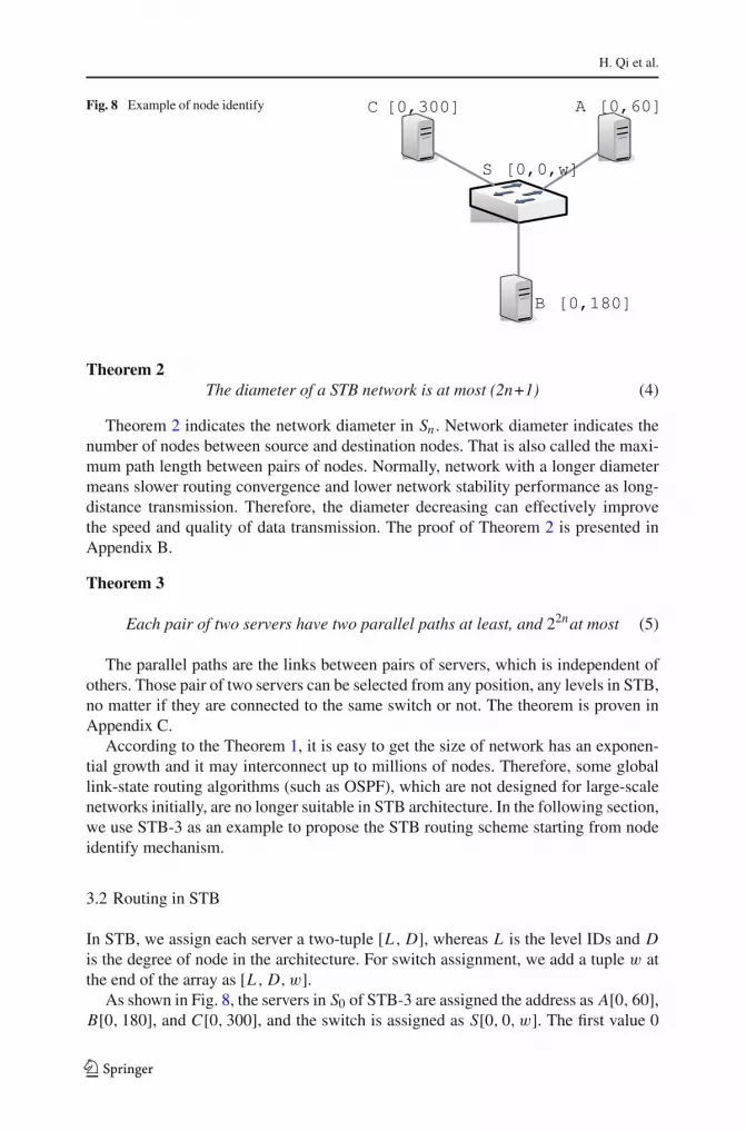
Fig. 8 Example of node identify
Theorem 2The diameter of a STB network is at most (2n+1) (4)
Theorem 2 indicates the network diameter in Sn . Network diameter indicates thenumber of nodes between source and destination nodes. That is also called the maxi-mum path length between pairs of nodes. Normally, network with a longer diametermeans slower routing convergence and lower network stability performance as long-distance transmission. Therefore, the diameter decreasing can effectively improvethe speed and quality of data transmission. The proof of Theorem 2 is presented inAppendix B.
Theorem 3
Each pair of two servers have two parallel paths at least, and 22nat most (5)
The parallel paths are the links between pairs of servers, which is independent ofothers. Those pair of two servers can be selected from any position, any levels in STB,no matter if they are connected to the same switch or not. The theorem is proven inAppendix C.
According to the Theorem 1, it is easy to get the size of network has an exponen-tial growth and it may interconnect up to millions of nodes. Therefore, some globallink-state routing algorithms (such as OSPF), which are not designed for large-scalenetworks initially, are no longer suitable in STB architecture. In the following section,we use STB-3 as an example to propose the STB routing scheme starting from nodeidentify mechanism.
3.2 Routing in STB
In STB, we assign each server a two-tuple [L , D], whereas L is the level IDs and Dis the degree of node in the architecture. For switch assignment, we add a tuple w atthe end of the array as [L , D, w].
As shown in Fig. 8, the servers in S0 of STB-3 are assigned the address as A[0, 60],B[0, 180], and C[0, 300], and the switch is assigned as S[0, 0, w]. The first value 0
123

Data center architecture in cloud computing
Fig. 9 Node identify in S1
indicates that those servers locate at 0-level of STB-3, and the second value showsthe degree for each node in the architecture. Such degree is a relative value comparedwith the position of switch in clockwise direction from 0◦ to 359◦. As S is 0◦ in thisarchitecture, we have server A is 60◦, B is 180◦, and C is 300◦.
Assign node address in S1 is shown as follows: D is a 1-level switch and locatesbetween A and C , so its address is D[1, 0, w]. Then the three servers in CellD trisectthe range of degree between server A and C , which is from 300◦ to 60◦. Hence weget the addresses for those three servers as E[1, 30], F[1, 0], and G[1, 330]. The restaddresses of nodes are assigned in the same way, which is shown in Fig. 9.
We denote that each data packet in STB has its own ID, source nodes ID, anddestination nodes ID, and intermediate nodes add their IDs into the head of packet indata forwarding. Once an intermediate node finds its own ID in a data packet (meansthis packet has been transferred by itself before), the packet is discarded to avoidlooping.
In STB, each server maintains a 2 − hops routing table including the address ofits neighbors. Whenever a source node desires to send data, first of all, it checks therouting table. Once the address of destination nodes is in the table, it means the twonodes are 2 − hops neighbor nodes. So the data packet can be transferred throughthe two hops from source to destination. Second, if there is no information aboutthe destination node in the table, the source node selects data forwarding directionaccording the degree of destination node and estimates path length depending level.An example is shown in Fig. 10 describing a part of 2-level STB-3 architecture forconvenience.
We assume that source node S wants to send data to a destination node D, and thelength of path is obviously more than two hops. In the first step, S[2, 345] forwards datato switch E[2, 0, w], and E sends data to F[1, 30]. In this step, E has two options:server F and server G. F is closer to D which is 45 and hence the data packet isforwarded to F . Similarly, the data are forwarded through H [1, 0, w], I [2, 30, w],A[0, 60], J [2, 90, w], M[1, 120, w] and finally arrive at destination node D[1, 150].
123

H. Qi et al.
Fig. 10 Node Identify in S1, STB-3
The pseudocode for path selection procedure of STB is shown in Algorithm 2.
Algorithm 2 Pseudocode for Path Selection/* src is source node, dst is destination node, i is the degree value of node, Path(s, d) indicates the pathfrom s to d */ST B−r table :: r t−lookup(addr−dst id) /*look up dst(id) in routing table */i f (r t → r t−dst == id) /* if the dst id is in routing table */
append addr−dst to path(s, d);goto send;
elsei f (|i−dst − i | ≤ 180) /* the forwarding path will not through i = 0 node */sendto(i−next Hop → (i, i−dst));
else{i f (i−dst > i){ /* i−dst ∈ (180, 360) & i−intermediate ∈ (0, 180)*/
send to(i−next Hop → 0);when (i == 0) received;send to(i−next Hop → i−dst);
}else{send to(i−next Hop → 360);when (i == 360/0) received;send to(i−next Hop → i−dst);
}
4 Performance evaluation
In this Section, we present the evaluation by using NS2 [22] to simulate the proposedSTB network architecture and evaluate the performance on shortest path length andthroughput by contrasting with DCell and BCube. We evaluate those architecturesin five different scenarios from level-0 to level-4 in area of 200 × 200 m. As an
123

Data center architecture in cloud computing
Fig. 11 A example network topology and simulation scenario
Fig. 12 When k = 3, S1network topology of STBarchitecture scenario in NS2
example, Fig. 11 shows the values of parameters between two nodes, and the restnodes and links in the architectures have the same parameters as well. As shown inFig. 11, the bandwidth of duplex link between node0 and node1 is 1 Gbps, and 10 mspropagation delay. Each node uses a DropT ail queue, of which the maximum size is10. An U D P agent and a NU L L agent are attached to both of the nodes to establishUDP connections. Moreover, a constant bi t rate (C B R) traffic generator is attachedto U D P agents to generator 1K B packets and 100 Mbps transmission rate. We alsouse a random perturbation scheme in data forwarding process to simulate expectednode and link failure. Figure 12 shows one of the scenarios of S1 topology in STBwhen k = 3, the number of servers and switches is 12 and 4. Figure 13 shows level-1topology of DCell and BCube, and the server and switches’ number are 12 and 4, 9 and6, respectively. All nodes and links in those architectures have the same parameters asin Fig. 11.
4.1 Average shortest path length
The average shortest path length means the average length between each pair of nodesin the network. The length of two nodes is the minimal number of links from one nodereaching to another. We use the Dijkstra’s algorithm [23,24] to calculate the shortest
123

H. Qi et al.
Fig. 13 Level-1 network topology of DCell and BCube scenario in NS2
Table 2 The average pathlength from S0 server to the restservers in different levels of STBwhen no node failure happens
Level No. of SVs No. of SWs AGt. Of SPL Avg. of SPL
STB-3 2 39 13 63 1.658
3 120 40 405 3.4
4 363 121 1,812 5.005
STB-4 2 48 21 160 3.404
3 340 85 1,344 3.964
STB-5 2 155 31 325 3.11
path length in the simulation. First, we assume there is no node failure happens in thenetwork. Table 2 shows that the average path length from one S0 server to the restservers in different levels of STB. The STB-3,4 and 5 indicate the number of serversconnecting one switch in the initial S0 level. We can see that the longest average pathlength in the table is when STB-3 in level 4, and the rest values are all no more than5 hops, which proves the Theorem 2 in Sect. 3.1.
Figure 14 shows the average of shortest path length and levels of STB in contrastwith DCell and BCube (when k = 3 in those of two architectures). When n = 0, thethree architectures have only basic (lowest) level; thus we have value of 1 for averageof shortest path length as those servers are directly linked to switch. With the levelincrease, the more servers are able to be supported in each of architecture and the lengthof shortest path for each server is increased as well. As we can see from the figure,DCell has a faster growing with the increasing of n; meanwhile, BCube and STB aregrowing slower than it. At the beginning stage, the average length of STB is shorterthan BCube; however, when n = 4, they almost have same value in this parameter.
Second, we evaluate the STB architecture in some servers failure happens situation.In this test, the proportion of server failure has been set in the beginning stage ofsimulation. Figure 15 shows the relations between the proportion and average ofshortest path length in a S4 network. As we can see from the figure, when the proportionremains between 0.02 and 0.2, the average length has a limited wave range between5.0 and 6.7.
STB has a better performance at “average short path length” comparing with DCelland BCube when the rate of server failure increases. As only one level of switches in
123

Data center architecture in cloud computing
Fig. 14 When k = 3, Average shortest path length in 0–4 levels of architectures without server failure
Fig. 15 Server failure and average of shortest path length in S4 STB network
DCell, almost all of data flows are transferred by servers. BCube has a shorter averagelength because all data packets are forwarded by switch. In Sect. 3.1 we have provedthat STB has a multiple parallel links between each two servers, hence data packetscan be delivered through the other parallel links once an original data forwardingpath failed. Therefore, the STB has the best performance contrast with the other twoarchitectures.
4.2 Throughput
Throughput is always a major parameter in network evaluation, especially for datacenter network. A higher throughput means a greater data transmission and faster
123

H. Qi et al.
Fig. 16 Throughput vs. time
Fig. 17 Throughput vs. proportion of server failure
information exchanging. In this simulation, we evaluate throughput of the proposedSTB architecture by calculating the proportion of sending and receiving packets witha period of time in all nodes.
In first step, we assume that no server failure happens. As shown in Fig. 16, thesimulation time start from 0 s, and we select every 50 s to check the throughput of eacharchitecture. At the beginning stage of simulation, STB has a higher throughput thanDCell and BCube as it has more servers to participate data forwarding. Throughputin all architectures decreases over the time; however, STB is slower because of themultiple parallel links in it. Data forwarding is completed at the 87 s in STB, 141 s inBCube, and 177 s in DCell, respectively.
Figure 17 compares the throughput changing when rate of failure node increasesin STB, DCell and BCube. Because of the load balancing scheme in DCell network,it has the lowest throughput in this simulation, and a least impact with the increase offailure node. STB has more parallel links providing the highest throughput in network,but also has a bigger impact by the failure node.
123

Data center architecture in cloud computing
We select the Paired Two-Sample for Means t test to analysis the sample datagenerated from the simulation and verify whether there is a significant differencebetween the performance of throughput of the proposed STB architecture and theDCell and BCube, respectively. Based on the 30 times simulations, the values ofP(T � t)two − tail are 0.003497545 and 0.006544028, which are less than 0.05,meaning that there are significant differences in STB as compared to DCell and BCube,in the performance of throughput when proportion of server failure happens.
Results indicate that STB has a better performance than DCell and BCube. As weknow that the bandwidth between switches is normally higher than switch and server,and it is also restricted by the lowest value between two servers in data forwarding,it is obviously that data forwards between switches is much faster than servers withsame path length. A major feature of STB is using fewer switches connecting moreservers, which ensures that the nodes located between two servers are switches, toprovide a higher transfer efficiency.
5 Conclusion
This paper presents a new architecture of DCN in cloud computing to enhance theperformance of DCN. STB architecture is established on the basis of Sierpinski trianglefractal, which solved the bottleneck problem of data transmission in traditional tree-based structure and increased network capacity in DCN as well. An angle-based nodeidentify mechanism is introduced for replacing the IP-based address allocation forsupporting the size of DCN with exponential growth.
In the near future, the hybrid-based structures could still be a major structure widelyused in DCN [25,26]. To be competitive, servers would need to obtain multi-coreprocessor, large memory and multiple network adapters to improve the network per-formance capacity and participate in data forwarding. However, there are several othertechnical and non-technical factors that need to be considered for further development.For example, servers often have lower performance in data transmission compared toswitches. Also, the existing routing algorithms would meet a radical shift when theydirectly transplant from traditional network to large DCN [27,28]. To overcome theseconcerns, a efficient dynamic schedule algorithm, DCN-oriented routing protocol witha significant advantage is necessary for providing high-quality service to end users.
Acknowledgments This work is part of the Mobile Cloud Computing research project at the MobileCloud Computing Research Lab at Faculty of Computer Science and Information Technology, Universityof Malaya, Malaysia. The project is fully funded by the Malaysian Ministry of Higher Education under theUniversity of Malaya High Impact Research Grant with reference UM.C/HIR/MOHE/FCSIT/03.
Appendix: A Proof of the Theorem 1
1. As S0 has k servers, thus the proportion of servers to switches is SVn : SWn = k : 1;similarly, the proportion in Cell is also true. As the STB architecture is constructedby adding multiple Cells based on previous level, so it is obvious that the proportionSVn : SWn = k : 1.
123

H. Qi et al.
2. As the STB is a recursive architecture, when n = 0, we can easily get SW0 = 1 =k0; similarly, when n = 1, SW1 = k + SW0 = k0 + k1, and SW2 = k + SW0 +SW1 = k0 + k1 + k2. Hence we can get SWn = k0 + k1 + k2 + · · · + kn−1 + kn ,nε(0,∞), that is SWn = 1 + ∑n
i=1 ki .
3. From the Eqs. 1 and 2, we get SVn−1 = k × SWn−1 = k(
1 + ∑n−1i=1 ki
)=
k + k × ∑n−1i=1 ki = k + ∑n
i=2 ki = 1 + ∑ni=1 ki .
Appendix: B Proof of the Theorem 2
We assume that a source node S and a destination node D locate at M-level and N -levelof STB architecture, SM and SN , respectively, where (M, N ≤ n). The maximum pathfor S to a S0 server is SM , SM−1, SM−2, ..., SM−n, ..., S1, S0. Similarly, the maximumpath for D to the a random S0 server is SN , SN−1, SN−2, ..., SN−n, ..., S1, S0. As only1 hop between each S0 server, so the maximum path length from S to D is M + N +1.When M = N = n, the maximum path length in STB is 2n + 1.
Appendix: C Proof of the Theorem 3
As we break the virtual link(s) between servers of (n − 1)-level and add Cell toconstruct n-level STB network, we have at least 2 parallel paths for each of twoservers. According to the Theorem 1, the maximum path length from source node Sto destination node D is M + N +1; thus we have 2M parallel path between S and S0,and 2N for D node. Therefore, when both S and D locate in same level M = N = n,we have that the number of most parallel paths for two nodes is 2M · 2N · 1 = 22n .
References
1. Baker S (2007) Google and the wisdom of clouds. Business Week. http://www.msnbc.msn.com/id/22261846/. Accessed 14 Apr 2014
2. Sanaei Z, Abolfazli S, Gani A, Buyya R (2013) Heterogeneity in mobile cloud computing: taxonomyand open challenges. IEEE Commun Surv Tutor. doi:10.1109/SURV.2013.050113.00090
3. Shiraz M, Ahmed E, Gani A, Han Q (2013) Investigation on runtime partitioning of elastic mobileapplications for mobile cloud computing. J Supercomput 67(1):84–103
4. Abolfazli S, Sanaei Z, Gani A, Shiraz M (2012) Momcc: Market-oriented architecture for mobile cloudcomputing based on service oriented architecture. Arxiv, preprint arXiv:1206.6209
5. Ghemawat S, Gobioff H, Leung S (2003) The google file system. In: ACM SIGOPS operating systemsreview, ACM, New York, vol 37, no. 5, pp 29–43
6. Dean J, Ghemawat S (2008) Mapreduce: simplified data processing on large clusters. Commun ACM51(1):107–113
7. Qi H, Gani A (2012) Research on mobile cloud computing: review, trend and perspectives. In: 2012Second International Conference on Digital Information and Communication Technology and it’sApplications (DICTAP), IEEE, pp 195–202
8. Bontempo C, Zagelow G (1998) The ibm data warehouse architecture. Commun ACM 41(9):38–489. Isard M, Budiu M, Yu Y, Birrell A, Fetterly D (2007) Dryad: distributed data-parallel programs from
sequential building blocks. ACM SIGOPS Oper Syst Rev 41(3):59–7210. Guo C, Wu H, Tan K, Shi L, Zhang Y, Lu S (2008) Dcell: a scalable and fault-tolerant network structure
for data centers. In: ACM SIGCOMM Computer Communication Review, ACM, New York, vol 38,pp 75–86
123

Data center architecture in cloud computing
11. Shiraz M, Gani A, Khokhar R (2012) Towards lightweight distributed applications for mobile cloudcomputing. In: 2012 IEEE International Conference on Computer Science and Automation Engineering(CSAE), IEEE, vol 1, pp 89–93
12. Sierpinski W (1916) Sur une courbe cantorienne qui contient une image biunivoque et continue detoute courbe donnée. Comptes Rendus 629
13. Al-Fares M, Loukissas A, Vahdat A (2008) A scalable, commodity data center network architecture.In: ACM SIGCOMM Computer Communication Review, ACM, New York, vol 38, pp 63–74
14. Greenberg A, Hamilton J, Maltz D, Patel P (2008) The cost of a cloud: research problems in data centernetworks. ACM SIGCOMM Comp Commun Rev 39(1):68–73
15. Greenberg A, Hamilton J, Jain N, Kandula S, Kim C, Lahiri P, Maltz D, Patel P, Sengupta S (2009)Vl2: a scalable and flexible data center network. ACM SIGCOMM Comp Commun Rev 39(4):51–62
16. Dally WJ, Towles BP (2004) Principles and practices of interconnection networks. Elsevier17. Abu-Libdeh H, Costa P, Rowstron A, O’Shea G, Donnelly A (2010) Symbiotic routing in future data
centers. In: ACM SIGCOMM Computer Communication Review, ACM New York, vol 40, pp 51–6218. Costa P, Zahn T, Rowstron A, O’Shea G, Schubert S (2009) Why should we integrate services, servers,
and networking in a data center? In: Proceedings of the 1st ACM workshop on Research on enterprisenetworking, ACM, New York, pp 111–118
19. Agrawal D, Chen C, Burke J (1998) Hybrid graph-based networks for multiprocessing. TelecommunSyst 10(1):107–134
20. Guo C, Lu G, Li D, Wu H, Zhang X, Shi Y, Tian C, Zhang Y, Lu S (2009) Bcube: a high performance,server-centric network architecture for modular data centers. ACM SIGCOMM Comp Commun Rev39(4):63–74
21. Popa L, Ratnasamy S, Lannaccone G, Krishnamurthy A, Stoica I (2010) A cost comparison of data-center network architectures. In: Proceedings of the 6th International Conference, ACM, New York, p16
22. McCanne S, Floyd S, Fall K, Varadhan K, et al (1997) Network simulator ns-223. Knuth D (1977) A generalization of dijkstra’s algorithm. Info Proc Lett 6(1):1–524. Goldberg A, Tarjan R (1996) Expected performance of dijkstras shortest path algorithm.
NEC Research Institute Report. http://citeseerx.ist.psu.edu/viewdoc/download?doi=10.1.1.54.4349&rep=rep1&type=pdf. Accessed 14 Apr 2014
25. Iosup A, Ostermann S, Yigitbasi M, Prodan R, Fahringer T, Epema D (2011) Performance analysis ofcloud computing services for many-tasks scientific computing. Parallel Distributed Syst IEEE Trans22(6):931–945
26. Khazaei H, Misic J, Misic V (2011) Performance analysis of cloud computing centers using m/g/m/m+r queueing systems. Parallel Distributed Syst IEEE Trans 99:1–1
27. Ahmed E, Shiraz M, Gani A (2013) Spectrum-aware distributed channel assignment for cognitive radiowireless mesh networks. Malay J Comp Sci 26(3):232–250
28. Whaiduzzaman M, Sookhak M, Gani A, Buyya R (2013) A survey on vehicular cloud computing. JNetw Comp Appl 40:325–344
123