shoreline stabilization to protect louisiana highway 82
TRANSCRIPT
TRANSPORTATION RESEARCH RECORD 1279 II
Shoreline Stabilization To Protect Louisiana Highway 82
BABAK NAGHAVI AND PETER A. ALLAIN
Several attempts by the Louisiana Department of Transportation and Dev~lopment to protect the shoreline and Louisiana Highway 82 are discussed. To identify the important factors needed for proper design of shore protection structures, failures of earlier efforts, as well as the success of recent efforts, are evaluated. An emphasis should be placed on the acquisition of wave data, as well as a survey of the offshore profile. Porosity of the revetments, underlayers , and geotextiles seems to be important in the stability ?f the .structure. Scour at the toe is another design consideration m d.es1gn of revetment structures. Project cost of shoreline protect10n was considerably reduced by providing alternates through competitive bidding. The 1984 and 1988 cabled and noncabled blocks and cast-in-place revetments have been exposed to several storms and have performed satisfactorily. The only damage to the roadway has been associated with landside foreslope at the time of overtopping.
Shoreline stabilization to stop erosion is an uncommon problem for most state transportation agencies. Occasionally, however, such corrective measures are needed to protect highways threatened by erosion in coastal areas. Identification and elimination of the cause of erosion is normally the best approach for solving the problem, but cannot always be accomplished . The second-best approach for solving the problem is the construction of coastal structures (1). Of these structures, revetments for shore stabilization is the most common. In order to avoid adverse results, revetment projects should be designed cautiously, and may require supplemental measures such as breakwaters or beach nourishment (2).
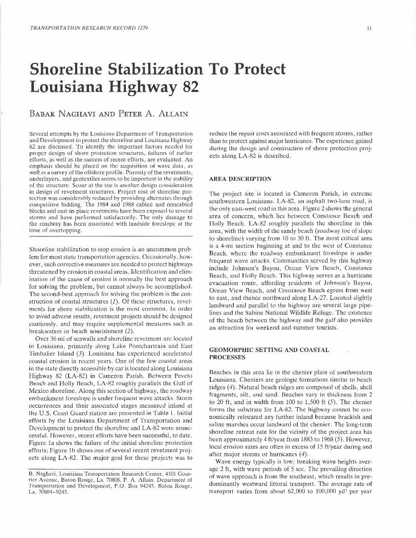
Over 36 mi of seawalls and shoreline revetment are located in Louisiana , primarily along Lake Pontchartrain and East Timbalier Island (3) . Louisiana has experienced accelerated coastal erosion in recent years. One of the few coastal areas in the state directly accessible by car is located along Louisiana Highway 82 (LA-82) in Cameron Parish. Between Peveto Beach and Holly Beach, LA-82 roughly parallels the Gulf of Mexico shoreline. Along this section of highway, the roadway embankment foreslope is under frequent wave attacks. Storm occurrences and their associated stages measured inland at the U.S. Coast Guard station are presented in Table 1. Initial efforts by the Louisiana Department of Transportation and Development to protect the shoreline and LA-82 were unsuccessful. However , recent efforts have been successful, to date . Figure la shows the failure of the initial shoreline protection efforts; Figure lb shows one of several recent revetment projects along LA-82. The major goal for these projects was to
B. Naghavi, Louisiana Transportation Research Center, 4101 Gourner Avenue, Baton Rouge , La . 70808. P. A. Allain , Department of Transportation and Development, P.O. Box 94245 , Baton Rouge La. 70804-9245. '
reduce the repair costs associated with frequent storms , rather than to protect against major hurricanes . The experience gained during the design and construction of shore protection projects along LA-82 is described.
AREA PESCRIPTION
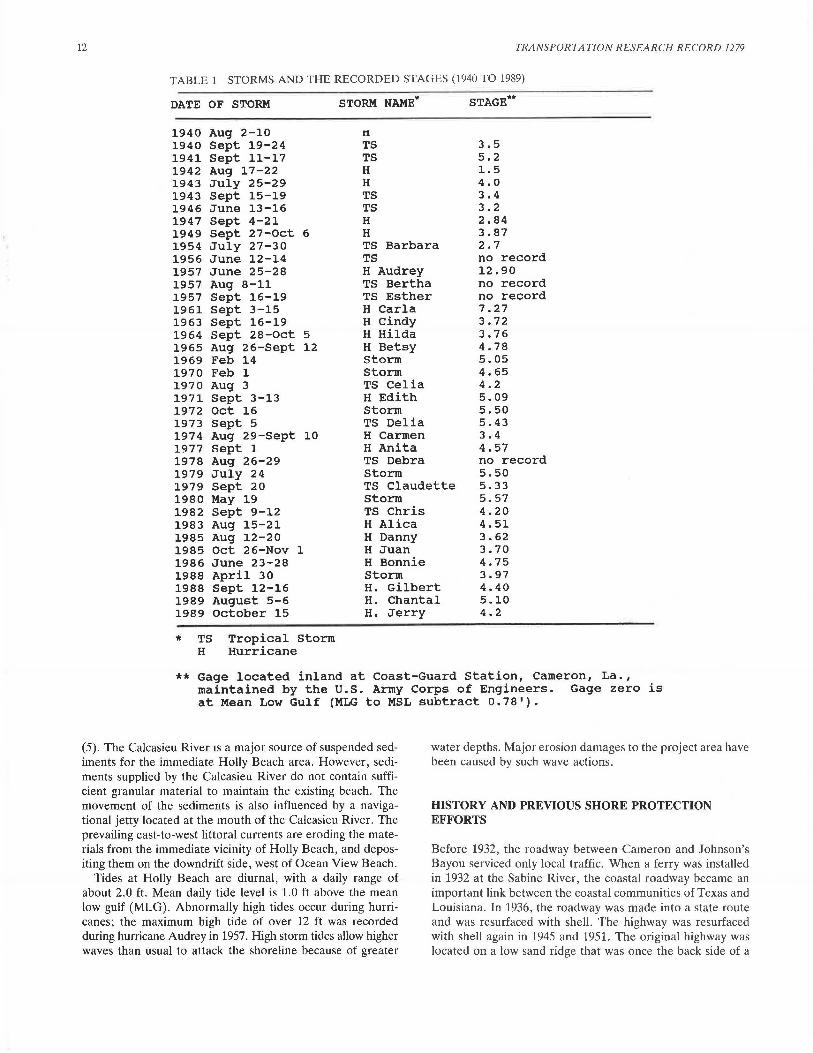
The project site is located in Cameron Parish, in extreme southwestern Louisiana. LA-82, an asphalt two-lane road, is the only east-west road in this area. Figure 2 shows the general area of concern, which lies between Constance Beach and Holly Beach. LA-82 roughly parallels the shoreline in this area, with the width of the sandy beach (roadway toe of slope to shoreline) varying from 10 to 30 ft. The most critical area is a 4-mi section beginning at and to the west of Constance Beach, where the roadway embankment foreslope is under frequent wave attacks . Communities served by this highway include Johnson's Bayou, Ocean View Beach, Constance Beach, and Holly Beach. This highway serves as a hurricane evacuation route, affording residents of Johnson's Bayou, Ocean View Beach, and Constance Beach egress from west to east, and thence northward along LA-27. Located slightly landward and parallel to the highway are several large pipelines and the Sabine National Wildlife Refuge. The existence of the beach between the highway and the gulf also provides an attraction for weekend and summer tourists.
GEOMORPHIC SETTING AND COAST AL PROCESSES
Beaches in this area lie in the chenier plain of southwestern Louisiana. Cheniers are geologic formations similar to beach ridges (4). Natural beach ridges are composed of shells , shell fragments, silt, and sand . Beaches vary in thickness from 2 to 20 ft, and in width from 100 to 1,500 ft (5). The chenier forms the substrate for LA-82. The highway cannot be economically relocated any further inland because brackish and saline marshes occur landward of the chenier. The long-term shoreline retreat rate for the vicinity of the project area has been approximately 4 ft/year from 1883 to 1968 (5). However, local ero~ion rates are often in excess of 15 ft/year during and after maior storms or hurricanes ( 4).
Wave energy typically is low; breaking wave heights average 2 ft, with wave periods of 5 sec. The prevailing direction of wave approach is from the southeast, which results in predominantly westward littoral transport. The average rate of transport varies from about 62,000 to 100,000 yd3 per year
12 TRANSPORTATION RESEARCH RECORD 1279
TABLE 1 STORMS AND THE RECORDED STAGES (1940 TO 1989)
DATE OF S'l'ORM STORM NAME* STAGE**
1940 Aug 2-10 r1
1940 Sept 19-24 TS 3.5 1941 Sept 11-17 TS 5.2 1942 Aug 17-22 H 1.5 1943 July 25-29 H 4.0 1943 Sept 15-19 TS 3.4 1946 June 13-16 TS 3.2 1947 Sept 4-21 H 2.84 1949 Sept 27-0ct 6 H 3.87 1954 July 27-30 TS Barbara 2.7 1956 June 12-14 TS no record 1957 June 25-28 H Audrey 12.90 1957 Aug 8-11 TS Bertha no record 1957 Sept 16-19 TS Esther no record 1961 Sept 3-15 H Carla 7.27 1963 Sept 16-19 H Cindy 3. 72 1964 Sept 28-0ct 5 H Hilda 3.76 1965 Aug 26-Sept 12 H Betsy 4.78 1969 Feb 14 storm 5.05 1970 Feb 1 Storm 4.65 1970 Aug 3 TS Celia 4.2 1971 Sept 3-13 H Edith 5.09 1972 Oct 16 Storm 5.50 1973 Sept 5 TS Delia 5.43 1974 Aug 29-Sept 10 H Carmen 3.4 1977 Sept l H Anita 4.57 1978 Aug 26-29 TS Debra no record 1979 July 24 storm 5.50 1979 Sept 20 TS Claudette 5.33 1980 May 19 Storm 5.57 1982 Sept 9-12 TS Chris 4.20 1983 Aug 15-21 H Alica 4.51 1985 Aug 12-20 H Danny 3.62 1985 Oct 26-Nov 1 H Juan 3.70 1986 June 23-28 H Bonnie 4.75 1988 April 30 Storm 3.97 1988 Sept 12-16 H. Gilbert 4.40 1989 August 5-6 H. Chantal 5.10 1989 October 15 H. Jerry 4.2
* TS Tropical Storm H Hurricane
**Gage located inland at Coast-Guard Station, Cameron, La., maintained by the U.S. Army Corps of Engineers. Gage zero is at Mean Low Gulf (MLG to MSL subtract 0.78').
(5). The Calcasieu River 1s a major source of suspended sediments for the immediate Holly Beach area. However, sediments supplied by the Calcasieu River do not contain sufficient granular material to maintain the existing beach. The movement of the sediments is also influenced by a navigational jetty located at the mouth of the Calcasieu River. The prevailing east-to-west littoral currents are eroding the materials from the immediate vicinity of Holly Beach, and depositing them on the downdrift side, west of Ocean View Beach.
Tides at Holly Beach are diurnal, with a daily range of about 2.0 ft. Mean daily tide level is 1.0 ft above the mean low gulf (MLG). Abnormally high tides occur during hurricanes; the maximum high tide of over 12 ft was recorded during hurricane Audrey in 1957. High storm tides allow higher waves than usual to attack the shoreline because of greater
water depths. Major erosion damages to the project area have been caused by such wave actions.
HISTORY AND PREVIOUS SHORE PROTECTION EFFORTS
Before 1932, the roadway between Cameron and Johnson's Bayou serviced only local traffic. When a ferry was installed in 1932 at the Sabine River, the coastal roadway became an important link between the coastal communities of Texas and Louisiana. In 1936, the roadway was made into a state route and was resurfaced with shell. The highway was resurfaced with shell again in 1945 and 1951. The original highway was located on a low sand ridge that was once the back side of a
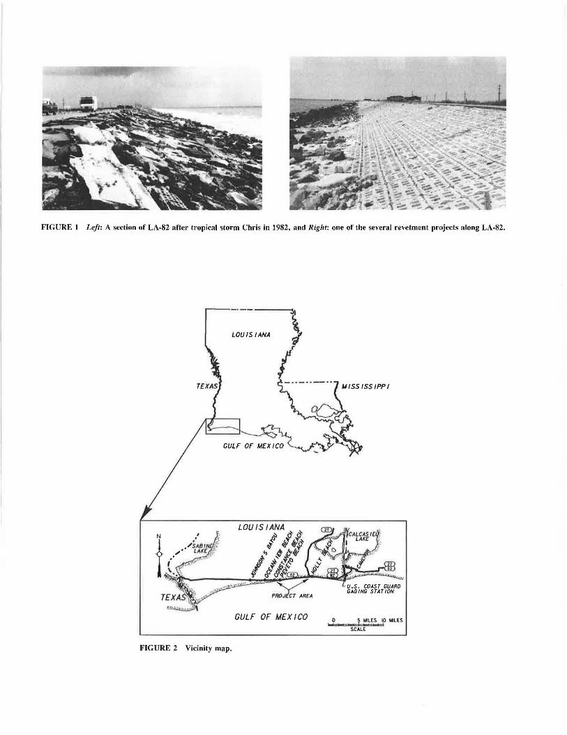
FIGURE 1 Left: A section of LA-82 after tropical storm Chris in 1982, and Right: one of the several revetment projects along LA-82.
-~-------....
~ j LOUISIANA
I
GULF OF MEXICO
FIGURE 2 Vicinity map.
. ? ~ MILES 1p MILES
SCALE
14
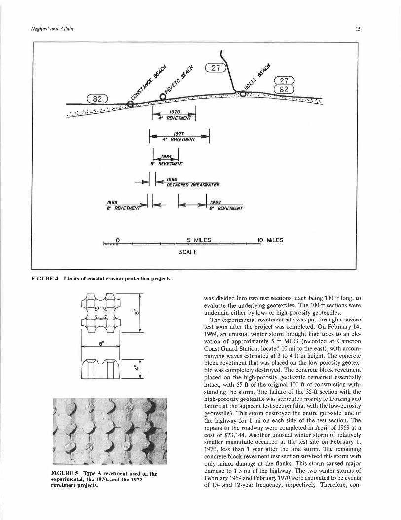
chenier. At this location, the highway was well protected from the gulf by at least 300 ft of beach and dunes. The highway became increasingly exposed to wave damage as the beach diminished and had to be relocated inland several times. Figure 3 shows the regression of the shoreline and the corresponding relocation of the highway. As further relocation of the highway became unsuitable, various revetment projects were initiated by the Louisiana Department of Transportation and Development. The project limits for these projects are shown in Figure 4.
The loss of beach was accelerated by seveial maior storms, which in turn made the highway vulnerable to subsequent storms. In June 1957, hurricane Audrey was the most severe storm of record to hit the area. The storm caused major damage to the highway and destroyed all the residences at Holly Beach, as well as most of the residences at the nearby town of Cameron. Erosion caused by hurricane Audrey left a 3-mi section of the highway exposed to wave action from the gulf.
LA-82 was greatly improved when the asphalt surfacing of the roadway was completed in May 1960 at a cost of $429,000. In September 1961, hurricane Carla caused severe damage to the newly completed highway. As a result of hurricane Carla, the 3-mi section of the roadway embankment exposed
TRANSPORTATION RESEARCH RECORD 1279
by hurricane Audrey was destroyed. The roadway was reconstructed 30 ft inland. Repairs from hurricane Carla were completed in April 1963 at a cost of $308,000.
In September 1963, hurricane Cindy damaged 1 V2 mi of the reconstructed roadway. From 1964 to 1969, the beach fronting the road continued to erode. The loss of beach left a 4-ft-high escarpment at the edge of the shoulder that required continual maintenance to prevent undermining of the pavement.
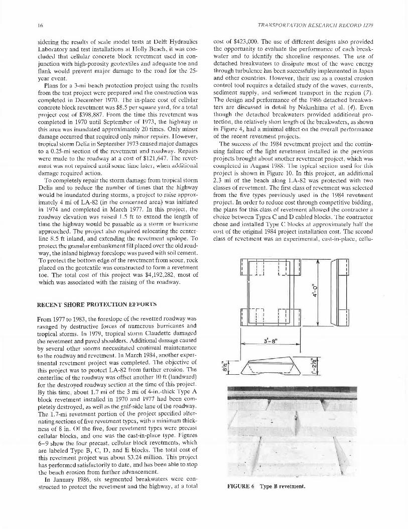
As the beach continued to erode and no other suitable location could be found to relocate the highway, state officials decided to protect the roadway. The first roadway protection project consisted of revetting the gulf-side roadway embankment foreslope. After considering several alternatives, the state engineers decided to use a 4-in.-thick cellular concrete block revetment. This 4-in.-thick block, shown in Figure 5 and labeled Type A block, was developed in Holland. In order to determine the stability of these blocks, a 1:5 scale model test was conducted at \l oorst Laboratory, a part of the Delft Laboratory in Holland. The scale model test, completed in December 1968, indicated that the revetment would remain stable for wave heights up to 3.6 ft. In order to test the prototype for real situations, a 200-ft prototype revetment was built along LA-82 by the Louisiana Department of Transportation and Development in January 1969 (6). The revetment
I APPROXIMATELY 300'
~7.77 MSL
30'
8.00 MSL 1963
~ 3~' -----f""'a'"".o~o:;._:,;M;,;::,:sL 1970 ----4MREVETMENT
38.5'
9.5 MSL 1977 4"REVETMENT
48.5' APPROXIMATELY 242' I
1984 9.25 MSL &. 1988 8" REVETMENT I 1986 DETACHED BREAKWATER
FIGURE 3 Regression of shoreline and corresponding relocation of LA-82.
Naghavi and Allain 15
... .. ....
1970 .. , REVETMENT
w B" REVE111£NT
I I 1986 ~ ... DETACHED 8R£Af(WATER
1988 I ' tr REVETIIENT- k- I 11988
1:mm:mi2E::::::==i==..t==1=~=±f?:::::M:=IL:i=E:;,;:,S~=~:=t::=:ilp MILES
SCALE
FIGURE 4 Limits of coastal erosion protection projects.
FIGURE 5 Type A revetment used on the experimental, the 1970, and the 1977 revetment projects.
was divided into two test sections, each being 100 ft long, to evaluate the underlying geotextiles. The 100-ft sections were underlain either by low- or high-porosity geotextiles.
The experimental revetment site was put through a severe test soon after the project was completed. On February 14, 1969, an unusual winter storm brought high tides to an elevation of approximately 5 ft MLG (recorded at Cameron Coast Guard Station, located 10 mi to the east), with accompanying waves estimated at 3 to 4 ft in height. The concrete block revetment that was placed on the low-porosity geotextile was completely destroyed . The concrete block revetment placed on the high-porosity geotextile remained essentially intact, with 65 ft of the original 100 ft of construction withstanding the storm. The failure of the 35-ft section with the high-porosity geotextile was attributed mainly to flanking and failure at the adjacent test section (that with the low-porosity geotextile). This storm destroyed the entire gulf-side lane of the highway for 1 mi on each side of the test section. The repairs to the roadway were completed in April of 1969 at a cost of $73 ,144. Another unusual winter storm of relatively smaller magnitude occurred at the test site on February 1, 1970, less than 1 year after the first storm. The remaining concrete block revetment test section survived this storm with only minor damage at the flanks. This storm caused major damage to 1.5 mi of the highway. The two winter storms of February 1969 and February 1970 were estimated to be events of 15- and 12-year frequency, respectively. Therefore, con-
16
sidering the results of scale model tests at Delft Hydraulics Laboratory and test installations at Holly Beach, it was concluded that cellular concrete block revetment used in conjunction with high-porosity geotextiles and adequate toe and flank would prevent major damage to the road for the 25-year event.
Plans for a 3-mi beach protection project using the results from the test project were prepared and the construction was completed in December 1970. The in-place cost of cellular concrete block revetment was $8.5 per square yard, for a total project cost of $398,887. From the time this revetment was completed in 1970 until September of 1973, the highway in this area was inundated approximately 20 times. Only minor damage occurred that required only minor repairs. However, tropical storm Delia in September 1973 caused major damages to a 0.25-mi section of the revetment and roadway. Repairs were made to the roadway at a cost of $121,647. The revet-
• ' • 1 '·1 - - "-. -- - 1 - .. - -- ___ l_ - - - ...l ...J!.._: - - -1 111tall was 11uL 1eµa11eu uuu1 ~uu1e uu1e rnte1, wuc11 auuH1u11a1 damage required action.
To completely repair the storm damage from tropical storm Delia and to reduce the number of times that the highway would be inundated during storms, a project to raise approximately 4 mi of LA-82 (in the concerned area) was initiated in 1974 and completed in March 1977. In this project, the roadway elevation was raised 1.5 ft to extend the length of time the highway would be passable as a storm or hurricane approached. The project also required relocating the centerline 8.5 ft inland, and extending the revetment upslope. To protect the granular embankment fill placed over the old roadway, the inland highway foreslope was paved with soil cement. To protect the bottom edge of the revetment from scour, rock placed on the geotextile was constructed to form a revetment toe. The total cost of this project was $4,192,282, most of which was associated with the raising of the roadway.
RECENT SHORE PROTECTION EJ<'l<'OK'l'S
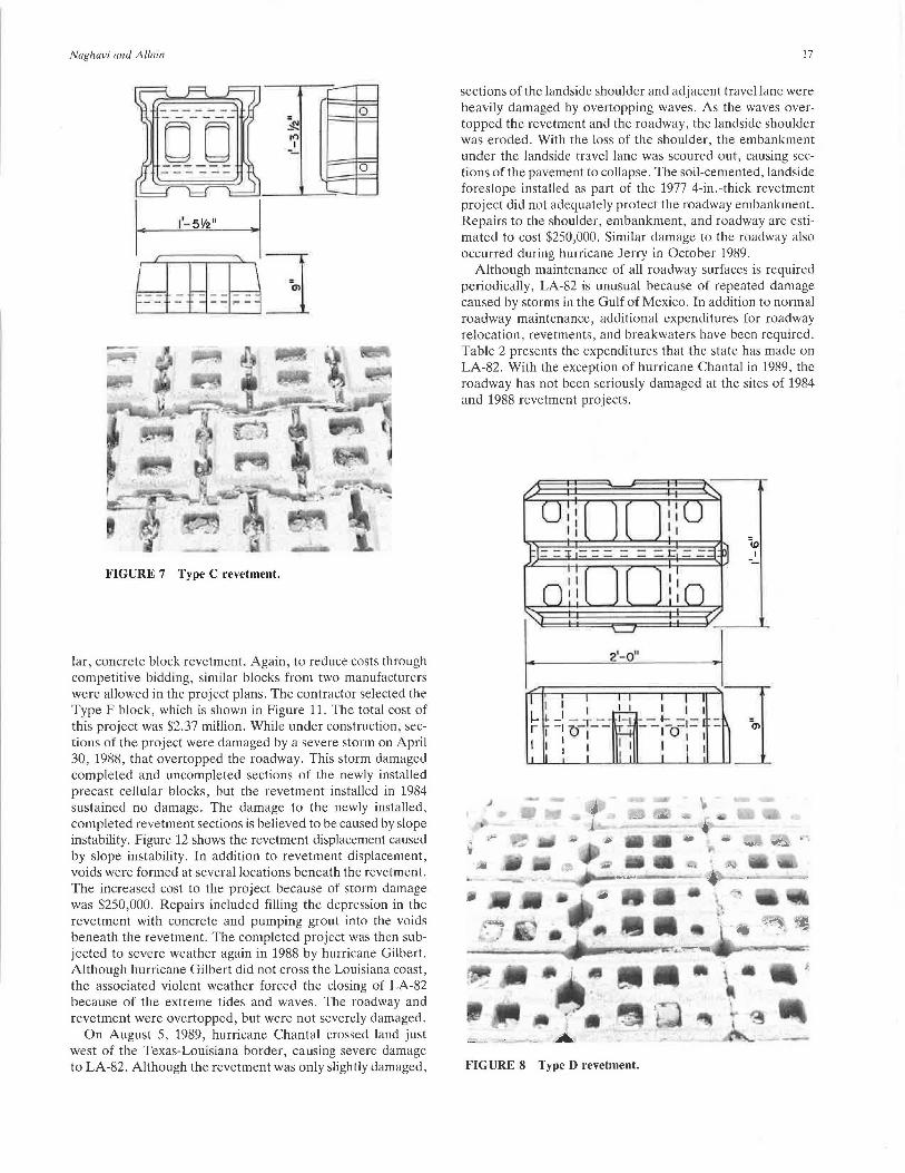
From 1977 to 1983, the foreslope of the revetted roadway was ravaged by destructive forces of numerous hurricanes and tropical storms. In 1979, tropical storm Claudette damaged the revetment and paved shoulders. Additional damage caused by several other storms necessitated continual maintenance to the roadway and revetment. In March 1984, another experimental revetment project was completed. The objective of this project was to protect LA-82 from further erosion. The centerline of the roadway was offset another 10 ft (landward) for the destroyed roadway section at the time of this project. By this time, about 1.7 mi of the 3 mi of 4-in.-thick Type A block revetment installed in 1970 and 1977 had been completely destroyed, as well as the gnlf-side lane of the roadway. The 1.7-mi revetment portion of the project specified alternating sections of five revetment types, with a minimum thickness of 8 in. Of the five, four revetment types were precast cellular blocks, and one was the cast-in-place type. Figures 6-9 show the four precast, cellular block revetments, which are labeled Type B, C, D, and E blocks. The total cost of this revetment project was about $3.24 million. This project has performed satisfactorily to date, and has been able to stop the beach erosion from further advancement.
In January 1986, six segmented breakwaters were constructed to protect the revetment and the highway, at a total
TRANSPORTATION RESEARCH RECORD 1279
cost of $423,000. The use of different designs also provided the opportunity to evaluate the performance of each breakwater and to identify the shoreline responses. The use of detached breakwaters to dissipate most of the wave energy through turbulence has been successfully implemented in Japan and other countries. However, their use as a coastal erosion control tool requires a detailed study of the waves, currents, sediment supply, and sediment transport in the region (7). The design and performance of the 1986 detached breakwaters are discussed in detail by Nakashima et al. ( 4). Even though the detached breakwaters provided additional protection, the relatively short length of the breakwaters, as shown in Figure 4, had a minimal effect on the overall performance of the recent revetment projects.
The success of the 1984 revetment project and the continuing failure of the light revetment installed in the previous projects brought about another revetment project, which was co111pleled iu August 1988. The lyµical sectiuu used fu1 lhis project is shown in Figure 10. In this project, an additional 2.3 mi of the beach along LA-82 was protected with two classes of revetment. The first class of revetment was selected from the five types previously used in the 1984 revetment project. In order to reduce cost through competitive bidding, the plans for this class of revetment allowed the contractor a choice between Types C and D cabled blocks. The contractor chose and installed Type C blocks at approximately half the cost of the original 1984 project installation cost. The second class of revetment was an experimental, cast-in-place, cellu-
I I
I I I l _ l L _ 1
-,, I I : f
31-a"
r I I
FIGURE 6 Type B revetment.
Naghavi and Allain
0
0
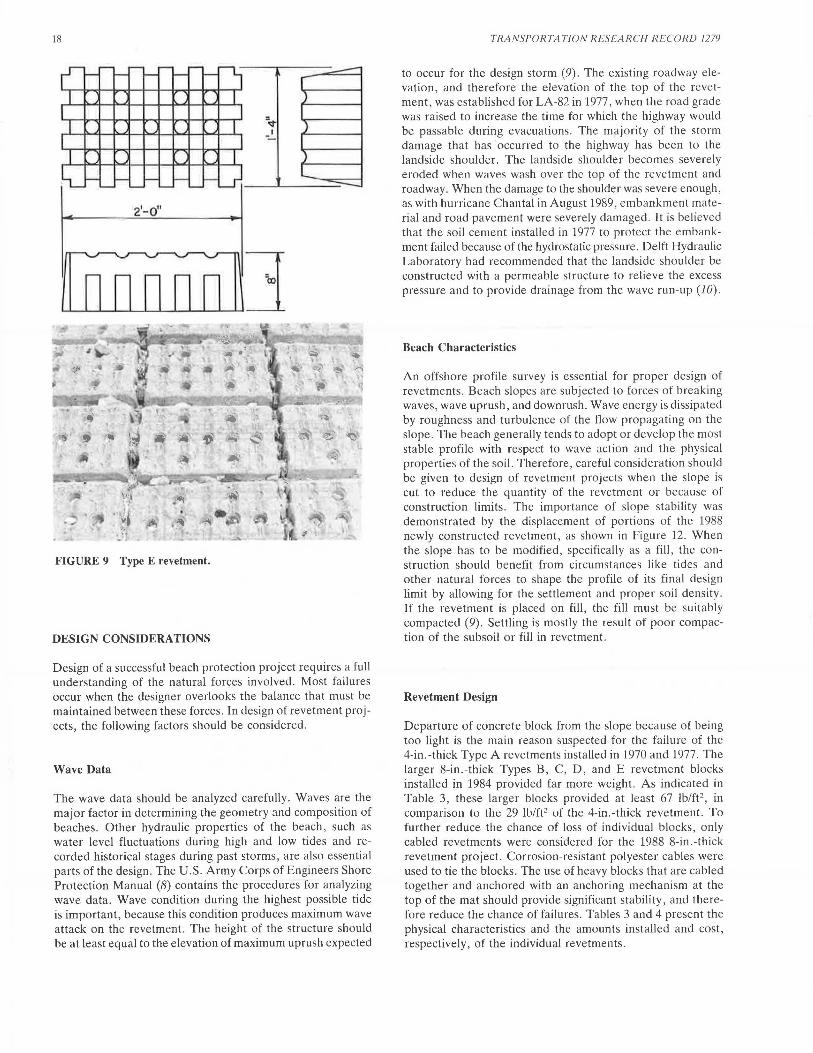
FIGURE 7 Type C revetment.
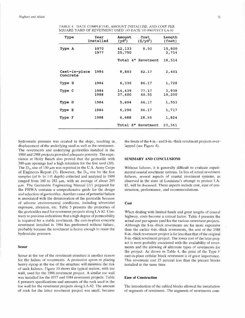
lar, concrete block revetment. Again, to reduce costs through competitive bidding, similar blocks from two manufacturers were allowed in the project plans. The contractor selected the Type F block, which is shown in Figure 11. The total cost of this project was $2.37 million. While under construction, sections of the project were damaged by a severe storm on April 30, 1988, that overtopped the roadway. This storm damaged completed and uncompleted sections of the newly installed precast cellular blocks, but the revetment installed in 1984 sustained no damage. The damage to the newly installed, completed revetment sections is believed to be caused by slope instability. Figure 12 shows the revetment displacement caused by slope instability. In addition to revetment displacement, voids were formed at several locations beneath the revetment. The increased cost to the project because of storm damage was $250,000. Repairs included filling the depression in the revetment with concrete and pumping grout into the voids beneath the revetment. The completed project was then subjected to severe weather again in 1988 by hurricane Gilbert. Although hurricane Gilbert did not cross the Louisiana coast, the associated violent weather forced the closing of LA-82 because of the extreme tides and waves. The roadway and revetment were overtopped, but were not severely damaged.
On August 5, 1989, hurricane Chantal crossed land just west of the Texas-Louisiana border, causing severe damage to LA-82. Although the revetment was only slightly damaged,
17
sections of the landside shoulder and adjacent travel lane were heavily damaged by overtopping waves. As the waves overtopped the revetment and the roadway, the landside shoulder was eroded. With the loss of the shoulder, the embankment under the landside travel lane was scoured out, causing sections of the pavement to collapse. The soil-cemented, landside foreslope installed as part of the 1977 4-in.-thick revetment project did not adequately protect the roadway embankment. Repairs to the shoulder, embankment, and roadway are estimated to cost $250,000. Similar damage to the roadway also occurred during hurricane Jerry in October 1989.
Although maintenance of all roadway surfaces is required periodically, LA-82 is unusual because of repeated damage caused by storms in the Gulf of Mexico. In addition to normal roadway maintenance, additional expenditures for roadway relocation, revetments, and breakwaters have been required. Table 2 presents the expenditures that the state has made on LA-82. With the exception of hurricane Chantal in 1989, the roadway has not been seriously damaged at the sites of 1984 and 1988 revetment projects.
I 2'-o" I
FIGURE 8 Type D revetment.
ID I --
18
2'-0"
FIGURE 9 Type E revetment.
DESIGN CONSIDERATIONS
Design of a successful beach protection project requires a full understanding of the natural forces involved. Most failures occur when the designer overlooks the balance that must be maintained between these forces . In design of revetment projects, the following factors should be considered.
Wave Data
The wave data should be analyzed carefully. Waves are the major factor in determining the geometry and composition of beaches. Other hydraulic properties of the beach, such as water level fluctuations during high and low tides and recorded historical stages during past storms, are also essential parts of the design. The U.S. Army Corps of Engineers Shore Protection Manual (8) contains the procedures for analyzing wave data. Wave condition during the highest possible tide is important, because this condition produces maximum wave attack on the revetment. The height of the structure should be at least equal to the elevation of maximum uprush expected
TRANSl'ORTATJON RESEARCH R ECORD 1279
to occur for the design storm (9). The existing roadway elevation, and therefore the elevation of the top of the revetment , was established for LA-82 in 1977, when the road grade was raised to increase the time for which the highway would be passable during evacuations. The majority of the storm damage that has occurred to the highway has been to the landside shoulder. The landside shoulder becomes severely ero<led when w<1ves wash over the top of the revetment and roadway. When the damage to the shoulder was severe enough, as with hurricane Chantal in August 1989, embankment material and road pavement were severely damaged. It is believed that the soil cement installed in 1977 to protect the emh;in kment failed because of the hydrostatic pressure. Delft Hydraulic Laboratory had recommended that the landside shoulder be constructed with a permeable structure to relieve the excess pressure and to provide drainage from the wave run-up (10).
Beach Characteristics
An offshore profile survey is essential for proper design of revetments. Beach slopes are subjected to forces of breaking waves, wave uprush, and downrush. Wave energy is dissipated by roughness and turbulence of the flow propagating on the slope . The beach generally tends to adopt or develop the most stable profile with respect to wave action and the physical properties of the soil. Therefore, careful consideration should be given to design of revetment projects when the slope is cut to reduce the quantity of the revetment or because of construction limits. The importance of slope stability was demonstrated by the displacement of portions of the 1988 newly constructed revetment, as shown in Figure 12. When the slope has to be modified, specifically as a fill, the construction should benefit from circumstances like tides and other natural forces to shape the profile of its final design limit by allowing for the settlement and proper soil density. If the revetment is placed on fill, the fill must be suitably compacted (9). Settling is mostly the result of poor compaction of the subsoil or fill in revetment.
Revetment Design
Departure of concrete block from the slope because of being too light is the main reason suspected for the failure of the 4-in.-thick Type A revetments installed in 1970 and 1977. The larger 8-in.-thick Types B, C, D, and E revetment blocks installed in 1984 provided far more weight. As indicated in Table 3, these larger blocks provided at least 67 lb/ft2
, in comparison to the 29 lu/fl2 uf the 4-in.-thick revetment. To further reduce the chance of loss of individual blocks , only cabled revetments were considered for the 1988 8-in.-thick revetment project. Corrosion-resistant polyester cables were used to tie the blocks . The use of heavy blocks that are cabled together and anchored with an anchoring mechanism at the top of the mat should provide significant stability, and therefore reduce the chance of failures . Tables 3 and 4 present the physical characteristics and the amounts installed and cost, respectively, of the individual revetments.
Naghavi and Allain
Exis ting Rip Rop
19
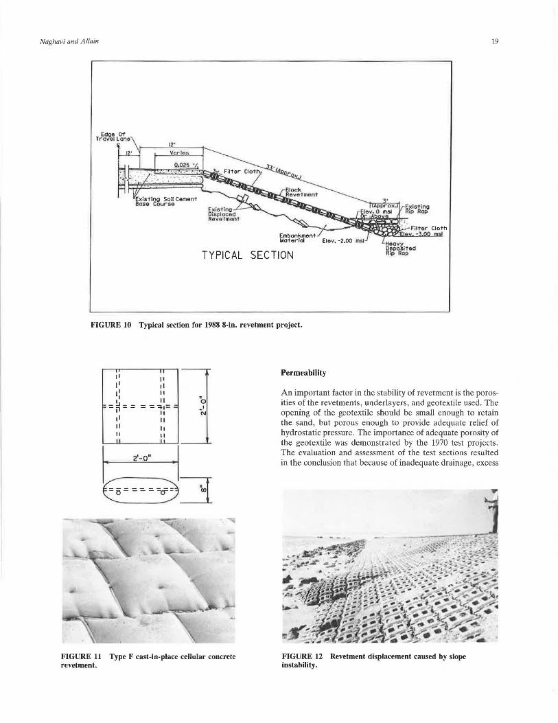
TYPICAL SECTION
FIGURE JO Typical section for 1988 8-in. revetment project.
" 11 II 11 11 II II I II =o
~ - !.J - -- jl - - = -=~1 =:: _, II C\I
11 II II 11 II II II "
FIGURE 11 Type F cast-in-place cellular concrete revetment.
Permeability
An important factor in the stability of revetment is the porosities of the revetments, underlayers, and geotextile used. The opening of the geotextile should be small enough to retain the sand, but porous enough to provide adequate relief of hydrostatic pressure. The importance of adequate porosity of the geotextile was demonstrated by the 1970 test projects. The evaluation and assessment of the test sections resulted in the conclusion that because of inadequate drainage, excess
FIGURE 12 Revetment displacement caused by slope instability.
•
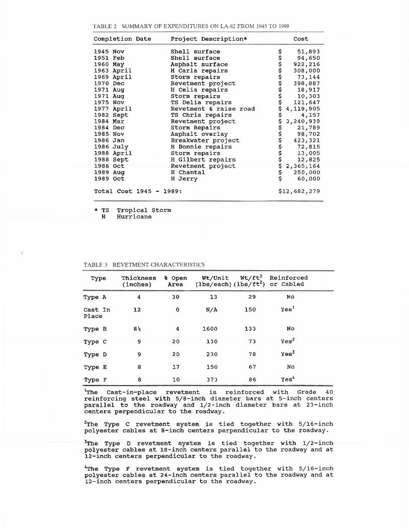
TABLE 2 SUMMARY OF EXPENDITURES ON LA-82 FROM 1945 TO 1989
Completion Date Project Description* Cost
1945 Nov Shell surface $ 51,893 1951 Feb Shell surface $ 94,650 1960 May Asphalt surface $ 922,216 1963 April H Carla repairs $ 308,000 1969 April Storm repairs $ 73,144 1970 Dec Revetment project $ 398,887 1971 Aug H Celia repairs $ 18,917 1971 Aug Storm repairs $ 10,303 1975 Nov TS Delia repairs $ 121,647 1977 April Revetment & raise road $ 4,119,905 1982 Sept TS Chris repairs $ 4,157 1984 Mar Revetment project $ 3,240,939 1984 Dec Storm Repairs $ 21,789 1985 Nov Asphalt overlay $ 98,702 1986 Jan Breakwater project $ 423,321 1986 July H Bonnie repairs $ 72,815 1988 April storm repairs $ 13,005 1988 Sept H Gilbert repairs $ 12,825 1988 Oct Revetment project $ 2,365,164 1989 Aug H Chantal $ 250,000 1989 Oct H Jerry $ 60,000
Total Cost 1945 - 1989: $12,682,279
* TS Tropical Storm H Hurricane
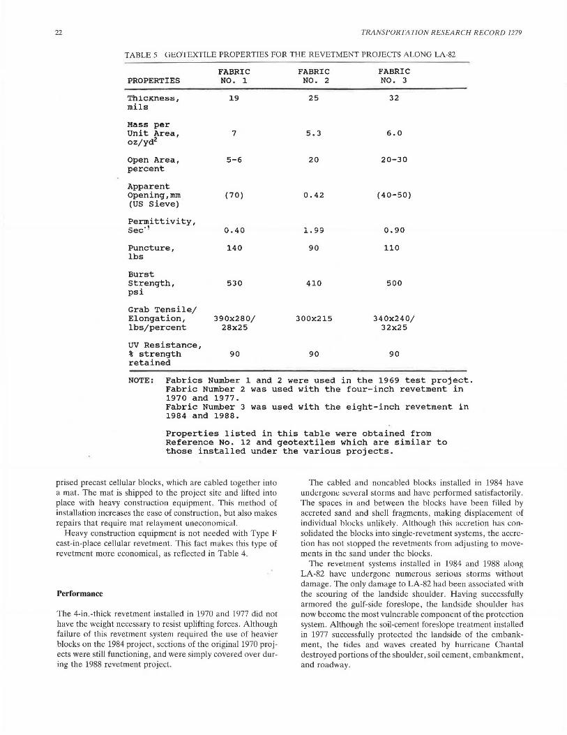
TABLE 3 REVETMENT CHARACTERISTICS
Type Thickness % Open (inches) Area
Wt/Unit Wt/ft2 Reinforced (lbs/each) (lbs/ft2 ) or Cabled
Type A
Cast In Place
Type B
Type C
Type D
Type E
Type F
4
12
9
9
8
8
30
0
4
20
20
17
10
13 29 No
N/A 150 Yes 1
1600 133 No
130 73 Yes2
230 78 Yes3
150 67 No
373 86 Yes4
1The cast-in-place revetment is reinforced with Grade 40 reinforcing steel with 5/8-inch diameter bars at 5-inch centers parallel to the roadway and 1/2-inch diameter bars at 23-inch centers perpendicular to the roadway.
2The Type c revetment system is tied together with 5/16-inch polyester cables at 8-inch centers perpendicular to the roadway.
3The Type D revetment system is tied together with 1/2-inch polyester cables at 18-inch centers parallel to the roadway and at 12-inch centers perpendicular to the roadway.
4The Type F revetment system is tied together with 5/16-inch polyester cables at 24-inch centers parallel to the roadway and at 12-inch centers perpendicular to the roadway.
Naghavi and Allain 21
TABLE 4 DATE COMPLETED, AMOUNT INSTALLED, AND COST PER SQUARE YARD OF REVETMENT USED TO DATE TO PROTECT LA-82
Type Year Installed
Type A 1970 1977
Cast-in-place 1984 Concrete
Type B 1984
Type c 1984 1988
Type D 1984
Type E 1984
Type F 1988
hydrostatic pressure was created in the slope, resulting in , displacement of the underlying sand as well as the revetment. The revetments and underlying geotextiles installed in the 1984 and 1988 projects provided adequate porosity. The experience at Holly Beach also proved that the geotextile with 300-µm openings had a high retention for the fine sand (JO). The D 50 size of 150 µm was reported in the U.S. Army Corps of Engineers Report (5). However, the D50 size for the five samples (of 0- to 1-ft depth) collected and analyzed in 1989 ranged from 160 to 285 µm, with an average of about 205 µm. The Geotextile Engineering Manual (11) prepared for the FHW A contains a comprehensive guide for the design and selection of geotextiles. Another cause of potential failure is associated with the deterioration of the geotextile because of adverse environmental conditions, including ultraviolet exposure, abrasion, etc. Table 5 presents the properties of the geotextiles used for revetment projects along LA-82. Contrary to previous indications that a high degree of permeability is required for a stable revetment, the cast-in-place concrete revetment installed in 1984 has performed without failure, probably because the revetment is heavy enough to resist the hydrostatic pressure.
Scour
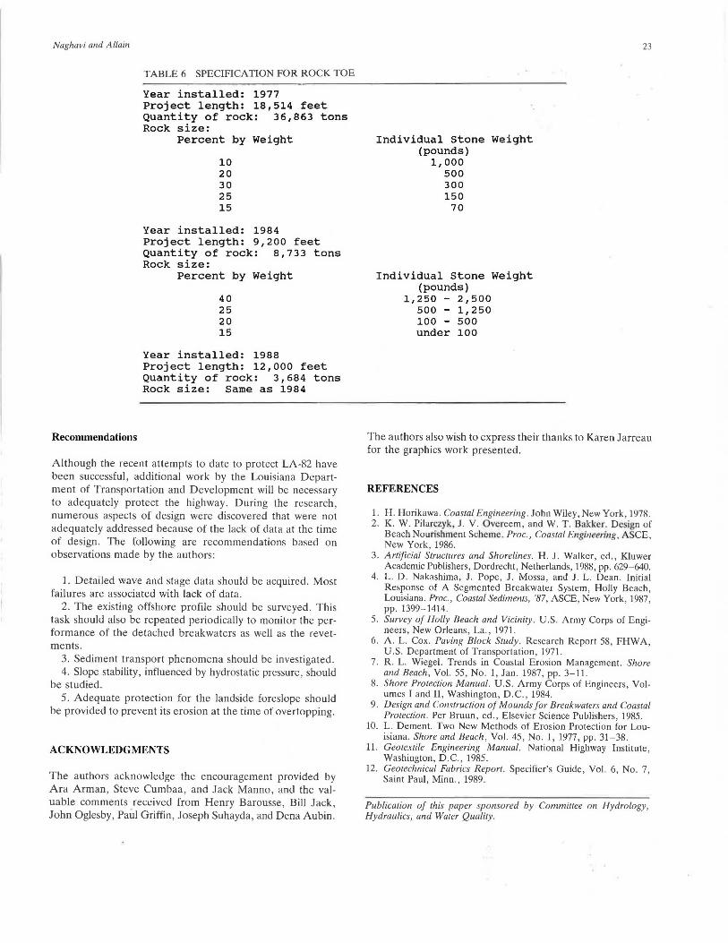
Scour at the toe of the revetment structure is another reason for the failure of revetments. A protective apron or placing heavy riprap at the toe of the structure will minimize the risk of such failures. Figure 10 shows the typical section, with toe wall, used for the 1988 revetment project. A similar toe wall was installed for the 1977 and 1984 revetment projects. Table 6 presents specifications and amounts of the rock used in the toe wall for the revetment projects along LA-82. The amount of rock for the latter revetment project was small, because
Amount Cost Length (yd2) ($/yd2) (feet)
42,133 8.50 15,800 25,750 2,714
Total 4" Revetment 18,514
8,803 8;L 17 2,401
6,336 86.17 1,728
14,439 77.17 3,938 37,400 40.55 10,200
5,694 66.17 1,553
6,296 66.17 1,717
6,688 28.95 1,824
Total 8 11 Revetment 23,361
the limits of the 4-in.- and 8-in.-thick revetment projects overlapped (see Figure 4).
SUMMARY AND CONCLUSIONS
Without failures, it is generally difficult to evaluate experimental coastal revetment systems. In lieu of actual revetment failures, several aspects of coastal revetment systems, as observed in the state of Louisiana's attempt to protect LA-82, will be discussed. These aspects include cost, ease of construction, performance, and recommendations.
Cost
When dealing with limited funds and great lengths of coastal highway, costs become a critical factor. Table 4 presents the actual cost per square yard for the various revetment projects. Although the 8-in.-thick revetments are far more expensive than the earlier 4-in.-thick revetments, the cost of the 1988 8-in.-thick revetment project is far less than that of the original 8-in.-thick revetment project. The lower cost of the later project is most probably associated with the availability of revetments and the allowing of alternate types of revetments for the project. As shown in Table 4, the price of the Type F cast-in-place cellular block revetment is of great importance. This revetment cost 25 percent less than the precast blocks installed at the same time.
Ease of Construction
The introduction of the cabled blocks allowed the installation of segments of revetment. The segments of revetments com-
22 TRANSPORTATION RESEARCH RECORD 1279
TABLE 5 GEOTEXTILE PROPERTIES FOR THE REVETMENT PROJECTS ALONG LA-82
PROPERTIES
ThicKness, mils
Mass per Unit Area, oz/yd2
Open Area, percent
Apparent Opening,mm (US Sieve)
Permittivity, Sec- 1
Puncture, lbs
Burst Strength, psi
Grab Tensile/ Elongation, lbs/percent
UV Resistance, % strength retained
FABRIC NO. 1
19
7
5-6
( 70)
0.40
140
530
390x280/ 28x25
90
FABRIC NO. 2
25
5.3
20
0.42
1. 99
90
410
300x215
90
FABRIC NO. 3
32
6.0
20-30
(40-50)
n nn U. :::;JU
110
500
340x240/ 32x25
90
NOTE: Fabrics Number 1 and 2 were used in the 1969 test project. Fabric Number 2 was used with the four-inch revetment in 1970 and 1977. Fabric Number 3 was used with the eight-inch revetment in 1984 and 1988.
Properties listed in this table were obtained from Reference No. 12 and geotextiles which are similar to those installed under the various projects.
prised precast cellular blocks, which are cabled together into a mat. The mat is shipped to the project site and lifted into place with heavy construction equipment. This method of installation increases the ease of construction, but also makes repairs that require mat relayment uneconomical.
Heavy construction equipment is not needed with Type F cast-in-place cellular revetment. This fact makes this type of revetment more economical, as reflected in Table 4.
Performance
The 4-in.-thick revetment installed in 1970 and 1977 did not have the weight necessary to resist uplifting forces. Although failure of this revetment system required the use of heavier blocks on the 1984 project, sections of the original 1970 projects were still functioning, and were simply covered over during the 1988 revetment project.
The cabled and noncabled blocks installed in 1984 have undergone several storms and have performed satisfactorily. The spaces in and between the blocks have been filled by accreted sand and shell fragments, making displacement of individual blocks unlikely. Although this accretion has consolidated the blocks into single-revetment systems, the accretion has not stopped the revetments from adjusting to movements in the sand under the blocks.
The revetment systems installed in 1984 and 1988 along LA-82 have undergone numerous serious storms without damage. The only damage to LA-82 had been associated with the scouring of the landside shoulder. Having successfully armored the gulf-side foreslope, the landside shoulder has now become the most vulnerable component of the protection system. Although the soil-cement foreslope treatment installed in 1977 successfully protected the landside of the embankment, the tides and waves created by hurricane Chantal destroyed portions of the shoulder, soil cement, embankment, and roadway.
Naghavi and Allain
Recommendations
TABLE 6 SPECIFICATION FOR ROCK TOE
Year installed: 1977 Project length: 18,514 feet Quantity of rock: 36,863 tons Rock size:
Percent by Weight
10 20 30 25 15
Year installed: 1984 Project length: 9,200 feet Quantity of rock: 8,733 tons Rock size:
Percent by Weight
40 25 20 15
Year installed: 1988 Project length: 12,000 feet Quantity of rock: 3,684 tons Rock size: Same as 1984
Although the recent attempts to date to protect LA-82 have been successful, additional work by the Louisiana Department of Transportation and Development will be necessary to adequately protect the highway. During the research, numerous aspects of design were discovered that were not adequately addressed because of the lack of data at the time of design. The following are recommendations based on observations made by the authors:
1. Detailed wave and stage data should be acquired. Most failures are associated with lack of data.
2. The existing offshore profile should be surveyed. This task should also be repeated periodically to monitor the performance of the detached breakwaters as well as the revetments .
3. Sediment transport phenomena should be investigated. 4. Slope stability, influenced by hydrostatic pressure, should
be studied. 5. Adequate protection for the landside foreslope should
be provided to prevent its erosion at the time of overtopping.
ACKNOWLEDGMENTS
The authors acknowledge the encouragement provided by Ara Arman, Steve Cumbaa, and Jack Manno, and the valuable comments received from Henry Barousse, Bill Jack, John Oglesby, Paul Griffin, Joseph Suhayda, and Dena Aubin.
Individual Stone Weight (pounds)
1,000 500 300 150
70
Individual Stone Weight (pounds)
1,250 - 2,500 500 - 1,250 100 - 500 under 100
23
The authors also wish to express their thanks to Karen Jarreau for the graphics work presented.
REFERENCES
l. H. Horikawa. Coastal Engineering . John Wiley, New York, 1978. 2. K. W. Pilarczyk, J. V. Overeem, and W. T. Bakker. Design of
Beach Nouri hment Scheme. Proc., Coastal Engineering, A CE, New York, 1986.
3. Artificial Structures and Shorelines. H.J. Walker, ed., Kluwer Academic Publishers, Dordrecht, Netherlands, 1988, pp. 629-640.
4. L. D. Nakashima, J. Pope, J. Mossa, and J. L. Dean. Initial Response of A Segmented Breakwater System, Holly Beach, Louisiana. Proc., Coastal Sediments, '87, ASCE, New York, 1987, pp. 1399-1414.
5. Survey of Holly Beach and Vicinity. U.S. Army Corps of Engineers, New Orleans, La., 1971.
6. A. L. Cox. Paving Block Study. Research Report 58, FHWA, U.S. Department of Transportation , 1971.
7. R. L. Wiegel. Trends in Coastal Erosion Management. Shore and Beach, Vol. 55, No. 1, Jan. 1987, pp. 3-11.
8. Shore Protection Manual. U.S. Army Corps of Engineers, Volumes I and II, Washington, D.C., 1984.
9. Design and Construction of Mounds for Breakwaters and Coastal Protection. Per Bruun, ed., Elsevier Science Publishers, 1985.
10. L. Dement. Two New Methods of Erosion Protection for Louisiana. Shore and Beach, Vol. 45, No. 1, 1977, pp. 31-38.
11. Geotextile Engineering Manual. National Highway Institute, Washington, D.C., 1985.
12. Geotechnical Fabrics Report. Specifier's Guide, Vol. 6, No. 7, Saint Paul, Minn., 1989.
Publication of this paper sponsored by Committee on Hydrology, Hydraulics, and Water Quality .