ship motion in irregular waves during a turning circle manoeuvre
TRANSCRIPT
Ship motion in irregular waves during a turning circle manoeuvre
Jerzy Matusiak, Claus Stigler Aalto University, Department of Applied Mechanics, Espoo, Finland
Abstract: Motion of a ship in stern quartering seas is investigated in model tests and using the so-called Laidyn computational model. Experiments and simulations are conducted as a turning circle manoeuvre in irregular long-crested waves. The operating conditions are selected so that a critical focusing of the irregular waves occurs yielding a resonance of roll motion. Keywords: ship hydrodynamics, ship maneuvering, roll resonance, stern quartering seas. 1. INTRODUCTION Stern quartering seas are known to be often a cause of seakeeping problems. There are several modes of stability loss in stern quartering seas such as broaching, parametric roll resonance or bow diving. Moreover, in certain conditions, there is a danger of roll resonance. The phenomena involved in the latter were much investigated, in particular in Japan (Takaishi 1996, Panjaitan 1998 and the others). A resonant condition for roll occurs as a result of the frequency shift of wave action. In certain quartering or following sea conditions the encounter wave spectrum changes so that the bandwidth of it gets narrower and moves towards low frequencies. This change in frequencies of encounter can be named a focusing effect as nearly all waves, disregarding their length, act on a ship with nearly the same frequency. Moreover, if the action of waves on a ship concentrates at the frequency close to the natural frequency of roll, this yields a resonant condition. This phenomenon is qualitatively taken into account in the IMO’s Guidance to the Master (IMO 2007), which identifies dangerous combinations of ship speed, heading and wave period. Roll resonance due to a focusing effect of quartering sea waves was investigated by model tests and numerical simulations. Experiments and simulations were conducted as a turning circle manoeuvre in irregular long-crested waves. Model tests were carried out in the multifunctional model basin of Aalto University. The primary goal of the investigation was to validate the theoretical model’s capability to simulate manoeuvring in irregular waves. The Laidyn method is meant for the evaluation of ship motions in waves. The ship is regarded as a rigid intact body. The mathematical model behind the method comprises the elements of manoeuvring and makes allowance for the non-linear large amplitude motions in regular or irregular waves. General description of the method was given in the previous HydroNav Symposium (Matusiak, 2010) and some details of the method were presented in Matusiak (2007). The present paper gives a description of the way the radiation forces and the forces associated with the manoeuvring are combined into a single model. The equations of ship motion are presented as well. Moreover, the focusing effect of stern quartering waves is illustrated with the aid of numerical simulations of ship motions. A comparison of ship motions in irregular long-crested waves during a turning circle manoeuver is presented as well. 2. A UNIFIED TREATMENT OF MANEUVERING AND SHIP MOTION IN WAVES The main problem of forming a unified model of ship dynamics that is capable to simulate ship maneuvering in waves is a difficulty to present the forces acting on a hull in yaw and sway motion that comprise the maneuvering part and the part associated with the wave action (seakeeping). It is customary to express the hydrodynamic sway force Yman and yaw moment Nman acting on a maneuvering ship with the aid of the so-called stability derivatives as follows
(1)
Yman = Y!v !v +Yvv +Y!r !r +YrrNman = N !v !v + Nvv + N !r !r + Nrr,
where v and r are the velocities of sway and yaw motion components. Equation 1 assumes a linearity dependence of forces and the corresponding motion velocities and accelerations. In the seakeeping theory the corresponding so-called radiation forces acting on an oscillating hull are usually given as
(2)
where a and b are denoted as added masses and damping coefficients that are dependent upon the frequency of motion. There is an evident similarity of both sets of above equations (1&2). Terms related to the accelerations can be named added masses, while terms related to velocities may be denoted as damping. The biggest difference is in the time scale of the considered motions. Manoeuvring motion is relatively slow when compared to ship motion in waves. Added masses and damping related to seakeeping are dependent upon the frequency ω of the oscillatory motion. In the time domain simulations of ship motions in waves the history of the previous motion has to be taken into account when evaluating the radiation forces. Time domain approach requires the so-called convolution integral representation of the radiation forces (Cummins, 1962). In this time approach the vector of radiation forces Xrad={Xrad,Yrad,Zrad,Krad,Mrad,Nrad} is represented by the expression:
(3)
where a∞ is the matrix comprising of the added mass coefficients for an infinite frequency and x is the response vector. Matrix function k is the so-called retardation function, which takes into account the memory effect of the radiation forces. This function can be evaluated as
(4)
where b is the frequency dependent added damping matrix. The k(t) functions have to be evaluated before the simulation. The Fast Fourier Transform algorithm can be used when evaluating the discretized retardation functions (Matusiak, 2001). 3. EQUATIONS OF MOTION
The equations of motion solved in time domain and resulting in a simulation of ship motion in waves are given below.
(5)
In the above equations m is ship’s mass, Iij are mass moments of inertia, terms aij and kij are the added mass coefficients corresponding to the infinite frequency and the elements of the memory function respectively. Additional components of the state vector are u, w, p and q that are velocities of surge, heave, roll and pitch motion components in the body-fixed co-ordinate system. The angular position of the ship is represented by the Euler angles φ and θ being roll and pitch angles. The terms depicted by subscript ‘man’ are the manoeuvring forces and moments represented by hull forces related to yaw and sway velocities, that is
Yrad = !a22 !v + b22v ! a26 !r + a26rNrad = !a62 !v + b62v ! a66 !r + b66r,
Xrad (t) = !a"!!x(t)! k!"
t
! t !!( ) !x(! )d!
k(t) = 2!b(" )cos(" t)d!
0
!
"
m+a11( ) !u + a15 !q = !mgsin! + Xresistance + Xprop + Xrudder + Xwave + Xman
!k15 + m+a22( ) rv ! qw( )m+a22( ) !v + a24 !p + a26 !r = mgcos! sin" + m+a11( ) pw ! ru( )+Yman
+Yrudder +Ywave ! k22 ! k24 ! k26m+a33( ) !w + a35 !q = mgcos! cos" +m uq ! vp( )+ Zwave ! k33 ! k35
a42 !v + Ix+a44( ) !p + a46 !r = Iy ! Iz( )qr !Yrudderzrudder + Kwave + Kman ! k44 ! k42 ! k46+2! p"#
a15 !u + a53 !w + Iy+a55( ) !q = Iy ! Ix( ) pr + Xrudderxrudder +Mwave ! k55 ! k53 ! k15
a62 !v + a64 !p + Iz+a66( ) !r = Ix ! Iy( ) pq +Yrudderxrudder + Nman + Nwave
!k66 ! k62 ! k64
Yman = Yvv +Yrr and Nman = Nvv + Nrr . Heeling moment Kman takes into account the fact that the manoeuvring sway force is located at a certain distance from the Centre-Of-Gravity. Subscript ‘rudder’ refers to rudder forces and to the location of the rudder in the body-fixed coordinate system. Forces and moments depicted with subscript ‘wave’ are the ones incorporating the restoring forces and moments and the wave loads. Thus Xwave represents added resistance in waves associated mainly with the changes of wetted surface and the Froude-Krylov pressures. An allowance for a viscous damping of roll is incorporated in the 4th equation. In the 2nd line of this equation ζ stands for a critical damping ratio and ωφ stands for the natural roll angular frequency. Still water resistance Xresistance and propeller thrust Xprop are evaluated from a known resistance coefficient and propeller open water characteristics. On the left-hand-side of equations 5 several terms related to motion accelerations occur in each of the equations. This means that equations are coupled and cannot be solved as such. Before the solution can be calculated, equations 5 have to be de-coupled. This is done numerically at each time step as follows. The equations 5 can be expressed in the matrix form as
, (6) where matrix
, vector
and vector B is built-up by the right-hand-sides of equations 5. Equation 6 can be written as
. (7) The set of six differential ordinary equations 7 is solved numerically using the Runge-Kutta 4th order scheme yielding state vector
This state vector is transferred to the inertial Earth-fixed co-ordinate system and integrated yielding the ship position (XG ,YG ,ZG ,!," ,# ) in space as a result (Matusiak 2007&2010). 3. MODEL TESTS Stigler (2012) investigated ship manoeuvring in irregular waves by conducting model tests using a RoPax model. Tens of tests were conducted either as turning circle tests or running the model on a straight course in stern quartering waves. The model was built in a scale of λ=39.022. Main dimensions of the RoPax are given in the table below and the lines drawings are shown in Figure 1.
A i !!X = B
A =
m+a11 0 0 0 a15 00 m+a22 0 a24 0 a260 0 m+a33 0 a35 00 a42 0 Ix+a44 0 a46a15 0 a53 0 Iy+a55 0
0 a62 0 a64 Iz+a66
!
"
#########
$
%
&&&&&&&&&
A!1 iA i !!X = !!X = A!1 iB
!X = (u,v,w, p,q,r)
!!X =
!u!v!w!p!q!r
!
"
###
$
###
%
&
###
'
###

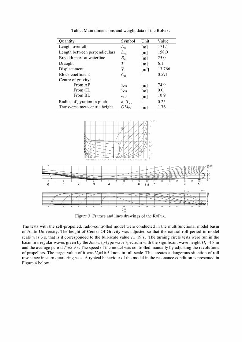
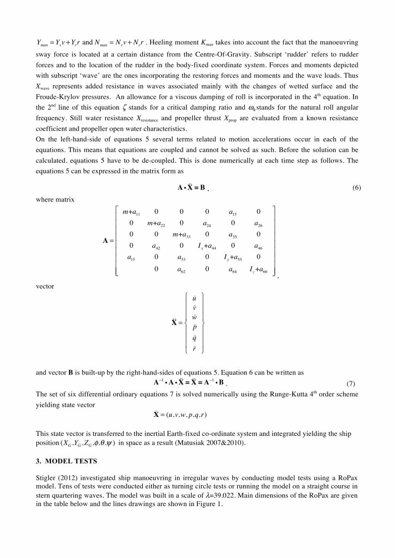
Table. Main dimensions and weight data of the RoPax.
Quantity Symbol Unit Value Length over all Loa [m] 171.4 Length between perpendiculars Lpp [m] 158.0 Breadth max. at waterline Bwl [m] 25.0 Draught T [m] 6.1 Displacement ∇ [m3] 13 766 Block coefficient CB – 0.571 Centre of gravity: From AP From CL From BL
xCG yCG zCG
[m] [m] [m]
74.9 0.0 10.9
Radius of gyration in pitch kyy/Lpp – 0.25 Transverse metacentric height GMT0 [m] 1.76
Figure 3. Frames and lines drawings of the RoPax.
The tests with the self-propelled, radio-controlled model were conducted in the multifunctional model basin of Aalto University. The height of Center-Of-Gravity was adjusted so that the natural roll period in model scale was 3 s, that is it corresponded to the full-scale value Tφ=19 s. The turning circle tests were run in the basin in irregular waves given by the Jonswap-type wave spectrum with the significant wave height HS=4.8 m and the average period T1=5.9 s. The speed of the model was controlled manually by adjusting the revolutions of propellers. The target value of it was VS=16.5 knots in full-scale. This creates a dangerous situation of roll resonance in stern quartering seas. A typical behaviour of the model in the resonance condition is presented in Figure 4 below.
RESEARCH REPORT VTT-R-02391-09
23 (44)
Table 3.1. Main dimensions of the Seatech-D ship.
Quantity Symbol Unit Value
Length over all Loa [m] 171.4
Length between pp. Lpp [m] 158.0
Breadth max. at waterline B wl [m] 25.0
Draught T [m] 6.1
Displacement ! [m3] 13 766
Block coefficient CB – 0.55
0 1 5432 109876 6.5
104 m
64.5 m
Figure 3.5. Lines drawings of the Seatech-D. The longitudinal locations of the force/torque
transducers are measured from AP. The midship transducer was at frame 4 and fore ship at
frame 6.5.
Figure 3.6. Seatech-D panel mesh in the calculations.
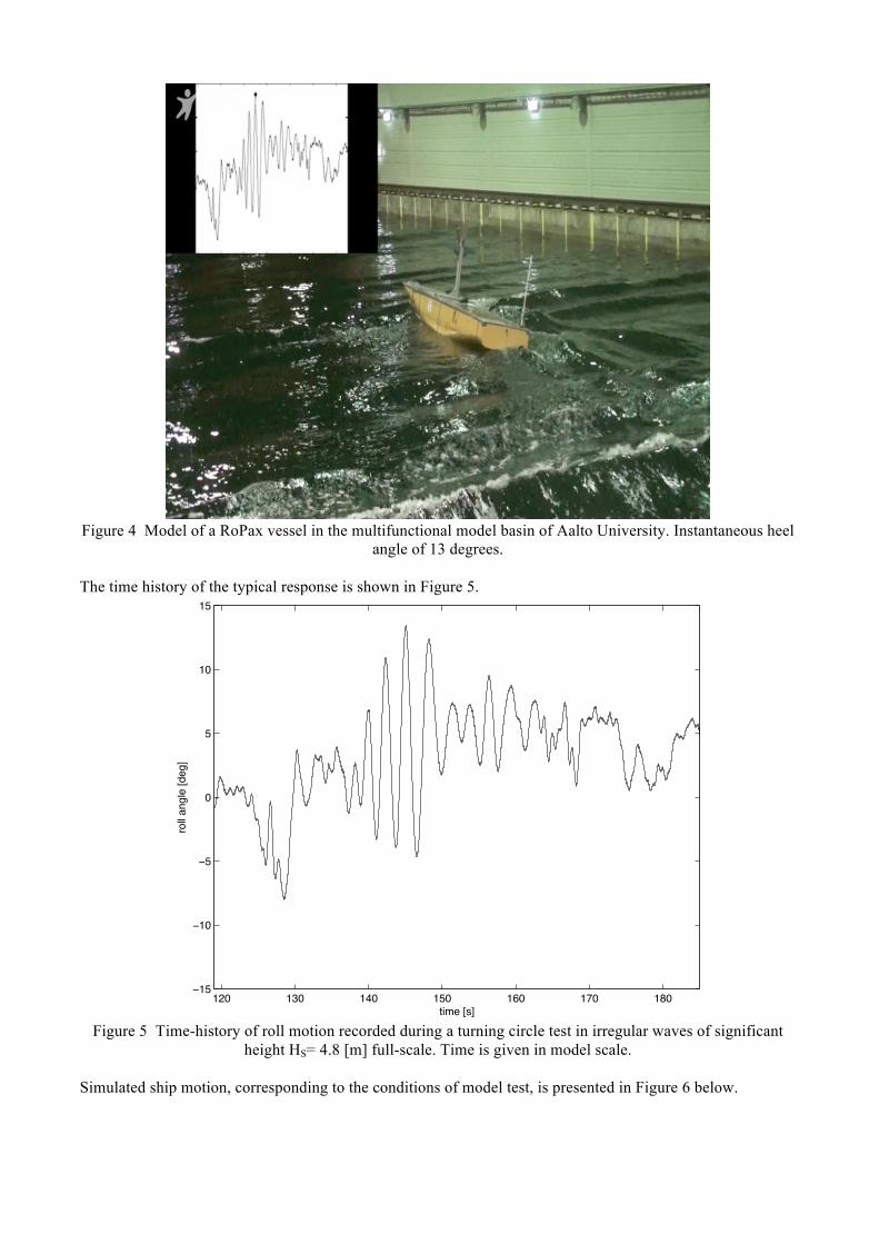
Figure 4 Model of a RoPax vessel in the multifunctional model basin of Aalto University. Instantaneous heel
angle of 13 degrees. The time history of the typical response is shown in Figure 5.
Figure 5 Time-history of roll motion recorded during a turning circle test in irregular waves of significant
height HS= 4.8 [m] full-scale. Time is given in model scale. Simulated ship motion, corresponding to the conditions of model test, is presented in Figure 6 below.
!"# !$# !%# !&# !'# !(# !)#!!&
!!#
!&
#
&
!#
!&
*+,-./01
2344.5674-./8-71
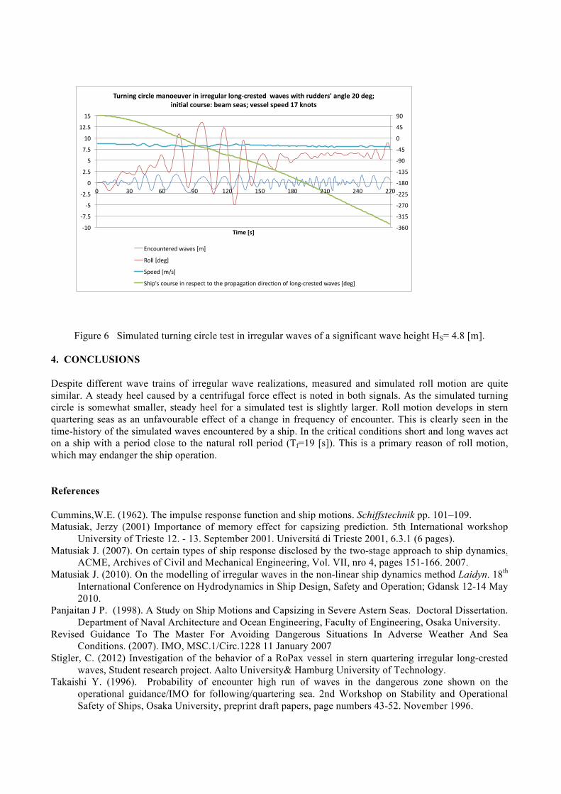
Figure 6 Simulated turning circle test in irregular waves of a significant wave height HS= 4.8 [m].
4. CONCLUSIONS Despite different wave trains of irregular wave realizations, measured and simulated roll motion are quite similar. A steady heel caused by a centrifugal force effect is noted in both signals. As the simulated turning circle is somewhat smaller, steady heel for a simulated test is slightly larger. Roll motion develops in stern quartering seas as an unfavourable effect of a change in frequency of encounter. This is clearly seen in the time-history of the simulated waves encountered by a ship. In the critical conditions short and long waves act on a ship with a period close to the natural roll period (Tf=19 [s]). This is a primary reason of roll motion, which may endanger the ship operation. References Cummins,W.E. (1962). The impulse response function and ship motions. Schiffstechnik pp. 101–109. Matusiak, Jerzy (2001) Importance of memory effect for capsizing prediction. 5th International workshop
University of Trieste 12. - 13. September 2001. Universitá di Trieste 2001, 6.3.1 (6 pages). Matusiak J. (2007). On certain types of ship response disclosed by the two-stage approach to ship dynamics.
ACME, Archives of Civil and Mechanical Engineering, Vol. VII, nro 4, pages 151-166. 2007. Matusiak J. (2010). On the modelling of irregular waves in the non-linear ship dynamics method Laidyn. 18th
International Conference on Hydrodynamics in Ship Design, Safety and Operation; Gdansk 12-14 May 2010.
Panjaitan J P. (1998). A Study on Ship Motions and Capsizing in Severe Astern Seas. Doctoral Dissertation. Department of Naval Architecture and Ocean Engineering, Faculty of Engineering, Osaka University.
Revised Guidance To The Master For Avoiding Dangerous Situations In Adverse Weather And Sea Conditions. (2007). IMO, MSC.1/Circ.1228 11 January 2007
Stigler, C. (2012) Investigation of the behavior of a RoPax vessel in stern quartering irregular long-crested waves, Student research project. Aalto University& Hamburg University of Technology.
Takaishi Y. (1996). Probability of encounter high run of waves in the dangerous zone shown on the operational guidance/IMO for following/quartering sea. 2nd Workshop on Stability and Operational Safety of Ships, Osaka University, preprint draft papers, page numbers 43-52. November 1996.
!"#$%
!"&'%
!()$%
!(('%
!&*$%
!&"'%
!+$%
!,'%
$%
,'%
+$%
!&$%
!)-'%
!'%
!(-'%
$%
(-'%
'%
)-'%
&$%
&(-'%
&'%
$% "$% #$% +$% &($% &'$% &*$% (&$% (,$% ()$%
!"#$%&'(%
!)*+"+,%-"*-.$%#/+0$)1$*%"+%"**$,)./*%.0+,2-*$'3$4%%5/1$'%5"36%*)44$*'7%/+,.$%89%4$,:%%"+";/.%-0)*'$<%=$/#%'$/':%1$''$.%'>$$4%?@%A+03'%
./012/34546%7894:%;<=%
>1??%;64@=%
AB446%;<C:=%
ADEBF:%0125:4%E/%54:B403%31%3D4%B51B8@8G1/%6E540G1/%1H%?1/@!054:346%7894:%;64@=%