shielding coatings based on carbon–polymer composites
TRANSCRIPT

AUTHOR QUERY FORM
Journal: SCT Please e-mail or fax your responses and any corrections to:E-mail: [email protected]: +1 619 699 6721
Article Number: 16978
Dear Author,
Any queries or remarks that have arisen during the processing of your manuscript are listed below and highlighted by flags inthe proof. Please check your proof carefully and mark all corrections at the appropriate place in the proof (e.g., by using on-screen annotation in the PDF file) or compile them in a separate list.
For correction or revision of any artwork, please consult http://www.elsevier.com/artworkinstructions.
Any queries or remarks that have arisen during the processing of your manuscript are listed below and highlighted by flags inthe proof. Click on the ‘Q’ link to go to the location in the proof.
Locationin article
Query / Remark: click on the Q link to goPlease insert your reply or correction at the corresponding line in the proof
Q1 Please confirm that given names and surnames have been identified correctly.
Q2 Please check the telephone number of the corresponding author, and correct if necessary.
Thank you for your assistance.
Our reference: SCT 16978 P-authorquery-v8
Page 1 of 1
UNCO
RRECTED P
RO
OF
1 Highlights
2 Surface & Coatings Technology xxx (2011) xxx–xxx
4
5 Shielding coatings based on carbon–polymer composites6
7 L. Vovchenko a,⁎, Yu. Perets a, I. Ovsienko a, L. Matzui a, V. Oliynyk a, V. Launetz b
89
a Departments of Physics and Radiophysics, Kyiv National Taras Shevchenko University, Volodymyrska str., 64, 01033 Kyiv, Ukraine10
b “Research-and-production concern Nauka”, pr. Peremogy, 37, 03056 Kyiv, Ukraine
11
12► Graphite nanoplatelets (GNPs) are promising fillers for composite electromagnetic shielding coatings. ► The value of shielding efficiency SET increases with13increase of conductive GNPs content in composite coating. ► Electromagnetic absorption loss is comparable with reflection loss in investigated composite14coatings.
15
16
Surface & Coatings Technology xxx (2011) xxx
SCT-16978; No of Pages 1
0257-8972/$ – see front matter © 2011 Elsevier B.V. All rights reserved.doi:10.1016/j.surfcoat.2011.08.018
Contents lists available at SciVerse ScienceDirect
Surface & Coatings Technology
j ourna l homepage: www.e lsev ie r .com/ locate /sur fcoat
Please cite this article as: L. Vovchenko, et al., Surf. Coat. Technol. (2011), doi:10.1016/j.surfcoat.2011.08.018
1
2Q1
34
5
67891011121314151617
35
36
37
38
39
40
41
42
43
44
45
46
47
48
49
50
51
52
53
54
55
56
57
58
Surface & Coatings Technology xxx (2011) xxx–xxx
Q2
SCT-16978; No of Pages 4
Contents lists available at SciVerse ScienceDirect
Surface & Coatings Technology
j ourna l homepage: www.e lsev ie r .com/ locate /sur fcoat
F
Shielding coatings based on carbon–polymer composites
L. Vovchenko a,⁎, Yu. Perets a, I. Ovsienko a, L. Matzui a, V. Oliynyk a, V. Launetz b
a Departments of Physics and Radiophysics, Kyiv National Taras Shevchenko University, Volodymyrska str., 64, 01033 Kyiv, Ukraineb “Research-and-production concern Nauka”, pr. Peremogy, 37, 03056 Kyiv, Ukraine
⁎ Corresponding author. Tel.: +38 044 5262384.E-mail address: [email protected] (L. Vovchenko).
0257-8972/$ – see front matter © 2011 Elsevier B.V. Alldoi:10.1016/j.surfcoat.2011.08.018
Please cite this article as: L. Vovchenko, et
O
a b s t r a c t
a r t i c l e i n f o18
Available online xxxx 1920
21
22
23
24
Keywords:Graphite nanoplateletsElectromagnetic shieldingReflection lossAbsorption lossDielectric permittivity
25
26
27
28
29
30
31
ED P
ROThe protective coating against electromagnetic radiation (EMR) on the base of polymer compositefilledwith two
types of graphite particles (ultra-disperse graphite C1 and graphite nanoplatelets — GNPs) had been preparedand investigated in the frequency range 25.5–37.5 GHz. The paint and epoxy resinwere used as polymer matrix.The content of graphite filler in composite was 5–15 wt.% and composite layer was applied as a coating on poly-ethylene (PE) substrate. The small size of carbon fillers permits to prepare thin films of composites (beginningfrom 100 μm) on polyethylene substrate. The using of GNPs as filler in composite coating was found to bemore promising for EMI shielding than the using of C1 graphite. The observed difference in the EMR shieldingefficiency is related with the better electrical characteristics and low percolation threshold in polymer filledwith GNPs (Ccr≈5.43 wt.%) as compared with polymer containing conventional carbon fillers. The shielding ef-ficiency SET increases with the content of graphite conductive component in CM coating and is equal to 8–10 dBfor the composite layers 10 wt.%GNPs-epoxy (200–300 μm thick) on PE substrate. Good agreement between ex-perimental and calculatedwithin themodel of double-layeredmediumdata on SET for epoxy coatingswith GNPshad been observed at the values of tan δ ranging within 0.15–0.28 and ε′ — within 17–35 for 5 and 10 wt.% ofGNPs in CM-layer, respectively.
32
rights reserved.
al., Surf. Coat. Technol. (2011), doi:10.1016/j.
© 2011 Elsevier B.V. All rights reserved.
3334
T
C59
60
61
62
63
64
65
66
67
68
69
70
71
72
73
74
75
76
77
78
79
UNCO
RRE1. Introduction
Thewide application of electromagnetic resource relatedwith the de-velopment of radio- andmobile communication, TV, data communicationand processing systems leads to arising of additional electromagneticradiation background negatively influencing other electronic equipment(electromagnetic interference EMI) and human organism. The electronicequipment could be damaged by the powerful impulse of electromagnet-ic radiation (EMR). Such radiation may induce voltage and currentoverloads that create degradation, breakdown, melting of semiconductorelements and, hence, failure of equipment including even switched-offdevices. So, the development of efficient protection against deleteriousinfluence of radio-frequency EMR on electronic equipment as well as onhuman organisms is seen to be a problem of special importance [1–3].
Carbon-based structures play important role in the EMR absorbingcoatings and EMR shielding [4–6] because of the lightness and suit-able electronic properties. For these composites, the effectiveness ofEMI shielding increases with increasing of the filler fraction andaspect ratio of the filler, defined as the ratio of the length to thediameter of the conductive particles. Recently, it became clear thatpolymer composites filled with nanostructured conducting compo-nents can be a new class of broad-band electromagnetic absorptionmaterials. There is a growing interest in fabricating of EMI shielding
80
81
82
83
composites using nanocarbon materials, such as nanofibers, nano-tubes, and nanofilaments [7–10], carbon aerogels [11], carbon nanor-ibbon networks [12], onion-like carbon (OLC) [13], as fillers becauseof the structural and electrical advantages of these nanoscale fillersin comparison with conventional carbon fillers (carbon fibers, carbonblacks, etc.). Nanocarbon materials have significantly larger specificarea and aspect ratio, and are able to form interconnected conductivenetworks in the matrix more easily. The low percolation threshold inelectrical conductivity for polymer-nanocarbon composites [14,15]allow us to prepare thin electroconducting shields (coatings) withdesirable elastic and adhesion characteristics even at low content ofcarbon nanofiller. For the entire cross-section of a filler unit beingeffectively used for shielding, the unit size of the filler should be com-parable to or less than the skin depth. Therefore, a filler of unit size(10-100)nm or less is typically preferred. The aim of this study wasto investigate the shielding characteristics of coatings based on poly-mers filled with ultra-disperse graphite particles.
2. Experimental procedures
We have investigated the shielding characteristics of two types ofcoatings: 1) coating based on paint and carbon fillers: ultra-dispersegraphite (C1) and sonicated thermoexfoliated graphite (TEG) [16](graphite nanoplatelets — GNPs) and 2) coating based on epoxy resinand sonicated TEG and TEG-Ni particles. The ultrasonic dispersing ofTEG powder (200 mg) in acetone solution for 4 hours was performedin ultrasonic bath. The support of Ni nanoparticles (40–100 nm) on
surfcoat.2011.08.018
84
85
86
87
88
89
90
91
92
93
94
95
96
97
98
99
100
101
102
103
104
105
106
107
108
109
110
111
112
113
114
115
116
117
118
119
120
121
122
123
124
125
126
127
128
129
130
131
132
133
134
135
136
137
Table 1 t1:1
The characteristics of graphite filler in polymer composite.t1:2t1:3Type of filler Size of particles d002, nm Lc, nm
t1:4Graphite C1 1–4 μm 0.3348 53t1:5Graphite nanoplatelets
(GNPs)0.2–10 μm (diameter) 30–100 nm(diameter of smallest particles)5–20 nm (thickness) agglomerates10–20 μm in size
0.3348 35
2 L. Vovchenko et al. / Surface & Coatings Technology xxx (2011) xxx–xxx
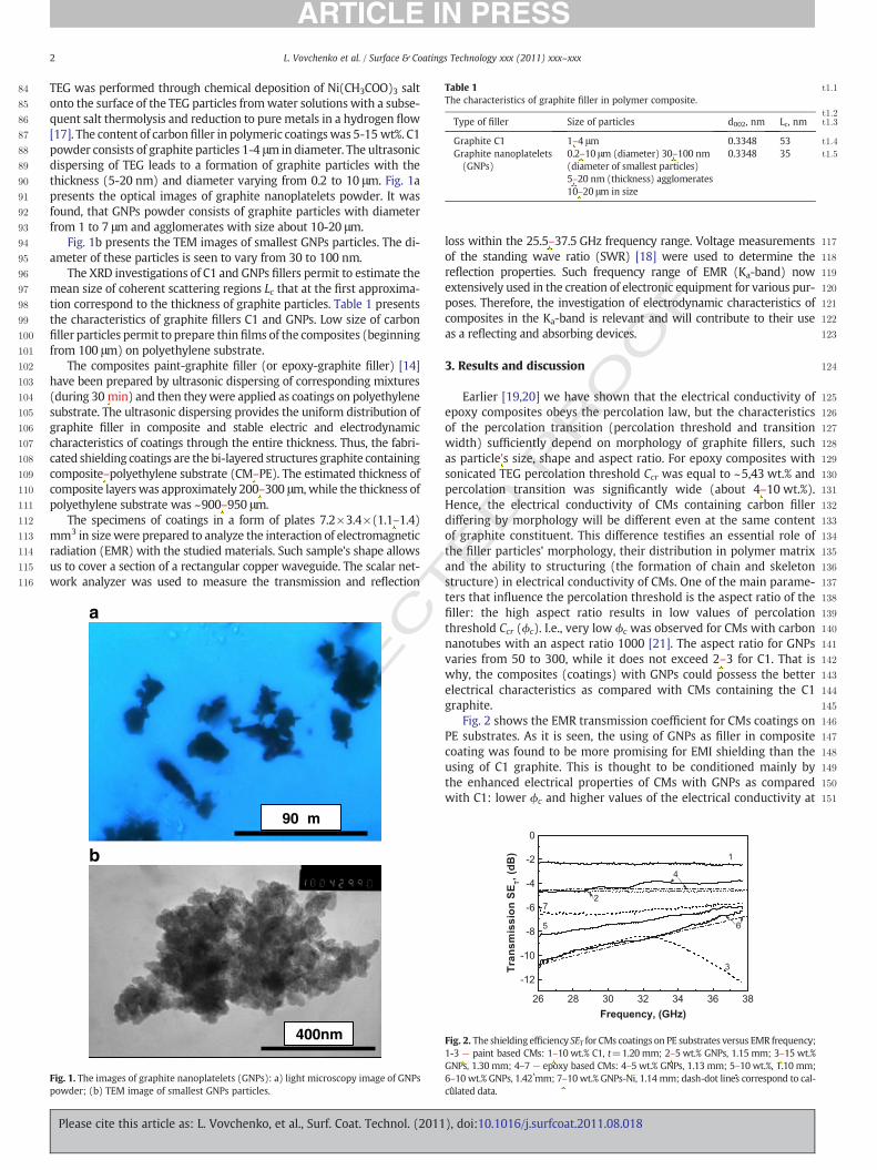
TEG was performed through chemical deposition of Ni(CH3COO)3 saltonto the surface of the TEG particles fromwater solutions with a subse-quent salt thermolysis and reduction to pure metals in a hydrogen flow[17]. The content of carbonfiller in polymeric coatingswas 5-15 wt%. C1powder consists of graphite particles 1-4 μm in diameter. The ultrasonicdispersing of TEG leads to a formation of graphite particles with thethickness (5-20 nm) and diameter varying from 0.2 to 10 μm. Fig. 1apresents the optical images of graphite nanoplatelets powder. It wasfound, that GNPs powder consists of graphite particles with diameterfrom 1 to 7 μm and agglomerates with size about 10-20 μm.
Fig. 1b presents the TEM images of smallest GNPs particles. The di-ameter of these particles is seen to vary from 30 to 100 nm.
The XRD investigations of C1 and GNPs fillers permit to estimate themean size of coherent scattering regions Lc that at the first approxima-tion correspond to the thickness of graphite particles. Table 1 presentsthe characteristics of graphite fillers C1 and GNPs. Low size of carbonfiller particles permit to prepare thin films of the composites (beginningfrom 100 μm) on polyethylene substrate.
The composites paint-graphite filler (or epoxy-graphite filler) [14]have been prepared by ultrasonic dispersing of corresponding mixtures(during 30 min) and then theywere applied as coatings on polyethylenesubstrate. The ultrasonic dispersing provides the uniform distribution ofgraphite filler in composite and stable electric and electrodynamiccharacteristics of coatings through the entire thickness. Thus, the fabri-cated shielding coatings are the bi-layered structures graphite containingcomposite–polyethylene substrate (CM–PE). The estimated thickness ofcomposite layers was approximately 200–300 μm,while the thickness ofpolyethylene substrate was ~900–950 μm.
The specimens of coatings in a form of plates 7.2×3.4×(1.1–1.4)mm3 in sizewere prepared to analyze the interaction of electromagneticradiation (EMR) with the studied materials. Such sample's shape allowsus to cover a section of a rectangular copper waveguide. The scalar net-work analyzer was used to measure the transmission and reflection
UNCO
RRECT 138
139
140
141
142
143
144
145
146
147
148
149
150
151
90µm
400nm
a
b
Fig. 1. The images of graphite nanoplatelets (GNPs): a) light microscopy image of GNPspowder; (b) TEM image of smallest GNPs particles.
Please cite this article as: L. Vovchenko, et al., Surf. Coat. Technol. (2011
ED P
RO
OF
loss within the 25.5–37.5 GHz frequency range. Voltage measurementsof the standing wave ratio (SWR) [18] were used to determine thereflection properties. Such frequency range of EMR (Ka-band) nowextensively used in the creation of electronic equipment for various pur-poses. Therefore, the investigation of electrodynamic characteristics ofcomposites in the Ka-band is relevant and will contribute to their useas a reflecting and absorbing devices.
3. Results and discussion
Earlier [19,20] we have shown that the electrical conductivity ofepoxy composites obeys the percolation law, but the characteristicsof the percolation transition (percolation threshold and transitionwidth) sufficiently depend on morphology of graphite fillers, suchas particle's size, shape and aspect ratio. For epoxy composites withsonicated TEG percolation threshold Ccr was equal to ~5,43 wt.% andpercolation transition was significantly wide (about 4–10 wt.%).Hence, the electrical conductivity of CMs containing carbon fillerdiffering by morphology will be different even at the same contentof graphite constituent. This difference testifies an essential role ofthe filler particles’ morphology, their distribution in polymer matrixand the ability to structuring (the formation of chain and skeletonstructure) in electrical conductivity of CMs. One of the main parame-ters that influence the percolation threshold is the aspect ratio of thefiller: the high aspect ratio results in low values of percolationthreshold Ccr (ϕc). I.e., very low ϕc was observed for CMs with carbonnanotubes with an aspect ratio 1000 [21]. The aspect ratio for GNPsvaries from 50 to 300, while it does not exceed 2–3 for C1. That iswhy, the composites (coatings) with GNPs could possess the betterelectrical characteristics as compared with CMs containing the C1graphite.
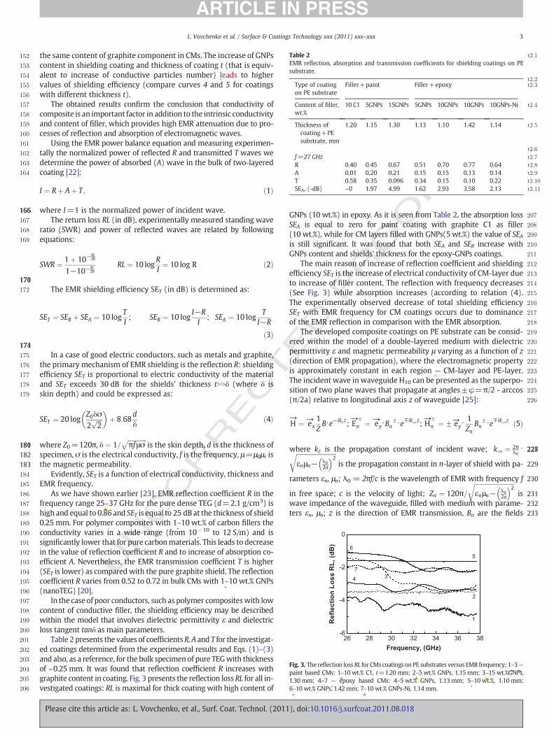
Fig. 2 shows the EMR transmission coefficient for CMs coatings onPE substrates. As it is seen, the using of GNPs as filler in compositecoating was found to be more promising for EMI shielding than theusing of C1 graphite. This is thought to be conditioned mainly bythe enhanced electrical properties of CMs with GNPs as comparedwith C1: lower ϕc and higher values of the electrical conductivity at
Fig. 2. The shielding efficiency SET for CMs coatings on PE substrates versus EMR frequency;1-3 — paint based CMs: 1–10 wt.% C1, t=1.20 mm; 2–5 wt.% GNPs, 1.15 mm; 3–15 wt.%GNPs, 1.30 mm; 4–7 — epoxy based CMs: 4–5 wt.% GNPs, 1.13 mm; 5–10 wt.%, 1.10 mm;6–10 wt.% GNPs, 1.42 mm; 7–10 wt.% GNPs-Ni, 1.14 mm; dash-dot lines correspond to cal-culated data.
), doi:10.1016/j.surfcoat.2011.08.018
T
F
152
153
154
155
156
157
158
159
160
161
162
163
164
165166167
168
169
170171172
173174175
176
177
178
179
180181182183184
185
186
187
188
189
190
191
192
193
194
195
196
197
198
199
200
201
202
203
204
205
206
207
208
209
210
211
212
213
214
215
216
217
218
219
220
221
222
223
224
225
226
227228
229
230
231232233
Table 2 t2:1
EMR reflection, absorption and transmission coefficients for shielding coatings on PEsubstrate.
t2:2t2:3Type of coating
on PE substrateFiller+paint Filler+epoxy
t2:4Content of filler,wt.%
10 C1 5GNPs 15GNPs 5GNPs 10GNPs 10GNPs 10GNPs-Ni
t2:5Thickness ofcoating+PEsubstrate, mm
1.20 1.15 1.30 1.13 1.10 1.42 1.14
t2:6
t2:7f=27 GHzt2:8R 0.40 0.45 0.67 0.51 0.70 0.77 0.64t2:9A 0.01 0.20 0.21 0.15 0.15 0.13 0.14t2:10T 0.58 0.35 0.096 0.34 0.15 0.10 0.22t2:11SEA, (-dB) ~0 1.97 4.99 1.62 2.93 3.58 2.13
Fig. 3. The reflection loss RL for CMs coatings on PE substrates versus EMR frequency; 1–3—paint based CMs: 1–10 wt.% C1, t=1.20 mm; 2–5 wt.% GNPs, 1.15 mm; 3–15 wt.%GNPs,1.30 mm; 4–7 — epoxy based CMs: 4–5 wt.% GNPs, 1.13 mm; 5–10 wt.%, 1.10 mm;6–10 wt.% GNPs, 1.42 mm; 7–10 wt.% GNPs-Ni, 1.14 mm.
3L. Vovchenko et al. / Surface & Coatings Technology xxx (2011) xxx–xxx
UNCO
RREC
the same content of graphite component in CMs. The increase of GNPscontent in shielding coating and thickness of coating t (that is equiv-alent to increase of conductive particles number) leads to highervalues of shielding efficiency (compare curves 4 and 5 for coatingswith different thickness t).
The obtained results confirm the conclusion that conductivity ofcomposite is an important factor in addition to the intrinsic conductivityand content of filler, which provides high EMR attenuation due to pro-cesses of reflection and absorption of electromagnetic waves.
Using the EMR power balance equation and measuring experimen-tally the normalized power of reflected R and transmitted T waves wedetermine the power of absorbed (A) wave in the bulk of two-layeredcoating [22]:
I ¼ Rþ Aþ T; ð1Þ
where I=1 is the normalized power of incident wave.The return loss RL (in dB), experimentally measured standing wave
ratio (SWR) and power of reflected waves are related by followingequations:
SWR ¼ 1þ 10−RL20
1−10−RL20
RL ¼ 10 logRI¼ 10 log R ð2Þ
The EMR shielding efficiency SET (in dB) is determined as:
SET ¼ SER þ SEA ¼ 10 logTI; SER ¼ 10 log
I−RI
; SEA ¼ 10 logT
I−R
ð3Þ
In a case of good electric conductors, such as metals and graphite,the primary mechanism of EMR shielding is the reflection R: shieldingefficiency SET is proportional to electric conductivity of the materialand SET exceeds 30 dB for the shields’ thickness tNNδ (where δ isskin depth) and could be expressed as:
SET ¼ 20 logZ0δσ2
ffiffiffi2
p� �
þ 8:68dδ
ð4Þ
where Z0=120π, δ ¼ 1=ffiffiffiffiffiffiffiffiffiffiffiffiπfμσ
pis the skin depth, d is the thickness of
specimen, σ is the electrical conductivity, f is the frequency, μ=μ0μr isthe magnetic permeability.
Evidently, SET is a function of electrical conductivity, thickness andEMR frequency.
As we have shown earlier [23], EMR reflection coefficient R in thefrequency range 25–37 GHz for the pure dense TEG (d=2.1 g/cm3) ishigh and equal to 0.86 and SET is equal to 25 dB at the thickness of shield0.25 mm. For polymer composites with 1–10 wt.% of carbon fillers theconductivity varies in a wide range (from 10−10 to 12 S/m) and issignificantly lower that for pure carbonmaterials. This leads to decreasein the value of reflection coefficient R and to increase of absorption co-efficient A. Nevertheless, the EMR transmission coefficient T is higher(SET is lower) as comparedwith the pure graphite shield. The reflectioncoefficient R varies from 0.52 to 0.72 in bulk CMs with 1–10 wt.% GNPs(nanoTEG) [20].
In the case of poor conductors, such as polymer compositeswith lowcontent of conductive filler, the shielding efficiency may be describedwithin the model that involves dielectric permittivity ε and dielectricloss tangent tanδ as main parameters.
Table 2 presents the values of coefficientsR, A and T for the investigat-ed coatings determined from the experimental results and Eqs. (1)–(3)and also, as a reference, for the bulk specimen of pure TEGwith thicknessof ~0.25 mm. It was found that reflection coefficient R increases withgraphite content in coating. Fig. 3 presents the reflection loss RL for all in-vestigated coatings: RL is maximal for thick coating with high content of
Please cite this article as: L. Vovchenko, et al., Surf. Coat. Technol. (2011
ED P
RO
OGNPs (10 wt.%) in epoxy. As it is seen from Table 2, the absorption lossSEA is equal to zero for paint coating with graphite C1 as filler(10 wt.%), while for CM layers filled with GNPs(5 wt.%) the value of SEAis still significant. It was found that both SEA and SER increase withGNPs content and shields’ thickness for the epoxy-GNPs coatings.
The main reason of increase of reflection coefficient and shieldingefficiency SET is the increase of electrical conductivity of CM-layer dueto increase of filler content. The reflection with frequency decreases(See Fig. 3) while absorption increases (according to relation (4).The experimentally observed decrease of total shielding efficiencySET with EMR frequency for CM coatings occurs due to dominanceof the EMR reflection in comparison with the EMR absorption.
The developed composite coatings on PE substrate can be consid-ered within the model of a double-layered medium with dielectricpermittivity ε and magnetic permeability μ varying as a function of z(direction of EMR propagation), where the electromagnetic propertyis approximately constant in each region — CM-layer and PE-layer.The incident wave in waveguide H10 can be presented as the superpo-sition of two plane waves that propagate at angles±φ=π/2 - arccos(π/2a) relative to longitudinal axis z of waveguide [25]:
→H ¼ →ex
1ZB⋅e−ikzz;
→E
F
n ¼ →ey⋅BnF⋅e∓ikznz;
→H
F
n ¼ F→ey⋅1Zn
BnF⋅e∓ikznz ð5Þ
where kz is the propagation constant of incident wave; kzn ¼ 2πλ0⋅ffiffiffiffiffiffiffiffiffiffiffiffiffiffiffiffiffiffiffiffiffiffiffiffiffiffi
εnμn− λ02a
� �2r
is the propagation constant in n-layer of shield with pa-
rameters εn, μn; λ0 = 2πf/c is the wavelength of EMR with frequency f
in free space; c is the velocity of light; Zn ¼ 120π=
ffiffiffiffiffiffiffiffiffiffiffiffiffiffiffiffiffiffiffiffiffiffiffiffiffiffiεnμn− λ0
2a
� �2r
iswave impedance of the waveguide, filled with medium with parame-ters εn, μn; z is the direction of EMR transmission, Bn are the fields
), doi:10.1016/j.surfcoat.2011.08.018
T
234235236
237
238
239
240
241
242243244
245
246
247
248
249
250
251
252
253
254
255
256
257
258
259
260
261
262
263
264
265
266
267
268
269
270
271
272
273
274
275
276
277
278
279
280
281
282
283
284
285
286
287
288
289
290
291292293294295296297298299300301302303304305306307308309310311312313314315316317318319320321322323324325326
327
4 L. Vovchenko et al. / Surface & Coatings Technology xxx (2011) xxx–xxx
ORREC
amplitudes, 2a is the larger dimension of waveguide. The upper andlower signs in →E F
n and→HF
n correspond to incident and reflected waves.Taking into account the absorption processes in material, dielec-
tric permittivity may be presented as a sum of real and imaginarypart εn=ε′n+ iε″n and for nonmagnetic materials (μ=1) propagationconstant is described by the relation kzn=kzn− iαn, where αn is theabsorption coefficient in n-layer. According to [24] for poor conduct-ing materials α may be presented as following:
αn ¼ 2πλ
⋅
ffiffiffiffiffiffiffiffiffiffiffiffiffiffiffiffiffiffiffiffiffiffiffiffiffiffiffiffiffiffiffiffiffiffiffiffiffiffiffiffiffiffiffiffiffiffiffiffiε′n⋅
ffiffiffiffiffiffiffiffiffiffiffiffiffiffiffiffiffiffiffiffiffiffiffiffiffiffiffiffi1þ tan2δn� �q
∓1
2
vuutð6Þ
where tan δn=ε′n/ε″n is a dielectric loss tangent.The boundary conditions for the electric and magnetic fields on
the surface of each layer give the required number of equations fordetermining all unknown parameters. So, for 2 layers we have thesystem of 6 linear equations and the same number of unknownparameters.
Depending on the task this systemof equations allows us to simulatethe unknown fields amplitudes Bn, using the known parameters (εn, μnand thickness) of each layer of shield, i.e. to predict the shielding char-acteristics due to reflection and absorption processes. On the otherhand, experimental data on amplitudes of reflected and transmittedwaves allows us to estimate the effective electrodynamic parametersof materials, such as εef, μef, α.
For such type of CMs (epoxy with 5-10 wt.% GNPs) the value of tan δranges within 0.15-0.28 and the value of ε′ — within 17–35 [20]. Usingthese values of tan δ and ε′ for epoxy-GNPs and ε′=2.16 for PEwe have estimated the shielding efficiency SET(dB) of coatings GNPs-epoxy+PE. The compared experimental (solid lines) and theoretical(dash-dot lines) SET data for coatings with 5 (curve 4) and 10 wt.%GNPs (curve 6) are presented in Fig. 2. The performed analysis hadshown that shielding efficiency of coating increases with increase of CMcoatings’ thickness and proportional to the value of effective dielectricpermittivity of CM layer.
4. Conclusions
The electromagnetic shielding characteristics of the coatingsbased on polymer matrix (paint or epoxy resin) and two types of car-bon fillers: ultra-disperse graphite C1 and sonicated thermoexfoliatedgraphite (graphite nanoplatelets — GNPs) were studied in the regionof electromagnetic radiation (EMR) frequency from 25.5 to 37.5 GHz.It was shown that the using of GNPs as filler in composite coating ismore promising for EMI shielding than the using of C1 graphite.This is thought to be related mainly with the enhanced electricalproperties of CMs with GNPs as compared with CM containing C1
UNC
Please cite this article as: L. Vovchenko, et al., Surf. Coat. Technol. (2011
graphite. The value of shielding efficiency SET increases with increaseof graphite conductive component content in CM coating. It wasfound that attenuation of EMR in CM coating filled with 10 wt.% ofgraphite C1 occurs predominantly due EMR reflection process in CMlayer, while in CM coatings filled with GNPs the EMR absorption pro-cesses are also significant. The coatings CM-layer+polyethylene sub-strate have been considered within the model of double-layeredmedium. The appropriate numerical analysis of these coating hadshown that the values of SET increases with increase of CM coatings’thickness and is proportional to the effective dielectric permittivityε of CM layer.
F
Acknowledgements
This study was financially supported by the STCU under projectNo. 4908.
ED P
RO
O
References
[1] N.C. Das, T. Chaki, D. Khastgir, A. Chakraborty, J. Appl. Polym. Sci. 80 (2001) 1601.[2] Y. Wang, X. Jing, Polym. Adv. Technol. 16 (2005) 344.[3] S. Shinagawa, Y. Kumagai, K. Urabe, J. Porous. Mater. 6 (1999) 185.[4] J. Wu, D.D.L. Chung, J. Electron. Mater. 37 (2008) 1088.[5] D.-L. Zhao, X. Li, Z.-M. Shen, Compos. Sci. Technol. 68 (2008) 2902.[6] J.-H. Oh, K.-S. Oh, C.-G. Kim, C.-S. Hong, Compos. Part B Eng. 35 (2004) 49.[7] R.C. Che, L.M. Peng, X.F. Duan, Q. Chen, X.L. Liang, Adv. Mater. 16 (2004) 401.[8] Y.L. Yang, M.C. Gupta, K.L. Dudley, R.W. Lawrence, Nano. Lett. 5 (2005) 2131.[9] P.C. Watts, W.K. Hsu, A. Barnes, B. Chambers, Adv. Mater. 15 (2003) 600.
[10] L.S. Schadler, S.C. Giannaris, P.M. Ajayan, Appl. Phys. Lett. 73 (1998) 3842.[11] S.S.Q. Zhang, C.G. Huang, Z.Y. Zhou, Z. Li, Mater. Sci. Eng. B 90 (2002) 38.[12] X.Q. Liu, D. Zhang, T. Fan, J. Gu, Y. Miyamoto, Z. Chen, Carbon 46 (2008) 461.[13] S.A. Maksimenko, V.N. Rodionova, G.Ya. Slepyan, V.A. Karpovich, O. Shenderova, J.
Walsh, V.L. Kuznetsov, I.N. Mazov, S.I. Moseenkov, A.V. Okotrub, Ph. Lambin,Diam. Relat. Mater. 16 (2007) 1231.
[14] H.J. Barraza, F. Pompeo, E.A. O'Rear, D.E. Resasco, Nano. Lett. 2 (2002) 797.[15] J.C. Grunlan, A.R. Mehrabi, M.V. Bannon, J.L. Bahr, Adv. Mater. 16 (2004) 150.[16] E. Kharkov, V. Lysov, L. Matsui, L. Vovchenko, M. Tsurule, and N. Morozovskaya,
“Arrangement for obtaining of thermoexfoliated graphite”, UA Patent 33777A,2001.
[17] L. Matzui, L. Vovchenko, L. Kapitanchuk, M. Zakharenko, M. Babich, Inorg. Mat. 39(2003) 1147.
[18] A.F. Harvey, D. Phil, Microwave engineering, Academic Press, London and NewYork, 1963.
[19] O. Lazarenko, L. Vovchenko, L. Matzui, Ju Perets, Mol. Cryst. Liq. Cryst. 536 (2011)304.
[20] L. Vovchenko, L. Matzui, V. Oliynyk, V. Launetz, Phys. Stat. Solid. C. 7 (2010) 1260.[21] J.K.W. Sandler, J.E. Kirk, I.A. Kinloch, M.S.P. Shaffer1, A.H. Windle, Polymer 44
(2003) 5893.[22] M.H. Al-Saleh, U. Sundararaj, Carbon 47 (2009) 1738.[23] L. Vovchenko, L. Matzui, V. Oliynyk, V. Launetz, Yu. Prylutskyy, D. Hui, Yu.
Strzhemechny, Int. J. Nanosci. 7 (2008) 263.[24] J. Joo, A.J. Epstein, Appl. Phys. Lett. 65 (1994) 2278.[25] L. Vovchenko, L. Matzui, V. Oliynyk, V. Launetz, Mol. Cryst. Liq. Cryst. 535 (2011)
179.
), doi:10.1016/j.surfcoat.2011.08.018