service manual - tr200 series drives
TRANSCRIPT

130R0566 MG14M102
*MG14M102*
March 2014 BAS-SVM01A-EN
Service Manual
TR200 New D-Frame, 110-400 kW
Only qualified personnel should install and service the equipment. The installation, starting up, and servicing of heating, ventilating, and air-conditioning equipment can be hazardous and requires specific knowledge and training. Improperly installed, adjusted or altered equipment by an unqualified person could result in death or serious injury. When working on the equipment, ovserve all precautions in the literature and on the tags, stickers, and labels that are attached to the equipment.
Trane optimizes the performance of homes and buildings around the world. A business of Ingersoll Rand, the leader in creating and sustaining safe, comfortable and energy efficient environments, Trane offers a broad p o r t f o l i o o f a d v a n c e d c o n t r o l s a n d H VA C s y s t e m s , c o m p r e h e n s i v e b u i l d i n g s e r v i c e s , a n d p a r t s . For more information, visit www.Trane.com.
Trane has a policy of continuous product and product data improvement and reserves the right to change design and specifications without notice.
© 2014 Trane All rights reservedBAS-SVM01A-EN 3 March 2014Supersedes: New
SAFETY WARNING
We are committed to using environmentallyconscious print practises that reduce waste.
Contents
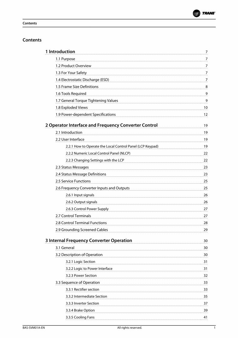
1 Introduction 7
1.1 Purpose 7
1.2 Product Overview 7
1.3 For Your Safety 7
1.4 Electrostatic Discharge (ESD) 7
1.5 Frame Size Definitions 8
1.6 Tools Required 9
1.7 General Torque Tightening Values 9
1.8 Exploded Views 10
1.9 Power-dependent Specifications 12
2 Operator Interface and Frequency Converter Control 19
2.1 Introduction 19
2.2 User Interface 19
2.2.1 How to Operate the Local Control Panel (LCP Keypad) 19
2.2.2 Numeric Local Control Panel (NLCP) 22
2.2.3 Changing Settings with the LCP 22
2.3 Status Messages 23
2.4 Status Message Definitions 23
2.5 Service Functions 25
2.6 Frequency Converter Inputs and Outputs 25
2.6.1 Input signals 26
2.6.2 Output signals 26
2.6.3 Control Power Supply 27
2.7 Control Terminals 27
2.8 Control Terminal Functions 28
2.9 Grounding Screened Cables 29
3 Internal Frequency Converter Operation 30
3.1 General 30
3.2 Description of Operation 30
3.2.1 Logic Section 31
3.2.2 Logic to Power Interface 31
3.2.3 Power Section 32
3.3 Sequence of Operation 33
3.3.1 Rectifier section 33
3.3.2 Intermediate Section 35
3.3.3 Inverter Section 37
3.3.4 Brake Option 39
3.3.5 Cooling Fans 41
Contents
BAS-SVM01A-EN All rights reserved. 1
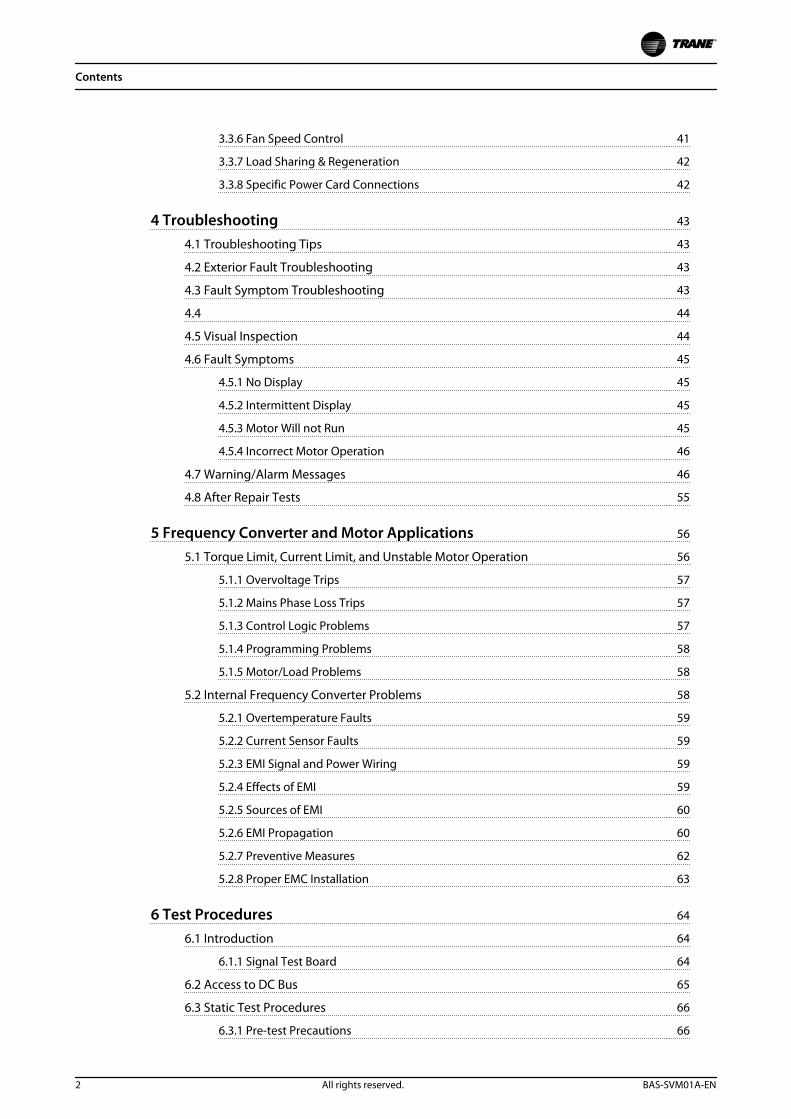
3.3.6 Fan Speed Control 41
3.3.7 Load Sharing & Regeneration 42
3.3.8 Specific Power Card Connections 42
4 Troubleshooting 43
4.1 Troubleshooting Tips 43
4.2 Exterior Fault Troubleshooting 43
4.3 Fault Symptom Troubleshooting 43
4.4 44
4.5 Visual Inspection 44
4.6 Fault Symptoms 45
4.5.1 No Display 45
4.5.2 Intermittent Display 45
4.5.3 Motor Will not Run 45
4.5.4 Incorrect Motor Operation 46
4.7 Warning/Alarm Messages 46
4.8 After Repair Tests 55
5 Frequency Converter and Motor Applications 56
5.1 Torque Limit, Current Limit, and Unstable Motor Operation 56
5.1.1 Overvoltage Trips 57
5.1.2 Mains Phase Loss Trips 57
5.1.3 Control Logic Problems 57
5.1.4 Programming Problems 58
5.1.5 Motor/Load Problems 58
5.2 Internal Frequency Converter Problems 58
5.2.1 Overtemperature Faults 59
5.2.2 Current Sensor Faults 59
5.2.3 EMI Signal and Power Wiring 59
5.2.4 Effects of EMI 59
5.2.5 Sources of EMI 60
5.2.6 EMI Propagation 60
5.2.7 Preventive Measures 62
5.2.8 Proper EMC Installation 63
6 Test Procedures 64
6.1 Introduction 64
6.1.1 Signal Test Board 64
6.2 Access to DC Bus 65
6.3 Static Test Procedures 66
6.3.1 Pre-test Precautions 66
Contents
2 All rights reserved. BAS-SVM01A-EN
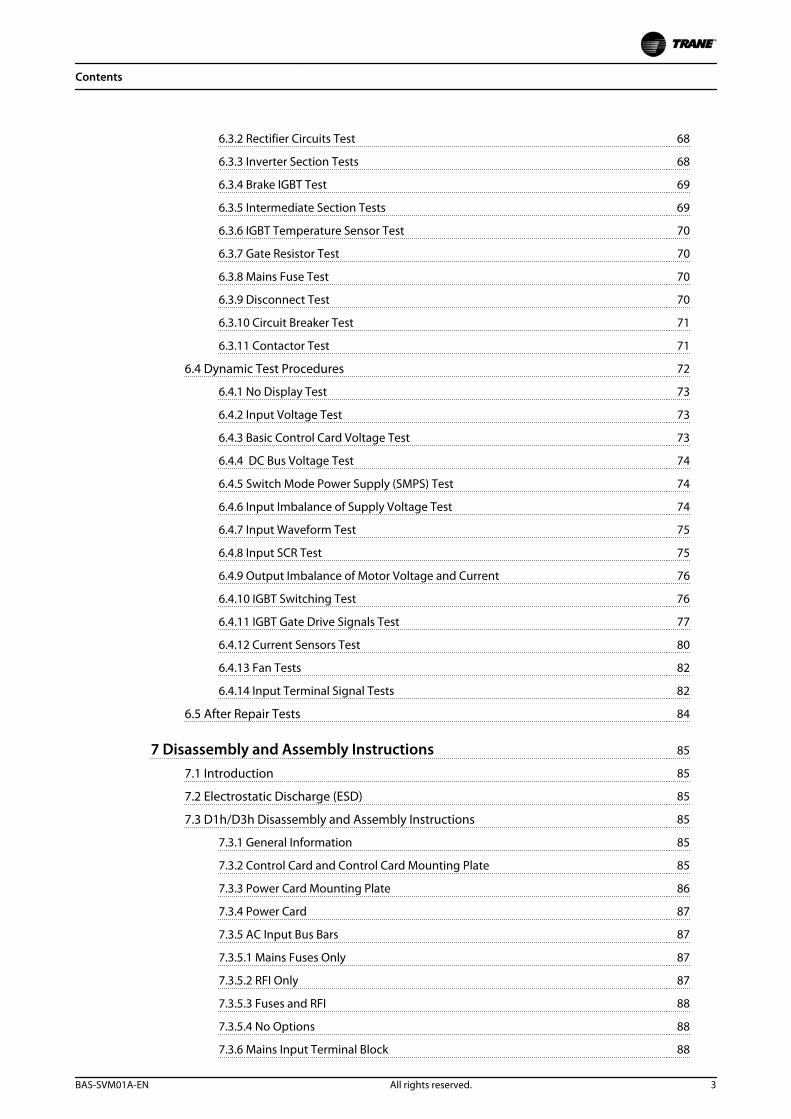
6.3.2 Rectifier Circuits Test 68
6.3.3 Inverter Section Tests 68
6.3.4 Brake IGBT Test 69
6.3.5 Intermediate Section Tests 69
6.3.6 IGBT Temperature Sensor Test 70
6.3.7 Gate Resistor Test 70
6.3.8 Mains Fuse Test 70
6.3.9 Disconnect Test 70
6.3.10 Circuit Breaker Test 71
6.3.11 Contactor Test 71
6.4 Dynamic Test Procedures 72
6.4.1 No Display Test 73
6.4.2 Input Voltage Test 73
6.4.3 Basic Control Card Voltage Test 73
6.4.4 DC Bus Voltage Test 74
6.4.5 Switch Mode Power Supply (SMPS) Test 74
6.4.6 Input Imbalance of Supply Voltage Test 74
6.4.7 Input Waveform Test 75
6.4.8 Input SCR Test 75
6.4.9 Output Imbalance of Motor Voltage and Current 76
6.4.10 IGBT Switching Test 76
6.4.11 IGBT Gate Drive Signals Test 77
6.4.12 Current Sensors Test 80
6.4.13 Fan Tests 82
6.4.14 Input Terminal Signal Tests 82
6.5 After Repair Tests 84
7 Disassembly and Assembly Instructions 85
7.1 Introduction 85
7.2 Electrostatic Discharge (ESD) 85
7.3 D1h/D3h Disassembly and Assembly Instructions 85
7.3.1 General Information 85
7.3.2 Control Card and Control Card Mounting Plate 85
7.3.3 Power Card Mounting Plate 86
7.3.4 Power Card 87
7.3.5 AC Input Bus Bars 87
7.3.5.1 Mains Fuses Only 87
7.3.5.2 RFI Only 87
7.3.5.3 Fuses and RFI 88
7.3.5.4 No Options 88
7.3.6 Mains Input Terminal Block 88
Contents
BAS-SVM01A-EN All rights reserved. 3
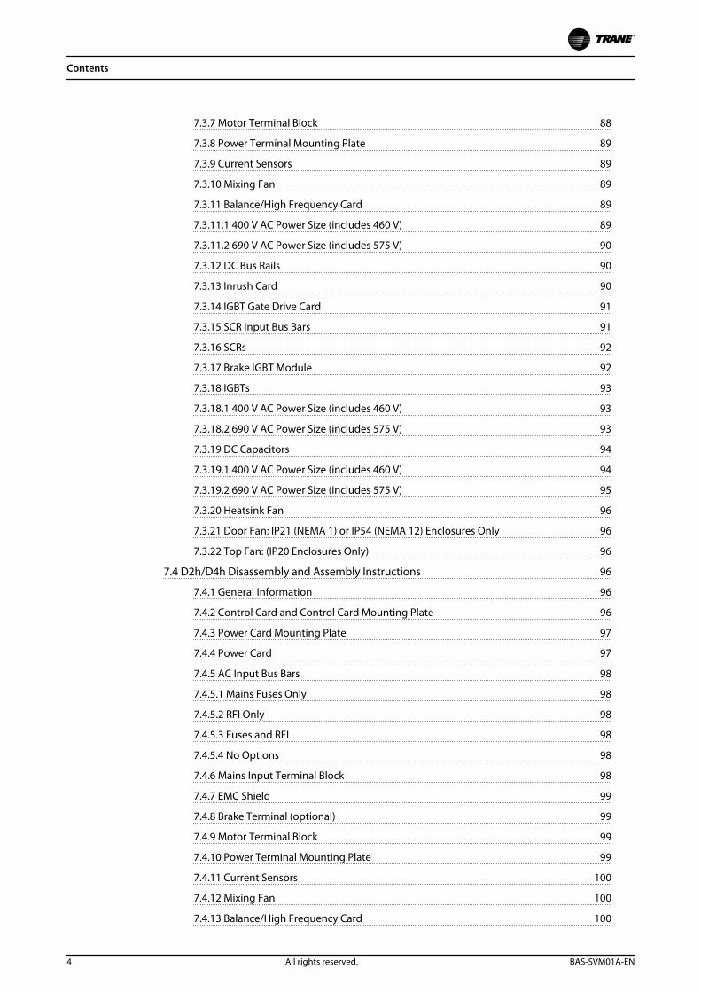
7.3.7 Motor Terminal Block 88
7.3.8 Power Terminal Mounting Plate 89
7.3.9 Current Sensors 89
7.3.10 Mixing Fan 89
7.3.11 Balance/High Frequency Card 89
7.3.11.1 400 V AC Power Size (includes 460 V) 89
7.3.11.2 690 V AC Power Size (includes 575 V) 90
7.3.12 DC Bus Rails 90
7.3.13 Inrush Card 90
7.3.14 IGBT Gate Drive Card 91
7.3.15 SCR Input Bus Bars 91
7.3.16 SCRs 92
7.3.17 Brake IGBT Module 92
7.3.18 IGBTs 93
7.3.18.1 400 V AC Power Size (includes 460 V) 93
7.3.18.2 690 V AC Power Size (includes 575 V) 93
7.3.19 DC Capacitors 94
7.3.19.1 400 V AC Power Size (includes 460 V) 94
7.3.19.2 690 V AC Power Size (includes 575 V) 95
7.3.20 Heatsink Fan 96
7.3.21 Door Fan: IP21 (NEMA 1) or IP54 (NEMA 12) Enclosures Only 96
7.3.22 Top Fan: (IP20 Enclosures Only) 96
7.4 D2h/D4h Disassembly and Assembly Instructions 96
7.4.1 General Information 96
7.4.2 Control Card and Control Card Mounting Plate 96
7.4.3 Power Card Mounting Plate 97
7.4.4 Power Card 97
7.4.5 AC Input Bus Bars 98
7.4.5.1 Mains Fuses Only 98
7.4.5.2 RFI Only 98
7.4.5.3 Fuses and RFI 98
7.4.5.4 No Options 98
7.4.6 Mains Input Terminal Block 98
7.4.7 EMC Shield 99
7.4.8 Brake Terminal (optional) 99
7.4.9 Motor Terminal Block 99
7.4.10 Power Terminal Mounting Plate 99
7.4.11 Current Sensors 100
7.4.12 Mixing Fan 100
7.4.13 Balance/High Frequency Card 100
Contents
4 All rights reserved. BAS-SVM01A-EN
7.4.13.1 400 V AC Power Size (includes 460 V) 100
7.4.13.2 690 V AC Power Size (includes 575 V) 101
7.4.14 IGBT Gate Drive Card 102
7.4.15 Inrush Card 102
7.4.16 SCR Input Bus Bars 102
7.4.17 SCRs 103
7.4.18 DC Bus Rails 103
7.4.18.1 Without Optional Brake 103
7.4.18.2 With Optional Brake 103
7.4.19 IGBTs 104
7.4.19.1 400 V AC Power Size (includes 460 V) 104
7.4.19.2 690 V AC Power Size (includes 575 V) 104
7.4.20 DC Capacitors 105
7.4.20.1 400 V AC Power Size (includes 460 V) 105
7.4.20.2 690 V AC Power Size (includes 575 V) 106
7.4.21 Heatsink Fan 107
7.4.22 Door Fan: IP21 (NEMA 1) or IP54 (NEMA 12) Enclosures Only 107
7.4.23 Top Fan (IP20 Enclosures only) 108
7.4.24 Brake IGBT Module 108
7.5 D6h Disassembly and Assembly Instructions 108
7.5.1 Overview 108
7.5.2 Removing the Heatsink Fan with Options Cabinet Present 109
7.5.3 Removing the Frequency Converter from the Options Cabinet 109
7.5.4 Contactor 110
7.5.5 Disconnect 110
7.6 D8h Disassembly and Assembly Instructions 110
7.6.1 Overview 110
7.6.2 Replacing the Heatsink Fan with Options Cabinet Present 111
7.6.3 Removing the Frequency Converter from the Options Cabinet 111
7.6.4 Contactor 112
7.6.5 Disconnect 112
7.7 Heatsink Access Panel 113
8 Special Test Equipment 114
8.1 Test Equipment 114
8.1.1 Split Bus Power Supply 114
8.1.2 Signal Test Board (p/n 176F8437) 114
8.1.3 Signal Test Board Extension 114
8.1.4 Signal Test Board Pin Outs 115
9 Spare Parts 118
Contents
BAS-SVM01A-EN All rights reserved. 5

9.1 Spare Parts 118
9.1.1 General Notes 118
9.1.2 DC Capacitor Bank 118
10 Block Diagrams 121
Index 122
Contents
6 All rights reserved. BAS-SVM01A-EN
1 Introduction
1.1 Purpose
The purpose of this manual is to provide detailed technicalinformation and instructions to enable a qualifiedtechnician to identify faults and perform repairs on D-frame frequency converters
It provides the reader with a general view of the mainassemblies and a description of the internal processing.This manual gives technicians the information needed fortroubleshooting and repair.
This manual provides instructions for the frequencyconverter models and voltage ranges described in chapter 1.5 Frame Size Definitions.
Use this manual with the operating instructions thataccompanied the frequency converter.
1.2 Product Overview
TR200 series frequency converters are designed for theHVAC markets. They operate in variable torque mode orconstant torque down to 15 Hz and include specialfeatures and options designed for fan and pumpapplications.
series frequency converters are designed for water andwaste water markets. They can operate in either constanttorque or variable torque with limited overload capabilities.Included are specific features and options for use onvarious water pumping and processing applications.
series frequency converters are fully programmable foreither constant torque or variable torque industrialapplications. They operate a variety of applications andincorporate a wide range of control and communicationoptions. These models are available in IP20 (chassis), IP21(NEMA 1), and IP54 (NEMA 12) enclosures.
1.3 For Your Safety
1.3.1 Warnings
WARNINGFrequency converters contain dangerous voltages whenconnected to mains. Only a competent technician shouldperform service.
WARNINGFor dynamic test procedures, mains input power isrequired and all devices and power supplies connectedto mains are energised at rated voltage. Use extremecaution when conducting tests in a powered frequencyconverter. Contact with powered components couldresult in electrical shock and personal injury.
WARNINGIn frequency converters equipped with the optionalcontactor or anti-condensation heater, there may still bepower inside the enclosure after the main power to theunit has been turned off.
1. DO NOT touch electrical parts of the frequencyconverter when connected to mains. After discon-necting from mains, wait 20 minutes beforetouching any components.
2. When repair or inspection is made, mains mustbe disconnected.
3. The [Stop] key on the control panel does notdisconnect mains.
4. During operation and while programmingparameters, it is possible for the motor to startwithout warning. Press [Stop] when changingdata.
1.4 Electrostatic Discharge (ESD)
WARNINGWhen performing service, use proper ESD procedures toprevent damage to sensitive components.
WARNINGDo not touch components on the circuit boards. Holdcircuit boards by the corners and edges only.
Many electronic components within the frequencyconverter are sensitive to static electricity. Voltages so lowthat they cannot be felt, seen, or heard can reduce the life,affect performance, or completely destroy sensitiveelectronic components.
Introduction
BAS-SVM01A-EN All rights reserved. 7
1 1
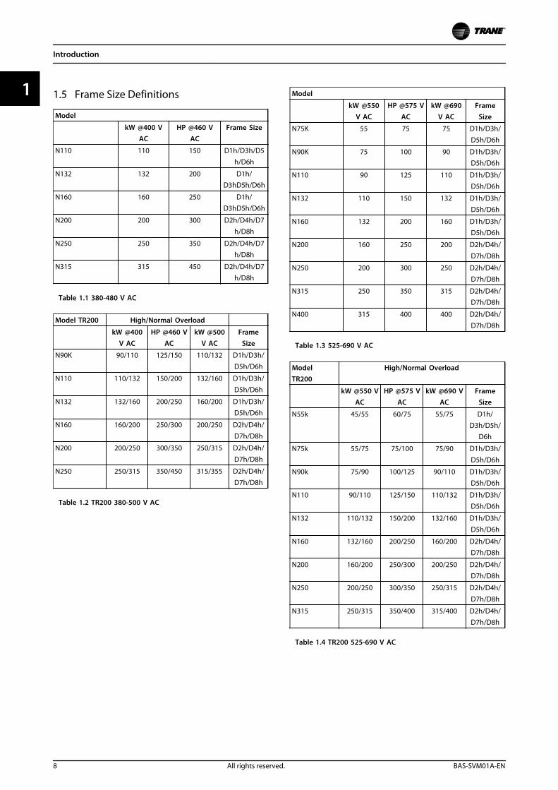
1.5 Frame Size Definitions
Model
kW @400 VAC
HP @460 VAC
Frame Size
N110 110 150 D1h/D3h/D5
h/D6h
N132 132 200 D1h/D3hD5h/D6h
N160 160 250 D1h/D3hD5h/D6h
N200 200 300 D2h/D4h/D7h/D8h
N250 250 350 D2h/D4h/D7h/D8h
N315 315 450 D2h/D4h/D7
h/D8h
Table 1.1 380-480 V AC
Model TR200 High/Normal Overload
kW @400V AC
HP @460 VAC
kW @500V AC
FrameSize
N90K 90/110 125/150 110/132 D1h/D3h/D5h/D6h
N110 110/132 150/200 132/160 D1h/D3h/D5h/D6h
N132 132/160 200/250 160/200 D1h/D3h/D5h/D6h
N160 160/200 250/300 200/250 D2h/D4h/D7h/D8h
N200 200/250 300/350 250/315 D2h/D4h/
D7h/D8h
N250 250/315 350/450 315/355 D2h/D4h/
D7h/D8h
Table 1.2 TR200 380-500 V AC
Model
kW @550V AC
HP @575 VAC
kW @690V AC
FrameSize
N75K 55 75 75 D1h/D3h/
D5h/D6h
N90K 75 100 90 D1h/D3h/D5h/D6h
N110 90 125 110 D1h/D3h/D5h/D6h
N132 110 150 132 D1h/D3h/D5h/D6h
N160 132 200 160 D1h/D3h/D5h/D6h
N200 160 250 200 D2h/D4h/
D7h/D8h
N250 200 300 250 D2h/D4h/
D7h/D8h
N315 250 350 315 D2h/D4h/D7h/D8h
N400 315 400 400 D2h/D4h/D7h/D8h
Table 1.3 525-690 V AC
ModelTR200
High/Normal Overload
kW @550 VAC
HP @575 VAC
kW @690 VAC
FrameSize
N55k 45/55 60/75 55/75 D1h/D3h/D5h/
D6h
N75k 55/75 75/100 75/90 D1h/D3h/
D5h/D6h
N90k 75/90 100/125 90/110 D1h/D3h/
D5h/D6h
N110 90/110 125/150 110/132 D1h/D3h/D5h/D6h
N132 110/132 150/200 132/160 D1h/D3h/D5h/D6h
N160 132/160 200/250 160/200 D2h/D4h/D7h/D8h
N200 160/200 250/300 200/250 D2h/D4h/D7h/D8h
N250 200/250 300/350 250/315 D2h/D4h/
D7h/D8h
N315 250/315 350/400 315/400 D2h/D4h/D7h/D8h
Table 1.4 TR200 525-690 V AC
Introduction
8 All rights reserved. BAS-SVM01A-EN
11
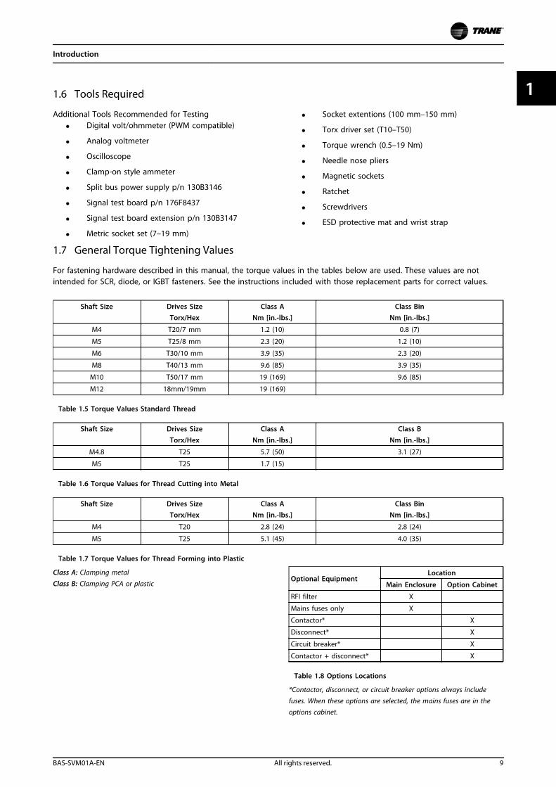
1.6 Tools Required
Additional Tools Recommended for Testing
• Digital volt/ohmmeter (PWM compatible)
• Analog voltmeter
• Oscilloscope
• Clamp-on style ammeter
• Split bus power supply p/n 130B3146
• Signal test board p/n 176F8437
• Signal test board extension p/n 130B3147
• Metric socket set (7–19 mm)
• Socket extentions (100 mm–150 mm)
• Torx driver set (T10–T50)
• Torque wrench (0.5–19 Nm)
• Needle nose pliers
• Magnetic sockets
• Ratchet
• Screwdrivers
• ESD protective mat and wrist strap
1.7 General Torque Tightening Values
For fastening hardware described in this manual, the torque values in the tables below are used. These values are notintended for SCR, diode, or IGBT fasteners. See the instructions included with those replacement parts for correct values.
Shaft Size Drives SizeTorx/Hex
Class ANm [in.-lbs.]
Class BinNm [in.-lbs.]
M4 T20/7 mm 1.2 (10) 0.8 (7)
M5 T25/8 mm 2.3 (20) 1.2 (10)
M6 T30/10 mm 3.9 (35) 2.3 (20)
M8 T40/13 mm 9.6 (85) 3.9 (35)
M10 T50/17 mm 19 (169) 9.6 (85)
M12 18mm/19mm 19 (169)
Table 1.5 Torque Values Standard Thread
Shaft Size Drives SizeTorx/Hex
Class ANm [in.-lbs.]
Class BNm [in.-lbs.]
M4.8 T25 5.7 (50) 3.1 (27)
M5 T25 1.7 (15)
Table 1.6 Torque Values for Thread Cutting into Metal
Shaft Size Drives SizeTorx/Hex
Class ANm [in.-lbs.]
Class BinNm [in.-lbs.]
M4 T20 2.8 (24) 2.8 (24)
M5 T25 5.1 (45) 4.0 (35)
Table 1.7 Torque Values for Thread Forming into Plastic
Class A: Clamping metal
Class B: Clamping PCA or plasticOptional Equipment
Location
Main Enclosure Option Cabinet
RFI filter X
Mains fuses only X
Contactor* X
Disconnect* X
Circuit breaker* X
Contactor + disconnect* X
Table 1.8 Options Locations
*Contactor, disconnect, or circuit breaker options always includefuses. When these options are selected, the mains fuses are in theoptions cabinet.
Introduction
BAS-SVM01A-EN All rights reserved. 9
1 1
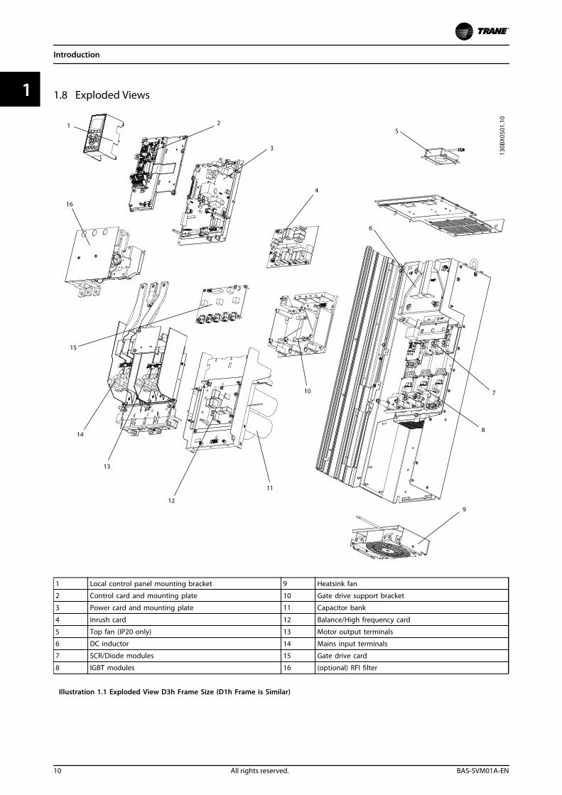
1.8 Exploded Views
1 Local control panel mounting bracket 9 Heatsink fan
2 Control card and mounting plate 10 Gate drive support bracket
3 Power card and mounting plate 11 Capacitor bank
4 Inrush card 12 Balance/High frequency card
5 Top fan (IP20 only) 13 Motor output terminals
6 DC inductor 14 Mains input terminals
7 SCR/Diode modules 15 Gate drive card
8 IGBT modules 16 (optional) RFI filter
Illustration 1.1 Exploded View D3h Frame Size (D1h Frame is Similar)
Introduction
10 All rights reserved. BAS-SVM01A-EN
11
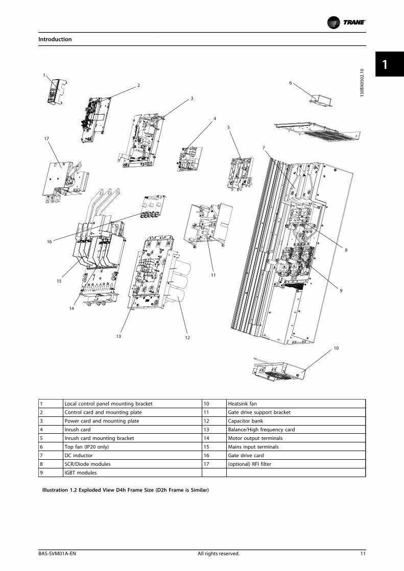
1 Local control panel mounting bracket 10 Heatsink fan
2 Control card and mounting plate 11 Gate drive support bracket
3 Power card and mounting plate 12 Capacitor bank
4 Inrush card 13 Balance/High frequency card
5 Inrush card mounting bracket 14 Motor output terminals
6 Top fan (IP20 only) 15 Mains input terminals
7 DC inductor 16 Gate drive card
8 SCR/Diode modules 17 (optional) RFI filter
9 IGBT modules
Illustration 1.2 Exploded View D4h Frame Size (D2h Frame is Similar)
Introduction
BAS-SVM01A-EN All rights reserved. 11
1 1
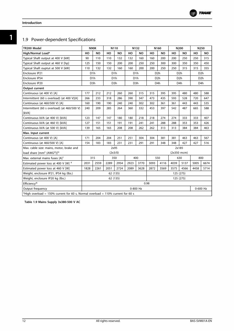
1.9 Power-dependent Specifications
TR200 Model N90K N110 N132 N160 N200 N250
High/Normal Load* HO NO HO NO HO NO HO NO HO NO HO NO
Typical Shaft output at 400 V [kW] 90 110 110 132 132 160 160 200 200 250 250 315
Typical Shaft output at 460 V [hp] 125 150 150 200 200 250 250 300 300 350 350 450
Typical Shaft ouptut at 500 V [kW] 110 132 132 160 160 200 200 250 250 315 315 355
Enclosure IP21 D1h D1h D1h D2h D2h D2h
Enclosure IP54 D1h D1h D1h D2h D2h D2h
Enclosure IP20 D3h D3h D3h D4h D4h D4h
Output current
Continuous (at 400 V) [A] 177 212 212 260 260 315 315 395 395 480 480 588
Intermittent (60 s overload) (at 400 V)[A] 266 233 318 286 390 347 473 435 593 528 720 647
Continuous (at 460/500 V) [A] 160 190 190 240 240 302 302 361 361 443 443 535
Intermittent (60 s overload) (at 460/500 V)
[kVA]
240 209 285 264 360 332 453 397 542 487 665 588
Continuous kVA (at 400 V) [kVA] 123 147 147 180 180 218 218 274 274 333 333 407
Continuous kVA (at 460 V) [kVA] 127 151 151 191 191 241 241 288 288 353 353 426
Continuous kVA (at 500 V) [kVA] 139 165 165 208 208 262 262 313 313 384 384 463
Max. Input current
Continuous (at 400 V) [A] 171 204 204 251 251 304 304 381 381 463 463 567
Continuous (at 460/500 V) [A] 154 183 183 231 231 291 291 348 348 427 427 516
Max. cable size: mains, motor, brake and
load share [mm2 (AWG2))]5)
2x95(2x3/0)
2x185(2x350 mcm)
Max. external mains fuses [A]1 315 350 400 550 630 800
Estimated power loss at 400 V [W] 4 2031 2559 2289 2954 2923 3770 3093 4116 4039 5137 5005 6674
Estimated power loss at 460 V [W] 1828 2261 2051 2724 2089 3628 2872 3569 3575 4566 4458 5714
Weight, enclosure IP21, IP54 kg (lbs.) 62 (135) 125 (275)
Weight, enclosure IP20 kg (lbs.) 62 (135) 125 (275)
Efficiency4) 0.98
Output frequency 0-800 Hz 0-600 Hz
*High overload = 150% current for 60 s, Normal overload = 110% current for 60 s
Table 1.9 Mains Supply 3x380-500 V AC
Introduction
12 All rights reserved. BAS-SVM01A-EN
11
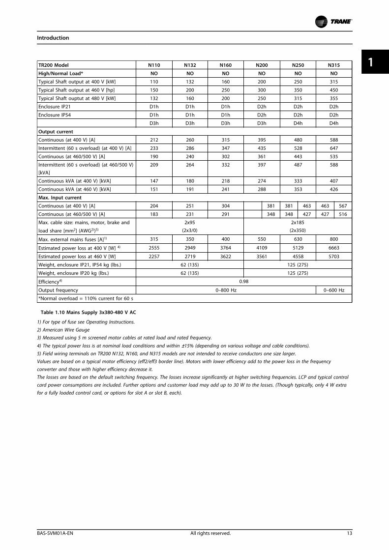
TR200 Model N110 N132 N160 N200 N250 N315
High/Normal Load* NO NO NO NO NO NO
Typical Shaft output at 400 V [kW] 110 132 160 200 250 315
Typical Shaft output at 460 V [hp] 150 200 250 300 350 450
Typical Shaft ouptut at 480 V [kW] 132 160 200 250 315 355
Enclosure IP21 D1h D1h D1h D2h D2h D2h
Enclosure IP54 D1h D1h D1h D2h D2h D2h
D3h D3h D3h D3h D4h D4h
Output current
Continuous (at 400 V) [A] 212 260 315 395 480 588
Intermittent (60 s overload) (at 400 V) [A] 233 286 347 435 528 647
Continuous (at 460/500 V) [A] 190 240 302 361 443 535
Intermittent (60 s overload) (at 460/500 V)
[kVA]
209 264 332 397 487 588
Continuous kVA (at 400 V) [kVA] 147 180 218 274 333 407
Continuous kVA (at 460 V) [kVA] 151 191 241 288 353 426
Max. Input current
Continuous (at 400 V) [A] 204 251 304 381 381 463 463 567
Continuous (at 460/500 V) [A] 183 231 291 348 348 427 427 516
Max. cable size: mains, motor, brake and
load share [mm2] (AWG2))5)
2x95
(2x3/0)
2x185
(2x350)
Max. external mains fuses [A]1) 315 350 400 550 630 800
Estimated power loss at 400 V [W] 4) 2555 2949 3764 4109 5129 6663
Estimated power loss at 460 V [W] 2257 2719 3622 3561 4558 5703
Weight, enclosure IP21, IP54 kg (lbs.) 62 (135) 125 (275)
Weight, enclosure IP20 kg (lbs.) 62 (135) 125 (275)
Efficiency4) 0.98
Output frequency 0–800 Hz 0–600 Hz
*Normal overload = 110% current for 60 s
Table 1.10 Mains Supply 3x380-480 V AC
1) For type of fuse see Operating Instructions.
2) American Wire Gauge3) Measured using 5 m screened motor cables at rated load and rated frequency.
4) The typical power loss is at nominal load conditions and within ±15% (depending on various voltage and cable conditions).5) Field wiring terminals on TR200 N132, N160, and N315 models are not intended to receive conductors one size larger.Values are based on a typical motor efficiency (eff2/eff3 border line). Motors with lower efficiency add to the power loss in the frequencyconverter and those with higher efficiency decrease it.The losses are based on the default switching frequency. The losses increase significantly at higher switching frequencies. LCP and typical controlcard power consumptions are included. Further options and customer load may add up to 30 W to the losses. (Though typically, only 4 W extrafor a fully loaded control card, or options for slot A or slot B, each).
Introduction
BAS-SVM01A-EN All rights reserved. 13
1 1
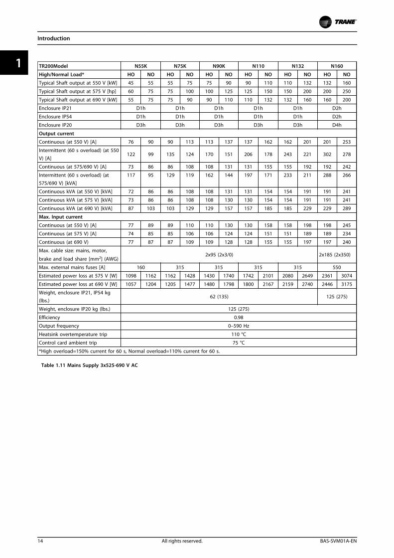
TR200Model N55K N75K N90K N110 N132 N160
High/Normal Load* HO NO HO NO HO NO HO NO HO NO HO NO
Typical Shaft output at 550 V [kW] 45 55 55 75 75 90 90 110 110 132 132 160
Typical Shaft output at 575 V [hp] 60 75 75 100 100 125 125 150 150 200 200 250
Typical Shaft output at 690 V [kW] 55 75 75 90 90 110 110 132 132 160 160 200
Enclosure IP21 D1h D1h D1h D1h D1h D2h
Enclosure IP54 D1h D1h D1h D1h D1h D2h
Enclosure IP20 D3h D3h D3h D3h D3h D4h
Output current
Continuous (at 550 V) [A] 76 90 90 113 113 137 137 162 162 201 201 253
Intermittent (60 s overload) (at 550V) [A]
122 99 135 124 170 151 206 178 243 221 302 278
Continuous (at 575/690 V) [A] 73 86 86 108 108 131 131 155 155 192 192 242
Intermittent (60 s overload) (at
575/690 V) [kVA]
117 95 129 119 162 144 197 171 233 211 288 266
Continuous kVA (at 550 V) [kVA] 72 86 86 108 108 131 131 154 154 191 191 241
Continuous kVA (at 575 V) [kVA] 73 86 86 108 108 130 130 154 154 191 191 241
Continuous kVA (at 690 V) [kVA] 87 103 103 129 129 157 157 185 185 229 229 289
Max. Input current
Continuous (at 550 V) [A] 77 89 89 110 110 130 130 158 158 198 198 245
Continuous (at 575 V) [A] 74 85 85 106 106 124 124 151 151 189 189 234
Continuous (at 690 V) 77 87 87 109 109 128 128 155 155 197 197 240
Max. cable size: mains, motor,
brake and load share [mm2] (AWG)2x95 (2x3/0) 2x185 (2x350)
Max. external mains fuses [A] 160 315 315 315 315 550
Estimated power loss at 575 V [W] 1098 1162 1162 1428 1430 1740 1742 2101 2080 2649 2361 3074
Estimated power loss at 690 V [W] 1057 1204 1205 1477 1480 1798 1800 2167 2159 2740 2446 3175
Weight, enclosure IP21, IP54 kg(lbs.)
62 (135) 125 (275)
Weight, enclosure IP20 kg (lbs.) 125 (275)
Efficiency 0.98
Output frequency 0–590 Hz
Heatsink overtemperature trip 110 °C
Control card ambient trip 75 °C
*High overload=150% current for 60 s, Normal overload=110% current for 60 s.
Table 1.11 Mains Supply 3x525-690 V AC
Introduction
14 All rights reserved. BAS-SVM01A-EN
11
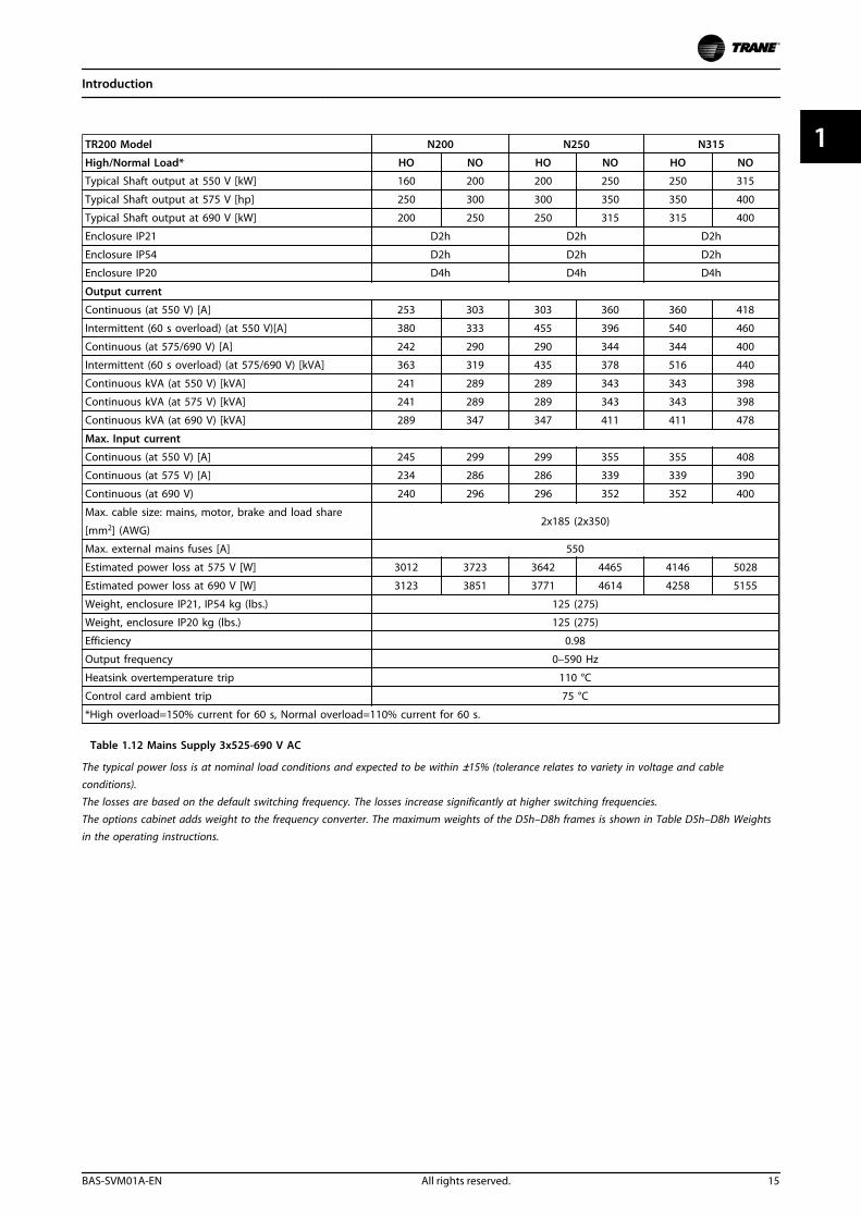
TR200 Model N200 N250 N315
High/Normal Load* HO NO HO NO HO NO
Typical Shaft output at 550 V [kW] 160 200 200 250 250 315
Typical Shaft output at 575 V [hp] 250 300 300 350 350 400
Typical Shaft output at 690 V [kW] 200 250 250 315 315 400
Enclosure IP21 D2h D2h D2h
Enclosure IP54 D2h D2h D2h
Enclosure IP20 D4h D4h D4h
Output current
Continuous (at 550 V) [A] 253 303 303 360 360 418
Intermittent (60 s overload) (at 550 V)[A] 380 333 455 396 540 460
Continuous (at 575/690 V) [A] 242 290 290 344 344 400
Intermittent (60 s overload) (at 575/690 V) [kVA] 363 319 435 378 516 440
Continuous kVA (at 550 V) [kVA] 241 289 289 343 343 398
Continuous kVA (at 575 V) [kVA] 241 289 289 343 343 398
Continuous kVA (at 690 V) [kVA] 289 347 347 411 411 478
Max. Input current
Continuous (at 550 V) [A] 245 299 299 355 355 408
Continuous (at 575 V) [A] 234 286 286 339 339 390
Continuous (at 690 V) 240 296 296 352 352 400
Max. cable size: mains, motor, brake and load share
[mm2] (AWG)2x185 (2x350)
Max. external mains fuses [A] 550
Estimated power loss at 575 V [W] 3012 3723 3642 4465 4146 5028
Estimated power loss at 690 V [W] 3123 3851 3771 4614 4258 5155
Weight, enclosure IP21, IP54 kg (lbs.) 125 (275)
Weight, enclosure IP20 kg (lbs.) 125 (275)
Efficiency 0.98
Output frequency 0–590 Hz
Heatsink overtemperature trip 110 °C
Control card ambient trip 75 °C
*High overload=150% current for 60 s, Normal overload=110% current for 60 s.
Table 1.12 Mains Supply 3x525-690 V AC
The typical power loss is at nominal load conditions and expected to be within ±15% (tolerance relates to variety in voltage and cableconditions).The losses are based on the default switching frequency. The losses increase significantly at higher switching frequencies.The options cabinet adds weight to the frequency converter. The maximum weights of the D5h–D8h frames is shown in Table D5h–D8h Weightsin the operating instructions.
Introduction
BAS-SVM01A-EN All rights reserved. 15
1 1

TR200 Model N75K N90K N110 N132 N160 N200
Normal Load* NO NO NO NO NO NO
Typical Shaft output at 550 V [kW] 55 75 90 110 132 160
Typical Shaft output at 575 V [hp] 75 100 125 150 200 250
Typical Shaft ouptut at 690 V [kW] 75 90 110 132 160 200
Enclosure IP21 D1h D1h D1h D1h D1h D2h
Enclosure IP54 D1h D1h D1h D1h D1h D2h
Enclosure IP20 D3h D3h D3h D3h D3h D4h
Output current
Continuous (at 550 V) [A] 90 113 137 162 201 253
Intermittent (60 s overload) (at 550V)[A]
99 124 151 178 221 278
Continuous (at 575/690 V) [A] 86 108 131 155 192 242
Intermittent (60 s overload) (at
575/690 V) [kVA]95 119 144 171 211 266
Continuous kVA (at 550 V) [kVA] 86 108 131 154 191 241
Continuous kVA (at 575 V) [kVA] 86 108 130 154 191 241
Continuous kVA (at 690 V) [kVA] 103 129 157 185 229 289
Max. Input current
Continuous (at 550 V) [A] 89 110 130 158 198 245
Continuous (at 575 V) [A] 85 106 124 151 189 234
Continuous (at 690 V) [A] 87 109 128 155 197 240
Max. cable size: mains, motor,
brake and load share [mm2] (AWG)2x95 (2x3/0)
2x185
(2x350 mcm)
Max. external mains fuses [A] 160 315 315 315 350 350
Estimated power loss at 575 V [W] 1161 1426 1739 2099 2646 3071
Estimated power loss at 690 V [W] 1203 1476 1796 2165 2738 3172
Weight, enclosure IP21, IP54 kg(lbs.)
62 (135) 125 (275)
Weight, enclosure IP20 kg (lbs.) 62 (135) 125 (275)
Efficiency 0.98
Output frequency 0–590 Hz
Heatsink overtemp. trip 110 °C
Power card ambient trip 75 °C
*Normal overload=110% current for 60 s
Table 1.13 Mains Supply 3x525-690 V AC
Introduction
16 All rights reserved. BAS-SVM01A-EN
11
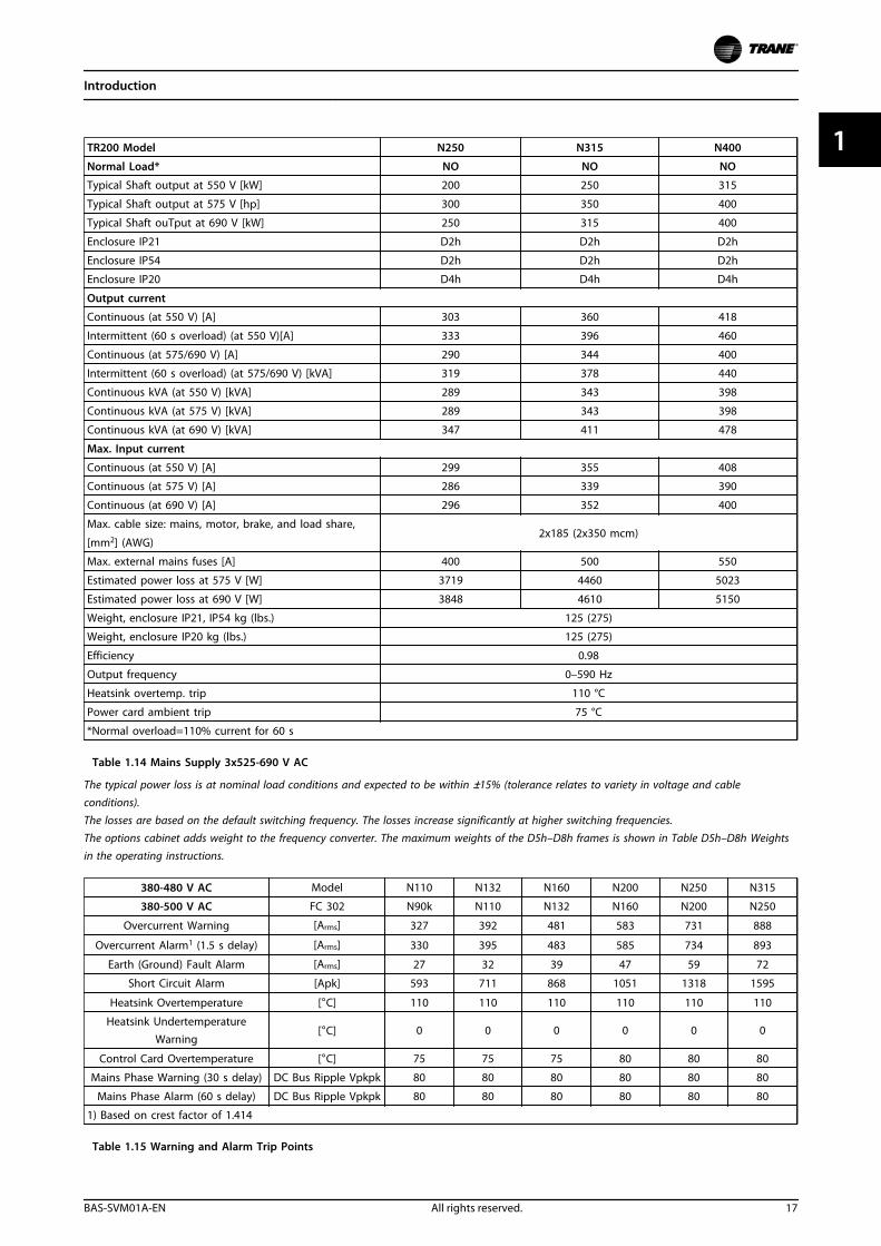
TR200 Model N250 N315 N400
Normal Load* NO NO NO
Typical Shaft output at 550 V [kW] 200 250 315
Typical Shaft output at 575 V [hp] 300 350 400
Typical Shaft ouTput at 690 V [kW] 250 315 400
Enclosure IP21 D2h D2h D2h
Enclosure IP54 D2h D2h D2h
Enclosure IP20 D4h D4h D4h
Output current
Continuous (at 550 V) [A] 303 360 418
Intermittent (60 s overload) (at 550 V)[A] 333 396 460
Continuous (at 575/690 V) [A] 290 344 400
Intermittent (60 s overload) (at 575/690 V) [kVA] 319 378 440
Continuous kVA (at 550 V) [kVA] 289 343 398
Continuous kVA (at 575 V) [kVA] 289 343 398
Continuous kVA (at 690 V) [kVA] 347 411 478
Max. Input current
Continuous (at 550 V) [A] 299 355 408
Continuous (at 575 V) [A] 286 339 390
Continuous (at 690 V) [A] 296 352 400
Max. cable size: mains, motor, brake, and load share,
[mm2] (AWG)2x185 (2x350 mcm)
Max. external mains fuses [A] 400 500 550
Estimated power loss at 575 V [W] 3719 4460 5023
Estimated power loss at 690 V [W] 3848 4610 5150
Weight, enclosure IP21, IP54 kg (lbs.) 125 (275)
Weight, enclosure IP20 kg (lbs.) 125 (275)
Efficiency 0.98
Output frequency 0–590 Hz
Heatsink overtemp. trip 110 °C
Power card ambient trip 75 °C
*Normal overload=110% current for 60 s
Table 1.14 Mains Supply 3x525-690 V AC
The typical power loss is at nominal load conditions and expected to be within ±15% (tolerance relates to variety in voltage and cableconditions).The losses are based on the default switching frequency. The losses increase significantly at higher switching frequencies.The options cabinet adds weight to the frequency converter. The maximum weights of the D5h–D8h frames is shown in Table D5h–D8h Weightsin the operating instructions.
380-480 V AC Model N110 N132 N160 N200 N250 N315
380-500 V AC FC 302 N90k N110 N132 N160 N200 N250
Overcurrent Warning [Arms] 327 392 481 583 731 888
Overcurrent Alarm1 (1.5 s delay) [Arms] 330 395 483 585 734 893
Earth (Ground) Fault Alarm [Arms] 27 32 39 47 59 72
Short Circuit Alarm [Apk] 593 711 868 1051 1318 1595
Heatsink Overtemperature [°C] 110 110 110 110 110 110
Heatsink UndertemperatureWarning
[°C] 0 0 0 0 0 0
Control Card Overtemperature [°C] 75 75 75 80 80 80
Mains Phase Warning (30 s delay) DC Bus Ripple Vpkpk 80 80 80 80 80 80
Mains Phase Alarm (60 s delay) DC Bus Ripple Vpkpk 80 80 80 80 80 80
1) Based on crest factor of 1.414
Table 1.15 Warning and Alarm Trip Points
Introduction
BAS-SVM01A-EN All rights reserved. 17
1 1
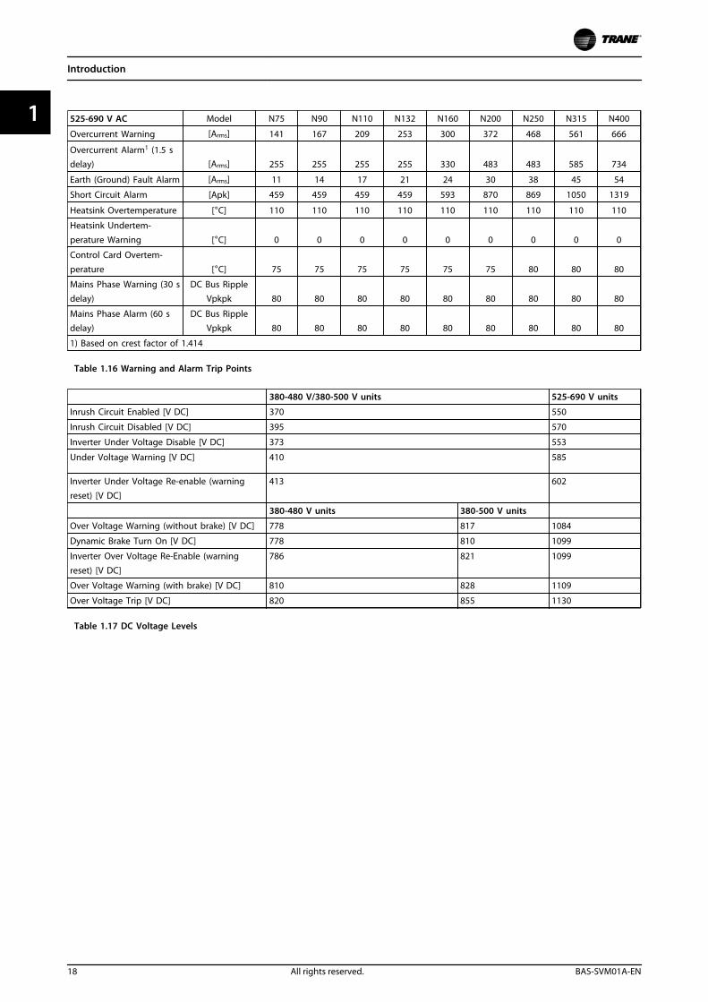
525-690 V AC Model N75 N90 N110 N132 N160 N200 N250 N315 N400
Overcurrent Warning [Arms] 141 167 209 253 300 372 468 561 666
Overcurrent Alarm1 (1.5 sdelay) [Arms] 255 255 255 255 330 483 483 585 734
Earth (Ground) Fault Alarm [Arms] 11 14 17 21 24 30 38 45 54
Short Circuit Alarm [Apk] 459 459 459 459 593 870 869 1050 1319
Heatsink Overtemperature [°C] 110 110 110 110 110 110 110 110 110
Heatsink Undertem-
perature Warning [°C] 0 0 0 0 0 0 0 0 0
Control Card Overtem-
perature [°C] 75 75 75 75 75 75 80 80 80
Mains Phase Warning (30 sdelay)
DC Bus RippleVpkpk 80 80 80 80 80 80 80 80 80
Mains Phase Alarm (60 sdelay)
DC Bus RippleVpkpk 80 80 80 80 80 80 80 80 80
1) Based on crest factor of 1.414
Table 1.16 Warning and Alarm Trip Points
380-480 V/380-500 V units 525-690 V units
Inrush Circuit Enabled [V DC] 370 550
Inrush Circuit Disabled [V DC] 395 570
Inverter Under Voltage Disable [V DC] 373 553
Under Voltage Warning [V DC] 410 585
Inverter Under Voltage Re-enable (warningreset) [V DC]
413 602
380-480 V units 380-500 V units
Over Voltage Warning (without brake) [V DC] 778 817 1084
Dynamic Brake Turn On [V DC] 778 810 1099
Inverter Over Voltage Re-Enable (warning
reset) [V DC]
786 821 1099
Over Voltage Warning (with brake) [V DC] 810 828 1109
Over Voltage Trip [V DC] 820 855 1130
Table 1.17 DC Voltage Levels
Introduction
18 All rights reserved. BAS-SVM01A-EN
11
2 Operator Interface and Frequency Converter Control
2.1 Introduction
Frequency converters are designed with self-diagnosticcircuitry to isolate fault conditions and activate displaymessages that simplify troubleshooting and service. Theoperating status of the frequency converter is displayed inreal time. Virtually every command given to the frequencyconverter results in some indication on the local controlpanel (keypad) display. Fault logs are maintained withinthe frequency converter for fault history.
The frequency converter monitors supply and outputvoltages along with the operational condition of the motorand load. When the frequency converter issues a warningor alarm, the fault is not always within the frequencyconverter itself. In fact, for most service calls, the faultcondition exists outside of the frequency converter. Mostof the warnings and alarms that the frequency converterdisplays are in response to faults outside of the frequencyconverter. This service manual provides techniques andtest procedures to help isolate a fault condition whether inthe frequency converter or elsewhere.
Familiarity with the information provided on the display isimportant. Additional diagnostic data can be accessedeasily through the keypad.
2.2 User Interface
2.2.1 How to Operate the Local ControlPanel (LCP Keypad)
The keypad is divided into four functional groups:
1. Graphical display with status lines.
2. Menu keys and indicator lights (LEDs) - selectingmode, changing parameters and switchingbetween display functions.
3. Navigation keys and indicator lights (LEDs).
4. Operation keys and indicator lights (LEDs).
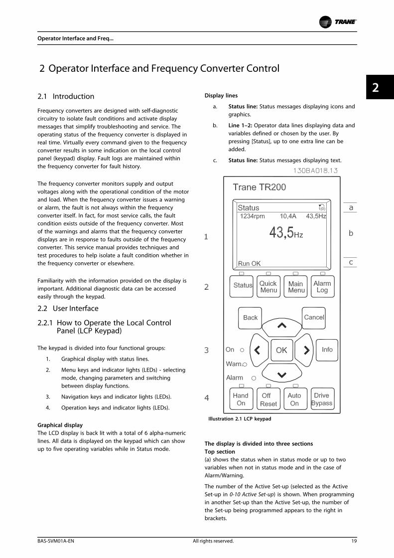
Graphical displayThe LCD display is back lit with a total of 6 alpha-numericlines. All data is displayed on the keypad which can showup to five operating variables while in Status mode.
Display lines
a. Status line: Status messages displaying icons andgraphics.
b. Line 1–2: Operator data lines displaying data andvariables defined or chosen by the user. Bypressing [Status], up to one extra line can beadded.
c. Status line: Status messages displaying text.
Illustration 2.1 LCP keypad
The display is divided into three sectionsTop section(a) shows the status when in status mode or up to twovariables when not in status mode and in the case ofAlarm/Warning.
The number of the Active Set-up (selected as the ActiveSet-up in 0-10 Active Set-up) is shown. When programmingin another Set-up than the Active Set-up, the number ofthe Set-up being programmed appears to the right inbrackets.
Operator Interface and Freq...
BAS-SVM01A-EN All rights reserved. 19
2 2
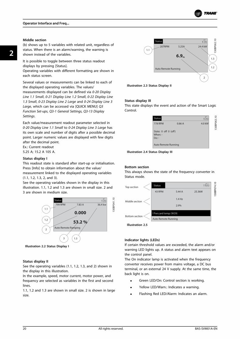
Middle section(b) shows up to 5 variables with related unit, regardless ofstatus. When there is an alarm/warning, the warning isshown instead of the variables.
It is possible to toggle between three status readoutdisplays by pressing [Status].Operating variables with different formatting are shown ineach status screen.
Several values or measurements can be linked to each ofthe displayed operating variables. The values/measurements displayed can be defined via 0-20 DisplayLine 1.1 Small, 0-21 Display Line 1.2 Small, 0-22 Display Line1.3 Small, 0-23 Display Line 2 Large and 0-24 Display Line 3Large, which can be accessed via [QUICK MENU] Q3Function Set-ups, Q3-1 General Settings, Q3-13 DisplaySettings.
Each value/measurement readout parameter selected in0-20 Display Line 1.1 Small to 0-24 Display Line 3 Large hasits own scale and number of digits after a possible decimalpoint. Larger numeric values are displayed with few digitsafter the decimal point.Ex.: Current readout5.25 A; 15.2 A 105 A.
Status display IThis readout state is standard after start-up or initialisation.Press [Info] to obtain information about the value/measurement linked to the displayed operating variables(1.1, 1.2, 1.3, 2, and 3).See the operating variables shown in the display in thisillustration. 1.1, 1.2 and 1.3 are shown in small size. 2 and3 are shown in medium size.
Illustration 2.2 Status Display I
Status display IISee the operating variables (1.1, 1.2, 1.3, and 2) shown inthe display in this illustration.In the example, speed, motor current, motor power, andfrequency are selected as variables in the first and secondlines.1.1, 1.2 and 1.3 are shown in small size. 2 is shown in largesize.
Illustration 2.3 Status Display II
Status display IIIThis state displays the event and action of the Smart LogicControl.
Illustration 2.4 Status Display III
Bottom sectionThis always shows the state of the frequency converter inStatus mode.
Illustration 2.5
Indicator lights (LEDs)If certain threshold values are exceeded, the alarm and/orwarning LED lights up. A status and alarm text appears onthe control panel.The On indicator lamp is activated when the frequencyconverter receives power from mains voltage, a DC busterminal, or an external 24 V supply. At the same time, theback light is on.
• Green LED/On: Control section is working.
• Yellow LED/Warn.: Indicates a warning.
• Flashing Red LED/Alarm: Indicates an alarm.
Operator Interface and Freq...
20 All rights reserved. BAS-SVM01A-EN
22
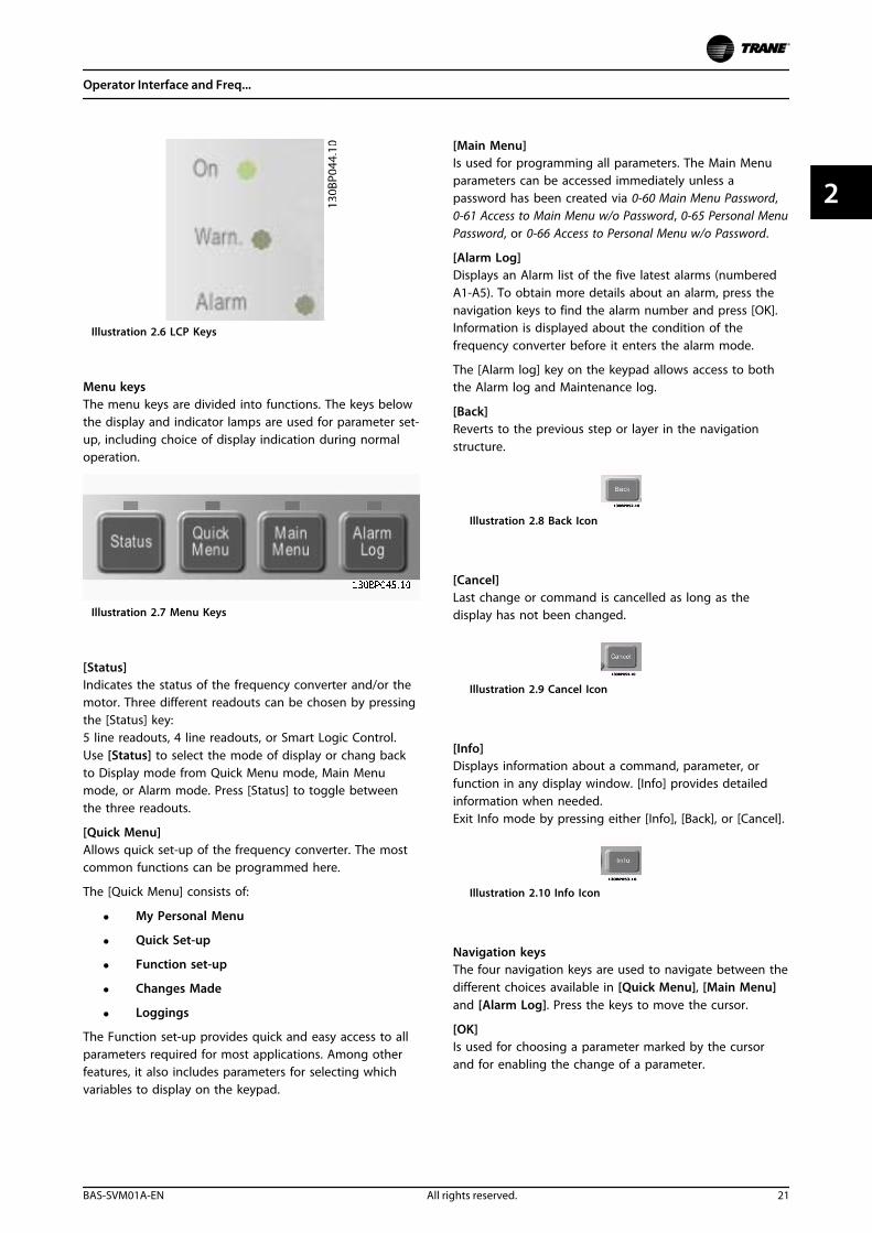
Illustration 2.6 LCP Keys
Menu keysThe menu keys are divided into functions. The keys belowthe display and indicator lamps are used for parameter set-up, including choice of display indication during normaloperation.
Illustration 2.7 Menu Keys
[Status]Indicates the status of the frequency converter and/or themotor. Three different readouts can be chosen by pressingthe [Status] key:5 line readouts, 4 line readouts, or Smart Logic Control.Use [Status] to select the mode of display or chang backto Display mode from Quick Menu mode, Main Menumode, or Alarm mode. Press [Status] to toggle betweenthe three readouts.
[Quick Menu] Allows quick set-up of the frequency converter. The mostcommon functions can be programmed here.
The [Quick Menu] consists of:
• My Personal Menu
• Quick Set-up
• Function set-up
• Changes Made
• Loggings
The Function set-up provides quick and easy access to allparameters required for most applications. Among otherfeatures, it also includes parameters for selecting whichvariables to display on the keypad.
[Main Menu]Is used for programming all parameters. The Main Menuparameters can be accessed immediately unless apassword has been created via 0-60 Main Menu Password,0-61 Access to Main Menu w/o Password, 0-65 Personal MenuPassword, or 0-66 Access to Personal Menu w/o Password.
[Alarm Log]Displays an Alarm list of the five latest alarms (numberedA1-A5). To obtain more details about an alarm, press thenavigation keys to find the alarm number and press [OK].Information is displayed about the condition of thefrequency converter before it enters the alarm mode.
The [Alarm log] key on the keypad allows access to boththe Alarm log and Maintenance log.
[Back]Reverts to the previous step or layer in the navigationstructure.
Illustration 2.8 Back Icon
[Cancel]Last change or command is cancelled as long as thedisplay has not been changed.
Illustration 2.9 Cancel Icon
[Info]Displays information about a command, parameter, orfunction in any display window. [Info] provides detailedinformation when needed.Exit Info mode by pressing either [Info], [Back], or [Cancel].
Illustration 2.10 Info Icon
Navigation keysThe four navigation keys are used to navigate between thedifferent choices available in [Quick Menu], [Main Menu]and [Alarm Log]. Press the keys to move the cursor.
[OK]Is used for choosing a parameter marked by the cursorand for enabling the change of a parameter.
Operator Interface and Freq...
BAS-SVM01A-EN All rights reserved. 21
2 2
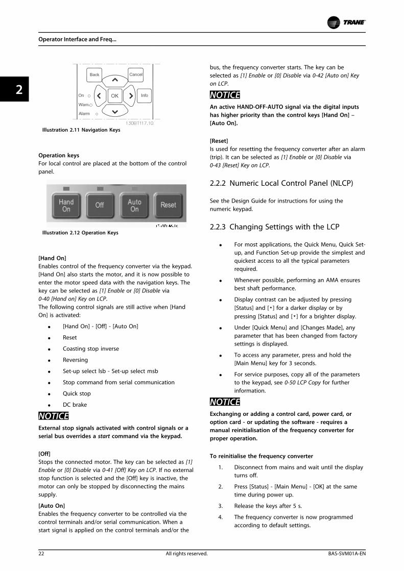
Illustration 2.11 Navigation Keys
Operation keysFor local control are placed at the bottom of the controlpanel.
Illustration 2.12 Operation Keys
[Hand On]Enables control of the frequency converter via the keypad.[Hand On] also starts the motor, and it is now possible toenter the motor speed data with the navigation keys. Thekey can be selected as [1] Enable or [0] Disable via0-40 [Hand on] Key on LCP.The following control signals are still active when [HandOn] is activated:
• [Hand On] - [Off] - [Auto On]
• Reset
• Coasting stop inverse
• Reversing
• Set-up select lsb - Set-up select msb
• Stop command from serial communication
• Quick stop
• DC brake
NOTICEExternal stop signals activated with control signals or aserial bus overrides a start command via the keypad.
[Off]Stops the connected motor. The key can be selected as [1]Enable or [0] Disable via 0-41 [Off] Key on LCP. If no externalstop function is selected and the [Off] key is inactive, themotor can only be stopped by disconnecting the mainssupply.
[Auto On]Enables the frequency converter to be controlled via thecontrol terminals and/or serial communication. When astart signal is applied on the control terminals and/or the
bus, the frequency converter starts. The key can beselected as [1] Enable or [0] Disable via 0-42 [Auto on] Keyon LCP.
NOTICEAn active HAND-OFF-AUTO signal via the digital inputshas higher priority than the control keys [Hand On] –[Auto On].
[Reset]Is used for resetting the frequency converter after an alarm(trip). It can be selected as [1] Enable or [0] Disable via0-43 [Reset] Key on LCP.
2.2.2 Numeric Local Control Panel (NLCP)
See the Design Guide for instructions for using thenumeric keypad.
2.2.3 Changing Settings with the LCP
• For most applications, the Quick Menu, Quick Set-up, and Function Set-up provide the simplest andquickest access to all the typical parametersrequired.
• Whenever possible, performing an AMA ensuresbest shaft performance.
• Display contrast can be adjusted by pressing[Status] and [] for a darker display or bypressing [Status] and [] for a brighter display.
• Under [Quick Menu] and [Changes Made], anyparameter that has been changed from factorysettings is displayed.
• To access any parameter, press and hold the[Main Menu] key for 3 seconds.
• For service purposes, copy all of the parametersto the keypad, see 0-50 LCP Copy for furtherinformation.
NOTICEExchanging or adding a control card, power card, oroption card - or updating the software - requires amanual reinitialisation of the frequency converter forproper operation.
To reinitialise the frequency converter
1. Disconnect from mains and wait until the displayturns off.
2. Press [Status] - [Main Menu] - [OK] at the sametime during power up.
3. Release the keys after 5 s.
4. The frequency converter is now programmedaccording to default settings.
Operator Interface and Freq...
22 All rights reserved. BAS-SVM01A-EN
22
For more information about initialisation, consult theoperating instructions.
Initialise the frequency converter to default settings in 2ways.
Recommended initialisation (via 14-22 Operation Mode)1. Select 14-22 Operation Mode
2. Press [OK]
3. Select [2] Initialisation
4. Press [OK]
5. Disconnect the mains supply and wait until thedisplay turns off.
6. Reconnect the mains supply - the frequencyconverter is now reset.
14-22 Operation Mode initialises all except:
• 14-50 RFI Filter
• 8-30 Protocol
• 8-31 Address
• 8-32 Baud Rate
• 8-35 Minimum Response Delay
• 8-36 Maximum Response Delay
• 8-37 Maximum Inter-Char Delay
• 15-00 Operating hours to 15-05 Over Volt's
• 15-20 Historic Log: Event to 15-22 Historic Log:Time
• 15-30 Alarm Log: Error Code to 15-32 Alarm Log:Time
Manual initialisation
1. Disconnect from mains and wait until the displayturns off.
2. 2a Press [Status] - [Main Menu] - [OK] atthe same time while power up for LCP102, Graphical Display
2b Press [Menu] - [OK] while power up forLCP 101, Numerical Display
3. Release the keys after 5 s.
4. The frequency converter is now programmedaccording to default settings.
This procedure initialises all except:15-00 Operating hours
15-03 Power Up's
15-04 Over Temp's
15-05 Over Volt's
NOTICEA manual initialisation also resets serial communication,RFI filter settings (14-50 RFI Filter) and fault log settings.
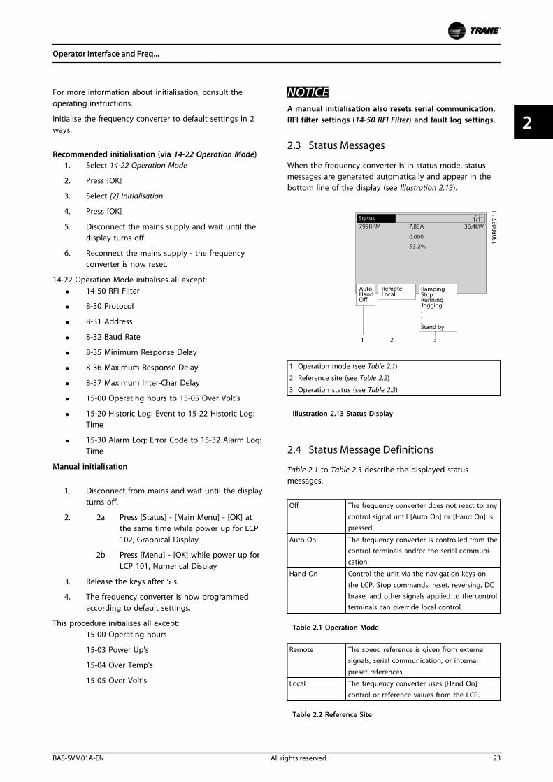
2.3 Status Messages
When the frequency converter is in status mode, statusmessages are generated automatically and appear in thebottom line of the display (see Illustration 2.13).
1 Operation mode (see Table 2.1)
2 Reference site (see Table 2.2)
3 Operation status (see Table 2.3)
Illustration 2.13 Status Display
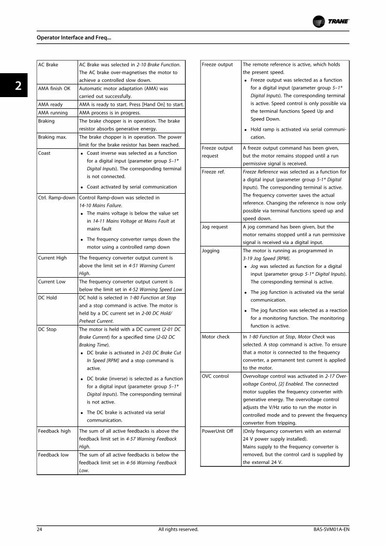
2.4 Status Message Definitions
Table 2.1 to Table 2.3 describe the displayed statusmessages.
Off The frequency converter does not react to anycontrol signal until [Auto On] or [Hand On] ispressed.
Auto On The frequency converter is controlled from thecontrol terminals and/or the serial communi-cation.
Hand On Control the unit via the navigation keys on
the LCP. Stop commands, reset, reversing, DCbrake, and other signals applied to the controlterminals can override local control.
Table 2.1 Operation Mode
Remote The speed reference is given from externalsignals, serial communication, or internalpreset references.
Local The frequency converter uses [Hand On]
control or reference values from the LCP.
Table 2.2 Reference Site
Operator Interface and Freq...
BAS-SVM01A-EN All rights reserved. 23
2 2
AC Brake AC Brake was selected in 2-10 Brake Function.The AC brake over-magnetises the motor toachieve a controlled slow down.
AMA finish OK Automatic motor adaptation (AMA) wascarried out successfully.
AMA ready AMA is ready to start. Press [Hand On] to start.
AMA running AMA process is in progress.
Braking The brake chopper is in operation. The brakeresistor absorbs generative energy.
Braking max. The brake chopper is in operation. The powerlimit for the brake resistor has been reached.
Coast • Coast inverse was selected as a functionfor a digital input (parameter group 5–1*Digital Inputs). The corresponding terminalis not connected.
• Coast activated by serial communication
Ctrl. Ramp-down Control Ramp-down was selected in14-10 Mains Failure.
• The mains voltage is below the value setin 14-11 Mains Voltage at Mains Fault atmains fault
• The frequency converter ramps down themotor using a controlled ramp down
Current High The frequency converter output current is
above the limit set in 4-51 Warning CurrentHigh.
Current Low The frequency converter output current is
below the limit set in 4-52 Warning Speed Low
DC Hold DC hold is selected in 1-80 Function at Stopand a stop command is active. The motor isheld by a DC current set in 2-00 DC Hold/
Preheat Current.
DC Stop The motor is held with a DC current (2-01 DCBrake Current) for a specified time (2-02 DCBraking Time).
• DC brake is activated in 2-03 DC Brake CutIn Speed [RPM] and a stop command is
active.
• DC brake (inverse) is selected as a function
for a digital input (parameter group 5–1*Digital Inputs). The corresponding terminalis not active.
• The DC brake is activated via serialcommunication.
Feedback high The sum of all active feedbacks is above the
feedback limit set in 4-57 Warning FeedbackHigh.
Feedback low The sum of all active feedbacks is below the
feedback limit set in 4-56 Warning FeedbackLow.
Freeze output The remote reference is active, which holdsthe present speed.
• Freeze output was selected as a functionfor a digital input (parameter group 5–1*Digital Inputs). The corresponding terminalis active. Speed control is only possible viathe terminal functions Speed Up andSpeed Down.
• Hold ramp is activated via serial communi-cation.
Freeze outputrequest
A freeze output command has been given,but the motor remains stopped until a runpermissive signal is received.
Freeze ref. Freeze Reference was selected as a function fora digital input (parameter group 5-1* DigitalInputs). The corresponding terminal is active.The frequency converter saves the actualreference. Changing the reference is now onlypossible via terminal functions speed up andspeed down.
Jog request A jog command has been given, but themotor remains stopped until a run permissivesignal is received via a digital input.
Jogging The motor is running as programmed in3-19 Jog Speed [RPM].
• Jog was selected as function for a digitalinput (parameter group 5-1* Digital Inputs).The corresponding terminal is active.
• The jog function is activated via the serial
communication.
• The jog function was selected as a reaction
for a monitoring function. The monitoringfunction is active.
Motor check In 1-80 Function at Stop, Motor Check wasselected. A stop command is active. To ensurethat a motor is connected to the frequencyconverter, a permanent test current is appliedto the motor.
OVC control Overvoltage control was activated in 2-17 Over-voltage Control, [2] Enabled. The connectedmotor supplies the frequency converter withgenerative energy. The overvoltage controladjusts the V/Hz ratio to run the motor incontrolled mode and to prevent the frequencyconverter from tripping.
PowerUnit Off (Only frequency converters with an external24 V power supply installed).Mains supply to the frequency converter isremoved, but the control card is supplied bythe external 24 V.
Operator Interface and Freq...
24 All rights reserved. BAS-SVM01A-EN
22
Protection md Protection mode is active. The unit hasdetected a critical status (an overcurrent orovervoltage).
• To avoid tripping, the switching frequencyis reduced to 4 kHz.
• If possible, protection mode ends afterapproximately 10 s.
• Protection mode can be restricted in14-26 Trip Delay at Inverter Fault.
QStop The motor is decelerating using 3-81 QuickStop Ramp Time.
• Quick stop inverse was selected as afunction for a digital input (parametergroup 5–1* Digital Inputs). Thecorresponding terminal is not active.
• The quick stop function was activated viaserial communication.
Ramping The motor is accelerating/decelerating usingthe active ramp up/down. The reference, alimit value, or a standstill is not yet reached.
Ref. high The sum of all active references is above thereference limit set in 4-55 Warning ReferenceHigh.
Ref. low The sum of all active references is below thereference limit set in 4-54 Warning ReferenceLow.
Run on ref. The frequency converter is running in thereference range. The feedback value matchesthe setpoint value.
Run request A start command has been given, but themotor is stopped until a run permissive signalis received via digital input.
Running The frequency converter drives the motor.
Sleep Mode The energy saving function is enabled. The
motor has stopped, but restarts automaticallywhen required.
Speed high Motor speed is above the value set in4-53 Warning Speed High.
Speed low Motor speed is below the value set in4-52 Warning Speed Low.
Standby In Auto On mode, the frequency converterstarts the motor with a start signal from adigital input or serial communication.
Start delay In 1-71 Start Delay, a delay starting time wasset. A start command is activated and themotor starts after the start delay time expires.
Start fwd/rev Start forward and start reverse were selected
as functions for 2 different digital inputs(parameter group 5–1* Digital Inputs). Themotor starts in forward or reverse depending
on which corresponding terminal is activated.
Stop The frequency converter has received a stop
command from the LCP, digital input, or serialcommunication.
Trip An alarm occurred and the motor is stopped.Once the cause of the alarm is cleared, thefrequency converter can be reset manually bypressing [Reset] or remotely by controlterminals or serial communication.
Trip lock An alarm occurred and the motor is stopped.Once the cause of the alarm is cleared, powermust be cycled to the frequency converter.The frequency converter can then be resetmanually by pressing [Reset] or remotely bycontrol terminals or serial communication.
Table 2.3 Operation Status
NOTICEIn auto/remote mode, the frequency converter requiresexternal commands to execute functions.
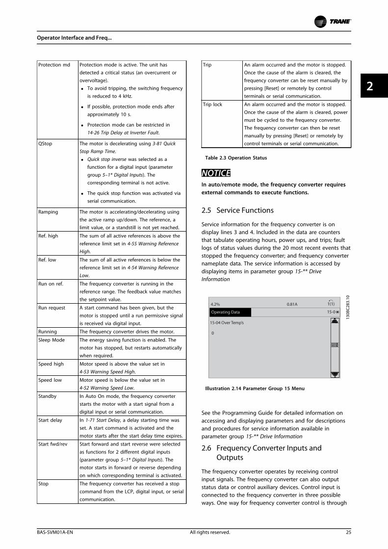
2.5 Service Functions
Service information for the frequency converter is ondisplay lines 3 and 4. Included in the data are countersthat tabulate operating hours, power ups, and trips; faultlogs of status values during the 20 most recent events thatstopped the frequency converter; and frequency converternameplate data. The service information is accessed bydisplaying items in parameter group 15-** DriveInformation
Illustration 2.14 Parameter Group 15 Menu
See the Programming Guide for detailed information onaccessing and displaying parameters and for descriptionsand procedures for service information available inparameter group 15-** Drive Information
2.6 Frequency Converter Inputs andOutputs
The frequency converter operates by receiving controlinput signals. The frequency converter can also outputstatus data or control auxiliary devices. Control input isconnected to the frequency converter in three possibleways. One way for frequency converter control is through
Operator Interface and Freq...
BAS-SVM01A-EN All rights reserved. 25
2 2
the keypad on the front of the frequency converter whenoperating in local (hand) mode. These inputs include start,stop, reset, and speed reference.
Another control source is through serial communicationfrom a serial bus. A serial communication protocol suppliescommands and references to the frequency converter, canprogram the frequency converter, and reads status datafrom the frequency converter. The serial bus connects tothe frequency converter through the RS-485 serial port orthrough a communication option card.
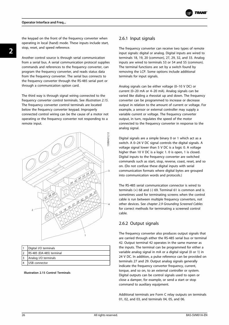
The third way is through signal wiring connected to thefrequency converter control terminals. See Illustration 2.15.The frequency converter control terminals are locatedbelow the frequency converter keypad. Improperlyconnected control wiring can be the cause of a motor notoperating or the frequency converter not responding to aremote input.
1 Digital I/O terminals
2 RS-485 (EIA-485) terminal
3 Analog I/O terminals
4 USB connector
Illustration 2.15 Control Terminals
2.6.1 Input signals
The frequency converter can receive two types of remoteinput signals: digital or analog. Digital inputs are wired toterminals 18, 19, 20 (common), 27, 29, 32, and 33. Analoginputs are wired to terminals 53 or 54 and 55 (common).The terminal functions are set by a switch found byremoving the LCP. Some options include additionalterminals for input signals.
Analog signals can be either voltage (0–10 V DC) orcurrent (0–20 mA or 4–20 mA). Analog signals can bevaried like dialing a rheostat up and down. The frequencyconverter can be programmed to increase or decreaseoutput in relation to the amount of current or voltage. Forexample, a sensor or external controller may supply avariable current or voltage. The frequency converteroutput, in turn, regulates the speed of the motorconnected to the frequency converter in response to theanalog signal.
Digital signals are a simple binary 0 or 1 which act as aswitch. A 0–24 V DC signal controls the digital signals. Avoltage signal lower than 5 V DC is a logic 0. A voltagehigher than 10 V DC is a logic 1. 0 is open, 1 is closed.Digital inputs to the frequency converter are switchedcommands such as start, stop, reverse, coast, reset, and soon. (Do not confuse these digital inputs with serialcommunication formats where digital bytes are groupedinto communication words and protocols.)
The RS-485 serial communication connector is wired toterminals (+) 68 and (-) 69. Terminal 61 is common and issometimes used for terminating screens when the controlcable is run between multiple frequency converters, notother devices. See chapter 2.9 Grounding Screened Cablesfor correct methods for terminating a screened controlcable.
2.6.2 Output signals
The frequency converter also produces output signals thatare carried through either the RS-485 serial bus or terminal42. Output terminal 42 operates in the same manner asthe inputs. The terminal can be programmed for either avariable analog signal in mA or a digital signal (0 or 1) in24 V DC. In addition, a pulse reference can be provided onterminals 27 and 29. Output analog signals generallyindicate the frequency converter frequency, current,torque, and so on, to an external controller or system.Digital outputs can be control signals used to open orclose a damper, for example, or send a start or stopcommand to auxiliary equipment.
Additional terminals are Form C relay outputs on terminals01, 02, and 03, and terminals 04, 05, and 06.
Operator Interface and Freq...
26 All rights reserved. BAS-SVM01A-EN
22
2.6.3 Control Power Supply
Terminals 12 and 13 provide 24 V DC low voltage power,to the digital input terminals (18–33). Those terminals mustbe supplied with power from either terminal 12 or 13, orfrom a customer supplied external 24 V DC power source.Improperly connected control wiring is a common serviceissue for a motor not operating or the frequency converternot responding to a remote input.
2.7 Control Terminals
Control terminals must be programmed. Each terminal hasspecific functions it performs and a numbered parameterassociated with it. See Table 2.4. The setting selected in theparameter enables the function of the terminal.
It is important to confirm that the control terminal isprogrammed for the correct function.
See the Programming Guide for details on changingparameters and the functions available for each controlterminal.
In addition, the input terminal must be receiving a signal.Confirm that the control and power sources are wired tothe terminal. Then check the signal.
Signals can be checked in two ways. To select digital inputfor display, press the [status] key as discussed previously,or use a voltmeter to check for voltage at the controlterminal. See chapter 6.4.14 Input Terminal Signal Tests
In summary, for proper frequency converter functioning,the frequency converter input control terminals mustbe:
• wired properly
• powered
• programmed correctly for the intended function
• receiving a signal
Operator Interface and Freq...
BAS-SVM01A-EN All rights reserved. 27
2 2
2.8 Control Terminal Functions
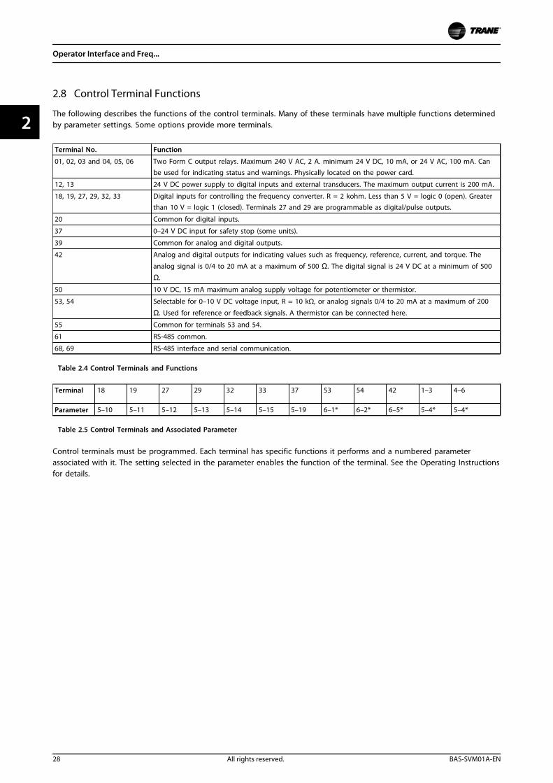
The following describes the functions of the control terminals. Many of these terminals have multiple functions determinedby parameter settings. Some options provide more terminals.
Terminal No. Function
01, 02, 03 and 04, 05, 06 Two Form C output relays. Maximum 240 V AC, 2 A. minimum 24 V DC, 10 mA, or 24 V AC, 100 mA. Canbe used for indicating status and warnings. Physically located on the power card.
12, 13 24 V DC power supply to digital inputs and external transducers. The maximum output current is 200 mA.
18, 19, 27, 29, 32, 33 Digital inputs for controlling the frequency converter. R = 2 kohm. Less than 5 V = logic 0 (open). Greaterthan 10 V = logic 1 (closed). Terminals 27 and 29 are programmable as digital/pulse outputs.
20 Common for digital inputs.
37 0–24 V DC input for safety stop (some units).
39 Common for analog and digital outputs.
42 Analog and digital outputs for indicating values such as frequency, reference, current, and torque. The
analog signal is 0/4 to 20 mA at a maximum of 500 Ω. The digital signal is 24 V DC at a minimum of 500
Ω.
50 10 V DC, 15 mA maximum analog supply voltage for potentiometer or thermistor.
53, 54 Selectable for 0–10 V DC voltage input, R = 10 kΩ, or analog signals 0/4 to 20 mA at a maximum of 200
Ω. Used for reference or feedback signals. A thermistor can be connected here.
55 Common for terminals 53 and 54.
61 RS-485 common.
68, 69 RS-485 interface and serial communication.
Table 2.4 Control Terminals and Functions
Terminal 18 19 27 29 32 33 37 53 54 42 1–3 4–6
Parameter 5–10 5–11 5–12 5–13 5–14 5–15 5–19 6–1* 6–2* 6–5* 5–4* 5–4*
Table 2.5 Control Terminals and Associated Parameter
Control terminals must be programmed. Each terminal has specific functions it performs and a numbered parameterassociated with it. The setting selected in the parameter enables the function of the terminal. See the Operating Instructionsfor details.
Operator Interface and Freq...
28 All rights reserved. BAS-SVM01A-EN
22
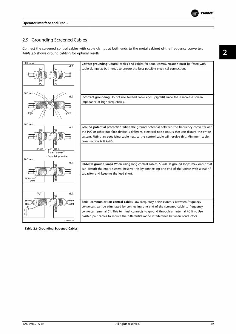
2.9 Grounding Screened Cables
Connect the screened control cables with cable clamps at both ends to the metal cabinet of the frequency converter.Table 2.6 shows ground cabling for optimal results.
Correct grounding Control cables and cables for serial communication must be fitted withcable clamps at both ends to ensure the best possible electrical connection.
Incorrect grounding Do not use twisted cable ends (pigtails) since these increase screenimpedance at high frequencies.
Ground potential protection When the ground potential between the frequency converter andthe PLC or other interface device is different, electrical noise occurs that can disturb the entiresystem. Fitting an equalizing cable next to the control cable will resolve this. Minimum cablecross section is 8 AWG.
50/60Hz ground loops When using long control cables, 50/60 Hz ground loops may occur thatcan disturb the entire system. Resolve this by connecting one end of the screen with a 100 nFcapacitor and keeping the lead short.
Serial communication control cables Low frequency noise currents between frequencyconverters can be eliminated by connecting one end of the screened cable to frequency
converter terminal 61. This terminal connects to ground through an internal RC link. Usetwisted-pair cables to reduce the differential mode interference between conductors.
Table 2.6 Grounding Screened Cables
Operator Interface and Freq...
BAS-SVM01A-EN All rights reserved. 29
2 2
3 Internal Frequency Converter Operation
3.1 General
This section is intended to provide an operational overview of the main assemblies and circuitry. This information gives therepair technician a better understanding of the frequency converter and aid in the troubleshooting process.
3.2 Description of Operation
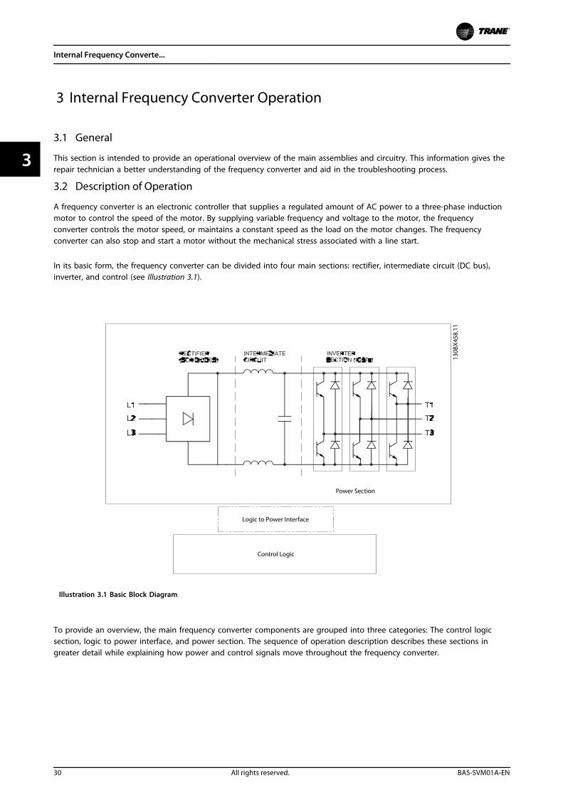
A frequency converter is an electronic controller that supplies a regulated amount of AC power to a three-phase inductionmotor to control the speed of the motor. By supplying variable frequency and voltage to the motor, the frequencyconverter controls the motor speed, or maintains a constant speed as the load on the motor changes. The frequencyconverter can also stop and start a motor without the mechanical stress associated with a line start.
In its basic form, the frequency converter can be divided into four main sections: rectifier, intermediate circuit (DC bus),inverter, and control (see Illustration 3.1).
130B
X458
.11
Power Section
Logic to Power Interface
Control Logic
Illustration 3.1 Basic Block Diagram
To provide an overview, the main frequency converter components are grouped into three categories: The control logicsection, logic to power interface, and power section. The sequence of operation description describes these sections ingreater detail while explaining how power and control signals move throughout the frequency converter.
Internal Frequency Converte...
30 All rights reserved. BAS-SVM01A-EN
33
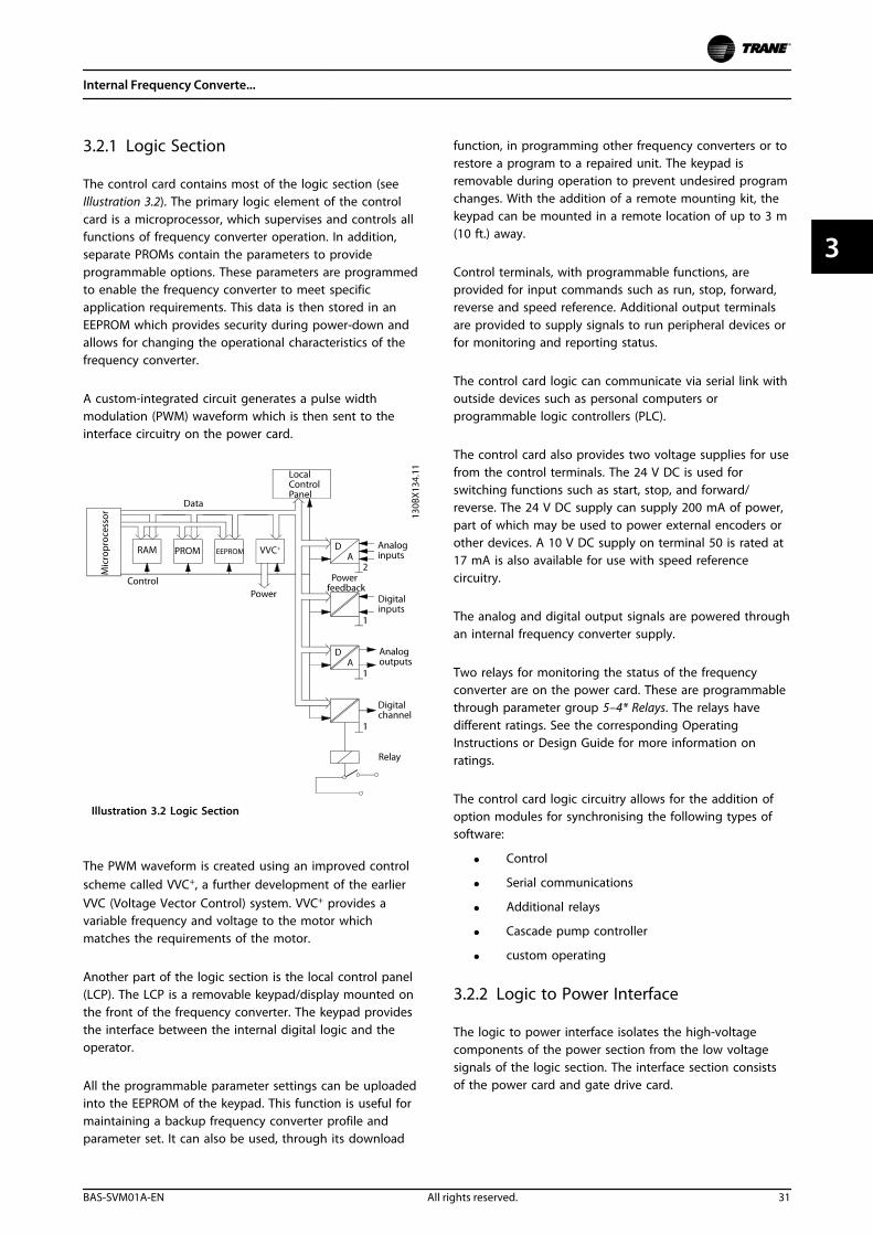
3.2.1 Logic Section
The control card contains most of the logic section (seeIllustration 3.2). The primary logic element of the controlcard is a microprocessor, which supervises and controls allfunctions of frequency converter operation. In addition,separate PROMs contain the parameters to provideprogrammable options. These parameters are programmedto enable the frequency converter to meet specificapplication requirements. This data is then stored in anEEPROM which provides security during power-down andallows for changing the operational characteristics of thefrequency converter.
A custom-integrated circuit generates a pulse widthmodulation (PWM) waveform which is then sent to theinterface circuitry on the power card.
Illustration 3.2 Logic Section
The PWM waveform is created using an improved controlscheme called VVC+, a further development of the earlierVVC (Voltage Vector Control) system. VVC+ provides avariable frequency and voltage to the motor whichmatches the requirements of the motor.
Another part of the logic section is the local control panel(LCP). The LCP is a removable keypad/display mounted onthe front of the frequency converter. The keypad providesthe interface between the internal digital logic and theoperator.
All the programmable parameter settings can be uploadedinto the EEPROM of the keypad. This function is useful formaintaining a backup frequency converter profile andparameter set. It can also be used, through its download
function, in programming other frequency converters or torestore a program to a repaired unit. The keypad isremovable during operation to prevent undesired programchanges. With the addition of a remote mounting kit, thekeypad can be mounted in a remote location of up to 3 m(10 ft.) away.
Control terminals, with programmable functions, areprovided for input commands such as run, stop, forward,reverse and speed reference. Additional output terminalsare provided to supply signals to run peripheral devices orfor monitoring and reporting status.
The control card logic can communicate via serial link withoutside devices such as personal computers orprogrammable logic controllers (PLC).
The control card also provides two voltage supplies for usefrom the control terminals. The 24 V DC is used forswitching functions such as start, stop, and forward/reverse. The 24 V DC supply can supply 200 mA of power,part of which may be used to power external encoders orother devices. A 10 V DC supply on terminal 50 is rated at17 mA is also available for use with speed referencecircuitry.
The analog and digital output signals are powered throughan internal frequency converter supply.
Two relays for monitoring the status of the frequencyconverter are on the power card. These are programmablethrough parameter group 5–4* Relays. The relays havedifferent ratings. See the corresponding OperatingInstructions or Design Guide for more information onratings.
The control card logic circuitry allows for the addition ofoption modules for synchronising the following types ofsoftware:
• Control
• Serial communications
• Additional relays
• Cascade pump controller
• custom operating
3.2.2 Logic to Power Interface
The logic to power interface isolates the high-voltagecomponents of the power section from the low voltagesignals of the logic section. The interface section consistsof the power card and gate drive card.
Internal Frequency Converte...
BAS-SVM01A-EN All rights reserved. 31
3 3
The control card handles much of the fault processing foroutput short circuit and ground fault conditions. Thepower card provides conditioning of these signals. Thecontrol card also handles scaling of current and voltagefeedback.
The power card contains a switch mode power supply(SMPS), which provides the unit with 24 V DC, (+) 18 V DC,(–) 18 V DC and 5 V DC operating voltage. The SMPSpowers the logic and interface circuitry. The SMPS issupplied by the DC bus voltage. The frequency converterscan be purchased with an optional secondary SMPS, whichis powered from a customer supplied 24 V DC source. Thissecondary SMPS provides power to the logic circuitry withmain input disconnected. It can keep units with communi-cation options live on a network when the frequencyconverter is not powered from the mains.
Circuitry for controlling the speed of the cooling fans isalso provided on the power card.
The gate drive signals from the control card to the outputtransistors (IGBTs) are isolated and buffered on the gatedrive card. In units that have the dynamic brake option,the driver circuits for the brake transistors are also on thiscard.
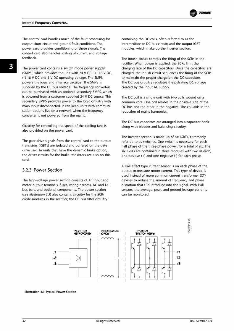
3.2.3 Power Section
The high-voltage power section consists of AC input andmotor output terminals, fuses, wiring harness, AC and DCbus bars, and optional components. The power section(see Illustration 3.3) also contains circuitry for the SCR/diode modules in the rectifier; the DC bus filter circuitry
containing the DC coils, often referred to as theintermediate or DC bus circuit; and the output IGBTmodules, which make up the inverter section.
The inrush circuit controls the firing of the SCRs in therectifier. When power is applied, the SCRs limit thecharging rate of the DC capacitors. Once the capacitors arecharged, the inrush circuit sequences the firing of the SCRsto maintain the proper charge on the DC capacitors.The DC bus circuitry regulates the pulsating DC voltagecreated by the input AC supply.
The DC coil is a single unit with two coils wound on acommon core. One coil resides in the positive side of theDC bus and the other in the negative. The coil aids in thereduction of mains harmonics.
The DC bus capacitors are arranged into a capacitor bankalong with bleeder and balancing circuitry.
The inverter section is made up of six IGBTs, commonlyreferred to as switches. One switch is necessary for eachhalf phase of the three-phase power, for a total of six. Thesix IGBTs are contained in three modules with two in each,one positive (+) and one negative (-) for each phase.
A Hall effect type current sensor is on each phase of theoutput to measure motor current. This type of device isused instead of more common current transformer (CT)devices to reduce the amount of frequency and phasedistortion that CTs introduce into the signal. With Hallsensors, the average, peak, and ground leakage currentscan be monitored.
Illustration 3.3 Typical Power Section
Internal Frequency Converte...
32 All rights reserved. BAS-SVM01A-EN
33
3.3 Sequence of Operation
3.3.1 Rectifier section
When power is first applied to the frequency converter, it enters through the input terminals (L1, L2, and L3) and on to thedisconnect and/or RFI filter option, depending on the configuration. If equipped with optional fuses, these fuses limitdamage caused by a short circuit in the power section. The input power is also connected to the inrush circuit. This circuitsupplies gate signals to the SCRs, with a high firing angle (near 180°) at first. The firing angle decreases with everysuccessive AC cycle until it reaches 0°. This process increases the DC voltage slowly over a period of several line cycles, thusgreatly reducing the current for charging the DC capacitors.
The low voltage power supplies are activated when the DC bus reaches approximately 50 V DC less than the alarm voltagelow for the DC bus. See chapter 1.9 Power-dependent Specifications. After a short delay, an inrush enable signal is sent fromthe control card to the inrush card SCR gating circuit. The SCRs are automatically gated when forward biased, acting similarto an uncontrolled rectifier as a result.
When the DC bus capacitors are fully charged, the voltage on the DC bus equals the peak voltage of the input AC line.Theoretically, this figure can be calculated by multiplying the AC line value by 1.414 (V AC x 1.414). However, since ACripple voltage is present on the DC bus, the actual DC value is closer to V AC x 1.38 under unloaded conditions and candrop to V AC x 1.32 while running under load. For example, a frequency converter connected to a nominal 460 V line, whilesitting idle, the DC bus voltage is approximately 635 V DC (460 x 1.38).
As long as power is applied to the frequency converter, this voltage is present in the intermediate and inverter circuits. It isalso fed to the switch mode power supply on the power card and is used for generating all other low voltage supplies.
Internal Frequency Converte...
BAS-SVM01A-EN All rights reserved. 33
3 3
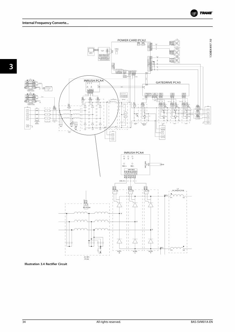
Illustration 3.4 Rectifier Circuit
Internal Frequency Converte...
34 All rights reserved. BAS-SVM01A-EN
33
3.3.2 Intermediate Section
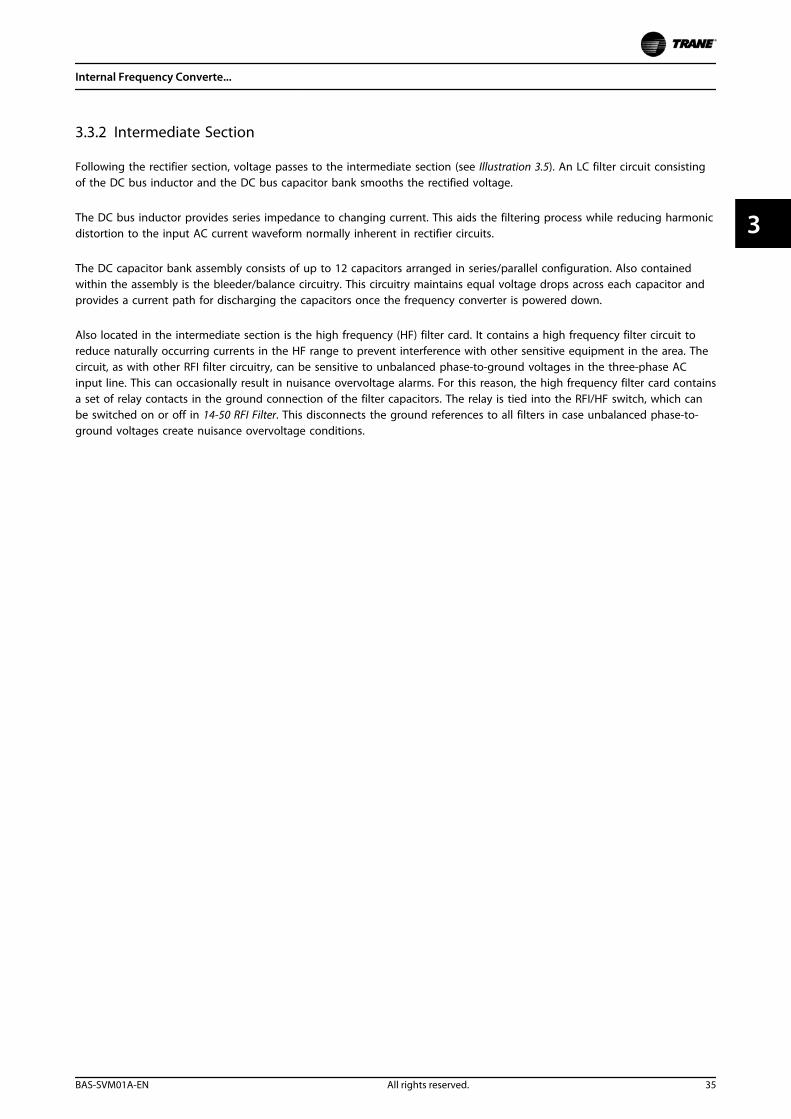
Following the rectifier section, voltage passes to the intermediate section (see Illustration 3.5). An LC filter circuit consistingof the DC bus inductor and the DC bus capacitor bank smooths the rectified voltage.
The DC bus inductor provides series impedance to changing current. This aids the filtering process while reducing harmonicdistortion to the input AC current waveform normally inherent in rectifier circuits.
The DC capacitor bank assembly consists of up to 12 capacitors arranged in series/parallel configuration. Also containedwithin the assembly is the bleeder/balance circuitry. This circuitry maintains equal voltage drops across each capacitor andprovides a current path for discharging the capacitors once the frequency converter is powered down.
Also located in the intermediate section is the high frequency (HF) filter card. It contains a high frequency filter circuit toreduce naturally occurring currents in the HF range to prevent interference with other sensitive equipment in the area. Thecircuit, as with other RFI filter circuitry, can be sensitive to unbalanced phase-to-ground voltages in the three-phase ACinput line. This can occasionally result in nuisance overvoltage alarms. For this reason, the high frequency filter card containsa set of relay contacts in the ground connection of the filter capacitors. The relay is tied into the RFI/HF switch, which canbe switched on or off in 14-50 RFI Filter. This disconnects the ground references to all filters in case unbalanced phase-to-ground voltages create nuisance overvoltage conditions.
Internal Frequency Converte...
BAS-SVM01A-EN All rights reserved. 35
3 3
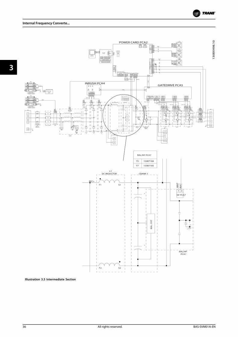
Illustration 3.5 Intermediate Section
Internal Frequency Converte...
36 All rights reserved. BAS-SVM01A-EN
33
3.3.3 Inverter Section
In the inverter section (see Illustration 3.7), gate signals aredelivered from the control card, through the power cardand gate drive card to the gates of the IGBTs. The seriesconnection of each set of IGBTs is delivered to the output,first passing through the current sensors.
Once a run command and speed reference are present, theIGBTs begin switching to create the output waveform, asshown in Illustration 3.6. Looking at the phase-to-phasevoltage waveform with an oscilloscope, the pulse widthmodulation (PWM) principal creates a series of pulseswhich vary in width. Basically, the pulses are narrower aszero crossing is approached and wider the farther fromzero crossing. The pulse duration of applied DC voltagecontrols the width. Although the voltage waveform is aconsistent amplitude, the inductance within the motorwindings averages the voltage delivered so, as the pulsewidth of the waveform varies, the average voltage themotor detects also varies. The resultant current waveformtakes on the sine wave shape common to an AC system.The rate at which the pulses occur determines thefrequency of the waveform. By employing a sophisticatedcontrol scheme, the frequency converter delivers a currentwaveform that nearly replicates a true AC sine wave.
Hall effect current sensors monitor the output current anddeliver proportional signals to the power card where theyare buffered and delivered to the control card. The controlcard logic uses these current signals to determine properwaveform compensations based on load conditions. Theyfurther serve to detect overcurrent conditions, includingground faults and phase-to-phase shorts on the output.
During normal operation, the power card and control cardare monitoring various functions within the frequencyconverter. The current sensors provide current feedbackinformation. The DC bus voltage is monitored as well asthe voltage delivered to the motor. A thermal sensormounted inside each IGBT module provides heatsinktemperature feedback.
130B
X13
6.10
Illustration 3.6 Output Voltage and Current Waveforms
Internal Frequency Converte...
BAS-SVM01A-EN All rights reserved. 37
3 3
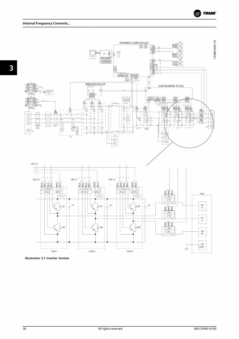
Illustration 3.7 Inverter Section
Internal Frequency Converte...
38 All rights reserved. BAS-SVM01A-EN
33
3.3.4 Brake Option
For frequency converters equipped with the dynamic brake option, a brake IGBT along with terminals 81(R-) and 82(R+) areincluded for connecting an external brake resistor.
The function of the brake IGBT (see Illustration 3.8) is to limit the voltage in the intermediate circuit, whenever the maximumvoltage limit is exceeded. It does this by switching the externally mounted resistor across the DC bus to remove excess DCvoltage present on the bus capacitors. Excess DC bus voltage is generally a result of an overhauling load causingregenerative energy to be returned to the DC bus. This occurs, for example, when the load drives the motor causing thevoltage to return to the DC bus circuit.
External placement of the brake resistor has the advantages of selecting the resistor based on application need, dissipatingthe energy outside of the control panel, and protecting the frequency converter from overheating when the brake resistor isoverloaded.
The Brake IGBT gate signal originates on the control card and is delivered to the brake IGBT via the power card and gatedrive card. Additionally, the power and control cards monitor the brake IGBT and brake resistor connection for short circuitsand overloads.
Internal Frequency Converte...
BAS-SVM01A-EN All rights reserved. 39
3 3
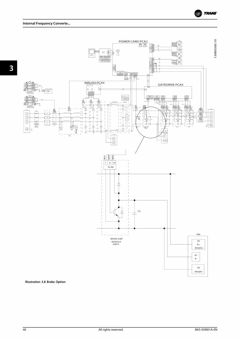
Illustration 3.8 Brake Option
Internal Frequency Converte...
40 All rights reserved. BAS-SVM01A-EN
33
3.3.5 Cooling Fans
All frequency converters in this size range are equippedwith cooling fans to provide airflow along the heatsink.Units in IP21 (NEMA 1) and IP54 (NEMA 12) enclosureshave a fan mounted in the enclosure door to provide moreairflow to the unit. IP20 enclosures have a fan mounted tothe top of the unit for more cooling. There is a small 24 VDC mixing fan mounted under the input plate. This fanoperates anytime the frequency converter is powered on.
All fans run on DC voltage from the power card. Themixing fan is powered by 24 V DC from the main switchmode power supply. The heatsink fan and the door/topfan are powered by 48 V DC from a dedicated switchmode power supply on the power card. Each fan hastachometer feedback to the control card to confirm thatthe fan is operating correctly. On/off and speed control ofthe fans is provided to reduce overall acoustical noise andextend the life of the fans.
The following conditions activate the fans:
• Output current greater than 60% of nominal
• High IGBT temperature
• Low IGBT temperature
• High control card temperature
• DC hold active
• DC brake active
• Dynamic brake circuit active
• During pre-magnetization of the motor
• AMA in progress
In addition to these conditions, the fans are always startedshortly after mains input power is applied to the frequencyconverter. Once fans are started, they run for a minimumof one minute.
3.3.6 Fan Speed Control
The following conditions cause the fans to run at fullspeed:
• Low IGBT temperature
• Active DC hold
• Active DC brake
• Active dynamic brake circuit
• Pre-magnetization of the motor
• AMA in progress
Mixing FanThe mixing fan runs at full speed whenever the frequencyconverter has power.
Heatsink FanThe IGBT temperature and the output current determinethe speed of the heatsink fan. That fan runs at the higherof the two settings.
If the output is greater than 60% of the nominal current,the fan runs at 100% speed. If the output current is lessthan 60% of the nominal current, the fan turns off.
When the IGBT temperature reaches the fan turn ontemperature, the fan starts and runs at its minimum speed.As the IGBT temperature increases, the fan speed increases.When the IGBT temperature reaches the fan maximumspeed temperature, the fan is running at 100% speed. Asthe IGBT temperature decreases, the fan speed decreases.The fan stops running when the IGBT temperature fallsbelow the fan turn off temperature.
• Fan turn on temperature = 40 °C
• Fan minimum speed temperature = 40 °C
• Fan maximum speed temperature = 80 °C
• Fan turn off temperature = 40 °C
Door/Top FanThe control card temperature, the IGBT temperature, andthe output current determine the speed of the door/topfan. The fan runs at the highest of the three settings.
If the output is greater than 60% of the nominal current,the fan runs at 100% speed. If the output current is lessthan 60% of the nominal current, the fan is turned off.
When the IGBT temperature reaches the fan turn ontemperature, the fan starts and runs at its minimum speed.As the IGBT temperature increases, the fan speed increases.When the IGBT temperature reaches the fan maximumspeed temperature, the fan is running at 100% speed. Asthe IGBT temperature decreases, the fan speed decreases.The fan stops running when the IGBT temperature fallsbelow the fan turn off temperature.
• Fan turn on temperature = 40 °C
• Fan minimum speed temperature = 40 °C
• Fan maximum speed temperature = 80 °C
• Fan turn off temperature = 40 °C
When the control card temperature reaches the fan turnon temperature, the fan starts and runs at its minimumspeed. As the control card temperature increases, the fanspeed increases. When the control card temperaturereaches the fan maximum speed temperature, the fan isrunning at 100% speed. As the control card temperaturedecreases, the fan speed decreases. The fan stops runningwhen the control card temperature falls below the fan turnoff temperature.
Internal Frequency Converte...
BAS-SVM01A-EN All rights reserved. 41
3 3
• Fan turn on temperature = 40 °C
• Fan minimum speed temperature = 40 °C
• Fan maximum speed temperature = 70 °C
• Fan turn off temperature = 35 °C
14-52 Fan Control commands the fans to run at a fixedspeed. If the fans are commanded to run at 100% speed,which overrides any other speed command.
3.3.7 Load Sharing & Regeneration
Units with the built-in load sharing option containterminals 89 (+) DC and 88 (-) DC. Within the frequencyconverter, these terminals connect to the DC bus on theinput side of the DC link reactor.
The use of the load sharing terminals has two configu-rations.
In one configuration, the terminals are used to tie the DCbus circuits of multiple frequency converters together,allowing one frequency converter in a regenerative modeto share its excess bus voltage with another frequency
converter in motoring mode. Doing so reduces the needfor external dynamic brake resistors while also savingenergy. Any number of frequency converters can beconnected in this way, as long as they are of the samevoltage rating. In addition, it may be necessary to installDC reactors and DC fuses and mains AC reactors on themains. Attempting such a configuration requires detailedconsiderations. Do not attempt without first consultingTrane Application Engineering.
In the second configuration, the frequency converter ispowered exclusively from a DC source. An external DCsource is required. Do not attempt without first consultingTrane Application Engineering
Units with a built-in regeneration option contain terminals82 (+)DC and 83 (-)DC. Within the frequency converter, theregeneration terminals connect to the DC bus on theoutput side of the DC link reactor.
Use regeneration terminals to connect one frequencyconverter to one external regeneration module. Do not usethe regeneration terminals to connect the DC bus circuitsof multiple frequency converters together.
3.3.8 Specific Power Card Connections
Connector MK106, terminals 104, 105 and 106 on thepower card, provide for the connection of an externaltemperature switch. The input could be used to monitorthe temperature of an external brake resistor. Two inputconfigurations are possible. A normally closed switch isconnected between terminals 104 and 106 or a normallyopen switch between terminals 104 and 105. If the inputchange states, the frequency converter trips on an Alarm27, Brake Chopper Fault. If no such input is used, or thenormally open configuration is selected, a jumper must beinstalled between terminals 104 and 106.
MK500, terminals 1, 2, and 3, and 4, 5, and 6, provideaccess to two auxiliary relays. This is a form C set ofcontacts, meaning one normally open and one normallyclosed contact on a single throw. The contacts are ratedfor a maximum of 240 V AC, 2 A and a minimum of 24 VDC, 10 mA, or 24 V AC, 100 mA. The relays can beprogrammed via 5-40 Function Relay to indicate frequencyconverter status.
Internal Frequency Converte...
42 All rights reserved. BAS-SVM01A-EN
33
4 Troubleshooting
4.1 Troubleshooting Tips
Before repairing a frequency converter, read andunderstand the following instructions.
1. Note all warnings concerning voltages present inthe frequency converter. Always verify thepresence of AC input voltage and DC link voltagebefore working on the unit. Some points in thefrequency converter are referenced to thenegative DC link. They are at DC link potentialeven though it sometimes appears on diagramsto be a neutral reference.
CAUTIONVoltage can be present for as long as 20 minutes onfrequency converters after removing power from theunit. See the label on the front of the frequencyconverter door for the specific discharge time.
2. Never apply power to a unit that is suspected ofbeing faulty. Many faulty components within thefrequency converter can damage othercomponents when power is applied. Alwaysperform the procedure for testing the unit afterrepair as described in chapter 4.7 After RepairTests.
3. Never attempt to defeat any fault protectioncircuitry within the frequency converter, as thisresults in unnecessary component damage andcan cause personal injury.
4. Always use factory approved replacement parts.The frequency converter is designed to operatewithin certain specifications. Incorrect parts canaffect tolerances and result in further damage tothe unit.
5. Read the instruction manual. A thoroughunderstanding of the unit is the best approach. Ifever in doubt, consult the factory or authorisedrepair centre for assistance.
4.2 Exterior Fault Troubleshooting
Servicing a frequency converter that has been operationalfor an extended period will be slightly different from anew installation. When using proper troubleshootingprocedures on a long-term installation, do not assume thata motor is wired properly, possibly overlooking issues suchas loose connections, improper programming, or addedequipment. It is best to develop a detailed approach,beginning with a physical inspection of the system. SeeTable 4.1 for items to examine.
4.3 Fault Symptom Troubleshooting
This troubleshooting section is organised based on thesymptom being experienced. Table 4.1, provides a visualinspection checklist. Often, wrong installation or wiring ofthe frequency converter causes the problem. The checklistprovides guidance through various items to inspect duringany frequency converter service process.
The following symptoms can suggest problems toinvestigate further:
• An unrecognizable display on the LCP
• Problems with motor operation
• A warning or alarm displayed by the frequencyconverter
The frequency converter processor monitors inputs andoutputs as well as internal frequency converter functions.Thus, an alarm or warning does not necessarily indicate aproblem within the frequency converter itself.
Each incident has further descriptions on how totroubleshoot that particular symptom. When necessary,further referrals are made to other parts of the manual formore procedures. chapter 4.3 Fault Symptom Trouble-shooting presents detailed discussions on areas offrequency converter and system troubleshooting that anexperienced repair technician must understand foreffective analysis.
Finally, a list of tests, chapter 4.7 After Repair Tests isprovided. Always perform these tests under the followingconditions:
• Starting a frequency converter for the first time.
• Approaching a frequency converter that issuspected of being faulty.
• After a repair to the frequency converter.
Troubleshooting
BAS-SVM01A-EN All rights reserved. 43
4 4
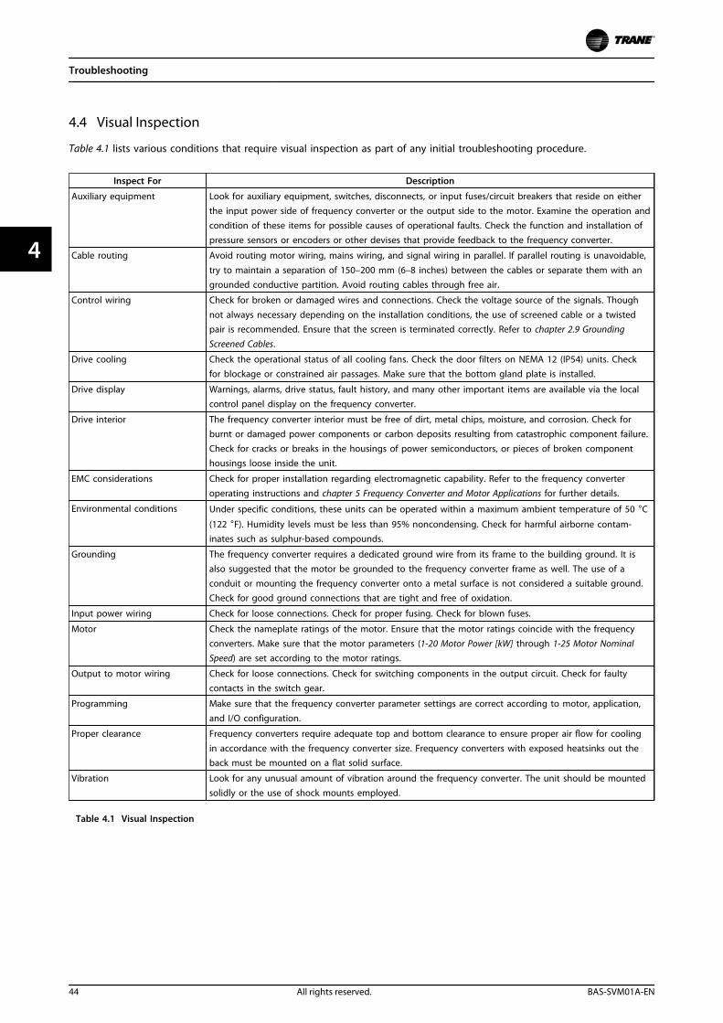
4.4 Visual Inspection
Table 4.1 lists various conditions that require visual inspection as part of any initial troubleshooting procedure.
Inspect For Description
Auxiliary equipment Look for auxiliary equipment, switches, disconnects, or input fuses/circuit breakers that reside on eitherthe input power side of frequency converter or the output side to the motor. Examine the operation andcondition of these items for possible causes of operational faults. Check the function and installation ofpressure sensors or encoders or other devises that provide feedback to the frequency converter.
Cable routing Avoid routing motor wiring, mains wiring, and signal wiring in parallel. If parallel routing is unavoidable,
try to maintain a separation of 150–200 mm (6–8 inches) between the cables or separate them with angrounded conductive partition. Avoid routing cables through free air.
Control wiring Check for broken or damaged wires and connections. Check the voltage source of the signals. Though
not always necessary depending on the installation conditions, the use of screened cable or a twistedpair is recommended. Ensure that the screen is terminated correctly. Refer to chapter 2.9 Grounding
Screened Cables.
Drive cooling Check the operational status of all cooling fans. Check the door filters on NEMA 12 (IP54) units. Checkfor blockage or constrained air passages. Make sure that the bottom gland plate is installed.
Drive display Warnings, alarms, drive status, fault history, and many other important items are available via the localcontrol panel display on the frequency converter.
Drive interior The frequency converter interior must be free of dirt, metal chips, moisture, and corrosion. Check forburnt or damaged power components or carbon deposits resulting from catastrophic component failure.Check for cracks or breaks in the housings of power semiconductors, or pieces of broken componenthousings loose inside the unit.
EMC considerations Check for proper installation regarding electromagnetic capability. Refer to the frequency converteroperating instructions and chapter 5 Frequency Converter and Motor Applications for further details.
Environmental conditions Under specific conditions, these units can be operated within a maximum ambient temperature of 50 °C
(122 °F). Humidity levels must be less than 95% noncondensing. Check for harmful airborne contam-inates such as sulphur-based compounds.
Grounding The frequency converter requires a dedicated ground wire from its frame to the building ground. It isalso suggested that the motor be grounded to the frequency converter frame as well. The use of aconduit or mounting the frequency converter onto a metal surface is not considered a suitable ground.Check for good ground connections that are tight and free of oxidation.
Input power wiring Check for loose connections. Check for proper fusing. Check for blown fuses.
Motor Check the nameplate ratings of the motor. Ensure that the motor ratings coincide with the frequencyconverters. Make sure that the motor parameters (1-20 Motor Power [kW] through 1-25 Motor NominalSpeed) are set according to the motor ratings.
Output to motor wiring Check for loose connections. Check for switching components in the output circuit. Check for faultycontacts in the switch gear.
Programming Make sure that the frequency converter parameter settings are correct according to motor, application,
and I/O configuration.
Proper clearance Frequency converters require adequate top and bottom clearance to ensure proper air flow for cooling
in accordance with the frequency converter size. Frequency converters with exposed heatsinks out theback must be mounted on a flat solid surface.
Vibration Look for any unusual amount of vibration around the frequency converter. The unit should be mountedsolidly or the use of shock mounts employed.
Table 4.1 Visual Inspection
Troubleshooting
44 All rights reserved. BAS-SVM01A-EN
44
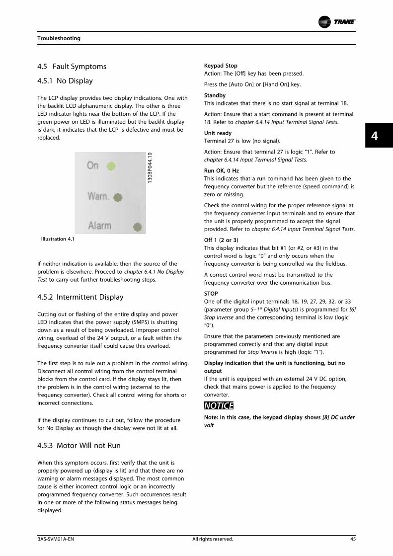
4.5 Fault Symptoms
4.5.1 No Display
The LCP display provides two display indications. One withthe backlit LCD alphanumeric display. The other is threeLED indicator lights near the bottom of the LCP. If thegreen power-on LED is illuminated but the backlit displayis dark, it indicates that the LCP is defective and must bereplaced.
Illustration 4.1
If neither indication is available, then the source of theproblem is elsewhere. Proceed to chapter 6.4.1 No DisplayTest to carry out further troubleshooting steps.
4.5.2 Intermittent Display
Cutting out or flashing of the entire display and powerLED indicates that the power supply (SMPS) is shuttingdown as a result of being overloaded. Improper controlwiring, overload of the 24 V output, or a fault within thefrequency converter itself could cause this overload.
The first step is to rule out a problem in the control wiring.Disconnect all control wiring from the control terminalblocks from the control card. If the display stays lit, thenthe problem is in the control wiring (external to thefrequency converter). Check all control wiring for shorts orincorrect connections.
If the display continues to cut out, follow the procedurefor No Display as though the display were not lit at all.
4.5.3 Motor Will not Run
When this symptom occurs, first verify that the unit isproperly powered up (display is lit) and that there are nowarning or alarm messages displayed. The most commoncause is either incorrect control logic or an incorrectlyprogrammed frequency converter. Such occurrences resultin one or more of the following status messages beingdisplayed.
Keypad StopAction: The [Off] key has been pressed.
Press the [Auto On] or [Hand On] key.
StandbyThis indicates that there is no start signal at terminal 18.
Action: Ensure that a start command is present at terminal18. Refer to chapter 6.4.14 Input Terminal Signal Tests.
Unit readyTerminal 27 is low (no signal).
Action: Ensure that terminal 27 is logic “1”. Refer tochapter 6.4.14 Input Terminal Signal Tests.
Run OK, 0 HzThis indicates that a run command has been given to thefrequency converter but the reference (speed command) iszero or missing.
Check the control wiring for the proper reference signal atthe frequency converter input terminals and to ensure thatthe unit is properly programmed to accept the signalprovided. Refer to chapter 6.4.14 Input Terminal Signal Tests.
Off 1 (2 or 3)This display indicates that bit #1 (or #2, or #3) in thecontrol word is logic “0” and only occurs when thefrequency converter is being controlled via the fieldbus.
A correct control word must be transmitted to thefrequency converter over the communication bus.
STOPOne of the digital input terminals 18, 19, 27, 29, 32, or 33(parameter group 5–1* Digital Inputs) is programmed for [6]Stop Inverse and the corresponding terminal is low (logic“0”).
Ensure that the parameters previously mentioned areprogrammed correctly and that any digital inputprogrammed for Stop Inverse is high (logic “1”).
Display indication that the unit is functioning, but nooutputIf the unit is equipped with an external 24 V DC option,check that mains power is applied to the frequencyconverter.
NOTICENote: In this case, the keypad display shows [8] DC undervolt
Troubleshooting
BAS-SVM01A-EN All rights reserved. 45
4 4
4.5.4 Incorrect Motor Operation
Occasionally, there is a fault where the motor continues torun, but not in the correct manner. There can be a numberof different causes for this type of fault. The following is alist of possible problems and recommended procedures fordetermining their causes.
Wrong speed/unit does not respond to commandPossible incorrect reference (speed command).
Ensure that the unit is programmed correctly according tothe reference signal being used, and that all referencelimits are set correctly as well. Perform chapter 6.4.14 InputTerminal Signal Tests to check for faulty reference signals.
Motor speed unstablePossible incorrect parameter settings, faulty currentfeedback circuit, loss of motor (output) phase.
Check the settings of all motor parameters, including allmotor compensation settings (slip compensation, loadcompensation, and so on). For closed loop operation,check PID settings. Perform the chapter 6.4.14 InputTerminal Signal Tests to check for faulty reference signals.Perform the chapter 6.4.9 Output Imbalance of MotorVoltage and Current to check for loss of motor phase.
Motor runs roughPossible over-magnetization (incorrect motor settings), oran IGBT misfiring.
NOTICEOther symptoms include motor stalling when loaded orthe frequency converter tripping on Alarm 13.
Check setting of all motor parameters. Perform thechapter 6.4.9 Output Imbalance of Motor Voltage and CurrentIf output voltage is unbalanced, perform thechapter 6.4.11 IGBT Gate Drive Signals Test
Motor draws high current but cannot startPossible open winding in the motor or open phase inconnection to the motor.
Perform the chapter 6.4.9 Output Imbalance of MotorVoltage and Current to ensure that the frequency converteris providing correct output (See Motor runs rough).
Run an AMA to check the motor for open windings andunbalanced resistance. Inspect all motor wiringconnections.
Motor will not brakePossible fault in the brake circuit. Possible incorrect settingin the brake parameters. The ramp down time is too short.Note: An alarm or warning message may occur.
Check all brake parameters and ramp down time(parameter group 2–0* and 3–4*).Perform chapter 6.3.4 Brake IGBT Test
4.6 Warning/Alarm Messages
4.6.1 Warning/Alarm Code List
A code on the display or the LEDs on the front of thefrequency converter signal a warning/alarm.
A warning indicates a condition that requires attention ora potentially alarming trend. A warning remains activeuntil the cause is no longer present. Under some circum-stances, motor operation may continue.
A trip is the action when an alarm has appeared. The tripremoves power to the motor. Reset it after the conditionhas been cleared by pressing [Reset] or through a digitalinput (parameter group 5–1*). The event that caused analarm cannot damage the frequency converter or cause adangerous condition. Alarms must be reset to restartoperation once their cause has been rectified.
There are three ways to reset:1. Pressing [Reset].
2. A digital reset input.
3. Serial communication/optional fieldbus resetsignal.
NOTICEAfter a manual reset pressing [Reset], [Auto On] must bepressed to restart the motor.
A trip lock is an action when a potentially damaging alarmoccurs. Power is removed from the motor. A trip lock canonly be reset after the condition is cleared by cyclingpower. Once the problem has been rectified, only thealarm continues flashing until the frequency converter isreset.
An X marked in Table 4.2 means that action occurs. Awarning precedes an alarm.
Troubleshooting
46 All rights reserved. BAS-SVM01A-EN
44
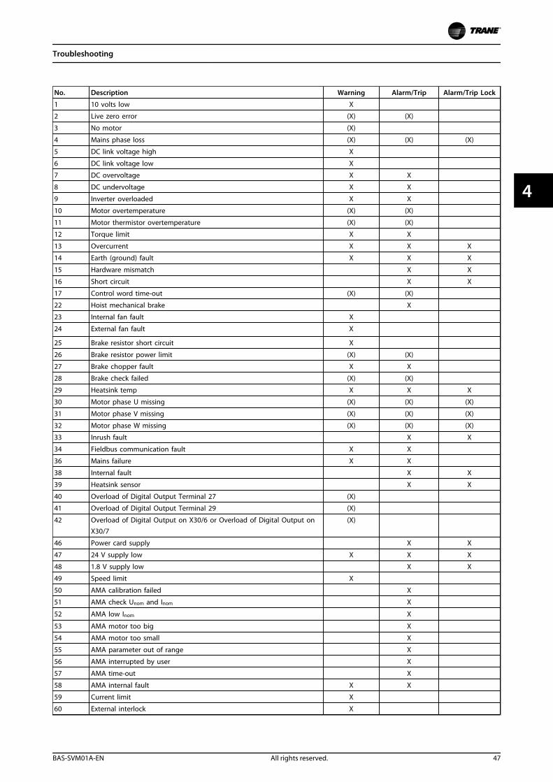
No. Description Warning Alarm/Trip Alarm/Trip Lock
1 10 volts low X
2 Live zero error (X) (X)
3 No motor (X)
4 Mains phase loss (X) (X) (X)
5 DC link voltage high X
6 DC link voltage low X
7 DC overvoltage X X
8 DC undervoltage X X
9 Inverter overloaded X X
10 Motor overtemperature (X) (X)
11 Motor thermistor overtemperature (X) (X)
12 Torque limit X X
13 Overcurrent X X X
14 Earth (ground) fault X X X
15 Hardware mismatch X X
16 Short circuit X X
17 Control word time-out (X) (X)
22 Hoist mechanical brake X
23 Internal fan fault X
24 External fan fault X
25 Brake resistor short circuit X
26 Brake resistor power limit (X) (X)
27 Brake chopper fault X X
28 Brake check failed (X) (X)
29 Heatsink temp X X X
30 Motor phase U missing (X) (X) (X)
31 Motor phase V missing (X) (X) (X)
32 Motor phase W missing (X) (X) (X)
33 Inrush fault X X
34 Fieldbus communication fault X X
36 Mains failure X X
38 Internal fault X X
39 Heatsink sensor X X
40 Overload of Digital Output Terminal 27 (X)
41 Overload of Digital Output Terminal 29 (X)
42 Overload of Digital Output on X30/6 or Overload of Digital Output onX30/7
(X)
46 Power card supply X X
47 24 V supply low X X X
48 1.8 V supply low X X
49 Speed limit X
50 AMA calibration failed X
51 AMA check Unom and Inom X
52 AMA low Inom X
53 AMA motor too big X
54 AMA motor too small X
55 AMA parameter out of range X
56 AMA interrupted by user X
57 AMA time-out X
58 AMA internal fault X X
59 Current limit X
60 External interlock X
Troubleshooting
BAS-SVM01A-EN All rights reserved. 47
4 4
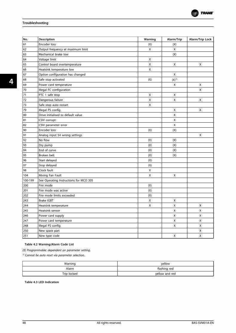
No. Description Warning Alarm/Trip Alarm/Trip Lock
61 Encoder loss (X) (X)
62 Output frequency at maximum limit X X
63 Mechanical brake low (X)
64 Voltage limit X
65 Control board overtemperature X X X
66 Heatsink temperature low X
67 Option configuration has changed X
68 Safe stop activated (X) (X)1)
69 Power card temperature X X
70 Illegal FC configuration X
71 PTC 1 safe stop X X
72 Dangerous failure X X X
73 Safe stop auto restart X
79 Illegal PS config X X
80 Drive initialised to default value X
81 CSIV corrupt X
82 CSIV parameter error X
90 Encoder loss (X) (X)
91 Analog input 54 wrong settings X
92 No flow (X) (X)
93 Dry pump (X) (X)
94 End of curve (X) (X)
95 Broken belt (X) (X)
96 Start delayed (X)
97 Stop delayed (X)
98 Clock fault X
104 Mixing Fan Fault X X
100-199 See Operating Instructions for MCO 305
200 Fire mode (X)
201 Fire mode was active (X)
202 Fire mode limits exceeded (X)
243 Brake IGBT X X
244 Heatsink temperature X X X
245 Heatsink sensor X X
246 Power card supply X X
247 Power card temperature X X
248 Illegal PS config X X
250 New spare part X
251 New type code X X
Table 4.2 Warning/Alarm Code List
(X) Programmable: dependent on parameter setting.1) Cannot be auto reset via parameter selection.
Warning yellow
Alarm flashing red
Trip locked yellow and red
Table 4.3 LED Indication
Troubleshooting
48 All rights reserved. BAS-SVM01A-EN
44
WARNINGHazardous Service Procedures!The maintenance and troubleshooting proceduresrecommended in this section of the manual could resultin exposure to electrical, mechanical or other potentialsafety hazards. Always refer to the safety warningsprovided throughout this manual concerning theseprocedures. Unless specified otherwise, disconnect allelectrical power including remote disconnect anddischarge all energy storing devices such as capacitorsbefore servicing. Follow proper lockout/tagoutprocedures to ensure the power can not be inadvertentlyenergized. When necessary to work with live electricalcomponents, have a qualified licensed electrician orother individual who has been trained in handling liveelectrical components perform these tasks. Failure tofollow all of the recommended safety warnings provided,could result in death or serious injury.
The warning/alarm information below defines eachwarning/alarm condition, provides the probable cause forthe condition, and details a remedy or troubleshootingprocedure.
WARNING 1, 10 Volts lowThe control card voltage is below 10 V from terminal 50.Remove some of the load from terminal 50, as the 10 Vsupply is overloaded. Max. 15 mA or minimum 590 Ω.
A short circuit in a connected potentiometer or improperwiring of the potentiometer can cause this condition.
Troubleshooting• Remove the wiring from terminal 50. If the
warning clears, the problem is with the wiring. Ifthe warning does not clear, replace the controlcard.
WARNING/ALARM 2, Live zero errorThis warning or alarm only appears if programmed in6-01 Live Zero Timeout Function. The signal on one of theanalog inputs is less than 50% of the minimum valueprogrammed for that input. Broken wiring or faulty devicesending the signal can cause this condition.
Troubleshooting• Check connections on all the analog input
terminals. Control card terminals 53 and 54 forsignals, terminal 55 common. MCB 101 terminals11 and 12 for signals, terminal 10 common. MCB109 terminals 1, 3, 5 for signals, terminals 2, 4, 6common).
• Check that the frequency converter programmingand switch settings match the analog signal type.
• Perform input terminal signal test.
WARNING/ALARM 4, Mains phase lossA phase is missing on the supply side, or the mainsvoltage imbalance is too high. This message also appearsfor a fault in the input rectifier on the frequency converter.Options are programmed at 14-12 Function at MainsImbalance.
Troubleshooting• Check the supply voltage and supply currents to
the frequency converter.
WARNING 5, DC link voltage highThe intermediate circuit voltage (DC) is higher than thehigh-voltage warning limit. The limit is dependent on thefrequency converter voltage rating. The unit is still active.
WARNING 6, DC link voltage lowThe intermediate circuit voltage (DC) is lower than the low-voltage warning limit. The limit is dependent on thefrequency converter voltage rating. The unit is still active.
WARNING/ALARM 7, DC overvoltageIf the intermediate circuit voltage exceeds the limit, thefrequency converter trips after a time.
Troubleshooting• Connect a brake resistor
• Extend the ramp time
• Change the ramp type
• Activate the functions in 2-10 Brake Function
• Increase 14-26 Trip Delay at Inverter Fault
• If the alarm/warning occurs during a power sag,use kinetic back-up (14-10 Mains Failure)
WARNING/ALARM 8, DC under voltageIf the DC-link voltage drops below the undervoltage limit,the frequency converter checks if a 24 V DC backup supplyis connected. If no 24 V DC backup supply is connected,the frequency converter trips after a fixed time delay. Thetime delay varies with unit size.
Troubleshooting• Check that the supply voltage matches the
frequency converter voltage.
• Perform input voltage test.
• Perform soft charge circuit test.
WARNING/ALARM 9, Inverter overloadThe frequency converter is about to cut out because of anoverload (too high current for too long). The counter forelectronic, thermal inverter protection issues a warning at98% and trips at 100%, while giving an alarm. Thefrequency converter cannot be reset until the counter isbelow 90%. The fault is that the frequency converter has run withmore than 100% overload for too long.
Troubleshooting
BAS-SVM01A-EN All rights reserved. 49
4 4
Troubleshooting• Compare the output current shown on the
keypad with the frequency converter ratedcurrent.
• Compare the output current shown on thekeypad with measured motor current.
• Display the thermal drive load on the keypad andmonitor the value. When running above thefrequency converter continuous current rating,the counter increases. When running below thefrequency converter continuous current rating,the counter decreases.
WARNING/ALARM 10, Motor overload temperatureAccording to the electronic thermal protection (ETR), themotor is too hot. Select whether the frequency converterissues a warning or an alarm when the counter reaches100% in 1-90 Motor Thermal Protection. The fault occurswhen the motor runs with more than 100% overload fortoo long.
Troubleshooting• Check for motor overheating.
• Check if the motor is mechanically overloaded
• Check that the motor current set in 1-24 MotorCurrent is correct.
• Ensure that Motor data in parameters 1-20 to1-25 are set correctly.
• If an external fan is in use, check in 1-91 MotorExternal Fan that it is selected.
• Running AMA in 1-29 Automatic Motor Adaptation(AMA) tunes the frequency converter to themotor more accurately and reduces thermalloading.
WARNING/ALARM 11, Motor thermistor over tempCheck whether the thermistor is disconnected. Selectwhether the frequency converter issues a warning or analarm in 1-90 Motor Thermal Protection.
WARNINGLive Electrical Components!
Troubleshooting• Check for motor overheating.
• Check if the motor is mechanically overloaded.
• When using terminal 53 or 54, check that thethermistor is connected correctly between eitherterminal 53 or 54 (analog voltage input) andterminal 50 (+10 V supply). Also check that theterminal switch for 53 or 54 is set for voltage.Check 1-93 Thermistor Source selects terminal 53or 54.
• When using digital inputs 18 or 19, check thatthe thermistor is connected correctly betweeneither terminal 18 or 19 (digital input PNP only)and terminal 50. Check 1-93 Thermistor Sourceselects terminal 18 or 19.
WARNINGDisconnect power before proceeding.
WARNING/ALARM 12, Torque limitThe torque has exceeded the value in 4-16 Torque LimitMotor Mode or the value in 4-17 Torque Limit GeneratorMode. 14-25 Trip Delay at Torque Limit can change thiswarning from a warning-only condition to a warningfollowed by an alarm.
Troubleshooting• If the motor torque limit is exceeded during ramp
up, extend the ramp up time.
• If the generator torque limit is exceeded duringramp down, extend the ramp down time.
• If torque limit occurs while running, possiblyincrease the torque limit. Make sure that thesystem can operate safely at a higher torque.
• Check the application for excessive current drawon the motor.
WARNING/ALARM 13, Over currentThe inverter peak current limit (approximately 200% of therated current) is exceeded. The warning lasts about 1.5 s,then the frequency converter trips and issues an alarm.Shock loading or quick acceleration with high inertia loadscan cause this fault. If the acceleration during ramp up isquick, the fault can also appear after kinetic back-up. Ifextended mechanical brake control is selected, trip can bereset externally.
Troubleshooting• Remove power and check if the motor shaft can
be turned.
• Check that the motor size matches the frequencyconverter.
• Check parameters 1-20 to 1-25 for correct motordata.
ALARM 14, Earth (ground) faultThere is current from the output phases to ground, eitherin the cable between the frequency converter and themotor or in the motor itself.
Troubleshooting• Remove power to the frequency converter and
repair the ground fault.
• Check for ground faults in the motor bymeasuring the resistance to ground of the motorleads and the motor with a megohmmeter.
Troubleshooting
50 All rights reserved. BAS-SVM01A-EN
44
WARNINGDisconnect power before proceeding.
ALARM 15, Hardware mismatchA fitted option is not operational with the present controlboard hardware or software.
Record the value of the following parameters and contactTrane:
• 15-40 FC Type
• 15-41 Power Section
• 15-42 Voltage
• 15-43 Software Version
• 15-45 Actual Typecode String
• 15-49 SW ID Control Card
• 15-50 SW ID Power Card
• 15-60 Option Mounted
• 15-61 Option SW Version (for each option slot)
ALARM 16, Short circuitThere is short-circuiting in the motor or motor wiring.
Remove power to the frequency converter and repair theshort circuit.
WARNINGDisconnect power before proceeding.
WARNING/ALARM 17, Control word timeoutThere is no communication to the frequency converter.The warning is only active when 8-04 Control TimeoutFunction is NOT set to [0] Off.If 8-04 Control Timeout Function is set to [5] Stop and Trip, awarning appears and the frequency converter ramps downuntil it stops then displays an alarm.
WARNINGLive Electrical Components!
Troubleshooting• Check connections on the serial communication
cable.
• Increase 8-03 Control Timeout Time
• Check the operation of the communicationequipment.
• Verify a proper installation based on EMCrequirements.
ALARM 18, Start failedThe speed has not been able to exceed 1-77 CompressorStart Max Speed [RPM] during start within the allowed time.(set in 1-79 Compressor Start Max Time to Trip). This may becaused by a blocked motor.
WARNING 23, Internal fan faultThe fan warning function is an extra protective functionthat checks if the fan is running/mounted. The fan warningcan be disabled in 14-53 Fan Monitor ([0] Disabled).
For the D, E, and F-frame filters, the regulated voltage tothe fans is monitored.
Troubleshooting• Check for proper fan operation.
• Cycle power to the frequency converter andcheck that the fan operates briefly at start-up.
• Check the sensors on the heat sink and controlcard.
WARNING 24, External fan faultThe fan warning function is an extra protective functionthat checks if the fan is running/mounted. The fan warningcan be disabled in 14-53 Fan Monitor ([0] Disabled).
Troubleshooting• Check for proper fan operation.
• Cycle power to the frequency converter andcheck that the fan operates briefly at start-up.
• Check the sensors on the heat sink and controlcard.
WARNING/ALARM 28, Brake check failedThe brake resistor is not connected or not working.Check 2-15 Brake Check.
ALARM 29, Heat Sink tempThe maximum temperature of the heat sink has beenexceeded. The temperature fault does not reset until thetemperature falls below a defined heatsink temperature.The trip and reset points are different based on thefrequency converter power size.
TroubleshootingCheck for the following conditions.
• Ambient temperature too high.
• Motor cable too long.
• Incorrect airflow clearance above and below thefrequency converter.
• Blocked airflow around the frequency converter.
• Damaged heatsink fan.
• Dirty heat sink.
ALARM 30, Motor phase U missingMotor phase U between the frequency converter and themotor is missing.
WARNINGDisconnect power before proceeding.
Remove power from the frequency converter and checkmotor phase U.
Troubleshooting
BAS-SVM01A-EN All rights reserved. 51
4 4
ALARM 31, Motor phase V missingMotor phase V between the frequency converter and themotor is missing.
WARNINGDisconnect power before proceeding.
Remove power from the frequency converter and checkmotor phase V.
ALARM 32, Motor phase W missingMotor phase W between the frequency converter and themotor is missing.
WARNINGDisconnect power before proceeding.
Remove power from the frequency converter and checkmotor phase W.
ALARM 33, Inrush faultToo many power-ups have occurred within a short timeperiod. Let the unit cool to operating temperature.
WARNING/ALARM 34, Fieldbus communication faultThe fieldbus on the communication option card is notworking.
WARNING/ALARM 36, Mains failureThis warning/alarm is only active if the supply voltage tothe frequency converter is lost and 14-10 Mains Failure isnot set to [0] No Function. Check the fuses to thefrequency converter and mains supply to the unit.
ALARM 38, Internal faultWhen an internal fault occurs, a code number defined inTable 4.4 is displayed.
Troubleshooting• Cycle power
• Check that the option is properly installed
• Check for loose or missing wiring
It may be necessary to contact your Trane supplier orservice department. Note the code number for furthertroubleshooting directions.
No. Text
0 Serial port cannot be initialised. Contact yourTrane supplier or Trane Service Department.
256-258 Power EEPROM data is defective or too old.
Replace power card.
512-519 Internal fault. Contact your Trane supplier or TraneService Department.
783 Parameter value outside of min/max limits
1024-1284 Internal fault. Contact your Trane supplier or theTrane Service Department.
1299 Option SW in slot A is too old
1300 Option SW in slot B is too old
1315 Option SW in slot A is not supported (not allowed)
No. Text
1316 Option SW in slot B is not supported (not allowed)
1379-2819 Internal fault. Contact your Trane supplier or Trane
Service Department.
2561 Replace control card
2820 LCP stack overflow
2821 Serial port overflow
2822 USB port overflow
3072-5122 Parameter value is outside its limits
5123 Option in slot A: Hardware incompatible with
control board hardware
5124 Option in slot B: Hardware incompatible withcontrol board hardware
5376-6231 Internal fault. Contact your Trane supplier or TraneService Department.
Table 4.4 Internal Fault Codes
ALARM 39, Heat Sink sensorNo feedback from the heat sink temperature sensor.
The signal from the IGBT thermal sensor is not available onthe power card. The problem could be on the power card,on the gate drive card, or the ribbon cable between thepower card and gate drive card.
WARNING 40, Overload of digital output terminal 27Check the load connected to terminal 27 or remove short-circuit connection. Check 5-01 Terminal 27 Mode.
WARNING 41, Overload of digital output terminal 29Check the load connected to terminal 29 or remove short-circuit connection. Check 5-02 Terminal 29 Mode.
WARNING 42, Overload of digital output on X30/6 oroverload of digital output on X30/7For X30/6, check the load connected to X30/6 or removethe short-circuit connection. Check 5-32 Term X30/6 DigiOut (MCB 101).
For X30/7, check the load connected to X30/7 or removethe short-circuit connection. Check 5-33 Term X30/7 DigiOut (MCB 101).
ALARM 45, Earth fault 2Ground fault.
Troubleshooting• Check for proper grounding and loose
connections.
• Check for proper wire size.
• Check motor cables for short-circuits or leakagecurrents.
ALARM 46, Power card supplyThe supply on the power card is out of range.
There are 3 power supplies generated by the switch modepower supply (SMPS) on the power card: 24 V, 5 V, ±18 V.When powered with 24 V DC with the MCB 107 option,only the 24 V and 5 V supplies are monitored. When
Troubleshooting
52 All rights reserved. BAS-SVM01A-EN
44
powered with 3-phase mains voltage, all 3 supplies aremonitored.
Troubleshooting• Check for a defective power card.
• Check for a defective control card.
• Check for a defective option card.
• If a 24 V DC power supply is used, verify propersupply power.
WARNING 47, 24 V supply lowThe 24 Vdc is measured on the control card. This alarmarises when the detected voltage of terminal 12 is lowerthan 18 V.
Troubleshooting• Check for a defective control card.
WARNING 48, 1.8 V supply lowThe 1.8Vdc supply used on the control card is outside ofallowable limits. The power supply is measured on thecontrol card. Check for a defective control card. If anoption card is present, check for an overvoltage condition.
WARNING 49, Speed limitWhen the speed is not within the specified range in4-11 Motor Speed Low Limit [RPM] and 4-13 Motor SpeedHigh Limit [RPM], the frequency converter shows a warning.When the speed is below the specified limit in 1-86 TripSpeed Low [RPM] (except when starting or stopping), thefrequency converter trips.
ALARM 50, AMA calibration failedContact Trane supplier or Trane service department.
ALARM 51, AMA check Unom and Inom
The settings for motor voltage, motor current and motorpower are wrong. Check the settings in parameters 1-20 to1-25.
ALARM 52, AMA low Inom
The motor current is too low. Check the settings.
ALARM 53, AMA motor too bigThe motor is too big for the AMA to operate.
ALARM 54, AMA motor too smallThe motor is too small for the AMA to operate.
ALARM 55, AMA parameter out of rangeThe parameter values of the motor are outside of theacceptable range. AMA cannot run.
ALARM 56, AMA interrupted by userThe user has interrupted the AMA.
ALARM 57, AMA internal faultTry to restart AMA again. Repeated restarts can over heatthe motor.
ALARM 58, AMA Internal faultContact the Trane supplier.
WARNING 59, Current limitThe current is higher than the value in 4-18 Current Limit.Ensure that motor data in parameters 1–20 to 1–25 are setcorrectly. Possibly increase the current limit. Be sure thatthe system can operate safely at a higher limit.
WARNING 60, External interlockA digital input signal is indicating a fault condition externalto the frequency converter. An external interlock hascommanded the frequency converter to trip. Clear theexternal fault condition. To resume normal operation,apply 24 Vdc to the terminal programmed for externalinterlock. Reset the frequency converter.
WARNING 62, Output frequency at maximum limitThe output frequency has reached the value set in4-19 Max Output Frequency. Check the application todetermine the cause. Possibly increase the outputfrequency limit. Be sure the system can operate safely at ahigher output frequency. The warning clears when theoutput drops below the maximum limit.
WARNING/ALARM 65, Control card over temperatureThe cut-out temperature of the control card is 80 °C.
Troubleshooting• Check that the ambient operating temperature is
within limits
• Check for clogged filters
• Check fan operation
• Check the control card
WARNING 66, Heat sink temperature lowThe frequency converter is too cold to operate. Thiswarning is based on the temperature sensor in the IGBTmodule.Increase the ambient temperature of the unit. Also, atrickle amount of current can be supplied to the frequencyconverter whenever the motor is stopped by setting2-00 DC Hold/Preheat Current at 5% and 1-80 Function atStop.
ALARM 67, Option module configuration has changedOne or more options have either been added or removedsince the last power-down. Check that the configurationchange is intentional and reset the unit.
ALARM 69, Power card temperatureThe temperature sensor on the power card is either toohot or too cold.
Troubleshooting• Check that the ambient operating temperature is
within limits.
• Check for clogged filters.
• Check fan operation.
• Check the power card.
Troubleshooting
BAS-SVM01A-EN All rights reserved. 53
4 4
ALARM 70, Illegal FC configurationThe control card and power card are incompatible. Tocheck compatibility, contact the Trane supplier with thetype code of the unit from the nameplate and the partnumbers of the cards.
ALARM 80, Drive initialised to default valueParameter settings are initialised to default settings after amanual reset. To clear the alarm, reset the unit.
ALARM 92, No flowA no-flow condition has been detected in the system.22-23 No-Flow Function is set for alarm. Troubleshoot thesystem and reset the frequency converter after the faulthas been cleared.
ALARM 93, Dry pumpA no-flow condition in the system with the frequencyconverter operating at high speed may indicate a drypump. 22-26 Dry Pump Function is set for alarm.Troubleshoot the system and reset the frequency converterafter the fault has been cleared.
ALARM 94, End of curveFeedback is lower than the set point. This may indicateleakage in the system. 22-50 End of Curve Function is set foralarm. Troubleshoot the system and reset the frequencyconverter after the fault has been cleared.
ALARM 95, Broken beltTorque is below the torque level set for no load, indicatinga broken belt. 22-60 Broken Belt Function is set for alarm.Troubleshoot the system and reset the frequency converterafter the fault has been cleared.
ALARM 96, Start delayedMotor start has been delayed due to short-cycleprotection. 22-76 Interval between Starts is enabled.Troubleshoot the system and reset the frequency converterafter the fault has been cleared.
WARNING 97, Stop delayedStopping the motor has been delayed due to short cycleprotection. 22-76 Interval between Starts is enabled.Troubleshoot the system and reset the frequency converterafter the fault has been cleared.
WARNING 98, Clock faultTime is not set or the RTC clock has failed. Reset the clockin 0-70 Date and Time.
WARNING 200, Fire modeThis warning indicates the frequency converter is operatingin fire mode. The warning clears when fire mode isremoved. See the fire mode data in the alarm log.
WARNING 201, Fire mode was activeThis indicates the frequency converter had entered firemode. Cycle power to the unit to remove the warning. Seethe fire mode data in the alarm log.
WARNING 202, Fire mode limits exceededWhile operating in fire mode one or more alarm conditionshave been ignored which would normally trip the unit.Operating in this condition voids unit warranty. Cycle
power to the unit to remove the warning. See the firemode data in the alarm log.
WARNING 203, Missing motorWith a frequency converter operating multi-motors, anunder-load condition was detected. This could indicate amissing motor. Inspect the system for proper operation.
WARNING 204, Locked rotorWith a frequency converter operating multi-motors, anoverload condition was detected. This could indicate alocked rotor. Inspect the motor for proper operation.
WARNING 250, New spare partA component in the frequency converter has beenreplaced. Reset the frequency converter for normaloperation.
WARNING 251, New typecodeThe power card or other components have been replacedand the typecode changed. Reset to remove the warningand resume normal operation.
Troubleshooting
54 All rights reserved. BAS-SVM01A-EN
44
4.7 After Repair Tests
Following any repair to a frequency converter or testing ofa frequency converter suspected of being faulty, thefollowing procedure must be followed. Following theprocedure ensures that all circuitry in the frequencyconverter is functioning properly before putting the unitinto operation.
1. Perform visual inspection procedures as describedin chapter 4.4 Visual Inspection.
2. Perform static test procedures to ensure thatfrequency converter is safe to start.
3. Disconnect motor leads from output terminals (U,V, W) of the frequency converter.
4. Apply AC power to frequency converter.
5. Give the frequency converter a run commandand slowly increase reference (speed command)to approximately 40 Hz.
6. Using an analog voltmeter or a DVM capable ofmeasuring true RMS, measure phase-to-phaseoutput voltage on all three phases: U to V, U toW, V to W. All voltages must be balanced within8 V. If unbalanced voltage is measured, refer tochapter 6.4.2 Input Voltage Test.
7. Stop the frequency converter and remove inputpower. Allow 20 minutes for DC capacitors todischarge fully.
8. Reconnect motor cables to frequency converteroutput terminals (U, V, W).
9. Reapply power and restart frequency converter.Adjust motor speed to a nominal level.
10. Using a clamp-on style ammeter, measure outputcurrent on each output phase. All currents mustbe balanced.
Troubleshooting
BAS-SVM01A-EN All rights reserved. 55
4 4
5 Frequency Converter and Motor Applications
5.1 Torque Limit, Current Limit, andUnstable Motor Operation
Excessive loading of the frequency converter could resultin warning or tripping on torque limit, overcurrent, orinverter time. Tripping is not a concern if the frequencyconverter is properly sized for the application andintermittent load conditions cause anticipated operation intorque limit or an occasional trip. However, nuisance orunexplained occurrences are sometimes the result ofimproperly setting specific parameters. The followingparameters are important in matching the frequencyconverter to the motor for optimum operation. Thesesettings need careful attention.
1-03 Torque Characteristics sets the mode in whichthe frequency converter operates.
Parameters 1-20 Motor Power [kW] to1-29 Automatic Motor Adaptation (AMA) match thefrequency converter to the motor and adapt tothe motor characteristics.
4-17 Torque Limit Generator Mode and 14-25 TripDelay at Torque Limit set the torque controlfeatures of the frequency converter for theapplication.
1-00 Configuration Mode sets the frequency converter foropen or closed loop operation or torque mode operation.In a closed loop configuration, a feedback signal controlsthe frequency converter speed. The settings for the PIDcontroller play a key role for stable operation in closedloop, as described in the Operating Instructions. In openloop, the frequency converter calculates the torquerequirement based on current measurements of the motor.
1-03 Torque Characteristics sets the frequency converter forconstant or variable torque operation. It is imperative thatthe correct torque characteristic is selected, based on theapplication. If the load type is constant torque and variabletorque is selected, it may be very difficult or impossible forthe frequency converter to start the load. Consult thefactory if uncertain about the torque characteristics of anapplication.
Parameters 1-20 Motor Power [kW] to 1-25 Motor NominalSpeed configure the frequency converter for the connectedmotor. These parameters are motor power, voltage,frequency, current, and rated motor speed. Accuratesetting of these parameters is crucial. Enter the motor datarequired as listed on the motor nameplate. For effectiveand efficient load control, the frequency converter relies
on this information for calculating the output waveform inresponse to the changing demands of the application.
1-29 Automatic Motor Adaptation (AMA) activates theautomatic motor adaptation (AMA) function. When AMA isperformed, the frequency converter measures the electricalcharacteristics of the motor and sets various frequencyconverter parameters based on the findings. Two keyparameter values set by this function are stator resistanceand main reactance, 1-30 Stator Resistance (Rs) and1-35 Main Reactance (Xh). If the motor operation isunstable, perform AMA. AMA can only be performed onsingle motor applications within the programming rangeof the frequency converter. Consult the OperatingInstructions for more on this function.
1-30 Stator Resistance (Rs) and 1-35 Main Reactance (Xh), asstated, are set by the AMA function, values supplied by themotor manufacturer, or left at the factory default values.Never adjust these parameters to random values even if itseems to improve operation. Such adjustments can resultin unpredictable operation under changing conditions.
4-16 Torque Limit Motor Mode sets the limit for frequencyconverter torque. The factory setting is 160% for TR200series and 110% for/seriesTR200 and vary with motorpower setting. For example, a frequency converterprogrammed to operate a small motor yields a highertorque limit value than one programmed to operate alarger size motor. It is important that this value is not settoo low for the requirements of the application. In somecases, it is desirable to have a torque limit set at a lesservalue. This offers protection for the application in that thefrequency converter limits the torque. A higher torque maybe required at initial startup, which could cause nuisancetripping.
14-25 Trip Delay at Torque Limit works with torque limit.This parameter selects the length of time the frequencyconverter operates in torque limit before a trip. The factorydefault value is off. This means that the frequencyconverter will not trip on torque limit, but it does notmean it will never trip from an overload condition. Builtinto the frequency converter is an internal inverter thermalprotection circuit. This circuit monitors the output load onthe inverter. If the load exceeds 100% of the continuousrating of the frequency converter, a timer is activated.When the load remains excessive long enough, thefrequency converter trips on inverter time. Adjustmentscannot be made to alter this circuit. Improper parametersettings affecting load current can result in premature tripsof this type. The timer can be displayed.
Frequency Converter and Mot...
56 All rights reserved. BAS-SVM01A-EN
55
5.1.1 Overvoltage Trips
This trip occurs when the DC bus voltage reaches its DCbus alarm voltage high. Before tripping, the frequencyconverter displays a high voltage warning. Most times, anover voltage condition is due to fast deceleration rampsregarding the inertia of the load. During deceleration ofthe load, inertia of the system acts to sustain the runningspeed. Once the motor frequency drops below the runningspeed, the load begins overhauling the motor. The motorbecomes a generator and starts returning energy to thefrequency converter. This is called regenerative energy.Regeneration occurs when the speed of the load is greaterthan the commanded speed. The diodes in the IGBTmodules rectify this return voltage, which raises the DCbus. If the amount of returned voltage is too high, thefrequency converter trips.
There are a few ways to overcome this situation. Onemethod is to reduce the deceleration rate so it takeslonger for the frequency converter to decelerate. Thefrequency converter can only decelerate the load slightlyfaster than it would take for the load to naturally coast toa stop. A second method is to allow the overvoltagecontrol circuit to take care of the deceleration ramp. Whenenabled, the overvoltage control circuit regulatesdeceleration at a rate that maintains the DC bus voltage ata level that keeps the unit from tripping. Overvoltagecontrol corrects minor, but not major discrepanciesbetween ramp rates. For example, if a deceleration ramp of100 seconds is required due to the inertia, and the ramprate is set at 70 seconds, the overvoltage control correctsit. However, with the same inertia, if the ramp is set at alarger difference, such as 3 seconds, overvoltage controlengages initially and then disengages, allowing thefrequency converter to trip. This trip is done deliberately toavoid confusion about the operation of the frequencyconverter. A third method in controlling regeneratedenergy is with a dynamic brake. The frequency convertermonitors the level of the DC bus. If the level becomes toohigh, the frequency converter switches the resistor acrossthe DC bus, and dissipates the unwanted energy into theexternal resistor bank mounted outside of the frequencyconverter. This increases deceleration rate.
Less often, the load causes an overvoltage condition whilerunning at speed. When this condition occurs, the dynamicbrake option or the overvoltage control circuit can beused. It works with the load in this way. As stated earlier,regeneration occurs when the speed of the load is greaterthan the commanded speed. If the load becomesregenerative while the frequency converter is running at asteady state speed, the overvoltage circuit increases thefrequency to match the speed of the load. The samerestriction on the amount of influence applies. Thefrequency converter adds about 10% to the base speed
before a trip occurs. Otherwise, the speed could continueto rise to potentially unsafe levels.
5.1.2 Mains Phase Loss Trips
The frequency converter actually monitors phase loss bymonitoring the amount of ripple voltage on the DC bus.Ripple voltage on the DC bus is a product of a phase loss.The main concern is that ripple voltage causes overheatingin the DC bus capacitors and the DC coil. If the ripplevoltage on the DC bus is left unchecked, the lifetime ofthe capacitors and DC coil is drastically reduced.
When the input voltage becomes unbalanced or a phasedisappears completely, the ripple voltage increases. Thiscauses the frequency converter to trip and issue Alarm 4. Aline disturbance or imbalance can also cause increased busripple. Loads affecting the form factor of the AC waveform,such as notching or defective transformers, cause linedisturbances. Mains imbalances that exceed 3% causesufficient DC bus ripple to initiate a trip.
Output disturbances can have the same effect of increasedripple voltage on the DC bus. A missing or lower thannormal output voltage on one phase can cause increasedripple on the DC bus. When a mains imbalance trip occurs,it is necessary to check both the input and output voltageof the frequency converter.
Severe imbalance of supply voltage or phase loss caneasily be detected with a voltmeter. Use an oscilloscope toview line disturbances. Conduct tests for input imbalanceof supply voltage, input waveform, and output imbalanceof supply voltage as described in chapter 6.4.2 InputVoltage Test, chapter 6.4.6 Input Imbalance of Supply VoltageTest, and chapter 6.4.9 Output Imbalance of Motor Voltageand Current.
5.1.3 Control Logic Problems
Problems with control logic can often be difficult todiagnose, since there is usually no associated faultindication. The typical complaint is simply that thefrequency converter does not respond to a givencommand. There are two basic commands that must begiven to any frequency converter in order to obtain anoutput. First, the frequency converter must be told to run(start command). Second, the frequency converter must betold how fast to run (reference or speed command).
The frequency converters are designed to accept varioussignals. Determine what types of signals the frequencyconverter is receiving. There are six digital inputs(terminals 18, 19, 27, 29, 32, 33), two analog inputs (53 and54), and the fieldbus (68, 69). A correct reading indicates
Frequency Converter and Mot...
BAS-SVM01A-EN All rights reserved. 57
5 5
that the microprocessor detects the desired signal. See chapter 2.6 Frequency Converter Inputs and Outputs.
Using the status information displayed by the frequencyconverter is the best method of locating problems of thisnature. By selecting within parameter group 0–2* LCP, line2 or 3 of the display can be set to indicate the signalscoming in. A correct reading indicates that themicroprocessor detects the desired signal. This data isavailable in parameter group 16-6* Inputs & Outputs.
If there is not a correct indication, the next step is todetermine whether the signal is present at the inputterminals. Perform this test with a voltmeter oroscilloscope in accordance with the chapter 6.4.14 InputTerminal Signal Tests.
If the signal is present at the terminal, the control card isdefective and must be replaced. If the signal is notpresent, the problem is external to the frequencyconverter. The circuitry providing the signal along with itsassociated wiring must then be checked.
5.1.4 Programming Problems
Difficulty with frequency converter operation can be aresult of improper programming of the frequencyconverter parameters. Programming errors affect frequencyconverter and motor operation in the areas of motorsettings, references and limits, and I/O configuration.
The frequency converter must be set up correctly for themotor or motors connected to it. Parameters 1-20 MotorPower [kW] to 1-25 Motor Nominal Speed must have datafrom the motor nameplate entered into the frequencyconverter. This data enables the frequency converterprocessor to match the frequency converter to powercharacteristics of the motor. The most common result ofinaccurate motor data is the motor drawing higher thannormal amounts of current to perform the task expectedof it. In such cases, setting the correct values for theseparameters and performing the automatic motoradaptation (AMA) function usually solves the problem.
Any references or limits set incorrectly results insubstandard performance. For instance, if maximumreference is set too low, the motor is unable to reach fullspeed. These parameters must be set according to therequirements of the particular installation. References areset in parameter group 3–0* Reference Limits.
Incorrectly set I/O configuration usually results in thefrequency converter not responding to the function ascommanded. For every control terminal input or output,there are corresponding parameter settings. These settingsdetermine how the frequency converter responds to an
input signal or the type of signal present at that output.Utilising an I/O function is a two-step process. The desiredI/O terminal must be wired properly, and thecorresponding parameter must be set accordingly. Controlterminals are programmed in parameter groups 5–0*Digital I/O Mode and 6–0* Analog I/O Mode.
5.1.5 Motor/Load Problems
Problems with the motor, motor wiring, or mechanical loadon the motor can develop in a number of ways. The motoror motor wiring can develop a phase-to-phase or phase-to-ground short resulting in an alarm indication. Checks mustbe made to determine whether the problem is in themotor wiring or the motor itself.
A motor with unbalanced, or non-symmetrical, impedanceson all three phases can result in uneven or roughoperation, or unbalanced output currents. Measure with aclamp-on style ammeter to determine whether the currentis balanced on the three output phases.
A torque limit alarm or warning usually indicates incorrectmechanical load. Disconnect the motor from the load, ifpossible, to determine whether this is the case.
Quite often, the indications of motor problems are similarto those of a defect in the frequency converter itself. Todetermine whether the problem is internal or external tothe frequency converter, disconnect the motor from thefrequency converter output terminals. Perform the outputimbalance of supply voltage test procedure on all threephases with an analog voltmeter. If the three voltagemeasurements are balanced, the frequency converter isfunctioning correctly. The problem, therefore, is external tothe frequency converter.
If the voltage measurements are not balanced, thefrequency converter is malfunctioning. This type ofmalfunction typically means that one or more output IGBTsare not switching on and off correctly. A defective IGBT orgate signal from the gate drive card can cause this.Perform the IGBT gate signal test.
5.2 Internal Frequency Converter Problems
Most problems related to failed frequency converter powercomponents can be identified by performing a visualinspection and the static tests as described in the testsection. However, there are a number of possible problemsthat must be diagnosed in a different manner. Thefollowing discusses many of the most common of theseproblems.
Frequency Converter and Mot...
58 All rights reserved. BAS-SVM01A-EN
55
5.2.1 Overtemperature Faults
When an overtemperature indication is displayed,determine whether this condition actually exists within thefrequency converter or whether the thermal sensor isdefective. This can easily be detected by touching theoutside of the unit, if the overtemperature condition is stillpresent. If not, check the temperature sensor with anohmmeter.
5.2.2 Current Sensor Faults
An overcurrent alarm that cannot be reset, even with themotor cables disconnected, sometimes indicates currentsensor failure.The frequency converter experiences frequent false earth(ground) fault trips due to the DC offset failure mode ofthe sensors.
An explanation of the internal makeup of a Hall effect typecurrent sensor helps to explain these faults. Included insidethe device is an op-amp to amplify the signal to usablelevels in the receiving circuitry. The output at zero inputlevel (zero current flow being measured) is zero volts,exactly halfway between the plus and minus power supplyvoltages. A tolerance of +/-15 mV is acceptable. In a three-phase system that is operating correctly, the sum of thethree output currents is always zero.
When the sensor becomes defective, the output voltagelevel varies by more than the 15 mV. The defective currentsensor in that phase indicates current flow when there isnone. This results in the sum of the three output currentsbeing a value other than zero, which is an indication ofleakage current flowing. If the deviation from zero (currentamplitude) approaches a specific level, the frequencyconverter assumes an earth (ground) fault and issues analarm.
To determine whether a current sensor is defective,disconnect the motor from the frequency converter, andthen observe the current in the frequency converterdisplay. With the motor disconnected, the current shouldbe zero. A frequency converter with a defective currentsensor indicates some current flow. Because the currentsensors for the higher horsepower frequency convertershave less resolution, an indication of a fraction of one ampis tolerable. However, that value should be considerablyless than one amp. If the display shows more than oneamp of current, there is a defective current sensor.
To determine which current sensor is defective, measurethe voltage offset at zero current for each current sensor.See chapter 6.4.12 Current Sensors Test.
5.2.3 EMI Signal and Power Wiring
The following is an overview of general signal and powerwiring considerations related electromagnetic compatibility(EMC) for typical commercial and industrial equipment.Only certain high-frequency phenomena (such as RFemissions, RF immunity) are discussed. Low-frequencyphenomena (such as harmonics, mains voltage imbalance,notching) are not covered. Special installations orcompliance to the European CE EMC directives requiresstrict adherence to relevant standards and are notdiscussed here.
5.2.4 Effects of EMI
While electromagnetic interference (EMI) related distur-bances to frequency converter operation are uncommon,the following detrimental EMI effects sometimes occur:
• Motor speed fluctuations
• Serial communication transmission errors
• Frequency converter CPU exception faults
• Unexplained frequency converter trips
A disturbance resulting from other nearby equipment ismore common. Generally, other industrial controlequipment has a high level of EMI immunity. However,non-industrial, commercial, and consumer equipment isoften susceptible to lower levels of EMI. Detrimental effectsto these systems include the following:
• Pressure/flow/temperature signal transmittersignal distortion or aberrant behaviour
• Radio and TV interference
• Telephone interference
• Computer network data loss
• Digital control system faults
Frequency Converter and Mot...
BAS-SVM01A-EN All rights reserved. 59
5 5
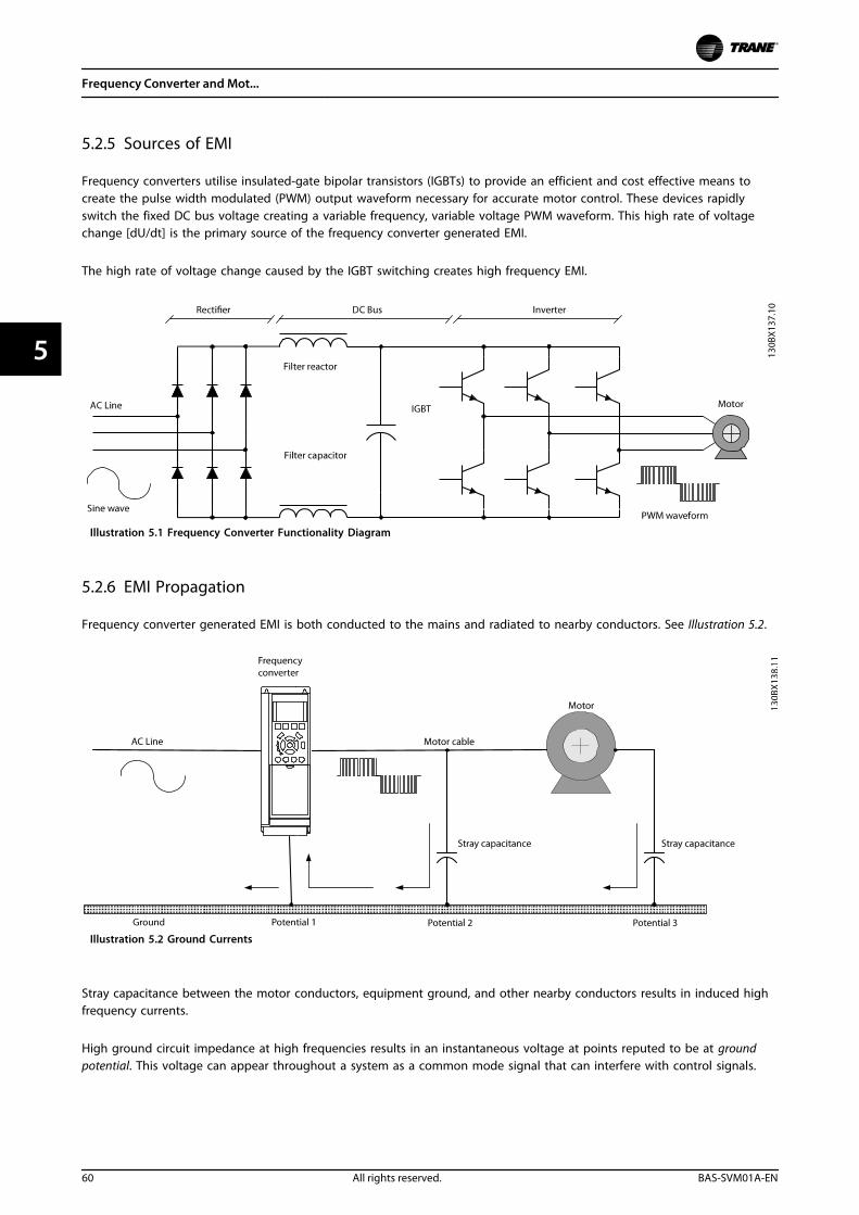
5.2.5 Sources of EMI
Frequency converters utilise insulated-gate bipolar transistors (IGBTs) to provide an efficient and cost effective means tocreate the pulse width modulated (PWM) output waveform necessary for accurate motor control. These devices rapidlyswitch the fixed DC bus voltage creating a variable frequency, variable voltage PWM waveform. This high rate of voltagechange [dU/dt] is the primary source of the frequency converter generated EMI.
The high rate of voltage change caused by the IGBT switching creates high frequency EMI.
Illustration 5.1 Frequency Converter Functionality Diagram
5.2.6 EMI Propagation
Frequency converter generated EMI is both conducted to the mains and radiated to nearby conductors. See Illustration 5.2.
Illustration 5.2 Ground Currents
Stray capacitance between the motor conductors, equipment ground, and other nearby conductors results in induced highfrequency currents.
High ground circuit impedance at high frequencies results in an instantaneous voltage at points reputed to be at groundpotential. This voltage can appear throughout a system as a common mode signal that can interfere with control signals.
Frequency Converter and Mot...
60 All rights reserved. BAS-SVM01A-EN
55
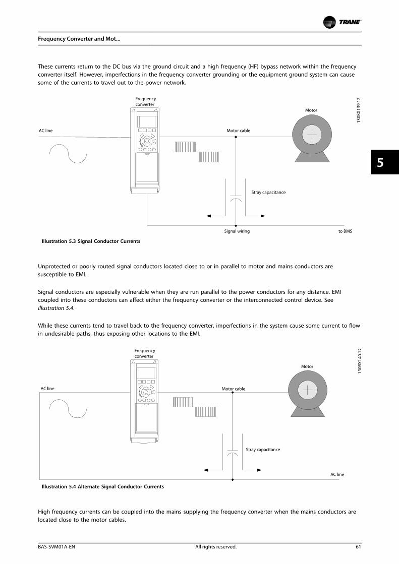
These currents return to the DC bus via the ground circuit and a high frequency (HF) bypass network within the frequencyconverter itself. However, imperfections in the frequency converter grounding or the equipment ground system can causesome of the currents to travel out to the power network.
Illustration 5.3 Signal Conductor Currents
Unprotected or poorly routed signal conductors located close to or in parallel to motor and mains conductors aresusceptible to EMI.
Signal conductors are especially vulnerable when they are run parallel to the power conductors for any distance. EMIcoupled into these conductors can affect either the frequency converter or the interconnected control device. SeeIllustration 5.4.
While these currents tend to travel back to the frequency converter, imperfections in the system cause some current to flowin undesirable paths, thus exposing other locations to the EMI.
Illustration 5.4 Alternate Signal Conductor Currents
High frequency currents can be coupled into the mains supplying the frequency converter when the mains conductors arelocated close to the motor cables.
Frequency Converter and Mot...
BAS-SVM01A-EN All rights reserved. 61
5 5
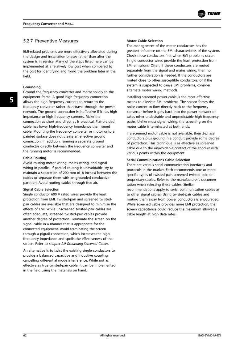
5.2.7 Preventive Measures
EMI-related problems are more effectively alleviated duringthe design and installation phases rather than after thesystem is in service. Many of the steps listed here can beimplemented at a relatively low cost when compared tothe cost for identifying and fixing the problem later in thefield.
GroundingGround the frequency converter and motor solidly to theequipment frame. A good high frequency connectionallows the high frequency currents to return to thefrequency converter rather than travel through the powernetwork. The ground connection is ineffective if it has highimpedance to high frequency currents. Make theconnection as short and direct as is practical. Flat-braidedcable has lower high-frequency impedance than roundcable. Mounting the frequency converter or motor onto apainted surface does not create an effective groundconnection. In addition, running a separate groundconductor directly between the frequency converter andthe running motor is recommended.
Cable RoutingAvoid routing motor wiring, mains wiring, and signalwiring in parallel. If parallel routing is unavoidable, try tomaintain a separation of 200 mm (6–8 inches) between thecables or separate them with an grounded conductivepartition. Avoid routing cables through free air.
Signal Cable SelectionSingle conductor 600 V rated wires provide the leastprotection from EMI. Twisted-pair and screened twisted-pair cables are available that are designed to minimise theeffects of EMI. While unscreened twisted-pair cables areoften adequate, screened twisted-pair cables provideanother degree of protection. Terminate the screen on thesignal cable in a manner that is appropriate for theconnected equipment. Avoid terminating the screenthrough a pigtail connection, which increases the highfrequency impedance and spoils the effectiveness of thescreen. Refer to chapter 2.9 Grounding Screened Cables.
An alternative is to twist the existing single conductors toprovide a balanced capacitive and inductive coupling,cancelling differential mode interference. While not aseffective as true twisted-pair cable, it can be implementedin the field using the materials on hand.
Motor Cable SelectionThe management of the motor conductors has thegreatest influence on the EMI characteristics of the system.Check these conductors first when EMI problems occur.Single conductor wires provide the least protection fromEMI emissions. Often, if these conductors are routedseparately from the signal and mains wiring, then nofurther consideration is needed. If the conductors arerouted close to other susceptible conductors, or if thesystem is suspected to cause EMI problems, consideralternate motor wiring methods.
Installing screened power cable is the most effectivemeans to alleviate EMI problems. The screen forces thenoise current to flow directly back to the frequencyconverter before it gets back into the power network ortakes other undesirable and unpredictable high frequencypaths. Unlike most signal wiring, the screening on themotor cable is terminated at both ends.
If a screened motor cable is not available, then 3-phaseconductors plus ground in a conduit provide some degreeof protection. This technique is as effective as screenedcable due to the unavoidable contact of the conduit withvarious points within the equipment.
Serial Communications Cable SelectionThere are various serial communication interfaces andprotocols in the market. Each recommends one or morespecific types of twisted-pair, screened twisted-pair, orproprietary cables. Refer to the manufacturer’s documen-tation when selecting these cables. Similarrecommendations apply to serial communication cables asto other signal cables. Using twisted-pair cables androuting them away from power conductors is encouraged.While screened cable provides more EMI protection, thescreen capacitance could reduce the maximum allowablecable length at high data rates.
Frequency Converter and Mot...
62 All rights reserved. BAS-SVM01A-EN
55
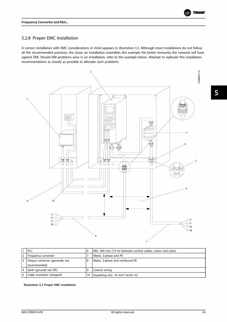
5.2.8 Proper EMC Installation
A correct installation with EMC considerations in mind appears in Illustration 5.5. Although most installations do not followall the recommended practices, the closer an installation resembles this example the better immunity the network will haveagainst EMI. Should EMI problems arise in an installation, refer to the example below. Attempt to replicate this installationrecommendation as closely as possible to alleviate such problems.
1 PLC 6 Min. 200 mm (7.9 in) between control cables, motor and mains
2 Frequency converter 7 Motor, 3-phase and PE
3 Output contactor (generally notrecommended)
8 Mains, 3-phase and reinforced PE
4 Earth (ground) rail (PE) 9 Control wiring
5 Cable insulation (stripped) 10 Equalizing min. 16 mm2 (0.025 in)
Illustration 5.5 Proper EMC Installation
Frequency Converter and Mot...
BAS-SVM01A-EN All rights reserved. 63
5 5
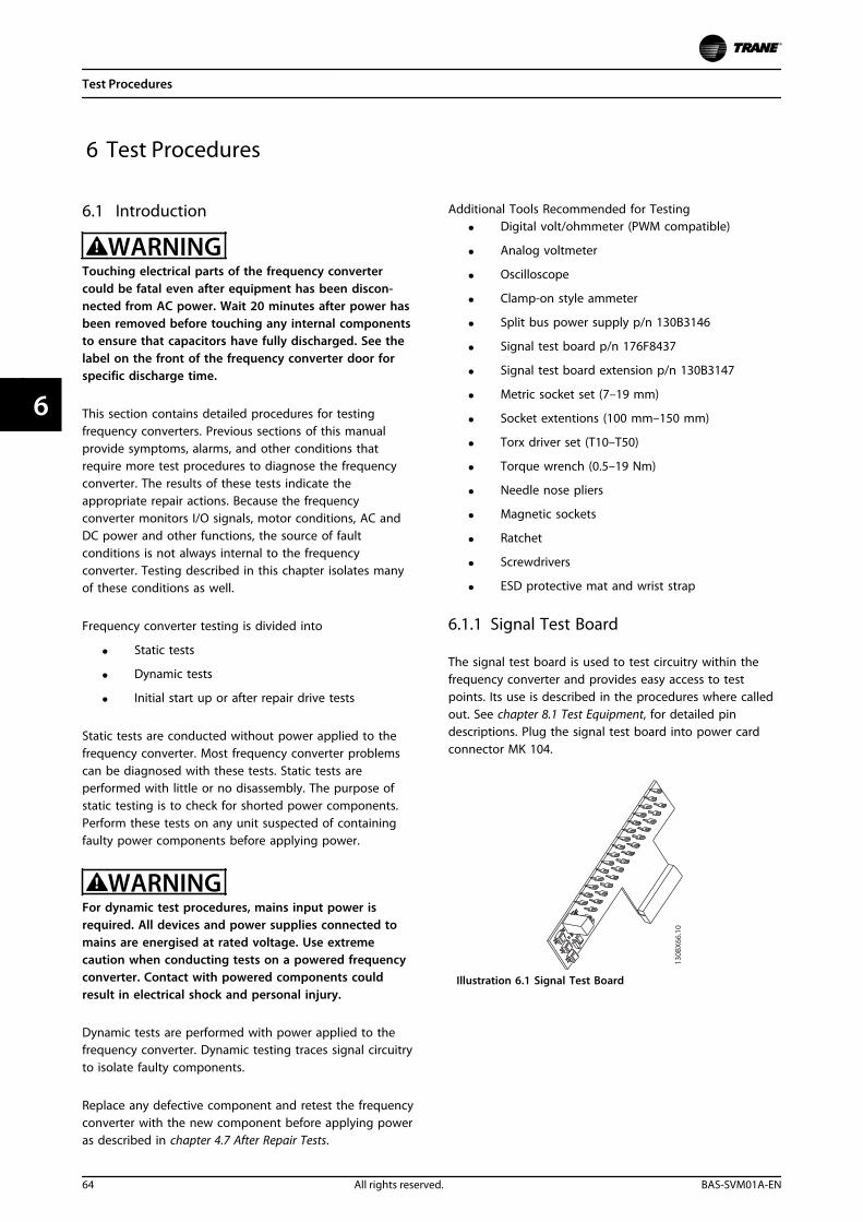
6 Test Procedures
6.1 Introduction
WARNINGTouching electrical parts of the frequency convertercould be fatal even after equipment has been discon-nected from AC power. Wait 20 minutes after power hasbeen removed before touching any internal componentsto ensure that capacitors have fully discharged. See thelabel on the front of the frequency converter door forspecific discharge time.
This section contains detailed procedures for testingfrequency converters. Previous sections of this manualprovide symptoms, alarms, and other conditions thatrequire more test procedures to diagnose the frequencyconverter. The results of these tests indicate theappropriate repair actions. Because the frequencyconverter monitors I/O signals, motor conditions, AC andDC power and other functions, the source of faultconditions is not always internal to the frequencyconverter. Testing described in this chapter isolates manyof these conditions as well.
Frequency converter testing is divided into
• Static tests
• Dynamic tests
• Initial start up or after repair drive tests
Static tests are conducted without power applied to thefrequency converter. Most frequency converter problemscan be diagnosed with these tests. Static tests areperformed with little or no disassembly. The purpose ofstatic testing is to check for shorted power components.Perform these tests on any unit suspected of containingfaulty power components before applying power.
WARNINGFor dynamic test procedures, mains input power isrequired. All devices and power supplies connected tomains are energised at rated voltage. Use extremecaution when conducting tests on a powered frequencyconverter. Contact with powered components couldresult in electrical shock and personal injury.
Dynamic tests are performed with power applied to thefrequency converter. Dynamic testing traces signal circuitryto isolate faulty components.
Replace any defective component and retest the frequencyconverter with the new component before applying poweras described in chapter 4.7 After Repair Tests.
Additional Tools Recommended for Testing
• Digital volt/ohmmeter (PWM compatible)
• Analog voltmeter
• Oscilloscope
• Clamp-on style ammeter
• Split bus power supply p/n 130B3146
• Signal test board p/n 176F8437
• Signal test board extension p/n 130B3147
• Metric socket set (7–19 mm)
• Socket extentions (100 mm–150 mm)
• Torx driver set (T10–T50)
• Torque wrench (0.5–19 Nm)
• Needle nose pliers
• Magnetic sockets
• Ratchet
• Screwdrivers
• ESD protective mat and wrist strap
6.1.1 Signal Test Board
The signal test board is used to test circuitry within thefrequency converter and provides easy access to testpoints. Its use is described in the procedures where calledout. See chapter 8.1 Test Equipment, for detailed pindescriptions. Plug the signal test board into power cardconnector MK 104.
130B
X66
.10
Illustration 6.1 Signal Test Board
Test Procedures
64 All rights reserved. BAS-SVM01A-EN
66
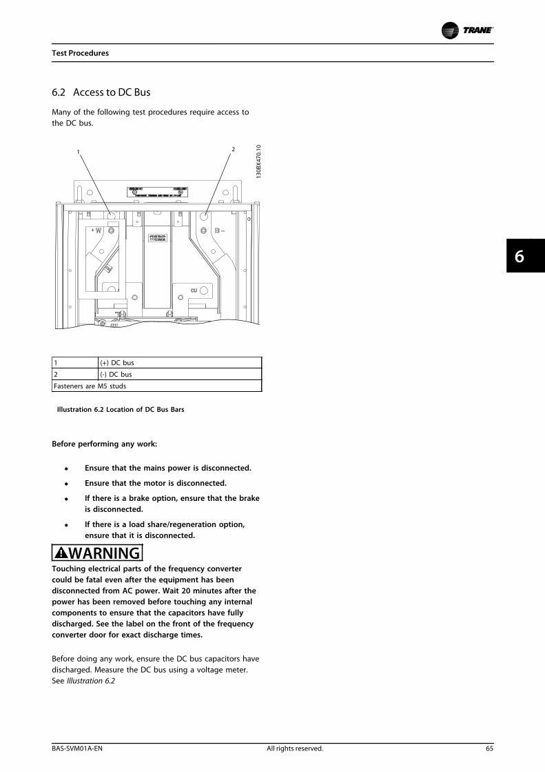
6.2 Access to DC Bus
Many of the following test procedures require access tothe DC bus.
1 (+) DC bus
2 (-) DC bus
Fasteners are M5 studs
Illustration 6.2 Location of DC Bus Bars
Before performing any work:
• Ensure that the mains power is disconnected.
• Ensure that the motor is disconnected.
• If there is a brake option, ensure that the brakeis disconnected.
• If there is a load share/regeneration option,ensure that it is disconnected.
WARNINGTouching electrical parts of the frequency convertercould be fatal even after the equipment has beendisconnected from AC power. Wait 20 minutes after thepower has been removed before touching any internalcomponents to ensure that the capacitors have fullydischarged. See the label on the front of the frequencyconverter door for exact discharge times.
Before doing any work, ensure the DC bus capacitors havedischarged. Measure the DC bus using a voltage meter.See Illustration 6.2
Test Procedures
BAS-SVM01A-EN All rights reserved. 65
6 6
6.3 Static Test Procedures
6.3.1 Pre-test Precautions
Consider the following safety precautions beforeperforming static tests.
• Prepare the work area according to the ESDregulations.
• Ground the ESD mat and wrist strap.
• Ensure that the ground connection betweenbody, the ESD mat, and the frequency converteris always present while performing service.
• Handle disassembled electronic parts with care.
• Perform the static test before powering up thefault unit.
• Perform static test after completing the repairand assembly of the frequency converter.
• Connect the frequency converter to the mainsonly after completion of static tests.
• Complete all necessary precautions for systemstartup, before applying power to frequencyconverter.
Perform all tests with a meter capable of testing diodes.Use a digital volt/ohmmeter (VOM) set on the diode scaleor an analog ohmmeter set on Rx100 scale. Before makingany checks, disconnect all input, motor and brake resistorconnections.
Illustration 6.3 is provided as a reference for finding theappropriate connectors described in the test procedures inthis section. Some connectors are optional and not on allfrequency converter configurations.
NOTICEFor best troubleshooting results, perform the static testprocedures described in this section in the orderpresented.
Diode DropA diode drop reading varies depending on the model ofohmmeter. Whatever the ohmmeter displays as a typicalforward bias diode is defined as a diode drop in theseprocedures. With a typical DVM, the voltage drop acrossmost components is around 0.300 to 0.500. The oppositereading is referred to as infinity and most display the valueOL for overload.
Test Procedures
66 All rights reserved. BAS-SVM01A-EN
66
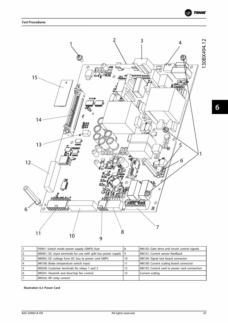
1 FK901: Switch mode power supply (SMPS) fuse 8 MK103: Gate drive and inrush control signals
2 MK901: DC input terminals for use with split bus power supply 9 MK101: Current sensor feedback
3 MK902: DC voltage from DC bus to power card SMPS 10 MK104: Signal test board connector
4 MK106: Brake temperature switch input 11 MK100: Current scaling board connector
5 MK500: Customer terminals for relays 1 and 2 12 MK102: Control card to power card connection
6 MK501: Heatsink and door/top fan control 13 Current scaling
7 MK502: RFI relay control
Illustration 6.3 Power Card
Test Procedures
BAS-SVM01A-EN All rights reserved. 67
6 6
6.3.2 Rectifier Circuits Test
Pay close attention to the polarity of the meter leads toidentify a faulty component if an incorrect readingappears.
NOTICEIf the unit has a circuit breaker, contactor, disconnect ormains fuse option, make test connections L1, L2, and L3to the output (drive) side of these devices.
Main rectifier circuit test part I1. Connect the positive (+) meter lead to the
positive (+) DC bus.
2. Connect the negative (–) meter lead to terminalsL1, L2, and L3 in sequence.
The correct reading is infinity. The meter starts at a lowvalue and slowly climbs towards infinity due to the metercharging capacitance within the frequency converter.
Incorrect readingWith the Part I test connection, the SCRs in the SCR/diodemodules are reverse biased so they are blocking currentflow. If a short circuit exists, the SCRs are shorted. Replacethe shorted SCR/diode module.
Main rectifier circuit test part II1. Reverse meter leads by connecting the negative
(–) meter lead to the positive (+) DC bus.
2. Connect the positive (+) meter lead to L1, L2, andL3 in sequence.
The correct reading is infinity.
Incorrect readingWith the Part II test connection, even though the SCRs inthe SCR/diode modules are forward biased by the meter,current does not flow through the SCRs without providinga signal to their gates.
A short circuit reading indicates either one or more of theSCRs are shorted in the SCR/diode module. Replace theshorted SCR/diode module.
Main rectifier circuit test part III1. Connect the positive (+) meter lead to the
negative (-) DC bus.
2. Connect the negative (-) meter lead to terminalsL1, L2, and L3 in sequence.
A diode drop indicates a correct reading.
Incorrect readingWith the Part III test connection, the diodes in the SCR/diode modules are forward biased. The meter reads thediode drops. If a short circuit exists, it would be possiblethat the SCR/diode modules are shorted. Replace theshorted SCR/diode module.
If an open reading occurs, replace the open SCR/diodemodule.
Main rectifier circuit test part IV1. Reverse meter leads by connecting the negative
(–) meter lead to the negative (-) DC bus.
2. Connect the positive (+) meter lead to L1, L2, andL3 in sequence.
Infinity is the correct reading. The meter starts at a lowvalue and slowly climbs toward infinity due to the metercharging capacitance within the frequency converter.
Incorrect readingWith the Part IV test connection, the diodes in the SCR/diode modules are reverse biased. If a short circuit exists,the diodes in the SCR/diode modules are shorted. Replacethe shorted SCR/diode module.
6.3.3 Inverter Section Tests
The inverter section is primarily made up of the IGBTs usedfor switching the DC bus voltage to create the output tothe motor. The IGBTs are grouped into module. Onemodule is used for each output phase.
CAUTIONDisconnect motor leads when testing the invertersection. With leads connected, a short circuit in onephase reads in all phases, making isolation difficult.
Before starting tests, ensure that the meter is set to diodescale.
Inverter test part I1. Connect the positive (+) meter lead to the (+)
positive DC bus.
2. Connect the negative (–) meter lead to terminalsU, V, and W in sequence.
Infinity is the correct reading. The meter starts at a lowvalue and slowly climbs toward infinity due to the metercharging capacitance within the frequency converter.
Inverter test part II1. Reverse the meter leads by connecting the
negative (-) meter lead to the positive (+) DC bus.
2. Connect the positive (+) meter lead to U, V, andW in sequence.
A diode drop indicates a correct reading.
Test Procedures
68 All rights reserved. BAS-SVM01A-EN
66
Inverter test part III1. Connect the positive (+) meter lead to the
negative (-) DC bus.
2. Connect the negative (-) meter lead to terminalsU, V, and W in sequence.
A diode drop indicates a correct reading.
Inverter test part IV1. Reverse the meter leads by connecting the
negative (-) meter lead to the negative (-) DC bus.
2. Connect the positive (+) meter lead to U, V, andW in sequence.
Infinitiy is a correct reading. The meter starts at a lowvalue and slowly climb toward infinity due to the metercharging capacitance within the frequency converter.
Incorrect readingAn incorrect reading in any inverter test indicates a failedIGBT module. Replace the IGBT module according to chapter 7 Disassembly and Assembly Instructions. Followingan IGBT failure, it is important to verify that the gate drivesignals are present and the wave form is correct. Seechapter 6.4.11 IGBT Gate Drive Signals Test.
6.3.4 Brake IGBT Test
This test can only be carried out on units equipped with adynamic brake option. If a brake resistor is connected toterminals R-(81) and R+(82), disconnect it beforeproceeding. Use an ohmmeter set on diode check orRx100 scale.
Brake IGBT test part I1. Connect the positive (+) meter lead to the brake
resistor terminal 82 (R+).
2. Connect the negative (-) meter lead to the brakeresistor terminal 81 (R-).
Infinity is a correct reading. The meter may start out at avalue and climb toward infinity as capacitance is chargedwithin the frequency converter.
Brake IGBT test part II1. Connect the positive (+) meter lead to the brake
resistor terminal 81 (R-).
2. Connect the negative (-) meter lead to the brakeresistor terminal 82 (R+).
A diode drop indicates a correct reading.
Brake IGBT test part III1. Connect the positive (+) meter lead to the brake
resistor terminal 81 (R-).
2. Connect the negative (-) meter lead to thenegative (-) DC bus.
Infinity is a correct reading. The meter may start out at avalue and climb toward infinity as capacitance is chargedwithin the frequency converter.
Brake IGBT test part IV1. Connect the negative (-) meter lead to the brake
resistor 81 (R-)
2. Connect the positive (+) meter lead to thenegative (-) DC bus.
A diode drop indicates a correct reading.
Incorrect readingAn incorrect reading on any of these tests indicates thatthe brake IGBT is defective. Replace the brake IGBTmodule.
6.3.5 Intermediate Section Tests
The intermediate section of the frequency converter ismade up of the DC bus capacitors, the DC coils, and thebalance circuit for the capacitors.
1. Test for short circuits with the ohmmeter set onRx100 scale or, for a digital meter, select diode.
2. Connect the positive (+) meter lead to the (+) DCand the negative (-) meter lead to the negative (-)DC.
3. The meter starts out with low ohms and thenmove towards infinity as the meter charges thecapacitors.
4. Reverse the meter leads such that the (-) meterlead is connected to the positive (+) DC and thepositive (+) meter lead is connected to thenegative (-) DC.
5. The meter pegs at zero while the meterdischarges the capacitors. The meter then beginsmoving slowly toward two diode drops as themeter charges the capacitors in the reversedirection. Although the test does not ensure thatthe capacitors are fully functional, it ensures thatno short circuits exist in the intermediate circuit.
Incorrect readingA short in the rectifier or inverter section could cause ashort circuit. Be sure that the tests for these circuits havealready been performed successfully. A failure in one ofthese sections could be read in the intermediate sectionsince they are all routed via the DC bus.
Test Procedures
BAS-SVM01A-EN All rights reserved. 69
6 6
If a short circuit is present, and the unit is equipped with abrake, perform the brake IGBT test next.
The only other likely cause for failure would be a defectivecapacitor.
There is not an effective test of the capacitor bank when itis fully assembled. It is unlikely that a physically damagedcapacitor would indicate a failure within the capacitorbank. If a failure is suspected, all the capacitors must bereplaced. Replace the capacitors in accordance with chapter 7 Disassembly and Assembly Instructions.
Further static tests could require some disassembly. See chapter 7 Disassembly and Assembly Instructions
6.3.6 IGBT Temperature Sensor Test
The temperature sensor is an NTC (negative temperaturecoefficient) device. As a result, high resistance means lowtemperature. As the temperature increases, resistancedecreases. Each IGBT module has a temperature sensormounted internally. The sensor is wired from each IGBTmodule to the gate drive card connector MK100.
On the gate drive card, the resistance signal is convertedto a frequency signal. The frequency signal is sent to thepower card for processing. The temperature data is used toregulate fan speed and to monitor for over and undertemperature conditions. There are 3 sensors, one in eachIGBT module.
1. Use ohmmeter set to read ohms.
2. Unplug connector MK100 on the gate drive card(see Illustration 6.9) and measure the resistanceacross each black and white pair.
The relationship between temperature and resistance isnonlinear. At 25 °C, the resistance is approximately 5kOhms. At 0 °C, the resistance is approximately 13.7 kΩ. At60 °C, the resistance is approximately 1.5 kΩ. The higherthe temperature, the lower the resistance.
6.3.7 Gate Resistor Test
Mounted to each IGBT module is an IGBT gate resistorboard containing gate resistors for the IGBT transistors. Insome cases, a defective IGBT can still produce goodreadings in the previous tests. In most cases, an IGBTfailure results in the failure of the gate resistors, so thegate resistor test can identify an IGBT failure.
Remove the AC input bus bars or RFI filter (depending onoptions) if necessary to access the gate drive card. See chapter 7 Disassembly and Assembly Instructions fordisassembly instructions.
A 3-pin test connector is on the gate drive card near eachgate signal lead. These leads are labelled MK500, MK502,MK600, MK602, MK700, MK702, and, if the frequencyconverter is equipped with a brake option, MK200. SeeIllustration 6.9
For the sake of clarity, refer to the 3 pins as one, two, andthree, reading bottom to top. Pins 1 and 2 of eachconnector are in parallel with the gate drive signal sent tothe IGBTs. Pin 1 is the signal and pin 2 is common.
With an ohmmeter, measure pins 1 and 2 of each testconnector. The reading should be the same for each testconnector.
Incorrect ReadingAn incorrect reading indicates either that the gate signalwires are not connected from the gate drive card to thegate resistor board, or that the gate resistors are defective.Connect the gate signal wires if needed. If the resistors aredefective, replace the entire IGBT module assembly. See chapter 7 Disassembly and Assembly Instructions fordisassembly and assembly information.
6.3.8 Mains Fuse Test
Optional mains fuses can be located in one of two places.In most cases, they are in the main enclosure. When anoptional contactor and disconnect are both present, themains fuses are located in the options cabinet betweenthese two components.For the mains fuse test:
1. Use an ohmmeter set to measure the ohms.
2. Measure the resistance across each fuse. A shortcircuit indicates good continuity. An open circuitmeans that the fuse needs to be replaced.
Perform the additional static checks before replacing thefuse.
6.3.9 Disconnect Test
The mains disconnect switch is optional. If present, it islocated in the options cabinet.For the mains disconnect test:
1. Use an ohmmeter set to read ohms.
2. Open the disconnect switch.
3. Measure the resistance across each of the threephases.
An open circuit (infinite resistance) is a correct reading. Ashort circuit (0 Ω) indicates a problem with the switch.
Test Procedures
70 All rights reserved. BAS-SVM01A-EN
66
1. Close the disconnect switch.
2. Measure the resistance across each of the threephases.
A short circuit (0 Ω) is a correct reading. An open circuit(infinite resistance) or high resistance reading indicates aproblem with the switch. Replace the disconnect switch.
6.3.10 Circuit Breaker Test
The circuit breaker is optional. If present, it is located inthe option cabinet.
1. Use an ohmmeter set to read Ohms.
2. Open the circuit breaker
3. Measure the resistance across each of threephases.
An open circuit (infinite resistance) is a correct reading. Ashort circuit (0 Ω) indicates a problem with the circuitbreaker.
1. Close the circuit breaker
2. Measure the resistance across each of the threephases.
A short circuit (0 Ω) is a correct reading. An open circuit(infinite resistance), or high resistance reading indicates aproblem with the circuit breaker.If there is a problem with any of the phases, replace thecircuit breaker.
6.3.11 Contactor Test
The contactor is optional. If present, it is located in theoption cabinet. The contactor uses a customer-supplied230 V AC control signal wired to the contactor coil. Whenpower is applied to the contactor coil, the contactor isclosed. When there is no power, the contact is open.
NOTICEComplete testing of the contactor requires an external230 V AC power supply.
Contactor Test part I1. Remove power to the contactor coil.
2. Use an ohmmeter to measure across each of thethree phases.
An open circuit (infinite resistance) is a correct reading. Ashort circuit (0 Ω) indicates a problem with the contactor.
Contactor Test part II1. Manually engage the contactor
2. With the contactor engaged, measure theresistance across each of the three phases.
A short circuit (0 Ω) is the proper reading. An open circuit(infinite resistance) or high resistance reading indicates aproblem with the contactor.
Contactor Coil Test
NOTICE230 V AC power is required to test the contactor coil
1. Apply power to the coil to energise thecontactor.
2. Use a voltmeter set to measure AC voltagebetween A1 and A2 on TB6.
3. Measure the resistance across each of the threephrases.
When power is applied, the contactor energises and isengaged. A short circuit (0 Ω) is a correct reading. An opencircuit (infinite resistance) or high resistance readingindicates a problem with the contactor.
If there is a problem with any of the phases, replace thecontactor.
Test Procedures
BAS-SVM01A-EN All rights reserved. 71
6 6
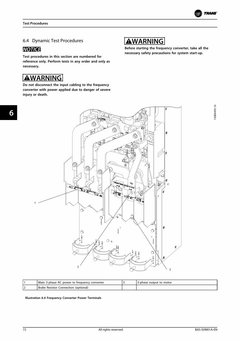
6.4 Dynamic Test Procedures
NOTICETest procedures in this section are numbered forreference only. Perform tests in any order and only asnecessary.
WARNINGDo not disconnect the input cabling to the frequencyconverter with power applied due to danger of severeinjury or death.
WARNINGBefore starting the frequency converter, take all thenecessary safety precautions for system start-up.
1 Main 3-phase AC power to frequency converter 3 3-phase output to motor
2 Brake Resistor Connection (optional)
Illustration 6.4 Frequency Converter Power Terminals
Test Procedures
72 All rights reserved. BAS-SVM01A-EN
66
Whenever possible, perform these procedures with a splitbus power supply. For more information, seechapter 8.1.1 Split Bus Power Supply.
NOTICEAlways perform static tests (chapter 6.3 Static TestProcedures) before applying power to the unit.
6.4.1 No Display Test
A frequency converter with no display can be the result ofseveral causes. Verify first that there is no display.
If the LCD display is dark and the green power-on LED isnot lit, proceed with the following tests.
6.4.2 Input Voltage Test
If the frequency converter is equipped with optionalequipment, ensure that it is functioning properly. Seechapter 6.3.9 Disconnect Test, chapter 6.3.8 Mains Fuse Test,chapter 6.3.11 Contactor Test, and chapter 6.3.10 CircuitBreaker Test for more information.
1. Apply power to frequency converter.
2. Use the voltmeter to measure the input mainsvoltage between the frequency converter inputterminals in sequence:L1 to L2L1 to L3L2 to L3
For 380–480 V/380-500 V frequency converters, allmeasurements must be within the range of 342–550 V AC.Readings of less than 342 V AC indicate problems with theinput mains voltage. For 525–690 V frequency converters,all measurements must be within the range of 446–759 VAC. Readings of less than 446 V AC indicate problems withthe input mains voltage.
In addition to the actual voltage reading, the balance ofthe voltage between the phases is also important. Thefrequency converter can operate within specifications aslong as the imbalance of supply voltage is not more than3%.
Trane calculates mains imbalance per an IEC specification.
• Imbalance = 0.67 X (Vmax – Vmin)/Vavg
For example, if three-phase readings were taken and theresults were 500 V AC, 478.5 V AC, and 478.5 V AC; then500 V AC is Vmax, 478.5 V AC is Vmin, and 485.7 V AC is Vavg,resulting in an imbalance of 3%.
Although the frequency converter can operate at highermains imbalances, this will shorten the lifetime of somecomponents, such as DC bus capacitors.
Incorrect reading
An incorrect reading here requires further investigation ofthe main supply. Typical items to check would be:
• Open (blown) input fuses or tripped circuitbreakers
• Open disconnects or line side contactors
• Problems with the power distribution system
CAUTIONOpen (blown) input fuses or tripped circuit breakersusually indicate a more serious problem. Beforereplacing fuses or resetting breakers, perform static testsdescribed in chapter 6.3 Static Test Procedures.
If the input voltage test was successful, check for voltageto the control card.
6.4.3 Basic Control Card Voltage Test
1. Measure the control voltage at terminal 12regarding terminal 20. A correct reading is 24 VDC (21–27 V DC).
An incorrect reading here could indicate that a fault in thecustomer connections is loading down the supply. Unplugthe terminal strip and repeat the test. If this test issuccessful, continue. Remember to check the customerconnections.
2. Measure the 10 V DC control voltage atterminal 50 regarding terminal 55. A correctreading is 10 V DC (9.2–11.2 V DC).
An incorrect reading here could indicate that a fault in thecustomer connections is loading down the supply. Unplugthe terminal strip and repeat the test. If this test issuccessful, continue. Remember to check the customerconnections.
A correct reading of both control card voltages wouldindicate that the LCP or the control card is defective.Replace the LCP with a known good one. If the problempersists, replace the control card in accordance with thedisassembly instructions.
Test Procedures
BAS-SVM01A-EN All rights reserved. 73
6 6
6.4.4 DC Bus Voltage Test
DC bus voltage test part I1. Using a voltmeter, read the DC bus voltage. See
chapter 6.2.1 Access to DC Bus for DC bus location.
The measured voltage should be at least 1.35 x the ACinput voltage.An incorrect reading could indicate a problem in theinrush circuit, or with the rectifier. See chapter 6.4.8 InputSCR Test.
DC bus voltage test part II1. Power down the frequency converter.
2. Wait for the DC bus to discharge.
3. Remove the control card mounting plate. Seechapter 7.3.2 Control Card and Control CardMounting Plate or chapter 7.4.2 Control Card andControl Card Mounting Plate.
4. Use an ohmmeter set to measure ohms.
5. Measure from (+) DC bus to power card MK902,pin 1.
6. Measure from (-) DC bus to power card MK902,pin 2.
A short circuit (0 ohms) is the correct reading.An incorrect reading indicates a bad connection betweenthe DC bus and the power card. Replace the wire harness.
DC bus voltage test part III• Measure across fuse F901 on the top of the
power card.
An open fuse indicates a failure of the power supplies onthe power card. Replace the power card.
6.4.5 Switch Mode Power Supply (SMPS)Test
The SMPS derives its power from the DC bus. The firstindication that the DC bus is charged is the DC bus chargeindicator light on the power card being lit. This LED,however, can be lit at a voltage still too low to enable thepower supplies.
First test for the presence of the DC bus.
1. Install the signal test board (with extension).
2. Install the split bus power supply. Power thepower card using split bus mode.chapter 8.1.1 Split Bus Power Supply.
3. Connect the negative (-) meter lead to terminal 4(common) of the signal board. With a positive (+)meter lead, check the following terminals on thesignal board.
Terminal Supply Voltage Range
11 (+)18 V 16.5–19.5 V DC
12 (-)18 V (-)16.5–-19.5 V DC
23 (+) 24 V 23–25 V DC
24 (+) 5 V 4.75–5.25 V DC
Table 6.1 Measured Voltages at Select Terminals
In addition, the signal test board contains three LEDindicators that indicate the presence of voltage as follows:
• Red LED (±)18 V DC supplies present
• Yellow LED (+)24 V DC supply present
• Green LED (+)5 V DC supply present
The lack of any one of these power supplies indicates thatthe low voltage supplies on the power card are defective.Replace the power card in accordance with thedisassembly procedures in chapter 7 Disassembly andAssembly Instructions.
6.4.6 Input Imbalance of Supply VoltageTest
All three phases should have an equal current draw. Someimbalance is possible, however, due to variations in thephase to phase input voltage.
A current measurement of each phase reveals thebalanced condition of the line. To obtain an accuratereading, it is necessary for the frequency converter to runat more than 40% of its rated load.
1. Perform the input voltage test before checkingthe current, in accordance with chapter 6.4.2 InputVoltage Test. Voltage imbalances automaticallyresult in a corresponding current imbalance.
2. Apply power to the frequency converter andplace it in run mode.
3. Using a clamp-on amp meter (analog preferred),read the current on each of three input lines atL1(R), L2(S), and L3(T). Typically, the current doesnot vary from phase to phase by more than 5%.If a greater current variation exists, it indicates apossible problem with the mains supply to thefrequency converter or a problem within thefrequency converter itself.One way to determine if the mains supply is atfault is to swap two of the incoming phases. If allthree phases are different from one another,swap the phase with the highest current with thephase with the lowest current.
4. Remove power to frequency converter.
5. Swap the phase.
Test Procedures
74 All rights reserved. BAS-SVM01A-EN
66
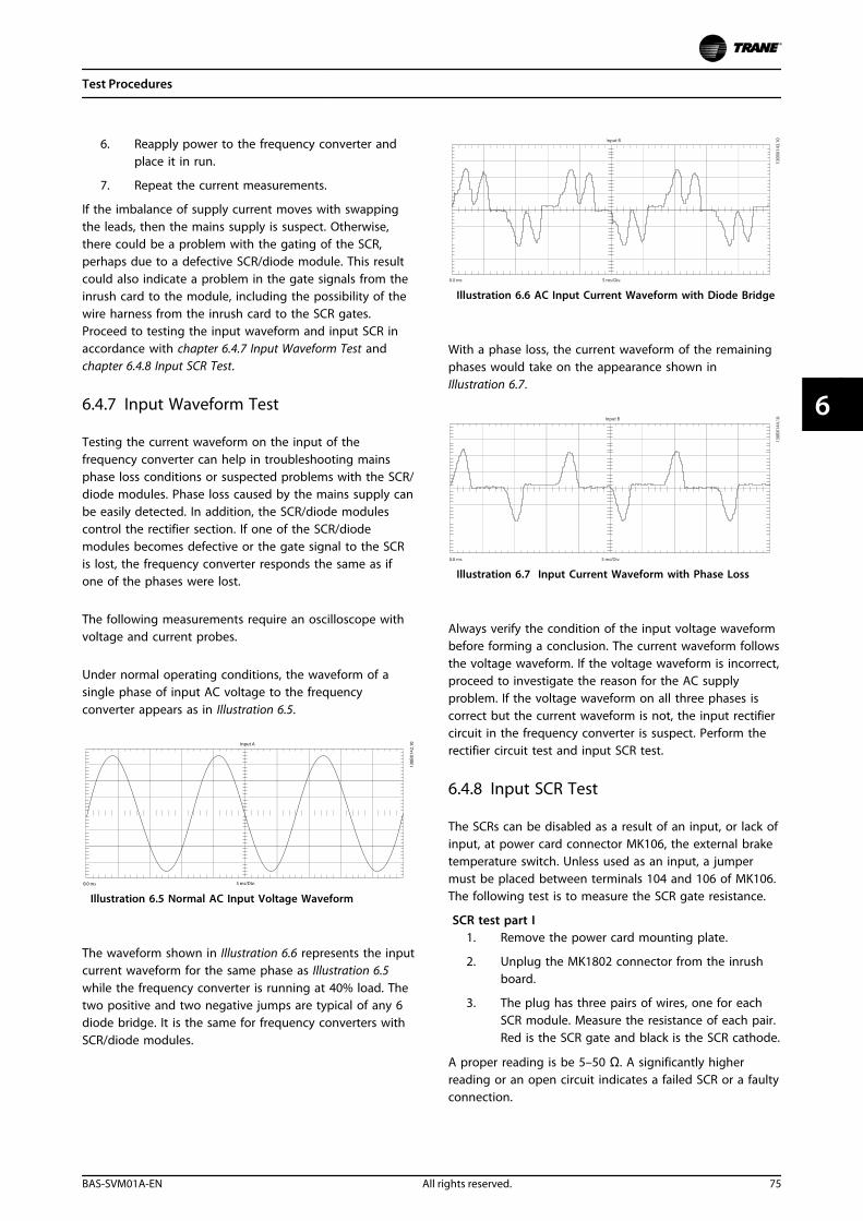
6. Reapply power to the frequency converter andplace it in run.
7. Repeat the current measurements.
If the imbalance of supply current moves with swappingthe leads, then the mains supply is suspect. Otherwise,there could be a problem with the gating of the SCR,perhaps due to a defective SCR/diode module. This resultcould also indicate a problem in the gate signals from theinrush card to the module, including the possibility of thewire harness from the inrush card to the SCR gates.Proceed to testing the input waveform and input SCR inaccordance with chapter 6.4.7 Input Waveform Test andchapter 6.4.8 Input SCR Test.
6.4.7 Input Waveform Test
Testing the current waveform on the input of thefrequency converter can help in troubleshooting mainsphase loss conditions or suspected problems with the SCR/diode modules. Phase loss caused by the mains supply canbe easily detected. In addition, the SCR/diode modulescontrol the rectifier section. If one of the SCR/diodemodules becomes defective or the gate signal to the SCRis lost, the frequency converter responds the same as ifone of the phases were lost.
The following measurements require an oscilloscope withvoltage and current probes.
Under normal operating conditions, the waveform of asingle phase of input AC voltage to the frequencyconverter appears as in Illustration 6.5.
Illustration 6.5 Normal AC Input Voltage Waveform
The waveform shown in Illustration 6.6 represents the inputcurrent waveform for the same phase as Illustration 6.5while the frequency converter is running at 40% load. Thetwo positive and two negative jumps are typical of any 6diode bridge. It is the same for frequency converters withSCR/diode modules.
Illustration 6.6 AC Input Current Waveform with Diode Bridge
With a phase loss, the current waveform of the remainingphases would take on the appearance shown inIllustration 6.7.
Illustration 6.7 Input Current Waveform with Phase Loss
Always verify the condition of the input voltage waveformbefore forming a conclusion. The current waveform followsthe voltage waveform. If the voltage waveform is incorrect,proceed to investigate the reason for the AC supplyproblem. If the voltage waveform on all three phases iscorrect but the current waveform is not, the input rectifiercircuit in the frequency converter is suspect. Perform therectifier circuit test and input SCR test.
6.4.8 Input SCR Test
The SCRs can be disabled as a result of an input, or lack ofinput, at power card connector MK106, the external braketemperature switch. Unless used as an input, a jumpermust be placed between terminals 104 and 106 of MK106.The following test is to measure the SCR gate resistance.
SCR test part I1. Remove the power card mounting plate.
2. Unplug the MK1802 connector from the inrushboard.
3. The plug has three pairs of wires, one for eachSCR module. Measure the resistance of each pair.Red is the SCR gate and black is the SCR cathode.
A proper reading is be 5–50 Ω. A significantly higherreading or an open circuit indicates a failed SCR or a faultyconnection.
Test Procedures
BAS-SVM01A-EN All rights reserved. 75
6 6
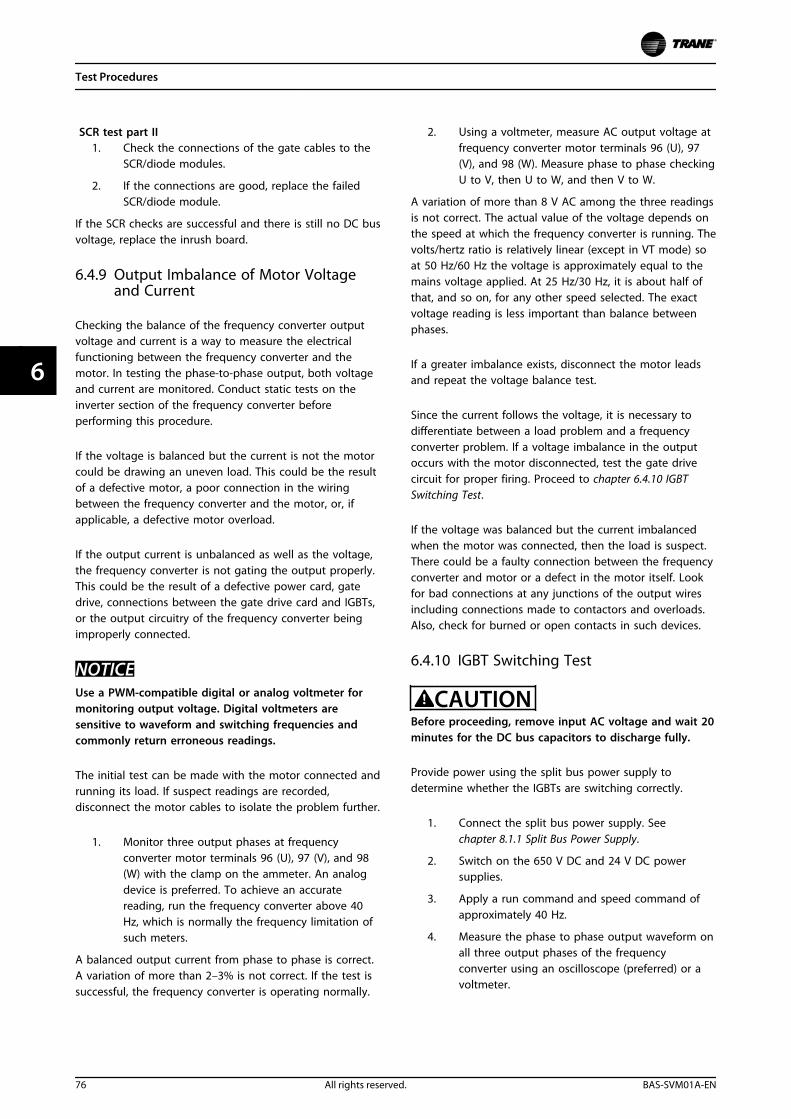
SCR test part II1. Check the connections of the gate cables to the
SCR/diode modules.
2. If the connections are good, replace the failedSCR/diode module.
If the SCR checks are successful and there is still no DC busvoltage, replace the inrush board.
6.4.9 Output Imbalance of Motor Voltageand Current
Checking the balance of the frequency converter outputvoltage and current is a way to measure the electricalfunctioning between the frequency converter and themotor. In testing the phase-to-phase output, both voltageand current are monitored. Conduct static tests on theinverter section of the frequency converter beforeperforming this procedure.
If the voltage is balanced but the current is not the motorcould be drawing an uneven load. This could be the resultof a defective motor, a poor connection in the wiringbetween the frequency converter and the motor, or, ifapplicable, a defective motor overload.
If the output current is unbalanced as well as the voltage,the frequency converter is not gating the output properly.This could be the result of a defective power card, gatedrive, connections between the gate drive card and IGBTs,or the output circuitry of the frequency converter beingimproperly connected.
NOTICEUse a PWM-compatible digital or analog voltmeter formonitoring output voltage. Digital voltmeters aresensitive to waveform and switching frequencies andcommonly return erroneous readings.
The initial test can be made with the motor connected andrunning its load. If suspect readings are recorded,disconnect the motor cables to isolate the problem further.
1. Monitor three output phases at frequencyconverter motor terminals 96 (U), 97 (V), and 98(W) with the clamp on the ammeter. An analogdevice is preferred. To achieve an accuratereading, run the frequency converter above 40Hz, which is normally the frequency limitation ofsuch meters.
A balanced output current from phase to phase is correct.A variation of more than 2–3% is not correct. If the test issuccessful, the frequency converter is operating normally.
2. Using a voltmeter, measure AC output voltage atfrequency converter motor terminals 96 (U), 97(V), and 98 (W). Measure phase to phase checkingU to V, then U to W, and then V to W.
A variation of more than 8 V AC among the three readingsis not correct. The actual value of the voltage depends onthe speed at which the frequency converter is running. Thevolts/hertz ratio is relatively linear (except in VT mode) soat 50 Hz/60 Hz the voltage is approximately equal to themains voltage applied. At 25 Hz/30 Hz, it is about half ofthat, and so on, for any other speed selected. The exactvoltage reading is less important than balance betweenphases.
If a greater imbalance exists, disconnect the motor leadsand repeat the voltage balance test.
Since the current follows the voltage, it is necessary todifferentiate between a load problem and a frequencyconverter problem. If a voltage imbalance in the outputoccurs with the motor disconnected, test the gate drivecircuit for proper firing. Proceed to chapter 6.4.10 IGBTSwitching Test.
If the voltage was balanced but the current imbalancedwhen the motor was connected, then the load is suspect.There could be a faulty connection between the frequencyconverter and motor or a defect in the motor itself. Lookfor bad connections at any junctions of the output wiresincluding connections made to contactors and overloads.Also, check for burned or open contacts in such devices.
6.4.10 IGBT Switching Test
CAUTIONBefore proceeding, remove input AC voltage and wait 20minutes for the DC bus capacitors to discharge fully.
Provide power using the split bus power supply todetermine whether the IGBTs are switching correctly.
1. Connect the split bus power supply. Seechapter 8.1.1 Split Bus Power Supply.
2. Switch on the 650 V DC and 24 V DC powersupplies.
3. Apply a run command and speed command ofapproximately 40 Hz.
4. Measure the phase to phase output waveform onall three output phases of the frequencyconverter using an oscilloscope (preferred) or avoltmeter.
Test Procedures
76 All rights reserved. BAS-SVM01A-EN
66
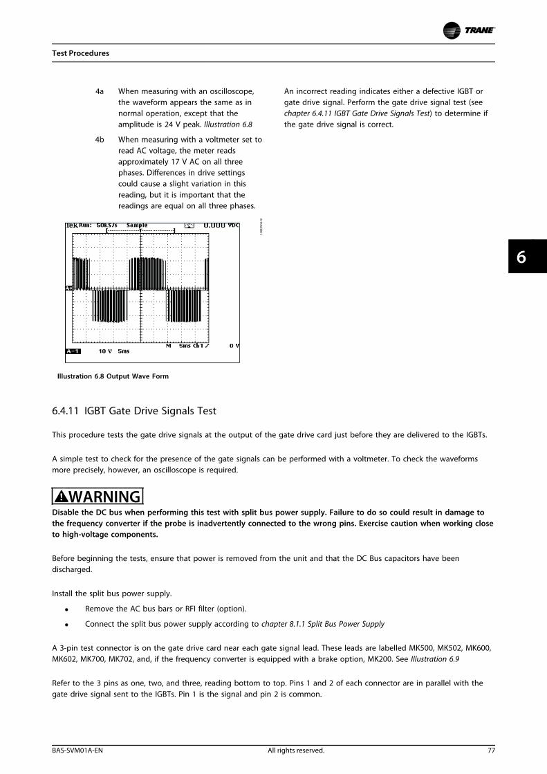
4a When measuring with an oscilloscope,the waveform appears the same as innormal operation, except that theamplitude is 24 V peak. Illustration 6.8
4b When measuring with a voltmeter set toread AC voltage, the meter readsapproximately 17 V AC on all threephases. Differences in drive settingscould cause a slight variation in thisreading, but it is important that thereadings are equal on all three phases.
Illustration 6.8 Output Wave Form
An incorrect reading indicates either a defective IGBT orgate drive signal. Perform the gate drive signal test (seechapter 6.4.11 IGBT Gate Drive Signals Test) to determine ifthe gate drive signal is correct.
6.4.11 IGBT Gate Drive Signals Test
This procedure tests the gate drive signals at the output of the gate drive card just before they are delivered to the IGBTs.
A simple test to check for the presence of the gate signals can be performed with a voltmeter. To check the waveformsmore precisely, however, an oscilloscope is required.
WARNINGDisable the DC bus when performing this test with split bus power supply. Failure to do so could result in damage tothe frequency converter if the probe is inadvertently connected to the wrong pins. Exercise caution when working closeto high-voltage components.
Before beginning the tests, ensure that power is removed from the unit and that the DC Bus capacitors have beendischarged.
Install the split bus power supply.
• Remove the AC bus bars or RFI filter (option).
• Connect the split bus power supply according to chapter 8.1.1 Split Bus Power Supply
A 3-pin test connector is on the gate drive card near each gate signal lead. These leads are labelled MK500, MK502, MK600,MK602, MK700, MK702, and, if the frequency converter is equipped with a brake option, MK200. See Illustration 6.9
Refer to the 3 pins as one, two, and three, reading bottom to top. Pins 1 and 2 of each connector are in parallel with thegate drive signal sent to the IGBTs. Pin 1 is the signal and pin 2 is common.
Test Procedures
BAS-SVM01A-EN All rights reserved. 77
6 6
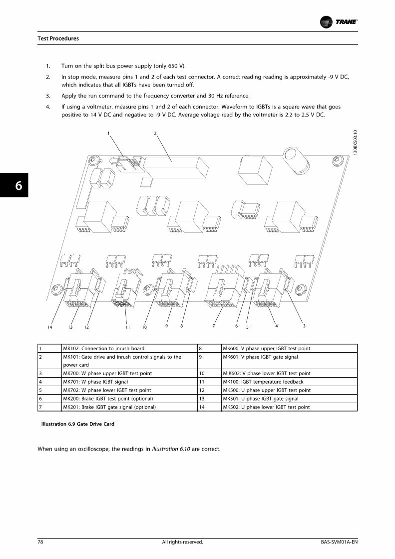
1. Turn on the split bus power supply (only 650 V).
2. In stop mode, measure pins 1 and 2 of each test connector. A correct reading reading is approximately -9 V DC,which indicates that all IGBTs have been turned off.
3. Apply the run command to the frequency converter and 30 Hz reference.
4. If using a voltmeter, measure pins 1 and 2 of each connector. Waveform to IGBTs is a square wave that goespositive to 14 V DC and negative to -9 V DC. Average voltage read by the voltmeter is 2.2 to 2.5 V DC.
1 MK102: Connection to inrush board 8 MK600: V phase upper IGBT test point
2 MK101: Gate drive and inrush control signals to thepower card
9 MK601: V phase IGBT gate signal
3 MK700: W phase upper IGBT test point 10 MIK602: V phase lower IGBT test point
4 MK701: W phase IGBT signal 11 MK100: IGBT temperature feedback
5 MK702: W phase lower IGBT test point 12 MK500: U phase upper IGBT test point
6 MK200: Brake IGBT test point (optional) 13 MK501: U phase IGBT gate signal
7 MK201: Brake IGBT gate signal (optional) 14 MK502: U phase lower IGBT test point
Illustration 6.9 Gate Drive Card
When using an oscilloscope, the readings in Illustration 6.10 are correct.
Test Procedures
78 All rights reserved. BAS-SVM01A-EN
66
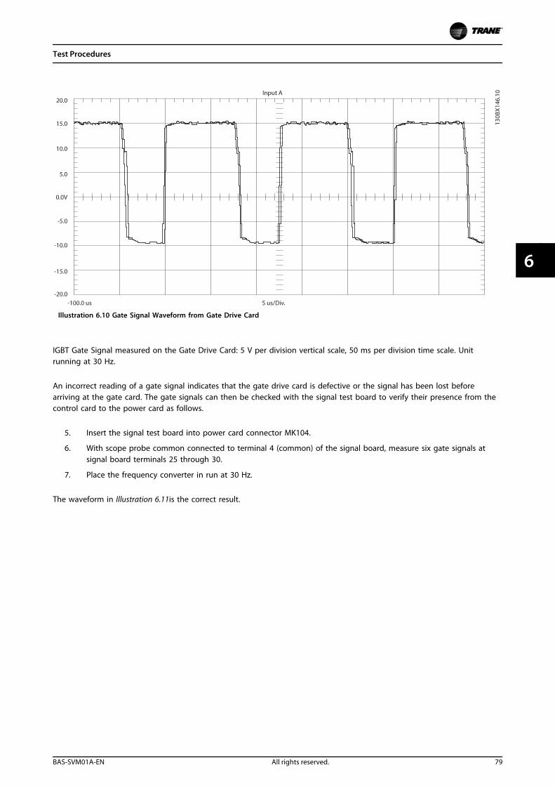
Illustration 6.10 Gate Signal Waveform from Gate Drive Card
IGBT Gate Signal measured on the Gate Drive Card: 5 V per division vertical scale, 50 ms per division time scale. Unitrunning at 30 Hz.
An incorrect reading of a gate signal indicates that the gate drive card is defective or the signal has been lost beforearriving at the gate card. The gate signals can then be checked with the signal test board to verify their presence from thecontrol card to the power card as follows.
5. Insert the signal test board into power card connector MK104.
6. With scope probe common connected to terminal 4 (common) of the signal board, measure six gate signals atsignal board terminals 25 through 30.
7. Place the frequency converter in run at 30 Hz.
The waveform in Illustration 6.11is the correct result.
Test Procedures
BAS-SVM01A-EN All rights reserved. 79
6 6
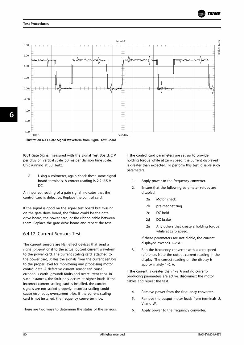
Illustration 6.11 Gate Signal Waveform from Signal Test Board
IGBT Gate Signal measured with the Signal Test Board: 2 Vper division vertical scale, 50 ms per division time scale.Unit running at 30 Hertz.
8. Using a voltmeter, again check these same signalboard terminals. A correct reading is 2.2–2.5 VDC.
An incorrect reading of a gate signal indicates that thecontrol card is defective. Replace the control card.
If the signal is good on the signal test board but missingon the gate drive board, the failure could be the gatedrive board, the power card, or the ribbon cable betweenthem. Replace the gate drive board and repeat the test.
6.4.12 Current Sensors Test
The current sensors are Hall effect devices that send asignal proportional to the actual output current waveformto the power card. The current scaling card, attached tothe power card, scales the signals from the current sensorsto the proper level for monitoring and processing motorcontrol data. A defective current sensor can causeerroneous earth (ground) faults and overcurrent trips. Insuch instances, the fault only occurs at higher loads. If theincorrect current scaling card is installed, the currentsignals are not scaled properly. Incorrect scaling couldcause erroneous overcurrent trips. If the current scalingcard is not installed, the frequency converter trips.
There are two ways to determine the status of the sensors.
If the control card parameters are set up to provideholding torque while at zero speed, the current displayedis greater than expected. To perform this test, disable suchparameters.
1. Apply power to the frequency converter.
2. Ensure that the following parameter setups aredisabled:
2a Motor check
2b pre-magnetizing
2c DC hold
2d DC brake
2e Any others that create a holding torquewhile at zero speed.
If these parameters are not diable, the currentdisplayed exceeds 1–2 A.
3. Run the frequency converter with a zero speedreference. Note the output current reading in thedisplay. The correct reading on the display isapproximately 1–2 A.
If the current is greater than 1–2 A and no current-producing parameters are active, disconnect the motorcables and repeat the test.
4. Remove power from the frequency converter.
5. Remove the output motor leads from terminals U,V, and W.
6. Apply power to the frequency converter.
Test Procedures
80 All rights reserved. BAS-SVM01A-EN
66
7. Run the frequency converter with a zero speedreference. Note the output current reading in thedisplay. A correct reading is less than 1 A.
If an incorrect reading was obtained from these tests,further tests of the current feedback signals are requiredusing the signal test board.
To test current feedback with the signal test board.
8. Remove power to the frequency converter. Makesure the DC bus is fully discharged.
9. Install the signal test board into power cardconnector MK104.
10. Using an ohmmeter, measure the resistancebetween terminals 1 and 4, 2 and 4, and 3 and 4of the signal test board. The correct resistance isan identical readings on all three terminals.
11. Reapply power to the frequency converter.
12. Using a voltmeter, connect the negative (-) meterlead to terminal 4 (common) of the signal testboard.
13. Run the frequency converter with a zero speedreference.
14. Measure the AC voltage at terminals 1, 2, and 3of the signal test board in sequence. Theseterminals correspond with current sensor outputsU, V, and W, respectively. Expect a reading nearzero volts but no greater than 15 mV.
The current sensor feedback signal in the circuit readsapproximately 400 mV at a 100% frequency converter load.Any reading above 15 mV while the frequency converter isat zero speed negatively affects the way the frequencyconverter interprets the feedback signal.
Replace the corresponding current sensor if a reading ofgreater than 15 mV occurs. See the disassemblyinstructions in chapter 7 Disassembly and AssemblyInstructions.
Table 6.2 and Table 6.3 contain approximate resistancereadings based on power and voltage rating and thecurrent scaling card. When measuring with the signal testboard, the reading could be higher due to meter leadresistance. A reading of no resistance indicates a missingscaling card.
Scaling ResistanceMeasured in Ω
TR200 Model
4.6 N110T4 N90kT5
3.8 N132T4 N110T5
3.1 N160T4 N132T5
2.6 N200T4 N160T5
5.1 N250T4 N200T5
Scaling ResistanceMeasured in Ω
TR200 Model
4.2 N315T4 N250T5
4.5 P110T4 P90kT5
3.8 P132T4 P110T5
3.1 P160T4 P132T5
2.6 P200T4 P160T5
5.1 P250T4 P200T5
4.2 P315T4 P250T5
2.6 P355T4 P315T5
2.6 P400T4 P355T5
2.3 P450T4 P400T5
4.2 P400T4 P450T5
4.2 P560T4 P500T5
2.6 P630T4 P560T5
2.3 P710T4 P630T5
4.2 P800T4 P710T5
2.6 P1M0T4 P800T5
Table 6.2 Scaling Resistance 380–500 V
Scaling ResistanceMeasured in Ω
TR200 Model
5.9 N75kT7 N55kT7
5.9 N90kT7 N75kT7
5.9 N110T7 N90kT7
5.9 N132T7 N110T7
5.0 N160T7 N132T7
4.0 N200T7 N160T7
3.2 N250T7 N200T7
2.7 N315T7 N250T7
5.6 N400T7 N315T7
5.9 P45kT7 P37kT7
5.9 P55kT7 P45kT7
5.9 P75kT7 P55kT7
5.9 P90kT7 P75kT7
5.9 P110T7 P90kT7
5.9 P132T7 P110T7
4.5 P160T7 P132T7
3.1 P200T7 P160T7
3.1 P250T7 P200T7
2.6 P315T7 P250T7
5.1 P400T7 P315T7
4.5 P450T7 P355T7
4.5 P500T7 P400T7
3.8 P560T7 P500T7
2.6 P630T7 P560T7
4.5 P710T7 P630T7
3.8 P800T7 P710T7
2.6 P900T7 P800T7
4.5 P1M0T7 P900T7
3.8 P1M2T7 P1M0T7
2.6 P1M4T7 P1M2T7
Table 6.3 Scaling Resistance 525–690 V
Test Procedures
BAS-SVM01A-EN All rights reserved. 81
6 6
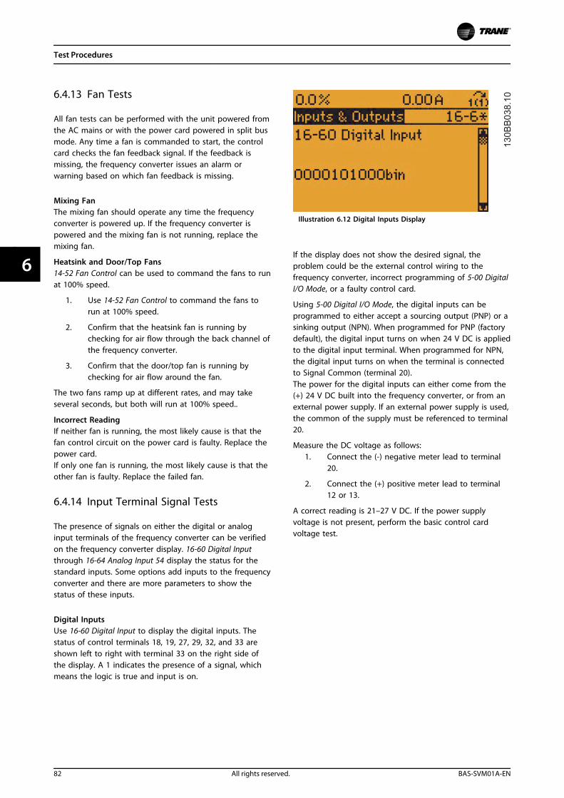
6.4.13 Fan Tests
All fan tests can be performed with the unit powered fromthe AC mains or with the power card powered in split busmode. Any time a fan is commanded to start, the controlcard checks the fan feedback signal. If the feedback ismissing, the frequency converter issues an alarm orwarning based on which fan feedback is missing.
Mixing FanThe mixing fan should operate any time the frequencyconverter is powered up. If the frequency converter ispowered and the mixing fan is not running, replace themixing fan.
Heatsink and Door/Top Fans14-52 Fan Control can be used to command the fans to runat 100% speed.
1. Use 14-52 Fan Control to command the fans torun at 100% speed.
2. Confirm that the heatsink fan is running bychecking for air flow through the back channel ofthe frequency converter.
3. Confirm that the door/top fan is running bychecking for air flow around the fan.
The two fans ramp up at different rates, and may takeseveral seconds, but both will run at 100% speed..
Incorrect ReadingIf neither fan is running, the most likely cause is that thefan control circuit on the power card is faulty. Replace thepower card.If only one fan is running, the most likely cause is that theother fan is faulty. Replace the failed fan.
6.4.14 Input Terminal Signal Tests
The presence of signals on either the digital or analoginput terminals of the frequency converter can be verifiedon the frequency converter display. 16-60 Digital Inputthrough 16-64 Analog Input 54 display the status for thestandard inputs. Some options add inputs to the frequencyconverter and there are more parameters to show thestatus of these inputs.
Digital InputsUse 16-60 Digital Input to display the digital inputs. Thestatus of control terminals 18, 19, 27, 29, 32, and 33 areshown left to right with terminal 33 on the right side ofthe display. A 1 indicates the presence of a signal, whichmeans the logic is true and input is on.
Illustration 6.12 Digital Inputs Display
If the display does not show the desired signal, theproblem could be the external control wiring to thefrequency converter, incorrect programming of 5-00 DigitalI/O Mode, or a faulty control card.
Using 5-00 Digital I/O Mode, the digital inputs can beprogrammed to either accept a sourcing output (PNP) or asinking output (NPN). When programmed for PNP (factorydefault), the digital input turns on when 24 V DC is appliedto the digital input terminal. When programmed for NPN,the digital input turns on when the terminal is connectedto Signal Common (terminal 20).The power for the digital inputs can either come from the(+) 24 V DC built into the frequency converter, or from anexternal power supply. If an external power supply is used,the common of the supply must be referenced to terminal20.
Measure the DC voltage as follows:1. Connect the (-) negative meter lead to terminal
20.
2. Connect the (+) positive meter lead to terminal12 or 13.
A correct reading is 21–27 V DC. If the power supplyvoltage is not present, perform the basic control cardvoltage test.
Test Procedures
82 All rights reserved. BAS-SVM01A-EN
66
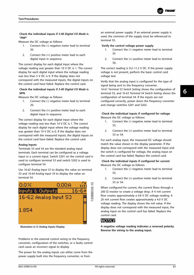
Check the individual inputs if 5-00 Digital I/O Mode is“PNP”
Measure the DC voltage as follows:1. Connect the (-) negative meter lead to terminal
20.
2. Connect the (+) positive meter lead to eachdigital input in sequence.
The correct display for each digital input where thevoltage reading was greater than 10 V DC is 1. The correctdisplay for each digital input where the voltage readingwas less than 5 V DC is 0. If the display does notcorrespond with the measured inputs, the digital inputs onthe control card have failed. Replace the control card.
Check the individual inputs if 5-00 Digital I/O Mode isNPN
Measure the DC voltage as follows:1. Connect the (-) negative meter lead to terminal
20.
2. Connect the (+) positive meter lead to eachdigital input in sequence.
The correct display for each digital input where thevoltage reading was less than 14 V DC is 1. The correctdisplay for each digital input where the voltage readingwas greater than 19 V DC is 0. If the display does notcorrespond with the measured inputs, the digital inputs onthe control card have failed. Replace the control card.
Analog InputsTerminals 53 and 54 are the standard analog inputterminals. Each terminal can be configured as a voltageinput or a current input. Switch S201 on the control card isused to configure terminal 53 and switch S202 is used toconfigure terminal 54.
Use 16-62 Analog Input 53 to display the value on terminal53 and 16-64 Analog Input 54 to display the value onterminal 54.
Illustration 6.13 Analog Inputs Display
Problems in the external control wiring to the frequencyconverter, configuration of the switches, or a faulty controlcard cause an incorrect signal to display.
The power for the analog inputs can either come from thepower supply built into the frequency converter, or from
an external power supply. If an external power supply isused, the common of the supply must be referenced toterminal 55.
Verify the control voltage power supply1. Connect the (-) negative meter lead to terminal
55
2. Connect the (+) positive meter lead to terminal50.
The correct reading is 9.2–11.2 V DC. If the power supplyvoltage is not present, perform the basic control cardvoltage test.
Verify that the analog input is configured for the type ofsignal being sent to the frequency converter.16-61 Terminal 53 Switch Setting shows the configuration ofterminal 53, and 16-63 Terminal 54 Switch Setting shows theconfiguration of terminal 54. If the inputs are notconfigured correctly, power down the frequency converterand change switches S201 and S202.
Check the individual inputs if configured for voltageMeasure the DC voltage as follows:
1. Connect the (-) negative meter lead to terminal55.
2. Connect the (+) positive meter lead to terminal53 or 54.
For each analog input, the measured DC voltage shouldmatch the value shown in the display parameter. If thedisplay does not correspond with the measured input andthe switch is configured for voltage, the analog input onthe control card has failed. Replace the control card.
Check the individual inputs if configured for currentMeasure the DC voltage as follows:
1. Connect the (-) negative meter lead to terminal55.
2. Connect the (+) positive meter lead to terminal53 or 54.
When configured for current, the current flows through a200 Ω resistor to create a voltage drop. A 4 mA currentflow creates approximately a 0.8 V DC voltage reading. A20 mA current flow creates approximately a 4.0 V DCvoltage reading. The display shows the mA value. If thedisplay does not correspond with the measured input, theanalog input on the control card has failed. Replace thecontrol card.
NOTICEA negative voltage reading indicates a reversed polarity.Reverse the wiring to the analog input.
Test Procedures
BAS-SVM01A-EN All rights reserved. 83
6 6
6.5 After Repair Tests
Following any repair to a frequency converter or testing ofa frequency converter suspected of being faulty, thefollowing procedure must be followed. Following theprocedure ensures that all circuitry in the frequencyconverter is functioning properly before putting the unitinto operation.
1. Perform visual inspection procedures as describedin chapter 4.4 Visual Inspection.
2. Perform static test procedures to ensure thatfrequency converter is safe to start.
3. Disconnect motor leads from output terminals (U,V, W) of the frequency converter.
4. Apply AC power to frequency converter.
5. Give the frequency converter a run commandand slowly increase reference (speed command)to approximately 40 Hz.
6. Using an analog voltmeter or a DVM capable ofmeasuring true RMS, measure phase-to-phaseoutput voltage on all three phases: U to V, U toW, V to W. All voltages must be balanced within8 V. If unbalanced voltage is measured, refer tochapter 6.4.2 Input Voltage Test.
7. Stop the frequency converter and remove inputpower. Allow 20 minutes for DC capacitors todischarge fully.
8. Reconnect motor cables to frequency converteroutput terminals (U, V, W).
9. Reapply power and restart frequency converter.Adjust motor speed to a nominal level.
10. Using a clamp-on style ammeter, measure outputcurrent on each output phase. All currents mustbe balanced.
Test Procedures
84 All rights reserved. BAS-SVM01A-EN
66
7 Disassembly and Assembly Instructions
7.1 Introduction
WARNINGFrequency converters contain dangerous voltages whenconnected to mains voltage. Do not disassemble whenpower is applied. Disconnect power to the frequencyconverter, and wait for a minimum period of 20 minutesfor the frequency converter capacitors to discharge fully.Competent technicians are the only persons qualified toperform these procedures.
NOTICEFrame size is used throughout this manual whereprocedures or components differ between frequencyconverters based upon the unit's physical size. Refer tothe tables in chapter 1.5 Frame Size Definitions todetermine frame size definitions.
In this chapter, chapter 7.3 D1h/D3h Disassembly andAssembly Instructions describes the disassembly procedurefor the D1h, D3h, D5h, and D6h frequency converter, and chapter 7.4 D2h/D4h Disassembly and Assembly Instructionsdescribes the procedure for D2h, D4h, D7h, and D8h.
7.2 Electrostatic Discharge (ESD)
ELECTROSTATIC DISCHARGE (ESD)Many electronic components within the frequencyconverter are sensitive to static electricity. Voltages so lowthat they are undetectable can reduce the life, affectperformance, or completely destroy sensitive electroniccomponents.
CAUTIONUse the correct ESD procedures to prevent damage tosensitive components when servicing the frequencyconverter.
7.3 D1h/D3h Disassembly and AssemblyInstructions
7.3.1 General Information
These disassembly instructions are based on IP21 (NEMA 1)IP54 (NEMA 12) enclosure. Some details vary for the IP20version.
7.3.2 Control Card and Control CardMounting Plate
1. Open the front panel door or remove the frontcover, depending on the enclosure type.
2. Remove the LCP cradle and LCP ribbon cable. TheLCP cradle can be removed by hand.
3. Remove any customer control wiring from thecontrol card and option cards.
4. Remove the 4 screws (T20) from the corners ofthe control card mounting plate.
5. Unplug the ribbon cable connecting the controlcard and the power card.
Reinstall in reverse order of this procedure and tightenhardware according to chapter 1.7 General TorqueTightening Values. See Illustration 7.1.
Disassembly and Assembly In...
BAS-SVM01A-EN All rights reserved. 85
7 7
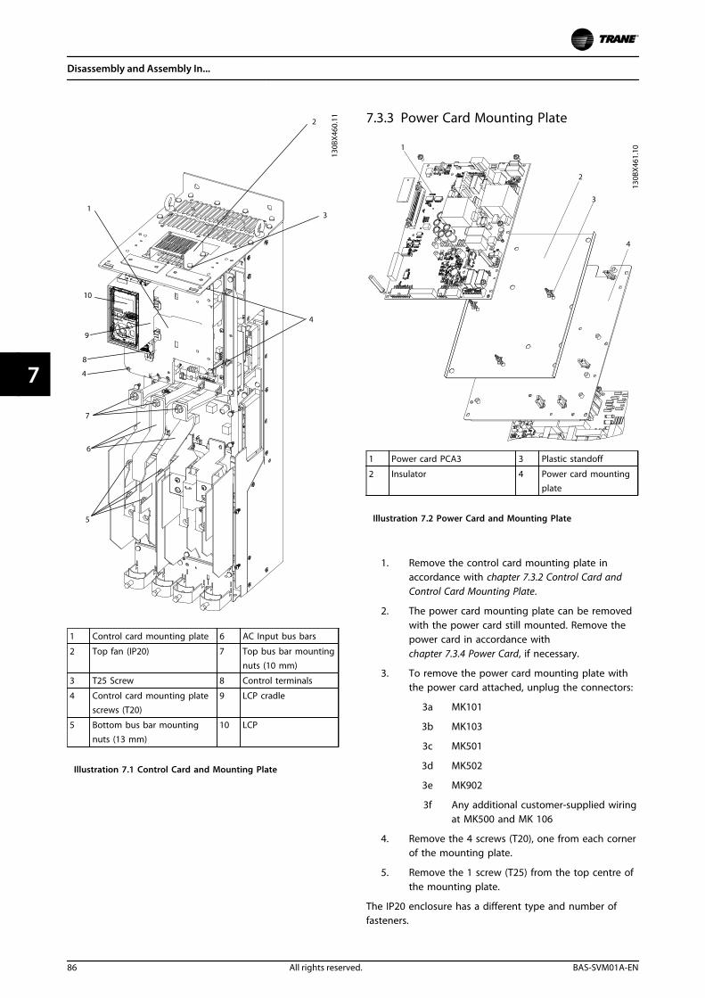
1 Control card mounting plate 6 AC Input bus bars
2 Top fan (IP20) 7 Top bus bar mountingnuts (10 mm)
3 T25 Screw 8 Control terminals
4 Control card mounting platescrews (T20)
9 LCP cradle
5 Bottom bus bar mounting
nuts (13 mm)
10 LCP
Illustration 7.1 Control Card and Mounting Plate
7.3.3 Power Card Mounting Plate
1 Power card PCA3 3 Plastic standoff
2 Insulator 4 Power card mountingplate
Illustration 7.2 Power Card and Mounting Plate
1. Remove the control card mounting plate inaccordance with chapter 7.3.2 Control Card andControl Card Mounting Plate.
2. The power card mounting plate can be removedwith the power card still mounted. Remove thepower card in accordance withchapter 7.3.4 Power Card, if necessary.
3. To remove the power card mounting plate withthe power card attached, unplug the connectors:
3a MK101
3b MK103
3c MK501
3d MK502
3e MK902
3f Any additional customer-supplied wiringat MK500 and MK 106
4. Remove the 4 screws (T20), one from each cornerof the mounting plate.
5. Remove the 1 screw (T25) from the top centre ofthe mounting plate.
The IP20 enclosure has a different type and number offasteners.
Disassembly and Assembly In...
86 All rights reserved. BAS-SVM01A-EN
77
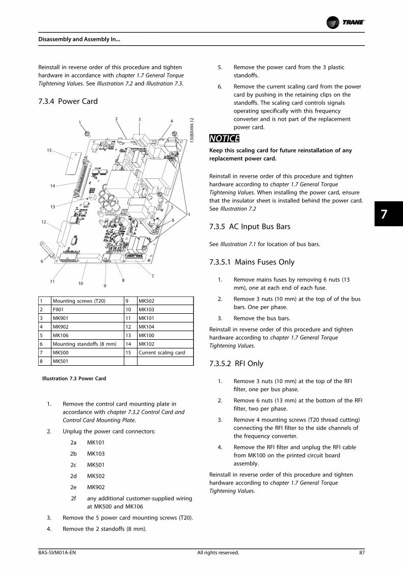
Reinstall in reverse order of this procedure and tightenhardware in accordance with chapter 1.7 General TorqueTightening Values. See Illustration 7.2 and Illustration 7.3.
7.3.4 Power Card
1 Mounting screws (T20) 9 MK502
2 F901 10 MK103
3 MK901 11 MK101
4 MK902 12 MK104
5 MK106 13 MK100
6 Mounting standoffs (8 mm) 14 MK102
7 MK500 15 Current scaling card
8 MK501
Illustration 7.3 Power Card
1. Remove the control card mounting plate inaccordance with chapter 7.3.2 Control Card andControl Card Mounting Plate.
2. Unplug the power card connectors:
2a MK101
2b MK103
2c MK501
2d MK502
2e MK902
2f any additional customer-supplied wiringat MK500 and MK106
3. Remove the 5 power card mounting screws (T20).
4. Remove the 2 standoffs (8 mm).
5. Remove the power card from the 3 plasticstandoffs.
6. Remove the current scaling card from the powercard by pushing in the retaining clips on thestandoffs. The scaling card controls signalsoperating specifically with this frequencyconverter and is not part of the replacementpower card.
NOTICEKeep this scaling card for future reinstallation of anyreplacement power card.
Reinstall in reverse order of this procedure and tightenhardware according to chapter 1.7 General TorqueTightening Values. When installing the power card, ensurethat the insulator sheet is installed behind the power card.See Illustration 7.2
7.3.5 AC Input Bus Bars
See Illustration 7.1 for location of bus bars.
7.3.5.1 Mains Fuses Only
1. Remove mains fuses by removing 6 nuts (13mm), one at each end of each fuse.
2. Remove 3 nuts (10 mm) at the top of of the busbars. One per phase.
3. Remove the bus bars.
Reinstall in reverse order of this procedure and tightenhardware according to chapter 1.7 General TorqueTightening Values.
7.3.5.2 RFI Only
1. Remove 3 nuts (10 mm) at the top of the RFIfilter, one per bus phase.
2. Remove 6 nuts (13 mm) at the bottom of the RFIfilter, two per phase.
3. Remove 4 mounting screws (T20 thread cutting)connecting the RFI filter to the side channels ofthe frequency converter.
4. Remove the RFI filter and unplug the RFI cablefrom MK100 on the printed circuit boardassembly.
Reinstall in reverse order of this procedure and tightenhardware according to chapter 1.7 General TorqueTightening Values.
Disassembly and Assembly In...
BAS-SVM01A-EN All rights reserved. 87
7 7
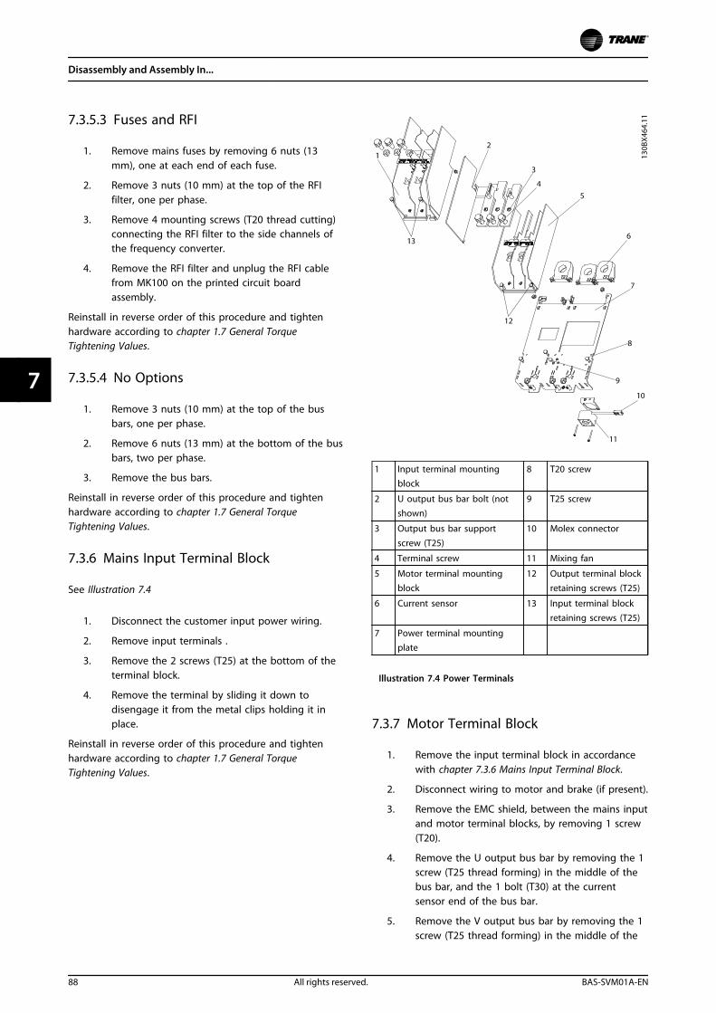
7.3.5.3 Fuses and RFI
1. Remove mains fuses by removing 6 nuts (13mm), one at each end of each fuse.
2. Remove 3 nuts (10 mm) at the top of the RFIfilter, one per phase.
3. Remove 4 mounting screws (T20 thread cutting)connecting the RFI filter to the side channels ofthe frequency converter.
4. Remove the RFI filter and unplug the RFI cablefrom MK100 on the printed circuit boardassembly.
Reinstall in reverse order of this procedure and tightenhardware according to chapter 1.7 General TorqueTightening Values.
7.3.5.4 No Options
1. Remove 3 nuts (10 mm) at the top of the busbars, one per phase.
2. Remove 6 nuts (13 mm) at the bottom of the busbars, two per phase.
3. Remove the bus bars.
Reinstall in reverse order of this procedure and tightenhardware according to chapter 1.7 General TorqueTightening Values.
7.3.6 Mains Input Terminal Block
See Illustration 7.4
1. Disconnect the customer input power wiring.
2. Remove input terminals .
3. Remove the 2 screws (T25) at the bottom of theterminal block.
4. Remove the terminal by sliding it down todisengage it from the metal clips holding it inplace.
Reinstall in reverse order of this procedure and tightenhardware according to chapter 1.7 General TorqueTightening Values.
1 Input terminal mountingblock
8 T20 screw
2 U output bus bar bolt (notshown)
9 T25 screw
3 Output bus bar support
screw (T25)
10 Molex connector
4 Terminal screw 11 Mixing fan
5 Motor terminal mountingblock
12 Output terminal blockretaining screws (T25)
6 Current sensor 13 Input terminal blockretaining screws (T25)
7 Power terminal mountingplate
Illustration 7.4 Power Terminals
7.3.7 Motor Terminal Block
1. Remove the input terminal block in accordancewith chapter 7.3.6 Mains Input Terminal Block.
2. Disconnect wiring to motor and brake (if present).
3. Remove the EMC shield, between the mains inputand motor terminal blocks, by removing 1 screw(T20).
4. Remove the U output bus bar by removing the 1screw (T25 thread forming) in the middle of thebus bar, and the 1 bolt (T30) at the currentsensor end of the bus bar.
5. Remove the V output bus bar by removing the 1screw (T25 thread forming) in the middle of the
Disassembly and Assembly In...
88 All rights reserved. BAS-SVM01A-EN
77
bus bar, and 1 bolt (T30) at the current sensorend of the bus bar. (Note the V bolt is shorterthan U and W)
6. Remove the W output bus bar by removing the 1screw (T25 thread forming) in the middle of thebus bar, and the 1 bolt (T30) at the currentsensor end of the bus bar.
7. Remove the 2 screws (T25) at the bottom of theterminal block.
8. Remove the terminal by sliding it down todisengage it from the metal clips holding it inplace.
Reinstall in reverse order of this procedure and tightenhardware according to chapter 1.7 General TorqueTightening Values.
7.3.8 Power Terminal Mounting Plate
1. Remove the motor terminal in accordance withchapter 7.3.7 Motor Terminal Block.
2. Remove the 4 screws (T20 thread cutting), twofrom each side of the plate.
3. For IP21 (NEMA 1) and IP54 (NEMA 12) enclosuresonly, remove 3 screws (T25) from the bottom ofthe frequency converter.
4. Unplug the mixing fan, located under themounting plate.
Reinstall in reverse order of this procedure and tightenhardware according to chapter 1.7 General TorqueTightening Values.
7.3.9 Current Sensors
1. Remove power terminal mounting plate inaccordance with chapter 7.3.8 Power TerminalMounting Plate.
2. Disconnect the wire harness from each currentsensor. Note which connector attaches to eachcurrent sensor.
3. Remove 6 screws (T20) connecting the currentsensors to the power terminal mounting plate, 2per current sensor.
Reinstall in reverse order of this procedure and tightenhardware according to chapter 1.7 General TorqueTightening Values.
NOTICENote for reassembly: The signal wire plug faces outwardsince it is important for the current sensor to point inthe proper direction.
7.3.10 Mixing Fan
1. Remove the power terminal mounting plate inaccordance with chapter 7.3.8 Power TerminalMounting Plate.
2. Remove the 2 screws attaching the fan to thepower terminal mounting plate.
Reinstall in reverse order of this procedure and tightenhardware according to chapter 1.7 General TorqueTightening Values.
7.3.11 Balance/High Frequency Card
7.3.11.1 400 V AC Power Size (includes 460V)
1. Remove the power terminal mounting plate inaccordance with chapter 7.3.8 Power TerminalMounting Plate.
2. Unplug the cable MK 100 on the balance/highfrequency card.
3. Remove the 1 standoff (8 mm) from the corner ofthe card.
4. Remove 3 nuts (8 mm).
NOTICETwo of the nuts also hold in place the (+) DC and (-) DCwire harness.Reinstall in reverse order of this procedure and tightenhardware according to chapter 1.7 General TorqueTightening Values.
NOTICENote the wire cable connections on the (+) UDC and (-)UDC terminals.
Disassembly and Assembly In...
BAS-SVM01A-EN All rights reserved. 89
7 7
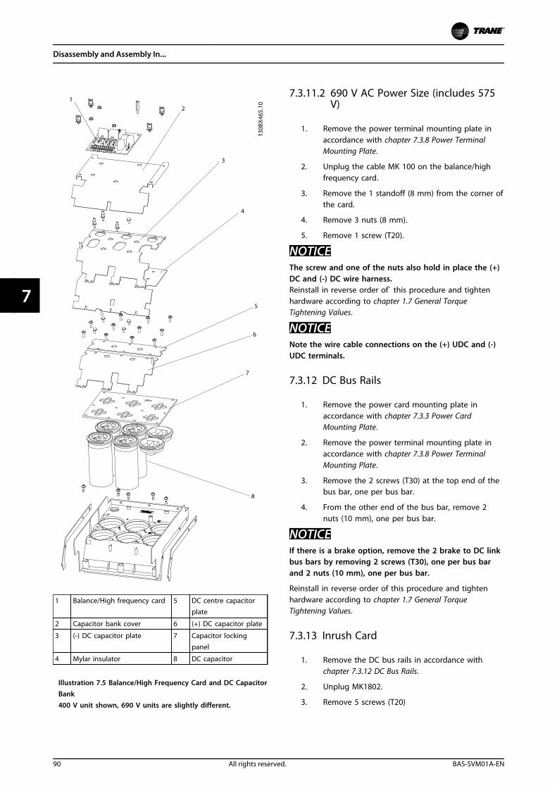
1 Balance/High frequency card 5 DC centre capacitorplate
2 Capacitor bank cover 6 (+) DC capacitor plate
3 (-) DC capacitor plate 7 Capacitor lockingpanel
4 Mylar insulator 8 DC capacitor
Illustration 7.5 Balance/High Frequency Card and DC CapacitorBank400 V unit shown, 690 V units are slightly different.
7.3.11.2 690 V AC Power Size (includes 575V)
1. Remove the power terminal mounting plate inaccordance with chapter 7.3.8 Power TerminalMounting Plate.
2. Unplug the cable MK 100 on the balance/highfrequency card.
3. Remove the 1 standoff (8 mm) from the corner ofthe card.
4. Remove 3 nuts (8 mm).
5. Remove 1 screw (T20).
NOTICEThe screw and one of the nuts also hold in place the (+)DC and (-) DC wire harness.Reinstall in reverse order of` this procedure and tightenhardware according to chapter 1.7 General TorqueTightening Values.
NOTICENote the wire cable connections on the (+) UDC and (-)UDC terminals.
7.3.12 DC Bus Rails
1. Remove the power card mounting plate inaccordance with chapter 7.3.3 Power CardMounting Plate.
2. Remove the power terminal mounting plate inaccordance with chapter 7.3.8 Power TerminalMounting Plate.
3. Remove the 2 screws (T30) at the top end of thebus bar, one per bus bar.
4. From the other end of the bus bar, remove 2nuts (10 mm), one per bus bar.
NOTICEIf there is a brake option, remove the 2 brake to DC linkbus bars by removing 2 screws (T30), one per bus barand 2 nuts (10 mm), one per bus bar.
Reinstall in reverse order of this procedure and tightenhardware according to chapter 1.7 General TorqueTightening Values.
7.3.13 Inrush Card
1. Remove the DC bus rails in accordance withchapter 7.3.12 DC Bus Rails.
2. Unplug MK1802.
3. Remove 5 screws (T20)
Disassembly and Assembly In...
90 All rights reserved. BAS-SVM01A-EN
77
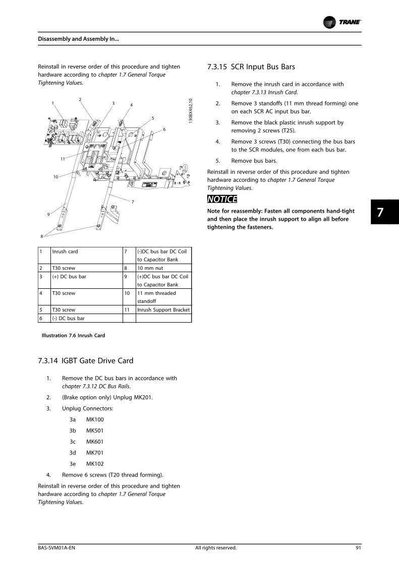
Reinstall in reverse order of this procedure and tightenhardware according to chapter 1.7 General TorqueTightening Values.
1 Inrush card 7 (-)DC bus bar DC Coilto Capacitor Bank
2 T30 screw 8 10 mm nut
3 (+) DC bus bar 9 (+)DC bus bar DC Coil
to Capacitor Bank
4 T30 screw 10 11 mm threadedstandoff
5 T30 screw 11 Inrush Support Bracket
6 (-) DC bus bar
Illustration 7.6 Inrush Card
7.3.14 IGBT Gate Drive Card
1. Remove the DC bus bars in accordance withchapter 7.3.12 DC Bus Rails.
2. (Brake option only) Unplug MK201.
3. Unplug Connectors:
3a MK100
3b MK501
3c MK601
3d MK701
3e MK102
4. Remove 6 screws (T20 thread forming).
Reinstall in reverse order of this procedure and tightenhardware according to chapter 1.7 General TorqueTightening Values.
7.3.15 SCR Input Bus Bars
1. Remove the inrush card in accordance withchapter 7.3.13 Inrush Card.
2. Remove 3 standoffs (11 mm thread forming) oneon each SCR AC input bus bar.
3. Remove the black plastic inrush support byremoving 2 screws (T25).
4. Remove 3 screws (T30) connecting the bus barsto the SCR modules, one from each bus bar.
5. Remove bus bars.
Reinstall in reverse order of this procedure and tightenhardware according to chapter 1.7 General TorqueTightening Values.
NOTICENote for reassembly: Fasten all components hand-tightand then place the inrush support to align all beforetightening the fasteners.
Disassembly and Assembly In...
BAS-SVM01A-EN All rights reserved. 91
7 7
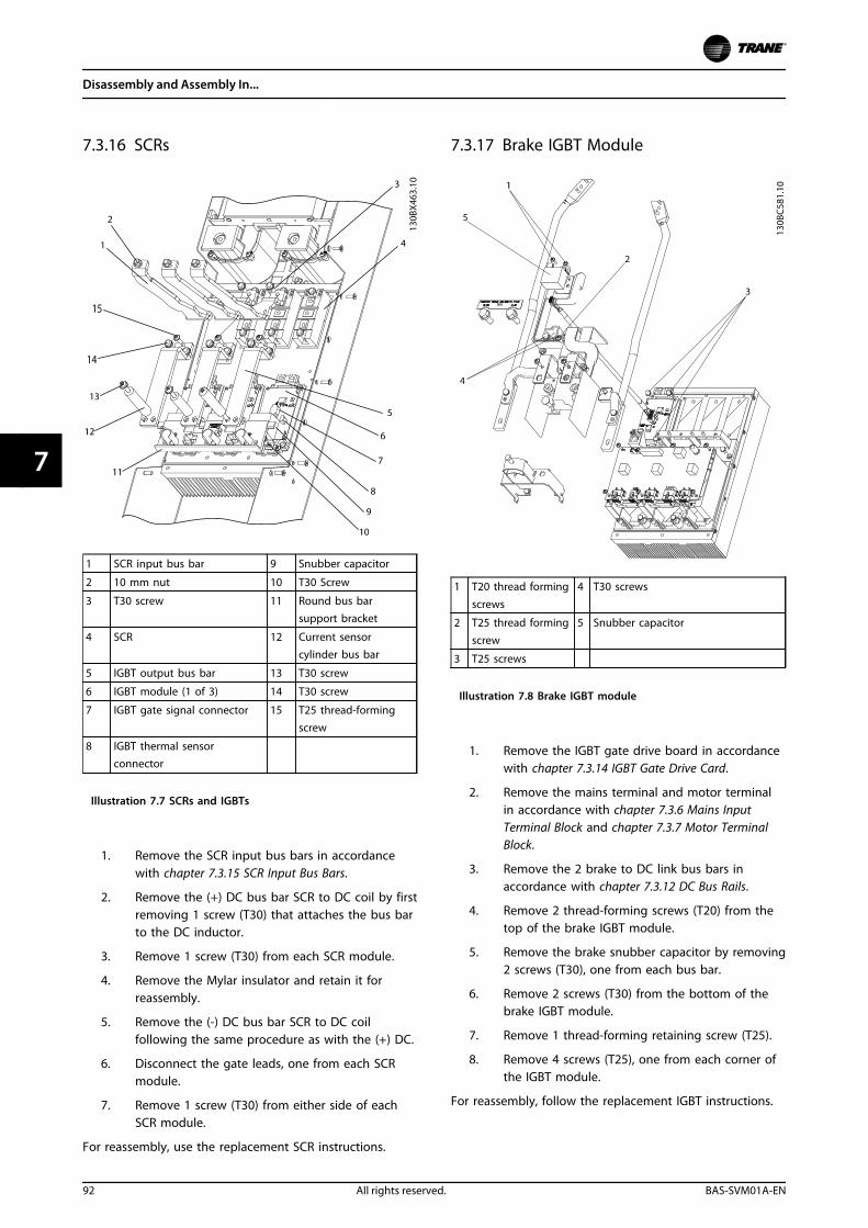
7.3.16 SCRs
1 SCR input bus bar 9 Snubber capacitor
2 10 mm nut 10 T30 Screw
3 T30 screw 11 Round bus barsupport bracket
4 SCR 12 Current sensorcylinder bus bar
5 IGBT output bus bar 13 T30 screw
6 IGBT module (1 of 3) 14 T30 screw
7 IGBT gate signal connector 15 T25 thread-forming
screw
8 IGBT thermal sensorconnector
Illustration 7.7 SCRs and IGBTs
1. Remove the SCR input bus bars in accordancewith chapter 7.3.15 SCR Input Bus Bars.
2. Remove the (+) DC bus bar SCR to DC coil by firstremoving 1 screw (T30) that attaches the bus barto the DC inductor.
3. Remove 1 screw (T30) from each SCR module.
4. Remove the Mylar insulator and retain it forreassembly.
5. Remove the (-) DC bus bar SCR to DC coilfollowing the same procedure as with the (+) DC.
6. Disconnect the gate leads, one from each SCRmodule.
7. Remove 1 screw (T30) from either side of eachSCR module.
For reassembly, use the replacement SCR instructions.
7.3.17 Brake IGBT Module
1 T20 thread forming
screws
4 T30 screws
2 T25 thread forming
screw
5 Snubber capacitor
3 T25 screws
Illustration 7.8 Brake IGBT module
1. Remove the IGBT gate drive board in accordancewith chapter 7.3.14 IGBT Gate Drive Card.
2. Remove the mains terminal and motor terminalin accordance with chapter 7.3.6 Mains InputTerminal Block and chapter 7.3.7 Motor TerminalBlock.
3. Remove the 2 brake to DC link bus bars inaccordance with chapter 7.3.12 DC Bus Rails.
4. Remove 2 thread-forming screws (T20) from thetop of the brake IGBT module.
5. Remove the brake snubber capacitor by removing2 screws (T30), one from each bus bar.
6. Remove 2 screws (T30) from the bottom of thebrake IGBT module.
7. Remove 1 thread-forming retaining screw (T25).
8. Remove 4 screws (T25), one from each corner ofthe IGBT module.
For reassembly, follow the replacement IGBT instructions.
Disassembly and Assembly In...
92 All rights reserved. BAS-SVM01A-EN
77
7.3.18 IGBTs
7.3.18.1 400 V AC Power Size (includes 460V)
1. Remove the gate drive card in accordance withchapter 7.3.14 IGBT Gate Drive Card.
2. Remove the SCR input bus bars in accordancewith chapter 7.3.15 SCR Input Bus Bars.
3. Remove the balance/high frequency card inaccordance with chapter 7.3.11 Balance/HighFrequency Card.
4. Remove the Mylar cover from the capacitor bank.
5. Remove the round bus bar support bracket byremoving 3 screws (T30).
6. Remove 1 screw (T25 thread forming) from eachIGBT output bus bar, one bus bar per IGBTmodule.
7. Remove the IGBT output bus bar by removing 2screws (T30), from each IGBT output bus bar, onebus bar per IGBT module.
8. Remove the IGBT temperature cable by discon-necting the cable from each IGBT module.
9. Remove the gate leads, one from each IGBTmodule.
10. Remove the snubber capacitor from each IGBTmodule by removing the 2 screws (T30)mounting the capacitor to the IGBT module.
11. Remove the (-) DC plate by removing:
11a 3 screws (T20 thread forming), next tothe IGBT modules
11b 1 standoff (8 mm) connecting the plateto the negative terminal of capacitor 3
11c Screws (T25) connecting the plate to thenegative terminals of capacitors 4 and 5.Number of T25 screws varies based onthe size of the frequency converter
12. Remove the Mylar insulator between the (-) DCplate and the (+) DC and DC centre capacitorplate. The screws connecting the (+) DC and DCcentre plates to the capacitors may have to beremoved to remove the insulator.
13. Remove the (+) DC plate by removing:
13a 3 screws (T20 thread forming) next tothe IGBT modules
13b 1 standoff (8 mm) connecting the plateto the positive terminal of capacitor 2
13c screws (T25) connecting the plate to thepositive terminals of capacitors 1 and 6.Number of T25 screws varies based onthe size of the frequency converter.
14. Remove the plastic IGBT support (not shown) byremoving 4 screws (T25).
15. Remove the IGBTs by removing 4 screws (T25)from each.
For reassembly, use the replacement IGBT instructions.
See Illustration 7.7
7.3.18.2 690 V AC Power Size (includes 575V)
1. Remove the gate drive card in accordance withchapter 7.3.14 IGBT Gate Drive Card.
2. Remove the SCR input bus bars in accordancewith chapter 7.3.15 SCR Input Bus Bars.
3. Remove the balance/high frequency card inaccordance with chapter 7.3.11 Balance/HighFrequency Card.
4. Remove the Mylar cover from the capacitor bank.
5. Remove the round bus bar support bracket byremoving 3 screws (T30).
6. Remove 1 screw (T25 thread forming) from eachIGBT output bus bar, one bus bar per IGBTmodule.
7. Remove the IGBT output bus bar by removing 2screws (T30) from each IGBT output bus bar, onebus bar per IGBT module.
8. Remove the IGBT temperature cable by discon-necting the cable from each IGBT module.
9. Remove the gate leads, one from each IGBT.
10. Remove the snubber capacitor from each IGBTmodule by removing the 2 screws (T30)mounting the capacitor to the IGBT module.
11. Remove the (-) DC plate by removing:
11a 3 screws (T20 thread forming) next tothe IGBT modules
11b 1 standoff (8 mm) connecting the plateto the negative terminal of capacitor 1
11c 1 screw (T25) from the negative terminalof capacitor 3
11d 1 round plastic alignment cap.
12. Remove the Mylar insulator between the (-) DCplate and the (+) DC plate. The screwsconnecting 1 of the 2 DC centre plates to thecapacitors may have to be removed to removethe insulator.
Disassembly and Assembly In...
BAS-SVM01A-EN All rights reserved. 93
7 7
13. Remove the (+) DC plate by removing 3 screws(T20 thread forming) next to the IGBT modulesand 2 screws (T25) connecting the plate to thepositive terminals of capacitors 5 and 6.
14. Remove the plastic IGBT support (not shown) byremoving 4 screws (T25).
15. Remove the IGBTs by removing 4 screws (T25)from each.
For reassembly, use the replacement IGBT instructions.
7.3.19 DC Capacitors
NOTICEWhen performing this procedure, always replace theentire capacitor bank, even if only one capacitor hasfailed.
7.3.19.1 400 V AC Power Size (includes 460V)
1. Remove the gate drive card in accordance withchapter 7.3.14 IGBT Gate Drive Card
2. Remove the balance/high frequency card inaccordance with chapter 7.3.11 Balance/HighFrequency Card.
3. Remove the Mylar cover from the capacitor bank.
4. Remove the round bus bar support bracket byremoving 3 screws (T30).
5. Remove 1 screw (T25 thread forming) from eachIGBT output bus bar, one bus bar per IGBTmodule.
6. Remove the IGBT bus bar by removing 2 screws(T30) from each IGBT output bus bar, one bus barper IGBT module.
7. Remove the snubber capacitor, one from eachIGBT module by removing 2 screws (T30).
8. Remove the (-) DC plate by removing:
8a 3 screws (T20 thread forming) next tothe IGBT modules
8b 1 standoff (8 mm) connecting the plateto the negative terminal of capacitor 3
8c Screws (T25) connecting the plate to thenegative terminals of capacitors 4 and 5.Number of T25 screws varies based onthe size of the frequency converter.
9. Remove the Mylar insulator between the (-) DCplate and the (+) DC and DC centre plates. Thescrews connecting the (+) DC and DC centreplates to the capacitor may have to be removedto remove the insulator.
10. Remove the (+) DC plate by removing:
10a 3 screws (T20 thread forming) adjacentto the IGBT modules
10b 1 standoff (8 mm) connecting the plateto the positive terminal of capacitor 2
10c Screws (T25) connecting the plate to thepositive terminals of capacitors 1 and 6.Number of T25 screws varies based onthe size of the frequency converter.
11. Remove the DC centre capacitor plate byremoving 1 standoff (8 mm) connecting the plateto the negative terminal of capacitor 1 and thescrews (T25) connecting the plate to theremaining capacitors. Number of T25 screwsvaries based on the size of the frequencyconverter.
12. Remove the capacitor locking panel by removing12 screws (T25 thread forming).
Reinstall in reverse order of this procedure and tightenhardware according to chapter 1.7 General TorqueTightening Values.
NOTICENote for reassembly: DC capacitor must fit into theretaining stud at the bottom.
Disassembly and Assembly In...
94 All rights reserved. BAS-SVM01A-EN
77
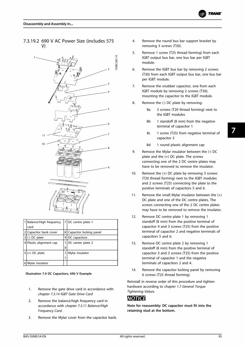
7.3.19.2 690 V AC Power Size (includes 575V)
1 Balance/High frequencycard
7 DC centre plate 1
2 Capacitor bank cover 8 Capacitor locking panel
3 (-) DC plate 9 DC capacitors
4 Plastic alignment cap 1
0
DC center plate 2
5 (+) DC plate 1
1
Mylar insulator
6 Mylar insulator
Illustration 7.9 DC Capacitors, 690 V Example
1. Remove the gate drive card in accordance withchapter 7.3.14 IGBT Gate Drive Card
2. Remove the balance/high frequency card inaccordance with chapter 7.3.11 Balance/HighFrequency Card.
3. Remove the Mylar cover from the capacitor bank.
4. Remove the round bus bar support bracket byremoving 3 screws (T30).
5. Remove 1 screw (T25 thread forming) from eachIGBT output bus bar, one bus bar per IGBTmodule.
6. Remove the IGBT bus bar by removing 2 screws(T30) from each IGBT output bus bar, one bus barper IGBT module.
7. Remove the snubber capacitor, one from eachIGBT module by removing 2 screws (T30),mounting the capacitor to the IGBT module.
8. Remove the (-) DC plate by removing:
8a 3 screws (T20 thread forming) next tothe IGBT modules
8b 1 standoff (8 mm) from the negativeterminal of capacitor 1
8c 1 screw (T25) from negative terminal ofcapacitor 3
8d 1 round plastic alignment cap
9. Remove the Mylar insulator between the (-) DCplate and the (+) DC plate. The screwsconnecting one of the 2 DC centre plates mayhave to be removed to remove the insulator.
10. Remove the (+) DC plate by removing 3 screws(T20 thread forming) next to the IGBT modulesand 2 screws (T25) connecting the plate to thepositive terminals of capacitors 5 and 6.
11. Remove the small Mylar insulator between the (+)DC plate and one of the DC centre plates. Thescrews connecting one of the 2 DC centre platesmay have to be removed to remove the insulator.
12. Remove DC centre plate 1 by removing 1standoff (8 mm) from the positive terminal ofcapacitor 4 and 3 screws (T25) from the positiveterminal of capacitor 2 and negative terminals ofcapacitors 5 and 6.
13. Remove DC centre plate 2 by removing 1standoff (8 mm) from the positive terminal ofcapacitor 3 and 3 screws (T25) from the positiveterminal of capacitor 1 and the negativeterminals of capacitors 2 and 4.
14. Remove the capacitor locking panel by removing6 screws (T25 thread forming).
Reinstall in reverse order of this procedure and tightenhardware according to chapter 1.7 General TorqueTightening Values.
NOTICENote for reassembly: DC capacitor must fit into theretaining stud at the bottom.
Disassembly and Assembly In...
BAS-SVM01A-EN All rights reserved. 95
7 7
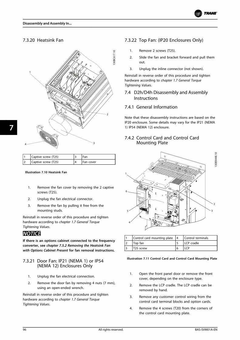
7.3.20 Heatsink Fan
1 Captive screw (T25) 3 Fan
2 Captive screw (T25) 4 Fan cover
Illustration 7.10 Heatsink Fan
1. Remove the fan cover by removing the 2 captivescrews (T25).
2. Unplug the fan electrical connector.
3. Remove the fan by pulling it free from themounting studs.
Reinstall in reverse order of this procedure and tightenhardware according to chapter 1.7 General TorqueTightening Values.
NOTICEIf there is an options cabinet connected to the frequencyconverter, see chapter 7.5.2 Removing the Heatsink Fanwith Options Cabinet Present for fan removal instructions.
7.3.21 Door Fan: IP21 (NEMA 1) or IP54(NEMA 12) Enclosures Only
1. Unplug the fan electrical connection.
2. Remove the door fan by removing 4 nuts (7 mm),using an open-ended wrench.
Reinstall in reverse order of this procedure and tightenhardware according to chapter 1.7 General TorqueTightening Values.
7.3.22 Top Fan: (IP20 Enclosures Only)
1. Remove 2 screws (T25).
2. Slide the fan and bracket forward and pull themout.
3. Unplug the inline connector (not shown).
Reinstall in reverse order of this procedure and tightenhardware according to chapter 1.7 General TorqueTightening Values.
7.4 D2h/D4h Disassembly and AssemblyInstructions
7.4.1 General Information
Note that these disassembly instructions are based on theIP20 enclosure. Some details may vary for the IP21 (NEMA1) IP54 (NEMA 12) enclosure.
7.4.2 Control Card and Control CardMounting Plate
1 Control card mounting plate 4 Control terminals
2 Top fan 5 LCP cradle
3 T25 screw 6 LCP
Illustration 7.11 Control Card and Control Card Mounting Plate
1. Open the front panel door or remove the frontcover, depending on the enclosure type.
2. Remove the LCP cradle. The LCP cradle can beremoved by hand.
3. Remove any customer control wiring from thecontrol card terminal blocks and option cards.
4. Remove the 4 screws (T20) from the corners ofthe control card mounting plate.
Disassembly and Assembly In...
96 All rights reserved. BAS-SVM01A-EN
77
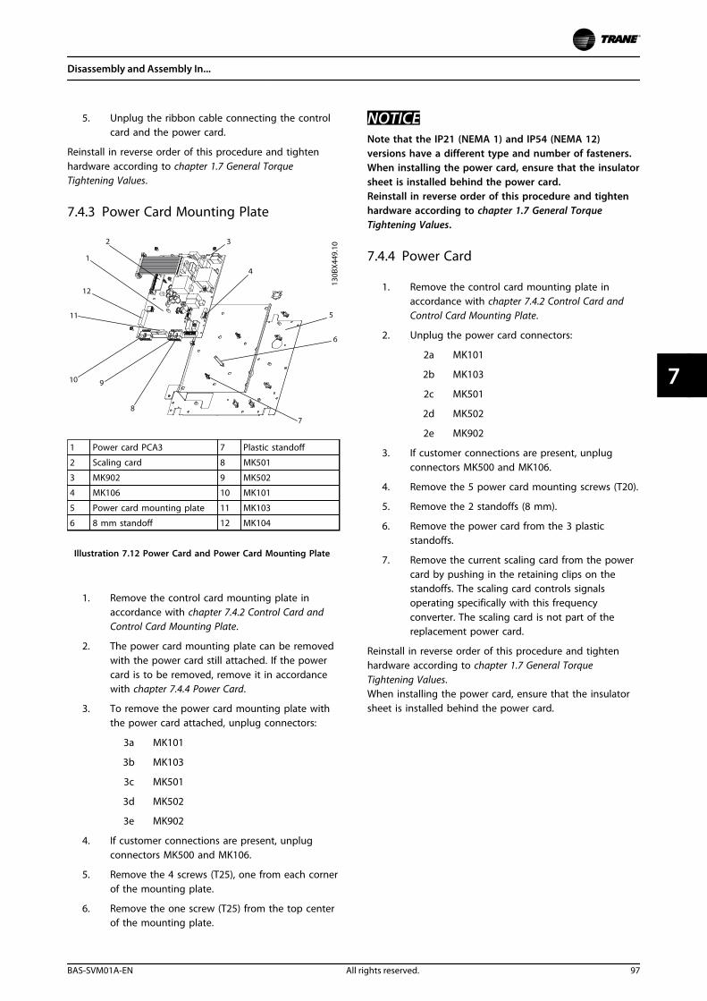
5. Unplug the ribbon cable connecting the controlcard and the power card.
Reinstall in reverse order of this procedure and tightenhardware according to chapter 1.7 General TorqueTightening Values.
7.4.3 Power Card Mounting Plate
1 Power card PCA3 7 Plastic standoff
2 Scaling card 8 MK501
3 MK902 9 MK502
4 MK106 10 MK101
5 Power card mounting plate 11 MK103
6 8 mm standoff 12 MK104
Illustration 7.12 Power Card and Power Card Mounting Plate
1. Remove the control card mounting plate inaccordance with chapter 7.4.2 Control Card andControl Card Mounting Plate.
2. The power card mounting plate can be removedwith the power card still attached. If the powercard is to be removed, remove it in accordancewith chapter 7.4.4 Power Card.
3. To remove the power card mounting plate withthe power card attached, unplug connectors:
3a MK101
3b MK103
3c MK501
3d MK502
3e MK902
4. If customer connections are present, unplugconnectors MK500 and MK106.
5. Remove the 4 screws (T25), one from each cornerof the mounting plate.
6. Remove the one screw (T25) from the top centerof the mounting plate.
NOTICENote that the IP21 (NEMA 1) and IP54 (NEMA 12)versions have a different type and number of fasteners.When installing the power card, ensure that the insulatorsheet is installed behind the power card.Reinstall in reverse order of this procedure and tightenhardware according to chapter 1.7 General TorqueTightening Values.
7.4.4 Power Card
1. Remove the control card mounting plate inaccordance with chapter 7.4.2 Control Card andControl Card Mounting Plate.
2. Unplug the power card connectors:
2a MK101
2b MK103
2c MK501
2d MK502
2e MK902
3. If customer connections are present, unplugconnectors MK500 and MK106.
4. Remove the 5 power card mounting screws (T20).
5. Remove the 2 standoffs (8 mm).
6. Remove the power card from the 3 plasticstandoffs.
7. Remove the current scaling card from the powercard by pushing in the retaining clips on thestandoffs. The scaling card controls signalsoperating specifically with this frequencyconverter. The scaling card is not part of thereplacement power card.
Reinstall in reverse order of this procedure and tightenhardware according to chapter 1.7 General TorqueTightening Values.When installing the power card, ensure that the insulatorsheet is installed behind the power card.
Disassembly and Assembly In...
BAS-SVM01A-EN All rights reserved. 97
7 7
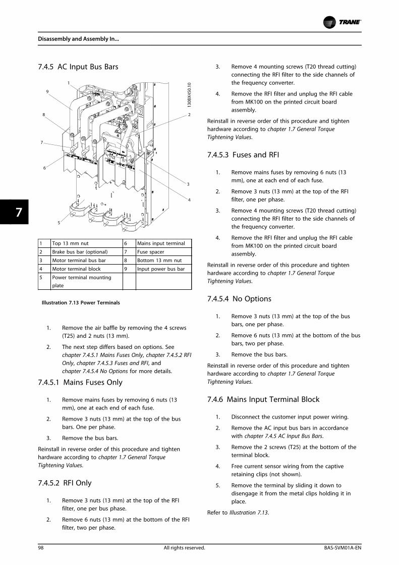
7.4.5 AC Input Bus Bars
1 Top 13 mm nut 6 Mains input terminal
2 Brake bus bar (optional) 7 Fuse spacer
3 Motor terminal bus bar 8 Bottom 13 mm nut
4 Motor terminal block 9 Input power bus bar
5 Power terminal mountingplate
Illustration 7.13 Power Terminals
1. Remove the air baffle by removing the 4 screws(T25) and 2 nuts (13 mm).
2. The next step differs based on options. Seechapter 7.4.5.1 Mains Fuses Only, chapter 7.4.5.2 RFIOnly, chapter 7.4.5.3 Fuses and RFI, andchapter 7.4.5.4 No Options for more details.
7.4.5.1 Mains Fuses Only
1. Remove mains fuses by removing 6 nuts (13mm), one at each end of each fuse.
2. Remove 3 nuts (13 mm) at the top of the busbars. One per phase.
3. Remove the bus bars.
Reinstall in reverse order of this procedure and tightenhardware according to chapter 1.7 General TorqueTightening Values.
7.4.5.2 RFI Only
1. Remove 3 nuts (13 mm) at the top of the RFIfilter, one per bus phase.
2. Remove 6 nuts (13 mm) at the bottom of the RFIfilter, two per phase.
3. Remove 4 mounting screws (T20 thread cutting)connecting the RFI filter to the side channels ofthe frequency converter.
4. Remove the RFI filter and unplug the RFI cablefrom MK100 on the printed circuit boardassembly.
Reinstall in reverse order of this procedure and tightenhardware according to chapter 1.7 General TorqueTightening Values.
7.4.5.3 Fuses and RFI
1. Remove mains fuses by removing 6 nuts (13mm), one at each end of each fuse.
2. Remove 3 nuts (13 mm) at the top of the RFIfilter, one per phase.
3. Remove 4 mounting screws (T20 thread cutting)connecting the RFI filter to the side channels ofthe frequency converter.
4. Remove the RFI filter and unplug the RFI cablefrom MK100 on the printed circuit boardassembly.
Reinstall in reverse order of this procedure and tightenhardware according to chapter 1.7 General TorqueTightening Values.
7.4.5.4 No Options
1. Remove 3 nuts (13 mm) at the top of the busbars, one per phase.
2. Remove 6 nuts (13 mm) at the bottom of the busbars, two per phase.
3. Remove the bus bars.
Reinstall in reverse order of this procedure and tightenhardware according to chapter 1.7 General TorqueTightening Values.
7.4.6 Mains Input Terminal Block
1. Disconnect the customer input power wiring.
2. Remove the AC input bus bars in accordancewith chapter 7.4.5 AC Input Bus Bars.
3. Remove the 2 screws (T25) at the bottom of theterminal block.
4. Free current sensor wiring from the captiveretaining clips (not shown).
5. Remove the terminal by sliding it down todisengage it from the metal clips holding it inplace.
Refer to Illustration 7.13.
Disassembly and Assembly In...
98 All rights reserved. BAS-SVM01A-EN
77
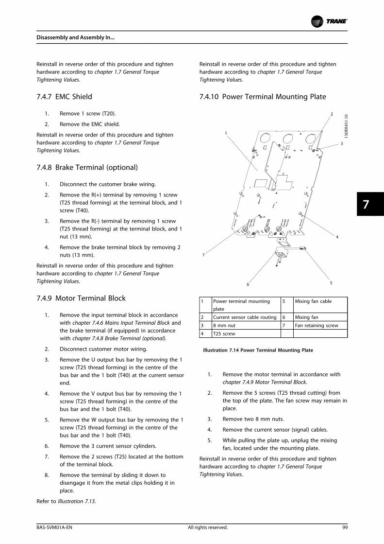
Reinstall in reverse order of this procedure and tightenhardware according to chapter 1.7 General TorqueTightening Values.
7.4.7 EMC Shield
1. Remove 1 screw (T20).
2. Remove the EMC shield.
Reinstall in reverse order of this procedure and tightenhardware according to chapter 1.7 General TorqueTightening Values.
7.4.8 Brake Terminal (optional)
1. Disconnect the customer brake wiring.
2. Remove the R(+) terminal by removing 1 screw(T25 thread forming) at the terminal block, and 1screw (T40).
3. Remove the R(-) terminal by removing 1 screw(T25 thread forming) at the terminal block, and 1nut (13 mm).
4. Remove the brake terminal block by removing 2nuts (13 mm).
Reinstall in reverse order of this procedure and tightenhardware according to chapter 1.7 General TorqueTightening Values.
7.4.9 Motor Terminal Block
1. Remove the input terminal block in accordancewith chapter 7.4.6 Mains Input Terminal Block andthe brake terminal (if equipped) in accordancewith chapter 7.4.8 Brake Terminal (optional).
2. Disconnect customer motor wiring.
3. Remove the U output bus bar by removing the 1screw (T25 thread forming) in the centre of thebus bar and the 1 bolt (T40) at the current sensorend.
4. Remove the V output bus bar by removing the 1screw (T25 thread forming) in the centre of thebus bar and the 1 bolt (T40).
5. Remove the W output bus bar by removing the 1screw (T25 thread forming) in the centre of thebus bar and the 1 bolt (T40).
6. Remove the 3 current sensor cylinders.
7. Remove the 2 screws (T25) located at the bottomof the terminal block.
8. Remove the terminal by sliding it down todisengage it from the metal clips holding it inplace.
Refer to Illustration 7.13.
Reinstall in reverse order of this procedure and tightenhardware according to chapter 1.7 General TorqueTightening Values.
7.4.10 Power Terminal Mounting Plate
1 Power terminal mounting
plate
5 Mixing fan cable
2 Current sensor cable routing 6 Mixing fan
3 8 mm nut 7 Fan retaining screw
4 T25 screw
Illustration 7.14 Power Terminal Mounting Plate
1. Remove the motor terminal in accordance withchapter 7.4.9 Motor Terminal Block.
2. Remove the 5 screws (T25 thread cutting) fromthe top of the plate. The fan screw may remain inplace.
3. Remove two 8 mm nuts.
4. Remove the current sensor (signal) cables.
5. While pulling the plate up, unplug the mixingfan, located under the mounting plate.
Reinstall in reverse order of this procedure and tightenhardware according to chapter 1.7 General TorqueTightening Values.
Disassembly and Assembly In...
BAS-SVM01A-EN All rights reserved. 99
7 7
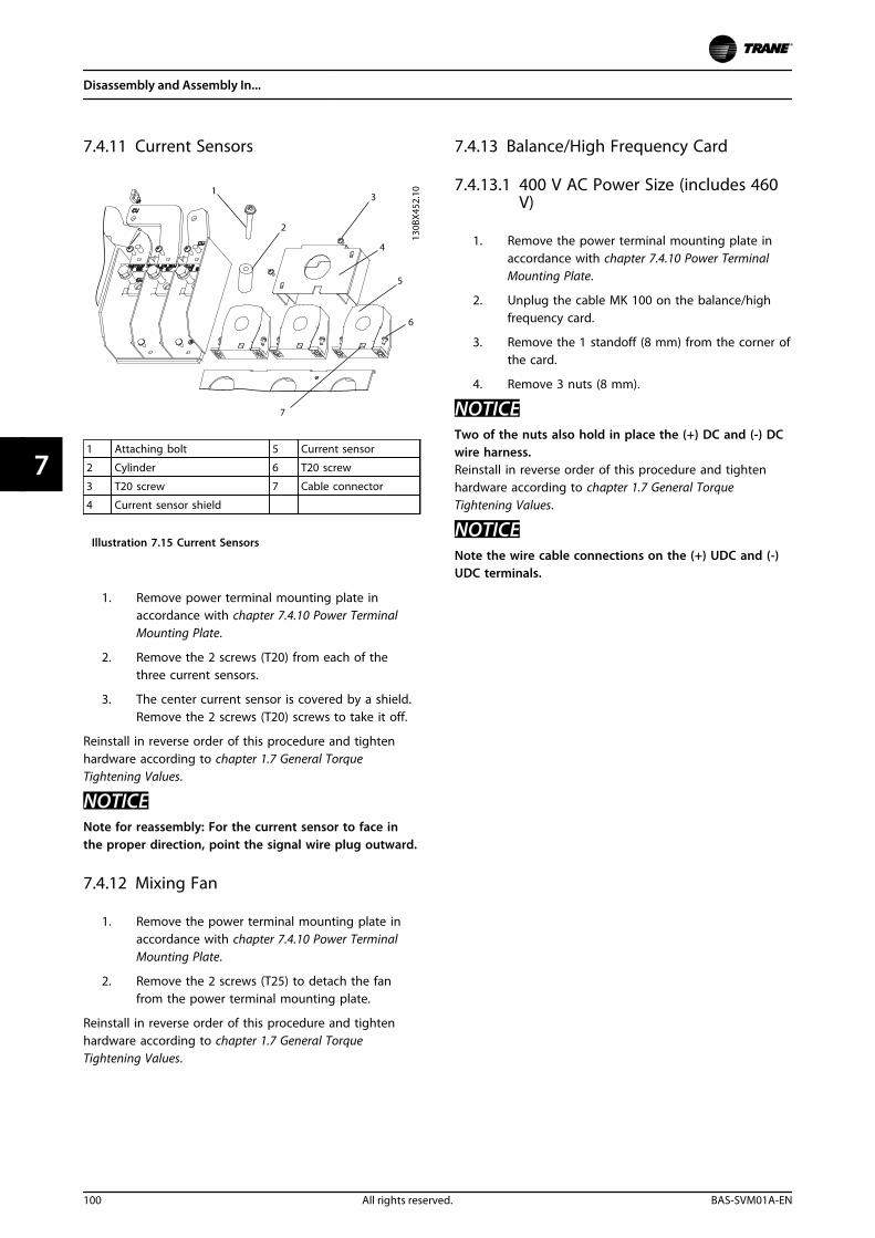
7.4.11 Current Sensors
1 Attaching bolt 5 Current sensor
2 Cylinder 6 T20 screw
3 T20 screw 7 Cable connector
4 Current sensor shield
Illustration 7.15 Current Sensors
1. Remove power terminal mounting plate inaccordance with chapter 7.4.10 Power TerminalMounting Plate.
2. Remove the 2 screws (T20) from each of thethree current sensors.
3. The center current sensor is covered by a shield.Remove the 2 screws (T20) screws to take it off.
Reinstall in reverse order of this procedure and tightenhardware according to chapter 1.7 General TorqueTightening Values.
NOTICENote for reassembly: For the current sensor to face inthe proper direction, point the signal wire plug outward.
7.4.12 Mixing Fan
1. Remove the power terminal mounting plate inaccordance with chapter 7.4.10 Power TerminalMounting Plate.
2. Remove the 2 screws (T25) to detach the fanfrom the power terminal mounting plate.
Reinstall in reverse order of this procedure and tightenhardware according to chapter 1.7 General TorqueTightening Values.
7.4.13 Balance/High Frequency Card
7.4.13.1 400 V AC Power Size (includes 460V)
1. Remove the power terminal mounting plate inaccordance with chapter 7.4.10 Power TerminalMounting Plate.
2. Unplug the cable MK 100 on the balance/highfrequency card.
3. Remove the 1 standoff (8 mm) from the corner ofthe card.
4. Remove 3 nuts (8 mm).
NOTICETwo of the nuts also hold in place the (+) DC and (-) DCwire harness.Reinstall in reverse order of this procedure and tightenhardware according to chapter 1.7 General TorqueTightening Values.
NOTICENote the wire cable connections on the (+) UDC and (-)UDC terminals.
Disassembly and Assembly In...
100 All rights reserved. BAS-SVM01A-EN
77
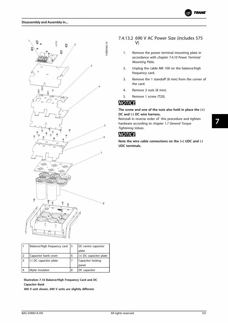
1 Balance/High frequency card 5 DC centre capacitorplate
2 Capacitor bank cover 6 (+) DC capacitor plate
3 (-) DC capacitor plate 7 Capacitor lockingpanel
4 Mylar insulator 8 DC capacitor
Illustration 7.16 Balance/High Frequency Card and DCCapacitor Bank400 V unit shown, 690 V units are slightly different.
7.4.13.2 690 V AC Power Size (includes 575V)
1. Remove the power terminal mounting plate inaccordance with chapter 7.4.10 Power TerminalMounting Plate.
2. Unplug the cable MK 100 on the balance/highfrequency card.
3. Remove the 1 standoff (8 mm) from the corner ofthe card.
4. Remove 3 nuts (8 mm).
5. Remove 1 screw (T20).
NOTICEThe screw and one of the nuts also hold in place the (+)DC and (-) DC wire harness.Reinstall in reverse order of` this procedure and tightenhardware according to chapter 1.7 General TorqueTightening Values.
NOTICENote the wire cable connections on the (+) UDC and (-)UDC terminals.
Disassembly and Assembly In...
BAS-SVM01A-EN All rights reserved. 101
7 7
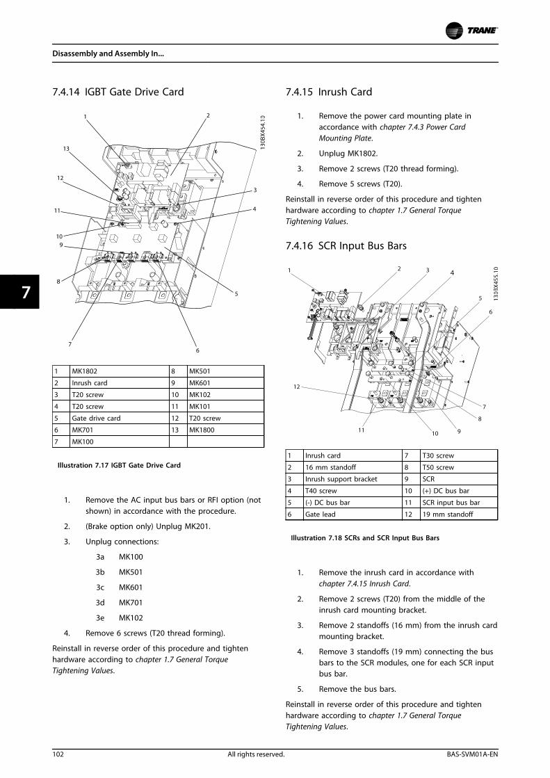
7.4.14 IGBT Gate Drive Card
1 MK1802 8 MK501
2 Inrush card 9 MK601
3 T20 screw 10 MK102
4 T20 screw 11 MK101
5 Gate drive card 12 T20 screw
6 MK701 13 MK1800
7 MK100
Illustration 7.17 IGBT Gate Drive Card
1. Remove the AC input bus bars or RFI option (notshown) in accordance with the procedure.
2. (Brake option only) Unplug MK201.
3. Unplug connections:
3a MK100
3b MK501
3c MK601
3d MK701
3e MK102
4. Remove 6 screws (T20 thread forming).
Reinstall in reverse order of this procedure and tightenhardware according to chapter 1.7 General TorqueTightening Values.
7.4.15 Inrush Card
1. Remove the power card mounting plate inaccordance with chapter 7.4.3 Power CardMounting Plate.
2. Unplug MK1802.
3. Remove 2 screws (T20 thread forming).
4. Remove 5 screws (T20).
Reinstall in reverse order of this procedure and tightenhardware according to chapter 1.7 General TorqueTightening Values.
7.4.16 SCR Input Bus Bars
1 Inrush card 7 T30 screw
2 16 mm standoff 8 T50 screw
3 Inrush support bracket 9 SCR
4 T40 screw 10 (+) DC bus bar
5 (-) DC bus bar 11 SCR input bus bar
6 Gate lead 12 19 mm standoff
Illustration 7.18 SCRs and SCR Input Bus Bars
1. Remove the inrush card in accordance withchapter 7.4.15 Inrush Card.
2. Remove 2 screws (T20) from the middle of theinrush card mounting bracket.
3. Remove 2 standoffs (16 mm) from the inrush cardmounting bracket.
4. Remove 3 standoffs (19 mm) connecting the busbars to the SCR modules, one for each SCR inputbus bar.
5. Remove the bus bars.
Reinstall in reverse order of this procedure and tightenhardware according to chapter 1.7 General TorqueTightening Values.
Disassembly and Assembly In...
102 All rights reserved. BAS-SVM01A-EN
77
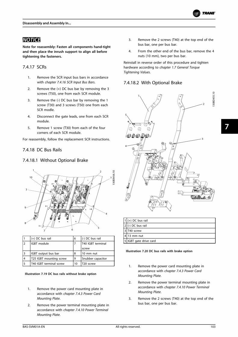
NOTICENote for reassembly: Fasten all components hand-tightand then place the inrush support to align all beforetightening the fasteners.
7.4.17 SCRs
1. Remove the SCR input bus bars in accordancewith chapter 7.4.16 SCR Input Bus Bars.
2. Remove the (+) DC bus bar by removing the 3screws (T50), one from each SCR module.
3. Remove the (-) DC bus bar by removing the 1screw (T30) and 3 screws (T50) one from eachSCR modle.
4. Disconnect the gate leads, one from each SCRmodule.
5. Remove 1 screw (T30) from each of the fourcorners of each SCR module.
For reassembly, follow the replacement SCR instructions.
7.4.18 DC Bus Rails
7.4.18.1 Without Optional Brake
1 (+) DC bus rail 6 (-) DC bus rail
2 IGBT module 7 T40 IGBT terminal
screw
3 IGBT output bus bar 8 10 mm nut
4 T25 IGBT mounting screw 9 Snubber capacitor
5 T40 IGBT terminal screw 10 T20 screw
Illustration 7.19 DC bus rails without brake option
1. Remove the power card mounting plate inaccordance with chapter 7.4.3 Power CardMounting Plate.
2. Remove the power terminal mounting plate inaccordance with chapter 7.4.10 Power TerminalMounting Plate.
3. Remove the 2 screws (T40) at the top end of thebus bar, one per bus bar.
4. From the other end of the bus bar, remove the 4nuts (10 mm), two per bus bar.
Reinstall in reverse order of this procedure and tightenhardware according to chapter 1.7 General TorqueTightening Values.
7.4.18.2 With Optional Brake
1 (+) DC bus rail
2 (-) DC bus rail
3 T40 screw
4 13 mm nut
5 IGBT gate drive card
Illustration 7.20 DC bus rails with brake option
1. Remove the power card mounting plate inaccordance with chapter 7.4.3 Power CardMounting Plate.
2. Remove the power terminal mounting plate inaccordance with chapter 7.4.10 Power TerminalMounting Plate.
3. Remove the 2 screws (T40) at the top end of thebus bar, one per bus bar.
Disassembly and Assembly In...
BAS-SVM01A-EN All rights reserved. 103
7 7
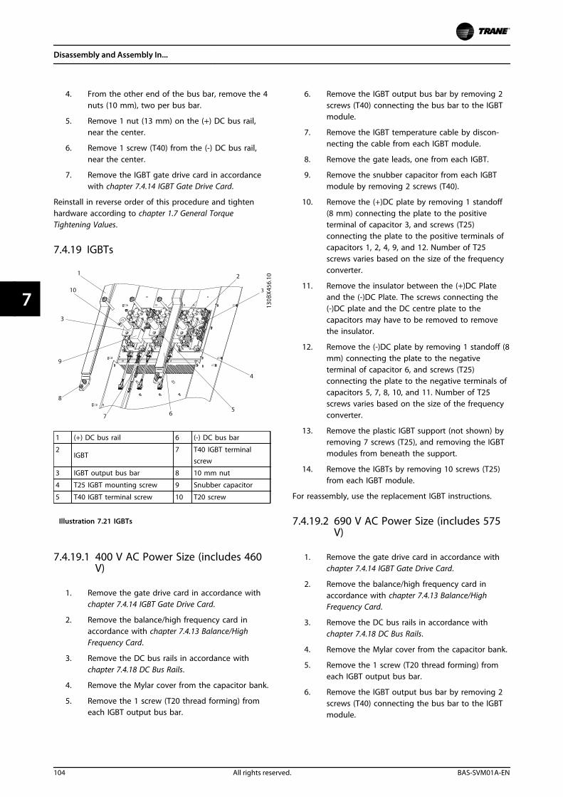
4. From the other end of the bus bar, remove the 4nuts (10 mm), two per bus bar.
5. Remove 1 nut (13 mm) on the (+) DC bus rail,near the center.
6. Remove 1 screw (T40) from the (-) DC bus rail,near the center.
7. Remove the IGBT gate drive card in accordancewith chapter 7.4.14 IGBT Gate Drive Card.
Reinstall in reverse order of this procedure and tightenhardware according to chapter 1.7 General TorqueTightening Values.
7.4.19 IGBTs
1 (+) DC bus rail 6 (-) DC bus bar
2IGBT
7 T40 IGBT terminalscrew
3 IGBT output bus bar 8 10 mm nut
4 T25 IGBT mounting screw 9 Snubber capacitor
5 T40 IGBT terminal screw 10 T20 screw
Illustration 7.21 IGBTs
7.4.19.1 400 V AC Power Size (includes 460V)
1. Remove the gate drive card in accordance withchapter 7.4.14 IGBT Gate Drive Card.
2. Remove the balance/high frequency card inaccordance with chapter 7.4.13 Balance/HighFrequency Card.
3. Remove the DC bus rails in accordance withchapter 7.4.18 DC Bus Rails.
4. Remove the Mylar cover from the capacitor bank.
5. Remove the 1 screw (T20 thread forming) fromeach IGBT output bus bar.
6. Remove the IGBT output bus bar by removing 2screws (T40) connecting the bus bar to the IGBTmodule.
7. Remove the IGBT temperature cable by discon-necting the cable from each IGBT module.
8. Remove the gate leads, one from each IGBT.
9. Remove the snubber capacitor from each IGBTmodule by removing 2 screws (T40).
10. Remove the (+)DC plate by removing 1 standoff(8 mm) connecting the plate to the positiveterminal of capacitor 3, and screws (T25)connecting the plate to the positive terminals ofcapacitors 1, 2, 4, 9, and 12. Number of T25screws varies based on the size of the frequencyconverter.
11. Remove the insulator between the (+)DC Plateand the (-)DC Plate. The screws connecting the(-)DC plate and the DC centre plate to thecapacitors may have to be removed to removethe insulator.
12. Remove the (-)DC plate by removing 1 standoff (8mm) connecting the plate to the negativeterminal of capacitor 6, and screws (T25)connecting the plate to the negative terminals ofcapacitors 5, 7, 8, 10, and 11. Number of T25screws varies based on the size of the frequencyconverter.
13. Remove the plastic IGBT support (not shown) byremoving 7 screws (T25), and removing the IGBTmodules from beneath the support.
14. Remove the IGBTs by removing 10 screws (T25)from each IGBT module.
For reassembly, use the replacement IGBT instructions.
7.4.19.2 690 V AC Power Size (includes 575V)
1. Remove the gate drive card in accordance withchapter 7.4.14 IGBT Gate Drive Card.
2. Remove the balance/high frequency card inaccordance with chapter 7.4.13 Balance/HighFrequency Card.
3. Remove the DC bus rails in accordance withchapter 7.4.18 DC Bus Rails.
4. Remove the Mylar cover from the capacitor bank.
5. Remove the 1 screw (T20 thread forming) fromeach IGBT output bus bar.
6. Remove the IGBT output bus bar by removing 2screws (T40) connecting the bus bar to the IGBTmodule.
Disassembly and Assembly In...
104 All rights reserved. BAS-SVM01A-EN
77
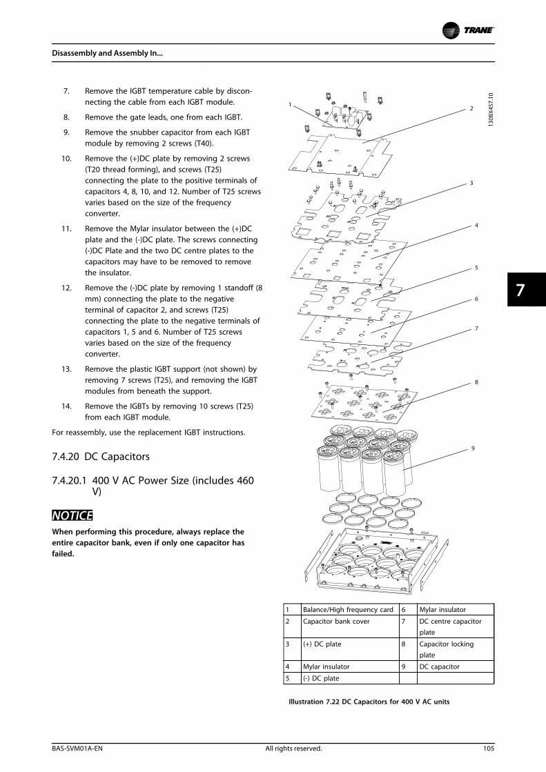
7. Remove the IGBT temperature cable by discon-necting the cable from each IGBT module.
8. Remove the gate leads, one from each IGBT.
9. Remove the snubber capacitor from each IGBTmodule by removing 2 screws (T40).
10. Remove the (+)DC plate by removing 2 screws(T20 thread forming), and screws (T25)connecting the plate to the positive terminals ofcapacitors 4, 8, 10, and 12. Number of T25 screwsvaries based on the size of the frequencyconverter.
11. Remove the Mylar insulator between the (+)DCplate and the (-)DC plate. The screws connecting(-)DC Plate and the two DC centre plates to thecapacitors may have to be removed to removethe insulator.
12. Remove the (-)DC plate by removing 1 standoff (8mm) connecting the plate to the negativeterminal of capacitor 2, and screws (T25)connecting the plate to the negative terminals ofcapacitors 1, 5 and 6. Number of T25 screwsvaries based on the size of the frequencyconverter.
13. Remove the plastic IGBT support (not shown) byremoving 7 screws (T25), and removing the IGBTmodules from beneath the support.
14. Remove the IGBTs by removing 10 screws (T25)from each IGBT module.
For reassembly, use the replacement IGBT instructions.
7.4.20 DC Capacitors
7.4.20.1 400 V AC Power Size (includes 460V)
NOTICEWhen performing this procedure, always replace theentire capacitor bank, even if only one capacitor hasfailed.
1 Balance/High frequency card 6 Mylar insulator
2 Capacitor bank cover 7 DC centre capacitorplate
3 (+) DC plate 8 Capacitor lockingplate
4 Mylar insulator 9 DC capacitor
5 (-) DC plate
Illustration 7.22 DC Capacitors for 400 V AC units
Disassembly and Assembly In...
BAS-SVM01A-EN All rights reserved. 105
7 7
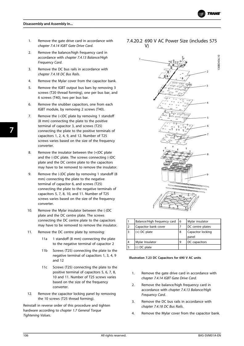
1. Remove the gate drive card in accordance withchapter 7.4.14 IGBT Gate Drive Card.
2. Remove the balance/high frequency card inaccordance with chapter 7.4.13 Balance/HighFrequency Card.
3. Remove the DC bus rails in accordance withchapter 7.4.18 DC Bus Rails.
4. Remove the Mylar cover from the capacitor bank.
5. Remove the IGBT output bus bars by removing 3screws (T20 thread forming), one per bus bar, and6 screws (T40), two per bus bar.
6. Remove the snubber capacitors, one from eachIGBT module, by removing 2 screws (T40).
7. Remove the (+)DC plate by removing 1 standoff(8 mm) connecting the plate to the positiveterminal of capacitor 3, and screws (T25)connecting the plate to the positive terminals ofcapacitors 1, 2, 4, 9, and 12. Number of T25screws varies based on the size of the frequencyconverter.
8. Remove the insulator between the (+)DC plateand the (-)DC plate. The screws connecting (-)DCplate and the DC centre plate to the capacitorsmay have to be removed to remove the insulator.
9. Remove the (-)DC plate by removing 1 standoff (8mm) connecting the plate to the negativeterminal of capacitor 6, and screws (T25)connecting the plate to the negative terminals ofcapacitors 5, 7, 8, 10, and 11. Number of T25screws varies based on the size of the frequencyconverter.
10. Remove the Mylar insulator between the (-)DCplate and the DC centre plate. The screwsconnecting the DC centre plate to the capacitorsmay have to be removed to remove the insulator.
11. Remove the DC centre plate by removing:
11a 1 standoff (8 mm) connecting the plateto the negative terminal of capacitor 2
11b Screws (T25) connecting the plate to thenegative terminal of capacitors 1, 3, 4, 9and 12
11c Screws (T25) connecting the plate to thepositive terminal of capacitors 5, 6, 7, 8,10 and 11. Number of T25 screws variesbased on the size of the frequencyconverter.
12. Remove the capacitor locking panel by removingthe 10 screws (T25 thread forming).
Reinstall in reverse order of this procedure and tightenhardware according to chapter 1.7 General TorqueTightening Values.
7.4.20.2 690 V AC Power Size (includes 575V)
1 Balance/High frequency card 6 Mylar insulator
2 Capacitor bank cover 7 DC centre plates
3 (+) DC plate 8 Capacitor lockingpanel
4 Mylar Insulator 9 DC capacitors
5 (-) DC plate
Illustration 7.23 DC Capacitors for 690 V AC units
1. Remove the gate drive card in accordance withchapter 7.4.14 IGBT Gate Drive Card.
2. Remove the balance/high frequency card inaccordance with chapter 7.4.13 Balance/HighFrequency Card.
3. Remove the DC bus rails in accordance withchapter 7.4.18 DC Bus Rails.
4. Remove the Mylar cover from the capacitor bank.
Disassembly and Assembly In...
106 All rights reserved. BAS-SVM01A-EN
77
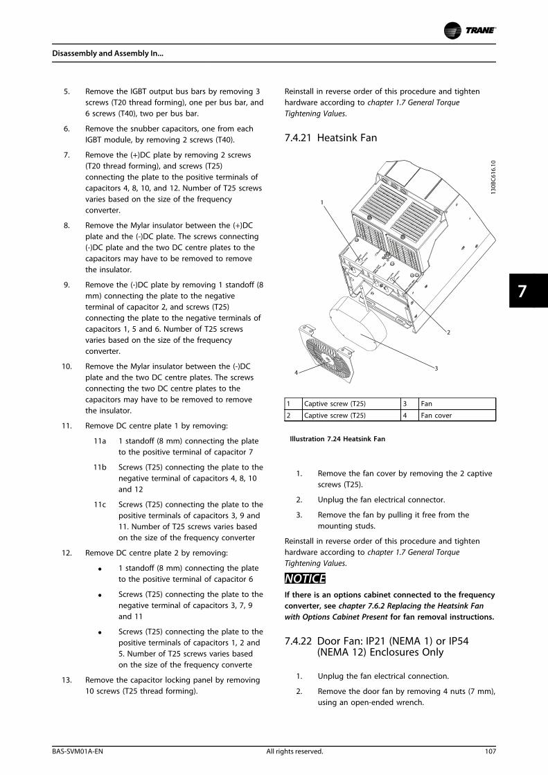
5. Remove the IGBT output bus bars by removing 3screws (T20 thread forming), one per bus bar, and6 screws (T40), two per bus bar.
6. Remove the snubber capacitors, one from eachIGBT module, by removing 2 screws (T40).
7. Remove the (+)DC plate by removing 2 screws(T20 thread forming), and screws (T25)connecting the plate to the positive terminals ofcapacitors 4, 8, 10, and 12. Number of T25 screwsvaries based on the size of the frequencyconverter.
8. Remove the Mylar insulator between the (+)DCplate and the (-)DC plate. The screws connecting(-)DC plate and the two DC centre plates to thecapacitors may have to be removed to removethe insulator.
9. Remove the (-)DC plate by removing 1 standoff (8mm) connecting the plate to the negativeterminal of capacitor 2, and screws (T25)connecting the plate to the negative terminals ofcapacitors 1, 5 and 6. Number of T25 screwsvaries based on the size of the frequencyconverter.
10. Remove the Mylar insulator between the (-)DCplate and the two DC centre plates. The screwsconnecting the two DC centre plates to thecapacitors may have to be removed to removethe insulator.
11. Remove DC centre plate 1 by removing:
11a 1 standoff (8 mm) connecting the plateto the positive terminal of capacitor 7
11b Screws (T25) connecting the plate to thenegative terminal of capacitors 4, 8, 10and 12
11c Screws (T25) connecting the plate to thepositive terminals of capacitors 3, 9 and11. Number of T25 screws varies basedon the size of the frequency converter
12. Remove DC centre plate 2 by removing:
• 1 standoff (8 mm) connecting the plateto the positive terminal of capacitor 6
• Screws (T25) connecting the plate to thenegative terminal of capacitors 3, 7, 9and 11
• Screws (T25) connecting the plate to thepositive terminals of capacitors 1, 2 and5. Number of T25 screws varies basedon the size of the frequency converte
13. Remove the capacitor locking panel by removing10 screws (T25 thread forming).
Reinstall in reverse order of this procedure and tightenhardware according to chapter 1.7 General TorqueTightening Values.
7.4.21 Heatsink Fan
1 Captive screw (T25) 3 Fan
2 Captive screw (T25) 4 Fan cover
Illustration 7.24 Heatsink Fan
1. Remove the fan cover by removing the 2 captivescrews (T25).
2. Unplug the fan electrical connector.
3. Remove the fan by pulling it free from themounting studs.
Reinstall in reverse order of this procedure and tightenhardware according to chapter 1.7 General TorqueTightening Values.
NOTICEIf there is an options cabinet connected to the frequencyconverter, see chapter 7.6.2 Replacing the Heatsink Fanwith Options Cabinet Present for fan removal instructions.
7.4.22 Door Fan: IP21 (NEMA 1) or IP54(NEMA 12) Enclosures Only
1. Unplug the fan electrical connection.
2. Remove the door fan by removing 4 nuts (7 mm),using an open-ended wrench.
Disassembly and Assembly In...
BAS-SVM01A-EN All rights reserved. 107
7 7
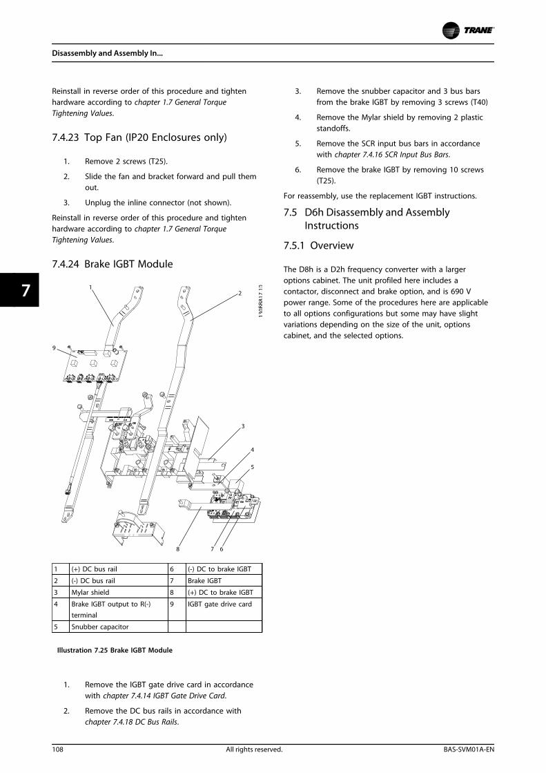
Reinstall in reverse order of this procedure and tightenhardware according to chapter 1.7 General TorqueTightening Values.
7.4.23 Top Fan (IP20 Enclosures only)
1. Remove 2 screws (T25).
2. Slide the fan and bracket forward and pull themout.
3. Unplug the inline connector (not shown).
Reinstall in reverse order of this procedure and tightenhardware according to chapter 1.7 General TorqueTightening Values.
7.4.24 Brake IGBT Module
1 (+) DC bus rail 6 (-) DC to brake IGBT
2 (-) DC bus rail 7 Brake IGBT
3 Mylar shield 8 (+) DC to brake IGBT
4 Brake IGBT output to R(-)terminal
9 IGBT gate drive card
5 Snubber capacitor
Illustration 7.25 Brake IGBT Module
1. Remove the IGBT gate drive card in accordancewith chapter 7.4.14 IGBT Gate Drive Card.
2. Remove the DC bus rails in accordance withchapter 7.4.18 DC Bus Rails.
3. Remove the snubber capacitor and 3 bus barsfrom the brake IGBT by removing 3 screws (T40)
4. Remove the Mylar shield by removing 2 plasticstandoffs.
5. Remove the SCR input bus bars in accordancewith chapter 7.4.16 SCR Input Bus Bars.
6. Remove the brake IGBT by removing 10 screws(T25).
For reassembly, use the replacement IGBT instructions.
7.5 D6h Disassembly and AssemblyInstructions
7.5.1 Overview
The D8h is a D2h frequency converter with a largeroptions cabinet. The unit profiled here includes acontactor, disconnect and brake option, and is 690 Vpower range. Some of the procedures here are applicableto all options configurations but some may have slightvariations depending on the size of the unit, optionscabinet, and the selected options.
Disassembly and Assembly In...
108 All rights reserved. BAS-SVM01A-EN
77
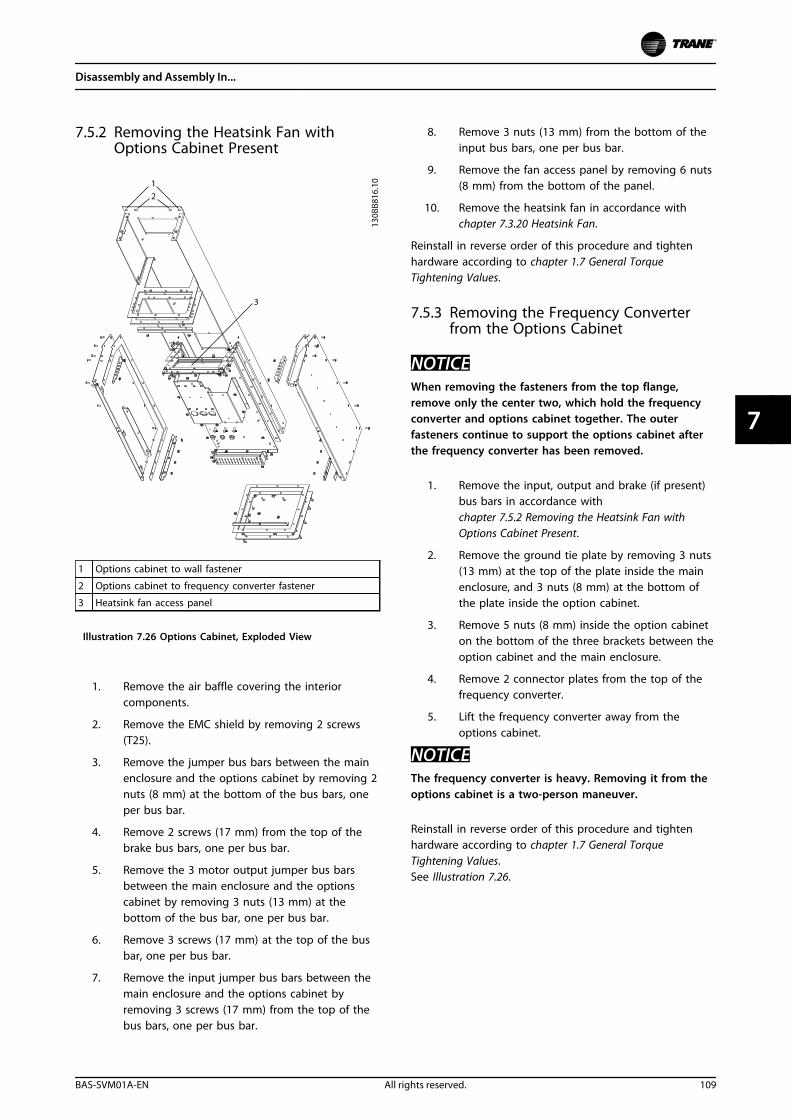
7.5.2 Removing the Heatsink Fan withOptions Cabinet Present
1 Options cabinet to wall fastener
2 Options cabinet to frequency converter fastener
3 Heatsink fan access panel
Illustration 7.26 Options Cabinet, Exploded View
1. Remove the air baffle covering the interiorcomponents.
2. Remove the EMC shield by removing 2 screws(T25).
3. Remove the jumper bus bars between the mainenclosure and the options cabinet by removing 2nuts (8 mm) at the bottom of the bus bars, oneper bus bar.
4. Remove 2 screws (17 mm) from the top of thebrake bus bars, one per bus bar.
5. Remove the 3 motor output jumper bus barsbetween the main enclosure and the optionscabinet by removing 3 nuts (13 mm) at thebottom of the bus bar, one per bus bar.
6. Remove 3 screws (17 mm) at the top of the busbar, one per bus bar.
7. Remove the input jumper bus bars between themain enclosure and the options cabinet byremoving 3 screws (17 mm) from the top of thebus bars, one per bus bar.
8. Remove 3 nuts (13 mm) from the bottom of theinput bus bars, one per bus bar.
9. Remove the fan access panel by removing 6 nuts(8 mm) from the bottom of the panel.
10. Remove the heatsink fan in accordance withchapter 7.3.20 Heatsink Fan.
Reinstall in reverse order of this procedure and tightenhardware according to chapter 1.7 General TorqueTightening Values.
7.5.3 Removing the Frequency Converterfrom the Options Cabinet
NOTICEWhen removing the fasteners from the top flange,remove only the center two, which hold the frequencyconverter and options cabinet together. The outerfasteners continue to support the options cabinet afterthe frequency converter has been removed.
1. Remove the input, output and brake (if present)bus bars in accordance withchapter 7.5.2 Removing the Heatsink Fan withOptions Cabinet Present.
2. Remove the ground tie plate by removing 3 nuts(13 mm) at the top of the plate inside the mainenclosure, and 3 nuts (8 mm) at the bottom ofthe plate inside the option cabinet.
3. Remove 5 nuts (8 mm) inside the option cabineton the bottom of the three brackets between theoption cabinet and the main enclosure.
4. Remove 2 connector plates from the top of thefrequency converter.
5. Lift the frequency converter away from theoptions cabinet.
NOTICEThe frequency converter is heavy. Removing it from theoptions cabinet is a two-person maneuver.
Reinstall in reverse order of this procedure and tightenhardware according to chapter 1.7 General TorqueTightening Values.See Illustration 7.26.
Disassembly and Assembly In...
BAS-SVM01A-EN All rights reserved. 109
7 7
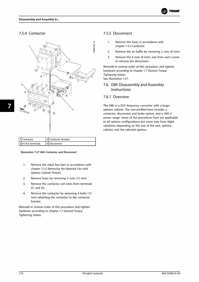
7.5.4 Contactor
1 Contactor 2 Contactor Bracket
3 A1/A2 terminals 4 Disconnect
Illustration 7.27 D6h Contactor and Disconnect
1. Remove the input bus bars in accordance withchapter 7.5.2 Removing the Heatsink Fan withOptions Cabinet Present.
2. Remove fuses by removing 3 nuts (13 mm)
3. Remove the contactor coil wires from terminalsA1 and A2.
4. Remove the contactor by removing 4 bolts (13mm) attaching the contactor to the contactorbracket.
Reinstall in reverse order of this procedure and tightenhardware according to chapter 1.7 General TorqueTightening Values.
7.5.5 Disconnect
1. Remove the fuses in accordance withchapter 7.5.4 Contactor.
2. Remove the air baffle by removing 2 nuts (8 mm).
3. Remove the 4 nuts (8 mm), one from each cornerto remove the disconnect.
Reinstall in reverse order of this procedure and tightenhardware according to chapter 1.7 General TorqueTightening Values.See Illustration 7.27.
7.6 D8h Disassembly and AssemblyInstructions
7.6.1 Overview
The D8h is a D2h frequency converter with a largeroptions cabinet. The unit profiled here includes acontactor, disconnect and brake option, and is 690 Vpower range. Some of the procedures here are applicableto all options configurations but some may have slightvariations depending on the size of the unit, optionscabinet, and the selected options.
Disassembly and Assembly In...
110 All rights reserved. BAS-SVM01A-EN
77
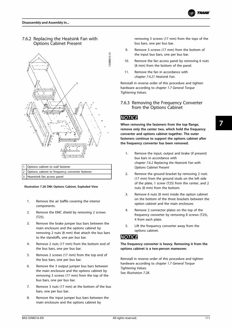
7.6.2 Replacing the Heatsink Fan withOptions Cabinet Present
1 Options cabinet to wall fastener
2 Options cabinet to frequency converter fastener
3 Heantsink fan access panel
Illustration 7.28 D8h Options Cabinet, Exploded View
1. Remove the air baffle covering the interiorcomponents.
2. Remove the EMC shield by removing 2 screws(T25).
3. Remove the brake jumper bus bars between themain enclosure and the options cabinet byremoving 2 nuts (8 mm) that attach the bus barsto the standoffs, one per bus bar.
4. Remove 2 nuts (17 mm) from the bottom end ofthe bus bars, one per bus bar.
5. Remove 2 screws (17 mm) from the top end ofthe bus bars, one per bus bar.
6. Remove the 3 output jumper bus bars betweenthe main enclosure and the options cabinet byremoving 3 screws (17 mm) from the top of thebus bars, one per bus bar.
7. Remove 3 nuts (17 mm) at the bottom of the busbars, one per bus bar.
8. Remove the input jumper bus bars between themain enclosure and the options cabinet by
removing 3 screws (17 mm) from the tops of thebus bars, one per bus bar.
9. Remove 3 screws (17 mm) from the bottom ofthe input bus bars, one per bus bar.
10. Remove the fan access panel by removing 6 nuts(8 mm) from the bottom of the panel.
11. Remove the fan in accordance withchapter 7.4.21 Heatsink Fan.
Reinstall in reverse order of this procedure and tightenhardware according to chapter 1.7 General TorqueTightening Values.
7.6.3 Removing the Frequency Converterfrom the Options Cabinet
NOTICEWhen removing the fasteners from the top flange,remove only the center two, which hold the frequencyconverter and options cabinet together. The outerfasteners continue to support the options cabinet afterthe frequency converter has been removed.
1. Remove the input, output and brake (if present)bus bars in accordance withchapter 7.6.2 Replacing the Heatsink Fan withOptions Cabinet Present
2. Remove the ground bracket by removing 2 nuts(17 mm) from the ground studs on the left sideof the plate, 1 screw (T25) from the center, and 2nuts (8 mm) from the bottom.
3. Remove 6 nuts (8 mm) inside the option cabineton the bottom of the three brackets between theoption cabinet and the main enclosure.
4. Remove 2 connector plates on the top of thefrequency converter by removing 8 screws (T25),4 from each plate.
5. Lift the frequency converter away from theoptions cabinet.
NOTICEThe frequency converter is heavy. Removing it from theoptions cabinet is a two-person maneuver.
Reinstall in reverse order of this procedure and tightenhardware according to chapter 1.7 General TorqueTightening Values.See Illustration 7.28.
Disassembly and Assembly In...
BAS-SVM01A-EN All rights reserved. 111
7 7
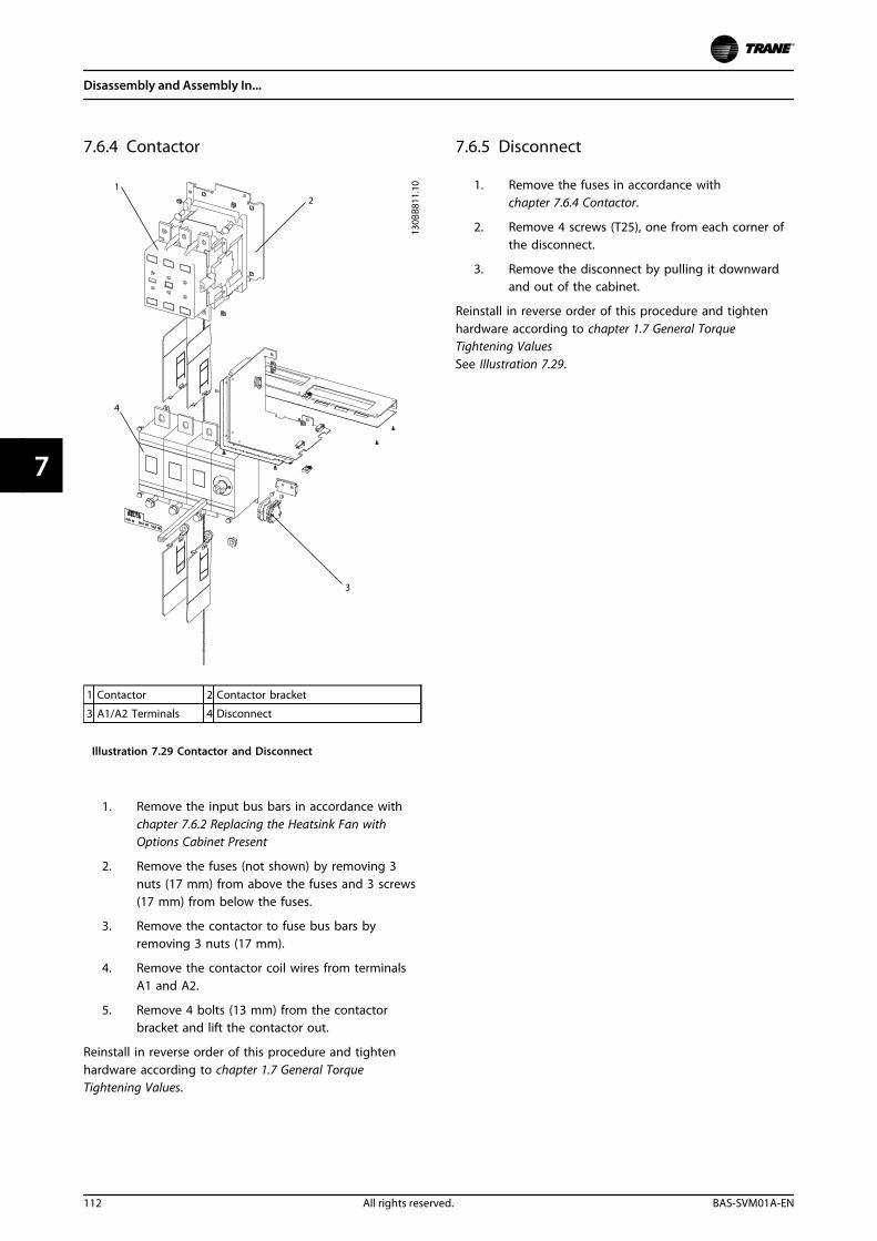
7.6.4 Contactor
1 Contactor 2 Contactor bracket
3 A1/A2 Terminals 4 Disconnect
Illustration 7.29 Contactor and Disconnect
1. Remove the input bus bars in accordance withchapter 7.6.2 Replacing the Heatsink Fan withOptions Cabinet Present
2. Remove the fuses (not shown) by removing 3nuts (17 mm) from above the fuses and 3 screws(17 mm) from below the fuses.
3. Remove the contactor to fuse bus bars byremoving 3 nuts (17 mm).
4. Remove the contactor coil wires from terminalsA1 and A2.
5. Remove 4 bolts (13 mm) from the contactorbracket and lift the contactor out.
Reinstall in reverse order of this procedure and tightenhardware according to chapter 1.7 General TorqueTightening Values.
7.6.5 Disconnect
1. Remove the fuses in accordance withchapter 7.6.4 Contactor.
2. Remove 4 screws (T25), one from each corner ofthe disconnect.
3. Remove the disconnect by pulling it downwardand out of the cabinet.
Reinstall in reverse order of this procedure and tightenhardware according to chapter 1.7 General TorqueTightening ValuesSee Illustration 7.29.
Disassembly and Assembly In...
112 All rights reserved. BAS-SVM01A-EN
77
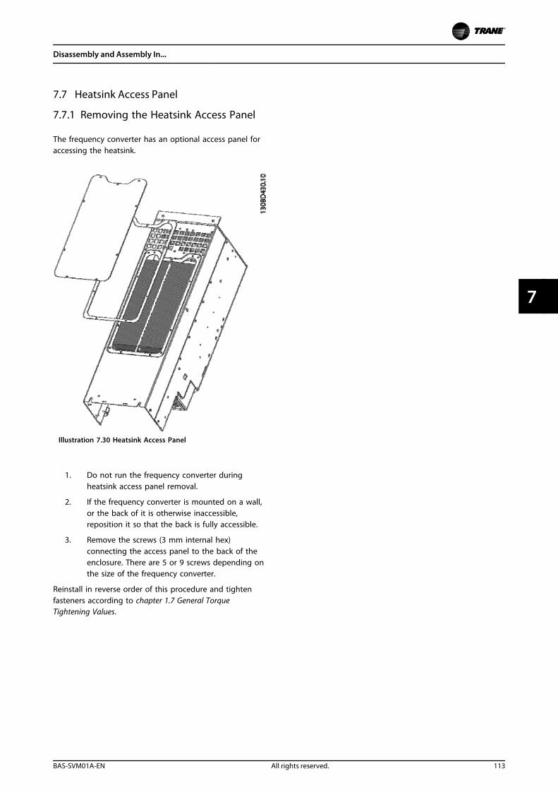
7.7 Heatsink Access Panel
7.7.1 Removing the Heatsink Access Panel
The frequency converter has an optional access panel foraccessing the heatsink.
Illustration 7.30 Heatsink Access Panel
1. Do not run the frequency converter duringheatsink access panel removal.
2. If the frequency converter is mounted on a wall,or the back of it is otherwise inaccessible,reposition it so that the back is fully accessible.
3. Remove the screws (3 mm internal hex)connecting the access panel to the back of theenclosure. There are 5 or 9 screws depending onthe size of the frequency converter.
Reinstall in reverse order of this procedure and tightenfasteners according to chapter 1.7 General TorqueTightening Values.
Disassembly and Assembly In...
BAS-SVM01A-EN All rights reserved. 113
7 7
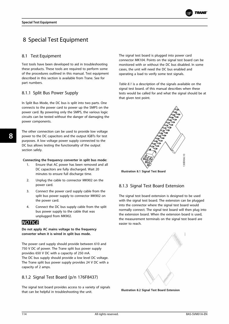
8 Special Test Equipment
8.1 Test Equipment
Test tools have been developed to aid in troubleshootingthese products. These tools are required to perform someof the procedures outlined in this manual. Test equipmentdescribed in this section is available from Trane. See forpart numbers.
8.1.1 Split Bus Power Supply
In Split Bus Mode, the DC bus is split into two parts. Oneconnects to the power card to power up the SMPS on thepower card. By powering only the SMPS, the various logiccircuits can be tested without the danger of damaging thepower components.
The other connection can be used to provide low voltagepower to the DC capacitors and the output IGBTs for testpurposes. A low voltage power supply connected to theDC bus allows testing the functionality of the outputsection safely.
Connecting the frequency converter in split bus mode:1. Ensure that AC power has been removed and all
DC capacitors are fully discharged. Wait 20minutes to ensure full discharge time.
2. Unplug the cable to connector MK902 on thepower card.
3. Connect the power card supply cable from thesplit bus power supply to connector MK902 onthe power card.
4. Connect the DC bus supply cable from the splitbus power supply to the cable that wasunplugged from MK902.
NOTICEDo not apply AC mains voltage to the frequencyconverter when it is wired in split bus mode.
The power card supply should provide between 610 and750 V DC of power. The Trane split bus power supplyprovides 650 V DC with a capacity of 250 mA.The DC bus supply should provide a low level DC voltage.The Trane split bus power supply provides 24 V DC with acapacity of 2 amps.
8.1.2 Signal Test Board (p/n 176F8437)
The signal test board provides access to a variety of signalsthat can be helpful in troubleshooting the unit.
The signal test board is plugged into power cardconnector MK104. Points on the signal test board can bemonitored with or without the DC bus disabled. In somecases, the unit will need the DC bus enabled andoperating a load to verify some test signals.
Table 8.1 is a description of the signals available on thesignal test board. of this manual describes when thesetests would be called for and what the signal should be atthat given test point.
130B
X66
.10
Illustration 8.1 Signal Test Board
8.1.3 Signal Test Board Extension
The signal test board extension is designed to be usedwith the signal test board. The extension can be pluggedinto the connector where the signal test board wouldnormally connect. The signal test board will then plug intothe extension board. When the extension board is used,the measurement terminals on the signal test board areeasier to reach.
Illustration 8.2 Signal Test Board Extension
Special Test Equipment
114 All rights reserved. BAS-SVM01A-EN
88
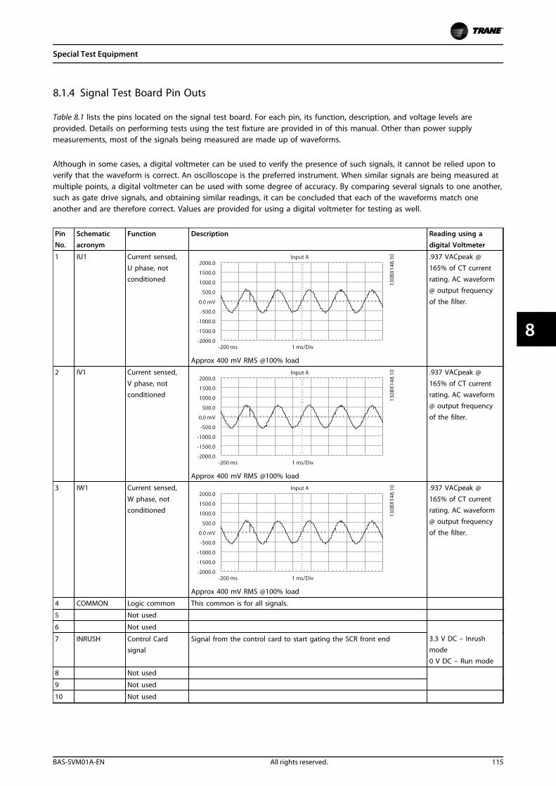
8.1.4 Signal Test Board Pin Outs
Table 8.1 lists the pins located on the signal test board. For each pin, its function, description, and voltage levels areprovided. Details on performing tests using the test fixture are provided in of this manual. Other than power supplymeasurements, most of the signals being measured are made up of waveforms.
Although in some cases, a digital voltmeter can be used to verify the presence of such signals, it cannot be relied upon toverify that the waveform is correct. An oscilloscope is the preferred instrument. When similar signals are being measured atmultiple points, a digital voltmeter can be used with some degree of accuracy. By comparing several signals to one another,such as gate drive signals, and obtaining similar readings, it can be concluded that each of the waveforms match oneanother and are therefore correct. Values are provided for using a digital voltmeter for testing as well.
PinNo.
Schematicacronym
Function Description Reading using adigital Voltmeter
1 IU1 Current sensed,
U phase, notconditioned
Approx 400 mV RMS @100% load
.937 VACpeak @
165% of CT currentrating. AC waveform@ output frequency
of the filter.
2 IV1 Current sensed,
V phase, notconditioned
Approx 400 mV RMS @100% load
.937 VACpeak @
165% of CT currentrating. AC waveform@ output frequency
of the filter.
3 IW1 Current sensed,
W phase, notconditioned
Approx 400 mV RMS @100% load
.937 VACpeak @
165% of CT currentrating. AC waveform@ output frequency
of the filter.
4 COMMON Logic common This common is for all signals.
5 Not used
6 Not used
7 INRUSH Control Cardsignal
Signal from the control card to start gating the SCR front end 3.3 V DC – Inrushmode0 V DC – Run mode
8 Not used
9 Not used
10 Not used
Special Test Equipment
BAS-SVM01A-EN All rights reserved. 115
8 8
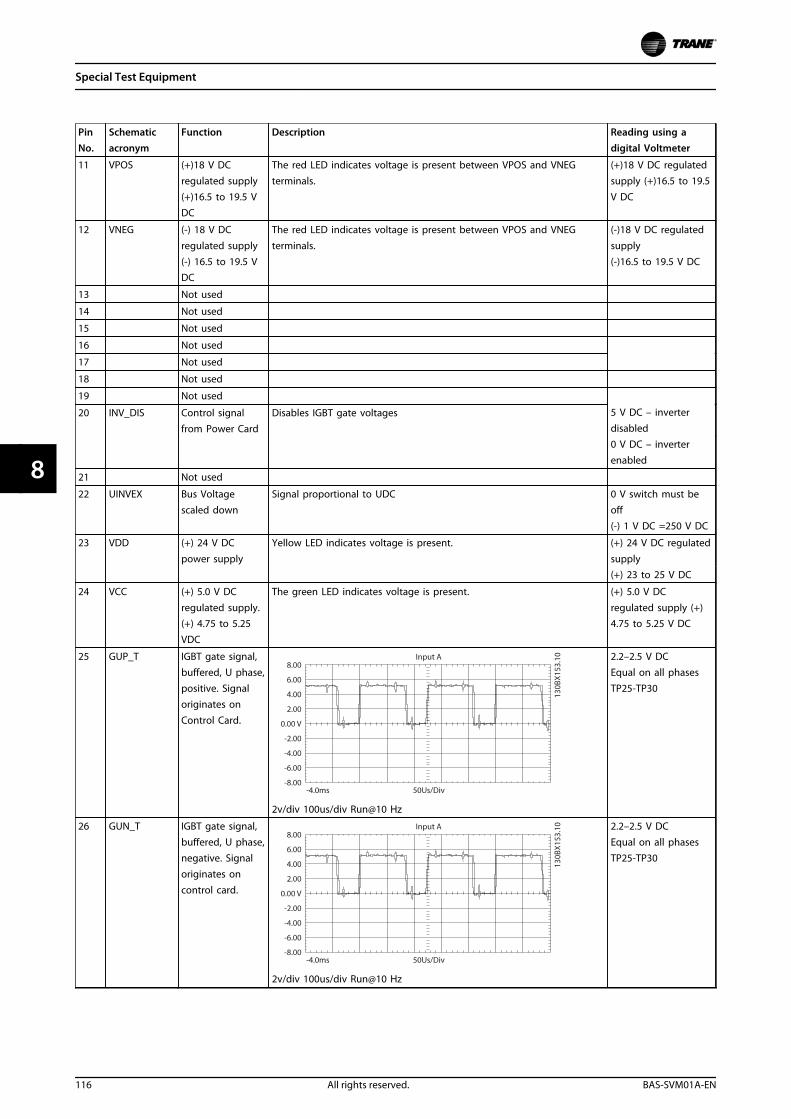
PinNo.
Schematicacronym
Function Description Reading using adigital Voltmeter
11 VPOS (+)18 V DCregulated supply(+)16.5 to 19.5 VDC
The red LED indicates voltage is present between VPOS and VNEGterminals.
(+)18 V DC regulatedsupply (+)16.5 to 19.5V DC
12 VNEG (-) 18 V DC
regulated supply(-) 16.5 to 19.5 VDC
The red LED indicates voltage is present between VPOS and VNEG
terminals.
(-)18 V DC regulated
supply(-)16.5 to 19.5 V DC
13 Not used
14 Not used
15 Not used
16 Not used
17 Not used
18 Not used
19 Not used
20 INV_DIS Control signalfrom Power Card
Disables IGBT gate voltages 5 V DC – inverterdisabled0 V DC – inverterenabled
21 Not used
22 UINVEX Bus Voltagescaled down
Signal proportional to UDC 0 V switch must beoff(-) 1 V DC =250 V DC
23 VDD (+) 24 V DC
power supply
Yellow LED indicates voltage is present. (+) 24 V DC regulated
supply(+) 23 to 25 V DC
24 VCC (+) 5.0 V DC
regulated supply.(+) 4.75 to 5.25VDC
The green LED indicates voltage is present. (+) 5.0 V DC
regulated supply (+)4.75 to 5.25 V DC
25 GUP_T IGBT gate signal,buffered, U phase,positive. Signaloriginates onControl Card.
2v/div 100us/div Run@10 Hz
2.2–2.5 V DCEqual on all phasesTP25-TP30
26 GUN_T IGBT gate signal,buffered, U phase,negative. Signaloriginates oncontrol card.
2v/div 100us/div Run@10 Hz
2.2–2.5 V DCEqual on all phasesTP25-TP30
Special Test Equipment
116 All rights reserved. BAS-SVM01A-EN
88
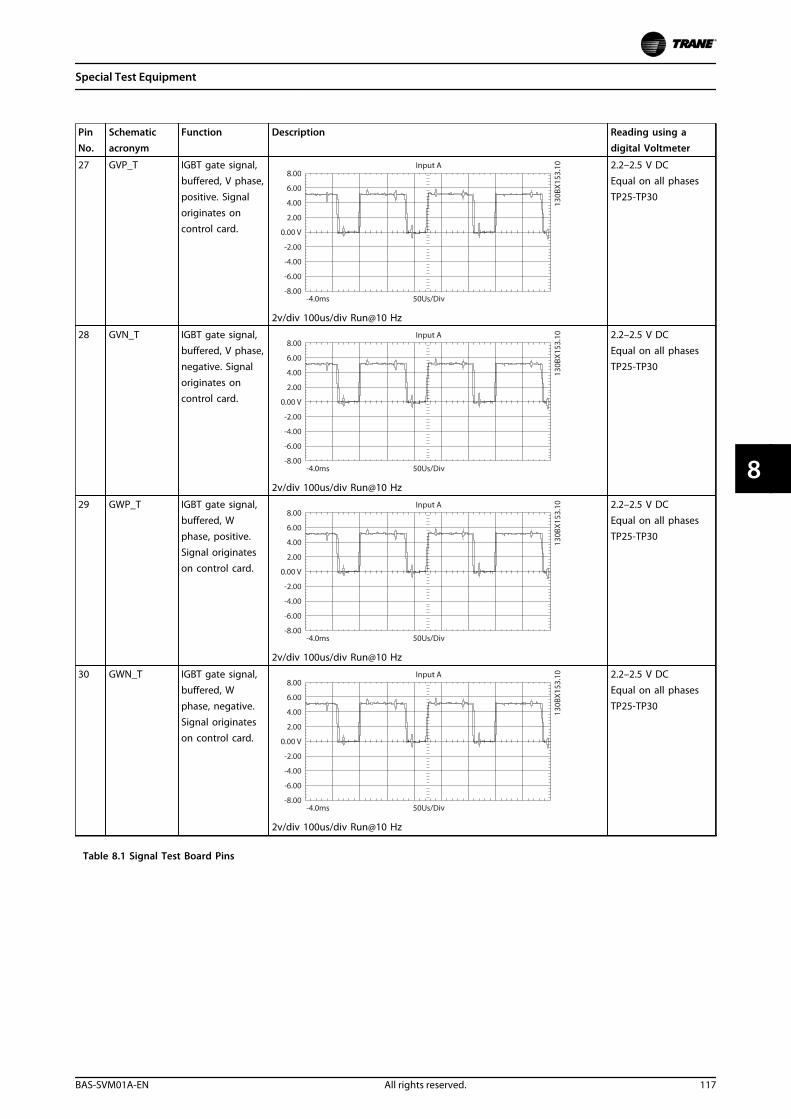
PinNo.
Schematicacronym
Function Description Reading using adigital Voltmeter
27 GVP_T IGBT gate signal,buffered, V phase,positive. Signaloriginates oncontrol card.
2v/div 100us/div Run@10 Hz
2.2–2.5 V DCEqual on all phasesTP25-TP30
28 GVN_T IGBT gate signal,buffered, V phase,negative. Signaloriginates oncontrol card.
2v/div 100us/div Run@10 Hz
2.2–2.5 V DCEqual on all phasesTP25-TP30
29 GWP_T IGBT gate signal,buffered, Wphase, positive.Signal originateson control card.
2v/div 100us/div Run@10 Hz
2.2–2.5 V DCEqual on all phasesTP25-TP30
30 GWN_T IGBT gate signal,buffered, Wphase, negative.Signal originateson control card.
2v/div 100us/div Run@10 Hz
2.2–2.5 V DCEqual on all phasesTP25-TP30
Table 8.1 Signal Test Board Pins
Special Test Equipment
BAS-SVM01A-EN All rights reserved. 117
8 8
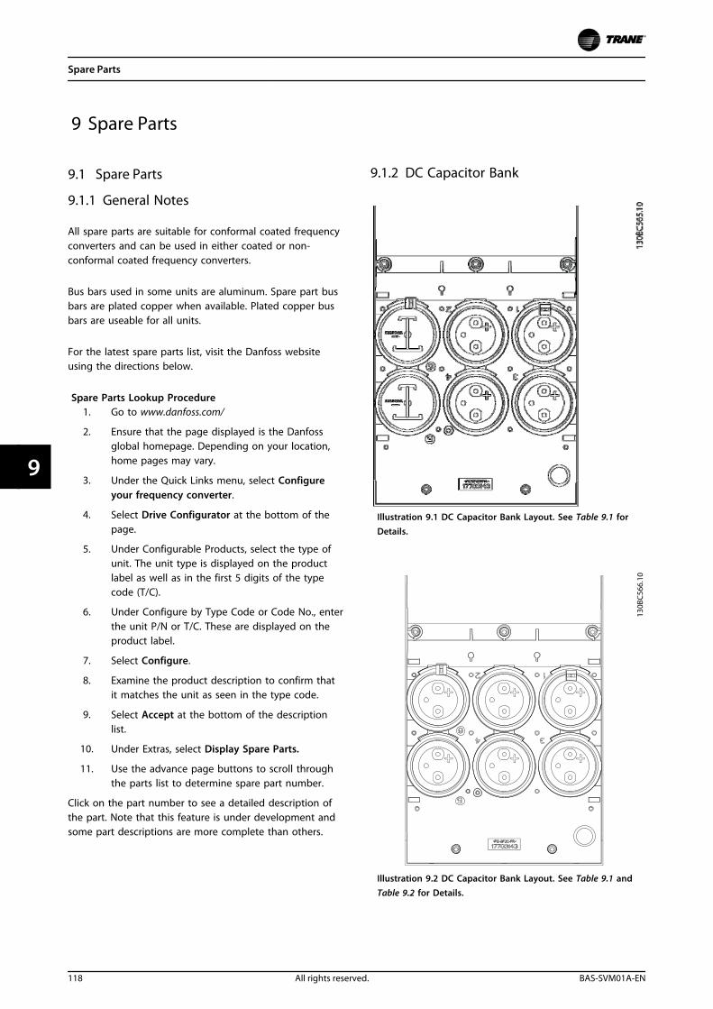
9 Spare Parts
9.1 Spare Parts
9.1.1 General Notes
All spare parts are suitable for conformal coated frequencyconverters and can be used in either coated or non-conformal coated frequency converters.
Bus bars used in some units are aluminum. Spare part busbars are plated copper when available. Plated copper busbars are useable for all units.
For the latest spare parts list, visit the Danfoss websiteusing the directions below.
Spare Parts Lookup Procedure1. Go to www.danfoss.com/
2. Ensure that the page displayed is the Danfossglobal homepage. Depending on your location,home pages may vary.
3. Under the Quick Links menu, select Configureyour frequency converter.
4. Select Drive Configurator at the bottom of thepage.
5. Under Configurable Products, select the type ofunit. The unit type is displayed on the productlabel as well as in the first 5 digits of the typecode (T/C).
6. Under Configure by Type Code or Code No., enterthe unit P/N or T/C. These are displayed on theproduct label.
7. Select Configure.
8. Examine the product description to confirm thatit matches the unit as seen in the type code.
9. Select Accept at the bottom of the descriptionlist.
10. Under Extras, select Display Spare Parts.
11. Use the advance page buttons to scroll throughthe parts list to determine spare part number.
Click on the part number to see a detailed description ofthe part. Note that this feature is under development andsome part descriptions are more complete than others.
9.1.2 DC Capacitor Bank
Illustration 9.1 DC Capacitor Bank Layout. See Table 9.1 forDetails.
Illustration 9.2 DC Capacitor Bank Layout. See Table 9.1 andTable 9.2 for Details.
Spare Parts
118 All rights reserved. BAS-SVM01A-EN
99
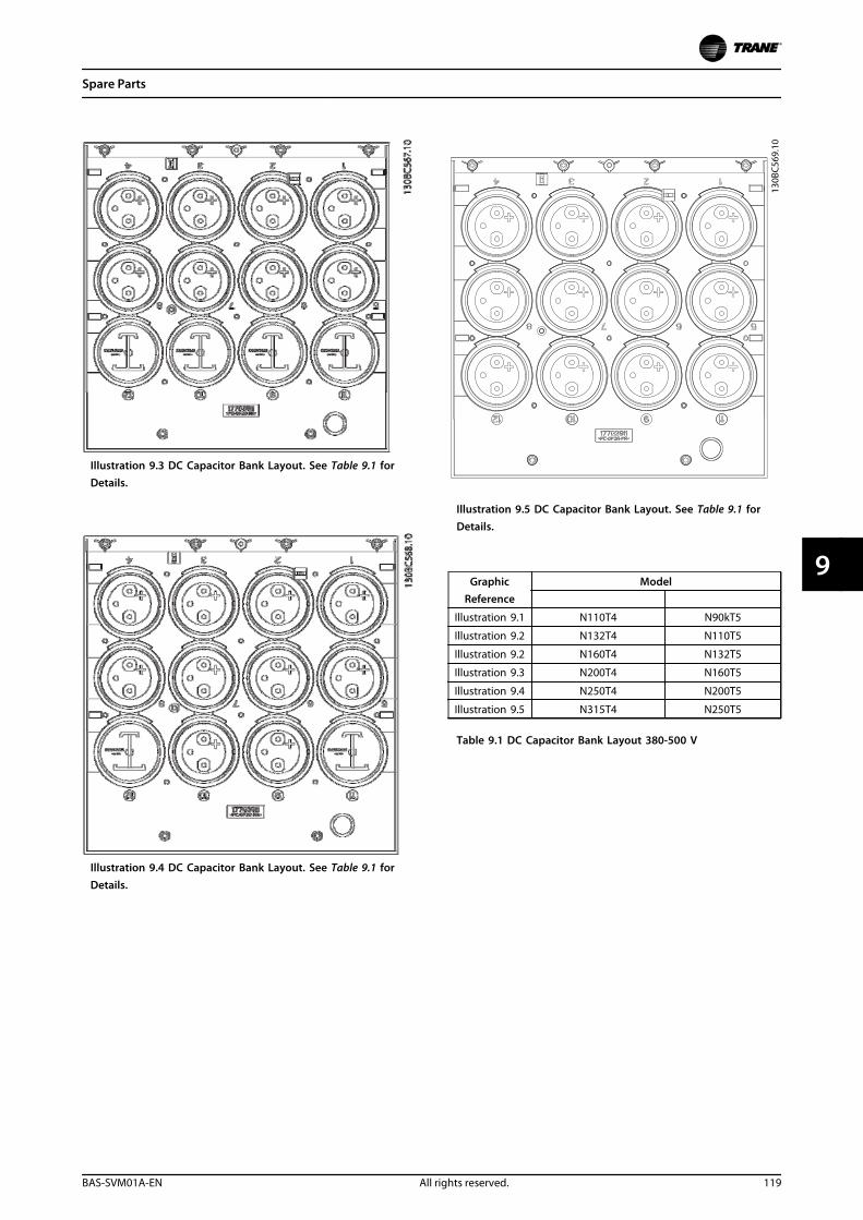
Illustration 9.3 DC Capacitor Bank Layout. See Table 9.1 forDetails.
Illustration 9.4 DC Capacitor Bank Layout. See Table 9.1 forDetails.
Illustration 9.5 DC Capacitor Bank Layout. See Table 9.1 forDetails.
GraphicReference
Model
Illustration 9.1 N110T4 N90kT5
Illustration 9.2 N132T4 N110T5
Illustration 9.2 N160T4 N132T5
Illustration 9.3 N200T4 N160T5
Illustration 9.4 N250T4 N200T5
Illustration 9.5 N315T4 N250T5
Table 9.1 DC Capacitor Bank Layout 380-500 V
Spare Parts
BAS-SVM01A-EN All rights reserved. 119
9 9
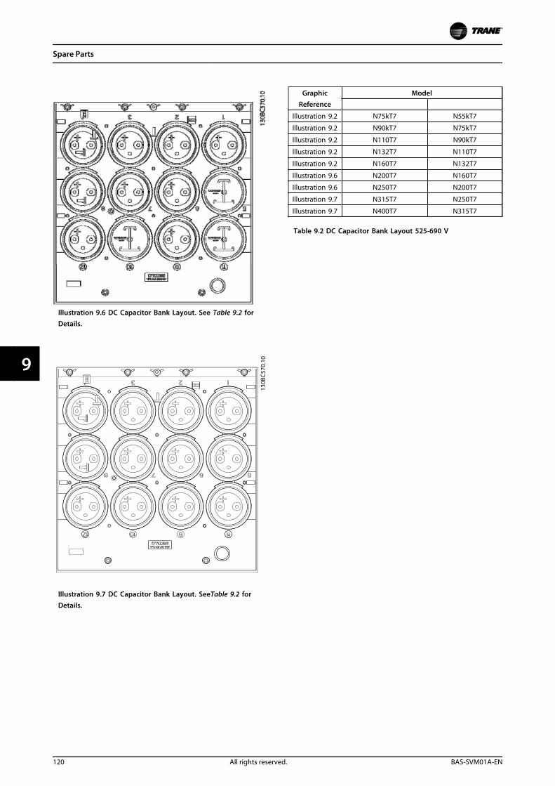
Illustration 9.6 DC Capacitor Bank Layout. See Table 9.2 forDetails.
130B
C570
.10
Illustration 9.7 DC Capacitor Bank Layout. SeeTable 9.2 forDetails.
GraphicReference
Model
Illustration 9.2 N75kT7 N55kT7
Illustration 9.2 N90kT7 N75kT7
Illustration 9.2 N110T7 N90kT7
Illustration 9.2 N132T7 N110T7
Illustration 9.2 N160T7 N132T7
Illustration 9.6 N200T7 N160T7
Illustration 9.6 N250T7 N200T7
Illustration 9.7 N315T7 N250T7
Illustration 9.7 N400T7 N315T7
Table 9.2 DC Capacitor Bank Layout 525-690 V
Spare Parts
120 All rights reserved. BAS-SVM01A-EN
99
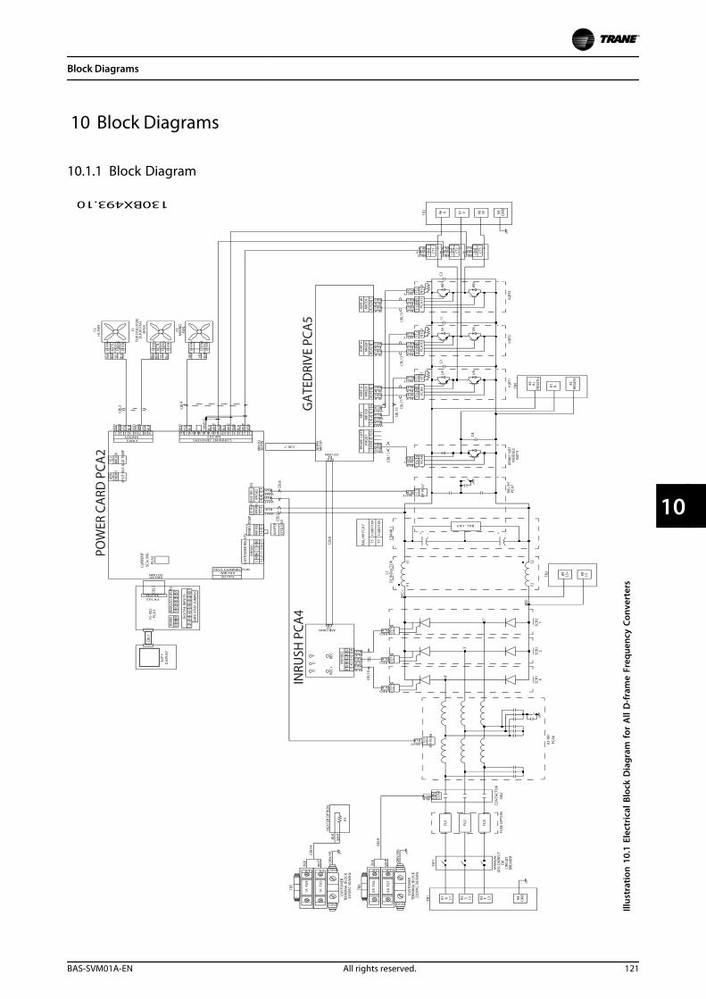
10 Block Diagrams
10.1.1 Block Diagram
Illus
trat
ion
10.
1 El
ectr
ical
Blo
ck D
iagr
am fo
r A
ll D
-fra
me
Freq
uenc
y Co
nver
ters
Block Diagrams
BAS-SVM01A-EN All rights reserved. 121
10 10
Index
AAlarm Message...................................................................................... 46
AMA...................................................................................... 22, 24, 50, 53
Analog input.......................................................................................... 49
Analog signal......................................................................................... 49
Auto on.............................................................................................. 23, 25
BBrake control.......................................................................................... 50
Brake resistor.......................................................................................... 49
Braking..................................................................................................... 24
CCapacitor.......................................................................................... 55, 84
Circuitry...................................................................................... 43, 55, 84
Coasting................................................................................................... 22
Communication option...................................................................... 52
Control card............................................................................................ 49
Control signal......................................................................................... 23
Control terminal............................................................................. 23, 25
Control word timeout......................................................................... 51
Current rating........................................................................................ 50
DDC current............................................................................................... 24
DC link....................................................................................................... 49
Default setting....................................................................................... 23
Diagnostic............................................................................................... 43
Digital input..................................................................................... 25, 50
EExternal command............................................................................... 25
FFault
Internal................................................................................................. 52
Feedback................................................................................... 24, 52, 54
Fire mode................................................................................................ 54
Fuse........................................................................................................... 52
GGraphical display.................................................................................. 19
HHand.......................................................................................................... 23
Hand on.................................................................................................... 23
Heat sink.................................................................................................. 52
IIndicator light........................................................................................ 20
Initialisation............................................................................................ 23
Input terminal........................................................................................ 49
Intermediate Circuit............................................................................. 49
KKeypad.................................................................................................. 0
LLCP............................................................................................................. 45
LED...................................................................................................... 19, 45
Local control........................................................................................... 23
Local control panel.............................................................................. 22
MMains voltage......................................................................................... 24
Motor current......................................................................................... 53
Motor data....................................................................................... 50, 53
Motor power.......................................................................................... 53
NNavigation key....................................................................................... 23
OOutput........................................................................................ 43, 55, 84
Output current............................................................................... 24, 50
Output voltage............................................................................... 55, 84
Overcurrent............................................................................................ 25
Overheating............................................................................................ 50
Overtemperature.................................................................................. 50
Overvoltage............................................................................................ 24
PPhase loss................................................................................................ 49
Programming......................................................................................... 49
QQuick menu............................................................................................ 21
RReference................................................................................... 23, 24, 25
Remote reference................................................................................. 24
Reset.............................................................................. 25, 49, 50, 53, 54
Index
122 All rights reserved. BAS-SVM01A-EN
Run permissive...................................................................................... 24
SSerial communication........................................................... 23, 24, 25
Setpoint.................................................................................................... 25
Short circuit............................................................................................ 51
Sleep mode............................................................................................. 25
Speed reference.................................................................................... 23
Status........................................................................................................ 21
Status message...................................................................................... 19
Status mode........................................................................................... 23
Stop command...................................................................................... 24
Supply voltage....................................................................................... 52
Switching frequency........................................................................... 25
TTest
ESD precaution................................................................................. 66
Torque...................................................................................................... 50
Troubleshooting............................................................................ 43, 49
VVoltage imbalance............................................................................... 49
WWarning.................................................................................................... 46
Index
BAS-SVM01A-EN All rights reserved. 123

130R0566 MG14M102
*MG14M102*
March 2014 BAS-SVM01A-EN
Service Manual
TR200 New D-Frame, 110-400 kW
Only qualified personnel should install and service the equipment. The installation, starting up, and servicing of heating, ventilating, and air-conditioning equipment can be hazardous and requires specific knowledge and training. Improperly installed, adjusted or altered equipment by an unqualified person could result in death or serious injury. When working on the equipment, ovserve all precautions in the literature and on the tags, stickers, and labels that are attached to the equipment.
Trane optimizes the performance of homes and buildings around the world. A business of Ingersoll Rand, the leader in creating and sustaining safe, comfortable and energy efficient environments, Trane offers a broad p o r t f o l i o o f a d v a n c e d c o n t r o l s a n d H VA C s y s t e m s , c o m p r e h e n s i v e b u i l d i n g s e r v i c e s , a n d p a r t s . For more information, visit www.Trane.com.
Trane has a policy of continuous product and product data improvement and reserves the right to change design and specifications without notice.
© 2014 Trane All rights reservedBAS-SVM01A-EN 3 March 2014Supersedes: New
SAFETY WARNING
We are committed to using environmentallyconscious print practises that reduce waste.