service manual - index of
TRANSCRIPT
SERVICE MANUALProduct Type: Digital Rear ProjectionChassis: ZP26/28Manual Series: PV154Manual Part #: 923-03506Model Line: EProduct Year: 2002
General Info ................................................. 1Service Menu ................................................ 2Servicing ..................................................... 3Part List ...................................................... 4Diagrams / PCB Layouts .................................. 5Schematics ................................................... 6
Published August 2002by Technical Publications
Zenith Electronics Corporation201 James Record Road
Huntsville, Alabama 35824-1513
Copyright 2002 by Zenith Electronics Corporation
Model Series:
CONTENTS
R50V26R56W28R60V26R65W28
Printed in U.S.A.
PV154 - 923-03506 ZP26/28 - SAFETY
PRODUCT SAFETY SERVICING GUIDELINES FOR AUDIO-VIDEO PRODUCTS
i
IMPORTANT SAFETY NOTICEThis manual was prepared for use only by properly trained audio-video servicetechnicians.
When servicing this product, under no circumstances should the originaldesign be modified or altered without permission from Zenith ElectronicsCorporation. All components should be replaced only with types identical tothose in the original circuit and their physical location, wiring and lead dressmust conform to original layout upon completion of repairs.
Special components are also used to prevent x-radiation, shock and fire hazard.These components are indicated by the letter “x” included in their componentdesignators and are required to maintain safe performance. No deviations areallowed without prior approval by Zenith Electronics Corporation.
Circuit diagrams may occasionally differ from the actual circuit used. This way,implementation of the latest safety and performance improvement changes intothe set is not delayed until the new service literature is printed.
CAUTION: Do not attempt to modify this product in any way. Never performcustomized installations without manufacturer’s approval. Unauthorizedmodifications will not only void the warranty, but may lead to property damageor user injury.
Service work should be performed only after you are thoroughly familiar withthese safety checks and servicing guidelines.
GRAPHIC SYMBOLS
The exclamation point within an equilateral triangle is intendedto alert the service personnel to important safety information inthe service literature.
The lightning flash with arrowhead symbol within an equilateraltriangle is intended to alert the service personnel to the presenceof noninsulated “dangerous voltage” that may be of sufficientmagnitude to constitute a risk of electric shock.
The pictorial representation of a fuse and its rating within anequilateral triangle is intended to convey to the service personnelthe following fuse replacement caution notice:CAUTION: FOR CONTINUED PROTECTION AGAINST RISK OF FIRE,REPLACE ALL FUSES WITH THE SAME TYPE AND RATING AS MARKEDNEAR EACH FUSE.
SERVICE INFORMATIONWhile servicing, use an isolation transformer for protection from AC line shock.After the original service problem has been corrected, make a check of thefollowing:
FIRE AND SHOCK HAZARD1. Be sure that all components are positioned to avoid a possibility of
adjacent component shorts. This is especially important on items trans-ported to and from the repair shop.
2. Verify that all protective devices such as insulators, barriers, covers,shields, strain reliefs, power supply cords, and other hardware have beenreinstalled per the original design. Be sure that the safety purpose of thepolarized line plug has not been defeated.
3. Soldering must be inspected to discover possible cold solder joints, soldersplashes, or sharp solder points. Be certain to remove all loose foreignparticles.
4. Check for physical evidence of damage or deterioration to parts and compo-nents, for frayed leads or damaged insulation (including the AC cord), andreplace if necessary.
5. No lead or component should touch a high current device or a resistorrated at 1 watt or more. Lead tension around protruding metal surfacesmust be avoided.
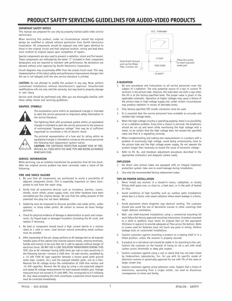
6. After reassembly of the set, always perform an AC leakage test on all exposedmetallic parts of the cabinet (the channel selector knobs, antenna terminals,handle and screws) to be sure that set is safe to operate without danger ofelectrical shock. DO NOT USE A LINE ISOLATION TRANSFORMER DURING THISTEST. Use an AC voltmeter having 5000 ohms per volt or more sensitivity inthe following manner: Connect a 1500 ohm, 10 watt resistor, paralleled bya .15 mfd 150V AC type capacitor between a known good earth groundwater pipe, conduit, etc.) and the exposed metallic parts, one at a time.Measure the AC voltage across the combination of 1500 ohm resistor and.15 mfd capacitor. Reverse the AC plug by using a non-polarized adaptorand repeat AC voltage measurements for each exposed metallic part. Voltagemeasured must not exceed 0.75 volts RMS. This corresponds to 0.5 milliampAC. Any value exceeding this limit constitutes a potential shock hazard andmust be corrected immediately.
X-RADIATION1. Be sure procedures and instructions to all service personnel cover the
subject of x-radiation. The only potential source of x-rays in current TVreceivers is the picture tube. However, this tube does not emit x-rays whenthe HV is at the factory-specified level. The proper value is given in theapplicable schematic. Operation at higher voltages may cause a failure ofthe picture tube or high-voltage supply and, under certain circumstancesmay produce radiation in excess of desirable levels.
2. Only factory-specified CRT anode connectors must be used.
3. It is essential that the service personnel have available an accurate andreliable high-voltage meter.
4. When the high-voltage circuitry is operating properly, there is no possibilityof an x-radiation problem. Every time a chassis is serviced, the brightnessshould be run up and down while monitoring the high voltage with ameter, to be certain that the high voltage does not exceed the specifiedvalue and that it is regulating correctly.
5. When troubleshooting and making test measurements in a product with aproblem of excessively high voltage, avoid being unnecessarily close tothe picture tube and the high voltage power supply. Do not operate theproduct longer than necessary to locate the cause of excessive voltage.
6. Refer to HV, B+, and shutdown adjustment procedures described in theappropriate schematics and diagrams (where used).
IMPLOSION1. All direct view picture tubes are equipped with an integral implosion
protection system; take care to avoid damage during installation.
2. Use only the recommended factory replacement tubes.
TIPS ON PROPER INSTALLATION1. Never install any receiver in a closed-in recess, cubbyhole, or closely
fitting shelf space over, or close to, a heat duct, or in the path of heatedair flow.
2. Avoid conditions of high humidity such as: outdoor patio installationswhere dew is a factor, near steam radiators where steam leakage is a factor,etc.
3. Avoid placement where draperies may obstruct venting. The customershould also avoid the use of decorative scarves or other coverings thatmight obstruct ventilation.
4. Wall- and shelf-mounted installations using a commercial mounting kitmust follow the factory-approved mounting instructions. A product mountedto a shelf or platform must retain its original feet (or the equivalentthickness in spacers) to provide adequate air flow across the bottom. Boltsor screws used for fasteners must not touch any parts or wiring. Performleakage tests on customized installations.
5. Caution customers against mounting a product on a sloping shelf or in atilted position, unless the receiver is properly secured.
6. A product on a roll-about cart should be stable in its mounting to the cart.Caution the customer on the hazards of trying to roll a cart with smallcasters across thresholds or deep pile carpets.
7. Caution customers against using a cart or stand that has not been listedby Underwriters Laboratories, Inc. for use with its specific model oftelevision receiver or generically approved for use with TVs of the same orlarger screen size.
8. Caution customers against using extension cords. Explain that a forest ofextensions, sprouting from a single outlet, can lead to disastrousconsequences to home and family.
A.C. Voltmeter
1500 OHM
10 WATT
Place this probe
on each exposed
metal part.
Good Earth Ground
such as the Water
Pipe, Conduit, etc.
0.15uF
PV154 - 923-03506 ZP26/28 - SAFETYii
CRT ANODE HIGH VOLTAGE MEASUREMENT PROCEDURE
To prevent possible exposure to radiation caused by excessive CRTAnode voltage, the High Voltage Shutdown circuit senses the levelof flyback pulse from “Flyback Transformer” representative of theactual high voltage on the CRT anode. When this level exceeds apredetermined voltage, the circuit shuts down the horizontal drive,preventing further generation of anode voltage. In this condition,the horizontal drive is “latched” off. The drive will remain off untilpower (via remote control or front panel) is re-cycled from “Off” to“On”.
Critical Safety components (designated with an “X” in the compo-nent designator) are designed to operate the CRT at a safe operatingAnode voltage and provide proper shutdown thresholds . If replace-ment of any of these components are deemed necessary, it is impor-tant to use original type Zenith replacement components. Afterreplacement is made, confirm proper Anode voltage using the fol-lowing procedure.
Measurement of the CRT Anode voltage must be performed using ahigh impedance high voltage meter, with no visible raster on thescreen, and operating at nominal horizontal scanning frequency.Connect a strong broadcast signal (or TV signal generator operatingat 15.734kHz horizontal scanning rate) to the RF input.
After discharging the CRT, connect a high impedance high voltagemeter to the CRT anode. Turn the television “on” and confirm a goodsignal is being displayed . Reduce Brightness and Contrast settingsuntil the picture is well extinguished. If the voltage reading ishigher than the maximum, verify circuit component values andproper operation.
B+ VDC HV NOM HV MAX(0 BEAM) KV KV
115 +/- 2% 30.2 30.5
SHUTDOWN TEST PROCEDURE
Equipment needed is a video generator, HV DC meter (0 to 40 KV,high Z), and a external variable power supply (0V to 6VDC @ 5Ampsminimum).
To verify the Shutdown Circuit is operating properly, Supply +6V DCto pin 1 of P1407 and ground to Heat sink of Q1413. If there is noraster and set goes into Shutdown, then the Shutdown Circuit isfunctional. If the set doesn’t go into Shutdown, then the Circuit isdefective.
ELECTROSTATICALLY SENSITIVE DEVICES
Some semiconductor (solid-state) devices can be damaged easily bystatic electricity. Such components commonly are called Electro-statically Sensitive (ES) Devices. Examples of typical ES devices areintegrated circuits and some field-effect transistors and semicon-ductor “chip” components. The following techniques should beused to help reduce the incidence of component damage caused bystatic electricity.
1. Immediately before handling any semiconductor component orsemiconductor-equipped assembly, drain off any electrostatic chargeon the body by touching a known earth ground. Alternatively, ob-tain and wear a commercially available discharging wrist strap de-vice, which should be removed for potential shock reasons prior toapplying power to the unit under test.
2. After removing an electrical assembly equipped with ES devices,place the assembly on a conductive surface such as an ESD mat, toprevent electrostatic charge buildup or exposure of the assembly.
3. Use only a grounded-tip soldering iron to solder or unsolder ESdevices.
4. Use only an anti-static solder removal device. Some solder re-moval devices not classified as “anti-static” can generate electricalcharges sufficient to damage ES devices.
5. Do not use freon-propelled chemicals. These can generate electri-cal charge sufficient to damage ES devices.
6. Do not remove a replacement ES device from its protective pack-age until immediately before you are ready to install t.(Most replace-ment ES devices are packaged with leads electrically shorted to-gether by conductive foam, aluminum foil, or comparable conduc-tive material.)
7. Immediately before removing the protective material from theleads of a replacement ES device, touch the protective material tothe chassis or circuit assembly into which the device will be in-stalled.
Caution: Be sure no power is applied to the chassis or circuit, andobserve all other safety precautions.
8. Minimize bodily motions when handling unpackaged replace mentES devices. (Otherwise, seemingly harmless motion, such as the brush-ing together of your clothing or the lifting of your foot from acarpeted floor, can generate static electricity sufficient to damagean ES device.)
REGULATORY INFORMATION
This equipment has been tested and found to comply with the limitsfor a Class B digital device, pursuant to Part 15 of the FCC Rules.These limits are designed to provide reasonable protection againstharmful interference when the equipment is operated in a residentialinstallation. This equipment generates, uses and can radiate radiofrequency energy and, if not installed and used in accordance withthe instruction manual, may cause harmful interference to radiocommunications. However, there is no guarantee that interferencewill not occur in a particular installation. If this equipment doescause harmful interference to radio or television reception, whichcan be determined by turning the equipment off and on, the user isencouraged to try to correct the interference by one or more of thefollowing measures: Reorient or relocate the receiving antenna; In-crease the separation between the equipment and receiver; Connectthe equipment into an outlet on a circuit different from that towhich the receiver is connected; Consult the dealer or an experi-enced radio/TV technician for help.
The presence of the DTV certification mark indicates that this prod-uct will successfully receive digital television transmissions thatconform to any and all of the video formats described in the ATSCDigital Television Standard.
The responsible party for this device’s compliance is:
Zenith Electronics Corporation201 James Record RoadHuntsville, AL 35824, USADigital TV Hotline: 1-800-243-0000
TRADEMARKS USED IN THIS MANUALDolby Digital® Manufactured under license from Dolby Laboratories.“Dolby” and the double-D symbol are trademarks of Dolby Laborato-ries. Confidential Unpublished Works. ©1992-1997 Dolby Laborato-ries, Inc. All rights reserved.
VCR Plus+, PlusCode and GUIDE Plus+ are trademarks of GemstarDevelopment Corporation. The VCR Plus+ and GUIDE Plus+ systemsare manufactured under license from Gemstar Development Corpora-tion and VCR Index Systems B.V., respectively.
Gemstar is not in any way liable for the accuracy of the programschedule information provided by the GUIDE Plus+ system. In noevent shall Gemstar be liable for any amounts representing loss ofprofits, loss of business, or indirect, special, or consequential dam-ages in connection with the provision or use of any informaion,equipment, or services relating to the GUIDE plus+ system.
SRS and the symbol are trademarks of SRS labs, Inc. SRS technologyis incorporated under license from SRS Labs, Inc.
Licensed by BBE Sound, Inc. under USP4638258 and 4482866. BBEand the symbol are registered trademarks of BBE Sound, Inc.
PRODUCT SAFETY SERVICING GUIDELINES FOR AUDIO-VIDEO PRODUCTS
PV154 - 923-03506 ZP26/28 - SAFETY- iii -
PRODUCT SAFETY SERVICING GUIDELINES FOR AUDIO-VIDEO PRODUCTS
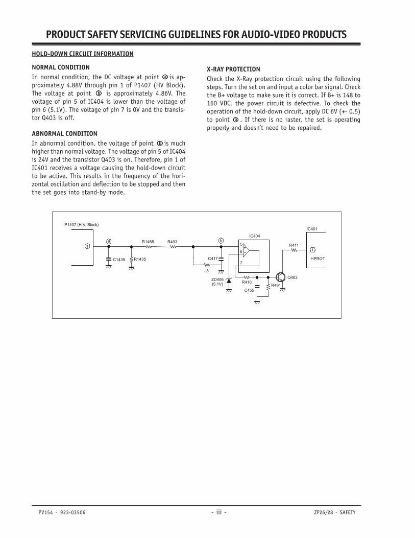
HOLD-DOWN CIRCUIT INFORMATION
NORMAL CONDITIONIn normal condition, the DC voltage at point is ap-proximately 4.88V through pin 1 of P1407 (HV Block).The voltage at point is approximately 4.86V. Thevoltage of pin 5 of IC404 is lower than the voltage ofpin 6 (5.1V). The voltage of pin 7 is 0V and the transis-tor Q403 is off.
ABNORMAL CONDITIONIn abnormal condition, the voltage of point is muchhigher than normal voltage. The voltage of pin 5 of IC404is 24V and the transistor Q403 is on. Therefore, pin 1 ofIC401 receives a voltage causing the hold-down circuitto be active. This results in the frequency of the hori-zontal oscillation and deflection to be stopped and thenthe set goes into stand-by mode.
a
a
b
b
C1439
1a
R1435
R1455 R493 b
J8
C417
ZD406(5.1V)
R411
R410
IC404
HPROT
C455R491
Q403
IC401
15
6
7
P1407 (H.V. Block)
X-RAY PROTECTIONCheck the X-Ray protection circuit using the followingsteps. Turn the set on and input a color bar signal. Checkthe B+ voltage to make sure it is correct. If B+ is 148 to160 VDC, the power circuit is defective. To check theoperation of the hold-down circuit, apply DC 6V (+- 0.5)to point . If there is no raster, the set is operatingproperly and doesn’t need to be repaired.
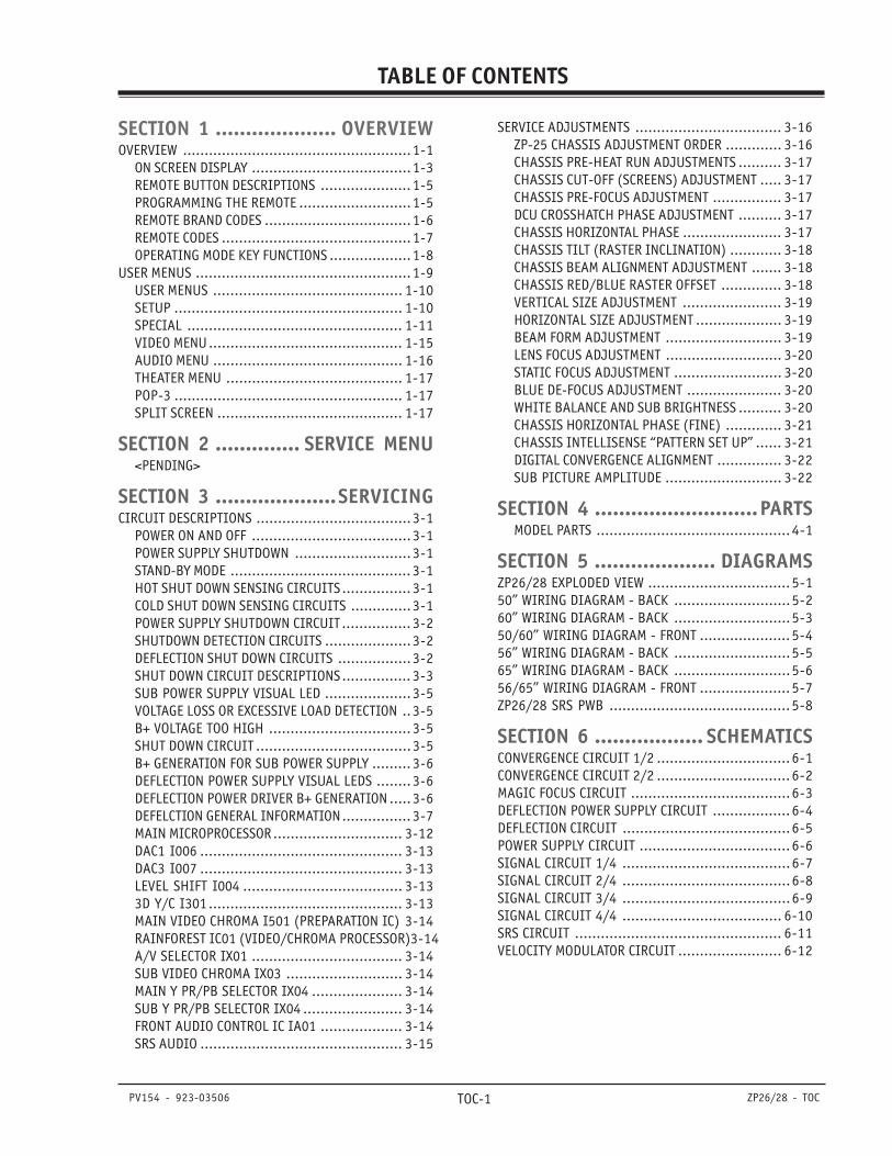
TABLE OF CONTENTS
PV154 - 923-03506 ZP26/28 - TOC
SECTION 1 .................... OVERVIEWOVERVIEW .....................................................1-1
ON SCREEN DISPLAY .....................................1-3REMOTE BUTTON DESCRIPTIONS ..................... 1-5PROGRAMMING THE REMOTE ..........................1-5REMOTE BRAND CODES ..................................1-6REMOTE CODES ............................................1-7OPERATING MODE KEY FUNCTIONS ...................1-8
USER MENUS ..................................................1-9USER MENUS ............................................ 1-10SETUP ..................................................... 1-10SPECIAL .................................................. 1-11VIDEO MENU............................................. 1-15AUDIO MENU ............................................ 1-16THEATER MENU ......................................... 1-17POP-3 ..................................................... 1-17SPLIT SCREEN ........................................... 1-17
SECTION 2 .............. SERVICE MENU<PENDING>
SECTION 3 ....................SERVICINGCIRCUIT DESCRIPTIONS ....................................3-1
POWER ON AND OFF .....................................3-1POWER SUPPLY SHUTDOWN ...........................3-1STAND-BY MODE .......................................... 3-1HOT SHUT DOWN SENSING CIRCUITS................ 3-1COLD SHUT DOWN SENSING CIRCUITS ..............3-1POWER SUPPLY SHUTDOWN CIRCUIT................ 3-2SHUTDOWN DETECTION CIRCUITS ....................3-2DEFLECTION SHUT DOWN CIRCUITS .................3-2SHUT DOWN CIRCUIT DESCRIPTIONS................ 3-3SUB POWER SUPPLY VISUAL LED ....................3-5VOLTAGE LOSS OR EXCESSIVE LOAD DETECTION ..3-5B+ VOLTAGE TOO HIGH ................................. 3-5SHUT DOWN CIRCUIT ....................................3-5B+ GENERATION FOR SUB POWER SUPPLY ......... 3-6DEFLECTION POWER SUPPLY VISUAL LEDS ........3-6DEFLECTION POWER DRIVER B+ GENERATION .....3-6DEFELCTION GENERAL INFORMATION................ 3-7MAIN MICROPROCESSOR.............................. 3-12DAC1 I006 ............................................... 3-13DAC3 I007 ............................................... 3-13LEVEL SHIFT I004 ..................................... 3-133D Y/C I301 ............................................. 3-13MAIN VIDEO CHROMA I501 (PREPARATION IC) 3-14RAINFOREST IC01 (VIDEO/CHROMA PROCESSOR)3-14A/V SELECTOR IX01 ................................... 3-14SUB VIDEO CHROMA IX03 ........................... 3-14MAIN Y PR/PB SELECTOR IX04 ..................... 3-14SUB Y PR/PB SELECTOR IX04 ....................... 3-14FRONT AUDIO CONTROL IC IA01 ................... 3-14SRS AUDIO ............................................... 3-15
TOC-1
SERVICE ADJUSTMENTS .................................. 3-16ZP-25 CHASSIS ADJUSTMENT ORDER ............. 3-16CHASSIS PRE-HEAT RUN ADJUSTMENTS .......... 3-17CHASSIS CUT-OFF (SCREENS) ADJUSTMENT ..... 3-17CHASSIS PRE-FOCUS ADJUSTMENT ................ 3-17DCU CROSSHATCH PHASE ADJUSTMENT .......... 3-17CHASSIS HORIZONTAL PHASE ....................... 3-17CHASSIS TILT (RASTER INCLINATION) ............ 3-18CHASSIS BEAM ALIGNMENT ADJUSTMENT ....... 3-18CHASSIS RED/BLUE RASTER OFFSET .............. 3-18VERTICAL SIZE ADJUSTMENT ....................... 3-19HORIZONTAL SIZE ADJUSTMENT .................... 3-19BEAM FORM ADJUSTMENT ........................... 3-19LENS FOCUS ADJUSTMENT ........................... 3-20STATIC FOCUS ADJUSTMENT ......................... 3-20BLUE DE-FOCUS ADJUSTMENT ...................... 3-20WHITE BALANCE AND SUB BRIGHTNESS .......... 3-20CHASSIS HORIZONTAL PHASE (FINE) ............. 3-21CHASSIS INTELLISENSE “PATTERN SET UP” ...... 3-21DIGITAL CONVERGENCE ALIGNMENT ............... 3-22SUB PICTURE AMPLITUDE ........................... 3-22
SECTION 4 ...........................PARTSMODEL PARTS ............................................. 4-1
SECTION 5 .................... DIAGRAMSZP26/28 EXPLODED VIEW ................................. 5-150” WIRING DIAGRAM - BACK ...........................5-260” WIRING DIAGRAM - BACK ...........................5-350/60” WIRING DIAGRAM - FRONT ..................... 5-456” WIRING DIAGRAM - BACK ...........................5-565” WIRING DIAGRAM - BACK ...........................5-656/65” WIRING DIAGRAM - FRONT ..................... 5-7ZP26/28 SRS PWB .......................................... 5-8
SECTION 6 .................. SCHEMATICSCONVERGENCE CIRCUIT 1/2 ............................... 6-1CONVERGENCE CIRCUIT 2/2 ............................... 6-2MAGIC FOCUS CIRCUIT .....................................6-3DEFLECTION POWER SUPPLY CIRCUIT .................. 6-4DEFLECTION CIRCUIT .......................................6-5POWER SUPPLY CIRCUIT ................................... 6-6SIGNAL CIRCUIT 1/4 .......................................6-7SIGNAL CIRCUIT 2/4 .......................................6-8SIGNAL CIRCUIT 3/4 .......................................6-9SIGNAL CIRCUIT 4/4 ..................................... 6-10SRS CIRCUIT ................................................ 6-11VELOCITY MODULATOR CIRCUIT ........................ 6-12

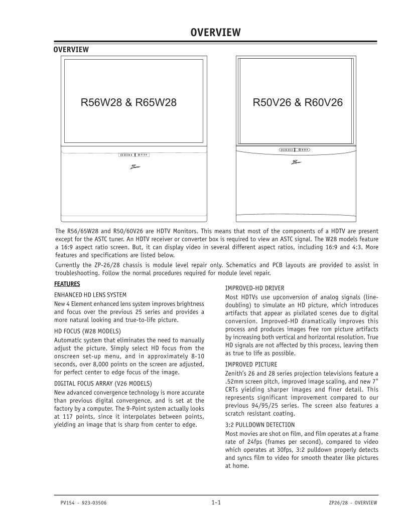
PV154 - 923-03506 1-1 ZP26/28 - OVERVIEW
OVERVIEW
SECTION 1
The R56/65W28 and R50/60V26 are HDTV Monitors. This means that most of the components of a HDTV are presentexcept for the ASTC tuner. An HDTV receiver or converter box is required to view an ASTC signal. The W28 models featurea 16:9 aspect ratio screen. But, it can display video in several different aspect ratios, including 16:9 and 4:3. Morefeatures and specifications are listed below.
Currently the ZP-26/28 chassis is module level repair only. Schematics and PCB layouts are provided to assist introubleshooting. Follow the normal procedures required for module level repair.
FEATURES
ENHANCED HD LENS SYSTEMNew 4 Element enhanced lens system improves brightnessand focus over the previous 25 series and provides amore natural looking and true-to-life picture.
HD FOCUS (W28 MODELS)Automatic system that eliminates the need to manuallyadjust the picture. Simply select HD focus from theonscreen set-up menu, and in approximately 8-10seconds, over 8,000 points on the screen are adjusted,for perfect center to edge focus of the image.
DIGITAL FOCUS ARRAY (V26 MODELS)New advanced convergence technology is more accuratethan previous digital convergence, and is set at thefactory by a computer. The 9-Point system actually looksat 117 points, since it interpolates between points,yielding an image that is sharp from center to edge.
R56W28 & R65W28 R50V26 & R60V26
OVERVIEW
IMPROVED-HD DRIVERMost HDTVs use upconversion of analog signals (line-doubling) to simulate an HD picture, which introducesartifacts that appear as pixilated scenes due to digitalconversion. Improved-HD dramatically improves thisprocess and produces images free rom picture artifactsby increasing both vertical and horizontal resolution. TrueHD signals are not affected by this process, leaving themas true to life as possible.
IMPROVED PICTUREZenith’s 26 and 28 series projection televisions feature a.52mm screen pitch, improved image scaling, and new 7"CRTs yielding sharper images and finer detail. Thisrepresents significant improvement compared to ourprevious 94/95/25 series. The screen also features ascratch resistant coating.
3:2 PULLDOWN DETECTIONMost movies are shot on film, and film operates at a framerate of 24fps (frames per second), compared to videowhich operates at 30fps, 3:2 pulldown properly detectsand syncs film to video for smooth theater like picturesat home.
PV154 - 923-03506 1-2 ZP26/28 - OVERVIEW
OVERVIEW
R50/60V26 SPECIFICATIONS
VIDEOPicture Tubes .......................................... 7" LFM
Resolution Display .......................... 540p or 1080i
Mirror ........................................ 1st Surface Glass
Lens System ..................................... Enhanced HD
Tuning System ....................... NTSC + Up Converter
Scan Velocity Modulation ................ Advanced SVM
Dynamic Focus ............................................... Yes
Digital Convergence ....................... 9-Point Digital
Color Temperature .......................... Cool/Warm/STD
Comb Filter .................................... Digital 3D Y/C
Horizontal Lines Resolution ..........................1200
Picture In Picture (PIP) ........................... 2 Tuner
Advanced features .. Light Sentry, Detail Enhance, Su-per Contrast, Gamma Correc-tion, Auto Flesh Tone, WideBand Video Amp
AUDIOFront Surround (SRS) ...................................... Yes
Mono/Stereo/MTS/SAP ............................ MTS/SAP
Bass/Treble/Balance (Tone Control) ................... Yes
Total Audio (Watts) ....................... 24W (2 x 12W)
Auto Noise Cancel .......................................... Yes
Audio Boost ......................................... Loudness
SPECIAL FEATURESHD Monitor ................................... Digital Display
Displays Digital Signals at 540por 1080i (User Selects)
Tri-lingual Menus ............. English, Spanish, French
Other features .. Icon Menus, Source ID, Channel La-bels, Parental Control with V-Chip, On/Off Timer, Flashback, CC,CC When Mute, 2 Level Mute,Channel Review, Channel Skip,Power Resume, On/Off Speaker Se-lection, Date/Time/Channel
CABINETDimensions and weight:
R50V26: 43.5"w x 52"h x 23.5"d @177Lbs
R60V26: 51.5"w x 60.5"h x 26.5"d @226Lbs
Finish ............................................... Light Silver
Screen Protector .............................High Contrast
Swivel/Casters .......................................... Casters
Control Panel Escut. (Buttons) ........................... 8
REMOTE CONTROLTransmitter Universal Remote w/Glow Channel & Vol-
ume
Model Number ....................................... MBR5045
APPROVALSUL, C-UL, NOM ....................................... UL, C-UL
UPC Code ............................. 50”:04464200642 6
60”:04464200632 7
SERVICE/LIMITED WARRANTYService Support Level .................. “M” Module Level
Warranty: Parts/CRT/Labor ...... 1 Year/2 Years/1 Year
R56/65W28 SPECIFICATIONS
VIDEOPicture Tubes .......................................... 7" LFM
Resolution Display ..........................540p or 1080i
Mirror ........................................ 1st Surface Glass
Lens System..................................... Enhanced HD
Tuning System ....................... NTSC + Up Converter
Lens Elements .................................................. 4
Lens Filters ......................Red & Green Color Purity
Screen w/Surface Diffuser ........ 160° Viewing Angle
Scan Velocity Modulation ................ Advanced SVM
Dynamic Focus ............................................... Yes
Digital Convergence ....................... 9-Point Digital
Picture In Picture (PIP) .................................. Yes
Picture Outside Picture (POP) .......... 3/Split Screen
Color Temperature .......................... Cool/Warm/STD
Black Level Exp./White Level CompressionNTSC Fixed
Home Theater Mode TV, Movie, Sports, Music, Reset
Comb Filter .................................... Digital 3D Y/C
Horizontal Lines Resolution ..........................1200
Picture In Picture (PIP) ........................... 2 Tuner
Aspect Ratio .......... Normal, Wide, Panoramic, Zoom
Advanced features .. Light Sentry, Detail Enhance, Su-per Contrast, Gamma Cor-rection, Auto Flesh Tone,Wide Band Video Amp
AUDIOFront Surround (SRS) ...................................... Yes
Mono/Stereo/MTS/SAP ............................ MTS/SAP
Bass/Treble/Balance (Tone Control) ................... Yes
Total Audio (Watts) ....................... 24W (2 x 12W)
Auto Noise Cancel .......................................... Yes
Audio Boost ......................................... Loudness

PV154 - 923-03506 1-3 ZP26/28 - OVERVIEW
OVERVIEW
SPECIAL FEATURESHD Monitor Digital DisplayDisplays Digital Signals at
540p or 1080i (User Selects)
Tri-lingual Menus ............ English, Spanish, French
Other features .. Icon Menus, Source ID, Channel La-bels, Parental Control with V-Chip, On/Off Timer, Flashback,CC, CC When Mute, 2 Level Mute,Channel Review, Channel Skip,Power Resume, On/Off SpeakerSelection, Date/Time/Channel,Energy Star®
CABINET DESCRIPTIONDimensions and weight:
R56W28: 54.1"W x 52.21"H x 24.2"D
R65W28: 60.01"W x 62.01"H x 26.3"D
Finish ............................................... Light Silver
Screen Protector .............................High Contrast
Swivel/Casters .......................................... Casters
Control Panel Escut. (Buttons) ........................... 8
REMOTE CONTROLTransmitter ..................... Universal Remote w/Glow
Model Number ....................................... MBR5045
STEREO
ST / SAP TV - PG DLSV
ANT 1 110
ABC10 : 00 AM
PIP ANT 1 14
SKIP ( C. S. )
OFF 10:05 AM
SLEEP 0:01
STEREO
ST / SAP TV - PG DLSV
ANT 1 110
ABC
10 : 00 AM
May 14 2002
C. SKIP ( C. S. )
OFF 10:05 AM
SLEEP 0:01
TVNormal
TV
Normal
MAIN PICTURE SOURCE
CHANNEL LABEL
TIME
Displays Main Picture SourceActive source highlighted).
Displays channel label youhave chosen.
Displays clock setting.
MONTH/DATE/YEARShows current month, date,and year.
PICTURE FORMATShows current Theater modesetting.
RATING BROADCAST
AUDIO BROADCAST
Displays the rating for the programcurrently being broadcast.
Displays signal’s audio broadcast.
AUDIO SELECTED
CHANNEL SKIP
SECURITY TIMER
SLEEP TIMER SET
Displays signal’s audio setting.
Shows that Channel Skip is active.
Displays time that TV is set toturn off.
Displays time left on Sleep Timerbefore TV shut off.
APPROVALSUL, C-UL, NOM....................................... UL, C-UL
UPC Code ............................ 56”:04464200622 8
65”:04464200612 9
SERVICE/LIMITED WARRANTYService Support Level ..................... “M” Module Level
Warranty: Parts/CRT/Labor ......... 1 Year/2 Years/1 Year
ON SCREEN DISPLAY
PV154 - 923-03506 1-4 ZP26/28 - OVERVIEW
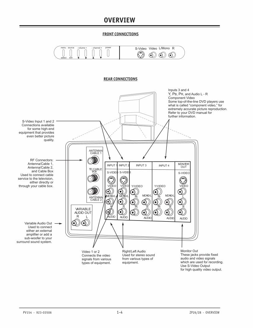
OVERVIEW
REAR CONNECTIONS
FRONT CONNECTIONS
S-Video Video L/Mono Rmenu source - volume + - channel + power
select exit
VARIABLEAUDIO OUT
R L
ANTENNA/CABLE 1
ANTENNA/CABLE 2
TO CABLEBOX
INPUT 1 INPUT 2
S-VIDEO S-VIDEO
MONO/L
R
MONO/L
R
VIDEO VIDEO
AUDIO AUDIO
MONITOROUT
S-VIDEO
L
R
VIDEO
AUDIO
INPUT 3 INPUT 4
Y/VIDEO
PB
PR R
MONO/L
AUDIO
Y/VIDEO
PB
PR R
MONO/L
AUDIO
Inputs 3 and 4
, , and Audio L - RComponent VideoSome top-of-the-line DVD players usewhat is called “component video,” forextremely accurate picture reproduction.Refer to your DVD manual forfurther information.
Y, P PB R
S-Video Input 1 and 2Connections available
for some high-endequipment that provides
even better picturequality.
RF Connectors:Antenna/Cable 1,Antenna/Cable 2,
and Cable BoxUsed to connect cable
service to the television,either directly or
through your cable box.
Variable Audio OutUsed to connect
either an externalamplifier or add a
sub-woofer to yoursurround sound system.
Video 1 or 2Connects the videosignals from varioustypes of equipment.
Right/Left AudioUsed for stereo soundfrom various types ofequipment.
Monitor OutThese jacks provide fixedaudio and video signalswhich are used for recording.Use S-Video Outputfor high quality video output.
PV154 - 923-03506 1-5 ZP26/28 - REMOTES
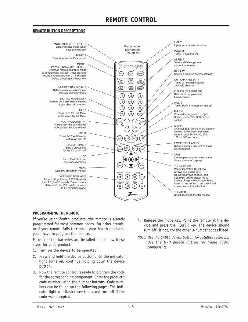
REMOTE CONTROLREMOTE BUTTON DESCRIPTIONS
PROGRAMMING THE REMOTEIf you’re using Zenith products, the remote is alreadyprogrammed for most common codes. For other brands,or if your remote fails to control your Zenith products,you’ll have to program the remote.
Make sure the batteries are installed and follow thesesteps for each product:1. Turn on the device to be operated.
2. Press and hold the device button until the indicatorlight turns on, continue holding down the devicebutton.
3. Now the remote control is ready to program the codefor the corresponding component. Enter the product’scode number using the number buttons. Code num-bers can be found on the following pages. The indi-cator light will flash three times and turn off if thecode was accepted.
1 2 3
4 5 6
7 8 9
0
mute
vol ch
flshbk
pause rew f fplay
record stop skip
CC quit
split
tv vcr
power
dvd hd/stb
cable
menu
multi
tv vcr cable hd/stb
light
dvd
sleep
mode
aspect
c skippip ch
display
fav ch
theatr
source
Part NumberMBR6045A924-10098
LIGHTLights keys for five seconds.
POWERTurns TV On and Off.
ASPECTSelects different pictureproportion formats.
DISPLAYShows current on-screen settings.
FLSHBK (FLASHBACK)Returns to the previouslytuned channel.
MULTITurns “POP-3” feature on and off.
PIP CHChannel tuning switch in SplitScreen mode. See Split Screensection.
C SKIPChannel Skip. Tunes to last channelviewed. Tunes back to originalchannel after 30, 60, 90, 120,150, or 180 seconds.
FAVORITE CHANNELSelect among 6 different channelclassifications.
QUITLeaves programming menus andclears screen of displays
THUMBSTICK(Menu Operation DirectionalArrows and Select key)Up/Down arrows choose, andLeft/Right arrows adjust menuoptions. Press the bulls eye Selectbutton in the center of the directionalarrows to confirm selection.
THEATERDirect access to theater modes.
CH - CHANNEL (+/ -)Tunes to next higher/loweravailable channel.
MODE INDICATOR LIGHTSLight indicates mode when
keys are pressed.
SOURCESelects available TV sources.
MUTEPress once for Soft Mute,press again for full Mute.
SPLITTurns the “Split Screen”
feature on and off.
SLEEP (TIMER)Sets a preset time
for the TV to turn off.
CCTurns On/Off Closedcaption/text options.
MENUDisplays on-screen menus.
MODESTV, VCR, Cable, DVD, HD/STB
Switches remote operating modeto control other devices. After pressinga Mode switch key, wait 2 - 3 seconds
before pressing any other key.
NUMBER KEYPAD 0 - 9Selects channels directly and
enters numerical values.
Use as the dash when selectingdigital channel numbers.
VOL - (VOLUME) (+/-)+ Increases the sound level.- Decreases the sound level.
Record, Stop, Pause, REW (Rewind),Play, FF (Fast Forward). These buttons
still operate the VCR while remote isin TV operating mode.
DIGITAL MODE DASH
VCR FUNCTION KEYS
4. Release the mode key. Point the remote at the de-vice and press the POWER key. The device shouldturn off. If not, try the other 3-number codes listed.
NOTE: Use the CABLE device button for satellite receivers.Use the DVD device button for home audiocomponents.
923-03460 1-6 ZP26/28 - REMOTES
REMOTE CONTROL
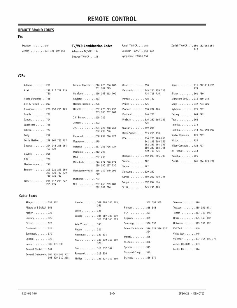
TVs
VCRs
Daewoo . . . . . . . 149
Zenith . . . . . . . . 101 121 149 152
TV/VCR Combination CodesAdventura TV/VCR . 154
Daewoo TV/VCR . . 148
Funai TV/VCR. . . . 154
Goldstar TV/VCR . . 153 172
Symphonic TV/VCR 154
Zenith TV/VCR . . . 150 152 153 154172
Admiral . . . . . . . 261
Akai . . . . . . . . . . 292 717 718 719720
Audio Dynamics . . 726
Bell & Howell . . . . 247
Broksonic . . . . . . 221 250 255 729
Candle . . . . . . . . 727
Canon . . . . . . . . . 704
Capeheart . . . . . . 728
Citizen . . . . . . . . 727
Craig . . . . . . . . . 212
Curtis Mathes . . . 259 266 725 727
Daewoo . . . . . . . 244 246 248 254703 729
Daytron . . . . . . . 246
DBX . . . . . . . . . . 726
Electrochrome. . . . 730
Emerson . . . . . . . 203 221 243 250293 721 722 729730 731 732
Fisher . . . . . . . . . 211 212 213 247265 274
General Electric . . 216 220 266 282701 702 725
Go Video . . . . . . . 256 262 263 700
Goldstar . . . . . . . 253
Harmon Kardon . . . 296
Hitachi . . . . . . . . 257 270 273 292705 706 707 708
J.C. Penny . . . . . . 268 726
Jensen . . . . . . . . 292
JVC . . . . . . . . . . 224 225 258 268292 299 726
Kenwood . . . . . . . 268 292 726 727
Magnavox . . . . . . 275
Marantz . . . . . . . 267 268 726 727
Memorex . . . . . . . 212 298
MGA . . . . . . . . . . 297 730
Mitsubishi . . . . . . 276 277 278 279280 296 297 730
Montgomery Ward 216 219 249 291730
MultiTech. . . . . . . 727
NEC . . . . . . . . . . 267 268 269 281292 709 726
Orion . . . . . . . . . 250
Panasonic . . . . . . 245 251 259 713714 715 716
Pentax . . . . . . . . 708 727
Philco . . . . . . . . . 275
Pioneer . . . . . . . 210 282 726
Portland . . . . . . . 246 727
ProScan . . . . . . . 216 260 266 282725
Quasar . . . . . . . . 259 295
Radio Shack . . . . . 213 265 730
RCA . . . . . . . . . . 216 220 228 240242 249 260 266282 283 284 285286 287 288 708710 711 725
Realistic . . . . . . . 212 213 265 730
Saisho. . . . . . . . . 722
Salora . . . . . . . . . 297
Samsung . . . . . . . 220 230
Sansui . . . . . . . . 289 292 709 726
Sanyo . . . . . . . . 212 247 294
Scott . . . . . . . . . 243 290 729
Sears . . . . . . . . . 211 212 213 265274
Sharp . . . . . . . . . 261 730
Signature 2000 . . . 216 219 249
Sony . . . . . . . . . 232 723 724
Sylvania . . . . . . . 275 297
Tatung . . . . . . . . 268 292
Teac . . . . . . . . . . 268
Teknika . . . . . . . . 272
Toshiba . . . . . . . . 213 274 290 297
Vector Research . . 726 727
Victor . . . . . . . . . 726
Video Concepts . . . 726 727
XR - 1000 . . . . . . 243
Yamaha . . . . . . . . 726
Zenith . . . . . . . . 201 224 225 229
Cable Boxes
Allegro . . . . . . . . 358 362
Allegro A-B Switch 361
Archer . . . . . . . . 325
Century . . . . . . . . 325
Citizen . . . . . . . . 325
Comtronic . . . . . . 326
Everquest. . . . . . . 379
Garrard . . . . . . . . 325
Gemini . . . . . . . . 305 331 338
General Electric. . . 367
General Instrument 304 305 306 307308 309 310 318
Hamlin . . . . . . . . 302 303 345 365366
Jasco . . . . . . . . . 325
Jerrold . . . . . . . . 304 307 308 309310 318 360 363
Kale Vision . . . . . 335
Macom . . . . . . . . 321
Magnavox . . . . . . 327 334
NSC . . . . . . . . . . 335 339 368 369370
Oak . . . . . . . . . . 311 332 342
Panasonic . . . . . . 313 320
Philips . . . . . . . . 325 327 347 350
352 354 355
Pioneer . . . . . . . . 315 343
RCA . . . . . . . . . . 341
Regency . . . . . . . 329
Samsung . . . . . . . 326 335
Scientific Atlanta 316 323 336 337364
Signal . . . . . . . . . 326
SL Marx . . . . . . . . 326
Sprucer . . . . . . . . 313
Standard Comp . . . 335
Stargate . . . . . . . 326 379
Teleview . . . . . . . 326
Texscan . . . . . . . 339 356 371
Tocom . . . . . . . . 317 318 346
Unika . . . . . . . . . 325 348 362
Universal . . . . . . 325 358 362
Vid Tech . . . . . . . 340
Video Way . . . . . . 349
Viewstar . . . . . . . 327 354 355 372
Zenith HT-2000. . . 353
Zenith PM . . . . . . 374
REMOTE BRAND CODES
PV154 - 923-03506 1-7 ZP26/28 - REMOTES
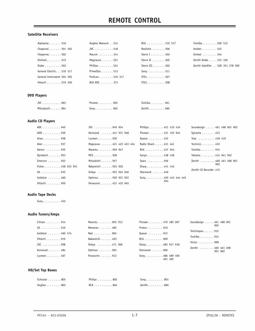
REMOTE CONTROLREMOTE CODES
DVD Players
Audio CD Players
Audio Tape Decks
Audio Tuners/Amps
Alphastar. . . . . . . 516
Chaparral . . . . . . . 501 502
Cheyenne. . . . . . . 502
Dishnet . . . . . . . . 515
Drake . . . . . . . . . 503
General Electric. . . 510 517
General Instrument 504 505
Hitachi . . . . . . . . 519 520
Hughes Network . . 514
JVC . . . . . . . . . . 518
Macom . . . . . . . . 314
Magnavox . . . . . . 521
Phillips . . . . . . . . 521
PrimeStar. . . . . . . 513
ProScan. . . . . . . . 510 517
RCA DSS . . . . . . . 373
RCA . . . . . . . . . . 510 517
Realistic . . . . . . . 506
Sierra I . . . . . . . . 502
Sierra II . . . . . . . 502
Sierra III . . . . . . . 502
Sony. . . . . . . . . . 511
STS1 . . . . . . . . . . 507
STS3 . . . . . . . . . . 508
Toshiba . . . . . . . . 509 512
Uniden . . . . . . . . 522
United . . . . . . . . 344
Zenith Drake. . . . . 312 330
Zenith Satellite . . 328 351 378 500
ADC . . . . . . . . . . 940
ADO . . . . . . . . . . 939
Aiwa. . . . . . . . . . 938
Akai . . . . . . . . . . 937
Denon . . . . . . . . 935
Dynatech . . . . . . . 953
Emerson . . . . . . . 952
Fisher . . . . . . . . . 438 933 951
GE . . . . . . . . . . . 932
Goldstar . . . . . . . 460
Hitachi . . . . . . . . 950
JVC . . . . . . . . . . 949 954
Kenwood . . . . . . 441 931 948
Luxman . . . . . . . . 930
Magnavox . . . . . . 421 422 433 434
Marantz . . . . . . . . 929 947
MCS . . . . . . . . . . 928
Mitsubishi . . . . . . 927
Nakamichi . . . . . . 925 926
Onkyo . . . . . . . . 923 924 946
Optimus . . . . . . . 920 921 922
Panasonic . . . . . . 431 432 945
Phillips . . . . . . . . 421 433 434
Pioneer . . . . . . . . 431 435 944
Quasar . . . . . . . . 432
Radio Shack . . . . . 431 441
RCA . . . . . . . . . . 437 943
Sanyo . . . . . . . . . 438 439
Sears . . . . . . . . . 936
Sharp . . . . . . . . . 441 442
Sherwood . . . . . . 449
Sony. . . . . . . . . . 420 443 444 445934
Soundesign . . . . . 461 498 901 902
Sylvania . . . . . . . 433
Teac . . . . . . . . . 418 419
Technics . . . . . . . 432
Toshiba . . . . . . . . 915
Yahama . . . . . . . . 414 941 942
Zenith . . . . . . . . 460 461 498 901902
Zenith CD Recorder 415
Sony. . . . . . . . . . 452
Citizen . . . . . . . . 914
GE . . . . . . . . . . . 916
Goldstar . . . . . . . 460 474
Hitachi . . . . . . . . 919
JVC . . . . . . . . . . 908
Kenwood . . . . . . . 484
Luxman . . . . . . . . 467
Marantz . . . . . . . . 903 913
Memorex . . . . . . . 485
Nad . . . . . . . . . . 904
Nakamichi . . . . . . 493
Onkyo . . . . . . . . 471 906
Optimus . . . . . . . 905
Panasonic . . . . . . 912
Pioneer . . . . . . . . 470 485 907
Proton . . . . . . . . 910
Quasar . . . . . . . . 912
RCA . . . . . . . . . . 909
Sharp . . . . . . . . . 483 917 918
Sherwood . . . . . . 900
Sony. . . . . . . . . . 486 489 490491 492
Soundesign . . . . . 461 498 901902
Techniques. . . . . . 912
Toshiba . . . . . . . . 915
Victor . . . . . . . . . 908
Zenith . . . . . . . . 460 461 498901 902
Satellite Receivers
JVC . . . . . . . . . . 965
Mitsubushi . . . . . . 964
Pioneer . . . . . . . . 963
Sony. . . . . . . . . . 962
Toshiba . . . . . . . . 961
Zenith. . . . . . . . . 960
HD/Set Top Boxes
Echostar . . . . . . . 805
Hughes . . . . . . . . 803
Philips . . . . . . . . 802
RCA . . . . . . . . . . 804
Sony. . . . . . . . . . 801
Zenith. . . . . . . . . 800
923-03460 1-8 ZP26/28 - REMOTES
REMOTE CONTROL
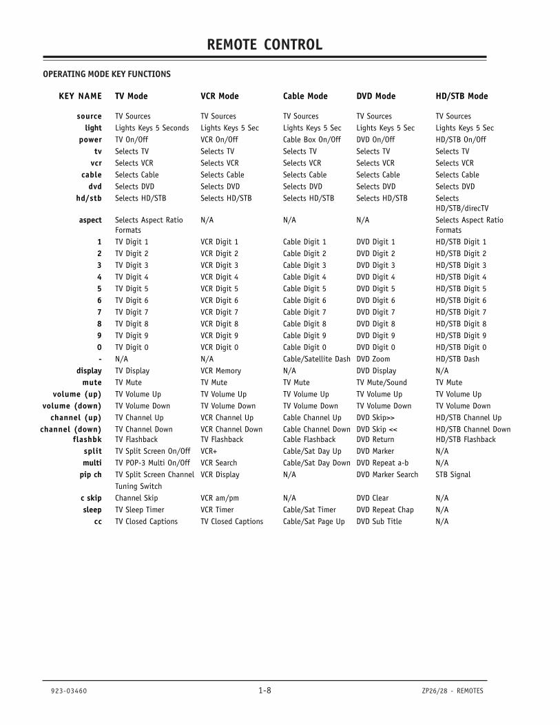
KEY NAME TV Mode VCR Mode Cable Mode DVD Mode HD/STB Mode
source TV Sources TV Sources TV Sources TV Sources TV Sourceslight Lights Keys 5 Seconds Lights Keys 5 Sec Lights Keys 5 Sec Lights Keys 5 Sec Lights Keys 5 Sec
power TV On/Off VCR On/Off Cable Box On/Off DVD On/Off HD/STB On/Offtv Selects TV Selects TV Selects TV Selects TV Selects TV
vcr Selects VCR Selects VCR Selects VCR Selects VCR Selects VCRcable Selects Cable Selects Cable Selects Cable Selects Cable Selects Cable
dvd Selects DVD Selects DVD Selects DVD Selects DVD Selects DVDhd/stb Selects HD/STB Selects HD/STB Selects HD/STB Selects HD/STB Selects
HD/STB/direcTVaspect Selects Aspect Ratio N/A N/A N/A Selects Aspect Ratio
Formats Formats1 TV Digit 1 VCR Digit 1 Cable Digit 1 DVD Digit 1 HD/STB Digit 12 TV Digit 2 VCR Digit 2 Cable Digit 2 DVD Digit 2 HD/STB Digit 23 TV Digit 3 VCR Digit 3 Cable Digit 3 DVD Digit 3 HD/STB Digit 34 TV Digit 4 VCR Digit 4 Cable Digit 4 DVD Digit 4 HD/STB Digit 45 TV Digit 5 VCR Digit 5 Cable Digit 5 DVD Digit 5 HD/STB Digit 56 TV Digit 6 VCR Digit 6 Cable Digit 6 DVD Digit 6 HD/STB Digit 67 TV Digit 7 VCR Digit 7 Cable Digit 7 DVD Digit 7 HD/STB Digit 78 TV Digit 8 VCR Digit 8 Cable Digit 8 DVD Digit 8 HD/STB Digit 89 TV Digit 9 VCR Digit 9 Cable Digit 9 DVD Digit 9 HD/STB Digit 90 TV Digit 0 VCR Digit 0 Cable Digit 0 DVD Digit 0 HD/STB Digit 0- N/A N/A Cable/Satellite Dash DVD Zoom HD/STB Dash
display TV Display VCR Memory N/A DVD Display N/Amute TV Mute TV Mute TV Mute TV Mute/Sound TV Mute
volume (up) TV Volume Up TV Volume Up TV Volume Up TV Volume Up TV Volume Upvolume (down) TV Volume Down TV Volume Down TV Volume Down TV Volume Down TV Volume Down
channel (up) TV Channel Up VCR Channel Up Cable Channel Up DVD Skip>> HD/STB Channel Upchannel (down) TV Channel Down VCR Channel Down Cable Channel Down DVD Skip << HD/STB Channel Down
flashbk TV Flashback TV Flashback Cable Flashback DVD Return HD/STB Flashbacksplit TV Split Screen On/Off VCR+ Cable/Sat Day Up DVD Marker N/Amulti TV POP-3 Multi On/Off VCR Search Cable/Sat Day Down DVD Repeat a-b N/A
pip ch TV Split Screen Channel VCR Display N/A DVD Marker Search STB SignalTuning Switch
c skip Channel Skip VCR am/pm N/A DVD Clear N/Asleep TV Sleep Timer VCR Timer Cable/Sat Timer DVD Repeat Chap N/A
cc TV Closed Captions TV Closed Captions Cable/Sat Page Up DVD Sub Title N/A
OPERATING MODE KEY FUNCTIONS
PV154 - 923-03506 1-9 ZP26/28 - REMOTES
REMOTE CONTROLUSER MENUS
fav ch (Channel) TV Favorite Channels VCR Channel Map Cable Page Down N/A N/Aquit TV Menu Quit VCR Quit Cable Quit DVD Resume HD/STB Quit
up arrow TV Select Up VCR Select Up Cable/Sat Up Arrow DVD Up Arrow HD/STB Up Arrowdown arrow TV Select Down VCR Select Down Cable/Sat Down Arrw DVD Down Arrow HD/STB Down arrow
left arrow TV Adjust Left VCR Tracking Down Cable/Sat Left Arrow DVD Left Arrow HD/STB Left arrowFavorite Channels
right arrow TV Adjust Right VCR Tracking Up Cable/Sat Right Arrw DVD Right Arrow HD/STB Right arrowFavorite Channels
Push “Select” � TV Menu Item Select VCR Enter Cable/Sat Enter DVD Enter HD/STB Entermenu TV Menu VCR Menu Cable/Sat Menu DVD Menu HD/STB Menu
Disc Menutheater TV Theater Modes N/A Cable/Sat Info DVD Open Close HD/STB Info
record VCR Record VCR Record Cable/Sat Buy DVD Angle N/Astop VCR Stop VCR Stop VCR Stop DVD Stop/Eject VCR Stop
I<< skip DVD Skip I<< DVD Skip I<< DVD Skip I<< DVD Skip I<< DVD Skip I<<skip >>I DVD Skip >>I DVD Skip >>I DVD Skip >>I DVD Skip >>I DVD Skip >>I
pause VCR Pause VCR Pause Cable/Sat Guide DVD Pause HD/STB Guiderew (rewind) VCR Rewind VCR Rewind VCR Rewind DVD Scan << VCR Rewind
play VCR Play VCR Play VCR Play DVD Play VCR Playff VCR Fast Forward VCR Fast Forward VCR Fast Forward DVD Scan >> VCR Fast Forward
Reference: MBR6045, 924-10098
KEY NAME TV Mode VCR Mode Cable Mode DVD Mode HD/STB Mode
PV154 - 923-03506 1-10 ZP26/28 - MENUS
USER MENUS
USER MENUS
SETUP
TRILINGUAL MENUSPress MENU to access the Setup menu. Use the DOWNarrow to choose Trilingual. Press the RIGHT arrowbutton to activate the Language menu option.
Use the UP/DOWN arrow button to choose your languagepreference for the on-screen menus, press Select toset and confirm. Press QUIT to exit and save yourchoice.
SIGNAL SOURCESelect Signal using the DOWN arrow button. Activatethe Signal Menu option by pressing the RIGHT arrowbutton. If your signal comes from an outdoor antenna,leave set at ANTENNA. If your signal comes from a cableTV service, select CATV 1 by pressing the DOWN arrowbutton. Press “select” to set (confirm) your choice,then press the MENU button to return to the SetupMenu. Now scan for avaible channels.
Trilingual Menus
Signal Antenna
Scan CATV 1
Channel Add/Del CATV 2
Channel Review
Clock Set
HD Focus
Picture Formats
QuitTo ExitTo Menu BarMenu
VIDEOSETUP AUDIO THEATER
SEL
SPECIAL
SCANChoose Scan mode by pressing the DOWN arrow buttonon your remote. Press the RIGHT arrow button tochoose Scan. Press the SELECT button on your remoteto begin Scan (the channel search).
Installing
Channel 110
50% Complete
QuitTo ExitTo Menu BarMenu
Trilingual Menus
Signal
Scan
Channel Add/Del
Channel Review
Clock Set
HD Focus
Picture Formats
VIDEOSETUP AUDIO THEATER
SEL
SPECIAL
If certain CATV channels are not received clearly inCATV1 mode, set the source to CATV2 mode.
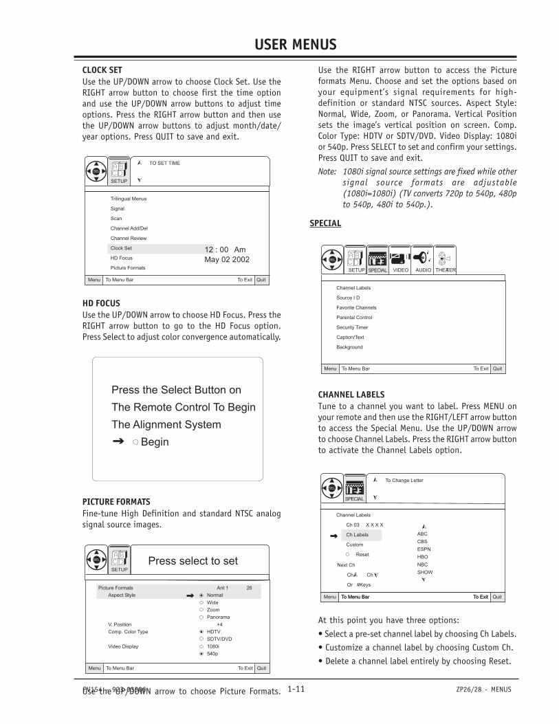
CHANNEL ADD/DEL (DELETE)Customize your channel selection list: Add Channelsnot found by Scan (Channel Search), Delete channelsyou don’t watch. Channels will appear when usingChannel Up/Down Press the MENU button on yourremote to access the Setup menu.
QuitTo ExitTo Menu BarMenu
Trilingual Menus
Signal Channel 03
Scan Add
Channel Add/Del Erase
Channel Review Next Channel
Clock Set Ch Ch
HD Focus Or # Keys
Picture Formats
SEL Press select to setSETUP
Use the UP/DOWN arrow to choose Channel Add/Del.Press the RIGHT arrow button to activate the ChannelAdd/Del menu option. Use the UP/DOWN arrow buttonto choose the Add or Erase option for the currentlychosen channel, press Select to set and confirm yourchoice. Press QUIT to exit and save your choice or usethe Channel UP/DOWN buttons/numbers to chooseanother channel to Add or Erase.
CHANNEL REVIEWUse the UP/DOWN arrow to choose the Channel Reviewoption. Use the RIGHT arrow button to activate theChannel Review menu option.
CHANNEL REVIEW Ant 1
Ch Id Scan Lock
1 * * * * ON ON
2 * * * * - - - -
3 * * * * - - - -
4 * * * * - - - -
5 * * * * - - - -
6 * * * * - - - -
7 * * * * - - - -
8 * * * * - - - -
QuitTo ExitTo Menu BarMenu
VIDEOSETUP AUDIO THEATER
SEL
SPECIAL
Use the UP/DOWN arrow button to cycle through yourchannel list and review the settings. (Each press ofUp/Down arrows will display the next eight channels.)Press QUIT to exit.
PV154 - 923-03506 1-11 ZP26/28 - MENUS
USER MENUSCLOCK SETUse the UP/DOWN arrow to choose Clock Set. Use theRIGHT arrow button to choose first the time optionand use the UP/DOWN arrow buttons to adjust timeoptions. Press the RIGHT arrow button and then usethe UP/DOWN arrow buttons to adjust month/date/year options. Press QUIT to save and exit.
12 : 00 Am
May 02 2002
TO SET TIME
QuitTo ExitTo Menu BarMenu
SEL
Trilingual Menus
Signal
Scan
Channel Add/Del
Channel Review
Clock Set
HD Focus
Picture Formats
SETUP
HD FOCUSUse the UP/DOWN arrow to choose HD Focus. Press theRIGHT arrow button to go to the HD Focus option.Press Select to adjust color convergence automatically.
Press the Select Button on
The Remote Control To Begin
The Alignment System
Begin
PICTURE FORMATSFine-tune High Definition and standard NTSC analogsignal source images.
Picture Formats Ant 1 26
Aspect Style Normal
Wide
Zoom
Panorama
V. Position +4
Comp. Color Type HDTV
SDTV/DVD
Video Display 1080i
540p
QuitTo ExitTo Menu BarMenu
SEL Press select to setSETUP
Use the UP/DOWN arrow to choose Picture Formats.
Use the RIGHT arrow button to access the Pictureformats Menu. Choose and set the options based onyour equipment’s signal requirements for high-definition or standard NTSC sources. Aspect Style:Normal, Wide, Zoom, or Panorama. Vertical Positionsets the image’s vertical position on screen. Comp.Color Type: HDTV or SDTV/DVD. Video Display: 1080ior 540p. Press SELECT to set and confirm your settings.Press QUIT to save and exit.
Note: 1080i signal source settings are fixed while othersignal source formats are adjustable(1080i=1080i) (TV converts 720p to 540p, 480pto 540p, 480i to 540p.).
SPECIAL
QuitTo ExitTo Menu BarMenu
Channel Labels
Source I D
Favorite Channels
Parental Control
Security Timer
Caption/Text
Background
VIDEOSETUP AUDIO THEATER
SEL
SPECIAL
CHANNEL LABELSTune to a channel you want to label. Press MENU onyour remote and then use the RIGHT/LEFT arrow buttonto access the Special Menu. Use the UP/DOWN arrowto choose Channel Labels. Press the RIGHT arrow buttonto activate the Channel Labels option.
ABC
CBS
ESPN
HBO
NBC
SHOW
To Change Letter
Channel Labels
Ch 03 X X X X
Ch Labels
Custom
Reset
QuitTo ExitTo Menu BarMenu QuitTo ExitTo Menu BarMenu
Next Ch
Ch Ch
Or #Keys
SEL
SPECIAL
At this point you have three options:
• Select a pre-set channel label by choosing Ch Labels.
• Customize a channel label by choosing Custom Ch.
• Delete a channel label entirely by choosing Reset.
PV154 - 923-03506 1-12 ZP26/28 - MENUS
USER MENUSUse the UP/DOWN arrows to choose an option. If youchose Ch Labels, press the RIGHT arrow button to accessthe preset channel label list and scroll through thislist using the UP/DOWN arrow buttons. When you findthe appropriate label for the channel, press the SELECTbutton.
If you select Custom Channel, press the RIGHT arrowbutton once and then use the UP/DOWN arrow buttonsto select individual letters and LEFT/RIGHT arrowbuttons to choose placement of letters.
If you wish to delete a channel label, choose Resetusing the UP/DOWN arrow buttons and then press theSELECT button on your remote. You will be asked “AreYou Sure?” press SELECT again if you are sure.
Use CHANNEL UP/DOWN buttons or the NUMBER KEYPADand choose another channel to label. Repeat steps forall channels you wish to label. Press QUIT to save andexit.
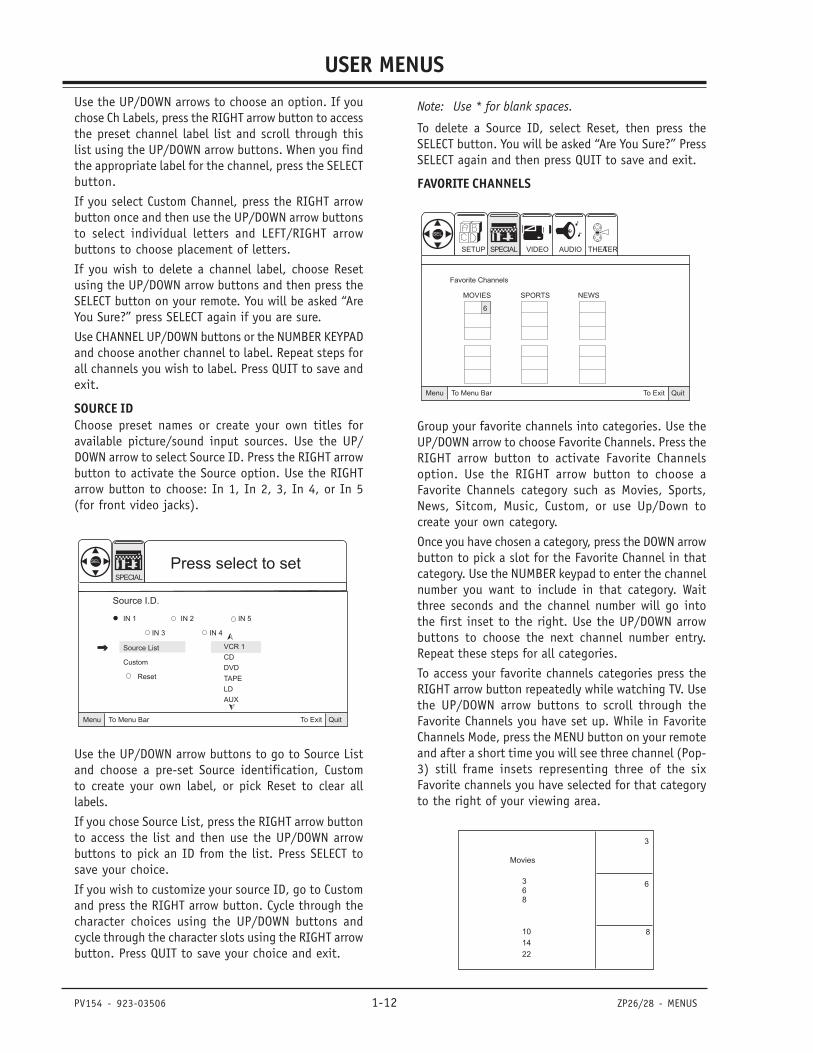
SOURCE IDChoose preset names or create your own titles foravailable picture/sound input sources. Use the UP/DOWN arrow to select Source ID. Press the RIGHT arrowbutton to activate the Source option. Use the RIGHTarrow button to choose: In 1, In 2, 3, In 4, or In 5(for front video jacks).
VCR 1
CD
DVD
TAPE
LD
AUX
QuitTo ExitTo Menu BarMenu
SEL Press select to setSPECIAL
Source I.D.
IN 1 IN 2 IN 5
IN 3 IN 4
Source List
Custom
Reset
Use the UP/DOWN arrow buttons to go to Source Listand choose a pre-set Source identification, Customto create your own label, or pick Reset to clear alllabels.
If you chose Source List, press the RIGHT arrow buttonto access the list and then use the UP/DOWN arrowbuttons to pick an ID from the list. Press SELECT tosave your choice.
If you wish to customize your source ID, go to Customand press the RIGHT arrow button. Cycle through thecharacter choices using the UP/DOWN buttons andcycle through the character slots using the RIGHT arrowbutton. Press QUIT to save your choice and exit.
Note: Use * for blank spaces.
To delete a Source ID, select Reset, then press theSELECT button. You will be asked “Are You Sure?” PressSELECT again and then press QUIT to save and exit.
FAVORITE CHANNELS
QuitTo ExitTo Menu BarMenu
MOVIES SPORTS NEWS
6
VIDEOSETUP AUDIO THEATER
SEL
SPECIAL
Favorite Channels
Group your favorite channels into categories. Use theUP/DOWN arrow to choose Favorite Channels. Press theRIGHT arrow button to activate Favorite Channelsoption. Use the RIGHT arrow button to choose aFavorite Channels category such as Movies, Sports,News, Sitcom, Music, Custom, or use Up/Down tocreate your own category.
Once you have chosen a category, press the DOWN arrowbutton to pick a slot for the Favorite Channel in thatcategory. Use the NUMBER keypad to enter the channelnumber you want to include in that category. Waitthree seconds and the channel number will go intothe first inset to the right. Use the UP/DOWN arrowbuttons to choose the next channel number entry.Repeat these steps for all categories.
To access your favorite channels categories press theRIGHT arrow button repeatedly while watching TV. Usethe UP/DOWN arrow buttons to scroll through theFavorite Channels you have set up. While in FavoriteChannels Mode, press the MENU button on your remoteand after a short time you will see three channel (Pop-3) still frame insets representing three of the sixFavorite channels you have selected for that categoryto the right of your viewing area.
Movies
368
10
14
22
3
6
8
PV154 - 923-03506 1-13 ZP26/28 - MENUS
USER MENUSNotes• Favorite Channels are only available on ANT 1 source.• If Parental Control Ratings are locked, it will disable
multiple channel insets (including the FavoriteChannels POP-3 insets).
• When POP-3 favorite channel is on, Closed Captionoption will not appear.
• If Closed Caption is set to Auto and Mute is on,Favorite Channels cannot be accessed.
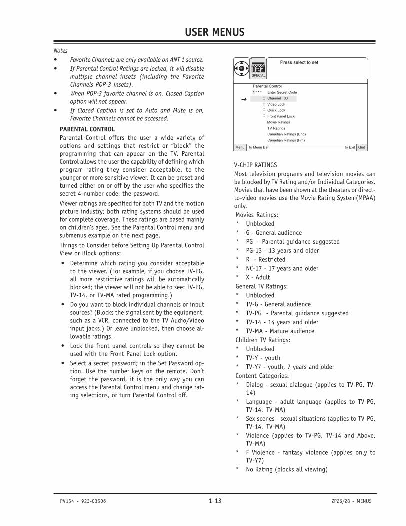
PARENTAL CONTROLParental Control offers the user a wide variety ofoptions and settings that restrict or “block” theprogramming that can appear on the TV. ParentalControl allows the user the capability of defining whichprogram rating they consider acceptable, to theyounger or more sensitive viewer. It can be preset andturned either on or off by the user who specifies thesecret 4-number code, the password.
Viewer ratings are specified for both TV and the motionpicture industry; both rating systems should be usedfor complete coverage. These ratings are based mainlyon children’s ages. See the Parental Control menu andsubmenus example on the next page.
Things to Consider before Setting Up Parental ControlView or Block options:
• Determine which rating you consider acceptableto the viewer. (For example, if you choose TV-PG,all more restrictive ratings will be automaticallyblocked; the viewer will not be able to see: TV-PG,TV-14, or TV-MA rated programming.)
• Do you want to block individual channels or inputsources? (Blocks the signal sent by the equipment,such as a VCR, connected to the TV Audio/Videoinput jacks.) Or leave unblocked, then choose al-lowable ratings.
• Lock the front panel controls so they cannot beused with the Front Panel Lock option.
• Select a secret password; in the Set Password op-tion. Use the number keys on the remote. Don’tforget the password, it is the only way you canaccess the Parental Control menu and change rat-ing selections, or turn Parental Control off.
QuitTo ExitTo Menu BarMenu
* * * * Enter Secret Code
Channel 03
Video Lock
Quick Lock
Front Panel Lock
Movie Ratings
TV Ratings
Canadian Ratings (Eng)
Canadian Ratings (Frn)
Press select to setSEL
SPECIAL
Parental Control
V-CHIP RATINGSMost television programs and television movies canbe blocked by TV Rating and/or Individual Categories.Movies that have been shown at the theaters or direct-to-video movies use the Movie Rating System(MPAA)only.Movies Ratings:* Unblocked* G - General audience* PG - Parental guidance suggested* PG-13 - 13 years and older* R - Restricted* NC-17 - 17 years and older* X - AdultGeneral TV Ratings:* Unblocked* TV-G - General audience* TV-PG - Parental guidance suggested* TV-14 - 14 years and older* TV-MA - Mature audienceChildren TV Ratings:* Unblocked* TV-Y - youth* TV-Y7 - youth, 7 years and olderContent Categories:* Dialog - sexual dialogue (applies to TV-PG, TV-
14)* Language - adult language (applies to TV-PG,
TV-14, TV-MA)* Sex scenes - sexual situations (applies to TV-PG,
TV-14, TV-MA)* Violence (applies to TV-PG, TV-14 and Above,
TV-MA)* F Violence - fantasy violence (applies only to
TV-Y7)* No Rating (blocks all viewing)
PV154 - 923-03506 1-14 ZP26/28 - MENUS
USER MENUSSETUPPress MENU and then the RIGHT/LEFT arrow buttonto access the Special Menu. Press the UP/DOWN arrowto choose Parental Control and then press the RIGHTarrow button to activate Parental Control. Whenprompted, enter the default code 7777 from thenumber keypad. If you wish to change the code, select“Change Secret Code” and enter the new code throughthe number keypad. If you forget your code, justreenter “7777” to reset to factory preset code.Use the UP/DOWN arrow button to choose your Blockoptions, press SELECT to confirm your choice:• Channel: Selects the channel you wish to restrict.• Video Lock: Selects the Video Inputs to be blocked.• Quick Lock: Blocks CH3 and CH4 on ANT 1 and 2,
as well as all 3 video input jacks.• Front Panel Lock: Blocks front panel controls from
being used. Only Power button will work whenthis feature is active.
Now you will set the Ratings for the channel youwish to block. Press the UP/DOWN arrows to selectthe following rating formats and press the RIGHT arrowbutton to activate each rating menu:• Movie Ratings: Sets ratings based on MPAA rat-
ings system.• TV Ratings: Sets ratings based on the age of viewer
and content of programming.• Canadian Ratings (Eng): Sets age ratings for Ca-
nadian broadcasting (Eng).• Canadian Ratings (Frn): Sets age ratings for Cana-
dian broadcasting (Frn).For each rating menu, use the UP/DOWN arrow buttonsto choose the level of rating you wish to block. Usethe SELECT button to lock or unlock the ratingselection. Press QUIT to save and exit.Notes• Select the input source first in order to use Video
lock; press the source button repeatedly on theremote until you select Input 1, Input 2, Input 3,Input 4, or Input 5. The same applies to unlockingthe Video Lock.
• If Ant 1 and Ant 2 are set to the same signal sourcemode if a channel is locked, it is locked on both Ant1 and Ant 2 inputs.
• Be sure the TV’s internal clock is set before usingany Parental Control options.
• Text automatically appears on the screen to indicateif Parental Control (Child Lock) is activate.
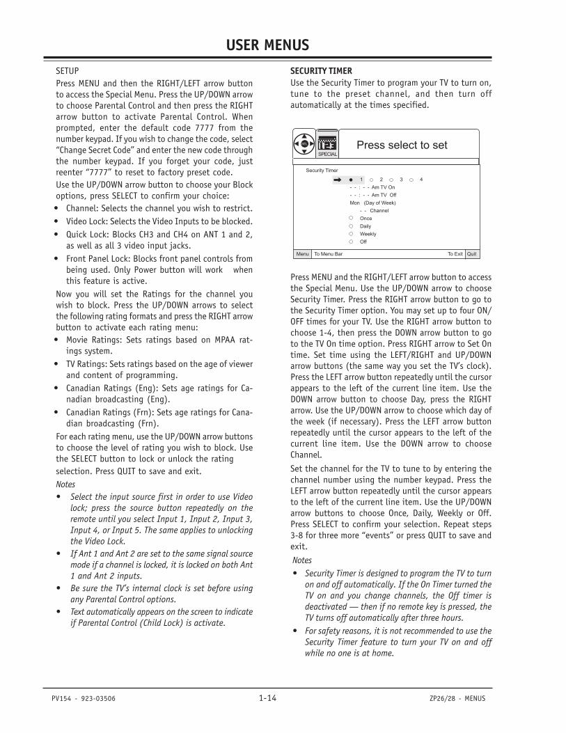
SECURITY TIMERUse the Security Timer to program your TV to turn on,tune to the preset channel, and then turn offautomatically at the times specified.
QuitTo ExitTo Menu BarMenu
1 2 3 4
- - : - - Am TV On
- - : - - Am TV Off
Mon (Day of Week)
- - Channel
Once
Daily
Weekly
Off
Security Timer
SEL Press select to setSPECIAL
Press MENU and the RIGHT/LEFT arrow button to accessthe Special Menu. Use the UP/DOWN arrow to chooseSecurity Timer. Press the RIGHT arrow button to go tothe Security Timer option. You may set up to four ON/OFF times for your TV. Use the RIGHT arrow button tochoose 1-4, then press the DOWN arrow button to goto the TV On time option. Press RIGHT arrow to Set Ontime. Set time using the LEFT/RIGHT and UP/DOWNarrow buttons (the same way you set the TV’s clock).Press the LEFT arrow button repeatedly until the cursorappears to the left of the current line item. Use theDOWN arrow button to choose Day, press the RIGHTarrow. Use the UP/DOWN arrow to choose which day ofthe week (if necessary). Press the LEFT arrow buttonrepeatedly until the cursor appears to the left of thecurrent line item. Use the DOWN arrow to chooseChannel.
Set the channel for the TV to tune to by entering thechannel number using the number keypad. Press theLEFT arrow button repeatedly until the cursor appearsto the left of the current line item. Use the UP/DOWNarrow buttons to choose Once, Daily, Weekly or Off.Press SELECT to confirm your selection. Repeat steps3-8 for three more “events” or press QUIT to save andexit.
Notes• Security Timer is designed to program the TV to turn
on and off automatically. If the On Timer turned theTV on and you change channels, the Off timer isdeactivated — then if no remote key is pressed, theTV turns off automatically after three hours.
• For safety reasons, it is not recommended to use theSecurity Timer feature to turn your TV on and offwhile no one is at home.
PV154 - 923-03506 1-15 ZP26/28 - MENUS
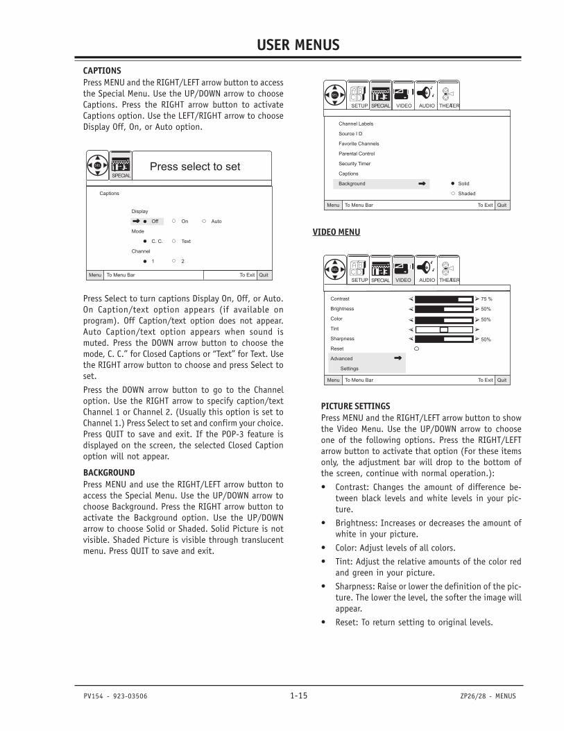
USER MENUSCAPTIONSPress MENU and the RIGHT/LEFT arrow button to accessthe Special Menu. Use the UP/DOWN arrow to chooseCaptions. Press the RIGHT arrow button to activateCaptions option. Use the LEFT/RIGHT arrow to chooseDisplay Off, On, or Auto option.
QuitTo ExitTo Menu BarMenu
Display
Off On Auto
Mode
C. C. Text
Channel
1 2
Captions
SEL Press select to setSPECIAL
Press Select to turn captions Display On, Off, or Auto.On Caption/text option appears (if available onprogram). Off Caption/text option does not appear.Auto Caption/text option appears when sound ismuted. Press the DOWN arrow button to choose themode, C. C.” for Closed Captions or “Text” for Text. Usethe RIGHT arrow button to choose and press Select toset.
Press the DOWN arrow button to go to the Channeloption. Use the RIGHT arrow to specify caption/textChannel 1 or Channel 2. (Usually this option is set toChannel 1.) Press Select to set and confirm your choice.Press QUIT to save and exit. If the POP-3 feature isdisplayed on the screen, the selected Closed Captionoption will not appear.
BACKGROUNDPress MENU and use the RIGHT/LEFT arrow button toaccess the Special Menu. Use the UP/DOWN arrow tochoose Background. Press the RIGHT arrow button toactivate the Background option. Use the UP/DOWNarrow to choose Solid or Shaded. Solid Picture is notvisible. Shaded Picture is visible through translucentmenu. Press QUIT to save and exit.
QuitTo ExitTo Menu BarMenu
VIDEOSETUP AUDIO THEATER
SEL
SPECIAL
Channel Labels
Source I D
Favorite Channels
Parental Control
Security Timer
Captions
Background Solid
Shaded
VIDEO MENU
QuitTo ExitTo Menu BarMenu
Contrast 75 %
Brightness 50%
Color 50%
Tint
Sharpness 50%
Reset
Advanced
Settings
VIDEOSETUP AUDIO THEATER
SEL
SPECIAL
PICTURE SETTINGSPress MENU and the RIGHT/LEFT arrow button to showthe Video Menu. Use the UP/DOWN arrow to chooseone of the following options. Press the RIGHT/LEFTarrow button to activate that option (For these itemsonly, the adjustment bar will drop to the bottom ofthe screen, continue with normal operation.):
• Contrast: Changes the amount of difference be-tween black levels and white levels in your pic-ture.
• Brightness: Increases or decreases the amount ofwhite in your picture.
• Color: Adjust levels of all colors.
• Tint: Adjust the relative amounts of the color redand green in your picture.
• Sharpness: Raise or lower the definition of the pic-ture. The lower the level, the softer the image willappear.
• Reset: To return setting to original levels.
PV154 - 923-03506 1-16 ZP26/28 - MENUS
USER MENUSRESETUse the UP/DOWN arrow to choose Reset (Reset restoresthe levels to their original settings). Press SELECT toconfirm your choice.
ADVANCED SETTINGSUse the UP/DOWN arrow to choose Advanced Settings.Press the RIGHT arrow button to activate the AdvancedSettings menu. Use the UP/DOWN arrow to choose fromthe following options. Press SELECT to confirm yourchoice:
• Light Sentry: Automatically monitors and adjustscontrast depending on room lighting to producea more natural picture. Also adjusts Auto FleshTone and Video Filter depending on signal.
• Auto Flesh: Automatically monitors and adjusts thecolor to maintain constant color levels even aftera program or channel changes.
• Weak Signal: Automatically reduces conspicuousnoise in the picture without degrading picturequality.
• Color Temperature: Set this to Warm for hotter col-ors such as red, set to Cool for less intense colorswith more blue, or Medium for normal color ap-pearance.
Press QUIT to save and exit.Notes• It may be necessary to adjust TINT for optimum
picture quality, when viewing component videosources (Y-PBPR) connected to Inputs 3/4.
• When viewing component video sources (Y-PBPR)connected to Inputs 3/4, if the TINT and COLORin the picture appear to be abnormal, check to besure that the correct Component Color Type is se-lected for the Picture Formats option on the Setupmenu.
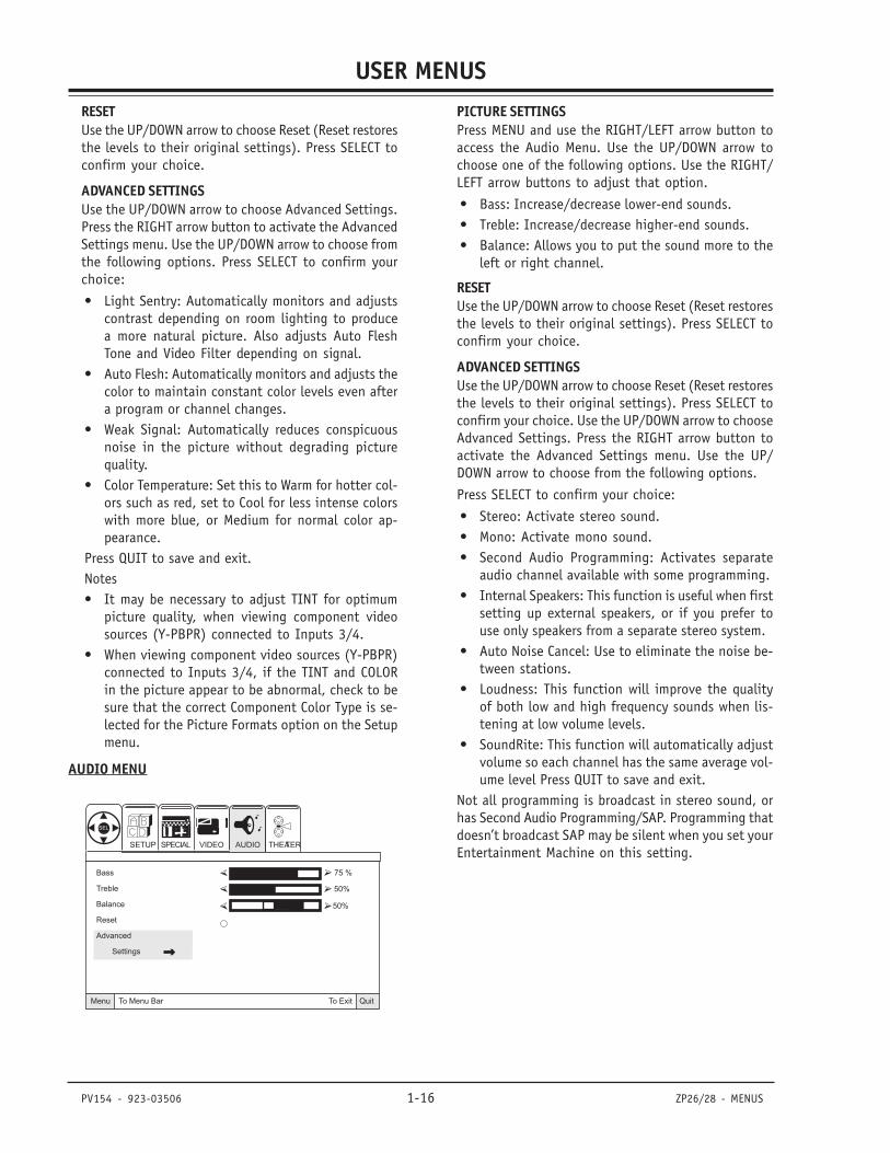
AUDIO MENU
Bass 75 %
Treble 50%
Balance 50%
Reset
Advanced
Settings
QuitTo ExitTo Menu BarMenu
VIDEOSETUP AUDIO THEATER
SEL
SPECIAL
PICTURE SETTINGSPress MENU and use the RIGHT/LEFT arrow button toaccess the Audio Menu. Use the UP/DOWN arrow tochoose one of the following options. Use the RIGHT/LEFT arrow buttons to adjust that option.
• Bass: Increase/decrease lower-end sounds.• Treble: Increase/decrease higher-end sounds.• Balance: Allows you to put the sound more to the
left or right channel.
RESETUse the UP/DOWN arrow to choose Reset (Reset restoresthe levels to their original settings). Press SELECT toconfirm your choice.
ADVANCED SETTINGSUse the UP/DOWN arrow to choose Reset (Reset restoresthe levels to their original settings). Press SELECT toconfirm your choice. Use the UP/DOWN arrow to chooseAdvanced Settings. Press the RIGHT arrow button toactivate the Advanced Settings menu. Use the UP/DOWN arrow to choose from the following options.
Press SELECT to confirm your choice:
• Stereo: Activate stereo sound.• Mono: Activate mono sound.• Second Audio Programming: Activates separate
audio channel available with some programming.• Internal Speakers: This function is useful when first
setting up external speakers, or if you prefer touse only speakers from a separate stereo system.
• Auto Noise Cancel: Use to eliminate the noise be-tween stations.
• Loudness: This function will improve the qualityof both low and high frequency sounds when lis-tening at low volume levels.
• SoundRite: This function will automatically adjustvolume so each channel has the same average vol-ume level Press QUIT to save and exit.
Not all programming is broadcast in stereo sound, orhas Second Audio Programming/SAP. Programming thatdoesn’t broadcast SAP may be silent when you set yourEntertainment Machine on this setting.
PV154 - 923-03506 1-17 ZP26/28 - MENUS
USER MENUSTHEATER MENU
QuitTo ExitTo Menu BarMenu
Theater Modes TV
Surround Movies
Music
Sports
Reset
THEATER
SEL
VIDEOSETUP AUDIOSPECIAL
THEATER MODESPress MENU and then the RIGHT/LEFT arrow button toaccess the Theater menu. Press DOWN arrow button toaccess the Theater Modes or Surround. To changeTheater Modes, press RIGHT arrow button to chooseTheater Modes.
Use the UP/DOWN arrow buttons to choose which modeyou prefer. Each is a preset setup designed to enhanceyour viewing experience. Use the UP/DOWN arrow tochoose Reset (Reset restores the levels to their originalsettings). Press SELECT to confirm your choice.
SURROUNDTo activate SRS® or BBE®, choose the Surround option,then choose SRS and/or BBE. Turn them on or offdepending on your preference. Press SELECT to set andconfirm your choice(s). Press QUIT to save and exit.
SRS retrieves the spatial information from any stereorecording and restores the original three-dimensionalsound field. As a result, the reproduced sound is muchcloser to that of a live performance. BBE improves thesound from all audio sources, providing a morecomplete high-definition reproduction of the originalperformance.
SRS and the symbol are trademarks of SRS labs, Inc.SRS technology is incorporated under license from SRSLabs, Inc.® Licensed by BBE Sound, Inc. underUSP4638258 and 4482866. BBE and the symbol areregistered trademarks of BBE Sound, Inc.
POP-3
10
11
12
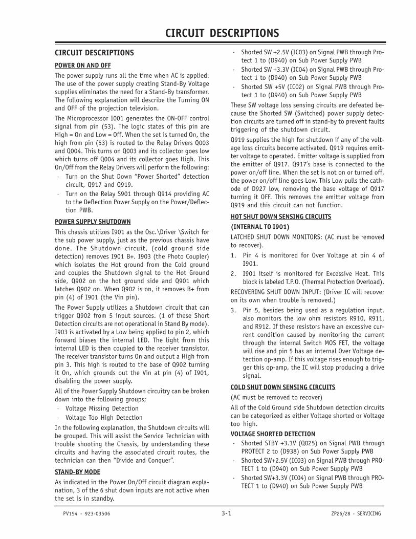
Main Picture POP-3 Channels
POP-3 (Picture-On-Picture) shows multiple channels onthe screen. With the TV on and Ant 1 source shown on-screen, press MULTI on the remote to turn on the POP-3feature. POP-3 shows three additional channels on theright side of the screen. The multi-channel display alsoincludes the channel number for reference. POP-3 willcontinue to display all the channels continuously, threechannels at-a-time.
Press MULTI again to turn POP-3 off. POP-3 is onlyavailable on Antenna/Cable 1 source. Closed Captioningwill not appear if POP-3 is active.
SPLIT SCREEN
Original Channel Additional Channel
Split Screen shows two live tunable channels on thescreen at the same time. With the TV on and Ant 1 sourceshown on-screen, press SPLIT on the remote to turn onthe Split Screen two-channel viewing feature.
Press PIP CH to switch channel tuning to the additionalchannel. Tune to a channel for the additional channelpicture. Press PIP CH to switch channel tuning back tothe original channel. Press SPLIT again to turn the featureoff and return to one channel viewing. Split Screen isonly available on Antenna/Cable 1 source.

- 1-18 -
CIRCUIT DESCRIPTIONS
PV154 - 923-03506 3-1 ZP26/28 - SERVICING
SECTION 3
CIRCUIT DESCRIPTIONSPOWER ON AND OFFThe power supply runs all the time when AC is applied.The use of the power supply creating Stand-By Voltagesupplies eliminates the need for a Stand-By transformer.The following explanation will describe the Turning ONand OFF of the projection television.
The Microprocessor I001 generates the ON-OFF controlsignal from pin (53). The logic states of this pin areHigh = On and Low = Off. When the set is turned On, thehigh from pin (53) is routed to the Relay Drivers Q003and Q004. This turns on Q003 and its collector goes lowwhich turns off Q004 and its collector goes High. ThisOn/Off from the Relay Drivers will perform the following:· Turn on the Shut Down “Power Shorted” detection
circuit, Q917 and Q919.· Turn on the Relay S901 through Q914 providing AC
to the Deflection Power Supply on the Power/Deflec-tion PWB.
POWER SUPPLY SHUTDOWNThis chassis utilizes I901 as the Osc.\Driver \Switch forthe sub power supply, just as the previous chassis havedone. The Shutdown circuit, (cold ground sidedetection) removes I901 B+. I903 (the Photo Coupler)which isolates the Hot ground from the Cold groundand couples the Shutdown signal to the Hot Groundside, Q902 on the hot ground side and Q901 whichlatches Q902 on. When Q902 is on, it removes B+ frompin (4) of I901 (the Vin pin).
The Power Supply utilizes a Shutdown circuit that cantrigger Q902 from 5 input sources. (1 of these ShortDetection circuits are not operational in Stand By mode).I903 is activated by a Low being applied to pin 2, whichforward biases the internal LED. The light from thisinternal LED is then coupled to the receiver transistor.The receiver transistor turns On and output a High frompin 3. This high is routed to the base of Q902 turningit On, which grounds out the Vin at pin (4) of I901,disabling the power supply.
All of the Power Supply Shutdown circuitry can be brokendown into the following groups;· Voltage Missing Detection· Voltage Too High Detection
In the following explanation, the Shutdown circuits willbe grouped. This will assist the Service Technician withtrouble shooting the Chassis, by understanding thesecircuits and having the associated circuit routes, thetechnician can then “Divide and Conquer”.
STAND-BY MODEAs indicated in the Power On/Off circuit diagram expla-nation, 3 of the 6 shut down inputs are not active whenthe set is in standby.
· Shorted SW +2.5V (IC03) on Signal PWB through Pro-tect 1 to (D940) on Sub Power Supply PWB
· Shorted SW +3.3V (IC04) on Signal PWB through Pro-tect 1 to (D940) on Sub Power Supply PWB
· Shorted SW +5V (IC02) on Signal PWB through Pro-tect 1 to (D940) on Sub Power Supply PWB
These SW voltage loss sensing circuits are defeated be-cause the Shorted SW (Switched) power supply detec-tion circuits are turned off in stand-by to prevent faultstriggering of the shutdown circuit.
Q919 supplies the high for shutdown if any of the volt-age loss circuits become activated. Q919 requires emit-ter voltage to operated. Emitter voltage is supplied fromthe emitter of Q917. Q917’s base is connected to thepower on/off line. When the set is not on or turned off,the power on/off line goes Low. This Low pulls the cath-ode of D927 low, removing the base voltage of Q917turning it OFF. This removes the emitter voltage fromQ919 and this circuit can not function.
HOT SHUT DOWN SENSING CIRCUITS(INTERNAL TO I901)LATCHED SHUT DOWN MONITORS: (AC must be removedto recover).
1. Pin 4 is monitored for Over Voltage at pin 4 ofI901.
2. I901 itself is monitored for Excessive Heat. Thisblock is labeled T.P.O. (Thermal Protection Overload).
RECOVERING SHUT DOWN INPUT: (Driver IC will recoveron its own when trouble is removed.)
3. Pin 5, besides being used as a regulation input,also monitors the low ohm resistors R910, R911,and R912. If these resistors have an excessive cur-rent condition caused by monitoring the currentthrough the internal Switch MOS FET, the voltagewill rise and pin 5 has an internal Over Voltage de-tection op-amp. If this voltage rises enough to trig-ger this op-amp, the IC will stop producing a drivesignal.
COLD SHUT DOWN SENSING CIRCUITS(AC must be removed to recover)
All of the Cold Ground side Shutdown detection circuitscan be categorized as either Voltage shorted or Voltagetoo high.
VOLTAGE SHORTED DETECTION· Shorted STBY +3.3V (Q025) on Signal PWB through
PROTECT 2 to (D938) on Sub Power Supply PWB· Shorted SW+2.5V (IC03) on Signal PWB through PRO-
TECT 1 to (D940) on Sub Power Supply PWB· Shorted SW+3.3V (IC04) on Signal PWB through PRO-
TECT 1 to (D940) on Sub Power Supply PWB
CIRCUIT DESCRIPTIONS
PV154 - 923-03506 3-2 ZP26/28 - SERVICING
· Shorted SW +5V (IC02) on Signal PWB through PRO-TECT 1 to (D940) on Sub Power Supply PWB
NOTE: PROTECT 1 will not go below 2.2V even if the 5V orthe 3.3V lines are open.
VOLTAGE TOO HIGH DETECTION· STBY +9V monitored by (D933, D934)· STBY +5V monitored by (D935, D936)
If any one of these circuits activate, the power supplywill STOP and create a Power Supply Shutdown Condi-tion.
POWER SUPPLY SHUTDOWN CIRCUITSHUTDOWN CIRCUITThere are a total of 6 individual Shutdown inputs. Inaddition, there are 3 Hot Ground side Shutdown inputsthat are specifically detected by the main power driverIC I901. These sensors circuits protect I901 fromexcessive current or voltage.
POWER SUPPLY SHUTDOWN EXPLANATIONThis chassis utilizes IP01 as the Osc.\Driver \Switchfor the Deflection power supply, just as the previouschassis have done. This IC is very similar to the previousversions. The Shutdown circuit, (cold ground sidedetection), is used to turn off the Relay S901 via thefollowing circuit, Connector PQD2 pin 1, Q916 theRelay Driver on the Sub Power Supply PWB and theRelay S901 also on the Sub Power Supply PWB.
The Power Supply utilizes a Shutdown circuit thatproduces a High from 12 different sources. When anyof these inputs cause a high on the Connector PQD2pin 1, the relay disengages, disabling the deflectionpower supply.
All of the Power Supply Shutdown circuitry can bebroken down into the following groups;
· Voltage Missing Detection· Excessive Current Detection· Voltage Too High Detection
In the following explanation, the Shutdown circuits willbe grouped. This will assist the Service Technician withtrouble shooting the Chassis, by understanding thesecircuits and having the associated circuit routes, thetechnician can then “Divide and Conquer”.
SHUTDOWN DETECTION CIRCUITSEXCESSIVE CURRENT DETECTIONOne very common circuit used in many televisionproducts is the B+ Excessive Current Sensing circuit.In this circuit is a low ohm resistor in series with theparticular power supply, (labeled B+ in the drawing).The value of this resistor is determined by the maximumcurrent allowable within a particular power supply. Inthe case of Figure 1, the value is shown as a 0.47
ohm, however it could be any low ohm value. Whenthe current demand increases, the voltage drop acrossthe resistor increases. If the voltage drop is sufficientto reduce the voltage on the base of the transistor,the transistor will conduct, producing a Shutdownsignal that is directed to the appropriate circuit.
VOLTAGE LOSS OR EXCESSIVE LOAD DETECTIONThe second most common circuit used is the VoltageLoss Detection circuit. This is a very simple circuitthat detects a loss of a particular power supply andsupplies a Pull-Down path for the base of a PNPtransistor.
This circuit consist of a diode connected by itscathode to a positive B+ power supply. Under normalconditions, the diode is reversed biases, which keepsthe base of Q1 pulled up, forcing it OFF. However, ifthere is a short or excessive load on the B+ line, thediode in effect will have a LOW on its cathode, turningit ON. This will allow a current path for the base biasof Q1, which will turn it ON and generates a ShutdownSignal.
B+ VOLTAGE TOO HIGH DETECTIONIn this circuit, a Zener diode is connected to a voltagedivider or in some cases, directly to a B+ power supply.If the B+ voltage increases, the voltage at the voltagedivider or the cathode of the zener diode will rise. Ifit gets to a predetermined level, the zener will fire.This action creates a Shutdown Signal.
NEGATIVE VOLTAGE LOSS DETECTIONThe purpose of the Negative Voltage Loss detectioncircuit is to compare the negative voltage with itscounter part positive voltage. If at any time, thenegative voltage drops or disappears, the circuit willproduce a Shutdown signal.
There are two resistors of equal value. One to thepositive voltage, (+12V) and one to the negativevoltage, (-12V). At their tie point, (neutral point),the voltage is effectually zero (0) volts. If the negativevoltage is lost due to an excessive load or defectivenegative voltage regulator, the neutral point will gopositive. This in turn will cause the zener diode tofire, creating a Shutdown Signal.
DEFLECTION SHUT DOWN CIRCUITSThere are a total of 12 Cold Ground Side individual Shutdown inputs. There are also 3 Hot Ground Side Shutdown inputs that are specifically detected by the mainpower driver IC, IP01 that protect it from excessivecurrent or over voltage. All of the Shut down detectioncircuits can be categorized by the four previouslydescribed circuits.
CIRCUIT DESCRIPTIONS
PV154 - 923-03506 3-3 ZP26/28 - SERVICING
HOT GROUND SIDE SHUT DOWN SENSING CIRCUITS(INTERNAL TO IP01)LATCHED SHUT DOWN MONITORS(AC must be removed to recover)
1. Pin 4 is monitored for Over Voltage internal toIP01.
2. IP01 itself is monitored for Excessive Heat. Thisblock is labeled T.P.O. (Thermal Protection Over-load).
RECOVERING SHUT DOWN INPUT(Driver IC will recover on it’s own when trouble isremoved)
3. Pin 5 besides being used as a regulation input, italso monitors low ohm resistors RP10, RP11, RP12,and RP16, (All are 0.22 ohm resistors). If theseresistors have an excessive current conditioncaused by monitoring the current through the in-ternal Switch MOS FET, the voltage will rise. Pin 5has an internal Over Voltage detection op-amp. Ifthis voltage rises enough to trigger this op-amp,the IC will stop producing a drive signal.
COLD GROUND SIDE SHUT DOWN CIRCUITSThese Circuits are broken down into the appropriatecategories as described earlier.
VOLTAGE LOSS DETECTION1. Shorted 220V (DP24 and DP25) Inverted by QP03
then through DP28
2. Shorted SW+35V (DP26) Inverted by QP03 thenthrough DP28
3. Shorted 28V (DP27) Inverted by QP03 thenthrough DP28
4. Shorted Deflection Transformer or Miss-operation(D707 and Q705) then through D705
NEGATIVE VOLTAGE LOSS DETECTION5. -28V Loss Detection (RP21, RP20, DP35, DP21 and
DP22)
EXCESSIVE CURRENT DETECTION6. 115V Deflection Power Supply (RP24, QP02, DP18,
DP19 and DP20)
7. 28V Vertical IC I601 Power Supply (R629, Q609,D608, and DP31)
VOLTAGE TOO HIGH DETECTION8. Excessive High Voltage Detection (DH17, DH13 and
DH15). Sensed from the 50P Voltage generatedfrom pin (5) of the Flyback Transformer TH01. Also,(DH14) sends a high command to the HorizontalDriver IC IH01 pin 7, to defeat Horizontal DriveOutput if this voltage goes too high.
9. Side Pincushion failure generating a High. (D702,and D703).
10. Deflection B+ Too High. (DP17, RP26 and RP27).
11. SW +9V Voltage Too High Detection. (DP29 andDP30)
12. ABL Voltage Too High Detection. (DH15)
If any one of these circuits are activated, the powersupply will STOP, and create a Power Supply Shut downCondition.
SHUT DOWN CIRCUIT DESCRIPTIONSShut down occurs when pin (1) of Connector PQD2 calledPROTECT goes High. This High is routed to the Sub PowerSupply PWB and is impressed on the base of the RelayDriver Transistor Q916 turning it On. When Q916 turnsOn, it removes the Power On High and the Relay S901will disengage and removes the AC source from the De-flection Power Supply.
Please use the Commonly Used Shut down Detection Cir-cuits for the description of how the circuit works.
VOLTAGE LOSS DETECTION1. Shorted 220V (DP24 and DP25) Inverted by QP03
then through DP28. The cathode of DP24 is con-nected directly to the 220V line. If it shorts, thiscircuit is activated and pulls the base of QP03low. This output High is routed through DP28 topin (1) of Connector PQD2 called PROTECT and ShutDown occurs as described above.
2. Shorted SW+35V (DP27) Inverted by QP03 thenthrough DP28. The cathode of DP27 is connecteddirectly to the SW+35V line. If it shorts, this cir-cuit is activated and pulls the base of QP03 low.This output High is routed through DP28 to pin(1) of Connector PQD2 called PROTECT and ShutDown occurs as described above.
3. Shorted 28V (DP27) Inverted by QP03 thenthrough DP2. The cathode of DP27 is connecteddirectly to the 28V line. If it shorts, this circuit isactivated and pulls the base of QP03 low. Thisoutput High is routed through DP28 to pin (1) ofConnector PQD2 called PROTECT and Shut Downoccurs as described above.
4. Shorted Deflection Transformer or (D707 and Q705)or D705. The Deflection circuit generates the ac-tual Drive signal used in the High Voltage sec-tion. If a problem occurs in this circuit, the CRTscould be damaged or burnt. D707 is connected toR728 which normally passes the same pulse as usedfor generation of the H. Blanking signal. This pulseis generated off the Deflection Transformer T752.The pulse is rectified by D707. This rectified volt-age is normally sent to the base of Q705 keepingit On and its collector Low. If the Deflection cir-cuit fails to produce the pulses for rectification,the base voltage of Q705 disappears and the tran-
CIRCUIT DESCRIPTIONS
PV154 - 923-03506 3-4 ZP26/28 - SERVICING
sistor turns Off, generating a High on its collec-tor. This output High is routed through D705 topin (1) of Connector PQD2 called PROTECT and ShutDown occurs as described above.
NEGATIVE VOLTAGE LOSS DETECTIONPlease use the Commonly Used Shutdown DetectionCircuits for the description of how the circuit works.
5. -28V Loss Detection (RP21, RP20, DP35, DP21 andDP22). RP21 (15K ohm) is connected to the nega-tive –28V line and RP20 (15K ohm) and DP35 (LED)is connected to the positive +28V line. The Cath-ode of DP21 monitors the neutral point where thesecomponents are connected. If the negative volt-age disappears, the zener DP21 fires. This high isrouted through DP22 to pin (1) of Connector PQD2called PROTECT and Shut Down occurs as describedabove.
EXCESSIVE CURRENT DETECTIONPlease use the Commonly Used Shutdown DetectionCircuits for the description of how the circuit works.
6. 115V Deflection Power Supply (RP24, QP02, DP18,DP19 and DP20), If an excessive current condi-tion of the Deflection B+ is detected by RP24 a0.47 ohm resistor, the base of QP02 would drop.This would turn on QP02 and the high producedat the collector would fire zener DP18. This Highwould be routed through DP19 through DP20 topin (1) of Connector PQD2 called PROTECT and ShutDown occurs as described above.
7. Vertical 28V for IC I601 Power Supply (R629, Q609,D608, and DP31). If an excessive current condi-tion of the Vertical B+ is detected by R629 a 0.68ohm resistor, the base of Q609 would drop. Thiswould turn on Q609 and the high produced at thecollector would be routed through D608 throughDP31 to pin (1) of Connector PQD2 called PRO-TECT and Shut Down occurs as described above.
VOLTAGE TOO HIGH DETECTIONPlease use the Commonly Used Shutdown DetectionCircuits for the description of how the circuit works.
8. Excessive High Voltage Detection (DH17, RH13,and DH15) is sensed from the Heater Voltage gen-erated from pin (5) of the Flyback TransformerTH01. Also, (DH14) sends a high command to theHorizontal Driver IC IH02 to defeat Horizontal DriveOutput if this voltage goes too high.
The Flyback Transformer TH01 generates a pulsecalled Heater. (Note: This does not go to the CRTsas heater voltage, it is used for Excessive HighVoltage Detection). If this voltage goes too high,indicating an excessive High Voltage condition,the high will be impressed on the cathode of DH15.This high is routed to pin (1) of Connector PQD2
called PROTECT and Shut Down occurs as describedabove.
9. Side Pincushion failure generating a High. (D702,and D703). The Side Pin Cushion op-amp circuitis comprised of I701. If a problem occurs in thiscircuit it creates a High from pin 7 of I701. Thishigh is impressed on the cathode of D702, andthe zener will fire. This High will be routed throughD703 to pin (1) of Connector PQD2 called PRO-TECT and Shut Down will occur as described above.
10.Deflection B+ Too High. DP17, RP26 and RP27
RP26 and RP27 form a voltage divider. The top sideof RP27 is monitored by DP17. If the Deflection115V voltage goes too high, the zener DP17 willfire. This high is routed through DP19 to pin (1)of Connector PQD2 called PROTECT and Shut Downoccurs as described above.
11.SW +9V Power Supply Too High Detection. (DP29and DP30). The SW +9V voltage is monitored byDP29. If this voltage goes too high, the zenerDP29 will fire. This high is routed through DP30to pin (1) of Connector PQD2 called PROTECT andShut Down occurs as described above.
12. ABL Voltage Too High Detection. (DP15)
The ABL voltage is generated by the voltage dropacross the ABL pull up resistors, (RH27 and RH28).According to the Flyback current demands. (SeeABL circuit diagram for details). The ABL voltageis clamped at a maximum of 11V by (DH16).
If the ABL voltage goes too high, the zener DP15will fire. This high is routed through to pin (1) ofConnector PQD2 called PROTECT and Shut Downoccurs as described above.
SHUT OFF DURING STAND-BYDuring Stand-By, some of the secondary voltages pro-duced are turned off, except the STBY voltages afterregulation. This could cause a potential problem withthe Short Detection circuits for shutdown. To avoidaccidental shut down, Q917 also controls the activityof Q919. During Stand-By, the output from the Micro-processor On/Off pin (53) is Low. This Low is invertedby Q003 and inverted again by Q004 and this Low isrouted to the base of Q917 turning it Off. This turns offQ917 because its base is pulled Low through D927. Thisaction turns off Q917. When Q917 is off, it doesn’t sup-ply emitter voltage to the Emitter of Q919. The base ofQ919 is connected to 3 Low Detection inputs from [PRO-TECT 1], (See the Sub Power Supply Shut Down Circuitexplanation for further details). PROTECT 1 monitorsIC02, 3 & 4 on the Signal PWB. IC02 produces 5.5V,IC03 produces 3.3V, and IC02 produces 2.2V.
NOTE: PROTECT 1 will never go below 2.2 V, unless the2.2V line is shorted.
CIRCUIT DESCRIPTIONS
PV154 - 923-03506 3-5 ZP26/28 - SERVICING
NOTE: If the 5.5V or the 3.3V regulators OPEN, the setwill not go into shut down, they must have a short toproduce a shut down input on PROTECT 1.
The set will shut down after the Screen go excessivelybright, but this is from the 115V over current sensor,not PROTECT 1. When the power supply is in Stand By,the Short Detection circuit could activate. By turningoff Q919, no accidental shut down operation can oc-cur.
SUB POWER SUPPLY VISUAL LEDThe Chassis has 1 Green LED on the Sub Power SupplyPWB. This chassis utilizes 1 Green LED in the power sup-ply cold side. The power supply operates in two differ-ent modes, Standby and Projection On mode. The LED islit in the Standby or Power On mode with the AC ap-plied and the TV ON or OFF;· SRS Audio Front 29V Regulator +29V indicated by
D912 Color GREEN
LED USAGE
The Visual LED is very useful in Trouble Shooting. With-out removing the back cover, some diagnostics can bemade. By observing the operation of the Green LED, thetechnician can determine if the Sub Power Supply isrunning or not. The following will examine how the LEDis illuminated.
POWER ON ENERGIZE:When the Microprocessor outputs a High from pin 53when power is turned ON, the high is inverted by Q003to a LOW. This low is inverted by Q004 to a HIGH androuted through the PQS1 connector pin 2. This high isrouted through R954, R951, D926 to the base of Q914.This transistor turns ON and it’s collector goes LOW.
This low is the Ground return for the Relay S901. The B+for the primary of the relay is the SBY +5V generated bythe switching transformer pin 15, rectified by D920,filtered by C935, L915, and C936.
When the relay S901 turns on, the contacts close andAC is routed to the Deflection circuit power supply andthe Deflection Power Supply is Energized.
DEFLECTION HORIZONTAL DRIVE ACTIVATION(IC01 Rainforest IC)
When the set has AC applied, one of the switch pulsesgenerated on the Sub Power PWB is the +11V pulse frompin 10 of the Switching Transformer I901. This +11Vpulse is rectified by D919 and filtered by C929. This+11V DC voltage is then routed to the +9V regulatorI906 pin 1. When the set is turned ON, the HorizontalDrive Power supply I906 is activated. This happens whenpin 2 of I906 goes high with the Power On/Off controlline from PQS1 pin 2. The +9V is output via pin 3 to thePQD2 connector pin 5. From here the +9V is routedthrough the Deflection PWB to the Signal PWB via PSD3
connector pin 11, through the coil LC03 to pin 19 ofIC01 the Rainforest IC. When this voltage is applied topin 19, the horizontal circuit inside the Rainforest ICis activated and a horizontal drive signal is output frompin 26. This H. Drive signal is routed through the PSD2connector pin 5 to the base of the horizontal drivetransistor Q709 on the Deflection PWB. The collector ofQ709 produces a drive signal routed through the drivetransformer T702 and output from pin 4 to the base ofthe Deflection Horizontal Output Transistor Q777 tobegin driving the deflection circuit which in turn, ac-tivates the High Voltage circuit.
The sub power supply in the chassis works very similarto the previous models, with some very significantexceptions. The use of the power supply creating theSBY+11V supply eliminates the need for a Stand-Bytransformer. The following explanation will describe theSub Power Supply Shut Down Circuit.
VOLTAGE LOSS OR EXCESSIVE LOAD DETECTIONThe second most common circuit used is the VoltageLoss Detection circuit. This is a very simple circuit thatdetects a loss of a particular power supply and suppliesa Pull-Down path for the base of a PNP transistor.
This circuit consists of a diode connected by itscathode to a positive B+ power supply. Under normalconditions, the diode is reverse biased, which keepsthe base of Q1 pulled up, forcing it OFF. However, ifthere is a short or excessive load on the B+ line, thediode in effect will have a LOW on its cathode, turningit ON. This will allow a current path for the base bias ofQ1, which will turn it ON and generate a Shutdown Signal.
B+ VOLTAGE TOO HIGHIn this circuit, a Zener diode is connected to a voltagedivider or, in some cases, directly to a B+ power supply.If the B+ voltage increases, the voltage at the voltagedivider or the cathode of the zener diode will rise. If itgets to a predetermined level, the zener will fire. Thisaction creates a Shutdown Signal.
SHUT DOWN CIRCUITShut down occurs when the shutdown Photo CouplerI903 is activated by pulling pin 2 low.
When I903 is activated by pulling pin 2 low it gives aground path for the emitter of the LED inside I903. Thelight produced by turning on this LED turns on theinternal photo receiver and generates a high out of pin(3). This high is routed to the base of Q902, turning iton. This grounds pin (4) of I901, removing Vin, andthe power supply stops working.
The reason for the photo sensor I903 is to isolate hotand cold ground.
CIRCUIT DESCRIPTIONS
PV154 - 923-03506 3-6 ZP26/28 - SERVICING
B+ GENERATION FOR SUB POWER SUPPLY DRIVERVcc for the Driver IC is first generated by the AC input.This voltage is called Start Up Voltage. I901 requires16V DC to operate normally. It will begin operation at6.8V DC on pin (4) of I901.
When AC is applied, AC is routed through the main fuseF901 (a 6 Amp fuse), then through Line filters L901,and L902 to prevent any internal high frequency radia-tion back into the AC power line. After passing the fil-ters it arrives at the main full wave bridge rectifier D901where it is converted to 150V DC voltage to be suppliedto the power supply switching transformer T901 pin (1).
One leg of the AC is routed to a half wave rectifier D906where it is rectified, routed through R903 and R904
(22K ohm resistors), filtered by C910, clamped by a 30VZener D902 and made available to pin (4) of I901 asstart up voltage. When this voltage reaches 6.8Vdc, theinternal Regulator of I901 is turned On and begins theoperation of I901.
When the power supply begins to operate by turning onand off the internal Switch MOS FET, the 150V DC routedthrough T901, in on pin 1 (Drain) and out on pin 2which is the Source. The Source of the internal SwitchMOS FET is routed out of pin (2) through three low ohmresistors to hot ground. When the internal Switch MOSFET turns on, it causes the transformer to saturate, build-ing up the magnet field. When the internal Switch MOSFET turns off, the magnet field collapses and the EMF iscoupled over to the secondary windings, as well as thedrive windings. The drive windings at pin (5) producea run voltage pulse which is rectified by D903, filteredby C909, then routed through R906, filtered again byC908, clamped by D902, and now becomes run voltage(16V) for I901.
DEFLECTION POWER SUPPLY VISUAL LEDSThe Chassis has 4 Green and 1 Red LEDs on the Deflec-tion Power Supply PWB. This chassis utilizes 4 GreenLEDs in the power supply cold side and a Red LED in theHOT side.
POWER ON MODEWhen the Power is turned ON, the LEDs light;
1) DP06 Indicating Vcc applied to the Power SupplyDriver IC IP01 pin 4 (Colored RED)
2) DP23 Indicating 115V Deflection B+ is available(Colored GREEN)
3) DP37 Indicating SW +5V B+ is available (ColoredGREEN)
4) DP11 Indicating SW +9V B+ is available (ColoredGREEN)
5) DP35 Indicating 28V B+ is available (ColoredGREEN)
LED USAGEThe Visual LEDs are useful in Trouble Shooting. Withoutremoving the back cover, some diagnostics can bemade. By observing the operation of the Red and GreenLEDs, the technician can determine if the DeflectionPower Supply is running. By monitoring these LEDs atturn on, one can determine if a line is loaded. If anLED tries to light then goes off, or only lights dimly, aloaded condition should be considered. Remember, thispower supply doesn’t operate when the set is inStandby. The following will examine each LED and howthey are lit.
DP06Indicating Vcc applied to the Power Supply Driver ICIP01 pin 4 (Colored RED). If B+ (Vcc) is present onthe Deflection Power Supply Driver IC? LED will be ON.
DP23Indicating 115V Deflection B+ is available (ColoredGREEN). This LED is connected directly to the 115 Vdeflection B+ line. If it’s lit, 115V is available.
DP37Indicating SW +5V B+ is available (Colored GREEN).This LED is connected directly to the SW +5V B+ line.If it’s lit, +5V is available.
DP11Indicating SW +9V B+ is available (Colored GREEN).This LED is connected directly to the SW +9V B+ line.If it’s lit, +9V is available.
DP35Indicating 28V B+ is available (Colored GREEN). ThisLED is connected directly to the +28V B+ line. If it’slit, +28V is available.
DEFLECTION POWER DRIVER B+ GENERATIONSTART UP VOLTAGE GENERATIONVcc for the Driver IC is first generated by the AC input.This voltage is called Start Up Voltage. IP01 requires21V DC to operate normally. It will begin to regulateat 14V DC on pin (4) of IP01.
When AC is applied by the relay on the Sub PowerSupply R901, AC is routed through the connector PQD1.Then it arrives at the main full wave bridge rectifierDP01 where it is converted to DC voltage. One leg ofthe AC is routed through RP02 and RP03 (3.9K ohmresistors), filtered by CP05, and made available to pin(4) of IP01 as start up voltage. The Red LED DP03 isilluminated by this power supply. When this voltagereaches 6.8Vdc, the internal Regulator of IP01 is turnedOn.
RUN VOLTAGE GENERATIONAfter the transformer TP91 is started, a pulse is outputfrom pin 8. This pulse is rectified by DP02, filtered by

CIRCUIT DESCRIPTIONS
PV154 - 923-03506 3-7 ZP26/28 - SERVICING
CP05 and takes over as Run Voltage (16.3V) at pin 4of IP01.
REGULATIONFigure 2 is a simplified diagram of the main PowerSupply used in some Projection Television chassis.
The primary control element of the power supply isIP01 (the Switching Regulator IC), in conjunction withtransformer TP91. These two components, along withthe supporting circuitry, comprise a closed loopregulation system.
Unlike previous Pulse Width Modulated (PWM) SwitchMode power supplies, the regulation system in thischassis utilizes Frequency Control Modulation with anoperational frequency of 60KHZ to 85KHZ,corresponding to full load and no load conditions,respectively. Primary regulation is provided by IP03,IP02 and into IP01, regulating the switching frequencyat pin (3) of I901 via pin 1.
Two voltages are developed that are needed to sustainrun and maintain regulation:
1. Run Voltage generated from pin (8 and 9) of TP91rectified by DP02 and supplies run voltage to IP01pin (4).
2. 115V Deflection Voltage generated from pin (11)of TP91, rectified by DP15 and used for regula-tion and powering the Deflection and regulationcircuitry.
DEFLECTION GENERAL INFORMATIONThe deflection circuit differs from conventional projec-tion products. It utilizes, two horizontal output cir-cuits. One for Deflection and one for High Voltage. Thereare many terms around the Horizontal circuit that arenot shown on the Diagram. Some of these terms are:
CUT OFFCut off collapses the Vertical circuit during I2C Busalignments, during CRT Set Up.
ABLABL voltage is generated by monitoring the currentthrough the Flyback transformer. This voltage willfluctuate down when the scene is bright and up whenthe scene is dark. The ABL voltage will manipulate thescreen brightness and contrast to prevent bloomingunder these conditions.
H BLKHorizontal and Vertical Blanking is developed withinthe Deflection circuit. The Horizontal Blanking pulseoperates around 13V P/P and is produced by taking asample pulse from the Deflection transformer T752.
V BLKThe Vertical Blanking pulse is generated from theVertical output IC, I601 pin (11). This pulse normallyoperates at 21V P/P.
IRThe Infrared Pulses coming from the remote controlare routed through the Deflection PWB to the DigitalConvergence Unit. During DCAM (Digital ConvergenceAdjustment Mode), the Remote Control providesmanipulation pulses for the DCU.
DIG RGB/ BUSYThis indicates Digital RGB and BUSY.
· Digital RGB represents the On Screen Charactersproduced by the DCU for generating the DigitalConvergence adjustment grid and text producedduring certain conditions such as HD Focus, Sen-sor Initialization, Data Storage, etc…
· Busy notifies the DAC1 (I006 pin 1) which in turnnotifies the Microprocessor I001 that the DCU hasentered the DCAM. During this time, the Micro-processor ignores the remote control commands.
D SIZEDigital Size is a control signal for raster enlargementwhen HD FOCUS is operated. Raster enlargement isrequired for the HD FOCUS PATTERN to hit the photosensors.
This signal is output from DCU and routed to the baseof Q710 for enlarging horizontal size through the PinCushion circuit and through Q603 to the VerticalOutput IC I601 pin (4) to enlarge the vertical size.
In some cases, this control signal is called “A.SIZE”.It’s the same function between DIG.SIZE and A.SIZE.
TO CONVERGENCE YOKESThe DCU provides compensation signal for deflectionabnormalities to the convergence output IC. The Con-vergence output IC in turn, amplifies the signals androutes them to the convergence yokes.
+B 115V1The Deflection transformer receives the 115V V1 DCsource.
+B 115V2The High Voltage Transformer TH01 (Flyback) receivesthe 115V V2 DC source.
HV PARABOLASee DF Out.
SCREEN 700V700V Supplied to the screen grids on the CRTs.
FOCUS 12KVFocus voltage supplied to the CRTs.
CIRCUIT DESCRIPTIONS
PV154 - 923-03506 3-8 ZP26/28 - SERVICING
30Kv HV30,000 volts DC supplied to the CRTs anodes.
TO DEFLECTION YOKESHorizontal and Vertical deflection wave forms drivingthe deflection yokes.
MAGIC SWITCHOutput from the DAC1 (I006 pin 7) when the customerselects HD FOCUS from the customer’s menu. This ener-gizes HD FOCUS, (Magic Focus).
SERVICE ONLY SWITCHEnters the Digital Convergence Adjustment Mode,(DCAM).
HORIZONTAL DRIVE CIRCUIT DESCRIPTION:When B+ arrives at the Rainforest IC IC01 pin (19), hori-zontal drive is output from pin (26). The drive signal isrouted through the connector PSD2 pin 5 to the Hori-zontal Driver Transistor Q751. This transistor switchesthe ground return for pin (8) of the Driver transformer(T751). 28 volts is supplied to pin (5) and this switch-ing allows EMF to develop. As this signal collapses, itcreates a pulse on the output pin of (T751) at pin (4)to the base of the Deflection Horizontal output transis-tor Q777.
Two transistors monitor the SW +9V line, Q707 and Q708.When the set is turned off, the H. Drive signal fromIC01 could stop too soon. If this were to happen, theHorizontal output transistor Q777 would be damaged.To prevent this, if the SW +9V line drops, Q707 sensesthis because its base voltage drops. The base of Q708rises and turns on, grounding the output from the H.Drive Transistor Q709.
Q709 transistor switches the primary windings of theDeflection Transformer T752.
T702 TRANSFORMER PRODUCES THE FOLLOWING OUT-PUT PULSES;••••• Deflection Pulse from pin (7): This pulse is used by:
1. X-Ray Protect through D707: This signal ismonitored by the X-Ray Protect circuit to placethe power supply into shut down if the Deflec-tion circuit doesn’t operate.
2. The Dynamic Focus OUT Circuit PWB throughPDK4 connector pin 5: A Dynamic Focus wave-form, (Horz. Parabola) is created. This is a para-bolic waveform that is superimposed upon thestatic focus voltage to compensate for beamshape abnormalities which occur on the out-side edges of the screen because the beam hasto travel further to those locations.
3. 1100V Generation circuit through D711, D712and the connector PDF1 pin 1.
This is the Dynamic Focus output voltage.· +28V, -26V and RETRACE PULSE +28V and -28V: The
+28V and the -28V are routed to the Deflection trans-former T752. They enter the transformer as a pure DCvoltage then a 7.5V P/P horizontal pulse is added tothe DC voltage and leave as +28P and M28P. Fromhere these voltages are routed to the Convergenceoutput section and they are rectified. They become+33V and -33V respectively. This process preventsthe need for another power supply. (Note: the M standsfor Minus voltage.)
H. BLK GENERATED FROM PIN 7:The Horizontal Pulse is also routed to the HorizontalBlanking generation transistor Q706. This transistorgenerates the 13V P/P called H Blk. This signal goes tothe following circuits:· To pin the PSD2 connector pin 7 to pin (24) of IC01
as FBP In. Here this signal is used as a comparisonsignal. It is compared to the reference signal com-ing in at pin (15) Horizontal Sync. If there are anydifferences between these two signals, the outputDrive signal from pin (26) is corrected.
NOTE: When a 1080i signal is input through componentinputs, the Rainforest IC detects this as well andoutputs the Vertical Squeeze (V. Squ) signal frompin (36). The Reference signal for Horizontal Syncnow becomes the Y input from component, pin (8).
· To the Convergence circuit for correction waveformgeneration.
· Sweep Loss Circuit (QN01) to shut off the CRTs ifHorizontal deflection is lost.
· Through the connector PSD2 pin (7): The H Blk sig-nal is routed from here to the Signal PWB to be usedby different circuits.
The Microprocessor uses this signal for OSD positioningand for Station Detection during Auto programmingwithin the coincidence detector.
The PinP unit uses this signal for switching purposes.Like the read/write clock, positioning, etc…
· The Horizontal Blanking signal H Blk from Q706 isalso sent to the High Voltage Driver IC IH01 pin (3).This IC uses this signal as its reference signal toproduce the High Voltage Drive waveform output frompin (1). This output is routed to the driver transis-tors, QH02. Then to the High Voltage HorizontalOutput Transistor QH01. This transistor switches theprimary of the Flyback transformer TH01. DeflectionB+ 115V2 is sent through pin (9) and output pin(10) to the collector of the Horizontal Output Tran-sistor QH01.
CIRCUIT DESCRIPTIONS
PV154 - 923-03506 3-9 ZP26/28 - SERVICING
A sample of the High Voltage is output from the Flybacktransformer TH01 pin (12). This voltage is sent to pin(9) of the High Voltage Driver IC IH01. This voltage iscompared to the reference voltage available at pin (12).If there is a difference between the two voltages, anerror voltage is generated and output from pin (10)and input again at pin (11) where it manipulates thePWM (Pulse Width Modulation) signal producing theHorizontal Drive signal output from pin (1).
The error signal from pin (10) is also sent to the SidePin Cushion circuit through (R752). This signal ma-nipulates the amount of pin cushion correction depen-dent upon the amount of High Voltage error voltagedetected by the Side Pin Cushion op-amp (I701) at pin(3).
It’s important to notice that the High Voltage circuitcan not function without the Horizontal Deflection cir-cuit providing a drive signal.
GENERAL INFORMATION:The deflection circuit differs from conventional prod-ucts. It utilizes two horizontal output circuits. One forDeflection and one for High Voltage. There are manyterms around the Horizontal circuit that are not shownon the Diagram. Some of these terms are explained first:
The key component in the Sweep Loss Detection circuitis QN02. This transistor is normally biased off. Whenthe base becomes more negative, it will be turned on,causing the SW +11V to be applied to two differentcircuits, the Spot circuit and the High Voltage Drivecircuit.
SPOT CIRCUITWhen QN02 is turned on, the SW +11V will be applied tothe anode of DN11, forward biasing it. This voltage willthen pass through DN11. It will then be clamped byDN12, and arrive at pin 3 of PSD2. It will then be di-rected to the Signal PWB where it will activate the VideoMute circuitry Q023 - Q021. This is done to preventCRT burns.
Another input to this circuit is pin 4 of PSD2 called“CUT OFF”. This will activate when accessing certainadjustment parameters in the service mode; i.e. turn-ing off vertical drive for making CRT drive or cut-offadjustments. When Vertical Drive is defeated, the Verti-cal Sweep loss circuit would activate. Cut Off is routedto QN06 to “inhibit” the Spot line from activating andshutting off the CRTs.
HIGH VOLTAGE DRIVE CIRCUITWhen QN02 is turned on, the SW +11V will also be routedthrough RN15 and DN09 and applied to the High Volt-age Drive IC IH01 at pin 14. When this occurs, the ICwill stop generating the drive signal that is used toproduce High Voltage via QH02, the High Voltage Driver.Again, this is done to prevent CRT burn, especially dur-
ing sweep loss.
CONCERNING QN02There are several factors that can affect the operationof QN02: namely loss of vertical or horizontal blankingand spot killer or spot protect from a shutdown in thedeflection power supply.
Loss of Vertical Blanking (V Blk)The Vertical pulse at the base of QN05 switches QN05on and off at the vertical rate. This discharges CN03sufficiently to prevent the base of QN04 from goinghigh to turn it on and activate QN02.
When the 24 Vp/p positive vertical blanking pulse ismissing from the base of QN05, it will be turned off,which will cause the collector to go high because CN03charges up through RN11. This in turn will cause QN04to turn on because its base pulls up high, creating anincrease of current flow from emitter to collector andup through RN08, (which is located across the emitterbase junction of QN02), to the SW +11V supply. Thisincrease of current flow through RN08 will bias on QN02and the events described in “Spot Circuit Activation”above will occur.
Loss of Horizontal Blanking (H Blk)The Horizontal pulse at the base of QN01 switches QN01on and off at the horizontal rate. This discharges CN02sufficiently to prevent the base of QN03 from goinghigh to turn it on and activate QN02.
When the 11.6 Vp/p positive horizontal blanking pulseis missing from the base of QN01, it will be turned off,which will cause the collector to go high through DN03,RN02 and SW +11V as CN02 charges. This in turn willcause QN03 to turn on because its base is pulled uphigh when DN02 fires. When QN03 turns on, an increaseof current flow from emitter to collector, through RN07,and up through RN08. This increase of current flowthrough RN08 will bias on QN02 and the events de-scribed in “Spot Circuit Activation” above will occur.
The Digital Convergence circuit is responsible for main-taining proper convergence of all three colors beingproduced by the CRTs. Many different abnormalities canbe quickly corrected by running HD FOCUS.
The Digital convergence Interconnect Diagram depictshow the Digital Convergence Circuit is interfaced withthe rest of the Projection’s circuits. The main compo-nents and/or circuits are;
• THE DIGITAL CONVERGENCE UNIT (DCU)
• INFRARED REMOTE RECEIVER
• ON SCREEN DISPLAY PATH
• CONVERGENCE OUTPUT STKs
• CONVERGENCE YOKES
CIRCUIT DESCRIPTIONS
PV154 - 923-03506 3-10 ZP26/28 - SERVICING
• HD FOCUS SENSORS AND INTERFACE
• MICROPROCESSOR
• RAINFOREST IC (Video Processor).
• SERVICE ONLY SWITCH
• MAGIC FOCUS (HD Focus) activation control.
THE DIGITAL CONVERGENCE UNIT (DCU)The DCU is the heart of the Digital convergence circuit.Held within are all the necessary components for gener-ating the necessary waveforms for correction, and asso-ciated memories for the adjustment data and Magic FocusData.
The Block above shows the relationship of the DCU tothe rest of the set. Note that the light being producedby the CRTs is what is used by the sensors for MagicFocus. This allows the DCU to make adjustments regard-less of circuit changes, by actually using the light onthe screen to make judgments.
EEPROM AND SRAMEach color can be adjusted in any one of 117 differentlocations. The internal workings of the DCU can actu-ally make 256 adjustment points per color. These ad-justment points are actual digital data stored in memory.This data represents a specific correction signal for thatspecific location. When the Service Technician makesany adjustment, the new information must be stored inthe, EEPROM. The EEPROM only stores the 117 differentadjustment points data, the SRAM interpolates to comeup the additional 139 adjustment points for a total of256 per color. The EEPROM data is slow in relationshipto the actual deflection raster change. The SRAM is avery fast memory. So, during the first application of ACpower, the EEPROM data is read and the SRAM makes theinterpolation. As long as power remains, interpolationno longer has to be made.
This can be seen during an adjustment. If the Interpo-lation key is pressed on the remote control, the SRAMmust make those additional calculations beyond the 117made by the Servicer and this is all placed into memory.
INFRARED REMOTE CONTROL INPUTThe Infrared Remote control signals manipulate the in-ternal data when the Service Only Switch is pressed onthe Deflection PWB. This process prevents the Micro-processor from responding to Remote commands, via aBusy line output from the DCU.
INTERNAL CONTROLLER, D/A CONVERTERSThe internal controller, takes the stored data and con-verts it to a complex Convergence correction waveformfor each color. The Data is converted through the D/Aconverter, 1st and 2nd sample and hold, the Low PassFilter that smooths out the parasitic harmonic pulsesfrom the digital circuit and the output Clamp that fixesthe DC offset level.
The DC offset voltage is adjusted by several things.
When a complete Digital Convergence procedure has beenperformed and the adjustment information stored inmemory by pressing the MULTI button twice, it isnecessary to run Sensor Initialization. This is done bypressing the MULTI button on the remote once, thenpressing the PinP Ch button. This begins apreprogrammed production of different light patterns.HD Focus memorizes the characteristics of the lightpattern produced by the digital convergence module.If a convergence touchup is required in the future, thecustomer simply activates HD Focus via the Customer’sMenu and the set begins another preprogrammedproduction of different light patterns. This automatedprocess that duplicates the same light pattern itmemorized from the initialization process, re-aligns theset to the memorized convergence condition.
“HD FOCUS” SENSORSThis process is a joint effort between the digitalconvergence module and 4 Photo-sensors, physicallylocated on the middle edges of the cabinet, just behindthe screen. The physical placement of the sensors assuresthat they will not produce a shadow on the screen thatcan be seen by the customer.
HD Focus is activated when the customer selects HDFocus in the Customer’s Menu. An on-screen graphicwill be displayed to confirm that the automatic conver-gence mode (HD Focus) has begun.
The digital convergence module produces differentpatterns for each CRT, and the sensors pick up thetransmitted light, generate a DC voltage. This voltageis sent to the DCU and converted to digital data andcompared with the memorized sensor initialization data.Distinct patterns will be generated in each primary color.As the process continues, the digital modulemanipulates the convergence correction waveforms thatit is producing to force the convergence back into theoriginal memorized configuration.
When all cycles have been completed, the set will returnto the original signal and the convergence will becorrected. In most cases, activating HD Focus will allowthe set to correct itself, without further adjustments.
EXPLANATION OF THE DIGITAL CONVERGENCE INTER-CONNECT DIAGRAM:INFRARED RECEIVER:During normal operation, the IR receiver directs it sig-nal to the Main Microprocessor where it interprets theincoming signal and performs a predefined set of op-erations. However, when the Service Only Switch ispressed, the Main Microprocessor must ignore remotecontrol commands. Now the DCU receives these com-mands and interprets them accordingly. The Micropro-cessor is notified when the DCU begins its operation by
CIRCUIT DESCRIPTIONS
PV154 - 923-03506 3-11 ZP26/28 - SERVICING
the BUSY line. As long as the BUSY line is active, theMain Microprocessor ignores the IR signal.
ON SCREEN DISPLAY PATH:MICROPROCESSOR SOURCE FOR OSD:
The On Screen Display signal path is shown with thenormal OSD information such as Channel Numbers, Vol-ume Graphic Bar, Main Menu, sent from the Main Micro-processor to the Rainforest IC IC01 pins 37, 38 and 39.These are positive pulses, about 5 V p/p and about 3uSin length dependant upon their actual horizontal timefor display.
DCU SOURCE FOR OSD:
When the Service Only switch is pressed, the Main Mi-croprocessor knows the DCU is Busy as described be-fore. Now the On Screen Display path is from the DCU tothe Rainforest IC IC01 pins 33, 34 and 35.
The output for the DCU OSD characters is from the PDGconnector pins (11 Dig Red, 12 Dig Green and 13 DigBlue). These are routed through their buffers (QK06 DigRed, QK07 Dig Green and QK08 Dig Blue) to the PDK1connector pins (2 Dig Red, 4 Dig Green and 5 Dig Blue)then through their buffers, (QC24 Dig Red, QC23 DigGreen and QC22 Dig Blue). Then it arrives at the RainforestIC IC01 at pins (35 Dig Red, 34 Dig Green and 33 DigBlue). When a character pulse arrives at any of thesepins, the internal color amp is saturated and the out-put is generated to the CRTs. Any combination of theseinputs generates either the primary color Red, Green orBlue or the complementary color Red and Green whichcreates Yellow, Red and Blue which creates Magenta orGreen and Blue which creates Cyan.
OUTPUT STKs:These are output amplifiers that take the correctionwaveforms generated by the DCU and amplify them tobe used by the Convergence Yoke assemblies for eachcolor.
RV is Red Vertical Convergence correction. Adjust thelocation either up or down.
RH is Red Horizontal Convergence correction. Adjustthe location either left or right.
GV is Green Vertical Convergence correction. Adjust thelocation either up or down.
GH is Green Horizontal Convergence correction. Adjustthe location either left or right.
BV is Blue Vertical Convergence correction. Adjust thelocation either up or down.
BH is Blue Horizontal Convergence correction. Adjustthe location either left or right.
CONVERGENCE YOKES:Each CRT has a Deflection Yoke and a Convergence Yokeassembly. The Deflection manipulates the beam in ac-cordance to the waveforms produced within the Hori-
zontal Deflection circuit or the Vertical Deflection cir-cuit. The Convergence Yoke assembly manipulates theBeam in accordance with the correction waveforms pro-duced by the DCU.
HD FOCUS (MAGIC FOCUS) SENSORS AND INTERFACE:Each of the four photo cells, called solar batteries, hasits own amp which develops the DC potential producedby the cells. Each amp is routed through the PDS1 con-nector and arrives at the PDS connector on the DCUwhere the DCU converts this DC voltage to Digital sig-nals. These digital signals are used only when HD Focusis activated via the Customer’s Menu and HD Focus runs.
MICROPROCESSOR:The Microprocessor is only involved in the Digital Con-vergence circuit related to IR (Infrared Remote ControlSignals). When the DCU is put into the Digital Conver-gence Adjustment Mode, DCAM or HD Focus is running,the Microprocessor ignores IR pulses. This is accom-plished by the BUSY signal from the DCU. The BUSY sig-nal is routed from the DCU out the PDG connector pin10, to the PDK1 connector pin 1, then the PSD1 con-nector pin 1 to the DAC1 I006 pin 1. Through I2C datacommunications SCL1 and SDA1, the DAC1 IC tell themicroprocessor that the DCU is busy.
RAINFOREST IC (Video Processor):The Rainforest IC, IC01 is only involved with the DigitalConvergence circuit related to the OSD path.
SERVICE ONLY SWITCH:The Service Only Switch is located just in front of theDigital Convergence Module on the Convergence PWB.If the front speaker grill is removed and the front ac-cess panel is opened, the switch will be on the far lefthand side. When this button is pressed with the TV ON,the DCU enters the DCAM, (Digital Convergence Adjust-ment Mode).
If the button is pressed and held down with the TV OFFand the power button is pressed and released, the Digi-tal Convergence RAM is cleared. Then, by releasing theService Only Switch, the DCU Grid appears. In the ClearedRAM state, there is no influence from the DCU related tobeam deflection. Magnetic centering, Red and Blue cen-ter offset and other adjustments requiring no influencefrom the DCU are performed in this mode as well as theability to enter the 3X3, (9 adjustment points) mode.
ABL VOLTAGE OPERATIONThe ABL voltage is generated from the ABL pin (3) ofthe Flyback transformer, TH01. The ABL pull-up resistorsare RH27 and RH28. They receive their pull up voltagefrom the B+ 115V2 ) line for Deflection generated fromthe Power Supply via TP91 pin 11, rectified by DP15,filtered by CP32 and then routed through the excessivecurrent sensing resistor RP24.
CIRCUIT DESCRIPTIONS
PV154 - 923-03506 3-12 ZP26/28 - SERVICING
The ABL voltage is determined by the current drawthrough the Flyback transformer. As the picturebrightness becomes brighter or increases, the demandfor replacement of the High Voltage being consumed isgreater. In this case, the flyback will work harder andthe current through the Flyback increases. This in turnwill decrease the ABL voltage. The ABL voltage is inverselyproportionate to screen brightness.
Also connected to the ABL voltage line is DH16. Thiszener diode acts as a clamp for the ABL voltage. If theABL voltage tries to increase above 11V due to a darkscene which decreases the current demand on theflyback, the ABL voltage will rise to the point that DH16dumps the excess voltage into the 11 line.
ACCL TRANSISTOR OPERATIONThe ABL voltage is routed through the PSD2 connectorpin 2, through the acceleration circuit RC62 and DC02to the base of QX18. Under normal conditions, thistransistor is nearly saturated. QX18 determines thevoltage being supplied to the cathode of DC01, whichis connected to pin 53 of the Rainforest IC, IC01.During an ABL voltage decrease due to an excessivebright circumstance, the base of QX18 will go down,this will drop the emitter voltage which in turn dropsthe cathode voltage of DC01. This in turn will pullvoltage away from pin 53 of the Rainforest IC, IC01.Internally, this reduces the contrast and brightnessvoltage which is being controlled by the I2C bus datacommunication from the Microprocessor arriving at pins30 and 31 of the Rainforest IC and reduces the overallbrightness, preventing blooming as well as reducing theColor saturation level to prevent color smear.
MAIN MICROPROCESSOROVERVIEWThe Microprocessor must keep communication with theChassis to maintain control over the individualcircuits. Some of the circuits must return informationas well so the Microprocessor will know how to respondto different requests.
The Microprocessor uses a combination of I2C Buscommunication and the Serial Data, Clock and Loadlines for control. The I2C communication scheme onlyrequires 2 lines for control. These lines are called SDAand SCL. Serial Data and Serial Clock respectively.
The Microprocessor also requires the use of what arecalled Fan Out IC or DACs, (Digital to AnalogConverters). This allows the Microprocessor to use onlytwo lines to control many different circuits.
Also, due to the fact that this Microprocessor operatesat the new 3.3Vdc voltage, it requires a Level Shift ICto bring up the DC level of the control lines to make itcompatible with the connected ICs.
The Microprocessor communicates with the followingICs:
ON THE SIGNAL PWB
Main Tuner U501
PinP Tuner U502
EEPROM I002
Flex Converter I301
DAC1 I006
DAC3 I007
Level Shift I004
3D Y/C I301
Main Video Chroma I501
Rainforest IC01
ON THE TERMINAL PWB
A/V Selector IX01
Sub Video Chroma IX03
Main Y Pr/Pb Selector IX04
Sub Y Pr/Pb Selector IX05
ON THE SURROUND PWB
Front Audio Control IA01
DATA COMMUNICATIONThe following explanations deal with thecommunication paths used between the Microprocessorand the respective ICs.
ON THE SIGNAL PWBMain Tuner U501 (with MTS outputs). TheMicroprocessor controls the Main Tuner by SDA (Data)and SCL (Clock) I2C communication lines. SCL1 andSDA1 lines for the Main Tuner are output from theMicroprocessor at pins 2 (SDA1) and 3 (SCL1)respectively. These lines go directly to the Main Tuner,SDA1 at pin (5) and SCL1 at pin (4). These lines controlband switching, programmable divider set-upinformation, pulse swallow tuning selection, etc.
PINP TUNER U502The Microprocessor controls the Main Tuner by SDA(Data) and SCL (Clock) I2C communication lines. SCL1and SDA1 lines for the Main Tuner are output fromthe Microprocessor at pins (2 SDA1 and 3 SCL1)respectively. These lines go directly to the Main Tuner,SDA1 at pin (5) and SCL1 at pin (4). These linescontrol band switching, programmable divider set-up information, pulse swallow tuning selection.
EEPROM I003The EEPROM is ROM for many different functions ofthe Microprocessor. Channel Scan or Memory List,Customer set ups for Video, Audio, Surround arememorized as well. Also, some of the Microprocessorsinternal sub routines have variables that are stored
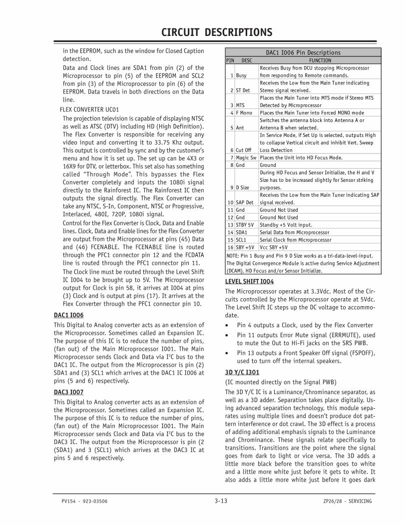
CIRCUIT DESCRIPTIONS
PV154 - 923-03506 3-13 ZP26/28 - SERVICING
in the EEPROM, such as the window for Closed Captiondetection.Data and Clock lines are SDA1 from pin (2) of theMicroprocessor to pin (5) of the EEPROM and SCL2from pin (3) of the Microprocessor to pin (6) of theEEPROM. Data travels in both directions on the Dataline.
FLEX CONVERTER UC01The projection television is capable of displaying NTSCas well as ATSC (DTV) including HD (High Definition).The Flex Converter is responsible for receiving anyvideo input and converting it to 33.75 Khz output.This output is controlled by sync and by the customer’smenu and how it is set up. The set up can be 4X3 or16X9 for DTV, or letterbox. This set also has somethingcalled “Through Mode”. This bypasses the FlexConverter completely and inputs the 1080i signaldirectly to the Rainforest IC. The Rainforest IC thenoutputs the signal directly. The Flex Converter cantake any NTSC, S-In, Component, NTSC or Progressive,Interlaced, 480I, 720P, 1080i signal.Control for the Flex Converter is Clock, Data and Enablelines. Clock, Data and Enable lines for the Flex Converterare output from the Microprocessor at pins (45) Dataand (46) FCENABLE. The FCENABLE line is routedthrough the PFC1 connector pin 12 and the FCDATAline is routed through the PFC1 connector pin 11.The Clock line must be routed through the Level ShiftIC I004 to be brought up to 5V. The Microprocessoroutput for Clock is pin 58, it arrives at I004 at pins(3) Clock and is output at pins (17). It arrives at theFlex Converter through the PFC1 connector pin 10.
DAC1 I006This Digital to Analog converter acts as an extension ofthe Microprocessor. Sometimes called an Expansion IC.The purpose of this IC is to reduce the number of pins,(fan out) of the Main Microprocessor I001. The MainMicroprocessor sends Clock and Data via I2C bus to theDAC1 IC. The output from the Microprocessor is pin (2)SDA1 and (3) SCL1 which arrives at the DAC1 IC I006 atpins (5 and 6) respectively.
DAC3 I007This Digital to Analog converter acts as an extension ofthe Microprocessor. Sometimes called an Expansion IC.The purpose of this IC is to reduce the number of pins,(fan out) of the Main Microprocessor I001. The MainMicroprocessor sends Clock and Data via I2C bus to theDAC3 IC. The output from the Microprocessor is pin (2(SDA1) and 3 (SCL1) which arrives at the DAC3 IC atpins 5 and 6 respectively.
LEVEL SHIFT I004The Microprocessor operates at 3.3Vdc. Most of the Cir-cuits controlled by the Microprocessor operate at 5Vdc.The Level Shift IC steps up the DC voltage to accommo-date.
• Pin 4 outputs a Clock, used by the Flex Converter
• Pin 11 outputs Error Mute signal (ERRMUTE), usedto mute the Out to Hi-Fi jacks on the SRS PWB.
• Pin 13 outputs a Front Speaker Off signal (FSPOFF),used to turn off the internal speakers.
3D Y/C I301(IC mounted directly on the Signal PWB)
The 3D Y/C IC is a Luminance/Chrominance separator, aswell as a 3D adder. Separation takes place digitally. Us-ing advanced separation technology, this module sepa-rates using multiple lines and doesn’t produce dot pat-tern interference or dot crawl. The 3D effect is a processof adding additional emphasis signals to the Luminanceand Chrominance. These signals relate specifically totransitions. Transitions are the point where the signalgoes from dark to light or vice versa. The 3D adds alittle more black before the transition goes to whiteand a little more white just before it gets to white. Italso adds a little more white just before it goes dark
PIN DESC FUNCTION
1 BusyReceives Busy from DCU stopping Microprocessor from responding to Remote commands.
2 ST DetReceives the Low from the Main Tuner indicating Stereo signal received.
3 MTSPlaces the Main Tuner into MTS mode if Stereo MTS Detected by Microprocessor
4 F Mono Places the Main Tuner into Forced MONO mode
5 AntSwitches the antenna block into Antenna A or Antenna B when selected.
6 Cut Off
In Service Mode, if Set Up is selected, outputs High to collapse Vertical circuit and inhibit Vert. Sweep Loss Detection
7 Magic Sw Places the Unit into HD Focus Mode.8 Gnd Ground
9 D Size
During HD Focus and Sensor Initialize, the H and V Size has to be increased slightly for Sensor striking purposes.
10 SAP DetReceives the Low from the Main Tuner indicating SAP signal received.
11 Gnd Ground Not Used12 Gnd Ground Not Used13 STBY 5V Standby +5 Volt input.14 SDA1 Serial Data from Microprocessor15 SCL1 Serial Clock from Microprocessor16 SBY +5V Vcc SBY +5V
DAC1 I006 Pin Descriptions
NOTE: Pin 1 Busy and Pin 9 D Size works as a tri-data-level-input. The Digital Convergence Module is active during Service Adjustment (DCAM), HD Focus and/or Sensor Initialize.
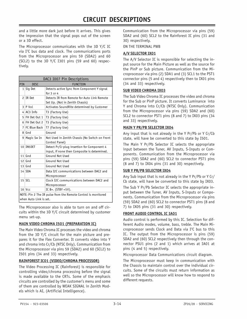
CIRCUIT DESCRIPTIONS
PV154 - 923-03506 3-14 ZP26/28 - SERVICING
and a little more dark just before it arrives. This givesthe impression that the signal pops out of the screenor a 3D effect.
The Microprocessor communicates with the 3D Y/C ICvia I2C bus data and clock. The communications portsfrom the Microprocessor are pins 59 (SDA2) and 60(SCL2) to the 3D Y/C I301 pins (59 and 60) respec-tively.
The Microprocessor also is able to turn on and off cir-cuits within the 3D Y/C circuit determined by customermenu set-up.
MAIN VIDEO CHROMA I501 (PREPARATION IC)The Main Video Chroma IC processes the video and chromafrom the 3D Y/C circuit for the main picture and pre-pares it for the Flex Converter. It converts video into Yand chroma into Cr/Cb (NTSC Only). Communication fromthe Microprocessor via pins 59 (SDA2) and 60 (SCL2) toI501 pins (34 and 33) respectively.
RAINFOREST IC01 (VIDEO/CHROMA PROCESSOR)The Video Processing IC (Rainforest) is responsible forcontrolling video/chroma processing before the signalis made available to the CRTs. Some of the emphasiscircuits are controlled by the customer’s menu and someof them are controlled by WEAK SIGNAL in Zenith Mod-els which is AI, (Artificial Intelligence).
Communication from the Microprocessor via pins (59)SDA2 and (60) SCL2 to the Rainforest IC pins (31 and30) respectively.
ON THE TERMINAL PWB
A/V SELECTOR IX01The A/V Selector IC is responsible for selecting the in-put source for the Main Picture as well as the source forthe PinP or Sub picture. Communication from the Mi-croprocessor via pins (2) SDA1 and (3) SCL1 to the PST1connector pins (5 and 4) respectively then to IX01 pins(34 and 33) respectively.
SUB VIDEO CHROMA IX03The Sub Video Chroma IC processes the video and chromafor the Sub or PinP picture. It converts Luminance intoY and Chroma into Cr/Cb (NTSC Only). Communicationfrom the Microprocessor via pins (59) SDA2 and (60)SCL2 to connector PST1 pins (8 and 7) to IX03 pins (34and 33) respectively.
MAIN Y PR/PB SELECTOR IX04Any input that is not already in the Y Pr/Pb or Y Cr/Cbstate, will have be converted to this state by I501.
The Main Y Pr/Pb Selector IC selects the appropriateinput between the Tuner, AV Inputs, S-Inputs or Com-ponents. Communication from the Microprocessor viapins (59) SDA2 and (60) SCL2 to connector PST1 pins(8 and 7) to IX04 pins (31 and 30) respectively.
SUB Y PR/PB SELECTOR IX04Any Sub input that is not already in the Y Pr/Pb or Y Cr/Cb state, will have be converted to this state by IX03.
The Sub Y Pr/Pb Selector IC selects the appropriate in-put between the Tuner, AV Inputs, S-Inputs or Compo-nents. Communication from the Microprocessor via pins(59) SDA2 and (60) SCL2 to connector PST1 pins (8 and7) to IX05 pins (31 and 30) respectively.
FRONT AUDIO CONTROL IC IA01Audio control is performed by this IC. Selection for dif-ferent Audio modes, volume, bass, treble. The Main Mi-croprocessor sends Clock and Data via I2C bus to thisIC. The output from the Microprocessor is pins (59)SDA2 and (60) SCL2 respectively then through the con-nector PSU1 pins (2 and 1) which arrives at IA01 atpins (4 and 5) respectively.
Microprocessor Data Communications circuit diagram.
The Microprocessor must keep in communication withthe Chassis to maintain control over the individual cir-cuits. Some of the circuits must return information aswell so the Microprocessor will know how to respond todifferent requests.
PIN DESC FUNCTION1 Sig Det Detects active Sync from Component Y signal
for 3 or 42 IR Det Detects IR from Remote for Auto Link Remote
Set Up. (Not in Zenith Chassis)3 P Vol Activates SoundRite determined by Customer
4 AC3 Info T3 (Factory Use)
5 FH Det Out 1 T3 (Factory Use)
6 FH Det Out 2 T3 (Factory Use)
7 FC Blue Back T7 (Factory Use)
8 Gnd Ground
9 Magic Sw In Not Used in Zenith Chassis (No Switch on Front Control Panel)
10 IN5DET Detect Pr/Cr plug insertion for Component 4 input, if none then Composite is determined.
11 Gnd Ground Not Used
12 Gnd Ground Not Used
13 Gnd Ground Not Used
14 SDA Data I2C communications between DAC2 and Microprocessor
15 SCL Clock I2C communications between DAC2 and Microprocessor
16 Vcc IC B+. (STBY +5V).
DAC3 I007 Pin Descriptions
NOTE: Pin 2 The IR pulse from the Remote Control is monitored when Auto Link is set.
CIRCUIT DESCRIPTIONS
PV154 - 923-03506 3-15 ZP26/28 - SERVICING
The Microprocessor uses a combination of I2C Bus com-munication and the Serial Data, Clock and Load linesfor control. The I2C communication scheme only requires2 lines for control. These lines are called SDA and SCL.Serial Data and Serial Clock respectively.
SRS AUDIO +29V REGULATOR INDICATED BY D912.The SRS Audio +29V supply is generated from pin (8) ofT901. This output is rectified by D910 and filtered byC915. The choke L912 adds further filtration and C917removes high frequency switching noise. This supply isrouted to the SRS Audio Output IC IJ01 via the connectorPAQ1 pin 1 and 2.This voltage is what illuminates the Green Visual TroubleShooting LED, D912.
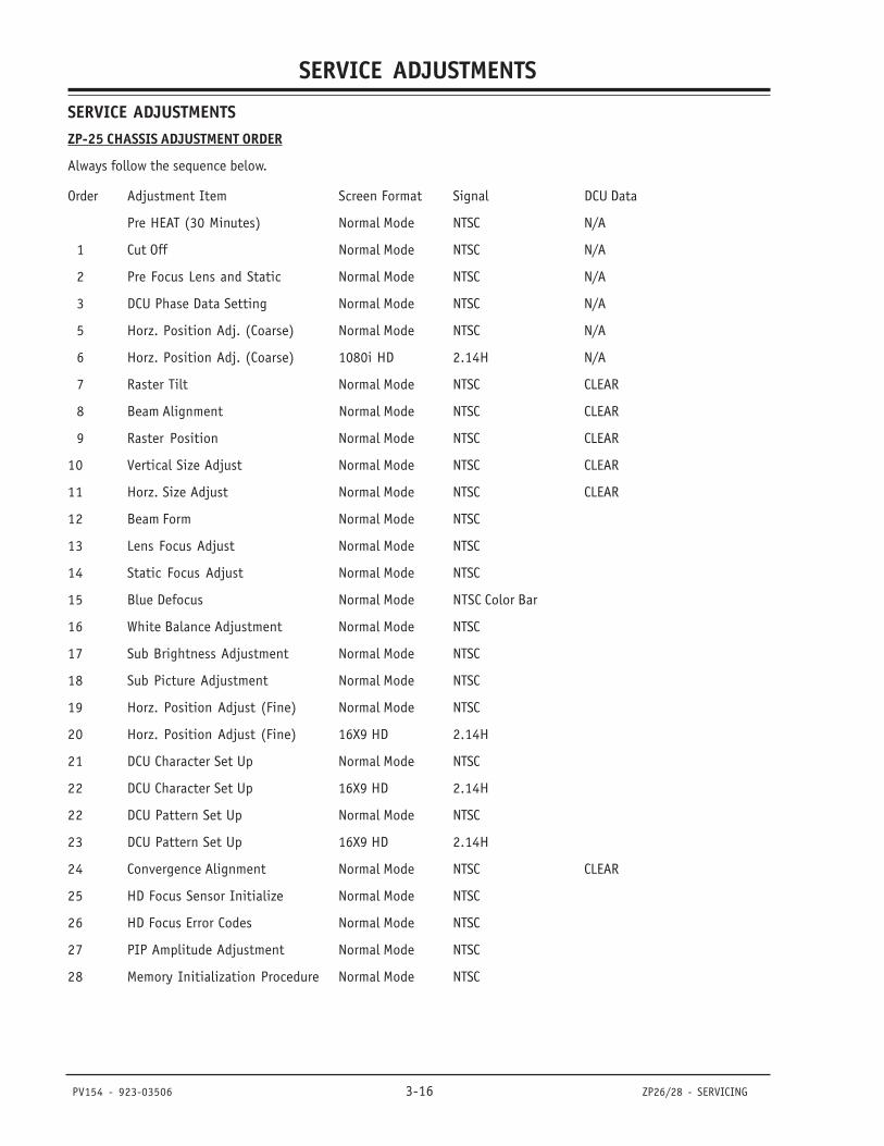
SERVICE ADJUSTMENTS
PV154 - 923-03506 3-16 ZP26/28 - SERVICING
SERVICE ADJUSTMENTSZP-25 CHASSIS ADJUSTMENT ORDER
Always follow the sequence below.
Order Adjustment Item Screen Format Signal DCU Data
Pre HEAT (30 Minutes) Normal Mode NTSC N/A
1 Cut Off Normal Mode NTSC N/A
2 Pre Focus Lens and Static Normal Mode NTSC N/A
3 DCU Phase Data Setting Normal Mode NTSC N/A
5 Horz. Position Adj. (Coarse) Normal Mode NTSC N/A
6 Horz. Position Adj. (Coarse) 1080i HD 2.14H N/A
7 Raster Tilt Normal Mode NTSC CLEAR
8 Beam Alignment Normal Mode NTSC CLEAR
9 Raster Position Normal Mode NTSC CLEAR
10 Vertical Size Adjust Normal Mode NTSC CLEAR
11 Horz. Size Adjust Normal Mode NTSC CLEAR
12 Beam Form Normal Mode NTSC
13 Lens Focus Adjust Normal Mode NTSC
14 Static Focus Adjust Normal Mode NTSC
15 Blue Defocus Normal Mode NTSC Color Bar
16 White Balance Adjustment Normal Mode NTSC
17 Sub Brightness Adjustment Normal Mode NTSC
18 Sub Picture Adjustment Normal Mode NTSC
19 Horz. Position Adjust (Fine) Normal Mode NTSC
20 Horz. Position Adjust (Fine) 16X9 HD 2.14H
21 DCU Character Set Up Normal Mode NTSC
22 DCU Character Set Up 16X9 HD 2.14H
22 DCU Pattern Set Up Normal Mode NTSC
23 DCU Pattern Set Up 16X9 HD 2.14H
24 Convergence Alignment Normal Mode NTSC CLEAR
25 HD Focus Sensor Initialize Normal Mode NTSC
26 HD Focus Error Codes Normal Mode NTSC
27 PIP Amplitude Adjustment Normal Mode NTSC
28 Memory Initialization Procedure Normal Mode NTSC
SERVICE ADJUSTMENTS
PV154 - 923-03506 3-17 ZP26/28 - SERVICING
CHASSIS PRE-HEAT RUN ADJUSTMENTSPRESET EACH ADJUSTMENT VR TO THE CONDITIONSHOWN: BEFORE PRE HEAT RUN.1. Red and Green Drive VR on the CRT PWB. This is
part of the I2C Service Menu. Set each to 3F. ToEnter Service Menu, press the SOURCE button andhold, then press the Power Button. Set comes onand displays Service Menu.
2. SCREEN VR ON FOCUS PACK. Pre Set fully counter-clockwise.
3. Focus VR on focus pack Pre Set fully clockwise. 4. Allow set to operate at least 30 Minutes before
beginning adjustments.
CHASSIS CUT-OFF (SCREENS) ADJUSTMENTADJUSTMENT PREPARATION:· Pre Heat Run should be finished.· Be sure Screen Color Temperature setting is in the
COOL mode· Room Light should be minimal.
ADJUSTMENT PROCEDURE:1. Go to I2C ADJ. Mode. (With power Off, press the
SOURCE button on the front panel and hold down,then press the POWER ON button and release bothbuttons. The Service Menu is displayed.)
2. Set R DRV (COOL) to center data value (3F).3. Set G DRV (COOL) to center data value (3F).4. Confirm that the R, G, and B CUTOFF (COOL) data
settings are [80].5. Adjust Screen VRs on Focus Pack fully counter clock
wise.6. Choose SERVICE item [1] of I2C ADJ. Mode. Select
CURSOR RIGHT and the Vertical will collapses.7. Adjust any Screen VR. Screen VR should be turned
clockwise gradually until that particular color isbarely visible.
8. Repeat for the other two colors.9. Exit SERVICE by pressing the CURSOR LEFT on re-
mote.10. Exit SERVICE MENU by pressing the MENU key on
the remote.
CHASSIS PRE-FOCUS ADJUSTMENTADJUSTMENT PREPARATION:Pre Heat Run should be finished.
FOCUS ADJUSTMENT:1. Short the 2pin sub-miniature connector on the
CRT PWB (PTS), to remove any color not beingadjusted and adjust one color at a time. (The ad-justment order of R, G and B is just an example.)PTSR for RED, PTSG for GREEN and PTSB for BLUE.
2. Adjust the Focus VR for Red until Focus is achieved.(A Fine Adjustment will be made later.)
3. Repeat for Blue and Green.
DCU CROSSHATCH PHASE ADJUSTMENTADJUSTMENT PREPARATION:· Cut Off adjustment should be finished.· Video Control: Brightness 90%, Contrast Max.
ADJUSTMENT PROCEDURE: NORMAL MODE1. Receive any NTSC signal.2. Press the SERVICE ONLY switch on the Convergence
PWB to enter DCAM mode and display DCU grid.3. Change the Remote Control into VCR mode.4. Press the (-) key on the Remote, Green Cross hatch
appears.5. Change the Remote Control into TV mode.6. Press the QUIT key. (This is the Phase adjustment
mode).7. Adjust data value using the keys indicated in the
chart below, until the data matches the values in-dicated in the chart.
Saving Data Values:8. Change the Remote Control into VCR mode.9. Press the (-) key on the Remote to exit phase mode.10. Change Remote Control into TV mode.11. Press MULTI key TWICE to store the information.12. When Green dots are displayed, press the MUTE
key on remote.13. Press the SERVICE ONLY switch to return to normal
video mode.PHASE MODE Display Format NORMAL DataADJUST ING Address Data Value4 and 6 keys on Remote PH-H BF2 and 5 keys on Remote PH-V 07Cursor Left t and Right u on Remote CR-H 4CCursor Up p and Down q on Remote CR-V 0C
CHASSIS HORIZONTAL PHASE (COARSE) ADJUSTMENTADJUSTMENT PREPARATION:· Cut Off, DCU Phase adjustments should be finished.· Video Control: Brightness 90%, Contrast Max.
ADJUSTMENT PROCEDURE WIDE MODE:1. Receive any NTSC crosshair signal.2. Screen Format is WIDE.3. Press the SERVICE ONLY switch on the convergence
PWB and display the Digital Convergence Cross-hatch pattern.
4. Mark the center of the Digital Convergence Cross-hatch Pattern with finger and press the SERVICEONLY switch to return to normal mode.
5. Enter the I2C Bus alignment menu (With Power Off,press and hold the SOURCE button on the frontpanel, then press the POWER button and Releaseboth buttons).
SERVICE ADJUSTMENTS
PV154 - 923-03506 3-18 ZP26/28 - SERVICING
6. Select Item H POSI and adjust the data so thatthe center of Video matches the location of theDigital Crosshatch pattern noted in step {4}.
7. Exit from the I2C Menu.
1080I HD MODE ADJUSTMENT: 1. Receive any 1080i (2.14H) signal and select that
input.2. Press the SERVICE ONLY switch on the deflection
PWB and display the Digital Convergence Cross-hatch pattern.
3. Mark the center of the Digital Convergence Cross-hatch Pattern with finger and press the SERVICEONLY switch to return to normal mode.
4. Enter the I2C Bus alignment menu (With Power Off,press and hold the SOURCE button on the frontpanel, then press the POWER button and Releaseboth buttons).
5. Select Item H POSI H6. Adjust the data up or down slightly to match the
Video to the center location found in step (10).7. Exit from the I2C Menu.NOTE: To enter the I2C Bus alignment menu, with Power
Off, press the SOURCE button on the front paneland hold it down, then press the POWER buttonand release both buttons. I2C adjustment menuwill appear.
CHASSIS TILT (RASTER INCLINATION) ADJUSTMENTADJUSTMENT PREPARATION:· The set can face any direction.· Receive the Cross-Hatch Signal· VIDEO CONTROLS: Factory Preset.· SCREEN FORMAT: should be NORMAL mode.· The lens focus should have been coarse adjusted.· The electrical focus should have been coarse
adjusted.· The Digital Convergence RAM should be cleared. · Turn power off, press and hold the SERVICE ONLY
switch on the Convergence PWB, then press thePOWER button.
ADJUSTMENT PROCEDURE:GREEN:1. Apply covers to the RED and BLUE lenses or short
the 2P Sub Mini connector [PTS] on R&B CRT PWBto produce only GREEN.
2. Turn the Green deflection yoke and adjust the TILTuntil the green is level. [+/- 2mm tolerance]. Seediagram.
RED:3. Remove cover or PTS short from RED CRT and align
RED with GREEN. [+/- 1mm tolerance when com-pared to Green]
BLUE:4. Remove cover or PTS short from BLUE and cover
the RED CRT. Align BLUE with GREEN. [+/- 1mmtolerance when compared to Green]
After Completion:5. Tighten DY Yoke Screws to 12+/-2 kg-cm.6. REMOVE ALL COVERS or SHORTS on the PTS con-
nectors. 7. Turn the Power Off.
CHASSIS BEAM ALIGNMENT ADJUSTMENTPREPARATION FOR ADJUSTMENT:· Pre Heat, Pre-optical focus, DCU Phase Data, H.
POSI Course and Raster Tilt adjustment should becompleted.
· Brightness: 90%· Contrast Max.· Receive cross hatch signals, or dot pattern· RASTER TILT adjustment should be finished.· SCREEN FORMAT should be NORMAL mode.Adjustment procedure:1. Green (G) tube beam alignment adjustment:2. Short-circuit 2P subminiature connector plug PTS
of Red (R) and Blue (B) on the CRT boards andproject only Green (G).
3. Put Green (G) tube beam alignment magnet to thecancel state as shown in Figure 1. (See Figure 1.)
4. Turn the Green (G) static focus VR counterclock-wise all the way and make sure of position of crosshatch center on screen.
5. Turn Green (G) static focus VR clockwise all theway.
6. Turn two Beam alignment magnet in any desireddirection and move cross hatch center to posi-tion found in step (3). (See Figure 2 below).
7. If image position does not shift when Green staticfocus VR is turned, adjustment is complete.
8. If image position does move, repeat steps [2]through [6].
9. Conduct beam alignment for Red and Blue in thesame way.
10. Red (R) focus on focus pack.11. Blue (B) focus on focus pack.12. Upon completion of adjustment, place a small
amount of white paint on the beam alignmentmagnets, to assure they don’t move.
CHASSIS RED/BLUE RASTER OFFSET ADJUSTMENTRaster Offset is necessary to conserve Memory allocation.It is very important to remember that the Red is offset
SERVICE ADJUSTMENTS
PV154 - 923-03506 3-19 ZP26/28 - SERVICING
Left of Center and Blue is offset Right of center. Pleaseuse the following information to accurately offset Redand Blue from center. Also see Overlay Dimensions forfurther details.
PREPARATION FOR ADJUSTMENT:· Video Control should be set at Factory Preset
condition.· Static Focus adjustment should be finished.
ADJUSTMENT PROCEDURE1. With Power Off, press the Service Only switch on
the Convergence PWB. While holding the ServiceOnly Switch down, press the Power On button. Pic-ture will appear without convergence correction.
2. Press the Service Only Switch to receive the DCUcross-hatch signal.
3. Turn the centering magnets of Red, Green and Blueand adjust so that the center point of the cross-hatch pattern satisfies the diagram below. (DCUdata is cleared). Remember Green is Centered. Redis to the left of Green and Blue is to the right ofGreen as indicated below.
o All Vertical positions are geometric center of screen.o Parameters are +/- 2mm.
MODELRED OFFSET LEFT
OF CENTERBLUE OFFSET
RIGHT OF CENTERASPECT
65" 15mm 25mm 16 X 961" 15mm 25mm 16 X 956" 15mm 25mm 16 X 9
VERTICAL SIZE ADJUSTMENTVERTICAL SIZE:· Receive an NTSC signal.· Video Control should be set to Factory Preset
condition.· Convergence should not be corrected.
ADJUSTMENT PROCEDURE:1. With Power Off, press and hold the Service Only
Switch on the Convergence PWB, then press thePower Button and Release. (Digital Convergencedata is cleared). Then release the Service OnlySwitch. DCU Grid appears.
2. Adjust using R607 (Vertical Size Adj. VR) to matchmarks on the Overlay. (See Figure Below)
3. Turn Power Off.NOTE: Centering magnet may be moved to facilitate.
Distance is important, not centering.
ALTERNATE METHOD:Adjust Vertical Size until the size matches the chartbelow.
ALTERNATE METHOD:Adj Vert Size until the size matches the chart below.Scrn Size 56” 61” 65”Scrn Format NORM NORM NORML= 590 645 690
All Adjustments are +/-5mm
HORIZONTAL SIZE ADJUSTMENTPREPARATION FOR ADJUSTMENT· Display Mode NORMAL· Install the correct Overlay.· Input an NTSC Signal.· Digital Convergence RAM should be cleared. · With Power Off, press the Service Only switch on
the Convergence PWB. While holding the ServiceOnly Switch down, press the Power On button andRelease. DCU Grid will appear without convergencecorrection.
NOTE: After entering DCAM, with each press of the ServiceOnly Switch, the picture will toggle between Videomode and DCU Grid.
· Project only the Green raster by selecting GreenAdjustment mode and pressing the MENU button.
ADJUSTMENT1. Adjust using R711 (Horz. Size Adj. VR) to match
marks on the Overlay. (See Figure Below)2. Press “Power Off” to exit DCAM. (Digital Conver-
gence Adjustment Mode.)
ALTERNATE METHOD:Adj Horiz Size until the size matches the chart below.Screen Size 56” 61” 65”Screen Format NORM NORM NORML= 1165 1270 1355
All Adjustments are +/-5mm
BEAM FORM ADJUSTMENTPREPARATION FOR ADJUSTMENTIMPORTANT: Screen format should be “NORMAL”.
1. Pre Heat, Cut-Off, Pre-optical focus, DCU PhaseData, H. Pos Course, Raster Tilt, Beam Alignment,Raster Position, Vertical and Horizontal Size ad-justment should be completed.
2. Brightness: 90%, Contrast: Max.3. Input a NTSC DOT signal.
ADJUSTMENTS PROCEDURE:4. Green CRT beam shape adjustment.5. Short-circuit 2P sub-mini connectors on Red and
Blue CRT PWB to project only the Green beam.6. Turn the green static focus VR fully clockwise.7. Make the dot at the screen center a true circle,
using the 4-Pole magnet shown in (Figure 1 be-
SERVICE ADJUSTMENTS
PV154 - 923-03506 3-20 ZP26/28 - SERVICING
low.)8. Also adjust the Red and Blue CRT beam shapes ac-
cording to the steps (1) to (3).9. After the adjustment is completed, return R, G and
B static VRs to the Best Focus point.
LENS FOCUS ADJUSTMENTPREPARATION FOR ADJUSTMENT· Receive the Cross-hatch pattern signal.· The electrical focus adjustment should have been
completed.· Deflection Yoke tilt should have been adjusted.· Brightness = 50%· Contrast = 60% to 70%
ADJUSTMENT PROCEDURE1. Short the 2 pin sub-miniature connector on the
CRT PWB PTS, to produce only the color beingadjusted and adjust one at a time. (The adjust-ment order of R, G and B is just an example.)
2. (See Figure 1) Loosen the fixing screw on the lensassembly so that the lens cylinder can be turned.(Be careful not to loosen the screw too much, asthis may cause movement of the lens cylinder whentightening.)
3. Rotate the cylinder back and forth to obtain thebest focus point, while observing the Cross-Hatch.(Observe the center of the screen). Located justbelow the screen are the two wooden panels. Re-move the panels to allow access to the focus ringson the Lenses.
4. After completing optical focus, tighten the fixingscrews for each lens.
5. When adjusting the Green Optical focus, be verycareful. Green is the most dominant of the colorguns and any error will be easily seen.
6. Repeat Electrical Focus if necessary.
STATIC FOCUS ADJUSTMENTADJUSTMENT PREPARATION· Pre Heat Run should be finished.
FOCUS ADJUSTMENT:1. Short the 2pin sub-miniature connector on the
CRT PWB (PTS) to remove any color not being ad-justed and adjust one color at a time. (The ad-justment order of R, G and B is just an example.)
2. Adjust the Focus VR for Red until maximum Focusis achieved.
3. Repeat for Blue and Green.
BLUE DE-FOCUS ADJUSTMENTADJUSTMENT PREPARATION:· Video Control: Brightness 90%, Contrast Max.· SCREEN FORMAT should be NORMAL mode.
ADJUSTMENT PROCEDURE1. Receive any NTSC crosshatch signal.2. Turn the B FOCUS VR fully clockwise.3. Adjust BLUE defocus according to the following
specifications. 1mm on each side equaling 2mmtotal. See figure Below.
WHITE BALANCE AND SUB BRIGHTNESS ADJUSTMENTADJUSTMENT CONDITIONS:· Cut Off and Blue Defocus must be complete.· High brightness white balance· Low brightness white balance· Set Color Temperature to COOL on Customer’s Menu.
ADJUSTMENT ITEMS:· Screen adjustment VRs on Focus Block· Drive adjustment performed using I2C Bus Align-
ment within Service Menu.
PREPARATION FOR ADJUSTMENT· Start adjustment 20 minutes or more after the
power is turned on.· Turn the brightness and black level OSD to mini-
mum by remote control.· Receive a tuner signal, (any channel, B/W would
be best).· Set the drive adjustments for Green and Red within
I2C Service Menu to their Data Centers (3F).
ADJUSTMENT PROCEDURESub Brightness:1. Go to I2C ADJ. Mode. (With power Off, press and
hold the SOURCE button on the front panel, thenpress the POWER button and release both buttons,Service Menu is displayed.)
2. Adjust the Sub Brightness Number [2] SUBBRT us-ing I2C Bus alignment procedure so only the slight-est white portions of the raster can be seen.
3. Exit Service Menu by pressing MENU button.4. Input a gray scale signal into any Video input and
select that input using the INPUT button on theremote or front control panel.
5. Turn the Brightness and Contrast OSD all the wayup.
6. Enter I2C the Service Menu again.7. Make the whites as white as possible using the
Red and Green Drive adjustment within I2C ServiceMenu . (10800K)
8. Exit the Service Menu by pressing the MENU but-ton on remote control.
9. Set the Brightness and Contrast to minimum.10. Adjust the low brightness areas to black and white,
using screen adjustment VRs (red, green, blue) onthe Focus Block assembly. (10800 K)
11. Check the high brightness whites again. If not

SERVICE ADJUSTMENTS
PV154 - 923-03506 3-21 ZP26/28 - SERVICING
OK, repeat steps 5 through 12.12. Press the MENU key on the remote to Exit Service
Menu. Remember: When adjusting the Screen con-trols, after the Cut Off adjustment has been com-pleted, never adjust the controls clockwise. Al-ways adjust counter clockwise. This lengthens tubelife.
CHASSIS HORIZONTAL PHASE (FINE) ADJUSTMENTADJUSTMENT PREPARATION:1. Cut Off, DCU Phase adjustments should be finished.2. Video Control: Brightness 90%, Contrast Max.
ADJUSTMENT PROCEDURE NORMAL MODE3. Receive any NTSC crosshair signal.4. Screen Format is NORMAL.5. Press the SERVICE ONLY switch on the convergence
PWB and display the Digital Convergence Cross-hatch pattern.
6. Mark the center of the Digital Convergence Cross-hatch Pattern with finger and press the SERVICEONLY switch to return to normal mode.
7. Enter the I2C Bus alignment menu and select ItemH POSI and adjust the data so that the center ofVideo matches the location of the Digital Cross-hatch pattern noted in step {4}.
8. Exit from the I2C Menu.16X9 HD Mode Adjustment: NOTE: I2C Service MenuCan Not be entered in the 16X9 HD Mode.
9. Receive any 2.14H signal.10. Change Screen Format 16X9 HD mode.11. Press the SERVICE ONLY switch on the deflection
PWB and display the Digital Convergence Cross-hatch pattern.
12. Mark the center of the Digital Convergence Cross-hatch Pattern with finger and press the SERVICEONLY switch to return to normal mode.
13. Enter the I2C Bus alignment menu and select Item[9] H POSI
14. Press SELECT key on R/C. (H POSI option is changedto HD mode. H POSI H appears). H POSI of 16X9HD mode data can be changed.
15. Adjust the data up or down slightly.16. Exit from the I2C Menu.17. Change Screen Format to 16X9 HD mode.18. Confirm that the Center of Video matches the Cen-
ter of the DCU Crosshatch determined in step (12).19. If center is not correct, Repeat steps (12) through
(18) until center is matched.NOTE: To enter the I2C Bus alignment menu, with Power
Off, press the INPUT button and hold it down, thenpress the POWER button. I2C adjustment menu willappear.
CHASSIS INTELLISENSE “PATTERN SET UP”
NOTE: This instruction should be applied when a new DCUis being replaced.
NOTE: This instruction shows how to set up the patternposition for Intellisense. Each model has a specificset up pattern position.
ADJUSTMENT PREPARATION:· Receive NTSC RF or Video Signal.· With Power Off, Press and HOLD the SERVICE ONLY
button on the Convergence/Focus PWB, then pressthe Power On/Off button and release, pictureappears, then release Service Button to bring upInternal Crosshatch.
NOTE: After entering the DCAM, each press of the ServiceOnly Switch will toggle between Video mode andDCU grid.
· Press the C SKIP (twice) to read the old ROM data,DCU Grid returns to normal with convergence cor-rection.
ADJUSTMENT PROCEDURE1. Make sure the Remote is in TV mode.2. Press the (-) key on R/C. (One additional line ap-
pears near the top and bottom.3. Change Remote to VCR mode.4. Press the (-) key. The PATTERN mode is displayed
as shown on the right.———>5. Change Remote back to TV mode.6. Use the 6 Key to rotate Arrow. Arrow rotates clock-
wise with each press on the 6 Key.7. Use the following Keys to switch color of patterns.
o Display : GREENo 0 : REDo Source : BLUE
8. Press the ? or ? Cursor to change the Pattern Po-sition Data in horizontal Direction to match thechart below.
9. Press the [?] or [?] Cursor keys to change the Pat-tern Position Data in Vertical Direction to matchthe chart below.
10.Press the MULTI key 2 times to write the changeddata into EEPROM. o First press, ADJ PAT-TERN ROM WRITE ? is displayed for alarm. oSecond press writes data into EEPROM. Green dotsappear after completion of operation.
11.Press the MUTE button 2 times to return to theDCU grid.
12. Power set off.

SERVICE ADJUSTMENTS
PV154 - 923-03506 3-22 ZP26/28 - SERVICING
NORMAL MODE: 0 1 2 3 4 5 6 7RH X 02 X FE X 02 X 04RV X 00 X 00 X 02 X 00GH X 00 X FE X 00 X 04GV X 00 X 00 X 02 X 00BH X 00 X FE X 00 X 04BV X 00 X 00 X 02 X 00
DIGITAL CONVERGENCE ALIGNMENTThere is no way to Calculate using a button on the remote.However, each time the data is saved, it performs thecalculate function.
DISPLAY selects GREEN Adj.
0 selects RED Adj.
SOURCE selects BLUE Adj.
SUB PICTURE AMPLITUDEPREPARATION FOR ADJUSTMENT· Sub Brightness adjustment should be finished.· Start adjustment 20 minutes after the power is
turned on.Condition should be set as follows:
· Contrast = MAX· Brightness = Center· Press “SPLIT” button on Remote Control. PIP ap-
pears on screen· Select Single mode. Receive NTSC white signal, for
the Main Picture and the Sub-Picture. (Do notuse Component Signals).
· Connect Probe on the P852 (CRT PWB — Green)to check sub-picture amplitude. Enter I2C adjust-ment Menu. Press Menu and scroll through pagesuntil TA1270-M appears.
ADJUSTMENT PROCEDURE1. Go to I2C adjustment Mode.2. Press “MENU” on remote to scroll through adjust-
ment pages, until TA1270-M appears at the top ofthe page.
3. Press “PIP CH” on remote control, TA1270-Mchanges to TA1270-S.
4. Observe P852 on the CRT PWB and change theTA1270-S “SUB CNT” I2C data so that the ampli-tude of the Sub Picture is the same level as that ofthe main picture. Shown below.
5. Exit Service Menu.Adjust SUB CNT until peak white of PinP matches peakwhite of the main picture.
ITEM INITIAL CONDITIONFUNCTIONNTSC Channel (Main, Sub) 03 CHSOURCE MODE Antenna ASLEEP TIMER Not RegisteredMULTI WINDOW MODE OffPIP Mode Single (Bottom Right)Freeze Mode Single (Bottom Right)SET UP SET UP SET UP TRILLINGUAL LANGUAGE EnglishSIGNAL AntennaScan 2 ~ 13 CHCHANNEL Add/Del --CLOCK SET Not RegisteredHD FOCUS --PICTURE FORMATSASPECT STYLE NormalV. POSITION 0COMPOSITE COLOR TYPE SDTV/HDVIDEO DISPLAY 1080iCUSTOMIZE CUSTOMIZE CUSTOMIZE CHANNEL LABEL Not RegisteredSOURCE ID Not RegisteredFAVORITE CHANNELS Not RegisteredPARENTAL CONTROLS Not RegisteredSECURITY TIMER Not RegisteredCAPTION / DISPLAY Not RegisteredCLOSED CAPTIONCCD DISPLAY OffCCD MODE C.C.CCD CHANNEL Channel 1MENU BACKGROUND ShadedVIDEO VIDEO VIDEO CONTRAST 100%BRIGHTNESS 50%COLOR 50%TINT CenterSHARPNESS 50%ADVANCED SETTINGSLIGHT SENTRY OffAUTO FRESH OnWEAK SIGNAL OffCOLOR TEMPERATURE Cool
ZP25 Factory Reset Condition

PV154 - 923-03506 3-1 ZP26/28 - PARTS
MODEL PARTSSECTION 4
MODEL PARTSAll HD-S models are module level repair only. Partscontact information is below.
Voice: 1-888-3-ZENITHFax: 1-888-6-ZENITHMail: ZENITH NATIONAL PARTS
P O Box 240007Huntsville, AL 35824-6407
R50V26LOC PART # DESCRIPTION1 NSP MIRROR MOUNT RIGHT2 NSP MIRROR MOUNT LEFT3 NSP MIRROR MOUNT UPPER4 992-10038 MIRROR5 NSP CABINET UPPER REAR6 874-10046 SCREEN ASS. WITH PROTECTOR7 PART OF 8 ESCUTCHEON UPPER8 833-10023 ESCUTCHEON ASSY.9 PART OF 8 ESCUTCHEON LEFT10 PART OF 8 ESCUTCHEON LOWER11 PART OF 8 ESCUTCHEON ANGLE BRACKET12 NSP MIRROR MOUNT LOWER13 965-10006 CASTER14 NSP FRONT ACESS COVER (WOOD)15 809-10810 GRILL16 849-10055 SPEAKER17 NSP BACK CENTER WOOD18 809-10807 CONTROL PANEL ASY19 814-10236 CABINET LOWER REAR20 809-10822 VM SUB PCB21 809-10726 CRX F-PACK22 809-10814 DELTA (R,G,B) LENSE23 809-10811 CONTROL POWER ASS. PWB24 PART OF 18 FRONT BUTTON ASSY PLASTIC25 809-10821 SCAN VELOCITY26 900-10072 CRT B.ASY(B)27 900-10071 CRT B.ASY(G)28 809-10823 AUDIO PWB29 809-10825 SIGNAL PWB30 809-10824 TERMINAL PWB31 809-10826 DEFLECTION PWB32 809-10820 CONVERGENCE PWB33 809-10844 STAND BY POWER SUPPLY34 809-10813 CPT PWB ASY35 845-00340 POWER CORD36 900-10070 CRT B.ASY(R)37 895-10143 DEFLECTION YOKE38 NSP REAR PORT PANEL PLASTIC39 809-10735 RF BLOCK40 874-10054 SCREEN PROTECTOR ONLY
901-10023 OP GUIDE924-10114 REMOTE CONTROL
R56W28LOC PART # DESCRIPTION1 NSP MIRROR MOUNT RIGHT2 NSP MIRROR MOUNT LEFT3 NSP MIRROR MOUNT UPPER4 992-10047 MIRROR GLASS5 NSP BACK UPPER WOOD6 874-10050 SCREEN ASS. WITH PROTECTOR7 PART OF 8 ESCUTCHEON UPPER8 814-10257 ESCUTCHEON ASS.9 PART OF 8 ESCUTCHEON LEFT/RIGHT SIDE10 PART OF 8 ESCUTCHEON LOWER11 PART OF 8 ESCUTCHEON ANGLE BRACKET12 857-10393 FRONT CENTER PANEL13 805-10003 MAGIC FOCUS SENSOR ONLY14 NSP BACK CENTER WOOD15 809-10841 SENSOR PWB16 938-10014 GRILL17 NSP FRONT ACESS COVER (WOOD)18 849-10055 SPEAKER19 809-10726 CRX F-PACK20 809-10836 VM SUB PCB21 965-10004 CASTER22 809-10807 CONTROL PANEL ASY23 809-10806 FRONT CONTROL PWB24 PRT OF 22 FRONT BUTTON ASSY PLASTIC25 NSP LOWER REAR BOARD26 NSP REAR PORT PANEL PLASTIC27 809-10735 AB RF SW ASSY28 809-10837 AUDIO PWB29 900-10071 CRT B.ASY(G)30 900-10072 CRT B.ASY(B)31 809-10835 SCAN VELOCITY32 809-10839 SIGNAL PWB33 809-10838 TERMINAL PWB34 809-10840 DEFLECTION PWB35 809-10834 CONVERGENCE PWB36 809-10855 STAND BY POWER SUPPLY PWB37 809-10805 ZP14C CPT PWB ASY38 845-00340 POWER CORD39 900-10070 CRT B.ASY(R)40 895-10143 DEFLECTION YOKE41 971-10024 DELTA (R,G,B) 260 A/B42 874-10048 SCREEN PROTECTOR ONLY
206-03282 OP GUIDE924-10098 REMOTE CONTROL
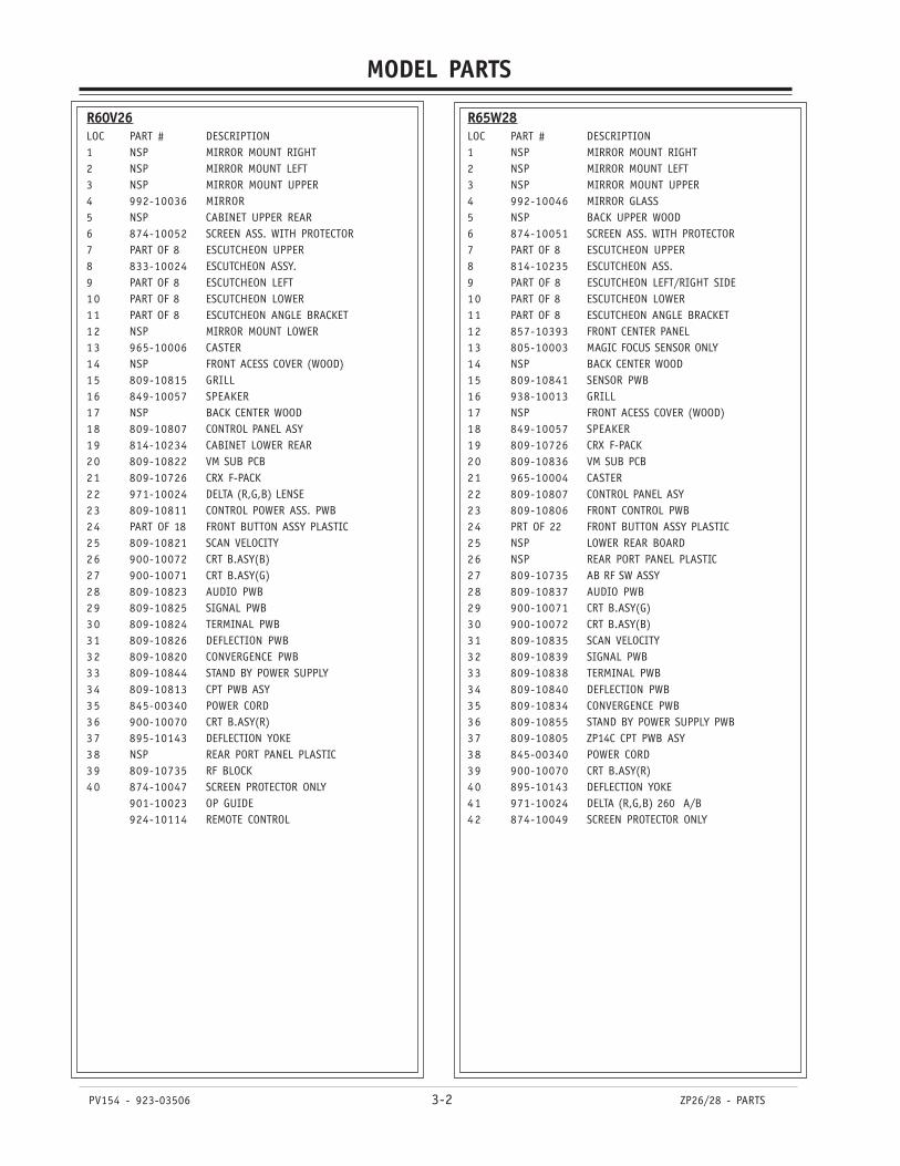
PV154 - 923-03506 3-2 ZP26/28 - PARTS
MODEL PARTS
R60V26LOC PART # DESCRIPTION1 NSP MIRROR MOUNT RIGHT2 NSP MIRROR MOUNT LEFT3 NSP MIRROR MOUNT UPPER4 992-10036 MIRROR5 NSP CABINET UPPER REAR6 874-10052 SCREEN ASS. WITH PROTECTOR7 PART OF 8 ESCUTCHEON UPPER8 833-10024 ESCUTCHEON ASSY.9 PART OF 8 ESCUTCHEON LEFT10 PART OF 8 ESCUTCHEON LOWER11 PART OF 8 ESCUTCHEON ANGLE BRACKET12 NSP MIRROR MOUNT LOWER13 965-10006 CASTER14 NSP FRONT ACESS COVER (WOOD)15 809-10815 GRILL16 849-10057 SPEAKER17 NSP BACK CENTER WOOD18 809-10807 CONTROL PANEL ASY19 814-10234 CABINET LOWER REAR20 809-10822 VM SUB PCB21 809-10726 CRX F-PACK22 971-10024 DELTA (R,G,B) LENSE23 809-10811 CONTROL POWER ASS. PWB24 PART OF 18 FRONT BUTTON ASSY PLASTIC25 809-10821 SCAN VELOCITY26 900-10072 CRT B.ASY(B)27 900-10071 CRT B.ASY(G)28 809-10823 AUDIO PWB29 809-10825 SIGNAL PWB30 809-10824 TERMINAL PWB31 809-10826 DEFLECTION PWB32 809-10820 CONVERGENCE PWB33 809-10844 STAND BY POWER SUPPLY34 809-10813 CPT PWB ASY35 845-00340 POWER CORD36 900-10070 CRT B.ASY(R)37 895-10143 DEFLECTION YOKE38 NSP REAR PORT PANEL PLASTIC39 809-10735 RF BLOCK40 874-10047 SCREEN PROTECTOR ONLY
901-10023 OP GUIDE924-10114 REMOTE CONTROL
R65W28LOC PART # DESCRIPTION1 NSP MIRROR MOUNT RIGHT2 NSP MIRROR MOUNT LEFT3 NSP MIRROR MOUNT UPPER4 992-10046 MIRROR GLASS5 NSP BACK UPPER WOOD6 874-10051 SCREEN ASS. WITH PROTECTOR7 PART OF 8 ESCUTCHEON UPPER8 814-10235 ESCUTCHEON ASS.9 PART OF 8 ESCUTCHEON LEFT/RIGHT SIDE10 PART OF 8 ESCUTCHEON LOWER11 PART OF 8 ESCUTCHEON ANGLE BRACKET12 857-10393 FRONT CENTER PANEL13 805-10003 MAGIC FOCUS SENSOR ONLY14 NSP BACK CENTER WOOD15 809-10841 SENSOR PWB16 938-10013 GRILL17 NSP FRONT ACESS COVER (WOOD)18 849-10057 SPEAKER19 809-10726 CRX F-PACK20 809-10836 VM SUB PCB21 965-10004 CASTER22 809-10807 CONTROL PANEL ASY23 809-10806 FRONT CONTROL PWB24 PRT OF 22 FRONT BUTTON ASSY PLASTIC25 NSP LOWER REAR BOARD26 NSP REAR PORT PANEL PLASTIC27 809-10735 AB RF SW ASSY28 809-10837 AUDIO PWB29 900-10071 CRT B.ASY(G)30 900-10072 CRT B.ASY(B)31 809-10835 SCAN VELOCITY32 809-10839 SIGNAL PWB33 809-10838 TERMINAL PWB34 809-10840 DEFLECTION PWB35 809-10834 CONVERGENCE PWB36 809-10855 STAND BY POWER SUPPLY PWB37 809-10805 ZP14C CPT PWB ASY38 845-00340 POWER CORD39 900-10070 CRT B.ASY(R)40 895-10143 DEFLECTION YOKE41 971-10024 DELTA (R,G,B) 260 A/B42 874-10049 SCREEN PROTECTOR ONLY


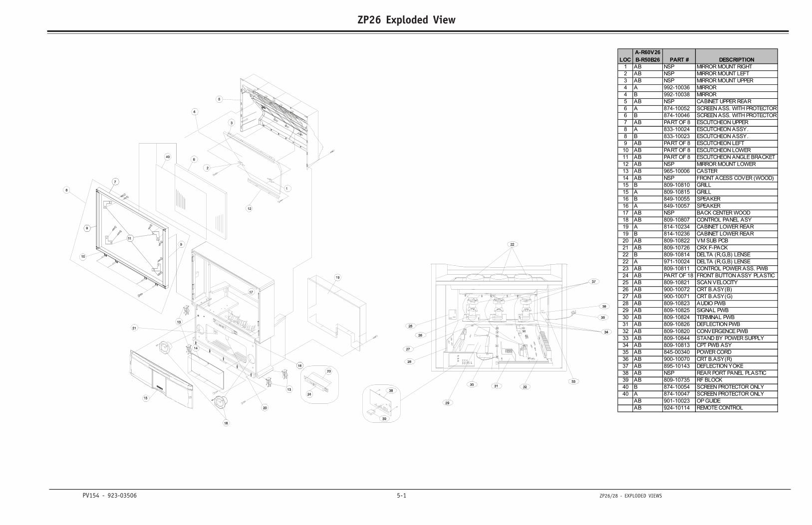
PV154 - 923-03506 5-1 ZP26/28 - EXPLODED VIEWS
ZP26 Exploded ViewSECTION 5
LOC
A-R60V26
B-R50B26 PART # DESCRIPTION
1 AB NSP MIRROR MOUNT RIGHT
2 AB NSP MIRROR MOUNT LEFT
3 AB NSP MIRROR MOUNT UPPER
4 A 992-10036 MIRROR
4 B 992-10038 MIRROR
5 AB NSP CABINET UPPER REAR
6 A 874-10052 SCREEN ASS. WITH PROTECTOR
6 B 874-10046 SCREEN ASS. WITH PROTECTOR
7 AB PART OF 8 ESCUTCHEON UPPER
8 A 833-10024 ESCUTCHEON ASSY.
8 B 833-10023 ESCUTCHEON ASSY.
9 AB PART OF 8 ESCUTCHEON LEFT
10 AB PART OF 8 ESCUTCHEON LOWER
11 AB PART OF 8 ESCUTCHEON ANGLE BRACKET
12 AB NSP MIRROR MOUNT LOWER
13 AB 965-10006 CASTER
14 AB NSP FRONT ACESS COVER (WOOD)
15 B 809-10810 GRILL
15 A 809-10815 GRILL
16 B 849-10055 SPEAKER
16 A 849-10057 SPEAKER
17 AB NSP BACK CENTER WOOD
18 AB 809-10807 CONTROL PANEL ASY
19 A 814-10234 CABINET LOWER REAR
19 B 814-10236 CABINET LOWER REAR
20 AB 809-10822 VM SUB PCB
21 AB 809-10726 CRX F-PACK
22 B 809-10814 DELTA (R,G,B) LENSE
22 A 971-10024 DELTA (R,G,B) LENSE
23 AB 809-10811 CONTROL POWER ASS. PWB
24 AB PART OF 18 FRONT BUTTON ASSY PLASTIC
25 AB 809-10821 SCAN VELOCITY
26 AB 900-10072 CRT B.ASY(B)
27 AB 900-10071 CRT B.ASY(G)
28 AB 809-10823 AUDIO PWB
29 AB 809-10825 SIGNAL PWB
30 AB 809-10824 TERMINAL PWB
31 AB 809-10826 DEFLECTION PWB
32 AB 809-10820 CONVERGENCE PWB
33 AB 809-10844 STAND BY POWER SUPPLY
34 AB 809-10813 CPT PWB ASY
35 AB 845-00340 POWER CORD
36 AB 900-10070 CRT B.ASY(R)
37 AB 895-10143 DEFLECTION YOKE
38 AB NSP REAR PORT PANEL PLASTIC
39 AB 809-10735 RF BLOCK
40 B 874-10054 SCREEN PROTECTOR ONLY
40 A 874-10047 SCREEN PROTECTOR ONLY
AB 901-10023 OP GUIDE
AB 924-10114 REMOTE CONTROL
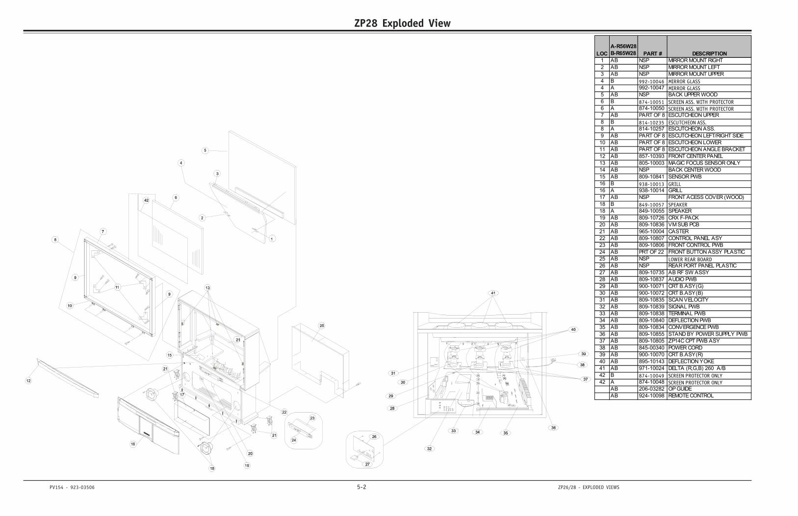
PV154 - 923-03506 5-2 ZP26/28 - EXPLODED VIEWS
ZP28 Exploded View
LOC
A-R56W28
B-R65W28 PART # DESCRIPTION1 AB NSP MIRROR MOUNT RIGHT
2 AB NSP MIRROR MOUNT LEFT
3 AB NSP MIRROR MOUNT UPPER
4 B 992-10046 MIRROR GLASS4 A 992-10047 MIRROR GLASS5 AB NSP BACK UPPER WOOD
6 B 874-10051 SCREEN ASS. WITH PROTECTOR6 A 874-10050 SCREEN ASS. WITH PROTECTOR7 AB PART OF 8 ESCUTCHEON UPPER
8 B 814-10235 ESCUTCHEON ASS.8 A 814-10257 ESCUTCHEON ASS.
9 AB PART OF 8 ESCUTCHEON LEFT/RIGHT SIDE
10 AB PART OF 8 ESCUTCHEON LOWER
11 AB PART OF 8 ESCUTCHEON ANGLE BRACKET
12 AB 857-10393 FRONT CENTER PANEL
13 AB 805-10003 MAGIC FOCUS SENSOR ONLY
14 AB NSP BACK CENTER WOOD
15 AB 809-10841 SENSOR PWB
16 B 938-10013 GRILL16 A 938-10014 GRILL
17 AB NSP FRONT ACESS COVER (WOOD)
18 B 849-10057 SPEAKER18 A 849-10055 SPEAKER
19 AB 809-10726 CRX F-PACK
20 AB 809-10836 VM SUB PCB
21 AB 965-10004 CASTER
22 AB 809-10807 CONTROL PANEL ASY
23 AB 809-10806 FRONT CONTROL PWB
24 AB PRT OF 22 FRONT BUTTON ASSY PLASTIC
25 AB NSP LOWER REAR BOARD26 AB NSP REAR PORT PANEL PLASTIC
27 AB 809-10735 AB RF SW ASSY
28 AB 809-10837 AUDIO PWB
29 AB 900-10071 CRT B.ASY(G)
30 AB 900-10072 CRT B.ASY(B)
31 AB 809-10835 SCAN VELOCITY
32 AB 809-10839 SIGNAL PWB
33 AB 809-10838 TERMINAL PWB
34 AB 809-10840 DEFLECTION PWB
35 AB 809-10834 CONVERGENCE PWB
36 AB 809-10855 STAND BY POWER SUPPLY PWB
37 AB 809-10805 ZP14C CPT PWB ASY
38 AB 845-00340 POWER CORD
39 AB 900-10070 CRT B.ASY(R)
40 AB 895-10143 DEFLECTION YOKE
41 AB 971-10024 DELTA (R,G,B) 260 A/B
42 B 874-10049 SCREEN PROTECTOR ONLY42 A 874-10048 SCREEN PROTECTOR ONLY
AB 206-03282 OP GUIDE
AB 924-10098 REMOTE CONTROL
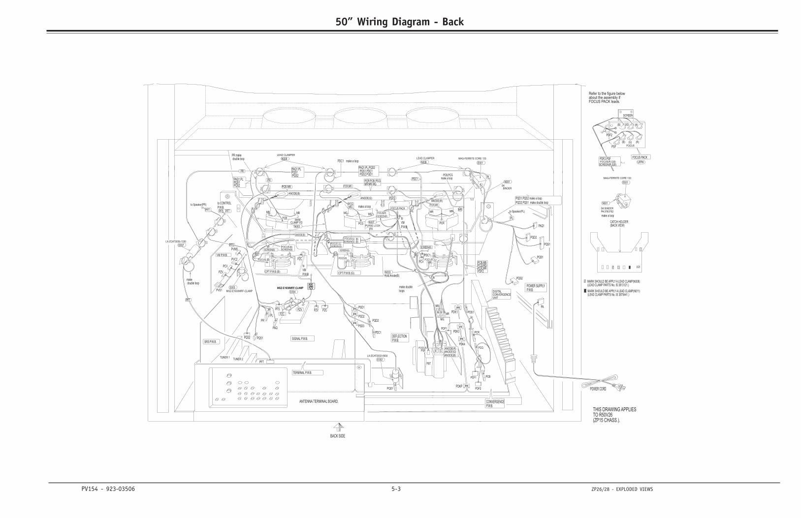
PV154 - 923-03506 5-3 ZP26/28 - EXPLODED VIEWS
50” Wiring Diagram - Back
PAQ1,PLPQS1PQS2
PAQ1,PLPQS1PQS2
MR
PAQ
to
VM
P.W.B.N003
Hold Anode(B)
make doubleloops
(LEAD CLAMP PARTS No. IS 3875441.)MARK SHOULD BE APPLY A LEAD CLAMP(N011)
MARK SHOULD BE APPLY A LEAD CLAMP(N008)(LEAD CLAMP PARTS No. IS 3813121.)
CATCH HOLDER(BACK VIEW)
PR
PQD1,PQS2 make a loop
PQD2,PQS1 make double loop
B
GRPSFFOCUS
PFTPFS,
Refer to the figure belowabout the assembly ifFOCUS PACK leads.
SCREEN
(B) (G) (R)
FOCUS
(B) (G) (R)
FOCUS PACK
UFPKFOCUS(R,G,B)SCREEN(R,G,B)
FBT
BACK SIDE
ANTENNA TERMINAL BOARD.
PDF2,PSF
PSF
PDF2
TERMINAL P.W.B.
(G)(B)
MB MG
(G)
FOCUS
FOCUSSCREEN
SRS P.W.B.
MG
PSD1
PSD2
PSD3
PQD2
PDC1
PFT
TUNER 1TUNER 2
CONVERGENCEP.W.B.
PDF2
PCBPDF1
PDK1
PDK3
PR
PL
PQS1
PZV PZC
PCR
PDK4
MB
PQD1
LX-ZCAT2032-0930
E002
E004
PCR
PCGANODE(R)ANODE(G)ANODE(B)
PCV (R)
SCREEN(G)
MAG-FERRITE CORE 133
E001
PDF1
MR
MAG-FERRITE CORE 133
E001
SK BINDERP#:3763752
make a loop
N001
PQS1
PQD2
PA
PQS2
PQD1
PAQ1
POWER SUPPLYP.W.B.
POWER CORD
THIS DRAWING APPLIESTO R50V26(ZP15 CHASS.).
DIGITALCONVERGENCEUNIT
PVMS
VM P.W.B.
PVC2
PZV
PCV
PVS1E003
MGZ-E1630MRF-CLAMP
FOCUS PACK
PZV
PZC
to
VM
P.W.B.
FOCUS
(G)
(G)(G)
(B)(B)SCREEN
FOCUS
ANODE(R)ANODE(G)
PCB,MB
MGPCG
MGZ-E1630MRF-CLAMPMGZ-E1630MRF-CLAMP
DEFLECTIONP.W.B.SIGNAL P.W.B.
ANODE(B)
PFT
makedouble loop
make a loop
WIRECLAMP VO
PDC1
PR makedouble loop
CPT P.W.B.(B) CPT P.W.B.(G)
MGMBPCB PCG
N003
PFSSCREEN(R)
PZVPZCPZVPZC
to CONTROL
P.W.B.MRMR
PCG
PCB
PFS
PQS2
PDS1
MB
PDKP
PDC1PZC
SCREEN(B)(B)FOCUS
SCREEN(B)
ANODE(B)
N001SKBINDER
PDF2
PDF2PCR,MRPCG,MGPCB,MB
PR
to Speaker(PR)
PQS2,PQD1PQS1,PDC1
PAQ1,PL,PQD2
PCR,MR
FOCUS(R)
SCREEN(R)
016PURSE LOCK
N007
LEAD CLAMPER
N008N008
LEAD CLAMPER
LX-ZCAT3035-1330
E007
PCB,PCGmake a loop
PCR,MRMRPCR
MG
FOCUS
PFT
PL
PL
to Speaker(PL)
PDC1 make a loop
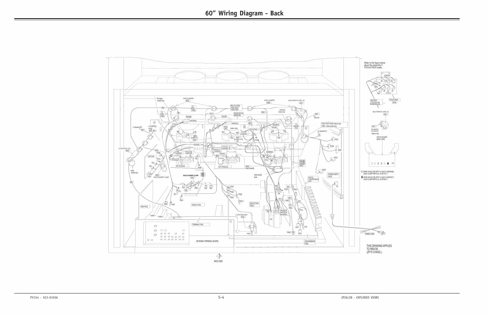
PV154 - 923-03506 5-4 ZP26/28 - EXPLODED VIEWS
60” Wiring Diagram - Back
to Speaker(PL)
PL
PL
PFT
FOCUS
MG
PCRMR
PCR,MR
make a loopPCB,PCG
MB,MR
E007
LX-ZCAT3035-1330
LEAD CLAMPER
N008N008
LEAD CLAMPER
N007PURSE LOCK
016
FOCUS(R)
SCREEN(R)
PCR,MR
PAQ1,PL,PQD2PQS1,PDC1PQS2,PQD1
to Speaker(PR)
PQS2
PLPQS1
PQS2
PLPQS1
PR
PCB,MBPCG,MGPCR,MRPDF2
PDF2
BINDERSK
N001
ANODE(B)
(B)SCREENFOCUS(B)
SCREEN(B)
PZCPDC1
PDKP
MB
PDS1
PQS2
PFS
PCB
PCG
MR MR
to CONTROL
P.W.B.
PZCPZVPZCPZV
SCREEN(R)PFS
N003
PCGPCBMB MG
CPT P.W.B.(G)CPT P.W.B.(B)
double loopPR make
PDC1
CLAMP VOWIRE
make a loop
double loopmake
PFT
ANODE(B)
SIGNAL P.W.B. P.W.B.DEFLECTION
MGZ-E1630MRF-CLAMPMGZ-E1630MRF-CLAMP
PCGMG
PCB,MB
ANODE(G)ANODE(R)
FOCUSSCREEN (B)
(B)(G)(G)
(G)
FOCUS
to
VM
P.W.B.
PZC
PZV
FOCUS PACK
MGZ-E1630MRF-CLAMP
E003PVS1
PCV
PZV
PVC2
VM P.W.B.
PVMS
UNITCONVERGENCEDIGITAL
(ZP15 CHASS.).TO R60V26THIS DRAWING APPLIES
POWER CORD
P.W.B.POWER SUPPLY
PAQ1
PQD1
PQS2
PA
PQD2
PQS1
N001
make a loop
P#:3763752SK BINDER
E001
MAG-FERRITE CORE 133
MR
PDF1
E001
MAG-FERRITE CORE 133
SCREEN(G)
(R)PCV
ANODE(B)ANODE(G)ANODE(R) PCG
PCR
E004
E002
LX-ZCAT2032-0930
PQD1
MB
PDK4
PCR
PZCPZV
PQS1
PL
PR
PDK3
PDK1
PDF1 PCB
PDF2
P.W.B.CONVERGENCE
TUNER 2TUNER 1
PFT
PDC1
PQD2
PSD3
PSD2
PSD1
MG
SRS P.W.B.
SCREENFOCUS
FOCUS
(G)
MGMB
(B) (G)
TERMINAL P.W.B.
PDF2
PSF
PDF2,PSF
ANTENNA TERMINAL BOARD.
BACK SIDE
FBT
SCREEN(R,G,B)FOCUS(R,G,B) UFPK
FOCUS PACK
(R)(G)(B)FOCUS
(R)(G)(B)
SCREEN
FOCUS PACK leads.about the assembly ifRefer to the figure below
PFS, PFT
FOCUSPSF R G
B
PQD1,PQS1,PQS2 make a loop
PQD2 make double loop
PR
(BACK VIEW)CATCH HOLDER
(LEAD CLAMP PARTS No. IS 3813121.)MARK SHOULD BE APPLY A LEAD CLAMP(N008)
MARK SHOULD BE APPLY A LEAD CLAMP(N011)(LEAD CLAMP PARTS No. IS 3875441.)
loopsmake double
Hold Anode(B)N003
to
VM
P.W.B.
PQD1
PCR
PAQ1
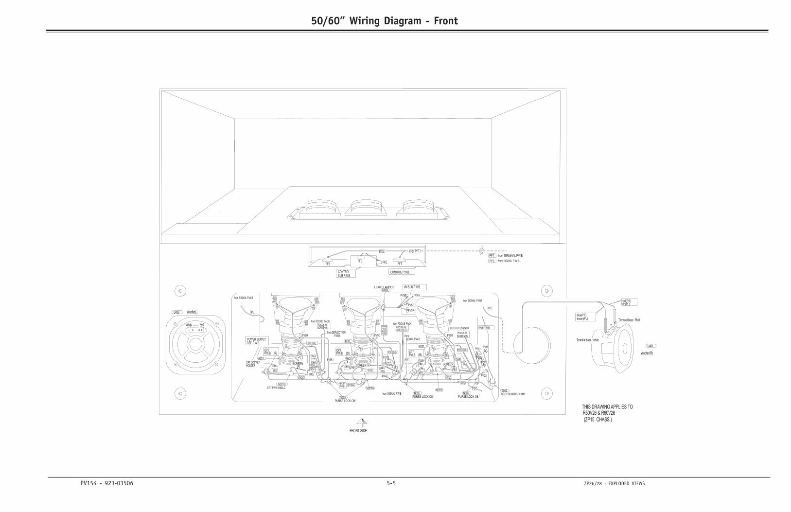
PV154 - 923-03506 5-5 ZP26/28 - EXPLODED VIEWS
50/60” Wiring Diagram - Front
LEAD CLAMPERN009
PVSG
CPTP.W.B. (B)
PFSPFC
PFT
#231
POWER SUPPLYDEF. P.W.B.
CPTP.W.B. (G)
CONTROL P.W.B.CONTROLSUB P.W.B.
PVMSPVSBPVSGPVSR
PVSR
SCREEN(B)
PVSB PVMS
PVSG
PVSR
NCPTR
CPT SOCKETHOLDER
CPT PWB SHIELD
FOCUS (B)
FOCUSSCREEN
(R)(R)
SCREEN (G)
FRONT SIDE
from SIGNAL P.W.B.
VM SUB P.W.B.
PURSE LOCK O8
PVSR
N005
red(PR)red(PL)
blue(PR)brown(PL)
Terminal base : white
Terminal base : Red
+
-
U401
Woofer(R)
VM P.W.B.
Woofer(L)
White Red
+
U402
-
from SIGNAL P.W.B.
PZV
PCV
PVMPVS1
PVS1
EGB1
NCPTBNCPTG
PVC1
FOCUS(B)
PZV
from SIGNAL P.W.B.
from DEFLECTIONP.W.B.
PFT
PFS from SIGNAL P.W.B.
from TERMINAL P.W.B.
from FOCUS PACK
E003MGZ-E1630MRF-CLAMPN005
PURSE LOCK O8
FOCUS(G)
PVS1
PVSG PVSB
PGVPRV
PDC1PCV
PVC2
PFC
PFS PFS PFT,
CPTP.W.B. (R)
FOCUS(R)
THIS DRAWING APPLIES TOR50V26 & R60V26
(ZP15 CHASS.)
PL
PR
PVS1PCV
SCREEN(R)
from FOCUS PACK
PURSE LOCK O8N005
ERG1
EGB1
PZC
PZC
SCREEN (G)FOCUS (G)
#231
fromSIGNAL P.W.B.
PVSB
PBV
PVS1
PVM
SCREEN(B)
ERG2
ERG2
EGB2
ERG2
ERG1
EGB2
#231
from FOCUS PACK
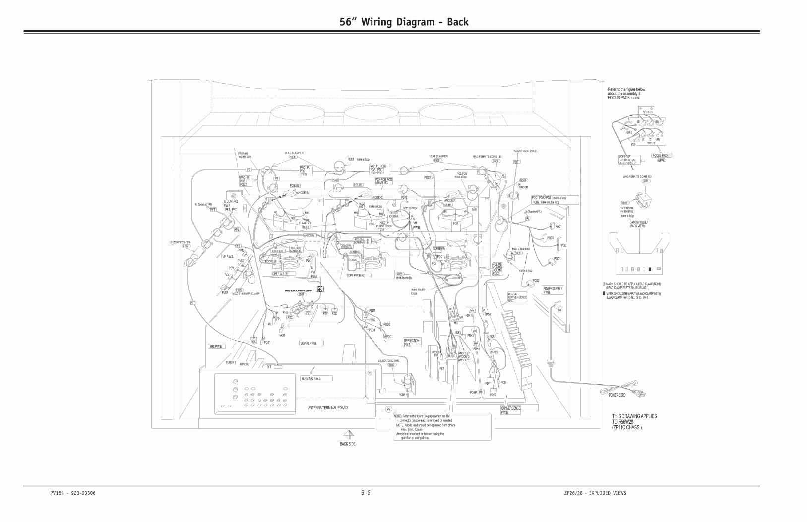
PV154 - 923-03506 5-6 ZP26/28 - EXPLODED VIEWS
56” Wiring Diagram - Back
PS
NOTE: Refer to the figure (04/page) when the HVconnector (anode lead) is removed or inserted.
NOTE: Anode lead should be separated from otherswires. (min. 10mm)
Anode lead must not be twisted during theoperation of wiring dress.
PFS
from SENSOR P.W.B.
PDS1
MGZ-E1630MRF
E005
make a loop
PQD1
PAQ1
PAQ1,PLPQS1PQS2
PAQ1,PLPQS1PQS2
MR
to
VM
P.W.B.N003
Hold Anode(B)
make doubleloops
(LEAD CLAMP PARTS No. IS 3875441.)MARK SHOULD BE APPLY A LEAD CLAMP(N011)
MARK SHOULD BE APPLY A LEAD CLAMP(N008)(LEAD CLAMP PARTS No. IS 3813121.)
CATCH HOLDER(BACK VIEW)
PR
PQD1,PQS2 PQS1 make a loop
PQD2 make double loop
B
GRPSFFOCUS
PFTPFS,
Refer to the figure belowabout the assembly ifFOCUS PACK leads.
SCREEN
(B) (G) (R)
FOCUS
(B) (G) (R)
FOCUS PACK
UFPKFOCUS(R,G,B)SCREEN(R,G,B)
FBT
BACK SIDE
ANTENNA TERMINAL BOARD.
PDF2,PSF
PSF
PDF2
TERMINAL P.W.B.
(G)(B)
MB MG
(G)
FOCUS
FOCUSSCREEN
SRS P.W.B.
MG
PSD1
PSD2
PSD3
PQD2
PDC1
PFT
TUNER 1TUNER 2
CONVERGENCEP.W.B.
PDF2
PCBPDF1
PDK1
PDK3
PR
PL
PQS1
PZV PZC
PCR
PDK4
MB
PQD1
LX-ZCAT2032-0930
E002
E004
PCR
PCGANODE(R)ANODE(G)ANODE(B)
PCV (R)
SCREEN(G)
MAG-FERRITE CORE 133
E001
PDF1
MR
MAG-FERRITE CORE 133
E001
SK BINDERP#:3763752
make a loop
N001
PQS1
PQD2
PA
PQS2
PQD1
PAQ1
POWER SUPPLYP.W.B.
POWER CORD
THIS DRAWING APPLIESTO R56W28(ZP14C CHASS.).
DIGITALCONVERGENCEUNIT
PVMS
VM P.W.B.
PVC2
PZV
PCV
PVS1E003
MGZ-E1630MRF-CLAMP
FOCUS PACK
PZV
PZC
to
VM
P.W.B.
FOCUS
(G)
(G)(G)
(B)(B)SCREEN
FOCUS
ANODE(R)ANODE(G)
PCB,MB
MGPCG
MGZ-E1630MRF-CLAMPMGZ-E1630MRF-CLAMP
DEFLECTIONP.W.B.SIGNAL P.W.B.
ANODE(B)
PFT
make a loop
WIRECLAMP VO
PDC1
PR makedouble loop
CPT P.W.B.(B) CPT P.W.B.(G)
MGMBPCB PCG
N003
PFSSCREEN(R)
PZVPZCPZVPZC
to CONTROL
P.W.B.
MRMR
PCG
PCB
PFS
PQS2
PDS1
MB
PDKP
PDC1PZC
SCREEN(B)(B)FOCUS
SCREEN(B)
ANODE(B)
N001SKBINDER
PDF2
PDF2PCR,MRPCG,MGPCB,MB
PR
to Speaker(PR)
PQS2,PQD1PQS1,PDC1
PAQ1,PL,PQD2
PCR,MR
FOCUS(R)
SCREEN(R)
016PURSE LOCK
N007
LEAD CLAMPER
N008N008
LEAD CLAMPER
LX-ZCAT3035-1330
E007
PCB,PCGmake a loop
PCR,MRMRPCR
MG
FOCUS
PFT
PL
PL
to Speaker(PL)
PDC1 make a loop
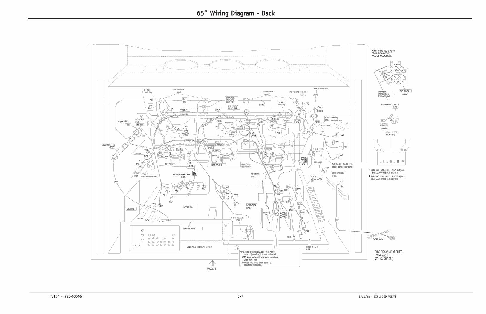
PV154 - 923-03506 5-7 ZP26/28 - EXPLODED VIEWS
65” Wiring Diagram - Back
PFT
to CONTROL
P.W.B.PFS,
PFS
Note: for J#02~, for J#01 ferrite
position is on the upper clamp
to Speaker(PL)
PL
PL
PFT
FOCUS
MG
PCR,PCG,PCBMR,MG,MB,PL
PCR,MR
make a loopPCB,PCG
MB,MR
E007
LX-ZCAT3035-1330
LEAD CLAMPER
N008N008
LEAD CLAMPER
N007PURSE LOCK
016
FOCUS(R)
SCREEN(R)
PCR,MR
PAQ1,PQD2PQS1,PDC1PQS2,PQD1
to Speaker(PR)
PQS2
PQS1
PQS2PQS1 PR
PCB,MBPCG,MGPCR,MRPDF2
PDF2
BINDERSK
N001
ANODE(B)
(B)SCREENFOCUS(B)
SCREEN(B)
PZCPDC1
PDKP
MB
PQS2
PFS
PCB
PCG
MR MR
PZCPZVPZCPZV
SCREEN(R)PFS
N003
CPT P.W.B.(G)CPT P.W.B.(B)
double loopPR make
PDC1
CLAMP VOWIRE
make a loop
PFT
ANODE(B)
SIGNAL P.W.B. P.W.B.DEFLECTION
MGZ-E1630MRF-CLAMPMGZ-E1630MRF-CLAMP
PCGMG
PCB,MB,PL
ANODE(G)ANODE(R)
FOCUSSCREEN (B)
(B)(G)(G)
(G)
FOCUS
to
VM
P.W.B.
PZC
PZV
FOCUS PACK
MGZ-E1630MRF-CLAMP
E003PVS1
PCV
PZV
PVC2
VM P.W.B.
PVMS
UNITCONVERGENCEDIGITAL
(ZP14C CHASS.).TO R65W28THIS DRAWING APPLIES
POWER CORD
P.W.B.POWER SUPPLY
PAQ1
PQD1
PQS2
PA
PQD2
PQS1
N001
make a loop
P#:3763752SK BINDER
E001
MAG-FERRITE CORE 133
MR
PDF1
E001
MAG-FERRITE CORE 133
SCREEN(G)
(R)PCV
ANODE(B)ANODE(G)ANODE(R) PCG
PCR
E004
E002
LX-ZCAT2032-0930
PQD1
MB
PDK4
PCR
PZCPZV
PQS1
PL
PR
PDK3
PDK1
PDF1 PCB
PDF2
P.W.B.CONVERGENCE
TUNER 2TUNER 1
PFT
PDC1
PQD2
PSD3
PSD2
PSD1
MG
SRS P.W.B.
SCREENFOCUS
FOCUS
(G)
MGMB
(B) (G)
TERMINAL P.W.B.
PDF2
PSF
PDF2,PSF
ANTENNA TERMINAL BOARD.
BACK SIDE
FBT
SCREEN(R,G,B)FOCUS(R,G,B) UFPK
FOCUS PACK
(R)(G)(B)FOCUS
(R)(G)(B)
SCREEN
FOCUS PACK leads.about the assembly ifRefer to the figure below
FOCUSPSF R G
B
PQD1 make a loop
PQD2 make double loop
PR
(BACK VIEW)CATCH HOLDER
(LEAD CLAMP PARTS No. IS 3813121.)MARK SHOULD BE APPLY A LEAD CLAMP(N008)
MARK SHOULD BE APPLY A LEAD CLAMP(N011)(LEAD CLAMP PARTS No. IS 3875441.)
loopsmake double
Hold Anode(B)N003
to
VM
P.W.B.
PQD1
PCR
PAQ1
PL
PL
PAQ1
PDS1
make a loop
E005
MGZ-E1630MRF
PDS1
from SENSOR P.W.B.
operation of wiring dress.
wires. (min. 10mm)
Anode lead must not be twisted during the
NOTE: Anode lead should be separated from others
connector (anode lead) is removed or inserted.NOTE: Refer to the figure (04/page) when the HV
PS
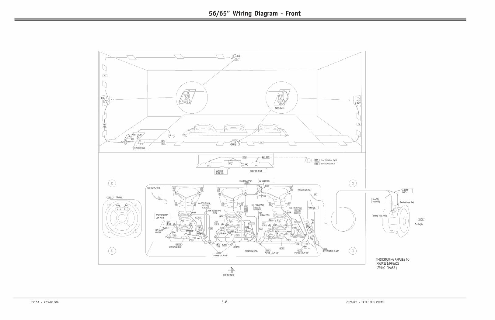
PV154 - 923-03506 5-8 ZP26/28 - EXPLODED VIEWS
56/65” Wiring Diagram - Front
LEAD CLAMPERN009
PVSG
CPTP.W.B. (B)
PFSPFC
PFT
#231
POWER SUPPLYDEF. P.W.B.
CPTP.W.B. (G)
CONTROL P.W.B.CONTROLSUB P.W.B.
PVMSPVSBPVSGPVSR
PVSR
SCREEN(B)
PVSB PVMS
PVSG
PVSR
NCPTR
CPT SOCKETHOLDER
CPT PWB SHIELD
FOCUS (B)
FOCUSSCREEN
(R)(R)
SCREEN (G)
FRONT SIDE
from SIGNAL P.W.B.
VM SUB P.W.B.
PURSE LOCK O8
PVSR
N005
red(PR)red(PL)
blue(PR)brown(PL)
Terminal base : white
Terminal base : Red
+
-
U401
Woofer(R)
VM P.W.B.
Woofer(L)
White Red
+
U402
-
from SIGNAL P.W.B.
PZV
PCV
PVMPVS1
PVS1
EGB1
NCPTBNCPTG
PVC1
FOCUS(B)
PZV
from SIGNAL P.W.B.
from DEFLECTIONP.W.B.
PFT
PFS from SIGNAL P.W.B.
from TERMINAL P.W.B.
from FOCUS PACK
E003MGZ-E1630MRF-CLAMPN005
PURSE LOCK O8
FOCUS(G)
PVS1
PVSG PVSB
PGVPRV
PDC1PCV
PVC2
PFC
PFS PFS PFT,
CPTP.W.B. (R)
FOCUS(R)
THIS DRAWING APPLIES TOR56W28 & R65W28
(ZP14C CHASS.)
PL
PR
PVS1PCV
SCREEN(R)
from FOCUS PACK
PURSE LOCK O8N005
ERG1
EGB1
PZC
PZC
SCREEN (G)FOCUS (G)
#231
fromSIGNAL P.W.B.
PVSB
PBV
PVS1
PVM
SCREEN(B)
ERG2
ERG2
EGB2
ERG2
ERG1
EGB2
#231
from FOCUS PACK
EAS3 / EAS5
PS1PS3PS1
PS1
PS1
PS3PS1
EAS1
EAS3
EAS7
EAS5
SENSOR P.W.B.
PS1 PDS1
PS3
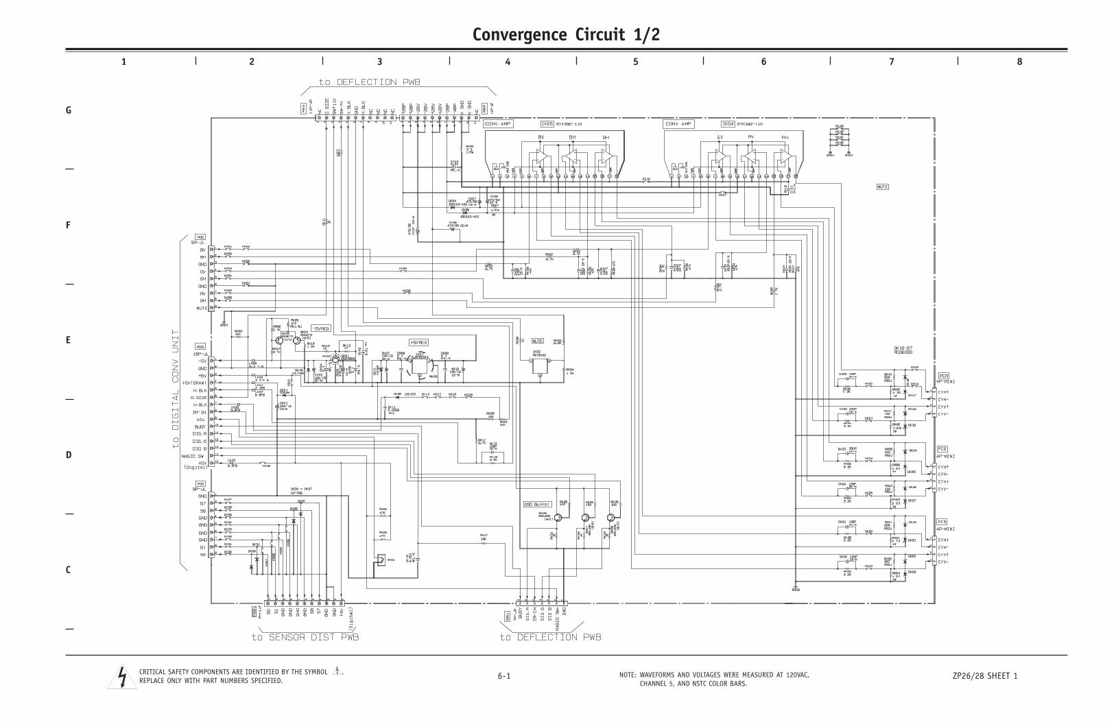
C
D
E
F
G
1 2 3 4 5 6 7 8
6-1 ZP26/28 SHEET 1NOTE: WAVEFORMS AND VOLTAGES WERE MEASURED AT 120VAC,CHANNEL 5, AND NSTC COLOR BARS.
CRITICAL SAFETY COMPONENTS ARE IDENTIFIED BY THE SYMBOL .REPLACE ONLY WITH PART NUMBERS SPECIFIED.
Convergence Circuit 1/2SECTION 6
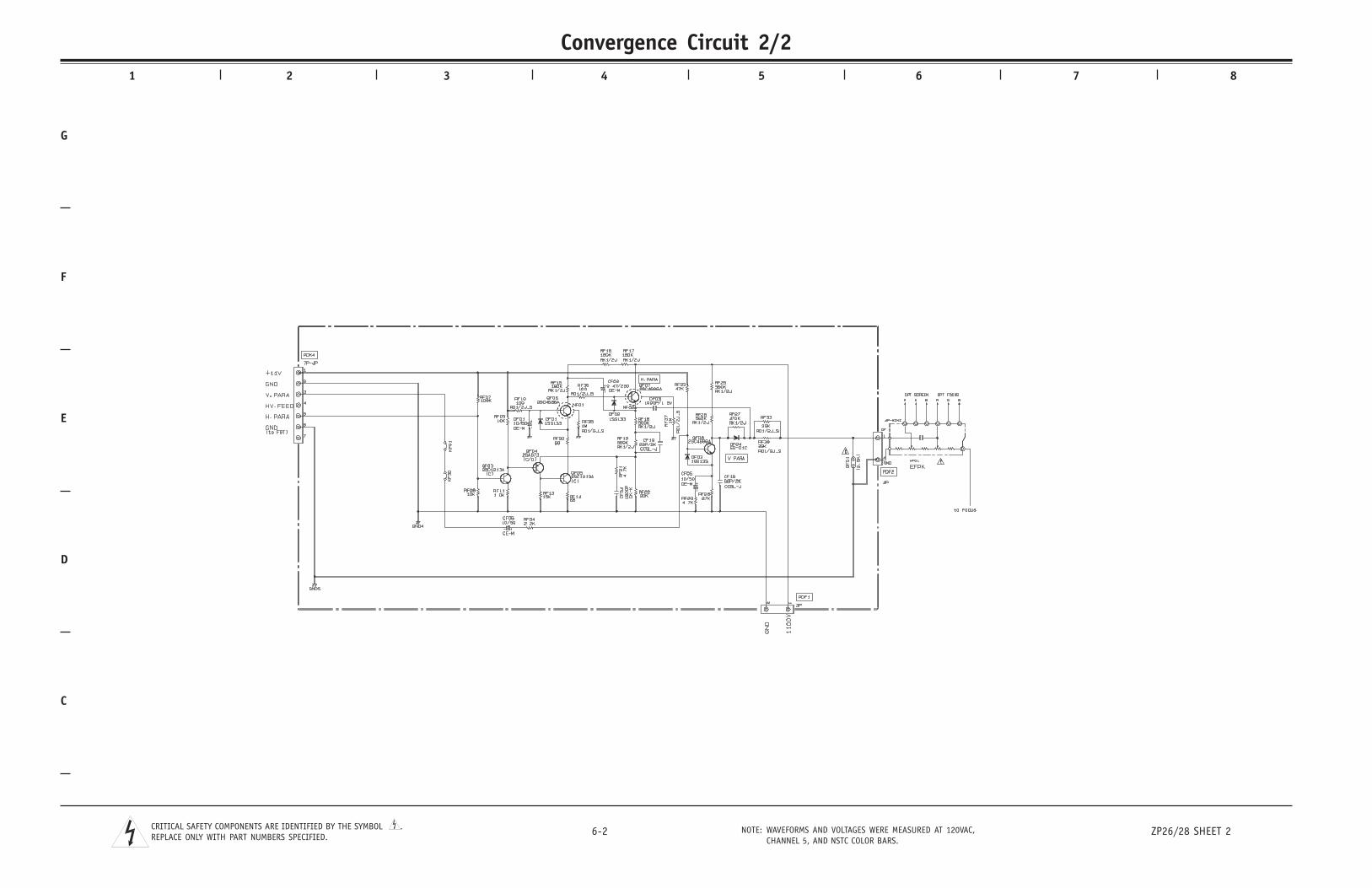
C
D
E
F
G
1 2 3 4 5 6 7 8
6-2 ZP26/28 SHEET 2NOTE: WAVEFORMS AND VOLTAGES WERE MEASURED AT 120VAC,CHANNEL 5, AND NSTC COLOR BARS.
CRITICAL SAFETY COMPONENTS ARE IDENTIFIED BY THE SYMBOL .REPLACE ONLY WITH PART NUMBERS SPECIFIED.
Convergence Circuit 2/2
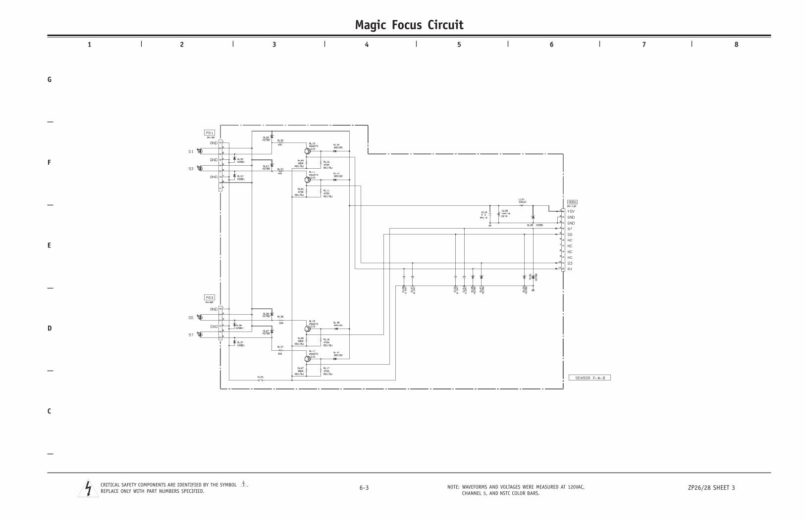
C
D
E
F
G
1 2 3 4 5 6 7 8
6-3 ZP26/28 SHEET 3NOTE: WAVEFORMS AND VOLTAGES WERE MEASURED AT 120VAC,CHANNEL 5, AND NSTC COLOR BARS.
CRITICAL SAFETY COMPONENTS ARE IDENTIFIED BY THE SYMBOL .REPLACE ONLY WITH PART NUMBERS SPECIFIED.
Magic Focus Circuit
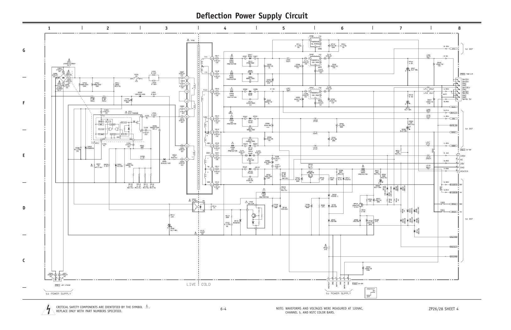
C
D
E
F
G
1 2 3 4 5 6 7 8
6-4 ZP26/28 SHEET 4NOTE: WAVEFORMS AND VOLTAGES WERE MEASURED AT 120VAC,CHANNEL 5, AND NSTC COLOR BARS.
CRITICAL SAFETY COMPONENTS ARE IDENTIFIED BY THE SYMBOL .REPLACE ONLY WITH PART NUMBERS SPECIFIED.
Deflection Power Supply Circuit
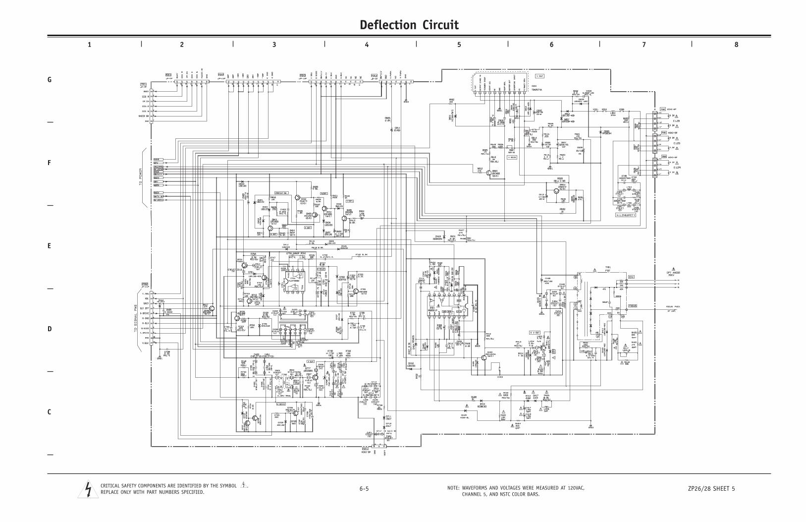
C
D
E
F
G
1 2 3 4 5 6 7 8
6-5 ZP26/28 SHEET 5NOTE: WAVEFORMS AND VOLTAGES WERE MEASURED AT 120VAC,CHANNEL 5, AND NSTC COLOR BARS.
CRITICAL SAFETY COMPONENTS ARE IDENTIFIED BY THE SYMBOL .REPLACE ONLY WITH PART NUMBERS SPECIFIED.
Deflection Circuit
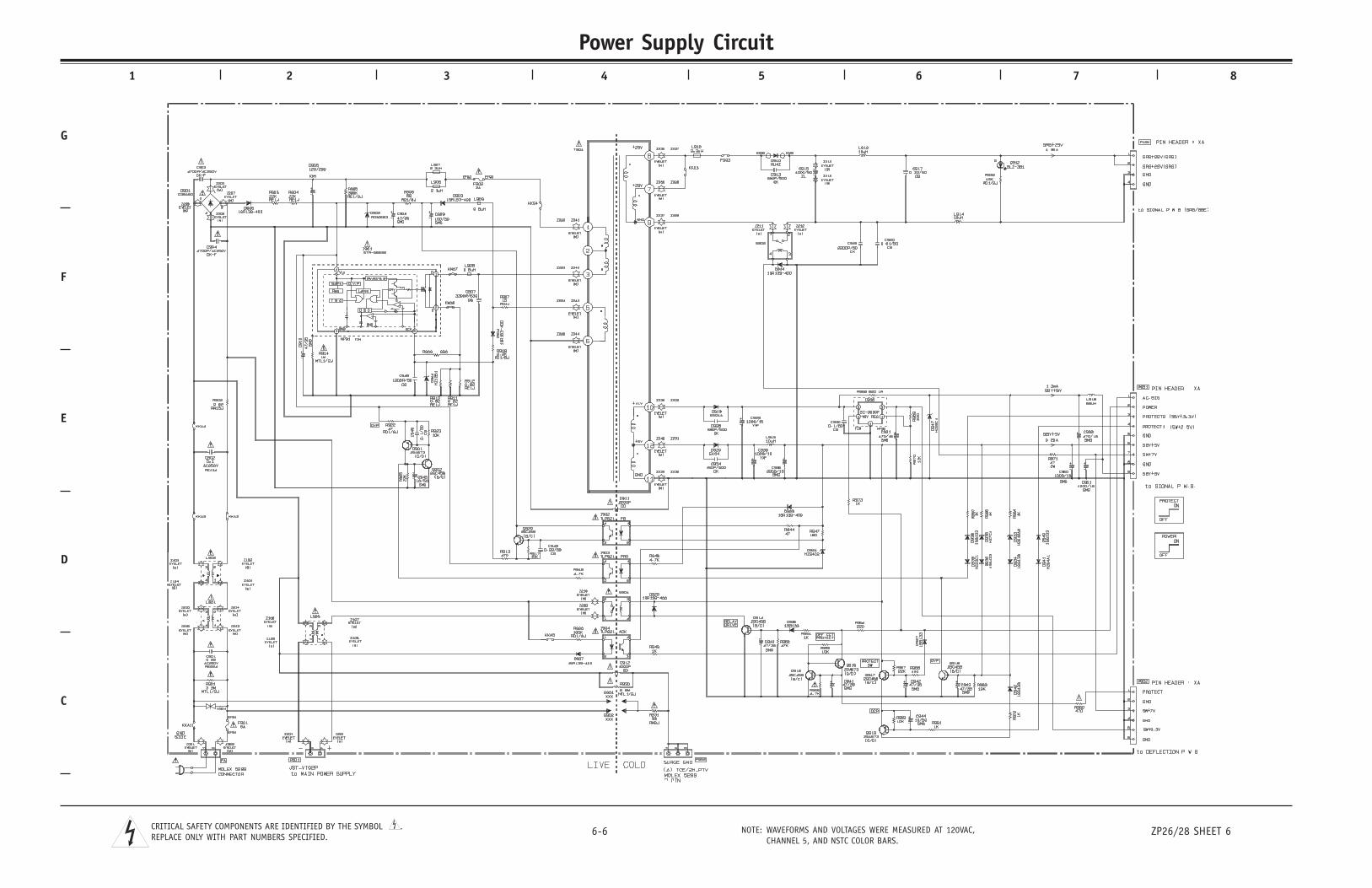
C
D
E
F
G
1 2 3 4 5 6 7 8
6-6 ZP26/28 SHEET 6NOTE: WAVEFORMS AND VOLTAGES WERE MEASURED AT 120VAC,CHANNEL 5, AND NSTC COLOR BARS.
CRITICAL SAFETY COMPONENTS ARE IDENTIFIED BY THE SYMBOL .REPLACE ONLY WITH PART NUMBERS SPECIFIED.
Power Supply Circuit
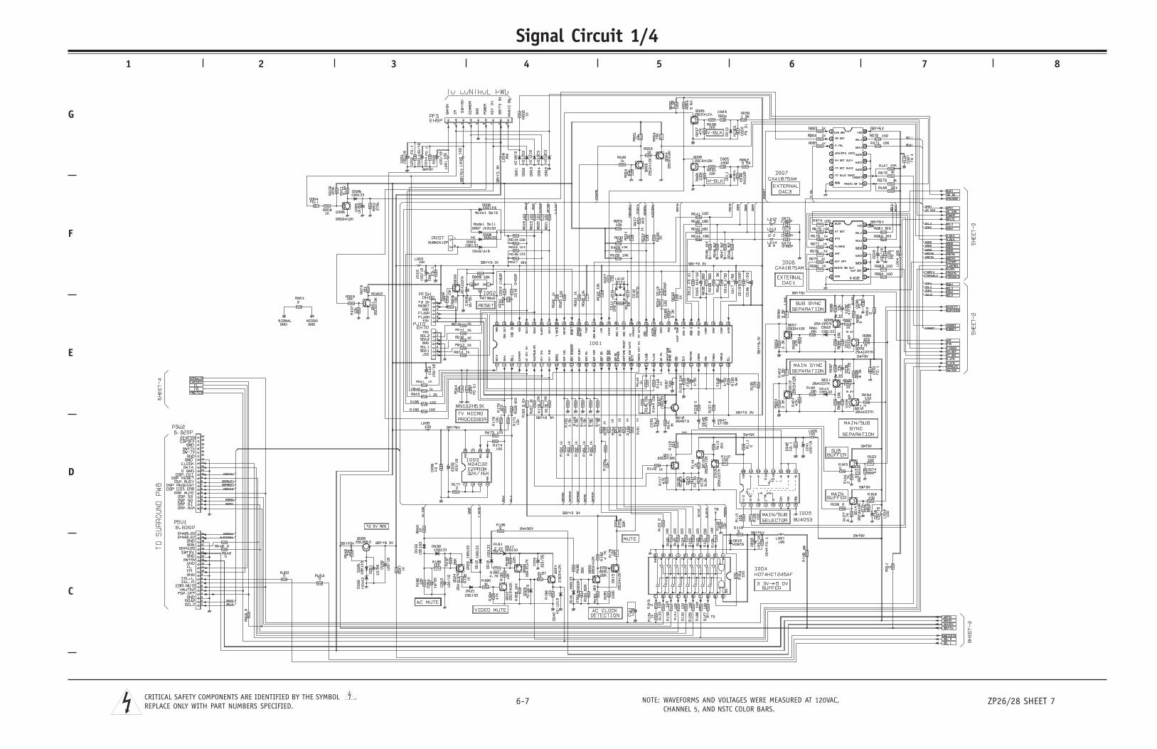
C
D
E
F
G
1 2 3 4 5 6 7 8
6-7 ZP26/28 SHEET 7NOTE: WAVEFORMS AND VOLTAGES WERE MEASURED AT 120VAC,CHANNEL 5, AND NSTC COLOR BARS.
CRITICAL SAFETY COMPONENTS ARE IDENTIFIED BY THE SYMBOL .REPLACE ONLY WITH PART NUMBERS SPECIFIED.
Signal Circuit 1/4
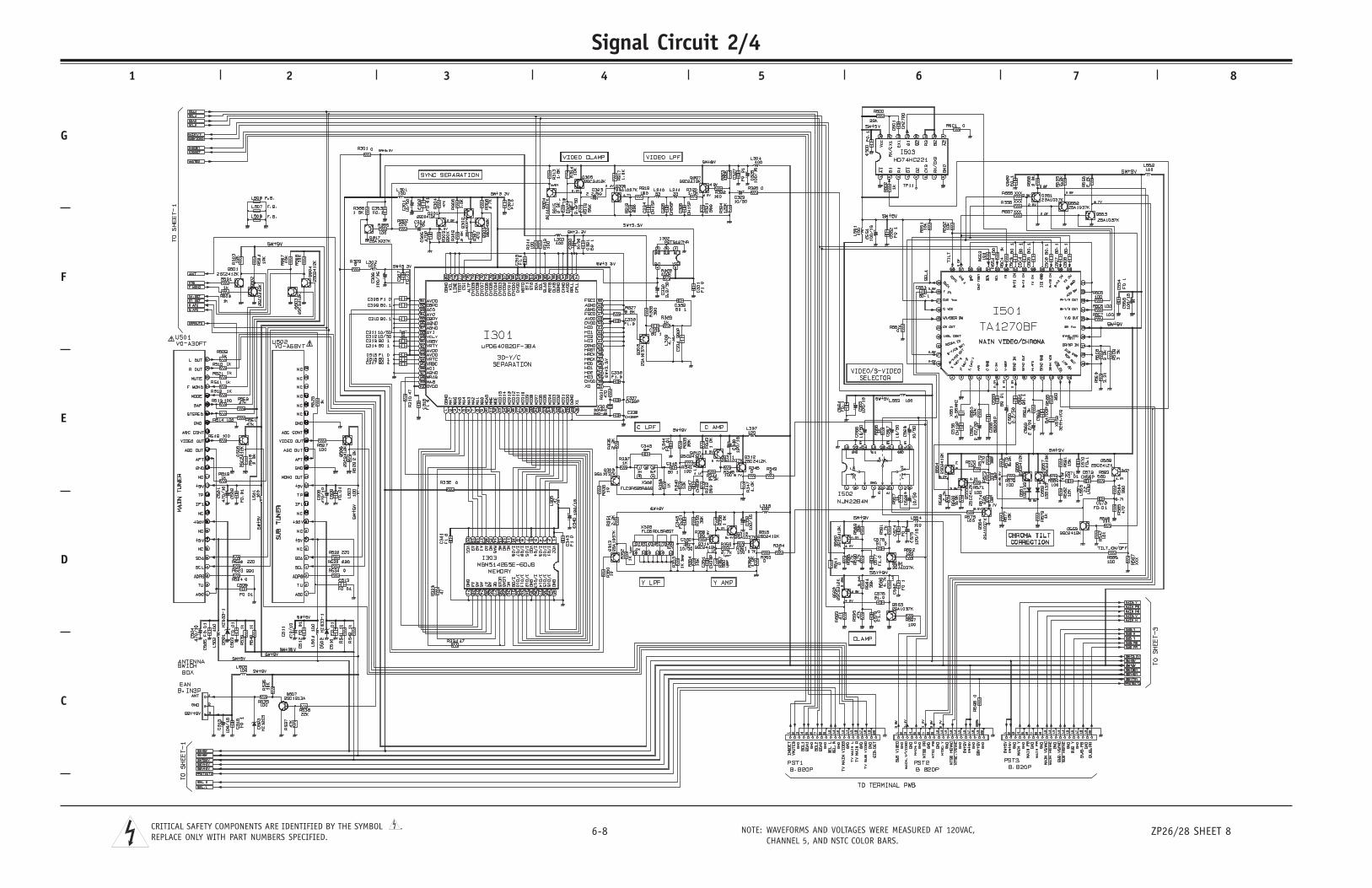
C
D
E
F
G
1 2 3 4 5 6 7 8
6-8 ZP26/28 SHEET 8NOTE: WAVEFORMS AND VOLTAGES WERE MEASURED AT 120VAC,CHANNEL 5, AND NSTC COLOR BARS.
CRITICAL SAFETY COMPONENTS ARE IDENTIFIED BY THE SYMBOL .REPLACE ONLY WITH PART NUMBERS SPECIFIED.
Signal Circuit 2/4
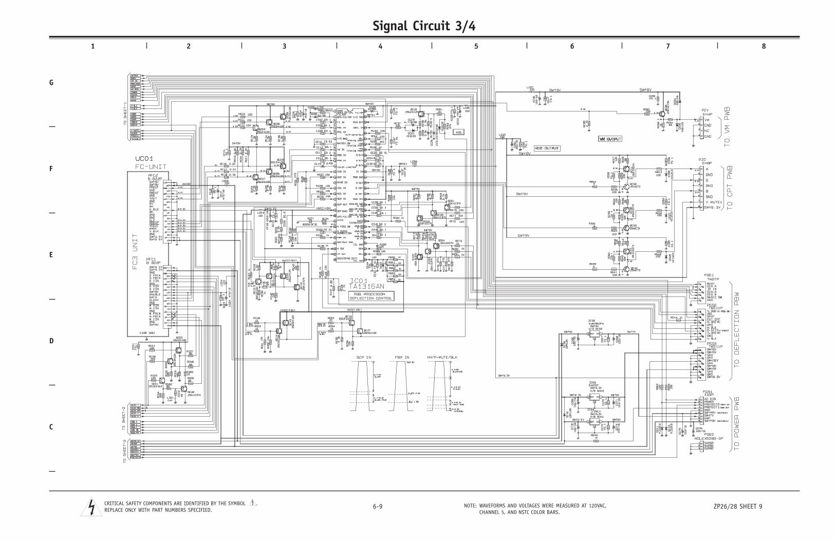
C
D
E
F
G
1 2 3 4 5 6 7 8
6-9 ZP26/28 SHEET 9NOTE: WAVEFORMS AND VOLTAGES WERE MEASURED AT 120VAC,CHANNEL 5, AND NSTC COLOR BARS.
CRITICAL SAFETY COMPONENTS ARE IDENTIFIED BY THE SYMBOL .REPLACE ONLY WITH PART NUMBERS SPECIFIED.
Signal Circuit 3/4
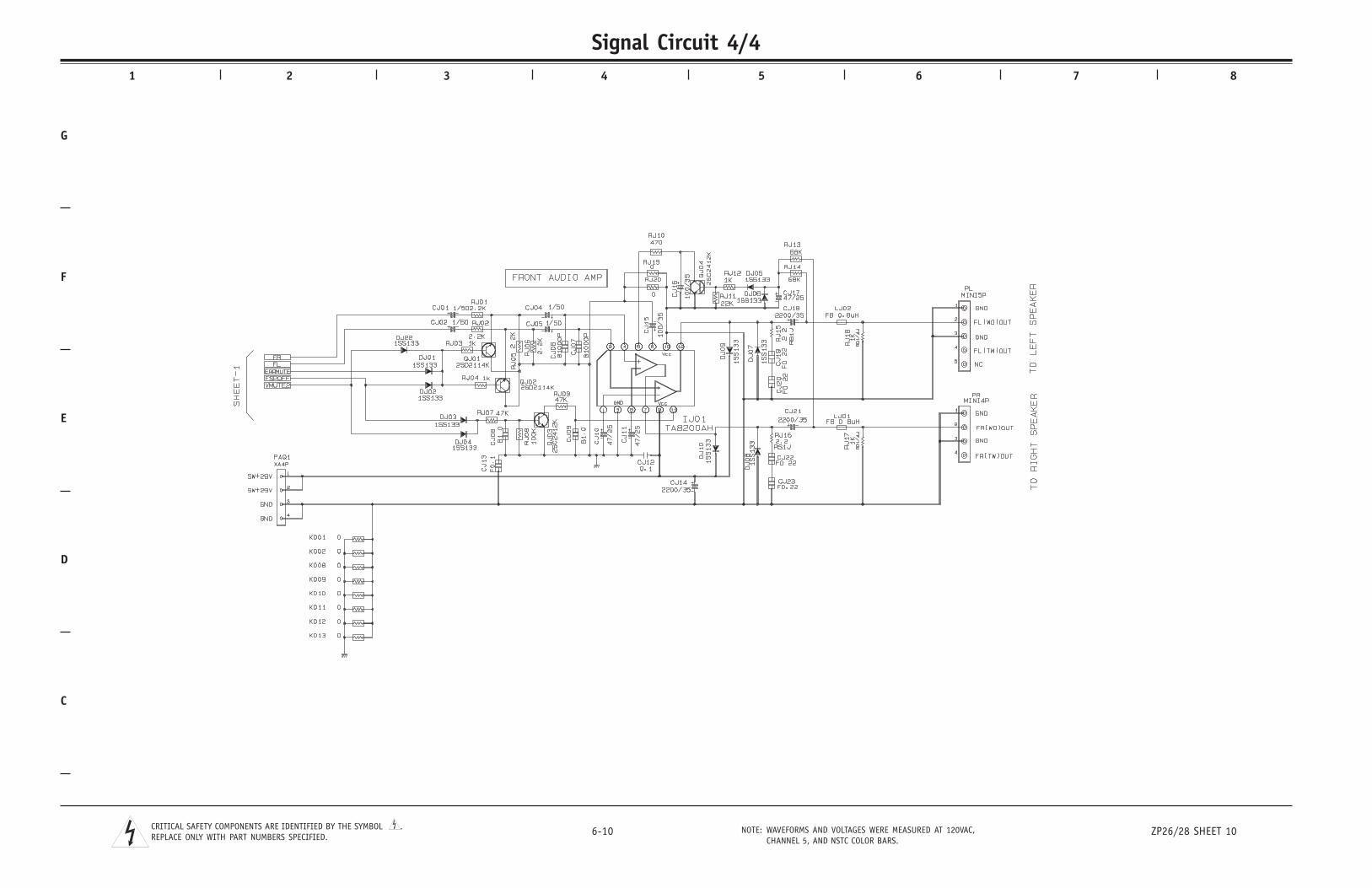
C
D
E
F
G
1 2 3 4 5 6 7 8
6-10 ZP26/28 SHEET 10NOTE: WAVEFORMS AND VOLTAGES WERE MEASURED AT 120VAC,CHANNEL 5, AND NSTC COLOR BARS.
CRITICAL SAFETY COMPONENTS ARE IDENTIFIED BY THE SYMBOL .REPLACE ONLY WITH PART NUMBERS SPECIFIED.
Signal Circuit 4/4
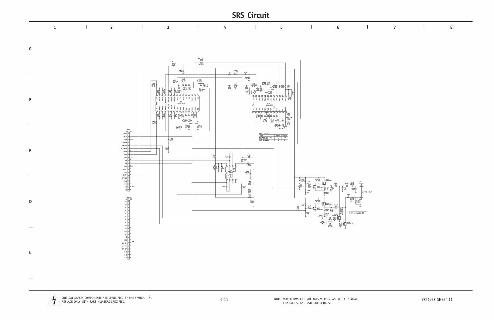
C
D
E
F
G
1 2 3 4 5 6 7 8
6-11 ZP26/28 SHEET 11NOTE: WAVEFORMS AND VOLTAGES WERE MEASURED AT 120VAC,CHANNEL 5, AND NSTC COLOR BARS.
CRITICAL SAFETY COMPONENTS ARE IDENTIFIED BY THE SYMBOL .REPLACE ONLY WITH PART NUMBERS SPECIFIED.
SRS Circuit
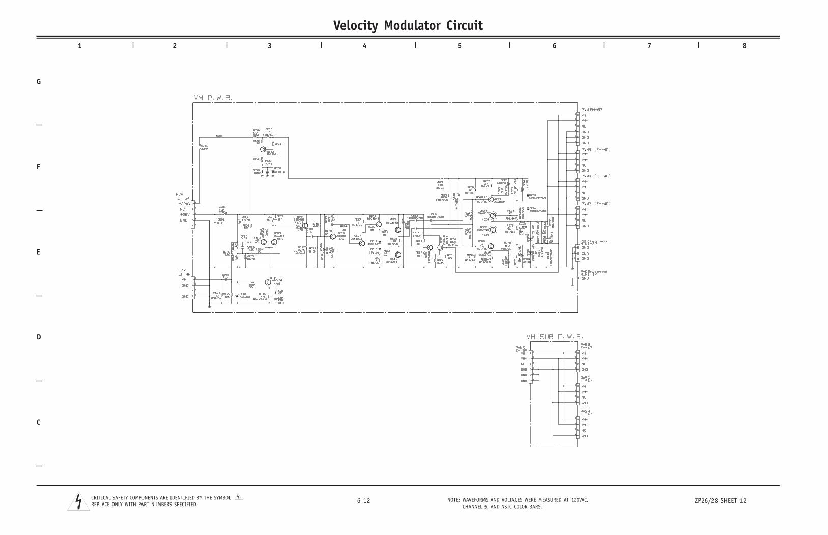
C
D
E
F
G
1 2 3 4 5 6 7 8
6-12 ZP26/28 SHEET 12NOTE: WAVEFORMS AND VOLTAGES WERE MEASURED AT 120VAC,CHANNEL 5, AND NSTC COLOR BARS.
CRITICAL SAFETY COMPONENTS ARE IDENTIFIED BY THE SYMBOL .REPLACE ONLY WITH PART NUMBERS SPECIFIED.
Velocity Modulator Circuit