securing smart homes with openflow - university of calgary
TRANSCRIPT
University of Calgary
PRISM: University of Calgary's Digital Repository
Graduate Studies The Vault: Electronic Theses and Dissertations
2020-07-06
Securing Smart Homes with OpenFlow: Feasibility,
Implementation, and Performance
Frank, Mitchell
Frank, M. (2020). Securing Smart Homes with OpenFlow: Feasibility, Implementation, and
Performance (Unpublished master's thesis). University of Calgary, Calgary, AB.
http://hdl.handle.net/1880/112298
master thesis
University of Calgary graduate students retain copyright ownership and moral rights for their
thesis. You may use this material in any way that is permitted by the Copyright Act or through
licensing that has been assigned to the document. For uses that are not allowable under
copyright legislation or licensing, you are required to seek permission.
Downloaded from PRISM: https://prism.ucalgary.ca

UNIVERSITY OF CALGARY
Securing Smart Homes with OpenFlow: Feasibility, Implementation, and Performance
by
Mitchell Frank
A THESIS
SUBMITTED TO THE FACULTY OF GRADUATE STUDIES
IN PARTIAL FULFILLMENT OF THE REQUIREMENTS FOR THE
DEGREE OF MASTER OF SCIENCE
GRADUATE PROGRAM IN COMPUTER SCIENCE
CALGARY, ALBERTA
JULY, 2020
c© Mitchell Frank 2020
Abstract
The Internet of Things (IoT) trend is introducing additional devices to home networks.
Home networks face the same threats as every other network. Recently, IoT devices have
been compromised by attackers and used as staging points for further attacks. Home users
may not have the technical capability or funding to run advanced security devices designed
to protect enterprises. Solutions to this problem exist, but in some cases, they rely on third
party cloud services or require custom protocols to be deployed within the home network.
Reliance on third party services comes with privacy implications, as well as the increased
risk for a third party to be responsible for securing a network they may not directly control.
Custom network protocols can effectively reduce the attack surface of home networks, but
these are not easily compatible with devices in operation today. In this paper, we examine the
feasibility of protecting home networks using OpenFlow enabled Access Points (APs). We
propose a solution which builds least-permissive policies for each device and subsequently
enforces the policies without requiring customized protocols. This allows the system to
protect any connected wireless device. The design allows for a flexible deployment model
and is capable of running on low cost hardware as an all-in-one unit. We perform a complete
implementation and evaluation of the solution. The system can effectively limit the ability
for compromised IoT devices to attack internal and external networks at a low cost to initial
connection times.
ii

Preface
This thesis is an original work by the author. No part of this thesis has been previously
published.
iii

Acknowledgements
I would like to thank my supervisor Dr. Ghaderi for the guidance and leadership throughout
this entire program. Thank you for your constructive feedback and advice through the
completion of this work. This would not have been possible without your support.
Thank you Catherine for your encouragement and perspective through this entire process.
I appreciate your sacrifices in keeping everything in life running while I spent countless
evenings and weekends sitting in my office. Thank you for making this possible.
A huge thank you to my family and friends for the ongoing support through this pro-
cess. I’d like to thank my parents for sparking my early interest in technology and for the
encouragement to pursue Computer Science. I am fortunate to be connected with so many
great people.
I’d like to thank my colleagues for the encouragement to accomplish this work. Thank
you Nayden for the guidance and recommendation for me to pursue a graduate degree. It is
an honour to work with and learn from you.
iv

Table of Contents
Abstract ii
Preface iii
Acknowledgements iv
Table of Contents v
List of Figures and Illustrations ix
List of Tables xi
List of Symbols, Abbreviations and Nomenclature xii
Epigraph xiv
1 Introduction 11.1 Security and the Internet of Things . . . . . . . . . . . . . . . . . . . . . . . 11.2 Problem Definition . . . . . . . . . . . . . . . . . . . . . . . . . . . . . . . . 31.3 Thesis Contributions . . . . . . . . . . . . . . . . . . . . . . . . . . . . . . . 41.4 Thesis Organization . . . . . . . . . . . . . . . . . . . . . . . . . . . . . . . . 5
2 Background Information and Related Work 72.1 Introduction . . . . . . . . . . . . . . . . . . . . . . . . . . . . . . . . . . . . 72.2 Network Models . . . . . . . . . . . . . . . . . . . . . . . . . . . . . . . . . . 82.3 Data Layer (Layer 2) . . . . . . . . . . . . . . . . . . . . . . . . . . . . . . . 9
2.3.1 Overview . . . . . . . . . . . . . . . . . . . . . . . . . . . . . . . . . 92.3.2 Message Types . . . . . . . . . . . . . . . . . . . . . . . . . . . . . . 92.3.3 Switch Operation . . . . . . . . . . . . . . . . . . . . . . . . . . . . . 102.3.4 Connectivity . . . . . . . . . . . . . . . . . . . . . . . . . . . . . . . . 11
2.4 Network Layer (Layer 3) . . . . . . . . . . . . . . . . . . . . . . . . . . . . . 112.4.1 Overview . . . . . . . . . . . . . . . . . . . . . . . . . . . . . . . . . 112.4.2 IP Addressing . . . . . . . . . . . . . . . . . . . . . . . . . . . . . . . 112.4.3 Dynamic Host Control Protocol . . . . . . . . . . . . . . . . . . . . . 122.4.4 Address Resolution Protocol . . . . . . . . . . . . . . . . . . . . . . . 13
2.5 Routing . . . . . . . . . . . . . . . . . . . . . . . . . . . . . . . . . . . . . . 13
v
2.6 Transport Layer (Layer 4) . . . . . . . . . . . . . . . . . . . . . . . . . . . . 152.6.1 Overview . . . . . . . . . . . . . . . . . . . . . . . . . . . . . . . . . 152.6.2 Ports . . . . . . . . . . . . . . . . . . . . . . . . . . . . . . . . . . . . 15
2.7 Domain Name System . . . . . . . . . . . . . . . . . . . . . . . . . . . . . . 162.8 Network Security . . . . . . . . . . . . . . . . . . . . . . . . . . . . . . . . . 17
2.8.1 Layer 2 Security . . . . . . . . . . . . . . . . . . . . . . . . . . . . . . 172.8.2 Layer 3 Security . . . . . . . . . . . . . . . . . . . . . . . . . . . . . . 192.8.3 Layer 4 Security . . . . . . . . . . . . . . . . . . . . . . . . . . . . . . 19
2.9 Software Defined Networking . . . . . . . . . . . . . . . . . . . . . . . . . . . 202.10 OpenFlow . . . . . . . . . . . . . . . . . . . . . . . . . . . . . . . . . . . . . 20
2.10.1 Messages . . . . . . . . . . . . . . . . . . . . . . . . . . . . . . . . . . 212.10.2 Controller Design Considerations . . . . . . . . . . . . . . . . . . . . 22
2.11 IoT Device Identification . . . . . . . . . . . . . . . . . . . . . . . . . . . . . 222.12 OpenFlow in WiFi and Security . . . . . . . . . . . . . . . . . . . . . . . . . 232.13 Cloud Based Firewalls . . . . . . . . . . . . . . . . . . . . . . . . . . . . . . 24
3 Flow Policy Enforcer 263.1 System Architecture . . . . . . . . . . . . . . . . . . . . . . . . . . . . . . . 263.2 Web Application . . . . . . . . . . . . . . . . . . . . . . . . . . . . . . . . . 273.3 OpenFlow Controller . . . . . . . . . . . . . . . . . . . . . . . . . . . . . . . 283.4 Client States . . . . . . . . . . . . . . . . . . . . . . . . . . . . . . . . . . . . 293.5 Device Policies . . . . . . . . . . . . . . . . . . . . . . . . . . . . . . . . . . 303.6 AP Default Rules . . . . . . . . . . . . . . . . . . . . . . . . . . . . . . . . . 313.7 Station Default Rules . . . . . . . . . . . . . . . . . . . . . . . . . . . . . . . 323.8 DNS Support . . . . . . . . . . . . . . . . . . . . . . . . . . . . . . . . . . . 33
4 Implementation 344.1 Web Application . . . . . . . . . . . . . . . . . . . . . . . . . . . . . . . . . 34
4.1.1 Overview . . . . . . . . . . . . . . . . . . . . . . . . . . . . . . . . . 344.1.2 User Interface . . . . . . . . . . . . . . . . . . . . . . . . . . . . . . . 354.1.3 API Endpoints . . . . . . . . . . . . . . . . . . . . . . . . . . . . . . 35
4.2 OpenFlow Controller . . . . . . . . . . . . . . . . . . . . . . . . . . . . . . . 384.2.1 Data Flow . . . . . . . . . . . . . . . . . . . . . . . . . . . . . . . . . 384.2.2 Concurrency . . . . . . . . . . . . . . . . . . . . . . . . . . . . . . . . 404.2.3 Packet Matching . . . . . . . . . . . . . . . . . . . . . . . . . . . . . 424.2.4 OpenFlow Rule Creation . . . . . . . . . . . . . . . . . . . . . . . . . 434.2.5 Packet Processing . . . . . . . . . . . . . . . . . . . . . . . . . . . . . 434.2.6 Database Access . . . . . . . . . . . . . . . . . . . . . . . . . . . . . 45
4.3 Challenges . . . . . . . . . . . . . . . . . . . . . . . . . . . . . . . . . . . . . 474.3.1 Packet Loss . . . . . . . . . . . . . . . . . . . . . . . . . . . . . . . . 474.3.2 Bidirectional Data Flow . . . . . . . . . . . . . . . . . . . . . . . . . 474.3.3 Code Efficiency . . . . . . . . . . . . . . . . . . . . . . . . . . . . . . 47
4.4 Deployment . . . . . . . . . . . . . . . . . . . . . . . . . . . . . . . . . . . . 484.4.1 Standalone Device . . . . . . . . . . . . . . . . . . . . . . . . . . . . 484.4.2 Server Deployment . . . . . . . . . . . . . . . . . . . . . . . . . . . . 51
vi
5 Security Analysis 525.1 Overview . . . . . . . . . . . . . . . . . . . . . . . . . . . . . . . . . . . . . . 525.2 Threat Modelling . . . . . . . . . . . . . . . . . . . . . . . . . . . . . . . . . 53
5.2.1 Overview . . . . . . . . . . . . . . . . . . . . . . . . . . . . . . . . . 535.2.2 System Boundary . . . . . . . . . . . . . . . . . . . . . . . . . . . . . 545.2.3 Data Flows . . . . . . . . . . . . . . . . . . . . . . . . . . . . . . . . 555.2.4 Threat Agents . . . . . . . . . . . . . . . . . . . . . . . . . . . . . . . 575.2.5 Attack Vectors and Mitigation Strategies . . . . . . . . . . . . . . . . 58
5.3 NIST 800-53 Assessment . . . . . . . . . . . . . . . . . . . . . . . . . . . . . 655.3.1 Overview . . . . . . . . . . . . . . . . . . . . . . . . . . . . . . . . . 655.3.2 Access Control (AC) . . . . . . . . . . . . . . . . . . . . . . . . . . . 675.3.3 Audit and Accountability (AU) . . . . . . . . . . . . . . . . . . . . . 675.3.4 Configuration Management (CM) . . . . . . . . . . . . . . . . . . . . 685.3.5 Identification and Authorization (IA) . . . . . . . . . . . . . . . . . . 685.3.6 System and Communications Protection (SC) . . . . . . . . . . . . . 685.3.7 System and Information Integrity (SI) . . . . . . . . . . . . . . . . . 69
5.4 Discussion . . . . . . . . . . . . . . . . . . . . . . . . . . . . . . . . . . . . . 69
6 Evaluation 716.1 Performance Testing . . . . . . . . . . . . . . . . . . . . . . . . . . . . . . . 72
6.1.1 Connection Testing . . . . . . . . . . . . . . . . . . . . . . . . . . . . 726.1.2 Scalability Testing . . . . . . . . . . . . . . . . . . . . . . . . . . . . 756.1.3 Blocked Connection Testing . . . . . . . . . . . . . . . . . . . . . . . 786.1.4 Latency Testing . . . . . . . . . . . . . . . . . . . . . . . . . . . . . . 816.1.5 Packet Size Variation . . . . . . . . . . . . . . . . . . . . . . . . . . . 866.1.6 CPU Stress Testing . . . . . . . . . . . . . . . . . . . . . . . . . . . . 886.1.7 WiFi Throughput Testing . . . . . . . . . . . . . . . . . . . . . . . . 916.1.8 Concurrent Connection Testing . . . . . . . . . . . . . . . . . . . . . 926.1.9 Performance Testing Summary . . . . . . . . . . . . . . . . . . . . . 93
6.2 IoT Device Analysis . . . . . . . . . . . . . . . . . . . . . . . . . . . . . . . 946.2.1 IoT Scale . . . . . . . . . . . . . . . . . . . . . . . . . . . . . . . . . 946.2.2 Smart TV . . . . . . . . . . . . . . . . . . . . . . . . . . . . . . . . . 94
6.3 System Discussion . . . . . . . . . . . . . . . . . . . . . . . . . . . . . . . . 976.3.1 Security . . . . . . . . . . . . . . . . . . . . . . . . . . . . . . . . . . 976.3.2 Usability . . . . . . . . . . . . . . . . . . . . . . . . . . . . . . . . . . 976.3.3 Comparison . . . . . . . . . . . . . . . . . . . . . . . . . . . . . . . . 98
7 Alternative Deployment 1007.1 Address Resolution Protocol . . . . . . . . . . . . . . . . . . . . . . . . . . . 100
7.1.1 ARP Spoofing . . . . . . . . . . . . . . . . . . . . . . . . . . . . . . . 1017.2 FPE-ARP . . . . . . . . . . . . . . . . . . . . . . . . . . . . . . . . . . . . . 102
7.2.1 ARP Controller . . . . . . . . . . . . . . . . . . . . . . . . . . . . . . 1037.3 Evaluation . . . . . . . . . . . . . . . . . . . . . . . . . . . . . . . . . . . . . 105
7.3.1 Packet Size Variation . . . . . . . . . . . . . . . . . . . . . . . . . . . 1067.3.2 Throughput Testing . . . . . . . . . . . . . . . . . . . . . . . . . . . 107
vii

7.4 Discussion . . . . . . . . . . . . . . . . . . . . . . . . . . . . . . . . . . . . . 107
8 Conclusion 1098.1 Summary . . . . . . . . . . . . . . . . . . . . . . . . . . . . . . . . . . . . . 1098.2 Future Work . . . . . . . . . . . . . . . . . . . . . . . . . . . . . . . . . . . . 110
Bibliography 112
viii
List of Figures and Illustrations
2.1 Comparison of the OSI and TCP/IP models. . . . . . . . . . . . . . . . . . . 82.2 Example of a small network topology. . . . . . . . . . . . . . . . . . . . . . . 102.3 Two separate networks connected using routers. . . . . . . . . . . . . . . . . 142.4 Network topology utilizing VLANs. . . . . . . . . . . . . . . . . . . . . . . . 18
3.1 Architecture of the Flow Policy Enforcer. . . . . . . . . . . . . . . . . . . . . 273.2 Graph representation of device states. . . . . . . . . . . . . . . . . . . . . . . 293.3 A screenshot of the stations page within the user interface. . . . . . . . . . . 31
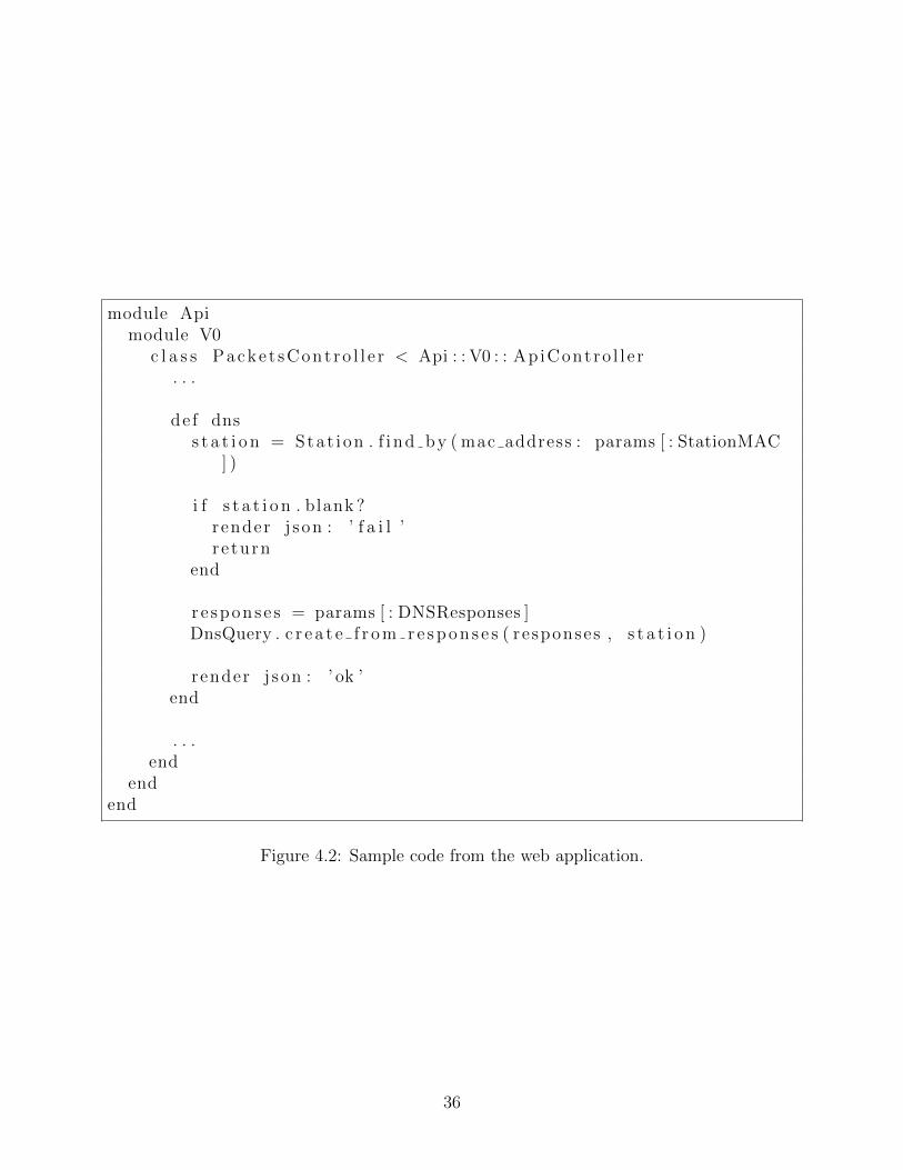
4.1 Screenshot of rule representation and usage information. . . . . . . . . . . . 354.2 Sample code from the web application. . . . . . . . . . . . . . . . . . . . . . 364.3 Sample route from the web application. . . . . . . . . . . . . . . . . . . . . . 374.4 Sample output from the rake routes command. . . . . . . . . . . . . . . . . . 374.5 Sequence diagram for learned packets. . . . . . . . . . . . . . . . . . . . . . 394.6 Algorithm for packet determination. . . . . . . . . . . . . . . . . . . . . . . . 424.7 Sample controller code for EAPOL rule creation. . . . . . . . . . . . . . . . 444.8 Sample controller code for packet processing. . . . . . . . . . . . . . . . . . . 454.9 Sample controller code for DNS rule matching. . . . . . . . . . . . . . . . . . 464.10 Commands used for initial installation and configuration of Open vSwitch. . 494.11 Sample hostapd configuration. . . . . . . . . . . . . . . . . . . . . . . . . . . 504.12 Sample dhcpcd.conf configuration. . . . . . . . . . . . . . . . . . . . . . . . . 50
5.1 Diagram of the system boundary. . . . . . . . . . . . . . . . . . . . . . . . . 555.2 Diagram of the system boundary with data flows. . . . . . . . . . . . . . . . 575.3 Diagram of the system boundary with data flows and threat agents. . . . . . 585.4 Diagram of the home network used for modelling attack vectors. . . . . . . . 595.5 Control AC-7 from the NIST 800-53 framework. . . . . . . . . . . . . . . . . 66
6.1 Raspberry Pi 4 used for system evaluation. . . . . . . . . . . . . . . . . . . . 716.2 Visual representation of the testing topologies. . . . . . . . . . . . . . . . . . 726.3 OpenFlow output of the bridge configured for connection testing. . . . . . . 746.4 OpenFlow command used to add virtual ports. . . . . . . . . . . . . . . . . . 766.5 OpenFlow output of the bridge configured for scalability testing. . . . . . . . 776.6 Individual packet processing time during scalability testing. . . . . . . . . . . 786.7 Individual packet processing time during blocked connection testing. . . . . . 796.8 Individual packet processing time during expanded blocked connection testing. 80
ix
6.9 Evaluation setup for measuring the impact of latency on the FPE. . . . . . . 816.10 OpenFlow output of the bridge configured for latency testing. . . . . . . . . 836.11 Individual packet processing time during latency connection testing. . . . . . 856.12 Topologies used for packet size testing. . . . . . . . . . . . . . . . . . . . . . 876.13 Total transfer time of 500MB using 100 Byte Segments. . . . . . . . . . . . . 896.14 Total transfer time of 500MB using 500 Byte Segments. . . . . . . . . . . . . 906.15 Total transfer time of 500MB using 1000 Byte Segments. . . . . . . . . . . . 906.16 Throughput per one-second interval. . . . . . . . . . . . . . . . . . . . . . . 916.17 Cumulative throughput during concurrent connection testing. . . . . . . . . 936.18 Screenshot of duplicate DNS requests. . . . . . . . . . . . . . . . . . . . . . . 94
7.1 Sample network topology. . . . . . . . . . . . . . . . . . . . . . . . . . . . . 1007.2 Attacker forging ARP Replies. . . . . . . . . . . . . . . . . . . . . . . . . . . 1027.3 Design of FPE-ARP. . . . . . . . . . . . . . . . . . . . . . . . . . . . . . . . 1037.4 Commands used for creating and peering patch ports. . . . . . . . . . . . . . 1037.5 Packet modifications performed by FPE-ARP. . . . . . . . . . . . . . . . . . 1057.6 Topology used for evaluating FPE-ARP. . . . . . . . . . . . . . . . . . . . . 1067.7 Throughput per one-second interval. . . . . . . . . . . . . . . . . . . . . . . 107
x
List of Tables
3.1 Default Rules Configured on Access Points . . . . . . . . . . . . . . . . . . . 313.2 Default Rules Per IoT Device . . . . . . . . . . . . . . . . . . . . . . . . . . 32
6.1 Average Connection Establishment Time per Topology . . . . . . . . . . . . 756.2 Average Transfer Time in Seconds per Topology and Segment Size . . . . . . 886.3 Sample DNS Queries from Smart TV . . . . . . . . . . . . . . . . . . . . . . 96
7.1 Rules for Each Pair of MAC addresses . . . . . . . . . . . . . . . . . . . . . 1047.2 Average Transfer Time in Seconds per Topology and Segment Size . . . . . . 106
xi

List of Symbols, Abbreviations andNomenclature
Symbol or abbreviation DefinitionAccess Point APAddress Resolution Protocol ARPCategory CATChallenge-Response Pair CRPCloud Service Provider CSPCommand and Control C&CConfidentiality, Availability, and Integrity CIADNS over HTTPS DoHDNS over TLS DoTDefense in Depth DIDDenial of Service DoSDistributed Denial of Service DDoSDomain Name System DNSDomain Specific Language DSLDynamic Host Control Protocol DHCPFlow Policy Enforcer FPEHyperText Transport Protocol HTTPInternet Protocol version 4 IPv4Internet Protocol IPInternet Service Provider ISPInternet of Things IoTIntrusion Detection System IDSIoT Intrusion Detection and Mitigation IoT-IDMJavaScript Object Notation JSONLocal Area Network LANMachine Learning MLMan in the Middle MITMMaximum Segment Size MSSMedia Access Control MACModel View Controller MVCMulti-Factor Authentication MFANational Institute of Standards and Technology NIST
xii
Network Address Translation NATNetwork Attached Storage NASOpen Systems Interconnection OSIOperating System OSOrganizationally Unique Identifier OUIPhysical Unclonable Function PUFPre-Shared Key PSKProtocol Data Unit PDUService Data Unit SDUService Set Identifier SSIDSoftware Defined Network SDNSoftware as a Service SaaSTransmission Control Protocol TCPTransport Layer Security TLSUniform Resource Identifier URIUser Datagram Protocol UDPVirtual Access Points VAPVirtual Local Area Networks VLANWide Area Network WANWireless Local Area Networks WLANWireless Termination Point WTP
xiii

Epigraph
We could soon be in a position where a determined adversary could shut down
our power and water, turn off our security systems, disrupt our ability to pro-
vide medical care, listen to our conversations, and monitor our movements.
Department of Defense, Policy Recommendations for the Internet of Things
xiv
Chapter 1
Introduction
1.1 Security and the Internet of Things
The Internet of Things (IoT) is the growing trend to connect every device to the Internet. It
is estimated that 500 billion devices will be connected to the Internet by the year 2030 [29].
The IoT trend is connecting many devices including: fitness devices, televisions, refrigerators,
washing machines, and alarm systems. IoT devices target both home and corporate networks.
Increased connectivity results in additional security challenges for networks. Networks
face a number of diverse threats, including: ransomware, malware, and denial of service
attacks. Cyber attacks have sparked a new industry, the Cyber Attack Business [42]. En-
terprise and home networks are targets for malicious actors.
The cyber security industry is growing rapidly to counter malicious actors. The cyber
security market is projected to have an estimated value of $248 billion by the year 2023
[48]. There are many products available in the market for advanced users and enterprises.
These solutions include technologies such as Intrusion Detection Systems (IDSs) and Next-
Generation Firewalls (NGFWs) [56]. These advanced solutions can be costly to acquire or
require specialized hardware and knowledge for proper configuration. This presents difficul-
ties when applying the same concepts to a home network as assumptions cannot be made
1
about the home user in terms of network administration capabilities. Devices marketed to-
wards home users have a track record of being inadequately hardened which has led to home
users being subject to attacks. Recent examples include the VPNFilter campaign [71] which
targets routers and is used as a staging point for future attacks. Search engines targeting
insecure network devices enable quick discovery of improperly configured or insecure devices
[49].
The National Institute of Standards and Technology (NIST) groups the challenges faced
by IoT devices into three categories [26]: device security, data security, and privacy. Device
security is essential in preventing the device from being used as a pivot point for further
attacks. Data security refers to protecting the Confidentiality, Availability and Integrity
(CIA) of data being generated or stored on the device. Privacy encompasses the protection
of an individuals’ privacy through the use of an IoT device. Following the CIA model, there
is a range of security issues that impact IoT devices such as data leakage, denial of service,
and impersonation (see [37] for a detailed discussion).
Transferring responsibility for home network protection to Internet Service Providers
(ISPs) is proposed as a solution for addressing IoT security problems [46]. Such an approach
could effectively address insecure IoT devices being connected to the internet. Two varia-
tions of this solution can be envisioned: thick and thin. In the thick security model, the
home user is ultimately responsible for all network security and the Internet Service Provider
(ISP) provides no support to the home user. In the thin security model, the ISP takes full
responsibility for the home network and is responsible for ensuring it remains secured. How-
ever, this approach may have legal implications for the ISP as discussed in [46]. IoT devices
also encounter availability challenges as they often rely on Cloud Service Providers (CSPs).
If a home relies on a cloud service with no local fallbacks, it may become unresponsive or un-
reliable if the upstream provider becomes unavailable. A solution is to place an offline device
in a home network to synchronize states between local and cloud services [33]. We explore
related work and our solution to address the aforementioned challenges in the remainder of
2

this paper.
1.2 Problem Definition
The attack surface of a network expands as any network device (including IoT devices)
are connected. OWASP defines the attack surface as “all of the different points where an
attacker could get into a system, and where they could get data out.” [58] The risk to a
home network further increases when IoT devices are improperly hardened or insufficiently
patched by either the device owner or manufacturer. This presents a security issue to home
networks as the deployment of IoT devices increases.
IoT device security has been addressed by commercially available solutions as well as
recent literature. Many home networks are constrained by funding availability and technical
administration capabilities. As a result, we propose a home IoT solution must meet the
following goals:
• Vendor agnostic: It must only require a compatible access point and not require hard-
ware from a specific manufacturer.
• Compatible: There can be no modification to the end devices or customization of
network protocols.
• Automatic: User interaction is not required. Additional functionality can be utilized
by the user if they choose to do so.
• Secure: IoT devices are limited to least-functionality to restrict their network access
in the event they are compromised.
We consider these goals to be realistic restrictions on a home IoT security solution. The
goal for the solution to be vendor agnostic provides the home user with greater choices
for equipment than a solution which requires specific hardware or deployment mechanisms.
3
Similarly, an effective solution for securing IoT devices available in the market must be
compatible with existing protocols and not require modification of the end devices. Auto-
matically securing new devices added to a network alleviates the issue of a solution being
only as effective as the operator. In the context of a home network, it is not realistic to ex-
pect every network operator to have extensive experience operating security devices such as
firewalls. Finally, we set the security goal for the solution to require least-functionality. Con-
figuring a permit by exception, deny by default policy for network access is a best practice
recommended by the NIST 800-53 framework [35].
1.3 Thesis Contributions
In this thesis, we present the design and evaluation of a solution to secure home networks
which we call the Flow Policy Enforcer (FPE). The FPE takes a least-permissive policy
based approach to network security. This enables IoT devices to operate as intended but
restricts their network functionality in the event they are compromised, thereby reducing
the ability for an attacker to use an IoT device to stage further attacks.
The FPE controls data flow through an OpenFlow enabled Access Point (AP). Such
APs are commercially available [23]. Utilizing OpenFlow to enforce network restrictions
displays the feasibility of this approach. As devices are connected, the FPE automatically
learns least-permissive policies for each device. After a period of time, the learned policy
is enforced on the device. This prevents a compromised device from being used to attack
other network resources. Additionally, the FPE does not require any cloud services for data
processing and all data resides in the privacy of the home network.
The contributions of this work are:
1. We review background information, recent literature, and best practices for network
security.
2. We present the Flow Policy Enforcer, our solution which utilizes OpenFlow to address
4
the security challenges associated with IoT devices.
3. We perform a full implementation of the FPE, discuss implementation details, and
deploy the FPE on low-cost hardware in a Local Area Network (LAN).
4. We present measurement of the system and demonstrate the effectiveness of our solu-
tion.
5. We perform a thorough threat model of the FPE installed in a LAN. Results from this
exercise can be used in consideration of other IoT security solutions.
6. We present suggestions for future work and areas in which IoT device security could
be explored in the future.
1.4 Thesis Organization
The remainder of this thesis is composed of the following chapters:
• Chapter 2 (Background Information and Related Work): We review background
information on network protocols with a focus on the Data and Network layers from
the OSI model. After we review background information we explore related works from
literature.
• Chapter 3 (Flow Policy Enforcer): We present our solution to secure IoT devices,
the Flow Policy Enforcer. The FPE operates on the principal of least permission to
and automatically secures IoT devices connected to an OpenFlow enabled access point
within the home network.
• Chapter 4 (Implementation): We performed a full implementation of the Flow Policy
Enforcer. In this chapter we explore the design decisions made in the implementation
of the system and discuss the components and concurrency models used to achieve the
goals of the system.
5
• Chapter 5 (Security Analysis): We performed a comprehensive security analysis of
the Flow Policy Enforcer. In this chapter, we discuss the threat model of the system
and compare it against an industry standard framework.
• Chapter 6 (Evaluation): We configured a Raspberry Pi 4 to operate as an Access
Point. We performed an evaluation of the system comparing it against standard tech-
nologies without OpenFlow, with the FPE running on an external server, and with the
FPE running on the Raspberry Pi itself. We also discuss the effectiveness of the FPE
in real-world scenarios.
• Chapter 7 (Alternative Deployment): We propose an alternative method of deploying
the FPE in a network using a technique known as ARP spoofing. We discuss the
architecture and perform a brief evaluation of this approach.
• Chapter 8 (Conclusion and Future Work): We review the problem and solution pro-
posed within this thesis. We explore opportunities for future work in this problem
area.
6
Chapter 2
Background Information and Related
Work
2.1 Introduction
Suppose Bob lives in a house on one end of a street. Alice lives in a house on the other end
of the same street. One day Bob wishes to write a letter to Alice. He gets out a pen and
some paper, writes a message, and places it in an envelope. Next, Bob writes Alice’s address
on the envelope and gives it to Eve. Eve reads the address on the envelope and delivers the
message to Alice. The key piece of information used by Eve to deliver the message was the
address.
Computer networks operate in a similar method. Each device in a network must be
uniquely identifiable with an address. When one computer wishes to send a message to
another, it must create a message with appropriate addressing and place it on the network.
If all goes well, intermediary network devices will read the address information and deliver
the entire message to the destination computer.
7
2.2 Network Models
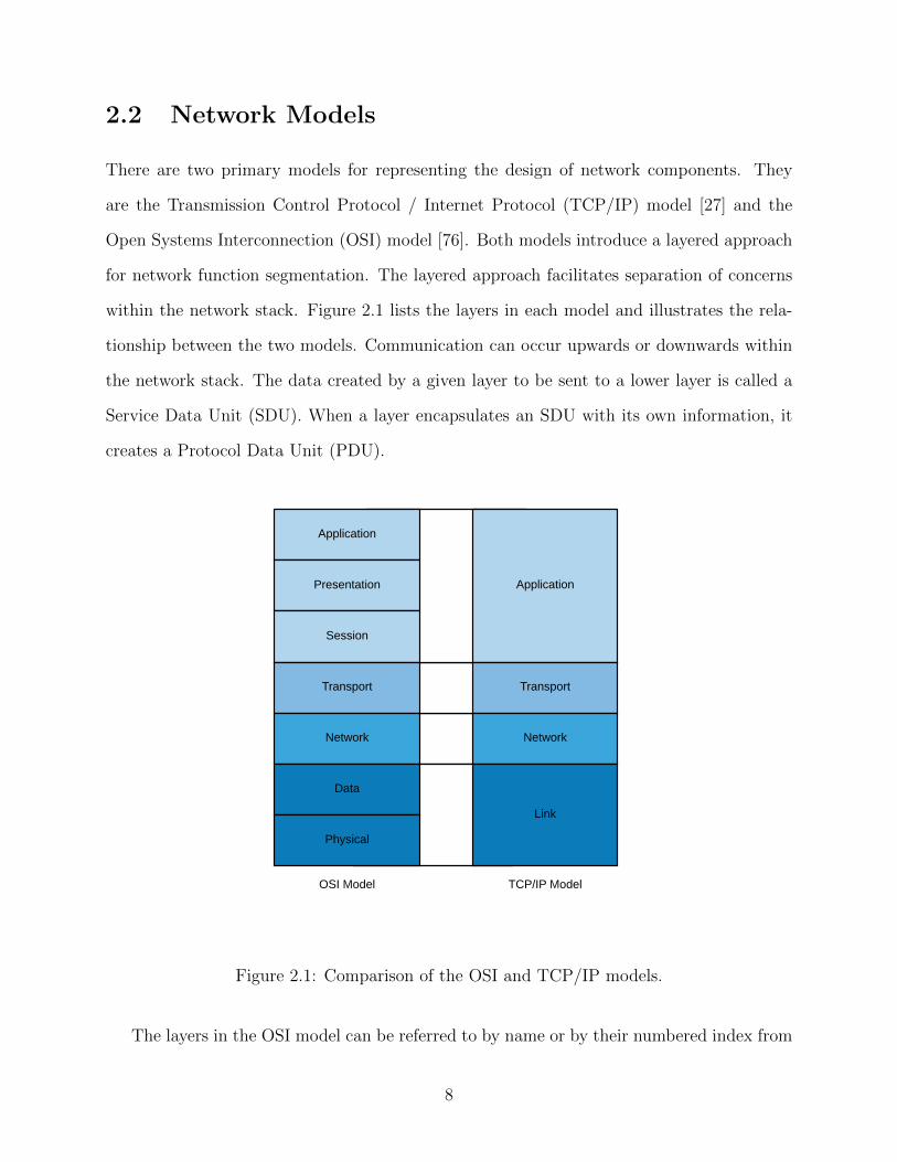
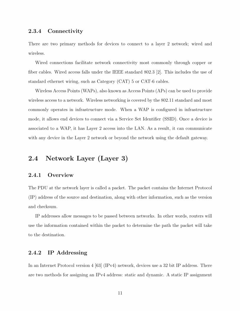
There are two primary models for representing the design of network components. They
are the Transmission Control Protocol / Internet Protocol (TCP/IP) model [27] and the
Open Systems Interconnection (OSI) model [76]. Both models introduce a layered approach
for network function segmentation. The layered approach facilitates separation of concerns
within the network stack. Figure 2.1 lists the layers in each model and illustrates the rela-
tionship between the two models. Communication can occur upwards or downwards within
the network stack. The data created by a given layer to be sent to a lower layer is called a
Service Data Unit (SDU). When a layer encapsulates an SDU with its own information, it
creates a Protocol Data Unit (PDU).
OSI Model TCP/IP Model
Application
Presentation
Session
Transport
Network
Data
Physical
Application
Transport
Network
Link
Figure 2.1: Comparison of the OSI and TCP/IP models.
The layers in the OSI model can be referred to by name or by their numbered index from
8
the lowest layer. For example, the Data layer may be called layer 2, the Network layer called
layer 3, and so on.
We will examine the following layers of the OSI model: data, network, and transport.
2.3 Data Layer (Layer 2)
2.3.1 Overview
The data layer sends and receives information over the physical link. The PDU at the data
layer is called a frame. The frame contains information on the Media Access Control (MAC)
address of the source and destination of the frame. The devices attached to a layer 2 network
are often said to be a part of a Local Area Network (LAN).
Every network interface is configured with a MAC address. The MAC address is con-
figured by the manufacturer of the equipment and is 48 bits in length. The first 24, 28,
or 36 bits (depending on the block size purchased by the manufacturer) of a MAC address
are the Organizationally Unique Identifier (OUI) and is registered to the manufacturer of
the network equipment [43]. The remaining bits of the MAC address are a unique number
assigned to the device. MAC addresses must be unique in a layer 2 network as they will be
used by other devices to make forwarding decisions. The MAC address of the sending device
and the destination device are included in each frame sent by a network device.
2.3.2 Message Types
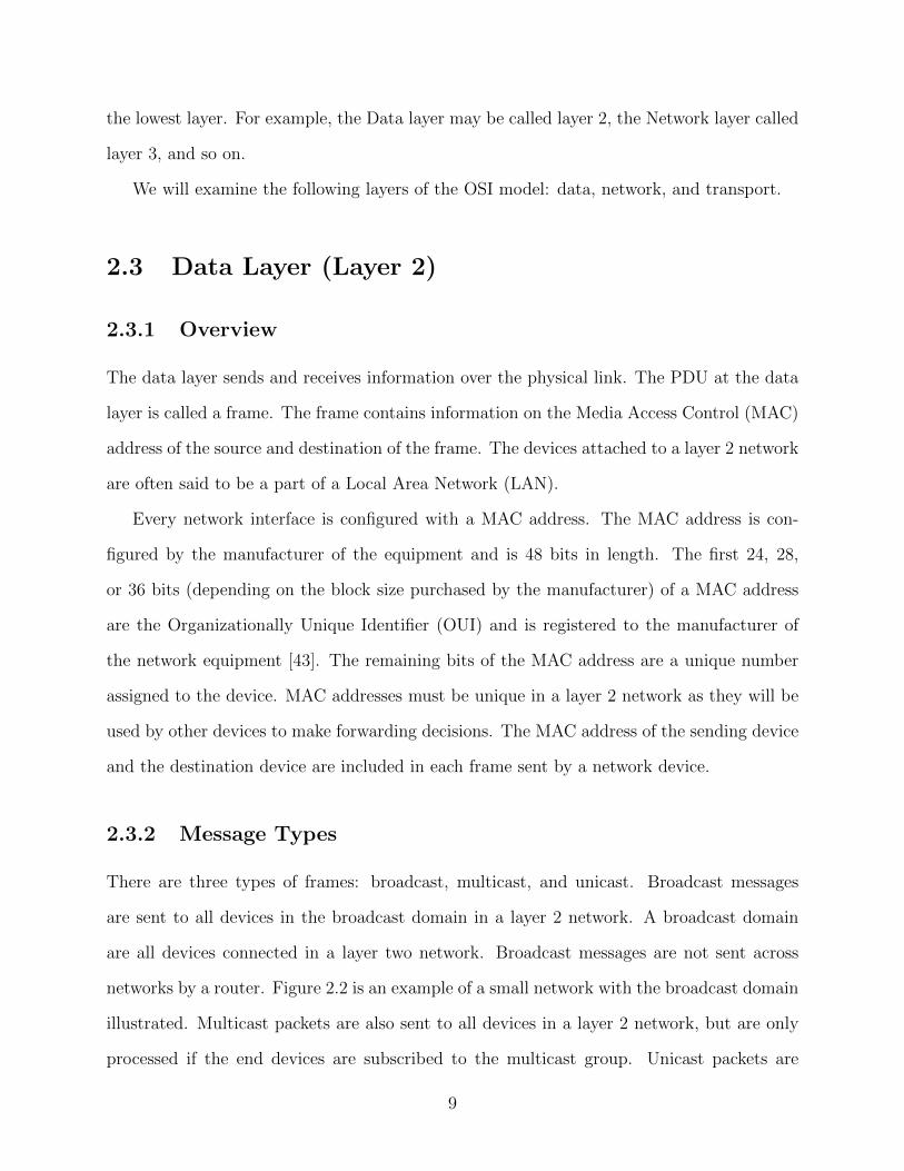
There are three types of frames: broadcast, multicast, and unicast. Broadcast messages
are sent to all devices in the broadcast domain in a layer 2 network. A broadcast domain
are all devices connected in a layer two network. Broadcast messages are not sent across
networks by a router. Figure 2.2 is an example of a small network with the broadcast domain
illustrated. Multicast packets are also sent to all devices in a layer 2 network, but are only
processed if the end devices are subscribed to the multicast group. Unicast packets are
9
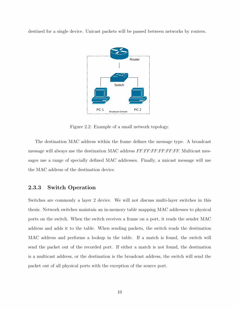
destined for a single device. Unicast packets will be passed between networks by routers.
Broadcast Domain
Router
Switch
PC 1 PC 2
Figure 2.2: Example of a small network topology.
The destination MAC address within the frame defines the message type. A broadcast
message will always use the destination MAC address FF:FF:FF:FF:FF:FF. Multicast mes-
sages use a range of specially defined MAC addresses. Finally, a unicast message will use
the MAC address of the destination device.
2.3.3 Switch Operation
Switches are commonly a layer 2 device. We will not discuss multi-layer switches in this
thesis. Network switches maintain an in-memory table mapping MAC addresses to physical
ports on the switch. When the switch receives a frame on a port, it reads the sender MAC
address and adds it to the table. When sending packets, the switch reads the destination
MAC address and performs a lookup in the table. If a match is found, the switch will
send the packet out of the recorded port. If either a match is not found, the destination
is a multicast address, or the destination is the broadcast address, the switch will send the
packet out of all physical ports with the exception of the source port.
10
2.3.4 Connectivity
There are two primary methods for devices to connect to a layer 2 network; wired and
wireless.
Wired connections facilitate network connectivity most commonly through copper or
fiber cables. Wired access falls under the IEEE standard 802.3 [2]. This includes the use of
standard ethernet wiring, such as Category (CAT) 5 or CAT-6 cables.
Wireless Access Points (WAPs), also known as Access Points (APs) can be used to provide
wireless access to a network. Wireless networking is covered by the 802.11 standard and most
commonly operates in infrastructure mode. When a WAP is configured in infrastructure
mode, it allows end devices to connect via a Service Set Identifier (SSID). Once a device is
associated to a WAP, it has Layer 2 access into the LAN. As a result, it can communicate
with any device in the Layer 2 network or beyond the network using the default gateway.
2.4 Network Layer (Layer 3)
2.4.1 Overview
The PDU at the network layer is called a packet. The packet contains the Internet Protocol
(IP) address of the source and destination, along with other information, such as the version
and checksum.
IP addresses allow messages to be passed between networks. In other words, routers will
use the information contained within the packet to determine the path the packet will take
to the destination.
2.4.2 IP Addressing
In an Internet Protocol version 4 [63] (IPv4) network, devices use a 32 bit IP address. There
are two methods for assigning an IPv4 address: static and dynamic. A static IP assignment
11
is configured on the device and will not change. Static assignments may lead to conflicts if
care is not taken and two devices are assigned the same IP address. As a solution to this
challenge, a Dynamic Host Control Protocol (DHCP) [34] server can be used to manage IP
addresses. We will discuss the operation of DHCP in greater detail later in this thesis.
IPv4 addresses fall into two main categories; private and public. Public IP addresses
are intended to be publicly routable; that is, they are designed to be announced between
networks. Private IP address ranges are defined by RFC1918 [66] and are meant for use only
in Local Area Networks (LANs).
IPv6 [31] (Internet Protocol version 6) addresses are 128 bits in length. There are a few
different types of IP addresses in IPv6 [39]. Global unicast addresses are designed to be
publicly routable and are typically assigned to every IPv6-enabled device. There are also
link-local addresses which identify each device connected on a single link but are not used
for purposes beyond device to device communication. Similar to IPv4, IPv6 addresses may
also be configured by a DHCP server in the network [55].
Packets can contain either IPv4 or IPv6 addresses based on the 4 bit version flag contained
within the packet. Packets will contain both the sender and destination IP addresses.
2.4.3 Dynamic Host Control Protocol
The IP address can be automatically requested by a device on a network from a Dynamic
Host Control Protocol (DHCP) server. The DHCP server will maintain a mapping of MAC
addresses to IP addresses and will prevent duplicate IP addresses from being assigned in a
network.
When the client and server are communicating, the DHCP protocol allows for options to
be specified. For example, clients may send the host name of the device. The DHCP server
may also include information about the default gateway and Domain Name System (DNS)
server for the network.
12
2.4.4 Address Resolution Protocol
Network devices need to be able to look up MAC addresses for their frames. If a device
only knows the IP address of the destination, it will not be able to send the frame without
the correct MAC address. The Address Resolution Protocol (ARP) [61] is a broadcast
message that a device can send to the network to request the MAC address associated from
a device which holds the IP address. When a device responds, it sends a unicast reply to
the requesting device.
2.5 Routing
Now that we have discussed how addressing works at the data and network layers, we can
explore how packets are sent between networks. Networks are connected together using
routers. This limits the broadcast domains to the devices and interfaces in a layer 2 network.
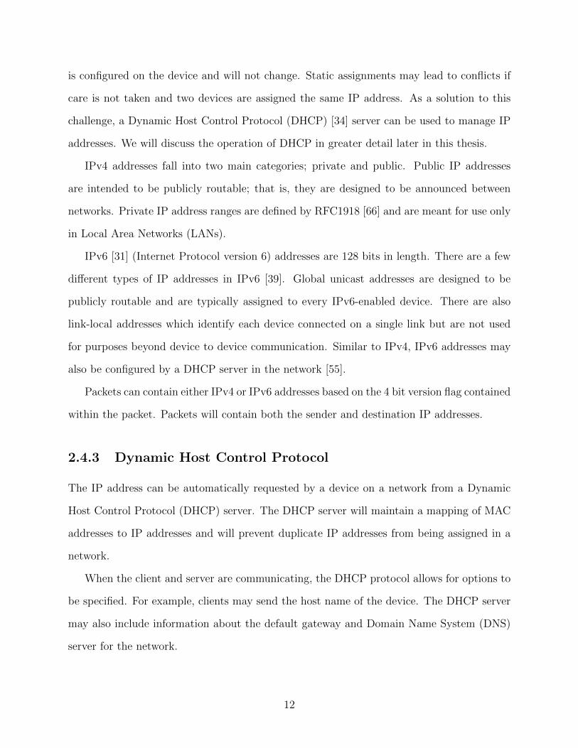
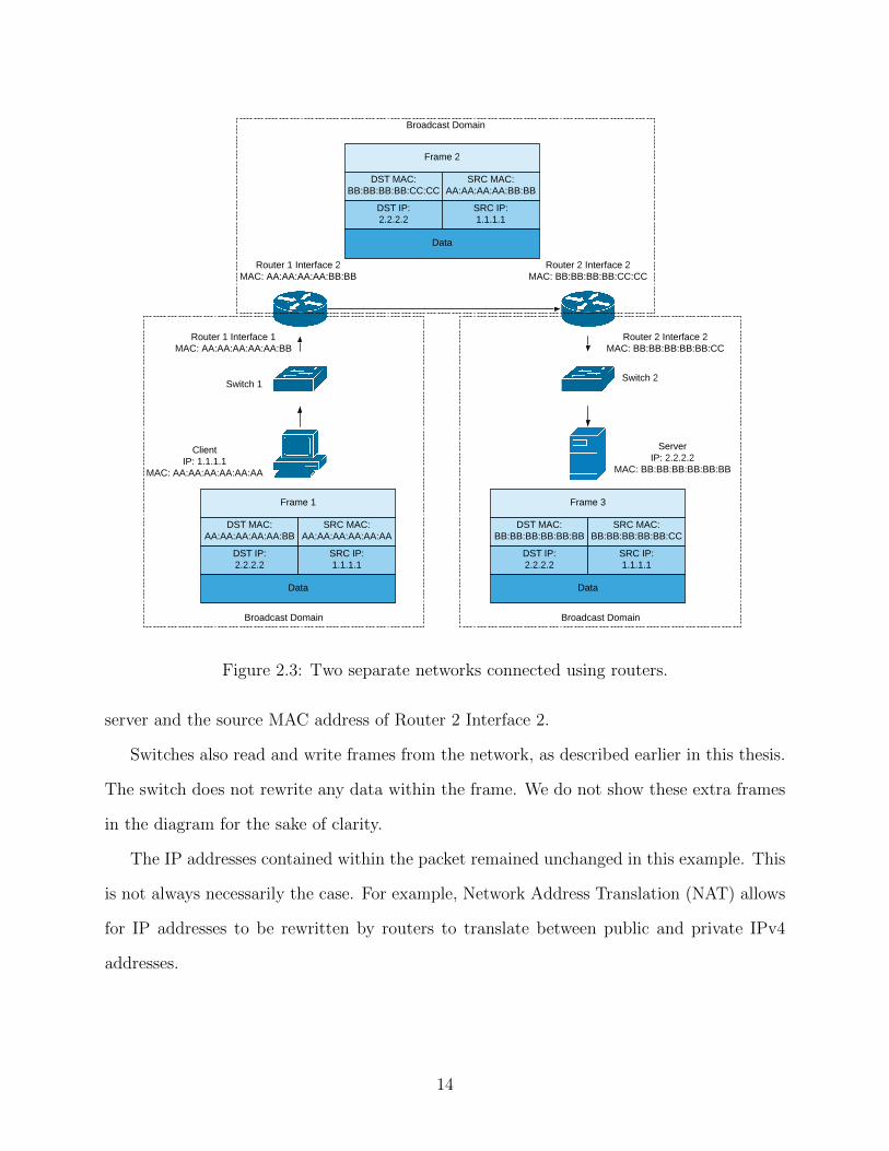
The interconnection of networks is what gives us the internet. Figure 2.3 is a sample network
consisting of two networks connected using routers.
In Figure 2.3 we have a client which is sending some data to a server. The client deter-
mines that the server is not on the same layer 2 network. As a result, it sets the destination
MAC address of the frame to the interface of Router 1 which is one the same layer 2 network.
The destination IP address of the packet is set to the server’s IP address.
When Router 1 receives the frame, it uses an in-memory routing table to determine
where the packet should be sent. It determines that the packet must be sent out of Router
1 Interface 2 and sets the destination MAC address to that of Router 2 Interface 2. When
Router 1 writes the frame, it uses the MAC address of Router 1 Interface 2 as the source
MAC address.
When Router 2 receives the frame, it follows the same pattern. First, it looks up which
interface belongs to the same network as the destination IP address. In this case, it is Router
2 Interface 2. It writes the frame out to switch 2 using the destination MAC address of the
13
Broadcast DomainBroadcast Domain
Switch 2Switch 1
ClientIP: 1.1.1.1
MAC: AA:AA:AA:AA:AA:AA
ServerIP: 2.2.2.2
MAC: BB:BB:BB:BB:BB:BB
Router 1 Interface 1MAC: AA:AA:AA:AA:AA:BB
Router 1 Interface 2MAC: AA:AA:AA:AA:BB:BB
Router 2 Interface 2MAC: BB:BB:BB:BB:BB:CC
Router 2 Interface 2MAC: BB:BB:BB:BB:CC:CC
Frame 1
DST MAC:AA:AA:AA:AA:AA:BB
SRC MAC:AA:AA:AA:AA:AA:AA
DST IP:2.2.2.2
SRC IP:1.1.1.1
Data
Frame 2
DST MAC:BB:BB:BB:BB:CC:CC
SRC MAC:AA:AA:AA:AA:BB:BB
DST IP:2.2.2.2
SRC IP:1.1.1.1
Data
Frame 3
DST MAC:BB:BB:BB:BB:BB:BB
SRC MAC:BB:BB:BB:BB:BB:CC
DST IP:2.2.2.2
SRC IP:1.1.1.1
Data
Broadcast Domain
Figure 2.3: Two separate networks connected using routers.
server and the source MAC address of Router 2 Interface 2.
Switches also read and write frames from the network, as described earlier in this thesis.
The switch does not rewrite any data within the frame. We do not show these extra frames
in the diagram for the sake of clarity.
The IP addresses contained within the packet remained unchanged in this example. This
is not always necessarily the case. For example, Network Address Translation (NAT) allows
for IP addresses to be rewritten by routers to translate between public and private IPv4
addresses.
14
2.6 Transport Layer (Layer 4)
2.6.1 Overview
The PDU at the transport layer is called the segment. Some information in the segment
includes the protocol, which can include the Transmission Control Protocol (TCP) [65] or
User Datagram Protocol (UDP) [64]. TCP and UDP segments contain other information
such as the source and destination ports.
TCP is a reliable delivery protocol. It uses a three-way handshake to initiate a new
connection between a two devices. Data transmission is acknowledged and it provides mech-
anisms for data retransmission if messages are lost or corrupted during communication.
Unlike TCP, UDP is an unreliable data transfer and it does not have built in mechanisms
to ensure all of the data is properly received.
2.6.2 Ports
TCP and UDP are two transport protocols used within networking at Layer 4. Both protocols
feature 16 bit fields called a port. A port is used by the operating system to allow a socket
to be associated to the connection. Similar to addresses in the other layers, each segment
will have a source port and a destination port.
When an application is sending data, it will typically be assigned a random source port
by the Operating System (OS) kernel. If a system is waiting to receive a connection, it will
typically listen on a well-defined port. For an example, port 80 is normally used for Hy-
perText Transport Protocol (HTTP) services. TCP and UDP segments will always contain
a source port and a destination port. This facilitates bidirectional communication as the
receiver will be able to direct responses back to the source port of the sender.
15
2.7 Domain Name System
The Domain Name System (DNS) [53] is designed to simplify network addresses. It provides
the ability for a user-friendly domain name to be mapped to an IP address. For example,
the domain name www.example.org may be mapped to the IPv4 address 1.2.3.4. When a
device tries to connect to a specific domain name, it will use the DNS protocol to look up
the IP address of the destination.
DNS queries can be performed either iteratively or recursively. If an iterative resolver
receives a query but does not know the answer, it will give the client the IP address of
another DNS server to try. A recursive resolver will perform the request on the behalf of the
client, working with other iterative or recursive resolvers until a response to the client has
been found.
A DNS response contains a number of resource records. Each resource record includes
at least the following fields: [52].
• Type: This specifies the type of the resource record. Some examples are:
– A: An IPv4 address
– CNAME : A canonical name record is used to point to another domain. Using
the previous example, the response for the domain name query example.org may
redirect to www.example.org.
• Data: This is the data corresponding to the record type.
• Time to Live: The time to live specifies the amount of time a given record may be
cached. This reduces the load on DNS infrastructure when servicing many clients.
There is no security provided in the DNS protocol. Queries are sent from a client to a
DNS server over UDP port 53. This means the data could be logged or modified by a Man in
the Middle (MITM) attack. Some protocols have been designed to alleviate these concerns,
such as DNS over HTTPS (DoH) [40], DNS over TLS (DoT) [41], and DNSCrypt [32].
16
2.8 Network Security
We have explored the basic concepts of networking. However, we have not considered security
as a part of the discussions. There are a number of ways to segregate a network from another,
in addition to segregating network devices within the same network. We will briefly discuss
some traditional methods of securing networks.
2.8.1 Layer 2 Security
Virtual LANs
Switches in a layer 2 network allow end devices to communicate with any other device
connected to the network. Layer 2 networks can be separated into Virtual Local Area
Networks (VLANs) through the use of 802.1Q [1]. This allows multiple computers to be
connected to the same switch and make it appear as though they are on separate layer 2
networks.
802.1Q adds support for VLAN Tagging in a network. Physical ports can be tagged with
different VLAN IDs. The switch will enforce packet forwarding rules based on VLAN tags.
These forwarding rules will provide a level of network segmentation between VLANs. Ports
can also be tagged as Trunk Ports which will pass all packets over the port regardless of
their VLAN tag. This allows a router to perform routing decisions for many VLANs on a
single physical port.
Enabling VLANs on a network switch requires the ability to configure the switch. This
is typically performed using a web interface or command line interface on a managed switch.
Switches which can not be configured are lower-cost and referred to as unmanaged switches.
17
Trunk Port
PC 1 PC 3
VLAN 1 VLAN 1
VLAN 2
PC 2
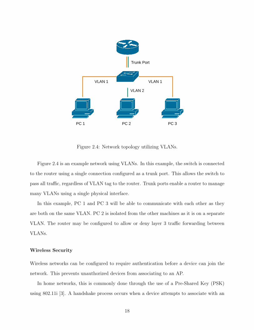
Figure 2.4: Network topology utilizing VLANs.
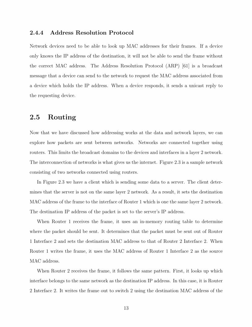
Figure 2.4 is an example network using VLANs. In this example, the switch is connected
to the router using a single connection configured as a trunk port. This allows the switch to
pass all traffic, regardless of VLAN tag to the router. Trunk ports enable a router to manage
many VLANs using a single physical interface.
In this example, PC 1 and PC 3 will be able to communicate with each other as they
are both on the same VLAN. PC 2 is isolated from the other machines as it is on a separate
VLAN. The router may be configured to allow or deny layer 3 traffic forwarding between
VLANs.
Wireless Security
Wireless networks can be configured to require authentication before a device can join the
network. This prevents unauthorized devices from associating to an AP.
In home networks, this is commonly done through the use of a Pre-Shared Key (PSK)
using 802.11i [3]. A handshake process occurs when a device attempts to associate with an
18
AP. The device and AP mutually validate that they have the same PSK without sending the
PSK over the air. Once mutual authentication succeeds, the device is able to communicate
with the rest of the network via the AP.
2.8.2 Layer 3 Security
Stateless Firewalls
Stateless firewalls provide packet filtering capabilities at layer 3. As we have previously
discussed, routers will forward packets between networks by comparing the destination IP
address to a routing table in memory. By default, no packet filtering is performed which
results in network devices being exposed to the internet.
A stateless firewall allows a network administrator to configure packet filtering based
on IP address information contained at layer 3. This provides coarse filtering capabilities
on either ingress or egress directions and provides some ability to restrict access between
networks.
2.8.3 Layer 4 Security
Stateful Firewalls
A stateful firewall installed on a router can be used to track the state of packets and fur-
ther restrict communications across networks. For example, a stateful firewall is capable of
tracking which device initiated a connection. This allows bidirectional communication across
networks to occur while restricting the set of devices allowed to initiate connections. State-
ful firewalls often inspect up to layer 4, including rules for defining TCP/UDP behaviour in
addition to inspecting port numbers.
19
2.9 Software Defined Networking
Traditional network devices such as routers and switches integrate the control and data planes
into a single device. The control plane makes decisions on how network traffic should be
forwarded within the device and the data plane is responsible for performing the forwarding
actions. Software Defined Networking (SDN) [45] is a model for separating the control plane
from the data plane. The control plane logic is brought into a centralized controller which can
make decisions based on the entire network layout. The network devices receive forwarding
instructions from the centralized controller and perform forwarding actions based on received
rules.
2.10 OpenFlow
OpenFlow is an SDN protocol which allows for detailed control of the forwarding plane
in network devices [73]. For example, in a conventional switch, the control plane and the
forwarding plane are combined in a single unit. OpenFlow allows the control plane to
be configurable. By extension, this configurability allows the forwarding plane to perform
custom actions as defined by the OpenFlow controller. The processing pipeline of OpenFlow
is defined in flow tables and flow entries.
Flow tables are read in sequential order and allow for sets of flow entries to be grouped
together in a single table. When a matching flow entry is found, the actions configured in
the flow entry are executed.
Flow entries are comprised of the following fields: a cookie, priority, match fields, coun-
ters, and actions. The flow entry can be configured to perform actions including modification
of the frame and sending it out of a specified port, group of ports, and sending the frame
itself to the network controller. A low priority flow entry can be used as a default action in
the device to handle unknown frames.
A controller is capable of configuring the flow rules on OpenFlow devices. Controllers can
20
add, update, and remove flow entries and flow tables from a central point in the network. This
allows for detailed control of network devices which extends beyond functionality provided
by standard network protocols.
2.10.1 Messages
OpenFlow controllers and switches are connected through an interface called the OpenFlow
Channel. The Channel communicates via a datapath. The datapath is a TCP connection
and can optionally be encrypted using Transport Layer Security (TLS). Communication is
performed using OpenFlow Messages. There are three classes of messages in the OpenFlow
specification: symmetric, controller-to-switch, and asynchronous. There are also experi-
menter messages which can be used for non-standard purposes.
Messages which can be sent by either a controller or switch at any time are called sym-
metric messages. There are two primary types of symmetric messages: hello and echo. Hello
messages are used upon initiation of an OpenFlow Channel. Echo messages can be sent at
any time by a controller or switch to determine if the connection is still alive.
Messages sent from a controller to a switch are called controller-to-switch. These messages
can be sent from a controller at any time. These messages include functionality which can
configure the switch (configuration), add or remove flow rules (modify-state), send packets
out of a specified switch port (packet-out), and gather data such as port statistics from the
switch (read-state).
Asynchronous messages may be sent from a switch to a controller at any time. These
messages are typically used to inform the controller of a state change on the switch. For
example, if a flow is removed from the switch, it will send a flow-remove message. If the
status of a port changes, a port-status message will be sent. A controller may also request
certain packets be sent from a switch in the event of a rule match. These messages are called
packet-in.
21
2.10.2 Controller Design Considerations
OpenFlow Controller design can draw from client-server architecture patterns [75] and con-
siderations for implementation has also been the subject of recent works [68, 67, 69, 75].
Considerations raised by the authors include: reliability, scalability, and security.
Reliability is an important consideration of controller design. Controllers are responsible
for orchestrating the flow of traffic within OpenFlow enabled devices. It is essential that
controllers remain available and do not unexpectedly cause network outages.
Scalability is a factor which must be considered when designing an OpenFlow Controller.
The level of scalability required may depend on the network topology and intended deploy-
ment of the controller. Other related considerations include distributed controllers in which
controllers may cooperatively manage a large set of devices.
OpenFlow Controllers are responsible for orchestrating the flow of data within the net-
work. As a result, it is essential that the controller is secure and does not open the network up
to compromise. Considerations include handling of malformed packets and any mechanism
that may be abused to adversely impact the CIA of the network.
2.11 IoT Device Identification
Successful identification of IoT devices can be used to provide the network with additional
information. This information could be used to restrict access or ensure that traffic originates
from a trusted IoT device. Aman et al. proposed a data provenance protocol for identifying
devices [25]. Their work builds on the use of Physical Unclonable Functions (PUFs) of
a device. A PUF is a feature of a physical object which can be treated as unique and
unclonable. When the IoT is initially deployed, a Challenge-Response Pair (CRP) from
the device is registered with the server. The PUFs are used to generate and register a set
of fingerprints with the server. Future communications between the IoT device and server
require the use of the appropriate fingerprint and can be used to mutually authenticate each
22
other.
Meidan et al. proposed the use of machine learning classifiers to identify IoT devices
based on network traffic in their solution called ProfilIoT [50]. Given a device and a series
of sessions, a classifier is constructed for each session of the device. These classifiers output
a probability for any input session that the input was generated by the device. The optimal
classification threshold for each of these single-session identifiers is calculated. Finally, the
optimal count of individual single-session identifiers is calculated to provide no false positives
or false negatives for a given device. Once the classifiers are constructed, session flows can
be run through the classifiers to identify which device is generating traffic on the network.
In [30], Danev et al. explore the identification of devices based on physical layer at-
tributes. These attributes can be the result of manufacturing imperfections or other in-
specification or out-of-specification operation of wireless equipment. In their survey, the
authors discuss the feasibility of identifying 802.11 wireless devices based on physical at-
tributes. Further research is required to determine feasibility, cost and other factors of this
approach.
Our solution varies from the approaches in [25] and [50] as we automatically build policies
for any device connected to the network. We do not require specialized hardware to identify
connection characteristics or perform machine learning based on sets of well-known devices.
2.12 OpenFlow in WiFi and Security
There are some works on using OpenFlow in WiFi networks. For example, Vestin et al.
explore the use of OpenFlow in Wireless Local Area Networks (WLANs) in [74]. In this
work, the CloudMAC platform is composed of the following pieces: Wireless Termination
Points (WTPs), Virtual Access Points (VAPs), an OpenFlow controller, and an OpenFlow
switch. The VAPs are virtual machines which run on a central server and perform actions as
if they were a traditional AP by processing frames. WTPs are antennas which are used solely
23
for the purpose of receiving and transmitting packets. The OpenFlow switch is controlled
by the OpenFlow controller and the controller sets up flow rules forwarding packets between
VAPs and WTPs. Performance testing done by the authors shows that the setup has low
enough latency to support traditional wireless clients.
Porras et al. proposed a method for securing OpenFlow flow rule changes called FortNOX
in [62]. FortNOX is an extension for the NOX OpenFlow controller and can be run as an
extension of the controller. FortNOX provides a mechanism for a network administrator to
define a policy for the network. FortNOX ensures that new flow entries do not conflict with
the policies defined for the network. In the case of a conflict, FortNOX performs a series
of comparisons, including the priority of the source requesting the rule to be added. An
administrator is notified in the case where a conflict cannot be resolved.
Our solution varies from [74] as we do not virtualize the AP functionality to an external
server. Similar to [62], we take a least-permissive policy based approach. Our solution
differs as we automatically learn and enforce policies on network devices instead of focusing
on conflicting OpenFlow rules.
2.13 Cloud Based Firewalls
Cloud based firewalls are another approach for protecting networks. These firewalls utilize a
cloud component for analysis and can scale in the cloud to meet customer demand. Taylor
et al. show this is a viable approach and explore the potential impact of latency and data
center locations in [72].
Shirali-Shahreza et al. introduce a cloud based solution for protecting home networks
in [70]. In this work, network protection is broken down into two main components: the
enforcer and the mastermind. The enforcer is a device which sits at the network edge. This
allows the enforcer to either allow or block flows at the edge of the network. The mastermind
is a cloud service that communicates with and configures the enforcer. The enforcer samples
24
flows and sends sampled packets to the mastermind. As the mastermind receives information
from the enforcer, it can update flow rules on the enforcer to block malicious flows, as well as
adjust the sampling rate on the enforcer to account for networking impact of the sampling
process.
Nobakht et al. proposed a method for protecting home networks called IoT Intrusion
Detection and Mitigation (IoT-IDM) in [57]. This approach proposes that a home user and
a Software as a Service (SaaS) provider coordinate on network security. The devices to be
monitored must be manually input by an administrator into the IoT-IDM system. Once
configured, a virtual sensor is created over the network flow which sends traffic to a feature
extractor. The feature extractor analyzes fields of interest to the flow and a detection unit
builds machine learning models based on the features. These models can then be placed in
a mitigation module which runs the machine learning modules and can block flows that are
considered to be malicious. The SaaS provider is responsible for configuration of the feature
extractor and detection units to identify which fields are of interest and which models should
be built off of acquired data.
Our approach differs from [70] and [57] as our solution is deployed within a LAN. Avoiding
reliance on third parties allows us to avoid privacy and availability concerns associated to
cloud based solutions.
25
Chapter 3
Flow Policy Enforcer
In this chapter we present the Flow Policy Enforcer (FPE). The FPE is our solution which
manages OpenFlow enabled access points and enforces security policies on connected de-
vices. The security policies are automatically learned based on the behaviour of each client.
The home network administrator may customize policies or grant unrestricted access to the
network to each connected device through a web-based user interface.
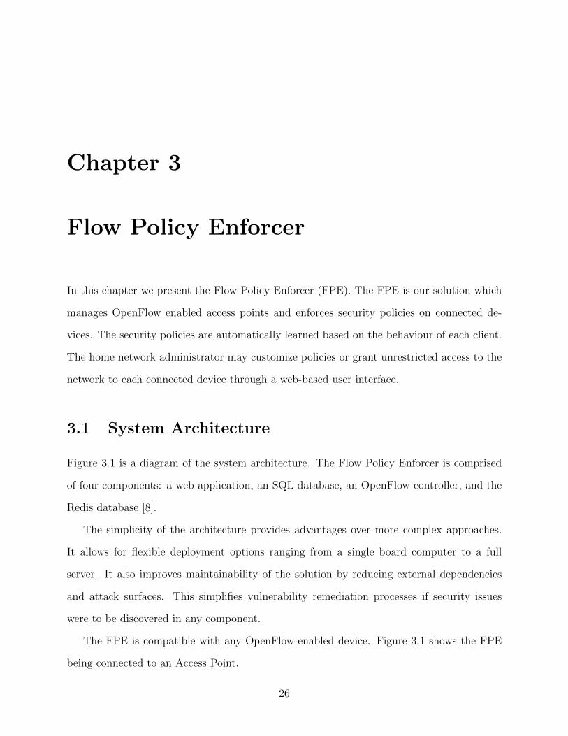
3.1 System Architecture
Figure 3.1 is a diagram of the system architecture. The Flow Policy Enforcer is comprised
of four components: a web application, an SQL database, an OpenFlow controller, and the
Redis database [8].
The simplicity of the architecture provides advantages over more complex approaches.
It allows for flexible deployment options ranging from a single board computer to a full
server. It also improves maintainability of the solution by reducing external dependencies
and attack surfaces. This simplifies vulnerability remediation processes if security issues
were to be discovered in any component.
The FPE is compatible with any OpenFlow-enabled device. Figure 3.1 shows the FPE
being connected to an Access Point.
26
Access PointFlow Policy Enforcer
Web ApplicationOpenFlow Controller
Redis
SQL Database
Open vSwitch
wlan0
eth0
hostapd
Figure 3.1: Architecture of the Flow Policy Enforcer.
3.2 Web Application
The web application is responsible for maintaining system state and integrity. It utilizes an
SQL database for all recorded data. The web application publishes messages to the controller
using Redis based on user interaction. For example, a message is sent to the controller via
Redis if the user decides to block all network access for a given device.
The web application provides a user interface. The interface is broken down into the
following pages:
• The access points pages provide user functionality for viewing which access points have
been managed by the FPE.
• The stations page lists devices which have been managed by the FPE. The user can
interact with this page to change device state and view rules which have been learned.
We will explore rules and device states in a later section.
• The rules page allows the user to edit sets of rules outside of a device association. This
allows a set of rules to be applied across a number of devices without requiring the
user to customize each rule for every device.
27
• The settings page provides functionality for configuring default settings for the system.
The user can configure the default state for devices connecting to the network and
customize the default learning time for devices placed in the IoT Learning state.
The web application also hosts a REST API which exposes functionality to the OpenFlow
controller. The API has two primary endpoints:
• The access points endpoint allows the controller to request an initial set of rules and
a list of managed devices from the web application. This endpoint is also used by the
controller to register a new station to a given AP. If a station has already been regis-
tered, its registration is updated to point to the newly associated AP. The registration
process is used to reduce the number of flow rules created for a given station in the
event that the system is managing multiple APs.
• The packets endpoint allows the controller to submit DNS lookups and statistics to the
web application. These data types are submitted to the web application for processing
as it is not critical to process the data quickly.
3.3 OpenFlow Controller
The OpenFlow controller interfaces between OpenFlow enabled access points, the web appli-
cation, and the SQL database. It communicates to the web application using the REST API,
receives messages from the web application via Redis queue subscriptions, and communicates
with access points using the OpenFlow protocol.
The controller maintains a persistent connection with each connected AP. When a con-
nection to an AP is created, the controller performs two main actions. First, it creates a set
of default rules on the AP. Secondly, it utilizes the access points API endpoint to request
an initial set of rules for each station which belongs to the AP. This persistent connection
is also used when the controller receives instructions to create or modify flow rules from the
web application.
28
The controller maintains a list of device states in memory. These device states are used
to determine which actions the controller should take when an unknown packet reaches
the controller through one of the default rules on the AP. If applicable, the controller will
process the packet, create a rule to permit the connection in the access point, and inject the
permitted packet through the data plane of the access point. This rule will be saved in the
SQL database as described in the next section.
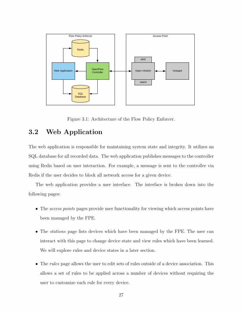
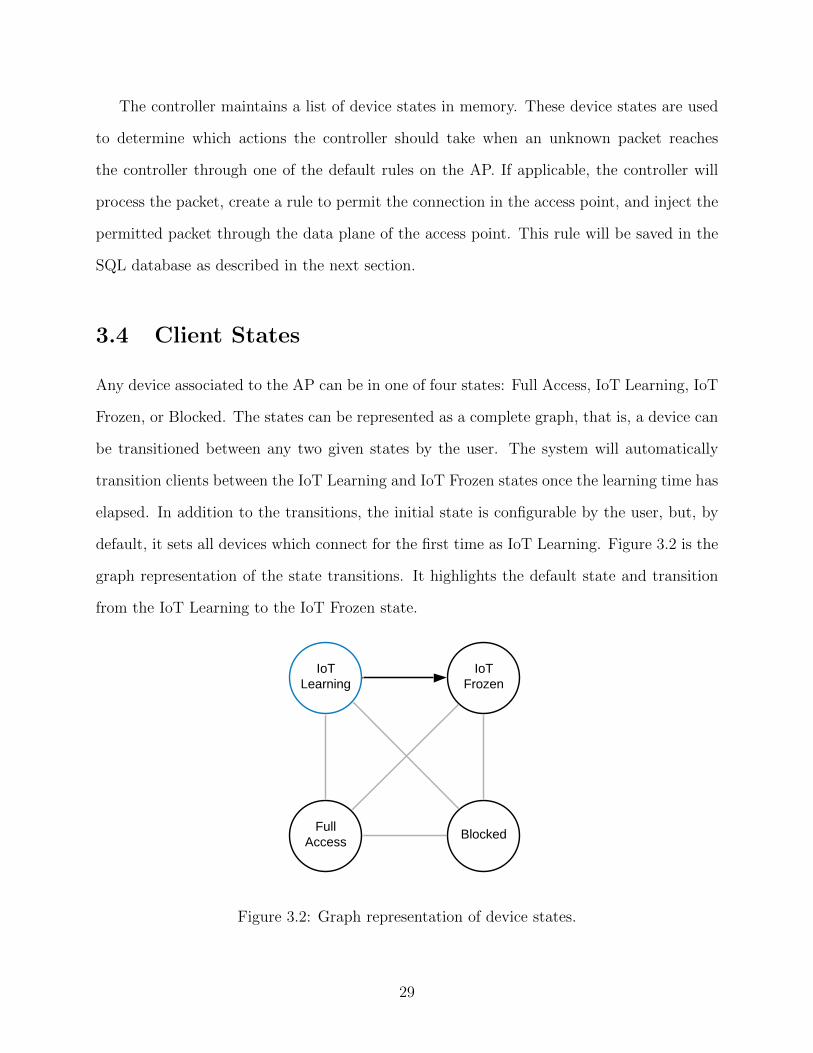
3.4 Client States
Any device associated to the AP can be in one of four states: Full Access, IoT Learning, IoT
Frozen, or Blocked. The states can be represented as a complete graph, that is, a device can
be transitioned between any two given states by the user. The system will automatically
transition clients between the IoT Learning and IoT Frozen states once the learning time has
elapsed. In addition to the transitions, the initial state is configurable by the user, but, by
default, it sets all devices which connect for the first time as IoT Learning. Figure 3.2 is the
graph representation of the state transitions. It highlights the default state and transition
from the IoT Learning to the IoT Frozen state.
IoT Learning
IoT Frozen
Full Access
Blocked
Figure 3.2: Graph representation of device states.
29
We assume that IoT devices initially connected to the network are not compromised.
Additionally, we assume that they will not be compromised for a period of time. By default,
we specify the learning time as 48 hours. These assumptions are made to provide learning
time for construction of per-device policies. The automatic transition between the IoT
Learning and IoT Frozen states satisfies the automatic goal of the system.
Full Access allows the device to have unrestricted access to local and external networks.
This is provided as an option in case the user connects a laptop or other device for which
they do not want to restrict access. The Blocked state creates a drop rule for the specified
device to prevent it from sending or receiving data on the network.
3.5 Device Policies
Each device being monitored is assigned a unique policy. A policy is a collection of rule
sets. Each rule set is a collection of rules. By default, every policy has a default learning
policy where automatically learned rules are recorded. Optionally, users can create custom
rule sets and apply them to multiple policies.
A rule is the collection of parameters which define allowed communication paths for the
device. Each rule is constructed of the following elements: source MAC address, destination
MAC address, source IP address, destination IP address, port, protocol (TCP or UDP),
and direction (inbound or outbound). The direction is used to configure the port on the
correct OpenFlow rule due to source port randomization. On outgoing connections from the
IoT device, the port is compared to the destination port of the external server. Conversely,
on incoming connections to an IoT device, the port is compared to the destination port to
the IoT device. The technical details of each rule are abstracted from the user in the web
interface. The devices can be assigned a custom name and icon. If the user goes into the
rule modification view, they can see the full details of each rule.
While a device is in IoT Learning state, the FPE module constructs policies by creating
30
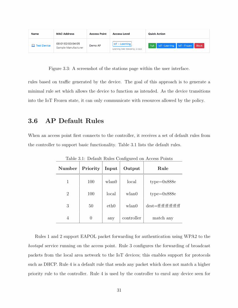
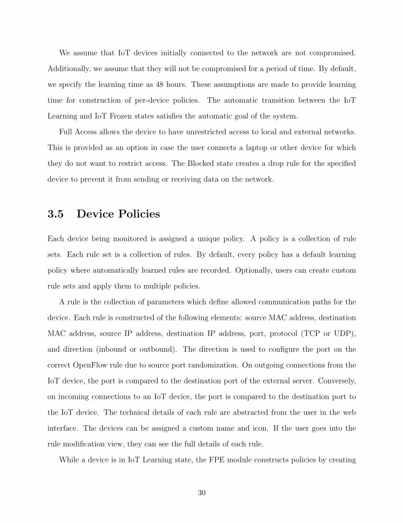
Figure 3.3: A screenshot of the stations page within the user interface.
rules based on traffic generated by the device. The goal of this approach is to generate a
minimal rule set which allows the device to function as intended. As the device transitions
into the IoT Frozen state, it can only communicate with resources allowed by the policy.
3.6 AP Default Rules
When an access point first connects to the controller, it receives a set of default rules from
the controller to support basic functionality. Table 3.1 lists the default rules.
Table 3.1: Default Rules Configured on Access Points
Number Priority Input Output Rule
1 100 wlan0 local type=0x888e
2 100 local wlan0 type=0x888e
3 50 eth0 wlan0 dest=ff:ff:ff:ff:ff:ff
4 0 any controller match any
Rules 1 and 2 support EAPOL packet forwarding for authentication using WPA2 to the
hostapd service running on the access point. Rule 3 configures the forwarding of broadcast
packets from the local area network to the IoT devices; this enables support for protocols
such as DHCP. Rule 4 is a default rule that sends any packet which does not match a higher
priority rule to the controller. Rule 4 is used by the controller to enrol any device seen for
31
the first time with the FPE. It also enables the controller to handle packets which do not
match other rules.
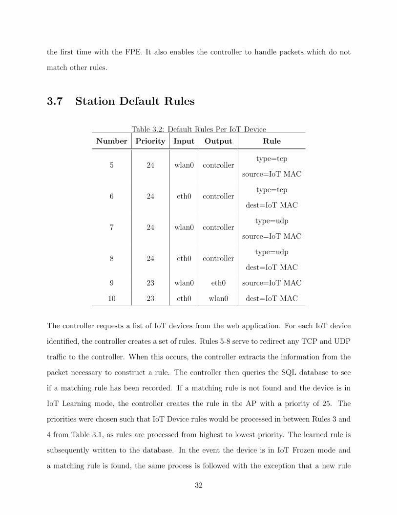
3.7 Station Default Rules
Table 3.2: Default Rules Per IoT Device
Number Priority Input Output Rule
5 24 wlan0 controllertype=tcp
source=IoT MAC
6 24 eth0 controllertype=tcp
dest=IoT MAC
7 24 wlan0 controllertype=udp
source=IoT MAC
8 24 eth0 controllertype=udp
dest=IoT MAC
9 23 wlan0 eth0 source=IoT MAC
10 23 eth0 wlan0 dest=IoT MAC
The controller requests a list of IoT devices from the web application. For each IoT device
identified, the controller creates a set of rules. Rules 5-8 serve to redirect any TCP and UDP
traffic to the controller. When this occurs, the controller extracts the information from the
packet necessary to construct a rule. The controller then queries the SQL database to see
if a matching rule has been recorded. If a matching rule is not found and the device is in
IoT Learning mode, the controller creates the rule in the AP with a priority of 25. The
priorities were chosen such that IoT Device rules would be processed in between Rules 3 and
4 from Table 3.1, as rules are processed from highest to lowest priority. The learned rule is
subsequently written to the database. In the event the device is in IoT Frozen mode and
a matching rule is found, the same process is followed with the exception that a new rule
32
is not written to the database. An idle timeout of 30 minutes is configured on IoT rules to
reduce the set of rules maintained in the access point. The rule is removed from the flow
table if a packet matching the rule has not been processed within the idle timeout.
Rules 9-10 allow other types of traffic between the station and the network such as ARP
and ICMP. It would be possible to expand on Rules 9-10 to make them more restrictive in
the future.
3.8 DNS Support
Restricting rules to IP addresses may be problematic when devices use DNS, as the desti-
nation IP address may change on future connections. In order to address this challenge, the
system dynamically tracks DNS responses and associates domain names with rules.
When the FPE creates an allow rule for UDP on port 53 on the inbound direction to an
IoT device, it creates a flow rule with a set of actions. First, the packet is sent to the IoT
device. Next, a VLAN tag is added to the packet and the packet is sent to the controller.
When the controller receives a packet and parses the VLAN tag, it sends the domain names
contained within the response to the web application. The web application records the IP
addresses associated to the domain name. This allows the web application to compare new
connection requests from IoT devices to both the initially-seen IP addresses and the IP
addresses associated with the domain name in the datastore.
33
Chapter 4
Implementation
In this chapter we discuss the implementation of the Flow Policy Enforcer. We designed and
implemented two main components of the system; the web application and the OpenFlow
controller. The web application primarily provides user functionality, such as managing
device policies or customizing permitted flows. The OpenFlow Controller is responsible for
communicating with Open vSwitch instances.
4.1 Web Application
4.1.1 Overview
The web application was written in Ruby on Rails, running on Ruby version 2.6.3 with the
Rails framework version 6.0.0. Ruby on Rails is a web development framework utilizing
the Ruby programming language. It is based on the Model View Controller (MVC) design
pattern [11]. Key features of Rails include application routing, built-in database manage-
ment, and view templating. This framework was chosen for cross compatibility across many
platforms. The FontAwesome [4] library was used for displaying intuitive icons in the user
interface.
34
4.1.2 User Interface
We performed a full implementation of the FPE for evaluation purposes. The implementation
(including views, models, and controllers) is 1771 lines of code. The web application allows
the user to view APs, stations, rules, and settings. Figure 3.3 is a screenshot from the
stations page within the user interface. This page shows information such as the device,
MAC address, manufacturer, and device state. The Quick Action buttons allow the user to
transition the device between any of the states.
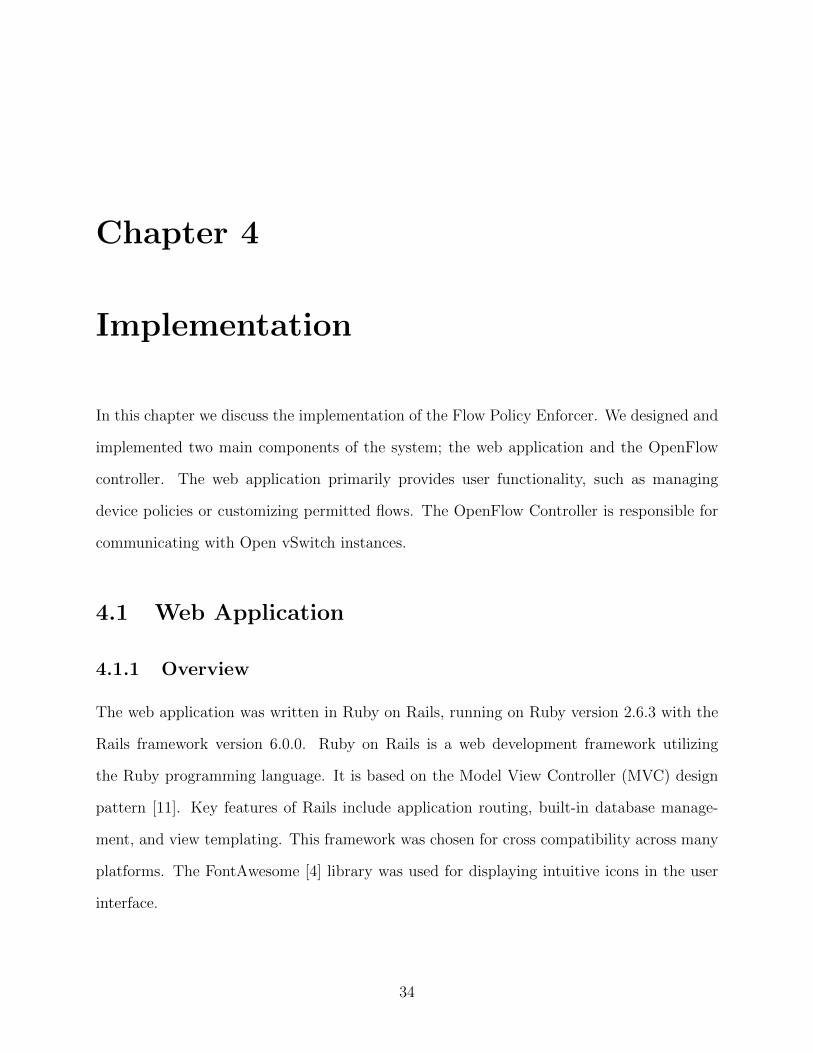
The user may select any station and view, modify, and delete the rules which restrict
the device to given flows once in the IoT Frozen state. Usage information for each rule is
gathered from the AP and displayed to the user. Figure 4.1 is a screenshot from the user
interface and shows the bandwidth usage of one iPerf3 [7] session between a station and a
server running on the LAN. The UI displays Home Network as the connection type as the
IP address belongs in the RFC1918 [66] range. Otherwise, it would display Internet.
Figure 4.1: Screenshot of rule representation and usage information.
Additionally, the user may modify the default learning time for IoT devices and the
default state for new devices connecting to the access point. The system defaults to IoT
Learning with 48 hours of learning time in order to provide secure default configurations.
4.1.3 API Endpoints
The web application hosts an API which is utilized by the OpenFlow controller. The API
endpoints send and receive data using JavaScript Object Notation (JSON) [18]. When Rails
receives a request with type application/json, it automatically converts the data into an
object.
35
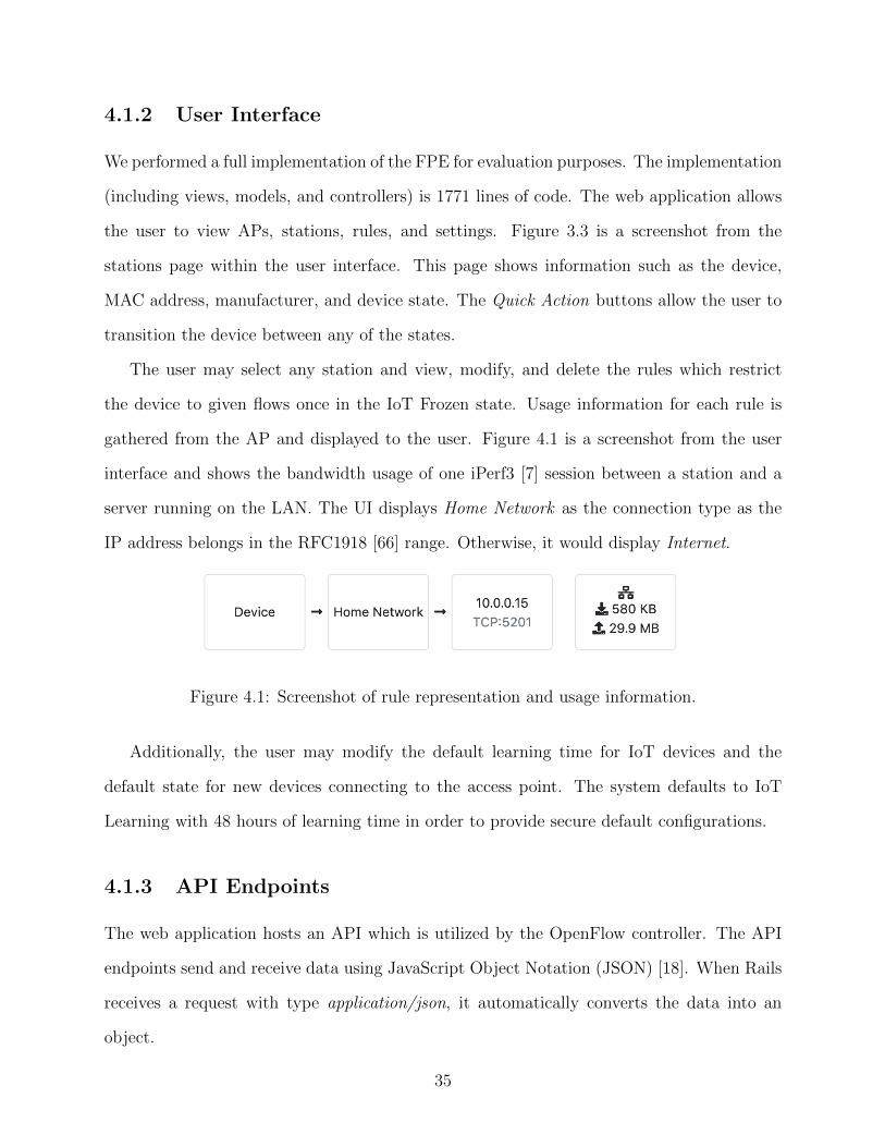
module Apimodule V0
c l a s s Packe t sCont ro l l e r < Api : : V0 : : Ap iContro l l e r. . .
de f dnss t a t i o n = Stat i on . f i nd by ( mac address : params [ : StationMAC
] )
i f s t a t i o n . blank ?render j son : ’ f a i l ’r e turn
end
re sponse s = params [ : DNSResponses ]DnsQuery . c r e a t e f r o m r e s p o n s e s ( responses , s t a t i o n )
render j son : ’ ok ’end
. . .end
endend
Figure 4.2: Sample code from the web application.
36
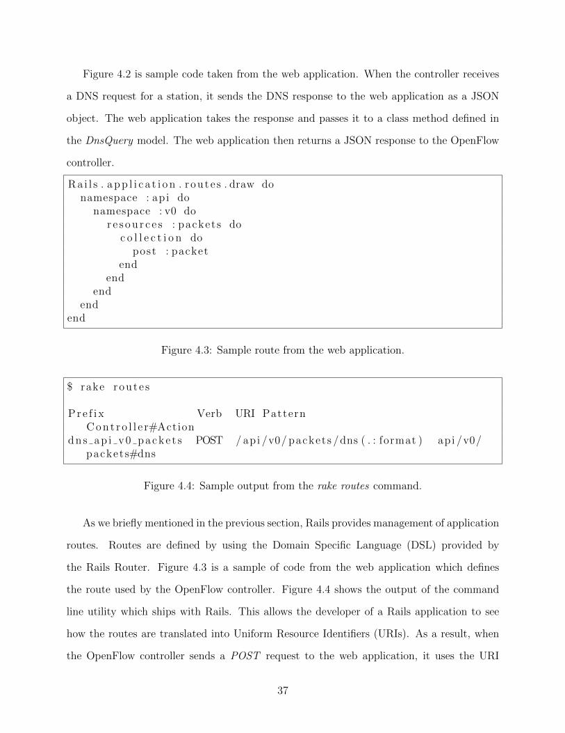
Figure 4.2 is sample code taken from the web application. When the controller receives
a DNS request for a station, it sends the DNS response to the web application as a JSON
object. The web application takes the response and passes it to a class method defined in
the DnsQuery model. The web application then returns a JSON response to the OpenFlow
controller.
Ra i l s . a p p l i c a t i o n . route s . draw donamespace : ap i do
namespace : v0 dor e s o u r c e s : packets do
c o l l e c t i o n dopost : packet
endend
endend
end
Figure 4.3: Sample route from the web application.
$ rake route s
Pr e f i x Verb URI PatternC o n t r o l l e r#Action
dns ap i v0 packe t s POST / api /v0/ packets /dns ( . : format ) api /v0/packets#dns
Figure 4.4: Sample output from the rake routes command.
As we briefly mentioned in the previous section, Rails provides management of application
routes. Routes are defined by using the Domain Specific Language (DSL) provided by
the Rails Router. Figure 4.3 is a sample of code from the web application which defines
the route used by the OpenFlow controller. Figure 4.4 shows the output of the command
line utility which ships with Rails. This allows the developer of a Rails application to see
how the routes are translated into Uniform Resource Identifiers (URIs). As a result, when
the OpenFlow controller sends a POST request to the web application, it uses the URI
37
http://127.0.0.1/api/v0/packets/dns.
4.2 OpenFlow Controller
The controller is a custom controller written in the Go programming language. It uses the
gopacket [6], gofc [5], and gorm [13] libraries for packet serialization, OpenFlow communica-
tion, and database communication. Not counting the external dependencies, the controller is
1604 lines of code, including whitespace and comments. Go compiles to a native executable
and allowed us to achieve a small memory footprint in comparison to other commonly used
OpenFlow controllers based off of the Java programming language. Go, in combination with
the aforementioned libraries, facilitates working with packet data and TCP connections,
such as the OpenFlow datapath. The ability to customize all OpenFlow actions enables the
controller to perform actions tailored to the FPE design.
4.2.1 Data Flow
Figure 4.5 is a sequence diagram representing the communication flow for packets being
processed by the FPE for the purpose of learning or enforcing a policy. In this case, there
are no rules for forwarding the packet installed in the Open vSwitch instance on the AP and
in this example the packet matches Rule 4 from the previous section.
38
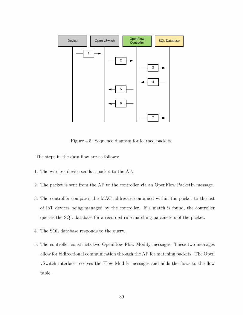
Device Open vSwitchOpenFlow Controller
SQL Database
1
2
3
5
4
6
7
Figure 4.5: Sequence diagram for learned packets.
The steps in the data flow are as follows:
1. The wireless device sends a packet to the AP.
2. The packet is sent from the AP to the controller via an OpenFlow PacketIn message.
3. The controller compares the MAC addresses contained within the packet to the list
of IoT devices being managed by the controller. If a match is found, the controller
queries the SQL database for a recorded rule matching parameters of the packet.
4. The SQL database responds to the query.
5. The controller constructs two OpenFlow Flow Modify messages. These two messages
allow for bidirectional communication through the AP for matching packets. The Open
vSwitch interface receives the Flow Modify messages and adds the flows to the flow
table.
39
6. The OpenFlow Controller constructs an OpenFlow PacketOut message with the packet
contained within the PacketIn message. This message is sent to the AP and the packet
is sent from the data plane in the device.
7. The OpenFlow Controller records the rule in the SQL database.
Steps 1-6 are followed for devices in the IoT Learning or IoT Frozen states. Step 7 would
not occur for a device in the IoT Frozen state. Additionally, steps 3-7 would not occur if a
matching rule was not found in the event the device is in the IoT Frozen state.
4.2.2 Concurrency
The OpenFlow controller is responsible for controlling the flow tables of all connected access
points. This places high performance demands on the controller as it must be able to quickly
process all requests. The gofc library was modified to improve performance when handling
a large number of incoming OpenFlow messages.
The Go programming language contains a feature called goroutines. Goroutines differ
from traditional threads provided by an operating system. When a Go process starts, it
creates a number of traditional threads and limits the number of threads executing at a
time to the number of cores on the system [12]. Goroutines are scheduled to run across the
available threads associated to the executable. If a goroutine reaches a blocking condition,
such as waiting on I/O from the operating system, other goroutines will be scheduled to
execute.
Channels are the primary mechanism for communication across goroutines. They can
function as a blocking queue for messages between goroutines and it is possible for a goroutine
to block on a channel read until a message is available.
The following goroutines are implemented in the OpenFlow Controller:
• Packet Bufferrer : This routine is responsible for reading all incoming messages from
the OpenFlow connection to the Open vSwitch instance. It maintains a rolling buffer
40
for incoming data and parses out complete OpenFlow messages from the TCP socket.
It adds messages to an internal channel for the Packet Processor.
• Packet Processor : This routine reads incoming OpenFlow messages and performs ac-
tions based on the incoming packet. If the packet is from a new IoT device associated
to the AP, it registers the station with the web application. If it is an existing IoT
device, it queues the incoming packet for the Packet Streamer.
• Packet Streamer : This routine performs all rule matching based on the packets received
from the Packet Processor. If the IoT device is in learning mode, it sends a message to
the Rule Writer. The Packet Streamer then continues to create OpenFlow messages
to permit the flows and inject the message. These are sent as messages to the Packet
Sender.
• Rule Writer : This routine is responsible for writing all learned rules to the SQL
database. This runs as a single goroutine so that it can ensure no duplicate rules
are written. It also prevents processing delays and waiting on write confirmations
from the SQL database.
• Packet Sender : This routine is responsible for sending OpenFlow messages to the
associated Open vSwitch instance. It receives messages via a message queue and writes
them out over the TCP socket one message at a time. This is done to prevent packets
from being delivered out of order to the AP. Additionally, problems can arise if multiple
goroutines attempt to write to a single TCP socket as the write operation may not be
thread-safe.
• Statistics Gatherer : Every 30 seconds, this routine sends an OpenFlow StatsRequest
to connected Open vSwitch instances. The StatsReply is then processed and sent to
the web application. This is tracked against each rule in the SQL database and allows
the user to view how much data is being transmitted over each individual rule.
41
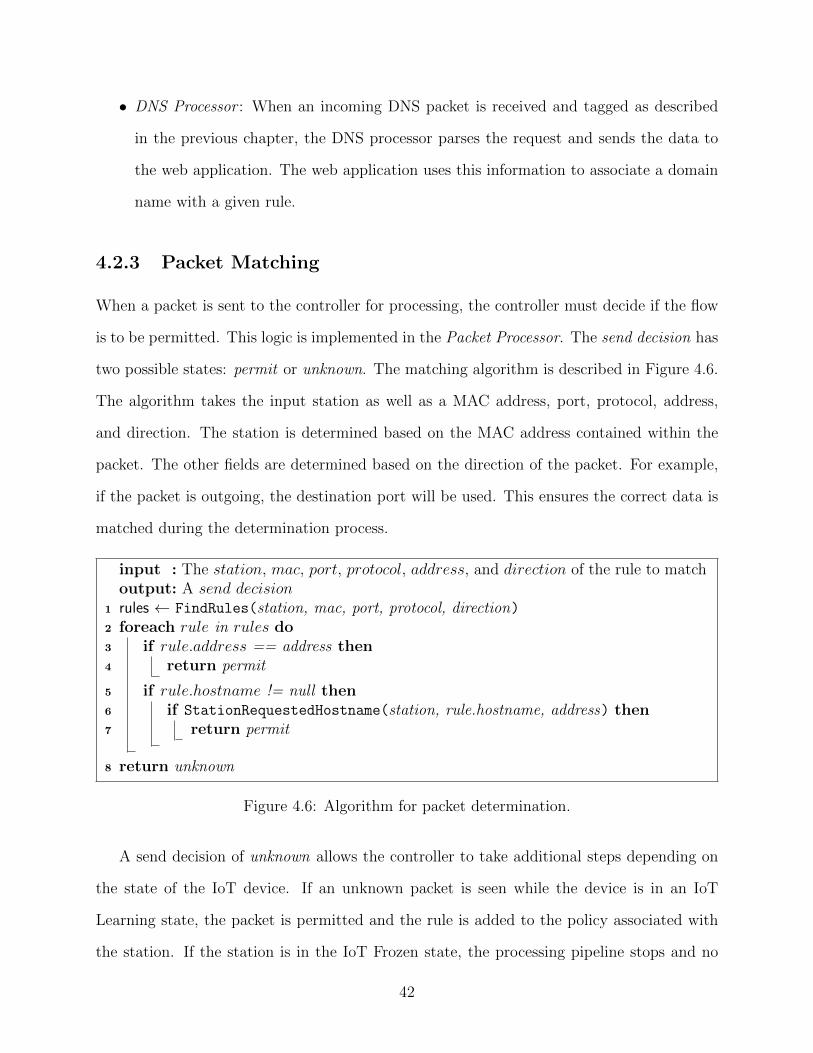
• DNS Processor : When an incoming DNS packet is received and tagged as described
in the previous chapter, the DNS processor parses the request and sends the data to
the web application. The web application uses this information to associate a domain
name with a given rule.
4.2.3 Packet Matching
When a packet is sent to the controller for processing, the controller must decide if the flow
is to be permitted. This logic is implemented in the Packet Processor. The send decision has
two possible states: permit or unknown. The matching algorithm is described in Figure 4.6.
The algorithm takes the input station as well as a MAC address, port, protocol, address,
and direction. The station is determined based on the MAC address contained within the
packet. The other fields are determined based on the direction of the packet. For example,
if the packet is outgoing, the destination port will be used. This ensures the correct data is
matched during the determination process.
input : The station, mac, port, protocol, address, and direction of the rule to matchoutput: A send decision
1 rules ← FindRules(station, mac, port, protocol, direction)2 foreach rule in rules do3 if rule.address == address then4 return permit
5 if rule.hostname != null then6 if StationRequestedHostname(station, rule.hostname, address) then7 return permit
8 return unknown
Figure 4.6: Algorithm for packet determination.
A send decision of unknown allows the controller to take additional steps depending on
the state of the IoT device. If an unknown packet is seen while the device is in an IoT
Learning state, the packet is permitted and the rule is added to the policy associated with
the station. If the station is in the IoT Frozen state, the processing pipeline stops and no
42
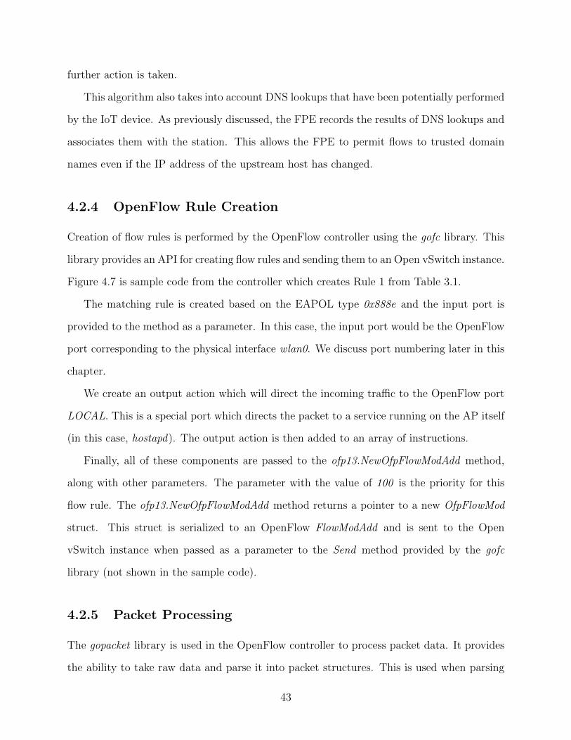
further action is taken.
This algorithm also takes into account DNS lookups that have been potentially performed
by the IoT device. As previously discussed, the FPE records the results of DNS lookups and
associates them with the station. This allows the FPE to permit flows to trusted domain
names even if the IP address of the upstream host has changed.
4.2.4 OpenFlow Rule Creation
Creation of flow rules is performed by the OpenFlow controller using the gofc library. This
library provides an API for creating flow rules and sending them to an Open vSwitch instance.
Figure 4.7 is sample code from the controller which creates Rule 1 from Table 3.1.
The matching rule is created based on the EAPOL type 0x888e and the input port is
provided to the method as a parameter. In this case, the input port would be the OpenFlow
port corresponding to the physical interface wlan0. We discuss port numbering later in this
chapter.
We create an output action which will direct the incoming traffic to the OpenFlow port
LOCAL. This is a special port which directs the packet to a service running on the AP itself
(in this case, hostapd). The output action is then added to an array of instructions.
Finally, all of these components are passed to the ofp13.NewOfpFlowModAdd method,
along with other parameters. The parameter with the value of 100 is the priority for this
flow rule. The ofp13.NewOfpFlowModAdd method returns a pointer to a new OfpFlowMod
struct. This struct is serialized to an OpenFlow FlowModAdd and is sent to the Open
vSwitch instance when passed as a parameter to the Send method provided by the gofc
library (not shown in the sample code).
4.2.5 Packet Processing
The gopacket library is used in the OpenFlow controller to process packet data. It provides
the ability to take raw data and parse it into packet structures. This is used when parsing
43
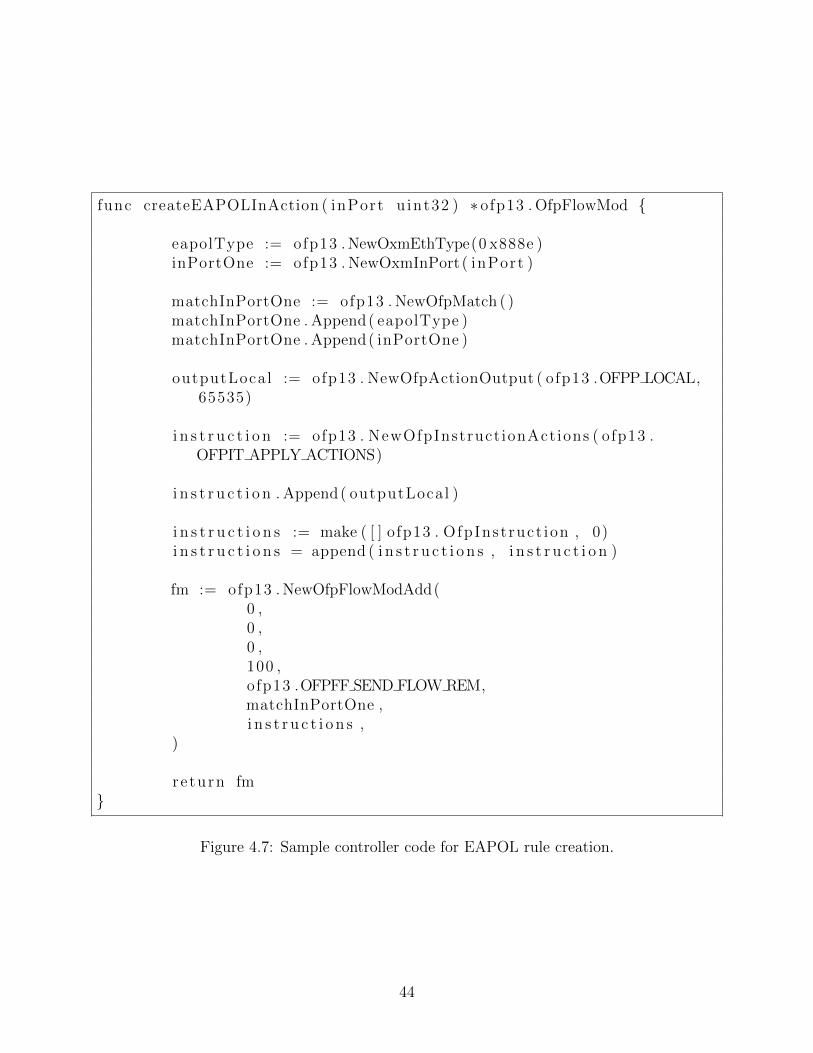
func createEAPOLInAction ( inPort u int32 ) ∗ ofp13 . OfpFlowMod {
eapolType := ofp13 . NewOxmEthType(0 x888e )inPortOne := ofp13 . NewOxmInPort ( inPort )
matchInPortOne := ofp13 . NewOfpMatch ( )matchInPortOne . Append( eapolType )matchInPortOne . Append( inPortOne )
outputLocal := ofp13 . NewOfpActionOutput ( ofp13 .OFPP LOCAL,65535)
i n s t r u c t i o n := ofp13 . NewOfpInstruct ionActions ( ofp13 .OFPIT APPLY ACTIONS)
i n s t r u c t i o n . Append( outputLocal )
i n s t r u c t i o n s := make ( [ ] ofp13 . OfpInst ruct ion , 0)i n s t r u c t i o n s = append ( i n s t r u c t i o n s , i n s t r u c t i o n )
fm := ofp13 . NewOfpFlowModAdd(0 ,0 ,0 ,100 ,ofp13 .OFPFF SEND FLOW REM,matchInPortOne ,i n s t r u c t i o n s ,
)
r e turn fm}
Figure 4.7: Sample controller code for EAPOL rule creation.
44
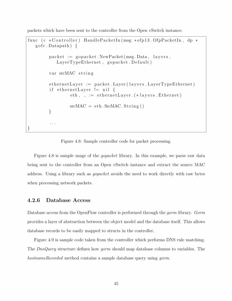
packets which have been sent to the controller from the Open vSwitch instance.
func ( c ∗C o n t r o l l e r ) HandlePacketIn (msg ∗ ofp13 . OfpPacketIn , dp ∗go f c . Datapath ) {
packet := gopacket . NewPacket (msg . Data , l a y e r s .LayerTypeEthernet , gopacket . Defau l t )
var srcMAC s t r i n g
ethernetLayer := packet . Layer ( l a y e r s . LayerTypeEthernet )i f e thernetLayer != n i l {
eth , := ethernetLayer . ( ∗ l a y e r s . Ethernet )
srcMAC = eth .SrcMAC. St r ing ( )}
. . .}
Figure 4.8: Sample controller code for packet processing.
Figure 4.8 is sample usage of the gopacket library. In this example, we parse raw data
being sent to the controller from an Open vSwitch instance and extract the source MAC
address. Using a library such as gopacket avoids the need to work directly with raw bytes
when processing network packets.
4.2.6 Database Access
Database access from the OpenFlow controller is performed through the gorm library. Gorm
provides a layer of abstraction between the object model and the database itself. This allows
database records to be easily mapped to structs in the controller.
Figure 4.9 is sample code taken from the controller which performs DNS rule matching.
The DnsQuery structure defines how gorm should map database columns to variables. The
hostnameRecorded method contains a sample database query using gorm.
45
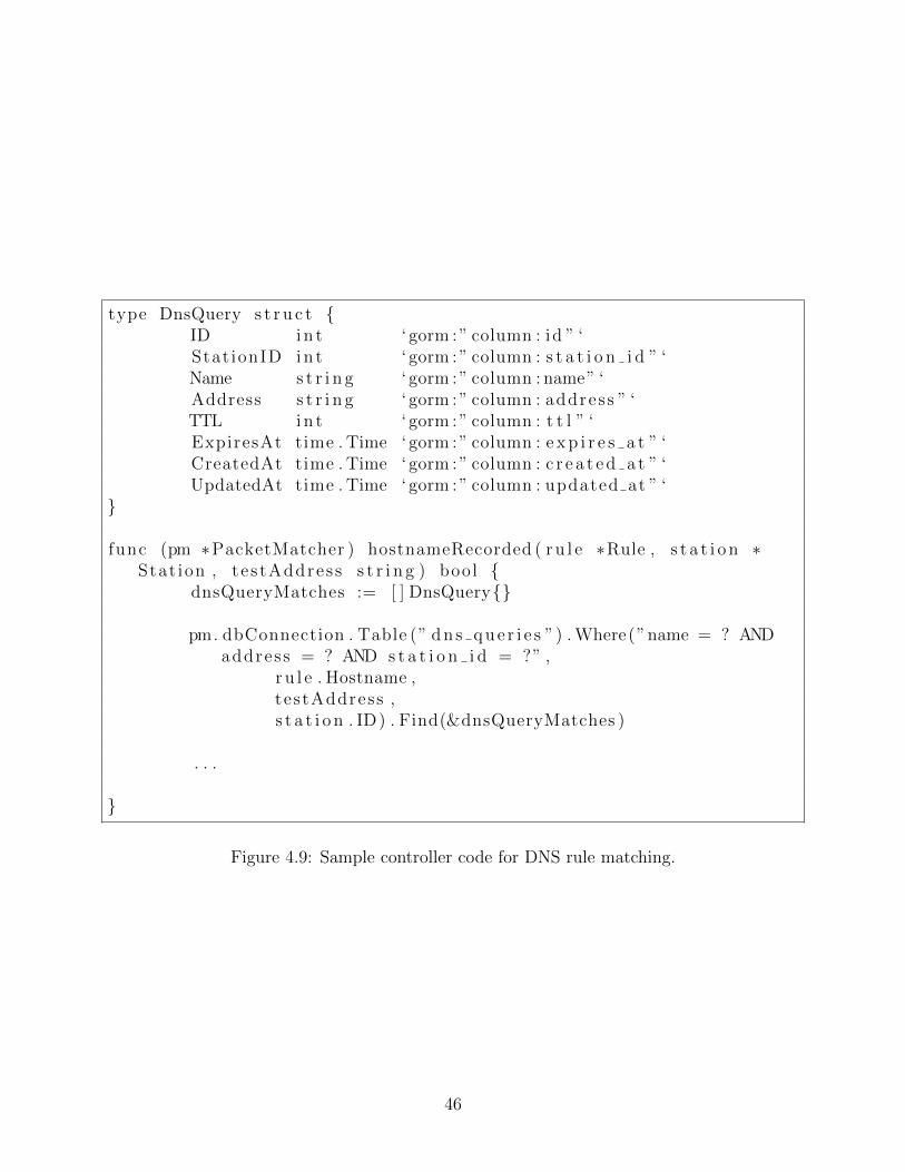
type DnsQuery s t r u c t {ID i n t ‘ gorm : ” column : id ” ‘Stat ionID i n t ‘ gorm : ” column : s t a t i o n i d ” ‘Name s t r i n g ‘ gorm : ” column : name” ‘Address s t r i n g ‘ gorm : ” column : address ” ‘TTL i n t ‘ gorm : ” column : t t l ” ‘ExpiresAt time . Time ‘ gorm : ” column : e x p i r e s a t ” ‘CreatedAt time . Time ‘ gorm : ” column : c r e a t e d a t ” ‘UpdatedAt time . Time ‘ gorm : ” column : updated at ” ‘
}
func (pm ∗PacketMatcher ) hostnameRecorded ( r u l e ∗Rule , s t a t i o n ∗Stat ion , te s tAddres s s t r i n g ) bool {
dnsQueryMatches := [ ] DnsQuery{}
pm. dbConnection . Table (” d n s q u e r i e s ”) . Where (”name = ? ANDaddress = ? AND s t a t i o n i d = ?” ,
r u l e . Hostname ,testAddress ,s t a t i o n . ID) . Find(&dnsQueryMatches )
. . .
}
Figure 4.9: Sample controller code for DNS rule matching.
46
4.3 Challenges
A number of challenges were faced during the implementation of the system.
4.3.1 Packet Loss
In an early implementation, the packet was passed from the OpenFlow controller to the web
application for processing and the PacketOut message was not utilized. As a result, the
first packet of each flow being lost and required the source to resend the packet. This led to
significant delays as it relied on the source operating system to retry the connection after the
flow was installed in the Open vSwitch. Persisting the packet in the OpenFlow controller
until a decision was made and then injecting it into the data plane of the Open vSwitch
alleviated this issue.
4.3.2 Bidirectional Data Flow
Each rule in the policy results in two flows being installed in the Open vSwitch instance. This
also requires the flow to be constructed from the perspective of the ingress and egress port.
For example, assume a device is connecting through the AP to a server. When the ingress
port is the wireless interface, the source MAC is the device and the destination MAC is the
server. When the ingress port is the ethernet interface, the source MAC is the server and the
destination MAC is the device. Application logic was written to create the least-permissive
flow rule with respect to the ingress and egress port.
4.3.3 Code Efficiency
Packet processing must be efficient in order to minimize impact to devices. Significant effort
went into the codebase and methods chosen to minimize the processing time within the
OpenFlow controller and the web application.
The OpenFlow controller consists of many concurrent routines. It balances the demands
47
of receiving packets from the Open vSwitch device, deciding whether packets are to be
permitted based on policies in the database, creating flow rules, injecting packets into the
data plane, gathering statistics, and intercepting DNS responses. Careful consideration went
into designing the concurrency model of the application.
4.4 Deployment
The FPE supports two deployment models. It can be run on a server and used with any
OpenFlow enabled AP in the network. It can also be deployed on a device configured to run
both the FPE and an AP, such as a Raspberry Pi. This flexible design allows the FPE to
protect any IoT device which operates as a client to 802.11 wireless networks. Monitoring
communications at the AP enables the system to prevent compromised IoT devices from
attacking internal and external resources.
The ability to use FPE with any available hardware without customizing any protocols
satisfies the goal of having a vendor agnostic solution. The user can elect to use FPE with the
vendor of their choice or run it on low-cost hardware. Additionally, the goal for compatibility
is achieved through the use of OpenFlow and well-defined protocols.
4.4.1 Standalone Device
When the FPE is deployed as a functioning AP and OpenFlow controller, it contains all of
the components in Table 3.1. We perform an evaluation of this deployment on a Raspberry
Pi 4 later in this thesis.
Configuring the Raspberry Pi for standalone deployment requires manual configuration
on top of the base Raspbian OS. In a production setting, these steps could be automated
for the home user. The commands used to install Open vSwitch and configure it are shown
in Figure 4.10.
Open vSwitch is installed using the apt-get command. Once installed, Open vSwitch
48
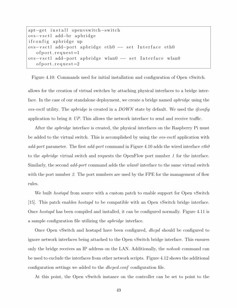
apt−get i n s t a l l openvswitch−switchovs−v s c t l add−br apbr idgei f c o n f i g apbr idge upovs−v s c t l add−port apbr idge eth0 −− s e t I n t e r f a c e eth0
o f p o r t r e q u e s t=1ovs−v s c t l add−port apbr idge wlan0 −− s e t I n t e r f a c e wlan0
o f p o r t r e q u e s t=2
Figure 4.10: Commands used for initial installation and configuration of Open vSwitch.
allows for the creation of virtual switches by attaching physical interfaces to a bridge inter-
face. In the case of our standalone deployment, we create a bridge named apbridge using the
ovs-vsctl utility. The apbridge is created in a DOWN state by default. We used the ifconfig
application to bring it UP. This allows the network interface to send and receive traffic.
After the apbridge interface is created, the physical interfaces on the Raspberry Pi must
be added to the virtual switch. This is accomplished by using the ovs-vsctl application with
add-port parameter. The first add-port command in Figure 4.10 adds the wired interface eth0
to the apbridge virtual switch and requests the OpenFlow port number 1 for the interface.
Similarly, the second add-port command adds the wlan0 interface to the same virtual switch
with the port number 2. The port numbers are used by the FPE for the management of flow
rules.
We built hostapd from source with a custom patch to enable support for Open vSwitch
[15]. This patch enables hostapd to be compatible with an Open vSwitch bridge interface.
Once hostapd has been compiled and installed, it can be configured normally. Figure 4.11 is
a sample configuration file utilizing the apbridge interface.
Once Open vSwitch and hostapd have been configured, dhcpd should be configured to
ignore network interfaces being attached to the Open vSwitch bridge interface. This ensures
only the bridge receives an IP address on the LAN. Additionally, the nohook command can
be used to exclude the interfaces from other network scripts. Figure 4.12 shows the additional
configuration settings we added to the dhcpcd.conf configuration file.
At this point, the Open vSwitch instance on the controller can be set to point to the
49
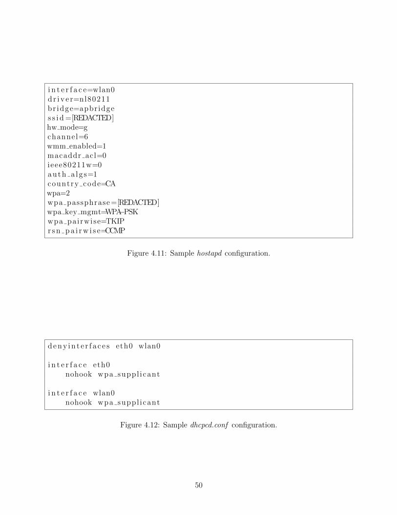
i n t e r f a c e=wlan0d r i v e r=nl80211br idge=apbr idges s i d =[REDACTED]hw mode=gchannel=6wmm enabled=1macaddr acl=0ieee80211w=0auth a l g s=1country code=CAwpa=2wpa passphrase =[REDACTED]wpa key mgmt=WPA−PSKwpa pairwise=TKIPr s n p a i r w i s e=CCMP
Figure 4.11: Sample hostapd configuration.
d e n y i n t e r f a c e s eth0 wlan0
i n t e r f a c e eth0nohook wpa suppl icant
i n t e r f a c e wlan0nohook wpa suppl icant
Figure 4.12: Sample dhcpcd.conf configuration.
50
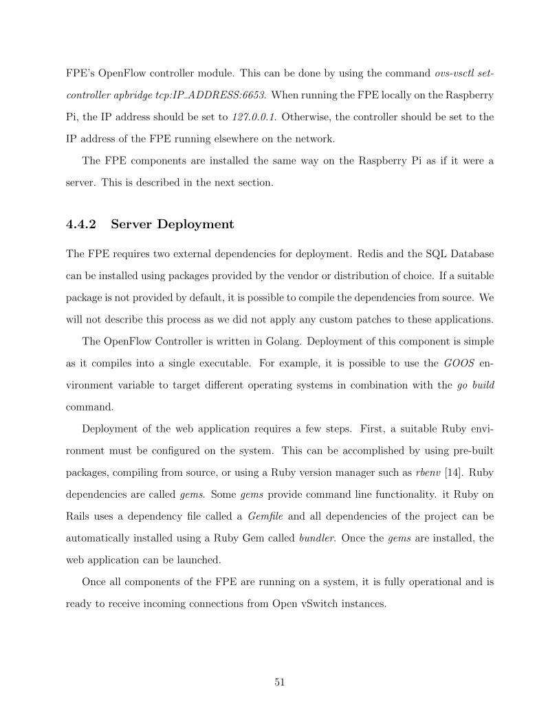
FPE’s OpenFlow controller module. This can be done by using the command ovs-vsctl set-
controller apbridge tcp:IP ADDRESS:6653. When running the FPE locally on the Raspberry
Pi, the IP address should be set to 127.0.0.1. Otherwise, the controller should be set to the
IP address of the FPE running elsewhere on the network.
The FPE components are installed the same way on the Raspberry Pi as if it were a
server. This is described in the next section.
4.4.2 Server Deployment
The FPE requires two external dependencies for deployment. Redis and the SQL Database
can be installed using packages provided by the vendor or distribution of choice. If a suitable
package is not provided by default, it is possible to compile the dependencies from source. We
will not describe this process as we did not apply any custom patches to these applications.
The OpenFlow Controller is written in Golang. Deployment of this component is simple
as it compiles into a single executable. For example, it is possible to use the GOOS en-
vironment variable to target different operating systems in combination with the go build
command.
Deployment of the web application requires a few steps. First, a suitable Ruby envi-
ronment must be configured on the system. This can be accomplished by using pre-built
packages, compiling from source, or using a Ruby version manager such as rbenv [14]. Ruby
dependencies are called gems. Some gems provide command line functionality. it Ruby on
Rails uses a dependency file called a Gemfile and all dependencies of the project can be
automatically installed using a Ruby Gem called bundler. Once the gems are installed, the
web application can be launched.
Once all components of the FPE are running on a system, it is fully operational and is
ready to receive incoming connections from Open vSwitch instances.
51
Chapter 5
Security Analysis
5.1 Overview
As we have discussed in the introduction, introducing network devices into an environment
increases the complexity and attack surface of the network itself. This increase in complexity
and attack surfaces introduces additional risk to the environment. In this chapter, we will
evaluate the security of the FPE design following two industry standard methods. First,
we will conduct a threat model and analysis of the project based on the OWASP Threat
Modelling Cheat Sheet [60] and the draft of the NIST 800-154 [36], Guide to Data-Centric
System Threat Modelling. Secondly, we will assess the design and implementation of the FP
against the NIST 800-53 framework. We will briefly discuss the results of these activities
and how this assessment displays the value of the Flow Policy Enforcer in a home network
setting.
52
5.2 Threat Modelling
5.2.1 Overview
Threat modelling is a comprehensive process used to understand the risks to the security of
an information system. At a high level, it involves the following steps:
• Identification of the system boundary: The system boundary is comprised of all com-
ponents under the control of the system designer or administrator and excludes the
components to which the system may be connected but not under ownership of the
system designer or administrator. [16]
• Identification of data flows: Once the system boundary has been defined, the data
flows of the information system should be added to the model. While it is important
to identify entry and exit points of the system, it is also important to consider data
communication flows within the system.
• Identification of threat agents: A threat agent is someone that may cause harm to the
information system. There are two varieties of threat agents: internal and external.
– Internal threat agents are individuals that are intended to have access to the
system, but may be a threat through either non-malicious or malicious intent.
For example, an authorized user of a network firewall opening ports without
understanding the implications may be a non-malicious user introducing risks to
the system. A malicious authorized user may try to use techniques to expand
their access beyond what is necessary to perform their duties. [17]
– External threat agents are individuals who wish to cause harm to the system. In
some cases, they may be an individual performing automated scans of networks
throughout the internet. In other cases, an external threat agent may be an
adversary targeting a specific individual or organization.
53
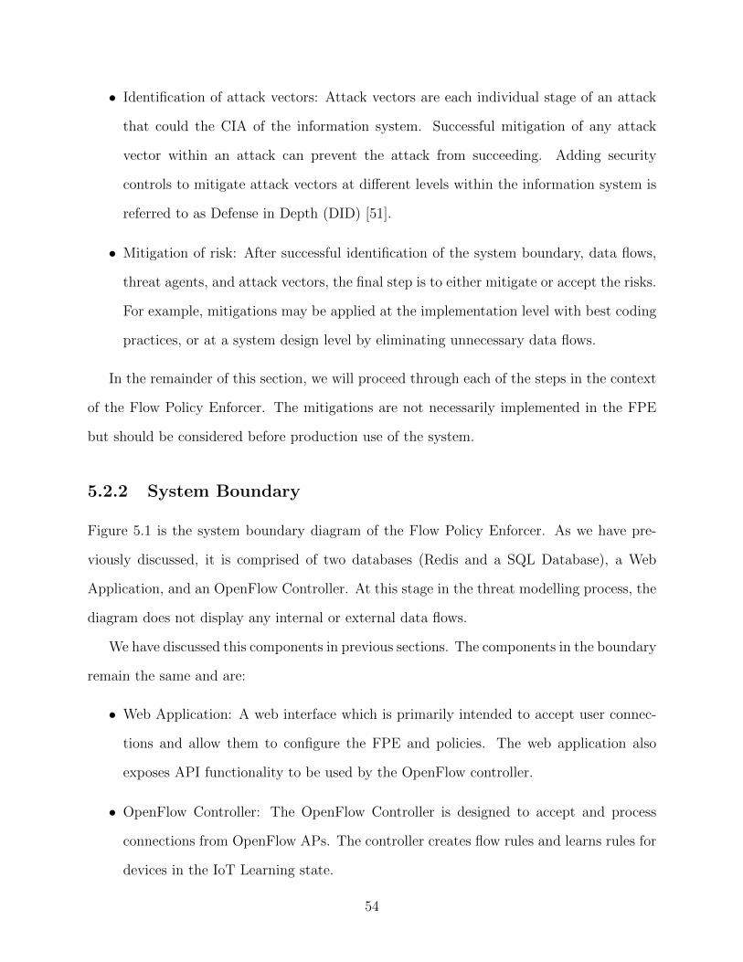
• Identification of attack vectors: Attack vectors are each individual stage of an attack
that could the CIA of the information system. Successful mitigation of any attack
vector within an attack can prevent the attack from succeeding. Adding security
controls to mitigate attack vectors at different levels within the information system is
referred to as Defense in Depth (DID) [51].
• Mitigation of risk: After successful identification of the system boundary, data flows,
threat agents, and attack vectors, the final step is to either mitigate or accept the risks.
For example, mitigations may be applied at the implementation level with best coding
practices, or at a system design level by eliminating unnecessary data flows.
In the remainder of this section, we will proceed through each of the steps in the context
of the Flow Policy Enforcer. The mitigations are not necessarily implemented in the FPE
but should be considered before production use of the system.
5.2.2 System Boundary
Figure 5.1 is the system boundary diagram of the Flow Policy Enforcer. As we have pre-
viously discussed, it is comprised of two databases (Redis and a SQL Database), a Web
Application, and an OpenFlow Controller. At this stage in the threat modelling process, the
diagram does not display any internal or external data flows.
We have discussed this components in previous sections. The components in the boundary
remain the same and are:
• Web Application: A web interface which is primarily intended to accept user connec-
tions and allow them to configure the FPE and policies. The web application also
exposes API functionality to be used by the OpenFlow controller.
• OpenFlow Controller: The OpenFlow Controller is designed to accept and process
connections from OpenFlow APs. The controller creates flow rules and learns rules for
devices in the IoT Learning state.
54
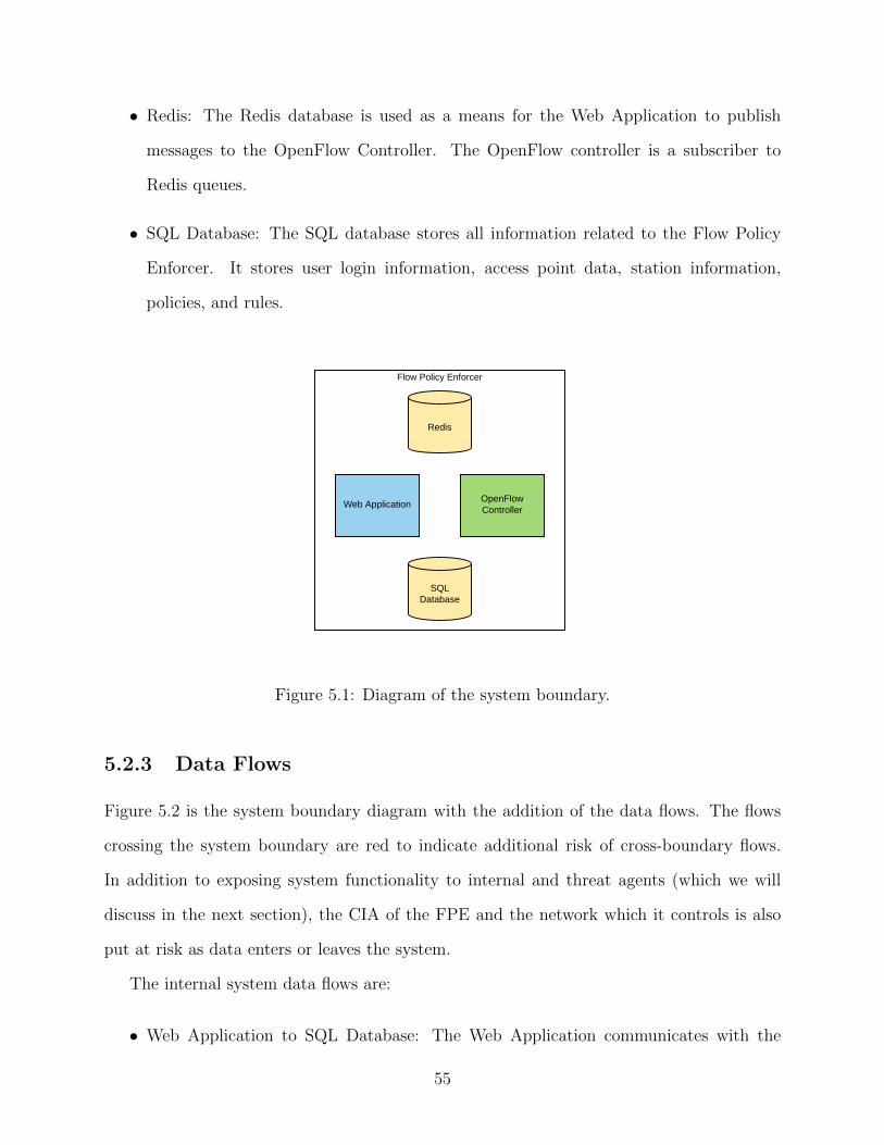
• Redis: The Redis database is used as a means for the Web Application to publish
messages to the OpenFlow Controller. The OpenFlow controller is a subscriber to
Redis queues.
• SQL Database: The SQL database stores all information related to the Flow Policy
Enforcer. It stores user login information, access point data, station information,
policies, and rules.
Flow Policy Enforcer
Web ApplicationOpenFlow Controller
Redis
SQL Database
Figure 5.1: Diagram of the system boundary.
5.2.3 Data Flows
Figure 5.2 is the system boundary diagram with the addition of the data flows. The flows
crossing the system boundary are red to indicate additional risk of cross-boundary flows.
In addition to exposing system functionality to internal and threat agents (which we will
discuss in the next section), the CIA of the FPE and the network which it controls is also
put at risk as data enters or leaves the system.
The internal system data flows are:
• Web Application to SQL Database: The Web Application communicates with the
55
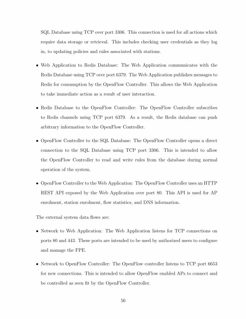
SQL Database using TCP over port 3306. This connection is used for all actions which
require data storage or retrieval. This includes checking user credentials as they log
in, to updating policies and rules associated with stations.
• Web Application to Redis Database: The Web Application communicates with the
Redis Database using TCP over port 6379. The Web Application publishes messages to
Redis for consumption by the OpenFlow Controller. This allows the Web Application
to take immediate action as a result of user interaction.
• Redis Database to the OpenFlow Controller: The OpenFlow Controller subscribes
to Redis channels using TCP port 6379. As a result, the Redis database can push
arbitrary information to the OpenFlow Controller.
• OpenFlow Controller to the SQL Database: The OpenFlow Controller opens a direct
connection to the SQL Database using TCP port 3306. This is intended to allow
the OpenFlow Controller to read and write rules from the database during normal
operation of the system.
• OpenFlow Controller to the Web Application: The OpenFlow Controller uses an HTTP
REST API exposed by the Web Application over port 80. This API is used for AP
enrolment, station enrolment, flow statistics, and DNS information.
The external system data flows are:
• Network to Web Application: The Web Application listens for TCP connections on
ports 80 and 443. These ports are intended to be used by authorized users to configure
and manage the FPE.
• Network to OpenFlow Controller: The OpenFlow controller listens to TCP port 6653
for new connections. This is intended to allow OpenFlow enabled APs to connect and
be controlled as seen fit by the OpenFlow Controller.
56
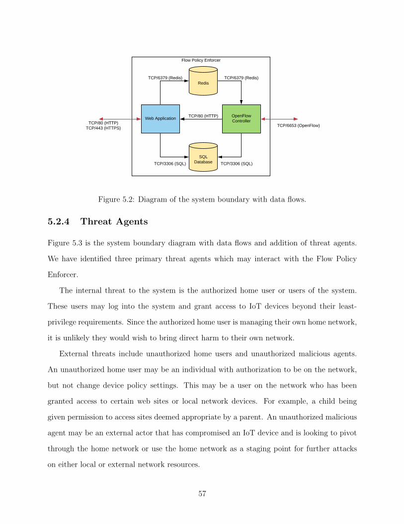
TCP/6653 (OpenFlow)
Flow Policy Enforcer
Web ApplicationOpenFlow Controller
Redis
SQL Database
TCP/80 (HTTP)TCP/443 (HTTPS)
TCP/80 (HTTP)
TCP/6379 (Redis)TCP/6379 (Redis)
TCP/3306 (SQL)TCP/3306 (SQL)
Figure 5.2: Diagram of the system boundary with data flows.
5.2.4 Threat Agents
Figure 5.3 is the system boundary diagram with data flows and addition of threat agents.
We have identified three primary threat agents which may interact with the Flow Policy
Enforcer.
The internal threat to the system is the authorized home user or users of the system.
These users may log into the system and grant access to IoT devices beyond their least-
privilege requirements. Since the authorized home user is managing their own home network,
it is unlikely they would wish to bring direct harm to their own network.
External threats include unauthorized home users and unauthorized malicious agents.
An unauthorized home user may be an individual with authorization to be on the network,
but not change device policy settings. This may be a user on the network who has been
granted access to certain web sites or local network devices. For example, a child being
given permission to access sites deemed appropriate by a parent. An unauthorized malicious
agent may be an external actor that has compromised an IoT device and is looking to pivot
through the home network or use the home network as a staging point for further attacks
on either local or external network resources.
57
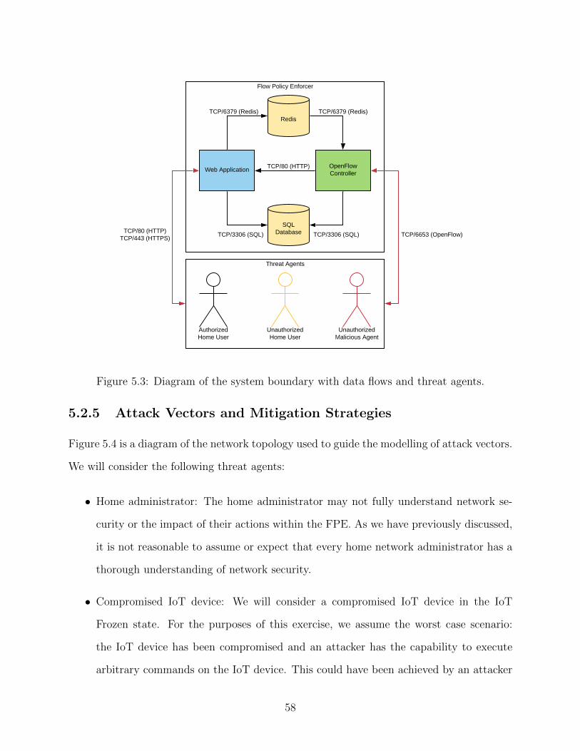
Threat Agents
TCP/6653 (OpenFlow)
Flow Policy Enforcer
Web ApplicationOpenFlow Controller
Redis
SQL DatabaseTCP/80 (HTTP)
TCP/443 (HTTPS)
TCP/80 (HTTP)
TCP/6379 (Redis)TCP/6379 (Redis)
TCP/3306 (SQL)TCP/3306 (SQL)
AuthorizedHome User
UnauthorizedHome User
UnauthorizedMalicious Agent
Figure 5.3: Diagram of the system boundary with data flows and threat agents.
5.2.5 Attack Vectors and Mitigation Strategies
Figure 5.4 is a diagram of the network topology used to guide the modelling of attack vectors.
We will consider the following threat agents:
• Home administrator: The home administrator may not fully understand network se-
curity or the impact of their actions within the FPE. As we have previously discussed,
it is not reasonable to assume or expect that every home network administrator has a
thorough understanding of network security.
• Compromised IoT device: We will consider a compromised IoT device in the IoT
Frozen state. For the purposes of this exercise, we assume the worst case scenario:
the IoT device has been compromised and an attacker has the capability to execute
arbitrary commands on the IoT device. This could have been achieved by an attacker
58
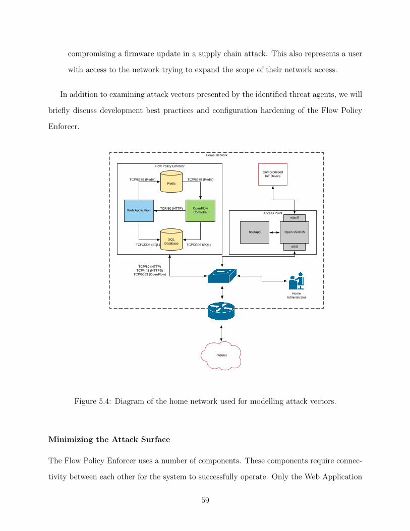
compromising a firmware update in a supply chain attack. This also represents a user
with access to the network trying to expand the scope of their network access.
In addition to examining attack vectors presented by the identified threat agents, we will
briefly discuss development best practices and configuration hardening of the Flow Policy
Enforcer.
Home Network
Access Point
hostapd
Flow Policy Enforcer
Web ApplicationOpenFlow Controller
Redis
SQL Database
TCP/80 (HTTP)TCP/443 (HTTPS)
TCP/6653 (OpenFlow)
TCP/80 (HTTP)
TCP/6379 (Redis)TCP/6379 (Redis)
TCP/3306 (SQL)TCP/3306 (SQL)
Open vSwitch
eth0
wlan0
CompromisedIoT Device
Internet
HomeAdministrator
Figure 5.4: Diagram of the home network used for modelling attack vectors.
Minimizing the Attack Surface
The Flow Policy Enforcer uses a number of components. These components require connec-
tivity between each other for the system to successfully operate. Only the Web Application
59
and the OpenFlow Controller require communication to services outside of the FPE bound-
ary. As such, the Redis and SQL Databases are configured to listen for traffic on a local
interface and are not be publicly exposed. This mitigates the threat of a device on the
network directly communicating with the databases and placing the system in an unknown
state.
Secure Development Practices
According to OWASP, input validation is one of the leading causes for vulnerabilities in
web applications [59]. These vulnerabilities occur when input is improperly validated before
being further processed by the system.
The Flow Policy Enforcer follows best practices and ensures data entering or leaving
the web application are well formatted. Parameterized SQL queries are used for all SQL
queries sent to the SQL Database. This prevents attacks from being successful against the
application by abusing input fields. This also prevents unintended errors from occurring in
the system during use by the authorized home administrator.
Misuse by the Home Administrator
The FPE allows the home administrator to have control over policies which control the level
of network access given to IoT devices connected to managed APs. This level of control
introduces the following attack vectors:
1. Granting additional scope to network devices: The Web Application allows the user
to grant Full Access to managed devices. As a result, the IoT device will not have
any network access restrictions. If this device were to become compromised, the FPE
would offer no protection.
2. Selecting Full Access as a default state: The default state for new devices connecting to
the FPE is IoT Learning. There is an option within the Web Application to allow this
60
to be configured to place devices in either the Full Access, IoT Learning, or Blocked
states. If the user selects Full Access, any new device connecting to the network will
be granted Full Access and the FPE will not secure any new devices.
3. Reuse of credentials: The Web Application uses a username and password for the
administrator login. This provides the opportunity for the home user to use a weak
password or reuse credentials across their different, unrelated accounts.
These attack vectors are not malicious by nature but present risk to the network as IoT
devices are added. The following mitigations could be applied:
• Attack vectors 1 and 2 could be mitigated by adding warnings to users before and
after selecting insecure settings for the FPE. This would be subject to human user
interaction studies and this left as an exercise for future work.
• Attack vector 3 could be mitigated by comparing passwords against insecure password
lists at the time of configuration. Additionally, Multi-Factor Authentication (MFA)
could be added as a second step during authentication, such as RFC 6238 [54]. These
strategies are recommended by NIST in Special Publication 800-63B [38].
Data Exfiltration
Assuming a threat agent has managed to compromise an IoT device, they may attempt
to exfiltrate data from the home network. This may include personal documents, such
as banking, pictures, or other sensitive information. The following attack vectors may be
attempted:
1. Compromising the FPE: If the IoT device has learned rules permitting access to the
FPE, the threat agent may be able to compromise the FPE. Once compromised, the
attacker could expand the scope of the IoT device to see all network resources.
61
2. Abuse of DNS rules: Suppose the attacker is able to successfully forge UDP packets
through the router to eth0 on the FPE. The attacker could trick the FPE into recording
DNS entries for falsified IP addresses in an attempt to expand outbound network access.
3. Confusing the home administrator: The attacker could fake connectivity issues on the
IoT device. In an attempt to resolve the device behaviour, the home administrator
may grant Full Access to the IoT device in an attempt to solve network issues, leading
to further compromises within the network.
The following mitigations to the above attack vectors could be applied:
• Attack vector 1 could be mitigated by the FPE placing drop entries on the AP for any
device in the IoT Learning or IoT Frozen states for connections to the FPE IP address,
regardless of port or protocol. Addition of these default flow rules would be a low cost
and provide additional protection to the home network.
• Attack vector 2 could be mitigated by having the FPE validate DNS requests by
confirming DNS responses from a trusted DNS source. The FPE could use a protocol
such as DNSCrypt [32] to ensure the query has not been tampered.
• Attack vector 3 could be addressed by informing the user of potential negative conse-
quences before granting the device Full Access. It would also be possible to examine
behaviour of dropped packets originating from the IoT device to determine the possi-
bility the device has been compromised or is behaving erratically.
Data Destruction
An attacker may intend to destroy or otherwise make information owned by the home user
unavailable. For example, an attacker may deploy ransomware designed to infect other
devices, encrypt the data, and request payment in order for the data to be decrypted. We
will consider the following attack vectors:
62
1. Denial of service against the FPE: An attacker may wish to cause local connectivity
issues in an attempt to bypass the FPE. The attack may trigger a large number of
packets which do not match any permitted rule, resulting in a large number of packets
being sent to the FPE for processing. This may cause issues in the Open vSwitch
instance or in the OpenFlow Controller.
2. Deployment of ransomware: An attacker may wish to deploy ransomware in the home
environment. The target of this attack may be data stored on the compromised IoT
device or on a Network Attached Storage (NAS) device located elsewhere on the net-
work.
The following mitigations could be applied to the system:
• Attack vector 1 could be mitigated by placing the IoT device in a Blocked state if
a certain threshold of blocked connections are reached. The threshold would need to
be balanced between providing adequate protection while not immediately causing a
properly functioning device to be blocked from the network.
• Attack vector 1 could be mitigated by configuring the Open vSwitch instance to operate
in secure mode. In this mode of operation, the Open vSwitch instance will not permit
traffic to flow or rules to be added until a connection is made to an OpenFlow controller.
Otherwise, the device would fail open and the network could be compromised.
• Attack vector 2 is a risk that would be limited by the normal operation of the Flow
Policy Enforcer. The compromised IoT device would only be able to attack network
devices on ports to which it had an allowed policy. However, assuming the compromised
IoT device did have access, the FPE in the current design would not prevent this type
of attack. A possible extension to the FPE would be an analysis of the types of data
it transmits and block any activity which is anomalous.
63

Staging Future Attacks
An attacker may not immediately use a compromised IoT device. They may enrol it in a
botnet or similar Command and Control (C&C) system. These are often used for launching
Denial of Service (DoS) or Distributed Denial of Service (DDoS) attacks. We will examine
the following attack vectors for this attacker’s objective:
1. Launching a DoS or DDoS attack: An agent in control of an IoT device may wish to
utilize the network to attack resources belonging to other individuals or groups. In the
case of a DDoS attack, the threat agent will instruct a large number of IoT devices
located in different networks to attack the same target.
2. Maintain persistent control of the IoT device: If the attacker has managed to com-
promise the IoT device, it may try to connect to a C&C server. This would allow an
attacker to maintain a persistent connection to many IoT devices and use them for
their own purposes.
The following mitigations could be applied to the system:
• Attack vector 1 is mitigated by the IoT Frozen state of the device. An attacker could
only utilize the compromised device to attack resources on the internet to which the
IoT device has already connected. This would limit the scope of the attack in many
cases to the IoT vendor. As discussed in the previous section, detection of anomalous
traffic patterns could further mitigate this risk. This is left as potential future work
identified by this threat modelling exercise.
• Attack vector 2 is also limited in effectiveness by the default behaviour of the IoT
Frozen state. The compromised IoT device could only connect to servers on the in-
ternet to which it has previously connected. This would effectively limit an attacker’s
C&C infrastructure to devices maintained by the IoT vendor. If the IoT vendor de-
64
tected malicious infrastructure in their environment and remediated the issue, the
compromised IoT device would be unable to connect to any other infrastructure.
Summary
The IoT Frozen state significantly reduces the capabilities of an attacker inside of a home
network. If the FPE was not present, an attacker would have full control of the device and
have network level access to any other device in the network.
There are attack vectors which are not fully mitigated by the Flow Policy Enforcer.
These have been noted as potential for future work, such as the detection of anomalous
traffic and pre-emptive transitioning of a device into the blocked state if there are too many
rule violations.
As we have seen, the risks of compromised IoT devices in a home network are significantly
lowered with the addition of the FPE. The FPE also makes it more difficult for a threat
agent to gain an initial foothold in the IoT device.
5.3 NIST 800-53 Assessment
5.3.1 Overview
NIST 800-53 is a publication put forth by the National Institute of Standards and Tech-
nology. Up to revision 4, the standard was designed to specify the set of security controls
organizations should consider when designing systems for the United States Federal Gov-
ernment [35]. Revision 5 is the latest draft version of the standard and has broadened the
scope beyond the US Federal Government to be a security reference to any individual or
organization designing solutions [19].
The framework is comprised of controls which are separated into control families. A
control family is a group of controls related to a specific area. For example, the family Access
Control (AC) is comprised of controls which relate to how access to the system is managed
65

and accessed. One control from the AC family is AC-7: Unsuccessful Logon Attempts.
Control AC-7 specifies guidance for how the system should manage repeated failed attempts
to log into the system. Controls may contain parameters which can be defined by the
individual implementing the control. This allows the individual implementing the control
to have some flexibility in defining how they meet the control. Figure 5.5 is the full text
of control AC-7. The parameters which can be defined are surrounded in square brackets.
Additionally, parameters can either be a custom defined value or a selection must be made
from pre-defined choices.
The information system:
a. Enforces a limit of [Assignment: organization-defined number] consecutive invalid logonattempts by a user during a [Assignment: organization-defined time period]; and
b. Automatically [Selection: locks the account/node for an [Assignment: organization-defined time period]; locks the account/node until released by an administrator; delaysnext logon prompt according to [Assignment: organization-defined delay algorithm]]when the maximum number of unsuccessful attempts is exceeded.
Figure 5.5: Control AC-7 from the NIST 800-53 framework.
In this section, we will not examine the Flow Policy Enforcer against every control in the
NIST 800-53 framework. We will examine the how the FPE improves the security posture
of home networks to which it is added for select controls from the following control families:
• Access Control (AC)
• Audit and Accountability (AU)
• Configuration Management (CM)
• Identification and Authorization (IA)
• System and Communications Protection (SC)
• System and Information Integrity (SI)
66
These control families were selected due to their relevance to the FPE in the context of
a home network. For example, it would not be relevant to discuss Personnel Security (PS)
as it is not the role of the system to determine the risk levels of individuals in the home
environment.
5.3.2 Access Control (AC)
The Flow Policy Enforcer adds a significant level of access control in a home network.
Assuming a home network consists of a traditional router and network switch, there are no
access restrictions between machines in the LAN. The addition of the Flow Policy enforcer
addresses a number of controls in the AC family.
The policy based approach utilizing rule sets which define appropriate levels of network
access address controls relating to information flow, such as Access Enforcement (AC-3),
Information Flow Enforcement (AC-4), Use of External Information Systems (AC-20), Re-
mote Access (AC-17), and Wireless Access (AC-18). The least permissive approach taken by
the IoT Learning phase addresses Least Privilege (AC-6). Giving the home user the ability
to view rules and modify policies also assists in addressing Account Management (AC-2) in
terms of reviewing permissions granted to network devices.
5.3.3 Audit and Accountability (AU)
Audit and Accountability controls address how the system provides the ability to audit
actions within the system. The IoT Learning phase and user interface provided by the FPE
assist with these controls in the context of a home network.
As we have seen in Figure 4.1, rules are displayed to the user along with the direction,
destination, and amount of traffic measured over each flow. This allows the FPE to meet
parts of Audit Events (AU-2) and Content of Audit Records (AU-3).
In the future, additional monitoring and audit logging could be added to the FPE to
further enhance the auditing capabilities provided to a home network.
67
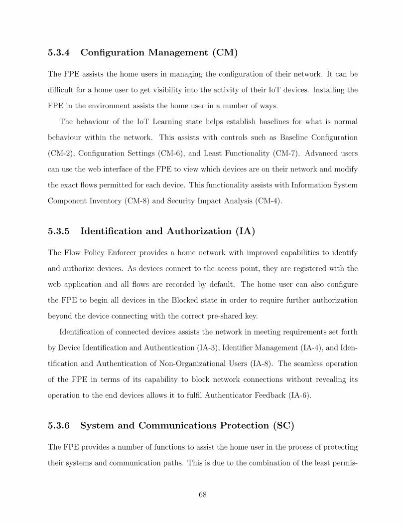
5.3.4 Configuration Management (CM)
The FPE assists the home users in managing the configuration of their network. It can be
difficult for a home user to get visibility into the activity of their IoT devices. Installing the
FPE in the environment assists the home user in a number of ways.
The behaviour of the IoT Learning state helps establish baselines for what is normal
behaviour within the network. This assists with controls such as Baseline Configuration
(CM-2), Configuration Settings (CM-6), and Least Functionality (CM-7). Advanced users
can use the web interface of the FPE to view which devices are on their network and modify
the exact flows permitted for each device. This functionality assists with Information System
Component Inventory (CM-8) and Security Impact Analysis (CM-4).
5.3.5 Identification and Authorization (IA)
The Flow Policy Enforcer provides a home network with improved capabilities to identify
and authorize devices. As devices connect to the access point, they are registered with the
web application and all flows are recorded by default. The home user can also configure
the FPE to begin all devices in the Blocked state in order to require further authorization
beyond the device connecting with the correct pre-shared key.
Identification of connected devices assists the network in meeting requirements set forth
by Device Identification and Authentication (IA-3), Identifier Management (IA-4), and Iden-
tification and Authentication of Non-Organizational Users (IA-8). The seamless operation
of the FPE in terms of its capability to block network connections without revealing its
operation to the end devices allows it to fulfil Authenticator Feedback (IA-6).
5.3.6 System and Communications Protection (SC)
The FPE provides a number of functions to assist the home user in the process of protecting
their systems and communication paths. This is due to the combination of the least permis-
68
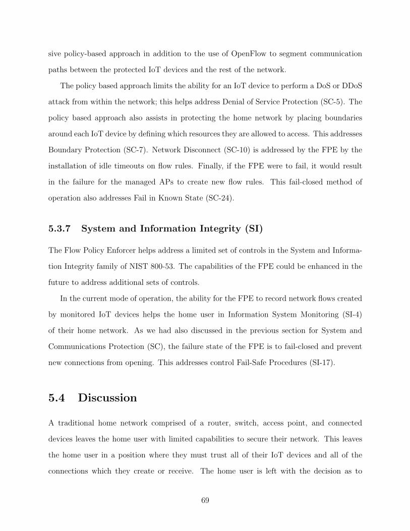
sive policy-based approach in addition to the use of OpenFlow to segment communication
paths between the protected IoT devices and the rest of the network.
The policy based approach limits the ability for an IoT device to perform a DoS or DDoS
attack from within the network; this helps address Denial of Service Protection (SC-5). The
policy based approach also assists in protecting the home network by placing boundaries
around each IoT device by defining which resources they are allowed to access. This addresses
Boundary Protection (SC-7). Network Disconnect (SC-10) is addressed by the FPE by the
installation of idle timeouts on flow rules. Finally, if the FPE were to fail, it would result
in the failure for the managed APs to create new flow rules. This fail-closed method of
operation also addresses Fail in Known State (SC-24).
5.3.7 System and Information Integrity (SI)
The Flow Policy Enforcer helps address a limited set of controls in the System and Informa-
tion Integrity family of NIST 800-53. The capabilities of the FPE could be enhanced in the
future to address additional sets of controls.
In the current mode of operation, the ability for the FPE to record network flows created
by monitored IoT devices helps the home user in Information System Monitoring (SI-4)
of their home network. As we had also discussed in the previous section for System and
Communications Protection (SC), the failure state of the FPE is to fail-closed and prevent
new connections from opening. This addresses control Fail-Safe Procedures (SI-17).
5.4 Discussion
A traditional home network comprised of a router, switch, access point, and connected
devices leaves the home user with limited capabilities to secure their network. This leaves
the home user in a position where they must trust all of their IoT devices and all of the
connections which they create or receive. The home user is left with the decision as to
69
whether or not they should accept the risk of each IoT device they add to their network.
This decision not only impacts the privacy and security of the device itself, but also the
security and privacy of the other devices and the data they contain on their network.
We have performed a thorough examination of the design of the FPE through the threat
modelling process. We have discussed and identified potential attack vectors on the system.
The evaluation of the attack vectors also led to the mitigations which would be applied to
the system before a full production deployment. The consideration of the threat model and
attack vectors provides the system designer the capability to consider threats and reduce the
attack surface of adding their device to a network. This process shows the addition of the
FPE does not significantly increase the attack surface of a home network.
We have also performed an analysis of how the FPE improves the security posture of
a home network through a brief analysis of select control families and controls from the
NIST 800-53 framework. The predictable, least-permissive, policy-based approach taken
by the FPE helps the home user increase the security posture of their network. This base
implementation of the FPE provides a platform for future expansion and enhanced decision
making capabilities. For example, in the future, it would be possible to augment the FPE
with sophisticated Machine Learning (ML) techniques.
70
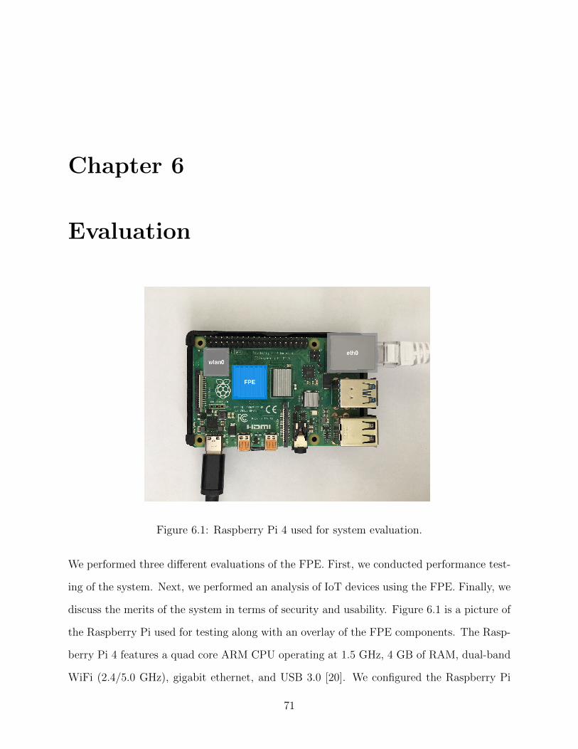
Chapter 6
Evaluation
Figure 6.1: Raspberry Pi 4 used for system evaluation.
We performed three different evaluations of the FPE. First, we conducted performance test-
ing of the system. Next, we performed an analysis of IoT devices using the FPE. Finally, we
discuss the merits of the system in terms of security and usability. Figure 6.1 is a picture of
the Raspberry Pi used for testing along with an overlay of the FPE components. The Rasp-
berry Pi 4 features a quad core ARM CPU operating at 1.5 GHz, 4 GB of RAM, dual-band
WiFi (2.4/5.0 GHz), gigabit ethernet, and USB 3.0 [20]. We configured the Raspberry Pi
71
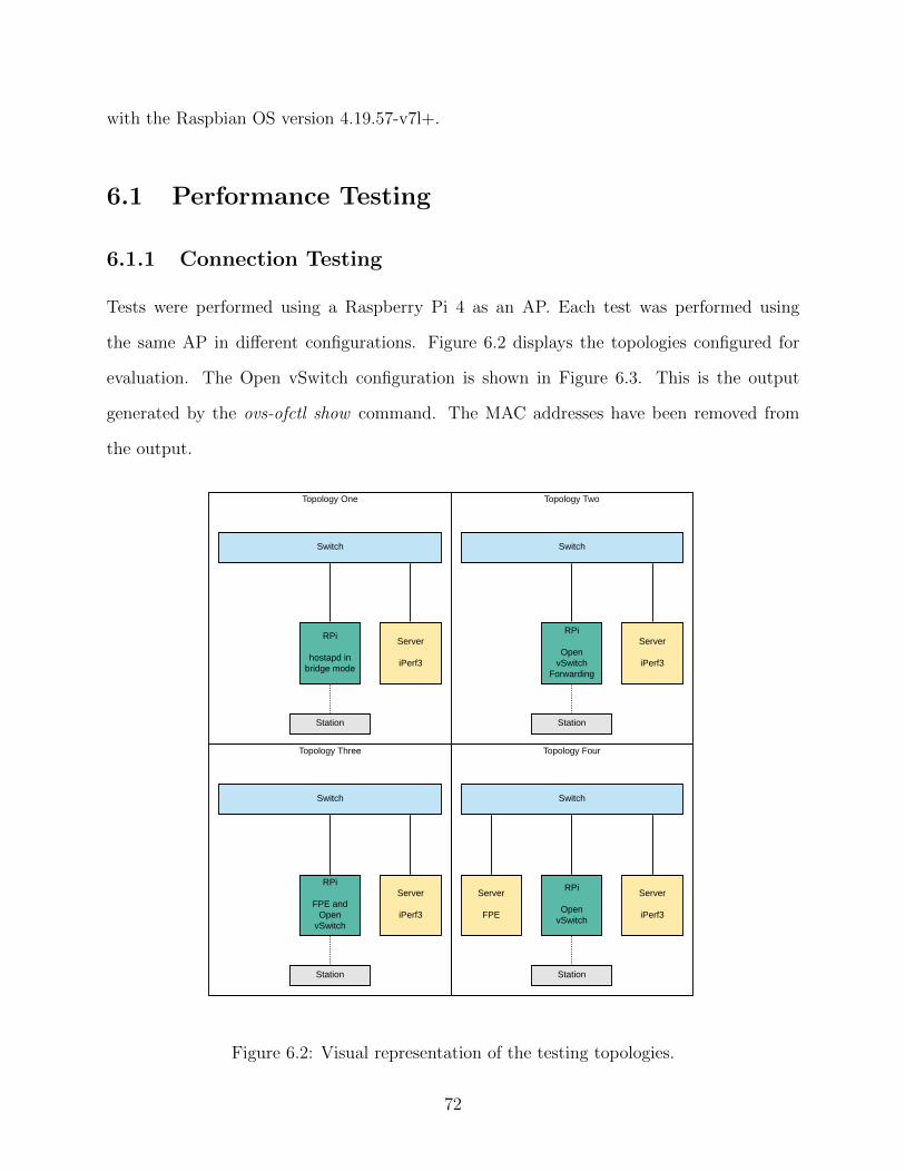
with the Raspbian OS version 4.19.57-v7l+.
6.1 Performance Testing
6.1.1 Connection Testing
Tests were performed using a Raspberry Pi 4 as an AP. Each test was performed using
the same AP in different configurations. Figure 6.2 displays the topologies configured for
evaluation. The Open vSwitch configuration is shown in Figure 6.3. This is the output
generated by the ovs-ofctl show command. The MAC addresses have been removed from
the output.
Topology One
Station
Switch
RPi
hostapd in bridge mode
Server
iPerf3
Topology Four
Station
Server
FPE
Switch
RPi
Open vSwitch
Server
iPerf3
Topology Three
Station
Switch
RPi
FPE and Open
vSwitch
Server
iPerf3
Topology Two
Station
Switch
RPi
Open vSwitch
Forwarding
Server
iPerf3
Figure 6.2: Visual representation of the testing topologies.
72
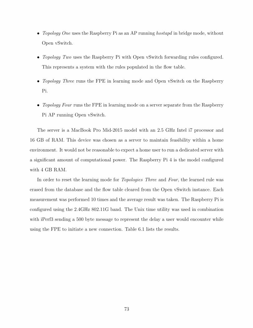
• Topology One uses the Raspberry Pi as an AP running hostapd in bridge mode, without
Open vSwitch.
• Topology Two uses the Raspberry Pi with Open vSwitch forwarding rules configured.
This represents a system with the rules populated in the flow table.
• Topology Three runs the FPE in learning mode and Open vSwitch on the Raspberry
Pi.
• Topology Four runs the FPE in learning mode on a server separate from the Raspberry
Pi AP running Open vSwitch.
The server is a MacBook Pro Mid-2015 model with an 2.5 GHz Intel i7 processor and
16 GB of RAM. This device was chosen as a server to maintain feasibility within a home
environment. It would not be reasonable to expect a home user to run a dedicated server with
a significant amount of computational power. The Raspberry Pi 4 is the model configured
with 4 GB RAM.
In order to reset the learning mode for Topologies Three and Four, the learned rule was
erased from the database and the flow table cleared from the Open vSwitch instance. Each
measurement was performed 10 times and the average result was taken. The Raspberry Pi is
configured using the 2.4GHz 802.11G band. The Unix time utility was used in combination
with iPerf3 sending a 500 byte message to represent the delay a user would encounter while
using the FPE to initiate a new connection. Table 6.1 lists the results.
73
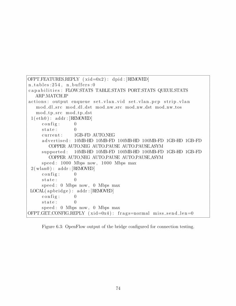
OFPT FEATURES REPLY ( xid=0x2 ) : dpid : [REMOVED]n t a b l e s : 254 , n b u f f e r s : 0c a p a b i l i t i e s : FLOW STATS TABLE STATS PORT STATS QUEUE STATS
ARP MATCH IPa c t i o n s : output enqueue s e t v l a n v i d s e t v l a n p c p s t r i p v l a n
mod dl s rc mod dl dst mod nw src mod nw dst mod nw tosmod tp src mod tp dst
1( eth0 ) : addr : [REMOVED]c o n f i g : 0s t a t e : 0cur r ent : 1GB−FD AUTO NEGadve r t i s ed : 10MB−HD 10MB−FD 100MB−HD 100MB−FD 1GB−HD 1GB−FD
COPPER AUTO NEG AUTO PAUSE AUTO PAUSE ASYMsupported : 10MB−HD 10MB−FD 100MB−HD 100MB−FD 1GB−HD 1GB−FD
COPPER AUTO NEG AUTO PAUSE AUTO PAUSE ASYMspeed : 1000 Mbps now , 1000 Mbps max
2( wlan0 ) : addr : [REMOVED]c o n f i g : 0s t a t e : 0speed : 0 Mbps now , 0 Mbps max
LOCAL( apbr idge ) : addr : [REMOVED]c o n f i g : 0s t a t e : 0speed : 0 Mbps now , 0 Mbps max
OFPT GET CONFIG REPLY ( xid=0x4 ) : f r a g s=normal m i s s s en d l en=0
Figure 6.3: OpenFlow output of the bridge configured for connection testing.
74
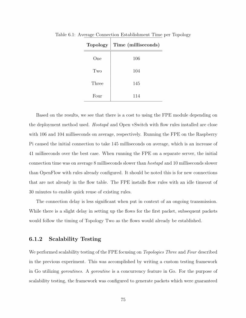
Table 6.1: Average Connection Establishment Time per Topology
Topology Time (milliseconds)
One 106
Two 104
Three 145
Four 114
Based on the results, we see that there is a cost to using the FPE module depending on
the deployment method used. Hostapd and Open vSwitch with flow rules installed are close
with 106 and 104 milliseconds on average, respectively. Running the FPE on the Raspberry
Pi caused the initial connection to take 145 milliseconds on average, which is an increase of
41 milliseconds over the best case. When running the FPE on a separate server, the initial
connection time was on average 8 milliseconds slower than hostapd and 10 milliseconds slower
than OpenFlow with rules already configured. It should be noted this is for new connections
that are not already in the flow table. The FPE installs flow rules with an idle timeout of
30 minutes to enable quick reuse of existing rules.
The connection delay is less significant when put in context of an ongoing transmission.
While there is a slight delay in setting up the flows for the first packet, subsequent packets
would follow the timing of Topology Two as the flows would already be established.
6.1.2 Scalability Testing
We performed scalability testing of the FPE focusing on Topologies Three and Four described
in the previous experiment. This was accomplished by writing a custom testing framework
in Go utilizing goroutines. A goroutine is a concurrency feature in Go. For the purpose of
scalability testing, the framework was configured to generate packets which were guaranteed
75
to result in new rules being learned by the system.
The physical ethernet and wireless interfaces were replaced with virtual interfaces in the
Open vSwitch instance. This allows the testing framework to bind to the virtual ports which
are used to send and receive packets. This is accomplished by setting the type of the port
when adding the port using ovs-vsctl command as seen in Figure 6.4.
sudo ovs−v s c t l add−port apbr idge iwlan0 −− s e t I n t e r f a c e iwlan0type=i n t e r n a l o f p o r t r e q u e s t=2
Figure 6.4: OpenFlow command used to add virtual ports.
Figure 6.5 shows the configuration of the Open vSwitch instance for this experiment.
The testing framework creates two primary goroutines. The producer injects the desired
number of packets on one virtual interface and records the time of packet creation in a
shared memory location. When the consumer thread receives a packet, it creates a new
goroutine, records the current time and goes into a waiting state. Once all of the packets
have been received, the consumers read from the shared memory location and record the
duration of time between packet injection and packet reception.
Figure 6.6 displays the experiment results. Each experiment was repeated 10 times and
the average result was recorded. For the maximum cases, the average of the maximums was
recorded.
76
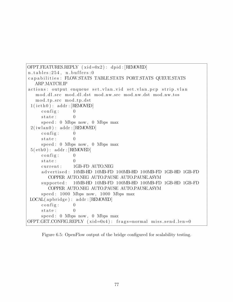
OFPT FEATURES REPLY ( xid=0x2 ) : dpid : [REMOVED]n t a b l e s : 254 , n b u f f e r s : 0c a p a b i l i t i e s : FLOW STATS TABLE STATS PORT STATS QUEUE STATS
ARP MATCH IPa c t i o n s : output enqueue s e t v l a n v i d s e t v l a n p c p s t r i p v l a n
mod dl s rc mod dl dst mod nw src mod nw dst mod nw tosmod tp src mod tp dst
1( i e th0 ) : addr : [REMOVED]c o n f i g : 0s t a t e : 0speed : 0 Mbps now , 0 Mbps max
2( iwlan0 ) : addr : [REMOVED]c o n f i g : 0s t a t e : 0speed : 0 Mbps now , 0 Mbps max
5( eth0 ) : addr : [REMOVED]c o n f i g : 0s t a t e : 0cur r ent : 1GB−FD AUTO NEGadve r t i s ed : 10MB−HD 10MB−FD 100MB−HD 100MB−FD 1GB−HD 1GB−FD
COPPER AUTO NEG AUTO PAUSE AUTO PAUSE ASYMsupported : 10MB−HD 10MB−FD 100MB−HD 100MB−FD 1GB−HD 1GB−FD
COPPER AUTO NEG AUTO PAUSE AUTO PAUSE ASYMspeed : 1000 Mbps now , 1000 Mbps max
LOCAL( apbr idge ) : addr : [REMOVED]c o n f i g : 0s t a t e : 0speed : 0 Mbps now , 0 Mbps max
OFPT GET CONFIG REPLY ( xid=0x4 ) : f r a g s=normal m i s s s en d l en=0
Figure 6.5: OpenFlow output of the bridge configured for scalability testing.
77
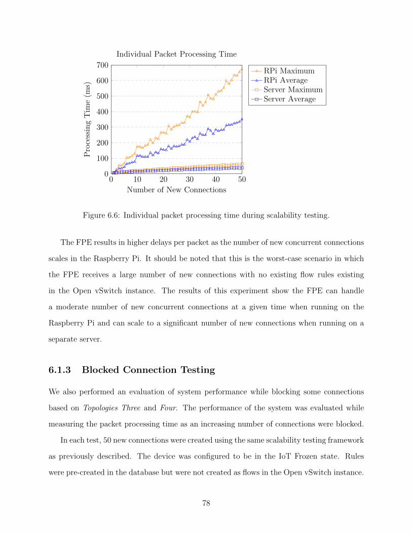
0 10 20 30 40 500
100
200
300
400
500
600
700
Number of New Connections
Pro
cess
ing
Tim
e(m
s)
Individual Packet Processing Time
RPi MaximumRPi AverageServer MaximumServer Average
Figure 6.6: Individual packet processing time during scalability testing.
The FPE results in higher delays per packet as the number of new concurrent connections
scales in the Raspberry Pi. It should be noted that this is the worst-case scenario in which
the FPE receives a large number of new connections with no existing flow rules existing
in the Open vSwitch instance. The results of this experiment show the FPE can handle
a moderate number of new concurrent connections at a given time when running on the
Raspberry Pi and can scale to a significant number of new connections when running on a
separate server.
6.1.3 Blocked Connection Testing
We also performed an evaluation of system performance while blocking some connections
based on Topologies Three and Four. The performance of the system was evaluated while
measuring the packet processing time as an increasing number of connections were blocked.
In each test, 50 new connections were created using the same scalability testing framework
as previously described. The device was configured to be in the IoT Frozen state. Rules
were pre-created in the database but were not created as flows in the Open vSwitch instance.
78
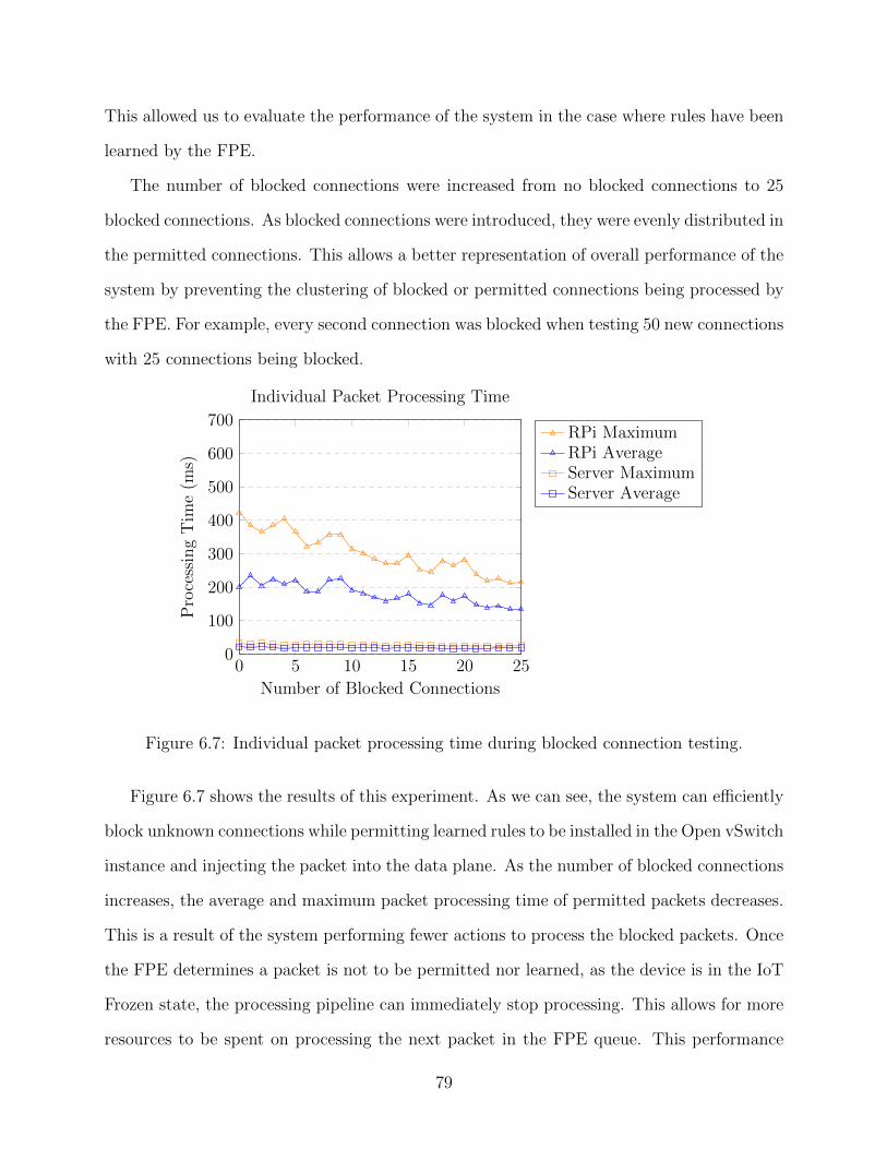
This allowed us to evaluate the performance of the system in the case where rules have been
learned by the FPE.
The number of blocked connections were increased from no blocked connections to 25
blocked connections. As blocked connections were introduced, they were evenly distributed in
the permitted connections. This allows a better representation of overall performance of the
system by preventing the clustering of blocked or permitted connections being processed by
the FPE. For example, every second connection was blocked when testing 50 new connections
with 25 connections being blocked.
0 5 10 15 20 250
100
200
300
400
500
600
700
Number of Blocked Connections
Pro
cess
ing
Tim
e(m
s)
Individual Packet Processing Time
RPi MaximumRPi AverageServer MaximumServer Average
Figure 6.7: Individual packet processing time during blocked connection testing.
Figure 6.7 shows the results of this experiment. As we can see, the system can efficiently
block unknown connections while permitting learned rules to be installed in the Open vSwitch
instance and injecting the packet into the data plane. As the number of blocked connections
increases, the average and maximum packet processing time of permitted packets decreases.
This is a result of the system performing fewer actions to process the blocked packets. Once
the FPE determines a packet is not to be permitted nor learned, as the device is in the IoT
Frozen state, the processing pipeline can immediately stop processing. This allows for more
resources to be spent on processing the next packet in the FPE queue. This performance
79
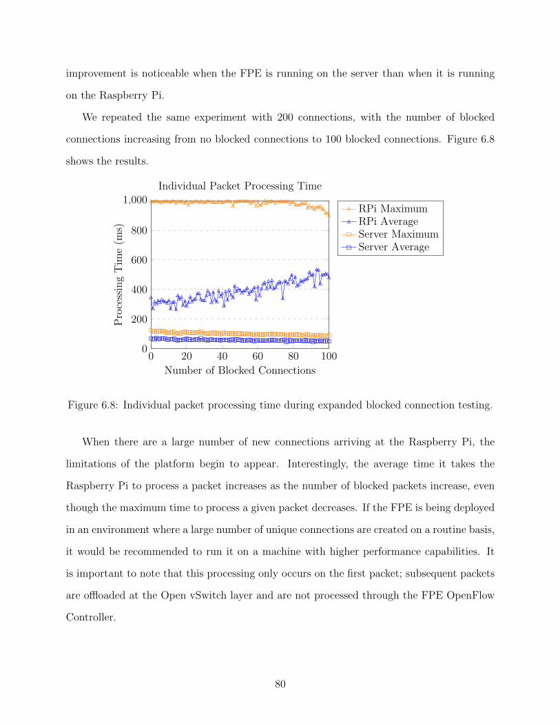
improvement is noticeable when the FPE is running on the server than when it is running
on the Raspberry Pi.
We repeated the same experiment with 200 connections, with the number of blocked
connections increasing from no blocked connections to 100 blocked connections. Figure 6.8
shows the results.
0 20 40 60 80 1000
200
400
600
800
1,000
Number of Blocked Connections
Pro
cess
ing
Tim
e(m
s)
Individual Packet Processing Time
RPi MaximumRPi AverageServer MaximumServer Average
Figure 6.8: Individual packet processing time during expanded blocked connection testing.
When there are a large number of new connections arriving at the Raspberry Pi, the
limitations of the platform begin to appear. Interestingly, the average time it takes the
Raspberry Pi to process a packet increases as the number of blocked packets increase, even
though the maximum time to process a given packet decreases. If the FPE is being deployed
in an environment where a large number of unique connections are created on a routine basis,
it would be recommended to run it on a machine with higher performance capabilities. It
is important to note that this processing only occurs on the first packet; subsequent packets
are offloaded at the Open vSwitch layer and are not processed through the FPE OpenFlow
Controller.
80
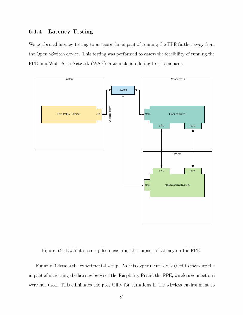
6.1.4 Latency Testing
We performed latency testing to measure the impact of running the FPE further away from
the Open vSwitch device. This testing was performed to assess the feasibility of running the
FPE in a Wide Area Network (WAN) or as a cloud offering to a home user.
Server
varia
ble
dela
y
Raspberry Pi
Measurement System
eth1 eth0
Switch
Laptop
Flow Policy Enforcer eth0 eth0 Open vSwitch
eth1 eth2
eth2
Figure 6.9: Evaluation setup for measuring the impact of latency on the FPE.
Figure 6.9 details the experimental setup. As this experiment is designed to measure the
impact of increasing the latency between the Raspberry Pi and the FPE, wireless connections
were not used. This eliminates the possibility for variations in the wireless environment to
81
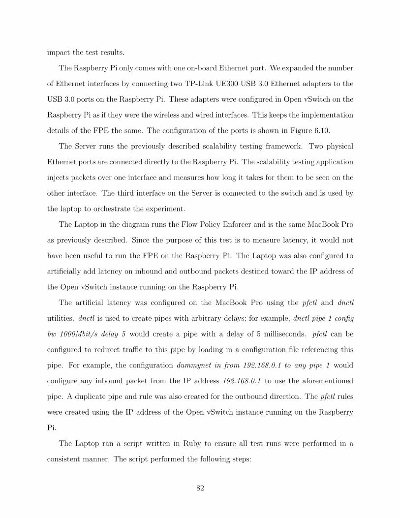
impact the test results.
The Raspberry Pi only comes with one on-board Ethernet port. We expanded the number
of Ethernet interfaces by connecting two TP-Link UE300 USB 3.0 Ethernet adapters to the
USB 3.0 ports on the Raspberry Pi. These adapters were configured in Open vSwitch on the
Raspberry Pi as if they were the wireless and wired interfaces. This keeps the implementation
details of the FPE the same. The configuration of the ports is shown in Figure 6.10.
The Server runs the previously described scalability testing framework. Two physical
Ethernet ports are connected directly to the Raspberry Pi. The scalability testing application
injects packets over one interface and measures how long it takes for them to be seen on the
other interface. The third interface on the Server is connected to the switch and is used by
the laptop to orchestrate the experiment.
The Laptop in the diagram runs the Flow Policy Enforcer and is the same MacBook Pro
as previously described. Since the purpose of this test is to measure latency, it would not
have been useful to run the FPE on the Raspberry Pi. The Laptop was also configured to
artificially add latency on inbound and outbound packets destined toward the IP address of
the Open vSwitch instance running on the Raspberry Pi.
The artificial latency was configured on the MacBook Pro using the pfctl and dnctl
utilities. dnctl is used to create pipes with arbitrary delays; for example, dnctl pipe 1 config
bw 1000Mbit/s delay 5 would create a pipe with a delay of 5 milliseconds. pfctl can be
configured to redirect traffic to this pipe by loading in a configuration file referencing this
pipe. For example, the configuration dummynet in from 192.168.0.1 to any pipe 1 would
configure any inbound packet from the IP address 192.168.0.1 to use the aforementioned
pipe. A duplicate pipe and rule was also created for the outbound direction. The pfctl rules
were created using the IP address of the Open vSwitch instance running on the Raspberry
Pi.
The Laptop ran a script written in Ruby to ensure all test runs were performed in a
consistent manner. The script performed the following steps:
82
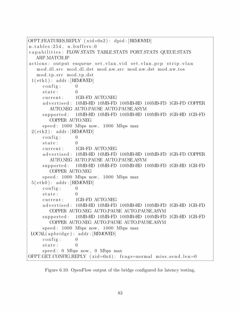
OFPT FEATURES REPLY ( xid=0x2 ) : dpid : [REMOVED]n t a b l e s : 254 , n b u f f e r s : 0c a p a b i l i t i e s : FLOW STATS TABLE STATS PORT STATS QUEUE STATS
ARP MATCH IPa c t i o n s : output enqueue s e t v l a n v i d s e t v l a n p c p s t r i p v l a n
mod dl s rc mod dl dst mod nw src mod nw dst mod nw tosmod tp src mod tp dst
1( eth1 ) : addr : [REMOVED]c o n f i g : 0s t a t e : 0cur r ent : 1GB−FD AUTO NEGadve r t i s ed : 10MB−HD 10MB−FD 100MB−HD 100MB−FD 1GB−FD COPPER
AUTO NEG AUTO PAUSE AUTO PAUSE ASYMsupported : 10MB−HD 10MB−FD 100MB−HD 100MB−FD 1GB−HD 1GB−FD
COPPER AUTO NEGspeed : 1000 Mbps now , 1000 Mbps max
2( eth2 ) : addr : [REMOVED]c o n f i g : 0s t a t e : 0cur r ent : 1GB−FD AUTO NEGadve r t i s ed : 10MB−HD 10MB−FD 100MB−HD 100MB−FD 1GB−FD COPPER
AUTO NEG AUTO PAUSE AUTO PAUSE ASYMsupported : 10MB−HD 10MB−FD 100MB−HD 100MB−FD 1GB−HD 1GB−FD
COPPER AUTO NEGspeed : 1000 Mbps now , 1000 Mbps max
5( eth0 ) : addr : [REMOVED]c o n f i g : 0s t a t e : 0cur r ent : 1GB−FD AUTO NEGadve r t i s ed : 10MB−HD 10MB−FD 100MB−HD 100MB−FD 1GB−HD 1GB−FD
COPPER AUTO NEG AUTO PAUSE AUTO PAUSE ASYMsupported : 10MB−HD 10MB−FD 100MB−HD 100MB−FD 1GB−HD 1GB−FD
COPPER AUTO NEG AUTO PAUSE AUTO PAUSE ASYMspeed : 1000 Mbps now , 1000 Mbps max
LOCAL( apbr idge ) : addr : [REMOVED]c o n f i g : 0s t a t e : 0speed : 0 Mbps now , 0 Mbps max
OFPT GET CONFIG REPLY ( xid=0x4 ) : f r a g s=normal m i s s s en d l en=0
Figure 6.10: OpenFlow output of the bridge configured for latency testing.
83

1. Reset previously learned rules for the MAC address used by the scalability testing
framework.
2. Start the OpenFlow Controller.
3. Set the inbound and outbound latency to the Open vSwitch instance to the same value
for the test.
4. Wait 20 seconds for the OpenFlow Controller to initiate a new connection with the
Open vSwitch instance.
5. Launch an SSH session on the Server and execute the scalability testing framework.
6. Write the results from the framework to a file.
7. Set the inbound and outbound latency to the Open vSwitch instance to zero.
8. Send a kill signal to the OpenFlow Controller.
Each latency test reports the average time it took to process each packet. Each test was
repeated three times and the average result was recorded. The scalability testing framework
was configured to simulate 25 new connections. Subsequent data was not tested as latency
to the FPE would not impact processing once flow rules are established on the Open vSwitch
instance.
84
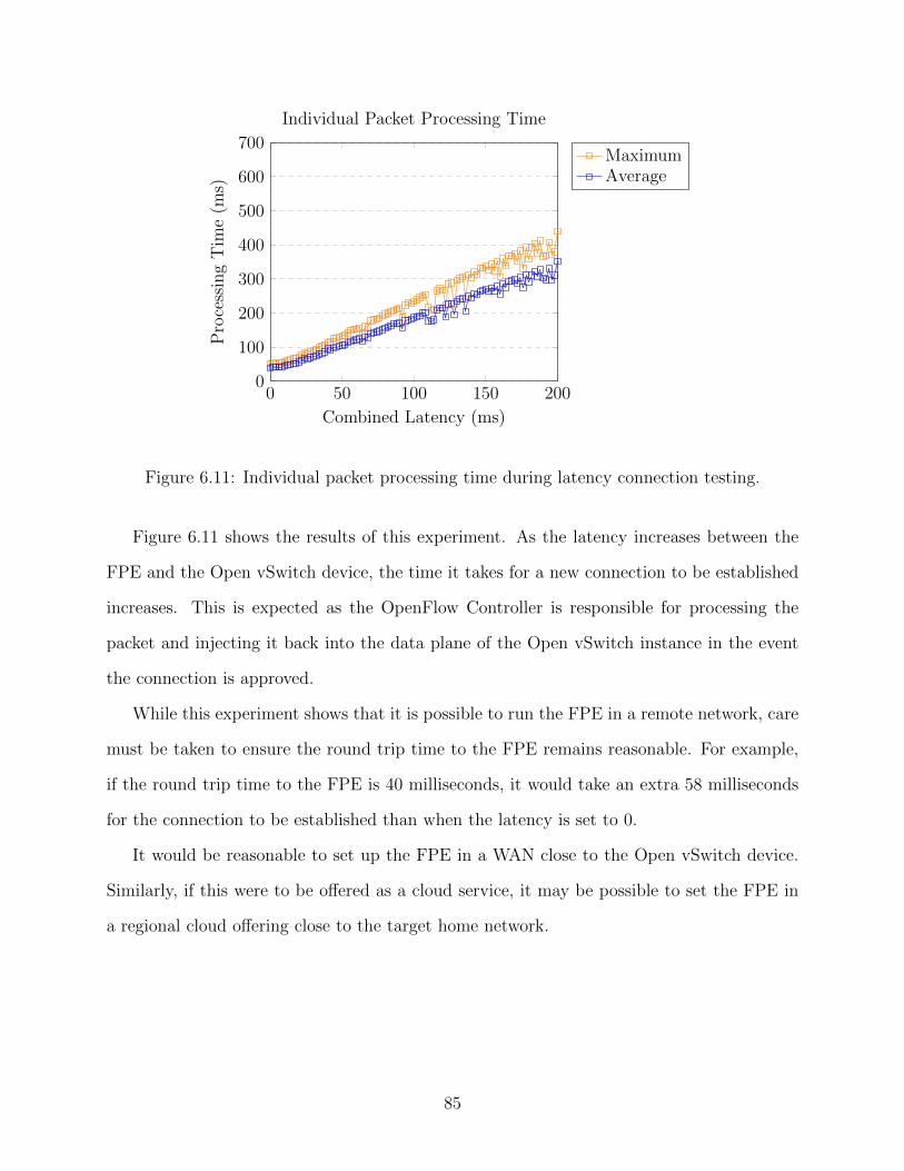
0 50 100 150 2000
100
200
300
400
500
600
700
Combined Latency (ms)
Pro
cess
ing
Tim
e(m
s)
Individual Packet Processing Time
MaximumAverage
Figure 6.11: Individual packet processing time during latency connection testing.
Figure 6.11 shows the results of this experiment. As the latency increases between the
FPE and the Open vSwitch device, the time it takes for a new connection to be established
increases. This is expected as the OpenFlow Controller is responsible for processing the
packet and injecting it back into the data plane of the Open vSwitch instance in the event
the connection is approved.
While this experiment shows that it is possible to run the FPE in a remote network, care
must be taken to ensure the round trip time to the FPE remains reasonable. For example,
if the round trip time to the FPE is 40 milliseconds, it would take an extra 58 milliseconds
for the connection to be established than when the latency is set to 0.
It would be reasonable to set up the FPE in a WAN close to the Open vSwitch device.
Similarly, if this were to be offered as a cloud service, it may be possible to set the FPE in
a regional cloud offering close to the target home network.
85
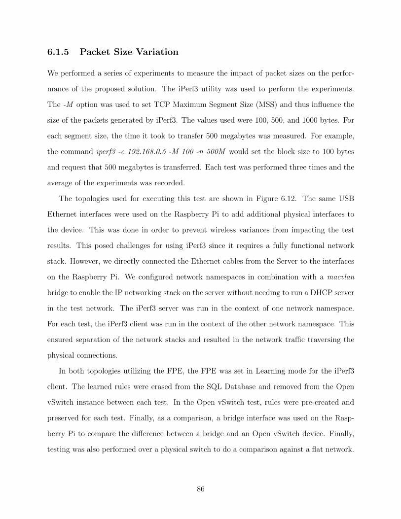
6.1.5 Packet Size Variation
We performed a series of experiments to measure the impact of packet sizes on the perfor-
mance of the proposed solution. The iPerf3 utility was used to perform the experiments.
The -M option was used to set TCP Maximum Segment Size (MSS) and thus influence the
size of the packets generated by iPerf3. The values used were 100, 500, and 1000 bytes. For
each segment size, the time it took to transfer 500 megabytes was measured. For example,
the command iperf3 -c 192.168.0.5 -M 100 -n 500M would set the block size to 100 bytes
and request that 500 megabytes is transferred. Each test was performed three times and the
average of the experiments was recorded.
The topologies used for executing this test are shown in Figure 6.12. The same USB
Ethernet interfaces were used on the Raspberry Pi to add additional physical interfaces to
the device. This was done in order to prevent wireless variances from impacting the test
results. This posed challenges for using iPerf3 since it requires a fully functional network
stack. However, we directly connected the Ethernet cables from the Server to the interfaces
on the Raspberry Pi. We configured network namespaces in combination with a macvlan
bridge to enable the IP networking stack on the server without needing to run a DHCP server
in the test network. The iPerf3 server was run in the context of one network namespace.
For each test, the iPerf3 client was run in the context of the other network namespace. This
ensured separation of the network stacks and resulted in the network traffic traversing the
physical connections.
In both topologies utilizing the FPE, the FPE was set in Learning mode for the iPerf3
client. The learned rules were erased from the SQL Database and removed from the Open
vSwitch instance between each test. In the Open vSwitch test, rules were pre-created and
preserved for each test. Finally, as a comparison, a bridge interface was used on the Rasp-
berry Pi to compare the difference between a bridge and an Open vSwitch device. Finally,
testing was also performed over a physical switch to do a comparison against a flat network.
86

FPE on Laptop Server
Raspberry Pi
eth1 eth0
Switch eth0 Open vSwitch
eth1 eth2
Laptop
Flow Policy Enforcer eth0
iperf client iperf server
macvlan1 macvlan0
netns 1 netns 2
FPE on PiServer
Raspberry Pi
eth1 eth0
Open vSwitch
eth1 eth2
Flow Policy Enforcer
iperf client iperf server
macvlan1 macvlan0
netns 1 netns 2
Open vSwitch Server
Raspberry Pi
eth1 eth0
Open vSwitch
eth1 eth2
iperf client iperf server
macvlan1 macvlan0
netns 1 netns 2
Bridge Server
Raspberry Pi
eth1 eth0
Bridged Interfaces
eth1 eth2
iperf client iperf server
macvlan1 macvlan0
netns 1 netns 2
Switch Servereth1 eth0
Switch
eth1 eth2
iperf client iperf server
macvlan1 macvlan0
netns 1 netns 2
Figure 6.12: Topologies used for packet size testing.
87
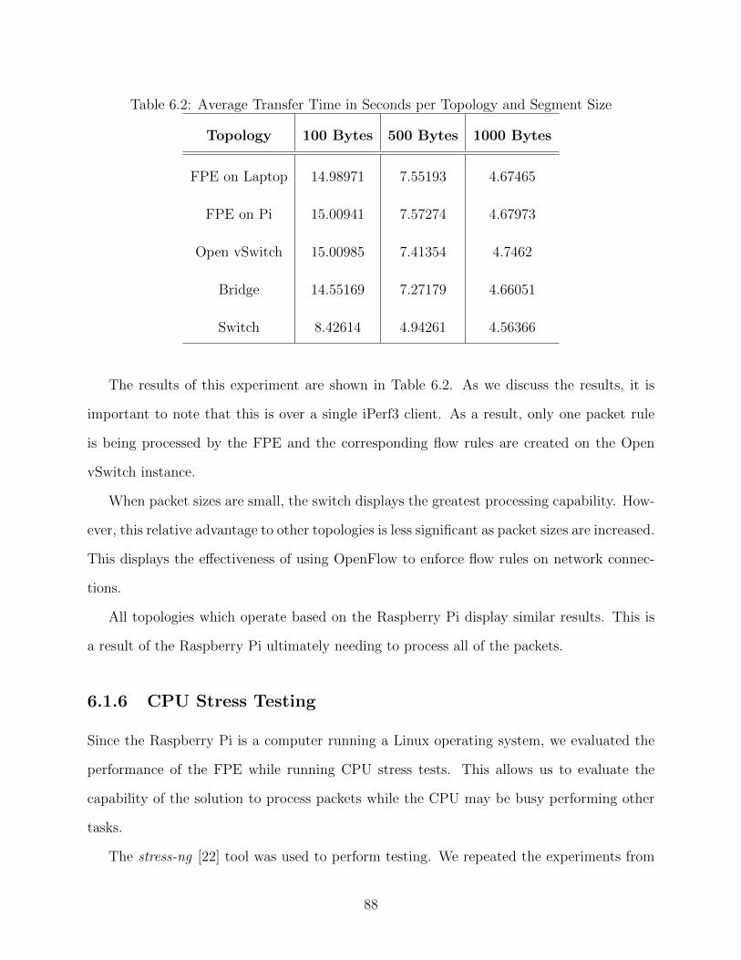
Table 6.2: Average Transfer Time in Seconds per Topology and Segment Size
Topology 100 Bytes 500 Bytes 1000 Bytes
FPE on Laptop 14.98971 7.55193 4.67465
FPE on Pi 15.00941 7.57274 4.67973
Open vSwitch 15.00985 7.41354 4.7462
Bridge 14.55169 7.27179 4.66051
Switch 8.42614 4.94261 4.56366
The results of this experiment are shown in Table 6.2. As we discuss the results, it is
important to note that this is over a single iPerf3 client. As a result, only one packet rule
is being processed by the FPE and the corresponding flow rules are created on the Open
vSwitch instance.
When packet sizes are small, the switch displays the greatest processing capability. How-
ever, this relative advantage to other topologies is less significant as packet sizes are increased.
This displays the effectiveness of using OpenFlow to enforce flow rules on network connec-
tions.
All topologies which operate based on the Raspberry Pi display similar results. This is
a result of the Raspberry Pi ultimately needing to process all of the packets.
6.1.6 CPU Stress Testing
Since the Raspberry Pi is a computer running a Linux operating system, we evaluated the
performance of the FPE while running CPU stress tests. This allows us to evaluate the
capability of the solution to process packets while the CPU may be busy performing other
tasks.
The stress-ng [22] tool was used to perform testing. We repeated the experiments from
88
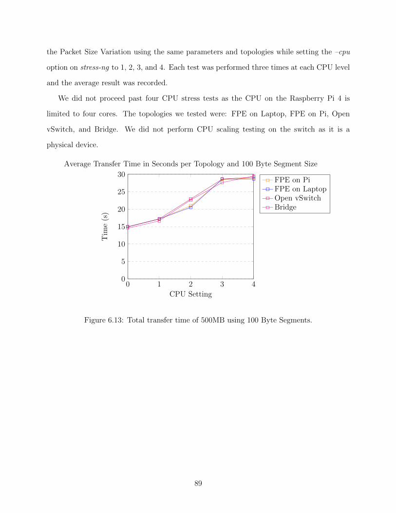
the Packet Size Variation using the same parameters and topologies while setting the –cpu
option on stress-ng to 1, 2, 3, and 4. Each test was performed three times at each CPU level
and the average result was recorded.
We did not proceed past four CPU stress tests as the CPU on the Raspberry Pi 4 is
limited to four cores. The topologies we tested were: FPE on Laptop, FPE on Pi, Open
vSwitch, and Bridge. We did not perform CPU scaling testing on the switch as it is a
physical device.
0 1 2 3 40
5
10
15
20
25
30
CPU Setting
Tim
e(s
)
Average Transfer Time in Seconds per Topology and 100 Byte Segment Size
FPE on PiFPE on LaptopOpen vSwitchBridge
Figure 6.13: Total transfer time of 500MB using 100 Byte Segments.
89
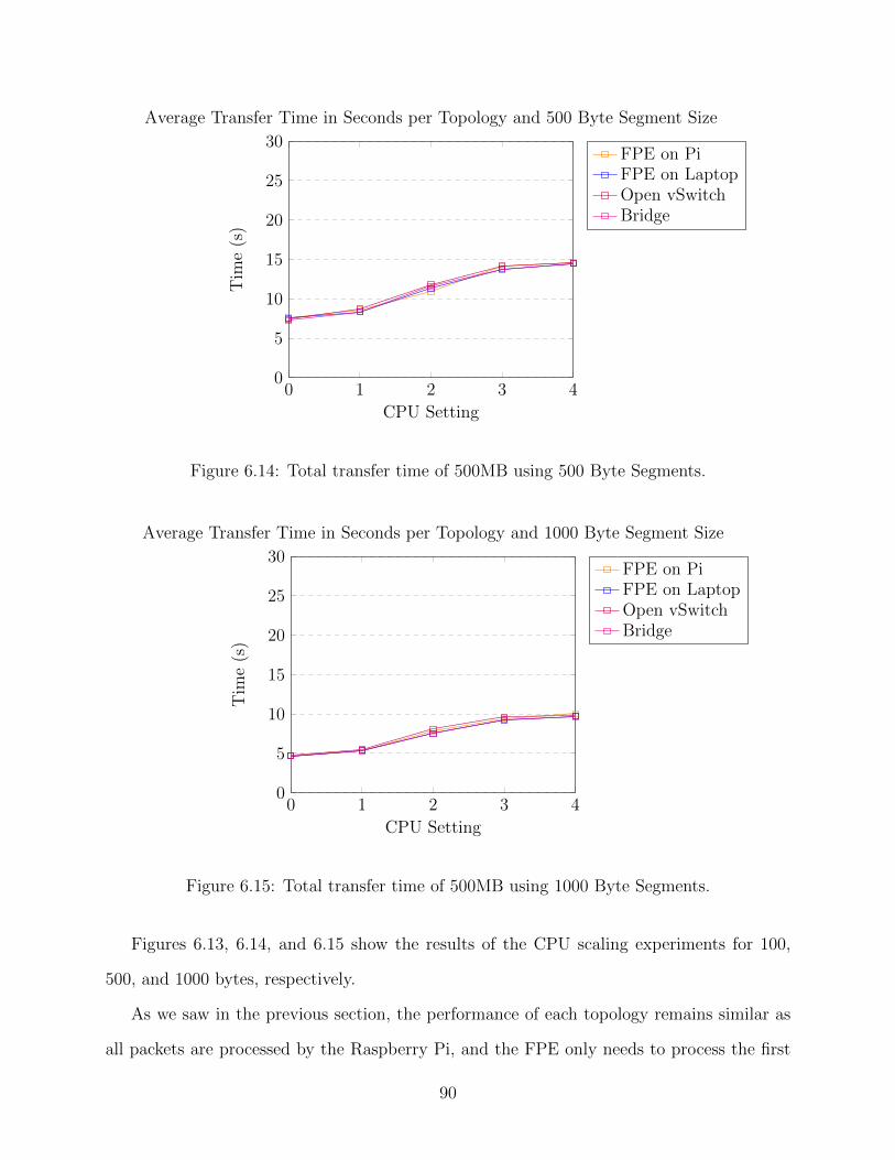
0 1 2 3 40
5
10
15
20
25
30
CPU Setting
Tim
e(s
)
Average Transfer Time in Seconds per Topology and 500 Byte Segment Size
FPE on PiFPE on LaptopOpen vSwitchBridge
Figure 6.14: Total transfer time of 500MB using 500 Byte Segments.
0 1 2 3 40
5
10
15
20
25
30
CPU Setting
Tim
e(s
)
Average Transfer Time in Seconds per Topology and 1000 Byte Segment Size
FPE on PiFPE on LaptopOpen vSwitchBridge
Figure 6.15: Total transfer time of 500MB using 1000 Byte Segments.
Figures 6.13, 6.14, and 6.15 show the results of the CPU scaling experiments for 100,
500, and 1000 bytes, respectively.
As we saw in the previous section, the performance of each topology remains similar as
all packets are processed by the Raspberry Pi, and the FPE only needs to process the first
90
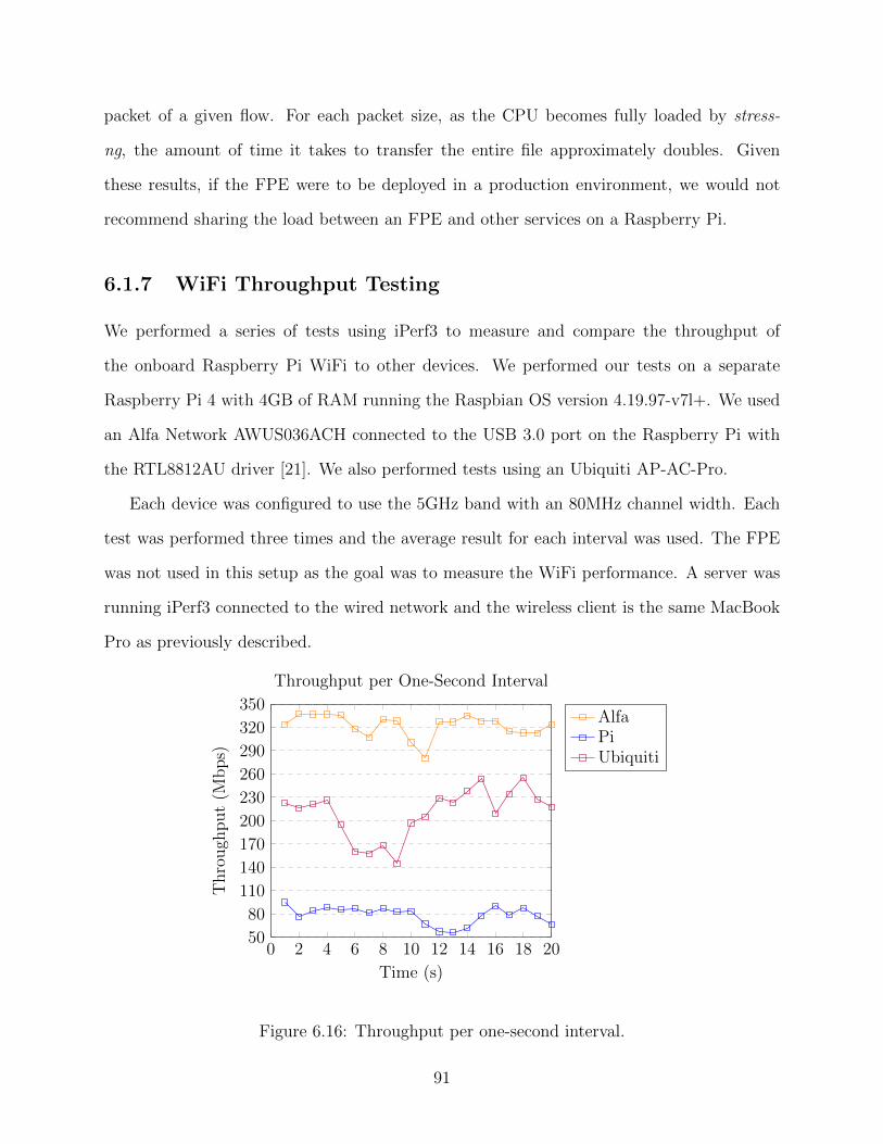
packet of a given flow. For each packet size, as the CPU becomes fully loaded by stress-
ng, the amount of time it takes to transfer the entire file approximately doubles. Given
these results, if the FPE were to be deployed in a production environment, we would not
recommend sharing the load between an FPE and other services on a Raspberry Pi.
6.1.7 WiFi Throughput Testing
We performed a series of tests using iPerf3 to measure and compare the throughput of
the onboard Raspberry Pi WiFi to other devices. We performed our tests on a separate
Raspberry Pi 4 with 4GB of RAM running the Raspbian OS version 4.19.97-v7l+. We used
an Alfa Network AWUS036ACH connected to the USB 3.0 port on the Raspberry Pi with
the RTL8812AU driver [21]. We also performed tests using an Ubiquiti AP-AC-Pro.
Each device was configured to use the 5GHz band with an 80MHz channel width. Each
test was performed three times and the average result for each interval was used. The FPE
was not used in this setup as the goal was to measure the WiFi performance. A server was
running iPerf3 connected to the wired network and the wireless client is the same MacBook
Pro as previously described.
0 2 4 6 8 10 12 14 16 18 2050
80
110
140
170
200
230
260
290
320
350
Time (s)
Thro
ugh
put
(Mbps)
Throughput per One-Second Interval
AlfaPiUbiquiti
Figure 6.16: Throughput per one-second interval.
91
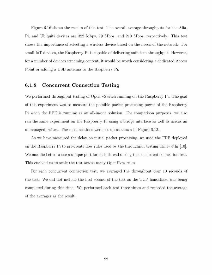
Figure 6.16 shows the results of this test. The overall average throughputs for the Alfa,
Pi, and Ubiquiti devices are 322 Mbps, 79 Mbps, and 210 Mbps, respectively. This test
shows the importance of selecting a wireless device based on the needs of the network. For
small IoT devices, the Raspberry Pi is capable of delivering sufficient throughput. However,
for a number of devices streaming content, it would be worth considering a dedicated Access
Point or adding a USB antenna to the Raspberry Pi.
6.1.8 Concurrent Connection Testing
We performed throughput testing of Open vSwitch running on the Raspberry Pi. The goal
of this experiment was to measure the possible packet processing power of the Raspberry
Pi when the FPE is running as an all-in-one solution. For comparison purposes, we also
ran the same experiment on the Raspberry Pi using a bridge interface as well as across an
unmanaged switch. These connections were set up as shown in Figure 6.12.
As we have measured the delay on initial packet processing, we used the FPE deployed
on the Raspberry Pi to pre-create flow rules used by the throughput testing utility ethr [10].
We modified ethr to use a unique port for each thread during the concurrent connection test.
This enabled us to scale the test across many OpenFlow rules.
For each concurrent connection test, we averaged the throughput over 10 seconds of
the test. We did not include the first second of the test as the TCP handshake was being
completed during this time. We performed each test three times and recorded the average
of the averages as the result.
92
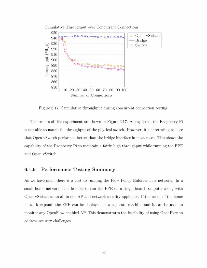
0 10 20 30 40 50 60 70 80 90 100850
860
870
880
890
900
910
920
930
940
950
Number of Connections
Thro
ugh
put
(Mbps)
Cumulative Throughput over Concurrent Connections
Open vSwitchBridgeSwitch
Figure 6.17: Cumulative throughput during concurrent connection testing.
The results of this experiment are shown in Figure 6.17. As expected, the Raspberry Pi
is not able to match the throughput of the physical switch. However, it is interesting to note
that Open vSwitch performed better than the bridge interface in most cases. This shows the
capability of the Raspberry Pi to maintain a fairly high throughput while running the FPE
and Open vSwitch.
6.1.9 Performance Testing Summary
As we have seen, there is a cost to running the Flow Policy Enforcer in a network. In a
small home network, it is feasible to run the FPE on a single board computer along with
Open vSwitch as an all-in-one AP and network security appliance. If the needs of the home
network expand, the FPE can be deployed on a separate machine and it can be used to
monitor any OpenFlow-enabled AP. This demonstrates the feasibility of using OpenFlow to
address security challenges.
93
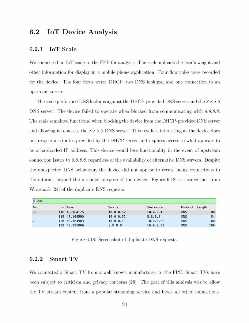
6.2 IoT Device Analysis
6.2.1 IoT Scale
We connected an IoT scale to the FPE for analysis. The scale uploads the user’s weight and
other information for display in a mobile phone application. Four flow rules were recorded
for the device. The four flows were: DHCP, two DNS lookups, and one connection to an
upstream server.
The scale performed DNS lookups against the DHCP-provided DNS server and the 8.8.8.8
DNS server. The device failed to operate when blocked from communicating with 8.8.8.8.
The scale remained functional when blocking the device from the DHCP-provided DNS server
and allowing it to access the 8.8.8.8 DNS server. This result is interesting as the device does
not respect attributes provided by the DHCP server and requires access to what appears to
be a hardcoded IP address. This device would lose functionality in the event of upstream
connection issues to 8.8.8.8, regardless of the availability of alternative DNS servers. Despite
the unexpected DNS behaviour, the device did not appear to create many connections to
the internet beyond the intended purpose of the device. Figure 6.18 is a screenshot from
Wireshark [24] of the duplicate DNS requests.
Figure 6.18: Screenshot of duplicate DNS requests.
6.2.2 Smart TV
We connected a Smart TV from a well known manufacturer to the FPE. Smart TVs have
been subject to criticism and privacy concerns [28]. The goal of this analysis was to allow
the TV stream content from a popular streaming service and block all other connections.
94
We obtained the list of domain names from the streaming service website. We created a rule
set for the streaming service domains and attached the rule set to the policy for the TV.
Since the domains provided by streaming service may use subdomains, we configured the
rule set to allow for any subdomain of the whitelisted domain names to be used.
We noted that the Smart TV attempts many connections to services beyond those nec-
essary for streaming content. A subset of DNS queries performed by the Smart TV are
listed in Table 6.3. Based on the DNS requests, these connections include connections to
advertising services, log aggregation services, and other vendor-managed servers. However,
we were able to successfully block these connections and create a least-permissive policy for
the device. In the end, the policy had nine rules: DHCP, DNS, and seven domain names for
the streaming service.
This demonstrates the value of configurability within the FPE to address privacy concerns
while still enabling an IoT device to perform desired functionality.
95

Table 6.3: Sample DNS Queries from Smart TV
Hostname
acr0.samsungcloudsolution.com
ads.samsungads.com
apps-pub.samsungcloudcdn.com
cdn.samsungcloudsolution.com
config.samsungads.com
events.samsungads.com
gpm.samsungqbe.com
lcprd1.samsungcloudsolution.net
log-config.samsungacr.com
log-ingestion.samsungacr.com
musicid.samsungcloud.tv
notice.samsungcloudsolution.com
noticecdn.samsungcloudsolution.com
oempprd.samsungcloudsolution.com
osb.samsungqbe.com
otn.samsungcloudcdn.com
otnprd10.samsungcloudsolution.net
samsungtifa.com
upu.samsungelectronics.com
xpu.samsungelectronics.com
96
6.3 System Discussion
6.3.1 Security
As we have seen, there is a cost to running the FPE in terms of connection setup. The cost
is reduced as flows are reused and the initial connection time is taken within context of a
larger transfer of data.
Suppose an attacker compromised an IoT device in each of the topologies in Figure 6.2,
and, in the case of the FPE topologies, the device is in the IoT Frozen state. In the first
two topologies, the attacker would have full access to the local network as there is no policy
enforcement on the network traffic. This device could be utilized to pivot and attack other
internal and external network resources.
The attacker would face a significant reduction in the ability to pivot within the network
in the cases where the FPE is running. The compromised IoT device would be restricted to
communication to ports and services that are defined in the policy for the IoT device. For ex-
ample, if the IoT device had never communicated via SMBv1, it would not be possible for an
attacker to utilize TCP ports 139 and 445 to execute the exploit known as ETERNALBLUE
[9] if vulnerable devices were located in the same LAN.
6.3.2 Usability
As we have previously discussed, the goal of the FPE is to provide a vendor agnostic solution
to securing smart homes. In order to effectively protect home networks, the solution must
be easy to setup and maintain.
The default FPE configuration automatically protects and limits IoT devices from ac-
cessing network resources beyond their initial connection requirements. Advanced users can
further restrict devices to communication to services of their choice.
The solution is capable of running on a low cost Raspberry Pi. The FPE workload can
be shifted to another computer on the network if higher performance is desired.
97
6.3.3 Comparison
Related Work
There are existing solutions and related work in the area of home network security. The FPE
differs from most existing approaches in two key areas: privacy and location of protection.
The FPE operates without using any SaaS offering or CSP. All learning is performed
locally within the network. This protects the privacy of home users as no data is sent to
a remote provider. It would be possible to enable the FPE to retrieve policies from an
upstream service and apply them to the devices, but care would need to be taken in order
to protect the privacy of the home user.
Network protection is often placed near the network edge. For example, a home router
may embed a firewall designed to prevent unauthorized network access. By utilizing an
OpenFlow-enabled AP, the FPE is capable of enforcing granular network rules closer to each
network device. This further enhances network protection by preventing a compromised
device from being utilized to attack adjacent devices within the same LAN. This movement
of protection at the edge to protection within the network brings the Zero Trust [44] model
to home networks.
Manufacturer Usage Description
One potential weakness of the FPE is the time devices spend in the IoT Learning state. It
would be possible for an IoT device to be compromised while the FPE is learning network
flows. This could be addressed by adding Manufacturer Usage Description (MUD) [47]
support to the FPE.
MUD is a standard designed to allow devices to specify network access policies when they
initially connect to a network. It relies on a MUD Manager operating within the network
to retrieve the policy located at the MUD URL. The MUD Manager can use this policy to
apply access restrictions through the configuration of network devices.
98

It is not a requirement for IoT devices to implement MUD. The FPE provides protection
of devices which do not implement the standard through the IoT Learning state. The FPE
could be enhanced to act as the MUD Manager in the event a MUD-enabled device is
connected. This would enable the FPE to immediately transition supported devices to the
IoT Frozen state and configure a policy with the appropriate rules.
99
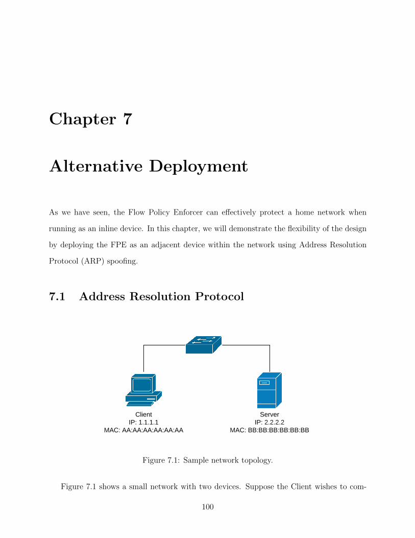
Chapter 7
Alternative Deployment
As we have seen, the Flow Policy Enforcer can effectively protect a home network when
running as an inline device. In this chapter, we will demonstrate the flexibility of the design
by deploying the FPE as an adjacent device within the network using Address Resolution
Protocol (ARP) spoofing.
7.1 Address Resolution Protocol
ClientIP: 1.1.1.1
MAC: AA:AA:AA:AA:AA:AA
ServerIP: 2.2.2.2
MAC: BB:BB:BB:BB:BB:BB
Figure 7.1: Sample network topology.
Figure 7.1 shows a small network with two devices. Suppose the Client wishes to com-
100

municate with the Server and it knows the IP address of the server. The client must also
know the MAC address of the Server in order to construct a frame.
The Client maintains an ARP table which contains mappings of IP addresses to MAC
addresses. First, the Client will check to see if it has a table entry for the Server. If the
Client finds a matching entry, it will use the associated MAC address. Otherwise, it will
send out a broadcast ARP request containing the MAC and IP address of the Client, as well
as the IP address of the Server.
The Server will receive this ARP Request, and respond with a unicast ARP Reply con-
taining the IP and MAC address of the Client as well as the IP and MAC address of the
server.
The Client will store this data in its own ARP table and use the MAC address contained
within the ARP Reply to send data to the server.
7.1.1 ARP Spoofing
ARP does not contain mechanisms to verify the sender of the ARP Reply. As a result, it is
possible for another device on the same network to forge ARP Replies to corrupt the ARP
table on a target device.
Figure 7.2 demonstrates the packets that an Attacker would need to generate in order
to spoof ARP packets in a network. In this example, the Client would associate the MAC
address of the Attacker to the IP address of the Server. Similarly, the Server would associate
the MAC address of the Attacker to the IP address of the Client. As a result, all traffic
originating from either the Client or the Server would pass through the Attacker.
As the Attacker receives traffic from the Client or Server, it will replace the Source MAC
address with the MAC address of itself. The Attacker may now perform a MITM attack on
communications occurring between the Client and the Server.
101
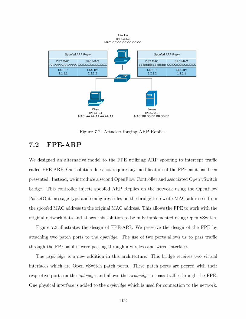
ClientIP: 1.1.1.1
MAC: AA:AA:AA:AA:AA:AA
ServerIP: 2.2.2.2
MAC: BB:BB:BB:BB:BB:BB
AttackerIP: 3.3.3.3
MAC: CC:CC:CC:CC:CC:CC
Spoofed ARP Reply
DST MAC:BB:BB:BB:BB:BB:BB
SRC MAC:CC:CC:CC:CC:CC:CC
DST IP:2.2.2.2
SRC IP:1.1.1.1
Spoofed ARP Reply
DST MAC:AA:AA:AA:AA:AA:AA
SRC MAC:CC:CC:CC:CC:CC:CC
DST IP:1.1.1.1
SRC IP:2.2.2.2
Figure 7.2: Attacker forging ARP Replies.
7.2 FPE-ARP
We designed an alternative model to the FPE utilizing ARP spoofing to intercept traffic
called FPE-ARP. Our solution does not require any modification of the FPE as it has been
presented. Instead, we introduce a second OpenFlow Controller and associated Open vSwitch
bridge. This controller injects spoofed ARP Replies on the network using the OpenFlow
PacketOut message type and configures rules on the bridge to rewrite MAC addresses from
the spoofed MAC address to the original MAC address. This allows the FPE to work with the
original network data and allows this solution to be fully implemented using Open vSwitch.
Figure 7.3 illustrates the design of FPE-ARP. We preserve the design of the FPE by
attaching two patch ports to the apbridge. The use of two ports allows us to pass traffic
through the FPE as if it were passing through a wireless and wired interface.
The arpbridge is a new addition in this architecture. This bridge receives two virtual
interfaces which are Open vSwitch patch ports. These patch ports are peered with their
respective ports on the apbridge and allows the arpbridge to pass traffic through the FPE.
One physical interface is added to the arpbridge which is used for connection to the network.
102
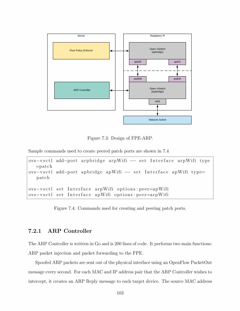
Raspberry PiServer
Open vSwitch(apbridge)
apWifi apEth
Open vSwitch(arpbridge)
eth0
arpWifi arpEth
Flow Policy Enforcer
ARP Controller
Network Switch
Figure 7.3: Design of FPE-ARP.
Sample commands used to create peered patch ports are shown in 7.4
ovs−v s c t l add−port arpbr idge arpWif i −− s e t I n t e r f a c e arpWif i type=patch
ovs−v s c t l add−port apbr idge apWifi −− s e t I n t e r f a c e apWifi type=patch
ovs−v s c t l s e t I n t e r f a c e arpWif i opt ions : peer=apWifiovs−v s c t l s e t I n t e r f a c e apWifi opt ions : peer=arpWif i
Figure 7.4: Commands used for creating and peering patch ports.
7.2.1 ARP Controller
The ARP Controller is written in Go and is 200 lines of code. It performs two main functions:
ARP packet injection and packet forwarding to the FPE.
Spoofed ARP packets are sent out of the physical interface using an OpenFlow PacketOut
message every second. For each MAC and IP address pair that the ARP Controller wishes to
intercept, it creates an ARP Reply message to each target device. The source MAC address
103
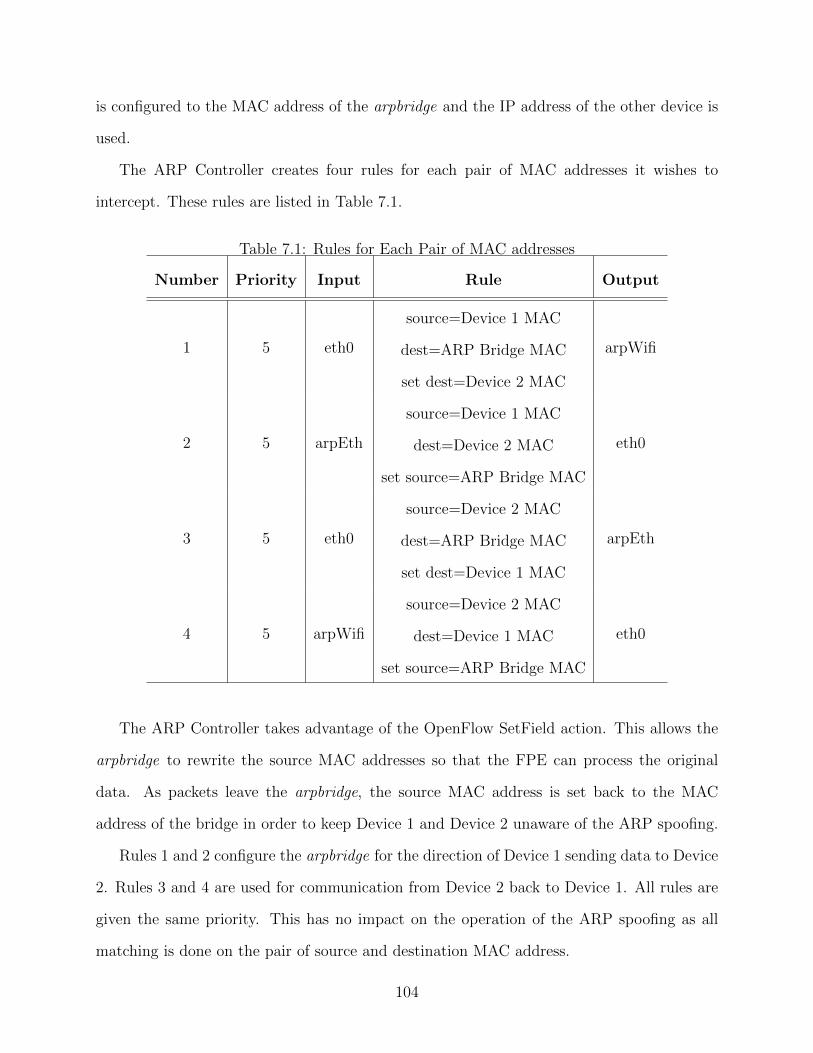
is configured to the MAC address of the arpbridge and the IP address of the other device is
used.
The ARP Controller creates four rules for each pair of MAC addresses it wishes to
intercept. These rules are listed in Table 7.1.
Table 7.1: Rules for Each Pair of MAC addresses
Number Priority Input Rule Output
1 5 eth0
source=Device 1 MAC
dest=ARP Bridge MAC
set dest=Device 2 MAC
arpWifi
2 5 arpEth
source=Device 1 MAC
dest=Device 2 MAC
set source=ARP Bridge MAC
eth0
3 5 eth0
source=Device 2 MAC
dest=ARP Bridge MAC
set dest=Device 1 MAC
arpEth
4 5 arpWifi
source=Device 2 MAC
dest=Device 1 MAC
set source=ARP Bridge MAC
eth0
The ARP Controller takes advantage of the OpenFlow SetField action. This allows the
arpbridge to rewrite the source MAC addresses so that the FPE can process the original
data. As packets leave the arpbridge, the source MAC address is set back to the MAC
address of the bridge in order to keep Device 1 and Device 2 unaware of the ARP spoofing.
Rules 1 and 2 configure the arpbridge for the direction of Device 1 sending data to Device
2. Rules 3 and 4 are used for communication from Device 2 back to Device 1. All rules are
given the same priority. This has no impact on the operation of the ARP spoofing as all
matching is done on the pair of source and destination MAC address.
104
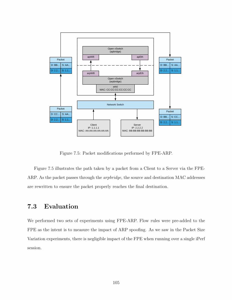
Open vSwitch(apbridge)
apWifi apEth
Open vSwitch(arpbridge)
eth0MAC: CC:CC:CC:CC:CC:CC
arpWifi arpEth
Network Switch
ClientIP: 1.1.1.1
MAC: AA:AA:AA:AA:AA:AA
ServerIP: 2.2.2.2
MAC: BB:BB:BB:BB:BB:BB
Packet
D: CC... S: AA...
D: 2.2... S: 1.1...
Packet
D: BB... S: AA...
D: 2.2... S: 1.1...
Packet
D: BB... S: AA...
D: 2.2... S: 1.1...
Packet
D: BB... S: CC...
D: 2.2... S: 1.1...
Figure 7.5: Packet modifications performed by FPE-ARP.
Figure 7.5 illustrates the path taken by a packet from a Client to a Server via the FPE-
ARP. As the packet passes through the arpbridge, the source and destination MAC addresses
are rewritten to ensure the packet properly reaches the final destination.
7.3 Evaluation
We performed two sets of experiments using FPE-ARP. Flow rules were pre-added to the
FPE as the intent is to measure the impact of ARP spoofing. As we saw in the Packet Size
Variation experiments, there is negligible impact of the FPE when running over a single iPerf
session.
105
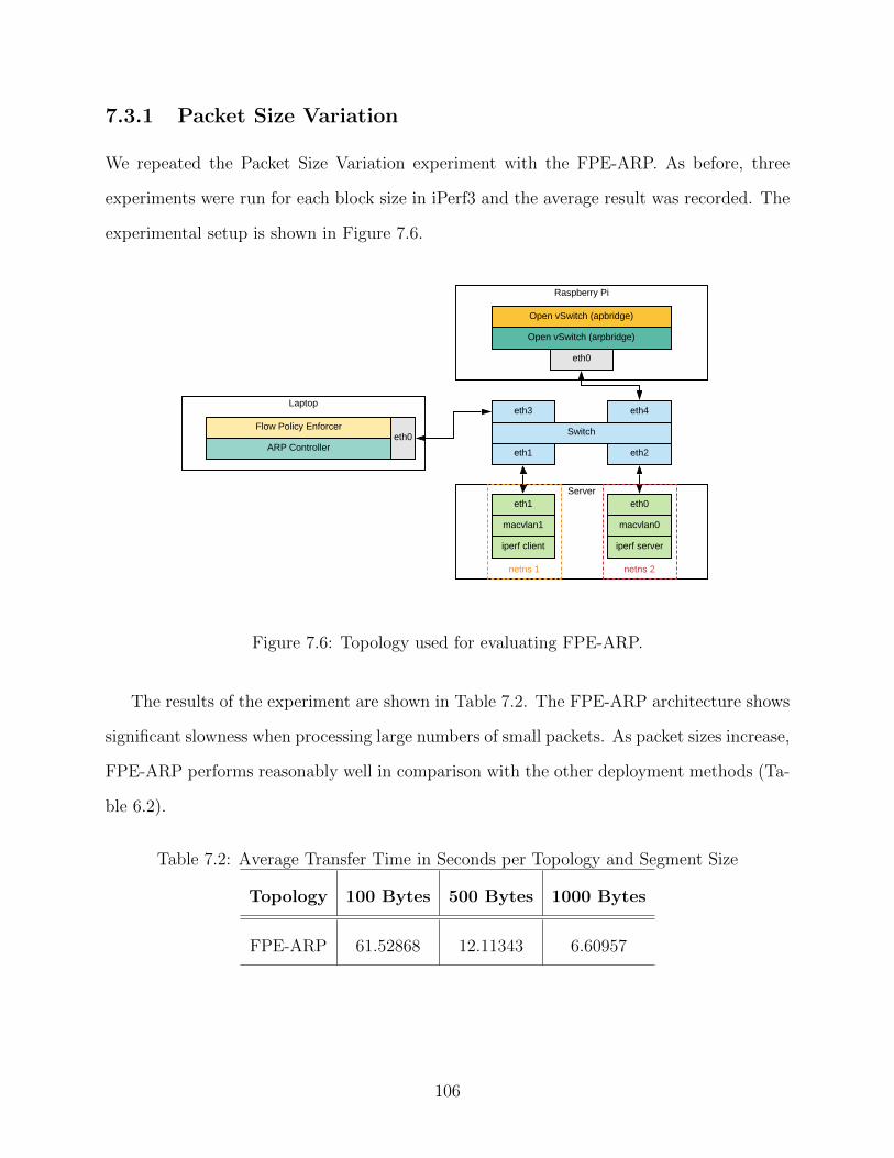
7.3.1 Packet Size Variation
We repeated the Packet Size Variation experiment with the FPE-ARP. As before, three
experiments were run for each block size in iPerf3 and the average result was recorded. The
experimental setup is shown in Figure 7.6.
Raspberry Pi
Laptop
Flow Policy Enforcereth0
Servereth1 eth0
Switch
eth1 eth2
iperf client iperf server
macvlan1 macvlan0
netns 1 netns 2
Open vSwitch (arpbridge)
eth0
Open vSwitch (apbridge)
ARP Controller
eth3 eth4
Figure 7.6: Topology used for evaluating FPE-ARP.
The results of the experiment are shown in Table 7.2. The FPE-ARP architecture shows
significant slowness when processing large numbers of small packets. As packet sizes increase,
FPE-ARP performs reasonably well in comparison with the other deployment methods (Ta-
ble 6.2).
Table 7.2: Average Transfer Time in Seconds per Topology and Segment Size
Topology 100 Bytes 500 Bytes 1000 Bytes
FPE-ARP 61.52868 12.11343 6.60957
106
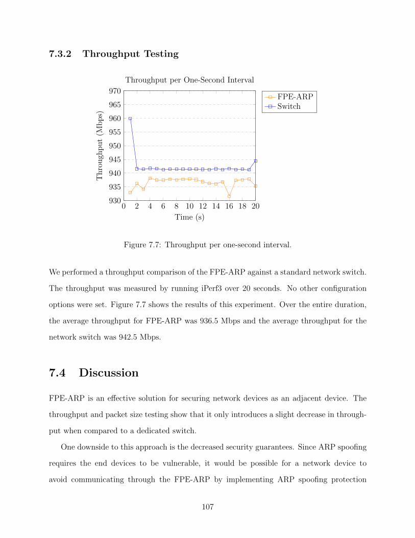
7.3.2 Throughput Testing
0 2 4 6 8 10 12 14 16 18 20930
935
940
945
950
955
960
965
970
Time (s)
Thro
ugh
put
(Mbps)
Throughput per One-Second Interval
FPE-ARPSwitch
Figure 7.7: Throughput per one-second interval.
We performed a throughput comparison of the FPE-ARP against a standard network switch.
The throughput was measured by running iPerf3 over 20 seconds. No other configuration
options were set. Figure 7.7 shows the results of this experiment. Over the entire duration,
the average throughput for FPE-ARP was 936.5 Mbps and the average throughput for the
network switch was 942.5 Mbps.
7.4 Discussion
FPE-ARP is an effective solution for securing network devices as an adjacent device. The
throughput and packet size testing show that it only introduces a slight decrease in through-
put when compared to a dedicated switch.
One downside to this approach is the decreased security guarantees. Since ARP spoofing
requires the end devices to be vulnerable, it would be possible for a network device to
avoid communicating through the FPE-ARP by implementing ARP spoofing protection
107

mechanisms.
FPE-ARP demonstrates the flexibility of the platform and utilization of OpenFlow stan-
dards. We are able to successfully perform ARP spoofing using built in mechanisms for field
modification and packet injection. using the SetField and PacketOut messages, respectively.
108
Chapter 8
Conclusion
8.1 Summary
In this thesis, we have reviewed core networking principles and recent literature on different
methods to secure home networks. We reviewed three main categories of securing IoT devices:
• IoT Device Identification
• OpenFlow in WiFi and Security
• Cloud Based Firewalls
In addition to reviewing recent work, we proposed a novel system for securing IoT devices
within home networks. The Flow Policy Enforcer is able to effectively protect the network
by restricting IoT device communications to least permissive rule sets. This prevents com-
promised devices from accessing internal and external network resources and reduces the
capability of an attacker to utilize a compromised IoT device. We have also shown Open-
Flow as a viable solution for securing IoT devices within home networks.
The Flow Policy Enforcer has the following advantages:
• It can be deployed on low-cost hardware. This reduces the burden on a home user
looking for effective protection of their IoT devices and network.
109
• It does not rely on cloud services. Keeping the data within the local area network
preserves the privacy of the home user as no cloud services are utilized.
• It uses standard network protocols. This ensures the FPE will work with any IoT
device which uses the 802.11 wireless protocol.
• It automatically protects IoT devices within a wireless network. No assumptions are
made about the capability of the network administrator; policies are automatically
learned based on the behaviour of an IoT device.
Since the FPE limits devices on a policy-based approach, it can limit the effectiveness of
zero day attacks on IoT devices and the associated damage these attacks may cause.
8.2 Future Work
There are many potential future research directions for the FPE:
• Network protocols beyond TCP or UDP: We focused solely on preventing a compro-
mised device from accessing TCP or UDP resources within a network. The FPE could
be expanded to be even more restrictive and allow devices to only use the protocols
they request during the learning period.
• Integration with other standards: Manufacturer Usage Description (RFC 8520 [47])
would allow for FPE to pre-populate policies and place them in the IoT Frozen state
without any learning time required.
• Actioning blocked packets: The FPE drops packets that do not match a rule set. It
would be possible to analyze blocked packets to determine if the device needs to go
back into the IoT Learning state or raise alerts on a potential compromise.
• Protection of devices beyond APs: The FPE operates on APs in a LAN. It would
be possible to take the system architecture and scale it across a network comprised
110
of OpenFlow enabled access points and switches. This would enable protection of
hardwired devices, such as a desktop computer.
• User interaction studies: The user interface could be studied and improved based on
user interaction studies. The result of these studies could be applied to the FPE and
other network security solutions designed for home users.
111

Bibliography
[1] Ieee standard for local and metropolitan area networks–bridges and bridged networks.
IEEE Std 802.1Q-2014 (Revision of IEEE Std 802.1Q-2011), pages 1–1832, Dec 2014.
[2] Ieee standard for ethernet. IEEE Std 802.3-2015 (Revision of IEEE Std 802.3-2012),
pages 1–4017, March 2016.
[3] Ieee standard for information technology—telecommunications and information ex-
change between systems local and metropolitan area networks—specific requirements -
part 11: Wireless lan medium access control (mac) and physical layer (phy) specifica-
tions. IEEE Std 802.11-2016 (Revision of IEEE Std 802.11-2012), pages 1–3534, Dec
2016.
[4] Fontawesome. https://fontawesome.com, Accessed 2019.
[5] gofc. https://github.com/Kmotiko/gofc, Accessed 2019.
[6] Gopacket. https://github.com/google/gopacket, Accessed 2019.
[7] iperf - the ultimate speed test tool for tcp, udp and sctp. https://iperf.fr/, Accessed
2019.
[8] Redis. https://redis.io/, Accessed 2019.
[9] Smb exploited: Wannacry use of eternalblue. https://www.fireeye.com/blog/
threat-research/2017/05/smb-exploited-wannacry-use-of-eternalblue.html, Accessed
2019.
112
[10] Ethr is a network performance measurement tool for tcp, udp & http. https://github.
com/microsoft/ethr, Accessed 2020.
[11] Getting started with rails. https://guides.rubyonrails.org/getting started.html, Ac-
cessed 2020.
[12] Go 1.5 release notes. https://golang.org/doc/go1.5, Accessed 2020.
[13] gorm. https://github.com/jinzhu/gorm, Accessed 2020.
[14] Groom your app’s ruby environment with rbenv. https://github.com/rbenv/rbenv,
Accessed 2020.
[15] hostapd: Initial ovs support. https://github.com/hschaa/hostapd/commit/
c89daaeca4ee90c8bc158e37acb1b679c823d7ab, Accessed 2020.
[16] Information system boundary. https://csrc.nist.gov/glossary/term/
information-system-boundary, Accessed 2020.
[17] Insider threat. https://awakesecurity.com/glossary/insider-threat/, Accessed 2020.
[18] Introducing json. https://www.json.org/json-en.html, Accessed 2020.
[19] Nist sp 800-53 revision 5 status update. https://csrc.nist.gov/CSRC/media/
Publications/sp/800-53/rev-5/draft/documents/draft sp800-53-rev5 update-message.
pdf, Accessed 2020.
[20] Raspberry pi 4 tech specs. https://www.raspberrypi.org/products/
raspberry-pi-4-model-b/specifications/, Accessed 2020.
[21] Rtl8812au/21au and rtl8814au driver with monitor mode and frame injection. https:
//github.com/aircrack-ng/rtl8812au, Accessed 2020.
[22] stress-ng. https://wiki.ubuntu.com/Kernel/Reference/stress-ng, Accessed 2020.
113
[23] Tq4600. https://alliedtelesis.com/en/documents/datasheet-tq4600-wireless-access-point,
Accessed 2020.
[24] Wireshark. https://www.wireshark.org/, Accessed 2020.
[25] Muhammad Naveed Aman, Kee Chaing Chua, and Biplab Sikdar. Secure data prove-
nance for the internet of things. In Proc. ACM IoTPTS, pages 11–14, New York, NY,
USA, 2017. ACM.
[26] K. Boeckl et al. Considerations for managing internet of things (iot) cybersecurity and
privacy risks. Technical report, National Institute of Standards and Technology, 2018.
[27] Robert Braden. Requirements for internet hosts-communication layers. Technical re-
port, 1989.
[28] J. Brodkin. Smart tvs are invading privacy and should be investigated, senators say.
July 2018.
[29] Cisco. Digital impact. https://www.cisco.com/c/dam/assets/csr/pdf/
Digital-Impact-Playbook.pdf, Accessed 2020.
[30] Boris Danev, Davide Zanetti, and Srdjan Capkun. On physical-layer identification of
wireless devices. ACM Comput. Surv., 45(1):6:1–6:29, December 2012.
[31] S. Deering et al. Internet protocol, version 6 (ipv6) specification. Technical report, 1998.
[32] DNSCrypt. Dnscrypt website. https://dnscrypt.info/, Accessed 2020.
[33] T. T. Doan et al. Towards a resilient smart home. In Proc. ACM IoT S&P, pages 15–21,
New York, NY, USA, 2018. ACM.
[34] Ralph Droms. Rfc 2131-dynamic host configuration protocol, march 1997. Obsoletes
RFC1541. Status: DRAFT STANDARD, 3(1), 1997.
114

[35] Joint Task Force and Transformation Initiative. Security and privacy controls for federal
information systems and organizations. NIST Special Publication, 800(53), 2013.
[36] Joint Task Force and Transformation Initiative. Draft nist special publication 800-154.
NIST Special Publication, 800(154), 2016.
[37] M. Frustaci et al. Evaluating critical security issues of the iot world: Present and future
challenges. IEEE IoT-J, 5(4):2483–2495, Aug 2018.
[38] P. Grassi et al. Digital identity guidelines - authentication and lifecycle management.
NIST Special Publication, 800(63B), 2017.
[39] R. Hinden et al. Ip version 6 addressing architecture. Technical report, 2006.
[40] P. Hoffman et al. Dns queries over https (doh). Technical report, 2018.
[41] Z. Hu et al. Specification for dns over transport layer security (tls). Technical report,
2018.
[42] K. Huang et al. Systematically understanding the cyber attack business: A survey.
ACM CSUR, 51(4):70:1–70:36, July 2018.
[43] IEEE Standards Association. Registration Authority, November 2019.
[44] J. Kindervag. Build security into your network’s dna: The zero trust network architec-
ture. Forrester Research Inc, pages 1–26, 2010.
[45] D. Kreutz et al. Software-defined networking: A comprehensive survey. Proc. of the
IEEE, 103(1):14–76, 2015.
[46] E. Kritzinger and S. von Solms. Home user security- from thick security-oriented home
users to thin security- oriented home users. In Proc. SAI, pages 340–345, Oct 2013.
[47] Eliot Lear, Ralph Droms, and Dan Romascanu. Manufacturer usage description speci-
fication. Technical report, 2019.
115

[48] Markets and Markets. Cybersecurity market by solution, service, security
type, deployment mode, organization size, industry vertical, and region -
global forecast to 2023. https://www.marketsandmarkets.com/Market-Reports/
cyber-security-market-505.html, September 2018.
[49] John Matherly. Complete guide to shodan. Shodan, LLC (2016-02-25), 2015.
[50] Y. Meidan et al. Profiliot: A machine learning approach for iot device identification
based on network traffic analysis. In Proc. ACM SAC, pages 506–509, New York, NY,
USA, 2017. ACM.
[51] Peter Mell, James Shook, and Richard Harang. Measuring and improving the effective-
ness of defense-in-depth postures. In Proceedings of the 2nd Annual Industrial Control
System Security Workshop, pages 15–22, 2016.
[52] P. Mockapetris. Domain names - implementation and specification. Technical report,
1987.
[53] Paul Mockapetris. Rfc-1034 domain names-concepts and facilities. Network Working
Group, page 55, 1987.
[54] D. M’Raihi et al. Totp: Time-based one-time password algorithm. Technical report,
2011.
[55] T. Mrugalski et al. Dynamic host configuration protocol for ipv6 (dhcpv6). Technical
report, 2018.
[56] K. Neupane, R. Haddad, and L. Chen. Next generation firewall for network security: A
survey. In Proc. IEEE SoutheastCon 2018, April 2018.
[57] M. Nobakht, V. Sivaraman, and R. Boreli. A host-based intrusion detection and miti-
gation framework for smart home iot using openflow. In Proc. ARES, pages 147–156,
Aug 2016.
116

[58] OWASP. Attack surface analysis cheat sheet. https://cheatsheetseries.owasp.org/
cheatsheets/Attack Surface Analysis Cheat Sheet.html, Accessed 2020.
[59] OWASP. Testing for input validation. https://www.owasp.org/index.php/Testing for
Input Validation, Accessed 2020.
[60] OWASP. Threat modeling cheat sheet. https://cheatsheetseries.owasp.org/cheatsheets/
Threat Modeling Cheat Sheet.html, Accessed 2020.
[61] David C Plummer. Rfc 826: An ethernet address resolution protocol. Network Working
Group, 1982.
[62] P. Porras et al. A security enforcement kernel for openflow networks. In Proc. ACM
HotSDN, pages 121–126, New York, NY, USA, 2012. ACM.
[63] J. Postel. Internet protocol. Technical report, 1981.
[64] Jon Postel et al. Rfc 768: User datagram protocol, 1980.
[65] Jon Postel et al. Rfc 793: Transmission control protocol, 1981.
[66] Y. Rekhter et al. Address allocation for private internets. Technical report, 1996.
[67] Sandra Scott-Hayward. Design and deployment of secure, robust, and resilient sdn
controllers. In Proceedings of the 2015 1st IEEE conference on network Softwarization
(NetSoft), pages 1–5. IEEE, 2015.
[68] Syed Abdullah Shah, Jannet Faiz, Maham Farooq, Aamir Shafi, and Syed Akbar Mehdi.
An architectural evaluation of sdn controllers. In 2013 IEEE International Conference
on Communications (ICC), pages 3504–3508. IEEE, 2013.
[69] Alexander Shalimov, Dmitry Zuikov, Daria Zimarina, Vasily Pashkov, and Ruslan
Smeliansky. Advanced study of sdn/openflow controllers. 10 2013.
117
[70] S. Shirali-Shahreza and Y. Ganjali. Protecting home user devices with an sdn-based
firewall. IEEE T-CE, 64(1):92–100, Feb 2018.
[71] Talos. New vpnfilter malware targets at least 500k networking devices worldwide. May
2018.
[72] C. R. Taylor et al. On the feasibility of cloud-based sdn controllers for residential
networks. In Proc. IEEE NFV-SDN, pages 1–6, Nov 2017.
[73] The Open Networking Foundation. OpenFlow Switch Specification, September 2012.
[74] J. Vestin et al. Cloudmac: Towards software defined wlans. ACM SIGMOBILE MC2R,
16(4):42–45, February 2013.
[75] Chiba Yasunobu and Sugyou Kazushi. Openflow controller architecture for large-scale
sdn networks. NEC Technical Journal, 8(2):41–44, 2014.
[76] Hubert Zimmermann. Osi reference model-the iso model of architecture for open systems
interconnection. IEEE TCOM, 28(4):425–432, 1980.
118