section 5 convey line & convey line accessories table of contents
TRANSCRIPT

SECTIO
N 5 C
ON
VE
Y LIN
E & CONVEY LIN
E ACCESSO
RIES
For Ordering and Pricing Information, Call Toll Free 1.800.748.7000
SECTION 5 CONVEY LINE & CONVEY LINE ACCESSORIESTABLE OF CONTENTS
S5-0
SECTION 5 – Convey Line & Convey Line Accessories
COUPLINGSCompression-Style Coupling . . . . . . . . . . . . . . . . . . . . . . . . . . . . . . . . . . . . . . . . . . . . . . . . . . . . . . . . . . . . . . . . S5-1Compression-Style Coupling with Side Bands . . . . . . . . . . . . . . . . . . . . . . . . . . . . . . . . . . . . . . . . . . . . . . . . . . . S5-1High-Pressure Couplings for Plain-End Pipe. . . . . . . . . . . . . . . . . . . . . . . . . . . . . . . . . . . . . . . . . . . . . . . . . . . . . S5-2High-Pressure Couplings for Grooved-End Pipe . . . . . . . . . . . . . . . . . . . . . . . . . . . . . . . . . . . . . . . . . . . . . . . . . S5-2Quick-Connect, Cam-and-Groove Couplings . . . . . . . . . . . . . . . . . . . . . . . . . . . . . . . . . . . . . . . . . . . . . . . . . . . . S5-3
TUBING AND PIPETubing & Pipe — Straight Lengths . . . . . . . . . . . . . . . . . . . . . . . . . . . . . . . . . . . . . . . . . . . . . . . . . . . . . . . . . . . . S5-9Internal-Spiral-Grooved Pipe and Tube. . . . . . . . . . . . . . . . . . . . . . . . . . . . . . . . . . . . . . . . . . . . . . . . . . . . . . . . . S5-10Directional, Shot-Peened Pipe . . . . . . . . . . . . . . . . . . . . . . . . . . . . . . . . . . . . . . . . . . . . . . . . . . . . . . . . . . . . . . . S5-10Standard Short- and Long-Radius Elbows. . . . . . . . . . . . . . . . . . . . . . . . . . . . . . . . . . . . . . . . . . . . . . . . . . . . . . . S5-11Convey Line Sight Glasses . . . . . . . . . . . . . . . . . . . . . . . . . . . . . . . . . . . . . . . . . . . . . . . . . . . . . . . . . . . . . . . . . . S5-1290° Wearback Elbows . . . . . . . . . . . . . . . . . . . . . . . . . . . . . . . . . . . . . . . . . . . . . . . . . . . . . . . . . . . . . . . . . . . . . . S5-1390° Wearback Elbows with Replaceable Channel . . . . . . . . . . . . . . . . . . . . . . . . . . . . . . . . . . . . . . . . . . . . . . . . . S5-14Wear-Resistant, Ceramic-Wrapped Elbows . . . . . . . . . . . . . . . . . . . . . . . . . . . . . . . . . . . . . . . . . . . . . . . . . . . . . . S5-15Standard and Special Welded Fabrications . . . . . . . . . . . . . . . . . . . . . . . . . . . . . . . . . . . . . . . . . . . . . . . . . . . . . S5-16Flexible Hose, Rubber — 688 SB Bulk Commodity . . . . . . . . . . . . . . . . . . . . . . . . . . . . . . . . . . . . . . . . . . . . . . . S5-17Flexible Hose, Rubber — 690 SB Bulk Commodity . . . . . . . . . . . . . . . . . . . . . . . . . . . . . . . . . . . . . . . . . . . . . . . S5-17Flexible Hose, PVC . . . . . . . . . . . . . . . . . . . . . . . . . . . . . . . . . . . . . . . . . . . . . . . . . . . . . . . . . . . . . . . . . . . . . . . . S5-18Flexible Hose Accessories . . . . . . . . . . . . . . . . . . . . . . . . . . . . . . . . . . . . . . . . . . . . . . . . . . . . . . . . . . . . . . . . . . . S5-18Flexible Hose Assemblies . . . . . . . . . . . . . . . . . . . . . . . . . . . . . . . . . . . . . . . . . . . . . . . . . . . . . . . . . . . . . . . . . . . S5-18Hose Stations. . . . . . . . . . . . . . . . . . . . . . . . . . . . . . . . . . . . . . . . . . . . . . . . . . . . . . . . . . . . . . . . . . . . . . . . . . . . . S5-19Vacuum Breaker Valves . . . . . . . . . . . . . . . . . . . . . . . . . . . . . . . . . . . . . . . . . . . . . . . . . . . . . . . . . . . . . . . . . . . . . S5-20Vacuum Modulating Valves . . . . . . . . . . . . . . . . . . . . . . . . . . . . . . . . . . . . . . . . . . . . . . . . . . . . . . . . . . . . . . . . . . S5-20

For Ordering and Pricing Information, Call Toll Free 1.800.748.7000S5-1
SECTION 5 CONVEY LINE & CONVEY LINE ACCESSORIESCompression-Style Couplings
COMPRESSION-STYLE COUPLINGDual-locking side bands grip the pipe and allow higheroperating pressures than standard compressioncouplings usually allow. These are especially effective in resisting line end pull and providing a superiorconnection when excessive vibration may be present.They have also proved to be extremely useful whenrepairing sections of convey lines, while also providinga positive seal. As found in the standard compressioncoupling assembly and disassembly is fast and easy.
PRODUCT FEATURES• Provide vastly improved axial force holding power to connect or repair pipe and tube
• Allows higher operating pressure then normallysuggested for compression type coupling
• Especially effective where line vibration is a problem• Available from 2-inch O.D through 24-inch O.D.nominal pipe or tubing sizes
• Complete coupling, or conversion kits available for existing couplings
COMPRESSION-STYLE COUPLINGCompression Couplings provide a positive seal for dilute phase pressure and vacuum pneumatic convey lineswhen joining plain end tubing, pipe, elbows and other line components. These couplings are available indifferent bolt count arrangements, with a wide variety of gaskets for use in a vast range of applications.Whether your application is low pressure conveying Aggregates, Food Products or Chemicals we can assist you in the identification of the right compression couplingarrangement for your needs. Remember when ordering thesecouplings for a Vacuum system to include the Gasket Protector to extend the coupling life. This style of compression coupling is generally used in systems with pressures of 15 PSI or less. The assembly and disassembly of these couplings is fast and easy.
PRODUCT FEATURES• Provides equalized pressure seal• Provided ready to install• Available in galvanized steel, aluminum or stainless steel• Includes inner sleeve for positive seal and extra rigidity• Available with black neoprene, white neoprene, high temperature as well as other gasket material
• Available from 0.75-inch to 24-inch, tubing and pipe
S5-2For Ordering and Pricing Information, Call Toll Free 1.800.748.7000
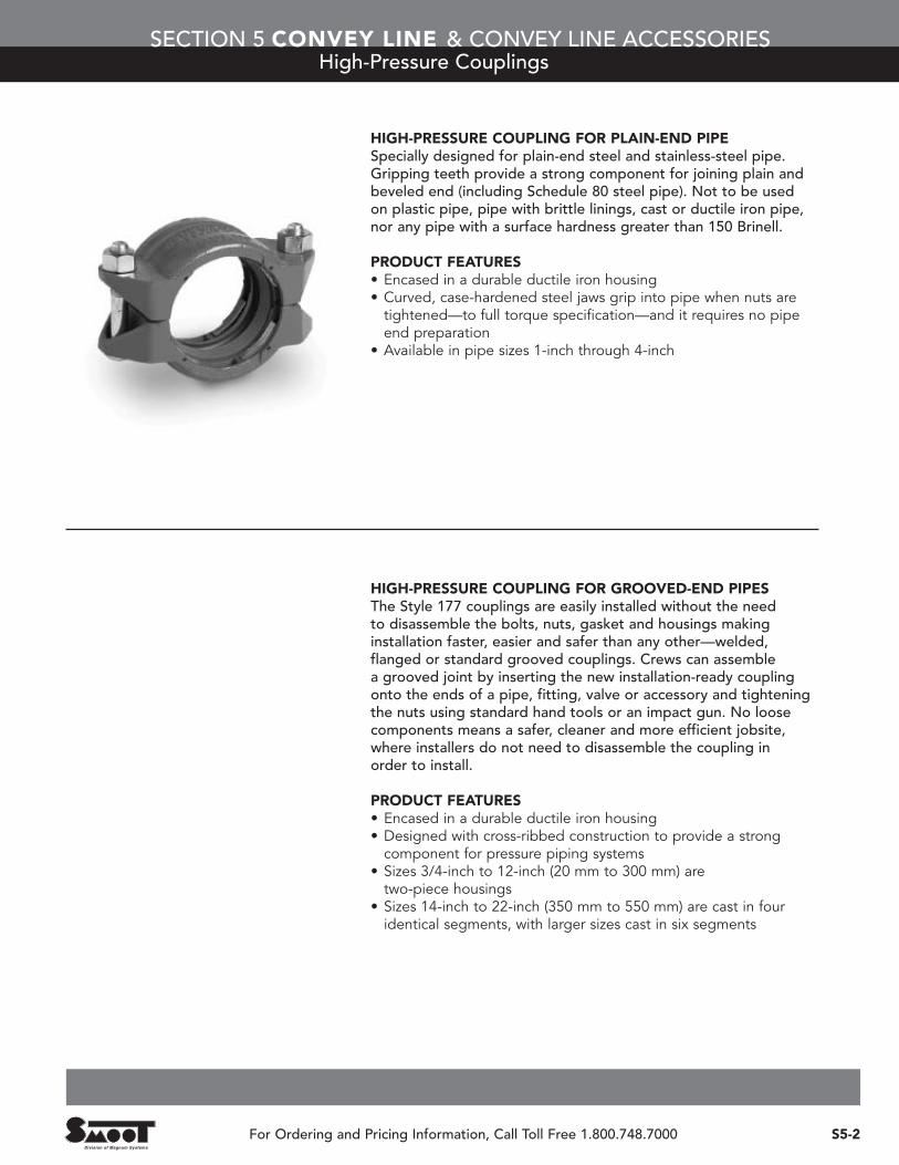
HIGH-PRESSURE COUPLING FOR PLAIN-END PIPESpecially designed for plain-end steel and stainless-steel pipe.Gripping teeth provide a strong component for joining plain andbeveled end (including Schedule 80 steel pipe). Not to be used on plastic pipe, pipe with brittle linings, cast or ductile iron pipe,nor any pipe with a surface hardness greater than 150 Brinell.
PRODUCT FEATURES• Encased in a durable ductile iron housing• Curved, case-hardened steel jaws grip into pipe when nuts aretightened—to full torque specification—and it requires no pipeend preparation
• Available in pipe sizes 1-inch through 4-inch
HIGH-PRESSURE COUPLING FOR GROOVED-END PIPESThe Style 177 couplings are easily installed without the need to disassemble the bolts, nuts, gasket and housings makinginstallation faster, easier and safer than any other—welded,flanged or standard grooved couplings. Crews can assemble a grooved joint by inserting the new installation-ready couplingonto the ends of a pipe, fitting, valve or accessory and tighteningthe nuts using standard hand tools or an impact gun. No loosecomponents means a safer, cleaner and more efficient jobsite,where installers do not need to disassemble the coupling in order to install.
PRODUCT FEATURES• Encased in a durable ductile iron housing• Designed with cross-ribbed construction to provide a strongcomponent for pressure piping systems
• Sizes 3/4-inch to 12-inch (20 mm to 300 mm) are two-piece housings
• Sizes 14-inch to 22-inch (350 mm to 550 mm) are cast in fouridentical segments, with larger sizes cast in six segments
SECTION 5 CONVEY LINE & CONVEY LINE ACCESSORIESHigh-Pressure Couplings

For Ordering and Pricing Information, Call Toll Free 1.800.748.7000S5-3
SECTION 5 CONVEY LINE & CONVEY LINE ACCESSORIESQuick-Connect, Cam-and-Groove Couplings
Recommended Operating Conditions by Materials and Conveyance Diameter
MATERIAL GASKETMAXIMUMWORKINGPRESSURE
SIZE IN INCHES
1/2 to3/4
1 1-1/4 1-1/2 2 2-1/2 3 4 5 6
ALUMINUM(not for use above 300°F)
Standard gasket +225°FViton gasket +350°F*
(Teflon® gaskets also available)
250 psi X X X X X150 psi X125 psi X100 psi X75 psi X X
FORGED BRASSStandard gasket +225°FViton gasket +350°F**Teflon gasket +450°F**
350 psi X X X X X250 psi X X100 psi X
CAST BRASSStandard gasket +225°FViton gasket +350°F*
(Teflon gaskets also available)
200 psi X X X X X150 psi X125 psi X100 psi X75 psi X X
MALLEABLE IRONStandard gasket +225°F; Viton gasket +350°F*
(Teflon gaskets also available)
125 psi X X100 psi X X X
STAINLESS STEELStandard gasket +225°FViton gasket +350°F**Teflon gasket +450°F**
250 psi X X X X X200 psi X100 psi X
MONELStandard gasket +225°FViton gasket +350°F**Teflon gasket +450°F**
250 psi X X X X X200 psi X150 psi X100 psi X
POLYPROPYLENEStandard gasket +70°FStandard gasket +200°F
100 psi X X X X X50 psi X X X X X
*For temperatures in excess of +225°F consult the Service Center for pressure ratings.**For temperatures in excess of +300°F consult the Service Center for pressure ratings.
QUICK-CONNECT, CAM-AND-GROOVE COUPLINGSSmoot Company distributes high quality quick connect/disconnect style couplings, sometimes referred to as“QD” Couplings, and their respective replacement parts. We present proven solutions at competitive pricingfor most all QD Coupling applications available on the market today. If you need assistance when specifying or ordering QD Couplings our knowledgeable sales staff will assist you through the selection process.
PRODUCT FEATURES• Sizes available from 1/2-inch through 12-inch for many types• Constructed of cast brass, aluminum, stainless steel, malleable iron or forged brass.
• Operating temperatures up to 450°F• Operating pressures up to 350 psig
STANDARD CONSTRUCTION MATERIALS• Cast Brass • Aluminum• 316 Stainless Steel • Malleable Iron• Polypropylene • Forged Brass
OPTIONAL CONSTRUCTION MATERIALS CONTACT THE SERVICE CENTER FOR PRICING
• Hard-Coat Aluminum • Hastalloy®C• Anodized Alumimum • Carpenter 20®• Monel

SECTION 5 CONVEY LINE & CONVEY LINE ACCESSORIESQuick-Connect, Cam-and-Groove Couplings
S5-4For Ordering and Pricing Information, Call Toll Free 1.800.748.7000
CouplersTypical dimensions in inches for aluminum*
SIZE A B C D E F G H J K L M
1/2 2-11/16 1-1/2 1-15/16 1-15/16 9/16 1-3/16 3-7/16 5/16 1-27/32 23/32 1-1/4 7/16
3/4 4-1/2 2-7/8 1-3/8 2-1/16 3/4 1-5/16 3-3/4 1/2 2-1/16 59/64 1-1/4 5/8
1 4-5/8 2-3/16 1-9/16 2-7/16 1 1-9/16 4-1/16 3/4 2-15/32 1-5/32 1-11/16 9/16
1-1/4 7-3/16 3-3/16 2-3/16 2-3/16 1-1/4 1-13/16 4-1/16 1 2-29/32 1-1/4 2-1/16 5/8
1-1/2 7-1/2 3-1/2 1-7/8 2-3/4 1-3/8 1-13/16 4-9/16 1-11/16 2-3/4 1-5/8 2 3/4
2 9-7/8 3-7/8 1-3/16 3-1/8 2 2-1/8 4-15/16 1-11/16 3-11/32 2 3 3/4
2-1/2 8-7/16 4-7/16 2-1/4 3-1/2 2-3/8 2-5/8 5-7/16 2-3/16 3-3/8 2-3/8 3-1/16 3/4
3 9-13/16 5-5/8 2-3/8 3-9/16 2-7/8 2-5/16 6-7/8 2-5/8 3-1/2 2-7/8 3-1/4 3/4
4 10-5/16 6-3/4 2-7/16 4 3-15/16 2-7/8 7-3/16 3-9/16 4 3-11/16 2-5/8 3/4
5 11-15/16 7-3/4 2-1/2 4 4-3/4 2-7/16 7-5/16 4-5/8 4-1/16 4-3/4 2-11/16 7/8
6 16-5/16 10-1/8 2-11/16 4-3/4 5-15/16 2-5/8 8-5/16 5-9/16 4-1/4 5-11/16 3-11/16 1-1/8
8 20-1/4 12-7/16 3-15/16 5-11/16 7-7/8 3-15/16 11-7/16 7-1/2 6-1/16 7-3/4 4-3/8 1-5/8
AdaptersTypical dimensions in inches for aluminum*
SIZE N O P R S T U V W X Y Z AA
1/2 1 1-9/16 9/16 1-3/16 5/16 3-3/8 1-5/8 1 1-7/8 1-9/32 9/16 19/32 1-1/32
3/4 1-3/8 1-17/32 3/4 1-7/8 5/16 4-3/16 1-3/4 1-3/8 2-3/16 1-3/8 3/4 7/16 1-1/8
1 1-15/16 2-1/8 1-1/8 1-3/4 3/4 4-7/8 2 1-9/16 2-9/16 1-11/16 31/32 9/16 1-1/4
1-1/4 2-15/16 2-1/8 1-1/8 2 1 5-1/4 2-3/8 1-15/16 3 2-1/8 1-1/8 5/8 1-3/8
1-1/2 2-9/32 2-3/16 1-3/8 2-7/32 1-1/4 4-5/8 2-1/4 2-1/4 3-3/32 2-3/16 1-3/8 11/16 1-3/4
2 2-11/16 2-7/16 1-25/32 5-5/8 1-11/16 5-3/8 2-3/8 2-11/16 3-3/8 2-7/16 1-3/4 3/4 2-1/16
2-1/2 3-5/16 2-11/16 2-5/32 3-5/16 2-5/32 6 2-5/8 3-1/16 3-7/8 2-11/16 2-5/32 11/16 1-7/8
3 3-15/16 2-3/4 2-7/8 4 2-5/8 6-11/16 2-11/16 3-15/16 3-15/16 2-3/4 2-7/8 7/8 2-1/8
4 5 3-1/16 3-7/8 5-3/16 3-5/8 5-1/2 2-3/4 4-7/8 4-1/2 3-1/16 3-27/32 7/8 2-3/8
5 6 3-15/16 4-7/8 6 4-5/8 7-7/16 3-1/8 6 4-17/32 3 4-3/4 1 2-1/4
6 — 3-9/32 5-31/32 7-5/32 5-9/16 8-7/8 3-1/16 — 4-23/32 2-31/32 5-15/16 1-1/4 2-5/8
8 9-1/2 5-1/2 7-9/16 9-15/16 7-3/4 11-7/8 3-7/8 9-1/2 6-1/4 4-1/2 7-3/4 1-5/8 4-1/16
*For the dimensions associated with other available materials, please contact the Service Center.
D
O
G
X
F
PART A PART E PART F DUST PLUG
L
M
AA
U
Z
E
PY
R
J
W
T
K
A B
N
VS
H
C

For Ordering and Pricing Information, Call Toll Free 1.800.748.7000S5-5
SECTION 5 CONVEY LINE & CONVEY LINE ACCESSORIESQuick-Connect, Cam-and-Groove Couplings
SIZEINCHES
ORDER NUMBER BY METAL SELECTIONCB
CAST BRASSAL
ALUMINUM*SS
316 STAINLESSMI
MALLEABLE IRONPP
POLYPROPYLENEBR
FORGED BRASS
1/2 5ACB 5AAL 5ASS 5AMI N/A 5ABR
3/4 7ACB 7AAL 7ASS 7AMI 7APP 7ABR
1 10ACB 10AAL 10ASS 10AMI 10APP 10ABR
1-1/4 12ACB 12AAL 12ASS 12AMI 12APP 12ABR
1-1/2 15ACB 15AAL 15ASS 15AMI 15APP 15ABR
2 20ACB 20AAL 20ASS 20AMI 20APP 20ABR
2-1/2 25ACB 25AAL 25ASS 25AMI N/A 25ABR
3 30ACB 30AAL 30ASS 30AMI 30APP 30ABR
4 40ACB 40AAL 40ASS 40AMI N/A 40ABR
5 50ACB 50AAL 50ASS 50AMI N/A N/A
6 60ACB 60AAL 60ASS 60AMI N/A N/A
SIZEINCHES
ORDER NUMBER BY METAL SELECTIONCB
CAST BRASSAL
ALUMINUM*SS
316 STAINLESSMI
MALLEABLE IRONPP
POLYPROPYLENEBR
FORGED BRASS
1/2 5BCB 5BAL 5BSS 5BMI N/A 5BBR
3/4 7BCB 7BAL 7BSS 7BMI 7BPP 7BBR
1 10BCB 10BAL 10BSS 10BMI 10BPP 10BBR
1-1/4 12BCB 12BAL 12BSS 12BMI 12BPP 12BBR
1-1/2 15BCB 15BAL 15BSS 15BMI 15BPP 15BBR
2 20BCB 20BAL 20BSS 20BMI 20BPP 20BBR
2-1/2 25BCB 25BAL 25BSS 25BMI N/A 25BBR
3 30BCB 30BAL 30BSS 30BMI 30BPP 30BBR
4 40BCB 40BAL 40BSS 40BMI N/A 40BBR
5 50BCB 50BAL 50BSS 50BMI N/A N/A
6 60BCB 60BAL 60BSS 60BMI N/A N/A
SIZEINCHES
ORDER NUMBER BY METAL SELECTIONCB
CAST BRASSAL
ALUMINUM*SS
316 STAINLESSMI
MALLEABLE IRONPP
POLYPROPYLENEBR
FORGED BRASS
1/2 5CCB 5CAL 5CSS 5CMI N/A 5CBR
3/4 7CCB 7CAL 7CSS 7CMI 7CPP 7CBR
1 10CCB 10CAL 10CSS 10CMI 10CPP 10CBR
1-1/4 12CCB 12CAL 12CSS 12CMI 12CPP 12CBR
1-1/2 15CCB 15CAL 15CSS 15CMI 15CPP 15CBR
2 20CCB 20CAL 20CSS 20CMI 20CPP 20CBR
2-1/2 25CCB 25CAL 25CSS 25CMI N/A 25CBR
3 30CCB 30CAL† 30CSS 30CMI 30CPP 30CBR
4 40CCB 40CAL† 40CSS 40CMI N/A 40CBR
5 50CCB 50CAL 50CSS 50CMI N/A N/A
6 60CCB 60CAL 60CSS 60CMI N/A N/A
SIZEINCHES
ORDER NUMBER BY METAL SELECTIONCB
CAST BRASSAL
ALUMINUM*SS
316 STAINLESSMI
MALLEABLE IRONPP
POLYPROPYLENEBR
FORGED BRASS
1/2 5DCB 5DAL 5DSS 5DMI N/A 5DBR
3/4 7DCB 7DAL 7DSS 7DMI 7DPP 7DBR
1 10DCB 10DAL 10DSS 10DMI 10DPP 10DBR
1-1/4 12DCB 12DAL 12DSS 12DMI 12DPP 12DBR
1-1/2 15DCB 15DAL 15DSS 15DMI 15DPP 15DBR
2 20DCB 20DAL 20DSS 20DMI 20DPP 20DBR
2-1/2 25DCB 25DAL 25DSS 25DMI N/A 25DBR
3 30DCB 30DAL 30DSS 30DMI 30DPP 30DBR
4 40DCB 40DAL 40DSS 40DMI N/A 40DBR
5 50DCB 50DAL 50DSS 50DMI N/A N/A
6 60DCB 60DAL 60DSS 60DMI N/A N/A
FEMALE COUPLERS / MALE THREAD• BSP and BST threads available on request
• Also available in 8-inch and 10-inch sizes
• Aluminum couplers are standard with stainless-steel handles; brass handles available on request
FEMALE COUPLERS / HOSE SHANK• Also available in 8-inch and 10-inch sizes
• Aluminum couplers are standard with stainless-steel handles; brass handles available on request
FEMALE COUPLERS / FEMALE THREAD• BSP and BST threads available on request
• Also available in 8-inch and 10-inch sizes
• Aluminum couplers are standard with stainless-steel handles; brass handles available on request
†3-inch and 4-inch aluminum are provided with machined shanks
MALE ADAPTERS / FEMALE THREAD• BSP and BST threads available on request
• Also available in 8-inch and 10-inch sizes

SIZEINCHES
ORDER NUMBER BY METAL SELECTIONCB
CAST BRASSAL
ALUMINUM*SS
316 STAINLESSMI
MALLEABLE IRONPP
POLYPROPYLENEBR
FORGED BRASS
1/2 5ECB 5EAL 5ESS 5EMI N/A 5EBR
3/4 7ECB 7EAL 7ESS 7EMI 7EPP 7EBR
1 10ECB 10EAL 10ESS 10EMI 10EPP 10EBR
1-1/4 12ECB 12EAL 12ESS 12EMI 12EPP 12EBR
1-1/2 15ECB 15EAL 15ESS 15EMI 15EPP 15EBR
2 20ECB 20EAL 20ESS 20EMI 20EPP 20EBR
2-1/2 25ECB 25EAL 25ESS 25EMI N/A 25EBR
3 30ECB 30EAL† 30ESS 30EMI 30EPP 30EBR
4 40ECB 40EAL† 40ESS 40EMI N/A 40EBR
5 50ECB 50EAL 50ESS 50EMI N/A N/A
6 60ECB 60EAL 60ESS 60EMI N/A N/A
SIZEINCHES
ORDER NUMBER BY METAL SELECTIONCB
CAST BRASSAL
ALUMINUM*SS
316 STAINLESSMI
MALLEABLE IRONPP
POLYPROPYLENEBR
FORGED BRASS
1/2 5FCB 5FAL 5FSS 5FMI N/A 5FBR
3/4 7FCB 7FAL 7FSS 7FMI 7FPP 7FBR
1 10FCB 10FAL 10FSS 10FMI 10FPP 10FBR
1-1/4 12FCB 12FAL 12FSS 12FMI 12FPP 12FBR
1-1/2 15FCB 15FAL 15FSS 15FMI 15FPP 15FBR
2 20FCB 20FAL 20FSS 20FMI 20FPP 20FBR
2-1/2 25FCB 25FAL 25FSS 25FMI N/A 25FBR
3 30FCB 30FAL 30FSS 30FMI 30FPP 30FBR
4 40FCB 40FAL 40FSS 40FMI N/A 40FBR
5 50FCB 50FAL 50FSS 50FMI N/A N/A
6 60FCB 60FAL 60FSS 60FMI N/A N/A
SIZEINCHES
ORDER NUMBER BY METAL SELECTIONCB
CAST BRASSAL
ALUMINUM*SS
316 STAINLESSMI
MALLEABLE IRONPP
POLYPROPYLENEBR
FORGED BRASS
1/2 5DPCB 5DPAL 5DPSS 5DPMI N/A 5DPBR
3/4 7DPCB 7DPAL 7DPSS 7DPMI 7DPPP 7DPBR
1 10DPCB 10DPAL 10DPSS 10DPMI 10DPPP 10DPBR
1-1/4 12DPCB 12DPAL 12DPSS 12DPMI 12DPPP 12DPBR
1-1/2 15DPCB 15DPAL 15DPSS 15DPMI 15DPPP 15DPBR
2 20DPCB 20DPAL 20DPSS 20DPMI 20DPPP 20DPBR
2-1/2 25DPCB 25DPAL 25DPSS 25DPMI N/A 25DPBR
3 30DPCB 30DPAL 30DPSS 30DPMI 30DPPP 30DPBR
4 40DPCB 40DPAL 40DPSS 40DPMI N/A 40DPBR
5 50DPCB 50DPAL 50DPSS 50DPMI N/A N/A
6 60DPCB 60DPAL 60DPSS 60DPMI N/A N/A
SIZEINCHES
ORDER NUMBER BY METAL SELECTIONCB
CAST BRASSAL
ALUMINUM*SS
316 STAINLESSMI
MALLEABLE IRONPP
POLYPROPYLENEBR
FORGED BRASS
1/2 5DCCB 5DCAL 5DCSS 5DCMI N/A 5DCBR
3/4 7DCCB 7DCAL 7DCSS 7DCMI 7DCPP 7DCBR
1 10DCCB 10DCAL 10DCSS 10DCMI 10DCPP 10DCBR
1-1/4 12DCCB 12DCAL 12DCSS 12DCMI 12DCPP 12DCBR
1-1/2 15DCCB 15DCAL 15DCSS 15DCMI 15DCPP 15DCBR
2 20DCCB 20DCAL 20DCSS 20DCMI 20DPCP 20DCBR
2-1/2 25DCCB 25DCAL 25DCSS 25DCMI N/A 25DCBR
3 30DCCB 30DCAL 30DCSS 30DCMI 30DCPP 30DCBR
4 40DCCB 40DCAL 40DCSS 40DCMI N/A 40DCBR
5 50DCCB 50DCAL 50DCSS 50DCMI N/A N/A
6 60DCCB 60DCAL 60DCSS 60DCMI N/A N/A
†3-inch and 4-inch aluminum are provided with machined shanks
MALE ADAPTERS / MALE THREAD• BSP and BST threads available on request
• Also available in 8-inch and 10-inch sizes
DUST PLUG• For use with couplers• Not for use in pressure applications
• Also available in 8-inch and 10-inch sizes
DUST CAP• For use with adapters• Not for use in pressure applications
• Also available in 8-inch and 10-inch sizes
• Aluminum couplers are standard with stainless-steel handles; brass handles available on request
MALE ADAPTERS / HOSE SHANK• Also available in 8-inch and 10-inch sizes
SECTION 5 CONVEY LINE & CONVEY LINE ACCESSORIESQuick-Connect, Cam-and-Groove Couplings
S5-6For Ordering and Pricing Information, Call Toll Free 1.800.748.7000
For Electric Motor Dimensions, contact The Service Center.

COUPLINGS FOR BUTT WELD (BW) OR SOCKET WELD (SW) — ADAPTERS• Specify tube size or pipe size schedule
• Also available in 8-inch and 10-inch sizes
For Ordering and Pricing Information, Call Toll Free 1.800.748.7000S5-7
SECTION 5 CONVEY LINE & CONVEY LINE ACCESSORIESQuick-Connect, Cam-and-Groove Couplings
SIZEINCHES
BUTT WELD ADAPTER SOCKET WELD ADAPTERBR
FORGED BRASSAL
ALUMINUMSS
316 STAINLESSBR
FORGED BRASSAL
ALUMINUMSS
316 STAINLESS
1 10ABWBR 10ABWAL 10ABWSS 10ASWBR 10ASWAL 10ASWSS
1-1/2 15ABWBR 15ABWAL 15ABWSS 15ASWBR 15ASWAL 15ASWSS
2 20ABWBR 20ABWAL 20ABWSS 20ASWBR 20ASWAL 20ASWSS
2-1/2 25ABWBR 25ABWAL 25ABWSS 25ASWBR 25ASWAL 25ASWSS
3 30ABWBR 30ABWAL 30ABWSS 30ASWBR 30ASWAL 30ASWSS
4 40ABWBR 40ABWAL 40ABWSS 40ASWBR 40ASWAL 40ASWSS
5 50ABWBR 50ABWAL 50ABWSS 50ASWBR 50ASWAL 50ASWSS
6 60ABWBR 60ABWAL 60ABWSS 60ASWBR 60ASWAL 60ASWSS
SIZEINCHES
BUTT WELD COUPLER SOCKET WELD COUPLERBR
FORGED BRASSAL
ALUMINUMSS
316 STAINLESSBR
FORGED BRASSAL
ALUMINUMSS
316 STAINLESS
1 10DBWBR 10DBWAL 10DBWSS 10DSWBR 10DSWAL 10DSWSS
1-1/2 15DBWBR 15DBWAL 15DBWSS 15DSWBR 15DSWAL 15DSWSS
2 20DBWBR 20DBWAL 20DBWSS 20DSWBR 20DSWAL 20DSWSS
2-1/2 25DBWBR 25DBWAL 25DBWSS 25DSWBR 25DSWAL 25DSWSS
3 30DBWBR 30DBWAL 30DBWSS 30DSWBR 30DSWAL 30DSWSS
4 40DBWBR 40DBWAL 40DBWSS 40DSWBR 40DSWAL 40DSWSS
5 50DBWBR 50DBWAL 50DBWSS 50DSWBR 50DSWAL 50DSWSS
6 60DBWBR 60DBWAL 60DBWSS 60DSWBR 60DSWAL 60DSWSS
SIZEINCHES
ADAPTERS (STRAIGHT THREAD)BR
FORGED BRASSAL
ALUMINUMSS
316 STAINLESS
1 10ASBR 10ASAL 10ASSS
1-1/2 15ASBR 15ASAL 15ASSS
2 20ASBR 20ASAL 20ASSS
2-1/2 25ASBR 25ASAL 25ASSS
3 30ASBR 30ASAL 30ASSS
4 40ASBR 40ASAL 40ASSS
5 50ASBR 50ASAL 50ASSS
6 60ASBR 60ASAL 60ASSS
3 x 2 3020ASBR N/A N/A
4 x 3 4030ASBR 4030ASAL N/A
SIZEINCHES
COUPLERS (STRAIGHT THREAD)BR
FORGED BRASSAL
ALUMINUMSS
316 STAINLESS
2 20DSBR 20DSAL 20DSSS
3 30DSBR 30DSAL 30DSSS
4 40DSBR 40DSAL 40DSSS
5 50DSBR 50DSAL 50DSSS
6 60DSBR 60DSAL 60DSSS
COUPLINGS FOR BUTT WELD (BW) OR SOCKET WELD (SW) — COUPLERS• Specify tube size or pipe size schedule
• Also available in 8-inch and 10-inch sizes
COUPLINGS FOR DRY PRODUCTS —ADAPTERS (STRAIGHT THREAD)
COUPLINGS FOR DRY PRODUCTS —COUPLERS (STRAIGHT THREAD)

ASA FLANGE COUPLINGS — FLA ADAPTERS• Standard with 150-lb, flat-face flange and bolt hole patterns for FLA parts
• Other flange configurations available on request
ASA FLANGE COUPLINGS — FLB COUPLERS• Standard with 150-lb, flat-face flange and bolt hole patterns for FLB parts
• Other flange configurations available on request
TANK TRUCK FLANGE COUPLINGS — LAT ADAPTERS• Available in aluminum only• Bolt hole patterns for LAT parts available on request
TANK TRUCK FLANGE COUPLINGS — LBT COUPLERS• Available in aluminum only• Bolt hole patterns for LBT parts available on request
HEAVY-DUTY BRASS COUPLINGS — SPECIAL DESIGN• Not interchangable with standard cam-and-groove couplings
SECTION 5 CONVEY LINE & CONVEY LINE ACCESSORIESQuick-Connect, Cam-and-Groove Couplings
S5-8For Ordering and Pricing Information, Call Toll Free 1.800.748.7000
SIZEINCHES
HEAVY-DUTY BRASS COUPLINGSPART AMALE
PART DFEMALE
DUSTCAP
DUSTPLUG GASKET
1/2 5AXB 5DXB 5DCXB 5DPXB 5GSKBUHD
3/4 7AXB 7DXB 7DCXB 7DPXB 7GSKBUHD
1 10AXB 10DXB 10DCXB 10DPXB 10GSKBUHD
1-1/4 12AXB 12DXB 12DCXB 12DPXB 12GSKBUHD
1-1/2 15AXB 15DXB 15DCXB 15DPXB 15GSKBUHD
2 20AXB 20DXB 20DCXB 20DPXB 20GSKBUHD
2-1/2 25AXB 25DXB 25DCXB 25DPXB 25GSKBUHD
3 30AXB 30DXB 30DCXB 30DPXB 30GSKBUHD
4 40AXB 40DXB 40DCXB 40DPXB 40GSKBUHD
SIZEINCHES
FLA ADAPTERSBR
FORGED BRASSAL
ALUMINUMSS
316 STAINLESS
1 10FLABR 10FLAAL 10FLASS
1-1/2 15FLABR 15FLAAL 15FLASS
2 20FLABR 20FLAAL 20FLASS
2-1/2 25FLABR 25FLAAL 25FLASS
3 30FLABR 30FLAAL 30FLASS
4 40FLABR 40FLAAL 40FLASS
6 60FLABR 60FLAAL 60FLASS
8 80FLABR 80FLAAL 80FLASS
SIZEINCHES
FLB COUPLERSBR
FORGED BRASSAL
ALUMINUMSS
316 STAINLESS
1 10FLBBR 10FLBAL 10FLBSS
1-1/2 15FLBBR 15FLBAL 15FLBSS
2 20FLBBR 20FLBAL 20FLBSS
2-1/2 25FLBBR 25FLBAL 25FLBSS
3 30FLBBR 30FLBAL 30FLBSS
4 40FLBBR 40FLBAL 40FLBSS
6 60FLBBR 60FLBAL 60FLBSS
8 80FLBBR 80FLBAL 80FLBSS
SIZEINCHES
LAT ADAPTERSAL
ALUMINUM
2 20LATAL
3 30LATAL
4 40LATAL
6 60LATAL
SIZEINCHES
LBT COUPLERSAL
ALUMINUM
2 20LBTAL
3 30LBTAL
4 40LBTAL
6 60LBTAL

For Ordering and Pricing Information, Call Toll Free 1.800.748.7000S5-9
SECTION 5 CONVEY LINE & CONVEY LINE ACCESSORIESTubing and Pipe
TUBING AND PIPE — STRAIGHT LENGTHS• Available in cut-to-length; 20-ft to 40-ft random lengths
• Available in: – aluminum– carbon steel– galvanized steel– stainless steel
PIPE AND TUBING MATERIAL SPECIFICATIONS
MATERIAL FORM ITEM NUMBER DESCRIPTION
ALUMINUM
ALLOY 6063 ASTM B-221
STRAIGHTS ASTM T-6
BENDS ASTM T-1
CARBONSTEEL
PIPE ASTM A-53 Seamless, welded black and galvanized steel pipe
TUBE ASTM A-513 Electric resistance welded carbon and alloy steel for use as mechanical tubing
STAINLESSSTEEL
PIPE ASTM A-312 Seamless and welded stainless steel pipe intended for high-temperature and general corrosiveservice. Twenty-four grades available, including 304, 316, 304L and 316L
TUBE ASTM A-249 Stainless steel tubing for general corrosion resisting and low- or high-temperature service
GALVANIZEDSTEEL
COATED PIPE ASTM A-53 Galvanized coated pipe
COATED TUBE ASTM A-513 Galvanized coated tube
TUBE ASTM Galvanized tube

SECTION 5 CONVEY LINE & CONVEY LINE ACCESSORIESTubing and Pipe
S5-10For Ordering and Pricing Information, Call Toll Free 1.800.748.7000
INTERNAL-SPIRAL-GROOVED PIPE AND TUBE• Grooved internal surfaces disrupt boundry layer of flow, encouraging product tumble rather than sliding flow and reducing “angel hair” in plastic pellets.
• Available in aluminum or stainless steel tube and pipe
• Available 2-inch O.D. through 8-inch I.P.S.• Sandblast and shot peened treatment alsoavailable
• Maximum length available is 20 feet
DIRECTIONAL SHOT-PEENED PIPEDirectional Shot-Peening the interior of a pipe ortube is performed to help reduce fines andstreamers when conveying plastic pellets or resinsin a “Dilute Phase” conveying process. After theinterior of a pipe receives a shot-peeningtreatment the interior would have a “dimpled”roughness, this causes the air used in the conveyprocess to create a turbulence in the line,specifically along the inner wall. This turbulence willreduce the product being conveyed from slidingdown the wall of the convey line thus reducing“Fines”, “Snake Skins” and “Streamers”.
Note: Shot-Peen treated pipe should only be used in “Dilute Phase” conveying systems, and is notrecommended for “Dense Phase” convey systems.

OD
STTangent
CLR
Cente
rline R
adius
DBend Anglein Degrees
OutsideDiameter
Outside RadiusInside Radius
Setback
Centerline to End
Face to End
OD
STTangent
For Ordering and Pricing Information, Call Toll Free 1.800.748.7000S5-11
SECTION 5 CONVEY LINE & CONVEY LINE ACCESSORIESElbows — Long and Short Radius
STANDARD SHORT AND LONG RADIUS ELBOWS• Pipe and tube bends up to 180 degrees, at a wide variety of bend radii
• Ceramic lined for abrasive applications• Available in: – aluminum– carbon steel– galvanized steel– stainless steel
• Special construction available upon request
• The Service Center has an extensive inventory of tube bends available for three-day shipment. Most popular bend sizes are stocked in carbon-steel, aluminim and stainless-steel materials.
FOR 90° BENDS• Face-to-End = CLR + Tangent + (1/2) OD
• Centerline-to-End = CLR + Tangent
• Setback = CLR (Centerline Radius)
FOR OTHER BENDS• Setback = CLR x (Tangent) 1/2 bend angle
• Centerline-to-End = Setback + Tangent
NOTES• Order Bends Stat: by outsidediameter, wall thickness, alloy,degree of bend, centerlineradius and tangent
• Wall Thickness: 16-ga. (0.063),14-ga. (0.083) and 11-ga. (0.120)tubing. Schedules 5, 10 and 40pipe. Other wall thicknessesavailable on request.
ELBOW BEND AVAILABILITY (MEASUREMENTS IN INCHES)
TUBESIZE
PIPESIZE
OUTSIDEDIAMETER
STANDARDTANGENT (ST) COMMON CENTERLINE RADII (CLR)
1 — 1.0 4 2.25 • 3 • 3.5 • 4 • 6
— 1 1.315 4 1.75 • 2 • 2.875 • 3 • 4 • 5
1-1/8 — 1.125 4 3 • 5
1-1/4 — 1.25 4 3 • 4 • 5 • 7.25
— 1-1/4 1.660 4 3.5 • 4 • 6.25
1-1/2 — 1.5 4 2 • 2.5 • 3 • 4 • 5 • 6 • 7.5 • 9 • 12 • 15 • 18 • 24 • 30 • 36 • 48
1-3/4 — 1.75 4 2.5 • 8 • 9 • 12 • 15 • 17 • 24 • 30 • 36 • 48
— 1-1/2 1.9 4 5 • 6 • 7.5 • 9 • 10 • 12 • 15 • 18 • 24 • 30 • 36 • 48
2 — 2.0 4 5 • 6 • 8 • 8.5 • 9 • 10 • 12 • 15 • 18 • 24 • 30 • 36 • 48
2-1/8 — 2.125 4-1/2 5 • 12 • 24 • 30 • 36
2-1/4 — 2.25 4-1/2 3 • 9 • 12 • 15 • 17 • 24 • 30 • 36 • 48
— 2 2.375 4 6 • 7.5 • 9 • 10 • 12 • 15 • 17 • 24 • 30 • 36 • 48
2-1/2 — 2.5 5 4 • 6 • 9 • 12 • 15 • 17 • 24 • 30 • 36 • 48
2-3/4 — 2.75 5-1/2 9 • 21 • 17 • 30 • 36 • 48
— 2-1/2 2.875 5 9 • 12 • 12.5 • 15 • 17 • 24 • 30 • 36 • 48 • 60
3 — 3.0 6 7.5 • 9 • 10 • 12 • 15 • 18 • 24 • 30 • 36 • 48 • 60
3-1/4 — 3.25 6-1/2 15 • 17 • 30
3-1/2 3 3.5 7 tube, 6 pipe 6 • 8.75 • 9 • 12 • 15 • 16 • 18 • 20 • 24 • 30 • 36 • 48
3-3/4 — 3.75 7-1/2 17 • 24 • 32 • 36 • 48
4 3-1/2 4.0 8 tube, 7 pipe 6 • 10 • 12 • 16 • 18 • 20 • 24 • 30 • 32 • 36 • 48 • 60
4-1/4 — 4.25 8-1/2 16 • 30 • 36 • 48 • 60
4-1/2 4 4.5 9 tube, 8 pipe 9 • 12 • 16 • 18 • 20 • 24 • 30 • 32 • 36 • 48 • 60
4-3/4 — 4.75 9-1/2 36 • 48 • 60 • 72
5 — 5.0 10 12.5 • 17 • 22 • 24 • 30 • 36 • 42 • 48 • 60 • 72
— 5 5.563 10 15 • 20 • 24 • 30 • 36 • 42 • 48 • 60 • 72
5-1/2 — 5.5 11 30 • 36 • 42 • 48 • 60 • 72
6 — 6.0 12 15 • 18 • 24 • 30 • 36 • 42 • 48 • 60 • 72
— 6 6.625 12 18 • 24 • 30 • 36 • 42 • 48 • 60 • 72
8 — 8.0 16 48 • 60 • 72
— 8 8.625 16 24 • 32 • 40 • 48 • 60 • 72
— 10 10.75 20 40 • 50
MATERIALMETAL SPECIFICATION
PIPE TUBING
ALUMINUM 6063-T1Extruded
6063-T1Extruded
STAINLESSSTEEL
T304ASTM A312
T304ASTM A249
CARBONSTEEL ASTM A53 ASTM A513
GALVANIZEDSTEEL Galv. A53 Galv. A513

SECTION 5 CONVEY LINE & CONVEY LINE ACCESSORIESConvey Line Sight Glasses
S5-12For Ordering and Pricing Information, Call Toll Free 1.800.748.7000
CONVEY LINE SIGHT GLASSES• Allows viewing of material flow• Smooth, straight-through interior• Air-tight seal• Viewing area available in: – acrylic– Pyrex®
• Pipe or tube available in: – aluminum– carbon steel– stainless steel
• Permanently attached grounding strip eliminates build up of static electricity
MATERIAL SPECIFICATION
ALUMINUM TUBING 6063-T1 and 6063-T6
SIGHT GLASS Cast acrylic resin
STEEL PIPE Schedule 40
ALUMINUM PIPE Schedule 40 (Schedules 5 and 10 also available)
TUBE WITH ALUMINUM ENDS — SIZE IN INCHES
PARTNUMBER
OVERALL O.D.OUTSIDE DIAMETER
A
TUBE O.D.OUTSIDE DIAMETER
B
TUBE I.D.INSIDE DIAMETER
C1-1/2-OD-16 1.750 1.500 1.375
2-OD-16 2.250 2.000 1.875
2-OD-11 2.250 2.000 1.750
2-1/4-OD-16 2.250 2.250 2.125
2-1/2-OD-16 2.750 2.500 2.375
2-1/2-OD-11 2.750 2.500 2.250
3-OD-16 3.250 3.000 2.875
3-OD-11 3.250 3.000 2.750
3-1/2-OD-16 3.750 3.500 3.375
3-1/2-OD-11 3.750 3.500 2.250
4-OD-16 4.250 4.000 3.875
4-OD-11 4.250 4.000 3.750
4-1/2-OD-16 4.750 4.500 1.375
4-1/2-OD-16 4.750 4.500 4.250
5-OD-14 5.250 5.000 4.875
5-OD-11 5.250 5.000 4.750
6-OD-11 6.500 6.000 5.750
PIPE WITH STEEL ENDS — SIZE IN INCHES
PARTNUMBER
OVERALL O.D.OUTSIDE DIAMETER
A
GLASS O.D.OUTSIDE DIAMETER
B
TUBE I.D.INSIDE DIAMETER
CSG-3-IPS 3.500 3.250 3.000
SG-3-1/2-IPS 4.000 3.750 3.500
SG-4-IPS 4.500 4.250 4.000
SG-5-IPS 5.563 5.250 5.000
SG-6-IPS 6.625 6.500 6.000
PIPE WITH STEEL ENDS — SIZE IN INCHES
PARTNUMBER
OVERALL O.D.OUTSIDE DIAMETER
A
TUBE O.D.OUTSIDE DIAMETER
B
TUBE I.D.INSIDE DIAMETER
CSG-2-IPS 2.500 2.375 2.000
SG-2-1/2-IPS 3.000 2.875 2.500
PIPE WITH ALUMINUM ENDS — SIZE IN INCHES
PARTNUMBER
OVERALL O.D.OUTSIDE DIAMETER
A
TUBE O.D.OUTSIDE DIAMETER
B
TUBE I.D.INSIDE DIAMETER
CSG-2-AP 2.500 2.375 2.000
SG-2-1/2-AP 3.000 2.875 2.500
PIPE WITH ALUMINUM ENDS — SIZE IN INCHES
PARTNUMBER
OVERALL O.D.OUTSIDE DIAMETER
A
GLASS O.D.OUTSIDE DIAMETER
B
TUBE I.D.INSIDE DIAMETER
CSG-3-AP 3.500 3.250 3.000
SG-3-1/2-AP 4.000 3.750 3.500
SG-4-AP 4.500 4.250 4.000
SG-5-AP 5.563 5.250 5.000
SG-6-AP 6.625 6.500 6.000
TUBE OR PIPE INSERTED IN CLEAR ACRYLIC CLEAR ACRYLIC INSERTED IN PIPE
ALL CONVEY LINE SIGHT GLASSES
1.5” 7.0” 1.5”3.0” 3.0” 1.5” 7.0” 1.5”3.0” 3.0”

OD
PipeTangent
F
C
HRC / HRA Outside RadiusBCenterline Radius
Bend Angle in Degrees(90° or 45° Standard)
Typical profile forsizes 1-1/2 to 8 Typical profile for
sizes 10 and 12
1/4-inch
3 inches
A
H E
G
G
E
For Ordering and Pricing Information, Call Toll Free 1.800.748.7000S5-13
SECTION 5 CONVEY LINE & CONVEY LINE ACCESSORIESWearback Elbows
90° WEARBACK ELBOWSDesigned for abrasive applications.
PRODUCT FEATURES• Long-radius design for minimal pressure loss with granular product
• Wear-through capable design retains product in hollow channel
• Available in Schedules 40 and 80• Available in standard or induction-hardened construction
Note: Wearback Elbows will provide improvedlife expectancy over standard elbows withoutwearbacks. However, Smoot cannot make anyspecific guarantees regarding the wear life.
PARTNUMBER
FORMED 90° ELBOW WEARBACK PARTS DIMENSIONS
APIPE SIZE
PIPEOUTSIDE
DIAMETER
BPIPE CLR
TANGENT CHRC / HRAOUTSIDERADIUS
90°HRF
WIDTHE F G H
CHANNEL PIPE
64-49-1 1-1/2 1.900 18 3-13/16 8-13/16 19.5 not required 1-1/2 4-3/4 1-1/2 3/4
64-49-2 2 2.375 24 4-3/4 10-1/4 25.8 not required 1-13/16 5-1/4 2 1
64-49-3 3 3.500 36 7 12-1/2 38.5 not required 2-1/2 5-1/4 3 1-7/16
64-49-4 4 4.500 48 9 16 50.8 not required 2-13/16 6-3/4 4 1-5/8
64-49-5 5 5.563 48 11-1/8 18-5/8 51.7 not required 3-11/16 7-1/4 4 1-5/8
64-49-6 6 6.625 60 13-1/4 20-1/4 64.1 not required 4-1/8 6-3/4 5 1-3/4
64-49-7 8 6.625 72 17-1/4 25-1/4 76.8 not required 4-13/16 7-3/4 7 2-1/8
64-49-8 10 10.75 96 21-1/2 33-1/2 101.9 14 5-7/8 11-3/4 15 3
64-49-9 12 12.75 96 25-1/2 38-1/2 103.0 15 7 12-3/4 16 3

OD
F
F
3” MAX
A
PipeTangent
D
B
E
G
I H
C
HRC / HRA Outside RadiusBCenterline Radius
Bend Angle in Degrees(90° or 45° Standard)
SECTION 5 CONVEY LINE & CONVEY LINE ACCESSORIESWearback Elbows
S5-14For Ordering and Pricing Information, Call Toll Free 1.800.748.7000
90° WEARBACK ELBOWS WITHREPLACEABLE-CHANNEL Designed for abrasive applications.Replace the wearback plate and not theentire elbow.
PRODUCT FEATURES• Long-radius design for minimal pressure loss with granular product
• Available with hollow, ceramic orcement-filled channels for maximumwear capability
• Available in Schedules 40 and 80• Available in standard or induction-hardened construction
Note: Wearback Elbows will provide improvedlife expectancy over standard elbows withoutwearbacks. However, Smoot cannot make anyspecific guarantees regarding the wear life.
PART NUMBERS FORMED 90° ELBOW DIMENSIONS QUANTITY
CERAMICFILL
ASSEMBLY
CEMENTFILL
ASSEMBLY
AIR FILLASSEMBLY
APIPESIZE
BCHANNELTANGENT(2 X OD)
PIPE ODOUTSIDEDIAMETER
CCLR
TANGENTC D E F G
HSIDEBOLTS
IENDBOLTS
JTOTALBOLTSANGLE PIPE
64-59-1A 64-59-1B 64-59-1C 1-1/2 3.8 1.900 18 3-13/16 8-13/16 19.71 4 1-1/2 7/16 3-5/8 30 4 30
64-59-2A 64-59-2B 64-59-2C 2 4.75 2.375 24 4-3/4 10-1/4 26.19 4 2 11/16 5-1/8 38 4 38
64-59-3A 64-59-3B 64-59-3C 3 7.00 3.500 36 7 12-1/2 38.56 4 2-3/8 5/8 6 54 4 54
64-59-4A 64-59-4B 64-59-4C 4 9.00 4.500 48 9 16 51.16 5 3 1 8 70 8 74
64-59-5A 64-59-5B 64-59-5C 5 11.13 5.563 48 11-1/8 18-5/8 51.86 5 3-3/4 1-1/16 10 74 8 78
64-59-6A 64-59-6B 64-59-6C 6 13.25 6.625 60 13-1/4 20-1/4 64.56 5 4-7/16 7/8 10 90 8 94
64-59-7A 64-59-7B 64-59-7C 8 17.25 8.625 72 17-1/4 25-1/4 77.26 6 5-1/8 15/16 11-1/2 108 8 112
64-59-8A 64-59-8B 64-59-8C 10 21.50 10.75 96 21-1/2 33-1/2 102.06 10 5-15/16 7/8 13 140 8 144
64-59-9A 64-59-9B 64-59-9C 12 25.50 12.75 96 25-1/2 38-1/2 103.36 10 7-1/4 1-5/16 17 148 12 156

For Ordering and Pricing Information, Call Toll Free 1.800.748.7000S5-15
SECTION 5 CONVEY LINE & CONVEY LINE ACCESSORIESWear-Resistant, Ceramic-Wrapper Elbows
CERAM-BACK® WEAR-RESISTANT, CERAMIC-WRAPPED ELBOWSDesigned to eliminate unwanted costs such asmaintenance, loss of material and downtime. These elbows replace a conventional elbow and are manufactured to remain on a system muchlonger, thus reducing costs and raising production.The Ceram-Back® Elbow has a jacket across theback of the core elbow which is approximately 1/2-inch of ceramic compound. This extremely-hard, ceramic jacket and core elbow is thenwrapped with an exterior material to maintain the hoop strength. Once the core elbow has wornthrough, the abrasion is transferred to the ceramic outer jacket. The core also acts as a staticconductor. Plain ends, flanges, and custom endsare available.
PRODUCT FEATURES• Elbow has a 1/4-inch ceramic compound jacket across the core elbow
• Ceramic compound has a Mohs hardness of 9+, second only to diamond (10 on the Mohs scale)
• Ceramic jacket and core elbow is wrapped with an exterior material to maintain hoop strength
• Easily replaces existing elbows• Available in any degree and standard CLRs• Pipe or tube available in: – aluminum– carbon steel– stainless steel– galvanized steel
• Various ends available upon request
INTERIOR SUBSTRATEREINFORCEMENT TOMAINTAIN EXTERIOR
HOOP STRENGTH
CERAMIC COMPOUND
CERAM-BACK CROSS SECTION
OUTSIDE RADIUS OF ELBOW

SECTION 5 CONVEY LINE & CONVEY LINE ACCESSORIESStandard and Special Welded Fabrications
S5-16For Ordering and Pricing Information, Call Toll Free 1.800.748.7000
Y-JOINT DIMENSIONS IN INCHES
O.D.OUTSIDE
DIAMETER
E = 30° E = 45°
C D C D
2 8 8 8 8
3 8 8 8 8
4 8 8 8 8
4-1/2 10 10 10 10
5 11 11 11 11
6 12 12 12 12
8 14 14 14 14
T-JOINT DIMENSIONS IN INCHES
O.D.OUTSIDE
DIAMETERA B
2 16 8
3 16 8
4 16 8
4-1/2 18 9
5 18 9
6 20 10
8 24 12
LATERAL JOINT DIMENSIONS IN INCHES
O.D.OUTSIDE
DIAMETER
F = 30° F = 45°
G H G H
2 8 16 8 16
3 10 20 8 16
4 12 24 10 20
4-1/2 12 24 10 20
5 15 30 12 24
6 18 36 15 30
8 22 40 18 36
A
B
D
C
E
H
G
F
STANDARD AND SPECIAL WELDED FABRICATIONS• Pipe or tube available in: – carbon steel– stainless steel– galvanized steel– aluminum

For Ordering and Pricing Information, Call Toll Free 1.800.748.7000S5-17
SECTION 5 CONVEY LINE & CONVEY LINE ACCESSORIESFlexibles Hoses & Accessories
FLEXIBLE RUBBER HOSE — 690 SB BULK COMMODITYDesigned for the transfer of bulk food product via vacuum, gravity of pneumatic systems where FDA sanitary tubing is required.
PRODUCT FEATURES• Type D3 food-grade, natural rubber tube, white with grey exterior
• Standard thickness is 3/16 inch, with 3/8-inch available on request
• Available 2-inch to 6-inch outside diameter• Synthetic, high-tensile textile reinforcment with wire helix
• Available with straight ends, enlarged ends available on request
Note: Not recommended for vinegar, mustard or other compounds containing acetic acid.
FLEXIBLE RUBBER HOSE — 688 SB BULK COMMODITYDesigned for the transfer of bulk food product via vacuum, gravity of pneumatic systems where abrasion resistance is required.
PRODUCT FEATURES• Type D3 natural rubber tube (black)• Standard thickness is 3/16 inch, with 3/8-inch available on request
• Available 2-inch to 6-inch outside diameter• Synthetic, high-tensile textile reinforcment with wire helix
• Available with straight ends, enlarged ends available on request

SECTION 5 CONVEY LINE & CONVEY LINE ACCESSORIESFlexibles Hoses & Accessories
S5-18For Ordering and Pricing Information, Call Toll Free 1.800.748.7000
FLEXIBLE PVC HOSEDesigned to handle most bulk conveying system requirements.
PRODUCT FEATURES• Suitable for vacuum or pressure service• Ideal for conveying pellet, granular or powder materials
• Available in clear or high-density PVC• Static dissipation ground wire also available
FLEXIBLE HOSE ACCESSORIESHose clamps designed for a wide variety of flexible hose applications, engineered for excellent gripand hold capacities.
PRODUCT FEATURES• Made of galvanized steel saddle, nuts andwashers with electroplated spiral-thread bolts
• Double-spiral bolt clamps for 1-1/2-inch to 10-inch hose sizes
• Optional stainless-steel construction available
FLEXIBLE HOSE ASSEMBLIESCustom-designed assemblies built to thecustomer’s specifications.
PRODUCT FEATURES• Rubber hose assembly available with thin-wall-style Quick Connectors or integral-hose-shank-style hose connectors
• Lengths up to 50 feet
For Ordering and Pricing Information, Call Toll Free 1.800.748.7000S5-19
SECTION 5 CONVEY LINE & CONVEY LINE ACCESSORIESFlexibles Hoses & Accessories
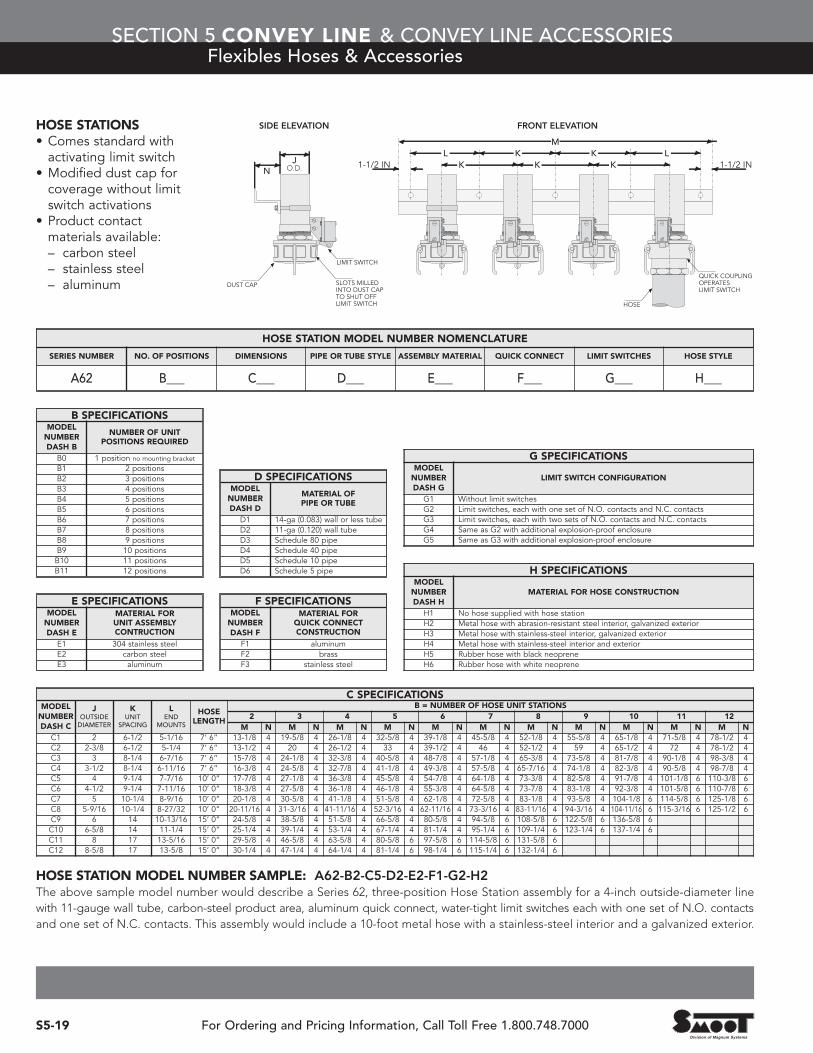
HOSE STATIONS• Comes standard with activating limit switch
• Modified dust cap for coverage without limit switch activations
• Product contact materials available:– carbon steel– stainless steel– aluminum
HOSE STATION MODEL NUMBER SAMPLE: A62-B2-C5-D2-E2-F1-G2-H2The above sample model number would describe a Series 62, three-position Hose Station assembly for a 4-inch outside-diameter linewith 11-gauge wall tube, carbon-steel product area, aluminum quick connect, water-tight limit switches each with one set of N.O. contactsand one set of N.C. contacts. This assembly would include a 10-foot metal hose with a stainless-steel interior and a galvanized exterior.
C SPECIFICATIONSMODEL
NUMBERDASH C
JOUTSIDEDIAMETER
KUNIT
SPACING
LEND
MOUNTS
HOSELENGTH
B = NUMBER OF HOSE UNIT STATIONS2 3 4 5 6 7 8 9 10 11 12
M N M N M N M N M N M N M N M N M N M N M NC1 2 6-1/2 5-1/16 7’ 6” 13-1/8 4 19-5/8 4 26-1/8 4 32-5/8 4 39-1/8 4 45-5/8 4 52-1/8 4 55-5/8 4 65-1/8 4 71-5/8 4 78-1/2 4C2 2-3/8 6-1/2 5-1/4 7’ 6” 13-1/2 4 20 4 26-1/2 4 33 4 39-1/2 4 46 4 52-1/2 4 59 4 65-1/2 4 72 4 78-1/2 4C3 3 8-1/4 6-7/16 7’ 6” 15-7/8 4 24-1/8 4 32-3/8 4 40-5/8 4 48-7/8 4 57-1/8 4 65-3/8 4 73-5/8 4 81-7/8 4 90-1/8 4 98-3/8 4C4 3-1/2 8-1/4 6-11/16 7’ 6” 16-3/8 4 24-5/8 4 32-7/8 4 41-1/8 4 49-3/8 4 57-5/8 4 65-7/16 4 74-1/8 4 82-3/8 4 90-5/8 4 98-7/8 4C5 4 9-1/4 7-7/16 10’ 0” 17-7/8 4 27-1/8 4 36-3/8 4 45-5/8 4 54-7/8 4 64-1/8 4 73-3/8 4 82-5/8 4 91-7/8 4 101-1/8 6 110-3/8 6C6 4-1/2 9-1/4 7-11/16 10’ 0” 18-3/8 4 27-5/8 4 36-1/8 4 46-1/8 4 55-3/8 4 64-5/8 4 73-7/8 4 83-1/8 4 92-3/8 4 101-5/8 6 110-7/8 6C7 5 10-1/4 8-9/16 10’ 0” 20-1/8 4 30-5/8 4 41-1/8 4 51-5/8 4 62-1/8 4 72-5/8 4 83-1/8 4 93-5/8 4 104-1/8 6 114-5/8 6 125-1/8 6C8 5-9/16 10-1/4 8-27/32 10’ 0” 20-11/16 4 31-3/16 4 41-11/16 4 52-3/16 4 62-11/16 4 73-3/16 4 83-11/16 4 94-3/16 4 104-11/16 6 115-3/16 6 125-1/2 6C9 6 14 10-13/16 15’ 0” 24-5/8 4 38-5/8 4 51-5/8 4 66-5/8 4 80-5/8 4 94-5/8 6 108-5/8 6 122-5/8 6 136-5/8 6C10 6-5/8 14 11-1/4 15’ 0” 25-1/4 4 39-1/4 4 53-1/4 4 67-1/4 4 81-1/4 4 95-1/4 6 109-1/4 6 123-1/4 6 137-1/4 6C11 8 17 13-5/16 15’ 0” 29-5/8 4 46-5/8 4 63-5/8 4 80-5/8 6 97-5/8 6 114-5/8 6 131-5/8 6C12 8-5/8 17 13-5/8 15’ 0” 30-1/4 4 47-1/4 4 64-1/4 4 81-1/4 6 98-1/4 6 115-1/4 6 132-1/4 6
B SPECIFICATIONSMODEL
NUMBERDASH B
NUMBER OF UNITPOSITIONS REQUIRED
B0 1 position no mounting bracket
B1 2 positionsB2 3 positionsB3 4 positionsB4 5 positionsB5 6 positionsB6 7 positionsB7 8 positionsB8 9 positionsB9 10 positionsB10 11 positionsB11 12 positions
E SPECIFICATIONSMODEL
NUMBERDASH E
MATERIAL FOR UNIT ASSEMBLYCONTRUCTION
E1 304 stainless steelE2 carbon steelE3 aluminum
D SPECIFICATIONSMODEL
NUMBERDASH D
MATERIAL OF PIPE OR TUBE
D1 14-ga (0.083) wall or less tubeD2 11-ga (0.120) wall tubeD3 Schedule 80 pipeD4 Schedule 40 pipeD5 Schedule 10 pipeD6 Schedule 5 pipe
F SPECIFICATIONSMODEL
NUMBERDASH F
MATERIAL FOR QUICK CONNECTCONSTRUCTION
F1 aluminumF2 brassF3 stainless steel
G SPECIFICATIONSMODEL
NUMBERDASH G
LIMIT SWITCH CONFIGURATION
G1 Without limit switchesG2 Limit switches, each with one set of N.O. contacts and N.C. contactsG3 Limit switches, each with two sets of N.O. contacts and N.C. contactsG4 Same as G2 with additional explosion-proof enclosureG5 Same as G3 with additional explosion-proof enclosure
H SPECIFICATIONSMODEL
NUMBERDASH H
MATERIAL FOR HOSE CONSTRUCTION
H1 No hose supplied with hose stationH2 Metal hose with abrasion-resistant steel interior, galvanized exteriorH3 Metal hose with stainless-steel interior, galvanized exteriorH4 Metal hose with stainless-steel interior and exteriorH5 Rubber hose with black neopreneH6 Rubber hose with white neoprene
HOSE STATION MODEL NUMBER NOMENCLATURE
SERIES NUMBER NO. OF POSITIONS DIMENSIONS PIPE OR TUBE STYLE ASSEMBLY MATERIAL QUICK CONNECT LIMIT SWITCHES HOSE STYLE
A62 B___ C___ D___ E___ F___ G___ H___
JO.D. K
K K LLM
K KN
1-1/2 IN 1-1/2 IN
SIDE ELEVATION FRONT ELEVATION
LIMIT SWITCH
DUST CAP
HOSE
SLOTS MILLEDINTO DUST CAPTO SHUT OFFLIMIT SWITCH
QUICK COUPLINGOPERATES LIMIT SWITCH

SECTION 5 CONVEY LINE & CONVEY LINE ACCESSORIESVacuum Valves
S5-20For Ordering and Pricing Information, Call Toll Free 1.800.748.7000
VACUUM BREAKER VALVESUsed in Vacuum Dilute Phase Conveying Systemsfor controlling vacuum while allowing the vacuumpump to remain running.
PRODUCT FEATURES• Aluminum and stainless steel construction, Style 1 vacuum breaker
• Carbon steel, aluminum and stainless steelconstruction available for Style 2 vacuum breaker
• Pneumatic actuated• Available with NEMA 4X, 7 and 9 electrical components
• 2-, 3- and 4-inch valves will be fitted with a Style 1 vacuum breaker
• 5-, 6- and 8-inch valves will be fitted with a Style 2 vacuum breaker
• Custom configurations available on request
VACUUM MODULATING VALVESUsed in Vacuum Dilute Phase Conveying Systemsto control and maintain a consistent vacuum withinthe onvey line.
PRODUCT FEATURES• Carbon steel, aluminum and stainless steelconstruction available
• Inlet filter to keep fugitive dust from entering the line
• Pneumatic actuated with infinite variable positioner
• Available with NEMA 4X, 7 and 9 electrical components
• 2-inch to 8-inch line connections; specify tube orpipe size when placing order
• Custom configurations available on request
Note: Customer to supply 80-120 PSI clean, dry andlubricated plant air. Customer will need to provide vacuumtransmitter and controls for modulating valve operation.
PROCESS PROCESS
1-60-110V Solenoid Valve0.5-inch conduit connection
1/4-inch NPT compressed air connectioncustomer to supply 75-125 PSIclean, dry and lubricated plant air
VENT
Style 1 vacuum breaker
Style 2 vacuum breaker and modulating valve