se300-ac-mmo-020 | navy tribe
TRANSCRIPT

UNCLASSIFIED
SE300-AC-MMO-020
REVISION 2
TECHNICAL MANUAL
INSTALLATION, OPERATION, AND MAINTENANCE
AN/SQH-4A
ACQUISITION SYSTEM,
BATTLE SPACE PROFILER
THIS MANUAL SUPERSEDES SE300-AC-MMO-020 DATED 15 JULY 2000 DISTRIBUTION STATEMENT D: DISTRIBUTION AUTHORIZED TO DOD AND DOD
CONTRACTORS ONLY; ADMINISTRATIVE/OPERATIONAL USE 30 MAY 2001. OTHER U.S. REQUESTS SHALL BE REFERRED TO NAVAL SEA SYSTEMS COMMAND (SEA-09T).
DESTRUCTION NOTICE: DESTROY BY ANY METHOD THAT WILL PREVENT
DISCLOSURE OF CONTENTS OR RECONSTRUCTION OF THE DOCUMENT.
PUBLISHED BY DIRECTION OF COMMANDER, NAVAL SEA SYSTEMS COMMAND
30 MAY 2001 UNCLASSIFIED

SE300-AC-MMO-020
A
INSERT LATEST CHANGED PAGES, DESTROY SUPERSEDED PAGES Dates of issue for original and changed pages are: Original 0 30 May 2001
TOTAL NUMBER OF PAGES IN THIS PUBLICATION IS 486 CONSISTING OF THE FOLLOWING:
Page No. Change No.* Page No. Change No.* Title ................................................................ 0 A..................................................................... 0 Change Record-1 .......................................... 0 Table of Contents i thru xv............................. 0 Foreword xvi thru xvii..................................... 0 Safety Summary xviii thru xxv ....................... 0 1-1 thru 1-29 .................................................. 0 2-1 thru 2-143 ................................................ 0 3-1 thru 3-24 .................................................. 0 4-1.................................................................. 0 5-1 thru 5-34 .................................................. 0 6-1 thru 6-54 .................................................. 0 7-1 thru 7-36 .................................................. 0 8-1 thru 8-32 .................................................. 0
Appendix A – A-1 thru A-74 ................................0 Appendix B – B-1 ................................................0 Glossary – Glossary-1 thru Glossary-2...............0 Foldouts – FP-1 thru FP-25.................................0 Problem Change Report .....................................0 Technical Manual Deficiency/ Evaluation Report (TMDER) ...............................0
*Zero in this column indicates an original page.
Note: The portion of the text affected by the changes is indicated by a vertical line in the outer margins of the page. Changes to illustrations are indicated by miniature pointing hands. Changes to diagrams are indicated by shaded areas.
LIST OF EFFECTIVE PAGES

SE300-AC-MMO-020
Change Record-1
RECORD OF CHANGES
CHANGE
NO. DATE TITLE AND/OR BRIEF DESCRIPTION ENTERED BY

SE300-AC-MMO-020
i
TABLE OF CONTENTS
CHAPTER PAGE LIST OF EFFECTIVE PAGES........................................................................................ A RECORD OF CHANGES ......................................................................Change Record-1 FOREWORD .................................................................................................................xvi SAFETY SUMMARY ................................................................................................... xviii CHAPTER 1 GENERAL INFORMATION .....................................................................1-1 1-1 GENERAL. ...................................................................................................1-1 1-1.1 Applicability...................................................................................................1-4 1-1.1.1 Tactics. .........................................................................................................1-4 1-1.2 Scope ...........................................................................................................1-4 1.2 EQUIPMENT DESCRIPTION.......................................................................1-4 1-2.1 Computer Hardware Equipment ...................................................................1-4 1-2.2 BSP Application Software.............................................................................1-5 1-2.3 Recoverable CTD Recorder. ........................................................................1-5 1-2.3.1 Sensors. .......................................................................................................1-6 1-2.3.1.1 Pressure Sensor...........................................................................................1-6 1-2.3.1.2 Conductivity Cell...........................................................................................1-6 1-2.3.1.3 Thermistor ....................................................................................................1-6 1-2.3.2 Batteries. ......................................................................................................1-9 1-2.3.3 SBE 5T Pump...............................................................................................1-9 1-2.3.4 Magnetic Reed Switch..................................................................................1-9 1-2.4. MK21 Interface. ............................................................................................1-9 1-2.5 Handling Assembly.......................................................................................1-9 1-2.5.1 Winch Assembly (Unit 4). .............................................................................1-9 1-2.5.1.1 Motor. ...........................................................................................................1-9 1-2.5.1.2 Operator's Control Panel ............................................................................1-11 1-2.5.1.3 Drum...........................................................................................................1-11 1-2.5.1.4 Electric Brake. ............................................................................................1-11 1-2.5.1.5 Handling Assembly Mounting Hardware.....................................................1-11 1-2.5.1.6 Manual Brake Control Wheel......................................................................1-11 1.2.5.1.7 Cable Guide Assembly and Cable Counter ................................................1-11 1-2.5.2 "J" Davit Assembly (Unit 5).........................................................................1-11 1-2.6 BSP System Hardware Interfaces ..............................................................1-11 1-2.6.1 Computer Equipment Interfaces. ................................................................1-12 1-2.6.2 PNotePro3 Surge Protector........................................................................1-12 1-2.6.3 Winch Assembly Interfaces ........................................................................1-12 1-2.7 CTD Recorder Storage Cabinet..................................................................1-12 1-2.8 LM3A Hand-Held Launcher And Expendable Probes.................................1-12 1-2.8.1 LM3A Hand-Held Launcher (Unit 10) .........................................................1-12 1-2.8.2 AR-20 System Selector (Unit 19)................................................................1-13 1-2.8.3 Launcher Cable ..........................................................................................1-13
SE300-AC-MMO-020
ii
1-2.8.4 Surface-Launched XBT And XSV...............................................................1-13 1-2.8.4.1 Expendable Bathythermograph (XBT)........................................................1-17 1-2.8.4.2 Expendable Sound Velocimeter (XSV).......................................................1-19 1-2.9 XBT/XSV Test Device, Equipment Description...........................................1-22 1-3 EQUIPMENT ILLUSTRATION....................................................................1-24 1-4 REFERENCE DATA...................................................................................1-24 1-4.1 Power and Cooling Requirements. .............................................................1-24 1-4.2 Environmental Tolerances..........................................................................1-24 1-4.3 External Interfaces......................................................................................1-24 1-5 EQUIPMENT, ACCESSORIES, AND DOCUMENTS SUPPLIED ..............1-28 CHAPTER 2 OPERATION ...........................................................................................2-1 2-1 INTRODUCTION. .........................................................................................2-1 2-2 CONTROLS AND INDICATORS. .................................................................2-1 2-2.1 Operation and Maintenance Panel Controls and Indicators. ........................2-1 2-2.2 BSP Software Screen Controls and Indicators .............................................2-1 2-2.2.1 Functions Supported. ...................................................................................2-5 2-2.2.2 Legends........................................................................................................2-5 2-2.2.2.1 Cursors/Symbols. .........................................................................................2-6 2-2.2.2.2 Display Indicators. ........................................................................................2-6 2-2.2.2.3 Screen Formats. ...........................................................................................2-7 2-2.2.3 Illustrations of Screen Displays.....................................................................2-7 2-3 OPERATING PROCEDURES ....................................................................2-82 2-3.1 Guidelines for Environmental Probe Selection. ..........................................2-82 2-3.2 Guidelines for Probe Deployment...............................................................2-85 2-3.2.1 Expendable Probe. .....................................................................................2-85 2-3.2.2 CTD Recorder ............................................................................................2-85 2-3.3 Emergency Procedures. .............................................................................2-86 2-3.3.1 CTD Recorder Snagged. ............................................................................2-86 2-3.3.2 Winch Cable Deployed off the Drum. .........................................................2-86 2-3.3.3 Emergency Manual Recovery.....................................................................2-87 2-4 PRE-MISSION SYSTEM SETUP ...............................................................2-88 2-4.1 Preoperational System Checks ..................................................................2-88 2-4.2 Preoperational Setup/Operational Check of the Handling Assembly..........2-88 2-4.3 CTD Recorder In-Air Test ...........................................................................2-89 2-4.4 Expendable Probe Pre-Operational Checkout Test....................................2-89 2-5 MISSION SYSTEM SETUP........................................................................2-90 2-5.1 Mission Briefing ..........................................................................................2-90

SE300-AC-MMO-020
iii
2-5.2 Prepare BSP Data Log Sheet.....................................................................2-90 2-6 PRE-CAST SETUP ....................................................................................2-91 2-6.1 Equipment Staging. ....................................................................................2-91 2-6.1.1 CTD Recorder Equipment Staging .............................................................2-91 2-6.1.2 Expendable Probe Equipment Staging.......................................................2-91 2-6.2 Start BSP System/Software Program. ........................................................2-93 2-7 COLLECT DATA AND ANNOTATE BSP LOG SHEET..............................2-93 2-7.1 Collect Data with CTD Recorder.................................................................2-93 2-7.1.1 Set Up CTD Recorder ................................................................................2-93 2-7.1.2 CTD Recorder Cast ....................................................................................2-94 2-7.1.3 Upload/Save CTD Data. .............................................................................2-99 2-7.1.4 Load Hex Profile .......................................................................................2-100 2-7.2 Collect Data with Expendable Probes ......................................................2-101 2-7.2.1 Set Up Interface........................................................................................2-101 2-7.2.2 Launch the Expendable Probe .................................................................2-102 2-7.2.3 Select Bottom and Save Expendable Probe Data ....................................2-102 2-7.2.4 Load Raw Profile ......................................................................................2-103 2-8 PROCESSING AND EDITING DATA .......................................................2-103 2-8.1 Raw Data File Interpretation.....................................................................2-103 2-8.1.1 CTD Recorder Casts ................................................................................2-104 2-8.1.2 Expendable Probe Casts..........................................................................2-104 2-8.2 Load Filtered Profile .................................................................................2-104 2-8.3 Sampling Probe Data ...............................................................................2-105 2-8.3.1 Data Interpretation Skills for Sampling .....................................................2-105 2-8.3.2 Editing a Sampled Profile .........................................................................2-106 2-8.4 Manual Data Entry Procedures.................................................................2-106 2-8.4.1 Background ..............................................................................................2-106 2-8.4.1.1 Detailed Procedures .................................................................................2-106 2-8.4.1.2 Sources of Information for Manual Data Entry..........................................2-109 2-8.4.2 Load Sampled Profile ...............................................................................2-109 2-9 COMPUTING SONAR PERFORMANCE .................................................2-110 2-9.1 Background ..............................................................................................2-110 2-9.1.1 Goals in Running the Sonar Performance Model (SPM) ..........................2-110 2-9.1.2 Top-Level Procedures ..............................................................................2-112 2-9.2 Set Environment/Targets..........................................................................2-112 2-9.2.1 Set Environmental Conditions ..................................................................2-112 2-9.2.1.1 Background ..............................................................................................2-112 2-9.2.1.2 Detailed Procedures .................................................................................2-116 2-9.2.2 Set Threat Type........................................................................................2-116 2-9.2.2.1 Background ..............................................................................................2-116 2-9.2.2.2 Detailed Procedures .................................................................................2-116

SE300-AC-MMO-020
iv
2-9.3 Setting Sonar Parameters. .......................................................................2-117 2-9.3.1 Background ..............................................................................................2-117 2-9.3.2 Detailed Procedures .................................................................................2-119 2-9.4 Interpreting Skills for Tilt/VDS Display. .....................................................2-119 2-9.5 Interpreting Skills for Raytrace..................................................................2-120 2-9.6 Sound Speed Structure. ...........................................................................2-121 2-9.6.1 Isovelocity.................................................................................................2-121 2-9.6.2 Negative Gradient.....................................................................................2-121 2-9.6.3 Positive Gradient. .....................................................................................2-121 2-9.6.4 Simple Layer.............................................................................................2-123 2-9.6.5 Mixed/Multi Layer. ....................................................................................2-123 2-9.7 General Tactical Use of the BSP..............................................................2-124 2-9.7.1 When to Use the Model ............................................................................2-124 2-9.7.2 Using BSP to Predict Alerted Range of the Day (ROD)............................2-126 2-9.7.2.1 Using BSP to Predict Alerted Range of the Day (ROD) for a Bottom Mine .....................................................................................2-128 2-9.7.2.2 Using BSP to Predict Alerted Range of the Day (ROD) for a Moored Mine ....................................................................................2-128 2-9.7.2.3 Using BSP to Predict Tactical Range of the Day (ROD)...........................2-128 2-9.7.3 Using BSP with Sonar Conditions Check. ................................................2-137 2-9.7.4 Determining the Required Interval for Using the BSP...............................2-138 2-10 PROCEDURES FOR FILE MANAGEMENT, AND PRINTING OF REPORTS................................................................2-140 2-10.1 Procedure to Import a Hex, Raw, Filtered, Sampled or Probe Config Data File(s) .....................................................................2-140 2-10.2 Procedure to Export a Hex, Raw, Filtered, or Sampled Data File(s).........2-140 2-10.3 Procedure to Delete a Hex, Raw, Filtered, or Sampled Data File(s) from the BSP Hard Drive ..........................................................................2-140 2-10.4 Procedure to Archive Hex, Raw, Filtered, or Sampled Data File(s) from the BSP Hard Drive ..........................................................................2-141 2-10.5 Procedure to Print a Report from the Report Pull-Down Menu.................2-141 2-10.6 Procedure to Print a Report from the Preview Window ............................2-141 2-10.7 Procedure to Reset Printer .......................................................................2-142 2-10.8 Procedure to Send a Message to the GCCS-M System...........................2-142 2-11 PROCEDURES FOR EXITING THE BSP SOFTWARE AND SECURING EQUIPMENT................................................................2-143 2-11.1 Procedure to Exit the BSP Software.........................................................2-143 2-11.2 Procedure to Secure Winch Station..........................................................2-143 CHAPTER 3 FUNCTIONAL DESCRIPTION ................................................................3-1 3-1 INTRODUCTION. .........................................................................................3-1

SE300-AC-MMO-020
v
3-2 GENERAL FUNCTIONAL DESCRIPTION. ..................................................3-1 3-2.1 Environmental Data Collection Function.......................................................3-1 3-2.2 Deployment and Recovery Function.............................................................3-2 3-2.3 Data Processing Function. ...........................................................................3-2 3-2.4 Data Display Function. .................................................................................3-2 3-2.5 Data Input/Output Function. .........................................................................3-2 3-2.5.1 Multiport Spooler Function............................................................................3-2 3-2.6 Power Distribution Function..........................................................................3-3 3-3 DETAILED FUNCTIONAL DESCRIPTION...................................................3-3 3-3.1 CTD Recorder Sensors. ...............................................................................3-3 3-3.1.1 Pressure Sensor Function. ...........................................................................3-3 3-3.1.2 Conductivity Cell Function. ...........................................................................3-4 3-3.1.3 Thermistor Function......................................................................................3-4 3-3.1.4 CTD Recorder Pump Function. ....................................................................3-4 3-3.1.5 Magnetic Reed Switch Function. ..................................................................3-4 3-3.2 LM3A Hand-Held Launcher Functional Description......................................3-5 3-3.2.1 Launcher Cable Function .............................................................................3-5 3-3.3 AR-20 System Selector Functional Description ............................................3-5 3-3.4 Expendable Probes Functional Description..................................................3-5 3-3.4.1 Expendable Bathythermograph (XBT) Function ...........................................3-6 3-3.4.2 Expendable Sound Velocimeter (XSV) Function ..........................................3-7 3-3.4.3 Depth Data Performance..............................................................................3-8 3-3.4.4 Temperature Data Performance...................................................................3-9 3-3.4.5 Sound Velocity Data Performance................................................................3-9 3-3.4.6 Data Transmission......................................................................................3-10 3-3.5 Handling System Components. ..................................................................3-10 3-3.5.1 Winch Assembly Functional Description.....................................................3-10 3-3.5.2 Winch Electrical Circuit Functional Description...........................................3-10 3-3.5.2.1 Winch Initialization......................................................................................3-10 3-3.5.2.2 Cable Pay-out Operation ............................................................................3-11 3-3.5.2.3 Cable Haul-in Operation .............................................................................3-12 3-3.5.3 "J" Davit Assembly Functional Description. ................................................3-12 3-3.6 Computer Functional Description. ..............................................................3-12 3-3.6.1 Removable Hard Drive Disks Function.......................................................3-12 3-3.6.2 Serial COM Port Function...........................................................................3-13 3-3.6.3 MK 21 Interface Card Function...................................................................3-13 3-3.6.4 Printer Function. .........................................................................................3-13 3-3.7 Power Distribution Functional Description. .................................................3-13 3-3.7.1 CTD Recorder Power. ................................................................................3-13 3-3.7.2 Winch Assembly Power. .............................................................................3-13 3-3.7.3 Computer Power.........................................................................................3-13 3-3.7.4 Multiport Spooler. .......................................................................................3-13 3-3.7.5 Printer Power..............................................................................................3-13 3-4 SYSTEM INTERFACE FUNCTIONAL DESCRIPTIONS............................3-14

SE300-AC-MMO-020
vi
3-4.1 Man-Machine Interface...............................................................................3-14 3-4.2 RS-232 Interface. .......................................................................................3-14 3-4.2.1 CTD Recorder RS-232 Interface. ...............................................................3-14 3-4.2.2 GCCS-M RS-232 Interface.........................................................................3-14 3-4.3 MK21 Interface. ..........................................................................................3-14 3-4.4 Printer Interface. .........................................................................................3-14 3-5 SOFTWARE PROGRAM FUNCTIONAL DESCRIPTION...........................3-15 3-5.1 Communicating with External Probes.........................................................3-15 3-5.1.1 Link to CTD Recorder.................................................................................3-15 3-5.1.2 Link to Expendable Probe ..........................................................................3-15 3-5.2 Inputting, Processing, Sampling, and Displaying Probe Data.....................3-15 3-5.2.1 Inputting Probe Data...................................................................................3-16 3-5.2.2 Probe File Types. .......................................................................................3-16 3-5.2.3 Processing Probe Data...............................................................................3-16 3-5.2.4 Sampling Probe Data. ................................................................................3-17 3-5.2.5 Displaying Probe Data................................................................................3-17 3-5.3 Entering Data Manually. .............................................................................3-17 3-5.4 Inputting Environmental, Sonar, and Threat Parameters............................3-18 3-5.5 Computing Sonar Performance (Tilt/VDS and Raytrace). ..........................3-22 3-5.6 Generating Outputs. ...................................................................................3-23 3-5.7 File Utilities. ................................................................................................3-23 3-5.7.1 File Import...................................................................................................3-23 3-5.7.2 File Export ..................................................................................................3-23 3-5.7.3 File Delete ..................................................................................................3-23 3-5.8 Probe Diagnostics ......................................................................................3-24 3-5.8.1 CTD Recorder Diagnostics .........................................................................3-24 CHAPTER 4 SCHEDULED MAINTENANCE ..............................................................4-1 4-1 INTRODUCTION. .........................................................................................4-1 CHAPTER 5 TROUBLESHOOTING............................................................................5-1 5-1 INTRODUCTION ........................................................................................5-1 5-2 TROUBLESHOOTING GUIDELINES...........................................................5-1 5-2.1 Troubleshooting Precautions. .......................................................................5-1 5-2.2 Electrostatic Sensitive Device (ESD) Precautions. .......................................5-1 5-3 TABULAR TROUBLESHOOTING DATA. ....................................................5-1 5-4 MAINTENANCE TURN ON PROCEDURE. .................................................5-3 5-5 MAINTENANCE TURN-OFF PROCEDURE. ...............................................5-3

SE300-AC-MMO-020
vii
5-6 BSP SYSTEM FAULTY SYMPTOM ANALYSIS. .........................................5-4 5-6.1 Inverter Diagnostics....................................................................................5-12 5-7 CTD RECORDER DIAGNOSTIC PROCEDURE........................................5-26 5-7.1 CTD Recorder In-Air Test ...........................................................................5-26 5-8 COMPUTER HARDWARE DIAGNOSTICS................................................5-28 5-9 AR-20 TROUBLESHOOTING PROCEDURES ..........................................5-30 CHAPTER 6 CORRECTIVE MAINTENANCE .............................................................6-1 6-1 INTRODUCTION. .........................................................................................6-1 6-2 ADJUSTMENTS AND ALIGNMENTS. .........................................................6-1 6-2.1 LM3A Hand-Held Launcher/Expendable Probe Adjustments and Alignments. .......................................................................6-1 6-2.2 Chain Adjustment Procedure........................................................................6-1 6-3 REPAIR. .......................................................................................................6-4 6-3.1 Standard Procedures....................................................................................6-4 6-3.1.1 Standard Power On. .....................................................................................6-4 6-3.1.2 Standard Power Off. .....................................................................................6-4 6-3.1.3 Standard ESD Handling Precautions............................................................6-5 6-3.1.4 Winch Cable Re-Termination Load Test.......................................................6-6 6-3.2 Computer Removal and Replacement..........................................................6-7 6-3.2.1 Removable Hard Drive Disk Removal and Replacement. ............................6-7 6-3.2.2 Printer Removal and Replacement...............................................................6-8 6-3.2.2.1 Print Cartridge Removal and Replacement. ...............................................6-11 6-3.2.3 Multiport Spooler Removal and Replacement. ...........................................6-11 6-3.2.4 MK 21 Interface Card Removal and Replacement. ....................................6-12 6-3.3. PNotePro3 Power Cord Removal and Replacement ..................................6-14 6-3.4 CTD Recorder Components Removal and Replacement. ..........................6-14 6-3.4.1 CTD Recorder Removal and Replacement. ...............................................6-14 6-3.4.2 SBE 5T Pump Removal and Replacement.................................................6-17 6-3.4.3 Zinc Anode Removal and Replacement. ....................................................6-18 6-3.4.4 D-cell Batteries Removal and Replacement. ..............................................6-19 6-3.4.5 Battery Housing O-Ring and Battery End Cap O-Ring Removal and Replacement .......................................................................................6-21 6-3.4.6 External Magnetic ON/OFF Switch Removal and Replacement.................6-23 6-3.4.7 Y-Cable Removal and Replacement. .........................................................6-24 6-3.4.8 Pressure Sensor Capillary Tube, Addition of Oil.........................................6-25 6-3.4.9 Air Bubble Trapped in Capillary Tube, Addition of Oil.................................6-26 6-3.4.10 Cleaning Connector Pins............................................................................6-26 6-3.5 Handling Assembly Components Removal and Replacement. ..................6-29

SE300-AC-MMO-020
viii
6-3.5.2 Varistor Removal and Replacement ...........................................................6-30 6-3.5.3 Line Filter Removal and Replacement........................................................6-31 6-3.5.4 Solid State Relay Removal and Replacement. ...........................................6-35 6-3.5.5 Contactor Removal and Replacement........................................................6-36 6-3.5.6 Inverter Removal and Replacement. ..........................................................6-39 6-3.5.7 Overload Relay Removal and Replacement...............................................6-41 6-3.5.8 On/Off Switch Removal and Replacement .................................................6-42 6-3.5.9 Joystick Removal and Replacement...........................................................6-43 6-3.5.10 Drive Assembly Removal and Replacement...............................................6-45 6-3.5.11 Drum Assembly Removal and Replacement ..............................................6-48 6-3.5.12 Idler Sprocket Assembly Removal and Replacement.................................6-50 6-3.5.13 Chain Removal and Replacement. .............................................................6-51 6-3.5.14 Band Brake Removal and Replacement.....................................................6-52 6-3.5.15 Cable Counter Removal and Replacement ................................................6-54 CHAPTER 7 PARTS LIST............................................................................................7-1 7-1 INTRODUCTION. .........................................................................................7-1 7-2 LIST OF MAJOR UNITS...............................................................................7-1 7-3 PARTS LIST .................................................................................................7-2 CHAPTER 8 INSTALLATION.......................................................................................8-1 8-1 INTRODUCTION. .........................................................................................8-1 8-2 INFORMATION AND MATERIALS REQUIRED FOR INSTALLATION........8-1 8-3 INSTALLATION LOCATION INFORMATION...............................................8-1 8-3.1 Computer Equipment Location .....................................................................8-1 8-3.2 Recoverable Conductivity, Temperature, Depth (CTD) Recorder Location ......................................................................................8-20 8-3.3 Handling Assembly Location ......................................................................8-20 8-3.4 GCCS-M System Location..........................................................................8-20 8-4 UNPACKING AND INSPECTION...............................................................8-20 8-4.1 Visual Inspection ........................................................................................8-20 8-4.2 Unpacking...................................................................................................8-20 8-4.3 Inspection and Inventory. ...........................................................................8-21 8-4.4 Repacking...................................................................................................8-21 8-5 PREPARATION OF FOUNDATIONS.........................................................8-21

SE300-AC-MMO-020
ix
8-6 EQUIPMENT INSTALLATION....................................................................8-22 8-6.1 Cable Installation. .......................................................................................8-22 8-6.2 LM3A Hand-Held Launcher (Unit 10) .........................................................8-22 8-6.3 AR-20 System Selector (Unit 19)................................................................8-23 8-6.4 Installation of Computer Equipment............................................................8-24 8-6.5 Installation of QAPlus Software ..................................................................8-24 8-6.6 Installation of Handling Assembly...............................................................8-24 8-6.7 Installation of BSP Storage Cabinet. ..........................................................8-24 8-7 INSTALLATION CHECK-OUT....................................................................8-26 8-7.1 General Information....................................................................................8-26 8-7.2 Test Equipment Needed. ...........................................................................8-26 8-7.3 Installation Standards Summary Sheet ......................................................8-26 8-7.4 Phase 1 — Installation Inspection ..............................................................8-26 8-7.4.1 Interconnecting Cable Conductor Measurements.......................................8-27 8-7.4.1.1 Tools, Parts, Materials, And Test Equipment Required ..............................8-27 8-7.4.1.2 Preliminary Procedure ................................................................................8-27 8-7.4.1.3 Interconnecting Cable Conductor Insulation Resistance ............................8-27 8-7.4.1.4 Interconnecting Cable Shield And Ground Continuity.................................8-28 8-7.4.1.5 Interconnecting Cable Signal Continuity.....................................................8-28 8-7.5 Phase 2 — Initial Turn-On and Preliminary Tests.......................................8-29 8-7.5.1 Cable Checkout. .........................................................................................8-29 8-7.5.2 Computer Checkout....................................................................................8-29 8-7.5.3 CTD Recorder Checkout ............................................................................8-30 8-7.5.4 Handling Assembly Checkout.....................................................................8-31 8-7.6 Phase 3 — Operational Verification............................................................8-31 8-8 PREPARATION FOR SHIPPING. ..............................................................8-32 8-8.1 BSP Computer Components, Units 1, 2, and 7 ..........................................8-32 8-8.2 BSP Recoverable Probe, Units 6 and 8......................................................8-32 8-8.3 BSP Winch Assembly, Unit 4......................................................................8-32

SE300-AC-MMO-020
x
LIST OF FIGURES
FIGURE PAGE Figure 1-1. Battle Space Profiler System...................................................................1-2 Figure 1-2. Recoverable CTD Recorder ....................................................................1-7 Figure 1-3. Recoverable CTD Recorder, Bottom View..............................................1-8 Figure 1-4. Handling Assembly ...............................................................................1-10 Figure 1-5. Computer Equipment Interfaces............................................................1-14 Figure 1-6. LM3A Hand-Held Launcher...................................................................1-15 Figure 1-7. AR-20 System Selector .........................................................................1-16 Figure 1-8. Expendable Bathythermograph (XBT), Exploded View.........................1-18 Figure 1-9. Expendable Sound Velocimeter (XSV), Exploded View........................1-21 Figure 1-10. XBT/XSV Test Device ...........................................................................1-23 Figure 2-1. BSP Main Display ...................................................................................2-4 Figure 2-2. BSP Cursors, Symbols, and Icons ..........................................................2-6 Figure 2-3. BSP Main Menu Bar Options ................................................................2-13 Figure 2-4a. BSP Main Display, Raytrace Area, Single Target Mode .......................2-18 Figure 2-4b. BSP Main Display, Raytrace Area, Multiple Targets Mode ...................2-21 Figure 2-5. BSP Main Display, Bottom Button Area ................................................2-24 Figure 2-6. BSP Main Display, Profile Header Info Area .........................................2-27 Figure 2-7a. SP Main Display, Search/Classify Bar Graph Area,
Single Target Mode...............................................................................2-29 Figure 2-7b. SP Main Display, Search/Classify Bar Graph Area,
Multiple Targets Mode...........................................................................2-30 Figure 2-8. Import <File Type> Profile .....................................................................2-32 Figure 2-9. Export <File Type> Profile.....................................................................2-34 Figure 2-10. Delete <File Type> Profile.....................................................................2-36 Figure 2-11. Select <File Type> Profile .....................................................................2-38 Figure 2-12. Edit Sampled Profile..............................................................................2-41 Figure 2-13. Save <File Type> Profile Display ..........................................................2-44 Figure 2-14. Filter Raw Profile Display (Filtering Display) .........................................2-46 Figure 2-15. CTD Recorder Probe Interface Display.................................................2-48 Figure 2-16. CTD Recorder Terminal Display ...........................................................2-52 Figure 2-17. Expendable Probe Interface Display .....................................................2-54 Figure 2-18. Expendable Probe Selection Display ....................................................2-56 Figure 2-19. Enter Manual Data Constraints Display ................................................2-58 Figure 2-20. Profile Header Information Display........................................................2-60 Figure 2-21. Environment/Target Window.................................................................2-63 Figure 2-22. Parameters for USER_SPEC Mine Type Window ................................2-66 Figure 2-23. Select Target Depth Display..................................................................2-68 Figure 2-24. Select Files for Archiving Display ..........................................................2-70 Figure 2-25. Report, Text SVP Sample .....................................................................2-72 Figure 2-26a. Report, Tilt/VDS Sample, Single Target Mode (Page 1) .......................2-73 Figure 2-26a. Report, Tilt/VDS Sample, Single Target Mode (Page 2) .......................2-74

SE300-AC-MMO-020
xi
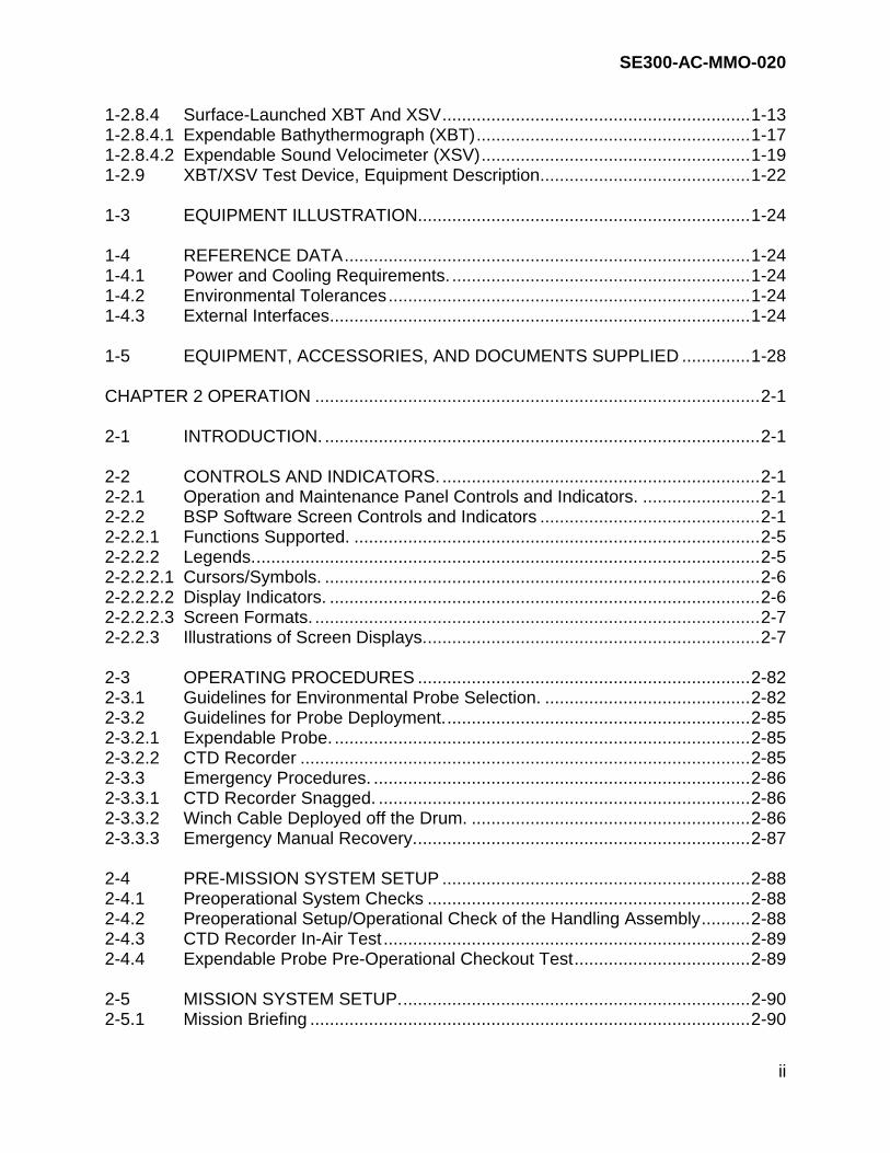
Figure 2-26b. Report, Tilt/VDS Sample, Multiple Targets Mode (Page 1) ...................2-75 Figure 2-26b. Report, Tilt/VDS Sample, Multiple Targets Mode (Page 2) ...................2-76 Figure 2-27. Report, SVP and Raytrace Sample.......................................................2-77 Figure 2-28a. Report, Raytrace Sample, Single Target Mode.....................................2-78 Figure 2-28b. Report, Raytrace Sample, Mutliple Targets Mode.................................2-79 Figure 2-29. Report, SVP Sample .............................................................................2-80 Figure 2-30. Report, Test Printer Sample..................................................................2-81 Figure 2-31. BSP System Operation, Overview ........................................................2-83 Figure 2-32. SPM Operation......................................................................................2-84 Figure 2-33. Towed Body Position Affect on Bottom Coverage...............................2-125 Figure 2-34. Towed Body Position Affect on Volume Coverage..............................2-127 Figure 2-35. Range of the Day, Bottom Mine (1).....................................................2-130 Figure 2-36. Range of the Day, Bottom Mine (2).....................................................2-131 Figure 2-37. Range of the Day, Bottom Mine (3).....................................................2-132 Figure 2-38. Range of the Day, Moored Mine (1) ....................................................2-133 Figure 2-39. Range of the Day, Moored Mine (2) ....................................................2-134 Figure 2-40. Range of the Day, Moored Mine (3) ....................................................2-135 Figure 2-41. Range of the Day, Moored Mine (4) ....................................................2-136 Figure 3-1. DE Mode Affect on Raytrace Display, ALL Mode..................................3-19 Figure 3-2. DE Mode Affect on Raytrace Display, TARGET 1 Mode.......................3-20 Figure 3-3. DE Mode Affect on Raytrace Display, TARGET 2 Mode.......................3-21 Figure 5-1. Y-Cable Pinouts ....................................................................................5-25 Figure 5-2. AR-20 System Selector .........................................................................5-31 Figure 5-3. AR-20 Contact Switch Identification ......................................................5-32 Figure 5-4(a).AR-20 System Selector Schematic Diagram (Sheet 1).........................2-33 Figure 5-4(b).AR-20 System Selector Schematic Diagram (Sheet 2).........................2-34 Figure 6-1A. Notebook, Right Side View......................................................................6-9 Figure 6-1B. Notebook, Left Side View........................................................................6-9 Figure 6-1C. Notebook, Rear Side View ....................................................................6-10 Figure 6-1D. Notebook, Bottom Side View.................................................................6-10 Figure 6-2. MK 21 Interface Card Dip Switch Settings ............................................6-13 Figure 6-3. Detail, Recoverable CTD Recorder.......................................................6-20 Figure 6-4. Battery Housing and Battery End Cap O-rings......................................6-22 Figure 6-5. Pressure Sensor Capillary Tube, Addition of Oil ...................................6-27 Figure 6-6. External Capillary Tube, Addition of Oil.................................................6-28 Figure 6-7. Winch Assembly Major Components ....................................................6-33 Figure 6-8. Electrical Control Box Component Layout.............................................6-34 Figure 6-9. Electrical Control Box Schematic ..........................................................6-38 Figure 7-1. BSP System Computer Equipment .......................................................7-22 Figure 7-2. MK 21 Circuit Board Location................................................................7-23 Figure 7-3. Recoverable CTD Recorder ..................................................................7-24 Figure 7-4. Hardware Spares Kit Detail, Recoverable CTD Recorder ....................7-25 Figure 7-5. Recoverable CTD Recorder, Battery Cover and O-rings .....................7-26 Figure 7-6. Recoverable CTD Recorder, Detail .......................................................7-27 Figure 7-7. Recoverable CTD Recorder — Connectors, Plugs, and Pump Mounting Kit .........................................................................7-28

SE300-AC-MMO-020
xii
Figure 7-8. Winch Assembly....................................................................................7-29 Figure 7-9. Winch Assembly Electrical Control Box ................................................7-30 Figure 7-10. LM3A Hand-Held Launcher...................................................................7-31 Figure 7-11. AR-20 System Selector .........................................................................7-32 Figure 7-12. Expendable Bathythermograph (XBT), Exploded View.........................7-33 Figure 7-13. Expendable Sound Velocimeter (XST), Exploded View........................7-34 Figure 7-14. XBT/XSV Test Device ...........................................................................7-35 Figure 7-15. Contact Pin Assembly, LM3A Hand-Held Launcher..............................7-36 Figure 8-1. Installation Standards Summary ...........................................................8-14 Figure 8-2. XBT/XSV Probe Device Storage ...........................................................8-15 Figure 8-3. Location for Watertight Junction Box and LM3A Hand-Held Launcher Stowage Locker ........................................8-16 Figure 8-4. LM3A Hand-Held Launcher...................................................................8-17 Figure 8-5. AR-20 System Selector Cable Installation.............................................8-18 Figure 8-6. LM3A Hand-Held Launcher and MK21 Card Cable Installation ...........8-19

SE300-AC-MMO-020
xiii
LIST OF TABLES
TABLE PAGE Table 1-1. CTD Recorder Warranty..........................................................................1-3 Table 1-2. XBT Data...............................................................................................1-17 Table 1-3. XSV Data ..............................................................................................1-17 Table 1-4. Summary of XBT/XSV Device Applications...........................................1-22 Table 1-5. Reference Data .....................................................................................1-25 Table 1-6. External Systems Interface ...................................................................1-28 Table 1-7. Equipment, Accessories, and Documents Supplied..............................1-28 Table 2-1. Operation and Maintenance Control and Indicator Table Index ..............2-2 Table 2-2. BSP System Hardware Equipment Components Controls and Indicators..........................................................................................2-8 Table 2-3. BSP Main Menu Bar Screen Controls and Indicators............................2-12 Table 2-4a. BSP Main Display, Raytrace Area Screen Controls and Indicators, Single Target Mode...............................................................................2-17 Table 2-4b. BSP Main Display, Raytrace Area Screen Controls and Indicators, Multiple Targets Mode...........................................................................2-20 Table 2-5. BSP Main Display, Bottom Button Area Screen Controls and Indicators........................................................................................2-23 Table 2-6. BSP Main Display, Profile Header Info Area Screen Controls and Indicators........................................................................................2-26 Table 2-7. BSP Main Display, TILT/VDS Bar Graph Area Screen Controls and Indicators .........................................................................2-28 Table 2-8. Import <File Type> Profile Screen Controls and Indicators...................2-31 Table 2-9. Export <File Type> Profile Screen Controls and Indicators...................2-33 Table 2-10. Delete <File Type> Profile Screen Controls and Indicators...................2-35 Table 2-11. Select <File Type> Profile Screen Controls and Indicators ...................2-37 Table 2-12. Edit Sampled Profile Screen Controls and Indicators............................2-40 Table 2-13. Save <File Type> Profile Screen Controls and Indicators.....................2-43 Table 2-14. Filter Raw Profile (Filtering Display) Screen Controls and Indicators ....2-45 Table 2-15. CTD Recorder Probe Interface Screen Controls and Indicators............2-47 Table 2-16. CTD Recorder Terminal Screen Controls and Indicators ......................2-51 Table 2-17. Expendable Probe Interface Screen Controls and Indicators................2-53 Table 2-18. Expendable Probe Selection Controls and Indicators ...........................2-55 Table 2-19. Enter Manual Data Constraints Screen Controls and Indicators ...........2-57 Table 2-20. Profile Header Information Screen Controls and Indicators ..................2-59 Table 2-21. Environment/Target Screen Controls and Indicators.............................2-62 Table 2-22. Parameters For USER_SPEC Mine Type Screen Controls and Indicators........................................................................................2-65 Table 2-23. Select Target Depth Screen Controls and Indicators ............................2-67 Table 2-24. Select Files for Archiving Controls and Indicators .................................2-69 Table 2-25. Probe Operational Restrictions .............................................................2-85 Table 2-26. BSP Data Log Sheet .............................................................................2-92 Table 2-27. Bottom Type Index Values ..................................................................2-114

SE300-AC-MMO-020
xiv
Table 2-28. Target Type/Target Strength...............................................................2-118 Table 2-29. Sonar Parameter Settings ...................................................................2-119 Table 2-30. Typical Surface Sound Velocity, Temperature and Salinity Values for Selected Areas...................................................................2-122 Table 2-31. BSP Sampling Frequency Interval Table ............................................2-139 Table 3-1. Inverter Output Terminal Voltages ........................................................3-11 Table 5-1. Troubleshooting Index.............................................................................5-2 Table 5-2. Frequency Values ...................................................................................5-6 Table 5-3. Readings Values .....................................................................................5-6 Table 5-4. BSP System Power Faults Analysis Chart ..............................................5-7 Table 5-5. BSP Mechanical Faults Analysis Chart .................................................5-13 Table 5-6. CTD Recorder and BSP Software Program, Faults Analysis Chart ......5-15 Table 5-7. CTD Recorder Software Diagnostics, Controls and Indicators..............5-27 Table 6-1. Index of Procedures ................................................................................6-2 Table 7-1. List of Major Components .......................................................................7-3 Table 7-2. Parts List .................................................................................................7-4 Table 7-3. List of Suppliers.....................................................................................7-18 Table 8-1. BSP Installation Control Drawings ..........................................................8-3 Table 8-2. BSP Input Power Requirements..............................................................8-4 Table 8-3. Tools and Materials Required for Installation ..........................................8-5 Table 8-4. Summary List of Installation Material ......................................................8-6 Table 8-5. BSP System Installation Information .......................................................8-9 Table 8-6. LM3A Hand-Held Launcher, Junction Box, and AR-20 Cable Wire List 8-10 Table 8-7. AR-20 System Selector and Computer Interface Cable Wire List .........8-11 Table 8-8. LM3A Hand-Held Launcher and Interface Cable Wire List (Ships without AR-20 System Selector) ................................................8-12 Table 8-9. LM3A Hand-Held Launcher Installation Information..............................8-13
LIST OF APPENDICES
APPENDIX PAGE Appendix A Professional QAPlus User’s Guide......................................................... A-1 Appendix B Reference Documents............................................................................ B-1
GLOSSARY
GLOSSARY PAGE Glossary .........................................................................................................Glossary-1

SE300-AC-MMO-020
xv
LIST OF FOLDOUTS
FOLDOUT PAGE FO-1. BSP System Hardware Equipment Components, Controls and Indicators FP-1 FO-2. BSP System Functional Block Diagram..................................................... FP-2 FO-3. BSP System Power Distribution Block Diagram ........................................ FP-3 FO-4. AN/SQH-4A System Block Diagram.......................................................... FP-4 FO-5. Notebook Computer, Outline and Installation Drawing .............................. FP-5 FO-6. Winch Assembly, Outline and Installation Drawing, Sheet 1 of 2 .............. FP-6 FO-7. Winch Assembly, Outline and Installation Drawing, Sheet 2 of 2 .............. FP-7 FO-8. Storage Cabinet, Outline and Installation Drawing .................................... FP-8 FO-9. Printer, Outline and Installation Drawing ................................................... FP-9 FO-10. Multiport Spooler, Outline and Installation Drawing................................. FP-10 FO-11. Davit, Outline and Installation Drawing.................................................... FP-11 FO-12. W1, Cable Running Sheet ....................................................................... FP-12 FO-13. W2, Cable Running Sheet ....................................................................... FP-13 FO-14. W3, Cable Running Sheet ....................................................................... FP-14 FO-15. W4, Cable Running Sheet ....................................................................... FP-15 FO-16. R-SO(1), Cable Running Sheet ............................................................... FP-16 FO-17. R-SO(3), Cable Running Sheet ............................................................... FP-17 FO-18. R-SO(4), Cable Running Sheet ............................................................... FP-18 FO-19. R-SO(5), Cable Running Sheet ............................................................... FP-19 FO-20. R-SO(6), Cable Running Sheet ............................................................... FP-20 FO-21. R-SO(7), Cable Running Sheet ............................................................... FP-21 FO-22. GCCS-M, Cable Running Sheet .............................................................. FP-22 FO-23. R-SO(10), Cable Running Sheet ............................................................. FP-23 FO-24. R-SO(11), Cable Running Sheet ............................................................. FP-24 FO-25. R-SO(12), Cable Running Sheet ............................................................. FP-25

SE300-AC-MMO-020
xvi
FOREWORD The AN/SQH-4A Acquisition System, Battle Space Profiler (BSP) (hereinafter referred to as the BSP system) Technical Manual (TM) contains descriptive, operational, and maintenance information required for using the BSP system. The TM is an overall system TM and contains information to operate and maintain the BSP system. A set of Original Equipment Manufacturer (OEM) manuals containing operation and maintenance instructions for certain BSP system components is provided separately. These OEM manuals are intended to supplement the information for the Commercial-Off-the-Shelf (COTS) equipment which is incorporated as part of the BSP system. It is important for the user to become familiar with the OEM manuals since they describe the BSP components in greater detail. It is also important for the OEM manuals to remain with the equipment. This technical manual contains eight chapters arranged as follows: Chapter 1 General Information and Safety Precautions Chapter 2 Operation Chapter 3 Functional Description Chapter 4 Scheduled Maintenance Chapter 5 Troubleshooting Chapter 6 Corrective Maintenance Chapter 7 Parts List Chapter 8 Installation This TM contains a master table of contents and includes a listing of all illustrations and tables. Pages of the TM set which are larger than 8.5 by 11 inches are placed at the back of the TM for easy reference. Figures on foldout pages are numbered "FO-1," "FO-2," etc. Foldout pages are assigned page numbers "FP-1/FP-2 (blank)," etc. The BSP technical manual includes a list of reference documents and a list of acronyms. APPENDIX A - QAPlus User's Manual. This appendix contains information on the QAPlus diagnostics software to aid the operator in troubleshooting computer problems. TACTICAL CONSIDERATIONS The performance of any minehunting sonar is controlled by the nominal performance of the sonar, the proficiency of the operator and the ambient environment in which the sonar must work. It has long been realized that a tactical environmental measurement and prediction system would be of great benefit in deployment and operation of minehunting sonars.

SE300-AC-MMO-020
xvii
BSP SONAR PERFORMANCE MODEL DESCRIPTION AND LIMITATIONS The BSP Sonar Performance Model (SPM) uses acoustic ray theory (Snell’s law) to calculate sonar ranges. Propagation losses are computed using a spherical spreading and absorption model, an empirical bottom reverberation model (McKinney/Anderson), and a theoretical/empirical hybrid surface reverberation model. The model assumes ideal beampatterns: flat, homogeneous bottom and surface, single aspect target source, and single value for volume reverberation. The model doesn’t account for acoustic wave interference, bottom features, clutter, target dimensions, multi-path, or signal processing gain. The model will yield conservative direct path ranges; targets may actually appear at ranges longer than the model prediction due to multi-path. The model will not make calculations for target depths between 10 feet and the surface. In particular, it is not known how reliable the model is for floating targets, which extend only one or two feet below the surface. The AN/SQQ-32 short pulse will indicate longer ranges than are observed, since target strength does not account for target dimensions, and use of short pulse may result in only partial illumination of the target in any given range cell. TECHNICAL MANUAL IMPROVEMENT REPORTS Ships, training activities, supply points, depots, Naval Shipyards and Supervisors of Shipbuilding are requested to arrange for the maximum practical use and evaluation of NAVSEA technical manuals. Reporting of errors, omissions, inconsistencies, and suggestions for improving this manual is encouraged and should be directed to the Commander, NAVSURFWARCEN (5E30), 4363 Missile Way, Port Hueneme, CA 93043-4307 on the NAVSEA Technical Manual Deficiency/Evaluation Report (TMDER), NAVSEA Form 4160/1. To facilitate such reporting, NAVSEA Form 4160/1 is included at the end of this manual. You may also submit TMDER to NAVSURFWARCEN (5E30) online via the Internet at http://nsdsa.nswses.navy.mil. All feedback comments shall be thoroughly investigated and originators will be advised of action resulting therefrom. Additional copies of NAVSEA Form 4160/1 may be requisitioned by MILSTRIP stock number 0116-LF-019-5300. Copies of this technical manual can be ordered from Commanding Officer, Attn CP20, COASTSYSTA Dahlgren Division, NAVSURFWARCEN, 6703 W. Highway 98, Panama City, FL 32407-7001. Request for changes in distribution shall be addressed to Commanding Officer, Attn E05L, COASTSYSTA Dahlgren Division, NAVSURFWARCEN, 6703 W. Highway 98, Panama City, FL 32407-7001.

SE300-AC-MMO-020
xviii
SAFETY SUMMARY Whenever failure to follow specific instructions could result in personal injury or death, this manual contains an appropriate warning. For emphasis, all are reprinted below, keyed to the manual reference in which they appear. Study them. Never go ahead with a dangerous job until you understand the warning that precedes it and know what to do to avoid getting hurt. WARNING 2-3.3.3b Do not attempt manual CTD Recorder recovery with winch power ON. Failure to comply may result in personnel injury and/or equipment damage. 2-7.1.2f Keep personnel clear of the winch cable while it is deploying to prevent injury. 2-7.1.2m When handling lines are disconnected, the "J" Davit will rotate counterclockwise and could endanger personnel. CHAPTER 6. CORRECTIVE MAINTENANCE The following procedures involve the use of hazardous materials. Ensure all personnel are familiar with the hazards listed in the specific manufacturer’s Material Safety Data Sheet (MSDS) and that Personal Protective Equipment (PPE) guidance is followed. 6-3.4.4a The battery compartment can become pressurized if salt water has seeped in. The end cap can become a projectile upon removal. Aim the cap away from personnel. 6-3.4.5a The battery compartment can become pressurized if salt water has seeped in. The end cap can become a projectile upon removal. Aim the cap away from personnel.

SE300-AC-MMO-020
xix
6-3.5.1 Lethal voltage exists inside the control box when energized. Use extreme caution when performing maintenance inside the control box. Follow all standard safety precautions in accordance with OPNAVINST 5100 Standard Safety Precautions for Forces Afloat. Do not work alone when servicing this unit. 6-3.5.2 Lethal voltage exists inside the control box when energized. Use extreme caution when performing maintenance inside the control box. Follow all standard safety precautions in accordance with OPNAVINST 5100 Standard Safety Precautions for Forces Afloat. Do not work alone when servicing this unit. 6-3.5.3 Lethal voltage exists inside the control box when energized. Use extreme caution when performing maintenance inside the control box. Follow all standard safety precautions in accordance with OPNAVINST 5100 Standard Safety Precautions for Forces Afloat. Do not work alone when servicing this unit. 6-3.5.4 Lethal voltage exists inside the control box when energized. Use extreme caution when performing maintenance inside the control box. Follow all standard safety precautions in accordance with OPNAVINST 5100 Standard Safety Precautions for Forces Afloat. Do not work alone when servicing this unit. 6-3.5.5 Lethal voltage exists inside the control box when energized. Use extreme caution when performing maintenance inside the control box. Follow all standard safety precautions in accordance with OPNAVINST 5100 Standard Safety Precautions for Forces Afloat. Do not work alone when servicing this unit. 6-3.5.6 Lethal voltage exists inside the control box when energized. Use extreme caution when performing maintenance inside the control box. Follow all standard safety precautions in accordance with OPNAVINST 5100 Standard Safety Precautions for Forces Afloat. Do not work alone when servicing this unit.

SE300-AC-MMO-020
xx
6-3.5.7 Lethal voltage exists inside the control box when energized. Use extreme caution when performing maintenance inside the control box. Follow all standard safety precautions in accordance with OPNAVINST 5100 Standard Safety Precautions for Forces Afloat. Do not work alone when servicing this unit. 6-3.5.8 Lethal voltage exists inside the control box when energized. Use extreme caution when performing maintenance inside the control box. Follow all standard safety precautions in accordance with OPNAVINST 5100 Standard Safety Precautions for Forces Afloat. Do not work alone when servicing this unit. 6-3.5.9 Lethal voltage exists inside the control box when energized. Use extreme caution when performing maintenance inside the control box. Follow all standard safety precautions in accordance with OPNAVINST 5100 Standard Safety Precautions for Forces Afloat. Do not work alone when servicing this unit. 6-3.5.10 Lethal voltage exists inside the control box when energized. Use extreme caution when performing maintenance inside the control box. Follow all standard safety precautions in accordance with OPNAVINST 5100 Standard Safety Precautions for Forces Afloat. Do not work alone when servicing this unit. 6-3.5.11 Lethal voltage exists inside the control box when energized. Use extreme caution when performing maintenance inside the control box. Follow all standard safety precautions in accordance with OPNAVINST 5100 Standard Safety Precautions for Forces Afloat. Do not work alone when servicing this unit. 6-3.5.12 Lethal voltage exists inside the control box when energized. Use extreme caution when performing maintenance inside the control box. Follow all standard safety precautions in accordance with OPNAVINST 5100 Standard Safety Precautions for Forces Afloat. Do not work alone when servicing this unit.

SE300-AC-MMO-020
xxi
6-3.5.13 Lethal voltage exists inside the control box when energized. Use extreme caution when performing maintenance inside the control box. Follow all standard safety precautions in accordance with OPNAVINST 5100 Standard Safety Precautions for Forces Afloat. Do not work alone when servicing this unit. 6-3.5.14 Lethal voltage exists inside the control box when energized. Use extreme caution when performing maintenance inside the control box. Follow all standard safety precautions in accordance with OPNAVINST 5100 Standard Safety Precautions for Forces Afloat. Do not work alone when servicing this unit. 8-6.5b Secure ship’s power to winch and tag out before effecting repairs or electrically connecting the winch to the W2 cable or personal injury may result. CAUTION Whenever failure to follow specific instructions could result in damage to equipment this manual contains an appropriate caution. For emphasis, all are reprinted below, keyed to the manual reference in which they appear. 2-3.3.1 It is imperative that the CTD Recorder be brought up from the bottom IMMEDIATELY if the cable becomes slack, or as soon as the CTD Recorder has been deployed to its desired depth, to prevent ingesting silt, sand, or mud into the pump. There is no recovery rate requirement. 2-3.3.1 If the CTD Recorder is unable to be retrieved due to winch damage or environmental capture (i.e., hung up on the bottom), slack off the cable allowing the attachment of a flotation device, and cut the cable noting the position. The flotation device will serve as a marker for emergency retrieval. 2-3.3.3c Do not operate the winch electrically with the brake manual release engaged. Failure to comply may cause brake friction disks to overheat, resulting in equipment damage.

SE300-AC-MMO-020
xxii
2-6.2b Ensure computer power is off prior to removing/inserting the removable hard drive. Loss of data or damage to the system board and hard drive may result. 2-7.1.2 Do not deploy the CTD Recorder while the bilges are being pumped. Deployment in oily water can cause a calibration shift in the CTD Recorder. If oily water conditions are observed, rinse the conductivity cell in a soap solution prior to deploying the CTD Recorder. 2-7.1.2 Do not wiggle the connector when removing from or attaching onto the connector pins. The pins may break, render the system inoperable, and require repair. 2-7.1.2b The conductivity cell is primarily made of glass and is subject to breakage. Disconnect the cell filler device by pulling straight away. 2-7.1.2i STOP paying out cable when there are 15 wraps of cable left on the drum. Loss of probe may result. The last fifteen wraps of cable, approximately 50 feet of cable, is painted red. 2-7.1.2i It is imperative that the CTD Recorder be brought up from the bottom IMMEDIATELY if the cable becomes slack, or as soon as the CTD Recorder has been deployed to its desired depth to prevent ingesting silt, sand, or mud into the pump. There is no recovery rate requirement. 2-7.1.2l When recovering the CTD Recorder, STOP the winch before the CTD Recorder reaches the snatch block. The impact may cause the winch cable to break and the CTD Recorder may be lost. 2-7.1.2u The conductivity cell is primarily made of glass and is subject to breakage if mishandled.

SE300-AC-MMO-020
xxiii
2-7.1.2w Do not wiggle the connector when removing from or attaching onto the connector pins. The pins may break, render the system inoperable, and require repair. 2-11b Do not press the power button on the computer to exit the BSP software and shut down the equipment. If the power button is pressed, LINUX file system files may become corrupted. 5-5a Do not press the power button on the computer to exit the BSP software and shut down the equipment. If the power button is pressed, LINUX file system files may become corrupted. 5-9b Do not press the power button on the computer to exit the BSP software and shut down the equipment. If the power button is pressed, LINUX file system files may become corrupted. 6-3.1.2a Do not press the power button on the computer to exit the BSP software and shut down the equipment. If the power button is pressed, LINUX file system files may become corrupted. 6-3.1.3a The BSP system contains devices that are extremely sensitive to static electrical charges which may be developed on the body and clothing. Extreme care should be taken when handling these devices both in and out of the equipment. Normal handling of circuit card assemblies involves the use of an antistatic wrist wrap. 6-3.2.1b Ensure computer power is off prior to removing/inserting the removable hard drive. Loss of data or damage to the system board and hard drive may result. 6-3.4.1g Do not wiggle the connector when removing from or attaching onto the connector pins. The pins may break, render the system inoperable, and require repair.

SE300-AC-MMO-020
xxiv
6-3.4.1v Do not wiggle the connector when removing from or attaching onto the connector pins. The pins may break, render the system inoperable, and require repair. 6-3.4.2a Do not wiggle the connector when removing from or attaching onto the connector pins. The pins may break, render the system inoperable, and require repair. 6-3.4.2i Do not wiggle the connector when removing from or attaching onto the connector pins. The pins may break, render the system inoperable, and require repair. 6-3.4.4f The screws on the battery cover must be fully tightened or battery power to the circuitry may be intermittent. 6-3.4.4i Ensure battery compartment end cap is not over-tightened. If the end cap is too tight, the O-ring will be crushed. 6-3.4.5g Ensure battery compartment end cap is not over-tightened. If the end cap is too tight, the O-ring will be crushed. 6-3.4.7a Do not wiggle the connector when removing from or attaching onto the connector pins. The pins may break, render the system inoperable, and require repair. 6-3.4.10b Do not wiggle the connector when removing from or attaching onto the connector pins. The pins may break, render the system inoperable, and require repair. 8-6.5a To ensure proper adhesion of caulk, deck and foundation should be free of moisture or puddling water.

SE300-AC-MMO-020
xxv
8-7.5.2c Ensure computer power is off prior to removing/inserting the removable hard drive. Loss of data or damage may result.

SE300-AC-MMO-020
1-1
CHAPTER 1
GENERAL INFORMATION
1-1 GENERAL. This volume contains the information necessary to operate and maintain the BSP system. The BSP system is a sonar support system capable of measuring the acoustic environmental factors of the water column and providing sonar range and coverage predictions based on the measured environment and Sonar Performance Model (SPM). The BSP system is used by the operator to "read" the water column for acoustic and environmental factors to improve the ship's minehunting effectiveness and efficiency. It incorporates primarily commercial-off-the-shelf (COTS) equipment. The BSP system is used prior to sonar conditions check, every 4 hours when minehunting requirements or conditions change noticeably, or when the ship moves to a new operations area. It is designed to operate within tropical to freezing climate ranges. a. The BSP system, depicted in figure 1-1, comprises the following major
components:
Notebook computer, multiport spooler, printer, and operating software, BSP application software, Recoverable CTD Recorder, Global Combat and Control System – Maritime (GCCS-M) serial interface, LM3A Hand-Held Launcher, and Handling assembly.
b. Warranty periods will be monitored by the designated In-Service Engineering
Agent. Warranty information on the BSP system components are the following:
(1) Recoverable Conductivity, Temperature, Depth (CTD) recorder (SBE 19-01) — 5-year warranty from date of delivery. See table 1-1 for CTD warranty periods listed by Command.
(2) Computer System — 3-year warranty from date of delivery. (3) Printer — 1-year warranty from date of delivery. (4) Winch Assembly — 1-year warranty from date of delivery. (5) Operating System software — 90-day warranty from date of delivery.

SE300-AC-MMO-020
1-2
Figure 1-1. Battle Space Profiler System
SURGE
(UNIT 3)PROTECTOR
CTDRECORDER
LM3A HAND-HELDLAUNCHER
(UNIT 10)
(UNIT 2)
COMPUTERNOTEBOOK
(UNIT 1)
BSP
(UNIT 7)SPOOLER
MULTIPORT
PRINTER
WINDOWS
LM3A HAND-HELDLAUNCHER
(UNIT 10)
JUNCTION BOX
JUNCTIONBOX
AR-20SYSTEM SELECTOR
(UNIT 19)
DAVIT ASSEMBLY(UNIT 5)
(UNIT 4)WINCH ASSEMBLY
(UNIT 8)CTD RECORDERRECOVERABLE
MEDALSYSTEM
CABINET(UNIT 6)
STORAGE

SE300-AC-MMO-020
1-3
Table 1-1. CTD Recorder Warranty
Command CTD Recorder 5-Year Warranty (from date of purchase)
INCHON 1911748-1902 21APR95 - 21APR00 CMWC 1919217-2587 31AUG98 - 31AUG03
INCHON 1919217-2586 31AUG98 - 31AUG03 MET PCOLA 1919217-2434 31AUG98 - 31AUG03
MWTC 1916478-2471 03JUL97 - 03JUL02 MCM 1 1917797-2433 28JAN98 - 28JAN03 MCM 2 1917797-2583 17FEB98 - 17FEB03 MCM 3 1917797-2584 17FEB98 - 17FEB03 MCM 4 193847-0523 07SEP00 - 07SEP05 MCM 5 1912866-2093 03JAN96 - 03JAN01 MCM 6 1911164-1859 20MAR95 - 20MAR00 MCM 7 1912866-2091 03JAN96 - 03JAN01 MCM 8 1911164-1858 13MAR95 - 13MAR00 MCM 9 1911637-1906 28APR95-28APR00
MCM 10 199810-1597 14APR94 - 14APR99 MCM 11 1917797-2548 28JAN98 - 28JAN03 MCM 12 1916479-2472 03JUL97 - 03JUL02 MCM 13 1916479-2473 03JUL97 - 03JUL02 MCM 14 1918231-2585 17MAR98 - 17MAR03 MHC 51 1920680-2806 29ARP99 - 29APR04 MHC 52 1920680-2804 29APR99 - 29APR04 MHC 53 193946-588 18FEB00 - 18FEB05 MHC 54 1919320-2588 29SEP98 - 29SEP03 MHC 55 193946-585 18FEB00 - 18FEB05 MHC 56 1919320-2589 29SEP98 - 29SEP03 MHC 57 1920680-2807 29APR99 - 29APR04 MHC 58 1922367-2706 10JAN00 - 10JAN05 MHC 59 1920680-2805 29APR99 - 29APR04 MHC 60 193946-586 01SEP99 - 01SEP04 MHC 61 1922367-2707 10JAN00 - 10JAN05 MHC 62 1920680-2803 29APR99 - 29APR04

SE300-AC-MMO-020
1-4
1-1.1 Applicability. The information contained in this manual applies to all mine countermeasures vessels equipped with the AN/SQH-4A Acquisition System BSP. This manual may be used in conjunction with the AN/SQQ-32(V) Minehunting Sonar Set (MSS) and its technical manual as applicable. 1-1.1.1 Tactics. The COMINEWARCOM Tactics Memorandum provides information on the tactical use of the SPM model in association with the BSP system. The tactics guide integrates the SPM model into mission planning, sonar conditions check, and environmental monitoring. 1-1.2 Scope. This manual contains the descriptive, operation, maintenance, and installation information required by the operator to use the BSP system. It includes information required by the sonar operator to collect data using either the CTD Recorder or expendable probes; process and sample the raw data; run the sonar performance model; interpret the data; and determine optimum sonar settings for various mission scenarios. 1-2 EQUIPMENT DESCRIPTION. The BSP system is a sonar support system consisting primarily of COTS hardware, US Navy data acquisition software, and the Oceanographic and Atmospheric Master Library (OAML)-certified SEARAY/Computer Aided Sonar Tactical Recommendation (CASTAR) acoustic model. The BSP system comprises the following:
a. Computer hardware equipment [notebook computer (unit 1), printer (unit 2), surge protector (unit 3), multiport spooler (unit 7)]
b. BSP application software
c. Recoverable CTD Recorder (unit 8)
d. Handling assembly: winch assembly (unit 4) and "J" Davit assembly (unit 5)
e. Hardware interfaces
f. CTD Recorder storage cabinet (unit 6)
g. LM3A Hand-Held Launcher (unit 10)
1-2.1 Computer Hardware Equipment. The BSP computer equipment, which is located in the CIC, is a notebook computer, Windows and LINUX-based system. It uses hardware and software interfaces to collect data from the recoverable and expendable probes and uses the SEARAY/CASTAR model with a graphical users' interface for computations. The computer equipment group includes the following: a. Unit 1. Notebook-configured Pentium/233 MegaHertz (MHZ) or faster central
processing unit (CPU), 1.44 Mega-byte (M-byte) floppy drive, 64 M-byte RAM or more internal memory, and a 24x or faster CD-ROM drive to support software installations.

SE300-AC-MMO-020
1-5
(1) Two, 6 Giga-byte or larger (G-byte) removable hard drive disks mounted in
screw-locked removable drive carriers. Only one removable hard drive disk can be inserted in the computer at any given time.
(2) Two serial ports to interface to the CTD Recorder and the Global Combat and
Control System – Maritime (GCCS-M). (3) A MK21 interface adapter card to support interface to the LM3A Hand-Held
Launcher. b. Unit 2. Ruggedized color inkjet printer interfaced through the parallel port of the
computer via the multiport spooler to provide tabular reports and graphical printouts.
c. Unit 3. PNotePro3 to provide power surge protection for the computer. d. Unit 9. Multiport spooler to provide system interface to the printer. The computer is configured with two removable, 6 G-Byte hard drives or larger. One drive is dedicated to a LINUX operating system (a PC-based UNIX operating system to support future integration with a TAC-4 computer) and BSP application software. The second drive is installed with a Windows 98 operating system and computer diagnostics software for general shipboard applications. 1-2.2 BSP Application Software. The BSP application software enables the user to establish communications and upload data from either the recoverable or expendable probe. It provides options to manipulate and edit data points, and allows the user to determine optimum sonar settings and predict performance. File utilities, message outputs, and probe diagnostics functions are supported in the software. 1-2.3 Recoverable CTD Recorder. (Figure 1-2) The CTD Recorder collects conductivity, temperature, and depth data. The CTD Recorder is lowered and raised using the handling assembly. The CTD Recorder consists of a plastic housing that contains environmental sensors, batteries, and electrical circuit cards; and an externally mounted pump, associated tubing, and interface cabling. The CTD Recorder can be used only when the ship is dead-in-the-water (DIW) to depths up to 1150 feet. Note that, due to possible trailback, maximum CTD recorder depth will vary; for instance, in current of 2 knots with maximum cable payout (1150 ft), maximum achievable CTD recorder depth will be reduced to approximately 600 feet. The equipment is mounted in a stainless steel cage which is attached to the winch cable and lowered into the water to collect temperature, electrical conductivity, and pressure data. The data is stored in the CTD Recorder's memory during a cast. A magnetic reed switch, mounted on the conductivity cell guard, turns on and off the data recording function. The assembly weighs 24 pounds in air (15 pounds in water).

SE300-AC-MMO-020
1-6
The Y-cable connects the pump to the 6-pin pump/data connector on the bottom of the CTD Recorder. The free end of the Y-cable provides the communications link to the computer when the CTD Recorder is not being deployed. The free end of the Y-cable is normally terminated with a 4-pin dummy connector when not interfacing with the computer. There is a 6-pin auxiliary input connector on the bottom of the CTD Recorder (Figure 1-3). This connection is not currently used. This connection would provide an interface to external sensors. This connector is terminated with a 6-pin dummy connector. To upload cast data once the CTD Recorder is retrieved, the Y-cable is reconnected to the CTD Recorder interface cable. The data stored in the CTD Recorder is uploaded via the CTD Recorder interface cable into the BSP software program for further processing and display. 1-2.3.1 Sensors. The following paragraphs describe the CTD Recorder's sensors. 1-2.3.1.1 Pressure Sensor. (Figure 1-3) A strain gauge voltage pressure sensor is located inside the plastic pressure housing and is vented to the atmosphere via an oil-filled capillary tube located on the housing bottom. The pressure sensor operates over 0 to 1,000 pounds per square inch, absolute (psia), which is equivalent to water depths of 1,968 feet (600 meters). 1-2.3.1.2 Conductivity Cell. (Figure 1-3) A glass conductivity cell is mounted inside a protective aluminum housing on the outside of the CTD Recorder. The conductivity cell, containing three internal electrodes, is a resistance input which is converted to conductivity frequencies. It is a fragile element of the CTD Recorder and requires careful handling by the operator. 1-2.3.1.3 Thermistor. (Figure 1-3) This sensor is a small probe located underneath the conductivity cell guard near the bottom of the CTD Recorder housing. It is a resistance input which is converted to temperature frequencies.

SE300-AC-MMO-020
1-7
CTD PROBEINTERFACE
4-PIN DUMMYCONNECTOR
LOCKING SLEEVE
PUMP UNIT
HOSE CLAMP
TUBING QUICKDISCONNECT
Y-CABLE
TIEDOWN STRAPS
CTD PROBEINTERFACE
4-PIN DUMMYCONNECTOR
LOCKING SLEEVE
PUMP UNIT
HOSE CLAMP
TUBING QUICKDISCONNECT
Y-CABLE
TIEDOWN STRAPS
Figure 1-2. Recoverable CTD Recorder

SE300-AC-MMO-020
1-8
THERMISTOR
CONDUCTIVITY CELL
PRESSURE PORT
DATA I/O CABLECONNECTOR(6-PIN)
AUXILIARY INPUTCONNECTOR
(6-PIN)
ON/OFF SWITCH
ZINC ANODE
THERMISTOR
CONDUCTIVITY CELL
PRESSURE PORT
DATA I/O CABLECONNECTOR(6-PIN)
AUXILIARY INPUTCONNECTOR
(6-PIN)
ON/OFF SWITCH
ZINC ANODE
Figure 1-3. Recoverable CTD Recorder, Bottom View

SE300-AC-MMO-020
1-9
1-2.3.2 Batteries. The CTD Recorder contains a battery pack of nine, D-cell, alkaline batteries for normal operations, and a lithium battery stored inside the probe's housing which maintains the memory and provides back-up power for the internal clock in the event of main battery exhaustion or failure. 1-2.3.3 SBE 5T Pump. The 2,000 rpm pump provides a constant flow rate through the conductivity cell regardless of the CTD Recorder's position in or speed through the water. The pump consists of a centrifugal pump head and a brushless DC ball bearing motor contained in a titanium pressure housing. The pump impeller and electric drive motor are magnetically coupled. 1-2.3.4 Magnetic Reed Switch. A two-position, magnetic reed switch is mounted on the conductivity cell guard. The switch turns on and off the data recording function. 1-2.4 MK21 Interface. A MK21 interface card, located inside the BSP computer, and an interconnecting cable are used to collect expendable probe data via the LM3A Hand-Held Launcher. 1-2.5 Handling Assembly. (Figure 1-4) The BSP handling assembly comprises the winch assembly (unit 4) and "J" Davit assembly (unit 5). The handling assembly is operated by two personnel to deploy and retrieve the CTD Recorder to depths up to 1150 feet. Note that, due to possible trailback, maximum CTD recorder depth will vary; for instance, in current of 2 knots with maximum cable payout (1150 ft), maximum achievable CTD recorder depth will be reduced to approximately 600 feet. It comprises primarily COTS equipment including a frame, a sealed electric 3/4-horsepower (Hp) motor, and drum. The winch frame and drum are constructed of aluminum. The single drum is equipped with 1,200 feet by 3/32-inch diameter stainless steel cable permanently attached. The winch frame has a davit socket to accommodate a standard, shipboard load handling davit. The shipboard davit can be rotated 360 degrees when attached to the winch assembly. The winch assembly is permanently mounted on ship’s exterior deck with stainless steel mounting hardware. The handling assembly weighs 370 pounds including the cable, davit base, and "J" Davit. 1-2.5.1 Winch Assembly (Unit 4). The winch assembly comprises the winch motor, drum, drive system, and band brake. The winch has a line pull of 110 pounds and a line pull speed of 100 feet per minute. It is controlled by the operator's control panel. A manual crank is provided for emergency retrieval of the cable and CTD Recorder. The winch assembly receives 12 amps 115 VAC ship's power for operation. Its overall dimensions are 35 inches wide by 16 inches deep by 33 inches high. 1-2.5.1.1 Motor. The motor is a 3/4-Hp, electric motor driving a speed reducer coupled to the drum shaft through sprockets and chain.

SE300-AC-MMO-020
1-10
Figure 1-4. Handling Assembly

SE300-AC-MMO-020
1-11
1-2.5.1.2 Operator’s Control Panel. (Refer to Figure 7-8, Winch Assembly) There are two controls on the operator’s control panel. The ON/OFF switch (4) is located on the right side of the panel. It is a red button with PULL-ON and PUSH-OFF. When in ON position, it is lighted. The winch control joystick (5) is located on the left side of the panel. The joystick is spring loaded to return to center position with a mechanical center lock. 1-2.5.1.3 Drum. (Refer to Figure 7-8, item number 2) The single aluminum drum is electrically driven and is mounted horizontally. It has 1,200 feet of 3/32-inch diameter stainless cable permanently attached to it. Bare drum rating is 110 pounds line pull at a variable line speed of 0-150 feet per minute. The drum measures 8 inches diameter by 10 inches wide; the flange measures 14 inches. A manually applied 1-inch band brake is located on the winch drum. 1-2.5.1.4 Electric Brake. (Refer to Figure 7-8) A spring set electric brake is incorporated into the winch drive assembly. The electric brake can be manually disengaged in degraded modes. A manual release (item number 10) located on the motor is used in case of a power failure. 1-2.5.1.5 Handling Assembly Mounting Hardware. The handling assembly is permanently attached to the deck on a single rigid flat mounting base. 1-2.5.1.6 Manual Brake Control Wheel. (Refer to Figure 7-8, number 11) While in degraded mode, the manual brake control wheel locks the drum from turning. Turn clockwise to engage, counterclockwise to disengage. 1-2.5.1.7 Cable Guide Assembly and Cable Counter. (Refer to Figure 7-8, number 12) The cable guide assembly is a manual crank used to neatly wrap the cable onto the drum or guide the cable during payout. The cable counter displays the length of cable, in feet, that is being payed out or hauled in, with an accuracy of +/- 5 feet at any length. 1-2.5.2 “J” Davit Assembly (Unit 5). The "J" Davit assembly consists of the handling lines, snatch block, shackles, and existing shipboard "J" Davit. 1-2.6 BSP System Hardware Interfaces. The following paragraphs describe BSP system hardware interfaces. 1-2.6.1 Computer Equipment Interfaces. (Figure 1-5) The system computer uses a CTD Recorder interface cable to communicate with and upload data from the CTD Recorder. The CTD Recorder interface cable runs from the computer serial port, COM1, to the Brantner RMG-4FS connector located near the CTD Recorder storage cabinet. The CTD Recorder is attached to the cable during set-up, data retrieval, and diagnostics. The computer also contains an interface to the GCCS-M system computer via serial port COM2. The computer uses an MK21 interface card to communicate with

SE300-AC-MMO-020
1-12
and receive data from the expendable probe via the LM3A Hand-Held Launcher. The computer has standard interfaces for the printer. 1-2.6.2 PNotePro3 Surge Protector. A surge protector is used with the notebook computer to protect it from shipboard power fluctuations. The PNotePro3 operates on 115 VAC power and must be rated for at least three amps. 1-2.6.3 Winch Assembly Interfaces. The winch assembly interfaces with a standard US Navy non-magnetic, 360-degree rotating "J" Davit. The winch assembly is designed for future upgrade through field installation to pass real-time data via an electrical-mechanical cable and slip ring. 1-2.7 CTD Recorder Storage Cabinet. The storage cabinet houses the CTD Recorder hardware at a location near the handling assembly. The storage cabinet provides proper storage orientation, environmental protection, and a container for shipping. 1-2.8 LM3A Hand-Held Launcher And Expendable Probes. The BSP system, when using the LM3A Hand-Held Launcher and expendable probes (Expendable Bathythermographs (XBT) or Expendable Sound Velocimeters (XSV) measures, transmits, and records either water temperature or sound velocity data from expendable probes launched while the surface ship is underway at maximum speeds of from 6 to 30 knots (ship speed depends on probe type). Figure 1-1 shows the relationship of the units within the BSP system. The BSP system can record expendable probe drop profiles to a maximum depth of between 1500 ft. (460 m) and 6000 ft. (1830 m) in 1½ to 6 minutes depending on probe type selected. The temperature and sound velocity probes are housed in expendable devices (XBT or XSV) which are dropped from a launcher and descend at a known rate while transmitting data back to the ship via dual conductor fine wire (for XBT; single-conductor wire for XSV). 1-2.8.1 LM3A Hand-Held Launcher (Unit 10). The Battle Space Profiler employs the LM3A Hand-Held Launcher, which provides the functions of physically supporting and electronically interfacing the probe assembly with the BSP computer. The LM3A (Figure 1-6) consists of a body, yoke, contact pin assembly, contact lever, and 50-foot electrical cable for connection via a junction box to the computer. Using the hand grip, the operator holds the launcher so that the LM3A protrudes beyond the edge of the deck. In order to insert the XBT/XSV device, the operator raises the contact lever. When the lever is lowered, the contact pin assembly makes contact with the XBT/XSV device terminals; the operator pulls the release pin; the probe drops from the canister into the water; and the data transmission begins. The LM3A Hand-Held Launcher provides portability, allows the operator more flexibility in selecting a launch position, and reduces interference with other equipment. When

SE300-AC-MMO-020
1-13
using the LM3A, the operator must hold it far enough over the side of the vessel to avoid contact of the probe wire with any other part of the ship. 1-2.8.2 AR-20 System Selector (Unit 19). The AR-20 System Selector (Figure 1-7) is installed on some systems. The AR-20 allows the connection of two LM3A Hand-Held Launchers (PORT and STBD) to the computer while maintaining the insulation resistance integrity required for system accuracy. 1-2.8.3 Launcher Cable. The LM3A launcher cable, used to connect the XBT/XSV probe device to the computer, is a 3/8-inch outer diameter insulated and shielded five-conductor cable supplied with the launcher. The LM3A Hand-Held Launcher normally is supplied with 50 feet of cable. Connections required to extend cable beyond the length supplied with the system must be made in watertight junction boxes. Continuity of ground and shield through the junction box is essential. Total cable length from launcher to computer must not exceed 600 feet. Any launcher may be ordered with additional cable, if required (see Chapter 7, Parts List). Connection from the launcher cable to the computer is made at the connection at rear of the computer (see Figure 1-5).
1-2.8.4 Surface-Launched XBT And XSV. The Surface-Launched Expendable Bathythermograph (XBT) and Sound Velocimeter (XSV) each consist of:
A ballistically shaped probe A canister Canister wire spool Thermistor (XBT) or sound velocity sensor (XSV) Probe wire spool Release pin End cap
The LM3A Hand-Held Launcher can launch several different models of the XBT or XSV which then transmit temperature of sound velocity data back to the onboard BSP computer via wire playing out from the probe spool and a similar spool in the canister. Table 1-2 and Table 1-3 outline XBT and XSV devices compatible with the BSP system, their operating depths, and application information.

SE300-AC-MMO-020
1-14
COM2: TO GCCS-M/MEDAL
MK21: TO LM3A HAND-HELD LAUNCHER
LPT1: TO PRINTERVIA MULTIPORT SPOOLER[CABLE R-SO(3)]
COM1: TO CTD RECORDER[CABLE R-SO(1)]
Figure 1-5. Computer Equipment Interfaces

SE300-AC-MMO-020
1-15
Figure 1-6. LM3A Hand-Held Launcher

SE300-AC-MMO-020
1-16
Figure 1-7. AR-20 System Selector

SE300-AC-MMO-020
1-17
Table 1-2. XBT Data
Model Application Max Depth Rated Ship Speed
Depth Resolution
T-4
Standard probe used by US Navy for ASW operations
1500 ft (460 m)
30 knots
25.5 in. (65 cm)
T-5
Deep ocean scientific and military applications
6000 ft
(1830 m)
6 knots
25.5 in. (65 cm)
T-7
Increased depth for improved sonar prediction in ASW, other military applications
2500 ft. (760 m)
15 knots
25.5 in. (65 cm)
T-11
25.5 in. 65 cm
Table 1-3. XSV Data
Model Applications Max Depth Rated Ship
Speed Depth
Resolution XSV-01
ASW applications where salinity varies; Naval and civilian oceanographic and acoustic applications
2790 ft. (850 m)
15 knots
12.5 in. (32 cm)
XSV-03
1-2.8.4.1 Expendable Bathythermograph (XBT). The expendable Bathythermograph (XBT) probe can be launched from surface ships to obtain measurements of sea temperature versus depth for real-time output to the computer for immediate or future analysis. The XBT (Figure 1-8) consists of contacts, canister, canister wire spool, release pin, end cap, probe, probe wire spool, and thermistor. The release pin retains the probe within the canister. The probe contains a temperature sensitive thermistor connected to two-conductor fine wire wound on a spool. The other end of the wire is wound on another wire spool within the canister.

SE300-AC-MMO-020
1-18
Figure 1-8. Expendable Bathythermograph (XBT), Exploded View

SE300-AC-MMO-020
1-19
When the operator removes the end cap from the canister, installs the canister in the launcher, and withdraws the release pin, the probe separates from the canister and descends through the water column, unreeling wire from the probe spool. The canister remains onboard within the launcher, unreeling wire from another spool within the canister. This dual spooling technique allows wire to lie free in the water from the point of entry without being affected by either the movement of the ship or the descending probe. The nose of the probe is weighted and the entire probe is spin-stabilized to assure constant descent at a known velocity. When the probe reaches maximum operating depth, the wire from both spools runs out, the trace is completed, and the probe drops to the bottom. Since most minehunting occurs in the littoral areas, the maximum operating depth of XBTs and XSVs is rarely reached. In addition to the thermistor in the nose of the probe, the XBT contains a seawater electrode. When the electrode comes in contact with seawater, the Start of Descent (SOD) signal circuit completes and the SOD signal is transmitted to the computer in a matter of milliseconds. Changes in water temperature are recorded by changes in the resistance of the thermistor as the XBT falls through the water. These changes in resistance are telemetered along a 39 AWG, two-conductor signal wire to the BSP computer where they are converted into measurements of absolute temperature, recorded, and displayed. The XBT is capable of temperature accuracies of +/- 0.2° Fahrenheit. The computer plots temperatures of 28.4°F to 96.8°F +/- 0.3°F. The three contacts sealed in potting compound in the breech end of the probe device canister complete the electrical connection from the launcher to the XBT when the breech is shut. The unreeling dual-conductor wire transmits resistance of the thermistor to water temperature through the canister and launcher to the onboard computer. The computer displays the data in graphical form on the display and records it on the hard drive for processing and analysis. Table 1-2 provides depth and ship speed information on XBT models that are compatible with the Battle Space Profiler system (surface ship application).
NOTE Table 2-1, Probe Depth vs. Time From Entry, provides depth equations
for each model of the XBT compatible with the system. 1-2.8.4.2 Expendable Sound Velocimeter (XSV). The XSV provides direct measurement of ocean sound velocity. The XSV obtains accurate sound velocity

SE300-AC-MMO-020
1-20
profiles for the support of under-ice ASW operations, coastal mine countermeasure operations, and oceanographic research. The XSV uses an insulated single-conductor fine wire to transmit sound velocity data from a sensor in the probe assembly to the BSP computer. The XSV (see Figure 1-9) consists of a ballistically shaped probe and a wire link similar to the XBT, a “sing-around” sound velocity (SV) sensor, a battery power supply, and an integrated circuit. Once the XSV is inserted in the LM3A Hand-Held Launcher, the operator pulls the release pin to launch the probe device. When the sensor’s internal electrode comes in contact with seawater, the SOD circuit completes and the chart trace begins within a few seconds signifying the start of XSV data collection. The XSV measures the speed of sound in water using a “sing-around” SV sensor. The SV sensor contains a piezoelectric ceramic transducer that pulses at 6.5 MHz, producing an acoustic signal. This signal travels from the transducer to a brass reflector and back again, covering a total path length of 52 mm (2 in.). The returning pulse initiates a new 6.5 MHz pulse, causing the signal to sing around within the sensor at a frequency of approx. 27 to 30 Hz, depending on the ambient temperature, pressure, and salinity. The XSV integrated circuitry divides down the “sing-around” frequency by a factor of 128 to accommodate the attenuation characteristics of the signal wire, using the following equation: SOUND VELOCITY (in feet per second) = (0.052)(3.28084) 1/128F – (2.35x10⁻⁷) where:
0.052 = The distance between the reflective ends of the
transducer within the XSV probe (52 mm) 3.28084 = Feet to meters conversion factor 1/128 = The term associated with a divide by 128 counter within the probe electronics F = Frequency in Hz 2.35x10-7 = The term associated with the time delay that exists between the transducer “pulse” generations The 210 to 233 Hz frequencies telemetered through the single-conductor fine wire link to the BSP System are directly proportional to sound velocity. Sound velocity data obtained by direct XSV measurements are most useful in oceanic areas such as the Arctic, Mediterranean, and coastal waters, where salinity variations may cause any computed sound velocity data (based on measured temperature profiles and an assumed salinity) to be inaccurate.

SE300-AC-MMO-020
1-21
Figure 1-9. Expendable Sound Velocimeter (XSV), Exploded View

SE300-AC-MMO-020
1-22
The XSV-01 depth range is 0 to 2790 feet and attains maximum depth after 166 seconds. The XSV-01 probe device depth can be calculated using the following equation:
D = 17.609t – 0.0048t
Where D is the depth in feet and t is time in seconds. 1-2.9 XBT/XSV Test Device, Equipment Description. The XBT/XSV Test Device simulates real-time probe profile data in three modes: STEP, ISO, and FINE. The XBT/XSV test device (see Figure 1-10) checks the readiness of the BSP computer to accept data from an actual XBT or XSV probe, and it tests the condition of the LM3A launcher and launcher cable and the connection from launcher to computer. The XBT/XSV Test Device is powered by a 9 VDC battery and can be reused.
Table 1-4. Summary of XBT/XSV Device Applications
XBT/XSV Device (FSCM No. 16848
P/N)
Max Speed (Knots)
Max Depth Application
T-4 30 1500 ft. (460 m)
Standard probe used by US Navy for ASW operations
T-5 6 6000 ft. (1830 m)
Deep ocean scientific and military applications
T-7 15 2500 ft. (760 m)
Increased depth for improved sonar prediction in ASW, other military applications
T-11 XSV-01 15 2790 ft.
(850 m) ASW applications where salinity varies; Naval and civilian oceanographic and acoustic applications
XSV-03 NOTES: 1. All probes may be used at speeds above rated maximum. However, there will be a proportional
reduction in depth capability. 2. All probes are shipped 12 to a case. 3. Shipping weight varies from 25 lbs. To 43 lbs., depending on probe type. 4. Dimensions of styrofoam shipping container vary from 17” x 14” x 18” (2.5 cu. Ft.) to 17” x 14” x 23”
(3.7cu. ft.)

SE300-AC-MMO-020
1-23
Figure 1-10. XBT/XSV Test Device

SE300-AC-MMO-020
1-24
1-3 EQUIPMENT ILLUSTRATION. The BSP system is shown in figure 1-1. The CTD Recorder is illustrated in figure 1-2 and figure 1-3. The winch/handling assembly is illustrated in figure 1-4. The computer interfaces are illustrated in figure 1-5. 1-4 REFERENCE DATA. Reference data pertaining to the overall BSP system, and its major components are provided in table 1-5. 1-4.1 Power and Cooling Requirements. The BSP system receives 115 VAC from ship's power. There are no cooling requirements associated with the BSP system, other than the computer hardware equipment group. These COTS components have their own internal fan as required. 1-4.2 Environmental Tolerances. The CTD Recorder and expendable probes are designed to operate in climates ranging from tropical to freezing climates. 1-4.3 External Interfaces. Table 1-6 lists all external interfaces required by the BSP system.

SE300-AC-MMO-020
1-25
Table 1-5. Reference Data
Item Characteristics Computer Hardware Equipment:
Computer
Type: Notebook, Pentium Memory: 64 M-Byte RAM or greater Speed: 233 MHZ or greater Input: 115 VAC, 60 Hz Storage: 2, 6 G-byte or greater removable hard drives
MK21 Card
CD-ROM Removable Hard Drive Disk 1 Removable Hard Drive Disk 2
Mfgr: Sippican Mfgr: Mfgr may vary Type: 24x or greater Windows 9x with QAPlus Diagnostics LINUX (for BSP application) with BSP application software
Printer
Mfgr: RITEC Type: Color, Inkjet Resolution: 600 dots per inch (dpi) black; 300 dpi color Input: 115 VAC, 60 Hz
Multiport Spooler
Mfgr: Blackbox Type: 4 serial ports, 8 parallel ports Input: 115 VAC, 60 Hz

SE300-AC-MMO-020
1-26
Table 1-5. Reference Data — Continued
Item Characteristics CTD Recorder
Mfgr: Sea-bird Electronics, Inc. Type: SBE 19-01 Model: P/N 90281 Firmware: Version 3.0 or higher
CID: Memory: 1,024 Kilo-bytes Input: 9, D-cell batteries (14.0 ± .05 Volts) Output: 0-5 Volts DC Baud rate: Selectable, default at 9600 Deployment speed: <150 ft/min Temp: 39°F to 113°F (-4°C to 45°C)
Depth Rating: 1,968 feet (600 meters) Main housing: 1,968 feet (600 meters) SBE 5T Pump: 34,448 feet (10,500 meters) Pressure sensor: 1,968 feet (600 meters)
CTD Recorder Sensors:
Pressure
Pressure Rating: 0 - 1,000 psia Range: 1,968 feet (600 meters) Accuracy: 0.25% of full scale range Resolution: 0.015% of full scale range
Conductivity
Range: 0 to 7 Siemens/meter (S/m) Standard range (salt water) Accuracy: 0.001 S/m/month Resolution: 0.0001 S/m
Temperature
Range: 23°F to 95°F (-5°C to +35°C) Accuracy: 0.02°F/6 months (0.01°C/6 months) Resolution: 0.002°F (0.001°C)
LM3A Hand-Held Launcher
Mfgr: Sippican

SE300-AC-MMO-020
1-27
Table 1-5. Reference Data - Continued
Item Characteristics Handling Assembly:
Lifting capacity: 50 lbs. Line pull capacity: 110 lbs. @ 0-150 ft/min. Deployment/Retrieval Speed: 100 ft/min bi-directional. Max weight: 295 lbs. Bare drum rating: 110 lbs. line pull @ 150 ft/min.
Motor:
Power: ¾ Hp Chassis Type: NEMA 4 Input Voltage: 230 VAC, 3-Phase Input Current: 12 Amps max. Input Frequency: Variable FLA: 2.2 SFA: 2.4 rpm: 1,725 Max Ambient Temp: 104° F (40° C) Mounting: horizontal
Inverter:
Power: 1 Hp, 0.75 KW Chassis Type: NEMA 1 Input Voltage: 115 VAC +/- 10%, 1-Phase Input Current: 8.9 Amps Input Frequency: 50/60 Hz +/- 2 Hz DC Output: 5.2 VDC (3 mA max.) and 13 VDC Output Voltage: 230 VAC 3-Phase Output Current: 4.0 Amps (max. continuous) Output Frequency: Variable Max Ambient Temp: 104° F (40° C)
Brake:
Rating: 125-150% of load Modes: Electrical (normal) and manual (degraded) operations Voltage: 115/208-230 Torque: 6 ft-lbs. Mounting: universal
Cable
Length: 1,200 feet Diameter: 3/32-inch Material: Stainless Steel 316

SE300-AC-MMO-020
1-28
Table 1-6. External Systems Interface
External System Interface Type Interface Connector
LM3A Hand-Held Launcher
Serial
MK21
GCCS-M
RS-232
M24308 (computer end)
1-5 EQUIPMENT, ACCESSORIES, AND DOCUMENTS SUPPLIED. The equipment, accessories, and documents supplied with the BSP system are listed in table 1-4. All other tools, fixtures and items are available through the Navy supply system.
Table 1-7. Equipment, Accessories, and Documents Supplied
Qty Nomenclature Unit No.
Overall Dimensions (in) Weight (lb.)
Volume (ft3)
1
BSP Computer:
1
6.38H X 16W X 16.5D
24
0.97
2 Removable Hard Drives: Windows 98 Removable Hard Drive Linux/BSP Removable Hard Drive
1 1
1.5H X 3.5W X 5.0D 1.5H X 3.5W X 5.0D
1.5 1.5
0.015 0.015
1
Multiport Spooler
9
3.0H X 6.63W X 12.0D
14
0.14
1
Printer
2
8.7H X 17.6W X 18D
26.5
1.60
1
PNotePro3
3
5H X 1.5W X 1.75D
0.5
0.008
1
Recoverable CTD Recorder
8
40H X 11W X 9.5D
24 (air) 15 (water)
2.42
1
Handling Assembly:
Winch Assembly "J" Davit Assembly Cover, Winch
4 5 N/A
33H X 35W X 16D 98.75H X 11.25W X 62.25D 30H X 36W X 16D
295 75 10
7.78 1.48 N/A

SE300-AC-MMO-020
1-29
Table 1-7. Equipment, Accessories, and Documents Supplied - Continued
Qty Nomenclature Unit No.
Overall Dimensions (in) Weight (lb.)
Volume (ft3)
1 or 2*
LM3A Hand-Held Launcher P/N 213550-1 FSCM 16848
10
13H X 18W X 8D
6.5
1.1
1**
AR-20 System Selector P/N 213627-1 FSCM 16848
19
---- ---- ----
1
Acquisition System, Battle Space Profiler Technical Manual
N/A
----
----
----
NOTES: *One LM3A Hand-Held Launcher is provided to ships not equipped with the AR-20 System Selector. Two LM3A Hand-Held Launchers are provided to ships equipped with the AR-20 System Selector. **Not all BSP systems are equipped with the AR-20 System Selector.

SE300-AC-MMO-020
2-1
CHAPTER 2
OPERATION
2-1 INTRODUCTION. This chapter provides illustrations and complete descriptions for the Battle Space Profiler (BSP) system hardware and software controls and indicators in paragraph 2-2. Paragraph 2-3 provides the operator with step-by-step procedures to use the BSP system equipment and software to accomplish the intended mission aboard the ship. To assist the operator in using the BSP program, paragraph 2-9 provides interpretation and tactical considerations. It is recommended the operator review paragraph 2-9 prior to using the BSP software program to gain a better understanding and obtain best results with the BSP software program. 2-2 CONTROLS AND INDICATORS. 2-2.1 Operation and Maintenance Panel Controls and Indicators. An index to the tables that identify and locate the operation and maintenance controls and indicators, and their corresponding illustrations, is provided in table 2-1. The functions of hardware controls and indicators are described in table 2-2. 2-2.2 BSP Software Screen Controls and Indicators. BSP software program screen displays are shown on the notebook computer at the operator's computer station. The BSP Main Display is presented in figure 2-1. These screen displays are used by the operator: to retrieve cast data; to load files; to manually enter parameters for model computation; and to select and manipulate data files and data points. Tables 2-3 through 2-23 document all BSP software controls (buttons) and indicators the operator uses to perform the mission. Each table is supported by an illustration. Each button or indicator is identified by callout with a legend defining the button function within the legend borders. The monitor screen displays can be printed out and the data used by the sonar operator to optimize the sonar's capabilities. The majority of all BSP system controls and indicators are linked to the software and are presented to the operator on the various screens that are displayed. The operator navigates through the screen displays using a combination of keyboard entries and track pad selections. Both the keyboard and track pad are required to navigate through the BSP screen displays. Most of the time, the track pad pointer will be visible on the screen. As the operator’s finger is moved across the track pad, the pointer, or arrow moves simultaneously across the display. When the pointer points to the desired button, the button’s function is executed by pressing and releasing, or clicking the left track pad button. The track pad pointer is used to select a variety of menus or buttons on a display.

SE300-AC-MMO-020
2-2
Table 2-1. Operation and Maintenance Control and Indicator Table Index
Table Figure Unit Equipment/Screen Display
Hardware Equipment:
2-2
FO-1
Unit 1
Computer, Notebook
2-2
FO-1
Unit 2
Printer
2-2
FO-1
Unit 8
CTD Recorder
2-2
FO-1
Unit 9
Multiport Spooler
2-2
FO-1
Unit 10
LM3A Hand-Held Launcher
2-2
FO-1
Unit 19
AR-20 System Selector
Handling Assembly Components:
2-2
FO-1
Unit 4
Winch Assembly
2-2
FO-1
Unit 5
"J" Davit Assembly
Screen Displays:
2-3
2-3
Unit 1
BSP Main Menu Bar
2-4a
2-4a
Unit 1
BSP Main Display, Raytrace Area, Screen Controls and Indicators, Single target Mode
2-4b
2-4b
Unit 1
BSP Main Display, Raytrace Area, Screen Controls and Indicators, Multiple Targets Mode
2-5
2-5
Unit 1
BSP Main Display, Bottom Button Area, Screen Controls and Indicators
2-6
2-6
Unit 1
BSP Main Display, Profile Header Info Area, Screen Controls and Indicators
2-7
2-7
Unit 1
BSP Main Display, Search/Classify Bar Graph Area, Screen Controls and Indicators
2-8
2-8
Unit 1
Import <File Type> Profile, Screen Controls and Indicators

SE300-AC-MMO-020
2-3
Table 2-1. Operation and Maintenance Control and Indicator Table Index - Continued
Table Figure Unit Equipment/Screen Display
2-9
2-9
Unit 1
Export <File Type> Profile, Screen Controls and Indicators
2-10
2-10
Unit 1
Delete <File Type> Profile, Screen Controls and Indicators
2-11
2-11
Unit 1
Select <File Type> Profile, Screen Controls and Indicators
2-12
2-12
Unit 1
Edit Sampled Profile, Screen Controls and Indicators
2-13
2-13
Unit 1
Save <File Type> Profile, Screen Controls and Indicators
2-14
2-14
Unit 1
Filter Raw Profile (Filtering Display), Screen Controls and Indicators
2-15
2-15
Unit 1
CTD Recorder Probe Interface, Screen Controls and Indicators
2-16
2-16
Unit 1
CTD Recorder Terminal, Screen Controls and Indicators
2-17
2-17
Unit 1
Expendable Probe Interface, Screen Controls and Indicators
2-18
2-18
Unit 1
Enter Manual Data Constraints, Screen Controls and Indicators
2-19
2-19
Unit 1
Profile Header Information, Screen Controls and Indicators
2-20
2-20
Unit 1
Environment/Targets, Screen Controls and Indicators
2-21
2-21
Unit 1
Parameters for USER-SPEC Mine Type, Screen Controls and Indicators
2-22
2-22
Unit 1
Select Target Depth, Screen Controls and Indicators
2-23
2-23
Unit 1
Select Files for Archiving, Screen Controls and Indicators

SE300-AC-MMO-020
2-4
Figure 2-1. BSP Main Display

SE300-AC-MMO-020
2-5
Pull-down menus are accessed from some of the options in the main menu bar. The main menu bar is the row of words located at the top of the BSP Main Display. Pull-down menus are displayed/opened either by clicking on a word in the main menu bar, or by using hot keys. Hot keys allow an operator to work with the keyboard instead of the track pad. Hot keys can be used when there is an underlined letter in a word contained in a menu. A hot key is activated by pressing an ALT key and the underlined letter key simultaneously. There are two ALT keys on the keyboard, one on each side of the space bar. For example, to execute the File option from the main menu bar, press an ALT key, hold it down, and press F for "File". Pressing ALT and F together will open the pull-down menu for the word "File". After making a selection from a pull-down menu, a new display will appear on the screen. These windows may have a variety of pushbuttons. The pushbutton’s function is executed by moving the track pad pointer over the pushbutton, displayed on the screen, and clicking the left track pad button. In addition to pushbuttons, various displays have pull-down buttons. Pull-down buttons look like pushbuttons, but when selected, they present a column of two or more pushbuttons. Pull-down buttons work like pull-down menus. When selected, additional selections appear and become available. Slide bars also appear in some windows. To move a slide bar using the track pad, place the pointer on the bar, press and hold the left track pad button, and drag the bar either left or right by sliding a finger across the track pad. To move a slide bar using the keyboard, first highlight the bar by clicking on it with the left track pad button, then use the left-or-right arrow keys on the keyboard to move the slide bar. Another way to control a displayed item is by clicking and dragging. To click-and-drag, position the track pad pointer over the object to be moved, press and hold the left track pad button, and slide a finger on the track pad to reposition the displayed item on the screen. 2-2.2.1 Functions Supported. There are five major activities associated with using the BSP system to accomplish its intended function:
a. Collect raw environmental data.
b. Sample/edit environmental raw data.
c. Establish the actual environment, sonar, and threat conditions.
d. Compute sonar performance.
e. Generate raytraces. 2-2.2.2. Legends. The display screens are illustrated in this chapter and are supported by tables that describe the controls and indicators for each display, with callouts to each button the operator may select. The display screens provide the

SE300-AC-MMO-020
2-6
operator with options to select a data file, edit data points and numeric values, and observe recomputed sonar performance scenarios which the sonar performance model has developed. 2-2.2.2.1 Cursors/Symbols. The BSP software uses several symbols, as presented in Figure 2-2, to assist the operator in interpreting and editing environmental data retrieved by the probes.
Towed body icon. The towed body icon on the BSP Main Display can be dragged to various depths to recalculate the sonar's performance.
Wristwatch icon. The wristwatch icon appears when the BSP software is performing a function (i.e., communicating with the CTD Recorder or computing sonar performance). The operator must wait for the icon to disappear before continuing.
Sound speed icon. The green circle with an associated numeric value represents the exact sound speed data at a specific depth.
Target icon. The target icons represent the estimated target strength and target location selected by the operator.
Sphere mine icon. The sphere mine icon represents large or small sphere mine types (or minelike objects).
Vertical cylinder mine icon. The vertical cylinder mine icon represents large or small vertically-oriented, cylindrical mine types (or minelike objects).
Horizontal cylinder mine icon. The horizontal cylinder mine icon represents large horizontally-oriented, cylindrical mine types (or minelike objects).
Horizontal line cursor. The horizontal line cursor represents water depth and is drawn coincident with the towed body icon.
Figure 2-2. BSP Cursors, Symbols, and Icons
2-2.2.2.2 Display Indicators. All BSP system indicators are described in tables and are supported by illustrations in this chapter.

SE300-AC-MMO-020
2-7
2-2.2.2.3 Screen Formats. The BSP system screen formats are described in the tables in this chapter and are supported by illustrations. 2-2.2.3 Illustrations of Screen Displays. A list of illustrations and screen displays the operator uses to run the BSP software program, with associated tables to describe them, are indexed in table 2-1 for operator reference.

SE300-AC-MMO-020
2-8
Table 2-2. BSP System Hardware Equipment Components Controls and Indicators (Refer to Foldout FO-1)
Index No. Switch/Indicator Function
Computer Equipment
1
Power Switch
Pushbutton turns the notebook computer power on or off.
2
POWER SLEEP/SUSPEND
Power indicator LED illuminates green when power is on. Indicator LED illuminates orange when the system enters Sleep or Suspend mode.
3
AC/IN CHARGE
Indicator LED illuminates green when the AC power adapter is connected and AC power is supplied by ship's service. Indicator LED illuminates orange when charging is in process.
4
BATTERY 2 & 3 BATTERY LOW
Indicator LED illuminates green when a battery pack is installed. Indicator LED illuminates orange when either of the batteries enters battery low status.
5
HDD FDD CD
Indicator LED illuminates orange when the hard disk drive (HDD), floppy disk drive (FDD), or the CD-ROM drive is active.
6
NUM LOCK
Indicator LED illuminates when the numeric keypad is activated by the Num Lock key on the keyboard. When illuminated, the alphabetic of the embedded numeric keypad is disabled.
7
CAPS LOCK
Indicator LED illuminates when the upper case state of all the English alphabetic keys is activated by the Caps Lock key on the keyboard.
8
SCROLL LOCK
Indicator LED illuminates when the Scroll Lock key is selected on the keyboard. Selection of Scroll Lock freezes the display when used with certain software programs.
Printer
9
POWER
Pushbutton switch/indicator turns printer power on or off and illuminates to indicate power on.
10
RESUME
Pushbutton switch/indicator resumes printing when selected while the printer is paused.
11
CARTRIDGE
Indicator illuminates when the status of a printer ink cartridge requires replacement.

SE300-AC-MMO-020
2-9
Table 2-2. BSP System Hardware Equipment Components
Controls and Indicators (Refer to Foldout FO-1) — Continued
Index No. Switch/Indicator Function
Multiport Spooler
12
POWER
Indicator illuminates when the multiport spooler power switch is switched to its on position.
13
Power Switch
Switch turns multiport spooler power on or off.
14
LEDs (1 through 12)
LEDs illuminate when polled to indicate activity on the line.
1 Serial input channel from the AN/SSQ-94 Combat System Integrated Trainer Equipment. Flashes green when polled and lights green when print data is received from the AN/SSQ-94.
2 Serial input channel reserved for future use. 3 Serial input channel reserved for future use. 4 Serial output channel reserved for future use. 5 Parallel input channel from the AN/SQH-4A
computer. Flashes green when polled but no activity is present. Illuminates green when print data is received from the AN/SQH-4A.
6 Parallel input channel reserved for future use. 7 Parallel input channel reserved for future use. 8 Parallel output channel reserved for future use. 9 Parallel input channel reserved for future use. 10 Parallel input channel reserved for future use. 11 Parallel input channel reserved for future use. 12 Parallel output channel to the AN/SQH-4A
printer. Light is dark when no print activity is provided to the printer. Lighted green when print data is supplied from any of the parallel or serial RS-232C channels.

SE300-AC-MMO-020
2-10
Table 2-2. BSP System Hardware Equipment Components Controls and Indicators
(Refer to Foldout FO-1) — Continued
Index No. Switch/Indicator Function
CTD Recorder
15
ON/OFF switch
Magnetic switch turns CTD Recorder logging function on or off.
Handling Assembly
16
On/Off switch
Winch power On/Off switch applies or removes winch power.
17
PAY OUT/STOP/HAUL IN
Joystick controller pays out and retrieves the winch cable. PAY OUT = pay out cable STOP = stops the winch HAUL IN = pay in cable
18
Manual brake
The manual drum brake can be applied to stop the drum from turning.
19
Electric brake release/engage switch
Release/engage switch, located on the winch drive assembly, can be used in case of power failure. The switch releases the electric brake which is coupled to the winch drive assembly.
20
Cable Counter
Numeric indicator displays the number of feet of payed out cable.

SE300-AC-MMO-020
2-11
Table 2-2. BSP System Hardware Equipment Components Controls and Indicators
(Refer to Foldout FO-1) — Continued
Index No. Switch/Indicator Function
21
AR-20 System Selector
If the AR-20 System Selector has been installed, this switch would select which LM3A Hand-Held Launcher to receive data from.
LM3A Hand-Held Launcher
22
Contact Lever
In order to insert the XBT/XSV device, the contact lever is raised. When the lever is lowered, the contact pin assembly makes contact with the XBT/XSV device terminals.
23
Probe Release Pin
To launch an expendable probe, withdraw the probe release pin.

SE300-AC-MMO-020
2-12
Table 2-3. BSP Main Menu Bar Screen Controls and Indicators
(Refer to Figure 2-3)
Index No.
Switch/Indicator (Nomenclature)
Function
1
File
Pull-down menu provides selections to copy files to/from floppy drive, delete files from hard drive, or exit BSP and return to login prompt. Each file option is described below.
2
Import
Provides window used to copy data files from floppy disk to hard drive. (See table 2-8).
3
Export
Provides window used to copy data files from hard drive to floppy disk. (See table 2-9).
4
Delete
Provides window used to delete data files from hard drive. (See table 2-10).
5
Quit
Shuts down BSP software and returns operator to login prompt.
6
Profile
Pull-down menu used to select profile types from the hard drive for use in BSP. In general terms, this pull-down menu is used:
to upload data from the hard drive or from the recoverable or expendable probe for use in BSP;
to manually enter SVP profile data; or
to save a profile.
Each profile option is described below.
7
Load Sampled Profile
Provides window used to select a sampled data profile from the hard drive. Selection causes the Select Sampled Profile window to be displayed. The Select Sampled Profile display lists stored data files for operator selection. (See table 2-11).

SE300-AC-MMO-020
2-13
Figure 2-3. BSP Main Menu Bar Options
Technical Manual
About
File
Import
Export
Delete
Quit
Profile Environment/Targets Report Message Help
Load Sampled Profile
Load Filtered Profile
Load Raw Profile
Load Hex Profile
Link to CTD Recorder
Link to Expendable Probe
Manual Data Entry
Save Current Profile
Default Conditions
Set Conditions
Text SVP
Tilt/VDS
SVP & Raytrace Plots
Test Printer
Reset Printer
MEDAL
NAVOCEANO
2345
1 6 15 18 24 27
2829
78
9
11
12 13
14
10
19
21
22
20
23
16
17
25
26

SE300-AC-MMO-020
2-14
Table 2-3. BSP Main Menu Bar Screen Controls and Indicators — Continued
(Refer to Figure 2-3)
Index No.
Switch/Indicator (Nomenclature)
Function
8
Load Filtered Profile
Provides window used to select a filtered data profile from the hard drive. Selection causes the Select Filtered Profile window to be displayed. The Select Filtered Profile display lists stored data files. (See table 2-11).
9
Load Raw Profile
Provides window used to select a raw data profile from the hard drive. Selection causes the Select Raw Profile window to be displayed. The Select Raw Profile display lists stored data files. (See table 2-11).
10
Load Hex Profile
Provides window used to select a hex data profile from the hard drive. Selection causes the Select Hex Profile window to be displayed. The Select Hex Profile display lists stored data files. (See table 2-11).
11
Link to CTD Recorder
Provides window used to establish an interface with the CTD Recorder to set up probe, upload or save data, and perform diagnostics. Selection causes the Link to CTD Recorder window to be displayed. (See table 2-15).
12
Link to Expendable Probe
Provides window to establish an interface with an Expendable Probe to collect data. Selection causes the Expendable Probe Interface window to be displayed. (See table 2-17).
13
Manual Data Entry
Provides window used to enter data points to represent a sound velocity profile, i.e., depth, temperature, salinity, and sound velocity by displaying the Enter Manual Data Constraints window. (See table 2-19).
14
Save Current Profile
Provides window used to save an SVP profile. Selection causes the Save <File Type> Profile window to be displayed. (See table 2-13).
15
Environment/Targets
Provides pull-down menu with options to accept default environmental conditions (wind speed, ship speed, and bottom type), or to enter numeric values based on actual conditions including target selection. Each environment option is described below.

SE300-AC-MMO-020
2-15
Table 2-3. BSP Main Menu Bar
Screen Controls and Indicators — Continued (Refer to Figure 2-3)
Index No.
Switch/Indicator (Nomenclature)
Function
16
Default Conditions
Selection accepts default conditions. Default conditions are: Ship speed: 3.0 kts Wind speed: 15.0 kts Bottom type: sand (2.0)
17
Set Conditions
Provides window used to adjust default conditions. Selection causes the Environmental Conditions and Target Selection pop-up box to be displayed. (See table 2-21).
18
Report
Provides pull-down menu used to select type of report. Each report option is described below. Once a report option is selected, options to Print or Preview are displayed. Print sends the report directly to the printer. Preview displays the report on the monitor screen for review.
To exit the Preview window, the operator must click and hold on File, then Quit.
19
Text SVP
Prints or displays a text report of sound velocity profile data points. (See figure 2-25).
20 Tilt/VDS Prints or displays a text report of minimum and maximum sonar ranges
for up to six discrete towed body depths. (See figure 2-26a and figure 2-26b).
21
SVP & Raytrace Plots
Provides pull-down menu used to select type of report. The selections are: Print SVP & Raytrace (See figure 2-27) Print Raytrace Only (See figure 2-28a and figure 2-28b) Print SVP Only (See figure 2-29) Preview
22
Test Printer
Prints out a test page. (See figure 2-30).
23
Reset Printer
Clears the printer queue and requests operator to cycle printer power to clear memory.
24
Message
Provides pull-down menu used to output sound velocity information to the MEDAL application software used by the GCCS-M or to the NAVOCEANO Database. Allows the operator to archive data files to a floppy disk via the NAVOCEANO option. Each message option is described below.

SE300-AC-MMO-020
2-16
Table 2-3. BSP Main Menu Bar
Screen Controls and Indicators — Continued (Refer to Figure 2-3)
Index No.
Switch/Indicator (Nomenclature)
Function
25
MEDAL
Outputs sound velocity profile presented on the main BSP display to the GCCS-M system via an RS-232 serial interface. Correct format of the Profile Header Information is required to successfully transmit messages to GCCS-M (See table 2-20 for format requirements).
26
NAVOCEANO
Selection causes the Select Files for Archiving window to be displayed with file selections for the NAVOCEANO Database preselected/highlighted for archiving. See table 2-24 for description of controls and indicators. The Select Files for Archiving window allows the operator to archive operator selected or all data files to floppy for back up purposes.
27
Help
Provides pull-down menu used to access help information and information about the BSP software version. Each help option is described below.
28
Technical Manual
Provides access to BSP Electronic Technical Manual (ETM).
29
About
Provides information on the current version of BSP software and what ship the software was configured for.

SE300-AC-MMO-020
2-17
Table 2-4a. BSP Main Display, Raytrace Area Screen Controls and Indicators,
Single Target Mode (Refer to Figure 2-4a)
Index No.
Switch/Indicator (Nomenclature)
Function
1
System Label Bar
Identifies selected sonar system.
2
Raytrace Area
Provides graphical display of sonar range in raytraces for the selected system. Detection ranges for each D/E are depicted in light green and dark green. Classify ranges for specific tilt angles are depicted in dark blue. Graphical representation of anticipated range versus target type for a given towed body depth. The end of the raytrace represents the -12dB signal-to-noise excess. Plot can be thought of as a profile view of the sonar beam as modified by the SVP. The vertical scale is in feet and the horizontal scale is in yards. Blue header area provides operator with ship speed, wind speed and SVP scale. The gray footer area provides operator with target mode indicator, bottom type, track point weighted sound velocity, and average sound velocity. The Raytrace Area also provides a crosshair showing depth and range. The crosshair is selected and moved by clicking on it and dragging it to a new position. The crosshair can be used to determine the range and depth of any point in the Raytrace Area.
3
Profile Area
The vertical column on the far right provides a representation of the SVP. The sound speed value at the towed body depth is indicated by a green circle and a numeric value. Water depth is provided at bottom right hand of graph. Sound velocity profile is represented by a white line.

SE300-AC-MMO-020
2-18
Figure 2-4a. BSP Main Display, Raytrace Area, Single Target Mode
12
53
4
12
53
4

SE300-AC-MMO-020
2-19
Table 2-4a. BSP Main Display, Raytrace Area Screen Controls and Indicators,
Single Target Mode — Continued (Refer to Figure 2-4a)
Index No.
Switch/Indicator (Nomenclature)
Function
4
Target Area
The middle vertical column indicates target strength by a red mine icon and numeric value. The numeric value represents estimated target strength.
5
Towed Body Area
To the left of the main display, a towed body icon is displayed. The towed body icon’s position can be selected by clicking on it and dragging it to a new position, providing unlimited "what if" scenarios to predict sonar performance at various towed body depths. The white horizontal cursor line is associated with the position of the towed body icon. When the towed body icon is dragged, a wristwatch icon appears to indicate that the SPM is recalculating sonar performance at the new towed body depth. Raytraces, SVP, and bar graphs in six window areas are redrawn to provide new representations based on the changed towed body depth.

SE300-AC-MMO-020
2-20
Table 2-4b. BSP Main Display, Raytrace Area Screen Controls and Indicators,
Multiple Targets Mode (Refer to Figure 2-4b)
Index No.
Switch/Indicator (Nomenclature)
Function
1
System Label Bar
Identifies selected sonar system.
2
Raytrace Area
Provides graphical display of sonar range in raytraces for the selected system. Detection ranges for each D/E are depicted in light green and dark green for target one and light red and dark red for target two. Classify ranges for specific tilt angles are depicted in dark blue for target one and light blue for target two. Graphical representation of anticipated range versus target type for a given towed body depth. The end of the raytrace represents the -12dB signal-to-noise excess. Plot can be thought of as a profile view of the sonar beam as modified by the SVP. The vertical scale is in feet and the horizontal scale is in yards. Blue header area provides operator with ship speed, wind speed and SVP scale. The gray footer area provides operator with target mode indicator, bottom type, track point weighted sound velocity, average sound velocity, and raytrace area legend. The raytrace legend shows the target type and the corresponding raytrace colors.
3
Profile Area
The vertical column on the far right provides a representation of the SVP. The sound speed value at the towed body depth is indicated by a green circle and a numeric value. Water depth is provided at bottom right hand of graph. Sound velocity profile is represented by a white line.

SE300-AC-MMO-020
2-21
Figure 2-4b. BSP Main Display, Raytrace Area, Multiple Targets Mode
12
53
4
12
53
4

SE300-AC-MMO-020
2-22
Table 2-4b. BSP Main Display, Raytrace Area Screen Controls and Indicators,
Multiple Targets Mode — Continued (Refer to Figure 2-4b)
Index No.
Switch/Indicator (Nomenclature)
Function
4
Target Area
The middle vertical column indicates target one strength by a red mine icon and numeric value and target two strength by a green mine icon and numeric value. The numeric value represents estimated target strength.
5
Towed Body Area
To the left of the main display, a towed body icon is displayed. The towed body icon’s position can be selected by clicking on it and dragging it to a new position, providing unlimited "what if" scenarios to predict sonar performance at various towed body depths. The white horizontal cursor line is associated with the position of the towed body icon. When the towed body icon is dragged, a wristwatch icon appears to indicate that the SPM is recalculating sonar performance at the new towed body depth. Raytraces, SVP, and bar graphs in six window areas are redrawn to provide new representations based on the changed towed body depth.

SE300-AC-MMO-020
2-23
Table 2-5. BSP Main Display, Bottom Button Area Screen Controls and Indicators
(Refer to Figure 2-5)
Index No.
Switch/Indicator (Nomenclature) Function
1
BSP Main Display, Bottom Button Area
Provides screen controls with options to change the sonar settings for calculating sonar performance.
NOTE: Sonar settings available are based on the selected sonar system. Descriptions below are based on the AN/SQQ-32. NOTE: When the environment, target, or sonar settings are changed, the display grays out and is not updated until the operator clicks on the Compute button.
2
SRCH_DE1:
Displays the DE1 detection angle from +4 to -12 range (+4, 0, -4, -8, -12). Raytrace for DE1 are displayed in yellow. Changes are made by clicking on the up/down arrows.
3
SRCH_DE2:
Displays the DE2 detection angle from +4 to -12 range (+4, 0, -4, -8, -12). Changes are made by clicking on the up/down arrows. Raytrace for DE2 are displayed in red.
NOTE: These two detection angles (items 2 and 3) are represented in orange in the TILT/VDS graphical display.
4
CLAS_DE:
Displays the classification angle from +10 to -40 in 1-degree increments. Changes are made by clicking on the up/down arrows. Raytrace for classify tilt angles are displayed in green.
5
RAYS:
Provides pull-down menu selections of which rays to display in the raytrace graphical display area.
6
SRCH PW:
Provides pull-down menu selections of search pulse width to be used in SPM calculation. Selections available for use are SHORT, MEDIUM, LONG, and XLONG.
7
SRCH FQ:
This button is not utilized and displays FIXED for the selection.

SE300-AC-MMO-020
2-24
Figure 2-5. BSP Main Display, Bottom Button Area
12
5
3
4
68
7 10 11
91
25
3
4
68
7 10 11
9

SE300-AC-MMO-020
2-25
Table 2-5. BSP Main Display, Bottom Button Area Screen Controls and Indicators — Continued
(Refer to Figure 2-5)
Index No.
Switch/Indicator (Nomenclature)
Function
8
DE MODE:
Provides selection of targets for which raytraces will be displayed and/or printed. Selections available for Multiple Target Mode are ALL, TARGET1, or TARGET2. In Single Target Mode only the TARGET1 selection is available.
9
CLAS PW:
This button is not utilized and displays FIXED for the selection.
10
CLAS FQ:
Provides pull-down menu selections of classification frequency to be used in SPM calculation. Selections available are LOW, MEDIUM, and HIGH.
11
Compute
Once the expected environment, sonar, and target parameters are entered, selecting Compute runs the SPM model and displays the recalculated raytraces in the Raytrace Area. The wristwatch icon appears while the SPM model performs calculations.

SE300-AC-MMO-020
2-26
Table 2-6. BSP Main Display, Profile Header Info Area Screen Controls and Indicators
(Refer to Figure 2-6)
Index
No.
Switch/Indicator (Nomenclature)
Function
1
Profile Header Info area
Displays information describing the active cast and allows the operator to modify descriptors.
2
Filename:
Filename reflects the sound velocity file used to calculate the sonar performance.
3
Lat:
Displays operator entered latitude of the cast.
4
Long:
Displays operator entered longitude of the cast.
5
Date:
Displays recorded date of the cast.
6
Time:
Displays recorded time of the cast.
7
Probe:
Displays type of probe (CTD Recorder, or expendable probe type) used during the cast.
8
Ship:
Displays Ship’s name.
9
Exercise:
Displays any descriptors added by the operator after the cast.
10
Edit Header Info
Provides the Profile Header Information window. See table 2-20.

SE300-AC-MMO-020
2-27
Figure 2-6. BSP Main Display, Profile Header Info Area

SE300-AC-MMO-020
2-28
Table 2-7. BSP Main Display, TILT/VDS Area Screen Controls and Indicators
(Refer to Figure 2-7a and Figure 2-7b)
Index No.
Switch/Indicator (Nomenclature)
Function
1
TILT/VDS Area
Displays up to six sets of bar graphs which represent detection (red and/or green) and classification (light blue and/or dark blue) ranges at various towed body (TB) depths and depression/elevation (D/E) angles against each selected threat type. This gives the operator a “quick-look” at what towed body angles and depth gives the best performance for the defined mine threat. After an assessment is made, the operator can fine tune the performance using the raytrace area and bottom button area.
2
Search
Graphically displays the range in yards for the associated detection angles at a given depth for each target.
3
TB: (ft)
Displays the towed body depth in feet that was used to calculate the ranges. The system selected towed body depths displayed are 17 feet (hull mount), 50-foot variable depth sonar (VDS), a maximum towed body depth (either 50 feet above the bottom, 30 feet above the bottom, or maximum cable scope), and up to three equally spaced depths between 50-foot VDS and maximum depth.
4
4 0 -4 -8 -12
Indicators provide the combined SRCH_DE1 and SRCH_DE2 detection angles at which the ranges are calculated.
5
0 600 1200
Indicators provide the scale of sonar range in yards.
6
Classify
Graphically displays the range in yards for the associated classification angles at a given depth for each target.
7
B LG CYL
Indicates the target type selected in Single target Mode or specifies MULTIPLE in Multiple Target Mode.
8
10 0 -10 -20 -30
Indicators provide the angles at which the classification ranges are calculated.
9
Tilt/VDS Legend
Indicates search and classify detection bar graph color mapping for each target selected. Common color bar graph represents detection ranges common to both targets.

SE300-AC-MMO-020
2-29
Figure 2-7a. BSP Main Display, Search/Classify Bar Graph Area, Single Target Mode
1
2
5
3
4
8
7
6
9
1
2
5
3
4
8
7
6
9

SE300-AC-MMO-020
2-30
Figure 2-7b. BSP Main Display, Search/Classify Bar Graph Area, Multiple Targets Mode
1
2
5
3
4
8
7
6
9
1
2
5
3
4
8
7
6
9

SE300-AC-MMO-020
2-31
Table 2-8. Import <File Type> Profile Screen Controls and Indicators
(Refer to Figure 2-8)
Index No.
Switch/Indicator (Nomenclature)
Function
1
Import <File Type> Profile window
Window used to select and copy a CTD Recorder configuration file, sampled, filtered, raw, or hex profile from floppy disk to the appropriate hard drive directory.
2
File List
Window displays list of profile files. Vertical scroll bar allows operator to view entire list of files. Horizontal scroll bar allows operator to view entire file name if the file name is too lengthy for complete view in the file list window.
3
Cancel
Removes this display and returns to BSP Main Display without copying the file from the floppy disk to the hard drive.
4
Done
If the file already exists on the hard drive, a window with "This file already exists in the disk directory. Are you sure you want to overwrite it?" appears. Selecting "No" clears this window and returns to the Import window. Selecting "Yes" copies the selected file from the floppy disk to the hard drive and returns to the BSP Main Display when completed.

SE300-AC-MMO-020
2-32
Figure 2-8. Import <File Type> Profile

SE300-AC-MMO-020
2-33
Table 2-9. Export <File Type> Profile Screen Controls and Indicators
(Refer to Figure 2-9)
Index No.
Switch/Indicator (Nomenclature)
Function
1
Export <File Type> Profile window
Window used to copy a CTD Recorder configuration file, or a sampled, filtered, raw, or hex profile from the hard drive to floppy disk.
2
File List
Window displays list of profile files. Vertical scroll bar allows operator to view entire list of files. Horizontal scroll bar allows operator to view entire file name if the file name is too lengthy for complete view in the file list window.
3
Cancel
Removes this display and returns to BSP Main Display without copying a file from the hard drive to the floppy disk.
4
Done
Displays a window with "If this file already exists on the floppy, it will be overwritten. Are you sure you want to do this?" Selecting "Yes" copies selected file to floppy disk and returns operator to BSP Main Display. Selecting "No" returns the operator to the Export <File Type> Profile window.

SE300-AC-MMO-020
2-34
Figure 2-9. Export <File Type> Profile

SE300-AC-MMO-020
2-35
Table 2-10. Delete <File Type> Profile Screen Controls and Indicators
(Refer to Figure 2-10)
Index No.
Switch/Indicator (Nomenclature)
Function
1
Delete <File Type> Profile window
Window used to delete a sampled, filtered, raw, or hex profile from the hard drive.
2
File List
Window displays list of profile files. Vertical scroll bar allows operator to view entire list of files. Horizontal scroll bar allows operator to view entire file name if the file name is too lengthy for complete view in the file list window.
3
Cancel
Removes this display and returns to BSP Main Display without deleting the file from the hard drive.
4
Delete File
Displays a window with "This will permanently delete this file from the disk directory. Are you sure you want to do this?" Selecting "Yes" deletes selected file from the hard drive and returns operator to BSP Main Display. Selecting "No" returns the operator to the Delete<File Type> Profile window.

SE300-AC-MMO-020
2-36
Figure 2-10. Delete <File Type> Profile

SE300-AC-MMO-020
2-37
Table 2-11. Select <File Type> Profile Screen Controls and Indicators
(Refer to Figure 2-11)
Index No.
Switch/Indicator (Nomenclature) Function
1
Select <File Type>
Profile window
Window provides list of <file type> profiles, vertical area to display SVP, scroll bars, selection path name for file, three control buttons, and window displaying profile header/background information.
2
Vertical display
When a file is selected from the Files window, the SVP of the file is displayed by a white line in the vertical display area.
3
Profile header
information
When a file is selected from the Files window, the profile’s header information is displayed. Refer to table 2-6 for description of profile header data elements that are displayed if sampled, raw, or filtered file types are selected. If a hex profile is selected, the following elements are displayed: * Sea-Bird SBE-19 Data File: * Filename = “hex file name” * Software Version 4.2 [BSP processing like seasoft 4.2] * Temperature SN = “serial number of probe” * Conductivity SN = “serial number of probe” * System Upload Time = “date and time cast was uploaded” * Latitude: “latitude of cast” * Longitude: “longitude of cast” * Ship: “ship name” * Exercise: “exercise description” * Probe: Seabird Recoverable Probe Additional elements are described in table 2-15.
4
Help
Inactive.
5
Cancel
Returns to BSP Main Display without loading a stored profile.

SE300-AC-MMO-020
2-38
Figure 2-11. Select <File Type> Profile

SE300-AC-MMO-020
2-39
Table 2-11. Select <File Type> Profile Screen Controls and Indicators — Continued
(Refer to Figure 2-11)
Index No.
Switch/Indicator (Nomenclature)
Function
6
OK
Selects the file, displayed in inverted video in the Files window, for processing. The next screen to be displayed depends upon which <File Type> window the OK is selected from. If OK is selected from the Select Sampled Profile window, the BSP software runs SPM with default settings and brings up BSP Main Display (figure 2-1). If OK is selected from the Select Filtered Profile window, the Edit Sampled Profile window appears. (See table 2-13). If OK is selected from the Select Raw Profile or the Select Hex Profile window, the Filter Raw Profile window appears. (See table 2-14).
7
Selection
When a file is selected from the files window, the filename of the selected profile is displayed in this area.
8
Files
Displays the list of files for the selected profile type. Raw, filtered, and sampled profile files are listed with *.cnv extension. Hex profile files are listed with a *.hex extension. When a file is selected, the filename is displayed in inverted video.
9
Directory
Displays the file path name for the selected profile type.

SE300-AC-MMO-020
2-40
Table 2-12. Edit Sampled Profile Screen Controls and Indicators
(Refer to Figure 2-12)
Index No.
Switch/Indicator (Nomenclature)
Function
1
Edit Sampled Profile window
Displays an SVP determined from probe data or manually entered SVP data for observing and/or editing. The Edit Sampled Profile display will include “[Manual Mode]” in the title bar when this screen is presented as part of manual data entry mode.
2
Left column display:
Graphically depicts the SVP. Data points are displayed as small circles which, when selected with the screen cursor, are highlighted. Allows operator to add, edit, and delete data points, using the screen cursor inside the display.
3
Middle column display:
Lists data point values in tabular form. Individual data points can be selected from this list. When selected, the data point is highlighted in the left column display and the right hand column displays its associated data.
4
Depth (units)
Numerically displays the depth of each data point displayed in the left column graphical display.
5
SV (units)
Numerically displays the sound velocity of each data point displayed in the left column graphical display.
6
Right column display:
Provides controls for entering/adjusting numeric values of Depth, Temperature, Salinity, and/or Sound Velocity. Data points are entered by first selecting the units of measurement for the new data point (See Index No. 7). New data points can be added by entering a unique depth with its associated SVP data and then selecting Add (See Index No. 12). Existing data points can be edited by first selecting the point to be modified and then entering adjusted values of temperature, salinity, and/or sound velocity.
Operator must enter one of the following combinations for a valid data point: 1) DEPTH and SV 2) DEPTH, TEMP, and SALINITY, and then select Compute which will determine and display the SV: value. 3) all numeric values if known.
NOTE: The operator must first click on units to switch between English or metric.

SE300-AC-MMO-020
2-41
Figure 2-12. Edit Sampled Profile

SE300-AC-MMO-020
2-42
Table 2-12. Edit Sampled Profile Screen Controls and Indicators — Continued
(Refer to Figure 2-12)
Index No.
Switch/Indicator (Nomenclature)
Function
7
Change Units
Provides a choice of using either English or metric units.
Depth/Speed
Provides selection of either feet and ft per sec or meters and m per sec.
Temp
Provides selection of either degrees Fahrenheit or degrees Celsius.
8
Depth:
Displays a numeric readout of the depth for the selected/highlighted data point with units of measurement (feet or meters). Cursor selection allows the operator to enter a value in this box (See item 6 above).
9
Temperature:
Displays a numeric readout of the temperature for the selected/highlighted data point with units of measurement F (Fahrenheit) or C (Celsius). Cursor selection allows the operator to enter a value in this box (see item 6 above).
10
Salinity:
Displays a numeric readout of the salinity for the selected/highlighted data point with units of measurement (psu). Cursor selection allows the operator to enter a value in this box.
11
Sound Velocity:
Displays a numeric readout of the sound velocity for the selected/highlighted data point with units of measurement (feet per second or meters per second). Cursor selection allows the operator to enter a value in this box (see item 6 above).
12
Compute
Computes sound velocity based on variables entered/displayed in the right hand column.
13
Add
Adds a data point to the profile. After the values are entered in the right hand column, selecting Add will update the left and middle column displays with the addition of the new data point.
14
Delete
Deletes the highlighted data point.
15
Reset
Resets all data points back to original sampled points.
16
Done
Accepts sampled profile and returns operator to BSP Main Display and runs SPM with the sampled profile. Does not save the sampled profile data to the hard drive.
17
Cancel
Removes the Edit Sampled Profile display from the screen and returns to the BSP Main Display without saving the sampled profile or running SPM on the sampled profile.
18
Help
Inactive.

SE300-AC-MMO-020
2-43
Table 2-13. Save <File Type> Profile Screen Controls and Indicators
(Refer to Figure 2-13)
Index No.
Switch/Indicator (Nomenclature)
Function
1
Save <File Type> Profile window
Window used to save a sampled, filtered, raw, or hex profile to the hard drive.
2
Files
Displays a list of <File Type> profile filenames (including directory path) stored on the hard drive. Vertical scroll bar allows operator to view entire list of files. Horizontal scroll bar allows operator to view entire file name if the file name is too lengthy for complete view in the file list window.
3
Help
Inactive.
4
Cancel
Removes this display and returns to BSP Main Display without saving the file.
5
OK
Saves selected file to hard drive and removes the Save <File Type> Profile window. The next screen to be displayed depends upon which <File Type> was saved.
6
Selection
Displays the directory and filename of either the current file (i.e. the file displayed on the BSP Main Display) or the file selected from the Files list. Clicking within this box provides access to edit the filename.

SE300-AC-MMO-020
2-44
Figure 2-13. Save <File Type> Profile Display

SE300-AC-MMO-020
2-45
Table 2-14. Filter Raw Profile (Filtering Display) Screen Controls and Indicators
(Refer to Figure 2-14)
Index No.
Switch/Indicator (Nomenclature)
Function
1
Filter Raw Profile pop-up display
Window provides Filtering display with filtered and raw data.
2
Raw
Displays separate profiles of raw temperature, salinity, and sound speed data.
Temperature
Provides operator with raw profile of temperature data collected from the cast.
Salinity
Provides operator with raw profile of salinity data (or manually entered salinity (XBT probe)) collected from the cast.
Sound Speed
Provides operator with raw profile of sound velocity computed from temperature, pressure, and salinity data.
Under Temperature, Salinity, and Sound Speed vertical columns, blue (upcast data) and white (downcast data) lines are displayed for CTD Recorder casts (hex files) or a single white line is displayed for LM3A Hand-Held Launcher casts (raw files).
3
Filtered Profile
Displays a white SVP showing only the filtered downcast data with filtering techniques applied.
4
Done
Accepts the filtered profile, clears the Filter Raw Profile display, and the Edit Sampled Profile display appears. (See table 2-12).
5
Cancel
Returns operator to BSP Main Display without loading the profile.
6
Save
Displays the Save Filtered Profile window which provides the controls to save the filtered data to the hard drive. (See table 2-13). After this file is saved, this display (Filter Raw Profile) is still displayed.
7
Help
Inactive.
8
Data point list
Displays data describing the first 49 points of cast data. (Most or all of the 49 data points are taken before the probe enters the water and should indicate expected values).

SE300-AC-MMO-020
2-46
Figure 2-14. Filter Raw Profile Display (Filtering Display)

SE300-AC-MMO-020
2-47
Table 2-15. CTD Recorder Probe Interface Screen Controls and Indicators
(Refer to Figure 2-15)
Index No.
Switch/Indicator (Nomenclature)
Function
1
CTD Recorder Interface window
Window used to control the interface with the CTD Recorder probe.
2
Establish Link
Establishes communication between computer and CTD Recorder. It takes about 30 seconds for the computer to establish communications link. While establishing link, messages will appear in Probe Status Header window: “ATTEMPTING TO ESTABLISH LINK WITH SEABIRD PROBE” and “READING PROBE STATUS or “UNABLE TO ESTABLISH LINK WITH SEABIRD.” The Cast Header Information window shows the casts stored in the probes memory and the Probe Status Information window provides the status information of the probe. Checks battery voltage and ensures the difference between the main voltage and cutoff voltage is less than 0.4 volts.
3
Upload Cast
Uploads the CTD Recorder cast highlighted in the Cast Header Information window. While uploading data, a message will appear in Probe Status Header window: “Uploading Data ....” Profile Header Information window appears (See table 2-20).
4
Save Cast
Uploads the CTD Recorder cast highlighted in the Cast Header Information window. Profile Header Information window appears. (See table 2-20).
5
Set Probe for Cast
Initializes the CTD Recorder. Sets date and time on probe to computer date and time. Sets probe conductivity range to salt water. Sets the sample rate to 2 Hz. Sets pump parameters to frequency of 3,500 Hz with a 45-second delay. Sets the number of external voltages to 4. Sets operating mode to profiling. While setting the probe for a cast, messages will appear in Probe Status Header window: “ATTEMPTING TO WAKE UP SEABIRD PROBE, INITIALIZING SEABIRD PROBE and PROBE HAS BEEN INITIALIZED.”

SE300-AC-MMO-020
2-48
3
2
1
10 4
5
6
7
8
9
3
2
1
10 4
5
6
7
8
9
Figure 2-15. CTD Recorder Probe Interface Display

SE300-AC-MMO-020
2-49
Table 2-15. CTD Recorder Probe Interface Screen Controls and Indicators — Continued
(Refer to Figure 2-15)
Index No.
Switch/Indicator (Nomenclature)
Function
6
Clear All Casts
Clears all casts from CTD Recorder memory. Operator provided with Yes or No option as a precaution. Messages will appear in Probe Status Header window: “ATTEMPTING TO WAKE UP SEABIRD PROBE”, “SEABIRD PROBE IS AWAKE”, “CLEARING CASTS FROM SEABIRD PROBE” and “SEABIRD CASTS HAVE BEEN CLEARED”.
7
Utilities
CTD Recorder Terminal pop-up window appears. Provides direct command access to the CTD Recorder. (See table 2-16). Selecting Utilities disconnects the link to the cast data.
8
Cancel/Close
Closes communications with CTD Recorder. Removes this display and returns to BSP Main Display.
9
Probe Status Header Window
Provides status messages when communicating with the probe and provides the status of the probe each time the link is established between the computer and the probe. The following are data fields that are displayed (expected values are shown in table 5-3):
DS SEACAT PROFILER “version” “probe serial #” “date” “time” strain gauge pressure sensor: “serial number of sensor” range = 1000 psia, tc “set by manufacturer after calibration” clk = “clock frequency” iop = “quiescent current” vmain = “D-cell battery voltage” vlith = “lithium battery voltage” mode = PROFILE ncasts = “number of casts stored in probe memory” sample rate = 1 scan every 0.5 seconds minimum raw conductivity frequency for pump turn on = 3500 hertz pump delay = 45 seconds samples = “number of samples stored in memory” free = “number of samples left in memory” lwait = 0 msec SW1 = C8 battery cutoff = 7.3 volts number of voltages sampled = 4 logdata = NO S>

SE300-AC-MMO-020
2-50
Table 2-15. CTD Recorder Probe Interface
Screen Controls and Indicators — Continued (Refer to Figure 2-15)
Index No.
Switch/Indicator (Nomenclature)
Function
10
Cast Header Information Window
Provides a list of CTD Recorder stored cast files available for operator selection after the link is established between the computer and the probe. The following data is presented for each file: “cast sequence number” “date of cast” “time of cast” samples “range of samples taken” sample rate = 1 scan every 0.5 seconds stop = switch off

SE300-AC-MMO-020
2-51
Table 2-16. CTD Recorder Terminal Screen Controls and Indicators
(Refer to Figure 2-16)
Index No.
Switch/Indicator (Nomenclature)
Function
CTD Recorder Terminal window
Provides access to perform diagnostic checks on the CTD Recorder to evaluate probe status. Refer to Chapter 5, table 5-7 for description of controls and indicators.
“CTRL + \” then “C”
Closes the CTD Recorder Terminal window and returns to the CTD Recorder Probe Interface window. The Ctrl and \ keys are depressed simultaneously, then depress the C key to return to the CTD Recorder Probe Interface window.

SE300-AC-MMO-020
2-52
Figure 2-16. CTD Recorder Terminal Display

SE300-AC-MMO-020
2-53
Table 2-17. Expendable Probe Interface Screen Controls and Indicators
(Refer to Figure 2-17)
Index No.
Switch/indicator (Nomenclature)
Function
1
Expendable Probe Interface window
Window used to interface with an Expendable Probe.
2
Establish Link
After depth (and salinity for XBT probes) is entered, the new drop button begins the launch sequence.
3
Select Probe
Causes the probe selection popup to appear, allowing the operator to select the type of probe to be launched.
4
Done
After data is obtained through selection of Establish Link, Done selects the data for processing and displays the Profile Header Information window. (See table 2-20).
5
Cancel/Close
Closes interface with the MK21 card and returns to BSP Main Display without processing Expendable Probe data.
6
Salinity:
Numerically displays a default salinity value, which can be selected and changed to a new value. A salinity value is required for temperature (XBT) probe drops.
7
Water Depth:
Water depth must be entered for all expendable probe drops and is numerically displayed when entered.
8
Procedure
Provides step-by-step procedure to obtain Expendable Probe cast data.
9
Message
Provides interface status messages. Before launch the background is red. During initialization and data acquisition, the background will turn yellow. Upon completion of the probe drop, the background will change to green.
10
Probe Type
Indicates probe type used for the collection of data. Initially has red background and turns green when a probe is selected.
11
Data
Transmitted data is graphically displayed in this area during downloading.

SE300-AC-MMO-020
2-54
Figure 2-17. Expendable Probe Interface Display

SE300-AC-MMO-020
2-55
Table 2-18. Expendable Probe Selection Controls and Indicators (Refer to Figure 2-18)
Index No.
Switch/Indicator (Nomenclature)
Function
1
Expendable Probe Selection window
Window provides the capability to select expendable probe.
2
Probe Selection:
Sets up software to receive data from selected probe.
3
Done
Returns operator to Expendable Probe Interface window.

SE300-AC-MMO-020
2-56
Figure 2-18. Expendable Probe Selection Display
1
2
3

SE300-AC-MMO-020
2-57
Table 2-19. Enter Manual Data Constraints Screen Controls and Indicators
(Refer to Figure 2-19)
Index No.
Switch/Indicator (Nomenclature)
Function
NOTE: Entered values are dependent on the Change Units switch.
1
Enter Manual Data Constraints window
Window provides the capability/opportunity to select/enter manual data for minimum and maximum sound speed and maximum depth.
2
Max Depth:
Enter maximum water depth in feet or meters. default: = 100.0
3
Min SV:
Enter minimum sound velocity in ft/sec or m/sec. default: = 4350.0
4
Max SV:
Enter maximum sound velocity in ft/sec or m/sec. default: = 5150.0
5
OK
Press to accept displayed values above. Proceeds to Profile Header Information window. (See table 2-20).
6
Change Units
Changes units between English and metric. When selected, values are automatically converted.
7
Cancel
Removes this display and returns to BSP Main Display without processing the manually entered data.

SE300-AC-MMO-020
2-58
Figure 2-19. Enter Manual Data Constraints Display

SE300-AC-MMO-020
2-59
Table 2-20. Profile Header Information Screen Controls and Indicators
(Refer to Figure 2-20)
Index No.
Switch/Indicator (Nomenclature)
Function
1
Profile Header Information window
Window provides the means to manually enter descriptive information about the cast. A data field is first selected/highlighted by positioning the screen cursor within it and clicking the over and clicking on each box.
2
Latitude
This data field is initially blank and is used to record the latitude associated with the profile. A valid entry must be made in this data field before selecting Done. Format should be DD MM.MMM X where D represents degrees, M represents minutes and X represents north (N) or south (S).
3
Longitude
This data field is initially blank and is used to record the longitude associated with the profile. A vaild entry must be made in this data field before selecting Done. Format should be DDD MM.MMM Y where D represents degrees, M represents minutes and Y represents east (E) or west (W).
4
Ship
Automatically displays the name of the ship from which the profile originated.
5
Exercise
This data field is initially blank and is used to enter the name of the exercise or any other descriptive data.
6
Date
Automatically displays either the current computer date for a new cast or the cast date for a previously saved file in DD/MM/YYYY format. Date information must be in the specified format to successfully send messages to GCCS-M.
7
Time
Automatically displays either the current computer time for a new cast or the cast time for a previously saved file in HH:MM:SS format. Time information must be in the specified format to successfully send messages to GCCS-M.

SE300-AC-MMO-020
2-60
Figure 2-20. Profile Header Information Display
1
2
5
3
4
7
6
8
9
1
2
5
3
4
7
6
8
9

SE300-AC-MMO-020
2-61
Table 2-20. Profile Header Information Screen Controls and Indicators — Continued
(Refer to Figure 2-20)
Index No.
Switch/Indicator (Nomenclature)
Function
8
Probe
Automatically displays the type of probe that was used to create the profile (CTD Recorder, expendable probe type, or Manual Data Entry).
9
Done
Selecting Done prior to entering data in both the Latitude and Longitude data fields causes a window to appear which states that these two data fields must be completed to continue. At this point, the OK in the window must be selected to clear this window so that the Latitude and Longitude data fields can be completed. Some error checking is also done to ensure a valid latitude and longitude has been entered. Errors will cause messages to be displayed to the operator indicating the location of the error. Selecting Done after the Latitude and Longitude data fields have been completed clears the Profile Header Information window.

SE300-AC-MMO-020
2-62
Table 2-21. Environment/Targets Screen Controls and Indicators
(Refer to Figure 2-21)
Index No.
Switch/Indicator (Nomenclature)
Function
1
Environment/Targets window
Provides window used to change environmental settings. The environmental settings should reflect the settings anticipated during minehunting.
2
Ship Speed:
Selects the ship’s speed from 0.5 - 10 kts in increments of 0.5 kts by moving the slide bar to the left or right.
3
True Wind Speed:
Selects the true wind speed from 0.0 - 50 kts in increments of 0.5 kts by moving the slide bar to the left or right.
4
Bottom Type:
Selects the bottom type from mud (1.0) - rock (4.0) in increments of 0.1 by moving the slide bar to the left or right.
5
TARGET 1
Provides pull-down menu selections of target strength (target type) for Target 1 to be used SPM calculation, based on the expected target in the environment. Generic mine types and user specified options can be selected. The options are listed below. For detailed definitions of target types, refer to table 2-26.
B LG CYL
Selects bottom large cylinder as the target type.
B SM CYL
Selects bottom small cylinder as the target type.
B OTHER
Selects bottom other as the target type.

SE300-AC-MMO-020
2-63
Figure 2-21. Environment/Targets Window
3
1
2
5
7
6
4
3
1
2
5
7
6
4

SE300-AC-MMO-020
2-64
Table 2-21. Environment/Targets Screen Controls and Indicators — Continued
(Refer to Figure 2-21)
Index No.
Switch/Indicator (Nomenclature)
Function
TARGET 1 - Continued
Selection of any of the following moored mine types causes the Select Target Depth window to appear, providing the option to adjust target depth to within 10 feet below the surface. See table 2-23.
M LG SPH
Selects moored large sphere as the target 1 type.
M SM SPH
Selects moored small sphere as the target 1 type.
MH LG CYL
Selects moored horizontal large cylinder as the target 1 type.
MV LG CYL
Selects moored vertical large cylinder as the target 1 type.
MV SM CYL
Selects moored vertical small cylinder as the target 1 type.
USER SPEC
Selects a user defined target as the target 1 type. The USER_SPEC Mine Type window appears on the screen providing target parameter selection/adjustment used to define the target type. The selectable parameters are target depth within 10 feet below the surface, search target strength, and classify target strength. Search target strengths are displayed in red (target 1) and green (target 2) (See table 2-22). Classify target strength are displayed in dark blue (target 1) and light blue (target 2).
6
TARGET 2
Provides pull-down menu selections of target strength (target type) for target 2 to be used for SPM calculation. When a second target type is selected, BSP enters the Multiple Targets Mode. Target types available in the Target 2 pull down are the same as for Target 1.
7
OK
Selects the above values for use in the SPM model. Closes the Environment window and returns to the BSP Main Display.

SE300-AC-MMO-020
2-65
Table 2-22. Parameters for USER_SPEC Mine Type Screen Controls and Indicators
(Refer to Figure 2-22)
Index No.
Switch/Indicator (Nomenclature)
Function
1
Parameters For USER_SPEC Mine Type window
Window used to create a user defined mine type.
2
Target n Depth:
Sets the target (mine) depth, for Target 1 or 2, from 10 feet to probe cast depth in increments of 1 foot by moving the slide bar to the left or right.
3
Target n Search Target Strength:
Sets the search target strength, for Target 1 or 2, from (-)25 to (-)9 dB in increments of 0.1 dB by moving the slide bar to the left or right.
4
Target n Classify Target Strength:
Sets the classify target strength, for Target 1 or 2, from (-)25 to (-)9 dB in increments of 0.1 dB by moving the slide bar to the left or right.
5
Done
Selects above values for use in the SPM model, removes this window and returns to the BSP Main Display.

SE300-AC-MMO-020
2-66
Figure 2-22. Parameters for USER_SPEC Mine Type Window
3
1
2
5
4
3
1
2
5
4

SE300-AC-MMO-020
2-67
Table 2-23. Select Target Depth Screen Controls and Indicators
(Refer to Figure 2-23)
Index No.
Switch/Indicator (Nomenclature)
Function
1
Select Target Depth window
Window used to change the target depth.
2
Select Target Depth:
Sets the target (mine) depth, for Target 1 or 2, from 10 feet to probe cast depth in increments of 1 foot by moving the slide bar to the left or right.
3
Done
Removes this window, and returns to the BSP Main Display.

SE300-AC-MMO-020
2-68
Figure 2-23. Select Target Depth Display
3
1
2
3
1
2

SE300-AC-MMO-020
2-69
Table 2-24. Select Files for Archiving Controls and Indicators
(Refer to Figure 2-24)
Index No.
Switch/Indicator (Nomenclature)
Function
1
Select Files for Archiving window
Window provides the ability to archive data files on floppy disk(s) for forwarding to NAVOCEANO. This pop-up also provides the capability to archive various files from operator specified time periods to floppy disk(s).
2
Data Types Column:
Provides a list of file types which can be selected for archiving. Any combination of the four specific file types may be selected.
3
Hex:
Selects hex data files as the type to be saved to floppy(s).
4
Raw:
Selects raw data files as the type to be saved to floppy(s).
5
Filtered:
Selects filtered data files as the type to be saved to floppy(s).
6
Sampled:
Selects sampled data files as the type to be saved to floppy(s).
7
NAVOCEANO:
Selects the file types that are required for the NAVOCEANO database to be saved to floppy(s). If NAVOCEANO is selected, no other data types may be selected/highlighted.
8
Probe Type:
Provides a list of probe types which can be selected for archiving. Any combination of probe types may be selected.
9
CTD:
Selects CTD data files for archiving when highlighted.
10
XBT:
Selects XBT data files for archiving when highlighted.
11
XSV:
Selects XSV data files for archiving when highlighted.
12
Manual:
Selects manually entered data files for archiving when highlighted.
13
File Dates:
Provides controls for selecting a tone period to archive files from.
14
All:
Selects all dates for the data and file types to be archived.
15
Range:
Selects specific dates for the data and file types to be archived.
16
From:
Selects a specific start date for the data and file types to be archived.
17
To:
Selects a specific end date for the data and file types to be archived.

SE300-AC-MMO-020
2-70
Figure 2-24. Select Files for Archiving Display

SE300-AC-MMO-020
2-71
Table 2-24. Select Files for Archiving Controls and Indicators — Continued
(Refer to Figure 2-24)
Index No.
Switch/Indicator (Nomenclature)
Function
18
Selected Files window:
Lists the files selected for archiving.
19
Cancel
Removes this window and returns to the BSP Main Display without archiving any files.
20
Done
Copies the selected files from the hard drive to the floppy disk(s), removes this window, and returns to the BSP Main Display.
21
Summary
Numeric indicators display the number of files selected, the total size of the files in kb, and the number of floppy disks required for the files selected.

SE300-AC-MMO-020
2-72
Figure 2-25. Report, Text SVP Sample

SE300-AC-MMO-020
2-73
Figure 2-26a. Report, Tilt/VDS Sample, Single Target Mode (Page 1)

SE300-AC-MMO-020
2-74
Figure 2-26a. Report, Tilt/VDS Sample, Single Target Mode (Page 2)

SE300-AC-MMO-020
2-75
Figure 2-26b. Report, Tilt/VDS Sample, Multiple Targets Mode (Page 1)

SE300-AC-MMO-020
2-76
Figure 2-26b. Report, Tilt/VDS Sample, Multiple Targets Mode (Page 2)

SE300-AC-MMO-020
2-77
Figure 2-27. Report, SVP and Raytrace Sample

SE300-AC-MMO-020
2-78
Figure 2-28a. Report, Raytrace Sample, Single Target Mode

SE300-AC-MMO-020
2-79
Figure 2-28b. Report, Raytrace Sample, Multiple Targets Mode

SE300-AC-MMO-020
2-80
Figure 2-29. Report, SVP Sample

SE300-AC-MMO-020
2-81
Figure 2-30. Report, Test Printer Sample

SE300-AC-MMO-020
2-82
2-3 OPERATING PROCEDURES. This section provides the procedures for operator/maintenance personnel to turn on, initialize, deploy, operate, and secure the BSP system. Procedures for emergency operations are also included. Troubleshooting and diagnostic procedures are contained in Chapter 5. Corrective maintenance procedures for the system are contained in Chapter 6, and are supported by parts lists found in Chapter 7. The following procedures are described in this chapter:
a. emergency operation b. ship deployment setup, inspection, and checks c. mission setup d. operational procedures
(1) CTD Recorder/Expendable Probe setup (2) CTD Recorder/Expendable Probe cast (3) BSP software procedures
e. data processing and interpretation f. tactical considerations. g. securing the system
NOTE
This technical manual defines: Mission: Period of time when ship is performing a defined act, for example - minehunting, route survey, etc. Ship Deployment: Period of time ship is away from port. CTD Recorder/Expendable Probe Deployment (Cast): Act of recording environmental data during a cast. The procedures are grouped in operational phases. Figures 2-31 and 2-32 are provided to show the sequence of steps and options available when using the BSP system.
2-3.1 Guidelines for Environmental Probe Selection. Sound velocity profiles can be
measured with the recoverable or expendable probe systems. In waters 1150 feet deep or less, the CTD Recorder is the preferred method to use due to its higher resolution and recoverability. Note that, due to possible trailback, maximum CTD recorder depth will vary; for instance, in current of 2 knots with maximum cable payout (1150 ft), maximum achievable CTD recorder depth will be reduced to approximately 600 feet. If the desired depth cannot be achieved due to trailback, use an expendable probe. A summary of these probes and their depth restrictions are shown in table 2-25.

SE300-AC-MMO-020
2-83
Figure 2-31. BSP System Operation, Overview
CONDUCTPREOPERATIONAL
SET-UP(2-4, 2-5)
INPUTSTORED HEX
DATA FILE(2-7.1.4)
INPUTCTD
RECORDERHEX DATA
(2-7.1.3)
INPUTEXPENDABLE
PROBERAW DATA
(2-7.2.3)
INPUTSTORED RAW
DATA FILE(2-7.2.4)
INPUTMANUAL
DATA(2-8.4)
CONDUCTCTD
RECORDERCAST
(2-7.1.2)
INITIALIZECTD
RECORDER(2-7.1.1)
CONDUCTEXPENDABLEPROBE DROP
(2-7.2)
FILTERRAW DATA
(FILTERED PROFILE)(2-8.1)
RUNSPM MODEL
(SAMPLED PROFILE)(2-9)
STARTCOMPUTER
SYSTEM(2-6)
INPUTSTOREDSAMPLE
DATA FILE(2-8.4.2)

SE300-AC-MMO-020
2-84
Figure 2-32. SPM Operation

SE300-AC-MMO-020
2-85
Table 2-25. Probe Operational Restrictions
Probe Water Depth
Shallow Deep
CTD Recorder
Water depth < 1150 feet Max cable payout = 150 ft/min Min cable payout = 75 ft/min Optimal cable payout = 110 ft/min Ship: Dead-In the Water (DIW) Sea State < 3 Water current <2 knots
Not Used
Expendable Probe Sound Velocity Temperature
Water depth < 1,500 ft XSV-03 (Ships Speed < 5 kts) XBT-11 (Ships Speed < 6 kts)
(1,500-2,790 ft) XSV-01 (Ships Speed < 15 kts) XBT-04 (Ships Speed < 30 kts)
2-3.2 Guidelines for Probe Deployment. CTD Recorder or expendable probe casts should be performed as near to the operational area (OPAREA) as possible for accurate sonar range predictions. 2-3.2.1 Expendable Probe. Expendable Probes launched from the LM3A Hand-Held Launcher requires very little in the way of preparations for taking casts. The operator should be aware of the probe types available, their operational capabilities, and should establish communications with the CIC before a cast is taken. The operator should also ensure to take a cast from the windward side of the ship in order to keep the wire trailing behind the probe from touching the side of the ship. 2-3.2.2 CTD Recorder. The CTD Recorder requires very little in the way of preparations for taking casts. The CTD Recorder can be removed from its storage cabinet, the conductivity cell storage/filler device is disconnected, and the CTD Recorder is attached to the winch cable for deployment. It is only suggested that the CTD Recorder be initialized to ensure the CTD Recorder’s date, time, and cast settings are correct and that there is ample battery voltage and memory to record the cast data. The ship should be positioned so that the wind impacts the side of the ship from which the CTD Recorder is to be lowered, so that the ship is "blown off the probe". In order to obtain accurate data and avoid fouling during the deployment and recovery, the ship should be dead-in-the-water. Sudden ship maneuvers made during a cast may invalidate the measurement and require a new cast or increase the risk of fouling the cable. The winch operator should have communication with the CIC BSP operator to communicate requests for operations and to report status. The communications should always include when the probe is in the water and when it is back on deck.

SE300-AC-MMO-020
2-86
2-3.3 Emergency Procedures. Three conditions exist where emergency procedures may be required: the CTD Recorder snags on the bottom or an object in the water, the winch cable comes off the drum, or a power loss to the winch assembly. 2-3.3.1 CTD Recorder Snagged. Perform the following steps if the CTD Recorder becomes snagged on the bottom or on an object in the water.
CAUTION
It is imperative that the CTD Recorder be brought up from the bottom IMMEDIATELY if the cable becomes slack, or as soon as the CTD Recorder has been deployed to its desired depth, to prevent ingesting silt, sand, or mud into the pump. There is no recovery rate requirement. If the CTD Recorder is unable to be retrieved due to winch damage or environmental capture (i.e., hung up on the bottom), slack off the cable allowing the attachment of a flotation device, and cut the cable noting the position. The flotation device will serve as a marker for emergency retrieval.
a. Locate emergency recovery equipment:
(1) standard flotation device (2) line (3) wire cutters.
b. Slack off the cable allowing the attachment of the flotation device. The flotation
device will serve as a marker for emergency retrieval. c. Attach line to the flotation device/CTD Recorder. d. Request CIC mark/note the ship’s position. e. Cut the cable beyond the "J" Davit snatch block. f. Launch a small boat and manually retrieve the CTD Recorder. 2-3.3.2 Winch Cable Deployed off the Drum. Perform the following steps if the winch cable comes off the drum.

SE300-AC-MMO-020
2-87
WARNING
a. Switch the winch On/Off switch to Off. b. Secure ship’s power to winch and tag out. 2-3.3.3 Emergency Manual Recovery. Perform the following procedure to manually retrieve the CTD Recorder using the winch assembly. This procedure would be required when power is lost to the winch assembly or an electrical/mechanical failure of the winch has occurred. a. Apply the manual brake to the winch drum to prevent further unspooling of the
cable.
Do not attempt manual CTD Recorder recovery with winch power On. Failure to comply may result in personnel injury and/or equipment damage.
b. Turn the winch power On/Off switch to Off.
Do not operate the winch electrically with the brake manual release engaged. Failure to comply may cause brake friction disks to overheat, resulting in equipment damage.
c. Release the electric brake by rotating the brake release clockwise. d. Insert the hand crank handle in the slot at the end of the shaft. e. While holding the hand crank to prevent additional payout, release the manual
brake. f. Rotate the hand crank clockwise to spool in the cable. g. After the CTD Recorder has been recovered, engage the electric brake by
rotating the brake release counterclockwise to its original position. h. Remove the hand crank and stow.
CAUTION

SE300-AC-MMO-020
2-88
2-4 PRE-MISSION SYSTEM SETUP. The following procedures should be performed prior to ship’s deployment for a minehunting mission. 2-4.1 Preoperational System Checks. a. Perform the following preoperational system checks:
(1) Twenty-four hours prior to the CTD Recorder deployment, check oil level in capillary tube assembly. If the oil level in the capillary tube is less than one-half full, or if an air bubble is visible in the tube, refer to Chapter 6 for procedures for adding oil or removing an air bubble.
(2) Twenty-four hours prior to the CTD Recorder deployment, wet the
conductivity cell by attaching the conductivity cell/filler device to the bottom of the conductivity cell and filling with distilled water, if the conductivity cell was not stored wet.
b. Inventory the types and quantities of expendable probes and the emergency
recovery equipment. 2-4.2 Preoperational Setup/Operational Check of the Handling Assembly. Perform preoperational setup and operational checks for the handling assembly. a. Remove the shipboard "J" Davit from its storage location. b. Attach shackles, snatch block, and handling lines to the "J" Davit. c. Insert "J" Davit assembly into the davit socket on the winch assembly. d. Rotate the "J" Davit assembly inside the socket from a forward position to an aft
position to ensure the "J" Davit rotates properly. e. Verify power to winch assembly at the bulkhead. Turn winch On/Off switch to
On. Allow the winch to warm up for a minimum of 15 seconds before operating the joystick. Ensure the winch pays the cable in the proper direction. Pay out 20 feet of cable onto the deck by moving the joystick to the pay out direction.
f. Rotate the "J" Davit inboard. g. Thread the cable through the davit snatch block. h. Attach the shackle to the end of the cable. i. Secure the shackle to the winch frame.

SE300-AC-MMO-020
2-89
j. Turn "J" Davit to aft and secure davit handling lines. k. Carefully haul in any excess cable. l. Secure power to the winch. m. Check communication on sound-powered phones at the winch station and LM3A
Hand-Held Launcher launch station. 2-4.3 CTD Recorder In-Air Test. Ensure that the CTD Recorder in-air test has been performed to verify the probe's in-air readings for depth, temperature, and salinity are within expected values. Refer to procedures in MRC R-3. 2-4.4 Expendable Probe Pre-Operational Checkout Test. Perform this test to verify the MK21 card is operational and the interface between the LM3A Hand-Held Launcher and the computer is functional.
NOTE To conduct this test, the XBT/XSV test probe is required. The XBT/XSV test device is currently obsolete and no other substitute is available.
a. Under Profile in the BSP main menu, click on Link to Expendable Probe. b. Select the Probe Type button. Select XSV-01 and enter 600 in the depth box. c. Select OK. Load the test probe into the hand-held launcher, but do not close the
breech. d. Set the test probe to SV 1. Ground the test probe. e. Press the New Drop button and wait for the Load probe and close breech
message to appear. f. When the Load probe and close breech message appears, press the start button
on the test canister. Ensure that the red LED is flashing and then close the breech.
g. After a delay, the Ready for launch message should appear. It takes about 40
seconds from the time that the test canister start button is pressed to start transmitting data. Once data transmission begins, the plot should begin drawing and data point data should appear in the message box. Click on the Done button.

SE300-AC-MMO-020
2-90
h The simulated probe drop is complete when the message box turns green and the MK21 Probe drop complete message appears.
i. Enter a random latitude and longitude in the Pop up and click on Done. j. Click O.K. k. Click on Done. l. Open the launcher breech and remove the test probe. 2-5 MISSION SYSTEM SETUP. The following procedures cover the steps to be completed in advance of the mission, including CTD Recorder preparation, operations area information collection, and BSP data log sheet completion. 2-5.1 Mission Briefing. In the mission briefing, the BSP system operator must do the following: a. Obtain mission information from TAO for completing the BSP Data Log Sheet
(table 2-26) prior to operations. Obtain information on the operations area, weather conditions, and water depth.
b. Inform the TAO of equipment status, equipment launch/recovery restrictions, ship
restrictions and deployment restrictions for employment of CTD Recorder and expendable probes (refer to table 2-25).
2-5.2 Prepare BSP Data Log Sheet. Using a copy of the BSP Data Log Sheet provided as table 2-26, obtain the following information and annotate in the appropriate blocks on the sheet. a. Obtain mission goals from the TAO (e.g., the specific target or maximum volume
coverage), primary probe selection, and the following data elements: (1) threat types and depth expected (2) VDS restrictions including: minimum towed body height above the bottom (3) expected bottom type (mud, sand, silt, and typography) (4) expected water depth of the operations area

SE300-AC-MMO-020
2-91
2-6 PRE-CAST SETUP. The following procedures cover the steps required to prepare a probe for launch and to start the BSP system software. 2-6.1 Equipment Staging. Perform pre-operational equipment procedures depending on the type of probe to be used: 2-6.1.1 CTD Recorder Equipment Staging. a. Remove the CTD Recorder from storage cabinet and secure against ship’s
motion. b. Hook up the CTD Recorder interface cable to the CTD Recorder Y-cable. c. Locate and set up the emergency recovery equipment (flotation device, wire
cutters, and line) in the vicinity of the winch station. 2-6.1.2 Expendable Probe Equipment Staging. Ensure required Expendable Probes are available.

SE300-AC-MMO-020
2-92
Table 2-26. BSP Data Log Sheet SHIP ______________________ MISSION ____________________________ LOG SHEET _____ of _____
CAST DATA ELEMENT
CAST NO. (EXAMPLE) CAST NO. CAST NO. CAST NO. CAST NO.
THREAT TYPES
Bottom Cyl-L, MANTA
VDS RESTRICTIONS
Hull Mount, 50' HAB
BOTTOM TYPE MWP/CHART/MSMT
Sand, Chart# 75162
PROBE USED
CTD / XBT
DATE (JULIAN)
1247
TIME (LOCAL)
0540
LATITUDE
30 10.051 N
LONGITUDE
086 16.512 W
WATER DEPTH
659'
PERSONNEL MAKING THE CAST
ET1 Myers
WEATHER WIND CONDITIONS SS GEN
17kts @16° 3' Sunny
VISUAL INSPECTION OF CTD RECORDER AFTER CAST
Checked OK

SE300-AC-MMO-020
2-93
2-6.2 Start BSP System/Software Program. Perform the following procedure to start the BSP program: a. Obtain the BSP removable hard drive from its storage location.
CAUTION
Ensure computer power is off prior to removing/inserting the removable hard drive. Loss of data or damage to the system board and hard drive may result.
b. Ensure the computer is off. Remove the WINDOWS removable hard drive from
the computer's hard drive slot. To remove the hard drive, unscrew the two screws and slide the hard drive out. Store the WINDOWS hard drive.
c. Insert the BSP removable hard drive into the computer's hard drive slot. Ensure
the hard drive is firmly in place and flush with the front of the computer. Tighten the two screws to secure the hard drive in place.
d. Turn on the computer equipment. Observe that the computer, printer, and
multiport spooler power indicators illuminate. e. At the login prompt, type the assigned login and press the Enter key. f. At the password prompt, type the assigned password and press the Enter key. g. At BSP startup menu, select the appropriate sonar type and press the Enter key.
Observe the BSP Main Display screen appears. 2-7 COLLECT DATA AND ANNOTATE BSP LOG SHEET. The following procedures provide the steps to be conducted to collect environmental data with either the CTD Recorder or an expendable probe. 2-7.1 Collect Data with CTD Recorder. Perform the following procedures to set up CTD Recorder, make a CTD cast, and upload, save, and annotate the cast data. 2-7.1.1 Set Up CTD Recorder. a. At BSP Main Menu bar, select Profile. Select Link to CTD Recorder. The CTD
Recorder Probe Interface window appears. b. Select Establish Link. As communications are established, the display provides
probe status messages in the Probe Status Header area, informing the operator of the probe communication status. When the link is established, a list of cast

SE300-AC-MMO-020
2-94
files are displayed in the Cast Header Information area of the CTD Recorder Probe Interface display.
c. In the Probe Status Header area, check available memory by observing the "free
= ____" on the ninth line down. Ensure there is a minimum of 1,000 free samples for every 100 feet of water depth (i.e. 600 foot water depth requires a minimum of 6,000 free samples). If more free memory is required, the operator should ensure casts in memory have been previously saved to the hard drive (refer to paragraph 2-7.1.3, step e) or are no longer required. To clear memory, click on Clear All Casts. The operator must confirm clearing memory by clicking on Yes, or cancel clearing memory by clicking on No.
NOTE
Step d does not need to be performed every time the CTD Recorder is set up for use. Step d should be performed in preparation for an exercise or prior to a series of casts and whenever the date or time displayed is questionable. Otherwise, skip step d and proceed to step e.
d. To ensure the CTD Recorder is properly set up, click on Set Probe For Cast.
The Probe Status Header window will display messages showing the status of the initialization.
e. Click on Cancel/Close to terminate communications with the CTD Recorder and
return to the BSP Main Display.
NOTE
Ensure communications terminate successfully before disconnecting the Y-cable from the CTD Recorder interface cable. Disconnecting too early will require the link to be re-established, resulting in a loss of time.
2-7.1.2 CTD Recorder Cast. Two personnel are required to take a CTD Recorder cast. One person functions as the forward line handler and communicator with the CIC. The other person functions as the aft line handler and winch operator. A cast requires the CTD Recorder to be deployed, and then recovered using the handling assembly. Perform this procedure to deploy and retrieve the CTD Recorder. Be cognizant of emergency procedures in paragraph 2-3.3 for operating under interfering conditions.

SE300-AC-MMO-020
2-95
CAUTION
Do not deploy the CTD Recorder while the bilges are being pumped. Deployment in oily water can cause a calibration shift in the CTD Recorder. If oily water conditions are observed, rinse the conductivity cell in a soap solution prior to deploying the CTD Recorder.
Do not wiggle the connector when removing from or attaching onto the connector pins. The pins may break, render the system inoperable, and require repair.
a. Carefully disconnect the CTD Recorder interface cable from the Y-cable. Attach
and hand-tighten the water-tight 4-pin female dummy connector with lock sleeve to the Y-cable.
CAUTION
The conductivity cell is primarily made of glass and is subject to breakage. Disconnect the cell filler device by pulling straight away.
b. On the CTD Recorder, disconnect the cell filler device from the conductivity cell
and place it in the CTD Recorder storage cabinet. Carry the CTD Recorder to the handling assembly.
c. At the winch station, perform the following steps:
(1) Ensure ship's power is supplied to the winch and remove the protective cover. (2) Ensure the float, cutters, and line are readily available. (3) Disconnect the shackle from the winch frame and attach it to the CTD
Recorder cage. Check the cable attachment loop and crimps.
d. Establish voice communication with the Bridge and CIC, via sound powered phones.
(1) Request the ship to be positioned to place the winch station on the windward
side, to hold the bow into the seas, and then to come to dead-in-the-water (DIW).

SE300-AC-MMO-020
2-96
(2) Request and receive a fathometer depth reading from the Bridge or CIC. (3) Request permission to deploy the CTD Recorder.
e. Position the "J" Davit outboard for deployment. (1) Loosen the forward and aft lines. (2) Turn the CTD Recorder’s magnetic ON/OFF switch to the ON position. (3) Lift the CTD Recorder over the ship's rail. (4) Using the handling lines, rotate the "J" Davit outboard. Align the davit snatch
block with the cable drum. (5) Secure the handling lines.
Launch the CTD Recorder:
WARNING
Keep personnel clear of the winch cable while it is deploying to prevent injury.
f. Move the winch joystick slightly to the PAY OUT position. Slowly lower the CTD
Recorder to approximately 5 feet below the water's surface and allow the joystick to return to its neutral position. Inform Bridge/CIC that the CTD Recorder is in the water. (1) Reset the cable counter to zero.
(2) Wait approximately 45 seconds until the sensors stabilize and the pump turns
on. This waiting period is critical to ensure the collection of good, valid data. g. Move the winch joystick to the max PAY OUT position to deploy the CTD
Recorder at full speed. Request CIC to log time of cast, latitude, longitude, and water depth.
h. As the CTD Recorder is being deployed, inspect the winch cable for rust, broken
wires, tight bends, twists, or excessive wear. If any of these conditions are deemed severe, stop the winch and retrieve according to steps k through o below.

SE300-AC-MMO-020
2-97
CAUTION
STOP paying out cable when there are 15 wraps of cable left on the drum. Loss of probe may result. The last fifteen wraps of cable, approximately 50 feet of cable, is painted red. It is imperative that the CTD Recorder be brought up from the bottom IMMEDIATELY if the cable becomes slack, or as soon as the CTD Recorder has been deployed to its desired depth to prevent ingesting silt, sand, or mud into the pump. There is no recovery rate requirement.
i. Monitor the length of cable deployed by viewing the cable counter. Slow the
descent when the counter approaches the fathometer depth. Continue to pay out cable until the cable goes slack, indicating that the probe has reached the sea floor.
j. If the CTD Recorder is unable to be retrieved due to winch damage or
environmental capture (i.e., hung up on the bottom). Refer to paragraph 2-3.3 for emergency procedures.
Retrieve the CTD Recorder: k. Move the winch joystick to the max HAUL IN position to recover the CTD
Recorder at full speed. Ensure the cable is evenly spooled onto the drum by rotating the level-wind lever. Rotate the lever until a mechanical stop is reached then reverse the direction of the lever until the other mechanical stop is reached. Continue operating the level-wind until all the required cable is hauled in. If the CTD Recorder is unable to be retrieved due to winch damage, refer to paragraph 2-3.3.3 to manually recover the CTD Recorder.
CAUTION
When recovering the CTD Recorder, STOP the winch before the CTD Recorder reaches the snatch block. The impact may cause the winch cable to break and the CTD Recorder may be lost.
l. When the CTD Recorder is near the water's surface as indicated by cable
counter or visual sighting of the CTD Recorder, slow the retrieval rate of the CTD Recorder. Release the joystick when the CTD Recorder is about one foot below the snatch block.

SE300-AC-MMO-020
2-98
WARNING
When handling lines are disconnected, the "J" Davit will rotate counterclockwise and could endanger personnel.
m. Loosen handling lines, rotate the "J" Davit inboard, and resecure handling lines.
Lift the CTD Recorder over the ship's rail. Pay out enough cable to place the CTD Recorder on deck.
n. Turn the CTD Recorder’s magnetic ON/OFF switch to the OFF position. o. Inform the Bridge the CTD Recorder is recovered. p. Repeat steps d through n if additional casts are desired and sufficient free
memory is available (See paragraph 2-7.1.1.c). q. Detach the CTD Recorder cage from the shackle and reattach the shackle to the
winch frame. r. Carefully haul in any excess cable. s. Secure the davit handling lines. t. Secure ship’s power to the winch.
CAUTION
The conductivity cell is primarily made of glass and is subject to breakage if mishandled.
NOTE
To effectively rinse the CTD's conductivity cell, direct the water into the pump exhaust port. This will direct water through the conductivity cell and tubing.
u. Perform a visual inspection of the CTD Recorder to ensure it was not damaged
during deployment or recovery.

SE300-AC-MMO-020
2-99
v. After each cast, rinse the CTD Recorder and handling assembly with fresh water. Ensure the conductivity cell is well rinsed. Reattach the conductivity cell filler device to the conductivity cell and fill it with distilled water. After the last cast, place the winch cover over the winch and secure in place.
CAUTION
Do not wiggle the connector when removing from or attaching onto the connector pins. The pins may break, render the system inoperable, and require repair.
w. Remove the 4-pin dummy connector from the Y-cable. Reattach the CTD
Recorder interface cable to the Y-cable and secure the CTD Recorder to protect from ship’s movement.
2-7.1.3 Upload/Save CTD Data. The following procedure provides the steps required to upload and save CTD Recorder data. a. After completing casts, return to the BSP computer station. Fill in remaining data
elements on BSP data log sheet describing the cast. b. Establish communications with the CTD Recorder by selecting Profile and then
Link to CTD Recorder from the main menu bar. The CTD Recorder Probe Interface window will appear.
c. Click on Establish Link. As communications are established, the display screen
provides messages in the Probe Status Header window informing the operator of the probe status. When the link is established, a list of casts is displayed in the Cast Header Info window.
d. Observe the list of cast files. Select the desired cast by matching the date and
time of cast to that on the BSP data log sheet. The cast header will be highlighted.
e. Upload desired cast (Used for single cast upload. Refer to paragraph 2-7.1.3.f
for multiple cast upload):
(1) Click on Upload Cast. Status messages will be provided in the Probe Status Header window. Once data is retrieved, the Profile Header Information window will appear.
(2) Fill in the Profile Header Information data elements (latitude, longitude,
exercise) using the information on the BSP data log sheet. To enter information, move the track pad pointer to the data box and click the left track

SE300-AC-MMO-020
2-100
pad button on the box. Use the keyboard to enter information. To move to the next data field, either push the TAB key on the keyboard or move the track pad pointer to the data box and click the left track pad button on the box.
(3) When all data elements are filled, click on the Done button. The Save Hex
Profile window will appear. (4) Observe the default file name indicated in the selection box. Click on OK to
accept the default file name. (5) The BSP software will store the file and bring up the Filter Raw Profile
display. Continue processing data by following the procedure in section 2-8.1.
f. Save desired casts (for multiple cast upload):
(1) Click on Save Cast. Status messages will be provided in the Probe Status Header window. Once data is retrieved, the Profile Header Information window will appear.
(2) Fill in the Profile Header Information data elements (latitude, longitude,
exercise) using the information on the BSP log sheet. To enter information, move the track pad pointer to the data box and click the left track pad button on the box. Use the keyboard to enter information. To move to the next data field, either push the TAB key on the keyboard or move the track pad pointer to the data box and click the left track pad button on the box.
(3) When all data elements are filled, click on the Done button. The Save Hex
Profile window will appear. (4) Observe the default file name indicated in the selection box. Click on OK to
accept the default file name. (5) The BSP software will store the file and then return to the Link to CTD
Recorder display. Repeat steps d) and f) to save additional casts. When all casts have been saved, click on Cancel/Close to close communications with the CTD Recorder. The BSP software will return to the BSP Main Display.
(6) To load/process one of these casts, refer to paragraph 2-7.1.4, Load Hex
Profile. 2-7.1.4 Load Hex Profile. The operator has the option to load hex profiles previously saved to the hard drive. a. At the BSP Main Menu, click on Profile. Click on Load Hex Profile. The Select
Hex Profile window appears which lists stored hex data profiles.

SE300-AC-MMO-020
2-101
b. Click on a file to observe the sound velocity profile and probe header information
for the file. The file name, graphic SVP and probe header information allow for easy identification of desired profile to load.
c. When the desired profile is observed, click on OK. The Filter Raw Profile window
appears and displays the temperature, salinity, and sound velocity profile of that selected file. Continue processing data by following the procedure in section 2-8.1.
2-7.2 Collect Data with Expendable Probes. Two personnel are required to collect data using expendable probes. One person is stationed at the BSP computer and the other person is stationed at the LM3A Hand-Held Launcher station. Perform the following procedures to set up the interface between the LM3A Hand-Held Launcher and BSP computer, deploy an expendable probe, and upload and annotate the cast data. 2-7.2.1 Set Up Interface. a. Establish voice communications between the BSP computer operator and the
LM3A Hand-Held Launcher station. b. At the LM3A Hand-Held Launcher station, ensure the breech is open on the
LM3A Hand-Held Launcher. c. At BSP Main Menu bar, click on Profile. Click on Link to Expendable Probe. The
Expendable Probe Interface window appears. Instructions for setting up the BSP and LM3A Hand-Held Launcher interface are shown on the display.
d. Click on the Select Probe button and select the type of probe to be launched.
Confirm selection with the LM3A Hand Held Launcher station, then click OK. e. From the fathometer reading and keel depth, enter the water depth in feet. A
white line appears in the right-hand field of the display when data transmission for the expendable probe initiates. If deploying an expendable bathythermograph (XBT), enter in an approximate salinity value. The salinity value can be obtained from a Mine Warfare Pilot.
f. On the BSP computer, Expendable Probe Interface window, click on New Drop.
The MK21 card will self test and initiate. Wait for the Load probe and close breach message.
g. At the LM3A Hand-Held Launcher station, remove the shipping cap from the
expendable probe. Insert the expendable probe into the launcher and close the breech. Observe that the Launch light is illuminated on the Launcher and that

SE300-AC-MMO-020
2-102
the correct probe type is indicated on the BSP display. This will confirm that the interface is set up and ready to accept data from the LM3A Hand-Held Launcher.
2-7.2.2 Launch the Expendable Probe.
NOTE
Do not launch the expendable probe until the Ready to launch message is displayed.
a. Request permission to launch the expendable probe. b. At the LM3A Hand-Held Launcher station, route the launcher to the port,
starboard, or stern of the ship. While holding the launcher, extend it over the side and point the launcher down towards the water. Pull the cotter pin, releasing the probe. Continue to hold the launcher extended away from the ship to prevent the copper wire from hitting the side of the ship. If the wire hits the side of the ship, there will be more noise in the data. Notify the BSP computer operator when the probe hits the water.
c. At the BSP computer station, log the date, time, latitude, longitude, and probe
type on the BSP data log sheet. d. At the BSP computer station, observe that data is visible and on the BSP
computer display. Once data collection is completed, indicated by message box turning green and the MK21 Probe drop complete message being displayed, notify the LM3A Hand-Held Launcher station to break the wire on the expendable probe.
e. At the LM3A Hand-Held Launcher station, open the breech, remove the
expendable probe housing. Store the LM3A Hand-Held Launcher in its storage case.
2-7.2.3 Select Bottom and Save Expendable Probe Data. a. On the Link to Expendable Probe display, move the track pad pointer to the white
horizontal depth indicator line. Click and drag the line to the estimated water depth. The water depth for XSV probes can usually be determined from a very pronounced horizontal spike on the data. This is an indication of the probe impacting the bottom. If there is not a pronounced horizontal spike or it is not at the expected depth, set the white horizontal depth indicator line at the depth recorded from the fathometer reading.
b. After selecting the bottom, click on Cancel/Close. The Profile Header Information
display will appear. Fill in the data elements (latitude, longitude, exercise) using the information on the BSP data log sheet. To enter information, move the track

SE300-AC-MMO-020
2-103
pad pointer to the data box and click on the box. Use the keyboard to enter information. To move to the next data field, either push the TAB key on the keyboard or move the track pad pointer to the data box and click on the box.
c. When all data elements are filled, click on the Done button. The Save Raw
Profile window will appear. d. Observe the default file name indicated in the selection box. Click on OK to
accept the default file name. e. The BSP software will store the file and bring up the Filter Raw Profile display.
Continue processing data by referring to section 2-8.1. 2-7.2.4 Load Raw Profile. The operator has the option to load raw profiles previously saved to the hard drive. a. At the BSP Main Menu, click on Profile. Click on Load Raw Profile. The Select
Raw Profile window appears which lists saved raw data profiles. b. Click on a file to observe the sound velocity profile and probe header information
for the file. The file name, graphic SVP and probe header information allows for easy identification of desired profiles to load.
c. When the desired profile is observed, click on OK. The Filter Raw Profile window
appears and displays the Temperature, Salinity, and Sound Speed profile of that selected file. Continue processing data by following the procedure in section 2-8.1.
2-8 PROCESSING AND EDITING DATA. The following procedures provide the steps that are performed at the BSP computer station to process/refine the data prior to running the sonar performance model. 2-8.1 Raw Data File Interpretation. From the Filter Raw Profile window, the operator must determine if the environmental cast (CTD Recorder/Expendable Probe) yielded reasonable data. The operator should check to ensure the water depth is reasonable and that the environmental values are within open ocean or littoral region boundaries. This information can be obtained from previous casts and Mine Warfare Pilots. Refer to paragraph 2-9.7, Sound Speed Structure. The BSP filtering software will remove most of these error sources including: a. all in-air data b. the first 5 feet of in-water data. The BSP software interpolates from 5 feet to the
surface.

SE300-AC-MMO-020
2-104
c. any noise sources caused when the CTD Recorder moves back into its own wake (reversals).
d. transients exceeding 2 standard deviations of the local average sound velocity
(every 10 data points are averaged and deviations removed. 2-8.1.1 CTD Recorder Casts. As soon as the magnetic switch is turned ON, data logging begins and continues until the switch is turned OFF. During this time, the probe experiences the in-air environment, the air/water environment, the water column, and the ocean bottom. These transients can cause significant noise sources. When assessing data from the CTD Recorder, the downcast (white line) and upcast (blue line) should be approximately the same shape. Unless the data is highly suspicious (straight-line, very noisy, or unbelievable values), the operator should assume the data is good. a. To save the filtered profile, click on the Save button. The Save Filtered Profile
display appears with a default file name in the Selection field. Click on OK to save under the default file name or modify the file name and then click on OK. The profile is saved to the hard drive and the BSP Main Display appears with the sonar performance calculated using the sound velocity profile.
b. To continue without saving the profile, click on the Done button, the Edit Sampled
Profile window appears. See paragraph 2-8.3 for guidance and data interpretation for sampling profile.
2-8.1.2 Expendable Probe Casts. As soon as the XBT or XSV probe hits the water, data logging begins and continues until the wire is broken or the BSP computer has timed out based on the entered water depth. During this time, the probe experiences the air/water environment, the water column, and the ocean bottom. These transients can cause significant noise sources. Unless the data is highly suspicious (straight-line, very noisy, or unbelievable values), the operator should assume the data is good. a. To save the filtered profile, click on the Save button. The Save Filtered Profile
display appears with a default file name in the Selection field. Click on OK to save under the default file name or modify the file name first and then click on OK. The profile is saved to the hard drive and the BSP Main Display appears with the sonar performance calculated using the sound velocity profile.
b. To continue without saving the profile, click on the Done button, the Edit Sampled
Profile window appears. See paragraph 2-8.3 for guidance and data interpretation for sampling profile.
2-8.2 Load Filtered Profile. The operator has the option to load filtered profiles previously saved to the hard drive.

SE300-AC-MMO-020
2-105
a. At BSP Main Menu bar, click on Profile. Click on Load Filtered Profile. The Select Filtered Profile window appears which lists saved filtered profiles.
b. Click on a file to observe the sound velocity profile and probe header information
for the file. The file name, graphic SVP and probe header information allow for easy identification of desired profile to load.
c. When the desired profile is observed, click on OK. The Edit Sampled Profile
window appears. See paragraph 2-8.3 for guidance and data interpretation for sampling profile.
2-8.3 Sampling Probe Data. Since the SPM is mathematically intensive, data reduction or "editing" is a necessary step. This is done prior to running the SPM to obtain estimates in a timely manner. The model will accept up to 50 data points. Experience has shown that even the most complex sound velocity profiles can be satisfactorily modeled using 50 carefully-selected data points or fewer. 2-8.3.1 Data Interpretation Skills for Sampling. The filtered profile is displayed in white, and the sampled profile is displayed in purple. The overwhelming majority of the time the operator can simply accept the sampled profile and proceed to running the SPM model. There may be a rare instance where the validity of sampled profile may be in question. In this situation the operator should reload the hex or raw profile in order to reevaluate the quality of the data. If the operator again accepts the filtered data, the operator may modify the data in the Edit Sampled Profile window as described in paragraph 2-8.3.2. a. To save the sampled profile, click on the Save button. The Save Sampled Profile
display appears with a default file name in the Selection field. Click on OK to save under the default file name or modify the file name first and then click on OK. The profile is saved to the hard drive and the BSP Main Display appears with the sonar performance calculated using the accepted sound velocity profile. In the Edit Sampled Profile window, select Done.
b. To continue without saving the profile, click on the Done button. The BSP Main
Display appears with the sonar performance calculated using the sound velocity profile. Refer to paragraph 2-9.1 for procedures on computing sonar performance.
c. After the BSP Main Display appears, the Environment window will appear. The
operator can select the setting for each of the three parameters by clicking on the appropriate bar and adjusting the slider bar to the desired numeric value. Once values are set or to accept default values, click on OK. If the parameters were changed, the BSP Main Display will update. These environmental parameters are described fully in paragraph 2-9.2.

SE300-AC-MMO-020
2-106
2-8.3.2 Editing a Sampled Profile. In the rare instance that the operator wishes to modify the sampled profile, this procedure should be performed using the graphical SVP window. Click on the data point to be modified using the track pad (the data point should now be green and the corresponding data point in the second column will be highlighted). If the point is to be deleted, click on the Delete button. If the data point is to be moved up, down, left or right, simply drag the sampled point to the desired location by selecting it, holding down the left track pad button, slide a finger across the track pad to reposition the point to the new location and then releasing the track pad button. Repeat until all desired data points are modified. a. To save the modified sampled profile, click on the Save button. The Save
Sampled Profile display appears with a default file name in the Selection field. Click on OK to save under the default file name or modify the file name first and then click on OK. The profile is saved to the hard drive and the BSP Main Display appears with the sonar performance calculated using the sound velocity profile.
b. To continue without saving the profile, click on the Done button. The BSP Main
Display appears with the sonar performance calculated using the sound velocity profile. Refer to paragraph 2-9.1 for procedures on computing sonar performance.
2-8.4 Manual Data Entry Procedures. 2-8.4.1 Background. The operator can use manual data entry to input tabular or graphical sound velocity data into the BSP program. Under normal circumstances, tabular depth versus sound velocity, temperature, or salinity data is obtained from historical data bases or other operational assets. Manual data is entered on the Edit Sampled Profile [Manual Mode] display. The data entry fields on the right hand side are normally used for manual data entry. In some cases, the operator can indiscriminately click in the graphical display on the left hand side and create a general profile. 2-8.4.1.1 Detailed Procedures. The following procedures are used to enter, edit, and save manual data sound velocity profiles. a. On the main menu bar, click on Profile and select Manual Data Entry b. The Enter Manual Data Constraints window appears. Select English or Metric
units using the Change Units button. Review data you wish to enter and determine the water depth and the minimum and maximum sound velocity. Enter the appropriate data into the data fields. If minimum and maximum sound velocity values are not known, accept the default values. Once data is entered, click on OK.
c. The Profile Header Information window appears. Enter the appropriate data in
latitude, longitude, and exercise to describe the location and source of the

SE300-AC-MMO-020
2-107
manual data. When completed, click on Done. The Edit Sampled Profile [Manual Mode] window will appear.
NOTE
Valid data entries include (1) depth and sound velocity, (2) depth and temperature with an assumed salinity, or (3) depth, temperature, and salinity. When using methods (2) or (3), the Compute button is used after each entry to calculate the corresponding sound velocity.
d. Adding data points to a profile: Option 1: Depth and Sound Velocity Known
(1) Position the cursor in the depth field and enter in the depth. The first depth entered is normally 0 feet and corresponds to the surface.
(2) Using the track pad or TAB key, move to the sound velocity data field. If
known, enter the sound velocity corresponding to the depth entry in step (1). (3) Click on the Add button. Observe the entered depth and sound velocity data
is displayed in the sound velocity profile graph on the left side and in the tabular list in the middle.
(4) Continue steps (1) through (3) until all data is entered.
Option 2: Depth and Temperature Known with an Assumed Salinity
(1) Position the cursor in the depth field and enter in the depth. The first depth entered is normally 0 feet and corresponds to the surface.
(2) Using the track pad or TAB key, move to the temperature data field. Enter in
the corresponding temperature for the water depth entered in step (1). (3) Using the track pad or TAB key, move to the salinity data field. Enter an
estimated salinity value (default is 35 ppt). (4) Click on the Compute button. Observe the sound velocity data field is filled
in. (5) Click on the Add button. Observe the entered depth and sound velocity data
is displayed in the sound velocity profile graph on the left side and the tabular list in the middle.
(6) Continue steps (1) through (5) until all data is entered.

SE300-AC-MMO-020
2-108
Option 3: Depth, Temperature, Salinity Known
(1) Position the cursor in the depth field and enter in the depth. The first depth entered is normally 0 feet and corresponds to the surface.
(2) Using the track pad or TAB key, move to the temperature data field. Enter in
the corresponding temperature for the water depth entered in step (1). (3) Using the track pad or TAB key, move to the salinity data field. Enter the
corresponding salinity value for the water depth entered in step (1). (4) Click on the Compute button. Observe the sound velocity data field is filled
in. (5) Click on the Add button. Observe the entered depth and sound velocity data
is displayed in the sound velocity profile graph on the left side and the tabular list in the middle.
(6) Continue steps (1) through (5) until all data is entered.
e. Determine if data entered is correct. If entries require editing, then perform the
following steps:
(1) Using the track pad, highlight the data point located in middle portion of the display. Observe the right hand data fields match the data point highlighted.
(2) Position the track pad cursor over the data field requiring correction and click
on the left track pad button. (3) Enter in the correct value. If depth or sound velocity is changed, click on Add
after making correction. If temperature or salinity is changed, click on Compute to calculate corrected sound velocity and then click on Add.
f. To save the manually entered profile, click on the Save button. The Save
Sampled Profile display appears with a default file name in the Selection field. Click on OK to save under the default file name or modify the file name first and then click on OK. The profile is saved to the hard drive and the BSP Main Display appears with the sonar performance calculated using the manual sound velocity profile.
g. To continue without saving the profile, click on the Done button. The BSP Main
Display appears with the sonar performance calculated using the manual sound velocity profile.

SE300-AC-MMO-020
2-109
h. After the BSP Main Display appears, the Environment window will appear. The operator can select the setting for each of the three parameters by clicking on the appropriate bar and adjusting the slider bar to the desired numeric value. Once values are set or to accept default values, click on OK. If the parameters were changed, the BSP Main Display will update. These environmental parameters are described fully in paragraph 2-9.2.
2-8.4.1.2 Sources of Information for Manual Data Entry. Sound velocity profiles, temperature profiles, and bottom index values can be found in the area's Mine Warfare Pilot. The Naval Oceanographic Command (NAVOCEANO) may provide data for areas not covered by a Mine Warfare Pilot or may have more up-to-date information than that contained in the Pilot. Ship's messages may also provide data for use with this function. 2-8.4.2 Load Sampled Profile. The operator can load a sampled data file into the BSP program. a. At main menu bar, click on Profile. Click on Load Sampled Profile. The Select
Sampled Profile window appears which lists saved sampled profiles. b. Click on a file to observe the sound velocity profile and probe header information
for the file. The file name, graphic SVP, and probe header information allow for easy identification of the desired file to load.
c. When the desired profile is observed, click on OK. The BSP Main Display screen
appears which displays the raytrace, water depth, signal/target strength, and sound velocity profile of that selected file. Refer to section 2-9.1 for procedures on computing sonar performance.
d. After the BSP Main Display appears, the Environment window will appear. The
operator can select the setting for each of the three parameters by clicking on the appropriate bar and adjusting the slider bar to the desired numeric value. Once values are set or to accept default values, click on OK. If the parameters were changed, the BSP Main Display will update. These environmental parameters are described fully in paragraph 2-9.2.

SE300-AC-MMO-020
2-110
2-9 COMPUTING SONAR PERFORMANCE. The following paragraphs provide guidance and procedures for understanding, interpreting, and using the SPM to achieve the goal of optimizing sonar coverage. 2-9.1 Background. The Computer Aided Sonar Tactical Recommendations (CASTAR) model resides within BSP and carries out the sonar performance calculations. The CASTAR model has the following limitations. a. CASTAR has been chosen to yield conservative direct path ranges. Targets may
appear at ranges longer than the model prediction due to multi-path. b. The model does not make calculations for target depths between 10 feet and the
surface. In particular, it is not known how reliable the model is for floating targets, which extend only one or two feet below the surface.
c. The AN/SQQ-32 short pulse will indicate longer ranges than are observed, since
the target strength values do not account for target dimensions, and use of short pulse may result in only partial illumination of the target in any given range cell.
d. The AN/SQQ-32 extra long pulse will indicate shorter ranges than are observed
due to high estimates of volume and boundary reverberation. e. The Tilt/VDS and Raytrace displays depict the sonar ranges at which the target
returns have a 12 dB or greater signal excess. This signal excess provides a high probability of operator recognition of targets displayed on the sonar. High clutter areas will reduce the operator’s ability to recognize target and can result in shorter ranges. A highly skilled operator may require less signal excess for target recognition, resulting in longer ranges.
f. The BSP assumes a 90-percentile target strength value. This means that the
target strength returns from 90 percent of the target's aspects are at this value or stronger. The model may yield inherently shorter ranges than the results of sonar conditions’ checks and still be correct. Sonar conditions’ checks look at only one or two aspects which could result in a significantly higher target signal strength than the comparable BSP value.
2-9.1.1 Goals in Running the Sonar Performance Model (SPM). The purpose of running the SPM is to determine the optimum towed body placement and tilt angles for water column or coverage. Experience in running the model and operator interpretation skills are required to efficiently run the model and arrive at the sonar setup solution. The model can be run against a single target (single target mode) or against two targets (multiple target mode). In multiple target mode the operator will have the ability to see sonar coverage (raytrace) against all threats. This will assist in placement of the towed body to ensure coverage against all threats. The output of the model is sets of towed body depths and tilt angles that provide the best coverage for the environment and

SE300-AC-MMO-020
2-111
threat types present. This information is passed to the TAO and used to set up the sonar for the mission. Actual sonar performance should be observed by conducting a sonar conditions check and the results compared to the model.
NOTE
Successful interpretation in using SPM relies on knowledge in OPTIMIZING sonar coverage. Optimum search coverage should be a trade-off between maximizing the search range and ensuring there is continuous search sonar coverage from the maximum range to the classification hand-off range. This provides adequate coverage to ensure the safety of the ship.
The bottom mine threat is normally the most difficult to detect. In addition, the lower the target strength the more difficult the mine is to detect.
The basic goals for running SPM are: a. When bottom threats are present, first optimize the search sonar for bottom
coverage. Optimum coverage should be a trade-off between maximizing the search range and ensuring there is continuous coverage from the maximum range to the classification hand-off range.
b. Adjust search sonar parameters to retain bottom coverage and maximize volume
coverage. For the AN/SQQ-32, the lower D/E is selected for adequate bottom coverage and the upper D/E is selected to maximize volume coverage. The upper and lower D/E angles are normally set eight degrees apart.
c. If the entire water column and bottom cannot be adequately covered (and
mission parameters dictate full volume and bottom coverage), notify the TAO that additional passes through the minefield are necessary for total volume and bottom coverage. Under these circumstances, optimize water column coverage (coverage from the surface to maximum depth possible) with the towed body high in the water column (hull mount or short scope VDS) and then determine towed body depth and tilt angles for completing coverage with a second pass.

SE300-AC-MMO-020
2-112
NOTE
Classification coverage may be limited by the towed body depth selected for optimum search sonar settings. Under these circumstances it may be necessary to make further trade-offs and adjustments of the towed body depth and tilt angle to optimize both search and classification coverage.
d. Once search parameters are established, run the SPM to determine if the
classification sonar can insonify the threat areas. When the classification sonar coverage does not overlap search sonar coverage, then it may be necessary to evaluate further trade-offs of adjusting the towed body for classification coverage.
e. Ensure SPM recommendations are compatible with deployment constraints on
the towed body, ship VDS restrictions, water depth limits, sea state restrictions, or possible danger of obstructions from moored objects in the water column.
2-9.1.2 Top-Level Procedures. Figure 2-31 provides a flowchart describing the steps in running SPM. The primary steps include (1) setting the environmental inputs, (2) setting the threat input, (3) interpreting Tilt/VDS display and selecting estimated towed body depth and sonar settings, (4) iterating to determine optimum sonar settings and towed body depth for optimum range and footprint for selected threat, and (5) printing out results. Prior to generating sonar performance estimates, the user must input the environment, threat, ship, and sonar variables. This data is measured or defined from other sources, such as Mine Warfare Pilots (MWP), Mine Warfare Environmental Decision Aids Library (MEDAL), minehunting objectives, and the TAO. These parameters have a major impact on the expected sonar range. 2-9.2 Set Environment/Targets. 2-9.2.1 Set Environmental Conditions. 2-9.2.1.1 Background. Three environmental inputs are required: ship speed, wind speed, and bottom type. The ship speed should represent the nominal minehunting speed. The default value is 3 knots. True wind speed should be measured using the ship’s anemometer and subtracting actual ship speed as acquired from the navigation system. Wind and speed are used to approximate surface reverberation. Surface reverberation is the sum total of scattering (the reradiation of sound) back toward the sonar source that comes from matter on or near the surface. Bottom index approximates bottom reverberation. Bottom reverberation is the sum total of scattering (the reradiation of sound) back toward the sonar source that comes from matter on or near the sea bottom. The user must be aware that most areas have

SE300-AC-MMO-020
2-113
inconsistent or patchy bottom types and that it is difficult to accurately characterize with a single value. The BSP model assumes the sea bottom is uniform and may be characterized by a single bottom index, a scaled number from 1.0 to 4.0, where 1.0 is mud, 2.0 is sand, 3.0 is gravel and 4.0 is rock. The BSP program allows non-whole number values for mixtures; e.g. 1.6 to represent combinations of mud and sand or silt. Bottom index values can be obtained from Table 2-26, based on the bottom type. Bottom backscatter is greatest over rock, shell, gravel, rippled sand or rough bottoms, and least over soft mud bottoms. It varies with grazing angle (the angle between the sound ray and the bottom), being less for lower grazing angles. Thus, bottom backscatter will be greater in situations where refractive downbending increases grazing angle and less where upbending decreases grazing angle. Bottom backscatter is particularly significant when searching for bottom mines. This is because the sonar pulse always insonifies a region around the target, which produces backscatter that arrives back at the sonar at the same time as the target echo. The user should choose a bottom type that corresponds to most of the area being covered by the BSP prediction. The bottom type for an operational area can be obtained from reading the bottom classification or composition from standard MEDAL Nautical Charts, Mine Warfare Pilots (MWP), or NAVOCEANO STOIC charts. These sources represent historical measurements. Most minehunting regions will have bottoms consisting of a combination of mud, silt, and sand with bottom indexes between 1.6 to 2.4. Areas with bottom indexes less than 1.6 consist of very soft muddy bottoms typical of rivers or estuaries. Areas with bottom indexes greater than 2.4 have coral or gravel/rocky bottoms. Areas with bottom indexes greater than 2.4 are very difficult to minehunt and typical detection ranges are extremely short. The default value for bottom index is 2.0 to represent a sand bottom.

SE300-AC-MMO-020
2-114
Table 2-27 Bottom Type Index Values
Bottom Type Chart Symbol Bottom Index
Mud, Clay, Ooze M, Cl, Oz 1.0 Calcareous Clay 1.0 Terrigenous Clay 1.0 Very Fine Silt 1.2 Calcareous Very Fine Silt 1.2 Calcareous Clayey Silt 1.2 Calcareous Silty Clay 1.2 Terrigenous Very Fine Silt 1.2 Terrigenous Clayey Silt 1.2 Terrigenous Silty Clay 1.2 Fine Silt 1.4 Calcareous Fine Silt 1.4 Terrigenous Fine Silt 1.4 Medium Silt, Ash Ca, Vol Ash, Ash 1.6 Calcareous Medium Silt 1.6 Calcareous Silt 1.6 Terrigenous Medium Silt 1.6 Terrigenous Silt 1.6 Coarse Silt 1.8 Calcareous Coarse Silt 1.8 Terrigenous Coarse Silt 1.8 Very Fine Sand 2.0 Calcareous Very Fine Sand 2.0 Calcareous Silty Sand 2.0 Calcareous Clayey Sand 2.0 Calcareous Sandy Sand 2.0 Calcareous Sandy Clay 2.0 Terrigenous Very Fine Sand 2.0 Terrigenous Silty Sand 2.0 Terrigenous Clayey Sand 2.0 Terrigenous Sandy Clay 2.0 Terrigenous Sandy Silt 2.0 Fine Sand, Quartz S, Ck, Qz 2.2 Calcareous Sand-Silt-Clay 2.2 Calcareous Fine Sand 2.2 Terrigenous Sand-Silt-Clay 2.2 Terrigenous Fine Sand 2.2 Medium Sand 2.4 Calcareous Medium Sand 2.4

SE300-AC-MMO-020
2-115
Table 2-27 Bottom Type Index Values — Continued
Bottom Type Chart Symbol Bottom Index
Calcareous Sand 2.4 Terrigenous Sand 2.4 Terrigenous Medium Sand 2.4 Coarse Sand P, Ms 2.6 Calcareous Coarse Sand 2.6 Terrigenous Coarse Sand 2.6 Very Coarse Sand 2.8 Calcareous Gravelly Sand 2.8 Calcareous Gravelly Silt 2.8 Calcareous Gravelly Clay 2.8 Calcareous Very Coarse Sand 2.8 Terrigenous Gravelly Sand 2.8 Terrigenous Gravelly Silt 2.8 Terrigenous Gravelly Clay 2.8 Terrigenous Very Coarse Sand 2.8 Gravel Granules G, St, Cn, Mn 3.0 Calcareous Granules 3.0 Calcareous Sandy Gravel 3.0 Calcareous Silty Gravel 3.0 Calcareous Clayey Gravel 3.0 Terrigenous Granules 3.0 Terrigenous Sandy Gravel 3.0 Terrigenous Silty Gravel 3.0 Terrigenous Clayey Gravel 3.0 Pebbles, Shells 3.25 Calcareous Pebbles, Shells 3.25 Calcareous Gravel/Shell Detritus 3.25 Terrigenous Pebbles, Shells 3.25 Terrigenous Gravel/Shell Detritus 3.25 Oyster Shells, Cobbles Oys, 3.5 Oyster Shells, Cobbles 3.5 Oyster Shells, Cobbles 3.5 Boulders Rk, Blds, 3.75 Calcareous Boulders 3.75 Terrigenous Boulders 3.75 Rock 4.0 Calcareous Rock (Reef) 4.0 Terrigenous Rock 4.0

SE300-AC-MMO-020
2-116
2-9.2.1.2 Detailed Procedures. The following steps are performed to set the environmental conditions prior to running the SPM model. a. At the main menu bar, click on Environment/Targets to select the environmental
variables. The operator has two options: accept Default Conditions (as shown below), or Set Conditions.
ship speed [3.0 kts] (surface) wind speed [15.0 kts] bottom type [sand (2.0)].
b. If Set Conditions is selected, three slider bars and two target buttons appear.
The operator can set the desired parameters for ship speed, wind speed, and bottom type by clicking on the appropriate bar and adjusting the slider bars to the desired numerical value. Once values are set, continue to set Threat Type, paragraph 2-9.2.2.
2-9.2.2 Set Threat Type. The following steps are performed to set the threat type. This procedure is used frequently when computing sonar performance to optimize settings for all appropriate threats. 2-9.2.2.1 Background. The TAO should provide information on the specific threat in the mine danger area. Threat inputs include the target type, target strength, and target depth. The BSP program pre-defines target strengths for a variety of generic target types. Target strength is a measure of the acoustic energy returned from a target. The target strength value used in the model represents the minimum signal return achieved from 90% of the target aspects. The target strength value is entered in decibels (dB). A larger negative number represents a weaker target. In addition, Table 2-27 shows the generic target name, BSP Main Display target abbreviation, and target strength value for the AN/SQQ-32 search sonar. The USER SPEC button allows operator entry of numeric target strength and associated target depth. If target strength is unknown then a correlation must be made between specific threats given by the TAO and the generic target name (i.e., Mk 52 is equivalent to large cylinder bottom, B LG CYL.) For moored mines, the operator must enter the target depth. If intelligence information provides a specific target depth, enter it. If the information provides a range of target depths, enter the midpoint. The default mine type is a bottom, large cylinder target (B LG CYL). 2-9.2.2.2 Detailed Procedures. a. Using guidance from the pre-mission brief, make target type selections using the
TARGET pull-down buttons located in the main menu bar, Environment/Targets, Set Conditions dialogue window. Click on a TARGET pull-down button in the Environment window. Select the generic mine types from the list or USER SPEC. Refer to Table 2-27 for target type definitions. Selecting only one Target type will operate BSP in the Single Target Mode. For BSP operation in Multiple Targets Mode, two target types must be selected. After operating in Multiple

SE300-AC-MMO-020
2-117
Targets Mode, Target two must be set to type None to return operation to Single Target Mode.
b. If a generic moored mine type is selected, a window appears to select target
depth. The operator uses the slider bar to set target depth. The moored mine target depth can be adjusted from 10 feet below the surface to the maximum water depth.
c. When USER SPEC is selected from the mine type list, a window appears to
select detect and classify target strength and target depth. Use the slider bar to set the target strengths and target depth. The detect and classify target strengths can be adjusted from -25 dB to -09 dB, and the target depth can be adjusted from 10 feet below the surface to the maximum water depth. When finished, click on OK to accept the target settings.
2-9.3 Setting Sonar Parameters. The following paragraphs detail the method for determining and setting sonar parameters. 2-9.3.1 Background. Sonar variable inputs are dependent on the sonar system used. For the AN/SQQ-32, search frequency and classification pulse width inputs to the SPM are fixed. Search and classify depression/elevation angles, towed body depth, search pulse width, inputs to the SPM and classification frequency can be changed to various settings. The Tilt/VDS bar graph display provides information in selecting the appropriate depression/elevation (tilt) angles and towed body depth. The RAYTRACE display guides the operator into fine tuning the D/E angles and towed body depth selections. The operator selects which raytraces to display (SEARCH, CLASSIFY, BOTH) for which targets (ALL, TARGET 1, TARGET 2). The AN/SQQ-32 search pulse width affects the range resolution of contacts on the console display. Increasing the pulse width will often lessen or remove the ping-to-ping variation in target echo, but can increase bottom reverberation and mask weaker targets. In selecting AN/SQQ-32 search pulse width, the operator should limit his selection to MEDIUM or LONG, since the model does not fully account for the associated reduction in target strength when using the SHORT pulse and overestimates reverberation when using the XLONG pulse. The default pulse width is MEDIUM. The AN/SQQ-32 classification sonar has three frequencies: LOW, MEDIUM, and HIGH. The low frequency permits longer sonar ranges. Increasing the frequency will increase the resolution of the target, but will decrease the range performance. The default classification frequency is LOW.

SE300-AC-MMO-020
2-118
Table 2-28. Target Type/Target Strength
TARGET NAME TARGET ABBREVIATION TARGET STRENGTH
AN/SQQ-32 (decibels - dB)
Large Cylinder – Bottom B LG CYL -20.0
Small Cylinder – Bottom B SM CYL -23.0
Other – Bottom B OTHER -23.0
Large Sphere – Moored M LG SPH -15.0
Small Sphere – Moored M SM SPH -18.0
Large Cylinder – Moored Horizontal MH LG CYL -18.0
Large Cylinder – Moored Vertical MV LG CYL -17.0
Small Cylinder – Moored Vertical MV SM CYL -20.0
No Target 2 None
NOTES: 1. Generic target strengths are nominal estimates and do not accurately reflect all
circumstances. For instance, a moored mine near the bottom will probably have a lower target strength than one near the surface because of the different geometry. The generic target does not take into account absorption coatings or other methods of reducing a mines target strength.
a. A large sphere is any target that is greater than or equal to 30 inches in diameter. This
category includes most of the old moored contact mines. b. A small sphere is any target that is smaller than 30 inches in diameter. This type of mine
is seldom encountered except in a riverine environment.
2. For large cylinders that are tethered very near the bottom, the small cylinder target should be
used in the model because of the decrease in target strength due to tactical geometry.
a. A large cylinder is any target that is greater than or equal to 16 inches in diameter. This includes most modern moored mines and a large percentage of modern bottom mines.
b. A small cylinder is any target that is less than 16 inches in diameter. This type of mine is usually a modified air-delivered bomb of relatively small size.
c. The other category includes truncated cones, angular box-like targets, etc. A large percentage of the new generation of high-tech mines fall into this category.
3. Selecting None for Target 2 will return BSP to the Single Target Mode of operation.

SE300-AC-MMO-020
2-119
2-9.3.2 Detailed Procedures. The button selections for sonar variables are located on the lower right hand corner of the BSP Main Display.
NOTE
If any sonar setting is changed, the Compute button must be clicked on for SPM to recalculate sonar coverage.
a. The operator selects which raytraces to display by clicking on the RAYS pull-
down button located on the lower portion of the main display. The operator can select BOTH, SEARCH, or CLASSIFY.
b. The operator selects the search and classification pulse width and frequency
parameters by clicking on the appropriate pull-down buttons and selecting one of the available settings. Table 2-28 shows the available parameter settings.
Table 2-29. Sonar Parameter Settings
SONAR PARAMETER AN/SQQ-32 OPTIONS (default in bold)
Transmit Vertical Beam Width N/A
SRCH PW (Search Pulse Width) XLONG, SHORT, MEDIUM, LONG
SRCH FQ (Search Frequency) FIXED
SRCH_DE1: +4, 0, -4, -8, -12
SRCH_DE2: +4, 0, -4, -8, -12
CLASS PW (Classify Pulse Width) FIXED
CLASS FQ (Classify Frequency) LOW, MEDIUM, HIGH
CLAS_DE +10 to -40 (1 degree increment) (-10)
c. The operator selects the search and classify D/E (tilt) angle using the up and
down arrow keys to increment. Table 2-28 shows the available parameter settings.
d. When desired changes have been made, the operator clicks on the Compute
button to re-run the model and observe the sonar performance changes. 2-9.4 Interpreting Skills for Tilt/VDS Display. The Tilt/VDS display shows the sonar's available minimum and maximum search and classification ranges against the selected

SE300-AC-MMO-020
2-120
threat(s) for various discrete tilt angles and towed body depths (up to six towed body depths). The software automatically selects up to six representative towed body depths: hull mount, 50-foot VDS, a maximum towed body depth (either 50 feet above the bottom, 30 feet above the bottom, or maximum cable scope), and up to three equally-spaced depths between 50-foot VDS and maximum depth. The sonar performance model is run against the selected threat types selected at these representative depths and five discrete search and classification tilt angles. The bar graph results show the approximate minimum and maximum ranges at which the target(s) should be viewable on the sonar display. When operating in Multiple Targets Mode, common areas highlighted in yellow for search and white for classify show the approximate minimum and maximum ranges at which both selected targets should be viewable on the sonar display. The Tilt/VDS display is used to quickly define the best general towed body depth and tilt angles needed to best insonify the threat(s) at a particular depth. The user should rerun the model for all expected threat types and produce TILT/VDS printouts for all threat types. Once printed, the user can review the printouts and determine the predominant towed body depths and tilt angles, which will provide coverage for all threats. The outputs of the Tilt/VDS give the operator more of an idea of where NOT to place the towed body rather than ONE choice of where TO place it. The goal is to find a depth and set of tilt angles, which will give coverage for mines on the bottom as well as mines in the water column. That is, try to maximize the coverage over the entire water column rather than optimize it for any particular mine type. In some cases it may not be feasible to provide coverage for multiple threats with a single selection of towed body depth and tilt angles. When this occurs, the operator must recommend multiple passes through the minefield with a towed body depth and tilt angles for each of the recommended passes. 2-9.5 Interpreting Skills for Raytrace. In order to run the model efficiently, the operator makes a best guess at a sonar depth and tilt angle based on the Tilt/VDS output and the graphical sound velocity profile. The towed body should not be placed too close to a depth where the sound velocity gradient changes rapidly. The operator then examines the report and the apparent effect of the sound velocity profile on the sonar "beam". The raytrace display shows a two-dimensional plot of the sonar’s predicted horizontal range and vertical coverage against target type(s) and target depth for a given towed body depth and D/E angles. The plot can be thought of as a profile view of the sonar beam as modified by the sound velocity profile. The plot should be viewed to verify that there are no undesired "holidays" or gaps in the water column coverage. Different mine types, which have different target strengths, will have different length and/or shape sonar rays. Selection of other sonar settings will also have an affect on the sonar rays. This screen should be viewed as the best estimate of the vertical search sonar envelope(s). As the operator varies selections of towed body depth, tilt angles, and sonar settings, the COMPUTE button must be selected to update the display.

SE300-AC-MMO-020
2-121
2-9.6 Sound Speed Structure. Sound velocity values in the ocean vary between 4,750 ft/sec to 5,155 ft/sec. Sound speed varies with temperature, salinity and depth. A one-degree Fahrenheit increase in water temperature increases sound speed by 10-13 ft/sec and a one parts-per-thousand increase in salinity increases sound speed by 3 ft/sec. In the open ocean where salinity is fairly constant with depth, the temperature profile generally governs the shape of the sound speed profile. In the open ocean, a mixed or isothermal layer is present in the first 400 feet of water depth. Below this layer is a thermocline in which the temperature decreases rapidly causing the sound velocity to also decrease with depth. Below the thermocline is a layer in which the sound velocity slightly increases due to increasing depth. In coastal zone areas, factors such as freshwater runoff, precipitation, tidal influences and evaporation effects can vary the sound velocity structure greatly from season to season and sometimes from day to day. In this shallow water area, salinity normally has the greater effect on sound velocity profile. Where salinity is the predominant factor, the CTD Recorder should be used to collect environmental data. Typical values for surface sound velocity, temperature and salinity for selected operational areas is provided in table 2-29. Sound velocity profile types can be categorized by the shape of the profile. The profile types, acoustic effects and examples of where they can be found are provided in the following paragraphs. 2-9.6.1 Isovelocity. The speed of sound is constant from the surface to the bottom. This type of profile occurs in coastal zone areas in the winter and/or summer months when the water column is well mixed. Examples are in the Yellow Sea off the West coast of Korea in the winter and in the coastal areas of the Gulf of Mexico in the winter and summer months. This type of profile is also observed after severe storms where wind and wave action mix the water column. Sound energy propagates in a straight line with no bending. 2-9.6.2 Negative Gradient. Sound velocity decreases with depth. This type of profile occurs when surface waters are warmer that the rest of the water column. Negative gradients start to form in the spring in coastal zone areas when the cool surface waters start to warm up with increasing air temperatures. This type of profile is seen in the Persian Gulf from May through September and off the East coast of Korea and in the Korea Strait in the summer months. Sound energy is bent downward toward the bottom. 2-9.6.3 Positive Gradient. Sound velocity increases with increasing depth. This occurs when the surface waters are colder than the rest of the water column. A positive sound velocity gradient is seen during the winter months of coastal zone areas, such as the Persian Gulf and in the waters off of North Korea, when colder air temperatures cause the sea's surface temperature to decrease and become cooler than the rest of the water column. In the open ocean, a positive gradient may occur in the upper portion of the water column after the passage of a cold front. Sound energy is bent upwards toward the surface.

SE300-AC-MMO-020
2-122
Table 2-30. Typical Surface Sound Velocity, Temperature and Salinity
Values for Selected Areas
AREA
TIME OF
YEAR
SOUND SPEED
PROFILE STRUCTURE
AVERAGE SURFACE
SOUND VELOCITY
(ft/sec)
AVERAGE SURFACE
TEMPERATURE (deg F)
AVERAGE SURFACE SALINITY
(ppt)
Winter
No Thermocline Slightly Positive SVP
5,020-5,050
70-78
40-41
Persian Gulf Entrance
Summer
Thermocline between 50-150 ft Negative SVP
5,072-5,099
78-94
39-42
Winter
No Thermocline Slightly Positive SVP
5,015
68-72
38-40
Central Persian Gulf
Summer
Thermocline between 50-150 ft Negative SVP
5,082-5,118
up to 93
38-40
Winter
No Thermocline Slightly Positive SVP
4,954-5,013
57-78
39-41
Northern Persian Gulf
Summer
Thermocline between 50-150 ft Negative SVP
5,079-5,095
up to 90
39-41
Yellow Sea (West coast Korea)
Winter
Stratified Salinity Layer Generally Isothermal Slightly Positive SVP
4,770-4,915
32-50
31-33

SE300-AC-MMO-020
2-123
Table 2-30. Typical Surface Sound Velocity, Temperature and Salinity Values for Selected Areas — Continued
AREA
TIME OF YEAR
SOUND SPEED
PROFILE STRUCTURE
AVERAGE SURFACE
SOUND VELOCITY
(ft/sec)
AVERAGE SURFACE
TEMPERATURE (deg F)
AVERAGE SURFACE SALINITY
(ppt)
High River Runoff
Summer
Stratified Salinity Layer Thermocline between 50-100 ft (extending to 150 ft in autumn) Negative SVP
4,960-5,035
70-82
31-33
Winter
None Available
None Available
54-62
33-35
Korea Strait
Summer Generally Negative SVP
4,965-5,015
76-80
31-34
Winter
Positive SVP
4,795-4,810
32-46
33-34
East coast of North Korea
Summer Negative SVP
4,975-5,020
70-76
33-34
Winter
Mixed Layer SVP (0-200 ft) then Generally Negative
4,790-5,010
44-52
33-34
East coast of South Korea
Summer
Generally Negative SVP
4,900-5,050
76-78
33-34
2-9.6.4 Simple Layer. A well-mixed surface layer with isovelocity characteristics lies over a negative gradient layer with sound velocity decreasing with depth. This type of profile occurs in coastal zone areas and in the open ocean when a negative gradient profile becomes mixed due to wind and wave action. Sound energy propagates in a straight line in the mixed portion of the water column and is bent downward sharply towards the bottom in the rest of the water column. 2-9.6.5 Mixed/Multi Layer. This type of profile exhibits two or more layers and can be found in coastal zone areas where freshwater runoff and tidal influences can change the profile shape rapidly. Sound energy propagates in a complex pattern. In cases where positive and negative gradient layers meet, a sound channel is formed at the apex of the two layers in which sound energy is trapped and can propagate over long distances.

SE300-AC-MMO-020
2-124
2-9.7 General Tactical Use of the BSP. 2-9.7.1 When to Use the Model. Environmental data collection and BSP runs will be performed when a mine countermeasures vessel (MCMV) conducts minehunting or route survey operations. The initial BSP run should be made in conjunction with the sonar conditions check. Paragraph 2-9.7.2 explains the role of BSP in the sonar conditions check. As the mission is conducted, minehunting system performance and environmental parameters should continue to be observed. This observation can be accomplished by continued monitoring of sonar search and classification ranges, periodic probe casts, periodic BSP model runs, and periodic sonar conditions check. Periodic probe casts and BSP model runs can assess changing environmental effects on search/classification ranges and ensure conditions are still favorable for safe minehunting. Significant changes in minehunting system performance or environmental parameters should be logged and included in amplifying data in daily reports. The MCM Commander will evaluate changes with respect to impact on percent clearance achieved and modify new tasking as appropriate to recognize these changes. The operator/TAO must decide the D/E angles and towed body depth which best address mission objectives. BSP is a vital tool for the TAO in determining the proper towed body deployment depth. The factors that must be considered in making the decision include: a. ship safety b. towed body safety c. towed body stability d. environmental conditions and the effect on bottom and vertical water column
coverage. Depth permitting, the towed body position is best defined by the BSP. Normally, this will be the best depth to obtain the proper search coverage of both bottom and moored contacts. The BSP raytrace display is a primary tool in determining whether the entire water column can be searched simultaneously or if multiple passes will be required to attain total vertical coverage. If a steep gradient exists and the threat is located above and below the layer, separate mission planning should be performed. Figure 2-32 demonstrates the impact of environmental factors on a sonar’s nominal ability to see bottom targets from hull mount. This occurs in areas where moderate to extreme positive or negative gradients exist. In the top portion of figure 2-32, the Tilt/VDS and raytrace display show no search or detection coverage of the bottom threat in hull mount. In the bottom portion of figure 2-32, the sonar is lowered to the suggested VDS depth and D/E (tilt) angles and the result is good bottom coverage.

SE300-AC-MMO-020
2-125
Figure 2-33. Towed Body Position Affect on Bottom Coverage

SE300-AC-MMO-020
2-126
Figure 2-33 demonstrates positioning the sonar’s towed body and D/E angles for full volume coverage. In the top portion of figure 2-33, the Tilt/VDS and raytrace display shows only volume coverage to 450 feet with the towed body in hull mount. There is no indication of adequate coverage for deeper moored threats and bottom targets. When the towed body is lowered to approximately 480 feet, total volume along with bottom coverage is achieved. 2-9.7.2 Using BSP to Predict Alerted Range of the Day (ROD).
NOTE Alerted range of the day is used by the sonar operator to provide an estimated range at which the sonar conditions check (SCC) target should appear on the sonar display. This does not take into account things like: operator experience, amount of clutter visible on the sonar display, attentiveness of the operator, improper setup of the sonar, marine growth on the target, mine burial or target aspect.
After the operator: Ø has determined the optimum towed body position and depth, and tilt angles,
Ø has positioned the towed body icon at the selected depth on the Raytrace
display,
Ø has selected the tilt (DE) angles in the bottom button area, Ø has entered the SCC check shape target strength or representative threat target
strength,
Ø has selected medium pulse width, and
Ø has selected the COMPUTE button, the operator then determines the alerted ROD, using the Raytrace display. The ROD is the predicted distance forward of the ship that the search sonar rays will travel and insonify a target for operator recognition. The operator must interpret the Raytrace display to make a prediction of the alerted ROD.

SE300-AC-MMO-020
2-127
Figure 2-34. Towed Body Position Affect on Volume Coverage

SE300-AC-MMO-020
2-128
2-9.7.2.1 Using BSP to Predict Alerted Range of the Day (ROD) for a Bottom Mine. To determine the alerted ROD for a bottom mine, the operator looks for the maximum distance to which the search rays reach the bottom. In figure 2-34, this intersection occurs at 375 yards. In figure 2-35, the alerted ROD would be 850 yards. There is an exception to the maximum intersection rule and this occurs when a non-uniformity of the rays is present. If the maximum occurs for a ray that diverges from the normal pattern/spread of the rays, the operator should not use that ray to determine the alerted ROD but should use the next ray to the left of the abnormally bent ray. An example of this divergence is provided in figure 2-36 for which the alerted range of the day would be 575 yards. 2-9.7.2.2 Using BSP to Predict Alerted Range of the Day (ROD) for a Moored Mine. The alerted ROD prediction gives the sonar operator an idea of when to expect to see the target during the sonar conditions check (SCC).
To determine the alerted ROD for a moored mine, the operator looks for the maximum distance to which the rays extend toward the target. In figure 2-37, the alerted ROD is 1060 yards. The operator should look at the range of the rays at the specified target depth as well as within a depth range of plus/minus where the threat is expected (plus or minus 10’, 50’, 100’, etc.) when determining the ROD for a moored target. In figure 2-37, including a range of depth in the ROD determination does not affect the prediction, given the consistent volume coverage. In figure 2-38 the alerted ROD, based on a target depth of exactly 70 feet, would be 475 yards. When considering the plus or minus 20 feet, the alerted ROD varies from 575 yards to 425 yards. The conservative prediction of 425 yards should be selected as the ROD. In figure 2-39, the rays are bent upward by the presence of a positive gradient. When considering the plus or minus 10 feet, the alerted ROD varies from 625 yards to 375 yards. The conservative prediction of 375 yards should be selected as the ROD. Figure 2-40 provides a challenging case for determining the alerted ROD. The sound velocity profile (SVP) is such that the sonar rays are bent in several different directions. At the target depth of 40 feet, the alerted range is predicted to be 250 yards. 2-9.7.2.3 Using BSP to Predict Tactical Range of the Day (ROD).
NOTE Tactical ROD is used to determine the characteristic detection width (A) with which final mission planning (track spacing) is determined. Tactical ROD should be used in association with the worst threat for a single pass. In the case of a multiple pass, the tactical range should be based on the worst threat identified for prosecution during the first pass. When time for the second pass nears, new track

SE300-AC-MMO-020
2-129
spacing will have to be established and the worst threat for the second pass would be used to determine the new tactical range. Based on the time transpired between the beginning of the first pass and the second pass, a new in-situ measurement may be required to verify environmental conditions.
The procedures used for establishing the tactical ROD are the same as for alerted range of the day with the exception of the selected pulse width and the target strength. The long pulse should be used vice the medium pulse, and the threat target strength should be used vice the SCC check shape target strength. When BSP alerted ROD and SCC ranges are within 100 yards of each other, rerun BSP to determine the tactical ROD.

SE300-AC-MMO-020
2-130
Figure 2-35. Range of the Day, Bottom Mine (1)

SE300-AC-MMO-020
2-131
Figure 2-36. Range of the Day, Bottom Mine (2)

SE300-AC-MMO-020
2-132
Figure 2-37. Range of the Day, Bottom Mine (3)

SE300-AC-MMO-020
2-133
Figure 2-38. Range of the Day, Moored Mine (1)

SE300-AC-MMO-020
2-134
Figure 2-39. Range of the Day, Moored Mine (2)

SE300-AC-MMO-020
2-135
Figure 2-40. Range of the Day, Moored Mine (3)

SE300-AC-MMO-020
2-136
Figure 2-41. Range of the Day, Moored Mine (4)

SE300-AC-MMO-020
2-137
2-9.7.3 Using BSP with Sonar Conditions Check. After ensuring that the BSP recommended sonar settings are in effect, a sonar conditions check (SCC) is performed. This involves placing a threat representative mine shape (normally a bottom target) in the water and optimizing the performance of the sonar against this shape. If the threat representative shape represents the lowest target strength threat then the outputs from this process include optimum sonar settings and a tactical range. Occasions may arise in which it is necessary to assess minehunting conditions without the benefit of a threat representative shape. When this occurs, the results of the SCC against a non-threat representative target and the BSP should be correlated. The two methods, SCC and BSP, should be within 100 yards. When the BSP is greater than the SCC range the following are potential causes and associated resolutions. a. Incorrect Bottom Index estimate or degraded sonar. To resolve, check sonar
settings and BSP inputs. b. If no correlation can be made, make minor changes to bottom index. c. If no correlation can still be made, make major changes to bottom index, record
new bottom index, and use that value for bottom index when predicting tactical range.
d. A record of input changes should be kept for future reference. When SCC is greater than the BSP range the following are potential causes and associated resolutions. a. Improper bearing for aspect dependent shape. To resolve, repeat detection
phase of SCC for aspect dependent target. b. Incorrect inputs in BSP. To resolve, ensure sonar setting and BSP inputs are
correct. c. If no correlation can be made, use BSP values to predict tactical range. d. A record of input changes should be kept for future reference. Once BSP and SCC are correlated, BSP should be rerun with the target strength of the anticipated mine threat. The target strength input(s) to the BSP should be adjusted to reflect the difference in target strengths. As an example, if a diablo was used for SCC, target strength input to the BSP would have been approximately -9 db but the mine threat was a large bottom cylinder with a target strength of –20 db.

SE300-AC-MMO-020
2-138
The BSP is provided as a tool to optimize sonar parameter settings in response to changing environmental conditions during a mission, without spending excessive time outside the minefield conducting SCC activities. The model limitations are in section 2-9.1. 2-9.7.4 Determining the Required Interval for Using the BSP. Several factors contribute to the possible change in overall maximum sonar detection and classification ranges. The principal categories of these factors include operator training/experience during watch changes, environmental changes, and equipment status changes. This section describes how to recognize when an environmental change is significant enough that a new Battle Space Profiler cast and/or prediction set should be performed. The environment consists of two major categories that will affect sonar performance. Factors which will change sonar ray bending (chiefly sound velocity gradients) and factors which will change detection cutoff levels (chiefly noise generators). When these factors change significantly the sonar operator should request another BSP cast and/or prediction set. Ray bending is governed by density changes as reflected by sound velocity changes within the water column and Snell's Laws of reflection. Density is determined by measuring principal seawater components like salinity, temperature, and pressure (depth) and using an empirical formula to compute sound velocity. Salinity and temperature at a given water depth can change due to surface heating or cooling, due to mixing caused by wave action or currents and water influx from river runoff, due to underwater springs, due to operation near desalinization plants, or due to rain. Pressure is very stable at specific depths and is only slightly affected by salinity and temperature. Environmental noise is governed by wind (chiefly at surface), bottom reverberation, and fish. The BSP allows operator input for noise caused by wind and bottom reverberation only. There is no measurement system in place for determining ambient noise in the sonar frequencies of interest. The standard "rule-of-thumb" is to obtain a BSP cast/prediction set every 4 hours or when ranges appear suspect to the sonar operator or evaluator. This interval is prescribed for a fairly stable, slowly changing environment. Table 2-30 presents environmentally driven recommendations for deviation from this rule.

SE300-AC-MMO-020
2-139
Table 2-31. BSP Sampling Frequency Interval Table
Condition Effect Action
OPAREA within 6 nautical miles of a river.
Fresh water river eddies can rapidly change salinity and temperature.
Increase BSP sampling & prediction frequency to every two hours.
Operation within 3 nautical miles of underwater springs (Springs are often noted on charts. Local fishermen may know of uncharted springs. Many underwater springs are located in the Persian Gulf).
Fresh water eddies can rapidly change salinity and temperature.
Increase BSP sampling & prediction frequency to every two hours.
Wind speed changes by seven or more knots since last prediction set
Wind changes increase or decrease surface noise.
Rerun prediction set for new wind speed (new cast not necessary.)
Sudden rain of more than one half inch falls within one hour.
Surface overlying or mixing of fresh water.
Increase BSP sampling & prediction frequency to every hour during the storm.
Target identified by EOD or mine neutralization vehicle (MNV) not as in prediction set.
Ranges different from predicted values.
Rerun prediction set with correct value (new cast not necessary.)
Measured surface current is greater than or equal to 0.75 knots.
Rapid water mixing with an influx of new potentially different density water.
Increase BSP sampling & prediction frequency to every two hours.
Vertical currents (strong vertical currents exist where internal waves are present, e.g. South China Sea).
Rapid water mixing.
Increase BSP sampling & prediction frequency to every two hours.
Bottom type or sample provided by EOD not as in prediction set.
Ranges different from predicted values.
Rerun prediction set with correct value (new cast not necessary.)
Sudden midday sun after cloud break.
Rapid surface warming.
Increase BSP sampling & prediction frequency to every two hours for six hours, then resume four hour interval.
Operation within 25 miles of a desalinization plant.
Desalinization plants periodically dump separated salt.
Increase BSP sampling & prediction frequency to every two hours.

SE300-AC-MMO-020
2-140
2-10 PROCEDURES FOR FILE MANAGEMENT, AND PRINTING OF REPORTS. Procedures for importing, exporting, and deleting files, and for creating report printouts is provided in the following paragraphs. 2-10.1 Procedure to Import a Hex, Raw, Filtered, Sampled or Probe Config Data File(s). a. Insert the floppy disk with the file(s) to be imported in drive A. b. At the BSP Main Menu bar, select File. Select Import. Select the file type to
import. The Import <File Type> Profile window will appear. c. In the File List window, select the file or files to be imported. Multiple files may
be imported at a time. d. Select Done. The selected file or files will be transferred from the floppy drive to
the BSP hard drive and the BSP Main Display will appear. 2-10.2 Procedure to Export a Hex, Raw, Filtered, or Sampled Data File(s). a. Insert the floppy disk, which the file(s) will be exported to, in drive A. b. At the BSP Main Menu bar, select File. Select Export. Select the file type to
export. The Export <File Type> Profile window will appear. c. In the File List window, select the file or files to be exported. Multiple files may
be exported at a time. d. Select Done. The selected file or files will be transferred from the BSP hard drive
to the floppy disk and the BSP Main Display will appear. e. Mark the floppy disk “Classified Confidential” using a U.S. Navy approved label. 2-10.3 Procedure to Delete a Hex, Raw, Filtered, or Sampled Data File(s) from the BSP Hard Drive. a. At the BSP Main Menu bar, select File. Select Delete. Select the file type to
delete. The Delete <File Type> Profile window will appear. b. In the File List window, select the file or files to be deleted. Multiple files may be
deleted at a time.

SE300-AC-MMO-020
2-141
c. Select Done. The selected file or files will be deleted from the BSP hard drive and the BSP Main Display will appear.
2-10.4 Procedure to Archive Hex, Raw, Filtered, or Sampled Data File(s) from the BSP Hard Drive. a. At the BSP Main Menu bar, select Message. Select NAVOCEANO. The Select
Files for Archiving window will appear. b. Under files types, select the file type(s) to be archived. c. Under probe type, select the probe type to be archived. d. Under dates, select All or enter a starting date and ending date. Ensure the
estimated number of disks are available to archive all selected files. e. Select Done. The selected files will be copied from the BSP hard drive. After all
the files have been copied, the BSP Main Display will appear. 2-10.5 Procedure to Print a Report from the Report Pull-Down Menu. a. Ensure the printer is on and paper is loaded. b. At the BSP Main Menu bar, select Report. c. From the Report pull-down menu, select the report to be printed. d. Select Print. The selected report will be sent to the printer and the BSP Main
Display will appear. 2-10.6 Procedure to Print a Report from the Preview Window. a. Ensure the printer is on and paper is loaded. b. At the BSP Main Menu bar, select Report. c. From the Report drop down menu, select the report to be printed. d. Select Preview. The selected report will be presented on the screen. e. From the preview menu select File. f. Select Print. The selected report will be sent to the printer. g. From the preview menu select File.

SE300-AC-MMO-020
2-142
h. Select Quit. The BSP Main Display will appear. 2-10.7 Procedure to Reset Printer. a. At the BSP Main Menu Bar, select Report. b. From the Report drop down menu, select Reset Printer. c. A pop-up warning dialog will be displayed on the screen. Select Yes to clear the
printer queue. d. A pop-up dialog window will be displayed, prompting the operator to cycle the
printer power. e. Switch the printer power switch to OFF to turn the printer off. f. Switch the printer power switch to ON to turn the printer on. g. In the pop-up dialog window, select OK. 2-10.8 Procedure to Send a Message to the GCCS-M System. a. Ensure that the GCCS-M system is on-line and the MEDAL application software
is running. b. Verify that the header information for Latitude, Longitude, Date and Time is
correctly formatted (refer to Table 2-19). c. At the BSP Main Menu bar, select MESSAGE. d. From the drop-down menu, select MEDAL

SE300-AC-MMO-020
2-143
2-11 PROCEDURES FOR EXITING THE BSP SOFTWARE AND SECURING EQUIPMENT.
2-11.1 Procedure to Exit the BSP Software. To exit the BSP software program, perform the following steps: a. Click on File. Click on Quit. This returns the operator to the login prompt.
CAUTION
Do not press the RESET or the power button on the CPU to exit the BSP software and shut down the equipment. If RESET or the power button is pressed, LINUX file system files may become corrupted.
b. At the login prompt, simultaneously press the CTRL, ALT, and DEL keys. c. Secure power to computer, monitor, and UPS. 2-11.2 Procedure to Secure Winch Station. Securing of the winch station should be completed pier side after completion of ship’s deployment. a. Remove shackle from the end of the winch cable and remove cable from the
snatch block. b. Haul in any excess cable. c. Reattach shackle to end of winch cable and secure to winch frame. d. Secure power to the winch. e. Remove "J" Davit from davit socket, and install davit socket cover. f. Remove shackles, snatch block, and handling lines from davit. g. Return the "J" Davit, shackles, snatch block, and handling lines to their
designated storage location.

SE300-AC-MMO-020
3-1
CHAPTER 3
FUNCTIONAL DESCRIPTION
3-1 INTRODUCTION. This chapter describes the functional operation of the Battle Space Profiler (BSP) system at two levels. The first level (paragraph 3-2) describes the general functions of the BSP system according to the BSP Functional Block Diagram, foldout (FO)-2. The second level (paragraph 3-3) describes, in closer detail, the functions of the components. 3-2 GENERAL FUNCTIONAL DESCRIPTION. The BSP system collects environmental data from a "column" of water from the surface to the required depth. The system then processes the measured environmental data to determine or predict the capabilities of the ship's sonar. Predictions of sonar performance (detection ranges, classification ranges, and volume coverage) are made based upon various sonar, environmental, and ship operational parameters. The sonar operational parameters are towed body depth, tilt angle, pulse width, and the acoustic target strength of the anticipated mine threat. The environmental parameters are the sound velocity profile, salinity profile, temperature profile, bottom type, and wind speed. The ship's operational parameter is ship speed. The BSP system performs the following major functions: a. Environmental data collection b. Deployment and recovery c. Data processing d. Data display e. Data input/output f. Power distribution. Foldout (FO)-2 depicts the BSP system functional block diagram. 3-2.1 Environmental Data Collection Function. The BSP system samples the water column using the recoverable conductivity, temperature, depth (CTD) recorder or an expendable probe. The CTD Recorder samples the water column environment by collecting raw conductivity, temperature, and pressure (depth) data. There are two types of expendable probes: XBT and XSV. The XBT expendable probe directly measures temperature. The XSV measures the speed of sound directly by measuring the time it takes a sound pulse to travel a known distance. The measurement depth is

SE300-AC-MMO-020
3-2
based on known fall rates for each expendable probe type. Both expendable probes provide this data in real time back to the MK21 card. 3-2.2 Deployment and Recovery Function. Deployment and recovery of the CTD Recorder is accomplished by the handling assembly. The handling assembly consists of the winch assembly and the "J" Davit assembly. The winch assembly provides the power and controls necessary to deploy and recover the CTD Recorder. The winch assembly also includes the mechanical interface for mounting the "J" Davit. The "J" Davit assembly provides the outboard extension to clear the side of the ship. The winch joystick control, located next to the winch power On/Off switch on the panel, provides directional and speed control of the winch drum. 3-2.3 Data Processing Function. The computer processes the environmental data after it is collected and uploaded to the central processing unit (CPU). Raw environmental data is filtered, sampled, and edited by the BSP software program and by operator selection. The BSP software program automatically filters and samples the environmental profile based on simple logic using accepted commercial and Navy standards, and the system operator further edits the selection as necessary. Predictions of sonar performance for the profile are computed for various sonar tilt angles and towed body depths using Navy algorithms. Raytraces are generated to predict the sound propagation paths. The software provides both graphical and tabular outputs. This information is used to determine the best towed body depth and tilt angles, and is used to assist in determining volume coverage and track spacing. 3-2.4 Data Display Function. The graphics displayed on the computer screen, provided by the BSP software, aid the operator in processing and assessing data retrieved by the probes. The BSP software program allows the operator to procedurally step through the functions necessary to collect data using the CTD Recorder or the expendable probes. Once data is collected from a probe, the BSP software steps the operator through profile filtering, profile sampling, and sonar performance predicting. 3-2.5 Data Input/Output Function. Aside from the environmental cast data received from either the CTD Recorder or the expendable probes, stored sound velocity profiles can be imported or exported to or from the 3 ½-inch floppy disk drive using file utilities. The MEDAL selection under Message on the main menu bar is used to export the loaded sound velocity profile used in the SPM calculations using a serial interface cable between the BSP and the GCCS-M system. To successfully send a message to the GCCS-M system, the Profile Header Information must be formatted correctly – refer to Table 2-19 for format requirements. The NAVOCEANO selection under Message on the main menu bar is used to export raw profiles to the 3½-inch floppy disk drive for submission into the NAVOCEANO database. The color printer provides a hard copy record of the BSP information as selected from the Reports drop down menu. 3-2.5.1 Multiport Spooler Function. The AN/SQH-4A system is connected to the printer via a Multiport Spooler (Unit 9). The AN/SSQ-94 On-Board Trainer (if installed) and the GCCS-M systems are also connected to the printer via the Multiport Spooler. The

SE300-AC-MMO-020
3-3
Multiport Spooler will monitor for print requests from the attached systems and will route the data to the first available attached printer(s) on a first-come, first served basis. The AN/SQH-4A and GCCS-M systems transmit data to the printer using standard 'switch box' style parallel cables, each connected to one of four parallel input ports on the Multiport Spooler; the AN/SSQ-94 transmits data to the printer via a standard serial cable connected to one of four serial input ports on the Multiport Spooler. The AN/SQH-4A printer uses a Centronix printer cable connected to one of four output ports on the Multiport Spooler. 3-2.6 Power Distribution Function. The CTD Recorder is powered by internally-mounted batteries. The winch assembly, the notebook computer, the multiport spooler, and the printer are each independently connected to ship's power. The notebook computer is powered via the PNotePro3, protecting the equipment from power surges. 3-3 DETAILED FUNCTIONAL DESCRIPTION. The following paragraphs describe the function of each of the BSP system components in detail. 3-3.1 CTD Recorder Sensors. The CTD Recorder main housing is a cylindrical, plastic pressure vessel designed for use to depths of 1,968 feet (600 meters), but is limited to 1150 feet due to cable length of the winch assembly. Note that, due to possible trailback, maximum CTD Recorder depth will vary; for instance, in current of 2 knots with maximum cable payout (1150 feet), maximum achievable CTD Recorder depth will be reduced to approximately 600 feet. The attached zinc anode protects the CTD Recorder against corrosion. The CTD Recorder employs conductivity, temperature, and pressure sensors for sampling the ocean environment. Conductivity and temperature frequencies are multiplexed through a precision Wein-bridge oscillator. The CTD Recorder data collection function is initiated when the magnetic switch is positioned to ON. During a "cast" the CTD Recorder runs continuously, drawing full operating current from the nine D-cell batteries. One counter switches sequentially and samples for conductivity, pressure, and temperature two times per second. All samples are stored in the probe’s memory until cleared by the operator. The conductivity and temperature sensors' inputs are resistance values which are converted into raw frequencies. Pressure data is stored as a voltage. Sensor data and reference frequencies are stored in a hexadecimal format every ½ second. These reference frequencies are used to correct for electronic drift. The CTD Recorder communicates with the BSP computer via a link using the CTD Recorder interface cable. The BSP system uses this link to send setup commands, uplink data, and perform diagnostics. This link is available only when the CTD Recorder is connected to the CTD Recorder interface cable. 3-3.1.1 Pressure Sensor Function. Pressure measurements are obtained via the pressure sensor capillary tube located on the bottom of the battery housing. The

SE300-AC-MMO-020
3-4
pressure is measured using a strain-gauge pressure sensor. The Paine strain-gauge pressure sensor is operated as a DC bridge. 3-3.1.2 Conductivity Cell Function. The electrical conductivity is measured using a glass conductivity cell. The conductivity cell contains three embedded internal electrodes which provide a resistance input. Conductivity data are stored as raw frequencies. The response time of the conductivity cell depends on the water flow through the cell. The pump (see paragraph 3-3.1.4) provides a constant water flow to the cell. The response time through the cell varies with the rate of descent if the CTD Recorder is deployed and the pump is not functioning.
3-3.1.3 Thermistor Function. The water temperature is measured using a pressure-protected thermistor. The thermistor is a resistance input, which is converted to temperature frequencies via the Wein-bridge oscillator. 3-3.1.4 CTD Recorder Pump Function. The pump provides a constant flow rate through the conductivity cell, independent of the probe's motion in the water. This enables the probe to collect more accurate conductivity data. Pump control logic sets the turn-on frequency and provides a time delay to let the air bleed out of the pump and plumbing. The turn on signal is based on the conductivity frequency and is normally set to 3,500 Hz which correlates to salt water. As the conductivity cell enters the water, the change in conductivity satisfies the pump turn-on logic and after the specified time delay, the pump turns on. 3-3.1.5 Magnetic Reed Switch Function. The magnetic ON/OFF switch, mounted on the conductivity cell guard, controls the data recording function and probe communications. The magnetic switch should be in the OFF position (towards the zinc anode) when the CTD Recorder is not logging data (i.e., during storage, communications with the BSP computer for set-up or data upload, and diagnostics). The magnetic switch should be in the ON position to begin data recording (i.e., prior to lowering the CTD Recorder into the water). If the battery voltage and available memory is sufficient, the CTD Recorder will write a header containing the time and cast number and will begin logging data in memory. When the magnetic switch is pushed to the OFF position, the CTD Recorder quits logging data and enters its low power quiescent mode. Each time the switch is turned on, a new cast is recorded in the CTD Recorder’s memory. 3-3.2 LM3A Hand-Held Launcher Functional Description. The LM3A Hand-Held Launcher consists of a body, yoke, contact pin assembly, contact lever, and 50-foot electrical cable for connection via a junction box to the computer. Using the hand grip, the operator holds the launcher so that the LM3A protrudes beyond the edge of the deck. In order to insert the XBT/XSV device, the operator raises the contact lever. When the lever is lowered, the contact pin assembly makes contact with the XBT/XSV device terminals; the operator pulls the release pin; the probe drops from the canister into the water; and the data transmission begins.

SE300-AC-MMO-020
3-5
The LM3A Hand-Held Launcher provides portability, allows the operator more flexibility in selecting a launch position, and reduces interference with other equipment. When using the LM3A, the operator must hold it far enough over the side of the vessel to avoid contact of the probe wire with any other part of the ship. 3-3.2.1 Launcher Cable Function. The LM3A launcher cable, used to connect the XBT/XSV probe device to the computer, is a 3/8-inch outer diameter insulated and shielded five-conductor cable supplied with the launcher. The LM3A Hand-Held Launcher normally is supplied with 50 feet of cable. Connections required to extend cable beyond the length supplied with the system must be made in watertight junction boxes. Continuity of ground and shield through the junction box is essential. Total cable length from launcher to computer must not exceed 600 feet. Connection from the launcher cable to the computer is made at the MK21 card connection at rear of the computer. 3-3.3 AR-20 System Selector Functional Description. Some BSP systems are equipped with AR-20 System Selector. The AR-20 consists of a select switch and 4 connectors for connecting up to two LM3A Hand-Held Launchers to a BSP computer. These connectors are labeled L-1 and L-2 for launchers and R-1 and R-2 for computers (R-2 is unused). The BSP system uses the AR-20 when more than one launcher is installed (PORT and STBD). The AR-20 System Selector consists of the following:
• Mounting plate • Sealing grip and O-ring (for each launcher and computer control sub-assembly) • SELECT knob with rotary switch • Terminal block • Cover
3-3.4 Expendable Probes Functional Description. The BSPsystem records ocean temperature or sound velocity transmitted to surface ships via Expendable Bathythermograph (XBT) or Expendable Sound Velocimeter (XSV) probes launched while the ship is underway. The BSP computer provides a profile of either temperature or sound velocity versus ocean depth data. The system also records probe data on a hard disk for immediate or future analysis. As soon as the sensor in the nose of the probe contacts the ocean surface, it begins to transmit data through the fine wire conductor to the BSP computer. A complete measurement of temperature (TEMP) versus depth or sound velocity (S/V) versus depth takes less than six minutes (see Table 2-1).

SE300-AC-MMO-020
3-6
The XBT or XSV probes are launched from the LM3A Hand-Held Launcher, and descend at a known rate while transmitting temperature or sound velocity to the onboard computer via fine wire conductor(s). Table 5-5 provides a listing of mnemonic codes used by the BSP to electronically transfer information transmitted through the launcher cable to the computer. 3-3.4.1 Expendable Bathythermograph (XBT) Function. The XBT consists of contacts, canister, canister wire spool, release pin, end cap, probe, probe wire spool, and thermistor. The release pin retains the probe within the canister. The probe contains s temperature sensitive thermistor connected to two-conductor fine wire wound on a spool. The other end of the wire is wound on another wire spool within the canister. When the operator removes the end cap from the canister, installs the canister in the launcher, and withdraws the release pin, the probe separates from the canister and descends through the water column, unreeling wire from the probe spool. The canister remains onboard within the launcher, unreeling wire from another spool within the canister. This dual spooling technique allows wire to lie free in the water from the point of entry without being affected by either the movement of the ship or the descending probe. The nose of the probe is weighted and the entire probe is spin-stabilized to assure constant descent at a known velocity. When the probe reaches maximum operating depth, the wire from both spools runs out, the trace is completed, and the probe drops to the bottom. In addition to the thermistor in the nose of the probe, the XBT contains a seawater electrode. When the electrode comes in contact with seawater, the Start of Descent (SOD) signal circuit completes and the SOD signal is transmitted to the computer in a matter of milliseconds. Changes in water temperature are recorded by changes in the resistance of the thermistor as the XBT falls through the water. These changes in resistance are telemetered along a 39 AWG, two-conductor signal wire to the BSP computer where they are converted into measurements of absolute temperature, recorded, and displayed. The XBT is capable of temperature accuracies of +/- 0.2° Fahrenheit. The computer plots temperatures of 28.4° to 95°F +/- 0.3°F. The three contacts sealed in potting compound in the breech end of the probe device canister complete the electrical connection from the launcher to the XBT when the breech is shut. The unreeling dual-conductor wire transmits resistance of the thermistor to water temperature through the canister and launcher to the onboard computer. The computer displays the data in graphical form on the display and records it on the hard drive for processing and analysis.

SE300-AC-MMO-020
3-7
3-3.4.2 Expendable Sound Velocimeter (XSV) Function. The XSV device consists of a zinc-weighted probe which contains an electronic “sing-around” circuit which acts as a S/V sensor (changing frequency over seawater density) connected to a seawater contact (sea electrode) and a single-conductor insulated magnet wire. When the sea electrode comes in contact with seawater, the probe’s battery power supply is energized to activate the electronic circuitry. When the sea return circuit is completed through the seawater to the ship’s hull with resistance of less than 10 KΩ, the recorder begins the XSV measurement. The XSV’s transponder frequency of 27 KHz to 30 KHz (dependent on the density of the seawater through which the acoustic signal is being transmitted) is divided down by 128 and transmitted over the signal wire as a frequency of between 210 and 233 Hz via the launcher breech contact pin and cable to the MK21 interface card in the BSP computer. The XSV probe’s frequency amplitude waveform is a 1.4 volt peak-to-peak reversed sine wave with 40 percent total harmonic distortion. Output impedance of the XSV probe is a purely resistive 360 Ω. The minimum probe output signal that the BSP recorder can track accurately is 50 millivolts peak-to-peak. The MK21 interface card reads contact of the probe’s sea electrode with seawater as the Start of Descent (SOD) signal. The MK21 card circuitry converts the probe’s frequency output into a digital word which is then processed by the BSP computer for analysis and output to the monitor and hard drive.

SE300-AC-MMO-020
3-8
3-3.4.3 Depth Data Performance. Depth data performance for the four probe devices compatible with the BSP system are as follows: (a) Range: T4: 0 to 1,500 ft. T7: 0 to 2,500 ft.
Based on the following equation: H = 21.232 t – 0.00709 t2 Where H is the depth in feet and t is the time in seconds and T4 attains maximum depth in 73 seconds. T7 attains maximum depth in 123 seconds. T5: 0 to 6,000 ft. Based on the following equation: H = 22.4 t - 0.00598 t2 Where H is the depth in feet and t is the time in seconds T5 attains maximum depth in 290 seconds. XSV-01: 0 to 2,790 ft. Based on the following equation: H = 17.609 t – 0.0048 t2
Where H is the depth in feet and t is the time in seconds XSV-01 attains max. depth in 166 seconds.
(b) Resolution: The external interface transfers ocean temperature or S/V
depth data at every 2 feet of probe descent beginning at 2 feet for the depth ranges given in (a) above.
(c) Accuracy: The external interface transfers ocean temperature or S/V
information within + 0.5% of depth or 2 ft., whichever is greater, as calculated from the equations given in (a) above.

SE300-AC-MMO-020
3-9
3-3.4.4 Temperature Data Performance. The BSP interface transfers ocean temperature vs. depth data according to the following specifications:
(a) Range: The external interface transfers ocean temperature data within a range of 27.5° F to 96.5°F. To indicate an out-of-scale measurement, a temperature of less than 27.5°F provides an error word indication of 14.96°F; a temperature greater than 96.5°F provides an error work indication of 100.03°F.
(b) Resolution: The external interface transfers ocean temperature data over
the range given in 9-2.1.2 (a) above to a resolution of at least 0.05° F. Resolution is defined as the uncertainty of the digital output to indicate correctly the smallest measurable increment of change at the input.
(c) Accuracy: The external system output temperature accuracy is at least +
0.2 F over the temperature measurement range from 28°F to 96°F. Accuracy is maintained over the entire ambient operating temperature range of the data recorder.
(d) Response: The external, system temperature output indicates a full scale
step change of input to within 0.2°F (i.e., probe input to BSP computer) within the time corresponding to 4ft. of probe descent following start of descent (SOD) signal.
3-3.4.5 Sound Velocity Data Performance. The BSP interface transfers ocean sound velocity vs. depth data according to the following requirement:
(a) Range: The external system output transfers in-scale sound velocity measurements over the range of from 4610 ft/sec to 5118 ft/sec to indicate out-of-scale measurements, a sound velocity of less than 4610 ft/sec provides an error word indication of 5119.87 ft/sec and a sound velocity of greater than 5118 ft/sec provides an error word indication of 5120.875 ft/sec.
(b) Resolution: The external interface transfers S/V data over the range
indicated in 9-2.1.3(a) above to a resolution of at least 0.2 ft/sec. (c) Accuracy: The external interface S/V accuracy is at least + 0.8 ft/sec.
Over the S/V measurement ranges given in 9-2.1.3(a) above. Accuracy is maintained over the entire ambient operating range of the BSP computer.

SE300-AC-MMO-020
3-10
(d) Response: The external interface S/V output implements a complete
probe frequency input S/V conversion within approx. 66 milliseconds (60-66 ms nominal) with the time corresponding to 1.2 ft of probe descent after SOP.
3-3.4.6 Data Transmission. The data transmitted over interface card contains temperature or sound velocity and depth information. J3: LM3A Hand-Held Launcher Wiring Conn – Pin Signal Name J3-Q Bridge Ground J3-H B-Lead J3-G A-Lead J3-B Shield AR-20 System Selector Conn – Pin Signal Name J3-P C-Lead 3-3.5 Handling System Components. The handling system is comprised of the winch assembly and the "J" Davit assembly. 3-3.5.1 Winch Assembly Functional Description. The winch assembly consists of the drum, the drive system, and the brake. The drive system comprises a 3/4 Hp, electric motor driving a speed reducer coupled to the drum shaft through sprockets and chain. Haul-in, stop, and pay-out are controlled by the joystick controller. Line speed is 100 feet per minute. The winch is equipped with an electric brake which is engaged when the joystick is in the STOP position. A manually-applied brake provides a backup capability to prevent the drum from turning when the electric brake is disengaged. The winch assembly is protected from the environment by a specially designed cover which should be installed whenever the winch is not in use. 3-3.5.2 Winch Electrical Circuit Functional Description. This section covers winch operation from input line power to winch operation. Refer to Figure 6-9. 3-3.5.2.1 Winch Initialization. When the winch bulkhead power is turned to ON, 115 volts AC is applied to TB1. This input power passes from TB1 through the fuses (F1 & F2), through the varistor and then through the line filter. The varistor serves as an input power spike suppressor. With the winch On/Off switch in the OFF position, input power is held static at the input to the contactor (K1), On/Off Switch (SW1), and electrical brake. When the On/Off switch is turned on, the contactor closes and applies 115 volts AC to the inverter. The inverter requires approximately 15 seconds to stabilize as it initializes.

SE300-AC-MMO-020
3-11
Once the inverter has initialized, various AC and DC voltages are available at it’s output terminals (see Table 3-1).
Table 3-1. Inverter Output Terminal Voltages
INVERTER TERMINALS
VOLTAGE READINGS (+/- 10%)
Joystick to NEUTRAL
VOLTAGE READINGS (+/- 10%)
Joystick to PAYOUT
VOLTAGE READINGS (+/- 10%)
Joystick to HAUL-IN
L1 to L2 120 VAC 120 VAC 120 VAC
M1 to M2 0 VAC 0 - 240 VAC (varies with joystick movement)
0 - 240 VAC (varies with joystick movement)
M2 to M3 0 VAC 0 - 240 VAC (varies with joystick movement)
0 - 240 VAC (varies with joystick movement)
M3 to M1 0 VAC 0 - 240 VAC (varies with joystick movement)
0 - 240 VAC (varies with joystick movement)
NO to RCM 120 VAC 120 VAC 120 VAC
V+ to CM 13 VDC 13 VDC 13 VDC
REF to CM 5.2 VDC 5.2 VDC 5.2 VDC
VIN to CM 0 VDC 0 - 5 VDC (varies with joystick movement)
0 - 5 VDC (varies with joystick movement)
FWD to CM 0 VDC 13 VDC 0 VDC
REV to CM 0 VDC 0 VDC 13 VDC
MOL to CM 13 VDC (0 VDC if overload relay tripped)
13 VDC (0 VDC if overload relay tripped)
13 VDC (0 VDC if overload relay tripped)
3-3.5.2.2 Cable Pay-out Operation. When the joystick is moved from its center(neutral) position to Pay-out, the solid state relay (K2) closes and completes the 115 volt AC circuit to the brake. With the 115 volts AC applied to both sides of the brake, the brake is released. This event is instantaneous to the initial joystick movement. In addition to the solid state relay closing, SW2 also closes when the joystick moves to the Pay-out position. After SW2 closes, a variable DC voltage (relative to the joystick position) is applied to the FWD contact on the inverter. This varying voltage is translated to a frequency output which controls the amount of volts AC (speed) applied to the motor via an overload relay (OL1). If the relay senses a

SE300-AC-MMO-020
3-12
current overload greater than 3 AMPs, the relay trips. As the joystick is moved back to the neutral position, the DC voltage sensed at the FWD terminal is reduced, thereby reducing the speed of the motor until the neutral position is reached. Once the neutral position is reached, the solid state relay closes and re-engages the brake. 3-3.5.2.3 Cable Haul-in Operation. When the joystick is moved from its neutral position to Haul-in, the solid state relay (K2) closes and completes the 115 volt AC circuit to the brake. With 115 volts AC applied to both sides of the brake, the brake is released. This event is instantaneous to the initial joystick movement. In addition to the solid state relay closing, SW3 also closes when the joystick moves to the Haul-in position. After SW3 closes, a variable DC voltage (relative to the joystick position) is applied to the REV contact on the inverter. This varying voltage is translated to a frequency output which controls the amount of volts AC (speed) applied to the motor via the overload relay (OL1). If the relay senses a current overload greater than 3 AMPs, the relay trips. As the joystick is moved back to the neutral position, the DC voltage sensed at the REV terminal is reduced, thereby reducing the speed of the motor until the neutral position is reached. Once the neutral position is reached, the solid state relay closes and re-engages the brake. 3-3.5.3 "J" Davit Assembly Functional Description. The "J" Davit assembly consists of the "J" Davit with a snatch block attached at its outboard end. The sheave guides the winch cable during deployment and recovery of the CTD Recorder. The CTD Recorder is attached to a shackle on the end of the winch cable. Handling lines are attached to the davit to provide a means to secure the davit outboard during deployment and inboard during stowage. 3-3.6 Computer Functional Description. The hardware described herein includes only the BSP-specific hardware that is installed in the notebook computer. This includes the removable hard drive disks and the MK21 interface card. The BSP system also includes a printer, multiport spooler, floppy drive, and a CD-ROM drive. The functions of these components are standard. 3-3.6.1 Removable Hard Drive Disks Function. The computer is equipped with one removable hard drive slot which accepts one of the two removable hard drive disks. One hard drive is provided to support the BSP system and the other hard drive is provided to support general personal computer (PC) applications (i.e., Windows 98). The BSP removable hard drive disk is loaded with the LINUX operating system, BSP application software, and associated sonar and environmental data files. The BSP software on the hard drive enables the operator to access data retrieved by the probes, manipulate this data, and run the sonar performance model. The general PC removable hard drive disk contains the Windows 98 operating system and the computer diagnostics application software. This hard drive disk provides the means to use the BSP computer for general shipboard purposes when the computer is not being used for BSP operations. The QAPlus diagnostics software, resident on the

SE300-AC-MMO-020
3-13
general PC removable hard drive disk, provides a means of aiding in fault isolation of hardware components such as the removable hard drive disks, serial ports, parallel port, floppy drive, etc. 3-3.6.2 Serial COM Port Function. The notebook computer’s two serial COM ports provide high-performance asynchronous serial communication compatible with the RS-232 interface to the CTD Recorder and the GCCS-M system. Their function is to support the transmission and processing of data between the computer and the CTD Recorder or exporting sound velocity profiles to the GCCS-M system. 3-3.6.3 MK21 Interface Card Function. The Mk21 interface card function is to provide the ability to communicate with the expendable probes and download environmental data from it. The card is mounted inside the expandable bay of the notebook computer and is connected by a 16-bit transition module and shipboard cabling to the LM3A Hand-Held Launcher.
3-3.6.4 Printer Function. The printer allows the operator to print out: Text SVP, Graphic SVP, Tilt/VDS, Raytrace, and SVP combined with Raytrace data. These printouts provide a visual reference for the Tactical Action Officer (TAO) or the Combat Information Center (CIC) watch officer. 3-3.7 Power Distribution Functional Description. (Foldout (FO-3) Distribution of power for the CTD Recorder, the winch assembly, the notebook computer, the multiport spooler, and the printer are described in the following paragraphs. 3-3.7.1 CTD Recorder Power. Nine alkaline D-cell batteries are stored inside the probe's battery housing to power the CTD Recorder. A lithium battery stored inside the probe's housing maintains the memory and provides back-up power for the internal clock in the event of main battery exhaustion or failure. The main batteries may be replaced without affecting either the real-time clock or memory. The lithium battery is not accessible at the shipboard level. 3-3.7.2 Winch Assembly Power. Ship's input of 115 VAC, 60 Hz, single-phase power is supplied to the winch assembly. 3-3.7.3 Computer Power. Ship's input of 115 VAC, 60 Hz, single-phase power is supplied to the PNotePro3 surge protector which in turn supplies 115 VAC, 60 Hz, single-phase power to the computer. 3-3.7.4 Multiport Spooler. Ship’s input of 115 VAC, 60 Hz, single-phase power is supplied to the multiport spooler power adapter power cord. 3-3.7.5 Printer Power. Ship's input of 115 VAC, 60 Hz, single-phase power is supplied to the printer.

SE300-AC-MMO-020
3-14
3-4 SYSTEM INTERFACE FUNCTIONAL DESCRIPTIONS. The system interfaces include a man-machine interface, an RS-232 interface, an expendable probe interface, and a printer interface. 3-4.1 Man-Machine Interface. The man-machine interface is provided by the display screen, keyboard, and track pad. The interface provides the means for operator interpretation of the presented data and operator control/operation of the BSP software to manipulate the data. 3-4.2 RS-232 Interface. The computer RS-232 serial ports interface with the CTD Recorder and the GCCS-M system via the COM ports at the rear of the computer. 3-4.2.1 CTD Recorder RS-232 Interface. The CTD interface provides communication between the probe and the computer for set-up, data uploads, and diagnostics. The CTD Recorder interface cable runs from the RS-232 interface quad cable to the CTD Recorder storage location. The interface is established by connecting the CTD Recorder Y-cable to the 4-pin Brantner connector on the CTD Recorder interface cable. The opposite end of the CTD Recorder interface cable is a 25-pin female connector. This connector is interfaced to the 25-pin male connector labeled COM1 on the rear of the computer. There is also an 8-foot, RS-232 cable that allows the CTD Recorder to be placed in the (CIC) and connected to the computer COM1 port to aid in the troubleshooting of the CTD Recorder. When the CTD Recorder is not interfaced with the computer, the interface at the Y-cable must be disconnected and the 4-pin dummy plug reattached to the CTD Recorder Y-cable. 3-4.2.2 GCCS-M RS-232 Interface. The GCCS-M interface cable allows the active sound velocity used in the SPM model calculations to be exported to the GCCS-M system. The interface is established by selecting MEDAL from the Message pull-down menu. The BSP instantaneously transmits the data to the GCCS-M system and returns the operator to the BSP Main Display. The GCCS-M interface cable runs from the computer COM2 port to the GCCS-M system port TTYC3 on the GCCS-M computer. Profile Header Information must be formatted correctly to successfully send a message to GCCS-M – refer to Table 2-19 for format requirements. 3-4.3 MK21 Interface. The interface for communicating between the LM3A Hand-Held Launcher and the computer is provided by the MK21 interface card installed in the expandable bay located and attached to the bottom of the computer, and the interconnecting interface cable. This interface cable is a permanent installation and should not be removed unless the computer is being serviced. 3-4.4 Printer Interface. The AN/SQH-4A system is connected to the printer via a Multiport Spooler (Unit 9). A standard 'switch box' style parallel cable is connected to the parallel output on the computer and one of four parallel inputs on the Multiport Spooler. The printer is connected to one of four output ports on the Multiport Spooler using a standard Centronix printer cable. The Multiport Spooler monitors for print

SE300-AC-MMO-020
3-15
requests from the attached system(s) and routes the print job to the first available attached printer(s) on a first-come, first-served basis. 3-5 SOFTWARE PROGRAM FUNCTIONAL DESCRIPTION. Chapter 2 describes the BSP software capabilities in detail. The functions of the major screen displays and their controls and indicators are described in paragraph 2-2. The functions and processes the operator uses, and the interpretive skills to aid the operator in using these procedures, are contained in paragraph 2-9. There are seven major BSP software functions provided to the operator: a. communicating with external probes b. inputting, processing, sampling, and displaying probe data c. entering data manually d. inputting environmental, sonar, and threat parameters e. computing sonar performance (Tilt/VDS and Raytrace) f. generating outputs g. performing file utilities. 3-5.1 Communicating with External Probes. The BSP software provides options for performing this function via these pull-down menu options: 3-5.1.1 Link to CTD Recorder. This software function allows the operator to establish communications with the CTD Recorder. Once communications are established, software options are provided to prepare the probe for cast(s), upload or save cast data to the computer, and perform CTD Recorder diagnostic checks. When data is uploaded or saved, the software prompts the user to enter mission information (position, ship name, exercise, etc.) to annotate the probe data. 3-5.1.2 Link to Expendable Probe. This software function allows the operator to establish an interface between the BSP computer and an expendable probe via the MK21 interface. The data from the expendable probe is passed to the BSP computer in real time. The software prompts the user to enter mission information (position, ship name, exercise, etc.) to annotate the probe data. In addition, a diagnostics function is provided to test the MK21 interface. 3-5.2 Inputting, Processing, Sampling, and Displaying Probe Data. The BSP software provides options for inputting, processing, sampling, and displaying data files (hex, raw, filtered, and sampled). These functions are performed via menu options and displays.

SE300-AC-MMO-020
3-16
3-5.2.1 Inputting Probe Data. The BSP software stores the recoverable and expendable probe cast data to the hard drive via the Profile Header Information and the Save Profile windows. When a probe cast is obtained using the Link to CTD Recorder or the Link to Expendable Probe, the BSP software saves the probe cast data and steps the operator through the filtering and sampling processes. The operator can store/save and retrieve historic probe data files to and from the hard drive. These probe data files can be from the ship’s BSP system or from another source (received and loaded into BSP using the file utilities function). The Load Hex Profile, Load Raw Profile, Load Filtered Profile, and Load Sampled Profile functions allow the operator to select a file type from the hard drive to use in the sonar performance model. These Load <File Type> Profile functions display the names of all probe files of the selected <File Type> that are stored on the hard drive. The operator can highlight a file name and the BSP software will display the sound velocity profile and mission information to aid in locating the desired file. Once the operator selects a file, the BSP software proceeds to the appropriate display for further data processing. 3-5.2.2 Probe File Types. There are four probe data file types: hex, raw, filtered, and sampled. Each file type is increasingly processed and manipulated for use as input to the sonar performance model. The file name and file extension identify the file type. The default file name starts with the first letter of its file type: h-hex, r-raw, f-filtered, or s-sampled. In addition, the BSP software adds a file extension: *.hex for hex files and *. cnv for raw, filtered, and sampled probe files. Hex files are hexadecimal data files which have been uploaded from the CTD Recorder. A hexadecimal file contains the frequency and voltage measurements made by the CTD Recorder. A raw data file represents the recoverable and expendable probe data converted to engineering units without any further processing. A filtered data file represents recoverable and expendable probe data that has been processed through two filters to exclude "bad" data. A sampled data file represents a sound velocity profile in the minimum number of points possible. A sampled profile is generated using the BSP software algorithm with operator editing or manual data entry. 3-5.2.3 Processing Probe Data. As discussed in paragraph 3-5.2.2, each file type represents an increasingly processed probe data file from the CTD Recorder or an expendable probe. Hex profiles are unprocessed voltages and frequencies measured by the CTD Recorder. Raw profiles are either CTD Recorder hex data converted to engineering units using the CTD Recorder’s configuration file, or expendable probe data received in engineering units. The raw profile data is passed through two filters. The first filter ensures each data point is increasing in depth (i.e., removes effects of heaving). The second filter eliminates points that differ from a localized mean by two standard deviations or more. The BSP software automatically attempts to process the profile data based on its file storage location. Different profile types are stored in separate directories.

SE300-AC-MMO-020
3-17
3-5.2.4 Sampling Probe Data. Since the sonar performance model is mathematically intensive, data reduction or "sampling" is done prior to running the sonar performance model. The model will accept up to 50 points. Experience has shown that even the most complex sound velocity profiles (SVPs) can be satisfactorily modeled using 50 or fewer carefully selected data points. The BSP software automatically picks points along the raw SVP to represent the SVP in the minimum number of points possible using the Naval Oceanographic Office's CHORDS algorithm. The CHORDS algorithm selects sampled points by incrementally fitting straight line segments to the filtered profile. The operator can add, delete, and edit points of the sampled profile using the Edit Sampled Profile display. 3-5.2.5 Displaying Probe Data. The BSP software displays the probe data and provides the user-interface for viewing, modifying, and accepting probe data files. There are two main displays: the Filter Raw Profile (filtering) display and the Edit Sampled Profile display. Once a hex or raw file is selected by the operator or is uploaded from the CTD Recorder or expendable probe respectively, the data is displayed on the Filter Raw Profile (filtering) display. This display shows the raw measurements and the resulting filtered sound velocity profile. The first three graphical fields of the filtering display show the raw temperature, salinity, and sound velocity data versus depth. The fourth graphical field shows the resulting filtered profile. On the Filter Raw Profile display, the down cast data is displayed in white and the upcast data is displayed in blue. This display provides options to store the data to the hard drive or proceed to the Edit Sampled Profile display without storing the filtered probe file. Once a filtered file is selected by the operator, the data is displayed on the Edit Sampled Profile (sampling) display. The sampling display shows the filtered profile in white and the sampled profile in purple. The filtered profile may be obscured where the sampled profile overlays it. In addition to the graphic overlay of the filtered and sampled profile, the sampled data points (depth and sound velocity) are listed in a table to the right of the graphics area. The operator can add points by pointing and clicking with the track pad pointer in the graphics field. As points are added, they are listed in the table. The operator can edit or delete points by highlighting the data point in the list. The operator can add points using the data entry fields on the far right side of the display. These fields accept text entries from the keyboard. 3-5.3 Entering Data Manually. The Manual Data Entry option provides the operator with the ability to manually enter a sound velocity profile. Sources for profile information can be found in Mine Warfare Pilots, Naval Oceanographic Office data bases, and ship's messages. These sources can provide early insight into an area's environmental characteristics. The manual data entry function allows the operator to see the effects of the environment on the sonar performance before arriving on station.

SE300-AC-MMO-020
3-18
The operator establishes the water depth and the minimum and maximum sound speeds, and then enters data using the sampling display. The operator then manually adds points to represent the SVP. The manual data entry accepts a variety of inputs in English or metric units: (1) depth, temperature, salinity, and sound velocity; (2) depth and sound velocity; or (3) depth, temperature, and salinity. The Compute button provides a function to compute sound velocity from a given temperature and salinity input. As data is entered, the graphics and tabular display areas are updated. The operator can also add points by pointing and clicking with the track pad pointer in the graphics field. Options to Add, Delete, and Reset the entered data are also provided. The operator can edit the profile header information to add identifying information such as the position, source of data, and probe type. When the operator completes sampling actions, the data can be saved to the hard drive or the operator can click on Done without choosing to save the data. At this point, the manually entered profile is processed by the sonar performance model and results are displayed on the BSP Main Display. 3-5.4 Inputting Environmental, Sonar, and Threat Parameters. Once a sampled SVP has been selected, the BSP software calculates sonar performance for a default set of environmental, sonar, and threat parameters. In order for the sonar performance data to be meaningful, the operator must input the conditions in which he expects to use the sonar. The environmental conditions to set are bottom type (bottom index), wind speed, and ship speed. The bottom type is a scaled value representing the bottom composition and its acoustic hardness. The wind speed is the actual wind speed. The ship speed is the ship speed during minehunting. These parameters are set by the Environmental option on the main menu bar. The sonar settings are dependent on the parameters of the installed mine countermeasures (MCM) sonar system. Generally, options are available for detection frequency, detection pulsewidth, classification frequency, and classification pulsewidth. The detection and classification frequencies should be set to the lowest available setting to maximize range. Pulsewidth should be set to medium or long. These parameters are changed using pushbuttons on the BSP Main Display. The threat parameter is set using the main menu Environment/Targets, Set Conditions dialogue window. The BSP software provides a list of generic target shapes. When selected, the software uses a projected target strength value contained in the BSP software. The list of target shapes includes a USER SPEC button that allows the operator to set the target strength and depth, if known. The threat should initially be set to the hardest threat, generally a bottom mine. The threat can be varied and the resulting effect on sonar performance displayed. Two threats can be selected to identify sonar detection ranges common to both targets. If DE Mode ALL produces a cluttered image in Multiple Targets Mode (see Figure 3-1), the operator can set DE Mode to TARGET 1 (see Figure 3-2) or to TARGET 2 (see Figure 3-3) to see how the sonar performs against each target.
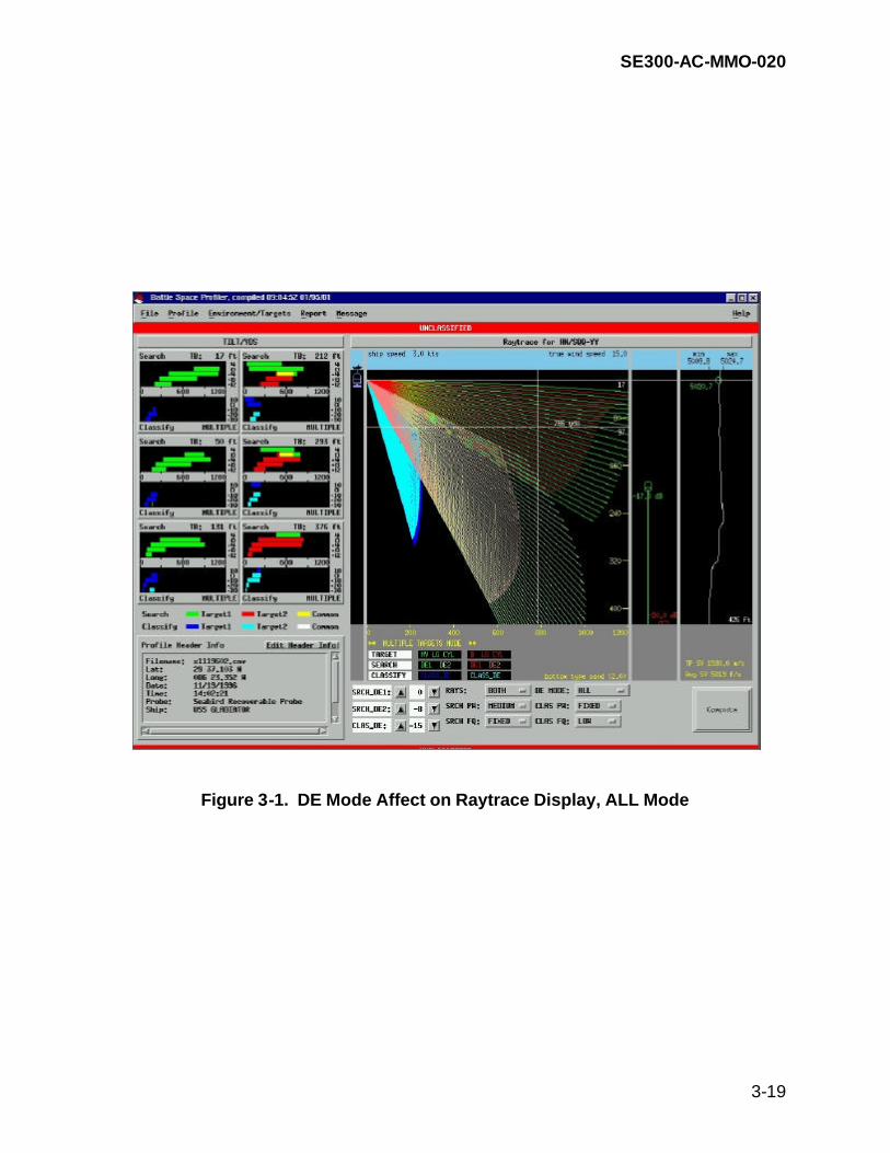
SE300-AC-MMO-020
3-19
Figure 3-1. DE Mode Affect on Raytrace Display, ALL Mode

SE300-AC-MMO-020
3-20
Figure 3-2. DE Mode Affect on Raytrace Display, TARGET 1 Mode

SE300-AC-MMO-020
3-21
Figure 3-3. DE Mode Affect on Raytrace Display, TARGET 2 Mode

SE300-AC-MMO-020
3-22
3-5.5 Computing Sonar Performance (Tilt/VDS and Raytrace). The BSP uses the Computer Aided Sonar Tactical Recommendations (CASTAR) model to compute sonar performance. Sonar performance is calculated using default environment, target, and sonar parameters or the operator’s inputted SVP and set environmental, sonar, and threat conditions. The sonar performance computations are accessed and displayed on the BSP Main Display. The BSP Main Display shows sonar performance using two graphic displays: Tilt/VDS and Raytrace. The TILT/VDS module calculates the minimum and maximum range for each D/E angle to a much greater resolution than the Raytrace module. The TILT/VDS provides a particular solution for the selected target, whereas the Raytrace solution provides a more general solution based on the sonar environment. Both solutions are accurate but are of differing resolutions. For this reason, the operator may see range differences at common sonar towed body depths. For each of the up to six towed body depths and accompanying D/E angles, the program computes the maximum and minimum range for that depth and angle. The program steps through the vertical beam width (at that D/E angle) in 0.5 degree increments (0.1 degree if the current angle is less than 0.51 degrees). At each angle increment, a new minimum and/or maximum range is stored along with the ray angle, if it is greater or less than the previously stored minimum or maximum range respectively. The convergence module then takes the maximum range solution ray angle, bounds it by ± 45 degrees and steps through with an angle increment of 0.05 degree. The minimum and maximum range is computed at each angle increment and again is stored if it is a new minimum or maximum. The convergence module then takes the maximum range solution ray angle, bounds it by 0.04 degrees, and steps it through with an angle increment of 0.01 degree (If the angle is less than 0.051 degrees, then the bound is 0.049 and the step is 0.001). The minimum and the maximum range is computed at each angle increment and stored if it is a new minimum or maximum. This process, performed by the TILT/VDS module, converges on the maximum range at the towed body depth, within the vertical beam width, and at the D/E angle to a resolution of 0.01 or 0.001 degree. The Raytrace module program steps through the vertical beam width in 0.25 degree increments for the towed body depth and the selected D/E angle. At each angle increment, the program plots the raytrace (range versus depth), starting with a range of 0.001 yards and out to the sonar maximum range in steps of 10 yards (25 yards if sonar maximum range is greater than or equal to 500 yards). If the surface, bottom, or "target no longer detectable" is reached, the raytrace is terminated.

SE300-AC-MMO-020
3-23
The Tilt/VDS display shows the detection and classification ranges for the specified target type at up to six towed body depths and discrete tilt angles. This display provides an overview of where to place the towed body for the threat selected. The raytrace display shows how the acoustic rays travel through the water column. Whenever a variable is changed, the BSP Main Display grays out until the operator clicks on the Compute button. When the Compute button is selected, the sonar performance is recalculated for the new settings. A new sonar performance calculation can also be made by moving the towed body icon to a different depth. Determining the optimum sonar settings and expected detection and classification ranges is an iterative process. The BSP software allows the operator to enter combinations of towed body depth and depression/elevation (tilt) angles to investigate sonar performance against the anticipated threat. Refer to Chapter 2, paragraph 2-9 for detailed explanations and interpretive skills pertaining to sonar performance computation. 3-5.6 Generating Outputs. The BSP software provides the functions necessary to print graphics or tabular data. The Report function on the main menu bar gives the operator choices for different printouts including Tilt/VDS tabular, Raytrace graphic and tabular, and SVP graphic and tabular. In addition, the BSP software allows the operator to generate SVP data files. The Message function on the main menu bar gives the operator choices for generating sound velocity profiles for the NAVOCEANO database or GCCS-M system. For the NAVOCEANO selection, the BSP software automatically selects the appropriate format and copies the data to the floppy drive. For the MEDAL selection, a message is sent over the RS-232 interface to GCCS-M. Profile Header Information must be formatted correctly to successfully send a message to GCCS-M – refer to Table 2-19 for format requirements. 3-5.7 File Utilities. The BSP software supports file import, export, and delete. 3-5.7.1 File Import. The BSP software supports importing probe data files (hex, raw, filtered, and sampled) and CTD Recorder configuration files from the computer's floppy disk drive. This function allows the BSP operator to use other sources for SVP files and also update and maintain the CTD Recorder's calibration coefficients. Previously archived data files from other BSP systems can be transferred to the BSP hard drive for use on the current system. 3-5.7.2 File Export. The BSP software supports exporting probe data files (hex, raw, filtered, and sampled) to the computer's floppy disk drive. This function allows the BSP operator to archive SVP files and provide data files to other BSP systems which can be transferred to the BSP hard drive. 3-5.7.3 File Delete. The BSP software supports deleting probe data files (hex, raw, filtered, and sampled) from the hard drive. This function allows the BSP operator to

SE300-AC-MMO-020
3-24
delete SVP files from in-air casts, bad casts, or other SVP files that are no longer required. 3-5.8 Probe Diagnostics. The BSP software supports limited diagnostic procedures for the CTD Recorder. 3-5.8.1 CTD Recorder Diagnostics. The BSP software allows the operator to perform diagnostics or preview the diagnostic condition of the probe by: (1) linking to the CTD Recorder and reviewing the information in the Probe Header Information window, (2) selecting the Utilities button on the CTD Recorder Interface window, or (3) performing an in-air test as directed in MRC R-3. If a link is established to the CTD Recorder, the various settings and readings are provided in the Probe Header Information window. The utilities interface provides a DOS based prompt window from which to execute specific diagnostic commands (see table 5-7). In addition to this interface, the operator may also perform an in-air test to verify temperature, conductivity cell, and pressure sensors readings. An 8-foot cable is also available to perform these same tests while the CTD Recorder is in the CIC. These diagnostics allow the operator to determine how well the CTD Recorder is functioning provided a link can be established between the CTD Recorder and the BSP computer.

SE300-AC-MMO-020
4-1
CHAPTER 4
SCHEDULED MAINTENANCE
4-1 INTRODUCTION. The scheduled maintenance for the Battle Space Profiler (BSP) system is summarized on maintenance index pages (MIPs) and described in detail on the maintenance requirement cards (MRCs) which are provided separately from this technical manual.

SE300-AC-MMO-020
5-1
CHAPTER 5
TROUBLESHOOTING
5-1 INTRODUCTION. Chapter 5 describes troubleshooting and diagnostic procedures which can be performed shipboard on the Battle Space Profiler (BSP) system. At the shipboard level, the BSP system operators can troubleshoot power failures of the computer equipment, winch components, and the recoverable conductivity, temperature, depth (CTD) recorder; mechanical failures of the handling assembly components; BSP software and operating software faults; and can perform some BSP software diagnostic steps. The printer is fully described in the Original Equipment Manufacturer (OEM) manual. If troubleshooting of this item is required, refer to the OEM manual. Troubleshooting steps are outlined here for the BSP system equipment. Once the malfunctioning component has been isolated and identified, refer to chapters 6 and 7 of this manual to complete the adjustment/alignment, repair, or removal/replacement of the failed item to maintain the operational capability of the BSP system. 5-2 TROUBLESHOOTING GUIDELINES. Table 5-1 provides an index of troubleshooting references. Tables 5-2 and 5-3 provide frequency and minimum and maximum values for the CTD Recorder, to be used as guidelines for troubleshooting. Tables 5-4 through 5-6 identify potential failures the operator may experience with the major components of the BSP system. Software diagnostics for the BSP software program are presented in table 5-7. 5-2.1 Troubleshooting Precautions. All safety precautions listed in the Foreword and Chapter 1 must be observed in performing troubleshooting procedures. Where emergency steps are located in this chapter, follow all warnings, cautions, and notes as they occur in the steps. All personnel should become familiar with and follow all safety rules governing ship’s troubleshooting and maintenance practices, such as safety manuals (OPNAVINST 5100), notices, and instructions. In the event of technical manual procedure and shipboard electrical safety procedure conflicts, the Shipboard Electrical Safety Procedures shall take precedence. 5-2.2 Electrostatic Discharge (ESD) Sensitive Device Precautions. Chapter 6, paragraph 6-3.1.3, provides a general procedure for handling ESD components. 5-3 TABULAR TROUBLESHOOTING DATA. The following tables describe potential faults the user may experience with the BSP system equipment. Where commercial off-the-shelf (COTS) manuals, provided in the appendices, have detailed information for troubleshooting and performing diagnostics, they are referenced in the table.

SE300-AC-MMO-020
5-2
Table 5-1. Troubleshooting Index
Functional Area
Troubleshooting
Table Reference
Troubleshooting
Diagram
Functional Description Paragraph
Alignment/ Adjustment Paragraph
1. Power input function:
a. 115VAC
5-4 1A - 1H
Foldout (FO)-3, BSP System Power Distribution Block Diagram
3-3.4.2 3-3.4.3 3-3.4.4 3-3.4.5
None
2. Unit function:
a. Unit 1 - Computer, Keyboard, Track Pad
5-4 1C, 5-6 3A - 3R
3-2.1 3-2.3 3-2.4 3-2.5 3-3.3 3-4.1 3-4.2
None
b. Unit 2 - Printer
5-4 1A, 5-6 3D
3-3.6.4
Refer to printer OEM manual
c. Unit 9 - Multiport Spooler
5-4 1B
3-2.5.1
None
d. Unit 4 - Winch Assembly
5-4 1E - 1H 5-5 2A - 2G
3-2.2 3-3.2.1
6-2.2
e. Unit 5 - "J" Davit Assembly
None
3-2.2
None
f. Unit 6 - Storage Cabinet
None
None
None
g. Unit 8 - Recoverable CTD Recorder
5-6 3A - 3Q
3-2.1 3-3.1
None

SE300-AC-MMO-020
5-3
5-4 MAINTENANCE TURN ON PROCEDURE. The operator must perform these steps to verify proper operation of the equipment as required following maintenance actions: a. Turn on the printer. Observe the power on indicator illuminates. Turn on the
computer. Observe power indicator illuminates on the computer. b. Log on to the BSP system. c. Select appropriate system. d. Observe BSP main display. e. Apply ship's power at the winch assembly circuit breaker. Turn the winch power
On/Off switch to On. Observe power indicator light illuminates. f. Pay out a few feet of cable. g. Haul in the cable payed out. 5-5 MAINTENANCE TURN-OFF PROCEDURE. Perform the following steps to exit the BSP software and shut down the equipment:
CAUTION
Do not press the power button on the computer to exit the BSP software and shut down the equipment. If the power button is pressed, LINUX file system files may become corrupted.
a. From the File drop down menu on the main menu bar, select Quit. The login
prompt will appear. b. Press the CTRL, ALT, and DEL keys simultaneously. The computer will perform
the shutdown function. c. While the message “It is now safe to turn off the computer” is visible on the
display screen, turn off the computer and associated equipment. d. Turn the winch power ON/OFF switch to OFF.

SE300-AC-MMO-020
5-4
e. Secure ship's power to the winch. 5-6 BSP SYSTEM FAULTY SYMPTOM ANALYSIS. The BSP system faulty symptom analysis is supported by computer diagnostics associ-ated with the computer hardware and the CTD Recorder. The following tables should be consulted to troubleshoot and diagnose BSP system failures. The BSP system has very limited built-in fault localization capabilities. Fault isolation is largely the responsibility of the operator/maintainer and the six-step troubleshooting method. A basic approach to troubleshooting for basic electronic systems uses a six-step procedure which should be used as an overall guideline for troubleshooting the BSP system. These steps are: a. Symptom recognition. Determine whether the equipment is functioning correctly
or incorrectly by identifying a sign of trouble. b. Symptom elaboration. Try to identify or clarify the indication of a symptom further
by adjusting the controls and indicators, settings, reviewing data, etc. c. Listing of probable faulty functions. The functional block diagram may be
followed to assist in determining the problem. d. Localizing the faulty function. Determine which functional unit is actually at fault. e. Localizing trouble to the lowest level of repair or replacement. f. Failure analysis. Determine if other failures have occurred as a result of the
initial problem. Maintain records on the findings. To support the troubleshooting process, the BSP system has two software tools to assist in fault isolation: the QAPlus diagnostics and the diagnostics resident in the BSP software program. The first tool, QAPlus, is a commercial off-the-shelf (COTS) software program. It re-sides on the Windows 98 hard drive and allows the technician to isolate problems asso-ciated with the computer hardware. It is used to perform diagnostics on the system board, RAM, video adapter, hard drive, floppy drive, CD-ROM, serial port, parallel port, printer, keyboard, track pad, and speaker. The QAPlus Users Manual is included as appendix A. The second tool is found in the BSP software and is used explicitly for troubleshooting the CTD Recorder. Access to this tool is found under Link to CTD Recorder and by

SE300-AC-MMO-020
5-5
selecting the Utilities button. This will give the technician a text window in which to send commands (see table 5-7) to the probe to determine its condition of operation.

SE300-AC-MMO-020
5-6
Table 5-2. Frequency Values
Environment
Conductivity Frequency
Air
2,885 Hz
Fresh water
2,800 Hz
Salt water (normal ocean)
3,500 Hz
Table 5-3. Readings Values
Setting
Minimum Reading
Maximum Reading
FR test diagnostic readings:
Conductivity (see note below)
2,884 Hz (dry cell, corrected frequency)
2,886 Hz (dry cell, corrected frequency)
Pressure
Close to 0 (dry cell) (Engineering Units)
Temperature
Ambient (corrected frequency) (Engineering Units)
Clock Frequency
32,767 Hz
32,768 Hz
Quiescent Current (Diagnostic Command J test)
40 micro amps Should read approximately 52 micro amps.
60 micro amps
Lithium battery voltage (Diagnostic Command DS test)
Should read above 3.8 volts. Probe will still function at 0. Rapid change may indicate a failure.
5.5
Battery (Diagnostic Command DS Test)
7.3 volts
14.5
Pump settings (Diagnostic Command DS Test)
3,500 Hz for salt water 45 second delay minimum
NOTE: The frequency response (conductivity) in air should agree to within 1 Hz. A reading with a greater discrepancy may indicate a problem.

SE300-AC-MMO-020
5-7
Table 5-4. BSP System Power Faults Analysis Chart
Symptom
Indication
Probable Cause
Remedy (Paragraph)
1. BSP SYSTEM POWER FAULTS
A. Printer fails to
energize.
Power on indicator is not illuminated.
Loose power cord
Inspect power cord connection.
Loss of ship’s power
Check ships circuit breakers.
Printer failure
Refer to printer OEM manual Remove/replace printer (6-3.2.2).
B. Multiport
Spooler fails to energize.
Power on indicator is not illuminated.
Loose power cord
Check connection to ship's power.
Loss of ship's power
Check ships circuit breakers
Power cord transformer failure
Remove/replace power cord.
Multiport Spooler failure
Remove/replace multiport spooler (6-3.2.3).
C. Computer
fails to energize.
Power on indicator is not illuminated.
Loose power cord
Check power connection.
PNotePro3 is not functioning
Check power output of PNotePro3.
Computer failure
Remove/replace computer (6-3.2).
D. Removable
hard drive disk fails to energize.
System does not initialize.
Removable hard drive disk is not seated properly.
Turn computer power off. Remove and reinsert hard drive disk.
Removable hard drive disk failure
Remove/replace hard drive disk (6-3.2.1)
Computer failure
Remove/replace computer (6-3.2).

SE300-AC-MMO-020
5-8
Table 5-4. BSP System Power Faults Analysis Chart — Continued
Symptom Indication Probable Cause Remedy
(Paragraph)
E. Winch motor
fails to energize.
Winch power indicator is not illuminated.
Loss of ship’s power
Ensure ship's power is applied to winch. Verify bulkhead power switch is in ON position. Verify ship's circuit breaker is in ON position.
Blown Fuse
Remove/replace fuse (6-3.5.1).
Winch power On/Off switch failure
Inspect electrical connection to winch power On/Off switch. Remove/replace winch power On/Off switch (6-3.5.8).
Winch power On/Off switch is in Off positions.
Set winch position selector switch to On. .
F. Winch motor
fails to energize.
Winch power indicator is illuminated.
System didn't have time to warm up prior to operation
Turn winch power ON/OFF switch to OFF. Wait 15 seconds, then switch to ON again. Wait 15 seconds, then attempt to operate again
Overload relay has tripped.
Reset overload relay.
Faulty wiring
Inspect electrical wiring.
Failed overload relay
Remove/replace overload relay (6-3.5.7).
Failed winch joystick controller
Remove/replace joystick (6-3.5.9).

SE300-AC-MMO-020
5-9
Table 5-4. BSP System Power Faults Analysis Chart — Continued
Symptom Indication Probable Cause Remedy (Paragraph)
F. Winch motor fails to
energize. (Continued)
Winch power indicator is illuminated/and no fault is indicated on inverter
Motor overloaded
Check that drive shaft is free to turn when brake is released.
Failed motor
Remove/replace drive assembly (6-3.5.10).
Inverter display is blank.
Lack of input voltage
Check input power for proper voltage. Check fuses.
Loose connections
Check input power termination.
Inverter displays F01, computer malfunction fault.
Corrupted memory
Reset control by pressing keypad stop key and holding for more than one second.
Inverter displays F02, parameter block fault.
Run inverter diagnostics (5-6.1)
Inverter displays F03, bus current measurement fault
Run inverter diagnostics (5-6.1)
Inverter displays F04, power supply overload
Run inverter diagnostics (5-6.1)

SE300-AC-MMO-020
5-10
Table 5-4. BSP System Power Faults Analysis Chart — Continued
Symptom
Indication
Probable Cause
Remedy
(Paragraph)
F. Winch motor fails to
energize. (Continued)
Inverter displays F05, bus under voltage.
Insufficient input voltage.
Verify proper input voltage. (See 5-6.1)
Inverter displays F06, output short circuit fault.
Motor failure
Verify motor windings are not shorted.
Shorted motor leads.
Verify motor leads are not shorted. Repair as required. (See 5-6.1)
Inverter displays F07, external trip fault
Motor drawing excessive current.
Check motor for overloading condition.
Motor overload relay not connected.
Connect motor overload relay. Verify connection of all external trip circuits used with motor overload relay. Reset motor overload relay.
Inverter displays F10, auto restart fault
Run inverter diagnostics. See 5-6.1
Inverter displays F11, ground fault.
Motor failure.
Verify motor windings are not shorted.
Shorted motor leads.
Verify motor leads are not shorted. Repair as required.

SE300-AC-MMO-020
5-11
Table 5-4. BSP System Power Faults Analysis Chart — Continued
Symptom
Indication
Probable Cause
Remedy (Paragraph)
F. Winch motor fails to
energize. (Continued)
Inverter displays F13, bus overvoltage fault.
Input voltage too high.
Check input voltage. (See 5-6.1)
Overhauling motor load.
Correct motor load.
Inverter displays F16, overcurrent during acceleration
(See 5-6.1)
Inverter displays F17, overcurrent during deceleration
(See 5-6.1)
Inverter displays F18, overcurrent while running
(See 5-6.1)
Inverter displays F19, heatsink overtemp fault
Motor overloaded.
Correct motor loading
Ambient temperature too high.
Provide cooling fans.
Inverter displays F20, timed overload
(See 5-6.1)
G. Winch motor
operates in only one direction.
Motor operates in one direction but not the other.
Faulty wiring/connections
Inspect connections to/from contactor.
Failed contactor
Remove/replace faulty contactor (6-3.5.5).
Failed winch joystick controller
Remove/replace faulty joystick controller (6-3.5.9).
H. Unstable speed
Unstable input power.
Correct input power.

SE300-AC-MMO-020
5-12
5-6.1 Inverter Diagnostics.
INVERTER TERMINALS
VOLTAGE READINGS (+/- 10%)
Joystick to NEUTRAL
VOLTAGE READINGS (+/- 10%)
Joystick to PAYOUT
VOLTAGE READINGS (+/- 10%)
Joystick to HAUL-IN
L1 to L2 120 VAC 120 VAC 120 VAC
M1 to M2 0 VAC 0 - 240 VAC (varies with joystick movement)
0 - 240 VAC (varies with joystick movement)
M2 to M3 0 VAC 0 - 240 VAC (varies with joystick movement)
0 - 240 VAC (varies with joystick movement)
M3 to M1 0 VAC 0 - 240 VAC (varies with joystick movement)
0 - 240 VAC (varies with joystick movement)
NO to RCM 120 VAC 120 VAC 120 VAC
V+ to CM 13 VDC 13 VDC 13 VDC
REF to CM 5.2 VDC 5.2 VDC 5.2 VDC
VIN to CM 0 VDC 0 - 5 VDC (varies with joystick movement)
0 - 5 VDC (varies with joystick movement)
FWD to CM 0 VDC 13 VDC 0 VDC
REV to CM 0 VDC 0 VDC 13 VDC
MOL to CM 13 VDC (0 VDC if overload relay tripped)
13 VDC (0 VDC if overload relay tripped)
13 VDC (0 VDC if overload relay tripped)
1. Remove Electrical Box cover (see 6-3.5.6) 2. Remove inverter lower cover by loosening the two set screws located in the upper corners. 3. Measure the voltage between each set of terminals in the Inverter Voltage Checks table and
record the voltages measured. 4. If the voltages are within the parameters given in the table, and the problem persists, replace the
inverter (see 6-3.5.6) 5. If the voltages measured are not within the parameters given in the table, provide the actual
voltage measurements to the designated technical support activity for assistance in further troubleshooting.

SE300-AC-MMO-020
5-13
Table 5-5. BSP Mechanical Faults Analysis Chart
Symptom
Indication
Probable Cause
Remedy
(Paragraph) 2. BSP SYSTEM MECHANICAL FAULTS
A. Winch assembly fails to pay out/haul in.
Power on indicator is illuminated.
Electric brake won't disengage and/or overload breaker tripped.
Verify electric brake won't disengage. Remove/replace electric brake.
Excessive noise is heard when joystick is placed in PAY OUT or HAUL IN
Interference of drum
Turn off power. Check for interference of drum.
Interference of chain
Check for interference of chain drive.
B. Winch assembly has
erratic or low speed condition.
Power on indicator is illuminated.
Electrical connection to ship's power is faulty.
Check electrical connections. Check power source.
Intermittent noise is heard.
Improper chain sprocket alignment
Check chain sprocket alignment.
Interference of drum
Turn off power. Check for interference of drum.
Motor will not reach maximum speed.
Motor overloaded
Check for mechanical overload. If unloaded drive shaft does not turn freely when brake is released, check bearings.
Motor runs rough at low speeds.
Misalignment of drive assembly.
Check coupling alignment.
C. Winch fails to take
up cable when activated.
Power on indicator is illuminated.
Overload breaker tripped.
Reset overload breaker.
Electric brake doesn't disengage.
Verify electric brake won't disengage. Remove/replace electric brake.

SE300-AC-MMO-020
5-14
Table 5-5. BSP Mechanical Faults Analysis Chart — Continued
Symptom
Indication
Probable Cause
Remedy
(Paragraph) C. Winch fails to take
up cable when activated. (Continued)
Noise is heard.
Failed bearing Failed speed reducer
If bearings or speed reducer are failing, remove/replace drum assembly or drive assembly respectively (6-3.5.11 or 6-3.5.10).
D. Winch continues to
pay out cable with joystick controller in STOP position.
Cable paying out
Defective electric brake
Secure ship’s power to winch and tag out. Remove/replace electric brake (6-3.5.10).
E. Oil seeping out
around gearbox or other places
Oil stains visible on base of winch or around speed reducer.
Oil leaking from damaged gaskets or seals
Check oil level. Remove/replace drive assembly (6-3.5.10).
F. Excessive vibration
of winch during operation.
Worn drum bearings
Remove/replace drum assembly (6-3.5.11).
G. No change in cable
counter reading during payout or haul-in.
Wire is off the cable counter guide.
Place wire back onto cable guide.
Failed cable counter
Remove/replace cable counter (6-3.5.15).

SE300-AC-MMO-020
5-15
Table 5-6. CTD Recorder and BSP Software Program, Faults Analysis Chart
Symptom
Indication
Probable Cause
Remedy (Paragraph)
3. BSP SYSTEM FAULTS
A. BSP software unable to communicate with CTD Recorder from the computer.
Establish Link is unsuccessful.
CTD Recorder magnetic switch is in the ON position.
Verify magnetic switch is in the OFF position.
Loose CTD Recorder interface cable connection.
Verify CTD Recorder interface cable connection.
Loose connection to computer COM1 port.
Check computer COM1 port connection.
Bad cable connection.
Verify all connections in the BSP-to-CTD path. Disconnect all connectors on CTD and computer and ensure that connector pins are not bent or corroded. Reinstall connectors.
Bad cable run.
Bring probe to CIC and reattempt to link to CTD using the 3-meter cable.
Failed CTD Recorder Y-cable.
Test Y-cable for continuity using Figure 5-1. Remove/replace Y-cable if shorts/opens are found.
Battery failure in CTD Recorder.
Manually check CTD Recorder battery voltage. Replace batteries if required.

SE300-AC-MMO-020
5-16
Table 5-6. CTD Recorder and BSP Software Program, Faults Analysis Chart — Continued
Symptom
Indication
Probable Cause
Remedy (Paragraph)
A. BSP software
unable to communicate with CTD Recorder from the computer. (Continued)
Probe memory failure.
Open CTD Recorder and remove the 9 D-cell batteries. At the bottom of the battery compartment, set the MEMORY RESET switch to RESET (see paragraph 6-3.4.4). After 10 minutes, set the MEMORY RESET switch back to the operational position and reinstall batteries and end cap. After establishing link to CTD Recorder, must Set Probe For Cast to initialize probe.
Failed computer COM1 port.
Exit BSP software. Disconnect CTD Recorder from interface cable. Connect loop-back adapter to COM1 port. Run MS-DOS diagnostics provided by manufacturer. Refer to Appendix A, QAPlus OEM manual for instructions.
B. Display screen does
not respond to keyboard.
Can not enter data with keyboard
BSP Software has locked up. Internal hardware failure.
Reboot computer via power switch. Refer to appendix A, QAPlus OEM manual to run computer diagnostics.
Keyboard failure Remove/replace computer (6-3.2).

SE300-AC-MMO-020
5-17
Table 5-6. CTD Recorder and BSP Software Program,
Faults Analysis Chart — Continued
Symptom
Indication
Probable Cause
Remedy
(Paragraph) C. Track pad does not
respond.
Screen icon does not respond to finger movement
BSP software has locked up
Reboot system.
Hardware failure
Refer to appendix A, QAPlus OEM manual to run computer diagnostics.
Track pad failure
Remove/replace computer (6-3.2).
D1. Printer has power
but will not print.
POWER indicator is illuminated.
Loose interface connection
Inspect interface connections and tighten.
Printer RESUME indicator is illuminated.
Printer paused.
Depress RESUME to continue printing.
Improper configuration in operating system setup
Verify setup in operating system (refer to printer OEM manual).
Printer POWER indicator is illuminated
Multiport Spooler is not powered on
Switch Multiport Spooler power switch to ON.
Printer failure
Remove/replace printer (6-3.2.2).
D2. Printer Output
Problem.
Printout contains garbled characters or strange text.
Printer/computer communications interrupted.
Reset printer (2-10.7).

SE300-AC-MMO-020
5-18
Table 5-6. CTD Recorder and BSP Software Program, Faults Analysis Chart — Continued
Symptom
Indication
Probable Cause
Remedy (Paragraph)
E. BSP system
software does not boot up.
Display screen is frozen.
Removable hard drive disk not fully inserted and secured.
Slide removable hard drive disk out, inspect connector pins, reinsert hard drive disk, and secure in place.
BSP software has become corrupt
Notify the system administrator to check setup. Verify Windows 98 hard drive disk operates properly. Run QAPlus diagnostics (refer to appendix A). Notify the SSA.
Removable hard drive disk failure
Remove/replace removable hard drive disk (6-3.2.1)
Computer failure Remove/replace computer (6-3.2)

SE300-AC-MMO-020
5-19
Table 5-6. CTD Recorder and BSP Software Program, Faults Analysis Chart — Continued
Symptom
Indication
Probable Cause
Remedy (Paragraph)
F. Windows does
not boot up.
Removable hard drive disk not fully inserted and secured.
Slide removable hard drive disk out, inspect connector pins, reinsert hard drive disk, and secure in place.
WINDOWS software has become corrupt
Reinstall WINDOWS software Notify the system administrator. Verify BSP hard drive disk operates properly Run QAPlus diagnostics (Appendix A).
Removable hard drive disk failure
Remove/replace removable hard drive disk (6-3.2.1).
Computer failure Remove/replace computer (6-3.2).

SE300-AC-MMO-020
5-20
Table 5-6. CTD Recorder and BSP Software Program, Faults Analysis Chart — Continued
Symptom Indication Probable Cause Remedy (Paragraph)
G. No CTD
Recorder data present after deployment.
Magnetic switch was not in ON position.
Inspect magnetic switch position. Check information in Probe Status Header window (Table 2-15).
Failing or failed D-cell batteries
Measure batteries under load condition. If loaded voltage reading drops below 8 VDC, replace batteries.
Bad water seal on CTD Recorder
Check O-rings.
External magnetic switch failure
Remove/replace external magnetic switch (6-3.4.6).
Internal switch failure CTD Recorder failure
Remove/replace CTD Recorder (6-3.4.1).
H. CTD maximum
recorded depth is much less than fathometer depth.
(1) SVP profile in Filter Pop-Up display is well short of anticipated depth, and (2) cast information in “Cast Header Information” window indicated “bat fail”. To view this information, scroll to the right in the window. “Bat fail” indicates that the reason the cast was terminated was due to insufficient battery voltage.
D-cell batteries in CTD recorder have insufficient current to drive CTD recorder electronics package.
Remove the CTD recorder access cover. Using a DVM, monitor the negative and positive terminals of the battery access plate. Monitor the voltage while the CTD recorder to static, and linking to the computer (or switch the CTD recorder on). If the monitored voltage drops below 8 VDC, replace D-cell batteries.

SE300-AC-MMO-020
5-21
Table 5-6. CTD Recorder and BSP Software Program, Faults Analysis Chart — Continued
Symptom
Indication
Probable Cause
Remedy
(Paragraph) I. No CTD Recorder
temperature data present after deployment.
Temperature data in Filter Raw Profile window is 0.00 for all data points.
CTD Recorder failure
Inspect temperature sensor. Perform an in-air cast (refer to PMS MRC R-3) Remove/replace CTD Recorder (6-3.4.1).
J. Meaningless data
was received.
Failed CTD Recorder.
Inspect CTD Recorder for external damage. Perform an in-air cast (refer to PMS MRC R-3). Remove/replace CTD Recorder (6-3.4.1).
K. Data lost from
previous cast(s) using CTD Recorder.
None. Check diagnostics status in window display.
L. BSP software
"bugs" occur.
Try to determine if problem is repeatable. Fill out software "trouble" report. Notify SSA.
M. Spikes in data
observed on display.
Bad cast. CTD relays stuck.
Repeat cast. Remove/replace CTD Recorder (6-3.4.1).
N. Abnormal salinity
readings observed.
Dirty conductivity cell.
Clean conductivity cell.
Pump failure.
Check pump for proper operation by performing pump functional check. Refer to PMS MRC R-3. The CTD Recorder can be used with the pump removed. Remove/replace pump (6-3.4.2).

SE300-AC-MMO-020
5-22
Table 5-6. CTD Recorder and BSP Software Program,
Faults Analysis Chart — Continued
Symptom
Indication
Probable Cause
Remedy
(Paragraph) O. No Salinity readings.
Temperature and depth readings present.
Software error.
Remove/reinstall batteries. Reset memory reset switch in bottom of the battery compartment (6-3.4.4). Do not replace batteries.
P. Insufficient memory
error during program execution. BSP program won't run.
Try to determine if problem is repeatable. Fill out software "trouble" report. Notify SSA.
Q. BSP software program
crashes.
Try to determine if problem is repeatable. Fill out software "trouble" report. Notify SSA.
R. CTD Recorder time and
date functions not registering/inaccurate.
Intermittent problem in CTD Recorder. "Glitch" in firmware. Failed CTD Recorder
Run diagnostics (5-7). Reset probe for cast. Remove/replace CTD Recorder (6-3.4.1).
S. IOP Current reading
300-400.
Failed CTD Recorder
Disconnect pump to isolate problem to either inside the probe or in the pump external sensor. Remove/replace pump (6-3.4.2). Remove/replace CTD Recorder (6-3.4.1).

SE300-AC-MMO-020
5-23
Table 5-6. CTD Recorder and BSP Software Program,
Faults Analysis Chart — Continued
Symptom
Indication
Probable Cause
Remedy
(Paragraph) T. BSP software cannot
send messages to MEDAL
Messages not received by MEDAL
BSP Profile Header information is not in correct format.
Verify Profile Header information is in the correct format (refer to Table 2-6).
Loose connection to computer COM2 port.
Check computer COM2 port connection.
Incorrect serial port setup on GCCS-M system.
Have GCCS-M verify Seabird serial port setup and open window to view data on the port. If data is present, port and cables are functioning properly and the problem resides in the GCCS-M system. Ensure MCM COMMS ALERTS are enabled on GCCS-M system and resend message from BSP. Review error alerts on GCCS-M.
Failed computer COM2 port.
Exit BSP software. Disconnect GCCS-M interface cable from computer. Connect loop-back adapter to COM2 port. Run MS-DOS diagnostics provided by manufacturer. Refer to Appendix A, QAPlus OEM manual for instructions.
Bad cable run.
Perform continuity checks between GCCS-M (TTY-C3) and BSP computer (COM2).

SE300-AC-MMO-020
5-24
Table 5-6. CTD Recorder and BSP Software Program,
Faults Analysis Chart — Continued
Symptom
Indication
Probable Cause
Remedy
(Paragraph)
U. BSP software does not communicate with Expendable Probe.
Loose MK21 cable connection at rear of computer.
Check MK21 cable connections at rear of computer and data recorder.

SE300-AC-MMO-020
5-25
Figure 5-1. Y-Cable Pinouts

SE300-AC-MMO-020
5-26
5-7 CTD RECORDER DIAGNOSTIC PROCEDURE. This procedure may be used by the operator to view diagnostic information provided by the BSP software. a. At the computer, boot up the BSP software program. At BSP login, type
assigned login and press Enter key. At password, type assigned password and press Enter key.
b. From the start up menu select a sonar type. c. At BSP Main Display, select Profile. Select Link to CTD Recorder, then select
Utilities. d. Press Enter two times to get the S> prompt. At this point, diagnostics commands
presented in table 5-7 may be entered to evaluate probe status. e. Press Ctrl and \ (the backslash key) simultaneously, then press C to return to the
CTD Recorder Interface window. 5-7.1 CTD Recorder In-Air Test. An in-air test of the CTD Recorder may be performed according to paragraph 2-4.2 to determine if the probe is properly calibrated and reading within expected ranges for temperature, depth, and salinity.
NOTE
As part of the diagnostic procedure, ensure the conductivity cell has air-dried first.

SE300-AC-MMO-020
5-27
Table 5-7. CTD Recorder Software Diagnostics, Controls and Indicators
(Refer to Figure 2-15)
Index No.
Switch/Indicator
Function
1
DS
Status command. Displays current status.
Operating current generally should read 100 - 130 milli amps.
2
J
Diagnostics command. Measures standby current (quiescent current). Reading range between 40 and 60 micro amps. Reading should be approximately 54 micro amps.
3
FR
Display command. Displays frequencies. Press ESC to stop. SEACAT will send: aaaaa.aaa bbbbb.bbb ccccc.ccc ddddd.ddd eeeee.eee fffff.fff aaaaa.aaa is the 400 ohm reference resistor frequency bbbbb.bbb is the 5000 ohm reference resistor frequency ccccc.ccc is the frequency generated by the conductivity cell ddddd.ddd is the frequency generated by the temperature sensor eeeee.eee is the corrected temperature frequency fffff.fff is the corrected conductivity frequency Typical values are (values following the decimal point are insignificant): 10041.xxx 2854.xxx 3590.xxx 2854.xxx 3636.xxx 2885.xxx
4
VR
Display command. Displays voltages. Press ESC a few times in quick succession to stop. The first column is the main battery voltage divided by 8.514. The second column is a voltage that represents the temperature in the pressure sensor. The third column is the pressure sensor voltage. Four columns are added after the last column for the external voltages sampled. Typical values are: 1.352 0.844 454.8 0.002 0.001 0.002 0.001 The last four values may fluctuate between 0.001 and 0.002.

SE300-AC-MMO-020
5-28
5-8 COMPUTER HARDWARE DIAGNOSTICS. The computer hardware diagnostics are aided by the QAPlus software. This software resides on the Windows 98 removable hard drive disk. The software will run a batch of tests to verify the correct operation of the hard drive disk, keyboard, track pad, system settings, etc. If the tests result in a failed hard drive disk, remove/replace the hard drive disk (refer to 6-3.2.1). If the keyboard or the track pad fails, remove/replace the notebook computer (refer to 6-3.2). QAPlus can be executed from either the Windows hard drive disk or from the program diskettes. To run the QAPlus diagnostics from the floppy drive, perform the following: a. If the BSP program is running, perform the following steps to exit the BSP
software and shut down the equipment:
CAUTION
Do not press the power button on the computer to exit the BSP software and shut down the equipment. If the power button is pressed, LINUX file system files may become corrupted.
b. From the File drop down menu on the main menu bar, select Quit. The login
prompt will appear. c. Press the Ctrl, Alt, and Del keys simultaneously. The computer will perform the
shutdown function. d. While the message “It is now safe to turn off the computer” is visible on the
display screen, turn off the computer and associated equipment. e. When prompted, turn off the computer. f. Disconnect the suspected cable. Attach the serial loopback connector to COM1
if troubleshooting the CTD Recorder interface or to COM2 if troubleshooting the GCCS-M system interface respectively. If troubleshooting the printer interface, connect the parallel loopback connector to the printer port on the back of the computer (the port that is connected to the multiport spooler).
g. Insert the QAPlus disk 1 of 2 into drive A. h. Turn on the computer.

SE300-AC-MMO-020
5-29
i. Enter ship’s Name [MHC-XX], Company [U.S. Navy], and Serial # [see diskette], then select F10.
j. Refer to appendix A for using the QAPlus software. k. Remove the disk from drive A. l. Turn the computer off.

SE300-AC-MMO-020
5-30
5-9 AR-20 TROUBLESHOOTING PROCEDURES. Figure 1-7 and Figure 5-2 identify the parts of the AR-20 System Selector. Figure 5-3 identifies the contacts switches on the AR-20 SELECT knob. Figure 5-4(a) and Figure 5-4(b) show the wiring diagram for the AR-20 System Selector. If new or replacement parts are needed for the AR-20 see Table 7-2 (P/N 213627-1).
If signal flow from the launcher to computer is interrupted at the AR-20 location, check electrical continuity at each input (L-1, L-2) and output (R-1) connector.

SE300-AC-MMO-020
5-31
Figure 5-2. AR-20 System Selector

SE300-AC-MMO-020
5-32
Figure 5-3. AR-20 Contact Switch Identification

SE300-AC-MMO-020
5-33
Figure 5-4(a). AR-20 System Selector Schematic Diagram (Sheet 1)

SE300-AC-MMO-020
5-34
Figure 5-4(b). AR-20 System Selector Schematic Diagram (Sheet 2)

SE300-AC-MMO-020
6-1
CHAPTER 6
CORRECTIVE MAINTENANCE
WARNING
The following procedures involve the use of hazardous materials. Ensure all personnel are familiar with the hazards listed in the specific manufacturer’s Material Safety Data Sheet (MSDS) and that Personnel Protective Equipment (PPE) guidance is followed.
6-1 INTRODUCTION. This chapter provides procedures for adjustment and alignment of the Battle Space Profiler (BSP) system components, corrective maintenance procedures which can be performed at the organizational (shipboard) level, and standard procedures provided to assist the operator in performing maintenance procedures. Table 6-1 provides an index of all of these procedures. 6-2 ADJUSTMENTS AND ALIGNMENTS. The following adjustments and alignments may be performed at the organizational (shipboard) level on the BSP equipment. 6-2.1 LM3A Hand-Held Launcher/Expendable Probes Adjustments and Alignments. 6-2.2 Chain Adjustment Procedure. Perform the following procedure to adjust the chain tension. TOOLS REQUIRED: Wrench, 7/16-inch Wrench, 9/16-inch a. Remove power to winch assembly. b. Remove the thirteen 1/4-inch capscrews and washers that attach the large
shroud to the frame. c. Remove shroud.

SE300-AC-MMO-020
6-2
d. Loosen the two 3/8-inch capscrews that secure the idler sprocket assembly to
the frame. Table 6-1. Index of Procedures
Procedure Paragraph Number
Adjustment and Alignment Procedures
6-2
LM3A Hand-Held Launcher/Expendable Probes
6-2.1
Chain Adjustment Procedure
6-2.2
Standard Procedures
6-3.1
Standard Power On
6-3.1.1
Standard Power Off
6-3.1.2
Standard ESD Handling Precautions
6-3.1.3
Winch Cable Re-Termination Load Test
6-3.1.4
Corrective Maintenance Procedures
6-3
Computer Removal and Replacement
6-3.2
Removable Hard Drive Disk Removal and Replacement
6-3.2.1
Printer Removal and Replacement
6-3.2.2
Print Cartridge Removal and Replacement
6-3.2.2.1
Multiport Spooler Removal and Replacement
6-3.2.3
MK21 Interface Card Removal and Replacement
6-3.2.4
PNotePro3 Removal and Replacement
6-3.3
CTD Recorder Removal and Replacement
6-3.4.1

SE300-AC-MMO-020
6-3
Table 6-1. Index of Procedures — Continued
Procedure Paragraph Number
SBE 5T Pump Removal and Replacement
6-3.4.2
Zinc Anode Removal and Replacement
6-3.4.3
D-cell Batteries Removal and Replacement
6-3.4.4
Battery Housing O-Ring and Battery End Cap O-Ring Removal and Replacement
6-3.4.5
External Magnetic ON/OFF Switch Removal and Replacement
6-3.4.6
Y-Cable Removal and Replacement
6-3.4.7
Pressure Sensor Capillary Tube, Addition of Oil
6-3.4.8
Air Bubble Trapped in Capillary Tube, Addition of Oil
6-3.4.9
Cleaning Connector Pins
6-3.4.10
Fuse Removal and Replacement
6-3.5.1
Varistor Removal and Replacement
6-3.5.2
Line Filter Removal and Replacement
6-3.5.3
Solid State Relay Removal and Replacement
6-3.5.4
Contactor Removal and Replacement
6-3.5.5
Inverter Removal and Replacement
6-3.5.6
Overload Relay Removal and Replacement
6-3.5.7
On/Off Switch Removal and Replacement
6-3.5.8
Joystick Removal and Replacement
6-3.5.9
Drive Assembly Removal and Replacement
6-3.5.10
Drum Assembly Removal and Replacement
6-3.5.11
Idler Sprocket Assembly Removal and Replacement
6-3.5.12
Chain Removal and Replacement
6-3.5.13
Band Brake Removal and Replacement
6-3.5.14
Cable Counter Removal and Replacement
6-3.5.15

SE300-AC-MMO-020
6-4
e. Adjust the position of the idler bracket assembly to allow for no more than 1/2-
inch of total play in the chain, but ensure that the chain is taut. f. Tighten the two 3/8-inch capscrews that secure the idler sprocket assembly to
the frame. g. Replace the shroud. Fasten the shroud to the frame with the 1/4-inch capscrews
and washers. h. Return equipment to readiness condition. 6-3 REPAIR. This section provides the information necessary to remove and replace the assemblies, subassemblies, and repairable parts in those hardware portions of the BSP system designated as repairable at the organizational (shipboard) level. Table 6-1 provides an index of organizational-level remove and replace procedures.
NOTE
Contact the BSP System Administrator aboard the ship for software program problems.
6-3.1 Standard Procedures. The following standard procedures may be referred to for quick reference to power on and power off the BSP system, and for electrostatic discharge (ESD) precautions. 6-3.1.1 Standard Power On. The operator must perform these steps to verify proper operation of the equipment as required following maintenance actions: a. Turn on the printer. Observe POWER switch/indicator illuminates. Turn on the
multiport spooler. Observe POWER indicator illuminates. Turn on the notebook computer. Observe POWER indicator illuminates on the computer.
b. Apply ship’s power to the winch assembly. Pull and twist knob to turn winch
power on. Observe indicator light illuminates on the winch power On/Off switch. 6-3.1.2 Standard Power Off. Perform this procedure to exit the BSP software and shut down the equipment.

SE300-AC-MMO-020
6-5
CAUTION
Do not press the power button on the computer to exit the BSP software and shut down the equipment. If the power button is pressed, LINUX file system files may become corrupted.
a. From the File drop down menu on the main menu bar, select Quit. The login
prompt will appear. b. Press the Ctrl, Alt, and Del keys simultaneously. The computer will perform the
shutdown function. c. While the message "It is now safe to turn off the computer” is visible on the
display screen, turn off the computer and associated computer equipment. 6-3.1.3 Standard ESD Handling Precautions. Perform this procedure to protect the equipment from damage due to electrostatic discharge. TOOLS REQUIRED: Antistatic wrist strap
CAUTION
The BSP system contains devices that are extremely sensitive to static electrical charges which may be developed on the body and clothing. Extreme care should be taken when handling these devices both in and out of the equipment. Normal handling of circuit card assemblies involves the use of an antistatic wrist strap.
a. Prior to touching an ESD-sensitive device, attach wrist strap to wrist and connect
the other end to the equipment chassis. b. Upon removal of the failed ESD-sensitive item, package in ESD-protective
packaging material. c. Do not probe or test ESD-sensitive items with a test equipment lead unless
necessary. When such probing is necessary, ground the meter and probes or test leads prior to touching the test terminals of the ESD-sensitive item.

SE300-AC-MMO-020
6-6
d. Ground the ESD-protective package containing the replacement ESD-sensitive item to the equipment chassis prior to opening to dissipate any accumulated charge on the package.
e. Open the package at the connector end if possible. Remove the ESD-sensitive
item from the ESD protective packaging and install the item in the equipment. Avoid touching parts, electrical terminals, and circuitry.
f. Perform all other required maintenance actions such as tightening of fasteners
and replacement of covers prior to removal of the antistatic wrist strap. 6-3.1.4 Winch Cable Re-Termination Load Test. Perform this procedure to load test the re-termination of the winch cable. TOOLS REQUIRED: None a. Position the ship with the port side to the dock. b. Configure the BSP Handling Assembly as if performing a cast except do not
install the BSP probe. c. Attach a safety line to the end of the winch cable and have personnel main in
from the dock. d. Pay out a sufficient amount of cable from the winch to allow the test weight to be
installed at the dock. Dockside personnel will keep tension on the cable while being initially payed out to the dock by using the safety line.
e. From the dockside, attach a test weight of 110 pounds +/- 10 pounds of weight to
the winch cable. Reattach the safety line to the test weight. f. With the safety line under tension, slowly allow the winch to suspend the test
weight. Dockside personnel should be prepared to catch the test weight should the re-termination fail, to avoid the test weight from making contact with the side of the ship.
g. Suspend the test weight for 10 minutes. h. After completion of the load test, have dockside personnel pull over the test
weight and remove from the winch cable. i. Perform a visual inspection of the re-termination for slippage of the cable through
either of the swages installed. j. If no slippage has occurred, then the re-termination has passed the load test.

SE300-AC-MMO-020
6-7
k. If slippage has occurred, then repeat the re-termination procedure and retest
using this load test until a satisfactory termination is achieved. 6-3.2 Computer Removal and Replacement. Perform this procedure to remove and replace the computer. TOOLS REQUIRED: Screwdriver, Flat Tip a. Perform the standard power off procedure of paragraph 6-3.1.2 to turn off all
computer system components. b. Remove the BSP removable hard drive disk (refer to procedure 6-3.2.1, steps b
and c). Store the BSP removable hard drive disk. c. Note the location of all cables connected to the rear of the computer (figure 6-1).
Disconnect the power cord and interface cables from the computer. d. Remove adjustable tie-down strap from the equipment. e. Unlatch the two mounting bars at the rear of the notebook computer. Slide the
computer rearward to remove it from the front two mounting bars and remove the computer from its shock mount.
f. Remove the computer. g. Install the replacement computer. h. Slide the computer into the front two mounting bars on its shock mount. Position
the rear two mounting bars and latch in place. i. Reinstall adjustable tie-down strap and secure the equipment in place. j. Connect the power cord and interface cables to the rear of the replacement
computer. k. Reinstall the BSP removable hard drive disk (refer to procedure 6-3.2.1, steps d
and e). l. Turn on all computer system components to verify operable status. 6-3.2.1 Removable Hard Drive Disk Removal and Replacement. Perform this procedure to remove and replace the removable hard drive disk. TOOLS REQUIRED:

SE300-AC-MMO-020
6-8
Screwdriver, Flat Tip a. Perform the standard power off procedure of paragraph 6-3.1.2 to turn the
computer off.
CAUTION
Ensure computer power is off prior to removing/inserting the removable hard drive. Loss of data or damage to the system board and hard drive may result.
b. Unscrew the two screws. c. Remove the removable hard drive disk from slot. d. Slide in the replacement removable hard drive disk. Ensure the drive is flush
with the drive slot. e. Tighten the two screws to secure the hard drive disk in place. f. Turn on the computer. Observe the computer boots up. 6-3.2.2 Printer Removal and Replacement. TOOLS REQUIRED: Cross tip screwdriver a. Perform the standard power off procedure of paragraph 6-3.1.2 to turn off the
computer and the printer. b. Disconnect the power cord and printer interface cable from the rear of the printer.

SE300-AC-MMO-020
6-9
Note: Expansion bay not shown.
Figure 6-1A. Notebook, Right Side View
Note: Expansion bay not shown.
Figure 6-1B. Notebook, Left Side View

SE300-AC-MMO-020
6-10
Note: Expansion bay not shown.
Figure 6-1C. Notebook, Rear View
Note: Expansion bay not shown.
Figure 6-1D. Notebook, Bottom View

SE300-AC-MMO-020
6-11
c. Unscrew, remove, and retain the seven mounting screws from the base of the printer. d. Remove the printer. e. Install the replacement printer. f. Secure the printer in place using the screws removed in step c. g. Connect the power cord and interface cable to the printer. h. Turn on all computer system components to verify operable status. i. Print a test page. 6-3.2.2.1 Print Cartridge Removal and Replacement. Refer to the printer OEM manual, to remove and replace the print cartridge. 6-3.2.3 Multiport Spooler Removal and Replacement. Perform this procedure to remove and replace the multiport spooler. TOOLS REQUIRED: Cross tip screwdriver a. Ensure that no print jobs are being processed by any of the systems that are
connected to the multiport spooler and turn off the multiport spooler power switch.
b. Disconnect the multiport spooler power cord and all computer and printer
interface cables from the rear of the unit.
NOTE
The AN/SQH-4A notebook computer can be connected directly to the ruggedized printer if a replacement spooler is not immediately available, using cable R-SO(3) which was disconnected from the multiport spooler and is still connected to the computer. First, remove cable R-SO(6) from the rear of the printer and store in a safe place. Connect cable R-SO(3) to the rear of the printer.
c. Unscrew the mounting hardware and remove the multiport spooler from its
mounting bracket.

SE300-AC-MMO-020
6-12
d. Install the replacement multiport spooler and secure to its mounting bracket with mounting hardware removed in step c.
e. Connect the power cord and all interface cables to the rear of the multiport
spooler in accordance with FO-10. f. Turn on the computer, multiport spooler, and the printer and verify operable
status. 6-3.2.4 MK21 Interface Card Removal and Replacement. Perform this procedure to remove and replace the MK21 interface card. TOOLS REQUIRED: Cross tip screwdriver a. Perform the standard power off procedure of paragraph 6-3.1.2 to turn off the
computer. b. Rotate the display screen to its closed position. c. Disconnect the power cord and all interface cables from the rear of the notebook
computer. d. Unlatch the two mounting bars at the rear of the notebook computer. Slide the
computer to the rear to remove it from the front two mounting bars and remove the computer from its shock mount.
e. Turn the computer upside down to access the bottom panel of the expansion bay.
f. Refer to and utilize the Standard ESD Handling Precautions procedure, paragraph
6-3.1.3. g. Unscrew, remove, and retain 13 cross tip screws from the bottom of the computer's
expansion bay and remove the bottom cover. h. Record the serial number (S/N) of the MK21 interface board.
i. Remove the screw from the board retaining clip. The clip is located inside the
expansion bay near the corner closest to the external interface connector. j. Remove interface card by sliding card out of the connector located down the center
of the expansion bay. Remove the clip from the failed card and install clip on the new card.

SE300-AC-MMO-020
6-13
k. Verify replacement MK21 card dip switches are set to the correct settings. Insert replacement card by positioning it inside the expansion bay and sliding the card into the connector until it is firmly seated.
l. Secure in place with mounting screw. Reinstall the hex screw extender.
m. Position the expansion bay cover in place and secure to the bottom of the computer
using the 13 cross tip screws. n. Slide the computer into the front two mounting bars on its shock mount. Position
the rear two mounting bars and latch in place. o. Turn on the computer and log on to BSP.
p. Perform MK21 checkout procedure (refer to paragraph 2-4.4) to ensure the
interface between the LM3A Hand-Held Launcher and BSP computer is functioning correctly.
q. Perform the standard power off procedure (refer to paragraph 6-3.1.2) to turn off
the computer.
Figure 6-2. MK21 Interface Card Dip Switch Settings
1 2
ON
MK21 CARD DIP SWITCH
MK21 INTERFACE TOLM3A HAND-HELD LAUNCHER MK21 TOGGLE SWITCH
1 2
ON
MK21 CARD DIP SWITCH
MK21 INTERFACE TOLM3A HAND-HELD LAUNCHER MK21 TOGGLE SWITCH

SE300-AC-MMO-020
6-14
6-3.3 PNotePro3 Power Cord Removal and Replacement. Perform this procedure to remove and replace the PNotePro3 power cord. TOOLS REQUIRED: None a. Perform the standard power off procedure of paragraph 6-3.1.2 to turn off the
computer. b. Unplug the PNotePro3 power cord from its respective ship's power receptacle.
c. Disconnect computer power cord from the PNotePro3 power cord.
d. Connect replacement PNotePro3 power cord to the computer power cord.
e. Plug PNotePro3 power cord into its respective ship's power receptacle.
f. Turn on the computer and verify operable status.
6-3.4 CTD Recorder Components Removal and Replacement. The following paragraphs describe removal and replacement procedures authorized at the organizational (shipboard) level for the CTD Recorder components. 6-3.4.1 CTD Recorder Removal and Replacement. Perform this procedure to remove and replace the CTD Recorder. TOOLS REQUIRED: None a. Remove the conductivity cell storage/filler device. Ensure the conductivity cell is
stored dry. b. Ensure the CTD Recorder is properly secured in shipping/storage box and the
cover is secured for shipment. c. Remove the adjustable tie-down strap and remove the shipping/storage box from
its storage location. d. Obtain replacement CTD Recorder. e. Ensure CTD Recorder magnetic switch is set to OFF. f. Unscrewing by hand, disconnect plastic locking sleeve from the 4-pin dummy
connector.

SE300-AC-MMO-020
6-15
CAUTION
Do not wiggle the connector when removing from or attaching onto the connector pins. The pins may break, render the system inoperable, and require repair.
g. Carefully pulling straight back from connector, remove the 4-pin dummy
connector. h. Connect the CTD Recorder interface cable to the CTD Recorder Y-cable.
NOTE
The CTD Recorder connector is designed to mate in only one position. Ensure proper orientation when making connection. Two small bumps on the cable connector should be aligned with largest-diameter connector pin.
i. Turn on the computer in order to update the CTD Recorder calibration
coefficients.. j. Log on to BSP.
NOTE
Calibration coefficients will be provided by the manufacturer on a 3-1/2-inch floppy disk. The floppy disk will be provided with the CTD Recorder when it is returned from the manufacturer after being overhauled and calibrated.
If more than one 3-1/2-inch floppy disk is provided by manufacturer, insert disk labeled Disk #1.
k. Insert 3-1/2-inch floppy disk with updated calibration coefficients in drive A of
computer. l. At BSP Main Display, click on "File" on the main menu bar at top of display. m. At file pull-down menu, click on Import. Select Probe Config File. The Import
CTD Recorder Probe Configuration File window appears.

SE300-AC-MMO-020
6-16
n. At the list of configuration files in the window, single-click on the applicable
configuration file to highlight it (the file name must match the recorder serial number).
o. At window, click on "Done". If the file name already exists in the disk directory,
the prompt "This file already exists in the disk directory. Are you sure you want to overwrite it?" will appear.
p. If the prompt "Are you sure you want to overwrite it?" appears, click on "Yes".
NOTE
The computer will upload updated calibration coefficients for the selected (highlighted) recorder configuration. The window will disappear and the BSP Main Display will return as the active window.
q. Remove 3-1/2-inch floppy disk from the computer and place disk(s) in storage
location. r. At BSP Main Display, click on "File" in menu line at top of display. s. Click on "Quit" on File pull-down menu. The login prompt will appear. t. At login prompt, press Ctrl, Alt, and Del keys simultaneously. The computer will
perform the shutdown function.
NOTE
The message, "It is now safe to turn off the computer" will appear when it is safe to remove power from computer.
u. While message, "It is now safe to turn off the computer" is visible on the display
screen, remove power from computer by depressing and releasing the power switch.

SE300-AC-MMO-020
6-17
CAUTION
Do not wiggle the connector when removing from or attaching onto the connector pins. The pins may break, render the system inoperable, and require repair.
v. Carefully disconnect the CTD Recorder interface cable from the CTD Recorder
Y-cable.
NOTE
The connector and plug are designed to mate in only one position. Ensure proper orientation when connecting plug to connector. Two small bumps on plug should be aligned with largest-diameter connector pin.
w. Ensuring proper orientation, connect the 4-pin dummy plug to the Y-cable by
pushing straight on until a popping sound is heard when connection is made. Do not wiggle plug or push side-to-side when making connection.
x. Connect plastic locking sleeve by hand-tightening. y. Reinstall the cell filler/storage device and fill the conductivity cell with distilled
water. z. Place CTD Recorder in shipping/storage container and secure. 6-3.4.2 SBE 5T Pump Removal and Replacement. (Figure 6-3) Perform this procedure to remove and replace the SBE 5T pump. TOOLS REQUIRED: Silicone compound (O-ring lubricant) (Hazardous Material) Straight tip screwdriver
CAUTION
Do not wiggle the connector when removing from or attaching onto the connector pins. The pins may break, rendering the system inoperable, and requiring repair.
a. Manually unscrew the locking sleeve on the pump connector to disconnect the Y-
cable from the pump. Carefully remove the cable from the pump by pulling straight away from the connector.

SE300-AC-MMO-020
6-18
b. Using a straight tip screwdriver, loosen the hose clamp. c. Retain the spacer. d. Carefully remove the female tubing quick disconnect from the male tubing quick
disconnect and remove the pump.
NOTE
Insert dummy plug into cable connector removed from pump. Casts can be made without the pump as long as the dummy plug is installed. Salinity data will be collected with slightly degraded accuracy in this configuration.
e. Carefully reattach the female tubing quick disconnect to the male tubing quick
disconnect on the replacement pump. f. Reinstall the spacer. g. Using a straight tip screwdriver, reinstall the hose clamp. h. Using PPE per MSDS, apply a small amount of lubricant to the replacement
pump connector.
CAUTION
Do not wiggle the connector when removing from or attaching onto the connector pins. The pins may break, render the system inoperable, and require repair.
i. Carefully attach the Y-cable to the pump by pushing the connector end straight
down. Hand-tighten the locking sleeve. 6-3.4.3 Zinc Anode Removal and Replacement. (Figure 6-3) Perform this procedure to remove and replace the zinc anode on the conductivity cell housing. TOOLS REQUIRED: Adjustable wrench Pliers a. Using the adjustable wrench, remove the nut from the anode. Use pliers to hold
the anode, if necessary, when loosening the nut. b. Replace the anode. Using the adjustable wrench, reinstall the nut to attach the
replacement anode to the conductivity cell housing.

SE300-AC-MMO-020
6-19
6-3.4.4 D-cell Batteries Removal and Replacement. (Figure 6-4) Perform this procedure to remove and replace the D-cell batteries inside the CTD Recorder housing. TOOLS REQUIRED: Adjustable wrench Cross tip screwdriver, magnetic tip Silicone compound (O-ring lubricant) (Hazardous Material) Nine D-cell batteries.
WARNING
The battery compartment can become pressurized if salt water has seeped in. The end cap can become a projectile when trying to remove it. Aim the end cap away from personnel.
a. Manually unscrew the battery compartment end cap (the end cap without any
connectors on it). If too tight, use an adjustable wrench to loosen the end cap. b. Using a magnetic cross tip screwdriver, remove the three screws and washers
from the battery cover and remove the battery cover plate. c. Remove all D-cell batteries.
NOTE
At the bottom of the battery compartment there is a small switch. This is the memory reset switch. Flip the switch to the opposite position and wait 10+ minutes, then flip the switch back.
d. Install nine fresh D-cell batteries with the positive terminal against the flat battery
contact, and the negative terminal against the spring contacts. Slide the batteries into their respective slots.

SE300-AC-MMO-020
6-20
Figure 6-3. Detail, Recoverable CTD Recorder

SE300-AC-MMO-020
6-21
e. Align the battery cover so that the flat contacts are over the positive battery contacts, and the spring contact is over the negative battery contact. Reinstall the battery cover plate using the magnetic cross tip screwdriver and three cross tip screws. Be sure to use the washers under the screws.
CAUTION
The screws on the battery cover must be fully tightened or battery power to the circuitry may be intermittent.
f. Check for battery voltage reading close to 14.0 volts at the screw heads marked
BAT POS and BAT NEG. g. Inspect the two battery housing O-rings, mating surfaces, and O-ring grooves. If
the O-rings (Parker 2-153 N674-70 or Parker 2-234 N603-70) require replacement, perform the procedure of paragraph 6-3.4.5.
h. Using PPE per MSDS, put a small amount of O-ring lubricant on both O-rings.
CAUTION
Ensure battery compartment end cap is not over-tightened. If the end cap is too tight, the O-ring will be crushed.
i. Reinstall the battery compartment end cap and hand-tighten. If the end cap
cannot be securely tightened by hand, use an adjustable wrench to ensure a tight seal. Do not overtighten the battery compartment end cap.
j. After installing the batteries, establish the link between the BSP computer and
the CTD Recorder by performing the procedure “Set Up CTD Recorder” per paragraph 2-7.1.1.
6-3.4.5 Battery Housing O-Ring and Battery End Cap O-Ring Removal and Replacement. (Figure 6-4) Perform this procedure to remove and replace the battery housing O-ring (2-153 N674-70) and battery end cap O-ring (2-234 E603-70). TOOLS REQUIRED: Adjustable wrench Alignment tool Paper towels Silicone compound (O-ring lubricant) (Hazardous Material)

SE300-AC-MMO-020
6-22
Figure 6-4. Battery Housing and Battery End Cap O-rings

SE300-AC-MMO-020
6-23
WARNING
The battery compartment can become pressurized if salt water has seeped in. The end cap can become a projectile when trying to remove it. Aim the end cap away from personnel.
a. Manually unscrew the battery compartment end cap (the end cap without any
connectors on it). If too tight, use an adjustable wrench to loosen the end cap. b. Using an alignment tool, remove and discard the battery housing O-ring (2-153
N674-70) and the battery end cap O-ring (2-234 E603-70). c. Clean the battery housing and end cap O-ring grooves with a clean paper towel. d. Visually inspect the battery housing and end cap O-ring grooves for nicks,
scratches, or burrs. e. Using PPE per MSDS, put a small amount of O-ring lubricant on fingertip and rub
lightly around the replacement O-ring (2-153 N674-70). Replace the battery housing O-ring.
f. Using PPE per MSDS, put a small amount of O-ring lubricant on fingertip and rub
lightly around the replacement battery end cap O-ring (2-234E603-70). Replace the battery end cap O-ring.
CAUTION
Ensure battery compartment end cap is not over-tightened. If the end cap is too tight, the O-ring will be crushed.
g. Reinstall the battery compartment end cap and hand-tighten. If the end cap
cannot be securely tightened by hand, use an adjustable wrench to ensure a tight seal. Do not overtighten the battery compartment end cap.
6-3.4.6 External Magnetic ON/OFF Switch Removal and Replacement. (Figure 6-3) Perform this procedure to remove and replace the external magnetic switch. TOOLS REQUIRED: Cross tip screwdriver

SE300-AC-MMO-020
6-24
a. Remove the SBE 5T pump (refer to paragraph 6-3.4.2). b. Remove the cross tip screws (4) and lockwashers from the conductivity cell cover
plate. c. Remove the conductivity cell cover plate. d. Note the orientation of the magnet on the switch to be replaced. Remove the
cross tip screws (2) on the magnetic switch. e. Replace the magnetic switch. With the conductivity cell cover plate facing open
with the anode on the right side, position the magnet away from the anode and facing away from the cover (same orientation as removed magnet).
f. Install the replacement magnetic switch using the cross tip screws (2) removed in
step d and tighten. g. Reinstall the conductivity cover plate using the cross tip screws (4) removed in
step b and tighten. h. Reinstall the pump (refer to paragraph 6-3.4.2). 6-3.4.7 Y-Cable Removal and Replacement. (Figure 6-3) Perform this procedure to remove and replace the Y-cable. TOOLS REQUIRED: Cutters Silicone compound (O-ring lubricant) (Hazardous Material) Cable Ties
CAUTION
Do not wiggle the connector when removing from or attaching onto the connector pins. The pins may break, render the system inoperable, and require repair.
NOTE
The connector and plug are designed to mate in only one position. Ensure proper orientation when connecting plug to connector. Two small bumps on plug should be aligned with largest-diameter connector pin.

SE300-AC-MMO-020
6-25
a. Unscrewing by hand, disconnect plastic locking sleeve from the 4-pin dummy
connector. b. Carefully pull straight back from connector to remove the 4-pin dummy
connector. c. Manually unscrew the locking sleeve on the pump connector to disconnect the Y-
cable from the pump. Carefully remove the cable from the pump by pulling straight up.
d. Place the CTD Recorder on its side. e. Manually unscrew the locking sleeve on the pump I/O connector to disconnect
the Y-cable from the bottom of the CTD Recorder. Carefully remove the cable from the pump by pulling straight away.
f. Using cutters, cut the cable ties holding the Y-cable to the CTD Recorder. g. Using PPE per MSDS, apply a small amount of lubricant to the pump connector
and pump/data connector. h. Carefully attach the Y-cable to the pump by pushing the receptacle end straight
down. Manually tighten the locking sleeve. i. Carefully attach the Y-cable to the pump/data connector by pushing the
receptacle end straight down. Manually tighten the locking sleeve. j. Using cable ties, reattach the Y-cable to the CTD Recorder. k. Ensuring proper orientation, connect the 4-pin dummy plug to the Y-cable by
pushing straight on until a popping sound is heard when connection is made. l. Connect plastic locking sleeve by hand-tightening. 6-3.4.8 Pressure Sensor Capillary Tube, Addition of Oil. (Figures 6-5 and 6-6) Perform this procedure to add oil to the pressure sensor capillary tube. This procedure is required when the oil present is one-third to one-half short of the open end of the tube. TOOLS REQUIRED: Adjustable wrench Oil refill kit (Hazardous Material) Paper towels a. Fill the syringe with approximately 2cc oil using the oil refill kit and PPE per
MSDS.

SE300-AC-MMO-020
6-26
b. Turn the CTD Recorder upside down and secure to ensure CTD Recorder will
not fall over. c. Using an adjustable wrench, carefully remove the external portion of the capillary
tube. d. Fill the oil capillary receptacle until the oil forms a meniscus (figure 6-5, view A)
using the syringe and PPE per MSDS. e. Ensure the external portion of the capillary tube is completely filled with oil (figure
6-6, view A) using PPE per MSDS. f. Ensure the two meniscuses meet (figure 6-6, view B). Reinstall the external
portion of the capillary tube. Do not over tighten. Wipe up any excess oil, using PPE per MSDS.
g. Return the CTD Recorder to the upright position. 6-3.4.9 Air Bubble Trapped in Capillary Tube, Addition of Oil. Repeat procedure 6-3.4.8 if an air bubble is observed in the capillary tube. 6-3.4.10 Cleaning Connector Pins. Perform this procedure to clean black discoloration from the connector pins. TOOLS REQUIRED: Isopropyl alcohol (Hazardous Material) Paper towels Lubricant/Silicone compound (Hazardous Material) a. Manually unscrew the locking sleeve.
CAUTION
Do not wiggle the connector when removing from or attaching onto the connector pins. The pins may break, render the system inoperable, and require repair.
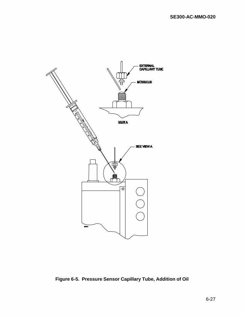
SE300-AC-MMO-020
6-27
Figure 6-5. Pressure Sensor Capillary Tube, Addition of Oil

SE300-AC-MMO-020
6-28
Figure 6-6. External Capillary Tube, Addition of Oil

SE300-AC-MMO-020
6-29
NOTE
The connector and plug are designed to mate in only one position. Ensure proper orientation when connecting plug to connector. Two small bumps on plug should be aligned with largest-diameter connector pin.
b. Remove the connector from the connector pins by carefully pulling straight off. c. Using PPE per MSDS, apply a small amount of alcohol to paper towel. Gently
wipe clean any black discoloration from the connector pins. d. Using PPE per MSDS, apply a small amount of lubricant to the connector. e. Reinstall the connector over the connector pins by carefully pushing the
connector straight on the pins. f. Manually screw on the locking sleeve. 6-3.5 Handling Assembly Components Removal and Replacement. The following paragraphs describe organizational (shipboard)-level authorized remove and replace procedures for failed components of the handling assembly. 6-3.5.1 Fuse Removal and Replacement. Perform this procedure to remove and replace winch electrical control box mounted fuse(s).
WARNING
Lethal voltage exists inside the control box when energized. Use extreme caution when performing maintenance inside the control box. Follow all standard safety precautions in accordance with OPNAVINST 5100 Standard Safety Precautions for Forces Afloat. Do not work alone when servicing this unit.
TOOLS REQUIRED: Fuse puller Screwdriver, cross tip, 6-inch a. Secure ship’s power to winch assembly and tag out. b. Remove the small shroud by removing the six hex head bolts to gain access to
the electrical control box cover screws. See figure 6-7 to locate shroud and components.

SE300-AC-MMO-020
6-30
c. Loosen the eight screws on the cover of the electrical control box. The electrical control box is located near the base of the winch, below the operator’s control panel. See figure 6-7 to locate the electrical control box.
d. Remove the box cover to expose the wiring and electrical components. e. Remove the fuse(s) from the fuse holder. See figure 6-8 to locate the item to be
removed. f. Replace the fuse. g. Before replacing control box cover, apply ship’s power to the winch and perform
a functional check. h. Replace the cover. i. Tighten the eight screws holding the cover in place. j. Replace the small shroud and tighten six hex head bolts to secure it. k. Return equipment to readiness condition. 6-3.5.2 Varistor Removal and Replacement. Perform this procedure to remove and replace winch electrical control box mounted varistor.
WARNING
Lethal voltage exists inside the control box when energized. Use extreme caution when performing maintenance inside the control box. Follow all standard safety precautions in accordance with OPNAVINST 5100 Standard Safety Precautions for Forces Afloat. Do not work alone when servicing this unit.
TOOLS REQUIRED: Crimping tool, terminal, hand Screwdriver, cross tip, 6-inch a. Secure ship’s power to winch assembly and tag out. b. Remove the small shroud by removing the six hex head bolts to gain access to
the electrical control box cover screws. See figure 6-7 to locate shroud and components.

SE300-AC-MMO-020
6-31
c. Loosen the eight screws on the cover of the electrical control box. The electrical
control box is located near the base of the winch, below the operator’s control panel. See figure 6-7 to locate the electrical control box.
d. Remove the box cover to expose the wiring and electrical components. e. Remove the varistor from across the terminals of the fuse holder. See figure 6-8
to locate the item to be removed. f. Attach a terminal connector to both ends of the varistor. g. Replace the varistor across the terminals of the fuse holder. h. Before replacing control box cover, apply ship’s power to the winch and perform
a functional check. i. Replace the cover. j. Tighten the eight screws holding the cover in place. k. Replace the small shroud and tighten six hex head bolts to secure it. l. Return equipment to readiness condition. 6-3.5.3 Line Filter Removal and Replacement. Perform this procedure to remove and replace winch electrical control box mounted line filter.
WARNING
Lethal voltage exists inside the control box when energized. Use extreme caution when performing maintenance inside the control box. Follow all standard safety precautions in accordance with OPNAVINST 5100 Standard Safety Precautions for Forces Afloat. Do not work alone when servicing this unit.
TOOLS REQUIRED: Screwdriver, cross tip, 6-inch a. Secure ship’s power to winch assembly and tag out.

SE300-AC-MMO-020
6-32
b. Remove the small shroud by removing the six hex head bolts to gain access to the electrical control box cover screws. See figure 6-7 to locate shroud and components.
c. Loosen the eight screws on the cover of the electrical control box. The electrical
control box is located near the base of the winch, below the operator's control panel. See figure 6-7 to locate the electrical control box.
d. Remove the box cover to expose the wiring and electrical components. e. Label and disconnect the leads from the line filter. See figure 6-8 to locate the
item to be removed. f. Remove the four mounting screws and washers. Note the orientation of the line
filter. g. Remove line filter. h. Replace line filter. Position in same orientation as the removed line filter.

SE300-AC-MMO-020
6-33
Figure 6-7. Winch Assembly Major Components
JOYSTICK
OPERATOR'SCONTROL BOX
ON/OFF SWITCH
SMALLSHROUD
DAVITSOCKET
MANUAL BRAKE
CABLE COUNTER
LEVELWINDASSEMBLY
DRIVEASSEMBLY
LARGESHROUD
IDLERSPROCKETASSEMBLY
CHAIN
DRUM ASSEMBLY ELECTRICAL CONTROL BOXBAND
BRAKE
ELECTRIC BRAKESWITCH

SE300-AC-MMO-020
6-34
Figure 6-8. Electrical Control Box Component Layout

SE300-AC-MMO-020
6-35
i. Replace the four mounting screws and washers. j. Reconnect all leads. Use figure 6-9, electrical control box schematic, to make
the right connections. k. Before replacing control box cover, apply ship's power to the winch and perform
a functional check. l. Replace the cover. m. Tighten the eight screws holding the cover in place. n. Replace the small shroud and tighten six hex head bolts to secure it. o. Return equipment to readiness condition. 6-3.5.4 Solid State Relay Removal and Replacement. Perform the following procedure to remove and replace winch electrical control box mounted solid state relay.
WARNING
Lethal voltage exists inside the control box when energized. Use extreme caution when performing maintenance inside the control box. Follow all standard safety precautions in accordance with OPNAVINST 5100 Standard Safety Precautions for Forces Afloat. Do not work alone when servicing this unit.
TOOLS REQUIRED: Screwdriver, cross tip, 6-inch a. Secure ship’s power to winch assembly and tag out. b. Remove the small shroud by removing the six hex head bolts to gain access to
the electrical control box cover screws. See figure 6-7 to locate shroud and components.
c. Loosen the eight screws on the cover of the electrical control box. The electrical
control box is located near the base of the winch, below the operator's control panel. See figure 6-7 to locate the electrical control box.
d. Remove the box cover to expose the wiring and electrical components.

SE300-AC-MMO-020
6-36
e. Label and disconnect leads from the relay. See figure 6-8 to locate the item to be removed.
f. Remove the two mounting screws and washers. Note the orientation of the
relay. g. Remove relay. h. Replace relay. Position in same orientation as the removed relay. i. Replace the two mounting screws and washers. j. Reconnect all leads. Use figure 6-9, electrical control box schematic, to make
the right connections. k. Before replacing control box cover, apply ship's power to the winch and perform
a functional check. l. Replace the cover. m. Tighten the eight screws holding the cover in place. n. Replace the small shroud and tighten six hex head bolts to secure it. o. Return equipment to readiness condition. 6-3.5.5 Contactor Removal and Replacement. Perform the following procedure to remove and replace winch electrical control box mounted contactor.
WARNING
Lethal voltage exists inside the control box when energized. Use extreme caution when performing maintenance inside the control box. Follow all standard safety precautions in accordance with OPNAVINST 5100 Standard Safety Precautions for Forces Afloat. Do not work alone when servicing this unit.
TOOLS REQUIRED: Screwdriver, cross tip, 6-inch a. Secure ship’s power to winch assembly and tag out.

SE300-AC-MMO-020
6-37
b. Remove the small shroud by removing the six hex head bolts to gain access to the electrical control box cover screws. See figure 6-7 to locate shroud and components.
c. Loosen the eight screws from the cover of the electrical control box. The
electrical control box is located near the base of the winch, below the operator's control panel. See figure 6-7 to locate the electrical control box.
d. Remove the box cover to expose the wiring and electrical components. e. Label and disconnect the leads from the contactor. See figure 6-8 to locate the
item to be removed. f. Remove the two mounting screws and washers. Note the orientation of the
contactor. g. Remove the contactor. h. Replace contactor. Position in same orientation as removed contactor. i. Replace two mounting screws and washers. j. Reconnect all leads. Use figure 6-9, electrical control box schematic, to make
the right connections. k. Before replacing control box cover, apply ship's power to the winch and perform
a functional check. l. Replace the cover. m. Tighten the eight screws holding the cover in place. n. Replace the small shroud and tighten six hex head bolts to secure it. o. Return equipment to readiness condition.

SE300-AC-MMO-020
6-38
Figure 6-9. Electrical Control Box Schematic

SE300-AC-MMO-020
6-39
6-3.5.6 Inverter Removal and Replacement. Perform the following procedure to remove and replace winch electrical control box mounted inverter.
WARNING
Lethal voltage exists inside the control box when energized. Use extreme caution when performing maintenance inside the control box. Follow all standard safety precautions in accordance with OPNAVINST 5100 Standard Safety Precautions for Forces Afloat. Do not work alone when servicing this unit.
TOOLS REQUIRED: Screwdriver, cross tip, 6-inch Screwdriver, flat tip, 6-inch, 5/32-inch tip Screwdriver, jewelers a. Secure ship’s power to winch assembly and tag out. b. Remove the small shroud by removing the six hex head bolts to gain access to
the electrical control box cover screws. See figure 6-7 to locate shroud and components.
c. Loosen the eight screws on the cover of the electrical control box. The electrical
control box is located near the base of the winch, below the operator's control panel. See figure 6-7 to locate the electrical control box.
d. Remove the box cover, to expose the wiring and electrical components. e. Remove the inverter’s support bracket mounting screws and washers. See
figure 6-8 to locate the item to be removed. f. Remove the support bracket.

SE300-AC-MMO-020
6-40
NOTE
The inverter cover comprises two pieces. g. Carefully lift off the bottom piece of the cover. h. Remove the two mounting screws and washers, exposed by the removal of the
bottom cover. i. Carefully remove the top piece of the cover. j. Remove the two mounting screws and washers through the circuit card and the
two resistor mounting screws and washers. Note the location and types of washers.
k. Label and disconnect the leads to the inverter. Note the orientation of the
inverter. l. Remove the inverter. m. Replace the inverter. Position in same orientation as the removed inverter. n. Replace the mounting screws and washers. o. Reconnect the leads to the inverter. Use figure 6-9, electrical control box
schematic, to make the right connections. p. Replace the inverter covers (both top and bottom). q. Replace the support bracket. r. Replace the support bracket mounting screws and washers.
NOTE
When power is first applied to the inverter, the inverter will require a few seconds to initialize before power can be applied to the motor.
s. Before replacing control box cover, apply ship's power to the winch and perform
a functional check.

SE300-AC-MMO-020
6-41
t. Replace the electrical control box cover. u. Tighten the eight screws to secure the electrical control box cover in place. v. Replace the small shroud and tighten six hex head bolts to secure it. w. Return equipment to readiness condition. 6-3.5.7 Overload Relay Removal and Replacement. Perform the following procedure to remove and replace winch electrical control box assembly overload relay.
WARNING
Lethal voltage exists inside the control box when energized. Use extreme caution when performing maintenance inside the control box. Follow all standard safety precautions in accordance with OPNAVINST 5100 Standard Safety Precautions for Forces Afloat. Do not work alone when servicing this unit.
TOOLS REQUIRED: Screwdriver, cross tip, 6-inch Wrench, adjustable a. Secure ship’s power to winch assembly and tag out. b. Remove the small shroud by removing the six hex head bolts to gain access to
the electrical control box cover screws. See figure 6-7 to locate shroud and components.
c. Loosen the eight screws on the cover of the electrical control box. The electrical
control box is located near the base of the winch, below the operator's control panel. See figure 6-7 to locate the electrical control box.
d. Remove the box cover to expose the wiring and electrical components. e. Label and disconnect the leads from the overload relay. See figure 6-8 to locate
the item to be removed. f. Remove the two mounting screws and washers. Note the orientation of the
overload relay. g. Remove the overload relay.

SE300-AC-MMO-020
6-42
h. Replace overload relay. Position in same orientation as the removed overload
relay. i. Replace the two mounting screws and washers. j. Reconnect all leads. See figure 6-9, electrical control box schematic, to make
the right connections. k. Before replacing control box cover, apply ship's power to the winch and perform
a functional check. l. Replace the electrical control box cover. m. Tighten the eight screws holding the cover in place. n. Replace the small shroud and tighten six hex head bolts to secure it. o. Return equipment to readiness condition. 6-3.5.8 On/Off Switch Removal and Replacement. Perform the following procedure to remove and replace operator control box mounted On/Off switch.
WARNING Lethal voltage exists inside the control box when energized. Use extreme caution when performing maintenance inside the control box. Follow all standard safety precautions in accordance with OPNAVINST 5100 Standard Safety Precautions for Forces Afloat. Do not work alone when servicing this unit. TOOLS REQUIRED: Screwdriver, cross tip, 6-inch a. Secure ship’s power to winch assembly and tag out. b. Loosen the four screws from the cover of the operator’s control box. See figure 6-7 to locate the operator's control box. c. Carefully remove the cover plate from the box. The On/Off switch and the
joystick controller are fastened to the top cover plate. d. Label and disconnect the leads connected to the On/Off switch. e. Unscrew the red knob (1), the retaining nut (2), remove the locking ring (3), and
remove the switch. Note the orientation of the On/Off switch.

SE300-AC-MMO-020
6-43
f. Remove the switch. g. Replace the switch. Position in same orientation as the removed switch. h. Connect all leads. i. Replace the cover. j. Tighten the four screws holding the cover in place. k. Apply ship's power to the winch and perform a functional check. l. Return equipment to readiness condition. 6-3.5.9 Joystick Removal and Replacement. Perform the following procedure to remove and replace operator’s control box mounted joystick.
WARNING
Lethal voltage exists inside the control box when energized. Use extreme caution when performing maintenance inside the control box. Follow all standard safety precautions in accordance with OPNAVINST 5100 Standard Safety Precautions for Forces Afloat. Do not work alone when servicing this unit.
TOOLS REQUIRED: Screwdriver, cross tip, 6-inch Screwdriver, jewelers Wrench, socket, 7/16-inch Dykes (Wire cutters) Wire ties, plastic String, small stuff a. Secure ship’s power to winch assembly and tag out. b. Remove the small shroud by removing the six hex head bolts to gain access to
the electrical control box cover screws. See figure 6-7 to locate shroud and components.
c. Loosen the eight screws on the cover of the electrical control box. The electrical
control box is located near the base of the winch, below the operator's control panel.

SE300-AC-MMO-020
6-44
d. Remove the electrical control box cover to expose the wiring and electrical
components. e. Inside the electrical control box, identify the wiring that runs from the operator's
control box joystick to the electrical control box. Refer to figure 6-9, electrical control schematic, to identify the appropriate wires. Label and disconnect these wires and attach a strong piece of twine or wire to the ends.
f. Inside the electrical control box, cut the wiring ties as necessary to allow removal
of the joystick wiring through the conduit. g. Loosen the four screws on the cover of the operator’s control box. See figure 6-7
to locate the operator’s control box. h. Carefully remove the cover plate from the box. The On/Off switch and the
joystick controller are fastened to the top cover plate. i. Inside the operator's control box, cut the wiring ties to separate the joystick wiring
from the emergency stop switch wiring. At the emergency stop switch end of the wire, disconnect the wire that runs between the joystick and the emergency stop switch.
j Remove the two attachment screws from the joystick controller. Note the
orientation of the joystick controller. Remove the joystick controller with wiring attached. As the wiring is pulled through the conduit, ensure that the twine or wire that was attached earlier is long enough to be used to pull the replacement joystick wiring back through the conduit.
k. Inside the operator's control box, disconnect the twine or wire from the joystick
wiring and attach to the replacement joystick wiring. Pull the twine or wire at the electrical control box end to feed the replacement joystick wiring through the conduit.
l. When the wiring is in place, position the replacement joystick controller in same
orientation as the removed joystick. Replace the two attachment screws. m. Remove the twine or wire and connect the joystick controller wiring inside the
electrical control box. See figure 6-9, electrical control box schematic, to make the right connections.
n. Replace the operator’s control box cover. o. Tighten the four screws holding the cover in place.

SE300-AC-MMO-020
6-45
p. Before replacing the electrical control box cover, apply ship's power to the winch and perform a functional check.
q. Replace the electrical control box cover. r. Tighten the eight screws holding the cover in place. s. Replace the small shroud and tighten six hex head bolts to secure it. t. Return equipment to readiness condition. 6-3.5.10 Drive Assembly Removal and Replacement. Perform the following procedure to remove and replace winch assembly drive assembly.
WARNING
Lethal voltage exists inside the control box when energized. Use extreme caution when performing maintenance inside the control box. Follow all standard safety precautions in accordance with OPNAVINST 5100 Standard Safety Precautions for Forces Afloat. Do not work alone when servicing this unit.
TOOLS REQUIRED: Screwdriver, cross tip, 6-inch Screwdriver, flat tip, 6-inch Wrench, 7/16-inch Wrench, 9/16-inch Wrench, allen, 1/8-inch Punch, pin, 1/4-inch Hammer, hand Pliers, long nose a. Secure ship’s power to winch assembly and tag out. b. Remove four 1/4-inch hex head bolts holding the bronze nut to the levelwind
assembly. Remove the nut. c. Remove the cable from the levewind assembly. d. Remove the thirteen hex head bolts and washers that attach the large shroud to
the frame and the six hex head bolts that attach the small shroud to the frame, using a 7/16-inch wrench. See figure 6-7 to locate shrouds.

SE300-AC-MMO-020
6-46
e. Remove both shrouds. f. Using an 1/8-inch allen wrench, remove the shaft collar from the manual brake
rod. The shaft collar is located at the end of brake rod near the drum. g. Remove the manual brake rod assembly. h. Remove the twelve 3/8-inch hex head bolts that attach the levelwind and
operator’s control box assembly to the frame. i. Remove four locknuts under the operator’s control box using 1/2" wrench. j. Remove cover plates by removing six bolts and four bolts from the brake and
motor electrical control boxes, respectively. k. Label and disconnect the two leads from the brake and the four leads from the
motor. l. Loosen the eight screws and remove the electrical control box cover. m. Disconnect the two leads from the brake, four leads from the motor, and the
leads from the operator's control box. Refer to figure 6-9, electrical control schematic.
n. Carefully lift off the top plate assembly with the levelwind and operator’s control
box, making sure not to damage the cables from the control box. Rotate the top plate assembly so as to allow the removal of the drive assembly, and secure the assembly out of the way.
o. Turn the electric brake switch to the clockwise position (1/4 turn) to release the
brake. p. Find the master link in the chain by manually rotating the drum. q. Pull pin in chain master link and remove master link. r. Remove the chain. s. Remove the four 3/8-inch bolts, using 9/16" wrench, from the gear reducer
mounting plate. t. Remove the four 1/4-inch bolts from the drive mounting bracket. u. Carefully lift out the drive assembly. Use lift straps if needed. v. Remove the four 1/4-inch bolts from the motor mounting feet.

SE300-AC-MMO-020
6-47
w. Remove the conduit from the motor and brake, disconnecting the wires from the
motor and brake. The wiring and conduit will be reused with the replacement assembly.
x. Replace the drive assembly. Reconnect wiring and conduit. y. Replace the four 1/4-inch bolts on the motor mounting feet. z. Slowly lower the drive assembly into place, using straps if necessary. aa. Replace the four hex head bolts holding the drive mounting bracket to the frame. ab. Replace the four hex head bolts holding the gear reducer mounting plate to the
frame. ac. Run conduit from the brake and motor to the electrical control box. Connect
brake and motor wires. ad. Replace the chain, master link, and pin in master link. ae. Adjust the position of the idler bracket assembly to allow for no more than 1/2-
inch of total play in the chain, but ensure that the chain is not overtightened. af. Carefully replace the top plate assembly, making sure that the four bolts from the
motor mounting are lined up and come through the holes in the top plate. ag. Route the conduit from the joystick control box to the electrical control box.
Reconnect wiring per electrical schematic. ah. Tighten the sealing locknut at the base of the control box. aj. Replace the twelve 3/8-inch hex head bolts that attach the top plate assembly to
the frame. ak. Replace the four locknuts on the motor mounting bolts. al. Replace the manual brake rod assembly and attach the shaft collar. am Route cable through level wind assembly and attach the bronze nut using four
1/4-inch hex head bolts. an. Turn the electric brake switch to the counterclockwise position (1/4 turn). ao. Apply ship's power to the winch and perform a functional check.

SE300-AC-MMO-020
6-48
ap. Replace the electrical control box cover and tighten the eight screws. aq. Replace the two shrouds. Fasten shrouds to the frame with the nineteen 1/4-
inch hex head bolts and washers. ar. Return equipment to readiness condition. 6-3.5.11 Drum Assembly Removal and Replacement. Perform the following procedure to remove and replace winch drum assembly.
WARNING
Lethal voltage exists inside the control box when energized. Use extreme caution when performing maintenance inside the control box. Follow all standard safety precautions in accordance with OPNAVINST 5100 Standard Safety Precautions for Forces Afloat. Do not work alone when servicing this unit.
TOOLS REQUIRED: Screwdriver, cross tip, 6-inch Wrench, 7/16-inch Wrench, 9/16-inch, open end Wrench, 13/16-inch Pliers, long nose Grease, winch drum a. Secure ship’s power to winch assembly and tag out. b. Remove the thirteen 1/4-inch hex head bolts and washers that attach the large
shroud to the frame and the six 1/4-inch hex head bolts and washers that attach the small shroud to the frame, using a 7/16-inch wrench.
c. Remove both shrouds. d. Remove four 1/4-inch hex head bolts holding the bronze nut to the levelwind
assembly. Remove the nut. e. Remove cable from the levelwind assembly. f. Remove cable from the winch drum. Loosen the four screws on the cable
retainer located on the drum flange to completely remove cable. Retain the cable for reuse.

SE300-AC-MMO-020
6-49
g. Remove the four 1/4-inch hex head bolts that attach the electrical control box to the frame. Carefully move the electrical control box off to the side of the winch, making sure that none of the wires are damaged.
h. Turn the electric brake switch to the clockwise position (1/4 turn). i. Find the master link in the chain by manually rotating the drum. j. Pull retaining clip from chain master link and remove master link. k. Remove the chain. l. Remove the grease fittings and the twelve 9/16-inch hex head bolts attaching the
bearing housing to the frame. m. Remove the drum assembly. n. Replace the drum assembly per the instructions on the replacement drum. o. Replace the twelve 9/16-inch hex head bolts attaching the bearing housings to
the frame and replace the grease fittings. p. Replace the chain. q. Replace master link, retainer clip, and pin. r. Adjust the position of the idler bracket assembly to allow for no more than 1/2
inch of total play in the chain, but ensure that the chain is not overly tight. s. Carefully move the electrical control box back into position and attach it to the
frame with the four 1/4 inch hex head bolts. s. Turn the electric brake switch to the counterclockwise position (1/4 turn). t. Apply ship's power and perform a functional check. u. Replace the electrical control box cover and tighten the eight screws to secure
the cover in place. v. Run cable through level wind assembly and attach cable to drum using the cable
retainer on the drum flange. Replace the bronze nut on the levelwind assembly. w. Spool cable using levelwind to neatly wrap the cable onto the drum. x. Connect the leads to the brake and motor.

SE300-AC-MMO-020
6-50
y. Apply ship's power to the winch and perform a functional check. z. Replace both shrouds and fasten them to the frame with the nineteen 1/4-inch
hex head bolts. aa. Return equipment to readiness condition. 6-3.5.12 Idler Sprocket Assembly Removal and Replacement. Perform the following procedure to remove and replace winch assembly idler sprocket assembly.
WARNING
Lethal voltage exists inside the control box when energized. Use extreme caution when performing maintenance inside the control box. Follow all standard safety precautions in accordance with OPNAVINST 5100 Standard Safety Precautions for Forces Afloat. Do not work alone when servicing this unit.
TOOLS REQUIRED: Wrench, 7/16-inch Wrench, 9/16-inch a. Secure ship’s power to winch assembly and tag out. b. Remove the twelve 1/4-inch hex head bolts and washers that attach the large
shroud to the frame. c. Remove the shroud. d. Remove the two 3/8-inch capscrews attaching the idler bracket to the frame. e. Remove idler bracket assembly. f. Replace idler bracket assembly onto frame and attach with 3/8-inch capscrews. g. Adjust the position of the idler bracket assembly to allow for no more than 1/2-
inch of total play in the chain, but ensure that the chain is not taut either. h. Apply ship's power to the winch and perform a functional check. i. Replace the shroud. Fasten shroud to the frame with the twelve 1/4-inch hex
head bolts and washers.

SE300-AC-MMO-020
6-51
j. Return equipment to readiness condition. 6-3.5.13 Chain Removal and Replacement. Perform the following procedure to remove and replace winch assembly chain.
WARNING
Lethal voltage exists inside the control box when energized. Use extreme caution when performing maintenance inside the control box. Follow all standard safety precautions in accordance with OPNAVINST 5100 Standard Safety Precautions for Forces Afloat. Do not work alone when servicing this unit.
TOOLS REQUIRED: Wrench, 7/16-inch Wrench, 9/16-inch Pliers, long nose a. Secure ship’s power to winch assembly and tag out. b. Remove the twelve 1/4-inch cap screws and washers that attach the large
shroud to the frame. c. Remove the shroud. d. Turn the electric brake switch to the clockwise position (1/4 turn). e. Find the master link in the chain by manually rotating the drum. f. Remove cotter pin from master link. g. Pull clip from chain master link and remove master link. h. Remove the chain. i. Replace the chain. j. Replace master link, clip and cotter pin. k. Adjust the position of the idler bracket assembly to allow for no more than 1/2-
inch of total play in the chain, but ensure that the chain is not taut either. l. Turn the electric brake switch to the counterclockwise position (1/4 turn).

SE300-AC-MMO-020
6-52
m. Apply ship's power to the winch and perform a functional check. n. Replace the shroud. Fasten shroud to the frame with the twelve 1/4-inch hex
head bolts and washers. o. Return equipment to readiness condition. 6-3.5.14 Band Brake Removal and Replacement. Perform the following procedure to remove and replace winch assembly band brake.
WARNING
Lethal voltage exists inside the control box when energized. Use extreme caution when performing maintenance inside the control box. Follow all standard safety precautions in accordance with OPNAVINST 5100 Standard Safety Precautions for Forces Afloat. Do not work alone when servicing this unit.
TOOLS REQUIRED: Wrench, 7/16-inch Wrench, 9/16-inch Wrench, 13/16-inch a. Secure ship’s power to winch assembly and tag out. b. Remove cable from level wind assembly c. Remove cable from winch drum. Loosen the four screws on the cable retainer
located on the drum flange to completely remove cable. Retain the cable for reuse.
d. Remove the thirteen 1/4-inch hex head bolts and washers that attach the large
shroud to the frame and the six 1/4-inch hex head bolts that attach the small shroud to the frame.
e. Remove both shrouds. f. Loosen the eight screws on the electrical control box cover and remove the
cover. g. Remove the four 1/4-inch hex head bolts that attach the electrical control box to
the frame.

SE300-AC-MMO-020
6-53
h. Carefully move the electrical control box off to the side of the winch, making sure
that none of the wires are damaged. i. Turn the electric brake switch to the clockwise position (1/4 turn). j. Find the master link in the chain by manually rotating the drum. k. Remove the clip from the master link, remove the master link, and remove the
chain. l. Remove the grease fittings and the twelve 9/16-inch hex head bolts that attach
the bearing housing to the frame. m. Remove the drum assembly and remove the brake band from the end of the
drum. n. Replace the brake band onto the end of the drum. o. Replace the drum. p. Install the twelve 9/16-inch hex head bolts to attach the bearing housings to the
frame and replace the grease fittings. q. Replace the chain and replace the master link. r. Adjust the position of the idler bracket assembly to allow for no more than one
half inch of total play in the chain, but ensure that the chain is not overly tight. s. Carefully move the electrical control box back into position and attach it to the
frame with the four 1/4-inch hex head bolts. t. Apply ship's power and perform a functional check. u. Replace the electrical control box cover and secure in place by tightening eight
screws. v. Run the cable through the level wind assembly and attach cable to drum using
the cable retainer on the rum flange. Replace the bronze nut on the level wind assembly.
w. Spool the cable onto the drum using the level wind to neatly wrap the cable on
the drum. x. Replace the small and the large shrouds and secure in place with the nineteen
1/4-inch hex head bolts.

SE300-AC-MMO-020
6-54
y. Return equipment to readiness condition. 6-3.5.15 Cable Counter Removal and Replacement. Perform the following procedure to remove and replace winch assembly cable counter. TOOLS REQUIRED: Screwdriver, cross tip, 6-inch Wrench, 7/16-inch Wrench, 9/16-inch a. Secure ship’s power to winch assembly and tag out. b. Remove the four machine screws attaching the cable counter to the levelwind
carriage assembly. c. Remove the cable counter. d. Replace cable counter, making sure that the pin in the cable counter shaft is
aligned with the slot in the sheave. e. Replace the four machine screws. f. Return equipment to readiness condition.

SE300-AC-MMO-020
7-1
CHAPTER 7 PARTS LIST
7-1 INTRODUCTION. This chapter provides the part-location description, part number identification, and source data for the components of the Battle Space Profiler (BSP) system that are subject to organizational (shipboard)-level adjustment, alignment, repair, or replacement. The major components of the BSP system are listed in table 7-1. It contains the component unit number, and the quantity required in the system. The figures in this chapter identify each repair part with an index number, which then can be used to find the part in the parts list, table 7-2. Table 7-2 includes the nomenclature, part number, and description for each shipboard repairable or replaceable assembly and component of the BSP system. Table 7-2 references the appropriate figure to aid in locating the correct part by index number. Table 7-2 also provides manufacturer Commercial and Government Entity (CAGE) code. Table 7-3 associates the CAGE entered in the parts list (table 7-2) with the name, address, and phone number of the supplier of the part. 7-2 LIST OF MAJOR UNITS. Table 7-1 describes the major units of the BSP system, their part numbers, and the illustration in this manual showing the unit, its parts, assemblies, and major sub-assemblies. Not all parts are depicted or called out on illustrations in this manual.

SE300-AC-MMO-020
7-2
7-3 PARTS LIST. Table 7-2 contains the parts list for the BSP system down to the subassembly repair level. Table 7-2 contain a list of parts, as shipped, for configurations of the BSP systems equipped with the LM3A Hand-held Launcher and the AR-20 System Selector. Table 7-2 lists information and part numbers for expendable probe devices.
The BSP system is compatible with the following expendable probe devices:
XBT probes, T-4, T-5, T-7, T7-11 XSV probes, XSV-01, XSV-03
Table 7-2 contains a listing of manufactured probe devices that operate with the BSP system, their performance descriptions, and part numbers.

SE300-AC-MMO-020
7-3
Table 7-1. List of Major Components
Unit Number
Quantity
Nomenclature
Page Number 1
1 EA
Computer, Notebook
7-3
2
Removable Hard Drive Disks
7-3
2
1
Printer
7-3
3
1
PnotePro3
7-3
4
1
Winch Assembly
7-6
5
1
"J" Davit Assembly
7-6
6
1
CTD Recorder Storage Cabinet
----
8
1
CTD Recorder
7-10
9
1
Multiport Spooler
7-3
10
1 or 2*
LM3A Hand-Held Launcher
*Quantity is two if system configuration has Unit 19 installed.
7-14
19
1**
AR-20 System Selector
** Not installed on all ships.
7-15

SE300-AC-MMO-020
7-4
Table 7-2. Parts List
Name and Description Notes Figure/Item No.
Notebook Computer Part No. 33029-001 CAGE 07070
GETAC Model A740T-8
7-1(1)
Surge Protector Part No. PNOTEPRO CAGE 0MG77
American Power Conversion
Not shown
Removable Hard Drive Disk Drive Part No. 33030-000 CAGE 07070
Contains Windows 98
7-1(2)
Removable Hard Drive Disk Drive Part No. 33030-014 CAGE 07070
Contains BSP software 7-1(2)
Multiport Spooler Part No. PI756A CAGE 59951
Black Box
7-1(3)
Multiport Spooler PC Power Cord Part No. PS803 CAGE 59951
Black Box
Not shown
Printer Part No. RDJ895 CAGE 09BZ2
RITEC Model RDJ895C
7-1(4)
Printer Cable Part No. EQN200-0006 CAGE 59951
7-1(6)
Printer Print Cartridge Part No. C1823A (Color Inkjet) Part No. HP51645A (Black Inkjet) CAGE 28480
HP DeskJet
7-1(5)
MK 21 Circuit Card Part No. 311579 CAGE 16848

SE300-AC-MMO-020
7-5
Table 7-2. Parts List — Continued
Name and Description Notes Figure/Item No.
Male Connector Part No. CBCA50673 CAGE 59951
Not shown
Hinge Set Part No. 1000728-01 CAGE 09BZ2
Printer Cover Hinges
7-1(9)
Latch, Compression Part No. 1001243-02 CAGE 09BZ2
Printer Latches
7-1(10)
Cover Cap, DB25 Part No. 3616001-01 CAGE 09BZ2
Printer
Not shown
Door, Printer Part No. 509EZ328-01-235 CAGE 09BZ2
Top Door for Printer
7-1(8)
Door, Printer Part No. 509EZ327-01-235 CAGE 09BZ2
Rear and Front Doors for Printer
7-1(7)
Shock Mount, PC Part No. 791901120103 CAGE 00PP6
Not shown
AC Adapter Cord Part No. 791901120110 CAGE 00PP6
AC Adapter Cord for Notebook PC
Not shown

SE300-AC-MMO-020
7-6
Table 7-2. Parts List — Continued
Name and Description Notes Figure/Item No.
Cable, Floppy Drive Part No. 791911120000 CAGE 00PP6
External Floppy Drive Cable
Not shown
Battery, PC Part No. 791911120360 CAGE 00PP6
Main Battery with Door
Not shown
Floppy Drive, PC Part No. 791911120400 CAGE 00PPC
External Floppy Drive
Not shown
CD-ROM Drive, PC Part No. 791911120402 CAGE 00PP6
Not shown
Power Cord, PC Part No. 795945300002 CAGE 00PP6
Not shown
Lanyard Part No. 9550070-19 CAGE 09BZ2
Lanyard for Printer Doors
Not shown

SE300-AC-MMO-020
7-7
Table 7-2. Parts List — Continued
Name and Description Notes Figure/Item No.
Drive Assembly Part No. 190-100-016 CAGE OK2D8
7-8(1)
Drum Assembly Part No. 190-100-017 CAGE OK2D8
7-8(2)
Idler Sprocket Assembly Part No. 190-100-018 CAGE OK2D8
7-8(3)
Switch, On/Off Part No. 800H-FRXTQH10RA4 CAGE 01121
7-8(4)
Joystick Assembly Part No. 190-100-095 CAGE OK2D8
7-8(5)
Chain, Roller Part No. 190-100-085 CAGE OK2D8
7-8(6)
Brake, Band Part No. 190-100-011 CAGE OK2D8
7-8(7)
Cable Counter Part No. 190-100-068 CAGE OK2D8
7-8(8)
Crank, Hand Part No. 190-100-008 CAGE OK2D8
Not shown
Cable, Winch Part No. 190-100-087 CAGE OK2D8
Stainless Steel
Not shown
Plug, Upper Bearing, Davit Part No. 190-100-083 CAGE OK2D8
Cover, Davit Socket
7-8(9)
Block, Snatch Part No. S0425-0075 CAGE 4W641
Not shown

SE300-AC-MMO-020
7-8
Table 7-2. Parts List — Continued
Name and Description Notes Figure/Item No.
Thimble, Rope Part No. AN100C4 CAGE 88044
Winch Assembly Hardware
Not shown
Washer, Flat Part No. AN960C4 CAGE 88044
Winch Assembly Hardware
Not shown
Washer, Flat Part No. AN960C8 CAGE 88044
Drum Assembly Mounting Hardware (0.375 in)
7-8(12)
Relay, Solid State Part No. C10699-3 CAGE 81755
Winch Electrical Control
Not shown
Varistor Part No. ERZ-V20-D201 CAGE 61058
Winch Electrical Control
Not shown
Washer, Flat Part No. MS15795-852 CAGE 96906
Winch Assembly Hardware (0.625 in)
Not shown
Screw, Cap, Hex Part No. MS35307-303 CAGE 96906
Winch Assembly Hardware (0.25 in x 0.5 in Long)
Not shown
Screw, Cap, Hex Part No. MS35307-358 CAGE 96906
Drum Assembly Mounting Hardware (0.375 in x 0.75 in Long)
7-8(12)
Washer, Lock Part No. MS35338-137 CAGE 96906
Winch Assembly Hardware (0.164 in)
Not shown
Washer, Lock Part No. MS35338-139 CAGE 96906
Winch Assembly Hardware (0.250 in)
Not shown
Washer, Lock Part No. MS35338-141 CAGE 96906
Drum Assembly Mounting Hardware (0.375 in)
7-8(12)

SE300-AC-MMO-020
7-9
Table 7-2. Parts List — Continued
Name and Description Notes Figure/Item No.
Sleeve, Wire Part No. MS51844-83 CAGE 96906
Winch Assembly Cable Hardware (3/32 in)
Not shown
Impeller Screw Part No. MS51957-45 CAGE 96906
Winch Assembly Hardware (0.164 in x 0.5 in Long)
Not shown
Screw, Machine Part No. MS51957-47 CAGE 96906
Winch Assembly Hardware (0.164 in x 0.75 in Long)
Not shown
Screw, Machine Part No. MS51957-50 CAGE 96906
Winch Assembly Hardware (0.164 in x 1.25 in Long)
Not shown
Clamp, Box Part No. ZL18SS6 CAGE 00843
Winch Electrical Box
Not shown
Lamp, Incandescent Part No. 120MB CAGE 92966
Winch Electrical Control
Not shown
Screw, Machine Part No. 9-25-7321-00 CAGE OTNP7
Winch Assembly Hardware
7-8(11)
Upper Bearing, Davit Part No. 190-100-038 CAGE OK2D8
Winch Assembly
7-8(13)
Fuse, Cartridge Part No. 30900-11 CAGE 34931
Winch Electrical Control
7-9(1)
Brake, Manual Release Assembly Part No. 5-07-5037-00 CAGE OK2D8
Winch Assembly
7-8(10)

SE300-AC-MMO-020
7-10
Table 7-2. Parts List — Continued
Name and Description Notes Figure/Item No.
Shackle, 1/2-inch Part No. S0116-0013 CAGE 4W641
Not shown
Shackle, 1/4-inch Part No. 3797T43 CAGE 39428
Not shown
Shackle, 5/8-inch Part No. S00116-FS16 CAGE 4W641
Not shown
Winch Cover, Soft Part No. 32233 CAGE 07070
Not shown
Terminal Board Part No. RB2573 CAGE 15912
7-9(3)
Filter, Radio Freq. Part No. 20VR1 CAGE 05245
7-9(4)
Relay, Solid State Part No. 120A10 CAGE 81755
7-9(5)
Contactor, Magnetic Part No. PRD7AG0 CAGE 77342
7-9(6)
Inverter Part No. 190-300-053 CAGE OK2D8
7-9(7)
Relay, Overload Part No. 3UA5900-1D CAGE 24005
7-9(8)

SE300-AC-MMO-020
7-11
Table 7-2. Parts List — Continued
Name and Description Notes Figure/Item No.
Recoverable CTD Recorder Part No. 31532-001 CAGE 9Z407
Multi-reference number 90281
7-3(1)
Battery Cover Part No. 80076.1 CAGE 9Z407
7-5(4)
O-ring, Battery housing Part No. 2-153 N674-70 CAGE 02697
7-5(5)
CTD Recorder S/S Container Part No. CW4515-1105CF CAGE 1MAS1
Storage/Shipping Container
FO-8
Hardware Kit, Fire Door Part No. 50126 CAGE 9Z407
Not shown

SE300-AC-MMO-020
7-12
Table 7-2. Parts List — Continued
Name and Description Notes Figure/Item No.
O-ring, Battery end cap Part No. 2-234 E603-70 CAGE 02697
7-5(1)
Cover plate, protective, conductivity cell Part No. 23118 CAGE 9Z407
7-4(1)
Magnetic ON/OFF Switch Part No. 50026 CAGE 9Z407
7-6(3)
Anode, Zinc Part No. 30044 CAGE 9Z407
7-3(4) 7-6(2)
Nylon Capillary Assembly Part No. 50029 CAGE 9Z407
7-7(5)
Data I/O Cable (4-pin, 2.5 meters) Part No. 80087 CAGE 9Z407
Troubleshooting Aid
7-7(1)
Dummy Plug (2-pin male pump cable plug) Part No. 17171.1 CAGE 9Z407
7-3(7) 7-7(9)
Y-cable (Pump/data) Part No. 17722 CAGE 9Z407
7-3(2)
Cover, Electrical Part No. 17046.1 CAGE 9Z407
Dummy Connector (4-pin, female, data I/O cable)
7-7(2)
Cover, Electrical Part No. 17043 CAGE 9Z407 QTY = 2
Locking Sleeve
7-7(3) 7-7(4)
Dummy Plug (2-pin, female, pump connector) Part No. 17044.1 CAGE 9Z407
7-7(8)

SE300-AC-MMO-020
7-13
Table 7-2. Parts List — Continued
Name and Description Notes Figure/Item No.
Dummy Connector (for 6-pin, auxiliary input) Part No. 17047.1 CAGE 9Z407
7-3(3)
Pump Unit, SBE 5T Part No. 90160.3 CAGE 9Z407
7-3(6)
Block, Pump Mounting Part No. 23612 CAGE 9Z407
7-7(6)
Tubing Connector Kit Part No. 50177 CAGE 9Z407
7-3(5) 7-6(1)
Hardware Spares Kit Part No. 50006 CAGE 9Z407
7-4
Screw, phillips head (for battery cover) 6-32 X 1/2-IN PH PHLPS SS QTY = 3 Part No. 30145
(Part of Hardware Spares Kit)
7-5(2)
Washer, flat (for battery cover) #6 flat SS QTY = 3 Part No. 30242
(Part of Hardware Spares Kit)
7-5(3)
Screw, phillips head (for conductivity cell protective cover plate) 8-32 X 5/16-IN PH PHLPS SS QTY = 4 Part No. 30359
(Part of Hardware Spares Kit)
7-4(4)
Washer, lock (for conductivity cell protective cover plate) #8 INT TOOTH LOCK SS QTY = 2 Part Number 30247
7-4(3)
Screw, machine, phillips head (for magnetic switch assembly) 8-32 X 1-IN PH PHLPS SS QTY = 2 Part No. 30163
(Part of Hardware Spares Kit)
7-4(8)

SE300-AC-MMO-020
7-14
Table 7-2. Parts List — Continued
Name and Description Notes Figure/Item No.
Spring, stock compression C0240-024-0500-S QTY = 2
(Part of 50026)
7-4(7)
Nut (for mounting zinc anode) 12-28 UNF-2B alum nut QTY = 1 Part No. 30408
(Part of Hardware Spares Kit)
7-4(6)
Washer (for zinc anode; one washer on each side of conductivity cell protective cover plate) #12 INT TOOTH LOCK SS QTY = 2 Part No. 30414
(Part of Hardware Spares Kit)
7-4(5)
Screw (for mounting bottom half of quick disconnect to conductivity cell protective cover plate) 4-40 X 5/16-IN PH PHLPS SS QTY = 2
(Part of 50177)
7-4(2)
Battery, Non-rechargeable Part No. BA-3030/U CAGE 81349
Alkaline, D-cells
Not shown

SE300-AC-MMO-020
7-15
Table 7-2. Parts List — Continued
Name and Description Notes Figure/Item No.
LM3A Hand-held Launcher Part No. 213550-1 CAGE 16848
7-10
Expendable Bathythermograph (XBT) Probe Part No. XBT T-4, 207592-1 Part No. XBT T-5, 211105-1 Part No. XBT T-7, 210883-1 Part No. XBT T-11, 21373-1 CAGE 16848, 96906 Probe units are packed 12 units per case; minimum order 12 units (1 case).
XBT T-4 Max Depth 1500 feet Max Ship Speed 30 knots Standard probe used by the U.S. Navy for ASW operations XBT T-5 Max Depth 6000 feet Max Ship Speed 60 knots Deep Ocean scientific and military applications XBT T-7 Max Depth 2500 feet Max Ship Speed 15 knots Increased depth for improved sonar prediction in ASW and other military applications XBT T-11 Max Depth 1500 feet Max Ship Speed 6 knots High resolution for U.S. Navy mine countermeasures and physical oceanographic applications

SE300-AC-MMO-020
7-16
Table 7-2. Parts List — Continued
Name and Description Notes Figure/Item No.
Expendable Sound Velocimeter (XSV) Probe Part No. XSV-01, 213796-1 CAGE 16848, 96906 Probe units are packed 12 units per case; minimum order 12 units (1 case).
XSV-01 Max Depth 2790 feet Max Ship Speed 15 knots ASW application where salinity varies: Naval and civilian oceanographic and acoustic applications XSV-03 Max Depth 2790 feet Max Ship Speed 5 knots High resolution data for improved mine countermeasures and ASW operations in shallow water, geographical survey work, and commercial oil industry support
XBT/XSV Test Device Part No. 410094-1 or 03051001 CAGE 16848, 88594
The Test Device does not have a Navy assigned REF DES. The Test Device uses one 9-volt battery, alkaline, 90201 MIL TYPE MN 1604 (or equivalent).
7-14
Contact Pin Assembly Part No. 213549-1 REF DES 9A1
(Recommended spare) Part of LM3A Hand-held Launcher, Part No. 213550-1
7-15
Mounting Plate Part No. 213613-1 CAGE 16848
Part of AR-20 System Selector, Part No. 213627-1
7-11(2)
Box Assembly Part No. 213633-2 CAGE 16848
Part of AR-20 System Selector, Part No. 213627-1
7-11(3)
Cover Part No. 213612-2 CAGE 16848
Part of AR-20 System Selector, Part No. 213627-1
7-11(4)

SE300-AC-MMO-020
7-17
Table 7-2. Parts List — Continued
Name and Description Notes Figure/Item No.
Sealing Grip (3/8” – 7/16”) Part No. 103731 CAGE 16848
Part of AR-20 System Selector, Part No. 213627-1
7-11(5)
Knob Part No. 103808 CAGE 16848
Part of AR-20 System Selector, Part No. 213627-1
7-11(6)
Rotary Switch Part No. 213631-1 CAGE 16848
Part of AR-20 System Selector, Part No. 213627-1
7-11(7)
Terminal Block Part No. 103807 CAGE 16848
Part of AR-20 System Selector, Part No. 213627-1
7-11(8)
O-ring Part No. 103446 CAGE 16848
Part of AR-20 System Selector, Part No. 213627-1
7-11(9)

SE300-AC-MMO-020
7-18
Table 7-3. List of Suppliers
CAGE Code Name and Address 88044
AERONAUTICAL STANDARDS GROUP Dept of Navy and Air Force United States
88041
AIR CORPS STANDARDS United States
01121
ALLEN-BRADLEY CO. 1201 S. 2nd St. Milwaukee, WI 53204 PHONE: (414) 382-2000
0MG77
AMERICAN POWER CONVERSION 132 Fairground Road P.O. Box 278 West Kingston, RI 02892 PHONE: (800) 788-5414
59951
BLACK BOX CORPORATION 1000 Park Drive Lawrence, PA 15055-9980 PHONE: (724) 746-5500
07070
COASTAL SYSTEMS STATION 6703 West Highway 98 Attn: Ed Doray, Code A12, Bldg 110 Panama City, FL 32407-7001 PHONE: (850) 235-5079
05245
CORCOM, INC 844 E. Rockland Rd. Libertyville, IL 60048-3358 PHONE: (847) 680-7410

SE300-AC-MMO-020
7-19
Table 7-3. List of Suppliers — Continued
CAGE Code Name and Address 00PP6
GETAC 15273 Alton Parkway Irvine, CA 92618 PHONE: (949) 789-0100
6V412
GET ENGINEERING CORPORATION 9350 Bond Avenue El Cajon, CA 92021 PHONE: (619) 443-8295
92966
GTE PRODUCTS CORPORATION Miniature Lamp Plant 275 W. Main Street Hillsboro, NH 03244 PHONE: (603) 464-5533
28480
HEWLETT PACKARD CO. 3000 Hanover St. Palo Alto, CA 94304-1112 PHONE: (415) 857-1501
00843
HOFFMAN ENGINEERING COMPANY 900 Ehlen Drive Anoka, MN 55303 PHONE: (612) 422-2211

SE300-AC-MMO-020
7-20
Table 7-3. List of Suppliers — Continued
CAGE Code Name and Address 34931
LANG MANUFACTURING COMPANY 6500 Merrill Creek Parkway Everitt, WA 98203 PHONE: (425) 349-2400
75915
LITTELFUSE TRACOR, INC 800 E. Northwest Hwy Des Plaines, IL 60016-3049 PHONE: (847) 824-1188
81755
LOCKHEED MARTIN CORP. Lockheed Martin Tactical Aircraft P.O. Box 748 Fort Worth, TX 76101 PHONE: (817) 763-6771
4W641
MARINE AND INDUSTRIAL SUPPLY COMPANY 150 Virginia Street Mobile, AL 36652 PHONE: (205) 438-4617
61058
MATSUSHITA ELECTRIC CORP OF AMERICA Panasonic Industrial Co Div Two Panasonic Way Secaucus, NJ 07094 PHONE: (201) 348-7000
39428
MCMASTER-CARR SUPPLY COMPANY 600 County Line Road Elmhurst, IL 60126-2034 PHONE: (630) 834-9600
81349
MILITARY SPECIFICATIONS Promulgated by military departments/agencies under authority of Defense Standardization Manual.
96906
MILITARY STANDARDS Promulgated by Military Departments

SE300-AC-MMO-020
7-21
Table 7-3. List of Suppliers — Continued
CAGE Code Name and Address
02697
PARKER HANNIFAN CORPORATION 2360 Palumbo Drive P.O. Box 11751 Lexington, KY 40512-1751 PHONE: (606) 269-2351
77342
POTTER AND BRUMFIELD, INC. A Siemens Co. 200 S. Richland Creek Dr. Princeton, IN 47671-0001 PHONE: (812) 386-1000
09BZ2
RITEC 940 Enchanted Way #105 Sini Valley, CA 93065 PHONE: (805) 577-9710
9Z407
SEA-BIRD ELECTRONICS, INC. 1808 136th Place NE Bellevue, WA 98005 PHONE: (206) 643-9866
24005
SIEMENS-ALLIS, INC. Power Switching Div
16848
SIPPICAN, INC. 7 Barnabas Road Marion, MA 02738-1421 PHONE: (508) 748-1160
OK2D8
SOUND OCEAN SYSTEMS, INC. P.O. Box 2978 Redmond, WA 98073-2978 PHONE: (206) 869-1834
1MAS1
TECHNOPAK PRODUCTS 4100 Creekpoint Court Danville, CA 94506 PHONE: (925) 736-5756
15912
THOMAS AND BETTS CORP Electronics Group 76 Fairbanks Irvine, CA 92718 PHONE: (800) 421-8618

SE300-AC-MMO-020
7-22
4
6
2
53
6
1
8
7 10
9
4
6
2
53
6
1
8
7 10
9
Figure 7-1. BSP System Computer Equipment

SE300-AC-MMO-020
7-23
Figure 7-2. MK21 Circuit Board Location

SE300-AC-MMO-020
7-24
Figure 7-3. Recoverable CTD Recorder

SE300-AC-MMO-020
7-25
Figure 7-4. Hardware Spares Kit Detail, Recoverable CTD Recorder

SE300-AC-MMO-020
7-26
Figure 7-5. Recoverable CTD Recorder, Battery Cover and O-rings

SE300-AC-MMO-020
7-27
Figure 7-6. Recoverable CTD Recorder, Detail

SE300-AC-MMO-020
7-28
1
2
3
4
5
9
8
67
1
2
3
4
5
9
8
667
Figure 7-7. Recoverable CTD Recorder — Connectors, Plugs, and Pump
Mounting Kit

SE300-AC-MMO-020
7-29
1
8 5
4
9
13
3
6
12
2 7 12
11
10
1
8 5
4
9
13
3
6
12
2 7 12
11
10
Figure 7-8. Winch Assembly

SE300-AC-MMO-020
7-30
7 6
4
2
1
5
8
3
7 6
4
2
1
5
8
3
Figure 7-9. Winch Assembly Electrical Control Box

SE300-AC-MMO-020
7-31
Figure 7-10. LM3A Hand-Held Launcher

SE300-AC-MMO-020
7-32
Figure 7-11. AR-20 System Selector

SE300-AC-MMO-020
7-33
Figure 7-12. Expendable Bathythermograph (XBT), Exploded View

SE300-AC-MMO-020
7-34
Figure 7-13. Expendable Sound Velocimeter (XSV), Exploded View

SE300-AC-MMO-020
7-35
Figure 7-14. XBT/XSV Test Device

SE300-AC-MMO-020
7-36
Figure 7-15. Contact Pin Assembly, LM3A Hand-Held Launcher

SE300-AC-MMO-020
8-1
CHAPTER 8
INSTALLATION
8-1 INTRODUCTION. This chapter contains the instructions and information necessary to unpack, install, and checkout the Battle Space Profiler (BSP) system. 8-2 INFORMATION AND MATERIALS REQUIRED FOR INSTALLATION. Figures and tables provided in this chapter to aid in locating and installing the BSP system and its associated equipment are: a. Table of installation drawings indicating NAVSEA drawing numbers, (table 8-1) b. Table of input power requirements, (table 8-2) c. Table of tools and materials required for installation (table 8-3) d. Table of installation material, including manufacturers’ P/Ns and supply codes,
(table 8-4) e. Block diagram of BSP system (FO-4) f. Outline and installation drawings for each unit of the BSP system (FO-5 through
FO-11) g. Cable running sheets (FO-12 through FO-26) h. Installation standards summary sheet (figure 8-1) i. BSP system shipping information (table 8-5). j. LM3A Hand-Held Launcher, Junction Box, and AR-20 cable wire list (table 8-6). k. AR-20 System Selector and computer interface cable wire list (table 8-7). l. LM3A Hand-Held Launcher and interface cable wire list (Ships without AR-20
System Selector) (table 8-8). m. LM3A Hand-Held Launcher installation information (table 8-9).
n. XBT/XSV Probe Device Storage (figure 8-2).

SE300-AC-MMO-020
8-2
o. Interconnecting wiring and cabling for PORT and STARBOARD LM3A Hand-Held Launchers (figure 8-6).
p. Location for watertight Junction Box and LM3A Hand-Held Launcher stowage
locker (figure 8-3). q. LM3A Hand-Held Launcher (figure 8-4). r. AR-20 System Selector cable installation (figure 8-5). s. LM3A Hand-Held Launcher and MK21 card cable installation (figure 8-6).

SE300-AC-MMO-020
8-3
Table 8-1. BSP Installation Control Drawings
Document Nomenclature Unit Number NAVSEA Number
AN/SQH-4A Acquisition System, Battle Space Profiler Drawing List
807-7243302
Block Diagram
807-7243303
Cable Running Sheets
807-7243304
Summary List of Installation Material
807-7243305
OUTLINE AND INSTALLATION DRAWINGS
Computer, Notebook
Unit 1
807-7243306
Winch Assembly
Unit 4
807-7243296
Recoverable CTD Recorder Storage Cabinet, All Weather
Unit 6
807-7243308
Printer
Unit 2
807-7243307
"J" Davit Assembly
Unit 5
807-7243300
Multiport Spooler
Unit 7
807-7243309

SE300-AC-MMO-020
8-4
Table 8-2. BSP Input Power Requirements
Input Characteristic Parameter
Ship’s Power
Deck: Note 1. Power Consumption Voltage Frequency Line Current Number of Phases
1.725 kW 115 VAC ± 5% 60 Hz. 15 amps 1
CIC: Note 2. Power Consumption Voltage Frequency Line Current Number of Phases
0.51 kW 115 VAC + 5% 60 Hz 4.4 amps 1
Notes: 1. Supplies power for the handling assembly. 2. Supplies power for the computer equipment. Requires a dedicated receptacle for the computer, one for the multiport spooler, and one for the printer.

SE300-AC-MMO-020
8-5
Table 8-3. Tools and Materials Required for Installation SCAT
Code
Test Equipment Category
Model Number Application
Cable ties, straps
VRT-16I-C
Cabling
*Caulk, packing
T-O-56
Handling assembly
Cloth, cleaning (lint-free cloth)
9Q-7920-00-044-9281 SPMIG 0294
All units
*Compound, antisieze
MIL-T-22361
Handling assembly
*Compound, silicone
9G-6850-00-880-7616
Handling assembly
Cutters, wire
N/A
Cabling
Gun, caulk
N/A
Handling assembly
Gun, solder
N/A
Cabling
4245
Multimeter, digital
9N-6625-01-213-9354 SPMIG 0901 89536-77/AN
All BSP system components
Pliers, electrician's
N/A
Cabling
Screwdriver, cross tip
N/A
Computer
Screwdriver, straight tip
N/A
Computer
*Solder
N/A
Cabling
Towel, paper
9Q-7920-00-965-1709 SPMIG 1398
All units
Calibrated weight
150 lbs.
Handling assembly
Wrench, combination 3/8-inch
N/A
Computer equipment
Wrench, combination 7/16-inch
N/A
Handling assembly
Wrench, combination, 3/4-inch (2 required)
N/A
Handling assembly
Wrench, combination 9/16-inch (2 required)
N/A
CTD Recorder storage cabinet
*Hazardous Material

SE300-AC-MMO-020
8-6
Table 8-4. Summary List of Installation Material
QUANTITY
ITEM NO.
NSWE
SWE ITEM NAME
PART, TYPE OR MODEL NUMBER
MANUFACTURER’S NAME OR FEDERAL SUPPLY CODE REMARKS
1
1
COMPUTER, NOTEBOOK
33029-001
07070
2
1
PRINTER
33028-001
07070
3
1
WINCH ASSEMBLY
31533-001
07070
4
1
DAVIT
803-1645271
80064
500# - 60" OUTREACH (SUPPLIED ONLY IF NOT ALREADY AVAILABLE AS PART OF SHIP’S RESOURCES)
5
1
MULTIPORT SPOOLER
PI756A
59951
6
1
SURGE PROTECTOR
PNOTEPRO
0MG77
7
1
RECORDER, CNDCT TEMP DEPTH, RECOVERABLE
31532-001
07070
CONTENTS OF ITEM 10
8
1
ENCLOSURE, WATERTIGHT (14 X 16 X 6 INCHES MINIMUM)
A1614CHN FSS6
HOFFMAN
USED TO HOUSE/STORE ITEMS 11, 12, 18, AND 36
9
1
HARD DRIVE ASSY
33030-011
07070
NOTE 4
10
1
CTD RECORDER STORAGE CABINET
CW4515-1105CF
1 MAS 1
RECORDER SHIPPING CONTAINER IS THE STORAGE CABINET TO BE MOUNTED ONBOARD SHIP
11
1
SHACKLE, 1/4-INCH
3797T43
OKVE6
12
1
BLOCK, 3-INCH
S0425-0075
4W641
13
AR
CABLE
DXOW-
MIL-C-24640/19
SIZE DETERMINED BY INSTALLING ACTIVITY, W2
14
AR
CABLE
TTXOW-3
MIL-C-24640/24
R-S0(1)
15
AR
CABLE
2XO-24
MIL-C-24640/12
R-S0(2)
16
2
CONNECTOR
M24308/2-281
R-S0(1) AND GCCS-M
17
1
CABLE ASSEMBLY
10031053-36
GET ENGRNG CORP
R-S0(9)
18
1
CABLE ASSEMBLY
RMG-4FS
15789
R-S0(7), NOTE 2
19
2
CABLE ASSEMBLY
BC01801
59951
R-SO(3) AND R-SO(6)
20
1
CABLE ASSEMBLY
79594530000
00PP6
R-S0(4), SUPPLIED WITH ITEM 1
21
1
CABLE ASSEMBLY
1EC 320 STD C13
W3, 3 CONDUCTOR POWER CORD, 6’, U/W ITEM 59
22
1
CONNECTOR
M81511/06EF01S1
GET 10030371
R-SO(2), NOTE 6
23
1
FITTING, CONDUIT TO PANEL
MIL-C-24758
712-381B03
GLENAIR 818-247-6000, NOTE 7
24
1
CONNECTOR COVER
RMG-MPD-LP
15789
R-S0(7)

SE300-AC-MMO-020
8-7
Table 8-4. Summary List of Installation Material — Continued
QUANTITY
ITEM NO. NSWE SWE ITEM NAME
PART, TYPE OR MODEL NUMBER
MANUFACTURER’S NAME OR FEDERAL SUPPLY CODE REMARKS
25
2
BACKSHELL
M24308/21-8
R-S0(1) AND GCCS-M
26
8
BOLT, HEX, .500-13 UNC-2A
MS90728-*
MTG HDW ITEM 3, *-SEE NOTE 1
27
8
NUT, HEX, .500-13 UNC-2B
MS51967-15
MTG HDW ITEM 3
28
8
WASHER, FLAT, .500 NOM
MS15795-855
MTG HDW ITEM 3
29
8
WASHER, LOCK, .500 NOM
MS35338-143
MTG HDW ITEM 3
30
7
SCREW, 82 DEG CSINK, .190-24 UNC-2A X .50 LG
MS51959-63
MTG HDW ITEM 2
31
AR
NYLON ROPE, TWISTED, 1/2-INCH
DAVIT STAYS
32
20
BOLT, HEX, .250-20 UNC-2A
MS12608-*
MTG HDW ITEM 1, *-SEE NOTE 1
33
20
NUT, SELF LOCKING, .250-20 UNC-2B
MS17830-4C
MTG HDW ITEM 1
34
40
WASHER, FLAT, .25 NOM
MS15795-852
MTG HDW ITEM 1
35
1
CONNECTOR BRACKET
31850-001
07070
MTG HDW ITEM 17
36
1
TERMINAL BOX
M24558/3-528
37
1
HARD DISK DRIVE
33030-000
07070
NOTE 4
38
2
STUFFING TUBE
M19622/1-002
U/W ITEM 8 AND 36 FOR R-SO(1).
39
2
PACKING ASSEMBLY
M19622/17-03
U/W ITEM 8 AND 36 FOR R-SO(1).
40
2
SHACKLE, 1/2-INCH
S00116-FS13
4W641
DAVIT STAYS
41
3
TERMINAL LUG
MS25036
W2, USED ON ITEM 3, SEE NOTE 3
42
6
TERMINAL LUG
MS25036
R-S0(1) AND R-S0(7), USED ON ITEM 36, SEE NOTE 3
43
4
SCREW, PAN HEAD, .112-40UNC-2A X .50 LG
MS51957-17
MTG HDW ITEM 35
44
4
NUT, HEX, .112-40UNC-2B
MS35649-244
MTG HDW ITEM 35
45
4
WASHER, PLAIN, FLAT, .112 NOM
AN960-C4
MTG HDW ITEM 35
46
4
WASHER, LOCK, .112 NOM
MS35338-135
MTG HDW ITEM 35
1.0

SE300-AC-MMO-020
8-8
Table 8-4. Summary List of Installation Material — Continued
QUANTITY
ITEM NO.
NSWE
SWE
ITEM NAME
PART, TYPE OR MODEL NUMBER
MANUFACTURER’S NAME OR FEDERAL SUPPLY CODE
REMARKS
47
1
SHACKLE, 5/8-INCH
S00116-FS16
4W641
MOUNTING HARDWARE ITEMS 4 AND 12
48
1
STUFFING TUBE
M19622/1-002
U/W ITEM 36 FOR R-SO(7)
49
1
PACKING ASSY
M19622/17-003
U/W ITEM 36 FOR R-SO(7)
50
1
COVER, WINCH ASSEMBLY
32233
07070
U/W ITEM 3
51
1
PLATE, CABLE ENTRANCE
32427
07070
U/W ITEM 3, NOTE 7
52
4
.25-20 UNC-2A BOLTS
MS35307-303
U/W ITEM 51, NOTE 7
53
4
WASHER, LOCK, .25 NOM
MS35338-139
U/W ITEM 51, NOTE 7
54
1
BRACKET, PRINTER
33027-1
07070
U/W ITEM 2
55
1
FIDDLE BOARD, CIC LOG DESK
33025-1
07070
U/W ITEM 6
56
1
SHRINK BOOT ADAPTER
310ES002NF12-327
06324
U/W ITEM 51, NOTE 7
57
1
SHRINK BOOT WITH FITTING
MS3109-2AU
U/W ITEM 51, NOTE 7
58
1
CABLE ASSEMBLY
791901120110
00PP6
R-SO(5), SUPPLIED WITH ITEM 1
59
1
CONNECTOR
MS27467T13B4S
W3, U/W ITEM 21
NOTES: 1. LENGTH TO BE DETERMINED BY INSTALLING ACTIVITY. 2. CABLE ASSEMBLY RMG-4FS CONSISTS OF AN UNDERWATER CONNECTOR POTTED TO 7 FEET OF CABLE, SEE CABLE RUNNING SHEETS 53711-807-7243304. 3. SIZE OF TERMINAL LUG TO BE DETERMINED BY INSTALLING ACTIVITY. 4. HARD DRIVE IS A SEPARATE PIECE, DELIVERED WITHIN COMPUTER, ITEM 1. HARD DRIVE IS ALTERED UNDER
DRAWING 07070-31534. 5. ITEM 37 AND ITEM 9 ARE PART OF ITEM 1. 6. ITEMS 38 AND 39 ARE SIZED TO MATE WITH TTXOW-3. 7. ITEM 22 INCLUDES STRAIGHT BACKSHELL AND CABLE CLAMP. 8. CABLE ENTRANCE PLATE AND INSTALLATION HARDWARE IS REQUIRED ONLY IN SPECIFIC INSTALLATIONS. SEE DRAWING 53711-807-7243296. REFERENCES: 1. DRAWING LIST - SEE DRAWING 807-7243302.

SE300-AC-MMO-020
8-9
Table 8-5. BSP System Installation Information
OVERALL DIMENSIONS
UNIT NO. & NAME H.
(in.)
W. (in.)
D.
(in.)
WGT. (lb.)
VOL.
(cu. ft.)
Unit 1 Computer 6.38 16.0 16.5 24 0.97
Unit 2 Printer 8.7 17.6 18.0 26.5 1.60
Unit 4 Winch Assembly 33.0 35.0 16.0 295 7.78
Unit 5 "J" Davit Assembly 98.75 11.25 62.25 75 1.48
Unit 6 CTD Recorder Storage Cabinet (w/Recorder)
18.44 17.81 48.13 84 9.15
Unit 7 Multiport Spooler 3.0 12.0 6.63 14 0.14
Unit 10 LM3A Hand-Held Launcher 13 18 8 6.5 1
Unit 19 AR-20 System Selector

SE300-AC-MMO-020
8-10
Table 8-6. LM3A Hand-Held Launcher, Junction Box, and AR-20 Cable Wire List LAUNCHER
(L1) CABLE R-SO14 (to Launcher L1) JUNCTION BOX CABLE WX
(to AR-20 L1 port) AR-20
--- WHITE (Signal Ground) TB1-1 WHITE (Signal Ground) TB1-2 Pin C BLACK (Temp Data ‘C’) TB1-2 BLACK (Temp Data ‘C’) TB1-3 Pin B GREEN (Temp Data ‘B’) TB1-3 GREEM (Temp Data ‘B’) TB1-4 Pin A RED (Temp Data ‘A’) TB1-4 RED (Temp Data ‘A’) TB1-5 --- Cable Shield E1 (ground stud) Cable Shield TB1-1 LAUNCHER
(L2) CABLE R-SO14 (to Launcher L2) JUNCTION BOX CABLE WX
(to AR-20 L2 port) AR-20
--- WHITE (Signal Ground) TB1-1 WHITE (Signal Ground) TB1-2 Pin C BLACK (Temp Data ‘C’) TB1-2 BLACK (Temp Data ‘C’) TB1-3 Pin B GREEN (Temp Data ‘B’) TB1-3 GREEN (Temp Data ‘B’) TB1-4 Pin A RED (Temp Data ‘A’) TB1-4 RED (Temp Data ‘A’) TB1-5 --- Cable Shield E1 (ground stud) Cable Shield TB1-1

SE300-AC-MMO-020
8-11
Table 8-7. AR-20 System Selector and Computer Interface Cable Wire List
AR-20 (R1) CABLE WX (to Computer via R1 port) COMPUTER
TB1-7 WHITE (Signal Ground) P-3 TB1-8 BLACK (Temp Data ‘C’) P-1 TB1-9 GREEN (Temp Data ‘B’) P-6 TB1-10 RED (Temp Data ‘A’) P-2 TB1-6 Cable Shield (NOTE 1)
AR-20 (R2) (unused)
CABLE WX (to Computer via R2 port)
(unused) COMPUTER
TB2-7 WHITE (Signal Ground) (none) TB2-8 BLACK (Temp Data ‘C’) (none) TB2-9 GREEN (Temp Data ‘B’) (none) TB2-10 RED (Temp Data ‘A’) (none) TB2-6 Cable Shield (NOTE 1)
NOTE 1: Cable shield to be intact through AR-20 System Selector, Junction Box to LM3A Hand-Held Launcher. Shield connected to white wire inside LM3A Hand-Held Launcher.

SE300-AC-MMO-020
8-12
Table 8-8. LM3A Hand-Held Launcher and Interface Cable Wire List (Ships without AR-20 System Selector)
LAUNCHER
CABLE R-SO14
(to Launcher)
LM-3A JUNCTION
BOX
CABLE R-SO13
MK21 JUNCTION
BOX
CABLE R-SO12
(to computer) COMPUTER
GND (Note 1)
WHITE (Signal Ground)
TB1-1 WHITE (Signal Ground)
TB1-1 WHITE (Signal Ground)
P-3
Pin C BLACK (Temp Data ‘C’)
TB1-2 BLACK (Temp Data ‘C’)
TB1-2 BLACK (Temp Data ‘C’)
P-1
Pin B GREEN (Temp Data ‘B’)
TB1-3 GREEN (Temp Data ‘B’)
TB1-3 GREEN (Temp Data ‘B’)
P-6
Pin A RED (Temp Data ‘A’)
TB1-4 RED (Temp Data ‘A’)
TB1-4 RED (Temp Data ‘A’)
P-2
(Note 1) Cable Shield
E1 (ground stud)
Cable Shield E1 (ground stud)
Cable Shield ---
NOTE 1: Cable shield to be intact Junction Box to LM3A Hand-Held Launcher. Shield connected to white wire at LM3A.

SE300-AC-MMO-020
8-13
Table 8-9. LM3A Hand-Held Launcher Installation Information
UNIT AND NAME P/N HEIGHT WIDTH DEPTH WEIGHT VOLUME
Unit 10 LM3A Launcher 213550-1 13 in. 18 in. 8 in. 6.5 lbs. 1. cu. Ft.
Unit 11 Expendable Probe Devices

SE300-AC-MMO-020
8-14
INSTALLATION STANDARDS SUMMARY SHEET
DATE: SHIP NO: Phase 1 - Installation Inspection Record in the following table, verification of inspection by placing initials in inspector box of table 1 of this summary sheet.
Description
Inspector
Check winch mounting hardware.
Check CTD storage cabinet hardware and straps.
Check computer ventilation.
Check cable runs and bulkhead penetrations for proper installation.
Check clearance of handling assembly for operation and maintenance.
Check connection of AN/SQH-4 to LM-3A Hand-Held Launcher and GCCS-M.
Check that intercabling connections are right.
Phase 2 - Initial Turn-on and Preliminary Tests. Identify the success of the initial turn-on and preliminary tests conducted on the BSP system. 1. Cable W2 has a voltage reading of 115 +/- 10 VAC. Yes No 2. Computer system indicators illuminated when power was turned on. Yes No 3. Figure 2-1 was displayed when the boot-up of the BSP software was performed. Yes No 4. The winch assembly power indicator illuminated when power was was turned on to the winch. Yes No Phase 3 - Operational Verification: Identify the success of the operational verification of the BSP system. 1. The pre-operational sequence as specified in 2.4.1 was successfully completed. Yes No 2. The test page as shown in Chapter 2 figure 2-27 was successfully printed. Yes No 3. The CTD Recorder in-air test was successfully completed. Yes No 4. The BSP system successfully linked with the LM-3A Hand-Held Launcher Yes No
Figure 8-1. Installation Standards Summary Sheet

SE300-AC-MMO-020
8-15
Figure 8-2. XBT/XSV Probe Device Storage

SE300-AC-MMO-020
8-16
Figure 8-3. Location for Watertight Junction Box and LM3A Hand-Held Launcher Stowage Locker

SE300-AC-MMO-020
8-17
Figure 8-4. LM3A Hand-Held Launcher

SE300-AC-MMO-020
8-18
Figure 8-5. AR-20 System Selector Cable Installation

SE300-AC-MMO-020
8-19
Figure 8-6. LM3A Hand-Held Launcher and MK21 Card Cable Installation

SE300-AC-MMO-020
8-20
8-3 INSTALLATION LOCATION INFORMATION. The following paragraphs describe the location requirements for the BSP system. Specific placement of the BSP system equipment is determined by system cabling, system operation, maintenance access, and cable clearance considerations. Space allocation must accommodate maintenance activities, including disassembling the handling assembly, attaching cables, and troubleshooting the computer equipment. 8-3.1 Computer Equipment Location. The computer equipment will be located in the combat information center (CIC) or any other area protected from the weather. Refer to the outline and installation drawings for size, weight, mating details, and environmental requirements for the computer equipment.
8-3.2 Recoverable Conductivity, Temperature, Depth (CTD) Recorder Location. The storage cabinet containing the CTD Recorder will be located in close proximity to the BSP handling assembly and freshwater washdown. Refer to the outline and installation drawing for size, weight, mounting details, and environmental requirements of the CTD Recorder. 8-3.3 Handling Assembly Location. The handling assembly consists of the winch assembly and the "J" Davit assembly. The handling assembly shall be located near amidships, along the outboard edge, either port or starboard. The height above water shall be minimized. Refer to the outline and installation drawing for size, weight and mounting requirements. 8-3.4 GCCS-M System Location. The GCCS-M system is an optional interface to the BSP system. Locate BSP to GCCS-M interface cable, if GCCS-M system is installed. If not installed, disregard installation instructions associated with this interface. 8-4 UNPACKING AND INSPECTION. When the BSP system equipment is received, the following procedures shall be followed. 8-4.1 Visual Inspection. Inspect each shipping container prior to unpacking and make note of any visible damage. Inspect the equipment and shipping materials for damage immediately after unpacking. If the condition of the container indicates that damage was caused during shipment or handling, notify the carrier and/or manufacturer immediately. 8-4.2 Unpacking. If possible, keep all shipping containers, packing slips, and warranty and service information. Keep packing materials for re-use. Guidelines on unpacking equipment have been extracted from MIL-E-17555H, "Electronic and Electrical Equipment, Accessories, and Provisioned Items (Repair Parts), Packaging Of." When unpacking the item, the following precautions shall be observed to prevent possible damage:

SE300-AC-MMO-020
8-21
a. Observe the arrows marked on the shipping container. These point to the cover that can be removed most readily.
b. Remove nails with a nail-puller only. c. Remove screws with screwdriver only. d. Never pound or hammer the shipping container. e. Keep all levers and crowbars away from the interior of the container. 8-4.3 Inspection and Inventory. Inspect and inventory the equipment as follows: a. Inventory each item as it is unpacked and compare completed inventory with
table 8-4, Summary List of Installation Material. Note any discrepancies and inform the shipper and/or manufacturer as appropriate.
b. Inspect all controls and switches to ensure that each control knob is tight on its
shaft, and that each switch cover is firmly seated. c. Ensure that the outside surfaces of each unit are clean and free of scratches,
nicks, cracks, or dents. 8-4.4 Repacking. It is recommended that the packing containers and materials received in shipment be used for repacking if they are intact. Otherwise, a new container must be fabricated in accordance with the specifications and dimensions of the equipment being shipped. Consult with the In-Service Engineering Agent (ISEA) before shipping equipment. 8-5 PREPARATION OF FOUNDATIONS. In the event it becomes necessary for the ship's company to prepare space for equipment installation, consult the appropriate installation drawing listed in table 8-1.

SE300-AC-MMO-020
8-22
8-6 EQUIPMENT INSTALLATION. This section describes the requirements and instructions for installing the BSP system. Observe installation standards for preserving watertight integrity. If any of the cables pass through bulkheads or beams, install proper sized bushings and packing. Install cables with sufficient length at each end to permit the initial installation of connectors, and repair and/or replacement of connectors without installation of new cables. Properly support and strap cables to prevent insulation damage. 8-6.1 Cable Installation. General instruction for the of cables is given in this section. a. Install cables W2, R-SO(1), R-SO(2), R-SO(7), and R-SO(9). Refer to block
diagram FO-4 and cable running sheets, FO-13, 16, 17, 18, 23, 25, and 26 respectively. Prior to installing cables R-SO(2) and R-SO(9), ensure the LM3A HAND-HELD LAUNCHER system is installed. The LM3A HAND-HELD LAUNCHER is an optional interface to the BSP system.
NOTE
Do not terminate cable W2 into 115 VAC power source until cable checkout, (paragraph 8-7.5.1).
b. Terminate cable W2 at the winch by locating the winch electronic housing, and
installing a stuffing tube in a suitable location for cable penetration. c. Connect to the internal terminal board by opening the access door of the winch
electronic housing. Refer to FO-6 for terminal board location. d. Ensure the GCCS-M system is installed. The GCCS-M system is an optional
interface to the BSP system. If GCCS-M is installed, install the BSP system mating connector onto the end of the GCCS-M interface cable using cable running sheet provided in FO-24.
e. Cables R-SO(3), R-SO(4), R-SO(5), R-SO(6), W1, W3, and W4 are SWE cable
assemblies and are installed during computer equipment installation. 8-6.2 LM3A Hand-Held Launcher (Unit 10). Use the LM3A Hand-Held Launcher (see Figure 1-6) in the same location as shown in Figure 8-6a. Hold the LM3A far enough over the side of the ship to avoid contact of the probe device or wire with any part of the ship. Stow as shown in Figure 8-5.
Make cable connections from the LM3A Hand-Held Launcher to the BSP Computer through watertight junction boxes. The LM3A stowage locker located above deck near

SE300-AC-MMO-020
8-23
the launch area(s) fore and/or aft should be watertight and may act as a junction box cable connection (see Figure 8-5) Refer to Paragraph 8-3.3 for location instructions for the LM3A Hand-Held Launcher when in use. The LM3A launcher is supplied with more than 50 feet of cable, if requested. The LM3A Hand-held Launcher cable is a 3/8” outer diameter insulated and shielded, five-conductor cable supplied with the launcher. Connect the LM3A Hand-Held Launcher cables W5 and W7 to junction box terminals TB1 and E1 using Figure 8-6 and Table 8-8. The LM3A is supplied with 50 ft. (or more if requested). If connectors are required to extend this length, they must be made in waterproof junction boxes. Total cable length from recorder to launcher must not exceed 600 ft. 8-6.3 AR-20 System Selector (Unit 19). Mount the AR-20 System Selector in a location near the BSP computer using the appropriate tools. To install the cabling, remove the eight pan-head screws and fiber washers from the AR-20 cover. The AR-20 is supported by a cable loop connection the box to the launcher and recorder switch. When the AR-20 is positioned as shown in Figure 8-5, the launcher (L1, L2) and computer (R1, R2 – not used) designations are identified by the seal grip position. Install the launchers (L1, L2) and computer (R1) cables as follows (see Figure 8-3, Figure 8-5, and Figure 8-6) a. When installing the AR-20 system selector, cut the launcher cable between the
computer and the launcher and prepare the cable ends as shown in Figure 8-6. b. Insert the launcher and computer cables through the sealing grip nut, washer,
grommet and connector. Split the grommet if necessary. c. Connect the launcher and computer cable leads to terminal blocks 1 and 2 (TB1
and TB2, see Figure 8-6). When connecting the LM3A Hand-Held Launcher, leave terminals 1 and 3 unused.
d. Tighten seal grip to secure and lock launcher and computer cables. When cable
connection is complete, replace AR-20 cover being careful not to pinch the cable loop from the switch. Install and tighten the eight pan-head screws with fiber washers.

SE300-AC-MMO-020
8-24
8-6.4 Installation of Computer Equipment. General instructions for installation of the computer equipment are given in this section. Follow the installation checkout procedure in paragraph 8-7.5.2 before operating the computer equipment.
NOTE
The ship's forces notebook computer may contain CLASSIFIED INFORMATION. Ensure hard drive disk of computer is secure before disconnecting and removing.
a. Position the computer, unit 1, for visual operation. Referring to FO-5, locate the
notebook computer with sufficient access and operational clearances. b. Mark the twenty mounting holes for the shock mount baseplate. Drill holes for
0.250 bolts and mount unit with twenty .250-20 UNC-2A hex head bolts, twenty .250-20 UNC-2B self-locking nuts, and forty .250 nominal washers.
c. Prior to installation of the printer, ensure printer ink cartridges are installed. If ink
cartridges are not installed, refer to paragraph 8-6.3 and install the cartridges. Position the multiport spooler (unit 7) and the printer (unit 2) within six feet of the notebook computer. Refer to FO-10 and FO-9 respectively for clearance requirements for these two units. Install these two components utilizing the printer bracket (see Table 8-4, Item No. 54). Mount these two units with the hardware specified on their respective foldouts.
d. Referring to the block diagram, FO-4, connect cables R-SO(1) through R-SO(6),
W1, W3, and W4 to the computer equipment, units 1, 2, and 7. Do not connect to ship's power at this time. Unit 3 (notebook computer power cable) and ship's power cables (W3 and W4) shall be connected to ship's power during the computer checkout procedures of paragraph 8-7.5.2.
e. If applicable, ensure the GCCS-M system is OFF. Terminate GCCS-M interface
cable and connect to the computer quad cable, connector P1 in accordance with FO-24.
8-6.5 Installation of QAPlus Software. Refer to Appendix A, QAPlus for installation instructions. 8-6.6 Installation of Handling Assembly. Perform the following procedure to install the handling assembly.

SE300-AC-MMO-020
8-25
CAUTION
To ensure proper adhesion of caulk, deck and foundation should be free of moisture or puddling water.
a. Locate the winch using FO-6 and FO-7 for installation requirements. Special
attention should be given to ensure mounting location is of sufficient strength to support the maximum environmental loads associated with the handling assembly. Install the winch assembly using eight 1/2-13 UNC-2A bolts, 1/2-13 UNC-2B nuts, 1/2 nominal lock washers, and a 1/2 nominal flat washer on both the bolt and nut side of the connection. Length of bolts shall be determined by installing activity. Caulk around the base of the winch to eliminate moisture and entrained water. Apply a liberal amount of anti-seize compound on the threaded portion of all fasteners, wipe off excess as required. Torque each bolt to 45-foot-pounds.
WARNING
Secure ship's power to winch and tag out before effecting repairs or electrically connecting the winch to the W2 cable or personal injury may result.
b. Electrically connect the winch to the W2 cable when specified in paragraph
8-7.5.4. c. Install 3-inch diameter block onto the "J" Davit using a 5/8-inch shackle. Install a
guide line onto each side of the "J" Davit using a 1/2-inch shackle. d. Install the "J" Davit assembly into winch assembly davit socket. e. Secure the handling assembly by securing guide lines to existing cleats. 8-6.7 Installation of BSP Storage Cabinet. a. Locate the BSP CTD Recorder storage cabinet using FO-8 for installation
requirements. b. Locate a tie-down bar on each end of the storage cabinet, in-line with the tie-
down handles on the storage cabinet. c. Install tie-down bars using hardware appropriate to the design of the tie-downs
and the material composition of the ship’s deck or bulkhead.

SE300-AC-MMO-020
8-26
8-7 INSTALLATION CHECK-OUT. This section contains general information regarding check-out of the BSP system hardware, and provides specific checkout procedures for each phase of installation. 8-7.1 General Information. The customer performs installation check-out by following the procedures outlined below. Installation check-out consists of step-by-step procedures to ensure that equipment is installed properly and that it works correctly and within tolerances. Perform the installation check-out procedures in three phases: PHASE 1 — Installation Inspection and Pre-Energizing Procedures PHASE 2 — Turn-On and Preliminary Tests PHASE 3 — Operation Verification Test 8-7.2 Test Equipment Needed. The only test equipment required is a digital multimeter. 8-7.3 Installation Standards Summary Sheet. The Installation Standards Summary sheet (figure 8-1) provides a record of information obtained during operation verification test procedures, and of initial voltage measurements. Use this information as a reference during subsequent scheduled performance tests. 8-7.4 Phase 1 — Installation Inspection. Perform the following installation inspection. a. Check 1/2-inch mounting bolts on the winch assembly. Ensure all eight bolts are
secured tightly. b. Check mounting hardware and hold-down straps securing the computer
components (units, 1, 2, and 7) in place. Ensure hold-down strap is sufficiently tight to secure the computer.
c. Check mounting hardware and hold-down straps on the CTD storage cabinet.
Ensure hold-down straps are sufficiently tight to secure the cabinet in place. d. Ensure the computer system has sufficient ventilation space. e. Ensure all cabling is secured properly and cables passing through watertight
bulkheads are installed with proper bushings and packing. f. Check that adequate clearance is available for proper operation and
maintenance of the handling assembly, with "J" Davit installed. g. If applicable, ensure proper connection to the GCCS-M system.

SE300-AC-MMO-020
8-27
h. Ensure all cabling connections are tightened securely. 8-7.4.1 Interconnecting Cable Conductor Measurements. This section outlines procedures for measuring interconnecting cable conductor insulation resistance, shield and ground continuity, and signal continuity. 8-7.4.1.1 Tools, Parts, Materials, And Test Equipment Required. The following items are required for interconnecting cable conductor measurements: 1. Electronic multimeter AN/USM-311 (SCAT 4245) or equivalent (See Table 1-6)
2. Two safety tags. 3. Electronic megohmeter Biddle Model BM10 or equivalent (SCAT 4448) (see Table 1-6) 4. 4-inch, medium duty, flat-tipped screwdriver 5. Used XBT canister with terminals soldered together (Figure 4-6)
WARNING
This equipment generates voltages capable of causing serious injury
or death. Do not work alone. Observe all applicable electrical safety precautions normally associated with insulation resistance testing of electrical equipment. Isolate probes and canisters used in testing insulation resistance and cable continuity.
8-7.4.1.2 Preliminary Procedure. Follow these procedures:
NOTE
Establish voice or sound-powered communication between BSP computer location and launch location.
1. Verify that POWER to BSP computer (Unit 1) is switched to OFF. 2. Tag-out Units 1 and 9 in accordance with individual ship’s tag-out procedure. 3. Open launcher breech and remove spent probe canister. 8-7.4.1.3 Interconnecting Cable Conductor Insulation Resistance. Follow these procedures to measure interconnecting cable conductor resistance:

SE300-AC-MMO-020
8-28
1. Remove interconnecting cable connector (R-SO12) from Unit 1 rear panel connector.
2. Connect insulation resistance test set (megohmeter) leads successively to
connector (W2P1) sockets as follows: Socket G to sockets H, P, Q Socket H to sockets P, Q Socket P to socket Q 3. Operate megohmeter and verify that test set indicates 100 MW (minimum) at
500 volts for each socket. 4. If indication is not a minimum of 100 MW at 500 volts, inspect cable connector
and junction box wiring. If condition persists, replace cable. 8-7.4.1.4 Interconnecting Cable Shield And Ground Continuity. Follow these procedures: 1. Set up multimeter to measure resistance on lowest scale. 2. Connect multimeter test lead between ship’s hull ground and cable connector
(W2P1) socket Q (need to update cable and pin numbers). 3. Verify meter indication is 5.0W (maximum). 4. If indication is greater than 5.0W, inspect ground wire connection to ship’s hull
and repeat test. If condition persists, replace cable. 5. Disconnect launcher wire leads from junction box terminals and repeat steps 3
and 4 above. If discrepancy persists, replace cable. 6. If necessary, remove launcher cover assembly, and inspect wiring. 8-7.4.1.5 Interconnecting Cable Signal Continuity. To measure interconnecting cable signal continuity, follow these procedures: 1. Insert used XBT canister (Figure 4-6) with terminals connected into launcher
(Unit 9). Shut launcher breech. 2. Connect multimeter test leads successively between (need to update cable and
pin numbers ) P3 connector sockets G and H, G and P, H and P, verify that meter indicates no more than 20.0W for each measurement, and that measurements agree to within 1.0W .

SE300-AC-MMO-020
8-29
3. If signal continuity checks are not as indicated in (2) above, repair or replace
cable. 4. Open launcher breech. 5. Remove XBT canister with shortened terminals to secure stowage. 6. Install used standard XBT canister in launcher (Unit 9) breech. Close breech
fully. 7. Reconnect interconnecting cable connector (R-SO12) to Unit 1 MK21 card
receptacle. 8. Remove tags from BSP Computer (Unit 1) and launcher (Unit 9) according to
individual ship’s tag-out procedure. 8-7.5 Phase 2 — Initial Turn-On and Preliminary Tests. Complete these procedures for phase 2 installation check-out. 8-7.5.1 Cable Checkout. Terminate cable W2 into 115 VAC power source only after ensuring power source cable W2 by turning on the winch power panel and verifying the power requirements according to the cable running sheet. After completion, ensure the power panel is turned off and tagged out. a. Perform continuity check of cables R-SO(1) and R-SO(2) according to the cable
running sheets (FO-16 and FO-17). 8-7.5.2 Computer Checkout. Perform the following procedure to install and test the BSP software on the computer hard drive. a. Obtain the removable hard drive containing the BSP software. b. Ensure that power is available and the computer is off.
Ensure computer power is off prior to removing/inserting the removable hard drive. Loss of data or equipment damage may result.
c. Slide the removable hard drive disk containing the BSP software into the slot on
the computer. Ensure the hard drive disk is firmly in place and flush with the front of the computer.
CAUTION

SE300-AC-MMO-020
8-30
d. Tighten the two screws to secure the hard drive disk in place.
1) Connect cables W1, W3, and W4 to the ship’s dedicated receptacles. e. Turn on the computer, printer, and multiport spooler. Observe that the computer,
printer, and multiport spooler power indicators illuminate. If unsuccessful, refer to Chapter 5, Troubleshooting.
f. Boot up the program. At the login prompt, type the assigned login and press the
Enter key. At the password prompt, type the assigned password and press the Enter key. Enter number of applicable shipboard sonar system and press enter. Observe that the BSP Main Display, as shown in figure 2-1 is present on the display screen (for procedures refer to chapter 2). If unsuccessful, refer to Chapter 5, Troubleshooting.
g. Turn computer system off. 8-7.5.3 CTD Recorder Checkout. Perform the following procedure to install and check the CTD Recorder: a. Remove the CTD Recorder (Seabird SBE 19) and ancillary materials from the
CTD storage box. b. Remove the watertight plug from the Y-cable and connect the 4-pin dummy
connector to the CTD Recorder interface cable. c. Ensure the magnetic ON/OFF switch is in the OFF position. d. Turn on the computer equipment. Boot up the BSP software. See paragraph 8-
7.5.2. e. Under Profile, click on Link to CTD Recorder to establish communications with
the CTD Recorder. (Refer to chapter 2 for procedure). f. The BSP program will respond with the display screen showing the probe status.
Check the Probe Header Status to ensure the following items are correct. If any of these settings are not correct, notify the Software Support Agency (SSA).
Serial Number - should match ID plate on the CTD Recorder Probe Software Version Number - should be 3.1.
g. Set up the probe for BSP operations by clicking on Set for Cast. h. Check the watertight integrity of all connectors on the CTD Recorder.

SE300-AC-MMO-020
8-31
8-7.5.4 Handling Assembly Checkout. a. Electrically connect cable W2 to the winch according to the block diagram (FO-
4), cable running sheet (FO-13), and winch outline and installation drawing (FO-6, and FO-7).
b. Turn on power to the winch and ensure the power indicator illuminates. c. Turn power off to the winch. 8-7.6 Phase 3 - Operational Verification. To ensure the BSP system is performing properly, the following tests are to be completed in sequence. a. Verify the CTD Recorder is functional. Refer to PMS MRC R-3 and conduct in-
air test. b. Verify the handling assembly equipment is functional. Perform preoperational
setup/operational check of handling assembly, as detailed in paragraph 2-4.2. c. Verify system operation according to the procedures in chapter 2 of this manual. d. Perform a CTD Recorder cast according to the procedure in chapter 2. Follow
the on-screen instructions according to chapter 2.

SE300-AC-MMO-020
8-32
8-8 PREPARATION FOR SHIPPING. If shipping becomes necessary for any equipment of the BSP system, follow these procedures for re-packing the equipment. 8-8.1 BSP Computer Components, Units 1, 2, and 7. To prepare any of the BSP computer components for reshipment follow these steps: a. Remove all intercabling connections to the component being reshipped. b. Place the computer component in a cardboard box of sufficient size to allow for a
protective volume of packing material to be packed on all sides of the component. Refer to table 8-5 for shipping information.
8-8.2 BSP Recoverable Probe, Units 6 and 8. The CTD Recorder is stored and shipped in the CTD Recorder storage cabinet. Therefore, no provisions are required for reshipment other than removal of the tie-down straps. 8-8.3 BSP Winch Assembly, Unit 4. To prepare the winch assembly for shipping, perform the following steps: a. Disconnect the winch power cable, W2, unbolt cable entrance plate and retain for
future use, and unbolt the winch from its mounting foundation by removing the eight 1/2-inch bolts.
b. Place the winch on a oversized wooden shipping pallet that is fabricated to
accept a fork lift. Bolt the winch to the wooden shipping pallet using the same winch mounting hole pattern. Refer to table 8-5 for shipping information.

SE300-AC-MMO-020
A-1
APPENDIX A
PROFESSIONAL QAPLUS USER'S GUIDE
Copyright 1991-1996 DiagSoft, Inc.
Scotts Valley, California 95066 ALL RIGHTS RESERVED
Printed in the USA December, 1995

SE300-AC-MMO-020
A-2
Trademarks: QAPlus and DiagSoft are registered trademarks of DiagSoft, Inc. All other products are trademarked by their respective companies. DIAGSOFT CUSTOMER LICENSE AGREEMENT IMPORTANT: CAREFULLY READ ALL THE TERMS AND CONDITIONS OF THIS AGREEMENT BEFORE OPENING THE DISKETTE PACKAGE. OPENING THE DISKETTE PACKAGE INDICATES YOUR ACCEPTANCE OF ALL OF THE TERMS AND CONDITIONS IN THIS AGREEMENT. If you do not agree to the terms and conditions in this entire agreement, promptly return the packaged disk and associated documentation unopened and your money are refunded. DiagSoft, Inc. thanks you for selecting one of our products for your computer diagnostic requirements. This is the DiagSoft Customer License Agreement that describes DiagSoft's license terms. After reading this license agreement, please complete, sign, and return the Warranty Registration Card to insure proper registration and notification of future upgrades. Software program and documentation constitute proprietary information of DiagSoft, Incorporated. The Software is owned by DiagSoft or its suppliers and is protected by international, federal and state laws. LICENSE: You have the non-exclusive right to use the enclosed Software program on only one computer at a time. You agree that you will not transfer or sub license these rights without prior written consent from DiagSoft. You may make one (1) backup copy of the program, in machine-readable form, for archival purposes. You must reproduce and include the copyright notice on the backup copy. You may freely move the program from one computer to another just so long as the program is used on only one computer at a time. You may not electronically distribute the program over a network. If you wish to use the Software on more than one computer at a time, you must license additional copies or request a multi-user license from DiagSoft You may not distribute copies of the program or documentation, in whole or in part, to another party. You may not, in any way, distort or otherwise modify the program or related documentation without prior written consent from DiagSoft Inc. You will use your best efforts and take all reasonable steps to protect the Software from unauthorized reproduction, publication, disclosure, or distribution, and you agree not to disassemble, decompile, reverse engineer, or transmit the Software in any form or by any means. You understand that the unauthorized reproduction of the Software and/or transfer of any copy may be a serious crime, as well as subjecting you to damages and attorney fees. TERM: This Customer License Agreement is effective from the day you receive the Software, and continues until you return the original magnetic media and all copies of the Software to DiagSoft. DiagSoft reserves the right to terminate this license if there is

SE300-AC-MMO-020
A-3
a violation of its terms or default by the Original Purchaser. Upon termination, for any reason, all copies of the Software must be returned to DiagSoft, and the Original Purchaser are liable to DiagSoft for any and all damages suffered as a result of the violation or default. LIMITED WARRANTY: DiagSoft warrants to the original licensee that the disk(s) on which the Software is recorded is free from defects in material and workmanship under normal use for a period of ninety days from the date of purchase as evidenced by a copy of your receipt or the return of the enclosed Warranty Registration Card to DiagSoft. Some states may not allow this disclaimer so this language may not apply to you. In such case, our liability are limited to the refund of the DiagSoft list price. UPDATES: All updates that are provided to you shall become part of the Software and be governed by the terms of this license agreement. U.S. GOVERNMENT RESTRICTED RIGHTS LEGEND: For units of the DOD: Restricted Rights Legend Use, duplication or disclosure by the Government is subject to restrictions set forth in subparagraph (c)(1)(ii) of the Rights in Technical Data and Computer Software Clause at 252,227-7013. For civilian agencies: Restricted Rights Legend Use, reproduction or disclosure is subject to the restrictions set forth in subparagraph (a) through (d) of the Commercial Computer Software - Restricted Rights clause at 52.227-19 and the limitations set forth in DiagSoft's standard commercial agreement for this software. Unpublished rights reserved under the copyright laws of the United States. MISCELLANEOUS: This agreement cannot and shall not be modified by purchase orders, advertising or other representations of anyone, unless a written amendment has been signed by an officer of DiagSoft. This License Agreement are governed by California law, and is deemed entered into at Scotts Valley, Santa Cruz County, California by both parties. For DiagSoft, Inc. Gordon H. Kraft, CEO December, 1995

SE300-AC-MMO-020
A-4
Chapter 1 -- Introduction Key Features Advanced Diagnostic Tests Flexible Test Control Detailed System Information Extensive System Utilities Registering Your Product Hardware/Software Requirements Typographical Conventions Installing Professional QAPlus Running Professional QAPlus Performance Notes Intruder Alert Command Line Options Scripting Help Exiting The Program Suggestions or Problems Getting the Most from Professional QAPlus Items to Have on Hand Basic Testing Configuration Running Under Windows, OS/2, Windows NT or DESQview IRQ Checking and Port Assignments Logical Units, Addresses, Ports and Memory Types Frequently Asked Technical Questions and Answers Summary Customer Support Chapter 2 -- Program Navigation & Use Program Navigation The Main Menu Diagnostics System Info Reports Utilities Exit Test Options Test Preferences Test Log Test Log Mode Save Script Log Message Queue — [F2] Local Menu — [F10] User Diagnostics Chapter 3 -- System Information and Reports

SE300-AC-MMO-020
A-5
Printing Reports Chapter 4 -- System Information In-Depth 1st MB Memory Map Device Drivers Environment (DOS) IRQ/DMA Hardware Configuration Processor Type Machine Type Numeric Processors Bus Type Base Memory Size Extended Memory, Available XMS Driver Version XMS Memory Available HMA Status Expanded Memory Driver Version Expanded Memory (Size), Available Primary Video (Adapter Type) Secondary Video Video Mode, EGA Switch DOS Hard Drives DOS Floppy Drives Clock Type COM Ports LPT Ports Mouse Driver Game Ports Sound Board MIDI Port PCI PCMCIA Plug and Play BIOS Configuration Disk Partitions PCI Configuration Chapter 5 -- Quick Check Testing Quick Test Group Chapter 6 -- Module Tests Running Selected Module Tests Running All Selected Modules Changing Selected Tests In Test Groups Changing LUNs

SE300-AC-MMO-020
A-6
Test Group Attributes Running An Individual Test Changing Test Parameters Chapter 7 -- Utilities RAM Chip Locator Motherboard RAM Editing Board Layouts (DIPs - standard memory chips) Editing Board Layouts (SIMM or SIP) Adding Memory Board Layouts Locating Faulty RAM Deleting Memory Board Layouts Loading System Configurations Adding New System Configurations Saving System Configurations Format Diskette File Editor File Edit Function Key Usage Hard Disk Utilities Read Drive Identification SCSI Utilities SCSI Bus Reset Utility Get Defects Utility Get Defects Utility Edit Defects Utility Clear Defect Table Save Defect Table SCSI Bus Integrity Scan Appendix A: Glossary

SE300-AC-MMO-020
A-7
Chapter 1 -- Introduction Professional QAPlus is the ultimate PC diagnostic program and is in use by many major PC service organizations worldwide. It provides an extensive set of advanced diagnostic functions and utilities for power users and service/support professionals to troubleshoot even the most difficult PC problems. KEY FEATURES Advanced Diagnostic Tests Professional QAPlus's diagnostic tests reliably identify most problems associated with the major components of an IBM AT, 386, 486, Pentium, PS/1, PS/2 or compatible computers (ISA, EISA, or Micro Channel, PCI or VESA Local Bus). It tests the system board CPU, NPU and chipsets, hard and floppy drives, CD-ROM drives, RAM, serial and parallel ports, video adapter, and identifies PCMCIA sockets and cards, Plug and Play version and nodes, printer, keyboard and mouse. Flexible Test Control Professional QAPlus's extensive test options let you run groups of tests in a batch, specify parameters to use for each test (e.g., video modes, disk cylinders, etc.), specify the number of passes you wish to run, log the test results to a text or dBASETM (.DBF) format file, and save all test settings as a script for future use. Detailed System Information Professional QAPlus provides detailed information on PC configuration, IRQ/DMA assignments, memory usage, device drivers and more. Extensive System Utilities Professional QAPlus includes sophisticated system utilities for maintaining PCs such as the Configuration File Editor, Bad RAM Locator, Format Diskette Utility and the Hard Drive Utility. REGISTERING YOUR PRODUCT Before you start Professional QAPlus, we recommend that you first fill out your Professional QAPlus Warranty Registration card and send it to us. We update Professional QAPlus frequently to accommodate support for the latest technologies and as a registered user you are eligible to receive these updates at a special discount price. You may also purchase other DiagSoft products such as the Windows version of QAPlus at a substantial savings. HARDWARE/SOFTWARE REQUIREMENTS

SE300-AC-MMO-020
A-8
* IBM AT, 386, 486, Pentium, P-6, PS/1, PS/2 or compatible computer * Monochrome, Hercules, CGA, EGA, VGA, SVGA or VESA VBE compliant display. * At least 571KB Bytes of free random-access memory (RAM). * ISA, EISA, Micro Channel, VESA Local Bus, PCMCIA or PCI system bus. * 1.44MB Floppy Disk Drive * DOS Version 3.1 (or later), or boot tracks. TYPOGRAPHICAL CONVENTIONS Note: Indicates information of special importance. [CTRL] Indicates a specific keyboard key to be pressed. [CTRL] + [ALT] Specific key combination to be pressed together. INSTALLING PROFESSIONAL QAPLUS
1. Insert the Professional QAPlus program diskette into the appropriate floppy drive. 2. On the desired hard drive, create a new directory called "QAPLUS" using the DOS Create Directory command. CD QAPLUS [ENTER] 3. Copy all files from the Professional QAPlus program disk to the newly created QAPLUS directory on your hard disk using the DOS Copy command.
A:COPY *.* C:\QAPLUS [ENTER] 4. If you wish to access the on-line user's guide from the hard disk (for quicker access), we suggest you also copy the information from the Manual on Disk diskette into the same directory using the same copy process. RUNNING PROFESSIONAL QAPLUS 1. If you are running Professional QAPlus from a floppy diskette, place the program diskette in floppy drive A: (or B:). 2. If you are running Professional QAPlus from a hard drive, change to the directory in which you have installed the program (the default location is C:\QAPLUS) using the DOS CD command.

SE300-AC-MMO-020
A-9
3. At the DOS prompt, type: QAPLUS [ENTER] PERFORMANCE NOTES Professional QAPlus has a program Base RAM requirement of approximately 571KB of free memory. If your system does not have this much available free RAM there are a number of options that will facilitate reducing the memory requirements of the program. For example, if you plan to do diagnostic testing only, and do not need direct access to the utility programs from within Professional QAPlus, you would load the program using the PROFPLUS.EXE executable instead of the normal QAPLUS.EXE program loader. In this instance you would still be able to access each of these utilities individually from the DOS prompt, after you have unloaded Professional QAPlus. To make additional memory available within your system, you may wish to temporarily unload net drivers or TSRs (by typing "rem" in front of the appropriate device drivers in your CONFIG.SYS or AUTOEXEC.BAT file). You might also wish to use the DOS=HIGH,UMB option in your CONFIG.SYS file, and to use the LOADHIGH and DEVICEHIGH options to load device drivers into high memory (HIMEM.SYS must also be loaded). With DOS 6.0 (or later) you can use the MEMMAKER option to free up enough Base RAM to run the full Professional QAPlus with all of its utility programs accessible from within the program. If there are specific tests that you do not plan to run, you can reduce program loading time by using the "-OXXXX" option discussed in the Command Line Options section of this chapter. Using this option omits specified test groups from testing. If you are using DOS 6.0 (or later), you can bypass the CONFIG.SYS and AUTOEXEC.BAT files to free up memory. To do this, on boot up, wait for the message "Starting MS-DOS" to appear on your screen. While this text is on your screen, press and release the [F5] key, or press and hold the [SHIFT] key. INTRUDER ALERT This utility ensures that nothing has corrupted the Professional QAPlus program before it starts. If a program alteration is detected, the program will not load. Pressing [ESC] suspends Intruder Alert activities and continues loading Professional QAPlus.
Note: If Intruder Alert detects a change in the main file, it prevents Professional QAPlus from functioning. In this instance you should:

SE300-AC-MMO-020
A-10
1. Contact the technical support staff at DiagSoft about getting a replacement program diskette, and 2. Use a current virus detection program to locate and eliminate any computer viruses on your system before running any other software. COMMAND LINE OPTIONS The following Command Line Options are available when initially starting Professional QAPlus from within its directory. QAPLUS /XXX [ENTER] = Where XXX represents the following: /HELP = Presents command line options list (/? works the same) /NOCRC = Disables CRC (virus) check /B&W = Forces mono mode /LOG=file = Sets log to specified file /INT10 = Forces BIOS use for screen writes /OXXX = Omits a test group (XXX) from testing /OALL = Omits all test groups from testing /IXXX = Includes a test group (XXX) for testing /OTITLE = Bypasses display of the opening .PCX file /SKIP=FAIL = During testing, treats a skipped test as a failed test /SKIP=PROMPT = Displays message if scripted test group is not found /USRCONFIG=file = Loads user-defined USERDIAG.CFG name /SCRIPT=file[,R] = Restores script environment /SCU_RND-XXXXX = Sets the random block count parameter to the specified value in the SCSI Devices Random Seek Verify test Note: You may use a "-" instead of a "/" as the command line switch. The /HELP command line option should be used by itself as it lists the command line options, but does not start the program. Any addition command line options would therefore serve no purpose. The /NOCRC (No Cyclic Redundancy Check) command line option disables the "Intruder Alert" virus check that is normally initiated on program start-up. The /B&W command line option forces the program to load in Black & White (Monochrome) mode, which is often more readable on many laptop computers that are otherwise technically "color compatible," but may not do an ideal job of presenting these colors as gray scales. The /LOG=file command line option directs Professional QAPlus to start the program using a specified Error Log "file". Please see Program Navigation & Use for further additional information on Error Logging. The /INT10 command line option forces Professional QAPlus to use the BIOS for screen writes.

SE300-AC-MMO-020
A-11
The /OXXX command line option, where XXX = test group (e.g., LPT, COM, HDU, FDU, VID, MBD, KBD, PDV, MEM, SCU, CDR, SYS), omits the designated test group from testing. The /OALL command line option omits ALL test groups from testing. The /IXXX command line option, where XXX = test group (e.g., LPT, COM, HDU, FDU, VID, MDB, KBD, PDV, MEM, SCU, CDR, SYS), inserts the designated test group for testing. The /SKIP=FAIL command line option, during testing (interactive or scripted), treats a missing device as a failure. During scripted testing, the /SKIP_PROMPT command line option, displays a message if a group specified in the script to be tested is not found. The /USERCONFIG= file command line option tells Professional QAPlus to look for a user diagnostics configuration file other than the default USERDIAG.CFG. The /SCRIPT=file[,R] command line options with the ",R" runs the selected script. Please see Program Navigation & Use for a description of Scripting. The /SCU_RND-XXXXX command line option sets the random block count parameter to the specified value in the SCSI Devices Random Seek Verify test.
SCRIPTING Scripting permits the user to select specific groups of tests, testing parameters and options and to save that selection for later use as a test "Script." To set up a test "script," first select all the appropriate test groups and specific tests you wish to run from the Module Testing section under Diagnostics. You should also select appropriate testing parameters and options. Please see Program Navigation & Use for further information on saving test scripts. HELP 1. You may access context-sensitive help from anywhere within Professional QAPlus by pressing [F1]. 2. Use the [*] and [*] to scroll through the help file. 3. Pressing the [F1] key from within a help screen provides a help index from which you may select different categories. One of the important help categories is Function Key Usage. 4. Pressing [ESC] exits Help and returns to where you left Professional QAPlus. EXITING THE PROGRAM

SE300-AC-MMO-020
A-12
Select this option from the Main Menu and press [ENTER] to Exit, or press [E], which has the same effect as moving the cursor and pressing [ENTER]. SUGGESTIONS OR PROBLEMS You may submit Software Performance Reports, by mail or FAX, following the outline of the SUPPORT.TXT file included on your program diskette. Please keep your original diskettes, version, and serial number handy! Your Professional QAPlus product serial number is printed on one of the product diskette labels. Product registration, upgrade offers, replacement diskettes and some forms of support require this information. We would appreciate any comments or suggestions you may have for improvements or additions to Professional QAPlus. It is through the feedback from our customers that we can keep this product up-to-date and working with all the newest hardware and peripherals as they become available. Please let us know of any comments you may have about program problems or incompatibilities that you have encountered. We have designed the program to permit ease of upgrading and it is our intention to continually upgrade Professional QAPlus to meet the needs of the most demanding users. Please print out and use the SUPPORT.TXT file for any comments you wish to make. Thank you for your input and comments. GETTING THE MOST FROM PROFESSIONAL QAPLUS This section familiarizes you with the purpose and most effective use of Professional QAPlus. By doing so we hope you are able to learn and understand more about your PC system, how to recognize when to use diagnostics, and some of the technical things that are not available through any type of software tools. Items to Have on Hand Some tests available within the diagnostic software require or can be more effective with additional hardware items. You should have the following items available for their respective tests: For diskette drive, data and DMA transfer tests: New, formatted, reliable 'test' diskettes with no bad areas. One of each type required for specific drives. 360KB, 1.2MB, 720KB, 1.44MB, 2.88MB (If appropriate)
For thorough serial port testing: 9 and/or 25 pin loopback plugs For thorough parallel port testing: 25 pin parallel loopback plug

SE300-AC-MMO-020
A-13
Basic Testing Configuration Diagnostic software works best when it has the most direct exposure to your hardware that you can provide. With few exceptions, this means starting up your system with no memory management, device driver or TSR (Terminate and Stay Resident) programs loaded, and with no device or environment enhancement parameters set -- loading only the primary diagnostic program, with or without DOS (COMMAND.COM, NDOS.COM, 4DOS.COM, etc.) Some examples of programs that can restrict complete hardware testing, slow performance, or yield erroneous results are:
Memory Managers (HIMEM.SYSTM, QEMMTM, 386MaxTM, EMM386TM, QRAMTM,...) Hard Drive Partitioning Software (DiskManagerTM, etc.) Hard Drive Compression Software (Stacker , SuperStor , etc.) Disk Caching Software (SMARTDRV , HyperDisk , NCACHE , PC- CACHE) Device Drivers (for video, special disks, sound cards, etc.) Enhancements (keyboard, video scrolling, floating point emulators, etc.) Anti-Virus software (NOVITSR , VSHIELD , NAV , CPAV , etc.)
Warning: Performing Hard Drive Diagnostic Cylinder tests on some hard drives modified with some partitioning or compression software packages may make the existing data unusable! ALWAYS BACK UP your data or presume the drive or data to be expendable when performing drive tests. The distribution diskettes provided by DiagSoft include a standard CONFIG.SYS file designed to run our products without intervening device drivers. This can be modified, as your system configuration requires, as discussed below. The default, preferred CONFIG.SYS file can be as simple as:
FILES = 20 BUFFERS=20 DEVICE=QAHERC.SYS SHELL=QAFE.EXE /OS=DRDOS5
The QAHERC.SYS device driver is provided by DiagSoft to allow access to the special features of Hercules compatible monochrome graphics video adapters for video graphics tests. Without this driver, Hercules adapters are identified as simple IBM Monochrome Display Adapters and no graphics features can be tested.

SE300-AC-MMO-020
A-14
Note: If you are using other supported video adapters you do not need to load QAHERC.SYS (i.e., the DEVICE=QAHERC.SYS) line is not necessary). The SHELL= entry indicates that the main diagnostic program is run when the system starts up. Without this entry, or an appropriate COMMAND.COM program available, the startup process would not be able to continue. RUNNING UNDER WINDOWS, OS/2, WINDOWS NT OR DESQVIEW Diagnostic software, unless designed specifically for testing the hardware attributes and features of multi-tasking environments (such as the QAPlus/2 product for OS/2 or the QAPlus/WIN-WIN product for Windows), should only be run from a clean DOS environment or the distribution diskette, as indicated above. Running some direct hardware tests under Windows or DESQview can cause warning messages, other applications running at the same time may fail, setup information may become corrupt, or your system may halt and require rebooting.
Some adapter cards and ports, and special adapter BIOS, may be available only through the multi-tasking control program. These items may appear to function normally, and can be tested to some extent, but you also test the intervening software. You also cannot be sure which specific address ranges of physical memory are being used. IRQ CHECKING AND PORT ASSIGNMENTS Determining and verifying hardware IRQ (Interrupt Request) assignments in your PC is most accurately done through known control of the various ports and devices in your system, without unpredictable or interfering events. A variety of devices in your system can generate hardware-level IRQ activity, either through their independent or asynchronous activity (timers, serial ports, LAN connections, keyboards, pointing devices), or through software control (parallel ports, hard and floppy disk controllers, timers). Ideally, no two devices should be active at the same time if they share an IRQ line (as is typical with COM1 & COM3, COM2 & COM4, or LPT1 and LPT3). If two devices sharing the same IRQ line are active at the same time, the software that controls each device has no way of determining which device caused the interruption, or which program should handle the event. The IRQ tests built into Professional QAPlus test one device at a time to accurately determine the use of IRQ lines individually. In some cases this may require action by the user to provide activity on a device (the mouse for instance). The accepted or default assignments for typical devices in PC systems are: IRQ Device IRQ Device (AT systems)

SE300-AC-MMO-020
A-15
0 Timer 8 Real Time Clock 1 Keyboard 9 Linked to IRQ2 2 None (XT), 10 Available/non-specific Cascade (AT) 3 Serial Ports: COM2, 11 Available/non-specific COM4 4 Serial Ports: COM1, 12 Available/non-specific COM3 5 Hard drive 13 Math Coprocessor controller (XT) Parallel Port: LPT2 14 Hard drive controller 6 Floppy drive 15 Available/non-specific 7 Parallel Ports: LPT1, LPT3 Optional devices may use one of many available or shared IRQ lines. Accepted or typical assignments for some optional devices may be:
IRQ Device IRQ Device 2-7, Network Adapters 15 Hard drive controller 10-12, 15 2-7, Sound cards 2-7, Pointing Device 10-12, 15 10-12, 15 In any PC system, there is a minimum of three devices that must be functional and assigned a dedicated, non-conflicting hardware IRQ line, typically wired within the system board and inaccessible to and unchangeable by the user. These devices are: - Keyboard - Timer (18Hz/55mSec timer "ticks") - Real Time Clock (AT-systems) Other devices that may provide hardware IRQ activity are: - Hard disk drive controllers - Floppy disk drive controllers - Serial Ports - Parallel Ports - Pointing device adapters - LAN adapters - Math coprocessors - other accessories IRQ lines are shown in Professional QAPlus diagnostics as having one of four conditions: - Occupied - Single Device Assignment - Multiple Device Assignments - Available OCCUPIED indicates that an IRQ line became active during testing, but that activity could not be traced to a specific device. An IRQ showing multiple devices is typical of a system with devices that share a single IRQ line. These devices should not be used at the same time, or conflicts and improper operation can result.
Similarly, all known and available devices found in the system are checked to see if they generate IRQ activity. These are shown as having one of three conditions: - A specific IRQ assignment - Stray - None NONE indicates that IRQ activity could not be found or determined for this known installed device that is expected to have a specific IRQ. Occasionally, as with pointing devices that require software drivers and use a serial port, the Serial Port is shown with

SE300-AC-MMO-020
A-16
NONE as its assignment. At the same time the MOUSE would be expected to appear as using that Serial Port's IRQ assignment. That port is then no longer available for use as a Serial Port (it's become the MOUSE port). A display of "STRAY" for a specific device indicates that another IRQ line became active at the same time that the specific device was tested. This indicates that you should disconnect one or more likely causes of unpredictable IRQ activity, and disable all memory resident (TSR) software. As mentioned above, there should be only one device assigned to any specific
IRQ line. LAN adapters are a very common cause of Stray IRQ assignments. Any specific assignment should match the accepted device and IRQ default values, as shown above. In some cases, when multiple devices appear assigned to the same IRQ (LPT1 and LPT3, or LPT1 and a mouse adapter, or LPT2 and a network adapter), the parallel ports do not use the IRQ line for printing under DOS, making one or two IRQ lines available for other devices (network cards). LOGICAL UNITS, ADDRESSES, PORTS AND MEMORY TYPES Professional QAPlus allows you to select various devices and memory types for testing based on Logical Unit Numbers (LUN) rather than by DOS designations. In most cases the logical unit designation is easier to follow, based on the type of hardware available in your system. Memory Types The Base RAM memory area exists in every system and is designated as LUN 1. The presence or absence of Extended, Expanded, Internal CPU or External Cache memory dictates the LUN assignments for these memory types. LUN assignments are made in the following order: Random Access Memory Extended Memory Expanded Memory Internal CPU Cache Memory External Cache Memory External CPU cache memory may be tested under the Memory Group if it is compatible with supported caching schemes. Disk Drive Assignments Floppy and hard disk drives are assigned Logical Unit Numbers in the order they are found at boot-up, and are made available for use. A failure to identify a drive at boot-up usually results in a second or subsequent drive becoming the first Logical Unit. In any case, the drive parameters shown in each test group indicate which drive type is found to be available for testing. System BIOS or software that provides for swapping drive designations will usually not affect the physical device versus Logical

SE300-AC-MMO-020
A-17
Unit designation available for testing. Typically the following Logical Unit Number assignments are made: LUN Logical Drive Floppy Disk Group 1 A: 2 B: 3 C: (w/o hard disk) 3 E: (w/ hard disk) 4 D: (w/o hard disk) 4 F: (w/ hard disk) Hard Disk Group 1 C: 2 D: Serial and Parallel Port Assignments As with the logical designations for these ports, Professional QAPlus assigns Logical Unit Numbers (LUNs) based on the order in which actual devices are found and available in the system. By IBM convention, you cannot have a second unit if you do not have a first. Similarly you cannot have a third unless you have two devices, or a fourth unless you have three devices. By this convention, it is possible for a serial port physically addressed as 2F8h (normally COM2) to become the first, and possibly only LUN available for testing. Ports are normally assigned to the following Logical Units at boot-up: Professional QAPlus LUN Physical Logical IRQ COM Port Group 1 3F8h COM1 4 2 2F8h COM2 3 3 3E8h COM3 4 4 2E8h COM4 3 Professional QAPlus LUN Physical Logical IRQ LPT Port Group 1 3BCh LPT1 7 2 378h LPT2 5 3 278h LPT3 7 The DOS MODE and PRINT programs, as well as applications that use BIOS or DOS device I/O rather than direct-to-hardware methods, use only the logical designations, regardless of the physical address. Applications that communicate directly with the hardware (as do most communications programs) typically default to the correct/assumed logical/physical designations listed above. If your port assignments do not match those shown, you may have trouble getting your software to work correctly without reconfiguring certain parameters. It is best, however, to set the physical address and IRQ of your ports to suit the logical order and convention.
Professional QAPlus requires that you match the port and IRQ assignments correctly for IRQ, interrupt and loopback tests. Note: As of this writing, no common DOS applications (using BIOS, DOS or direct I/O) require that the LPT/parallel ports have an IRQ line assigned and connected to work properly for printing. This can leave you two extra IRQ lines for network or sound cards. OS/2 and Windows 95 require proper IRQ assignments for proper printing operations, and some parallel port adapters for disk and tape drives may require the IRQ line. FREQUENTLY ASKED TECHNICAL QUESTIONS AND ANSWERS

SE300-AC-MMO-020
A-18
This section represents many of the questions called-in or faxed to our Customer Support representatives. We hope that you will find it informative not only during the time you use our products, but during any of your experiences with PCs and their application. "How much time does it take to run the tests?" A nominal 80486, 66MHz system with 8 megabytes of RAM, two floppy diskette drives, and a 40 megabyte hard drive may be expected to complete a full suite of test groups (from CPU to video, I/O port, disk and RAM testing) in approximately 8-15 minutes. A similarly equipped 80286, 12 MHz system may be expected to take approximately 15-30 minutes. You may select or exclude individual test within a group, or entire test groups, as your needs or time requirements dictate. This allows you to screen an entire system, or concentrate on one particular area of the system to facilitate troubleshooting. "Why can't I test my Extended memory? My system has 'x' megabytes of Extended memory available..." A specific expanded memory manager (EMM) may convert all of the Extended Memory into Expanded Memory, depending on its installation and parameters. In this case, you can run the Expanded Memory Test, or remove the EMM manager from your CONFIG.SYS file. "Why doesn't Professional QAPlus test the RAM between 640k and 1024k?" (Blocks 40 63) There is no physical system RAM memory in the region between the DOS base RAM (640k) and the beginning of Extended memory at 1 megabyte. These memory addresses are use by the system boot ROM, video RAM, and other hardware devices. Memory management software may assign blocks of extended memory to open memory addresses in this area, creating Upper Memory Blocks or High RAM, that may be available to load device drivers and TSRs, but this memory cannot be tested as UMB or High RAM specifically. Any video RAM that exists in the address area between 640k and 768k (A000h-BFFFh) is tested in the video test group. Video, disk and system ROMs are not tested directly. "Can your software tell me if my video monitor is bad?" Yes, but only through the visual appearance of the various tests you see on the screen. In most cases you will be able to determine individual color problems or video mode incompatibilities, which can usually be solved by a small adjustment or switch or mode setting at the monitor or video adapter. Consult your monitor, video adapter or system documentation for more details on video modes and compatibility.

SE300-AC-MMO-020
A-19
No diagnostic software can test the monitor directly. The monitor is connected through a video adapter that keeps computer and monitor signals separated. There is also no standard for the internal workings of various monitors beyond sending the video signals from the video adapter. Diagnosing internal monitor problems should be done only by qualified technical personnel and requires the use of special test equipment to probe the internal parts of the monitor. "Your software is incompatible with my motherboard..." -or- "Your software indicates that my system always/sometimes fails a test, but I have no problems running my other software..." DiagSoft products are designed to follow the timing and programming parameters set forth in Intel and IBM documentation relative to PC and compatible systems. They have been tested and proven on the majority of name brand and clone PC systems. In cases where there appears to be an incompatibility, it is usually due to a slight deviation in hardware timing or component selection, the use of unexpected register or hardware addresses for some devices, or different but compatible efforts of BIOS designers that may interfere with normal, expected timing or register values. We will consult with any system vendors towards exact determination and correction of these items, based on our tests and findings. When and if we are able to test the actual hardware system ourselves, we can determine many of the anomalies and advise of the situation. Unfortunately, there are many system makers who have not documented their systems well, or who are now out of business, or the components are obsolete, and many times the only choice in repairing a system is replacement of major components. We recommend that you run our diagnostics on a system you are interested in buying to assure compatibility. Many manufacturers use our software in their factory or distribute licensed copies of it with their systems to improve their quality assurance and prove to you that the system is performing as it should. In a few cases we find we have to change the way we do certain tests because of the differences in so many types of systems. Assessing and enhancing the methods for testing various hardware requires that we have hardware available for us to evaluate. This work leads us towards better tests, and often provides an opportunity to improve the quality and compatibility of many products. "Why won't Professional QAPlus allow me to low-level format my IDE drive?" Most IDE disk drives do not accept the DOS standard low-level format commands. Allowing this feature when it is not available in the drive is unnecessary.

SE300-AC-MMO-020
A-20
Some IDE drives do accept a standard low-level format command, and allow the format to occur, but then the drive is effectively useless because both the data and the track and sector information have been formatted over. With other drives the format appears to run and completes very quickly. In this case the drive simply accepts the command and returns a message indicating success without actually doing anything. Many IDE drive manufacturers offer a special formatting program that does not destroy the track location data on the drive, while formatting, testing, and mapping out any bad areas in the data portion of the drive. Consult your dealer, drive manufacturer, or the drive maker's BBS to obtain a copy of the format utility appropriate for your drive. "If a test is non-destructive, why do I need to have the diskette write-enabled?" During disk drive tests, for each section of the disk being tested, the software reads and stores the existing data, then it writes a test pattern, reads and verifies the test pattern, then replaces the original data on the disk. This is non-destructive, and preserves data and prior bad track or sector mappings. Unless the test is interrupted by removing the diskette or a power or other system failure, the original data and format are preserved. This form of testing is more thorough than read-only testing. Destructive tests make no attempt to read or save existing data, except the original format information when possible or necessary, and simply writes test patterns across the entire media, then performs data read and verification tests on the media. This form of testing is not affected by prior data patterns and yields deeper qualification of the media and disk system regardless of track and sector mappings. If destructive tests are performed on hard disks; low-level formatting, partitioning and DOS formatting are required upon test completion. NOTE: BACK UP YOUR DATA! DO NOT USE YOUR ONLY AVAILABLE DISK FOR DESTRUCTIVE or WRITE/READ TESTING! Always use a known, high-quality, blank but formatted (data only, DOS system files and COMMAND.COM are not necessary or advised) "scratch" diskette for any diskette drive testing. Diskette system tests can give false failure information if the diskette is bad or marginal. "Why doesn't Professional QAPlus recognize my SCSI controller or hard drive?" The Professional QAPlus SCSI tests and utilities are written specifically for different SCSI controllers. SCSI controller are often slightly different between manufacturers. Please refer to the README file for a list of currently supported SCSI controllers.

SE300-AC-MMO-020
A-21
We are constantly testing current and new hardware products for inclusion into the test programs. It is likely that we are in the process of including the make and model of controller you are using for a future program release. "Why are the DMA tests skipped?" "What does the 'VCPI present' message mean?" -or- "My system appears to run slowly or lock up on the DMA test..." When Professional QAPlus finds a VCPI-compliant memory manager present (QEMM, 386Max, etc.), it skips over the DMA register and transfer tests because these tests would take a very long time to complete, since the memory manager would have to handle every request for DMA operations as the test is run. We found this delay to be unacceptable to most users. (This does not apply to non-VCPI memory managers such as EMM386 or those providing only LIMS-EMS services, usually to a specific EMS add-in card.) To run the DMA tests you will have to restart your system without the VCPI program loaded and running. (REMark the memory manager line in your CONFIG.SYS file and reboot.) Summary While we cannot always address system or application specific questions, or perform in-depth physical or technical troubleshooting, owing to the thousands of systems and configuration possibilities, we will try to help within reason. Many problems may require that you take your system to the original point-of-sale or a qualified service center. DiagSoft welcomes your suggestions, input, or inquiries regarding any problems not adequately addressed in the software or documentation. If you can, provide us with as much information possible about your motherboard, chipset, disk drives and controllers, video components and accessories. If we cannot help you directly or immediately, we will use the information we receive to follow up as best we can towards improving the products and providing you the tools you need. CUSTOMER SUPPORT If you have any problems getting Professional QAPlus to run properly: please call DIAGSOFT Customer Support at: (408) 438-8247, send us a FAX at (408) 438-7113, use our BBS at (408) 438-8997

SE300-AC-MMO-020
A-22
use our Internet E-Mail address [email protected], or contact DiagSoft via CompuServe at GO DIAGSOFT [If you don't have a CompuServe membership, you can get one by calling one of the following numbers and asking for representative 538. U.S. and Canada: (800) 524-3388 or (614) 457-0802. or write us at: DIAGSOFT, Inc. 5615 Scotts Valley Drive, Suite 140 Scotts Valley, CA 95066 For further information on the DiagSoft Product Family, you may write or call as indicated above, or you may get in touch with us through the DiagSoft Internet Home Page at http://www.diagsoft.com. Note: You may want to use the form contained in the file, SUPPORT.TXT, for sending in problems or suggestions by mail, E-Mail or FAX. You should also include a copy of your system information report from Professional QAPlus.

SE300-AC-MMO-020
A-23
Chapter 2 -- Program Navigation & Use PROGRAM NAVIGATION Professional QAPlus has been designed to facilitate smooth and rapid navigation through its menus, tests and utilities. Note: All screen examples in this manual are representative of the screens and menus presented by Professional QAPlus Movement and selection are accomplished using the following keys: [ENTER] = Select Item, Run Test Module or Run Test [down arrow] = Move Cursor Down [up arrow] = Move Cursor Up [F1] = Help [F2] = View the Log Message Queue (after some tests are run) [ESC] = Go Back to Previous Menu 1st Letter = Position Cursor & Select Notes: 1. Throughout Professional QAPlus, pressing the first letter of any option on a Professional QAPlus menu is the same as moving to that item with the cursor and pressing [ENTER]. 2. This does not apply to test selection on Test Group Screens. As the cursor bar is moved up or down in the Module Test Selection window, the right hand screen changes to show the attributes, parameters, and selected tests of the corresponding Test Group. The diamond "diamond" mark indicates a module selected for testing. Please refer to the Module Tests chapter for a further discussion of the test selection process. The indicated attributes are characteristics of the selected Test Module that are used by Professional QAPlus to determine which tests to run or how to run selected tests. Attributes are also used to limit the allowable range of parameters (e.g., ending cylinder). Parameters are values selected by the user to establish the scope of tests. For example, you might choose to select Extended Memory testing parameters so as to limit the testing to a specific range of test blocks by specifying the starting and ending memory block. This might be appropriate if prior experience has indicated that problems are likely to exist in this area of memory. By selecting these limiting parameters you will reduce memory testing time. Additional functions are available in the Module Test Selection screen and the Test Group screen using the following keys:

SE300-AC-MMO-020
A-24
[TAB] = Move to Test Group (or Move to Parameters) [SPACE BAR] = Toggle Modules/Tests On/Off [F10] = Local Menu [+] = Next Logical Unit Number (COM1, COM2, etc.) [-] = Previous Logical Unit Number You may wish to either stop running a specific test or stop testing altogether after you have started a test. If you press [ESC] while a test is running, at the first available opportunity the test pauses and the "Skip/Abort Test Menu" appears with the following options: Continue Skip to next test Skip to next group Abort all tests If you select the first option, the tests continue where they were interrupted. If you select "Skip to next test" the current test is skipped but remaining tests for the selected Test Module continue. Selecting "Skip to next group," skips all the rest of the tests in the current test group, and "Abort all tests" exits back to the previous menu. THE MAIN MENU The main menu is presented after the start-up procedure has run a virus check (CRC check) on the QAPLUS.EXE file, a configuration check is performed on the system, and the title screens have been removed by pressing the [SPACE BAR]. Diagnostics This menu option provides commands for Module Tests (Chapter 5), Quick Tests (Chapter 4) and test Options (later in this chapter). System Info This menu option provides access to the various categories of system- related information that Professional QAPlus provides. System Information is discussed in briefly in Chapter 3 and in detail in Chapter 19. Reports This menu item provides a menu of System Information reports that can be printed by Professional QAPlus. The procedure for printing reports is discussed in Chapter 3. Utilities This menu item provides access to a wide variety of utilities available via Professional QAPlus. Please refer to Chapter 6 for detailed information on these utilities. Exit This option quits Professional QAPlus.

SE300-AC-MMO-020
A-25
TEST OPTIONS Note: The Test Option menu can be chosen from the Diagnostics Menu or by pressing [F10] while in a diagnostics screen. Test Preferences The Halt On Error, Beep On Error and Pause Between Test options are toggled on or off by moving the cursor highlight bar to the desired option, then pressing [ENTER]. The result will be seen on the message line at the bottom of the screen. Halt On Error Your options for this item are HaltOnError or NoErrorHalt. The default setting is NoErrorHalt. If you select HaltOnError the program halts if an error is found. You are able to resume testing after the halt by pressing any key. If you select NoErrorHalt, the program continues testing without a halt. Beep On Error Your options for this item are BeepOnError or NoErrorBeep. If you select BeepOnError, a beep sounds whenever a test reports an error. The default setting is NoErrorBeep. Lap Count This parameter determines the number of times each set of tests is executed. When selected, you may enter a number from 1 to 9999. The looping is controlled on a block basis, not on an individual test basis. Therefore, if tests A, B, and C are selected and the Lap Count is set to 3, the test execution sequence is A B C / A B C / A B C. The default setting is 1. Pause Control This control specifies whether or not to pause between test groups (modules) and wait for you to press any key to continue. The available options are PauseBetween or NoPause. The default setting is NoPause. If you choose NoPause, testing continues without a pause from one test group to the next. LOG RESULTS Test Log This menu item provides five options: Selecting No Logging turns OFF the Test Log, and selecting one of the other options turns the Test Log ON. Once the Test Log has been enabled, a log is created with the following information:

SE300-AC-MMO-020
A-26
The date and time the log was opened. The start and end times of each module tested, and for each test selected for that module. The results of the testing. The date and time the log was closed.
Disabling the Test Log writes the date and time to the Test Log along with a message indicating that the log has been closed. Any Test Log is automatically closed on exiting the program. If Test Log has been enabled, hardware configuration is automatically entered at the beginning of the log. 1. If you wish to print your test logs directly to a printer connected to COM1 or LPT1, select either of these from the Test Log Menu options. The Test Log is printed out in the same format as an ASCII File. 2. Please be sure that your printer is properly connected, prepared and turned on before making one of these selections. 3. If ASCII is selected, you are prompted to type in the name of the Test Log file. Professional QAPlus automatically assigns the extension .LOG to the file if you do not specify a file extension. The file is stored in ASCII text format. The ASCII- text log file can be viewed using the File Edit utility or any ASCII word processor. Note: If you do not rename the log, new information is appended (added to) the currently selected file the next time you use the test log facilities. If .DBF is selected, you are prompted to fill in the information on an Open DBF File screen. This creates a new file, or opens an existing dBASETM compatible file, to insert new information regarding the current test computer. The Computer Type, Serial Number and Work Center lines identify the computer being tested. The last three items make it easy to identify the test log information of a specific computer system when you use the same .DBF file to record the test results of several different computers. Notes: 1. If you plan to run Hard Disk tests and to do test logging, run the test logging on a drive other than the drive(s) to be tested. If you log to a drive that is to be tested, the logging is disabled for the remainder of the test cycle. 2. Please also note that if you wish to use a previously existing database file to log test results, you must type the previous file's name. You need not type in the .DBF extension as that is entered automatically when you press [ENTER] to accept your input.

SE300-AC-MMO-020
A-27
ASCII Test Log Format Each time an individual test is started or completed, an ASCII log entry would appear as above. As indicated in the above example, the Test ID Number includes the following information:
Year Month Date Hour Minutes Seconds Test Group Test Number LUN (Logical Unit Num) Test Name or Other Test Information
Note: The printer output to via a COM port or LPT (parallel) port would be identical to the ASCII text log format. .DBF Test Log Format A .DBF output file would be somewhat different than an ASCII test log format file. It would contain the additional fields Record, Work Center, Serial Number, and Computer Type before the Date and Time fields, and the Pass field would appear before the Test Group field. Test Log Mode Once a Test Log (COM, LPT, ASCII or .DBF) has been selected, the Test Log Mode selection will automatically become either LogAll (log all test results including Pass), LogFail (log Failures only) or LogF/S/A (log Failures, test Skips and test Aborts). These options are toggled by moving the highlight cursor to the Test Log Mode and pressing the [ENTER] key to change the options, which can be seen on the Message Bar at the bottom of the screen. Save Script After you have selected the tests you wish to run, and chosen the appropriate test parameters, you may wish to save these values for future use. This process is called "Scripting." 1. To accomplish this, select Save Script, the last item on the Options Menu. Please note that you must complete your selection of tests and test options before choosing this item, as it actually saves the test settings that it sees at the time Save Script is chosen. 2. If, for example, you had selected the file name "PCTEST1," Professional QAPlus would have automatically added the extension ".QA". To load and run Professional QAPlus with this Test Script, therefore, you would enter:
QAPLUS /SCRIPT=pctest1,R [ENTER] 3. Adding the ",R" actually Runs the tests listed in the named Test Script. If this is omitted, Professional QAPlus simply loads the program with the test settings as previously saved in the chosen Script File.

SE300-AC-MMO-020
A-28
Note: If the test script were located in a directory other than the default program directory, you would precede the file name with the appropriate path. In the above example this might be something like:
QAPLUS /SCRIPT=d:\scripts\pctest1,R [ENTER] If you do not use the procedure described at the end of this section to call up a previously saved Script File, the program loads the default Professional QAPlus test script the next time it is loaded. Note: It is not necessary to add an extension to the Script File name, either when you first save it or when you later call it up for use. The default extension of .QA is used unless you specify otherwise. LOG MESSAGE QUEUE -- [F2] This function key displays a message window that shows you the test results to date. It is not necessary to have test logging turned on for this function to be available. You must have run at least one test before there is any testing information in the Log Message Queue. Also, this function only shows testing from the current Professional QAPlus session. It is not designed to look at test results from previous Professional QAPlus sessions. Use the up and down arrow keys or the [HOME], or [END] keys to move around in the Log Message Queue, and [ESC] to exit this message window. LOCAL MENU -- [F10] This function key calls up a local menu that is accessible when the Module Tests Menu is displayed, or from individual Test Group test screens. Selecting Test Options from this menu serves as a shortcut for accessing and changing the Test Options (without having to back through the regular menus). 1. Selecting Single Test moves from the Module Test Menu to the Relevant Test Group window for the test selection. 2. Selecting Next LUN and Previous LUN changes from one Logical Unit Number (LUN) or device to another (i.e., HD1 to HD2, or Base Memory to Extended Memory). The Local Menu also shows the relevant cursor key shortcut for each of the selections so that you do not have to call up the menu to move to the selected Test Group window or change the LUN for testing. USER DIAGNOSTICS

SE300-AC-MMO-020
A-29
Professional QAPlus allows you to run other programs as "TESTS," and to include information from these other programs in the test log. These other programs would normally be 3rd-party programs, such as those included with an adapter, or pointer device, such as a mouse or graphics tablet. Before Professional QAPlus can find these programs to run as the User Diagnostics test group, information about them must be included in a file called USERDIAG.CFG. This is an ASCII text file that may created using Professional QAPlus's File Editor, or any other ASCII text word processor. It must include the following three items for each test to be run: Program Name (.COM & .EXE files only) Test Description of the test to be run Command line parameters to be passed to "Program Name" Notes: 1. All of the information for a given test must be on a single line, and a semicolon ";" must separate the items on the line. 2. It is important, for the User Diagnostics to be found and executed by Professional QAPlus, that you press the [ENTER] key at the end of each line of text in the USERDIAG.CFG file to force a CR/LF. 3. If the program executable is in a directory other than the QAPLUS directory (or other directory you have designated to contain the Professional QAPlus program files), that directory must be listed in the "PATH =" section of the AUTOEXEC.BAT used when the computer was booted prior to running Professional QAPlus. 4. You may use a User Diagnostics .CFG file other than USERDIAG.CFG if you use the command line "USRCONFIG=filename" when running Professional QAPlus. For example you might use: QAPLUS /USRCONFIG=MYTESTS.CFG USERDIAG.CFG Example An example USERDIAG.CFG file might look like the following:
Program Name; Test Description; Command Line Parameter NICTEST.EXE; Network Interface Controller; 280h BBSMODEM.EXE; 9600 Baud 5 Line Modem; 5 TEST1.EXE; Generic 1; TEST2.EXE; Generic 2; TESTALL.EXE; CMD 1; 1 TESTALL.EXE; CMD 2; 2 TESTALL.EXE; CMD 3; 3
Note: You may have more than one Command Line Parameter for any given test.

SE300-AC-MMO-020
A-30
When these tests are viewed on the Test Group window for the User Diags test group they appear as follows:
Network Interface Controller 9600 Baud 5 Line Modem Generic 1 Generic 2 CMD 1 CMD 2 CMD 3
Each test is automatically assigned a test number by Professional QAPlus. The test numbers start at 201 and continue upward as needed. The number for the above tests would be as follows:
201 Network Interface Controller 202 9600 Baud 5 Line Modem 203 Generic 1 204 Generic 2 205 CMD 1 206 CMD 2 207 CMD 3
Error Return Codes For Professional QAPlus to properly determine whether the test PASSED, FAILED, or ABORTED, it reads the return code determined from the program after it has finished reading. Therefore, for the test to be registered properly in the Professional QAPlus test log, the user diagnostic tests must generate the following return (error) codes as they finishes testing: Error Code Meaning 0 PASS 1 FAIL 2 or greater ABORT Abort messages from the user diagnostic test program also report the ABORT error code, as anything greater than 1 specifies an ABORT.

SE300-AC-MMO-020
A-31
Chapter 3 -- System Information and Reports The facilities in the System Info sub-menu provide a quick look, or "Snapshot," at how the system under test is configured. Following a detailed start-up system analysis, Professional QAPlus can examine: This information is obtained by Professional QAPlus as it examines the computer you are testing. Each of the listed types of information is obtained specifically for the computer on which Professional QAPlus is currently being run. For example, to take a quick look at the Hardware Configuration of the computer you are working on, select Hardware Config. from the SysInfo menu. PRINTING REPORTS 1. To print out reports, select Reports from the Main Menu, then move the cursor to the System Information items you wish to select for report printout and select them for printing using the [SPACE BAR]. A diamond to the left of an item indicates that it has been selected for printout. 2. When you have selected the items for which you wish to print out a report, press [ENTER] to bring up the Report Log Menu. 3. Select the Print Destination from the Report Log Menu (either COM1, LPT1 or File) and press [ENTER], or press [ESC] to return to the Report Menu. If you select COM1 or LPT1, the report is printed out. 4. If you select File and press [ENTER], you are prompted to type in a file name (use standard DOS file naming conventions). The default file name is QAPLUS.RPT. After you have typed in a new file name, or if you wish to use the default report file name, press [ENTER] to create the file. The file is in ASCII text format that can be read and edited by most word processors.

SE300-AC-MMO-020
A-32
Chapter 4 -- System Information In-Depth The facilities under the System Information Menu provide information on how the system under test is configured. This section describes the options under this menu. The menu options provide detailed system information on:
1st MB MEMORY MAP This screen, accessed by selecting 1st MB Memory Map from the System Info Menu, provides information specifically on the first megabyte of memory addresses in your computer system. The screen indicates the memory location (by block number and address) and how the memory is being used (the "Owner"). Memory segments may include System ROM, Used or Unused High Memory, High ROM, Video RAM, and Base Memory.
For memory blocks with a "greater than" (>) sign next to them, you can press [ENTER] and get more information.
Base Memory - The programs residing in base memory and upper memory blocks are displayed in a window. The memory address for each segment of memory allocated is given in hexadecimal value, and memory size is given in bytes. The term Owner refers to the program name or device type using that memory, and Type refers to the use of the segment (e.g., environment, program, data, etc.) ROM - The contents of System and Video ROMs are displayed in a window that may be scrolled. DEVICE DRIVERS Device drivers are programs that let the operating system recognize devices that are not part of the computer. For example, modems, printers, and external disk drives are considered devices. Although they aren't normally considered as separate physical devices, even RAM drives and disk-caching programs are devices as far as the computer is concerned. Specific examples of device drivers you are likely to encounter include: ANSI.SYS, DRIVER.SYS, RAMDRIVE.SYS, or HIMEM.SYS. The technical information provided on the Device Drivers screen indicates the starting location in memory, a 16-bit code of flags that provide information to the computer about the driver, the use by DOS or an installable device, the device driver name, and the technical characteristics of the driver. ENVIRONMENT (DOS) The DOS Environment identifies the COMSPEC file and its location, the prompt and path for the system you are testing, and any other DOS

SE300-AC-MMO-020
A-33
Environment settings. It also indicates the address location of the Environment information and its size. IRQ/DMA This screen, accessed by selecting IRQ/DMA from the System Info Menu, provides information regarding which devices (e.g., COM Port, Network Card, Hard Drives, etc.) are using which interrupt lines. In the upper left portion of the IRQ/DMA detection screen you will find the ROM BIOS (Read Only Memory, Basic Input/Output System) information for your computer system. If your BIOS brand is not reported at the upper left of the IRQ/DMA detection screen it should not cause you any concern or adversely affect the various tests and performance evaluations carried out by Professional QAPlus. Notes: 1. Checking for IRQs on some devices may result in improper operation of the IRQ report functioning (i.e., when two devices share the same IRQ there is a conflict). If this happens, use the IRQ checking menu, which precedes the actual IRQ check, to deselect devices for IRQ checking. The diamond before the device indicates that it is selected for IRQ checking. Pressing the [SPACE BAR] when the device has been highlighted toggles that selection off. Press [ENTER] to Continue. 2. The second screen presented before the IRQ/DMA checking is carried out lets you select/deselect devices for DMA checking. The diamond before the device indicates that it is selected for DMA checking. Pressing the [SPACE BAR] when the device has been highlighted toggles that selection off. Press [ENTER] to continue. Below the ROM BIOS the current version of DOS is listed. Professional QAPlus recognizes any DOS version later than 2.00. Below the DOS listing is the DMA Channel Usage: Direct Memory Access allows the computer Input/Output devices to access memory directly, bypassing the CPU. At least one channel should be assigned to floppy disk drives. On the right side of the screen you will find a listing of the actual Interrupt Assignments (with an indication of what hardware is utilizing that Interrupt). At a minimum, interrupts should be assigned to: System Timer, Keyboard, and Floppy Disk. If installed there should also be interrupts for various communication ports (COM1, COM2, etc.,) Fixed Disk, and possibly LPT1 (parallel printer port). With current technology, there are a maximum of 15 available interrupts (out of 16 actual IRQ vectors), although generally fewer than that are indicated for most computers. Unused IRQ/DMA channels are designated as "Available". The IRQ/DMA report is also helpful in locating unexpected, or "Stray" interrupts. For example, there might be a card in your computer utilizing an IRQ that you had not anticipated.

SE300-AC-MMO-020
A-34
This information can be very helpful if, for example, you are installing a network card and need to assign it to an available IRQ, thereby avoiding IRQ conflicts. Many compatibility problems encountered when installing new devices or components in a computer can often be attributed to IRQ conflicts. If you suspect an IRQ conflict, a recommended procedure is to first check the IRQ/DMA Detection screen to see if both the items you are concerned about are reported. If only one of them is reported, shut down the computer and remove one of the items; then check the IRQ/DMA Detection screen again. If you still see an item indicated for the relevant IRQ, you do have a conflict and should reinstall the other item using a different IRQ assignment. Examples of this might be a mouse and a COM1 serial port, both of which may be trying to use IRQ 04. Notes: 1. Professional QAPlus can only determine if an interrupt assignment is allocated when the appropriate device driver is installed (i.e., a mouse driver). 2. To help ensure your report is complete, always install the appropriate device drivers before you run this report. Generally, device drivers are set up to automatically load via your CONFIG.SYS file on boot-up. This means that if you run Professional QAPlus from a floppy disk that does not have the related device drivers in a CONFIG.SYS file, the device will not be listed on the IRQ/DMA screen. It may also be helpful to keep a list of how each add-in board is configured for the computer you are testing. HARDWARE CONFIGURATION Hardware Configuration is accessed by selecting Hardware Config. from the System Info menu. This report provides detailed information on the physical configuration of your computer system and its associated peripherals. Note that some of the items represented below will not appear in your report if you do not have the corresponding hardware or device drivers installed. The information categories are: After you select Hardware Config., a screen is presented that permits you to select/deselect devices for Hardware Configuration checking. This might be helpful if a device is causing problems or forcing a screen lockup during the Hardware Configuration check. By eliminating one or more devices from the check, you may be able to locate the device causing the problems more easily. The diamond before the device indicates that it is selected for Hardware Configuration checking. Pressing the [SPACE BAR] when the device has been highlighted toggles that selection off. Press [ENTER] to continue. Processor Type Please refer to the README file for a list of the currently supported Processor Types.

SE300-AC-MMO-020
A-35
Machine Type If your Machine (computer) Type (manufacturer/model) is determined by Professional QAPlus, it is shown on the same line, to the right of the Processor Type. Numeric Processors Please refer to the README file for a list of the currently supported Numeric Coprocessor Types. Note that the 80486 (certain models) and Pentium identifications refer to CPUs that also contain a numeric coprocessor Bus Type Professional QAPlus recognizes the ISA, Micro Channel, EISA, PCI, and PCMCIA bus types. Base Memory Size Generally the maximum amount of Base Memory recognized by DOS is 640KB bytes. Professional QAPlus reports this memory up to 640KB. Extended Memory, Available If you have an AT, 386, 486 class or better PC, you may have more memory than the maximum 640KB accessible by DOS. This memory is called "extended memory", and its address starts at 1024KB. Although DOS doesn't directly use extended memory, some print spoolers, RAM disks, and specialized applications can make effective use of it. For example, Microsoft Windows 3.1 uses extended memory with it's HIMEM.SYS driver. In addition, UNIX, Windows NT, Windows 95 (and later), and OS/2 fully recognize and use extended memory. In the case of a DOS application running in a DOS window under Windows, UNIX, Windows NT, Windows 95 (and later), or OS/2, it is still only able to directly access 640KB RAM, although some systems provide for multiple 640KB DOS windows. Professional QAPlus reports the total amount of memory and the amount available. XMS Driver Version

SE300-AC-MMO-020
A-36
The Microsoft Extended Memory Specification provides a method for Windows Real Mode applications to access extended memory. XMS Memory Available This indicates the amount of memory at physical addresses starting from 1024KB that can be addressed by a 80x86 (or Pentium or P6 and compatibles) running in protected mode. Windows 3.0 and later take full advantage of this extended memory. HMA Status Indicates whether the High Memory Area is active (available) or inactive (unavailable). Expanded Memory Driver Version This indicates the version number of the software interface (Expanded Memory Manager) or driver that provides access to Expanded Memory. Expanded Memory (Size), Available Expanded Memory, also known as LIMS-EMS (or EEMS for the Enhanced Expanded Memory Specification), was designed to overcome the DOS 640KB memory limit with some programs and utilities developed to utilize such Expanded Memory. Professional QAPlus reports the total amount of Expanded Memory and the total amount available. Note: If you are testing a computer utilizing software drivers that allow it to use Extended Memory as simulated Expanded Memory, the appropriate software drivers must be specified in your CONFIG.SYS file, and the computer must be booted up with this file present for Professional QAPlus to find your Expanded Memory. Primary Video (Adapter Type) This tells you exactly what type of video adapter (card) is installed in the computer you are testing. Professional QAPlus recognizes the MDA (Monochrome Display Adapter), CGA (Color Graphics Adapter), EGA (Enhanced Graphics Adapter, VGA (Video Graphics Array), PGA (Professional Graphics Adapter), SVGA, VESA VBE compliant, and the Hercules Mono Graphics Adapter (MGA). If you have a non-standard video adapter, in most cases it emulates one of the standard video modes and that is what is recognized. If you have two video adapters installed (1 color, 1 monochrome), both are noted. If you are using an analog monitor, that is also noted. Video BIOS (Manufacturer)

SE300-AC-MMO-020
A-37
This tells you what Video BIOS is being used in the computer you are testing, as well as the version of the VESA VBE, if present. Text Base Address(es) The base address (in hexadecimal value) in video memory to which text can be written. Video RAM Size Video RAM is reported as the actual amount available for standard VGA supported devices; and as the amount available for VGA use, depending on the adapters' configuration, for VESA VBE compliant adapters. Secondary Video If you have more than one video adapter installed in your system, the type of the secondary adapter (the one not used at system bootup) is listed on this line. It shows as "none" if you have only a single video adapter installed in your system. Video Mode, EGA Switch This section displays the text mode that your primary video adapter was in when starting Professional QAPlus. It also shows an EGA switch setting for compatibility. On most current DOS computers, if you are running Professional QAPlus, the video mode would be EGA mode. DOS Hard Drives The drive adapter types and addresses are indicated. Types include: ST506/MFM, ESDI, SCSI, and IDE. DOS Floppy Drives Professional QAPlus itemizes your installed floppy disk drives and shows their capacity. Professional QAPlus recognizes up to 2.88Mb Floppy Drives on AT or later type systems. If the number or type of drives reported is incorrect, you may have improperly configured your computer CMOS. Clock Type If you are working on an 80386 or later class computer with a battery- backed CMOS, this is indicated here.

SE300-AC-MMO-020
A-38
COM Ports This line displays a list of all serial ports installed on the computer you are testing. Professional QAPlus reports up to four serial ports and their respective I/O addresses: COM1, COM2, COM3, and COM4. If you have more serial ports than are reported, one or more ports may be configured for the same I/O address. If this is the case, you must reconfigure the unrecognized serial port so that it uses a unique I/O address. LPT Ports This line displays a list of all parallel ports installed on the computer you are testing. Professional QAPlus reports up to three parallel ports and their respective memory addresses. They are listed as: LPT1, LPT2 and LPT3. If you have more parallel ports than are reported, you may find that one or more ports are configured with the same I/O address and are therefore not recognized by the computer. If this is the case, you must change the I/O address of the unrecognized parallel port before it will appear in the report and be functional in the system. Mouse Driver This line reports number of buttons on the mouse if the mouse driver is present, or not present if a mouse driver is not found. Certain types of mice are found as hardware without requiring software drivers. This provides the mouse vendor and version number -- if available. Note: If a system uses primarily Windows applications, it may have only the Windows mouse driver available, saving memory space by not loading a DOS mouse driver. In this instance, Professional QAPlus will not detect the Windows mouse driver. Game Ports This line reports whether or not a game (joystick) port is detected in the system. Sound Board This item identifies supported sound cards, and the address of the card in Hexadecimal value. MIDI Port This identifies Rolan MPU-401 (and compatible) MIDI ports and the address of the card in Hexadecimal value.

SE300-AC-MMO-020
A-39
PCI This item indicates whether or not a PCI type bus system is detected. PCMCIA This indicates both the number of detected PCMCIA slots, and the number of cards detected in those slots. Plug and Play This indicates the presence of a BIOS that supports the Plug and Play feature. BIOS CONFIGURATION This report identifies parameters and values used by the system BIOS. The following items are determined: BIOS copyright and date Video Information COM1-COM4 addresses and timeout values for BIOS COM communications LPT1-LPT3 addresses and timeout values for BIOS LPT communications Floppy Disk Information Hard Disk Information Keyboard Buffer Size DISK PARTITIONS Each hard drive identified by the BIOS is examined in order to determine the structure of the drive. For each drive, all partitions are displayed. For each partition found, the following is identified: Type of Partition Starting cylinder/head/sector Ending cylinder/head/sector Boot sector information Volume Size PCI CONFIGURATION This information item is only available if a PCI bus is present in the host system. Each PCI bus found in the system is scanned for devices. All such devices on each particular bus are reported. The following information is obtained for each bus found: Slot Number Vendor Device ID Device Type

SE300-AC-MMO-020
A-40
Chapter 5 -- Quick Check Testing The Quick Check test function on Professional QAPlus performs a quick test of most modules. The Quick Check uses a group of preselected tests and does not perform any interactive or destructive tests.
1. From the directory in which you have installed Professional QAPlus, type: QAPLUS [ENTER]. 2. From the main menu, first select Diagnostics, then select Quick Check.
QUICK TEST GROUP When Professional QAPlus is loaded, it automatically checks your system's hardware configuration. The program then automatically prepares a Quick Test suite that exercises various Test Modules from among those available. In those instances where using the full suite of available tests for a particular Test Module would be too time consuming, as with Memory Tests for example, a somewhat reduced suite of tests is prepared. As each Test Group finishes its test suite, the test results may be seen in the lower right Log screen, and you are prompted to: "Press any key to continue" (if the PauseBetween option has been previously selected). The quick tests are often sufficient to diagnose most computer problems or equipment malfunctions. If necessary, you may then opt for the more detailed and extensive testing available through the Module Test mode of testing. A more complete suite of tests including interactive tests is also available. Select Module Tests from the Diagnostics menu, then move the selection bar down on the Module Tests menu to Run All Selected. The default suite of tests is somewhat more extensive than that offered by the Quick Check testing mode, although quite a bit less extensive than available by selecting all individual tests from each relevant Module.

SE300-AC-MMO-020
A-41
Chapter 6 -- Module Tests The Module Tests mode permits you to either run individual tests; tests on just one Module (i.e., floppy disk tests); or to run groups of tests from several Modules. In this test mode you may select how tests are set up, how many times they are run (number of laps), and how errors are noted and logged. From the Main Menu, select Diagnostics, then select Module Tests. You are presented with the above menu. Please refer to Chapter 2 for tips on program Navigation and Use. As you cursor down the Test Module Selection menu, note that the Test Group window to the right changes to correspond to the highlighted Module. Note: In the example shown above, "SCSI Devices" is not preceded by a diamond selection mark, and appears in different colored text. This is an indication that no SCSI devices were found during the start-up configuration check and this is therefore an "unselectable" test module. This type of indication would also apply for any other test module whose corresponding device was not found in the system by Professional QAPlus. RUNNING SELECTED MODULE TESTS
1. To run all selected tests (indicated by a diamond) for a highlighted Module, simply press [ENTER] from that highlighted Module cursor position. This runs all selected tests in that test group for the selected LUN (Logical Unit Number -- i.e., COM1, COM2, etc.). 2. To run the tests for all LUNs from a given test module you would "deselect" all but the desired test module, then move to the bottom of the Module Tests Menu and choose Run All Selected.
RUNNING ALL SELECTED MODULES By highlighting this item and pressing [ENTER], all selected tests from all selected Modules are run. An item (Test or Module) is selected for testing if there is a diamond in parentheses next to the item. CHANGING SELECTED TESTS IN TEST GROUPS
1. From the Module Tests Menu, use the cursor keys to move to the desired Module, then press the [TAB] key to move into the expanded Test Group window.

SE300-AC-MMO-020
A-42
2. You may now cursor up or down to the test you wish to select or deselect. Pressing the [SPACE BAR] at the highlighted test toggles between select (indicated by a diamond) and deselect. 3. Pressing the first letter of a test will not activate the test, unlike menu operation.
CHANGING LUNs In some instances you may have more than one Logical Unit Number (LUN) for a particular module. LUNs represent individual devices within a test group or module. For example, you might have two floppy drives, or two hard disk drives. You might also have base, extended, expanded, internal cache and external cache memory installed in the computer you are working on, that may result in as many as four or five different LUNs in the Memory Test Group. From either the Module Test Menu or the Test Group Window you may change to a different LUN (where applicable) by pressing '+' (Next LUN), or '-' (Previous LUN). TEST GROUP ATTRIBUTES In the upper right hand portion of the test screen (or just the upper portion if you have switched to an individual test group screen), are the attributes for the related test group. RUNNING AN INDIVIDUAL TEST
1. Pressing [ENTER] at a highlighted test runs just that test, indicating the results in the lower right hand Test Log window and recording the results in the Test Log if you have enabled Test Logging. 2. When the test has completed, pressing [ESC] returns you to the Test Group Menu.
CHANGING TEST PARAMETERS Test parameters for specific tests are indicated in a Test Parameter window to the right of the Test Group window, if appropriate.
1. Professional QAPlus selects default parameters in accordance with its system check, but you may change these parameters by pressing the [TAB] key to move from a highlighted test to its corresponding test parameters. 2. You may then type in the desired parameters. 3. Pressing the [ESC] key moves you back to the Test Group menu. 4. Pressing [ESC] again returns you to the Module Tests menu.

SE300-AC-MMO-020
A-43
Chapter 7 -- Utilities Along with the very extensive system information provided by Professional QAPlus, the program also includes several helpful utilities. RAM CHIP LOCATOR If the Memory test detects errors, it will provide Memory Locations and Bits for the defective chips, SIMM or SIP. With this information, and a proper configuration of the memory board(s) in the RAM Chip Locator utility, you can determine exactly where the defective memory is physically located. In this section's memory discussion, both board layouts and system configuration are mentioned. Board Layouts are the physical memory arrangements on the motherboard and other memory boards. A System Configuration (or template), on the other hand, consists of all the board layouts (both motherboard and additional memory boards) for a computer system saved as a named group. Notes:
1. It should be noted that, for this utility to function effectively, it is necessary to know in advance whether the parity chip (DIP type memory only) is at the top or the bottom of the row of chips, and whether the rows are arranged left to right (0, 1, 2, 3) or right to left (3, 2, 1, 0). Unless these are specified by the computer manufacturer on a detailed specification sheet, it is often impossible to determine parity chip position. If the computer being tested uses SIMMs or SIPs, you will not need to know parity chip location, but you will need to know if the layout is horizontal or vertical, the number of SIMMs/SIPs per bank, the number of bits per SIMM/SIP, the arrangement of the banks on the motherboard, the chip size and the interleave. Some of this information is available directly from the motherboard, but without all of this information from the computer manufacturer you will probably not be able to effectively localize bad chip position with the RAM Chip Locator.
2. Currently the QAPlus RAM Chip Locator can not locate a defective SIMM if it is located on a multiple SIMM extender that permits installing multiple SIMMs in a single SIMM bank.
Motherboard RAM When you first run the RAM Chip Locator, if a single default system configuration has been provided by the computer manufacturer, that configuration should be presented for your selection.
1. If several preconfigured system configuration templates have been installed by the computer manufacturer or reseller, a list of template names are presented from which you are to select the appropriate choice for the computer system being tested. This selection for the test computer should be included in the computer documentation. Simply move the cursor to the appropriate selection and press

SE300-AC-MMO-020
A-44
[ENTER]. If the manufacturer has not provided a default system memory-configuration template, the default system will indicate no memory.
2. If the motherboard layout of the test computer is different than that shown on any of the templates provided by the computer manufacturer, you must first edit one of the provided configuration templates within the RAM Chip Locator utility so that the screen indication of the motherboard layout matches that of the actual computer motherboard layout. 3. You should then save this new system configuration so it is available the next time you run the RAM Chip Locator utility with this computer.
Editing Board Layouts (DIPs - standard memory chips) Note: If you have a system build since the beginning of 1994, it is most likely that your computer will use SIMM memory modules instead of DIPs.
1. If the initial system configuration for the motherboard of the test computer is incorrect, or if memory has been added or taken away from the motherboard, press [F2], then select Edit Board to change the board on-screen layout.
You would use this same procedure to edit additional memory boards that have been added to the test system (after they are initially set using the Add Board function).
2. From the Utility menu, select RAM Chip Locator. 3. Select Board by pressing [F2]. 4. Move the highlight cursor to Edit Board and press [ENTER]. 5. You are asked to select the appropriate Chip Type. Older style XT and AT computer systems generally use DIP style memory chips (rows of individual memory chips instead of the long single block SIMM or SIP types of memory). Please refer to the computer owner's guide if you are not sure what type of memory chip the test computer uses. Move the cursor until it highlights DIP, then press [ENTER]. 6. You are asked to select the appropriate Word Size. For an XT or older PC style computer, the Word Size is 8 bits. That is, an XT computer transfers information on its bus 8 bits at a time. For an 80286 AT style computer the word size is 16 bits, and for 80386 and 80486 computers the word size is 32 bits. To select your choice of Word Size move the cursor to the appropriate value and press [ENTER]. 7. You are asked if the parity chips are on the bottom. Respond by pressing (Y)es or (N)o. Please refer to the computer documentation for the location of the parity chips.

SE300-AC-MMO-020
A-45
8. You are asked if the chip banks are arranged from bottom to top or left to right. Respond by pressing (Y)es or (N)o. Please refer to the computer documentation for the relative arrangement of the chip banks. 9. You are asked to enter the memory chip size. The options range from Empty to 32MB Chips. If there are 4 banks of 256KB chips in the test computer and you have selected a 32-bit word size, move the highlight cursor to 256k Chips and press [ENTER]. Because you have selected a 32-bit word size, Professional QAPlus knows automatically that it has at least 4 banks (columns are indicated on screen during this process). Each time you press the [ENTER] key you will see the column indication change at the top of the chip selection window. In this instance the next indication would be Column 4. If there is just 1MB of RAM in the test computer, cursor down to done, then press [ENTER]. If there is 2MB or RAM, you would select 256KB chips for Column 4, and then select done from the next screen. Columns 1, 2, 3, 5, 6 and 7 are automatically selected by the program as also containing 256KB chips. 10. Finally, you should press [F6] to save the current system board configuration. You are prompted to type in a name for the board, then press [ENTER] to save the configuration under that name.
Note: If you choose not to save the configuration you have just edited, it will not be saved and the next time you use the utility for this computer, the system configuration will default to the one previously saved, if available. Editing Board Layouts (SIMM or SIP)
1. If the initial motherboard layout is incorrect, or if memory has been added or taken away from the board, press [F2], then select Edit Board to change the motherboard on-screen layout. 2. From the Utility menu, select RAM Chip Locator. 3. Select Board by pressing [F2]. 4. Move the highlight cursor to Edit Board and press [ENTER]. 5. You are asked to select the appropriate Chip Type. Newer computers generally use the long single block SIMM or SIP type memory chips (instead of the older style XT and AT computer systems that generally use DIP style rows of individual memory chips). Please refer to the computer owner's guide if you are not sure what type of memory chip the test computer uses.

SE300-AC-MMO-020
A-46
6. You are asked to select the Orientation of the chips. The choices are Horizontal or Vertical as seen from the front of the computer system. Select the appropriate value for the Orientation and then press [ENTER]. 7. If you indicated a Vertical Orientation you are asked if the chips are arranged from bottom to top (the numerical arrangement on the board as determined by the computer manufacturer). If you selected Horizontal Orientation you are asked if the chips are arranged from left to right. 8. You are asked to select the Number of SIMMs/SIPs per Bank. (The board layout is divided into banks or specific groups of SIMMs or SIPs.) Please refer to the computer documentation for this information. 9. Next you are prompted to indicate the Bits per SIMM/SIP. The choices are 8/9, 16/18 or 32/36. Refer to the computer documentation for this information. 10. You are asked to indicate whether the banks are arranged from top to bottom (or left to right depending on the orientation selected in step 6). Respond with (Y)es or (N)o as appropriate. 11. You are asked to enter the Memory Chip Size. The options range from Empty to 32MB Chips. If there are 4 banks of 1MB SIMMs in the test computer you would move the highlight cursor to 1MB Chips and press [ENTER] four times. Each time you press the [ENTER] key you will see the column indication change at the top of the chip selection window. When the appropriate number of columns have been selected (each with the proper chip type indicated by the highlight cursor) you would move the cursor down to done and press [ENTER]. 12. Next you would select the appropriate Interleave from the indicated choices. Please refer to the computer documentation for this information. To make your selection move the highlight cursor to the appropriate value and press [ENTER]. 13. Finally, you should save the edited configuration by pressing [F6] and then typing an appropriate eight character name, then pressing [ENTER] to save the configuration with that name.
Note: If you choose not to save the configuration you have just edited, it will not be saved and the next time you use the utility for this computer, the system configuration will default to the one previously saved, if available. If you have correctly responded to each question, the diagrammed motherboard layout on screen will correspond to the motherboard layout of the test computer. With this proper layout you are able to properly locate bad chips on the motherboard (using this RAM Chip Locator utility in conjunction with the memory testing functions Professional QAPlus).

SE300-AC-MMO-020
A-47
Adding Memory Board Layouts If there are additional memory boards installed in the test computer, before doing the actual memory testing you should add these boards into the system configuration screen using the following procedure.
1. From the Utility menu, select RAM Chip Locator if you have not done so already. 2. If there is more than one system configuration available on your test diskette, you are prompted to select the appropriate system name. Move the cursor the to desired system configuration name and press [ENTER]. 3. Next you should press the [F2] key, to select Board. You must then select Add Board, then press [ENTER], or [ESC] if you decide not to add a board at this time. 4. You are asked to name the board you are adding. You should assign an arbitrary name. If you insert a space in the name it will only recognize the first word as the name for the board. 5. Repeat the steps in editing either DIP boards or SIMM/SIP boards as described in the preceding paragraphs for each memory board in your system.
As you scroll off the screen with additional boards, note that the [PGUP], [PGDN] and [HOME] keys allow you to move between board layouts on screen. Locating Faulty RAM After successfully adding all of your memory boards into the RAM Chip Locator section, you may now accurately locate any faulty RAM designated during memory testing with your diagnostic software.
1. From the Utility menu, select RAM Chip Locator. 2. Next, press [F3] to enter the Bad Bit and Address of the Faulty RAM memory testing. Note that if any faulty RAM is discovered during testing, both the bad bit and the memory address are reported. 3. You are prompted to enter the Bad Bit Number. After you have entered the correct value, press [ENTER]. 4. You are prompted to enter the value for the Memory Address. Press [ENTER] after you have entered the correct value.
If the memory tests have indicated more than one faulty RAM location, please repeat steps 2. through 4. as necessary.

SE300-AC-MMO-020
A-48
Deleting Memory Board Layouts
1. To delete a board (other than the motherboard which cannot be deleted), press [F2] for Board. 2. Next select Remove Board with the highlight cursor and press [ENTER]. 3. From the list of board names, select the board you wish to remove using the highlight cursor and press [ENTER]. Note again that you will not be permitted to remove the motherboard.
Loading System Configurations You can load a pre-defined or previously saved layout by pressing [F5] from within the RAM Chip Locator. A list of available configurations is presented from which you may select the appropriate configuration to load. Move the cursor to the desired selection and press [ENTER]. Adding New System Configurations There is no distinct menu selection for this process. It is accomplished by loading an existing system configuration and then editing it using the procedures described in the preceding sections.
1. When you have completed the modifications you wish, press [F6] to Save the new configuration.
2. Select the [Save using new system name...] option from the top of the list of current configuration layouts. 3. At the prompt, type in the desired name for the new system configuration. This layout will be available for loading the next time you use the RAM Chip Locator.
Note: If you plan to test a number of different computers with diverse configurations, please give the saved configurations descriptive names that will facilitate identification of the appropriate system configuration. Saving System Configurations After you have configured a system configuration using this utility, you should save it to a particular name by pressing [F6] and then typing in the desired name and pressing [ENTER]. Notes:

SE300-AC-MMO-020
A-49
1. You must do this even when you have added a memory board to an existing system configuration and given its board name. The system configuration name is a separate name and should be a distinct name to avoid confusion.
2. If you do not save the configuration you have just edited (or added), it will not be automatically saved, and you will have to repeat the process at a later time. 3. If you plan to test a number of different computers with diverse configurations, please give the saved configurations descriptive names that will facilitate identification of the appropriate system configuration.
FORMAT DISKETTE This utility allows you to format a floppy diskette from within Professional QAPlus. On selecting this utility your options are:
Format A: high density Format A: low density Format B: high density Format B: low density
After making the appropriate drive selection, you are warned that all data on the selected drive will be lost, and you are then instructed to insert a blank diskette in the selected drive. FILE EDITOR Professional QAPlus provides an editing capability to modify text files such as your AUTOEXEC.BAT and CONFIG.SYS files. It can edit these files both in the root directory of hard drive C:, and those on floppy drive A:. This gives you the capability to edit these files to improve the test computer's performance, and to eliminate unnecessary lines. The File Editor is an ASCII text editor that uses simple function key commands.
1. From the Utility menu, select File Editor, then press [ENTER]. 2. From the Files selection box, select the file you wish to edit. Note that if you wish to edit the CONFIG.SYS or AUTOEXEC.BAT files on floppy drive A:, please be sure that you have inserted the appropriate diskette before selecting one of these files for editing. 3. Make whatever changes you wish to make. The arrow keys move the cursor, and function keys perform search and block editing functions (as described in the following paragraphs). To access help for the function keys, press [F1]. When you are finished, press [F10] to update the file with the changes you have made, or [ESC] to quit the editing process without making any changes.

SE300-AC-MMO-020
A-50
File Edit Function Key Usage
To access help for the function keys, press [F1]. Arrow Keys -- The arrow (or cursor) keys allow you to move to the place in the text where you wish to make changes. [CTRL][*] -- Moves to the beginning of the next word. [CTRL][*] -- Moves to the beginning of the previous word. [CTRL][END] -- Erases all text to the end of the current line. [HOME] Key -- If this key is pressed once, the cursor is moved to the start of the current line. If this key is pressed twice, the cursor moves to the start of the current screen (if the file is long and you have move below the first screen of text). If this key is pressed three times the cursor moves to the very beginning of the file being edited. [END] Key -- This has exactly the opposite effect of the [HOME] key. If this key is pressed once, the cursor is moved to the end of the current line. If this key is pressed twice, the cursor moves to the bottom of the current screen (if the file is long and you have move above the lower screens of text). If this key is pressed three times, the cursor moves to the very end of the file being edited. [F2] -- Pressing this key enters the search mode. You are prompted to enter the search word(s) on a reverse highlighted line at the bottom of the File Edit screen. After typing in the desired word(s), press [ENTER]. [F3] -- Pressing this key finds the next occurrence of the designated search word(s). [F4] -- If you have not marked an active block of text for an editing process, pressing this key marks the start of a block of text. If a block of text has already been marked, pressing this key unmarks the active block. [F5] -- To complete the block marking you would use the arrow keys to move from the start of the block (where you pressed [F4]) to the point where you wish to end the block, then press [F5]. This key has no effect if you did not previously press [F4] to start marking a block of text. [F6] -- Pressing this key while the cursor is within an active (marked) block of text indicates that the active block of text is to be moved from its current location. To move the block of text, move the cursor to the new location and press [F6] again. If there is no active block of text, [F6] is ignored.

SE300-AC-MMO-020
A-51
[F7] -- Pressing this key while the cursor is within an active (marked) block of text indicates that the active block of text is to be copied to another location. To copy the block of text, move the cursor to the new location and press [F7] again. If there is no active block of text, [F7] is ignored. [F8] -- To delete an active block of text, place the cursor within that block, then press the [F8] key. If there is no active block of text, [F8] is ignored. [F10] -- To save all changes and exit the File Editor, press [F10].
Notes:
1. It is recommended that you save a backup copy on a bootable floppy diskette of the AUTOEXEC.BAT and CONFIG.SYS files before making any changes, in case the changes cause problems in starting the test computer. 2. The default text editing mode of the File Editor is the insert mode. To toggle between overtype and insert modes, press [INS].
HARD DISK UTILITIES Read Drive Identification This utility is used to obtain various drive characteristics on AT/IDE drives. The ID command is issued to the drive in order to obtain the following:
drive controller model firmware revision onboard buffers size default translation parameters (use these to set CMOS)
SCSI UTILITIES Note: With the exception of "SCSI Bus Reset," that also works if you only have a SCSI Sequential Access device (Tape Drive) on your system, these utilities currently apply only to SCSI Direct Access Devices (Hard Drives). Testing, however, is carried out on both SCSI Direct Access (Hard Disks) and Sequential Access Devices (Streaming Tape Drives.) SCSI Bus Reset Utility This utility immediately clears all SCSI devices from the Bus. During the reset condition, the state of all SCSI bus signals, other than reset, are not defined. The reset is performed only on the SCSI bus which controls the currently selected device (i.e., a second SCSI bus on which no SCSI device has been selected will NOT be reset by this utility). Get Defects Utility

SE300-AC-MMO-020
A-52
This utility deletes all entries in the current Device Defect Table derived from the Primary Defect List and the Grown Defect Lists. The utility reads the Primary Defect List and the Grown Defect Lists from the currently selected device and enters the contents in the Device Defect Table. Any logical blocks in the Defect Table will remain. Edit Defects Utility This utility displays the defect entries in logical block format, bytes from index format or physical sector format. You can add and delete entries using the [INS] and [DEL] keys. Defect Table Fields Entry Field
A: Detected by diagnostic program [logical block format only]. P: Primary defect list read from device [physical sector or BCI format] G: Grown defect list read from device [physical sector or BCI format] M: Manually entered [logical block, physical sector or BCI format]
Status Field
blank: Entered from Primary Defect List, Grown Defect List or manually. non_blank: Sense key of SCSI operation that detected defect [automatic entry in logical block defect format only].
Flag Field
F: The defect has been reassigned using the device format command [physical sector and bytes from index formats only] R: The defect has been reassigned using the device reassign blocks command [logical block defect format only] D: The entry is defective and has been entered from the Primary Defect List or manually, and the current status of the defect is unknown [may or may not be currently reassigned]. Cylinder field: physical cylinder for physical sector and bytes from index formats, blank for logical block format.

SE300-AC-MMO-020
A-53
Sector Field: physical sector for physical sector, blank for bytes from index and logical block formats. BCI Field: bytes count from index for bytes from index formats, blank for physical sector and logical block formats.
Block Field: logical block for logical block format, blank for physical sector and bytes from index formats.
Clear Defect Table This utility clears the defect table for the currently selected device. Save Defect Table The defect table for the currently selected device is written to the filename that corresponds to its ID and LUN on the A: floppy disk drive. SCSI Bus Integrity Scan This process will do an initial scan of all SCSI LUN's and ID's. Once the initial scan has been completed, the test will continue to "monitor" the SCSI bus to ensure that there are no changes detected. In the event an addition or omission from the SCSI bus is detected, it is immediately reported to the user.

SE300-AC-MMO-020
A-54
Appendix A: Glossary This appendix describes many of the terms used throughout this manual. Address: These numbers refer to a Segment: Offset position in RAM in what is technically know as a System Virtual Machine. Most Device Drivers are loaded into lower memory (Base Memory) although some can be loaded into upper memory. This information is primarily of interest to programmers. Application: The task to be performed by a computer program or system. For example: Computer Aided Design, Word Processing, and Data Base Processing are computer applications. Argument: A variable to which either a logical or numerical value may be assigned. ASCII: An acronym for The ANSI (American National Standards Institute) Standard Code for Information Interchange. Pronounced "ask-ee". A 7-bit standard code adopted to facilitate data interchange among varied computer equipment and software. We've seen whole chapters of books on this, so we will not try to go into further detail. ASCII Character Set: The first 128 (0-127) characters of the ANSI character set. Asynchronous: Relating to a mode of data communications that provides a variable time interval between characters during transmission. Attribute: A word describing the manner in which a computer handles a variable or a feature of a device. Auto Execute: A program, executable file or series of programs that start by themselves when you boot up the computer. The actual file that loads these into the computer is called an AUTOEXEC.BAT file (auto executable batch file). Average Seek Time: The average time the hard disk requires to find a particular piece of information. Backup Copy: A copy of a file or program that is kept in case the original is destroyed or corrupted. Bad Sector: A sector on a floppy or hard disk that will not read or write correctly. Base Address: If you have any add-in memory boards, you must configure each with this starting memory address location that this memory will occupy. Each board must have a unique base address and memory addresses cannot "overlap."

SE300-AC-MMO-020
A-55
Base Memory: This is the memory available on all DOS computers. Up to 640KB of RAM can be accessed in base memory when running under current versions of DOS. UNIX OS offers a much higher base memory, generally only hardware limited. Batch File: An executable file that groups a number of programs or executable files that they may run in order. These files are characterized by a ".bat" ending. Batch Processing: A technique by which programs (or tests in this case) to be executed are collected together for processing in groups or "batches". Baud (Rate): Generally used as unit for measuring data transmission speed. One baud is 1 bit per second. 2400 baud would therefore be 2400 bits per second. More precisely it is a measure of information density. Benchmark: Comparison testing -- sometimes against an established "benchmark" standard. A point of reference from which measurements can be made. BIOS: Basic Input Output System. Bit: Binary Digit. Either 1 or 0, representing either on or off. These can be thought of as switching impulses. This is the smallest logical level of computer data. There are eight bits in a byte. Boot: Short for Bootstrap. The process of turning on the computer and getting a DOS prompt. This involves loading part of the operating system into the computer's main memory. Bootable: Program disks that can start the computer by themselves without first requiring that a DOS disk be inserted for start-up. Boot Sector: The sector on a disk (or floppy diskette) on which the boot tracks are located. Boot Tracks: That portion of a disk (or floppy diskette) containing the boot information that starts DOS and allows programs to be accessed on the media. Bug: A term used to describe a mistake in a computer program, or system, or a computer component malfunction. Bus: A channel or path for transferring data and electrical signals. An XT class PC has an 8-bit bus; an AT style uses a 16-bit bus; and the newer 386 computers utilize a 32-bit bus. An analogy might be that a 32-lane freeway passes several million cars from one location to another much faster than an 8-lane freeway in much the same way that a 32-bit bus system can transfer a million bits of data from one part of the computer to another much faster than an 8-bit bus system.

SE300-AC-MMO-020
A-56
Byte: A grouping of adjacent binary digits (bits) operated on by the computer as a unit — generally 1 byte = 8 bits = 1 character. Cache: See Disk Cache. Cascade: The chaining of 2 chips (interrupt & DMA) so as to allow both chips to be controlled or control one INT line (IRQ's) or ACK/DACK lines (DMA). CD-ROM: Compact Disk-Read Only Memory. CD-ROM disks look like music CDs, however they generally contain computer data rather than music (although some disks may contain both). Centronics Interface: The most popularly used type of parallel printer interface (connection). CGA: Color Graphics Adapter. This video adapter can display both text in graphics with resolutions of 640X200 pixels at two colors, or 320X200 pixels at four colors on screen. Text characters are generally made up of an 8X8 pixel matrix. Channel: A path for electrical or electronic transmission between two or more points. In a computer a DMA controller will control a number of DMA channels. Checksum: A summation of bits used to verify data integrity and is summed according to an arbitrary set of rules. Class: In this instance, a group of computers having the same or similar characteristics. Clearing: Replacing the information in a register, storage unit or storage location with zeros or blanks; or erasing displayed text and/or graphics images from a screen. Clock/Calendar: A battery backed-up chip in an AT class computer that keeps track of the date and time automatically, after being properly setup. It can also be used in a PC/XT computer, however no standard exists. Clock Speed: The oscillator frequency at which the computer operates. Usually measured in MEGAHERTZ (1 million cycles per second). In conjunction with other influencing factors, this is generally a good indication of how fast a particular computer will operate. Clone: A product/computer designed to be a copy of another. CMOS: An abbreviation for Complementary MOS. A low-power Metal Oxide Semiconductor chip that provided lower power consumption than standard MOS chips. CMOS Memory: The battery backed-up part of memory on an AT or 386 class PC that stores the time, date, and other setup information. A program called "SETUP" is usually included with these PC's to set the values stored in CMOS memory. Generally referred to as CMOS RAM.

SE300-AC-MMO-020
A-57
CMOS Setup: A program called "SETUP" is usually included with AT or 386 class and beyond PCs to set the values stored in CMOS memory. Generally referred to as CMOS RAM. Code: A set of rules used to convert data from one form to another, as in writing program code. Command: A computer instruction or control signal. Command Line Switch: Also sometimes known as a Command Line Option -- an additional single word instruction (generally immediately preceded by a forward slash "/" or a dash "-") that is typed after the program executable at the Command Line in the Properties item. Comma Separated Value (CSV): In this file format, a comma is placed between each value (or field) on a line (or record) of test log (each separate record must use the same number of fields per record). This type of file can be imported into may data bases and spread sheets. COM Port: The communication ports of the computer that allow you to communicate via modem, to control a mouse or other serial device. All data moves sequentially over the same wire, one bit after another. Generally slower than a parallel device but information can be sent further over this type of connector before the onset of signal degradation. Addressed by the computer as COM1, COM2, etc. Computerese: If you understand and can intelligently converse using all of the terms in this glossary, you are capable of speaking "computerese". COM1, COM2, COM3, COM4: See Serial Port. CONFIG.SYS: The file that tells the computer to load certain system "drivers" as the computer boots up, and provides it with other important configuration information. Configure: To assemble a selection of hardware and software into a system and to adjust or modify each of the parts so that they will all work together. Configuration: The combination of parameters and their related values, along with the attributes that apply to a device (or test group). Contiguous: Adjacent or adjoining — next to one another, as in files located contiguously on a hard disk, thus allowing maximum hard disk efficiency. Controller (Disk Drive): The electronics on your system board or on a disk drive adapter card that control the physical operations of the floppy and hard disks that are connected to the computer.

SE300-AC-MMO-020
A-58
Conventional Memory: The first 640K of RAM in an MS-DOS (or compatible operating system) computer. It is used to run applications. Coprocessor: An auxiliary processor that performs time consuming tasks to free the CPU for other functions. Examples are a floating- point math coprocessor (NPU), or another type of microprocessor that lets one type of computer emulate (work the same as) another. CPU: Central Processing Unit. This is the "brains" of the computer. MS-DOS compatible computers use any of the following Intel microprocessors: 8088, 8086, 80C88, 80C86, 80186, 80286, 80386, or 80486. Some other PC compatible computers may use the NEC V20 or V30 CPUs. Ctrl: An abbreviation for Control — used on the control key of a computer keyboard. Cursor: A position indicator used on a video display terminal (computer screen). Cycle: A periodic sequence of events, such as instruction cycles or memory cycles. Cylinder: The sum of the tracks instantaneously accessible by the read/write heads of a fixed or floppy drive. For a floppy diskette, a cylinder is a particular track on both side 0 and side 1 of the disk. The same track Number on all "Platters" (both sides) of a fixed disk. Taken as whole, the several tracks are said to form a "cylinder". DataBase: A collection of related information about a specific subject. It is generally organized in so as to provide a base for retrieving information to assist in making decisions. Data Record: A complete unit of related data listed in named data fields in a database management program. For example, if there were 25 homes listed in a real estate database, each home would generally constitute an individual record. Data Transfer Time: This is a measure of the amount of time required to read and write data to the hard disk. This is a measure of how fast the hard disk can actually save and retrieve information. dBASE: One of the principal data base standards. Debug: Literally, a method for getting rid of bugs, problems, or malfunctions in software, or hardware. Dedicated: Relating to programs, computers, or procedures that are designed or reserved for special use. Default: An assertion made by a system or language translator when no specific choice is given by the program or the user. The initial value of a parameter.

SE300-AC-MMO-020
A-59
Device: A computer peripheral, or more generally, any piece of physical equipment within or attached to a computer or an integrated circuit -- an electronic part. Device Drivers: Programs that let the operating system recognize devices that are not "standard equipment". A series of instructions a computer follows to prepare data for transfer to and from a particular peripheral device. Software Device Drivers are used to standardize the format of data between these various peripherals and the central processor. DEVICEHIGH: The start of a command line in the CONFIG.SYS file that is used to load a device driver into high memory. Must be used following, and conjunction with the HIMEM.SYS command line (also in the CONFIG.SYS file). For example: DEVICE=C:\DOS\HIMEM.SYS DEVICE=C:\DOS\EMM386.EXE NOEMS HIGHSCAN BUFFERS=15,0 FILES=30 DOS=UMB DOS=HIGH DEVICEHIGH /L:1,39488 =C:\DOS\DBLSPACE.SYS /MOVE Dhrystone: A standard benchmark for measuring the basic processing speed of a computer. Pronounced "dry stone". Diagnosis: The process of isolating and identifying errors or malfunctions in computer software or equipment. Diagnostic: A program or operation for determining what is wrong with a computer, its peripherals, or software. DIP Switches: Dual In-line Package switches — small switches in many computers and peripherals used to set up or adjust equipment. Directory: A subsection on the hard disk holding specific (typically related) files. For example it might be appropriate to have all of the DOS files in their own DOS Directory. The use of directories prevents the user from having to sort through too many files to find the right one. Generally directories (and their subdirectories) are arranged to hold related files for a particular program, or for a particular subject or time period. Disable: To remove or deactivate normal operational capacity or prevent further operation of a peripheral device. The opposite of Enable. Disk: A magnetic device for storing information and programs that is accessible by a computer. Also called a Diskette. Disk Access Time: See Seek Time.

SE300-AC-MMO-020
A-60
Disk Cache: A method of improving disk access performance by saving the most recently read disk data in RAM. The next time the computer tries to read that same data from the hard disk, the cache copies it from the faster memory instead. Disk Controller Card: A peripheral circuit card that connects a disk drive to a computer and controls its operation. Disk Crash: A condition in which a disk drive is rendered unusable, usually caused by contact between the flying read/write head of the disk and the surface of the disk. Also called a Head Crash. Disk Drive: A device which stores or retrieves data from disks. Disk Drive Controller (Adapter): The electronics on your system board or on a disk drive adapter card that control the physical operations of the floppy and hard disks that are connected to the computer. Diskette: A low-cost floppy disk used by computers for storing data. Disk File: A file (logical grouping of information) that is stored on a magnetic disk. Disk Operating System: This program and its associated bundle of utilities provides all of the basic functions the computer and most software need to operate properly. All personal computers require some form of DOS. The PC uses MS-DOS or PC-DOS. Disk Partition: A logical portion of a disk that organizes smaller blocks of data to be handled more efficiently and conveniently. Disk Sector: Corresponds to a block of data storage area between two successive radials on the disk. This is somewhat analogous to the way a pie would be cut into slices. DMA: Direct Memory Access. The PC has a special microchip that manages requests for memory access from peripheral devices without intervention by the CPU. This chip is called the DMA Controller. DMA Channel: Available Direct Memory Access conduits. See DMA. DOS: See Disk Operating System. DOSSHELL: A command to start the MS-DOS Shell. The Shell specifies the name and location of the command interpreter you want MS-DOS to use. In this case MS-DOS is to use its own COMMAND.COM file.

SE300-AC-MMO-020
A-61
Drivers: A series of instructions a computer follows to prepare data for transfer to and from a particular peripheral device. Software Device Drivers are used to standardize the format of data between these various peripherals and the central processor. Dynamic RAM: Read/Writeable RAM Circuitry that stores information as charges on MOS capacitors. Generally this is volatile memory, and requires periodic refreshing. It is also generally lost from the system when the power to the computer is turned off. ECU: The EISA Configuration Utility. EEMS: Enhanced Expanded Memory Specification. See Expanded Memory. Efficiency: The ratio of the resources consumed to produce a given amount of output. EGA: Enhanced Graphics Adapter. This adapter can display text and graphics at up to 640X350 pixel resolution and 16 colors out of a palette of 64 available colors. It is downward compatible to run CGA and MDA software. EISA: Extended Industry Standard Architecture computer bus. EMS: Expanded Memory Specification. See Expanded Memory. Enable: To switch on a computer device or software facility so that it can operate. The opposite of Disable. Environment: In this instance, relevant information about the AUTOEXEC.BAT file, the command specifications and the physical environment through which the programs are running. EPROM: Erasable, Programmable Read Only Memory used to save system BIOS. They can be reprogrammed many times using special EPROM Programming devices. Erase: To remove data from storage without replacing it. Error: Any deviation of a computed or measured quantity from the theoretically correct or true value. As distinguished from a Fault or Malfunction. Error Checking: The process for verifying error free data transmission. Error Log: A file or printout recording (or Logging) the errors encountered during testing. In this instance, it also records Faults and Malfunctions as errors. ESDI: Enhanced Systems Device Interface - a type of hard drive interface. Execute: To run a program on a computer or to carry out an instruction.

SE300-AC-MMO-020
A-62
Expanded Memory: This memory is in addition to the maximum 640KB RAM recognized by DOS and can be used on all types of PC's. Also known as EMS and designed by Lotus, Intel, and Microsoft (LIM), expanded memory gives large programs access to more memory than normally allowed by DOS. This specification has now been adopted by a number of hardware and software manufacturers and is even an integral part of DOS 4.0. There are a number of add-in boards available to give the PC expanded memory, when used in conjunction with the appropriate software drivers. Some software programs let you use AT style extended memory to emulate expanded memory, others actually make the hard disk look like expanded memory or "virtual" memory, although this generally is a rather slow solution. Expansion Boards: Expansion boards can contain extra memory, serial ports, network hardware, etc. Also called Expansion Cards. They fit into the Expansion Slots inside the PC on the motherboard. Extended Memory: This memory is only available on AT, 386 and 486 class PC's. If the PC has more than 1Mb of memory, it is referred to as extended memory. This memory can be addressed by some RAM disks and a number of applications. OS/2 and UNIX programs are able to address this memory as regular memory, as do other current multiuser/multitasking operating systems at this time. Some utility programs even let you use this memory as expanded memory. Fault: A condition that causes a component, a computer, or a peripheral device to not perform to its design specifications. Feedback Circuit: A circuit that returns a portion of the output signal of an electronic circuit or control system to the corresponding input of the circuit or system. File: A collection of related records or data, treated as a basic unit of storage. FILES: As part of the CONFIG.SYS file, this refers to the number of files that can be open at the same time in your computer memory. File Server: A principal computer on a computer network on which files shared by various network users are stored Fixed Disk: A non-removable storage media (although some companies now make removable fixed disks or fixed disk systems). They are also known as a "hard disk" or "Winchester disk drives." Fixed disks provide massive amounts of storage with relatively fast access times. Typically, a fixed disk can store 30 to 100 times as much information as a floppy disk and access the information in about 1/20th the time. There are a number of standards utilized by today's Intel processor based computers including ESDI, IDE, MFM, RLL, and SCSI. Flicker: An undesirable, unsteady lighting of a display due to inadequate refresh rate and/or fast persistence.

SE300-AC-MMO-020
A-63
Floating Point Math: Math calculations that are not limited by a fixed decimal point. For example calculating pi to more than two decimal places would be a floating point math calculation. Floppy Disks: Flexible, removable storage media. Standard sizes and capacities supported by DOS include: 5 1/4" 360KB and 1.2M capacities (although some computers also support a 5 1/4" 720KB format); and 3 1/2" 720KB and 1.44M capacities. Format: Any method of arranging information that is to be stored or displayed. For example, a disk must be formatted before data can be stored on it in a retrievable form. Fragmented File: A file that is broken up in parts, stored in various areas of the hard disk or floppy diskette. It can generally be accessed, but generally slower than if it was a contiguous file. Game Port: An optional Input/Output connector on the computer for connecting a joystick. Generally it is a 15-pin connector. Graphics: Any computer-generated picture produced on a screen, or other output device. Graphics Resolution: A measure of the detail in which graphics can be drawn by output hardware. The higher the resolution, the greater the detail. For example, an 800X600 pixel video display has a much higher graphics resolution capability than a 320X200 pixel video display. Grid: As used here: The horizontal and vertical lines on a chart to aid the viewer in determining the value of a point on that chart. Handshaking: The procedures and protocol used by two computers or a computer and an attached peripheral device to establish communication. Hard Disk: See Fixed Disk. Hardware: The physical components or equipment that make up a computer system, including connecting cables and peripherals. Hardware Configuration: The relationships and arrangement of the various pieces of equipment that make up a computer system, and the settings that permit them to communicate with one another. Head: A device that reads, writes, or erases data on magnetic media. Generally an electromagnetic device, very much analogous to the recording and playback heads of a home cassette tape recorder. In contrast to a home tape recorders however, with

SE300-AC-MMO-020
A-64
computer disk heads, both the media and the head move to achieve proper positioning for recording and playback. Hercules Mono: A monochrome graphics standard with 720X348 graphics resolution and 640X348 text resolution. High Density Diskette: Either an 3 1/2", 1.44 Megabyte diskette or a 5 1/4", 1.2 Megabyte diskette. Highlighted: An indication that text/graphic/file or other object has been selected for action by your next command. Highlighted text appears in reverse video. HIMEM.SYS: A DOS device driver (supplied by Microsoft with DOS and Windows) that is used to configure the upper memory area, extended memory, and the high memory area to permit properly written programs and utilities to access those areas. It is used in the CONFIG.SYS file. For Example: DEVICE=C:\DOS\HIMEM.SYS Hi-Res Graphics: An abbreviation for High Resolution Graphics. Input: The introduction of data from an external device or a storage device into the computer's main memory. Contrasted to Output. Input Device: A unit, such as a keyboard or a mouse, used to enter data into a computer. Integrated Circuit: A semiconductor component, containing a large number of equivalent functional devices Abbreviated I.C., and often nick-named "chips". Intel 8088/8086: This CPU (Central Processing Unit) I.C. forms the basis for the IBM PC/XT and most XT level compatibles. The 8086 offers somewhat faster performance than the 8088. Intel 80286: Computers with this CPU are generally categorized as PC AT class computers. Intel 80386: The first of the 32-bit data bus computer CPU's. Intel 80486: The current powerhouse CPU used in the '386 class computers. It integrates a number of what used to be discrete chips in it's predecessors including a built-in math coprocessor. Interactive: Two-way communication between a computer and its operator. An operator can modify or terminate a program and receive feedback from the system for guidance and verification.

SE300-AC-MMO-020
A-65
Interface: Literally, the place where two things come together or join. A Centronics parallel interface is the connection between a parallel printer cable and the computer. The keyboard may be considered the interface between the computer and its operator. Interface Card: See expansion card. Interleave: On a hard disk, the interleave defines how the sectors on a track are organized. For example, an interleave of 3 means that sector 1 and sector 2 are separated by two intervening sectors. So if the PC wants to read an ENTIRE track, the hard disk must spin 3 complete revolutions. This is done because hard disks spin so fast that the PC is usually not finished processing the sector it just read by the time the next sector is available for reading. An interleave spreads the sectors apart to give the PC a better chance to read the data the first time it spins past. If the interleave is too low, the hard disk must spin an entire revolution before the next section of data can be read. Generally the more accurate the interleave with regard to the capabilities of the computer, the faster data may be transferred from the hard disk to RAM. Interactive Testing: Tests which require user input (i.e., keyboard tests). Interrupt Request: See IRQ. I/O: Input/Output, as in: the serial port is a computer I/O device. IRQ: Interrupt ReQuest. This is a signal that a device issues to the Interrupt controller in the PC when it wants the processor's attention, at which time the CPU temporarily suspends program execution and the services the interrupt. After the interrupt has been processed, program control is again returned to the interrupted program. The Intel 8086 family of microprocessors supports several interrupt levels and priorities. ISA: Industry Standard Architecture. Commonly referred to as the IBM AT Bus. Joystick: An input device, attached to the game port, generally used for controlling action computer video games. Kilobyte: 1,024 bytes. Typically referred to as "KB," this is the unit of measurement when referring to memory capacity or storage capacity. See also Megabyte. LAN: Local Area Network. Landing: The Landing Zone on the hard disk is the cylinder on which the heads will park to prevent damage or data loss. LIM: Lotus, Intel, Microsoft. See Expanded Memory. Location: A place in the computer's memory where specific information is to be stored.

SE300-AC-MMO-020
A-66
LOADHIGH (abbreviated LH): The start of a command line in the AUTOEXEC.BAT file that is used to load a program or utility into high memory. For example: LH /L:0;1,45488 /S C:\DOS\SMARTDRV.EXE The "/L:0;1,45488 /S" are special instructions automatically generated by the DOS MEMMAKER.EXE program that tell where in high memory SMARTDRV.EXE is to be loaded. Log: An ongoing record, in this case of test results. Logical Drive: A physical drive may have several logical drives. For example the 150Mbyte hard disk may have 5 logical drives (c:, d:, e:, f: and g:) each of 30Mbyte capacity. Loopback Plug: A simple connector that connects the output signals of a port to the input signals of the same port. There are both parallel and serial loopback plugs. Lo-Res Graphics: An abbreviation of Low Resolution Graphics, in contrast to Hi-Res graphics. LPT1, LPT2 or LPT2: Line PrinTer port (see Parallel Port). Malfunction: A failure in the operation of the CPU or a peripheral device. In contrast to an error, which is less serious. Master Disk: An original program system disk. Math Coprocessors: See NPU. Media: The physical substance upon which data is recorded, such as floppy disks, hard disks, magnetic tapes, or paper. Megabyte: 1,024KB bytes, or 1,048,576 bytes. This term is used to describe the storage space of devices with very large storage capacities or the RAM capacity of some of the newer 80386 and 80486 computers. Megahertz: A unit of measurement to define the operating speed of a particular piece of electronic equipment. With Hertz replacing the old term "cycles per second", megahertz would be essentially one million cycles per second. MDA: Monochrome Display Adapter. This board can display only monochrome text and text characters. Memory: The storage facilities of the computer (both the storage memory and the volatile active memory). Computer memory generally consists of volatile DRAMS or

SE300-AC-MMO-020
A-67
SIMMS, although some types of non- volatile CMOS may be used for some regular memory purposes in certain laptop computers. The changing (program memory) is called RAM, and the static (BIOS) memory is called ROM. Memory Chip: A semiconductor device that stores information in the form of electrical charges. This storage is generally volatile, and must be refreshed periodically. The Random Access Memory of a computer is on Memory I.C.'s. Memory Map: An image in memory of programs, TSRs, etc. that are currently residing in standard RAM. Menu: A list of options within a program that allows the user to select which part of the program to execute. Menu Item: A choice listed in a Menu. MFM (Drive): Modified Frequency Modulation. A recording method used on magnetic media. MHz: An abbreviation for Megahertz, or 1 million cycles per second. Micro Channel: An IBM PS/2 proprietary system bus. Microprocessor: The basic central processing unit that controls arithmetic, logic and control operations in a computer. Examples are the Intel 8088, 8086, 80286 and 80386. Mode: The method or condition of operation, or the form of a number, name, or expression. MODEM: An acronym for Modulator/Demodulator — a device that translates digital pulses from a computer into analog signals for telephone transmission, and vice versa. Module: One logical part of a program. Also, an interchangeable plug-in item containing components. Monitor: A video display. Monochrome: Single color. Motherboard: See System Board. Mouse: A graphic input device which controls a cursor on screen for graphic programs or a highlight box for some text programs. Derives its name from its vague similarity to the well-known rodent, and by the fact that it has a "tail" extending to the computer. It generally connects to either a serial port or a dedicated, separate bus mouse card.

SE300-AC-MMO-020
A-68
MS-DOS: MicroSoft Disk Operating System -- generally referred to as DOS. Multi-I/O: Multiple Input/Output board. For example, a Multi-I/O board on an XT class computer may combine two serial ports, a parallel port, a battery backed-up clock/calendar and a game port — all on the same expansion card. The purpose of this combination is to save available expansion slots in the computer. An AT class PC would generally be likely to have everything except the clock/calendar, as that is generally on the motherboard. NEC V20/V30: These CPU chips are actually clones of the Intel 8088 and 8086, respectively. They are generally somewhat faster than their Intel equivalents and operate in 8080 compatible mode. Network: A group of computers interconnected by cables or via active modems and appropriate software. Also known as LAN (Local Area Network). Network File Server: A principal computer on a computer network on which files shared by various network users are stored. NPU: Numeric Processing Unit. Also known as the "Math Co-processor," this I.C. is typically an optional part of a PC. It significantly improves the PC's ability to complete complex "floating point" mathematical computations. The following Intel NPU's are used in PC's: 8087, 80287, 80387. Also available are some new math chips from other companies such as the Wietek math chips. It is important to pair the correct NPU with the correct CPU, although in some instances you can use an 80287 chip on certain 80386 computers and still realize an important improvement in math processing speed at less cost than installing an 80387 NPU (and with less performance improvement). OEM: An abbreviation for Original Equipment Manufacturer. A company or organization that purchases computers and peripheral equipment for use as components in products and equipment that they sell in turn to their customers. On-Line: Equipment that is physically connected to a computer and has been turned on. The opposite is Off-Line. Open: The process required to begin work with a file or document. Output Device: A unit that is used for transferring or printing out data or values from a computer in a desirable (understandable) form. A video screen and a printer are each output devices. Paging: A method by which memory is shifted or swapped in segments or "pages" from extended memory to standard RAM, and back again. Palette: The set of available color in a computer graphic system.

SE300-AC-MMO-020
A-69
Parallel Port: On most PC's, it is a 25-pin, female DB type connector located in the back of the PC. Parallel ports will transmit 8 bits of information simultaneously on 8 "parallel" wires. This port is used to connect a parallel device such as a printer to the PC. The computer will generally refer to these ports as LPT1 or LPT2 (Line Printer) ports. Parameter: An arbitrary constant or variable. Partition: An area in memory (or disk space) assigned to a program during its execution. A Logical Drive partition would be that portion of a given Physical Drive assigned to a particular Logical Drive. Pass: A complete input, processing, or testing cycle in the execution of a computer program or testing procedure. Path: For a hard drive (or floppy drive), the directories and subdirectories that programs should look in for particular executable files, if they are not found in the current directory. This is generally set up in an AUTOEXEC.BAT file in the root directory of the hard disk. PC: The original IBM PC (Personal Computer). Now refers generically to any Personal Computer. PCI: The Peripheral Connect Interface system bus. Performance: A major factor in determining the total productivity of a system. It is generally determined by a combination of availability, throughput, and response time. Performance Panel: A graphic display of computer speed: such as video speed, CPU speed, or hard disk speed. Peripherals: External devices attached to the computer, such as a printer, a joystick or a mouse. PGA: The Professional Graphics Adapter. A very high resolution color controller adapter which requires a specific hi-res (PGA) monitor, or a high resolution multisync monitor. Physical Drives: A physically separate and individual hard disk drive. In contrast to logical drives, several of which may be designated on any given physical drive. Pixel: A Picture Element that is the smallest unit on the display screen grid that can be stored, displayed, or addressed. The individual dots of light on screen used to make up characters or graphics. For example, a VGA graphics screen would be composed of 640X480 pixels. A pixel on a color display, if magnified, is seen to consist of even smaller dots, the "triads" or stripes of R, G & B phosphor dots coated on the inside of

SE300-AC-MMO-020
A-70
the CRT. The dot pitch describes the small dots of the CRT as a hardware limitation of the display itself, rather then of the video board driving it. Polling: Checking periodically (as in polling registers). Port: That portion of a computer through which a peripheral device may communicate with the CPU. POS: Programmable Option Select. POST: Power On Self Test. This is the set of tests the PC executes when you turn it on. It usually includes a simple memory test. Postscript: A standard "Page Description Language" developed and supported by Adobe, allowing printers to flexibly scale fonts and print out very complex graphics. Postscript is rapidly becoming the industry standard page description language. Precomp: See Write Precompensation. Print Spooler: A portion of RAM or hard disk space (or external device) to which software will print files. This spooler then handles the I/O and data transfer to the printer, leaving the computer free to undertake other tasks. Program: A series of instructions that will cause a computer to process data. Prompt: A character or message provided by the computer to indicate that it is ready to accept keyboard input. In DOS, an example would be the "C:>" prompt. Pull-Down (Menu): A menu structure in which you are to click on an item from a top of the screen horizontal menu, and keep pressing on the mouse button as you pull the cursor down to the item you wish to select. In some instances releasing the mouse button at the selected item will select it. On other systems simply clicking and then releasing the mouse button will cause the menu to drop down, and a similar procedure will select the submenu item. RAM: Random Access Memory. This is the memory the PC uses to run programs. On a PC it comes in four forms: Base, CMOS, Extended and Expanded. Please see the appropriate glossary entries for definitions of these terms. RAM Disk: A temporary, logical drive located in memory that can be accessed very fast by the computer. If you have a large enough RAM Disk, you may wish to have your Windows temporary files directed to this RAM Disk. Please refer to your Windows documentation for further information on temporary files. Read: To get information from any input or file storage media, such as reading a magnetic disk.

SE300-AC-MMO-020
A-71
Real-Time Clock: A timing circuit in the computer that keeps track of time. See also Clock/Calendar. Reboot: To stop and boot the operating system again — to restart the computer. Record (Data): A complete unit of related data listed in named data fields in a database management program. For example, if there were 25 homes listed in a real estate database, each home would generally constitute an individual record. Refreshing: The process of constantly reactivating and restoring information that decays or fades away when left idle, (for example: dynamic RAM and video). Also, a cool drink after a hot day in front of your computer. Relative Address: The address to which a base address must be added in order to form the absolute address of a particular storage location. Remote: Physically distant from a local computer. A computer in another city or state is in a remote location relative to one on your desk. Report: The grouping of related facts so as to be easily understood by the reader. Reserved Cylinder: A non-data cylinder of a fixed disk reserved for parking the drive heads when the computer is turned off. This cylinder may also contain defect tables for the drive. Resolution: The amount of information that a video display can reproduce at a given moment. See also Hi-Res and Lo-Res. RLL (Drive): Run Length Limited. A formatting technique used to increase the information capacity on a fixed disk above the normal amount allowed by MFM. ROM: Read Only Memory. A PC's BIOS is stored in ROM. Root Directory: The start-up or base directory of a hard disk. For example, the root directory for C: drive would be "C:\". All other directories come off the root directory. SCSI (Drive): Small Computer Systems Interface. A type of fixed disk. Sectors: A portion of the track on a magnetic disk surface that is numbered and can hold a specified number of characters. A pie-shaped section on the surface of a magnetic disk or diskette. Seek Time: The time it takes for the hard disk to find a particular piece of information on the drive. See also Track-to-Track Seek Time and Average Seek Time. Also called Disk Access Time.

SE300-AC-MMO-020
A-72
Select: To highlight an item by clicking it with a mouse or using the appropriate keystroke combinations. Serial Port(s): The communications or COM ports of the computer that allow you to communicate via modem, to control a mouse or other serial device. All data moves sequentially over the same wire, one bit after another. Generally slower than a parallel device. Addressed by the computer as COM1, COM2, etc. Server (Network): One of the principal computers connected to a Local Area Network on which a number of users may share files and applications. A small local area network may only have one server. Setup: The procedure (and file — generally setup.com) utilized to properly configure the AT class computer so that in will remember in CMOS RAM the correct date, time, hard disk and floppy disk types, etc. Also applies to setting up programs and other computer related "things". Shadow RAM: On an AT type system, that memory between 640KB and 1024KB that is not generally accessible to most MS-DOS programs. Some setup utilities allow you to load system and or video ROM into this shadow RAM to speed up ROM access. SIMMTM: Single In-line Memory Module -- One of the currently used memory "chips". SIP: Single In-line Package -- One of the currently used memory "chips" Software: The programs or instructions that tell a computer what to do. Software Device Drivers: A series of instructions a computer follows to prepare data for transfer to and from a particular peripheral device. Software Device Drivers are used to standardize the format of data between these various peripherals and the central processor. String: A group of numbers or characters. Subdirectory: See Directory. Suite: A set or group of closely related programs. SVGA: Super VGA mode. Generally referred to as 800x600x16 resolution and above. System Board: This is the PC's main circuit board. Also called a system board. It contains the CPU, NPU (if present), DMA controller, keyboard controller, RAM, ROM, and expansion slots. On AT class PCs you will also generally find CMOS RAM and the Clock/Calendar chip and the battery to back it up. System Disk: A disk which contains the operating system.

SE300-AC-MMO-020
A-73
Tab Delimited: In this file format a tab is placed between each value (or field) on a line (or record) of test log (each separate record must use the same number of fields per record). Test Log: A file or printout recording (or Logging) the results encountered during testing. Throughput: A measure of the total amount of useful processing carried out by a computer system in a given time period. Toggle: To switch back and forth between two alternatives. Track: When you format a disk, the magnetic surface of the media gets organized into concentric circles called tracks that are used to store information. Track-to-Track Seek Time: The amount of time required to move the head between adjacent tracks on the floppy or hard disk. Transfer: To move information from location to another. Transfer Rate: How fast the hard disk can actually write and read data. Also abbreviated here as xfer rate. TSR: A utility program that has been designed to be loaded before regular applications, and to remain in RAM at all times so that it can be quickly accessed, even from within another program. These should be used with care if you are only running DOS applications, because DOS does not provide a protected mode in which programs can operate without the possibility of interference from other programs. Turbo: The fastest of two or more possible clock speeds — generally used in the context of an "Turbo" XT class computer, perhaps running at about twice the speed of a normal XT PC. Upper Memory (Area): The area in RAM between the 640K limit of base memory and 1M. MS-DOS 5.0 and later and several memory management programs (such as HIMEM.SYS) can configure the upper memory area to provide access for its use by system utilities and application programs. User-Friendly: Easy to use. User (Network): Generally a person who can be reached via the network. Generally, the user must log on to the network (sign in) to have access to the various files and applications. Utility: A program that helps the user run, enhance, create, or analyze other programs, operating systems, or equipment.

SE300-AC-MMO-020
A-74
VGA: Video Graphics Array. Can display text and graphics at up to 640X480 pixels at 16 colors, or 320X200 at 256 colors out of a palette of 262,144 colors. It is generally downward compatible to run software requiring EGA, CGA, or MDA displays. Virtual Memory: Extending the apparent size of a computer's RAM by using part of the hard disk as an extension of RAM. Memory access will generally be slower as disk access is almost always considerably slower than memory access. Warm Boot: This process allows restarting the computer by reloading the operating system without the need to press the reset switch or turn the power off and back on. With most PC type computers this process is accomplished by pressing the [CTRL]-[ALT]-[DEL] together. Whetstone: A standard benchmark for measuring how fast a computer can calculate floating point numbers. Pronounced "wet stone". Word Size: The word size relates to the size of the data bus utilized in the computer. For PC's with 8088 and V20 processors, the word size is 8 bits, or 1 byte. For PC's with 8086, V30, and 80286 processors, the word size is 16 bits, or 2 bytes. For PC's with 80386 and 486 processors, the word size is 32 bits, or 4 bytes. Write: The process of transferring information from the computer to an output medium or device. Write Precompensation (Precomp): A method of shifting bits as they are written to a hard disk to overcome the tendency of adjacent bits on the inner cylinders of a hard disk to spread apart. In most instances this value is predetermined by the manufacturer. Only in rare instances will you have access to this value in the hard disk BIOS, and you should be very careful to stipulate the manufacturers recommended setting for write precompensation if you enter any changes to the hard disk BIOS. Write Protect: A procedure for preventing a disk or tape from being written to. Xfer Rate: See Transfer Rate.

SE300-AC-MMO-020
B-1
APPENDIX B REFERENCE DOCUMENTS
HP DeskJet Printer User's Guide for Windows Ship Alteration Record for Install Battle Space Profiler ESWBS 46511 Computer User’s Manual SCSI Interface Card User’s Manual J-656B Pentium PCI Main Board (INTEL Triton Chip Set) User's Manual Diamond Multimedia, Stealth 64 Video VRAM User's Guide Goldstar, CD-ROM Drive Owner's Manual, Mode GCD-R542B Princeton Graphic Systems, Ultr 17 User's Manual MS-DOS CD-ROM Extension with Device Drivers Microsoft Windows 95 (or 98) Setup Boot Disk QA Plus®/FE User’s Manual

SE300-AS-MMO-020
Glossary-1
GLOSSARY
AT AWG American Wire Gauge BSP Battle Space Profiler CAGE Commercial and Government Entity (Code) CASTAR Computer Aided Sonar Tactical Recommendation CD-ROM Compact Disk - Read Only Memory CIC Combat Information Center COASTSYSTA Coastal Systems Station COTS Commercial Off-the-Shelf CPU Central Processing Unit CTD Conductivity, temperature, depth D/E Depression/elevation DIW Dead-in-the-water DPI Dots per inch D/R Deployment/Recovery ECP Engineering Change Proposal EP Electro-photographic ESD Electrostatic Discharge FO Foldout G-byte Giga-byte GCCS-M Global Combat and Control System – Maritime Hz Hertz Hp Horsepower ICD Installation Control Drawing ID Inner diameter I/O Input/Output IR Infrared ISEA In-Service Engineering Agent M-byte Mega-byte MCM Mine Countermeasures MEDAL Mine Warfare Environmental Decision Aid Library MHC Minehunter, Coastal MHZ MegaHertz MRC Maintenance Requirement Card MSMT Measurement MSS Minehunting Sonar Set MWP Mine Warfare Pilot NAVSEA Naval Sea Systems Command NiCad Nickel-Cadmium NOR Notice of Revision NSN National Stock Number NTDS Naval Tactical Data System OAML Oceanographic and Atmospheric Master Library

SE300-AS-MMO-020
Glossary-2
OD Outer diameter OEM Original Equipment Manufacturer PC Personal computer PMS Periodic Maintenance System psia Pounds per square inch, absolute RAM Random access memory rpm Revolutions per minute S/N Serial number SBE Shortened name for Seabird CTD profiler SC Sonar conditions (check) SCAT Sub-Category Code SCSI Small Computer System Interface SPM Sonar Performance Model SSA Software Support Agent, Coastal Systems Station TAO Tactical Action Officer TBD To Be Determined TM Technical Manual UPS Uninterruptible Power Supply VAC Volts alternating current VDC Volts direct current VDS Variable Depth Sonar VGA

SE300-AC-MMO-020
FP-1
AR-20 SYSTEM SELECTOR(UNIT 19)
DAVIT ASSEMBLY(UNIT 5)
(UNIT 4)WINCH ASSEMBLY
(UNIT 8)CTD RECORDERRECOVERABLE
MULTIPORT
(UNIT 2)PRINTER
11109
SURGEPROTECTOR
(UNIT 3)
12
1413
(UNIT 7)SPOOLER
23
A
A
VIEW A-A
LM3A HAND-HELD LAUNCHER(UNIT 10)
15
21
1617
20
19
18
22
87
56
2
(UNIT 1)COMPUTERNOTEBOOK
43
1
FO-1. BSP SYSTEM HARDWARE EQUIPMENT COMPONENTS, CONTROLS AND INDICATORS

SE300-AC-MMO-020
FP-2
INPUT POWER
POWERINPUT
RS-232
INTERFACE
MK21
INTERFACE
RS-232
INTERFACE
FO-2. BSP SYSTEM FUNCTIONAL BLOCK DIAGRAM

SE300-AC-MMO-020
FP-3
W2
R-SO(7)
HAND-HELDR-SO(12)
GCCS-MSYSTEM
R-SO(6)
R-SO(3)
W3
W4
CIC:
R-SO(5)
LM3A
LAUNCHER
R-SO(11)
W1
DECK:
R-SO(4) R-SO(10)
R-SO(1) COMM CABLE PUMP-DATA Y-CABLE
FO-3. BSP SYSTEM POWER DISTRIBUTION BLOCK DIAGRAM

SE300-AC-MMO-020
FP-4
FO-4. AN/SQH-4A SYSTEM BLOCK DIAGRAM

SE300-AC-MMO-020
FP-5
FO-5. NOTEBOOK COMPUTER, OUTLINE AND INSTALLATION DRAWING

SE300-AC-MMO-020
FP-6
FO-6. WINCH ASSEMBLY, OUTLINE AND INSTALLATION DRAWING, SHEET 1 OF 2

SE300-AC-MMO-020
FP-7
FO-7. WINCH ASSEMBLY, OUTLINE AND INSTALLATION DRAWING, SHEET 2 OF 2

SE300-AC-MMO-020
FP-8
FO-8. STORAGE CABINET, OUTLINE AND INSTALLATION DRAWING

SE300-AC-MMO-020
FP-9
FO-9. PRINTER, OUTLINE AND INSTALLATION DRAWING

SE300-AC-MMO-020
FP-10
FO-10. MULTIPORT SPOOLER, OUTLINE AND INSTALLATION DRAWING

SE300-AC-MMO-020
FP-11
FO-11. DAVIT, OUTLINE AND INSTALLATION DRAWING

SE300-AC-MMO-020
FP-12
FO-12. W1, CABLE RUNNING SHEET

SE300-AC-MMO-020
FP-13
FO-13. W2, CABLE RUNNING SHEET

SE300-AC-MMO-020
FP-14
FO-14. W3, CABLE RUNNING SHEET

SE300-AC-MMO-020
FP-15
FO-15. W4, CABLE RUNNING SHEET

SE300-AC-MMO-020
FP-16
FO-16. R-SO(1) , CABLE RUNNING SHEET
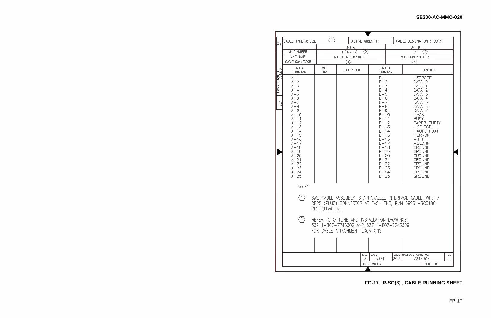
SE300-AC-MMO-020
FP-17
FO-17. R-SO(3) , CABLE RUNNING SHEET

SE300-AC-MMO-020
FP-18
FO-18. R-SO(4) , CABLE RUNNING SHEET

SE300-AC-MMO-020
FP-19
FO-19. R-SO(5), CABLE RUNNING SHEET

SE300-AC-MMO-020
FP-20
FO-20. R-SO(6), CABLE RUNNING SHEET

SE300-AC-MMO-020
FP-21
FO-21. R-SO(7), CABLE RUNNING SHEET

SE300-AC-MMO-020
FP-22
FO-22. GCCS-M, CABLE RUNNING SHEET

SE300-AC-MMO-020
FP-23
FO-23. R-SO(10) , CABLE RUNNING SHEET

SE300-AC-MMO-020
FP-24
FO-24. R-SO(11) , CABLE RUNNING SHEET

SE300-AC-MMO-020
FP-25
FO-25. R-SO(12) , CABLE RUNNING SHEET

SE300-AC-MMO-020
PROBLEM CHANGE REPORT
Title: Date: S/W Version Number: Originator: Phone: System: SC DET CLX Display SC-VME DET-VME CLX-VME (place X in front) Category: S/W H/W Doc (place X in front) Problem Description: System H/W and S/W configuration when error occurred: List any Known Workarounds: Proposed Solution: Can problem be duplicated? Yes No Intermittent (place X in front)

Ref: NAVSEAINST 4160.3A (Insert Classification of TMDER Here) CLASSIFICATION: NAVSEA S0005-AA-GYD-030/TMMP
NAVSEA/SPAWAR TECHNICAL MANUAL DEFICIENCY/EVALUATION REPORT (TMDER) INSTRUCTION: Continue on 8 1/2" x 11" paper if additional space is needed. 1. USE THIS REPORT TO INDICATE DEFICIENCIES, PROBLEMS, AND RECOMMENDATIONS RELATING TO PUBLICATION. 2. FOR CLASSIFIED TMDERS. SEE OPNAVINST 5510H FOR MAILING CLASSIFIED TMDERS.
3. Submit TMDERS at web site http://nsdsa.nswses.navy.mil or mail
1. PUB NO.
2. VOL/PART
3. REV. NO./DATE OR TM CH. NO./DATE
4. SYSTEM/EQUIPMENT IDENTIFICATION
5. TITLE
6. REPORT CONTROL NUMBER (UIC-YEAR-XXXX)
7. RECOMMENDED CHANGES TO PUBLICATION PAGE NO. A.
PARA- GRAPH B.
C. RECOMMENDED CHANGES AND REASONS
8. ORIGINATOR'S NAME AND WORK CENTER (Please Print)
9. DATE
10. DSN/COMM NO.
11. TRANSMITTED TO; (NSDSA WILL FILL IN)
12. SHIP HULL NO. AND/OR STATION ADDRESS (Do Not Abbreviate)
13. ORIGINATORS EMAIL ADDRESS
NAVSEA 4160/1 (REV 2-99) SN 0116-LF-019-5300 (Destroy Old Stock)

-----------------------------------------------------------------------------------FOLD HERE DEPARTMENT OF THE NAVY PLACE POSTAGE HERE Official Business
COMMANDER NSDSA CODE 5E30 NAVSURFWARCENDIV 4363 MISSILE WAY PORT HUENEME CA 93043-4307
-----------------------------------------------------------------------------------FOLD HERE NAVSEA 4160/1 (REV 2/99) BACK