scat team leader
TRANSCRIPT

SCAT Team Leader
NOAA Position Qualification Guidelines: • • • • • •
Has completed SCAT Team Coordinator/Team Leader training course Has current HAZWOPER certification Has participated as a member on a SCAT in at least two significant responses Has completed the following NIMS training courses: ICS-100, ICS-200, ICS-700, and ICS-800 For NOAA personnel, has the most current required training dictated by NOAA policies Has knowledge of the coastal ecology, processes, and/or geology of the affected area
Responsibilities: • •
•
•
• • • •
• • •
•
• •
• •
•
• • •
All SCAT Team Member responsibilities Ensure that field gear for SCAT teams (maps, photography equipment, GPS, communications, etc.) are adequate and assembled prior to deployment Ensure that field gear and safety equipment are maintained by SCAT Team Members and reports any problems to the SCAT Coordinator Review each SCAT segment assigned to their team prior to deployment for issues such as access sites (vehicle, boat, helicopter), problematic terrain (streams, cliffs), special safety considerations, communications, limitations, etc. Manage the team while it conducts field surveys Act as the team Safety Officer Make sure that the forms and sketches are 100% completed in the field Guide the team toward consensus on treatment recommendations, priorities, special constraints, etc., and notes dissenting opinions Brief the SCAT Coordinator and other SCAT Leaders on field survey results Aware of Best Management Practices that are inplace Record cleanup issues and any other spill-specific issues identified by the team that need to be addressed Determine need for additional expertise to address specific sites, i.e., archaeologist, geomorphologist, response cleanup experts, etc. Provide quality control of field-collected data for use in the Incident Command Post Recommend to SCAT Coordinator modifications to cleanup methods and target cleanup endpoints based on SCAT Team recommendations Can serve as Deputy SCAT Coordinator, if required Manage and assist with field documentation of observed oiling conditions and/or record photo/waypoint details Obtain briefing information and special instructions from Environmental Unit Leader, and/or SCAT Team Coordinator, and shares information as appropriate. Read and sign the incident-specific Site Safety Plan Perform other tasks as defined by the SCAT Coordinator Generate and make sure all SCAT team members sign the incident-specific Site Safety Plan
15

SCAT Team Member
NOAA Position Qualification Guidelines: • • • • •
Has current HAZWOPER certification Has completed the following NIMS training courses: ICS-100, ICS-200, ICS-700, and ICS-800 Has completed formal SCAT training, preferably a 3-day course For NOAA personnel, has the most current required training dictated by NOAA policies Has a general knowledge of the coastal ecology, coastal processes, and/or geology
Responsibilities: • • •
•
•
•
• •
•
•
• •
Assist in data collection on shoreline types, oiling conditions and special considerations Recommend site-specific constraints or precautions to be followed during cleanup Recommend need for cleanup, considering cleanup guidelines and endpoints, site safety, and sensitive resources Recommend shoreline cleanup methods, priorities, and endpoints considering cleanup guidelines, site safety, and sensitive resources Assist with field documentation of observed oiling conditions (e.g., record photos, waypoints and related details) Ensure that field gear and safety equipment are maintained and reports any problems to the SCAT Leader Monitor effectiveness of cleanup Identify and be aware of sensitive resources and shares information with other SCAT members Work to achieve consensus among SCAT Team Members on treatment recommendations, priorities, constraints, etc. Obtain briefing information and special instructions from SCAT Coordinator and/or SCAT Team Leader Read and sign the incident-specific Site Safety Plan Is responsible for personal safety
• •
•
• • •
Has experience in evaluating cleanup methods for different shoreline types Is proficient with operating a Global Positioning System (GPS) unit, including collection, upload, and download of waypoints and track lines and selecting datum and coordinate formats (see SCAT GPS Guidelines in Appendix H) Is proficient with operating a digital camera, including setting the correct date and time (see SCAT Photography Guidelines in Appendix G) Knows proper sampling methods and how to maintain chain of custody of samples Has experience conducting field surveys Knows how to download images captured in the field and organize them based on standard protocols
16

SCAT Data Manager
NOAA Position Qualification Guidelines: • • • • • •
• • •
Has the ability to set up and maintain hardware and software needed for response Has completed the following NIMS training courses: ICS-100, ICS-200, ICS-700 and ICS-800 Has completed Introduction to SCAT training course (familiar with SCAT terminology) Is proficient in use of commonly used spreadsheet software (e.g., Excel) Is proficient in use of database software to manage SCAT data Knows how to operate a GPS, including collection of waypoints and track lines, selecting datum and coordinate formats, and download data to computer Is proficient in use of commonly used GIS software (e.g., ArcGIS) Is skilled in creation of output files in various formats (e.g., Google Earth KMZ files) Has general knowledge of relational database structures
Responsibilities (see also Chapter 7): •
• • • •
•
• • • • • • •
Assist the SCAT Coordinator in optimizing SCAT data collection (forms and process), management, and reporting to support operational decisions Modify existing SCAT data entry forms as needed (working with SCAT Coordinator) Review daily SCAT forms for completeness and consistency Enter or supervise the entry of daily SCAT data Conduct data quality assurance/quality control (QA/QC); identifies common data problems and trains SCAT members how to prevent future problems Generate daily summary reports (database-generated) of shoreline cleanup status, maps (hard copy, KMZ, PDF) of shoreline cleanup status, and specific data summaries determined by the SCAT Coordinator and Incident Command Maintain an archive of all SCAT data (e.g., forms, photographs, GPS data, etc.) Provide access to all SCAT data entry forms and field manuals to Incident Command Is prepared to work odd and extended hours Read and sign the incident-specific Site Safety Plan Is aware of health and safety issues for a particular work site Manage field team photographs using appropriate database and protocols Manage field team GPS data using appropriate software
•
•
• •
Is proficient with operating a GPS, including collection, upload, and download of waypoints and track lines and selecting datum and coordinate formats (see SCAT GPS Guidelines in Appendix H) Is proficient with operating a digital camera, including setting the correct date and time (see SCAT Photography Guidelines in Appendix G) Is proficient with downloading images captured in the field and organizing/labeling them Understand proper sampling methodologies and chain of custody protocols
17

SCAT Data Management Team
NOAA Position Qualification Guidelines: • • • • •
• • •
•
• • • •
Has the ability to set up and maintain hardware and software needed for response Has completed Introduction to SCAT training course (familiar with SCAT terminology) Is proficient in use of commonly used spreadsheet software (e.g., Excel) Is proficient in use of commonly used database software (e.g., Access) Know how to operate a GPS, including collection of waypoints and track lines, selecting datum and coordinate formats, and download data to computer Is proficient in use of commonly used GIS software (e.g., ArcGIS) Is skilled in creation of output files in various formats (e.g., Google Earth KMZ files) Know how to operate a digital camera, including setting the correct date and time and organizing photos based on SCAT protocols Is proficient in use of commonly used photo georeferencing software (e.g., GPS PhotoLink, OziPhoto, OziExplorer) Has general knowledge of relational database structures Has general knowledge of QA/QC procedures Has the ability to diagnose/troubleshoot hardware/software/networking issues Is proficient in standard spatial data directory structures, file naming conventions
Responsibilities (see also Chapter 7): •
•
•
•
Assist with producing daily status maps showing current SCAT deployments and assessment activities; maintain archive copies for distribution and reference Assist with obtaining weather from NOAA sources and post and print for morning ops briefings Assist with managing and QA/QC SCAT Teams’ GPS tracklogs and waypoints from GPS units and digital photos; process with appropriate software tools (e.g., OziExplorer, GPS Photo Link, HoudahGeo) Assist with making SCAT maps available in all appropriate formats, including hard copies, PDFs, and Google Earth KML/KMZ files
•
•
• • • •
Know how to operate a digital camera, set the correct date/time and organize photos based on SCAT protocols Is proficient in use of commonly used photo georeferencing software (e.g., GPS PhotoLink, OziPhoto, OziExplorer) Has general knowledge of QA/QC procedures Has the ability to diagnose/troubleshoot hardware/software/networking issues Is proficient in standard spatial data directory structures, file naming conventions Can delegate work to and manage additional SCAT information management team members, if required
18

SCAT-Ops Liaison For large, complex responses, SCAT teams will be very busy conducting surveys and may not have the time to work in the field with Operations Supervisors as shoreline cleanup begins. Under these conditions, a SCAT-Ops Liaison position may be created, particularly during the early phase of the response. This position should be filled by experienced responders who understand both SCAT and shoreline cleanup operations.
SCAT Logistics Coordinator For responses that require complex logistics to get SCAT teams into the field, making all the logistical arrangements is a full-time job. A Logistics Coordinator will be essential to making sure that the teams have the resources needed to get to their assigned segments, including field and safety gear, boats, aircraft, and vehicles.
Responsibilities: •
•
•
• •
Develop a daily tasking plan for all SCAT teams. This plan should extend out several days and be posted on white boards for all to review. This information is to include team number, team members by organization, location name and segments to be surveyed, departure time, and any special instructions Prepare and submit ICS-213 resource request forms to order any resources needed, such as type of boats or aircraft, vehicles, and field and safety gear, in time for these resources to be ordered to meet the tasking plan Track the status reports from the teams in the field, particularly when they depart/arrive back to the deployment area (e.g., marina, airport) Repair/replace field and safety gear returned by the teams Attend the daily SCAT debrief to learn of any logistical or safety issues so they can be resolved
Responsibilities: •
•
• • •
Be the link between SCAT and Operations to make sure that Operation Supervisors understand the shoreline treatment recommendations, how they should be interpreted, and best practices for implementation Meet with the Operations Supervisors in each Operations Division to discuss the shoreline treatment recommendations and clarify any misunderstandings Visit each work crew to observe operations and answer questions about methods Discuss with the SCAT Coordinator any issues raised by the Operations Section Document daily activities with a daily report that includes photographs of the operations and any issues that need to be addressed
19

5 Shoreline Assessment Process and Activities
The following sections describe the full range of activities normally conducted as part of the shoreline assessment process for the steps outlined below.
The degree to which each activity is implemented depends on the complexity of the spill. Flexibility is important; activities should be modified as appropriate to specific spill conditions. Yet every SCAT Program should contain these basic activities.
Various resources and tools have been developed to assist SCAT Coordinators, Team Leaders, and Team Members in conducting each of these activities. These tools and resources are briefly summarized below.
Shoreline Assessment Job-Aid: A pocket-sized, laminated field guide used by members of Shoreline Assessment Teams to assist them in recording accurate field observations in a concise, systematic, and standard format. It consists of color photographic examples of all shoreline assessment terms, shoreline types, and cleanup methods. NOAA produced the Job-Aid in 1998 and updated it in 2007. Laminated hardcopies are available for purchase and electronic copies are available for download at: http://response.restoration.noaa.gov/sites/default/files/jobaid_shore_assess_aug2007.pdf
20

In addition, shoreline assessment manuals have been developed by Environment Canada, CEDRE, and the United Kingdom, as listed in the references cited.
Characteristics of Response Strategies: A Guide for Spill Response Planning in Marine Environments: A pocket-sized field guide that summarizes the technical rational for selecting response methods and describes shoreline treatment methods in terms of their objectives, descriptions, applicable habitats, when to use, biological constraints, environmental effects, and waste generation.Prepared by NOAA in 2000 and updated in 2010. Hardcopies are available at no costs and electronic copies are available for download at: http://response.restoration.noaa.gov/sites/default/files/Characteristics_Response_Strategies.pdf
Characteristic Coastal Habitats: Choosing Spill Response Alternatives: A pocket-sized guide that illustrates typical physical and biological attributes of coastal habitats at risk from oil spills. For each of 18 shoreline types, it includes a sketch, description, predicted oil behavior, response considerations, and the response method table. It is a useful aid for training people who will be participating in Shoreline Assessment surveys. Prepared by NOAA in 2000 and updated in 2010. Hardcopies are available at no cost and electronic copies are available for download at: http://response.restoration.noaa.gov/sites/default/files/Characteristic_Coastal_Habitats.pdf
Environmental Sensitivity Index (ESI) Maps: Provide detailed data on shoreline habitats, sensitive biological and human-use resources, and life-history data on biological resources. The latest ESI maps can be downloaded at: http://response.restoration.noaa.gov/maps-and-spatial-data/environmental-sensitivity-index-esi-maps.html
Open Water Oil Identification Job Aid for Aerial Observation: Field guide to assess the character and extent of oil spilled on the water. It was updated in 2012. Laminated hardcopies are available for purchase and soft copies are available at: http://response.restoration.noaa.gov/sites/default/files/OWJA_2012.pdf
International Tanker Owners Pollution Federation Limited (ITOPF) Technical Information Papers (TIPs): A series of seventeen papers that describe technological advances and ITOPF's more recent collective experience on a wide range of marine pollution topics. Each paper covers a specific subject in a concise manner, illustrated with photographs and diagrams. Available at: http://www.itopf.com/information-services/publications/
21

5.1 Reconnaissance Survey
Objectives •
• •
Obtain overall perspective on shoreline types and degree of contamination in the area of impact. Determine areal extent of oiling on the shoreline. Identify logistical constraints to shoreline access for both shoreline assessment and cleanup teams.
Responsibility • Usually conducted by the SCAT Coordinator, although
someone with local-area knowledge can also be a valuable participant.
Methods • • • •
•
•
Should be conducted in the first day or two of the incident and as oil expands into new areas. Review maps to become familiar with area and resource concerns. It is best to conduct an aerial survey, but it could also be conducted by vessel, vehicle, or foot. Develop a flight plan of the area to be surveyed and brief the pilot on the survey objectives, flight line direction (so that the key observers have direct view of the shoreline), likely duration, and special requirements such as flight altitude. Fly entire impact area (~400 feet altitude at a maximum of 100 miles per hour) in helicopter or high-wing aircraft. Schedule the flight during low tide to view maximum extent of potentially oiled shoreline. Use GPS and topographic maps or nautical charts to record:
- - - - -
Flight path, including date and time; Objective descriptors of shoreline oiling conditions2; Location of floating oil, possibly affecting shoreline oiling conditions; References to photographs/video taken; and Access points for survey teams, especially in remote areas.
•
•
After the aerial survey, compile your observations, tracklines, photographs, etc. into a report to share with other SCAT personnel. Select key photographs, particularly of oiled areas needing immediate response, to brief Operations and Planning. Visit representative ground sites to confirm and scale the degree of shoreline impacts and note special problems, such as potential for burial of oil, which could affect cleanup decision planning.
2 Objective oiling descriptors (Chapter 6, Figure 6) must be modified according to observations made during the reconnaissance survey.
22

5.2 Segmenting the Shoreline
Objective • Divide the shoreline into operational working units, called segments, for recording and
tracking survey data and making treatment recommendations.
Responsibility •
•
Can be completed in the command post by the SCAT Coordinator or workgroup using maps, or in the field by SCAT Teams. Local-area knowledge will be valuable. Some areas already have pre-segmented shorelines identified in their Area Contingency Plan.
Methods • •
• •
•
•
• •
•
Generate base maps from digital databases or aerial imagery. Mark segments based on similarity of geomorphology (refer to ESI maps), degree of oiling, or the boundary of an Operations zone; local staff familiar with the area should be involved. Segment boundaries should be readily recognizable in the field. Size segments appropriate to spill conditions and total area of impact (often 0.2 to 2.0 km long). Because separate forms are completed for each segment, the interval should not be so small that the number of forms required becomes unmanageable for the size of the spill. Use divisions or zones already in use by cleanup operations, when possible. Develop the segment-naming scheme with the Operations Section so it is most useful. SCAT segments should not include multiple Operations work zones. Consider the logistics for deploying cleanup crews when segmenting the shoreline. For example, segment boundaries along a uniform shoreline (e.g., long sand beach) could be between two access points. For long uniform shorelines select a fixed length, such as 500 m, and mark with stakes or flags Pre-number segments with alphanumeric code (e.g., BI-9 for segment number 9 on Block Island; or A-1 for the first segment in cleanup zone A). Remember that the spill responders may not be familiar with local geographic names. When segmenting a river shoreline, river miles and river bank (e.g., left or right descending) are often used to delineate each segment.
As an example, on the eastern end of Galveston Island, Texas (Figure 5, top), the parks are different segments because of their special management status, the Gulf beaches are segmented based on access routes, and the other segments are based on shoreline type. For inland spills, oil often spreads laterally and contaminates habitats over larger areas, such as in a floodplain, rather than forming a relatively narrow band along a shoreline. In these cases, SCAT teams may define segments as areas or polygons, as shown in Figure 5 (bottom) for the 2010 spill into the Yellowstone River, Montana. It may be difficult to determine appropriate boundaries between segments in areas of thick vegetation. SCAT teams need to be flexible and have more creativity when surveying under these kinds of conditions. Up-to-date aerial photographs will be essential to determine locations and mark boundaries. Use of GPS in track mode will also be essential for documenting the actual areas surveyed.
23

Figure 5. (top) Example of shoreline segmenting. (bottom) Example SCAT segments for the 2010
Yellowstone River spill; note the need for polygons where the oil spread into the river floodplain.
24

5.3 Developing Spill-Specific Cleanup Guidelines and Endpoints
Endpoints are selected based on general cleanup objectives, which are to: 1) minimize exposure hazards for human health; 2) speed recovery of impacted areas if possible; and 3) reduce the threat of additional or prolonged natural resource impacts. These objectives lead to developing cleanup strategies that do not cause more harm to the environment than good.
Ideally, cleanup efforts will return the resource to its baseline condition without suffering further impact or affecting other resources. Aggressive and inappropriate cleanup techniques can make matters worse. Less intrusive methods or natural recovery are often preferable. The best cleanup strategy is often not the one that removes the most oil; rather, it is the strategy that removes oil that poses a greater risk of injury than would result from cleanup, and allows remaining oil to be removed by natural processes.
Objectives •
•
Guide the Operations Section in conducting specific cleanup methods to minimize adverse environmental impact. Provide the Operations Section with environmental and safety constraints on conducting cleanup activities in specific habitats.
Responsibility • SCAT Coordinator, agency staff, major landowners, and Team Leaders.
Methods • •
A more detailed discussion of how to develop cleanup endpoints follows this bulleted list. Develop spill-specific cleanup objectives, guidelines, and target endpoints. Refer to the Characteristics of Response Strategies Job-Aid that describes cleanup methods. Cleanup methods are usually generated for each shoreline type that is oiled. Appendix C describes the ESI shoreline types (see Table 1), expected oil behavior, and general response considerations. Guidelines for shoreline cleanup endpoints that can be used as the basis for developing the spill-specific cleanup endpoints are provided in Table 2. Evaluate proposed cleanup methods for potential habitat or resource effects. Identify time-critical and degree-of-use issues to be combined with cleanup priorities and endpoints. Identify sensitive resources that may be adversely affected by the proposed treatment methods (e.g., rich intertidal biota on rocky shores where low-pressure ambient-water flushing will be used). Consult with the NOAA National Marine Fisheries Service (NMFS) and U.S. Fish and Wildlife Service (USFWS) about compliance with Section 7 of the Endangered Species Act (ESA). See Box 2 for a summary of the process to make this determination during an emergency response.
• •
•
25

• Consult with NOAA’s National Marine Fisheries Service to comply with regulations to protect Essential Fish Habitat under the Magnuson-Stevens Fishery Conservation and Management Act.
• Determine if there are Historic Properties (such as archaeological or cultural resources) in the area of operations that could be disturbed by cleanup activities. See Box 3 for the process to make this determination during an emergency response.
• Discuss among stakeholders the trade-off issues between the desire to remove all the oil versus the potential impacts associated with intensive treatments. Consider natural removal processes and the timing of habitat use. Even the presence of cleanup workers can disturb wildlife such as marine mammals at haulout sites and nesting birds and sea turtles.
• Write operational guidelines to minimize adverse impacts (e.g., restrict flushing operations to times when the rich biota zones are underwater). Date the guidelines in order to track revisions.
• Conduct field trials and evaluate new methods or equipment to determine effectiveness and potential adverse effects.
• Observe actual operations to confirm the method’s use, i.e., that the cleanup is effective and is not more damaging than the oil alone.
• Modify cleanup guidelines as the oil changes from weathering, rendering the technique ineffective, or when unacceptable impacts occur under actual use.
26

Table 1. ESI shoreline types for three habitat settings. The color scheme for the ESI classifications is shown in the first column.
ESI NO. ESTUARINE LACUSTRINE RIVERINE
1A Exposed rocky shores Exposed rocky shores Exposed rocky banks
1B Exposed, solid man-made structures
Exposed, solid man-made structures
Exposed, solid man-made structures
1C Exposed rocky cliffs with boulder talus base
Exposed rocky cliffs with boulder talus base
Exposed rocky cliffs with boulder talus base
2A Exposed wave-cut platforms in bedrock, mud, or clay
Shelving bedrock shores Rocky shoals; bedrock ledges
2B Exposed scarps and steep slopes in clay
3A Fine- to medium-grained sand beaches
3B Scarps and steep slopes in sand Eroding scarps in unconsolidated sediments
Exposed, eroding banks in unconsolidated sediments
3C Tundra cliffs
4 Coarse-grained sand beaches Sand beaches Sandy bars and gently sloping banks
5 Mixed sand and gravel beaches
Mixed sand and gravel beaches
Mixed sand and gravel bars and gently sloping banks
6A Gravel beaches (granules and pebbles)
Gravel beaches Gravel bars and gently sloping banks
6B Riprap Riprap Riprap 7 Exposed tidal flats Exposed tidal flats
8A Sheltered scarps in bedrock, mud, or clay
Sheltered scarps in bedrock, mud, or clay
8B Sheltered, solid man-made structures
Sheltered, solid man-made structures
Sheltered, solid man-made structures
8C Sheltered riprap Sheltered riprap Sheltered riprap 8D Sheltered rocky rubble shores 8E Peat shorelines
8F Vegetated, steeply-sloping
bluffs 9A Sheltered tidal flats Sheltered sand/mud flats 9B Vegetated low banks Vegetated low banks Vegetated low banks 9C Hypersaline tidal flats
10A Salt- and brackish-water marshes
10B Freshwater marshes Freshwater marshes Freshwater marshes 10C Swamps Swamps Swamps
10D Scrub-shrub wetlands; Mangroves
Scrub-shrub wetlands Scrub-shrub wetlands
10E Inundated low-lying tundra
27

Table 2. Guidelines for development of cleanup endpoints. Use these guidelines to develop spill-specific cleanup endpoints for terminating active cleanup.
No Oil Observed (NOO): Not Detectable by Sight, Smell, Feel
This endpoint is often used for sand beaches where oil removal can be effective without delaying resource recovery.
Visual inspections are preferred over chemical analysis of samples because of: difficulty of sampling areas with high variability; time and costs to complete sampling and analysis; and lack of guidelines on what levels are safe.
Visible Oil But No More than Background
This endpoint is often applied where there is a significant background rate of tar ball deposition on the shoreline.
No Longer Generates Sheens that Will Affect Sensitive Areas, Wildlife, or Human Health
This endpoint is used where sheening persists after cleanup efforts become ineffective, or on sensitive habitats where further cleanup efforts will cause more harm than natural removal. Residual sheening should persist over a relatively short time period.
Sheen is an oil film ranging from barely visible to dull colors. Sorbents effectiveness is usually limited in recovery of sheens. Consider the amount and duration of sheening, and the distance to sensitive resources, to determine if sheening poses a significant threat.
Consider the degree of exposure: high wave/tidal exposure speeds removal and breaks up sheens; sheltered areas will sheen longer and sheens will be more persistent.
Consider the degree and timing of use: sheening may be tolerated in areas or during periods of low use; even minor sheens may not be tolerated in areas of high use, such as swimming beaches.
No Longer Rubs Off on Contact
This endpoint is usually defined as oil removal to a stain or coat, or weathering to the point that it is no longer sticky. It is applied to hard substrates (rocky shores, seawalls, riprap, gravel) and vegetation (marshes, mangroves).
The objective is to prevent oiling of fur, feathers, and feet of wildlife, and oiling of people and property during contact with oiled surfaces.
Consider the degree and timing of use: high-use areas often require higher cleanliness, whereas natural removal is allowed in low-use areas where further cleanup efforts will be disruptive.
Oil Removal to Allow Recovery/ recolonization Without Causing More Harm than Natural Removal of Oil Residues
This endpoint is used where further oil removal will result in excessive habitat disruption (e.g., trampling of soft sediments and plant roots, mixing oil deeper, extensive sediment removal, vegetation cutting) or high biota mortality (e.g., from high-pressure, hot-water washing of intertidal communities).
It is also used for areas with difficult access, which limits the type of cleanup that can be conducted along that shoreline segment.
Consider the potential for erosion from excessive sediment removal, particularly where erosion/deposition patterns of the beach cycle will re-work and clean sediments within an acceptable time frame.
28

Box 2:
Complying with Section 7 of the Endangered Species Act (ESA) During Oil Spill Response
• •
•
•
•
•
•
•
•
•
•
ESA provides protection for listed species and their designated critical habitats (50 CFR 402). Section 7 of the ESA prohibits “take” of individual animals or adverse modification or destruction of critical habitat. Take is defined as to harass, harm, pursue, hunt, shoot, wound, kill, trap, capture, or collect, or to attempt to engage in any such conduct. Federal agencies must ensure that their actions don’t jeopardize the continued existence of listed species or destroy critical habitat. The FOSC (either USCG or USEPA), as the Lead Federal Agency, must determine whether or not listed species and/or critical habitats are present within the area of the operation. Action is defined as “…all activities or programs of any kind authorized, funded, or carried out, in whole or in part, by Federal agencies in the United States or upon the high seas.” Federal agencies conduct interagency consultation, (aka Section 7 consultation), with the US Fish and Wildlife Service and National Marine Fisheries Service either formally or informally on any action that may affect listed species. The USFWS and/or NMFS generate Best Management Practices (BMPs) for response-related activities to minimize impacts to listed species and critical habitats. These become part of the shoreline treatment recommendations that are issued to the Operations Section. Depending on the spill conditions, these recommendations may require special agency field monitors during cleanup operations to document compliance with the BMPs Furthermore, there may be a need to document SCAT compliance with any BMPs that have been developed for SCAT teams to follow during their field surveys. The Inter-agency Memorandum of Agreement Regarding Oil Spill Planning and Response Activities Under the Federal Water Pollution Control Act’s National Oil and Hazardous Substances Pollution Contingency Plan and the Endangered Species Act (dated 2001) is available at: http://www.uscg.mil/npfc/docs/PDFs/urg/App/ESA_MOA_AppA_04.pdf
29

The SCAT Coordinator can form a work group to evaluate cleanup options and make recommendations on other issues that arise. Besides reviewing published studies and case histories, they can consider on-site testing for effectiveness and environmental effects of the proposed method(s) under the spill-specific conditions. The selection of shoreline treatment methods involves choices (aka tradeoffs) between the degree of oil removal and degree of impact associated with the
Box 3:
Complying with Section 106 of the National Historic Preservation Act (NHPA) During Oil Spill Response
•
•
•
•
•
•
•
•
•
•
•
•
Under Section 106 of 36 CFR 800, Federal agencies are required to take into account the effects of their undertakings on historic properties that are listed in, or eligible for, inclusion in the National Register of Historic Places (NRHP). The FOSC (either USCG or USEPA), as the Lead Federal Agency, must determine whether or not NRHP-eligible Historic Properties are present within the area of the operation. If Historic Properties are present, the Lead Federal Agency must then determine whether or not the undertaking will have an adverse effect on them. This determination is made by consulting with State Historic Preservation Offices (SHPOs), Native American tribes, Federal land managers, and other stakeholders on the presence of and potential adverse effects to Historic Properties prior to the start of cleanup operations. After consultations, the FOSC, the SHPO, and other stakeholders reach an agreement on how the adverse effects on Historic Properties will be addressed such as avoidance, monitoring, mitigation, or other procedure. A Historic Properties Specialist oversees the Section 106 process during the development of shoreline treatment recommendations and develops recommendations to be implemented by SCAT and Operations during their work. Examples include: No Known Cultural Concern – Work can proceed without archaeological monitoring. If cultural concerns are discovered, work must stop and Section 106 Team notified. Potential Cultural Concern – Project area requires archaeological survey before work can proceed. 250 Meter Sensitivity Zone – Project is within 250 meters of a known cultural resource. Archaeological monitoring required during the undertaking. There is a Programmatic Agreement under the National Contingency Plan whereby this process is expedited during oil spill emergencies. In some regions of high sensitivity, archaeologists and/or tribal representatives may accompany the SCAT teams to identify unknown historic sites, confirm current condition of known sites, and make sure that SCAT team activities do not disturb such sites. The Programmatic Agreement on Protection of Historical Properties During Emergency Response Under the National Oil and Hazardous Substances Pollution Contingency Plan is available at: http://www.achp.gov/NCP-PA.html.
30

method as shown in Figure 6. Method 3 was too aggressive; though it removed the most oil, it also had the longest recovery rate. Method 2 removed less oil but had moderate habitat recovery. Method 1 was the best option; it removed the most oil and had the best recovery.
Figure 6. Impact and recovery of various cleanup methods, including natural recovery. Note that
Cleanup method 3 removed the most oil but had the longest habitat recovery. Cleanup method 1 was the best option because it removed more oil and had the fastest habitat recovery.
Guidelines for cleanup endpoints that consider this tradeoff concept are outlined in Table 2. Although the highest cleanup endpoint is removal to the point of no observed oil, this is often not possible, particularly if there is a background rate of oil deposition (e.g., natural seeps, shipping traffic). In these cases, a more appropriate endpoint would be cleanup of visible oil, but not exceeding the background amount. Note that “visible” oil applies not only to oil on the surface, but also subsurface oil that must be exposed in trenches dug into the sediments. When shoreline cleanup to achieve these endpoints is likely to cause added harm to the environment, three additional endpoints may be considered:
•
•
•
Oil removal to the point where the shoreline no longer generates sheens that affect sensitive areas, wildlife, or human health; Oil removal to the point where it no longer rubs off (e.g., no longer sticky or tacky or a threat to wildlife); and Oil removal to the point that allows recovery/recolonization without causing more harm than leaving the oil in place.
31

Cleanup Endpoints and Trade-off Issues by ESI Shoreline Type
Examples of cleanup endpoints and trade-off issues used at previous oil spills for different shoreline types are included below, to assist you in developing spill- and site-specific endpoints. Each spill will have a unique combination of oil type, rate of natural removal, biological sensitivity, timing windows (how quickly the cleanup has to be completed), and human use issues that may lead to different endpoints. Note that many of the endpoints incorporate SCAT terms.
Exposed Rocky Shores and Wave-Cut Platforms (ESI = 1A and 2)
Cleanup Trade-off Issues
•
•
•
•
•
Shoreline access is often difficult, dangerous, and limited to low tides and calm wave conditions. Rapid natural removal rates are expected, so these shorelines usually have lower priority for cleanup. Thus, cleanup endpoints are seldom an issue because onshore cleanup activities are not initiated. High wave energy at these sites usually breaks up sheens, limiting the distance sheens can spread and thus the areal extent of threat to sensitive resources. Timing is often a critical component in allowing natural removal to proceed, particularly for the presence of migratory waterfowl, seabird nesting, and breeding activities of marine mammals. May consider limited removal of persistent residues that are affecting sensitive resources (e.g., sources of sheens very near active bird nesting colonies).
Why Cleanup Endpoints for Inland Spills are Often More Stringent
•
•
•
•
•
•
Inland habitats often lack some of the physical processes (such as waves and tidal currents) that can speed the rate of natural removal of oil residues after treatment operations are terminated. The direct human uses of inland habitats, such as for drinking water, recreation, industrial use, and irrigation, require a higher degree of treatment compared to marine environments to avoid human health and socio-economic impacts. Spills in close proximity to where people live, work, or recreate often require treatment to a higher level. Inland spills can affect smaller waterbodies where there are slower rates of dilution and degradation. There may be large-scale differences in water levels during the response, causing oil to be stranded well above normal levels where it can pose hazards to wildlife as well as humans using these areas. Many states have sediment quality guidelines that must be met as part of the remediation phase after the emergency response is completed.
32

Example Cleanup Endpoints
• • •
•
No accessible oiled debris. No surface oil greater than Stain or Coat on solid surfaces >20% distribution. In inaccessible areas where further oil removal is not possible because of safety restrictions, cleanup can be terminated when the shoreline no longer generates sheens that affect sensitive wildlife. On exposed rocky shores used as marine mammal haulouts, persistent oil should be removed until the oil is no longer sticky, unless cleanup is too disruptive to animals at the site.
Solid Man-Made Structures (ESI = 1B and 8B) (e.g., seawalls, pier pilings, bulkheads)
Cleanup Trade-off Issues
•
•
•
These shoreline types often occur in developed areas with chronic sources of pollutants or habitat degradation, so they usually have low biological sensitivity. More intrusive techniques are considered because of their lower biological use and need to minimize human exposure in areas of high public use. The lower part of the structure can have rich attached biota that should be protected during manual scraping or high-temperature, high-pressure flushing.
Example Cleanup Endpoints
• •
•
No accessible oiled debris. In industrial areas, no longer generates oil greater than sheens. In public access areas, no longer generates sheens. No surface oil greater than 20% Coat or Stain. In areas of high public use or visibility, no surface oil greater than 10% Coat or Stain.
Sand Beaches (ESI = 3 and 4)
Cleanup Trade-off Issues
• •
•
•
Amenity beaches often require a quick cleanup and high degree of cleanliness. The sand beach cycle is usually short, so re-worked and re-located sediments often can be rapidly returned to their normal profile on exposed beaches. Wave action can be an effective final “polishing” process, removing residual stains. Oil on the surface of sand beaches is relatively easy to clean; however, difficulties arise when the oil is buried because of the amount of sediment that must be removed. Where sand can be replaced by existing nourishment projects, more sediment removal is generally allowed to quickly remove oil from public beaches.
Example Cleanup Endpoints
• •
No visible oil on the surface. No oiled wrack. Wrack that is not oiled should not be removed from the beach.
33

•
•
•
All tar balls or tar patties that could be removed by reasonable cleanup techniques should be removed. Remaining tar balls and tar patties should be at or below normal background frequency. Increases in tar ball frequency above background will require further cleanup. No subsurface oil layers in pits dug into the beach. Buried tar balls should be at or below background frequency. On beaches with high resource value, such as those in Wildlife Refuges, less stringent endpoints can be used to minimize impacts to the habitat that would affect beach use by shorebirds or sea turtles.
Mixed Sand and Gravel Beaches (ESI = 5) and Gravel Beaches (ESI = 6A)
Cleanup Trade-off Issues
•
•
•
•
Beaches with a significant amount of gravel are relatively difficult to clean because they have high potential for deep penetration and burial. Deeply penetrated oil can be a chronic source of remobilized oil for months or longer. Natural replenishment rates of gravel are slow, so sediment removal is usually minimized and sediment reworking or natural removal considered after gross oil removal is completed. The most difficult issue is removal of persistent, deeply penetrated oil because of the degree of physical disruption to both the beach profile and sediment distribution patterns. It is difficult to predict how long natural removal at a specific site will take. Gravel is mobilized mostly during storms, so it could take months to years for a coarse gravel beach to return to normal after extensive physical disruption.
Example Cleanup Endpoints
• •
•
No surface oil more than 10% Coat or Stain on the gravel-sized sediments. No subsurface oil greater than 20% Coat or Stain. Occurrences of buried tar balls should be at or below background frequency. In remote, difficult access areas, no more than 20% Coat or Stain on the gravel-sized sediments, and subsurface oil no more than 5% Oil Residue.
Riprap Structures (ESI = 6B)
Cleanup Trade-off Issues
•
•
•
•
Riprap often occurs in developed areas with chronic sources of pollutants or habitat degradation nearby. More intrusive techniques are considered because of their lower biological use and need to minimize human exposure in high public use and populated areas. It is extremely difficult to completely remove oil from crevices and undersides of the riprap because they are inaccessible. It sometimes requires replacing the oiled pieces of riprap, which can be highly intrusive and expensive. With higher residues remaining, they can release sheens for weeks or longer.
34

Example Cleanup Endpoints
• • •
•
No accessible oiled debris. In industrial areas, no longer generates sheens. Sorbents will be deployed to recover sheens. No surface oil greater than 20% Coat or Stain. In areas of high public use or visibility, no surface oil greater than 10% Coat or Stain. In areas of high public access, no oil on the surface that rubs off on contact.
Exposed and Sheltered Tidal Flats (ESI = 7 and 9)
Cleanup Trade-off Issues
•
•
The risks of physical disruption and mixing of the oil are very high, thus passive cleanup (e.g., deploying sorbents) is often the only activity. Even then, extreme care is needed. Since there is usually another shoreline type at the upper intertidal zone, care is needed to prevent impacts to the lower tidal flat during cleanup activities along the shoreline.
Example Cleanup Endpoints
• • •
No longer generates sheens that will affect sensitive areas, wildlife, or human health. No oiled wrack. Wrack that is not oiled should not be removed from the flat. Oil removal can be terminated when further cleanup efforts will result in excessive habitat disruption that will cause more harm than natural removal of oil residues.
Marshes (ESI = 10A and 10 B)
Cleanup Trade-off Issues
•
•
•
•
Natural removal rates are very slow. Thick oil on vegetation is usually removed only when the vegetation dies back and sloughs off. Generally efforts focus on recovery of free oil trapped in the marsh and deployment of sorbents to recover sheens. Most types of active cleanup in the marsh can cause significant habitat impact and slow overall recovery. Foot traffic on the vegetation should be minimized; use boardwalks, work from boats, or restrict work to the marsh edge. Oil on marsh vegetation generally weathers to a dry coat within weeks, after which it is a lower threat of oiling wildlife using the marsh.
Example Cleanup Endpoints
• • • • •
No oil on vegetation that can rub off on contact. No longer generates sheens that will affect sensitive areas, wildlife, or human health. No free-floating oil in the marsh. No longer generates sheens that will affect sensitive areas, wildlife, or human health. As low as reasonably practicable, considering the allowed treatment methods and net environmental benefit
35

Mangroves (ESI = 10D)
Cleanup Trade-off Issues
•
•
•
•
Natural removal rates are very slow. Thick oil on vegetation is usually removed only when the vegetation dies back and sloughs off. Generally efforts focus on recovery of free oil trapped in the mangrove fringe and deployment of sorbents to pick up sheens. Most types of active cleanup in the mangrove can cause significant habitat impact and slow recovery. Foot traffic into the mangrove forest should be minimized; use boardwalks, work from boats, or restrict work to the mangrove fringe. Oil on the prop roots and leaves generally weathers to a dry coat within weeks, after which it is a lower threat of oiling wildlife using the mangrove.
Example Cleanup Endpoints
• • • •
No oil on prop roots and leaves that can rub off on contact. No longer generates sheens that will affect sensitive areas, wildlife, or human health. No accessible free-floating oil in the mangrove forest. No accessible oiled wrack. Wrack that is not oiled should not be removed.
Large Debris (e.g., Logs, Abandoned Vessels) Excluding Historic/Cultural Items
Cleanup Trade-off Issues
•
•
•
Large pieces of debris are difficult to remove and generate large volumes of waste for transport and disposal. Oil on the debris generally weathers to a dry coat within weeks, after which it is a lower threat of oiling wildlife. Only the more heavily oiled parts of the debris should be removed (if they can be separated), leaving behind less oiled parts.
Example Cleanup Endpoints
• • •
No surface oil greater than Stain or Coat > 20% distribution. No oil on surfaces that can rub off on contact. Do not conduct wholesale removal of unoiled natural debris.
36

5.4 Pre-survey Planning and Daily Team Assignments
Objective • Based on reconnaissance survey
information, determine areas to be surveyed, field logistics, and team assignments.
Responsibility • SCAT Coordinator, Team Leaders
Methods •
• •
• •
•
•
• •
• •
• • •
•
Revise the standard shoreline oiling codes and forms, if needed, to fit spill conditions. Form teams with appropriate membership (expertise and affiliation) Assign team leaders. Generally they are most experienced person in SCAT. See Chapter 4 for responsibilities and qualifications. Ensure that all Team Members have the required safety training. Each Team Member must read and sign the Incident Site Safety Plan and the SCAT Field Safety Plan and discuss specific safety concerns related to SCAT activities. The SCAT Field Safety Plan must include a communications plan with set times or events when each team checks in by phone or radio. Appendix F includes the SCAT Field Safety Plan for the MC 252 response as an example. Determine logistical requirements for the teams and coordinate requests to the Logistics Section. Assign survey areas (primary and backup) for each team, based on priorities, logistics, local expertise, and land management or ownership. Generate base maps showing the segment boundaries and names. Distribute Operations Division and/or segment maps for primary and backup areas; distribute SOS forms and codes, base maps, and sketch sheets (see Chapter 6 for forms and codes). Distribute field equipment (see checklist in Appendix A). Brief team on survey objectives, logistics (e.g., transportations, communications, food), and safety issues. Discuss cleanup endpoints, guidelines for recommending treatment, and criteria for priorities. Discuss reporting requirements and schedules. Calibrate on the first field day by having all Team Members visit a segment together and agree on how the oiling descriptions will be applied. This step is essential. Schedule a debrief at the end of the day for all SCAT teams to report findings and safety issues, and to plan assignments for the following day.
37

5.5 Shoreline Surveys
Objectives •
• •
Collect data on shoreline types, oiling conditions, and ecological and human-use resources for each segment. Reach agreement on treatment recommendations and priorities for specific segments. Confirm that recommendations are effective and beneficial to the environment (refer to list of questions in Chapter 3).
Responsibility • SCAT Team
Methods • •
•
•
•
•
•
• •
•
• •
Comply with the Incident Site Safety Plan and the SCAT Field Safety Plan at all times. Confirm segment boundaries upon arrival at the assigned segment, or if not yet determined, delineate segment boundaries during the SCAT survey. Conduct survey to identify shoreline types (refer to Table 1) and extent of oiling. The team should spread out so that the entire intertidal and supratidal zones are covered. Describe the shoreline characteristics, surface oil conditions, subsurface oil conditions, and special considerations (ecological, recreational, cultural) using standard terms and codes on the Shoreline Oiling Survey (SOS) form. Section 6 provides more details about the forms, terms, and codes. See Appendix I for a step-by-step guidance on completing the SOS form. It is important to always dig pits in permeable substrates. Look at the shoreline for clues as to where oil may have become buried by the deposition of clean sediment. Also dig pits to determine the thickness of oil penetration below the surface. Sketch the segment, if appropriate, focusing on the oil distribution and special considerations. See Appendix E for a primer on drawing field sketches. Delineate the start/end of each oil zone within the segment, by waypoints AND marks on the segment map. Zones can be along shore or cross shore, where the oiling degree and/or shoreline type changes, such as along a sand beach with surface residue that changes to a riprap wall with coat along shore or dunes in the supratidal zone that contains a small number of tarballs. Note presence of submerged oil in nearshore zone for spills of heavy oil. Log and locate all photographs taken. Use a photo scale (an example is included in Appendix D) for close-up photographs (see photography guidance in Appendix G). Collect oil and/or sediment samples based on identified needs. However, sampling should not detract from SCAT’s primary mission. Discuss and agree on the need for treatment recommendations and priorities. Complete the surveys each day in time to meet reporting deadlines.
NOTE: SCAT teams cannot direct cleanup contractors in the field, though teams can document unapproved cleanup methods or improper techniques. The SCAT Coordinator will communicate with the Planning or Operations Section Chief to rectify the problem.
38

5.6 Submitting Field Data
Objective • Provide data needed to support shoreline
treatment decisions and operations.
Responsibility • SCAT Team, SCAT Coordinator, SCAT Data
Managers
Methods •
•
•
•
• • • •
• •
•
Check all field maps and forms for accuracy, completeness, and legibility. Download digital photographs and GPS tracklines to generate survey maps, if appropriate (SCAT data managers can assist if on scene). See Appendices G and H for more details on these downloads. Generate a SCAT data package for each day’s surveys that includes the completed forms, sketches, and maps showing the areas surveyed, and representative photographs of the habitats and oiling conditions. Be sure to write notes for each photograph noting its location and explaining what each represents. The SCAT Coordinator and/or data manager will review the package and identify missing or incomplete data. Copy all forms, sketches, and field notes for the field team as needed; keep originals on file. Summarize treatment recommendations by segment. Debrief the SCAT Coordinator on special issues, problems, and recommendations. Team Leads should call in or send electronically by email or text the results for urgent needs or when the teams are working remotely and unable to return to the Command Post each day. Attend end of day SCAT debrief meeting and get next day’s assignment. Create summary tables and maps identifying segments to be treated, degree-of-oiling categories, or other products as needed (see Chapter 7 for more information on SCAT data management support and products). Early in the response, SCAT data must be generated in a timely manner so treatment recommendations get assigned to the Operations Section quickly.
39

5.7 Cleanup Evaluation/Effectiveness Monitoring
Objectives •
•
•
Monitor cleanup operations routinely to evaluate progress of cleanup activities and assess the need for modifying cleanup methods or endpoints. Investigate reports of new oiling, changes in erosional/depositional processes that are affecting oil behavior and the response, or other issues. Conduct tests to evaluate new treatment methods.
Responsibility • SCAT Coordinator, Government representatives, major landowners, and SCAT Teams
Methods •
•
•
•
•
•
Visit segments where cleanup activities are being conducted to ensure that approved methods are being properly implemented. Respond to requests for changes in approved cleanup methods to address specific problems or changes in oiling conditions that render the approved methods ineffective. Organize and conduct field-testing and monitoring programs, if needed, during evaluation or use of innovative treatment methods. Establish and monitor beach profile transects to document beach erosion and deposition on beaches, which can be very important if there is a risk for deep burial of oil during a depositional period. Modify cleanup endpoints, as needed, due to changes in oiling conditions, safety issues or seasonal changes (e.g., winter freeze-up or start of bird-nesting on a segment). Produce summary reports and documentation on special issues, problems, and changes in recommendations related to shoreline treatment methods and endpoints.
40

5.8 Post-Cleanup Inspections
Objective • Inspect segments that the Operations
Section declares ready to determine if they meet endpoints or require further treatment.
Responsibility • SCAT Team, Land Manager, Land Owner,
and Local government representatives (sometimes called a Sign-off Team or a Cleanup Assessment Review Team). Agencies must delegate sign-off authority to their representatives on the team.
Methods •
•
•
•
•
•
•
•
•
SCAT Coordinator receives notification from the Operations Section that a segment is ready for inspection. Determine additional representatives that need to participate in the inspection, such as the land manager, landowner, or local government representatives. For large spills, it may be appropriate to conduct a pre-inspection with just SCAT to make sure that the segment is ready before involving these others. Inspect the segment against the cleanup endpoints (preferably using the same team that did the original survey). The original field sketch/map/ photographs can be very helpful for evaluating effectiveness of the treatment. There are three possible outcomes of the inspection (see Figure 3): No Oil Observed, No Further Treatment, or Further Treatment Recommended. Determine if further treatment is required using standard shoreline assessment terms, forms, and sketches, or develop special forms for this purpose. If further treatment is recommended, the segment goes back to Operations, with identification of specific areas to be treated. Depending on the spill-specific response plan, SCAT can recommend that the segment be moved out of the “active” cleanup phase, to the next phase, such as patrol and monitoring or passive treatment (usually deployment and maintenance of sorbents to recover sheens). If the segment meets endpoints or if no further treatment is recommended because of net environmental benefit, the segment can be submitted for final approval by the Unified Command to be moved out of the response. Submit the result of the inspection by SCAT to the Planning Section using the required forms, other documentation, and signatures. For some responses, a Shoreline Inspection Report (SIR) is used to document agreement among the Team Members of the results of the inspection, with all Team Members signing the form. See Appendix D for two example SIR forms used at past spills. Because this last step can range from simple to complex, there is no one form that would apply to all responses.
41

5.9 Final Sign-Off of Cleanup Activities
Objective • Approve the termination of all cleanup activities at each segment.
Responsibility • Unified Command.
Methods •
•
•
Following post-cleanup segment inspections that meet cleanup endpoint criteria, the SCAT Coordinator reviews the results of the SCAT team inspection to make sure that endpoints have been met and the documentation is complete. This documentation is turned into the Planning Section who reviews/approves it and forwards the package to the Unified Command for their final review and approval. Note that, for some spills, there may be a need for Section 106 review of and sign off on the package before it goes to the Unified Command. The Unified Command or their representatives sign the segment out of the response or to the next phase of the response.
42

6 Shoreline Survey Terms, Codes, and Forms
Using standard terms and forms to describe and report shoreline-oiling conditions are the basic building blocks of shoreline assessment. Ambiguous words, such as “heavy” oiling, do not provide the necessary detail to document the oiling condition or the need for and type of cleanup to be conducted. The terminology and codes used by SCAT teams for most oil spills are defined in Figures 7-11. SCAT teams need to be trained and calibrated so they can consistently apply these terms to spill-specific conditions. The terminology and codes for spills of light refined products are somewhat different and defined in Table 3. To aid teams in uniformly estimating percent cover, two different types of percent cover estimator charts are included in Appendix D. The Shoreline Assessment Job-Aid is a valuable field tool to help teams use proper terminology and protocols in the field.
All Team Members must agree on how they will use these terms and codes for a specific spill. Thus, a calibration field exercise, conducted jointly by all Team Members during the first survey, is always necessary. For responses that extend over months and during rotation of Team Members, re-calibration will be needed.
Various forms have been developed to record the observations of shoreline assessment teams, depending on the oiling conditions, environments, and shoreline types. All of the forms use the standard codes and terms in Figures 7-11. Operations staff will also need training and guidance on how to interpret SCAT data, although they usually see summary reports. Appendix D contains copies of all forms and explanation of terms and codes.
Shoreline Oiling Survey (SOS) form: used for most coastal shoreline oiling conditions. An example for an example segment and accompanying SCAT map is shown in Figures 12 and 13. Section 6 of the form allows recording of surface oiling conditions for tar balls (as # per unit area) when the oiling distribution is less than 1%. Subsurface oiling conditions are documented by digging pits and recording the pit information in Section 7. This form is the most complex and requires a high level of training to complete it properly.
Wetlands SOS form: includes fields to record the oiling characteristics on the marsh soils as well as the height, thickness, and % distribution of oiling of the vegetation.
Tar Ball SOS form: used to record more detailed information for spills with widely scattered tar ball oiling. Figure 14 is a Tar Ball SOS form completed for Zones A-D shown in Figure 11.
River and Stream SOS forms: used on inland spills, notably the 2010 Enbridge spill in the Kalamazoo River in Michigan and the 2011 Silvertip spill in the Yellowstone River in Montana.
Field Observer form: for use for Type 4-5 responses, or during larger responses to quickly get field information back to Operations early in the response.
All forms have fields for entering oiling conditions for the different “zones” within a segment. Each zone represents a unique combination of shoreline/habitat type, oiling conditions, and tidal zone/river bank/stream bank. Zones can be along shore, such as where the shoreline type changes from sand beach to riprap; or cross shore, such as oil in a marsh in the upper intertidal zone as well as on a tidal flat in the middle intertidal zone. Treatment methods and endpoints may vary with each zone.
43

Figure 7. Sediment Types.
R Bedrock outcrops G Granule (2- mm) B Boulder (>256 mm in diameter) S Sand (0.06-2 mm) C Cobble (64-256 mm) M Mud (silt and clay, <0.06 mm) P Pebble (4-64 mm) RR Riprap (man-made permeable rubble)
R B
C P
G S
M RR
44

Figure 8. Oil Distribution.
C Continuous 91 - 100% B Broken 51 - 90% P Patchy 11 - 50% S Sporadic 1 - 10% T Trace <1%
C B
P S
T
45

Figure 9. Surface and Subsurface Oiling Descriptors – Thickness.
TO Thick Oil (fresh oil or mousse >1 cm thick) CV Cover (oil or mousse from >0.1 cm to <1 cm on any surface) CT Coat (visible oil <0.1 cm, which can be scraped off with fingernail) ST Stain (visible oil, which cannot be scraped off with fingernail) FL Film (transparent or iridescent sheen, or oily film)
TO CV
CT ST
FL
46

Figure 10. Surface Oiling Descriptors – Type.
FR Fresh Oil (unweathered, liquid oil) MS Mousse (emulsified oil occurring over broad areas) TB Tar Balls (discrete accumulations of oil <10 cm in diameter) PT Patties (discrete accumulations of oil >10 cm in diameter) TC Tar (highly weathered oil, of tarry, nearly solid consistency) SR Surface Oil Residue (non-cohesive, heavily oiled surface sediments, characterized
as soft, incipient asphalt pavements) AP Asphalt Pavement (cohesive, heavily oiled surface sediments)
FR M
TB PT
TC SR
AP
47

Figure 11. Subsurface Oiling Descriptors.
Table 3. SCAT terms to be used for spills of light, refined products.
Surface and Subsurface Oiling Descriptors – Thickness SM Smell No visible oil; detectable only by smell FL Film Feels greasy when sediments are rubbed SH Sheen Visible sheen on water surfaces CT Coat Visible coating of oil PO Pooled Liquid oil accumulated on surface
Surface Oiling Descriptors – Color None Brown Shiny Yellow Rainbow Red
OP Oil-Filled Pores (pore spaces are completely filled with oil to the extent that the oil flows out of the sediments when disturbed). May also consist of weathered oil, such as a buried lens of asphalt pavement
PP Partially Filled Pores (pore spaces partially filled with oil, but the oil does not flow out of the sediments when disturbed)
OR Oil Residue (sediments are visibly oiled with black/brown coat or cover on the clasts (individual sediment particles), but little or no accumulation of oil within the pore spaces). Modifiers can be used, such as heavy oil reside (HOR); moderate oil residue (MOR); and light oil residue (LOR)
OF Oil Film (sediments are lightly oiled with an oil film, or stain, on the clasts) TR Trace (discontinuous film or spots of oil, an odor, or tackiness)
OP PP
OR OF
48

Figure 12. Combined SOS Form completed for an example survey shown in Figure 13.
49

Figure 13. SCAT map for the example survey from the SOS form in Figure 12. Note that way points are used to define the boundaries between SCAT zones A, B, C, etc. and short notes are made about the oiling conditions, matching the data on the SOS form in Figure 12.
50

Figure 14 Tar Ball SOS Form completed for zones A-D in the example survey in Figure 13. Waypoints
denote the start and end of the SCAT zones as well as the segment.
51

Calculating Degree of Oiling SCAT data are used to generate statistics on the number of shoreline miles by degree-of-oiling categories to the Unified Command. Two matrices that can be used to generate summary oiling descriptors, in terms of what is defined as “heavy,” “medium,” “light,” and “very light” for a specific spill are provided in Figure 15. These oiling categories are defined based on the width of oiling bands on the shoreline (as measured perpendicular to the shoreline), the percent cover of oil within the band, and oil thickness using a two-step process:
•
•
The width of the oil on the shoreline and the percent cover determine an initial oiling degree category using the top matrix; The thickness of the oil determines the final oiling degree using the bottom matrix. For example, a shoreline with a >3 m band of oil with 100% coverage is initially classified as Heavy surface cover. However, if the oil thickness is only a stain or film, the final surface oil category is Light; if the oil thickness is >0.1 cm, the final category is defined as Heavy.
The SCAT Data Managers use these matrices to generate statistics and maps. However, SCAT teams should not use these terms during their field surveys. Terms such as heavy, moderate, light, and very light are only for final summaries and maps. The matrices in Figure 15 should be modified by consensus for the spill-specific conditions, particularly the width of the oiled band that are defined as Wide, Medium, Narrow, and Very Narrow.
52

Figure 15. Matrices to be used in the two-step process to assign an oiling category for a segment. In the first step, the surface oiling degree is based on the width and the surface distribution. In the second step, the oiling category from the first matrix is combined with oil thickness in the second matrix to define the final oiling category. From Owens and Sergy (2000). Modify for the spill-specific conditions, particularly the width of Wide, Medium, Narrow, and Very Narrow.
Subsurface Oil…Always a Problem
Subsurface oil is a site-specific problem that must be delineated by labor-intensive digging to determine the areal extent of the subsurface layers. SCAT teams dig a pit using a pointed-edge shovel to at least 50 cm or to the water table. It is difficult to determine the presence or location of oiled sediments when the pit fills with water, and pits in sand tend to slump in when the water table is reached. The team looks for areas that appear depositional, such as at the high-tide berm, the horn of cusps, or updrift of groins or rocky outcrops. It is important to keep track of the changing tide levels between spring and neap tides. Oil may be buried in the high spring tide berm, which could be in the supratidal zone during neap tides.
When digging a pit, the spoils should be placed on the side of the pit that is towards the sun, so that when taking photographs, the sun is behind you, the sediment surface behind the pit is visible, and the light can shine on the side of the pit. The presence of subsurface oil is noted on the shoreline
53

survey form and delineated on a map. However, cleanup crews may not be able to locate the subsurface oil by reading the forms and maps. One common approach is to provide the survey team with surveyor’s flags to mark the location of subsurface oil to be removed.
In fine-grained sediments (mud to small pebbles), if the oil has penetrated from the surface to no more than 5 cm, it is called surface oil (Figure 16A). Any oil that is deeper than 5 cm is called subsurface oil. In coarse-grained sediments (large pebbles to boulders), the subsurface begins at the bottom of the first layer of sediment (Figure 16B). We follow this approach because the first layer of coarse sediment can often be much greater than 5 cm.
A. B.
Figure 16. Definition of subsurface oil in fine-grained (A) and coarse-grained (B) sediments. From
Owens and Sergy (2000).
Subsurface oiling is recorded in Section 7 of the SOS form using the descriptors and codes in Figure 11 (see completed examples in Figure 12).
Field Sketches are Important! Sketches are a very important component of the field survey data. Sketches are better than photographs at characterizing overall conditions. Sketches help reviewers put the tabular data on oiled area and type into perspective, which assists decision-making. They document conditions better than photographs, videotapes, or statistics, and they allow better temporal comparisons. The sketches are particularly useful for spills when SCAT teams change over time. They can be used during post-cleanup inspections of segments to identify the locations of oil that were to be removed, and become the blueprint against which the effectiveness of the cleanup can be compared. Appendix E is a primer on drawing field sketches. A blank field sketch form is provided in Appendix D.
The objective of the shoreline surveys should always be remembered: to collect the information needed by decision-makers to formulate and approve shoreline cleanup plans. From these surveys, cleanup officials should be able to use the data to develop a detailed cleanup plan, including equipment and manpower needs. Government agencies should be able to use these data, along with natural resources information, to develop cleanup priorities, identify site-specific or temporal constraints, and understand and approve the proposed cleanup plan.
54

7 SCAT Data Management and Products
SCAT Data Management The SCAT data management process should result in efficient and effective management of consistent and high-quality data for the shoreline assessment process, and promote their seamless integration into shoreline cleanup planning and operations.
Many products and tools are produced and developed by the SCAT Coordinator, Teams, and Data Managers that vary by spill Type as outlined in Chapter 2 (Type 3 is simple, Type 1 is very complex). Table 4 provides a short description of these products and tools for each spill Type.
SCAT Data Manager The SCAT Data Manager is the on-scene lead for the management of data and production of materials to convey shoreline conditions and other information collected as part of SCAT activities. The SCAT Data Manager establishes and implements protocols for the documentation, processing, display, and archiving of the shoreline oiling data collected during an incident. The SCAT Data Manager works closely with the SCAT Coordinator and the EU within the Unified Command to design and manage an effective data management system for the shoreline assessment component of the response. See Chapter 4 for more on responsibilities and qualifications.
First 24-48 hrs into response •
•
•
•
•
Meet with SCAT Coordinator and the EU to establish general expectations, procedures, and accountability for SCAT data management tasks; review division and segment designations; and select and (if necessary modify) SCAT forms and associated documents. Evaluate personnel and equipment requirements for data management with SCAT Coordinator. Meet with SCAT teams prior to field mobilization to instruct/review field documentation protocols and data forms. Provide daily SCAT Data Management reports to SCAT Coordinator and (as appropriate) other members of the EU and Unified Command. Ensure that selected SCAT data are made available for response agencies’ internal use and to support public affairs products and events.
48 – 72 hrs into response • With SCAT Coordinator, review data management performance after first SCAT field
mobilization; modify forms and protocols as necessary. Daily Expectations
• Attend daily Unified Command briefings and support the SCAT Coordinator during assignments and updates.
55

Table 4. List of the types of SCAT data products created during spills of different degrees of complexity. Continued on the next page.
Type of Product Products/ Tools Type 3 Type 2 Type 1 Where It Goes How It's Created
Primary Data
Products
SCAT Field Data Collection
Paper forms filled out in the field; includes notes
and field sketches
Paper forms filled out in the field; includes notes, field sketches or maps,
may include tracklines/WPs
Paper forms filled out in the field; or eSCAT if
available; includes notes and survey specific field
maps with tracklines/WPs
SCAT Coordinator; SCAT Data Manager
Forms filled out in the field by SCAT
teams/Data Team generates maps with
tracklines/WPs for teams to use as base maps
SCAT Photographs
Each team organizes their photos into daily folders, includes key
photos with their daily report
Each team georeferences and
organizes their photos into daily folders on a
server
Teams turn in their camera/GPS for Data Team to organize into
folders and georeference SCAT Data Manager Taken in the field by
SCAT Team Members
Special Field Requests (subsurface
oiling data, beach profiles)
None None Subsurface oiling and/or beach profiles recorded
on response specific forms
SCAT Data Manager Collected by SCAT teams or Operations
Derived Data
Products
Interim SCAT Daily Summary
Written summary of segments surveyed and recommendations for
treatment
Written summary of segments surveyed and recommendations for
treatment
Written summary of segments surveyed and recommendations for
treatment
For SCAT Coordinator for discussion at the
afternoon Planning Meeting
SCAT Coordinator compiles verbal reports
from the Teams
Shoreline Oiling Maps
Digitize shoreline oiling degrees on digital base
map and/or other products (e.g. KMZ)
Digitize shoreline oiling degrees on digital base
map and/or other products
(e.g. KMZ)
Shoreline oiling map production/tracking by
GIS, exported in various formats for distribution
Situation Unit, Documentation,
Planning, Operations
Digitize shoreline w/oiling extents either from SCAT database,
field notes/sketch maps, spreadsheet
Shoreline Treatment Recommendation/
Priorities
Map showing segments and attached table with
treatment recommendations and
priorities
General STRs for different habitats
/conditions; detailed maps of treatment
segments
STR written for each segment, with consults and approvals at many
levels
To EU, then Planning, then IAP
SCAT Coordinator generates this daily
Shoreline Operational Stage
Map
Digitize operational stage on digital base
map and/or other products (e.g. KMZ)
Digitize operational stage on digital base
map and/or other products (e.g. KMZ)
Operational stage map production/tracking by
GIS, exported in various formats for distribution
Situation Unit, Documentation,
Planning, Operations
Designation from Operations and SCAT
(Stage 1, 2, passive, etc.); database updated; GIS
maps created
Shoreline Oiling & Stage Table
Calcs of shoreline lengths by shoreline
type and oiling degree; operational stage
Spreadsheet calcs of shoreline lengths by
type and oiling degree; operational stage
GIS calcs of shoreline lengths by type and
oiling degree; operational stage
Situation Unit, Documentation,
Planning, Operations
Export from database or spreadsheet, then
tabulation
56

Table 4. Cont. List of the types of SCAT data products created during spills of different degrees of complexity.
Type of Product Products/ Tools Type 3 Type 2 Type 1 Where It Goes How It's Created
Planning and
Organizational
Products
Shoreline Treatment Guidelines/ Endpoints
Written document (short)
Written document (long)
Written document (longest)
For UC sign-off (through the EU)
Multi-agency group through consensus
Shoreline Inspection Form
Paper form per segment with check-offs against
cleanup endpoints
Paper form per segment with check-offs against
cleanup endpoints
Paper form per segment with check-offs against
cleanup endpoints SCAT Team Sign-off
SCAT Coordinator generates specific form
based on cleanup plan/process
Shoreline Inspection Report
Typed list of sign-off status by segment
Printout of updated spreadsheet list with
sign-off status by segment
Printout of updates database and maps with
sign-off status EU then Planning SCAT Teams
Derived Data
Products Data
Management Tools
Sites of Special Concern Maps/Lists
List/map showing sites of concern/ constraints
ID'ed by SCAT/EU
Annotate base map with sites of special concern;
use symbols for each type
GIS entry of sites of special concern for
maps/export as KMZ file; use symbols for each
type
Situation Unit, Documentation,
Planning, Operations
ICS 232 and 232a form from EU; digitized in GIS; tracked in Access database
SCAT Segment/ Division Base Maps
Photocopies of topo maps, Google maps, aerial photos, etc. for
SCAT teams to mark on
Computer-generated maps at different scales
(graphics computer programs)
Computer-generated maps at different scales
with predefined segments (GIS)
SCAT Teams; Planning; Situation
Unit
SCAT/Operations designate boundaries;
Digitized in GIS; Base maps created
SCAT Assignment Tracking
Lists of # of teams, members, contact info,
assignments
ICS 204 for SCAT Team ICS 204 for SCAT Team Planning for input to
IAP SCAT Coordinator generates this daily
SCAT Equipment Tracking Form
Log of equipment issued to SCAT Teams, with accountable person
contact info
Log of equipment issued to SCAT Teams, with accountable person
contact info
Log of equipment issued to SCAT Teams, with
accountable person contact info
SCAT Coordinator Simple spreadsheet
SCAT Data Entry
None; Manual calculations of degree of oiling from SCAT data for each segment
Data entered and manipulated in
spreadsheet; calc of oiling degree
Data entered daily into response-specific
database; calc of oiling degree; update of GIS
data
SCAT Coordinator SCAT Data Management
57

•
•
Re-examine staffing requirements and inform the SCAT Coordinator when the data management workload will exceed current staffing levels. Provide and receive feedback on data management performance at SCAT and other Unified Command briefings.
SCAT Data Management Team The SCAT Data Management Team is an on-scene group (with off-site support as needed) of technical experts that assists the SCAT Data Manager with the management of data and production of materials to convey shoreline conditions and other information collected as part of SCAT activities. The SCAT Data Management Team implements protocols for the processing, display, and archiving of the shoreline assessment data collected during an incident and helps to design and implement an effective data management system for the shoreline assessment component of the response. See Chapter 4 for more on responsibilities and qualifications.
First 24 – 48 hrs into response •
•
•
•
• •
Establish file directory structure and file naming conventions for managing documents, data, and photos. Coordinate with Situation and Environmental Units for relevant spill response data and map transfers (e.g., high resolution base maps, overflight maps, other data) by email or FTP or manual. Inventory locally-available spatial data and maps to provide high-resolution guidance for field teams; identify shoreline access points, restricted areas, and hazards that affect SCAT activities and ensure this information is communicated to appropriate SCAT team leaders. Create base maps for field planning & use, including laminated or other weather-resistant versions. Establish both on-site backup and off-site, secure FTP repository for all data. Develop and maintain Contact List for SCAT Team Members .
48 – 72 hrs into response • Develop data archival strategy (e.g., offsite external drives/FTP/server, used for ongoing
reference and long-term documentation). Daily Expectations
•
• •
•
Produce daily status maps showing current SCAT deployments and assessment activities; maintain archive copies for distribution and reference. Obtain weather from the NOAA National Weather Service and post for morning briefings. Manage and QA/QC SCAT teams’ GPS tracklogs and waypoints from GPS units and digital photos; process with appropriate software tools (e.g., OziExplorer, GPS Photo Link, HoudahGeo). SCAT maps made available in all appropriate formats, including hard copies, PDFs and Google Earth KML/KMZ files.
58

Shoreline Assessment Summaries Note that SCAT forms are not always included in the report generated for the Planning and Operations Sections. They need the final products of the survey: the shoreline types and oiling conditions; the treatment methods to be applied; and any ecological or cultural resource concerns. Often two types of data summaries are needed: a tabular summary by cleanup zones; and maps for display. Box 4 is an example SCAT summary report for a simple spill. The types of data that should be included in any tabular summary are:
Date: For some spills, changing conditions will require repeat surveys, so the date of the survey is very important. Segment Number(s), Name, Division Number, Operations Zone: Use the shoreline segment name. Group segments by Operations Division. Summary of Oiling Conditions: The oiling condition can rapidly change. You need to describe the oiling condition when the treatment recommendation was made. Treatment Recommendations: Use standard terms, as listed in the cleanup descriptions in Appendix B. Site-specific Constraints: Clearly identify these as to location and activity in the field (e.g., do not allow cleanup crews to enter marshes).
Box 4:
Simple SCAT Daily Summary for [date]
Shoreline segments requiring cleanup action. See attached reports for more detail. BR1 - Re-oiled, mousse and tar balls with 10-15% coverage, no subsurface oil. No cleanup activity present. RECOMMENDATION: Revisit by cleanup crew doing manual recovery, revisit daily. BR2 - Re-oiled, 10% coverage of film, mousse, and tar balls, no subsurface oil. No cleanup activity present. RECOMMENDATION: Revisit by cleanup crew doing manual recovery, revisit daily. BR3 - 20% tar balls more evenly dispersed as compared to yesterday, no subsurface oil. Small cleanup crew (15 people) present. RECOMMENDATION: Continue cleanup. BR4 - 10-15% tar balls, no subsurface oil. Cleanup activity in progress. RECOMMENDATION: Continue cleanup operations. BR5 - Oil still leaching from South Jetty, snare being deployed and tended. RECOMMENDATION: Maintain snare on both south and north side of South Jetty with frequent tending to ensure effective capture of oil leaching from riprap. EB - No oil observed. Snare is stranded on East Beach near the jetty. RECOMMENDATION: Manual recovery of snare and other oily debris washing up.
59

Aerial photography can be used as a basemap for displaying SCAT data by segment. Oblique photographs of oiled shorelines under their current conditions can be readily obtained during aerial surveys. Figure 17 is an example using oblique photography to delineate cleanup areas and recommendations, from the M/V Selendang Ayu spill in Alaska. In this case, available imagery was too coarse in scale or had too much cloud cover, which are issues for much of the remote areas of the Alaska coastline. Figure 18 is an example using vertical imagery, from the T/V Athos spill in the Delaware River, November 2004. Although eye-catching and immediately informative, these types of reporting require Team Members with the time and skill to produce them.
Figure 17. Example of using oblique aerial photographs as the basemap for presenting the results of the SCAT survey at the M/V Selendang Ayu spill in Alaska, USA.
You can graphically represent SCAT data on maps and as statistical summaries. Use maps to show the distribution of oiled shoreline and the degrees of oiling. Use computer-mapping software to tabulate the number of miles of shoreline by oiling degree and cleanup status (Table 5). Figure 19 shows an example shoreline oiling map for East San Francisco Bay, CA from the M/V Cosco Busan spill in 2006. Standardize definitions for the shoreline oiling categories (modify your definitions using the process outlined in Figure 15). These are important measures for reporting the progress of the cleanup.
60

Figure 18. Example of using vertical aerial imagery as the basemap for presenting the results of the
SCAT survey at the M/V Athos 1 oil spill in the Delaware River near Philadelphia, PA.
Table 5. Tabular summary of the miles of shoreline by state and status within the Shoreline Cleanup Completion Plan process for the Deepwater Horizon oil spill.
State
Total Segment Length
Surveyed
Length of Shoreline by Segments within Status Category (miles)
STR Process SIR1 Process
(Pending Approval) Removal Actions
Deemed Complete
Removal Actions
Deemed Complete
Operational Pause
Louisiana 3191 105 97 11 2977 0
Mississippi 228 26 5 19 176 2
Alabama 238 41 5 15 177 0
Florida 480 28 10 1 441 0
DOI 239 65 7 2 152 14
All States* 4375 265 123 48 3924 16
61

Figure 19. Example of shoreline oiling summary map from the 2006 M/V Cosco Busan spill in San
Francisco Bay, CA.
62

8 Planning for Shoreline Assessments
Define the Roles in the Area Contingency Plan
You are encouraged to plan ahead for shoreline assessments through the Area Committee. The Area Contingency Plan can identify the personnel, process, and logistics to be used for shoreline assessments before a spill occurs. It can also pre-approve the use of cleanup methods for special problem areas. This kind of pre-planning should include:
• •
Identifying staff who are qualified as a SCAT Coordinator; and Identifying a pool of government personnel who can represent their agencies’ concerns and be available to do shoreline assessments for the duration of a spill. These personnel must be trained in shoreline processes, SCAT terms, and cleanup methods.
Process •
•
• •
Develop a strategy for establishing Operational Divisions and/or segmenting shorelines in your area. Pre-approve the use of treatment methods for each shoreline type. Form workgroups to identify special cleanup concerns (e.g., cutting of oiled seaweeds, use of shoreline cleaning agents, recovery of submerged oil), research the cleanup options, and make recommendations on their use for inclusion in planning documents. Develop general guidelines for cleanup endpoints. Decide how to transition SCAT Teams into Sign-off Teams.
Logistics
• •
•
Identify and acquire SCAT equipment. Identify the need for air boats, shallow-draft boats, or special vehicles, particularly in remote areas. Identify the types of communications needed by field teams (e.g., radios, cellular phones).
63

9 References and Further Reading
CEDRE, 2006. Surveying Sites Polluted by Oil. An Operational Guide for Conducting an Assessment. Centre de documentation, de recherche et d’experimentations sur les pollutions accidentelles dex eaux, Brest, France, 41 pp.
Crosby, C., J. Bauer, and D. Gardner. 2008. The Alaska shoreline cleanup and guidance manual. In Proceedings of the 2008 International Oil Spill Conference, Washington, DC: American Petroleum Institute, pp. 1209-1214.
International Tanker Owners Pollution Federation Limited (ITOPF). Technical Information Papers (TIPs). Available at: http://www.itopf.com/information-services/publications/
Lamarche A. and E.H. Owens. 1997. Integrated SCAT data and geographical information systems to support shoreline cleanup operators. In Proceedings of the 1997 International Oil Spill Conference, Washington, DC: American Petroleum Institute, pp. 499-506.
Lamarche A., D. Reimer, E.H. Owens, S. Laforest, A. Laflamme and S. Clement. 2004. A Personal Digital Assistant (PDA) system for data acquisition during shoreline assessment field surveys. In Proceedings of the 27th Arctic and Marine Oils Spill Program (AMOP) Technical Seminar, Ottawa, Ontario, Canada: Emergency Sciences Division, Environment Canada, pp. 245-259.
Lankford, J.F, I. Zelo, and M.R. Stumbaugh. 2008. A system for integrated SCAT data collection and management: eSCAT, SCATDB, and Photologger. In Proceedings of the 2008 International Oil Spill Conference, Washington, DC: American Petroleum Institute, pp. 481-484.
Michel, J., R. Yender, G.A. Sergy, E.H. Owens, R.D. Martin, and J.A. Tarpley, 2001. Improving the shoreline assessment process with new SCAT forms. In Proceedings of the 2001 International Oil Spill Conference, Washington, DC: American Petroleum Institute, pp. 1515-1522.
International Maritime Organization (IMO). 2205. Manual on Oil Pollution. Section IV –
Combatting Oil Spills. IMO Report No. IA569. London, UK.
International Petroleum Industry Environmental Conservation Association (IPIECA). 2007. Oil Spill Preparedness and Response. Report Series Summary 1990-2007. London, UK. 42 pp.
MCA, 2007. The UK SCAT Manual. A Field Guide to the Documentation of Oiled Shorelines in the UK. UK Maritime & Coastguard Agency, Southampton, UK. 47 pp. + vi.
National Oceanic and Atmospheric Administration (NOAA) & American Petroleum Institute. 1994. Options for Minimizing Environmental Impacts of Freshwater Spill Response. Seattle, WA: Hazardous Materials Response and Assessment Division, National Oceanic and Atmospheric Administration. 130 pp. + appendices.
National Oceanic and Atmospheric Administration (NOAA) and American Petroleum Institute. 2001. Environmental Considerations for Oil Spill Response. Seattle, WA: Hazardous Materials Response and Assessment Division, National Oceanic and Atmospheric Administration.
64

Northwest Area Committee. 2013. Setting up a Shoreline Assessment Program. 58 pp.
Owens, E., and A. Teal. 1990. Shoreline cleanup following the Exxon Valdez oil spill: Field data collection within the S.C.A.T. program. In Proceedings of the 13th Arctic and Marine Oil Spill Program Technical Seminar, Ottawa, Ontario, Canada: Emergency Sciences Division, Environment Canada, pp. 411-421.
Owens, E.H., and G.A. Sergy. 2000. The SCAT Manual – A Field Guide to the Documentation and Description of Oiled Shorelines. Second Edition. Edmonton, Alberta: Environment Canada. 108 pp.
Owens, E.H., and G.A. Sergy. 2004. The Arctic SCAT Manual – A Field Guide to the Documentation and Description of Oiled Shorelines in Arctic Environments. Edmonton, Alberta: Environment Canada. 172 pp.
Owens, E.H., J.W. Engles, S. Lehmann, H.A. Parker-Hall, P.D. Reimer, and J. Whitney. 2008. M/V Selendang Ayu response: Shoreline surveys and data management; treatment recommendations; and the completion inspection process. In Proceedings of the 2008 International Oil Spill Conference, Washington, DC: American Petroleum Institute, pp. 1193-1199.
USCG (U.S. Coast Guard). 2013. Coast Guard Incident Management Handbook, COMDTPUB P3120.17 (series). Washington, DC: Office of Response, U.S. Coast Guard.
65

Appendices Appendix A: SCAT Equipment Checklist Appendix B: Brief Descriptions of Shoreline Cleanup Methods Appendix C: Shoreline Descriptors, Including Oil Behavior and Response Considerations Appendix D: Examples of SCAT Forms and Guides Appendix E: A Primer on Drawing Field Sketches Appendix F: Example SCAT Field Safety Plan Appendix G: SCAT Photography Guidelines Appendix H: SCAT GPS Guidelines Appendix I: Step-by-Step Guidelines for Filling out the SOS Form
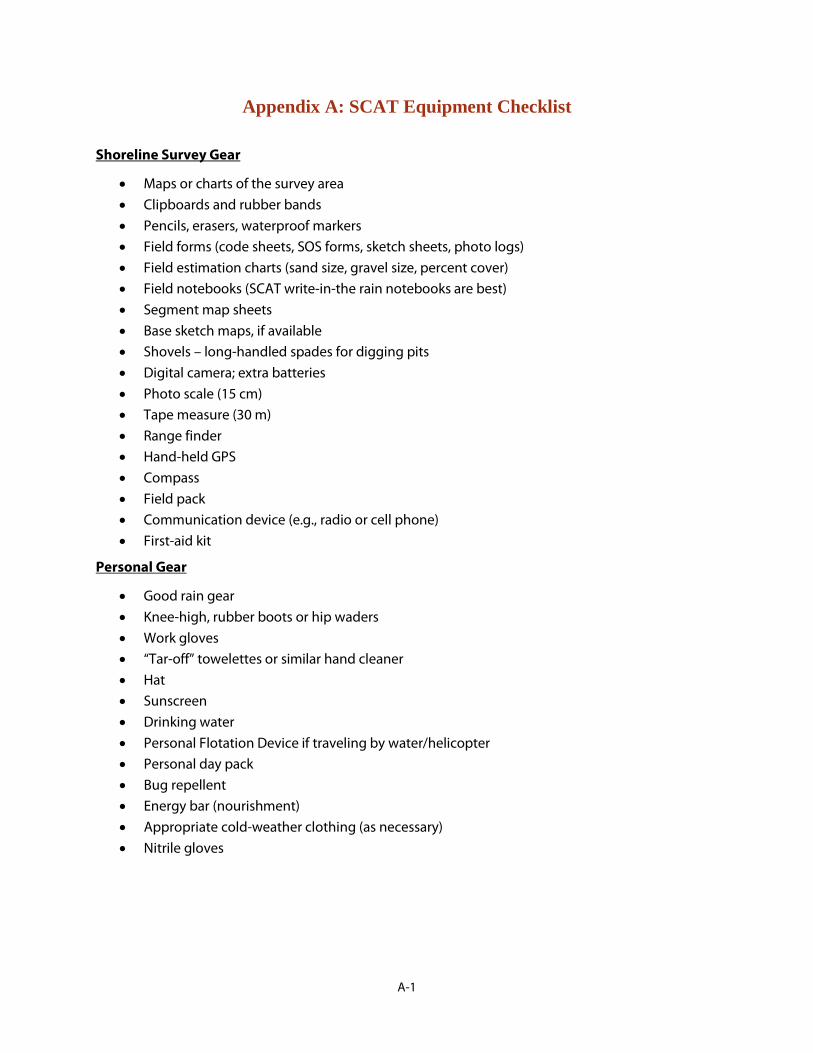
Appendix A: SCAT Equipment Checklist
Shoreline Survey Gear
• • • • • • • • • • • • • • • • • •
Maps or charts of the survey area Clipboards and rubber bands Pencils, erasers, waterproof markers Field forms (code sheets, SOS forms, sketch sheets, photo logs) Field estimation charts (sand size, gravel size, percent cover) Field notebooks (SCAT write-in-the rain notebooks are best) Segment map sheets Base sketch maps, if available Shovels – long-handled spades for digging pits Digital camera; extra batteries Photo scale (15 cm) Tape measure (30 m) Range finder Hand-held GPS Compass Field pack Communication device (e.g., radio or cell phone) First-aid kit
Personal Gear
• • • • • • • • • • • • •
Good rain gear Knee-high, rubber boots or hip waders Work gloves “Tar-off” towelettes or similar hand cleaner Hat Sunscreen Drinking water Personal Flotation Device if traveling by water/helicopter Personal day pack Bug repellent Energy bar (nourishment) Appropriate cold-weather clothing (as necessary) Nitrile gloves
A-1

Appendix B: Brief Descriptions of Shoreline Cleanup Methods
Introduction This section describes methods currently in use during cleanup of oil spills in marine environments and habitats. For each method the following is provided: a summary of the objective in using the method, a general description of the method, applicable habitat types, conditions under which the methods should be used (constraints commonly applied to the use of the method to protect sensitive biological resources), and the environmental effects expected from the proper use of the method. Some of the methods listed require special authorization for use during a spill; appropriate agencies must be contacted about the need for special approvals.
A problem which occurs after all major oil spills is that there is a large quantity of oily wastes and debris that is generated and must be dealt with as part of the response action. A cleanup strategy that minimizes the impact to all sensitive aspects of the environment and minimizes the amount of oily wastes is the most optimal. Each cleanup option should be examined with the problem of waste generation and disposal in mind.
Additional guidance for the application of shoreline cleanup methods appropriate for each shoreline type can be found in oil spill manuals and guidance documents by the International Maritime Organization, International Petroleum Industry Environmental Conservation Association, and NOAA (listed in the references section). Methods listed are:
Natural Recovery Steam Cleaning Barriers/Berms Sand Blasting Physical Herding Elasticity Modifiers Manual Oil Removal Herding Agents Mechanical Oil Removal Solidifiers Sorbents Surface Washing Agents Vacuum Nutrient Enrichment Debris Removal (Biostimulation) Sediment Reworking/Tilling Natural Microbe Seeding Vegetation Cutting/Removal (Bioaugmentation) Flooding In-situ Burning Low-Pressure, Ambient-Water Flushing High-Pressure, Ambient-Water Flushing Low-Pressure, Hot-Water Flushing High-Pressure, Hot-Water Flushing
B-1
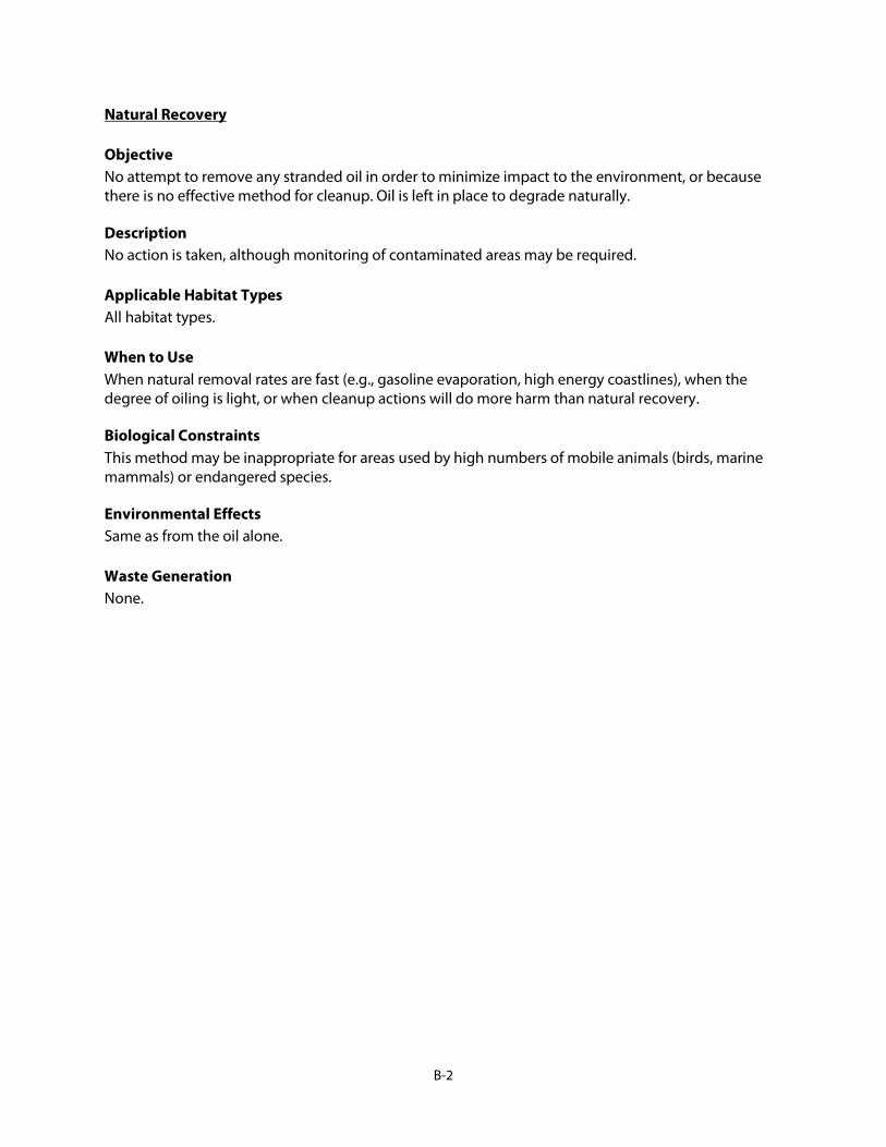
Natural Recovery
Objective No attempt to remove any stranded oil in order to minimize impact to the environment, or because there is no effective method for cleanup. Oil is left in place to degrade naturally.
Description No action is taken, although monitoring of contaminated areas may be required.
Applicable Habitat Types All habitat types.
When to Use When natural removal rates are fast (e.g., gasoline evaporation, high energy coastlines), when the degree of oiling is light, or when cleanup actions will do more harm than natural recovery.
Biological Constraints This method may be inappropriate for areas used by high numbers of mobile animals (birds, marine mammals) or endangered species.
Environmental Effects Same as from the oil alone.
Waste Generation None.
B-2

Barriers/Berms
Objective To prevent entry of oil into a sensitive area or to divert oil to a collection area.
Description A physical barrier (other than a boom) is placed across an area to prevent oil from passing. Barriers can consist of earthen berms, trenches, sand bags, wood/metal sheets, Hesco baskets, or filter fences. When it is necessary for water to pass because of water volume, underflow or overflow dams are used.
Applicable Habitat Types At the mouths of creeks or streams to prevent oil from entering, or to prevent oil in the creek from being released into offshore waters. Also, on beaches where a berm can be built above the high tide line to prevent oil from overwashing the beach and entering a sensitive back-beach habitat (e.g., lagoon).
When to Use When the oil threatens sensitive habitats and other barrier options are not feasible. However, where they are placed on shorelines exposed to wave action, they should be removed prior to storm activity.
Biological Constraints Responders must minimize disturbance to bird and sea turtle nesting areas, beaver dams, or other sensitive areas. Placement of dams and filter fences could cause excessive physical disruptions, particularly in wetlands.
Environmental Effects May disrupt or contaminate sediments and adjacent vegetation. The natural beach (or shore) profile should be restored (may take weeks to months on gravel beaches). Trenching may enhance penetration of oil and quantity of contaminated sediments. May require a permit from the U.S. Army Corps of Engineers.
Waste Generation Sediment barriers will become contaminated on the oil side and filter fence materials will have to be disposed of as oily wastes.
B-3

Physical Herding
Objective To free any oil trapped in debris or vegetation on water; to direct floating oil towards containment and recovery devices; or to divert oil from sensitive areas.
Description Plunging water jets, water or air hoses, and propeller wash can be used to dislodge trapped oil and divert or herd it to containment and recovery areas. May emulsify the oil. Mostly conducted from small boats, although larger boats such as tugs can be used to generate stronger currents or influence larger areas (such as oil trapped deep under piers).
Applicable Habitat Types In nearshore areas where there are little or no currents, and in and around man-made structures such as wharves and piers.
When to Use In low-current or stagnant water bodies, to herd oil toward recovery devices. In high-current situations, used to divert floating oil away from sensitive areas.
Biological Constraints When used near shore and in shallow water, must be careful not to disrupt bottom sediments or submerged aquatic vegetation.
Environmental Effects May generate high levels of suspended sediments and mix them with the oil, resulting in deposition of contaminated sediments in benthic habitats.
Waste Generation None.
B-4

Manual Oil Removal/Cleaning
Objective To remove oil with hand tools and manual labor.
Description Removal of surface oil using hands, rakes, shovels, buckets, scrapers, sorbents, pitch forks, etc., and placing in containers. No mechanized equipment is used except for transport of workers and collected oil and debris. Includes underwater recovery of submerged oil by divers, for example, with hand tools.
Applicable Habitat Types Can be used on all habitat types.
When to Use Light to moderate oiling conditions for stranded oil, or heavy oils on water or submerged on the bottom, that have formed semi-solid or solid masses and that can be picked up manually.
Biological Constraints Foot traffic over sensitive areas (wetlands, tidal pools, etc.) should be restricted or prevented. There may be periods when shoreline access should be avoided, such as during bird nesting. Special permission or archaeological monitoring will be needed to dig in areas with known cultural resources
Environmental Effects Minimal, if surface disturbance by responders and waste generation is controlled.
Waste Generation May generate significant quantities of oil mixed with sediment and debris which must be properly disposed of or treated. Decontamination of hand tools may produce oily wastewater that must be treated properly. Worker personal protective gear is usually disposed of daily or decontaminated and the resulting oily wastewater treated properly.
B-5

Mechanical Oil Removal
Objective To remove oil from shorelines, and bottom sediments using mechanical equipment.
Description Oil and oiled materials are collected and removed using mechanical equipment not specifically designed for pollution response, such as backhoes, graders, bulldozers, dredges, draglines, beach cleaners, etc. Requires systems for temporary storage, transportation, and final treatment and disposal of collected material.
Applicable Habitat Types On land, possible wherever surface sediments are both amenable to, and accessible by, heavy equipment. For submerged oil, used in sheltered areas where oil accumulates. On water, used on viscous or solid contained oil.
When to Use When large amounts of oiled materials must be removed. Care should be taken to remove sediments only to the depth of oil penetration, which can be difficult with heavy equipment. Should be used carefully where excessive sediment removal may erode the beach or shore. Mechanical removal of buried oil consists of the removal and sidecasting of clean overburden, removal of oiled sediments by either manual or mechanical methods, and the replacement of the clean overburden. Care is also needed to minimize further oil penetration from uncontrolled vehicle traffic.
Biological Constraints Heavy equipment use may be restricted in sensitive habitats (e.g., wetlands, soft substrates) or areas used by protected species. Special permission or archaeological monitoring will be needed to use equipment to excavate in areas with known cultural resources. Generation of high suspended sediment concentrations adjacent to seagrass beds or coral reef habitats may be prohibited. Access and work areas may be restricted, or traffic corridors designated, to prevent physical disturbance to adjacent, unoiled areas. The noise generated by the mechanical equipment may present a constraint as well.
Environmental Effects The equipment is heavy, with many support personnel required. May be detrimental if excessive sediments are removed without replacement. All organisms in the sediments will be affected, although the need to remove the oil may make this response method the best overall alternative. Resuspension of exposed oil and fine-grained, oily sediments can affect adjacent bodies of water.
Waste Generation Can generate large quantities of contaminated sediment and debris that must be treated or landfilled. The amount of waste generated by this cleanup option should be given careful consideration by response planners when reviewing potential environmental impacts of the oily wastes, debris, and residues.
B-6

Sorbents
Objective To remove surface oil by absorption by oleophilic (oil-attracting) material placed at the waterline or on treated surfaces. This method can also include use of loose, organic sorbents on oiled vegetated surfaces to reduce the risk of wildlife oiling.
Description Sorbent material is placed on the floating oil or water surface, allowing it to sorb oil or is used to wipe or dab stranded oil. Forms include sausage boom, pads, rolls, sweeps, snares, and loose granules or particles. These products can be synthetically produced or be natural substances. Efficacy depends on the capacity of the particular sorbent, wave or tidal energy available for lifting the oil off the substrate, and oil type and stickiness. Recovery of all sorbent material is mandatory. Loose, organic sorbents may be applied to the oil surface and lightly raked into the oil, then removed.
Applicable Habitat Types Can be used on any habitat or environment type. However, when deployed in areas exposed to wave action, they need to be firmly anchored or removed during storms, to prevent stranding on the shoreline, particularly along wetlands.
When to Use When oil is free-floating close to shore or stranded on shore. The oil must be able to be released from the substrate and sorbed by the sorbent. As a secondary treatment method after gross oil removal, and in sensitive areas where access is restricted. Selection of sorbent varies by oil type: heavy oils only coat surfaces, requiring a high surface area to be effective, whereas lighter oils can penetrate sorbent material.
Biological Constraints Access for deploying and retrieving sorbents should not adversely affect wildlife. Application in soft or sensitive habitats will require use of walking boards. Sorbents should not be used in a fashion that would endanger or trap wildlife. Sorbents left in place too long can break apart and present an ingestion hazard to wildlife.
Environmental Effects Physical disturbance of habitat during deployment and retrieval. Improperly deployed or tended sorbent material can crush or smother sensitive organisms.
Waste Generation Must be regularly collected for proper disposal, so care should be taken to select and use sorbents effectively. Prevent overuse and generation of large amounts of lightly oiled sorbents. Waste-to-energy should be emphasized rather than disposal.
B-7

Vacuum
Objective To remove oil pooled on a shoreline substrate or subtidal sediments.
Description A vacuum unit is attached via a flexible hose to a suction head that recovers free oil. The equipment can range from small, portable units that fill individual 55-gallon drums to large supersuckers that are truck- or vessel-mounted and can generate enough suction to lift large rocks. Removal rates from substrates can be extremely slow.
Applicable Habitat Types Any accessible habitat type. May be mounted on vessels (including airboats) for water-based operations, on trucks driven to the recovery area, or hand-carried to remote sites.
When to Use When oil is stranded on the substrate, pooled against a shoreline, concentrated in trenches or trapped in vegetation. Usually requires shoreline access points.
Biological Constraints Special restrictions should be established for areas where foot traffic and equipment operation may be damaging, such as soft substrates. Operations in wetlands must be very closely monitored, and a site-specific list of procedures and restrictions developed to prevent damage to vegetation, such as use of walking boards, monitoring to prevent excessive damage to vegetation and soils, and use in combination was low-pressure flushing to lift the oil off the substrate and vegetation.
Environmental Effects Minimal, if foot and vehicular traffic are controlled and minimal substrate/vegetation is damaged or removed.
Waste Generation Collected oil and or oil/water mix will need to be stored temporarily prior to recycling or disposal. Oil may be recyclable; if not, it will require disposal in accordance with local regulations. Large amounts of water are often recovered, requiring separation and treatment.
B-8

Debris Removal
Objective To remove debris in path of spill prior to oiling, and to remove contaminated debris from the shoreline and water surface.
Description Manual or mechanical removal of debris (driftwood, seaweed, trash, wreckage) from the shore or water surface. Can include cutting and removal of oiled logs.
Applicable Habitat Types Can be used on any habitat or environment type where access is safe.
When to Use When debris is heavily contaminated and provides a potential source of secondary oil release; an aesthetic problem; a source of contamination for other resources that use the area such as birds and small mammals; likely to clog skimmers; or likely to cause safety problems for responders. Used in areas of wrack accumulation on beaches prior to oiling to minimize the amount of oiled debris to be handled.
Biological Constraints Foot traffic over sensitive areas (wetlands, spawning grounds) must be restricted. May be periods when entry should be denied (spawning periods, influx of large numbers of migratory waterfowl). Debris may also be a habitat and an important source of prey (for example, shorebirds feeding in wrack on beaches). Unoiled or lightly oiled debris should not be removed.
Environmental Effects Physical disruption of substrate, especially when mechanized equipment must be deployed to recover a large quantity of debris.
Waste Generation Will generate contaminated debris (volume depends on what, and how much, is collected, e.g., logs, brush). Unless there is an approved hazardous waste incinerator that will take oily debris, burning will seldom be allowed, especially on-site burning. However, this option should still be explored, especially for remote locations, with the appropriate state or federal agencies that must give approvals for burning.
The advantage of pre-spill debris collections is that waste disposal requirements will likely be less restrictive than if the debris is oiled. Once oiled, the debris is likely to be handled as a hazardous waste.
B-9

Sediment Reworking/Tilling
Objective To break up oily sediments and surface oil deposits, increasing their surface area, and bringing deeper subsurface oil layers to the surface, thus enhancing the rate of degradation through aeration. Also, to increase the rate of sediment re-working by wave action.
Description The oiled sediments are roto-tilled, disked, or otherwise mixed using mechanical equipment or manual tools. Along beaches, oiled sediments may also be pushed to the lower intertidal zone to enhance natural cleanup by wave activity (surf washing). On gravel beaches, the process may be aided with high-volume flushing.
Applicable Habitat Types On any sedimentary substrate that can support mechanical equipment or foot traffic and hand tilling.
When to Use On sand to gravel beaches with subsurface oil, where sediment removal is not feasible (due to erosion or transportation and disposal problems). On sand beaches where the sediment is stained or lightly oiled. Also appropriate for sites where the oil is stranded above the normal high waterline, so that the sediments can be reworked by wave action.
Biological Constraints Avoid use on shores near sensitive wildlife habitats, such as fish-spawning areas or bird-nesting or concentration areas because of the potential for release of oil and oiled sediments into adjacent bodies of water. Should not be used adjacent to sensitive subtidal habitats such as shellfish beds, seagrass, or coral reefs.
Environmental Effects Mixing of oil into sediments could further expose organisms that live below the original layer of oil. Repeated reworking could delay re-establishing of these organisms. Refloated oil and oily suspended sediments from treated sites could contaminate adjacent waterbodies and shorelines.
Waste Generation None.
B-10

Vegetation Cutting/Removal
Objective To remove portions of oiled vegetation or oil trapped in vegetation to prevent oiling of wildlife or secondary oil releases.
Description Oiled vegetation is cut with weed trimmers, blades, etc., and picked or raked up and bagged for disposal. May require use of loose, organic sorbents to recover oil that is exposed and poses contact hazards to wildlife.
Applicable Habitat Types Habitats composed of vegetation, such as wetlands, seagrass beds, and kelp beds that contain emergent, herbaceous vegetation or floating, aquatic vegetation.
When to Use When the risk of oiled vegetation contaminating wildlife is greater than the value of the vegetation that is to be cut, and there is no less-destructive method that removes or reduces the risk to acceptable levels. Also, to remove thick oil residues under the oiled vegetation.
Biological Constraints Operations must be strictly monitored to minimize the degree of root destruction and mixing of oil deeper into the sediments. Any foot traffic on sensitive substrates will require use of walking boards. Access in bird-nesting areas should be restricted during nesting seasons. Cutting only the oiled portions of the plants and leaving roots and as much of the stem as possible minimizes impact to plants.
Environmental Effects Vegetation removal will destroy habitat for many animals. Cut areas will have reduced plant growth and, in some instances, plants may be killed. Cutting at the base of the plant stem may allow oil to penetrate the substrate, causing subsurface contamination. Along exposed sections of shoreline, the vegetation may not recover, resulting in erosion and habitat loss. Trampled areas will recover much more slowly.
Waste Generation Cut portions of oiled plants must be collected and disposed of properly.
B-11

Flooding/Deluge
Objective To lift and wash oil stranded on land to the water’s edge for collection.
Description A perforated header pipe or hose is placed above the oiled shore or bank. Ambient-temperature water is pumped through the header pipe at low pressure and flows downslope to the water where any released oil is trapped by booms and recovered by skimmers or other suitable equipment. On porous sediments, water flows through the substrate, pushing loose oil ahead of it. On saturated, fine-grained sediments, the technique becomes more of a surface oil lifting and flushing.
Applicable Habitat Types All shoreline types where the equipment can be effectively deployed. Not effective in steep intertidal areas.
When to Use In heavily oiled areas when the oil is still fluid and adheres loosely to the substrate, and where oil has penetrated into gravel sediments. This method is frequently used with other washing techniques (low- or high-pressure, cold-to-hot-water flushing).
Biological Constraints Special care should be taken to recover oil where nearshore habitats contain rich biological communities. Not appropriate for soft, muddy substrates.
Environmental Effects Habitat may be physically disturbed by foot traffic during operations and smothered by sediments washed down the slope. If containment methods are not sufficient, oil and oiled sediments may be flushed into adjacent areas. Flooding may cause sediment loss and erosion of the shoreline and shallow rooted vegetation. Oiled sediment may be transported to nearshore areas, contaminating them and burying benthic organisms.
Waste Generation Depends on the effectiveness of the collection method.
B-12

Low-Pressure, Ambient-Water Flushing
Objective To remove fluid oil that has adhered to the substrate or man-made structures, pooled on the surface, or become trapped in vegetation.
Description Ambient-temperature water is sprayed at low pressures (<10 pounds per square inch [psi] or <72 kilopascals [kpa]), usually from hand-held hoses, to lift oil from the substrate and float it to the water’s edge for recovery by skimmers, vacuum, or sorbents. Can be conducted from barges with long-reach spray systems. Usually used with a flooding system to prevent released oil from re-adhering to the substrate downstream of the treatment area.
Applicable Habitat Types On sediment substrates, riprap, and solid, man-made structures, where the oil is still fluid. In wetlands and along vegetated banks where oil is trapped in vegetation.
When to Use Where fluid oil is stranded onshore or floating on shallow intertidal areas.
Biological Constraints May need to restrict use so that the oil/water effluent does not drain across sensitive intertidal habitats, and that mobilized sediments do not affect rich subtidal communities. Use from boats will reduce the need for foot traffic in soft substrates and vegetation. Flushed oil must be recovered to prevent further oiling of adjacent areas.
Environmental Effects If containment methods are not sufficient, oil and oiled sediments may be flushed into adjacent areas. Flooding may cause sediment loss and erosion of the shoreline and shallow rooted vegetation. Some trampling of substrate and attached biota may occur.
Waste Generation Depends on the effectiveness of the collection method.
B-13

High-Pressure, Ambient-Water Flushing
Objective To remove oil that has adhered to hard substrates or man-made structures.
Description Similar to low-pressure flushing, except that water pressure is 100-1,000 psi (720-7,200 kpa). High-pressure spray will more effectively remove sticky or viscous oils. If low water volumes are used, sorbents are placed directly below the treatment area to recover the oil.
Applicable Habitat Types On bedrock, man-made structures, and gravel substrates.
When to Use When low-pressure flushing is not effective at removing adhered oil, which must be removed to prevent continued oil release or for aesthetic reasons. When a directed water jet can remove oil from hard-to-reach sites.
Biological Constraints May need to restrict flushing so that the oil does not drain across sensitive habitats. Flushed oil must be recovered to prevent further oiling of adjacent areas. Should not be used directly on attached algae nor rich, intertidal areas.
Environmental Effects All attached animals and plants in the direct spray zone will be removed, even when used properly. May drive oil deeper into the substrate or erode fine sediments from shorelines if water jet is improperly applied. If containment methods are not sufficient, oil and oiled sediments may be flushed into adjacent areas. Some trampling of substrate and attached biota will occur.
Waste Generation Depends on the effectiveness of the collection method.
B-14

Low-Pressure, Hot-Water Flushing
Objective To remove non-liquid/non-fluid oil that has adhered to the substrate or man-made structures, or pooled on the surface.
Description Hot water (90°F [32°C] up to 170°F [75°C]) is sprayed with hoses at low pressures (<10 psi [<72 kpa]) to liquefy and lift oil from the substrate and float it to the water’s edge for recovery by skimmers, vacuums, or sorbents. Used with flooding to prevent released oil from re-adhering to the substrate.
Applicable Habitat Types On bedrock, sand to gravel substrates, and man-made structures.
When to Use Where heavy, but relatively fresh, oil is stranded onshore. The oil must be heated above its pour point so it will flow. Less effective on sticky oils.
Biological Constraints Avoid wetlands or rich intertidal communities so that the hot oil/water effluent does not contact sensitive habitats. Operations from boats will help reduce foot traffic in soft substrates and vegetation. Flushed oil must be recovered to prevent further oiling of adjacent areas. Should not be used directly on attached algae or in rich, intertidal areas.
Environmental Effects Hot water contact can kill attached animals and plants. If containment methods are not sufficient, oil may be flushed into adjacent areas. Flooding may cause sediment loss and erosion of the shoreline and shallow rooted vegetation. Some trampling of substrate and biota will occur.
Waste Generation Depends on the effectiveness of the collection method.
B-15

High-Pressure, Hot-Water Flushing
Objective To mobilize weathered and viscous oil strongly adhered to surfaces.
Description Hot water (32°C up to 77°C) is sprayed with hand-held wands at pressures greater than 720 kpa. If used without water flooding, this procedure requires immediate use of vacuum or sorbents to recover the oil/water runoff. When used with a flooding system, the oil is flushed to the water surface for collection by skimmers, vacuum, or sorbents.
Applicable Habitat Types Gravel substrates, bedrock, and man-made structures.
When to Use When oil has weathered to the point that warm water at low pressure no longer effectively removes oil. To remove viscous oil from man-made structures for aesthetic reasons.
Biological Constraints Use should be restricted so that the oil/water effluent does not drain across sensitive habitats (damage can result from exposure to oil, oiled sediments, and hot water). Should not be used directly on attached algae nor rich intertidal areas. Released oil must be recovered to prevent further oiling of adjacent habitats.
Environmental Effects All attached animals and plants in the direct spray zone will be removed or killed, even when used properly. Oiled sediment may be transported to shallow nearshore areas, contaminating them and burying benthic organisms.
Waste Generation Depends on the effectiveness of the collection method.
B-16

Steam Cleaning
Objective To remove heavy residual oil from solid substrates or man-made structures.
Description Steam or very hot water (171°F [77°C] to 212°F [100°C]) is sprayed with hand-held wands at high pressure (2,000 psi [14,400 kpa]). Water volumes are very low compared to flushing methods.
Applicable Habitat Types Man-made structures such as seawalls and riprap.
When to Use When heavy oil residue must be removed for aesthetic reasons, and when hot-water flushing is not effective, and limited biota are present on the treatment area.
Biological Constraints Not to be used in areas of soft substrates, vegetation, nor high biological abundance directly on, or below, the structure.
Environmental Effects Complete destruction of all organisms in the spray zone. Difficult to recover all released oil. If containment methods are not sufficient, oil may be flushed into nearshore areas.
Waste Generation Depends on the effectiveness of the collection method. Usually sorbents are used, generating significant waste volumes.
B-17

Sand Blasting
Objective To remove heavy residual oil from solid substrates or man-made structures.
Description Use of sandblasting equipment to remove oil from the substrate. May include recovery of used (oiled) sand.
Applicable Habitat Types On heavily oiled bedrock and artificial structures such as seawalls and riprap.
When to Use When heavy oil residue must be cleaned for aesthetic reasons, and even steam cleaning is not effective.
Biological Constraints Not to be used in areas of soft substrates, vegetation, nor high biological abundance directly below, or adjacent to, the structures.
Environmental Effects Complete destruction of all organisms in the blast zone. Possible smothering of organisms by sand in adjacent areas. Unrecovered, used sand will introduce oiled sediments into the adjacent habitat. Oiled sediment may be transported to shallow nearshore areas, contaminating them and burying benthic organisms.
Waste Generation Will need to recover and dispose of oiled sand used in blasting.
B-18

Elasticity Modifiers
Objective To impart visco-elastic properties to floating oil, thereby increasing skimming rates.
Description The liquid product is applied at a rate of 1:13 to 1:150 product:oil ratio, depending on the oil type. Some mixing is required and is usually provided by the water spray during application. Treated oil is gelatinous, or semi-solid, but still fluid; there is no chemical change in the oil. The primary purpose is to increase skimmer efficiency removal rates while minimizing water recovery amounts. Increases the efficiency of some skimmers, but may clog other skimmers, pumps, and storage containers.
Applicable Habitat Types On all water environments where oil can be contained for skimming. Not for use on wetlands nor debris because of increased adhesive properties of the treated oil.
When to Use When skimmer efficiency is low. Must be used with booming or other physical containment. Ideal for use on this slicks of light refined oils that are very difficult to recover with mechanical equipment or sorbents. Requires RRT approval for use.
Biological Constraints Not suitable for vegetated shores or where there is extensive debris mixed in the oil. Should be avoided when birds or other wildlife cannot be kept away from the treated oil.
Environmental Effects May increase the smothering effect of oil on organisms; therefore, the treatment should be considered only where recovery of the treated oil is likely.
Waste Generation If skimming efficiency is increased, will reduce the volume of water in oil/water collections. Effects on recycling of oil treated with elasticity modifiers is unknown.
B-19

Surface Collecting Agents
Objective To collect or herd oil into a smaller area and thicker slick in order to increase recovery. Can be used to herd oil away from sensitive areas or to help keep oil contained when it is necessary to move a boom.
Description These agents, which are insoluble surfactants and have a high spreading pressure, are applied in small quantities (1-2 gallons per lineal mile [2.5-5 liters per lineal kilometer]) to the clean water surrounding the edge of a fresh oil slick. They contain the oil, prevent spreading, but do not hold the spill in place. Hand-held or vessel-mounted systems can be used. Must be applied early in spill, when oil is still fluid.
Applicable Habitat Types On all still water environments.
When to Use Potential use for collection and protection. For collection, used to push slicks out from under docks and piers where it has become trapped, or in harbors where the equipment is readily accessible for use early in the spill. For protection in low-current areas, used to push slicks away from sensitive resources such as wetlands. Also used in ice environments to thicken oil. Not effective in fast currents, rough seas, or rainfall.
Biological Constraints Not suitable for use in very shallow water or fish-spawning areas.
Environmental Effects Direct acute toxicity to surface-layer organisms possible, though available products vary greatly in their aquatic toxicity.
Waste Generation Same as for manual oil recovery.
B-20

Solidifiers
Objective To change the physical state of spilled oil from a liquid to a solid to increase recovery rates.
Description Chemical agents (polymers) are applied to oil at rates of 10-50 percent or more, solidifying the oil in minutes to hours. Various broadcast systems, such as leaf blowers, water cannons, or fire suppression systems, can be modified to apply the product over large areas. Can be applied to both floating and stranded oil. Mixing is usually needed and can be done with a strong water spray. Can be placed in booms, pads, pillows, and socks and used like a sorbent.
Applicable Habitat Types All water environments, bedrock, sediments, and artificial structures.
When to Use To immobilize the oil prevent refloating from a shoreline, penetration into the substrate, or further spreading. However, the oil may not fully solidify unless the product is well mixed with the oil, and may result in a mix of solid and untreated oil. Generally not used on heavy oil spills that are already viscous. Requires RRT approval.
Biological Constraints Must be able to recover all treated material.
Environmental Effects Available products are insoluble and have very low aquatic toxicity. Unrecovered solidified oil may have longer impact because of slow weathering rates. Physical disturbance of habitat may occur during application and recovery in soft sediments where foot traffic is used.
Waste Generation If skimming efficiency is increased, solidifiers may reduce the volume of water collected during oil recovery. Oil treated with solidifiers is typically disposed of in landfills.
B-21

Surface Washing Agents
Objective To increase the efficiency of oil removal from contaminated substrates.
Description Special formulations are applied to the substrate, as a presoak and/or flushing solution, to soften or lift weathered or heavy oils from the substrate to enhance flushing methods. The intent is to lower the water temperature and pressure required to mobilize the oil from the substrate during flushing. Some agents will disperse the oil as it is washed off the beach, others will not.
Applicable Habitat Types On any habitat where water flooding and flushing procedures are applicable. Has been used to increase the removal of oil adhered to vegetation.
When to Use When the oil has weathered to the point where it cannot be removed using ambient water temperatures and low pressures. This approach may be most applicable where flushing effectiveness decreases as the oil weathers. Requires RRT approval for use.
Biological Constraints When the product does not disperse the oil into the water column, the released oil must be recovered from the water surface. Use should be restricted so that the oil/water effluent does not drain across sensitive habitats. Other concerns are where suspended sediment concentrations are high, near wetlands, and near sensitive nearshore resources.
Environmental Effects The toxicity and effects on dispersability of treated oil vary widely among products. Selection of a product should take into consideration the toxicity of the product.
Waste Generation Because treated oil must be recovered, waste generation is a function of recovery method, which often includes sorbents.
B-22

Nutrient Enrichment (Biostimulation)
Objective To accelerate the rate of oil degradation due to natural microbial processes by adding nutrients (generally nitrogen and phosphorus) that stimulate microbial growth.
Description Liquid products are diluted in water and applied with spray or injection systems. Dry products may be applied by hand or spray systems. Oleophilic fertilizers are sprayed neat directly on the oiled surface. The frequency of nutrient addition is determined by monitoring pore water so that the nitrate-N concentration are in the range of 2-10 milligrams per liter. Regular tilling or other means of aeration may be needed to maintain minimum oxygen levels, break up the oil residues, and mix the nutrients with the oiled sediments.
Applicable Habitat Types On any shoreline habitat type where access is allowed and nutrients are deficient.
When to Use Only when nutrients are limiting the rates of natural microbial degradation. On moderately to heavily oiled substrates, after other techniques have been used to remove free product; on lightly oiled shorelines, where other techniques are destructive or ineffective; and where nutrients limit natural attenuation. Most effective on light to medium crude oils and fuel oils. Less effective where oil residues are thick. Not considered for gasoline spills, which evaporate rapidly. Fertilizers can increase the growth of vegetation, which could speed the oil degradation by phyto-remediation. Biodegradation of hydrocarbons requires: oil-degrading microbes (which naturally occur in the coastal and marine environment), nutrients (nitrogen and phosphorus), oxygen, moisture, and time, any of which can be limiting. Requires RRT approval for use.
Biological Constraints Avoid using ammonia-based fertilizers at highly elevated concentrations because un-ionized ammonia is toxic to aquatic life at very low levels. Nitrate is an equally good nitrogen source, minus the ecotoxicity. If nutrients are applied properly with monitoring, eutrophication should not be a problem. Only nutrient additives proven to be nontoxic and effective in either the lab or the field should be used. Check fertilizers for their metal content because some common products contain relatively high levels of metals. Contact toxicity of oleophilic nutrients may restrict their use, as other chemicals in the product could be more toxic to aquatic organisms in the presence of oil.
Environmental Effects Detrimental effects to shoreline from foot or vehicle traffic caused by workers applying nutrients (unless nutrients are sprayed from a vessel or aircraft). No wastes generated.
B-23

Natural Microbe Seeding (Bioaugmentation)
Objective A form of bioremediation used to accelerate natural microbial degradation of oil by adding high numbers of oil-degrading microorganisms.
Description Formulations containing specific hydrocarbon-degrading microbes are added to the oiled area because indigenous hydrocarbon degraders are low in number, or those that are present cannot degrade the oil effectively. Because microbes require nitrogen and phosphorus to convert hydrocarbons to biomass, formulations containing these oil degraders must also contain adequate nutrients. Bioaugmentation has not been demonstrated in the scientific literature to be effective on marine and coastal oil spills.
Bioaugmentation appears less effective than biostimulation because: 1) hydrocarbon degraders are ubiquitous in nature and, when an oil spill occurs at a given site, the influx of oil will cause an immediate increased response in the hydrocarbon degrading populations; but, 2) if nutrients are in limited supply, the rate of oil biodegradation will be less than optimal; thus, 3) supplying nutrients will enhance the process initiated by the spill, but adding microorganisms will not, because they still lack the necessary nitrogen and phosphorus to support growth.
Applicable Habitat Types Insufficient information on impacts or effectiveness to make a judgment on habitat.
When to Use There is insufficient information on impact or effectiveness of this method to make a judgment on when to use it. Requires RRT approval for use.
Biological Constraints Avoid using ammonia-based fertilizers adjacent to water bodies because un-ionized ammonia is toxic to aquatic life at very low levels. Nitrate is an equally good nitrogen source, minus the ecotoxicity. If the product containing nutrients is applied properly with adequate monitoring, eutrophication should not be a problem; however, toxicity tests should be evaluated carefully, as other chemicals in the product would be toxic to aquatic organisms.
Environmental Effects Detrimental physical effects to shoreline from foot or vehicle traffic cause by workers applying bioaugmentation product (unless nutrients are applied from a vessel or aircraft). No wastes generated.
B-24

In-situ Burning
Objective To remove oil from the water surface or habitat by burning the oil in place.
Description Oil floating on the water surface is collected into slicks at least 2-3 mm thick and ignited. The oil can be contained in fire-resistant booms, or by natural barriers such as ice or the shoreline. On land, oil can be burned when it is on a combustible substrate such as vegetation, logs, or other debris. Oil can be burned from non-flammable substrates using a burn promoter. On sedimentary substrates, it may be necessary to dig trenches for oil to accumulate in pools to a thickness that will sustain burning. Heavy oils are more difficult to ignite but can sustain a burn once ignited. Emulsified oils may not ignite or sustain a burn when the water content is great than about 25%. Where sinking of the burn residue is of concern, it may be possible to collect the burn residues while they are still hot and buoyant.
Applicable Habitat Types On most habitats except dry, muddy substrates where heat may impact the biological productivity of the habitat. May increase oil penetration into permeable substrate. Generally not suitable for woody vegetation such as mangroves and hardwood swamps.
When to Use On floating slicks, early in the spill event when the oil can be kept thick enough to sustain the burn. Removal rates of 50,000 gallons per hour can be achieved for a burn area of 10,000 square feet (930 square meters). On land, where there is heavy oil in areas neither amendable nor accessible to physical removal, and the oil must be removed quickly. Under ideal condition, removal efficiencies can exceed 90%. There are many potential applications for spills in ice. Requires RRT approval for use during coastal and marine spills.
Biological Constraints Most biota in the burn area will be impacted. The possible effects of smoke on wildlife and populated areas should be evaluated. In vegetated and mud habitats, a water layer will minimize impacts to sediments and roots
Environmental Effects Temperature and air quality effects are likely to be localized and short-lived. Toxicological impact from burn residues may be of concern, depending on the oil type and amount of residue. On-water, burn residues are likely to sink. Studies have predicted that ~50% of international crudes would sink in seawater after cooling. On land, removal of residues and unburned oil is often necessary for crude and heavy oils. The success of the burn in vegetated habitats is a function of the season of the burn, vegetation type, and water level at the time of the burn.
Waste Generation Any residues remaining after burning will need to be collected and landfilled, but with an efficient burn will be a small fraction of the original oil volume.
B-25

Appendix C: Shoreline Descriptors, Including Oil Behavior and Response Considerations
EXPOSED ROCKY SHORES ESI =1A Description
•
•
•
•
The intertidal zone is steep (greater than 30 degree slope) and narrow with very little width Sediment accumulations are uncommon and usually ephemeral, because waves remove the debris that has slumped from the eroding cliffs There is strong vertical zonation of intertidal biological communities Species density and diversity vary greatly, but barnacles, snails, mussels, seastars, limpets, sea anemones, shore crabs, polychaetes, and macroalgae can be abundant
Predicted Oil Behavior • • • •
Oil is held offshore by waves reflecting off the steep, hard surfaces Any oil that is deposited is rapidly removed from exposed faces The most resistant oil would remain as a patchy band at or above the high tide line Impacts to intertidal communities are expected to be short-term; an exception would be where heavy concentrations of a light refined product came ashore very quickly
Response Considerations • •
Cleanup is usually not required Access can be difficult and dangerous
EXPOSED, SOLID MAN-MADE STRUCTURES ESI =1B Description
•
•
•
•
•
These are solid, man-made structures such as seawalls, groins, revetments, piers, and port facilities Many structures are constructed of concrete, wood, or metal They are built to protect the shore from erosion by waves, boat wakes, and currents, and thus are exposed to rapid natural removal processes Often there is no exposed substrate at low tide, but multiple habitats are indicated if present Attached animals and plants are sparse to common
Predicted Oil Behavior • • •
Oil is held offshore by waves reflecting off the steep, hard surface in exposed settings Oil readily adheres to the dry, rough surfaces, but it does not adhere to wet substrates The most resistant oil would remain as a patchy band at or above the high tide line
C-1

Response Considerations • •
Cleanup is usually not required High-pressure water spraying may be conducted to remove risk of contamination of people or vessels, or to improve aesthetics
EXPOSED WAVE-CUT PLATFORMS IN BEDROCK ESI = 2A Description
•
•
•
•
•
•
These shores consist of a bedrock shelf or platform of highly variable width and very gentle slope The surface of the platform is irregular; tidal pools are common The shoreline may be backed by a steep scarp or low bluff There may be a perched beach of sand- to boulder-sized sediments at the base of the scarp Small accumulations of gravel can be found in the tidal pools and crevices in the platform These habitats can support large populations of encrusting animals and plants, with rich tidal pool communities; barnacles, snails, mussels, and macroalgae are often abundant
Predicted Oil Behavior •
•
Oil will not adhere to the rock platform, but rather be transported across the platform and accumulate along the high tide line Persistence of oiled sediments is usually short-term, except in wave shadows or where the oil was deposited high above normal wave activity
Response Considerations • •
Cleanup is usually not required Where the high tide area is accessible, it may be feasible to remove heavy oil accumulations and oiled debris
EXPOSED SCARPS AND STEEP SLOPES IN CLAY ESI = 2B Description
•
•
•
•
•
These habitats generally occur along exposed wetlands and major river tributaries in the marsh where the currents cut a steep bank into the marsh soils Scarp heights vary from about 0.3 to 1 m and usually consist of a heavily rooted, peaty soil May be fronted by a narrow beach of fine to medium-grained sand and/or shell fragments Low biological utilization because of eroding banks Typically backed by wetland vegetation
C-2

Predicted Oil Behavior • •
Oil is not expected to adhere to the wet, impermeable clay surface There may be a thin band of oil left at or above the high water line
Response Considerations • •
Cleanup is usually not required, because any stranded oil is quickly removed by wave action Access may be difficult
FINE- TO MEDIUM-GRAINED SAND BEACHES ESI = 3A Description
•
•
•
•
These beaches are flat to moderately sloping and relatively hard packed There can be heavy accumulations of wrack present They are utilized by birds and sea turtles for nesting Upper beach fauna include ghost crabs and amphipods; lower beach fauna can be moderate, but highly variable
Predicted Oil Behavior • •
• •
•
•
Light oil accumulations will be deposited as oily swashes or bands along the upper intertidal zone Heavy oil accumulations will cover the entire beach surface; oil will be lifted off the lower beach with the rising tide Maximum penetration of oil into fine- to medium-grained sand is about 10-15 cm Burial of oiled layers by clean sand within the first week after a spill typically will be less than 30 cm along the upper beach face Organisms living in the beach sediment may be killed by smothering or lethal oil concentrations in the interstitial water Biological impacts include temporary declines in infauna, which can affect shorebird foraging areas
Response Considerations • •
•
•
•
These beaches are among the easiest shoreline types to clean Cleanup should concentrate on removing oil and oily debris from the upper swash zone once oil has come ashore Manual cleanup, rather than road graders and front-end loaders, is advised to minimize the volume of sand removed from the shore and requiring disposal All efforts should focus on preventing the mixing of oil deeper into the sediments by vehicular and foot traffic Mechanical reworking of lightly oiled sediments from the high tide line to the middle intertidal zone can be effective along beaches
C-3

SCARPS AND STEEP SLOPES IN SAND ESI = 3B Description
•
•
•
•
Occurs where sandy bluffs are undercut by waves or currents and slump Some scarps are fronted by narrow beaches, if the erosion rates are moderate and episodic Trees growing at the top of these slopes are eventually undercut and the logs can accumulate at the base of the scarp Biological utilization by birds and infauna is low
Predicted Oil Behavior •
• •
Any stranded oil will concentrate at the high-water line and may penetrate sandy sediments Oil will also adhere to the dry surfaces of any logs that have accumulated at the base of the scarp There is little potential for burial except when major slumping of the bluff occurs
Response Considerations • •
•
In many cases, cleanup is not necessary because of the short residence time of the oil The need for removal of oiled sediments and debris should be carefully evaluated because of the potential for increased erosion Closely supervised manual labor should be used so that the minimal amount of material is removed during cleanup
COARSE-GRAINED SAND BEACHES ESI = 4 Description
•
•
These beaches are moderate sloping, of variable width, and have soft sediments. These characteristics combine to lower their trafficability Generally species density and diversity is lower than on fine-grained sand beaches
Predicted Oil Behavior •
•
• • • •
During small spills, oil will be deposited primarily as a band along the high tide line Under very heavy accumulations, oil may spread across the entire beach face, though the oil will be lifted off the lower beach with the rising tide Penetration of oil into coarse-grained sand can reach 25 cm Burial of oiled layers by clean sand can be as rapid as one tidal cycle and to depths of 60 cm or more Burial to depths over 1m is possible if the oil comes ashore at the start of a depositional period Biological impacts include temporary declines in infaunal populations, which can also affect important shorebird foraging areas
Response Considerations • Cleanup should concentrate on removing oil and oily debris from the upper swash zone once oil has
come ashore
C-4

•
• •
Manual cleanup, rather than road graders and front-end loaders, is advised to minimize the volume of sand removed from the shore and requiring disposal Efforts should focus on preventing mixing of oil deeper into the sediments by vehicular and foot traffic Mechanical reworking of lightly oiled sediments from the high tide line to the middle intertidal zone can be effective along beaches
MIXED SAND AND GRAVEL BEACHES ESI = 5 Description
•
•
•
•
Because of the mixed sediment sizes, there may be zones of pure sand, pebbles, or cobbles There can be large-scale changes in the sediment distribution patterns depending upon season, because of the transport of the sand offshore during storms Because of sediment mobility and desiccation, exposed beaches tend to have low densities of attached animals and plants Presence of attached algae, mussels, and barnacles indicates beaches that are relatively sheltered, with the more stable substrate supporting a richer biota
Predicted Oil Behavior • • •
•
•
During small spills, oil will be deposited along and above the high-tide swash Large spills will spread across the entire intertidal area Oil penetration into the beach sediments may be up to 50 cm; however, the sand fraction can be quite mobile, and oil behavior is much like on a sand beach if the sand fraction exceeds about 40 percent Burial of oil may be deep at and above the high tide line, where oil tends to persist, particularly where beaches are only intermittently exposed to waves In sheltered pockets on the beach, pavements of asphalted sediments can form if there is no removal of heavy oil accumulations because most of the oil remains on the surface
Response Considerations • • • •
•
•
Remove heavy accumulations of pooled oil from the upper beach All oiled debris should be removed; sediment removal should be limited as much as possible Sediment removal should be limited as much as possible Low-pressure flushing can be used to float oil away from the sediment for recovery by skimmers or sorbents. High-pressures should be avoided because of potential for transporting contaminated finer sediment (sand) to the lower intertidal or subtidal zones. Mechanical reworking of oiled sediments from the high tide zone to the middle intertidal zone can be effective in areas regularly exposed to wave activity. Oiled sediments should not be relocated below the mid-tide zone In-place tilling may be used to reach deeply buried oil layers on exposed beaches
C-5

GRAVEL BEACHES ESI = 6A Description
•
•
•
•
Gravel beaches are composed of sediments ranging in size from pebbles to boulders They can be very steep, with multiple, wave-built berms forming the upper beach Attached biota are usually restricted to the lowest parts of the beach, where the sediments are less mobile The presence of attached biota indicates beaches that are relatively sheltered, with the more stable substrate supporting richer biological communities
Predicted Oil Behavior • •
•
•
Stranded oil is likely penetrate deeply into gravel beaches because of their high permeability On exposed beaches, oil can be pushed over the high tide and storm berms, pooling and persisting above the normal zone of wave wash Long-term persistence will be controlled by the depth of penetration versus the depth of routine reworking by storm waves On sheltered portions of beaches, chronic sheening and formation of asphalt pavements is likely where accumulations are heavy
Response Considerations • • • •
•
•
Heavy accumulations of pooled oil should be removed quickly from the upper beach All oiled debris should be remove Sediment removal should be limited as much as possible Low- to high-pressure flushing can be used to lift oil from the sediments for recovery by skimmers or sorbents Mechanical reworking of oiled sediments from the high tide zone to the middle intertidal zone can be effective in areas regularly exposed to wave activity (as evidenced by storm berms). Oiled sediments should not be relocated below the mid-tide zone In-place tilling may be used to reach deeply buried oil layers on exposed beaches
RIPRAP ESI = 6B Description
•
•
•
•
Riprap structures are composed of cobble- to boulder-sized blocks of rock, concrete, etc. Riprap structures are used as revetments and groins for shoreline protection and breakwaters and jetties around inlets and marinas Attached biota are sparse at the upper intertidal zone, but more common in the lower intertidal They are common in highly developed waterfront areas
C-6

Predicted Oil Behavior • • •
Deep penetration of oil between the blocks is likely, with oiling of trapped debris Oil adheres readily to the rough surfaces of the blocks Uncleaned oil can cause chronic leaching until the oil hardens
Response Considerations •
• •
When the oil is fresh and liquid, high-pressure spraying and/or water flooding may be effective if all liberated oil is recovered Heavy and weathered oils are more difficult to remove, requiring scraping and/or hot-water spraying Removal of oiled debris deep in the crevices will be difficult
EXPOSED TIDAL FLATS ESI = 7 Description
•
•
•
• •
Exposed tidal flats are broad, flat intertidal areas composed primarily of sand and minor amounts of shell, gravel, or mud The presence of sand indicates that tidal currents and waves are strong enough to mobilize the sediments They are usually associated with another shoreline type on the landward side of the flat, though they can occur as separate shoals; they are commonly associated with tidal inlets The sediments are water saturated, with only the higher ridges drying out during low tide Biological utilization can be very high, with large numbers of infauna, heavy use by birds for roosting and foraging, and use by foraging fish
Predicted Oil Behavior • Oil does not usually adhere to the surface of exposed tidal flats, but rather moves across the flat and
accumulates at the high-tide line• Deposition of oil on the flat may occur on a falling tide if concentrations are heavy• Oil does not penetrate water-saturated sediments, but may penetrate the tops of the ridges and coat
gravel/shell• Biological damage may be severe, primarily to infauna, reducing food sources for birds and fish
Response Considerations • Currents and waves can be very effective in natural removal of the oil• Cleanup can be done only during low tide, thus there is a narrow window of opportunity• Use of machinery should be restricted to prevent mixing of oil into the sediments• Manual removal methods are preferred, though worker access may be difficult
C-7

SHELTERED ROCKY SHORES ESI = 8A Description
•
•
•
These shores are characterized by a rocky substrate that can vary widely in permeability. Of particular concern are rocky shores that have a semi-permeable veneer of angular rubble overlying the bedrock The wider shores may have some surface sediments, but the bedrock is the dominant substrate type Species density and diversity vary greatly, but attached biota may be present at high densities at lower tidal elevations
Predicted Oil Behavior • •
•
•
Oil will adhere readily to the rough rocky surface, forming a distinct oil band along the high tide line Even on wide ledges, the lower intertidal zone usually stays wet (particularly when algae covered), preventing oil from adhering to the rock surface Heavy and weathered oils can cover the upper zone with little impacts to the rich biological communities of the lower zone Where the rubble is loosely packed, oil will penetrate deeply, causing long-term contamination of the subsurface sediments
Response Considerations • •
•
Low- to high-pressure spraying at ambient water temperatures is most effective when the oil is fresh Extreme care must be taken not to spray in the biologically rich lower intertidal zone or when the tidal level reaches that zone Do not cut oiled, attached algae; use sorbents to recover oil as it is remobilized by tidal action
SHELTERED, SOLID MAN-MADE STRUCTURES ESI = 8B Description
•
•
• •
These are structures such as seawalls, groins, revetments, piers, and port facilities, constructed of concrete, wood, or metal Most of the structures are designed to protect a single lot, thus their composition, design, and condition are highly variable Often there is no exposed shore at low tide There can be dense attachments of animal and plant life
Predicted Oil Behavior • •
Oil will adhere readily to rough surfaces, particularly along the high tide line, forming a distinct oil band The lower intertidal zone usually stays wet (particularly if algae covered), preventing oil from adhering to the surface
C-8

Response Considerations • •
Cleanup of seawalls is usually conducted for aesthetic reasons or to prevent leaching of oil Low- to high-pressure spraying at ambient water temperatures is most effective when the oil is fresh
SHELTERED TIDAL FLATS ESI = 9A Description
•
•
•
•
•
Sheltered tidal flats are composed of mud with minor amounts of sand and shell They are present in calm-water habitats, sheltered from major wave activity, and frequently backed by marshes The sediments are very soft and cannot support even light foot traffic in many areas Large concentrations of bivalves, worms, and other invertebrates are in the sediments They are heavily utilized by birds for feeding
Predicted Oil Behavior •
• •
•
•
Oil does not usually adhere to the surface of sheltered tidal flats, but rather moves across the flat and accumulates at the high-tide line Oil can strand on the flat during a falling tide if concentrations are heavy Oil will not penetrate the water-saturated sediments, but could penetrate burrows or other crevices in muddy sediments In areas of high suspended sediments, sorption of oil can result in deposition of contaminated sediments on the flats Biological impacts may be severe
Response Considerations • •
•
These are high-priority areas because cleanup options are limited Cleanup of the flat surface is very difficult because of the soft substrate; many methods may be restricted Low-pressure flushing and deployment of sorbents from shallow-draft boats may be attempted
SHELTERED, VEGETATED LOW BANKS ESI = 9B Description
•
•
These habitats are either low banks with grasses or trees and tree roots exposed to the water They are flooded occasionally by high water
Predicted Oil Behavior •
•
•
During low-water conditions there is little impact, with the oil coating a narrow band of sediment at the water level During high-water conditions, the oil will cover and coat the grasses and base of trees May cause loss of the grasses, but the trees should survive unless oil penetrates and persists in the substrate
C-9

Response Considerations •
•
•
Low-pressure flushing of oiled areas is effective in removing moderate to heavy accumulations of oil from along the banks Sorbent and containment boom should be placed on the water side of the cleanup operations to contain and collect oil outflow Low- to high-pressure flushing can be used to remove oil from tree roots and trunks, if deemed necessary in high-use areas
SALT-AND BRACKISH-WATER MARSHES ESI = 10A Description
•
•
•
• • •
These are intertidal wetlands that consist of emergent, herbaceous vegetation. Depending on location and inter-annual variations in rainfall and runoff, associated vegetation may include species tolerant of or adapted to salt, brackish, or tidal freshwater conditions The marsh width may vary widely, from a narrow fringe to extensive areas Sediments are composed of organic-rich mud except on the margins of islands or along rivers where sand is abundant Exposed areas are located along bays with wide fetches and along heavily trafficked waterways Sheltered areas are not exposed to significant wave or boat wake activity Resident flora and fauna are abundant with numerous species with high utilization by birds, fish, and shellfish
Predicted Oil Behavior • •
•
•
•
•
Oil adheres readily to the vegetation of most species The band of coating will vary widely, depending upon the water level at the time oil slicks are in the vegetation; there may be multiple bands Large slicks will persist through multiple tidal cycles and coat the entire stem from the high tide line to the base Heavy oil coating will be restricted to the outer fringe of thick vegetation, although lighter oils can penetrate deeper, to the limit of tidal influence Medium to heavy oils do not readily adhere to or penetrate the fine sediments, but can pool on the surface or in burrows Light oils can penetrate the top few centimeters of sediment; under some circumstances oil can penetrate burrows and cracks up to 1 m
Response Considerations • • • • •
Under light oiling, the best practice is natural recovery Natural removal processes and rates should be evaluated prior to conducting cleanup Heavily pooled oil can be removed by vacuum, sorbents, or low-pressure flushing Cleanup activities should be carefully supervised to avoid vegetation damage Any cleanup activity must not mix the oil deeper into the sediments; trampling of the roots must be minimized
C-10

• Aggressive cleanup methods should only be considered when other resources present (migratory birds,listed species) are at great risk from leaving the oiled vegetation in place
FRESHWATER MARSHES ESI = 10B Description
•
•
•
•
These are grassy wetlands composed of emergent herbaceous vegetation They occur upstream of brackish vegetation in the upper estuary and along creeks and rivers Those along major channels are exposed to strong currents and boat wakes; smaller channels tend to be sheltered Resident flora and fauna are abundant
Predicted Oil Behavior • •
•
•
Oil adheres readily to the vegetation The band of coating will vary widely, depending upon the water level at the time oil slicks are in the vegetation; there may be multiple bands Most of the time, there will be a narrow band because of the small changes in water levels; the band can be very large during high-water events Heavy oil coating will be restricted to the outer fringe of thick vegetation, although lighter oils can penetrate deeper
Response Considerations • • • • •
•
Under light oiling, the best practice is natural recovery Natural removal processes and rates should be evaluated prior to conducting cleanup Heavy accumulations of pooled oil can be removed by vacuum, sorbents, or low-pressure flushing Cleanup activities should be carefully supervised to avoid vegetation damage Any cleanup activity must not mix the oil deeper into the sediments. Trampling of the roots must be minimized Aggressive cleanup methods should be considered only when other resources present (listed species, nesting birds) are at great risk from leaving the oiled vegetation in place
SWAMPS ESI = 10C Description
•
•
•
•
Swamps consist of shrubs and hardwood forested wetlands, essentially flooded forests Vegetation is taller, on average, than 6 m The sediment tends to be silty clay with large amounts of organic debris They are seasonally flooded, though there are many low, permanently flooded areas Resident flora and fauna are abundant with numerous species
Predicted Oil Behavior • Oil behavior depends on whether the swamp is flooded or not
C-11

•
• • •
• •
During floods, most of the oil passes through the forest, coating the vegetation at the waterline, which changes levels throughout the flood event Oiled woody vegetation is less sensitive than grasses to oil coating Some oil can be trapped and pooled on the swamp flood plain as water levels drop Penetration into the floodplain soils is usually limited because of high water, saturated soils, muddy composition, surface organic debris, and vegetation cover Large amounts of oily debris can remain During dry periods, terrestrial spills flow downhill and accumulate in depressions or reach waterbodies
Response Considerations • • •
• •
Under light oiling, the best practice is to let the area recover naturally Heavy accumulations of pooled oil can be removed by vacuum, sorbents, or low-pressure flushing Under stagnant water conditions, herding of oil with water spray may be needed to push and thicken oil to collection areas Oily debris can be removed where there is access Any cleanup activity must not mix the oil deeper into the sediments
MANGROVES (SCRUB-SHRUB WETLANDS) ESI = 10D Description
•
•
•
• •
Roots and trunks are typically intertidal; the lower leaves are flooded at high tide The width of the forest can vary from one tree, to many kilometers The substrate types can include mud, sand, leaf letter, or peat, often as a veneer over bedrock Wrack accumulations can be very heavy They are highly productive, serve as nursery habitat, and support a great diversity of animal and plant species
Predicted Oil Behavior • •
• • • •
Oil can wash through mangroves if the oil comes ashore at high tide If there is a berm or shoreline present, oil tends to concentrate and penetrate into the sediments or accumulated wrack/litter Heavy and emulsified oil can be trapped in thickets of mangrove prop roots or dense young trees Oil readily adheres to prop roots, tree trunks, and pneumatophores Re-oiling from resuspended or released oil residues may cause additional injury over time Oiled trees may start to show evidence of effects (leaf yellowing) days to weeks after oiling; tree mortality may take months, especially for heavy oils
Response Considerations •
• • •
Oiled wrack can be removed once the threat of oiling has passed. Wrack can actually protect the trees from direct oil contact Sorbent boom can be placed in front of oiled forests to recover released oil In most cases, no other cleanup activities are recommended Where thick oil accumulations are not being naturally removed, low-pressure flushing or vacuum may be attempted at the outer fringe
C-12

• No attempt should be made to clean interior mangroves, except where access to the oil is possible from terrestrial areas
• It is extremely important to prevent disturbance of soft substrates by foot traffic; thus most activities should be conducted from boats
C-13

Appendix D: Examples of SCAT Forms and Guides
Shoreline Oiling Summary (SOS) Forms/Explanations and Codes
- - - - - -
Combined Tar Ball Wetland River Stream Field Observer
Shoreline Treatment Recommendation (STR) Form Example
Shoreline Inspection Report (SIR) Examples
Sketch Map Form
% Oil Distribution Estimators
Grain Size Estimator
Photo Scale and Photography Guidelines Using the Scale
D-1

D-2

SHORELINE OILING SUMMARY (SOS) FORM EXPLANATIONS
Calibration IS VERY IMPORTANT! Do a calibration exercise to make sure that all teams are consistently using the same terms and estimations.
Units: Use of metric units is preferred. However, if you must use English units, be consistent and note which are used (feet, inches).
Tide Height: Circle the tidal elevation during the survey, and if the tide was rising or falling during the survey.
Segment/Survey Length: Always record both segment and survey lengths on the first survey, especially where the team creates the segments in the field. On repeat surveys, always enter in the Survey Length, especially if only part of the segment is surveyed.
Start/End GPS: The preferred format for latitude and longitude is decimal degrees, but be consistent among teams. Record the datum if different than WGS84.
SURFACE OILING CONDITIONS
Zone ID: Use a different ID for each oil occurrence, e.g., two distinct bands of oil at mid-tide and high-tide levels, or alongshore where the oil distribution changes from 10 % to 50%. Describe each oil occurrence on a separate line.
Tidal Zone: Use the codes to indicate the location of the oil being described, as in the lower (LI), mid (MI), or upper (UI) intertidal zone, or in the supra (SU) tidal zone (above the normal high tide level).
Distribution: Enter the estimated percent of oil on the surface (preferred), or codes for the following intervals: C Continuous 91-100% cover B Broken 51-90% P Patchy 11-50% S Sporadic <1-10% T Trace <1%
Surface Oiling Descriptors - Thickness: Use the following codes: TO Thick Oil (fresh oil or mousse > 1 cm thick) CV Cover (oil or mousse from >0.1 cm to <1 cm on any surface) CT Coat (visible oil <0.1 cm, which can be scraped off with fingernail) ST Stain (visible oil, which cannot be scraped off with fingernail) FL Film (transparent or iridescent sheen or oily film)
Surface Oiling Descriptors - Type FR Fresh Oil (unweathered, liquid oil) MS Mousse (emulsified oil occurring over broad areas) TB Tar Balls (discrete accumulations of oil <10 cm in diameter) PT Patties (discrete accumulations of oil >10 cm in diameter) TC Tar (highly weathered oil, of tarry, nearly solid consistency) SR Surface Oil Residue (non-cohesive, oiled surface sediments) AP Asphalt Pavements (cohesive, heavily oiled surface sediments) No No oil (no evidence of any type of oil)
SUBSURFACE OILING CONDITIONS Oiled Interval: Measure the depths from the sediment surface to top/bottom of subsurface oiled layer. Enter multiple oil layers on separate lines.
Subsurface Oiling Descriptors: Use the following codes: OP Oil-Filled Pores (pore spaces are completely filled with oil) PP Partially Filled Pores (the oil does not flow out of the sediments when disturbed) OR Oil Residue (sediments are visibly oiled with black/brown coat or cover on the clasts, but little or no accumulation of oil within the pore spaces) OF Oil Film (sediments are lightly oiled with an oil film, or stain on the clasts) TR Trace (discontinuous film or spots of oil, or an odor or tackiness)
Sheen Color: Describe sheen on the water table as brown (B), rainbow (R), silver (S), or none (N)
D-3

TAR BALL SHORELINE OILING SUMMARY FORM Page of
D-4

TAR BALL SHORELINE OILING SUMMARY FORM EXPLANATIONS
Calibration IS VERY IMPORTANT! Do a calibration exercise to make sure that all teams are consistently using the same terminology and estimations.
Units: Use of metric units is preferred. However, if you must use English units, be consistent and note which are used (feet, inches).
Tide Height: Circle the tidal elevation during the survey, and if the tide was rising or falling during the survey.
Segment/Surveyed Length: Always record both segment and survey lengths on the first survey, especially where the SCAT team creates the segments in the field. On repeat surveys, always enter in the Length Surveyed, especially if only part of the segment is surveyed.
Start/End GPS: The preferred format for latitude and longitude is decimal degrees, but be consistent among teams. Record the datum if different than WGS84.
Shoreline Type: Indicate the primary and secondary shoreline types (use the ESI number codes) for the entire segment or sub-segment being surveyed.
TAR BALL DESCRIPTION This section is divided into “Zones.” Use a different Zone to describe changes in: presence/absence, size, or concentration of tar balls, or different shoreline types.
Start/End WP: Record the way point (WP) for the start and end of each Area.
Shoreline Type: Record the shoreline type(s) present in each oiled zone using the ESI code.
Tar Balls Observed on Shoreline? It is important to indicate if no tar balls are observed.
Tar Balls Observed on Water? It is important to indicate if tar balls are still coming ashore or mobile.
Oiled Debris Observed? If yes, describe type, location, and degree oiling for oiled debris under Comments. Use the following descriptors for type:
Wrack unattached vegetation that can be important feeding areas for shorebirds Logs large pieces of wood that cannot be readily removed by hand Trash man-made materials (e.g., plastic, glass, paper) that can be removed by hand Sorbents sorbent pads, rolls, boom, etc. used during the spill response Peat degraded organic material that has been eroded; includes coffee grounds
Tidal Zone: Check off the location of the tar balls being described, as in the lower (LI), mid (MI), upper (UI), or supra (SU) tidal zone (above the normal high tide level).
Length and Width: Enter the dimensions where tar balls of uniform average size and density are observed. If no tar balls are observed, enter the dimensions of the area surveyed.
Average Number of Tar Balls within Area: Enter the estimate of the number of tar balls in the surveyed area. Options include:
Total number - use where so few tar balls are present that they can be readily counted
Concentration - enter as an average, range, or max per unit area (e.g., 1-2/yd2, 3-5 max)
Average Size of Tar Balls: Visually estimate the most common or frequent size of tar balls in the surveyed area. Enter a range if tar ball sizes are not uniform. Indicate units by circling.
Tar Balls Collected? Provide details in the Comments Section. Indicate if all or only part of the observed tar balls were collected.
D-5

D-6

WETLAND OILING SUMMARY FORM EXPLANATIONS
Calibration is VERY IMPORTANT! Make sure that all teams are consistently using the same terminology and estimations.
Units: Use metric (m, cm) units. Record Latitude and Longitude in decimal degrees. Set datum on GPS units to WGS84.
Tide Height: Circle the tidal elevation during the survey, and if the tide was rising or falling during the survey.
Segment/Survey Length: Always record both segment and survey lengths on the first survey, especially where the SCAT team creates the segments in the field. On repeat surveys, always enter in the Survey Length, especially if only part of the segment is surveyed.
Start/End GPS: Record the GPS Way Point and the Lat/Long of the start and end of the survey.
SURFACE OILING CONDITIONS
Zone ID: Identify Zones sequentially by letter (A to Z) along a Segment and describe each oil occurrence on a separate line. Indicate oiling on the vegetation by adding a V to the Zone ID (e.g. AV, If different oiling conditions exist along the same length of beach (e.g., two distinct bands of oil at mid-tide and high-tide levels) identify them by their letter code followed by a number (e.g. A1 & A2). Change to a new letter (zone) when alongshore oil distribution changes (e.g. from 10 % to 50%).
Zone ID: Use a different ID for each different oil occurrence and differentiate between oil on the substrate (S) and vegetation (V). Describe each different occurrence on a separate line.
Shoreline Type: Record the shoreline type(s) present in each oiled zone using the ESI code.
Way Points: Record GPS Way Points (WP) for start and end of each zone.
Tidal Zone: Use the codes to indicate the location of the oil being described, as in the lower (LI), mid (MI), or upper (UI) intertidal zone, or in the supra (SU) tidal zone (above the normal high tide level).
Distribution: Enter the estimated percent of oil on the surface (preferred), or codes for the following intervals: C Continuous 91-100% B Broken 51-90% P Patchy 11-50% S Sporadic <1-10% T Trace <1%
Surface Oiling Descriptors - Thickness:
TO Thick Oil (fresh oil or mousse > 1 cm thick)
CV Cover (oil or mousse from >0.1 cm to <1 cm on any surface)
CT Coat (visible oil <0.1 cm, which can be scraped off with fingernail)
ST Stain (visible oil, which cannot be scraped off with fingernail)
FL Film (transparent or iridescent sheen or oily film)
Surface Oiling Descriptors – Type: FR Fresh Oil (unweathered, liquid oil) MS Mousse (emulsified oil occurring
over broad areas) TB Tar Balls (discrete accumulations
of oil <10 cm in diameter) TC Tar (highly weathered oil, of tarry,
nearly solid consistency) SR Surface Oil Residue (non-
cohesive, oiled surface sediments) AP Asphalt Pavements (cohesive,
heavily oiled surface sediments) No No oil (no evidence of any oil)
Oil on Plants: Indicate the width of the band of oiling on the plants in the Zone information. Describe what part of the vegetation is oiled in the Comments. Terms will vary depending on vegetation type (e.g., stems for marshes, trunks for trees).
Cross-Section Sketch: Draw entire intertidal and supra-tidal zone, showing the oil relative to normal high tide (important to determine re-mobilization and potential for natural removal).
D-7

D-8

RIVER BANK SHORELINE OILING SUMMARY FORM EXPLANATIONS
Calibration IS VERY IMPORTANT! Do a calibration exercise to make sure that all teams are consistently using the same terms and estimations.
Units: Use of metric units is preferred. However, if you must use English units, be consistent.
Water Level: Circle the water level during the survey, and if the water level was rising or falling during the survey.
Segment/Survey Length: Always record both segment and survey lengths on the first survey, especially where the team creates the segments in the field. On repeat surveys, always enter in the Survey Length, especially if only part of the segment is surveyed.
Start/End GPS: The preferred format for latitude and longitude is decimal degrees, but be consistent among teams. Record the datum if different than WGS84.
SURFACE OILING CONDITIONS
Zone ID: Use a different ID for each oil occurrence, e.g., two distinct bands of oil on the upper bank and in overbank areas, or along the bank where the oil distribution changes from 10 % to 50%. Describe each oil zone on a separate line.
River Bank Zone: Use the codes to indicate the location of the oil being described, as in the midstream (MS), lower bank (LB), upper bank (UB), or overbank (OB) zone above the normal water level.
Distribution: Enter the percent of oil on the surface (preferred), or codes for the following intervals: C Continuous 91-100% cover B Broken 51-90% P Patchy 11-50% S Sporadic <1-10% T Trace <1%
Surface Oiling Descriptors - Thickness: Use the following codes: TO Thick Oil (fresh oil or mousse > 1 cm thick) CV Cover (oil or mousse from >0.1 cm to <1 cm on any surface) CT Coat (visible oil <0.1 cm, which can be scraped off with fingernail) ST Stain (visible oil, which cannot be scraped off with fingernail) FL Film (transparent or iridescent sheen or oily film)
Surface Oiling Descriptors - Type FR Fresh Oil (unweathered, liquid oil) MS Mousse (emulsified oil occurring over broad areas) TB Tar Balls (discrete accumulations of oil <10 cm in diameter) PT Patties (discrete accumulations of oil >10 cm in diameter) TC Tar (highly weathered oil, of tarry, nearly solid consistency) SR Surface Oil Residue (non-cohesive, oiled surface sediments) AP Asphalt Pavements (cohesive, heavily oiled surface sediments) No No oil (no evidence of any type of oil)
SUBSURFACE OILING CONDITIONS Oiled Interval: Measure the depths from the sediment surface to top/bottom of subsurface oiled layer. Enter multiple oil layers on separate lines.
Subsurface Oiling Descriptors: Use the following codes: OP Oil-Filled Pores (pore spaces are completely filled with oil) PP Partially Filled Pores (the oil does not flow out of the sediments when disturbed) OR Oil Residue (sediments are visibly oiled with black/brown coat or cover on the clasts, but little or no
accumulation of oil within the pore spaces) OF Oil Film (sediments are lightly oiled with an oil film, or stain on the clasts) TR Trace (discontinuous film or spots of oil, or an odor or tackiness)
Sheen Color: Describe sheen on the water table as brown (B), rainbow (R), silver (S), or none (N)
D-9

D-10

STREAM BANK SHORELINE OILING SUMMARY FORM EXPLANATIONS
Calibration IS VERY IMPORTANT! Do a calibration exercise to make sure that all teams are consistently using the same terms and estimations.
Units: Use of metric units is preferred. However, if you must use English units, be consistent and note which are used (feet, inches).
Water Level: Circle the water level during the survey, and if the water level was rising or falling during the survey.
Segment/Survey Length: Always record both segment and survey lengths on the first survey, especially where the team creates the segments in the field. On repeat surveys, always enter in the Survey Length, especially if only part of the segment is surveyed.
Start/End GPS: The preferred format for latitude and longitude is decimal degrees, but be consistent among teams. Record the datum if different than WGS84.
SURFACE OILING CONDITIONS: Record the following for each bank of the stream, left and right, facing downstream
Zone ID: Use a different ID for each oil occurrence, e.g., two distinct bands of oil on the upper bank and in overbank areas, or along the bank where the oil distribution changes from 10 % to 50%. Describe each oil occurrence on a separate line.
Stream Bank Zone: Use the codes to indicate the location of the oil being described, as in the midstream (MS), lower bank (LB), upper bank (UB), or overbank (OB) zone above the normal water level.
Distribution: Enter the estimated percent of oil on the surface (preferred), or codes for the following intervals: C Continuous 91-100% cover B Broken 51-90% P Patchy 11-50% S Sporadic <1-10% T Trace <1%
Surface Oiling Descriptors - Thickness: Use the following codes: TO Thick Oil (fresh oil or mousse > 1 cm thick) CV Cover (oil or mousse from >0.1 cm to <1 cm on any surface) CT Coat (visible oil <0.1 cm, which can be scraped off with fingernail) ST Stain (visible oil, which cannot be scraped off with fingernail) FL Film (transparent or iridescent sheen or oily film)
Surface Oiling Descriptors - Type FR Fresh Oil (unweathered, liquid oil) MS Mousse (emulsified oil occurring over broad areas) TB Tar Balls (discrete accumulations of oil <10 cm in diameter) PT Patties (discrete accumulations of oil >10 cm in diameter) TC Tar (highly weathered oil, of tarry, nearly solid consistency) SR Surface Oil Residue (non-cohesive, oiled surface sediments) AP Asphalt Pavements (cohesive, heavily oiled surface sediments) No No oil (no evidence of any type of oil)
SUBSURFACE OILING CONDITIONS Oiled Interval: Measure the depths from the sediment surface to top/bottom of subsurface oiled layer. Enter multiple oil layers on separate lines.
Subsurface Oiling Descriptors: Use the following codes: OP Oil-Filled Pores (pore spaces are completely filled with oil) PP Partially Filled Pores (the oil does not flow out of the sediments when disturbed) OR Oil Residue (sediments are visibly oiled with black/brown coat or cover on the clasts, but little or no accumulation of oil within the pore spaces) OF Oil Film (sediments are lightly oiled with an oil film, or stain on the clasts) TR Trace (discontinuous film or spots of oil, or an odor or tackiness)
Sheen Color: Describe sheen on the water table as brown (B), rainbow (R), silver (S), or none (N)
D-11

Field Observer Form for Quick Shoreline Assessment
2. Any shoreline impact observed? (circle) Yes No 3. If “Yes”, provided approximate length & width of impact. Length Width 4. Was oil observed in the nearby water? (circle) Yes No If 2 and 4 are “No”, STOP HERE.
6. Oil Condition Fresh Oil Mousse Tarballs Tarpatties Tarmats Tar Asphalt (Check all oil types present) (<10cm) (10-50cm) (>50cm) 7. Oiled Wildlife Check any observed impacted wildlife birds fish invertebrates other? (crabs, etc.)
Report your observations to the Field Observer Coordinator in the Situation Unit.
D-12

Incident Name: Shoreline Treatment Recommendation Operational Permit to Work Local Name: STR#: Survey Date: Segment Name: Location: Shoreline Type(s): Treatment Type: Surface Subsurface Submerged Manual Mechanical Oiled Areas for Treatment:
Cleanup Recommendations:
Staging and Logistics Constraints/Waste Issues:
Ecological Concerns:
Cultural / Historical Concerns:
Safety Concerns:
Attachments: Segment Map Sketch SCAT Form Fact Sheet Other:
D-13

Segment Inspection Report for _________________________________________________________
Segment ID: ____________________________ Segment Name _______________________________
Survey Date: ____________________________ Survey Time: _______________________________
Tides: ______________________________________ Weather: _______________________________ Inspection Completed Along Entire Segment: Yes / No
Result/Recommendation:
□ No oil observed. □ Meets cleanup endpoints. □ No further treatment recommended. □ Further treatment recommended.
□ Continued monitoring required.
SCAT Team Members: Name Signature
______________________________________ ____________________________________________ FOSC Rep
______________________________________ ____________________________________________ SOSC Rep
______________________________________ ____________________________________________ RP Rep
______________________________________ ____________________________________________ Landowner/Other Rep
(Provide written details of frequency and schedule.)
(Provide written details of issues and required actions.)
D-14

Segment Inspection Report Example 2
D-15

D-16

Source: Owens E.H., and G.A. Sergy. 2000. The SCAT Manual – A Field Guide to the Documentation
and Description of Oiled Shorelines. Second Edition. Environmental Canada, Edmonton, Alberta. 108 pp.
D-17

Grain-size estimator chart for the different types of gravel. Diagram shown is smaller than actual size.
D-18

Photo scale to be used for close-up photographs.
Where to put the photo scale when taking a photograph of the ground surface.
Where to put the photo scale when taking a photograph of a pit.
D-19

Appendix E: A Primer on Drawing Field Sketches
The field sketch is an important component of the shoreline assessment process for two principal reasons: (1) it provides a focused picture of the oil distribution within the entire segment, or sub-segment, on a single piece of paper (or image); and (2) it adds discipline to the field observation process, because it forces the person doing the sketch to make detailed mental notes of all the relevant features.
Step 1 Once you arrive at the segment, imagine yourself held aloft 150 feet by a balloon as you quickly walk around the entire segment. This will give you a mental overview of the spatial distribution of all the relevant features in the segment that should be included in the sketch.
Step 2 Determine the dimensions of the segment and dig trenches to look for subsurface oil. Divide the duties among Team Members (e.g., one to sketch, one or two to pace or tape distances). Pace (or tape) the length and width of the intertidal zone and the size of some of the more conspicuous features, such as groins or seawall segments. Using a pencil, lightly sketch these measurements on the field sheet in Figure E-1 below. Orient the longest dimension along the long axis of the paper. Add scale and north arrow (use English or metric units, as dictated by the situation).
Figure E-1. Example of field sketch map dimensions and scale.
E-1

Step 3 Lightly sketch in the outline of the intertidal zone or habitat being surveyed. Show in final form (i.e., heavy pencil marks) the areal distribution of the oil, using a hatched pattern. The oil distribution should be the most conspicuous feature on the sketch, as shown in Figure E-2.
Figure E-2. Example of a field sketch map with outline of surveyed area.
Step 4 Identify critical elements of the sketch, using the following symbology:
E-2

Step 5 Fill in the rest of the details of the sketch, showing highlights of the morphology (e.g., beach berms, tidal channels); conspicuous features, such as fences, large logs, and seawalls that would help identify the site; zones of vegetation; and access points, such as roads and parking areas.
Step 6 (Optional) Where appropriate, draw a topographic cross-chapter of the intertidal zone, showing significant topographic breaks (e.g., beach berm crests) and oiled zones.
Step 7 Make sure that the form is completely filled in with site location, date and time of survey, and names of survey Team Members. Review the checklist on the left side of form.
Figure E-3 is an example of a completed beach sketch.
Figure E-3. Example of a completed beach sketch.
E-3

Appendix F: Example SCAT Field Safety Plan
1. Intent
The intent of this Field Safety Plan is to establish a structured process and disciplined approach to the mitigation of health, safety and environmental risks associated with our operations and activities and to share our learning with the Incident Management Team. This safety plan applies to the Houma Shoreline Cleanup Assessment Technique (SCAT) Team.
2. Communications
2.1. Daily Pre-Mission Safety Meetings will be conducted at site with each team. Sample Job Hazard Analyses are located at the end of this document. Specific topics to include:
Lessons learned from the prior day’s mission Current weather PPE requirements Food and Water Communications -
-
check comms on LWIN radio (GCI-5) or Green Sticker depending where the team is surveying confirm handheld VHF radio on same channel as boat/aircraft pilot
Review boat/flight plan with boat or aircraft pilot Training requirements Check with each Team Member if they have safety concerns that need to be mitigated before leaving
2.2. Each team is equipped with a
•
Cell Phone and/or Motorola XTS 2500i handheld – for contact between field team and base Uniden VHF handheld radio – for contact between field team and boat/aircraft pilot Satellite Telephone – backup in case cell and Motorola handheld fail (dial country code 001 + 10 digit phone number)
2.3 The Field Team Lead shall call in when departing or arriving a location via boat, helicopter or vehicle. The SCAT desk phone numbers are: xxx-xxx-xxxx.
2.4. SCAT Team Logistics at the Command Post must update the SCAT Status Board upon notification from any SCAT Field Team.
2.5. Each SCAT Field Team will be provided with a copy of this safety plan, the medical plan, and at least one set of area maps.
F-1

3. Vehicle Safety
3.1. Pre-Trip Plan (Maps, directions) 3.2. Seat Belt use is mandatory 3.3. Observe all posted speed limits 3.4. No use of cell phones by driver unless car is stopped and in Park position
4. Accidents – Injuries – Spills – Near Misses
4.1. Any accidents, injuries, spills or near misses must be reported to the SCAT Field Coordinators as soon as possible. The SCAT Coordinator will report the incident to the Safety Officer within two hours of the incident by calling xxx-xxx-xxxx.
4.2. Reporting of the incident or near miss on the “Preliminary HSSE Incident Report –short form” will be initiated by the SCAT Field Coordinators with the assistance of the injured person or SCAT Field Team. It is the responsibility of the SCAT Field Coordinators to notify the appropriate personnel within the Incident Management Team.
4.3. Any accidents, spills or near-misses will be discussed at the daily SCAT Field Report meeting to identify appropriate mitigation, ensure reporting is completed, and to share lessons learned.
5. Training
5.1. Any member of a SCAT Field Team is required to have the following Safety Training.
Level I and II BP Safety Induction 40 hour Hazwoper Certification – or accompanied by someone with 40 hour Hazwoper PHI Helicopter Pre-Flight Safety Briefing Vessel/Air-boat Safety Briefing Inclement Weather Training and Heat Stress training
ATV Training 5.2. The Team Lead must have current 40 hour Hazwoper training. The preferred number of people on a
SCAT team is three. A minimum of two people is required.
6. Personal Protective Equipment
6.1. Each SCAT Field Team Member is expected to don the following Personal Protection Equipment while on a boat or in a helicopter.
First Aid Kit Hearing Protection – Double Hearing Protection for Airboats Personal Floatation Devices •
•
•
USCG Type 1 floatation devices for use in open ocean offshore situations and within 50/50 weather rule. USCG Type 2 floatation device for use in calm inland waters with good chance of rapid rescue response USCG Type 3 floatation device also for use in calm inland waters with good chance of rapid rescue response
Eye Protection on boats (Sunglasses or Safety Glasses) Hand Protection (nitrile) if handling oil – (as needed) Mosquito Repellant (as needed) Sunscreen and hat (as needed) Waterproof boots (as needed)
F-2

If working in cleanup operational area, abide by site Personal Protection Equipment requirements (i.e. hard hats, chicken feet etc.)
7. Weather
7.1. SCAT Logistics and Safety personnel will monitor the Daily regional and local weather 7.2. SCAT Field Teams will be given weather updates when they call in to the Command Post 7.3. If the SCAT Logistics and Safety personnel identify a serious weather risk, the affected SCAT
Field Teams will be notified by cell phone and/or VHF radio as possible 7.4. On days where there is a threat of thunderstorms or rain, use lightning detectors that are in place on
all lead crew boats. 8. Emergency Notification
8.1. On Water Emergencies -Coast Guard – VHF GCI-5 8.2. Land Emergencies, Fire and Ambulance – phone 911 8.3. Water Patrol: xxx-xxx-xxxx
9. Leadership
9.1. While on an aircraft, boat or airboat, SCAT Team Members will follow pilot/skipper instructions at all times. The SCAT Team Leader is responsible for the following:
Bring Safety Plan and Medical Plan on each mission Conduct Pre-Mission Safety Meeting Report all accidents, spills or near-misses to SCAT Coordinator Ensure all Team Members can operate communications Ensure all Team Members know Safety Training and Personal Protection Equipment requirements If any Team Member believes there are safety risks that must be mitigated prior to starting the mission, resolve issue or call off mission.
10. Reviewing and Updating Changing conditions may occur which wil require review and revision of the Field Safety Plan. Triggers for review of the plan may include grounding of much larger quanities of oil, stranding of fresher oil (more volatiles), proximity to cleanup operations and Team memner reports of safety violations or safety concerns.
F-3

Appendix G: SCAT Photography Guidelines
PURPOSE There are several reasons to take photos in the field. In the end though the goal of SCAT photos is to tell a story about what happened. Each photo should tell a specific part. Before taking a photo you should consider what critical information you are trying to convey. Did the photo capture the details you need? Are there key images (data) that you have missed? In the first case you should reframe or retake the photo. In the second you should look for photos that will fill in the gaps. So remember – Make your photos tell the story of oiling conditions, including wildlife, important shoreline features, access points and other useful operational items.
BEFORE GOING IN THE FIELD
Preparing Gear Make sure you have assembled a full photography kit appropriate for SCAT field work. Refer to the reference section of this document for the Full SCAT Gear checklist and the Field SCAT Gear checklist.
•
•
•
•
Charge batteries (Generally every evening during a response.) Have at least one spare battery or extra sets of AA or AAA batteries if that is what your camera uses. Format memory cards (Be sure to save all images to a computer and/or the SCAT data managers, as all data will be lost during formatting. Also, formatting must be done with the camera they are to be used with, not the computer or other camera.) Check lens for dirt (Clean with special paper or cleaning cloth for that purpose to avoid damaging the lens coating.) Camera settings: -
-
-
-
-
-
-
-
-
Resolution – High Quality (should generate a photo file size of 5 to 10 MB), assuming you have an adequate memory card for the whole day. ISO – Is a measure of how sensitive the camera light sensor is. Use "Auto" and the camera will use the optimal ISO for the conditions. Mode – Program (P) if you have any doubt. "Auto" may prevent using many of the recommended settings for SCAT. Time stamp – OFF! Especially if you or the data managers are using GPS-Photo Link (NOAA does). Unlike film, there is no need to clutter your photo and use up pixel space with a time stamp. That information is automatically recorded in “EXIF” data–which is part of your image file. Time – Local time. Avoid using the "GMT offset" feature as that can prevent proper import into some software Continuous picture numbering – Set to use a running count for file names even after changing or formatting memory cards. You don’t want the camera to start from 1 each time. Daily folders – Set camera to create a new folder each day. This helps with organization if you don’t download daily. Advanced settings – Reset. If you use advanced settings like spot metering, custom white balance, etc. it’s a good idea to return these to auto or a general setting before you go into the field. Camera reset – Most cameras have a way to return all settings to the factory default values. This is useful if images are poor or you’ve been experimenting with different camera settings and you can’t determine what setting may be causing the problem.
G-1

Learn Basic Camera Functions It is absolutely critical that you know how to use the camera you will be using before you go into the field. With digital cameras, the photos are free; the basic advice for learning is practice, practice, practice. Note that during SCAT surveys, you will want to limit your photos to those useful to Planning and Operations, to avoid having to sort through them later. Remember, your photos should tell the story of what the SCAT team is finding.
The following are some basic camera functions that everyone should know. Many cameras require you to be in “P” (program) mode, not “A” (auto) to use these.
•
•
•
•
•
•
Light metering: Spot. At this setting the camera meters the exposure at a designated spot in the photo frame. For most cameras the spot is shown as a box or circle in the center of the viewfinder. Spot metering is helpful if your priority subject is much darker or lighter than the rest of the frame. Light metering: Exposure compensation (+/-) adjustment. This lets you manually tell the camera to make the photo lighter or darker. It works like the lighter-darker adjustment on most copy machines. White balance adjustments: White balance settings help the camera adjust the colors in the photos based on the type of light (fluorescent, incandescent, sunny, cloudy, etc.) Most of the time Auto White Balance works fine, but sometimes the camera does not adjust correctly. Manually choosing the type of light can fix the problem. Review photos: Know how to use your camera display to review a photo. Know how to zoom in on the photo in the display screen to check focus, exposure, and other key details. The Tele – Wide buttons usually allow you to zoom once the camera is in review mode. Forced flash: In dim light or harsh shadows you may need to force the camera to use the flash to avoid losing details. If so, use the "Flash On" rather than the "Auto Flash" setting. Continuous shooting: Most cameras will shoot consecutive photos while you hold down the shutter, having the potential to generate many extra photos. Only use it if you have a need to record fast moving wildlife.
Learn Basic GPS Functions Basic GPS capability is essential for all field work, including photography. After the field work, all photos can be geo-referenced using software such as GPS Photolink. There are a number of key functions you need to set including: local time zone, datum, track (wrap, interval), WAAS (on), etc. Refer to the companion "Basic SCAT GPS Management & Standards" guide for more detail.
Regarding Cameras with Built-in GPS – Most built-in GPS units in cameras don't provide the same functionality as good separate units, and they can use up batteries fast. On built-in GPS, it may not be possible to change the settings as recommended in our GPS user guidelines. Also, downloading the GPS files to the GPS-photo linking software generally used by the information management team does not work properly. Bottom Line: Turn off the built-in GPS and use a separate GPS receiver!
In the Field
What Photos to Take on a SCAT Survey It is important to take a basic set of photographs of every segment during every survey, including:
• Overview photographs of the habitat: For coastal segments, it is best to stand just above the high-tide line and aim across the intertidal zone to the water line, to show shoreline type, slope, and oil location.
G-2

•
•
•
Close-up photographs of all types of oil in each zone: Use a photo scale. Take photographs looking alongshore to show the width of the oil and vertically to show more detail. Photograph every pit: Use a photo scale on the sediment surface in the upper right side of the pit, if possible. Be sure that the pit wall is not covered by a shadow, that any oiled layers are clearly visible. Take a photo of the pit location on the shoreline. Oiled/dead wildlife: Use a photo scale and get as close as needed to be able to identify the species and the presence/absence of oiling.
Basic Photo Technique
Photos with scales •
•
•
•
•
15 cm scales are standard. Be sure the scale is labeled. Commonly available scales use alternating yellow and black 1 cm bands. For oily conditions, use disposable scales of standard length, such as 15 cm long wooden sticks. (Use a photograph to document the length in relation to a printed scale). Scales should have intermediate reflectance, not all bright white. A bright scale can cause the camera to underexpose the rest of the photo. Try to place the scale consistently in one location. The lower right of the frame is recommended. NEVER place the scale near the center of the photo! The scale must be the same distance from the lens as the target object. Otherwise, the scale does not accurately reflect the target's size. A scale cannot be used for distant targets, but sometimes an object near the target can be helpful if its size is known or can be estimated.
Avoid harsh shadows • Use spot metering or camera flash to eliminate harsh shadows that can obscure details. Use one of
each if you’re not sure which is better. Remember that setting the exposure for shadows may wash out and lose detail in bright areas of the photo.
Review critical photos • •
Use the review feature to ensure that your photos show what you need. Use zoom-in function (often the "Tele-Wide" buttons) on the camera display to see if you captured necessary details.
Adjust camera if needed • It is critical to make adjustments if photos are not coming out well.
Put every photo in perspective Every close-up should be followed by one or more wider-angle shots that will show the close-up in the context of the rest of the environment. The closer the initial shot the more perspective shots are needed.
Consistent, repetitive photo process Taking photos in the same order will help to ensure that you don’t miss important photos and will help keep things organized so it’s easier to review your photos later. The following are examples of how you might do this:
• •
Start each new location with panorama shots and maybe a narrative video. Always shoot your subjects from the most close-up to the most zoomed out.
Notes • Note key photos and important details in field notes.
G-3

• •
Record basic information - locations, times, photographer, team members. Descriptions of GPS locations or waypoints. As backup, write down the Lat/Longs.
GPS Check • •
Take waypoints for photos occasionally (good check later for GPS-photo synchronization) To document GPS accuracy, take photos at (not of) landmark locations shown on commercial maps. Note photo number and location. • Examples of landmarks: road intersections, coastal promontories, stream outlets, shore access
locations, lighthouses, etc.
Flying Taking photos from a plane or helicopter can be difficult and requires additional skills. Point and shoot cameras can take good photos from the air but SLRs typically perform much better.
•
• •
• •
•
•
Use manual focus to set cameras to infinity (∞). This avoids accidentally auto focusing on the window. Image stabilized cameras or lenses will help. To prevent transmitting aircraft vibration to the camera, do not rest the camera on an aircraft window frame or other part of the aircraft structure. Instead, hold the camera with your arms braced against your legs or torso, or the camera held against your face. Avoid shooting through a bubble window. They can distort the image. Smaller aircraft often have sliding windows, or easily removable windows or doors. Make arrangements with your pilot before take-off. Consider using one zoom level. Survey flights often are directed to maintain a specific altitude. By maintaining a constant zoom level you will be able to compare items in successive photos. Remember, you can't use the small photo scales in aerial photos. However, if an object of known (or an estimated) size is near the target, it can provide a size reference or perspective. Notes to record: Capture the basic flight plan including altitude and distance from shore. Aircraft type. Pilot and passenger names. Where you are sitting, port or starboard.
Special Requirements for Litigation or Enforcement Photos If you know or suspect that your photos may be evidence in a civil or enforcement case, then additional steps are needed, beyond what is provided in this guidance, to ensure the photos are litigation quality and have been handled, transferred, and archived using proper chain of custody procedures SPECIFIC TO DIGITAL PHOTOGRAPHY. Basic guidance includes taking high quality and useful photos for SCAT purposes. Save all raw images before manipulating or deleting. Make a copy set for photo editing or file naming. Seek specific guidance from your organization for protocols involving chain of custody of digital photography.
Secondary, but Useful, Reasons to take Photos: To Document the Incident, the Location, overall response efforts, and personnel. SCAT photos are primarily used to document the team's findings for the response. However, the USCG and other federal and state agencies always have need of photos to communicate, in broad strokes, what happened. The audience may be upper level management, Congressional hearings, court, the USCG National Pollution Fund Center, public hearings, training talks, outreach events, etc. If time permits, try to capture the photos needed for all these audiences while in the field. You may not get a second chance. The following is a partial list of subjects to try to document:
• How the spill happened – including source
G-4

• • • • • •
Cleanup/remedial efforts Personnel working/sampling Direct observations of resource exposure or injuries Wildlife Survey platforms: boats, aircraft, trucks Vistas and scenery shots
In locations where a time series would be helpful, compose the photo so it will be easy to repeat. It is easy to repeat photos for a time series by standing in the same spot, centering the view on a permanent object, and using the same focal length (“zoom” setting). Take notes and bring a marked print when you return to take subsequent photos to help match the images.
Process: Logging photos Locating photos in space and time is necessary to ensure that your photos are useful SCAT data and not useless files. In the field, record all photos in either your field logbook or a photo log form. After returning from the field, follow the "downloading" procedure established by the SCAT Coordinator and/or SCAT Team Leader. This will frequently involve bringing your camera and GPS unit to one of the Information Management (IM) Team assigned this function in the command or forward operations post. The IM member is usually located with the SCAT Coordinator. The IM Team may set up a database system for logging photos. If so, know what data and format is needed for that system.
A photo log or field notes should include:
Photographer Date and Time Note/Caption Incident Name
G-5

Photography - Full gear list Camera With neck strap Case – large Sized to hold all your camera gear Case – small Sized to hold and protect your camera and gear in the field Memory cards 1-2 extra depending on size – 200-300 full resolution photos on
each is good Rechargeable batteries Proprietary battery: 2 is OK, 3 is better
AA: two sets of rechargeables are OK – you’ll have extra alkaline or lithium in your kit for GPS, etc.
Battery charger One for each type of rechargeable you carry Lens cleaning kit Card reader Get one that accepts many card types so you can get photos from
others. Cable – Camera to PC Should come with the camera Camera manual Paper and pdf Underwater housing or rain
shield / kit Optional - useful in rough weather and small boat ops. A few cameras are waterproof or have a compact underwater housing that only fits that model. These are not too heavy. Flexible vinyl underwater cases or rain shields can be folded up and are easier to take in the field if you need them.
Photo scale 15 cm waterproof, 15 cm disposable. Not white or light colored. Grey or yellow and black are best
Image viewing software All computers have decent software for reviewing photos. Many cameras also have good viewing software.
Image editing software Optional. Good for processing photos for presentations etc. External hard drives For storing and archiving lots of photos and backing up the
computer hard drive. Photo logging database Usually the Information Management team will have this. GPS-photo linking software Usually the Information Management team will have this. DVD-Rs – NOT RWs Primarily for litigation quality archiving. Usually the
Information Management team will have this. Waterproof bag Dry sack or heavy duty Ziplock bags Polarizing lens Optional – reduces glare and reflections. They may interfere with
recording oil sheens, so use caution. GPS Field notebook
G-6

Photography - Field gear list Camera With neck strap Case – small Sized to hold and protect your camera and gear in the field Memory cards 1-2 extra depending on size – 2-300 full resolution photos on each is
good Rechargeable batteries Proprietary battery: 2 is OK, 3 is better
AA two sets are OK – you’ll have extra alkaline batteries in your kit for GPS, etc.
Lens cleaning kit Underwater housing / kit Optional - useful in rough weather and small boat ops. A few cameras
are waterproof or have a compact underwater housing that only fits that model. These are not too heavy. Flexible vinyl underwater cases or rain shields can be folded up and are easier to take in the field if you need them.
Photo scale 15 cm waterproof, 15 cm disposable. Not white or light colored. Grey or yellow & black are best
Waterproof bag Dry sack or heavy duty Ziplock bags Polarizing lens Optional – reduces glare and reflections GPS With a remote antenna if using in aircraft. Field notebook
G-7

Appendix H: SCAT GPS Guidelines
PURPOSE The use of modern Global Positioning Satellite receivers (GPS) allows very precise location information to be acquired by SCAT teams using small hand held GPS receivers. The team members can track and record their path, waypoints and other data for later download directly to a computer, to be linked with various GIS programs (including Google Earth). Additionally, by taking certain steps prior to (or during, and sometimes after) field use, the GPS data can be linked to digital photos taken during the same time period by using software designed for this purpose (such as GeoJot Core by Geospatial Experts, used by NOAA). This allows the photos to be linked to a specific time and location. This guide provides the appropriate GPS unit settings and actions for SCAT team use. In the event you are using a camera with built in GPS, these guidelines also apply to setting and using the GPS feature. BEFORE GOING IN THE FIELD OR STARTING TRAINING The following are basic GPS practices that SCAT field team members should follow. Specific GPS devices are not covered in this document since operation can vary from brand to brand or year to year. For more information please see your device’s manual. SCAT members for an actual response are expected to become as familiar as possible with how their device works prior to actual response use. Prior to SCAT training, students should become familiar with these GPS procedures and the specific units they will use during training.
GPS Data Definitions •
•
Track or Trackline or Track Log: The “breadcrumb trail”; a stream of continuous data points recorded when the unit’s Track Log is turned on, saved to the GPS memory (ex. overflight path, extent of assessed shoreline).
o
o
o
Active Track Log – Currently being recorded into the GPS’ memory. The GPS-photo linking software (such as GeoJot) will only read an Active Track Log so we encourage keeping this file until everything has been processed for the day. Saved Track Log – An Active Track Log compressed, named and saved in the GPS device. The GPS discards the time data track to save space. You cannot geo-reference photos with a named track; we discourage using them. Important Note: Do not save your track log as this will strip off important date/time information that is necessary for GPS-photo linking operations
Waypoints: A specific location manually captured by the user and saved to GPS’ memory (ex. location of marine debris object, location of sample). Enter specific names into unit or accept the default waypoint names and record them in your field notes.
GPS Setup • • •
•
Set time zone and/or GMT offset for the current field location (see table below) Set time format to 24 hour clock Set datum to WGS84 (make default if possible). It is critical to make sure the datum is set correctly. Coordinates are downloaded using the datum setting on the GPS. Conversion later can be difficult. Check battery levels before use each day. A fresh set or fresh charge is recommended every day. Carry extra batteries
H-1

•
•
•
•
•
•
Adjust screen visibility if operating in bright sunlight or overcast skies (typically under the Setup menu) Set your GPS to provide coordinates in Decimal Degrees (e.g. 48.408) unless you have a specific need for coordinates in degrees minutes seconds (e.g. 48° 24’ 30”) or degrees decimal minutes (e.g. 48° 24.5”). This will make it easier for writing down coordinates in your Photo Log or notebook and using them in the future. Set Track options:
o
o
Choose an appropriate sampling rate (5 seconds is good for driving or flying, 15 is more appropriate for walking). If you don’t have time options, choose more often or most often Set track to wrap when full (keeps the newest data)
Begin each incident with a clean GPS clear of previous tracks or waypoints to avoid conflicting or confusing information. Download waypoints and tracks each day after field work and process accordingly (see Data Management Plan, OziExplorer, or consult with data management team). Refer to "Data Download" later in this guide for file formats to use. If you have an older GPS or are having problems with running out of memory, you can clear the day’s track log but only after downloading AND processing your GPS data and photos. Waypoints typically do not need to be cleared as they may be used as reference on other days.
GPS Accessories (include in GPS kit) • •
•
Data cable for downloading your unit to a computer (including adapters if needed) Waterproof bag or dry bag to protect unit and clip to a pack for easy access and consistent reception. Handheld units are generally waterproof, but extra protection helps, plus they generally don't float. External antenna if you plan to fly. You may need to position the antennae around the platform to get good reception. A suction cup mount is best to stick to windows. Most aircraft have very few magnetic surfaces.
Data Collection (Check device manual for specific instructions) • •
•
Unit should be able to locate and track at least 3 satellites to provide precise location data. Waypoints – Click the MARK option or hold down Enter to capture a point location. Select OK to save the waypoint. Use a field data sheet or notebook to write down waypoint ID and notes. If time permits, recording the Lat/Lon manually is also a good idea. Track Log – Ensure the GPS is recording a track. DO NOT SAVE your track file in the GPS.
Field Use • Leave GPS on while in the field for the day. This will ensure that it is recording a track log for all
of your photos. Most GPS units will have plenty of memory and power to handle a full day – see above about checking battery levels!
If you plan to use your GPS data to sync up with photos that are being taken in the field (such as with GeoJot software used by NOAA):
•
•
Take a photo of GPS showing its date and time stamp with seconds designation each day before heading out. Immediately review photo in your camera for glare and blurriness problems and retake if necessary. It’s important that this photo is clear and easily legible. It is not necessary to take waypoints of photo locations while simultaneously shooting photos. The track line and photos will sync up later.
H-2

• Check GPS batteries every evening. Charge or replace them as needed. It’s important to carry spare GPS and camera batteries when in the field.
Data Download Your GPS data can be downloaded in a variety of ways using different applications. The most important step to remember is downloading the original data in a format so it can be uploaded again, used in other applications, or saved for long-term data management. MapSource by Garmin or OziExplorer on your computer are suitable for managing the original data.
•
•
•
MapSource Garmin – Full GPS data management. Can create waypoints and tracks, shapefiles and KML/KMZ files. Has worldwide coverage of roads. Navigation charts for Garmin can be purchased. Save data as both Garmin Database (.gdb) and GPS Exchange (.gpx) formats. OziExplorer – Full GPS data management. Can upload data, nautical charts, etc., and download tracks and waypoints. Creates ArcGIS shapefiles and Google Earth KML/KMZ files. Works with almost all GPS devices. License and software installation required for use. MN DNR Garmin – Free download from Minnesota Department of Natural Resources that manages GPS data and also creates a toolbar for use in ArcView. Can export waypoints and tracks to Google Earth or ArcGIS and perform basic hot-linking. Supports only Garmin GPS devices. Do not use this software to download a GPS Track Log as the .gpx format is incompatible with some GPS-photo linking software, and you will not be able to link photos with GPS locations.
If you need to import your GPS data for visualization, but not GPS management, then you can use the following tools:
• GeoJot Core by Geospatial Experts – Can import Garmin tracks and waypoints or Magellan tracks and sync them to digital photos. License and software installation required for use.
• Google Earth – Can import waypoints and tracks directly from Garmin or Magellan devices and save them as KML files. This is not recommended for long-term data management.
GMT Reference
Time Zone GMT Standard
Time GMT Daylight
Savings
Puerto Rico & USVI -4 -4
Eastern -5 -4
Central -6 -5
Mountain -7 -6
Pacific -8 -7
Alaska -9 -8
Hawaii & Guam -10 -10
Am. Samoa -11 -11
There are some idiosyncrasies in the U.S. but this is a general reference.
H-3

Appendix I: Step-by-Step Guidelines for Filling out the Shoreline Oiling Summary (SOS) Form
Section 1 Section 1 includes general information about the segment, date and time of the survey, etc. You will be given the segment ID on a base map, or you will be generating them in the field for the first survey of the segment. The tide height during the survey is very important to record. In the example below, the survey was started about mid-tide when the tide was falling.
Section 2 The names and organization of each member of the team must be recorded in Section 2, along with the Team Number.
Section 3 This is where you record the total length of the segment (it can be estimated in the field or generated later using the waypoints). If you were not able to complete the segment, record the length that you were able to survey (and be sure to note that on the map as well). Everyone on a SCAT team should know how to use a GPS and set waypoints (see guidelines in Appendix H). Waypoints are a very efficient way to accurately record the locations of the segment boundaries (as well as other features in the segment such as pits). Before you go out into the field, make sure that the GPS you are using has the Datum set to WGS84 and the coordinates set to Decimal Degrees (e.g., 48.408). When you start a segment, locate the starting point and collect a waypoint and write down the coordinates. When you decide to end this segment and start a new one, repeat this process.
I-1

Section 4 The BACKSHORE Character refers to the shore zone as a whole and includes the area inland and landward of the intertidal zone. This is the area where operational activities to implement the treatment recommendations take place. It defines access constraints to the intertidal zone as well as the potential for staging areas adjacent to the segment to be treated. In the example below, the backshore consisted of a beach with some riprap in front of a structure.
The ESI Shoreline Type refers to the intertidal habitat (between low and high tides). Refer to Table 1 in the Shoreline Assessment Manual for the ESI shoreline types and numbers. The Primary shoreline type is the one that is most common within the segment. The Secondary shoreline type(s) are all the other shoreline types that are present within the segment. You should circle all the shoreline types that are oiled. In the example below, a fine-grained sand beach (ESI = 3) is the Primary shoreline type; there are also riprap (ESI = 6B) and salt marshes (ESI = 10A) present. All the shoreline types have some oiling.
Section 5 The Operational Features provide information on the presence, type, and amount of oiled debris. Note that bags generally are filled to 20 pounds, to make them easier to handle by workers. It is important to provide information on access to the segment, from either the immediate backshore or from adjacent segments, and if the backshore area is suitable as a staging area for equipment, worker deployment, and waste handling. Describe in as much detail as possible about the backshore access. Make additional notes under Section 8 (Comments) as necessary.
Section 6 The Surface Oiling Description section applies to oil on the surface (defined as oil on the shoreline surface and down to 5 cm in the surface sediments). You assess the oiling by walking the entire segment.
If no surface oil is present, mark the NO box under Oil Character
If surface oil is present:
STEP 1: Decide if the oiling in the segment is relatively uniform in terms of the shoreline type, tidal zone location, width, % distribution, oil thickness, and oil character.
I-2

− −
If Yes, there is only 1 zone to be described in STEP 2. In No, then you need to break the segment into multiple zones, each with it’s own descriptors. These zones can be alongshore (e.g., one end of the segment has much higher oil accumulated against a riprap groin) or cross-shore (e.g., most of the oil is located in the upper intertidal zone, but there is a small amount of oiled debris in the supratidal zone).
STEP 2: For each zone, decide the start and end of the zone and record the waypoints. Enter the Environmental Sensitivity Index (ESI) shoreline type, tidal zone, length and width of the oiled zone, the average % distribution of oil within that length and width, the oil thickness, and oil character. In the example below, the oil occurs in 2 zones: A = the sand beach along the entire segment where the oil occurs in the upper intertidal zone and is 3 m wide, 15% distribution, 0.5 cm thick (=cover), and fresh oil; and B = a riprap revetment in front of a structure where the oil occurs in both the upper intertidal and supratidal zones and is 2 m wide and 25% distribution of fresh oil that is thicker than 1 cm (=thick oil or TO) in places (so both TO and CV are marked).
There is also a small marsh (ESI = 10A) in the segment that had 2 patches of thick oil in the entire marsh, so this was recorded in the column under <1% as 2/20 m2 with the average and largest size of the patches being 2 cm.
STEP 3: Mark each zone on a map or make a sketch of the segment showing the locations of the zones.
Section 7 The Subsurface Oiling Description section applies to oil below the surface. Dig pits in areas with surface oil and in depositional areas to look for oil that may be buried. In the example below, 5 pits were dug into the sand beach (Zone A), so they were numbered A-1, A-2, etc. Record the waypoint for each pit (or locate it on your base map or sketch), the substrate type (e.g., pebble, sand, mud, etc.) both at the surface and with depth, and the location of the pit in the intertidal zone. Try to dig pits to at least 50 cm, or to the water table, and record the pit depth. The oiled interval is the depth below the surface where the oiled sediment occurs. In the example below, pit A-1 had oil from the surface to 6 cm; pit B had clean sand from the surface to 5 cm, and oiled sand from 5 to 10 cm, and clean below that to a depth of 45 cm. Both pits were dug to 45 cm because that is where the water table was encountered. Note that when water accumulates in the pit, you need to record if there is a sheen (and it’s color as brown, rainbow, silver, or none) on the water surface. Pits A- 3 and A-4 (dug in the upper intertidal zone) and Pit A-5 (dug in the middle intertidal zone) had no subsurface oil.
I-3

Section 8 The Comments section is where you summarize the oiling conditions and make recommendations for treatment, record observations on wildlife, and other comments. You also note photographs and if there is a sketch or map attached.
I-4