scad assistive mobility system
TRANSCRIPT
Effort Reduction and Collision Avoidance for
Powered Wheelchairs; SCAD
Assistive Mobility System
Martin Langner
PhD
2012
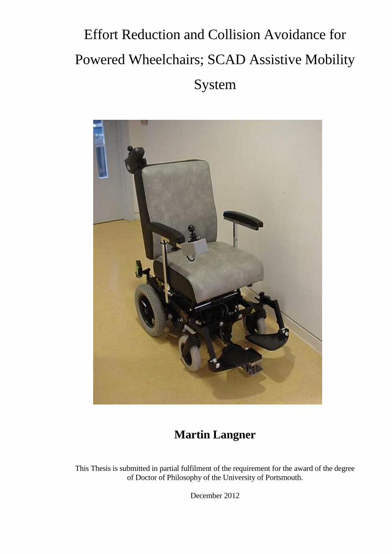
Effort Reduction and Collision Avoidance for
Powered Wheelchairs; SCAD Assistive Mobility
System
Martin Langner
This Thesis is submitted in partial fulfilment of the requirement for the award of the degree
of Doctor of Philosophy of the University of Portsmouth.
December 2012

“Whilst registered as a candidate for this degree, I have not been registered for any other
research award. The results and conclusions embodied in this Thesis are the work of the
named candidate and have not been submitted for any other award”
i
ABSTRACT
The new research described in this dissertation created systems and methods to assist
wheelchair users and provide them with new realistic and interesting driving opportunities.
The work also created and applied novel effort reduction and collision avoidance systems
and some new electronic interactive devices.
A Scanning Collision Avoidance Device (SCAD) was created that attached to standard
powered wheelchairs to help prevent children from driving into things. Initially,
mechanical bumpers were used but they made many wheelchairs unwieldy, so a novel
system that rotated a single ultra-sonic transducer was created. The SCAD provided
wheelchair guidance and assisted with steering. Optical side object detectors were
included to cover blind spots and also assist with doorway navigation. A steering lockout
mode was also included for training, which stopped the wheelchair from driving towards a
detected object.
Some drivers did not have sufficient manual dexterity to operate a reverse control. A
reverse turn manoeuvring mode was added that applied a sequential reverse and turn
function, enabling a driver to escape from a confined situation by operating a single turn
control.
A new generation of Proportional SCAD was created that operated with proportional
control inputs rather than switches and new systems were created to reduce veer, including
effort reduction systems. New variable switches were created that provided variable speed
control in place of standard digital switches and all that research reduced the number of
control actions required by a driver.
Finally, some new systems were created to motivate individuals to try new activities.
These included a track-guided train and an adventure playground that including new
interactive systems.
The research was initially inspired by the needs of young people at Chailey Heritage, the
novel systems provided new and more autonomous driving opportunities for many
powered wheelchair users in less structured environments
Keywords: Scanning Collision Avoidance generator, doorway navigation, effort reduction
systems.
ii
TABLE OF CONTENTS
ABSTRACT --------------------------------------------------------------------------------i
TABLE OF CONTENTS-----------------------------------------------------------------ii
DECLARATION--------------------------------------------------------------------------ix
LIST OF TABLES------------------------------------------------------------------------ x
LIST OF FIGURES----------------------------------------------------------------------- x
ABBREVIATIONS----------------------------------------------------------------------xv
ACKNOWLEDGEMENTS---------------------------------------------------------- xvii
DISSEMINATION--------------------------------------------------------------------xviii
Chapter 1 - Introduction
1.1 Summary of the research ------------------------------------------------------------ 1
1.2 The earlier research.------------------------------------------------------------------ 3
1.3 Mechanical bumpers. ---------------------------------------------------------------- 5
1.4 Non-contact object sensing.--------------------------------------------------------- 7
1.5 Creation of a Scanning Collision Avoidance Device (SCAD).---------------- 8
1.6 Cost effectiveness -------------------------------------------------------------------- 8
1.7 Structure of the Dissertation.-------------------------------------------------------- 9
1.8 Research work completed. ---------------------------------------------------------12
1.9 Published work.----------------------------------------------------------------------13
Chapter 2 - Literature survey and background to the research. -----14
2.1 Introduction.--------------------------------------------------------------------------14
2.2 Automated Guided Vehicles.(AGVs) --------------------------------------------16
2.2.1 Types of automated guided vehicles. -----------------------------------20
2.3 Walking and climbing tele-operated robots.-------------------------------------21
2.4 Wheeled tele-operated robots. -----------------------------------------------------22
2.5 Guidance. -----------------------------------------------------------------------------23
2.5.1 First generation off-wire guidance.--------------------------------------24
2.5.2 Second generation off-wire guidance. ----------------------------------25
2.5.3 Third generation off-wire guidance. ----------------------------------- 26
2.6 Guidance technology for use with powered wheelchairs. ---------------------26
iii
2.7 Advanced wheelchair systems. ----------------------------------------------------28
2.7.1 INCH: - an intelligent wheelchair prototype. --------------------------30
2.7.2 The CALL center "Smart Wheelchair" ---------------------------------31
2.7.3 SENARIO-------------------------------------------------------------------32
2.7.4 M3S --------------------------------------------------------------------------33
2.7.5 VAHM. - assisted navigation for powered wheelchairs. ------------33
2.7.6 NavChair. -------------------------------------------------------------------35
2.7.7 The Swedish slingan project.---------------------------------------------36
2.8 Sensors. -------------------------------------------------------------------------------37
2.8.1 Ultrasonic sensing.---------------------------------------------------------38
2.8.2 Vision systems.-------------------------------------------------------------41
2.8.3 Laser range finders.--------------------------------------------------------42
2.9 A human operator within the control loop. --------------------------------------43
2.10 Control. ------------------------------------------------------------------------------46
2.11 Fly-By-Wire (FBW) -----------------------------------------------------------51
2.12 Projects for people with special needs. -----------------------------------------52
2.13 Discussion---------------------------------------------------------------------------54
Chapter 3-Effort reduction systems-------------------------------------60
3.1 Veer reduction -----------------------------------------------------------------------60
3.1.1 Adjusting for veer subjectively - corridor assessment----------------63
3.1.2 Objective methods of veer detection------------------------------------64
3.1.3 Correction feedback -------------------------------------------------------65
3.1.4 The rolling road test bed --------------------------------------------------65
3.1.5 Testing-----------------------------------------------------------------------68
3.1.6 Ride quality-----------------------------------------------------------------70
3.2 Variable discrete controls ----------------------------------------------------------71
3.2.1 Range of proportionality--------------------------------------------------74
3.2.2 Training to use proportional systems -----------------------------------75
3.2.3 Variable switches ----------------------------------------------------------76
3.2.4 Case study-------------------------------------------------------------------79
3.2.5 Hampered by the wheelchair---------------------------------------------81
3.2.6 Testing-----------------------------------------------------------------------83
3.3 Discussion ----------------------------------------------------------------------------86
iv
Chapter 4-Object detection devices for powered wheelchairs ------88
4.1 Selection of switching method ----------------------------------------------------89
4.2 Prototype mechanical bumper -----------------------------------------------------89
4.2.1 Bumper collision response states ----------------------------------------91
4.2.2 Drive motor interface------------------------------------------------------92
4.3 Audible warning system------------------------------------------------------------94
4.4 Reversing bumpers------------------------------------------------------------------96
4.5 Chapter summary--------------------------------------------------------------------98
Chapter 5-A new Scanning Collision Avoidance Device (SCAD)101
5.1 Introduction ------------------------------------------------------------------------ 101
5.2 Background------------------------------------------------------------------------- 102
5.3 Mechanical bumpers -------------------------------------------------------------- 104
5.4 Selection of the transducer ------------------------------------------------------- 105
5.5 A prototype ultrasonic detection system --------------------------------------- 108
5.6 A first ultrasonic scanning collision avoidance device ((SCAD)----------- 112
5.7 Further developments of SCAD------------------------------------------------- 118
5.8 Considering continuous rotation ------------------------------------------------ 120
5.9 Using a stepper motor------------------------------------------------------------- 122
5.10 Object warning system --------------------------------------------------------- 133
5.11 Enclosure protection------------------------------------------------------------- 138
5.12 Discussion------------------------------------------------------------------------- 138
Chapter 6-Using the SCAD to assist with steering ----------------- 140
6.1 Object detection positioning ----------------------------------------------------- 140
6.2 Increasing and segmenting the scan -------------------------------------------- 148
6.3 Joystick emulator ------------------------------------------------------------------ 150
6.4 Automatic obstacle avoidance--------------------------------------------------- 150
6.5 Side detectors ---------------------------------------------------------------------- 153
6.6 Developing the guidance system for an unstructured environment -------- 163
6.7 Adapted object scanning control logic during turning ----------------------- 182
6.8 Determination of the wheelchair steering avoidance control ---------------.185
6.9 Non-steering intervention SCAD ----------------------------------------------- 193
Chapter 7-Initial testing of the SCAD------------------------------- 196
7.1 SCAD before and after avoidance control intervention.--------------------- 196
7.2 Difficulties with motor speed compensation ---------------------------------- 202
v
7.3 Range reduction to pass through a doorway----------------------------------- 203
7.4 Children learning to drive -------------------------------------------------------- 207
7.5 Enhancement of avoidance control --------------------------------------------- 209
7.6 A first proportional SCAD ------------------------------------------------------- 212
7.7 Joystick control voltages --------------------------------------------------------- 213
7.8 Single switch control-------------------------------------------------------------- 219
7.9 Further development and future work ------------------------------------------ 221
7.10 Connections to the moving transducer---------------------------------------- 227
7.11 Sensor vulnerability ------------------------------------------------------------- 227
Chapter 8 - Technical testing of the SCAD-------------------------- 230
8.1 Collision avoidance control ------------------------------------------------------ 230
8.2 Angular resolution of the scanning system for object detection------------ 231
8.2.1 Specular reflection and transducer polar response ------------------ 231
8.3 Separation between the detection of wanted and unwanted objects ------- 233
8.4 Ground surface edge testing ----------------------------------------------------- 234
8.5 Auto steering collision avoidance----------------------------------------------- 238
8.6 Object approach angle object avoidance compensation --------------------- 242
8.7 Mounting position for the SCAD head----------------------------------------- 246
8.8 Testing the SCAD ----------------------------------------------------------------- 250
8.9. Supplementary detectors ------------------------------------------------------- 256
8.9.1 Integration of the side detectors in to control system ------------- 259
8.9.2 Sensor conflict --------------------------------------------------------- 259
8.9.3 Detection of overhanging objects ------------------------------------- 260
Chapter 9 - Human trials testing with children---------------------- 261
9.1 Introduction ------------------------------------------------------------------------ 261
9.2 Testing the new contact-less SCAD system ----------------------------------- 262
9.3 The SCAD with a driver control interface ------------------------------------- 267
9.4 Training areas ---------------------------------------------------------------------- 268
9.5 Auto-steer--------------------------------------------------------------------------- 269
9.6 Direction lockout training mode ------------------------------------------------ 270
9.7 Considerations about crashing--------------------------------------------------- 274
9.8 Adding a reverse turn manoeuvring function to the SCAD ----------------- 275
9.8.1 Child understanding of what the SCAD was doing and why------ 278
9.8.2 Course restoration-------------------------------------------------------- 379
vi
9.9 Discussion -------------------------------------------------------------------------- 280
Chapter 10-Staff discussions and interviews ------------------------ 282
10.1 Benefits of mobility for young people ---------------------------------------- 283
10.2 Value of assistive technology -------------------------------------------------- 284
10.3 Do young people need help with their mobility?---------------------------- 287
10.4 Human help versus technical assistive support ------------------------------ 289
10.5 Assistive technology taking control over a young person------------------ 292
10.6 Raising expectations------------------------------------------------------------- 294
10.7 Learnt helplessness -------------------------------------------------------------- 296
10.8 A young person leaving the school-------------------------------------------- 298
10.9 A young person understanding the task--------------------------------------- 299
10.10 Wheelchair control and frustration------------------------------------------- 301
10.11 Risk------------------------------------------------------------------------------- 303
10.12 Other discussion points -------------------------------------------------------- 306
10.13 Conclusion----------------------------------------------------------------------- 309
Chapter 11-Discussion and conclusions ----------------------------- 312
11.1 Effort reduction systems -------------------------------------------------------- 312
11.2 Object detection devices for powered wheelchairs ------------------------- 313
11.3 The new Scanning Collision Avoidance Device (SCAD) ----------------- 314
11.4 Assisting with steering ---------------------------------------------------------- 316
11.5 The initial testing of the SCAD ------------------------------------------------ 317
11.6 Technical testing and functional considerations----------------------------- 319
11.7 Human trials ---------------------------------------------------------------------- 321
11.8 Validation interviews and discussion groups -------------------------------- 323
11.9 The train, adventure playground and interactive systems------------------ 325
Chapter 12-Future work------------------------------------------------ 328
12.1 Veer detection and correction systems---------------------------------------- 328
12.2 Audio (talking) sign point system --------------------------------------------- 331
12.3 Power stander base developments integrating guidance systems --------- 333
12.4 Single switch scanning controlled SCAD based system ------------------- 335
12.5 Potential commercialisation ---------------------------------------------------- 336
Appendix A ------------------------------------------------------------- 337
A.1 Ethical considerations ------------------------------------------------------------ 337
vii
Appendix B ------------------------------------------------------------- 339
B.1 Intelligence in robots ------------------------------------------------------------- 339
B.2 Communications ------------------------------------------------------------------ 341
B.2.1 Radio ---------------------------------------------------------------------- 341
B.2.2 Infrared ------------------------------------------------------------------ 341
B.3 Force feedback -------------------------------------------------------------------- 341
B.4 Sensor fusion ---------------------------------------------------------------------- 343
B.5 Navigation ------------------------------------------------------------------------- 344
Appendix C-Track systems-------------------------------------------- 345
C.1 Introduction ------------------------------------------------------------------------ 345
C.2 A first mobility platform and simple track ------------------------------------ 345
C.3 Incorporation of track junctions---------- -------------------------------------- 347
C.3.1 Detecting the junction -------------------------------------------------- 349
C.4 Junction control ------------------------------------------------------------------ 350
C.5 Multi-junction systems----------------------------------------------------------- 351
C.6.1 Two channel multiplexed tracks -------------------------------------- 351
C.6.2 Binary coded multiplexed track --------------------------------------- 353
C.6.3 Track driver generator design ----------------------------------------- 354
C.6.4 The un-coded track generator------------------------------------------ 356
C.6.5 Wheelchair track control ----------------------------------------------- 357
C.6.6 Positional tracking------------------------------------------------------- 357
C.7 The expanding system------------------------------------------------------------ 358
C.8 Moving children away from the track------------------------------------------ 359
C.9 Summary --------------------------------------------------------------------------- 360
Appendix D-The train locomotive, adventure playground and
interactive systems------------------------------------------------------ 361
D.1 Introduction------------------------------------------------------------------------ 361
D.2 Multi sensory room--------------------------------------------------------------- 361
D.3 The train---------------------------------------------------------------------------- 363
D.3.1 Child drivers at different stages of their development ------------- 364
D.3.2 Non-disabled and disabled children in a combined activity ------ 365
D.3.3 Children taking responsibility for others----------------------------- 367
D.3.4 Shared control ----------------------------------------------------------- 367
D.3.5 Group working ---------------------------------------------------------- 368
viii
D.3.6 Turn taking--------------------------------------------------------------- 368
D.4 The adventure tunnel ------------------------------------------------------------- 369
D.5 The development of a Mobile Interactive Control system (MIC) --------- 371
D.6 Bidirectional object control selectivity ---------------------------------------- 377
D.7 Control distribution--------------------------------------------------------------- 384
D.7.1 Sound effects generator ------------------------------------------------ 385
D.7.2 Mobile interactive control distribution------------------------------- 388
D.7.3 Powered mobility systems incorporating MIC systems ----------- 389
D.7.4 Power stander mobile base unit --------------------------------------- 390
D.8 Summary--------------------------------------------------------------------------- 392
References----------------------------------------------------------------- 393
x
LIST OF TABLES Table 3.1 Operational functions that can be selected ----------------------------------------------------------83
Table 5.1 Characteristics of optical and ultra-sonic sensors ----------------------------------------------- 107
Table 5.2 Possible conditions for start up and normal running--------------------------------------------- 131
Table 6.1 The detection comparison between various objects --------------------------------------------- 158
Table 6.2 Wheelchair driver speed table ----------------------------------------------------------------------- 175
Table 7.1 Doorway discrimination logic function------------------------------------------------------------ 205
Table 8.1 Ground surfaces testing to determine the critical detection angle of detection-------------- 237
Table 8.2 Variations in the critical angle of object detection ----------------------------------------------- 238
Table 8.3 The effects of surface type on the critical angle -------------------------------------------------- 242
LIST OF FIGURES Figure 2.1 .(1950’s) Style Siemans Dematic AGV. GOX ‘Guide-O-Matic -------------------------------18
Figure 2.2 AGVs that were made by ‘Siemans Dematic’ through the decades ---------------------------18
Figure 2.3 Reproduced from [Langner Mphil Thesis (2004)]-------------------------------------------------23
Figure 2.4 The CALL center Smart Wheelchair.Reproduced from [Nisbet (2000)] ---------------------31
Figure 2.5 The prototype VAHM ---------------------------------------------------------------------------------34
Figure 2.6 The NavChair -------------------------------------------------------------------------------------------35
Figure 2.7 The NavChair Assistive Wheelchair Navigation System[Levine (1999)] --------------------50
Figure 2.8 A young chin switch driver. [Thornett (1990)] ---------------------------------------------------53
Figure 3.1 A young person trying to control his veering wheelchair----------------------------------------63
Figure 3.2 Rolling road test bed ----------------------------------------------------------------------------------66
Figure 3.3 Swivel detector marked by the yellow arrow -----------------------------------------------------68
Figure 3.4 The author testing the veer compensating system ------------------------------------------------69
Figure 3.5 No veer compensation --------------------------------------------------------------------------------71
Figure 3.6 Compensation applied --------------------------------------------------------------------------------71
Figure 3.7 Progressive response to an applied control action ------------------------------------------------76
Figure 3.8 Paddle switch (un-operated) --------------------------------------------------------------------------77
Figure 3.9 Paddle switch (operated) ------------------------------------------------------------------------------77
Figure 3.10 Paddle control (un-operated)-------------------------------------------------------------------------78
Figure 3.11 Paddle control (operated)-----------------------------------------------------------------------------78
Figure 3.12 Hand switch controls----------------------------------------------------------------------------------79
Figure 3.13 Horseshoe surround switches ------------------------------------------------------------------------80
Figure 3.14 The young person trying to control his veering wheelchair ------------------------------------81
Figure 3.15 Trialling his new vari-controls-----------------------------------------------------------------------84
Figure 3.16 Driving and maintaining his course across the path ---------------------------------------------85
Figure 4.1 Prototype mechanical bumper-------------------------------------------------------------------------90
Figure 4.2 Bumper collision states --------------------------------------------------------------------------------91
Figure 4.3 Bumper Electrical wiring diagram -------------------------------------------------------------------92
Figure 4.4 Bumper in collision -------------------------------------------------------------------------------------93
Figure 4.5 A single switch operated track chair with mechanical bumper----------------------------------95
Figure 4.6 Bumper in collision -------------------------------------------------------------------------------------96
Figure 4.7 Rear bumper fitted to a standard ‘Apollo powered wheelchair’---------------------------------97
Figure 5.1 Simplified overhead view of a powered wheelchair and drivers head,
showing a detection zone ---------------------------------------------------------------------------- 105
Figure 5.2 Single Polaroid transducer fitted to a powered wheelchair------------------------------------- 115
Figure 5.3 Strong target echo ------------------------------------------------------------------------------------- 116
Figure 5.4 No detectable target echo ---------------------------------------------------------------------------- 116
Figure 5.5 Round vertical objects were generally more detectable ---------------------------------------- 117
Figure 5.6 Transducer types--------------------------------------------------------------------------------------- 118
Figure 5.7 Transducer rotation (small) -------------------------------------------------------------------------- 119
Figure 5.8 Transducer rotation (large) P119
Figure 5.9 Polaroid 600 transducer polar response P120
Figure 5.10 SCAD head position. Using 7.5° step angle motor. 12° dispersion angle transducer 122
Figure 5.11 Scan sweep diagram--------------------------------------------------------------------------------- 123
Figure 5.12 Scan motion (reciprocal scan) --------------------------------------------------------------------- 125
Figure 5.13 Ultra-sonic pulse / echo sample event sequence within one sector
(object sampling) ------------------------------------------------------------------------------------ 126
Figure 5.14 Single detected object ‘X’ off centre ------------------------------------------------------------- 127
Figure 5.15 Single detected object ‘X’ at centre--------------------------------------------------------------- 127
xi
Figure 5.16 SCAD sensor head mounted on an ‘Apollo’ Wheelchair ------------------------------------- 129
Figure 5.17 Prototype SCAD assembly and enclosure------------------------------------------------------- 129
Figure 5.18 Retro-reflective sensor ------------------------------------------------------------------------------ 130
Figure 5.19 The test circuit used with an optical (photo transistor) sensor ------------------------------- 131
Figure 5.20 Optical disc and sensor assembly ----------------------------------------------------------------- 132
Figure 5.21 Latching rotation direction control circuit ------------------------------------------------------- 133
Figure 5.22 Schematic layout of the SCAD object warning system --------------------------------------- 134
Figure 5.23 Oscillator waveform (main clock) ---------------------------------------------------------------- 135
Figure 5.24 Functional timing diagram ------------------------------------------------------------------------- 136
Figure 5.25 Blanking pulse timing------------------------------------------------------------------------------- 136
Figure 5.26 Pulse stretching and beep sound generator circuit---------------------------------------------- 137
Figure 6.1 Multi-zone scan pattern ------------------------------------------------------------------------------ 141
Figure 6.2 Block diagram of the SCAD control system and zone partition object indicators --------- 142
Figure 6.3 Close up picture of the prototype test SCAD and directional indicator light---------------- 143
Figure 6.4 Prototype SCAD and bread board electronics placed on a wheelbase ----------------------- 144
Figure 6.5 Detection of a doorframe with extended detection range stopped the wheelchair --------- 144
Figure 6.6 SCAD sensor mounting position ------------------------------------------------------------------- 146
Figure 6.7 Specula reflection prevents detection of the wall ------------------------------------------------ 147
Figure 6.8 Angle of approach that the wall can be detected------------------------------------------------- 147
Figure 6.9 The 90° scan with was not usable for the training system-------------------------------------- 148
Figure 6.10 Side detector mounting position------------------------------------------------------------------- 154
Figure 6.11 Object detection by triangulation ----------------------------------------------------------------- 155
Figure 6.12 Differences in cross-sectional area between objects in the operating environment------- 156
Figure 6.13 Side detector control function system diagram ------------------------------------------------- 157
Figure 6.14 Infrared detection ------------------------------------------------------------------------------------ 159
Figure 6.15 Ultrasonic detection --------------------------------------------------------------------------------- 159
Figure 6.16 Testing to provide the limits for object detection----------------------------------------------- 159
Figure 6.17 The angle of the transmitting IR beam had been changed and
intersection points were set to reduce detection range---------------------------------------- 160
Figure 6.18 Grating bars------------------------------------------------------------------------------------------- 161
Figure 6.19 Optical side detector--------------------------------------------------------------------------------- 161
Figure 6.20 Refining the width and spacing of the grating bars by successive tests -------------------- 161
Figure 6.21 An example of sensor conflict --------------------------------------------------------------------- 162
Figure 6.22 Cones detected for steering guidance------------------------------------------------------------- 164
Figure 6.23 Wall not detected ------------------------------------------------------------------------------------ 164
Figure 6.24 A representation of the testing of the wheelchair systems with a wall P165
Figure 6.25 Collision angle testing ------------------------------------------------------------------------------ 165
Figure 6.26 Critical angle of uncertainty------------------------------------------------------------------------ 167
Figure 6.27 Wall detected between the limits 83º – 97 º ----------------------------------------------------- 167
Figure 6.28 Wall not detected, resulting in a collision ------------------------------------------------------- 168
Figure 6.29 The off-set sensor detected the wall -------------------------------------------------------------- 169
Figure 6.30 Transducer optical position maker mounting disc --------------------------------------------- 169
Figure 6.31 Functional diagram of the reciprocal stepper motor control---------------------------------- 170
Figure 6.32 Pulse / echo samples 120° step span-------------------------------------------------------------- 171
Figure 6.33 Pulse / echo step sampling cycle 33.3 ms-------------------------------------------------------- 171
Figure 6.34 Scanning control re-development to provide twelve scan sectors --------------------------- 173
Figure 6.35 Adding sectors to provide a 180° scan ----------------------------------------------------------- 174
Figure 6.36 Oscilloscope timing trace transducer signal burst ---------------------------------------------- 176
Figure 6.37 Pulse / echo sample events delay event diagram ----------------------------------------------- 177
Figure 6.38 Scan sector timing ----------------------------------------------------------------------------------- 178
Figure 6.39 Spin and arc turn comparison for the test-------------------------------------------------------- 179
Figure 6.40 Approximation of turning speed for object detection------------------------------------------ 180
Figure 6.41 Right turn side sector scanning -------------------------------------------------------------------- 182
Figure 6.42 Adapted half scanning control diagram---------------------------------------------------------- 183
Figure 6.43 Stopping after each control action ---------------------------------------------------------------- 186
Figure 6.44 Forwards driving whilst pulsing the right steering switch ------------------------------------ 186
Figure 6.45 Simple direct test collision control interface ---------------------------------------------------- 187
Figure 6.46 High angle of approach with variable outcomes ----------------------------------------------- 188
Figure 6.47 Low angle of approach over corrected outcome------------------------------------------------ 189
Figure 6.48 Object not detected, both drive wheels rotated at the same RPM --------------------------- 190
Figure 6.49 Object detected on the left, system responded by reducing Right drive wheel RPM ---- 190
xii
Figure 6.50 Proportionate collision turn avoidance----------------------------------------------------------- 191
Figure 6.51 Gentle object avoidance turn----------------------------------------------------------------------- 191
Figure 6.52 Maximum object avoidance control -------------------------------------------------------------- 192
Figure 6.53 Wheelchair drive wheel rotation acceleration and deceleration time constants ----------- 192
Figure 6.54 DX controller hand held programming tool----------------------------------------------------- 193
Figure 6.55 Three left side scan zone pairs and three right side (mirrored and shown dotted) -------- 193
Figure 6.56 Object detection and speed reduction system --------------------------------------------------- 194
Figure 7.1 Low angle collision ----------------------------------------------------------------------------------- 197
Figure 7.2 Mid angle collision control -------------------------------------------------------------------------- 198
Figure 7.3 High angle collision control ------------------------------------------------------------------------- 200
Figure 7.4 Head-On trajectory------------------------------------------------------------------------------------ 200
Figure 7.5 Applied load compensation-------------------------------------------------------------------------- 202
Figure 7.6 Left and right zone detected the aperture---------------------------------------------------------- 203
Figure 7.7 The reduced range allowed the wheelchair to get closer to a wall ---------------------------- 204
Figure 7.8 Sector grouping---------------------------------------------------------------------------------------- 205
Figure 7.9 Range contraction within approach limits--------------------------------------------------------- 206
Figure 7.10 Range reduction not logically possible----------------------------------------------------------- 206
Figure 7.11 Inductive joystick output voltage against joystick displacement ---------------------------- 213
Figure 7.12 Resulting forwards directional control, both drive wheels rotated forwards
at the same speed ------------------------------------------------------------------------------------ 214
Figure 7.13 Resulting right arc turn------------------------------------------------------------------------------ 214
Figure 7.14 Resulting right spin---------------------------------------------------------------------------------- 215
Figure 7.15 Left and right scan sector grouping--------------------------------------------------------------- 215
Figure 7.16 Object detected right steering blocked ---------------------------------------------------------- 216
Figure 7.17. Reverse right turn into the object----------------------------------------------------------------- 216
Figure 7.18 An object detected in both front zones stopped driving --------------------------------------- 217
Figure 7.19 Linking speed and range together----------------------------------------------------------------- 218
Figure 7.20. A prototype direction scanner coupled with SCAD sensors on a wheelchair
detected the walls and objects in the path of travel and provided electronic
steering guidance------------------------------------------------------------------------------------ 220
Figure 7.21 Time comparison at the end of the test ---------------------------------------------------------- 221
Figure 7.22 Progressive scan ------------------------------------------------------------------------------------- 224
Figure 7.23 Object detection cycle scanning ------------------------------------------------------------------ 225
Figure 7.24 Alternate left to right sweep------------------------------------------------------------------------ 225
Figure 7.25 Alternate right to left scan-------------------------------------------------------------------------- 226
Figure 7.26 Alternate scan cycle control------------------------------------------------------------------------ 226
Figure 8.1 Different approach and departure angles ---------------------------------------------------------- 230
Figure 8.2 Polar response plot for the SensComp 600 instrument grade type
electrostatic transducer showing the -3db points as red lines ---------------------------------- 232
Figure 8.3 Target not detected because much of the sound pulse did not return to the transducer---- 232
Figure 8.4 Target detected because sufficient sound energy returned to the transducer ---------------- 233
Figure 8.5 Back scatter testing------------------------------------------------------------------------------------ 234
Figure 8.6 Back scatter testing with object detected ---------------------------------------------------------- 235
Figure 8.7 Ground reflection test platform --------------------------------------------------------------------- 236
Figure 8.8 Doormat critical angle testing ----------------------------------------------------------------------- 237
Figure 8.9 Critical angle avoidance testing--------------------------------------------------------------------- 239
Figure 8.10 Critical object approach angle --------------------------------------------------------------------- 240
Figure 8.11 Approach angle > than critical angle (82º) ------------------------------------------------------ 240
Figure 8.12 Shows the approach angle tolerance of the system -------------------------------------------- 241
Figure 8.13 The effect of specula reflection on the critical angle------------------------------------------- 241
Figure 8.14 Scan sweep zone allocations----------------------------------------------------------------------- 243
Figure 8.15 Extended outer zone--------------------------------------------------------------------------------- 246
Figure 8.16 Adjustable CAPS system--------------------------------------------------------------------------- 247
Figure 8.17 Obscuration of detection by caster swivelling -------------------------------------------------- 249
Figure 8.18 The SCAD detector was moved forwards to provide castor swivel clearance ------------ 249
Figure 8.19 the first SCAD prototype enclosure -------------------------------------------------------------- 250
Figure 8.20 The robust aluminium ------------------------------------------------------------------------------ 251
Figure 8.21 Loose transducer twin wire connections--------------------------------------------------------- 252
Figure 8.22 The transducer was mounted on a bobbin with wires spiral wound------------------------- 252
Figure 8.23 Testing for dead spots------------------------------------------------------------------------------- 254
Figure 8.24 Infrared side detector with background suppression ------------------------------------------ 256
xiii
Figure 8.25 Side detectors mounted over the rear drive wheels -------------------------------------------- 257
Figure 8.26 Left door frame was detected ---------------------------------------------------------------------- 258
Figure 8.27 Momentary detection of a table leg -------------------------------------------------------------- 258
Figure 8.28 Optimised side detector mounting position ----------------------------------------------------- 258
Figure 9.1 A young driver using a track guided wheelchair fitted with a prototype
mechanical bumper ----------------------------------------------------------------------------------- 261
Figure 9.2 The bumper was less effective for larger wheelchair frame sizes----------------------------- 262
Figure 9.3 SCAD and track detector mounted on the powered wheelchair------------------------------- 263
Figure 9.4 Driving towards a person ---------------------------------------------------------------------------- 264
Figure 9.5 She responded to the sound chirp------------------------------------------------------------------- 264
Figure 9.6 Roadway cones --------------------------------------------------------------------------------------- 268
Figure 9.7 Deciding which switch to operate ------------------------------------------------------------------ 270
Figure 9.8 Object beacon indicator lights----------------------------------------------------------------------- 271
Figure 9.9 Driving around the school using illuminated drive control switches ------------------------ 272
Figure 9.10 Using auditory sound direction prompting ------------------------------------------------------ 273
Figure 9.11 Automatic reverse turn manoeuvring------------------------------------------------------------- 276
Figure 9.12 The wheelchair trajectory during object detection --------------------------------------------- 280
Figure 12.1 Castor rotation sensor ------------------------------------------------------------------------------- 329
Figure 12.2 The inflexible wheelchair frame ------------------------------------------------------------------ 329
Figure 12.3 The testable gyro based anti-veer system-------------------------------------------------------- 330
Figure 12.4 A young track driver hearing a sign post identification beacon------------------------------ 331
Figure 12.5 Young people testing the audio sign system ---------------------------------------------------- 332
Figure 12.6 Testing a remote triggering message system---------------------------------------------------- 332
Figure 12. 7 A young wheelchair driver testing a power stander combination--------------------------- 333
Figure 12.8 Children using their switch controls ------------------------------------------------------------- 334
Figure 12.9 Developing a purpose built power base---------------------------------------------------------- 334
Figure 12.10 Video picture of the test run destination-------------------------------------------------------- 335
Figure B.1 The Merlin robot, reproduced from [Stott phd 2002] originally from [Galt (1999)] ------ 340
Figure C.1 Non permanent plastic track sections-------------------------------------------------------------- 346
Figure C.2 Star junction ------------------------------------------------------------------------------------------- 347
Figure C.3 Track termination resistors-------------------------------------------------------------------------- 348
Figure C.4 Track sensor head incorporating junction -------------------------------------------------------- 349
Figure C.5 Junction manoeuvre control------------------------------------------------------------------------- 350
Figure C.6 Multiplexed junction energisation ----------------------------------------------------------------- 352
Figure C.7 Coded multiplexed structure ------------------------------------------------------------------------ 353
Figure C.8 Schematic of the FM coded track generator------------------------------------------------------ 354
Figure C.9 Line receiver module--------------------------------------------------------------------------------- 355
Figure C.10 Schematic diagram of the un-coded track generator ------------------------------------------ 356
Figure D.1 Multi-sensory room at Chailey Heritage School ------------------------------------------------ 362
Figure D.2 Two switch set connected to radio module------------------------------------------------------- 363
Figure D.3 Remote controlled distribution panel-------------------------------------------------------------- 363
Figure D.4 The first train locomotive trials--------------------------------------------------------------------- 364
Figure D.5 Switch selections ------------------------------------------------------------------------------------- 365
Figure D.6 Child CAPS inserts----------------------------------------------------------------------------------- 366
Figure D.7 Tender buggies and the author’s daughter testing out the system ---------------------------- 368
Figure D.8 A selection of remote controllable devices built into the tunnel------------------------------ 369
Figure D.9 Environmental (MIC) Mobile Interactive Control --------------------------------------------- 370
Figure D.10 A young child using the activity arch------------------------------------------------------------ 371
Figure D.11 Control function transition from driving to environmental control------------------------- 372
Figure D.12 Returning control to wheelchair drive ----------------------------------------------------------- 373
Figure D.13 Stage 1, wheelchair drive mode ------------------------------------------------------------------ 374
Figure D.14 Stage 2 ------------------------------------------------------------------------------------------------ 375
Figure D.15 Stage 3, the MIC had switched to environmental device control --------------------------- 376
Figure D.16 Stage 4, reverting back to wheelchair control and leaving device control----------------- 377
Figure D.17 Coded infra-red transceivers ---------------------------------------------------------------------- 378
Figure D.18 Remote pendants ------------------------------------------------------------------------------------ 379
Figure D.19 Buggy open access---------------------------------------------------------------------------------- 379
Figure D.20 Mini CAPS B1-B3---------------------------------------------------------------------------------- 380
Figure D.21 Mini CAPS A1-A3 --------------------------------------------------------------------------------- 380
Figure D.22 Child CAPS II --------------------------------------------------------------------------------------- 380
Figure D.23 Adjustable padded seat for nursery children---------------------------------------------------- 380
xiv
Figure D.24 Locomotive in the open access position--------------------------------------------------------- 381
Figure D.25 Locomotive sub-assembly------------------------------------------------------------------------- 382
Figure D.26 Locomotive body shell ----------------------------------------------------------------------------- 383
Figure D.27 Tracking control distribution---------------------------------------------------------------------- 384
Figure D.28. Additional supplementary carrier fail detector coil and signal amplifier ----------------- 386
Figure D.29 Modified front end electronics and carrier fail override-------------------------------------- 387
Figure D.30 Locomotive and tender buggy mechanical linking-------------------------------------------- 388
Figure D.31 Locomotive and tender buggy switch control-------------------------------------------------- 388
Figure D.32 Assessment SCAD powered wheelchair-------------------------------------------------------- 389
Figure D.33 Mobile MIC unit ------------------------------------------------------------------------------------ 390
Figure D.34 Power stander base---------------------------------------------------------------------------------- 391
Figure D.35 Power stander mobile interactive controls ------------------------------------------------------ 391
xv
ABBREVIATIONS ABS acrynol butile styrene
ADD advanced detection distance
AGC automatic gain control
AGV automated guided vehicle
AIWC advanced integrated wheelchair control
AM amplitude modulation
CAN control area network
CCD charge coupled device
CCW counter clockwise
CHS Chailey Heritage School
CMOS complimentary metal oxide silicone
CTFM constant transmission frequency modulation
CW clockwise
DC direct current
DSP digital signal programming
ECU European Currency
EFCS electronic flight control system
EM electro magnetic
EMC electro magnetic compatibility
EMF electro motive force
EMP electro magnetic pulse
EPIC electric powered indoor chair
EPIOC electric powered indoor outdoor chair
ESD electro static discharge
FBW fly-by-wire
FM frequency modulation
GIDS generic intelligent driver support
GND ground – earth / signal path return
GPS global positioning system
HCI human computer interaction
Hz frequency cycles per second
IC integrated circuit
INCH intelligent wheelchair prototype
IR infrared
IVHS intelligent vehicle highway system
KHZ frequency cycles per second
LED light emitting diode
LRF laser range finder
M3S input-device output-device safety-device protocol
MIC mobile interactive control
mm milli-meter
MOD modulation
MOS metal oxide silicone
ms milli-second
Naidex innovation and inspiration for the care industry
NERO nuclear electric robot.
Op-Amp operational amplifier
Opto optical sensor
OSC oscillator
PCB printed circuit board
xvi
PIC peripheral interface controller
PLL phase locked loop
PPM pulse position modulation
PSU power supply unit
PWM pulse width modulation
RFI radio frequency interference
RFID radio frequency identification device
RPM revolutions per minuet
RX receiver
SCAD scanning collision avoidance device
SENARIO sensor aided intelligent wheelchair navigation
SPRINT strategic program for innovation and technology
TIDE European unions collaborative funding initiative
TX transmitter
VAHM vehicle autonome pour handicapés moteurs
VCO voltage controlled oscillator
VR variable resistor
4WD four wheel drive

xvii
Acknowledgements
The author wishes to express his gratitude to the following:
Specifically:
To Dr David Sanders TD for agreeing to direct the research and for his help, guidance and
encouragement throughout. Many thanks to him for the speed with which he assisted with
the last steps of the writing-up.
To Dr Giles Tewkesbury MBE for the management of academic matters related to the
research and expertise in electronics and software engineering.
T0 Dr Simon Chester and Dr David Robinson for their help with chapter corrections and
advice.
My sincere thanks go to:
Sylvia Lamb (Principal) and Simon Yates (Head of School) and the governors at Chailey
Heritage for sponsoring the research and for enabling me to assimilate my engineering
skills and test my research in the school environment.
Donna Cowan (Technical Director of Rehabilitation Engineering Services) for her help,
support and encouragement. To Robert Taylor (Premises Manager) for giving me the time
to finish my Dissertation and Vicky Smith (Roberts PA) for proof reading.
To Roger Greenland as my mentor and sounding board and the late Andrew Brown for his
encouragement and understanding.
My friends, the children at Chailey Heritage School for their determination to succeed in
their driving tasks and putting up with all my add-hock experimental trials.
But especially to
My family, Mum and Dad for having the faith in me to do the work.
In particular Sue (my wife), my children for their support and understanding, Alice (my
daughter) for testing some of the systems and Alex (my son) for putting me straight on a
few technical issues and generally for putting up with me, for being patient and for helping
me by being guinea-pigs for some of the new systems and research.
xviii
DISSEMINATION
LANGNER M (2010) Using a scanning collision avoidance device to assist with steering.
Journal of Intelligent Mobility, Volume 13, Number 2, ISSN:1472-7633, pp 213- 238.
LANGNER M,SANDERS D A & TEWKESBURY G E (2010) Improving wheelchair
driving using a sensor system to control wheelchair-veer and variable-switches as an
alternative to digital switches or joysticks, Industrial robot international journal Vol. 37
No.2, pp 157-167.
M LANGNER (2009) A new scanning collision avoidance device. Journal of
Intelligent Mobility ISSN 1472-7633. Volume 12 (2), pp 182-199.
LANGNER M & SANDERS D A (2008) Controlling wheelchair direction on slopes,
Journal of assistive technologies, Vol.2 No.2, pp 32-42.
1
Chapter 1
Introduction
Previous research undertaken by the Author of this dissertation had created a network
of tracks at Chailey Heritage School. Track guidance provided limited driving
opportunities for young people who were not considered suitable for powered
mobility. This formed the background for the new research described in this
dissertation. Many young people wanted to drive their wheelchairs away from the
tracks but they could not do so safely.
Ethical considerations are included in appendix A
1.1 Summary of the research
This research resulted in the creation of the Scanning Collision Avoidance Device
(SCAD), which was attached to standard powered wheelchairs. The new hardware
and time line that was created during this research is listed below:
• Bumper detectors [Year 1-2]
• Audible object warning system [Year 1.5 - 2]
• The creation of SCAD [Year 2-4]
• Auto steering SCAD [Year 2-3]
• Side object detectors [Year 3-4]
• Direction lockout training interface [Year 3-4]
• Reverse turn manoeuvring systems [Year 3-4]
• SCAD proportional control [Year 5-6]
• Proportional switches [Year 6-7]
• Interactive playground and track guided train [Year 3 -6]
• Veer reduction system [Year 6-7]
To help prevent children from driving into things, initial work started by making
mechanical bumpers (Page 88) to cut the drive power when a wheelchair was in
2
collision with an object. To provide feedback about bumper operation an audible
object warning was provided as an indicator that assistance was required for the diver.
The addition of mechanical bumpers made many wheelchairs unwieldy to drive, so
new research started with the creation of a novel system that rotated a single ultra-
sonic transducer that sent sound pulses at stepped periods of rotation . This led to the
development the SCAD (Page 112) which detected objects without making contact.
For this new work, ultrasonic sensors were selected for non-contact proximity and
ranging. This SCAD system provided object detection for the front of the wheelchair
and gave a warning sound to a blind driver that objects were nearby. The SCAD was
that it used a single rotating transducer in place of a multiple transducer array.
Non-contact object sensing provided new opportunities to extend this research. The
SCAD was developed further to provide wheelchair guidance from detected objects in
the path of travel. This became the auto-steering SCAD (page 150) capable of
steering along a corridor when a single drive switch was activated.
The front castors caused a blind spot at the side of the wheelchair. Optical side object
detectors (Page 153) were developed to cover this blind spot and also assisted with
doorway navigation.
The SCAD provided wheelchair steering assistance, however NHS therapists that
worked within the school were concerned that automated assistance may hider a child
learning to drive for themselves. A steering lockout mode (page 270) was included
for training purposes, which blocked driving toward a detected object. This provided
a need for a diver to problem solve in order to seek an appropriate drive direction that
was clear of obstacles.
The auto-steering SCAD enabled new or novice drivers to get into an area of
confinement that required them to reverses out of the situation. Some drivers did not
have sufficient manual dexterity to operate a reverse control. A reverse turn
manoeuvring mode (page 275) was added to the SCAD control options. This applied
a sequential reverse and turn function. The wheelchair then automatically
manoeuvred away from detected objects when a turn control was operated, enabling
the driver to escape from a confined situation by operating a single turn control.
3
The main applications for the SCAD were for drivers using switch controls that
provided an On – Off control function. Switches did not control the wheelchair speed.
Whilst this was suitable for those who did not have refined hand control movement,
many people with finer control of their limbs used a proportional joystick and did not
want to use switches.
A new version of Proportional SCAD (Page 212) was created that operated with a
proportional control inputs. This blocked driving directions towards detected object
that was logically the same as the auto-steering SCAD.
New systems to reduce veer including effort reduction systems (Page 64) were created
towards the end of this research. New variable switches were created that provided
variable speed control in place of the standard digital switches. That research
generally reduced the number of control actions required by a driver (page 71). .
Finally, some new systems were created to motivate individuals to try new activities.
These included a track-guided train (Page 363) and an adventure playground including
new interactive systems (page 367).
Chailey Heritage staff, (NHS) Clinical Services Therapy staff, children, young adults
(and their close associates) were involved at all stages.
Although the research was initially inspired by the needs of young people at Chailey
Heritage, the novel systems provided new and more autonomous driving opportunities
for many powered wheelchair users in less structured environments.
1.2 The earlier research
This new work builds the earlier research that had created a new track guided
electromagnetic wheelchair guidance system that was published by the author in
[Langner (2004)]. At the beginning of that earlier research it was observed that some
children could not drive their wheelchairs because their hand function was not good
enough to operate joysticks, which were the main type of control system. Joysticks
required good hand grasping skills and movement coordination within a small area
4
(16 sqcm). Many children could not drive because of the demands of the joystick.
Work continued to make switch controls that were easier for some children to operate.
Switches could be put in positions that were more suitable for a child to reach and
separated to spread out the control directions beyond the limited movement span
provided by the joystick.
Children started to drive more because of the application of switch controls. Some
children had limited hand function and could not operate the switches; other children
had athotoid movements and problems with spasticity. Many children with poor hand
function did have good head control and could turn their heads enough to operate
suitably positioned switches. New controls were created that could be operated by
children using their chin and some children started to drive competently by using
these. Those children were mentally agile and did not require any type of additional
guidance support. Work continued to create a variety of controls that could translate
the young person’s functional and repeatable personal hand or head movements into
switched outputs. The creation of these new controls meant that many children started
to drive and become independent in their powered wheelchairs.
Despite the creation of new switching controls, some children were still not able to
drive their wheelchairs independently, even though many of their friends and
classmates were. Many of these children had sufficient physical co-ordination
movement and were not necessarily anymore physically disabled than children who
were using the new switch controls to drive independently. They may not have had
sufficient cognitive ability to be able to work out the sequence of controls necessary to
steer their wheelchair. Helpers encouraged children to be mobile because they
thought that these children were not doing everything that their classmates were doing.
These children wanted to drive but could not, so some helpers pushed those children
around in their wheelchairs or intervened to operate their controls for them, just to
give them a sense of mobility. These children could not be given switch controls in
case they might charge into a wall or be a danger to others and to themselves because
they could not start, stop and steer.
It was necessary to determine if they simply needed more practice with driving or if
there was something more fundamental in their development that meant they would
5
not be able to use switch controls. It was obvious that these children wanted to drive
but when they tried driving, they needed assistance from helpers to enable them to
become mobile (or at least to have some experience of wheelchair driving). A turning
point in the development of assistive technology centred on a girl who was almost
totally blind. She had sensitive hearing and was intelligent but was severely
physically impaired and could not use her hands to control a switch. She could use
her chin and she did have good head movement.
Helpers encouraged her to drive because she wanted to. She could not be provided
with a powered wheelchair because she did not meet criteria for competency to drive.
A powered wheelchair was loaned to her with a joystick mounted on the side. She
rested her arm on the joystick and drove in circles because that was the only thing she
could do safely, although she was able to feel the experience of starting and stopping.
Occasionally she lost control and would spiral out and crash into things so she was
reliant on helpers to guide her. One of those helpers suggested that some kind of
track, similar to a railway line, could be used to guide her wheelchair. A track system
was created that enabled young people to get from one point to another without going
astray. Children then became frustrated because the tracks did not always lead to the
places where they wanted to be. For example, a blind track driver wanted to go to
places other than her classroom and toilet areas, which were connected by track.
There were also other problems; even on a track she would crash or bump into things.
She had good hearing and could almost sense if someone was there but she could not
sense inanimate objects.
1.3 Mechanical bumpers
The initial work described in this dissertation used mechanical bumpers to stop
children from driving into things. This was challenging for a number of reasons. A
strip bumper could be mounted around a wheelchair. When the wheelchair hit
something, it could impact quite heavily and could be like a crash even though the
motor power was cut after a collision had occurred. Trials with strip bumpers
demonstrated that energy absorption was over a small distance of just a few
millimetres. So children could drive into things and hurt themselves or damage
equipment. A latched system was used in earlier experiments. That system cut power
to the motor when the bumper was touched. The power would stay cut until a helper
6
reset the system, after ensuring that the child was safe to proceed. Sometimes children
did not understand why the wheelchair had suddenly stopped due to bumper
operation. Prior to the application of bumpers, children just crashed into things and
carried on driving. So an audible warning device was added to give an indication of
when an object was struck. This modified system stopped the power or gave a sound
warning or both, as described by these scenarios:
Scenario A: A child drives along and strikes an object. The child hears a
sound warning and takes his hand off the switch.
Scenario B: A child drives along and hits something. Power to the motor is
cut and he cannot drive any further until a helper resets the system.
Scenario C: A child drives along and hits something. Power to the motor is
cut and the child hears a beep at the same time.
These scenarios were tested with young people and new bumper systems were created
to improve energy absorption. Bumpers operated over a 10 cm displacement,
providing 10 cm for deceleration after contact with an object. These new bumper
systems had to accommodate objects being hit at different angles of impact.
Collisions with objects could be either ‘head on’ or side impacts. These bumpers
were curved and semi circular to provide energy absorption from side impacts. On
occasions these bumpers jammed as a result of a hard strike and could remain in the
object struck condition resulting in the wheelchair driver being rendered temporarily
immobile because the wheelchair drive power would be cut. Sometimes the bumpers
needed repairing.
These new bumpers limited damage to children, wheelchairs and obstructing objects,
but were subject to physical damage themselves. They also increased the length of the
wheelchairs. To be effective, bumpers needed to protrude the normal dimensions of a
wheelchair. Children were provided with trays on their wheelchairs and these could
protrude beyond the bumper. This reduced the effectiveness of bumpers on collisions
with walls because the tray would make contact before the bumper.
Extending bumpers caused wheelchairs to become un-drivable because the chair
became too long and bumpers could be accidentally triggered, causing movement to
7
be hindered. Results from tests with mechanical bumpers established that it was
helpful to give children warning of impending collisions. Mechanical bumpers
increased confidence of both children and helpers. The new bumper systems proved
useful but were not practical or sustainable in the longer term.
Some children who had a mechanical bumper, became frustrated by it because it was
vulnerable to damage and was an obstruction when helpers were transferring children
in and out of their wheelchairs, although object detection was a helpful feature.
One child had a bumper at the back of her wheelchair because she had behavioural
problems that caused her to reverse into people deliberately. A control system was
created to cut the power for a timed period after contact with an object. Driving was
reinstated after the timed period had elapsed, providing an object was no longer being
detected by the bumper.
1.4 Non-contact object sensing
It was necessary to develop a better way of detecting objects that overcame the
limitations of mechanical bumpers. The main methods used for non contact detection
were ultrasonic, and infrared. Laser range finding systems were also commercially
available but these were too expensive at the time of this research.
Infrared optical sensors were used for non contact detection. Objects could be sensed
by triangulation where objects within a specified distance reflected an infrared beam
back to a sensor. The colour of objects had affected how much reflective energy was
returned. For example, white objects reflected well and were detected at a greater
distance than dark objects, which were poor reflectors. There were problems with
objects being detected at a specified range due to the target colour and area,
particularly as lighter target objects reflected more light energy than darker objects.
Infrared beams were narrow and had a small cross sectional area. This was necessary
for background suppression, so objects could be detected within a specified distance.
Multiple infrared beams could be used to cover sufficient area for efficient object
detection at the front of a wheelchair. There could be problems with multi path
reflections causing false detection. Auto-focusing systems used by video cameras
were considered. Those systems were capable of focusing on a specific target. The
8
active sensing areas were small compared to the area of objects that needed to be
detected. Also, auto focus systems were too slow due to their processing times.
Ultrasonic sensors were selected because objects could be detected and ranged quickly
by the time of flight principle, where measuring the time taken for a sound pulse to
travel between the sensor and the object can determine the object distance.
1.5 Creation of a Scanning Collision Avoidance Device (SCAD)
New research started creating a non-contact proximity object detection system that
used ultrasonic ranging. A system was created that rotated a single ultrasonic
transducer that sent ultrasonic pulses at stepped periods of rotation and was the first
prototype SCAD object detector. This was a wide angle object detector and audible
warning device for people using a track following powered wheelchair. The essential
aspect of the SCAD system was the generation of multiple zones without increasing
the physical size of the detector head. A natural progression beyond the imposed
access limitations of the track routes was the creation of a system that guided itself by
sensing the local environment. The SCAD provided a protected environment but
required a higher driver skill level than was required for track driving. For the
development of a guiding SCAD system, a method of determining the position of
detected objects was required. This potentially offered more opportunities for learner
drivers with visual impairments and spatial perception problems to drive with more
freedom
1.6 Cost effectiveness
To provide effective object detection for a wheelchair, a significant number of
separate transducers were required. The Nav chair described on (page 35) used twelve
separate transducers, each individually protected in their separate enclosures.
Associated with this was the signal processing electronics necessary each transducer.
The SCAD consisted of a single transducer and stepper motor that covered the same
area as a 12 transducer array. This proved to be particularly cost effective, even when
taking into account the cost of the stepper motor (similar in cost to a single
transducer). Additionally many multi element transducer array systems needed their
transducers to be performance matched, and this was not necessary with a single
9
transducer.
At the time of writing there was not any directly comparable systems that were
commercially available other than the SMART wheelchair system produced by Smile
Rehab. The cost for this was approximately £11,000 including the wheelchair. This
provided optical line following and had two ultrasonic detectors for object detection.
It should be noted that this SMART system did not provide navigation or guidance
support via the object detectors. Their purpose was to provide a stop function when
an object had been detected directly at the front of the wheelchair.
The main cost a multi-element system was the transducers and their respective
enclosures. The SCAD required only one transducer, enclosure and a motor. This
represented a considerable cost saving. A SCAD system including the wheelchair
could be made for half the cost of the SMART system approximately at £5000.
1.7 Structure of the Dissertation
This dissertation begins by investigating the literature and Chapter 2 is a survey and
background to the research. Chapter 2 considers independent mobility and loss of
mobility, ability to drive, safety aspects, the Smart wheelchair, AGVs (Automated
Guided Vehicles), guidance systems, guidance, line detection, off-wire guidance,
communications, the Swedish Slingan Project, sensors, control, joysticks, fly-by-wire,
special needs and navigation and computer based vision systems.
Chapter 3 describes research to create new systems to assist users to steer their
powered wheelchairs, including systems to reduce veer and the change from a set of
digital switches to a set of new variable switches for some powered-wheelchair users.
The term ‘effort reduction’ was applied to this new area of work
With the on-going implementation and use of the track guidance systems and as
powered wheelchair users left the track systems, object detection needed to be
considered. This is described in Chapter 4. Even on the track systems, drivers
sometimes collided with people or stationary wheelchairs and there was no warning of
an impending collision until it had occurred. These considerations formed the basis
for experimenting with bumper systems for the detection of objects.
10
Bumpers made wheelchairs bigger, so later work went on to create a new contact-less
proximity object sensing system. That system was called a Scanning Collision
Avoidance Device (SCAD) and is described in Chapter 5. The new system offered a
greater opportunity for learners to drive with more freedom, as the SCAD provided a
protected environment but it required a higher driver skill level; in particular,
navigation and recognition skills. Mechanical bumpers and energy absorption with
audible warning devices were investigated along with infrared background suppressed
sensors.
Events in which drivers collided or misjudged distance became the focus of further
work and that is described in Chapter 6. The principle of rotating the ultrasonic
transducer & sending ultrasonic pulses through stepped periods of rotation had been
used and evaluated in Chapter 5, but with the development of the automatic assisted
steering SCAD system, a better idea of the position of detected objects was required.
Chapter 6 describes the use of the SCAD to assist with steering because some children
were being encouraged to drive more independently and often crashed. A new
guidance system was created to help children gain a greater sense of personal
independence by reducing the frequent need to be rescued.
More accurate positioning was considered so the width of scans was increased and
segmented. Work then began to improve wheelchair control, particularly for those
with in-built motor speed compensation. Side detectors that used infrared were
introduced and the guidance system was further developed for use in unstructured
environments.
Chapter 7 describes the initial testing of the SCAD and transition of the collision
avoidance system from the laboratory to the real world; to be used with children in
their familiar environment. The collision control system was developed by successive
trial applications including collision avoidance testing. Real life driving issues are
discussed and an understanding of the human versus automatic system help is formed.
The difficulties experienced with motor speed compensation are discussed and range
contraction is considered for doorway navigation. A new scanning method was
created that halved the scan time but did not double the echo sampling frequency.
11
Chapter 8 describes the technical testing of SCAD. The first SCAD system described
in Chapter 5 was used as a test bed to establish the principles. Further testing was
undertaken to gain a better understanding. Specular reflection and transducer polar
response are considered along with the separation between the detection of wanted
and unwanted objects. Auto steering collision avoidance was tested and the position
for the SCAD head mounting was investigated.
Chapter 9 describes trials with children at Chailey Heritage School, beginning with the
mechanical bumper systems and moving on to the new contact-less SCAD system that
included crashing, the addition of a reverse and turn function and an understanding of
what wheelchairs were doing and why.
The research described in this dissertation attempted to reduce the number of control
actions required by a driver. There were human issues that influenced system
development and the direction of the research and these are discussed in Chapter 10.
Interviews with helpers are included to validate the research. In general, the
interviewees stated that the new assistive systems created in this research helped
increase independence and provided new driving opportunities for children.
Chapter 11 is a discussion of the research and a consideration of the conclusions.
Chapter 12 proposes future work.
Appendix C describes the track systems that existed at Chailey Heritage at the
beginning of the research and that were described in [Langner (2004)]. Those systems
provided a form of mobility and an assessment tool for use with a range of postural
support systems. Although the systems had track junctions, the children using the
systems were restricted to driving on the tracks. The main work in this dissertation
aimed to get the children away from the tracks to allow them to drive their
wheelchairs wherever they wanted to go.
Appendix D describes different ways of using the new systems created during the
research, specifically a track guided train, an adventure playground and interactive
systems. These were created to motivate individuals to try new activities. They
12
allowed children to exercise personal control and the train provided an early driving
experience and introduced powered mobility as a fun activity.
1.8 Research work completed
During the research the following new systems were created to provide opportunities
and driving experience for young people with complex needs:
New novel research work.
• Used scanning ultrasonic sensor to assist with steering
• Segmented scans from a single sensor to:
• reduced scan time
• identified where objects were
• then automatically help to avoid obstacles
• Created a method to reduce ghosting from a scanning sensor
• Created a method to reduce ranges for doorway navigation
• Created methods to provide variable levels of assistance to a user
• Automatic reverse turn manoeuvring influenced by a user
• Created a method of veer correction
• Used proportional switches to provide bespoke fine motor control
The following new methods were created:
Using a SCAD to assist with steering
Object detection with detected object positioning
Segmenting a scan
Decreasing scan time
Automatic steering obstacle avoidance
SCAD trajectory collision control
Range contraction for doorway navigation
Automatic reverse turn manoeuvring
Audio and visual Prompting systems
13
1.9 Published work
The following papers were published during the research
LANGNER M (2010) Using a scanning collision avoidance device to assist with
steering. Journal of Intelligent Mobility, Volume 13, Number 2, ISSN:1472-7633, pp
213- 238.
LANGNER M,SANDERS D A & TEWKESBURY G E (2010) Improving
wheelchair driving using a sensor system to control wheelchair-veer and variable-
switches as an alternative to digital switches or joysticks, Industrial robot international
journal Vol. 37 No.2, pp 157-167.
M LANGNER (2009) A new scanning collision avoidance device. Journal of
Intelligent Mobility ISSN 1472-7633. Volume 12 (2), pp 182-199.
LANGNER M & SANDERS D A (2008) Controlling wheelchair direction on
slopes, Journal of assistive technologies, Vol.2 No.2, pp 32-42.
Other relevant papers published before this research
LANGNER M (2004) A wheelchair guidance system for people with special needs,
MPhil thesis, University of Portsmouth.
LANGNER M (2002) Single track system for powered wheelchairs to provide an
opportunity for children to safely venture away from helpers with greater autonomy,
Journal of Intelligent Mobility, Volume 5, Number 1, ISSN:1472-7633, pp 65-77.
LANGNER M (2000) Mobile and interactive equipment at Chailey Heritage School.
Journal of intelligent Mobility, Volume 3, ISSN: 1472-7633, pp 35-37.
14
Chapter 2.
Literature survey and background to the research
2.1 Introduction
Studies of the behaviour of children with motor disabilities showed them to be poorly
motivated and dependent on their carers [Butler(1986)]. They did not possess a
curiosity about their environment, which a child would normally exhibit. This was the
case even when their disability would not have interfered with their potential
performance. [Butler (1984)] used specially constructed miniature powered vehicles
for her work with young disabled children. Some improvements in behaviour and
motivation were noticed during her work. Powered wheelchairs that were easy to use
and safe could improve the chances of a severely disabled child achieving improved
independence. The research described in this Dissertation created new systems to help
achieve this.
Independence for young people may not be experienced for two important reasons:
personal motor disability and low expectations of parents and carers [Langner (2000)].
Deprivation of an experience may lead to ‘learned helplessness’, a condition in which
a child has given up trying to control his world [Verburg et al (1984)].
Failure to encounter an opportunity could significantly increase the time required to
acquire the skill necessary to drive a powered wheelchair. Some of the problems
experienced when teaching a new user to drive a powered wheelchair are described in
[Chase (1990)]. [Douglas (1987)] described teaching a pre-school child to steer a
powered wheelchair via a mouth-operated joystick. Some problems were encountered
during learning, but positive effects on emotional, intellectual and behavioural
development were noted.
Teaching a person to drive a powered wheelchair can be a long and difficult process
for teachers and learners. The length of time required for some potential users to learn
even basic skills can cause the cost to be large. A project at the CALL centre in
Edinburgh used a SMART wheelchair [Nesbit (2000)] to teach potential users some
basic skills of wheelchair driving [Craig et al., (1995a) & (1995b)]. The response of a
15
wheelchair to stimuli from a user was pre-programmed to suit the learning level of the
user. As the user became more skilled, the responses of the SMART wheelchair
system could be changed to encourage development. [Langner (1995)] and [Langner
(2000)] used a track system at a Chailey Heritage special school to encourage self-
initiated mobility. Some children found that system was beneficial as it allowed them
the freedom to move unaided between classrooms, toilets and dining areas. That
system has been in use since 1992 and has been extended to include the majority of
the school and living areas.
A discussion of the need for and the effect of Smart wheelchair technology was
presented in [Nelson (1990)]. Nelson advocated sympathetic application of
technology to wheelchairs. He suggested that a wheelchair that does all the work for a
disabled user will not force them to improve and adapt. Nelson also discussed safety
aspects of the technology.
[Devito (1996)] proposed a wheelchair system that could be integrated into a nursing
home. Devito’s system was designed for elderly users and he suggested that many of
them were probably motor car users. A smart wheelchair system would probably cost
no more than a second hand car and could provide them with a higher standard of
living. The proposed system used Intelligent Vehicle Highway System (IVHS)
technology to navigate through a few known routes within the nursing home.
There have been many investigations into the application of technology for
wheelchairs [Beattie (1993)], [Bell (1993) & (1994)], [Bourhis (1993) and [Nisbet
(1988)]. Some investigations have applied AGV technology directly to a wheelchair
application [Rao (1989)]; other investigations have used adapted AGV technology or
attempted to create new algorithms and systems to assist a wheelchair user [Pruski
(1992)].
Independent mobility such as crawling, walking and running are usually acquired in
the first two years of life [Verburg (1984)]. Being able to transport oneself also had a
positive effect on the general development of a person. [Hanson (2008)] suggested
the provision of powered mobility as an effective accommodation for young children
with motor impairments. Mobility also confers the benefit of learning through: fun,
16
exploration, hide and seek, football (via foot rest) and follow my leader type activities
Douglas [1987].
Perhaps more than any other physical deficit, loss of mobility is a constant reminder of
an individuals dependence [Nelson (1990)]. [Chase (1990)] reported in a case study
that an adult having severe disabilities demonstrated improvements in self-confidence,
ability to socialize and general functional ability as a result of a 5 year powered
mobility training program.
The CALL Centre in Scotland developed the SMART Wheelchair with ‘Loop
Steering’ that defined mobility as giving benefits of increased motivation and other
positive effects on the general development of a person resulting from the use of smart
wheelchairs [Odor and Watson (1994)]. [Y Demiris (2009)] suggested knowing when
to assist children and adults with sensori-motor disabilities significantly increased
their autonomy through the use of assistive robots.
[Langner (2004)] created a system to give some children the opportunity to drive
along predetermined pathways. [Goodwin (1992)] demonstrated the possibility of
technologically aided systems that could enhance the prospect of improved
independent mobility for some with a disability. [Kang W (2008)] developed an
omni-directional robot that helped disabled people in a factory environment. [Hiroki
Murakami (2009)] stated that driving performance needed be improved because of the
number of driving accidents caused by elderly operator’s narrow sight and poor
joystick operation.
All of these studies suggested that a new powered wheelchair system could provide
benefits. The research began by considering the technologies used in industry.
2.2 Automated guided vehicles (AGVs)
The technology to drive automated platforms around in structured environments such
as warehouses or factories has been available for many years. Automated Guided
Vehicles (AGVs) transport goods and raw materials from place to place within
predetermined and controlled areas. Some AGVs depend on hidden tracks [Wakaumi
17
et al (1989)]. Visible tracks painted or built into the floor of a factory have been
practical alternatives to sinking cables into the floor [Hartley (1987)] & [Goodwin
(1992)]. Marking the floor has been suitable for 'clean' environments where the floor
does not become too obscured. [Bostel (1996)] described how AGVs could use static
beacons or "bar codes".
Sonar sensors using the time of flight principle to measure range have been widely
used on autonomous vehicles. [Jörg (1996)] discussed such systems. [Hinkel (1988)]
described how some vision based systems used a stereoscopic view to detect obstacles
but those systems could require time consuming data processing. As an alternative, a
laser range finder could provide accurate and fast range information but those systems
can be expensive [Sanders (1993)].
The new research work described in this dissertation used ultrasonic time of flight
sensors.
Self powered mobility systems had been available for many years. Items could be
transported to and from specific destinations by predetermined routes [Langner Mphil
Thesis (2004)] AGVs could be track guided which was analogous to a railway system
and AGVs could go into areas that would have been hazardous for people. The two
most common forms of guidance technology were inductive and optical line guidance
and systems using a mix of inductive line guidance and optical position markers.
Measuring the distance and speed the vehicle had moved using odometry provided
control flexibility for re-routing, for example, around temporary obstructions.
A method of automating the man-aboard tow truck that had been used in factories for
years was devised in 1953 by Siemans Dematic Company. An example is shown in
Figure 2.1. A track was created by embedding a wire in the factory floor. A guidance
system was created with sensors on the bottom of the tow truck that looked for a
magnetic field.
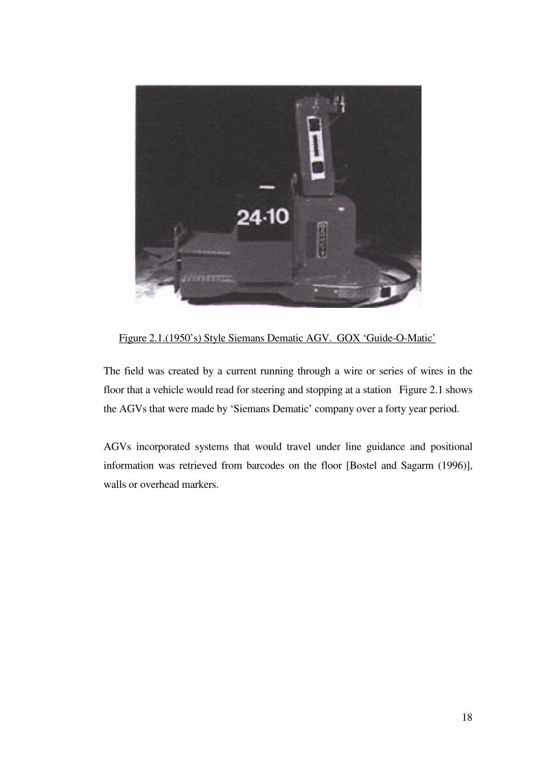
18
The field was created by a current running through a wire or series of wires in the
floor that a vehicle would read for steering and stopping at a station Figure 2.1 shows
the AGVs that were made by ‘Siemans Dematic’ company over a forty year period.
AGVs incorporated systems that would travel under line guidance and positional
information was retrieved from barcodes on the floor [Bostel and Sagarm (1996)],
walls or overhead markers.
Figure 2.1.(1950’s) Style Siemans Dematic AGV. GOX ‘Guide-O-Matic’
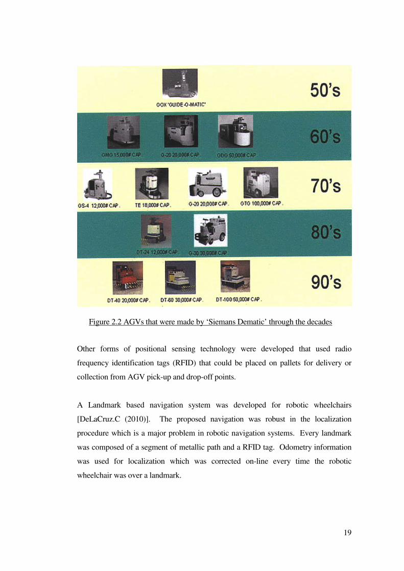
19
Other forms of positional sensing technology were developed that used radio
frequency identification tags (RFID) that could be placed on pallets for delivery or
collection from AGV pick-up and drop-off points.
A Landmark based navigation system was developed for robotic wheelchairs
[DeLaCruz.C (2010)]. The proposed navigation was robust in the localization
procedure which is a major problem in robotic navigation systems. Every landmark
was composed of a segment of metallic path and a RFID tag. Odometry information
was used for localization which was corrected on-line every time the robotic
wheelchair was over a landmark.
Figure 2.2 AGVs that were made by ‘Siemans Dematic’ through the decades
20
2.2.1 Types of automated guided vehicles
Typically, Autonomous Guided Vehicles (AGVs) were designed to transport goods or
raw materials. Many are described in [Stott (1997)]. Some more sophisticated
vehicles, were able to leave a pre-set path and navigate a different route around an
obstruction, for example the system described by [Hartley (1987)].
In 1998, a robot named Nomad was deployed into the Patriot Hills region of
Antarctica. The robot was designed as an independent, isolated autonomous vehicle
with little chance of operator intervention. The ability of a stereo vision system and
laser scanner to perceive polar terrain and the autonomous navigation system were
described in [Moorhead et al (1999)]. Navigation was assisted using landmark-based
navigation and millimetre wave radar.
The NASA mission to Mars involved the Mars Pathfinder Rover or Microrover
spacecraft. [Stone (1996)]. The Microrover was deployed from the mission vehicle
onto the surface of Mars and was then employed on experiments and tasks that
involved moving across the surface of Mars. The Microrover was a six wheeled, all
wheel drive mobile robot [Matijevic (1996)]. It was equipped with many sensors to
assist the vehicle to safely negotiate the Martian landscape.
Due to the communication delay caused by the distance from Earth to Mars, the
autonomous system was required to deal with any unexpected hazards independently
of the operator [Stone (1996)] & [Morrison, Nguyen (1996)]. Many mobile robots are
wheeled vehicles. Walking robots have also been investigated.
A walking robot can have advantages over a wheeled robot especially in unstructured
and rugged terrain. Several articulated legged vehicles have been built and the
potential of these mechanisms for negotiating rough terrain have been described by
[Kumar, Waldron (1989)].
A variety of automated AGVs have been built to provide manufacturing support and
labor saving operations:
• Towing vehicles (designed to pull load carrying carts)
21
• Assembly vehicles (designed to transport products through an assembly
process)
• Storage and retrieval vehicles (designed to lift and lower loads)
• Sorting transfer vehicles (designed to automatically load and un-load at pickup
and deposit points located around conveyor systems)
• Wheeled tele-operated robots
• Walking and climbing tele-operated robots
2.3 Walking and climbing tele-operated robots
Climbing vehicles have been developed for the nuclear industry, notably these
included the NERO and MAVIS vehicles as described by [Burrows et al (1991)] and
[Luk et al (1993)], but these vehicles were non-articulated and were designed to
operate in a particular mode. They were not suitable for unstructured environments.
At the University of Portsmouth a team led by Professor Collie developed several
remotely operated articulated-legged climbing vehicles principally for nuclear
environments [Beer (1994)]. A unique control technique provided a complaint force /
position servo control at the limb level and a task orientated control system at the
operator level [Luk et al (1991)]. With an articulated thorax [Collie et al (1993)] &
[Collie, Luk (1993)]. RobugIIs was capable of performing autonomous floor-wall
transfers [Bevan et al (1993)] and climbing semi-structured vertical surfaces, for
example the side of a ships hull.
Previous work at the University of Portsmouth has investigated systems that would
provide reflex control for pneumatically actuated articulated legged tele-robotic
vehicles that would operate in a hostile nuclear environment [Hewer (1995)], [Beer
(1994)], [Luk et al (1993)] and [Collie et al (1993)].
The environment in which a robot is required to work necessitates the need for
intelligent control [Meystrel (1988)]. Systems that are subject to multiple purposes
and abstract goals cannot be handled by current methodologies [Franklin, Selfridge
(1990)].
22
[Yamaguchi (2007)] developed a robotic chair for mobility over steep and narrow
stairways for elderly and disabled people living in a house with steep and narrow
stairways. The robot chair was vertically moved by actuation of electric cylinders and
horizontally moved by push-pull operation given by an attendant. Up and down
motions of the robot chair on the stairway were executed through combinations of
motor and cylinder actuations.
2.4 Wheeled tele-operated robots
[Galt (1999)] reported that ethical questions had arisen concerning the future
development of robotic machines, in particular the relationship between robots and
humans. Many people are simply scared by the thought of the inevitable loss of
control that is a consequence of automation. [Fernandez-Carmona (2009)] considered
wheelchair assisted navigation designed for disabled people who were able to drive a
robotic wheelchair on their own. The main novelty was that the wheelchair provided
the amount of help needed at each moment, to avoid loss of residual abilities.
A majority of 20th century robots were stationary or, had at most, limited motion
along fixed guide ways in one or two directions [Galt (1999)]. Commercially used
robots had little or no intelligence. One of the most common types of robot was the
fixed-base manipulator arm used in industrial production lines. These robot "arms"
were generally only mobile in the extension of the joints and as such had tightly
controlled, well-defined work-spaces. A mobile robot does not necessarily entertain
this luxury. The task of developing a mobile robot becomes more difficult when it is
considered that :
• Environments in which the vehicle may be required to operate will often be
geometrically unstructured, cluttered with obstacles and difficult to model or
predict
• The complex nature of the operating environments may provide uncontrollable
factors that cause the vehicle to malfunction or become damaged
• The facilities that a mobile robot has for sensing the environment are often
incapable of achieving high accuracy and can give only approximate
indications of the environmental structure. Also, without the facility for
absolute calibration, these sensing errors will accumulate over prolonged
periods
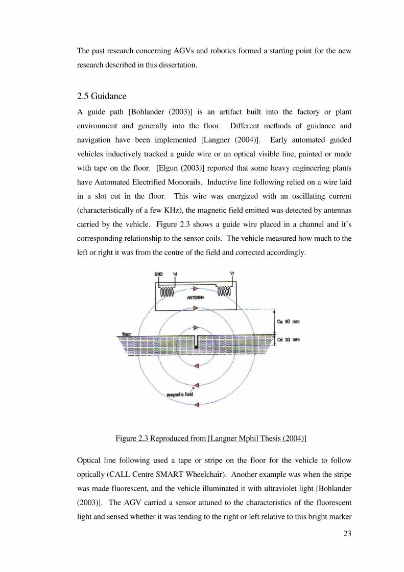
23
The past research concerning AGVs and robotics formed a starting point for the new
research described in this dissertation.
2.5 Guidance
A guide path [Bohlander (2003)] is an artifact built into the factory or plant
environment and generally into the floor. Different methods of guidance and
navigation have been implemented [Langner (2004)]. Early automated guided
vehicles inductively tracked a guide wire or an optical visible line, painted or made
with tape on the floor. [Elgun (2003)] reported that some heavy engineering plants
have Automated Electrified Monorails. Inductive line following relied on a wire laid
in a slot cut in the floor. This wire was energized with an oscillating current
(characteristically of a few KHz), the magnetic field emitted was detected by antennas
carried by the vehicle. Figure 2.3 shows a guide wire placed in a channel and it’s
corresponding relationship to the sensor coils. The vehicle measured how much to the
left or right it was from the centre of the field and corrected accordingly.
Optical line following used a tape or stripe on the floor for the vehicle to follow
optically (CALL Centre SMART Wheelchair). Another example was when the stripe
was made fluorescent, and the vehicle illuminated it with ultraviolet light [Bohlander
(2003)]. The AGV carried a sensor attuned to the characteristics of the fluorescent
light and sensed whether it was tending to the right or left relative to this bright marker
Figure 2.3 Reproduced from [Langner Mphil Thesis (2004)]
24
line. Variations on this theme included the use of white stripes on a dark floor, retro-
flective stripes that could respond to infra red light (Smart Wheelchair Systems) and
metal film stripes [Goodwin (1992)]. In the latter case, the sensing of the guide path
could be through metal detection rather than optical means. Ferrite stripes and
magnetic sensing systems had also been developed [Wakaumi (1989)].
There was considerable interest in the development of systems that could operate
without a guide wire or stripe. Many companies and people had tried to invent a
replacement for the inductive guide wire. In later years agricultural AGVs used
Global Positional System GPS navigation and systems with laser scanners, microwave
transponders, inertia gyros, ultrasonic sensors, embedded magnets and camera vision
systems.
Knowledge gained about the different tried-and-tested methods of line detection
provided a baseline for consideration of guided systems described in this dissertation.
2.5.1 First generation off-wire guidance
It was common for vehicles to be able to leave a guide path when instructed and go for
a short distance to a work station or pick-up / delivery spot, perform an operation, (for
example load transfer) and then return to the guide path. In other cases, vehicles were
programmed to make turns at intersections without using wires or to make ‘U-turns’
off wire. While it was away from the guide path a vehicle might count the number of
wheel revolutions and may measure the angle of wheels used for steering, thereby
constantly computing an estimated position. This form of navigation had commonly
been referred to as dead reckoning by odometry [Borenstien (1997)]. After a distance
of 3-10 metres, the position estimate accumulated error (from bumpiness in the floor,
wheel slips and other noise) and the vehicle needed to return to the guide path to avoid
getting lost.
Sometimes AGVs needed to cross a region where it was not practically possible to lay
a guide path. This necessitated an independent form of navigation. It was possible for
a vehicle to ‘home’ onto a beacon using a technique called ‘beam riding’. A light
source (for example, a bright red LED or laser indicated the intended path the vehicle
was required to go) was aimed at the vehicle. The AGV could be equipped with a
25
sensor to detect this beam and guide itself by keeping the light at the centre of its field
of view. Some problems included obscuration of the guiding beam. A related but
more advanced method was the use of a vision system that looked ahead for
landmarks.
2.5.2 Second generation off-wire guidance
Many users resisted changing paths or asking for new installations simply to avoid
cutting channels in the floor. With software-determined guidance, it was possible to
make frequent changes. This needed to be sufficiently accurate and reliable so that it
did not represent a hazard. The accuracy obtained from a wire guided system could be
used as a standard. ‘Off – wire’ guidance systems could be expected to position the
vehicle to within 1 cm in areas of close proximity to other objects. Nearly all second
generation machines made use of odometry and dead reckoning as an important
source of information. Beam riding or similar optical schemes had also been used in
some systems, particularly for alignment near a workstation.
Systems could navigate between workstations in a clean room by a combination of
dead reckoning and inertial guidance. Conceptually, inertial guidance did not rely on
external artifacts for its frame of reference. If inertial guidance was used as a primary
source of positional data, a two or three axis accelerometer and a two or three axis
rotation sensor were required. Measurements obtained from these devices could be
integrated in order to derive the position and attitude of the vehicle. Any such inertial
device would generate small spurious signals that caused the state of the information
to drift with time and result in cumulative errors in positional data. It was necessary to
reset the inertial navigator periodically before the drift moved the output out of
tolerance.
Optical systems have been used in factory environments using ‘lighthouse navigation’
[Bohlander (2003)]. In these systems a vehicle repeatedly scanned a light beam
through an arc around it and looked for reflections back from reflectors. The system
could compute its location provided it was able to detect at least two or preferably
three reflectors. When reflectors could not be seen then odometry and dead reckoning
methods were used.
26
2.5.3 Third generation off-wire guidance
The development of machines that could mimic the navigation skills of human beings
has formed the basis for on-going research. Candidates for this type of technology
included: computer vision systems [Appleton, Williams (1987)], [McKerrow (1991)],
[Sanders (1993)], [Sanders; Lambert; Graham-Jones, et al. (2009c)], [Sanders;
Lambert,; Graham-Jones, et al. (2010c)] and laser range finding [Parnichkun and
Samadi (1999)]. Sonic imaging techniques have also been developed using several
different principles: modulated waves [Teshigawara et al (1989)], frequency sweeps
[Lindstedt (1996)]. Echo location methods have also been described by [Stott,Sanders
(1996)], [Stott (1997] and [Stott (2002)].
Vision systems involve a camera, lighting and a computer. There are at least two
different ways to implement an attentive vision system, using either a bottom up
approach or a top down approach [Garibotto (1999)]. For the bottom up approach the
low-level features extracted from the camera image have been used to orient the
system to a particular area of interest. With the top-down approach, the visual
recognition task was driven by a specific goal and was constrained within a set of
processing algorithms. Vision systems were suitable candidates for use on a mobile
vehicle but their respective cost, complexity and environmental modifications could
be less attractive. Further appropriate references can be found in [Appleton, Williams
(1997)], [McKerrow (1991)] and [Sanders (1993)]. These systems were complicated
and expensive. [Jia P,. Hu,H (2009)] created some novel human-machine interfaces
for disabled and elderly people to control intelligent wheelchairs using facial and head
gestures.
The various technologies were considered when selecting the sensors and systems for
the powered wheelchairs used in the new research described in this dissertation.
2.6 Guidance technology for use with powered wheelchairs
Inductive systems tended to rely on hidden wires, ferrite markers and inductive loops
set into the floor surface of the working environment [Wakaumi et al (1989)]. An
active system required a signal current to generate a traceable magnetic field.
Magnetic pickups would be able to sense the wire position. The inductive guidance
27
frequency could be specific to certain routes [Wakaumi FMS Magazine (1989)].
Radio instructions could be transmitted to some vehicles to cause them to change their
travel path [Hartly (1987)].
Other forms of passive guidance tracks included optically detected tracks such as
painted lines on a floor surface. The principal of retro-reflection had been used by the
Smart wheelchair [CALL centre publication (1993a)]. Retro-reflective optical tape
could be stuck to the floor, when infrared light was targeted at a specific angle,
generally the reflected light could be detected at the same angle back from the
transmitted source. Navigation through a structured route using walls to provide a
reference for guidance had been attempted [Goodwin (2000)]. In that research,
ultrasonic sensors mounted on the side on an electrically powered mobility aide were
used to detect the side wall. A time of flight principle was used to determine the
distance from a wall and control software provided the feedback control to maintain
the system at a controlled distance parallel to the wall. [Goodwin (2000)]
demonstrated that computer control algorithms could allow a system to recognize
typical signatures, for-example doorway apertures, and then set a course to
compensate so that no significant course deviation occurred whilst passing an open
doorway.
Work on the development of a guidance system for a powered wheelchair was
undertaken by [Yoder, Baumgartner, Skaar (1996)]. The navigation and control of the
wheelchair was based on accurate estimations of the location of the wheelchair within
its operating workspace. Estimates of the wheelchair position and orientation were
produced by combining drive-wheel rotation information with the visual observations
of small passive ‘cues’ that were within the wheelchairs operating region, typically on
the walls and on other stationary objects. The system could follow routes throughout
the environment. Of particular interest was the task level (or supervisory) control
strategies adopted. Task level control of the wheelchair allowed the user to specify
the desired route to be performed by the wheelchair system, for example ‘go to the
kitchen table’. The desired task was chosen by the user by selecting the destination
toward which the user wished to proceed. Once the task was specified, the wheelchair
system controlled the chair in order to carry out the desired task. The user of the
system retained supervisory control of the wheelchair at all times. Other forms of
28
passive inductive line guidance included [Goodwin (1992)] who described the
operation of an AGV that used four inductive sensors that detected adhesive
aluminised tape fixed to the floor.
2.7 Advanced wheelchair systems
[Stott (1997)] discussed advanced and intelligent wheelchair systems. Of particular
relevance to the work described in this dissertation was the SMART Wheelchair
[Craig et al (1995a) & (1995b)] and [Nesbit (2000)]. The SMART wheelchair was
described as a set of tools for assisting the development of disabled children and is
described in section 2.7.2.
The NavChair project aimed to create a wheelchair system that co-operated with the
user in a shared decision making process [Bell et al (1994)]. The modified wheelchair
was equipped with a ring of ultrasonic sensors that could detect the environment and
calculated new trajectories for the wheelchair which approximated to the nearest
practical trajectory to that directed by the user.
A more robotic approach was the Senario project [Beattie (1993)]. The wheelchair
was equipped with many sensors including scanners to read wall mounted bar-code
beacons, laser range finders and radio beacon detectors to provide an automated
navigational system. At an estimated cost of 20,000 ECU per wheelchair the system
was expensive. Another development was a voice activated wheelchair [Murai
(2009)]. The system had two major functions, firstly a collision avoidance function by
using sensor information. This function had three autonomous movements of stop,
avoidance and deceleration. The second function was the elevator entry/exit function
which worked smoothly in a variety of situations.
Another wheelchair drawing heavily on robotic and autonomous technology was
described by [Gomi, Ide (1996)]. An autonomous wheelchair system was built into an
unmodified Fortress wheelchair. This system was interesting as behavior based
artificial intelligence was used to control the wheelchair which reduced the
dependence of the control algorithms on the hardware (by having a more flexible
approach). The sensors were for collision detection, infrared rangers and a stereo
vision system faced forward of the wheelchair. The vision system used landmark
29
navigation to move autonomously. The joystick could be used at any time to override
the control hardware. A behavior-based approach was used to establish on-board
autonomy at minimal cost, maximum safety and transparency in appearance. Two
power wheelchairs had been built and tried with the new system. Some autonomous
navigation outside was demonstrated. The system was able to navigate the wheelchair
in an automatic mode where the user did not need to make any decisions about the
route that was being driven. The system was complex which would tend to make it
expensive. A system of this type runs the risk of taking control from the user and
becoming an automated platform. High cost systems would also be outside the scope
of many powered wheelchair users. The systems described in this dissertation aimed
to provide some of the functions of the system described by [Gomi, Ide (1996)] useful,
in order to provide assistance to a powered wheelchair user without becoming too
expensive to be practical.
[Bourhis, Pino (1996)] presented some results from the VAHM (Vehicule Autonome
pour Handicapés Moteurs) project which aimed to improve the control of powered
wheelchairs by adding autonomous mobility systems. Three operating modes were
used to adapt the system to a diversity of situations. In the autonomous mode a global
trajectory was planned, and the user intervened to point the goal and stop if need be.
The assisted manual mode allowed access to wall following. Finally, in the manual
mode, the powered wheelchair became the unmodified system again. [Yoder et al
(1996)] discussed the development of an automatically guided wheelchair for
individuals who were severely disabled. A combined vision and acoustic sensor
system was used on the wheelchair. The techniques used were mainly concerned with
autonomous navigation which differs from the approach adopted at Portsmouth,
described by [Stott (1997)], where the user retained overall responsibility for
navigating the wheelchair.
There were interesting developments in a four wheel drive omni-directional
wheelchair described by [Masayoshi (2008)]. This was intended to enhance the
mobility of conventional wheelchairs. The mobile mechanism equipped four wheels,
two omni-wheels in front side and two normal tires in rear side.
The normal wheel and the omni-wheel, mounted on the same side of the base were
30
interconnected by belt transmissions to rotate in unison with a drive motor, i.e. a
synchro-drive transmission. To rotate a chair at the center of the mobile base about
vertical axis, the third motor was installed on the platform.
The prototype wheelchair with the proposed 4WD system was capable of climbing
over a high single step and translating a chair in any direction with/without rotation.
The system enabled wheelchairs to move with greater freedom and led to the
development of a novel control format in which the driver body postion controlled the
wheelchair. [Kenichi (2008)] proposed an Omnidirectional Electric Wheelchair that
had four omniwheels for the omnidirectional movement. Two of the omniwheels
were arranged to be the X-axis direction and the other two were arranged to be the Y-
axis direction. By controlling the movement of the omniwheels, the wheelchair could
instantaneously rotate and move in all directions. The operator's posture was used as a
signal to control the wheelchair.
2.7.1 INCH: An intelligent wheelchair prototype
Work by [Rao, Kuc (1989)] was an early look at the problems faced by visually
impaired wheelchair users but could also be applied to wheelchair users with
sensory-motor impairment. The "INCH" prototype wheelchair platform was powered
by two stepper motors and a microprocessor based control system. Six Polaroid
ultrasonic transducers were fitted to this platform in the following locations: directly
in front of the front wheels for forward motion, directly behind the rear wheels for
reverse operation and one each side of the front of the wheelchair for turning motions.
The sensors were directed towards the floor to constantly check the chair to the floor
distance.
Input from the user was simulated and the controller was able to modify the trajectory
of the wheelchair when a drop off was detected. This early work demonstrated the
positive assistance that could be afforded to a wheelchair user by a computer system.
The prototype was successful in avoiding drop-offs when programmed to move in
random directions on a tabletop.
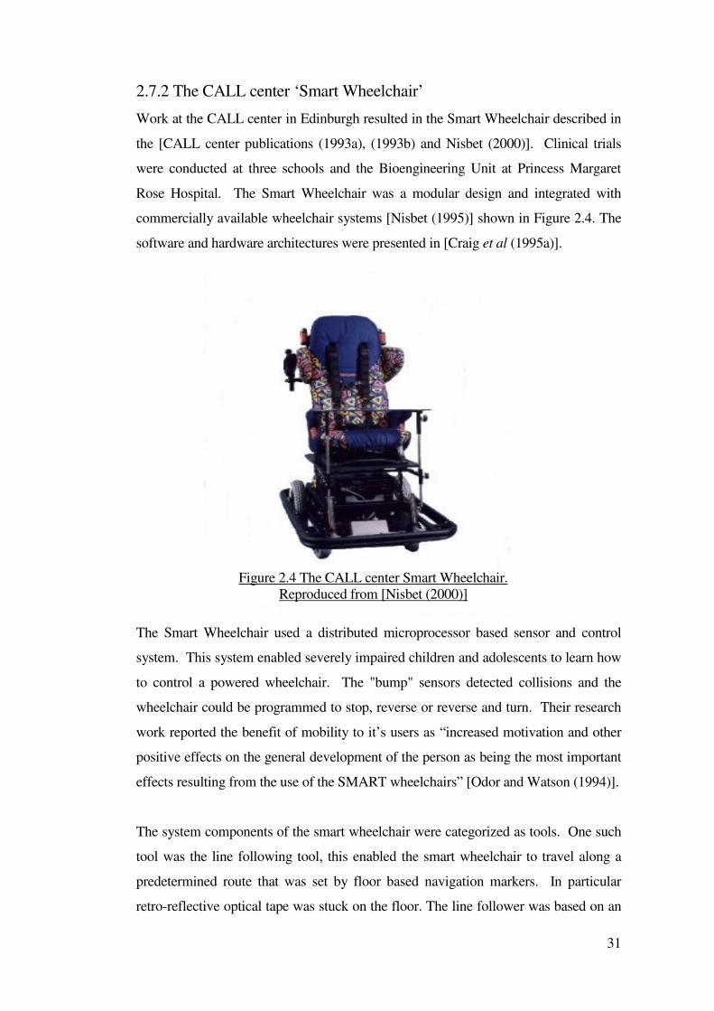
31
2.7.2 The CALL center ‘Smart Wheelchair’
Work at the CALL center in Edinburgh resulted in the Smart Wheelchair described in
the [CALL center publications (1993a), (1993b) and Nisbet (2000)]. Clinical trials
were conducted at three schools and the Bioengineering Unit at Princess Margaret
Rose Hospital. The Smart Wheelchair was a modular design and integrated with
commercially available wheelchair systems [Nisbet (1995)] shown in Figure 2.4. The
software and hardware architectures were presented in [Craig et al (1995a)].
The Smart Wheelchair used a distributed microprocessor based sensor and control
system. This system enabled severely impaired children and adolescents to learn how
to control a powered wheelchair. The "bump" sensors detected collisions and the
wheelchair could be programmed to stop, reverse or reverse and turn. Their research
work reported the benefit of mobility to it’s users as “increased motivation and other
positive effects on the general development of the person as being the most important
effects resulting from the use of the SMART wheelchairs” [Odor and Watson (1994)].
The system components of the smart wheelchair were categorized as tools. One such
tool was the line following tool, this enabled the smart wheelchair to travel along a
predetermined route that was set by floor based navigation markers. In particular
retro-reflective optical tape was stuck on the floor. The line follower was based on an
Figure 2.4 The CALL center Smart Wheelchair.
Reproduced from [Nisbet (2000)]
32
optical line operating with infrared transmitter / receiver sensors to detect the edges of
the tape. The switch operated as a dead mans handle in which the system stopped
when he or she had stopped pressing the switch.
Modification of the environment was required when floor based navigation markers
were used which made them more suitable for use in schools where the markers were
permanent. An additional tool used an array of six ultrasonic transceivers that could
be attached to the front framework of the smart system, appropriately named the slow
down tool. The sensors could detect an object in the forward path of travel and their
outputs were used to reduce the speed of the wheelchair. This was part of a damage
limitation philosophy [CALL centre publication (1993a)] and not intended to stop the
pilot getting to where he or she wishes to be, only to stop them hitting it quite as hard.
The Smart Wheelchair program was notable for its clinical based approach. [Craig et
al (1995b)] discussed evaluation methodologies that were used during the Smart
program. The [CALL centre publication (1993a)] indicated observed improvements
in the motivation and quality of life of the users involved in the SMART wheelchair
training system. This reasoning took account of conditions involved with detecting
objects that could also stop the driver from reaching their intended destination.
An advanced vision based smart wheelchair system was described by [Satoh (2007)]
to support safe self-movement for disabled people. This system had functions of
detecting both the potential hazards in a moving environment and the control gestures
of a user.
2.7.3 SENARIO
A large "smart" wheelchair project was the European TIDE project "SENARIO"
described by [Beattie (1993)]. This project aimed to produce an autonomous
wheelchair for a hospital environment. The project included fitting a laser range
finder, tilt detectors, wall barcode readers, radio beacon detectors and an intelligent
navigational capability to a powered wheelchair. The wheelchair system was
designed to have an autonomous capability to enable a patient to be transported
around a building without the need for a carer to be present. The cost of the
SCENARIO wheelchair was in the region of 20,000 ECU per unit. This is expensive
for even large institutions.
33
The new work described in this dissertation was aimed at low-cost solutions to some
of the problems associated with mobility. An approach was taken during this new
work described in this dissertation to maximise the impact of the new systems whist
remaining affordable and transparent to the system user.
2.7.4 M3S
The M3S project ran under the IMMeDIAte program which was part of the European
Union's Strategic Program for Innovation and Technology, (SPRINT). The project
was concerned with providing a standard protocol for the connection of input and
output devices to systems for use by the disabled [Dillon (1995)].
A standard wheelchair was limited to one input and one output device. The input
device was normally a joystick and the output device or end effector was the
wheelchair itself. As rehabilitation technology equipment increases in complexity and
flexibility the need for standard plug-in connections may become more important.
The M3S project allowed flexibility for the user of systems through the use of a
standard bus system. All devices were able to connect to this bus and communicate
automatically. This opened the possibility of a user having access to more than one
input device, possibly a joystick for normal use and a set of head switches for use
while carrying things. Other output devices could be operated from the same input
device. For example, it may be more convenient to the user to have access to a
keypad as well as a joystick to allow the seamless transition from driving the
wheelchair to operating a manipulator. The system was also able to allow the addition
of "smart" devices such as collision avoidance modules or navigational hardware.
With an advanced system such as M3S the addition of high technology devices to a
wheelchair could become more practical and allow wheelchair systems to be
developed in line with an individual's changing requirements.
2.7.5 VAHM Assisted navigation for powered wheelchairs
[Pruski, Bourhis (1992)] and [Bourhis et al (1993)] described how a powered
wheelchair was automated in order to assist a disabled user. Their work at The
University Of Metz in France demonstrated how automating some of the low-level
tasks involved in driving a powered wheelchair could assist a severely disabled user.
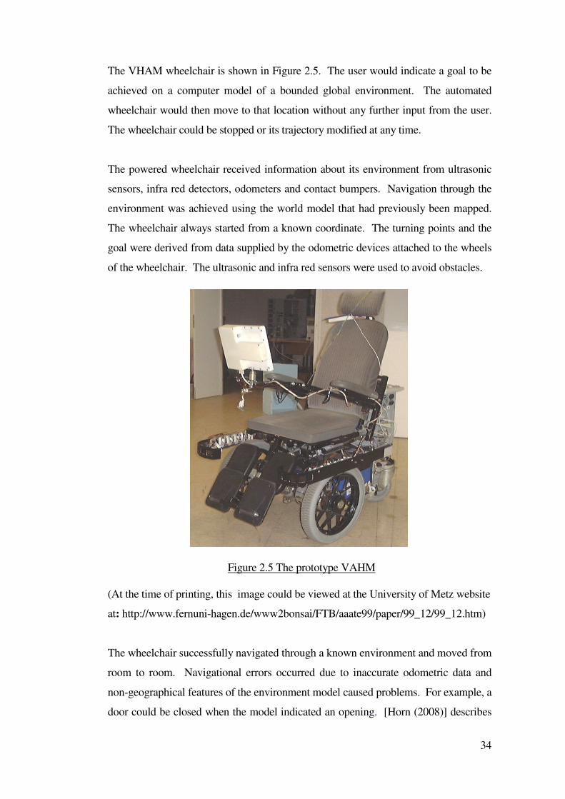
34
The VHAM wheelchair is shown in Figure 2.5. The user would indicate a goal to be
achieved on a computer model of a bounded global environment. The automated
wheelchair would then move to that location without any further input from the user.
The wheelchair could be stopped or its trajectory modified at any time.
The powered wheelchair received information about its environment from ultrasonic
sensors, infra red detectors, odometers and contact bumpers. Navigation through the
environment was achieved using the world model that had previously been mapped.
The wheelchair always started from a known coordinate. The turning points and the
goal were derived from data supplied by the odometric devices attached to the wheels
of the wheelchair. The ultrasonic and infra red sensors were used to avoid obstacles.
(At the time of printing, this image could be viewed at the University of Metz website
at: http://www.fernuni-hagen.de/www2bonsai/FTB/aaate99/paper/99_12/99_12.htm)
The wheelchair successfully navigated through a known environment and moved from
room to room. Navigational errors occurred due to inaccurate odometric data and
non-geographical features of the environment model caused problems. For example, a
door could be closed when the model indicated an opening. [Horn (2008)] describes
Figure 2.5 The prototype VAHM
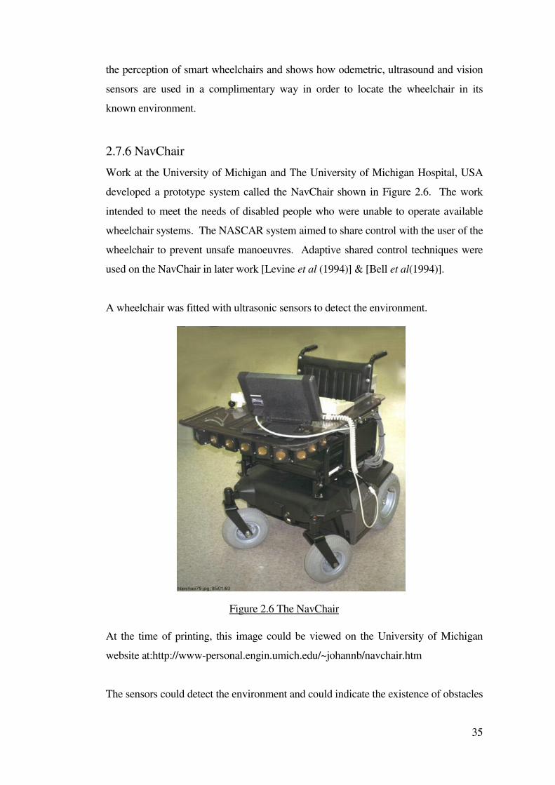
35
the perception of smart wheelchairs and shows how odemetric, ultrasound and vision
sensors are used in a complimentary way in order to locate the wheelchair in its
known environment.
2.7.6 NavChair
Work at the University of Michigan and The University of Michigan Hospital, USA
developed a prototype system called the NavChair shown in Figure 2.6. The work
intended to meet the needs of disabled people who were unable to operate available
wheelchair systems. The NASCAR system aimed to share control with the user of the
wheelchair to prevent unsafe manoeuvres. Adaptive shared control techniques were
used on the NavChair in later work [Levine et al (1994)] & [Bell et al(1994)].
A wheelchair was fitted with ultrasonic sensors to detect the environment.
At the time of printing, this image could be viewed on the University of Michigan
website at:http://www-personal.engin.umich.edu/~johannb/navchair.htm
The sensors could detect the environment and could indicate the existence of obstacles
Figure 2.6 The NavChair
36
in the path of the wheelchair. A problem occurred when trying to provide assistance
to a user because only that person themself knew their real intention. The sensor
system sometimes detected several possible safe paths. For the wheelchair to act in an
assistive manner it needed to detect the intentions of the user and take the user more
easily to that goal. An identification technique was used in an attempt to interpret the
wishes of the user and polar histograms were used to identify safe paths for the
wheelchair. This information was combined and a modified path executed by the
wheelchair. Conflicts occurred which interfered with the path selected by the
wheelchair. When approaching a doorway for example, the wheelchair could not
distinguish between the user's wish to perform a "door passage" routine or an
"obstacle avoidance" routine, which would take it past the door, and alongside the
wall. The system required more information about the intention of the user in order to
automatically perform mode selection.
A technique called "Stimulus Response Modeling" (SRM) was developed that
automatically determined the most appropriate mode of operation for the wheelchair.
This improved the Navchair's ability to interpret the wishes of the user. The SRM
technique learnt the user responses to stimuli by initiating a disturbance to the
wheelchair movements and measuring the user's response to the disturbance. Also the
Vector Field Histogram technique was developed into the Minimum Vector Field
Histogram technique. The performance of the NavChair improved to the point where
the chair would follow walls, avoid obstacles and navigate through doorways.
An aspect of this work was the requirement to successfully interpret the wishes of the
user and the incorporation of this information in the execution of a collision free path.
Sonar sensors were used to detect the environment and a local map was built in the
computer. Tests showed that the NavChair could be driven through a corridor by a
blindfolded operator at about half the speed of an experienced sighted user without
collisions.
2.7.7 The Swedish slingan project
Work aimed at improving independent mobility for people with disabilities was
undertaken in Sweden and described by [Langner (2004)]. This project offered
persons with severe motor disabilities and additional developmental problems the
opportunity to transport themselves using a wheelchair. The project was carried out in
37
the form of a driving school. The participants visited once a week for driving training
using a wheelchair. These systems used optical sensors with reflecting tape on the
floor.
2.8 Sensors
The wheelchair used in this research needed to be capable of detecting the
environment. A sensor system for a powered wheelchair needed to be accurate,
rugged, reliable, suitable for attaching to a wheelchair and cheap. A human operator
was the most accurate source of data but the accuracy of a human could be impaired
by disability. In these cases a complementary sensor system was required to assist the
operator. One of the key factors for obstacle avoidance was the implementation of
sensors. Analyzing the characteristics of various sensors was undertaken by [Tian
Zhihong (2009)] looking at a method of detecting obstacles and avoiding obstacles
used by electric wheelchairs.
Sonar sensors using the time of flight principal to measure range have been widely
used on AGVs [Hinkel et al, (1988)]. Some vision-based systems have used a
stereoscopic view to detect obstacles but these systems can require timeconsuming
data processing. As an alternative, a laser range finder could provide accurate and fast
range information [Gutmann, Schlegel, (1996)]. Sensor systems could be considered
to be within the following categories:
• Contact sensors
• Non-contact sensors
• Human operator
Contact sensors could be the simplest form of sensing for a system. Contact bumpers
were fitted to the SMART wheelchair [Nisbet (1998)] and [Nisbet (2000)] and the
chair described by [Langner (2000)]. Contact bumpers could also be used to initiate
automatic sequences for the wheelchair such as reverse and turn. Other contact
sensing methods were used by [Luk et al (1988)] and [Sanders et al (1987)] who used
the change in motor currents of a robot manipulator arm to detect contact with the
environment.
[Korzeniowski (1996)] optimised the tracking of a surface by an end effector. As the
38
environmental conditions changed, the reliability of sensors could also change. The
amount by which the systems reliance on sensor data must also change, was
discussed. Tracking a surface is an integral task for many autonomous systems. It
could be used for navigation, surface preparation or object recognition. There are two
types of control for surface following, continuous and discontinuous. A robot may
maintain contact and continuously track the surface or touch the surface at
discontinuous points. In order that the whole process can be optimised in terms of
time to complete a task and the amount of data collected. A balance was sought
between the continuous and non-continuous methods. The tracking method was
computed by a tracking algorithm using the partial data sets provided by sensors. It
was common practice to outfit automated systems with the ability to gather data from
many sensors. As the environmental conditions changed, the system’s reliance on
sensor data also changed. This work focused on the addition of the supervisory
learning module for choosing the method of surface tracking.
Non-contact sensors use a variety of techniques and mediums to sense the
environment. Typically the non-contact sensors may be passive or active. Passive
sensors are dependent upon the target providing an output that can be detected by a
sensor; such as heat, light or sound. Passive sensors would not normally be useful to
mobile vehicle applications as the sensor system could not initiate a sensor sweep.
Active sensor systems can initiate sensor sweeps of the environment on command of
the control system. Data could therefore be provided to the control system when it
was required, regardless of the target to be detected. Typically, a sensor system could
use sound as in an ultrasonic sensor system or electromagnetic energy. Visible light
was often used by sensor systems that used vision-based systems. Infrared could be
used as a form of proximity sensing. Radio frequency (radar) could also be used
along with scanning and rotating lasers. Some examples of suitable non-contact
sensors are examined in this section. An unusual example of a multi-element sensors
system is based on a radar sensor and is described by [Bouraima (2008)] who
described a six port 77GHz collision avoidance radar sensor configuration. This
system provided velocity and range information.
2.8.1 Ultrasonic sensing
Ultrasonic range-finding and object-detection systems have used several principles,
39
including: modulated waves [Teshigawara et al, (1989)], frequency sweeps [Lindstedt,
(1996)] or echo location [Stott, Sanders (1996)] & [Stott et al, (1997)]. Kay used a
novel sensor array and constant transmission frequency modulation (CTFM) sweeps
to assist blind people to detect their environment [Kay (1999a & b)]. A CTFM system
examines the response of the environment to a frequency swept sine wave. The shape
of the envelope returned to the receiver is determined by the properties of the
environment. It is possible to recognise objects by the frequency spectrum of the
receiver signal. [McKerrow, Harper (1999)] successfully differentiated between types
of leafy plants with their system. More information on ultrasonic sensor systems can
be found in [McCloy, Harris (1986)] and [Fu et al (1987)].
Single frequency pulse-echo systems can encode information on pulses in order to
reduce interference between different systems. [Kleeman (1999)] used a known
separation between two pulses to identify different systems. The receiver signal was
rapidly sampled and the separation was read as each pulse train was received. Pulses
from other sensors were rejected. Accurate angular resolution was also possible by
using two receivers mounted close to the transmitter and measuring slight time delays
between pulses.
Previous low cost systems for navigational assistance for disabled wheelchair users
have provided little more than simple obstacle and collision avoidance, or have
followed a pre-defined fixed route defined by a white line or a buried wire [Langner
(2000)]. [ Calder (2009)] described assistive technology devices that are portable
electronic hand held devices that are either hand held or worn by the visually impaired
user, to warn of obstacles ahead. Many assistive technology devices used ultrasonic
pulse-echo techniques to gauge subject to object distance. Some used infrared light
transceivers or laser technology to locate and warn of obstacles. These devices exhibit
a number of problems, the most significant of which are related to the interface
display that conveys navigation/obstacle warning information to the user. Other
sensory channels should not be compromised by the device. This is exactly what can
happen when, for example, audio signals are used in obstacle warning on/off displays
or more significantly in orientation solutions, where continuous streams of
synthetically generated stereo sound mask the natural ambient sound cues used by the
blind.
40
Other research has used complex high cost multi-sensor mode systems closely
resembling industrial, military or space exploration applications. These systems used
natural features or artificial beacons to produce accurate maps of the operating
environments. The progress of the vehicle is monitored and corrected using multi-
sensor techniques such as vision cameras, odometry and triangulation from beacons
located in the environment. Such systems have required modification of the operating
environment and have resulted in a fully autonomous vehicle providing little or no
overall control by the user. Whilst proving technical feasibility, their cost and
complexity has not resulted in practical and affordable solutions for the wheelchair
user.
The purpose of the present study was to bridge the gap between these two previous
areas of research and to provide navigational assistance at an affordable cost, in the
area described by [Goodwin (2000)] as maximum functionality at minimum cost.
Low cost ultrasonic sensors enabled a wheelchair to operate in an unknown
(previously unmapped) environment whilst leaving the user in overall control.
Hardware modifications to a commercial powered wheelchair enabled data from
ultrasonic arrays and the user’s joystick to be interrogated and mixed by a computer to
provide appropriate signals for the wheelchair drive motors.
A simulation program was created to interpret the sensor signals that would be
generated from the various conditions likely to be encountered by a wheelchair and to
develop the various control strategies. The simulation was able to differentiate
between the various environmental conditions and select the appropriate action using
the control algorithms.
The sensor data interpretation modules together with the control algorithms, from the
simulation, were incorporated into a practical system for controlling the wheelchair.
In tests, data from the sensors were used to detect and evaluate localised changes in
the environment and used to determine appropriate signals for the drive wheel motors.
It was found that the wheelchair controller and the geometry of the wheelchair
resulted in a degradation of the expected wheelchair response. This was overcome in
two ways: firstly by modifying the control algorithm and secondly by changing the
wheelchair geometry.
41
Ultrasonic sensors were selected for the new work described in this dissertation.
2.8.2 Vision Systems
Vision systems usually involve a camera, a lighting system and a computer. The
camera must be capable of providing images of sufficient quality for the system
algorithms to decode and recognise objects or features. There are at least two
different ways to implement an attentive vision system, using either a bottom-up or a
top-down approach [Garibotto (1999)]. In the case of a bottom up approach the low-
level features extracted from the camera image are used to orient the system to a
particular area of interest. In a top-down approach the visual recognition task is
driven by a specific goal and is constrained within a set of processing algorithms.
Garibotto referred to mail sorting systems, car number plate location, reading traffic
control signals, signs and landmark identification in autonomous navigation systems.
Garibotto suggests that a top-down scheme is more effective as a more accurate
control of the system is possible.
[Volodymyr (2008)] described a system for guiding blind and visually impaired
wheelchair users along a clear path that used computer vision to sense the presence of
obstacles or other terrain features and warn the user accordingly.
[Elarbi-Boudihir (2008)] described a visual guidance system for autonomous
navigation. The visual navigation of mobile robots rely mostly on road edge detection
from images taken form an onboard camera. The algorythms used to detect road
edges give globally satisfactory results. The control system involved a fuzzy approach
to function in the presence of several image artefacts, such as shadows in spaces and
lighting changes.
Anther interesting area of research was Playbot. This was a long-term, large-scale
research project, whose goal was to provide a vision-based computer controlled
wheelchair that enables children and adults with mobility impairments to become
more independent. [Andreopoulos (2008)] showed how Playbot can actively search
an indoor environment to localize a door, approach the door, use a mounted robotic
arm to open the door and go through the door, using exclusively vision-based sensors
42
without using a map of the environment. Vision systems are a suitable consideration
when selecting a sensor system for a mobile vehicle system. Considering the cost and
complexity of the system and the need to control the environment can make them a
less desirable choice. Other information on vision systems can be found in Appleton
and [Williams (1987)] & [McKerrow (1991)].
2.8.3 Laser range finders
Laser range finders can be effective and a fast method for measuring a distance to an
object. Due to their fast response, they can be useful in real-time systems [Parnichkun
(1999)]. In their paper, a long-range laser range finder (LRF) was developed. Not all
LRF systems were designed for range finding. [Jiminez et al (1999)] described a
laser-based computer vision system used on an automatic fruit recognition system. It
was based on an infrared laser range-finder sensor that provided range and reflectance
images and was designed to detect spherical objects in non-structured environments.
Similar techniques could possibly be applied to navigational systems for the
recognition of waypoints or landmarks. Further work concerning a direct application
for disabled people was collision prevention of a compact powered wheelchair using
an optical SOKUIKI sensor and applying fuzzy theory. This was described by
[Yasuda (2009)]. Some wheelchair users could not operate a powered wheelchair
sufficiently by using a joystick. A prototype control system was constructed
consisting of buttons or levers. The obstacle detection was mainly provided by
SOKUIKI optical sensors, which observed the front of the wheelchair. Additional
auxiliary optical sensors observed the side of the wheelchair. Fuzzy logic was applied
in order to improve system function for wheelchair user.
A novel automated mine detection system was described in [Das et al (1999)]. A
human operator was capable of sweeping a mine detector across rough ground without
hitting it. The operator can follow the ground profile with the detector head close to
the ground without hitting the ground or any objects on it.
Other information on laser range finders can be found in [Schilling(1990)] and [Dodd,
Rossol (1979)].
43
2.9 A Human operator within the control loop
Automated systems tend to carry out a set of tasks or procedures in response to stimuli
such as sensor input or a pre-set collection of rules. A tele-operated system receives
commands from an operator remote from the system via a communication link. The
operator remains in control. In a system where the operator and a separate control
system are working together, conflicts can occur. The problem of placing an operator
within the control loop has been investigated widely. Notably with the introduction of
intelligent and assistive systems to motor vehicles. A system was described by
[Carlson (2008)] about collaborative control in human wheelchair interaction. It
reduced the need for dexterity in precise manoeuvres. Distributing control
appropriately between man and machine is particularly pertinent to assistive
technology. Shared control techniques were used. Precise manoeuvres, such as
driving through doorways, was achieved with a reduced level of dexterity, requiring
fewer corrective joystick movements.
Work at the University of Portsmouth has investigated tele-operation [Sanders
(2009a)]. That work discovered that the efficiency of tele-operation partly
depended on the way a human interacted with a mobile-robot. The work
investigated how to make tasks easier for a human tele-operator using an expert
system to interpret joystick and sensor data [Sanders (2010a)]. Simple expert
systems improved that interaction using ultrasonic sensors. Results were presented
from a series of timed tasks completed by tele-operators using a joystick to control
a mobile-robot [Sanders (2009b)].
Tele-operators completed tests both with and without sensors and using the recently
published systems to compare results [Sanders (2010b)]. The research suggested
that the amount of sensor support should be varied depending on circumstances
[Sanders (2011)]. [Galer (1995)] described new ‘in-vehicle systems’ that provided
the driver with information about the driving task, routes to take on a journey, the
availability of parking facilities, congestion ahead and so on. Some systems went
further than simply providing the driver with information, they also took appropriate
action in place of the driver. Examples included autonomous intelligent cruise control
and lane keeping devices. These technological advances have the potential to improve
the comfort, convenience and safety and reduce accidents. When vehicular problems
44
become demanding, system designers have often proposed replacing the driver with
computer automation (and non-human sensors) [McIlvaine Parsons (1996)]. [Little
(1997)] presents more information on proposed systems for “smart vehicles”.
[Lee (1994)] and [Lee, Morey (1992)] investigated the increasing use of automation to
supplement human intervention in controlling complex systems. The use of
automation could change the operators’ role from active controllers (directly involved
with the system) to supervisory controllers (managing the use of different degrees of
automatic and manual control). The relationship between trust in automatic
controllers, self-confidence in manual control abilities, and the use of automatic
controllers are discussed. Trust, combined with self-confidence were examined and
showed how trust and self-confidence relate to the use of automation.
In general, automation was used when trust exceeded self-confidence, and manual
control when the opposite was true. Since trust and self-confidence were two factors
that guided operators interactions with automation. The design of supervisory control
systems should include provisions to ensure that operators trust reflects the
capabilities of the automation and operators self-confidence reflects their abilities to
control the system manually. There is an interesting connection with the two Airbus
disasters discussed in [Learmount (1991)] and the work by Lee. [Carroll (1997)]
discussed the use of computers in improving the usability of computer systems and
applications in a history of Human-Computer Interaction over the last 20 years.
Human-Computer Interaction (HCI) is described as the area of intersection between
psychology and the social sciences, on the one hand, and computer science and
technology, on the other. HCI researchers analyse and design specific user-interface
technologies (e.g. three-dimensional pointing devices, interactive video). They study
and improve the processes of technology development (e.g., usability evaluation,
design rationale). Through the past two decades, HCI has progressively integrated its
scientific concerns with the engineering goal of improving the usability, and
establishing a body of technical knowledge and methodology.
[Parsons (1996)] presented a system that could advise an operator with the Generic
Intelligent Driver Support (GIDS) project. The method proposed in the GIDS project
was to create four simultaneous computer simulations (experts) of a car driver’s
response to a common road situation. One simulation represented what a driver would
45
be doing, another was a reference or what an ideal driver would be doing and the third
detected the difference between them. The fourth model advised the driver what he
should be doing. The system was said to be adaptive and would adapt to the driver’s
intentions, capabilities and abilities.
Tele-operation was described by [Kwitowski et al (1995)] as a technology that could
provide significant health and safety improvements in mining operations by locating
machine operators hundreds of metres away from the face area. The US Bureau of
Mines developed a tele-operation system for continuous mining and haulage
equipment. This system featured near real-time closed-loop control.
A tele-operation system for a powered wheelchair was described by [Gunderson et al
(1996)]. A remote camera system was fitted to a powered wheelchair and a video link
was established with an operator at a control station. If the user of the wheelchair
became ill or tired whilst outside the care centre, they could call the operator via a
radio link, then the control station operator would guide the wheelchair back to safety
using a tele-operation system and wheelchair mounted video cameras.
[Wiker (1993)] discussed Tele-robotics in general. Studies had shown that the effect
of tele-robotics work on tele-operators could be having the reverse effect to that
desired. It could take an operator longer to complete a task using tele-operation.
Some operators become fatigued and frustrated and suffered from motion sickness
during tasks. Whilst it was still desirable to use manually operated or automatic
systems, there was still a place for tele-robotics in inaccessible or dangerous areas
[Hewer (1997)].
Many wheelchair users had problems in orienting themselves and manoeuvring their
wheelchair in congested environments. The ‘Collaborative Wheelchair Project
developed a system for motion guidance [Boy E, Teo CL, E Burdet (2002)]. Motion
guidance was provided by software defined paths corresponding to the users ability.
Walk-through programming was used to define a path. The user physically traced out
a path with the wheelchair in free mode. This path was recorded by odometer sensors
and check points detected by on-board CCD cameras. The recorded path could then
be used in subsequent operator movements. The collaborative learning process
46
enabled the user to define a guide path by physical example and an ‘elastic mode’ of
operation let the user deviate from the guide path. The two together gave
collaborative learning. The Collaborative Wheelchair with Path Guidance Assistance
was considered by [Zeng (2006)].
The concept at the heart of the Collaborative Wheelchair was to rely on the user’s
motion planning skills and to assist the maneuvering with path guidance. The user
decided where to go and controlled the speed (including start and stop), while the
system guided the wheelchair along software-defined paths. More information on
tele-operation is in [Sheridan (1992)] and [Sheridan (1996)].
2.10 Control
The environment in which a robot is required to work necessitates the need for
intelligent control [Meystrel (1988)]. Many of the assumptions made by control
theory need to be reconsidered if robots are to handle future tasks. Systems that are
subject to multiple purposes and abstract goals cannot be handled by current
methodologies [Franklin, Selfridge (1990)]. A localization function was considered
[Touati (2010)] as the main process for improving performances in terms of autonomy
and mobility. Making a wheelchair intelligent and autonomous allowed the
development of new methodologies to help people with disabilities.
Robustness is especially important if vehicles are to function effectively in complex
environments. Robustness has two aspects. Firstly, it implies that a tele-operated
vehicle can cope effectively with unexpected changes in its environment such as
rough or uneven terrain. Secondly, it implies that a robot can also cope with damage
to itself. Many authors have acknowledged that a hierarchal structure is essential for
effective control of articulated limbed tele-robotic vehicles, [Vlacic, Harashima
(2001)}, [Luk, Collie, Billingsley et al (1991)], [Meystel (1988)]. The higher levels
define tasks or sub-goals for the lower levels and monitor their status [Kumar,
Waldron (1989)].
Wheelchair controllers are produced by a number of manufacturers and are essentially
servo controllers that allow the wheelchair operator to control the large currents of the
drive motors using a joystick or other input device. Other features are built into the
47
controllers that provide safety for the user. Acceleration, deceleration, speed and
turning are affected by safety systems in the controller [Crane (1995)]. The safety
systems can be adjusted by carers to suit the individual requirements of the user.
Modular systems are available that have simplified the connection of controllers and
their sub-systems using a bus system [Taylor (1995)]. The majority of wheelchair
systems rely on a joystick as the only input to the system. In most cases this is
sufficient. The work described in this dissertation was aimed at those situations when
the user required a more intelligent controller system to drive a powered wheelchair
safely.
In the past, the control system has been regarded as the most crucial aspect of a mobile
robot [Galt (1999)] and [Song, Waldron (1989)]. The development of an effective
control system is difficult. [Gray (1996)] stated that the development of system
architectures for mobile robots and the integration of the required enabling techniques
of control, actuators, sensors and artificial intelligence provide some of the most
interesting intellectual challenges in current engineering development. [Fezari (2007)]
describes the design of an embedded system used to facilitate the control of a
wheelchair.
Wheelchair users are able to operate a joystick to control the chair but many more
severely handicapped users need some other means of controlling this type of robot.
The designed system is based on grouping a microcontroller with a set of ultrasonic
modules and a voice recognition processor for isolated word and speaker control. The
resulting design is used to control a wheelchair for disabled individuals based on a
vocal command.
The control system is ultimately responsible for stable operation. Any foreseeable,
and often unforeseeable events must be dealt with if the vehicle is to be used in serious
applications where robustness, reliability and efficiency are essential. The control
system must be planned and constructed so that the derived control behaviour,
conforms to safety and efficiency specifications. Also, the control system should
allow for future expansion and provide a means to reconfigure the system. The
problem is considerable when the device to be controlled has many input and output
parameters.
48
The most important considerations are the safety and reliability of both the human
operator and the wheelchair (and others). Such issues generally vary depending on the
application. In application areas such as healthcare, transportation, construction,
surveillance, agriculture and the service industries, advanced robotic devices will
come into close proximity to humans without the usual safety barriers normally
associated with manufacturing robots. An advanced mobile robot should have the
ability to operate in unstructured environments where hazards may be encountered.
Safety issues become paramount for both operational and legal requirements. This
raises a paradox within the systems, complex, intelligent behaviour can be
unpredictable yet it must be made possible to predict that the control system will
ensure safety at all times. In essence, the control behaviour should be inherently
robust and enable the device to cope with a span of difficult scenarios so that
performance will degrade in a predictable and safe manner.
The architecture of the control system should be designed for minimum representation
and complexity. This suggestion aims at creating an architecture which will be simple
to follow and understand, and thus easy for new operators to use and modify. Also,
reducing complexity will inevitably reduce development time by simplifying
debugging operations. The potential for map-ability of the control system to new
machines would greatly benefit from a minimalist design. The system must have
provisions for reconfiguration and extension. It is clear that it would be difficult to
devise an ideal control structure within the first iteration. It is therefore important to
provide a generic framework that can be updated and improved with new principles
and characteristics, without the requirement for major reconfiguration. Thus, over a
period of time the system can evolve into one that is satisfactory for our needs. This
approach also allows for the latest technologies to be integrated into the existing
system.
Development time could be reduced if control systems were transferable. Often
research and development of control systems have been specific to the vehicle in
question, with map-ability to other systems difficult, if not impossible.
Many adaptive control strategies have been around for a long time but it is AI-based
adaptive methods such as those using artificial neural networks and genetic
49
algorithms, that are achieving results [Galt (1999)]. This is due to their ability to learn
in a way that many believe is akin to human behaviour that can be found in nature.
Adaptive control is being used more and more for the development of mobile vehicles
[Galt (1999)]. A suitably applied control system that was self-optimising could make
a wheelchair faster, safer and more efficient.
Two main drive wheel and caster configurations are widely available on powered
wheelchairs. These being rear drive motors with front casters using differential
steering, and or, front wheel drive with rear trailing castors. Generally powered
wheelchairs were classified by wheelchair services and dealers into two types:
• (EPIC) (Electric Powered Indoor Chair)
• (EPIOC) (Electric Powered Indoor Outdoor Chair)
These could be difficult to steer on anything but smooth flat floor surfaces and hence
driving performance was significantly affected by the type of terrain. [Collins,
Kauzlarich (1998)] commented that a disadvantage of front wheel drive rear caster
powered chairs was that they were known to be directionally unstable and required
more manipulation by the joystick user. This was also typical of rear wheel drive
types but the veer characteristic differed.
Caster drift and camber related veering was a problem for differentially steered front
or rear wheel drive wheelchairs. The effect of the weight and the positioning of the
wheelchair occupant affected the severity of the camber associated veer. To
compensate for this, some wheelchairs, for example the NavChair, had rotation
sensors built into the motor drive units. [Langner (2008)] developed a system that
controlled and reduced wheelchair veer on slopes. This system used a rotation sensor
on the caster to provide steering control feedback. Later work included implementing
wheelchair deviation detection using solid state gyroscopes.
The NavChair shown in Figure 2.7, was developed at the University of Michigan
Hospital [Levine (1999)]. This provided independent closed loop velocity feedback
[Jaros (1993)]. By monitoring the velocity feedback, electronic speed compensation
could be applied to keep the wheelchair on the piloted course.
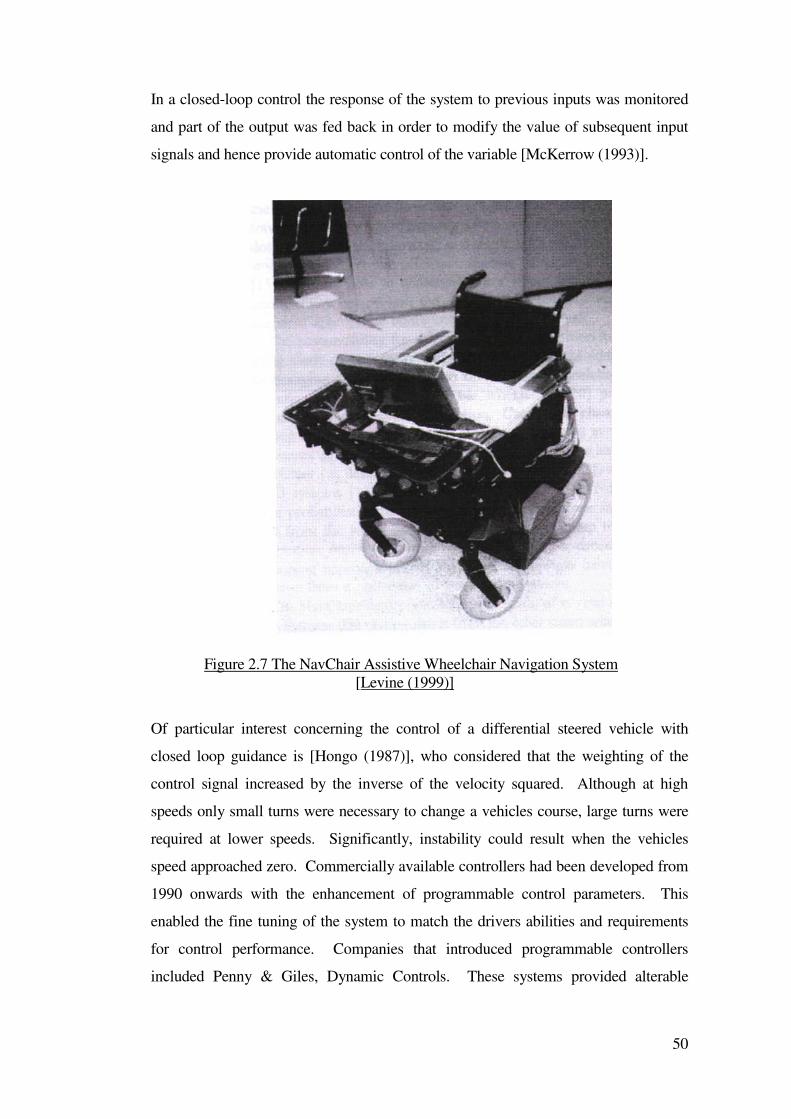
50
In a closed-loop control the response of the system to previous inputs was monitored
and part of the output was fed back in order to modify the value of subsequent input
signals and hence provide automatic control of the variable [McKerrow (1993)].
Figure 2.7 The NavChair Assistive Wheelchair Navigation System
[Levine (1999)]
Of particular interest concerning the control of a differential steered vehicle with
closed loop guidance is [Hongo (1987)], who considered that the weighting of the
control signal increased by the inverse of the velocity squared. Although at high
speeds only small turns were necessary to change a vehicles course, large turns were
required at lower speeds. Significantly, instability could result when the vehicles
speed approached zero. Commercially available controllers had been developed from
1990 onwards with the enhancement of programmable control parameters. This
enabled the fine tuning of the system to match the drivers abilities and requirements
for control performance. Companies that introduced programmable controllers
included Penny & Giles, Dynamic Controls. These systems provided alterable
51
(programmable) options of, forward, reverse, turning and acceleration, deceleration
speed and time values.
For developmental research, the preferred driver profiles did not offer the closed loop
system performance required for alternative system guided control. [Jaro, Levine,
Bell (1994)] found it necessary to redesign the joystick interface during their
development of the NavChair wheelchair navigation system. Signal conditioning
within the joystick module, that limited velocity and acceleration of the wheelchair
when under normal user control, produced an unacceptable delay in the response of
the wheelchair. The joystick was modified to bypass this conditioning feature and to
enable the raw signal data to be input directly to the controller. For some systems
there can be a fundamental limit on the processing signal speed. A good example is
with the Dynamic DX system which was based on the CAN serial data transmission
standard. Each transmitted frame took 20 ms and additional incremental program
control operations increased this time further. During the creation of the Chailey track
guidance system, modification was required to the commercial wheelchair controller
in order to speed-up response time.
2.11 Fly – By –Wire (FBW)
Fly-By-Wire (FBW) is a term which loosely describes a system where control data is
passed around a system using electronic signals by wire [Sanders, Baldwin (2001)].
[Machine Design (1992)] gives a brief general introduction to FBW technology. The
technology has been applied to aircraft. [Hamond et al (1989)] described the
Electronic Flight Control System destined for use on Boeing aircraft and notably, the
Airbus aircraft. [Learmount (1991)] examined two Airbus crashes that cast doubt
over the reliability of the FBW systems in aircraft. The reports are interesting because
they may indicate the over reliance of the pilots on the technology.
[Hammond et al (1989)] describes the Electronic Flight Control System (EFCS)
destined for use on Boeing aircraft. The use of multi-channel independent control
systems are presented and the safety applications discussed. The entirely electronic
FBW system replaced the mechanical cable/quadrant/pushrod system used on earlier
aeroplanes. The FBW system, must meet high standards of integrity and reliability.
52
The heart of the FBW concept is the use of redundant, dissimilar computing and
communication channels.
Modern wheelchair control systems, for example Dynamic Controls and Penny &
Giles (Omni’+’ controls), used a control technology that fell within the definition of
fly-by-wire. Control data is passed around the system by a serial data stream. The
interlinked system components on a wheelchair could include: joystick, drive motors,
actuators (elevating leg rest) and environmental control transmitters
An important aspect about FBW was its reliability and immunity from data transport
errors that could have an adverse effect on personal safety. Factors concerning the
transmission medium that could increase immunity to electromagnetic susceptibility
to data corruption included the use of optical fiber signal lines. It is particularly
notable that reliability is a key issue that must extend beyond the transport of data
around a control system. An example of the design of a highly safe model vehicle for
rear-end collision avoidance was described by [Kasuga (2009)] who presented the
design of a highly safe driving control system using different kinds of sensors and its
evaluation in order to avoid the rear-end collision of the model vehicle. An
appropriate combination of different kinds of sensors is introduced to reduce the
occurrence of multiple faults, it is also shown in the experiment that the rear-end
collision avoidance can be achieved even if a fault occurs at any sensor.
2.12 Projects for people with special needs
Due to the rich diversity of user requirements, a project called the M3S interface was
established to provide an adaptable interface for a wide range of needs. Performance
factors for wheelchairs could be tailored to match individual requirements. The main
purpose of the project was to allow different user control devices to be used. This
entailed the development of joysticks, ultrasonic head movement detectors, speech
recognition systems, eye movement detection and sip – puff tubes. A wide range of
output devices such as environmental controls for domestic lighting and telephone
communications had been developed and these were frequently used as add-on
modules with a wheelchair.
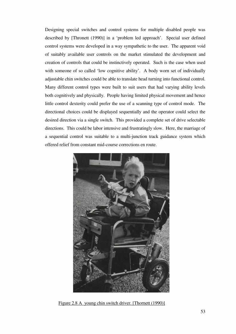
53
Designing special switches and control systems for multiple disabled people was
described by [Thronett (1990)] in a ‘problem led approach’. Special user defined
control systems were developed in a way sympathetic to the user. The apparent void
of suitably available user controls on the market stimulated the development and
creation of controls that could be instinctively operated. Such is the case when used
with someone of so called ‘low cognitive ability’. A body worn set of individually
adjustable chin switches could be able to translate head turning into functional control.
Many different control types were built to suit users that had varying ability levels
both cognitively and physically. People having limited physical movement and hence
little control dexterity could prefer the use of a scanning type of control mode. The
directional choices could be displayed sequentially and the operator could select the
desired direction via a single switch. This provided a complete set of drive selectable
directions. This could be labor intensive and frustratingly slow. Here, the marriage of
a sequential control was suitable to a multi-junction track guidance system which
offered relief from constant mid-course corrections en route.
Figure 2.8 A young chin switch driver. [Thornett (1990)]
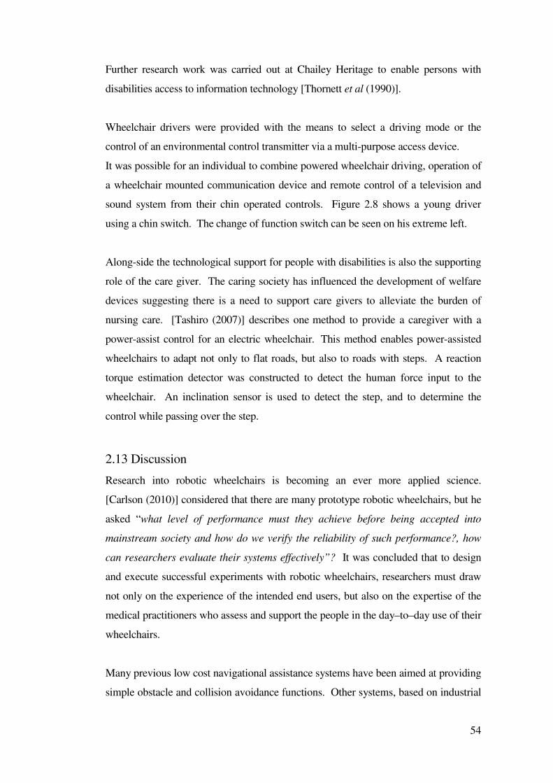
54
Further research work was carried out at Chailey Heritage to enable persons with
disabilities access to information technology [Thornett et al (1990)].
Wheelchair drivers were provided with the means to select a driving mode or the
control of an environmental control transmitter via a multi-purpose access device.
It was possible for an individual to combine powered wheelchair driving, operation of
a wheelchair mounted communication device and remote control of a television and
sound system from their chin operated controls. Figure 2.8 shows a young driver
using a chin switch. The change of function switch can be seen on his extreme left.
Along-side the technological support for people with disabilities is also the supporting
role of the care giver. The caring society has influenced the development of welfare
devices suggesting there is a need to support care givers to alleviate the burden of
nursing care. [Tashiro (2007)] describes one method to provide a caregiver with a
power-assist control for an electric wheelchair. This method enables power-assisted
wheelchairs to adapt not only to flat roads, but also to roads with steps. A reaction
torque estimation detector was constructed to detect the human force input to the
wheelchair. An inclination sensor is used to detect the step, and to determine the
control while passing over the step.
2.13 Discussion
Research into robotic wheelchairs is becoming an ever more applied science.
[Carlson (2010)] considered that there are many prototype robotic wheelchairs, but he
asked “what level of performance must they achieve before being accepted into
mainstream society and how do we verify the reliability of such performance?, how
can researchers evaluate their systems effectively”? It was concluded that to design
and execute successful experiments with robotic wheelchairs, researchers must draw
not only on the experience of the intended end users, but also on the expertise of the
medical practitioners who assess and support the people in the day–to–day use of their
wheelchairs.
Many previous low cost navigational assistance systems have been aimed at providing
simple obstacle and collision avoidance functions. Other systems, based on industrial
55
automated guided vehicle technology, have enabled a wheelchair to follow a line or a
buried wire along a pre-defined fixed route within a school or institutional
environment. The routes were defined by the positioning of lines or buried wires,
which have involved modification of the environment. Whilst reducing the
wheelchair users dependence on helpers, these systems have provided limited personal
choice in the selection of routes and increased a users level of independence to an
extent where some have progressed to “normal” unguided powered wheelchairs.
Other research has been conducted using complex multi-sensor mode systems closely
resembling industrial, military or space exploration applications. Natural features,
artificial beacons and accurate maps of the operating environment have been created
from which a trajectory has been determined. The movement of the vehicle has
sometimes been monitored and corrected using multi-sensor techniques such as vision
cameras, odometry and self-location from natural landmarks or artificial beacons
located in the environment. Such systems have enabled a vehicle to operate in a
previously known and modified environment.
More complex systems, that did not require modification of the environment, have
enabled a vehicle to operate in a previously unknown environment. Both systems
have resulted in fully autonomous vehicles that could provide little or no personal
control to be exercised by the user. Although proving the technical feasibility of such
systems within the laboratory, their cost and complexity have not provided the
wheelchair user with a practical and affordable solution. Powered wheelchairs and
many other aids for disabled people tend to be personally adapted for the individual
person. Some requirements result in a unique piece of equipment being manufactured
in a rehabilitation workshop. Even successfully deployed powered wheelchair
systems such as the SMART wheelchair are not considered suitable for all powered
wheelchair users. A generic solution, although theoretically and financially desirable,
is probably not feasible.
The provision of navigational assistance, rather than fully autonomous transportation,
to a powered wheelchair user which assisted that user to operate in a previously
unknown and unmodified environment was a promising area for research.

56
Fully autonomous vehicles have tended to require accurate and fast sensing systems.
Slow or inaccurate sensor systems tend to limit the speed of the vehicle and the
accuracy that the vehicle could navigate. Any form of mapping an unknown
environment by a free ranging vehicle can be a long process and demand a specific
pattern for the vehicle to follow. It is possible that a free ranging wheelchair could
gather enough sensory data to map an environment. It is likely that the map would
contain gaps. It may be possible to use simple low cost sensors to provide
navigational assistance for a free-ranging powered wheelchair. The extent to which
the assistance could be intelligent, given the low quality of information that a low-cost
system could produce, was investigated during the new work described in this
dissertation.
Variations in the operating conditions, such as floor surfaces, gradients and tyres make
the maintenance of a straight line course difficult even for an expert powered
wheelchair user. The interface between the wheelchair system and the user could
sometimes be confused. An obstacle avoidance system can prevent a user from
driving a wheelchair to an exact position. An intelligent wheelchair system should
aim to allow the user access to any safe area without injury to the user, damaging the
environment or damaging the wheelchair system. The new intelligent wheelchair
system created during this work would allow a severely disabled person to use a
powered wheelchair more safely than with an unmodified powered wheelchair
system.
There were problems involved with the application of assisted mobility systems for
people with disabilities. Some of these were:
• The type of difficulties the person had with driving a powered wheelchair
• The application of the assisstive system
• What the system provided
At Chailey Heritage (pre-1990) powered wheelchairs were provided to children and
young adults who could demonstrate suitable dexterity and fine control of joysticks as
generally powered wheelchairs were fitted with joysticks. Before the start of the work
described in this dissertation, joysticks were the main form of control. There was
provision of bespoke switch controls that were developed and made by the Lady
Hoare Rehabilitation Engineering Unit at Chailey Heritage.
57
The control systems that were provided were usually the preserve of those who had or
were able to develop accurate switch control. A project that was research funded by
the Spastics Society created special switch controls [Thornett (1990)]. This provided
an increase in the variety of control options and these were made available to the
school pupils. Two important aspects involved with driving were: the pupil’s mental
cognitive understanding and physical control dexterity. There could also be additional
sensory impairments to consider, for example, visual impairment could exclude those
who could be physically and mentally able to drive.
At Chailey Heritage high value was placed on personal mobility and many children
were not driving. Some areas of this work were described by [Langner (2010)] to
improve wheelchair driving using a sensor system to control wheelchair-veer and
variable-switches as an alternative to digital switches or joysticks. The work done at
centres elsewhere (The CALL Centre) offered mobility to those who could not drive
conventionally. There were also Automated Guided Vehicle systems in use in
industry that used techniques which could transfer into applications for assisstive
mobility for disabled drivers.
The projects and systems described in this Chapter did not all relate to applications
which assisted wheelchair users. The automated guided systems used in industry,
demonstrated practical examples of how it could be possible to apply guidance control
systems to motorized platforms. Systems that relied on white optically detectable
lines or guiding signal wires along a pre-defined route or strategically located beacons,
involved modification of the particular environment.
Research has been conducted using high-cost multi-sensor mode systems closely
resembling industrial applications. Using environmental features or artificial
beacons, maps of the operating environment have been created, enabling a trajectory
route to be implemented. The subsequent travel of the vehicle can be monitored
and/or corrected from the processed data obtained from using multi-sensor systems
including vision cameras, odometry, triangulation and inertial guidance.
Such systems based on artificial beacons have enabled a vehicle to operate in a
previously known and modified environment. More complex systems that did not
58
require modification of the environment enabled a vehicle to operate in a previously
unknown environment. Some systems have evolved into fully autonomous vehicles
that provide little or no personal control by the user. Although proving the technical
feasibility of such systems in the laboratory or industrial environment, their cost and
complexity have not provided wheelchair users with a practical and affordable device.
The development of the Chailey Heritage Multi-Junction Wheelchair Guidance
System was specifically for users to drive in their living and school environment.
Additionally, the system needed to operate within the constraints imposed by cost,
environment, type of wheelchair and user control. These parameters could not be
practically changed.
At the early stage of the research described in this dissertation, young drivers
demonstrated an ability to initiate driving by the operation of a driving control switch.
Often the nature of the operator’s disabilities meant that stopping their wheelchair
before contact or collision with an object was not reliable. Indeed some children
could not understand the concept of stopping before impact, or could not stop because
of sensory deprivation. Objects could be detected by:
• Contact sensor (bumper)
• Non-contact (proximity) sensors
• Personal operator sensory function and ability
Direct contact bumper detectors could provide a warning and cut power to the
wheelchair drive motors when in a collision. These were basic forms of control
intervention and were used on the SMART wheelchair [Nesbit (1996)] and [Nesbit
(2000)] and the track following wheelchair described by [Langner (2000)]. The
SMART system could be programmed to respond to physical contact with an object.
Such sequences could include automatic reverse and turn manoeuvers.
Factory oriented AGVs could also be equipped with a contact sensor. They may also
have additional non-contact proximity sensors mounted onboard. A mix of sensors
and multiple sensor types on the same vehicle provided a safeguard in case of a failure
of one of the sensors. If, for example, a sonic sensor ‘mis-read’ the mechanical
bumper could be a backup. Other contact sensing methods were used by [Luk et al
(1988)] and [Sanders et al (1987)] who used the change in motor current of a
manipulator to detect contact with the environment.
59
Contact-less sensing had the advantage of detecting objects without physically
touching and sometimes the ability to determine the range of an object. This could be
through time of flight delay. Ultrasonic techniques have been widely used in this
application due to their low cost and generally acceptable accuracy. [Stott (1997)] and
[Stott (2002)] and [Goodwin (2000)] used ultrasonic time of flight ranging as the
primary source of guidance for autonomous vehicle research. Other forms of object
detection could be achieved optically using infrared transmitters and receivers, laser
range finders, triangulation or phase correlation.
Laser Range Finding (LRF) could be an effective and fast method for measuring
distance. Due to fast response LRF could be useful in real-time systems [Parnichkun,
Samadi (1999)]. They described LRF as ‘a single point optical triangulation
instrument, which detected distance information quickly without touching the object
being measured’.
Sonar systems using time of flight principles were widely used in many vehicle
systems as a means of obstacle detection and avoidance and this was generally
cheaper than LRF technology. [Stott (1997)] used ultrasonic detectors in the
development of a system that could detect doorway signatures for the purpose of
doorway navigation.
Some extra notes on intelligence in robots, communication, force feedback, sensor
fusion and navigation are included in Appendix B for wider reading.
60
Chapter 3
Effort reduction systems
This Chapter describes research to create new systems to assist users to steer their
powered wheelchairs.
3.1 Veer reduction
A veer reduction system was designed to help wheelchair users drive across sloping
ground without veering off course. The research involved the creation of simple and
affordable systems that could be attached to many standard powered wheelchairs.
Engaging in an active lifestyle is beneficial for maintaining quality of life [Pate RR
(1995), U.S. Department of Health and Human Services (2000)] and a powered
wheelchair can help towards providing that lifestyle for some people. Independent
mobility such as crawling, walking, and running are usually acquired in the first two
years of life [Verburg (1984)]. These abilities and their development are often taken
for granted but some disabled people do not experience them. Instead a powered
wheelchair may provide a partially equivalent process [Langner (2004)].
[Trefler (2004)] completed a study to measure the effects of individually prescribed
wheelchair systems. Wheelchair users rely on their wheelchairs for mobility for
extended periods of time every day [Wolf E (2007)], [Cooper RA (2002)] and several
studies have investigated the mobility characteristics and activity levels of wheelchair
users, for example [Tolerico ML (2007)], although these have tended to concentrate
on manual wheelchairs. It is generally accepted that wheelchairs have provided an
opportunity for increased continuity in the lives of some people, for example stroke
survivors [Barker DJ (2004)] and a wheelchair has often made activity and
participation in wider society possible [Brandt A (2004)]. [Buning (2001)] stated that
the transition to a powered wheelchair enhances occupational performance,
competence, adaptability, and self-esteem for persons with severe mobility
impairments.
As wheelchair technology becomes increasingly sophisticated and complex, so do
61
decisions regarding who gets what wheelchair [Hubbard SL (2007)] and evaluating
the use of powered wheelchairs is important because of the increasing number of
people with disabilities who are being provided with one [Pettersson (2007)]. These
decisions are even more significant because large amounts of money are being spent
on wheelchairs. For example, manual and power wheelchairs and scooters were the
second, third, and fifth highest Prosthetics and Sensory Aids Service spending totals
respectively during the year 2000 (that translated to a cost of more than $50 million in
that year alone for the US Veterans Health Administration).
[Woods B (2003)] wrote a short history of powered wheelchairs, a survey of
wheelchair providers was completed by [Guerette P (2005)] and a survey of
wheelchair-use by residents of nursing homes was completed by [Fuchs RH (2003)]
and these are included as references for further reading.
Powered wheelchairs are normally supplied with a proportional joystick. This enables
a user to control speed and direction. A small amount of joystick movement in the
selected direction and the wheelchair will start a gentle turn in that direction. If the
driver applies more joystick movement then the wheelchair will turn more sharply.
Similarly for speed, when the joystick is progressively moved forward, the wheelchair
will progressively increase speed.
Wheelchairs generally steer by having two swiveling caster wheels. This simple
system provides maneuverability. The drive wheels rotate at speeds determined by
joystick operation. To go forwards in a straight line both drive wheels rotate at the
same speed. To turn, one drive wheel rotates faster than the other.
Problems with this configuration occur when the wheelchair is driven along sloping
ground because the casters can swivel in the direction of the slope [Brubaker CE
(1986)]. Gravity causes the wheelchair to start an unwanted turn or ‘veer’. The driver
usually senses this and applies correction to counter this veer. This causes extra work
for the driver as the chair goes in an unintended direction. This situation is
exacerbated for switch users, as switches cannot provide fine control to trim and
compensate for veer. A switch user will frequently need to hop between directions
and forward control switches to keep control of the intended direction. Wheelchairs
62
can also veer when driven over a flat surface. This can occur as a result of imbalances
in the drive motors, tyre wear and mechanical friction of the moving parts and caster /
wheel bearings. Some modern wheelchair controls can electronically trim and
compensate so that a chair can hold a straight direction on level ground. They will not
automatically correct for changes in wheelchair loading and sloping ground effects.
To address these problems, some systems were considered to model the environment
around the wheelchair [Sanders (1995a)], predict terrain ahead of the wheelchair
[Urwin-wright (2002)], [Urwin-wright (2003)] and [Stott (2000)], consider forces on
the wheelchair [Sanders(2007)] or to plan paths for the wheelchair [Goodwin (1997)]
and [Sanders (1995b)]. These were rejected as too complex and / or to expensive.
Other researchers had investigated the use of safety restraints to assist in wheelchair
use [Van Roosmalen L (2005)] but it was considered better to investigate ways of
assisting users in steering their wheelchairs.
[Gaal RP (1997)] stated that aspects of wheelchair stability, particularly the effects of
wheelchair configuration are important engineering issues affecting wheelchair safety.
Some studies have investigated changing the rear-wheel camber angle to reduce veer
but they have had differing results [Perdios (2007)]. Increased rear-wheel camber has
some minor disadvantages, such as increased wheelbase and decreased wheelchair
height although some studies report some advantages [Brubaker CE (1986)]. More
recent studies suggest little or no advantage with cambered wheels to improve veer
[Buckley SM (1998)] although [Trudel G (1997)] suggested that camber improved
maneuverability and stability on a side slope and recent results of user preference
surveys conducted by [Perdios A (2007)] appear to support this finding (although no
difference in comfort was detected). Increased chair width can improve turning
stability and reduce downward turning tendency on side slopes but any advantage in
that change of design may be cancelled out by problems when a user is negotiating
obstacles [Denison I (1994)] and [Trudel G (1995)]. In addition, many camber studies
have been conducted using non-disabled subjects with little or no experience in using
powered wheelchairs, with the results then extrapolated [Van der Woude LH (2001)],
[Ruggles DL(1994)], [Brubaker (1986)]; [Reid M (1990)] and [Rudins A (1997)] and
sometimes to powered wheelchairs. This method was often used to form larger or
more convenient sample sizes, and the results may not all be directly applicable. The
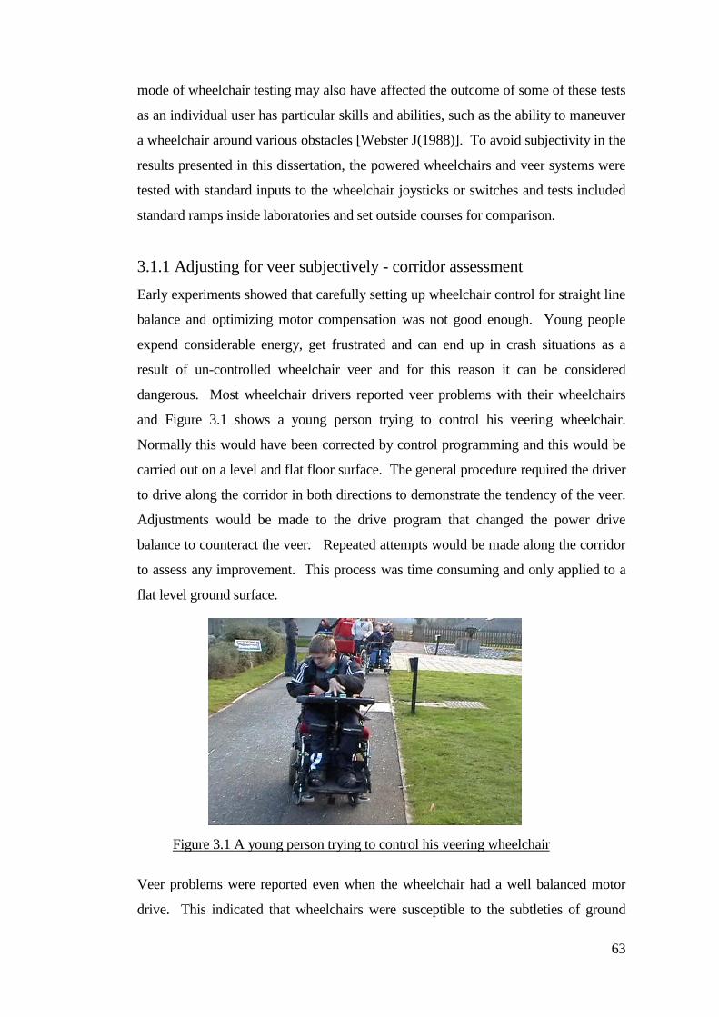
63
mode of wheelchair testing may also have affected the outcome of some of these tests
as an individual user has particular skills and abilities, such as the ability to maneuver
a wheelchair around various obstacles [Webster J(1988)]. To avoid subjectivity in the
results presented in this dissertation, the powered wheelchairs and veer systems were
tested with standard inputs to the wheelchair joysticks or switches and tests included
standard ramps inside laboratories and set outside courses for comparison.
3.1.1 Adjusting for veer subjectively - corridor assessment
Early experiments showed that carefully setting up wheelchair control for straight line
balance and optimizing motor compensation was not good enough. Young people
expend considerable energy, get frustrated and can end up in crash situations as a
result of un-controlled wheelchair veer and for this reason it can be considered
dangerous. Most wheelchair drivers reported veer problems with their wheelchairs
and Figure 3.1 shows a young person trying to control his veering wheelchair.
Normally this would have been corrected by control programming and this would be
carried out on a level and flat floor surface. The general procedure required the driver
to drive along the corridor in both directions to demonstrate the tendency of the veer.
Adjustments would be made to the drive program that changed the power drive
balance to counteract the veer. Repeated attempts would be made along the corridor
to assess any improvement. This process was time consuming and only applied to a
flat level ground surface.
Veer problems were reported even when the wheelchair had a well balanced motor
drive. This indicated that wheelchairs were susceptible to the subtleties of ground
Figure 3.1 A young person trying to control his veering wheelchair
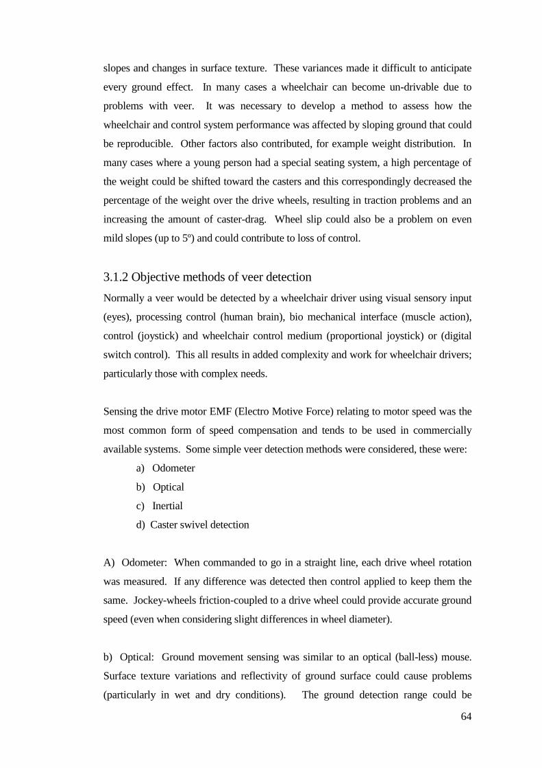
64
slopes and changes in surface texture. These variances made it difficult to anticipate
every ground effect. In many cases a wheelchair can become un-drivable due to
problems with veer. It was necessary to develop a method to assess how the
wheelchair and control system performance was affected by sloping ground that could
be reproducible. Other factors also contributed, for example weight distribution. In
many cases where a young person had a special seating system, a high percentage of
the weight could be shifted toward the casters and this correspondingly decreased the
percentage of the weight over the drive wheels, resulting in traction problems and an
increasing the amount of caster-drag. Wheel slip could also be a problem on even
mild slopes (up to 5º) and could contribute to loss of control.
3.1.2 Objective methods of veer detection
Normally a veer would be detected by a wheelchair driver using visual sensory input
(eyes), processing control (human brain), bio mechanical interface (muscle action),
control (joystick) and wheelchair control medium (proportional joystick) or (digital
switch control). This all results in added complexity and work for wheelchair drivers;
particularly those with complex needs.
Sensing the drive motor EMF (Electro Motive Force) relating to motor speed was the
most common form of speed compensation and tends to be used in commercially
available systems. Some simple veer detection methods were considered, these were:
a) Odometer
b) Optical
c) Inertial
d) Caster swivel detection
A) Odometer: When commanded to go in a straight line, each drive wheel rotation
was measured. If any difference was detected then control applied to keep them the
same. Jockey-wheels friction-coupled to a drive wheel could provide accurate ground
speed (even when considering slight differences in wheel diameter).
b) Optical: Ground movement sensing was similar to an optical (ball-less) mouse.
Surface texture variations and reflectivity of ground surface could cause problems
(particularly in wet and dry conditions). The ground detection range could be
65
extended by using an optical magnifier.
c) Inertial: Gyro / rate of rotation sensor measuring the precession of a gyro to the
rotation of the wheelchair when veer causes turning downhill. Consideration must be
given to the effects of other variables, for example slopes, shock, vibration, drift and
time to establish a reference heading.
At the time of writing the relative complexity and cost of these systems remains high
compared to using caster-swivel-detection.
d) Caster swivel detection: The selected method for veer detection was by caster-
angle-measurement. Providing direct measurement of steering error and providing
feedback to the wheelchair drive control system. A single caster could lose contact
with the ground and therefore averaging two caster-swivel-detector-outputs could
provide and generate better feedback but to simplify the systems and reduce costs,
experimental trials were based on a single caster-swivel-detector. To reduce the
tendency for misreads if the caster lost contact with the ground, the system
incorporated a short-term-memory and any sudden swivel changes were ignored by
the correction system. Locking the casters manually required substantial further
development of the caster mechanics and so caster locking was effectively achieved
electronically by using swivel-feedback-information to feedback to the wheelchair
drive controller.
3.1.3 Correction feedback
At the point when the veer was first detected, the chair had already begun to alter
course. The job of the correction system was to minimize this drift from the required
course. The amount of compensation feedback determined how accurately the
wheelchair held its course against gravity pulling against the chair. The amount of
applied feedback was critical to avoiding problems of instability.
3.1.4 The rolling road test bed
A rolling-road was developed as an assessment tool to study the affects of wheelchair
loading in a controlled environment. For a wheelchair to travel in a straight line, both
66
drive wheels needed to rotate at the same speed (assuming they were exactly equal in
diameter). An accurate assessment can be obtained by using tacho measurement
wheels coupled to the main wheelchair drive wheels. Tacho sensing of the motor
drive shaft speed does not take into account variances of wheel diameters and wheel
slip. Remote taco sensing provided sufficient accuracy for the straight line test but
could not control the drive loading. The rolling-road test-bed shown in Figure 3.2,
was developed to assess drive motor and control performance. This test-bed
incorporated tacho-rotation speed-sensing and variable-dynamic-loading. The test-
bed provided individual distance counters for left and right drive wheels respectively,
differential drive balance indicator (veer) and drive speed Kph indicators. It was
necessary to provide separate speed and distance information to determine the
motor/drive speed characteristics separately.
Trials with the test bed were conducted on sample wheelchairs to evaluate the
effectiveness of the rolling road system. These trials demonstrated the importance of
measurable parameters that affected veer that were not apparent during corridor tests
with wheelchair drivers. The rolling road system was also more convenient for
younger wheelchair drivers who did not have to endure the frustrations of the corridor
test (which could often be indecisive).
Most modern wheelchair control systems incorporate programmable load
compensation. This helps keep the wheelchair speed constant when driving up or
Figure 3.2 Rolling road test bed
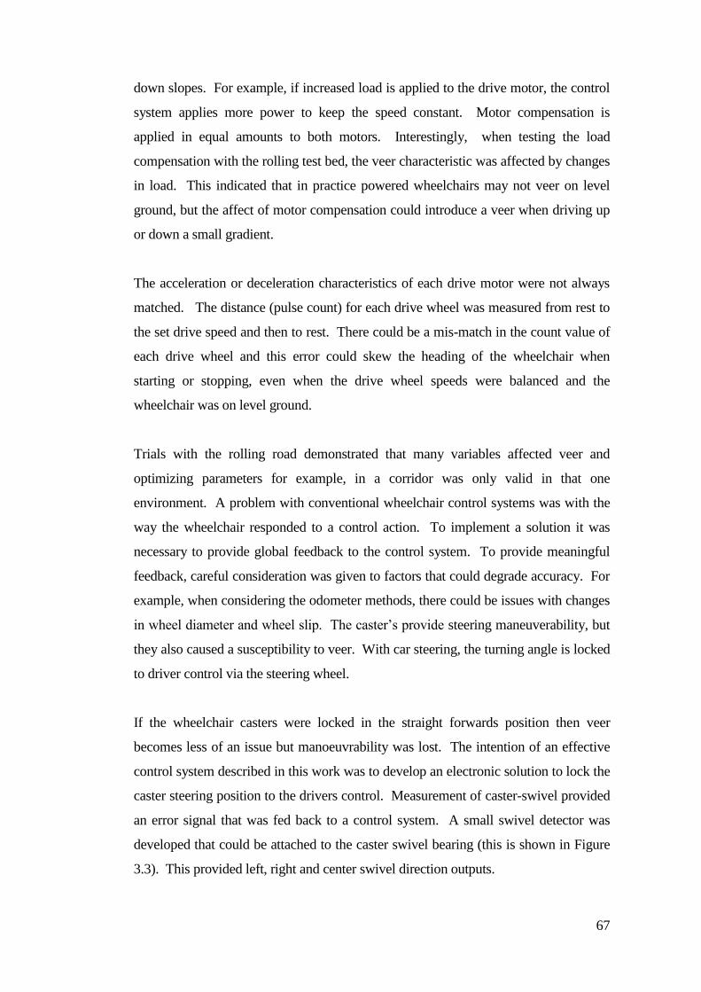
67
down slopes. For example, if increased load is applied to the drive motor, the control
system applies more power to keep the speed constant. Motor compensation is
applied in equal amounts to both motors. Interestingly, when testing the load
compensation with the rolling test bed, the veer characteristic was affected by changes
in load. This indicated that in practice powered wheelchairs may not veer on level
ground, but the affect of motor compensation could introduce a veer when driving up
or down a small gradient.
The acceleration or deceleration characteristics of each drive motor were not always
matched. The distance (pulse count) for each drive wheel was measured from rest to
the set drive speed and then to rest. There could be a mis-match in the count value of
each drive wheel and this error could skew the heading of the wheelchair when
starting or stopping, even when the drive wheel speeds were balanced and the
wheelchair was on level ground.
Trials with the rolling road demonstrated that many variables affected veer and
optimizing parameters for example, in a corridor was only valid in that one
environment. A problem with conventional wheelchair control systems was with the
way the wheelchair responded to a control action. To implement a solution it was
necessary to provide global feedback to the control system. To provide meaningful
feedback, careful consideration was given to factors that could degrade accuracy. For
example, when considering the odometer methods, there could be issues with changes
in wheel diameter and wheel slip. The caster’s provide steering maneuverability, but
they also caused a susceptibility to veer. With car steering, the turning angle is locked
to driver control via the steering wheel.
If the wheelchair casters were locked in the straight forwards position then veer
becomes less of an issue but manoeuvrability was lost. The intention of an effective
control system described in this work was to develop an electronic solution to lock the
caster steering position to the drivers control. Measurement of caster-swivel provided
an error signal that was fed back to a control system. A small swivel detector was
developed that could be attached to the caster swivel bearing (this is shown in Figure
3.3). This provided left, right and center swivel direction outputs.
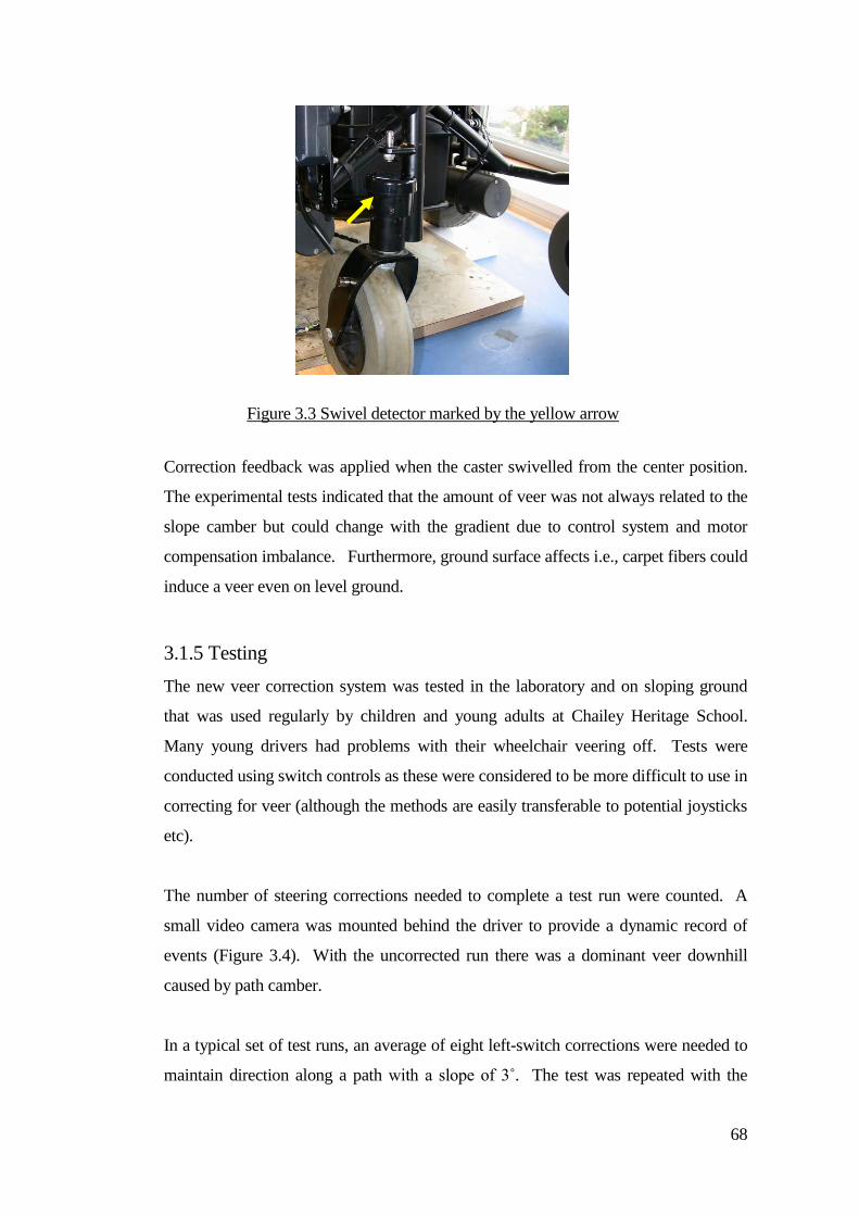
68
Correction feedback was applied when the caster swivelled from the center position.
The experimental tests indicated that the amount of veer was not always related to the
slope camber but could change with the gradient due to control system and motor
compensation imbalance. Furthermore, ground surface affects i.e., carpet fibers could
induce a veer even on level ground.
3.1.5 Testing
The new veer correction system was tested in the laboratory and on sloping ground
that was used regularly by children and young adults at Chailey Heritage School.
Many young drivers had problems with their wheelchair veering off. Tests were
conducted using switch controls as these were considered to be more difficult to use in
correcting for veer (although the methods are easily transferable to potential joysticks
etc).
The number of steering corrections needed to complete a test run were counted. A
small video camera was mounted behind the driver to provide a dynamic record of
events (Figure 3.4). With the uncorrected run there was a dominant veer downhill
caused by path camber.
In a typical set of test runs, an average of eight left-switch corrections were needed to
maintain direction along a path with a slope of 3˚. The test was repeated with the
Figure 3.3 Swivel detector marked by the yellow arrow
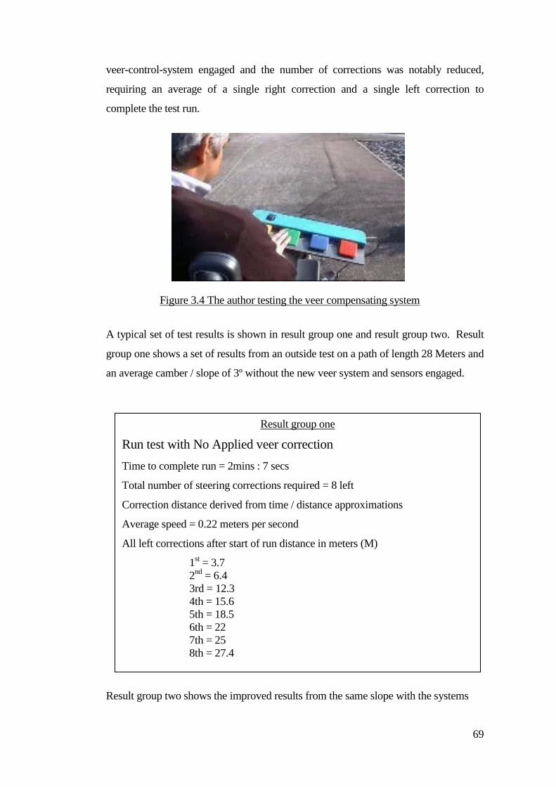
69
veer-control-system engaged and the number of corrections was notably reduced,
requiring an average of a single right correction and a single left correction to
complete the test run.
A typical set of test results is shown in result group one and result group two. Result
group one shows a set of results from an outside test on a path of length 28 Meters and
an average camber / slope of 3º without the new veer system and sensors engaged.
Result group two shows the improved results from the same slope with the systems
Figure 3.4 The author testing the veer compensating system
Result group one
Run test with No Applied veer correction
Time to complete run = 2mins : 7 secs
Total number of steering corrections required = 8 left
Correction distance derived from time / distance approximations
Average speed = 0.22 meters per second
All left corrections after start of run distance in meters (M)
1st = 3.7
2nd
= 6.4
3rd = 12.3
4th = 15.6
5th = 18.5
6th = 22
7th = 25
8th = 27.4
70
engaged.
Figures 3.5 and Figures 3.6 show video stills from an indoor veer test in the laboratory
on a 4 meter ramp (with a left slope of 3º). The run had only the forward switch
control activated. The wheelchair was weighted with 30 Kg. The difference between
the trajectory with the system engaged and without the system is significant.
3.1.6 Ride quality
It was noted that when forward drive was selected after a turn manoeuvre then the
wheelchair could be quickly ‘snapped’ back into straight-forward drive. This was due
to the resulting caster angle after the turn being ‘off-center’. When forward drive was
selected the fast acting correction system tried to restore the wheelchair to a straight-
line direction. This post-turn harsh correction was not desirable for drivers who were
used to a softer control characteristic.
To reduce this effect a short ‘post-turn veer-correction-delay’ was introduced after a
turn manoeuvre. This provided time for the wheelchair to softly restore the straight
line direction before the veer correction system cut-in.
Result group two
Test with veer correction applied
Time to complete run 1 min : 29 secs
Average speed 0.315 meters per second
Total number of steering corrections required = 1 right and 1 left total
Approximate correction distance in meters (M)
1st Right correction distance = 9.4
1st Left correction distance = 22.4
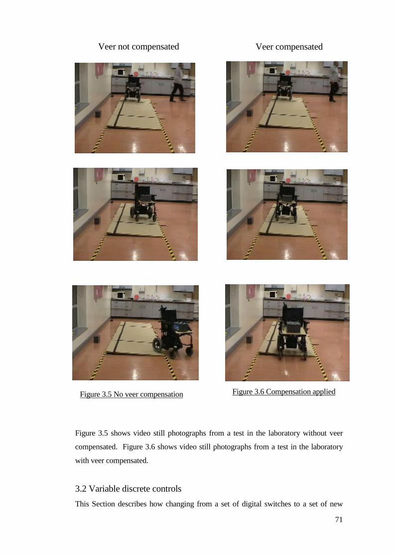
71
Figure 3.5 shows video still photographs from a test in the laboratory without veer
compensated. Figure 3.6 shows video still photographs from a test in the laboratory
with veer compensated.
3.2 Variable discrete controls
This Section describes how changing from a set of digital switches to a set of new
Veer not compensated Veer compensated
Figure 3.5 No veer compensation Figure 3.6 Compensation applied
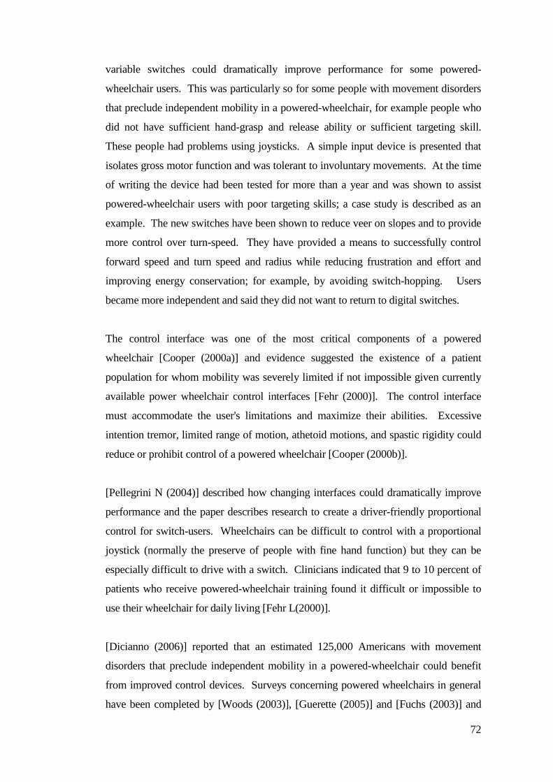
72
variable switches could dramatically improve performance for some powered-
wheelchair users. This was particularly so for some people with movement disorders
that preclude independent mobility in a powered-wheelchair, for example people who
did not have sufficient hand-grasp and release ability or sufficient targeting skill.
These people had problems using joysticks. A simple input device is presented that
isolates gross motor function and was tolerant to involuntary movements. At the time
of writing the device had been tested for more than a year and was shown to assist
powered-wheelchair users with poor targeting skills; a case study is described as an
example. The new switches have been shown to reduce veer on slopes and to provide
more control over turn-speed. They have provided a means to successfully control
forward speed and turn speed and radius while reducing frustration and effort and
improving energy conservation; for example, by avoiding switch-hopping. Users
became more independent and said they did not want to return to digital switches.
The control interface was one of the most critical components of a powered
wheelchair [Cooper (2000a)] and evidence suggested the existence of a patient
population for whom mobility was severely limited if not impossible given currently
available power wheelchair control interfaces [Fehr (2000)]. The control interface
must accommodate the user's limitations and maximize their abilities. Excessive
intention tremor, limited range of motion, athetoid motions, and spastic rigidity could
reduce or prohibit control of a powered wheelchair [Cooper (2000b)].
[Pellegrini N (2004)] described how changing interfaces could dramatically improve
performance and the paper describes research to create a driver-friendly proportional
control for switch-users. Wheelchairs can be difficult to control with a proportional
joystick (normally the preserve of people with fine hand function) but they can be
especially difficult to drive with a switch. Clinicians indicated that 9 to 10 percent of
patients who receive powered-wheelchair training found it difficult or impossible to
use their wheelchair for daily living [Fehr L(2000)].
[Dicianno (2006)] reported that an estimated 125,000 Americans with movement
disorders that preclude independent mobility in a powered-wheelchair could benefit
from improved control devices. Surveys concerning powered wheelchairs in general
have been completed by [Woods (2003)], [Guerette (2005)] and [Fuchs (2003)] and
73
these are included as references for further reading. Other useful general information
can be found in [Cooper (2002)], [Tolerico (2007)], [Trefler (2004)] and [Wolf
(2007)].
If a person had fine control of hand (or head or foot) then a joystick could work well.
A joystick can provide an intuitive control medium, accurately translating fine control
movements. It can quickly respond to a progressive change speed and direction and
was usually the device of choice. High intellectual function could be associated with
fine control. Poor physical control was not always an indicator of low intellectual
reasoning.
A typical joystick had a movement span change range from 1 to 16 square
centimetres. For those with less fine control then a joystick could be extended. One
of the fundamental requirements for a joystick to work was that the person had good
hand grasp and release ability and good targeting skill; if there were any problems
with these then operation could become frustrating.
[Krishnamurthy (2006)] suggested that some people who cannot achieve fine enough
movements to control a joystick with their hand may be able to use their tongue,
[Gosain (2007)] suggested foot control and [Taylor (2003)] suggested head
movement. [Langner (2004)] suggested using a track system, [Goodwin (1997)] and
[Stott (2000)] suggested navigation systems to assist and [Sanders (2007)] listed some
force sensing systems that might help but generally simple switch input devices were
used ; usually digital (on-off). A switch could provide:
A simple input device in the first instance that was easy to operate
Isolation of gross motor function
Assistance to a user with poor targeting skills
Tolerance to involuntary movements
Selectivity (where control directions are separated)
Immediate control output to a responding device
Research work described in this paper aimed to explore methods and ideas to create a

74
more Proportional World (rather than digital) for a switch user and to help the users to
derive a sense of proportionality within a digital switch medium.
Some initial questions were considered:
Were switch candidates practicing and learning within their proportional
control band of movement?
Did people have sufficiency of fine movement device control?
Should variable control format devices be given to young people as a first
stage (their first introduction to control)?
Did people who have switches need more graded control in their lives?
Could people benefit if there was a way to provide them with fully graded-
control?
3.2.1 Range of proportionality
Potential users were provided with some proportional control. If they did not use the
proportional range but operated instead at the extremes (flat-out or ‘off’) then they did
not have sufficient graded control.
The control band was adjusted to be within a range that matched their individual
movement skill. For example, the first 50% of joystick movement could be translated
to wheelchair linear speed. The next 50% of movement might be adjusted to only
increase wheelchair speed by a further 25%.
Joystick control operation could also be fed back depending on system performance
(how the wheelchair moved).
In everyday life, proportional control is applied to almost everything, for example
when driving a car, the speed is controlled through pressing the accelerator, breaking
is controlled by how hard the foot peddle is pressed, turn rate is controlled by the
position of the steering wheel etc; in the home, taps are progressively turned on or off
and objects are moved carefully using an appropriate amount of speed for the task or
action.
For people using digital switches, timing becomes more crucial so consideration was
given to methods that might be used to introduce some proportionalty (especially to
75
give people a better sense of control). It was necessary to do this in such a way that
did not worry them or make their task even more difficult. Many people find it hard
enough to address a switch reliably, so the idea of introducing graded control could be
thought of as an added burden.
To provide a sense of variable control when using switches it was necessary for
wheelchair users to develop their timing skills. Drivers would briefly (momentarily
tap) their switches in order to drive or turn more slowly because people did not always
want to go at one fixed speed. Speed selection by a wheelchair driver using switches
was considered, but it needed to be set in advance. A switch control interface was
therefore developed (multimode interface) by the author of this Dissertation and this
provided two selectable speed settings. Drivers were able to select slow or faster
driving by operating a mode switch.
There were situations where time constraints did not allow for the selection of slower
speeds without halting the wheelchair, for example when travelling relatively fast
outdoors and stopping to reselect a slower appropriate speed for entering indoors and
negotiating obstacles. Conversely a proportional control driver could seamlessly
change their wheelchair speed without stopping.
3.2.2 Training to use proportional systems
Many people may not have a good mix of timing and perception skills to execute turns
(some might under or over steer) and they may not be able to respond appropriately to
driving dynamics. Some (with Cerebral Palsy for example) may have some degree of
proportionality within their movements and this area of work could help to train them
to exercise graded control and develop a sense of proportionality.
Devices were available that responded in a variable way (such as an electric light with
a potentiometer) so that tests could be conducted to discover if potential system users
could change the brightness (in other tests the colour could change in response to
movement). A more practical example could be controlling the flow of water to fill
jugs to a particular level (perhaps as a developing skill in preparation for driving). In
this work a variable display unit was built to provide practice at variable control. This
consisted of a light projection box with a ground glass screen that displayed an image
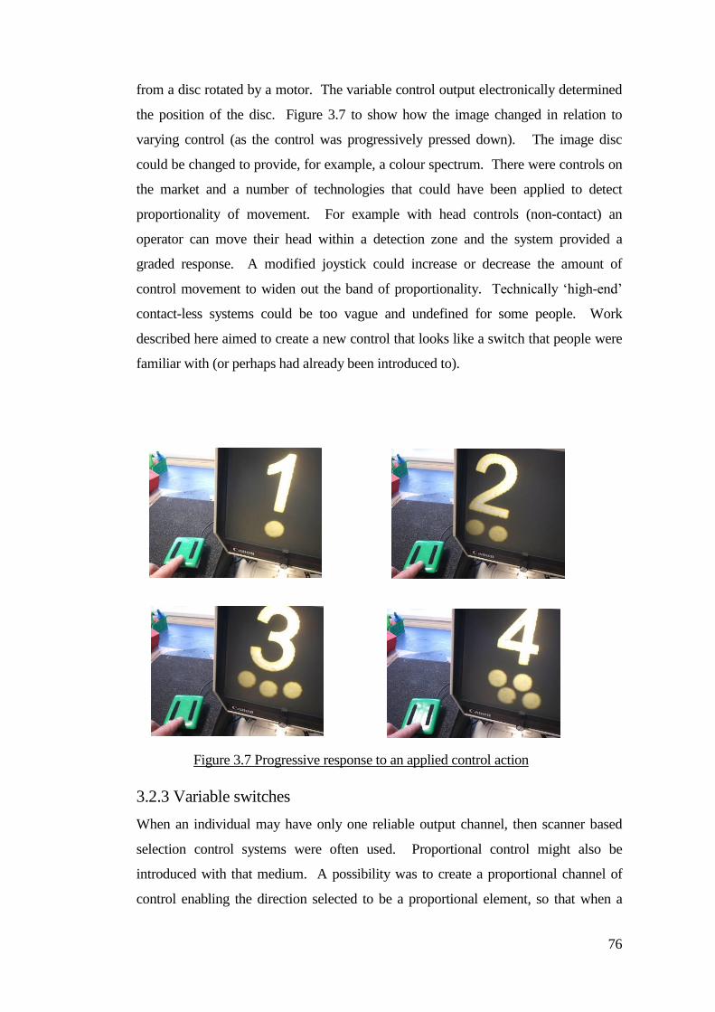
76
from a disc rotated by a motor. The variable control output electronically determined
the position of the disc. Figure 3.7 to show how the image changed in relation to
varying control (as the control was progressively pressed down). The image disc
could be changed to provide, for example, a colour spectrum. There were controls on
the market and a number of technologies that could have been applied to detect
proportionality of movement. For example with head controls (non-contact) an
operator can move their head within a detection zone and the system provided a
graded response. A modified joystick could increase or decrease the amount of
control movement to widen out the band of proportionality. Technically ‘high-end’
contact-less systems could be too vague and undefined for some people. Work
described here aimed to create a new control that looks like a switch that people were
familiar with (or perhaps had already been introduced to).
3.2.3 Variable switches
When an individual may have only one reliable output channel, then scanner based
selection control systems were often used. Proportional control might also be
introduced with that medium. A possibility was to create a proportional channel of
control enabling the direction selected to be a proportional element, so that when a
Figure 3.7 Progressive response to an applied control action
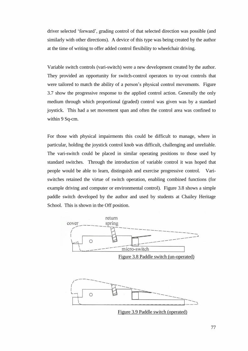
77
driver selected ‘forward’, grading control of that selected direction was possible (and
similarly with other directions). A device of this type was being created by the author
at the time of writing to offer added control flexibility to wheelchair driving.
Variable switch controls (vari-switch) were a new development created by the author.
They provided an opportunity for switch-control operators to try-out controls that
were tailored to match the ability of a person’s physical control movements. Figure
3.7 show the progressive response to the applied control action. Generally the only
medium through which proportional (graded) control was given was by a standard
joystick. This had a set movement span and often the control area was confined to
within 9 Sq-cm.
For those with physical impairments this could be difficult to manage, where in
particular, holding the joystick control knob was difficult, challenging and unreliable.
The vari-switch could be placed in similar operating positions to those used by
standard switches. Through the introduction of variable control it was hoped that
people would be able to learn, distinguish and exercise progressive control. Vari-
switches retained the virtue of switch operation, enabling combined functions (for
example driving and computer or environmental control). Figure 3.8 shows a simple
paddle switch developed by the author and used by students at Chailey Heritage
School. This is shown in the Off position.
Figure 3.8 Paddle switch (un-operated)
Figure 3.9 Paddle switch (operated)
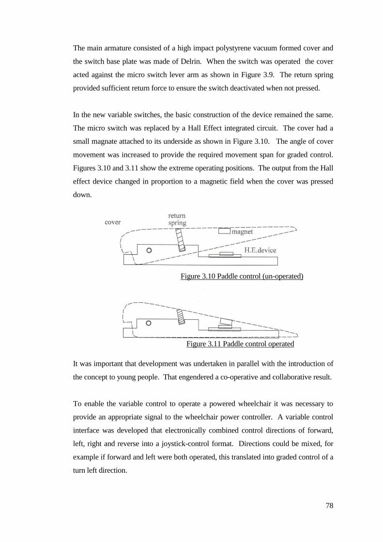
78
The main armature consisted of a high impact polystyrene vacuum formed cover and
the switch base plate was made of Delrin. When the switch was operated the cover
acted against the micro switch lever arm as shown in Figure 3.9. The return spring
provided sufficient return force to ensure the switch deactivated when not pressed.
In the new variable switches, the basic construction of the device remained the same.
The micro switch was replaced by a Hall Effect integrated circuit. The cover had a
small magnate attached to its underside as shown in Figure 3.10. The angle of cover
movement was increased to provide the required movement span for graded control.
Figures 3.10 and 3.11 show the extreme operating positions. The output from the Hall
effect device changed in proportion to a magnetic field when the cover was pressed
down.
It was important that development was undertaken in parallel with the introduction of
the concept to young people. That engendered a co-operative and collaborative result.
To enable the variable control to operate a powered wheelchair it was necessary to
provide an appropriate signal to the wheelchair power controller. A variable control
interface was developed that electronically combined control directions of forward,
left, right and reverse into a joystick-control format. Directions could be mixed, for
example if forward and left were both operated, this translated into graded control of a
turn left direction.
Figure 3.10 Paddle control (un-operated)
Figure 3.11 Paddle control operated
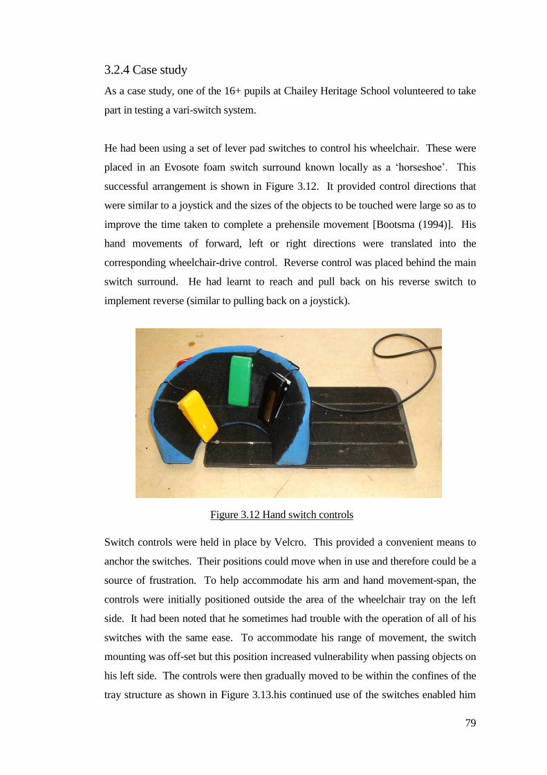
79
3.2.4 Case study
As a case study, one of the 16+ pupils at Chailey Heritage School volunteered to take
part in testing a vari-switch system.
He had been using a set of lever pad switches to control his wheelchair. These were
placed in an Evosote foam switch surround known locally as a ‘horseshoe’. This
successful arrangement is shown in Figure 3.12. It provided control directions that
were similar to a joystick and the sizes of the objects to be touched were large so as to
improve the time taken to complete a prehensile movement [Bootsma (1994)]. His
hand movements of forward, left or right directions were translated into the
corresponding wheelchair-drive control. Reverse control was placed behind the main
switch surround. He had learnt to reach and pull back on his reverse switch to
implement reverse (similar to pulling back on a joystick).
Switch controls were held in place by Velcro. This provided a convenient means to
anchor the switches. Their positions could move when in use and therefore could be a
source of frustration. To help accommodate his arm and hand movement-span, the
controls were initially positioned outside the area of the wheelchair tray on the left
side. It had been noted that he sometimes had trouble with the operation of all of his
switches with the same ease. To accommodate his range of movement, the switch
mounting was off-set but this position increased vulnerability when passing objects on
his left side. The controls were then gradually moved to be within the confines of the
tray structure as shown in Figure 3.13.his continued use of the switches enabled him
Figure 3.12 Hand switch controls
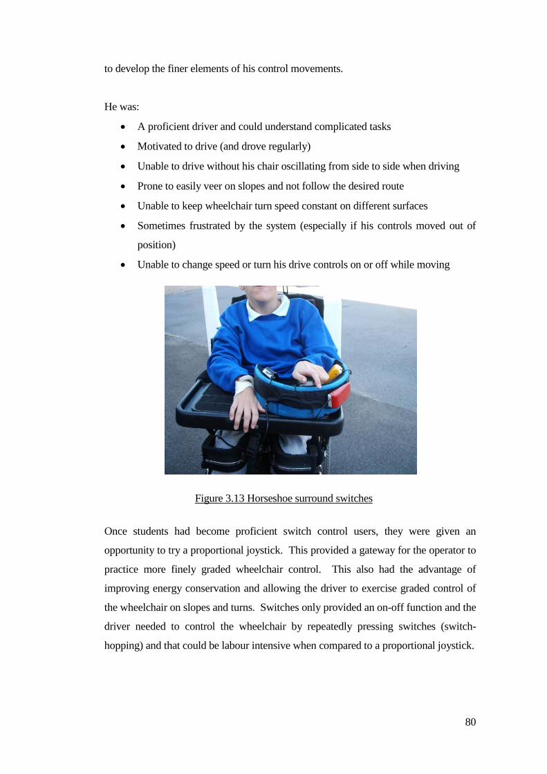
80
to develop the finer elements of his control movements.
He was:
A proficient driver and could understand complicated tasks
Motivated to drive (and drove regularly)
Unable to drive without his chair oscillating from side to side when driving
Prone to easily veer on slopes and not follow the desired route
Unable to keep wheelchair turn speed constant on different surfaces
Sometimes frustrated by the system (especially if his controls moved out of
position)
Unable to change speed or turn his drive controls on or off while moving
Once students had become proficient switch control users, they were given an
opportunity to try a proportional joystick. This provided a gateway for the operator to
practice more finely graded wheelchair control. This also had the advantage of
improving energy conservation and allowing the driver to exercise graded control of
the wheelchair on slopes and turns. Switches only provided an on-off function and the
driver needed to control the wheelchair by repeatedly pressing switches (switch-
hopping) and that could be labour intensive when compared to a proportional joystick.
Figure 3.13 Horseshoe surround switches
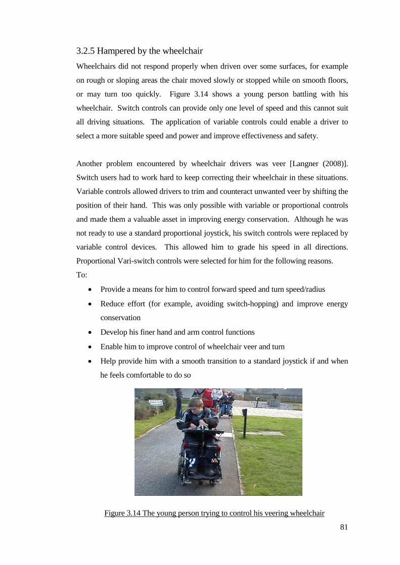
81
3.2.5 Hampered by the wheelchair
Wheelchairs did not respond properly when driven over some surfaces, for example
on rough or sloping areas the chair moved slowly or stopped while on smooth floors,
or may turn too quickly. Figure 3.14 shows a young person battling with his
wheelchair. Switch controls can provide only one level of speed and this cannot suit
all driving situations. The application of variable controls could enable a driver to
select a more suitable speed and power and improve effectiveness and safety.
Another problem encountered by wheelchair drivers was veer [Langner (2008)].
Switch users had to work hard to keep correcting their wheelchair in these situations.
Variable controls allowed drivers to trim and counteract unwanted veer by shifting the
position of their hand. This was only possible with variable or proportional controls
and made them a valuable asset in improving energy conservation. Although he was
not ready to use a standard proportional joystick, his switch controls were replaced by
variable control devices. This allowed him to grade his speed in all directions.
Proportional Vari-switch controls were selected for him for the following reasons.
To:
Provide a means for him to control forward speed and turn speed/radius
Reduce effort (for example, avoiding switch-hopping) and improve energy
conservation
Develop his finer hand and arm control functions
Enable him to improve control of wheelchair veer and turn
Help provide him with a smooth transition to a standard joystick if and when
he feels comfortable to do so
Figure 3.14 The young person trying to control his veering wheelchair
82
This young person tested the prototype control system with the variable switches and
demonstrated that he could control speed using them. The original arrangement of
digital-switches (a horse-shoe arrangement) required control movements that were
similar to a joystick (except for reverse). The horseshoe provided an expansion of
movement which was a better match for his range of movement skills (although
reverse control was more of a problem). Initially, a reverse switch was placed to the
side of the horseshoe ring. Sometimes this would be a nuisance for him and he solved
the problem by suggesting that the reverse switch should be placed behind the forward
switch. This required a pull-back movement that was similar to using a joystick.
Most of the problems he had with driving control were due to the dynamics of the
wheelchair and the way the wheelchair was affected by the type of ground he was
driving on.
If he was driving along a path with a modest camber (for example from left to right),
then the wheelchair had a tendency to drift to the right. He needed to work hard to
counteract this drift by applying his left control more than his right in order to
continue along the path.
An initial problem was that the switch function responded asymmetrically by turning
faster to the right and slower to the left. His reactions to control to the right were not
always fast enough. A second problem was that the wheelchair would stall when
commanded to turn up the slope. Often the wheelchair’s speed compensation was not
sufficient to provide a constant speed for different rolling resistances. Wheelchair
veer was often controlled by drivers quickly alternating left and right control
directions (switch-hopping).
The first introduction was to a variable control format that looked and behaved like a
switch. This raised the question of whether long-term switch users could unlearn
some of the coping strategies they had learnt with switch control.
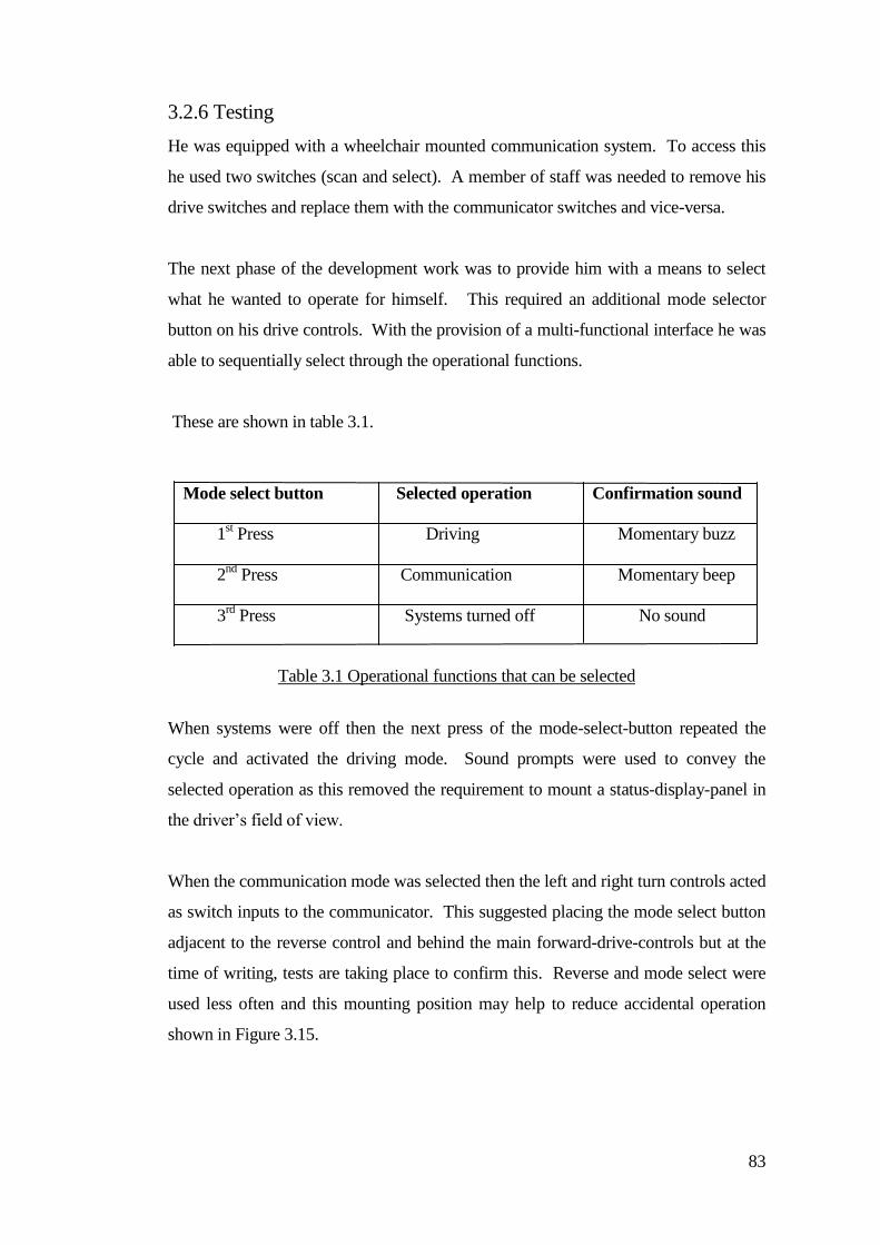
83
3.2.6 Testing
He was equipped with a wheelchair mounted communication system. To access this
he used two switches (scan and select). A member of staff was needed to remove his
drive switches and replace them with the communicator switches and vice-versa.
The next phase of the development work was to provide him with a means to select
what he wanted to operate for himself. This required an additional mode selector
button on his drive controls. With the provision of a multi-functional interface he was
able to sequentially select through the operational functions.
These are shown in table 3.1.
Mode select button Selected operation Confirmation sound
1st Press Driving Momentary buzz
2nd
Press Communication Momentary beep
3rd
Press Systems turned off No sound
When systems were off then the next press of the mode-select-button repeated the
cycle and activated the driving mode. Sound prompts were used to convey the
selected operation as this removed the requirement to mount a status-display-panel in
the driver’s field of view.
When the communication mode was selected then the left and right turn controls acted
as switch inputs to the communicator. This suggested placing the mode select button
adjacent to the reverse control and behind the main forward-drive-controls but at the
time of writing, tests are taking place to confirm this. Reverse and mode select were
used less often and this mounting position may help to reduce accidental operation
shown in Figure 3.15.
Table 3.1 Operational functions that can be selected
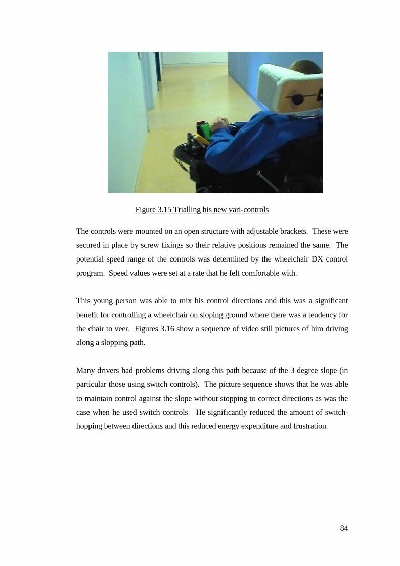
84
The controls were mounted on an open structure with adjustable brackets. These were
secured in place by screw fixings so their relative positions remained the same. The
potential speed range of the controls was determined by the wheelchair DX control
program. Speed values were set at a rate that he felt comfortable with.
This young person was able to mix his control directions and this was a significant
benefit for controlling a wheelchair on sloping ground where there was a tendency for
the chair to veer. Figures 3.16 show a sequence of video still pictures of him driving
along a slopping path.
Many drivers had problems driving along this path because of the 3 degree slope (in
particular those using switch controls). The picture sequence shows that he was able
to maintain control against the slope without stopping to correct directions as was the
case when he used switch controls He significantly reduced the amount of switch-
hopping between directions and this reduced energy expenditure and frustration.
Figure 3.15 Trialling his new vari-controls
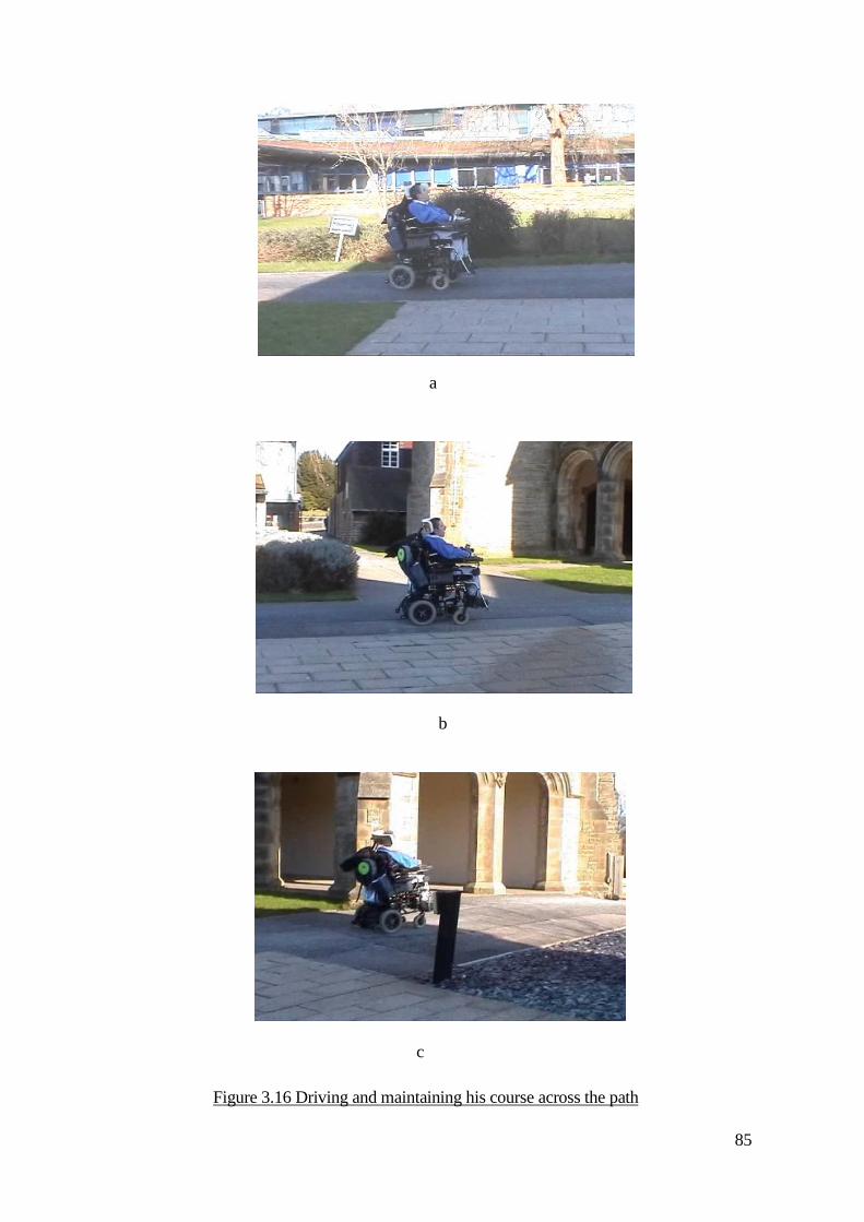
85
a
b
c
Figure 3.16 Driving and maintaining his course across the path
86
At the time of writing, the young person described had been using his variable control
for a year and has achieved a high level of driving independence. He has learnt to mix
his control directions which helps in situations controlling wheelchair veer and he can
grade his speed in critical situations. He says he does not want to go back to on-off
switches as he can exploit the subtleties of proportional control for different drive
conditions.
Outcomes included a reduced initial reaction time and movement time but a greatly
improved driving accuracy.
3.3 Discussion
Tests with and without the new veer correction system demonstrated that a simple
feedback system could reduce the amount of effort needed by a driver to counteract
any tendency for a wheelchair to veer. It was important to develop a system that was
robust and not affected by changeable parameters through normal wear and tear. The
experimental system was primarily intended for switch users. Control feedback could
be adapted and incorporated into proportional control systems as these provide a
continuous feedback signal rather than on-off signals.
The limit of veer correction seemed dependant on the traction capabilities of the
wheelchair, power of the motors coupled with the wheel grip characteristics and
weight distribution over the ground surface which could be rough or smooth. The
system still tried to correct the veer even if the drive wheel skidded. This could be a
problem if the feedback was too aggressive, as a sharp response could cause skid (loss
of traction). If the response was as shown in the experiments presented, then the veer
was not completely removed.
The second section described how changing from a set of digital switches to a set of
new variable switches could dramatically improve performance for some powered-
wheelchair users. This was especially for some people with movement disorders that
preclude independent mobility in a powered-wheelchair.
A simple input device was presented that isolates gross motor function and was
87
tolerant to involuntary movements. The device has been tested for more than a year
and has been shown to assist powered-wheelchair users with poor targeting skills (a
more proportional world rather than digital is created for a switch user). A case study
was described as an example. The new switches have been shown to reduce veer on
slopes and to provide more control over turn-speed. They have provided a means to
successfully control forward speed and turn speed and radius while reducing
frustration and effort and improving energy conservation. Users have become more
independent and say they do not want to return to digital switches.
More research work is required to test how many digital-switch users may be able to
use the new switches and to test whether users are practicing and learning within their
proportional control band of movement. Through the introduction of variable control
it is hoped that people will be able to learn, distinguish and exercise progressive
control. Vari-switches still retain the virtue of switch operation in that they can
enable other combined functions. Research is also required to test whether some less
motivated or proficient drivers could benefit (especially some with reduced
understanding of complicated tasks) and whether these new systems might help
provide a transition to standard joysticks for some people in the future.
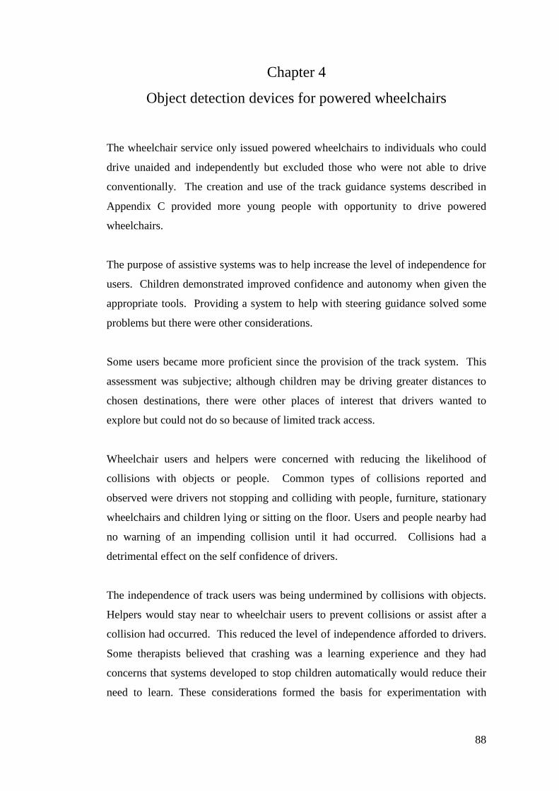
88
Chapter 4
Object detection devices for powered wheelchairs
The wheelchair service only issued powered wheelchairs to individuals who could
drive unaided and independently but excluded those who were not able to drive
conventionally. The creation and use of the track guidance systems described in
Appendix C provided more young people with opportunity to drive powered
wheelchairs.
The purpose of assistive systems was to help increase the level of independence for
users. Children demonstrated improved confidence and autonomy when given the
appropriate tools. Providing a system to help with steering guidance solved some
problems but there were other considerations.
Some users became more proficient since the provision of the track system. This
assessment was subjective; although children may be driving greater distances to
chosen destinations, there were other places of interest that drivers wanted to
explore but could not do so because of limited track access.
Wheelchair users and helpers were concerned with reducing the likelihood of
collisions with objects or people. Common types of collisions reported and
observed were drivers not stopping and colliding with people, furniture, stationary
wheelchairs and children lying or sitting on the floor. Users and people nearby had
no warning of an impending collision until it had occurred. Collisions had a
detrimental effect on the self confidence of drivers.
The independence of track users was being undermined by collisions with objects.
Helpers would stay near to wheelchair users to prevent collisions or assist after a
collision had occurred. This reduced the level of independence afforded to drivers.
Some therapists believed that crashing was a learning experience and they had
concerns that systems developed to stop children automatically would reduce their
need to learn. These considerations formed the basis for experimentation with
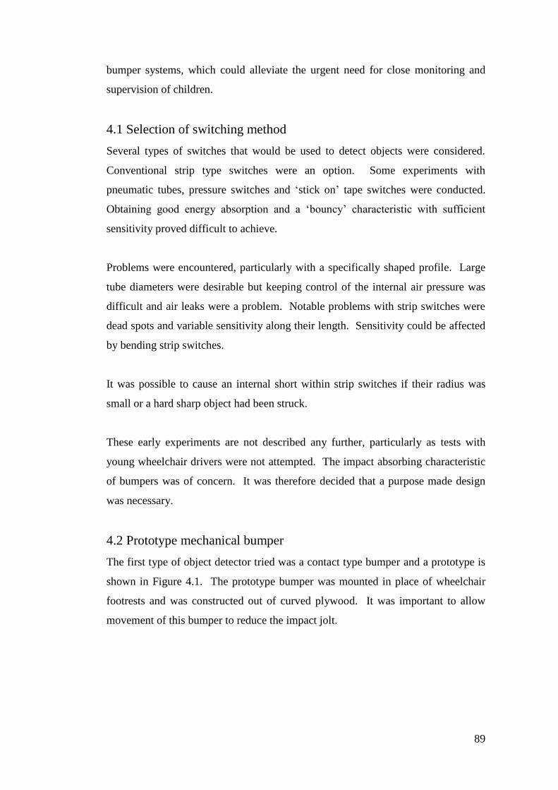
89
bumper systems, which could alleviate the urgent need for close monitoring and
supervision of children.
4.1 Selection of switching method
Several types of switches that would be used to detect objects were considered.
Conventional strip type switches were an option. Some experiments with
pneumatic tubes, pressure switches and ‘stick on’ tape switches were conducted.
Obtaining good energy absorption and a ‘bouncy’ characteristic with sufficient
sensitivity proved difficult to achieve.
Problems were encountered, particularly with a specifically shaped profile. Large
tube diameters were desirable but keeping control of the internal air pressure was
difficult and air leaks were a problem. Notable problems with strip switches were
dead spots and variable sensitivity along their length. Sensitivity could be affected
by bending strip switches.
It was possible to cause an internal short within strip switches if their radius was
small or a hard sharp object had been struck.
These early experiments are not described any further, particularly as tests with
young wheelchair drivers were not attempted. The impact absorbing characteristic
of bumpers was of concern. It was therefore decided that a purpose made design
was necessary.
4.2 Prototype mechanical bumper
The first type of object detector tried was a contact type bumper and a prototype is
shown in Figure 4.1. The prototype bumper was mounted in place of wheelchair
footrests and was constructed out of curved plywood. It was important to allow
movement of this bumper to reduce the impact jolt.
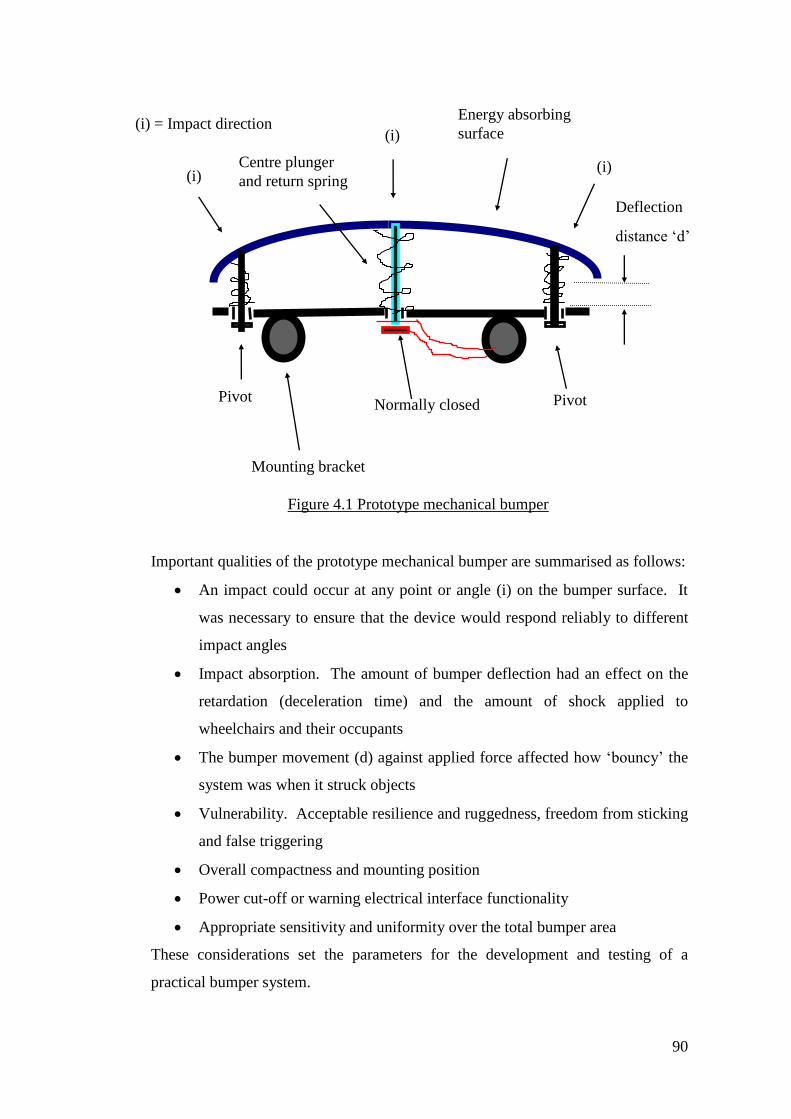
90
Important qualities of the prototype mechanical bumper are summarised as follows:
An impact could occur at any point or angle (i) on the bumper surface. It
was necessary to ensure that the device would respond reliably to different
impact angles
Impact absorption. The amount of bumper deflection had an effect on the
retardation (deceleration time) and the amount of shock applied to
wheelchairs and their occupants
The bumper movement (d) against applied force affected how ‘bouncy’ the
system was when it struck objects
Vulnerability. Acceptable resilience and ruggedness, freedom from sticking
and false triggering
Overall compactness and mounting position
Power cut-off or warning electrical interface functionality
Appropriate sensitivity and uniformity over the total bumper area
These considerations set the parameters for the development and testing of a
practical bumper system.
Normally closed
contact
Pivot Pivot
(i)
(i)
(i)
(i) = Impact direction
Mounting bracket
Deflection
distance ‘d’
Energy absorbing
surface
Centre plunger
and return spring
Figure 4.1 Prototype mechanical bumper
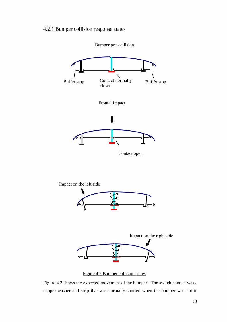
91
4.2.1 Bumper collision response states
Figure 4.2 shows the expected movement of the bumper. The switch contact was a
copper washer and strip that was normally shorted when the bumper was not in
Frontal impact.
Contact open
Impact on the left side
Impact on the right side
Contact normally
closed Buffer stop Buffer stop
Bumper pre-collision
Figure 4.2 Bumper collision states
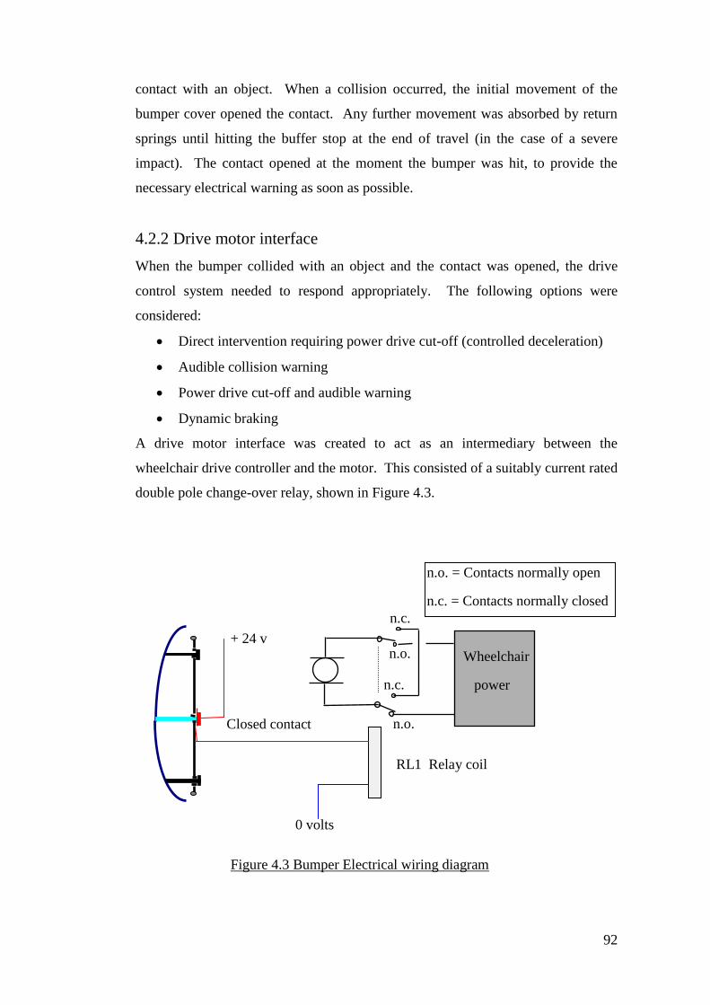
92
contact with an object. When a collision occurred, the initial movement of the
bumper cover opened the contact. Any further movement was absorbed by return
springs until hitting the buffer stop at the end of travel (in the case of a severe
impact). The contact opened at the moment the bumper was hit, to provide the
necessary electrical warning as soon as possible.
4.2.2 Drive motor interface
When the bumper collided with an object and the contact was opened, the drive
control system needed to respond appropriately. The following options were
considered:
Direct intervention requiring power drive cut-off (controlled deceleration)
Audible collision warning
Power drive cut-off and audible warning
Dynamic braking
A drive motor interface was created to act as an intermediary between the
wheelchair drive controller and the motor. This consisted of a suitably current rated
double pole change-over relay, shown in Figure 4.3.
Wheelchair
power
controller
RL1 Relay coil
0 volts
+ 24 v
Closed contact n.o.
n.o.
n.c.
n.c.
n.o. = Contacts normally open
n.c. = Contacts normally closed
Figure 4.3 Bumper Electrical wiring diagram
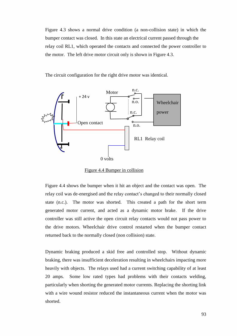
93
Figure 4.3 shows a normal drive condition (a non-collision state) in which the
bumper contact was closed. In this state an electrical current passed through the
relay coil RL1, which operated the contacts and connected the power controller to
the motor. The left drive motor circuit only is shown in Figure 4.3.
The circuit configuration for the right drive motor was identical.
Figure 4.4 shows the bumper when it hit an object and the contact was open. The
relay coil was de-energised and the relay contact’s changed to their normally closed
state (n.c.). The motor was shorted. This created a path for the short term
generated motor current, and acted as a dynamic motor brake. If the drive
controller was still active the open circuit relay contacts would not pass power to
the drive motors. Wheelchair drive control restarted when the bumper contact
returned back to the normally closed (non collision) state.
Dynamic braking produced a skid free and controlled stop. Without dynamic
braking, there was insufficient deceleration resulting in wheelchairs impacting more
heavily with objects. The relays used had a current switching capability of at least
20 amps. Some low rated types had problems with their contacts welding,
particularly when shorting the generated motor currents. Replacing the shorting link
with a wire wound resistor reduced the instantaneous current when the motor was
shorted.
Wheelchair
power
controller
RL1 Relay coil
0 volts
+ 24 v
Open contact n.o.
n.o.
n.c.
n.c. Motor
Figure 4.4 Bumper in collision
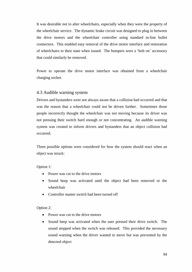
94
It was desirable not to alter wheelchairs, especially when they were the property of
the wheelchair service. The dynamic brake circuit was designed to plug in between
the drive motors and the wheelchair controller using standard in-line bullet
connectors. This enabled easy removal of the drive motor interface and restoration
of wheelchairs to their state when issued. The bumpers were a ‘bolt on’ accessory
that could similarly be removed.
Power to operate the drive motor interface was obtained from a wheelchair
charging socket.
4.3 Audible warning system
Drivers and bystanders were not always aware that a collision had occurred and that
was the reason that a wheelchair could not be driven further. Sometimes those
people incorrectly thought the wheelchair was not moving because its driver was
not pressing their switch hard enough or not concentrating. An audible warning
system was created to inform drivers and bystanders that an object collision had
occurred.
Three possible options were considered for how the system should react when an
object was struck:
Option 1:
Power was cut to the drive motors
Sound beep was activated until the object had been removed or the
wheelchair
Controller master switch had been turned off
Option 2:
Power was cut to the drive motors
Sound beep was activated when the user pressed their drive switch. The
sound stopped when the switch was released. This provided the necessary
sound warning when the driver wanted to move but was prevented by the
detected object
95
Option 3:
Power was cut to the drive motors
Pressing the drive switch activated the bleep
These different options provided extra help when training young drivers to respond
to warnings of collisions. It was interesting to note the effect of warning signals on
drivers.
The loudness and sound quality of audible warnings were significant. Some
warnings could be startling and disconcerting to drivers. Experimenting with the
sound type and mode showed that option 2 was generally preferable with a soft
pure tone.
Figures 4.5 and 4.6 show captured video pictures of a bumper fitted to a track chair.
Figure 4.5 shows a young girl who used a single switch to control her track driving.
She had poor vision and used the audible warning as feedback in addition to direct
object detection intervention stopping.
Figure 4.5 A single switch operated track chair with mechanical bumper
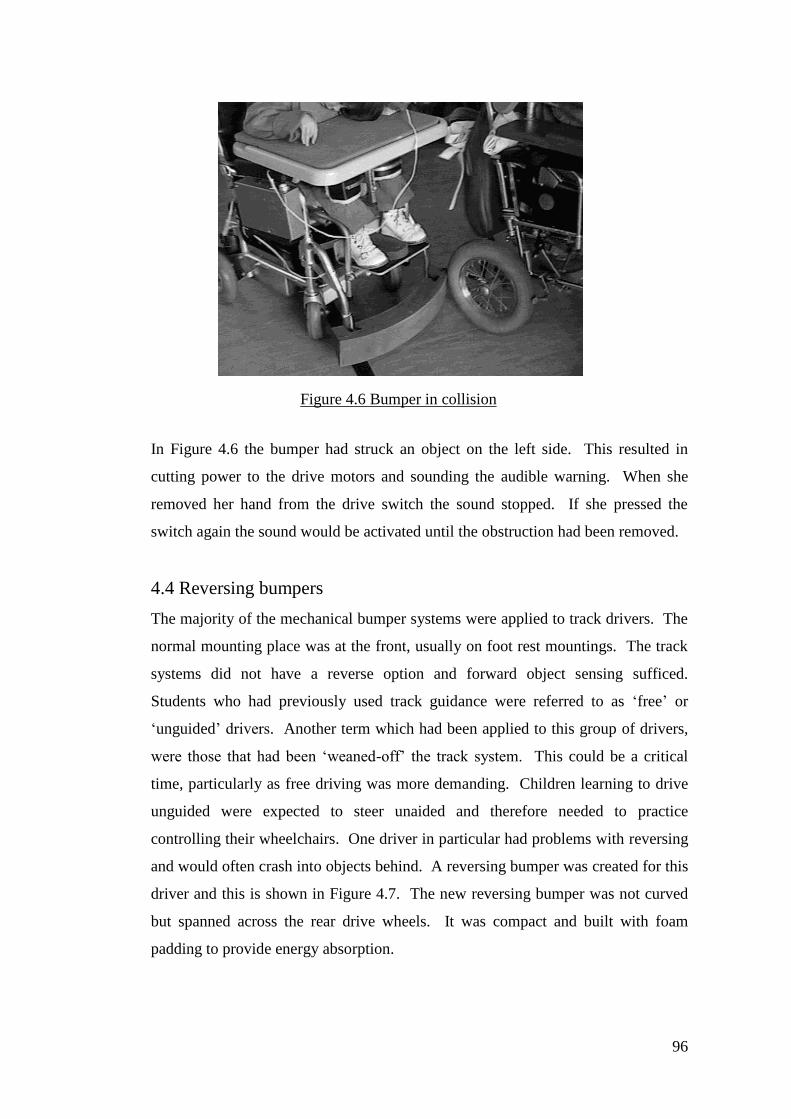
96
In Figure 4.6 the bumper had struck an object on the left side. This resulted in
cutting power to the drive motors and sounding the audible warning. When she
removed her hand from the drive switch the sound stopped. If she pressed the
switch again the sound would be activated until the obstruction had been removed.
4.4 Reversing bumpers
The majority of the mechanical bumper systems were applied to track drivers. The
normal mounting place was at the front, usually on foot rest mountings. The track
systems did not have a reverse option and forward object sensing sufficed.
Students who had previously used track guidance were referred to as ‘free’ or
‘unguided’ drivers. Another term which had been applied to this group of drivers,
were those that had been ‘weaned-off’ the track system. This could be a critical
time, particularly as free driving was more demanding. Children learning to drive
unguided were expected to steer unaided and therefore needed to practice
controlling their wheelchairs. One driver in particular had problems with reversing
and would often crash into objects behind. A reversing bumper was created for this
driver and this is shown in Figure 4.7. The new reversing bumper was not curved
but spanned across the rear drive wheels. It was compact and built with foam
padding to provide energy absorption.
Figure 4.6 Bumper in collision
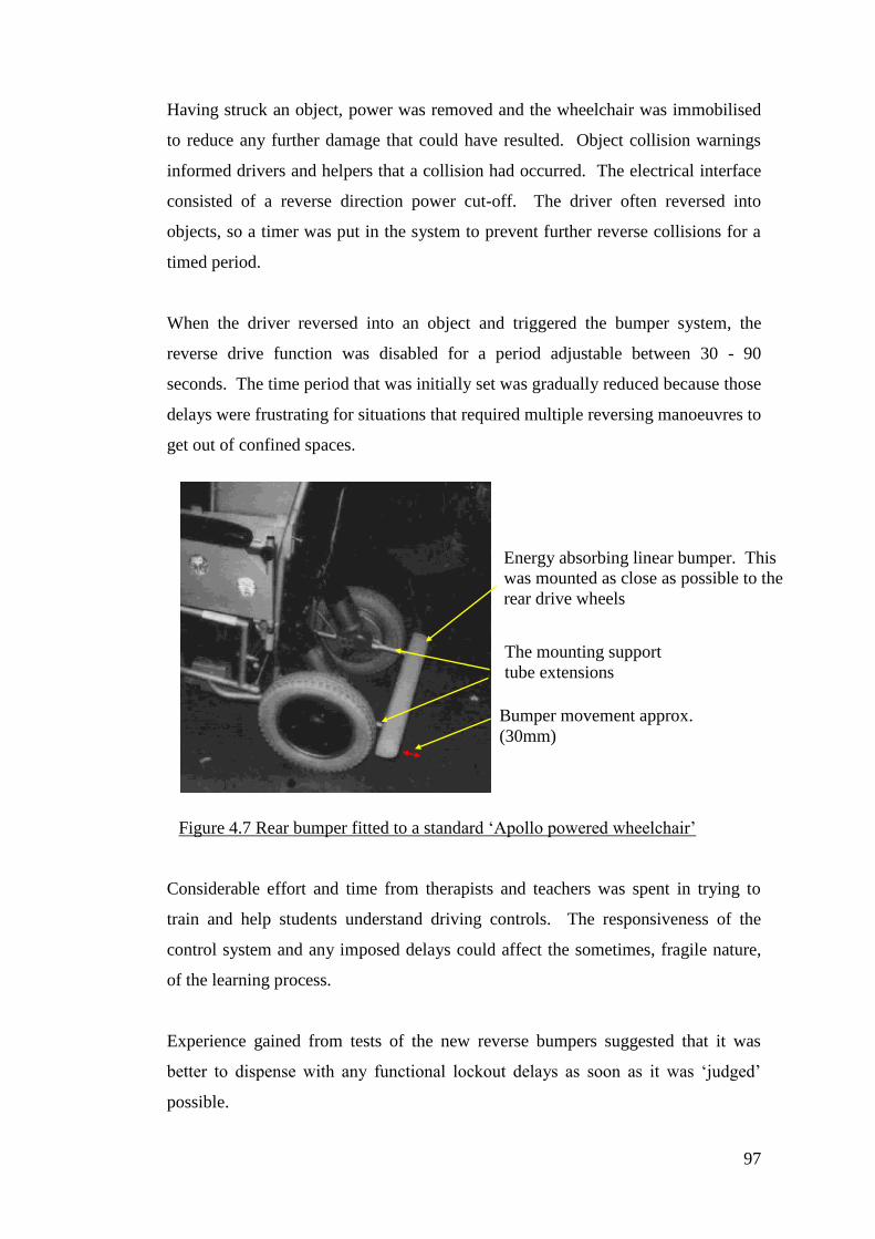
97
Having struck an object, power was removed and the wheelchair was immobilised
to reduce any further damage that could have resulted. Object collision warnings
informed drivers and helpers that a collision had occurred. The electrical interface
consisted of a reverse direction power cut-off. The driver often reversed into
objects, so a timer was put in the system to prevent further reverse collisions for a
timed period.
When the driver reversed into an object and triggered the bumper system, the
reverse drive function was disabled for a period adjustable between 30 - 90
seconds. The time period that was initially set was gradually reduced because those
delays were frustrating for situations that required multiple reversing manoeuvres to
get out of confined spaces.
Considerable effort and time from therapists and teachers was spent in trying to
train and help students understand driving controls. The responsiveness of the
control system and any imposed delays could affect the sometimes, fragile nature,
of the learning process.
Experience gained from tests of the new reverse bumpers suggested that it was
better to dispense with any functional lockout delays as soon as it was ‘judged’
possible.
Figure 4.7 Rear bumper fitted to a standard ‘Apollo powered wheelchair’
Energy absorbing linear bumper. This
was mounted as close as possible to the
rear drive wheels
The mounting support
tube extensions
Bumper movement approx.
(30mm)
98
4.5 Chapter summary
Creation of a guiding system for children in powered wheelchairs provided them
with opportunities for independent exploration. This was beyond the boundaries
and restrictions imposed by the young person’s physical disability and reduced
dependence on personal helpers. With normal un-guided systems, helpers steered
young peoples chairs’ as a means to help. The tracked guidance system reduced
this need. There was still a need for helpers to stop drivers from colliding into
objects in the path of their travel. Helpers acted to protect children, others nearby,
and reduce potential damage to their environment.
Independence gained by young people using the track was compromised by their
inability to bring their wheelchair to a controlled stop when necessary. Helpers
tried to train children to recognise situations leading up to a crash. Inevitably, this
was hampered by children’s disabilities, particularly in cases of visual impairment.
Some therapists believed that crashing was a learning experience and they had
concerns that systems developed to stop children automatically would reduce their
need to learn. Teachers however, liked to see children driving with increased
independence, even with the addition of a bumper system.
It was important to note how the trainers, teachers, carers and child drivers
responded during collision situations. There could be tensions and differences of
opinion between the therapist and teachers so different system response modes of
operation were incorporated into the development of a crash prevention system.
The following statements describe what occurred when an object was struck by a
wheelchair:
a) Wheelchair jolted when striking an object
b) Audible alarm was triggered
c) Drive power was cut
d) Events after the bumper had struck an object
e) Drive power reset
a) Physical contact with the object was fundamentally necessary for the bumper to
operate. Control action was applied in a short space of time and distance after
contact with the object. Physical transference of energy was unavoidable. The

99
design of the bumper softened the rate of deceleration. For some drivers,
knowing they had struck an object by the perception of a movement (jolt) was
enough for them to take action for themselves and stop activating their control
switch.
b) If a driver’s perception or control awareness was not sufficient for them to
perceive physical contact with an object, the addition of a bumper activated
sound alarm provided reinforcement. The alarm also provided a warning to
bystanders that a collision incident had occurred and this may need their
attention. A certain level of trust was placed on the driver to stop when they
heard the alarm and this emphasised learning and taking personal control
responsibility.
c) Cutting the drive power was a significant control intervention. This was a
statement that the child could not be trusted to take appropriate control action,
particularly stopping in a critical situation. The effect of the bumper
intervention was primarily damage limitation.
d) Power was restored when the object had been removed and the bumper
deactivated. Observations indicated that typical circumstances were, firstly,
objects moved away from the bumper. For example: a person or another
wheelchair who reacted instinctively. Secondly, helper intervention acted to
clear the object away from the wheelchair bumper. Drive power was
subsequently restored when the bumper was no longer in contact with the object.
Consequently this was a momentary mode of operation.
e) Child behavioural issues required higher levels of applied control intervention
beyond just momentarily cutting the drive power after an object was struck.
There were occasions when some children would repeatedly or deliberately
crash.
Additional control interventions were applied where there were repeated attempts
by a young person to collide with objects. Some helpers and therapists considered
this to be attention seeking behaviour and additionally the noise caused and the
physical jolting through crashing provided sensory feedback to the driver. Cutting
the drive power once an object had been struck immobilised the driver from further
collisions until an attendant reset the drive power. This bought the incident to the
attention of people who could then specifically help the child. The most drastic
100
form of intervention was a timed lockout. When the bumper had been activated the
wheelchair drive power was cut for periods up to 90 seconds. This was an attempt
to break the repeated cycle of children deliberately reversing and crashing into
objects. There was no practical method for discriminating against accidental
collision triggering. The lockout timer could be manually reset.
Detecting objects by physical contact was disadvantageous for the progression of
children learning to drive with an assistive system. Positive control action needed
to occur before object contact. The physical contact power cut-off system was a
‘last resort’ intervention. Mechanical bumpers often sustained damage mainly due
to variations of object strike angles. Carers would sometimes be hampered by the
bumper structure when placing a child in or out of their driving seat.
The appearance of bumper systems accentuated the aspect of a young person’s
disability. Bumpers caused other difficulties because the necessary physical
dimensions required by bumpers to absorb impact energy and this added to the
footprint of the wheelchair. Unfortunately, bumpers increased the difficulty for
wheelchair manoeuvring and reduced drivability, although this was less significant
when using the track guided system.
Later work described in this Dissertation created a contact-less (proximity) object
sensing system that provided the same function by applying contact-less collision
avoidance.
101
Chapter 5
A new Scanning Collision Avoidance Device (SCAD)
5.1 Introduction
This Chapter describes the creation of a first prototype Scanning Collision Avoidance
Device (SCAD). This became a successor to the mechanical bumper system used for
track and limited driver training described in Chapter 4. A major limitation of the
mechanical type bumper was its footprint size. This became untenably large when
trying to increase the detection range to help improve the stop control performance of
wheelchairs. Drivers collided with objects and misjudged object distance. This
became the focus of further obstacle avoidance development work. New research
started creating a non-contact proximity object detection system that used ultra-sonic
ranging. This reduced the need for obtrusive physical bumper detectors. Pupils that
had been using the track (described in Appendix C) had not been required to exercise
their own steering control. It became possible for many track drivers to start
practicing their wheelchair steering.
A natural progression beyond the imposed access limitations of the track routes was
the creation of a system that guided itself by sensing the local environment. This
potentially offered more opportunities for learner drivers with visual impairments and
spatial perception problems to drive with more freedom. The SCAD provided a
protected environment but required a higher driver skill level than was required for
track driving. In particular the requirements for navigation and recognition skills
within the drivers environment were greater than when track driving. A system was
developed by the author of this dissertation that rotated an ultra-sonic transducer. This
sent ultrasonic pulses at stepped periods of rotation and was the first prototype SCAD
object detector. This was intended to be a wide angle object detector and audible
warning device for people using a track following powered wheelchair. There were
notable anomalies with the detector, mostly arising out of the repetitive pulse echo
sampling. Old returning echoes would sometimes conflict with nearby ‘in-range’
target echoes. The sample update time was also slower than desired. The system
worked well enough to be of value in detecting nearby objects. For the development
of a guiding SCAD system, a method of determining the position of detected objects
102
was required. The essential aspect of the SCAD system was the generation of
multiple zones without increasing the physical size of the detector head.
5.2 Background
Some disabled children at Chailey Heritage were not able to drive wheelchairs. For
example, their hand function was not proficient enough to operate a joystick, the most
used form of control associated with wheelchairs. Joysticks required hand grasping
and release skills and controlled movement coordination within a small area (16 Sq
cm). Many children could not drive because of the demands of the joystick. New
work started to make switch controls, which were easier for some children to operate
than the joysticks. The switches could be placed in positions that were more suitable
for a child to reach and separated in such a way that spread out the control directions
so that children could discriminate between different control directions.
Some children began to drive more using switch controls. Some children did not have
enough refined hand function though (even for switches), particularly children with
athatoid movements and problems with spasticity. Many children with poor hand
function could turn their heads to look at people and the author was involved in
research to create new controls that could be operated by the chin. Some children
started to drive competently with chin controls. Some of these children were mentally
agile and did not require any type of additional guidance support. The research work
continued to create a variety of controls that could translate whatever repeatable
movement the young person had into a useable switched output. Children started to
drive and become independent in their powered wheelchairs. Over a period of time it
became clear that there were groups of children who were not driving and they could
see that a lot of their friends and classmates were now driving (and they were not).
What was interesting about this group was that they might have been co-ordinated and
they were not necessarily any more physically disabled than any other group that were
driving. They did not have the cognitive ability to work out the sequence of controls
necessary to steer their wheelchair. Helpers tried to encourage children to be mobile
and the children wanted to drive but could not.
Some helpers tried to help too much. They would push children in wheelchairs
around when they did not need to. Staff would intervene and operate the drivers
103
controls just to try to keep them safe while trying to give them a sense of mobility.
For example, if a group of children were provided with switches, then at first they
might drive straight into a wall or be a danger to others (and to themselves) because it
took time to master starting, stopping and steering. This inspired new research to
assist wheelchair drivers further. A question was, did children just need more practice
at driving or was there something more fundamental in their development? (which
could allow them to progress in such a way that they could become independent
drivers). What was known was that children wanted to drive (and wanted to try to
drive) but they needed specific (and a lot of) human help to enable them to become
mobile or at least to have some experience of wheelchair driving.
The creation of the new assistive technology centred around a girl who was almost
totally blind. Her hearing was good and she was intelligent but she was severely
physically impaired. She could not use her hands to control a switch but she could use
her chin. She could turn her head in the direction people were talking to her. She
wanted to drive and staff were encouraging her but the wheelchair service would not
provide her with a powered wheelchair because she could not drive unaided. A
powered wheelchair was loaned to her. She would rest her arm on the joystick and go
around in circles because that was the only thing she could safely do. Staff would
hold her hands and she would go around in circles and at least feel the experience of
starting and stopping. Occasionally she would spiral out and crash into things. She
wanted to try to drive to specific places but she was reliant on helpers to guide her. A
member of staff had said “it would be good if you could put her on some kind of
railway line”. So that is what was done [Langner, (2002)] and that was the situation at
the beginning of the research described in this dissertation.
The railway line concept allowed children to drive from one point to another without
going astray. Children then became frustrated because the tracks did not go to all of
the places where they wanted to go. The young girl driver wanted to go to other
places besides just her classroom, toilet areas and the corridors where the track went.
There we also other problems; even on a track she would crash or bump into things.
This did not happen often because she had good hearing and could hear if someone
was there, but she could not do that with inanimate objects.
104
5.3 Mechanical bumpers
Mechanical bumpers were investigated. This was more challenging than expected for
a number of reasons. For example, if a strip bumper was placed around a wheelchair
and it hit something, then it could impact heavily and crash. The motor power would
be cut after the collision had occurred. When initial trials started with prototype strips,
the energy was absorbed over a relatively small distance (a few millimetres) and
children could drive into things, and although power was cut, the crash had already
occurred. Part of the control system used for those earlier experiments included a
latched system, in which if the bumper was touched, then it would cut the power. The
power would stay cut until a member of staff reset the system and made sure that the
object and the child were safe to proceed. A warning was needed to indicate to the
child why the wheelchair had suddenly stopped so an audible warning device was
added to give an indication of when an object had been struck.
The mechanical bumpers were subject to physical damage and they increased the
physical length of the wheelchair because the bumper needed to protrude beyond the
normal dimensions of a wheelchair in order to be effective. In addition, children were
provided with trays on their wheelchairs and these could protrude beyond the bumper,
which reduced the effectiveness of the bumper during collisions with walls (as the tray
would make contact before the bumper). Extending the bumper increased driving
difficulty because of the increased base size and there were problems with accidental
operation of a bumper. The use of the mechanical bumpers established that it was
necessary to give children warning of impending collisions. Bumpers were vulnerable
to damage and were a hindrance when staff were transferring children in and out of
their wheelchairs. Nonetheless, the bumpers proved that object detection provided
help to wheelchair users.
Older and larger children had bigger seating systems, longer footrests, larger trays etc.
The protection provided by the bumpers was compromised by overhanging equipment
on the wheelchair. If a wall was struck ‘head-on’ then the tray or foot rest would
make contact before the bumper. Extending the bumpers to overcome this caused
problems with driving and functionality. The swing of the chair and the extended
bumper was too large and door frames would often catch the bumper and un-
necessary triggering would occur. It became clear that detection was required over a
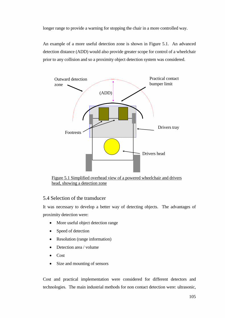
105
longer range to provide a warning for stopping the chair in a more controlled way.
An example of a more useful detection zone is shown in Figure 5.1. An advanced
detection distance (ADD) would also provide greater scope for control of a wheelchair
prior to any collision and so a proximity object detection system was considered.
5.4 Selection of the transducer
It was necessary to develop a better way of detecting objects. The advantages of
proximity detection were:
More useful object detection range
Speed of detection
Resolution (range information)
Detection area / volume
Cost
Size and mounting of sensors
Cost and practical implementation were considered for different detectors and
technologies. The main industrial methods for non contact detection were: ultrasonic,
Outward detection
zone
Practical contact
bumper limit
Footrests Drivers tray
(ADD)
Drivers head
Figure 5.1 Simplified overhead view of a powered wheelchair and drivers
head, showing a detection zone
106
optical, laser range finding, infra red and vision systems.
Infra-red sensors were considered. They could use triangulation (where an object
reflected the beam back to a sensor at a specified distance) but testing demonstrated
that the colour of the reflecting object had an effect on how much reflective energy
was returned. For example, a white object provided good reflection and could be
detected at a greater distance than a dark object (a poor reflecting object). Infra-red
beams were also narrow (they had a small cross sectional area) and background
suppression was required. Testing suggested that several infrared beams would be
needed to cover sufficient area at the front of the wheelchair.
There were also problems with multi path reflections from shiny objects (causing false
detections). Most commercially available systems had background suppression but
the retro reflective sensors were short-range and not suitable for object detection for a
powered wheelchair. Vision systems were also considered, for example the auto
focusing systems used by video cameras. They were capable of focusing on a specific
target, but the active areas were small when compared to what was required for
effective object detection and ranging in front of a powered wheelchair. Operation of
the auto focus systems was slow and had unsuitable reaction times. To provide
effective advanced warning of an object, a detection range of one to two metres was
desirable.
Some systems were expensive (for example laser range finding) and others were
potentially more complex (for example vision systems). Optical and ultra-sonic
sensors were considered to be the most useful and their characteristics are presented in
Table 5.1. Laser range finders and complex vision systems were not considered
further due to cost restrictions. Experiments with optical and ultrasonic devices
indicated that each had specific advantages and drawbacks and both could be affected
by the nature of the object target. Optical target reflectivity and colour affected the
optical sensing characteristics.
This could be further affected by the cross sectional area of the target object. Ultra-
sonic detection was affected by target angle as most of the sound energy could be
reflected away from the source (specula reflection).
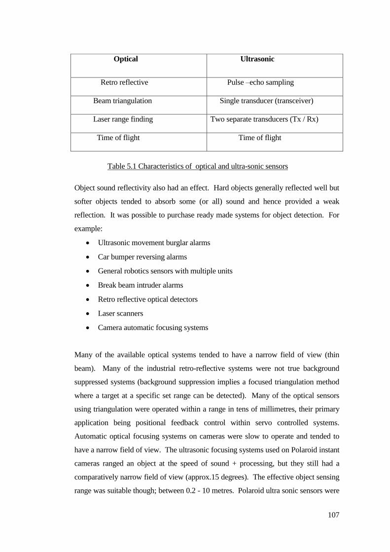
107
Object sound reflectivity also had an effect. Hard objects generally reflected well but
softer objects tended to absorb some (or all) sound and hence provided a weak
reflection. It was possible to purchase ready made systems for object detection. For
example:
Ultrasonic movement burglar alarms
Car bumper reversing alarms
General robotics sensors with multiple units
Break beam intruder alarms
Retro reflective optical detectors
Laser scanners
Camera automatic focusing systems
Many of the available optical systems tended to have a narrow field of view (thin
beam). Many of the industrial retro-reflective systems were not true background
suppressed systems (background suppression implies a focused triangulation method
where a target at a specific set range can be detected). Many of the optical sensors
using triangulation were operated within a range in tens of millimetres, their primary
application being positional feedback control within servo controlled systems.
Automatic optical focusing systems on cameras were slow to operate and tended to
have a narrow field of view. The ultrasonic focusing systems used on Polaroid instant
cameras ranged an object at the speed of sound + processing, but they still had a
comparatively narrow field of view (approx.15 degrees). The effective object sensing
range was suitable though; between 0.2 - 10 metres. Polaroid ultra sonic sensors were
Optical Ultrasonic
Retro reflective Pulse –echo sampling
Beam triangulation Single transducer (transceiver)
Laser range finding Two separate transducers (Tx / Rx)
Time of flight Time of flight
Table 5.1 Characteristics of optical and ultra-sonic sensors
108
selected for further experimentation. They were affordable and generally could detect
most objects in the environment.
Multi-element ultrasonic sensing systems were used for the (University of Edinburgh
SMART Wheelchair). These consisted of six separate sensors mounted around the
front of the wheelchair. These could demonstrably detect objects, but the system was
structurally complex and had notable gaps in the detection area.
5.5 A prototype ultrasonic detection system
Ultrasonic sensors were cheap and during testing they provided adequate performance
using time of flight measurements. Ultrasonic tape measures and focusing systems for
cameras were accurate for the task. Ultrasonic methods were less complex than
optical methods but when detecting some objects then problems occurred with specula
reflection. The angle of the detected object affected detection. Polaroid produced
transducers and the associated electronic driver electronics as a package. A prototype
system was created that interfaced to the Polaroid system. It fired sound pulses and
listened for target echoes. It was found that the system was capable of detecting
pencil size objects at ranges of 1-2 metres and this was sufficient for the SCAD
application. A problem was that the transducer dispersion angle (beam width) was
approximately 15º and this was not enough to cover the area required for the
wheelchair.
An object detection assessment was conducted within the intended environment,
(Chailey Heritage School) specifically to determine the number and type of objects
that could be detected at either wheelchair tray or footrest height. A single transducer
was placed on a wheelchair. The wheelchair was then pushed around the school
including the same areas in which the children would drive. Objects that could be
detected were walls, objects protruding from walls, doorframes, other wheelchairs,
bags, people and objects on the ground for example shoes and toys. Some objects did
not always show an edge, sometimes causing unreliable detection including clothing.
Some soft fabrics did not reflect sufficient sound to be detected reliably. The
assessment indicated that approximately that 70% of these objects were detected at
wheelchair tray height compared to 90% at footrest height. This increase was due to
109
detecting a majority of objects at ground level.
Consideration was given to how children drove their wheelchairs. There were
requirements for special seating systems that needed to be placed in and out of
wheelchairs, perhaps many times daily, particularly when a child needed to use the
toilet or to have therapy sessions. It was important that the transducer system did not
get in the way or get damaged at those times. When mounted onto the tray structure,
the system needed be removable and releasable cables and connectors were necessary.
As a result the systems became vulnerable to misalignment.
The transducer was placed under the footrests so that objects at low level could be
detected, for example curbs, shoes or low lying objects (small children and animals).
The detector was securely fixed to the wheelchair frame (including connections). In
this position, curb edges and wooden borders could also be detected. Roadways were
created where necessary using simple detectable objects (for example, plastic cups).
There were issues about not being able to detect objects due to the narrow vertical
width of the scan when compared to width of the lateral scan. Overhangs from
shelves, table tops and voids under tables could not be reliably detected. An
experiment was conducted with a transducer looking upward. Specula reflection
problems (due to the angle of the sound beam) prevented reliable detection and a
vertical scanning system was not developed further. In later work there were
problems with a child driving under tables and an experiment was conducted using an
optical background suppressed sensor mounted between the footrest looking up at an
angle of approx 45º in front of the wheelchair.
This provided useful single point detection for flat overhanging objects as the infrared
beam was less affected by specula reflection because more detectable energy was
reflected back to the sensor. There was a problem with the commercial optical object
sensor device as this used a modulated infrared beam to provide immunity from
environmental light interference. This operated on a similar frequency to the high
frequency fluorescent lighting used in the building and because the sensor was looking
upwards, then the wheelchair would often stop when under a fluorescent light.
The general detection of objects with the ultrasonic system was affected by specula
reflection. The transducer could detect objects with a small cross-sectional area (for
110
example a pencil when in a vertical position). An object placed at an angle may not
be detected. Walking the wheelchair test system around the school provided valuable
information about the type of objects that were detected and the nature of those that
were not. There were notable problems with sloping objects (for example chair legs,
especially when they sloped away from the detector). Most vertical (or near vertical)
structures could be reliably detected. In fact, there were occasions when specula
reflection was an advantage, particularly when the gradient changed when driving up
a ramp. In those cases the ground was not detected at the point of transition between
flat to sloping ground.
The horizontal width detection was too narrow to be of practical use with a single
transducer. Multiple transducer arrays were considered to extend the area covered but
there could still be gaps in the detection field. Several transducer elements would be
required to reduce gaps and accordingly the whole transducer would become large. It
was a concern that a system with many separate sensing elements would be vulnerable
to damage and misalignment. Therefore was desirable to develop a cheaper, simpler
and more compact system that would not significantly add to the wheelchair structure.
Placing the transducer onto a motor solved two problems. Firstly, only one sensor
was needed so that it was not necessary to try to match the characteristics of separate
transducers and secondly a single transducer and motor was compact and could
therefore be mounted more discreetly onto a wheelchair. Firing sound pulses at
intervals of rotation provided a potentially flexible way of creating detection zones.
The choice of motor was significant though.
Two methods were considered for pulse echo sampling, firstly, the motor
continuously rotated and pulses were sampled on the fly and, secondly, the motor
starting and stopping at each sample zone. The first option required a rotary
connection between the transducer and stationary electronics. Testing showed that
taking a pulse echo sample when the transducer was moving smudged the transducer
polar response and meant that it was not facing the same point when receiving an
object echo. The second option (making the motor stop at each pulse echo sample
zone) required a stepper motor for starting and stopping because it rotated in precise
steps. A DC type motor required additional positional (and possibly velocity)
111
feedback and continuous start-stops would need high starting and stopping currents to
provide sufficient acceleration and deceleration between the sample zones and scan
end points. This would have reduced the life of the motor brushes. Conversely,
stepper motors required drive electronics and provided phase sequence switching to
stimulate rotation.
The use of reciprocation motion or continuous rotation were considered. Coupling the
transducer to the electronics for continuous rotation proved difficult with the
prototypes. Two methods were considered: using a slip ring and an inductive
connection. A slip ring was subject to wear and noise whilst inductive coupling
required additional drive electronics (which altered the matching characteristics
between the Polaroid ranging electronic interface and the transducer). In view of these
considerations it was decided to use a reciprocating transducer scanning motion. The
transducer could then be simply connected by a pair of thin wires. There were
problems with wire fatigue (and the wires would break). This became the subject of
some later work to develop an improved method of transducer wire connection.
A 15º per step motor was selected to obtain the closest match between the step angle
and the transducer dispersion angle. An optical method was used to define the end
points of the scan. A small disc was made from ABS plastic and fitted to the motor
shaft. The underside of the disc was painted matt black. The top of the disc formed a
mounting platform and the transducer was bonded to this with adhesive. The scan end
points were identified with white marks painted on the black disc surface. Two small
retro-reflective optical sensors were mounted on a purpose designed and built PCB
that fitted between the top of the stepper motor and the underside of the disc. Control
electronics were created to drive the stepper motor so that when the disc rotated the
end point marker was detected and that triggered the motor to change direction. The
step pulses were counted and the change of rotation was determined by a pre-set count
value at the scan end point. The second optical position sensor acted as a guard, the
position of the transducer was not initially at the start ‘reset’ point. This ensured that
the transducer would not fully rotate when switched on, as a full rotation could
damage the transducer connecting wires.
Using a stepper motor to rotate the transducer proved that scanning was a compact
viable alternative to a multiple-transducer array. That next issue was to decide the rate
112
of pulse echo sampling. Initially there were problems with false echoes from
previously sent pulses being detected (causing ghost detection) from by multi-path
echoes. The Polaroid ranging electronics was primarily designed for single shot
ranging up to 10 metres. This was in excess of what was necessary for the wheelchair
object sensing application (particularly when sending repeated pulse streams). The
transmit power was reduced by placing a resistor between the pulse transformer and
drive transistor. The energy of multi-path returning pulses was reduced and made the
system usable within internal environments. Ghosting problems were reduced but not
eliminated. In addition it was noted that increasing the frequency of the pulse echo
sampling also increased the ghost problems.
The first scanning experiments were at low speed (approximately 20 Hz) and a
complete scan cycle was completed in one second. It was desirable to increase the
sample rate as the wheelchair moved less distance between samples and provided
earlier detection of an object. This became the subject of some later work.
5.6 A first ultrasonic scanning collision avoidance device (SCAD)
The collision avoidance device needed to meet the following considerations:
Compact physical size
Wide angle (field) of view
Gap-less detection zone
Fast update (sample) time
Simplified engineering construction
Discretely mountable (not affecting general wheelchair engineering)
Polaroid ultrasonic sensors were selected. These were supplied with a single
transceiver (transducer) and front-end electronic interface circuit board. A single
transducer had a typical angle of dispersion of 12° or 15° depending on type.
In order to detect the presence of an object, the transducer operated as a transmitter
and receiver (transceiver). A sound pulse was transmitted, a reflecting object in the
path of the sound returned a sound echo. The time of flight between the transmit pulse
and the received echo provided a measure of distance. Atmospheric conditions also
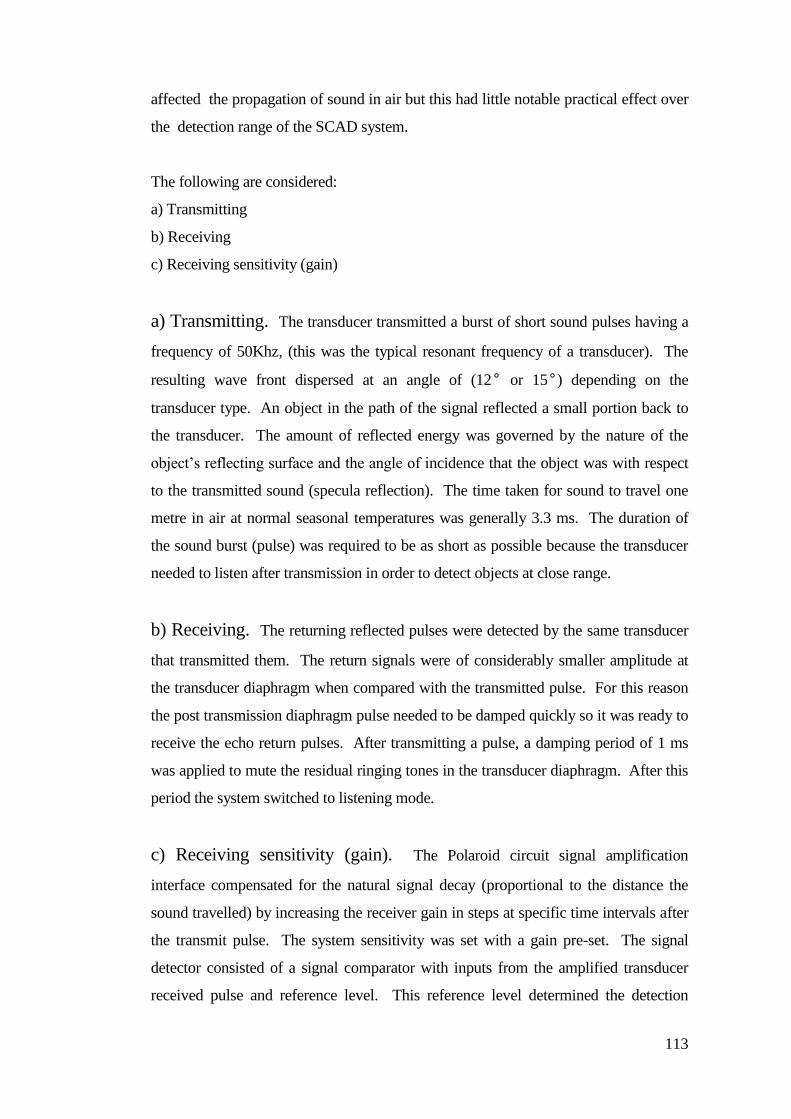
113
affected the propagation of sound in air but this had little notable practical effect over
the detection range of the SCAD system.
The following are considered:
a) Transmitting
b) Receiving
c) Receiving sensitivity (gain)
a) Transmitting. The transducer transmitted a burst of short sound pulses having a
frequency of 50Khz, (this was the typical resonant frequency of a transducer). The
resulting wave front dispersed at an angle of (12° or 15°) depending on the
transducer type. An object in the path of the signal reflected a small portion back to
the transducer. The amount of reflected energy was governed by the nature of the
object’s reflecting surface and the angle of incidence that the object was with respect
to the transmitted sound (specula reflection). The time taken for sound to travel one
metre in air at normal seasonal temperatures was generally 3.3 ms. The duration of
the sound burst (pulse) was required to be as short as possible because the transducer
needed to listen after transmission in order to detect objects at close range.
b) Receiving. The returning reflected pulses were detected by the same transducer
that transmitted them. The return signals were of considerably smaller amplitude at
the transducer diaphragm when compared with the transmitted pulse. For this reason
the post transmission diaphragm pulse needed to be damped quickly so it was ready to
receive the echo return pulses. After transmitting a pulse, a damping period of 1 ms
was applied to mute the residual ringing tones in the transducer diaphragm. After this
period the system switched to listening mode.
c) Receiving sensitivity (gain). The Polaroid circuit signal amplification
interface compensated for the natural signal decay (proportional to the distance the
sound travelled) by increasing the receiver gain in steps at specific time intervals after
the transmit pulse. The system sensitivity was set with a gain pre-set. The signal
detector consisted of a signal comparator with inputs from the amplified transducer
received pulse and reference level. This reference level determined the detection
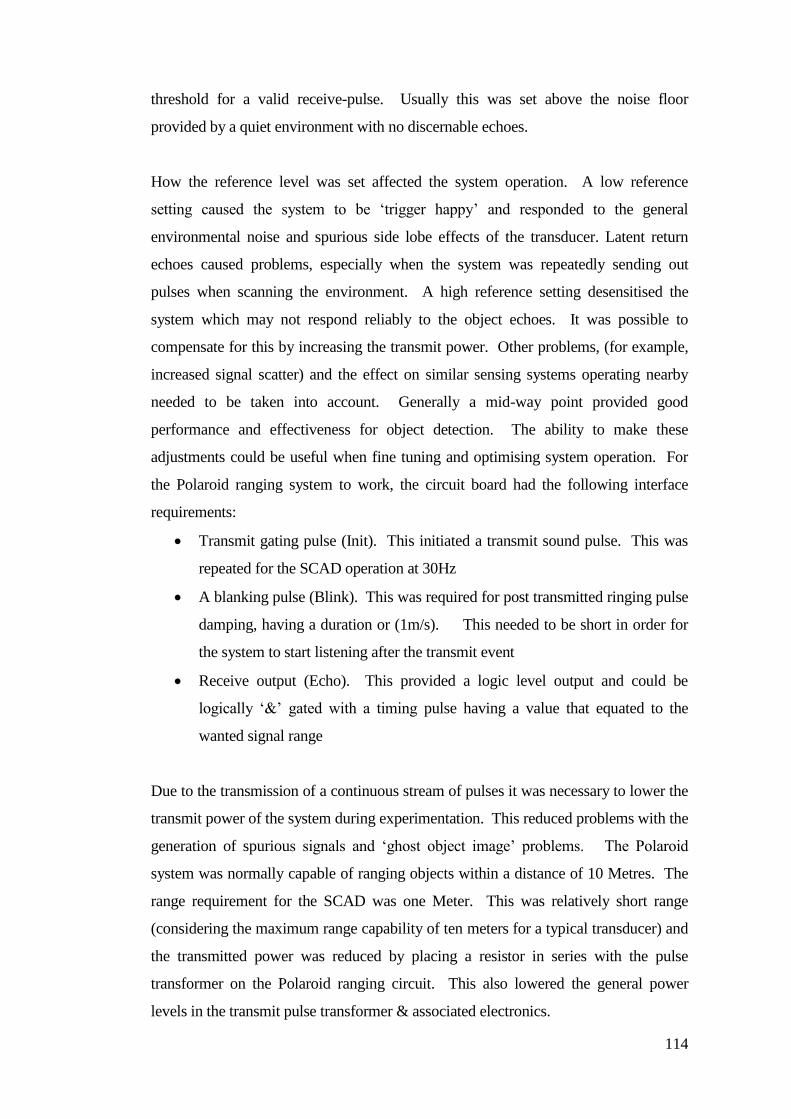
114
threshold for a valid receive-pulse. Usually this was set above the noise floor
provided by a quiet environment with no discernable echoes.
How the reference level was set affected the system operation. A low reference
setting caused the system to be ‘trigger happy’ and responded to the general
environmental noise and spurious side lobe effects of the transducer. Latent return
echoes caused problems, especially when the system was repeatedly sending out
pulses when scanning the environment. A high reference setting desensitised the
system which may not respond reliably to the object echoes. It was possible to
compensate for this by increasing the transmit power. Other problems, (for example,
increased signal scatter) and the effect on similar sensing systems operating nearby
needed to be taken into account. Generally a mid-way point provided good
performance and effectiveness for object detection. The ability to make these
adjustments could be useful when fine tuning and optimising system operation. For
the Polaroid ranging system to work, the circuit board had the following interface
requirements:
Transmit gating pulse (Init). This initiated a transmit sound pulse. This was
repeated for the SCAD operation at 30Hz
A blanking pulse (Blink). This was required for post transmitted ringing pulse
damping, having a duration or (1m/s). This needed to be short in order for
the system to start listening after the transmit event
Receive output (Echo). This provided a logic level output and could be
logically ‘&’ gated with a timing pulse having a value that equated to the
wanted signal range
Due to the transmission of a continuous stream of pulses it was necessary to lower the
transmit power of the system during experimentation. This reduced problems with the
generation of spurious signals and ‘ghost object image’ problems. The Polaroid
system was normally capable of ranging objects within a distance of 10 Metres. The
range requirement for the SCAD was one Meter. This was relatively short range
(considering the maximum range capability of ten meters for a typical transducer) and
the transmitted power was reduced by placing a resistor in series with the pulse
transformer on the Polaroid ranging circuit. This also lowered the general power
levels in the transmit pulse transformer & associated electronics.
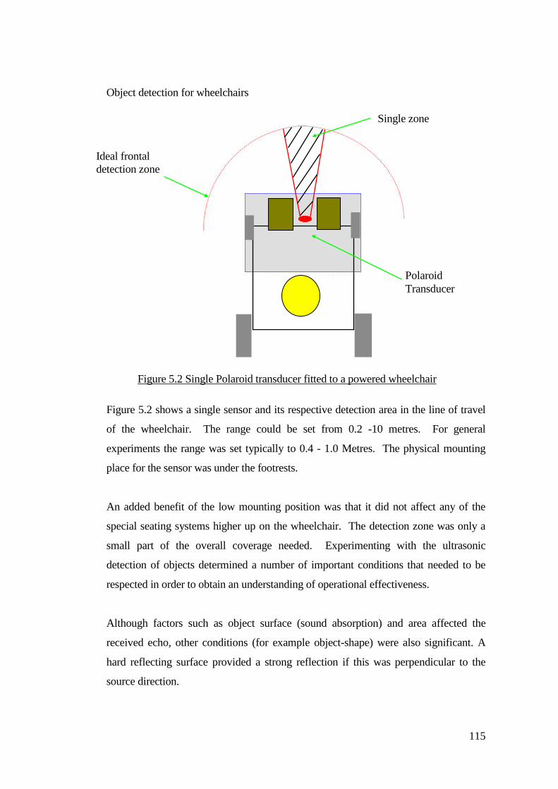
115
Object detection for wheelchairs
Figure 5.2 shows a single sensor and its respective detection area in the line of travel
of the wheelchair. The range could be set from 0.2 -10 metres. For general
experiments the range was set typically to 0.4 - 1.0 Metres. The physical mounting
place for the sensor was under the footrests.
An added benefit of the low mounting position was that it did not affect any of the
special seating systems higher up on the wheelchair. The detection zone was only a
small part of the overall coverage needed. Experimenting with the ultrasonic
detection of objects determined a number of important conditions that needed to be
respected in order to obtain an understanding of operational effectiveness.
Although factors such as object surface (sound absorption) and area affected the
received echo, other conditions (for example object-shape) were also significant. A
hard reflecting surface provided a strong reflection if this was perpendicular to the
source direction.
Polaroid
Transducer
Ideal frontal
detection zone
Single zone
Figure 5.2 Single Polaroid transducer fitted to a powered wheelchair
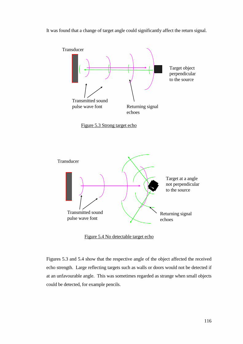
116
It was found that a change of target angle could significantly affect the return signal.
Figures 5.3 and 5.4 show that the respective angle of the object affected the received
echo strength. Large reflecting targets such as walls or doors would not be detected if
at an unfavourable angle. This was sometimes regarded as strange when small objects
could be detected, for example pencils.
Target object
perpendicular
to the source
Transducer
Transmitted sound
pulse wave font Returning signal
echoes
Figure 5.3 Strong target echo
Transducer
Transmitted sound
pulse wave font Returning signal
echoes
Target at a angle
not perpendicular
to the source
Figure 5.4 No detectable target echo
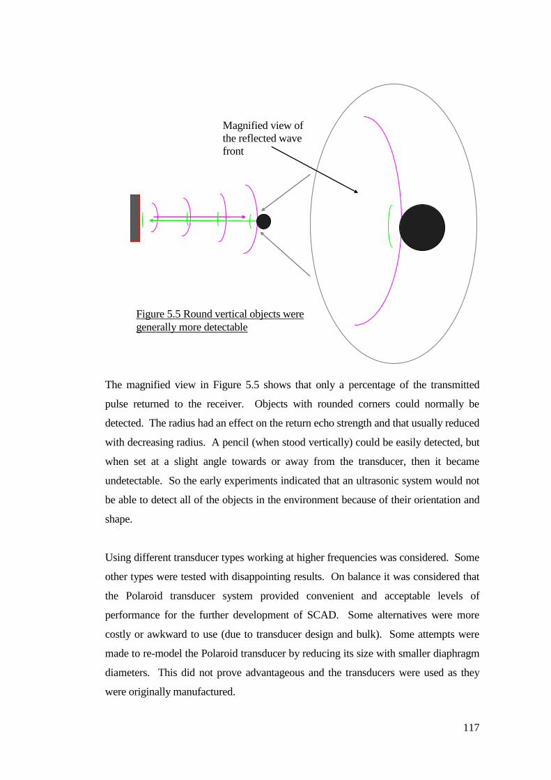
117
The magnified view in Figure 5.5 shows that only a percentage of the transmitted
pulse returned to the receiver. Objects with rounded corners could normally be
detected. The radius had an effect on the return echo strength and that usually reduced
with decreasing radius. A pencil (when stood vertically) could be easily detected, but
when set at a slight angle towards or away from the transducer, then it became
undetectable. So the early experiments indicated that an ultrasonic system would not
be able to detect all of the objects in the environment because of their orientation and
shape.
Using different transducer types working at higher frequencies was considered. Some
other types were tested with disappointing results. On balance it was considered that
the Polaroid transducer system provided convenient and acceptable levels of
performance for the further development of SCAD. Some alternatives were more
costly or awkward to use (due to transducer design and bulk). Some attempts were
made to re-model the Polaroid transducer by reducing its size with smaller diaphragm
diameters. This did not prove advantageous and the transducers were used as they
were originally manufactured.
Magnified view of
the reflected wave
front
Figure 5.5 Round vertical objects were
generally more detectable
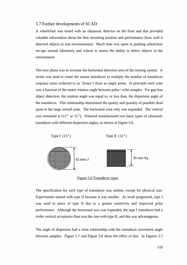
118
5.7 Further developments of SCAD
A wheelchair was tested with an ultrasonic detector on the front and that provided
valuable information about the best mounting position and performance (how well it
detected objects in real environments). Much time was spent in pushing wheelchair
set-ups around laboratory and school to assess the ability to detect objects in the
environment.
The next phase was to increase the horizontal detection area of the sensing system. A
motor was used to rotate the sensor transducer to multiply the number of transducer
response areas (referred to as ‘Zones’) from as single point. In principle each zone
was a function of the motor rotation angle between pulse / echo samples. For gap-less
object detection, the rotation angle was equal to, or less than, the dispersion angle of
the transducer. This relationship determined the quality and quantity of possible dead
spots in the large overall zone. The horizontal zone only was expanded. The vertical
axis remained at (12° or 15°). Polaroid manufactured two basic types of ultrasonic
transducer with different dispersion angles, as shown in Figure 5.6.
Type I (15°) Type II (12°)
The specification for each type of transducer was similar, except for physical size.
Experiments started with type II because it was smaller. As work progressed, type I
was used in place of type II due to a greater sensitivity and improved polar
performance. Although the horizontal axis was expanded, the type I transducer had a
wider vertical acceptance than was the case with type II, and this was advantageous.
The angle of dispersion had a close relationship with the transducer movement angle
between samples. Figure 5.7 and Figure 5.8 show the effect of this. In Figures 5.7
42 mm Ø 30 mm Sq
Figure 5.6 Transducer types
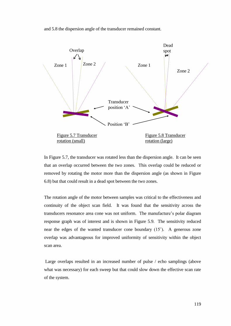
119
and 5.8 the dispersion angle of the transducer remained constant.
In Figure 5.7, the transducer was rotated less than the dispersion angle. It can be seen
that an overlap occurred between the two zones. This overlap could be reduced or
removed by rotating the motor more than the dispersion angle (as shown in Figure
6.8) but that could result in a dead spot between the two zones.
The rotation angle of the motor between samples was critical to the effectiveness and
continuity of the object scan field. It was found that the sensitivity across the
transducers resonance area cone was not uniform. The manufacture’s polar diagram
response graph was of interest and is shown in Figure 5.9. The sensitivity reduced
near the edges of the wanted transducer cone boundary (15˚). A generous zone
overlap was advantageous for improved uniformity of sensitivity within the object
scan area.
Large overlaps resulted in an increased number of pulse / echo samplings (above
what was necessary) for each sweep but that could slow down the effective scan rate
of the system.
Position ‘B’
Transducer
position ‘A’
Zone 1 Zone 2
Overlap
Zone 1
Zone 2
Dead
spot
Figure 5.7 Transducer
rotation (small)
Figure 5.8 Transducer
rotation (large)
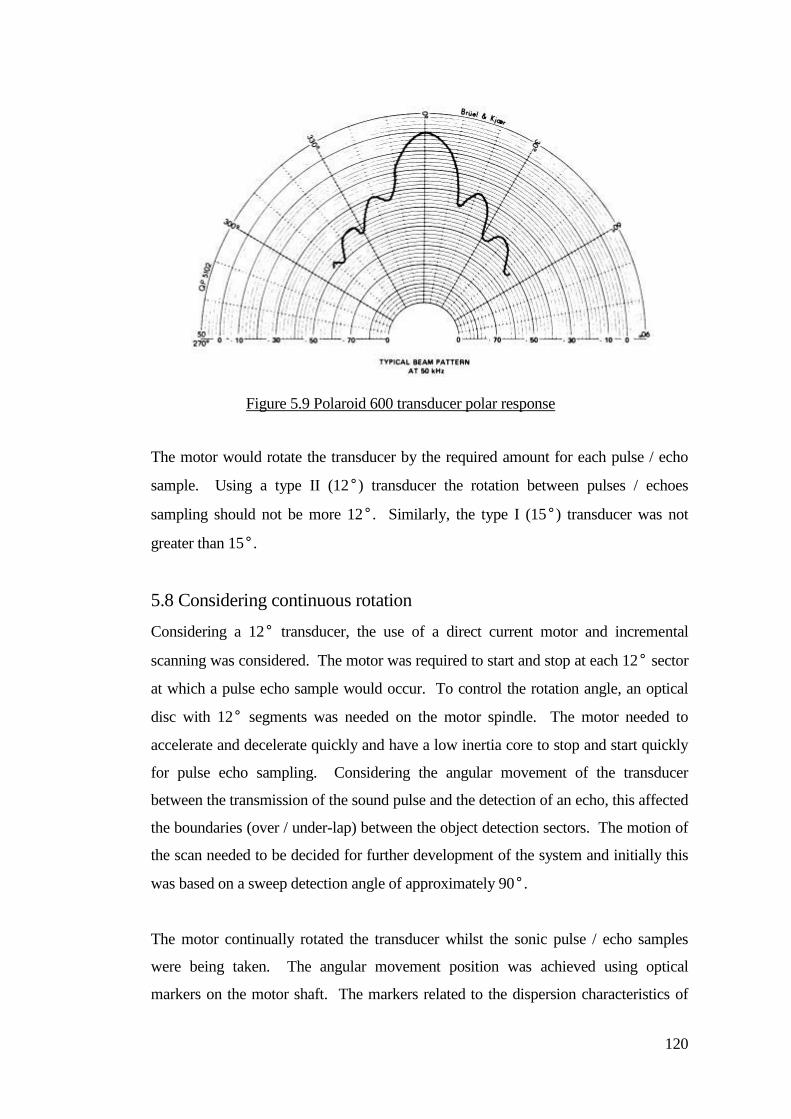
120
The motor would rotate the transducer by the required amount for each pulse / echo
sample. Using a type II (12°) transducer the rotation between pulses / echoes
sampling should not be more 12°. Similarly, the type I (15°) transducer was not
greater than 15°.
5.8 Considering continuous rotation
Considering a 12° transducer, the use of a direct current motor and incremental
scanning was considered. The motor was required to start and stop at each 12° sector
at which a pulse echo sample would occur. To control the rotation angle, an optical
disc with 12° segments was needed on the motor spindle. The motor needed to
accelerate and decelerate quickly and have a low inertia core to stop and start quickly
for pulse echo sampling. Considering the angular movement of the transducer
between the transmission of the sound pulse and the detection of an echo, this affected
the boundaries (over / under-lap) between the object detection sectors. The motion of
the scan needed to be decided for further development of the system and initially this
was based on a sweep detection angle of approximately 90°.
The motor continually rotated the transducer whilst the sonic pulse / echo samples
were being taken. The angular movement position was achieved using optical
markers on the motor shaft. The markers related to the dispersion characteristics of
Figure 5.9 Polaroid 600 transducer polar response
characteristics
121
the transducer to provide gap free detection. With a single transducer sweeping the
detection angle of 90°, there was a wrap around delay resulting from the time to rotate
the transducer the remaining 270° to the scan start position. The use of two
transducers back to back was considered in order to reduce this time but that required
electrical coupling and switching (either in the form of slip rings or inductive coupling
to the moving transducer).
The transducer operated in two ways, as a (Tx) transmitter and (Rx) receiver. In order
to transmit a sound pulse the transducers were excited with a short burst of pulses. The
ultrasonic sound chirp was generated from 16 needle pulses that resonated the
transducer diaphragm. This developed an electrostatic potential of 200-400 volts
within the transducer. To receive a return echo the transducer became a sensitive
electrostatic microphone. This generated a low level signal which was subsequently
amplified. The dynamic range of the coupling medium had to be large enough to
work in both modes. The following were considered:
a) Slip rings
b) Inductive coupling
c) Reciprocal scanning
a) Slip rings. Anticipated problems associated with slip rings included electrical
noise and mechanical wear. Each transducer needed to be switched in and out at the
appropriate part of rotation at the scan start and stop points.
b) Inductive coupling. This would involve specific development which detracted
from the physical development of the scanner in its own right, particularly in view of
the demanding electrical requirements of the transducer. It should be noted that the
associated Polaroid ranging circuit board was designed to be connected directly to a
transducer. The two components, transducer and ranging circuit, were designed to
match their respective electrical characteristics. The interposition of any different
coupling mediums may have caused problems (mis-matching) resulting in poor
detection performance.
c) Reciprocal scanning. The problem with transducer coupling could be avoided
by using a pair of flexible wires to connect the transducer directly to the ranging
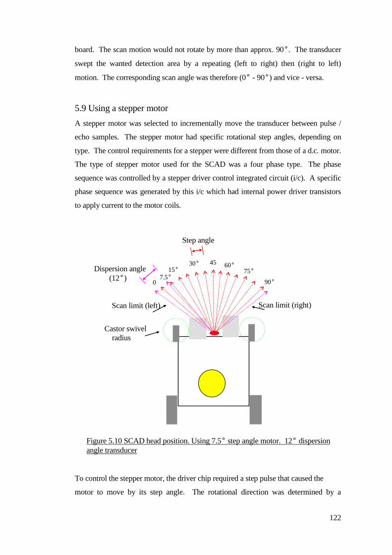
122
board. The scan motion would not rotate by more than approx. 90°. The transducer
swept the wanted detection area by a repeating (left to right) then (right to left)
motion. The corresponding scan angle was therefore (0° - 90°) and vice - versa.
5.9 Using a stepper motor
A stepper motor was selected to incrementally move the transducer between pulse /
echo samples. The stepper motor had specific rotational step angles, depending on
type. The control requirements for a stepper were different from those of a d.c. motor.
The type of stepper motor used for the SCAD was a four phase type. The phase
sequence was controlled by a stepper driver control integrated circuit (i/c). A specific
phase sequence was generated by this i/c which had internal power driver transistors
to apply current to the motor coils.
To control the stepper motor, the driver chip required a step pulse that caused the
motor to move by its step angle. The rotational direction was determined by a
Castor swivel
radius
0
°
7.5° 15°
30° 45
°
60° 75°
90°
Dispersion angle
(12°)
Step angle
Scan limit (left) Scan limit (right)
Figure 5.10 SCAD head position. Using 7.5° step angle motor. 12° dispersion
angle transducer
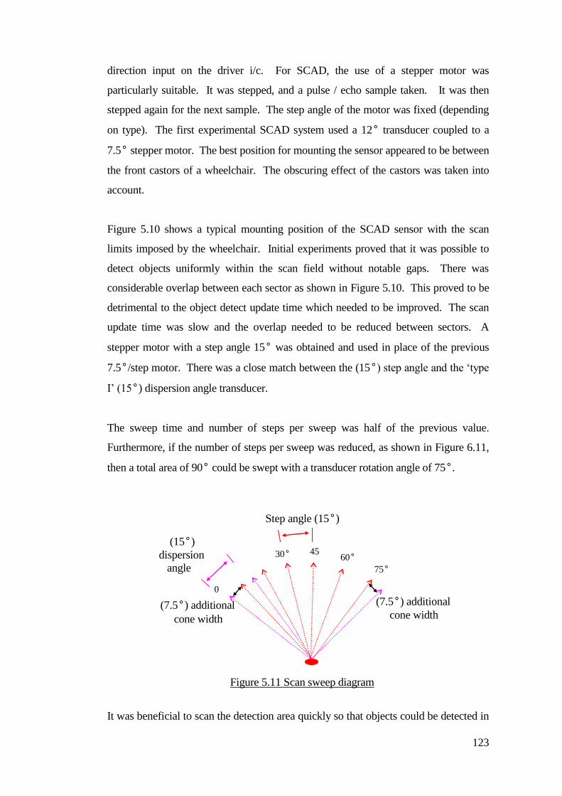
123
direction input on the driver i/c. For SCAD, the use of a stepper motor was
particularly suitable. It was stepped, and a pulse / echo sample taken. It was then
stepped again for the next sample. The step angle of the motor was fixed (depending
on type). The first experimental SCAD system used a 12° transducer coupled to a
7.5° stepper motor. The best position for mounting the sensor appeared to be between
the front castors of a wheelchair. The obscuring effect of the castors was taken into
account.
Figure 5.10 shows a typical mounting position of the SCAD sensor with the scan
limits imposed by the wheelchair. Initial experiments proved that it was possible to
detect objects uniformly within the scan field without notable gaps. There was
considerable overlap between each sector as shown in Figure 5.10. This proved to be
detrimental to the object detect update time which needed to be improved. The scan
update time was slow and the overlap needed to be reduced between sectors. A
stepper motor with a step angle 15° was obtained and used in place of the previous
7.5°/step motor. There was a close match between the (15°) step angle and the ‘type
I’ (15°) dispersion angle transducer.
The sweep time and number of steps per sweep was half of the previous value.
Furthermore, if the number of steps per sweep was reduced, as shown in Figure 6.11,
then a total area of 90° could be swept with a transducer rotation angle of 75°.
It was beneficial to scan the detection area quickly so that objects could be detected in
0
°
30° 45
°
60° 75°
Step angle (15°)
(15°)
dispersion
angle
(7.5°) additional
cone width
(7.5°) additional
cone width
Figure 5.11 Scan sweep diagram
124
the shortest possible time. There were two apparent delays: time of flight delay and
scan target delay. Sound propagation in air is generally 0.3 Meters / ms. The distance
of a detectable object from the transducer was determined by measuring the time
between the transmission of the sound pulse and the time taken for the reception of the
echo. The time allowed was for the round trip (there and back) from the object. For
example the time taken for sound to travel one metre is 3.33 ms. This was doubled
due to the return journey, therefore the total time required for ranging the object was
6.66 ms. The scanning motion required a finite amount of time to move between
pulse echo samples. This took account of the time of flight delay and the mechanical
movement constraints of the system.
The time taken for the detection of an object within the scan field was dependent on
its position relative to the scan motion. The detection time for an object appearing
within the wanted detection distance varied depending on which part of the scan cycle
the object first appeared. The worst case (longest detect time) between updates was
for the complete sweep cycle time. The shortest time was between adjacent sample
sectors 15°. The sweep cycle time was therefore:
pulse sample time frequency (50ms) x number of sectors (12) = 600ms per sweep
Figure 5.12 shows a complete reciprocal scan cycle (sweep). The blue & red direction
arrows indicate the cycle movement direction (one way and then the other).
The overall worst case detection delay was derived from:
Maximum detection delay = sweep cycle time + time of flight delay for a set object
range.
Knowing this delay was a factor in determining the effective detection range for a
moving wheelchair. If the detection response was slow compared to the vehicle speed
then the object detection warning was too late. This could be compensated by
increasing the range of detection (to look further ahead), but that caused problems
with the unwanted detection of objects at the side of the wheelchair.
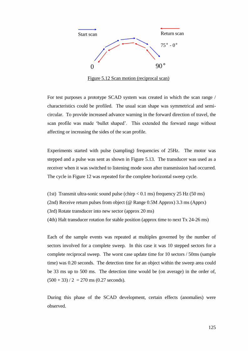
125
For test purposes a prototype SCAD system was created in which the scan range /
characteristics could be profiled. The usual scan shape was symmetrical and semi-
circular. To provide increased advance warning in the forward direction of travel, the
scan profile was made ‘bullet shaped’. This extended the forward range without
affecting or increasing the sides of the scan profile.
Experiments started with pulse (sampling) frequencies of 25Hz. The motor was
stepped and a pulse was sent as shown in Figure 5.13. The transducer was used as a
receiver when it was switched to listening mode soon after transmission had occurred.
The cycle in Figure 12 was repeated for the complete horizontal sweep cycle.
(1st) Transmit ultra-sonic sound pulse (chirp < 0.1 ms) frequency 25 Hz (50 ms)
(2nd) Receive return pulses from object (@ Range 0.5M Approx) 3.3 ms (Apprx)
(3rd) Rotate transducer into new sector (approx 20 ms)
(4th) Halt transducer rotation for stable position (approx time to next Tx 24-26 ms)
Each of the sample events was repeated at multiples governed by the number of
sectors involved for a complete sweep. In this case it was 10 stepped sectors for a
complete reciprocal sweep. The worst case update time for 10 sectors / 50ms (sample
time) was 0.20 seconds. The detection time for an object within the sweep area could
be 33 ms up to 500 ms. The detection time would be (on average) in the order of,
(500 + 33) / 2 = 270 ms (0.27 seconds).
During this phase of the SCAD development, certain effects (anomalies) were
observed.
0
°
90°
Start scan
0 - 75°
Return scan
75° - 0°
Figure 5.12 Scan motion (reciprocal scan)
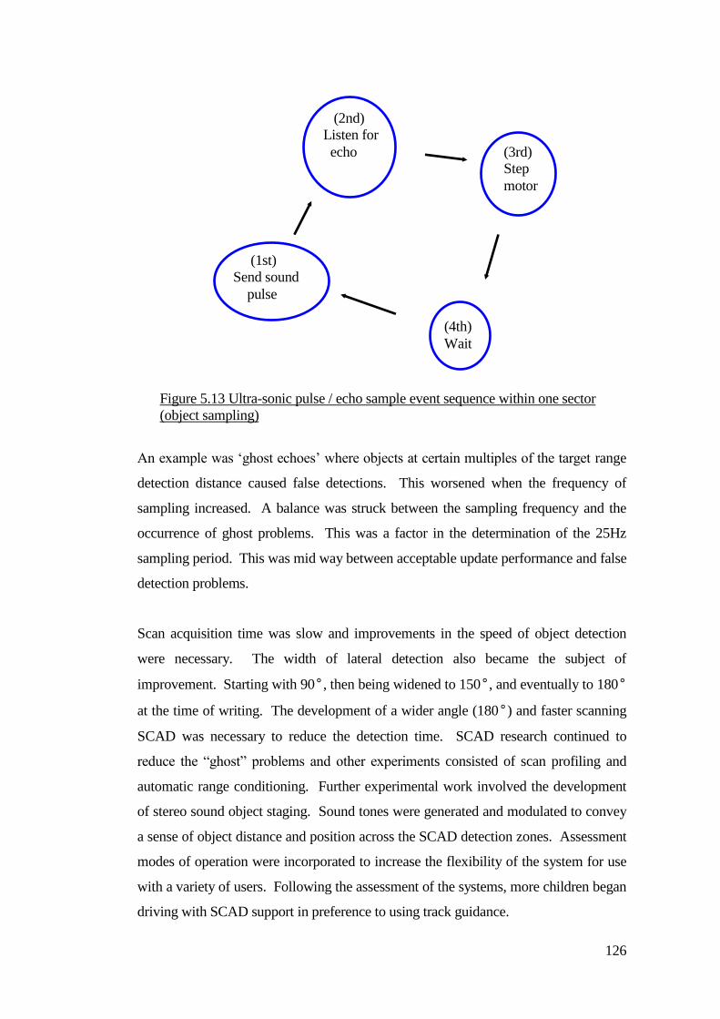
126
An example was ‘ghost echoes’ where objects at certain multiples of the target range
detection distance caused false detections. This worsened when the frequency of
sampling increased. A balance was struck between the sampling frequency and the
occurrence of ghost problems. This was a factor in the determination of the 25Hz
sampling period. This was mid way between acceptable update performance and false
detection problems.
Scan acquisition time was slow and improvements in the speed of object detection
were necessary. The width of lateral detection also became the subject of
improvement. Starting with 90°, then being widened to 150°, and eventually to 180°
at the time of writing. The development of a wider angle (180°) and faster scanning
SCAD was necessary to reduce the detection time. SCAD research continued to
reduce the “ghost” problems and other experiments consisted of scan profiling and
automatic range conditioning. Further experimental work involved the development
of stereo sound object staging. Sound tones were generated and modulated to convey
a sense of object distance and position across the SCAD detection zones. Assessment
modes of operation were incorporated to increase the flexibility of the system for use
with a variety of users. Following the assessment of the systems, more children began
driving with SCAD support in preference to using track guidance.
(3rd)
Step
motor
(4th)
Wait
(1st)
Send sound
pulse
(2nd)
Listen for
echo
Figure 5.13 Ultra-sonic pulse / echo sample event sequence within one sector
(object sampling)
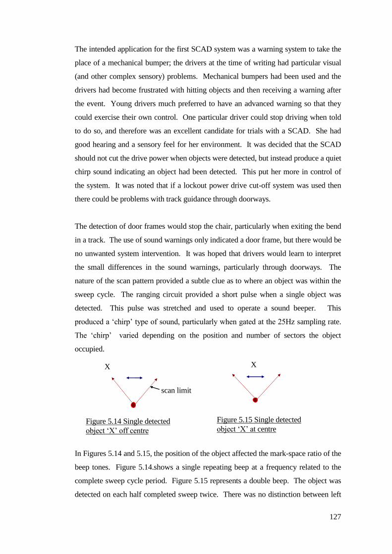
127
The intended application for the first SCAD system was a warning system to take the
place of a mechanical bumper; the drivers at the time of writing had particular visual
(and other complex sensory) problems. Mechanical bumpers had been used and the
drivers had become frustrated with hitting objects and then receiving a warning after
the event. Young drivers much preferred to have an advanced warning so that they
could exercise their own control. One particular driver could stop driving when told
to do so, and therefore was an excellent candidate for trials with a SCAD. She had
good hearing and a sensory feel for her environment. It was decided that the SCAD
should not cut the drive power when objects were detected, but instead produce a quiet
chirp sound indicating an object had been detected. This put her more in control of
the system. It was noted that if a lockout power drive cut-off system was used then
there could be problems with track guidance through doorways.
The detection of door frames would stop the chair, particularly when exiting the bend
in a track. The use of sound warnings only indicated a door frame, but there would be
no unwanted system intervention. It was hoped that drivers would learn to interpret
the small differences in the sound warnings, particularly through doorways. The
nature of the scan pattern provided a subtle clue as to where an object was within the
sweep cycle. The ranging circuit provided a short pulse when a single object was
detected. This pulse was stretched and used to operate a sound beeper. This
produced a ‘chirp’ type of sound, particularly when gated at the 25Hz sampling rate.
The ‘chirp’ varied depending on the position and number of sectors the object
occupied.
In Figures 5.14 and 5.15, the position of the object affected the mark-space ratio of the
beep tones. Figure 5.14.shows a single repeating beep at a frequency related to the
complete sweep cycle period. Figure 5.15 represents a double beep. The object was
detected on each half completed sweep twice. There was no distinction between left
X
scan limit
Figure 5.14 Single detected
object ‘X’ off centre
X
Figure 5.15 Single detected
object ‘X’ at centre

128
or right object position or object distance. It was possible to judge a doorway by the
sound signature. Larger objects occupying more than one sector produced ‘chirp’
sounds as successive beeps repeating at 25Hz. in bursts. No particular emphasis was
placed on the young driver in terms of training and understanding the differences of
the sound beeps. This was an effect that was noted as a by-product of the scanning
technique. Some blind users were intuitive and would often stop inches before a track
junction even without hearing the chirping SCAD. They appeared to be able to sense
when people were around and to extract information from the sounds in the
environment, for example familiar sounds and voices.
So the SCAD was really supplementary for some blind powered wheelchair users, but
it would give warning if something appeared unexpectedly. A power cut-off system
was not developed for some of those users because they responded well to the warning
sound and the SCAD would have problems with spurious detection (which could have
stopped them unnecessarily).
There were still a lot of children with mechanical bumpers on their wheelchairs whilst
some children were moved onto the prototype SCAD systems. To some extent the
mechanical bumpers were becoming a liability because of their vulnerability and a
lack of effectiveness (especially in not providing advanced warning). In order to be
used by everybody, the prototype SCAD systems needed to change from being an
audible warning system to a power cut-off system; mainly because the children with
mechanical bumpers could not be relied upon to stop when they heard a sound
warning. The focus of new research became contact-less object sensing, especially as
it became “un-cool” to have a mechanical bumper on your wheelchair. The SCAD
system needed modifications to operate in a power cut-off mode, but there were a
number of issues to be addressed concerning false ‘ghost’ object detection and slow
response time.
The essential requirements of the SCAD detector head were to be compact and
simple. Figure 6.16 was captured from a video sequence showing the prototype
SCAD sensor head mounted on a track following wheelchair. The mounting position
was clear of detecting the foot-rests, so the sensor had a clear sweep in the front (line
of travel of the chair). Figure 5.17.is a diagram of the prototype SCAD assembly.
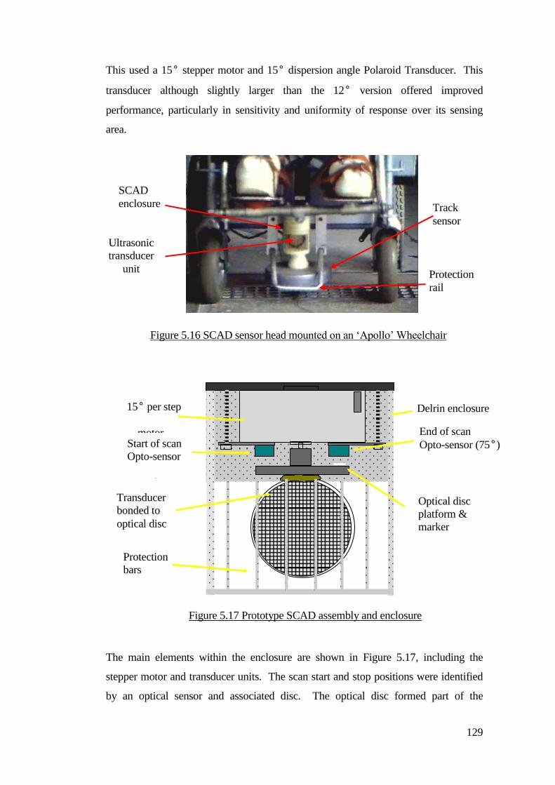
129
This used a 15° stepper motor and 15° dispersion angle Polaroid Transducer. This
transducer although slightly larger than the 12° version offered improved
performance, particularly in sensitivity and uniformity of response over its sensing
area.
The main elements within the enclosure are shown in Figure 5.17, including the
stepper motor and transducer units. The scan start and stop positions were identified
by an optical sensor and associated disc. The optical disc formed part of the
Transducer
bonded to
optical disc
Optical disc
platform &
marker
End of scan
Opto-sensor (75°)
Delrin enclosure 15° per step
motor Start of scan
Opto-sensor
(0°)
Protection
bars
Figure 5.17 Prototype SCAD assembly and enclosure
SCAD
enclosure
Ultrasonic
transducer
unit
Track
sensor
Protection
rail
Figure 5.16 SCAD sensor head mounted on an ‘Apollo’ Wheelchair
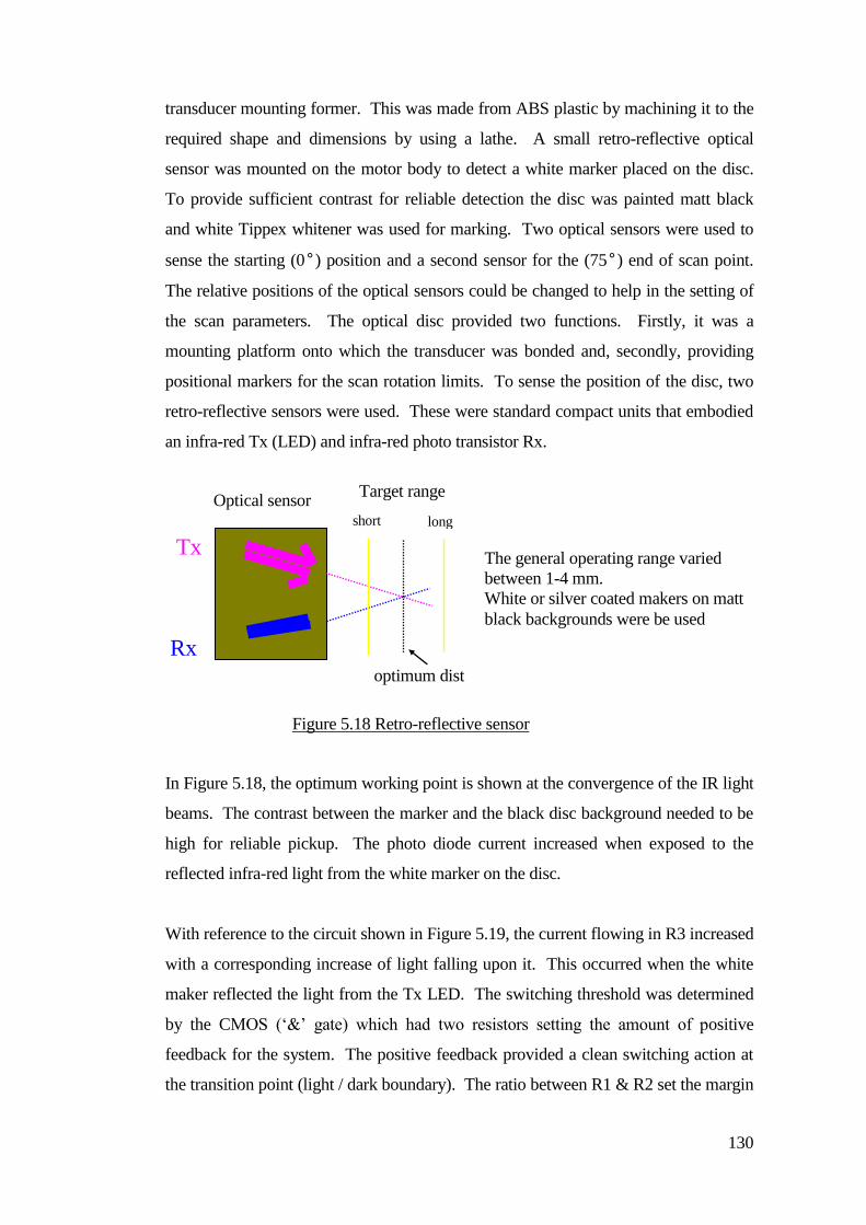
130
transducer mounting former. This was made from ABS plastic by machining it to the
required shape and dimensions by using a lathe. A small retro-reflective optical
sensor was mounted on the motor body to detect a white marker placed on the disc.
To provide sufficient contrast for reliable detection the disc was painted matt black
and white Tippex whitener was used for marking. Two optical sensors were used to
sense the starting (0°) position and a second sensor for the (75°) end of scan point.
The relative positions of the optical sensors could be changed to help in the setting of
the scan parameters. The optical disc provided two functions. Firstly, it was a
mounting platform onto which the transducer was bonded and, secondly, providing
positional markers for the scan rotation limits. To sense the position of the disc, two
retro-reflective sensors were used. These were standard compact units that embodied
an infra-red Tx (LED) and infra-red photo transistor Rx.
In Figure 5.18, the optimum working point is shown at the convergence of the IR light
beams. The contrast between the marker and the black disc background needed to be
high for reliable pickup. The photo diode current increased when exposed to the
reflected infra-red light from the white marker on the disc.
With reference to the circuit shown in Figure 5.19, the current flowing in R3 increased
with a corresponding increase of light falling upon it. This occurred when the white
maker reflected the light from the Tx LED. The switching threshold was determined
by the CMOS (‘&’ gate) which had two resistors setting the amount of positive
feedback for the system. The positive feedback provided a clean switching action at
the transition point (light / dark boundary). The ratio between R1 & R2 set the margin
Target range Optical sensor
short long
optimum dist
The general operating range varied
between 1-4 mm.
White or silver coated makers on matt
black backgrounds were be used
Tx
Rx
Figure 5.18 Retro-reflective sensor
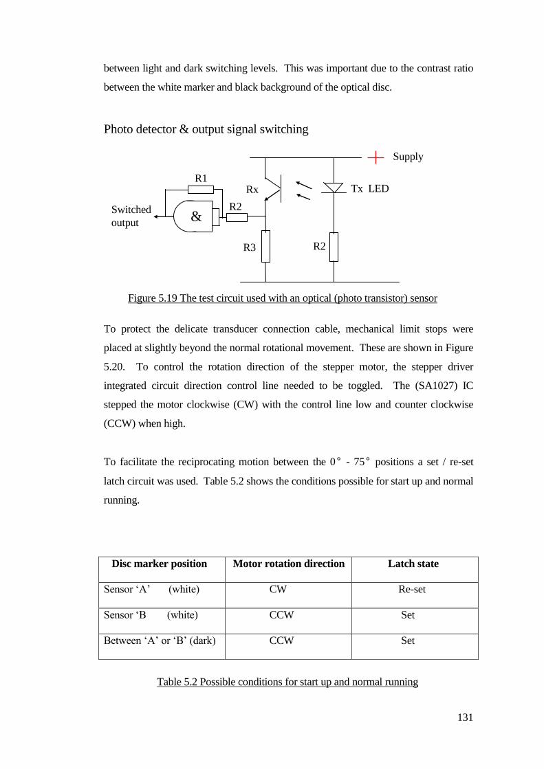
131
between light and dark switching levels. This was important due to the contrast ratio
between the white marker and black background of the optical disc.
Photo detector & output signal switching
To protect the delicate transducer connection cable, mechanical limit stops were
placed at slightly beyond the normal rotational movement. These are shown in Figure
5.20. To control the rotation direction of the stepper motor, the stepper driver
integrated circuit direction control line needed to be toggled. The (SA1027) IC
stepped the motor clockwise (CW) with the control line low and counter clockwise
(CCW) when high.
To facilitate the reciprocating motion between the 0° - 75° positions a set / re-set
latch circuit was used. Table 5.2 shows the conditions possible for start up and normal
running.
Disc marker position Motor rotation direction Latch state
Sensor ‘A’ (white) CW Re-set
Sensor ‘B (white) CCW Set
Between ‘A’ or ‘B’ (dark) CCW Set
Supply
Rx Tx LED
R3 R2
R1
& R2 Switched
output
Figure 5.19 The test circuit used with an optical (photo transistor) sensor
Table 5.2 Possible conditions for start up and normal running
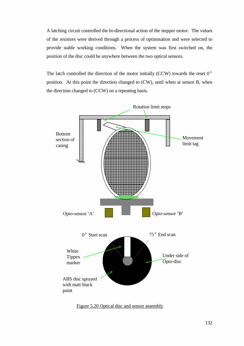
132
A latching circuit controlled the bi-directional action of the stepper motor. The values
of the resistors were derived through a process of optimisation and were selected to
provide stable working conditions. When the system was first switched on, the
position of the disc could be anywhere between the two optical sensors.
The latch controlled the direction of the motor initially (CCW) towards the reset 0°
position. At this point the direction changed to (CW), until when at sensor B, when
the direction changed to (CCW) on a repeating basis.
Opto-sensor ‘B’ Opto-sensor ‘A’
0° Start scan
limit
75° End scan
limit
Bottom
section of
casing
Rotation limit stops
Movement
limit tag
Under side of
Opto-disc
ABS disc sprayed
with matt black
paint
White
Tippex
marker
Figure 5.20 Optical disc and sensor assembly
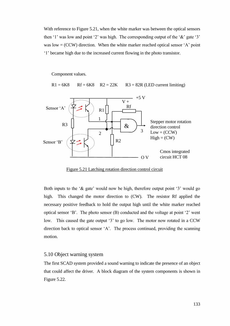
133
With reference to Figure 5.21, when the white marker was between the optical sensors
then ‘1’ was low and point ‘2’ was high. The corresponding output of the ‘&’ gate ‘3’
was low = (CCW) direction. When the white marker reached optical sensor ‘A’ point
‘1’ became high due to the increased current flowing in the photo transistor.
Both inputs to the ‘& gate’ would now be high, therefore output point ‘3’ would go
high. This changed the motor direction to (CW). The resistor Rf applied the
necessary positive feedback to hold the output high until the white marker reached
optical sensor ‘B’. The photo sensor (B) conducted and the voltage at point ‘2’ went
low. This caused the gate output ‘3’ to go low. The motor now rotated in a CCW
direction back to optical sensor ‘A’. The process continued, providing the scanning
motion.
5.10 Object warning system
The first SCAD system provided a sound warning to indicate the presence of an object
that could affect the driver. A block diagram of the system components is shown in
Figure 5.22.
&
Sensor ‘A’
(0°)
Sensor ‘B’
(75°)
V +
O V
Rf
R2
R1
1
2 3
Stepper motor rotation
direction control
Low = (CCW)
High = (CW)
R3
Cmos integrated
circuit HCT 08
Component values.
R1 = 6K8 Rf = 6K8 R2 = 22K R3 = 82R (LED current limiting)
Figure 5.21 Latching rotation direction control circuit
+5 V
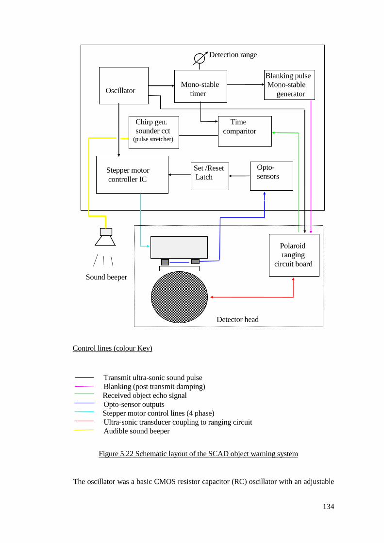
134
Transmit ultra-sonic sound pulse
Blanking (post transmit damping)
Received object echo signal Opto-sensor outputs
Stepper motor control lines (4 phase) Ultra-sonic transducer coupling to ranging circuit Audible sound beeper
The oscillator was a basic CMOS resistor capacitor (RC) oscillator with an adjustable
Stepper motor
controller IC
Opto-
sensors
interface
Set /Reset
Latch
Oscillator
Clock gen.
Mono-stable
timer
Time
comparitor
Blanking pulse
Mono-stable
generator
Chirp gen.
sounder cct (pulse stretcher)
Polaroid
ranging
circuit board
Detector head
Detection range
control
Sound beeper
Figure 5.22 Schematic layout of the SCAD object warning system
Control lines (colour Key)
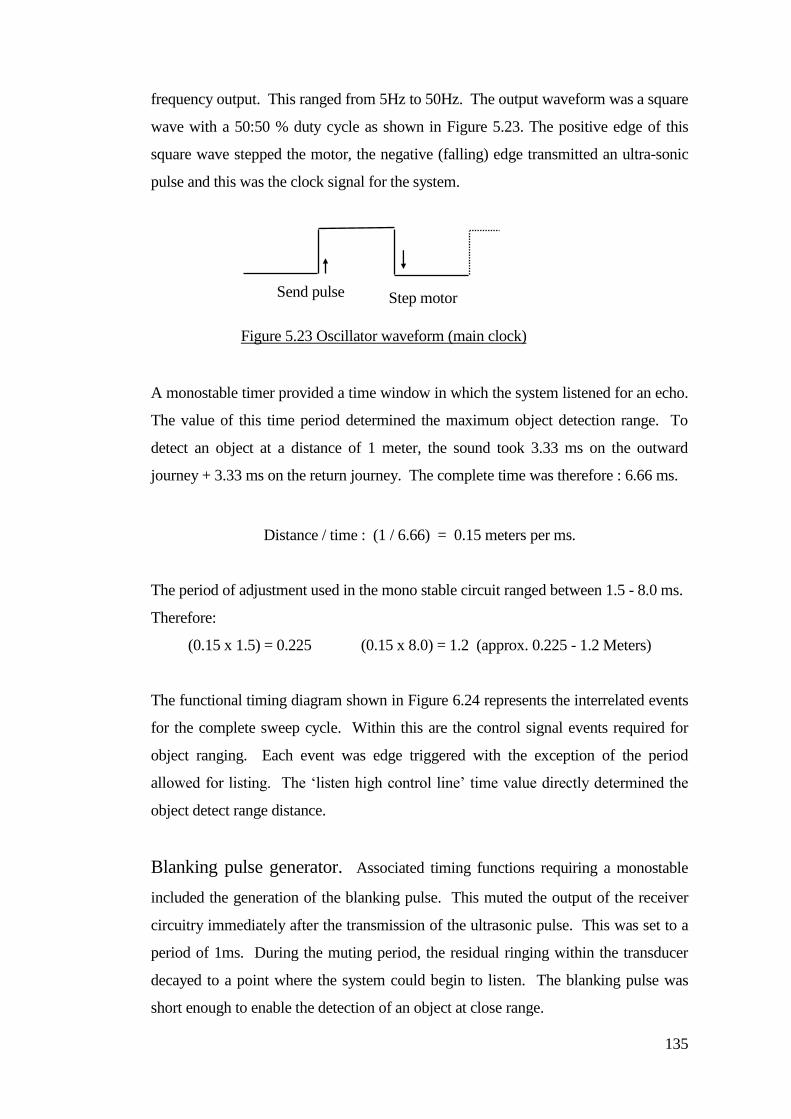
135
frequency output. This ranged from 5Hz to 50Hz. The output waveform was a square
wave with a 50:50 % duty cycle as shown in Figure 5.23. The positive edge of this
square wave stepped the motor, the negative (falling) edge transmitted an ultra-sonic
pulse and this was the clock signal for the system.
A monostable timer provided a time window in which the system listened for an echo.
The value of this time period determined the maximum object detection range. To
detect an object at a distance of 1 meter, the sound took 3.33 ms on the outward
journey + 3.33 ms on the return journey. The complete time was therefore : 6.66 ms.
Distance / time : (1 / 6.66) = 0.15 meters per ms.
The period of adjustment used in the mono stable circuit ranged between 1.5 - 8.0 ms.
Therefore:
(0.15 x 1.5) = 0.225 (0.15 x 8.0) = 1.2 (approx. 0.225 - 1.2 Meters)
The functional timing diagram shown in Figure 6.24 represents the interrelated events
for the complete sweep cycle. Within this are the control signal events required for
object ranging. Each event was edge triggered with the exception of the period
allowed for listing. The ‘listen high control line’ time value directly determined the
object detect range distance.
Blanking pulse generator. Associated timing functions requiring a monostable
included the generation of the blanking pulse. This muted the output of the receiver
circuitry immediately after the transmission of the ultrasonic pulse. This was set to a
period of 1ms. During the muting period, the residual ringing within the transducer
decayed to a point where the system could begin to listen. The blanking pulse was
short enough to enable the detection of an object at close range.
Send pulse Step motor
Figure 5.23 Oscillator waveform (main clock)
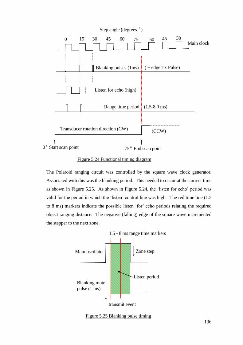
136
The Polaroid ranging circuit was controlled by the square wave clock generator.
Associated with this was the blanking period. This needed to occur at the correct time
as shown in Figure 5.25. As shown in Figure 5.24, the ‘listen for echo’ period was
valid for the period in which the ‘listen’ control line was high. The red time line (1.5
to 8 ms) markers indicate the possible listen ‘for’ echo periods relating the required
object ranging distance. The negative (falling) edge of the square wave incremented
the stepper to the next zone.
Main clock 0
Blanking pulses (1ms)
15 30 45 60 75 60 45 30
Listen for echo (high)
Range time period (1.5-8.0 ms)
( + edge Tx Pulse)
Transducer rotation direction (CW) (CCW)
Step angle (degrees °)
0° Start scan point 75° End scan point
Figure 5.24 Functional timing diagram
Listen period
Blanking mute
pulse (1 ms)
transmit event
Zone step Main oscillator
output
1.5 - 8 ms range time markers
Figure 5.25 Blanking pulse timing
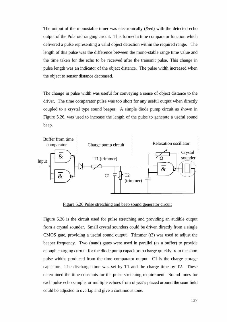
137
The output of the monostable timer was electronically (&ed) with the detected echo
output of the Polaroid ranging circuit. This formed a time comparator function which
delivered a pulse representing a valid object detection within the required range. The
length of this pulse was the difference between the mono-stable range time value and
the time taken for the echo to be received after the transmit pulse. This change in
pulse length was an indicator of the object distance. The pulse width increased when
the object to sensor distance decreased.
The change in pulse width was useful for conveying a sense of object distance to the
driver. The time comparator pulse was too short for any useful output when directly
coupled to a crystal type sound beeper. A simple diode pump circuit as shown in
Figure 5.26, was used to increase the length of the pulse to generate a useful sound
beep.
Figure 5.26 is the circuit used for pulse stretching and providing an audible output
from a crystal sounder. Small crystal sounders could be driven directly from a single
CMOS gate, providing a useful sound output. Trimmer (t3) was used to adjust the
beeper frequency. Two (nand) gates were used in parallel (as a buffer) to provide
enough charging current for the diode pump capacitor to charge quickly from the short
pulse widths produced from the time comparator output. C1 is the charge storage
capacitor. The discharge time was set by T1 and the charge time by T2. These
determined the time constants for the pulse stretching requirement. Sound tones for
each pulse echo sample, or multiple echoes from object’s placed around the scan field
could be adjusted to overlap and give a continuous tone.
&
&
&
T1 (trimmer)
T2
(trimmer) C1
Relaxation oscillator
Crystal
sounder t3
Charge pump circuit
Buffer from time
comparator
Input
Figure 5.26 Pulse stretching and beep sound generator circuit
138
A short piece of video and sound recording was taken in which this sound can be
heard and that is available form the author on request.
5.11 Enclosure protection
It was noted that the construction of the SCAD scanner enclosure, particularly the
protection bars could have an effect on the performance of the system. Due to the
delicate nature of the transducer and motor assembly, damage could result if hit,
poked or kicked etc. Experiments were tried using protective metal meshes and
gauzes to wrap around the sensor system. Problems occurred with internal sound
reflection problems. The ultra-sonic pulses bounced back and forth within the sensor
enclosure. Better results were obtained by using metal bars of (3mm) diameter.
Generally the amount of protection was balanced with system performance. For
example, thin bars might be transparent to system operation but offered less structural
protection than obtainable from thicker bars which, may cause unwanted false
detection problems. Angling the bars slightly reduced the possibility of internal signal
scatter by reflecting some of the sound energy away from the face of the transducer.
5.12 Discussion
The SCAD system described so far was created as a successor to the mechanical
bumper system used for track driver training. The major disadvantage with the
mechanical type bumper was its footprint size. This became untenably large when
increasing the amount of advance object warning and stop control requirements for the
wheelchair. Non-contact proximity object detection provided by ultra-sonic ranging
reduced the need for large overhanging physical bumper detectors. Pupils that had
been using the track had not had a real opportunity to exercise their own steering
control. Many young and older track drivers began to start practicing with their
wheelchair steering. One option was for them to try a normal switch or joystick to
control a powered wheelchair. This did not have a protective mechanism except for a
mechanical power cut-off bumper. This was normally implemented to reduce the
amount of damage caused by a driver impacting with objects or people. Drivers
colliding and misjudging object distance became the focus of further obstacle
avoidance development work.
139
One of the main reasons for the creation of the track guidance system was to help train
and provide experience for students driving within a safer environment. This enabled
them to reach destinations of their choice with greater independence and freedom
from staff and helpers. A natural progression beyond the limitation of access provided
from the track routes was a system that could guide itself by sensing the local
environment. This offered a greater opportunity for learner drivers and those with
visual impairments and spatial perception problems to drive with more freedom. The
SCAD provided a protected environment but required a higher driver skill level than
for track driving. In particular the requirements for navigation and recognition skills
of the environment were greater than those initially starting driving on the track.
The principal of rotating the ultra-sonic transducer and sending ultrasonic pulses
through stepped periods of rotation had been used and evaluated with the first
prototype SCAD single field detector. This had been intended as a wide angle audible
warning device for people (such as a blind girl) using a track following powered
wheelchair. There were anomalies with the detector, mostly arising out of the
repetitive pulse echo sampling. Old returning echoes could sometimes conflict with
nearby in-range targets, the sample time was also slower than desired etc. In spite of
some of these drawbacks the system worked sufficiently to detect nearby objects. The
phase of the development of the automatic assisted steering SCAD system required
object position placement and this is described in Chapter 6
140
Chapter 6
Using the SCAD to assist with steering
Children were often given training sessions by therapists who encouraged them to
drive more independently by walking with them and only providing help with controls
when necessary. Some children often crashed into things and required help to
negotiate an exit from a situation. This was by necessity a ‘hands on’ exercise. Often
therapists and helpers prompted a child to help them problem-solve, but physical
intervention was frequently required. Some therapists favoured a view that crashing
was an important learning experience that provided valuable feedback to the driver.
The objective behind creation of a guidance system was to help children gain a greater
sense of personal independence by reducing the number of times help was needed.
The SCAD provided children with an opportunity to negotiate a way forward in their
driving situation without needing a helper to intervene (except perhaps verbally to
offer advice or information).
The effect of system intervention had to some extent been tested by the use of the
track guidance system, as children had become more independent from helpers when
driving between track destinations. Children themselves demonstrated that they could
safely venture away from helpers (and many enjoyed this).
6.1 Object detection positioning
The starting point for the creation of a new system was to partition the SCAD
detection areas into three zones. Each zone consisted of two separate 15 sectors
producing separate zones of left, forward and right (each being 30 wide). A new
prototype SCAD was constructed using a 15 per step motor and a standard
instrument grade ‘Polaroid’ ultra-sonic transducer. The construction method used was
similar to the first SCAD (single field) unit. The transducer was bonded to an optical
disc having a marker indicating the scan start point.
Figure 6.1 shows the SCAD zones relative to start scan point. The ultra-sonic
transducer motion control system was operationally similar to the SCAD bumper
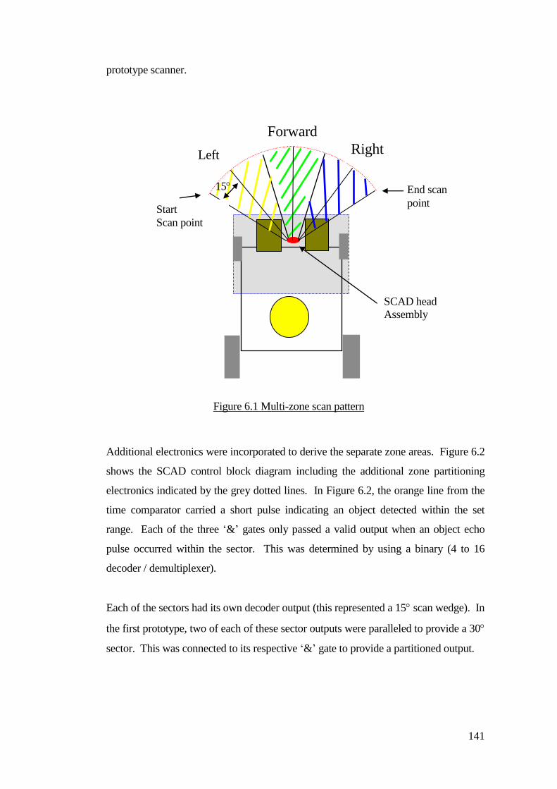
141
prototype scanner.
Additional electronics were incorporated to derive the separate zone areas. Figure 6.2
shows the SCAD control block diagram including the additional zone partitioning
electronics indicated by the grey dotted lines. In Figure 6.2, the orange line from the
time comparator carried a short pulse indicating an object detected within the set
range. Each of the three ‘&’ gates only passed a valid output when an object echo
pulse occurred within the sector. This was determined by using a binary (4 to 16
decoder / demultiplexer).
Each of the sectors had its own decoder output (this represented a 15 scan wedge). In
the first prototype, two of each of these sector outputs were paralleled to provide a 30
sector. This was connected to its respective ‘&’ gate to provide a partitioned output.
Left
Forward
Right
SCAD head
Assembly
Start
Scan point
15
Figure 6.1 Multi-zone scan pattern
End scan
point
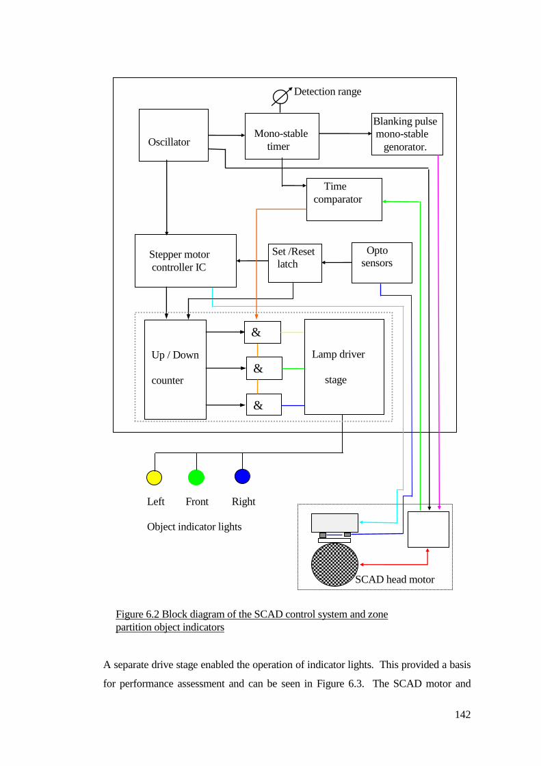
142
A separate drive stage enabled the operation of indicator lights. This provided a basis
for performance assessment and can be seen in Figure 6.3. The SCAD motor and
Stepper motor
controller IC
Opto
sensors
interface
Set /Reset
latch
Oscillator
Clock gen.
Mono-stable
timer
Time
comparator
Blanking pulse
mono-stable
genorator.
Detection range
control
Up / Down
counter &
&
&
Lamp driver
stage
Left Front Right
Object indicator lights
SCAD head motor
assembly
Figure 6.2 Block diagram of the SCAD control system and zone
partition object indicators
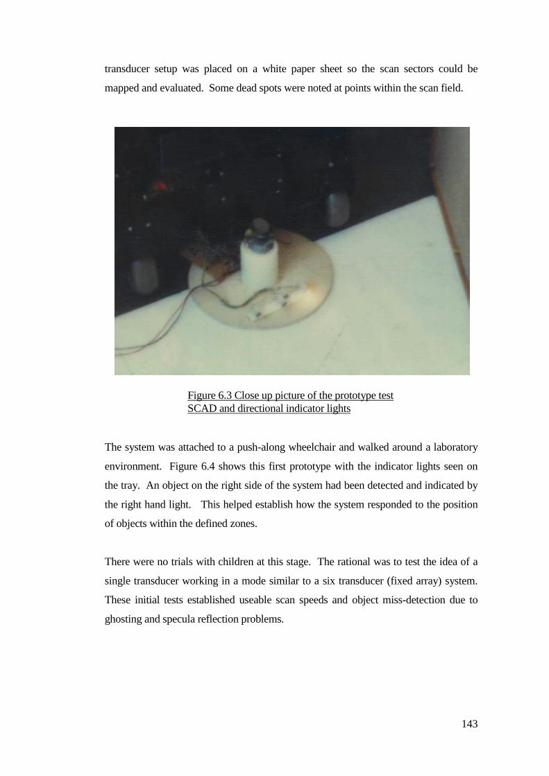
143
transducer setup was placed on a white paper sheet so the scan sectors could be
mapped and evaluated. Some dead spots were noted at points within the scan field.
The system was attached to a push-along wheelchair and walked around a laboratory
environment. Figure 6.4 shows this first prototype with the indicator lights seen on
the tray. An object on the right side of the system had been detected and indicated by
the right hand light. This helped establish how the system responded to the position
of objects within the defined zones.
There were no trials with children at this stage. The rational was to test the idea of a
single transducer working in a mode similar to a six transducer (fixed array) system.
These initial tests established useable scan speeds and object miss-detection due to
ghosting and specula reflection problems.
Figure 6.3 Close up picture of the prototype test
SCAD and directional indicator lights
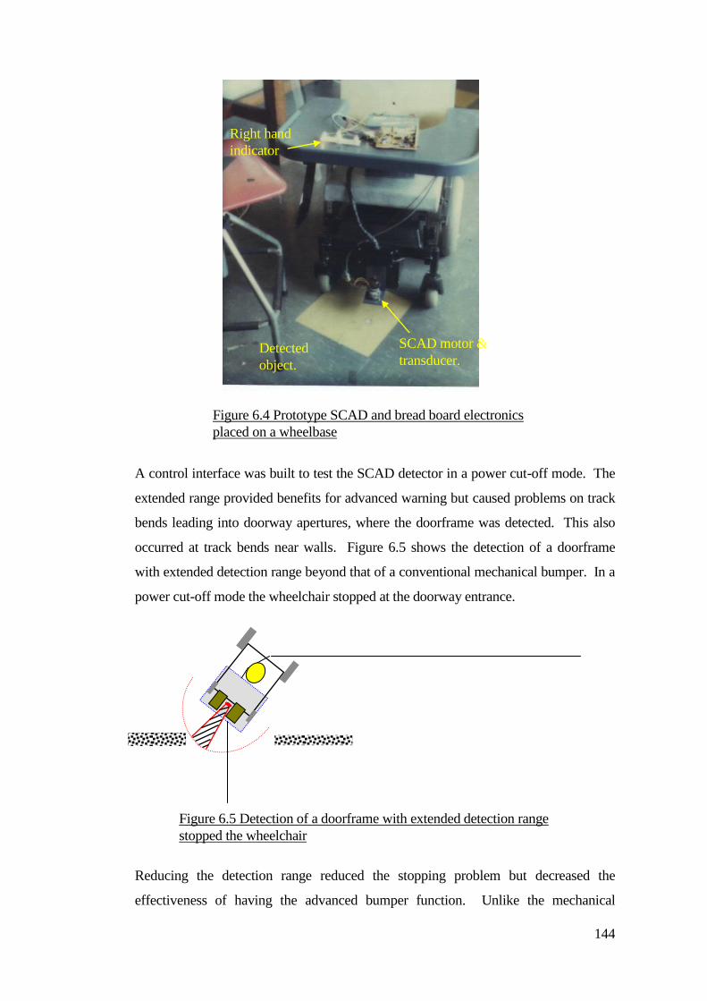
144
A control interface was built to test the SCAD detector in a power cut-off mode. The
extended range provided benefits for advanced warning but caused problems on track
bends leading into doorway apertures, where the doorframe was detected. This also
occurred at track bends near walls. Figure 6.5 shows the detection of a doorframe
with extended detection range beyond that of a conventional mechanical bumper. In a
power cut-off mode the wheelchair stopped at the doorway entrance.
Reducing the detection range reduced the stopping problem but decreased the
effectiveness of having the advanced bumper function. Unlike the mechanical
Figure 6.4 Prototype SCAD and bread board electronics
placed on a wheelbase
Right hand
indicator
SCAD motor &
transducer. Detected
object.
Figure 6.5 Detection of a doorframe with extended detection range
stopped the wheelchair
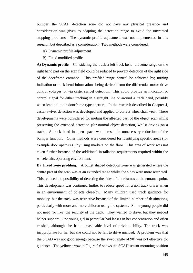
145
bumper, the SCAD detection zone did not have any physical presence and
consideration was given to adapting the detection range to avoid the unwanted
stopping problems. The dynamic profile adjustment was not implemented in this
research but described as a consideration. Two methods were considered:
A) Dynamic profile adjustment
B) Fixed modified profile
A) Dynamic profile. Considering the track a left track bend, the zone range on the
right hand part on the scan field could be reduced to prevent detection of the right side
of the doorframe entrance. This profiled range control be achieved by; turning
indication or track bend information being derived from the differential motor drive
control voltages, or via caster swivel detection. This could provide an indication or
control signal for either tracking in a straight line or around a track bend, possibly
when leading into a doorframe type aperture. In the research described in Chapter 4,
caster swivel detection was developed and applied to correct wheelchair veer. These
developments were considered for muting the affected part of the object scan whilst
preserving the extended detection (for normal object detection) whilst driving on a
track. A track bend in open space would result in unnecessary reduction of the
bumper function. Other methods were considered for identifying specific areas (for
example door apertures), by using markers on the floor. This area of work was not
taken further because of the additional installation requirements required within the
wheelchairs operating environment.
B) Fixed zone profiling. A bullet shaped detection zone was generated where the
centre part of the scan was at an extended range whilst the sides were more restricted.
This reduced the possibility of detecting the sides of doorframes at the entrance point.
This development was continued further to reduce speed for a non track driver when
in an environment of objects close-by. Many children used track guidance for
mobility, but the track was restrictive because of the limited number of destinations,
particularly with more and more children using the systems. Some young people did
not need (or like) the security of the track. They wanted to drive, but they needed
helper support. One young girl in particular had lapses in her concentration and often
crashed, although she had a reasonable level of driving ability. The track was
inappropriate for her but she could not be left to drive unaided. A problem was that
the SCAD was not good enough because the swept angle of 90º was not effective for
guidance. The yellow arrow in Figure 7.6 shows the SCAD sensor mounting position
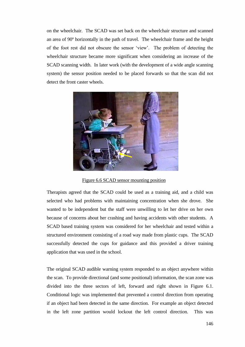
146
on the wheelchair. The SCAD was set back on the wheelchair structure and scanned
an area of 90º horizontally in the path of travel. The wheelchair frame and the height
of the foot rest did not obscure the sensor ‘view’. The problem of detecting the
wheelchair structure became more significant when considering an increase of the
SCAD scanning width. In later work (with the development of a wide angle scanning
system) the sensor position needed to be placed forwards so that the scan did not
detect the front caster wheels.
Therapists agreed that the SCAD could be used as a training aid, and a child was
selected who had problems with maintaining concentration when she drove. She
wanted to be independent but the staff were unwilling to let her drive on her own
because of concerns about her crashing and having accidents with other students. A
SCAD based training system was considered for her wheelchair and tested within a
structured environment consisting of a road way made from plastic cups. The SCAD
successfully detected the cups for guidance and this provided a driver training
application that was used in the school.
The original SCAD audible warning system responded to an object anywhere within
the scan. To provide directional (and some positional) information, the scan zone was
divided into the three sectors of left, forward and right shown in Figure 6.1.
Conditional logic was implemented that prevented a control direction from operating
if an object had been detected in the same direction. For example an object detected
in the left zone partition would lockout the left control direction. This was
Figure 6.6 SCAD sensor mounting position
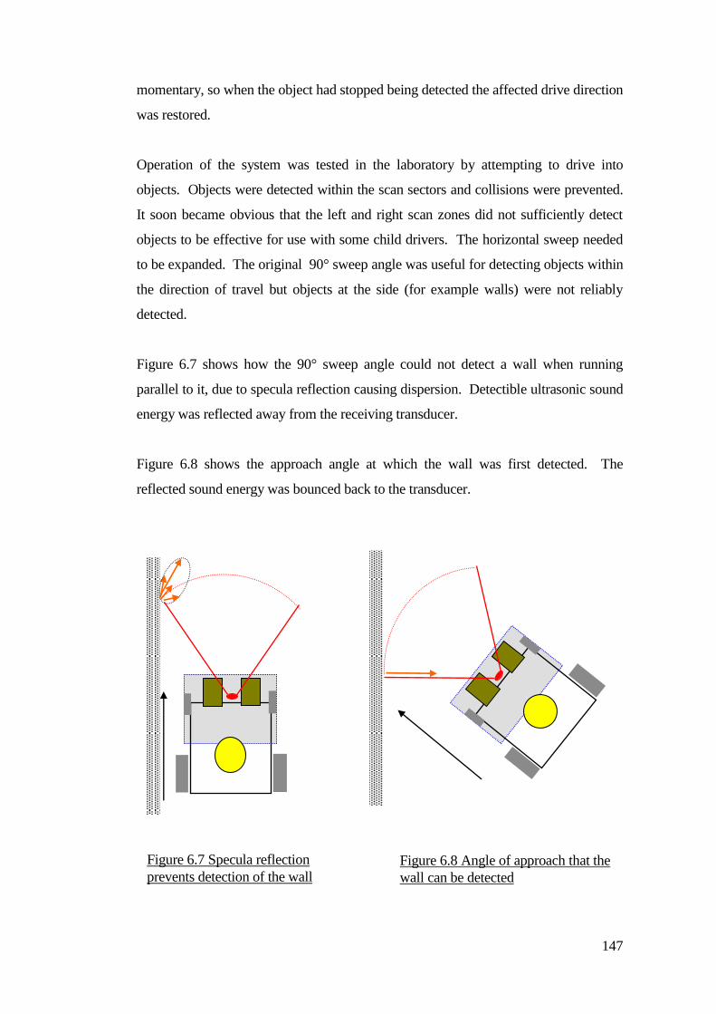
147
momentary, so when the object had stopped being detected the affected drive direction
was restored.
Operation of the system was tested in the laboratory by attempting to drive into
objects. Objects were detected within the scan sectors and collisions were prevented.
It soon became obvious that the left and right scan zones did not sufficiently detect
objects to be effective for use with some child drivers. The horizontal sweep needed
to be expanded. The original 90° sweep angle was useful for detecting objects within
the direction of travel but objects at the side (for example walls) were not reliably
detected.
Figure 6.7 shows how the 90° sweep angle could not detect a wall when running
parallel to it, due to specula reflection causing dispersion. Detectible ultrasonic sound
energy was reflected away from the receiving transducer.
Figure 6.8 shows the approach angle at which the wall was first detected. The
reflected sound energy was bounced back to the transducer.
Figure 6.7 Specula reflection
prevents detection of the wall Figure 6.8 Angle of approach that the
wall can be detected
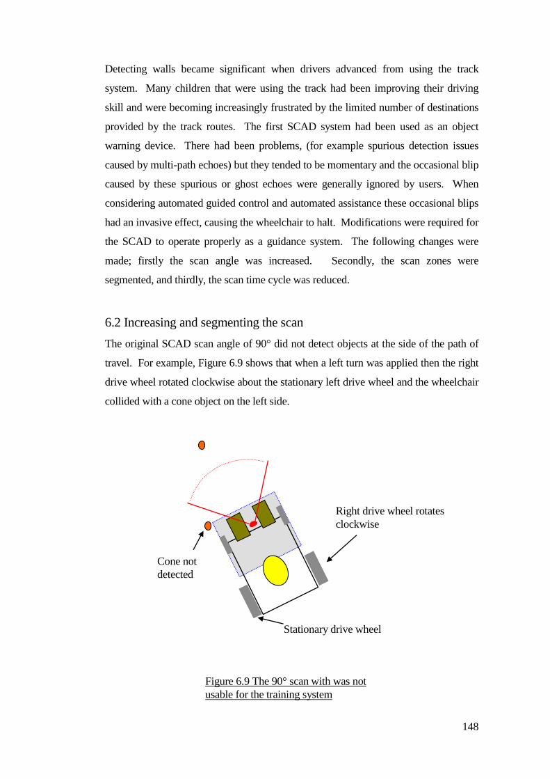
148
Detecting walls became significant when drivers advanced from using the track
system. Many children that were using the track had been improving their driving
skill and were becoming increasingly frustrated by the limited number of destinations
provided by the track routes. The first SCAD system had been used as an object
warning device. There had been problems, (for example spurious detection issues
caused by multi-path echoes) but they tended to be momentary and the occasional blip
caused by these spurious or ghost echoes were generally ignored by users. When
considering automated guided control and automated assistance these occasional blips
had an invasive effect, causing the wheelchair to halt. Modifications were required for
the SCAD to operate properly as a guidance system. The following changes were
made; firstly the scan angle was increased. Secondly, the scan zones were
segmented, and thirdly, the scan time cycle was reduced.
6.2 Increasing and segmenting the scan
The original SCAD scan angle of 90° did not detect objects at the side of the path of
travel. For example, Figure 6.9 shows that when a left turn was applied then the right
drive wheel rotated clockwise about the stationary left drive wheel and the wheelchair
collided with a cone object on the left side.
Right drive wheel rotates
clockwise
Stationary drive wheel
Cone not
detected
Figure 6.9 The 90° scan with was not
usable for the training system
149
Problems were caused by increasing the number of sectors to widen the horizontal
scan, particularly as this increased the scan cycle time. For early trials the wheelchair
speed was reduced to maintain control. This provided extra time for the wheelchair to
stop or change course when an object was detected within range.
Zone discrimination was intended for drivers who wanted to come off of the track but
who were not quite able to master driving without assistance. Drivers sometimes
returned to situations where helpers intervened and took control away from them. To
provide a continuum of progression for children who had previously been on track,
but who felt restricted by it, SCAD was selected as the next stage for their
development.
Testing began using three scan sectors, left, forwards and right. The logic was simple,
as each sector was ANDed with each switch direction control. For example, if an
object was detected in the left zone, the logic prevented the left driving operation. If
an object was detected in the forward zone, then forward driving would be disabled
and reverse enabled etc.
There were problems with wheelchair control when sensing its local environment and
how an object was approached could be significant. For example, if an object was
approached at a slight angle then only a small steering correction was necessary
because the angle of incidence from the wall was small. If the approach was ‘head on’
then more significant avoidance was required. This was not just a matter of cutting
motor power when an object was detected and then restoring the power when the
object was no longer detected. There needed to be specific levels and specific rules
about how power was applied. The first SCAD system did not have this feature but
consisted of ‘on-off’ relay logic (Niadex, 1995). This system did not perform well in
real environments because of the narrow scan field and poor dynamic control of the
wheelchair. This used crude relay control without any motor speed compensation.
Although this setup performed a basic object avoidance function in the laboratory
environment, when a child sat in the wheelchair then the increased weight affected
system control. These problems significantly reduced the effectiveness of the first
prototype SCAD.
150
6.3 Joystick emulator
Joysticks were the primary form of control that was used for wheelchair steering. The
joystick provided a two channel voltage output that changed in proportion to the
joystick movement. Standard wheelchair power controllers used these voltages to
control the power in each of the wheelchair motors, allowing a driver to control the
speed and direction of his or her wheelchair. It was necessary for the SCAD system to
emulate these joystick control voltages in order for the power controller to operate.
An emulator interface was developed that generated the required joystick control
voltages. When a forwards drive control was operated, then the joystick emulator
provided the same voltage as that of a joystick when the stick was pushed forward.
Similarly if a turn switch was selected, then a joystick turn voltage was generated.
There were problems when a fixed joystick control voltage was applied to a power
controller when, for example, a wheelchair stopped during a manoeuvre or going up
an incline. Sometimes staff manually pushed a wheelchair because it had stopped.
This required a increase of motor power for the wheelchair to keep moving.
Commercially available power controllers incorporated in-built motor speed
compensation. This increased the motor power when the motor experienced an
increase in loading. The application of motor speed compensation was of great
benefit and effective for a wheelchair (particularly around sharp turns without halting).
6.4 Automatic obstacle avoidance
The first SCAD system was based on switch controlled wheelchairs. Although
performance was poor, that testing established the principals of object avoidance.
Using the commercially available speed compensating wheelchair controllers for the
SCAD application required further development of the interfaces that converted the
switching control voltages generated from SCAD, into compatible joystick analogue
voltages.
There were further problems with the first prototype SCAD. It had a slow scanning
speed and long object detection update times. There were also inherent problems
151
with long response times when interfacing the commercial proportional control units
because these tended to have inbuilt damped control characteristics. This was
necessary to avoid over responsive control characteristics when using a joystick. The
SCAD interface needed a faster closed loop response time. This contradicted the
more desirable acceleration and deceleration time that joystick drivers preferred. So
there were two problems: firstly, long object detection time required for a wider object
scan, and secondly, wheelchair power controllers had long dynamic response times.
Work began to speedup the environmental sensing of objects in order to avoid
collisions and to reduce the system response time. The first prototype SCAD system
was useful for the initial experiments and for training the first group of children (who
had previously been using tracks).
Plastic cups were painted bright orange and were used to create a detectable roadway.
Driving experiments with children started using the SCAD within the cup roadways.
One young child had been using the track with switch controls. She became frustrated
by the track and wanted to drive with more freedom and greater opportunity, but she
had problems with concentration and would often not be looking where she was going
and crash into things. The therapists worked with the child to help her drive the
prototype SCAD wheelchair within the roadway of cones. When she drove using
automatic guidance, she just operated her forwards control and the system guided her
within the cones.
There was not much functional difference between the track system and the SCAD
cone roadway. This proved that the systems worked technically but did not train the
young driver or make her think about problem solving. It became necessary to
incorporate extra modes (operating functions) to stop the wheelchair and to
automatically avoid objects. A lockout mode was tested that stopped the wheelchair
when an object was detected. The driver was required to make control manoeuvres
and select the correct direction in order to proceed. For example, if an object had been
detected on the right of the wheelchair, then the right and forwards steering controls
were disabled and the driver could only proceed by operating the left or reverse
control switch. Pressing the forward drive control and letting the system do the work
was no longer the only option. The child tried driving with this direction lockout
function, but it became clear that she did not understand the driving process,
152
particularly why the chair would stop. She tended not to apply the correct steering
manoeuvres.
There were also questions about her understanding of the artificial driving
environment using the cones (orange cups). It was not clear whether she actually saw
the cones and could identify them as requiring her to drive within their boundaries.
This presented a different situation to her that was not her usual school driving
environment and she wanted to go back to driving on a track. It became clear that the
new systems meant much more to children when they were driving around their own
familiar school environment instead of in a laboratory setup. From then on, the
laboratory was only used for technical testing and all user testing took place in real
environments.
The original prototype SCAD could not be used effectively around the general school
environment because it did not detect the variety of different objects reliably and it
had a slow speed of response. Trials continued with children driving within a more
structured but real environment. Light and sound prompts were added to the system
in order to encourage children to make a control selection when the wheelchair was
stopped by the SCAD system.
The cones were reliably detected and the children were kept safe within a controlled
but real environment with little risk of going astray, although some still did.
The initial driving sessions with child drivers forced future research work out of the
laboratory and into the real world, typically the school environment. To continue the
training work that had been started using the roadway of cones, some children used
switches that were made as part of the research. These were made with transparent
covers that incorporated light bulbs. These were coloured coded to give each control
direction an identity. When an object was detected then the opposite corresponding
control would flash, for example if a child drove into an object on the right, then the
left hand yellow switch would flash whilst the object was being detected. If a child
could not proceed in any forward direction then the reverse control would flash.
When this first prototype system was used in the school buildings problems were
reported about the system stopping when there were no objects close at hand. This
153
was mostly because of ghost return echoes and ground / slope edge effects. The most
significant problems were caused by doorways as the SCAD was not effective at
detecting doorframes and other objects at the side of the chair. When the system was
tested for doorway navigation in the laboratory it corrected the steering of wheelchairs
by detecting objects close-by the door frame and the edges of the doorframe. The
majority of the tests were successful. This was not the case when children used the
system and they often crashed into the side of the doorframe.
During the test runs without a driver the forward control was continually operated so
the chair could perform the necessary steering control corrections. When the children
drove the wheelchairs then they would perhaps do unpredictable things. For example,
they might stop midway through a door frame and try to make a turn. At that point
the doorframe was not detected by the SCAD sensor and a collision would result.
Children sometimes stopped and turned midway because they were not perceptually
aware to realise that the rear of their wheelchair had not yet cleared the doorframe.
6.5 Side detectors
Some children could drive using a single SCAD sensor at the front of the chair. For
others that was not sufficient. The child’s understanding (and sometimes training) for
the task of driving needed additional work. Some needed more sensors. Additional
side detectors were considered. An optical system was selected for this purpose
because acceptable tolerance concerning specula reflection could be obtained. The
main target types in this case were walls and doorframes. It was desirable to keep the
number of sensors to a minimum to reduce maintenance requirements and system
vulnerability.
A side detector consisted of a collimated infra-red beam transmitter and narrow angle
optical receiver that detected objects by triangulation as shown in Figure 6.10. The
acceptance angle of the receiver was restricted by a reflector to provide background
suppression. This limited the detection range to stop objects being detected outside of
the wanted area.
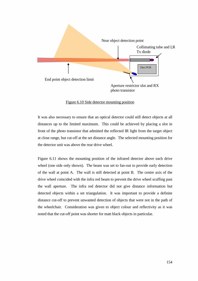
154
It was also necessary to ensure that an optical detector could still detect objects at all
distances up to the limited maximum. This could be achieved by placing a slot in
front of the photo transistor that admitted the reflected IR light from the target object
at close range, but cut-off at the set distance angle. The selected mounting position for
the detector unit was above the rear drive wheel.
Figure 6.11 shows the mounting position of the infrared detector above each drive
wheel (one side only shown). The beam was set to fan-out to provide early detection
of the wall at point A. The wall is still detected at point B. The centre axis of the
drive wheel coincided with the infra red beam to prevent the drive wheel scuffing past
the wall aperture. The infra red detector did not give distance information but
detected objects within a set triangulation. It was important to provide a definite
distance cut-off to prevent unwanted detection of objects that were not in the path of
the wheelchair. Consideration was given to object colour and reflectivity as it was
noted that the cut-off point was shorter for matt black objects in particular.
Aperture restrictor slot and RX
photo transistor
End point object detection limit
Near object detection point
Elect PCB
Collimating tube and I,R
Tx diode
Figure 6.10 Side detector mounting position
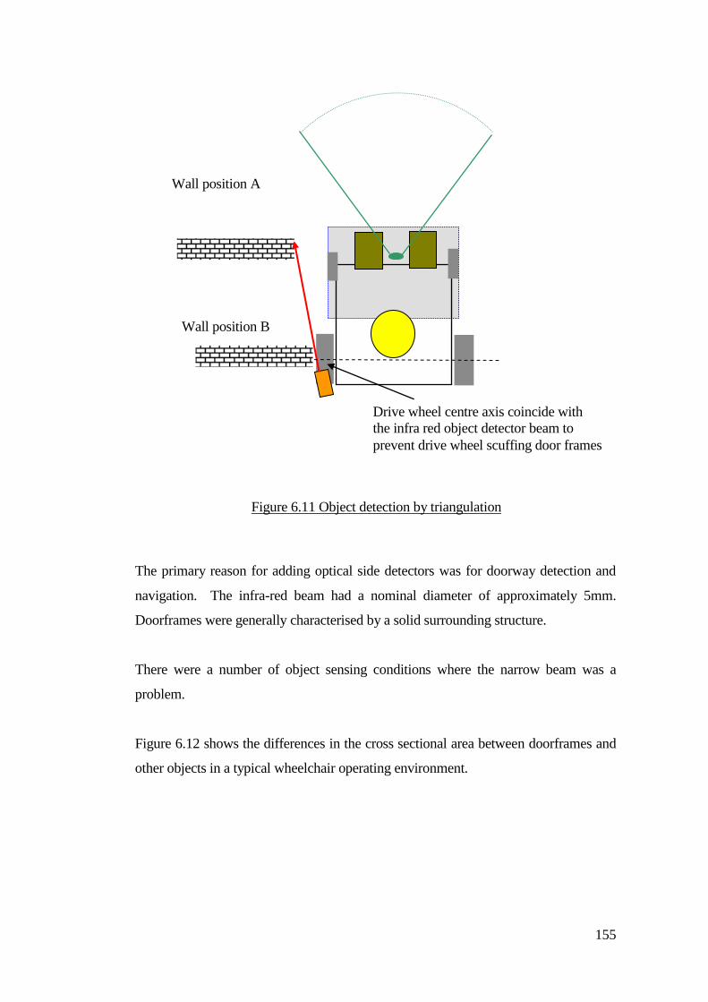
155
The primary reason for adding optical side detectors was for doorway detection and
navigation. The infra-red beam had a nominal diameter of approximately 5mm.
Doorframes were generally characterised by a solid surrounding structure.
There were a number of object sensing conditions where the narrow beam was a
problem.
Figure 6.12 shows the differences in the cross sectional area between doorframes and
other objects in a typical wheelchair operating environment.
Figure 6.11 Object detection by triangulation
Drive wheel centre axis coincide with
the infra red object detector beam to
prevent drive wheel scuffing door frames
Wall position B
Wall position A
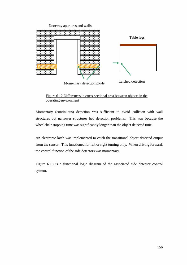
156
Momentary (continuous) detection was sufficient to avoid collision with wall
structures but narrower structures had detection problems. This was because the
wheelchair stopping time was significantly longer than the object detected time.
An electronic latch was implemented to catch the transitional object detected output
from the sensor. This functioned for left or right turning only. When driving forward,
the control function of the side detectors was momentary.
Figure 6.13 is a functional logic diagram of the associated side detector control
system.
Table legs
Figure 6.12 Differences in cross-sectional area between objects in the
operating environment
Doorway apertures and walls
Momentary detection mode Latched detection
mode
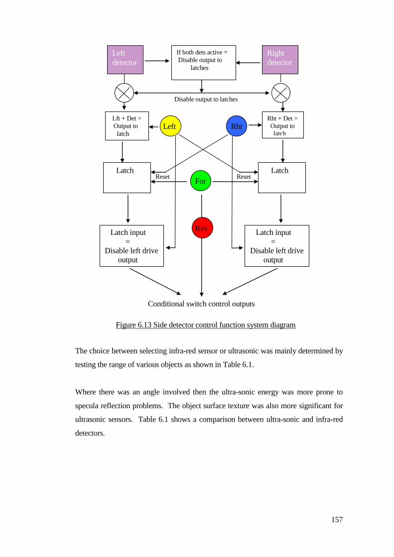
157
The choice between selecting infra-red sensor or ultrasonic was mainly determined by
testing the range of various objects as shown in Table 6.1.
Where there was an angle involved then the ultra-sonic energy was more prone to
specula reflection problems. The object surface texture was also more significant for
ultrasonic sensors. Table 6.1 shows a comparison between ultra-sonic and infra-red
detectors.
Lft + Det =
Output to
latch
Latch
Rht + Det =
Output to
latch
Latch Reset Reset
Latch input
=
Disable left drive
output
Latch input
=
Disable left drive
output
Left
detector
Right
detector
If both dets active =
Disable output to
latches
Disable output to latches
Left Rht
For
Rev
Conditional switch control outputs
Figure 6.13 Side detector control function system diagram

158
Type of Object Ultra-Sonic Infra-Red
Doorframes Good Good
Table legs Good Good
Wall guidance
applications
Poor Good
Table cloths Medium Good
People Medium - Good Good
Table 6.1 The detection comparison between various objects
The most significant factor was the reliability of object detection. This was affected
by the angle of the object surface and how much signal energy returned to the sensor
as shown in Figures 6.14 and 6.15.
Reflectance tests determined differences between IR and ultra-sonic sensing systems.
Both systems performed well when sensing objects that were perpendicular to the
radiated energy.
The most significant parameter influencing the choice of sensing medium was the
detection of walls for guidance. Most walls tended to have a smooth texture and most
of the radiated energy was sent away from the sensor.
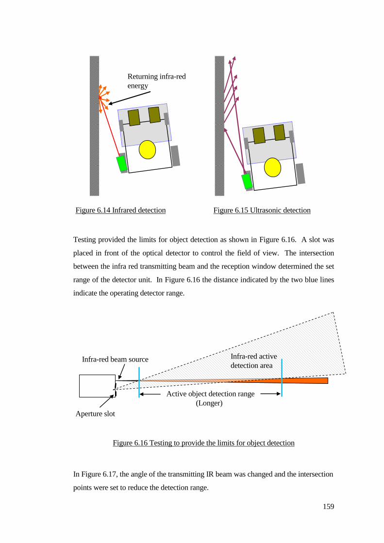
159
Testing provided the limits for object detection as shown in Figure 6.16. A slot was
placed in front of the optical detector to control the field of view. The intersection
between the infra red transmitting beam and the reception window determined the set
range of the detector unit. In Figure 6.16 the distance indicated by the two blue lines
indicate the operating detector range.
Figure 6.16 Testing to provide the limits for object detection
In Figure 6.17, the angle of the transmitting IR beam was changed and the intersection
points were set to reduce the detection range.
Infra-red beam source
Aperture slot
Infra-red active
detection area
Active object detection range
(Longer)
Figure 6.14 Infrared detection Figure 6.15 Ultrasonic detection
Returning infra-red
energy
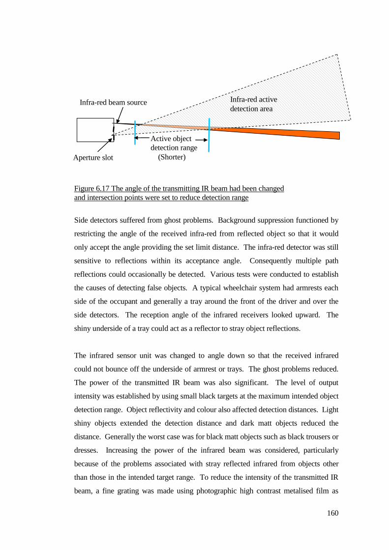
160
Figure 6.17 The angle of the transmitting IR beam had been changed
and intersection points were set to reduce detection range
Side detectors suffered from ghost problems. Background suppression functioned by
restricting the angle of the received infra-red from reflected object so that it would
only accept the angle providing the set limit distance. The infra-red detector was still
sensitive to reflections within its acceptance angle. Consequently multiple path
reflections could occasionally be detected. Various tests were conducted to establish
the causes of detecting false objects. A typical wheelchair system had armrests each
side of the occupant and generally a tray around the front of the driver and over the
side detectors. The reception angle of the infrared receivers looked upward. The
shiny underside of a tray could act as a reflector to stray object reflections.
The infrared sensor unit was changed to angle down so that the received infrared
could not bounce off the underside of armrest or trays. The ghost problems reduced.
The power of the transmitted IR beam was also significant. The level of output
intensity was established by using small black targets at the maximum intended object
detection range. Object reflectivity and colour also affected detection distances. Light
shiny objects extended the detection distance and dark matt objects reduced the
distance. Generally the worst case was for black matt objects such as black trousers or
dresses. Increasing the power of the infrared beam was considered, particularly
because of the problems associated with stray reflected infrared from objects other
than those in the intended target range. To reduce the intensity of the transmitted IR
beam, a fine grating was made using photographic high contrast metalised film as
Infra-red beam source
Aperture slot
Infra-red active
detection area
Active object
detection range
(Shorter)
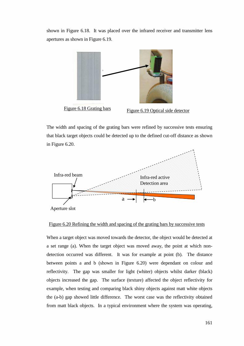
161
shown in Figure 6.18. It was placed over the infrared receiver and transmitter lens
apertures as shown in Figure 6.19.
The width and spacing of the grating bars were refined by successive tests ensuring
that black target objects could be detected up to the defined cut-off distance as shown
in Figure 6.20.
When a target object was moved towards the detector, the object would be detected at
a set range (a). When the target object was moved away, the point at which non-
detection occurred was different. It was for example at point (b). The distance
between points a and b (shown in Figure 6.20) were dependant on colour and
reflectivity. The gap was smaller for light (whiter) objects whilst darker (black)
objects increased the gap. The surface (texture) affected the object reflectivity for
example, when testing and comparing black shiny objects against matt white objects
the (a-b) gap showed little difference. The worst case was the reflectivity obtained
from matt black objects. In a typical environment where the system was operating,
Infra-red beam
source
Aperture slot
Infra-red active
Detection area
Figure 6.18 Grating bars Figure 6.19 Optical side detector
a b
Figure 6.20 Refining the width and spacing of the grating bars by successive tests
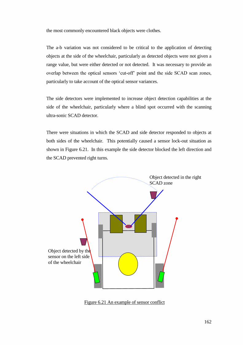
162
the most commonly encountered black objects were clothes.
The a-b variation was not considered to be critical to the application of detecting
objects at the side of the wheelchair, particularly as detected objects were not given a
range value, but were either detected or not detected. It was necessary to provide an
overlap between the optical sensors ‘cut-off’ point and the side SCAD scan zones,
particularly to take account of the optical sensor variances.
The side detectors were implemented to increase object detection capabilities at the
side of the wheelchair, particularly where a blind spot occurred with the scanning
ultra-sonic SCAD detector.
There were situations in which the SCAD and side detector responded to objects at
both sides of the wheelchair. This potentially caused a sensor lock-out situation as
shown in Figure 6.21. In this example the side detector blocked the left direction and
the SCAD prevented right turns.
Object detected by the
sensor on the left side
of the wheelchair
Object detected in the right
SCAD zone
Figure 6.21 An example of sensor conflict

163
There was concern that this could be a significant cause of frustration for child drivers.
Importantly the development of a collision avoidance system should provide increased
independence and not hamper driving. Conditional logic was implemented to prevent
the wheelchair from becoming un-drivable. The SCAD sensor operation disabled the
functional outputs of the side detectors when the forward drive control was operated.
This suppressed object detection function at the sides of the wheelchair until the
SCAD detector was free of detected objects. Paradoxically this meant that the
wheelchair would continue to drive but may have collided with a potentially detectible
object at the side.
6.6 Developing the guidance system for an unstructured environment
The initial work with the children strongly indicated the need to move away from
laboratory testing conditions. It did not appear to be beneficial to take children out of
their normal environment and put them into an engineered environment (for example
into a roadway of cones) and then to expect them to understand. Once the testing
moved into real environments then the children would often push forward
developments by their willingness to explore new environments. It became important
to develop and incorporate systems for people living their normal lives (or living
pattern). The initial work did provide a test bed and highlighted the need for further
technical developments but taking the system out into a young person’s familiar
environment highlighted its deficiencies.
Disabled people exposed weaknesses in the system (more so than non-disabled
people). The most significant deficiencies exposed by drivers with disabilities were:
the SCAD had insufficient scan width, long object update time, ghosting and
problems with dynamic wheelchair control.
The problems with the 120º SCAD scan width, object detection update time and
ghosting were inter-related. Work began to evaluate a suitable increase in the number
of pulse echo samples for the improved horizontal object detection.
Figures 6.22 and 6.23 shows a comparison between detecting roadway marker cones
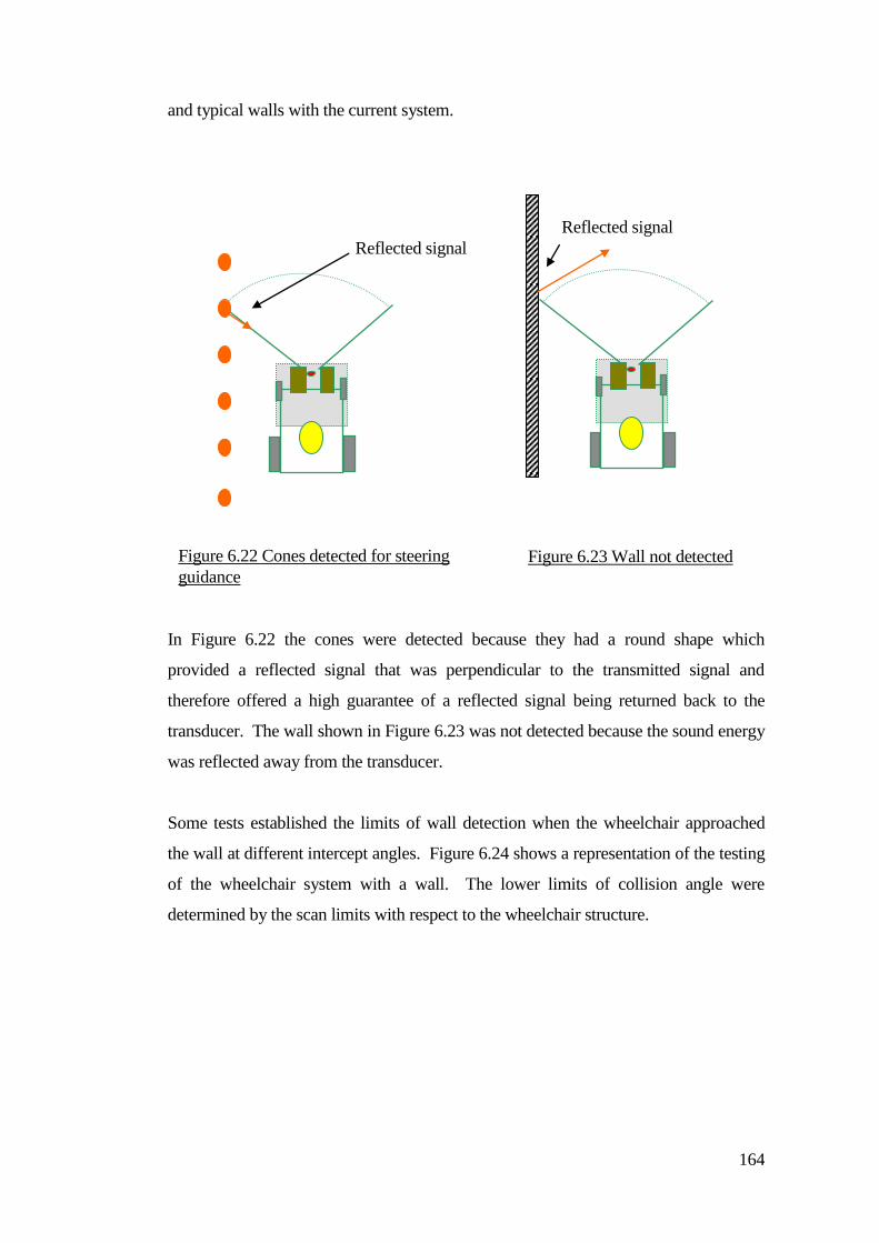
164
and typical walls with the current system.
In Figure 6.22 the cones were detected because they had a round shape which
provided a reflected signal that was perpendicular to the transmitted signal and
therefore offered a high guarantee of a reflected signal being returned back to the
transducer. The wall shown in Figure 6.23 was not detected because the sound energy
was reflected away from the transducer.
Some tests established the limits of wall detection when the wheelchair approached
the wall at different intercept angles. Figure 6.24 shows a representation of the testing
of the wheelchair system with a wall. The lower limits of collision angle were
determined by the scan limits with respect to the wheelchair structure.
Figure 6.22 Cones detected for steering
guidance
Figure 6.23 Wall not detected
Reflected signal
Reflected signal
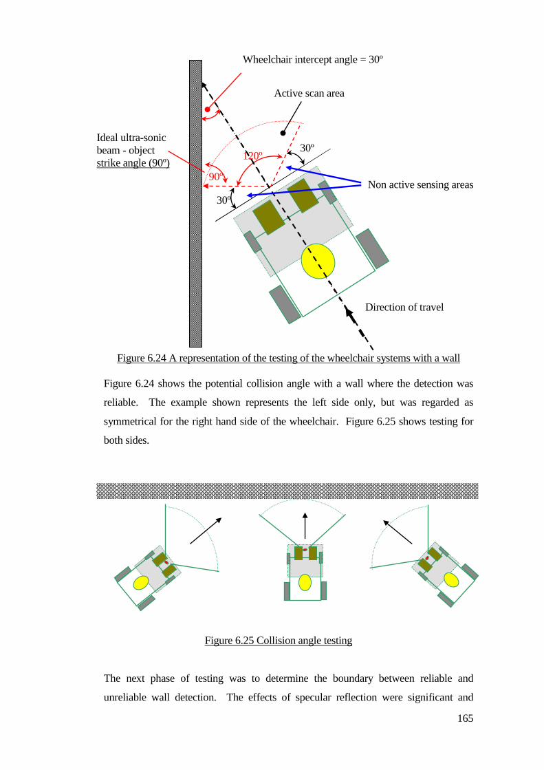
165
Figure 6.24 A representation of the testing of the wheelchair systems with a wall
Figure 6.24 shows the potential collision angle with a wall where the detection was
reliable. The example shown represents the left side only, but was regarded as
symmetrical for the right hand side of the wheelchair. Figure 6.25 shows testing for
both sides.
The next phase of testing was to determine the boundary between reliable and
unreliable wall detection. The effects of specular reflection were significant and
Figure 6.25 Collision angle testing
120º
30º
30º
Wheelchair intercept angle = 30º
Active scan area
Direction of travel
Non active sensing areas
Ideal ultra-sonic
beam - object
strike angle (90º)
90º
166
therefore when the collision angle was reduced then the wall avoidance was less
reliable. Three conditional states were tested:
Certain (reliable detection)
Uncertain (50% detection) and (50% non-detection)
No detection
Higher collision angles from 90º reducing to 30º as represented by Figure 6.26
returned reliable collision detection because generally the reflecting surface was
perpendicular to the ultra-sonic transducer. The certainty of detection was related to
the ultra-sonic beam with respect to the object strike angle and object surface texture
and is referred to as the critical angle. This affected the amount of returning sound
energy reflected from the object.
Object reflectivity testing revealed that smooth surfaces presented a narrow critical
angle. This was consistent with smooth plastered walls and glass structures within
buildings and was the worst case situation. Brick walls and concrete structures
presented a wider critical angle which was attributable to their rougher texture having
surface elements that reflected directly back to the receiving transducer. Brick
structures had a level of uncertainty of detection and could exhibit narrow critical
angles.
Uncertainty of object detection occurred where the wheelchair could be expected to
collide or not collide with the wall.
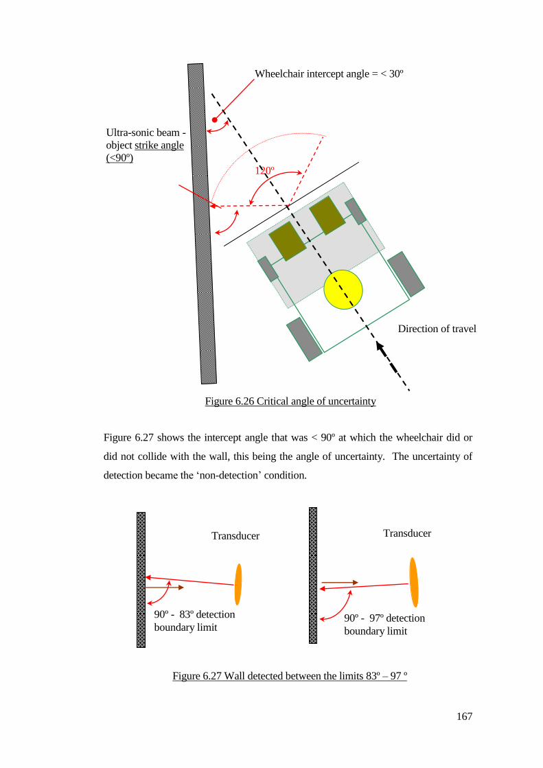
167
Figure 6.27 shows the intercept angle that was < 90º at which the wheelchair did or
did not collide with the wall, this being the angle of uncertainty. The uncertainty of
detection became the ‘non-detection’ condition.
Direction of travel
Ultra-sonic beam -
object strike angle
(<90º)
Figure 6.26 Critical angle of uncertainty
120º
Wheelchair intercept angle = < 30º
Figure 6.27 Wall detected between the limits 83º – 97 º
90º - 83º detection
boundary limit 90º - 97º detection
boundary limit
Transducer Transducer
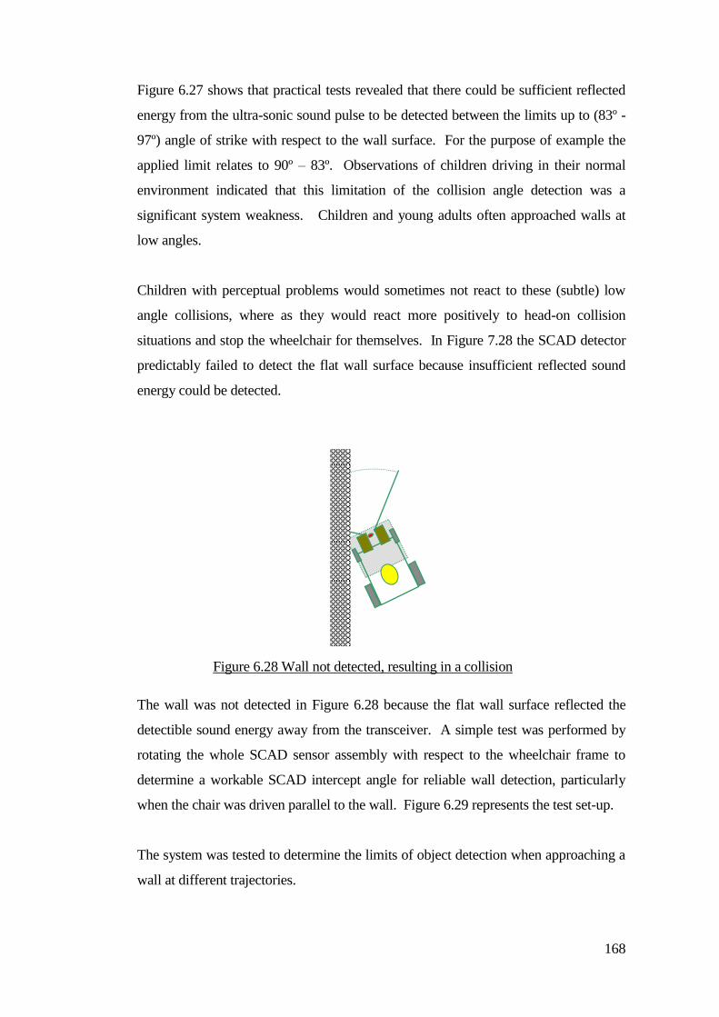
168
Figure 6.27 shows that practical tests revealed that there could be sufficient reflected
energy from the ultra-sonic sound pulse to be detected between the limits up to (83º -
97º) angle of strike with respect to the wall surface. For the purpose of example the
applied limit relates to 90º – 83º. Observations of children driving in their normal
environment indicated that this limitation of the collision angle detection was a
significant system weakness. Children and young adults often approached walls at
low angles.
Children with perceptual problems would sometimes not react to these (subtle) low
angle collisions, where as they would react more positively to head-on collision
situations and stop the wheelchair for themselves. In Figure 7.28 the SCAD detector
predictably failed to detect the flat wall surface because insufficient reflected sound
energy could be detected.
The wall was not detected in Figure 6.28 because the flat wall surface reflected the
detectible sound energy away from the transceiver. A simple test was performed by
rotating the whole SCAD sensor assembly with respect to the wheelchair frame to
determine a workable SCAD intercept angle for reliable wall detection, particularly
when the chair was driven parallel to the wall. Figure 6.29 represents the test set-up.
The system was tested to determine the limits of object detection when approaching a
wall at different trajectories.
Figure 6.28 Wall not detected, resulting in a collision
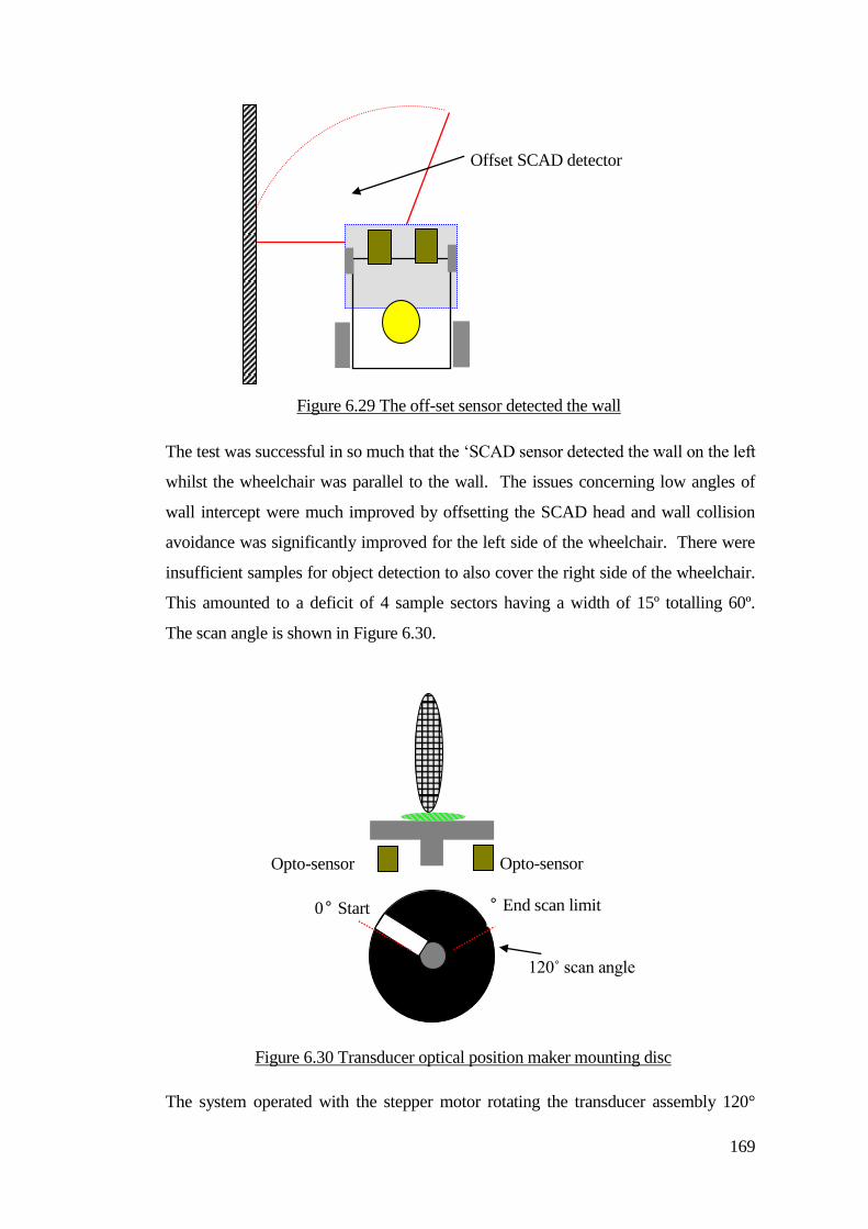
169
The test was successful in so much that the ‘SCAD sensor detected the wall on the left
whilst the wheelchair was parallel to the wall. The issues concerning low angles of
wall intercept were much improved by offsetting the SCAD head and wall collision
avoidance was significantly improved for the left side of the wheelchair. There were
insufficient samples for object detection to also cover the right side of the wheelchair.
This amounted to a deficit of 4 sample sectors having a width of 15º totalling 60º.
The scan angle is shown in Figure 6.30.
The system operated with the stepper motor rotating the transducer assembly 120°
Figure 6.29 The off-set sensor detected the wall
Offset SCAD detector
Opto-sensor
‘B’
Opto-sensor
‘A’ 0° Start
scan
Limit
° End scan limit
limit
Figure 6.30 Transducer optical position maker mounting disc
120˚ scan angle
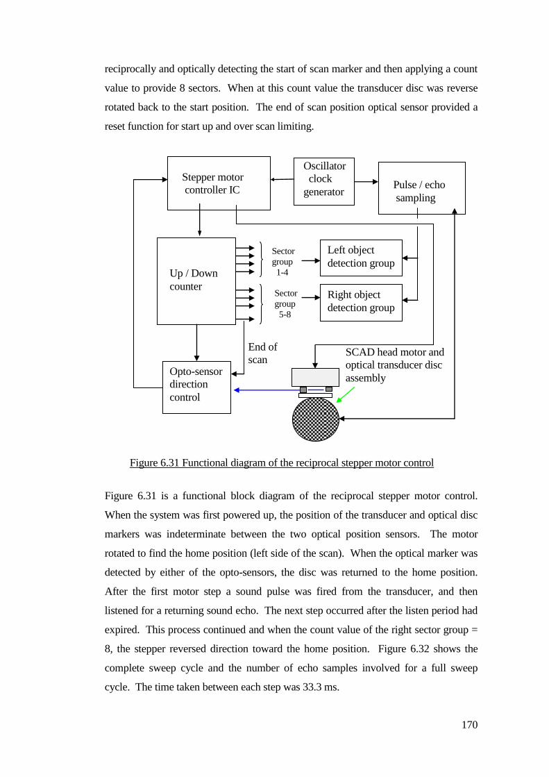
170
reciprocally and optically detecting the start of scan marker and then applying a count
value to provide 8 sectors. When at this count value the transducer disc was reverse
rotated back to the start position. The end of scan position optical sensor provided a
reset function for start up and over scan limiting.
Figure 6.31 is a functional block diagram of the reciprocal stepper motor control.
When the system was first powered up, the position of the transducer and optical disc
markers was indeterminate between the two optical position sensors. The motor
rotated to find the home position (left side of the scan). When the optical marker was
detected by either of the opto-sensors, the disc was returned to the home position.
After the first motor step a sound pulse was fired from the transducer, and then
listened for a returning sound echo. The next step occurred after the listen period had
expired. This process continued and when the count value of the right sector group =
8, the stepper reversed direction toward the home position. Figure 6.32 shows the
complete sweep cycle and the number of echo samples involved for a full sweep
cycle. The time taken between each step was 33.3 ms.
Stepper motor
controller IC
Oscillator
clock
generator
Up / Down
counter
Opto-sensor
direction
control
SCAD head motor and
optical transducer disc
assembly
Left object
detection group
Right object
detection group
Sector
group
1-4
Sector
group
5-8
End of
scan
Pulse / echo
sampling
Figure 6.31 Functional diagram of the reciprocal stepper motor control
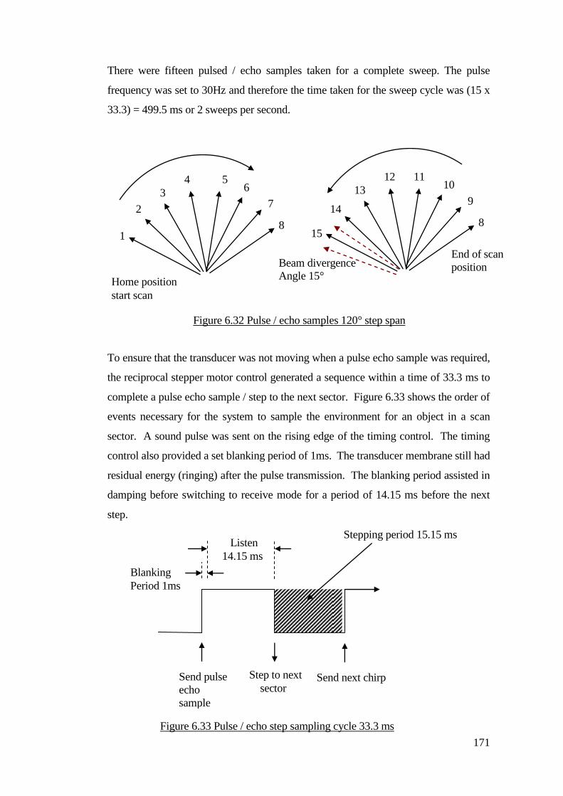
171
There were fifteen pulsed / echo samples taken for a complete sweep. The pulse
frequency was set to 30Hz and therefore the time taken for the sweep cycle was (15 x
33.3) = 499.5 ms or 2 sweeps per second.
To ensure that the transducer was not moving when a pulse echo sample was required,
the reciprocal stepper motor control generated a sequence within a time of 33.3 ms to
complete a pulse echo sample / step to the next sector. Figure 6.33 shows the order of
events necessary for the system to sample the environment for an object in a scan
sector. A sound pulse was sent on the rising edge of the timing control. The timing
control also provided a set blanking period of 1ms. The transducer membrane still had
residual energy (ringing) after the pulse transmission. The blanking period assisted in
damping before switching to receive mode for a period of 14.15 ms before the next
step.
1
2
3
4 5 6
7
8 15
14
13
12 11 10
9
8
Figure 6.32 Pulse / echo samples 120° step span
Home position
start scan
Beam divergence
Angle 15°
Send pulse
echo
sample
Step to next
sector
Listen
14.15 ms
Stepping period 15.15 ms
Blanking
Period 1ms
Send next chirp
Figure 6.33 Pulse / echo step sampling cycle 33.3 ms
End of scan
position

172
The step period had a time window of 15.15ms. Some magnetic bounce between the
poles of the stepper motor was noted and this was affected by the stepping frequency
and mass of the transducer and mounting assembly. Work started to increase the
number of pulse / echo samples for the complete scan to provide the required 180°
sweep.
Increasing the number of pulse echo samples for the object detection scan increased
the time required for the complete object detection sample sweep. This was
significant in terms of how far the wheelchair moved between object detection
updates. Adding the required four sectors provided a total of twelve and increased the
scan time by 33%.
The stepper motor control electronics was modified to provide the additional sectors.
The scanning process remained the same and Figure 6.34 shows the modified
scanning control electronics and the re-grouping of the scan sectors from four to six
sectors in each group and the end of scan count number that was similarly changed
from eight to twelve. This necessitated making changes to the position of the end of
scan opto-detector because the transducer disc now rotated the extra 60º or more (to
detect the disc marker).
As the transducer rotated to the end of scan point the count value of 12 triggered the
change of transducer rotation to return to the home position. The end point optical
detector would not be triggered unless an abnormal condition occurred.
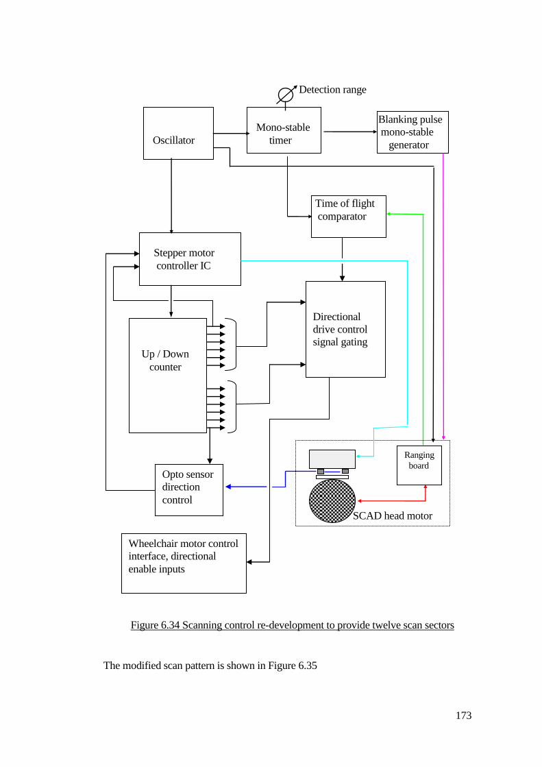
173
The modified scan pattern is shown in Figure 6.35
Stepper motor
controller IC
Oscillator
Clock gen.
Mono-stable
timer
Time of flight
comparator
Blanking pulse
mono-stable
generator
Detection range
control
Up / Down
counter
Directional
drive control
signal gating
Opto sensor
direction
control
SCAD head motor
assembly
Ranging
board
Wheelchair motor control
interface, directional
enable inputs
Figure 6.34 Scanning control re-development to provide twelve scan sectors
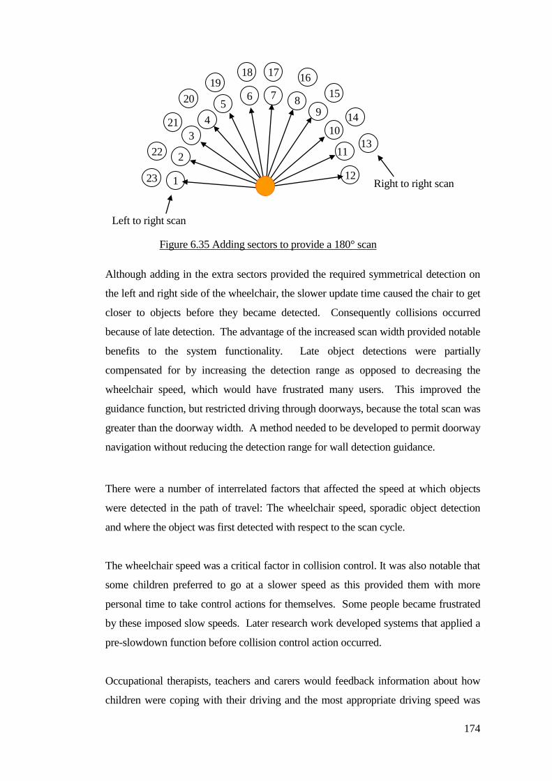
174
Although adding in the extra sectors provided the required symmetrical detection on
the left and right side of the wheelchair, the slower update time caused the chair to get
closer to objects before they became detected. Consequently collisions occurred
because of late detection. The advantage of the increased scan width provided notable
benefits to the system functionality. Late object detections were partially
compensated for by increasing the detection range as opposed to decreasing the
wheelchair speed, which would have frustrated many users. This improved the
guidance function, but restricted driving through doorways, because the total scan was
greater than the doorway width. A method needed to be developed to permit doorway
navigation without reducing the detection range for wall detection guidance.
There were a number of interrelated factors that affected the speed at which objects
were detected in the path of travel: The wheelchair speed, sporadic object detection
and where the object was first detected with respect to the scan cycle.
The wheelchair speed was a critical factor in collision control. It was also notable that
some children preferred to go at a slower speed as this provided them with more
personal time to take control actions for themselves. Some people became frustrated
by these imposed slow speeds. Later research work developed systems that applied a
pre-slowdown function before collision control action occurred.
Occupational therapists, teachers and carers would feedback information about how
children were coping with their driving and the most appropriate driving speed was
1
2
3
4
7 8 5
6
9
10
11
12
13
14
15
16 17 18
20
19
21
22
23 Right to right scan
Left to right scan
Figure 6.35 Adding sectors to provide a 180° scan
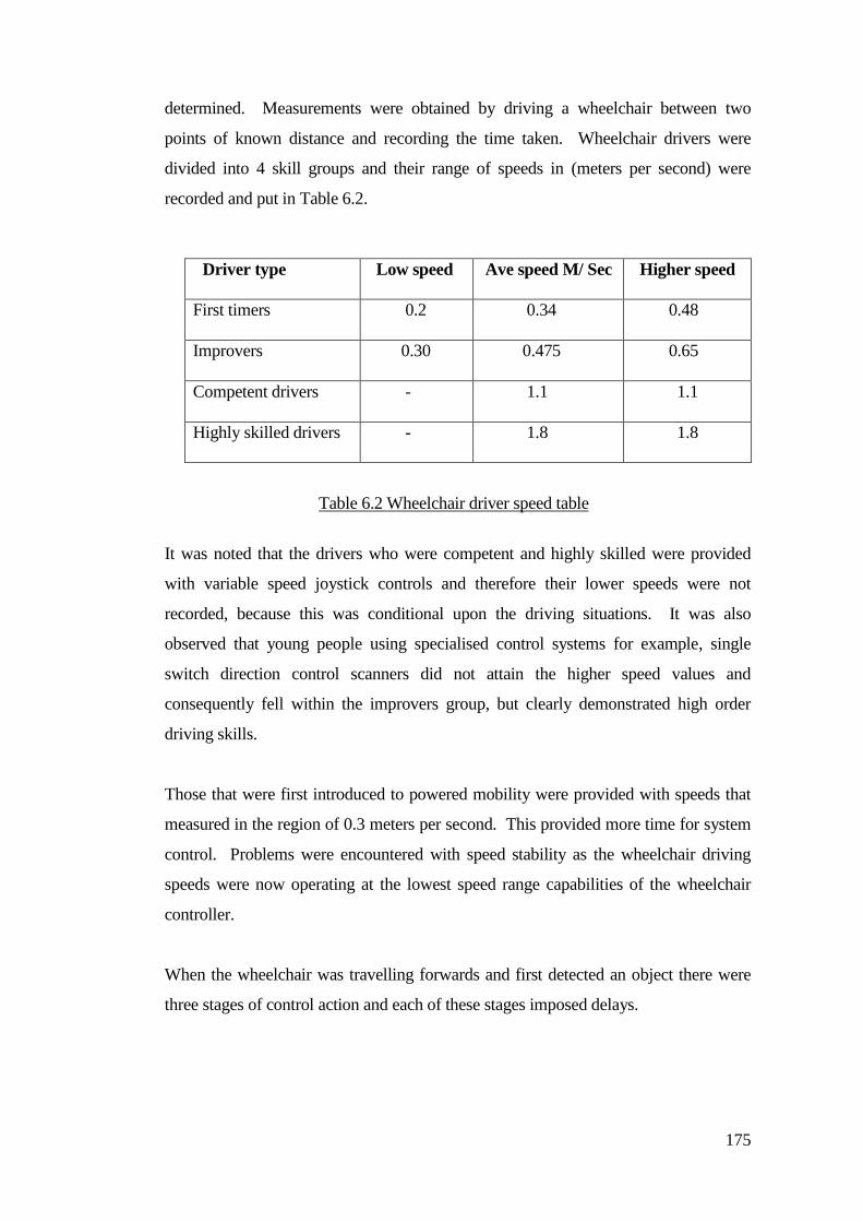
175
determined. Measurements were obtained by driving a wheelchair between two
points of known distance and recording the time taken. Wheelchair drivers were
divided into 4 skill groups and their range of speeds in (meters per second) were
recorded and put in Table 6.2.
Driver type Low speed Ave speed M/ Sec Higher speed
First timers 0.2 0.34 0.48
Improvers 0.30 0.475 0.65
Competent drivers - 1.1 1.1
Highly skilled drivers - 1.8 1.8
It was noted that the drivers who were competent and highly skilled were provided
with variable speed joystick controls and therefore their lower speeds were not
recorded, because this was conditional upon the driving situations. It was also
observed that young people using specialised control systems for example, single
switch direction control scanners did not attain the higher speed values and
consequently fell within the improvers group, but clearly demonstrated high order
driving skills.
Those that were first introduced to powered mobility were provided with speeds that
measured in the region of 0.3 meters per second. This provided more time for system
control. Problems were encountered with speed stability as the wheelchair driving
speeds were now operating at the lowest speed range capabilities of the wheelchair
controller.
When the wheelchair was travelling forwards and first detected an object there were
three stages of control action and each of these stages imposed delays.
Table 6.2 Wheelchair driver speed table
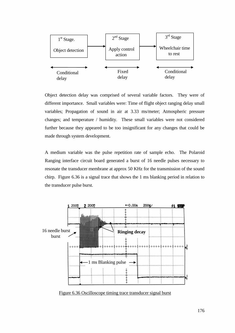
176
Object detection delay was comprised of several variable factors. They were of
different importance. Small variables were: Time of flight object ranging delay small
variables; Propagation of sound in air at 3.33 ms/meter; Atmospheric pressure
changes; and temperature / humidity. These small variables were not considered
further because they appeared to be too insignificant for any changes that could be
made through system development.
A medium variable was the pulse repetition rate of sample echo. The Polaroid
Ranging interface circuit board generated a burst of 16 needle pulses necessary to
resonate the transducer membrane at approx 50 KHz for the transmission of the sound
chirp. Figure 6.36 is a signal trace that shows the 1 ms blanking period in relation to
the transducer pulse burst.
1st Stage.
Object detection
2nd
Stage
Apply control
action
3rd
Stage
Wheelchair time
to rest
Conditional
delay
Fixed
delay
Conditional
delay
Figure 6.36 Oscilloscope timing trace transducer signal burst
(200µs/ div).
Ringing decay 16 needle burst
burst
1 ms Blanking pulse
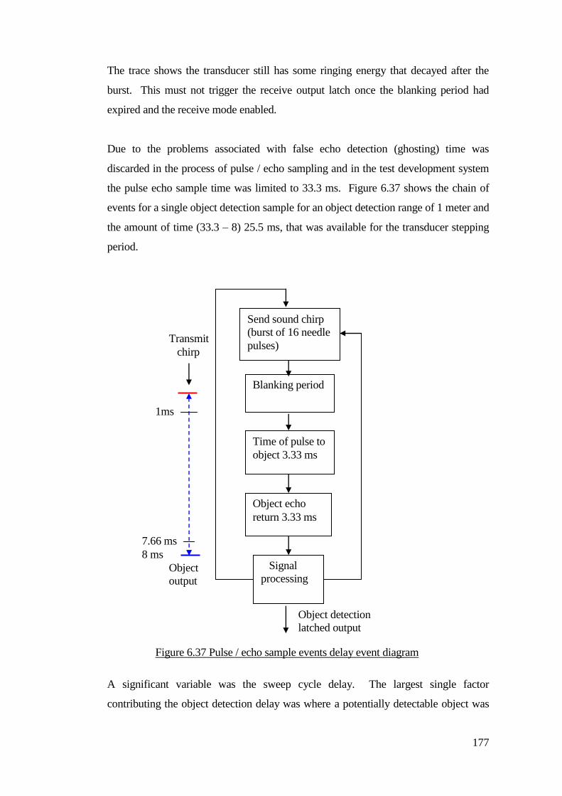
177
The trace shows the transducer still has some ringing energy that decayed after the
burst. This must not trigger the receive output latch once the blanking period had
expired and the receive mode enabled.
Due to the problems associated with false echo detection (ghosting) time was
discarded in the process of pulse / echo sampling and in the test development system
the pulse echo sample time was limited to 33.3 ms. Figure 6.37 shows the chain of
events for a single object detection sample for an object detection range of 1 meter and
the amount of time (33.3 – 8) 25.5 ms, that was available for the transducer stepping
period.
A significant variable was the sweep cycle delay. The largest single factor
contributing the object detection delay was where a potentially detectable object was
Send sound chirp
(burst of 16 needle
pulses)
Blanking period
Time of pulse to
object 3.33 ms
Object echo
return 3.33 ms
Signal
processing
Object detection
latched output
Figure 6.37 Pulse / echo sample events delay event diagram
1ms
7.66 ms
Transmit
chirp
Object
output
8 ms
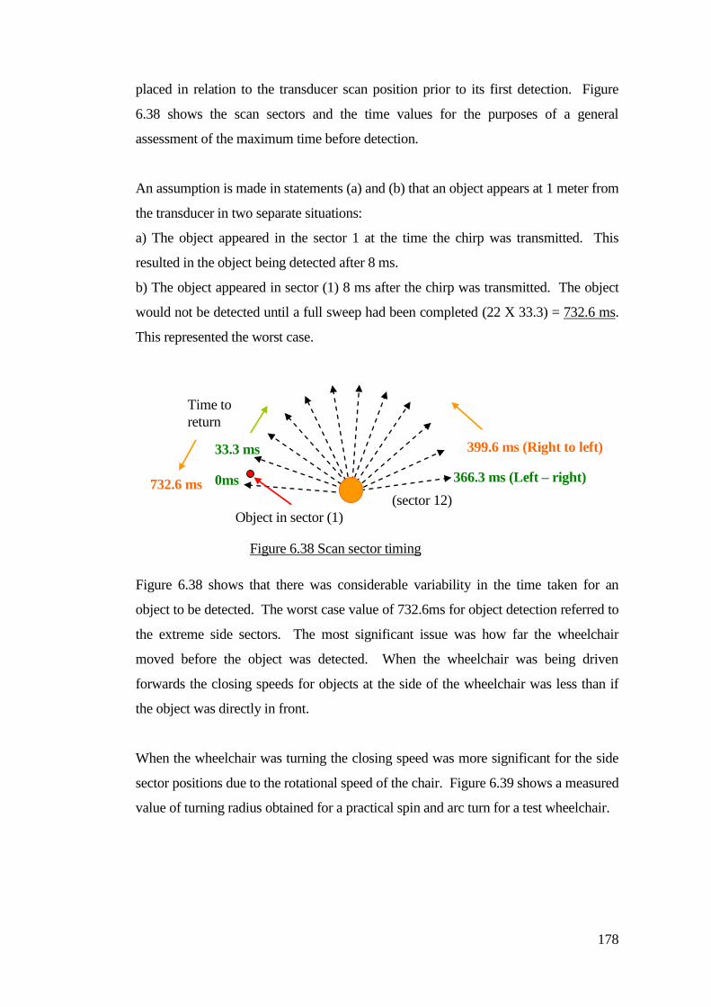
178
placed in relation to the transducer scan position prior to its first detection. Figure
6.38 shows the scan sectors and the time values for the purposes of a general
assessment of the maximum time before detection.
An assumption is made in statements (a) and (b) that an object appears at 1 meter from
the transducer in two separate situations:
a) The object appeared in the sector 1 at the time the chirp was transmitted. This
resulted in the object being detected after 8 ms.
b) The object appeared in sector (1) 8 ms after the chirp was transmitted. The object
would not be detected until a full sweep had been completed (22 X 33.3) = 732.6 ms.
This represented the worst case.
Figure 6.38 shows that there was considerable variability in the time taken for an
object to be detected. The worst case value of 732.6ms for object detection referred to
the extreme side sectors. The most significant issue was how far the wheelchair
moved before the object was detected. When the wheelchair was being driven
forwards the closing speeds for objects at the side of the wheelchair was less than if
the object was directly in front.
When the wheelchair was turning the closing speed was more significant for the side
sector positions due to the rotational speed of the chair. Figure 6.39 shows a measured
value of turning radius obtained for a practical spin and arc turn for a test wheelchair.
0ms 366.3 ms (Left – right)
399.6 ms (Right to left)
732.6 ms
33.3 ms
Object in sector (1)
Time to
return
(sector 12)
Figure 6.38 Scan sector timing
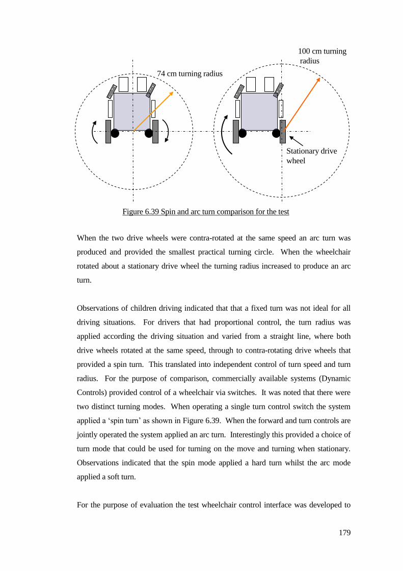
179
When the two drive wheels were contra-rotated at the same speed an arc turn was
produced and provided the smallest practical turning circle. When the wheelchair
rotated about a stationary drive wheel the turning radius increased to produce an arc
turn.
Observations of children driving indicated that that a fixed turn was not ideal for all
driving situations. For drivers that had proportional control, the turn radius was
applied according the driving situation and varied from a straight line, where both
drive wheels rotated at the same speed, through to contra-rotating drive wheels that
provided a spin turn. This translated into independent control of turn speed and turn
radius. For the purpose of comparison, commercially available systems (Dynamic
Controls) provided control of a wheelchair via switches. It was noted that there were
two distinct turning modes. When operating a single turn control switch the system
applied a ‘spin turn’ as shown in Figure 6.39. When the forward and turn controls are
jointly operated the system applied an arc turn. Interestingly this provided a choice of
turn mode that could be used for turning on the move and turning when stationary.
Observations indicated that the spin mode applied a hard turn whilst the arc mode
applied a soft turn.
For the purpose of evaluation the test wheelchair control interface was developed to
100 cm turning
radius
74 cm turning radius
Stationary drive
wheel
Figure 6.39 Spin and arc turn comparison for the test
wheelchair.
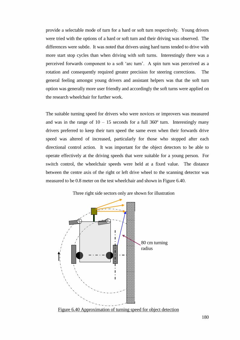
180
provide a selectable mode of turn for a hard or soft turn respectively. Young drivers
were tried with the options of a hard or soft turn and their driving was observed. The
differences were subtle. It was noted that drivers using hard turns tended to drive with
more start stop cycles than when driving with soft turns. Interestingly there was a
perceived forwards component to a soft ‘arc turn’. A spin turn was perceived as a
rotation and consequently required greater precision for steering corrections. The
general feeling amongst young drivers and assistant helpers was that the soft turn
option was generally more user friendly and accordingly the soft turns were applied on
the research wheelchair for further work.
The suitable turning speed for drivers who were novices or improvers was measured
and was in the range of 10 – 15 seconds for a full 360º turn. Interestingly many
drivers preferred to keep their turn speed the same even when their forwards drive
speed was altered of increased, particularly for those who stopped after each
directional control action. It was important for the object detectors to be able to
operate effectively at the driving speeds that were suitable for a young person. For
switch control, the wheelchair speeds were held at a fixed value. The distance
between the centre axis of the right or left drive wheel to the scanning detector was
measured to be 0.8 meter on the test wheelchair and shown in Figure 6.40.
Three right side sectors only are shown for illustration
80 cm turning
radius
Figure 6.40 Approximation of turning speed for object detection
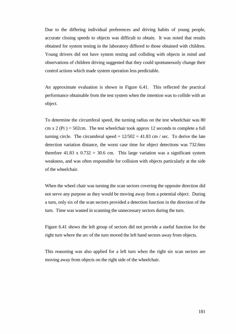
181
Due to the differing individual preferences and driving habits of young people,
accurate closing speeds to objects was difficult to obtain. It was noted that results
obtained for system testing in the laboratory differed to those obtained with children.
Young drivers did not have system testing and colliding with objects in mind and
observations of children driving suggested that they could spontaneously change their
control actions which made system operation less predictable.
An approximate evaluation is shown in Figure 6.41. This reflected the practical
performance obtainable from the test system when the intention was to collide with an
object.
To determine the circumferal speed, the turning radius on the test wheelchair was 80
cm x 2 (Pi ) = 502cm. The test wheelchair took approx 12 seconds to complete a full
turning circle. The circumferal speed = 12/502 = 41.83 cm / sec. To derive the late
detection variation distance, the worst case time for object detections was 732.6ms
therefore 41.83 x 0.732 = 30.6 cm. This large variation was a significant system
weakness, and was often responsible for collision with objects particularly at the side
of the wheelchair.
When the wheel chair was turning the scan sectors covering the opposite direction did
not serve any purpose as they would be moving away from a potential object. During
a turn, only six of the scan sectors provided a detection function in the direction of the
turn. Time was wasted in scanning the unnecessary sectors during the turn.
Figure 6.41 shows the left group of sectors did not provide a useful function for the
right turn where the arc of the turn moved the left hand sectors away from objects.
This reasoning was also applied for a left turn when the right six scan sectors are
moving away from objects on the right side of the wheelchair.
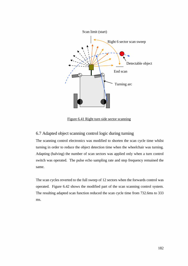
182
6.7 Adapted object scanning control logic during turning
The scanning control electronics was modified to shorten the scan cycle time whilst
turning in order to reduce the object detection time when the wheelchair was turning.
Adapting (halving) the number of scan sectors was applied only when a turn control
switch was operated. The pulse echo sampling rate and step frequency remained the
same.
The scan cycles reverted to the full sweep of 12 sectors when the forwards control was
operated. Figure 6.42 shows the modified part of the scan scanning control system.
The resulting adapted scan function reduced the scan cycle time from 732.6ms to 333
ms.
Figure 6.41 Right turn side sector scanning
Scan limit (start)
End scan
Right 6 sector scan sweep
Detectable object
Turning arc
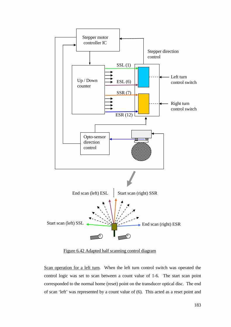
183
Scan operation for a left turn. When the left turn control switch was operated the
control logic was set to scan between a count value of 1-6. The start scan point
corresponded to the normal home (reset) point on the transducer optical disc. The end
of scan ‘left’ was represented by a count value of (6). This acted as a reset point and
Stepper motor
controller IC
Up / Down
counter
Opto-sensor
direction
control
Stepper direction
control
End scan (right) ESR
Start scan (right) SSR End scan (left) ESL
Start scan (left) SSL
Left turn
control switch
Right turn
control switch
SSL (1)
ESL (6)
SSR (7)
ESR (12)
Figure 6.42 Adapted half scanning control diagram
184
the stepper motor direction was reversed and returned the transducer disc back to the
(home) start point of the scan. This process continued for the duration of left switch
control operation.
Scan operation for a right turn. When the right turn switch was operated the end of
scan point remained at the normal scan end point count value (12). When the
transducer disc rotated to this point the direction the transducer direction was reversed
to rotate the transducer back to the home position. This was set to the count value (7)
at start of scan ‘right’. The scan was operating between count values of 7 – 12, and
this continued for the duration of right switch control operation. When the turn
control was released the scan reverted to the full twelve sector sweep and operated
between the normal home position at start left scan point (1).
The object detector was sending pulses at 33.3 ms intervals. If an object was detected
in a particular sector there was 33.3ms until the next pulse echo sample. A large
object could be detected in the next sector and therefore the object detection period
could span 66.6 ms. 33.3ms was the minimum time for a momentary object detection.
This time period was not sufficient to apply a sustained control action for wheelchair
collision control. It was necessary to stretch the object detection period to enable the
wheelchair control system to respond. When an object was detected during the sweep
an object detect latch was set, but only for the complete sweep period. If the object
was detected again in the next successive sweep, the latch was re-triggered and the
object detection state was held active for the control system to apply a steering
correction or stop the wheelchair.
Not all objects were ideal reflectors and the reflecting surface of the objects could vary
with respect to the sensing transducer particularly when the wheelchair and sensor
system was moving. Due to the cyclic nature of the object scan, some objects that
either had a small reflecting cross sectional area or those that were larger but reflected
most of the ultra-sonic energy away were not detected repeatedly for each scan sweep.
If an object was detected on every sweep, momentary control was applied for collision
control.
Evaluation of the scanning method highlighted factors that increased the object
185
detection time and this was related to where the object was with respect to the scan
cycle. The most favourable object position was the mid point of the scan.
The SCAD was scanning for objects in the path of travel. When an object first
became in range the point of detection was dependant on where the transducer was
looking in the sweep cycle. There were delays that all contributed to the time taken
for the wheelchair to stop or change heading to avoid a collision after an object had
become within the detection range. Other conditions were:
Scan cycle to object detection delay
Time of flight echo ranging echo delay
Speed of the wheelchair
Deceleration time, when switch released
Applied system damping
Motor compensation
Payload
6.8 Determination of the wheelchair steering avoidance control
Video recordings were made of a group of skilled wheelchair drivers that used
variable speed control joysticks and those that used switches. When a young person
had well developed hand function (fine motor skills), joysticks had the advantage of
translating personal control actions into accurate speed and steering control.
Many children taking part in this research did not have sufficient ability to use a
joystick effectively. Observations of how children used switches to control their
wheelchair steering highlighted many differences. Due to the complex nature of a
young person’s disabilities, some critical factors affected how children operated their
switches. The design of the control system needed to take account of this. The
wheelchair was operated by pressing a switch to activate driving for forwards,
backwards or turning. The control was momentary in which driving operation at a
fixed speed occurred so long as the child sustained enough operational force to
activate the switch.
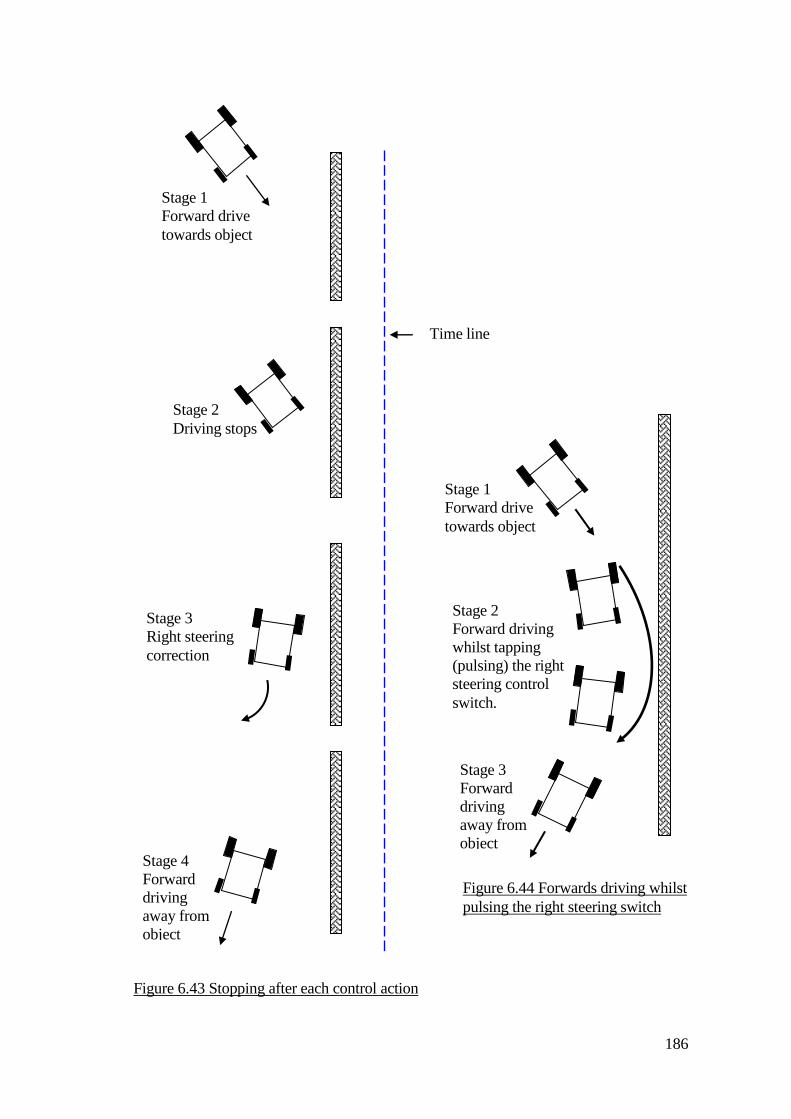
186
Figure 6.44 Forwards driving whilst
pulsing the right steering switch
Stage 1
Forward drive
towards object
Stage 2
Driving stops
Stage 3
Right steering
correction
Stage 4
Forward
driving
away from
object
Figure 6.43 Stopping after each control action
Stage 1
Forward drive
towards object
Stage 2
Forward driving
whilst tapping
(pulsing) the right
steering control
switch.
Stage 3
Forward
driving
away from
object
Time line
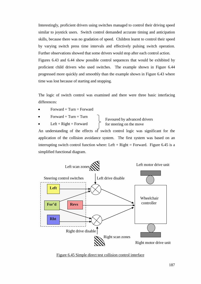
187
Interestingly, proficient drivers using switches managed to control their driving speed
similar to joystick users. Switch control demanded accurate timing and anticipation
skills, because there was no gradation of speed. Children learnt to control their speed
by varying switch press time intervals and effectively pulsing switch operation.
Further observations showed that some drivers would stop after each control action.
Figures 6.43 and 6.44 show possible control sequences that would be exhibited by
proficient child drivers who used switches. The example shown in Figure 6.44
progressed more quickly and smoothly than the example shown in Figure 6.43 where
time was lost because of starting and stopping.
The logic of switch control was examined and there were three basic interfacing
differences:
Forward + Turn = Forward
Forward + Turn = Turn
Left + Right = Forward
An understanding of the effects of switch control logic was significant for the
application of the collision avoidance system. The first system was based on an
interrupting switch control function where: Left + Right = Forward. Figure 6.45 is a
simplified functional diagram.
Favoured by advanced drivers
for steering on the move
Figure 6.45 Simple direct test collision control interface
diagram.
Wheelchair
controller For’d
Rht
Left
Right drive disable
Left drive disable
Left scan zones
Right scan zones
Revs
Right motor drive unit
Steering control switches
Left motor drive unit
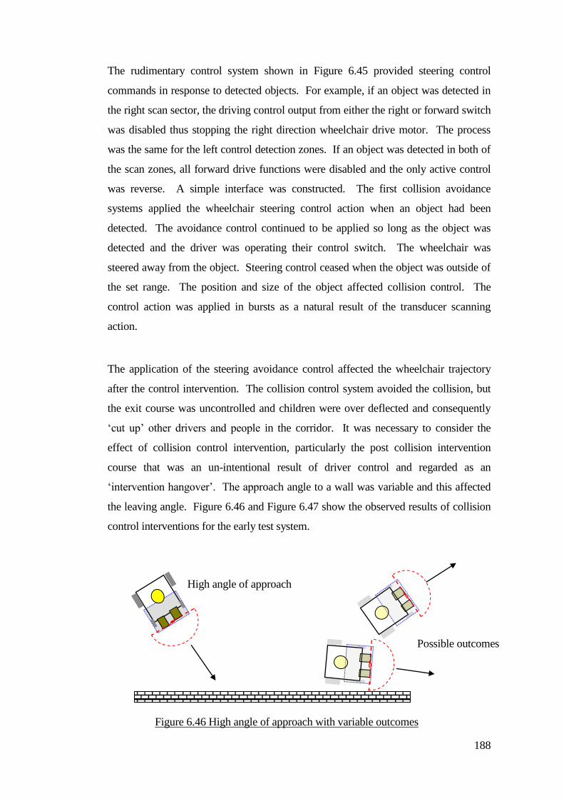
188
The rudimentary control system shown in Figure 6.45 provided steering control
commands in response to detected objects. For example, if an object was detected in
the right scan sector, the driving control output from either the right or forward switch
was disabled thus stopping the right direction wheelchair drive motor. The process
was the same for the left control detection zones. If an object was detected in both of
the scan zones, all forward drive functions were disabled and the only active control
was reverse. A simple interface was constructed. The first collision avoidance
systems applied the wheelchair steering control action when an object had been
detected. The avoidance control continued to be applied so long as the object was
detected and the driver was operating their control switch. The wheelchair was
steered away from the object. Steering control ceased when the object was outside of
the set range. The position and size of the object affected collision control. The
control action was applied in bursts as a natural result of the transducer scanning
action.
The application of the steering avoidance control affected the wheelchair trajectory
after the control intervention. The collision control system avoided the collision, but
the exit course was uncontrolled and children were over deflected and consequently
‘cut up’ other drivers and people in the corridor. It was necessary to consider the
effect of collision control intervention, particularly the post collision intervention
course that was an un-intentional result of driver control and regarded as an
‘intervention hangover’. The approach angle to a wall was variable and this affected
the leaving angle. Figure 6.46 and Figure 6.47 show the observed results of collision
control interventions for the early test system.
High angle of approach
Possible outcomes
Figure 6.46 High angle of approach with variable outcomes
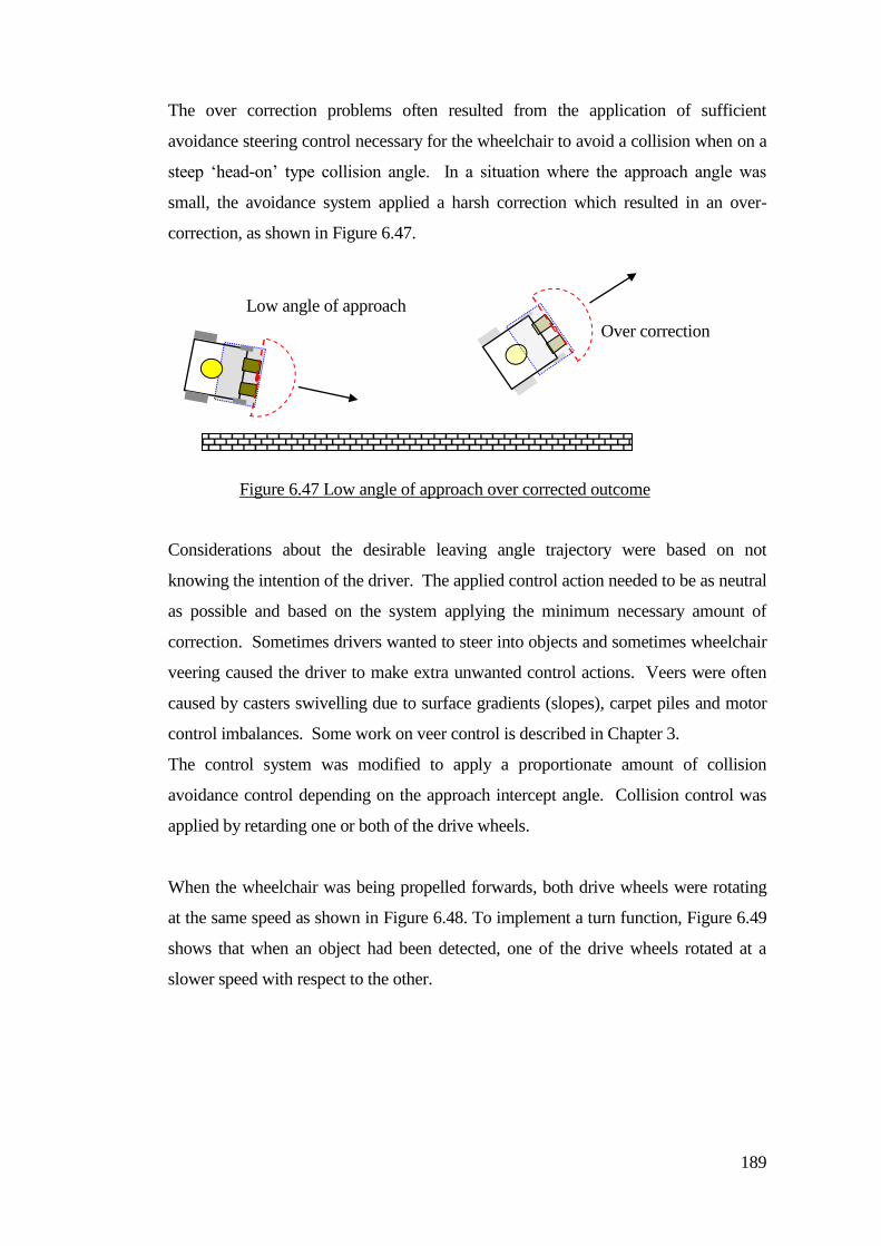
189
The over correction problems often resulted from the application of sufficient
avoidance steering control necessary for the wheelchair to avoid a collision when on a
steep ‘head-on’ type collision angle. In a situation where the approach angle was
small, the avoidance system applied a harsh correction which resulted in an over-
correction, as shown in Figure 6.47.
Considerations about the desirable leaving angle trajectory were based on not
knowing the intention of the driver. The applied control action needed to be as neutral
as possible and based on the system applying the minimum necessary amount of
correction. Sometimes drivers wanted to steer into objects and sometimes wheelchair
veering caused the driver to make extra unwanted control actions. Veers were often
caused by casters swivelling due to surface gradients (slopes), carpet piles and motor
control imbalances. Some work on veer control is described in Chapter 3.
The control system was modified to apply a proportionate amount of collision
avoidance control depending on the approach intercept angle. Collision control was
applied by retarding one or both of the drive wheels.
When the wheelchair was being propelled forwards, both drive wheels were rotating
at the same speed as shown in Figure 6.48. To implement a turn function, Figure 6.49
shows that when an object had been detected, one of the drive wheels rotated at a
slower speed with respect to the other.
Low angle of approach
Figure 6.47 Low angle of approach over corrected outcome
Over correction
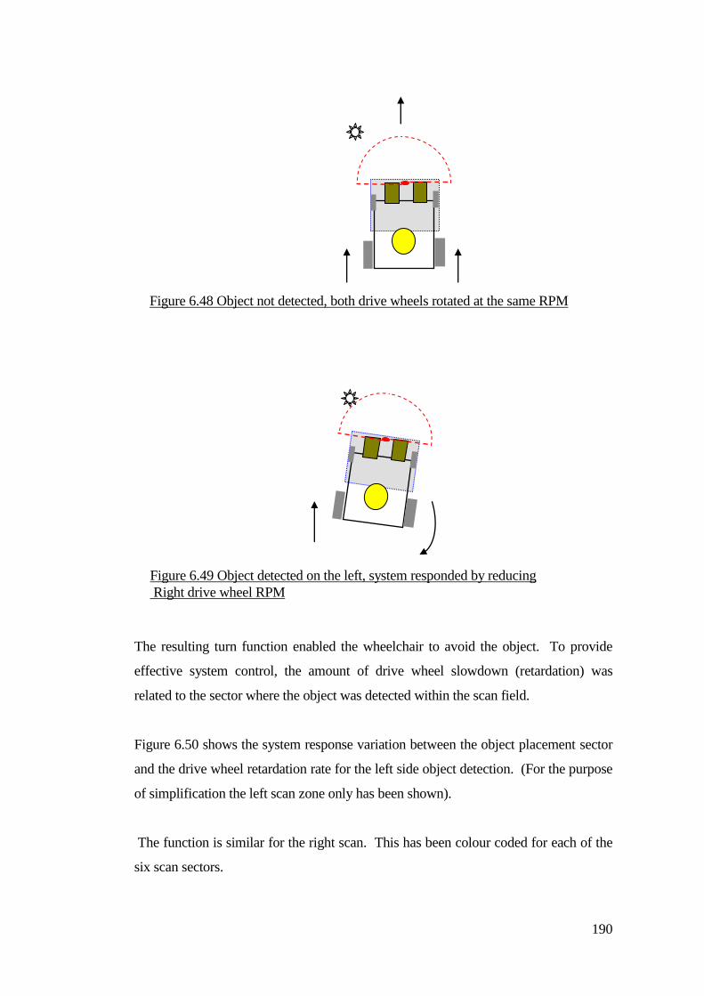
190
The resulting turn function enabled the wheelchair to avoid the object. To provide
effective system control, the amount of drive wheel slowdown (retardation) was
related to the sector where the object was detected within the scan field.
Figure 6.50 shows the system response variation between the object placement sector
and the drive wheel retardation rate for the left side object detection. (For the purpose
of simplification the left scan zone only has been shown).
The function is similar for the right scan. This has been colour coded for each of the
six scan sectors.
Figure 6.48 Object not detected, both drive wheels rotated at the same RPM
Figure 6.49 Object detected on the left, system responded by reducing
Right drive wheel RPM
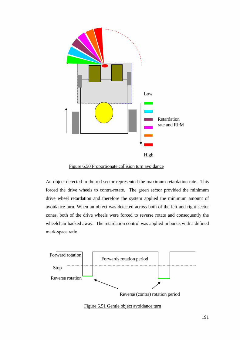
191
An object detected in the red sector represented the maximum retardation rate. This
forced the drive wheels to contra-rotate. The green sector provided the minimum
drive wheel retardation and therefore the system applied the minimum amount of
avoidance turn. When an object was detected across both of the left and right sector
zones, both of the drive wheels were forced to reverse rotate and consequently the
wheelchair backed away. The retardation control was applied in bursts with a defined
mark-space ratio.
Low
High
Retardation
rate and RPM
Figure 6.50 Proportionate collision turn avoidance
Forwards rotation period
Reverse (contra) rotation period
Stop
Figure 6.51 Gentle object avoidance turn
Reverse rotation
Forward rotation
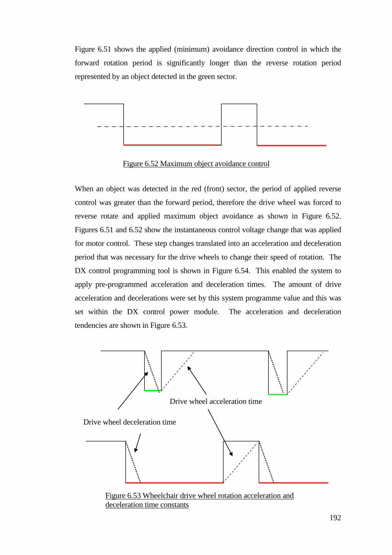
192
Figure 6.51 shows the applied (minimum) avoidance direction control in which the
forward rotation period is significantly longer than the reverse rotation period
represented by an object detected in the green sector.
When an object was detected in the red (front) sector, the period of applied reverse
control was greater than the forward period, therefore the drive wheel was forced to
reverse rotate and applied maximum object avoidance as shown in Figure 6.52.
Figures 6.51 and 6.52 show the instantaneous control voltage change that was applied
for motor control. These step changes translated into an acceleration and deceleration
period that was necessary for the drive wheels to change their speed of rotation. The
DX control programming tool is shown in Figure 6.54. This enabled the system to
apply pre-programmed acceleration and deceleration times. The amount of drive
acceleration and decelerations were set by this system programme value and this was
set within the DX control power module. The acceleration and deceleration
tendencies are shown in Figure 6.53.
Figure 6.52 Maximum object avoidance control
Drive wheel deceleration time
Drive wheel acceleration time
Figure 6.53 Wheelchair drive wheel rotation acceleration and
deceleration time constants
.
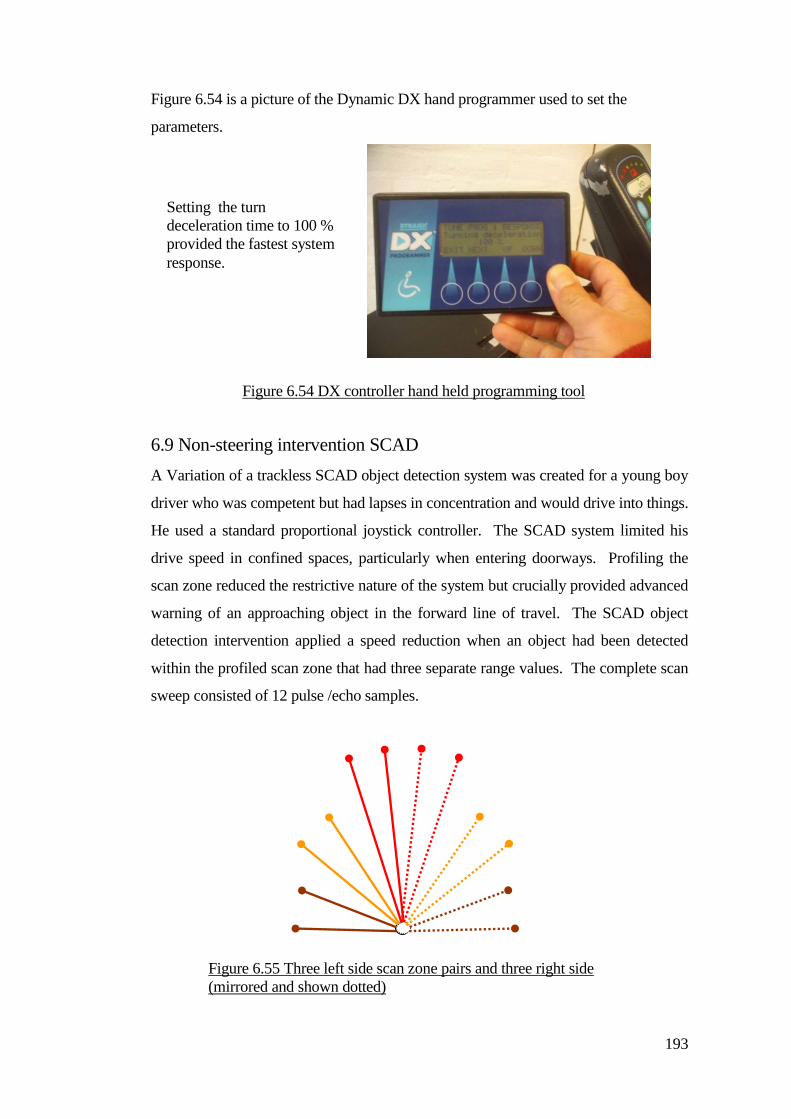
193
Figure 6.54 is a picture of the Dynamic DX hand programmer used to set the
parameters.
6.9 Non-steering intervention SCAD
A Variation of a trackless SCAD object detection system was created for a young boy
driver who was competent but had lapses in concentration and would drive into things.
He used a standard proportional joystick controller. The SCAD system limited his
drive speed in confined spaces, particularly when entering doorways. Profiling the
scan zone reduced the restrictive nature of the system but crucially provided advanced
warning of an approaching object in the forward line of travel. The SCAD object
detection intervention applied a speed reduction when an object had been detected
within the profiled scan zone that had three separate range values. The complete scan
sweep consisted of 12 pulse /echo samples.
Setting the turn
deceleration time to 100 %
provided the fastest system
response.
Figure 6.54 DX controller hand held programming tool
Figure 6.55 Three left side scan zone pairs and three right side
(mirrored and shown dotted)
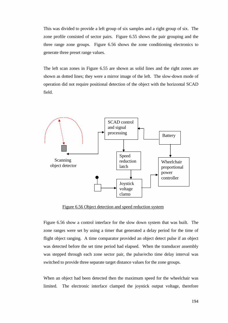
194
This was divided to provide a left group of six samples and a right group of six. The
zone profile consisted of sector pairs. Figure 6.55 shows the pair grouping and the
three range zone groups. Figure 6.56 shows the zone conditioning electronics to
generate three preset range values.
The left scan zones in Figure 6.55 are shown as solid lines and the right zones are
shown as dotted lines; they were a mirror image of the left. The slow-down mode of
operation did not require positional detection of the object with the horizontal SCAD
field.
Figure 6.56 show a control interface for the slow down system that was built. The
zone ranges were set by using a timer that generated a delay period for the time of
flight object ranging. A time comparator provided an object detect pulse if an object
was detected before the set time period had elapsed. When the transducer assembly
was stepped through each zone sector pair, the pulse/echo time delay interval was
switched to provide three separate target distance values for the zone groups.
When an object had been detected then the maximum speed for the wheelchair was
limited. The electronic interface clamped the joystick output voltage, therefore
SCAD control
and signal
processing
Joystick
voltage
clamp
Scanning
object detector Wheelchair
proportional
power
controller
Battery
Speed
reduction
latch
Figure 6.56 Object detection and speed reduction system
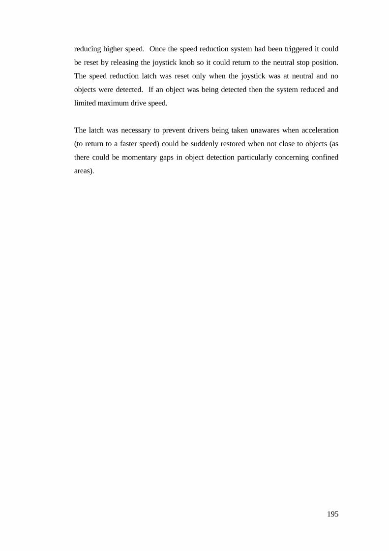
195
reducing higher speed. Once the speed reduction system had been triggered it could
be reset by releasing the joystick knob so it could return to the neutral stop position.
The speed reduction latch was reset only when the joystick was at neutral and no
objects were detected. If an object was being detected then the system reduced and
limited maximum drive speed.
The latch was necessary to prevent drivers being taken unawares when acceleration
(to return to a faster speed) could be suddenly restored when not close to objects (as
there could be momentary gaps in object detection particularly concerning confined
areas).
196
Chapter 7
Initial testing of the SCAD
This Chapter describes the transition of the collision avoidance system from the
laboratory environment to real world; the children’s familiar environment. The
collision control system was developed by successive trial applications including
collision avoidance testing. Real life driving issues are discussed, in which the SCAD
system needed to provide an adequate level of driver support.
An understanding of the human versus automatic system was formed and professional
people concerned with child development had strong views regarding the application
of assistive technology. A main parameter of SCAD operation was that it offered a
variable level of driver support. There was a requirement for the system to be
adaptable, particularly to take account of the complexities of the children’s personal
difficulties and obstacles encountered in the real environment. An example of this,
was the creation of automatic object range contraction to enable the wheelchair to pass
through doorways, which would have been prevented by a fixed range system. The
concept of effort reduction began to develop when collision avoidance control was
provided for young drivers using single switch direction selection.
7.1 SCAD before and after avoidance control intervention Collision avoidance tests were conducted in a school hall and recorded using a digital
video camera operating at 30 frames per second. The camera was mounted eight
meters above the floor over a stage wall that provided a detectable surface. The
wheelchair was set on a collision course with the stage wall at various intercept
angles. Forward drive control was operated by a lump of blutac that enabled selection
of sustained driving. Multiple trajectory tests were carried out. Three of the test runs
are shown for low angle in the range of (0˚ to 20˚), mid angle (20˚ to 45˚) and high
angle (45˚ to 80˚) wall collisions. Repeated collision tests were carried out and some
are shown for the purpose of illustration. The amount of collision intervention has
been shown in Figures 7.1 to 7.4.
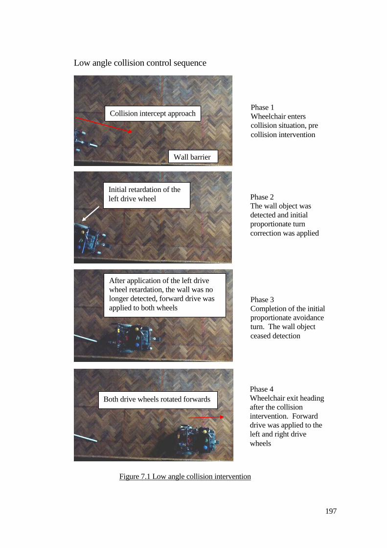
197
Low angle collision control sequence
Phase 3 Completion of the initial proportionate avoidance turn. The wall object ceased detection
After application of the left drive wheel retardation, the wall was no longer detected, forward drive was applied to both wheels
Phase 4 Wheelchair exit heading after the collision intervention. Forward drive was applied to the left and right drive wheels
Both drive wheels rotated forwards
Phase 1 Wheelchair enters collision situation, pre collision intervention
Wall barrier
Collision intercept approach
Phase 2 The wall object was detected and initial proportionate turn correction was applied
Initial retardation of the left drive wheel
Figure 7.1 Low angle collision intervention
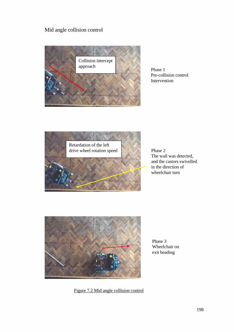
198
Mid angle collision control
Phase 2 The wall was detected, and the castors swivelled in the direction of wheelchair turn
Retardation of the left drive wheel rotation speed
Phase 1 Pre-collision control Intervention
Collision intercept approach
Phase 3 Wheelchair on exit heading
Figure 7.2 Mid angle collision control
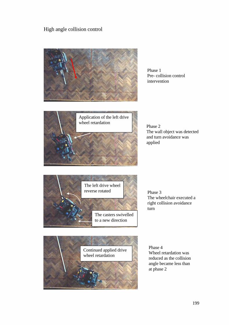
199
High angle collision control
Phase 2 The wall object was detected and turn avoidance was applied
Phase 1 Pre- collision control intervention
Phase 3 The wheelchair executed a right collision avoidance turn
Continued applied drive wheel retardation
Phase 4 Wheel retardation was reduced as the collision angle became less than at phase 2
The left drive wheel reverse rotated
The casters swivelled to a new direction
Application of the left drive wheel retardation
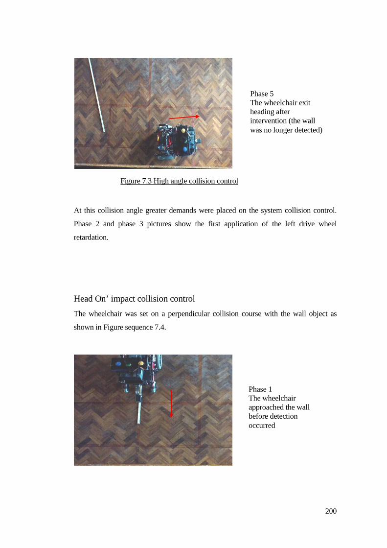
200
At this collision angle greater demands were placed on the system collision control.
Phase 2 and phase 3 pictures show the first application of the left drive wheel
retardation.
Head On’ impact collision control The wheelchair was set on a perpendicular collision course with the wall object as
shown in Figure sequence 7.4.
Phase 1 The wheelchair approached the wall before detection occurred
Phase 5 The wheelchair exit heading after intervention (the wall was no longer detected)
Figure 7.3 High angle collision control
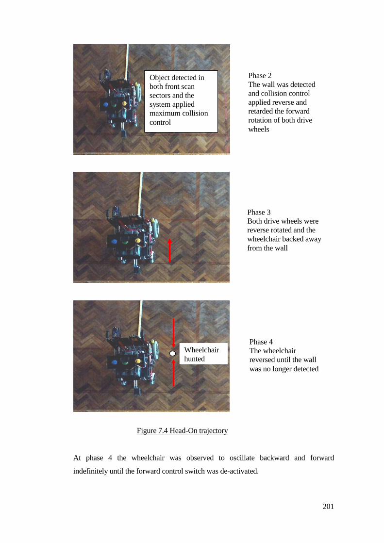
201
At phase 4 the wheelchair was observed to oscillate backward and forward
indefinitely until the forward control switch was de-activated.
Phase 2 The wall was detected and collision control applied reverse and retarded the forward rotation of both drive wheels
Object detected in both front scan sectors and the system applied maximum collision control
Phase 3 Both drive wheels were reverse rotated and the wheelchair backed away from the wall
Phase 4 The wheelchair reversed until the wall was no longer detected
Wheelchair hunted
Figure 7.4 Head-On trajectory
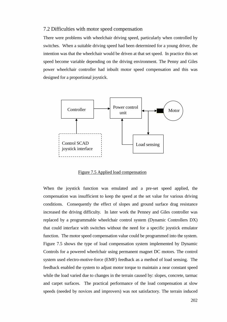
202
7.2 Difficulties with motor speed compensation There were problems with wheelchair driving speed, particularly when controlled by
switches. When a suitable driving speed had been determined for a young driver, the
intention was that the wheelchair would be driven at that set speed. In practice this set
speed become variable depending on the driving environment. The Penny and Giles
power wheelchair controller had inbuilt motor speed compensation and this was
designed for a proportional joystick.
When the joystick function was emulated and a pre-set speed applied, the
compensation was insufficient to keep the speed at the set value for various driving
conditions. Consequently the effect of slopes and ground surface drag resistance
increased the driving difficulty. In later work the Penney and Giles controller was
replaced by a programmable wheelchair control system (Dynamic Controllers DX)
that could interface with switches without the need for a specific joystick emulator
function. The motor speed compensation value could be programmed into the system.
Figure 7.5 shows the type of load compensation system implemented by Dynamic
Controls for a powered wheelchair using permanent magnet DC motors. The control
system used electro-motive-force (EMF) feedback as a method of load sensing. The
feedback enabled the system to adjust motor torque to maintain a near constant speed
while the load varied due to changes in the terrain caused by: slopes, concrete, tarmac
and carpet surfaces. The practical performance of the load compensation at slow
speeds (needed by novices and improvers) was not satisfactory. The terrain induced
Power control unit
Controller
Load sensing
Motor
Control SCAD joystick interface
Figure 7.5 Applied load compensation
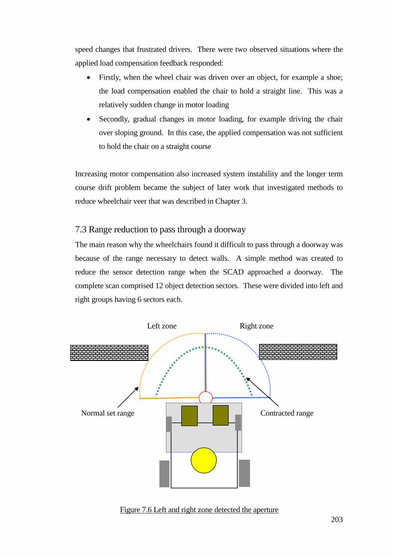
203
speed changes that frustrated drivers. There were two observed situations where the
applied load compensation feedback responded:
• Firstly, when the wheel chair was driven over an object, for example a shoe;
the load compensation enabled the chair to hold a straight line. This was a
relatively sudden change in motor loading
• Secondly, gradual changes in motor loading, for example driving the chair
over sloping ground. In this case, the applied compensation was not sufficient
to hold the chair on a straight course
Increasing motor compensation also increased system instability and the longer term
course drift problem became the subject of later work that investigated methods to
reduce wheelchair veer that was described in Chapter 3.
7.3 Range reduction to pass through a doorway
The main reason why the wheelchairs found it difficult to pass through a doorway was
because of the range necessary to detect walls. A simple method was created to
reduce the sensor detection range when the SCAD approached a doorway. The
complete scan comprised 12 object detection sectors. These were divided into left and
right groups having 6 sectors each.
Figure 7.6 Left and right zone detected the aperture
Left zone Right zone
Normal set range Contracted range
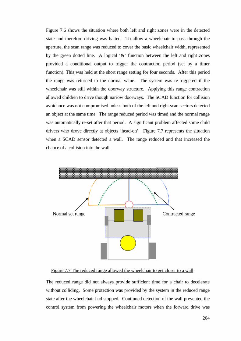
204
Figure 7.6 shows the situation where both left and right zones were in the detected
state and therefore driving was halted. To allow a wheelchair to pass through the
aperture, the scan range was reduced to cover the basic wheelchair width, represented
by the green dotted line. A logical ‘&’ function between the left and right zones
provided a conditional output to trigger the contraction period (set by a timer
function). This was held at the short range setting for four seconds. After this period
the range was returned to the normal value. The system was re-triggered if the
wheelchair was still within the doorway structure. Applying this range contraction
allowed children to drive though narrow doorways. The SCAD function for collision
avoidance was not compromised unless both of the left and right scan sectors detected
an object at the same time. The range reduced period was timed and the normal range
was automatically re-set after that period. A significant problem affected some child
drivers who drove directly at objects ‘head-on’. Figure 7.7 represents the situation
when a SCAD sensor detected a wall. The range reduced and that increased the
chance of a collision into the wall.
The reduced range did not always provide sufficient time for a chair to decelerate
without colliding. Some protection was provided by the system in the reduced range
state after the wheelchair had stopped. Continued detection of the wall prevented the
control system from powering the wheelchair motors when the forward drive was
Figure 7.7 The reduced range allowed the wheelchair to get closer to a wall
Normal set range Contracted range
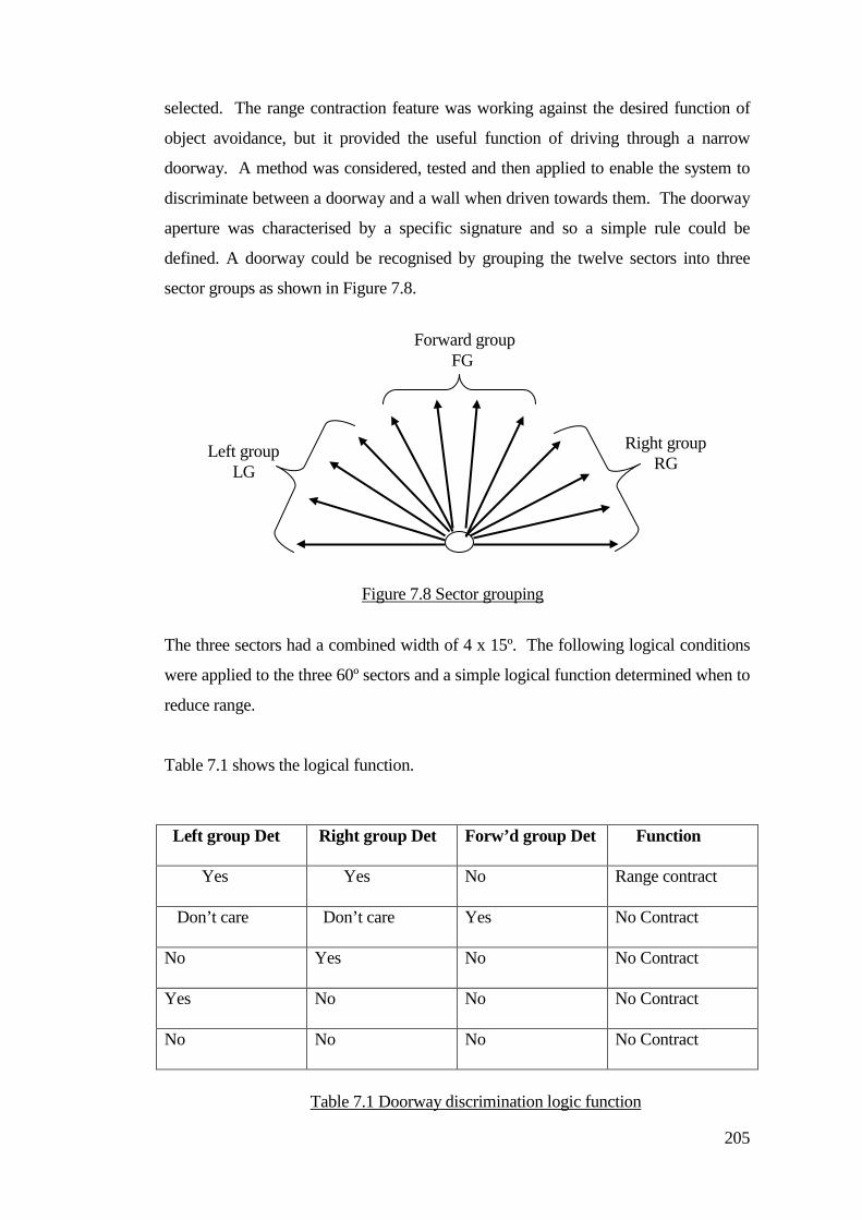
205
selected. The range contraction feature was working against the desired function of
object avoidance, but it provided the useful function of driving through a narrow
doorway. A method was considered, tested and then applied to enable the system to
discriminate between a doorway and a wall when driven towards them. The doorway
aperture was characterised by a specific signature and so a simple rule could be
defined. A doorway could be recognised by grouping the twelve sectors into three
sector groups as shown in Figure 7.8.
The three sectors had a combined width of 4 x 15º. The following logical conditions
were applied to the three 60º sectors and a simple logical function determined when to
reduce range.
Table 7.1 shows the logical function.
Left group Det Right group Det Forw’d group Det Function
Yes Yes No Range contract
Don’t care Don’t care Yes No Contract
No Yes No No Contract
Yes No No No Contract
No No No No Contract
Left group LG
Right group RG
Forward group FG
Figure 7.8 Sector grouping
Table 7.1 Doorway discrimination logic function
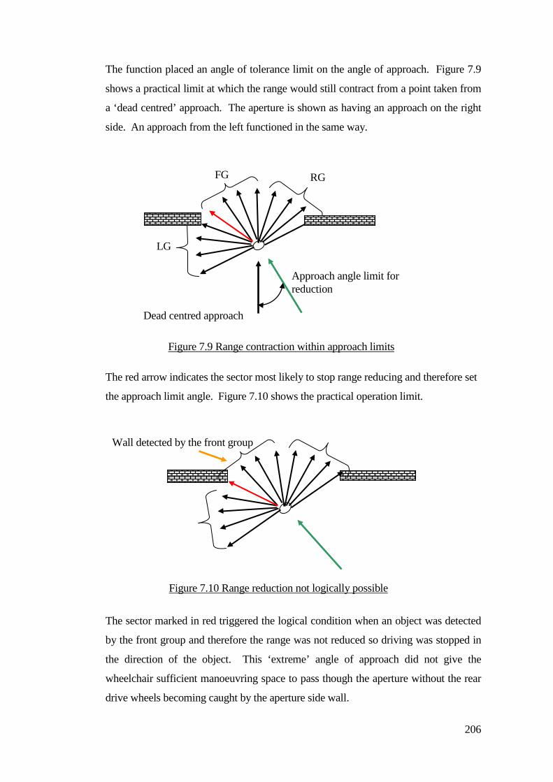
206
The function placed an angle of tolerance limit on the angle of approach. Figure 7.9
shows a practical limit at which the range would still contract from a point taken from
a ‘dead centred’ approach. The aperture is shown as having an approach on the right
side. An approach from the left functioned in the same way.
The red arrow indicates the sector most likely to stop range reducing and therefore set
the approach limit angle. Figure 7.10 shows the practical operation limit.
The sector marked in red triggered the logical condition when an object was detected
by the front group and therefore the range was not reduced so driving was stopped in
the direction of the object. This ‘extreme’ angle of approach did not give the
wheelchair sufficient manoeuvring space to pass though the aperture without the rear
drive wheels becoming caught by the aperture side wall.
Figure 7.10 Range reduction not logically possible
Wall detected by the front group
Figure 7.9 Range contraction within approach limits
Approach angle limit for reduction
Dead centred approach
LG
FG RG

207
7.4 Children learning to drive
There was a conflict regarding user control of the wheelchair and system control.
Some therapists believed that system intervention blurred the boundaries of
wheelchair control. This made if difficult to determine what level of control was
being applied by the child driver. Other therapists believed that assistive technology
improved the chances of young child drivers, who would not normally drive without
helpers close at hand or even be provided with wheelchairs. The personal child
achievement of getting to places and moving themselves (even with technical help)
provided increased confidence.
Stages of child driver development were observed, in which children progressed
through stages of driving with a normal wheelchair to experience crashing, direct
wheelchair steering and control feedback. The effect of collision control on the driver
was considered. For example, did they understand why their wheelchair had altered
course when an object had been detected? Therapists at CHS developed a driving
programme in which young people were put through training with basic switch
controls, for example, simple straight line driving and circling. This helped link cause
and affect with the child’s own understanding of the task.
The therapists had specific driving sessions with child drivers on a weekly basis. The
time the therapist spent with each child was short compared to the time the child had
available to drive throughout the school day. Sometimes continuity of control for
young drivers could be different for the training session. An example was when a
child was familiar with their switch controls and the therapist wanted to introduce
joystick practice. In the longer term a child may gain the skills for joystick control.
There could be a transition period in which the child was more proficient with
switches.
Opinions varied about whether an assistive system took part of the decision process
away from the child, as the system would do the work of avoiding the object without
the child having to do it. Some believed assistive technology made it possible for
young people to have an introduction to driving without the constant need for
bystanders and helpers. There were questions being asked, for example, ‘are we
208
creating child robots’?
Observations of child drivers showed differences in personal driving skill and
anticipation. There were situations in which the system acted or responded in order to
stop a collision. Interestingly, who or what acted first. The system might cut power
to avoid a collision, or the driver might act before the system.
It was important to consider what effect collision control had on the child driver, for
example, did they understand why the wheelchair altered course when objects were
detected. Sensations of acceleration and deceleration were felt during collision
control. Importantly the child always initiated the driving function. No process
occurred without the switch being operated, apart from a system controlled stop.
There were issues relating to children being pushed when they could be driving
themselves. Did children understand when they were being pushed and not driving
under their own control, when they still had access to switch controls in front of them?
The child might not understand why a switch was not operating, even though it was
making a clicking sound when the child pressed it. The motion of the chair became
independent of switch control when it was being pushed. The nature of how human
help was given was considered.
There was a conflict of interest between children and helpers. Children needed to be
allowed to make mistakes and not to be always be told where to go or drive. The
school time table imposed the need for children to reach specific destinations within
time set frames and this also sometimes compromised the amount of freedom given to
drivers.
The level of applied SCAD operation needed to be suitable for individual
requirements and changes. It was important that the child’s own ability was not
swamped by system interventions. System control options were incorporated that
enabled system functional operating changes to be made. These were graduated to
progressively offer increased or decreased autonomous driving functions.
Operation of the wheelchair when lockout mode was selected was intended to be a
209
training mode in which a child was expected to problem-solve during driving
situations. This lockout mode was regarded as a minimal intervention. An
operational example was where an object was detected on the right side of the
wheelchair. The control system disabled the function of the right turn and forward
control switch. The child driver was expected to work out for them self which switch
should be operated in order to drive away from the object. In the example where an
object had been detected on the left side, the control options available to a child were
right and reverse. Operation of the forwards control caused the wheelchair to head for
the object and that was therefore disabled for the period in which the object was
detected. In situations of open space where no objects were detected within the set
range of the detector, the wheelchair reverted to normal steering control.
When auto-steer was selected, the system applied increased collision avoidance
control. Using a similar example where an object was detected on the right side of the
wheelchair, operation of the right turn control switch was disabled. Operating the
forwards control enabled the system to apply collision control intervention. This
system intervention stopped at the point at which no objects were detected in the path
of travel. The wheelchair control system reverted to the normal function of
momentary steering control similar to lockout system operation.
7.5 Enhancement of avoidance control Many young children that had been driving using a track guided system were
generally required to operate three switches: a forwards drive switch, and left and right
junction turn controls. Sometimes it was necessary to simplify the controls, for
example, just a single switch could be used for some young drivers. When drivers
developed their cognitive understanding and control of the task then more control
options could be provided (typically junction turn selection control switches). It was
not considered practical to provide track drivers with a reverse control. One particular
concern was that a young driver would not be able to see their driving direction and
consequently would collide with objects. Additionally it was not justifiable to add the
extra hardware and control systems required.
There was a need for the application of a reverse function when driving in a free
situation. The term ‘free driver’ was used by staff helpers and therapists to describe a
210
driver who was not guided by a track. To help a young person with their transition
from driving a track guided wheelchair to becoming a free driver, their familiar
driving control set-up remained the same. In many cases a reverse control was not
provided. When driving using collision avoidance, inevitably a young person would
need a reverse function, perhaps to escape from a bottleneck situation. The control
interface for the SCAD system incorporated a reverse input. Where a young person
had the ability to operate a reverse control they could use it. The test systems did not
have a sensor to detect objects behind the wheelchair in order to reduce system
complexity. The reverse function was time-limited. When the reverse control was
activated the wheelchair responded for a set period (typically three seconds). After
this period, reverse driving stopped even though the reverse switch might be activated.
Some drivers learned that they could continue reversing by re-activating their reverse
control. Later developments incorporated a latch circuit that prevented re-triggering
of the reverse direction control when no objects were being detected.
An automatic reverse and turn mode was created that provided a systematic reverse
process so that a young person could manoeuvre their wheelchair out of a bottleneck
with their turn control switches. This mode of control operated when an object had
been detected to the left or right side of the wheelchair. For example, if an object had
been detected on the right side of the wheelchair and the user operated their right
switch, the system responded by applying a reverse control function. The wheelchair
backed away to a point where the object was no longer detected. This cycle continued
until the wheelchair was clear of the object and the driver maintained operation of the
right turn control.
A turn delay was incorporated when the automatic reverse and turn manoeuvring
functioned after the delay period had expired. This provided a window of time that
prevented the wheelchair engaging reverse in order to provide a driver with thinking
time. There were some situations, in which a driver may not have required the
automatic reverse function, particularly corridors.
There were different operational parameters that could be applied as part of a collision
control strategy. The amount of system support needed to be flexible and responsive
to the changing needs of the children. The application of specific operational modes
211
helped classify the system operation. Two system controls were provided that preset
collision intervention and the functional collision avoidance was set by a mode
number.
• Mode 1 Object detection driving lockout
• Mode 2 Object detection driving lockout + automatic reverse and turn
• Mode 3 Driving collision avoidance
• Mode 4 Driving collision avoidance + automatic reverse and turn
The distance the wheelchair was from an object before a control intervention occurred
was set by the range control number.
• Range (0) = Short (system protection non-collision control)
• Ranges (1 – 4) = Short increasing to long object detection distances
• Range (5) = Extended range + automatic range reduction for doorway
navigation
Detection operation was retained for range (0) to provide some minimal system
protection, to reduce damage if the system was driven into walls. The object detection
range was set by a range control number. The range value (0) indicated no practical
system support. To protect the sensor a short detection limit was applied, typically
20cm. Even with this residual level it should be noted that the therapists preferred an
all-off state. They believed that the collision system should be switched off so that it
did not function in any way.
The inclusion of side detectors provided additional object detection support, although
some drivers did not necessarily need this. For assessment applications the side
detectors were mounted on the wheelchair and their outputs switched off when not
required. To provide system flexibility the SCAD or infrared side sensors could be
switched in and out of operation independently.
The concern of the therapists was noted and later systems incorporated a kill option.
Even at the shortest object detection range (system protection), system operation
blurred the boundaries between human control and system control. It was further
212
noted that some children in particular wanted to drive close to an object of interest and
collision control intervention hindered this, for example a child wanting to operate a
wall mounted light switch. The range control settings could only be adjusted by
attendants and not the drivers themselves.
7.6 A first proportional SCAD A young driver who had a self destructive disorder, LeschNyan syndrome started
driving his wheelchair using a switch joystick. He needed a collision avoidance
system because he would sometimes be intent on harming himself or crashing. The
switch joystick became frustrating for him and was not a suitable match for his
abilities. He had demonstrated finer personal hand control (provided he was suitably
restrained). The SCAD system only operated with switched inputs. Therapists
assessed him for a proportional joystick and he demonstrated a high level of
competence and a definite preference but therapists, school staff and carers were
unhappy to let him drive without an appropriate collision avoidance system.
The main considerations involved with the application of collision control for
proportional joystick drivers were object detection controlled wheelchair slow down
(deceleration) and collision control steering intervention.
A new control interface was created. The existing ultra-sonic scanning control system
remained the same. The object detection signals were used with comparators that
blocked the joystick direction and speed output when object detect signals were
present. Proportionality was applied for speed control of the wheelchair and not in
proportion to the detected object distance. When an object had been detected, steering
control towards that direction was blocked. A definite cut-off point was preferred in
order to provide firm feedback to the driver so that they knew that a system control
intervention had occurred. Lessons were learnt from previous work in which system
intervention had blurred the boundaries of human and system control.
A driving control interface was developed that used a method of direction blocking.
This was placed between the joystick voltage outputs and the power control joystick
input control lines. The joystick shown in Figure 7.11 provided a forward control
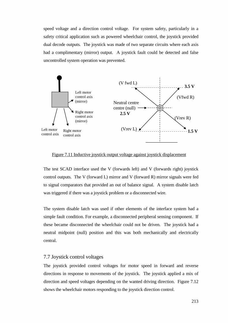
213
speed voltage and a direction control voltage. For system safety, particularly in a
safety critical application such as powered wheelchair control, the joystick provided
dual decode outputs. The joystick was made of two separate circuits where each axis
had a complimentary (mirror) output. A joystick fault could be detected and false
uncontrolled system operation was prevented.
The test SCAD interface used the V (forwards left) and V (forwards right) joystick
control outputs. The V (forward L) mirror and V (forward R) mirror signals were fed
to signal comparators that provided an out of balance signal. A system disable latch
was triggered if there was a joystick problem or a disconnected wire.
The system disable latch was used if other elements of the interface system had a
simple fault condition. For example, a disconnected peripheral sensing component. If
these became disconnected the wheelchair could not be driven. The joystick had a
neutral midpoint (null) position and this was both mechanically and electrically
central.
7.7 Joystick control voltages The joystick provided control voltages for motor speed in forward and reverse
directions in response to movements of the joystick. The joystick applied a mix of
direction and speed voltages depending on the wanted driving direction. Figure 7.12
shows the wheelchair motors responding to the joystick direction control.
Figure 7.11 Inductive joystick output voltage against joystick displacement
Right motor control axis
(Vrev L)
(Vfwd R)
(V fwd L)
(Vrev R)
Left motor control axis
Neutral centre centre (null) 2.5 V
Left motor control axis (mirror)
Right motor control axis (mirror)
1.5 V
3.5 V
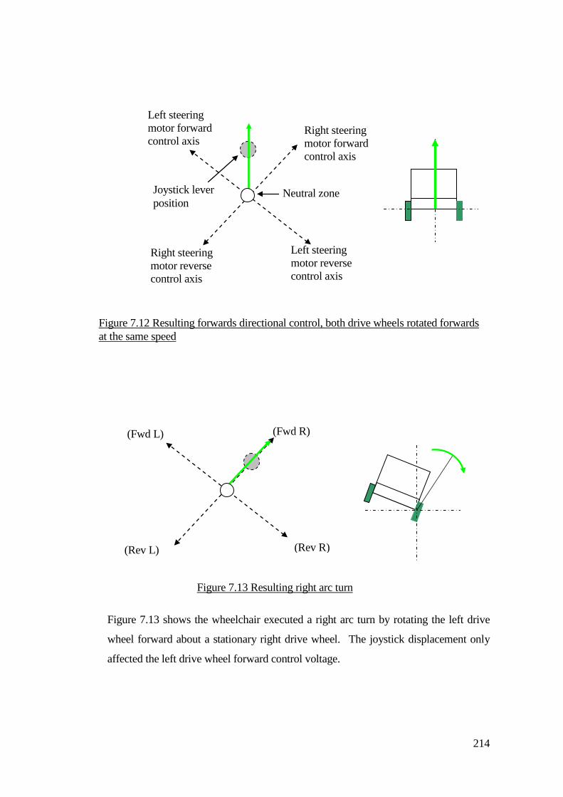
214
Figure 7.13 shows the wheelchair executed a right arc turn by rotating the left drive
wheel forward about a stationary right drive wheel. The joystick displacement only
affected the left drive wheel forward control voltage.
Figure 7.13 Resulting right arc turn
(Rev L)
(Fwd R) (Fwd L)
(Rev R)
Figure 7.12 Resulting forwards directional control, both drive wheels rotated forwards at the same speed
Right steering motor forward control axis
Joystick lever position
Right steering motor reverse control axis
Left steering motor forward control axis
Left steering motor reverse control axis
Neutral zone

215
At this joystick position a spin turn resulted from contra-rotating drive wheels. Figure
7.14 shows point C on the joystick forward control axis controlled forwards rotation
of the left drive wheel, whilst point Q controlled reverse rotation on the right drive
wheel. A method of control voltage blocking stopped the progressive change of
joystick output voltage beyond a certain point. When an object was detected, control
blocking voltages were generated that were in opposition to the driving direction that
would take the chair towards the object.
The object scan sectors were divided into two areas (left and right shells respectively)
as shown in Figure 7.15. Each shell had six scan sectors for the left detection zone
and six scan sectors for the right detection zone.
Figure 7.14 Resulting right spin
(Rev L)
(Fwd R) (Fwd L)
(Rev R)
C
Q
Right object detection zone shell.
Left object detection zone shell.
Figure 7.15 Left and right scan sector grouping
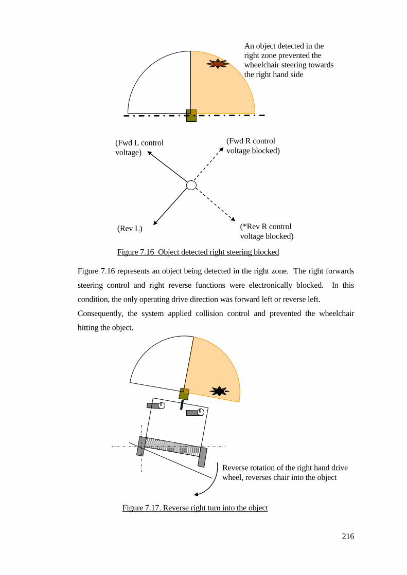
216
Figure 7.16 represents an object being detected in the right zone. The right forwards
steering control and right reverse functions were electronically blocked. In this
condition, the only operating drive direction was forward left or reverse left.
Consequently, the system applied collision control and prevented the wheelchair
hitting the object.
(Rev L)
(Fwd R control voltage blocked)
(Fwd L control voltage)
(*Rev R control voltage blocked)
Figure 7.16 Object detected right steering blocked
An object detected in the right zone prevented the wheelchair steering towards the right hand side
Figure 7.17. Reverse right turn into the object
Reverse rotation of the right hand drive wheel, reverses chair into the object
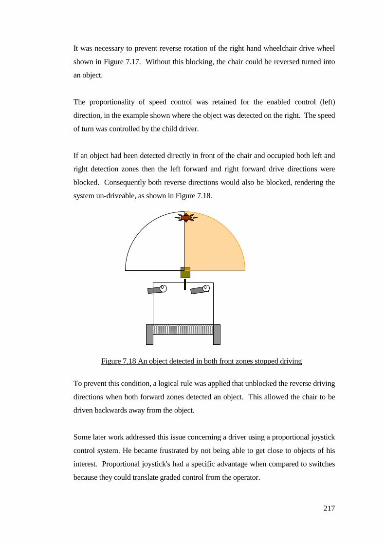
217
It was necessary to prevent reverse rotation of the right hand wheelchair drive wheel
shown in Figure 7.17. Without this blocking, the chair could be reversed turned into
an object.
The proportionality of speed control was retained for the enabled control (left)
direction, in the example shown where the object was detected on the right. The speed
of turn was controlled by the child driver.
If an object had been detected directly in front of the chair and occupied both left and
right detection zones then the left forward and right forward drive directions were
blocked. Consequently both reverse directions would also be blocked, rendering the
system un-driveable, as shown in Figure 7.18.
To prevent this condition, a logical rule was applied that unblocked the reverse driving
directions when both forward zones detected an object. This allowed the chair to be
driven backwards away from the object.
Some later work addressed this issue concerning a driver using a proportional joystick
control system. He became frustrated by not being able to get close to objects of his
interest. Proportional joystick's had a specific advantage when compared to switches
because they could translate graded control from the operator.
Figure 7.18 An object detected in both front zones stopped driving
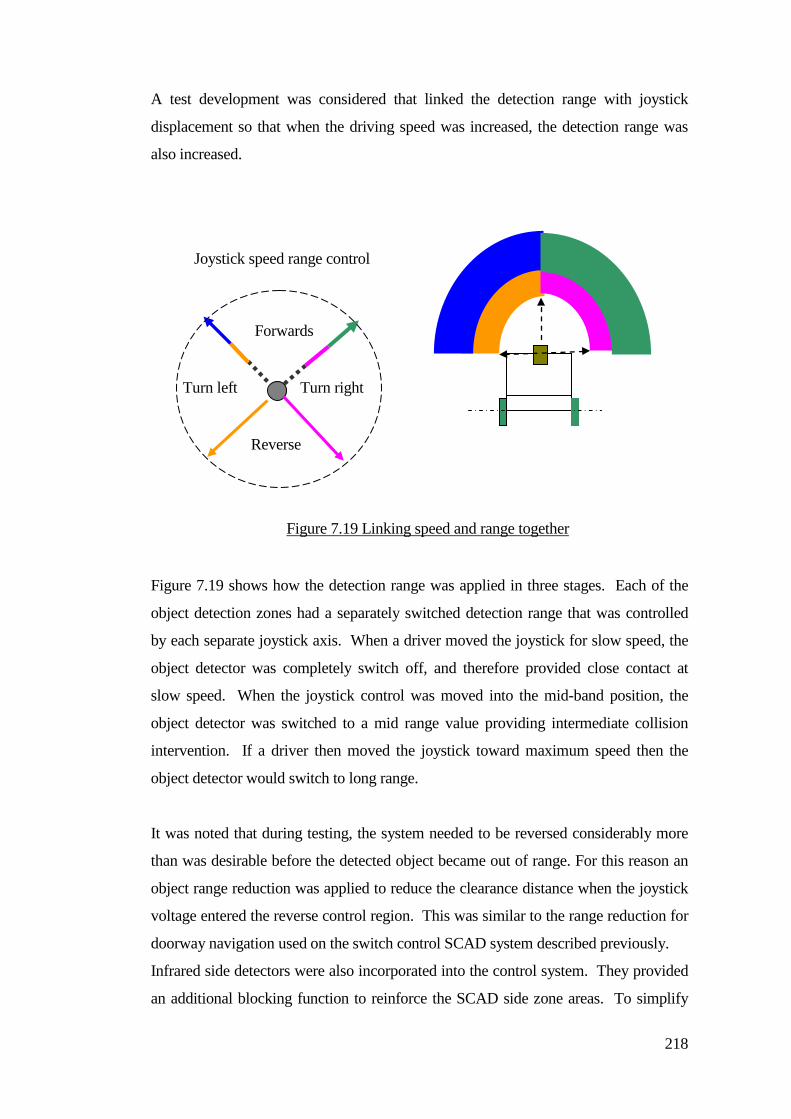
218
A test development was considered that linked the detection range with joystick
displacement so that when the driving speed was increased, the detection range was
also increased.
Figure 7.19 shows how the detection range was applied in three stages. Each of the
object detection zones had a separately switched detection range that was controlled
by each separate joystick axis. When a driver moved the joystick for slow speed, the
object detector was completely switch off, and therefore provided close contact at
slow speed. When the joystick control was moved into the mid-band position, the
object detector was switched to a mid range value providing intermediate collision
intervention. If a driver then moved the joystick toward maximum speed then the
object detector would switch to long range.
It was noted that during testing, the system needed to be reversed considerably more
than was desirable before the detected object became out of range. For this reason an
object range reduction was applied to reduce the clearance distance when the joystick
voltage entered the reverse control region. This was similar to the range reduction for
doorway navigation used on the switch control SCAD system described previously.
Infrared side detectors were also incorporated into the control system. They provided
an additional blocking function to reinforce the SCAD side zone areas. To simplify
Figure 7.19 Linking speed and range together
Reverse
Forwards
Joystick speed range control
Turn right Turn left
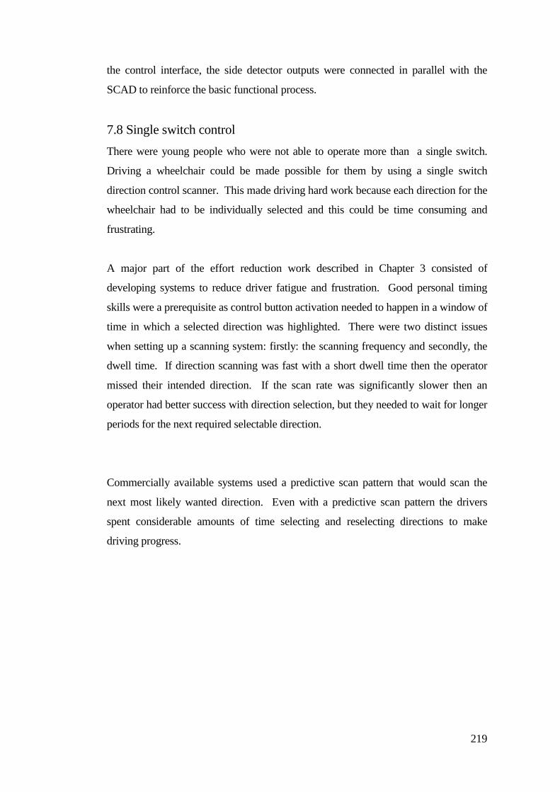
219
the control interface, the side detector outputs were connected in parallel with the
SCAD to reinforce the basic functional process.
7.8 Single switch control There were young people who were not able to operate more than a single switch.
Driving a wheelchair could be made possible for them by using a single switch
direction control scanner. This made driving hard work because each direction for the
wheelchair had to be individually selected and this could be time consuming and
frustrating.
A major part of the effort reduction work described in Chapter 3 consisted of
developing systems to reduce driver fatigue and frustration. Good personal timing
skills were a prerequisite as control button activation needed to happen in a window of
time in which a selected direction was highlighted. There were two distinct issues
when setting up a scanning system: firstly: the scanning frequency and secondly, the
dwell time. If direction scanning was fast with a short dwell time then the operator
missed their intended direction. If the scan rate was significantly slower then an
operator had better success with direction selection, but they needed to wait for longer
periods for the next required selectable direction.
Commercially available systems used a predictive scan pattern that would scan the
next most likely wanted direction. Even with a predictive scan pattern the drivers
spent considerable amounts of time selecting and reselecting directions to make
driving progress.
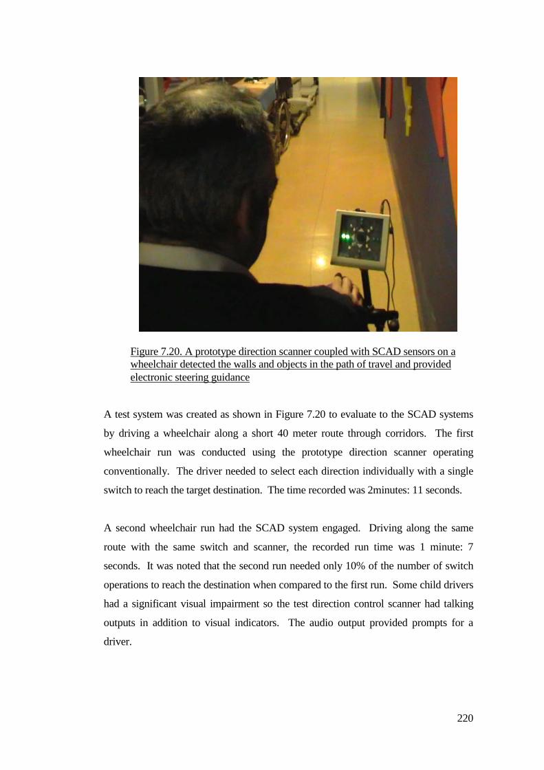
220
A test system was created as shown in Figure 7.20 to evaluate to the SCAD systems
by driving a wheelchair along a short 40 meter route through corridors. The first
wheelchair run was conducted using the prototype direction scanner operating
conventionally. The driver needed to select each direction individually with a single
switch to reach the target destination. The time recorded was 2minutes: 11 seconds.
A second wheelchair run had the SCAD system engaged. Driving along the same
route with the same switch and scanner, the recorded run time was 1 minute: 7
seconds. It was noted that the second run needed only 10% of the number of switch
operations to reach the destination when compared to the first run. Some child drivers
had a significant visual impairment so the test direction control scanner had talking
outputs in addition to visual indicators. The audio output provided prompts for a
driver.
Figure 7.20. A prototype direction scanner coupled with SCAD sensors on a wheelchair detected the walls and objects in the path of travel and provided electronic steering guidance
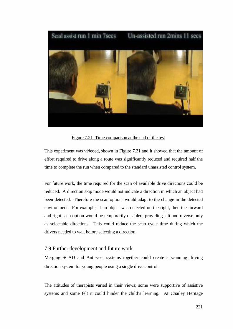
221
This experiment was videoed, shown in Figure 7.21 and it showed that the amount of
effort required to drive along a route was significantly reduced and required half the
time to complete the run when compared to the standard unassisted control system.
For future work, the time required for the scan of available drive directions could be
reduced. A direction skip mode would not indicate a direction in which an object had
been detected. Therefore the scan options would adapt to the change in the detected
environment. For example, if an object was detected on the right, then the forward
and right scan option would be temporarily disabled, providing left and reverse only
as selectable directions. This could reduce the scan cycle time during which the
drivers needed to wait before selecting a direction.
7.9 Further development and future work Merging SCAD and Anti-veer systems together could create a scanning driving
direction system for young people using a single drive control.
The attitudes of therapists varied in their views; some were supportive of assistive
systems and some felt it could hinder the child’s learning. At Chailey Heritage
Figure 7.21 Time comparison at the end of the test
222
School, therapists felt that collision avoidance reduced the need to learn driving skills.
Crashing and contact with the environment was an essential part of the learning
process.
Therapists in other centres believed that assistive driving systems helped a young
person build their confidence. To give a child an opportunity to experience driving
under their own control (in terms of switch control operation) and providing a steering
function that was more independent from helpers. Young people who would not
normally be considered (or who were excluded from driving) were given an
opportunity to drive by using a guided system.
The way SCAD was used (and how it was used) was dictated by the philosophy of the
people that used it, and this fed back into how the system changed and developed over
time. Proportional switch controls eased the transition to a joystick. Switch control
users found it a big step to transfer their skill to standard proportional joystick devices.
Sometimes it was necessary to increase the control movement by mechanical methods
to match the ability of the young person’s control actions. Most reported operational
problems were caused by cables, interconnection weakness and sensor obscuration
because of securing straps and shoe laces hanging over the sensors. These were
temporary problem that could easily be fixed.
At Chailey Heritage School, wheelchair drivers would carry considerable amounts of
luggage hanging off the back of their wheelchair handle bars. It was advantageous to
keep the number of required sensors low to reduce obscuration and reliability
problems. For this reason the implementation of a specific object reversing sensor
was not rigorously pursued and a time protected reverse function was provided
instead. It was important that the implementation of a SCAD system did not put extra
demands on the driver. The intention was to reduce the amount of effort required and
the level of helper intervention.
There were problems with the first test systems that under or over corrected when an
object was detected and sometimes collided with an object that the wheelchair was
trying to avoid. If the system over corrected, then the wheelchair would steer a course
that was disproportionate to the direction desired by the driver. Collision control

223
development reduced the number of inappropriate collision interventions by
considering where the object was in relation the wheelchair.
Pre-collision and post collision avoidance trajectories were monitored. Test runs were
conducted in which the wheelchair was set on various collision angles with a wall.
The pre and post trajectory directions were recorded to assess system performance.
The difference between an automated system helping and a human helping was
considered. People were not always on hand to help drivers. Children knew that the
SCAD system was always available and this had a positive effect on the children’s
self confidence. Getting out of trouble with automated help and not human help
became a matter of personal pride.
There could be a conflict of interests, a clash of wills (agendas) between where the
child wanted to go and where the helper wanted the child to go. System neutrality,
where the system applied basic rules and control functions was reasonably predictable.
The problem solving methods applied by humans varied and outcomes were not
predictable.
Applying SCAD with a scaleable amount of collision control (support), allowed a
record (or back marker) to be kept of ability level. Child progression was considered
using the analogy of bicycle stabilizers, as initial support enabled some independence
from helper support. Stabilisers reduced the possibility of toppling, and damaging
confidence, crashing or becoming tangled with objects. When a child improved and
built up confidence then the stabilizers could be adjusted to provide increased latitude.
Over a period of further use, the stabilizers became a hindrance and restricted a child
from gaining further independence.
Observations showed that when children had developed better balancing skills then
they depended less on the stabilizer support. There was a balance between extra
freedom from not having the stabilizers against the child dependence and the level of
risk involved.
With the SCAD system, the level of assistive support was not as obvious as the
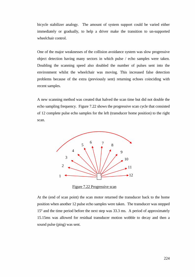
224
bicycle stabilizer analogy. The amount of system support could be varied either
immediately or gradually, to help a driver make the transition to un-supported
wheelchair control.
One of the major weaknesses of the collision avoidance system was slow progressive
object detection having many sectors in which pulse / echo samples were taken.
Doubling the scanning speed also doubled the number of pulses sent into the
environment whilst the wheelchair was moving. This increased false detection
problems because of the extra (previously sent) returning echoes coinciding with
recent samples.
A new scanning method was created that halved the scan time but did not double the
echo sampling frequency. Figure 7.22 shows the progressive scan cycle that consisted
of 12 complete pulse echo samples for the left (transducer home position) to the right
scan.
At the (end of scan point) the scan motor returned the transducer back to the home
position when another 12 pulse echo samples were taken. The transducer was stepped
15º and the time period before the next step was 33.3 ms. A period of approximately
15.15ms was allowed for residual transducer motion wobble to decay and then a
sound pulse (ping) was sent.
1
3
5 7
9
11
10
12
8 6
4
2
Figure 7.22 Progressive scan
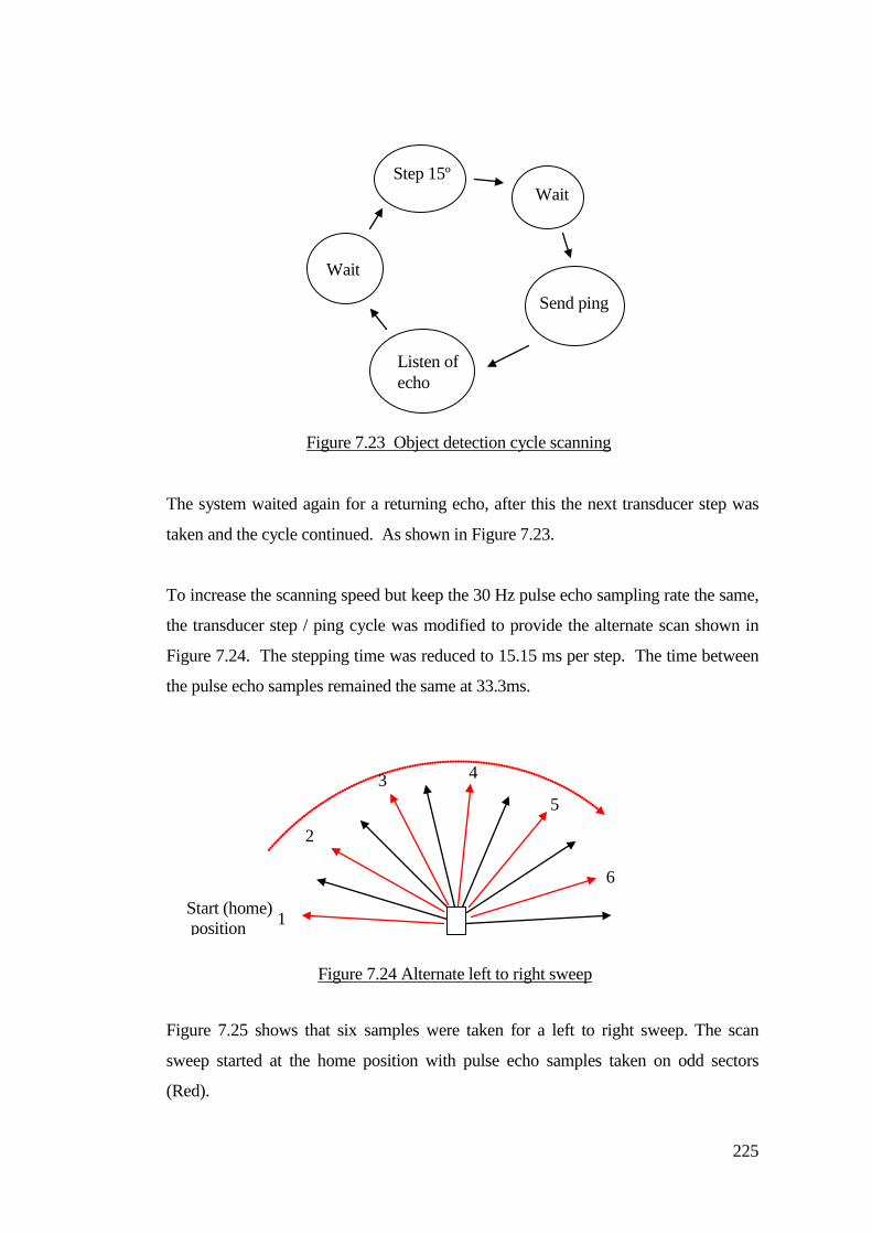
225
The system waited again for a returning echo, after this the next transducer step was
taken and the cycle continued. As shown in Figure 7.23.
To increase the scanning speed but keep the 30 Hz pulse echo sampling rate the same,
the transducer step / ping cycle was modified to provide the alternate scan shown in
Figure 7.24. The stepping time was reduced to 15.15 ms per step. The time between
the pulse echo samples remained the same at 33.3ms.
Figure 7.25 shows that six samples were taken for a left to right sweep. The scan
sweep started at the home position with pulse echo samples taken on odd sectors
(Red).
Step 15º
Send ping
Listen of echo
Wait
Wait
Figure 7.23 Object detection cycle scanning
1
2
3 4
5
6
Figure 7.24 Alternate left to right sweep
Start (home) position
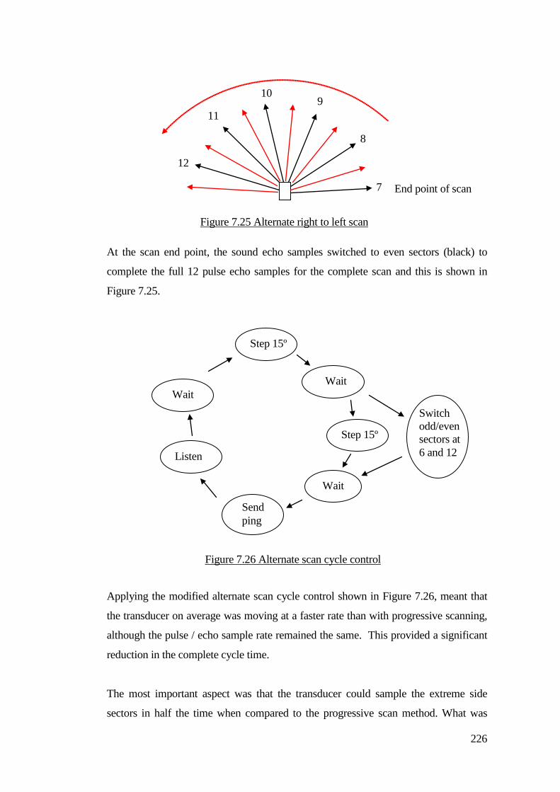
226
At the scan end point, the sound echo samples switched to even sectors (black) to
complete the full 12 pulse echo samples for the complete scan and this is shown in
Figure 7.25.
Applying the modified alternate scan cycle control shown in Figure 7.26, meant that
the transducer on average was moving at a faster rate than with progressive scanning,
although the pulse / echo sample rate remained the same. This provided a significant
reduction in the complete cycle time.
The most important aspect was that the transducer could sample the extreme side
sectors in half the time when compared to the progressive scan method. What was
12
11
10 9
8
7
Figure 7.25 Alternate right to left scan
End point of scan
Step 15º
Wait
Step 15º
Wait
Send ping
Switch odd/even sectors at 6 and 12 Listen
Wait
Figure 7.26 Alternate scan cycle control
227
particularly interesting was the rapidly moving transducer reduced false detection due
to ghosting. Subsequently the sample frequency was raised to 50Hz. This further
reduced the sweep cycle time. Therefore an approximation for a 20ms sample rate
was 20ms X 12 sectors for a complete sweep of 240ms. This was an improved figure
when compared to the 732.6 ms for the progressive full scan time and 333ms for the
progressive half scan method. The signal scattering in the sensed environment was
reduced by lowering the transmitted power of the ping by adding a current limiting
resistor to the transducer pulse transformer. This also limited the effect on other near-
by systems.
7.10 Connections to the moving transducer The rapidly moving transducer placed an increased strain on the transducer connecting
wires and consequently the system failed to detect objects due to wire fatigue. A new
method of connection was created that was similar to the spiral wire connection used
in moving coil meters. This consisted of a small wire bobbin which formed part of the
transducer mounting base. Several turns of narrow gauge twin insulated wire was
wound onto the bobbin and fixed to a stationary point for making the connection to
the ranging circuit board. The other end of the twin wire was connected to the
transducer. The reciprocating motion of the motor and associated mounted transducer
caused the wire to wind and unwind without causing bending that could cause a wire
fracture. Long term testing of this connection method concluded that this was a
satisfactory method and at the time of writing there has not been a failure due to wire
fatigue after five or more years of use.
7.11 Sensor vulnerability The SCAD head enclosure was constructed to provide acoustic transparency and
robustness. Construction of the enclosure incorporated mechanical scan limit stops.
The protection bars were angled to reduce internal signal scattering and self pick-up.
The position of the sensor head with respect to the wheelchair frame required an
adjustable mounting to enable it to scan the extreme side sectors with sufficient
clearance to avoid detecting the castor wheels when they swivelled forwards, for
example, when the chair was driven backwards.
228
When wheelchairs were loaded into and out of transport vehicles the SCAD sensor
could get damaged, becoming caught on tail lifts for example. Additionally, children
were pushed around places where there were curbs and un-even ground. Ongoing
work incorporated dual sensor mountings for both SCAD and track sensors and
consideration was given to the design of swing away sensor mountings. Detachable
sensor mountings were built for both track and the SCAD sensor enclosures, including
the electrical interconnections. This was particularly needed for drivers who had their
own wheelchair that went home with them.
Methods were considered to reduce sensor vulnerability. The sensor was vulnerable
because it needed to protrude beyond the front castor wheels, particularly when they
swivelled forward during reversing. If the sensor was mounted further back (so it did
not protrude) then when driving forwards, the castors would be trailing and did not
cause problems. From a functional perspective, the guidance system would operate.
It was only after a reverse manoeuvre that this mounting position became
impracticable because the castors swivelled back and obscured the side sectors.
The main reason that the SCAD sensor was placed at the front wheelchair was to
provide detection clearance when the chair was driven backwards and the castors
swivelled forwards. After a reverse manoeuvre, the chair could not be driven
forwards because of the detection of the front castors. For this reason the sensor head
scan needed to be clear and this made it vulnerable. Two methods were considered to
reduce the problem of castor detection when they swivelled forwards, castor position
switch and side sector muting.
Castor position switch.
A magnet was attached on the castor swivel bearing and a
reed relay on the wheelchair frame provided two switching points to denote the
obscuring position. The switched output disabled the extreme left and right side
object detection zones to stop castor detection. The castor angle switches detected
when the castors swivelled back to a trailing position after the chair started to move
forwards.
Side sector muting. The extreme side sectors were affected by the castor. A muting
distance was considered that electronically blocked detection for objects at the
229
distance that the castor was detected. The SCAD head was positioned near to the
ground. Ground clearance and the functional sensing position were considered. The
castor detection distance was constant and within a defined (castor) limit or range
band. The extreme side sectors would detect a castor, but they might respond to a
detected object within the defined limit, thus creating an exclusion zone. Control
action would not be applied if an object was detected in the exclusion zone but
collision intervention would occur if the object was detected outside of the exclusion
zone.
The castor position switch and side sector muting options were not incorporated into
the systems and work continued with a fixed mounting system. The footrests tended
to be above the SCAD sensor. Taller children needed their footrest lowered to
accommodate leg length. This caused problems with detection of the underside of the
footrest fixing assemblies. Detection of the underside of the footrest was reduced by
fixing a flat metal sheet on the under side of the footrest. The sheet covered irregular
mounting attachments, the flat surface did not reflect back to the sensor.
Sensor ground clearance was a balance between the unwanted detection of ground
surface irregularities and slopes. The low level SCAD mounting was good for the
detection of shoes, people and animals at ground level. Importantly the sensor was
vulnerable to damage from skimming and striking ground objects, door thresholds,
and loading in and out of transport vehicles. The SCAD head could get damaged
when being pushed around by helpers. Resilient mounting structures using shock
absorbing exhaust (type) flexible rubber bushes were also investigated. This could all
be considered in future work.
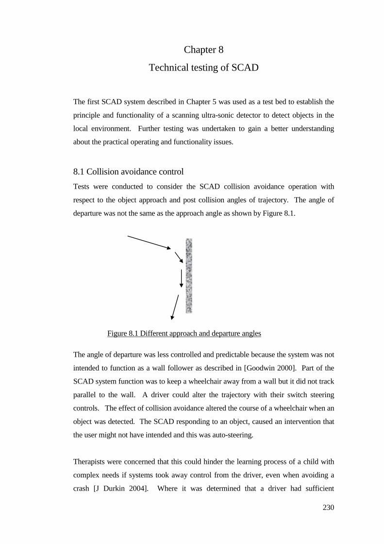
230
Chapter 8
Technical testing of SCAD
The first SCAD system described in Chapter 5 was used as a test bed to establish the
principle and functionality of a scanning ultra-sonic detector to detect objects in the
local environment. Further testing was undertaken to gain a better understanding
about the practical operating and functionality issues.
8.1 Collision avoidance control
Tests were conducted to consider the SCAD collision avoidance operation with
respect to the object approach and post collision angles of trajectory. The angle of
departure was not the same as the approach angle as shown by Figure 8.1.
The angle of departure was less controlled and predictable because the system was not
intended to function as a wall follower as described in [Goodwin 2000]. Part of the
SCAD system function was to keep a wheelchair away from a wall but it did not track
parallel to the wall. A driver could alter the trajectory with their switch steering
controls. The effect of collision avoidance altered the course of a wheelchair when an
object was detected. The SCAD responding to an object, caused an intervention that
the user might not have intended and this was auto-steering.
Therapists were concerned that this could hinder the learning process of a child with
complex needs if systems took away control from the driver, even when avoiding a
crash [J Durkin 2004]. Where it was determined that a driver had sufficient
Figure 8.1 Different approach and departure angles
231
understanding of collision avoidance and the reason why, then this became less
controversial. Then the operation was referred to as ‘energy conserving’, where the
driver was relived of some of the burden of steering and crashing.
During the research, the collision strategy was reviewed so that the auto-steering
function could be switched ‘off’. This meant that when a chair was on course for a
collision, the associated direction was halted without any applied automatic
correction. This intervention strategy did not alter the course of the wheelchair when
an object had been detected, instead it halted the wheelchair. The driver was required
to problem solve in order to proceed. Introducing a wall following mode of operation
was not considered because it might confuse a child about how their wheelchair was
functioning. That could be the subject of future research.
8.2 Angular resolution of the scanning system for object detection
The SCAD system was intended to function as a reflex system where the driver
provided the course planning and the intention to drive to selected places. The SCAD
system intervened at the closest point to avoid a collision or provide a short term
course correction. This minimised the system bias upon the driver’s intent to control
their wheelchair. The system bias relating to the collision avoidance system formed a
major part of the work involved in the creation of the SCAD.
Other supportive systems intended to provide environmental clues where the driver
was within their environment. This was the subject of subsidiary audio signpost
systems developed by the author of this Dissertation.
The dispersion angle of the transmitted sound pulse varied depending on the object
distance from the transducer. The greatest sensing width occurred at the extremes of
the set sensing distance.
8.2.1 Specular reflection and transducer polar response
The polar response diagram for the transducer is shown in Figure 8.2.
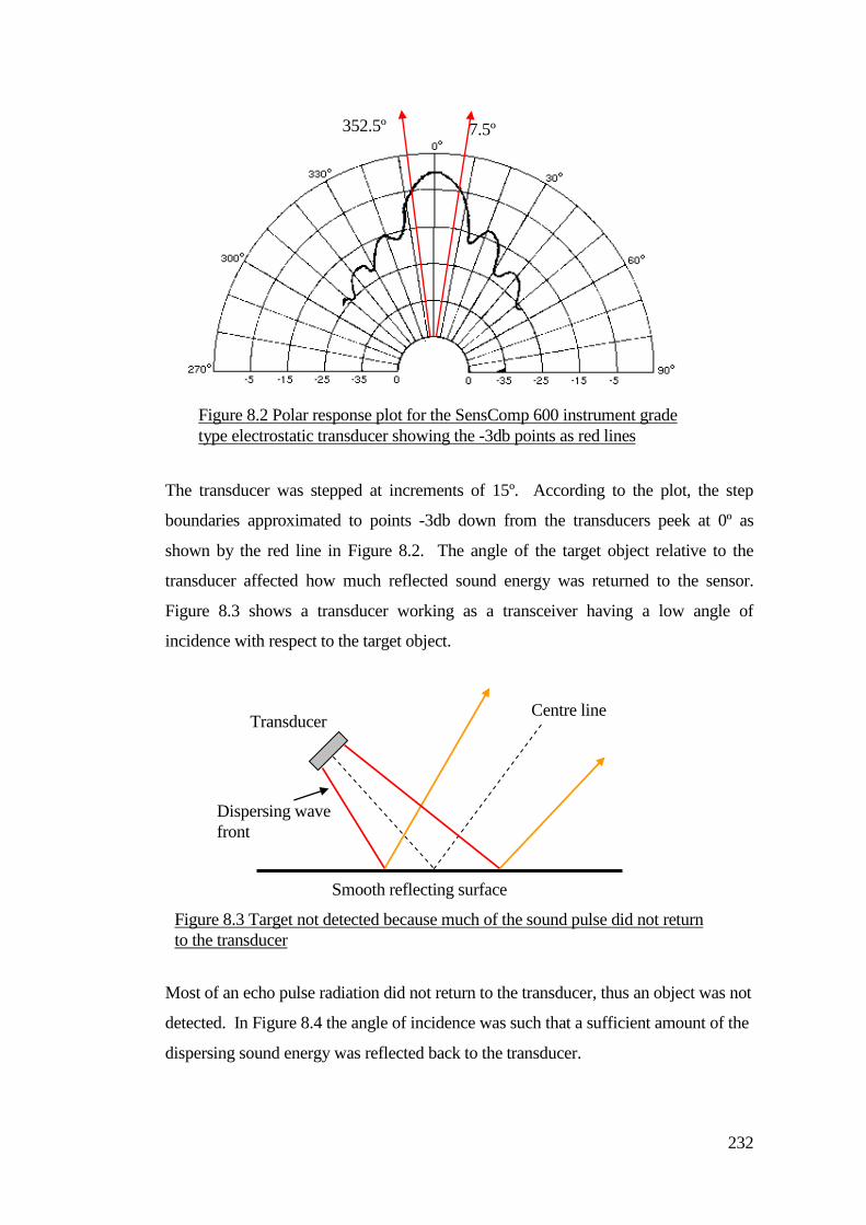
232
The transducer was stepped at increments of 15º. According to the plot, the step
boundaries approximated to points -3db down from the transducers peek at 0º as
shown by the red line in Figure 8.2. The angle of the target object relative to the
transducer affected how much reflected sound energy was returned to the sensor.
Figure 8.3 shows a transducer working as a transceiver having a low angle of
incidence with respect to the target object.
Most of an echo pulse radiation did not return to the transducer, thus an object was not
detected. In Figure 8.4 the angle of incidence was such that a sufficient amount of the
dispersing sound energy was reflected back to the transducer.
Centre line Transducer
Dispersing wave
front
Smooth reflecting surface
Figure 8.3 Target not detected because much of the sound pulse did not return
to the transducer
Figure 8.2 Polar response plot for the SensComp 600 instrument grade
type electrostatic transducer showing the -3db points as red lines
7.5º 352.5º
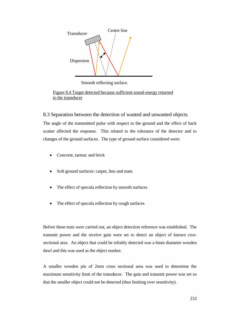
233
8.3 Separation between the detection of wanted and unwanted objects
The angle of the transmitted pulse with respect to the ground and the effect of back
scatter affected the response. This related to the tolerance of the detector and to
changes of the ground surfaces. The type of ground surface considered were:
Concrete, tarmac and brick
Soft ground surfaces: carpet, lino and mats
The effect of specula reflection by smooth surfaces
The effect of specula reflection by rough surfaces
Before these tests were carried out, an object detection reference was established. The
transmit power and the receive gain were set to detect an object of known cros-
sectional area. An object that could be reliably detected was a 6mm diameter wooden
dawl and this was used as the object marker.
A smaller wooden pin of 2mm cross sectional area was used to determine the
maximum sensitivity limit of the transducer. The gain and transmit power was set so
that the smaller object could not be detected (thus limiting over sensitivity).
Centre line Transducer
Dispersion
angle
Smooth reflecting surface.
Figure 8.4 Target detected because sufficient sound energy returned
to the transducer
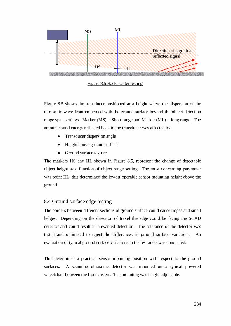
234
Figure 8.5 shows the transducer positioned at a height where the dispersion of the
ultrasonic wave front coincided with the ground surface beyond the object detection
range span settings. Marker (MS) = Short range and Marker (ML) = long range. The
amount sound energy reflected back to the transducer was affected by:
Transducer dispersion angle
Height above ground surface
Ground surface texture
The markers HS and HL shown in Figure 8.5, represent the change of detectable
object height as a function of object range setting. The most concerning parameter
was point HL, this determined the lowest operable sensor mounting height above the
ground.
8.4 Ground surface edge testing
The borders between different sections of ground surface could cause ridges and small
ledges. Depending on the direction of travel the edge could be facing the SCAD
detector and could result in unwanted detection. The tolerance of the detector was
tested and optimised to reject the differences in ground surface variations. An
evaluation of typical ground surface variations in the test areas was conducted.
This determined a practical sensor mounting position with respect to the ground
surfaces. A scanning ultrasonic detector was mounted on a typical powered
wheelchair between the front casters. The mounting was height adjustable.
Figure 8.5 Back scatter testing
HL HS
ML MS
Direction of significant
reflected signal
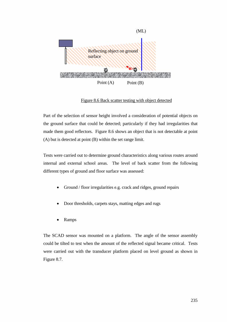
235
Part of the selection of sensor height involved a consideration of potential objects on
the ground surface that could be detected; particularly if they had irregularities that
made them good reflectors. Figure 8.6 shows an object that is not detectable at point
(A) but is detected at point (B) within the set range limit.
Tests were carried out to determine ground characteristics along various routes around
internal and external school areas. The level of back scatter from the following
different types of ground and floor surface was assessed:
Ground / floor irregularities e.g. crack and ridges, ground repairs
Door thresholds, carpets stays, matting edges and rugs
Ramps
The SCAD sensor was mounted on a platform. The angle of the sensor assembly
could be tilted to test when the amount of the reflected signal became critical. Tests
were carried out with the transducer platform placed on level ground as shown in
Figure 8.7.
Figure 8.6 Back scatter testing with object detected
Reflecting object on ground
surface
Point (A) Point (B)
(ML)
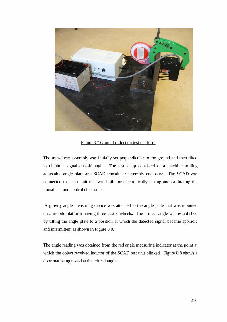
236
The transducer assembly was initially set perpendicular to the ground and then tilted
to obtain a signal cut-off angle. The test setup consisted of a machine milling
adjustable angle plate and SCAD transducer assembly enclosure. The SCAD was
connected to a test unit that was built for electronically testing and calibrating the
transducer and control electronics.
A gravity angle measuring device was attached to the angle plate that was mounted
on a mobile platform having three castor wheels. The critical angle was established
by tilting the angle plate to a position at which the detected signal became sporadic
and intermittent as shown in Figure 8.8.
The angle reading was obtained from the red angle measuring indicator at the point at
which the object received indictor of the SCAD test unit blinked. Figure 8.8 shows a
door mat being tested at the critical angle.
Figure 8.7 Ground reflection test platform
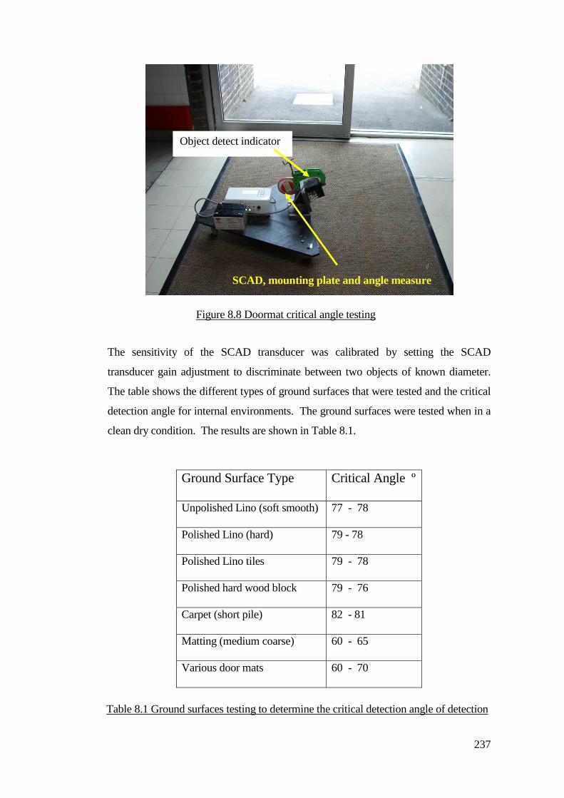
237
The sensitivity of the SCAD transducer was calibrated by setting the SCAD
transducer gain adjustment to discriminate between two objects of known diameter.
The table shows the different types of ground surfaces that were tested and the critical
detection angle for internal environments. The ground surfaces were tested when in a
clean dry condition. The results are shown in Table 8.1.
Ground Surface Type Critical Angle º
Unpolished Lino (soft smooth) 77 - 78
Polished Lino (hard) 79 - 78
Polished Lino tiles 79 - 78
Polished hard wood block 79 - 76
Carpet (short pile) 82 - 81
Matting (medium coarse) 60 - 65
Various door mats 60 - 70
Object detect indicator
SCAD, mounting plate and angle measure
Figure 8.8 Doormat critical angle testing
Table 8.1 Ground surfaces testing to determine the critical detection angle of detection
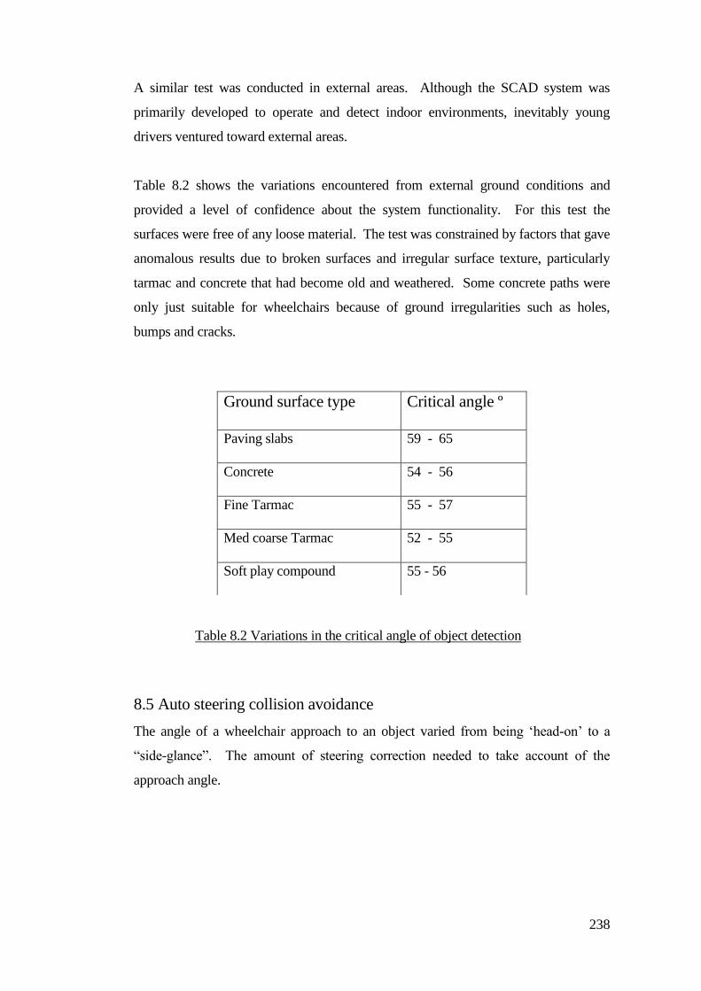
238
A similar test was conducted in external areas. Although the SCAD system was
primarily developed to operate and detect indoor environments, inevitably young
drivers ventured toward external areas.
Table 8.2 shows the variations encountered from external ground conditions and
provided a level of confidence about the system functionality. For this test the
surfaces were free of any loose material. The test was constrained by factors that gave
anomalous results due to broken surfaces and irregular surface texture, particularly
tarmac and concrete that had become old and weathered. Some concrete paths were
only just suitable for wheelchairs because of ground irregularities such as holes,
bumps and cracks.
8.5 Auto steering collision avoidance
The angle of a wheelchair approach to an object varied from being ‘head-on’ to a
“side-glance”. The amount of steering correction needed to take account of the
approach angle.
Ground surface type Critical angle º
Paving slabs 59 - 65
Concrete 54 - 56
Fine Tarmac 55 - 57
Med coarse Tarmac 52 - 55
Soft play compound 55 - 56
Table 8.2 Variations in the critical angle of object detection
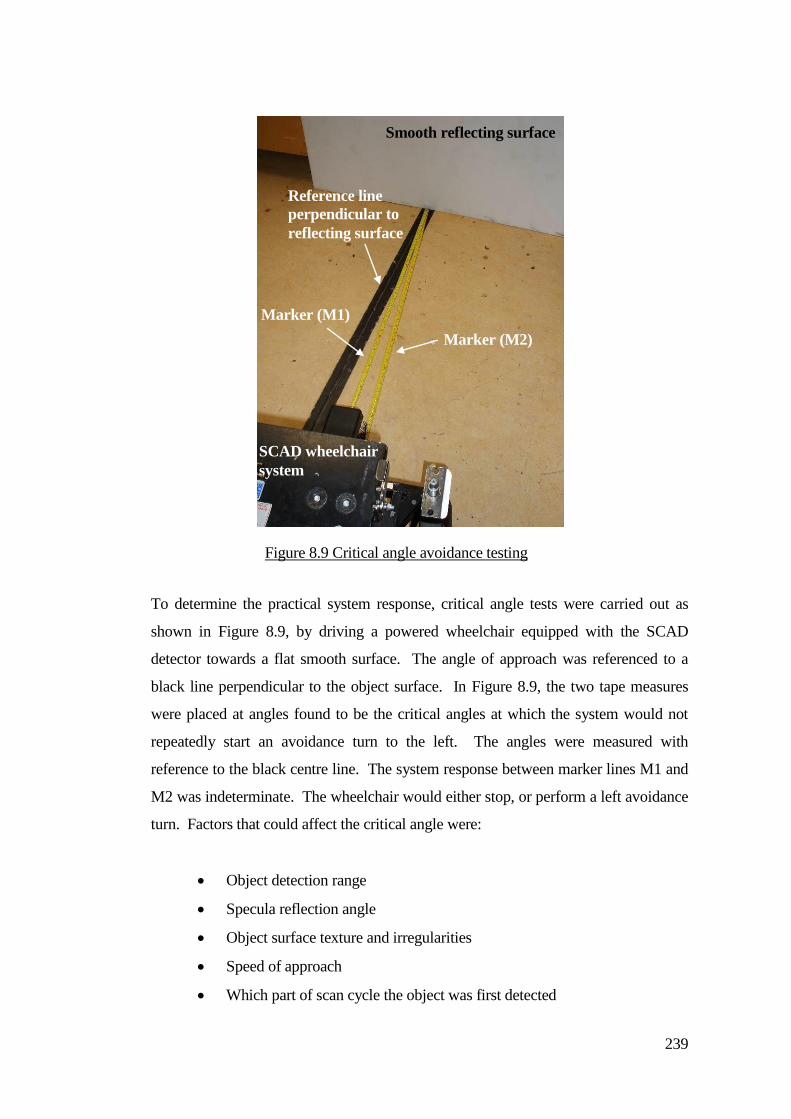
239
To determine the practical system response, critical angle tests were carried out as
shown in Figure 8.9, by driving a powered wheelchair equipped with the SCAD
detector towards a flat smooth surface. The angle of approach was referenced to a
black line perpendicular to the object surface. In Figure 8.9, the two tape measures
were placed at angles found to be the critical angles at which the system would not
repeatedly start an avoidance turn to the left. The angles were measured with
reference to the black centre line. The system response between marker lines M1 and
M2 was indeterminate. The wheelchair would either stop, or perform a left avoidance
turn. Factors that could affect the critical angle were:
Object detection range
Specula reflection angle
Object surface texture and irregularities
Speed of approach
Which part of scan cycle the object was first detected
Marker (M2)
Reference line
perpendicular to
reflecting surface
Marker (M1)
SCAD wheelchair
system
Smooth reflecting surface
Figure 8.9 Critical angle avoidance testing
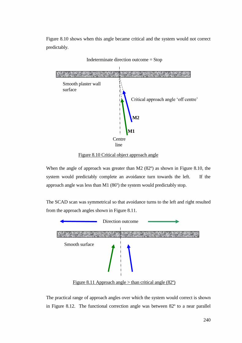
240
Figure 8.10 shows when this angle became critical and the system would not correct
predictably.
When the angle of approach was greater than M2 (82º) as shown in Figure 8.10, the
system would predictably complete an avoidance turn towards the left. If the
approach angle was less than M1 (86º) the system would predictably stop.
The SCAD scan was symmetrical so that avoidance turns to the left and right resulted
from the approach angles shown in Figure 8.11.
The practical range of approach angles over which the system would correct is shown
in Figure 8.12. The functional correction angle was between 82º to a near parallel
Critical approach angle ‘off centre’
Direction outcome
Figure 8.11 Approach angle > than critical angle (82º)
Smooth surface
Figure 8.10 Critical object approach angle
Indeterminate direction outcome = Stop
Smooth plaster wall
surface
M1
M2
Centre
line
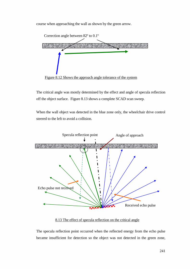
241
course when approaching the wall as shown by the green arrow.
The critical angle was mostly determined by the effect and angle of specula reflection
off the object surface. Figure 8.13 shows a complete SCAD scan sweep.
When the wall object was detected in the blue zone only, the wheelchair drive control
steered to the left to avoid a collision.
The specula reflection point occurred when the reflected energy from the echo pulse
became insufficient for detection so the object was not detected in the green zone,
8.13 The effect of specula reflection on the critical angle
Correction angle between 82º to 0.1º
Figure 8.12 Shows the approach angle tolerance of the system
Specula reflection point
Received echo pulse
Echo pulse not received
Angle of approach
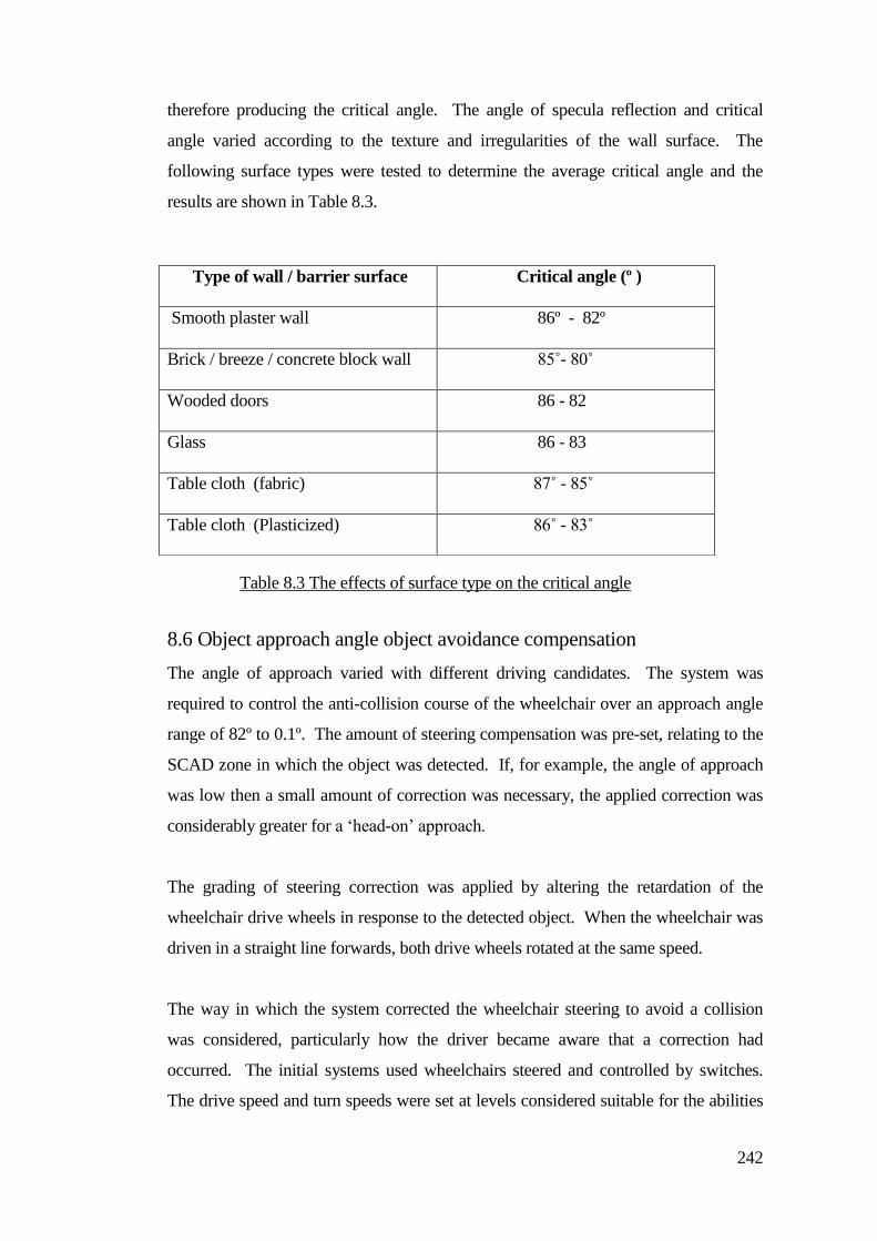
242
therefore producing the critical angle. The angle of specula reflection and critical
angle varied according to the texture and irregularities of the wall surface. The
following surface types were tested to determine the average critical angle and the
results are shown in Table 8.3.
8.6 Object approach angle object avoidance compensation
The angle of approach varied with different driving candidates. The system was
required to control the anti-collision course of the wheelchair over an approach angle
range of 82º to 0.1º. The amount of steering compensation was pre-set, relating to the
SCAD zone in which the object was detected. If, for example, the angle of approach
was low then a small amount of correction was necessary, the applied correction was
considerably greater for a ‘head-on’ approach.
The grading of steering correction was applied by altering the retardation of the
wheelchair drive wheels in response to the detected object. When the wheelchair was
driven in a straight line forwards, both drive wheels rotated at the same speed.
The way in which the system corrected the wheelchair steering to avoid a collision
was considered, particularly how the driver became aware that a correction had
occurred. The initial systems used wheelchairs steered and controlled by switches.
The drive speed and turn speeds were set at levels considered suitable for the abilities
Type of wall / barrier surface Critical angle (º )
Smooth plaster wall 86º - 82º
Brick / breeze / concrete block wall 85˚- 80˚
Wooded doors 86 - 82
Glass 86 - 83
Table cloth (fabric) 87˚ - 85˚
Table cloth (Plasticized) 86˚ - 83˚
Table 9.3
Table 8.3 The effects of surface type on the critical angle
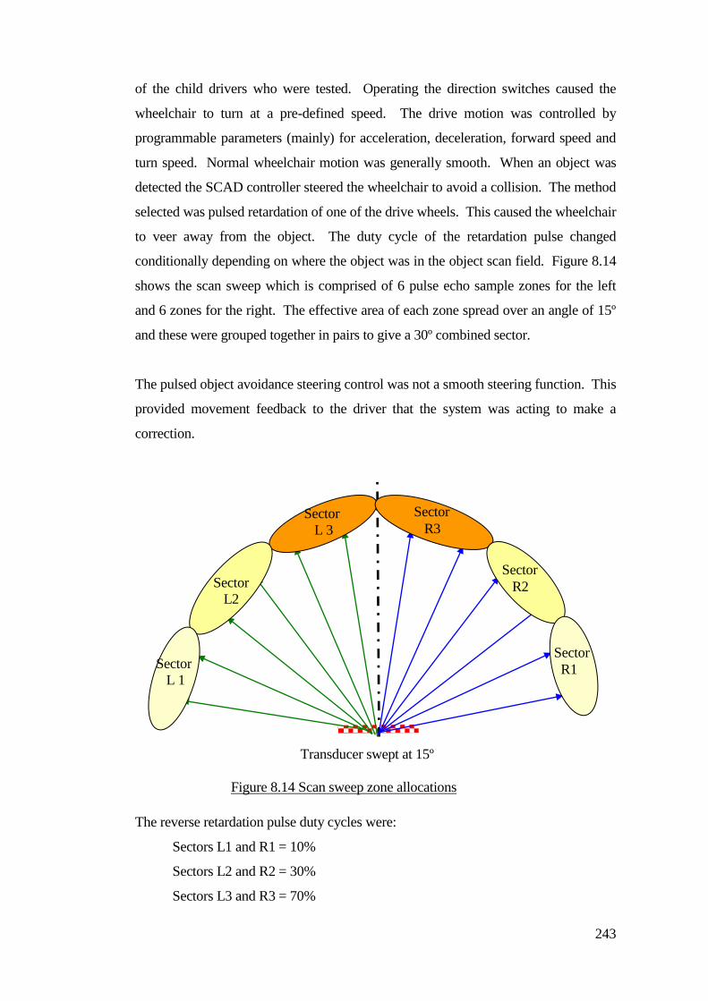
243
of the child drivers who were tested. Operating the direction switches caused the
wheelchair to turn at a pre-defined speed. The drive motion was controlled by
programmable parameters (mainly) for acceleration, deceleration, forward speed and
turn speed. Normal wheelchair motion was generally smooth. When an object was
detected the SCAD controller steered the wheelchair to avoid a collision. The method
selected was pulsed retardation of one of the drive wheels. This caused the wheelchair
to veer away from the object. The duty cycle of the retardation pulse changed
conditionally depending on where the object was in the object scan field. Figure 8.14
shows the scan sweep which is comprised of 6 pulse echo sample zones for the left
and 6 zones for the right. The effective area of each zone spread over an angle of 15º
and these were grouped together in pairs to give a 30º combined sector.
The pulsed object avoidance steering control was not a smooth steering function. This
provided movement feedback to the driver that the system was acting to make a
correction.
The reverse retardation pulse duty cycles were:
Sectors L1 and R1 = 10%
Sectors L2 and R2 = 30%
Sectors L3 and R3 = 70%
Sector
L 1
Sector
L2
Sector
L 3
Transducer swept at 15º
increments.
Sector
R3
Sector
R2
Sector
R1
Figure 8.14 Scan sweep zone allocations
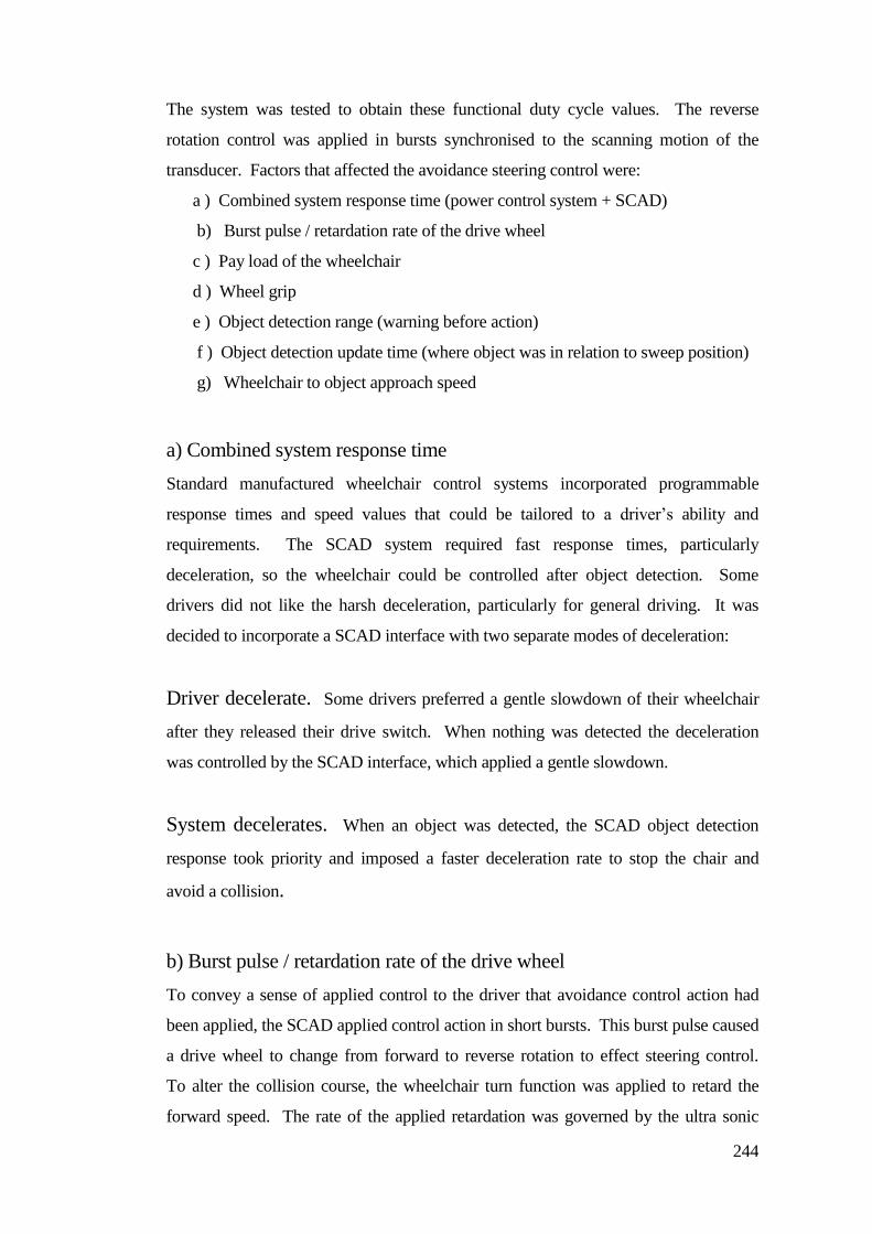
244
The system was tested to obtain these functional duty cycle values. The reverse
rotation control was applied in bursts synchronised to the scanning motion of the
transducer. Factors that affected the avoidance steering control were:
a ) Combined system response time (power control system + SCAD)
b) Burst pulse / retardation rate of the drive wheel
c ) Pay load of the wheelchair
d ) Wheel grip
e ) Object detection range (warning before action)
f ) Object detection update time (where object was in relation to sweep position)
g) Wheelchair to object approach speed
a) Combined system response time
Standard manufactured wheelchair control systems incorporated programmable
response times and speed values that could be tailored to a driver’s ability and
requirements. The SCAD system required fast response times, particularly
deceleration, so the wheelchair could be controlled after object detection. Some
drivers did not like the harsh deceleration, particularly for general driving. It was
decided to incorporate a SCAD interface with two separate modes of deceleration:
Driver decelerate. Some drivers preferred a gentle slowdown of their wheelchair
after they released their drive switch. When nothing was detected the deceleration
was controlled by the SCAD interface, which applied a gentle slowdown.
System decelerates. When an object was detected, the SCAD object detection
response took priority and imposed a faster deceleration rate to stop the chair and
avoid a collision.
b) Burst pulse / retardation rate of the drive wheel
To convey a sense of applied control to the driver that avoidance control action had
been applied, the SCAD applied control action in short bursts. This burst pulse caused
a drive wheel to change from forward to reverse rotation to effect steering control.
To alter the collision course, the wheelchair turn function was applied to retard the
forward speed. The rate of the applied retardation was governed by the ultra sonic
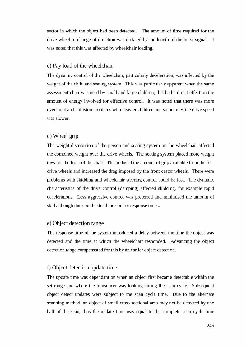
245
sector in which the object had been detected. The amount of time required for the
drive wheel to change of direction was dictated by the length of the burst signal. It
was noted that this was affected by wheelchair loading.
c) Pay load of the wheelchair
The dynamic control of the wheelchair, particularly deceleration, was affected by the
weight of the child and seating system. This was particularly apparent when the same
assessment chair was used by small and large children; this had a direct effect on the
amount of energy involved for effective control. It was noted that there was more
overshoot and collision problems with heavier children and sometimes the drive speed
was slower.
d) Wheel grip
The weight distribution of the person and seating system on the wheelchair affected
the combined weight over the drive wheels. The seating system placed more weight
towards the front of the chair. This reduced the amount of grip available from the rear
drive wheels and increased the drag imposed by the front castor wheels. There were
problems with skidding and wheelchair steering control could be lost. The dynamic
characteristics of the drive control (damping) affected skidding, for example rapid
decelerations. Less aggressive control was preferred and minimised the amount of
skid although this could extend the control response times.
e) Object detection range
The response time of the system introduced a delay between the time the object was
detected and the time at which the wheelchair responded. Advancing the object
detection range compensated for this by an earlier object detection.
f) Object detection update time
The update time was dependant on when an object first became detectable within the
set range and where the transducer was looking during the scan cycle. Subsequent
object detect updates were subject to the scan cycle time. Due to the alternate
scanning method, an object of small cross sectional area may not be detected by one
half of the scan, thus the update time was equal to the complete scan cycle time
246
including the time of flight delay. Larger objects could be detected on both halves of
the scan; therefore two updates would occur for a complete sweep cycle.
g) Wheelchair to object approach speed
To increase the control time for object avoidance the scan range was increased and
this restricted some drivers. The slow speed of driving frustrated many drivers. To
provide a solution for this an additional scan zone was applied and is shown in Figure
8.15. This provided an extended outer zone that acted as a pre-slow-down prior to
control intervention. This provided a compromise for accessibility, increased speed in
less confined areas and provided more time for the control system to exercise a control
manoeuvre.
8.7 Mounting position for the SCAD head
When children and young adults used their powered wheelchair they were usually
supported by special seating systems.
Left control
Zone
Right control
zone
Extended outer zone
pre-slowdown
SCAD
Figure 8.15 Extended outer zone
247
Chailey Heritage Engineering had conducted some research and developed the
Chailey Adjustable Posture Seat (CAPS) systems shown in Figure 8.16. These also
incorporated a tray that was detachable from the seat. The child and the CAPS needed
to be transferable to enable the child access to their powered wheelchair.
A multi-element sensor array was considered. Multiple transducer units had been
used on smart systems. Multi-element sensor arrays needed an enclosure for each
transducer and twelve would be required to provide the same combined sensory field
angle that could be obtained from one single scanning SCAD transducer. Considering
individual transducer matching and overlap characteristics, multiple arrays had the
advantage of firing pulses in different directions at the same time. SCAD had the
advantage of compactness and possible agile scan sequences and profiled range shape.
A single transducer also simplified the amount of required electronics and inter-
connections.
Consideration of SCAD mounting positions included:
a) To cause minimal obstruction when transferring children and seating systems
b) Not affected by the occupant
c) Structural integrity of mountings
Figure 8.16 Adjustable CAPS system
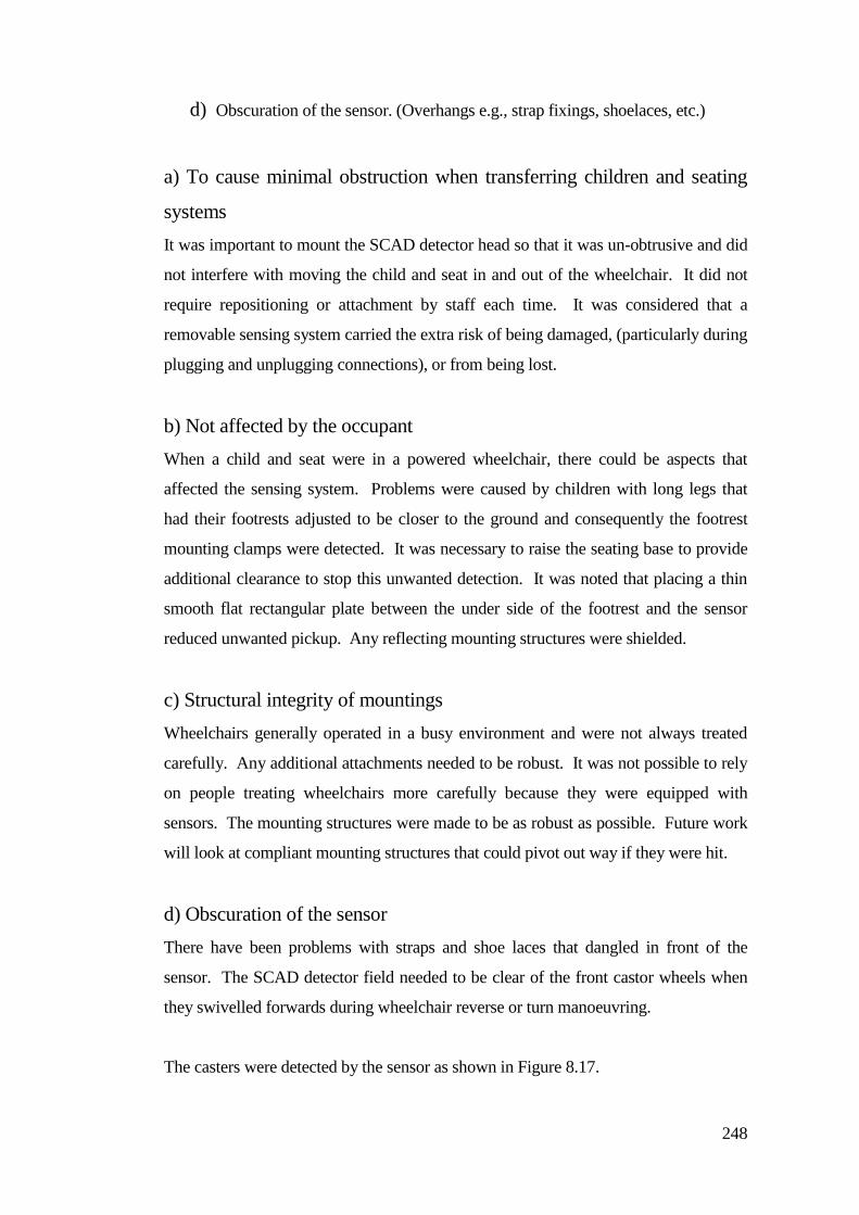
248
d) Obscuration of the sensor. (Overhangs e.g., strap fixings, shoelaces, etc.)
a) To cause minimal obstruction when transferring children and seating
systems
It was important to mount the SCAD detector head so that it was un-obtrusive and did
not interfere with moving the child and seat in and out of the wheelchair. It did not
require repositioning or attachment by staff each time. It was considered that a
removable sensing system carried the extra risk of being damaged, (particularly during
plugging and unplugging connections), or from being lost.
b) Not affected by the occupant
When a child and seat were in a powered wheelchair, there could be aspects that
affected the sensing system. Problems were caused by children with long legs that
had their footrests adjusted to be closer to the ground and consequently the footrest
mounting clamps were detected. It was necessary to raise the seating base to provide
additional clearance to stop this unwanted detection. It was noted that placing a thin
smooth flat rectangular plate between the under side of the footrest and the sensor
reduced unwanted pickup. Any reflecting mounting structures were shielded.
c) Structural integrity of mountings
Wheelchairs generally operated in a busy environment and were not always treated
carefully. Any additional attachments needed to be robust. It was not possible to rely
on people treating wheelchairs more carefully because they were equipped with
sensors. The mounting structures were made to be as robust as possible. Future work
will look at compliant mounting structures that could pivot out way if they were hit.
d) Obscuration of the sensor
There have been problems with straps and shoe laces that dangled in front of the
sensor. The SCAD detector field needed to be clear of the front castor wheels when
they swivelled forwards during wheelchair reverse or turn manoeuvring.
The casters were detected by the sensor as shown in Figure 8.17.
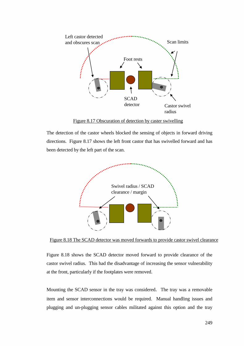
249
The detection of the castor wheels blocked the sensing of objects in forward driving
directions. Figure 8.17 shows the left front castor that has swivelled forward and has
been detected by the left part of the scan.
Figure 8.18 shows the SCAD detector moved forward to provide clearance of the
castor swivel radius. This had the disadvantage of increasing the sensor vulnerability
at the front, particularly if the footplates were removed.
Mounting the SCAD sensor in the tray was considered. The tray was a removable
item and sensor interconnections would be required. Manual handling issues and
plugging and un-plugging sensor cables militated against this option and the tray
SCAD
detector
Foot rests
Castor swivel
radius
Scan limits
Swivel radius / SCAD
clearance / margin
Left castor detected
and obscures scan
Figure 8.17 Obscuration of detection by caster swivelling
Figure 8.18 The SCAD detector was moved forwards to provide castor swivel clearance
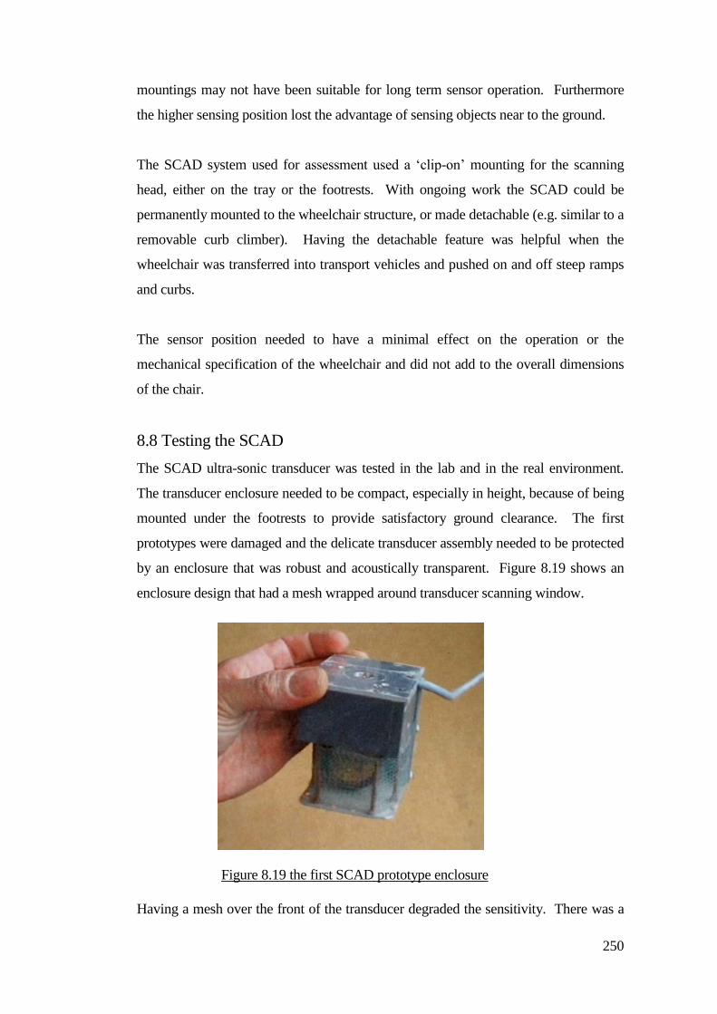
250
mountings may not have been suitable for long term sensor operation. Furthermore
the higher sensing position lost the advantage of sensing objects near to the ground.
The SCAD system used for assessment used a ‘clip-on’ mounting for the scanning
head, either on the tray or the footrests. With ongoing work the SCAD could be
permanently mounted to the wheelchair structure, or made detachable (e.g. similar to a
removable curb climber). Having the detachable feature was helpful when the
wheelchair was transferred into transport vehicles and pushed on and off steep ramps
and curbs.
The sensor position needed to have a minimal effect on the operation or the
mechanical specification of the wheelchair and did not add to the overall dimensions
of the chair.
8.8 Testing the SCAD
The SCAD ultra-sonic transducer was tested in the lab and in the real environment.
The transducer enclosure needed to be compact, especially in height, because of being
mounted under the footrests to provide satisfactory ground clearance. The first
prototypes were damaged and the delicate transducer assembly needed to be protected
by an enclosure that was robust and acoustically transparent. Figure 8.19 shows an
enclosure design that had a mesh wrapped around transducer scanning window.
Having a mesh over the front of the transducer degraded the sensitivity. There was a
Figure 8.19 the first SCAD prototype enclosure
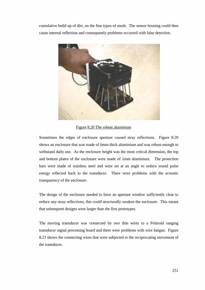
251
cumulative build up of dirt, on the fine types of mesh. The sensor housing could then
cause internal reflection and consequently problems occurred with false detection.
Sometimes the edges of enclosure aperture caused stray reflections. Figure 8.20
shows an enclosure that was made of 6mm thick aluminium and was robust enough to
withstand daily use. As the enclosure height was the most critical dimension, the top
and bottom plates of the enclosure were made of 1mm aluminium. The protection
bars were made of stainless steel and were set at an angle to reduce sound pulse
energy reflected back to the transducer. There were problems with the acoustic
transparency of the enclosure.
The design of the enclosure needed to have an aperture window sufficiently clear to
reduce any stray reflections, this could structurally weaken the enclosure. This meant
that subsequent designs were larger than the first prototypes.
The moving transducer was connected by two thin wires to a Polaroid ranging
transducer signal processing board and there were problems with wire fatigue. Figure
8.21 shows the connecting wires that were subjected to the reciprocating movement of
the transducer.
Figure 8.20 The robust aluminium
enclosure
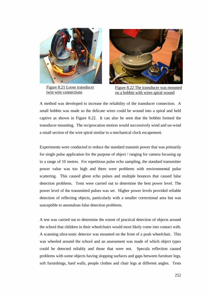
252
A method was developed to increase the reliability of the transducer connection. A
small bobbin was made so the delicate wires could be wound into a spiral and held
captive as shown in Figure 8.22. It can also be seen that the bobbin formed the
transducer mounting. The reciprocation motion would successively wind and un-wind
a small section of the wire spiral similar to a mechanical clock escapement.
Experiments were conducted to reduce the standard transmit power that was primarily
for single pulse application for the purpose of object / ranging for camera focusing up
to a range of 10 metres. For repetitious pulse echo sampling, the standard transmitter
power value was too high and there were problems with environmental pulse
scattering. This caused ghost echo pulses and multiple bounces that caused false
detection problems. Tests were carried out to determine the best power level. The
power level of the transmitted pulses was set. Higher power levels provided reliable
detection of reflecting objects, particularly with a smaller correctional area but was
susceptible to anomalous false detection problems.
A test was carried out to determine the extent of practical detection of objects around
the school that children in their wheelchairs would most likely come into contact with.
A scanning ultra-sonic detector was mounted on the front of a push wheelchair. This
was wheeled around the school and an assessment was made of which object types
could be detected reliably and those that were not. Specula reflection caused
problems with some objects having slopping surfaces and gaps between furniture legs,
soft furnishings, hard walls, people clothes and chair legs at different angles. Tests
Figure 8.21 Loose transducer
twin wire connections Figure 8.22 The transducer was mounted
on a bobbin with wires spiral wound
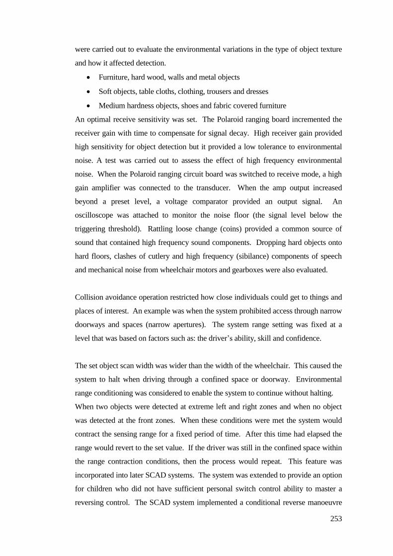
253
were carried out to evaluate the environmental variations in the type of object texture
and how it affected detection.
Furniture, hard wood, walls and metal objects
Soft objects, table cloths, clothing, trousers and dresses
Medium hardness objects, shoes and fabric covered furniture
An optimal receive sensitivity was set. The Polaroid ranging board incremented the
receiver gain with time to compensate for signal decay. High receiver gain provided
high sensitivity for object detection but it provided a low tolerance to environmental
noise. A test was carried out to assess the effect of high frequency environmental
noise. When the Polaroid ranging circuit board was switched to receive mode, a high
gain amplifier was connected to the transducer. When the amp output increased
beyond a preset level, a voltage comparator provided an output signal. An
oscilloscope was attached to monitor the noise floor (the signal level below the
triggering threshold). Rattling loose change (coins) provided a common source of
sound that contained high frequency sound components. Dropping hard objects onto
hard floors, clashes of cutlery and high frequency (sibilance) components of speech
and mechanical noise from wheelchair motors and gearboxes were also evaluated.
Collision avoidance operation restricted how close individuals could get to things and
places of interest. An example was when the system prohibited access through narrow
doorways and spaces (narrow apertures). The system range setting was fixed at a
level that was based on factors such as: the driver’s ability, skill and confidence.
The set object scan width was wider than the width of the wheelchair. This caused the
system to halt when driving through a confined space or doorway. Environmental
range conditioning was considered to enable the system to continue without halting.
When two objects were detected at extreme left and right zones and when no object
was detected at the front zones. When these conditions were met the system would
contract the sensing range for a fixed period of time. After this time had elapsed the
range would revert to the set value. If the driver was still in the confined space within
the range contraction conditions, then the process would repeat. This feature was
incorporated into later SCAD systems. The system was extended to provide an option
for children who did not have sufficient personal switch control ability to master a
reversing control. The SCAD system implemented a conditional reverse manoeuvre
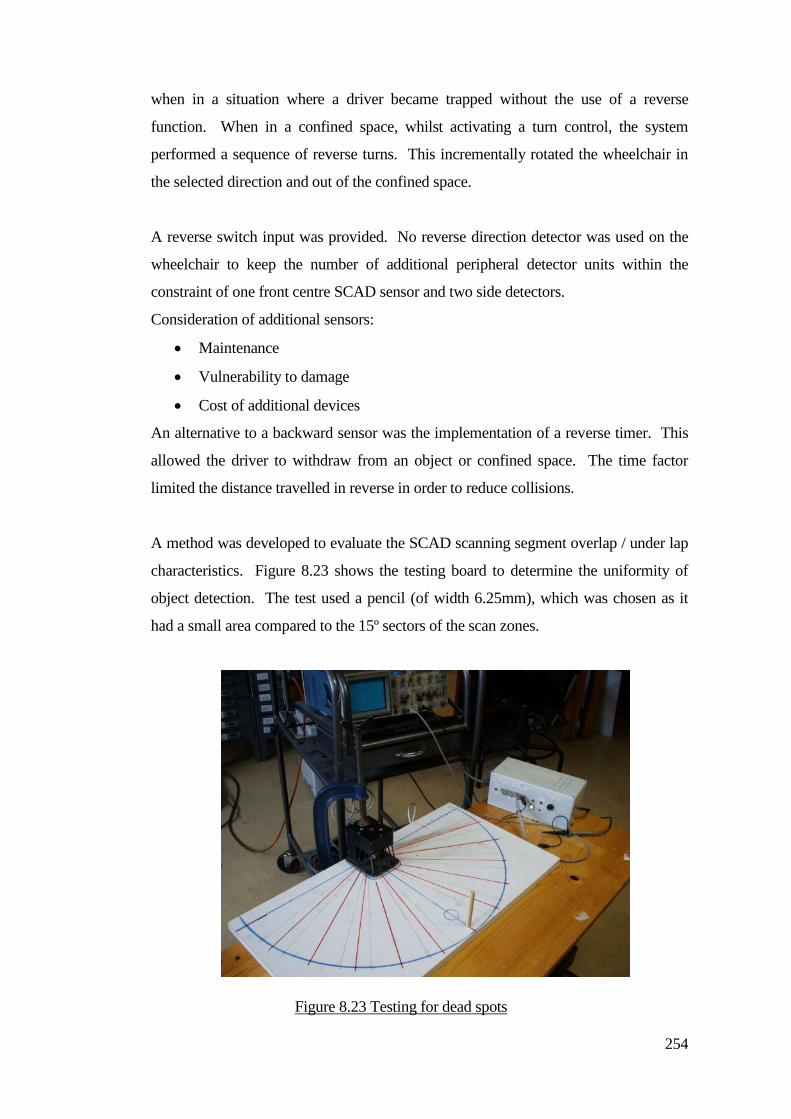
254
when in a situation where a driver became trapped without the use of a reverse
function. When in a confined space, whilst activating a turn control, the system
performed a sequence of reverse turns. This incrementally rotated the wheelchair in
the selected direction and out of the confined space.
A reverse switch input was provided. No reverse direction detector was used on the
wheelchair to keep the number of additional peripheral detector units within the
constraint of one front centre SCAD sensor and two side detectors.
Consideration of additional sensors:
Maintenance
Vulnerability to damage
Cost of additional devices
An alternative to a backward sensor was the implementation of a reverse timer. This
allowed the driver to withdraw from an object or confined space. The time factor
limited the distance travelled in reverse in order to reduce collisions.
A method was developed to evaluate the SCAD scanning segment overlap / under lap
characteristics. Figure 8.23 shows the testing board to determine the uniformity of
object detection. The test used a pencil (of width 6.25mm), which was chosen as it
had a small area compared to the 15º sectors of the scan zones.
Figure 8.23 Testing for dead spots
255
To assess dead spots within the sweep, the pencil was moved across each sector and
dead spots were recorded. The stepper motor, with the mass of the transducer
exhibited resonances that caused changes in the step angle. Tests were carried out to
change motor excitation levels, half stepping, damping, step rate and the mass of the
transducer to improve the uniformity of the sweep zones at a 50Hz pulse sampling
rate. Using reciprocal scanning, the update time for object detection varied depending
on the position of an object within the scan. At the centre, an object was swept twice
as fast as at the extreme sides. Experiments were conducted to increase detection
speed by half scanning when turning corners, but this work was not continued, as half
scanning caused a blind spot on the opposing side of the full scan field.
The first SCAD system used progressive scanning. An assessment was made of the
over and under laps between the sectors in the scan sweep on both clockwise and
counter clockwise scanning directions. There were problems with ghosting. This
worsened when the pulse repetition rate increased, and the chair would stop
inappropriately. This caused significant restrictions with the usable pulse repetition
rate. Problems were encountered by children colliding with objects because of the
slow response of the detection sweep. The speed of the wheelchair was reduced to
provide more time for the system to respond, some drivers became frustrated, and
wanted to drive faster. The detection range was extended to provide an increase in the
time margin for object detection, but this caused problems by restricting access
throughout the driver’s environment.
Experiments were undertaken to decrease the scan cycle time. During turning, the
scan was switched to a half scan sweep to reduce update time. The update time for
object detection varied depending on the position of the object within the scan. At the
centre, the object was swept in less time than at the extreme sides. Experiments were
conducted to increase detection speed by half sweep scanning when turning corners.
A faster complete sweep was needed. Alternate pulse / echo sample was developed,
but that had alternating sector gaps in each scan direction. A full sweep cycle was
twice as fast as sequential / progressive scanning. This effectively interlaced the
sector gaps. Therefore if the left to right sweep missed an object then the right to left
sweep would detect the object. The alternate scan method had an advantage of
increased detection speed.
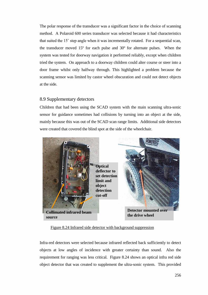
256
The polar response of the transducer was a significant factor in the choice of scanning
method. A Polaroid 600 series transducer was selected because it had characteristics
that suited the 15˚ step angle when it was incrementally rotated. For a sequential scan,
the transducer moved 15º for each pulse and 30º for alternate pulses. When the
system was tested for doorway navigation it performed reliably, except when children
tried the system. On approach to a doorway children could alter course or steer into a
door frame whilst only halfway through. This highlighted a problem because the
scanning sensor was limited by castor wheel obscuration and could not detect objects
at the side.
8.9 Supplementary detectors
Children that had been using the SCAD system with the main scanning ultra-sonic
sensor for guidance sometimes had collisions by turning into an object at the side,
mainly because this was out of the SCAD scan range limits. Additional side detectors
were created that covered the blind spot at the side of the wheelchair.
Infra-red detectors were selected because infrared reflected back sufficiently to detect
objects at low angles of incidence with greater certainty than sound. Also the
requirement for ranging was less critical. Figure 8.24 shows an optical infra red side
object detector that was created to supplement the ultra-sonic system. This provided
Figure 8.24 Infrared side detector with background suppression
Optical
deflector to
set detection
limit and
object
detection
cut-off
Collimated infrared beam
source
Detector mounted over
the drive wheel
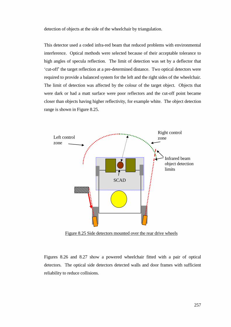
257
detection of objects at the side of the wheelchair by triangulation.
This detector used a coded infra-red beam that reduced problems with environmental
interference. Optical methods were selected because of their acceptable tolerance to
high angles of specula reflection. The limit of detection was set by a deflector that
‘cut-off’ the target reflection at a pre-determined distance. Two optical detectors were
required to provide a balanced system for the left and the right sides of the wheelchair.
The limit of detection was affected by the colour of the target object. Objects that
were dark or had a matt surface were poor reflectors and the cut-off point became
closer than objects having higher reflectivity, for example white. The object detection
range is shown in Figure 8.25.
Figures 8.26 and 8.27 show a powered wheelchair fitted with a pair of optical
detectors. The optical side detectors detected walls and door frames with sufficient
reliability to reduce collisions.
Left control
zone
Right control
zone
SCAD
Infrared beam
object detection
limits
Figure 8.25 Side detectors mounted over the rear drive wheels
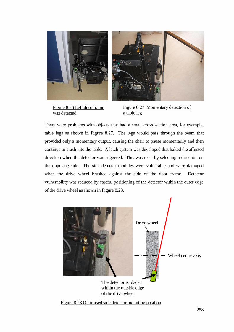
258
There were problems with objects that had a small cross section area, for example,
table legs as shown in Figure 8.27. The legs would pass through the beam that
provided only a momentary output, causing the chair to pause momentarily and then
continue to crash into the table. A latch system was developed that halted the affected
direction when the detector was triggered. This was reset by selecting a direction on
the opposing side. The side detector modules were vulnerable and were damaged
when the drive wheel brushed against the side of the door frame. Detector
vulnerability was reduced by careful positioning of the detector within the outer edge
of the drive wheel as shown in Figure 8.28.
Figure 8.26 Left door frame
was detected
Figure 8.27 Momentary detection of
a table leg
The detector is placed
within the outside edge
of the drive wheel
Wheel centre axis
Drive wheel
Figure 8.28 Optimised side detector mounting position
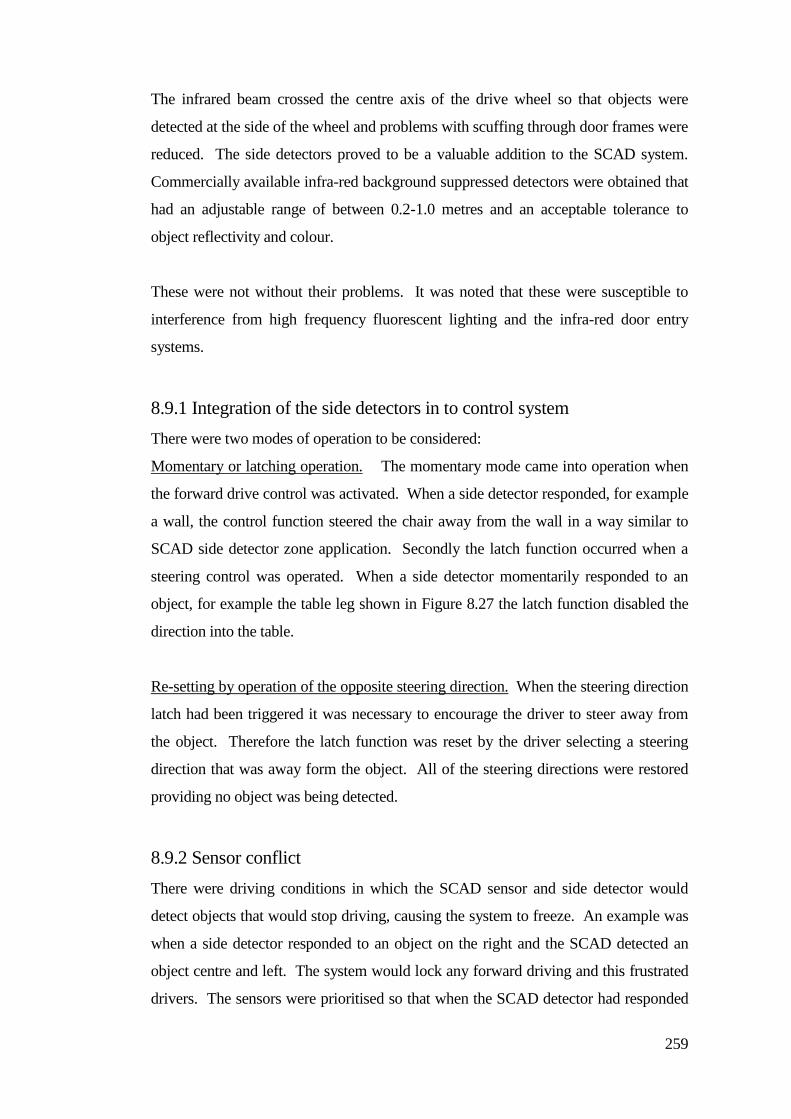
259
The infrared beam crossed the centre axis of the drive wheel so that objects were
detected at the side of the wheel and problems with scuffing through door frames were
reduced. The side detectors proved to be a valuable addition to the SCAD system.
Commercially available infra-red background suppressed detectors were obtained that
had an adjustable range of between 0.2-1.0 metres and an acceptable tolerance to
object reflectivity and colour.
These were not without their problems. It was noted that these were susceptible to
interference from high frequency fluorescent lighting and the infra-red door entry
systems.
8.9.1 Integration of the side detectors in to control system
There were two modes of operation to be considered:
Momentary or latching operation. The momentary mode came into operation when
the forward drive control was activated. When a side detector responded, for example
a wall, the control function steered the chair away from the wall in a way similar to
SCAD side detector zone application. Secondly the latch function occurred when a
steering control was operated. When a side detector momentarily responded to an
object, for example the table leg shown in Figure 8.27 the latch function disabled the
direction into the table.
Re-setting by operation of the opposite steering direction. When the steering direction
latch had been triggered it was necessary to encourage the driver to steer away from
the object. Therefore the latch function was reset by the driver selecting a steering
direction that was away form the object. All of the steering directions were restored
providing no object was being detected.
8.9.2 Sensor conflict
There were driving conditions in which the SCAD sensor and side detector would
detect objects that would stop driving, causing the system to freeze. An example was
when a side detector responded to an object on the right and the SCAD detected an
object centre and left. The system would lock any forward driving and this frustrated
drivers. The sensors were prioritised so that when the SCAD detector had responded
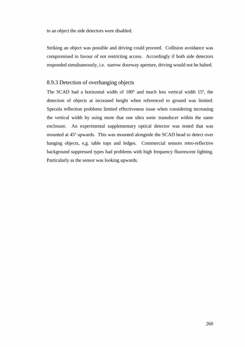
260
to an object the side detectors were disabled.
Striking an object was possible and driving could proceed. Collision avoidance was
compromised in favour of not restricting access. Accordingly if both side detectors
responded simultaneously, i.e. narrow doorway aperture, driving would not be halted.
8.9.3 Detection of overhanging objects
The SCAD had a horizontal width of 180º and much less vertical width 15º, the
detection of objects at increased height when referenced to ground was limited.
Specula reflection problems limited effectiveness issue when considering increasing
the vertical width by using more that one ultra sonic transducer within the same
enclosure. An experimental supplementary optical detector was tested that was
mounted at 45º upwards. This was mounted alongside the SCAD head to detect over
hanging objects, e,g. table tops and ledges. Commercial sensors retro-reflective
background suppressed types had problems with high frequency fluorescent lighting.
Particularly as the sensor was looking upwards.
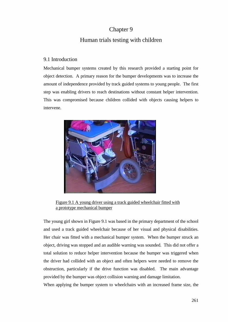
261
Chapter 9
Human trials testing with children
9.1 Introduction
Mechanical bumper systems created by this research provided a starting point for
object detection. A primary reason for the bumper developments was to increase the
amount of independence provided by track guided systems to young people. The first
step was enabling drivers to reach destinations without constant helper intervention.
This was compromised because children collided with objects causing helpers to
intervene.
The young girl shown in Figure 9.1 was based in the primary department of the school
and used a track guided wheelchair because of her visual and physical disabilities.
Her chair was fitted with a mechanical bumper system. When the bumper struck an
object, driving was stopped and an audible warning was sounded. This did not offer a
total solution to reduce helper intervention because the bumper was triggered when
the driver had collided with an object and often helpers were needed to remove the
obstruction, particularly if the drive function was disabled. The main advantage
provided by the bumper was object collision warning and damage limitation.
When applying the bumper system to wheelchairs with an increased frame size, the
Figure 9.1 A young driver using a track guided wheelchair fitted with
a prototype mechanical bumper
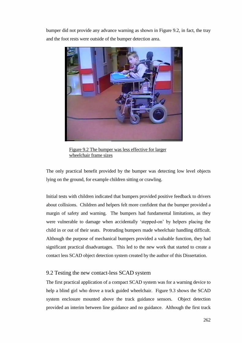
262
bumper did not provide any advance warning as shown in Figure 9.2, in fact, the tray
and the foot rests were outside of the bumper detection area.
The only practical benefit provided by the bumper was detecting low level objects
lying on the ground, for example children sitting or crawling.
Initial tests with children indicated that bumpers provided positive feedback to drivers
about collisions. Children and helpers felt more confident that the bumper provided a
margin of safety and warning. The bumpers had fundamental limitations, as they
were vulnerable to damage when accidentally ‘stepped-on’ by helpers placing the
child in or out of their seats. Protruding bumpers made wheelchair handling difficult.
Although the purpose of mechanical bumpers provided a valuable function, they had
significant practical disadvantages. This led to the new work that started to create a
contact less SCAD object detection system created by the author of this Dissertation.
9.2 Testing the new contact-less SCAD system
The first practical application of a compact SCAD system was for a warning device to
help a blind girl who drove a track guided wheelchair. Figure 9.3 shows the SCAD
system enclosure mounted above the track guidance sensors. Object detection
provided an interim between line guidance and no guidance. Although the first track
Figure 9.2 The bumper was less effective for larger
wheelchair frame sizes
263
driver developed her independence by using track guidance she wanted to be able to
detect possible collision situations involving people and objects. Most of the time, she
needed a helper with her even though she was guided by a track. The helper would
provide warnings of congestion and possible collision risks.
This young track driver had acute hearing and she was able to discriminate certain
places along her track routes but she was at risk of collisions with objects and other
children. In many cases her driving was stopped through non availability of staff.
This put her at a disadvantage as the amount she drove was compromised through
staffing issues.
This young driver used a set of experimental adjustable chin switches that was
developed as part of a control development project funded by the Spastics Society at
Chailey Heritage.
Figure 9.3 SCAD and track detector mounted on the
powered wheelchair
Scanning Collision
Avoidance Detector
(SCAD)
Track detector unit
Guide wire in
channel
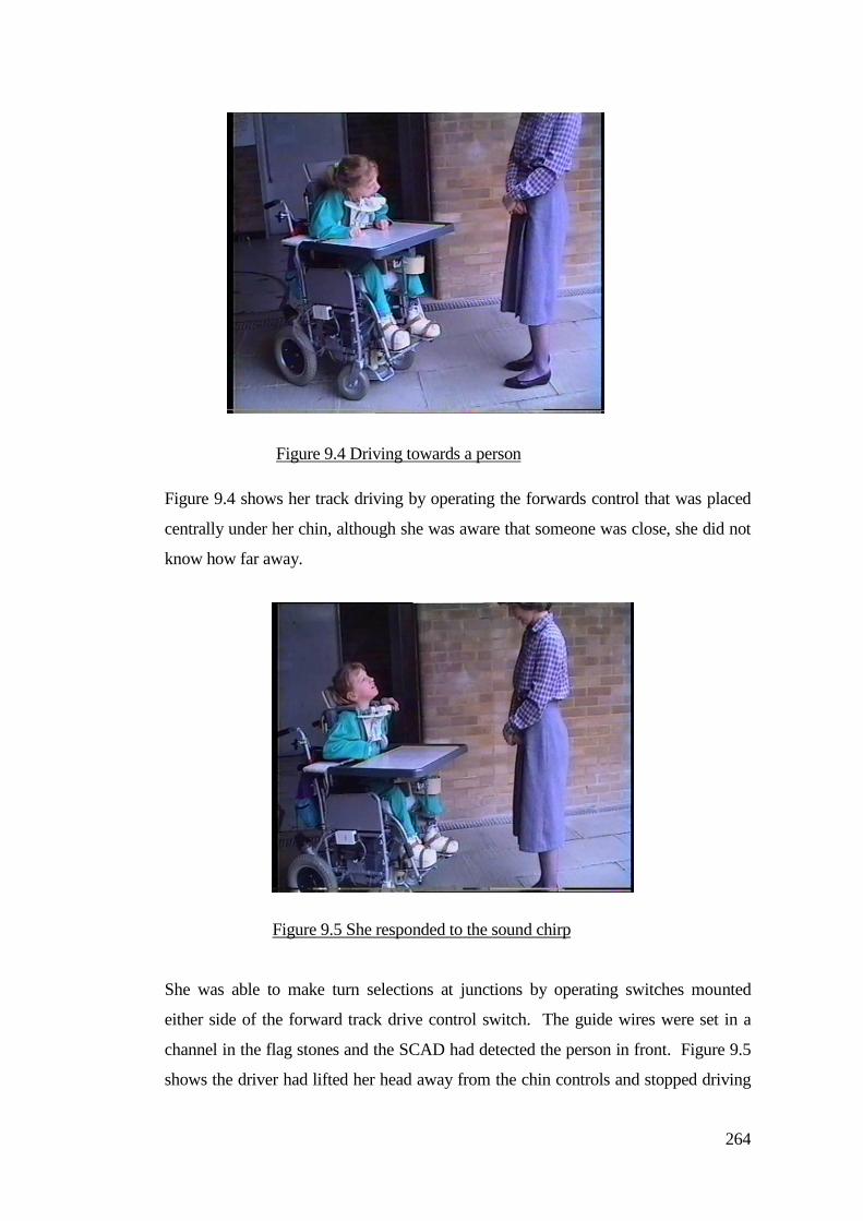
264
Figure 9.4 shows her track driving by operating the forwards control that was placed
centrally under her chin, although she was aware that someone was close, she did not
know how far away.
She was able to make turn selections at junctions by operating switches mounted
either side of the forward track drive control switch. The guide wires were set in a
channel in the flag stones and the SCAD had detected the person in front. Figure 9.5
shows the driver had lifted her head away from the chin controls and stopped driving
Figure 9.5 She responded to the sound chirp
Figure 9.4 Driving towards a person
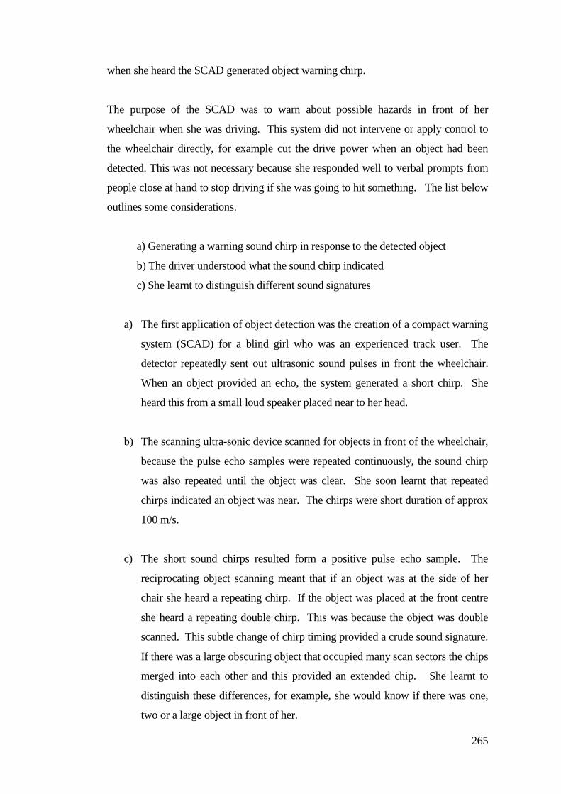
265
when she heard the SCAD generated object warning chirp.
The purpose of the SCAD was to warn about possible hazards in front of her
wheelchair when she was driving. This system did not intervene or apply control to
the wheelchair directly, for example cut the drive power when an object had been
detected. This was not necessary because she responded well to verbal prompts from
people close at hand to stop driving if she was going to hit something. The list below
outlines some considerations.
a) Generating a warning sound chirp in response to the detected object
b) The driver understood what the sound chirp indicated
c) She learnt to distinguish different sound signatures
a) The first application of object detection was the creation of a compact warning
system (SCAD) for a blind girl who was an experienced track user. The
detector repeatedly sent out ultrasonic sound pulses in front the wheelchair.
When an object provided an echo, the system generated a short chirp. She
heard this from a small loud speaker placed near to her head.
b) The scanning ultra-sonic device scanned for objects in front of the wheelchair,
because the pulse echo samples were repeated continuously, the sound chirp
was also repeated until the object was clear. She soon learnt that repeated
chirps indicated an object was near. The chirps were short duration of approx
100 m/s.
c) The short sound chirps resulted form a positive pulse echo sample. The
reciprocating object scanning meant that if an object was at the side of her
chair she heard a repeating chirp. If the object was placed at the front centre
she heard a repeating double chirp. This was because the object was double
scanned. This subtle change of chirp timing provided a crude sound signature.
If there was a large obscuring object that occupied many scan sectors the chips
merged into each other and this provided an extended chip. She learnt to
distinguish these differences, for example, she would know if there was one,
two or a large object in front of her.

266
Through general observation the children who were using the track were also
restricted by it. The development and application of the track guidance systems
provided children with a mobility opportunity that enabled them to reach specific
destinations through line guidance. The tracks also imposed a barrier to children who
wanted to go to other places and explore.
Therapists were asking and wanting children to come off the track and go free drive
(no tracks), but many children still had problems with controlling their wheelchairs
and were driving much shorter distances than they had been when they were using the
track system.
These are observations of the track guidance:
a) The track provided a high of level driver support
b) The track system provided a child with a secure pathway
c) The track prevented the child going astray; staff would know in advance
where a child was going and their destination options
d) Children wanted more options and choice of destinations (free drive)
e) Children became restricted by the track
a) The high level driver support given by the track provided a driving opportunity for
young people who otherwise needed cares and helpers to continually guide their
wheelchairs. The track gave a young driver personal space so they were able to
develop a sense of independence. A young person was able to operate a single switch
to control starting and stopping. The track provided steering and a safe passage to a
specific destination, but the track was highly controlling and restricting.
b) The track provided fixed guide routes. Many children were able to learn the route
destinations through practice and staff were secure in the knowledge that young
people would only be able to drive along specific routes. The secure path provided by
the track enabled young drivers to practice and develop awareness of their driving
environment particularly because the control feedback was consistent.
c) The fixed nature of the track prevented children from going astray. Staff and cares
felt confident that children would only be able to travel in specific areas. An
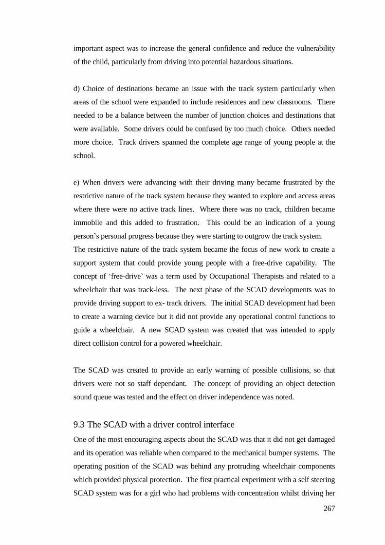
267
important aspect was to increase the general confidence and reduce the vulnerability
of the child, particularly from driving into potential hazardous situations.
d) Choice of destinations became an issue with the track system particularly when
areas of the school were expanded to include residences and new classrooms. There
needed to be a balance between the number of junction choices and destinations that
were available. Some drivers could be confused by too much choice. Others needed
more choice. Track drivers spanned the complete age range of young people at the
school.
e) When drivers were advancing with their driving many became frustrated by the
restrictive nature of the track system because they wanted to explore and access areas
where there were no active track lines. Where there was no track, children became
immobile and this added to frustration. This could be an indication of a young
person’s personal progress because they were starting to outgrow the track system.
The restrictive nature of the track system became the focus of new work to create a
support system that could provide young people with a free-drive capability. The
concept of ‘free-drive’ was a term used by Occupational Therapists and related to a
wheelchair that was track-less. The next phase of the SCAD developments was to
provide driving support to ex- track drivers. The initial SCAD development had been
to create a warning device but it did not provide any operational control functions to
guide a wheelchair. A new SCAD system was created that was intended to apply
direct collision control for a powered wheelchair.
The SCAD was created to provide an early warning of possible collisions, so that
drivers were not so staff dependant. The concept of providing an object detection
sound queue was tested and the effect on driver independence was noted.
9.3 The SCAD with a driver control interface
One of the most encouraging aspects about the SCAD was that it did not get damaged
and its operation was reliable when compared to the mechanical bumper systems. The
operating position of the SCAD was behind any protruding wheelchair components
which provided physical protection. The first practical experiment with a self steering
SCAD system was for a girl who had problems with concentration whilst driving her
268
powered wheelchair and often she collided with objects, people and other wheelchairs.
She normally drove a powered wheelchair with four separate button type hand
switches mounted on a tray in front of her.
New work was started to provide a training environment and supportive driving
systems.
9.4 Training areas
Driving training and practice using a SCAD assisted powered wheelchair began in the
main school hall at Chailey Heritage. This offered sufficient space and seclusion from
normal distractions within the school environment. A simple roadway lined with
plastic cups sprayed with bright fluorescent orange paint provided markers and
boundaries for a road way. The cups were separated by twice the width of the
wheelchair to replicate the normal average corridor width around the school complex.
The young driver was placed within the artificial roadway scheme as seen in Figure
10.6. Initially she drove though the roadway with the SCAD turned off. Her driving
was then monitored without SCAD to see whether she would stray out of the road
markers. Some cups were squashed as can be seen in Figure 9.6.
When the SCAD was turned on, she became captive within the roadway and could
only progress by driving to the end of the road way or by operating her reverse
control. There was no practical reversing object sensor fitted to the system. A drive
timeout gave a small amount of limited reverse driving. The reverse drive time period
Figure 9.6 Roadway cones
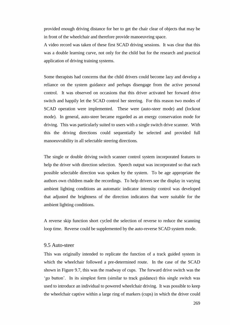
269
provided enough driving distance for her to get the chair clear of objects that may be
in front of the wheelchair and therefore provide manoeuvring space.
A video record was taken of these first SCAD driving sessions. It was clear that this
was a double learning curve, not only for the child but for the research and practical
application of driving training systems.
Some therapists had concerns that the child drivers could become lazy and develop a
reliance on the system guidance and perhaps disengage from the active personal
control. It was observed on occasions that this driver activated her forward drive
switch and happily let the SCAD control her steering. For this reason two modes of
SCAD operation were implemented. These were (auto-steer mode) and (lockout
mode). In general, auto-steer became regarded as an energy conservation mode for
driving. This was particularly suited to users with a single switch drive scanner. With
this the driving directions could sequentially be selected and provided full
manoeuvrability in all selectable steering directions.
The single or double driving switch scanner control system incorporated features to
help the driver with direction selection. Speech output was incorporated so that each
possible selectable direction was spoken by the system. To be age appropriate the
authors own children made the recordings. To help drivers see the display in varying
ambient lighting conditions an automatic indicator intensity control was developed
that adjusted the brightness of the direction indicators that were suitable for the
ambient lighting conditions.
A reverse skip function short cycled the selection of reverse to reduce the scanning
loop time. Reverse could be supplemented by the auto-reverse SCAD system mode.
9.5 Auto-steer
This was originally intended to replicate the function of a track guided system in
which the wheelchair followed a pre-determined route. In the case of the SCAD
shown in Figure 9.7, this was the roadway of cups. The forward drive switch was the
‘go button’. In its simplest form (similar to track guidance) this single switch was
used to introduce an individual to powered wheelchair driving. It was possible to keep
the wheelchair captive within a large ring of markers (cups) in which the driver could
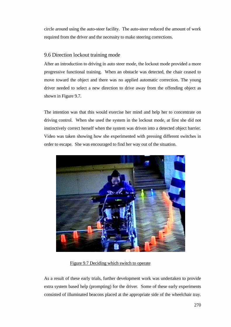
270
circle around using the auto-steer facility. The auto-steer reduced the amount of work
required from the driver and the necessity to make steering corrections.
9.6 Direction lockout training mode
After an introduction to driving in auto steer mode, the lockout mode provided a more
progressive functional training. When an obstacle was detected, the chair ceased to
move toward the object and there was no applied automatic correction. The young
driver needed to select a new direction to drive away from the offending object as
shown in Figure 9.7.
The intention was that this would exercise her mind and help her to concentrate on
driving control. When she used the system in the lockout mode, at first she did not
instinctively correct herself when the system was driven into a detected object barrier.
Video was taken showing how she experimented with pressing different switches in
order to escape. She was encouraged to find her way out of the situation.
As a result of these early trials, further development work was undertaken to provide
extra system based help (prompting) for the driver. Some of these early experiments
consisted of illuminated beacons placed at the appropriate side of the wheelchair tray.
Figure 9.7 Deciding which switch to operate
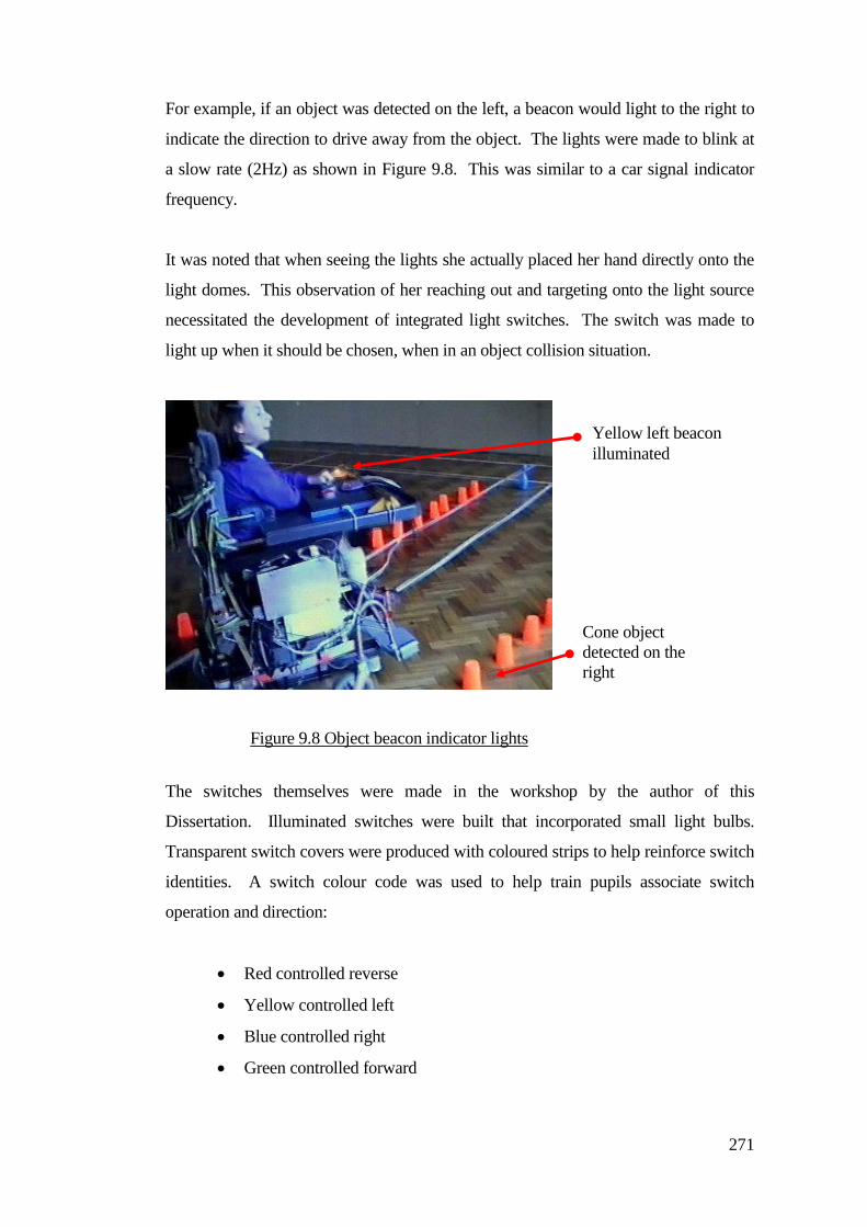
271
For example, if an object was detected on the left, a beacon would light to the right to
indicate the direction to drive away from the object. The lights were made to blink at
a slow rate (2Hz) as shown in Figure 9.8. This was similar to a car signal indicator
frequency.
It was noted that when seeing the lights she actually placed her hand directly onto the
light domes. This observation of her reaching out and targeting onto the light source
necessitated the development of integrated light switches. The switch was made to
light up when it should be chosen, when in an object collision situation.
The switches themselves were made in the workshop by the author of this
Dissertation. Illuminated switches were built that incorporated small light bulbs.
Transparent switch covers were produced with coloured strips to help reinforce switch
identities. A switch colour code was used to help train pupils associate switch
operation and direction:
Red controlled reverse
Yellow controlled left
Blue controlled right
Green controlled forward
Yellow left beacon
illuminated
Cone object
detected on the
right
Figure 9.8 Object beacon indicator lights
272
Figure 9.9 shows a picture from a sequence of video taken of her driving out of the
hall into a corridor. The lights only operated when an object had been detected. In
this case the wall had been detected on the right.
Further work with automatic system prompting led to the inclusion of speech output
devices as there were some children who did not like or responded positively to the
light switches.
Audible prompting of switch operation and was provided as an alternative to the light
system. The sound message was triggered when the system was driven towards an
object. Digitally recorded phrases e.g., “press the blue switch” were used as prompts.
Figure 9.9 Driving around the school using
illuminated drive control switches
A wall (object)
was detected on
the right side of
the wheelchair
Yellow (left
turn switch)
illuminated
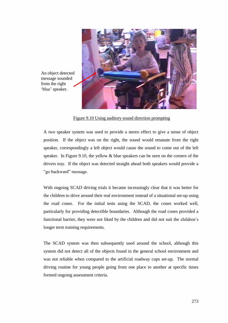
273
A two speaker system was used to provide a stereo effect to give a sense of object
position. If the object was on the right, the sound would emanate from the right
speaker, correspondingly a left object would cause the sound to come out of the left
speaker. In Figure 9.10, the yellow & blue speakers can be seen on the corners of the
drivers tray. If the object was detected straight ahead both speakers would provide a
“go backward” message.
With ongoing SCAD driving trials it became increasingly clear that it was better for
the children to drive around their real environment instead of a situational set-up using
the road cones. For the initial tests using the SCAD, the cones worked well,
particularly for providing detectible boundaries. Although the road cones provided a
functional barrier, they were not liked by the children and did not suit the children’s
longer term training requirements.
The SCAD system was then subsequently used around the school, although this
system did not detect all of the objects found in the general school environment and
was not reliable when compared to the artificial roadway cups set-up. The normal
driving routine for young people going from one place to another at specific times
formed ongoing assessment criteria.
Figure 9.10 Using auditory sound direction prompting
An object detected
message sounded
from the right
‘blue’ speaker.

274
9.7 Considerations about crashing
a) Too much crashing was hampering children who wanted get to places
b) Not enough crashing was hampering the learning experience
c) Children were impeded through not having a reverse control
a) Often children would not be allowed to drive because of staff and helper concerns
about their safety and crashing into things and people. The track system [Langner
(2004)] provided a means for young drivers to drive without constant helper support
and enabled young people to reach destinations. The track became restrictive for
advancing drivers who wanted to drive free. The tests with SCAD (particularly the
road cones) demonstrated that helpers could step back and allow the children to drive
and problem solve with a reduced fear of crashing.
b) The first practical applications of the SCAD with young people provided some
practical feedback that reduced the amount of crashes. Some therapists were
concerned that SCAD control interventions took control away from the driver and that
children needed to learn to control their wheelchair through the crashing experience.
The technical development of the SCAD took account of this and incorporated
adjustable parameters that reduced or increased the amount of SCAD collision control.
The therapists still wanted to be able to completely disengage the SCAD.
The author of this dissertation was reluctant to implement this because, a residual level
of object detection provided some self protection for the system. A system kill switch
was provided and this removed any doubts about system intervention when the young
person was driving.
The therapists became more relaxed when young people demonstrated that they
understood the concept of driving, the therapists became less concerned with the
conflict of child learning and system support and became encouraging about SCAD
support to reduce the amount of effort needed from young people to control their
wheelchairs. This formed the subject of work presented here or possible future work
to create effort reducing systems.
c) Observations showed that children drove into situations in which they were not able
275
to free themselves, most particularly room corners so children become stuck with their
wheelchairs and helpers intervened. Helpers would pull back the child’s wheelchair,
or operate a reverse control if this was available.
Many children did not have sufficient personal physical ability to use a reverse control
and were not always provided with one, furthermore, there were issues concerning
some children not being able to look in the reverse direction.
A reverse control was given to children when they were ready. At this stage children
needed to learn about when to use reverse and problems with crashing whilst going
backwards. Considerations about control function selectivity and targeting
necessitated the child learning a control strategy in which accidental reverse operation
was minimised in favour of deliberate operation.
9.8 Adding a reverse turn manoeuvring function to the SCAD
A reverse function was necessary to enable children to back themselves away from
obstructions or situations where they had become trapped, for example in a room
corner. When the driver did not have a reverse switch, the SCAD control system
applied a reverse turn manoeuvring control sequence.
Figure 9.11 shows a reverse turn manoeuvring turn sequence that started when a turn
switch (left) was operated. Figure 9.11 also shows the sequence of automatic events
that provided the reverse turn manoeuvring function. It can be seen that this operation
is repeated and at stage 3, the wheelchair has started to turn out of the confined area in
the direction of the selected (left) turn control.
The stages 1, 2 and 3 continued until the chair was free of the obstruction whilst a turn
control (left) was operated. A delay was provided to stop the reverse function acting
immediately when an object was detected and this reduced the chance of the reverse
turn manoeuvring acting when not required.
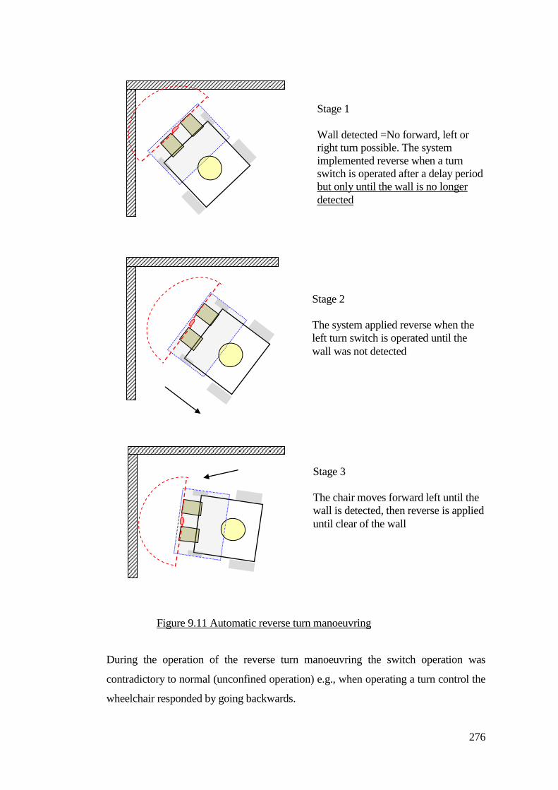
276
During the operation of the reverse turn manoeuvring the switch operation was
contradictory to normal (unconfined operation) e.g., when operating a turn control the
wheelchair responded by going backwards.
Stage 1
Wall detected =No forward, left or
right turn possible. The system
implemented reverse when a turn
switch is operated after a delay period
but only until the wall is no longer
detected
Stage 2
The system applied reverse when the
left turn switch is operated until the
wall was not detected
Stage 3
The chair moves forward left until the
wall is detected, then reverse is applied
until clear of the wall
Figure 9.11 Automatic reverse turn manoeuvring
277
It was noted that a child being able to get free from trapped situations was preferred by
people in general.
Some staff commented children maybe confused when avoiding objects. Did the
children understand what the SCAD was doing and why their wheelchair responded
differently during the function of collision avoidance? The switch control function
changed, for example, in pre-collision, the forward drive switch controlled the
forwards motion. When the SCAD detected an object on the left, pressing the forward
control caused the wheelchair to steer to the right to avoid the object and vice versa.
This reflected the child’s understanding about what control manoeuvres were
necessary in order steer around objects and the associated resulting motion of the
wheelchair. Switching off the automatic collision control function was preferred by
the occupational therapist, as this to some extent, converted the SCAD into a learning
tool. When the SCAD stopped the chair by the detection of an object, the driver
needed to operate the correct switch in order to proceed. In this situation the child was
suspended in a pre-collision state but not physically trapped or in contact with an
object. Occupational Therapists preferred a bias towards a child problem solving
when driving. There was a conflict of opinion because some school staff also valued
child autonomy.
For flexibility the SCAD control system was subsequently developed to incorporate a
range of functional modes. These modes were selectable.
Auto steer
Non-auto steer (lockout mode)
Object detection range
Pre-slow down
Automatic reverse turn manoeuvring
No system object detect function
Children that had been using a track guided wheelchair were not provided with a
reverse control. Reverse driving on the track was deemed counter productive as
prolonged reverse travel with the driver facing in the forward direction was not linked
278
to normal mobility. Interestingly, some children liked reversing in their un-guided
wheel chair. Children having early exposure to going backwards in rear facing car
chairs or prams and push chairs, where the child was facing the person who is pushing
them are factors in early child development.
Incorporation of the automatic reverse functions for turning (non-reverse
switch).
The avoidance control modes were adapted to suit the learning phases and
stages of the children.
It was noted that automatic steering guidance could enable children to become trapped
in confined space, for example, in room corners or amongst clusters of furniture.
When the auto steer was turned off, as favoured by therapists, the chair would be
difficult for the driver to steer within the scan detection boundaries. The child’s
driving corridor was narrowed by the system. This was a significant problem with
SCAD in the non –auto steer mode and this is the subject of future work, particularly
as it made the chair more difficult to drive and young drivers were stopped by the
system in confined spaces.
9.8.1 Child understanding of what the SCAD was doing and why
The normal control operating parameters of the powered wheelchair were being learnt
by drivers using the system. When drivers were operating switches or joysticks the
relative control functions translated into wheelchair movement. With the
interventions applied by the SCAD system the control response relationship changed
conditionally. Concerns were raised by some therapy staff about the child’s
understanding of these interventions. Children were told that the chair had stopped
because there was an object close in front or to the side of their chair. The driver
pressed the switch and the chair did not move. Normally before the application of
track or SCAD assistance staff guided the child if they were there at the time.
Observed common human interactions with child drivers:
Giving verbal commands to the child to correct an aspect of driving
Telling the child to stop prior to an impending collision, verbal prompt
279
warnings
Praising the child for good progress
Physical gesturing
Removing a child who became stuck by physical intervention by disengaging
the drive wheels so the chair can be manoeuvred into the clear
Operating the child’s controls directly to manoeuvre the chair
Exerting control actions by holding the child’s arm or hand
Conflict of needs, e.g., the child wanted to go somewhere that the helper did
not want the child to go
Observations showed that helpers changed the drivers coarse by steering the chair by
its push handles whilst the child was driving. This was a common practice mostly to
expedite the child’s progress. On many occasions the child was not asked and may not
have been aware of what was happening.
9.8.2 Course restoration
The wheelchair altered course after collision avoidance operation. Figure 9.12 shows
that a new heading would often result when the SCAD control system had intervened.
It was necessary to consider the child understanding and confidence in the system.
To restore the chair to the previous heading required a system memory of the previous
pre-collision heading.
For the system to do this it would be performing a manoeuvre not directed by the
driver. This represented a different form of intervention compared to the SCAD
avoiding or stopping before a physical object. Post detection course restoration
required an intervention control sequence from system memory without detecting a
physical object.
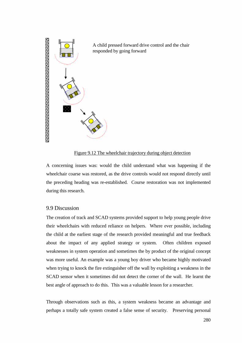
280
A concerning issues was: would the child understand what was happening if the
wheelchair coarse was restored, as the drive controls would not respond directly until
the preceding heading was re-established. Course restoration was not implemented
during this research.
9.9 Discussion
The creation of track and SCAD systems provided support to help young people drive
their wheelchairs with reduced reliance on helpers. Where ever possible, including
the child at the earliest stage of the research provided meaningful and true feedback
about the impact of any applied strategy or system. Often children exposed
weaknesses in system operation and sometimes the by product of the original concept
was more useful. An example was a young boy driver who became highly motivated
when trying to knock the fire extinguisher off the wall by exploiting a weakness in the
SCAD sensor when it sometimes did not detect the corner of the wall. He learnt the
best angle of approach to do this. This was a valuable lesson for a researcher.
Through observations such as this, a system weakness became an advantage and
perhaps a totally safe system created a false sense of security. Preserving personal
A child pressed forward drive control and the chair
responded by going forward
Figure 9.12 The wheelchair trajectory during object detection
281
awareness was still needed for some individuals to reach their goals and not through a
‘totally’ automated approach.
When testing systems, the assumption that it worked in the lab environment and it
would also work for the child was proved wrong. The testing of the SCAD doorway
control guidance operated reliably when in the lab. When tested with a child it
crashed into the side of the doorframe.
It was assumed the driver wanted to get through the doorway, but the child changed
their mind at a critical moment when passing thorough and made a turn. The frame
was beyond the SCAD detector range and consequently collided. Perhaps also the
child’s physical awareness of space was a problem in that he thought he was clear of
the doorframe when in reality he was halfway through. A practical solution to this
was made by adding side detectors because of this valuable trial.
The application of SCAD systems started with an artificial road environment. This
tested the system operation but children soon wanted get into and around their real
environment. The application of this research made minimal changes to the child’s
wheelchair equipment and the environment. A priority was given to adapting the
research based systems in preference to wheelchair modifications, particularly as these
were used on a daily basis.
Therapists asked if the system could be switched off as they may want to assess a
particular child driving without any form of assistance. Providing system function
controls, particularly the most appropriate was learned through the system application
and user feedback. ‘Backing off amount’ of system help at the earliest opportunity
gave young drivers an option to demonstrate their skills. The SCAD system provided
steering guidance and crash protection but this could reduce the ability for drivers to
get close to objects, for example, draw handles and pushing open doors. Using SCAD
systems showed that preventing close contact with objects frustrated some drivers.
Significantly reducing the wheelchair speed instead of halting the wheelchair proved a
useful exercise in combining restrictions and access requirements.

282
Chapter 10
Staff discussions and interviews
The research described in this dissertation was primarily targeted at reducing the
number of control actions required by a driver. There were human issues that
influenced the system development and the direction of the research and these are
discussed in this Chapter. For example, how did the system affect young people and
their associated teachers, helpers, carers and therapists? The author generated an
initial suggestion list to highlight some general points concerning young people using
the new systems when driving and interacting with their local environment.
The list was used to guide interviews with twelve professional people working with
children in clinical, educational and caring roles in order to get feedback about the
impact of the research and to validate the work.
Subjects discussed were:
10.1) The benefits of mobility for young people
10.2) The value of assistive technology
10.3) Do young people need help with their mobility?
10.4) Human help versus technical assistive support
10.5) Assistive technology taking control over a young person
10.6) Raising expectations
10.7) Learnt helplessness
10.8) A young person leaving the school
10.9) A child (young person) understanding of the task
10.10) Wheelchair control and frustration
10.11) Risk
10.12) Other discussion points
Interview sessions were recorded and converted to text using a keyboard and voice
recognition software. The context of what was said has been interpreted as accurately
as possible.
The subjects are considered in the following sections and interviewees are identified
by a simple three digit code. All interviewees were aware of the SCAD assistive
technology created during this research.
283
10.1 Benefits of mobility for young people
The interviewees were positive about a young person’s need for mobility, especially
independence and how this was central to other aspects of life. Mobility was
considered to be a pivotal aspect to learning and achievement.
(RM1) “I would say absolutely vital. I think the kids here need to explore as
much of life as they possibly can. I think if they can move themselves that is
an ideal situation and if they can have some control over where they go, that is
giving them something which is inestimable really. But in any case, mobility
is part of life and we should be able to offer everything that they can take up
really. It’s giving them a choice isn't it. I think in everything that we do for
the kids we need to be able to give them as much choice as possible. And if it
is self powered mobility that is giving them a choice of going where they want
to. I know that might be restricted, but it is giving them a choice. It is opening
up other aspects of life and experience.”
(KD1) “I think initially it is of value because they can use it to do something
for themselves. That might just be driving round in circles going in and out of
the room. The other end is that there are students who can usefully get safely
from A and to B. That's kind of very functional driving so there is a difference
between a kind of play and function. It replaces toddler and baby freedom to
explore at their own volition I think. I think primarily it is important because
it's a sense of going where they want to go and looking at what they want to
look at, not just independence in terms of going from A to B, independence in
terms of finding out about things. Some of our students might not start driving
sometimes until they are 11 or 12 years old, so they are miles behind”.
(HC1) “I think it is essential in terms of developing independence, confidence,
personal autonomy and being able to do those things which other children
would be doing at the same age. It enables them to vote with their feet if they
want to. Other children if they don't want to do something, they can get up
and walk away. It enables students to make choices themselves and to do that
independently without relying on somebody else to assist them. Children have
one life and they should be given every opportunity to enjoy every moment of
their life and even when they move and things aren't followed through, that is
284
tremendously unfortunate but surely should not prevent them achieving with
the help of whatever technology that can be provided for them here. I would
say that we need to be looking at improving what happens when they move on
rather than not doing so much now”.
(AB1) “I think it can offer them independence and the degree of independence
can depend on the ability of the child but it is something that gives them an
opportunity to move from A to B, where they couldn't possibly otherwise.
The benefits are they can go where they want to, they can choose where they
want to go, especially a child that has no verbal communication, he/she is at
the complete mercy of who is pushing them where and when”.
(SO1) “Yes because it develops their perceptual awareness, it develops their
social skills and their independence. I think for some of our children who are
not going to have mobility under their own steam, powered mobility is
essential, if they are going to have any mobility. It rates very highly but I
think some children are learning a lot of other mobility skills with their
walkers, biking, horse riding , swimming to a degree, there's other things as
well that feed into that process, but I still think children should have
independent ability to move from room to room within their environment”.
The general view expressed by the interviewees was that personal mobility was
important for the well being of young people. Some complex disabilities required
constant personal help. This validated the need to undertake research that could create
new systems to provide supportive mobility systems to increase the independence of
young persons.
10.2 Value of assistive technology
The interviewees thought the new research based systems were beneficial because
they helped young people explore and offered increased independence. They moved
about with greater freedom from helpers, particularly encouraging non drivers to
become drivers.
(SO2) “I think its independence. I think some children will find driving at a
young age or older very difficult if they got a degree of physical disability or
visual disability that is not going to allow them to drive. That should not stop
285
them driving. We should enable them to do as much as possible”.
(F2) “Being able to give these children means and ways of being independent
and to explore is so, so important. Because every moment of their life is
governed by other people. For students that are learning to drive to build up
their confidence, because if they have an accident it is going to knock their
confidence in driving further. And a lot of these children are not given such a
scary task. I think that the basic functionality of assistive mobility is amazing,
but it needs to be more personal to the actual child and how they use it. Take
for example a child in this class who uses a head switch to drive; when he uses
his head switch, he has to turn his head to the side, so when he is moving
forwards he cannot actually see where he's going. These children are amazing
because they have to be patient throughout their entire lives. Particularly
because of their communication difficulties, they don't often speak up. Unless
they are asked a question maybe repeatedly you can't get to the bottom of
things”.
(RM2) “Yes, I think apart from the choice, enabling children to have
achievements is good. So I think if by some means you can give them control,
they otherwise would not have the opportunity for an achievement. I
personally feel that everything we do at Chailey is a learning experience and I
think that for certain children, some of those benefits are greater than they
might get in a classroom. So I think, you know it’s horses for courses, for
some children giving them that control and choice is so valuable that time
from other activities would be justified”.
(PB 2) “You can't possibly put the child into a wheelchair, give them a control
system and expect them to be able to drive it. And some children learn that
very quickly, given the joystick they very rapidly work out that pushing the
joystick forwards takes you forward and what have you. But some children
don't have enough muscle control to stop and to turn corners and to get
through doorways. So you have to be able to assist them with that so that they
would hopefully build up to driving by themselves. But if they don't, at least
they can still drive”.
(DC 2) “The majority of children at Chailey Heritage cannot walk
independently or at least functionally walk. Therefore, the answer to that is
yes, they do need help with their mobility. I think the children have a wide
286
range of needs, both physical and cognitive, and therefore a range of assistive
technologies can be brought to bear in order to assist them with either
becoming independent, becoming partially independent within a set
environment or using mobility as a therapeutic fun thing, a plaything”.
(LM2) “I think for young people with complex physical medical difficulties
we have in our population here at Chailey, there will always be room for
assistive technology. It's getting the balance between how much help we are
giving them and whether we are then taking away any kind of control
development from them”.
(MW2) “I think it is more important for our children than it is to you or I,
basically because we should have that ability to actually look, assess and make
decisions to a point, whereas I think perhaps the decision-making process for
some of the children is slow or slower and the assistive technology would be
of great assistance to them. If you go back to the children where their motor
control is not that precise, the turn right or turn left is left on too long and
therefore they have to overcompensate to come back. Any technology which
is actually going to make driving smoother has to be of benefit to them. I
think it must be enabling for the people to be able to say I want to go to point
A, and to be able to get there if as you say there is an obstacle in the way, the
device can help steering guidance. If they could override the system where it
may block them getting to things and then turn it back on, that would be
brilliant. Then we have to think about everybody else that might come into
contact with it whether it be furniture or whether it be people, there is the
safety aspect as well. I was going to mention the likes of J who currently has a
chair fitted with a track. That is fine whilst it is around the site here but the
attendant controls on the back are very, very delicate, it is very easy to over
steer with a very slight movement, all of a sudden you're shooting off to the
left. This is like Nintendo controls. The other thing which is a real problem is
the fact that when you're away from the site you cannot get used to the
attendant control. A lot of people are frightened because it is so precise and
so volatile I suppose in its movement. They turn it off. But then of course you
don't have any handles with which to actually push apart from the two
verticals in the frame of the chair. So if there was something which was more
of a conventional grip it would make it easier”.
287
(KD2) “Well, as far as my understanding is, if the child has not got their
hands on a switch or head on a switch or joystick, the chair is not going to
move. It depends if the child wants to use it as a way to get from A to B,
because that's what it would be in that situation wouldn't it, because it would
not be so much of a plaything because it would be so much driven by the
technology, so if they were interested in that aspect of getting themselves from
A to B with technology then I think that would be good”.
(AB2) “At the very top. At the very, very top. You know, what better thing
than to be able to go out independently, but that is at the very top. In a school
like this I would put it far above everything, I would, like communication. I
understand that some people, if they are on the track that can't be transferred
outside. Better to have loved and lost than to never have loved at all”.
(HC2) “Is this the chair that detects the environment it is in? The almost in
between stage, having seen the beginnings of research on that line it offers
those children the next step on in terms of their independence. I think it is
absolutely crucial and at no stage should a child be held back if technology can
in some way support them on to the next step”.
The interviewees suggested that the application of the work described in this
dissertation was of value to young people, particularly for increasing their autonomy
and freedom within their local environment. It helped them to gain confidence and
personal achievement. The new research based systems enabled young people with a
visual disability to have a driving opportunity and reduced the need for helper
intervention.
10.3 Do young people need help with their mobility?
The immediate response of the people interviewed was that this question had an
obvious ‘yes’ answer. Two particular interviewees added comments that mobility
systems had a definite value for young people because they had not attained
independent mobility skills or abilities within the normal developmental age range.
(JD3) “Yes they need help with their mobility, because the majority of them
from babies, don’t get the normal experience of exploring their environments,
288
that moving around not being able to crawl or to be able to touch, to be able to
explore the objects, to be able to understand what is hard and soft and to get
the autonomy to develop as a typically developing child can to explore their
environment”.
(LM3) “Yes I do. I don't think they have the cognitive ability necessarily or
the control expertise to make full use of potential independence though.
One of the big problems again is with the SCAD is that it does not pick up
voids, like under a table. There is the issue of veer of the wheelchair, which I
know you are thinking about. I think that confuses them sometimes because
they are expecting to get to do something and actually it’s how they deal with
camber etc. I don't know if the technology is there, something that could be a
vertical scanning as well as the horizontal scan. Some children who seek to
get into trouble because they think the SCAD will be protecting and actually it
has not picked up something and so they may be driving into something like a
table”.
(SO) “To me, I think when they first start, you want to make it as easy as
possible for them to use the switches. They've got to learn to negotiate and
they got that ability to move. For a lot of children, starting off on a track
which cuts out a lot about decision making and makes it simple and also it is
quite exciting to get to somewhere and for them to make a positive choice at a
junction. I have no problem with a young child starting on the track, and then
once they have got the idea with switches, making choices which might take
you one way or the other switch may take you the other way, you are learning
all those skills, but you are safe and you can't crash. But you are also learning
to pass things and you're learning to stop. You've actually got all skills you are
learning even though you’re supposedly just on the track”.
The general conclusion from the interviewees was that technical assistive help was
needed because the young person’s personal disabilities prevented them from normal
exploration and personal interaction through their own coordinated movement. The
general feeling was that mobility should be introduced at the earliest opportunity.
289
10.4 Human help versus technical assistive support
The responses from the interviewees indicated that there were many issues affecting
the learning development of a young person. A significant concern was the
understanding of a young person to the applied assistive support and where this fitted
in with their learning stages and driving with increased safety. There were also issues
of conflict where helpers may have different agendas to the young person driving.
(LM4) “I think there's merits to both. I do think staff need training as to how
much assistance they can give, when not to give assistance and to allow the
child to make their own decisions and work things out themselves and for how
long. I think as staged progression, I think they have to have a person to start
with. And then I guess it depends on the cognitive ability of a child as to
whether they understand what is happening when they activate a control. That
they actually do understand that cause and effect, that this is me doing that,
and if I do it that way this happens to me, or I am trying to do that, nothing is
happening. Why? Problem solving? I think that's quite a cognitive leap. I
think when children have the time to drive independently, the system helps
them there, because then the helper tends to back off and allow them the time.
I think you see people being helped when time is short and there is a time
pressure because they have to get back to class in time for lunch, or down to
the residential bungalow, or whatever. Where there is no time limit on it then
I think people are much more prepared to allow pupils to make their own
choices and then the system helps them. I think some of them are denied
personal control, some of them are very aware of that and I do know because
some pupils have said it, that they resent that, because I am perfectly capable
of driving up here and whether it is a school assistant or it is an escort, because
they want to get on the bus quickly, they overrule them. You know, if I just
got my independence I would be very frustrated about that. I think there is
frustration there, somehow within systems we have to build in that time to
allow these children that time. Is it that they had to leave 10 minutes ahead of
the rest of their class because they can then independently drive to lunch. I
would argue that that is a very valid reason to do that”.
(KD4) “I hate seeing a child who is being driven along by their joystick
290
because somebody is in a hurry to get to somewhere”.
(PB4) “It's not the same because the child is not in control then. It is just an
adult human doing it, because they can do so little, so few things for
themselves, to be able to sit in a wheelchair and okay people are watching
them, there's always somebody around, but at least they are doing it
themselves. Even those children who are perfectly able to drive and to drive as
fast as he wants to get there very often has his joystick control take over by
able-bodied grown-ups and being driven there because they haven't got the
time to let him drive there himself; he's got to get on a taxi, as soon as a taxi
driver sees him he's driven somewhere”.
(DC4) “I think, it is very difficult to determine the effects on our children
because of the limitations of their communication and so sometimes there is a
lot of interpretation which has to be made within their communication. So I
think to get to the heart of it would obviously be good to ask the children
themselves, but there are issues around that. I think the assistive technology
can certainly enhance their ability to be mobilised efficiently. I think like
some others, there can be concerns that when you just apply technology in a
sort of blanket form to see how it falls with different people. You can find it
falling very unevenly, such that you find some kids are being maybe not
cognitively up there in terms of what it is that they are doing and why things
are happening, and we went through that process of trying to unravel some of
that and had got out of the habit of just blanket applying technology. It works
for so and so, let's see how it falls with little Johnny and little everybody else,
and I think that is a positive thing, more of an analysis of where the children
are at and introducing things by steps”.
(JD4) “I think it is a huge area when you talk about human approach because
again that was part of what I looked at and researched, in that everyone talks
about training a child to learn powered mobility, and what they are realistically
talking about or what you can gather from research data because there is very
little in there, people are talking about training, the chance to use the powered
wheelchair as a machine and how to operate the machine. When you look at
electronic mobility guidance systems, you've got to look at where the child is
in their learning process and if you introduce them to soon then you're not
allowing the child the opportunity to cognitively learn what each of the
291
switches or buttons do when they press them, and that is something that came
out in the research. When I was working with typically developing children,
they got very confused if the chair suddenly took over and the chair did not do
what the child was expecting.
Where electronic assistive technology was helpful for the children was at
stages where they did not have the refinement skills and they could not get
through a doorway and they were not prepared to work out how to get through
the doorway. It became too frustrating and the chair taking over helped those
children but they had been through a basic pre-learning where they understood
and had worked out what each of the switches did. It was down to their
refinement skills that they weren't able to achieve that, until they've had more
practice. So it is looking at when you put in this equipment and when you take
it away and that has to be worked out with the child and the child has to be in
control of that”.
(RG4) “The one advantage of the controlled system is that it might often be
incorrect but it has the advantage of never being biased. In other words a
technical solution never brings anything to help in a problem other than what it
can provide. Whereas a person can bring preconceptions to what the child
wants”.
(RM4) “Well again I think I suppose we're talking about safety aren’t we?
Human help is a very safe way of getting about but it is denying choice to a
great deal. With very good human help then choices are avoided as much as
possible. At its basic level, a person who is pushing has got control.
Hopefully they are extending choice with the person they are pushing but
ultimately they have got control. With a robotic system, you are to some
extent handing the control to the child so that really it is their choice. So for
the right children there is obviously a huge benefit for them being able to
choose if they can. It is the grey areas in between the two where it is difficult.
I think that children here have benefited enormously from some of the systems
we've offered”.
(HC4) “The difficulty is, it is a school and therefore the school has targets and
curriculum’s they have to teach to time and have to get from A to B in order to
be doing the curriculum. Therefore there are pressures of time and as much as
possible we do support the students in their mobility. At the same time we
292
have to be present at certain times to do lessons, but that is where Chailey
comes into its own as a whole community, because although within perhaps a
school day on a time table, a lot of the students live in a bungalow and there
are activities like scouts, where they are given opportunities then, and I guess
that is where as much time should be given and encouragement given to their
mobility. The children that go home perhaps don’t necessarily get given those
opportunities. For one thing, home is often small, so driving potential or time
to drive at home may be not be as much for the students that are at home
compared to the ones that stay on site”.
The research work was validated because the interviewees felt that it provided young
people with their own means of control. Using assistive systems provided young
drivers with opportunities to make driving choices without the continual presence of
helpers who might intervene and override them. The creation of the research based
systems described in this Dissertation was mindful of the learning stages of the young
people.
10.5 Assistive technology taking control over a young person
Some interviewees highlighted particular factors. For example, a young person’s
understating of why the machine had applied a control action was important, whilst
other interviewees felt that the combined function of personal control and machine
control enhanced the driving process. It was important that the young person achieved
a goal, and that this was the young persons own achievement even with applied
technical assistance.
(HC5) “I think we are looking at this from an able-bodied mind in that we
might think it is taking over but for some of the children in the school every
movement of their head or arms take such a huge amount of effort. I think
perhaps you have to look at it from what we might think the machine is taking
over still involves quite a lot from the children in the school”.
(DC5) “That is a tricky one isn't it because it is like the chair has to suddenly
start absorbing all sorts of different factors as well as the child's personality
and wants and dislikes. Short of just applying lots of semi-rigid rules to the
293
logic of that chair, you could very easily start it doing something, or just as
easily misinterpret what the child is doing; there is no way of linking into the
child's intent, that is the thing”.
(HC5) “Not so much that it becomes too difficult for them and they wanted to
give up, but just enough to move on. At the end of the day, if it is improving
the quality of life then surely it has to be important and it has to be
significant”.
(JD5) “I feel that during the child's learning, it is very important for them to be
able to bang and crash into walls and if you take that away then you are taking
away a whole area, and people on the whole tend to want to avoid that piece of
learning because it is seen to be physically destructive, and also tends to be an
adults agenda. From clinical experience of watching the children where they
go through a process of needing to crash, bang, scrape, that is a very important
feedback mechanism for children to be able to work out depth perception and
to be able to work out directional control. If you take that away then they
don't ever get that very valuable learning experience”.
(RG5) “I am not aware that we ever go for a solution where the machine is
ever in control. I am aware that many developments are perhaps trying where
the equipment does everything but I'm not aware that our alternative solutions
in fact were ever based on that premise. So I would say no, I don't think we do
too much. It would only be in the minutiae of the smallest aspect could you
say the equipment is doing something which the child ought to be doing. We
have in the past offered options”.
(MW5) “Well it's not just with wheelchairs that this is happening. Just within
the last couple of weeks they are talking about collision avoidance been
incorporated and commonplace within vehicles that you and I drive in the next
10 years. It’s technology that is actually affecting everything we do where
there is control of a vehicle, but then at some stage the device is going to cut in
and if the child is aware of that then they are going to say, I can just drive it
anywhere and if I get overloaded it will stop me anyway. Unless you allow a
certain amount of danger and a certain amount of injury to occur. In which
case what to you do?”
(F5) “I would hope; that before that system was put in place then the child's
abilities would be evaluated. And at the end of the day, in this situation we are
294
talking about children and young people, and as a parent you have to at the
end of the day let them do things, but you need to guide them. If you have to
make a decision on their health or safety then it is your duty to do so. Again it
is at an individual basis”.
(PB5) “It depends where you are with the wheelchair thing, if they know they
cannot crash, they never had to learn not to crash but because of the way
you've done it, so they are taken off that system, so they are put on a more
reduced crash ability type system like SCAD. So they have got those steps of
moving up to independent mobility but if you simply left them on the track
which you could do and it went places. They are not going to learn a thing
after a while are they?”
The comments from the interviewees indicated that the applied research work helped
young people perform tasks that they were otherwise not able to perform without
helper intervention. The work described in this Dissertation helped young people
drive through doorways and along corridors, and enabled young drivers to refine their
skills through practice. The systems reduced the chances of young people giving-up
because driving was too much hard work. Safety was also a factor in which the
research base systems acted to stop collisions where objects and possible hazards were
detected. This therefore protected driving opportunities, and reduced the chances of
young drivers having control taken away from them by the application of human help.
10.6 Raising expectations
In general the interviewees thought that raising expectations was a consequence of
providing new systems and providing young people with new experiences, preferably
under their own control.
(RM6) “I don't think it's wrong to raise expectations but I think we need to
invest in systems that they can take away with them because otherwise we
could be frustrating them. There is one line of thinking which is that everyday
counts and particularly if some of the kids here are not going to have long
lives so that any day’s achievement is good. But I think a lot of them are
going to leave Chailey and not have the facilities they've got here so we must
295
also bear that in mind, I think. So I would like to see assistive systems that
they can take away. The track system is honestly not something they are
likely to encounter elsewhere, so maybe that could be used for sort of limited
achievements but not building towards a particular goal but I think if we are
inventing or investing in systems that are going to be possible for them to take
away, then that would be great. So I think there are two things, one is a
limited goal for a day-to-day achievement and the other is building to
increasing skill which could go on through life. They are rather different
things really”.
(LM6) “I think these young people have a right to get the best provision they
can possibly have. The fact it might not happen outside is no reason for us not
to give it to them. They need to know what they can do, what rights they have
and then they can do. We, to a certain degree, can influence what else is
happening. To me there is no point in doing what we do at all, if we're just
going to say, well there is no point in doing it because they are not going to
have it afterwards. It's all part of promoting disability and the equality”.
(SO6) “You could say that about me using a magic mix to chop like a chef! Is
that wrong? A lot of children are not getting the experiences that a young
child would get and by assistive technology, learning to negotiate a doorway
first of all on the track system and then maybe a SCAD, then they do.
Children need lots and lots of experience”.
(RG6) “Quite simply (and it's incredibly simple) we should always provide as
much of a similar experience to the so-called normal child. In other words,
that any technology that is put in to help must never be an end in itself but
should only be a step towards a normal experience of the world”.
Many of the interviewees said that raising expectations was of positive benefit, as this
placed an expectation on the young person to achieve as opposed to being a passive
onlooker, even when the research based systems gave the appearance that a child was
driving by providing the driving control function. Some interviewees suggested that
this put pressure on other organisations to provide extended support in other centres
and services.

296
10.7 Learnt helplessness
The responses from the interviews varied in their interpretation of learnt helplessness.
For example: taking the easy way to do things, being passive or learnt behaviour.
Recognising an individual’s achievement and building progressive steps in child
learning was considered important.
(F7) “You have got to look at these things and remember that inside there is a
child and we were all children and if there is an easy option we can take it.
And again each child is different and cognitive ability needs to be taken into
consideration again during the evaluation period. And for some children, that
learnt behaviour is the only option and that's as far as they are going to get. I
don't see why if they have learnt behaviour, why they should not be given the
chance to do things”.
(PB7) “It depends on the child, and that's where you have to build in
progressive steps, in some ways to keep making it harder and harder for them,
but not to a point where say the control of what they're doing becomes so hard
that they give up driving altogether. But you've got to get to a point where
they are happy driving. And it strikes me that when you see children who
have left here or other children like these children here, very often they don't
drive once they become adults because it becomes too much of an effort and
they have a full-time carer and they'd rather be pushed than drive”.
(LM7) “The experience with children with disabilities is that they can be very
passive and we work hard to give them control or give them a choice. That
actually the child isn't making the choice, it's all being done for them, so they
can just sit there and not make any decisions. The child just presses a switch
and it will get them somewhere and something will be looking after the child.
I think we have to be sensible to where we are overstepping that line. I was
going to say that if I wanted to go through the door and the SCAD won't allow
me because it's sees it as an obstacle because the door is shut, I don't know
how we get over that. Is there an override button or something like that, that
can be provided? I think the collision avoidance device keeps them safe. It
also comes down to agendas again. What is the helpers agenda as opposed to
what is the pupil's agenda? What is it that they want to do? A young person
297
may decide, I don't want to go back up to the hall, that is why I want to go this
way, but perhaps for whatever reason, somebody will override that and say I'm
sorry you can't make that decision, you have to go this way. We don't have
time to do that or you're going the wrong way without perhaps exploring the
reasons why that young person wants to go that way. And again that to me,
whether its technology or its human assistant, overrides their independence”.
(RM7) “Well I think there are two aspects. One is that they've got to be able
to recognize the achievement, so they have got to have sufficient control
themselves with the help of whatever technology you can give them to get that
achievement and then I think it's very valuable indeed. But the other aspect is
the possibility of continuing with that after Chailey, because otherwise it can
be very frustrating for them if they make that achievement here and then have
no possibility of following it up. So I think whatever technology, it must be
something they can take away with them. That is my feeling”.
(AB7) “I don't agree that any system can totally do it for the child, they've got
to press a switch for themselves. I think things like a SCAD chair, okay if the
SCAD chair stops children bumping into walls, fantastic. It does not matter
that it is the technology helping. If a child had no legs and he was fitted with
an artificial whatever, they're not his real legs and he couldn't do it without
them, that's fine. It's the goal of getting where you want”.
(MW 7) “That's what I said about the cars. There was something in the news
recently about a car in America that they are currently developing and possibly
be in production within 10 years where literally you just get in and you press
the button and it takes over. Because it is laser guided, and will travel at 30 or
40 miles an hour and will actually detect other moving objects within the
carriageway, and will stop and break or accelerate coming up to junctions. It
will detect other vehicles moving in front and go left and right, it is an
incredible thing. But as I said, it is a lazy way of doing things”.
None of the interviewees thought that the systems created by the research added to
learnt helplessness. Helping young people to reach goals and, importantly, being able
to back-off the amount of applied system support were important factors concerning
child development and independence. One particular comment was that “I don’t agree
that any system can totally do it all for the child they’ve got to press a switch for
298
themselves”. This was true, as at some point a child had to operate a control to make
things happen.
10.8 A young person leaving the school
The interviewees thought that the new systems for the young people may not be
supported or provided in other places. Concerns were raised about some young
people who may not have continued access to facilities and support structures that
they had been using as part of their learning and development at the school.
(DC8) It is a difficult one, because they get an opportunity here to do
something that they probably won't get once they leave. And therefore I think
it has to be weighed up in terms of how that might affect that child, and again
that is a really difficult one because you don't know how it is going to affect
them, so you see how well they actually get on with something. I guess in
general, one would go for giving a child an opportunity to experience
something rather than not. However I do think there has to be quite a
measured approach in terms of just limiting expectations of what then can be
picked up outside. I think it is big enough of a fall once they leave here,
certainly for the children themselves and their families in terms of what adult
services they move into and I think perhaps just better preparation, perhaps it
can be met. Perhaps it is about preparing parents and children much earlier
about how things are out there in the rest of the world in terms of services.
Because if they were a little more motivated, a little more empowered to
actually take things into their own hands, they would be aware of what could
happen and therefore either foresee it and decide, well let's just say no to this
now, or indeed say, we know there's not going to be anything out there but
maybe this can happen at weekends at home still, or that kind of thing.
(HC8) And that's the problem with the future placements and the future
wheelchair companies and not what is provided here, but that is about
educating the public sector in a way. I guess Chailey is seen as being one of a
kind and a great many people never come into contact with the sorts of
technology that are used here but my guess is that disability is changing
because of the disability discrimination act that is coming in to support
299
disabled people in the community. I would guess there is scope there in
moving things forward to educate the wider world than Chailey Heritage.
(F8) I would bring up the issue of equal opportunities with that, I think just
because these children have disabilities and differences to us, it should not
mean that they have to put up with what is on the market. People should be
going further to make sure these children have the best.
(SO8) It does not go out into the community. It is limited to probably
institutions where things have been set up, but I'm not saying you should not
have it just because it is not everywhere. It's really only the track that doesn't
go out into the community. The SCAD goes out.
Although the interviewees had concerns about the on-going provision of technological
support that this research provided, the general opinion was that this should not stop
the creation of bespoke research based systems. Furthermore some interviewees
stated that the imposition of the Disability and the Equality Act [2010], helped
reinforce the need to research and create systems to help enhance a young person’s
independence.
10.9 A young person understanding the task.
Interviewees felt that the young person’s understanding of the reason and purpose they
were driving was important. Some interviewees said it was sometimes hard to
determine if the young person was driving or if the assistive system was driving the
child.
(DC9) Whose needs are you meeting in terms of giving the child this assistive
technology? Yes they might be able to be in the chair with everybody else in
the class. That's fine, but actually, as long as it is not raising people's
expectations and the family around them, in terms of suddenly they hear so
and so, he's driving he's doing really well and the expectation is that if he is
driving then he's functionally driving and therefore he can be independent, or
achieve some level of independence with it, and that is not always the case.
(KD9) Yes, I suppose I think if a student understands that. I think it would be
good if the student understood that. They found it difficult to avoid obstacles
300
and therefore understood they were using a SCAD because of that reason. I
think if the student knows and understands the process of it, like for instance
the student I have in mind, understands. He knows when he's had a SCAD
and it is useful for him and I think that's a really useful way ahead. I just think
it might be a bit odd for students who don't really understand what is going on
and I don't know how you know whether they understand or not, unless it's
very clear.
(JD9) The wheelchairs themselves are not designed to be user-friendly. The
appearance of the chair was undoubtedly important for the child and also the
parent because a parent reacted positively to a powered chair when it looked
like a toy as opposed to the typical NHS wheelchair that was provided. When
you talk to children and young people further along the line who have got past
using the chair and realise it is part of their lifestyle skills it is a very important
part of how they move around their environment and I am having to use things
like single switch control scanners, that is very frustrating for them in that
often it is not reliable, the switches are not reliable. The connections aren't
reliable and it is all very precarious at times and when you're getting into that
level of sophistication of electronic equipment it certainly does not meet the
needs of the young people. Using a powered wheelchair with a scanner and
the amount of veer and the amount of correction that they have to make and
the head switches and sometimes the unreliable nature of the head switch
when they hit they had to wait for the scanner to go all the way round again,
there are lots of areas.
What the children described back was working with systems that don't do
what the children asked them to do because they are inconsistent and they are
unreliable and they have to constantly keep adjusting and realigning the chair.
(LM9) Difficult one! Again, it has to be based on the individual experience I
think, and how quickly they develop those skills. It may be that they don't
ever develop a skill where they are going to be independently able to control
their environment. But they are going to either need somebody there or some
help there. I don't think you can say there's an end point, perhaps take each
individual, it is very difficult to say.
(PB9) That is where you start taking the controls off isn't it? So the child is
having to learn.
301
The responses from the interviewees suggested that child understanding was a difficult
area because the research systems could give the impression that the young person
was steering their wheelchair, when in reality the system was. The interviewees felt it
was important that the young person understood the reason they were driving and the
value of personal independence.
This suggested that the new work described in this Dissertation about audio and visual
prompting systems needed to be taken further to help young drivers understand the
reason when, for example, a wheelchair had altered course because an object had been
detected.
10.10 Wheelchair control and frustration
The interviewees commented that there were aspects of wheelchair driving that
needed investigation, particularly wheelchair steering.
(JD10) Those children who were using switches have got very gross
movements and may have not been able to refine there fine motor skill.
Children who are learning to operate joysticks may not have had refined
manipulation of the joystick. Although it appears switch users take longer I
suspect that some joystick users are constantly having to refine their
movements and they are constantly having to use their motor skills to correct
the chair rather than steering the wheelchair to where they want to go.
(F10) Yes I think the kind of problems such as veering wheelchairs need to be
looked at. The young man I was talking about earlier, his front wheels were
off, so every time he drove, he was not driving where he wanted to go, plus the
fact he could not see where he was going. But it was not until I had asked
him, your wheels are going in the wrong direction, I know I'm going in the
wrong direction, but he had not told anybody, he was just saying I don't want
to drive, I don't want to drive.
(PB10) Partly because the conditions here, that they know they cannot control
that veer to the left say. They are not fast enough to respond to the way the
chair is behaving. I think the things that I would like to see improved is that
factor of the wheelchair veering on a very small slope and it makes it
impossible for a child to learn and those that have learnt, they know full well
302
that they pressed forward and may start going left. You are building in a huge
amount of problems for the child whereas, if the chair would just go forward
when you press forward it would just make life easier. The chair lets them
down doesn't it? If it means they don't have to make so many adjustments, if
you could do that to the chair so they don't have to do it through the switches
that would improve things, yes make it much easier.
(AB10) Yes veers, veers is the obvious one, and that is really frustrating.
Well, I think that must be so frustrating. Take one particular child who is
doing exactly the right thing, he is pressing forwards and it is just going way
off the point where he wants to go. Then it's becomes such hard work.
(MW10) The presentation you did on the anti-veer device that you were trying
to put forward for certain children, that would be an enormous benefit. It
really would. Not only around the site here but even when we are out at other
colleges. The corridors are narrow to gain access around the site and there are
lots of left-hand, right-hand and 90° turns all of the time. It must be frustrating
when they are having to make little contact with their controls to steer and yet
that is too much for the restriction of the corridors. It must be very frustrating
for them.
(SO10) Some children will learn to drive. They have become automatic
because they physically find it easy and they have got a degree of mobility
around on the floor and they have learnt to negotiate. They don't have visual
problems. They don't have any other problems like that so they can now drive.
I don't think they get quite so tired as children who are constantly changing
switches and are having to control their bodies with an enormous amount of
effort. They are never really going to become very good drivers because it is
so hard for them. Whereas perhaps if we make it easier they will become
more independent.
The most significant problem reported by the interviewees was wheelchair veers.
Many of interviewees had spent a lot of time helping young people steer their
wheelchair because of the effects of slopes and uneven terrain had caused a driver to
drift off line. This generated a lot of frustration to the young drivers and helpers. The
variability of wheelchair control did not provide consistent feedback for young drivers
to refine their driving skills.
303
A new anti-veer system was created by the author during the research and wheelchair
trials demonstrated that wheelchair veer was significantly reduced. This formed the
subject of later work and the system is described in Chapter 4.
10.11 Risk
The interviewees thought that the nature of a young persons disabilities put them at
risk, particularly wheelchair driving. They took the view that this risk needed to be
balanced against providing a young person with opportunities to do things. Health
and safety legislation could act against the purpose of providing independence in a
special school.
(RM11) We are increasingly more conscious of risk aren't we and risk
assessment, personally I think sometimes too much but you have got to weigh
the benefits to the child against the risk to them. Obviously outside of a
controlled environment the risks are likely to be greater so any system we are
offering has got to be either used within a controlled environment or won't add
greatly to the risk of injury. For some kids the sky's the limit. For others you
have got to be very conscious of the risk. I think the benefits of choice and
freedom outweigh the risk on balance but I think one of the problems you are
going to have is, it is very hard to know what environment some of the kids
here are they're likely to end up in, so it's very hard to get a picture of where
they like to be five years after leaving Chailey. So it is a difficult choice. My
own feeling is that we should allow them to do things if children have positive
attitude and the systems suit them. We should encourage them to use
equipment to their best ability and invest in the right equipment. I think that
you should not be over depressed by thoughts of risk. Because choice is more
important than risk, I think then presumably they will be with adults who can
help them make those decisions.
(LM11) Initially as a safety issue for a young person. So that they can't drive
themselves into a wall or into somebody or into an object say, like the
collision avoidance device. I think that is perhaps the next stage. Again we
have to understand whether the child understands safety issues and knows
when they are putting themselves at risk. I think the track gives some people a
304
security feeling, that they know they are not going to get into any trouble, that
they know that if they do this and do that they will get to a certain place.
Certainly children with visual impairments; I think some of them have found
that reassuring. It can be that they then move from that secure thing because
they then want to explore the boundaries but again I think there are these
stages where we have to give them as much security as we can and then judge
it that they are ready, or they themselves can make the choice; are you ready to
move off the track and try free driving? It's like learning to drive a car
yourself. You don't want to go out without anybody who’s got dual controls
initially until you've got the skills yourself and you become more comfortable.
(M11) You know, with your own children you have to start somewhere and
actually to instruct them and show them the element of danger. Perhaps we
could make an obstacle course around here so children can try and find their
way around. On the one hand you want the pupils to achieve their own
independence but only where they are in the confines where there is no danger
to themselves or other people. Do you allow them to control crash so they can
experience what it is like? You have got the classic going down to the
bungalows. The fencing was put up as a result of the youngster going off-road
and tipping over his wheelchair. That could have been fatal. Do you
introduce a system of controlled crashing, where you know they are going to
experience the jolt, or a tipping of the wheelchair to a degree but there is built-
in safety so that where you know it is only going to go over a little bit, is not
going to go right over? You put your tilt platform on gala day. Could you
incorporate some form of technology like that into a sort of crash scenario, so
that, this is what's going to happen if you do whatever? Perhaps you could
build a power point presentation or something and link it to that so they can
see where they are going to feel what they have learned because they had
driven off course.
(PB11) Some of it is safety. There are very few children you can trust
completely to go off somewhere and not have to watch some of them that they
are not going down a ditch somewhere. The SCAD doesn't pick up spaces
under tables and there are a lot of spaces under tables. It doesn't always pick
up people's legs sometimes and where as it will pick up walls and things you
don't want it to pickup. It's not just a matter of driving towards walls and
305
doors is it? There's lots of other stuff around as well it needs to be able to
intelligently suss out, there's a table in front and now I know that there is a gap
but I can't keep driving under the table.
(F11) Yes driving under tables. You are never going to have perfection. I
think you can protect children too much. Again coming back to the parent
issue you have to give a level of protection. Obviously if they are cognitively
able again it is the individual child. There are dangers.
(AB11) What makes me really annoyed is I do have a mobility group and we
used to go all the way around the site, but we are not allowed to now because
of health and safety. I'm sorry, you know, but how can you ever, just because
one day nothing to do with school one evening a car was seen to come up the
wrong way so we’re not allowed to go that way now? That's another issue.
There should be more opportunity for mobility groups. On a Friday, I used to
have about four students, and never got beyond driving to and from the
bungalows but at least we could explore other environments, but now they're
not allowed to go there on there own and it was a choice, it was an option.
(SO11) I think crashing. I think for a lot of our children the very young ones
probably don't need to crash because before you had all this lovely technology
they went crash bang wallop and everybody used to jump to grab them take
their hands off the control and try to save them. And I think that was really
scary so I think what they need to do first is a bit like learning to drive a car
you don't take away the dual control until you have got some idea as to what
you're doing and then you can organise them to have a safe crash or two. But I
think for some children it is very scary because they've never been able to
make mistakes. In fact they're making mistakes. Where they're going
mentally, thinking I'm going there and gone off there is quite enough of a
mistake in their psyche to begin with. I don't need to crash. That is another
whole concept. I mean they're not used to making mistakes. Otherwise I think
they could very easily and very quickly just switch off. That was a really
nasty experience i’m not doing that again. Children are given so few
opportunities to make mistakes. In fact you would have to count out the times
they make mistakes and are allowed to make mistakes. I think they need to
make mistakes and take risks.

306
The interviewees thought that the research improved the chances of young people
driving because it reduced the risk associated with driving. Through the application of
the research, crashing was provided as an option. For example, the collision
avoidance system gave a choice of allowing children to crash or not to crash. This
could be for reasons of preserving a young person’s self confidence that could be
damaged by a bad driving experience. It was recognised that systems created by this
research provided new driving opportunities to young people with visual impairments.
10.12 Other discussion points
A variety of topics were discussed further. Many of the interviewees worked with
young people having complex disabilities. It was difficult to capture the wide
spectrum of issues by using a questionnaire with specific subjects. The following
statements resulted from open discussion and provided a broader picture of the issues
relating to people working in a school and caring environment:
a) Why are we not sure of what the child wants to do?
b) Giving the control to the young person to turn the assistive system off
c) Can AT have side effect problems?
d) Assistive Technology masking what the child is doing
e) Integrating assisted mobility into the curriculum
f) Priorities
g) Cost influencing people decisions
h) Define the term ‘energy conservation’
i) Future developments
a) Why are we not sure of what the child wants to do? (RG) The obvious barrier
is language ability. It's such a basic one. For conventional children it is such a
basic statement because you can ask somebody what they wanted to do now and
the answer is reasonable. Not necessarily totally explicit but it's a reasonable
answer. Children with disabilities, all too often people say, do you want to do this
do you want to do that and unless you ask or correctly identify what the child is
really thinking about, almost everything from then on tends to be a bit of a
disaster, because you never really tried to measure against what the child wants,
which is the only point of the whole thing, you are measuring against your own
preconceptions that you bring to the task.
307
b) Giving the control to the young person to turn the assistive system off. (SO) I
would not have a problem with that. It is probably very useful to have the ability
to have the SCAD switched on in some environments and then, it's part of the
learning process to either have very controlled areas where they learn to drive
without the SCAD on, or to push a bit of furniture or to get really close to
something so that they can reach it or what ever it is they want to do. I think the
more we can grade their learning to drive in very small steps, the more successful
the children will be. To me the track is actually the initial step and then you move
gradually up to the SCAD and then to the normal.
c) Can assistive technology have side effect problems? (KD) I don't know
actually, the answer to that, whether or not. I think definitely driving is something
that most students really enjoy and find very valuable. Whether it is functional or
not. Yes I think it would be good for most students to have the opportunity to see
which way they wanted to go, but a student might not have the capability to free
drive in a useful way. They might just enjoy going around and around in circles or
something. Then they might not even want to go on the track but at least they had
the chance to do that.
d) Assistive technology masking what the child is doing. (PB) Do you need to
know what the child is actually doing, if they are getting from one place to
another, you don't have to know what is inside their heads do you.
e) Integrating assisted mobility into the curriculum. (DC) I can see that it would
be something really hard to change because I think the school has got quite used
to using assistive technology in a certain way and there key areas where it comes
in, for example, computer access to some children but not necessarily other bits of
kit for others, and so I think there needs to be. I thought not just by a person like
yourself who is the ‘AT’ person, the assistive technology developer person to
come in. I think there has to be a concerted effort by actually the teachers at the
school, to look out there and see how other schools might be approaching this
problem, just do a sort of benchmark or reality check in terms of how well they are
measuring up, in terms of allowing the development of these sorts of skills which
are very key in terms of independence and life skills, socialisation skills which
308
would be within any typical school. I think there is a need for maybe a working
group as teachers as well as someone like yourself to actually go out there and see
how well things are going, to take a measure of how things are going in other
schools
f) Priorities. (F) Personally I think that communication, because you can make a
singing and whistling chair but if the child cannot communicate to you that this is
wrong or whatever, it is pointless. So communication should always be the key
start point.
g) Cost influencing people decisions. (JD) From the research that I did and
when I consulted with my peer professionals it was put forward by people in the
NHS that it was costs and safety and finance and risk but what also came out quite
clearly was there is a lack of knowledge and understanding and people are
applying a very outdated medical model approach to provision of equipment
which was traditionally set up for adults and not children. The children are
dismissed because they say that the finances are not there, but it is not just about
finance. It is also about looking at needs and looking at creative ways of finding
partnerships to supply the equipment. It is not just down to money and finance
there are other factors as well, which is attitudes and lack of knowledge.
h) Define the term ‘energy conservation’. (JD) I would define it for a child who
is looking at using powered mobility. That the amount of physical effort,
coordination that they have to put in to operate the switch to get the chair to move,
along with the time that it takes them to get from A to B.
i) Future developments. (JD) I think it is about research which is child led and
that the children are the ones who decide where the areas of research need to take
place, that they design the research program from the beginning. They are literally
in the driving seat that they decide what is important and what is a priority and
what needs to happen next.
309
10.13 Conclusion
This is a brief synopsis of opinions taken from discussions with the interviewees.
In general, the interviewees stated that the new assistive systems created in this
research helped increase independence and provided new driving opportunities for
young people at the school. It was noted that some interviewees felt that too much
help could be provided and this risked “switching off” the young person from making
an effort. When considering developments with automated sensing collision
avoidance devices (SCAD), many interviewees stated it was important that a young
person initiated the process of movement by pressing a control button.
It was noted from the interviewees that frustration was very evident from young
people. Especially when a young person had their own powered wheelchair but was
pushed around (particularly when they were able to drive themselves). One particular
area of conflict was children being overridden by helpers. This could be because the
young person’s rate of progress did not match the need for them to get to places in a
set amount of time. Many young people got frustrated when they were overruled by
helpers. It was suggested that when a powered wheelchair had an attendant control,
helpers sometimes found it difficult to steer the wheelchair.
The school curriculum time table added constraints. Some interviewees suggested
that the school establishment should build in more time to allow young people to self
drive more. Although a conflict of agendas was always going to be a problem where
the helper’s agenda was weighted in favour of the young persons agenda.
One interviewee stated there was a particular problem across the school “there are
barriers of language ability” and there were issues about the accuracy of interpretation
and jumping to wrong conclusions about what the child wanted to say. One
interviewee stated that, “The School should provide as much of a normal school
experience as possible”. In practice this was hard to achieve but many interviewees
felt that amongst all the equipment there was a young person and the focus should not
always be on the equipment.
Assistive technology needed to be more personal sometimes, to address specific
personal issues such as a user with head switches. When he drove he had to turn his

310
head away from looking where he was driving when selecting control directions.
Some interviewees felt that the systems created during this research should be
introduced to young children at the earliest opportunity to help them gain confidence
in making control decisions and learning to gain driving skills in a safer controlled
environment. Children should be allowed to make mistakes and take risks, although
in a controlled situation, using a SCAD system to grade the learning process, either by
increasing or reducing the amount of guidance support.
Opinions differed from the interviewees about students and driving hazards. Some of
them thought the system should be able to detect more things (for example under
tables), whilst others thought it was wrong to apply too much protection or apply
system intelligence. Again too much help may cause the young person not to apply
their own best effort and become de-motivated and not apply or develop their own
problem solving skills.
The new systems described in this research were regarded as energy conserving (in
terms of the amount of applied personal effort) and this was considered to be a
valuable asset for young people to have on their wheelchair drive system. The term
‘Energy Conservation’ was used by the occupational therapists and this was defined
by one interviewee as “The amount of physical effort, coordination that they have to
put in to operate the switch to get the chair to move, along with the time that it takes
them to get from A to B”.
Young people with gross motor function had difficulty with fine controls, for example
joysticks. Switches were used because they were more appropriate and because they
were larger targets for control action.
Some interviewees felt that future research should be child led and to give children the
choice to drive or not to drive. Many interviewees felt that the down side of the
research based systems were that they did not go out into the community.
It was commented that some children may never develop the skills to become
independent drivers. This may be because of age, issues with cognitive ability and
311
profound physical disabilities.
Some interviewees felt that child intention was sometimes difficult to gauge when
there were preconceptions about what a young person wanted or needed. One
interviewee in particular felt strongly that child led research, was better by asking
young people what type of research should be undertaken; however the researcher
may think differently about what is good for the young person and what the young
people themselves may want. The author posed the question, “surely any young
person in a wheelchair would want an anti-veer system?”. The interviewee responded
“Why don’t you ask them”, because it is possible they may want to work at control
themselves. If the SCAD stopped a driver from going through a door, should the
young person override the system? There is always room for assistive technology and
future developments.
Many various issues relating to child independence were discussed and it was widely
felt that the systems created for people with complex disabilities through research
must have the involvement of the person they were designed to help. The opinions of
the users, helpers and professionals and the experiences of the young people feed into
the development and design process; this was regarded with particularly high
importance.
Interestingly, when interviewees were asked ‘should the collision avoidance system be
improved’? some commented that it did not detect gaps under tables. Interestingly,
some interviewees suggested children could be over protected and in the real world
environment, the child needed to develop its own self protection skills. This again
reflected the importance of child inclusion in the system development process and
creating systems that were adaptable and had changeable operational parameters.
In particular many interviewees felt that the scale and amount of systematic help
should not “switch the child off” in terms of applying their own problem solving
ability. Providing just enough help to encourage a young person to drive and build
confidence through a positive experience was generally thought valuable, but in
reality hard to achieve. Many interviewees said that the new research described in this
dissertation was a significant step to meet this challenge.
312
Chapter 11
Discussion and conclusions
Through the research work conducted and described in this Dissertation children have
been able to drive without intense ‘hands on’ supervision. This has enabled them to
gain self confidence and further improvement of their personal control skills.
At Chailey Heritage (pre-1990) powered wheelchairs were only provided to children
and young adults who could demonstrate suitable dexterity and fine control of
joysticks because powered wheelchairs were usually fitted with joysticks. There were
Automated Guided Vehicles systems in use in industry that used techniques which
could transfer into applications for assistive mobility for disabled drivers.
A Multi-Junction Wheelchair Guidance System had been created before this research,
specifically for users to drive in their living and school environment. This is included
in appendix C. The new work carried out and described in this Dissertation drew
strength from that previous work and from the knowledge of working examples of
automated guidance systems used in industry and the Swedish Slingan project
A track system existed at the beginning of this research Langner [2004] and no new
claims are made in this Dissertation about the creation of that system. It provided a
form of mobility and an assessment tool for use with a range of postural support
systems and provided an opportunity for children to safely venture away from helpers
with greater autonomy. Once children started to demonstrate improved driving
competence using track guidance, the restrictive nature of the track routes became
evident. Children wanted to break free of the system constraints. The new research
work described in this Dissertation started here and aimed to create a system that
could enable guidance by detecting the local environment (and not have to use tracks).
11.1 Effort Reduction Systems
Test runs with and without the new veer correction system demonstrated that a simple
feedback system could reduce the amount of effort needed by a driver to counteract
the tendency for a wheelchair to veer. The experimental system was primarily
313
intended for switch users. Feedback could be adapted and incorporated into
proportional control systems as these provide continuous feedback operation rather
than on-off signals.
The limit of veer correction seemed dependant on the traction capabilities of the
wheelchair, power of the motors coupled with the wheel grip characteristics and
weight distribution over the ground surface [which could be rough or smooth]. The
system would still try to correct the veer even if the drive wheel skidded. This could
be a problem it the feedback was too aggressive, as a sharp response could cause a
skid (loss of traction). If the response was as shown in the experiments so far, then the
veer is not completely removed but significantly reduced.
Changing from a set of digital switches to a set of new variable switches improved
performance for some powered-wheelchair users. This was helpful for people that did
not have sufficient hand-grasp and release ability and sufficient targeting skill to be
able to use joysticks effectively. In Chapter 3 a simple input device was presented that
isolated gross motor function and was tolerant to involuntary movements. The device
was tested for more than a year and shown to assist powered-wheelchair users with
poor targeting skills. This offered a proportional control medium for users that would
otherwise be given a digital switch.
A case study was described as an example. The new variable control enabled one
driver in particular to control and reduce veers on slopes and to provide proportionate
control of turn-speed. They provided a means to successfully control forward speed,
turn speed and radius while reducing frustration, effort and improving personal energy
conservation. Users became more independent and said they did not want to return to
digital switches. Through the introduction of variable control it is hoped that people
will be able to learn, distinguish and exercise progressive control. Vari-switches still
retain the virtue of switch operation in that they can enable other combined functions.
11.2 Object detection devices for powered wheelchairs
The creation of a guiding system for children in powered wheelchairs provided them
with an opportunity for independent exploration and independence. This was beyond
314
the boundaries and restrictions imposed by the young person’s physical disability and
the necessary requirement for a personal helper. With normal un-guided systems the
helper would naturally steer the young persons chair as a means to help and tracked
guidance system reduced this need. There was still a need for the helper to stop the
driver from colliding into objects in the path of their travel. Again the helper would
act to protect the child and others close by and reduce impact damage to the
environment.
Chapter 4 described work on the development of mechanical bumper systems. The
potential independence gained by young people using the track was compromised by
their inability to stop in critical situations. Crashing into objects was regarded as a
matter of child safety. Some therapists believed that crashing was a learning
experience and they had concerns that systems developed to stop the child
automatically would reduce their need to learn. Teachers shared the view that they
would like to see children driving with increased independence.
Because trainers, teachers, carers and child drivers responded differently during and
after collisions, different responsive modes of operation were needed. In addition,
visual impact of bumper systems was not a positive image for a young person. The
bumpers appearance accentuated aspects of disability. Ironically, the physical
dimensions required a bumper to absorb impact energy and the size of the bumper
systems added to the footprint of a wheelchair. This unfortunately increased difficulty
for wheelchair drivers, although for a guided system this was not such an issue. Later
research created a contact less (proximity) object sensing system that provided the
basic contact bumper function and contact less collision avoidance.
11.3 The new Scanning Collision Avoidance Device (SCAD)
Chapter 5 described the creation of the first prototype Scanning Collision Avoidance
Device (SCAD). This early system was created as a successor to the mechanical
bumper system used for track and limited driver training. The major disadvantage
with the mechanical type bumper was its footprint size. This became larger when
increasing the amount of advanced warning. Non-contact proximity object detection
(provided by ultra-sonic ranging) reduced the need for large over- hanging physical
315
bumper detectors. The events in which drivers would collide and misjudge object
distance became the focus of further work.
The principal of rotating the ultra-sonic transducer & sending ultrasonic pulses
through stepped periods of rotation had been used and evaluated with the first
prototype SCAD single field detector. This had originally been intended as a wide
angle audible warning device for people (such as a blind girl). There were notable
anomalies with the detector, mostly arising out of the repetitive pulse echo sampling.
Old returning echoes could sometimes conflict with nearby in-range targets, the
sample time was slower than desired etc. In spite of some of these drawbacks the
system worked well enough to be of some value in detecting nearby objects.
Ultrasonic sensors were cheap and during testing they worked quite well when using
time of flight measurements. A single transducer was used and samples were taken
individually. Placing the transducer at a lower level (under the footrests) allowed the
objects at low level to be detected, for example curbs, shoes and low lying objects
(small children and animals).
It was desirable to increase the sample rate as the wheelchair would move less
distance between samples and provide earlier detection. That became the subject of
some later work. Experimenting with the ultrasonic detection of objects determined a
number of important conditions that needed to be respected in order to obtain an
understanding of operational effectiveness. Although factors such as object surface
(sound absorption) and area could have an effect on the received echo, other
conditions (for example object-shape) were also significant.
A wheelchair was tested with an ultrasonic detector on the front and that provided
valuable information about the best mounting position and performance (how well it
detected objects in real environments). Much time was spent in pushing wheelchair
set-ups around laboratories and schools to assess their ability to detect the
environment. The prototype system was given to a blind girl and the SCAD provided
a warning sound when it detected an object ahead of her. The young driver responded
well to the warning sound.
316
For wider use, the prototype SCAD systems needed to be able to cut off power;
mainly because all the children with mechanical bumpers could not be relied upon to
stop with only a sound warning. The focus became contact-less sensing, especially as
it became “un-cool” to have a mechanical bumper on your wheelchair. The essential
requirements of the SCAD detector head were to be compact and simple. The
construction of the SCAD scanner enclosure, particularly the protection bars, could
have an effect on performance. Due to the delicate nature of the transducer & motor
assembly, damage could result if hit, poked or kicked etc. Experiments were carried
out using protective meshes and gauzes to wrap around the sensor system.
11.4 Assisting with steering
Chapter 6 described developments to the scanning collision avoidance device to assist
with steering. This enabled the SCAD to offer children an opportunity to drive
without needing a helper to intervene (except perhaps verbally). The effect of system
intervention had to some extent been tested by the use of the track guidance system,
where children had become more independent from helpers when driving between
track destinations. Many children demonstrated they could safely venture away from
helpers (and many enjoyed doing that).
A SCAD based training system was tested within a structured environment consisting
of a road way made from plastic cups. The SCAD successfully detected the cups for
guidance and that immediately provided a driver training application that was used in
the school.
This first SCAD system was based on switch controlled wheelchairs. Although object
detection performance was poor, testing established the principals of object avoidance.
Using the commercially available speed compensating wheelchair controllers for the
SCAD application required further development of interfaces that converted the
switching control voltages generated from SCAD into joystick analogue voltages.
Some children could drive using a single SCAD sensor at the front of the chair. For
others that was not sufficient. Some drivers did not have a well developed sense of
spacial awareness and appreciation of the wheelchair physical size. Although the front
sensing SCAD guided the wheelchair it did not detect objects at the side (for example
317
a doorframe). Additional optical detectors with background suppression were used.
Infra-red was selected because of a higher tolerance concerning specula reflection
compared to an ultra sonic system. The main target types in this case were walls and
doorframes.
It was desirable to keep the number of sensors to a minimum. The initial work
indicated the need to move away from laboratory testing. It did not appear to be
beneficial to take children out of their normal environment and put them into a
structured and artificial environment (for example into a roadway of cones) and then
to expect that the task would be understood. Once testing moved into real
environments then children would often push developments by their willingness to
explore new environments. It became important to develop and incorporate systems
for people living their normal lives (or living pattern). The initial work provided a test
bed and highlighted a need for further technical developments but taking the early
systems out into the young person’s familiar environment highlighted some
deficiencies. Disabled people exposed weaknesses in the system (more so than non-
disabled people).
11.5 The initial testing of the SCAD
Initial testing is described in Chapter 7. The collision control system was developed
by successive trial applications including collision avoidance testing. Real life driving
issues were discussed, in which the SCAD system, needed to provide an adequate
level of driver support. There was conflict regarding user control of the wheelchair
and system control. Some therapists believed that system intervention blurred the
boundaries. This made if difficult to determine what level of control was being
applied by the child driver. Other therapists believed that assistive technology
improved the chances of young child drivers who would not normally be provided
with wheelchairs or drive without helpers close at hand. The personal achievement of
getting to places and moving themselves (even with technical help) provided
increased confidence.
Stages of child driver development were identified in which the child progressed
through stages of driving with a normal wheelchair to experience crashing, direct
wheelchair steering and control feedback. Opinions varied about taking part of the
318
decision process away from the child, as the system would do the work of avoiding an
object. Some teachers believed assistive technology made it possible for young
people to have an introduction to driving without the constant need for bystanders.
There were questions being asked about, were we are creating child robots?
Observations of child drivers showed differences in personal driving skill and their
anticipation. There were situations in which the system acted or responded first in
order to stop a collision.
There were issues relating to how well children understood when they were being
pushed and not driving under their own control when they still had access to switch
controls in front of them. Some children might not understand why a switch was not
responding, even though the switch was still making a clicking sound. The motion of
a chair became independent of switch control when it was pushed. The nature of how
human help was given varied. The level of SCAD applied needed to be suitable for
individual needs and changes. It was important that the childs own ability was not
swamped by the system interventions.
System control options were incorporated. These were graduated to progressively
offer increased autonomy.
A test system was created to evaluate the SCAD system by driving a wheelchair along
a short 40 meter route of corridors. This provided proof that the SCAD significantly
reduce the amount of driver control actions need to reach a destination.
Some therapists believed that assistive driving systems helped a young person build
their confidence. Young people who would not normally be considered (or who were
excluded from driving) were given an opportunity by using a guided system. The way
SCAD was used (and how it was used) was partly dictated by the philosophy of the
people that used it, and this fed back into how the system changed and developed
through the research.
One weakness that became evident was slow progressive object detection having
many sectors in which pulse / echo sample were taken. Doubling the scanning speed
also doubled the number of pulses sent into the environment whilst a wheelchair was
319
moving. This significantly increased false detection problems because of extra (stray)
returning echoes coinciding with recent samples.
A new scanning method was created that halved the scan time but did not double the
sampling frequency. The transducer moved at a faster rate, although the pulse / echo
sample rate remained the same. This provided a significant reduction of the complete
cycle time.
The most important aspect was that the transducer could sample the extreme side
sectors in half the time when compared to the progressive scan. What was interesting
was that the rapidly moving transducer reduced the problems of false detection due to
ghosting. Subsequently the sample frequency was raised to 50Hz and this further
reduced the sweep cycle time. The rapidly moving transducer placed increased strain
on the transducer connecting wires and consequently the system failed due to wire
fatigue. A new method of connection was created, similar to the spiral wire
connection used in moving coil meters. Long term testing of this connection method
concluded that this was a satisfactory method and to date there has not been a failure
due to wire fatigue.
The SCAD head enclosure was constructed to provide acoustic transparency and
robustness. Construction of the enclosure incorporated mechanical scan limit stops.
The protection bars were angled to reduce internal signal scattering and self pick-up.
Steering avoidance control affected the wheelchair trajectory. The collision control
system avoided the collision, but the exit course was uncontrolled and children were
sometimes over deflected and consequently ‘cut up’ other drivers and people who
were also travelling along a corridor.
11.6 Technical testing and functional considerations
Chapter 8 described further technical testing undertaken to gain a better understanding
about practical operating and functionality issues. During the research, the collision
strategy was reviewed so that the auto-steering function could be switched ‘off’. This
meant that when a chair was on course for a collision, that direction was halted
without any automatic correction. This intervention strategy did not alter the course of
the wheelchair when an object had been detected, instead it halted the wheelchair.
320
The driver was required to problem solve in order to proceed.
The way in which the system corrected the wheelchair to avoid a collision was
considered, particularly how the driver became aware that a correction had occurred.
The initial systems used switches. The drive speed and turn speeds were set at levels
suitable for the abilities of the child drivers who were tested.
When an object had been detected, a wheelchair would steer to avoid a collision. The
method selected was pulsed retardation of one of the drive wheels. This caused a
wheelchair to veer away from an object. The duty cycle of the retardation pulse
would vary conditionally depending on where an object was in the scan field.
The pulsed nature of the applied correction provided feedback to the driver that the
system was acting to make a correction.
The dynamic control of the wheelchair (particularly deceleration) was affected by the
weight of the child and seating system. This was particularly apparent when the same
assessment chair was used by small and large children; this had a direct effect on the
amount of energy involved for effective control. It was noted that there were more
overshoot and collision problems with heavier children and sometimes the drive speed
was slower.
When children and young adults used their powered wheelchairs, they were usually
supported by special seating systems. Chailey Heritage Engineering had conducted
some research and developed the Chailey Adjustable Posture Seat (CAPS) systems.
The mounting position of the SCAD detector head was considered so that it was un-
obtrusive and did not interfere with normal operations when putting a child and seat in
and out of a wheelchair. Wheelchairs generally operated in a busy environment and
were not always treated carefully. Any additional attachments needed to be robust in
order to survive. It was not possible to rely on people treating wheelchairs more
carefully because they were equipped with sensors, therefore the mounting structures
were made of materials similar in gauge to that of the wheelchair frame.
An environmental survey was carried out to determine the extent of practical detection
of objects around Chailey Heritage School that children would most likely come into
321
contact. Tests were carried out to evaluate the environmental variations in the type of
object texture and how it affected detection. The optimal receive sensitivity was then
set. The Polaroid ranging board incremented the receiver gain with time to
compensate for propagation signal decay. High receiver gain provided high levels of
object detection, but it provided a low tolerance to environmental noise.
Collision avoidance restricted how close individuals could get to things and places of
interest. An example was, that the system sometimes prohibited access through
narrow doorways and spaces (narrow apertures). The system range setting was fixed
at a level based on factors such as, the ability and estimated skill and confidence of the
driver.
Environmental range conditioning was applied to enable the system to drive though a
confined space (doorway) that was less than the set scan width. The system would
contract the sensing range for a fixed period of time. After this time, the range would
revert to the set value. This enabled drivers to get through doorways that were
narrower than the normal object range setting. A reverse timer allowed a user to
withdraw from an object or confined space. The time factor limited the distance
travelled in reverse in order to reduce collisions and provided a satisfactory reverse
limiter function.
There were driving conditions in which the SCAD sensor and side detector would
detect objects that would stop driving. An example was, when a side detector
responded to an object on the right and the SCAD to an object centre and left. The
system would lock any forward driving and this frustrated drivers. The sensors were
therefore prioritised so that when the SCAD detector responded to an object, the side
detectors would be disabled. This prevented a driver from becoming stuck because of
the sensors detecting objects.
11.7 Human trials
Chapter 9 described human trials with children. The first introduction of object
detection was a mechanical bumper system. These successfully increased the level of
independence of young people and reduced the need for helper intervention. Initial
322
tests indicated that bumpers provided positive feedback to drivers about collisions.
Children and helpers felt more confident that the bumper provided a margin of safety
and warning although it had fundamental limitations, particularly because the bumpers
themselves were vulnerable and were sometimes damaged.
The first practical application of the compact SCAD system was as a warning device
for a blind girl who drove a track guided wheelchair. The SCAD provided a warning
to her about possible hazards in front of her wheelchair. Through general observation,
the children who were using the track were also restricted by it. Therapists wanted
children to come away from the track but children still had problems with controlling
their wheelchairs. An encouraging aspect of the SCAD used on a child’s wheelchair
was that it did not get damaged and it’s operation was reliable, compared to the earlier
bumper systems.
Children tested the first prototype SCAD systems. A simple roadway lined with
plastic cups sprayed with bright fluorescent orange paint provided markers and
boundaries for a road way. A video record was taken of these first SCAD driving
sessions. It was clear that there was a double learning curve, not only for the child but
for the development and practical application of the driving training systems. As a
result of these early trials, further development work was undertaken to provide extra
system based help (prompting) for the user. Some of these early experiments
consisted of illuminated beacons placed at the appropriate side. For example if an
object was detected on the left, a beacon would light or make a sound to the right in
order to indicate the direction to drive away from an object.
With ongoing SCAD driving trials it became increasingly clear that it was better for
children to drive around in their real environment rather than a situational set-up using
the road cones.
An improved system was created and the SCAD system was subsequently used
around the whole school. This formed a better training format for the children as their
driving gained extra purpose. The normal driving routine of young people going from
one place to another at specific times then formed on-going assessment criteria for the
next part of the research.
323
The research work described in this Dissertation started because of observations of the
difficulties young children had with driving. Often they would not be allowed to drive
because of staff and helper concerns. Children generally had a strong desire for
independence, but this was heavily reliant on personal helpers to guide their chairs.
The track system provided a means for young drivers to drive without constant helper
support [Langner (2004)]. The test with SCAD (particularly the road cones)
demonstrated that helpers could step back and allow children to drive.
A reverse function was implemented to enable children to back themselves away from
obstructions. Many young drivers did not have a reverse control because of their
limited physical or mental ability. The reverse function was important for the young
person to master because it provided them the means to manoeuvre out of situations
where they became trapped.
Some staff noted that SCAD collision avoidance may confuse some children. Did the
children understand what the SCAD was doing and why their wheelchair responded
differently during collision avoidance. The switch control function changed, (for
example in pre-collision, the forward drive switch controlled the forwards motion);
when the SCAD detected an object on the left, pressing the forward control caused the
wheelchair to steer to the right to avoid the object and vice versa. This change of
control function confused some children. This reflected the child’s understanding
about what control manoeuvres were necessary in order steer around objects and the
associated resulting motion of the wheelchair. Switching off the automatic collision
control function was an option for occupational therapist’s, and to some extent
converted the SCAD into a learning tool.
11.8 Validation interviews and discussion groups
Some staff discussions and interviews were recorded in Chapter 10. Twelve
professional people working with children in clinical, educational and caring roles
were interviewed. The general view was that personal mobility was important for the
well being of young people. Some complex disabilities required constant help. This
validated the need to undertake the research. The interviewees suggested that the
researched was of value to young people, particularly for increasing their autonomy
and freedom that helped them to gain confidence and personal achievement Technical
324
assistive help was needed because a young person’s personal disabilities sometimes
prevented them from normal exploration and personal interaction. A general feeling
was that mobility should be introduced at the earliest opportunity.
The interviewees felt that assistive systems provided young drivers with opportunities
to make driving choices without the continual presence of helpers who might
intervene and override them. The creation of the research based systems was mindful
of the learning stages of the young people. Some comments from the interviewees
indicated that the applied research work helped young people perform tasks that they
were otherwise not able to perform without helper intervention. The research helped
young people drive through doorways and along corridors, and enabled young drivers
to refine their skills through practice. The systems reduced the chances of young
people giving-up because driving was too much hard work. Safety was also a factor
in which the research systems acted to stop collisions where objects and possible
hazards were detected. This protected driving opportunities, and reduced the chances
of young drivers having control taken away from them through the application of
human help.
Many interviewees said that raising expectation was a positive benefit, as this placed
an expectation on a young person to achieve, as opposed to being a passive on-looker,
even when the research based systems only gave the appearance that a child was
driving. Some interviewees suggested that this put pressure on other organisations to
provide extended support. None of the interviewees thought that the new systems
created by the research added to learnt helplessness. Helping young people to reach
goals and, importantly, being able to back-off the amount of applied system support,
were important factors for child development and independence. One particular
comment was that, “I don’t agree that any system can totally do it all for the child.
They’ve got to press a switch for themselves”.
Although the interviewees had concerns about the on-going provision of technological
support, the general opinion was that this should not stop the creation of bespoke
research based systems. Furthermore, some interviewees stated that the imposition of
the DDA (Disability Discrimination Act) helped reinforce the need to research and
create systems to help enhance a young person’s independence. The interviewees felt
325
it was important that a young person understood the reason they were driving and the
value of personal independence. This suggested that the new work described in this
Dissertation about audio and visual prompting systems needed to be taken further to
help young drivers understand the reason when, for example, a wheelchair had altered
course because an object had been detected. The most significant problem reported by
the interviewees was wheelchair veers. Many of interviewees had spent a lot of time
helping young people steer their wheelchair because of the effects of slopes and
uneven terrain had caused a driver to drift off line. This generated frustration.
A new anti-veer system was created by the author during the research and wheelchair
trials demonstrated that wheelchair veer was significantly reduced. The interviewees
thought that research improved the chances of young people driving because it
reduced risk. Through the research, crashing was provided as an option. For
example, the collision avoidance system gave a choice of allowing children to crash or
not to crash. This could be for preserving self confidence that could be damaged by a
bad driving experience. It was clearly recognised that systems created by this research
provided new driving opportunities to young people with visual impairments.
Some interviewees felt that the new systems created during this research should be
introduced to young children at the earliest opportunity. Children started to be
allowed to make mistakes and take risks, although in a controlled situation. A SCAD
system could be used to grade the learning process, either by increasing or reducing
the amount of guidance support.
Some interviewees felt that child intention was sometimes difficult to gauge. One
interviewee in particular felt strongly that child led research was better. The author
posed the question, “surely any young person in a wheelchair would want an anti-veer
system”. The interviewee responded “Why don’t you ask them”, because it is
possible they may want to work at control themselves.
11.9 The train, adventure playground and interactive systems
Appendix D described the train, adventure playground and interactive systems.
The creation of Track and SCAD systems provided support to help young people to
drive their wheelchairs with reduced reliance on helpers. A reason for the creation of
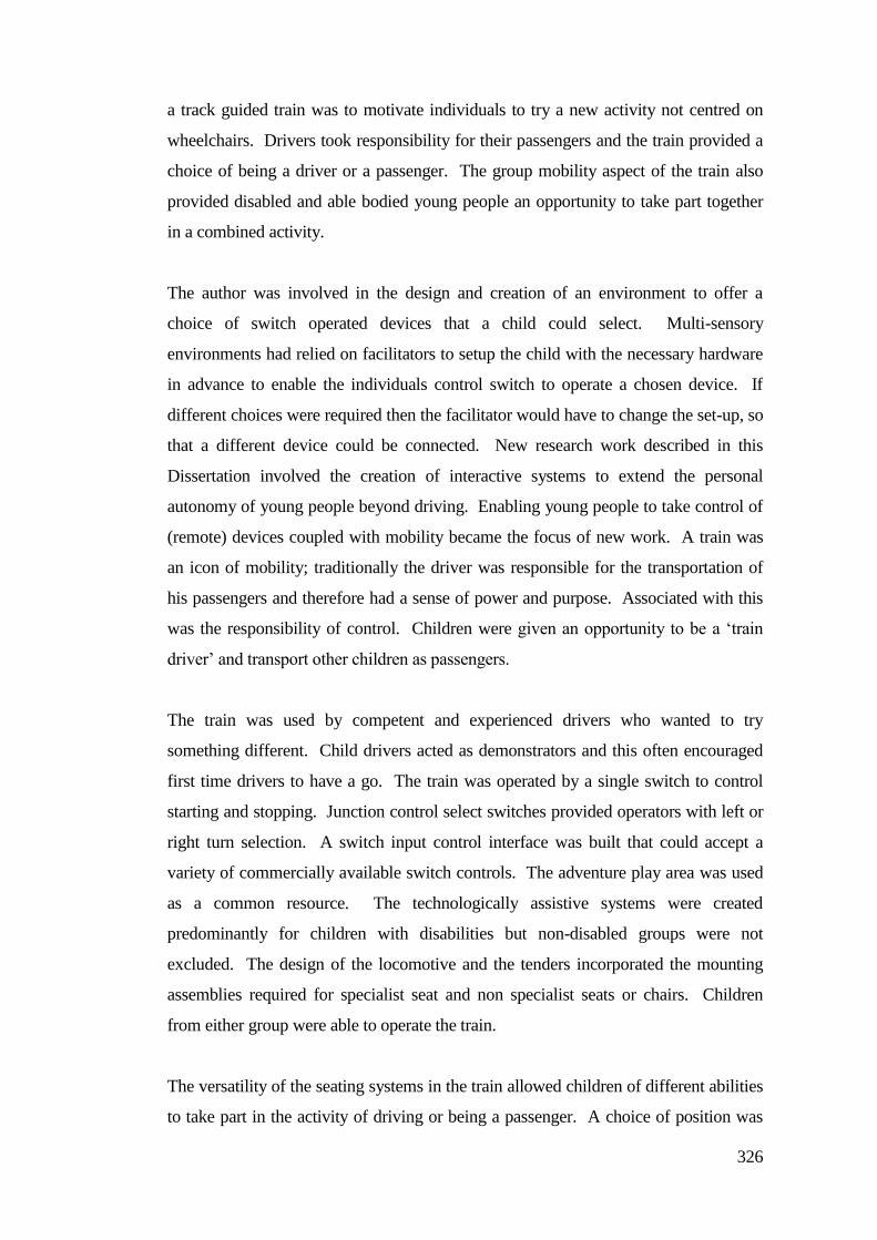
326
a track guided train was to motivate individuals to try a new activity not centred on
wheelchairs. Drivers took responsibility for their passengers and the train provided a
choice of being a driver or a passenger. The group mobility aspect of the train also
provided disabled and able bodied young people an opportunity to take part together
in a combined activity.
The author was involved in the design and creation of an environment to offer a
choice of switch operated devices that a child could select. Multi-sensory
environments had relied on facilitators to setup the child with the necessary hardware
in advance to enable the individuals control switch to operate a chosen device. If
different choices were required then the facilitator would have to change the set-up, so
that a different device could be connected. New research work described in this
Dissertation involved the creation of interactive systems to extend the personal
autonomy of young people beyond driving. Enabling young people to take control of
(remote) devices coupled with mobility became the focus of new work. A train was
an icon of mobility; traditionally the driver was responsible for the transportation of
his passengers and therefore had a sense of power and purpose. Associated with this
was the responsibility of control. Children were given an opportunity to be a ‘train
driver’ and transport other children as passengers.
The train was used by competent and experienced drivers who wanted to try
something different. Child drivers acted as demonstrators and this often encouraged
first time drivers to have a go. The train was operated by a single switch to control
starting and stopping. Junction control select switches provided operators with left or
right turn selection. A switch input control interface was built that could accept a
variety of commercially available switch controls. The adventure play area was used
as a common resource. The technologically assistive systems were created
predominantly for children with disabilities but non-disabled groups were not
excluded. The design of the locomotive and the tenders incorporated the mounting
assemblies required for specialist seat and non specialist seats or chairs. Children
from either group were able to operate the train.
The versatility of the seating systems in the train allowed children of different abilities
to take part in the activity of driving or being a passenger. A choice of position was
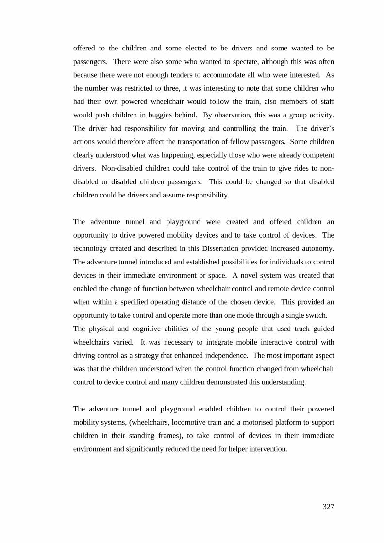
327
offered to the children and some elected to be drivers and some wanted to be
passengers. There were also some who wanted to spectate, although this was often
because there were not enough tenders to accommodate all who were interested. As
the number was restricted to three, it was interesting to note that some children who
had their own powered wheelchair would follow the train, also members of staff
would push children in buggies behind. By observation, this was a group activity.
The driver had responsibility for moving and controlling the train. The driver’s
actions would therefore affect the transportation of fellow passengers. Some children
clearly understood what was happening, especially those who were already competent
drivers. Non-disabled children could take control of the train to give rides to non-
disabled or disabled children passengers. This could be changed so that disabled
children could be drivers and assume responsibility.
The adventure tunnel and playground were created and offered children an
opportunity to drive powered mobility devices and to take control of devices. The
technology created and described in this Dissertation provided increased autonomy.
The adventure tunnel introduced and established possibilities for individuals to control
devices in their immediate environment or space. A novel system was created that
enabled the change of function between wheelchair control and remote device control
when within a specified operating distance of the chosen device. This provided an
opportunity to take control and operate more than one mode through a single switch.
The physical and cognitive abilities of the young people that used track guided
wheelchairs varied. It was necessary to integrate mobile interactive control with
driving control as a strategy that enhanced independence. The most important aspect
was that the children understood when the control function changed from wheelchair
control to device control and many children demonstrated this understanding.
The adventure tunnel and playground enabled children to control their powered
mobility systems, (wheelchairs, locomotive train and a motorised platform to support
children in their standing frames), to take control of devices in their immediate
environment and significantly reduced the need for helper intervention.
328
Chapter 12
Future work
The research described in this Dissertation identified several new areas of research,
some of which have been started during the write up phase of this dissertation. These
are described in the following sections.
12.1 Veer detection and correction systems
12.2 Track based audio (talking) sign post system
12.3 Power stander base developments integrating guidance systems
12.4 Single switch scanning controlled SCAD based control system
12.5 Potential commercialisation
Other work to be considered in the future is:
Proportional wheelchair control system incorporating SCAD
Proportional switch controls (including force feedback)
Merging track and SCAD systems together on a wheelchair
Tilt in space motional feedback platforms
Integrating veer detection and SCAD systems
Mobility devices for sporting activities (robotics for ball retrieval /
collection / throwing)
Personal energy tapping systems for student powered activities and energy
measurement applications
Haptic (force feedback) joystick linked to object detection feedback
12.1 Veer detection and correction systems
Theses systems are described in Chapter 3 and development work is continuing.
There were problems with the experimental anti-veer sensor. The castor swivel and
veer conditions were detected and fed back to the electronic wheelchair steering
control. The first anti-veer system shown in Figure 12.1, consisted of rotation sensor
created to fit over the front castor bearing.
329
.
This system demonstrated that troublesome wheelchair veer could be detected and
significantly reduced but there were problems if the wheelchair castor became caught
in a pothole or lost contact with the ground.
Observations showed that wheelchair frames were generally not flexible and did not
have any form of usable suspension. There were occasions when the wheelchair was
driven over uneven ground and castor angle feedback was unreliable (as seen in
Figure 12.2). This caused errors that resulted in indeterminate operation.
Work has started on developing a new system using swivel detectors on both castors
to reduce problems if one castor was lifted off the ground; the other would still be in
contact. This presented a new issue of how the system would know which castor was
Figure 12.2 The inflexible wheelchair frame
Figure 12.1 Castor rotation sensor
Rotation
sensor
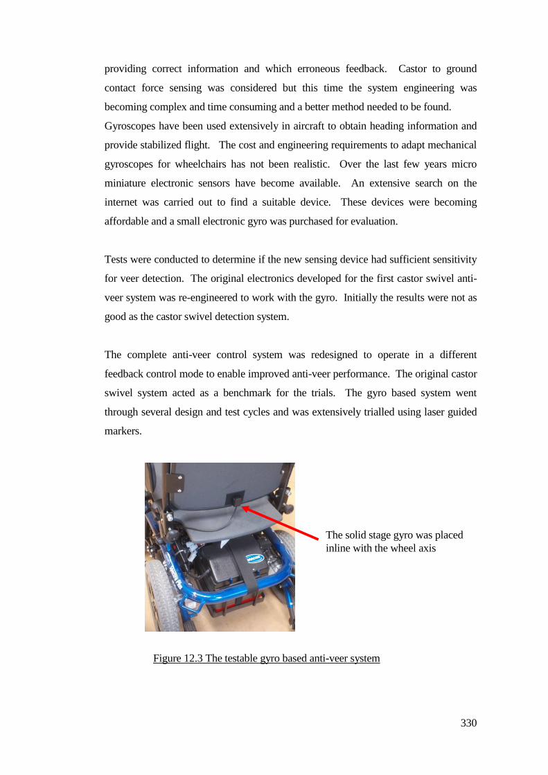
330
providing correct information and which erroneous feedback. Castor to ground
contact force sensing was considered but this time the system engineering was
becoming complex and time consuming and a better method needed to be found.
Gyroscopes have been used extensively in aircraft to obtain heading information and
provide stabilized flight. The cost and engineering requirements to adapt mechanical
gyroscopes for wheelchairs has not been realistic. Over the last few years micro
miniature electronic sensors have become available. An extensive search on the
internet was carried out to find a suitable device. These devices were becoming
affordable and a small electronic gyro was purchased for evaluation.
Tests were conducted to determine if the new sensing device had sufficient sensitivity
for veer detection. The original electronics developed for the first castor swivel anti-
veer system was re-engineered to work with the gyro. Initially the results were not as
good as the castor swivel detection system.
The complete anti-veer control system was redesigned to operate in a different
feedback control mode to enable improved anti-veer performance. The original castor
swivel system acted as a benchmark for the trials. The gyro based system went
through several design and test cycles and was extensively trialled using laser guided
markers.
The solid stage gyro was placed
inline with the wheel axis
Figure 12.3 The testable gyro based anti-veer system
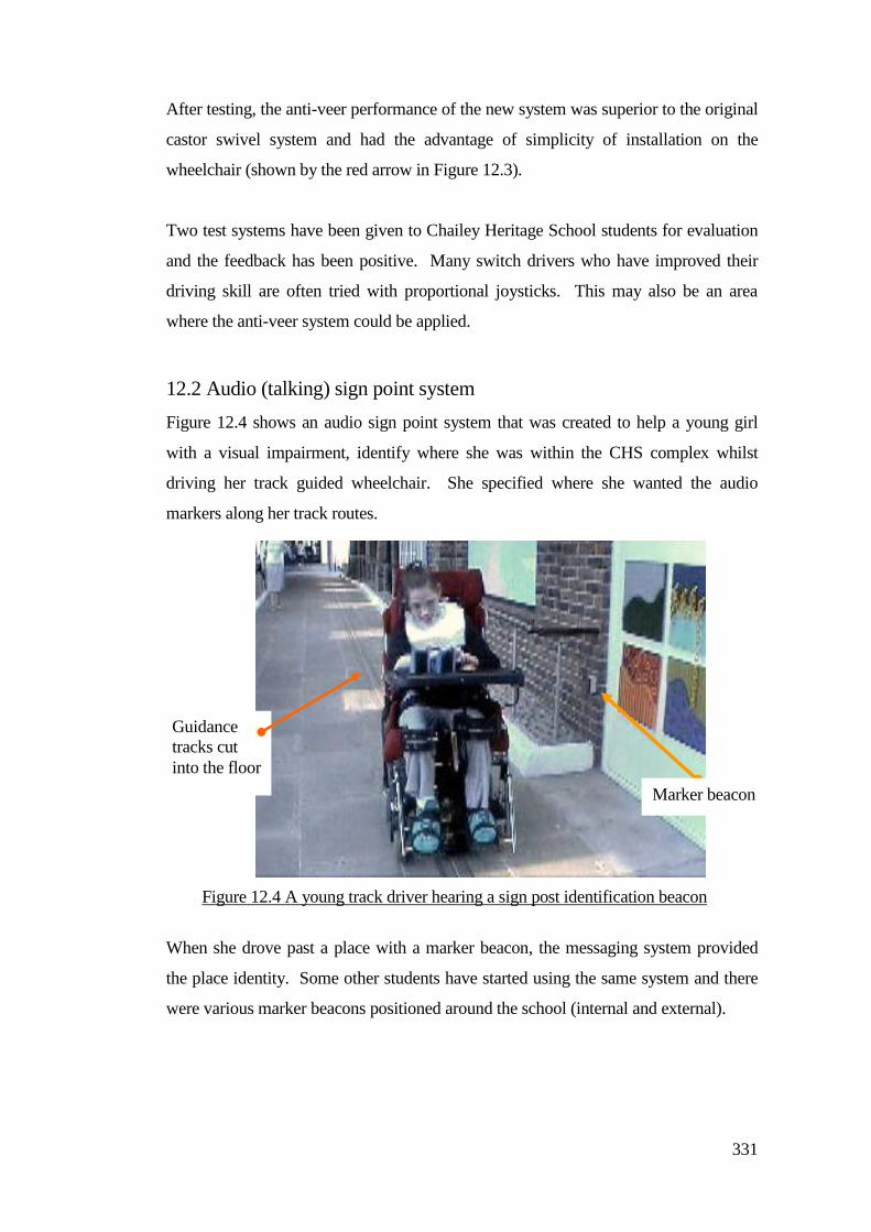
331
After testing, the anti-veer performance of the new system was superior to the original
castor swivel system and had the advantage of simplicity of installation on the
wheelchair (shown by the red arrow in Figure 12.3).
Two test systems have been given to Chailey Heritage School students for evaluation
and the feedback has been positive. Many switch drivers who have improved their
driving skill are often tried with proportional joysticks. This may also be an area
where the anti-veer system could be applied.
12.2 Audio (talking) sign point system
Figure 12.4 shows an audio sign point system that was created to help a young girl
with a visual impairment, identify where she was within the CHS complex whilst
driving her track guided wheelchair. She specified where she wanted the audio
markers along her track routes.
When she drove past a place with a marker beacon, the messaging system provided
the place identity. Some other students have started using the same system and there
were various marker beacons positioned around the school (internal and external).
Marker beacon
Guidance
tracks cut
into the floor
Figure 12.4 A young track driver hearing a sign post identification beacon
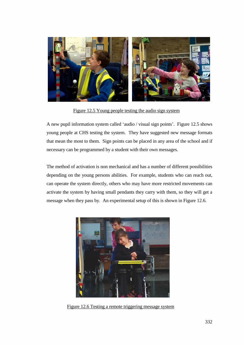
332
A new pupil information system called ‘audio / visual sign points’. Figure 12.5 shows
young people at CHS testing the system. They have suggested new message formats
that mean the most to them. Sign points can be placed in any area of the school and if
necessary can be programmed by a student with their own messages.
The method of activation is non mechanical and has a number of different possibilities
depending on the young persons abilities. For example, students who can reach out,
can operate the system directly, others who may have more restricted movements can
activate the system by having small pendants they carry with them, so they will get a
message when they pass by. An experimental setup of this is shown in Figure 12.6.
Figure 12.5 Young people testing the audio sign system
Figure 12.6 Testing a remote triggering message system
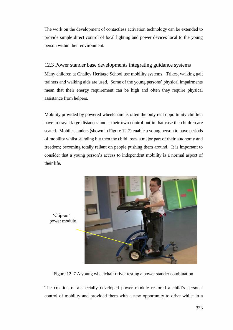
333
The work on the development of contactless activation technology can be extended to
provide simple direct control of local lighting and power devices local to the young
person within their environment.
12.3 Power stander base developments integrating guidance systems
Many children at Chailey Heritage School use mobility systems. Trikes, walking gait
trainers and walking aids are used. Some of the young persons’ physical impairments
mean that their energy requirement can be high and often they require physical
assistance from helpers.
Mobility provided by powered wheelchairs is often the only real opportunity children
have to travel large distances under their own control but in that case the children are
seated. Mobile standers (shown in Figure 12.7) enable a young person to have periods
of mobility whilst standing but then the child loses a major part of their autonomy and
freedom; becoming totally reliant on people pushing them around. It is important to
consider that a young person’s access to independent mobility is a normal aspect of
their life.
The creation of a specially developed power module restored a child’s personal
control of mobility and provided them with a new opportunity to drive whilst in a
‘Clip-on’
power module
Figure 12. 7 A young wheelchair driver testing a power stander combination
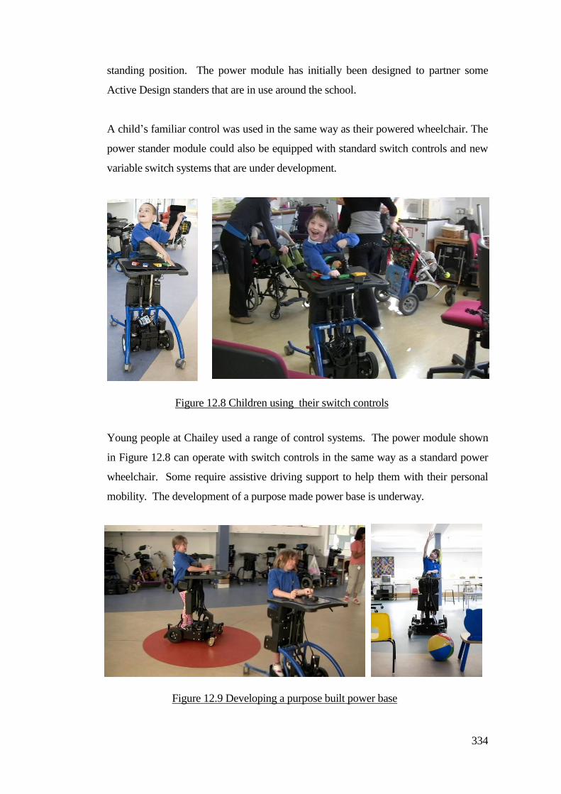
334
standing position. The power module has initially been designed to partner some
Active Design standers that are in use around the school.
A child’s familiar control was used in the same way as their powered wheelchair. The
power stander module could also be equipped with standard switch controls and new
variable switch systems that are under development.
Young people at Chailey used a range of control systems. The power module shown
in Figure 12.8 can operate with switch controls in the same way as a standard power
wheelchair. Some require assistive driving support to help them with their personal
mobility. The development of a purpose made power base is underway.
Figure 12.8 Children using their switch controls
Figure 12.9 Developing a purpose built power base
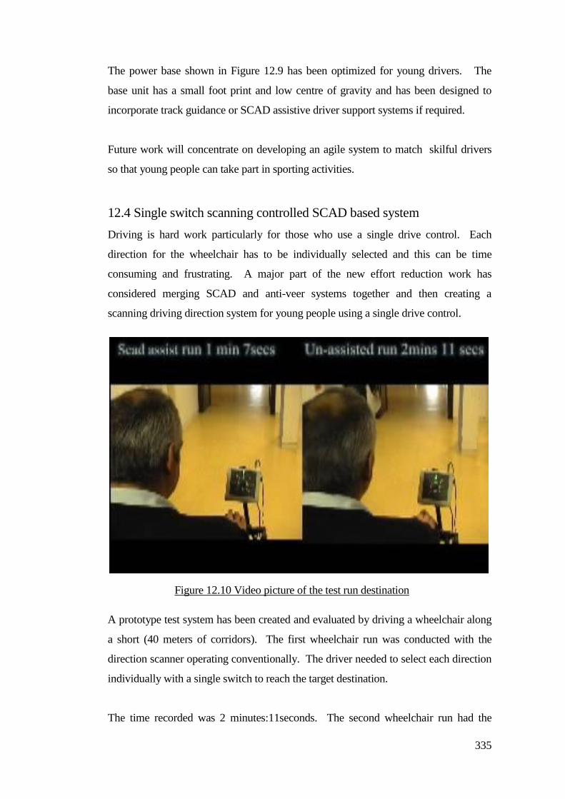
335
The power base shown in Figure 12.9 has been optimized for young drivers. The
base unit has a small foot print and low centre of gravity and has been designed to
incorporate track guidance or SCAD assistive driver support systems if required.
Future work will concentrate on developing an agile system to match skilful drivers
so that young people can take part in sporting activities.
12.4 Single switch scanning controlled SCAD based system
Driving is hard work particularly for those who use a single drive control. Each
direction for the wheelchair has to be individually selected and this can be time
consuming and frustrating. A major part of the new effort reduction work has
considered merging SCAD and anti-veer systems together and then creating a
scanning driving direction system for young people using a single drive control.
A prototype test system has been created and evaluated by driving a wheelchair along
a short (40 meters of corridors). The first wheelchair run was conducted with the
direction scanner operating conventionally. The driver needed to select each direction
individually with a single switch to reach the target destination.
The time recorded was 2 minutes:11seconds. The second wheelchair run had the
Figure 12.10 Video picture of the test run destination

336
SCAD system engaged.
Driving along the same route with the same switch, the run time was reduced to 1
minute:7seconds. It was noted that the second run needed only 10% of the number of
switch operations (when compared to the first run) to reach the destination.
This experiment was videoed and a clip is shown in Figure 12.10. The video showed
that the amount of effort required to drive along the route was 90% less in terms of the
number of control actions and it took half the time when compared to the standard
control system. The next phase of the effort reduction project is to create a working
system for students to test around the school complex and to monitor their reactions
and progress.
12.5 Potential commercialisation
During the process of this research interest was shown by visitors to the school,
parents of children and those who had attended presentations and seminars about this
research. Although this research was primarily applied to children, there were
enquiries about applications that could involve older people and possibly those in care
homes.
There were often questions and enquiries about the commercial availability of track
and SCAD systems. Indeed the author of this Dissertation had built systems privately
in his own home workshop, however the numbers produced were limited and did not
meet the numbers of enquiries.
At the time of writing Chailey Heritage School are perusing ways to make the SCAD
and track based assistive technology commercially available. This involved Author
working with enterprise organizations and people within the school with business
connections.

337
Appendix A
A.1 Ethical considerations
The aim of the research described in this Dissertation was to improve the
independence and self confidence of young people at Chailey Heritage School;
children with multiple complex disabilities. The young people were asked if they
wanted to take part in testing and trying new systems. It was carefully explained to
them, often by a person they knew and trusted, that they were taking part in new work
to help them drive. Many children could not communicate verbally and
communication with some children was a personal process. It was critical that a child
understood as best they could and that the children’s responses were interpreted
correctly. Sometimes special symbols were used and methods of eye gaze and
specific head movements or gestures were involved.
The work undertaken in this research was conducted under the guidance of the NHS
Chailey Clinical Services Organisation. The occupational therapists would oversee
research aspects, in particular identifying potential candidates and arraigning driving
practise sessions with the young people. Additionally Chailey Heritage School
applied strict safeguarding and child protection policies. This helped ensure that every
young person having special needs was being fully supported. Also a school
governing committee was kept informed throughout the progress of the research.
Children were not the only participants in the research. It was important to inform the
staff who were associated with the young people. Presentations and demonstrations
were given to therapy, teaching, caring staff and parents to explain the purpose and the
structure of the research work. At these meetings any concerns or views from the staff
were noted, particularly if there were any issues regarding children who had a
significant medical condition.
Parents or guardians were informed and their consent or otherwise was obtained.
Parents, family members and key workers were invited to visit or be present or
involved with driving sessions.

338
Photographic permission was obtained for all of the children shown in this
Dissertation. At the time of this research most children at Chailey Heritage School
had photographic permission for their picture to go into the public domain. Often
video recordings were made of the sessions and copies made and given to parents and
therapy staff.
There were some young people who had photographic restrictions. Accordingly, any
video recordings or pictures taken for research purposes were kept alongside the
young person’s medical record files. These were held in a secure place for which only
specific members of staff had access.
In all driving research based sessions an occupational therapist, physiotherapist or
specific key worker was present. A young person sometimes responded positively
when a particular person was with them. Conversely sometimes particular people had
an adverse effect and this was noted.
Teaching and medical nursing staff were informed about the times children would be
taking part in the research so they could find them if needed. Accordingly any
disruption to school lessons or child related activities was minimised wherever
possible.
If a child became distressed or anxious during a driving session, they would be taken
away from the situation unless the issue could be resolved by communication at the
time. Sometimes children were uncomfortable in their seating or posture support
system, so it was important to establish the cause of their discomfort.
As the research progressed the SCAD and track systems were used by more young
people. The requirements for a therapist and researcher to be around was reduced.
Generally the research based systems became integrated within the general school
activities that the children were involved with. Reporting structures were setup so that
the children’s progress or problems could be reported or monitored by nominated
members of staff.
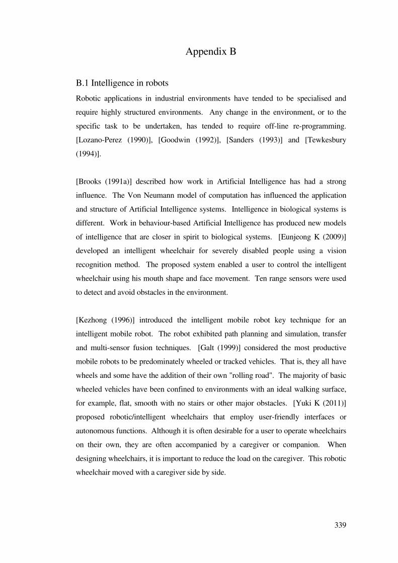
339
Appendix B
B.1 Intelligence in robots
Robotic applications in industrial environments have tended to be specialised and
require highly structured environments. Any change in the environment, or to the
specific task to be undertaken, has tended to require off-line re-programming.
[Lozano-Perez (1990)], [Goodwin (1992)], [Sanders (1993)] and [Tewkesbury
(1994)].
[Brooks (1991a)] described how work in Artificial Intelligence has had a strong
influence. The Von Neumann model of computation has influenced the application
and structure of Artificial Intelligence systems. Intelligence in biological systems is
different. Work in behaviour-based Artificial Intelligence has produced new models
of intelligence that are closer in spirit to biological systems. [Eunjeong K (2009)]
developed an intelligent wheelchair for severely disabled people using a vision
recognition method. The proposed system enabled a user to control the intelligent
wheelchair using his mouth shape and face movement. Ten range sensors were used
to detect and avoid obstacles in the environment.
[Kezhong (1996)] introduced the intelligent mobile robot key technique for an
intelligent mobile robot. The robot exhibited path planning and simulation, transfer
and multi-sensor fusion techniques. [Galt (1999)] considered the most productive
mobile robots to be predominately wheeled or tracked vehicles. That is, they all have
wheels and some have the addition of their own "rolling road". The majority of basic
wheeled vehicles have been confined to environments with an ideal walking surface,
for example, flat, smooth with no stairs or other major obstacles. [Yuki K (2011)]
proposed robotic/intelligent wheelchairs that employ user-friendly interfaces or
autonomous functions. Although it is often desirable for a user to operate wheelchairs
on their own, they are often accompanied by a caregiver or companion. When
designing wheelchairs, it is important to reduce the load on the caregiver. This robotic
wheelchair moved with a caregiver side by side.
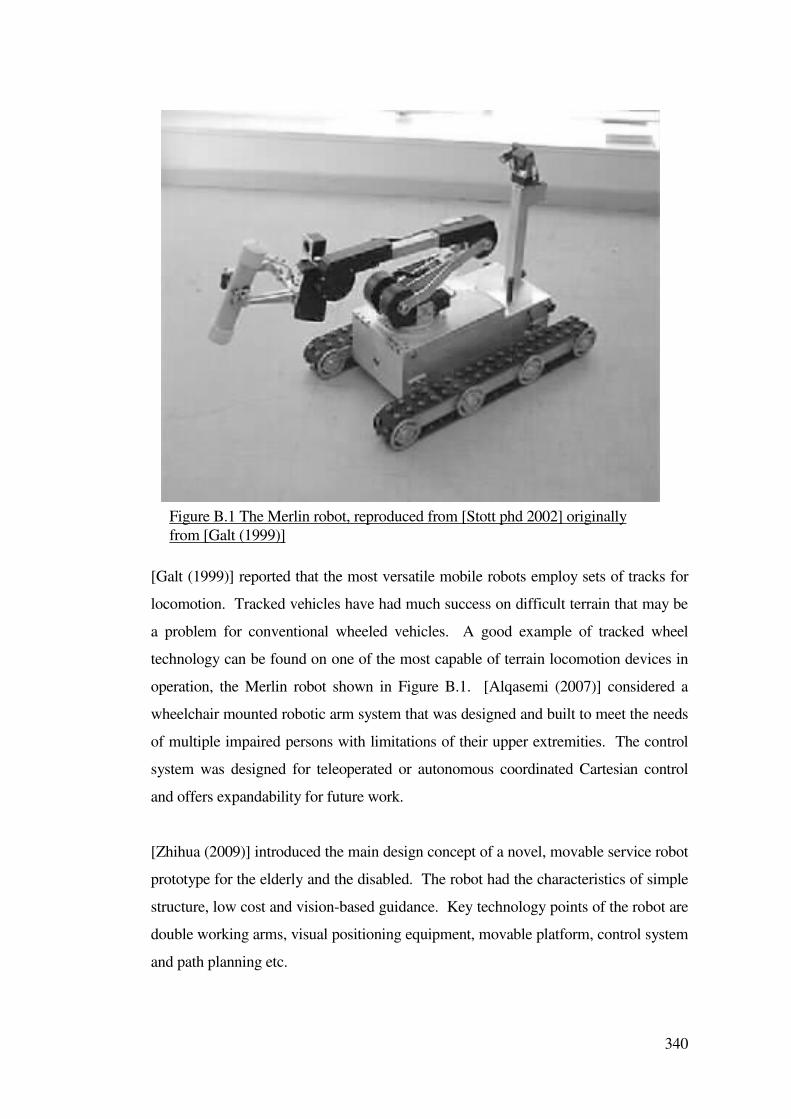
340
[Galt (1999)] reported that the most versatile mobile robots employ sets of tracks for
locomotion. Tracked vehicles have had much success on difficult terrain that may be
a problem for conventional wheeled vehicles. A good example of tracked wheel
technology can be found on one of the most capable of terrain locomotion devices in
operation, the Merlin robot shown in Figure B.1. [Alqasemi (2007)] considered a
wheelchair mounted robotic arm system that was designed and built to meet the needs
of multiple impaired persons with limitations of their upper extremities. The control
system was designed for teleoperated or autonomous coordinated Cartesian control
and offers expandability for future work.
[Zhihua (2009)] introduced the main design concept of a novel, movable service robot
prototype for the elderly and the disabled. The robot had the characteristics of simple
structure, low cost and vision-based guidance. Key technology points of the robot are
double working arms, visual positioning equipment, movable platform, control system
and path planning etc.
Figure B.1 The Merlin robot, reproduced from [Stott phd 2002] originally
from [Galt (1999)]
341
The work described in this Dissertation, built on this previous work on automated
applications for persons having disabilities and problems with wheelchair control.
B.2 Communications
For wire guided systems it could be convenient for fixed control computers to
communicate with the vehicle. This was achieved by combining the communicating
signals and guidance signals on the same wire [Langner Thesis (2004)]. A vehicle
picked up both and unscrambled them. Similarly the vehicle could transmit
information back through the same medium to a computer, providing a two-way link.
Two mediums were considered in sections B.2.1 and B.2.2.
B.2.1 Radio
Frequency modulated radio links could be installed that provided near-continuous
communication with all vehicles. [Hartley (1987)] used radio instructions to change
the path of some vehicles. Real time wireless sensor networks have been developed to
help provide information to visually impaired people to help give them more
independence within in their local environment. [Sevillano (2009)] describes the
availability of inexpensive low power hardware including, low power Cmos cameras
and wireless devices that make it possible to deploy a wireless sensor network to
function as a navigation aid for wheelchairs.
B.2.2 Infrared
Infrared links were also used for local interactive communication. Infrared had
advantages when compared with radio because the areas covered could be tightly
controlled and contained within operational areas or cells.
B.3 Force feedback
A human and a robot could carry out a task which was not attainable by themselves.
In particular, a human recognizes environments and plans a trajectory without
collision with obstacles. A robot can generate a controlled force more consistently
than a human. [Katsura S(2004)] considered a combination of human ability and robot
capacity based on force commands from a human.
342
Another technique for assisting a user to steer a powered wheelchair was described by
[Brienza, Angelo (1996)], with a force feedback joystick and control algorithm for
wheelchair obstacle avoidance. Common tasks such as traversing through doorways,
turning around in halls or travelling on a straight path were described as being
complicated by an inability to accurately and reliably control the wheelchair with a
joystick or other common input device. Or, by a sensory impairment that prevented
the user from receiving feedback from the environment”. An active joystick with
force feedback to indicate obstacles in the environment was developed.
An active force feedback joystick was used to assist a user to navigate in an unknown
environment. Sensors were fitted to the wheelchair to sense that environment. The
wheelchair system had two modes of assistance; passive assist where the joystick
became stiffer to discourage trajectories which would cause a collision, and active
assist where the wheelchair system moved the joystick to degrees of freedom (moved
the central position). Active assist steered the wheelchair away from objects. Passive
assist tried to make the user steer away from an object.
The paper led to the suggestion that this system could be connected to a device that
could assist in unknown environments and to help in pre-mapped environments along
predetermined paths. A related application using power assist control by repulsive
compliance control of an electric wheelchair was described by [Shabita (2008)], who
described a power assist control to assist in the pushing task of an electric driven
wheelchair. Wheelchairs were widely used in the daily lives of disabled people. A
new power assist control for the pushing task was proposed as an intelligent function
of wheelchair. This was called a repulsive compliance control. In this strategy, the
reaction force of human input into object is estimated and was utilized to generate the
power assist torque for the wheels and made it easier to carry out the pushing task by
wheelchair users.
Further work was undertaken with the aim of implementing a force feedback joystick
system with a set of range sensors. [Bourhis (2007)] considered a system intended for
people with a disability for whom a traditional joystick control (or any other adapted
sensor control) was difficult or impossible because of their severe motor disabilities.
The force feedback was calculated according to the proximity of the obstacles and
343
helped the user, without forcing them, to move towards a free direction.
B.4 Sensor fusion
A single sensor system working in isolation typically could provide limited
information for the system. Sensor arrays may be used to enhance data rate and
accuracy of the system. Sensor fusion methods are described in [Purcell, Huisoon
(1993)], [Chang, Song (1996)], [Fatemi, Lecocq (1996)], [Guey et al (1997)]and
(Sanders (1993)].
[Song (1996)] described a navigation system that allowed a robot to travel in an
environment about which it had no prior knowledge. Data from multiple ultrasonic
range sensors were fused into a representation called Heuristic Asymmetric Mapping
to deal with the problem of uncertainties in the raw sensory data caused mainly by the
transducer’s beam-opening angle and specular reflections. A potential field method
was used for on-line path planning based on the constructed grid based sonar map.
The problems faced by users of ultrasonic sensors include the high incidence of
misreads which was typical of these systems. Histogrammic In Motion Mapping
(HIMM) and Vector Field Histograms (VFH) have been used to reduce the effect of
misreads. [Murphy(1996)] compared HIMM/VFH and Dempster-Shafer techniques
for obstacle detection for a moving robot. The HIMM/VFH methodology worked
well for a robot navigating at high speeds, but the algorithms showed poor
performance at lower speeds in cluttered areas as the beam width created a wide, slow
moving area in which the object could be located. The number of grid elements
updated varied as a function of the robot’s velocity. In addition, varying the beam
width with the velocity of the robot improved the updating of an occupancy grid using
Dempster-Shafer theory versus that of HIMM. The Dempster-Shafer method tended
to handle noise better and make smoother and more realistic maps.
[Gilbert ,Johnson (1985)] and [Khatib (1986)] applied the method of representing
obstacles by distance functions, in the case of Khatib, who was motivated by the
electrostatic repulsion between like charges. For example, the mover and obstacles
could be represented by positive charges. This artificial potential repulsion approach
was aimed at the local, short-term avoidance of obstacles in real time rather than
344
automatic planning of paths. Although the algorithm did not quite solve the find-path
problem, the use of a repulsion force made this algorithm original and the system
worked in near real time. The function tended to infinity as the point approached the
surface and was zero beyond a certain distance from the obstacle. This representation
had the advantage that the task of calculating the distance between a robot and an
obstacle was replaced by the task of evaluating the simpler function. Compared to
solid geometry or polyhedral models, these calculations were relatively fast.
The repulsion force was generated by a fictitious potential field around each obstacle
due to a potential assigned to it. When any link of a robot arm approached an
obstacle, a repulsive force pushed the link away from the obstacle.
B.5 Navigation
Navigation is primarily concerned with path selection. It uses the terrain and
information from other sensors to chart the most appropriate course for the vehicle
[Kumar, Waldron (1989)]. In path planning, a prerequisite to circumventing any
obstacle is to detect it. Various methods for detecting obstacles have been proposed
by different authors including [Doty, Govindaraj (1982)], [Sanders et al (1992)] and
[Fu, Gonzalez ,Lee (1987)].
Many researchers were interested in electric wheelchair automation because of the
mobility problems met by a certain number of young disabled and older people. [Njah
M (2009)] proposed a system equipped with unit control and sensors to extract some
information.
A fuzzy controller generated control information to the wheelchair wheels to reach the
target position. An example of retrieving location data universally was via the (GPS)
Global Positioning Satellite System. Originally developed by the US defense
department for military purposes, twenty four satellites were launched at high cost.
The system accuracy was purposefully degraded for military purposes, but potential
accuracies to within one meter could be achieved [Borenstien et al (1997)]. This
navigation system has found a wide commercial market and is used for shipping,
aircraft and general transportation of goods and personal transport.
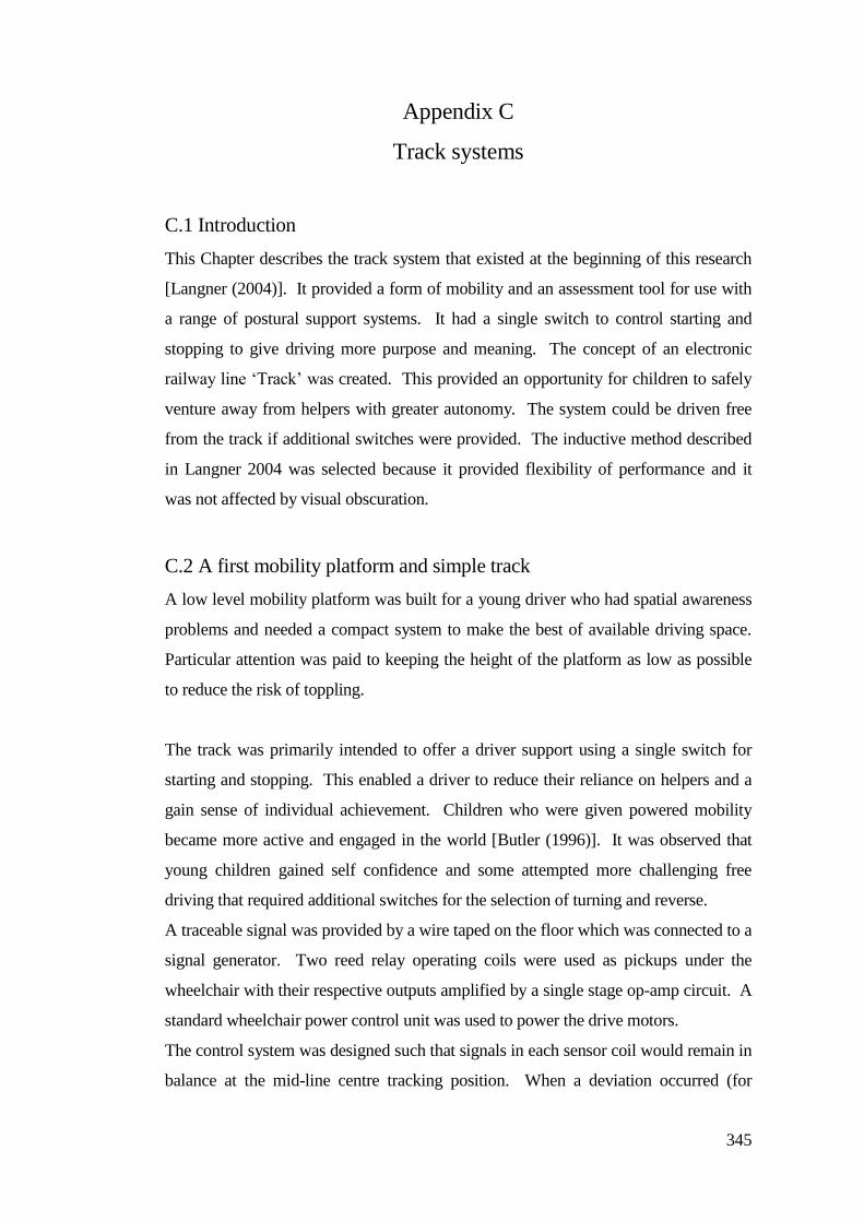
345
Appendix C
Track systems
C.1 Introduction
This Chapter describes the track system that existed at the beginning of this research
[Langner (2004)]. It provided a form of mobility and an assessment tool for use with
a range of postural support systems. It had a single switch to control starting and
stopping to give driving more purpose and meaning. The concept of an electronic
railway line ‘Track’ was created. This provided an opportunity for children to safely
venture away from helpers with greater autonomy. The system could be driven free
from the track if additional switches were provided. The inductive method described
in Langner 2004 was selected because it provided flexibility of performance and it
was not affected by visual obscuration.
C.2 A first mobility platform and simple track
A low level mobility platform was built for a young driver who had spatial awareness
problems and needed a compact system to make the best of available driving space.
Particular attention was paid to keeping the height of the platform as low as possible
to reduce the risk of toppling.
The track was primarily intended to offer a driver support using a single switch for
starting and stopping. This enabled a driver to reduce their reliance on helpers and a
gain sense of individual achievement. Children who were given powered mobility
became more active and engaged in the world [Butler (1996)]. It was observed that
young children gained self confidence and some attempted more challenging free
driving that required additional switches for the selection of turning and reverse.
A traceable signal was provided by a wire taped on the floor which was connected to a
signal generator. Two reed relay operating coils were used as pickups under the
wheelchair with their respective outputs amplified by a single stage op-amp circuit. A
standard wheelchair power control unit was used to power the drive motors.
The control system was designed such that signals in each sensor coil would remain in
balance at the mid-line centre tracking position. When a deviation occurred (for
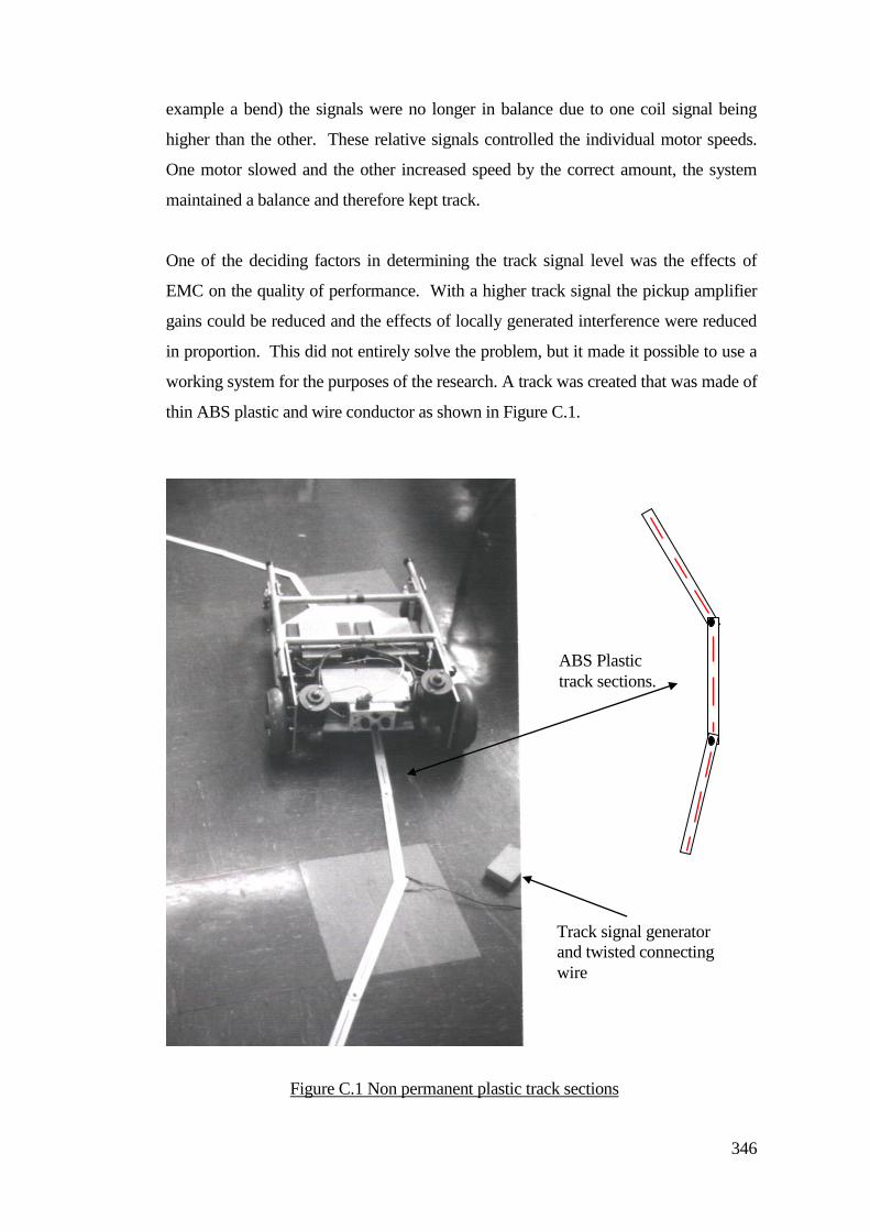
346
example a bend) the signals were no longer in balance due to one coil signal being
higher than the other. These relative signals controlled the individual motor speeds.
One motor slowed and the other increased speed by the correct amount, the system
maintained a balance and therefore kept track.
One of the deciding factors in determining the track signal level was the effects of
EMC on the quality of performance. With a higher track signal the pickup amplifier
gains could be reduced and the effects of locally generated interference were reduced
in proportion. This did not entirely solve the problem, but it made it possible to use a
working system for the purposes of the research. A track was created that was made of
thin ABS plastic and wire conductor as shown in Figure C.1.
ABS Plastic
track sections.
Track signal generator
and twisted connecting
wire
Figure C.1 Non permanent plastic track sections
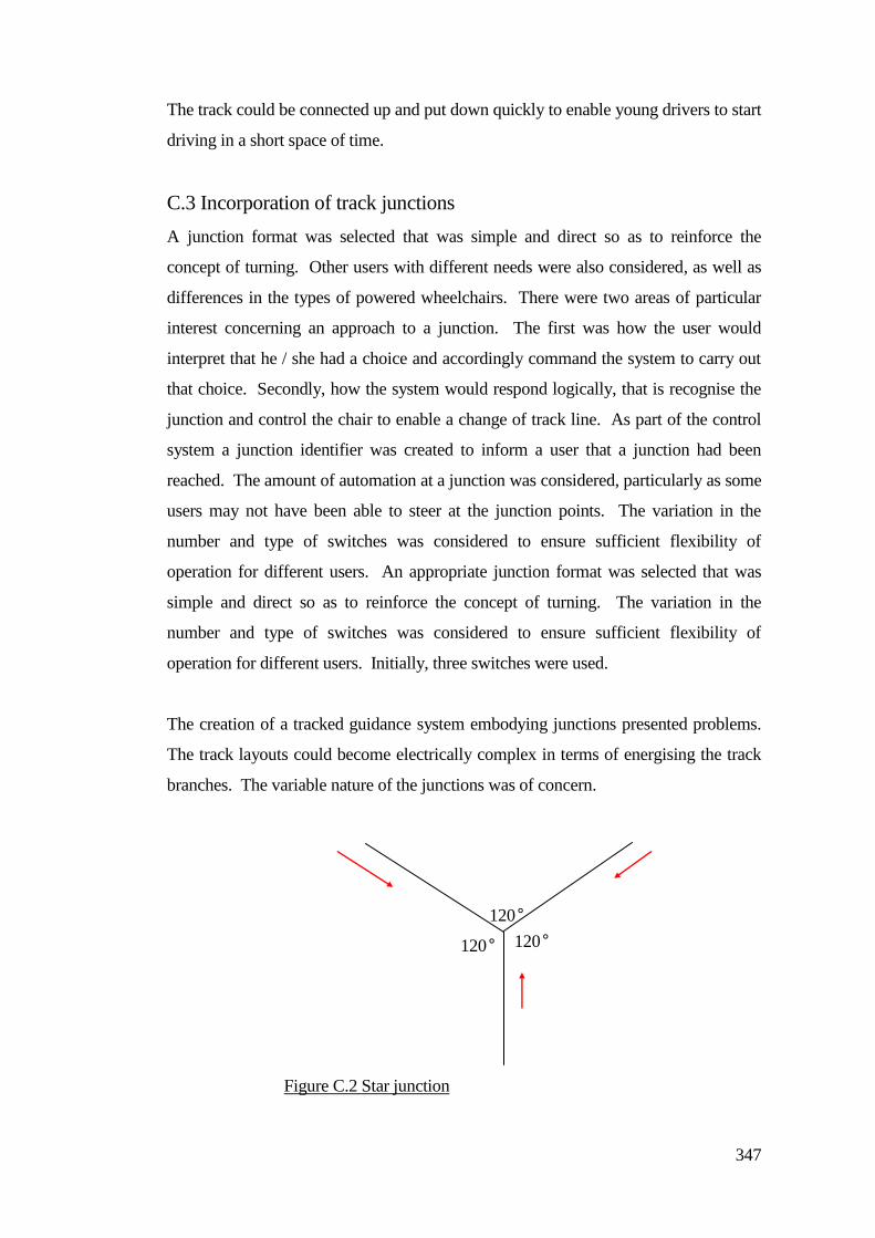
347
The track could be connected up and put down quickly to enable young drivers to start
driving in a short space of time.
C.3 Incorporation of track junctions
A junction format was selected that was simple and direct so as to reinforce the
concept of turning. Other users with different needs were also considered, as well as
differences in the types of powered wheelchairs. There were two areas of particular
interest concerning an approach to a junction. The first was how the user would
interpret that he / she had a choice and accordingly command the system to carry out
that choice. Secondly, how the system would respond logically, that is recognise the
junction and control the chair to enable a change of track line. As part of the control
system a junction identifier was created to inform a user that a junction had been
reached. The amount of automation at a junction was considered, particularly as some
users may not have been able to steer at the junction points. The variation in the
number and type of switches was considered to ensure sufficient flexibility of
operation for different users. An appropriate junction format was selected that was
simple and direct so as to reinforce the concept of turning. The variation in the
number and type of switches was considered to ensure sufficient flexibility of
operation for different users. Initially, three switches were used.
The creation of a tracked guidance system embodying junctions presented problems.
The track layouts could become electrically complex in terms of energising the track
branches. The variable nature of the junctions was of concern.
120°
120° 120°
Figure C.2 Star junction
348
For a young new user, a simple and repeatable choice was desirable, for this reason a
simplified junction was created that offered the same left or right direction selection
for any approach spur. This is shown in Figure C.2.
The guidance system needed additional detectors and control logic for junction
detection and control but it proved difficult to use or alter the existing tracking
components for the junction detection process. Figure C.2 shows a star type junction
that had the same options for any approach spur. These were always left or right.
This was a simple starting point for users to learn direction selection. The star had a
recognisable signature that simplified the detection process. Although the junction
was symmetrical by appearance, the electromagnetic field strengths were not. The
feed wire or the source conductor connected to the track generator divided into two, to
form the junction spurs. This also divided the signal in each of the spurs to half the
feed level. Spurs would be different lengths and accordingly have different relative
resistances. Figure C.3 shows the termination resistors were used to equalise the path
resistances and signal levels.
The return signal paths from the track end points to the signal generator used the
electrical mains earth cable for convenience. Detecting a junction required additional
pickup coils that did not produce any meaningful output during normal track
following. When at a junction they both produced a significant signal output from the
Termination
resister
VR1
V1
Gnd Gnd
Gnd
120°
120° 120°
Signal
generator
Left spur Right spur
Figure C.3 Track termination resistors
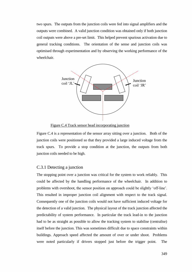
349
two spurs. The outputs from the junction coils were fed into signal amplifiers and the
outputs were combined. A valid junction condition was obtained only if both junction
coil outputs were above a pre-set limit. This helped prevent spurious activation due to
general tracking conditions. The orientation of the sense and junction coils was
optimised through experimentation and by observing the working performance of the
wheelchair.
Figure C.4 is a representation of the sensor array sitting over a junction. Both of the
junction coils were positioned so that they provided a large induced voltage from the
track spurs. To provide a stop condition at the junction, the outputs from both
junction coils needed to be high.
C.3.1 Detecting a junction
The stopping point over a junction was critical for the system to work reliably. This
could be affected by the handling performance of the wheelchair. In addition to
problems with overshoot, the sensor position on approach could be slightly ‘off-line’.
This resulted in improper junction coil alignment with respect to the track signal.
Consequently one of the junction coils would not have sufficient induced voltage for
the detection of a valid junction. The physical layout of the track junction affected the
predictability of system performance. In particular the track lead-in to the junction
had to be as straight as possible to allow the tracking system to stabilise (centralise)
itself before the junction. This was sometimes difficult due to space constraints within
buildings. Approach speed affected the amount of over or under shoot. Problems
were noted particularly if drivers stopped just before the trigger point. The
Junction
coil ‘JL’ Junction
coil ‘JR’
Figure C.4 Track sensor head incorporating junction
detector. coils.
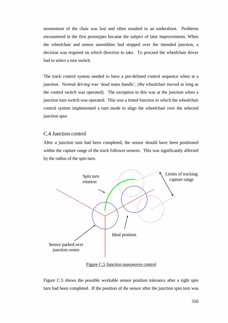
350
momentum of the chair was lost and often resulted in an undershoot. Problems
encountered in the first prototypes became the subject of later improvements. When
the wheelchair and sensor assemblies had stopped over the intended junction, a
decision was required on which direction to take. To proceed the wheelchair driver
had to select a turn switch.
The track control system needed to have a pre-defined control sequence when at a
junction. Normal driving was ‘dead mans handle’, (the wheelchair moved as long as
the control switch was operated). The exception to this was at the junction when a
junction turn switch was operated. This was a timed function in which the wheelchair
control system implemented a turn mode to align the wheelchair over the selected
junction spur.
C.4 Junction control
After a junction turn had been completed, the sensor should have been positioned
within the capture range of the track follower sensors. This was significantly affected
by the radius of the spin turn.
Figure C.5 shows the possible workable sensor position tolerance after a right spin
turn had been completed. If the position of the sensor after the junction spin turn was
Limits of tracking
capture range Spin turn
rotation
Sensor parked over
junction centre
Ideal position
Figure C.5 Junction manoeuvre control
351
outside of the ‘capture range’ the induced voltages in the tracking coils were too low
to provide the necessary control voltages for guidance tracking and the system failed.
In practice the junction overshoots were mainly caused by fast approach speeds. To
counter this, the deceleration time of the wheelchair was shortened to reduce the over
shoot. This produced an abrupt stop when driving at an acceptable speed when the
junction trigger point had been reached. Similarly when the user stopped by
deactivating the drive switch then the wheelchair stopped abruptly.
C.5 Multi-junction systems
There were fundamental problems limiting the number of junctions due to signal
division at junction spurs. When the track conductor divided to produce a junction,
so did the tracking signal current. This put a severe limit on the number of junctions.
Early research was mainly targeted at a small group of individuals. During this time,
the concept of guided travel for children started to provide opportunities for others
who were having difficulties driving or who had not been introduced to powered
wheelchair driving before. Further research work was undertaken to expand the
number of users on the track and to increase the number of junctions.
C.6.1 Two channel multiplexed tracks
A new multi-junction wheelchair guidance system was created. The new multi-
junction system used a different method of signal branching where track signal was
time distributed. The spurs of the junction were sequentially energised with a signal
level that was set to be equal for each limb of the junction.
A different method of energisation was applied to address the problem of signal
division as shown by Figure C.6.
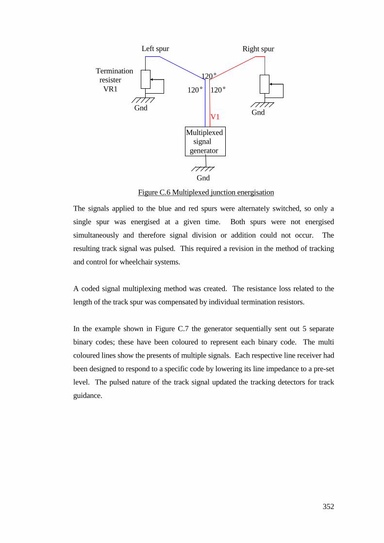
352
The signals applied to the blue and red spurs were alternately switched, so only a
single spur was energised at a given time. Both spurs were not energised
simultaneously and therefore signal division or addition could not occur. The
resulting track signal was pulsed. This required a revision in the method of tracking
and control for wheelchair systems.
A coded signal multiplexing method was created. The resistance loss related to the
length of the track spur was compensated by individual termination resistors.
In the example shown in Figure C.7 the generator sequentially sent out 5 separate
binary codes; these have been coloured to represent each binary code. The multi
coloured lines show the presents of multiple signals. Each respective line receiver had
been designed to respond to a specific code by lowering its line impedance to a pre-set
level. The pulsed nature of the track signal updated the tracking detectors for track
guidance.
Termination
resister
VR1
V1
Gnd Gnd
Gnd
120°
120° 120°
Multiplexed
signal
generator
Left spur Right spur
Figure C.6 Multiplexed junction energisation
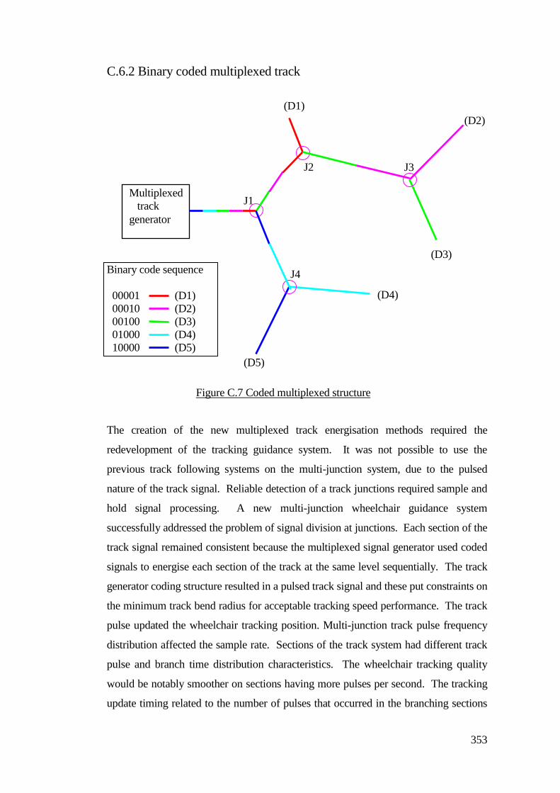
353
C.6.2 Binary coded multiplexed track
Binary code sequence
00001 (D1)
00010 (D2)
00100 (D3)
01000 (D4)
10000 (D5)
The creation of the new multiplexed track energisation methods required the
redevelopment of the tracking guidance system. It was not possible to use the
previous track following systems on the multi-junction system, due to the pulsed
nature of the track signal. Reliable detection of a track junctions required sample and
hold signal processing. A new multi-junction wheelchair guidance system
successfully addressed the problem of signal division at junctions. Each section of the
track signal remained consistent because the multiplexed signal generator used coded
signals to energise each section of the track at the same level sequentially. The track
generator coding structure resulted in a pulsed track signal and these put constraints on
the minimum track bend radius for acceptable tracking speed performance. The track
pulse updated the wheelchair tracking position. Multi-junction track pulse frequency
distribution affected the sample rate. Sections of the track system had different track
pulse and branch time distribution characteristics. The wheelchair tracking quality
would be notably smoother on sections having more pulses per second. The tracking
update timing related to the number of pulses that occurred in the branching sections
(D2)
(D3)
(D4)
(D5)
J1
J2 J3
J4
Multiplexed
track
generator
(D1)
Figure C.7 Coded multiplexed structure
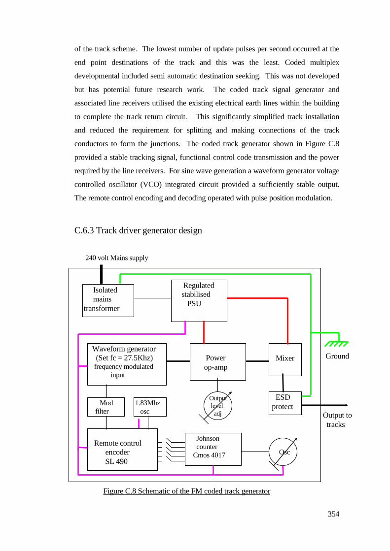
354
of the track scheme. The lowest number of update pulses per second occurred at the
end point destinations of the track and this was the least. Coded multiplex
developmental included semi automatic destination seeking. This was not developed
but has potential future research work. The coded track signal generator and
associated line receivers utilised the existing electrical earth lines within the building
to complete the track return circuit. This significantly simplified track installation
and reduced the requirement for splitting and making connections of the track
conductors to form the junctions. The coded track generator shown in Figure C.8
provided a stable tracking signal, functional control code transmission and the power
required by the line receivers. For sine wave generation a waveform generator voltage
controlled oscillator (VCO) integrated circuit provided a sufficiently stable output.
The remote control encoding and decoding operated with pulse position modulation.
C.6.3 Track driver generator design
Regulated
stabilised
PSU
Isolated
mains
transformer
Mixer
Power
op-amp
Waveform generator
(Set fc = 27.5Khz) frequency modulated
input
Mod
filter
1.83Mhz
osc
Remote control
encoder
SL 490
Johnson
counter
Cmos 4017 Osc
ESD
protect
240 volt Mains supply
Output
level
adj Output to
tracks
Ground
Figure C.8 Schematic of the FM coded track generator
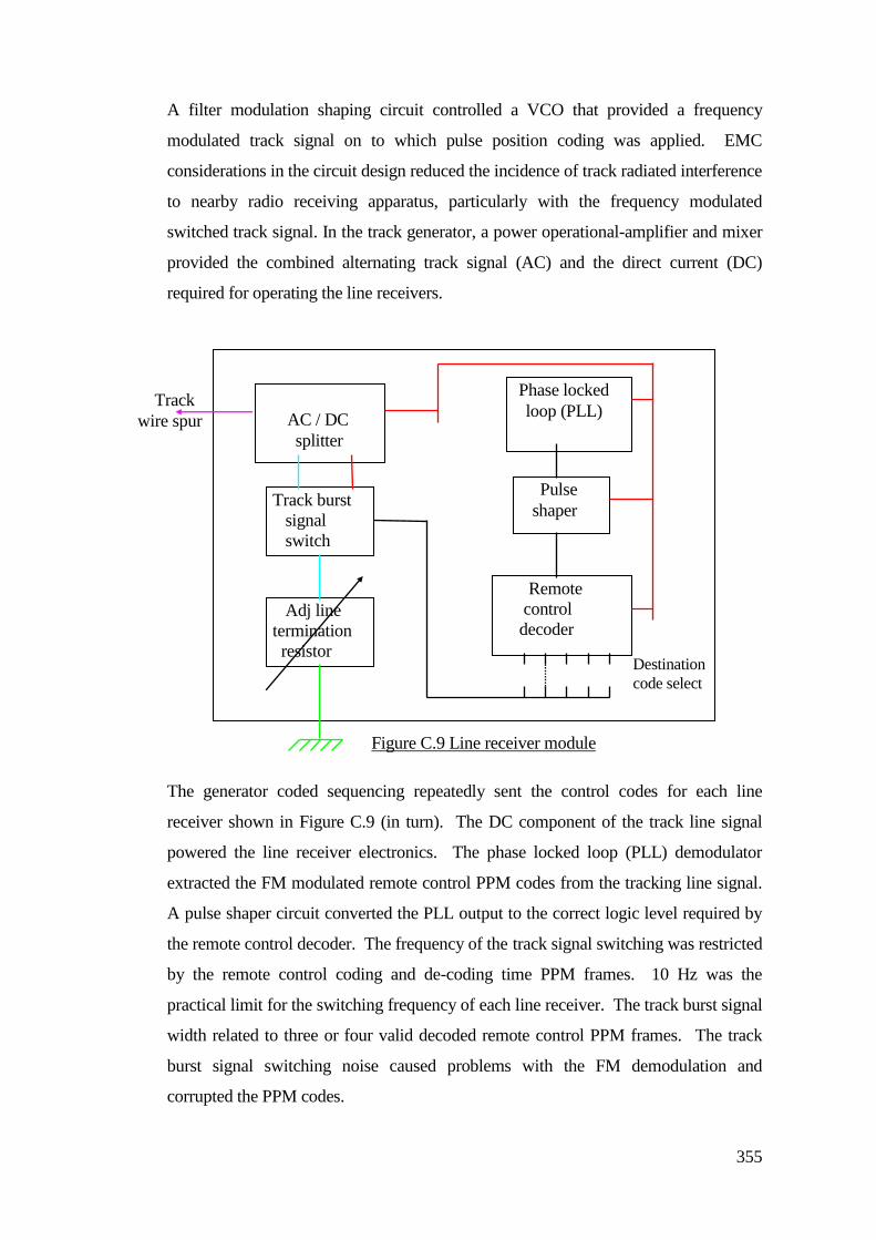
355
A filter modulation shaping circuit controlled a VCO that provided a frequency
modulated track signal on to which pulse position coding was applied. EMC
considerations in the circuit design reduced the incidence of track radiated interference
to nearby radio receiving apparatus, particularly with the frequency modulated
switched track signal. In the track generator, a power operational-amplifier and mixer
provided the combined alternating track signal (AC) and the direct current (DC)
required for operating the line receivers.
The generator coded sequencing repeatedly sent the control codes for each line
receiver shown in Figure C.9 (in turn). The DC component of the track line signal
powered the line receiver electronics. The phase locked loop (PLL) demodulator
extracted the FM modulated remote control PPM codes from the tracking line signal.
A pulse shaper circuit converted the PLL output to the correct logic level required by
the remote control decoder. The frequency of the track signal switching was restricted
by the remote control coding and de-coding time PPM frames. 10 Hz was the
practical limit for the switching frequency of each line receiver. The track burst signal
width related to three or four valid decoded remote control PPM frames. The track
burst signal switching noise caused problems with the FM demodulation and
corrupted the PPM codes.
AC / DC
splitter
Phase locked
loop (PLL)
Pulse
shaper
Remote
control
decoder
Track burst
signal
switch
Adj line
termination
resistor Destination
code select
Track
wire spur
Figure C.9 Line receiver module
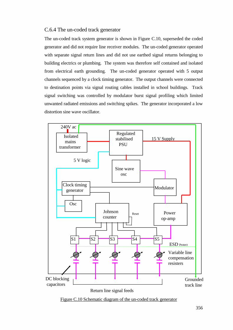
356
C.6.4 The un-coded track generator
The un-coded track system generator is shown in Figure C.10, superseded the coded
generator and did not require line receiver modules. The un-coded generator operated
with separate signal return lines and did not use earthed signal returns belonging to
building electrics or plumbing. The system was therefore self contained and isolated
from electrical earth grounding. The un-coded generator operated with 5 output
channels sequenced by a clock timing generator. The output channels were connected
to destination points via signal routing cables installed in school buildings. Track
signal switching was controlled by modulator burst signal profiling which limited
unwanted radiated emissions and switching spikes. The generator incorporated a low
distortion sine wave oscillator.
Regulated
stabilised
PSU
Isolated
mains
transformer
Power
op-amp
Johnson
counter
Clock timing
generator
S1 S2 S3 S4 S5
Osc
Sine wave
osc
Modulator
ESD Protect
5 V logic
Supply
15 V Supply
Return line signal feeds
Grounded
track line
Reset
Variable line
compensation
resisters
DC blocking
capacitors
Figure C.10 Schematic diagram of the un-coded track generator
240V ac
357
The generator outputs were protected from electro static discharge by transient
suppression diodes.
C.6.5 Wheelchair track control
The continuous carrier tracking based wheelchair systems would not operate on the
new pulsed multi-junction track system. The inclusion of sample & hold signal
processing held the pickup coil voltage levels between track signal pulses was
necessary. The signal sampling technique updated the tracking position with every
track signal pulse. Factors that affected the gating (sampling period) included the
speed of response of the charge capacitor used for signal level retention. Optimizing
the rate of response to a fall in the detected pickup signal level improved tracking
around bends.
Accurate synchronization of the signal sampling system with the track signal pulses
captured the track burst signal level the moment it occurred. The application of a
sample and hold circuit to sensor coil designations included the left, right and sensor
pickup coils and not the junction detect coils.
C.6.6 Positional tracking
At a junction the distribution of junction signals included track signal busts required
by other sections of the track layout. The junctions were symmetrical in terms of the
magnetic intensity of the separate signal bursts. Ongoing problems with junction
control resulted in the implementation of positional feedback. Pickup signals were
referenced against a fixed value so that an overshoot margin could be derived. The
system would then implement reverse drive that repositioned the sensor back over the
junction. The practical junction detection and system triggering made further use of
positional feedback for junction control that spotted selected track spurs and
terminated the post junction turn control sequence. The processes of signal extraction
from the outputs from the junction sensor coils provided the functions of automatic
junction pullback including the pullback start and release triggering process. The
system no longer operated on a hit and miss basis.
The applied amplification and filtering provided optimized tracking sensitivity and
358
had sufficient bandwidth to accommodate the frequency modulated track signal. The
sensor enclosure shape, size and coil geometry evolved because of available mounting
space on the wheelchairs. The effects of ferrous mounting materials close to the
sensor head distorted the detection of the tracking signal. Plastic mounting materials
reduced the problem, but were not robust. Improvements in the mounting assemblies
resulted in an adjustable mounting structure made of aluminum that was physically
robust and caused little distortion of the magnetic field. Sensor balance testing could
be accomplished by fine adjustment of the sensor mounting. The balance affected
how the system performed in terms of symmetrical operation. Out of balance
conditions resulted in un-equal tracking performance on left or right bends and
possible miss-queuing at junctions. With the growth, particularly, of the external track
sections, some users wanted to travel faster. There were problems caused by track
following over runs.
The practical method for bend slowdown retarded the wheelchair speed at the initial
part of a bend. This used an additional track signal level pickup coil positioned in
advance of the main tracking coils. The detected signal would drop, which enabled
the slowdown function on the bend approach. The sensor head enclosure was
extended to incorporate the optional slow down sensor.
C.7 The expanding system
The continued improvement of one young girl in particular led to the addition of more
junctions in the track route to extend her choices of destination. Track guided
mobility proved useful and daily routines were set-up to drive from the classroom to
the toilet area and vice versa. The first practical application of a junction provided
drivers with access to the classroom, toilet and breakfast areas. The guidance system
needed additional detectors and control logic for junction detection and control. The
stopping point over a junction was critical for the system to work reliably. The
physical layout of the track junction affected the predictability of system performance.
A dedicated track generator was created to provide a permanent track signal. An
essential part of the track systems was the signal return lines. It was found that earth
return lines consisted of general plumbing as well as other routes and mains cables
could exist under some floor sections. When near the track runs it was noted that
359
signal cancellations occurred causing the wheelchair to stop at these points. During
later track installation work it became important to carry out an electromagnetic
survey using test track lines to assess any interactions along a proposed route.
A thin PVC hazard warning tape was used and protected the track conductor. When
the tracking wire is out of sight, for example under a carpet, surface identifiers were
required to visually indicate the track line, coloured round circles over the junctions
and a wall map for staff information.
Track following wheelchairs were used for an increasing number of children. At the
time of writing approximately 60 young people were driving and 15 of those were
using and sharing track guided wheelchairs. Additionally, the amount of track routes
around the school increased to provide access via internal and external paths and
corridors leading to classrooms, toilets, dinning and living skill areas, nurses,
residential bungalows and adventure play areas. At the time of writing approximately
1 Km of tracks had been provided.
The system needed improvements, particularly to the smoothness of tracking and
cornering reliability. Although there was a proportional element in the control
interface, the system drove in a ‘jerky’ manner. The speed of driving affected the
stability of tracking, particularly along a straight piece of track. At faster speeds there
could be problems with smoothness. The weight loading of the wheelchair could
affect stability. Mechanical wear in the motor drive system also caused problems, in
particular drive slack. This resulted in movement that could not be controlled, and
generally became worse with ageing.
C.8 Moving children away from the track
Once children started to demonstrate improved driving competence when using track
guidance, the restrictive nature of the track routes became evident. Children wanted to
break free of the system constraints, but some needed the benefit of guided support to
preserve their personal achievement and self esteem. New research work began to
create a system that could enable guidance by detecting the local environment and not
relying on tracks. The remainder of this dissertation describes that new research work.
360
C.9 Summary
The development and application of track guidance system provided opportunities for
young people to drive who were not normally given a wheelchair because of their
physical and visual impairments. Interestingly many children were motivated to drive
and this forced the necessity to create a system that incorporated multiple track
junctions to provide track driving within and around the whole school complex.
Drivers who had been advancing their driving skill whilst track driving wanted new
driving opportunities but they were not competent to drive an un-guided system to
safely reach destinations.
New research described in Chapter 5 provided trackless guided support for young
people who wanted to advance their driving opportunities.
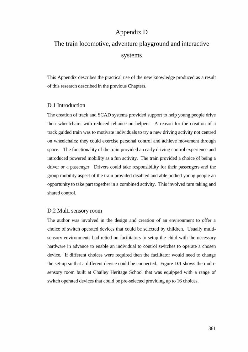
361
Appendix D
The train locomotive, adventure playground and interactive
systems
This Appendix describes the practical use of the new knowledge produced as a result
of this research described in the previous Chapters.
D.1 Introduction
The creation of track and SCAD systems provided support to help young people drive
their wheelchairs with reduced reliance on helpers. A reason for the creation of a
track guided train was to motivate individuals to try a new driving activity not centred
on wheelchairs; they could exercise personal control and achieve movement through
space. The functionality of the train provided an early driving control experience and
introduced powered mobility as a fun activity. The train provided a choice of being a
driver or a passenger. Drivers could take responsibility for their passengers and the
group mobility aspect of the train provided disabled and able bodied young people an
opportunity to take part together in a combined activity. This involved turn taking and
shared control.
D.2 Multi sensory room
The author was involved in the design and creation of an environment to offer a
choice of switch operated devices that could be selected by children. Usually multi-
sensory environments had relied on facilitators to setup the child with the necessary
hardware in advance to enable an individual to control switches to operate a chosen
device. If different choices were required then the facilitator would need to change
the set-up so that a different device could be connected. Figure D.1 shows the multi-
sensory room built at Chailey Heritage School that was equipped with a range of
switch operated devices that could be pre-selected providing up to 16 choices.
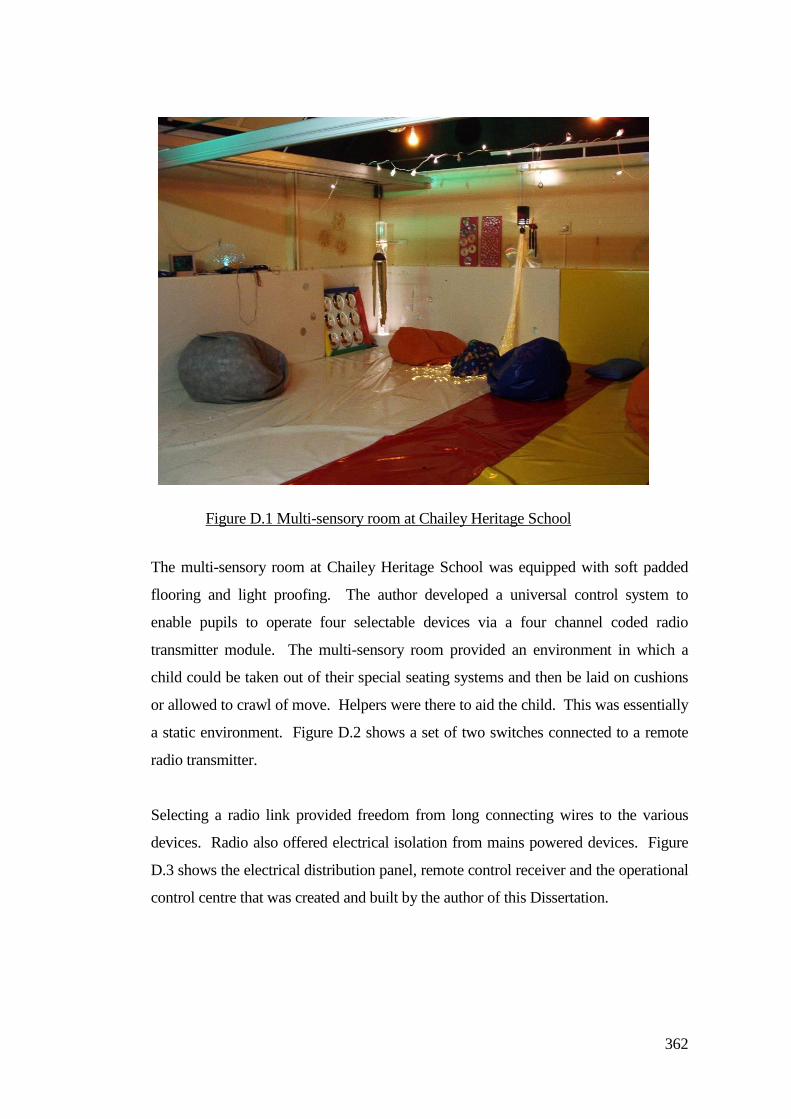
362
The multi-sensory room at Chailey Heritage School was equipped with soft padded
flooring and light proofing. The author developed a universal control system to
enable pupils to operate four selectable devices via a four channel coded radio
transmitter module. The multi-sensory room provided an environment in which a
child could be taken out of their special seating systems and then be laid on cushions
or allowed to crawl of move. Helpers were there to aid the child. This was essentially
a static environment. Figure D.2 shows a set of two switches connected to a remote
radio transmitter.
Selecting a radio link provided freedom from long connecting wires to the various
devices. Radio also offered electrical isolation from mains powered devices. Figure
D.3 shows the electrical distribution panel, remote control receiver and the operational
control centre that was created and built by the author of this Dissertation.
Figure D.1 Multi-sensory room at Chailey Heritage School
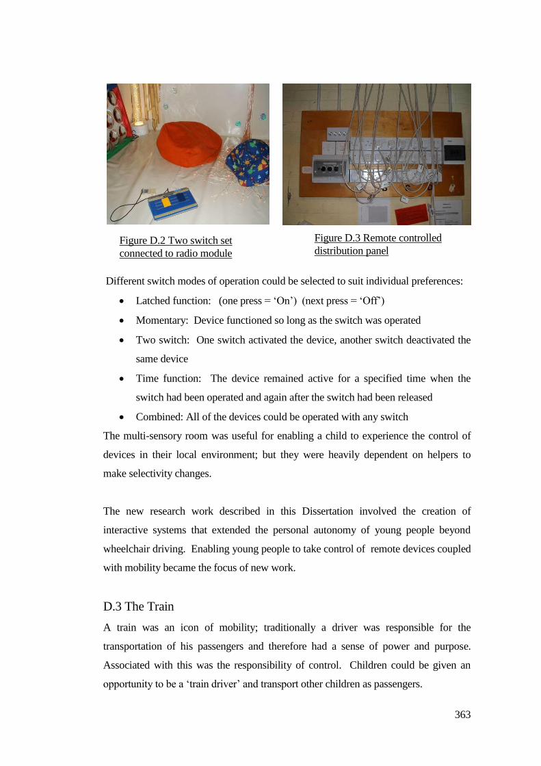
363
Different switch modes of operation could be selected to suit individual preferences:
Latched function: (one press = ‘On’) (next press = ‘Off’)
Momentary: Device functioned so long as the switch was operated
Two switch: One switch activated the device, another switch deactivated the
same device
Time function: The device remained active for a specified time when the
switch had been operated and again after the switch had been released
Combined: All of the devices could be operated with any switch
The multi-sensory room was useful for enabling a child to experience the control of
devices in their local environment; but they were heavily dependent on helpers to
make selectivity changes.
The new research work described in this Dissertation involved the creation of
interactive systems that extended the personal autonomy of young people beyond
wheelchair driving. Enabling young people to take control of remote devices coupled
with mobility became the focus of new work.
D.3 The Train
A train was an icon of mobility; traditionally a driver was responsible for the
transportation of his passengers and therefore had a sense of power and purpose.
Associated with this was the responsibility of control. Children could be given an
opportunity to be a ‘train driver’ and transport other children as passengers.
Figure D.3 Remote controlled
distribution panel Figure D.2 Two switch set
connected to radio module
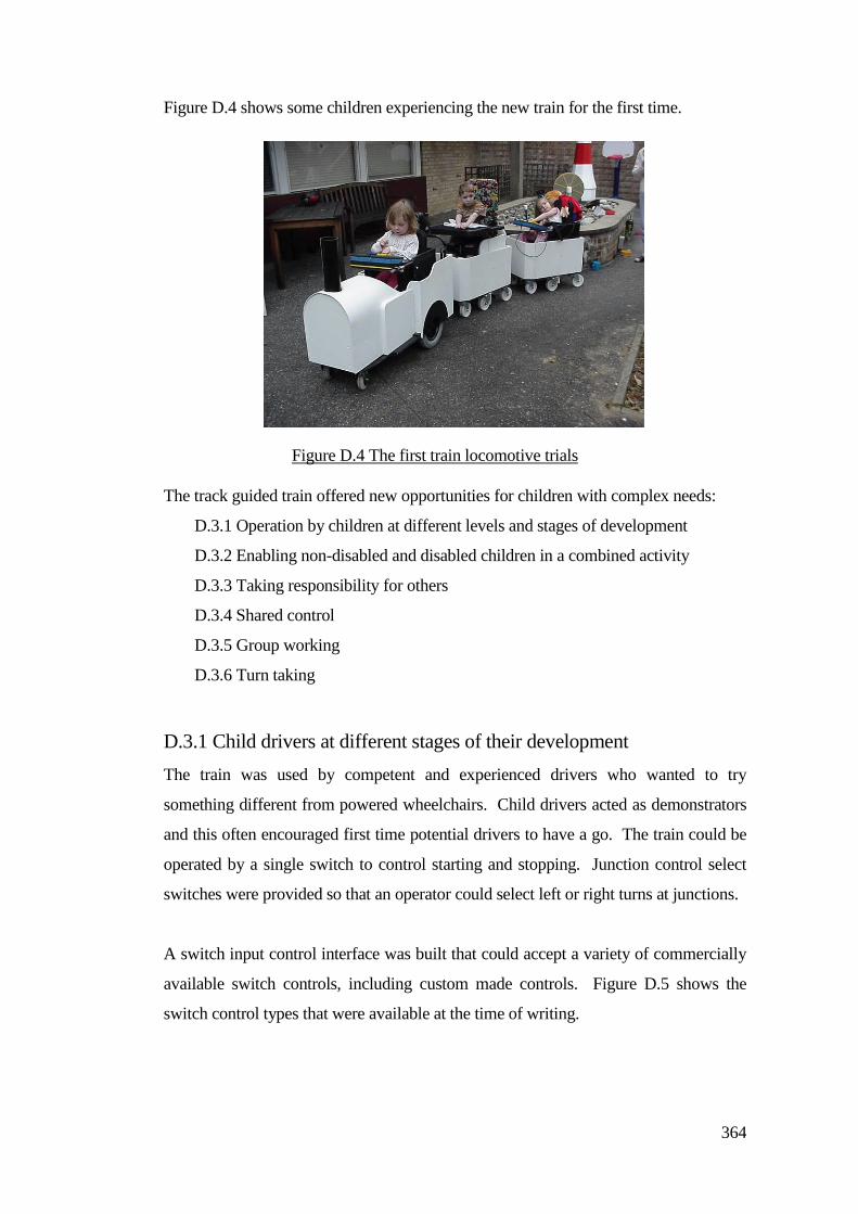
364
Figure D.4 shows some children experiencing the new train for the first time.
The track guided train offered new opportunities for children with complex needs:
D.3.1 Operation by children at different levels and stages of development
D.3.2 Enabling non-disabled and disabled children in a combined activity
D.3.3 Taking responsibility for others
D.3.4 Shared control
D.3.5 Group working
D.3.6 Turn taking
D.3.1 Child drivers at different stages of their development
The train was used by competent and experienced drivers who wanted to try
something different from powered wheelchairs. Child drivers acted as demonstrators
and this often encouraged first time potential drivers to have a go. The train could be
operated by a single switch to control starting and stopping. Junction control select
switches were provided so that an operator could select left or right turns at junctions.
A switch input control interface was built that could accept a variety of commercially
available switch controls, including custom made controls. Figure D.5 shows the
switch control types that were available at the time of writing.
Figure D.4 The first train locomotive trials
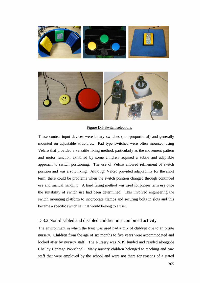
365
These control input devices were binary switches (non-proportional) and generally
mounted on adjustable structures. Pad type switches were often mounted using
Velcro that provided a versatile fixing method, particularly as the movement pattern
and motor function exhibited by some children required a subtle and adaptable
approach to switch positioning. The use of Velcro allowed refinement of switch
position and was a soft fixing. Although Velcro provided adaptability for the short
term, there could be problems when the switch position changed through continued
use and manual handling. A hard fixing method was used for longer term use once
the suitability of switch use had been determined. This involved engineering the
switch mounting platform to incorporate clamps and securing bolts in slots and this
became a specific switch set that would belong to a user.
D.3.2 Non-disabled and disabled children in a combined activity
The environment in which the train was used had a mix of children due to an onsite
nursery. Children from the age of six months to five years were accommodated and
looked after by nursery staff. The Nursery was NHS funded and resided alongside
Chailey Heritage Pre-school. Many nursery children belonged to teaching and care
staff that were employed by the school and were not there for reasons of a stated
Figure D.5 Switch selections
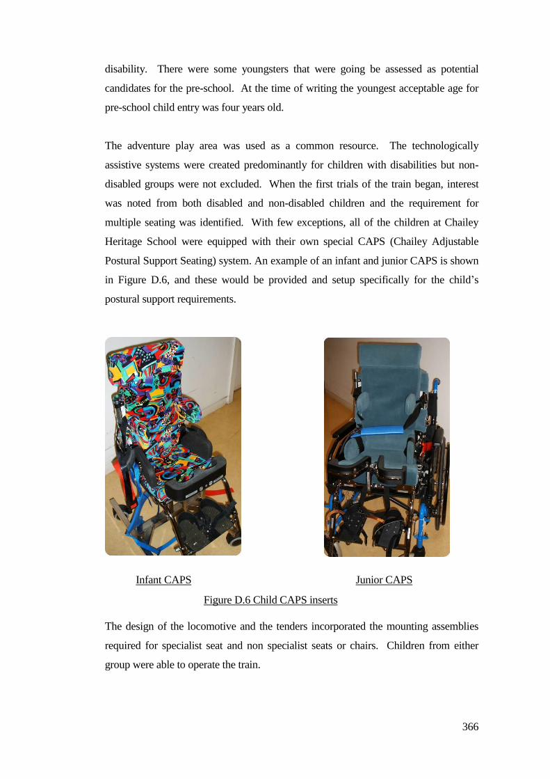
366
disability. There were some youngsters that were going be assessed as potential
candidates for the pre-school. At the time of writing the youngest acceptable age for
pre-school child entry was four years old.
The adventure play area was used as a common resource. The technologically
assistive systems were created predominantly for children with disabilities but non-
disabled groups were not excluded. When the first trials of the train began, interest
was noted from both disabled and non-disabled children and the requirement for
multiple seating was identified. With few exceptions, all of the children at Chailey
Heritage School were equipped with their own special CAPS (Chailey Adjustable
Postural Support Seating) system. An example of an infant and junior CAPS is shown
in Figure D.6, and these would be provided and setup specifically for the child’s
postural support requirements.
The design of the locomotive and the tenders incorporated the mounting assemblies
required for specialist seat and non specialist seats or chairs. Children from either
group were able to operate the train.
Infant CAPS Junior CAPS
Figure D.6 Child CAPS inserts
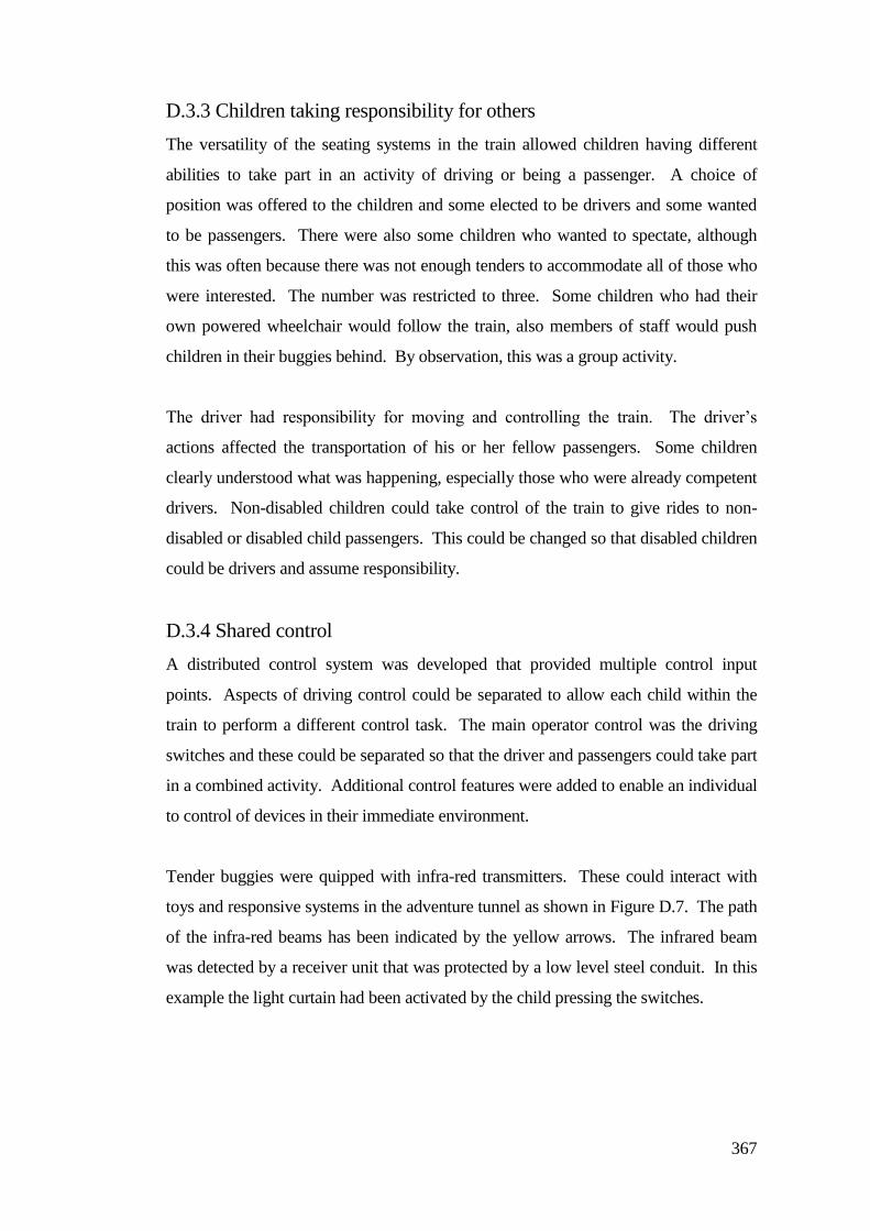
367
D.3.3 Children taking responsibility for others
The versatility of the seating systems in the train allowed children having different
abilities to take part in an activity of driving or being a passenger. A choice of
position was offered to the children and some elected to be drivers and some wanted
to be passengers. There were also some children who wanted to spectate, although
this was often because there was not enough tenders to accommodate all of those who
were interested. The number was restricted to three. Some children who had their
own powered wheelchair would follow the train, also members of staff would push
children in their buggies behind. By observation, this was a group activity.
The driver had responsibility for moving and controlling the train. The driver’s
actions affected the transportation of his or her fellow passengers. Some children
clearly understood what was happening, especially those who were already competent
drivers. Non-disabled children could take control of the train to give rides to non-
disabled or disabled child passengers. This could be changed so that disabled children
could be drivers and assume responsibility.
D.3.4 Shared control
A distributed control system was developed that provided multiple control input
points. Aspects of driving control could be separated to allow each child within the
train to perform a different control task. The main operator control was the driving
switches and these could be separated so that the driver and passengers could take part
in a combined activity. Additional control features were added to enable an individual
to control of devices in their immediate environment.
Tender buggies were quipped with infra-red transmitters. These could interact with
toys and responsive systems in the adventure tunnel as shown in Figure D.7. The path
of the infra-red beams has been indicated by the yellow arrows. The infrared beam
was detected by a receiver unit that was protected by a low level steel conduit. In this
example the light curtain had been activated by the child pressing the switches.
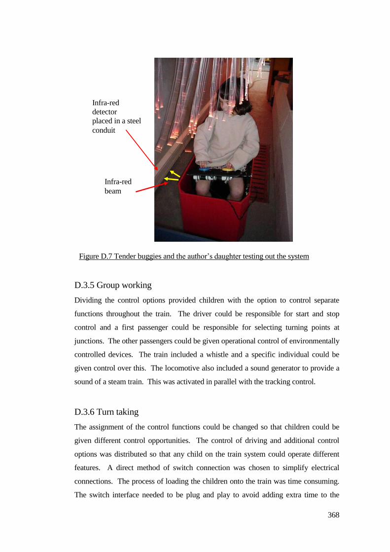
368
D.3.5 Group working
Dividing the control options provided children with the option to control separate
functions throughout the train. The driver could be responsible for start and stop
control and a first passenger could be responsible for selecting turning points at
junctions. The other passengers could be given operational control of environmentally
controlled devices. The train included a whistle and a specific individual could be
given control over this. The locomotive also included a sound generator to provide a
sound of a steam train. This was activated in parallel with the tracking control.
D.3.6 Turn taking
The assignment of the control functions could be changed so that children could be
given different control opportunities. The control of driving and additional control
options was distributed so that any child on the train system could operate different
features. A direct method of switch connection was chosen to simplify electrical
connections. The process of loading the children onto the train was time consuming.
The switch interface needed to be plug and play to avoid adding extra time to the
Infra-red
detector
placed in a steel
conduit
Infra-red
beam
Figure D.7 Tender buggies and the author’s daughter testing out the system
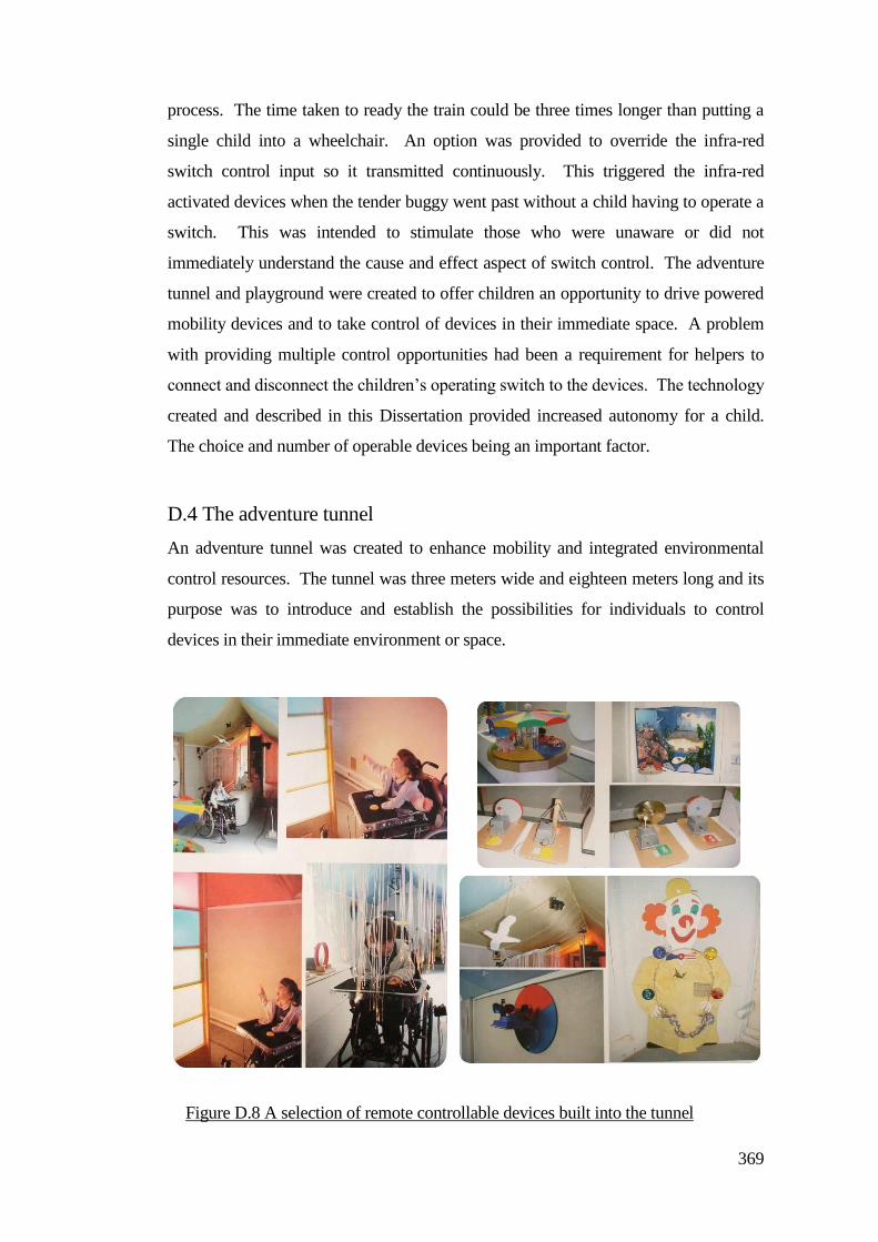
369
process. The time taken to ready the train could be three times longer than putting a
single child into a wheelchair. An option was provided to override the infra-red
switch control input so it transmitted continuously. This triggered the infra-red
activated devices when the tender buggy went past without a child having to operate a
switch. This was intended to stimulate those who were unaware or did not
immediately understand the cause and effect aspect of switch control. The adventure
tunnel and playground were created to offer children an opportunity to drive powered
mobility devices and to take control of devices in their immediate space. A problem
with providing multiple control opportunities had been a requirement for helpers to
connect and disconnect the children’s operating switch to the devices. The technology
created and described in this Dissertation provided increased autonomy for a child.
The choice and number of operable devices being an important factor.
D.4 The adventure tunnel
An adventure tunnel was created to enhance mobility and integrated environmental
control resources. The tunnel was three meters wide and eighteen meters long and its
purpose was to introduce and establish the possibilities for individuals to control
devices in their immediate environment or space.
Figure D.8 A selection of remote controllable devices built into the tunnel
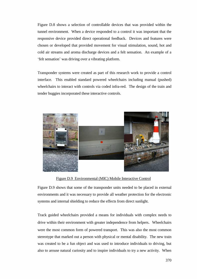
370
Figure D.8 shows a selection of controllable devices that was provided within the
tunnel environment. When a device responded to a control it was important that the
responsive device provided direct operational feedback. Devices and features were
chosen or developed that provided movement for visual stimulation, sound, hot and
cold air streams and aroma discharge devices and a felt sensation. An example of a
‘felt sensation’ was driving over a vibrating platform.
Transponder systems were created as part of this research work to provide a control
interface. This enabled standard powered wheelchairs including manual (pushed)
wheelchairs to interact with controls via coded infra-red. The design of the train and
tender buggies incorporated these interactive controls.
Figure D.9 shows that some of the transponder units needed to be placed in external
environments and it was necessary to provide all weather protection for the electronic
systems and internal shielding to reduce the effects from direct sunlight.
Track guided wheelchairs provided a means for individuals with complex needs to
drive within their environment with greater independence from helpers. Wheelchairs
were the most common form of powered transport. This was also the most common
stereotype that marked out a person with physical or mental disability. The new train
was created to be a fun object and was used to introduce individuals to driving, but
also to arouse natural curiosity and to inspire individuals to try a new activity. When
Figure D.9 Environmental (MIC) Mobile Interactive Control
transponder units
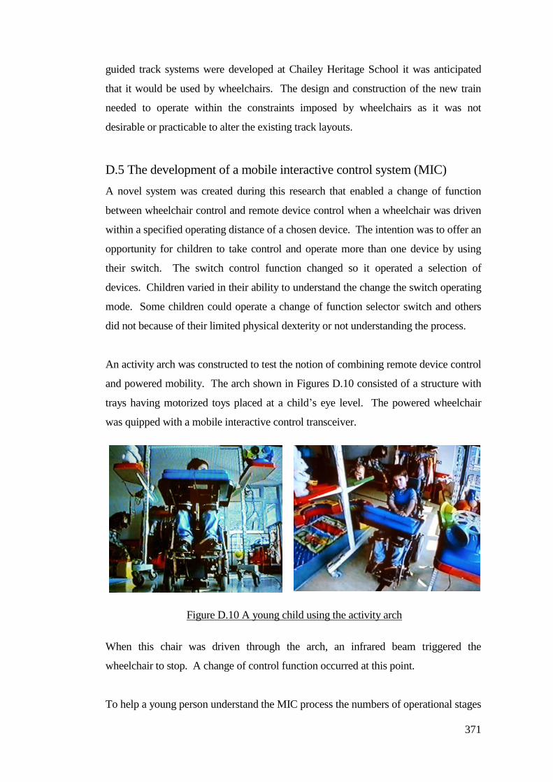
371
guided track systems were developed at Chailey Heritage School it was anticipated
that it would be used by wheelchairs. The design and construction of the new train
needed to operate within the constraints imposed by wheelchairs as it was not
desirable or practicable to alter the existing track layouts.
D.5 The development of a mobile interactive control system (MIC)
A novel system was created during this research that enabled a change of function
between wheelchair control and remote device control when a wheelchair was driven
within a specified operating distance of a chosen device. The intention was to offer an
opportunity for children to take control and operate more than one device by using
their switch. The switch control function changed so it operated a selection of
devices. Children varied in their ability to understand the change the switch operating
mode. Some children could operate a change of function selector switch and others
did not because of their limited physical dexterity or not understanding the process.
An activity arch was constructed to test the notion of combining remote device control
and powered mobility. The arch shown in Figures D.10 consisted of a structure with
trays having motorized toys placed at a child’s eye level. The powered wheelchair
was quipped with a mobile interactive control transceiver.
When this chair was driven through the arch, an infrared beam triggered the
wheelchair to stop. A change of control function occurred at this point.
To help a young person understand the MIC process the numbers of operational stages
Figure D.10 A young child using the activity arch
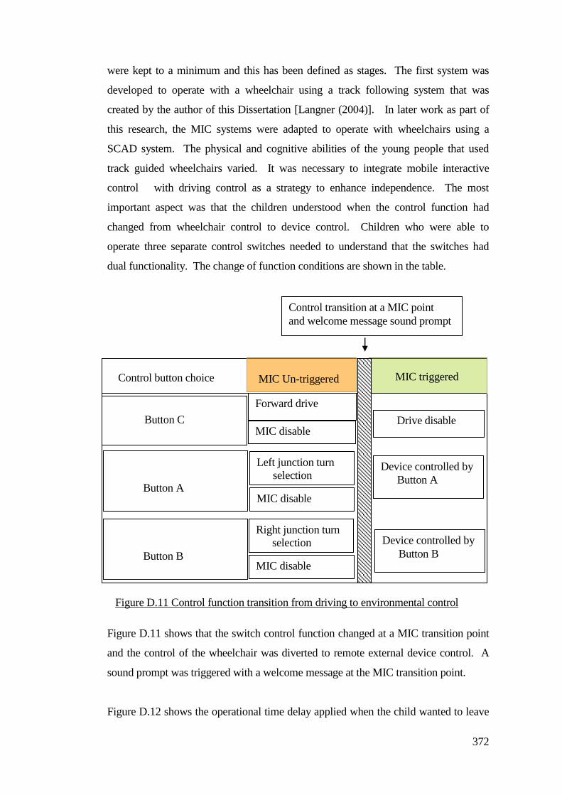
372
were kept to a minimum and this has been defined as stages. The first system was
developed to operate with a wheelchair using a track following system that was
created by the author of this Dissertation [Langner (2004)]. In later work as part of
this research, the MIC systems were adapted to operate with wheelchairs using a
SCAD system. The physical and cognitive abilities of the young people that used
track guided wheelchairs varied. It was necessary to integrate mobile interactive
control with driving control as a strategy to enhance independence. The most
important aspect was that the children understood when the control function had
changed from wheelchair control to device control. Children who were able to
operate three separate control switches needed to understand that the switches had
dual functionality. The change of function conditions are shown in the table.
Figure D.11 shows that the switch control function changed at a MIC transition point
and the control of the wheelchair was diverted to remote external device control. A
sound prompt was triggered with a welcome message at the MIC transition point.
Figure D.12 shows the operational time delay applied when the child wanted to leave
Figure D.11 Control function transition from driving to environmental control
MIC triggered Control button choice MIC Un-triggered
Button C
Forward drive
MIC disable Drive disable
Button A
Left junction turn
selection Device controlled by
Button A
MIC disable
Button B
Right junction turn
selection
MIC disable
Device controlled by
Button B
Control transition at a MIC point
and welcome message sound prompt
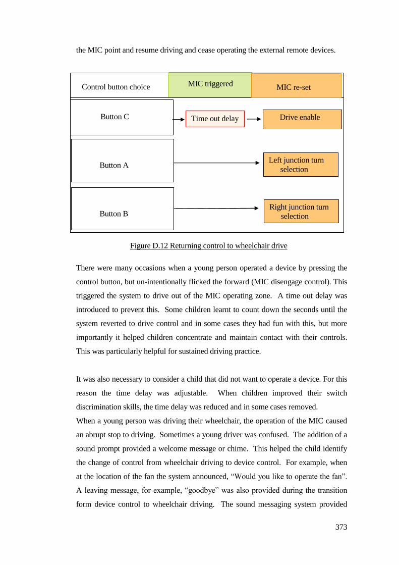
373
the MIC point and resume driving and cease operating the external remote devices.
There were many occasions when a young person operated a device by pressing the
control button, but un-intentionally flicked the forward (MIC disengage control). This
triggered the system to drive out of the MIC operating zone. A time out delay was
introduced to prevent this. Some children learnt to count down the seconds until the
system reverted to drive control and in some cases they had fun with this, but more
importantly it helped children concentrate and maintain contact with their controls.
This was particularly helpful for sustained driving practice.
It was also necessary to consider a child that did not want to operate a device. For this
reason the time delay was adjustable. When children improved their switch
discrimination skills, the time delay was reduced and in some cases removed.
When a young person was driving their wheelchair, the operation of the MIC caused
an abrupt stop to driving. Sometimes a young driver was confused. The addition of a
sound prompt provided a welcome message or chime. This helped the child identify
the change of control from wheelchair driving to device control. For example, when
at the location of the fan the system announced, “Would you like to operate the fan”.
A leaving message, for example, “goodbye” was also provided during the transition
form device control to wheelchair driving. The sound messaging system provided
MIC triggered Control button choice MIC re-set
Button C Drive enable
Button A Left junction turn
selection
Button B Right junction turn
selection
Time out delay
Figure D.12 Returning control to wheelchair drive
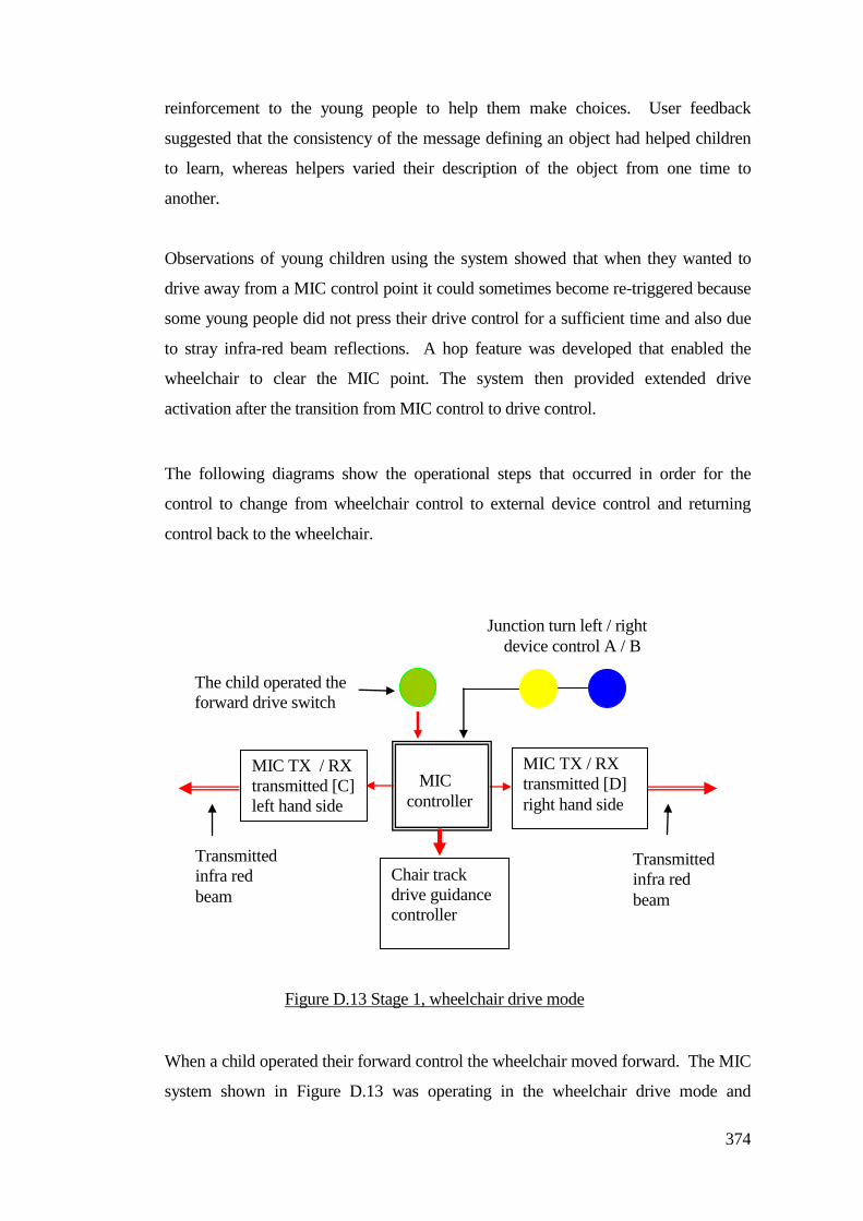
374
reinforcement to the young people to help them make choices. User feedback
suggested that the consistency of the message defining an object had helped children
to learn, whereas helpers varied their description of the object from one time to
another.
Observations of young children using the system showed that when they wanted to
drive away from a MIC control point it could sometimes become re-triggered because
some young people did not press their drive control for a sufficient time and also due
to stray infra-red beam reflections. A hop feature was developed that enabled the
wheelchair to clear the MIC point. The system then provided extended drive
activation after the transition from MIC control to drive control.
The following diagrams show the operational steps that occurred in order for the
control to change from wheelchair control to external device control and returning
control back to the wheelchair.
When a child operated their forward control the wheelchair moved forward. The MIC
system shown in Figure D.13 was operating in the wheelchair drive mode and
The child operated the
forward drive switch
Chair track
drive guidance
controller
MIC TX / RX
transmitted [D]
right hand side
MIC TX / RX
transmitted [C]
left hand side
Transmitted
infra red
beam
Transmitted
infra red
beam
Figure D.13 Stage 1, wheelchair drive mode
MIC
controller
Junction turn left / right
device control A / B
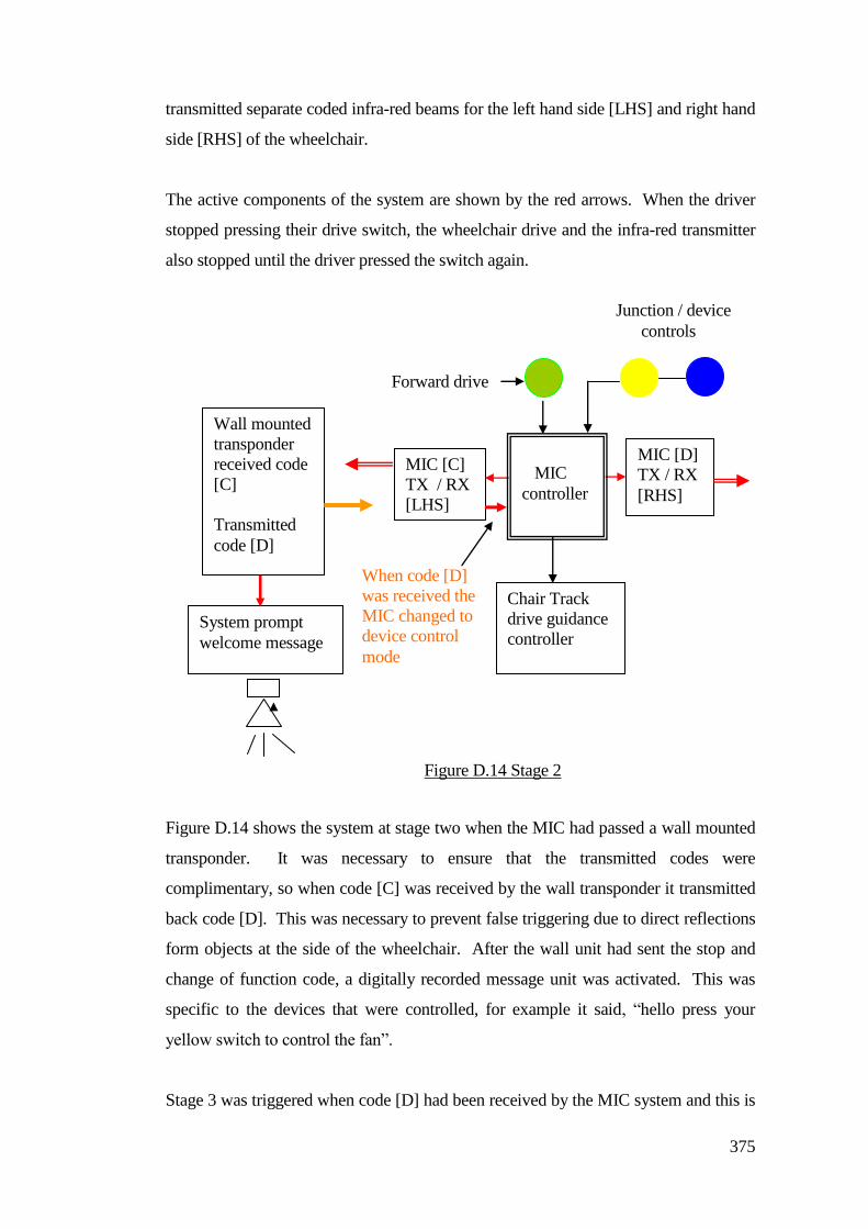
375
transmitted separate coded infra-red beams for the left hand side [LHS] and right hand
side [RHS] of the wheelchair.
The active components of the system are shown by the red arrows. When the driver
stopped pressing their drive switch, the wheelchair drive and the infra-red transmitter
also stopped until the driver pressed the switch again.
Figure D.14 shows the system at stage two when the MIC had passed a wall mounted
transponder. It was necessary to ensure that the transmitted codes were
complimentary, so when code [C] was received by the wall transponder it transmitted
back code [D]. This was necessary to prevent false triggering due to direct reflections
form objects at the side of the wheelchair. After the wall unit had sent the stop and
change of function code, a digitally recorded message unit was activated. This was
specific to the devices that were controlled, for example it said, “hello press your
yellow switch to control the fan”.
Stage 3 was triggered when code [D] had been received by the MIC system and this is
MIC [D]
TX / RX
[RHS]
MIC [C]
TX / RX
[LHS]
Figure D.14 Stage 2
Wall mounted
transponder
received code
[C]
Transmitted
code [D]
MIC
controller
Forward drive
Junction / device
controls
Chair Track
drive guidance
controller
When code [D]
was received the
MIC changed to
device control
mode
System prompt
welcome message
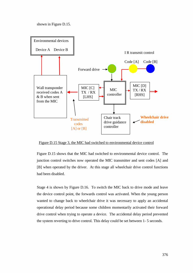
376
shown in Figure D.15.
Figure D.15 shows that the MIC had switched to environmental device control. The
junction control switches now operated the MIC transmitter and sent codes [A] and
[B] when operated by the driver. At this stage all wheelchair drive control functions
had been disabled.
Stage 4 is shown by Figure D.16. To switch the MIC back to drive mode and leave
the device control point, the forwards control was activated. When the young person
wanted to change back to wheelchair drive it was necessary to apply an accidental
operational delay period because some children momentarily activated their forward
drive control when trying to operate a device. The accidental delay period prevented
the system reverting to drive control. This delay could be set between 1- 5 seconds.
MIC [D]
TX / RX
[RHS]
MIC [C]
TX / RX
[LHS]
Figure D.15 Stage 3, the MIC had switched to environmental device control
Wall transponder
received codes A
& B when sent
from the MIC
MIC
controller
Forward drive
I R transmit control
Code [A] Code [B]
Chair track
drive guidance
controller
Wheelchair drive
disabled
Environmental devices
Device A Device B
Transmitted
codes
[A] or [B]
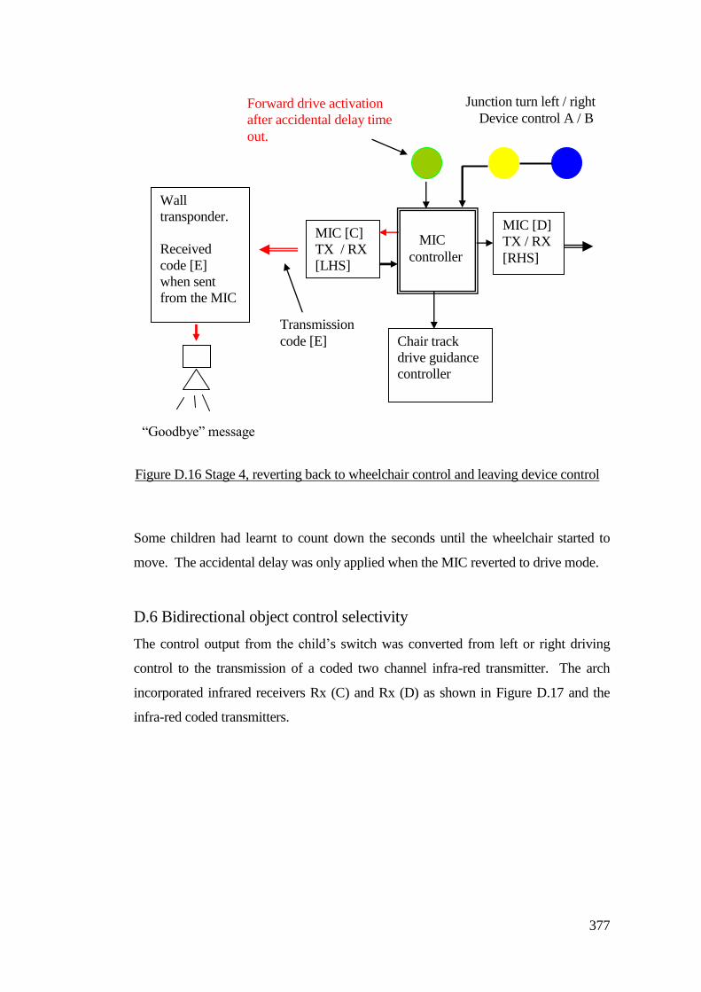
377
Some children had learnt to count down the seconds until the wheelchair started to
move. The accidental delay was only applied when the MIC reverted to drive mode.
D.6 Bidirectional object control selectivity
The control output from the child’s switch was converted from left or right driving
control to the transmission of a coded two channel infra-red transmitter. The arch
incorporated infrared receivers Rx (C) and Rx (D) as shown in Figure D.17 and the
infra-red coded transmitters.
MIC [D]
TX / RX
[RHS]
MIC [C]
TX / RX
[LHS]
Wall
transponder.
Received
code [E]
when sent
from the MIC
MIC
controller
Forward drive activation
after accidental delay time
out.
Chair track
drive guidance
controller
Junction turn left / right
Device control A / B
Transmission
code [E]
“Goodbye” message
Figure D.16 Stage 4, reverting back to wheelchair control and leaving device control
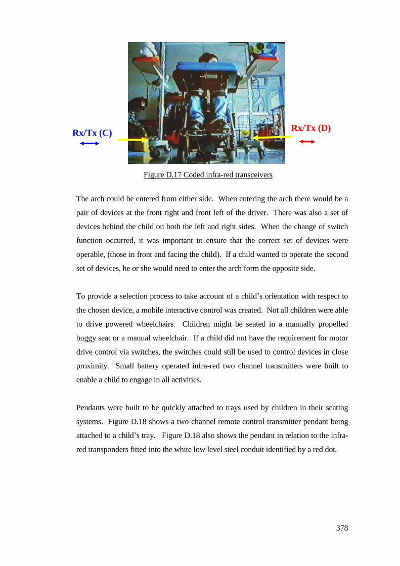
378
The arch could be entered from either side. When entering the arch there would be a
pair of devices at the front right and front left of the driver. There was also a set of
devices behind the child on both the left and right sides. When the change of switch
function occurred, it was important to ensure that the correct set of devices were
operable, (those in front and facing the child). If a child wanted to operate the second
set of devices, he or she would need to enter the arch form the opposite side.
To provide a selection process to take account of a child’s orientation with respect to
the chosen device, a mobile interactive control was created. Not all children were able
to drive powered wheelchairs. Children might be seated in a manually propelled
buggy seat or a manual wheelchair. If a child did not have the requirement for motor
drive control via switches, the switches could still be used to control devices in close
proximity. Small battery operated infra-red two channel transmitters were built to
enable a child to engage in all activities.
Pendants were built to be quickly attached to trays used by children in their seating
systems. Figure D.18 shows a two channel remote control transmitter pendant being
attached to a child’s tray. Figure D.18 also shows the pendant in relation to the infra-
red transponders fitted into the white low level steel conduit identified by a red dot.
Rx/Tx (D) Rx/Tx (C)
Figure D.17 Coded infra-red transceivers
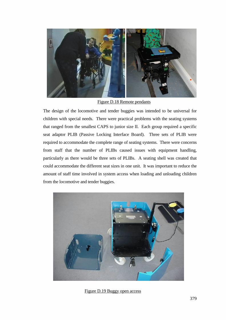
379
The design of the locomotive and tender buggies was intended to be universal for
children with special needs. There were practical problems with the seating systems
that ranged from the smallest CAPS to junior size II. Each group required a specific
seat adaptor PLIB (Passive Locking Interface Board). Three sets of PLIB were
required to accommodate the complete range of seating systems. There were concerns
from staff that the number of PLIBs caused issues with equipment handling,
particularly as there would be three sets of PLIBs. A seating shell was created that
could accommodate the different seat sizes in one unit. It was important to reduce the
amount of staff time involved in system access when loading and unloading children
from the locomotive and tender buggies.
Figure D.19 Buggy open access
Figure D.18 Remote pendants
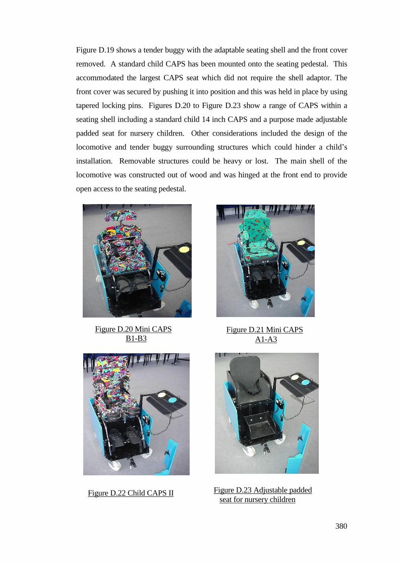
380
Figure D.19 shows a tender buggy with the adaptable seating shell and the front cover
removed. A standard child CAPS has been mounted onto the seating pedestal. This
accommodated the largest CAPS seat which did not require the shell adaptor. The
front cover was secured by pushing it into position and this was held in place by using
tapered locking pins. Figures D.20 to Figure D.23 show a range of CAPS within a
seating shell including a standard child 14 inch CAPS and a purpose made adjustable
padded seat for nursery children. Other considerations included the design of the
locomotive and tender buggy surrounding structures which could hinder a child’s
installation. Removable structures could be heavy or lost. The main shell of the
locomotive was constructed out of wood and was hinged at the front end to provide
open access to the seating pedestal.
Figure D.21 Mini CAPS
A1-A3
Figure D.20 Mini CAPS
B1-B3
Figure D.23 Adjustable padded
seat for nursery children Figure D.22 Child CAPS II
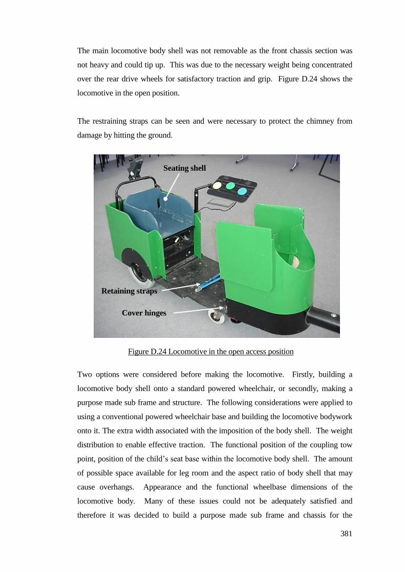
381
The main locomotive body shell was not removable as the front chassis section was
not heavy and could tip up. This was due to the necessary weight being concentrated
over the rear drive wheels for satisfactory traction and grip. Figure D.24 shows the
locomotive in the open position.
The restraining straps can be seen and were necessary to protect the chimney from
damage by hitting the ground.
Two options were considered before making the locomotive. Firstly, building a
locomotive body shell onto a standard powered wheelchair, or secondly, making a
purpose made sub frame and structure. The following considerations were applied to
using a conventional powered wheelchair base and building the locomotive bodywork
onto it. The extra width associated with the imposition of the body shell. The weight
distribution to enable effective traction. The functional position of the coupling tow
point, position of the child’s seat base within the locomotive body shell. The amount
of possible space available for leg room and the aspect ratio of body shell that may
cause overhangs. Appearance and the functional wheelbase dimensions of the
locomotive body. Many of these issues could not be adequately satisfied and
therefore it was decided to build a purpose made sub frame and chassis for the
Figure D.24 Locomotive in the open access position
Cover hinges
Retaining straps
Seating shell
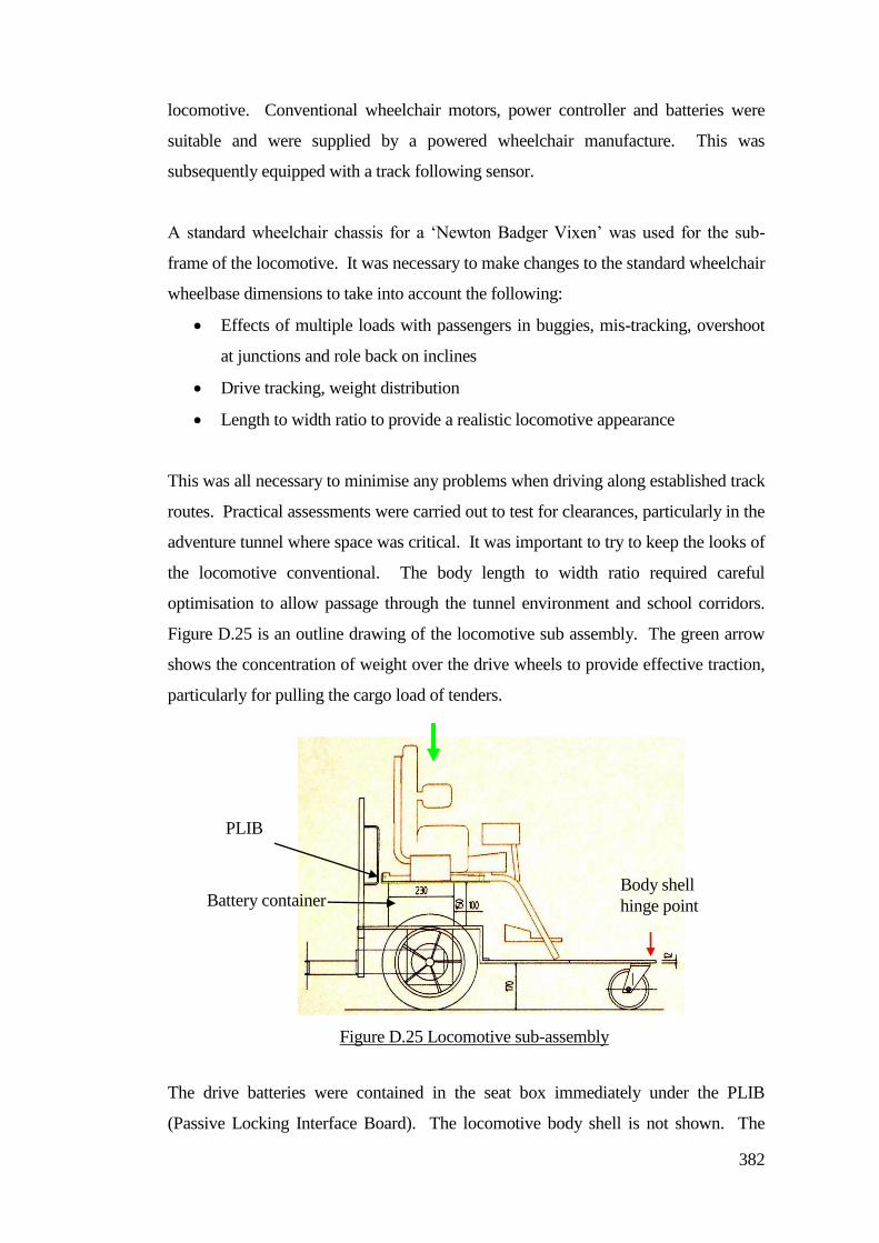
382
locomotive. Conventional wheelchair motors, power controller and batteries were
suitable and were supplied by a powered wheelchair manufacture. This was
subsequently equipped with a track following sensor.
A standard wheelchair chassis for a ‘Newton Badger Vixen’ was used for the sub-
frame of the locomotive. It was necessary to make changes to the standard wheelchair
wheelbase dimensions to take into account the following:
Effects of multiple loads with passengers in buggies, mis-tracking, overshoot
at junctions and role back on inclines
Drive tracking, weight distribution
Length to width ratio to provide a realistic locomotive appearance
This was all necessary to minimise any problems when driving along established track
routes. Practical assessments were carried out to test for clearances, particularly in the
adventure tunnel where space was critical. It was important to try to keep the looks of
the locomotive conventional. The body length to width ratio required careful
optimisation to allow passage through the tunnel environment and school corridors.
Figure D.25 is an outline drawing of the locomotive sub assembly. The green arrow
shows the concentration of weight over the drive wheels to provide effective traction,
particularly for pulling the cargo load of tenders.
The drive batteries were contained in the seat box immediately under the PLIB
(Passive Locking Interface Board). The locomotive body shell is not shown. The
Figure D.25 Locomotive sub-assembly
PLIB
Battery container Body shell
hinge point
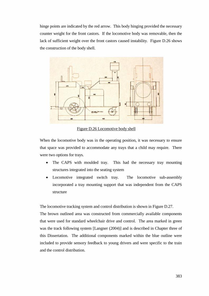
383
hinge points are indicated by the red arrow. This body hinging provided the necessary
counter weight for the front castors. If the locomotive body was removable, then the
lack of sufficient weight over the front castors caused instability. Figure D.26 shows
the construction of the body shell.
When the locomotive body was in the operating position, it was necessary to ensure
that space was provided to accommodate any trays that a child may require. There
were two options for trays.
The CAPS with moulded tray. This had the necessary tray mounting
structures integrated into the seating system
Locomotive integrated switch tray. The locomotive sub-assembly
incorporated a tray mounting support that was independent from the CAPS
structure
The locomotive tracking system and control distribution is shown in Figure D.27.
The brown outlined area was constructed from commercially available components
that were used for standard wheelchair drive and control. The area marked in green
was the track following system [Langner (2004)] and is described in Chapter three of
this Dissertation. The additional components marked within the blue outline were
included to provide sensory feedback to young drivers and were specific to the train
and the control distribution.
Figure D.26 Locomotive body shell
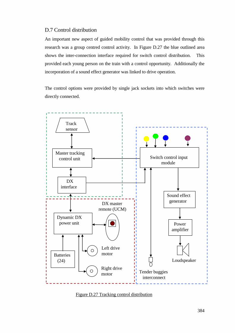
384
D.7 Control distribution
An important new aspect of guided mobility control that was provided through this
research was a group centred control activity. In Figure D.27 the blue outlined area
shows the inter-connection interface required for switch control distribution. This
provided each young person on the train with a control opportunity. Additionally the
incorporation of a sound effect generator was linked to drive operation.
The control options were provided by single jack sockets into which switches were
directly connected.
Dynamic DX
power unit
Batteries
(24)
Left drive
motor
Right drive
motor
Sound effect
generator DX master
remote (UCM)
Tender buggies
interconnect
DX
interface
Master tracking
control unit
Track
sensor
Switch control input
module
Figure D.27 Tracking control distribution
Loudspeaker
Power
amplifier
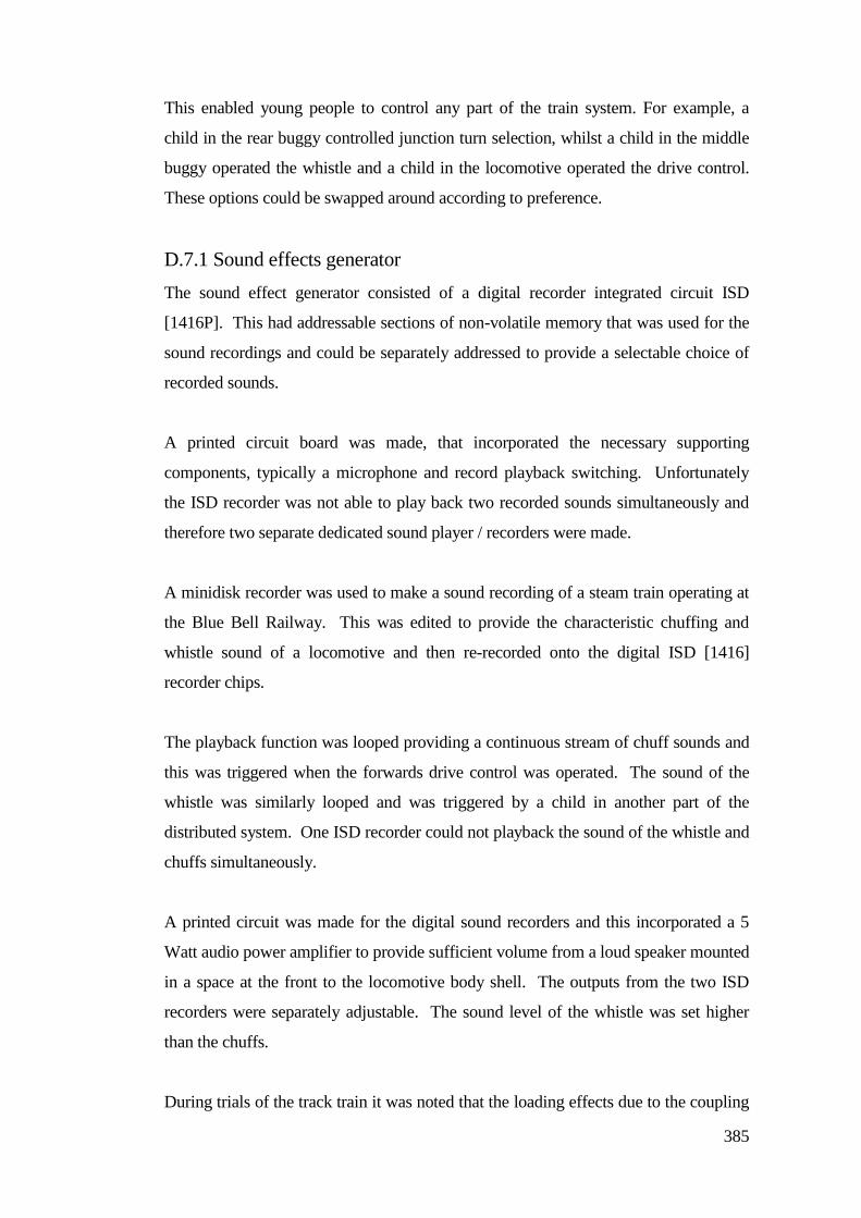
385
This enabled young people to control any part of the train system. For example, a
child in the rear buggy controlled junction turn selection, whilst a child in the middle
buggy operated the whistle and a child in the locomotive operated the drive control.
These options could be swapped around according to preference.
D.7.1 Sound effects generator
The sound effect generator consisted of a digital recorder integrated circuit ISD
[1416P]. This had addressable sections of non-volatile memory that was used for the
sound recordings and could be separately addressed to provide a selectable choice of
recorded sounds.
A printed circuit board was made, that incorporated the necessary supporting
components, typically a microphone and record playback switching. Unfortunately
the ISD recorder was not able to play back two recorded sounds simultaneously and
therefore two separate dedicated sound player / recorders were made.
A minidisk recorder was used to make a sound recording of a steam train operating at
the Blue Bell Railway. This was edited to provide the characteristic chuffing and
whistle sound of a locomotive and then re-recorded onto the digital ISD [1416]
recorder chips.
The playback function was looped providing a continuous stream of chuff sounds and
this was triggered when the forwards drive control was operated. The sound of the
whistle was similarly looped and was triggered by a child in another part of the
distributed system. One ISD recorder could not playback the sound of the whistle and
chuffs simultaneously.
A printed circuit was made for the digital sound recorders and this incorporated a 5
Watt audio power amplifier to provide sufficient volume from a loud speaker mounted
in a space at the front to the locomotive body shell. The outputs from the two ISD
recorders were separately adjustable. The sound level of the whistle was set higher
than the chuffs.
During trials of the track train it was noted that the loading effects due to the coupling
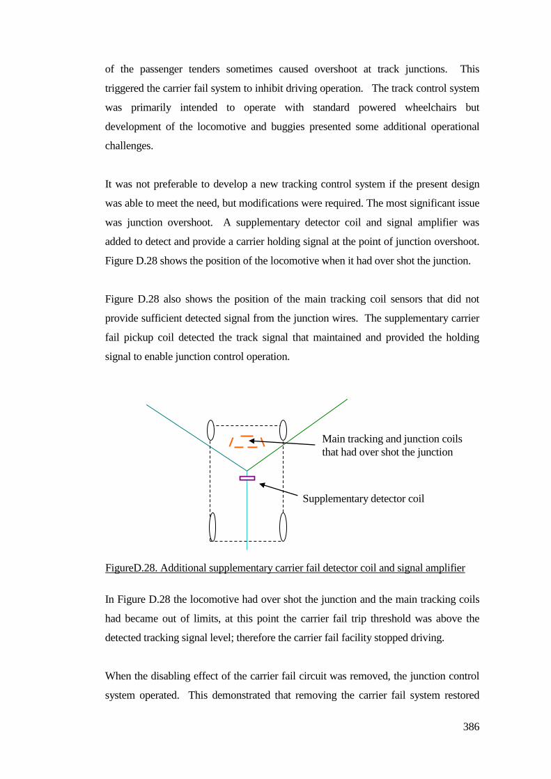
386
of the passenger tenders sometimes caused overshoot at track junctions. This
triggered the carrier fail system to inhibit driving operation. The track control system
was primarily intended to operate with standard powered wheelchairs but
development of the locomotive and buggies presented some additional operational
challenges.
It was not preferable to develop a new tracking control system if the present design
was able to meet the need, but modifications were required. The most significant issue
was junction overshoot. A supplementary detector coil and signal amplifier was
added to detect and provide a carrier holding signal at the point of junction overshoot.
Figure D.28 shows the position of the locomotive when it had over shot the junction.
Figure D.28 also shows the position of the main tracking coil sensors that did not
provide sufficient detected signal from the junction wires. The supplementary carrier
fail pickup coil detected the track signal that maintained and provided the holding
signal to enable junction control operation.
In Figure D.28 the locomotive had over shot the junction and the main tracking coils
had became out of limits, at this point the carrier fail trip threshold was above the
detected tracking signal level; therefore the carrier fail facility stopped driving.
When the disabling effect of the carrier fail circuit was removed, the junction control
system operated. This demonstrated that removing the carrier fail system restored
Main tracking and junction coils
that had over shot the junction
Supplementary detector coil
FigureD.28. Additional supplementary carrier fail detector coil and signal amplifier
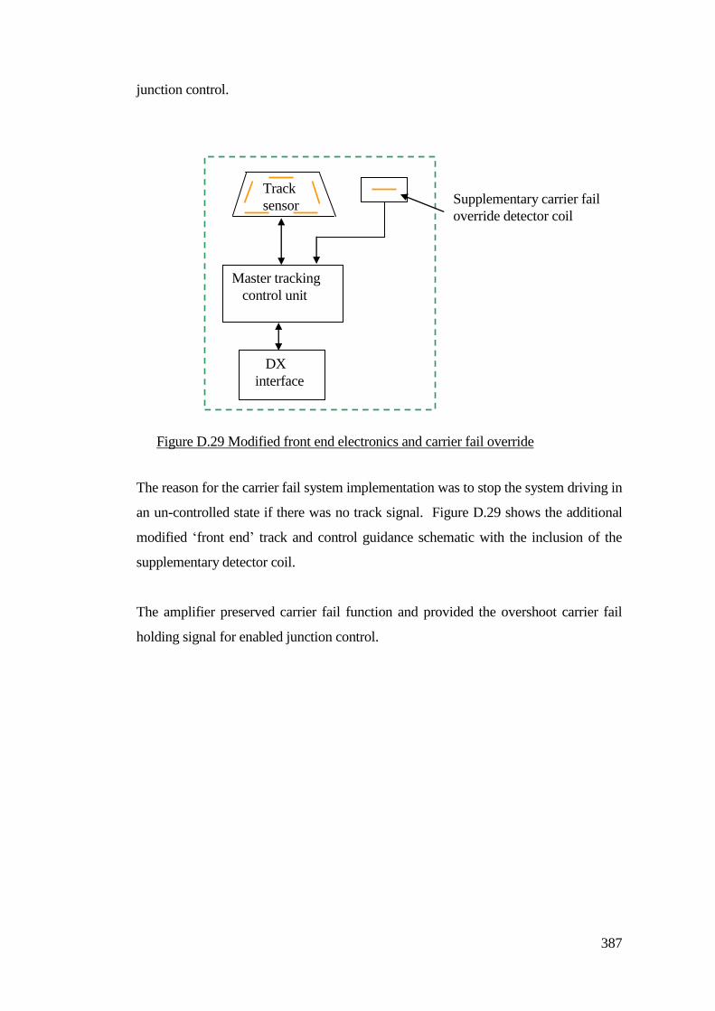
387
junction control.
The reason for the carrier fail system implementation was to stop the system driving in
an un-controlled state if there was no track signal. Figure D.29 shows the additional
modified ‘front end’ track and control guidance schematic with the inclusion of the
supplementary detector coil.
The amplifier preserved carrier fail function and provided the overshoot carrier fail
holding signal for enabled junction control.
DX
interface
Master tracking
control unit
Track
sensor
Supplementary carrier fail
override detector coil
Figure D.29 Modified front end electronics and carrier fail override
ooverrideoverride.detector.
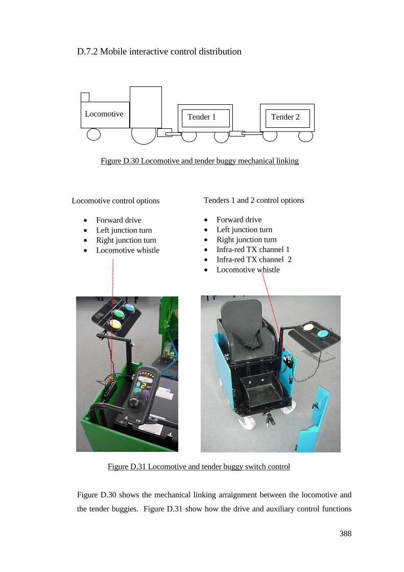
388
D.7.2 Mobile interactive control distribution
Figure D.30 shows the mechanical linking arraignment between the locomotive and
the tender buggies. Figure D.31 show how the drive and auxiliary control functions
Tenders 1 and 2 control options
Forward drive
Left junction turn
Right junction turn
Infra-red TX channel 1
Infra-red TX channel 2
Locomotive whistle
Locomotive control options
Forward drive
Left junction turn
Right junction turn
Locomotive whistle
Tender 1 Tender 2 Locomotive
Figure D.31 Locomotive and tender buggy switch control
ffunctionsinput.modules.
Figure D.30 Locomotive and tender buggy mechanical linking
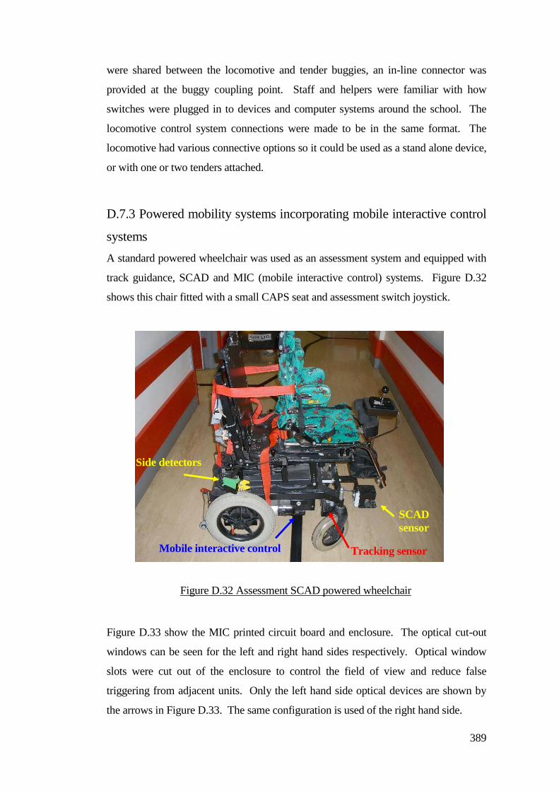
389
were shared between the locomotive and tender buggies, an in-line connector was
provided at the buggy coupling point. Staff and helpers were familiar with how
switches were plugged in to devices and computer systems around the school. The
locomotive control system connections were made to be in the same format. The
locomotive had various connective options so it could be used as a stand alone device,
or with one or two tenders attached.
D.7.3 Powered mobility systems incorporating mobile interactive control
systems
A standard powered wheelchair was used as an assessment system and equipped with
track guidance, SCAD and MIC (mobile interactive control) systems. Figure D.32
shows this chair fitted with a small CAPS seat and assessment switch joystick.
Figure D.33 show the MIC printed circuit board and enclosure. The optical cut-out
windows can be seen for the left and right hand sides respectively. Optical window
slots were cut out of the enclosure to control the field of view and reduce false
triggering from adjacent units. Only the left hand side optical devices are shown by
the arrows in Figure D.33. The same configuration is used of the right hand side.
Side detectors
SCAD
sensor
Tracking sensor Mobile interactive control
Figure D.32 Assessment SCAD powered wheelchair
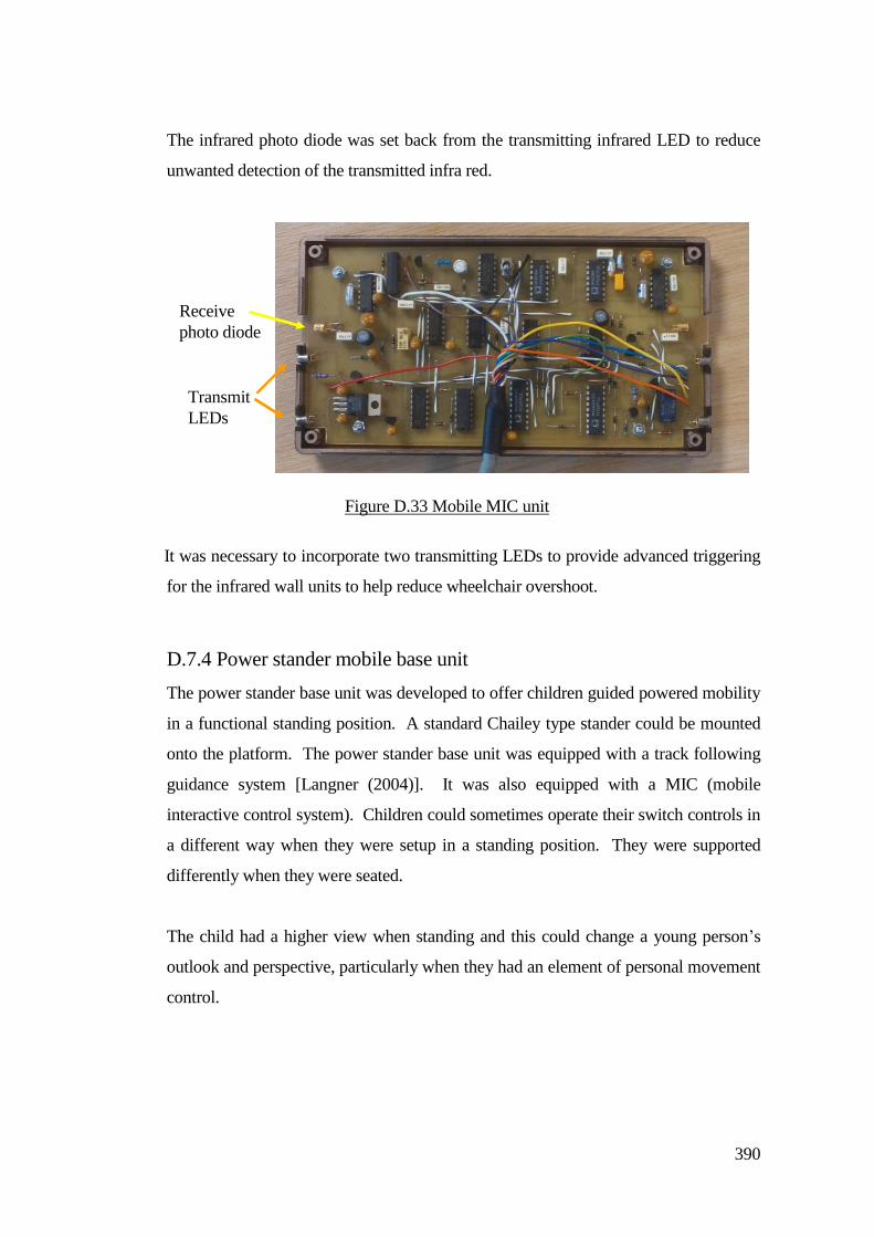
390
The infrared photo diode was set back from the transmitting infrared LED to reduce
unwanted detection of the transmitted infra red.
It was necessary to incorporate two transmitting LEDs to provide advanced triggering
for the infrared wall units to help reduce wheelchair overshoot.
D.7.4 Power stander mobile base unit
The power stander base unit was developed to offer children guided powered mobility
in a functional standing position. A standard Chailey type stander could be mounted
onto the platform. The power stander base unit was equipped with a track following
guidance system [Langner (2004)]. It was also equipped with a MIC (mobile
interactive control system). Children could sometimes operate their switch controls in
a different way when they were setup in a standing position. They were supported
differently when they were seated.
The child had a higher view when standing and this could change a young person’s
outlook and perspective, particularly when they had an element of personal movement
control.
Figure D.33 Mobile MIC unit
Receive
photo diode
Transmit
LEDs
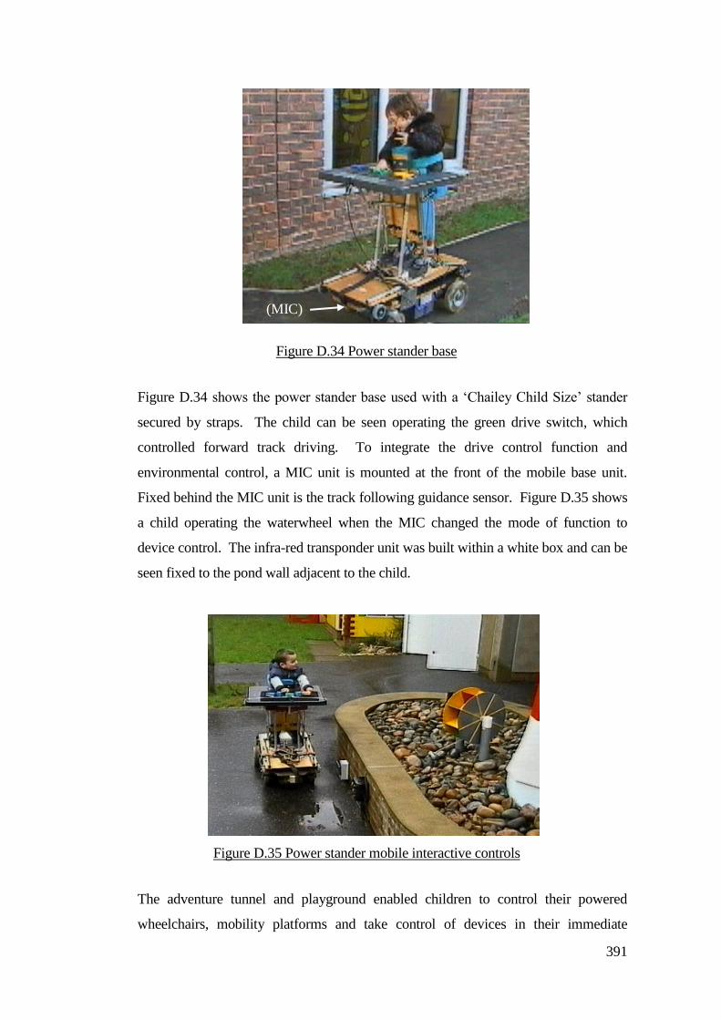
391
Figure D.34 shows the power stander base used with a ‘Chailey Child Size’ stander
secured by straps. The child can be seen operating the green drive switch, which
controlled forward track driving. To integrate the drive control function and
environmental control, a MIC unit is mounted at the front of the mobile base unit.
Fixed behind the MIC unit is the track following guidance sensor. Figure D.35 shows
a child operating the waterwheel when the MIC changed the mode of function to
device control. The infra-red transponder unit was built within a white box and can be
seen fixed to the pond wall adjacent to the child.
The adventure tunnel and playground enabled children to control their powered
wheelchairs, mobility platforms and take control of devices in their immediate
Figure D.34 Power stander base
platform.
(MIC)
Figure D.35 Power stander mobile interactive controls
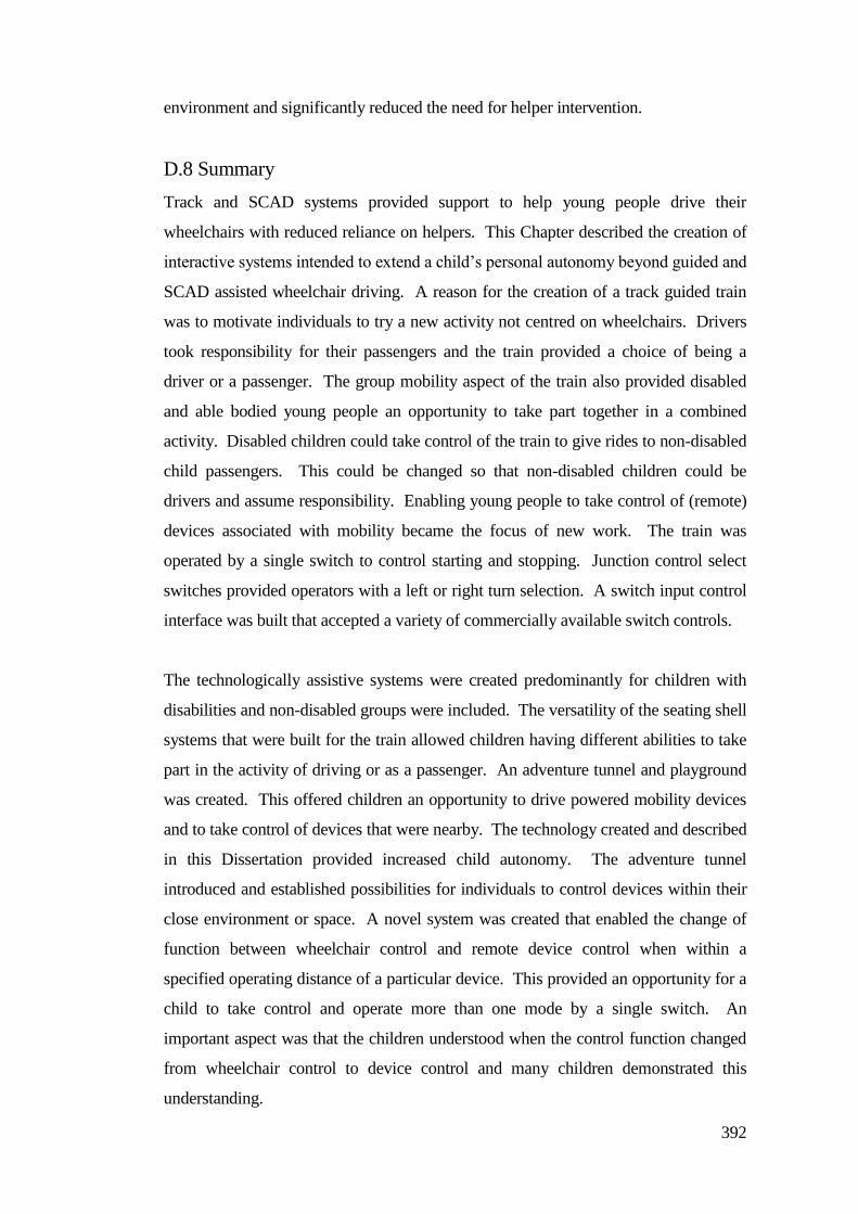
392
environment and significantly reduced the need for helper intervention.
D.8 Summary
Track and SCAD systems provided support to help young people drive their
wheelchairs with reduced reliance on helpers. This Chapter described the creation of
interactive systems intended to extend a child’s personal autonomy beyond guided and
SCAD assisted wheelchair driving. A reason for the creation of a track guided train
was to motivate individuals to try a new activity not centred on wheelchairs. Drivers
took responsibility for their passengers and the train provided a choice of being a
driver or a passenger. The group mobility aspect of the train also provided disabled
and able bodied young people an opportunity to take part together in a combined
activity. Disabled children could take control of the train to give rides to non-disabled
child passengers. This could be changed so that non-disabled children could be
drivers and assume responsibility. Enabling young people to take control of (remote)
devices associated with mobility became the focus of new work. The train was
operated by a single switch to control starting and stopping. Junction control select
switches provided operators with a left or right turn selection. A switch input control
interface was built that accepted a variety of commercially available switch controls.
The technologically assistive systems were created predominantly for children with
disabilities and non-disabled groups were included. The versatility of the seating shell
systems that were built for the train allowed children having different abilities to take
part in the activity of driving or as a passenger. An adventure tunnel and playground
was created. This offered children an opportunity to drive powered mobility devices
and to take control of devices that were nearby. The technology created and described
in this Dissertation provided increased child autonomy. The adventure tunnel
introduced and established possibilities for individuals to control devices within their
close environment or space. A novel system was created that enabled the change of
function between wheelchair control and remote device control when within a
specified operating distance of a particular device. This provided an opportunity for a
child to take control and operate more than one mode by a single switch. An
important aspect was that the children understood when the control function changed
from wheelchair control to device control and many children demonstrated this
understanding.
393
References
ALQASEMI R & DUBET R (2007). Redundancy Control and Optimization of a 9-DoF Wheelchair-Mounted Robotic Arm
System. Proceedings of the 2007 IEEE International Symposium on Computational Intelligence in Robotics and
Automation Jacksonville, FL, USA, June 20-23, 2007. ISBN: 1-4244-0790-7, pp 504-509.
APPLETON E & WILLIAMS D J (1997). ‘Industrial Robot Applications’. Open University Press Robotics Series. ISBN
0 335 1406 9.
ANDREOPOULOS A & TSOTSOS J K (2008). Active Vision for Door Localization and Door Opening using Playbot: A
Computer Controlled Wheelchair for People with Mobility Impairments. Canadian Conference on Computer and Robot Vision
(28th -30
th May 2008). ISBN: 978-0-7695-3153-3, pp 3-10.
BARKER D J, REID D, COTT C (2004). Acceptance and meanings of wheelchair use in senior stroke survivors. American
Journal of Occupational Therapy 58 (2), pp 221-230. ISSN: 0272-9490.
BEATTIE (1993). ”The SENARIO (Sensor Aided Intelligent Wheelchair Navigation) Project (TIDE Project 1047”, IEE
Colloquium on New Developments in Electric Vehicles for Disabled Persons, (Professional Group P6) , Digest Paper No
1995/055, IEE, London, 17th. March 1995, pp 2/1 – 2/4.
BEER J (1994). “Autonomous Climbing Robots at the University of Portsmouth”, IEEIE, Electro Technology, August-
September, pp 1-6.
BELL D, LEVINE S, KOREN Y, JAROS L. & BORENSTEIN J (1993) “ An Identification Technique for Adaptive Shared
Control in Human-Machine Systems”, Proc. 15th. Intl. Conf. of IEEE Engineering in Medicine & Biology, 1993, pp 1299-1300.
BELL D, BORENSTEIN J, LEVINE S, KOREN Y. & JAROS L (1994) “An Assistive Navigation System for a Wheelchair
based upon Mobile Robot Obstacle Avoidance”, IEEE Proc Conf. on Robotics & Automation, 1994, pp 2018-2022.
BEVAN N R, COLLIE A A, WHITE T S & LUK B L (1993), “A Sensor Based Autonomous Climbing Vehicles for
Unstructured Environments”, 10th International Symposium on Automation and Robotics in Construction.
BORENSTEIN J. et al (1997). “Mobile Robot Positioning: Sensors & Techniques” Journal of Robotic Systems 14(4) pp 231-
249.
BOOTSMA R J, MARTENUIK R G, MACKENZIE C L & ZAAL FTJM (1994). “The speed-accuracy trade-off in
manual prehension – effects of movement aplitude, object size and object width on kinemati characteristics”, Experimental
Brain Research, Vol. 98 No. 3, pp 535-541.
BOSTEL A.J & SAGARM V.K (1996). ‘Dynamic Control Systems for AGVs’, Computing and Control Engineering Journal,
Aug 1996,Vol 7, No.4 pp 169-176.
BOURHIS G, MOUMEN K. PINO P. ROHMER S. & PRUSKI A (1993). "Assisted Navigation for a Powered
Wheelchair".Proc. of IEEE. Int Conf on Systems, Man and Cybernetics. 1993. pp 553-558.
BOURHIS G, PINO P (1996). “Mobile Robotics and Mobility Assistance for People with Motor Impairments: Rational
Justification for the VAHM Project”, IEEE Trans. on Rehabilitation Engineering, Vol.4 No.1, pp 7-12.
BOURHIS G. SAHNOUN M (2007). Assisted Control Mode for a Smart Wheelchair. Proceedings of the 2007 IEEE 10th
International Conference on Rehabilitation Robotics, June 12-15, Noordwijk, The Netherlands. 2007, pp158-163.
BOY E, TEO C L, BURDET E (2002). ‘Collaborative Wheelchair Assistant’ Dept of Mechanical engineering National
University of Singapore. Intelligent Robots and Systems IEEE/RSJ International Conference. ISBN: 0-7803-7398-7, pp 1511-
1516 Vol 2.
BRANDT A, IWARSSON S, STAHLE A (2004). Older people's use of powered wheelchairs for activity and participation.
Jnl of Rehabilitation Medicine 36 (2), pp 70-77. ISSN: 1650-1977.
BRIENZA D M & ANGELO J (1996). “A force feedback joystick and control algorithm for wheelchair obstacle avoidance”.
Disability and Rehabilitation. Vol. 18. No. 3, pp 123-129.
394
BROOKS R A. (1991a). “Intelligence Without Reason”. Proc. of Int. Joint Conf. On Artificial Intelligence. (1991), pp569-
595.
BRUBAKER C E, McLAURIN C A, McCLAY I S (1986). Effects of side slope on wheelchair performance. J Rehabil Res
Dev. 23 (2), pp 55-58.
BUCKLEY S M, BHAMBHANIYN (1998). The effects of wheelchair camber on physiological and perceptual responses in
younger and older men. Adapt Phys Activ 15, pp 15-24.
BUNING M E, ANGELO J A, SCHMELER M R (2001). Occupational performance and the transition to powered mobility:
A pilot study. American Journal of Occupational Therapy 55 (3), pp 339-344. ISSN: 0272-9490.
BUTLER (1984). "Motorized wheelchair driving by disabled children". Archives of physical medicine and rehabilitation.
1984. Part 65 pp 95 - 97.
BUTLER (1986). "Effects of powered mobility on self - initiated behaviors of very young children with locomotor disability"
Proceedings of conf on Developmental medicine and Child Neurol. 1986 Part 28 pp 325 - 332.
CALDER D J (2009). Assistive Technology Interfaces For The Blind. 3rd IEEE International Conference on Digital
Ecosystems and Technologies. Curtin University of Technology Bentley, ISBN: 978-1-4244-2345-3, pp 318-323.
CALL CENTER (1993a). Evolution and use of Call Center Smart Wheelchairs 1986-1993’, Call Center, University of
Edinburgh, 1993, pp1-10.
CALL CENTER (1993b). ‘An Introduction to the Call smart Wheelchair’, Call Center, University of Edinburgh., 1993, pp1-
15.
CARLSON T, DEMIRIS Y (2008). Collaborative Control in Human Wheelchair Interaction Reduces the Need for Dexterity
in Precise Manoeuvres. Proceedings of the ACM/IEEE HRI-08 Workshop on Robotic Helpers, pp 59-66, 12th March 2008.
CARLSON T, DEMIRIS Y (2010). Robotic Wheelchairs: Scientific Experimentation or Social Intervention? In Proc. of the
Euron GEM Sig Workshop on The Role of Experiments in Robotics Research at ICRA 2010, Anchorage, Alaska, May, 2010.
CARROLL J M, (1997). “Human-computer interaction: psychology as a science of design”. Int. Jnl. Human-Computer
studies (1997) 46, pp 501-522.
CHANG CC & SONG K (1996). “Sensor-Based Motion Planning of a Mobile Robot in a Dynamic Environment”. Proc of the
IEEE IECON Int. Conf. on Industrial. Equipment.1996. pp 766-771.
CHASE J, BAILEY D M (1990). “Evaluating the Potential for Powered Mobility”. The American Jnl. Of Occupational
Therapy. Vol 44. No 12. December 1990. pp1125-1129.
COLLIE A A, LUK B L & WHITE T S (1993). “Climbing Robots for the Nuclear Industry, Remote Techniques for Nuclear
Plant”, Proceedings of the Conference by the BNES, 10-13 May, pp 356-359.
COLLINS TJ, KAUZLARICH J J (1998). ‘Directional Instability of Rear Caster Wheelchairs’, Journal of Rehabilitation
research and Vevt.,Vol.25,No.3,1998, pp1-18.
COOPER R A, THORMAN T, COOPER R, DVORZNAK M J, FITZGERALD S G, AMMER W, SONG-FENG G,
BONINGER M L (2002). Driving characteristics of electric-powered wheelchair users: How far, fast, and often do people
drive? Arch Phys Med Rehab, 83 (2), pp 250-55.
CRAIG I, NISBET P, ODOR P. & WATSON M (1995 a). ‘Evaluation Methodologies for Rehabilitation Technology’.
Call Center, University of Edinburgh.
DAS Y, RUSSELL K, KIRCANSKI N, GOLDENBERG A A (1999). “An articulated robotic scanner for mine detection: a
novel approach to vehicle mounted systems”. Proceedings of the SPIE. The-International-Society-for-Optical-Engineering.
vol.3710, pt.1-2; pp 1396-404.
DeLaCRUZ C , CELESTEW, BASTOS F (2010). A Robust Navigation System For Robotic Wheelchairs .Control
Engineering Practice 19 (2011) Electrical EngineeringDepartment,UniversidadeFederaldoEspı´rito
Santo,Av.FernandoFerrari514,CampusUniversita´rio, 29075-910Vito´ria, ES,Brazil 575–590 0967-0661.
395
DEMIRIS T (2009). Knowing when to assist: developmental issues in lifelong assistiverobotics. Proceedings of the 31st
Annual International Conference of the IEEE Engineering in Medicine and Biology Society (EMBC 2009),
pp 3357-3360.
DEMIRIS T, CARLSON T (2009) “Lifelong robot-assisted mobility: models, tools, and challenges,” IET Seminar
Digests, vol. 2009, no.(12725), pp 7-7.
DENISON I, SHAW J, ZUYDERHOFF R (1994). The effect of components on manual wheelchair performance.
Wheelchair selection. British Columbia rehabilitation equipment evaluation. 1st ed. Vancouver (British Columbia, Canada): BC
Rehab; pp.31-40.
DEVITO F A (1996). “Intelligent wheelchair/nursing home system”. Proc of the Int. Symp. on automotiv. tech. and
automation (29th). Florence, Italy, Automotive Automation Ltd. June 1996, pp279-285.
DILLON B (1995). "A general-purpose Multiple Master Multiple Slave intelligent interface for the rehabilitation environment."
Proc of the 1st Symp on Powered Vehicles for Disabled Persons. University of Portsmouth. ISBN 0-9527524-0-9. pp 35-42.
DODD G & ROSSOL L (1979). “Computer vision and sensor-based robots”. Plenum Press. ISBN 0 306 40305 6.
DOTY & GOVINDARAJ (1982). "Robot obstacle detection and avoidance determined by Actuator Torques and Joint
Positions", Proc of IEEE, CH1749-1/82/0000-0470, pp 470-473.
DOUGLAS J & RYAN M, (1987) “A Pre-School severely disabled boy and his powered wheelchair: a case study”. Child:
care, health and development , 1987, 13, 303-309.
DYNAMIC CONTROLS Ltd. Sales literature. [[email protected]]
EUNJEONG K, JIN S J, EUN Y K, & NAM S G (2009). An Intelligent Wheelchair to enable mobility of severely disabled
and elder people. Consumer Electronics. ICCE’09 Digest of Technical Papers International Confirence. ISBN 978-1-4244-
4701-5, pp 1,2.
FEHR L, LANGBEIN W E, SKAAR S B (2000). “Adequacy of power wheelchair control interfaces for persons with several
disabilities: A clinical survey”, Journal of Rehabilitation Research and Development, 37(3): 353-360.
FERN´ANDEZ-CARMONA M, FERN´ANDEZ-ESPEJO B, PEULA J M, URDIALES C and F. SANDOVAL (2009). Efficiency based collaborative control modulated by biometrics for wheelchair assisted navigation. 2009 IEEE 11th
International Conference on Rehabilitation Robotics Kyoto International Conference Center. ISSN:1945-7898, pp 737-742.
FEZARI M, BOUSBIA-SALAH M (2007)." Speech and Sensors in Guiding an Electric Wheelchair", AVT Journal
(Automatic Control and Computer Sciences Journal), Springer Link Publication, Vol. 41 no. I, pp.39-43, 2007.
ELARBI-BOUDIHIR, KHELIFI S F (2008). A Neuro-Fuzzy Visual Guidance System for Autonomous Navigation.
Proceedings of the International MultiConference of Engineers and Computer Scientists 2008 Vol II
IMECS 2008, 19-21 March, 2008, Hong Kong. ISBN: 978-988-17012, pp1-3.
FATEMI A & LECOCQ H (1996). "Multi-sensor detection schemes for mobile robots". Proc of the SPIE. Int. Soc. for
Optical Engineering. Vol. 2905. 1996. pp150 - 160.
FRANKLIN J A, SELFRIDGE O G (1990). “Some New Directions for Adaptive Control Theory in Robotics”, Neural
Networks (14) ISBN 0-262-13261.
FUCHS R H, GROMAK T A (2003). Wheelchair use by residents of nursing homes: Effectiveness in meeting positioning
and mobility needs. Assistive Technology 15 (2), ISSN: 1040-0435, pp 151-163.
FU K.S., GONZALES RC. & LEE C S G (1987). “Robotics: Control, Sensing, Vision and Intelligence. ISBN 0 07 100421 1.
GAAL R P, REBHOLTZ N, HOTCHKISS RD, PFAELZER PF (1997). Wheelchair rider injuries: Causes and
consequences for wheelchair design and selection. Jnl Rehabilitation research and development 34 (1), ISSN: 0748-7711, pp
58-71.
GALER M. (1995). “Driver Vehicle Interaction and Human Factors”. Smart Vehicles: J.P. Pauuweleussen, H.B. Pacejka
(eds.) pp381-387.
GALT (1999). “Soft Computing Based Motion Control For An Eight-Legged Robot”. PhD, University of Portsmouth.

396
GARIBOTTO G (1999). ‘Altering Mechanisms in Attentive Vision Systems’. Human and Machine Perception 2.
Emergence, Attention, and Creativity. Kluwer Academic, Dordrecht, Netherlands; 1999; pp 99-105.
GILBERT & JOHNSON (1985). "Distance functions and their application to robot path planning in the presence of
obstacles". IEEE Journal of Robotics and Automation, Vol RA-1, No 1, pp 21-30.
GOODWIN M J (1992). ‘Mphil Thesis University of Portsmouth’.
GOODWIN M J, SANDERS D A, POLAND GA, et al (1997). Navigational assistance for disabled wheelchair-users. Jnl
Systems Architecture 43 (1-5), pp 73-79.
GOODWIN M J (2000). Phd Thesis ‘Navigational Assistance for disabled Wheelchair users’. University of Portsmouth.
GOMI T. & IDE K.(1996) “The Development of an Intelligent Wheelchair”, Proc.of IEEE Intelligent Vehicles Symposium ,
1996, pp 71-75.
GOSAIN D, JYOTI D, ASIWAL D, SINGH S, MAHESHWARI S & AGAWAL S K. (2007). “Design and development
of a foot controlled mobility device” Proceedings of the 2nd
Frontiers in Biomedical Devices Conference, pp 83-87.
GRAY J O (1996). “Recent Developments in Advanced Robotics and Intelligent Systems”, IEE Computing and Control
Engineering Journal, December 1996, pp267-276.
GUEY J C, BELL M R & COFFEY J T (1997). “An Information-theoretic Approach to the Design of a Distributed Cascade
of Sensors”. Jnl. of the Franklin Inst, Vol. 33B, No. 4, pp 707-736.
GUNDERSEN RW, SMITH S J & ABBOTT B A (1996). “Applications of virtual reality technology to wheelchair remote
steering systems” Proc of the 1st Euro. Conf on Disability, Virtual Reality and Ass Technologies. U.K. ISBN 0 7049 1140 X, pp
47-56.
GUERETTE P, TEFFT D, FURUMASU J (2005). Pediatric powered wheelchairs: Results of a national survey of providers.
Assistive Technology 17 (2), pp 144-158. ISSN: 1040-0435.
GUTMANN J S & SCHLEGEL C (1996). “AMOS: Comparison of Scan Matching Approaches for Self-Localization in
Indoor Environments”, 1st Euromicro Workshop on Advanced Mobile Robots (EUROBOT '96). IEEE Comput. Soc. Press, Los
Alamitos, CA, USA; pp 61-67.
HAMMOND R A, NEWMAN D S & YEH Y C (1989). “On Fly-By-Wire Control System And Statisticasl Analysis Of
System Performance”.
HANSEN L (2008). Evidence and Outcomes for Power Mobility Intervention with Young Children. CASE makers
Sources of Information About Early Childhood & Family Support Practices. Volume 4, Number 1. pp1-5.
HARTLEY J (1987). ‘Guided vehicles are moving with the times’. The FMS Magazine. Vol 5(3), July 1987 pp126-128.
HEWER N D (1995). “Aspects of design for inspection robots in a nuclear environment”. Mphil, University of Portsmouth.
HINKEL R, KNIERIEMAN T & PUTTKAMER V (1988). "MOBOT II - An autonomous mobile robot for indoor
applications". 19th Int. Symp. and Exhibition on Robots. 1988 Sydney, Australia, pp 491 - 504.
HIROKI M & HIROKAZU S (2009). Fuzzy Algorithm Based Obstacle Avoidance Control of Electric Powered Wheelchair
using Ultrasonic Sensor Department of Electrical, Electronics and Computer Engineering, Faculty of Engineering, Chiba
Institute of Technology. ISBN:978-1-4244-4648-3, pp 4251-4256.
HONGO T,ARAKAWA H et al. (1987). ‘An Automatic Guidance System for a Self-Controlled Vehicle’. IEEE Trans. on
Industrial Electronics, Vol. IE-34, No.1, pp.5-10.
HUBBARD S L, ITZGERALD S , VOGEL B, REKER D & COOPER R A, BONINGER M (2007), Distribution and cost
of wheelchairs and scooters provided by Veterans Health Administration Volume 44 Number 4, pp 581-592.
JIA P & HU H (2009). Active shape model-based user identification for an intelligent wheelchair. Int. J. Advanced
Mechatronic Systems, Vol. 1, No. 4, 2009 pp 299-307.
397
JORG K.W. & BERG M (1996). "First results in eliminating crosstalk & noise by applying pseudo-random sequences to
mobile robot sonar sensing". IEEE proceedings of EUROBOT 96, 1996, pp 40 - 45.
JOROS L A, BELL D A, LEVINE S P et al (1993). ‘Navchair: Design of an Assisstive Navigation system for Wheelchairs’,
Proc. RESNA 93 13th. Annual Conf June 12-17, 1993, pp 379-381.
KAM M., ZHU X. & KALATA P (1997) “Sensor fusion for Mobile Robot Navigation”. Proc. of the IEEE, Vol. 85, No.1,
Jan 1997, pp 108-119.
KANG J W, KIM B S & CHUNG M J (2008). Development of Omni-Directional Mobile Robots with Mecanum Wheels
Assisting the Disabled in a Factory Environment. International Conference on Control, Automation and Systems ICCAS
2008. ISBN:978-89-950038-9-3, pp 2070-2075.
KASUGA T, YAKUBO S (2009). Design of a Highly Safe Model Vehicle for Rear-End Collision Avoidance Considering
Multiple Faults of Sensors. 2009 International Conference on Computational Intelligence, Modelling and Simulation.
ISBN:978-1-4244-5200-2, pp 63-68.
KATSURA S & OHNISHI K (2004). Human Cooperative Wheelchair for Haptic
Interaction Based on Dual Compliance Control. IEEE Transactions on Industrial Electronics, Vol. 51, No. 1, Feburary
2004. pp 221-228.
KAY L (1999A). “Sonar-now a viable alternative to vision”. Sensor Review , Published by MCB University Press. Vol.19,
No.3, pp178-179.
KAY L (1999B). “ACTFM acoustic spatial sensing technology: its use by blind persons and robots”. Sensor Review,
Published by MCB University Press. Vol. 19, No 3, 1999, pp 195-201.
KEZHONG H, HAIHANG S, MUHE G & HONG W. (1996). “Research of Intelligent Mobile Robot Key Techniques”.
Proc of the IEEE Int. Conf. on Ind. Tech., 1996, pp 503-507.
KHATIB O (1986). “Real-Time Obstacle Avoidance for Manipulators and Mobile Robots”, Intl. Journal of Robotic Research,
Vol. 5, No. 1, pp 90-98.
KLEEMAN L (1999). “Real-time mobile robot sonar with interference rejection”. Sensor Review. MCB Press, Vol 19, No 3,
pp 214-221.
KORZENIOWSKI K A (1996). “Using supervised learning to fuse sensor data for surface tracking in complex
environments”. Proc. Of SPIE. Vol. 2911. 1996, pp2-8.
KUMAR V R & WALDRON K J (1989). “A Review of Research on Walking Robotics, The Robotics Review”, Khatib,
Craig & Lozano-Pérez, MIT Press, ISBN 0-262-11135-7.
KWITOWSKI A J, BRAUTIGAM A L & MONAGHAN W D (1995). "Teleoperated continuous mining machine for
improved safety". Proc. of 7th US mine ventilation symp. August 1995, pp 753-759.
LANGNER M C (1995) “The Development of Special Mobility Systems at Chailey Heritage”, Proc. 1st. Symp.on Powered
Wheelchairs, Univ..of Portsmouth, Aug. 1995, pp12-17, ISBN 0-9527524-0-9.
LANGNER M C (2000). ‘Mobile and Interactive Equipment at Chailey Heritage School’. Proc. 3rd
symp. Powered Vehicles
for the disabled, pp 35-37. ISSN:1472-7633.
LANGNER M C (2004). Mphil Thesis ‘A Wheelchair Guidance System For People With Complex Needs’.
LANGNER M & SANDERS D A (2008). Controlling wheelchair direction on slopes, Journal of assistive technologies, Vol.2
No. 2 pp 32-42.
LANGNER M, SANDERS D A & TEWKESBURY G E (2010). Improving wheelchair driving using a sensor system to
control wheelchair-veer and variable-switches as an alternative to digital switches or joysticks, Industrial robot international
journal Vol. 37 No.2 pp 157-167.
LEARMOUNT D (1991). ‘Fly-by-Wire: The verdict’. Electronics World and Wireless Word. July 1991, pp 593-595.
LEE J D & MORAY M (1992). "Trust, control strategies and allocation of function in human-machine systems".
Ergonomics. Vol. 35, No 10, pp 1243-1270.
398
LEE J D (1994). "Trust self-confidence, and operators' adaptation to automation." Int journal Human-Computer Studies. Vol
40, pp 153-184.
LEVINE P, BELL D & KOREN Y (1994). ‘Navchaitr: an example of a shared-control system for assisstive technologies’.
Proc of 4th Int. Conf. on Computers for Handicapped Persons 1994. pp 136-143.
LEVINE P, BELL D, JAROS L, SIMSON R & KOREN Y (1999). ‘The NavChair Assistive Wheelchair Navigation
System’ Transactions on Rehabilitation Engineering, Vol. 7. No . 4 December (1999), pp 443-451.
LINDSTEDT G (1996). ‘Recognition using frequency sonar sweep’’. Proc. Eurobot 96, IEEE Computer Society, ISBN 0-
8186-7695-7, pp 46-53.
LITTLE C (1997). The Intelligent Vehicle Initiative. “Advancing Human-Centered Smart Vehicles”. Public Roads. 1997,
61/2 (Sept./Oct.), pp18-25.
LUK B L et al (1988). ‘Stochastic Force Sensing applications in Robotics’. Proc of Euormicro 88,Zurich. Pub by N. Holland,
Sept 88, pp 419-423.
LUK B L, COLLIE A A & BILLINGSLEY J (1991). “ROBUG II: An Intelligent Wall Climbing Robot”, Proceedings IEEE
International Conference on Robotics and Automation, pp 2342-2347.
LUK B L, COLLIE A A & WHITE T S (1993). “NERO - A Teleoperated Wall Climbing Vehicle for Assisting Inspection of
a Nuclear Reactor Pressure Vessel”, 13th ASME International Computers and Engineering Conference and Exposition, San
Diego, California, USA, 8-12 August.
MACHINE DESIGN (1992). ‘Fly-by-Wire just the beginning’. New trends. Machine Design Magazine. Jan.23,1992 pp12-15.
NJAH M & JALLOULI M (2009). Synthesis of a Fuzz Controller For The Navigation of an Electric Wheelchair for the
Handicapped. 2009, 6th International Multi-Conference on systems, Signals and Devices. Research unit on Intelligent Control,
design & Optimization of complex Systems (ICOS). University of Sfax, Sfax Engineering School. ISBN:978-1-4244-4345-
1, pp 1-5.
McCLOY D & HARRIS D M (1986). “Robotics: An introduction”. Open University Press robotics Series. ISBN 0 335
154302 6.
McKERROW P J & HARPER N L (1999). “Recognising leafy plants with in-air sonar”. Sensor Review , Published by
MCB University Press. Vol.19, No.3, pp 202-206.
McKERROW P J (1991). ‘Introduction to Robotics. Addison-Wesley publishing company. ISBN 0 201 18240 8.
MCILVAINE PARSONS H (1996). “A Visionary Project for Drivers”. Ergonomics in Design,Jan. 1996, pp11-14.
MEYSTREL A (1988). “Intelligent control in Robotics”, Robotic Systems 5 (4), pp 269-308.
MATIJEVIC J (1996). “Mars Pathfinder Microrover - Implementing a Low Cost Planetary Mission Experiment”,
Proceedings of the Second IAA International Conference on Low-Cost Planetary Missions, John Hopkins University Applied
Physics Laboratory, Laurel, Maryland, April 1996.
MEYSTREL A (1988). “Intelligent control in Robotics”, Robotic Systems 5 (4), pp 269-308.
MOOREHEAD S, SIMMONS R, APOSTOLOPOULOS D, & WHITTAKER W L (1999) "Autonomous Navigation Field
Results of a Planetary Analog Robot in Antarctica," International ymposium on Artificial Intelligence, Robotics and Automation
in Space, June, 1999.
MORRISON J. & NGUYEN T (1996). “On-Board Software for the Mars Pathfinder Microrover”, Proceedings of the Second
IAA International Conference on Low-Cost Planetary Missions, John Hopkins University Applied Physics Laboratory, Laurel,
Maryland, April 1996.
McKERROW P J (1993). ‘Introduction to Robotics’. Addison-Wesley. ISBN 0 201 18240 8.
MURAI A, MIZUGUCHI M, SAITOH T, OSAKI T & KONISHI R (2009). Elevator Available Voice Activated
Wheelchair. The 18th IEEE International Symposium on Robot and Human Interactive Communication Toyama, Japan,
Sept. 27-Oct. 2, 2009. ISSN 1944-9445, pp 730-735.
399
MURPHY R R, GOMES K & HERSHBERGER D (1996) "Ultrasonic data as a function of robot velocity". Proc of the
SPIE. Int. soc. for Optical Engineering. Vol. 2905. 1996, pp 114-126.
NELSON I M, VEBURG G, GIBNEY D & KORBAL L (1990). “The Smart Wheelchair: A Discussion of the promises and
pitfalls”. Proc of RESNA 13th AN Conf. Washington DC USA, pp307-308.
NESBET P (1995). “Learning through Smart Wheelchairs”. Proc of the first Symp on Powered Vehicles for disabled Persons.
University of Portsmouth. ISBN 0 9527524-0-9, pp 46-53.
NESBET P (1996). “Integrating assisstive technologies: current practices and future possibilities”. Medical-Engineering and
Physics. Vol.18. no3: April 1996; pp 193-202.
NISBET P D, ODOR J P & LOUDON I R (1988). "The CALL Centre smart wheelchair". Proc. of 1st Int. Workshop on
Robotic Applications to Healthcare. June 1988, pp 9.1 - 9.10.
NESBET P (2000). ‘The Smart Wheelchair’. Proc. 3rd
symp. Powered Vehicles for the Disabled, ISSN: 1472-7633, pp50-54.
ODOR P, WATSON M (1994). Learning through the use of Smart Wheelchairs: Call Center, University of Edinburgh.
PARNICHKUN M & SAMDI V (1999). ‘High-accuracy-long-range measurement by automatic multi-mode measurement
scheme based laser range finder’ IEEE International Symposium on Intelligent Signal Processing and Communication Systems.
Signal Communications Beyond 2000. King Mongkuts Inst. Technol, Bangkok, Thailand, pp 411-414.
PARSONS H M (1996). “A Visionary Project for Drivers”. Ergonomics in Design. January 1996. pp11-14.
PATE R R, PRATT M, BLAIR S N, HASKELL W L, MACERA C A, BOUCHARD C, BUCHNER D, ETTINGER W,
HEATH G W, KING A C, et al. (1995). Physical activity and public health. A recommendation from the Centers for Disease
Control and Prevention and the American College of Sports Medicine. 273 (5), pp 402-7.
PELLEGRINI N, GUILLON B, PRIBENT H, PELLEGRINI M, ORLIKOVSKI D, RAPHAEL J C & LAFASO F
(2004). “Optimization of Power Wheelchair control for patients with severe Duchene muscular dystrophy”, neuromuscular
Disorders, Vol 14 No. 5, pp 297-300.
PENNY & GILES CONTROLS TECHNOLOGY Ltd. (Sales Literature). [www.pgdt.com].
PERDIOS ANGELIKI, SAWATZKY J, SHEEL W (2007). Effects of camber on wheeling efficiency in the experienced
and inexperienced wheelchair user. Journal of Rehabilitation Research & Development, Volume 44, Number 3, pp 459-466.
PETTERSSON I, AHLSTROM G, AHLSTROM, GERD, TORNQUIST K (2007). The value of an outdoor powered
wheelchair with regard to the quality of life of persons with stroke: A follow-up study. Assistive Technology 19 (3), pp 143-
153. ISSN: 1040-0435.
PRUSKI A & BOURHIS G (1992). "The VAHM Project: a Cooperation Between an Autonomous Mobile Platform and a
Disabled Person". Proc. of the 1992 IEEE Int. Conf on Robotics and Automation, pp 268-273.
PURCELL D W & HUISOON J P (1993). "A Curved Array Transducer For Autonomous Vehicle Navigation", Proc of the
Acoustic Sensing And Imaging Conf. Publication No. 369, IEE 1993, pp32-37.
RAO S & KUC R (1989). "INCH: An intelligent wheelchair prototype", Proc of the 15th North East Bioengineering Conf
(1989) USA, pp 35-36.
REID M, LAWRIE A T, HUNTER J, WARREN P M (1990). The effect of steering on the physiological energy cost of
wheelchair propulsion. Scand J Rehabil Med. 22 (3), pp 139-43.
RUDINS A, LASKOWSKI E R, GROWNEY E S, CAHALAN T D, AN K N (1997). Kinematics of the elbow during
wheelchair propulsion: A comparison of two wheelchairs and two stroking techniques. Arch Phys Med Rehabil. 78 (11), pp
1204-1210.
RUGGLES D L, CAHALAN T D, AN K N (1994). Biomechanics of wheelchair propulsion by able-bodied subjects. Arch
Phys Med Rehab. 75 (5), pp 540-544.

400
SANDERS DA, HERRING D, NAGHDY F & BILLINGSLEY J (1987). ‘Advances in adaptive robot path control using
information from servo amplifier currents’. Third International Conference on Electrical Machines and Drives (Conf. Publ.
No282). IEE, London, UK; 1987;xi370 pp 300-305.
SANDERS D A, BEVAN N & WHITE T S. (1992). "Resolving conflicts in the data from an on board sensor system". Proc
of the Dedicated Conference on Mechatronics (part of ISATA 92), Florence, Italy, June 92, pp 489 - 496.
SANDERS D A (1993). ‘Making Complex Machinery Move: Automatic Programming and Path Planning’, Research studies
press ISBN 0 86380-141/1, and J Wiley ISBN 0 471-93793/2.
SANDERS D A (1995a). “Real time geometric modeling using models in an actuator space and Cartesian space”, jnl. Of
Robotic Systems, Vol. 12 No.1, pp19-28.
SANDERS D A (1995b). The modification of pre-planned manipulator paths to improve the gross motions associated with the
pick and place task. ROBOTICA 13: pp 77-85 Part 1.
SANDERS, D A, BALDWIN (2001). X-by-wire technology. Total vehicle technogy: challenging current thinking, pp3-12
Published: 2001.
SANDERS D A (1997). “Viewpoint- force sensing”, industrial Robot:An International jnl, Vol. 34 No. 4, pp 268.
SANDERS D A (2009a). Analysis of the effects of time delays on the teleoperation of a mobile robot in various modes of
operation. Industrial Robot and International Journal Volume: 36 Issue: 6, pp 570-584.
SANDERS D A (2009b). Comparing speed to complete progressively more difficult mobile robot paths between human tele-
operators and humans with sensor-systems to assist. Assembly Automation Volume: 29 Issue: 3, pp 230-248.
SANDERS D A (2010a). Comparing ability to complete simple tele-operated rescue or maintenance mobile-robot tasks with
and without a sensor system. SENSOR REVIEW Volume: 30 Issue: 1 Pages: 40-50.
SANDERS D A, GRAHAM-JONES J; GEGOV A (2010b). Improving ability of tele-operators to complete progressively
more difficult mobile robot paths using simple expert systems and ultrasonic sensors. INDUSTRIAL ROBOT-AN
INTERNATIONAL JOURNAL Volume: 37 Issue: 5, pp 431-440.
SANDERS D A, LAMBERT G, GRAHAM-JONES J, et al (2010c). A robotic welding system using image processing
techniques and a CAD model to provide information to a multi-intelligent decision module. Assembly Automation Volume: 30
Issue: 4, pp 323-332.
SANDERS D A, TEWKESBURY G, STOTY I J, et al. (2011). Simple expert systems to improve an ultrasonic sensor-
system for a tele-operated mobile-robot. SENSOR REVIEW Volume: 31 Issue: 3, pp 246-260.
SCHILLING R J (1990). “Fundamentals of robotics; Analysis and Control”.Prentice-Hall International. ISBN 0-13-334376-6.
SEVILLANO JL, CASCADO D, CAGIGAS D, VINCENTI S, LUJAN C & RIO F. (2009). A real-time wireless sensor
network for wheelchair navigation. Computer Systems and Applications AICCSA. IEEE/ACS International Confirence May
10th-13
th 2009. ISBN 978-1-4244-3807-5, pp103-108.
SHERIDAN T B (1996). Human-centered automalion: oxymoron or common sense. Proc. IEEE International Conference on
Systems, Man and Cybernetics,Vancouver Canada, 1996.
SHERIDAN T B (1992). Telerobotics, Automalion and Human Supervisory Control, Cambridge Massachusetts: The MIT
Press, 1992.
SHIBATA T & MURAKAMI T (2008). Power Assist Control by Repulsive Compliance Control of an Electric Wheelchair.
Advanced Motion Control, 2008. AMC ’08. 10th IEEE International workshop on 26
th -28
th March. ISBN: 978-1-4244-1702-5,
pp 504-509.
SONG S M & WALDRON K J (1989). “Machines that walk: the adaptive suspension vehicle”, MIT Press.
SONG K & CHEN C (1996). “Application of Heuristic Asymmetric Mapping for Mobile Robot Navigation Using Ultrasonic
Sensors”. Jnl. Of Intelligent and Robotic Systems. Vol. 17, pp 243-264. 1996.
401
STONE H W (1996). “Mars Pathfinder Microrover: A Low-Cost, Low-Power Spacecraft”, Proceedings of the 1996 AIAA
Forum on Advanced Developments in Space Robotics, Madison, WI, August 1996.
STOTT I J (1997). Mphil Thesis ‘Computer Assistance for Users of Powered Wheelchairs’ University of Portsmouth.
STOTT I J & SANDERS D A (1996). ‘Modification of a Wheelchair Trajectory by the Integration of Ultrasonic Sensor
Data.’ Proc of 1st Symposium on Powered Wheelchairs for Disabled Persons, Uni of Portsmouth Aug 1995, ISBN 0 9527524
0 9, pp 4-7.
STOTT I J & SANDERS D A (2000). New powered wheelchair systems for the rehabilitation of some severely disabled
users. International journal of rehabilitation research. 23 (3): pp149-153.
STOTT I J (2002). Phd Dissertation University of Portsmouth.
TASHIRO S & MURAKAMI T (2007). Power-Assist Control of an Electric Wheelchair Considering Step Passage.
Advanced Intelligent Mechatronics International Conference. ISBN:978-1-4244-1263-1, pp 1-6.
TOUATI Y, ALI-CHERIF A & ACHILI B (2010). Smart Wheelchair design and monitoring via Wired and Wireless
Networks. 2009 IEEE Symposium on Industrial Electronics and Applications (ISIEA 2009). ISBN:978-1-42444681-0, pp
920-925.
TAYLOR P B & NGUYEN H T (2003). Performance of a head-movement interface for wheelchair control”. Proceedings of
the 25th Annual International Conference of the IEEE Engineerin in Medicine and Biology Society, Canun, pp 1590-1593, 1/4
(25) part 1-4.
TEWKESBURY GE (1994). “Design using Distributed Intelligence within Advanced Production Machinery” PhD.
University of Portsmouth.
TESHIGAWARA M, SHIBATA F & TERAMOTO H (1989). ‘High resolution (0.2 mm) and fast response (2 ms) range
finder for industrial use in air’. Proceedings of IEEE Ultrasonics Symposium (Cat. No89CH2791-2). New York, USA; vol 1.
pp.636-42.
THORNETT C E E. et al (1990). ‘Designing special switches and control systems for multiply handicapped young people-
problem-led approach’. Journal of Medical Engineering and Technology, Vol 14 No3 (May/June 1990) pp.87-91.
THORNETT C E E, LANGNER M C & BROWN A W S. (1990). “Disabled access information technology-a portable
adaptable, multi-purpose device”. Jnl Biomed. Eng 1990, Vol. 12 May, pp 205-208.
TIAN Z, XU W & LIU X (2009). Obstacle Avoidance Method Study of Electric
Wheelchair. Intelligent systems and Applications International Workshop. ISBN:978-1-4244-3893-8, pp1-4.
TOLERICO M S, DING D, COOPER R A, SPAETH D M, FITZGERRALD S G, COOPE R, KELLEHER A &
BONINGER M L (2007). Assessing mobility characteristics and activity levels of manual wheelchair users. Journal of
Rehabilitation Research & development. Volume 44 Number 4, pp 561-572.
TREFLER E, FITZGERALD S G, HOBSON D A, BURSICK T, JOSEPH R (2004). Outcomes of wheelchair systems
intervention with residents of long-term care facilities. Assistive Technology 16 (1) ISSN: 1040-0435, pp18-27. .
TRUDEL G, KIRBY R L, BELL A C (1995). Mechanical effects of rear-wheel camber on wheelchairs. Assistive Technology
(2), pp 79-86.
TRUDEL G, KIRBY R L, ACKROYD-STOLARZ S A, KIRKLAND S (1997). Effects of rear-wheel camber on
wheelchair stability. Arch Phys Med Rehab 78 (1), pp78-81.
URWIN WRIGHT S, SANDERS & CHEN S (2002) Terrain prediction for an eight-legged robot. Journal of Robotic
Systems, Vol 19, No 2, pp 91-98, published by Wiley.
URWIN WRIGHT S, SANDERS D A & CHEN S (2003). Predicting terrain contours using a feed-forward neural network.
Engineering applications of artificial intelligence 16 (5-6), pp 465-472.
U.S. DEPARTMENT OF HEALTH ANG HUMAN SERVICES (2000). Healthy people 2010: Understanding and
improving health. 2nd ed. Washington (DC): U.S. Department of Health and Human Services.
402
VAN DER WOUDER L H, VEEGER H E, DALLMEIJER A J, JANSSEN T W, ROZENDAAL L A (2001). Biomechanics and physiology in active manual wheelchair propulsion. Med Eng Phys. 23 (10), pp 713-33.
VAN-ROOSMALEN L, REED M P, BERTOCCI G E (2005). Pilot study of safety belt usability for vehicle occupants
seated in wheelchairs. Assistive Technology 17 (1): ISSN: 1040-0435, pp 23-36.
VERBURG G, SNELL E, PILKINGTON M & MILLER M (1984). “Effects of powered mobility on young handicapped
children and their families”. Proc. of the rehabilitation engineering Soc. of N. America. June 1984 Ottwa, pp172-173.
VLACIC, M HARASHIMA P F - Eds (2001). Intelligent Vehicle Technologies - Theory and Application Butterworth-
Heinemann Butterworth-Heinemann, (Reed Educational and Professional Publishing, a member of the Elseviered Elsevier
group). Oxford, UK.
VOLODYMYR L, JAMES C, WILLIAM G & HUIYING S (2008). Computer Vision-Based Clear Path Guidance for
Blind Wheelchair Users. ASSETS’08, October 13–15, 2008, Halifax, Nova Scotia, Canada ACM 978-1-59593-976-
0/08/10.
WADA M (2008). Development of a 4WD Omnidirectional Wheelchair . Department of Human-Robotics, Saitama
Institute of Technology, Saitama, Japan
SICE Annual Conference 2008. August 20-22, 2008. ISBN:978-4-90776430-2, pp 1767-1771.
WAKAUMI H., TSUKAGOSHI Y, MIURA T & YAMAUCHI F (1989). ‘AGV systems uses magnetic marker lattice lines’
The FMS Magazine, Vol 7(1) January (1989), pp35-38.
WEBSTER J S, COTTAM G , GOUVIER W D, BLANTON P, BEISSEL G F, WOFFORD J (1988). Wheelchair
obstacle course performance in right cerebral vascular accident victims. J Clin Exp Neuropsychol. 11 (2), pp 295-310.
WIKER S F (1993). “The human/robot interface”. Aerospace America. Oct 1993, pp30-33.
WOODS B WATSON (2003). A short history of powered wheelchairs. Assistive Technology 15 (2). ISSN: 1040-0435,
pp164-180.
WOLF E, COOPER R A, PEARLMAN J, FITZGERALD S G and KELLEHER A (2007), Longitudinal assessment of
vibrations during manual and power wheelchair driving over select sidewalk surfaces. Journal of Rehabilitation Research &
Development, Volume 44, Number 4, pp 573-580.
YAMAGUCHI. M, IMAZATO.M, MOROMUGI S and ISHIMATSU T (2007). A Robot Chair for Mobility at Steep and Narrow Stairways. Control, Automation and Systems Confirence ICCAS 2007. ISBN 978-89-950038-6-2, pp 2393-2396.
YASUDA T, SUEHIRO N & TANAKA K (2009). Strategies for Collision Prevention of a Compact PoweredWheelchair
using SOKUIKI Sensor and applying Fuzzy Theory. Proceedings of the 2009 IEEE International Conference on Robotics
and Biomimetics December 19 -23, 2009. ISBN 978-1-4244-4774-9, pp 202-208.
YODER J D, BAUMGARTNER E T & SKAAR S B (1996). “Initial results in the development of a guidance system for a
powered wheelchair”. IEEE-Transactions-on-Rehabilitation-Engineering. vol.4, no.3; Sept. 1996; pp143-51.
YUKI K, ELLY T, YOSHINORY K & YOSHINORY K (2011). Situation-Driven Control of a Robotic Wheelchair to
Follow a Caregiver. Frontiers of Computer Vision. Korea-Japan joint workshop Confirence 9-11th
Feb 2011. ISBN: 978-1-
61284-677-4, pp1-6.
ZHIHUA Z, JIANYONG Z and GANG L (2009). Development of a Movable Service Robot with Double Working Arms
for the Elderly and the Disabled. 2009. International Conference on Electronic Computer Technology. Department of
Electronics and Information Engineering. ISBN: 978-0-7695-3559-3, pp 636-640.